
asme-viii-div-2-2019.pdf - Iran Mavad
873
-
Upload
khangminh22 -
Category
Documents
-
view
0 -
download
0
Transcript of asme-viii-div-2-2019.pdf - Iran Mavad


ASME BPVC.VI I I .2-2019
Div is ion 2Al te rnat ive Ru les
SECTION VII IRules for Construct ion of Pressure Vessels
2019 ASME Boiler andPressure Vessel CodeAn International Code
Copyright ASME International (BPVC) Provided by IHS under license with ASME Licensee=Khalda Petroleum/5986215001, User=Amer, Mohamed
Not for Resale, 07/02/2019 14:07:58 MDTNo reproduction or networking permitted without license from IHS
--`,```,,,,,````,`,``,,`,,`,`-`-`,,`,,`,`,,`---

Markings such as “ASME,” “ASME Standard,” or any other marking including “ASME,” ASME
logos, or the ASME Single Certification Mark shall not be used on any item that is not constructed
in accordance with all of the applicable requirements of the Code or Standard. Use of ASME’s
name or logos or of the ASME Single Certification Mark requires formal ASME certification; if no
certification program is available, such ASME markings may not be used. (For Certification and
Accreditation Programs, see https://www.asme.org/shop/certification‐accreditation.)
Items produced by parties not formally possessing an ASME Certificate may not be described,
either explicitly or implicitly, as ASME certified or approved in any code forms or other document.
Copyright ASME International (BPVC) Provided by IHS under license with ASME Licensee=Khalda Petroleum/5986215001, User=Amer, Mohamed
Not for Resale, 07/02/2019 14:07:58 MDTNo reproduction or networking permitted without license from IHS
--`,```,,,,,````,`,``,,`,,`,`-`-`,,`,,`,`,,`---
www.iran-mavad.com
مرجع تخصصی مهندسین مواد و متالورژی

VIIIRULES FOR CONSTRUCTIONOF PRESSURE VESSELS
Division 2
Alternative RulesASME Boiler and Pressure Vessel Committeeon Pressure Vessels
AN INTERNATIONAL CODE
2019 ASME Boiler &Pressure Vessel Code2019 Edition July 1, 2019
Two Park Avenue • New York, NY • 10016 USA
Copyright ASME International (BPVC) Provided by IHS under license with ASME Licensee=Khalda Petroleum/5986215001, User=Amer, Mohamed
Not for Resale, 07/02/2019 14:07:58 MDTNo reproduction or networking permitted without license from IHS
--`,```,,,,,````,`,``,,`,,`,`-`-`,,`,,`,`,,`---
www.iran-mavad.com
مرجع تخصصی مهندسین مواد و متالورژی

Date of Issuance: July 1, 2019
This international code or standard was developed under procedures accredited as meeting the criteria forAmerican National Standards and it is an American National Standard. The Standards Committee that approvedthe code or standard was balanced to assure that individuals from competent and concerned interests havehad an opportunity to participate. The proposed code or standard was made available for public review and com-ment that provides an opportunity for additional public input from industry, academia, regulatory agencies, andthe public-at-large.ASME does not “approve," "certify," “rate,” or “endorse” any item, construction, proprietary device, or activity.ASME does not take any position with respect to the validity of any patent rights asserted in connection with any
items mentioned in this document, and does not undertake to insure anyone utilizing a standard against liabilityfor infringement of any applicable letters patent, nor assume any such liability. Users of a code or standard areexpressly advised that determination of the validity of any such patent rights, and the risk of infringement of suchrights, is entirely their own responsibility.Participation by federal agency representative(s) or person(s) affiliated with industry is not to be interpreted as
government or industry endorsement of this code or standard.ASME accepts responsibility for only those interpretations of this document issued in accordance with the es-
tablished ASME procedures and policies, which precludes the issuance of interpretations by individuals.The endnotes and preamble in this document (if any) are part of this American National Standard.
ASME Collective Membership Mark
ASME Single Certification Mark
"ASME" and the above ASME symbols are registered trademarks of The American Society of Mechanical Engineers.
No part of this document may be reproduced in any form, in an electronicretrieval system or otherwise, without the prior written permission of the
publisher.
Library of Congress Catalog Card Number: 56-3934Printed in the United States of America
Adopted by the Council of The American Society of Mechanical Engineers, 1914; latest edition 2019.
The American Society of Mechanical EngineersTwo Park Avenue, New York, NY 10016-5990
Copyright © 2019 byTHE AMERICAN SOCIETY OF MECHANICAL ENGINEERS
All rights reserved
Copyright ASME International (BPVC) Provided by IHS under license with ASME Licensee=Khalda Petroleum/5986215001, User=Amer, Mohamed
Not for Resale, 07/02/2019 14:07:58 MDTNo reproduction or networking permitted without license from IHS
--`,```,,,,,````,`,``,,`,,`,`-`-`,,`,,`,`,,`---
www.iran-mavad.com
مرجع تخصصی مهندسین مواد و متالورژی

TABLE OF CONTENTS
List of Sections . . . . . . . . . . . . . . . . . . . . . . . . . . . . . . . . . . . . . . . . . . . . . . . . . . . . . . . . . . . . . . . . . . . . . . . . . . . . . . xviForeword . . . . . . . . . . . . . . . . . . . . . . . . . . . . . . . . . . . . . . . . . . . . . . . . . . . . . . . . . . . . . . . . . . . . . . . . . . . . . . . . . . . xviiiStatement of Policy on the Use of the ASME Single Certification Mark and Code Authorization in Advertising xxStatement of Policy on the Use of ASME Marking to Identify Manufactured Items . . . . . . . . . . . . . . . . . . . . . . xxSubmittal of Technical Inquiries to the Boiler and Pressure Vessel Standards Committees . . . . . . . . . . . . . . . xxiPersonnel . . . . . . . . . . . . . . . . . . . . . . . . . . . . . . . . . . . . . . . . . . . . . . . . . . . . . . . . . . . . . . . . . . . . . . . . . . . . . . . . . . . xxivSummary of Changes . . . . . . . . . . . . . . . . . . . . . . . . . . . . . . . . . . . . . . . . . . . . . . . . . . . . . . . . . . . . . . . . . . . . . . . . . xlviList of Changes in Record Number Order . . . . . . . . . . . . . . . . . . . . . . . . . . . . . . . . . . . . . . . . . . . . . . . . . . . . . . . . livCross-Referencing and Stylistic Changes in the Boiler and Pressure Vessel Code . . . . . . . . . . . . . . . . . . . . . . . lviii
Part 1 General Requirements . . . . . . . . . . . . . . . . . . . . . . . . . . . . . . . . . . . . . . . . . . . . . . . . . . . . . . . . . 11.1 General . . . . . . . . . . . . . . . . . . . . . . . . . . . . . . . . . . . . . . . . . . . . . . . . . . . . . . . . . . . . . . . . . . . . . . . 11.2 Scope . . . . . . . . . . . . . . . . . . . . . . . . . . . . . . . . . . . . . . . . . . . . . . . . . . . . . . . . . . . . . . . . . . . . . . . . . 11.3 Standards Referenced by This Division . . . . . . . . . . . . . . . . . . . . . . . . . . . . . . . . . . . . . . . . . . . . 41.4 Units of Measurement . . . . . . . . . . . . . . . . . . . . . . . . . . . . . . . . . . . . . . . . . . . . . . . . . . . . . . . . . . . 41.5 Tolerances . . . . . . . . . . . . . . . . . . . . . . . . . . . . . . . . . . . . . . . . . . . . . . . . . . . . . . . . . . . . . . . . . . . . 51.6 Technical Inquiries . . . . . . . . . . . . . . . . . . . . . . . . . . . . . . . . . . . . . . . . . . . . . . . . . . . . . . . . . . . . . 51.7 Tables . . . . . . . . . . . . . . . . . . . . . . . . . . . . . . . . . . . . . . . . . . . . . . . . . . . . . . . . . . . . . . . . . . . . . . . . 5
Annex 1-B Definitions . . . . . . . . . . . . . . . . . . . . . . . . . . . . . . . . . . . . . . . . . . . . . . . . . . . . . . . . . . . . . . . . . . . 7
Annex 1-C Guidance for the Use of U.S. Customary and SI Units in the ASME Boiler and PressureVessel Codes . . . . . . . . . . . . . . . . . . . . . . . . . . . . . . . . . . . . . . . . . . . . . . . . . . . . . . . . . . . . . . . . 9
Part 2 Responsibilities and Duties . . . . . . . . . . . . . . . . . . . . . . . . . . . . . . . . . . . . . . . . . . . . . . . . . . . . 152.1 General . . . . . . . . . . . . . . . . . . . . . . . . . . . . . . . . . . . . . . . . . . . . . . . . . . . . . . . . . . . . . . . . . . . . . . . 152.2 User Responsibilities . . . . . . . . . . . . . . . . . . . . . . . . . . . . . . . . . . . . . . . . . . . . . . . . . . . . . . . . . . . . 152.3 Manufacturer’s Responsibilities . . . . . . . . . . . . . . . . . . . . . . . . . . . . . . . . . . . . . . . . . . . . . . . . . . . 172.4 The Inspector . . . . . . . . . . . . . . . . . . . . . . . . . . . . . . . . . . . . . . . . . . . . . . . . . . . . . . . . . . . . . . . . . . 20
Annex 2-A Guide for Certifying a User’s Design Specification . . . . . . . . . . . . . . . . . . . . . . . . . . . . . . . . 21
Annex 2-B Guide for Certifying a Manufacturer’s Design Report . . . . . . . . . . . . . . . . . . . . . . . . . . . . . 23
Annex 2-C Report Forms and Maintenance of Records . . . . . . . . . . . . . . . . . . . . . . . . . . . . . . . . . . . . . . 25
Annex 2-D Guide for Preparing Manufacturer’s Data Reports . . . . . . . . . . . . . . . . . . . . . . . . . . . . . . . . 28
Annex 2-E Quality Control System . . . . . . . . . . . . . . . . . . . . . . . . . . . . . . . . . . . . . . . . . . . . . . . . . . . . . . . . 42
Annex 2-F Contents and Method of Stamping . . . . . . . . . . . . . . . . . . . . . . . . . . . . . . . . . . . . . . . . . . . . . . 45
Annex 2-G Obtaining and Using Certification Mark Stamps . . . . . . . . . . . . . . . . . . . . . . . . . . . . . . . . . . 50
Annex 2-H Guide to Information Appearing on the Certificate of Authorization . . . . . . . . . . . . . . . . 52
Annex 2-I Establishing Governing Code Editions and Cases for Pressure Vessels and Parts . . . . . 53
Annex 2-J Qualifications and Requirements for Certifying Engineers and Designers . . . . . . . . . . . 54
Part 3 Materials Requirements . . . . . . . . . . . . . . . . . . . . . . . . . . . . . . . . . . . . . . . . . . . . . . . . . . . . . . . 573.1 General Requirements . . . . . . . . . . . . . . . . . . . . . . . . . . . . . . . . . . . . . . . . . . . . . . . . . . . . . . . . . . 573.2 Materials Permitted for Construction of Vessel Parts . . . . . . . . . . . . . . . . . . . . . . . . . . . . . . . . . 573.3 Supplemental Requirements for Ferrous Materials . . . . . . . . . . . . . . . . . . . . . . . . . . . . . . . . . . 643.4 Supplemental Requirements for Cr–Mo Steels . . . . . . . . . . . . . . . . . . . . . . . . . . . . . . . . . . . . . . 663.5 Supplemental Requirements for Q&T Steels With Enhanced Tensile Properties . . . . . . . . . . 67
iii
Copyright ASME International (BPVC) Provided by IHS under license with ASME Licensee=Khalda Petroleum/5986215001, User=Amer, Mohamed
Not for Resale, 07/02/2019 14:07:58 MDTNo reproduction or networking permitted without license from IHS
--`,```,,,,,````,`,``,,`,,`,`-`-`,,`,,`,`,,`---
www.iran-mavad.com
مرجع تخصصی مهندسین مواد و متالورژی

3.6 Supplemental Requirements for Nonferrous Materials . . . . . . . . . . . . . . . . . . . . . . . . . . . . . . . 683.7 Supplemental Requirements for Bolting . . . . . . . . . . . . . . . . . . . . . . . . . . . . . . . . . . . . . . . . . . . . 693.8 Supplemental Requirements for Castings . . . . . . . . . . . . . . . . . . . . . . . . . . . . . . . . . . . . . . . . . . . 713.9 Supplemental Requirements for Hubs Machined From Plate . . . . . . . . . . . . . . . . . . . . . . . . . . 733.10 Material Test Requirements . . . . . . . . . . . . . . . . . . . . . . . . . . . . . . . . . . . . . . . . . . . . . . . . . . . . . . 743.11 Material Toughness Requirements . . . . . . . . . . . . . . . . . . . . . . . . . . . . . . . . . . . . . . . . . . . . . . . . 773.12 Allowable Design Stresses . . . . . . . . . . . . . . . . . . . . . . . . . . . . . . . . . . . . . . . . . . . . . . . . . . . . . . . 883.13 Strength Parameters . . . . . . . . . . . . . . . . . . . . . . . . . . . . . . . . . . . . . . . . . . . . . . . . . . . . . . . . . . . . 883.14 Physical Properties . . . . . . . . . . . . . . . . . . . . . . . . . . . . . . . . . . . . . . . . . . . . . . . . . . . . . . . . . . . . . 883.15 Design Fatigue Curves . . . . . . . . . . . . . . . . . . . . . . . . . . . . . . . . . . . . . . . . . . . . . . . . . . . . . . . . . . 893.16 Design Values for Temperatures Colder Than −30°C (−20°F) . . . . . . . . . . . . . . . . . . . . . . . . . . 893.17 Nomenclature . . . . . . . . . . . . . . . . . . . . . . . . . . . . . . . . . . . . . . . . . . . . . . . . . . . . . . . . . . . . . . . . . 893.18 Definitions . . . . . . . . . . . . . . . . . . . . . . . . . . . . . . . . . . . . . . . . . . . . . . . . . . . . . . . . . . . . . . . . . . . . 893.19 Tables . . . . . . . . . . . . . . . . . . . . . . . . . . . . . . . . . . . . . . . . . . . . . . . . . . . . . . . . . . . . . . . . . . . . . . . . 893.20 Figures . . . . . . . . . . . . . . . . . . . . . . . . . . . . . . . . . . . . . . . . . . . . . . . . . . . . . . . . . . . . . . . . . . . . . . . 99
Annex 3-A Allowable Design Stresses . . . . . . . . . . . . . . . . . . . . . . . . . . . . . . . . . . . . . . . . . . . . . . . . . . . . . . 124
Annex 3-B Requirements for Material Procurement . . . . . . . . . . . . . . . . . . . . . . . . . . . . . . . . . . . . . . . . 146
Annex 3-C ISO Material Group Numbers . . . . . . . . . . . . . . . . . . . . . . . . . . . . . . . . . . . . . . . . . . . . . . . . . . . 147
Annex 3-D Strength Parameters . . . . . . . . . . . . . . . . . . . . . . . . . . . . . . . . . . . . . . . . . . . . . . . . . . . . . . . . . . 148
Annex 3-E Physical Properties . . . . . . . . . . . . . . . . . . . . . . . . . . . . . . . . . . . . . . . . . . . . . . . . . . . . . . . . . . . . 155
Annex 3-F Design Fatigue Curves . . . . . . . . . . . . . . . . . . . . . . . . . . . . . . . . . . . . . . . . . . . . . . . . . . . . . . . . . 156
Part 4 Design by Rule Requirements . . . . . . . . . . . . . . . . . . . . . . . . . . . . . . . . . . . . . . . . . . . . . . . . . . 1704.1 General Requirements . . . . . . . . . . . . . . . . . . . . . . . . . . . . . . . . . . . . . . . . . . . . . . . . . . . . . . . . . . 1704.2 Design Rules for Welded Joints . . . . . . . . . . . . . . . . . . . . . . . . . . . . . . . . . . . . . . . . . . . . . . . . . . . 1774.3 Design Rules for Shells Under Internal Pressure . . . . . . . . . . . . . . . . . . . . . . . . . . . . . . . . . . . . . 2074.4 Design of Shells Under External Pressure and Allowable Compressive Stresses . . . . . . . . . . 2344.5 Design Rules for Openings in Shells and Heads . . . . . . . . . . . . . . . . . . . . . . . . . . . . . . . . . . . . . 2584.6 Design Rules for Flat Heads . . . . . . . . . . . . . . . . . . . . . . . . . . . . . . . . . . . . . . . . . . . . . . . . . . . . . . 2914.7 Design Rules for Spherically Dished Bolted Covers . . . . . . . . . . . . . . . . . . . . . . . . . . . . . . . . . . 3004.8 Design Rules for Quick-Actuating (Quick-Opening) Closures . . . . . . . . . . . . . . . . . . . . . . . . . . . 3094.9 Design Rules for Braced and Stayed Surfaces . . . . . . . . . . . . . . . . . . . . . . . . . . . . . . . . . . . . . . . 3114.10 Design Rules for Ligaments . . . . . . . . . . . . . . . . . . . . . . . . . . . . . . . . . . . . . . . . . . . . . . . . . . . . . . 3134.11 Design Rules for Jacketed Vessels . . . . . . . . . . . . . . . . . . . . . . . . . . . . . . . . . . . . . . . . . . . . . . . . . 3194.12 Design Rules for Noncircular Vessels . . . . . . . . . . . . . . . . . . . . . . . . . . . . . . . . . . . . . . . . . . . . . . 3344.13 Design Rules for Layered Vessels . . . . . . . . . . . . . . . . . . . . . . . . . . . . . . . . . . . . . . . . . . . . . . . . . 3814.14 Evaluation of Vessels Outside of Tolerance . . . . . . . . . . . . . . . . . . . . . . . . . . . . . . . . . . . . . . . . . 4004.15 Design Rules for Supports and Attachments . . . . . . . . . . . . . . . . . . . . . . . . . . . . . . . . . . . . . . . . 4014.16 Design Rules for Flanged Joints . . . . . . . . . . . . . . . . . . . . . . . . . . . . . . . . . . . . . . . . . . . . . . . . . . . 4184.17 Design Rules for Clamped Connections . . . . . . . . . . . . . . . . . . . . . . . . . . . . . . . . . . . . . . . . . . . . 4444.18 Design Rules for Shell-and-Tube Heat Exchangers . . . . . . . . . . . . . . . . . . . . . . . . . . . . . . . . . . . 4534.19 Design Rules for Bellows Expansion Joints . . . . . . . . . . . . . . . . . . . . . . . . . . . . . . . . . . . . . . . . . 5134.20 Design Rules for Flexible Shell Element Expansion Joints . . . . . . . . . . . . . . . . . . . . . . . . . . . . . 550
Annex 4-A . . . . . . . . . . . . . . . . . . . . . . . . . . . . . . . . . . . . . . . . . . . . . . . . . . . . . . . . . . . . . . . . . . . . . . . . . . . . . . 554
Annex 4-B Guide for the Design and Operation of Quick-Actuating (Quick-Opening) Closures . . . 555
Annex 4-C Basis for Establishing Allowable Loads for Tube-to-Tubesheet Joints . . . . . . . . . . . . . . . 558
Annex 4-D Guidance to Accommodate Loadings Produced by Deflagration . . . . . . . . . . . . . . . . . . . . 566
Annex 4-E Tube Expanding Procedures and Qualification . . . . . . . . . . . . . . . . . . . . . . . . . . . . . . . . . . . 568
Part 5 Design by Analysis Requirements . . . . . . . . . . . . . . . . . . . . . . . . . . . . . . . . . . . . . . . . . . . . . . . 5795.1 General Requirements . . . . . . . . . . . . . . . . . . . . . . . . . . . . . . . . . . . . . . . . . . . . . . . . . . . . . . . . . . 5795.2 Protection Against Plastic Collapse . . . . . . . . . . . . . . . . . . . . . . . . . . . . . . . . . . . . . . . . . . . . . . . . 580
iv
Copyright ASME International (BPVC) Provided by IHS under license with ASME Licensee=Khalda Petroleum/5986215001, User=Amer, Mohamed
Not for Resale, 07/02/2019 14:07:58 MDTNo reproduction or networking permitted without license from IHS
--`,```,,,,,````,`,``,,`,,`,`-`-`,,`,,`,`,,`---
www.iran-mavad.com
مرجع تخصصی مهندسین مواد و متالورژی

5.3 Protection Against Local Failure . . . . . . . . . . . . . . . . . . . . . . . . . . . . . . . . . . . . . . . . . . . . . . . . . . 5855.4 Protection Against Collapse From Buckling . . . . . . . . . . . . . . . . . . . . . . . . . . . . . . . . . . . . . . . . . 5865.5 Protection Against Failure From Cyclic Loading . . . . . . . . . . . . . . . . . . . . . . . . . . . . . . . . . . . . . 5875.6 Supplemental Requirements for Stress Classification in Nozzle Necks . . . . . . . . . . . . . . . . . . 5985.7 Supplemental Requirements for Bolts . . . . . . . . . . . . . . . . . . . . . . . . . . . . . . . . . . . . . . . . . . . . . 5995.8 Supplemental Requirements for Perforated Plates . . . . . . . . . . . . . . . . . . . . . . . . . . . . . . . . . . . 6005.9 Supplemental Requirements for Layered Vessels . . . . . . . . . . . . . . . . . . . . . . . . . . . . . . . . . . . . 6005.10 Experimental Stress Analysis . . . . . . . . . . . . . . . . . . . . . . . . . . . . . . . . . . . . . . . . . . . . . . . . . . . . . 6005.11 Fracture Mechanics Evaluations . . . . . . . . . . . . . . . . . . . . . . . . . . . . . . . . . . . . . . . . . . . . . . . . . . 6005.12 Definitions . . . . . . . . . . . . . . . . . . . . . . . . . . . . . . . . . . . . . . . . . . . . . . . . . . . . . . . . . . . . . . . . . . . . 6005.13 Nomenclature . . . . . . . . . . . . . . . . . . . . . . . . . . . . . . . . . . . . . . . . . . . . . . . . . . . . . . . . . . . . . . . . . 6035.14 Tables . . . . . . . . . . . . . . . . . . . . . . . . . . . . . . . . . . . . . . . . . . . . . . . . . . . . . . . . . . . . . . . . . . . . . . . . 6075.15 Figures . . . . . . . . . . . . . . . . . . . . . . . . . . . . . . . . . . . . . . . . . . . . . . . . . . . . . . . . . . . . . . . . . . . . . . . 616
Annex 5-A Linearization of Stress Results for Stress Classification . . . . . . . . . . . . . . . . . . . . . . . . . . . 619
Annex 5-B Histogram Development and Cycle Counting for Fatigue Analysis . . . . . . . . . . . . . . . . . . 637
Annex 5-C Alternative Plasticity Adjustment Factors and Effective Alternating Stress for ElasticFatigue Analysis . . . . . . . . . . . . . . . . . . . . . . . . . . . . . . . . . . . . . . . . . . . . . . . . . . . . . . . . . . . . . 640
Annex 5-D Stress Indices . . . . . . . . . . . . . . . . . . . . . . . . . . . . . . . . . . . . . . . . . . . . . . . . . . . . . . . . . . . . . . . . . 645
Annex 5-E Design Methods for Perforated Plates Based on Elastic Stress Analysis . . . . . . . . . . . . . 652
Annex 5-F Experimental Stress and Fatigue Analysis . . . . . . . . . . . . . . . . . . . . . . . . . . . . . . . . . . . . . . . 683
Part 6 Fabrication Requirements . . . . . . . . . . . . . . . . . . . . . . . . . . . . . . . . . . . . . . . . . . . . . . . . . . . . . 6906.1 General Fabrication Requirements . . . . . . . . . . . . . . . . . . . . . . . . . . . . . . . . . . . . . . . . . . . . . . . . 6906.2 Welding Fabrication Requirements . . . . . . . . . . . . . . . . . . . . . . . . . . . . . . . . . . . . . . . . . . . . . . . . 6956.3 Special Requirements for Tube-to-Tubesheet Welds . . . . . . . . . . . . . . . . . . . . . . . . . . . . . . . . . 7006.4 Preheating and Heat Treatment of Weldments . . . . . . . . . . . . . . . . . . . . . . . . . . . . . . . . . . . . . . 7006.5 Special Requirements for Clad or Weld Overlay Linings, and Lined Parts . . . . . . . . . . . . . . . . 7066.6 Special Requirements for Tensile Property Enhanced Q&T Ferritic Steels . . . . . . . . . . . . . . . 7076.7 Special Requirements for Forged Fabrication . . . . . . . . . . . . . . . . . . . . . . . . . . . . . . . . . . . . . . . 7126.8 Special Fabrication Requirements for Layered Vessels . . . . . . . . . . . . . . . . . . . . . . . . . . . . . . . 7166.9 Special Fabrication Requirements for Expansion Joints . . . . . . . . . . . . . . . . . . . . . . . . . . . . . . . 7186.10 Nomenclature . . . . . . . . . . . . . . . . . . . . . . . . . . . . . . . . . . . . . . . . . . . . . . . . . . . . . . . . . . . . . . . . . 7196.11 Tables . . . . . . . . . . . . . . . . . . . . . . . . . . . . . . . . . . . . . . . . . . . . . . . . . . . . . . . . . . . . . . . . . . . . . . . . 7196.12 Figures . . . . . . . . . . . . . . . . . . . . . . . . . . . . . . . . . . . . . . . . . . . . . . . . . . . . . . . . . . . . . . . . . . . . . . . 740
Annex 6-A Positive Material Identification Practice . . . . . . . . . . . . . . . . . . . . . . . . . . . . . . . . . . . . . . . . . 745
Part 7 Inspection and Examination Requirements . . . . . . . . . . . . . . . . . . . . . . . . . . . . . . . . . . . . . . 7537.1 General . . . . . . . . . . . . . . . . . . . . . . . . . . . . . . . . . . . . . . . . . . . . . . . . . . . . . . . . . . . . . . . . . . . . . . . 7537.2 Responsibilities and Duties . . . . . . . . . . . . . . . . . . . . . . . . . . . . . . . . . . . . . . . . . . . . . . . . . . . . . . 7537.3 Qualification of Nondestructive Examination Personnel . . . . . . . . . . . . . . . . . . . . . . . . . . . . . . 7537.4 Examination of Welded Joints . . . . . . . . . . . . . . . . . . . . . . . . . . . . . . . . . . . . . . . . . . . . . . . . . . . . 7537.5 Examination Method and Acceptance Criteria . . . . . . . . . . . . . . . . . . . . . . . . . . . . . . . . . . . . . . . 7597.6 Final Examination of Vessel . . . . . . . . . . . . . . . . . . . . . . . . . . . . . . . . . . . . . . . . . . . . . . . . . . . . . . 7667.7 Leak Testing . . . . . . . . . . . . . . . . . . . . . . . . . . . . . . . . . . . . . . . . . . . . . . . . . . . . . . . . . . . . . . . . . . . 7667.8 Acoustic Emission . . . . . . . . . . . . . . . . . . . . . . . . . . . . . . . . . . . . . . . . . . . . . . . . . . . . . . . . . . . . . . 7667.9 Tables . . . . . . . . . . . . . . . . . . . . . . . . . . . . . . . . . . . . . . . . . . . . . . . . . . . . . . . . . . . . . . . . . . . . . . . . 7677.10 Figures . . . . . . . . . . . . . . . . . . . . . . . . . . . . . . . . . . . . . . . . . . . . . . . . . . . . . . . . . . . . . . . . . . . . . . . 778
Annex 7-A Responsibilities and Duties for Inspection and Examination Activities . . . . . . . . . . . . . . 793
Part 8 Pressure Testing Requirements . . . . . . . . . . . . . . . . . . . . . . . . . . . . . . . . . . . . . . . . . . . . . . . . 7988.1 General Requirements . . . . . . . . . . . . . . . . . . . . . . . . . . . . . . . . . . . . . . . . . . . . . . . . . . . . . . . . . . 7988.2 Testing . . . . . . . . . . . . . . . . . . . . . . . . . . . . . . . . . . . . . . . . . . . . . . . . . . . . . . . . . . . . . . . . . . . . . . . 8008.3 Alternative Pressure Testing . . . . . . . . . . . . . . . . . . . . . . . . . . . . . . . . . . . . . . . . . . . . . . . . . . . . . 8018.4 Documentation . . . . . . . . . . . . . . . . . . . . . . . . . . . . . . . . . . . . . . . . . . . . . . . . . . . . . . . . . . . . . . . . 801
v
Copyright ASME International (BPVC) Provided by IHS under license with ASME Licensee=Khalda Petroleum/5986215001, User=Amer, Mohamed
Not for Resale, 07/02/2019 14:07:58 MDTNo reproduction or networking permitted without license from IHS
--`,```,,,,,````,`,``,,`,,`,`-`-`,,`,,`,`,,`---
www.iran-mavad.com
مرجع تخصصی مهندسین مواد و متالورژی

8.5 Nomenclature . . . . . . . . . . . . . . . . . . . . . . . . . . . . . . . . . . . . . . . . . . . . . . . . . . . . . . . . . . . . . . . . . 802
Part 9 Pressure Vessel Overpressure Protection . . . . . . . . . . . . . . . . . . . . . . . . . . . . . . . . . . . . . . . . 8039.1 General Requirements . . . . . . . . . . . . . . . . . . . . . . . . . . . . . . . . . . . . . . . . . . . . . . . . . . . . . . . . . . 8039.2 Pressure Relief Valves . . . . . . . . . . . . . . . . . . . . . . . . . . . . . . . . . . . . . . . . . . . . . . . . . . . . . . . . . . 8049.3 Nonreclosing Pressure Relief Devices . . . . . . . . . . . . . . . . . . . . . . . . . . . . . . . . . . . . . . . . . . . . . . 8049.4 Calculation of Rated Capacity for Different Relieving Pressures and/or Fluids . . . . . . . . . . . 8049.5 Marking and Stamping . . . . . . . . . . . . . . . . . . . . . . . . . . . . . . . . . . . . . . . . . . . . . . . . . . . . . . . . . . 8049.6 Provisions for Installation of Pressure-Relieving Devices . . . . . . . . . . . . . . . . . . . . . . . . . . . . . 8059.7 Overpressure Protection by Design . . . . . . . . . . . . . . . . . . . . . . . . . . . . . . . . . . . . . . . . . . . . . . . 805
Annex 9-A Best Practices for the Installation and Operation of Pressure Relief Devices . . . . . . . . 806
FIGURES2-F.1 Form of Stamping . . . . . . . . . . . . . . . . . . . . . . . . . . . . . . . . . . . . . . . . . . . . . . . . . . . . . . . . . . . . . . . . . . . 493.1 Cr–Mo Heat Treatment Criteria . . . . . . . . . . . . . . . . . . . . . . . . . . . . . . . . . . . . . . . . . . . . . . . . . . . . . . . . 993.2 Typical Locations for Tensile Specimens . . . . . . . . . . . . . . . . . . . . . . . . . . . . . . . . . . . . . . . . . . . . . . . . 1003.3 Charpy V-Notch Impact Test Requirements for Full-Size Specimens for Carbon and Low Alloy Steels
as a Function of the Minimum Specified Yield Strength — Parts Not Subject to PWHT . . . . . . . 1013.3M Charpy V-Notch Impact Test Requirements for Full-Size Specimens for Carbon and Low Alloy Steels
as a Function of the Minimum Specified Yield Strength — Parts Not Subject to PWHT . . . . . . . 1023.4 Charpy V-Notch Impact Test Requirements for Full-Size Specimens for Carbon and Low Alloy Steels
as a Function of the Minimum Specified Yield Strength — Parts Subject to PWHT or NonweldedParts . . . . . . . . . . . . . . . . . . . . . . . . . . . . . . . . . . . . . . . . . . . . . . . . . . . . . . . . . . . . . . . . . . . . . . . . . . . . 103
3.4M Charpy V-Notch Impact Test Requirements for Full-Size Specimens for Carbon and Low Alloy Steelsas a Function of the Minimum Specified Yield Strength — Parts Subject to PWHT or NonweldedParts . . . . . . . . . . . . . . . . . . . . . . . . . . . . . . . . . . . . . . . . . . . . . . . . . . . . . . . . . . . . . . . . . . . . . . . . . . . . 104
3.5 Illustration of Lateral Expansion in a Broken Charpy V-Notch Specimen . . . . . . . . . . . . . . . . . . . . . 1053.6 Lateral Expansion Requirements . . . . . . . . . . . . . . . . . . . . . . . . . . . . . . . . . . . . . . . . . . . . . . . . . . . . . . . 1063.6M Lateral Expansion Requirements . . . . . . . . . . . . . . . . . . . . . . . . . . . . . . . . . . . . . . . . . . . . . . . . . . . . . . . 1063.7 Impact Test Exemption Curves — Parts Not Subject to PWHT . . . . . . . . . . . . . . . . . . . . . . . . . . . . . . 1073.7M Impact Test Exemption Curves — Parts Not Subject to PWHT . . . . . . . . . . . . . . . . . . . . . . . . . . . . . . 1093.8 Impact Test Exemption Curves — Parts Subject to PWHT and Nonwelded Parts . . . . . . . . . . . . . . 1113.8M Impact Test Exemption Curves — Parts Subject to PWHT and Nonwelded Parts . . . . . . . . . . . . . . 1133.9 Typical Vessel Details Illustrating the Governing Thickness . . . . . . . . . . . . . . . . . . . . . . . . . . . . . . . . 1153.10 Typical Vessel Details Illustrating the Governing Thickness . . . . . . . . . . . . . . . . . . . . . . . . . . . . . . . . 1163.11 Typical Vessel Details Illustrating the Governing Thickness . . . . . . . . . . . . . . . . . . . . . . . . . . . . . . . . 1173.12 Reduction in the MDMT Without Impact Testing — Parts Not Subject to PWHT . . . . . . . . . . . . . . . 1183.12M Reduction in the MDMT Without Impact Testing — Parts Not Subject to PWHT . . . . . . . . . . . . . . . 1193.13 Reduction in the MDMT Without Impact Testing — Parts Subject to PWHT and Nonwelded Parts 1203.13M Reduction in the MDMT Without Impact Testing — Parts Subject to PWHT and Nonwelded Parts 1213.14 Orientation and Location of Transverse Charpy V-Notch Specimens . . . . . . . . . . . . . . . . . . . . . . . . . 1223.15 Weld Metal Delta Ferrite Content . . . . . . . . . . . . . . . . . . . . . . . . . . . . . . . . . . . . . . . . . . . . . . . . . . . . . . 1233.16 HAZ Impact Specimen Removal . . . . . . . . . . . . . . . . . . . . . . . . . . . . . . . . . . . . . . . . . . . . . . . . . . . . . . . . 1233-F.1 Fatigue Curve for Carbon, Low Alloy, Series 4XX, High Alloy, and High Tensile Strength Steels for
Temperatures Not Exceeding 700°F — σu t s ≤ 80 ksi . . . . . . . . . . . . . . . . . . . . . . . . . . . . . . . . . . . 1613-F.1M Fatigue Curve for Carbon, Low Alloy, Series 4XX, High Alloy, and High Tensile Strength Steels for
Temperatures Not Exceeding 371°C — σu t s ≤ 552 MPa . . . . . . . . . . . . . . . . . . . . . . . . . . . . . . . . . 1613-F.2 Fatigue Curve for Carbon, Low Alloy, Series 4XX, High Alloy, and High Tensile Strength Steels for
Temperatures Not Exceeding 700°F — σu t s = 115 ksi to 130 ksi . . . . . . . . . . . . . . . . . . . . . . . . . 1623-F.2M Fatigue Curve for Carbon, Low Alloy, Series 4XX, High Alloy, and High Tensile Strength Steels for
Temperatures Not Exceeding 371°C — σu t s = 793 MPa to 892 MPa . . . . . . . . . . . . . . . . . . . . . . . 1623-F.3 Fatigue Curve for Series 3XX High Alloy Steels, Nickel–Chromium–Iron Alloy, Nickel–Iron–
Chromium Alloy, and Nickel–Copper Alloy for Temperatures Not Exceeding 800°F . . . . . . . . . . 1633-F.3M Fatigue Curve for Series 3XX High Alloy Steels, Nickel–Chromium–Iron Alloy, Nickel–Iron–
Chromium Alloy, and Nickel–Copper Alloy for Temperatures Not Exceeding 427°C . . . . . . . . . . 163
vi
Copyright ASME International (BPVC) Provided by IHS under license with ASME Licensee=Khalda Petroleum/5986215001, User=Amer, Mohamed
Not for Resale, 07/02/2019 14:07:58 MDTNo reproduction or networking permitted without license from IHS
--`,```,,,,,````,`,``,,`,,`,`-`-`,,`,,`,`,,`---www.iran-mavad.com
مرجع تخصصی مهندسین مواد و متالورژی

3-F.4 Fatigue Curve for Wrought 70–30 Copper–Nickel for Temperatures Not Exceeding 700°F — σy s ≤18 ksi . . . . . . . . . . . . . . . . . . . . . . . . . . . . . . . . . . . . . . . . . . . . . . . . . . . . . . . . . . . . . . . . . . . . . . . . . . . 164
3-F.4M Fatigue Curve for Wrought 70–30 Copper–Nickel for Temperatures Not Exceeding 371°C — σy s ≤134 MPa . . . . . . . . . . . . . . . . . . . . . . . . . . . . . . . . . . . . . . . . . . . . . . . . . . . . . . . . . . . . . . . . . . . . . . . . . 164
3-F.5 Fatigue Curve for Wrought 70–30 Copper–Nickel for Temperatures Not Exceeding 700°F — σy s =30 ksi . . . . . . . . . . . . . . . . . . . . . . . . . . . . . . . . . . . . . . . . . . . . . . . . . . . . . . . . . . . . . . . . . . . . . . . . . . . 165
3-F.5M Fatigue Curve for Wrought 70–30 Copper–Nickel for Temperatures Not Exceeding 371°C — σy s =207 MPa . . . . . . . . . . . . . . . . . . . . . . . . . . . . . . . . . . . . . . . . . . . . . . . . . . . . . . . . . . . . . . . . . . . . . . . . . 165
3-F.6 Fatigue Curve for Wrought 70–30 Copper–Nickel for Temperatures Not Exceeding 700°F — σy s =45 ksi . . . . . . . . . . . . . . . . . . . . . . . . . . . . . . . . . . . . . . . . . . . . . . . . . . . . . . . . . . . . . . . . . . . . . . . . . . . 166
3-F.6M Fatigue Curve for Wrought 70–30 Copper–Nickel for Temperatures Not Exceeding 371°C — σy s =310 MPa . . . . . . . . . . . . . . . . . . . . . . . . . . . . . . . . . . . . . . . . . . . . . . . . . . . . . . . . . . . . . . . . . . . . . . . . . 166
3-F.7 Fatigue Curve for Nickel–Chromium–Molybdenum–Iron, Alloys X, G, C-4, and C-276 for Tempera-tures Not Exceeding 800°F . . . . . . . . . . . . . . . . . . . . . . . . . . . . . . . . . . . . . . . . . . . . . . . . . . . . . . . . . . 167
3-F.7M Fatigue Curve for Nickel–Chromium–Molybdenum–Iron, Alloys X, G, C-4, and C-276 for Tempera-tures Not Exceeding 427°C . . . . . . . . . . . . . . . . . . . . . . . . . . . . . . . . . . . . . . . . . . . . . . . . . . . . . . . . . . 167
3-F.8 Fatigue Curve for High Strength Bolting for Temperatures Not Exceeding 700°F — MaximumNominal Stress ≤ 2.7SM . . . . . . . . . . . . . . . . . . . . . . . . . . . . . . . . . . . . . . . . . . . . . . . . . . . . . . . . . . . . 168
3-F.8M Fatigue Curve for High Strength Bolting for Temperatures Not Exceeding 371°C — MaximumNominal Stress ≤ 2.7SM . . . . . . . . . . . . . . . . . . . . . . . . . . . . . . . . . . . . . . . . . . . . . . . . . . . . . . . . . . . . 168
3-F.9 Fatigue Curve for High Strength Bolting for Temperatures Not Exceeding 700°F — MaximumNominal Stress > 2.7SM . . . . . . . . . . . . . . . . . . . . . . . . . . . . . . . . . . . . . . . . . . . . . . . . . . . . . . . . . . . . 169
3-F.9M Fatigue Curve for High Strength Bolting for Temperatures Not Exceeding 371°C — MaximumNominal Stress > 2.7SM . . . . . . . . . . . . . . . . . . . . . . . . . . . . . . . . . . . . . . . . . . . . . . . . . . . . . . . . . . . . 169
4.2.1 Weld Joint Locations Typical of Categories A, B, C, D, and E . . . . . . . . . . . . . . . . . . . . . . . . . . . . . . . . 2034.2.2 Some Bracket, Lug, and Stiffener Attachment Weld Details . . . . . . . . . . . . . . . . . . . . . . . . . . . . . . . . . 2034.2.3 Some Acceptable Methods of Attaching Stiffening Rings . . . . . . . . . . . . . . . . . . . . . . . . . . . . . . . . . . . 2054.2.4 Some Acceptable Skirt Weld Details . . . . . . . . . . . . . . . . . . . . . . . . . . . . . . . . . . . . . . . . . . . . . . . . . . . . 2064.3.1 Conical Shell . . . . . . . . . . . . . . . . . . . . . . . . . . . . . . . . . . . . . . . . . . . . . . . . . . . . . . . . . . . . . . . . . . . . . . . . 2284.3.2 Offset Transition Detail . . . . . . . . . . . . . . . . . . . . . . . . . . . . . . . . . . . . . . . . . . . . . . . . . . . . . . . . . . . . . . . 2284.3.3 Torispherical Head of Uniform Thickness . . . . . . . . . . . . . . . . . . . . . . . . . . . . . . . . . . . . . . . . . . . . . . . 2294.3.4 Torispherical Head of Different Thickness of Dome and Knuckle . . . . . . . . . . . . . . . . . . . . . . . . . . . . 2294.3.5 Ellipsoidal Head . . . . . . . . . . . . . . . . . . . . . . . . . . . . . . . . . . . . . . . . . . . . . . . . . . . . . . . . . . . . . . . . . . . . . 2294.3.6 Local Thin Band in a Cylindrical Shell . . . . . . . . . . . . . . . . . . . . . . . . . . . . . . . . . . . . . . . . . . . . . . . . . . 2304.3.7 Shells Subjected to Supplemental Loadings . . . . . . . . . . . . . . . . . . . . . . . . . . . . . . . . . . . . . . . . . . . . . . 2314.3.8 Conical Transition Details . . . . . . . . . . . . . . . . . . . . . . . . . . . . . . . . . . . . . . . . . . . . . . . . . . . . . . . . . . . . 2324.3.9 Reinforcement Requirements for Conical Transition Junction . . . . . . . . . . . . . . . . . . . . . . . . . . . . . . 2334.3.10 Parameters for Knuckle and Flare Design . . . . . . . . . . . . . . . . . . . . . . . . . . . . . . . . . . . . . . . . . . . . . . . 2344.4.1 Lines of Support or Unsupported Length for Typical Vessel Configurations . . . . . . . . . . . . . . . . . . . 2514.4.2 Lines of Support or Unsupported Length for Unstiffened and Stiffened Cylindrical Shells . . . . . . . 2524.4.3 Stiffener Ring Parameters . . . . . . . . . . . . . . . . . . . . . . . . . . . . . . . . . . . . . . . . . . . . . . . . . . . . . . . . . . . . 2534.4.4 Various Arrangements of Stiffening Rings for Cylindrical Vessels Subjected to External Pressure 2544.4.5 Maximum Arc of Shell Left Unsupported Because of a Gap in the Stiffening Ring of a Cylindrical Shell
Under External Pressure . . . . . . . . . . . . . . . . . . . . . . . . . . . . . . . . . . . . . . . . . . . . . . . . . . . . . . . . . . . 2554.4.6 Lines of Support or Unsupported Length for Unstiffened and Stiffened Conical Shells . . . . . . . . . . 2564.4.7 Lines of Support or Unsupported Length for Unstiffened and Stiffened Conical Shell Transitions
With or Without a Knuckle . . . . . . . . . . . . . . . . . . . . . . . . . . . . . . . . . . . . . . . . . . . . . . . . . . . . . . . . . 2574.5.1 Nomenclature for Reinforced Openings . . . . . . . . . . . . . . . . . . . . . . . . . . . . . . . . . . . . . . . . . . . . . . . . . 2794.5.2 Nomenclature for Variable Thickness Openings . . . . . . . . . . . . . . . . . . . . . . . . . . . . . . . . . . . . . . . . . . 2804.5.3 Radial Nozzle in a Cylindrical Shell . . . . . . . . . . . . . . . . . . . . . . . . . . . . . . . . . . . . . . . . . . . . . . . . . . . . . 2814.5.4 Hillside Nozzle in a Cylindrical Shell . . . . . . . . . . . . . . . . . . . . . . . . . . . . . . . . . . . . . . . . . . . . . . . . . . . . 2824.5.5 Nozzle in a Cylindrical Shell Oriented at an Angle From the Longitudinal Axis . . . . . . . . . . . . . . . . 2834.5.6 Radial Nozzle in a Conical Shell . . . . . . . . . . . . . . . . . . . . . . . . . . . . . . . . . . . . . . . . . . . . . . . . . . . . . . . . 2844.5.7 Nozzle in a Conical Shell Oriented Perpendicular to the Longitudinal Axis . . . . . . . . . . . . . . . . . . . . 2854.5.8 Nozzle in a Conical Shell Oriented Parallel to the Longitudinal Axis . . . . . . . . . . . . . . . . . . . . . . . . . 2864.5.9 Radial Nozzle in a Formed Head . . . . . . . . . . . . . . . . . . . . . . . . . . . . . . . . . . . . . . . . . . . . . . . . . . . . . . . 287
vii
Copyright ASME International (BPVC) Provided by IHS under license with ASME Licensee=Khalda Petroleum/5986215001, User=Amer, Mohamed
Not for Resale, 07/02/2019 14:07:58 MDTNo reproduction or networking permitted without license from IHS
--`,```,,,,,````,`,``,,`,,`,`-`-`,,`,,`,`,,`---
www.iran-mavad.com
مرجع تخصصی مهندسین مواد و متالورژی

4.5.10 Hillside or Perpendicular Nozzle in a Spherical Shell or Formed Head . . . . . . . . . . . . . . . . . . . . . . . 2884.5.11 Example of Two Adjacent Nozzle Openings . . . . . . . . . . . . . . . . . . . . . . . . . . . . . . . . . . . . . . . . . . . . . . 2894.5.12 Example of Three Adjacent Nozzle Openings . . . . . . . . . . . . . . . . . . . . . . . . . . . . . . . . . . . . . . . . . . . . 2894.5.13 Metal Area Definition for A2 With Variable Thickness of Set-in Nozzles . . . . . . . . . . . . . . . . . . . . . . 2904.5.14 Metal Area Definition for A2 With Variable Thickness of Set-on Nozzles . . . . . . . . . . . . . . . . . . . . . 2914.6.1 Integral Flat Head With a Large Central Opening . . . . . . . . . . . . . . . . . . . . . . . . . . . . . . . . . . . . . . . . . 3004.7.1 Type A Dished Cover With a Bolting Flange . . . . . . . . . . . . . . . . . . . . . . . . . . . . . . . . . . . . . . . . . . . . . 3074.7.2 Type B Spherically Dished Cover With a Bolting Flange . . . . . . . . . . . . . . . . . . . . . . . . . . . . . . . . . . . 3084.7.3 Type C Spherically Dished Cover With a Bolting Flange . . . . . . . . . . . . . . . . . . . . . . . . . . . . . . . . . . . 3084.7.4 Type D Spherically Dished Cover With a Bolting Flange . . . . . . . . . . . . . . . . . . . . . . . . . . . . . . . . . . . 3094.7.5 Type D Head Geometry for Alternative Design Procedure . . . . . . . . . . . . . . . . . . . . . . . . . . . . . . . . . . 3094.9.1 Typical Forms of Welded Staybolts . . . . . . . . . . . . . . . . . . . . . . . . . . . . . . . . . . . . . . . . . . . . . . . . . . . . . 3134.10.1 Example of Tube Spacing With the Pitch of Holes Equal in Every Row . . . . . . . . . . . . . . . . . . . . . . . 3154.10.2 Example of Tube Spacing With the Pitch of Holes Unequal in Every Second Row . . . . . . . . . . . . . . 3154.10.3 Example of Tube Spacing With the Pitch of Holes Varying in Every Second and Third Row . . . . . 3164.10.4 Example of Tube Spacing With the Tube Holes on Diagonal Lines . . . . . . . . . . . . . . . . . . . . . . . . . . . 3164.10.5 Diagram for Determining the Efficiency of Longitudinal and Diagonal Ligaments Between Openings
in Cylindrical Shells . . . . . . . . . . . . . . . . . . . . . . . . . . . . . . . . . . . . . . . . . . . . . . . . . . . . . . . . . . . . . . . . 3174.10.6 Diagram for Determining the Equivalent Efficiency of Diagonal Ligaments Between Openings in
Cylindrical Shells . . . . . . . . . . . . . . . . . . . . . . . . . . . . . . . . . . . . . . . . . . . . . . . . . . . . . . . . . . . . . . . . . . 3184.11.1 Types of Jacketed Vessels . . . . . . . . . . . . . . . . . . . . . . . . . . . . . . . . . . . . . . . . . . . . . . . . . . . . . . . . . . . . . 3324.11.2 Types of Partial Jackets . . . . . . . . . . . . . . . . . . . . . . . . . . . . . . . . . . . . . . . . . . . . . . . . . . . . . . . . . . . . . . 3334.11.3 Half Pipe Jackets . . . . . . . . . . . . . . . . . . . . . . . . . . . . . . . . . . . . . . . . . . . . . . . . . . . . . . . . . . . . . . . . . . . . 3344.12.1 Type 1 Noncircular Vessels . . . . . . . . . . . . . . . . . . . . . . . . . . . . . . . . . . . . . . . . . . . . . . . . . . . . . . . . . . . 3674.12.2 Type 2 Noncircular Vessels . . . . . . . . . . . . . . . . . . . . . . . . . . . . . . . . . . . . . . . . . . . . . . . . . . . . . . . . . . . 3684.12.3 Type 3 Noncircular Vessels . . . . . . . . . . . . . . . . . . . . . . . . . . . . . . . . . . . . . . . . . . . . . . . . . . . . . . . . . . . 3694.12.4 Type 4 Noncircular Vessels . . . . . . . . . . . . . . . . . . . . . . . . . . . . . . . . . . . . . . . . . . . . . . . . . . . . . . . . . . . 3704.12.5 Type 5 Noncircular Vessels . . . . . . . . . . . . . . . . . . . . . . . . . . . . . . . . . . . . . . . . . . . . . . . . . . . . . . . . . . . 3714.12.6 Type 6 Noncircular Vessels . . . . . . . . . . . . . . . . . . . . . . . . . . . . . . . . . . . . . . . . . . . . . . . . . . . . . . . . . . . 3724.12.7 Type 6 Noncircular Vessels . . . . . . . . . . . . . . . . . . . . . . . . . . . . . . . . . . . . . . . . . . . . . . . . . . . . . . . . . . . 3734.12.8 Type 7 Noncircular Vessels . . . . . . . . . . . . . . . . . . . . . . . . . . . . . . . . . . . . . . . . . . . . . . . . . . . . . . . . . . . 3744.12.9 Type 8 Noncircular Vessels . . . . . . . . . . . . . . . . . . . . . . . . . . . . . . . . . . . . . . . . . . . . . . . . . . . . . . . . . . . 3754.12.10 Type 9 Noncircular Vessels . . . . . . . . . . . . . . . . . . . . . . . . . . . . . . . . . . . . . . . . . . . . . . . . . . . . . . . . . . . 3764.12.11 Type 10 Noncircular Vessels . . . . . . . . . . . . . . . . . . . . . . . . . . . . . . . . . . . . . . . . . . . . . . . . . . . . . . . . . . 3774.12.12 Type 11 Noncircular Vessels . . . . . . . . . . . . . . . . . . . . . . . . . . . . . . . . . . . . . . . . . . . . . . . . . . . . . . . . . . 3784.12.13 Type 12 Noncircular Vessels . . . . . . . . . . . . . . . . . . . . . . . . . . . . . . . . . . . . . . . . . . . . . . . . . . . . . . . . . . 3794.12.14 Multi-Diameter Holes . . . . . . . . . . . . . . . . . . . . . . . . . . . . . . . . . . . . . . . . . . . . . . . . . . . . . . . . . . . . . . . . 3794.12.15 Rectangular Vessels With Multiple Compartments . . . . . . . . . . . . . . . . . . . . . . . . . . . . . . . . . . . . . . . . 3804.13.1 Some Acceptable Layered Shell Types . . . . . . . . . . . . . . . . . . . . . . . . . . . . . . . . . . . . . . . . . . . . . . . . . . 3874.13.2 Some Acceptable Layered Head Types . . . . . . . . . . . . . . . . . . . . . . . . . . . . . . . . . . . . . . . . . . . . . . . . . . 3884.13.3 Transitions of Layered Shell Sections . . . . . . . . . . . . . . . . . . . . . . . . . . . . . . . . . . . . . . . . . . . . . . . . . . . 3894.13.4 Some Acceptable Welded Joints of Layered-to-Layered and Layered-to-Solid Sections . . . . . . . . . . 3904.13.5 Some Acceptable Solid Head Attachments to Layered Shell Sections . . . . . . . . . . . . . . . . . . . . . . . . . 3914.13.6 Some Acceptable Flat Heads and Tubesheets With Hubs Joining Layered Shell Sections . . . . . . . . 3944.13.7 Some Acceptable Flanges for Layered Shells . . . . . . . . . . . . . . . . . . . . . . . . . . . . . . . . . . . . . . . . . . . . . 3954.13.8 Some Acceptable Layered Head Attachments to Layered Shells . . . . . . . . . . . . . . . . . . . . . . . . . . . . . 3964.13.9 Some Acceptable Nozzle Attachments to Layered Shell Sections . . . . . . . . . . . . . . . . . . . . . . . . . . . . 3974.13.10 Some Acceptable Supports for Layered Vessels . . . . . . . . . . . . . . . . . . . . . . . . . . . . . . . . . . . . . . . . . . 3994.13.11 Gap Between Vessel Layers . . . . . . . . . . . . . . . . . . . . . . . . . . . . . . . . . . . . . . . . . . . . . . . . . . . . . . . . . . . 4004.14.1 LTA Blend Radius Requirements . . . . . . . . . . . . . . . . . . . . . . . . . . . . . . . . . . . . . . . . . . . . . . . . . . . . . . . 4004.15.1 Horizontal Vessel on Saddle Supports . . . . . . . . . . . . . . . . . . . . . . . . . . . . . . . . . . . . . . . . . . . . . . . . . . 4104.15.2 Cylindrical Shell Without Stiffening Rings . . . . . . . . . . . . . . . . . . . . . . . . . . . . . . . . . . . . . . . . . . . . . . . 4114.15.3 Cylindrical Shell With Stiffening Rings in the Plane of the Saddle . . . . . . . . . . . . . . . . . . . . . . . . . . . 4124.15.4 Cylindrical Shell With Stiffening Rings on Both Sides of the Saddle . . . . . . . . . . . . . . . . . . . . . . . . . . 4134.15.5 Locations of Maximum Longitudinal Normal Stress and Shear Stress in the Cylinder . . . . . . . . . . . 4144.15.6 Locations of Maximum Circumferential Normal Stresses in the Cylinder . . . . . . . . . . . . . . . . . . . . . 415
viii
Copyright ASME International (BPVC) Provided by IHS under license with ASME Licensee=Khalda Petroleum/5986215001, User=Amer, Mohamed
Not for Resale, 07/02/2019 14:07:58 MDTNo reproduction or networking permitted without license from IHS
--`,```,,,,,````,`,``,,`,,`,`-`-`,,`,,`,`,,`---
www.iran-mavad.com
مرجع تخصصی مهندسین مواد و متالورژی

4.15.7 Skirt Attachment Location on Vertical Vessels . . . . . . . . . . . . . . . . . . . . . . . . . . . . . . . . . . . . . . . . . . . 4164.15.8 A Typical Hot-Box Arrangement for Skirt Supported Vertical Vessels . . . . . . . . . . . . . . . . . . . . . . . . 4174.16.1 Integral Type Flanges . . . . . . . . . . . . . . . . . . . . . . . . . . . . . . . . . . . . . . . . . . . . . . . . . . . . . . . . . . . . . . . . 4364.16.2 Integral Type Flanges With a Hub . . . . . . . . . . . . . . . . . . . . . . . . . . . . . . . . . . . . . . . . . . . . . . . . . . . . . . 4374.16.3 Integral Type Flanges With Nut Stops — Diameter Less Than or Equal to 450 mm (18 in.) . . . . . 4384.16.4 Integral Type Flanges With Nut Stops — Diameter Greater Than 450 mm (18 in.) . . . . . . . . . . . . . 4394.16.5 Loose Type Flanges . . . . . . . . . . . . . . . . . . . . . . . . . . . . . . . . . . . . . . . . . . . . . . . . . . . . . . . . . . . . . . . . . . 4404.16.6 Loose-Type Lap Joint Type Flanges . . . . . . . . . . . . . . . . . . . . . . . . . . . . . . . . . . . . . . . . . . . . . . . . . . . . . 4414.16.7 Reverse Flanges . . . . . . . . . . . . . . . . . . . . . . . . . . . . . . . . . . . . . . . . . . . . . . . . . . . . . . . . . . . . . . . . . . . . . 4424.16.8 Location of Gasket Reaction Load Diameter . . . . . . . . . . . . . . . . . . . . . . . . . . . . . . . . . . . . . . . . . . . . . 4434.17.1 Typical Hub and Clamp Configuration . . . . . . . . . . . . . . . . . . . . . . . . . . . . . . . . . . . . . . . . . . . . . . . . . . 4524.17.2 Typical Clamp Lugs Configurations . . . . . . . . . . . . . . . . . . . . . . . . . . . . . . . . . . . . . . . . . . . . . . . . . . . . . 4534.18.1 Terminology of Heat Exchanger Components . . . . . . . . . . . . . . . . . . . . . . . . . . . . . . . . . . . . . . . . . . . . 4984.18.2 Tubesheet Geometry . . . . . . . . . . . . . . . . . . . . . . . . . . . . . . . . . . . . . . . . . . . . . . . . . . . . . . . . . . . . . . . . . 4994.18.3 Typical Untubed Lane Configurations . . . . . . . . . . . . . . . . . . . . . . . . . . . . . . . . . . . . . . . . . . . . . . . . . . . 5004.18.4 U-Tube Tubesheet Configurations . . . . . . . . . . . . . . . . . . . . . . . . . . . . . . . . . . . . . . . . . . . . . . . . . . . . . . 5014.18.5 Fixed Tubesheet Configurations . . . . . . . . . . . . . . . . . . . . . . . . . . . . . . . . . . . . . . . . . . . . . . . . . . . . . . . 5024.18.6 Zd , Zv , Zw , and Zm Versus Xa . . . . . . . . . . . . . . . . . . . . . . . . . . . . . . . . . . . . . . . . . . . . . . . . . . . . . . . . . 5034.18.7 Fm Versus Xa (0.0 ≤ Q3 ≤ 0.8) . . . . . . . . . . . . . . . . . . . . . . . . . . . . . . . . . . . . . . . . . . . . . . . . . . . . . . . . 5044.18.8 Fm Versus Xa (−0.8 ≤ Q3 ≤ 0.0) . . . . . . . . . . . . . . . . . . . . . . . . . . . . . . . . . . . . . . . . . . . . . . . . . . . . . . . 5054.18.9 Different Shell Thickness and/or Material Adjacent to the Tubesheets . . . . . . . . . . . . . . . . . . . . . . . 5054.18.10 Floating Tubesheet Heat Exchangers . . . . . . . . . . . . . . . . . . . . . . . . . . . . . . . . . . . . . . . . . . . . . . . . . . . 5064.18.11 Stationary Tubesheet Configurations . . . . . . . . . . . . . . . . . . . . . . . . . . . . . . . . . . . . . . . . . . . . . . . . . . . 5074.18.12 Floating Tubesheet Configurations . . . . . . . . . . . . . . . . . . . . . . . . . . . . . . . . . . . . . . . . . . . . . . . . . . . . . 5084.18.13 Some Acceptable Types of Tube-to-Tubesheet Strength Welds . . . . . . . . . . . . . . . . . . . . . . . . . . . . . . 5094.18.14 Tube Layout Perimeter . . . . . . . . . . . . . . . . . . . . . . . . . . . . . . . . . . . . . . . . . . . . . . . . . . . . . . . . . . . . . . . 5104.18.15 Integral Channels . . . . . . . . . . . . . . . . . . . . . . . . . . . . . . . . . . . . . . . . . . . . . . . . . . . . . . . . . . . . . . . . . . . 5114.18.16 Some Representative Configurations Describing the Minimum Required Thickness of the Tubesheet
Flanged Extension, hr . . . . . . . . . . . . . . . . . . . . . . . . . . . . . . . . . . . . . . . . . . . . . . . . . . . . . . . . . . . . . . 5124.18.17 Kettle Shell . . . . . . . . . . . . . . . . . . . . . . . . . . . . . . . . . . . . . . . . . . . . . . . . . . . . . . . . . . . . . . . . . . . . . . . . . 5124.18.18 Location of Tubesheet Metal Temperature, T ʹ , at the Rim . . . . . . . . . . . . . . . . . . . . . . . . . . . . . . . . . 5134.18.19 Nozzles Adjacent to Tubesheets . . . . . . . . . . . . . . . . . . . . . . . . . . . . . . . . . . . . . . . . . . . . . . . . . . . . . . . 5144.19.1 Typical Bellows Expansion Joints . . . . . . . . . . . . . . . . . . . . . . . . . . . . . . . . . . . . . . . . . . . . . . . . . . . . . . 5374.19.2 Starting Points for the Measurement of the Length of Shell on Each Side of Bellows . . . . . . . . . . . 5384.19.3 Possible Convolution Profile in Neutral Position . . . . . . . . . . . . . . . . . . . . . . . . . . . . . . . . . . . . . . . . . . 5394.19.4 Dimensions to Determine Ixx . . . . . . . . . . . . . . . . . . . . . . . . . . . . . . . . . . . . . . . . . . . . . . . . . . . . . . . . . 5394.19.5 Bellows Subjected to an Axial Displacement x . . . . . . . . . . . . . . . . . . . . . . . . . . . . . . . . . . . . . . . . . . . 5404.19.6 Bellows Subjected to a Lateral Deflection y . . . . . . . . . . . . . . . . . . . . . . . . . . . . . . . . . . . . . . . . . . . . . . 5404.19.7 Bellows Subjected to an Angular Rotation θ . . . . . . . . . . . . . . . . . . . . . . . . . . . . . . . . . . . . . . . . . . . . . 5414.19.8 Cyclic Displacements . . . . . . . . . . . . . . . . . . . . . . . . . . . . . . . . . . . . . . . . . . . . . . . . . . . . . . . . . . . . . . . . . 5424.19.9 Cyclic Displacements . . . . . . . . . . . . . . . . . . . . . . . . . . . . . . . . . . . . . . . . . . . . . . . . . . . . . . . . . . . . . . . . . 5424.19.10 Cyclic Displacements . . . . . . . . . . . . . . . . . . . . . . . . . . . . . . . . . . . . . . . . . . . . . . . . . . . . . . . . . . . . . . . . . 5434.19.11 Some Typical Expansion Bellows Attachment Welds . . . . . . . . . . . . . . . . . . . . . . . . . . . . . . . . . . . . . . 5444.19.12 Cp Versus C1 and C2 . . . . . . . . . . . . . . . . . . . . . . . . . . . . . . . . . . . . . . . . . . . . . . . . . . . . . . . . . . . . . . . . 5454.19.13 Cf Versus C1 and C2 . . . . . . . . . . . . . . . . . . . . . . . . . . . . . . . . . . . . . . . . . . . . . . . . . . . . . . . . . . . . . . . . . 5464.19.14 Cd Versus C1 and C2 . . . . . . . . . . . . . . . . . . . . . . . . . . . . . . . . . . . . . . . . . . . . . . . . . . . . . . . . . . . . . . . . 5474.20.1 Typical Flexible Shell Element Expansion Joints . . . . . . . . . . . . . . . . . . . . . . . . . . . . . . . . . . . . . . . . . . 5524.20.2 Typical Nozzle Attachment Details Showing Minimum Length of Straight Flange or Outer Shell
Element . . . . . . . . . . . . . . . . . . . . . . . . . . . . . . . . . . . . . . . . . . . . . . . . . . . . . . . . . . . . . . . . . . . . . . . . . 5534-C.1 Some Acceptable Types of Tube-to-Tubesheet Joints . . . . . . . . . . . . . . . . . . . . . . . . . . . . . . . . . . . . . . 5644-C.2 Typical Test Fixtures for Expanded or Welded Tube-to-Tubesheet Joints . . . . . . . . . . . . . . . . . . . . . 5655.1 Stress Categories and Limits of Equivalent Stress . . . . . . . . . . . . . . . . . . . . . . . . . . . . . . . . . . . . . . . . 6165.2 Example of Girth Weld Used to Tie Layers for Solid Wall Equivalence . . . . . . . . . . . . . . . . . . . . . . . 6175.3 Example of Circumferential Butt Weld Attachment Between Layered Sections in Zone of
Discontinuity . . . . . . . . . . . . . . . . . . . . . . . . . . . . . . . . . . . . . . . . . . . . . . . . . . . . . . . . . . . . . . . . . . . . . 6175.4 An Example of Circle Weld Used to Tie Layers for Solid Wall Equivalence . . . . . . . . . . . . . . . . . . . . 618
ix
Copyright ASME International (BPVC) Provided by IHS under license with ASME Licensee=Khalda Petroleum/5986215001, User=Amer, Mohamed
Not for Resale, 07/02/2019 14:07:58 MDTNo reproduction or networking permitted without license from IHS
--`,```,,,,,````,`,``,,`,,`,`-`-`,,`,,`,`,,`---
www.iran-mavad.com
مرجع تخصصی مهندسین مواد و متالورژی

5-A.1 Stress Classification Line (SCL) and Stress Classification Plane (SCP) . . . . . . . . . . . . . . . . . . . . . . . . 6265-A.2 Stress Classification Lines (SCLs) . . . . . . . . . . . . . . . . . . . . . . . . . . . . . . . . . . . . . . . . . . . . . . . . . . . . . . 6275-A.3 Stress Classification Line Orientation and Validity Guidelines . . . . . . . . . . . . . . . . . . . . . . . . . . . . . . 6285-A.4 Computation of Membrane and Bending Equivalent Stresses by the Stress Integration Method Using
the Results From a Finite Element Model With Continuum Elements . . . . . . . . . . . . . . . . . . . . . . 6295-A.5 Continuum Finite Element Model Stress Classification Line for the Structural Stress Method . . . . 6305-A.6 Computation of Membrane and Bending Equivalent Stresses by the Structural Stress Method Using
Nodal Force Results From a Finite Element Model With Continuum Elements . . . . . . . . . . . . . . 6315-A.7 Processing Nodal Force Results With the Structural Stress Method Using the Results From a Finite
Element Model With Three-Dimensional Second Order Continuum Elements . . . . . . . . . . . . . . . 6325-A.8 Processing Structural Stress Method Results for a Symmetric Structural Stress Range . . . . . . . . . . 6335-A.9 Computation of Membrane and Bending Equivalent Stresses by the Structural Stress Method Using
the Results From a Finite Element Model With Shell Elements . . . . . . . . . . . . . . . . . . . . . . . . . . . 6345-A.10 Processing Nodal Force Results With the Structural Stress Method Using the Results From a Finite
Element Model With Three-Dimensional Second Order Shell Elements . . . . . . . . . . . . . . . . . . . . . 6355-A.11 Element Sets for Processing Finite Element Nodal Stress Results With the Structural Stress Method
Based on Stress Integration . . . . . . . . . . . . . . . . . . . . . . . . . . . . . . . . . . . . . . . . . . . . . . . . . . . . . . . . . 6365-D.1 Direction of Stress Components . . . . . . . . . . . . . . . . . . . . . . . . . . . . . . . . . . . . . . . . . . . . . . . . . . . . . . . 6495-D.2 Nozzle Nomenclature and Dimensions . . . . . . . . . . . . . . . . . . . . . . . . . . . . . . . . . . . . . . . . . . . . . . . . . . 6505-D.3 Nomenclature and Loading for Laterals . . . . . . . . . . . . . . . . . . . . . . . . . . . . . . . . . . . . . . . . . . . . . . . . . 6515-E.1 Perforated Plate Geometry Details . . . . . . . . . . . . . . . . . . . . . . . . . . . . . . . . . . . . . . . . . . . . . . . . . . . . . 6785-E.2 Perforated Plate Geometry Details . . . . . . . . . . . . . . . . . . . . . . . . . . . . . . . . . . . . . . . . . . . . . . . . . . . . . 6795-E.3 Boundary Conditions for Numerical Analysis . . . . . . . . . . . . . . . . . . . . . . . . . . . . . . . . . . . . . . . . . . . . 6805-E.4 Stress Orientations for Perforated Plate With Triangular Pattern Holes . . . . . . . . . . . . . . . . . . . . . . 6815-E.5 Stress Orientations for Perforated Plate With Square Pattern Holes . . . . . . . . . . . . . . . . . . . . . . . . . 6825-F.1 Construction of the Testing Parameter Ratio Diagram . . . . . . . . . . . . . . . . . . . . . . . . . . . . . . . . . . . . . 6885-F.2 Construction of the Testing Parameter Ratio Diagram for Accelerated Tests . . . . . . . . . . . . . . . . . . 6896.1 Peaking Height at a Category A Joint . . . . . . . . . . . . . . . . . . . . . . . . . . . . . . . . . . . . . . . . . . . . . . . . . . . 7406.2 Weld Toe Dressing . . . . . . . . . . . . . . . . . . . . . . . . . . . . . . . . . . . . . . . . . . . . . . . . . . . . . . . . . . . . . . . . . . 7406.3 Forged Bottle Construction . . . . . . . . . . . . . . . . . . . . . . . . . . . . . . . . . . . . . . . . . . . . . . . . . . . . . . . . . . . 7416.4 Solid-to-Layer and Layer-to-Layer Test Plates . . . . . . . . . . . . . . . . . . . . . . . . . . . . . . . . . . . . . . . . . . . 7426.5 Tensile Specimens for Layered Vessel Construction . . . . . . . . . . . . . . . . . . . . . . . . . . . . . . . . . . . . . . . 7436.6 Toroidal Bellows Manufacturing Tolerances . . . . . . . . . . . . . . . . . . . . . . . . . . . . . . . . . . . . . . . . . . . . . 7447.1 Examination of Layered Vessels . . . . . . . . . . . . . . . . . . . . . . . . . . . . . . . . . . . . . . . . . . . . . . . . . . . . . . . 7787.2 Examination of Layered Vessels . . . . . . . . . . . . . . . . . . . . . . . . . . . . . . . . . . . . . . . . . . . . . . . . . . . . . . . 7797.3 Aligned Rounded Indications . . . . . . . . . . . . . . . . . . . . . . . . . . . . . . . . . . . . . . . . . . . . . . . . . . . . . . . . . . 7807.4 Groups of Aligned Rounded Indications . . . . . . . . . . . . . . . . . . . . . . . . . . . . . . . . . . . . . . . . . . . . . . . . . 7807.5 Charts for 3 mm (1/8 in.) to 6 mm (1/4 in.) Wall Thickness, Inclusive . . . . . . . . . . . . . . . . . . . . . . . . . 7817.6 Charts for Over 6 mm (1/4 in.) to 10 mm (3/8 in.) Wall Thickness, Inclusive . . . . . . . . . . . . . . . . . . . 7817.7 Charts for Over 10 mm (3/8 in.) to 19 mm (3/4 in.) Wall Thickness, Inclusive . . . . . . . . . . . . . . . . . . 7827.8 Charts for Over 19 mm (3/4 in.) to 50 mm (2 in.) Wall Thickness, Inclusive . . . . . . . . . . . . . . . . . . . 7837.9 Charts for Over 50 mm (2 in.) to 100 mm (4 in.) Wall Thickness, Inclusive . . . . . . . . . . . . . . . . . . . 7847.10 Charts for Over 100 mm (4 in.) Wall Thickness . . . . . . . . . . . . . . . . . . . . . . . . . . . . . . . . . . . . . . . . . . 7857.11 Single Indications . . . . . . . . . . . . . . . . . . . . . . . . . . . . . . . . . . . . . . . . . . . . . . . . . . . . . . . . . . . . . . . . . . . 7867.12 Multiple Planar Flaws Oriented in a Plane Normal to the Pressure-Retaining Surface . . . . . . . . . . 7877.13 Surface and Subsurface Flaws . . . . . . . . . . . . . . . . . . . . . . . . . . . . . . . . . . . . . . . . . . . . . . . . . . . . . . . . . 7887.14 Nonaligned Coplanar Flaws in a Plane Normal to the Pressure-Retaining Surface . . . . . . . . . . . . . . 7897.15 Multiple Aligned Planar Flaws . . . . . . . . . . . . . . . . . . . . . . . . . . . . . . . . . . . . . . . . . . . . . . . . . . . . . . . . . 7907.16 Dimension a for Partial Penetration and Fillet Welds . . . . . . . . . . . . . . . . . . . . . . . . . . . . . . . . . . . . . 7917.17 Dimensions a and d for a Partial Penetration Corner Weld . . . . . . . . . . . . . . . . . . . . . . . . . . . . . . . . 792
TABLES1.1 Year of Acceptable Edition of Referenced Standards in This Division . . . . . . . . . . . . . . . . . . . . . . 51.2 Standard Units for Use in Equations . . . . . . . . . . . . . . . . . . . . . . . . . . . . . . . . . . . . . . . . . . . . . . . . . . 61-C.1 Typical Size or Thickness Conversions for Fractions . . . . . . . . . . . . . . . . . . . . . . . . . . . . . . . . . . . . 101-C.2 Typical Size or Thickness Conversions . . . . . . . . . . . . . . . . . . . . . . . . . . . . . . . . . . . . . . . . . . . . . . . . 10
x
Copyright ASME International (BPVC) Provided by IHS under license with ASME Licensee=Khalda Petroleum/5986215001, User=Amer, Mohamed
Not for Resale, 07/02/2019 14:07:58 MDTNo reproduction or networking permitted without license from IHS
--`,```,,,,,````,`,``,,`,,`,`-`-`,,`,,`,`,,`---
www.iran-mavad.com
مرجع تخصصی مهندسین مواد و متالورژی

1-C.3 Typical Size or Length Conversions . . . . . . . . . . . . . . . . . . . . . . . . . . . . . . . . . . . . . . . . . . . . . . . . . . 111-C.4 Typical Nominal Pipe Size Conversions . . . . . . . . . . . . . . . . . . . . . . . . . . . . . . . . . . . . . . . . . . . . . . . 111-C.5 Typical Area Conversions . . . . . . . . . . . . . . . . . . . . . . . . . . . . . . . . . . . . . . . . . . . . . . . . . . . . . . . . . . . 121-C.6 Typical Volume Conversions . . . . . . . . . . . . . . . . . . . . . . . . . . . . . . . . . . . . . . . . . . . . . . . . . . . . . . . . 121-C.7 Typical Pressure Conversions . . . . . . . . . . . . . . . . . . . . . . . . . . . . . . . . . . . . . . . . . . . . . . . . . . . . . . . 121-C.8 Typical Strength Conversions . . . . . . . . . . . . . . . . . . . . . . . . . . . . . . . . . . . . . . . . . . . . . . . . . . . . . . . 131-C.9 Typical Temperature Conversions . . . . . . . . . . . . . . . . . . . . . . . . . . . . . . . . . . . . . . . . . . . . . . . . . . . 131-C.10 Conversion Factors . . . . . . . . . . . . . . . . . . . . . . . . . . . . . . . . . . . . . . . . . . . . . . . . . . . . . . . . . . . . . . . . 142-A.1 Typical Certification of Compliance of the User’s Design Specification . . . . . . . . . . . . . . . . . . . . . 222-B.1 Typical Certification of Compliance of the Manufacturer’s Design Report . . . . . . . . . . . . . . . . . . . 242-D.1 Instructions for the Preparation of Manufacturer’s Data Reports . . . . . . . . . . . . . . . . . . . . . . . . . . 282-D.2 Supplementary Instructions for the Preparation of Manufacturer’s Data Reports for Layered
Vessels . . . . . . . . . . . . . . . . . . . . . . . . . . . . . . . . . . . . . . . . . . . . . . . . . . . . . . . . . . . . . . . . . . . . . . . . 302-J.1 Design Activities Requiring a Certifying Engineer . . . . . . . . . . . . . . . . . . . . . . . . . . . . . . . . . . . . . . . 553.1 Material Specifications . . . . . . . . . . . . . . . . . . . . . . . . . . . . . . . . . . . . . . . . . . . . . . . . . . . . . . . . . . . . . 893.2 Composition Requirements for 2.25Cr–1Mo–0.25V Weld Metal . . . . . . . . . . . . . . . . . . . . . . . . . . . 903.3 Toughness Requirements for 2.25Cr–1Mo Materials . . . . . . . . . . . . . . . . . . . . . . . . . . . . . . . . . . . . 903.4 Low Alloy Bolting Materials for Use With Flanges Designed to 4.16 . . . . . . . . . . . . . . . . . . . . . . . 913.5 High Alloy Bolting Materials for Use With Flanges Designed to 4.16 . . . . . . . . . . . . . . . . . . . . . . . 923.6 Aluminum Alloy, Copper, and Copper Alloy Bolting Materials for Use With Flanges Designed to
4.16 . . . . . . . . . . . . . . . . . . . . . . . . . . . . . . . . . . . . . . . . . . . . . . . . . . . . . . . . . . . . . . . . . . . . . . . . . . . 923.7 Nickel and Nickel Alloy Bolting Materials for Use With Flanges Designed to 4.16 . . . . . . . . . . . . 933.8 Bolting Materials for Use With Flanges Designed to Part 5 . . . . . . . . . . . . . . . . . . . . . . . . . . . . . . . 933.9 Maximum Severity Levels for Castings With a Thickness of Less Than 50 mm (2 in.) . . . . . . . . 933.10 Maximum Severity Levels for Castings With a Thickness of 50 mm to 305 mm (2 in. to 12 in.) 943.11 Charpy Impact Test Temperature Reduction Below the Minimum Design Metal Temperature . 943.12 Charpy V-Notch Impact Test Requirements for Full-Size Specimens for Carbon and Low Alloy
Steels as a Function of the Minimum Specified Yield Strength — Parts Not Subject to PWHT(See Figures 3.3 and 3.3M) . . . . . . . . . . . . . . . . . . . . . . . . . . . . . . . . . . . . . . . . . . . . . . . . . . . . . . . 94
3.13 Charpy V-Notch Impact Test Requirements for Full-Size Specimens for Carbon and Low AlloySteels as a Function of the Minimum Specified Yield Strength — Parts Subject to PWHT orNonwelded Parts (See Figures 3.4 and 3.4M) . . . . . . . . . . . . . . . . . . . . . . . . . . . . . . . . . . . . . . . . 95
3.14 Impact Test Exemption Curves — Parts Not Subject to PWHT (See Figures 3.7 and 3.7M) . . . . 963.15 Impact Test Exemption Curves — Parts Subject to PWHT and Nonwelded Parts (See Figures 3.8
and 3.8M) . . . . . . . . . . . . . . . . . . . . . . . . . . . . . . . . . . . . . . . . . . . . . . . . . . . . . . . . . . . . . . . . . . . . . . 963.16 Reduction in the MDMT, TR , Without Impact Testing — Parts Not Subject to PWHT
(See Figures 3.12 and 3.12M) . . . . . . . . . . . . . . . . . . . . . . . . . . . . . . . . . . . . . . . . . . . . . . . . . . . . . 973.17 Reduction in the MDMT, TR , Without Impact Testing — Parts Subject to PWHT and Nonwelded
Parts (See Figures 3.13 and 3.13M) . . . . . . . . . . . . . . . . . . . . . . . . . . . . . . . . . . . . . . . . . . . . . . . . 983.18 Required HAZ Impact Test Specimen Set Removal . . . . . . . . . . . . . . . . . . . . . . . . . . . . . . . . . . . . . . 983-A.1 Carbon Steel and Low Alloy Materials . . . . . . . . . . . . . . . . . . . . . . . . . . . . . . . . . . . . . . . . . . . . . . . . 1253-A.2 Quenched and Tempered High Strength Steels . . . . . . . . . . . . . . . . . . . . . . . . . . . . . . . . . . . . . . . . . 1303-A.3 High Alloy Steel . . . . . . . . . . . . . . . . . . . . . . . . . . . . . . . . . . . . . . . . . . . . . . . . . . . . . . . . . . . . . . . . . . . 1313-A.4 Aluminum Alloys . . . . . . . . . . . . . . . . . . . . . . . . . . . . . . . . . . . . . . . . . . . . . . . . . . . . . . . . . . . . . . . . . . 1373-A.5 Copper Alloys . . . . . . . . . . . . . . . . . . . . . . . . . . . . . . . . . . . . . . . . . . . . . . . . . . . . . . . . . . . . . . . . . . . . . 1383-A.6 Nickel and Nickel Alloys . . . . . . . . . . . . . . . . . . . . . . . . . . . . . . . . . . . . . . . . . . . . . . . . . . . . . . . . . . . . 1383-A.7 Titanium and Titanium Alloys . . . . . . . . . . . . . . . . . . . . . . . . . . . . . . . . . . . . . . . . . . . . . . . . . . . . . . . 1403-A.8 Ferrous Bolting Materials for Design in Accordance With Part 4 . . . . . . . . . . . . . . . . . . . . . . . . . . 1413-A.9 Aluminum Alloy and Copper Alloy Bolting Materials for Design in Accordance With Part 4 . . . 1433-A.10 Nickel and Nickel Alloy Bolting Materials for Design in Accordance With Part 4 . . . . . . . . . . . . . 1443-A.11 Bolting Materials for Design in Accordance With Part 5 . . . . . . . . . . . . . . . . . . . . . . . . . . . . . . . . . 1443-D.1 Stress–Strain Curve Parameters . . . . . . . . . . . . . . . . . . . . . . . . . . . . . . . . . . . . . . . . . . . . . . . . . . . . . 1513-D.2 Cyclic Stress–Strain Curve Data . . . . . . . . . . . . . . . . . . . . . . . . . . . . . . . . . . . . . . . . . . . . . . . . . . . . . . 1513-D.2M Cyclic Stress–Strain Curve Data . . . . . . . . . . . . . . . . . . . . . . . . . . . . . . . . . . . . . . . . . . . . . . . . . . . . . . 1533-F.1 Smooth Bar Fatigue Curve Stress Amplitude Correction Equations . . . . . . . . . . . . . . . . . . . . . . . . 1593-F.2 Coefficients for the Welded Joint Fatigue Curves . . . . . . . . . . . . . . . . . . . . . . . . . . . . . . . . . . . . . . . 160
xi
Copyright ASME International (BPVC) Provided by IHS under license with ASME Licensee=Khalda Petroleum/5986215001, User=Amer, Mohamed
Not for Resale, 07/02/2019 14:07:58 MDTNo reproduction or networking permitted without license from IHS
--`,```,,,,,````,`,``,,`,,`,`-`-`,,`,,`,`,,`---
www.iran-mavad.com
مرجع تخصصی مهندسین مواد و متالورژی

3-F.2M Coefficients for the Welded Joint Fatigue Curves . . . . . . . . . . . . . . . . . . . . . . . . . . . . . . . . . . . . . . . 1604.1.1 Design Loads . . . . . . . . . . . . . . . . . . . . . . . . . . . . . . . . . . . . . . . . . . . . . . . . . . . . . . . . . . . . . . . . . . . . . 1764.1.2 Design Load Combinations . . . . . . . . . . . . . . . . . . . . . . . . . . . . . . . . . . . . . . . . . . . . . . . . . . . . . . . . . . 1764.1.3 Load Factor, β , and Pressure Test Factors, βT , γmin , and γS t /S , for Class 1 and Class 2 Con-
struction and Hydrostatic or Pneumatic Testing . . . . . . . . . . . . . . . . . . . . . . . . . . . . . . . . . . . . . . 1774.2.1 Definition of Weld Categories . . . . . . . . . . . . . . . . . . . . . . . . . . . . . . . . . . . . . . . . . . . . . . . . . . . . . . . 1834.2.2 Definition of Weld Joint Types . . . . . . . . . . . . . . . . . . . . . . . . . . . . . . . . . . . . . . . . . . . . . . . . . . . . . . . 1844.2.3 Definition of Material Types for Welding and Fabrication Requirements . . . . . . . . . . . . . . . . . . . 1844.2.4 Some Acceptable Weld Joints for Shell Seams . . . . . . . . . . . . . . . . . . . . . . . . . . . . . . . . . . . . . . . . . . 1844.2.5 Some Acceptable Weld Joints for Formed Heads . . . . . . . . . . . . . . . . . . . . . . . . . . . . . . . . . . . . . . . 1864.2.6 Some Acceptable Weld Joints for Unstayed Flat Heads, Tubesheets Without a Bolting Flange, and
Side Plates of Rectangular Pressure Vessels . . . . . . . . . . . . . . . . . . . . . . . . . . . . . . . . . . . . . . . . . 1884.2.7 Some Acceptable Weld Joints With Butt Weld Hubs . . . . . . . . . . . . . . . . . . . . . . . . . . . . . . . . . . . . . 1894.2.8 Some Acceptable Weld Joints for Attachment of Tubesheets With a Bolting Flange . . . . . . . . . . 1904.2.9 Some Acceptable Weld Joints for Flange Attachments . . . . . . . . . . . . . . . . . . . . . . . . . . . . . . . . . . . 1904.2.10 Some Acceptable Full Penetration Welded Nozzle Attachments Not Readily Radiographable . . 1934.2.11 Some Acceptable Pad Welded Nozzle Attachments and Other Connections to Shells . . . . . . . . . 1954.2.12 Some Acceptable Fitting-Type Welded Nozzle Attachments and Other Connections to Shells . . 1974.2.13 Some Acceptable Welded Nozzle Attachments That Are Readily Radiographable . . . . . . . . . . . . 1984.2.14 Some Acceptable Partial Penetration Nozzle Attachments . . . . . . . . . . . . . . . . . . . . . . . . . . . . . . . . 2004.2.15 Nozzle Necks Attached to Piping of Lesser Wall Thickness . . . . . . . . . . . . . . . . . . . . . . . . . . . . . . . 2014.2.16 Corner Welds for Flexible Shell Element Expansion Joints . . . . . . . . . . . . . . . . . . . . . . . . . . . . . . . 2014.3.1 Large End Junction . . . . . . . . . . . . . . . . . . . . . . . . . . . . . . . . . . . . . . . . . . . . . . . . . . . . . . . . . . . . . . . . 2204.3.2 Small End Junction . . . . . . . . . . . . . . . . . . . . . . . . . . . . . . . . . . . . . . . . . . . . . . . . . . . . . . . . . . . . . . . . 2214.3.3 Pressure Applied to Large End Junction . . . . . . . . . . . . . . . . . . . . . . . . . . . . . . . . . . . . . . . . . . . . . . . 2214.3.4 Equivalent Line Load Applied to Large End Junction . . . . . . . . . . . . . . . . . . . . . . . . . . . . . . . . . . . . 2224.3.5 Pressure Applied to Small End Junction . . . . . . . . . . . . . . . . . . . . . . . . . . . . . . . . . . . . . . . . . . . . . . . 2234.3.6 Equivalent Line Load Applied to Small End Junction . . . . . . . . . . . . . . . . . . . . . . . . . . . . . . . . . . . . 2244.3.7 Stress Calculations — Knuckle — Large End Cylinder . . . . . . . . . . . . . . . . . . . . . . . . . . . . . . . . . . . 2244.3.8 Stress Calculations — Flare — Small End Cylinder . . . . . . . . . . . . . . . . . . . . . . . . . . . . . . . . . . . . . 2264.4.1 Maximum Metal Temperature for Compressive Stress Rules . . . . . . . . . . . . . . . . . . . . . . . . . . . . . 2504.4.2 Algorithm for Computation of Predicted Inelastic Buckling Stress, Fic . . . . . . . . . . . . . . . . . . . . . . 2504.5.1 Minimum Number of Pipe Threads for Connections . . . . . . . . . . . . . . . . . . . . . . . . . . . . . . . . . . . . . 2784.5.2 Nozzle Minimum Thickness Requirements . . . . . . . . . . . . . . . . . . . . . . . . . . . . . . . . . . . . . . . . . . . . 2784.6.1 C Parameter for Flat Head Designs . . . . . . . . . . . . . . . . . . . . . . . . . . . . . . . . . . . . . . . . . . . . . . . . . . . 2954.6.2 Junction Stress Equations for an Integral Flat Head With Opening . . . . . . . . . . . . . . . . . . . . . . . . 2994.6.3 Stress Acceptance Criteria for an Integral Flat Head With Opening . . . . . . . . . . . . . . . . . . . . . . . . 2994.7.1 Junction Stress Equations and Acceptance Criteria for a Type D Head . . . . . . . . . . . . . . . . . . . . . 3074.9.1 Stress Factor for Braced and Stayed Surfaces . . . . . . . . . . . . . . . . . . . . . . . . . . . . . . . . . . . . . . . . . . 3124.11.1 Design of Closure Member of Jacket to Shell . . . . . . . . . . . . . . . . . . . . . . . . . . . . . . . . . . . . . . . . . . . 3224.11.2 Design of Jacket Penetration Details . . . . . . . . . . . . . . . . . . . . . . . . . . . . . . . . . . . . . . . . . . . . . . . . . . 3284.11.3 Coefficients for Eq. (4.11.5) . . . . . . . . . . . . . . . . . . . . . . . . . . . . . . . . . . . . . . . . . . . . . . . . . . . . . . . . . 3304.12.1 Noncircular Vessel Configurations and Types . . . . . . . . . . . . . . . . . . . . . . . . . . . . . . . . . . . . . . . . . . 3444.12.2 Stress Calculations and Acceptance Criteria for Type 1 Noncircular Vessels (Rectangular Cross
Section) . . . . . . . . . . . . . . . . . . . . . . . . . . . . . . . . . . . . . . . . . . . . . . . . . . . . . . . . . . . . . . . . . . . . . . . . 3454.12.3 Stress Calculations and Acceptance Criteria for Type 2 Noncircular Vessels (Rectangular Cross
Section With Unequal Side Plate Thicknesses) . . . . . . . . . . . . . . . . . . . . . . . . . . . . . . . . . . . . . . . 3464.12.4 Stress Calculations and Acceptance Criteria for Type 3 Noncircular Vessels (Chamfered Rectan-
gular Cross Section) . . . . . . . . . . . . . . . . . . . . . . . . . . . . . . . . . . . . . . . . . . . . . . . . . . . . . . . . . . . . . 3484.12.5 Stress Calculations and Acceptance Criteria for Type 4 Noncircular Vessels (Reinforced Rectan-
gular Cross Section) . . . . . . . . . . . . . . . . . . . . . . . . . . . . . . . . . . . . . . . . . . . . . . . . . . . . . . . . . . . . . 3494.12.6 Stress Calculations and Acceptance Criteria for Type 5 Noncircular Vessels (Reinforced Rectan-
gular Cross Section With Chamfered Corners) . . . . . . . . . . . . . . . . . . . . . . . . . . . . . . . . . . . . . . . 3514.12.7 Stress Calculations and Acceptance Criteria for Type 6 Noncircular Vessels (Reinforced Octagonal
Cross Section With Chamfered Corners) . . . . . . . . . . . . . . . . . . . . . . . . . . . . . . . . . . . . . . . . . . . . 353
xii
Copyright ASME International (BPVC) Provided by IHS under license with ASME Licensee=Khalda Petroleum/5986215001, User=Amer, Mohamed
Not for Resale, 07/02/2019 14:07:58 MDTNo reproduction or networking permitted without license from IHS
--`,```,,,,,````,`,``,,`,,`,`-`-`,,`,,`,`,,`---
www.iran-mavad.com
مرجع تخصصی مهندسین مواد و متالورژی

4.12.8 Stress Calculations and Acceptance Criteria for Type 7 Noncircular Vessels (Rectangular CrossSection With Single-Stay Plate or Multiple Bars) . . . . . . . . . . . . . . . . . . . . . . . . . . . . . . . . . . . . . 358
4.12.9 Stress Calculations and Acceptance Criteria for Type 8 Noncircular Vessels (Rectangular CrossSection With Double-Stay Plate or Multiple Bars) . . . . . . . . . . . . . . . . . . . . . . . . . . . . . . . . . . . . . 359
4.12.10 Stress Calculations and Acceptance Criteria for Type 9 Noncircular Vessels (Obround CrossSection) . . . . . . . . . . . . . . . . . . . . . . . . . . . . . . . . . . . . . . . . . . . . . . . . . . . . . . . . . . . . . . . . . . . . . . . . 360
4.12.11 Stress Calculations and Acceptance Criteria for Type 10 Noncircular Vessels (Reinforced ObroundCross Section) . . . . . . . . . . . . . . . . . . . . . . . . . . . . . . . . . . . . . . . . . . . . . . . . . . . . . . . . . . . . . . . . . . 361
4.12.12 Stress Calculations and Acceptance Criteria for Type 11 Noncircular Vessels (Obround CrossSection With Single-Stay Plate or Multiple Bars) . . . . . . . . . . . . . . . . . . . . . . . . . . . . . . . . . . . . . 363
4.12.13 Stress Calculations and Acceptance Criteria for Type 12 Noncircular Vessels (Circular CrossSection With Single-Stay Plate) . . . . . . . . . . . . . . . . . . . . . . . . . . . . . . . . . . . . . . . . . . . . . . . . . . . . 364
4.12.14 Effective Width Coefficient . . . . . . . . . . . . . . . . . . . . . . . . . . . . . . . . . . . . . . . . . . . . . . . . . . . . . . . . . . 3654.12.15 Compressive Stress Calculations . . . . . . . . . . . . . . . . . . . . . . . . . . . . . . . . . . . . . . . . . . . . . . . . . . . . . 3664.15.1 Stress Coefficients for Horizontal Vessels on Saddle Supports . . . . . . . . . . . . . . . . . . . . . . . . . . . . 4094.16.1 Gasket Factors for Determining the Bolt Loads . . . . . . . . . . . . . . . . . . . . . . . . . . . . . . . . . . . . . . . . . 4244.16.2 Recommended Minimum Gasket Contact Width . . . . . . . . . . . . . . . . . . . . . . . . . . . . . . . . . . . . . . . . 4254.16.3 Effective Gasket Width for Determining the Bolt Loads . . . . . . . . . . . . . . . . . . . . . . . . . . . . . . . . . . 4264.16.4 Flange Stress Factors Equations Involving Diameter . . . . . . . . . . . . . . . . . . . . . . . . . . . . . . . . . . . . 4284.16.5 Flange Stress Factor Equations . . . . . . . . . . . . . . . . . . . . . . . . . . . . . . . . . . . . . . . . . . . . . . . . . . . . . . 4304.16.6 Moment Arms for Flange Loads for the Operating Condition . . . . . . . . . . . . . . . . . . . . . . . . . . . . . 4324.16.7 Flange Moments of Inertia . . . . . . . . . . . . . . . . . . . . . . . . . . . . . . . . . . . . . . . . . . . . . . . . . . . . . . . . . . 4324.16.8 Flange Stress Equations . . . . . . . . . . . . . . . . . . . . . . . . . . . . . . . . . . . . . . . . . . . . . . . . . . . . . . . . . . . . 4334.16.9 Flange Stress Acceptance Criteria . . . . . . . . . . . . . . . . . . . . . . . . . . . . . . . . . . . . . . . . . . . . . . . . . . . . 4334.16.10 Flange Rigidity Criterion . . . . . . . . . . . . . . . . . . . . . . . . . . . . . . . . . . . . . . . . . . . . . . . . . . . . . . . . . . . 4344.16.11 Bolt Spacing Equations . . . . . . . . . . . . . . . . . . . . . . . . . . . . . . . . . . . . . . . . . . . . . . . . . . . . . . . . . . . . . 4344.16.12 Moment Factor, FM . . . . . . . . . . . . . . . . . . . . . . . . . . . . . . . . . . . . . . . . . . . . . . . . . . . . . . . . . . . . . . . . . 4354.17.1 Flange Stress Equations . . . . . . . . . . . . . . . . . . . . . . . . . . . . . . . . . . . . . . . . . . . . . . . . . . . . . . . . . . . . 4504.17.2 Flange Stress Acceptance Criteria . . . . . . . . . . . . . . . . . . . . . . . . . . . . . . . . . . . . . . . . . . . . . . . . . . . . 4514.18.1 Effective Elastic Modulus and Poisson’s Ratio for a Perforated Plate With an Equilateral Triangular
Hole Pattern . . . . . . . . . . . . . . . . . . . . . . . . . . . . . . . . . . . . . . . . . . . . . . . . . . . . . . . . . . . . . . . . . . . . 4924.18.2 Effective Elastic Modulus and Poisson’s Ratio for a Perforated Plate With a Square Hole Pattern 4934.18.3 Evaluation of Za , Zd , Zv , Zw , Zm , and Fm . . . . . . . . . . . . . . . . . . . . . . . . . . . . . . . . . . . . . . . . . . . . . . . 4934.18.4 Evaluation of Ft ,min and Ft ,max . . . . . . . . . . . . . . . . . . . . . . . . . . . . . . . . . . . . . . . . . . . . . . . . . . . . . . 4954.18.5 Flexible Shell Element Expansion Joint Load Cases and Stress Limits . . . . . . . . . . . . . . . . . . . . . . 4954.18.6 Tubesheet Effective Bolt Load, W* . . . . . . . . . . . . . . . . . . . . . . . . . . . . . . . . . . . . . . . . . . . . . . . . . . . . 4964.18.7 Load Combinations Required to Evaluate the Heat Exchanger for the Design Condition . . . . . . 4964.18.8 Load Combinations Required to Evaluate the Heat Exchanger for Each Operating Condition x . . 4964.18.9 Load Combinations Required to Evaluate the Heat Exchanger for Each Operating Condition x . . 4974.19.1 Maximum Design Temperatures for Application of the Rules of 4.19 . . . . . . . . . . . . . . . . . . . . . . 5274.19.2 Stress Calculations and Acceptability Criteria for U-Shaped Unreinforced Bellows Subject to In-
ternal Pressure . . . . . . . . . . . . . . . . . . . . . . . . . . . . . . . . . . . . . . . . . . . . . . . . . . . . . . . . . . . . . . . . . 5284.19.3 Method to Determine Coefficient Cp . . . . . . . . . . . . . . . . . . . . . . . . . . . . . . . . . . . . . . . . . . . . . . . . . . . 5294.19.4 Method to Determine Coefficient Cf . . . . . . . . . . . . . . . . . . . . . . . . . . . . . . . . . . . . . . . . . . . . . . . . . . . 5304.19.5 Method to Determine Coefficient Cd . . . . . . . . . . . . . . . . . . . . . . . . . . . . . . . . . . . . . . . . . . . . . . . . . . . 5304.19.6 Allowable Number of Cycles for U-Shaped Unreinforced Bellows . . . . . . . . . . . . . . . . . . . . . . . . . 5314.19.7 Stress Calculations and Acceptability Criteria for U-Shaped Reinforced Bellows Subject to Internal
Pressure . . . . . . . . . . . . . . . . . . . . . . . . . . . . . . . . . . . . . . . . . . . . . . . . . . . . . . . . . . . . . . . . . . . . . . . 5324.19.8 Allowable Number of Cycles for U-Shaped Reinforced Bellows . . . . . . . . . . . . . . . . . . . . . . . . . . . 5334.19.9 Stress Calculations and Acceptability Criteria for Toroidal Bellows Subject to Internal Pressure 5344.19.10 Stress and Axial Stiffness Coefficients for Toroidal Bellows . . . . . . . . . . . . . . . . . . . . . . . . . . . . . . 5354.19.11 Allowable Number of Cycles for Toroidal Bellows . . . . . . . . . . . . . . . . . . . . . . . . . . . . . . . . . . . . . . 5364-C.1 Efficiencies for Welded and/or Expanded Tube-to-Tubesheet Joints . . . . . . . . . . . . . . . . . . . . . . . 563TEXP-1 Instructions for Filling Out TEPS Form . . . . . . . . . . . . . . . . . . . . . . . . . . . . . . . . . . . . . . . . . . . . . . . 5755.1 Loads and Load Cases to Be Considered in a Design . . . . . . . . . . . . . . . . . . . . . . . . . . . . . . . . . . . . 6075.2 Load Combination Parameters . . . . . . . . . . . . . . . . . . . . . . . . . . . . . . . . . . . . . . . . . . . . . . . . . . . . . . 608
xiii
Copyright ASME International (BPVC) Provided by IHS under license with ASME Licensee=Khalda Petroleum/5986215001, User=Amer, Mohamed
Not for Resale, 07/02/2019 14:07:58 MDTNo reproduction or networking permitted without license from IHS
--`,```,,,,,````,`,``,,`,,`,`-`-`,,`,,`,`,,`---
www.iran-mavad.com
مرجع تخصصی مهندسین مواد و متالورژی

5.3 Load Case Combinations and Allowable Stresses for an Elastic Analysis . . . . . . . . . . . . . . . . . . . . 6095.4 Load Case Combinations and Load Factors for a Limit-Load Analysis . . . . . . . . . . . . . . . . . . . . . . 6105.5 Load Case Combinations and Load Factors for an Elastic–Plastic Analysis . . . . . . . . . . . . . . . . . . 6105.6 Examples of Stress Classification . . . . . . . . . . . . . . . . . . . . . . . . . . . . . . . . . . . . . . . . . . . . . . . . . . . . . 6115.7 Uniaxial Strain Limit for Use in Multiaxial Strain Limit Criterion . . . . . . . . . . . . . . . . . . . . . . . . . . 6135.8 Temperature Factors for Fatigue-Screening Criteria . . . . . . . . . . . . . . . . . . . . . . . . . . . . . . . . . . . . 6135.9 Fatigue-Screening Criteria for Method A . . . . . . . . . . . . . . . . . . . . . . . . . . . . . . . . . . . . . . . . . . . . . . 6145.10 Fatigue-Screening Criteria Factors for Method B . . . . . . . . . . . . . . . . . . . . . . . . . . . . . . . . . . . . . . . 6145.11 Weld Surface Fatigue-Strength-Reduction Factors . . . . . . . . . . . . . . . . . . . . . . . . . . . . . . . . . . . . . . 6145.12 Weld Surface Fatigue-Strength-Reduction Factors . . . . . . . . . . . . . . . . . . . . . . . . . . . . . . . . . . . . . . 6145.13 Fatigue Penalty Factors for Fatigue Analysis . . . . . . . . . . . . . . . . . . . . . . . . . . . . . . . . . . . . . . . . . . . 6155-A.1 Structural Stress Definitions for Continuum Finite Elements . . . . . . . . . . . . . . . . . . . . . . . . . . . . . 6235-A.2 Structural Stress Definitions for Shell or Plate Finite Elements . . . . . . . . . . . . . . . . . . . . . . . . . . . 6245-D.1 Stress Indices for Nozzles in Spherical Shells and Portions of Formed Heads . . . . . . . . . . . . . . . 6475-D.2 Stress Indices for Nozzles in Cylindrical Shells . . . . . . . . . . . . . . . . . . . . . . . . . . . . . . . . . . . . . . . . . 6475-D.3 Stress Indices for Laterals . . . . . . . . . . . . . . . . . . . . . . . . . . . . . . . . . . . . . . . . . . . . . . . . . . . . . . . . . . 6485-E.1 Values of E* for Perforated Tubesheets With an Equilateral Triangular Pattern . . . . . . . . . . . . . 6595-E.2 Values of v* for Perforated Tubesheets With an Equilateral Triangular Pattern . . . . . . . . . . . . . 6605-E.3 Values of E* for Perforated Tubesheets With a Square Pattern . . . . . . . . . . . . . . . . . . . . . . . . . . . 6605-E.4 Values of v* for Perforated Tubesheets With a Square Pattern . . . . . . . . . . . . . . . . . . . . . . . . . . . 6615-E.5 Effective Elastic Modulus, Poisson’s Ratio, and Shear Modulus for a Perforated Plate With a Tri-
angular Hole Pattern . . . . . . . . . . . . . . . . . . . . . . . . . . . . . . . . . . . . . . . . . . . . . . . . . . . . . . . . . . . . . 6615-E.6 Effective Elastic Modulus, Poisson’s Ratio, and Shear Modulus for a Perforated Plate With a Square
Hole Pattern — Pitch Direction . . . . . . . . . . . . . . . . . . . . . . . . . . . . . . . . . . . . . . . . . . . . . . . . . . . . 6625-E.7 Effective Elastic Modulus, Poisson’s Ratio, and Shear Modulus for a Perforated Plate With a Square
Hole Pattern — Diagonal Direction . . . . . . . . . . . . . . . . . . . . . . . . . . . . . . . . . . . . . . . . . . . . . . . . . 6635-E.8 Orthotropic Effective Elasticity Matrix for a Perforated Plate With an Equilateral Triangular Hole
Pattern . . . . . . . . . . . . . . . . . . . . . . . . . . . . . . . . . . . . . . . . . . . . . . . . . . . . . . . . . . . . . . . . . . . . . . . . 6645-E.9 Orthotropic Effective Elasticity Matrix for a Perforated Plate With a Square Hole Pattern . . . . . 6655-E.10 Equations for Determining Stress Components Based on the Results From an Equivalent Plate
Analysis for an Equilateral Rectangular Hole Pattern . . . . . . . . . . . . . . . . . . . . . . . . . . . . . . . . . . 6665-E.11 Stress Factor Kx Coefficients — Triangular Hole Pattern . . . . . . . . . . . . . . . . . . . . . . . . . . . . . . . . . 6665-E.12 Stress Factor Ky Coefficients — Triangular Hole Pattern . . . . . . . . . . . . . . . . . . . . . . . . . . . . . . . . . 6685-E.13 Stress Factor Kxy Coefficients — Triangular Hole Pattern . . . . . . . . . . . . . . . . . . . . . . . . . . . . . . . . 6695-E.14 Stress Factor Kxz Coefficients — Triangular Hole Pattern . . . . . . . . . . . . . . . . . . . . . . . . . . . . . . . . 6715-E.15 Stress Factor Kyz Coefficients — Triangular Hole Pattern . . . . . . . . . . . . . . . . . . . . . . . . . . . . . . . . 6725-E.16 Stress Factors Kx and Ky Coefficients — Rectangular Hole Pattern . . . . . . . . . . . . . . . . . . . . . . . . 6735-E.17 Stress Factor Kxy — Square Hole Pattern . . . . . . . . . . . . . . . . . . . . . . . . . . . . . . . . . . . . . . . . . . . . . 6745-E.18 Stress Factors Kxz and Kyz — Square Hole Pattern . . . . . . . . . . . . . . . . . . . . . . . . . . . . . . . . . . . . . 6755-E.19 Boundary Conditions for the Numerical Analysis (See Figure 5-E.3) . . . . . . . . . . . . . . . . . . . . . . . 6776.1 Equations for Calculating Forming Strains . . . . . . . . . . . . . . . . . . . . . . . . . . . . . . . . . . . . . . . . . . . . . 7196.2.A Post-Cold-Forming Strain Limits and Heat-Treatment Requirements for P-No. 15E Materials . . 7206.2.B Post-Fabrication Strain Limits and Required Heat Treatment for High Alloy Materials . . . . . . . 7206.3 Post-Fabrication Strain Limits and Required Heat Treatment for Nonferrous Materials . . . . . . . 7216.4 Maximum Allowable Offset in Welded Joints . . . . . . . . . . . . . . . . . . . . . . . . . . . . . . . . . . . . . . . . . . . 7226.5 Acceptable Welding Process and Limitations . . . . . . . . . . . . . . . . . . . . . . . . . . . . . . . . . . . . . . . . . . 7226.6 Maximum Reinforcement for Welded Joints . . . . . . . . . . . . . . . . . . . . . . . . . . . . . . . . . . . . . . . . . . . 7236.7 Minimum Preheat Temperatures for Welding . . . . . . . . . . . . . . . . . . . . . . . . . . . . . . . . . . . . . . . . . . 7236.8 Requirements for Postweld Heat Treatment (PWHT) of Pressure Parts and Attachments for Ma-
terials: P-No. 1, Group 1, 2, 3 . . . . . . . . . . . . . . . . . . . . . . . . . . . . . . . . . . . . . . . . . . . . . . . . . . . . . . 7256.9 Requirements for Postweld Heat Treatment (PWHT) of Pressure Parts and Attachments for Ma-
terials: P-No. 3, Group 1, 2, 3 . . . . . . . . . . . . . . . . . . . . . . . . . . . . . . . . . . . . . . . . . . . . . . . . . . . . . . 7266.10 Requirements for Postweld Heat Treatment (PWHT) of Pressure Parts and Attachments for Ma-
terials: P-No. 4, Group 1, 2 . . . . . . . . . . . . . . . . . . . . . . . . . . . . . . . . . . . . . . . . . . . . . . . . . . . . . . . . 7276.11 Requirements for Postweld Heat Treatment (PWHT) of Pressure Parts and Attachments for Ma-
terials: P-No. 5A; P-No. 5B, Group 1; and P-No. 5C, Group 1 . . . . . . . . . . . . . . . . . . . . . . . . . . . . 728
xiv
Copyright ASME International (BPVC) Provided by IHS under license with ASME Licensee=Khalda Petroleum/5986215001, User=Amer, Mohamed
Not for Resale, 07/02/2019 14:07:58 MDTNo reproduction or networking permitted without license from IHS
--`,```,,,,,````,`,``,,`,,`,`-`-`,,`,,`,`,,`---
www.iran-mavad.com
مرجع تخصصی مهندسین مواد و متالورژی

6.11.A Requirements for Postweld Heat Treatment (PWHT) of Pressure Parts and Attachments for Ma-terials: P-No. 15E, Group 1 . . . . . . . . . . . . . . . . . . . . . . . . . . . . . . . . . . . . . . . . . . . . . . . . . . . . . . . . 729
6.12 Requirements for Postweld Heat Treatment (PWHT) of Pressure Parts and Attachments for Ma-terials: P-No. 6, Group 1, 2, 3 . . . . . . . . . . . . . . . . . . . . . . . . . . . . . . . . . . . . . . . . . . . . . . . . . . . . . . 730
6.13 Requirements for Postweld Heat Treatment (PWHT) of Pressure Parts and Attachments for Ma-terials: P-No. 7, Group 1, 2; and P-No. 8 . . . . . . . . . . . . . . . . . . . . . . . . . . . . . . . . . . . . . . . . . . . . . 731
6.14 Requirements for Postweld Heat Treatment (PWHT) of Pressure Parts and Attachments for Ma-terials: P-No. 9A, Group 1, and P-No. 9B, Group 1 . . . . . . . . . . . . . . . . . . . . . . . . . . . . . . . . . . . . 732
6.15 Requirements for Postweld Heat Treatment (PWHT) of Pressure Parts and Attachments for Ma-terials: P-No. 10A, Group 1; P-No. 10C, Group 1; P-No. 10H, Group 1; P-No. 10I, Group 1; P-No.10K, Group 1; and P-No. 45 . . . . . . . . . . . . . . . . . . . . . . . . . . . . . . . . . . . . . . . . . . . . . . . . . . . . . . . 734
6.16 Alternative Postweld Heat Treatment Requirements . . . . . . . . . . . . . . . . . . . . . . . . . . . . . . . . . . . . 7366.17 Postweld Heat Treatment Requirements for Quenched and Tempered Materials in Table 3-A.2 7376.18 Quench and Tempered Steels Conditionally Exempt From Production Impact Tests . . . . . . . . . . 7386.19 High Nickel Alloy Filler for Quench and Tempered Steels . . . . . . . . . . . . . . . . . . . . . . . . . . . . . . . . 7386.20 Mandrel Radius for Guided Bend Tests for Forged Fabrication . . . . . . . . . . . . . . . . . . . . . . . . . . . 7386.21 U-Shaped Unreinforced and Reinforced Bellows Manufacturing Tolerances . . . . . . . . . . . . . . . . . 7396-A.9.2-1 Technical Data Sheet for PMI . . . . . . . . . . . . . . . . . . . . . . . . . . . . . . . . . . . . . . . . . . . . . . . . . . . . . . . . 7527.1 Examination Groups for Pressure Vessels . . . . . . . . . . . . . . . . . . . . . . . . . . . . . . . . . . . . . . . . . . . . . 7677.2 Nondestructive Examination . . . . . . . . . . . . . . . . . . . . . . . . . . . . . . . . . . . . . . . . . . . . . . . . . . . . . . . . 7687.3 Selection of Nondestructive Testing Method for Full Penetration Joints . . . . . . . . . . . . . . . . . . . . 7727.4 Nondestructive Examination of Layered Vessels . . . . . . . . . . . . . . . . . . . . . . . . . . . . . . . . . . . . . . . . 7727.5 NDE Techniques, Method, Characterization, Acceptance Criteria . . . . . . . . . . . . . . . . . . . . . . . . . . 7737.6 Visual Examination Acceptance Criteria . . . . . . . . . . . . . . . . . . . . . . . . . . . . . . . . . . . . . . . . . . . . . . . 7737.7 Radiographic Acceptance Standards for Rounded Indications (Examples Only) . . . . . . . . . . . . . . 7757.8 Flaw Acceptance Criteria for Welds With Thicknesses Between 6 mm (1/4 in.) and Less Than
13 mm (1/2 in.) . . . . . . . . . . . . . . . . . . . . . . . . . . . . . . . . . . . . . . . . . . . . . . . . . . . . . . . . . . . . . . . . . . 7757.9 Flaw Acceptance Criteria for Welds With Thicknesses Between 13 mm (1/2 in.) and Less Than
25 mm (1 in.) . . . . . . . . . . . . . . . . . . . . . . . . . . . . . . . . . . . . . . . . . . . . . . . . . . . . . . . . . . . . . . . . . . . 7767.10 Flaw Acceptance Criteria for Welds With Thicknesses Between 25 mm (1 in.) and Less Than or
Equal to 300 mm (12 in.) . . . . . . . . . . . . . . . . . . . . . . . . . . . . . . . . . . . . . . . . . . . . . . . . . . . . . . . . . 7767.11 Flaw Acceptance Criteria for Welds With Thicknesses Greater Than 300 mm (12 in.) . . . . . . . . 7777-A.1 Inspection and Examination Activities and Responsibilities/Duties . . . . . . . . . . . . . . . . . . . . . . . . 795
FORMSA-1 Manufacturer’s Data Report for Pressure Vessels . . . . . . . . . . . . . . . . . . . . . . . . . . . . . . . . . . . . . . . . . 31A-1P Manufacturer’s Data Report for Plate Heat Exchangers . . . . . . . . . . . . . . . . . . . . . . . . . . . . . . . . . . . . 34A-2 Manufacturer’s Partial Data Report . . . . . . . . . . . . . . . . . . . . . . . . . . . . . . . . . . . . . . . . . . . . . . . . . . . . 36A-3 Manufacturer’s Data Report Supplementary Sheet . . . . . . . . . . . . . . . . . . . . . . . . . . . . . . . . . . . . . . . . 39A-3L Manufacturer’s Data Report Supplementary Sheet . . . . . . . . . . . . . . . . . . . . . . . . . . . . . . . . . . . . . . . . 40A-4 Manufacturer’s Data Report Supplementary Sheet Shell-and-Tube Heat Exchangers . . . . . . . . . . . . 414.19.1 Metric Form Specification Sheet for ASME Section VIII, Division 2 Bellows Expansion Joints, Metric
Units . . . . . . . . . . . . . . . . . . . . . . . . . . . . . . . . . . . . . . . . . . . . . . . . . . . . . . . . . . . . . . . . . . . . . . . . . . . . 5484.19.2 U.S. Customary Form Specification Sheet for ASME Section VIII, Division 2 Bellows Expansion Joints,
U.S. Customary Units . . . . . . . . . . . . . . . . . . . . . . . . . . . . . . . . . . . . . . . . . . . . . . . . . . . . . . . . . . . . . . . 549TEXP-1 Tube Expanding Procedure Specification (TEPS) . . . . . . . . . . . . . . . . . . . . . . . . . . . . . . . . . . . . . . . . . 573TEXP-2 Suggested Format for Tube-to-Tubesheet Expanding Procedure Qualification Record for Test
Qualification (TEPQR) . . . . . . . . . . . . . . . . . . . . . . . . . . . . . . . . . . . . . . . . . . . . . . . . . . . . . . . . . . . . . . 577
xv
Copyright ASME International (BPVC) Provided by IHS under license with ASME Licensee=Khalda Petroleum/5986215001, User=Amer, Mohamed
Not for Resale, 07/02/2019 14:07:58 MDTNo reproduction or networking permitted without license from IHS
--`,```,,,,,````,`,``,,`,,`,`-`-`,,`,,`,`,,`---
www.iran-mavad.com
مرجع تخصصی مهندسین مواد و متالورژی

ð19Þ LIST OF SECTIONSSECTIONSI Rules for Construction of Power Boilers
II Materials• Part A — Ferrous Material Specifications• Part B — Nonferrous Material Specifications• Part C — Specifications for Welding Rods, Electrodes, and Filler Metals• Part D — Properties (Customary)• Part D — Properties (Metric)
III Rules for Construction of Nuclear Facility Components• Subsection NCA — General Requirements for Division 1 and Division 2• Appendices• Division 1– Subsection NB — Class 1 Components– Subsection NC — Class 2 Components– Subsection ND — Class 3 Components– Subsection NE — Class MC Components– Subsection NF — Supports– Subsection NG — Core Support Structures
• Division 2 — Code for Concrete Containments• Division 3 — Containment Systems for Transportation and Storage of Spent Nuclear Fuel and High-LevelRadioactive Material
• Division 5 — High Temperature Reactors
IV Rules for Construction of Heating Boilers
V Nondestructive Examination
VI Recommended Rules for the Care and Operation of Heating Boilers
VII Recommended Guidelines for the Care of Power Boilers
VIII Rules for Construction of Pressure Vessels• Division 1• Division 2 — Alternative Rules• Division 3 — Alternative Rules for Construction of High Pressure Vessels
IX Welding, Brazing, and Fusing Qualifications
X Fiber-Reinforced Plastic Pressure Vessels
XI Rules for Inservice Inspection of Nuclear Power Plant Components• Division 1 — Rules for Inspection and Testing of Components of Light-Water-Cooled Plants• Division 2 — Requirements for Reliability and Integrity Management (RIM) Programs for Nuclear Power
Plants
XII Rules for Construction and Continued Service of Transport Tanks
xvi
Copyright ASME International (BPVC) Provided by IHS under license with ASME Licensee=Khalda Petroleum/5986215001, User=Amer, Mohamed
Not for Resale, 07/02/2019 14:07:58 MDTNo reproduction or networking permitted without license from IHS
--`,```,,,,,````,`,``,,`,,`,`-`-`,,`,,`,`,,`---
www.iran-mavad.com
مرجع تخصصی مهندسین مواد و متالورژی

INTERPRETATIONS
Interpretations are issued in real time in ASME’s Interpretations Database at http://go.asme.org/Interpretations. His-torical BPVC interpretations may also be found in the Database.
CODE CASES
The Boiler and Pressure Vessel Code committees meet regularly to consider proposed additions and revisions to theCode and to formulate Cases to clarify the intent of existing requirements or provide, when the need is urgent, rules formaterials or constructions not covered by existing Code rules. Those Cases that have been adopted will appear in theappropriate 2019 Code Cases book: “Boilers and Pressure Vessels” or “Nuclear Components.” Each Code Cases bookis updated with seven Supplements. Supplements will be sent or made available automatically to the purchasers ofthe Code Cases books up to the publication of the 2021 Code. Code Case users can check the current status of any CodeCase at http://go.asme.org/BPVCCDatabase. Code Case users can also view an index of the complete list of Boiler andPressure Vessel Code Cases and Nuclear Code Cases at http://go.asme.org/BPVCC.
xvii
Copyright ASME International (BPVC) Provided by IHS under license with ASME Licensee=Khalda Petroleum/5986215001, User=Amer, Mohamed
Not for Resale, 07/02/2019 14:07:58 MDTNo reproduction or networking permitted without license from IHS
--`,```,,,,,````,`,``,,`,,`,`-`-`,,`,,`,`,,`---
www.iran-mavad.com
مرجع تخصصی مهندسین مواد و متالورژی

ð19Þ FOREWORD*
In 1911, The American Society of Mechanical Engineers established the Boiler and Pressure Vessel Committee to for-mulate standard rules for the construction of steam boilers and other pressure vessels. In 2009, the Boiler and PressureVessel Committee was superseded by the following committees:(a) Committee on Power Boilers (I)(b) Committee on Materials (II)(c) Committee on Construction of Nuclear Facility Components (III)(d) Committee on Heating Boilers (IV)(e) Committee on Nondestructive Examination (V)(f) Committee on Pressure Vessels (VIII)(g) Committee on Welding, Brazing, and Fusing (IX)(h) Committee on Fiber-Reinforced Plastic Pressure Vessels (X)(i) Committee on Nuclear Inservice Inspection (XI)(j) Committee on Transport Tanks (XII)(k) Technical Oversight Management Committee (TOMC)Where reference is made to “the Committee” in this Foreword, each of these committees is included individually and
collectively.The Committee’s function is to establish rules of safety relating only to pressure integrity, which govern the
construction** of boilers, pressure vessels, transport tanks, and nuclear components, and the inservice inspection of nu-clear components and transport tanks. The Committee also interprets these rules when questions arise regarding theirintent. The technical consistency of the Sections of the Code and coordination of standards development activities of theCommittees is supported and guided by the Technical Oversight Management Committee. This Code does not addressother safety issues relating to the construction of boilers, pressure vessels, transport tanks, or nuclear components, orthe inservice inspection of nuclear components or transport tanks. Users of the Code should refer to the pertinent codes,standards, laws, regulations, or other relevant documents for safety issues other than those relating to pressure integ-rity. Except for Sections XI and XII, and with a few other exceptions, the rules do not, of practical necessity, reflect thelikelihood and consequences of deterioration in service related to specific service fluids or external operating environ-ments. In formulating the rules, the Committee considers the needs of users, manufacturers, and inspectors of pressurevessels. The objective of the rules is to afford reasonably certain protection of life and property, and to provide a marginfor deterioration in service to give a reasonably long, safe period of usefulness. Advancements in design and materialsand evidence of experience have been recognized.This Code contains mandatory requirements, specific prohibitions, and nonmandatory guidance for construction ac-
tivities and inservice inspection and testing activities. The Code does not address all aspects of these activities and thoseaspects that are not specifically addressed should not be considered prohibited. The Code is not a handbook and cannotreplace education, experience, and the use of engineering judgment. The phrase engineering judgment refers to technicaljudgments made by knowledgeable engineers experienced in the application of the Code. Engineering judgments mustbe consistent with Code philosophy, and such judgments must never be used to overrule mandatory requirements orspecific prohibitions of the Code.The Committee recognizes that tools and techniques used for design and analysis change as technology progresses
and expects engineers to use good judgment in the application of these tools. The designer is responsible for complyingwith Code rules and demonstrating compliance with Code equations when such equations are mandatory. The Codeneither requires nor prohibits the use of computers for the design or analysis of components constructed to the
* The information contained in this Foreword is not part of this American National Standard (ANS) and has not been processed in accordancewith ANSI's requirements for an ANS. Therefore, this Foreword may contain material that has not been subjected to public review or a con-sensus process. In addition, it does not contain requirements necessary for conformance to the Code.
** Construction, as used in this Foreword, is an all-inclusive term comprising materials, design, fabrication, examination, inspection, testing,certification, and pressure relief.
xviii
Copyright ASME International (BPVC) Provided by IHS under license with ASME Licensee=Khalda Petroleum/5986215001, User=Amer, Mohamed
Not for Resale, 07/02/2019 14:07:58 MDTNo reproduction or networking permitted without license from IHS
--`,```,,,,,````,`,``,,`,,`,`-`-`,,`,,`,`,,`---
www.iran-mavad.com
مرجع تخصصی مهندسین مواد و متالورژی

requirements of the Code. However, designers and engineers using computer programs for design or analysis are cau-tioned that they are responsible for all technical assumptions inherent in the programs they use and the application ofthese programs to their design.
The rules established by the Committee are not to be interpreted as approving, recommending, or endorsing any pro-prietary or specific design, or as limiting in any way the manufacturer’s freedom to choose any method of design or anyform of construction that conforms to the Code rules.
The Committee meets regularly to consider revisions of the rules, new rules as dictated by technological development,Code Cases, and requests for interpretations. Only the Committee has the authority to provide official interpretations ofthis Code. Requests for revisions, new rules, Code Cases, or interpretations shall be addressed to the Secretary in writingand shall give full particulars in order to receive consideration and action (see Submittal of Technical Inquiries to theBoiler and Pressure Vessel Standards Committees). Proposed revisions to the Code resulting from inquiries will be pre-sented to the Committee for appropriate action. The action of the Committee becomes effective only after confirmationby ballot of the Committee and approval by ASME. Proposed revisions to the Code approved by the Committee are sub-mitted to the American National Standards Institute (ANSI) and published at http://go.asme.org/BPVCPublicReview toinvite comments from all interested persons. After public review and final approval by ASME, revisions are published atregular intervals in Editions of the Code.
The Committee does not rule on whether a component shall or shall not be constructed to the provisions of the Code.The scope of each Section has been established to identify the components and parameters considered by the Committeein formulating the Code rules.
Questions or issues regarding compliance of a specific component with the Code rules are to be directed to the ASMECertificate Holder (Manufacturer). Inquiries concerning the interpretation of the Code are to be directed to the Commit-tee. ASME is to be notified should questions arise concerning improper use of the ASME Single Certification Mark.
When required by context in this Section, the singular shall be interpreted as the plural, and vice versa, and the fem-inine, masculine, or neuter gender shall be treated as such other gender as appropriate.
xix
Copyright ASME International (BPVC) Provided by IHS under license with ASME Licensee=Khalda Petroleum/5986215001, User=Amer, Mohamed
Not for Resale, 07/02/2019 14:07:58 MDTNo reproduction or networking permitted without license from IHS
--`,```,,,,,````,`,``,,`,,`,`-`-`,,`,,`,`,,`---
www.iran-mavad.com
مرجع تخصصی مهندسین مواد و متالورژی

ð19Þ
ð19Þ
STATEMENT OF POLICY ON THE USE OF THE ASME SINGLECERTIFICATION MARK AND CODE AUTHORIZATION IN
ADVERTISING
ASME has established procedures to authorize qualified organizations to perform various activities in accordancewith the requirements of the ASME Boiler and Pressure Vessel Code. It is the aim of the Society to provide recognitionof organizations so authorized. An organization holding authorization to perform various activities in accordance withthe requirements of the Code may state this capability in its advertising literature.Organizations that are authorized to use the ASME Single Certification Mark for marking items or constructions that
have been constructed and inspected in compliance with the ASME Boiler and Pressure Vessel Code are issued Certifi-cates of Authorization. It is the aim of the Society to maintain the standing of the ASME Single Certification Mark for thebenefit of the users, the enforcement jurisdictions, and the holders of the ASME Single Certification Mark who complywith all requirements.Based on these objectives, the following policy has been established on the usage in advertising of facsimiles of the
ASME Single Certification Mark, Certificates of Authorization, and reference to Code construction. The American Societyof Mechanical Engineers does not “approve,” “certify,” “rate,” or “endorse” any item, construction, or activity and thereshall be no statements or implications that might so indicate. An organization holding the ASME Single Certification Markand/or a Certificate of Authorization may state in advertising literature that items, constructions, or activities “are built(produced or performed) or activities conducted in accordance with the requirements of the ASME Boiler and PressureVessel Code,” or “meet the requirements of the ASME Boiler and Pressure Vessel Code.”An ASME corporate logo shall notbe used by any organization other than ASME.The ASME Single Certification Mark shall be used only for stamping and nameplates as specifically provided in the
Code. However, facsimiles may be used for the purpose of fostering the use of such construction. Such usage may beby an association or a society, or by a holder of the ASME Single Certification Mark who may also use the facsimilein advertising to show that clearly specified items will carry the ASME Single Certification Mark.
STATEMENT OF POLICY ON THE USE OF ASME MARKING TOIDENTIFY MANUFACTURED ITEMS
The ASME Boiler and Pressure Vessel Code provides rules for the construction of boilers, pressure vessels, and nuclearcomponents. This includes requirements for materials, design, fabrication, examination, inspection, and stamping. Itemsconstructed in accordance with all of the applicable rules of the Code are identified with the ASME Single CertificationMark described in the governing Section of the Code.Markings such as “ASME,” “ASME Standard,” or any other marking including “ASME” or the ASME Single Certification
Mark shall not be used on any item that is not constructed in accordance with all of the applicable requirements of theCode.Items shall not be described on ASME Data Report Forms nor on similar forms referring to ASME that tend to imply
that all Code requirements have been met when, in fact, they have not been. Data Report Forms covering items not fullycomplying with ASME requirements should not refer to ASME or they should clearly identify all exceptions to the ASMErequirements.
xx
Copyright ASME International (BPVC) Provided by IHS under license with ASME Licensee=Khalda Petroleum/5986215001, User=Amer, Mohamed
Not for Resale, 07/02/2019 14:07:58 MDTNo reproduction or networking permitted without license from IHS
--`,```,,,,,````,`,``,,`,,`,`-`-`,,`,,`,`,,`---
www.iran-mavad.com
مرجع تخصصی مهندسین مواد و متالورژی

ð19ÞSUBMITTAL OF TECHNICAL INQUIRIES TO THE BOILER ANDPRESSURE VESSEL STANDARDS COMMITTEES
1 INTRODUCTION
(a) The following information provides guidance to Code users for submitting technical inquiries to the applicableBoiler and Pressure Vessel (BPV) Standards Committee (hereinafter referred to as the Committee). See the guidelineson approval of new materials under the ASME Boiler and Pressure Vessel Code in Section II, Part D for requirements forrequests that involve adding new materials to the Code. See the guidelines on approval of new welding and brazing ma-terials in Section II, Part C for requirements for requests that involve adding new welding and brazing materials (“con-sumables”) to the Code.
Technical inquiries can include requests for revisions or additions to the Code requirements, requests for Code Cases,or requests for Code Interpretations, as described below:
(1) Code Revisions. Code revisions are considered to accommodate technological developments, to address admin-istrative requirements, to incorporate Code Cases, or to clarify Code intent.
(2) Code Cases. Code Cases represent alternatives or additions to existing Code requirements. Code Cases are writ-ten as a Question and Reply, and are usually intended to be incorporated into the Code at a later date. When used, CodeCases prescribe mandatory requirements in the same sense as the text of the Code. However, users are cautioned thatnot all regulators, jurisdictions, or Owners automatically accept Code Cases. The most common applications for CodeCases are as follows:
(-a) to permit early implementation of an approved Code revision based on an urgent need(-b) to permit use of a new material for Code construction(-c) to gain experience with new materials or alternative requirements prior to incorporation directly into the
Code(3) Code Interpretations
(-a) Code Interpretations provide clarification of the meaning of existing requirements in the Code and are pre-sented in Inquiry and Reply format. Interpretations do not introduce new requirements.
(-b) If existing Code text does not fully convey the meaning that was intended, or conveys conflicting require-ments, and revision of the requirements is required to support the Interpretation, an Intent Interpretation will be issuedin parallel with a revision to the Code.
(b) Code requirements, Code Cases, and Code Interpretations established by the Committee are not to be consideredas approving, recommending, certifying, or endorsing any proprietary or specific design, or as limiting in any way thefreedom of manufacturers, constructors, or Owners to choose any method of design or any form of construction thatconforms to the Code requirements.
(c) Inquiries that do not comply with the following guidance or that do not provide sufficient information for the Com-mittee’s full understanding may result in the request being returned to the Inquirer with no action.
2 INQUIRY FORMAT
Submittals to the Committee should include the following information:(a) Purpose. Specify one of the following:(1) request for revision of present Code requirements(2) request for new or additional Code requirements(3) request for Code Case(4) request for Code Interpretation
(b) Background. The Inquirer should provide the information needed for the Committee’s understanding of the In-quiry, being sure to include reference to the applicable Code Section, Division, Edition, Addenda (if applicable), para-graphs, figures, and tables. Preferably, the Inquirer should provide a copy of, or relevant extracts from, the specificreferenced portions of the Code.
xxi
Copyright ASME International (BPVC) Provided by IHS under license with ASME Licensee=Khalda Petroleum/5986215001, User=Amer, Mohamed
Not for Resale, 07/02/2019 14:07:58 MDTNo reproduction or networking permitted without license from IHS
--`,```,,,,,````,`,``,,`,,`,`-`-`,,`,,`,`,,`---
www.iran-mavad.com
مرجع تخصصی مهندسین مواد و متالورژی

(c) Presentations. The Inquirer may desire to attend or be asked to attend a meeting of the Committee to make a for-mal presentation or to answer questions from the Committee members with regard to the Inquiry. Attendance at a BPVStandards Committee meeting shall be at the expense of the Inquirer. The Inquirer’s attendance or lack of attendance ata meeting will not be used by the Committee as a basis for acceptance or rejection of the Inquiry by the Committee. How-ever, if the Inquirer’s request is unclear, attendance by the Inquirer or a representative may be necessary for the Com-mittee to understand the request sufficiently to be able to provide an Interpretation. If the Inquirer desires to make apresentation at a Committee meeting, the Inquirer should provide advance notice to the Committee Secretary, to ensuretime will be allotted for the presentation in the meeting agenda. The Inquirer should consider the need for additionalaudiovisual equipment that might not otherwise be provided by the Committee. With sufficient advance notice to theCommittee Secretary, such equipment may be made available.
3 CODE REVISIONS OR ADDITIONS
Requests for Code revisions or additions should include the following information:(a) Requested Revisions or Additions. For requested revisions, the Inquirer should identify those requirements of the
Code that they believe should be revised, and should submit a copy of, or relevant extracts from, the appropriate require-ments as they appear in the Code, marked up with the requested revision. For requested additions to the Code, the In-quirer should provide the recommended wording and should clearly indicate where they believe the additions should belocated in the Code requirements.(b) Statement of Need. The Inquirer should provide a brief explanation of the need for the revision or addition.(c) Background Information. The Inquirer should provide background information to support the revision or addition,
including any data or changes in technology that form the basis for the request, that will allow the Committee to ade-quately evaluate the requested revision or addition. Sketches, tables, figures, and graphs should be submitted, as appro-priate. The Inquirer should identify any pertinent portions of the Code that would be affected by the revision or additionand any portions of the Code that reference the requested revised or added paragraphs.
4 CODE CASES
Requests for Code Cases should be accompanied by a statement of need and background information similar to thatdescribed in 3(b) and 3(c), respectively, for Code revisions or additions. The urgency of the Code Case (e.g., project un-derway or imminent, new procedure) should be described. In addition, it is important that the request is in connectionwith equipment that will bear the ASME Single Certification Mark, with the exception of Section XI applications. The pro-posed Code Case should identify the Code Section and Division, and should be written as a Question and a Reply, in thesame format as existing Code Cases. Requests for Code Cases should also indicate the applicable Code Editions and Ad-denda (if applicable) to which the requested Code Case applies.
5 CODE INTERPRETATIONS
(a) Requests for Code Interpretations should be accompanied by the following information:(1) Inquiry. The Inquirer should propose a condensed and precise Inquiry, omitting superfluous background infor-
mation and, when possible, composing the Inquiry in such a way that a “yes” or a “no” Reply, with brief limitations orconditions, if needed, can be provided by the Committee. The proposed question should be technically and editoriallycorrect.
(2) Reply. The Inquirer should propose a Reply that clearly and concisely answers the proposed Inquiry question.Preferably, the Reply should be “yes” or “no,” with brief limitations or conditions, if needed.
(3) Background Information. The Inquirer should provide any need or background information, such as described in3(b) and 3(c), respectively, for Code revisions or additions, that will assist the Committee in understanding the proposedInquiry and Reply.If the Inquirer believes a revision of the Code requirements would be helpful to support the Interpretation, the In-
quirer may propose such a revision for consideration by the Committee. In most cases, such a proposal is not necessary.(b) Requests for Code Interpretations should be limited to an Interpretation of a particular requirement in the Code or
in a Code Case. Except with regard to interpreting a specific Code requirement, the Committee is not permitted to con-sider consulting-type requests such as the following:
(1) a review of calculations, design drawings, welding qualifications, or descriptions of equipment or parts to de-termine compliance with Code requirements
xxii
Copyright ASME International (BPVC) Provided by IHS under license with ASME Licensee=Khalda Petroleum/5986215001, User=Amer, Mohamed
Not for Resale, 07/02/2019 14:07:58 MDTNo reproduction or networking permitted without license from IHS
--`,```,,,,,````,`,``,,`,,`,`-`-`,,`,,`,`,,`---
www.iran-mavad.com
مرجع تخصصی مهندسین مواد و متالورژی

(2) a request for assistance in performing any Code-prescribed functions relating to, but not limited to, materialselection, designs, calculations, fabrication, inspection, pressure testing, or installation
(3) a request seeking the rationale for Code requirements
6 SUBMITTALS
(a) Submittal. Requests for Code Interpretation should preferably be submitted through the online Interpretation Sub-mittal Form. The form is accessible at http://go.asme.org/InterpretationRequest. Upon submittal of the form, the In-quirer will receive an automatic e-mail confirming receipt. If the Inquirer is unable to use the online form, theInquirer may mail the request to the following address:
SecretaryASME Boiler and Pressure Vessel CommitteeTwo Park AvenueNew York, NY 10016-5990
All other Inquiries should be mailed to the Secretary of the BPV Committee at the address above. Inquiries are unlikelyto receive a response if they are not written in clear, legible English. They must also include the name of the Inquirer andthe company they represent or are employed by, if applicable, and the Inquirer’s address, telephone number, fax num-ber, and e-mail address, if available.
(b) Response. The Secretary of the appropriate Committee will provide a written response, via letter or e-mail, as ap-propriate, to the Inquirer, upon completion of the requested action by the Committee. Inquirers may track the status oftheir Interpretation Request at http://go.asme.org/Interpretations.
xxiii
Copyright ASME International (BPVC) Provided by IHS under license with ASME Licensee=Khalda Petroleum/5986215001, User=Amer, Mohamed
Not for Resale, 07/02/2019 14:07:58 MDTNo reproduction or networking permitted without license from IHS
--`,```,,,,,````,`,``,,`,,`,`-`-`,,`,,`,`,,`---
www.iran-mavad.com
مرجع تخصصی مهندسین مواد و متالورژی

ð19Þ PERSONNELASME Boiler and Pressure Vessel Standards Committees,
Subgroups, and Working GroupsJanuary 1, 2019
TECHNICAL OVERSIGHT MANAGEMENT COMMITTEE (TOMC)
T. P. Pastor, ChairS. C. Roberts, Vice ChairS. J. Rossi, Staff SecretaryR. W. BarnesR. J. BasileT. L. BedeauxD. L. BergerD. A. BowersJ. CameronA. ChaudouetD. B. DeMichaelR. P. DeublerP. D. EdwardsJ. G. FeldsteinN. A. FinneyJ. A. Hall
T. E. HansenG. W. HembreeJ. F. HenryR. S. Hill IIIW. M. LundyR. E. McLaughlinG. C. ParkM. D. RanaR. F. Reedy, Sr.F. J. Schaaf, Jr.G. ScribnerB. F. ShelleyW. J. SperkoD. SrnicR. W. SwayneJ. E. Batey, Contributing Member
Subgroup on Research and Development (TOMC)
R. W. Barnes, ChairS. J. Rossi, Staff SecretaryD. A. CanonicoJ. F. HenryR. S. Hill III
W. HoffelnerB. HrubalaT. P. PastorS. C. RobertsD. Andrei, Contributing Member
Subgroup on Strategic Initiatives (TOMC)
S. C. Roberts, ChairS. J. Rossi, Staff SecretaryR. W. BarnesT. L. BedeauxG. W. HembreeJ. F. HenryR. S. Hill III
B. HrubalaM. H. JawadR. E. McLaughlinG. C. ParkT. P. PastorR. F. Reedy, Sr.
Special Working Group on High Temperature Technology (TOMC)
D. Dewees, ChairF. W. BrustT. D. BurchellP. R. Donavin
B. F. HantzJ. F. HenryR. I. JetterP. Smith
HONORARY MEMBERS (MAIN COMMITTEE)
F. P. BartonT. M. CullenG. E. FeigelO. F. HeddenM. H. JawadA. J. Justin
W. G. KnechtJ. LeCoffT. G. McCartyG. C. MillmanR. A. MoenR. F. Reedy, Sr.
ADMINISTRATIVE COMMITTEE
T. P. Pastor, ChairS. C. Roberts, Vice ChairS. J. Rossi, Staff SecretaryR. J. BasileD. A. BowersJ. CameronD. B. DeMichaelJ. A. Hall
G. W. HembreeR. S. Hill IIIR. E. McLaughlinM. D. RanaB. F. ShelleyR. R. StevensonR. W. Swayne
MARINE CONFERENCE GROUP
H. N. Patel, ChairS. J. Rossi, Staff SecretaryJ. G. Hungerbuhler, Jr.
G. NairN. ProkopukJ. D. Reynolds
xxiv
Copyright ASME International (BPVC) Provided by IHS under license with ASME Licensee=Khalda Petroleum/5986215001, User=Amer, Mohamed
Not for Resale, 07/02/2019 14:07:58 MDTNo reproduction or networking permitted without license from IHS
--`,```,,,,,````,`,``,,`,,`,`-`-`,,`,,`,`,,`---
www.iran-mavad.com
مرجع تخصصی مهندسین مواد و متالورژی

CONFERENCE COMMITTEE
C. B. Cantrell — Nebraska, ChairJ. T. Amato — Minnesota, ViceChair
D. A. Douin — Ohio, SecretaryM. J. Adams — Ontario, CanadaW. Anderson — MississippiR. Becker — ColoradoR. J. Brockman — MissouriR. J. Bunte — IowaJ. H. Burpee — MaineM. J. Byrum — AlabamaS. Chapman — TennesseeD. C. Cook — CaliforniaB. J. Crawford — GeorgiaE. L. Creaser — New Brunswick,Canada
J. J. Dacanay — HawaiiC. Dautrich — North CarolinaR. DeLury — Manitoba, CanadaD. Eastman — Newfoundland andLabrador, Canada
D. A. Ehler — Nova Scotia, CanadaJ. J. Esch — DelawareT. J. Granneman II — OklahomaE. G. Hilton — VirginiaC. Jackson — City of Detroit,Michigan
M. L. Jordan — KentuckyE. Kawa, Jr. — MassachusettsA. Khssassi — Quebec, CanadaJ. Klug — City of Milwaukee,Wisconsin
K. J. Kraft — MarylandK. S. Lane — AlaskaL. C. Leet — City of Seattle,Washington
J. LeSage, Jr. — LouisianaA. M. Lorimor — South DakotaM. Mailman — NorthwestTerritories, Canada
D. E. Mallory — New HampshireW. McGivney — City of New York,New York
A. K. Oda — WashingtonL. E. Parkey — IndianaM. Poehlmann — Alberta, CanadaJ. F. Porcella — West VirginiaC. F. Reyes — CaliforniaM. J. Ryan — City of Chicago,Illinois
D. A. Sandfoss — NevadaM. H. Sansone — New YorkA. S. Scholl — British Columbia,Canada
T. S. Seime — North DakotaC. S. Selinger — Saskatchewan,Canada
J. E. Sharier — OhioN. Smith — PennsylvaniaR. Spiker — North CarolinaD. J. Stenrose — MichiganR. J. Stimson II — KansasR. K. Sturm — UtahD. K. Sullivan — ArkansasR. Tomka — OregonS. R. Townsend — Prince EdwardIsland, Canada
R. D. Troutt — TexasM. C. Vogel — IllinoisT. J. Waldbillig — WisconsinD. M. Warburton — FloridaM. Washington — New Jersey
INTERNATIONAL INTEREST REVIEW GROUP
V. FelixY.-G. KimS. H. LeongW. LinO. F. Manafa
C. MinuY.-W. ParkA. R. R. NogalesP. Williamson
COMMITTEE ON POWER BOILERS (BPV I)
R. E. McLaughlin, ChairE. M. Ortman, Vice ChairU. D’Urso, Staff SecretaryD. I. AndersonJ. L. ArnoldD. L. BergerK. K. ColemanP. D. EdwardsJ. G. FeldsteinG. W. GalanesT. E. HansenJ. F. HenryJ. S. HunterG. B. KomoraF. MassiL. MoedingerP. A. MolvieY. OishiJ. T. PillowM. Slater
J. M. TanzoshD. E. TompkinsD. E. TuttleJ. VattappillyM. WadkinsonR. V. WielgoszinskiF. ZellerH. Michael, DelegateD. A. Canonico, Honorary MemberD. N. French, Honorary MemberJ. Hainsworth, Honorary MemberC. Jeerings, Honorary MemberW. L. Lowry, Honorary MemberJ. R. MacKay, Honorary MemberT. C. McGough, Honorary MemberB. W. Roberts, Honorary MemberR. D. Schueler, Jr., HonoraryMember
R. L. Williams, Honorary MemberL. W. Yoder, Honorary Member
Subgroup on Design (BPV I)
J. Vattappilly, ChairG. B. Komora, Vice ChairD. I. Anderson, SecretaryD. DeweesH. A. Fonzi, Jr.J. P. Glaspie
L. KruppP. A. MolvieL. S. TsaiM. WadkinsonC. F. Jeerings, Contributing Member
Subgroup on Fabrication and Examination (BPV I)
J. L. Arnold, ChairP. F. Gilston, Vice ChairP. Becker, SecretaryD. L. BergerS. FincherG. W. GalanesJ. HainsworthT. E. Hansen
P. JenningsC. T. McDarisR. E. McLaughlinR. J. NewellY. OishiJ. T. PillowR. V. Wielgoszinski
Subgroup on General Requirements and Piping (BPV I)
E. M. Ortman, ChairD. E. Tompkins, Vice ChairF. Massi, SecretaryP. BeckerD. L. BergerP. D. EdwardsT. E. HansenM. IshikawaM. Lemmons
R. E. McLaughlinB. J. MollitorJ. T. PillowD. E. TuttleM. WadkinsonR. V. WielgoszinskiC. F. Jeerings, Contributing MemberW. L. Lowry, Contributing Member
Subgroup on Locomotive Boilers (BPV I)
P. Boschan, ChairJ. R. Braun, Vice ChairS. M. Butler, SecretaryA. BieseckerC. CrossR. C. Franzen, Jr.G. W. GalanesD. W. Griner
S. D. JacksonM. A. JanssenS. A. LeeL. MoedingerG. M. RayR. B. StoneM. W. Westland
xxv
Copyright ASME International (BPVC) Provided by IHS under license with ASME Licensee=Khalda Petroleum/5986215001, User=Amer, Mohamed
Not for Resale, 07/02/2019 14:07:58 MDTNo reproduction or networking permitted without license from IHS
--`,```,,,,,````,`,``,,`,,`,`-`-`,,`,,`,`,,`---
www.iran-mavad.com
مرجع تخصصی مهندسین مواد و متالورژی

Subgroup on Materials (BPV I)
K. K. Coleman, ChairK. Hayes, Vice ChairM. Lewis, SecretaryS. H. BowesD. A. CanonicoG. W. GalanesP. F. GilstonJ. F. HenryJ. S. HunterE. Liebl
F. MasuyamaM. OrtolaniD. W. RahoiJ. M. TanzoshJ. VattappillyF. ZellerM. Gold, Contributing MemberB. W. Roberts, ContributingMember
Subgroup on Solar Boilers (BPV I)
P. Jennings, ChairR. E. Hearne, SecretaryH. A. Fonzi, Jr.
J. S. HunterF. MassiE. M. Ortman
Task Group on Modernization (BPV I)
D. I. Anderson, ChairU. D’Urso, Staff SecretaryJ. L. ArnoldD. DeweesG. W. GalanesJ. P. GlaspieT. E. Hansen
J. F. HenryR. E. McLaughlinP. A. MolvieE. M. OrtmanD. E. TuttleJ. Vattappilly
Germany International Working Group (BPV I)
A. Spangenberg, ChairM. BremickerP. ChavdarovB. DaumeJ. FleischfresserR. HelmholdtR. KauerD. KoelblS. KrebsT. LudwigR. A. Meyers
H. MichaelF. MiunskeB. MüllerH. SchroederM. SykoraJ. Henrichsmeyer, ContributingMember
P. Paluszkiewicz, ContributingMember
R. Uebel, Contributing Member
India International Working Group (BPV I)
H. Dalal, ChairA. R. Patil, Vice ChairT. Dhanraj, SecretaryP. BrahmaM. R. KalahasthiS. A. KumarA. J. PatilS. Purkait
S. RadhakrishnanG. V. S. RaoM. G. RaoU. RevisankaranG. U. ShankerD. K. ShrivastavaK. SinghaS. Venkataramana
COMMITTEE ON MATERIALS (BPV II)
J. Cameron, ChairJ. F. Grubb, Vice ChairC. E. O’Brien, Staff SecretaryA. AppletonA. ChaudouetJ. R. FouldsD. W. GandyJ. A. HallJ. F. HenryK. M. HottleM. IshikawaF. MasuyamaK. E. OrieD. W. RahoiE. ShapiroM. J. SlaterR. C. SutherlinJ. M. TanzoshR. G. YoungF. ZellerO. Oldani, DelegateF. Abe, Contributing MemberH. D. Bushfield, ContributingMember
D. A. Canonico, ContributingMember
D. B. Denis, Contributing MemberJ. D. Fritz, Contributing MemberM. Gold, Contributing MemberW. Hoffelner, Contributing MemberM. Katcher, Contributing MemberR. K. Nanstad, ContributingMember
M. L. Nayyar, Contributing MemberD. T. Peters, Contributing MemberB. W. Roberts, ContributingMember
J. J. Sanchez-Hanton, ContributingMember
R. W. Swindeman, ContributingMember
E. Upitis, Contributing MemberT. M. Cullen, Honorary MemberW. D. Edsall, Honorary MemberG. C. Hsu, Honorary MemberR. A. Moen, Honorary MemberC. E. Spaeder, Jr., HonoraryMember
A. W. Zeuthen, Honorary Member
Executive Committee (BPV II)
J. Cameron, ChairC. E. O’Brien, Staff SecretaryA. AppletonA. ChaudouetM. GoldJ. F. GrubbJ. F. Henry
M. IshikawaD. L. KurleR. W. MikitkaE. ShapiroM. J. SlaterR. C. SutherlinR. W. Swindeman
Subgroup on External Pressure (BPV II)
D. L. Kurle, ChairS. Guzey, Vice ChairJ. A. A. Morrow, SecretaryL. F. CampbellH. ChenD. S. GriffinJ. F. Grubb
M. H. JawadS. KrishnamurthyR. W. MikitkaC. R. ThomasM. WadkinsonM. Katcher, Contributing Member
Subgroup on Ferrous Specifications (BPV II)
A. Appleton, ChairK. M. Hottle, Vice ChairC. Hyde, SecretaryH. ChenB. M. DingmanM. J. DosdourianO. ElkadimD. FialkowskiM. GoldT. GrahamJ. M. GrockiJ. F. Grubb
J. GundlachD. S. JanikowskiL. J. LavezziS. G. LeeW. C. MackA. S. MelilliK. E. OrieD. PoweleitJ. ShickE. UpitisR. ZawieruchaJ. D. Fritz, Contributing Member
xxvi
Copyright ASME International (BPVC) Provided by IHS under license with ASME Licensee=Khalda Petroleum/5986215001, User=Amer, Mohamed
Not for Resale, 07/02/2019 14:07:58 MDTNo reproduction or networking permitted without license from IHS
--`,```,,,,,````,`,``,,`,,`,`-`-`,,`,,`,`,,`---
www.iran-mavad.com
مرجع تخصصی مهندسین مواد و متالورژی

Subgroup on International Material Specifications (BPV II)
M. Ishikawa, ChairA. R. Nywening, Vice ChairB. Mruk, SecretaryA. ChaudouetP. ChavdarovH. ChenA. F. GarbolevskyD. O. Henry
W. M. LundyE. UpitisF. ZellerO. Oldani, DelegateD. A. Canonico, ContributingMember
H. Lorenz, Contributing MemberT. F. Miskell, Contributing Member
Subgroup on Nonferrous Alloys (BPV II)
E. Shapiro, ChairS. Yem, Vice ChairJ. Robertson, SecretaryR. BeldykJ. CallandJ. M. DownsJ. F. GrubbD. MaitraJ. A. McMaster
D. W. RahoiW. RenR. C. SutherlinJ. WeritzR. WrightD. B. Denis, Contributing MemberM. Katcher, Contributing MemberD. T. Peters, Contributing Member
Subgroup on Physical Properties (BPV II)
J. F. Grubb, ChairG. Aurioles, Sr.D. ChandiramaniP. ChavdarovH. EshraghiB. F. HantzR. D. JonesP. K. LamS. Neilsen
D. W. RahoiP. K. RaiE. ShapiroM. S. SheltonD. K. VermaS. YemH. D. Bushfield, ContributingMember
D. B. Denis, Contributing Member
Subgroup on Strength, Ferrous Alloys (BPV II)
M. J. Slater, ChairS. W. Knowles, Vice ChairD. A. CanonicoA. Di RienzoJ. R. FouldsJ. A. HallJ. F. HenryF. MasuyamaT. OnoM. Ortolani
D. W. RahoiM. S. SheltonJ. M. TanzoshR. G. YoungF. ZellerF. Abe, Contributing MemberM. Gold, Contributing MemberM. Nair, Contributing MemberB. W. Roberts, ContributingMember
Subgroup on Strength of Weldments (BPV II & BPV IX)
G. W. Galanes, ChairK. L. Hayes, Vice ChairS. H. BowesK. K. ColemanM. DenaultP. D. FlennerJ. R. FouldsD. W. GandyM. GhahremaniJ. F. HenryE. Liebl
W. F. Newell, Jr.J. PensoD. W. RahoiB. W. RobertsW. J. SperkoJ. P. Swezy, Jr.J. M. TanzoshM. Gold, Contributing MemberJ. J. Sanchez-Hanton, ContributingMember
Working Group on Materials Database (BPV II)
J. F. Henry, ChairC. E. O’Brien, Staff SecretaryF. AbeJ. R. FouldsM. J. SlaterR. C. SutherlinD. Andrei, Contributing MemberJ. L. Arnold, Contributing Member
J. Grimes, Contributing MemberW. Hoffelner, Contributing MemberD. T. Peters, Contributing MemberW. Ren, Contributing MemberB. W. Roberts, ContributingMember
R. W. Swindeman, ContributingMember
Working Group on Creep Strength Enhanced Ferritic Steels (BPV II)
J. F. Henry, ChairM. Ortolani, Vice ChairJ. A. Siefert, SecretaryS. H. BowesD. A. CanonicoK. K. ColemanP. D. FlennerJ. R. FouldsG. W. GalanesM. LangF. MasuyamaT. MelfiW. F. Newell, Jr.
J. ParkerJ. J. Sanchez-HantonW. J. SperkoJ. M. TanzoshR. H. WorthingtonR. G. YoungF. ZellerF. Abe, Contributing MemberG. Cumino, Contributing MemberB. W. Roberts, ContributingMember
R. W. Swindeman, ContributingMember
Working Group on Data Analysis (BPV II)
J. F. Grubb, ChairJ. R. FouldsJ. F. HenryF. MasuyamaM. OrtolaniW. RenM. SubanovicM. J. SwindemanF. Abe, Contributing Member
M. Gold, Contributing MemberW. Hoffelner, Contributing MemberM. Katcher, Contributing MemberD. T. Peters, Contributing MemberB. W. Roberts, ContributingMember
R. W. Swindeman, ContributingMember
China International Working Group (BPV II)
A. T. Xu, SecretaryW. FangQ. C. FengS. HuoF. KongH. LiJ. LiS. LiZ. RongcanS. TanC. WangJ. WangQ.-J. WangX. Wang
F. YangG. YangH.-C. YangJ. YangR. YeL. YinD. ZhangH. ZhangX.-H. ZhangYingkai ZhangYong ZhangQ. ZhaoS. Zhao
xxvii
Copyright ASME International (BPVC) Provided by IHS under license with ASME Licensee=Khalda Petroleum/5986215001, User=Amer, Mohamed
Not for Resale, 07/02/2019 14:07:58 MDTNo reproduction or networking permitted without license from IHS
--`,```,,,,,````,`,``,,`,,`,`-`-`,,`,,`,`,,`---
www.iran-mavad.com
مرجع تخصصی مهندسین مواد و متالورژی

COMMITTEE ON CONSTRUCTION OF NUCLEAR FACILITYCOMPONENTS (BPV III)
R. S. Hill III, ChairR. B. Keating, Vice ChairJ. C. Minichiello, Vice ChairA. Byk, Staff SecretaryT. M. AdamsA. AppletonR. W. BarnesW. H. BorterC. W. BrunyT. D. BurchellR. P. DeublerP. R. DonavinA. C. EberhardtJ. V. GardinerJ. GrimmS. HunterR. M. JesseeR. I. JetterC. C. KimG. H. KooV. KostarevM. A. LockwoodK. A. ManolyD. E. Matthews
M. N. MitchellM. MorishitaD. K. MortonT. NagataJ. E. NestellE. L. PleinsR. F. Reedy, Sr.I. SaitoS. ShamG. J. SoloveyW. K. Sowder, Jr.W. J. SperkoJ. P. TuckerC. S. WithersH.-T. Wang, DelegateC. T. Smith, Contributing MemberM. Zhou, Contributing MemberE. B. Branch, Honorary MemberG. D. Cooper, Honorary MemberD. F. Landers, Honorary MemberR. A. Moen, Honorary MemberC. J. Pieper, Honorary MemberK. R. Wichman, Honorary Member
Executive Committee (BPV III)
R. S. Hill III, ChairA. Byk, Staff SecretaryT. M. AdamsC. W. BrunyP. R. DonavinJ. V. GardinerJ. Grimm
R. B. KeatingJ. C. MinichielloJ. A. MunshiJ. E. NestellS. ShamG. J. SoloveyW. K. Sowder, Jr.
Subcommittee on Design (BPV III)
P. R. Donavin, ChairT. M. Adams, Vice ChairR. L. BrattonC. W. BrunyR. P. DeublerM. A. GrayS. HorowitzR. I. JetterR. B. KeatingK. A. ManolyR. J. MastersonD. E. MatthewsS. McKillop
M. N. MitchellW. J. O’Donnell, Sr.S. ShamJ. P. TuckerW. F. WeitzeT. YamazakiJ. YangR. S. Hill III, Contributing MemberG. L. Hollinger, ContributingMember
M. H. Jawad, Contributing MemberK. Wright, Contributing Member
Subgroup on Component Design (SC-D) (BPV III)
T. M. Adams, ChairR. B. Keating, Vice ChairS. Pellet, SecretaryD. J. AmmermanG. A. AntakiS. AsadaJ. F. BallC. BasavarajuD. ChowdhuryR. P. DeublerP. HirschbergM. KassarO.-S. KimH. KobayashiK. A. ManolyR. J. MastersonD. E. Matthews
J. C. MinichielloD. K. MortonT. M. MustoT. NagataI. SaitoG. C. SlagisJ. R. StinsonG. Z. TokarskiJ. P. TuckerP. VockC. WilsonJ. YangC. W. Bruny, Contributing MemberA. A. Dermenjian, ContributingMember
K. R. Wichman, Honorary Member
Working Group on Core Support Structures (SG-CD) (BPV III)
J. Yang, ChairD. Keck, SecretaryL. C. HartlessJ. F. KielbT. LiszkaiH. S. Mehta
M. NakajimaM. D. SnyderR. VollmerT. M. WigerY. WongR. Z. Ziegler
Working Group on Design of Division 3 Containment Systems(SG-CD) (BPV III)
D. J. Ammerman, ChairG. BjorkmanV. BrozS. HorowitzS. KleinD. W. LewisJ. C. Minichiello
D. K. MortonX. ZhaiX. ZhangD. Dunn, AlternateI. D. McInnes, Contributing MemberH. P. Shrivastava, ContributingMember
Working Group on HDPE Design of Components (SG-CD) (BPV III)
T. M. Musto, ChairJ. Ossmann, SecretaryT. M. AdamsT. A. BaconM. BrandesS. ChoiJ. R. HebeisenP. KrishnaswamyK. A. Manoly
M. MartinJ. C. MinichielloD. P. MunsonF. J. Schaaf, Jr.R. StakenborghsJ. WrightM. T. Audrain, AlternateD. Burwell, Contributing Member
xxviii
Copyright ASME International (BPVC) Provided by IHS under license with ASME Licensee=Khalda Petroleum/5986215001, User=Amer, Mohamed
Not for Resale, 07/02/2019 14:07:58 MDTNo reproduction or networking permitted without license from IHS
--`,```,,,,,````,`,``,,`,,`,`-`-`,,`,,`,`,,`---
www.iran-mavad.com
مرجع تخصصی مهندسین مواد و متالورژی

Working Group on Piping (SG-CD) (BPV III)
G. A. Antaki, ChairG. Z. Tokarski, SecretaryT. M. AdamsT. A. BaconC. BasavarajuJ. CatalanoF. ClaeysC. M. FaidyR. G. GiladaN. M. GrahamM. A. GrayR. J. GurdalR. W. HauptA. HiranoP. HirschbergM. Kassar
J. KawahataR. B. KeatingV. KostarevD. LiebT. B. LittletonJ. F. McCabeJ. C. MinichielloI.-K. NamG. C. SlagisN. C. SutherlandC.-I. WuY. Liu, Contributing MemberA. N. Nguyen, Contributing MemberM. S. Sills, Contributing MemberE. A. Wais, Contributing Member
Working Group on Pressure Relief (SG-CD) (BPV III)
J. F. Ball, ChairJ. W. DicksonS. JonesR. KrithivasanR. LackK. R. MayD. MillerT. Patel
K. ShoresI. H. TsengJ. YuN. J. Hansing, AlternateB. J. Yonsky, AlternateS. T. French, Contributing MemberD. B. Ross, Contributing Member
Working Group on Pumps (SG-CD) (BPV III)
D. Chowdhury, ChairJ. V. Gregg, Jr., SecretaryX. DiM. D. EftychiouC. GabhartJ. KikushimaR. Klein
R. LadefianW. LienauK. J. NoelR. A. PatrickJ. SulleyA. G. WashburnY. Wong
Working Group on Supports (SG-CD) (BPV III)
J. R. Stinson, ChairU. S. Bandyopadhyay, SecretaryK. AvrithiT. H. BakerF. J. BirchR. P. DeublerN. M. GrahamR. J. Masterson
S. PelletI. SaitoC. StirzelG. Z. TokarskiA. TsirigotisL. VandershipP. WisemanJ. Huang, Alternate
Working Group on Valves (SG-CD) (BPV III)
P. Vock, ChairS. Jones, SecretaryM. C. BuckleyR. FarrellG. A. JollyJ. LambinT. LippucciC. A. Mizer
H. O’BrienJ. O’CallaghanK. E. Reid IIJ. SulleyI. H. TsengJ. P. TuckerN. J. Hansing, Alternate
Working Group on Vessels (SG-CD) (BPV III)
D. E. Matthews, ChairS. Willoughby, SecretaryJ. ArthurC. BasavarajuM. KassarR. B. KeatingD. KeckJ. I. KimO.-S. KimT. MitsuhashiD. MurphyT. J. Schriefer
M. C. ScottP. K. ShahJ. ShupertC. TuryloD. VlaicuC. WilsonT. YamazakiR. Z. ZieglerB. Basu, Contributing MemberA. Kalnins, Contributing MemberW. F. Weitze, Contributing Member
Subgroup on Design Methods (SC-D) (BPV III)
C. W. Bruny, ChairP. R. Donavin, Vice ChairS. McKillop, SecretaryK. AvrithiL. DaviesS. R. GosselinM. A. GrayJ. V. Gregg, Jr.H. T. Harrison IIIK. HsuD. Keck
J. I. KimM. N. MitchellW. J. O’Donnell, Sr.W. D. ReinhardtP. SmithS. D. SnowR. VollmerW. F. WeitzeK. WrightT. M. Adams, Contributing Member
Working Group on Design Methodology (SG-DM) (BPV III)
S. McKillop, ChairR. Vollmer, SecretaryK. AvrithiC. BasavarajuD. L. CaldwellC. M. FaidyR. FarrellH. T. Harrison IIIC. F. Heberling IIP. HirschbergM. KassarR. B. KeatingJ. I. KimH. Kobayashi
T. LiszkaiJ. F. McCabeS. RanganathW. D. ReinhardtP. K. ShahS. D. SnowS. WangW. F. WeitzeJ. WenT. M. WigerK. WrightJ. YangR. D. Blevins, Contributing MemberM. R. Breach, Contributing Member
Working Group on Environmental Effects (SG-DM) (BPV III)
L. Davies, ChairB. D. Frew, SecretaryP. J. DobsonJ. I. Kim
J. E. NestellM. OsterfossT. J. SchrieferI. H. Tseng
Working Group on Environmental Fatigue Evaluation Methods(SG-DM) (BPV III)
M. A. Gray, ChairW. F. Weitze, SecretaryT. M. AdamsS. AsadaK. AvrithiR. C. CipollaT. M. DamianiC. M. FaidyT. D. GilmanS. R. GosselinY. He
P. HirschbergH. S. MehtaT. MetaisJ.-S. ParkB. PellereauI. SaitoD. VlaicuK. WangK. WrightR. Z. Ziegler
xxix
Copyright ASME International (BPVC) Provided by IHS under license with ASME Licensee=Khalda Petroleum/5986215001, User=Amer, Mohamed
Not for Resale, 07/02/2019 14:07:58 MDTNo reproduction or networking permitted without license from IHS
--`,```,,,,,````,`,``,,`,,`,`-`-`,,`,,`,`,,`---www.iran-mavad.com
مرجع تخصصی مهندسین مواد و متالورژی

Working Group on Fatigue Strength (SG-DM) (BPV III)
P. R. Donavin, ChairM. S. Shelton, SecretaryT. M. DamianiC. M. FaidyP. GillS. R. GosselinR. J. GurdalC. F. Heberling IIC. E. HinnantP. HirschbergK. Hsu
S. H. KleinsmithS. MajumdarS. N. MalikH. S. MehtaS. MohantyS. RanganathA. TsirigotisD. Dewees, Contributing MemberW. J. O'Donnell, Sr., ContributingMember
K. Wright, Contributing Member
Working Group on Graphite and Composite Design(SG-DM) (BPV III)
M. N. Mitchell, ChairT. D. Burchell, SecretaryA. AppletonS.-H. ChiW. J. GeringerS. T. GonczyM. G. Jenkins
Y. KatohJ. OssmannW. WindesA. YeshnikS. YuG. L. ZengN. McMurray, Alternate
Working Group on Probabilistic Methods in Design(SG-DM) (BPV III)
M. Golliet, ChairT. AsayamaK. AvrithiG. BrouetteJ. Hakii
D. O. HenryR. S. Hill IIIM. MorishitaP. J. O'ReganI. Saito
Special Working Group on Computational Modeling for ExplicitDynamics (SG-DM) (BPV III)
G. Bjorkman, ChairD. J. Ammerman, Vice ChairV. Broz, SecretaryM. R. BreachJ. M. JordanS. KuehnerD. Molitoris
W. D. ReinhardtP. Y.-K. ShihS. D. SnowC.-F. TsoM. C. YakshU. ZenckerA. Rigato, Alternate
Subgroup on Elevated Temperature Design (SC-D) (BPV III)
S. Sham, ChairT. AsayamaC. Becht IVF. W. BrustP. CarterM. E. CohenB. F. HantzM. H. JawadR. I. JetterK. KimuraG. H. KooT. Le
J. E. NestellR. WrightA. B. Hull, AlternateD. S. Griffin, Contributing MemberS. Majumdar, Contributing MemberD. L. Marriott, ContributingMember
W. J. O'Donnell, Sr., ContributingMember
R. W. Swindeman, ContributingMember
Working Group on Allowable Stress Criteria (SG-ETD) (BPV III)
R. Wright, ChairM. J. Swindeman, SecretaryC. J. JohnsK. KimuraT. LeD. MaitraM. McMurtreyJ. E. Nestell
W. RenS. ShamX. WeiS. N. Malik, AlternateJ. R. Foulds, Contributing MemberR. W. Swindeman, ContributingMember
Working Group on Analysis Methods (SG-ETD) (BPV III)
P. Carter, ChairM. J. Swindeman, SecretaryM. E. CohenR. I. JetterT. LeM. C. Messner
S. ShamX. WeiA. Tsirigotis, AlternateS. Krishnamurthy, ContributingMember
Working Group on Creep-Fatigue and Negligible Creep (SG-ETD)(BPV III)
T. Asayama, ChairF. W. BrustP. CarterM. E. CohenR. I. JetterG. H. KooT. LeB.-L. Lyow
M. McMurtreyM. C. MessnerH. QianS. ShamY. WangX. WeiN. McMurray, Alternate
Working Group on Elevated Temperature Construction (SG-ETD)(BPV III)
A. Mann, ChairC. Nadarajah, SecretaryD. I. AndersonD. DeweesB. F. HantzM. H. JawadR. I. JetterS. KrishnamurthyT. Le
M. N. MitchellP. PrueterM. J. SwindemanN. McMurray, AlternateJ. P. Glaspie, Contributing MemberD. L. Marriott, ContributingMember
B. J. Mollitor, Contributing Member
Working Group on High Temperature Flaw Evaluation (SG-ETD)(BPV III)
F. W. Brust, ChairP. CarterS. KalyanamT. LeM. C. MessnerH. Qian
P. J. RushD.-J. ShimX. WeiS. X. XuN. McMurray, Alternate
Special Working Group on Inelastic Analysis Methods (SG-ETD)(BPV III)
M. C. Messner, ChairS. X. Xu, SecretaryR. W. BarnesJ. A. BlancoT. HassanG. H. Koo
B.-L. LyowS. ShamM. J. SwindemanX. WeiG. L. Zeng
xxx
Copyright ASME International (BPVC) Provided by IHS under license with ASME Licensee=Khalda Petroleum/5986215001, User=Amer, Mohamed
Not for Resale, 07/02/2019 14:07:58 MDTNo reproduction or networking permitted without license from IHS
--`,```,,,,,````,`,``,,`,,`,`-`-`,,`,,`,`,,`---
www.iran-mavad.com
مرجع تخصصی مهندسین مواد و متالورژی

Subgroup on General Requirements (BPV III)
J. V. Gardiner, ChairJ. Rogers, SecretaryV. ApostolescuA. AppletonS. BellJ. R. BerryG. BrouetteJ. W. HighlandsE. V. ImbroK. A. KavanaghY.-S. KimB. McGlone
E. C. RenaudT. N. RezkD. J. RoszmanW. K. Sowder, Jr.R. SpuhlG. E. SzabaturaD. M. VickeryC. S. WithersJ. DeKleine, Contributing MemberH. Michael, Contributing MemberC. T. Smith, Contributing Member
Working Group on Duties and Responsibilities (SG-GR) (BPV III)
S. Bell, ChairN. DeSantis, SecretaryJ. R. BerryP. J. CocoY. Diaz-CastilloJ. V. Gardiner
E. V. ImbroK. A. KavanaghD. J. RoszmanB. S. SandhuJ. L. WilliamsJ. DeKleine, Contributing Member
Working Group on Quality Assurance, Certification, and Stamping(SG-GR) (BPV III)
B. McGlone, ChairJ. Grimm, SecretaryV. ApostolescuA. AppletonG. BrouetteO. ElkadimS. M. GoodwinJ. HarrisJ. W. HighlandsK. A. KavanaghY.-S. KimD. T. Meisch
R. B. PatelE. C. RenaudT. N. RezkJ. RogersW. K. Sowder, Jr.R. SpuhlJ. F. StrunkG. E. SzabaturaD. M. VickeryC. S. WithersC. A. Spletter, Contributing Member
Special Working Group on General Requirements Consolidation(SG-GR) (BPV III)
J. V. Gardiner, ChairC. T. Smith, Vice ChairS. BellM. B. CusickY. Diaz-CastilloJ. GrimmJ. M. LyonsB. McGloneR. B. PatelE. C. RenaudT. N. Rezk
J. RogersD. J. RoszmanB. S. SandhuG. J. SoloveyR. SpuhlG. E. SzabaturaJ. L. WilliamsC. S. WithersS. F. Harrison, Jr., ContributingMember
Working Group on General Requirements for Graphite and CeramicComposite Core Components and Assemblies (SG-GR) (BPV III)
A. Appleton, ChairW. J. Geringer, SecretaryJ. R. BerryT. D. BurchellM. N. Mitchell
E. C. RenaudW. WindesA. YeshnikN. McMurray, Alternate
Subgroup on Materials, Fabrication, and Examination (BPV III)
J. Grimm, ChairB. D. Frew, Vice ChairS. Hunter, SecretaryW. H. BorterT. D. BurchellS. ChoP. J. CocoR. H. DavisG. B. GeorgievS. E. GingrichM. GollietL. S. HarbisonR. M. JesseeJ. Johnston, Jr.C. C. KimM. Lashley
T. MelfiI.-K. NamJ. OssmannJ. E. O’SullivanM. C. ScottW. J. SperkoJ. R. StinsonJ. F. StrunkW. WindesR. WrightS. YeeH. Michael, DelegateR. W. Barnes, Contributing MemberG. R. Cannell, Contributing MemberD. B. Denis, Contributing Member
Working Group on Graphite and Composite Materials (SG-MFE)(BPV III)
T. D. Burchell, ChairM. N. Mitchell, SecretaryA. AppletonR. L. BrattonS. R. CadellS.-H. ChiA. CovacS. W. DomsS. F. DuffyW. J. GeringerS. T. Gonzcy
M. G. JenkinsY. KatohJ. OssmannM. RoemmlerN. SalstromT. ShibataW. WindesA. YeshnikS. YuG. L. ZengN. McMurray, Alternate
Working Group on HDPE Materials (SG-MFE) (BPV III)
G. Brouette, ChairM. A. Martin, SecretaryW. H. BorterM. C. BuckleyM. GollietJ. HakiiJ. Johnston, Jr.P. Krishnaswamy
D. P. MunsonT. M. MustoS. PattersonS. SchuesslerR. StakenborghsM. TroughtonJ. WrightB. Hauger, Contributing Member
Joint ACI-ASME Committee on Concrete Components for NuclearService (BPV III)
J. A. Munshi, ChairJ. McLean, Vice ChairJ. Cassamassino, Staff SecretaryC. J. BangL. J. ColarussoA. C. EberhardtF. FarzamP. S. GhosalB. D. HovisT. C. InmanC. JonesO. JovallT. KangN.-H. LeeT. Muraki
N. OrbovicJ. F. StrunkG. ThomasT. TonyanS. WangJ. F. Artuso, Contributing MemberS. Bae, Contributing MemberJ.-B. Domage, Contributing MemberB. B. Scott, Contributing MemberM. R. Senecal, ContributingMember
Z. Shang, Contributing MemberM. Sircar, Contributing MemberC. T. Smith, Contributing Member
xxxi
Copyright ASME International (BPVC) Provided by IHS under license with ASME Licensee=Khalda Petroleum/5986215001, User=Amer, Mohamed
Not for Resale, 07/02/2019 14:07:58 MDTNo reproduction or networking permitted without license from IHS
--`,```,,,,,````,`,``,,`,,`,`-`-`,,`,,`,`,,`---
www.iran-mavad.com
مرجع تخصصی مهندسین مواد و متالورژی

Working Group on Design (BPV III-2)
N.-H. Lee, ChairS. Wang, Vice ChairM. AllamS. BaeL. J. ColarussoA. C. EberhardtF. FarzamP. S. GhosalB. D. HovisT. C. InmanC. JonesO. JovallJ. A. Munshi
T. MurakiG. ThomasM. Diaz, Contributing MemberA. Istar, Contributing MemberS.-Y. Kim, Contributing MemberJ. Kwon, Contributing MemberB. R. Laskewitz, ContributingMember
B. B. Scott, Contributing MemberZ. Shang, Contributing MemberM. Shin, Contributing MemberM. Sircar, Contributing Member
Working Group on Materials, Fabrication, and Examination(BPV III-2)
T. Tonyan, ChairA. Eberhardt, Vice ChairM. AllamC. J. BangB. BirchJ.-B. DomageP. S. GhosalC. Jones
T. KangN.-H. LeeZ. ShangJ. F. StrunkI. ZivanovicJ. F. Artuso, Contributing MemberB. B. Scott, Contributing Member
Special Working Group on Modernization (BPV III-2)
N. Orbovic, ChairJ. McLean, Vice ChairA. AdediranO. JovallN. Stoeva
S. WangI. ZivanovicJ.-B. Domage, Contributing MemberF. Lin, Contributing MemberM. A. Ugalde, Contributing Member
Subgroup on Containment Systems for Spent Nuclear Fuel andHigh-Level Radioactive Material (BPV III)
G. J. Solovey, ChairD. J. Ammerman, Vice ChairG. BjorkmanV. BrozS. HorowitzS. KleinD. W. LewisD. K. MortonE. L. Pleins
J. WellwoodX. J. ZhaiD. Dunn, AlternateW. H. Borter, Contributing MemberP. E. McConnell, ContributingMember
N. M. Simpson, ContributingMember
R. H. Smith, Contributing Member
Subgroup on Fusion Energy Devices (BPV III)
W. K. Sowder, Jr., ChairD. Andrei, Staff SecretaryD. J. Roszman, SecretaryM. BashirL. C. CadwalladerB. R. DoshiG. HoltmeierK. A. KavanaghK. KimI. KimihiroS. LeeG. Li
X. LiP. MokariaT. R. MuldoonM. PortonF. J. Schaaf, Jr.P. SmithY. SongM. TrosenC. WaldonI. J. ZatzR. W. Barnes, Contributing Member
Working Group on General Requirements (BPV III-4)
D. J. Roszman, Chair W. K. Sowder, Jr.
Working Group on In-Vessel Components (BPV III-4)
M. Bashir, ChairY. Carin
M. Kalsey
Working Group on Magnets (BPV III-4)
S. Lee, Chair K. Kim, Vice Chair
Working Group on Materials (BPV III-4)
M. Porton, Chair P. Mummery
Working Group on Vacuum Vessels (BPV III-4)
I. Kimihiro, ChairL. C. CadwalladerB. R. Doshi
Q. ShijunY. Song
Subgroup on High Temperature Reactors (BPV III)
J. E. Nestell, ChairN. BroomT. D. BurchellM. E. CohenR. I. JetterG. H. KooD. K. MortonS. Sham
W. WindesA. YeshnikG. L. ZengN. McMurray, AlternateX. Li, Contributing MemberM. Morishita, Contributing MemberL. Shi, Contributing Member
Working Group on High Temperature Gas-Cooled Reactors(BPV III-5)
J. E. Nestell, ChairN. BroomT. D. BurchellR. I. JetterY. W. KimT. Le
D. K. MortonS. ShamG. L. ZengS. N. Malik, AlternateX. Li, Contributing MemberL. Shi, Contributing Member
Working Group on High Temperature Liquid-Cooled Reactors(BPV III-5)
S. Sham, ChairM. ArcaroT. AsayamaR. W. BarnesP. CarterM. E. CohenA. B. HullR. I. Jetter
G. H. KooT. LeJ. E. NestellX. WeiC. Moyer, AlternateS. Majumdar, Contributing MemberM. Morishita, Contributing MemberG. Wu, Contributing Member
xxxii
Copyright ASME International (BPVC) Provided by IHS under license with ASME Licensee=Khalda Petroleum/5986215001, User=Amer, Mohamed
Not for Resale, 07/02/2019 14:07:58 MDTNo reproduction or networking permitted without license from IHS
--`,```,,,,,````,`,``,,`,,`,`-`-`,,`,,`,`,,`---
www.iran-mavad.com
مرجع تخصصی مهندسین مواد و متالورژی

Argentina International Working Group (BPV III)
J. Fernández, ChairA. Politi, Vice ChairO. Martinez, Staff SecretaryA. Gomez, SecretaryA. AcroglianoW. AgreloG. O. AnteriM. AnticoliC. A. ArayaJ. P. BalbianiA. A. BetervideD. O. BordatoG. BourguigneM. L. CappellaA. ClausR. G. CoccoA. ColeffA. J. Dall’OstoL. M. De BarberisD. P. DelfinoD. N. Dell’ErbaF. G. DiezA. Dominguez
S. A. EcheverriaE. P. FresquetM. M. GamizoI. M. GuerreiroR. S. Hill IIII. A. KnorrM. F. LiendoL. R. MiñoJ. MonteR. L. MorardA. E. PastorE. PizzichiniJ. L. RacamatoH. C. SanziG. J. ScianG. G. SebastianM. E. SzarkoP. N. ToranoA. TurrinO. A. VerasteguiM. D. ViglianoP. YamamotoM. Zunino
China International Working Group (BPV III)
J. Yan, ChairW. Tang, Vice ChairY. He, SecretaryL. GuoY. JingD. KangY. LiB. LiangH. LinS. LiuW. LiuJ. MaK. MaoD. E. MatthewsW. Pei
G. SunZ. SunG. TangL. TingY. TuY. WangH. WuX. WuS. XueZ. YinG. ZhangW. ZhangW. ZhaoY. ZhongZ. Zhong
German International Working Group (BPV III)
J. Wendt, ChairD. Koelbl, Vice ChairR. Gersinska, SecretaryH.-R. BathP. R. DonavinR. DöringA. HuberR. E. HueggenbergC. HuttnerE. IacopettaM. H. KoeppenC. Kuschke
H.-W. LangeT. LudwigX. PitoisetM. ReichertG. RoosJ. RudolphH. SchauL. SybertR. TrieglaffF. WilleS. Zickler
India International Working Group (BPV III)
R. N. Sen, ChairS. B. Parkash, Vice ChairA. D. Bagdare, SecretaryS. AithalH. DalalS. Kovalai
D. KulkarniR. KumarE. I. PleinsM. PonnusamyK. R. ShahB. K. Sreedhar
Korea International Working Group (BPV III)
G. H. Koo, ChairS. S. Hwang, Vice ChairO.-S. Kim, SecretaryH. S. ByunS. ChoG.-S. ChoiS. ChoiJ. Y. HongN.-S. HuhJ.-K. HwangC. JangI. I. JeongH. J. KimJ.-I. KimJ.-S. KimK. KimM.-W. KimS.-S. KimY.-B. KimY.-S. Kim
D. KwonB. LeeD. LeeSanghoon LeeSangil LeeS.-G. LeeH. LimI.-K. NamB. NohC.-K. OhC. ParkH. ParkJ.-S. ParkY. S. PyunT. ShinS. SongW. J. SperkoJ. S. YangO. Yoo
Special Working Group on Editing and Review (BPV III)
D. E. Matthews, ChairR. L. BrattonR. P. DeublerA. C. Eberhardt
S. HorowitzJ. C. MinichielloR. F. Reedy, Sr.C. Wilson
Special Working Group on HDPE Stakeholders (BPV III)
M. Brandes, ChairS. Patterson, SecretaryT. M. AdamsS. ChoiC. M. FaidyM. GollietR. M. JesseeJ. Johnston, Jr.M. LashleyK. A. Manoly
D. P. MunsonT. M. MustoJ. E. O’SullivanV. RohatgiF. J. Schaaf, Jr.R. StakenborghsM. TroughtonJ. WrightD. Burwell, Contributing Member
Special Working Group on Honors and Awards (BPV III)
R. M. Jessee, ChairA. AppletonR. W. Barnes
D. E. MatthewsJ. C. Minichiello
Special Working Group on Industry Experience for New Plants(BPV III & BPV XI)
J. T. Lindberg, ChairJ. Ossmann, ChairM. C. Buckley, SecretaryA. CardilloT. L. ChanP. J. HennesseyD. O. HenryJ. HoncharikC. G. Kim
O.-S. KimK. MatsunagaD. E. MatthewsR. E. McLaughlinD. W. SanduskyT. TsurutaR. M. WilsonS. M. YeeA. Tsirigotis, Alternate
xxxiii
Copyright ASME International (BPVC) Provided by IHS under license with ASME Licensee=Khalda Petroleum/5986215001, User=Amer, Mohamed
Not for Resale, 07/02/2019 14:07:58 MDTNo reproduction or networking permitted without license from IHS
--`,```,,,,,````,`,``,,`,,`,`-`-`,,`,,`,`,,`---
www.iran-mavad.com
مرجع تخصصی مهندسین مواد و متالورژی

Special Working Group on International Meetings (BPV III)
D. E. Matthews, ChairA. Byk, Staff SecretaryR. W. BarnesT. D. BurchellR. L. CraneP. R. Donavin
R. S. Hill IIIM. N. MitchellE. L. PleinsR. F. Reedy, Sr.C. A. SannaW. J. Sperko
Special Working Group on New Plant Construction Issues (BPV III)
E. L. Pleins, ChairM. C. Scott, SecretaryA. CardilloP. J. CocoJ. HoncharikE. V. ImbroO.-S. KimM. Kris
J. C. MinichielloD. W. SanduskyR. R. StevensonM. L. WilsonH. XuJ. YanN. J. Hansing, AlternateA. Byk, Contributing Member
Special Working Group on Regulatory Interface (BPV III)
E. V. Imbro, ChairP. Malouines, SecretaryS. BellA. CardilloP. J. CocoJ. GrimmJ. Honcharik
K. MatsunagaD. E. MatthewsB. McGloneA. T. Roberts IIIR. R. StevensonM. L. WilsonN. J. Hansing, Alternate
COMMITTEE ON HEATING BOILERS (BPV IV)
J. A. Hall, ChairT. L. Bedeaux, Vice ChairC. R. Ramcharran, Staff SecretaryB. CalderonJ. CallandJ. P. ChicoineJ. M. DownsJ. L. KleissJ. KlugP. A. Molvie
R. D. TrouttM. WadkinsonR. V. WielgoszinskiH. Michael, DelegateD. Picart, DelegateB. J. Iske, AlternateA. Heino, Contributing MemberS. V. Voorhees, ContributingMember
Subgroup on Care and Operation of Heating Boilers (BPV IV)
R. D. Troutt, ChairC. R. Ramcharran, Staff SecretaryB. AheeT. L. BedeauxJ. CallandJ. M. Downs
J. A. HallJ. L. KleissP. A. MolvieM. WadkinsonC. Lasarte, Contributing Member
Subgroup on Cast Boilers (BPV IV)
J. P. Chicoine, ChairC. R. Ramcharran, Staff SecretaryT. L. BedeauxJ. M. Downs
J. A. HallJ. L. KleissM. Mengon
Subgroup on Materials (BPV IV)
M. Wadkinson, ChairC. R. Ramcharran, Staff SecretaryL. BadziagowskiT. L. Bedeaux
J. CallandJ. M. DownsJ. A. HallB. J. Iske
Subgroup on Water Heaters (BPV IV)
J. Calland, ChairC. R. Ramcharran, Staff SecretaryB. AheeL. BadziagowskiJ. P. ChicoineC. Dinic
B. J. IskeJ. L. KleissP. A. MolvieM. A. TaylorT. E. TrantR. D. Troutt
Subgroup on Welded Boilers (BPV IV)
P. A. Molvie, ChairC. R. Ramcharran, Staff SecretaryB. AheeL. BadziagowskiT. L. BedeauxB. CalderonJ. Calland
C. DinicJ. L. KleissM. MengonR. D. TrouttM. WadkinsonR. V. Wielgoszinski
COMMITTEE ON NONDESTRUCTIVE EXAMINATION (BPV V)
G. W. Hembree, ChairN. A. Finney, Vice ChairC. R. Ramcharran, Staff SecretaryJ. BennettP. L. BrownM. A. BurnsN. CarterC. EmslanderA. F. GarbolevskyJ. F. HalleyP. T. HayesS. A. JohnsonF. B. KovacsB. D. LaiteC. MayL. E. MullinsA. B. Nagel
T. L. PlasekF. J. SattlerP. B. ShawC. VorwaldG. M. Gatti, DelegateX. Guiping, DelegateS. J. Akrin, Contributing MemberJ. E. Batey, Contributing MemberA. S. Birks, Contributing MemberN. Y. Faransso, ContributingMember
R. W. Kruzic, Contributing MemberH. C. Graber, Honorary MemberO. F. Hedden, Honorary MemberJ. R. MacKay, Honorary MemberT. G. McCarty, Honorary Member
Executive Committee (BPV V)
N. A. Finney, ChairG. W. Hembree, Vice ChairC. R. Ramcharran, Staff SecretaryC. Emslander
S. A. JohnsonF. B. KovacsA. B. NagelC. Vorwald
Subgroup on General Requirements/Personnel Qualifications andInquiries (BPV V)
C. Emslander, ChairN. Carter, Vice ChairJ. BennettT. ClausingN. A. FinneyG. W. HembreeS. A. JohnsonF. B. KovacsK. KruegerC. May
D. I. MorrisA. B. NagelS. J. Akrin, Contributing MemberJ. E. Batey, Contributing MemberA. S. Birks, Contributing MemberN. Y. Faransso, ContributingMember
J. P. Swezy, Jr., ContributingMember
xxxiv
Copyright ASME International (BPVC) Provided by IHS under license with ASME Licensee=Khalda Petroleum/5986215001, User=Amer, Mohamed
Not for Resale, 07/02/2019 14:07:58 MDTNo reproduction or networking permitted without license from IHS
--`,```,,,,,````,`,``,,`,,`,`-`-`,,`,,`,`,,`---
www.iran-mavad.com
مرجع تخصصی مهندسین مواد و متالورژی

Subgroup on Surface Examination Methods (BPV V)
S. A. Johnson, ChairC. May, Vice ChairP. L. BrownN. CarterT. ClausingN. FarenbaughN. A. FinneyJ. F. HalleyK. HayesG. W. HembreeB. D. LaiteL. E. Mullins
A. B. NagelF. J. SattlerP. B. ShawM. WolfD. WoodwardG. M. Gatti, DelegateS. J. Akrin, Contributing MemberJ. E. Batey, Contributing MemberA. S. Birks, Contributing MemberN. Y. Faransso, ContributingMember
R. W. Kruzic, Contributing Member
Subgroup on Volumetric Methods (BPV V)
A. B. Nagel, ChairC. May, Vice ChairP. L. BrownJ. M. DavisN. A. FinneyA. F. GarbolevskyJ. F. HalleyR. W. HardyP. T. HayesG. W. HembreeS. A. JohnsonF. B. Kovacs
C. MagruderL. E. MullinsT. L. PlasekF. J. SattlerC. VorwaldG. M. Gatti, DelegateS. J. Akrin, Contributing MemberJ. E. Batey, Contributing MemberN. Y. Faransso, ContributingMember
R. W. Kruzic, Contributing Member
Special Working Group on Advanced Ultrasonic Testing Technique(BPV V)
L. E. Mullins, ChairK. Krueger, Vice ChairD. AdkinsD. BajulaN. A. FinneyJ. L. Garner
J. F. HaleyP. T. HayesM. LozevC. MagruderM. Sens
Special Working Group on Full Matrix Capture (FMC) UltrasonicTesting (BPV V)
P. T. Hayes, ChairK. Hayes, Vice ChairD. AdkinsD. BajulaD. BraconnierJ. CattyB. ErneS. FalterN. A. FinneyJ. L. GarnerR. T. GrotenhuisJ. F. HalleyG. W. HembreeB. D. Laite
F. LapriseM. LozevC. MagruderF. MorrowL. E. MullinsA. B. NagelE. PeloquinD. RichardM. SensD. TompkinsJ. VinyardO. VolfC. Wassink
Special Working Group on the Use of Unmanned Aerial Vehicles/Systems for Inspection (BPV V)
G. W. Hembree, ChairP. J. Coco, Vice ChairL. Pulgarin, Staff SecretaryA. BloyeT. CinsonJ. DiPalmaM. EllisS. FlashR. T. GrotenhuisK. HayesP. T. HayesR. JanowiakC. MayL. E. MullinsM. OrihuelaL. Petrosky
P. C. PrahlJ. SchroeterK. SchuppM. SensA. T. TaggartR. VaydaK. H. Kim, DelegateR. J. Winn, DelegateL. Zhang, DelegateQ. Chen, Contributing MemberA. Cook, Contributing MemberA. E. Krauser, Contributing MemberX. Wen, Contributing MemberF. Wu, Contributing MemberY. Yang, Contributing Member
Working Group on Acoustic Emissions (SG-VM) (BPV V)
N. Y. Faransso, ChairS. R. Doctor, Vice ChairJ. CattyV. F. Godinez-Azcuaga
R. K. MillerM. A. Gonzalez, AlternateJ. E. Batey, Contributing Member
Working Group on Radiography (SG-VM) (BPV V)
C. Vorwald, ChairF. B. Kovacs, Vice ChairJ. AndersonP. L. BrownC. EmslanderA. F. GarbolevskyR. W. HardyG. W. HembreeC. JohnsonS. A. JohnsonB. D. LaiteC. May
R. J. MillsA. B. NagelT. L. PlasekT. VidimosB. WhiteD. WoodwardS. J. Akrin, Contributing MemberJ. E. Batey, Contributing MemberN. Y. Faransso, ContributingMember
R. W. Kruzic, Contributing Member
Working Group on Ultrasonics (SG-VM) (BPV V)
N. A. Finney, ChairJ. F. Halley, Vice ChairD. AdkinsC. BrownJ. M. DavisC. EmslanderP. T. HayesS. A. JohnsonK. KruegerB. D. LaiteC. MagruderC. May
L. E. MullinsA. B. NagelK. PageF. J. SattlerD. TompkinsD. Van AllenJ. VinyardC. VorwaldN. Y. Faransso, ContributingMember
R. W. Kruzic, Contributing Member
Working Group on GuidedWave Ultrasonic Testing (SG-VM) (BPV V)
N. Y. Faransso, ChairS. A. Johnson, Vice ChairD. AlleyneJ. F. HalleyG. M. Light
P. MudgeM. J. QuarryJ. VanvelsorJ. E. Batey, Contributing Member
xxxv
Copyright ASME International (BPVC) Provided by IHS under license with ASME Licensee=Khalda Petroleum/5986215001, User=Amer, Mohamed
Not for Resale, 07/02/2019 14:07:58 MDTNo reproduction or networking permitted without license from IHS
--`,```,,,,,````,`,``,,`,,`,`-`-`,,`,,`,`,,`---
www.iran-mavad.com
مرجع تخصصی مهندسین مواد و متالورژی

Italy International Working Group (BPV V)
P. L. Dinelli, ChairA. Veroni, SecretaryT. AldoR. BertolottiF. BrescianiG. CamposN. CaputoM. ColomboF. Ferrarese
E. FerrariM. A. GrimoldiG. LuoniO. OldaniU. PapponettiP. PedersoliM. ZambonG. Gobbi, Contributing MemberG. Pontiggia, Contributing Member
COMMITTEE ON PRESSURE VESSELS (BPV VIII)
R. J. Basile, ChairS. C. Roberts, Vice ChairE. Lawson, Staff SecretaryS. J. Rossi, Staff SecretaryG. Aurioles, Sr.J. CameronA. ChaudouetD. B. DeMichaelJ. P. GlaspieJ. F. GrubbB. F. HantzL. E. Hayden, Jr.M. KowalczykD. L. KurleM. D. LowerR. MahadeenS. A. MarksR. W. MikitkaG. M. MitalB. R. MorelockT. P. PastorD. T. PetersM. J. PischkeM. D. RanaG. B. Rawls, Jr.
F. L. RichterC. D. RoderyJ. C. SowinskiD. SrnicD. B. StewartP. L. SturgillD. A. SwansonJ. P. Swezy, Jr.S. TeradaE. UpitisA. VietK. XuP. A. McGowan, DelegateH. Michael, DelegateK. Oyamada, DelegateM. E. Papponetti, DelegateX. Tang, DelegateW. S. Jacobs, Contributing MemberG. G. Karcher, ContributingMember
K. T. Lau, Contributing MemberU. R. Miller, Contributing MemberK. Mokhtarian, ContributingMember
K. K. Tam, Honorary Member
Executive Committee (BPV VIII)
S. C. Roberts, ChairS. J. Rossi, Staff SecretaryG. Aurioles, Sr.R. J. BasileM. KowalczykD. L. Kurle
M. D. LowerR. MahadeenS. A. MarksG. M. MitalD. A. SwansonA. Viet
Subgroup on Design (BPV VIII)
D. A. Swanson, ChairJ. C. Sowinski, Vice ChairM. Faulkner, SecretaryG. Aurioles, Sr.S. R. BabkaO. A. BarskyR. J. BasileM. R. BreachF. L. BrownD. ChandiramaniB. F. HantzC. E. HinnantC. S. HinsonM. H. JawadS. KrishnamurthyD. L. KurleM. D. LowerR. W. MikitkaB. MilletT. P. Pastor
M. D. RanaG. B. Rawls, Jr.S. C. RobertsC. D. RoderyT. G. SeippD. SrnicS. TeradaJ. VattappillyR. A. WhippleK. XuK. Oyamada, DelegateM. E. Papponetti, DelegateW. S. Jacobs, Contributing MemberP. K. Lam, Contributing MemberK. Mokhtarian, ContributingMember
S. C. Shah, Contributing MemberK. K. Tam, Contributing MemberE. Upitis, Contributing MemberZ. Wang, Contributing Member
Working Group on Design-By-Analysis (BPV VIII)
B. F. Hantz, ChairT. W. Norton, SecretaryD. A. ArnettR. G. BrownD. DeweesC. F. Heberling IIC. E. HinnantM. H. JawadS. KataokaS. KilambiK. D. Kirkpatrick
S. KrishnamurthyA. MannN. McKieG. A. MillerC. NadarajahP. PrueterM. D. RanaT. G. SeippM. A. ShahS. TeradaK. Saboda, Contributing Member
Subgroup on Fabrication and Examination (BPV VIII)
S. A. Marks, ChairE. A. Whittle, Vice ChairT. Halligan, SecretaryB. R. Morelock, SecretaryN. CarterD. I. MorrisO. MuletM. J. PischkeM. J. RiceC. D. RoderyB. F. ShelleyP. L. Sturgill
J. P. Swezy, Jr.E. UpitisK. Oyamada, DelegateW. J. Bees, Contributing MemberL. F. Campbell, ContributingMember
W. S. Jacobs, Contributing MemberJ. Lee, Contributing MemberJ. Si, Contributing MemberR. Uebel, Contributing MemberX. Xue, Contributing MemberB. Yang, Contributing Member
Subgroup on General Requirements (BPV VIII)
M. D. Lower, ChairJ. P. Glaspie, Vice ChairF. L. Richter, SecretaryR. J. BasileT. P. BeirneD. T. DavisD. B. DeMichaelM. FaulknerF. HamtakL. E. Hayden, Jr.J. HoskinsonT. P. Pastor
D. K. PeetzG. B. Rawls, Jr.S. C. RobertsJ. C. SowinskiP. SperanzaD. SrnicD. B. StewartD. A. SwansonR. UebelZ. Wang, Contributing MemberY. Yang, Contributing Member
xxxvi
Copyright ASME International (BPVC) Provided by IHS under license with ASME Licensee=Khalda Petroleum/5986215001, User=Amer, Mohamed
Not for Resale, 07/02/2019 14:07:58 MDTNo reproduction or networking permitted without license from IHS
--`,```,,,,,````,`,``,,`,,`,`-`-`,,`,,`,`,,`---
www.iran-mavad.com
مرجع تخصصی مهندسین مواد و متالورژی

Task Group on Fired Heater Pressure Vessels (BPV VIII)
F. Hamtak, ChairJ. HoskinsonW. KimS. KirkT. P. Pastor
J. RustE. SmithD. SrnicJ. P. Swezy, Jr.
Task Group on Subsea Applications (BPV VIII)
K. Karpanan, ChairM. Sarzynski, Vice ChairL. P. AntalffyR. C. BielP. BunchJ. EllensA. J. GrohmannS. HarbertX. Kaculi
F. KirkemoC. LanN. McKieS. K. ParimiJ. R. SimsY. WadaR. Cordes, Contributing MemberD. T. Peters, Contributing Member
Task Group on UG-20(f) (BPV VIII)
S. Krishnamurthy, ChairT. L. AndersonK. E. BagnoliR. P. DeublerB. F. Hantz
B. R. MacejkoJ. PensoM. PragerM. D. Rana
Task Group on U-2(g) (BPV VIII)
D. A. Swanson, ChairG. Aurioles, Sr.S. R. BabkaR. J. BasileD. K. ChandiramaniR. MahadeenT. W. Norton
T. P. PastorR. F. Reedy, Sr.S. C. RobertsD. SrnicJ. P. Swezy, Jr.R. UebelK. K. Tam, Contributing Member
Subgroup on Heat Transfer Equipment (BPV VIII)
G. Aurioles, Sr., ChairP. Matkovics, Vice ChairM. D. Clark, SecretaryD. AngstadtS. R. BabkaJ. H. BarbeeO. A. BarskyL. BowerT. BunyarattaphantuA. ChaudouetD. L. KurleR. MahadeenS. Mayeux
S. NeilsenE. SmithA. M. VoytkoR. P. WibergI. G. Campbell, ContributingMember
G. G. Karcher, ContributingMember
T. W. Norton, Contributing MemberJ. Pasek, Contributing MemberD. Srnic, Contributing MemberZ. Tong, Contributing Member
Working Group on Plate Heat Exchangers (BPV VIII)
P. Matkovics, ChairS. R. BabkaK. DevlinJ. F. GrubbV. GudgeF. Hamtak
R. MahadeenS. A. MarksD. I. MorrisM. J. PischkeD. SrnicS. Sullivan
Subgroup on High Pressure Vessels (BPV VIII)
G. M. Mital, ChairK. Subramanian, Vice ChairA. P. Maslowski, Staff SecretaryL. P. AntalffyR. C. BielP. N. ChakuL. FridlundR. T. HallmanJ. A. KappK. KarpananA. K. KhareS. C. MordreG. T. NelsonD. T. PetersE. A. RodriguezE. D. RollK. C. Simpson, Jr.J. R. SimsE. Smith
F. W. TatarS. TeradaC. TippleJ. L. TraudR. WinkY. XuR. Cordes, Contributing MemberR. D. Dixon, Contributing MemberR. M. Hoshman, ContributingMember
Y. Huang, Contributing MemberJ. Keltjens, Contributing MemberF. Kirkemo, Contributing MemberK.-J. Young, Contributing MemberD. J. Burns, Honorary MemberD. M. Fryer, Honorary MemberG. J. Mraz, Honorary MemberE. H. Perez, Honorary Member
Subgroup on Materials (BPV VIII)
M. Kowalczyk, ChairJ. Cameron, Vice ChairK. Xu, SecretaryP. ChavdarovA. Di RienzoJ. F. GrubbS. KilambiD. MaitraJ. PensoD. W. RahoiJ. RobertsonR. C. Sutherlin
E. UpitisJ. D. Fritz, Contributing MemberM. Katcher, Contributing MemberW. M. Lundy, Contributing MemberJ. A. McMaster, ContributingMember
B. Pletcher, Contributing MemberR. Schiavi, Jr., Contributing MemberP. G. Wittenbach, ContributingMember
X. Wu, Contributing Member
Subgroup on Toughness (BPV VIII)
D. L. Kurle, ChairK. Xu, Vice ChairN. CarterT. HalliganW. S. JacobsS. KrishnamurthyK. E. OrieM. D. RanaF. L. Richter
K. SubramanianD. A. SwansonJ. P. Swezy, Jr.S. TeradaE. UpitisJ. VattappillyK. Oyamada, DelegateK. Mokhtarian, ContributingMember
Subgroup on Graphite Pressure Equipment (BPV VIII)
A. Viet, ChairC. W. Cary, Vice ChairG. C. BechererF. L. Brown
J. D. ClementsR. W. DickersonE. SoltowA. A. Stupica
xxxvii
Copyright ASME International (BPVC) Provided by IHS under license with ASME Licensee=Khalda Petroleum/5986215001, User=Amer, Mohamed
Not for Resale, 07/02/2019 14:07:58 MDTNo reproduction or networking permitted without license from IHS
--`,```,,,,,````,`,``,,`,,`,`-`-`,,`,,`,`,,`---
www.iran-mavad.com
مرجع تخصصی مهندسین مواد و متالورژی

China International Working Group (BPV VIII)
X. Chen, ChairB. Shou, Vice ChairZ. Fan, SecretaryY. ChenZ. ChenJ. CuiR. DuanW. GuoB. HanJ. HuQ. HuH. HuiD. LuoY. Luo
C. MiaoX. QianL. SunB. WangC. WuF. XuF. XuanY. YangK. ZhangYanfeng ZhangYijun ZhangS. ZhaoJ. ZhengG. Zhu
Germany International Working Group (BPV VIII)
P. Chavdarov, ChairA. Spangenberg, Vice ChairH. P. Schmitz, SecretaryB. DaumeA. EmrichJ. FleischfresserR. HelmholdtR. KauerD. KoelblS. Krebs
T. LudwigR. A. MeyersH. MichaelG. NaumannS. ReichM. SykoraP. Paluszkiewicz, ContributingMember
R. Uebel, Contributing Member
India International Working Group (BPV VIII)
D. Chandiramani, ChairD. Kulkarni, Vice ChairA. D. Dalal, SecretaryP. ArulkumarB. BasuP. U. GandhiV. Jayabalan
P. C. PathakS. B. PatilV. V. P. KumarM. P. ShahP. G. ShahV. T. ValavanM. Sharma, Contributing Member
Italy International Working Group (BPV VIII)
A. Teli, ChairA. Veroni, SecretaryB. G. AlboraliP. AliprandiA. AvogadriR. BoattiA. CamanniM. ColomboP. ContiP. L. DinelliF. Finco
M. GuglielmettiA. F. MagriP. MantovaniM. MassobrioM. MillefantiL. MoracchioliP. PacorG. PontiggiaC. SangalettiS. SartiG. Gobbi, Contributing Member
Special Working Group on Bolted Flanged Joints (BPV VIII)
R. W. Mikitka, ChairG. Aurioles, Sr.D. Bankston, Jr.W. BrownH. ChenA. Mann
W. McDanielM. OsterfossJ. R. PayneG. B. Rawls, Jr.R. Wacker
Task Group on Impulsively Loaded Vessels (BPV VIII)
A. M. Clayton, ChairG. A. AntakiD. D. BarkerJ. E. Didlake, Jr.T. A. DuffeyK. HayashiK. W. KingR. KitamuraR. A. LeishearP. O. LeslieF. Ohlson
E. A. RodriguezC. RomeroN. RushtonJ. H. StoflethQ. Dong, Contributing MemberH.-P. Schildberg, ContributingMember
J. E. Shepherd, ContributingMember
M. Yip, Contributing Member
Subgroup on Interpretations (BPV VIII)
R. Mahadeen, ChairE. Lawson, Staff SecretaryG. Aurioles, Sr.S. R. BabkaR. J. BasileJ. CameronN. CarterC. W. CaryD. B. DeMichaelR. D. DixonM. KowalczykD. L. KurleM. D. LowerA. MannP. Matkovics
G. M. MitalD. I. MorrisD. T. PetersS. C. RobertsC. D. RoderyT. G. SeippD. B. StewartP. L. SturgillD. A. SwansonJ. P. Swezy, Jr.J. VattappillyA. VietP. G. WittenbachK. XuT. P. Pastor, Contributing Member
COMMITTEE ON WELDING, BRAZING, AND FUSING (BPV IX)
D. A. Bowers, ChairM. J. Pischke, Vice ChairE. Lawson, Staff SecretaryM. BernasekM. A. BoringJ. G. FeldsteinP. D. FlennerS. E. GingrichK. L. HayesR. M. JesseeJ. S. LeeW. M. LundyT. MelfiW. F. Newell, Jr.D. K. PeetzJ. PillowE. G. ReicheltM. J. RiceM. B. Sims
W. J. SperkoP. L. SturgillJ. P. Swezy, Jr.E. W. WoelfelA. Roza, DelegateM. Consonni, Contributing MemberS. A. Jones, Contributing MemberA. S. Olivares, ContributingMember
S. Raghunathan, ContributingMember
M. J. Stanko, Contributing MemberP. L. Van Fosson, ContributingMember
R. K. Brown, Jr., Honorary MemberM. L. Carpenter, Honorary MemberB. R. Newmark, Honorary MemberS. D. Reynolds, Jr., HonoraryMember
Subgroup on Brazing (BPV IX)
M. J. Pischke, ChairE. W. BeckmanA. F. GarbolevskyS. A. Marks
N. MohrA. R. NyweningJ. P. Swezy, Jr.
xxxviii
Copyright ASME International (BPVC) Provided by IHS under license with ASME Licensee=Khalda Petroleum/5986215001, User=Amer, Mohamed
Not for Resale, 07/02/2019 14:07:58 MDTNo reproduction or networking permitted without license from IHS
--`,```,,,,,````,`,``,,`,,`,`-`-`,,`,,`,`,,`---
www.iran-mavad.com
مرجع تخصصی مهندسین مواد و متالورژی

Subgroup on General Requirements (BPV IX)
P. L. Sturgill, ChairS. A. Marks, SecretaryE. W. BeckmanJ. P. BellD. A. BowersP. GilstonF. HamtakA. Howard
R. M. JesseeD. K. PeetzJ. PillowH. B. PorterJ. P. Swezy, Jr.E. W. WoelfelE. Molina, DelegateB. R. Newmark, Honorary Member
Subgroup on Materials (BPV IX)
M. Bernasek, ChairT. AndersonJ. L. ArnoldE. CutlipS. E. GingrichL. S. HarbisonR. M. JesseeT. MelfiS. D. NelsonM. J. Pischke
A. RozaC. E. SainzW. J. SperkoP. L. SturgillJ. WarrenC. ZanfirV. G. V. Giunto, DelegateB. Krueger, Contributing MemberM. J. Stanko, Contributing Member
Subgroup on Plastic Fusing (BPV IX)
E. W. Woelfel, ChairD. BurwellK. L. HayesR. M. JesseeJ. Johnston, Jr.J. E. O’Sullivan
E. G. ReicheltM. J. RiceS. SchuesslerM. TroughtonJ. Wright
Subgroup on Welding Qualifications (BPV IX)
M. J. Rice, ChairJ. S. Lee, Vice ChairK. L. Hayes, SecretaryM. BernasekM. A. BoringD. A. BowersR. B. CorbitP. D. FlennerL. S. HarbisonM. HeinrichsW. M. LundyT. MelfiW. F. Newell, Jr.B. R. Newton
S. RaghunathanE. G. ReicheltM. B. SimsW. J. SperkoS. A. SpragueP. L. SturgillJ. P. Swezy, Jr.T. C. WiesnerA. D. WilsonD. Chandiramani, ContributingMember
M. Consonni, Contributing MemberM. Dehghan, Contributing Member
Germany International Working Group (BPV IX)
P. Chavdarov, ChairA. Spangenberg, Vice ChairE. Lawson, Staff SecretaryP. Thiebo, SecretaryJ. DaldrupB. DaumeE. Floer
R. HelmholdtS. KrebsT. LudwigG. NaumannA. RozaK.-G. ToelleF. Wodke
Italy International Working Group (BPV IX)
A. Camanni, ChairA. Veroni, SecretaryP. AngeliniM. BernasekR. BoattiP. L. DinelliF. FerrareseE. LazzariM. Mandina
M. MassobrioA. S. MonastraL. MoracchioliP. PacorG. PontiggiaS. VerderameA. VolpiG. Gobbi, Contributing Member
COMMITTEE ON FIBER-REINFORCED PLASTIC PRESSURE VESSELS(BPV X)
B. Linnemann, ChairB. F. Shelley, Vice ChairP. D. Stumpf, Staff SecretaryA. L. BeckwithF. L. BrownJ. L. BustillosB. R. ColleyT. W. CowleyI. L. DinovoD. EisbergM. R. Gorman
B. HebbL. E. HuntD. L. KeelerD. H. McCauleyN. L. NewhouseG. RamirezJ. R. RichterD. O. Yancey, Jr.P. H. ZiehlD. H. Hodgkinson, ContributingMember
COMMITTEE ON NUCLEAR INSERVICE INSPECTION (BPV XI)
R. W. Swayne, ChairS. D. Kulat, Vice ChairD. W. Lamond, Vice ChairK. Verderber, Staff SecretaryV. L. ArmentroutJ. F. BallW. H. BamfordM. L. BensonJ. M. BoughmanS. B. BrownT. L. ChanR. C. CipollaD. R. CordesD. D. DavisH. DoR. L. DyleE. V. Farrell, Jr.M. J. FerlisiP. D. FisherE. B. GerlachT. J. GriesbachJ. HakiiM. L. HallD. O. HenryD. R. LeeJ. T. LindbergG. A. LofthusH. Malikowski
G. NavratilS. A. NormanJ. E. O’SullivanN. A. PalmG. C. ParkA. T. Roberts IIID. A. ScarthF. J. Schaaf, Jr.J. C. Spanner, Jr.D. J. TillyD. E. WaskeyJ. G. WeicksH. D. Chung, DelegateC. Ye, DelegateW. C. Holston, AlternateR. O. McGill, AlternateT. Nuoffer, AlternateB. R. Newton, Contributing MemberC. D. Cowfer, Honorary MemberR. E. Gimple, Honorary MemberF. E. Gregor, Honorary MemberO. F. Hedden, Honorary MemberR. D. Kerr, Honorary MemberP. C. Riccardella, Honorary MemberR. A. West, Honorary MemberC. J. Wirtz, Honorary MemberR. A. Yonekawa, Honorary Member
Executive Committee (BPV XI)
S. D. Kulat, ChairR. W. Swayne, Vice ChairK. Verderber, Staff SecretaryW. H. BamfordM. L. BensonR. L. DyleM. J. FerlisiE. B. Gerlach
D. W. LamondJ. T. LindbergG. NavratilT. NuofferG. C. ParkJ. C. Spanner, Jr.W. C. Holston, Alternate
xxxix
Copyright ASME International (BPVC) Provided by IHS under license with ASME Licensee=Khalda Petroleum/5986215001, User=Amer, Mohamed
Not for Resale, 07/02/2019 14:07:58 MDTNo reproduction or networking permitted without license from IHS
--`,```,,,,,````,`,``,,`,,`,`-`-`,,`,,`,`,,`---
www.iran-mavad.com
مرجع تخصصی مهندسین مواد و متالورژی

Argentina International Working Group (BPV XI)
F. M. Schroeter, ChairM. F. Liendo, Vice ChairO. Martinez, Staff SecretaryD. A. CipollaA. ClausD. CostaD. P. DelfinoD. N. Dell’ErbaA. DominguezS. A. EcheverriaE. P. FresquetM. M. GamizoI. M. Guerreiro
F. LlorenteR. J. LopezM. MagliocchiL. R. MiñoJ. MonteM. D. PeredaA. PolitiC. G. RealG. J. ScianM. J. SolariP. N. ToranoP. Yamamoto
China International Working Group (BPV XI)
J. H. Liu, ChairY. Nie, Vice ChairC. Ye, Vice ChairM. W. Zhou, SecretaryJ. F. CaiH. ChenH. D. ChenY. ChengY. B. GuoY. HongqiD. R. HornY. HouD. M. KangS. X. LinY. Liu
W. N. PeiL. ShiweiY. X. SunG. X. TangQ. WangQ. W. WangZ. S. WangL. XingF. XuQ. YinK. ZhangY. ZhangY. ZheZ. M. Zhong
German International Working Group (BPV XI)
R. Döring, ChairR. Trieglaff, Vice ChairR. Piel, SecretaryH.-R. BathA. CasseS. DuganM. HagenbruchE. IacopettaH.-W. Lange
N. LeglT. LudwigX. PitoisetM. ReichertH. SchauL. SybertzJ. WendtS. Zickler
Special Working Group on Editing and Review (BPV XI)
R. W. Swayne, ChairM. Orihuela
K. R. RaoD. J. Tilly
Task Group on Inspectability (BPV XI)
J. T. Lindberg, ChairM. J. Ferlisi, SecretaryW. H. BamfordA. CardilloD. R. CordesP. GiontaD. O. HenryE. HenryJ. HoncharikJ. HowardR. Klein
C. LatiolaisD. LiebG. A. LofthusD. E. MatthewsP. J. O’ReganJ. OssmannS. A. SaboP. SullivanC. ThomasJ. Tucker
Task Group on ISI of Spent Nuclear Fuel Storage and TransportationContainment Systems (BPV XI)
K. Hunter, ChairM. Orihuela, SecretaryD. J. AmmermanW. H. BorterJ. BroussardS. BrownC. R. BryanT. CarraherD. DunnN. FalesR. C. FolleyG. GrantB. GuthermanS. HorowitzM. W. JosephM. KeeneM. Liu
K. MauskarR. M. MeyerB. L. MontgomeryT. NuofferR. M. PaceE. L. PleinsM. A. RichterB. SarnoR. SindelarJ. C. Spanner, Jr.M. StaleyJ. WellwoodX. J. ZhaiP.-S. Lam, AlternateG. White, AlternateJ. Wise, AlternateH. Smith, Contributing Member
Subgroup on Evaluation Standards (SG-ES) (BPV XI)
W. H. Bamford, ChairN. A. Palm, SecretaryM. BrumovskyH. D. ChungR. C. CipollaC. M. FaidyB. R. GantaT. J. GriesbachK. HasegawaK. HojoD. N. HopkinsD. R. LeeY. S. LiR. O. McGill
H. S. MehtaK. MiyazakiR. M. PaceJ. C. PoehlerS. RanganathD. A. ScarthD.-J. ShimG. L. StevensA. UdyawarT. V. VoG. M. WilkowskiS. X. XuM. L. Benson, Alternate
Task Group on Evaluation of Beyond Design Basis Events (SG-ES)(BPV XI)
R. M. Pace, ChairS. X. Xu, SecretaryG. A. AntakiP. R. DonavinR. G. GiladaT. J. GriesbachM. HayashiK. Hojo
S. A. KleinsmithH. S. MehtaD. V. SommervilleT. V. VoK. R. WichmanG. M. WilkowskiT. Weaver, Contributing Member
xl
Copyright ASME International (BPVC) Provided by IHS under license with ASME Licensee=Khalda Petroleum/5986215001, User=Amer, Mohamed
Not for Resale, 07/02/2019 14:07:58 MDTNo reproduction or networking permitted without license from IHS
--`,```,,,,,````,`,``,,`,,`,`-`-`,,`,,`,`,,`---
www.iran-mavad.com
مرجع تخصصی مهندسین مواد و متالورژی

Working Group on Flaw Evaluation (SG-ES) (BPV XI)
R. C. Cipolla, ChairS. X. Xu, SecretaryW. H. BamfordM. L. BensonB. BezensekM. BrumovskyH. D. ChungT. E. DemersM. A. EricksonC. M. FaidyM. M. FarooqB. R. GantaR. G. GiladaF. D. HayesP. H. HoangK. HojoD. N. HopkinsY. KimV. LacroixD. R. Lee
Y. S. LiM. LiuH. S. MehtaG. A. A. MiessiK. MiyazakiS. NoronhaR. K. QashuS. RanganathP. J. RushD. A. ScarthW. L. ServerD.-J. ShimS. SmithM. UddinA. UdyawarT. V. VoB. WasilukK. R. WichmanG. M. Wilkowski
Working Group on Flaw Evaluation Reference Curves (BPV XI)
G. L. Stevens, ChairA. Udyawar, SecretaryW. H. BamfordM. L. BensonF. W. BrustR. C. CipollaM. M. FarooqA. E. FreedK. HasegawaD. N. HopkinsR. JanowiakK. Kashima
K. KoyamaD. R. LeeH. S. MehtaK. MiyazakiB. PellereauS. RanganathD. A. ScarthD.-J. ShimS. SmithT. V. VoS. X. Xu
Working Group on Operating Plant Criteria (SG-ES) (BPV XI)
N. A. Palm, ChairA. E. Freed, SecretaryK. R. BakerW. H. BamfordM. BrumovskyT. L. DicksonR. L. DyleM. A. EricksonT. J. GriesbachM. HayashiR. JanowiakS. A. KleinsmithH. Kobayashi
H. S. MehtaA. D. OdellR. M. PaceJ. C. PoehlerS. RanganathW. L. ServerC. A. TomesA. UdyawarT. V. VoD. P. WeaklandH. Q. XuT. Hardin, Alternate
Working Group on Pipe Flaw Evaluation (SG-ES) (BPV XI)
D. A. Scarth, ChairG. M. Wilkowski, SecretaryK. AzumaM. L. BensonM. BrumovskyF. W. BrustH. D. ChungR. C. CipollaN. G. CofieT. E. DemersC. M. FaidyM. M. FarooqB. R. GantaS. R. GosselinC. E. Guzman-LeongK. HasegawaP. H. HoangK. HojoD. N. HopkinsE. J. Houston
R. JanowiakS. KalyanamK. KashimaV. LacroixY. S. LiR. O. McGillH. S. MehtaG. A. A. MiessiK. MiyazakiS. H. PelletP. J. RushW. L. ServerD.-J. ShimS. SmithA. UdyawarT. V. VoB. WasilukS. X. XuA. Alleshwaram, Alternate
Task Group on Evaluation Procedures for Degraded Buried Pipe(WG-PFE) (BPV XI)
R. O. McGill, ChairS. X. Xu, SecretaryF. G. AbattG. A. AntakiR. C. CipollaR. G. GiladaK. HasegawaK. M. Hoffman
R. JanowiakM. KassarM. MoenssensD. P. MunsonR. M. PaceP. J. RushD. A. Scarth
Subgroup on Nondestructive Examination (SG-NDE) (BPV XI)
J. C. Spanner, Jr., ChairD. R. Cordes, SecretaryM. BrileyC. BrownT. L. ChanS. E. CumblidgeK. J. HackerJ. Harrison
D. O. HenryJ. T. LindbergG. A. LofthusS. A. SaboF. J. Schaaf, Jr.R. V. SwainC. A. Nove, Alternate
Working Group on Personnel Qualification and Surface Visual andEddy Current Examination (SG-NDE) (BPV XI)
J. T. Lindberg, ChairC. Brown, SecretaryJ. E. AycockJ. BennettS. E. CumblidgeA. Diaz
N. FarenbaughD. O. HenryC. ShinskyJ. C. Spanner, Jr.T. ThulienJ. T. Timm
Working Group on Procedure Qualification and VolumetricExamination (SG-NDE) (BPV XI)
G. A. Lofthus, ChairJ. Harrison, SecretaryM. BrileyA. BushmireD. R. CordesS. R. DoctorK. J. HackerW. A. Jensen
D. A. KullC. A. NoveS. A. SaboR. V. SwainS. J. ToddD. K. ZimmermanB. Lin, Alternate
xli
Copyright ASME International (BPVC) Provided by IHS under license with ASME Licensee=Khalda Petroleum/5986215001, User=Amer, Mohamed
Not for Resale, 07/02/2019 14:07:58 MDTNo reproduction or networking permitted without license from IHS
--`,```,,,,,````,`,``,,`,,`,`-`-`,,`,,`,`,,`---
www.iran-mavad.com
مرجع تخصصی مهندسین مواد و متالورژی

Subgroup on Repair/Replacement Activities (SG-RRA) (BPV XI)
E. B. Gerlach, ChairE. V. Farrell, Jr., SecretaryJ. F. BallM. BrandesS. B. BrownR. ClowP. D. FisherM. L. HallS. L. McCrackenA. B. Meichler
B. R. NewtonJ. E. O’SullivanG. C. ParkP. RaynaudR. R. StevensonR. W. SwayneD. J. TillyD. E. WaskeyJ. G. WeicksW. C. Holston, Alternate
Working Group on Welding and Special Repair Processes (SG-RRA)(BPV XI)
D. E. Waskey, ChairD. J. Tilly, SecretaryD. BarborakS. J. FindlanP. D. FisherR. C. FolleyM. L. HallW. C. HolstonC. C. Kim
M. KrisS. E. MarletteS. L. McCrackenD. B. MeredithB. R. NewtonJ. E. O’SullivanD. SegletesJ. G. Weicks
Task Group on Temper Bead Welding (BPV XI)
S. J. Findlan, ChairD. BarborakM. L. HallS. L. McCrackenD. B. MeredithN. MohrB. R. Newton
J. E. O’SullivanD. SegletesJ. TatmanD. J. TillyD. E. WaskeyJ. G. Weicks
Task Group on Weld Overlay (BPV XI)
S. L. McCracken, ChairS. J. FindlanM. L. HallS. HunterS. E. Marlette
D. B. MeredithP. RaynaudD. SegletesD. E. WaskeyJ. G. Weicks
Working Group on Non-Metals Repair/Replacement Activities(SG-RRA) (BPV XI)
J. E. O'Sullivan, ChairS. Schuessler, SecretaryM. BrandesJ. Johnston, Jr.M. LashleyM. P. Marohl
T. M. MustoS. PattersonA. PridmoreP. RaynaudF. J. Schaaf, Jr.R. Stakenborghs
Task Group on Repair by Carbon Fiber Composites(WGN-MRR) (BPV XI)
J. E. O'Sullivan, ChairS. F. ArnoldS. W. ChoiD. R. DecheneM. GollietL. S. GordonM. KuntzM. P. MarohlC. A. NoveR. P. Ojdrovic
A. PridmoreP. RaynaudS. RiosV. RoyJ. SealeyN. StoevaM. F. UddinJ. WenB. Davenport, AlternateC. W. Rowley, Alternate
Working Group on Design and Programs (SG-RRA) (BPV XI)
S. B. Brown, ChairA. B. Meichler, SecretaryO. BhattyR. ClowR. R. CroftE. V. Farrell, Jr.E. B. Gerlach
H. MalikowskiG. C. ParkM. A. PyneP. RaynaudR. R. StevensonR. W. Swayne
Task Group on Risk-Informed Categorization and Treatment(BPV XI)
S. L. McCracken, ChairT. AnselmiH. DoM. J. FerlisiE. B. GerlachK. W. HallA. E. KeyserS. D. KulatD. W. Lamond
A. B. MeichlerG. NavratilS. A. NormanP. J. O’ReganJ. E. O’SullivanM. RalstinT. V. VoJ. G. Weicks
Subgroup on Water-Cooled Systems (SG-WCS) (BPV XI)
G. Navratil, ChairJ. Nygaard, SecretaryJ. M. AgoldV. L. ArmentroutJ. M. BoughmanS. B. BrownS. T. ChesworthD. D. DavisH. Q. DoR. L. DyleM. J. Ferlisi
K. W. HallP. J. HennesseyK. M. HoffmanS. D. KulatD. W. LamondT. NomuraT. NuofferH. M. Stephens, Jr.M. WeisM. J. Homiack, Alternate
Task Group on High Strength Nickel Alloys Issues (SG-WCS) (BPV XI)
H. Malikowski, ChairW. H. BamfordK. DietrichP. R. DonavinR. L. DyleK. M. HoffmanC. Lohse
S. E. MarletteB. L. MontgomeryG. C. ParkW. SimsJ. C. Spanner, Jr.D. E. Waskey
Working Group on Containment (SG-WCS) (BPV XI)
H. M. Stephens, Jr., ChairS. G. Brown, SecretaryP. S. GhosalH. T. HillB. LehmanJ. A. Munshi
M. SircarP. C. SmithF. SyedR. ThamesS. Walden
xlii
Copyright ASME International (BPVC) Provided by IHS under license with ASME Licensee=Khalda Petroleum/5986215001, User=Amer, Mohamed
Not for Resale, 07/02/2019 14:07:58 MDTNo reproduction or networking permitted without license from IHS
--`,```,,,,,````,`,``,,`,,`,`-`-`,,`,,`,`,,`---
www.iran-mavad.com
مرجع تخصصی مهندسین مواد و متالورژی

Working Group on Inspection of Systems and Components(SG-WCS) (BPV XI)
M. J. Ferlisi, ChairM. Weis, SecretaryJ. M. AgoldR. W. BlydeK. CaverC. Cueto-FelguerosoH. Q. DoK. W. HallM. L. G. Heras
K. M. HoffmanJ. HowardS. D. KulatE. LantzG. J. NavratilT. NomuraJ. C. NygaardJ. C. Younger
Working Group on Pressure Testing (SG-WCS) (BPV XI)
J. M. Boughman, ChairS. A. Norman, SecretaryT. AnselmiB. CaseyY.-K. ChungM. J. Homiack
A. E. KeyserD. W. LamondJ. K. McClanahanT. P. McClureB. L. MontgomeryC. Thomas
Task Group on Buried Components Inspection and Testing(WG-PT) (BPV XI)
D. W. Lamond, ChairJ. M. Boughman, SecretaryM. Moenssens, SecretaryT. AnselmiV. L. Armentrout
B. DavenportA. HiserJ. OssmannS. Rios
Working Group on Risk-Informed Activities (SG-WCS) (BPV XI)
M. A. Pyne, ChairS. T. Chesworth, SecretaryJ. M. AgoldC. Cueto-FelguerosoA. E. FreedJ. HakiiK. W. HallM. J. Homiack
S. D. KulatD. W. LamondE. LantzG. J. NavratilP. J. O’ReganN. A. PalmD. VetterJ. C. Younger
Working Group on General Requirements (BPV XI)
T. Nuoffer, ChairJ. Mayo, SecretaryJ. F. Ball
T. L. ChanP. J. HennesseyA. T. Roberts III
Subgroup on Reliability and Integrity Management Program(SG-RIM) (BPV XI)
F. J. Schaaf, Jr., ChairA. T. Roberts III, SecretaryT. AnselmiN. BroomS. R. DoctorJ. D. FletcherJ. T. FongT. GrahamJ. Grimm
B. HealdD. M. JonesD. R. LeeB. LinR. K. MillerR. W. SwayneS. TakayaR. Vayda
Working Group on MANDE (BPV XI)
H. M. Stephens, Jr., ChairS. R. DoctorN. A. FinneyJ. T. Fong
D. O. HenryL. E. MullinsM. Turnbow
JSME/ASME Joint Task Group for System-Based Code (SWG-RIM)(BPV XI)
T. Asayama, ChairS. R. DoctorK. DozakiM. HayashiD. M. JonesY. Kamishima
D. R. LeeH. MachidaA. T. Roberts IIIF. J. Schaaf, Jr.S. TakayaD. Watanabe
COMMITTEE ON TRANSPORT TANKS (BPV XII)
N. J. Paulick, ChairM. D. Rana, Vice ChairJ. Oh, Staff SecretaryA. N. AntoniouP. ChilukuriW. L. GarfieldM. Pitts
T. A. RogersS. StaniszewskiA. P. VargheseY. Doron, Contributing MemberR. Meyers, Contributing MemberM. R. Ward, Contributing Member
Executive Committee (BPV XII)
M. D. Rana, ChairN. J. Paulick, Vice ChairJ. Oh, Staff Secretary
M. PittsS. StaniszewskiA. P. Varghese
Subgroup on Design and Materials (BPV XII)
A. P. Varghese, ChairR. C. Sallash, SecretaryD. K. ChandiramaniP. ChilukuriY. DoronR. D. HayworthS. L. McWilliamsN. J. PaulickM. D. RanaT. A. Rogers
M. ShahS. StaniszewskiK. XuA. T. Duggleby, ContributingMember
G. G. Karcher, ContributingMember
M. R. Ward, Contributing MemberJ. Zheng, Contributing Member
Subgroup on Fabrication, Inspection, and Continued Service(BPV XII)
M. Pitts, ChairP. ChilukuriY. DoronW. GarfieldR. D. HayworthO. MuletJ. RobertsT. A. Rogers
M. RudekR. C. SallashL. SelenskyS. StaniszewskiS. E. Benet, Contributing MemberG. McRae, Contributing MemberA. S. Olivares, ContributingMember
xliii
Copyright ASME International (BPVC) Provided by IHS under license with ASME Licensee=Khalda Petroleum/5986215001, User=Amer, Mohamed
Not for Resale, 07/02/2019 14:07:58 MDTNo reproduction or networking permitted without license from IHS
--`,```,,,,,````,`,``,,`,,`,`-`-`,,`,,`,`,,`---
www.iran-mavad.com
مرجع تخصصی مهندسین مواد و متالورژی

Subgroup on General Requirements (BPV XII)
S. Staniszewski, ChairA. N. AntoniouY. DoronJ. L. FreilerW. L. GarfieldO. MuletB. F. PittelM. PittsT. RummelR. C. Sallash
L. SelenskyP. Chilukuri, Contributing MemberT. J. Hitchcock, ContributingMember
G. McRae, Contributing MemberS. L. McWilliams, ContributingMember
T. A. Rogers, Contributing MemberD. G. Shelton, Contributing MemberM. R. Ward, Contributing Member
Subgroup on Nonmandatory Appendices (BPV XII)
N. J. Paulick, ChairS. Staniszewski, SecretaryP. ChilukuriM. PittsT. A. RogersD. G. Shelton
S. E. Benet, Contributing MemberD. D. Brusewitz, ContributingMember
Y. Doron, Contributing MemberT. J. Hitchcock, ContributingMember
COMMITTEE ON OVERPRESSURE PROTECTION (BPV XIII)
D. B. DeMichael, ChairJ. P. Glaspie, Vice ChairC. E. O’Brien, Staff SecretaryJ. F. BallJ. BurgessJ. W. DicksonA. DonaldsonS. F. Harrison, Jr.D. MillerB. K. NutterT. PatelM. PoehlmannD. E. TompkinsZ. WangJ. A. WestA. WilsonB. Calderon, AlternateH. Aguilar, Contributing Member
R. W. Barnes, Contributing MemberR. D. Danzy, Contributing MemberM. Elias, Contributing MemberD. Felix, Contributing MemberA. Frigerio, Contributing MemberA. Hassan, Contributing MemberP. K. Lam, Contributing MemberJ. M. Levy, Contributing MemberM. Mengon, Contributing MemberJ. Mize, Contributing MemberM. Mullavey, Contributing MemberS. K. Parimi, Contributing MemberJ. Phillips, Contributing MemberR. Raman, Contributing MemberM. Reddy, Contributing MemberK. Shores, Contributing MemberD. E. Tezzo, Contributing Member
Executive Committee (BPV XIII)
J. P. Glaspie, ChairC. E. O’Brien, Staff SecretaryJ. F. BallD. B. DeMichael
A. DonaldsonD. MillerB. K. NutterJ. A. West
Subgroup on Design and Materials (BPV XIII)
D. Miller, ChairC. E. BeairA. BieseckerW. E. ChapinJ. L. FreilerB. JoergensenV. KalyanasundaramB. J. MollitorB. MrukT. PatelA. C. Ramirez
G. RamirezJ. A. WestA. WilliamsD. J. Azukas, Contributing MemberR. D. Danzy, Contributing MemberA. Hassan, Contributing MemberR. Miyata, Contributing MemberM. Mullavey, Contributing MemberS. K. Parimi, Contributing MemberK. Shores, Contributing Member
Subgroup on General Requirements (BPV XIII)
A. Donaldson, ChairD. J. AzukasJ. F. BallM. Z. BrownJ. BurgessD. B. DeMichaelM. EliasT. M. FabianiS. T. FrenchJ. GillhamJ. P. GlaspieR. Klimas, Jr.Z. E. KumanaP. K. LamJ. M. LevyK. R. MayJ. MizeL. MoedingerM. MullaveyJ. PhillipsB. F. Pittel
M. PoehlmannK. ShoresD. E. TezzoD. E. TompkinsJ. F. WhiteB. Calderon, Contributing MemberP. Chavdarov, ContributingMember
J. L. Freiler, Contributing MemberG. D. Goodson, ContributingMember
C. Haldiman, Contributing MemberB. Joergensen, ContributingMember
C. Lasarte, Contributing MemberM. Mengon, Contributing MemberD. E. Miller, Contributing MemberR. Miyata, Contributing MemberB. Mruk, Contributing MemberR. Raman, Contributing MemberM. Reddy, Contributing Member
Subgroup on Nuclear (BPV XIII)
J. F. Ball, ChairJ. W. DicksonS. JonesR. KrithivasanK. R. MayD. MillerT. Patel
K. ShoresI. H. TsengJ. YuN. J. Hansing, AlternateB. J. Yonsky, AlternateS. T. French, Contributing MemberD. B. Ross, Contributing Member
Subgroup on Testing (BPV XIII)
B. K. Nutter, ChairT. P. BeirneB. CalderonV. ChicolaJ. W. DicksonB. EngmanR. J. GarnettR. HoukD. T. KelleyR. LackM. MengonC. SharpeJ. R. ThomasZ. WangA. Wilson
S. Alessandro, ContributingMember
J. Britt, Contributing MemberW. E. Chapin, Contributing MemberJ. Cockerham, ContributingMember
R. Miyata, Contributing MemberJ. Mize, Contributing MemberM. Mullavey, Contributing MemberR. Raman, Contributing MemberA. C. Ramirez, ContributingMember
G. Ramirez, Contributing MemberK. Shores, Contributing Member
xliv
Copyright ASME International (BPVC) Provided by IHS under license with ASME Licensee=Khalda Petroleum/5986215001, User=Amer, Mohamed
Not for Resale, 07/02/2019 14:07:58 MDTNo reproduction or networking permitted without license from IHS
--`,```,,,,,````,`,``,,`,,`,`-`-`,,`,,`,`,,`---
www.iran-mavad.com
مرجع تخصصی مهندسین مواد و متالورژی

COMMITTEE ON BOILER AND PRESSURE VESSEL CONFORMITYASSESSMENT (CBPVCA)
R. V. Wielgoszinski, ChairG. Scribner, Vice ChairG. Moino, Staff SecretaryP. Murray, Staff SecretaryJ. P. ChicoineD. C. CookP. D. EdwardsT. E. HansenB. L. KrasiunP. F. MartinL. E. McDonaldD. MillerI. PowellD. E. TuttleR. UebelE. A. WhittleP. Williams
T. P. Beirne, AlternateM. Blankinship, AlternateJ. W. Dickson, AlternateJ. M. Downs, AlternateB. J. Hackett, AlternateW. Hibdon, AlternateY.-S. Kim, AlternateB. Morelock, AlternateM. Poehlmann, AlternateR. Rockwood, AlternateL. Skarin, AlternateR. D. Troutt, AlternateB. C. Turczynski, AlternateS. V. Voorhees, AlternateD. Cheetham, Contributing MemberA. J. Spencer, Honorary Member
COMMITTEE ON NUCLEAR CERTIFICATION (CNC)
R. R. Stevenson, ChairJ. DeKleine, Vice ChairL. Powers, Staff SecretaryS. AndrewsG. GobbiS. M. GoodwinJ. W. HighlandsK. A. HuberK. A. KavanaghJ. C. KraneM. A. LockwoodL. M. PlanteT. E. QuakaG. SzabaturaC. TuryloD. M. VickeryE. A. WhittleC. S. WithersJ. Ball, Alternate
P. J. Coco, AlternateN. DeSantis, AlternateC. Dinic, AlternateP. D. Edwards, AlternateD. P. Gobbi, AlternateK. M. Hottle, AlternateP. Krane, AlternateM. Martin, AlternateD. Nenstiel, AlternateM. Paris, AlternateE. L. Pleins, AlternateP. F. Prescott, AlternateA. Torosyan, AlternateS. V. Voorhees, AlternateM. Wilson, AlternateS. Yang, AlternateS. F. Harrison, Jr., ContributingMember
xlv
Copyright ASME International (BPVC) Provided by IHS under license with ASME Licensee=Khalda Petroleum/5986215001, User=Amer, Mohamed
Not for Resale, 07/02/2019 14:07:58 MDTNo reproduction or networking permitted without license from IHS
--`,```,,,,,````,`,``,,`,,`,`-`-`,,`,,`,`,,`---
www.iran-mavad.com
مرجع تخصصی مهندسین مواد و متالورژی

SUMMARY OF CHANGES
Errata to the BPV Code may be posted on the ASME website to provide corrections to incorrectly published items, or tocorrect typographical or grammatical errors in the BPV Code. Such Errata shall be used on the date posted.
Information regarding Special Notices and Errata is published by ASME at http://go.asme.org/BPVCerrata.
Changes given below are identified on the pages by a margin note, (19), placed next to the affected area.
The Record Numbers listed below are explained in more detail in “List of Changes in Record Number Order” followingthis Summary of Changes.
Page Location Change (Record Number)
xvi List of Sections Updated
xviii Foreword Penultimate paragraph revised
xx Statement of Policy on theUse of the ASME SingleCertification Mark andCode Authorization inAdvertising
Revised
xx Statement of Policy on theUse of ASME Marking toIdentify ManufacturedItems
Revised
xxi Submittal of TechnicalInquiries to the Boilerand Pressure VesselStandards Committees
In para. 4, third sentence revised
xxiv Personnel Updated
2 1.2.1.2 Added, and subsequent paragraphs redesignated (17-2657)
3 1.2.4.2 In first sentence, cross-reference revised (17-2657)
3 1.2.6.1 Subparagraph (c) revised (17-2588)
4 1.4 Subparagraphs (a) through (c) revised (13-2204)
5 Table 1.1 References updated (14-598, 18-72, 18-1976)
6 Table 1.2 Added (13-2204)
7 1-B.2 1-B.2.9 and 1-B.2.14 added, and existing paragraphs redesignated(16-2128)
9 1-C.1 Revised (13-2204)
15 2.2.2 (1) Added, and subsequent paragraphs redesignated (18-220)(2) Paragraphs 2.2.2.1 and 2.2.2.2 (formerly 2.2.1.1 and 2.2.1.2)
revised (16-2128, 18-220)
15 2.2.3.1 (1) Subparagraph (e)(1) revised (11-482)(2) Subparagraph (e)(4) added (11-482)
17 2.3.1.3 Added (18-220)
18 2.3.3 Revised in its entirety (16-2128)
xlvi
Copyright ASME International (BPVC) Provided by IHS under license with ASME Licensee=Khalda Petroleum/5986215001, User=Amer, Mohamed
Not for Resale, 07/02/2019 14:07:58 MDTNo reproduction or networking permitted without license from IHS
--`,```,,,,,````,`,``,,`,,`,`-`-`,,`,,`,`,,`---
www.iran-mavad.com
مرجع تخصصی مهندسین مواد و متالورژی

Page Location Change (Record Number)
19 2.3.7 Added, and subsequent paragraphs redesignated (16-2128)
20 2.4.1 Revised (17-2783)
20 2.4.2 Revised (17-2783)
21 Annex 2-A Revised in its entirety (16-2128, 16-2890)
23 Annex 2-B Revised in its entirety (16-2128, 16-2890)
25 2-C.1.1 Subparagraph (c) revised (17-2588)
28 Table 2-D.1 Instructions for Note No. (44) revised (17-231)
41 Form A-4 In line 4, first fill-in field corrected by errata (17-2075)
43 2-E.5 First paragraph designated as 2-E.5.1, and 2-E.5.2 added (16-2128)
45 2-F.1 Revised in its entirety (15-317, 17-2588)
46 2-F.4 Paragraphs 2-F.4.1(a) and 2-F.4.2 revised (16-2848, 17-2588)
49 Figure 2-F.1 Revised (17-2588)
50 2-G.1 Revised (17-230)
52 Annex 2-H Deleted (17-230)
53 2-I.2 Revised in its entirety (17-3289)
54 Annex 2-J Added (16-2128)
58 3.2.4.2 Revised (15-2814)
58 3.2.5.2 Revised in its entirety (17-1800)
66 3.3.7.4 Added (16-662)
71 3.8.2.2 In first sentence of subpara. (c), cross-reference corrected by errata(17-2075)
75 3.10.3.1 Revised (16-1839)
75 3.10.4.2 Subparagraph (c) revised (16-466)
76 3.10.4.5 Subparagraphs (c) and (d) revised (16-466, 17-2562)
78 3.11.2.4 Subparagraph (a) revised (16-450, 18-2303)
79 3.11.2.5 Subparagraph (d) revised (18-280)
81 3.11.2.10 In subpara. (a), “(b) and (c)” corrected by errata to “(b) or (c)”(19-247)
82 3.11.4.1 Subparagraph (c)(1)(-a) revised (18-1315)
87 3.11.8.2 (1) Subparagraph (c) revised (18-1563, 18-2228)(2) Subparagraph (g) added (15-2814)
87 3.11.8.3 Subparagraph (f)(2) revised (18-1930)
88 3.11.8.4 Subparagraphs (a) and (b) revised (18-277, 18-1622)
89 Table 3.1 Nominal composition 3Cr–1Mo–1/4V–Cb–Ca added (16-144)
98 Table 3.18 Revised in its entirety (18-2228)
xlvii
Copyright ASME International (BPVC) Provided by IHS under license with ASME Licensee=Khalda Petroleum/5986215001, User=Amer, Mohamed
Not for Resale, 07/02/2019 14:07:58 MDTNo reproduction or networking permitted without license from IHS
--`,```,,,,,````,`,``,,`,,`,`-`-`,,`,,`,`,,`---
www.iran-mavad.com
مرجع تخصصی مهندسین مواد و متالورژی

Page Location Change (Record Number)
107 Figure 3.7 (1) Under “Material Assignments” for Curve A, subpara. (c) added(16-450, 18-2303)
(2) Under “Material Assignments” for Curve B, subpara. (k) revised(16-450, 18-2303)
(3) Under “Material Assignments” for Curve C, cross-references insubpara. (i) corrected by errata (17-3322)
109 Figure 3.7M (1) Under “Material Assignments” for Curve A, subpara. (c) added(16-450, 18-2303)
(2) Under “Material Assignments” for Curve B, subpara. (k) revised(16-450, 18-2303)
(3) Under “Material Assignments” for Curve C, cross-references insubpara. (i) corrected by errata (17-3322)
111 Figure 3.8 (1) Under “Material Assignments” for Curve A, subpara. (c) added(16-450, 18-2303)
(2) Under “Material Assignments” for Curve B, subpara. (k) revised(16-450, 18-2303)
(3) Under “Material Assignments” for Curve C, cross-references insubpara. (i) corrected by errata (17-3322)
113 Figure 3.8M (1) Under “Material Assignments” for Curve A, subpara. (c) added(16-450, 18-2303)
(2) Under “Material Assignments” for Curve B, subpara. (k) revised(16-450, 18-2303)
(3) Under “Material Assignments” for Curve C, cross-references insubpara. (i) corrected by errata (17-3322)
125 Table 3-A.1 Rows added (16-144)
130 Table 3-A.2 Row added (17-2272)
131 Table 3-A.3 SA/EN 10028-7 and Note (2) added (09-1776)
156 3-F.1.2 Subparagraphs (a)(1), (a)(2), (b), (c)(1), (c)(2), (c)(3), (d), (e)(1),and (e)(2) revised (18-1054)
170 4.1.1.5.2 Revised (15-1065)
173 4.1.6.4 Added (17-2204)
173 4.1.6.5 Added (17-2204)
175 4.1.13 Definitions of ΩP and ΩPP added (11-482)
176 Table 4.1.1 Descriptions of D and E revised, and Design Load Parameter Srevised to Ss (11-482, 17-2657)
176 Table 4.1.2 Revised in its entirety (11-482)
178 4.2.5.3 In subpara. (e), cross-reference corrected by errata (17-2075)
180 4.2.5.6 Subparagraphs (b)(2), (e)(1), (f)(1), and (f)(2) revised (17-2074,17-2272)
182 4.2.6 (1) Definition of R revised (17-2074)(2) Definition of t sh added (17-2074)
200 Table 4.2.14 In figures for Details 1 and 2, SI values revised (16-2925)
205 Figure 4.2.3 Editorially revised
212 4.3.10.2 Subparagraphs (b) and (c) revised (11-1402)
213 4.3.11.4 Steps 1 and 2 revised (15-2711)
xlviii
Copyright ASME International (BPVC) Provided by IHS under license with ASME Licensee=Khalda Petroleum/5986215001, User=Amer, Mohamed
Not for Resale, 07/02/2019 14:07:58 MDTNo reproduction or networking permitted without license from IHS
--`,```,,,,,````,`,``,,`,,`,`-`-`,,`,,`,`,,`---
www.iran-mavad.com
مرجع تخصصی مهندسین مواد و متالورژی

Page Location Change (Record Number)
214 4.3.11.5 Steps 1 and 2 revised (15-2711)
215 4.3.12.2 Steps 1 and 2 revised (15-2711)
216 4.3.12.3 Steps 1 and 2 revised (15-2711)
217 4.3.13 Definitions for D , tC , tL , and tS revised (15-2711, 16-1214)
224 Table 4.3.7 Acceptance Criteria revised (17-2500)
226 Table 4.3.8 Acceptance Criteria revised (17-2500)
228 Figure 4.3.1 Revised (16-1214)
231 Figure 4.3.7 Revised (11-1402)
232 Figure 4.3.8 In subcaptions, the word “and” editorially corrected to “End”
235 4.4.2 Paragraph revised (18-2099)
235 4.4.3 Revised in its entirety, and equations in subsequent paragraphsredesignated (18-2099)
236 4.4.4.1 Equations (4.4.7) through (4.4.11) [formerly eqs. (4.4.9) through(4.4.13)] revised (16-2182)
237 4.4.4.4 Revised (16-2182)
237 4.4.5.1 Step 3 revised (18-2099)
238 4.4.5.2 Equation citations revised (18-2099)
241 4.4.6.2 Equation citation revised (18-2099)
241 4.4.7.1 Step 3 revised (18-2099)
242 4.4.12.2 Subparagraphs (b)(1), (c), (d), and (j) revised (18-2099)
246 4.4.12.4 (1) In subpara. (c), second sentence, “F la ” editorially corrected to“F1a”
(2) In eq. (4.4.110) [formerly eq. (4.4.131)], “662” corrected byerrata to “622” (17-654)
247 4.4.15 (1) Definitions of Fhe f and Fic revised (18-2099)(2) Definitions of Ld , Lec , and Les added (16-2182)
250 Table 4.4.2 Added (18-2099)
251 Figure 4.4.1 Editorially revised
255 Figure 4.4.5 x-axis label and General Notes revised (16-2182)
269 4.5.11.1 Revised (18-1263)
270 4.5.13.1 Added, and subsequent paragraphs redesignated (14-136)
294 4.6.5 Definition of C revised (13-1075)
313 Figure 4.9.1 Editorially revised
315 Figure 4.10.1 Editorially revised
315 Figure 4.10.2 Editorially revised
316 Figure 4.10.3 Editorially revised
339 4.12.6.3 Equations (4.12.35) and (4.12.36) revised (17-2377)
372 Figure 4.12.6 Editorially revised
xlix
Copyright ASME International (BPVC) Provided by IHS under license with ASME Licensee=Khalda Petroleum/5986215001, User=Amer, Mohamed
Not for Resale, 07/02/2019 14:07:58 MDTNo reproduction or networking permitted without license from IHS
--`,```,,,,,````,`,``,,`,,`,`-`-`,,`,,`,`,,`---
www.iran-mavad.com
مرجع تخصصی مهندسین مواد و متالورژی

Page Location Change (Record Number)
373 Figure 4.12.7 Editorially revised
395 Figure 4.13.7 Editorially revised
384 4.13.12.1 Subparagraph (d) revised (17-2205)
384 4.13.12.3 Subparagraph (a) and eq. (4.13.10) [formerly eq. (4.13.9)] revised(17-2205)
385 4.13.13 (1) Definition of h revised (17-2205)(2) Definitions of Ke ; m , n ; S ; Sag ; Sb ; and ΔSn added (17-2205)
387 Figure 4.13.1 Notes editorially revised
389 Figure 4.13.3 Editorially revised
391 Figure 4.13.5 Editorially revised
396 Figure 4.13.8 Editorially revised
399 Figure 4.13.10 Editorially revised
400 Figure 4.14.1 Editorially revised
401 4.15.3.1 Equation (4.15.1) revised (18-1538)
402 4.15.3.2 In subpara. (a), “vessel, M1 ” corrected by errata to “vessel, M 2 ”(17-3322, 18-1538)
403 4.15.3.4 Subparagraphs (e)(1) and (e)(2) revised (17-1222)
407 4.15.6 (1) Definitions of h and h2 revised (18-1538)(2) Definitions of shy and sy added (17-1222)
419 4.16.4.2 Revised (03-1596)
419 4.16.4.3 First paragraph and subpara. (a) revised (17-97, 17-1800)
419 4.16.6.1 Equation (4.16.8) revised (17-127)
421 4.16.8 Subparagraph (d) added (18-413)
422 4.16.12 Added, and subsequent paragraphs redesignated (18-1306)
422 4.16.13 (1) Definition of Cus deleted (17-127)(2) Definitions of FM and PR added (18-1306)
426 Table 4.16.3 Facing Sketch 2 editorially revised
435 Table 4.16.12 Added (18-1306)
440 Figure 4.16.5 Editorially revised
441 Figure 4.16.6 Editorially revised
452 Figure 4.17.1 Editorially revised
454 4.18.3 Subparagraph (h) added (07-1495)
454 4.18.4 Subparagraphs (d) and (f) revised (16-295, 17-145)
457 4.18.7.4 Step 9(b) revised (17-1222)
462 4.18.8.4 (1) Equations (4.18.80), (4.18.84), and (4.18.93) corrected by errata(17-654)
(2) Step 8(b) revised (17-1222)
475 4.18.9.4 Step 8(b) revised (17-1222)
505 Figure 4.18.9 Title revised (17-1599)
l
Copyright ASME International (BPVC) Provided by IHS under license with ASME Licensee=Khalda Petroleum/5986215001, User=Amer, Mohamed
Not for Resale, 07/02/2019 14:07:58 MDTNo reproduction or networking permitted without license from IHS
--`,```,,,,,````,`,``,,`,,`,`-`-`,,`,,`,`,,`---
www.iran-mavad.com
مرجع تخصصی مهندسین مواد و متالورژی

Page Location Change (Record Number)
487 4.18.15 (1) In subpara. (c), definition of S y added, and in subpara. (d),definitions of fac t c , T ′ , T ′ c , and T ′ s added (11-163, 17-1222,17-2150)
(2) In subpara. (e), definition of St revised (16-662)
493 Table 4.18.3 In penultimate equation, “Fm(X)” corrected by errata to “Fm(x)”(17-654)
499 Figure 4.18.2 Editorially revised
511 Figure 4.18.15 (1) Illustration (c) added (16-295)(2) Notes editorially revised
513 Figure 4.18.18 Added (11-163)
514 Figure 4.18.19 Added (07-1495)
513 4.19.2 Subparagraph (f) revised (17-178)
515 4.19.3.2 Revised in its entirety, and equations in subsequent paragraphsredesignated (06-261, 17-178, 18-453)
519 4.19.5.7 (1) Subparagraphs (c)(2)(-c) and (c)(3) added, and subsequentsubparagraph redesignated (17-178)
(2) Former subpara. (c)(4) deleted (17-178)
523 4.19.8.5 Revised in its entirety (06-261, 18-1820)
523 4.19.8.6 Designator and title added, and former 4.19.8.5 revised andredesignated as 4.19.8.6 (06-261, 18-1820)
525 4.19.11 (1) Definitions of K0 , K1 , K2 , K3 ; K ʹ0 , K ʹ1 , K ʹ2 , K ʹ3 ; and Sq added(06-261, 18-453)
(2) Definition of St revised (06-261)
531 Table 4.19.6 Section headings and General Note (b) revised (17-178, 17-2269)
533 Table 4.19.8 Section headings and General Note (b) revised (17-178, 17-2269)
536 Table 4.19.11 Section headings and General Note (b) revised (17-178, 17-2269)
540 Figure 4.19.6 Revised (18-1820)
541 Figure 4.19.7 Revised (18-1820)
542 Figure 4.19.8 Editorially revised
542 Figure 4.19.9 Editorially revised
543 Figure 4.19.10 Editorially revised
548 Form 4.19.1 (1) In line 12, unit of measure for “Moment” corrected by errata(17-3322)
(2) Note (1) added (06-261)
549 Form 4.19.2 Note (1) added (06-261)
558 4-C.1.5 Subparagraphs (a) and (b) revised (08-829)
559 4-C.1.6 First sentence revised (14-2469)
559 4-C.2 (1) Equations (4-C.2) and (4-C.3) revised (08-829)(2) Equations (4-C.7) through (4-C.10) added (17-1897)
562 4-C.6 (1) Definitions of d i , E , Et , f r e , Pe , Rm , ro , T , Ta , α , and α t added(08-829, 17-1897)
(2) Definition of fT revised (08-829)
li
Copyright ASME International (BPVC) Provided by IHS under license with ASME Licensee=Khalda Petroleum/5986215001, User=Amer, Mohamed
Not for Resale, 07/02/2019 14:07:58 MDTNo reproduction or networking permitted without license from IHS
--`,```,,,,,````,`,``,,`,,`,`-`-`,,`,,`,`,,`---
www.iran-mavad.com
مرجع تخصصی مهندسین مواد و متالورژی

Page Location Change (Record Number)
563 Table 4-C.1 Note (8) added (08-829)
564 Figure 4-C.1 Editorially revised
583 5.2.2.5 First sentence revised (11-482)
583 5.2.3.3 Revised (15-199)
583 5.2.3.4 Subparagraph (a) revised (15-199)
584 5.2.4.2 Revised (15-199)
584 5.2.4.3 Subparagraph (a) revised (15-199)
586 5.4.1.2 Subparagraphs (a) and (b) revised (11-482)
594 5.5.5.2 Equations (5.47), (5.49), and (5.50) revised (17-806)
596 5.5.6.1 Subparagraph (b) revised (11-482)
603 5.13 (1) Definitions of ΩP , ΩpP,mPk, and
nPk added (11-482, 17-806)(2) Definition of nσem,k revised (17-806)
608 Table 5.2 Revised in its entirety (11-482, 17-2657)
609 Table 5.3 Revised in its entirety (11-482)
610 Table 5.5 Design Condition (3) revised (18-1925)
613 Table 5.7 (1) Fourth row revised (18-128)(2) Note (4) deleted (18-128)
616 Figure 5.1 Revised (17-2782)
619 Annex 5-A “(Informative)” added to title by errata (18-1864)
637 Annex 5-B “(Informative)” added to title by errata (18-1864)
645 Annex 5-D “(Normative)” added to title by errata (18-1864)
691 6.1.2.3 (1) Subparagraph (c) revised (18-490)(2) Subparagraph (d) deleted, and former subpara. (f) redesignated
as (d) (18-490)
692 6.1.2.4 First paragraph revised (16-2090)
692 6.1.2.5 Subparagraph (b) revised (16-2090)
699 6.2.5.8 Last sentence revised (16-1507)
701 6.4.2.2 Subparagraph (e) revised (16-2840)
702 6.4.2.6 Revised (17-2194)
705 6.4.6 Paragraph 6.4.6.2 deleted and subsequent paragraphs redesignated(17-1554)
720 Table 6.2.A Note (2) revised (14-598)
721 Table 6.3 Revised (18-2519)
729 Table 6.11.A (1) In first column, subparas. (c), (d)(2), and (d)(4) revised (14-598)(2) In second column, maximum holding temperatures deleted
(14-598)
731 Table 6.13 “Materials: P-No. 8” section revised (18-1198)
734 Table 6.15 Subparagraph (g) added (18-1198)
737 Table 6.17 “Grade or Type” entry for SA-553 revised (17-2272)
lii
Copyright ASME International (BPVC) Provided by IHS under license with ASME Licensee=Khalda Petroleum/5986215001, User=Amer, Mohamed
Not for Resale, 07/02/2019 14:07:58 MDTNo reproduction or networking permitted without license from IHS
--`,```,,,,,````,`,``,,`,,`,`-`-`,,`,,`,`,,`---
www.iran-mavad.com
مرجع تخصصی مهندسین مواد و متالورژی

Page Location Change (Record Number)
738 Table 6.18 SA-553, Type III added (17-2272)
740 Figure 6.2 Editorially revised
753 7.3 Revised (17-3223)
755 7.4.3.6 Added (17-2145)
756 7.4.9.3 Subparagraph (b) revised (17-2272)
757 7.4.11.3 Subparagraphs (a) and (b) revised (18-1090)
758 7.4.11.4 Subparagraphs (b) and (c) revised (18-1090)
760 7.5.3.2 Subparagraphs (a)(1) and (b)(1)(-c) revised (17-2145)
761 7.5.4.2 Subparagraph (b)(3) revised (17-2145)
762 7.5.5.1 First paragraph, subparas. (c) and (e), and Note in subpara. (f)revised (17-1847, 17-2195, 18-1936)
767 Table 7.1 Material Group 11.1 added (18-1959)
768 Table 7.2 (1) Column headings and Notes (4) and (5) revised (17-2145,18-1959)
(2) Under “Type of Weld” for Joint Category D, cross-reference toTable 4-C.1 corrected by errata to Figure 4-C.1 (17-2075)
793 Annex 7-A “(Normative)” added to title by errata (18-1864)
798 8.1.1 Subparagraphs (b) and (c) revised (16-250)
798 8.1.2 Subparagraphs (d) and (e)(2) revised (12-1556, 18-1976)
799 8.1.3.1 Revised (16-250)
800 8.2 Revised in its entirety (16-250)
801 8.3 (1) Former 8.3 deleted, and former 8.4 through 8.6 redesignated as8.3 through 8.5, respectively (16-250)
(2) In 8.4.1 and 8.4.2(c), cross-references revised (16-250)
802 8.5 Definition of γmin deleted (16-250)
liii
Copyright ASME International (BPVC) Provided by IHS under license with ASME Licensee=Khalda Petroleum/5986215001, User=Amer, Mohamed
Not for Resale, 07/02/2019 14:07:58 MDTNo reproduction or networking permitted without license from IHS
--`,```,,,,,````,`,``,,`,,`,`-`-`,,`,,`,`,,`---
www.iran-mavad.com
مرجع تخصصی مهندسین مواد و متالورژی

LIST OF CHANGES IN RECORD NUMBER ORDER
Record Number Change
03-1596 Revised 4.16.4.2.06-261 Revised procedure for cycle counting and stress ranges in 4.19.3.2(a). Split 4.19.8.5 into two
paragraphs, one dealing with displacement and the other dealing with displacement range.Added a note for a more precise description of the displacements on the specification forms.
07-1495 Added 4.18.3(h) stating new rules for openings near tubesheets.08-829 Added joints f, g, and h (expanded and welded) to rules also including joints i, j, and k (ex-
panded only).Added new note for explosive and hydraulic expansion joints.Added cautionary notes when fT is negative.
09-1776 Added materials in Table 3-A.3 with note giving the correspondence between grades and typesof materials.
11-163 Added an illustration showing the location of T' and cited it in the nomenclature.Added three definitions (T' , T's , and T'c) that were inadvertently deleted in the 2015 Edition.
11-482 Replaced 0.9 factor on pressure with new operating pressure load factor in Tables 4.1.2 and 5.3.Revised Table 5.3 to include design and operating load combinations with clarification onwhich load combinations are used when evaluating specific stress categories.Updated nomenclature and various references in Parts 2, 4, and 5 to support the changes.
11-1402 Revised 4.3.10.2(b) to include an inequality limiting the value of ϕ .Revised 4.3.10.2(c) to include an inequality limiting the value of α .Revised eq. (4.3.43) to represent the radial stress on the outside surface of the shell.Deleted the variable e , added the variable ϕ , deleted the existing dimension for t (which alsoerroneously included the variable e), and redrew the dimensional line for variable t measuredperpendicular to the cone surface in Figure 4.3.7.
12-1556 Revised 8.1.2(e)(2) to include vessels with internal linings to have a leak test performed priorto the installation of the linings.
12-2063 Revised minimum hold time from 1 h to 15 min in Table 6.10.13-1075 Revised definition of C in 4.6.5.13-2204 Revised 1-4 to limit any material data from Section VIII, Division 2, or Section II, Part D in Code
calculations to the units listed in Table 1.2.Added Table 1.2 to 1-4.Corrected reference in Annex 1-C to clarify that the term equations as used in 1-C.1 is referringto equations used throughout the Division and not any equations listed in Annex 1-C.
14-136 Added 4.15.13.1 stating the limit of reinforcement between nozzles and a gross structural dis-continuity.
14-598 Revised Tables 1.1, 6.2.A, and 6.11.A to address Mn + Ni limits for weld consumables and PWHTlimits for P-No. 15E Group 1 pressure vessels.
14-2469 Added references to Annex 4-E.15-199 Revised 5.2.3.3 to clarify the definition of limit load, and revised 5.2.3.4, 5.2.4.2, and 5.2.4.3 to
clarify the definition of plastic collapse load.15-317 Deleted 2-F.1(h)(1) and 2-F.1(h)(2), which are the W and F construction types.15-1065 Revised 4.1.1.5.2 to clarify design requirements.15-2711 Revised 4.3.11.4, Step 1; 4.3.12.2, Step 1; 4.3.11.4, Step 2; 4.3.12.2, Step 2; 4.3.11.5, Step 1;
4.3.12.3, Step 1; 4.3.11.5, Step 2; and 4.3.12.3, Step 2.In 4.3.13, added “nominal” to the definitions of tC , tL , and tS , and revised the definition of tC toindicate that it is the nominal thickness at the large or small end as applicable.
15-2814 Added 3.11.8.2(g), and revised 3.2.4.2 addressing requirements for toughness testing and ac-ceptance criteria for weld metal and HAZ test specimens when qualifying a WPS for joining dis-similar metals where WPS qualification with toughness testing is required.
16-144 Added 3Cr–1Mo–0.25V–Cb–Ca alloy steels in Tables 3.1 and 3-A.1.16-250 Revised 8.1.3.1, combined 8.2 and 8.3, and deleted γmin from nomenclature.16-295 Revised 4.18.4(d).
liv
Copyright ASME International (BPVC) Provided by IHS under license with ASME Licensee=Khalda Petroleum/5986215001, User=Amer, Mohamed
Not for Resale, 07/02/2019 14:07:58 MDTNo reproduction or networking permitted without license from IHS
--`,```,,,,,````,`,``,,`,,`,`-`-`,,`,,`,`,,`---
www.iran-mavad.com
مرجع تخصصی مهندسین مواد و متالورژی

Record Number Change
16-450 Revised 3.11.2.4(a); added (c) for Curve A and revised (k) for Curve B in Figures 3.7, 3.7M, 3.8,and 3.8M.
16-466 Revised 3.10.4.2(c) and 3.10.4.5(c).16-662 Added 3.3.7.4 for clarification on what tubesheet allowable stress to use when the tubesheet is
clad.16-1214 Revised definition of D in 4.3.13, and revised Figure 4.3.1.16-1507 Revised 6.2.5.8 to add nickel-based alloys to the list of base metals on which filler metals
NiCrMo-3 and NiCrMo-12 can be used.16-1839 Revised the cross-reference in 3.10.3.1 from 3.2.8 to 3.2.8.3 and 3.2.8.4.
Deleted the words “welded pipe or tubes and as,” and added the word “nonwelded” after theword “standard.”
16-2090 Revised 6.1.2.4 and 6.1.2.5. The minimum annealing time was reduced from 10 min to20 min/in.
16-2128 Revised Annex 1-B to add Certifying Engineer and Designer.Revised Part 2 to indicate Certifying Engineer must certify the UDS and MDR.Editorially revised Annex 2-A.Revised Annex 2-B to change from Professional Engineer to Certifying Engineer.Revised Annex 2-B for requirements of MDR certification by a Designer.Editorially revised Table 2-B.1.Revised Annex 2-E for requirements of QC System to cover procedures for qualifications of Cer-tifying Engineers and designers.Added new Annex 2-J.
16-2182 Revised eq. (4.4.9), which replaces the variable Lec with L and the variable R with Ro .Revised the inequality of eq. (4.4.9), which replaces the value of the coefficients 0.2 and 0.0242with 0.1 and 0.0282, respectively, and replaces the variable R with Ro .Revised eqs. (4.4.10) through (4.4.13), which replaces the variable R with Rm .Revised eq. (4.4.12), which replaces the value of the exponent 0.54 with 0.054.Revised 4.4.4.4 to replace the variable Le with Les .Revised Figure 4.4.5 and the corresponding figure notes to replace the variable Lce with Ld .Added definitions for variables Ld , Lec , and Les in 4.4.15.
16-2840 Added sentence “Section IX is the governing document for P-Numbers and Group Numbers” to6.4.2.2.
16-2848 Revised 2-F.4.2 to include parts for which the parts manufacturer does not prepare a Manufac-turer’s Design Report.
16-2890 Added punctuation and required vessel class to Tables 2-A.1 and 2-B.1.16-2925 Corrected the metric value of the recess dimension in Table 4.2.14, Details 1 and 2.17-97 Revised 4.16.4.3 to clarify that the rules are intended to apply to flanges that are machined from
plate, bar stock, or billet.17-127 Deleted variable Cus from eq. (4.16.8) and 4.16.12.17-145 Added option to use design pressure in operating loading cases in 4.18.4(f).17-178 Revised 4.19.3.2(b) to make required testing more clear. Added 4.19.3.2(c) for fatigue curves of
materials not in 4.19.17-230 Deleted Annex 2-H.17-231 Deleted the word “Inspector’s” in Table 2-D.1, Note (44).17-654 Errata correction. See Summary of Changes for details.17-788 Revised material constant m2 for precipitation hardening nickel base material in Table 3-D.1.17-806 Revised eqs. (5.47), (5.49), and (5.50) to add crack face pressure.17-1222 Revised shear in 4.15.3.4(e); 4.18.7.4, Step 9; 4.18.8.4, Step 8; and 4.18.9.4, Step 8 to include a
yield limit as well.17-1554 Deleted the requirement to PWHT welds in UNS C95400 castings in 6.4.6.2.17-1599 Revised the title word from “Increased” to “Different” in Figure 4.18.9.17-1800 Revised 3.2.5.2 and 4.16.4.3 to incorporate the Section VIII, Division 1 Code Cases 2155 and
2156-1 and reconcile 3.2.5.2 and 4.16.4.3.17-1847 Revised 7.5.5.1(c) and 7.5.5.1(e).17-1897 Added formulas for interfacial pressures Po and PT to Annex 4-C.
lv
Copyright ASME International (BPVC) Provided by IHS under license with ASME Licensee=Khalda Petroleum/5986215001, User=Amer, Mohamed
Not for Resale, 07/02/2019 14:07:58 MDTNo reproduction or networking permitted without license from IHS
--`,```,,,,,````,`,``,,`,,`,`-`-`,,`,,`,`,,`---
www.iran-mavad.com
مرجع تخصصی مهندسین مواد و متالورژی

Record Number Change
17-2074 Replaced t s with t sh in 4.2.5.6(e)(1), 4.2.5.6(f)(1), and 4.2.5.6(f)(2).Revised definition of R , and added definition for t sh in 4.2.6 to address the changes in 4.2.5.6.
17-2075 Errata correction. See Summary of Changes for details.17-2145 Added 7.4.3.6 to define the thickness for the NDE methods covered in Part 7, and added refer-
ences to 7.4.3.6 in 7.5.3.2, 7.5.4.2, and Table 7.2, Notes (4) and (5).17-2150 Added plasticity factors in 4.18.9.5 to the respective nomenclatures.17-2194 Revised 6.4.2.6 to address PWHT of welds between dissimilar metals.17-2195 Revised Note in 7.5.5.1(f).17-2204 Added 4.1.6.4 and 4.1.6.5 to Part 4.17-2205 Revised 4.13.12.17-2269 Editorially revised Tables 4.19.6, 4.19.8, and 4.19.11.17-2272 Revised Tables 3-A.2, 6.17, and 6.18 to include SA-553, Type III.17-2377 Inserted “+…” and “...+” in eqs. (4.12.35) and (4.12.36).17-2500 Separated the terms for Acceptance Criteria in Tables 4.3.7 and 4.3.8.17-2562 Revised the wording of 3.10.4.5(d) to the way it was in the 2004 Edition.17-2588 Revised 1.2.6, 2.3, and Annexes 2-C, 2-F, and 2-H.17-2657 Replaced 1.2.1.1 with 1.2.1.1 and 1.2.1.2, renumbered paragraphs in section, and updated re-
ferences in 1.2.4.2, Table 4.1.1, and Table 5.2.17-2782 Revised Figure 5.1 to reflect relationship between Pm and PL + Pb as included in Section VIII,
Division 2 before the 2007 rewrite.17-2783 Revised the AIA and Inspector Qualification references in 2.4.1 and 2.4.2.17-3223 Deleted reference to Section V, Article 1, T-120(h), and added reference to T-120(j) and
T-120(k) in 7.3.17-3289 Revised Annex 2-I, 2-I.2.17-3322 Errata correction. See Summary of Changes for details.18-72 Updated year of acceptable edition for ASME B16.47, and added ASCE/SEI 7-16.18-128 Revised material constantm2 for precipitation hardening nickel base material in Table 5.7, and
replaced “Super alloys” with “Precipitation hardenable nickel base” in lieu of Note (4).Revised maximum temperature to be consistent with Table 3-D.1.
18-220 Added 2.2.2 and 2.3.1.3 to permit pressure vessels being designed and constructed to the samedesign specifications to follow a single UDS, and their compliance to the UDS, and Code rules tobe documented on a single MDR.
18-277 Added a sentence to the end of 3.11.8.4(a) and 3.11.8.4(b).18-280 Deleted “(including bolts and nuts)” from 3.11.2.5(d).18-413 Revised 4.16 to state that flange rigidity rules are not required for split loose flanges.18-453 Revised coefficient names in correlation testing fatigue equations in 4.19, and added names in
the nomenclature.18-490 Revised 6.1.2.3 to include provisions for relaxing post-forming heat treatment requirements for
thin-walled tubing and pipe.18-1054 Revised the computed stress amplitude limits (upper and lower bounds) for the smooth-bar
fatigue curve equations in Annex 3-F.18-1090 Revised 7.4.11.3(a), 7.4.11.3(b), 7.4.11.4(a), 7.4.11.4(b), and 7.4.11.4(c).18-1198 Added the cautionary note in Tables 6.13 and 6.15.18-1263 Revised 4.5.11.1.18-1306 Added 4.16.12 to add the provisions from the Code Case.
Added Table 4.16.12, and renumbered nomenclature in 4.16.13.18-1315 Revised ferrite number limit for 316L from 5 to 10 in 3.11.4.1(c)(1)(-a).18-1538 Added t to the square-root sign in eq. (4.15.1).
Revised second instance of M1 to M2 in 4.15.3.2(a).Corrected errors in definitions of h and h2 in 4.15.6.
18-1563 Added last sentence to 3.11.8.2(c).18-1622 Added a paragraph reference to the first sentence after 3.11.8.2 in 3.11.8.4(a).18-1820 Added difference between “extension” and “compression” in 4.19.8.5, and added alternative
formulas for the calculation of the total equivalent axial displacement range in 4.19.8.6.18-1864 Errata correction. See Summary of Changes for details.
lvi
Copyright ASME International (BPVC) Provided by IHS under license with ASME Licensee=Khalda Petroleum/5986215001, User=Amer, Mohamed
Not for Resale, 07/02/2019 14:07:58 MDTNo reproduction or networking permitted without license from IHS
--`,```,,,,,````,`,``,,`,,`,`-`-`,,`,,`,`,,`---
www.iran-mavad.com
مرجع تخصصی مهندسین مواد و متالورژی

Record Number Change
18-1925 Revised global criteria item (3) in Table 5.5.18-1930 Revised 3.11.8.3(f)(2).18-1936 Added “or Mandatory Appendix XI, as applicable” to 7.5.5.1.18-1959 Added ISO Material Group 11.1 to Examination Groups 1b, 2b, and 3b in Tables 7.1 and 7.2.18-1976 Revised Table 1.1 to update year of acceptable edition of ASME PCC-2 to 2018, and revised
8.1.2(d) to align with Article-numbering format of ASME PCC-2.18-2099 Revised 4.4.2 to provide a reference to 4.4.3 to determine the value of Fic .
Revised 4.4.3 to provide a procedure to calculate the material’s tangent modulus of elasticity atdesign temperature and the resulting predicted inelastic buckling stress, Fic .Deleted the closed-form equations to determine F i c in 4.4.5.1, 4.4.7.1, and 4.4.12.2(b),4.4.12.2(c), and 4.4.12.2(d).Corrected the definition of Fic in 4.4.15. Added Table 4.4.2 to provide a possible algorithm to beused in determining the value of Fic used in the tangent modulus calculation.
18-2228 Revised the second sentence in 3.11.8.2(c) to clarify the intent of the Code.Revised Table 3.18 to clarify the intent of the Code related to the approximate location of thenotch in the test specimens.
18-2303 Revised 3.11.2.4 and Figures 3.7, 3.7M, 3.8, and 3.8M to address low toughness concerns withSA-105.
18-2519 Added other nickel alloys from Table UNF-23.3 of Section VIII, Division 1 and from Tables 3.7,3-A.6, and 3-A.10 in Table 6.3 after cross-checking the maximum use temperature from SectionII, Part D and Code Cases.
19-247 Errata correction. See Summary of Changes for details.
lvii
Copyright ASME International (BPVC) Provided by IHS under license with ASME Licensee=Khalda Petroleum/5986215001, User=Amer, Mohamed
Not for Resale, 07/02/2019 14:07:58 MDTNo reproduction or networking permitted without license from IHS
--`,```,,,,,````,`,``,,`,,`,`-`-`,,`,,`,`,,`--- www.iran-mavad.com
مرجع تخصصی مهندسین مواد و متالورژی

CROSS-REFERENCING AND STYLISTIC CHANGES IN THE BOILERAND PRESSURE VESSEL CODE
There have been structural and stylistic changes to BPVC, starting with the 2011 Addenda, that should be noted to aidnavigating the contents. The following is an overview of the changes:
Subparagraph Breakdowns/Nested Lists Hierarchy
• First-level breakdowns are designated as (a), (b), (c), etc., as in the past.• Second-level breakdowns are designated as (1), (2), (3), etc., as in the past.• Third-level breakdowns are now designated as (-a), (-b), (-c), etc.• Fourth-level breakdowns are now designated as (-1), (-2), (-3), etc.• Fifth-level breakdowns are now designated as (+a), (+b), (+c), etc.• Sixth-level breakdowns are now designated as (+1), (+2), etc.
Footnotes
With the exception of those included in the front matter (roman-numbered pages), all footnotes are treated as end-notes. The endnotes are referenced in numeric order and appear at the end of each BPVC section/subsection.
Submittal of Technical Inquiries to the Boiler and Pressure Vessel Standards Committees
Submittal of Technical Inquiries to the Boiler and Pressure Vessel Standards Committees has been moved to the frontmatter. This information now appears in all Boiler Code Sections (except for Code Case books).
Cross-References
It is our intention to establish cross-reference link functionality in the current edition and moving forward. To facil-itate this, cross-reference style has changed. Cross-references within a subsection or subarticle will not include the des-ignator/identifier of that subsection/subarticle. Examples follow:• (Sub-)Paragraph Cross-References. The cross-references to subparagraph breakdowns will follow the hierarchy of
the designators under which the breakdown appears.– If subparagraph (-a) appears in X.1(c)(1) and is referenced in X.1(c)(1), it will be referenced as (-a).– If subparagraph (-a) appears in X.1(c)(1) but is referenced in X.1(c)(2), it will be referenced as (1)(-a).– If subparagraph (-a) appears in X.1(c)(1) but is referenced in X.1(e)(1), it will be referenced as (c)(1)(-a).– If subparagraph (-a) appears in X.1(c)(1) but is referenced in X.2(c)(2), it will be referenced as X.1(c)(1)(-a).
• Equation Cross-References. The cross-references to equations will follow the same logic. For example, if eq. (1) ap-pears in X.1(a)(1) but is referenced in X.1(b), it will be referenced as eq. (a)(1)(1). If eq. (1) appears in X.1(a)(1) butis referenced in a different subsection/subarticle/paragraph, it will be referenced as eq. X.1(a)(1)(1).
lviii
Copyright ASME International (BPVC) Provided by IHS under license with ASME Licensee=Khalda Petroleum/5986215001, User=Amer, Mohamed
Not for Resale, 07/02/2019 14:07:58 MDTNo reproduction or networking permitted without license from IHS
--`,```,,,,,````,`,``,,`,,`,`-`-`,,`,,`,`,,`---
www.iran-mavad.com
مرجع تخصصی مهندسین مواد و متالورژی

PART 1GENERAL REQUIREMENTS
1.1 GENERAL
1.1.1 INTRODUCTION1.1.1.1 This Division contains mandatory requirements, specific prohibitions, and nonmandatory guidance for the
design, materials, fabrication, examination, inspection, testing, and certification of pressure vessels and their associatedpressure relief devices.
1.1.1.2 The Code does not address all aspects of these activities. Those aspects that are not specifically addressedshould not be considered prohibited and shall be addressed by appropriate engineering judgment. Engineering judg-ment shall be consistent with the philosophy of this Division, and such judgments shall never be used to overrule man-datory requirements or specific prohibitions of this Division.
1.1.2 ORGANIZATION1.1.2.1 The requirements of this Division are contained in the nine Parts listed below. Each of these Parts and An-
nexes is composed of paragraphs that are identified by an alphanumeric numbering system in accordance with the ISOStandard Template for the Preparation of Normative-Type Documents. References to paragraphs are made directly byreference to the paragraph number. For example, the Scope is referenced as 1.2.
(a) Part 1 – General Requirements, provides the scope of this division and establishes the extent of coverage(b) Part 2 – Responsibilities and Duties, sets forth the responsibilities of the user and Manufacturer, and the duties of
the Inspector(c) Part 3 – Materials Requirements, provides the permissible materials of construction, applicable material specifi-
cation and special requirements, physical properties, allowable stresses, and design fatigue curves(d) Part 4 – Design by Rule Requirements, provides requirements for design of vessels and components using rules(e) Part 5 – Design by Analysis Requirements, provides requirements for design of vessels and components using ana-
lytical methods(f) Part 6 – Fabrication Requirements, provides requirements governing the fabrication of vessels and parts(g) Part 7 – Examination and Inspection Requirements, provides requirements governing the examination and inspec-
tion of vessels and parts(h) Part 8 – Pressure Testing Requirements, provides pressure testing requirements(i) Part 9 – Pressure Vessel Overpressure Protection, provides rules for pressure relief devices
1.1.2.2 Mandatory and nonmandatory requirements are provided as normative and informative annexes, respec-tively, to the specific Part under consideration. The Normative Annexes address specific subjects not covered elsewherein this Division and their requirements are mandatory when the subject covered is included in construction under thisDivision. Informative Annexes provide information and suggested good practices.
1.1.2.3 The materials, design, fabrication, examination, inspection, testing, and certification of pressure vessels andtheir associated pressure relief devices shall satisfy all applicable Parts and Normative Annexes shown above in order toqualify the construction in accordance with this Division.
1.1.3 DEFINITIONSThe definitions for the terminology used in this Part are contained in Annex 1-B.
1.2 SCOPE
1.2.1 OVERVIEW1.2.1.1 In the scope of this Division, pressure vessels are containers for the containment of pressure, either internal
or external. This pressure may be obtained from an external source or by the application of heat from a direct or indirectsource as a result of a process, or any combination thereof.
1
ASME BPVC.VIII.2-2019
Copyright ASME International (BPVC) Provided by IHS under license with ASME Licensee=Khalda Petroleum/5986215001, User=Amer, Mohamed
Not for Resale, 07/02/2019 14:07:58 MDTNo reproduction or networking permitted without license from IHS
--`,```,,,,,````,`,``,,`,,`,`-`-`,,`,,`,`,,`---www.iran-mavad.com
مرجع تخصصی مهندسین مواد و متالورژی

ð19Þ 1.2.1.2 Vessels with an internal or external design pressure not exceeding 103 kPa (15 psi) and multichamberedvessels of which the design pressure on the common elements does not exceed 103 kPa (15 psi) were not consideredwhen the rules of this Division were developed and are not considered within the scope.
1.2.1.3 The rules of this Division may be used for the construction of the following pressure vessels. These vesselsshall be designated as either a Class 1 or Class 2 vessel in conformance with the User’s Design Specification required inPart 2.(a) Vessels to be installed at a fixed (stationary) location for a specific service where operation and maintenance con-
trol is retained during the useful life of the vessel by the user and is in conformance with the User’s Design Specificationrequired by Part 2.(b) Pressure vessels installed in ocean-going ships, barges, and other floating craft or used for motor vehicle or rail
freight. For these applications it is necessary that prior written agreement with the jurisdictional authority be estab-lished covering operation and maintenance control for a specific service. This operation and maintenance control mustbe retained during the useful life of the pressure vessel by the user in conformance with the User’s Design Specificationrequired in Part 2. Such a pressure vessel as described above may be constructed and stamped within the scope of thisDivision, provided it meets all other requirements as specified with the following additional provisions.
(1) Loading conditions imposed by movement of the pressure vessel during operation and by relocation of the pres-sure vessel between work sites or due to loading and discharge, as applicable, shall be considered in the design.
(2) The User’s Design Specification shall include the agreements that define those aspects of operation and main-tenance control unique to the particular pressure vessel.(c) Pressure vessels or parts subject to direct firing from the combustion of fuel (solid, liquid, or gaseous), that are not
within the scope of Section I, III, or IV may be constructed in accordance with the rules of this Division.(d) Unfired steam boilers shall be constructed in accordance with the rules of Section I or Section VIII, Division 1.(e) The following pressure vessels in which steam is generated shall be constructed in accordance with the rules of
Section VIII, Division 1 or this Division:(1) Vessels known as evaporators or heat exchangers;(2) Vessels in which steam is generated by the use of heat resulting from operation of a processing system contain-
ing a number of pressure vessels such as used in the manufacture of chemical and petroleum products; and(3) Vessels in which steam is generated but not withdrawn for external use.
1.2.1.4 The scope of this Division has been established to identify components and parameters considered in for-mulating the rules given in this Division. Laws or regulations issued by municipality, state, provincial, federal, or otherenforcement or regulatory bodies having jurisdiction at the location of an installation establish the mandatory applic-ability of the Code rules, in whole or in part, within the jurisdiction. Those laws or regulations may require the use of thisDivision of the Code for vessels or components not considered to be within its scope. These laws or regulations should bereviewed to determine size or service limitations of the coverage which may be different or more restrictive than thosegiven here.
1.2.2 ADDITIONAL REQUIREMENTS FOR VERY HIGH PRESSURE VESSELS1.2.2.1 The rules of this Division do not specify a limitation on pressure but are not all-inclusive for all types of con-
struction. For very high pressures, some additions to these rules may be necessary to meet the design principles andconstruction practices essential to vessels for such pressures. However, only in the event that, after application of addi-tional design principles and construction practices, the vessel still complies with all of the requirements of the Code, mayit be stamped with the Certification Mark.
1.2.2.2 As an alternative to this Division, Section VIII, Division 3 should be considered for the construction of vesselsintended for operating pressures exceeding 68.95 MPa (10,000 psi).
1.2.3 GEOMETRIC SCOPE OF THIS DIVISIONThe scope of this Division is intended to include only the vessel and integral communicating chambers, and shall in-
clude the following:(a)Where external piping, other pressure vessels including heat exchangers, or mechanical devices (i.e., pumps, mix-
ers, or compressors) are to be connected to the vessel:(1) The welding end connection for the first circumferential joint for welded connections (see 4.2.5.9).(2) The first threaded joint for screwed connections.(3) The face of the first flange for bolted and flanged connections. Optionally, when the first flange is welded to the
nozzle neck, the weld connecting the flange to the nozzle neck may be considered as the first circumferential joint, pro-vided this construction is documented in the User’s Design Specification and is properly described on the vessel drawingand the Manufacturer’s Data Report Form.
2
ASME BPVC.VIII.2-2019
Copyright ASME International (BPVC) Provided by IHS under license with ASME Licensee=Khalda Petroleum/5986215001, User=Amer, Mohamed
Not for Resale, 07/02/2019 14:07:58 MDTNo reproduction or networking permitted without license from IHS
--`,```,,,,,````,`,``,,`,,`,`-`-`,,`,,`,`,,`---
www.iran-mavad.com
مرجع تخصصی مهندسین مواد و متالورژی
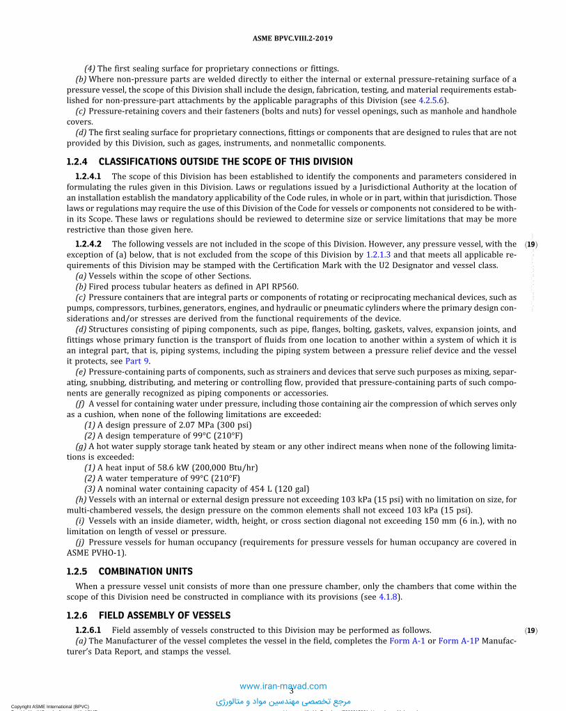
ð19Þ
ð19Þ
(4) The first sealing surface for proprietary connections or fittings.(b)Where non-pressure parts are welded directly to either the internal or external pressure-retaining surface of a
pressure vessel, the scope of this Division shall include the design, fabrication, testing, and material requirements estab-lished for non-pressure-part attachments by the applicable paragraphs of this Division (see 4.2.5.6).
(c) Pressure-retaining covers and their fasteners (bolts and nuts) for vessel openings, such as manhole and handholecovers.
(d) The first sealing surface for proprietary connections, fittings or components that are designed to rules that are notprovided by this Division, such as gages, instruments, and nonmetallic components.
1.2.4 CLASSIFICATIONS OUTSIDE THE SCOPE OF THIS DIVISION1.2.4.1 The scope of this Division has been established to identify the components and parameters considered in
formulating the rules given in this Division. Laws or regulations issued by a Jurisdictional Authority at the location ofan installation establish the mandatory applicability of the Code rules, in whole or in part, within that jurisdiction. Thoselaws or regulations may require the use of this Division of the Code for vessels or components not considered to be with-in its Scope. These laws or regulations should be reviewed to determine size or service limitations that may be morerestrictive than those given here.
1.2.4.2 The following vessels are not included in the scope of this Division. However, any pressure vessel, with theexception of (a) below, that is not excluded from the scope of this Division by 1.2.1.3 and that meets all applicable re-quirements of this Division may be stamped with the Certification Mark with the U2 Designator and vessel class.
(a) Vessels within the scope of other Sections.(b) Fired process tubular heaters as defined in API RP560.(c) Pressure containers that are integral parts or components of rotating or reciprocating mechanical devices, such as
pumps, compressors, turbines, generators, engines, and hydraulic or pneumatic cylinders where the primary design con-siderations and/or stresses are derived from the functional requirements of the device.
(d) Structures consisting of piping components, such as pipe, flanges, bolting, gaskets, valves, expansion joints, andfittings whose primary function is the transport of fluids from one location to another within a system of which it isan integral part, that is, piping systems, including the piping system between a pressure relief device and the vesselit protects, see Part 9.
(e) Pressure-containing parts of components, such as strainers and devices that serve such purposes as mixing, separ-ating, snubbing, distributing, and metering or controlling flow, provided that pressure-containing parts of such compo-nents are generally recognized as piping components or accessories.
(f) A vessel for containing water under pressure, including those containing air the compression of which serves onlyas a cushion, when none of the following limitations are exceeded:
(1) A design pressure of 2.07 MPa (300 psi)(2) A design temperature of 99°C (210°F)
(g) A hot water supply storage tank heated by steam or any other indirect means when none of the following limita-tions is exceeded:
(1) A heat input of 58.6 kW (200,000 Btu/hr)(2) A water temperature of 99°C (210°F)(3) A nominal water containing capacity of 454 L (120 gal)
(h) Vessels with an internal or external design pressure not exceeding 103 kPa (15 psi) with no limitation on size, formulti-chambered vessels, the design pressure on the common elements shall not exceed 103 kPa (15 psi).
(i) Vessels with an inside diameter, width, height, or cross section diagonal not exceeding 150 mm (6 in.), with nolimitation on length of vessel or pressure.
(j) Pressure vessels for human occupancy (requirements for pressure vessels for human occupancy are covered inASME PVHO-1).
1.2.5 COMBINATION UNITSWhen a pressure vessel unit consists of more than one pressure chamber, only the chambers that come within the
scope of this Division need be constructed in compliance with its provisions (see 4.1.8).
1.2.6 FIELD ASSEMBLY OF VESSELS1.2.6.1 Field assembly of vessels constructed to this Division may be performed as follows.(a) The Manufacturer of the vessel completes the vessel in the field, completes the Form A-1 or Form A-1P Manufac-
turer’s Data Report, and stamps the vessel.
3
ASME BPVC.VIII.2-2019
Copyright ASME International (BPVC) Provided by IHS under license with ASME Licensee=Khalda Petroleum/5986215001, User=Amer, Mohamed
Not for Resale, 07/02/2019 14:07:58 MDTNo reproduction or networking permitted without license from IHS
--`,```,,,,,````,`,``,,`,,`,`-`-`,,`,,`,`,,`---
www.iran-mavad.com
مرجع تخصصی مهندسین مواد و متالورژی

ð19Þ
(b) The Manufacturer of parts of a vessel to be completed in the field by some other party stamps these parts in ac-cordance with Code rules and supplies the Form A-2 Manufacturer’s Partial Data Report to the other party. The otherparty, who must hold a valid U2 Certificate of Authorization, makes the final assembly, performs the required NDE, per-forms the final pressure test, completes the Form A-1 or Form A-1P Manufacturer’s Data Report, and stamps the vessel.(c) The field portion of the work is completed by a holder of a valid U2 Certificate of Authorization other than the
vessel Manufacturer. The Certificate holder performing the field work is required to supply a Form A-2 Manufacturer’sPartial Data Report covering the portion of the work completed by his organization (including data on the pressure testif conducted by the Certificate holder performing the field work) to the Manufacturer responsible for the Code vessel.The vessel Manufacturer applies his Certification Mark with U2 Designator in the presence of a representative from hisInspection Agency and completes the Form A-1 or Form A-1P Manufacturer’s Data Report with his Inspector.
1.2.6.2 In all three alternatives, the party completing and signing the Form A-1 or Form A-1P Manufacturer’s DataReport assumes full Code responsibility for the vessel. In all three cases, each Manufacturer’s Quality Control Systemshall describe the controls to assure compliance by each Certificate holder.
1.2.7 PRESSURE RELIEF DEVICESThe scope of this Division includes provisions for pressure relief devices necessary to satisfy the requirements of
Part 9.
1.3 STANDARDS REFERENCED BY THIS DIVISION
(a) Throughout this Division, references are made to various standards, such as ASME standards, which describe partsor fittings or which establish dimensional limits for pressure vessel parts. These standards, with the year of the accept-able edition, are listed in Table 1.1.(b) Rules for the use of these standards are stated elsewhere in this Division.
1.4 UNITS OF MEASUREMENT
(a) Either U.S. Customary, SI, or any local customary units may be used to demonstrate compliance with requirementsof this edition related to materials, fabrication, examination, inspection, testing, certification, and overpressureprotection.(b) A single system of units shall be used for all aspects of design except where otherwise permitted by this Division.
When components are manufactured at different locations where local customary units are different than those used forthe general design, the local units may be used for the design and documentation of that component within the limita-tions given in (c). Similarly, for proprietary components or those uniquely associated with a system of units differentthan that used for the general design, the alternate units may be used for the design and documentation of that compo-nent within the limitations given in (c).(c) For any single equation, all variables shall be expressed in a single system of units. Calculations using any material
data published in this Division or Section II, Part D (e.g., allowable stresses, physical properties, external pressure designfactor B) shall be carried out in one of the standard units given in Table 1.2. When separate equations are provided forU.S. Customary and SI units, those equations shall be executed using variables in the units associated with the specificequation. Data expressed in other units shall be converted to U.S. Customary or SI units for use in these equations. Theresult obtained from execution of these equations or any other calculations carried out in either U.S. Customary or SIunits may be converted to other units.(d) Production, measurement and test equipment, drawings, welding procedure specifications, welding procedure
and performance qualifications, and other fabrication documents may be in U.S. Customary, SI or local customary unitsin accordance with the fabricator’s practice. When values shown in calculations and analysis, fabrication documents ormeasurement and test equipment are in different units, any conversions necessary for verification of Code complianceand to ensure that dimensional consistency is maintained shall be in accordance with the following:
(1) Conversion factors shall be accurate to at least four significant figures(2) The results of conversions of units shall be expressed to a minimum of three significant figures
(e) Conversion of units, using the precision specified above shall be performed to assure that dimensional consistencyis maintained. Conversion factors between U.S. Customary and SI units may be found in Annex 1-C. Whenever local cus-tomary units are used the Manufacturer shall provide the source of the conversion factors which shall be subject to ver-ification and acceptance by the Authorized Inspector or Certified Individual.(f) Dimensions shown in the text, tables and figures, whether given as a decimal or a fraction, may be taken as a dec-
imal or a fraction and do not imply any manufacturing precision or tolerance on the dimension.
4
ASME BPVC.VIII.2-2019
Copyright ASME International (BPVC) Provided by IHS under license with ASME Licensee=Khalda Petroleum/5986215001, User=Amer, Mohamed
Not for Resale, 07/02/2019 14:07:58 MDTNo reproduction or networking permitted without license from IHS
--`,```,,,,,````,`,``,,`,,`,`-`-`,,`,,`,`,,`---www.iran-mavad.com
مرجع تخصصی مهندسین مواد و متالورژی

ð19Þ
(g)Material that has been manufactured and certified to either the U.S. Customary or SI material specification (e.g.,SA-516 or SA-516M) may be used regardless of the unit system used in design. Standard fittings (e.g., flanges, elbows,etc.) that have been certified to either U.S. Customary units or SI units may be used regardless of the units system used indesign.
(h) All entries on a Manufacturer’s Data Report and data for Code-required nameplate marking shall be in units con-sistent with the fabrication drawings for the component using U. S. Customary, SI, or local customary units. Units (eitherprimary or alternative) may be shown parenthetically. Users of this Code are cautioned that the receiving Jurisdictionshould be contacted to ensure the units are acceptable.
1.5 TOLERANCES
The Code does not fully address tolerances. When dimensions, sizes, or other parameters are not specified with tol-erances, the values of these parameters are considered nominal, and allowable tolerances or local variances may be con-sidered acceptable when based on engineering judgment and standard practices as determined by the designer.
1.6 TECHNICAL INQUIRIES
A procedure for submittal of Technical Inquiries to the ASME Boiler and Pressure Vessel Code Committee is containedin the front matter.
1.7 TABLES
Table 1.1Year of Acceptable Edition of Referenced Standards in This Division
Title Number Year
Marking and Labeling Systems ANSI/UL-969 Latest editionFitness-For-Service API 579-1/ASME
FFS-12016
Materials and Fabrication of 21/4Cr–1Mo, 21/4Cr–1Mo–1/4V, 3Cr–1Mo, and 3Cr–1Mo–1/4V SteelHeavy Wall Pressure Vessels for High-Temperature, High-Pressure Hydrogen Service
API RP 934-A 2008 (2012Addendum)
Seat Tightness of Pressure Relief Valves API Standard 527 2014, Fourth editionFired Heaters for General Refinery Service API Standard 560 Latest editionMinimum Design Loads and Associated Criteria for Buildings and Other Structures ASCE/SEI 7 2016Nuts for General Applications: Machine Screw Nuts, Hex, Square, Hex Flange, and Coupling Nuts(Inch Series)
ASME/ANSIB18.2.2
Latest edition
Unified Inch Screw Threads (UN and UNR Thread Form) ASME B1.1 Latest editionMetric Screw Threads — M Profile ASME B1.13M Latest editionPipe Threads, General Purpose, Inch ASME B1.20.1 Latest editionMetric Screw Threads — MJ Profile ASME B1.21M Latest editionPipe Flanges and Flanged Fittings, NPS 1/2 Through NPS 24 Metric/Inch Standard ASME B16.5 2013Factory Made Wrought Steel Buttwelding Fittings ASME B16.9 Latest editionForged Steel Fittings, Socket-Welding and Threaded ASME B16.11 Latest editionMetallic Gaskets for Pipe Flanges — Ring Joint, Spiral-Wound and Jacketed ASME B16.20 Latest editionLarge Diameter Steel Flanges, NPS 26 Through NPS 60 Metric/Inch Standard ASME B16.47 2017Metric Heavy Hex Screws ASME B18.2.3.3M Latest editionMetric Hex Bolts ASME B18.2.3.5M Latest editionMetric Heavy Hex Bolts ASME B18.2.3.6M Latest editionMetric Fasteners for Use in Structural Applications ASME B18.2.6M Latest editionConformity Assessment Requirements ASME CA-1 Latest editionGuidelines for Pressure Boundary Bolted Flange Joint Assembly ASME PCC-1 2013Repair of Pressure Equipment and Piping ASME PCC-2 2018Pressure Relief Devices ASME PTC 25 2014Qualifications for Authorized Inspection ASME QAI-1 Latest editionStandard Practice for Quantitative Measurement and Reporting of Hypoeutectoid Carbon andLow-Alloy Steel Phase Transformations
ASTM A1033 Latest edition
Standard Reference Photographs for Magnetic Particle Indications on Ferrous Castings ASTM E125 1963 (R2008)[Note (1)]
5
ASME BPVC.VIII.2-2019
Copyright ASME International (BPVC) Provided by IHS under license with ASME Licensee=Khalda Petroleum/5986215001, User=Amer, Mohamed
Not for Resale, 07/02/2019 14:07:58 MDTNo reproduction or networking permitted without license from IHS
--`,```,,,,,````,`,``,,`,,`,`-`-`,,`,,`,`,,`---www.iran-mavad.com
مرجع تخصصی مهندسین مواد و متالورژی

ð19Þ
Table 1.1Year of Acceptable Edition of Referenced Standards in This Division (Cont'd)
Title Number Year
Standard Practice for Fabricating and Checking Aluminum Alloy Ultrasonic Standard ReferenceBlocks
ASTM E127 2015
Standard Test Methods for Conducting Creep, Creep-Rupture, and Stress-Rupture Tests of MetallicMaterials
ASTM E139 Latest edition
Standard Hardness Conversion Tables for Metals Relationship Among Brinell Hardness, VickersHardness, Rockwell Hardness, Superficial Hardness, Knoop Hardness, and ScleroscopeHardness
ASTM E140 Latest edition
Standard Reference Radiographs for Heavy-Walled [2 to 41/2 in. (50.8 to 114 mm)] Steel Castings ASTM E186 2015Standard Test Method of Conducting Drop Weight Test to Determine Nil Ductility TransitionTemperature of Ferritic Steel
ASTM E208 2006 (R2012)[Note (1)]
Standard Reference Radiographs for High-Strength Copper-Base and Nickel-Copper Alloy Castings ASTM E272 2015Standard Reference Radiographs for Heavy-Walled [41/2 to 12 in. (114 to 305 mm)] Steel Castings ASTM E280 2015Standard Reference Radiographs for Steel Castings up to 2 in. (51 mm) in Thickness ASTM E446 2015Standard Procedures for Calibrating Magnetic Instruments to Measure the Delta Ferrite Contentof Austenitic and Duplex Austenitic-Ferrite Stainless Steel Weld Metal
AWS 4.2M 2006
Metallic materials — Charpy pendulum impact test — Part 1: Test method ISO 148-1 2009Metallic materials — Charpy pendulum impact test — Part 2: Verification of testing machines ISO 148-2 2008Metallic materials— Charpy pendulum impact test— Part 3: Preparation and characterization ofCharpy V-notch test pieces for indirect verification of pendulum impact machines
ISO 148-3 2008
Petroleum, petrochemical and natural gas industries — Fired heaters for general refinery service ISO 13705 Latest editionStandard Practice for Ultrasonic Examination of Steel Forgings SA-388/SA-388M Latest edition
NOTE:(1) “R” indicates reaffirmed.
Table 1.2Standard Units for Use in Equations
Quantity SI Units U.S. Customary Units
Linear dimensions (e.g., length, height, thickness, radius, diameter) millimeters (mm) inches (in.)Area square millimeters (mm2) square inches (in.2)Volume cubic millimeters (mm3) cubic inches (in.3)Section modulus cubic millimeters (mm3) cubic inches (in.3)Moment of inertia of section millimeters4 (mm4) inches4 (in.4)Mass (weight) kilograms (kg) pounds mass (lbm)Force (load) newtons (N) pounds force (lbf)Bending moment newton‐millimeters (N·mm) inch‐pounds (in.‐lb)Pressure, stress, stress intensity, and modulus of elasticity megapascals (MPa) pounds per square inch (psi)Energy (e.g., Charpy impact values) joules (J) foot‐pounds (ft‐lb)Temperature degrees Celsius (°C) degrees Fahrenheit (°F)Absolute temperature kelvin (K) Rankine (°R)Fracture toughness MPa square root meters (MPa ) ksi square root inches (ksi )
Angle degrees or radians degrees or radiansBoiler capacity watts (W) Btu/hr
6
ASME BPVC.VIII.2-2019
Copyright ASME International (BPVC) Provided by IHS under license with ASME Licensee=Khalda Petroleum/5986215001, User=Amer, Mohamed
Not for Resale, 07/02/2019 14:07:58 MDTNo reproduction or networking permitted without license from IHS
--`,```,,,,,````,`,``,,`,,`,`-`-`,,`,,`,`,,`---
www.iran-mavad.com
مرجع تخصصی مهندسین مواد و متالورژی

ð19Þ
ANNEX 1-BDEFINITIONS
(Normative)
1-B.1 INTRODUCTION
This Annex contains definitions of terms generally used in this Division. Definitions relating to specific applicationsmay also be found in related Parts of this Division.
1-B.2 DEFINITION OF TERMS
1-B.2.1 Acceptance by the Inspector, accepted by the Inspector - an indication that the Inspector has reviewed asubject in accordance with his duties as required by the rules of this Division and after such review is able to signthe Certificate of Inspection for the applicable Manufacturer’s Data Report Form.
1-B.2.2 ASME Designated Organization – see ASME CA-1.
1-B.2.3 ASME designee – see ASME CA-1.
1-B.2.4 Certificate of Compliance – a document that states that the material represented has been manufactured,sampled, tested and inspected in accordance with the requirements of the material specification (including year of issue)and any other requirements specified in the purchase order or contract shown on the certificate and has been found tomeet such requirements. This document may be combined with the Materials Test Report (see 1-B.2.19) as a singledocument.
1-B.2.5 Certificate of Authorization – a document issued by the Society that authorizes the use of the ASME Certi-fication Mark and appropriate designator for a specified time and for a specified scope of activity.
1-B.2.6 Certification Mark – an ASME symbol identifying a product as meeting Code requirements.
1-B.2.7 Certification Mark Stamp – a metallic stamp issued by the Society for use in impressing the CertificationMark.
1-B.2.8 Certification Designator (Designator) – the symbol used in conjunction with the Certification Mark for thescope of activity described in a Manufacturer’s Certificate of Authorization.
1-B.2.9 Certifying Engineer – an engineer or other technically competent professional duly accredited and qualifiedto practice engineering as required by this Division.
1-B.2.10 Class 1 Vessel – a vessel that is designed using the allowable stresses from Section II, Part D, Subpart 1,Table 2A or Table 2B.
1-B.2.11 Class 2 Vessel – a vessel that is designed using the allowable stresses from Section II, Part D, Subpart 1,Table 5A or Table 5B.
1-B.2.12 Communicating Chambers – appurtenances to a vessel that intersect the shell or heads of a vessel and forman integral part of the pressure-containing enclosure.
1-B.2.13 Construction – an all-inclusive term comprising materials, design, fabrication, examination, inspection,testing, certification, and pressure relief.
1-B.2.14 Designer – an individual who is qualified to design pressure vessels in accordance with the rules of thisDivision by demonstrated knowledge in Code requirements and proficiency in selecting correct design formulas and ap-propriate values to be used when preparing the design of a pressure vessel.
1-B.2.15 Local Jurisdictional Authority – an agency enforcing laws or regulations applicable to pressure vessels.
7
ASME BPVC.VIII.2-2019
Copyright ASME International (BPVC) Provided by IHS under license with ASME Licensee=Khalda Petroleum/5986215001, User=Amer, Mohamed
Not for Resale, 07/02/2019 14:07:58 MDTNo reproduction or networking permitted without license from IHS
--`,```,,,,,````,`,``,,`,,`,`-`-`,,`,,`,`,,`---
www.iran-mavad.com
مرجع تخصصی مهندسین مواد و متالورژی

1-B.2.16 Manufacturer – the organization responsible for construction of a pressure vessel, vessel component, orpart or the organization responsible for the manufacture of pressure relief devices in accordance with the rules of thisDivision and who holds an ASME Certificate of Authorization to apply the Certification Mark to such an item.
1-B.2.17 Material – any substance or product form covered by a material specification in Section II Part A, B, or C orany other substance or product form permitted for use in pressure vessel construction by this Division.
1-B.2.18 Material Manufacturer – the organization responsible for the production of products meeting the require-ments of the material specification and accepting the responsibility for any statements or data in any required Certificateof Compliance or Material Test Report representing the material.
1-B.2.19 Material Test Report – a document in which the results of tests, examinations, repairs, or treatments re-quired by the material specification to be reported are recorded, including those of any supplementary requirements orother requirements stated in the order for the material. This document may be combined with a Certificate of Compli-ance (see 1-B.2.4) as a single document.
1-B.2.20 User – the organization that purchases the finished pressure vessel for its own use or as an agent for theowner. The user’s designated agent may be either a design agency specifically engaged by the user, the Manufacturer of asystem for a specific service which includes a pressure vessel as a part and which is purchased by the user, or an orga-nization which offers pressure vessels for sale or lease for specific services.
8
ASME BPVC.VIII.2-2019
Copyright ASME International (BPVC) Provided by IHS under license with ASME Licensee=Khalda Petroleum/5986215001, User=Amer, Mohamed
Not for Resale, 07/02/2019 14:07:58 MDTNo reproduction or networking permitted without license from IHS
--`,```,,,,,````,`,``,,`,,`,`-`-`,,`,,`,`,,`---
www.iran-mavad.com
مرجع تخصصی مهندسین مواد و متالورژی

ð19Þ
ANNEX 1-CGUIDANCE FOR THE USE OF U.S. CUSTOMARY AND SI UNITS IN
THE ASME BOILER AND PRESSURE VESSEL CODES
(Informative)
1-C.1 USE OF UNITS IN EQUATIONS
The equations in this Division are suitable for use only with either the SI or U.S. Customary units provided in Table 1.2or with the units provided in the nomenclatures associated with the equations. It is the responsibility of the individualand organization performing the calculations to ensure that appropriate units are used. Either SI or U.S. Customary unitsmay be used as a consistent set. When necessary to convert from one system to another, the units shall be converted to atleast four significant figures for use in calculations and other aspects of construction.
1-C.2 GUIDELINES USED TO DEVELOP SI EQUIVALENTS
(a) U.S. Customary units are placed in parenthesis after the SI unit in the text.(b) In general, both SI and U.S. Customary tables are provided if interpolation is expected. The table designation (e.g.,
table number) is the same for both the SI and the U.S. Customary tables, with the addition of an M after the table numberfor the SI Table. In the text, references to a Table use only the primary table number (i.e., without the M). For some smalltables, where interpolation is not required, U.S. Customary units are placed in parenthesis after the SI unit.
(c) Separate SI and U.S. Customary versions of graphical information (charts) are provided, except that if both axes aredimensionless a single figure (chart) is used.
(d) In most cases, conversions of units in the text were done using hard SI conversion practices, with some soft con-versions on a case-by-case basis as appropriate. This was implemented by rounding the SI values to the number of sig-nificant figures of implied precision in the existing U.S. Customary units. For example, 3000 psi has an implied precisionof one significant figure. Therefore, the conversion to SI units would typically be to 20,000 kPa. This is a difference ofabout 3% from the “exact” or soft conversion of 20,684.27 kPa. However, the precision of the conversion was deter-mined by the Committee on a case-by-case basis. More significant digits were included in the SI equivalent if therewas any question. The values of allowable stress in Section II, Part D generally include three significant figures.
(e) Minimum thickness and radius values that are expressed in fractions of an inch were generally converted accord-ing to Table 1-C.1.
(f) For nominal sizes that are in even increments of inches, even multiples of 25 mm were generally used. Intermedi-ate values were interpolated rather than converting and rounding to the nearest mm. See examples in Table 1-C.2. Notethat this table does not apply to nominal pipe sizes (NPS), which are covered in Table 1-C.4.
(g) For nominal pipe sizes, the relationships shown in Table 1-C.4 were used.(h) Areas in square inches (in.2) were converted to square millimeters (mm2), and areas in square feet (ft2) were con-
verted to square meters (m2), see examples in Table 1-C.5.(i) Volumes in cubic inches (in.3) were converted to cubic millimeters (mm3), and volumes in cubic feet (ft3) were
converted to cubic meters (m3), see examples in the Table 1-C.6.(j) Although the pressure should always be in MPa or psi for calculations, there are cases where other units are used
in the text. For example, kPa is sometimes used for low pressures and ksi is sometimes used for high pressures andstresses. Also, rounding was to one significant figure (two at the most) in most cases, see examples in Table 1-C.7. Notethat 14.7 psi converts to 101 kPa, while 15 psi converts to 100 kPa. While this may seem at first glance to be an anomaly,it is consistent with the rounding philosophy.
(k) Material properties that are expressed in psi or ksi (e.g., allowable stress, yield and tensile strength, elastic mod-ulus) were generally converted to MPa to three significant figures. See example in Table 1-C.8.
9
ASME BPVC.VIII.2-2019
Copyright ASME International (BPVC) Provided by IHS under license with ASME Licensee=Khalda Petroleum/5986215001, User=Amer, Mohamed
Not for Resale, 07/02/2019 14:07:58 MDTNo reproduction or networking permitted without license from IHS
--`,```,,,,,````,`,``,,`,,`,`-`-`,,`,,`,`,,`---
www.iran-mavad.com
مرجع تخصصی مهندسین مواد و متالورژی

(l) In most cases, temperatures (e.g., for PWHT) were rounded to the nearest 5°C. Depending on the implied precisionof the temperature, some were rounded to the nearest 1°C or 10°C or even 25°C. Temperatures colder than 0°F (negativevalues) were generally rounded to the nearest 1°C. The examples in Table 1-C.9 were created by rounding to the nearest5°C, with one exception.
1-C.3 SOFT CONVERSION FACTORS
Table 1-C.10 of “soft” conversion factors is provided for convenience. Multiply the U.S. Customary value by the factorgiven to obtain the SI value. Similarly, divide the SI value by the factor given to obtain the U.S. Customary value. In mostcases it is appropriate to round the answer to three significant figures.
1-C.4 TABLES
Table 1-C.1Typical Size or Thickness Conversions for Fractions
Fraction in U.S. Customary Units, in. Proposed SI Conversion, mm Difference, %1/32 0.8 –0.83/64 1.2 –0.81/16 1.5 5.53/32 2.5 –5.01/8 3 5.5
5/32 4 –0.83/16 5 –5.07/32 5.5 1.01/4 6 5.55/16 8 –0.8
3/8 10 –5.07/16 11 1.01/2 13 –2.49/16 14 2.05/8 16 –0.8
11/16 17 2.63/4 19 0.37/8 22 1.01 25 1.6
Table 1-C.2Typical Size or Thickness Conversions
Size, in. Size, mm
1 2511/8 2911/4 3211/2 382 50
21/4 5721/2 643 7531/2 894 100
41/2 114
10
ASME BPVC.VIII.2-2019
Copyright ASME International (BPVC) Provided by IHS under license with ASME Licensee=Khalda Petroleum/5986215001, User=Amer, Mohamed
Not for Resale, 07/02/2019 14:07:58 MDTNo reproduction or networking permitted without license from IHS
--`,```,,,,,````,`,``,,`,,`,`-`-`,,`,,`,`,,`--- www.iran-mavad.com
مرجع تخصصی مهندسین مواد و متالورژی

Table 1-C.2Typical Size or Thickness Conversions (Cont'd)
Size, in. Size, mm
5 1256 1508 20012 300
18 45020 50024 60036 90040 1 00054 1 35060 1 50072 1 800
Table 1-C.3Typical Size or Length Conversions
Size or Length, ft Size or Length, m
3 15 1.5
200 60
Table 1-C.4Typical Nominal Pipe Size Conversions
U.S. Customary Practice SI Practice U. S. Customary Practice SI Practice
NPS 1/8 DN 6 NPS 20 DN 500NPS 1/4 DN 8 NPS 22 DN 550NPS 3/8 DN 10 NPS 24 DN 600NPS 1/2 DN 15 NPS 26 DN 650NPS 3/4 DN 20 NPS 28 DN 700
NPS 1 DN 25 NPS 30 DN 750NPS 11/4 DN 32 NPS 32 DN 800NPS 11/2 DN 40 NPS 34 DN 850NPS 2 DN 50 NPS 36 DN 900NPS 21/2 DN 65 NPS 38 DN 950
NPS 3 DN 80 NPS 40 DN 1 000NPS 31/2 DN 90 NPS 42 DN 1 050NPS 4 DN 100 NPS 44 DN 1 100NPS 5 DN 125 NPS 46 DN 1 150NPS 6 DN 150 NPS 48 DN 1 200
NPS 8 DN 200 NPS 50 DN 1 250NPS 10 DN 250 NPS 52 DN 1 300NPS 12 DN 300 NPS 54 DN 1 350NPS 14 DN 350 NPS 56 DN 1 400NPS 16 DN 400 NPS 58 DN 1 450NPS 18 DN 450 NPS 60 DN 1 500
11
ASME BPVC.VIII.2-2019
Copyright ASME International (BPVC) Provided by IHS under license with ASME Licensee=Khalda Petroleum/5986215001, User=Amer, Mohamed
Not for Resale, 07/02/2019 14:07:58 MDTNo reproduction or networking permitted without license from IHS
--`,```,,,,,````,`,``,,`,,`,`-`-`,,`,,`,`,,`---
www.iran-mavad.com
مرجع تخصصی مهندسین مواد و متالورژی

Table 1-C.5Typical Area Conversions
Area in U.S. Customary Area in SI
1 in.2 650 mm2
6 in.2 4 000 mm2
10 in.2 6 500 mm2
5 ft2 0.5 m2
Table 1-C.6Typical Volume Conversions
Volume in U.S. Customary Volume in SI
1 in.3 16 000 mm3
6 in.3 100 000 mm3
10 in.3 160 000 mm3
5 ft3 0.14 m3
Table 1-C.7Typical Pressure Conversions
Pressure in U.S. Customary Pressure in SI
0.5 psi 3 kPa2 psi 15 kPa3 psi 20 kPa10 psi 70 kPa14.7 psi 101 kPa
15 psi 100 kPa30 psi 200 kPa50 psi 350 kPa100 psi 700 kPa150 psi 1 MPa
200 psi 1.5 MPa250 psi 1.7 MPa300 psi 2 MPa350 psi 2.5 MPa400 psi 3 MPa
500 psi 3.5 MPa600 psi 4 MPa1,200 psi 8 MPa1,500 psi 10 MPa
12
ASME BPVC.VIII.2-2019
Copyright ASME International (BPVC) Provided by IHS under license with ASME Licensee=Khalda Petroleum/5986215001, User=Amer, Mohamed
Not for Resale, 07/02/2019 14:07:58 MDTNo reproduction or networking permitted without license from IHS
--`,```,,,,,````,`,``,,`,,`,`-`-`,,`,,`,`,,`---
www.iran-mavad.com
مرجع تخصصی مهندسین مواد و متالورژی

Table 1-C.8Typical Strength Conversions
Strength in U.S. Customary, psi Strength in SI, MPa
30,000 20538,000 26060,000 41570,000 48095,000 655
Table 1-C.9Typical Temperature Conversions
Temperature, °F Temperature, °C
70 20100 38120 50150 65200 95
250 120300 150350 175400 205450 230
500 260550 290600 315650 345700 370
750 400800 425850 455900 480925 495
950 5101,000 5401,050 5651,100 5951,150 620
1,200 6501,250 6751,800 9801,900 1 0402,000 1 0952,050 1 120
13
ASME BPVC.VIII.2-2019
Copyright ASME International (BPVC) Provided by IHS under license with ASME Licensee=Khalda Petroleum/5986215001, User=Amer, Mohamed
Not for Resale, 07/02/2019 14:07:58 MDTNo reproduction or networking permitted without license from IHS
--`,```,,,,,````,`,``,,`,,`,`-`-`,,`,,`,`,,`---
www.iran-mavad.com
مرجع تخصصی مهندسین مواد و متالورژی

Table 1-C.10Conversion Factors
U.S. Customary SI Conversion Factor Notes
in. mm 25.4 …ft m 0.3048 …in.2 mm2 645.16 …ft2 m2 0.09290304 …in3 mm3 16,387.064 …
ft3 m3 0.02831685 …US Gal. m3 0.003785412 …psi MPa 0.0068948 Used exclusively in equationspsi kPa 6.894757 Used only in text and for nameplateft-lb J 1.355818 …
°F °C 5/9(°F − 32) Not for temperature difference°F °C 5/9(°F) For temperature differences onlyR K 5/9 Absolute temperature
lbm kg 0.4535924 …lbf N 4.448222 …
in.-lb N·mm 112.98484 Use exclusively in equationsft-lb N·m 1.3558181 Use only in text
1.0988434 …
Btu/hr W 0.2930711 Use for Boiler rating and heat transferlb/ft3 kg/m3 16.018463 …
14
ASME BPVC.VIII.2-2019
Copyright ASME International (BPVC) Provided by IHS under license with ASME Licensee=Khalda Petroleum/5986215001, User=Amer, Mohamed
Not for Resale, 07/02/2019 14:07:58 MDTNo reproduction or networking permitted without license from IHS
--`,```,,,,,````,`,``,,`,,`,`-`-`,,`,,`,`,,`---
www.iran-mavad.com
مرجع تخصصی مهندسین مواد و متالورژی

ð19Þ
ð19Þ
PART 2RESPONSIBILITIES AND DUTIES
2.1 GENERAL
2.1.1 INTRODUCTIONThe user, Manufacturer, and Inspector involved in the production and certification of vessels in accordance with this
Division have definite responsibilities or duties in meeting the requirements of this Division. The responsibilities andduties set forth in the following relate only to compliance with this Division, and are not to be construed as involvingcontractual relations or legal liabilities.
2.1.2 DEFINITIONSThe definitions for the terminology used in this Part are contained in Annex 1-B.
2.1.3 CODE REFERENCEThe Code Edition year on the User’s Design Specification and Manufacturer’s Design Report shall be the same as the
Code Edition year on the Manufacturer’s Data Report.
2.2 USER RESPONSIBILITIES
2.2.1 GENERALIt is the responsibility of the user or an agent acting on behalf of the user to provide a User’s Design Specification for
each pressure vessel to be constructed in accordance with this Division. The User’s Design Specification shall containsufficient detail to provide a complete basis for design and construction in accordance with this Division. It is the user’sresponsibility to specify, or cause to be specified, the effective Code edition and vessel class to be used for construction.
2.2.2 MULTIPLE IDENTICAL VESSELSA single User’s Design Specification may be prepared to support the design of more than one pressure vessel that is to
be located in a single, specific jurisdiction provided that the environmental requirements and jurisdictional regulatoryauthority applied for each installation location are clearly specified and are the same or more conservative thanrequired.
2.2.2.1 Class 1. The User’s Design Specification shall be certified by a Certifying Engineer meeting the requirementsdescribed in Annex 2-A when the user provides the data required by 2.2.3.1(f)(1) and 2.2.3.1(f)(2) to perform a fatigueanalysis.
2.2.2.2 Class 2. The User’s Design Specification shall be certified by a Certifying Engineer in accordance with Annex2-A.
2.2.3 USER’S DESIGN SPECIFICATION2.2.3.1 The User’s Design Specification shall include but not necessarily be limited to the following:(a) Installation Site(1) Location(2) Jurisdictional authority if applicable(3) Environmental conditions
(-a) Wind design loads including relevant factors (i.e., design wind speed, exposure, gust factors)(-b) Earthquake design loads(-c) Snow loads(-d) Lowest one day mean temperature for location
(b) Vessel Identification(1) Vessel number or identification
15
ASME BPVC.VIII.2-2019
Copyright ASME International (BPVC) Provided by IHS under license with ASME Licensee=Khalda Petroleum/5986215001, User=Amer, Mohamed
Not for Resale, 07/02/2019 14:07:58 MDTNo reproduction or networking permitted without license from IHS
--`,```,,,,,````,`,``,,`,,`,`-`-`,,`,,`,`,,`---
www.iran-mavad.com
مرجع تخصصی مهندسین مواد و متالورژی

(2) Service fluid for proprietary fluids specific properties needed for design, e.g., gas, liquid, density, etc.(c) Vessel Configuration and Controlling Dimensions
(1) Outline drawings(2) Vertical or horizontal(3) Openings, connections, closures including quantity, type and size, and location (i.e., elevation and orientation)(4) Principal component dimensions in sufficient detail so that volume capacities can be determined(5) Support method
(d) Design Conditions(1) Specified design pressure. The specified design pressure is the design pressure, see 4.1.5.2(a), required at the
top of the vessel in its operating position. It shall include suitable margins required above the maximum anticipated op-erating pressure to ensure proper operation of the pressure relief devices. The MAWP of the vessel may be set equal tothis specified design pressure. If the actual MAWP of the vessel is calculated, it shall not be less than the specified designpressure.
(2) Design temperature and coincident specified design pressure (see 4.1.5.2(d)).(3)Minimum Design Metal Temperature (MDMT) and coincident specified design pressure (see 4.1.5.2(e)).(4) Dead loads, live loads, and other loads required to perform the load case combinations required in Parts 4 and 5.
(e) Operating Conditions(1) Operating pressure and pressure load factor for occasional load combinations in Tables 4.1.2 and 5.3(2) Operating temperature(3) Fluid transients and flow and sufficient properties for determination of steady-state and transient thermal gra-
dients across the vessel sections, if applicable (see 5.5.2)(4) Dead loads, live loads, and other operating loads required to perform the load case combinations required in
Part 5(f) Design Fatigue Life
(1) Cyclic operating conditions and whether or not a fatigue analysis of the vessel as required shall be determined inaccordance with 4.1.1.4. When a fatigue analysis is required, provide information in sufficient detail so that an analysisof the cyclic operation can be carried out in accordance with 5.5.
(2)When a vessel is designed for cyclic conditions, the number of design cycles per year and the required vesseldesign life in years shall be stated.
(3)When cyclic operating conditions exist and a fatigue analysis is not required based on comparable equipmentexperience, this shall be stated. The possible harmful effects of the design features listed in 5.5.2.2(a) through 5.5.2.2(f)shall be evaluated when contemplating comparable equipment experience.
(4) Corrosion Fatigue(-a) The design fatigue cycles given by eqs. (3-F.1) and (3-F.4) do not include any allowances for corrosive con-
ditions and may be modified to account for the effects of environment other than ambient air that may cause corrosionor subcritical crack propagation. If corrosion fatigue is anticipated, a factor should be chosen on the basis of experienceor testing, by which the calculated design fatigue cycles (fatigue strength) should be reduced to compensate for thecorrosion.
(-b) When using eq. (3-F.4) an environmental modification factor shall be specified in the User’s DesignSpecification.
(-c) If due to lack of experience it is not certain that the chosen stresses are low enough, it is advisable that thefrequency of inspection be increased until there is sufficient experience to justify the factor used. This need for increasedfrequency should be stated in the User’s Design Specification.(g)Materials of Construction
(1)Material specification requirements shall be in accordance with one or more of the following criteria.(-a) Specification of materials of construction in accordance with Part 3.(-b) Generic material type (i.e., carbon steel or Type 304 Stainless Steel). The user shall specify requirements that
provide an adequate basis for selecting materials to be used for the construction of the vessel. The Manufacturer shallselect the appropriate material from Part 3, considering information provided by the user per (3).
(2) The user shall specify the corrosion and/or erosion allowance.(3) The user, when selecting the materials of construction, shall consider the following:(-a) Damage mechanisms associated with the service fluid at design conditions. Informative and nonmandatory
guidance regarding metallurgical phenomena is provided in Section II, Part D, Nonmandatory Appendix A; API RP 571;and WRC Bulletins 488, 489, and 490.
(-b) Minimum Design Metal Temperature and any additional toughness requirements.(-c) The need for specific weld filler material to meet corrosion resistance requirements, see 6.2.5.8.
16
ASME BPVC.VIII.2-2019
Copyright ASME International (BPVC) Provided by IHS under license with ASME Licensee=Khalda Petroleum/5986215001, User=Amer, Mohamed
Not for Resale, 07/02/2019 14:07:58 MDTNo reproduction or networking permitted without license from IHS
--`,```,,,,,````,`,``,,`,,`,`-`-`,,`,,`,`,,`---
www.iran-mavad.com
مرجع تخصصی مهندسین مواد و متالورژی

ð19Þ
(h) Loads and Load Cases(1) The user shall specify all expected loads and load case combinations as listed in 4.1.5.3.(2) These loading data may be established by:
(-a) Calculation(-b) Experimental methods(-c) Actual experience measurement from similar units(-d) Computer analysis(-e) Published data
(i) Overpressure Protection(1) The user shall be responsible for the design, construction and installation of the overpressure protection system
unless it is delegated to the Manufacturer. This system shall meet the requirements of Part 9.(2) The type of over pressure protection intended for the vessel shall be documented in the User’s Design Specifi-
cation as follows (see 9.1):(-a) Type of overpressure protection system (e.g., type of pressure relief valve, rupture disc, etc.)(-b) System design (see 9.7)
(3) The user shall state if jurisdictional acceptance is required prior to operation of the vessel.
2.2.3.2 Additional Requirements. The user shall state what additional requirements are appropriate for the in-tended vessel service such as:
(a) Additional requirements such as non-destructive examination, restricted chemistry, or heat treatments(b) Type of weld joints and the extent of required nondestructive examinations(c) Nonmandatory or optional provisions of this Division that are considered to be mandatory for the subject vessel(d) Any special requirements for marking and their location (see 4.1 and Annex 2-F)(e) Requirements for seals and/or bolting for closures and covers(f) Additional requirements relating to erection loadings(g) Any agreements which resolve the problems of operation and maintenance control unique to the particular pres-
sure vessel. See also 2.2.3.1(f)(4)(-c).(h) Specific additional requirements relating to pressure testing such as:(1) Fluid properties and test temperature limits(2) Position of vessel and support/foundation adequacy if field hydrostatic testing is required(3) Location: Manufacturer’s facility or on-site(4) Cleaning and drying(5) Selection of pressure test method, see 8.1.1(6) Application of paints, coatings and linings, see 8.1.2(e)
2.3 MANUFACTURER’S RESPONSIBILITIES
2.3.1 CODE COMPLIANCE2.3.1.1 The Manufacturer is responsible for the structural and pressure-retaining integrity of a vessel or part there-
of, as established by conformance with the requirements of the rules of this Division and the requirements in the User’sDesign Specification.
2.3.1.2 The Manufacturer completing any vessel or part marked with the Certification Mark with the U2 Designatorand class or the Certification Mark with the PRT Designator in accordance with this Division has the responsibility tocomply with all the applicable requirements of this Division and, through proper certification, to ensure that any workby others also complies with the requirements of this Division. The Manufacturer shall certify compliance with theserequirements by completing a Manufacturer’s Data Report (see 2.3.4).
2.3.1.3 A single Manufacturer’s Design Report may be completed and certified to document more than one pressurevessel that is to be located in a single, specific jurisdiction, provided that the details of design and construction demon-strate that the environmental requirements and jurisdictional regulatory authority applied for each installation locationare the same or more conservative than required.
2.3.2 MATERIALS SELECTION2.3.2.1 When generic material types (i.e., carbon steel or Type 304 Stainless Steel) are specified, the Manufacturer
shall select the appropriate material from Part 3, considering information provided by the user per 2.2.3.1(g)(3).
2.3.2.2 Any material substitutions by the Manufacturer are subject to approval of the user.
17
ASME BPVC.VIII.2-2019
Copyright ASME International (BPVC) Provided by IHS under license with ASME Licensee=Khalda Petroleum/5986215001, User=Amer, Mohamed
Not for Resale, 07/02/2019 14:07:58 MDTNo reproduction or networking permitted without license from IHS
--`,```,,,,,````,`,``,,`,,`,`-`-`,,`,,`,`,,`---
www.iran-mavad.com
مرجع تخصصی مهندسین مواد و متالورژی

ð19Þ 2.3.3 MANUFACTURER’S DESIGN REPORT2.3.3.1 Certification of a Manufacturer's Design Report for Class 1.(a) The Manufacturer’s Design Report shall be certified by a Certifying Engineer in accordance with Annex 2-B when
any of the following are performed:(1) fatigue analysis(2) use of Part 5 to determine thickness of pressure parts when design rules are not provided in Part 4(3) use of Part 4.8 to design a quick‐actuating closure(4) a dynamic seismic analysis
(b) The Manufacturer’s Design Report may be certified by a designer in accordance with Annex 2-B when none of theconditions of (a)(1) through (a)(4) applies.
2.3.3.2 Certification of a Manufacturer’s Design Report for Class 2. The Manufacturer’s Design Report shall becertified by a Certifying Engineer in accordance with Annex 2-B.
2.3.3.3 Contents of the Manufacturer's Design Report. The Manufacturer shall provide a Manufacturer’s DesignReport that includes:(a) Final as-built drawings.(b) The actual material specifications used for each component.(c) Design calculations and analysis that establish that the design as shown on the drawings complies with the re-
quirements of this Division for the design conditions that have been specified in the User’s Design Specification.(d) Any methods of design used that are not covered by the rules of this Division.
(1) Documentation of design-by-rule calculations in Part 4 shall include the following:(-a) The name and version of computer software, if applicable(-b) Loading conditions and boundary conditions used to address the load cases in the User’s Design
Specification(-c) Material models utilized for all required physical properties (i.e., stress–strain data, modulus of elasticity,
Poisson’s ratio, thermal expansion coefficient, thermal conductivity, thermal diffusivity), strength parameters (i.e., yieldand tensile strength), and allowable stresses
(-d) Detailed calculations, including results from all of the applicable steps in the calculations, showing the accep-tance criteria utilized to meet the requirements of this Division.
(-e) A summary of the calculation results(2) Documentation of design-by-analysis calculations in Part 5 shall include the following:(-a) A detailed description of the numerical method used, including the name and version of computer software,
if applicable(-b) Description of model geometry (including element type for finite element analysis)(-c) Loading conditions and boundary conditions used to address the load cases in the User’s Design
Specification(-d) Material models utilized for all required physical properties (i.e., modulus of elasticity, Poisson’s ratio, ther-
mal expansion coefficient, thermal conductivity, thermal diffusivity), strength parameters (i.e., yield and tensilestrength), strain limits, if applicable, and the design membrane stress intensity per Part 3
(-e) Description of whether material nonlinearity is utilized in the analysis including a description of the materialmodel (i.e., stress–strain curve and cyclic stress–strain curve)
(-f)Description of the numerical analysis procedure (i.e., static analysis, thermal analysis (temperature andstress), buckling analysis, natural frequency analysis, dynamic analysis) and whether a geometrically linear or nonlinearoption is invoked
(-g) Graphical display of relevant results (i.e., numerical model, deformed plots, and contour plots of thermal andstress results)
(-h) Method used to validate the numerical model (i.e., mesh sensitivity review and equilibrium check for finiteelement analysis, e.g., check of hoop stress in a component away from structural discontinuity and a check to ensure thatglobal equilibrium is achieved between applied loads and reactions at specified boundary conditions)
(-i)Description of results processing performed to establish numerical analysis results (i.e., stress linearizationmethod, use of centroidal or nodal values for stress, strain, and temperature results)
(-j)A summary of the numerical analysis results showing the acceptance criteria utilized to meet the require-ments of this Division
(-k) Electronic storage of analysis results including input files and output files that contain numerical analysisresults utilized to demonstrate compliance with the requirements of this Division(e) The results of any fatigue analyses according to 5.5, as applicable.(f) Any assumptions used by the Manufacturer to perform the vessel design.
18
ASME BPVC.VIII.2-2019
Copyright ASME International (BPVC) Provided by IHS under license with ASME Licensee=Khalda Petroleum/5986215001, User=Amer, Mohamed
Not for Resale, 07/02/2019 14:07:58 MDTNo reproduction or networking permitted without license from IHS
--`,```,,,,,````,`,``,,`,,`,`-`-`,,`,,`,`,,`---
www.iran-mavad.com
مرجع تخصصی مهندسین مواد و متالورژی

ð19Þ
2.3.4 MANUFACTURER’S DATA REPORTThe Manufacturer shall certify compliance to the requirements of this Division by the completion of the appropriate
Manufacturer’s Data Report as described in Annex 2-C and Annex 2-D.
2.3.5 MANUFACTURER’S CONSTRUCTION RECORDSThe Manufacturer shall prepare, collect and maintain construction records and documentation as fabrication pro-
gresses, to show compliance with the Manufacturer’s Design Report (e.g., NDE reports, repairs, deviations from draw-ings, etc.). An index of the construction records files, in accordance with the Manufacturer’s Quality Control system, shallbe maintained current (see 2-C.3). These construction records shall be maintained by the Manufacturer for the durationas specified in 2-C.3.
2.3.6 QUALITY CONTROL SYSTEMThe Manufacturer shall have and maintain a Quality Control System in accordance with Annex 2-E.
2.3.7 MANUFACTURER’S DESIGN PERSONNELThe Manufacturer has the responsibility of ensuring all personnel performing and/or evaluating design activities are
competent in the area of design (see Annexes 2‐C and 2‐J).
2.3.8 CERTIFICATION OF SUBCONTRACTED SERVICES2.3.8.1 The Quality Control system shall describe the manner in which the Manufacturer (Certificate Holder) con-
trols and accepts the responsibility for the subcontracting of activities. The Manufacturer shall ensure that all contractedactivities meet the requirements of this Division.
2.3.8.2 Work such as forming, nondestructive examination, heat treating, etc., may be performed by others (forwelding, see 6.1.4.2). It is the vessel Manufacturer’s responsibility to ensure that all work performed complies withall the applicable requirements of this Division. After ensuring compliance, and obtaining concurrence of the Inspector,the vessel may be stamped with the Certification Mark.
2.3.8.3 Subcontracts that involve welding on the pressure boundary components for construction under the rules ofthis Division, other than as provided in 6.1.4.2 and for repair welds permitted by the ASME material specifications, shallbe made only to subcontractors holding a valid U2 Certificate of Authorization. All such subcontracted welding shall bedocumented on Form A-2; see Annex 2-D.
2.3.8.4 A Manufacturer may engage individuals by contract for their services as Welders or Welding Operators, atshop or site locations shown on his Certification of Authorization, provided all of the following conditions are met:
(a) The work to be done by Welders or Welding Operators is within the scope of the Certificate of Authorization.(b) The use of such Welders or Welding Operators is described in the Quality Control system of the Manufacturer. The
Quality Control System shall include a requirement for direct supervision and direct technical control of the Welders andWelding operators, acceptable to the Manufacturer’s accredited Authorized Inspection Agency.
(c) The Welding Procedures have been properly qualified by the Manufacturer, according to Section IX.(d) The Welders and Welding Operators are qualified by the Manufacturer according to Section IX to perform these
procedures.(e) Code responsibility and control is retained by the Manufacturer.
2.3.9 INSPECTION AND EXAMINATIONThe Manufacturer’s responsibility for inspection and examination is summarized in Annex 7-A.
2.3.10 APPLICATION OF CERTIFICATION MARKVessels or parts shall be stamped in accordance with the requirements in Annex 2-F. The procedure to obtain and use
a Certification Mark is described in Annex 2-G.
19
ASME BPVC.VIII.2-2019
Copyright ASME International (BPVC) Provided by IHS under license with ASME Licensee=Khalda Petroleum/5986215001, User=Amer, Mohamed
Not for Resale, 07/02/2019 14:07:58 MDTNo reproduction or networking permitted without license from IHS
--`,```,,,,,````,`,``,,`,,`,`-`-`,,`,,`,`,,`---
www.iran-mavad.com
مرجع تخصصی مهندسین مواد و متالورژی

ð19Þ
ð19Þ
2.4 THE INSPECTOR
2.4.1 IDENTIFICATION OF INSPECTORAll references to Inspectors throughout this Division mean the Authorized Inspector as defined in this paragraph. All
inspections required by this Division shall be by an Inspector regularly employed by an ASME accredited AuthorizedInspection Agency, as defined in ASME QAI-1, or by a company that manufacturers pressure vessels exclusively forits own use and not for resale that is defined as a User-Manufacturer. This is the only instance in which an Inspectormay be in the employ of the Manufacturer.
2.4.2 INSPECTOR QUALIFICATIONAll Inspectors shall have been qualified in accordance with ASME QAI-1.
2.4.3 INSPECTOR’S DUTIES2.4.3.1 It is the duty of the Inspector to make all the inspections specified by the rules of this Division. In addition,
the Inspector shall make other such inspections as considered necessary in order to ensure that all requirements havebeen met. Some typical required inspections and verifications that are defined in the applicable rules are included in theInspector’s responsibility for inspection and examination as summarized in Annex 7-A.
2.4.3.2 The Inspector of the completed vessel does not have the duty of establishing the accuracy of the design cal-culations but has the duty of verifying that the required design calculations have been performed. The Inspector has theduty of verifying that the Manufacturer of the completed vessel has the User’s Design Specification on file and that therequirements specified therein have been addressed in the Manufacturer’s Design Report. The Inspector shall verify thatboth the User’s Design Specification and the Manufacturer’s Design Report are certified in accordance with the require-ments of this Division.
2.4.3.3 The Inspector shall verify that the Manufacturer has a valid Certificate of Authorization and is working ac-cording to an approved Quality Control System including having a system in place to maintain the documentation for theManufacturer’s construction records current with production, and the reconciliation of any deviations from the Manu-facturer’s Design Report.
2.4.3.4 The Inspector shall certify the Manufacturer’s Data Report. When the Inspector has certified by signing theManufacturer’s Data Report, this indicates acceptance by the Inspector. This acceptance does not imply assumption bythe Inspector of any responsibilities of the Manufacturer.
20
ASME BPVC.VIII.2-2019
Copyright ASME International (BPVC) Provided by IHS under license with ASME Licensee=Khalda Petroleum/5986215001, User=Amer, Mohamed
Not for Resale, 07/02/2019 14:07:58 MDTNo reproduction or networking permitted without license from IHS
--`,```,,,,,````,`,``,,`,,`,`-`-`,,`,,`,`,,`---
www.iran-mavad.com
مرجع تخصصی مهندسین مواد و متالورژی

ð19ÞANNEX 2-AGUIDE FOR CERTIFYING A USER’S DESIGN SPECIFICATION
(Normative)
2-A.1 GENERAL
(a)When required in 2.2.1, one or more individuals in responsible charge of the specification of the vessel and therequired design conditions shall certify that the User’s Design Specification meets the requirements of this Divisionand any additional requirements needed for adequate design. Such certification requires the signature(s) of one or moreCertifying Engineers as described in (b). One or more individuals may sign the documentation based on information theyreviewed and the knowledge and belief that the objectives of this Division have been satisfied.
(b) One or more individuals in responsible charge of the specification of the vessel and the required design conditionsshall certify that the User’s Design Specification meets the requirements in 2.2.2. Such certification requires the signa-ture(s) of one or more Certifying Engineers with the requisite technical stature and, when applicable, jurisdictionalauthority to sign such a document. One or more individuals shall sign the documentation based on information they re-viewed and the knowledge and belief that the objectives of this Division have been satisfied. In addition, these indivi-duals shall prepare a statement to be affixed to the document attesting to compliance with the applicablerequirements of the Code (see 2‐A.2.3).
2-A.2 CERTIFICATION OF THE USER’S DESIGN SPECIFICATION
2-A.2.1 When required by 2.2.1.1 or 2.2.1.2, certification of the User’s Design Specification requires the signature(s)of one or more Certifying Engineers with requisite experience and qualifications as defined in Annex 2‐J. The CertifyingEngineer(s) shall certify that the User’s Design Specification meets the requirements of 2.2.2.
(a) The Certifying Engineer(s) shall prepare a statement to be affixed to the document attesting to compliance withthe applicable requirements of the Code (see 2-A.2.3).
(b) This Certifying Engineer shall be other than the Certifying Engineer who certifies the Manufacturer’s Design Re-port, although both may be employed by or affiliated with the same organization.
(c) The Certifying Engineer shall identify the location and authority under which he or she has received the authorityto perform engineering work stipulated by the user in the User’s Design Specification.
2-A.2.2 When more than one Certifying Engineer certifies and signs the User’s Design Specification the area of ex-pertise shall be noted next to their signature under “areas of responsibilities” (e.g., design, metallurgy, pressure relief,fabrication). In addition, one of the Certifying Engineers signing the User’s Design Specification shall certify that all ele-ments required by this Division are included in the Specification.
2-A.2.3 An example of a typical User’s Design Specification Certification Form is shown in Table 2-A.1.
21
ASME BPVC.VIII.2-2019
Copyright ASME International (BPVC) Provided by IHS under license with ASME Licensee=Khalda Petroleum/5986215001, User=Amer, Mohamed
Not for Resale, 07/02/2019 14:07:58 MDTNo reproduction or networking permitted without license from IHS
--`,```,,,,,````,`,``,,`,,`,`-`-`,,`,,`,`,,`---www.iran-mavad.com
مرجع تخصصی مهندسین مواد و متالورژی

2-A.3 TABLES
Table 2-A.1Typical Certification of Compliance of the User’s Design Specification
CERTIFICATION OF COMPLIANCE OFTHE USER’S DESIGN SPECIFICATION
I (We), the undersigned, being experienced and competent in the applicable field of design related to pressure vessel requirements relative tothis User’s Design Specification, certify that to the best of my knowledge and belief it is correct and complete with respect to the Design andService Conditions given and provides a complete basis for construction in accordance with Part 2, 2.2.3 and other applicable requirementsof the ASME Section VIII, Division 2 Pressure Vessel Code, Class , Edition, and Code Case(s) .
This certification is made on behalf of the organization that will operate these vessels (company name) .
Certified by:Title and areas ofresponsibility:
Date:
Certified by:Title and areas ofresponsibility:
Date:
Certifying Engineer Seal: (As required)
Date:
Engineer’s registration authority:
Registration authority location:
Engineer’s registration number (if applicable):
22
ASME BPVC.VIII.2-2019
Copyright ASME International (BPVC) Provided by IHS under license with ASME Licensee=Khalda Petroleum/5986215001, User=Amer, Mohamed
Not for Resale, 07/02/2019 14:07:58 MDTNo reproduction or networking permitted without license from IHS
--`,```,,,,,````,`,``,,`,,`,`-`-`,,`,,`,`,,`---
www.iran-mavad.com
مرجع تخصصی مهندسین مواد و متالورژی

ð19ÞANNEX 2-BGUIDE FOR CERTIFYING A MANUFACTURER’S DESIGN REPORT
(Normative)
2-B.1 GENERAL
(a) As required in 2.3.3, one or more individuals in responsible charge of the design and construction of the vessel(s)shall certify that the Manufacturer’s Design Report is complete, accurate, and in accordance with the User’s Design Spec-ification, and that all the requirements of this Division and any additional requirements needed for adequate design havebeen met. Such certification requires the signature(s) of one or more individuals as described in (b). One or more indi-viduals may sign the documentation based on information they reviewed and the knowledge and belief that the require-ments of this Division have been satisfied.
(b) One or more individual(s) experienced in pressure vessel design shall certify that the Manufacturer’s Design Re-port meets the requirements in 2.3.3. Such certification requires the signature(s) of one or more individuals with therequisite technical and corporate authority needed for such a document. These responsible individuals shall sign thedocumentation based on information they have reviewed and the knowledge and belief that the objectives of this Divi-sion have been satisfied. In addition, these individuals shall prepare a statement to be affixed to the document attestingto compliance with the applicable requirements of the Code (see 2‐B.2.4).
(c) The Inspector shall review the Manufacturer’s Design Report and ensure that the requirements of 2.4.3 have beensatisfied.
2-B.2 CERTIFICATION OF MANUFACTURER’S DESIGN REPORT BY A CERTIFYING ENGINEER
2-B.2.1 When required by either 2.3.3.1(a) or 2.3.3.2, certification of the Manufacturer’s Design Report requires thesignature(s) of one or more Certifying Engineers with requisite experience and qualifications as defined in Annex 2‐J.The Certifying Engineer(s) shall certify that the Manufacturer’s Design Report meets the requirements of 2.3.3.
(a) The Certifying Engineer(s) shall prepare a statement to be affixed to the document attesting to compliance withthe applicable requirements of the Code (see 2-B.4).
(b) This Certifying Engineer shall be other than the Certifying Engineer who certifies the User’s Design Specification,although both may be employed by or affiliated with the same organization.
(c) The Certifying Engineer shall identify the location and authority under which he or she has reached the authorityto perform engineering work stipulated by the user in the User's Design Specification.
2-B.2.2 When more than one Certifying Engineer certifies and signs the Manufacturer’s Design Report, the area ofexpertise shall be noted next to their signature under “areas of responsibilities” (e.g., design, metallurgy, pressure relief,fabrication). In addition, one of the Certifying Engineers signing the Manufacturer’s Design Report shall certify that allelements required by this Division are included in the Report.
2-B.3 CERTIFICATION OF A MANUFACTURER’S DESIGN REPORT BY A DESIGNER
When permitted by 2.3.3.1(b), certification of the Manufacturer’s Design Report requires the signature(s) of one ormore Designers with requisite experience and qualifications as defined in Annex 2‐J. The Designer(s) shall certify thatthe Manufacturer’s Design report meets the requirements of 2.3.3. The Inspector shall review the Manufacturer’s DesignReport and ensure that the requirements of 2.4.3 have been satisfied.
(a) The Designer shall prepare a statement to be affixed to the document attesting to its compliance with the applic-able requirements of the Code (see 2‐B.4).
23
ASME BPVC.VIII.2-2019
Copyright ASME International (BPVC) Provided by IHS under license with ASME Licensee=Khalda Petroleum/5986215001, User=Amer, Mohamed
Not for Resale, 07/02/2019 14:07:58 MDTNo reproduction or networking permitted without license from IHS
--`,```,,,,,````,`,``,,`,,`,`-`-`,,`,,`,`,,`---
www.iran-mavad.com
مرجع تخصصی مهندسین مواد و متالورژی

(b)When more than one Designer certifies and signs the Manufacturer’s Design Report, the area of expertise shall benoted next to their signature under “areas of responsibilities” (e.g., design, metallurgy, pressure relief, fabrication). Inaddition, one of the Designers signing the Manufacturer’s Design Report shall certify that all elements required by thisDivision are included in the report.
2-B.4 MANUFACTURER’S DESIGN REPORT CERTIFICATION FORM
An example of a typical Manufacturer’s Design Report Certification Form is shown in Table 2-B.1.
2-B.5 TABLES
Table 2-B.1Typical Certification of Compliance of the Manufacturer’s Design Report
CERTIFICATION OF COMPLIANCE OFTHE MANUFACTURER’S DESIGN REPORT
I (We), the undersigned, being experienced and competent in the applicable field of design related to pressure vessel construction relativeto the certified User’s Design Specification, certify that to the best of my knowledge and belief the Manufacturer’s Design Report is complete,accurate and complies with the User’s Design Specification and with all the other applicable construction requirements of theASME Section VIII, Division 2 Pressure Vessel Code, Class , Edition, andCode Case(s) .
This certification is made on behalf of the Manufacturer (company name) .
Certified by:
Title and areas of responsibility:
Date:
Certified by:
Title and areas of responsibility:
Date:
Certifying Engineer Seal: (As required)
Date:
Engineer’s registration authority:
Registration authority location:
Engineer’s registration number (if applicable):
Authorized Inspector Review:
Date:
24
ASME BPVC.VIII.2-2019
Copyright ASME International (BPVC) Provided by IHS under license with ASME Licensee=Khalda Petroleum/5986215001, User=Amer, Mohamed
Not for Resale, 07/02/2019 14:07:58 MDTNo reproduction or networking permitted without license from IHS
--`,```,,,,,````,`,``,,`,,`,`-`-`,,`,,`,`,,`---
www.iran-mavad.com
مرجع تخصصی مهندسین مواد و متالورژی

ð19Þ
ANNEX 2-CREPORT FORMS AND MAINTENANCE OF RECORDS
(Normative)
2-C.1 MANUFACTURER’S DATA REPORTS
2-C.1.1 A Manufacturer’s Data Report shall be completed by the Manufacturer for each pressure vessel to bestamped with the Certification Mark.
(a) For sample report forms and guidance in preparing Manufacturer’s Data Reports, see Annex 2-D.(b) A Manufacturer’s Data Report shall be filled out on Form A-1 or Form A-1P by the Manufacturer and shall be
signed by the Manufacturer and the Inspector for each pressure vessel stamped with the Certification Mark with theU2 Designator and class.
(c) A Manufacturer’s Data Report shall be filled out on Form A-2 by the Manufacturer and shall be signed by the Man-ufacturer and the Inspector for each part stamped with the Certification Mark with the U2 or PRT Designator, as applic-able. Same-day production of vessel parts may be reported on a single parts-documenting Form A-2, provided all of thefollowing requirements are met:
(1) Vessel parts are identical.(2) Vessel parts are manufactured for stock or for the same user or his designated agent.(3) Serial numbers are in uninterrupted sequence.(4) The Manufacturer’s written Quality Control System includes procedures to control the development, distribu-
tion, and retention of the Manufacturer’s Data Reports.(d) Horizontal spacing for information on each page may be altered as necessary. All information must be addressed;
however, footnotes described in the “Remarks” block are acceptable, e.g., for multiple cases of “none” or “not applicable.”(e) The method of completing the Manufacturer’s Data Report shall be consistent. The report shall be typed or hand-
written using legible printing. Handwritten additions or corrections shall be initialed and dated by the Manufacturer’srepresentative and Inspector.
(f) Forms shall not contain advertising slogans, logos, or other commercial matter.(g)Manufacturer’s Data Report Forms may be preprinted or computer generated. Forms shall be identical in size, ar-
rangement, and content, as shown in this Appendix, except that additional lines may be added or Form A-3 or Form A-4may be used.
When using forms that result in multiple pages, each page shall be marked to be traceable to the first page of the form.For Forms A-1 and A-2, each page shall contain, at the top of the page, as a minimum, the Manufacturer’s name, Man-ufacturer’s serial number, CRN (as applicable), and National Board number (as applicable), as shown on the first page ofthe form.
Additionally, on all forms, each sheet shall contain the page number and total number of pages that compose the com-plete form. These requirements do not apply to Forms A-3 and A-4, which are intended to be single-page forms attachedto another form.
2-C.1.2 Special Requirements for Layered Vessels. A description of the layered shell and/or layered heads shall begiven on the Manufacturer’s Data Report, describing the number of layers, their thickness or thicknesses, and type ofconstruction (see Table 2-D.2 for the use of Form A-3, Manufacturer’s Data Report Supplementary Sheet). An exampleof the use of Form A-3 illustrating the minimum required data for layered construction is given in Form A-3L.
2-C.1.3 Special Requirements for Combination Units.(a) Those chambers included within the scope of this Division shall be described on the same Manufacturer’s Data
Report. This includes the following, as applicable:(1) for differential pressure design, the maximum differential design pressure for each common element and the
name of the higher pressure chamber(2) for mean metal temperature design, the maximum mean metal design temperature for each common element
25
ASME BPVC.VIII.2-2019
Copyright ASME International (BPVC) Provided by IHS under license with ASME Licensee=Khalda Petroleum/5986215001, User=Amer, Mohamed
Not for Resale, 07/02/2019 14:07:58 MDTNo reproduction or networking permitted without license from IHS
--`,```,,,,,````,`,``,,`,,`,`-`-`,,`,,`,`,,`---
www.iran-mavad.com
مرجع تخصصی مهندسین مواد و متالورژی

(3) for a common element adjacent to a chamber not included within the scope of this Division, the common ele-ment design conditions from that chamber(b) It is recommended that those chambers not included within the scope of this Division be described in the “Re-
marks” section of the Manufacturer’s Data Report.(c) For fixed tubesheet heat exchangers, Form A-4 shall be completed in conjunction with Form A-1.
2-C.1.4 The Manufacturer shall distribute the Manufacturer’s Data Report as indicated below.(a) Furnish a copy of the Manufacturer’s Data Report to the user and, upon request, to the Inspector;(b) Submit a copy of the Manufacturer’s Data Report to the appropriate enforcement authority in the jurisdiction in
which the vessel is to be installed where required by law;(c) Keep a copy of the Manufacturer’s Data Report on file in a safe repository for at least 3 yr;(d) In lieu of (b) or (c) above, the vessel may be registered and the Manufacturer’s Data Reports filed with the National
Board of Boiler and Pressure Vessel Inspectors, 1055 Crupper Ave., Columbus, Ohio 43229, USA, where permitted by thejurisdiction in which the vessel is to be installed.
2-C.2 MANUFACTURER’S PARTIAL DATA REPORTS
2-C.2.1 The parts Manufacturer shall indicate under “Remarks” the extent the Manufacturer has performed any orall of the design functions. For guidance in preparing Manufacturer’s Partial Data Reports, see Annex 2-D.
2-C.2.2 Manufacturer’s Partial Data Reports for pressure vessel parts requiring examination under this Division,which are furnished to the Manufacturer responsible for the completed vessel, shall be executed by the parts Manufac-turer’s Inspector in accordance with this Division (see 2.3.1.2). All Manufacturer’s Partial Data Reports, Form A-2, shallbe attached to the Manufacturer’s Data Report, Form A-1 or Form A-1P.
2-C.2.3 A Manufacturer with multiple locations, each holding its own Certificate of Authorization, may transferpressure vessel parts from one of its locations to another without Manufacturer’s Partial Data Reports, provided theQuality Control System describes the method of identification, transfer, and receipt of the parts. For cases in which aManufacturer has multiple locations that include both shop and field locations, and the field assembly of the vessel iscompleted by one Manufacturer’s location that is different from the part Manufacturer’s location(s), the name of theManufacturer responsible for field assembly shall be shown on Line 1 of the Manufacturer’s Data Report. The Manufac-turer responsible for field assembly shall complete and sign both the Shop and Field portions of the Manufacturer’s DataReport.
2-C.3 MAINTENANCE OF RECORDS
2-C.3.1 The Manufacturer shall maintain a file for three years after stamping of the vessel, and furnish to the userand, upon request, to the Inspector, the reports and records shown below. It is noted that items that are included in theManufacturer’s Quality Control System meet the requirements of these subparagraphs.(a) User’s Design Specification (see 2.2.3)(b)Manufacturer’s Design Report (see 2.3.3)(c) Manufacturer’s Data Report (see 2.3.4)(d)Manufacturer’s Construction Records and Manufacturer’s Partial Data Reports (see 2.3.5)
(1) Tabulated list of all material used for fabrication with Materials Certifications and Material Test Reports, and arecord of any repairs to pressure-retaining material that require a radiographic examination by the rules of this Division.The record of the repairs shall include the location of the repair, examination results, and the repair procedures.
(2) Fabrication information including all heat treatment requirements, forming and rolling procedure when pre-pared, an inspection and test plan identifying all inspection points required by the user, and signed inspection reports
(3) List of any subcontracted services or parts, if applicable(4)Welding Procedure Specifications (WPS), Procedure Qualification Records (PQR), weld map and Welder/Weld-
ing Operator Performance Qualification Records for each welder who welded on the vessel(5) Pressure parts documentation and certifications(6) Record of all heat treatments including post weld heat treatment (these records may be either the actual heat
treatment charts or a certified summary description of heat treatment time and temperature)(7) Results of production test plates, if applicable(8) NDE procedures, records of procedure demonstrations, and records of personnel certifications
26
ASME BPVC.VIII.2-2019
Copyright ASME International (BPVC) Provided by IHS under license with ASME Licensee=Khalda Petroleum/5986215001, User=Amer, Mohamed
Not for Resale, 07/02/2019 14:07:58 MDTNo reproduction or networking permitted without license from IHS
--`,```,,,,,````,`,``,,`,,`,`-`-`,,`,,`,`,,`---
www.iran-mavad.com
مرجع تخصصی مهندسین مواد و متالورژی

(9) All reports stating the results of inspection, nondestructive examinations, and testing, including radiographicexamination, ultrasonic examination, magnetic particle examination, liquid dye penetrant examination, and hardnesstests; and documentation of the Manufacturer’s acceptance of the examination results
(10) All nonconformance reports including resolution and a detailed description of any repairs including repair pro-cedures, a sketch, photo, or drawing indicating the location and size of the repaired area
(11) Charts or other records of required hydrostatic, pneumatic, or other tests. Test logs shall include the test date,testing fluid, duration of the test, temperature of the test fluid, and test pressure
(12) Dimensional drawings of the as-built condition
2-C.3.2 The Manufacturer shall maintain a complete set of radiographs until the signing of the Manufacturer’s DataReport, and furnish upon request to the user and, upon request to the Inspector [see 7.5.3.1(a)].
27
ASME BPVC.VIII.2-2019
Copyright ASME International (BPVC) Provided by IHS under license with ASME Licensee=Khalda Petroleum/5986215001, User=Amer, Mohamed
Not for Resale, 07/02/2019 14:07:58 MDTNo reproduction or networking permitted without license from IHS
--`,```,,,,,````,`,``,,`,,`,`-`-`,,`,,`,`,,`---www.iran-mavad.com
مرجع تخصصی مهندسین مواد و متالورژی

ð19Þ
ANNEX 2-DGUIDE FOR PREPARING MANUFACTURER’S DATA REPORTS
(Informative)
2-D.1 INTRODUCTION
2-D.1.1 The instructions in this Annex provide general guidance to the Manufacturer in preparing the Manufac-turer’s Data Reports as required in 2.3.4.
2-D.1.2 Manufacturer’s Data Reports required by this Division are not intended for pressure vessels that do notmeet the provisions of this Division, including those of special design or construction that require and receive approvalby jurisdictional authorities under, laws, rules, and regulations of the respective state or municipality in which the vesselis to be installed.
2-D.1.3 The instructions for completing the Manufacturer’s Data Reports are identified by numbers correspondingto numbers on the sample forms in this Annex (see Forms A-1, A-1P, A-2, A-3, and A-4).
2-D.1.4 Where more space is needed than has been provided on the form for any item, indicate in the space “SeeRemarks,” “See attached Form A-3,” or “See attached Form A-4,” as appropriate.
2-D.1.5 For fixed tubesheet heat exchangers, Form A-4 shall be completed.
2-D.1.6 It is not intended that these Manufacturer’s Data Reports replace in any way the required Manufacturer’sDesign Report (2.3.3) or the Manufacturer’s Construction Records (2.3.5). It is intended that the Manufacturer’s DataReports be used for identifying the vessel, retrieval of records, and certification of compliance with this Division andwith the User’s Design Specification, by the Manufacturer and by the Inspector.
2-D.2 TABLES
Table 2-D.1Instructions for the Preparation of Manufacturer’s Data Reports
Applies to Form NoteNo. InstructionsA-1 A-1P A-2 A-3 A-4
X X X X X 1 Name, street address, city, state or province (as applicable), and country of Manufacturer.X X … X X 2 Name and address of purchaser.X X … X X 3 Name of user, and address where vessel is to be installed.… … X … … 4 Name and address of Manufacturer who will use the vessel part in making the complete vesselX X X … X 5 Type of vessel, such as horizontal or vertical, tank, separator, heat exchanger, reactor.
… … X … … 6 Brief description of vessel part (i.e., shell, two-piece head, tube, bundle).X X X X X 7 An identifying Manufacturer’s serial number marked on the vessel (or vessel part) (see Annex 2-F).X X X X X 8 Applicable Jurisdiction Registration No.X X X … X 9 Indicate drawing numbers, including revision numbers, which cover general assembly and list materials.
For Canadian registration, the number of the drawing approved by the applicable jurisdictionalauthority.
… … X … … 10 Organization that prepared drawing.
X X X X X 11 Where applicable, National Board Number from Manufacturer’s Series of National Board Numbers.X X X … … 12 Issue date of Section VIII, Division 2 under which vessel was manufactured, and vessel class.X X X … … 13 All Code Case numbers when the vessel is manufactured to any Code Cases.
28
ASME BPVC.VIII.2-2019
Copyright ASME International (BPVC) Provided by IHS under license with ASME Licensee=Khalda Petroleum/5986215001, User=Amer, Mohamed
Not for Resale, 07/02/2019 14:07:58 MDTNo reproduction or networking permitted without license from IHS
--`,```,,,,,````,`,``,,`,,`,`-`-`,,`,,`,`,,`---
www.iran-mavad.com
مرجع تخصصی مهندسین مواد و متالورژی

Table 2-D.1Instructions for the Preparation of Manufacturer’s Data Reports (Cont'd)
Applies to Form NoteNo. InstructionsA-1 A-1P A-2 A-3 A-4
X … … … … 14 To be completed when one or more parts of the vessel are furnished by others and certified onManufacturer’s Data Report Form A-2 as required by Annex 2-F. The part manufacturer’s name andserial number should be indicated.
X X X … … 15 Show the complete ASME Specification number and grade of the actual material used in the vessel part.Material is to be as designated in Section VIII, Division 2 (e.g., “SA-285 C”). Exceptions: A specificationnumber for a material not identical to an ASME Specification may be shown only if such material meetsthe criteria in the Foreword of this Section. When material is accepted through a Code Case, theapplicable Case Number shall be shown.
X X X … … 16 Thickness is the nominal thickness of the material used in the fabrication of the vessel. It includescorrosion allowance.
X X X … … 17 State corrosion allowance on thickness.X … X … … 18 Indicate whether the diameter is inside diameter or outside diameter.X … X … … 19 The shell length shall be shown as the overall length between closure or transition section welds, for a
shell of a single diameter. In other cases, define length, as appropriate.X … X … … 20 Type of longitudinal joint in cylindrical section, or any joint in a sphere (e.g., Type No.1 butt, or seamless)
per 4.2.
X X X … … 21 State the temperature and time if heat treatment is performed by the Manufacturer (i.e., postweld heattreatment, annealing, or normalizing). Explain any special cooling procedure under “Remarks.”
X … X … … 22 Indicate examination applied to longitudinal seams. Any additional examinations should be includedunder “Remarks.”
X … X … … 23 Type of welding used in girth joints in the cylindrical section (see 20).X … X … … 24 Indicate examination applied to girth joints (see 22).X … X … … 25 Number of cylindrical courses, or belts, required to make one shell.
X … X … … 26 Show specified minimum thickness of head after forming. State dimensions that define the head shape.X X X … … 27 Bolts used to secure removable head or heads of vessel and vessel sections.X … X … … 28 For jacketed vessels, explain the type of jacket closures used.X X X … X 29 Show the internal maximum allowable working pressure and the external maximum allowable working
pressure.X X X … X 30 Show the coincident temperatures that correspond to the internal maximum allowable working pressure
and the external maximum allowable working pressure, as applicable.
X X X … … 31 Showminimum Charpy V-notch impact value required and impact test temperature. If exempted, indicateunder “Remarks” paragraph under which exemption was taken.
X X X … … 32 Show minimum design metal temperature.X X X … … 33 Show hydrostatic or other tests made with specified test pressure at top of vessel in the test position.
Cross out words (pneumatic, hydrostatic, or combination test pressure) that do not apply. Indicateunder “Remarks” if vessel was tested in the vertical position. See Part 8 for special requirements forcombination units.
X X X … … 34 Indicate nozzle or other opening that is designated for pressure relief.X X X … … 35 Show other nozzles and openings by size and type (see 50).
X X X … … 36 Show opening designated for inspection. Show location.X X X … … 37 Indicate provisions for support of the vessel and any attachments for superimposed equipment.X X X … … 38 Indicate whether fatigue analysis is required per Part 4.X X X … … 39 Describe contents or service of the vessel.X X X … … 40 Space for additional comments, including any Code restrictions on the vessel or any unusual Code
requirements that have been met, such as those noted in 21, 22, 24, 31, and 33, or in 1.2.1 and 1.2.2;2-C.1.3; or 5.10. Indicate stiffening rings, if used.
X X X … … 41 Certificate of Compliance block is to show the name of the Manufacturer as shown on his ASME CodeCertificate of Authorization. This should be signed in accordance with organizational authority definedin the Quality Control System (see Annex 2-E).
X X X … … 42 This certificate is to be completed by the Manufacturer to show the disposition of the User’s DesignSpecification and the Manufacturer’s Design Report, and to identify the individuals who certify themper 2.2.3 and 2.3.3, respectively (see 49).
29
ASME BPVC.VIII.2-2019
Copyright ASME International (BPVC) Provided by IHS under license with ASME Licensee=Khalda Petroleum/5986215001, User=Amer, Mohamed
Not for Resale, 07/02/2019 14:07:58 MDTNo reproduction or networking permitted without license from IHS
--`,```,,,,,````,`,``,,`,,`,`-`-`,,`,,`,`,,`---
www.iran-mavad.com
مرجع تخصصی مهندسین مواد و متالورژی

Table 2-D.1Instructions for the Preparation of Manufacturer’s Data Reports (Cont'd)
Applies to Form NoteNo. InstructionsA-1 A-1P A-2 A-3 A-4
X X X X X 43 This certificate is to be completed by the Manufacturer and signed by the Authorized Inspector whoperforms the shop inspection.
X X X X X 44 This National Board Authorized Inspector Commission number must be shown.X X … … … 45 This certificate is for the Authorized Inspector to sign for any field construction or assembly work (see 44
for National Board Authorized Inspector Commission number requirements). Indicate the method usedto pressure test the vessel.
… … … X X 46 Fill in information identical to that shown on the Data Report to which this sheet is supplementary.… … … X X 47 Fill in information for which there was insufficient space for a specific item on the Data Report Form as
identified by the notation “See attached Form A-3” or “See attached Form A-4” on the Data Report.Identify the information by the applicable Data Report Item Number.
… … X … … 48 Indicate data, if known.X X X … … 49 Registration locale (as required per 2.2.3 and 2.3.3).X X X … … 50 Data entries with descriptions acceptable to Inspector. Abbreviations, coded identification, or reference
to Code Figure and sketch number may be used to define any generic name. For ASME B16.5 flanges,the class should be identified. Flange facing and attachment to neck is not required. Some typicalabbreviations are shown below.• Flanged fabricated nozzle: CI. 300 flg• Long weld neck flange: CI. 300 Iwn• Weld end fabricated nozzle: w.e.
X X X … … 51 Material for nozzle neck. Flange material not necessary.X X X … … 52 Nominal nozzle neck thickness. For ASME B16.ll and similar parts, class designation may be substituted
for thickness.… … … … X 53 Fill in data required by 4.18.14.3(b).… X … … … 54 Indicate whether the heat transfer plates are gasketed, semiwelded, or brazed.… X … … … 55 Indicate the endplate width and length dimensions.… X … … … 56 Describe
(a) heat transfer plate model name(b) heat transfer plate nominal thickness(c) maximum number of heat transfer plates for the given frame configuration(d) quantity of heat transfer plates pressure tested and installed at the time of shipment(e) maximum and minimum tightening dimension of installed heat transfer plates at the time of
shipment
Table 2-D.2Supplementary Instructions for the Preparation of Manufacturer’s Data Reports for Layered
Vessels
Note Letter Instructions
A Letter symbols indicate instructions that supplement the instructions of Table 2-D.1.B The Form A-3L is not available preprinted as shown. It is intended as an example of suggested use of Form A-3 for reporting data for
a vessel of layered construction. It is intended that the Manufacturer develop his own arrangement to provide supplementary datathat describes his vessel.
C Note the NDE performed (RT, PT, MT, UT).D Applies only when heads are of layered construction.E Indicates if seamless or welded.
F When more than one layer thickness is used, add lines as needed.G Indicate diameter of vent holes in the layers.H Indicate whether vent holes are in random locations in each layer, or are drilled through all layers.I Indicate locations of nozzles and openings; layered shell; layered head.J Indicate method of attachment and reinforcement of nozzles and openings in layered shells and layered heads. Refer to figure
number if applicable.
30
ASME BPVC.VIII.2-2019
Copyright ASME International (BPVC) Provided by IHS under license with ASME Licensee=Khalda Petroleum/5986215001, User=Amer, Mohamed
Not for Resale, 07/02/2019 14:07:58 MDTNo reproduction or networking permitted without license from IHS
--`,```,,,,,````,`,``,,`,,`,`-`-`,,`,,`,`,,`---
www.iran-mavad.com
مرجع تخصصی مهندسین مواد و متالورژی

F5 F7
F15
F23
F15 F20 F21 F22 F15 F20 F21 F22
F16
F8
F2
F3
F9
F1
F21
F20
F17F26
F28
F29 F29
F31
F33
F15
F15
F15
F15
F23
F29 F29
F31 F31
F33
F20
F17
F21
F24
F27
F32 F32
F16
F21
F21
F30 F30 F32 F32
F22
F19
F24
F17
F17
F17
F31
F16
F16
F30 F30
F18
F13
F11
F22
F19
F25
F12F12
FORM A-1 MANUFACTURER’S DATA REPORT
FOR PRESSURE VESSELS
As Required by the Provisions of the ASME Code Rules, Section VIII, Division 2
1. Manufactured and certified by (Name and address of manufacturer)
2. Manufactured for (Name and address of purchaser)
3. Location of installation (Name and address)
4. Type Horiz. or vert. tank Mfr.’s serial no. CRN Drawing no. Nat'l. Bd. no. Year built
5. The chemical and physical properties of all parts meet the requirements of material specifications of the ASME BOILER AND PRESSURE VESSEL CODE. The design, construction, and workmanship conform to ASME Code, Section VIII, Division 2.
Year Class Code case no. Items 6 to 11 incl. to be completed for single wall vessels, jackets of jacketed vessels, or shells of heat exchangers
6. Shell Material (spec. no., grade) Nom. thk. Corr. allow. Diameter Length (overall)
7. Seams Longitudinal Heat treatment Nondestructive examination
Girth Heat treatment Nondestructive examination No. of courses
8. Heads: (a) Matl. (b) Matl.Spec. no., grade Spec. no., grade
Location (Top, Bottom, End)
Minimum Thickness
Corrosion Allowance
Crown Radius
Knuckle Radius
EllipticalRatio
Conical Apex Angle
Hemispherical Radius
Flat Diameter Side to Pressure (Convex or Concave)
(a) (b)
9. If removable, bolts used (describe other fastenings):Matl. spec. no., grade, size, number
10. Jacket closure If bar, give dimensions If bolted, describe or sketch.Describe as ogee and weld, bar, etc.
11. MAWP (External)
Impact test At test temperature of
Hydro., pneu., or comb test pressure Items 12 and 13 to be completed for tube sections
12. TubesheetsStationary matl. (spec. no.,
grade) Nom. thk. Attach. (wld., bolted)
Floating matl. (spec. no.,grade)
Corr. allow.
13. TubesMatl. (spec. no., grade) O.D. Type (straight or "U")
Items 14 to 18 incl. to be completed for inner chambers of jacketed vessels, or channels of heat exchangers
14. ShellNom. thk. Diameter Length (overall)
15. SeamsLongitudinal Heat treatment Nondestructive examination
Girth Heat treatment Nondestructive examination No. of courses
16. Heads: (a) Matl. (b) Matl.Spec. no., grade Spec. no., grade
Location (Top, Bottom, End)
Minimum Thickness
Corrosion Allowance
Crown Radius Knuckle Elliptical Conical Apex Angle
Hemispherical Radius
Flat Diameter Side to Pressure (Convex or Concave)
(a) (b)
17. If removable, bolts used (describe other fastenings):Matl. spec. no., grade, size, number
18. MAWP Min. design metal temp.(External)
Impact test At test temperature of
Hydro., pneu., or comb test pressure
at
at
at max. temp.
Min. design metal temp.at max. temp.
Radius Ratio
(07/17)
Diam. (subject to pressure) Corr. allow.
(Diam.) Nom. thk. Attach. (wld., bolted)
.
(Internal) (External) (Internal)
Nom. thk. Number
Material (spec. no., grade) Corr. allow.
(Internal) (External) (Internal)
Page of
31
ASME BPVC.VIII.2-2019
Copyright ASME International (BPVC) Provided by IHS under license with ASME Licensee=Khalda Petroleum/5986215001, User=Amer, Mohamed
Not for Resale, 07/02/2019 14:07:58 MDTNo reproduction or networking permitted without license from IHS
--`,```,,,,,````,`,``,,`,,`,`-`-`,,`,,`,`,,`---
www.iran-mavad.com
مرجع تخصصی مهندسین مواد و متالورژی

F F F34 35 36
F37
F35 F35 F50 F15 F51 F16 F52
F38
F21 F22 F24 F31 F33 F37 F40 F47
F42 F49
F42
F41
F41
F43
F41
F44F43
F42
F41
F49
F39
F36
F41
F7 F8 F11
FORM A-1
Items below to be completed for all vessels where applicable.19. Nozzles inspection and safety valve openings
22. Service: Fatigue analysis required andYes or no Describe contents or service
Remarks:
CERTIFICATION OF DESIGN
User’s Design Specification on file atManufacturer’s Design Report on file atUser’s Design Specification certified by PE State Reg. No.Manufacturer’s Design Report certified by PE State Reg. No.
CERTIFICATE OF SHOP COMPLIANCE
We certify that the statements in this report are correct and that all details of design, material, construction, and workmanship of this vessel conform to the ASME Code for Pressure Vessels, Section VIII, Division 2.“U2” Certificate of Authorization No. expires Date Co. name Signed
Manufacturer Representative
CERTIFICATE OF SHOP INSPECTIONVessel made by atI, the undersigned, holding a valid commission issued by the National Board of Boiler and Pressure Vessel Inspectors and employed by
ofhave inspected the pressure vessel described in this Manufacturer’s Data Report onand state that, to the best of my knowledge and belief, the Manufacturer has constructed this pressure vessel in accordance with ASME Code,Section VIII, Division 2. By signing this certificate neither the Inspector nor his employer makes any warranty, expressed or implied, concerning the pressure vessel described in this Manufacturer’s’ Data Report. Furthermore, neither the Inspector nor his employer shall beliable in any manner for any personal injury or property damage or a loss of any kind arising from or connected with this inspection.Date Signed Commissions
Authorized Inspector National Board Authorized Inspector Commission number
Purpose(lnlet, Outlet, Drain, etc.)
No. Diam. or Size Type Material Nom. Thk. Reinforcement Material How Attached Location
21. Support Skirt Lugs Legs Other AttachedYes or no No. No. Describe Where and how
, ,
(07/17)
Manufactured by
Manufacturer’s Serial No. CRN National Board No.
Page of
Body Flanges on Shells20. Body Flanges
15 27 15F F F
15 27 15F F F
15F
15F
Num & SizeWasher
(OD, ID, thk) Washer MaterialFlange Thk
Bolting
No. LocationMin Hub Thk Bolting MaterialType Material How AttachedID OD
Body Flanges on Heads
Num & SizeWasher
(OD, ID, thk) Washer MaterialFlange Thk
Bolting
No. LocationMin Hub Thk Bolting MaterialType Material How AttachedID OD
32
ASME BPVC.VIII.2-2019
Copyright ASME International (BPVC) Provided by IHS under license with ASME Licensee=Khalda Petroleum/5986215001, User=Amer, Mohamed
Not for Resale, 07/02/2019 14:07:58 MDTNo reproduction or networking permitted without license from IHS
--`,```,,,,,````,`,``,,`,,`,`-`-`,,`,,`,`,,`---
www.iran-mavad.com
مرجع تخصصی مهندسین مواد و متالورژی

CERTIFICATE OF FIELD ASSEMBLY COMPLIANCE
We certify that the field assembly construction of all parts of this vessel conforms with the requirements of Section VIII, Division 2of the ASME BOILER AND PRESSURE VESSEL CODE.
“U2” Certificate of Authorization No. expires
Date Co. name Signed Assembler that certified and constructed field assembly Representative
(07/17)
CERTIFICATE OF FIELD ASSEMBLY INSPECTION
I, the undersigned, holding a valid commission issued by the National Board of Boiler and Pressure Vessel Inspectors and employed by of
have compared the statements in this Manufacturer’s Data Report with the described pressure vessel and state that parts referred to asdata itemsnot included in the certificate of shop inspection, have been inspected by me and that, to the best of my knowledge and belief, the Manufacturer has constructed and assembled this pressure vessel in accordance with the ASME Code, Section VIII, Division 2.The described vessel was inspected and subjected to a hydrostatic test of . By signing this certificate neither the Inspector nor his employer makes any warranty, expressed or implied, concerning the pressurevessel described in this Manufacturer’s Data Report. Furthermore, neither the Inspector nor his employer shall be liable in any mannerfor any personal injury or property damage or a loss of any kind arising from or connected with this inspection.
Date Signed Commissions Authorized Inspector National Board Authorized Inspector Commission number
.
FORM A-1
F41
F45
F44F43
F41
F7 F8 F11
Manufactured by
Manufacturer’s Serial No. CRN National Board No.
Page of
33
ASME BPVC.VIII.2-2019
Copyright ASME International (BPVC) Provided by IHS under license with ASME Licensee=Khalda Petroleum/5986215001, User=Amer, Mohamed
Not for Resale, 07/02/2019 14:07:58 MDTNo reproduction or networking permitted without license from IHS
--`,```,,,,,````,`,``,,`,,`,`-`-`,,`,,`,`,,`---
www.iran-mavad.com
مرجع تخصصی مهندسین مواد و متالورژی

4. Type(Horizontal or vertical) (Gasketed, semiweld, brazed)
(b) (c)(Fixed material) (Movable material) (Other material)
7. Frame compression bolts and nuts
8. Impact test
9. Heat transfer plates
,
,
Qty. Type
Material
13. Supports:
15. Remarks:
14. Service: Fatigue analysis required
Lugs Legs Feet Others Attached
6. Endplates: (a)
No. Quantity Width Length Thickness Corr. Allow. Heat Treat Temp. Time
10. Chamber 1, MAWP
(Quantitiy of plates at shipment) (Minimum tightening dimension) (Maximum tightening dimension)
at max. temp MDMT at Hydro/pneu. test press.
11. Chamber 2, MAWP
12. Nozzles, connections, inspections, and safety valve openings:
at max. temp MDMT at Hydro/pneu. test press.
(Quantitiy) (Quantitiy) (Describe) (Where and how)
(Yes or No) (Describe contents or service)
Purpose(Inlet, Outlet,Drain, etc.)
Dia. orSize Nozzle Flange
FlangeRating
Nozzle Thickness How AttachedLocation
(Insp./Open.)Nom. C.A. Nozzle Flange
5. The chemical and physical properties of all parts meet the requirements of material specifications of the ASME BOILER AND PRESSUREVESSEL CODE. The design, construction, and workmanship conform to ASME Code, Section VIII, Division 2.
[Edition (Year)] Code case no.
Year built (National Board no.)
FORM A-1P MANUFACTURER’S DATA REPORT
FOR PLATE HEAT EXCHANGERS
As Required by the Provisions of the ASME Code Rules, Section VIII, Division 2
1. Manufactured and certified by
(Name and address of Manufacturer)
2. Manufactured for(Name and address of Purchaser)
3. Location of installation(Name and address)
F13F12
F1
F2
F3
F5 F54 F7 F8 F9
F27
F31
F56 F56
F56
F29 F30 F32
F32F30F29
F29
F29
F33
F33
F56 F56
F56
F55 F55 F16 F21 F21 F21F17
F35F34 F36 F35 F35 F50 F50 F36F15 F15F51 F16 F17F52
F37 F37 F37 F37
F38 F39
F40 F47F31F21
F15 F15F15
F15
(Manufacturer’s serial no.) (Drawing no.)(CRN)
(Quantity, diameter, material specification, and grade)
[Indicate YES and the component(s) impact tested, or NO]
(Plate model) (Material specification and grade) (Thickness) (Maximum plate count for frame assembly)
(07/17)
Page of
34
ASME BPVC.VIII.2-2019
Copyright ASME International (BPVC) Provided by IHS under license with ASME Licensee=Khalda Petroleum/5986215001, User=Amer, Mohamed
Not for Resale, 07/02/2019 14:07:58 MDTNo reproduction or networking permitted without license from IHS
--`,```,,,,,````,`,``,,`,,`,`-`-`,,`,,`,`,,`---
www.iran-mavad.com
مرجع تخصصی مهندسین مواد و متالورژی

F42 F49
F42
F41
F41
F43
F41
F44F43
F42
F41
F49
F41
F45
F44F43
F41
F7 F8 F11
FORM A-1P
CERTIFICATION OF DESIGN
User’s Design Specification on file atManufacturer’s Design Report on file atUser’s Design Specification certified by PE State Reg. No.Manufacturer’s Design Report certified by PE State Reg. No.
CERTIFICATE OF SHOP COMPLIANCEWe certify that the statements in this report are correct and that all details of design, material, construction, and workmanship of thisplate heat exchanger conform to the ASME Code for Pressure Vessels, Section VIII, Division 2.
“U2” Certificate of Authorization No. expires
Date Name SignedManufacturer Representative
CERTIFICATE OF SHOP INSPECTION
Plate heat exchanger made by at
I, the undersigned, holding a valid commission issued by the National Board of Boiler and Pressure Vessel Inspectors and employed by of
have inspected the plate heat exchanger described in this Manufacturer’s Data Report on
Date Signed Commissions Authorized Inspector
,
(07/17)
CERTIFICATE OF FIELD ASSEMBLY COMPLIANCE
“U2” Certificate of Authorization No. expires
Date Name SignedAssembler Representative
CERTIFICATE OF FIELD ASSEMBLY INSPECTION
I, the undersigned, holding a valid commission issued by the National Board of Boiler and Pressure Vessel Inspectors and employed by of
Date Signed Commissions Authorized Inspector National Board Authorized Inspector Commission number
National Board Authorized Inspector Commission number
and state that, to the best of my knowledge and belief, the Manufacturer has constructed this plate heat exchanger in accordance with ASME Code, Section VIII, Division 2. By signing this certificate neither the Inspector nor his/her employer makes any warranty, expressed or implied, concerning the plate heat exchanger described in this Manufacturer’s’ Data Report. Furthermore, neither the Inspector nor his/her employer shall be liable in any manner for any personal injury or property damage or a loss of any kind arising from or connected with this inspection.
We certify that the field assembly construction of all parts of this plate heat exchanger conforms with the requirements of Section VIII, Division 2 of the ASME BOILER AND PRESSURE VESSEL CODE.
have compared the statements in this Manufacturer’s Data Report with the described plate heat exchanger and state that parts referred to asdata itemsnot included in the certificate of shop inspection, have been inspected by me and that, to the best of my knowledge and belief, the Manufacturer has constructed and assembled this pressure vessel in accordance with the ASME Code, Section VIII, Division 2.The described plate heat exchanger was inspected and subjected to a hydrostatic test of .By signing this certificate neither the Inspector nor his/her employer makes any warranty, expressed or implied, concerning the plate heat exchanger described in this Manufacturer’s Data Report. Furthermore, neither the Inspector nor his/her employer shall be liable in any manner for any personal injury or property damage or a loss of any kind arising from or connected with this inspection.
Manufactured by
Manufacturer’s Serial No. CRN National Board No.
Page of
,
35
ASME BPVC.VIII.2-2019
Copyright ASME International (BPVC) Provided by IHS under license with ASME Licensee=Khalda Petroleum/5986215001, User=Amer, Mohamed
Not for Resale, 07/02/2019 14:07:58 MDTNo reproduction or networking permitted without license from IHS
--`,```,,,,,````,`,``,,`,,`,`-`-`,,`,,`,`,,`---www.iran-mavad.com
مرجع تخصصی مهندسین مواد و متالورژی

1. Manufactured and certified by
2. Manufactured for
3. Location of installation
4. TypeHoriz. or vert. tank Mfr’s. Serial No. Drawing No. Nat’l Board No.CRN Year built
5. The chemical and physical properties of all parts meet the requirements of material specifications of the ASME BOILER AND PRESSURE VESSEL CODE. The design,construction, and workmanship conform to ASME Code, Section VIII, Division 2.
Year Class Code case No.
6. Constructed to: Drawing No. Drawing Prepared by Description of part inspected
Items 7 to 12 incl. to be completed for single wall vessels, jackets of jacketed vessels, or shells of heat exchangers
7. Shell Material (Spec. No., Grade) Nom. thk. Corr. allow. diameter Length (overall)
8. SeamsLongitudinal Heat treatment Nondestructive Examination
Girth Heat treatment Nondestructive Examination No. of Courses
9. Heads: (a) Matl. (b) Matl.Spec., No., Grade Spec., No., Grade
Location (Top,Bottom, End)
MinimumThickness
CorrosionAllowance
CrownRadius
KnuckleRadius Elliptical Ratio
HemisphericalRadius Flat Diameter
Side to Pressure(Convex or Concave)
(a)(b)
10. If removable, bolts used (describe other fastenings):Matl. Spec. No. Grade Size Number
11. Jacket closure If bar, give dimensions If bolted, describe or sketch.Describe as ogee and weld, bar. etc
12. MAWP (internal) (external) (internal) (external)
Impact test At test temperature of
Min. design metal temp.
Hydro., pneu., or comb test pressure
Items 13 and 14 to be completed for tube sections.
13. Tubesheets Stationary matl. (Spec. No.,
Grade) Diam. (Subject to pressure) Nom. thk. Corr. Allow. Attach. (wld., bolted)
Floating matl. (Spec. No., Grade)
(Diam. ) Nom. thk. Corr. Allow. Attach. (wld., bolted)
14. Tubes Matl. (Spec. No.. Grade) O.D. Nom. thk. Number Type (straight or "U")
Items 15 to 18 incl. to be completed for inner chambers of jacketed vessels, or channels of heat exchangers
15. Shell Material (Spec. No., Grade) Nom. thk. Corr. allow. diameter Length (overall)
16. SeamsLongitudinal Heat treatment Nondestructive Examination
Girth Heat treatment Nondestructive Examination No. of Courses
17. Heads: (a) Matl. (b) Matl.Spec., No., Grade Spec., No., Grade
18. If removable, bolts used (describe other fastenings):Matl. Spec. No. Grade Size Number
19. Design press. at max. temp. . Charpy impact
at test temp. of . Min. design metal temp. at
Pneu., hydro., or comb. pressure test
(07/17)
FORM A-2 MANUFACTURER’S PARTIAL DATA REPORT
A PART OF A pressure Vessel Fabricated by One Manufacturer for Another Manufacturer
As Required by the Provisions of the ASME Code Rules, Section VIII, Division 2
(Name and address of manufacturer)
(Name and address of purchaser)
(Name and address)
Conical Apex Angle
Location (Top,Bottom, End)
MinimumThickness
CorrosionAllowance
CrownRadius
KnuckleRadius Elliptical Ratio
HemisphericalRadius Flat Diameter
Side to Pressure(Convex or Concave)
(a)(b)
Conical Apex Angle
at max. temp. at
Page of
F4
3
5
F1
7 8 9 11
1212 13
15 16 17 1918
6
20 21 22
21 24 2523
26 17
15 20 21 22 15 20 21 22
27
28
29 29 30 30 32 32
31 31
33
15
15
15
18 16 17
16 17
15 16 17 18 19
2221
242123
20
29 30
31
31
32
33
36
ASME BPVC.VIII.2-2019
Copyright ASME International (BPVC) Provided by IHS under license with ASME Licensee=Khalda Petroleum/5986215001, User=Amer, Mohamed
Not for Resale, 07/02/2019 14:07:58 MDTNo reproduction or networking permitted without license from IHS
--`,```,,,,,````,`,``,,`,,`,`-`-`,,`,,`,`,,`---
www.iran-mavad.com
مرجع تخصصی مهندسین مواد و متالورژی

Items below to be completed for all vessels where applicable
20. Nozzles inspection and safety valve openings Purpose
(lnlet, Outlet, Drain, etc) No. Diam. or Size Type Material Nom. Thk. Reinforcement Material How Attached Location
22. Support Skirt Lugs Legs Other AttachedYes or No No. No Describe Where and how
Remarks:
Body Flanges on Shells21. Body Flanges
(07/17)
FORM A-2
34
36
48
37F
15 16 3635
50 51 52
35
35
21 22 24 31 33 37 40 47
F41
F7 F8 F11
15 27 15F F F
15 27 15F F F
15F
15F
Manufactured by
Manufacturer’s Serial No. CRN National Board No.
Page of
Num & SizeWasher
(OD, ID, thk) Washer MaterialFlange Thk
Bolting
No. LocationMin Hub Thk Bolting MaterialType Material How AttachedID OD
Body Flanges on Heads
Num & SizeWasher
(OD, ID, thk) Washer MaterialFlange Thk
Bolting
No. LocationMin Hub Thk Bolting MaterialType Material How AttachedID OD
37
ASME BPVC.VIII.2-2019
Copyright ASME International (BPVC) Provided by IHS under license with ASME Licensee=Khalda Petroleum/5986215001, User=Amer, Mohamed
Not for Resale, 07/02/2019 14:07:58 MDTNo reproduction or networking permitted without license from IHS
--`,```,,,,,````,`,``,,`,,`,`-`-`,,`,,`,`,,`---
www.iran-mavad.com
مرجع تخصصی مهندسین مواد و متالورژی

CERTIFICATION OF DESIGN
User’s Design Specification on file atManufacturer’s Design Report on file atUser’s Design Specification certified by PE State Reg. No.Manufacturer’s Design Report certified by PE State Reg. No.
CERTIFICATE OF SHOP COMPLIANCE We certify that the statements in this report are correct and that all details of design, material, construction, and workmanship of this vessel conform to the ASME Code for Pressure Vessels, Section VIII, Division 2.“U2” or “PRT”Certificate of Authorization No expires
Date Co. name SignedManufacturer Representative
CERTIFICATE OF SHOP INSPECTION
I, the undersigned, holding a valid commission issued by the National Board of Boiler and Pressure Vessel Inspectors and employed by of
have inspected the part of a pressure vessel described in this Manufacturer’s Data Report on
Date Signed Commissions Authorized Inspector National Board Authorized Inspector Commission number
,,
and state that, to the best of my knowledge and belief, the Manufacturer has constructed this part in accordance with ASME Code, Section VIII,Division 2. By signing this certificate neither the Inspector nor his employer makes any warranty, expressed or implied, concerning the part described inthis Manufacturer’s’ Data Report. Furthermore, neither the Inspector nor his employer shall be liable in any manner for any personal injury or propertydamage or a loss of any kind arising from or connected with this inspection.
(07/17)
FORM A-2
42 49
42 49
42
41
43
43 44
41
41 41
F41
F7 F8 F11
Manufactured by
Manufacturer’s Serial No. CRN National Board No.
Page of
38
ASME BPVC.VIII.2-2019
Copyright ASME International (BPVC) Provided by IHS under license with ASME Licensee=Khalda Petroleum/5986215001, User=Amer, Mohamed
Not for Resale, 07/02/2019 14:07:58 MDTNo reproduction or networking permitted without license from IHS
--`,```,,,,,````,`,``,,`,,`,`-`-`,,`,,`,`,,`---
www.iran-mavad.com
مرجع تخصصی مهندسین مواد و متالورژی

FORM A-3 MANUFACTURER’S DATA REPORT
SUPPLEMENTARY SHEET
As Required by the Provisions of the ASME Code Rules, Section VIII, Division 2
1. Manufactured and certified by
2. Manufactured for
3. Location of installation
4. Type
Data ReportItem Number Remarks
Date Co. name SignedManufacturer Representative
Date Signed Commissions Authorized Inspector National Board Authorized Inspector Commission number
(07/17)
(Name and address of manufacturer)
(Name and address of purchaser)
(Name and address)
Horiz. or vert. tank Mfr’s. Serial No. Drawing No. Nat’l Board No.CRN Year built
2
3
1
5 7
4746
8 9 11
4643 4643
444643
39
ASME BPVC.VIII.2-2019
Copyright ASME International (BPVC) Provided by IHS under license with ASME Licensee=Khalda Petroleum/5986215001, User=Amer, Mohamed
Not for Resale, 07/02/2019 14:07:58 MDTNo reproduction or networking permitted without license from IHS
--`,```,,,,,````,`,``,,`,,`,`-`-`,,`,,`,`,,`---
www.iran-mavad.com
مرجع تخصصی مهندسین مواد و متالورژی

RemarksItem 6 or 7 (a) layered construction type: (Concentric, wrapped, spiral, coil wound, shrink fit, etc.) Nom. Layer(Shell) Location Mat’l. Layer Thk. Nom. Thk.Tot. No. Courses NDE
(b) Inner Shell(c) Dummy Layer(d) Layers:(e) Overwraps:
Item 8 (a) Layered Construction Type: (Formed, Machined, Segmental, etc.)(Heads) (b) Inner Head
(c) Dummy Layer(d) Layers:(a) Layered Construction Type: (1) Inner Head(2) Dummy Layer(3) Layers:
Item 21 Diam Hole Staggered Layers or Radial Through(Vent holes in layers)
(a) Layered Shell
(b) Layered Head
Item 24 Gaps Have Been Controlled According to the Provisions of Paragraph:(Remarks) (See 4.13.12.1, 14.13.12.2, and 14.13.12.3)
Date Co. name SignedManufacturer Representative
Date Signed Commissions Authorized Inspector National Board Authorized Inspector Commission number
(07/17)
FORM A-3L MANUFACTURER’S DATA REPORT
SUPPLEMENTARY SHEET
As Required by the Provisions of the ASME Code Rules, Section VIII, Division 2
1. Manufactured and certified by
2. Manufactured for
3. Location of installation
4. Type
(Name and address of manufacturer)
(Name and address of purchaser)
(Name and address)
Horiz. or vert. tank Mfr’s. Serial No. Drawing No. Nat’l Board No.CRN Year built
Data Report Item Number
3
2
1
5
15 F 16 25
15 F
H
16 20E
46 A B 47
7 8 9 11
G
B
44
I J
C
C
40
ASME BPVC.VIII.2-2019
Copyright ASME International (BPVC) Provided by IHS under license with ASME Licensee=Khalda Petroleum/5986215001, User=Amer, Mohamed
Not for Resale, 07/02/2019 14:07:58 MDTNo reproduction or networking permitted without license from IHS
--`,```,,,,,````,`,``,,`,,`,`-`-`,,`,,`,`,,`---
www.iran-mavad.com
مرجع تخصصی مهندسین مواد و متالورژی

ð19Þ
Tubesheet Min. Max.
(units) (units) (units) (units) (units)
Co. Name
Signed CommissionsAuthorized Inspector
Manufacturer Representative
Date
Date Signed
National Board Authorized Inspector Commission number
Data ReportItem Number Remarks
Design
FIXED TUBESHEET HEAT EXCHANGERS
Allowable Axial Differential Thermal
Expansion Range
(units) (units)Name of Condition
Design/Operating Pressure Ranges Design/Operating Metal Temperatures
Shell Side Min.
(units)
Max.Tube Side
Shell Channel Tubes
(units)
Min.
(units)
Max.
(07/19)
1. Manufactured and certified by
2. Manufactured for
3. Location of installation
4. Type
(Name and address of manufacturer)
(Name and address of purchaser)
(Name and address)
Horizontal, vertical, or sloped Mfr’s. Serial No. Drawing No. Nat’l Board No.CRN Year built
FORM A-4 MANUFACTURER'S DATA REPORT SUPPLEMENTARY SHEET
SHELL-AND-TUBE HEAT EXCHANGERS
As Required by the Provisions of the ASME Code Rules, Section VIII, Division 2
3
2
1
5 7 8 9 11
53
46 47
53
29 29
53
29
53
29
53
30
53
30
53
30
53
30
53
30
53
30
53
4643
4643
4643
464443
41
ASME BPVC.VIII.2-2019
Copyright ASME International (BPVC) Provided by IHS under license with ASME Licensee=Khalda Petroleum/5986215001, User=Amer, Mohamed
Not for Resale, 07/02/2019 14:07:58 MDTNo reproduction or networking permitted without license from IHS
--`,```,,,,,````,`,``,,`,,`,`-`-`,,`,,`,`,,`---
www.iran-mavad.com
مرجع تخصصی مهندسین مواد و متالورژی

ANNEX 2-EQUALITY CONTROL SYSTEM
(Normative)
2-E.1 GENERAL
2-E.1.1 The Manufacturer shall have and maintain a Quality Control System that will establish that all Code require-ments, including material, design, fabrication, examination (by the Manufacturer), and inspection of vessels and vesselparts (by the Inspector), will be met. Provided that Code requirements are suitably identified, the system may includeprovisions for satisfying any requirements by the Manufacturer or user that exceed minimum Code requirements andmay include provisions for quality control of non-Code work. In such systems, the Manufacturer of vessels and vesselparts may make changes in parts of the system that do not affect the Code requirements without securing acceptanceby the Inspector (see 2.1.1). When revisions are made to Quality Control Systems of Manufacturers of pressure reliefvalves, they must be accepted by the ASME Designated Organization before implementation if such revisions affect Coderequirements.
2-E.1.2 The system that the Manufacturer uses to meet the requirements of this Division shall be one suitable for theManufacturer’s circumstances. The necessary scope and detail of the system shall depend on the complexity of the workperformed and on the size and complexity of the Manufacturer’s organization. A written description of the system theManufacturer will use to produce a Code item shall be available for review. Depending upon the circumstances, the de-scription may be brief or extensive.
2-E.1.3 The written description may contain information of a proprietary nature relating to the Manufacturer’s pro-cesses. Therefore, the Code does not require any distribution of this information except for the Inspector’s or ASME de-signee’s copy as covered by 2-E.15.3 and 2-E.16.3. It is intended that information learned about the system inconnection with the evaluation will be treated as confidential and that all loaned descriptions will be returned to theManufacturer upon completion of the evaluation.
2-E.1.4 The Quality Control System of UV Certificate holders shall be in accordance with the requirements of Divi-sion 1.
2-E.2 OUTLINE OF FEATURES INCLUDED IN THE QUALITY CONTROL SYSTEM
The following is a guide to some of the features which should be covered in the written description of the QualityControl System and is equally applicable to both shop and field work.(a) The information associated with 2.3 and Annex 7-A.(b) The complexity of the work includes factors such as design simplicity versus complexity, the types of materials and
welding procedures used, the thickness of materials, the types of nondestructive examinations applied, and whetherheat treatments are applied.(c) The size and complexity of the Manufacturer’s organization includes factors such as the number of employees, the
experience level of employees, the number of vessels produced, and whether the factors defining the complexity of thework cover a wide or narrow range.
2-E.3 AUTHORITY AND RESPONSIBILITY
The authority and responsibility of those in charge of the Quality Control System shall be clearly established. Personsperforming quality control functions shall have sufficient and well-defined responsibility, the authority, and the organi-zational freedom to identify quality control problems and to initiate, recommend, and provide solutions.
42
ASME BPVC.VIII.2-2019
Copyright ASME International (BPVC) Provided by IHS under license with ASME Licensee=Khalda Petroleum/5986215001, User=Amer, Mohamed
Not for Resale, 07/02/2019 14:07:58 MDTNo reproduction or networking permitted without license from IHS
--`,```,,,,,````,`,``,,`,,`,`-`-`,,`,,`,`,,`---
www.iran-mavad.com
مرجع تخصصی مهندسین مواد و متالورژی

ð19Þ
2-E.4 ORGANIZATION
An organization chart showing the relationship between management and engineering, purchasing, manufacturing,field construction, inspection, and quality control is required to reflect the actual organization. The purpose of this chartis to identify and associate the various organizational groups with the particular function for which they are responsible.The Code does not intend to encroach on the Manufacturer’s right to establish, and from time to time to alter, whateverform of organization the Manufacturer considers appropriate for its Code work.
2-E.5 DRAWINGS, DESIGN CALCULATIONS, AND SPECIFICATION CONTROL
2-E.5.1 The Manufacturer’s Quality Control System shall provide procedures which will ensure that the latest ap-plicable drawings, design calculations, specifications, and instructions, required by the Code, as well as authorizedchanges, are used for manufacture, assembly, examination, inspection, and testing. The system shall ensure that author-ized changes are included, when appropriate, in the User’s Design Specification and/or in the Manufacturer’s DesignReport.
2-E.5.2 The Manufacturer’s or Assembler’s Quality Control System shall provide procedures that will ensure Cer-tifying Engineers and Designers performing design activities are competent for each activity they perform (see Annex2-J).
2-E.6 MATERIAL CONTROL
The Manufacturer shall include a system of receiving control that will ensure that the material received is properlyidentified and has documentation including required material certifications or material test reports to satisfy Code re-quirements as ordered. The system material control shall ensure that only the intended material is used in Codeconstruction.
2-E.7 EXAMINATION AND INSPECTION PROGRAM
The Manufacturer’s Quality Control System shall describe the fabrication operations, including examination, suffi-ciently to permit the Inspector or ASME designee to determine at what stages specific inspections are to be performed.
2-E.8 CORRECTION OF NONCONFORMITIES
There shall be a system agreed upon with the Inspector for correction of nonconformities. A nonconformity is anycondition which does not comply with the applicable rules of this Division. Nonconformities must be corrected or elimi-nated in some way before the completed component can be considered to comply with this Division.
2-E.9 WELDING
The Quality Control System shall include provisions for indicating that welding conforms to requirements of Section IXas supplemented by this Division.
2-E.10 NONDESTRUCTIVE EXAMINATION
The Quality Control System shall include provisions for identifying nondestructive examination procedures the Man-ufacturer or Assembler will apply to conform to the requirements of this Division.
2-E.11 HEAT TREATMENT
The Quality Control System shall provide controls to ensure that heat treatments as required by the rules of this Divi-sion are applied. Means shall be indicated by which the Inspector or ASME designee will be ensured that these Code heattreatment requirements are met. This may be by review of furnace time-temperature records or by other methods asappropriate.
43
ASME BPVC.VIII.2-2019
Copyright ASME International (BPVC) Provided by IHS under license with ASME Licensee=Khalda Petroleum/5986215001, User=Amer, Mohamed
Not for Resale, 07/02/2019 14:07:58 MDTNo reproduction or networking permitted without license from IHS
--`,```,,,,,````,`,``,,`,,`,`-`-`,,`,,`,`,,`---
www.iran-mavad.com
مرجع تخصصی مهندسین مواد و متالورژی

2-E.12 CALIBRATION OF MEASUREMENT AND TEST EQUIPMENT
The Manufacturer shall have a system for the calibration of examination, measuring, and test equipment used in ful-fillment of requirements of this Division.
2-E.13 RECORDS RETENTION
The Manufacturer shall have a system for the maintenance of Data Reports and records as required by this Division.Requirements for maintenance of records are given in 2-C.3. Additionally, retained records as required by this Divisionand the Quality Control System shall be made available to the Authorized Inspector Supervisors or to review teams de-signated by ASME.
2-E.14 SAMPLE FORMS
The forms used in this Quality Control System and any detailed procedures for their use shall be available for review.The written description shall make necessary references to these forms.
2-E.15 INSPECTION OF VESSELS AND VESSEL PARTS
2-E.15.1 Inspection of vessels and vessel parts shall be by the Inspector as defined in 2.4.
2-E.15.2 The written description of the Quality Control System shall include reference to the Inspector.
2-E.15.3 The Manufacturer shall make available to the Inspector, at the Manufacturer’s plant or construction site, acurrent copy of the written description of the Quality Control System.
2-E.15.4 The Manufacturer’s Quality Control System shall provide for the Inspector at the Manufacturer’s plant tohave access to the User’s Design Specification, the Manufacturer’s Design Report, and all drawings, calculations, speci-fications, procedures, process sheets, repair procedures, records, test results, and other documents as necessary for theInspector to perform his duties in accordance with this Division. The Manufacturer may provide such access either to hisown files of such documents or by providing copies to the Inspector.
2-E.16 INSPECTION OF PRESSURE RELIEF VALVES
2-E.16.1 Inspection of pressure relief valves shall be by a designated representative of ASME, as described in Part 9.
2-E.16.2 The written description of the Quality Control System shall include reference to the ASME designee.
2-E.16.3 The valve Manufacturer shall make available to the ASME designee, at the Manufacturer’s plant, a currentcopy of the written description of the applicable Quality Control System.
2-E.16.4 The valve Manufacturer’s Quality Control System shall provide for the ASME designee to have access to alldrawings, calculations, specifications, procedures, process sheets, repair procedures, records, test results, and any otherdocuments as necessary for the designee to perform his duties in accordance with this Division. The Manufacturer mayprovide such access either to his own files of such documents or by providing copies to the designee.
44
ASME BPVC.VIII.2-2019
Copyright ASME International (BPVC) Provided by IHS under license with ASME Licensee=Khalda Petroleum/5986215001, User=Amer, Mohamed
Not for Resale, 07/02/2019 14:07:58 MDTNo reproduction or networking permitted without license from IHS
--`,```,,,,,````,`,``,,`,,`,`-`-`,,`,,`,`,,`---
www.iran-mavad.com
مرجع تخصصی مهندسین مواد و متالورژی

ð19Þ
ANNEX 2-FCONTENTS AND METHOD OF STAMPING
(Normative)
2-F.1 REQUIRED MARKING FOR VESSELS
Each pressure vessel to which the Certification Mark with the U2 Designator and class is applied shall be marked withthe following:
(a) The official Certification Mark with the U2 Designator and class, as shown in Figure 2-F.1, sketch (a), which shall bestamped on vessels certified in accordance with this Division.
(b) The name of the Manufacturer of the pressure vessel as it is shown on the Certificate of Authorization or an ab-breviation accepted by ASME, preceded by “Certified by.”A trademark is not considered to be sufficient identification forvessels or parts constructed to this Division.
(c) The Manufacturer’s serial number (MFG SER).(d) The MAWP (Maximum AllowableWorking Pressure), internal or external, at the coincident maximum design metal
temperature. When a vessel is specified to operate at more than one pressure and temperature condition, such values ofcoincident pressure and design temperature shall be added to the required markings. The maximum allowable workingpressure (external) is required only when specified as a design condition.
(e) The MDMT (minimum design metal temperature) at coincident MAWP in accordance with Part 3.(f) The year built.(g) Code Edition (see 2.1.3).(h) The construction type, i.e., all of the applicable construction types shall be marked under the Certification Mark
and U2 Designator and class or, if marking is by a fabricator of pressure vessel parts only, under the Certification Markand PRT Designator. WL (welded layered) is the only construction type that is required to be marked on the vessel.
(i) Heat treatment markings shall be as follows:(1) The letters HT shall be applied under the Certification Mark and U2 Designator and class and under the Certi-
fication Mark and PRT Designator, as applicable, when the complete vessel has been postweld heat treated in accordancewith Part 3.
(2) The letters PHT shall be applied under the Certification Mark and U2 Designator and class or under the Certi-fication Mark and PRT Designator, as applicable, when only part of the complete vessel has been postweld heat treated inaccordance with Part 3.
(j) When the complete vessel or vessel parts are inspected by a user’s Inspector as provided in 2.4.1, the word USERshall be marked above the
(1) Certification Mark and U2 Designator and class for complete pressure vessels or vessel parts, as applicable, or(2) Certification Mark and PRT Designator for parts only, which have been fabricated by a Manufacturer holding a
valid PRT Certificate of Authorization
2-F.2 REQUIRED MARKING FOR COMBINATION UNITS
(a) Those chambers included within the scope of this Division shall be marked. The marking shall include the name ofeach chamber (e.g., process chamber, jacket, tubes, channel) and its corresponding data. The markings shall be groupedin one location on the combination unit or applied to each individual chamber. Each detachable chamber shall be markedto identify it with the combination unit. When required, the marking shall include the following:
(1) for differential pressure design, the maximum differential design pressure for each common element and thename of the higher pressure chamber
(2) for mean metal temperature design, the maximum mean metal design temperature for each common element
45
ASME BPVC.VIII.2-2019
Copyright ASME International (BPVC) Provided by IHS under license with ASME Licensee=Khalda Petroleum/5986215001, User=Amer, Mohamed
Not for Resale, 07/02/2019 14:07:58 MDTNo reproduction or networking permitted without license from IHS
--`,```,,,,,````,`,``,,`,,`,`-`-`,,`,,`,`,,`---
www.iran-mavad.com
مرجع تخصصی مهندسین مواد و متالورژی

ð19Þ
(3) for a common element adjacent to a chamber not included within the scope of this Division, the common ele-ment design conditions from that chamber(b) It is recommended that the design conditions for those chambers not included within the scope of this Division be
marked on the combination unit. The markings may be on the applicable chamber or grouped as described in 2-F.2(a),provided they are not included in the markings covered by the Certification Mark.
2-F.3 APPLICATION OF STAMP
The Certification Mark with the U2 Designator and class or the Certification Mark with the PRT Designator shall beapplied by the Manufacturer only with the approval of the Inspector, and after the hydrostatic test and all other requiredinspection and testing has been satisfactorily completed. Such application of the Certification Mark with the U2 Desig-nator and class or the Certification Mark with the PRT Designator, together with final certification in accordance with therules of this Division, shall confirm that all applicable requirements of this Division and the User’s Design Specificationhave been satisfied.
2-F.4 PART MARKING
2-F.4.1 Parts of pressure vessels for which Partial Data Reports are required shall be marked by the parts Manu-facturer with the following:(a) the official Certification Mark with, as applicable, the
(1) U2 Designator and class, as shown in Figure 2-F.1, above the word “PART,” or(2) PRT Designator, as shown in Figure 2-F.1
(b) the name of the Manufacturer of the part, preceded by the words “Certified by”(c) the Manufacturer’s serial number assigned to the part(d) the MAWP and coincident maximum design metal temperature (see Part 2)(e) the MDMT (minimum design metal temperature) at the MAWP (see Part 3)
2-F.4.2 The requirements for part marking in accordance with 2-F.4.1(d) and 2-F.4.1(e) do not apply for thefollowing:(a) parts for which the parts Manufacturer does not prepare a Manufacturer's Design Report(b) overpressure relief devices that are covered in Part 9
2-F.5 APPLICATION OF MARKINGS
Markings required in 2-F.1 through 2-F.4 shall be applied by one of the following methods:(a) Nameplate – A separate metal nameplate, of a metal suitable for the intended service, at least 0.5 mm (0.02 in.)
thick, shall be permanently attached to the vessel or to a bracket that is permanently attached to the vessel. The name-plate and attachment shall be such that removal shall require willful destruction of the nameplate or its attachment sys-tem. The attachment weld to the vessel shall not adversely affect the integrity of the vessel. Attachment by welding shallnot be permitted on materials enhanced by heat treatment or on vessels that have been pre-stressed.
(1) Only the Certification Mark need be stamped on the nameplate.(2) All other data may be stamped, etched, or engraved on the nameplate (see 2-F.7).(3) The nameplate for the vessel may be attached to a component other than the pressure-retaining shell under the
following conditions:(-a) The UDS shall state the need for not directly attaching the nameplate on the vessel shell.(-b) The nameplate shall be located in a clearly visible location and welded to the vessel skirt or other component
that is permanently attached to the vessel.(-c) The nameplate location shall be indicated in the remarks on the Data report.
(b) Directly on Vessel Shell(1)Markings shall be stamped, with low stress type stamps, directly on the vessel, located on an area designated as
a low stress area by the Manufacturer in the Manufacturer’s Design Report (see 2.3.3).(2)Markings, including the Certification Mark, may be electrochemically etched on the external surfaces on the ves-
sel under the following conditions:(-a) The markings are acceptable to the user as indicated in the User’s Design Specification.(-b) The data shall be in characters not less than 8 mm (5/16 in.) high.(-c) The materials shall be limited to high alloy steels and nonferrous materials.
46
ASME BPVC.VIII.2-2019
Copyright ASME International (BPVC) Provided by IHS under license with ASME Licensee=Khalda Petroleum/5986215001, User=Amer, Mohamed
Not for Resale, 07/02/2019 14:07:58 MDTNo reproduction or networking permitted without license from IHS
--`,```,,,,,````,`,``,,`,,`,`-`-`,,`,,`,`,,`---
www.iran-mavad.com
مرجع تخصصی مهندسین مواد و متالورژی

(-d) The process controls for electrochemical etching shall be described in the Quality Control System and shallbe acceptable to the Authorized Inspector. The process controls shall be established so that it can be demonstrated thatthe characters will be at least 0.1 mm (0.004 in.) deep.
(-e) The external vessel surface condition where electrochemical etching is acceptable shall be clean, uncoated,and unpainted.
(-f)The electrochemical etching shall not result in any detrimental effect to the materials of the vessel.(c) Adhesive Attachment – Nameplates may be attached with pressure-sensitive acrylic adhesive systems in accor-
dance with the following requirements.(1) Adhesive systems for the attachment of nameplates are limited to:
(-a) The use of pressure-sensitive acrylic adhesives that have been preapplied by the nameplate manufacturer toa nominal thickness of at least 0.13 mm (0.005 in.) and that are protected with a moisture-stable liner
(-b) Use for vessels with design temperatures within the range of −40°C to 150°C (−40°F to 300°F) inclusive(-c) Application to clean, bare metal surfaces, with attention being given to removal of anti-weld spatter com-
pound that may contain silicone(-d) Use of pre-qualified application procedures as outlined in (2)(-e) Use of the pre-applied adhesive within an interval of 2 years after adhesive application
(2) Nameplate Application Procedure Qualification(-a) The Manufacturer’s Quality Control System (see Annex 2-E) shall define that written procedures, acceptable
to the Inspector, for the application of adhesive-backed nameplates shall be prepared and qualified.(-b) The application procedure qualification shall include the following essential variables, using the adhesive
and nameplate manufacturers’ recommendations where applicable:(-1) Description of the pressure-sensitive acrylic adhesive system employed, including generic composition(-2) The qualified temperature range, the cold box test temperature shall be −40°C (−40°F) for all applications(-3) Materials of nameplate and substrate when the mean coefficient of expansion at design temperature of
one material is less than 85% of that for the other material(-4) Finish of the nameplate and substrate surfaces(-5) The nominal thickness and modulus of elasticity at application temperature of the nameplate when name-
plate preforming is employed — a change of more than 25% in the quantity: [(nameplate nominal thickness)2 × name-plate modulus of elasticity at application temperature] will require requalification
(-6) The qualified range of preformed nameplate and companion substrate contour combinations when pre-forming is employed
(-7) Cleaning requirements for the substrate(-8) Application temperature range and application pressure technique(-9) Application steps and safeguards
(-c) Each procedure used for nameplate attachment by pressure-sensitive acrylic adhesive systems shall be qual-ified for outdoor exposure in accordance with Standard UL-969, Marking and Labeling Systems, with the following ad-ditional requirements.
(-1) Width of nameplate test strip shall not be less than 25 mm (1 in.).(-2) Nameplates shall have an average adhesion of not less than 1.4 N/mm (8 lb/in.) of width after all exposure
conditions, including low temperature.(-3) Any change in (-b) shall require requalification.(-4) Each lot or package of nameplates shall be identified with the adhesive application date.
2-F.6 DUPLICATE NAMEPLATE
A duplicate nameplate may be attached on the support, jacket, or other permanent attachment to the vessel. All dataon the duplicate nameplate, including the Certification Mark with U2 Designator and class, shall be cast, etched, en-graved, or stamped. The Inspector need not witness this marking. The duplicate nameplate shall be marked “DUPLI-CATE.” The use of duplicate nameplates, and the stamping of the Certification Mark on the duplicate nameplate, shallbe controlled as described in the Manufacturer’s Quality Control System.
47
ASME BPVC.VIII.2-2019
Copyright ASME International (BPVC) Provided by IHS under license with ASME Licensee=Khalda Petroleum/5986215001, User=Amer, Mohamed
Not for Resale, 07/02/2019 14:07:58 MDTNo reproduction or networking permitted without license from IHS
--`,```,,,,,````,`,``,,`,,`,`-`-`,,`,,`,`,,`---
www.iran-mavad.com
مرجع تخصصی مهندسین مواد و متالورژی

2-F.7 SIZE AND ARRANGEMENTS OF CHARACTERS FOR NAMEPLATE AND DIRECT STAMPINGOF VESSELS
2-F.7.1 The data shall be in characters not less than 8mm (5/16 in.) high and shall be arranged substantially as shownin Figure 2-F.1. Characters shall be either indented or raised at least 0.10 mm (0.004 in.) and shall be legible andreadable.
2-F.7.2 Where space limitations do not permit the requirements of 2-F.7.1 to be met, such as for parts with outsidediameters of 89 mm (3.5 in.) or smaller, the required character size to be stamped directly on the vessel may be 3 mm(1/8 in.).
2-F.8 ATTACHMENT OF NAMEPLATE OR TAG
If all or part of the data is marked on the nameplate or tag before it is attached to the vessel, the Manufacturer shallensure that the nameplate with the correct marking has been attached to the vessel to which it applies as described intheir Quality Control System. The Inspector shall verify that this has been done.
48
ASME BPVC.VIII.2-2019
Copyright ASME International (BPVC) Provided by IHS under license with ASME Licensee=Khalda Petroleum/5986215001, User=Amer, Mohamed
Not for Resale, 07/02/2019 14:07:58 MDTNo reproduction or networking permitted without license from IHS
--`,```,,,,,````,`,``,,`,,`,`-`-`,,`,,`,`,,`---
www.iran-mavad.com
مرجع تخصصی مهندسین مواد و متالورژی

ð19Þ
2-F.9 FIGURES
Figure 2-F.1Form of Stamping
U2CLASS (1 or 2)
Letters Denoting the Construction Type[see 2-F.1(h), (i), and (j), and 2-F.4.1(a)]
(a) [Note (1)]
PRT
Letters Denoting the Construction Type[see 2-F.1(h), (i), and (j), and 2-F.4.1(a)]
(b) [Note (1)]
USER (when inspected by user’s Inspector as provided in 2.4.1)
USER (when inspected by user’s Inspector as provided in 2.4.1)
Certified by
(Name of Manufacturer)
Maximum Allowable Working Pressure (Internal)
Maximum Allowable Working Pressure (External) [Note (2)]
Minimum Design Temperature
Manufacturer’s Serial Number
Year Built
Code Edition
at
at
at
GENERAL NOTES:(a) For cases where the MAWP (internal) and MAWP (external) have the same designated coincident temperature, the values may be com-
bined on a single line as follows:
(b) The letters “FV” may be used to designate a full vacuum condition, e.g., 150 psi/FV at 300°F.
NOTES:(1) Information within parentheses or brackets is not part of the required marking. Phrases identifying data may be abbreviated; minimum
abbreviations shall be MAWP, MDMT, S/N, and year, respectively.(2) The maximum allowable working pressure (external) required only when specified as a design condition.
49
ASME BPVC.VIII.2-2019
Copyright ASME International (BPVC) Provided by IHS under license with ASME Licensee=Khalda Petroleum/5986215001, User=Amer, Mohamed
Not for Resale, 07/02/2019 14:07:58 MDTNo reproduction or networking permitted without license from IHS
--`,```,,,,,````,`,``,,`,,`,`-`-`,,`,,`,`,,`---
www.iran-mavad.com
مرجع تخصصی مهندسین مواد و متالورژی
ð19Þ
ANNEX 2-GOBTAINING AND USING CERTIFICATION MARK STAMPS
(Normative)
2-G.1 CERTIFICATION MARK
A Certificate of Authorization to use the Certification Mark with the U2, PRT, or UV Designator (see https://www.asme.org/shop/certification-accreditation) shown in Annex 2-F will be granted by ASME pursuant to the provi-sions of the following paragraphs. Stamps for applying the Certification Mark shall be obtained from ASME.
2-G.2 APPLICATION FOR CERTIFICATE OF AUTHORIZATION
Any organization desiring a Certificate of Authorization shall apply to ASME in accordance with the certification pro-cess of ASME CA-1. Authorization to use Certification Marks may be granted, renewed, suspended, or withdrawn as spe-cified in ASME CA-1.
2-G.3 ISSUANCE OF AUTHORIZATION
A Certificate of Authorization shall be issued in accordance with ASME CA-1.
2-G.4 DESIGNATED OVERSIGHT
The Manufacturer shall comply with the requirements of ASME CA-1 for designated oversight by use of an AuthorizedInspection Agency.
2-G.5 QUALITY CONTROL SYSTEM
Any Manufacturer holding or applying for a Certificate of Authorization shall demonstrate a Quality Control Systemthat meets the requirements of ASME CA-1 and Annex 2-E.
2-G.6 EVALUATION OF THE QUALITY CONTROL SYSTEM
2-G.6.1 The issuance or renewal of a Certificate of Authorization is based upon ASME’s evaluation and approval ofthe Quality Control System, and shall be in accordance with ASME CA-1.
2-G.6.2 Before issuance or renewal of a Certificate of Authorization for use of the Certification Mark with the U2Designator and class or the Certification Mark with the PRT Designator, the Manufacturer’s facilities and organizationare subject to a joint review by a representative of his Authorized Inspection Agency and an individual certified as anASME designee who is selected by the concerned legal jurisdiction. For those areas where there is no jurisdiction orwhere a jurisdiction does not choose to select an ASME designee to review a Manufacturer’s facility, an ASME designeeselected by ASME shall perform that function. Where the jurisdiction is the Manufacturer’s Inspection Agency, the jur-isdiction and the ASME designee shall make the joint review and joint report.
2-G.6.3 Before issuance or renewal of a Certificate of Authorization for use of the Certification Mark with the UVDesignator, the valve Manufacturer’s facilities and organization are subject to a review by an ASME designee.
50
ASME BPVC.VIII.2-2019
Copyright ASME International (BPVC) Provided by IHS under license with ASME Licensee=Khalda Petroleum/5986215001, User=Amer, Mohamed
Not for Resale, 07/02/2019 14:07:58 MDTNo reproduction or networking permitted without license from IHS
--`,```,,,,,````,`,``,,`,,`,`-`-`,,`,,`,`,,`---
www.iran-mavad.com
مرجع تخصصی مهندسین مواد و متالورژی

2-G.7 CODE CONSTRUCTION BEFORE RECEIPT OF CERTIFICATE OF AUTHORIZATION
A Manufacturer may start fabricating Code items before receipt of a Certificate of Authorization to use a CertificationMark and Designator under the conditions specified in ASME CA-1.
51
ASME BPVC.VIII.2-2019
Copyright ASME International (BPVC) Provided by IHS under license with ASME Licensee=Khalda Petroleum/5986215001, User=Amer, Mohamed
Not for Resale, 07/02/2019 14:07:58 MDTNo reproduction or networking permitted without license from IHS
--`,```,,,,,````,`,``,,`,,`,`-`-`,,`,,`,`,,`---
www.iran-mavad.com
مرجع تخصصی مهندسین مواد و متالورژی

ð19Þ ANNEX 2-HGUIDE TO INFORMATION APPEARING ON THE CERTIFICATE OF
AUTHORIZATION
DELETED
52
ASME BPVC.VIII.2-2019
Copyright ASME International (BPVC) Provided by IHS under license with ASME Licensee=Khalda Petroleum/5986215001, User=Amer, Mohamed
Not for Resale, 07/02/2019 14:07:58 MDTNo reproduction or networking permitted without license from IHS
--`,```,,,,,````,`,``,,`,,`,`-`-`,,`,,`,`,,`---
www.iran-mavad.com
مرجع تخصصی مهندسین مواد و متالورژی

ð19Þ
ANNEX 2-IESTABLISHING GOVERNING CODE EDITIONS AND CASES FOR
PRESSURE VESSELS AND PARTS
(Normative)
2-I.1 GENERAL
(a) After Code revisions are approved by ASME, they may be used beginning with the date of issuance shown on theCode. Except as noted below, revisions become mandatory six months after the date of issuance. Code Cases are permis-sible and may be used beginning with the date of approval by ASME. Only Code Cases that are specifically identified asbeing applicable to this Section may be used. At the time a Code Case is applied, only the latest revision may be used.Code Cases that have been incorporated into this Section or have been annulled shall not be used.
(b) Changes in the Code and Code Cases that have been published prior to completion of the pressure vessel or partmay include details critical to the intended service conditions of the pressure vessel, which should be considered by theManufacturer. Application of such changes shall be a matter of agreement between the Manufacturer and the user. Spe-cific incorporated Code provisions from later editions that have been applied to construction shall be noted in the “Re-marks” section of the Manufacturer’s Data Report.
2-I.2 CONSTRUCTION
(a) The Manufacturer of any complete vessel or part that is to be stamped with the ASME Certification Mark requiredby this Section (see Annex 2-C) has the responsibility of ensuring through proper Code certification that all work per-formed complies with the effective Code Edition as follows:
(1) Vessels. The Code Edition used for construction of a pressure vessel shall be either the Edition that is mandatoryon the date the pressure vessel is contracted for by the Manufacturer, or a published Edition issued by ASME prior to thecontract date that is not yet mandatory [see 2-I.1(a)].
(2) Subcontracted Parts. When a vessel Manufacturer subcontracts some of the construction to another CertificateHolder, the part Manufacturer shall construct the part to the Code Edition established for the entire pressure vessel.
(3) Parts Built for Stock. Parts built for stock shall be constructed to either the Edition that is mandatory at the timeof Code certification or a published Edition issued by ASME prior to Code certification that is not yet mandatory [see2-I.1(a)].
(4) Parts Used From Stock.When a vessel Manufacturer uses a part from stock, the vessel Manufacturer shall ensurethat the part fully satisfies all applicable Code requirements for the Code Edition used for construction of the completevessel.
(b) It is permitted to use overpressure protection requirements from the Edition in effect when the vessel is placed inservice.
2-I.3 MATERIALS
For parts subject to stress due to pressure, the Manufacturer shall use material conforming to one of the specificationslisted as approved for use in the Edition specified for construction, or listed as approved for use in the Guideline forAcceptable ASTM Editions or in the Guideline for Acceptable Non-ASTM Editions in Section II, Part A or Part B.
53
ASME BPVC.VIII.2-2019
Copyright ASME International (BPVC) Provided by IHS under license with ASME Licensee=Khalda Petroleum/5986215001, User=Amer, Mohamed
Not for Resale, 07/02/2019 14:07:58 MDTNo reproduction or networking permitted without license from IHS
--`,```,,,,,````,`,``,,`,,`,`-`-`,,`,,`,`,,`---
www.iran-mavad.com
مرجع تخصصی مهندسین مواد و متالورژی

ð19Þ ANNEX 2-JQUALIFICATIONS AND REQUIREMENTS FOR CERTIFYING
ENGINEERS AND DESIGNERS
2-J.1 INTRODUCTION
(a) Persons engaged in design activity shall be competent in the topic of each design activity performed and shall beable to show evidence of this competency as described in 2-J.2.(b)When a Certifying Engineer is required by 2.3.3.1 to certify the Manufacturer’s Design Report, it is permissible for a
Designer to perform the design activity, provided all the following requirements are met:(1) The Designer has evidence of competence in the topic of design under consideration.(2) The Designer is working under the responsible charge1 of a Certifying Engineer.
2-J.2 COMPETENCY REQUIREMENTS
(a) The Designer may engage in any activity required by this Division or any supplemental requirements from theUser’s Design Specification except for Code activities listed in Table 2-J.1, unless the requirements of 2-J.1(b) are met.(b) The Certifying Engineer may engage in any design activity required by this Division or any supplemental require-
ments from the User’s Design Specification.
2-J.3 QUALIFICATION REQUIREMENTS
2-J.3.1 GENERAL
(a) One or more persons within the Manufacturer’s organization shall be qualified to perform design work in accor-dance with the requirements of this Annex for any design activity listed in the Manufacturer’s Quality Control System(see 2-E.5).(b) The qualifications of 2-J.3.2 and 2-J.3.3 shall also apply to Certifying Engineers and Designers that are engaged by
the Manufacturer by contract or agreement for their services.
2-J.3.2 CERTIFYING ENGINEERS
(a) The Certifying Engineer shall attest in writing that they understand and meet the requirements of the ASME Codeof Ethics and shall meet the requirements of (c) and (d) and 2-J.3.1(b).(b) The Certifying Engineer may perform any design activity required by this Division for which the engineer has a
minimum of 4 yr of experience in the design of pressure vessels.(1) For engineers who certify the Manufacturer’s Design Report, this experience shall be demonstrated through
documentation certified by a Manufacturer.(2) For engineers who certify the User’s Design Specification, this experience shall be demonstrated through doc-
umentation maintained by the Certifying Engineer.(c) The Certifying Engineer shall be a chartered, registered, or licensed engineer within either the jurisdiction where
the design activity takes place or the jurisdiction of the location of installation.(d) The Certifying Engineer shall be chartered, registered, or licensed in accordance with one or more of the following:
(1) a registered Professional Engineer in at least one state of the United States or province of Canada(2) the International Register of Professional Engineers by an authorized member of the International Professional
Engineers Agreement (IPEA)(3) an authorized member of the Asia Pacific Economic Cooperation (APEC)(4) an authorized member of the European Federation of National Engineering Associations (FEANI)
1 For further information regarding responsible charge, see the National Society of Professional Engineers Position Statement No. 1778.
54
ASME BPVC.VIII.2-2019
Copyright ASME International (BPVC) Provided by IHS under license with ASME Licensee=Khalda Petroleum/5986215001, User=Amer, Mohamed
Not for Resale, 07/02/2019 14:07:58 MDTNo reproduction or networking permitted without license from IHS
--`,```,,,,,````,`,``,,`,,`,`-`-`,,`,,`,`,,`---
www.iran-mavad.com
مرجع تخصصی مهندسین مواد و متالورژی

2-J.3.3 DESIGNERS
(a) A Designer engaged in and/or having responsible oversight for pressure vessel design shall as a minimum hold thequalification described in (1). Optionally, the Designer may also hold any of the additional qualifications described in (2)through (4).
(1) General Pressure Vessel Design. The ability to demonstrate through documentation that they have a minimum of4 yr of experience in pressure vessel design. This qualification includes all design activity required for this Division thatthey engage in, or as listed in the Manufacturer’s Quality Control System, except as provided for in (2), (3), and (4).
(2) Heat Exchanger Design. The ability to demonstrate through documentation that they have a minimum of 2 yr ofexperience in each design Code activity for heat exchanger tubesheets (4.18), bellows expansion joints (4.19), and flex-ible shell element expansion joints (4.20).
(3) Numerical Analysis. The ability to demonstrate through documentation that they have a minimum of 2 yr of ex-perience performing design calculations not specifically addressed in this Division, including numerical analysis. A De-signer engaged in the performance of numerical analysis shall be able to demonstrate through documentation that theyhave received instruction in the use and understanding of any numerical analysis computer program(s). This documen-tation shall be provided to the Designer by one of the following:
(-a) the developer of the computer program (e.g., the software vendor)(-b) a training course acceptable to or licensed by the developer(-c) a Certifying Engineer with requisite knowledge of the computer program and qualifications to train others
on its use(4) Quick-Actuating Closures. The ability to demonstrate through documentation that they have a minimum of 2 yr
of experience in design activity for quick-actuating closures (4.8).(b) The experience requirements of (2), (3), and (4) may be acquired concurrently.(c) The Designer’s qualification(s) remain valid if they can demonstrate through documentation design activity com-
pleted within a continuous period of 36 months for each of their qualification(s) in (1), (2), (3), or (4).
2-J.4 CERTIFICATION REQUIREMENTS
2-J.4.1 CERTIFYING ENGINEERS
(a) The Manufacturer who employs (directly or by contract) the engineer who certifies the Manufacturer’s Design Re-port shall prepare a statement, in conjunction with 2-J.3.2(b)(1), that the Certifying Engineer is qualified to perform thedesign activities used.
(b) Engineers who certify the User’s Design Specification shall indicate their qualification as shown in 2-J.3.2(b)(2).(c) Unless otherwise modified by the Manufacturer as stated in their Quality Control Manual, certification of pressure
vessel design competence qualification expires for all design activities when no single design activity has occurred with-in a continuous period of 36 months.
2-J.4.2 DESIGNERS
(a) The Manufacturer who employs (directly or by contract) the Designer who certifies the Manufacturer’s Design Re-port shall prepare a statement that the Designer is qualified to perform the design activities used.
Table 2-J.1Design Activities Requiring a Certifying
Engineer
Design Activities Code Location
Performance of numerical analysis 5.1.2Fatigue assessments
Elastic stress analysis 5.5.3Elastic–plastic stress analysis 5.5.4Elastic analysis and structural stress 5.5.5
Design due to seismic reactionsLinear response history procedure 5.1.3Nonlinear response history procedure 5.1.3
Quick-actuating closures 4.8
55
ASME BPVC.VIII.2-2019
Copyright ASME International (BPVC) Provided by IHS under license with ASME Licensee=Khalda Petroleum/5986215001, User=Amer, Mohamed
Not for Resale, 07/02/2019 14:07:58 MDTNo reproduction or networking permitted without license from IHS
--`,```,,,,,````,`,``,,`,,`,`-`-`,,`,,`,`,,`---
www.iran-mavad.com
مرجع تخصصی مهندسین مواد و متالورژی

(b) Unless otherwise modified by the Manufacturer as stated in their Quality Control Manual, certification of pressurevessel design competence qualification expires for all Code activities when no single design activity has occurred withina continuous period of 36 months.
2-J.4.3 REACTIVATIONCertification may be reactivated by either of the following methods:(a) continuity of the design activity for a 6-month period(b) completion of eight or more professional development hours (PDHs) consisting of one or more of the following
activities:(1) taught or attended an appropriate course, training program, or seminar covering the design topic(2) attended a technical society meeting related to the topic
56
ASME BPVC.VIII.2-2019
Copyright ASME International (BPVC) Provided by IHS under license with ASME Licensee=Khalda Petroleum/5986215001, User=Amer, Mohamed
Not for Resale, 07/02/2019 14:07:58 MDTNo reproduction or networking permitted without license from IHS
--`,```,,,,,````,`,``,,`,,`,`-`-`,,`,,`,`,,`---
www.iran-mavad.com
مرجع تخصصی مهندسین مواد و متالورژی

PART 3MATERIALS REQUIREMENTS
3.1 GENERAL REQUIREMENTS
The requirements for materials used in the construction of pressure vessel parts according to the rules of this Divisionare defined in this Part. General rules and supplemental requirements are defined for different material types and pro-duct forms. In cases of conflicts, the requirements stipulated in the paragraphs containing “Supplemental Requirements”shall govern.
3.2 MATERIALS PERMITTED FOR CONSTRUCTION OF VESSEL PARTS
3.2.1 MATERIALS FOR PRESSURE PARTS3.2.1.1 Materials used for the construction of pressure parts shall conform to one of the specifications given in Sec-
tion II, and shall be limited to those material specifications shown in the allowable design stress tables in Annex 3-Aunless specifically allowed by other rules of this Division.
3.2.1.2 Materials outside the limits of size, thickness, or weight limits stipulated in the title or scope clause of thematerial specification given in Section II and permitted by 3.2.1.1 may be used if the material is in compliance with theother requirements of the specification and a size, thickness, or weight limitation is not given in the allowable designstress table (see Annex 3-A) or in Table 7.2. For specifications in which chemical composition or mechanical propertiesvary with size or thickness, materials outside the range shall be required to conform to the composition and mechanicalproperties shown for the nearest specified range.
3.2.1.3 Materials shall be proven of weldable quality. Satisfactory qualification of the welding procedure under Sec-tion IX is considered as proof.
3.2.1.4 Materials for which fatigue curves are provided (see 3.15) shall be used in construction of vessels or vesselparts subject to fatigue unless the fatigue analysis exemption criteria of 5.5.2 are satisfied.
3.2.1.5 Materials other than those allowed by this Division shall not be used unless data therein are submitted toand approved by the Boiler and Pressure Vessel Committee in accordance with Section II, Part D, Mandatory Appendix 5.
3.2.1.6 The rules in this Division do not provide detailed requirements for selection of an alloy suitable for the in-tended service or the amount of corrosion allowance to be provided. It is required that the user or his designated agentassure the materials used for the construction of vessels or vessel parts are suitable for the intended service conditionswith respect to mechanical properties, resistance to corrosion, erosion, oxidation, and other damage mechanisms antici-pated during service life. Informative and nonmandatory guidance regarding metallurgical phenomena that occur in ma-terial subject to certain process environments is provided in Section II, Part D, Nonmandatory Appendix A.
3.2.1.7 The material specifications listed in Annex 3-A of this Division include a column of UNS (Unified NumberingSystem) numbers assigned to identify the various alloy compositions. These numbers are used in the rules of this Divi-sion whenever reference is made to materials of approximately the same chemical composition that are furnished undermore than one approved specification or in more than one product form.
3.2.2 MATERIALS FOR ATTACHMENTS TO PRESSURE PARTS3.2.2.1 Except as permitted in 3.2.2.2, materials for non-pressure parts which are welded to pressure parts shall
meet all the requirements of 3.2.1 and all supplemental requirements stipulated in this Part [see 2.2.3.1(g)].
3.2.2.2 Except as limited in 3.5 for quenched and tempered steels, or by 6.7 for forged vessel construction wherewelding is not permitted, minor attachments may be of a non-ASMEmaterial and may be welded directly to the pressurepart, provided the criteria listed below are satisfied. In this context, minor attachments are parts of small size [i.e., notover 10 mm (3/8 in.) thick or 80 cm3 (5 in.3) volume] that support no load or insignificant loads (i.e., stress calculationsare not required in the Manufacturer’s judgment), such as name plates, insulation supports, and locating lugs.
57
ASME BPVC.VIII.2-2019
Copyright ASME International (BPVC) Provided by IHS under license with ASME Licensee=Khalda Petroleum/5986215001, User=Amer, Mohamed
Not for Resale, 07/02/2019 14:07:58 MDTNo reproduction or networking permitted without license from IHS
--`,```,,,,,````,`,``,,`,,`,`-`-`,,`,,`,`,,`---
www.iran-mavad.com
مرجع تخصصی مهندسین مواد و متالورژی

ð19Þ
ð19Þ
(a) The material is identified and is suitable for welding. Satisfactory qualification of welding procedure under SectionIX is considered as proof.(b) The material is compatible insofar as welding is concerned with that to which the attachment is to be made.(c) The welds are postweld heat treated when required by 6.4.2 of this Division.
3.2.3 WELDING MATERIALS3.2.3.1 Welding materials used for the construction of pressure parts shall comply with the requirements of this
Division, those of Section IX, and the applicable qualified welding procedure specification.
3.2.3.2 When the welding materials comply with one of the specifications in Section II, Part C, the marking or tag-ging of the material, containers, or packages as required by the applicable Section II specification may be adopted foridentification in lieu of a Test Report or a Certificate of Compliance. When the welding materials do not comply withone of the specifications of Section II, the marking or tagging shall be identifiable with the welding materials set forthin the welding procedure specification, and may be acceptable in lieu of a Test Report or a Certificate of Compliance.
3.2.4 DISSIMILAR MATERIALS3.2.4.1 The user or his designated agent shall ensure that the coupling of dissimilar materials will not have a detri-
mental effect on the corrosion rate or service life of the vessel (see Section II, Part D, Nonmandatory Appendix A).
3.2.4.2 The requirements for the base metals, heat-affected zones (HAZ), and weld metals of weldments betweenmetals having different impact testing requirements and acceptance criteria shall be applied in accordance with therules of this Division.
3.2.5 PRODUCT SPECIFICATIONS3.2.5.1 The term plate as used in this Division also includes sheet and strip.
3.2.5.2 See below.(a) Rods and Bars Used for Pressure Parts. Rods and bars may be used in pressure vessel construction for pressure
parts such as flange rings [see 4.16.4.3(a)], stiffening rings, frames for reinforced openings, stays and staybolts, and sim-ilar parts.(b) Parts Machined From Rod and Bar. Pressure parts such as hollow, cylindrically shaped parts, heads, caps, flanges,
elbows, return bends, tees, and header tees may be machined directly from rod or bar as provided below.(1) Examination by the magnetic particle or liquid penetrant method in accordance with the requirements of Part 7
shall be as follows:(-a) for flanges: the back of the flange and outer surface of the hub(-b) for heads, caps, elbows, return bends, tees, and header tees: all surfaces(-c) for hollow, cylindrically shaped parts: no surface examination needed
(2) Parts may be machined from rod or bar having a hot-worked diameter not greater than 140 mm (5.50 in.), pro-vided that the axial length of the part is approximately parallel to the metal flow lines of the stock.
(3) Parts may be machined from rod or bar having a hot-worked diameter greater than 140 mm (5.50 in.), but notgreater than 205 mm (8.00 in.), provided the axial length of the part is approximately parallel to the metal flow lines ofthe stock, and the minimum required thickness of the component is calculated following the rules of this Division using50% of the specified allowable stress.
(4) As an alternative to (3) and for rod or bar having a hot-worked diameter greater than 205 mm (8.00 in.), partsmay be machined from such rod or bar if the following requirements are met:
(-a) The longitudinal axis of the part shall be parallel to the longitudinal axis of the rod or bar.(-b) In addition to the tension test specimens required by the material specification, at least two transverse ten-
sion test specimens that have the same diameter shall be taken from each lot (as defined in the material specification) ofrod or bar material.
(-1) The second specimen shall be taken at 90 deg around the perimeter from the first specimen.(-2) The axis of the tension test specimen shall be located, as nearly as practicable, midway between the center
thickness and the surface of the rod or bar.(-3) Both specimens shall meet the mechanical property requirements of the material specification.(-4) For Table 3-A.1 materials, the reduction of area shall be not less than 30%.
(-c) Each rod or bar, before machining, shall be 100% ultrasonically examined perpendicular to the longitudinalaxis by the straight beam technique in accordance with SA-388. The rod or bar shall be unacceptable if either of thefollowing occurs:
58
ASME BPVC.VIII.2-2019
Copyright ASME International (BPVC) Provided by IHS under license with ASME Licensee=Khalda Petroleum/5986215001, User=Amer, Mohamed
Not for Resale, 07/02/2019 14:07:58 MDTNo reproduction or networking permitted without license from IHS
--`,```,,,,,````,`,``,,`,,`,`-`-`,,`,,`,`,,`---
www.iran-mavad.com
مرجع تخصصی مهندسین مواد و متالورژی

(-1) The examination results show one or more indications accompanied by loss of back reflection larger than60% of the reference back reflection.
(-2) The examination results show indications larger than 40% of the reference back reflection when accom-panied by a 40% loss of back reflection.
(-d) For heads and the flat portion of caps, the examinations of (-c) shall also be performed in the axial direction.(-e) Before welding, the cut surfaces of the part adjacent to the weld shall be examined by magnetic particle or
liquid penetrant methods in accordance with Part 7.
3.2.5.3 When a material specification is not listed in this Division covering a particular wrought product of a grade,but there is an approved specification listed in this Division covering some other wrought product of that grade, theproduct for which there is no specification listed may be used, provided:
(a) The chemical and mechanical properties, heat treating requirements, and requirements for deoxidation, or grainsize requirements conform to the approved specification listed in this Division. The stress values for that specificationgiven in Annex 3-A shall be used.
(b) The material specification is published Section II and covers that grade.(c) For the case of welded product forms without the addition of filler metal, the appropriate stress intensity values
are multiplied by 0.85.(d) The product is not fabricated by fusion welding with the addition of filler metal unless it is fabricated in accor-
dance with the rules of this Division as a pressure part.(e) The mill test reports reference the specifications used in producing the material and in addition make reference to
this paragraph.
3.2.5.4 Forgings certified to SA-105, SA-181, SA-182, SA-350, SA-403, and SA-420 may be used as tubesheets andhollow cylindrical forgings for pressure vessel shells that otherwise meet all the rules of this Division, provided that thefollowing additional requirements are met:
(a) Forgings certified to SA-105 or SA-181 shall be subject to one of the austenitizing heat treatments permitted bythese specifications.
(b) One tension test specimen shall be taken from each forging weighing more than 2 250 kg (5,000 lb). The largestobtainable tension test specimen as specified by the test methods referenced in the applicable specification shall beused. Except for upset-disk forgings, the longitudinal axis of the test specimen shall be taken parallel to the directionof major working of the forging. For upset-disk forgings, the longitudinal axis of the test specimen shall be taken inthe tangential direction. When agreed to by the Manufacturer, and when not prohibited by the material specification,test specimens may be machined from specially forged test blocks meeting the provisions for such as provided inSA-266 or other similar specifications for large forgings.
(c) For quenched and tempered forgings weighing more than 4 500 kg (10,000 lb) at the time of heat treatment, twotension test specimens shall be taken from each forging. These shall be offset 180 deg from each other, except if thelength of the forging, excluding test prolongations, exceeds 3.7 m (12 ft); then one specimen shall be taken from eachend of the forging.
3.2.6 CERTIFICATION3.2.6.1 Certificate of Compliance and Material Test Report.(a) The Manufacturer shall ensure all requirements of the material specification, and all special requirements of Part 3
of this Division, that are to be fulfilled by the materials manufacturer have been complied with. The Manufacturer shallaccomplish this by obtaining Certificates of Compliance or Material Test Reports. These documents shall include resultsof all required tests and examinations, evidence of compliance with the material specifications and additional require-ments as applicable. When the specification permits certain specific requirements to be completed later, those incom-plete items shall be noted on the material documentation. When these specific requirements have been completed bysomeone other than the material manufacturer, this completion shall be documented and attached to the materialdocumentation.
(b) For plates, the Manufacturer shall receive a copy of the test report or reports as prepared by the material manu-facturer or by the material manufacturer and subsequent processors, if any, responsible for the data, and shall maintainthe reports as part of his construction records.
(c) For all other product forms, the Manufacturer shall receive a copy of the test report as prepared by the materialmanufacturer. When preparing a test report, a material manufacturer may transcribe data produced by other organiza-tions, provided he accepts responsibility for the accuracy and authenticity of the data.
(d) All conflicts between the material specification and the supplemental requirements stipulated in this Part shall benoted, and compliance with the supplemental requirements shall be certified.
59
ASME BPVC.VIII.2-2019
Copyright ASME International (BPVC) Provided by IHS under license with ASME Licensee=Khalda Petroleum/5986215001, User=Amer, Mohamed
Not for Resale, 07/02/2019 14:07:58 MDTNo reproduction or networking permitted without license from IHS
--`,```,,,,,````,`,``,,`,,`,`-`-`,,`,,`,`,,`---
www.iran-mavad.com
مرجع تخصصی مهندسین مواد و متالورژی

3.2.6.2 Certificate of Compliance and Material Test Reports by Other Than Materials Manufacturer.(a) Except as otherwise provided in 3.2.5.3 and 3.2.7, if the requirements in a material specification listed in Annex
3-A have been completed by other than the materials manufacturer, then the vessel Manufacturer shall obtain supple-mentary material test reports and the Inspector shall examine these documents and determine that they represent thematerial and meet the requirements of the material specification.(b) The vessel Manufacturer shall certify compliance with all the supplemental requirements stipulated in this Part for
any of the treatments or examinations specified herein. The certification shall include certified reports of results of alltests and examinations performed on the materials by the vessel Manufacturer.
3.2.7 PRODUCT IDENTIFICATION AND TRACEABILITY3.2.7.1 General Requirements.(a)Material for pressure parts shall be organized so that when the vessel is completed, one complete set of the ori-
ginal identification markings required in the specifications for all materials of construction will be clearly visible. In casethe original identification markings are unavoidably cut out or the material is divided into two or more parts, the vesselManufacturer shall assure identification of each piece of material during fabrication and subsequent identification of themarkings on the completed vessel by using the methods listed below.
(1) Accurate transfer of the original identification markings to a location where the markings will be visible on thecompleted vessel.
(2) Identification by coded marking, described in the Quality System Manual, acceptable to the Inspector and trace-able to the original required marking.(b) An as-built sketch or tabulation of materials shall be made, identifying each piece of material with a test report or,
where permitted by this Part, with a Certificate of Compliance and the coded marking that ensure identification of eachpiece of material during fabrication and subsequent identification in the completed vessel.(c) When plate specification heat treatments are not performed by the material manufacturer, they shall be performed
by, or under the control of, the vessel Manufacturer who shall then place the letter “T” following the letter “G” in the Millplate marking (see SA-20) to indicate that the heat treatments required by the material specification have been per-formed. The fabricator shall also document in accordance with 3.2.6.2(b) that the specified heat treatments have beenperformed in accordance with the material manufacturer’s recommendation.
3.2.7.2 Method of Transferring Markings by the Manufacturer.(a) Transfer of markings shall be made prior to cutting except that the Manufacturer may transfer markings imme-
diately after cutting, provided the control of these transfers is described in the Manufacturer’s written Quality ControlSystem. The Inspector need not witness the transfer of the marks but shall be satisfied that it has been done correctly.(b) The material may be marked by any method acceptable to the Inspector; however, all steel stamping shall be done
with commercially available “low stress” dies.(c) Where the service conditions prohibit die-stamping for material identification, and when so specified by the user,
the material manufacturer and the vessel Manufacturer shall mark the required data on the plates in a manner whichwill allow positive identification upon delivery. The markings must be recorded so that each plate will be positively iden-tified in its position in the completed vessel to the satisfaction of the Inspector.
3.2.7.3 Transfer of Markings by Other Than the Manufacturer.(a)When material is to be formed into shapes by anyone other than the Manufacturer of the completed pressure ves-
sel and the original markings as required by the applicable material specification are unavoidably cut out, or the materialis divided into two or more parts, the manufacturer of the shape shall either:
(1) Transfer the original identification markings to another location on the shape.(2) Provide for identification by the use of a coded marking traceable to the original required marking, using a
marking method agreed upon and described in the Quality Control System of the Manufacturer of the completed pres-sure vessel.(b) The mill certification of the mechanical and chemical properties requirements of the material formed into shapes,
in conjunction with the above modified marking requirements, shall be considered sufficient to identify these shapes.Manufacturer’s Partial Data Reports and parts stamping are not required unless there has been fabrication of the shapesthat include welding, except as exempted by 3.2.8.2.
3.2.7.4 Marking of Plates. The material manufacturer’s identification marking required by the material specifica-tion shall not be stamped on plate material less than 6 mm (1/4 in.) in thickness unless the following requirements aremet.(a) The materials shall be limited to P-No. 1 Group Nos. 1 and 2.(b) The minimum nominal plate thickness shall be 5 mm (3/16 in.) or the minimum nominal pipe wall thickness shall be
4 mm (0.154 in.).
60
ASME BPVC.VIII.2-2019
Copyright ASME International (BPVC) Provided by IHS under license with ASME Licensee=Khalda Petroleum/5986215001, User=Amer, Mohamed
Not for Resale, 07/02/2019 14:07:58 MDTNo reproduction or networking permitted without license from IHS
--`,```,,,,,````,`,``,,`,,`,`-`-`,,`,,`,`,,`---
www.iran-mavad.com
مرجع تخصصی مهندسین مواد و متالورژی

(c) The MDMT shall be no colder than −29°C (−20°F).
3.2.8 PREFABRICATED OR PREFORMED PRESSURE PARTS FURNISHED WITHOUT A CODE STAMP3.2.8.1 General Requirements.(a) Prefabricated or preformed pressure parts for pressure vessels that are subject to stresses due to pressure and
that are furnished by others or by the Manufacturer of the completed vessel shall conform to all applicable requirementsof this Division except as permitted in 3.2.8.2, 3.2.8.3, 3.2.8.4, and 3.2.8.5.
(b)When the prefabricated or preformed parts are furnished with a nameplate that contains product identifyingmarks and the nameplate interferes with further fabrication or service, and where stamping on the material is prohib-ited, the Manufacturer of the completed vessel, with the concurrence of the Authorized Inspector, may remove the name-plate. The removal of the nameplate shall be noted in the “Remarks” section of the vessel Manufacturer’s Data Report.The nameplate shall be destroyed.
(c) The rules of 3.2.8.2, 3.2.8.3, 3.2.8.4, and 3.2.8.5 below shall not be applied to welded shells or heads or to quick-actuating closures (4.8).
(d) Parts furnished under the provisions of 3.2.8.2, 3.2.8.3, or 3.2.8.4 need not be manufactured by a Certificate ofAuthorization Holder.
(e) Prefabricated or preformed pressure parts may be supplied as follows:(1) cast, forged, rolled, or die-formed nonstandard pressure parts(2) cast, forged, rolled, or die-formed standard pressure parts, either welded or nonwelded, that comply with an
ASME product standard(3) cast, forged, rolled, or die-formed standard pressure parts, either welded or nonwelded, that comply with a stan-
dard other than an ASME product standard
3.2.8.2 Cast, Forged, Rolled, or Die-Formed Nonstandard Pressure Parts.(a) Pressure parts such as shells, heads, removable doors, and pipe coils that are wholly formed by casting, forging,
rolling, or die forming may be supplied basically as materials. All such parts shall be made of materials permitted underthis Division, and the Manufacturer of the part shall furnish identification in accordance with 3.2.6.1.
Such parts shall be marked with the name or trademark of the parts manufacturer and with such other markings aswill serve to identify the particular parts with accompanying material identification.
(b) The Manufacturer of the completed vessel shall be satisfied that the part is suitable for the design conditions spe-cified for the completed vessel in accordance with the rules of this Division.
3.2.8.3 Cast, Forged, Rolled, or Die-Formed Standard Pressure Parts, Either Welded or Nonwelded, That ComplyWith an ASME Product Standard.
(a) Pressure parts that comply with an ASME product standard accepted by reference in 4.1.11. The ASME productstandard establishes the basis for the pressure–temperature rating and marking unless modified in 4.1.11.
(b) Flanges and flanged fittings may be used at the pressure–temperature ratings specified in the appropriate stan-dard listed in this Division.
(c) Materials for standard pressure parts shall be as follows:(1) as permitted by this Division or(2) as specifically listed in the ASME product standard
(d)When welding is performed it shall meet the following:(1) the requirements of 6.2.2.1(a) and 6.2.2.2 through 6.2.2.5, or;(2) the welding requirements of SA-234
(e) Pressure parts, such as welded standard pipe fittings, welding caps, and flanges that are fabricated by one of thewelding processes recognized by this Division do not require inspection, material certification in accordance with 3.2.6,or Partial Data Reports, provided the requirements of 3.2.8.3 are met.(f) If postweld heat treatment is required by the rules of this Division, it may be performed either in the location of the
parts manufacturer or in the location of the Manufacturer of the vessel to be marked with the Certification Mark.(g) If radiography or other volumetric examination is required by the rules of this Division, it may be performed at one
of the following locations:(1) the location of the Manufacturer of the completed vessel(2) the location of the pressure parts manufacturer
(h) Parts made to an ASME product standard shall be marked as required by the ASME product standard.(i) The Manufacturer of the completed vessels shall have the following responsibilities when using standard pressure
parts that comply with an ASME product standard:(1) Ensure that all standard pressure parts comply with applicable rules of this Division.(2) Ensure that all standard pressure parts are suitable for the design conditions of the completed vessel.
61
ASME BPVC.VIII.2-2019
Copyright ASME International (BPVC) Provided by IHS under license with ASME Licensee=Khalda Petroleum/5986215001, User=Amer, Mohamed
Not for Resale, 07/02/2019 14:07:58 MDTNo reproduction or networking permitted without license from IHS
--`,```,,,,,````,`,``,,`,,`,`-`-`,,`,,`,`,,`---
www.iran-mavad.com
مرجع تخصصی مهندسین مواد و متالورژی

(3)When volumetric examination is required by the rules of this Division, obtain the completed radiographs, prop-erly identified, with a radiographic inspection report, and any other applicable volumetric examination report.(j) The Manufacturer shall fulfill these responsibilities by obtaining when necessary, documentation as provided be-
low, provide for retention of this documentation, and have such documentation available for examination by the Inspec-tor when requested. The documentation shall contain at a minimum:
(1)material used(2) the pressure–temperature rating of the part(3) The basis for establishing the pressure–temperature rating
3.2.8.4 Cast, Forged, Rolled, or Die-Formed Standard Pressure Parts, Either Welded or Nonwelded, That ComplyWith a Standard Other Than an ASME Product Standard.(a) Standard pressure parts that are either welded or nonwelded and comply with a manufacturer’s proprietary stan-
dard or a standard other than an ASME product standard may be supplied by(1) a Certificate of Authorization holder(2) a pressure parts manufacturer
(b) Parts of small size falling within this category for which it is impossible to obtain identified material or that may bestocked and for which material certification in accordance with 3.2.6 cannot be obtained and are not customarily furn-ished, may be used for parts as described in 3.2.2.2.(c) Materials for these parts shall be as permitted by this Division only.(d)When welding is performed, it shall meet the requirements of 6.2.2.1(a) and 6.2.2.2 through 6.2.2.5.(e) Pressure parts, such as welded standard pipe fittings, welding caps, and flanges that are fabricated by one of the
welding processes recognized by this Division do not require inspection, material certification in accordance with 3.2.6,or Partial Data Reports provided the requirements of 3.2.8.4 are met.(f) If postweld heat treatment is required by the rules of this Division, it may be performed either in the location of the
parts manufacturer or in the location of the Manufacturer of the completed vessel.(g) If radiography or other volumetric examination is required by the rules of this Division, it may be performed at one
of the following locations:(1) The location of the Manufacturer of the completed vessel(2) The location of the parts Manufacturer(3) The location of the pressure parts manufacturer
(h)Marking for these parts shall be as follows:(1)with the name or trademark of the Certificate Holder or the pressure part manufacturer and any other markings
as required by the proprietary standard or other standard used for the pressure part.(2)with a permanent or temporary marking that will serve to identify the part with the Certificate Holder or the
pressure parts manufacturer’s written documentation of the particular items, and that defines the pressure–temperature rating of the part.(i) The Manufacturer of the completed vessels shall have the following responsibilities when using standard pressure
parts:(1) Ensure that all standard pressure parts comply with applicable rules of this Division(2) Ensure that all standard pressure parts are suitable for the design conditions of the completed vessel.(3)When volumetric examination is required by the rules of this Division, obtain the completed radiographs, prop-
erly identified, with a radiographic inspection report, and any other applicable volumetric examination report.(j) The Manufacturer of the completed vessel shall fulfill the responsibilities of (i) by one of the following methods:
(1) Obtain when necessary, documentation as provided below, provide for retention of this documentation, andhave such documentation available for examination by the Inspector when requested or
(2) Perform an analysis of the pressure part in accordance with the rules of this Division. This analysis shall be in-cluded in the documentation and shall be made available for examination by the Inspector when requested.(k) The documentation shall contain at a minimum the following:
(1)material used(2) the pressure–temperature rating of the part(3) the basis for establishing the pressure–temperature rating(4) a written certification by the pressure parts manufacturer that all welding complies with Code requirements
3.2.8.5 The Code recognizes that a Certificate of Authorization Holder may fabricate parts in accordance with3.2.8.4, and that are marked in accordance with 3.2.8.4(h). In lieu of the requirement in 3.2.8.4(d), the Certificate ofAuthorization Holder may subcontract to an individual or organization not holding an ASME Certificate of Authorizationstandard pressure parts that are fabricated to a standard other than an ASME product standard, provided all the follow-ing conditions are met:
62
ASME BPVC.VIII.2-2019
Copyright ASME International (BPVC) Provided by IHS under license with ASME Licensee=Khalda Petroleum/5986215001, User=Amer, Mohamed
Not for Resale, 07/02/2019 14:07:58 MDTNo reproduction or networking permitted without license from IHS
--`,```,,,,,````,`,``,,`,,`,`-`-`,,`,,`,`,,`---
www.iran-mavad.com
مرجع تخصصی مهندسین مواد و متالورژی

(a) The activities to be performed by the subcontractor are included within the Certificate Holder’s Quality ControlSystem.
(b) The Certificate Holder’s Quality Control System provides for the following activities associated with subcontract-ing of welding operations, and these provisions shall be acceptable to the Manufacturer’s Authorized Inspection Agency.
(1) The welding processes permitted by this Division that are permitted to be subcontracted.(2)Welding operations(3) Authorized Inspection activities(4) Placement of the Certificate of Authorization Holders marking in accordance with (d).
(c) The Certificate Holder’s Quality Control System provides for the requirements of 7.2.2 to be met at the subcontrac-tor’s facility.
(d) The Certificate Holder shall be responsible for reviewing and accepting the Quality Control Programs of thesubcontractor.
(e) The Certificate Holder shall ensure that the subcontractor uses written procedures and welding operations thathave been qualified as required by this Division.
(f) The Certificate Holder shall ensure that the subcontractor uses personnel that have been qualified as required bythis Division.
(g) The Certificate Holder and the subcontractor shall describe in their Quality Control Systems the operational con-trol of procedure and personnel qualifications of the subcontracted welding operations.
(h) The Certificate Holder shall be responsible for controlling the quality and ensuring that all materials and parts thatare welded by subcontractors and submitted to the Inspector for acceptance, conform to all applicable requirements ofthis Division.
(i) The Certificate Holder shall describe in their Quality Control Systems the operational control for maintainingtraceability of materials received from the subcontractor.
(j) The Certificate Holder shall receive approval for subcontracting from the Authorized Inspection Agency prior tocommencing of activities.
3.2.9 DEFINITION OF PRODUCT FORM THICKNESS3.2.9.1 The requirements in this Division make reference to thickness. When the material specification does not
specify thickness, the following definitions of nominal thickness apply.(a) Plate – the thickness is the dimension of the short transverse dimension.(b) Forgings – the thickness is the dimension defined as follows:(1) Hollow Forgings – the nominal thickness is measured between the inside and the outside surfaces (radial
thickness).(2) Disk Forgings– the nominal thickness is the axial length (axial length ≤ outside the diameter).(3) Flat Ring Forgings – for axial length less than or equal to 50 mm (2 in.), the axial length is the nominal thickness;
for axial length greater than 50 mm (2 in.), the radial thickness is the nominal thickness (axial length less than the radialthickness).
(4) Rectangular Solid Forgings – the least rectangular dimension is the nominal thickness.(5) Round, Hexagonal and Octagonal Solid Forgings - the nominal thickness is the diameter or distance across the
flats (axial length > diameter or distance across the flats).(c) Castings – for castings of the general shapes described for forgings, the same definitions apply. For other castings,
the maximum thickness between two cast coincidental surfaces is the nominal thickness.
3.2.9.2 The definition of nominal thickness for postweld heat treat requirements is covered in 6.4.2.7.
3.2.10 PRODUCT FORM TOLERANCES3.2.10.1 Plate. Plate material shall be ordered not thinner than the design thickness. Vessels made of plate furn-
ished with an undertolerance of not more than the smaller value of 0.3 mm (0.01 in.) or 6% of the ordered thicknessmay be used at the full design pressure for the thickness ordered if the material specification permits such an under-tolerance. If the specification to which the plate is ordered allows a greater undertolerance, the ordered thickness ofthe material shall be sufficiently greater than the design thickness so that the thickness of the material furnished isnot more than the smaller of 0.3 mm (0.01 in.) or 6% under the design thickness.
3.2.10.2 Pipe and Tube. If pipe or tube is ordered by its nominal wall thickness, the manufacturing undertoleranceon wall thickness shall be taken into account. After the minimum required wall thickness is determined, it shall be in-creased by an amount sufficient to provide the manufacturing undertolerance allowed in the pipe or tube specification.
63
ASME BPVC.VIII.2-2019
Copyright ASME International (BPVC) Provided by IHS under license with ASME Licensee=Khalda Petroleum/5986215001, User=Amer, Mohamed
Not for Resale, 07/02/2019 14:07:58 MDTNo reproduction or networking permitted without license from IHS
--`,```,,,,,````,`,``,,`,,`,`-`-`,,`,,`,`,,`---
www.iran-mavad.com
مرجع تخصصی مهندسین مواد و متالورژی
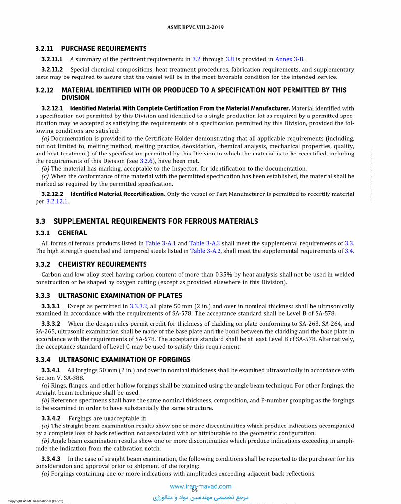
3.2.11 PURCHASE REQUIREMENTS3.2.11.1 A summary of the pertinent requirements in 3.2 through 3.8 is provided in Annex 3-B.
3.2.11.2 Special chemical compositions, heat treatment procedures, fabrication requirements, and supplementarytests may be required to assure that the vessel will be in the most favorable condition for the intended service.
3.2.12 MATERIAL IDENTIFIED WITH OR PRODUCED TO A SPECIFICATION NOT PERMITTED BY THISDIVISION
3.2.12.1 Identified Material With Complete Certification From the Material Manufacturer.Material identified witha specification not permitted by this Division and identified to a single production lot as required by a permitted spec-ification may be accepted as satisfying the requirements of a specification permitted by this Division, provided the fol-lowing conditions are satisfied:(a) Documentation is provided to the Certificate Holder demonstrating that all applicable requirements (including,
but not limited to, melting method, melting practice, deoxidation, chemical analysis, mechanical properties, quality,and heat treatment) of the specification permitted by this Division to which the material is to be recertified, includingthe requirements of this Division (see 3.2.6), have been met.(b) The material has marking, acceptable to the Inspector, for identification to the documentation.(c) When the conformance of the material with the permitted specification has been established, the material shall be
marked as required by the permitted specification.
3.2.12.2 Identified Material Recertification. Only the vessel or Part Manufacturer is permitted to recertify materialper 3.2.12.1.
3.3 SUPPLEMENTAL REQUIREMENTS FOR FERROUS MATERIALS
3.3.1 GENERALAll forms of ferrous products listed in Table 3-A.1 and Table 3-A.3 shall meet the supplemental requirements of 3.3.
The high strength quenched and tempered steels listed in Table 3-A.2, shall meet the supplemental requirements of 3.4.
3.3.2 CHEMISTRY REQUIREMENTSCarbon and low alloy steel having carbon content of more than 0.35% by heat analysis shall not be used in welded
construction or be shaped by oxygen cutting (except as provided elsewhere in this Division).
3.3.3 ULTRASONIC EXAMINATION OF PLATES3.3.3.1 Except as permitted in 3.3.3.2, all plate 50 mm (2 in.) and over in nominal thickness shall be ultrasonically
examined in accordance with the requirements of SA-578. The acceptance standard shall be Level B of SA-578.
3.3.3.2 When the design rules permit credit for thickness of cladding on plate conforming to SA-263, SA-264, andSA-265, ultrasonic examination shall be made of the base plate and the bond between the cladding and the base plate inaccordance with the requirements of SA-578. The acceptance standard shall be at least Level B of SA-578. Alternatively,the acceptance standard of Level C may be used to satisfy this requirement.
3.3.4 ULTRASONIC EXAMINATION OF FORGINGS3.3.4.1 All forgings 50 mm (2 in.) and over in nominal thickness shall be examined ultrasonically in accordance with
Section V, SA-388.(a) Rings, flanges, and other hollow forgings shall be examined using the angle beam technique. For other forgings, the
straight beam technique shall be used.(b) Reference specimens shall have the same nominal thickness, composition, and P-number grouping as the forgings
to be examined in order to have substantially the same structure.
3.3.4.2 Forgings are unacceptable if:(a) The straight beam examination results show one or more discontinuities which produce indications accompanied
by a complete loss of back reflection not associated with or attributable to the geometric configuration.(b) Angle beam examination results show one or more discontinuities which produce indications exceeding in ampli-
tude the indication from the calibration notch.
3.3.4.3 In the case of straight beam examination, the following conditions shall be reported to the purchaser for hisconsideration and approval prior to shipment of the forging:(a) Forgings containing one or more indications with amplitudes exceeding adjacent back reflections.
64
ASME BPVC.VIII.2-2019
Copyright ASME International (BPVC) Provided by IHS under license with ASME Licensee=Khalda Petroleum/5986215001, User=Amer, Mohamed
Not for Resale, 07/02/2019 14:07:58 MDTNo reproduction or networking permitted without license from IHS
--`,```,,,,,````,`,``,,`,,`,`-`-`,,`,,`,`,,`---
www.iran-mavad.com
مرجع تخصصی مهندسین مواد و متالورژی

(b) Forgings containing one or more discontinuities which produce traveling indications accompanied by reducedback reflections. A traveling indication is defined as an indication that displays sweep movement of the oscilloscopescreen at constant amplitudes as the transducer is moved.
3.3.4.4 In the case of angle beam examination, the following conditions shall be reported to the purchaser for hisconsideration and approval prior to shipment of the forging:
(a) Indications having an amplitude exceeding 50% of the calibration block amplitude.(b) Clusters of indications located in a small area of the forging with amplitudes less than 50% of the calibration notch
amplitude. A cluster of indications is defined as three or more indications exceeding 10% of the standard calibrationnotch amplitude and located in any volume approximately a 50 mm (2 in.) or smaller cube.
3.3.4.5 Additional nondestructive examination procedures or trepanning may be employed to resolve questions ofinterpretation of ultrasonic indications.
3.3.5 MAGNETIC PARTICLE AND LIQUID PENETRANT EXAMINATION OF FORGINGS3.3.5.1 Following final machining by the manufacturer, all accessible surfaces of forgings having a nominal thickness
greater than 100 mm (4 in.), such as contour and variable-thickness nozzles, integrally hubbed tubesheets, standard orcustom flanges, and other forgings that are contour shaped or machined to essentially the finished product configurationprior to heat treatment, shall be examined by the magnetic particle method in accordance with ASTM A275/A275M orby the liquid penetrant method in accordance with ASTM E165. The evaluation of indications detected by the magneticparticle method or by the liquid penetrant method and the acceptance standards shall be in accordance with Part 7 ofthis Division.
3.3.5.2 Unacceptable imperfections shall be removed and the areas shall be reexamined to ensure complete re-moval of the unacceptable imperfection. Unless prohibited by the material specification, the forgings may be repairwelded with the approval of the vessel Manufacturer. Repairs shall be made utilizing welding procedures that have beenqualified in accordance with Section IX. The repaired forging shall meet all requirements of this Division.
3.3.6 INTEGRAL AND WELD METAL OVERLAY CLAD BASE METAL3.3.6.1 Applied Linings. Material used for applied corrosion resistant lining may be any metallic material of weld-
able quality, provided all applicable requirements of this Division are satisfied.
3.3.6.2 Design Calculations Based on Total Thickness.(a) Base material with corrosion resistant integral or weld metal overlay cladding used in construction in which the
design calculations are based on total thickness including cladding (4.1.9) shall consist of base plate listed in one of thematerial tables in Part 3 and shall conform to one of the following specifications or utilize weld metal overlay claddingmeeting the requirements of this Division.
(1) SA-263, Specification for Corrosion-Resisting Chromium-Steel Clad Plate, Sheet and Strip;(2) SA-264, Specification for Corrosion-Resisting Chromium-Nickel Steel Clad Plate, Sheet and Strip; or(3) SA-265, Specification for Nickel and Nickel-Base Alloy Clad Steel Plate.
(b) Base material with corrosion resistant integral cladding in which any part of the cladding is included in the designcalculations, as permitted in (a), that is constructed of multiple cladding plates welded together prior being bonded tothe base material shall have the cladding-alloy-to-cladding-alloy welding that is performed prior to bonding to the basematerial:
(1) performed by a Manufacturer holding a Certificate of Authorization.(2) radiographically examined for their full length in the manner prescribed in 7.5.3. In place of radiographic exam-
ination, welds may be ultrasonically examined for their full length (see 7.5.5).(3) be supplied with a Partial Data Report if that welding is not performed by the vessel Manufacturer.
3.3.6.3 Design Calculations Based on Base-Plate Thickness. Clad plate used in constructions in which the designcalculations are based on the base-plate thickness, exclusive of the thickness of the cladding material, may consist of anybase-plate material satisfying the requirements of Part 3 and any metallic integral or weld metal overlay cladding ma-terial of weldable quality that meets the requirements of 6.5 of this Division.
3.3.6.4 Shear Strength of Bond of Integrally Clad Plates. Integrally clad plates in which any part of the cladding isincluded in the design calculations, as permitted in 4.1.9, shall show aminimum shear strength of 140 MPa (20 ksi) whentested in the manner described in the plate specification. One shear test shall be made on each such clad plate and theresults shall be reported on the test report. A shear or bond strength test is not required for weld metal overlay cladding.
3.3.6.5 Removal of Cladding for Mill Tension Tests.When any part of the cladding thickness is specified an allow-ance for corrosion, such added thickness shall be removed before mill tension tests.
65
ASME BPVC.VIII.2-2019
Copyright ASME International (BPVC) Provided by IHS under license with ASME Licensee=Khalda Petroleum/5986215001, User=Amer, Mohamed
Not for Resale, 07/02/2019 14:07:58 MDTNo reproduction or networking permitted without license from IHS
--`,```,,,,,````,`,``,,`,,`,`-`-`,,`,,`,`,,`---
www.iran-mavad.com
مرجع تخصصی مهندسین مواد و متالورژی

ð19Þ
3.3.7 CLAD TUBESHEETS3.3.7.1 Tube-to-tubesheet welds in the cladding of either integral or weld metal overlay clad tubesheets may be con-
sidered strength welds (full or partial), provided the welds meet the design requirements of 4.18.10. In addition, whenthe strength welds are to be made in the clad material of integral clad tubesheets, the integral clad material to be used fortubesheets shall meet the requirements in (a) and (b) for any combination of clad and base materials. The shear strengthtest and ultrasonic examination specified in (a) and (b) are not required for weld metal overlay clad tubesheets.(a) Integral clad material shall be shear strength tested in accordance with SA-263. One shear test shall be made on
each integral clad plate or forging, and the results shall be reported on the material test report.(b) Integral clad material shall be ultrasonically examined for bond integrity in accordance with SA-578, including
Supplementary Requirement S1, and shall meet the acceptance criteria given in SA-263 for Quality Level Class 1.
3.3.7.2 When the design calculations for clad tubesheets are based on the total thickness including the cladding, theclad material shall meet any additional requirements specified in 3.3.6.
3.3.7.3 When tubesheets are constructed using linings or integral cladding that does not meet the requirements of3.3.7.1(a) and 3.3.7.1(b), the strength of the tube-to-tubesheet joint shall not be dependent upon the connection betweenthe tubes and the lining or integral cladding, as applicable.
3.3.7.4 When the tubes are strength welded (full or partial) to integral or weld metal overlay clad tubesheets, Stshall be the allowable stress value of the integral cladding or the wrought material whose chemistry most closely ap-proximates that of the weld metal overlay cladding. The thickness of the integral or weld metal clad overlay materialshall be sufficient to prevent any of the strength weld from extending into the base material.
3.4 SUPPLEMENTAL REQUIREMENTS FOR Cr–Mo STEELS
3.4.1 GENERAL3.4.1.1 The rules in 3.4 include supplemental requirements for fabrication and testing for Cr-Mo steels. The materi-
als and appropriate specifications covered by this paragraph are listed in Table 3.1.
3.4.1.2 Certification that the requirements of 3.4 have been satisfied shall be shown on the Manufacturer’s Data Re-port Form.
3.4.2 POSTWELD HEAT TREATMENTThe final postweld heat treatment shall be in accordance with the requirements of 6.4.2 of this Division.
3.4.3 TEST SPECIMEN HEAT TREATMENT3.4.3.1 Two sets of tension specimens and one set of Charpy impact specimens shall be tested. One set each of the
tension specimens shall be exposed to heat treatment Condition A. The second set of tension specimens and the set ofCharpy specimens shall be exposed to heat treatment Condition B.(a) Condition A – Temperature shall be no lower than the actual maximum vessel-portion temperature, less 14°C
(25°F). Time at temperature shall be no less than 80% of the actual holding time of the vessel portion exposed tothe maximum vessel-portion temperature.(b) Condition B – Temperature shall be no higher than the actual minimum vessel-portion temperature, plus 14°C
(25°F). Time at temperature shall be no more than 120% of the actual hold time of the vessel portion exposed to theminimum vessel-portion temperature.
3.4.3.2 The suggested procedure for establishing the test specimen heat treatment parameters are shown below.(a) Establish maximum and minimum temperatures and hold times for the vessel/component heat treatment based
on experience/equipment;(b) Determine Conditions A and B for the test specimen heat treatments;(c) Vessel heat treatment temperature and hold time limitations, and test specimen Conditions A and B, are shown in
Figure 3.1.
3.4.4 WELDING PROCEDURE QUALIFICATIONS AND WELDING CONSUMABLES TESTING3.4.4.1 Welding procedure qualifications using welding consumables of the same classification or trade designation
as those to be used in production shall be made for material welded to itself or to other materials. The qualifications shallconform to the requirements of Section IX, and the maximum tensile strength at room temperature shall be 760 MPa(110 ksi) (for heat treatment Conditions A and B). Welding shall be limited to submerged-arc (SAW) and shieldedmetal-arc (SMAW) processes for 3Cr–1Mo–1/4V–Ti–B material only.
66
ASME BPVC.VIII.2-2019
Copyright ASME International (BPVC) Provided by IHS under license with ASME Licensee=Khalda Petroleum/5986215001, User=Amer, Mohamed
Not for Resale, 07/02/2019 14:07:58 MDTNo reproduction or networking permitted without license from IHS
--`,```,,,,,````,`,``,,`,,`,`-`-`,,`,,`,`,,`---www.iran-mavad.com
مرجع تخصصی مهندسین مواد و متالورژی

3.4.4.2 Weld metal from each heat or lot of electrodes and filler-wire–flux combination shall be tested, unless spe-cific heat- or lot-traceable test reports meeting the additional requirements of 3.4 related to welding consumables test-ing have been provided by the welding consumables manufacturer. The minimum and maximum tensile properties shallbe met in postweld heat treated (PWHT) Conditions A and B. The minimum Charpy V-notch impact properties shall bemet in PWHT Condition B. Testing shall be in general conformance with SFA-5.5 for covered electrodes and SFA-5.23 forfiller wire-flux combinations.
3.4.4.3 Duplicate testing in PWHT Condition A and PWHT Condition B (see 3.4.3) is required. The minimum tensilestrength and Charpy impact properties for the base metal shall be met. Charpy impact testing is only required for Con-dition B.
3.4.4.4 For 21/4Cr–1Mo–1/4V material, the weld metal shall meet the compositional requirements listed in Table 3.2.For all other materials, the minimum carbon content of the weld metal shall be 0.05%.
3.4.4.5 In addition for 21/4Cr–1Mo and 21/4Cr–1Mo–1/4V material, Category A welds intended for design tempera-tures above 440°C (825°F), each heat of filler wire and flux combination used in production shall also be qualified bya weld metal stress-rupture test performed in accordance with ASTM E139 or other equivalent national or internationaltest standard on specimens machined parallel (all weld metal specimens) and transverse to the weld axis (one specimeneach), applying the following testing parameters and acceptance criteria:
(a) The specimen diameter within the gage length shall be 13 mm (1/2 in.) or greater. The specimen centerline shall belocated at the 0.25-t thickness location (or closer to the center) for material 19 mm (3/4 in.) and greater in thickness.
(b) The gage length for the transverse specimen shall include the weld and at least 19 mm (3/4 in.) of base metal ad-jacent to the fusion line.
(c) The test material shall be postweld heat treated to Condition A.(d) For 21/4Cr–1Mo material, the condition of the stress-rupture test shall be 210 MPa (30 ksi) at 510°C (950°F). The
time of failure shall exceed 650 hr.(e) For 21/4Cr–1Mo–1/4V material, the condition of the stress-rupture test shall be 210 MPa (30 ksi) at 540°C (1000°F).
The time of failure shall exceed 900 hr.
3.4.5 TOUGHNESS REQUIREMENTS
The minimum toughness requirements for base metal, weld metal, and heat-affected zone, after exposure to the sim-ulated postweld heat treatment Condition B, are shown in Table 3.3. If the material specification or other parts of thisDivision have more demanding toughness requirements, they shall be met.
3.5 SUPPLEMENTAL REQUIREMENTS FOR Q&T STEELS WITH ENHANCED TENSILEPROPERTIES
3.5.1 GENERAL3.5.1.1 The supplemental requirements in 3.5 apply to ferritic steels with tensile properties enhanced by quenching
and tempering and shall be used in conjunction with the other requirements of this Division. The material specificationsfor these steels are shown in Table 3-A.2.
3.5.1.2 The requirements of this paragraph are not intended to apply to steels listed in Table 3-A.1 that are furn-ished in such thicknesses that heat treatment, involving the use of accelerated cooling, including liquid quenching, isused to obtain structures comparable to those attained by normalizing thinner sections.
3.5.2 PARTS FOR WHICH Q&T STEELS MAY BE USED
High strength quenched and tempered steels shown in Table 3-A.2, may be used for the entire vessel or for individualcomponents of vessels that are joined to other grades of quenched and tempered steels, or to other steels conforming tospecifications listed in Tables 3-A.1, 3-A.3, and 3-A.6, subject to the requirements and limitations of this Division.
3.5.3 STRUCTURAL ATTACHMENTS3.5.3.1 Except as permitted in 3.5.3.2 below, all permanent structural attachments other than minor attachments
specified in 3.5.3.3 and stiffening rings that are welded directly to pressure parts shall be made of material whose spe-cified minimum yield strength is within ±20% of that of the material to which they are attached.
67
ASME BPVC.VIII.2-2019
Copyright ASME International (BPVC) Provided by IHS under license with ASME Licensee=Khalda Petroleum/5986215001, User=Amer, Mohamed
Not for Resale, 07/02/2019 14:07:58 MDTNo reproduction or networking permitted without license from IHS
--`,```,,,,,````,`,``,,`,,`,`-`-`,,`,,`,`,,`---
www.iran-mavad.com
مرجع تخصصی مهندسین مواد و متالورژی

3.5.3.2 All permanent structural attachments welded directly to a shell or head constructed of a material conform-ing to SA-333, Grade 8, SA-334, Grade 8, SA-353, SA-522, SA-553, and SA-645 Grade A shall be made from a materialcovered by these same specifications, or nickel alloys UNS N06625 or N10276, or from wrought non-hardenable auste-nitic stainless steels. If an austenitic stainless steel is used, consideration should be given to the additional weld stressesresulting from the difference in thermal expansion between the attachment and the shell.
3.5.3.3 If the following conditions are met, the material of minor attachments given in 4.2.5.6(c) may be used. Thedefinition of minor attachments is given in 4.2.5.1(h).(a) The specified minimum tensile strength of quenched and tempered steel for pressure parts shall be less than 690
MPa (100 ksi).(b) The specified minimum yield strength of minor attachments shall be within +20% and −60% of that of the material
to which they are attached.
(c) If the minor attachment is welded in the area less than from any gross structural discontinuity, where Rm
is the mean radius of the shell, and t is the thickness of the shell, the stress evaluation in accordance with Part 5 shall beperformed.(d) If the continuous fillet weld is used, the leg dimension of fillet weld shall not be less than 0.25t , where t is the
thickness of the minor attachment.(e) The effect of differential thermal expansion shall be considered when the thermal expansion coefficient of the min-
or attachment differs from that of the pressure part to which it is attached.(f) Welding materials with room-temperature tensile strength equivalent to that of quenched and tempered steels
shall be used.(g) The welds shall be postweld heat treated when required by Part 6.
3.6 SUPPLEMENTAL REQUIREMENTS FOR NONFERROUS MATERIALS
3.6.1 GENERALNonferrous materials covered by 3.6 shall conform to one of the specifications listed in Tables 3-A.4, 3-A.5, 3-A.6, and
3-A.7, and shall be used in conjunction with the other requirements of this Division.
3.6.2 ULTRASONIC EXAMINATION OF PLATESAll plates 50 mm (2 in.) and over in nominal thickness shall be ultrasonically examined in accordance with the applic-
able requirements of the ASTM standards and ASME specifications listed below:(a) SE-114, Ultrasonic Testing by Reflection Method Using Pulsed Longitudinal Waves Induced by Direct Contact;(b) E214, Immersed Ultrasonic Testing by the Reflection Method Using Pulsed Longitudinal Waves;(c) E127, Fabricating and Checking Aluminum Alloy Ultrasonic Standard Reference Blocks;(d) SB-548, Ultrasonic Testing of Aluminum Plate.
3.6.3 ULTRASONIC EXAMINATION OF FORGINGS3.6.3.1 Insofar as practicable, all solid rectangular forgings shall be examined by the straight beam technique from
two directions at approximately right angles. Hollow forgings including flanges and rings 50 mm (2 in.) and over in nom-inal thickness shall be examined using the angle beam technique by either the contact method or the immersion method.Reference specimens and acceptance criteria shall be examined from one face or surface normal to the axis in the cir-cumferential direction unless the wall thickness or geometric configuration makes angle beam examination impractic-able. Disk forgings shall be examined from one flat side and from the circumferential surface.
3.6.3.2 The entire volume of metal shall be ultrasonically examined at some state of manufacture. For heat-treatedmaterial, examination after final heat treatment is preferred, but if the contour of the forging precludes complete exam-ination at this stage, the maximum possible volume of the forging shall be reexamined after the final heat treatment.
3.6.3.3 The method used in the examination of forgings shall conform to the following requirements.(a) In straight beam examination, the transducers shall be 19 mm to 29 mm (3/4 in. to 11/8 in.) in diameter or 25 mm
(1 in.) square. The nominal frequency shall be appropriate for the material being examined. The instrument shall be setso that the first back reflection is 75% ± 5% of the screen height when the transducer is placed on the indication-freearea of the forging.(b) In angle beam examination by the contact method, a 25 mm × 25 mm (1 in. × 1 in.) or 25 mm × 38 mm (1 in.
× 11/2 in.), 45 deg. transducer shall be used at an appropriate frequency.(c) In angle beam examination by the immersion method, a 19 mm (3/4 in.) diameter transducer oriented at an approx-
imate angle of inclination shall be used at an appropriate frequency.
68
ASME BPVC.VIII.2-2019
Copyright ASME International (BPVC) Provided by IHS under license with ASME Licensee=Khalda Petroleum/5986215001, User=Amer, Mohamed
Not for Resale, 07/02/2019 14:07:58 MDTNo reproduction or networking permitted without license from IHS
--`,```,,,,,````,`,``,,`,,`,`-`-`,,`,,`,`,,`---
www.iran-mavad.com
مرجع تخصصی مهندسین مواد و متالورژی

(d) Angle beam examination shall be calibrated with a notch of a depth equal to the smaller of 10 mm (3/8 in.) or 3% ofthe nominal section thickness, a length of approximately 25 mm (1 in.) and width not greater than two times the depth.
3.6.3.4 The material shall be unacceptable (unless repaired in accordance with the rules of this Division) if straightbeam examination shows one or more discontinuities which produce indications accompanied by a complete loss ofback reflection not associated with or attributable to the geometric configuration, or if angle beam examination resultsshow one or more discontinuities which produce indications exceeding that of the calibration notch.
3.6.4 LIQUID PENETRANT EXAMINATION OF FORGINGS3.6.4.1 Following final machining by the manufacturer all accessible surfaces of thick and complex forgings, such as
contour nozzles, thick tubesheets, flanges, and other complex forgings that are contour shaped or machined to essen-tially the finished product configuration prior to heat treatment, shall be examined by the liquid penetrant method inaccordance with Practice E165.
3.6.4.2 The evaluation of indications detected by the liquid penetrant method and the acceptance standards shall bein accordance with Part 7 of this Division.
3.6.4.3 Unacceptable imperfections shall be removed and the areas shall be reexamined to ensure complete re-moval of the unacceptable imperfection. Unless prohibited by the material specification, the forgings may be repairwelded with the approval of the vessel Manufacturer. Repairs shall be made utilizing welding procedures that have beenqualified in accordance with Section IX. The repaired forging shall meet all requirements of this Division.
3.6.5 CLAD PLATE AND PRODUCTS
Clad plate or products used in construction for which the design calculations are based on total thickness, includingcladding, shall consist of base plate listed in one of the material tables in this Division and shall conform to one of thefollowing specifications:
(a) SB-209, Specification for Aluminum Alloy Sheet and Plate.(b) SB-211, Specification for Aluminum Alloy Extruded Bars, Rods, Shapes, and Tubes.
3.6.6 CLAD TUBESHEETS
Clad tubesheets that will contain strength welded tube-to-tubesheet joints in the cladding shall meet the requirementsof 3.3.7 and any applicable requirements specified in 3.6.5.
3.7 SUPPLEMENTAL REQUIREMENTS FOR BOLTING
3.7.1 GENERAL
The supplemental requirements in 3.7 are required for all bolts, studs, and nuts supplied with vessels constructed tothis Division.
3.7.2 EXAMINATION OF BOLTS, STUDS, AND NUTS
Bolts, studs, and nuts covered by the material specifications listed in Annex 3-A shall be subjected to the followingexaminations:
(a) All areas of threads, shanks, and heads of final machined parts shall be visually examined. Discontinuities, such aslaps, seams, cracks are unacceptable.
(b) All bolts, studs, and nuts over 25 mm (1 in.) nominal bolt size shall be examined by the magnetic particle methodor by the liquid penetrant method in accordance with Part 7 of this Division. This examination shall be performed on thefinished component after threading or on the material stock at approximately the finished diameter before threadingand after heading (if involved). Linear non-axial indications are unacceptable. Linear indications greater than 25 mm(1 in.) in length are unacceptable.
(c) All bolts, studs, and nuts greater than 50 mm (2 in.) nominal bolt size shall be ultrasonically examined over theentire surface prior to threading in accordance with the following requirements:
(1) Examination shall be carried out by the straight beam, radial scan method.(2) Examination shall be performed at a nominal frequency of 2.25 MHz with the search unit not to exceed 645 mm2
(1 in.2) in area.(3) Calibration sensitivity shall be established by adjustment of the instrument so that the first back screen reflec-
tion is 75% to 90% of full screen height.
69
ASME BPVC.VIII.2-2019
Copyright ASME International (BPVC) Provided by IHS under license with ASME Licensee=Khalda Petroleum/5986215001, User=Amer, Mohamed
Not for Resale, 07/02/2019 14:07:58 MDTNo reproduction or networking permitted without license from IHS
--`,```,,,,,````,`,``,,`,,`,`-`-`,,`,,`,`,,`---
www.iran-mavad.com
مرجع تخصصی مهندسین مواد و متالورژی

(4) Any discontinuity which causes an indication in excess of 20% of the height of the first back reflection or anydiscontinuity which prevents the production of the first back reflection of 50% of the calibration amplitude is notacceptable.(d) All bolts, studs, and nuts greater than 100 mm (4 in.) nominal bolt size shall be ultrasonically examined over an
entire end surface before or after threading in accordance with the following requirements:(1) Examination shall be carried out by the straight beam, longitudinal scan method.(2) Examination shall be performed at a nominal frequency of 2.25 MHz with the search unit not to exceed 320 mm2
(0.5 in.2) in area.(3) Calibration shall be established on a test bar of the same nominal composition and diameter as the production
part and a minimum of one half of the length. A 10 mm (3/8 in.) diameter × 76 mm (3 in.) deep flat bottom hole shall bedrilled in one end of the bar and plugged to full depth. A distance amplitude correction curve shall be established byscanning from both ends of the test bar.
(4) Any discontinuity which causes an indication in excess of that produced by the calibration hole in the referencespecimen as corrected by the distance amplitude correction curve is not acceptable.
3.7.3 THREADING AND MACHINING OF STUDS3.7.3.1 Studs shall be threaded the full length, or shall be machined down to the root diameter of the thread in the
unthreaded portion, provided that the threaded portions are at least 1.5 diameters in length.
3.7.3.2 Studs greater than 8 diameters in length may have an unthreaded portion which has the nominal diameter ofthe thread, provided the following requirements are met:(a) The threaded portion shall be at least 1.5 diameters in length.(b) The stud shall be machined down to the root diameter of the thread for a minimum distance of 0.5 diameters ad-
jacent to the threaded portion.(c) Suitable transition shall be provided between the root diameter and the unthreaded portion.(d) Particular consideration shall be given to any dynamic loadings.
3.7.4 USE OF WASHERS
When washers are used in conjunction with torquing methods (e.g., the use of manual or hydraulic torque wrenches)for the purpose of bolt tightening, they shall be designed to provide a smooth and low-friction contact surface for thenuts, which are important considerations when torquing methods are used for bolt tightening.
NOTE: Flat washers typically should be 6 mm (1/4 in.) thick and made of through-hardened, wrought low alloy steel. See ASME PCC-1 for moreinformation.
3.7.5 FERROUS BOLTING3.7.5.1 Material for Ferrous Bolting.(a) Approved specifications for ferrous bolting are given in Annex 3-A, Tables 3-A.8, 3-A.9, 3-A.10 and 3-A.11.(b) High alloy steel studs, bolts, and nuts may be used with carbon and low alloy steel components, provided they are
suitable for the application (see Section II, Part D, Nonmandatory Appendix A, A-300).(c) Nonferrous nuts and washers may be used with ferrous bolts and studs, provided they are suitable for the appli-
cation. Consideration shall be given to the differences in thermal expansion and possible corrosion resulting from com-bination of dissimilar materials.
3.7.5.2 Material for Ferrous Nuts and Washers.(a)Material for nuts and washers shall conform to SA-194, SA-563, or to the requirements for nuts in the specification
for the bolting material with which they are to be used.(b)Materials for ferrous nuts and washers shall be selected as follows:
(1) Carbon or low alloy steel nuts and carbon or low alloy steel washers of approximately the same hardness as thenuts may be used for metal temperatures not exceeding 480°C (900°F).
(2) Alloy steel nuts shall be used for metal temperatures exceeding 480°C (900°F). Washers, if used, shall be of alloysteel equivalent to the nut material.
3.7.5.3 Requirements for Ferrous Nuts.(a) Nuts shall be semifinished, chamfered, and trimmed. Nuts shall be threaded to Class 2B or finer tolerances accord-
ing to ASME B1.1.(b) For use with flanges conforming to ASME/ANSI B16.5, nuts shall conform to at least to the dimensions given in
ASME/ANSI B18.2.2 for Heavy Series Nuts.
70
ASME BPVC.VIII.2-2019
Copyright ASME International (BPVC) Provided by IHS under license with ASME Licensee=Khalda Petroleum/5986215001, User=Amer, Mohamed
Not for Resale, 07/02/2019 14:07:58 MDTNo reproduction or networking permitted without license from IHS
--`,```,,,,,````,`,``,,`,,`,`-`-`,,`,,`,`,,`---
www.iran-mavad.com
مرجع تخصصی مهندسین مواد و متالورژی

ð19Þ
(c) For use with connections designed in accordance with rules in 4.16, nuts may be of the American National Stan-dard Heavy Series or they may be of other dimensions provided their strength is equal to that of the bolting, giving dueconsideration to the bolt hole clearance, bearing area, thread form and class of it, thread shear, and radial thrust fromthreads.
(d) Nuts shall engage the threads for the full depth of the nut or, in the case of cap nuts, to a depth equivalent to thedepth of a standard nut.
(e) Nuts of special design may be used, provided their strength is equal to that of the bolting.
3.7.6 NONFERROUS BOLTING3.7.6.1 Material for Nonferrous Bolting. Approved specifications for Nonferrous bolting are given in Annex 3-A,
Tables 3-A.9 and 3-A.10, and 3-A.11.
3.7.6.2 Condition of Material Selected and Allowable Stress Value.(a)When nonferrous bolts are machined from heat-treated, hot-rolled, or cold-worked material and are not subse-
quently hot worked or annealed, the allowable design stress values in Section II, Part D, Subpart 1, Table 3 to be usedin design shall be based on the condition of material selected.
(b)When nonferrous bolts are fabricated by hot heading, the allowable design stress values for annealed materials inSection II, Part D, Subpart 1, Table 3 shall apply unless the manufacturer can furnish adequate control data to show thatthe tensile properties of hot-rolled or heat-treated bars or hot-finished or heat-treated forgings are being met, in whichcase the allowable stress values for the material in the hot finished condition may be used.
(c) When nonferrous bolts are fabricated by cold heading, the allowable design stress values for annealed materials inSection II, Part D, Subpart 1, Table 3 shall apply unless the manufacturer can furnish adequate control data to show thathigher design stresses, as agreed upon may be used. In no case shall such stresses exceed the allowable stress valuesgiven in Section II, Part D, Subpart 1, Table 3 for cold-worked bar stock.
3.7.6.3 Materials for Nonferrous Nuts and Washers.(a)Materials for ferrous nuts used with nonferrous bolting shall conform to 3.7.5.3.(b) Nonferrous nuts and washers may be made of any suitable material listed in Tables 3-A.5, 3-A.6, and 3-A.7.
3.7.6.4 Requirements for Nonferrous Nuts. Nonferrous nuts shall meet the requirements in 3.7.5.3.
3.7.7 MATERIALS FOR FERROUS AND NONFERROUS NUTS OF SPECIAL DESIGN
Nuts of special design, such as wing nuts, may be made of any suitable wrought material permitted by this Division,and shall be either: hot or cold forged; or machined from hot-forged, hot-rolled, or cold-drawn bars.
3.8 SUPPLEMENTAL REQUIREMENTS FOR CASTINGS
3.8.1 GENERAL3.8.1.1 Each casting shall be marked with the name, trademark, or other traceable identification of the manufacturer
and the casting identification, including material designation. The casting manufacturer shall furnish certification thateach casting conforms to all the applicable requirements in the casting specification and the requirements of this Divi-sion. The certification of castings shall also indicate the nature, location, and extent of any repairs.
3.8.1.2 All castings to be welded shall be of weldable grade.
3.8.2 REQUIREMENTS FOR FERROUS CASTINGS3.8.2.1 Centrifugal Steel Castings. In addition to the minimum requirements of the material specification, all sur-
faces of centrifugal castings shall be machined after heat treatment to a finish not coarser than 6.35 µmm (250 µin.)arithmetic average deviation.
3.8.2.2 Nondestructive Examination of Ferrous Castings.(a) General – Castings shall be examined by radiographic, ultrasonic, magnetic particle and liquid penetrant methods
examination as provided herein and shall meet the requirements of (a) through (d), inclusive. Radiographic examination,and when required ultrasonic examination, of castings shall be made after at least one austenitizing heat treatment, ex-cept austenitic castings not requiring heat treatment may have radiographic and ultrasonic examination performed atany stage of manufacture. Magnetic particle or liquid penetrant examinations shall be made after final heat treatmentand after final machining of machined areas.
71
ASME BPVC.VIII.2-2019
Copyright ASME International (BPVC) Provided by IHS under license with ASME Licensee=Khalda Petroleum/5986215001, User=Amer, Mohamed
Not for Resale, 07/02/2019 14:07:58 MDTNo reproduction or networking permitted without license from IHS
--`,```,,,,,````,`,``,,`,,`,`-`-`,,`,,`,`,,`---
www.iran-mavad.com
مرجع تخصصی مهندسین مواد و متالورژی

(b) Radiographic Examination – All parts of ferrous castings regardless of thickness shall be fully radiographed in ac-cordance with the procedures of Section V, Article 2. The radiographs shall be compared to the appropriate RadiographicStandard listed below, and the maximum acceptable severity levels for imperfection shall be as follows:
(1) For castings having radiographed thickness of less than 50 mm (2 in.), ASTM E446, Standard Reference Radio-graphs for Steel Castings up to 2 in. (50 mm) in Thickness, and with maximum severity levels as shown in Table 3.9.
(2) For castings having radiographed thickness from 50 mm to 305 mm (2 in. to 12 in.), ASTM E186, Standard Re-ference Radiographs for Heavy-Walled [2 to 41/2 in. (50.8 to 114 mm)] Steel Castings, or ASTM E280, Standard ReferenceRadiographs for Heavy-Walled [41/2 to 12 in. (114 to 305 mm)] Steel Castings, as appropriate, and with maximum se-verity levels as shown in Table 3.10.(c) Ultrasonic Examination – All parts of ferrous castings over 305 mm (12 in.) thick shall be examined by ultrasonic
methods in accordance with the procedures of Section V, Article 5. Castings with imperfections shown by discontinuitieswhose reflections exceed the height equal to 20% of the normal back reflection, or which reduce the height of the backreflections by more than 30% during movement of the transducer 50mm (2 in.) in any direction are unacceptable unlessother methods of nondestructive testing, such as radiographic examination, demonstrate to the satisfaction of the vesselManufacturer and the Inspector that the indications are acceptable or unless such imperfections are removed and thecasting is repaired.(d)Magnetic Particle Examination – Castings of ferromagnetic material shall be examined on all surfaces by a mag-
netic particle method in accordance with Part 7 of this Division. Castings with imperfections shown by Type I indicationsor by indications exceeding Degree I of Types II, III, IV, and V of ASTM E125, Reference Photographs for Magnetic ParticleIndications on Ferrous Castings, are unacceptable unless the imperfections are removed and casting is repaired.(e) Liquid Penetrant Examination – Castings of nonferromagnetic material shall be examined on all surfaces by a li-
quid penetrant method in accordance with Part 7 of this Division. Castings with cracks and linear imperfections exceed-ing the following limits are unacceptable:
(1) Linear indications resulting in more than six indications in any 40 mm × 150 mm (11/2 in. × 6 in.) rectangle or90 mm (3.5 in.) diameter circle with these taken in the most unfavorable location relative to the indications beingevaluated.
(2) Linear imperfections resulting in indications more than 6 mm (1/4 in.) in length for thicknesses up to 19 mm(3/4 in.), one third of the thickness in length for thicknesses from 19 mm (3/4 in.) to 57 mm (2.25 in.), and 19 mm(3/4 in.) in length for thicknesses over 57 mm (2.25 in.). Aligned acceptable imperfections separated from one anotherby a distance equal to the length of the longer imperfection are acceptable.
(3) All nonlinear imperfections which are indicated to have any dimension which exceeds 2.5 mm (0.0938 in.).
3.8.2.3 Repairing of Ferrous Castings.(a) Castings with unacceptable imperfections may be repaired. Whenever an imperfection is removed and subsequent
repair by welding is not required, the affected area shall be blended into the surrounding surface so as to avoid sharpnotches, crevices, or corners.(b) Repairing of Ferrous Castings by Welding – Castings having imperfections in excess of the maximum sizes per-
mitted in 3.8.2.2 may be repaired by welding if the imperfections are removed and providing prior approval is obtainedfrom the vessel Manufacturer. To ensure complete removal of such imperfections prior to making repairs the base metalshall be reexamined by either magnetic particle or liquid penetrant examination, if it is ferromagnetic, or by liquid pen-etrant examination, if it is nonferromagnetic.
(1) Requirements for Examining Repairs in Castings – All weld repairs of depth exceeding 10 mm (3/8 in.) or 20% ofthe section thickness, whichever is the lesser, shall be examined by radiography and by magnetic particle examination orliquid penetrant examination, if the material is magnetic, or by liquid penetrant examination, if it is nonferromagnetic, inaccordance with 3.8.2.2. Where the depth of the repairs is less than 20% of the section thickness or 25 mm (1 in.), which-ever is the lesser, and where the repaired section cannot be radiographed effectively, the first layer of each 6 mm (1/4 in.)thickness of deposited weld metal and the finished weld surface shall be examined, as indicated previously by magneticparticle or liquid penetrant examination. The finished surface examination shall be made after any heat treating opera-tions that are applied to the casting. Weld repairs resulting from ultrasonic examination shall be examined by ultrasonicmethods.
(2) Postweld Heat Treatment of Repaired Castings –When repair welding is done after heat treatment of the cast-ing, the casting shall be postweld heat treated after repair welding of the casting.
(3) Required Welding Procedure and Welder Qualifications – All welding shall be performed with a welding proce-dure qualified in accordance with Section IX. The procedure qualification tests shall be performed on specimens of castmaterial of the same specification and subject to the same heat treatment before and after welding as will be applied tothe work. All welders and operators performing this welding shall also be qualified in accordance with Section IX.
72
ASME BPVC.VIII.2-2019
Copyright ASME International (BPVC) Provided by IHS under license with ASME Licensee=Khalda Petroleum/5986215001, User=Amer, Mohamed
Not for Resale, 07/02/2019 14:07:58 MDTNo reproduction or networking permitted without license from IHS
--`,```,,,,,````,`,``,,`,,`,`-`-`,,`,,`,`,,`---
www.iran-mavad.com
مرجع تخصصی مهندسین مواد و متالورژی

(4) Certification of Weld Repairs – The location and extent of the weld repairs together with the repair procedureand examination results shall be recorded and transmitted as part of the certification.
3.8.3 REQUIREMENTS FOR NONFERROUS CASTINGS3.8.3.1 Examination of Nonferrous Castings. All nonferrous castings shall be examined in accordance with the
following:(a) Each casting shall be subjected to 100% visual examination and to liquid penetrant examination on all surfaces in
accordance with 3.8.2.2(e). These examinations shall be performed following the final heat treatment applied to thecasting.
(b) All parts of castings shall be subjected to complete radiographic examination and the radiographs shall be com-pared with the radiographic standards of ASTM E272, Reference Radiographs for Inspection of High Strength CopperBase and Nickel-Copper Castings. Acceptable castings shall meet Class 1 standards, if the wall thickness is less than25 mm (1 in.) or Class 2 standards if the wall thickness is greater than or equal to 25 mm (1 in.) as defined in theSpecification.
(c) All parts of castings with a thickness greater than 305 mm (12 in.) shall be ultrasonically examined in accordancewith the procedures given in SE-114. Any imperfections whose reflections do not exceed a height equal to 20% of thenormal back reflection or do not reduce the height of the back reflection by more than 30% during movement of thetransducer 50 mm (2 in.), in any direction, shall be considered acceptable. The above limits are established for theuse of transducers having approximately 645 mm2 (1 in.2) of area.
3.8.3.2 Repairing of Nonferrous Castings by Welding. Upon approval by the vessel Manufacturer, castings subjectto rejection because of these examinations may be repaired in accordance with the following requirements.
(a) Castings having imperfections in excess of the maximum sizes permitted in 3.8.3.1 may be repaired by welding, ifthe imperfections are removed and provided prior approval is obtained from the vessel Manufacturer. To assure com-plete removal of such imperfections, prior to making repairs, the base metal shall be reexamined by liquid penetrantexamination.
(b) All weld repairs of depth exceeding 10 mm (3/8 in.), or 20% of the section thickness, whichever is the lesser, shallbe examined by radiography and by liquid penetrant examination in accordance with 3.8.3.1. Where the depth of repairsis less than 20% of the section thickness or 25 mm (1 in.), whichever are the lesser, and where the repaired sectioncannot be radiographed effectively, the first layer of each 6 mm (3/4 in.) thickness of deposited weld metal and the fin-ished weld surface shall be examined, as indicated previously, by liquid penetrant examination. The finished surface ex-amination shall be made after any heat treating operation that is applied to the casting. Weld repairs resulting fromultrasonic examination shall be examined by ultrasonic methods.
(c) When repair welding is done after heat treatment of the casting, the casting shall be postweld heat treated afterrepair welding.
(d) All welding shall be performed using welding procedures qualified in accordance with Section IX. The procedurequalifications shall be performed on test specimens of cast material of the same specification and subject to the sameheat treatments before and after welding as will be applied to the work. All welders and welding operators performingthis welding shall be qualified in accordance with Section IX.
(e) The location and extent of the weld repairs together with the repair procedure and examination results shall berecorded and transmitted as part of the certification.
3.9 SUPPLEMENTAL REQUIREMENTS FOR HUBS MACHINED FROM PLATE
3.9.1 GENERAL
The supplemental requirements of 3.9 are required for plate materials that are used in the fabrication of hubs fortubesheets, lap joint stub ends, and flat heads machined from plate when the hub length is in the through thickness di-rection of the plate.
3.9.2 MATERIAL REQUIREMENTS3.9.2.1 Plate shall be manufactured by a process that produces material having through thickness properties which
are at least equal to those specified in the material specification. Such plate can be but is not limited to that produced bymethods such as electroslag (ESR) and vacuum arc remelt (VAR). The plate must be tested and examined in accordancewith the requirements of the material specification and the additional requirements specified in the followingparagraphs.
73
ASME BPVC.VIII.2-2019
Copyright ASME International (BPVC) Provided by IHS under license with ASME Licensee=Khalda Petroleum/5986215001, User=Amer, Mohamed
Not for Resale, 07/02/2019 14:07:58 MDTNo reproduction or networking permitted without license from IHS
--`,```,,,,,````,`,``,,`,,`,`-`-`,,`,,`,`,,`---
www.iran-mavad.com
مرجع تخصصی مهندسین مواد و متالورژی

3.9.2.2 Test specimens, in addition to those required by the material specifications, shall be taken in a directionparallel to the axis of the hub and as close to the hub as practical, as shown in Figure 3.2. At least two tensile test speci-mens shall be taken from the plate in the proximity of the hub, with one specimen taken from the center third of the platewidth as rolled, and the second specimen taken at 90 deg around the circumference from the other specimen. Both speci-mens shall meet the mechanical property requirements of the material specification. For carbon and low alloy steels, thereduction of area shall not be less than 30%; for those materials for which the material specification requires a reductionof area value greater than 30%, the higher value shall be met.
3.9.2.3 Subsize test specimens conforming to the requirements of SA-370, Figure 5 may be used if necessary, inwhich case the value for percent elongation in 50 mm (2 in.), required by the material specification, shall apply tothe gage length specified in SA-370, Figure 5.
3.9.2.4 Tension test specimen locations are shown in Figure 3.2.
3.9.3 EXAMINATION REQUIREMENTS3.9.3.1 After machining the part, regardless of thickness, shall be ultrasonically examined by the straight beam tech-
nique in accordance with SA-388. The examination shall be in two directions approximately at right angles, i.e., from thecylindrical or flat rectangular surfaces of the hub and in the axial direction of the hub. The part shall be unacceptable if(a) the examination results show one or more indications accompanied by loss of back reflection larger than 60% of
the reference back reflection, and(b) the examination results show indications larger than 40% of the reference back reflection when accompanied by a
40% loss of back reflection.
3.9.3.2 Before welding the hub of the tubesheet flange or flat head to the adjacent shell, the hub shall be examinedby magnetic particle or liquid penetrant methods in accordance with Part 7.
3.9.3.3 After welding, the weld and the area of the hub for at least 13 mm (1/2 in.) from the edge of the weld shall be100% radiographed in accordance with Part 7. As an alternate, the weld and hub area adjacent to the weld may be ul-trasonically examined in accordance with Part 7.
3.9.4 DATA REPORTS AND MARKING
Whenever the provisions of this supplemental requirement are used, they shall be indicated on the Data Report. Spe-cial markings are not required.
3.10 MATERIAL TEST REQUIREMENTS
3.10.1 GENERAL
Material tests required by this Division shall be performed in accordance with 3.10.
3.10.2 REQUIREMENTS FOR SAMPLE TEST COUPONS3.10.2.1 Heat Treatment. Heat treatment as used in this Division shall include all thermal treatments during fab-
rication at 480°C (900°F) and above.
3.10.2.2 Provisions of Sample Test Coupons. When material is subjected to heat treatment during fabrication, thetest specimens required by this Division shall be obtained from sample coupons which have been heat treated in thesame manner as the material, including such heat treatments as were applied by the material producer before shipment.The required tests may be performed by the material producer or the fabricator.
3.10.2.3 Heat Treating of Sample Test Coupons.(a) The material used in the vessel shall be represented by test specimens that have been subjected to the same man-
ner of heat treatment, including postweld heat treatment. The kind and number of tests and test results shall be as re-quired by the material specification. The vessel Manufacturer shall specify the temperature, time, and cooling rates towhich the material will be subject during fabrication. Material from which the specimens are prepared shall be heated atthe specified temperature within the tolerance established by the manufacturer for use in actual fabrication. The totaltime at temperature shall be within at least 80% of the total time at temperature during actual heat treatment of theproduct and may be performed in a single cycle. Simulation of postweld heat treatment may be applied to the test speci-men blanks.(b) Heat treatment of material is not intended to include such local heating as flame or arc cutting, preheating, weld-
ing, or heating below the critical range of tubing or pipe for bending or sizing.
74
ASME BPVC.VIII.2-2019
Copyright ASME International (BPVC) Provided by IHS under license with ASME Licensee=Khalda Petroleum/5986215001, User=Amer, Mohamed
Not for Resale, 07/02/2019 14:07:58 MDTNo reproduction or networking permitted without license from IHS
--`,```,,,,,````,`,``,,`,,`,`-`-`,,`,,`,`,,`---
www.iran-mavad.com
مرجع تخصصی مهندسین مواد و متالورژی

ð19Þ
ð19Þ
3.10.3 EXEMPTIONS FROM REQUIREMENT OF SAMPLE TEST COUPONS3.10.3.1 Standard Pressure Parts. An exception to the requirements of 3.10.2.2 and 3.10.2.3 shall apply to standard
nonwelded items such as described in 3.2.8.3 and 3.2.8.4. These may be subjected to postweld heat treatment with thevessel or vessel part without the same treatment being required of the test specimens. This exception shall not apply tocastings that are specially designed or to cast wrought fittings.
3.10.3.2 For Materials When PWHT to Table 6.16.Materials listed in Section IX, Table QW/QB-422 as P-No. 1 Group3 and P-No. 3, Groups 1 and 2 that are certified in accordance with 3.10.2.2 and 3.10.2.3 from test specimens subjectedto the PWHT requirements of Table 6.8 or Table 6.9 need not be recertified if subjected to the alternative PWHT con-ditions permitted in Table 6.16.
3.10.3.3 Re-Austenitized Materials. All thermal treatments which precede a thermal treatment that fully austeni-tizes the material need not be accounted for by the specimen heat treatments, provided the austenitizing temperature isat least as high as any of the preceding thermal treatments.
3.10.4 PROCEDURE FOR OBTAINING TEST SPECIMENS AND COUPONS3.10.4.1 Plates.(a) Unless otherwise specified, test specimens shall be taken in accordance with the requirements of the applicable
material specification, except for the provisions in (b), (c), and (d) below. Tension test specimens and Charpy V-notchspecimens shall be orientated in the direction perpendicular to the final direction of the plate rolling.
(b)When the plate is heat treated with a cooling rate faster than still-air cooling from the austenitizing temperature,the specimens shall be taken in accordance with requirements of applicable material specifications and 1t from anyheat-treated edge, where t is the nominal thickness of the material.
(c) Where a separate test coupon is used to represent the vessel material, it shall be of sufficient size to ensure that thecooling rate of the region from which the test specimens are removed represents the cooling rate of the material at least1/4t deep and 1t from any edge of the product. Unless cooling rates applicable to the bulk pieces or product are simulatedin accordance with 3.10.5, the dimensions of the coupon shall be not less than 3t × 3t × 1t , where t is the nominal thick-ness of the material.
(d)When flat heads, tubesheets, and flanges with integral hubs for butt welding are to be machined from plate, addi-tional specimens shall be taken in the locations as shown in Figure 3.2.
3.10.4.2 Forgings.(a) Test specimens shall be taken in accordance with the applicable material specification, except for the provisions in
(b), (c), and (d) below.(b)When the forging is heat treated with a cooling rate faster than still-air cooling from the austenitizing temperature
the specimens shall be taken at least 1/4t of the maximum heat-treated thickness from one surface and 1t from a secondsurface. This is normally referred to as 1/4t × 1t , where t is the maximum heat-treated thickness. A thermal buffer may beused to achieve these conditions unless cooling rates applicable to the bulk forgings are simulated in accordance with3.10.5.
(c) For thick and complex forgings, such as contour nozzles, thick tubesheets, flanges, and other complex forgings thatare contour shaped or machined to essentially the finished product configuration prior to heat treatment, the registeredengineer who prepares the Design Report shall designate the surfaces of the finished product subject to high tensilestresses in service. Test specimens for these products shall be removed from prolongations or other stock providedon the product. The specimens shall be removed as follows:
(1) The distance from the longitudinal axis of the specimen to the nearest heat-treated surface shall be no less thanthe distance from the location where the maximum tensile stress is expected to the nearest heat-treated surface. Thisdistance shall be at least 19 mm (3/4 in.).
(2) The distance from the mid-length of the specimen to a second heat-treated surface shall be at least twice thedistance in (1). This distance shall be at least 38 mm (1.5 in.).
(d)With prior approval of the vessel Manufacturer, test specimens for flat ring and simple ring forgings may be takenfrom a separately forged piece under the following conditions.
(1) The separate test forging shall be of the same heat of material and shall be subjected to substantially the samereduction and working as the production forgings it represents.
(2) The separate test forging shall be heat treated in the same furnace charge and under the same conditions as theproduction forgings.
(3) The separate test forging shall be of the same nominal thickness as the production forgings. Test specimen ma-terial shall be removed as required in (a) and (b).
75
ASME BPVC.VIII.2-2019
Copyright ASME International (BPVC) Provided by IHS under license with ASME Licensee=Khalda Petroleum/5986215001, User=Amer, Mohamed
Not for Resale, 07/02/2019 14:07:58 MDTNo reproduction or networking permitted without license from IHS
--`,```,,,,,````,`,``,,`,,`,`-`-`,,`,,`,`,,`---
www.iran-mavad.com
مرجع تخصصی مهندسین مواد و متالورژی

ð19Þ
3.10.4.3 Tubular Products. Specimens shall be taken in accordance with the requirements of the applicable mate-rial specification.
3.10.4.4 Bars and Bolting Materials.(a) Test specimens shall be taken in accordance with the requirements of the applicable material specification, except
for the provisions of (b) below.(b) Test specimens shall be at least 1/4t from the outside or rolled surface and with the end of the specimen no closer
than one diameter or thickness from the heat-treated end.(c) For bolting, the specimens shall be taken in conformance with the applicable material specification and with the
end of the specimen no closer than one diameter or thickness from a heat-treated end.
3.10.4.5 Castings.(a) The conventional separately cast test coupon meets the intent of 3.10.5 where normalizing or accelerated cooling
heat treatments are employed on castings having a maximum thickness of less than 50 mm (2 in.).(b) For castings having a thickness of 50 mm (2 in.) and over, the specimens shall be taken from the casting (or the
extension of it) at least 1/4t of the maximum heat-treated thickness from one surface and 1t from a second surface. Athermal buffer may be used.(c) For massive castings that are cast or machined to essentially the finished product configuration prior to heat treat-
ment, the registered engineer who prepares the Design Report shall designate the surfaces of the finished product sub-ject to high tensile stresses in service. Test specimens for these products shall be removed from prolongations or otherstock provided on the product. The specimens shall be removed as follows:
(1) The distance from the longitudinal axis of the specimen to the nearest heat-treated surface shall be no less thanthe distance from the location where the maximum tensile stress is expected to the nearest heat-treated surface. Thisdistance shall be at least 19 mm (3/4 in.).
(2) The distance from the mid-length of the specimen to a second heat-treated surface shall be at least twice thedistance in (1). This distance shall be at least 38 mm (1.5 in.).(d)With prior approval of the vessel Manufacturer, test specimens may be taken from a separately cast test coupon
under the following conditions:(1) The separate test coupon shall be of the same heat of material and shall be subjected to substantially the same
casting practices as the production casting it represents.(2) The separate test coupon shall be heat treated in the same furnace charge and under the same conditions as the
production casting, unless cooling rates applicable to bulk castings are simulated in accordance with 3.10.5.(3) The separate test coupon shall be of the same nominal thickness as the production casting. Test specimen ma-
terial shall be removed from the region midway between mid-thickness and the surface and shall not be nearer than onthickness to a second surface.
3.10.5 PROCEDURE FOR HEAT TREATING TEST SPECIMENS FROM FERROUS MATERIALS3.10.5.1 General requirements for heat treating of sample test coupons are covered in 3.10.2.3.
3.10.5.2 When ferritic steel products are subjected to normalizing or accelerated cooling from the austenitizingtemperature, the test specimens representing those products shall be cooled at a rate similar to and no faster thanthe main body of the product except in the case of certain forgings and castings [see 3.10.4.2(c) and 3.10.4.5(c)]. Thisrule shall apply for specimens taken directly from the product as well as those taken from separate test coupons rep-resenting the product. The following general techniques may be applied to all product forms or test coupons represent-ing the product.(a) Any procedure may be applied which can be demonstrated to produce a cooling rate in the test specimen that
matches the cooling rate of the main body of the product at the region midway between mid-thickness and surface(1/4t ) and no nearer any heat-treated edge than a distance equal to the nominal thickness, t , being cooled within14°C (25°F) and 20 sec at all temperatures after cooling begins from the austenitizing temperature.(b) Faster cooling rates at product edges may be compensated for by:
(1) Taking the test specimens at least 1t from a quenched edge where t equals the product thickness.(2) Attaching a steel pad at least 1t wide by a partial penetration weld to the product edge where specimen are to be
removed.(3) Using thermal buffers or insulation at the product edge where specimens are to be removed.
(c) If cooling rate data for the product and cooling rate device control devices for the test specimens are available, thetest specimens may be heat treated in the device to represent the product, provided that the provisions of (a) are met.(d)When the material is clad or weld deposit overlayed by the product prior to normalizing or accelerated cooling
from the austenitizing temperature, the full thickness samples shall be clad or the weld deposit overlayed before suchheat treatments.
76
ASME BPVC.VIII.2-2019
Copyright ASME International (BPVC) Provided by IHS under license with ASME Licensee=Khalda Petroleum/5986215001, User=Amer, Mohamed
Not for Resale, 07/02/2019 14:07:58 MDTNo reproduction or networking permitted without license from IHS
--`,```,,,,,````,`,``,,`,,`,`-`-`,,`,,`,`,,`---
www.iran-mavad.com
مرجع تخصصی مهندسین مواد و متالورژی

3.10.6 TEST COUPON HEAT TREATMENT FOR NONFERROUS MATERIALS3.10.6.1 Fabrication heat treatments of nonferrous material are normally not necessary. If heat treatment is per-
formed, it shall be by agreement between the user and the vessel Manufacturer.
3.10.6.2 Materials where the mechanical properties are affected by fabrication heat treatments shall be representedby test specimens that have been subjected to the simulated fabrication heat treatments. The vessel Manufacturer shallspecify the pertinent fabrication heat treatment parameters to the material manufacturer.
3.10.6.3 The requirements of 3.10.6.2 above exclude annealing and stress relieving.
3.11 MATERIAL TOUGHNESS REQUIREMENTS
3.11.1 GENERAL3.11.1.1 Charpy V-notch impact tests shall be made for materials used for shells, heads, nozzles, and other pressure-
containing parts, as well as for the structural members essential to structural integrity of the vessel, unless exempted bythe rules of 3.11.
(a) Toughness requirements for materials listed in Table 3-A.1 (carbon and low alloy steel materials except boltingmaterials) are given in 3.11.2.
(b) Toughness requirements for materials listed in Table 3-A.2 (quenched and tempered steels with enhanced tensileproperties) are given in 3.11.3.
(c) Toughness requirements for materials listed in Table 3-A.3 (high alloy steels except bolting materials) are given in3.11.4.
(d) Toughness requirements for materials listed in Table 3-A.4 through 3-A.7 (nonferrous alloys) are given in 3.11.5.(e) Toughness requirements for all bolting materials are given in 3.11.6.
3.11.1.2 Toughness testing procedures and requirements for impact testing of welds and vessel test plates of ferrousmaterials are given in 3.11.7 and 3.11.8, respectively.
3.11.1.3 Throughout 3.11, reference is made to the Minimum Design Metal Temperature (MDMT). The MDMT is partof the design basis of the vessel and is defined in 4.1.5.2(e). The rules in 3.11 are used to establish an acceptable MDMTfor the material based on the materials of construction, product form, wall thickness, stress state, and heat treatment.
3.11.2 CARBON AND LOW ALLOY STEELS EXCEPT BOLTING3.11.2.1 Toughness Requirements for Carbon and Low Alloy Steels.(a) Impact tests shall be performed on carbon and low alloy materials listed in Table 3-A.1 for all combinations of
materials and MDMTs except as exempted by 3.11.2.3, 3.11.2.4, 3.11.2.5, or 3.11.2.8. The provisions for impact test ex-emption in 3.11.2.3 through 3.11.2.5 shall not apply for SA/NF A36-215 Grade P440 NJ4.
(b)When impact testing is necessary, the following toughness values are required.(1) If the specified minimum tensile strength is less than 655 MPa (95 ksi), then the required minimum energy for
all specimen sizes shaIl be that shown in Figure 3.3 and Figure 3.4 for vessel parts not subject to postweld heat treat-ment (PWHT) and vessel parts subject to PWHT or nonwelded parts, respectively, multiplied by the ratio of the actualspecimen width along the notch to the width of a full-size specimen, except as otherwise provided in 3.11.7.2(b).
(2) If the specified minimum tensile strength is greater than or equal to 655 MPa (95 ksi), then the minimum lateralexpansion (see Figure 3.5) opposite the notch for all specimen sizes shall not be less than the values shown in Figure 3.6.
3.11.2.2 Required Impact Testing Based on the MDMT, Thickness, and Yield Strength.(a) If the governing thickness (see 3.11.2.3(b) at any welded joint or of any nonwelded part exceeds 100 mm (4 in.)
and the MDMT is colder than 43°C (110°F), then impact testing is required.(b)Materials having a specified minimum yield strength greater than 450 MPa (65 ksi) shall be impact tested.
3.11.2.3 Exemption From Impact Testing Based on the MDMT, Thickness, and Material Specification.(a) Figure 3.7 for parts not subject to PWHT or Figure 3.8 for parts subject to PWHT shall be used to establish impact
testing exemptions based on the impact test exemption curve for the subject material specification and grade or class ofthe steel, MDMT, and governing thickness of a welded part. If an MDMT and thickness combination for the subject ma-terial is on or above the applicable impact test exemption curve in Figure 3.7 or Figure 3.8, then impact testing is notrequired except as required by 3.11.8 for weld metal and heat-affected zones.
(b) The governing thickness, tg , of a welded part is determined using the following criteria. Examples of the governingthickness for some typical vessel details are shown in Figures 3.9, 3.10, and 3.11.
77
ASME BPVC.VIII.2-2019
Copyright ASME International (BPVC) Provided by IHS under license with ASME Licensee=Khalda Petroleum/5986215001, User=Amer, Mohamed
Not for Resale, 07/02/2019 14:07:58 MDTNo reproduction or networking permitted without license from IHS
--`,```,,,,,````,`,``,,`,,`,`-`-`,,`,,`,`,,`---
www.iran-mavad.com
مرجع تخصصی مهندسین مواد و متالورژی

ð19Þ
(1) For all product forms except castings:(-a) For butt joints except those in flat heads and tubesheets, the nominal thickness of the thickest welded joint
[see Figure 3.9, sketch (a)],(-b) For corner, fillet, or lap-welded joints, including attachments as defined in 3.11.1.1, the thinner of the two
parts joined,(-c) For flat heads or tubesheets, the larger of (-b) above or the flat component thickness divided by 4.
(2) The governing thickness of a casting shall be its largest nominal thickness.(3) The governing thickness of flat nonwelded parts, such as bolted flanges, tubesheets, and flat heads, is the flat
component thickness divided by 4.(4) The governing thickness of a nonwelded dished head is the greater of the flat flange thickness divided by 4 or the
minimum thickness of the dished portion.(c) Components such as shells, heads, nozzles, manways, reinforcing pads, stiffening rings, flanges, tubesheets, flat
cover plates, backing strips, and attachments that are essential to the structural integrity of the vessel when weldedto pressure-retaining components shall be treated as separate components. Each component shall be evaluated for im-pact test requirements based on its individual material classification, governing thickness [see (b)], and the MDMT. Forwelded assemblies comprised of more than two components (e.g., nozzle-to-shell joint with reinforcing pad), the gov-erning thickness and permissible MDMT of each of the individual welded joints of the assembly shall be determined,and the warmest MDMT shall be used as the permissible MDMT of the welded assembly.(d) Figure 3.7 limits the maximum nominal governing thickness for welded parts not subject to postweld heat treat-
ment to 38 mm (11/2 in.). Some vessels may have welded non-postweld-heat-treated pressure parts whose thickness ex-ceeds the nominal governing thickness of 38 mm (11/2 in.). Examples of such welded and non-postweld-heat-treatedpressure parts are thick tubesheets, flat heads, and thick insert plates (with beveled edges) with nozzles or load-carryingstructural attachments. Such welded non-postweld-heat-treated pressure parts shall be impact tested and shall meet theimpact test requirements of this Division.(e) Impact testing is not required for materials with a thickness of 2.5 mm (0.099 in.) and thinner, but such exempted
materials shall not be used at design metal temperatures colder than −48°C (−55°F). For components made from DN 100(NPS 4) pipe or smaller and for equivalent size of tubes of P-No. 1 materials, the following exemptions from impact test-ing are also permitted as a function of the specified minimum yield strength (SMYS) of the material for metal tempera-tures of −104°C (−155°F) and warmer:
(1) For SMYS between 140 MPa and 240 MPa (20 ksi and 35 ksi), inclusive, the thickness exemption for impact test-ing is 6 mm (1/4 in.).
(2) For SMYS between 250 MPa and 310 MPa (36 ksi and 45 ksi), inclusive, the thickness exemption for impact test-ing is 3.2 mm (1/8 in.).
(3) For SMYS higher than 315 MPa (46 ksi), inclusive, the thickness exemption for impact testing is 2.5 mm(0.099 in.).(f) Note that the rules in this paragraph for the exemption of impact testing do not provide assurance that all test
results for these materials will satisfy the impact test acceptance criteria of 3.11.2.1(b).
3.11.2.4 Exemption From Impact Testing Based on Material Specification and Product Form.(a) Impact testing is not required for the ferritic steel flanges shown below when produced to fine grain practice and
supplied in heat-treated condition (normalized, normalized and tempered, or quenched and tempered after forging)when used at design temperatures no colder than −29°C (−20°F) and no colder than −18°C (0°F) when supplied inthe as-forged condition:
(1) ASME B16.5 flanges.(2) ASME B16.47 flanges.(3) Long weld neck flanges, defined as forged nozzles that meet the dimensional requirements of a flanged fitting
given in ASME B16.5 but have a straight hub/neck. The neck inside diameter shall not be less than the nominal size of theflange, and the outside diameter of the neck and any nozzle reinforcement shall not exceed the diameter of the hub asspecified in ASME B16.5.(b)Materials produced and impact tested in accordance with the requirements of the specifications shown below are
exempt from impact testing by the rules of this Division at MDMTs not more than 3°C (5°F) colder than the test tem-perature required by the specification.
(1) SA-320(2) SA-333(3) SA-334(4) SA-350(5) SA-352
78
ASME BPVC.VIII.2-2019
Copyright ASME International (BPVC) Provided by IHS under license with ASME Licensee=Khalda Petroleum/5986215001, User=Amer, Mohamed
Not for Resale, 07/02/2019 14:07:58 MDTNo reproduction or networking permitted without license from IHS
--`,```,,,,,````,`,``,,`,,`,`-`-`,,`,,`,`,,`---
www.iran-mavad.com
مرجع تخصصی مهندسین مواد و متالورژی

ð19Þ
(6) SA-420(7) SA-437(8) SA-508 Grade 5 Class 2(9) SA-540 except for materials produced under Table 2, note 4 in this specification(10) SA-765
3.11.2.5 Exemption From Impact Testing Based on Design Stress Values.(a) A colder MDMT for a component than that derived from 3.11.2.2 or 3.11.2.3 may be determined in accordance with
the procedure outlined below.Step 1. For the welded part under consideration, determine the nominal thickness of the part, tn , and the required
governing thickness of the part, tg , using 3.11.2.3(b).Step 2. Determine the applicable material toughness curve to be used in Figure 3.7 for parts not subject to PWHT or
Figure 3.8 for parts subject to PWHT. See 3.11.2.2(b) for materials having a specified minimum yield strength greaterthan 450 MPa (65 ksi).
Step 3. Determine the MDMT from Figure 3.7 for parts not subject to PWHT or Figure 3.8 for parts subject to PWHTbased on the applicable toughness curve and the governing thickness, tg . For materials having a specified minimumyield strength greater than 450 MPa (65 ksi), the MDMT shall be determined by impact testing per 3.11.2.2(b).
Step 4. Based on the design loading conditions at the MDMT, determine the stress ratio, Rts , using one of the equationsshown below. Note that this ratio can be computed in terms of required design thickness and nominal thickness, appliedstress and allowable design stress, or applied pressure and maximum allowable working pressure based on the designrules in this Division or ASME/ANSI pressure–temperature ratings.
ð3:1Þ
ð3:2Þ
ð3:3Þ
Step 5. Determine the final value of the MDMT and evaluate results.(a) If the computed value of the Rts ratio from Step 4 is less than or equal to 0.3 for Class 1, or 0.24 for Class 2, then set
the MDMT to −104°C (−155°F).(b) If the computed value of the Rts ratio from Step 4 is greater than 0.3 for Class 1, or 0.24 for Class 2, then determine
the temperature reduction, TR . If the specified minimum yield strength is less than or equal to 450 MPa (65 ksi), thendetermine TR from Figure 3.12 for parts not subject to PWHT or Figure 3.13 for parts subject to PWHT based on the Rts
ratio from Step 4. If the specified minimum yield strength is greater than 450 MPa (65 ksi) for parts subject to PWHT,then determine the temperature reduction, TR from eq. (3.4). The final computed value of the MDMT is determinedusing eq. (3.5). The reduction in the MDMT given by eq. (3.5) shall not exceed 55°C (100°F) Impact testing is not requiredif the specified MDMT is warmer than the computed MDMT. However, if the specified MDMT are colder than −48°C(−55°F), impact testing is required.
ð3:4Þ
ð3:5Þ(b) The procedure in 3.11.2.5(a) above is repeated for each welded part, and the warmest MDMT of all welded parts is
the MDMT for the vessel.(c) For a flange attached by welding, the procedure in 3.11.2.5(a) above can be used by determining the temperature
reduction as determined for the neck or shell to which the flange is attached. The bolt-up condition need not be consid-ered when determining the temperature reduction for flanges.
79
ASME BPVC.VIII.2-2019
Copyright ASME International (BPVC) Provided by IHS under license with ASME Licensee=Khalda Petroleum/5986215001, User=Amer, Mohamed
Not for Resale, 07/02/2019 14:07:58 MDTNo reproduction or networking permitted without license from IHS
--`,```,,,,,````,`,``,,`,,`,`-`-`,,`,,`,`,,`---
www.iran-mavad.com
مرجع تخصصی مهندسین مواد و متالورژی

(d) For components not stressed in primary membrane tensile stress such as flat heads, covers, tubesheets, andflanges, the MDMT shall not be colder than the MDMT derived from 3.11.2.3 or the impact test temperature less theallowable temperature reduction as determined in 3.11.2.5(a). The ratio used in 3.11.2.5(a) shall be the ratio of the max-imum design pressure at the MDMT to the maximum allowable pressure (MAP) of the component at the MDMT.
3.11.2.6 Adjusting the MDMT for Impact Tested Materials.(a) For components that are impact tested, the components may be used at a MDMT colder than the impact test tem-
perature, provided the stress ratio defined in 3.11.2.5(a), Step 4 is less than one and the MDMT is not colder than −104°C(−155°F). For such components, the MDMT shall not be colder than the impact test temperature less the allowable tem-perature reduction as determined from 3.11.2.5 (i.e., the starting point for the MDMT calculation in 3.11.2.5(a), Step 3, isthe impact test temperature). [See 3.11.2.4(b)].(b) One common usage of the exemptions in 3.11.2.5 and 3.11.2.6 will be for vessels in which the pressure is depen-
dent on the vapor pressure of the contents (e.g., vessels in refrigeration, or hydrocarbon processing plants with operat-ing systems that do not permit immediate repressurization). For such services, the primary thickness calculations (shelland head) normally will be made for the maximum design pressure coincident with the design (MDMT) temperatureexpected. The ratio of required thickness/nominal thickness as defined in 3.11.2.5(a), Step 4, for the design conditionis then calculated. Thickness calculations are also made for other expected pressures at coincident temperature, alongwith the ΔT difference from the MDMT [see 3.11.2.5(a), Step 3], and the thickness ratio defined in 3.11.2.5(a), Step 4.Ratio/ΔT points that are on or below the line in Figure 3.12 (for as-welded parts) or Figure 3.13 (for PWHT or non-welded parts), as applicable, are acceptable, but in no case may the operating temperature be colder than −104°C(−155°F). Comparison of pressure–temperature coincident ratios or stress coincident ratios may also be used as illu-strated in 3.11.2.5(a), Step 4.
3.11.2.7 Vessel or Components Operating Below the MDMT. Vessels or components may be operated at tempera-tures colder than the MDMT stamped on the nameplate if:(a) The provisions of 3.11.2 are met when using the reduced (colder) operating temperature as the MDMT, but in no
case shall the operating temperature be colder than −104°C (−155°F); or(b) For vessels or components whose thicknesses are based on pressure loading only, the coincident operating tem-
perature may be as cold as the MDMT stamped on the nameplate less the allowable temperature reduction as deter-mined from 3.11.2.5. The ratio used in 3.11.2.5(a), Step 4, of the procedure in 3.11.2.5 shall be the ratio of maximumpressure at the coincident operating temperature to the design pressure of the vessel at the stamped MDMT, but inno case shall the operating temperature be colder than −104°C (−155°F).
3.11.2.8 Establishment of the MDMT Using a Fracture Mechanics Methodology.(a) In lieu of the procedures in 3.11.2.1 through 3.11.2.7, the MDMT may be established using a fracture mechanics
approach. The fracture mechanics procedures shall be in accordance with API 579-1/ASME FFS, Part 9, Level 2 or Level3.(b) The assessment used to determine the MDMT shall include a systematic evaluation of all factors that control the
susceptibility to brittle fracture, e.g., stresses from the applied loadings including thermal stresses, flaw size, fracturetoughness of the base metal and welded joints, heat treatment, and the loading rate.(c) The reference flaw size used in the fracture mechanics evaluation shall be a surface flaw with a depth of
a = min[t/4, 25 mm (1 in.)] and a length of 2c = 6a where t is the thickness of the plate containing the reference flaw.If approved by the user, an alternative reference flaw size may be used based on the weld joint geometry and the NDEthat will be used and demonstrated for qualification of the vessel (see Part 7).(d) The material fracture toughness shall be established using the exemption curve for the material (see Notes to
Figures 3.7 and 3.8) and MPC Charpy impact energy correlation described in API 579-1/ASME FFS-1, Appendix F,F.4. If approved by the user, an alternative material fracture toughness may be used based on fracture toughness testresults.(e) The MDMT established using a fracture mechanics approach shall not be colder than that given in 3.11.2.3(e).
3.11.2.9 Postweld Heat Treatment Requirements for Materials in Low Temperature Service.(a) If the MDMT is colder than −48°C (−55°F) and the stress ratio defined in 3.11.2.5(a), Step 4 is greater than or equal
to 0.3 for Class 1, or 0.24 for Class 2, then welded joints shall be subject to PWHT in accordance with the requirements of6.4.2.(b) The requirement in (a) above does not apply to the welded joints listed in (1) and (2) below in vessel or vessel
parts fabricated of P-No. 1 materials that are impact tested at the MDMT or colder in accordance with 3.11.2.1. The mini-mum average energy requirement for base metal, weld metal, and heat-affected zones shall be 41 J (30 ft-lb) instead ofthe values shown in Figure 3.3 for parts not subject to PWHT or Figure 3.4 for parts subject to PWHT or for nonweldedparts.
80
ASME BPVC.VIII.2-2019
Copyright ASME International (BPVC) Provided by IHS under license with ASME Licensee=Khalda Petroleum/5986215001, User=Amer, Mohamed
Not for Resale, 07/02/2019 14:07:58 MDTNo reproduction or networking permitted without license from IHS
--`,```,,,,,````,`,``,,`,,`,`-`-`,,`,,`,`,,`---
www.iran-mavad.com
مرجع تخصصی مهندسین مواد و متالورژی

ð19Þ
(1) Type 1 Category A and B joints, not including cone-to-cylinder junctions, that have been 100% radiographed.Category A and B joints attaching sections of unequal thickness shall have a transition with a slope not exceeding 3:1.
(2) Fillet welds having leg dimensions not exceeding 10 mm (3/8 in.) attaching lightly loaded attachments, providedthe attachment material and the attachment weld meet the requirements of 3.11.2 and 3.11.8. Lightly loaded attach-ments, for this application, are defined as attachments in which the stress in the attachment weld does not exceed25% of the allowable stress. All such welds shall be examined by liquid penetrant or magnetic particle examinationin accordance with Part 7 of this Division.
3.11.2.10 Impact Tests of Welding Procedures.(a) For welded construction, the welding procedure qualification shall include impact testing of weld metals in accor-
dance with 3.11.2.1 when required by (b) or (c).(b)Welds made with filler metal shall be deposited using welding procedures qualified with impact testing when(1) either base metal is required to be impact tested by the rules of this Division; or(2) any individual weld pass exceeds 13 mm (1/2 in.) in thickness and the MDMT is colder than 21°C (70°F); or(3) joining base metals exempt from impact testing by 3.11.2.3, 3.11.2.4, and 3.11.2.5 when the MDMT is colder than
−48°C (−55°F); or(4) joining base metals from Figure 3.7 or Figure 3.8, Curves C or D, or metals exempted from impact testing by
3.11.2.4(b), and the MDMT is colder than −29°C (−20°F) but not colder than −48°C (−55°F). Qualification of the weldingprocedure with impact testing is not required when no individual weld pass in the fabrication weld exceeds 6 mm (1/4in.) in thickness, and each heat and/or lot of filler metal or combination of heat and/or lot of filler metal and batch of fluxhas been classified by their manufacturer through impact testing per the applicable SFA specification at a temperaturenot warmer than the MDMT. Additional testing beyond the scope of the SFA specification may be performed by the fillermetal and/or flux manufacturer to expand their classification for a broader range of temperatures.
(c) Except for welds made as part of the material specification, welds made without the use of filler metal shall becompleted using welding procedures qualified with impact testing when
(1) either base metal is required to be impact tested by the rules of this Division; or(2) the thickness at the weld exceeds 13 mm (1/2 in.) for all MDMTs, or 8 mm (5/16 in.) when the MDMT is colder than
10°C (50°F); or(3) joining base metals exempt from testing by 3.11.2.4(b) when the MDMT is colder than −48°C (−55°F).
3.11.3 QUENCHED AND TEMPERED STEELS3.11.3.1 Toughness Requirements for Quenched and Tempered Ferritic Steels.(a) All quenched and tempered steels listed in Table 3-A.2 shall be subject to Charpy V-notch testing.(b) Impact tests shall be conducted at a temperature not warmer than the MDMT determined in 4.1.5.2(d). However,
in no case shall the impact test temperature be warmer than 0°C (32°F).(c) Materials may be used at temperatures colder than the MDMT as permitted below.(1)When the stress ratio defined in 3.11.2.5(a), Step 4 is 0.3 or less for Class 1, or 0.24 or less for Class 2, the cor-
responding MDMT shall not be colder than −104°C (−155°F).(2)When the stress ratio defined in 3.11.2.5(a), Step 4 is greater than 0.3 for Class 1, or 0.24 for Class 2, the corre-
sponding MDMT shall not be colder than the impact test temperature less the allowable temperature reduction as de-termined in 3.11.2.5(a) and shall in no case be colder than −104°C (−155°F).
3.11.3.2 Impact Testing.(a) Preparation of Test Specimens – All test specimens shall be prepared from the material in its final heat-treated
condition according to the requirements of 3.11.7.2.(b) Number of Impact Tests and Test Specimens – One Charpy V-notch impact test shall consist of three test speci-
mens. For as-rolled plates, one Charpy V-notch test shall be made from each as-rolled plate. For heat-treated plates (nor-malized, normalized and tempered, or quenched and tempered), one Charpy V-notch test shall be made from each plate-as-heat-treated. One Charpy V-notch test shall be made from each heat of bars, pipe, tubing, rolled sections, forged partsor castings included in any one heat treatment lot. The number of impact tests shall not be less than required by thematerial specification.
(c) Locations and Orientation of Test Specimens –The location and orientation of the specimens shall be the same asrequired for Charpy type impact tests by 3.11.7.2 and 3.11.7.3 except that specimens from plates shall be transverse tothe final direction of rolling and for forgings and pipe, transverse to the direction of major work (see Figure 3.14).
(d) The minimum lateral expansion shall be in accordance with 3.11.2.1(b)(2).(e) Retesting shall be in accordance with 3.11.7.6.
81
ASME BPVC.VIII.2-2019
Copyright ASME International (BPVC) Provided by IHS under license with ASME Licensee=Khalda Petroleum/5986215001, User=Amer, Mohamed
Not for Resale, 07/02/2019 14:07:58 MDTNo reproduction or networking permitted without license from IHS
--`,```,,,,,````,`,``,,`,,`,`-`-`,,`,,`,`,,`---
www.iran-mavad.com
مرجع تخصصی مهندسین مواد و متالورژی

ð19Þ
3.11.3.3 Drop-Weight Tests.(a)When the MDMT is colder than −29°C (−20°F), drop-weight tests as defined by ASTM E208, Conducting Drop-
Weight Test to Determine Nil-Ductility Transition Temperature of Ferritic Steels, shall be made on all materials listedin Table 3-A.2, with the following exceptions:
(1) SA-522 for any MDMT;(2) SA-353 and SA-553 when the temperature is not colder than −196°C (−320°F);(3) SA-645 Grade A when the temperature is not colder than −170°C (−275°F).
(b) Number of Tests for Plates – For plates 16 mm (5/8 in.) thick and greater, one drop-weight test (two specimens)shall be made for each plate in the as-heat-treated condition (see 3.11.3.2).(c) Number of Tests for Forgings and Castings – For forgings and castings of all thicknesses, one drop-weight test (two
specimens) shall be made for each heat in any one heat treatment lot. The sampling procedure shall comply with therequirements of ASTM E208. Specimen locations for forgings shall be the same as specified in SA-350 for location ofimpact test specimens (SA-350, paragraph 7.2.3).(d) Required Test Results – Each of the two test specimens shall meet the “no-break” criterion, as defined by ASTM
E208, at the test temperature.
3.11.4 HIGH ALLOY STEELS EXCEPT BOLTING3.11.4.1 Toughness Requirements for High Alloy Steels.(a) Impact tests shall be performed on high alloy materials listed in Table 3-A.3 for all combinations of materials and
MDMTs except as exempted by 3.11.4.3 or 3.11.4.5. Impact testing is required for UNS S17400 materials. Impact testsshall be made from sets of three specimens: one set from the base metal, one set from the weld metal, one set from theheat-affected zone (HAZ). Specimens shall be subjected to the same thermal treatments as the part or vessel that thespecimens represent.(b)When the MDMT is −196°C (−320°F) and warmer, impact tests shall be conducted at the MDMT or colder, and the
minimum lateral expansion opposite the notch shall be no less than 0.38 mm (0.015 in.) for MDMTs of −196°C (−320°F)and warmer.(c) When the MDMT is colder than −196°C (−320°F), production welding processes shall be limited to shielded metal
arc welding (SMAW), gas metal arc welding (GMAW), submerged arc welding (SAW), plasma arc welding (PAW), and gastungsten arc welding (GTAW). Each heat, lot, or batch of filler metal and filler metal/flux combination shall be pre-usetested as required by 3.11.4.5(d)(1) through 3.11.4.5(d)(3). Exemption from pre-use testing as allowed by3.11.4.5(d)(4) and 3.11.4.5(d)(5) is not applicable. Notch toughness testing shall be performed as specified in (1) or(2) below, as appropriate.
(1) If using Type 316L weld filler metal, or Type 308L filler metal welded with GTAW or GMAW process,(-a) Weld metal deposited from each heat of Type 316L filler metal shall have a Ferrite Number (FN) no greater
than 10, and a weld metal deposited from each heat of Type 308L filler metal shall have a FN in the range of 4 to 14, asmeasured by a ferritescope or magna gauge calibrated in accordance with AWS A4.2, or as determined by applying thechemical composition from the test weld to Figure 3.15.
(-b) Toughness tests shall be conducted at −196°C (−320°F) on three sets of three specimens: one set from thebase metal, one set from the weld metal, one set from the HAZ.
(-c) Each of the three specimens from each test set shall have a lateral expansion opposite the notch not less than0.53 mm (0.021 in.).
(2)When the qualifying conditions of (1) cannot be met:(-a) Weld metal deposited from each heat or lot of austenitic stainless steel filler metal used in production shall
have a FN no greater than the FN determined for the test weld.(-b) Toughness tests shall be conducted at −196°C (−320°F) on a set of three specimens from the base metal.
Each of three specimens shall have a lateral expansion opposite the notch no less than 0.53 mm (0.021 in.).(-c) ASTM E1820 J I c tests shall be conducted on two sets of two specimens: one set from the HAZ, one set from
the weld metal, at a test temperature no warmer than MDMT. The HAZ specimen orientation shall be T-L. A KIc (J) value
no less than is required for all specimens tested.
(3)When the required toughness test specimens do not meet the lateral expansion requirements in (1)(-c) or(2)(-b), ASTM E1820 J I c tests shall be conducted on an additional set of two specimens representing the failed set oftoughness test specimens at a test temperature no warmer than MDMT. The specimen orientation for the base metal
and HAZ shall be T-L. A KIc (J) value no less than is required for all specimens tested.
82
ASME BPVC.VIII.2-2019
Copyright ASME International (BPVC) Provided by IHS under license with ASME Licensee=Khalda Petroleum/5986215001, User=Amer, Mohamed
Not for Resale, 07/02/2019 14:07:58 MDTNo reproduction or networking permitted without license from IHS
--`,```,,,,,````,`,``,,`,,`,`-`-`,,`,,`,`,,`---
www.iran-mavad.com
مرجع تخصصی مهندسین مواد و متالورژی

3.11.4.2 Required Impact Tests When Thermal Treatments Are Performed. Impact tests are required at the testtemperature in accordance with 3.11.4.1 but no warmer than 21°C (70°F) whenever thermal treatments within the tem-perature ranges listed for the following materials are applied.
(a) Austenitic stainless steels thermally treated between 480°C and 900°C (900°F and 1650°F), except for Types 304,304L, 316, and 316L which are thermally treated at temperatures between 480°C and 705°C (900°F and 1300°F), areexempt from impact testing, provided the MDMT is −29°C (−20°F) and warmer and vessel production impact tests of thethermally treated weld metal are performed for Category A and B joints.
(b) Austenitic-ferritic duplex stainless steels thermally treated at temperatures between 315°C and 955°C (600°Fand 1750°F).
(c) Ferritic chromium stainless steels and martensitic chromium stainless steels thermally treated at temperaturesbetween 425°C and 730°C (800°F and 1350°F).
Thermal treatments of materials do not include thermal cutting.
3.11.4.3 Exemptions From Impact Testing for Base Materials and HAZs. Impact testing is not required for the fol-lowing combinations of base metals and HAZs (if welded) and MDMT, except as modified in 3.11.4.2.
(a) For austenitic chromium-nickel stainless steels as follows:(1) Those having a carbon content not exceeding 0.10% at MDMTs of −196°C (−320°F) and warmer. (The value of
the carbon content may be specified by the purchaser, or must be within the limits of the material specification.);(2) Those types having a carbon content exceeding 0.10% (the value of the carbon content may be as specified by
the purchaser) at MDMTs of −48°C (−55°F) and warmer;(3) For castings at MDMTs of −29°C (−20°F) and warmer.
(b) For austenitic chromium-manganese-nickel stainless steels (200 series) as follows:(1) Having a carbon content not exceeding 0.10% at MDMTs of −196°C (−320°F) and warmer;(2) Having a carbon content exceeding 0.10% at MDMTs of −48°C (−55°F) and warmer;(3) For castings at MDMTs of −29°C (−20°F) and warmer.
(c) For the following steels in all product forms at MDMTs of −29°C (−20°F) and warmer:(1) Austenitic-ferritic duplex steels with a nominal material thickness of 10 mm (3/8 in.) and thinner;(2) Ferritic chromium stainless steels with a nominal material thickness of 3 mm (1/8 in.) and thinner;(3)Martensitic chromium stainless steels with a nominal material thickness of 6 mm (1/4 in.) and thinner.
(d) Impact tests are not required where the maximum obtainable Charpy specimen has a width along the notch lessthan 2.5 mm (0.099 in.).
(e) Impact testing of materials is not required, except as modified by 3.11.4.2, when the coincident ratio of appliedstress in tension to allowable tensile stress is less than 0.3 for Class 1, or 0.24 for Class 2. The applied stress is the stressfrom pressure and non-pressure loadings, including those listed in Table 4.1.1 which result in general primary mem-brane tensile stress.
3.11.4.4 Exemptions From Impact Testing for Welding Procedure Qualifications. For welding procedure qualifi-cations, impact testing is not required for the following combinations of weld metals and MDMT except as modified by3.11.4.2.
(a) For austenitic chromium-nickel stainless steel base materials having a carbon content not exceeding 0.10%,welded without the addition of filler metal, at MDMTs of −104°C (−155°F) and warmer.
(b) For austenitic weld metal:(1) Having a carbon content not exceeding 0.10% and produced with filler metals conforming to SFA-5.4, SFA-5.9,
SFA-5.11, SFA-5.14, and SFA-5.22 at MDMTs of −104°C (−155°F) and warmer;(2) Having a carbon content exceeding 0.10% and produced with filler metals conforming, to SFA- 5.4, SFA-5.9,
SFA-5.11, SFA-5.14, and SFA-5.22 at MDMTs of −48°C (−55°F) and warmer.(c) For the following weld metal, if the base metal of similar chemistry is exempt as stated in 3.11.4.3(c) above, then
the weld metal shall also be exempt at MDMTs of −29°C (−20°F) and warmer:(1) Austenitic-ferritic duplex steels;(2) Ferritic chromium stainless steels; and(3)Martensitic chromium stainless steels.
3.11.4.5 Required Impact Testing for Austenitic Stainless Steel Welding Consumables With MDMT Colder Than−104°C (−155°F). For production welds at MDMTs colder than −104°C (−155°F), all of the following conditions shall besatisfied:
(a) The welding processes are limited to SMAW, SAW, GMAW, GTAW, and PAW;(b) The applicable Welding Procedure Specifications (WPSs) are supported by Procedure Qualification Records
(PQRs) with impact testing in accordance with the requirements of 3.11.7 and 3.11.4.1, or when the applicable PQRis exempted from impact testing by other provisions of this Division;
83
ASME BPVC.VIII.2-2019
Copyright ASME International (BPVC) Provided by IHS under license with ASME Licensee=Khalda Petroleum/5986215001, User=Amer, Mohamed
Not for Resale, 07/02/2019 14:07:58 MDTNo reproduction or networking permitted without license from IHS
--`,```,,,,,````,`,``,,`,,`,`-`-`,,`,,`,`,,`---
www.iran-mavad.com
مرجع تخصصی مهندسین مواد و متالورژی

(c) The weld metal (produced with or without the addition of filler metal) has a carbon content not exceeding 0.10%;(d) The weld metal is produced by filler metal conforming to Section II, Part C, SFA-5.4, SFA-5.9, SFA-5.11, SFA-5.14,
and SFA-5.22 as modified below.(1) Each heat and/or lot of welding consumables to be used in production welding with the SMAW and GMAW pro-
cesses shall be pre-use tested by conducting impact tests in accordance with 3.11.4.1. Test coupons shall be prepared inaccordance with Section II, Part C, SFA-5.4, A9.3.5 utilizing the WPS to be used in production welding.
(2) Each heat of filler metal and batch of flux combination to be used in production welding with the SAW processshall be pre-use tested by conducting impact tests in accordance with 3.11.4.1. Test coupons shall be prepared in accor-dance with Section II, Part C, SFA-5.4, A9.3.5 utilizing the WPS to be used in production welding.
(3) Combining more than one welding process or more than one heat, lot, and/or batch of welding material into asingle test coupon is unacceptable. Pre-use testing in accordance with 3.11.4.1 may be conducted by the welding con-sumable manufacturer, provided mill test reports are furnished with the consumables.
(4) The following filler metals may be used without pre-use testing of each heat, lot, and/or batch provided that theprocedure qualification impact testing in accordance with 3.11.8 at the MDMT or colder is performed using the samemanufacturer brand and type filler metal: ENiCrFe-2; ENiCrFe-3; ENiCrMo-3; ENiCrMo-4; ENiCrMo-6; ERNiCr-3;ERNiCrMo-3; ERNiCrMo-4; SFA-5.4, E310-15 or 16.
(5) The following filler metals may be used without pre-use testing of each heat and/or lot provided that procedurequalification impact testing in accordance with 3.11.8 at the MDMT or colder is performed: ER308L, ER316L, and ER310used with the GTAW or PAW processes.
3.11.4.6 Required Impact Testing for Vessel Production Test Plates.(a) For welded construction, of duplex stainless steels, ferritic stainless steels and martensitic stainless steels, vessel
production impact tests in accordance with 3.11.8.4 are required if the welding procedure qualification requires impacttesting, unless otherwise exempted by the rules of this Division.(b) For welded construction of austenitic stainless steels, vessel (production) impact tests in accordance with 3.11.8.4
are required unless exempted as follows in (1) and (2):(1) At MDMTs of −104°C (−155°F) and warmer, vessel (production) impact tests are exempted, provided the impact
test exemption requirements for the applicable Weld Procedure Qualification in 3.11.4.4 are satisfied.(2) At MDMTs colder than −104°C (−155°F) but no colder than −196°C (−320°F), vessel (production) impact tests
are exempted, provided the pre-use test requirements in 3.11.4.5 are satisfied.(3) At MDMTs colder than −196°C (−320°F), vessel (production) impact tests or ASTM E1820 J I c tests shall be con-
ducted in accordance with 3.11.4.1(c).(c) Vessel Production Impact Testing for Autogeneous Welds in Austenitic Stainless Steels – For autogenous welds
(welded without filler metal) in austenitic stainless steels, vessel (production) impact tests are not required when allof the following conditions are satisfied:
(1) The material is solution annealed after welding.(2) The MDMT is not colder than −196°C (−320°F).
3.11.5 NONFERROUS ALLOYS3.11.5.1 Nonferrous materials listed in Tables 3-A.4 through 3-A.7, together with deposited weld metal within the
range of composition for material in that Table, do not undergo a marked drop in impact resistance at subzero tempera-ture. Therefore, additional requirements are not specified for:(a)Wrought aluminum alloys when they are used at temperature down to −269°C (−452°F);(b) Copper and copper alloys, nickel and nickel alloys, and cast aluminum alloys when they are used at temperatures
down to −198°C (−325°F); and(c) Titanium or zirconium and their alloys used at temperatures down to −59°C (−75°F).
3.11.5.2 The nonferrous materials listed in Tables 3-A.4 through 3-A.7 may be used at lower temperatures thanthose specified herein and for other weld metal compositions, provided the user satisfies himself by suitable test resultssuch as determinations of tensile elongation and sharp-notch tensile strength (compared to unnotched tensile strength)that the material has suitable ductility at the design temperature.
3.11.6 BOLTING MATERIALS3.11.6.1 Bolting Materials for Use With Flanges Designed to 4.16.(a) Impact tests are not required for bolting materials listed in Tables 3.4, 3.5, 3.6, and 3.7 when used at MDMTs equal
to or warmer than those shown in these Tables.
84
ASME BPVC.VIII.2-2019
Copyright ASME International (BPVC) Provided by IHS under license with ASME Licensee=Khalda Petroleum/5986215001, User=Amer, Mohamed
Not for Resale, 07/02/2019 14:07:58 MDTNo reproduction or networking permitted without license from IHS
--`,```,,,,,````,`,``,,`,,`,`-`-`,,`,,`,`,,`---
www.iran-mavad.com
مرجع تخصصی مهندسین مواد و متالورژی

(b) Bolting materials to be used for colder temperatures than those shown in Tables 3.4 through 3.7 shall conform toSA-320, except that the toughness criterion shall be Charpy V-notch with acceptance criteria in accordance with 3.11.2or 3.11.4, as applicable.
3.11.6.2 Bolting Materials for Use With Flanges Designed to Part 5 of This Division. Impact testing is required forthe ferrous bolting materials listed in Table 3-A.11 for use with flanges designed in accordance with Part 5 of this Divi-sion. The average for three Charpy V-notch impact specimens shall be at least 41 J (30 ft-lb), with the minimum value forany individual specimen not less than 34 J (25 ft-lb).
3.11.7 TOUGHNESS TESTING PROCEDURES3.11.7.1 Test Procedures.(a) Impact test procedures and apparatus shall conform to the applicable paragraphs of SA-370 or ISO 148 (Parts 1, 2,
and 3).(b) The impact test temperature shall not be warmer than the MDMT (see 4.1.5.2(e)).
3.11.7.2 Test Specimens.(a) Each set of impact tests shall consist of three specimens.(b) The impact test specimens shall be of the Charpy V-notch type and shall conform in all respects to the specimen
requirements of SA-370 (for Type A specimens). The standard full-size (10 mm × 10mm) specimen, when obtainable,shall be used, except that for materials that normally have absorbed energy in excess of 244 J (180 ft-lb) when testedusing full size specimens at the specified testing temperature, subsize (10 mm × 6.7 mm) specimens may be used in lieuof full-size specimens. However, when this option is used, the acceptance value shall be 102 J (75 ft-lb) minimum foreach specimen.
(c) For material from which full-size specimens cannot be obtained, either due to the material shape or thickness, thespecimens shall be either the largest possible subsize specimen obtainable or specimens of full material thickness whichmay be machined to remove surface irregularities [the test temperature criteria of 3.11.7.5 shall apply for carbon andlow alloy materials having a specified minimum tensile strength less than 655 MPa (95 ksi) when the width along thenotch is less than 80% of the material thickness]. Alternatively, such material may be reduced in thickness to producethe largest possible Charpy subsize specimen. Toughness tests are not required where the maximum obtainable Charpyspecimen has a width along the notch less than 2.5 mm (0.099 in.), but carbon steels too thin to impact test shall not beused for design temperatures colder than −48°C (−55°F), subject to the exemptions provided by 3.11.2.9.
3.11.7.3 Product Forms.(a) Impact test specimens of each product form shall be located and oriented in accordance with the requirements of
3.10.4.(b) The manufacturer of small parts, either cast or forged, may certify a lot of not more than 20 duplicate parts by
reporting the results of one set of impact specimens taken from one such part selected at random, provided the samespecification and heat of material and the same process of production, including heat treatment, were used for all of thelot. When the part is too small to provide the three specimens of at least minimum size indicated in 3.11.7.2, then impacttest do not need to be performed (see 3.11.7.2(c)).
3.11.7.4 Certification of Compliance With Impact Test Requirements.(a) Certified reports of impact tests by the materials manufacturer will be acceptable evidence that the material meets
the requirements of this paragraph, provided:(1) The specimens taken are representative of the material delivered [see 3.11.7.3(a)] and the material is not sub-
jected to heat treatment during or following fabrication that will materially reduce its impact properties; or(2) The materials from which the specimens are removed are heat treated separately such that they are represen-
tative of the material in the finished vessel.(b) The Manufacturer of the vessel may have impact tests made to prove the suitability of a material which the ma-
terials manufacturer has not impact tested, provided the number of tests and the method of taking the test specimensshall be as specified for the materials manufacturer.
3.11.7.5 Impact Test Temperature Criteria. For all Charpy impact tests, the following test temperature criteria shallbe observed.
(a)Materials of Thickness Equal to or Greater Than 10 mm (0.394 in.) –Where the largest obtainable Charpy V-notchspecimen has a width along the notch of at least 8 mm (0.315 in.), the Charpy test of such a specimen shall be conductedat a temperature not warmer than the MDMT. Where the largest possible test specimen has a width along the notch lessthan 8 mm (0.315 in.), the test shall be conducted at a temperature colder than the MDMT by the amount shown in Table3.11 for the specimen width. Note that this requirement does not apply when the option of 3.11.7.2(b) is used.
85
ASME BPVC.VIII.2-2019
Copyright ASME International (BPVC) Provided by IHS under license with ASME Licensee=Khalda Petroleum/5986215001, User=Amer, Mohamed
Not for Resale, 07/02/2019 14:07:58 MDTNo reproduction or networking permitted without license from IHS
--`,```,,,,,````,`,``,,`,,`,`-`-`,,`,,`,`,,`---
www.iran-mavad.com
مرجع تخصصی مهندسین مواد و متالورژی

(b)Materials With Thickness Less Than 10 mm (0.394 in.) –Where the largest obtainable Charpy V-notch specimenhas a width along the notch of at least 80% of the material thickness, the Charpy test of such a specimen shall be con-ducted at a temperature not warmer than the MDMT. Where the largest possible test specimen has a width along thenotch of less than 80% of the material thickness, the test for carbon steel and low alloy materials having a specified mini-mum tensile strength of less than 655 MPa (95 ksi) shall be conducted at a temperature colder than the MDMT by anamount equal to the difference, see Table 3.11, between the temperature reduction corresponding to the actual materialthickness and the temperature reduction corresponding to the Charpy specimen width actually tested. This requirementdoes not apply when the option of 3.11.7.2(b) is used. For Table 3-A.2, carbon and low alloy materials having a specifiedminimum tensile strength greater than or equal to 655 MPa (95 ksi), for high alloy materials and quenched and tem-pered material with enhanced tensile properties, the test shall be conducted at a temperature not warmer than theMDMT.
3.11.7.6 Retests.(a) Absorbed Energy Criteria – If the absorbed energy criteria are not met, retesting in accordance with the applicable
procedures of SA-370 shall be permitted.(b) Lateral Expansion Criteria – retests shall be performed as follows:
(1) Retesting is permitted if the average value for three specimens equals or exceeds the value required.(-a) For materials of Table 3-A.1 (carbon and low alloy steels) having specified minimum tensile strengths of
655 MPa (95 ksi) or greater and for Table 3-A.2 (Q&T steels with enhanced strength properties) materials, if the mea-sured value of lateral expansion for one specimen in a group of three is less than that required in Figure 3.6.
(-b) For materials of Table 3-A.3 (high alloy steels) for MDMTs no colder than −196°C (−320°F), if the measuredvalue of lateral expansion for one specimen in a group of three is less than 0.38 mm (0.015 in.), but not less thantwo-thirds of the value required.
(-c) For materials of Table 3-A.3 (high alloy steels) for for MDMTs colder than −196°C (−320°F), if the value oflateral expansion for one specimen of a set is less than 0.53 mm (0.021 in.).
(-d) For materials of Table 3-A.2 (Q&T steel with enhanced strength properties), if the measured value of lateralexpansion for one specimen in a group of three is less than that required in Figure 3.6 but not less than two-thirds of therequired value.
(2) The retest shall consist of three additional specimens. For materials of Table 3-A.1 (carbon and low alloy steels)having specified minimum tensile strengths of 655 MPa (95 ksi) or greater and for Table 3-A.2 (Q&T steels with en-hanced strength properties) materials, the retest value for each specimen must equal or exceed the value required inFigure 3.3 and Figure 3.4 for specimens not subject to PWHT and specimens subject to PWHT or nonwelded specimens,respectively. For materials of Table 3-A.3 (high alloy steels), the retest value for each specimen must equal or exceed0.38 mm (0.015 in.) for MDMTs no colder than −196°C (−320°F). For MDMTs colder than −196°C (−320°F), see3.11.2.1(b)(2) and 3.11.4.1(b).
(3) In the case of materials with properties enhanced by heat treatment, the material may be reheat treated andretested if the required values are not obtained in the retest or if the values in the initial test are less than the valuesrequired for retest. After reheat treatment, a set of three specimens shall be made; for acceptance, the lateral expansionof each of the specimens must equal or exceed the value required in Figure 3.6.(c) When an erratic result is caused by a defective specimen or there is uncertainty in the test procedure, a retest will
be allowed. When the option of 3.11.7.2(b) is used for the initial test and the acceptance of 102 J (75 ft-lb) minimum isnot attained, a retest using full-size (10 mm × 10 mm) specimens will be allowed.
3.11.8 IMPACT TESTING OF WELDING PROCEDURES AND TEST PLATES OF FERROUS MATERIALS3.11.8.1 Impact Tests.(a) For steel vessels of welded construction, the impact toughness of welds and heat-affected zones of procedure qua-
lification test plates and vessel test plates (production impact test plates) shall be determined as required in thisparagraph.(b) All test plates shall be subjected to heat treatment, including cooling rates and aggregate time at temperature or
temperatures as established by the manufacturer for use in actual manufacture. Heat treatment requirements of 6.4.2,3.10.2, and 3.10.4 shall apply to test plates, except that the provisions of 3.10.3.2 are not applicable to test plates forwelds joining P-No. 3, Groups 1 and 2 materials. For P-No. 1, Groups 1, 2, and 3 materials, impact testing of the weldsand heat-affected zones of the weld procedure qualification and production test plates need not be repeated when thefabrication heat treatment differs from the heat treatment applied to the test plates, provided the PWHT or simulatedheat treatment cycles applied to the test plates and the production welds were applied observing the holding tempera-tures and times specified in Table 6.8 or the holding temperatures and times permitted in Table 6.16.
86
ASME BPVC.VIII.2-2019
Copyright ASME International (BPVC) Provided by IHS under license with ASME Licensee=Khalda Petroleum/5986215001, User=Amer, Mohamed
Not for Resale, 07/02/2019 14:07:58 MDTNo reproduction or networking permitted without license from IHS
--`,```,,,,,````,`,``,,`,,`,`-`-`,,`,,`,`,,`---
www.iran-mavad.com
مرجع تخصصی مهندسین مواد و متالورژی

ð19Þ
ð19Þ
3.11.8.2 Location, Orientation, Temperature, and Values of Weld Impact Tests.(a) All weld impact tests shall comply with the following requirements.(b) Each set of weld metal impact specimens shall be taken across the weld with the notch in the weld metal. Each
specimen shall be oriented so that the notch is normal to the surface of the material, and one face of the specimen shallbe within 1.5 mm (1/16 in.) of the surface of the material. When procedure tests are made on material over 38 mm(11/2 in.) in thickness, two sets of impact specimens shall be taken from the weld with one set located within 1.5 mm(1/16 in.) of the surface of one side of the material and one set taken as near as practical midway between the surfaceand the center of thickness of the opposite side as described above [see Section IX, QW-200.4(a)].
(c) Each set of heat-affected zone impact specimens shall be taken across the weld and of sufficient length to locate,after etching, the notch in the affected zone. The number of heat-affected zone impact specimen sets to be removed, andthe location of the centerline in the prepared test specimens, shall be as shown in Table 3.18 and Figure 3.16. Test speci-mens that are full sized or the largest obtainable subsized test specimens that have been removed and prepared with thewidth along the notch located fully within the specified range of removal depth are acceptable. The notch shall be cutapproximately normal to the material surface in such a manner as to include as much heat-affected zone material aspossible in the resulting fracture. Where the material thickness permits, the axis of the notch may be inclined to allowthe root of the notch to align parallel to the fusion line.
(d) For welds made by a solid-state welding process, such as for electric resistance-welded (ERW) pipe, the weld im-pact tests shall consist only of one set of three specimens taken across the weld with the notch at the weld centerline.Each specimen shall be oriented so that the notch is normal to the surface of the material and one face of the specimenshall be within 1.5 mm (1/16 in.) of the surface of the material.(e) The test temperature for welds and heat-affected zones shall not be higher than for the base materials.(f) Impact values shall be at least as high as those required for the base materials (see 3.11.2, 3.11.3, and 3.11.4, as
applicable).(g)When qualifying a WPS for welding base metals having different impact testing requirements and acceptance cri-
teria, the following shall apply:(1) The weld metal impact test specimens shall meet the acceptance criteria for either base metal.(2)When HAZ tests are required, separate test specimens shall be removed from the HAZ of each base metal that
requires impact testing, and those specimens shall meet the acceptance criteria for the base metal from which they wereremoved.
3.11.8.3 Impact Tests for Welding Procedures.(a)Welding procedure impact tests shall be made on welds and heat-affected zones when base materials are required
to be impact tested, except as exempted by 3.11.4.4 and 3.11.2.10.(b) If impact tests are required for the deposited weld, but the base material is exempted from impact tests, welding
procedure test plates shall be made. The test plate material shall be material of the same P-Number and Group Numberused in the vessel. One set of impact specimens shall be taken with the notch approximately centered in the weld metaland perpendicular to the surface; the heat-affected zone need not be impact tested.
(c) When the welding procedure employed for production welding is used for fillet welds only, it shall be qualified bya groove weld qualification test. The qualification test plate or pipe material shall meet the requirements of 3.11.7 whenimpact testing is a requirement. This welding procedure test qualification is in addition to the requirements of SectionIX, QW-202.2 for P-No. 11 materials.
(d) The supplementary essential variables specified in Section IX, QW-250, for impact testing are required.(e) For test plates or pipe receiving a postweld heat treatment in which the lower critical temperature is exceeded, the
maximum thickness qualified is the thickness of the test plate or pipe.(f) For materials of Table 3-A.1 (carbon steel and low alloy steel), the test plate material shall satisfy all of the follow-
ing requirements relative to the material to be used in production:(1) Be of the same P-Number and Group Number;(2) Be in the same heat-treated condition, and the heat-treated condition shall be noted on the PQR and WPS used
for construction;(3)Meet the minimum toughness requirements 3.11.2, 3.11.3, and 3.11.4, as applicable for the thickest material of
the range of base material qualified by the procedure.(g) Multiple-Process Welding Procedures. When qualifying a welding procedure with impact testing that employs mul-
tiple welding processes, or multiple sets of essential and supplementary essential variables for a welding process, thewelding procedure shall be qualified by testing separate sets of impact test specimens removed from the weld metal andheat-affected zone, as follows:
(1) The requirements of 3.11.8.1 shall be met.
87
ASME BPVC.VIII.2-2019
Copyright ASME International (BPVC) Provided by IHS under license with ASME Licensee=Khalda Petroleum/5986215001, User=Amer, Mohamed
Not for Resale, 07/02/2019 14:07:58 MDTNo reproduction or networking permitted without license from IHS
--`,```,,,,,````,`,``,,`,,`,`-`-`,,`,,`,`,,`---
www.iran-mavad.com
مرجع تخصصی مهندسین مواد و متالورژی

ð19Þ
(2) The requirements of 3.11.8.2 specifying the location, number, and orientation of test specimens to be removedfor each welding process or set of variables shall be modified as follows:
(-a) The weld metal thickness shall be considered the base metal thickness.(-b) The surface of the last deposited layer of weld metal shall be considered the weld surface.(-c) The root side of the first deposited layer of weld metal shall be considered the root surface.
(3) If the weld thickness for a welding process or set of variables is small enough that the maximum obtainableCharpy specimen has a width along the notch less than 2.5 mm (0.099 in.), toughness testing of the weld metal andheat-affected zone is not required for that welding process or set of variables.
3.11.8.4 Impact Tests of Vessel Test Plates.(a)When the base material or welding procedure qualification requires impact testing, impact tests of welds and
heat-affected zones shall be made for Category A and B joints in accordance with 3.11.8.2 and 3.11.8.3 for each qualifiedwelding procedure used on each vessel. The test plate shall be from one of the heats of steel used for the vessel or groupof vessels and shall be welded as an extension to the end of a production Category A joint where practicable, or weldedas close to the start of production welding as practicable, utilizing equipment, welding materials, and procedures whichare to be used on the production joint. The test plate shall also represent each welding process or welding process com-bination used in production on Category A joints.(b) For Category B joints that are welded using a different welding procedure than used on Category A joints, a test
plate shall be welded under the production welding conditions used for the vessel, using the same type of equipment andat the same location and using the same procedures as used for the joint, and it shall be welded concurrently with theproduction welds or as close to the start of production welding as practicable. The test plate shall also represent eachwelding process or welding process combination used in production on Category B joints.(c) Number of Vessel Impact Test Plates Required
(1) For each vessel, one test plate shall be made for each welding procedure used for joints of Categories A and B,unless the vessel is one of several as defined in (2). In addition, for Category A and B joints, the following requirementsshall apply:
(-a) If automatic, machine, or semiautomatic welding is performed, a test plate shall be made in each positionemployed in the vessel welding.
(-b) If manual welding is also employed, a test plate shall be made in the flat position only, except if welding is tobe performed in other positions a test plate need be made in the vertical position only (where the major portions of thelayers of welds are deposited in the vertical upward direction). The vertically welded test plate will qualify the manualwelding in all positions.
(-c) The vessel test plate shall qualify the impact requirements for vessel materials thickness in accordance withSection IX, Tables QW-451.1 and QW-451.2 (including Notes), except that, if the thickness is less than 16 mm (5/8 in.), thethickness of the test material is the minimum thickness qualified.
(2) For several vessels or parts of vessels, welded within any 3 month period at one location, the plate thickness ofwhich does not vary by more than 6 mm (1/4 in.) or 25%, whichever is greater, and of the same specification and grade ofmaterial, a test plate shall be made for each 122 m (400 ft) of joints welded by the same procedure.(d) If the vessel test plate fails to meet the impact requirements, the welds represented by the test plate shall be un-
acceptable. Reheat treatment and retesting, or retesting only, are permitted.
3.12 ALLOWABLE DESIGN STRESSES
The design stresses for materials permitted by this Division are given in Annex 3-A.
3.13 STRENGTH PARAMETERS
The strength parameters for materials permitted by this Division are given in Annex 3-D.
3.14 PHYSICAL PROPERTIES
The following physical properties for all permissible materials of construction are given in the tables referenced inAnnex 3-E.(a) Young’s Modulus(b) Thermal Expansion Coefficient(c) Thermal Conductivity(d) Thermal Diffusivity
88
ASME BPVC.VIII.2-2019
Copyright ASME International (BPVC) Provided by IHS under license with ASME Licensee=Khalda Petroleum/5986215001, User=Amer, Mohamed
Not for Resale, 07/02/2019 14:07:58 MDTNo reproduction or networking permitted without license from IHS
--`,```,,,,,````,`,``,,`,,`,`-`-`,,`,,`,`,,`---www.iran-mavad.com
مرجع تخصصی مهندسین مواد و متالورژی

ð19Þ
3.15 DESIGN FATIGUE CURVES
Design fatigue curves for nonwelded and for welded construction are provided in Annex 3-F. As an alternative, theadequacy of a part to withstand cyclic loading may be demonstrated by means of fatigue test following the requirementsof Annex 5-F. However, the fatigue test shall not be used as justification for exceeding the allowable values of primary orprimary plus secondary stresses.
3.16 DESIGN VALUES FOR TEMPERATURES COLDER THAN −30°C (−20°F)
For design temperatures colder than −30°C (−20°F), the allowable design stress values and strength parameter valuesto be used in design shall not exceed those given in the pertinent tables in Section II, Part D for −30°C to 40°C (−20°Fto 100°F), unless specifically addressed elsewhere in this Division.
3.17 NOMENCLATURE
a = reference flaw depth.2c = reference flaw length.E = joint efficiency (see Part 7) used in the calculation of t r . For castings, the quality factor or joint efficiency E ,
whichever governs design, shall be used.E* = E* equal to E except that E* shall not be less than 0.80, or E* = max[E , 0.80].CA = corrosion allowance
MDMT = minimum design metal temperature.Pa = applied pressure for the condition under consideration.
P ra t i ng = maximum allowable working pressure based on the design rules in this Division of ASME/ANSI pressure–temperature ratings.
Rts = stress ratio defined as the stress for the operating condition under consideration divided by the stress at thedesign minimum temperature. The stress ratio may also be defined in terms of required and actual thick-nesses, and for components with pressure–temperature ratings, the stress ratio is computed as the appliedpressure for the condition under consideration divided by the pressure rating at the MDMT.
S = allowable stress from Annex 3-ASy = specified minimum yield strength.S* = applied general primary stress.t = reference flaw plate thickness.tg = governing thickness.tn = nominal uncorroded thickness. For welded pipe where a mill undertolerance is allowed by the material spec-
ification, the thickness after mill undertolerance has been deducted shall be taken as the nominal thickness.Likewise, for formed heads, the minimum specified thickness after forming shall be used as the nominalthickness.
tr = required thickness of the part under consideration in the corroded condition for all applicable loadingsTR = reduction in MDMT based on available excess thickness.
3.18 DEFINITIONS
The definitions for the terminology used in this Part are contained in Annex 1-B.
3.19 TABLES
Table 3.1Material Specifications
Nominal Composition Type/Grade Specification Product Form
21/4Cr–1Mo Grade 22, CI. 3 SA-508 ForgingsGrade 22, CI. 3 SA-541 ForgingsType B, CI. 4 SA-542 PlatesGrade 10CrMo9–10 SA/EN 10028-2 Plates
89
ASME BPVC.VIII.2-2019
Copyright ASME International (BPVC) Provided by IHS under license with ASME Licensee=Khalda Petroleum/5986215001, User=Amer, Mohamed
Not for Resale, 07/02/2019 14:07:58 MDTNo reproduction or networking permitted without license from IHS
--`,```,,,,,````,`,``,,`,,`,`-`-`,,`,,`,`,,`---
www.iran-mavad.com
مرجع تخصصی مهندسین مواد و متالورژی

Table 3.1Material Specifications (Cont'd)
Nominal Composition Type/Grade Specification Product Form
21/4Cr–1Mo–1/4V Grade F22V SA-182 ForgingsGrade F22V SA-336 ForgingsGrade 22V SA-541 ForgingsType D, CI. 4a SA-542 PlatesGrade 22V SA-832 Plates
3Cr–1Mo–1/4V–Cb–Ca Grade F3VCb SA-182 ForgingsGrade F3VCb SA-336 ForgingsGrade 3VCb SA-508 ForgingsGrade 3VCb SA-541 ForgingsType E, Cl. 4a SA-542 PlatesGrade 23V SA-832 Plates
3Cr–1Mo–1/4V–Ti–B Grade F3V SA-182 ForgingsGrade F3V SA-336 ForgingsGrade 3V SA-508 ForgingsGrade 3V SA-541 ForgingsType C, CI. 4a SA-542 PlatesGrade 21 V SA-832 Plates
Table 3.2Composition Requirements for 2.25Cr–1Mo–0.25V Weld Metal
WeldingProcess C Mn Si Cr Mo P S V Cb
SAW 0.05–0.15 0.50–1.30 0.05–0.35 2.00–2.60 0.90–1.20 0.015 max 0.015 max 0.20–0.40 0.010–0.040SMAW 0.05–0.15 0.50–1.30 0.20–0.50 2.00–2.60 0.90–1.20 0.015 max 0.015 max 0.20–0.40 0.010–0.040GTAW 0.05–0.15 0.30–1.10 0.05–0.35 2.00–2.60 0.90–1.20 0.015 max 0.015 max 0.20–0.40 0.010–0.040GMAW 0.05–0.15 0.30–1.10 0.20–0.50 2.00–2.60 0.90–1.20 0.015 max 0.015 max 0.20–0.40 0.010–0.040
Table 3.3Toughness Requirements for 2.25Cr–1Mo Materials
Number of Specimens Impact Energy, J ( ft-lb)
Average of 3 54 (40)Only one in the set 48 (35)
GENERAL NOTE: Full size Charpy V-notch, transverse, tested at the MDMT.
90
ASME BPVC.VIII.2-2019
Copyright ASME International (BPVC) Provided by IHS under license with ASME Licensee=Khalda Petroleum/5986215001, User=Amer, Mohamed
Not for Resale, 07/02/2019 14:07:58 MDTNo reproduction or networking permitted without license from IHS
--`,```,,,,,````,`,``,,`,,`,`-`-`,,`,,`,`,,`---
www.iran-mavad.com
مرجع تخصصی مهندسین مواد و متالورژی

Table 3.4Low Alloy Bolting Materials for Use With Flanges Designed to 4.16
MaterialSpecification Material Type/Grade Diameter, mm ( in.)
MDMT Without Impact Testing,°C (°F)
Low Alloy Bolting
SA-193
B5 Up to 102 (4), inclusive −29 (−20)
B7 64 (21/2) and under −48 (−55)
Over 64 to 102 (21/2 to 4), inclusive −40 (−40)
Over 102 to 178 (4 to 7), inclusive −40 (−40)
B7M 64 (21/2) and under −48 (−55)
B16 64 (21/2) and under −29 (−20)
Over 64 to 102 (21/2 to 4), inclusive −29 (−20)
Over 102 to 178 (4 to 7), inclusive −29 (−20)
SA-320
L7 64 (21/2) and under See 3.11.2.4(b)
L7 A Up to 64 (21/2), inclusive See 3.11.2.4(b)
L7M 64 (21/2) and under See 3.11.2.4(b)
L43 25 (1) and under See 3.11.2.4(b)
SA-325 1 13 to 38 (1/2 to 11/2), inclusive −29 (−20)
SA-354BC Up to 102 (4), −18 (0)
BD Up to 102 (4), inclusive −7 (+20)
SA-437 B4B, B4C All diameters See 3.11.2.4(b)
SA-449 … Up to 76 (3), inclusive −29 (−20)
SA-508 5 CI. 2 All diameters See 3.11.2.4(b)
SA-540
B21 All diameters Impact test is required
B23 CI. 1 & 2 All diameters Impact test is required
B23 CI. 3 & 4 Up to 152 (6), inclusive See 3.11.2.4(b)
Over 152 to 241 (6 to 91/2), inclusive Impact test is required
B23 CI. 5 Up to 203 (8), inclusive See 3.11.2.4(b)
Over 203 to 241 (8 to 91/2), inclusive Impact test is required
B24 CI. 1 Up to 152 (6), inclusive See 3.11.2.4(b)
Over 152 to 203 (6 to 8), inclusive Impact test is required
B24 CI. 2 Up to 178 (7), inclusive See 3.11.2.4(b)
Over 178 to 241 (7 to 91/2), inclusive Impact test is required
B24 CI. 3 & 4 Up to 203 (8), inclusive See 3.11.2.4(b)
Over 203 to 241 (8 to 91/2), inclusive Impact test is required
B24 CI. 5 Up to 241 (91/2), inclusive See 3.11.2.4(b)
B24V CI. 3 All diameters See 3.11.2.4(b)
Low Alloy Steel Nuts
SA-194 2, 2H, 2HM, 3, 4, 7, 7M, 16 All diameters −48 (−55)
SA-540 B21, B23, B24, B24V All diameters −48 (−55)
91
ASME BPVC.VIII.2-2019
Copyright ASME International (BPVC) Provided by IHS under license with ASME Licensee=Khalda Petroleum/5986215001, User=Amer, Mohamed
Not for Resale, 07/02/2019 14:07:58 MDTNo reproduction or networking permitted without license from IHS
--`,```,,,,,````,`,``,,`,,`,`-`-`,,`,,`,`,,`---
www.iran-mavad.com
مرجع تخصصی مهندسین مواد و متالورژی

Table 3.5High Alloy Bolting Materials for Use With Flanges Designed to 4.16
MaterialSpecification Material Type/Grade Diameter, mm ( in.)
MDMT Without Impact Testing,°C (°F)
SA-193 B6 102 (4) and under −29 (−20)B8 CI. 1 All diameters −254 (−425)B8 CI. 2 Up to 38 (11/2), inclusive Impact test is requiredB8C CI. 1 All diameters −254 (−425)B8C CI. 2 19 to 38 (0.75 to 11/2), inclusive Impact test is required
SA-193 B8M CI. 1 All diameters −254 (−425)B8M2 51 to 64 (2 to 21/2), inclusive Impact test is requiredB8MNA CI. 1A All diameters −196 (−320)B8NA CI. 1A All diameters −196 (−320)B8P CI. 1 All diameters Impact test is requiredB8P CI. 2 Up to 38 (11/2), inclusive Impact test is requiredB8S, 88SA All diameters Impact test is requiredB8T CI. 1 All diameters −254 (−425)B8T CI, 2 19 to 25 (3/4 to 1), inclusive Impact test is required
SA-320 B8 CI. 1 All diameters See 3.11.2.4(b)B8 CI. 2 Up to 25 (1), inclusive See 3.11.2.4(b)B8A CI. 1A All diameters See 3.11.2.4(b)B8C CI. 1 & 1A All diameters See 3.11.2.4(b)B8C CI. 2 Up to 25 (1), inclusive See 3.11.2.4(b)B8CA CI. 1A All diameters See 3.11.2.4(b)B8F CI. 1 All diameters See 3.11.2.4(b)B 8FA CI. 1A All diameters See 3.11.2.4(b)B8M CI. 1 All diameters See 3.11.2.4(b)B8M CI. 2 Up to 38 (11/2), inclusive See 3.11.2.4(b)B8MA CI. 1A All diameters See 3.11.2.4(b)B8T CI. 1 All diameters See 3.11.2.4(b)B8T CI. 2 Up to 38 (11/2), inclusive See 3.11.2.4(b)B8TA CI. 1A All diameters See 3.11.2.4(b)
SA-453 651 CI. A & B, 660 CI. A & B All diameters Impact test is required
SA-479 XM-19 Up to 8 (203), inclusive Impact test is required
SA-564 630 Up to 8 (203), inclusive. Impact test is required
SA-705 630 Up to 8 (203), inclusive. Impact test is required
Table 3.6Aluminum Alloy, Copper, and Copper Alloy Bolting Materials for Use With Flanges Designed to 4.16
Material Specification UNS
SB-98 C65100, C65500, C66100SB-150 C61400, C62300, C63000, C64200SB-187 C10200, C11000SB-211 A92014, A92024, A96061
GENERAL NOTE: The MDMT for all bolting material listed in this Table is −196°C (-320°F).
92
ASME BPVC.VIII.2-2019
Copyright ASME International (BPVC) Provided by IHS under license with ASME Licensee=Khalda Petroleum/5986215001, User=Amer, Mohamed
Not for Resale, 07/02/2019 14:07:58 MDTNo reproduction or networking permitted without license from IHS
--`,```,,,,,````,`,``,,`,,`,`-`-`,,`,,`,`,,`---
www.iran-mavad.com
مرجع تخصصی مهندسین مواد و متالورژی

Table 3.7Nickel and Nickel Alloy Bolting Materials for Use With Flanges Designed to 4.16
Material Specification UNS
SB-160 N02200, N02201SB-164 N04400 N04405SB-166 N06600SB-335 N10001, N10665SB-408 N08800, N08810SB-425 N08825SB-446 N06625
SB-572 N06002, R30556SB-573 N10003SB-574 N06022, N06455, N10276SB-581 N06007, N06030, N06975SB-621 N08320SB-637 N07718, N07750
GENERAL NOTE: The MDMT for all bolting material listed in this Table is −196°C (−320°F).
Table 3.8Bolting Materials for Use With Flanges Designed to Part 5
Material Specification Material Grade
SA-193 B5, B6, B7, B7M, B8, B8C, B8M, B8MNA, B8NA, B8R, B8RA, B8S, B8SA, B8T, B16SA-320 L43SA-437 B4B, B4CSA-453 651, 660SA-540 B21, B22, 823, B24, B24V
SA-564 630SA-705 630SB-164 N04400, N04405SB-637 N07718, N07750
GENERAL NOTE: See 3.11.6.2 for impact testing requirements.
Table 3.9Maximum Severity Levels for Castings With a Thickness of Less Than 50 mm (2 in.)
Imperfection Category Thickness <25 mm (1 in.) Thickness 25 mm < 50 mm (1 in. < 2 in.)
A – Gas porosity 1 2B – Sand and slag 2 3C – Shrinkage (four types) 1 3D – Cracks 0 0E – Hot tears 0 0F - Inserts 0 0G – Mottling 0 0
93
ASME BPVC.VIII.2-2019
Copyright ASME International (BPVC) Provided by IHS under license with ASME Licensee=Khalda Petroleum/5986215001, User=Amer, Mohamed
Not for Resale, 07/02/2019 14:07:58 MDTNo reproduction or networking permitted without license from IHS
--`,```,,,,,````,`,``,,`,,`,`-`-`,,`,,`,`,,`---
www.iran-mavad.com
مرجع تخصصی مهندسین مواد و متالورژی

Table 3.10Maximum Severity Levels for Castings With a Thickness of 50 mm to 305 mm (2 in. to 12 in.)
Imperfection CategoryThickness 50 mm to 115 mm
(2 in. to 41/2 in.)Thickness >115 mm to 305 mm
(>41/2 in. to 12 in.)
A - Gas porosity 2 2B – Sand and slag inclusions 2 2C – Shrinkage – Type 1 1 2C – Shrinkage – Type 2 2 2C – Shrinkage – Type 3 3 2D – Cracks 0 0E – Hot tears 0 0
Table 3.11Charpy Impact Test Temperature Reduction Below the Minimum Design Metal Temperature
Actual Material Thickness [See 3.11.7.5(b)] or Charpy ImpactSpecimen Width Along the Notch Temperature Reduction
mm in. °C °F
10 (full-size standard bar) 0.394 0 09 0.354 0 08 0.315 0 07.5 (3/4 size bar) 0.295 3 57 0.276 4 86.65 (2/3 size bar) 0.262 6 10
6 0.236 8 155 (1/2 size bar) 0.197 11 204 0.158 17 303.33 (1/3 size bar) 0.131 19 353 0.118 22 402.5 (1/4 size bar) 0.099 28 50
GENERAL NOTES:(a) Straight line interpolation for intermediate values is permitted.(b) For carbon and low alloy materials having a specified minimum tensile strength of less than 655 MPa (95 ksi) when the subsize Charpy
impact width is less than 80% of the material thickness.
Table 3.12Charpy V-Notch Impact Test Requirements for Full-Size Specimens for Carbon and Low Alloy Steels
as a Function of the Minimum Specified Yield Strength — Parts Not Subject to PWHT(See Figures 3.3 and 3.3M)
Thickness,mm
CVN, (J)
Thickness,in.
CVN, (ft-lb)
Specified Minimum Yield Strength, MPa Specified Minimum Yield Strength, ksi
205 260 345 450 550 30 38 50 65 80
6 27 27 27 27 27 0.25 20 20 20 20. 2010 27 27 27 27 31 0.375 20 20 20 20 2313 27 27 27 27 36 0.5 20 20 20 20 2716 27 27 27 29 43 0.625 20 20 20 21 32
19 27 27 27 34 51 0.75 20 20 20 25 3725 27 27 27 45 62 1 20 20 20 33 4632 27 27 34 53 72 1.25 20 20 25 39 5338 27 27 40 61 82 1.5 20 20 30 45 60
GENERAL NOTE: The Charpy V-notch values given in this table represent a smooth curve in Figures 3.3 and 3.3M.
94
ASME BPVC.VIII.2-2019
Copyright ASME International (BPVC) Provided by IHS under license with ASME Licensee=Khalda Petroleum/5986215001, User=Amer, Mohamed
Not for Resale, 07/02/2019 14:07:58 MDTNo reproduction or networking permitted without license from IHS
--`,```,,,,,````,`,``,,`,,`,`-`-`,,`,,`,`,,`---www.iran-mavad.com
مرجع تخصصی مهندسین مواد و متالورژی

Table 3.13Charpy V-Notch Impact Test Requirements for Full-Size Specimens for Carbon and Low Alloy Steelsas a Function of the Minimum Specified Yield Strength — Parts Subject to PWHT or Nonwelded
Parts (See Figures 3.4 and 3.4M)
Thickness,mm
CVN, J
Thickness,in.
CVN, ft-lb
Specified Minimum Specified Yield Strength, MPa Specified Minimum Specified Yield Strength, ksi
205 260 345 450 550 30 38 50 65 80
6 27 27 27 27 27 0.25 20 20 20 20 2010 27 27 27 27 27 0.375 20 20 20 20 2013 27 27 27 27 27 0.5 20 20 20 20 2016 27 27 27 27 27 0.625 20 20 20 20 2019 27 27 27 27 27 0.75 20 20 20 20 20
25 27 27 27 27 27 1 20 20 20 20 2032 27 27 27 27 34 1.25 20 20 20 20 2538 27 27 27 27 40 1.5 20 20 20 20 3044 27 27 27 31 47 1.75 20 20 20 23 3551 27 27 27 35 52 2 20 20 20 26 38
57 27 27 27 40 56 2.25 20 20 20 29 4164 27 27 27 43 60 2.5 20 20 20 32 4470 27 27 29 46 64 2.75 20 20 21 34 4776 27 27 31 49 68 3 20 20 23 36 5083 27 27 33 52 71 3.25 20 20 25 38 52
89 27 27 35 54 74 3.5 20 20 26 40 5495 27 27 37 56 76 3.75 20 20 27 42 56
102 27 27 38 58 78 4 20 20 28 43 58.108 27 27 39 59 80 4.25 20 20 29 44 59114 27 27 40 60 81 4.5 20 20 29 45 60
121 27 27 40 61 82 4.75 20 20 30 45 60127 27 27 41 61 82 5 20 20 30 45 61133 27 27 41 61 82 5.25 20 20 30 45 61140 27 27 41 61 82 5.5 20 20 30 45. 61146 27 27 41 61 82 5.75 20 20 30 45 61
152 27 27 41 61 82 6 20 20 30 45 61159 27 27 41 61 82 6.25 20 20 30 45 61165 27 27 41 61 82 6.5 20 20 30 45 61171 27 27 41 61 82 6.75 20 20 30 45 61178 27 27 41 61 82 7 20 20 30 45 61
GENERAL NOTE: The Charpy V-notch values given in this table represent a smooth curve in Figures 3.4 and 3.4M.
95
ASME BPVC.VIII.2-2019
Copyright ASME International (BPVC) Provided by IHS under license with ASME Licensee=Khalda Petroleum/5986215001, User=Amer, Mohamed
Not for Resale, 07/02/2019 14:07:58 MDTNo reproduction or networking permitted without license from IHS
--`,```,,,,,````,`,``,,`,,`,`-`-`,,`,,`,`,,`---
www.iran-mavad.com
مرجع تخصصی مهندسین مواد و متالورژی

Table 3.14Impact Test Exemption Curves — Parts Not Subject to PWHT (See Figures 3.7 and 3.7M)
Thickness,mm
Exemption Curve, °C Thickness,in.
Exemption Curve, °F
A B C D A B C D
0 20.5 −0.6 −21.7 −36.1 0 68.9 30.9 −7.1 −33.110 20.5 −0.6 −21.7 −36.1 0.394 68.9 30.9 −7.1 −33.113 22.9 1.8 −19.3 −33.7 0.5 73.3 35.3 −2.7 −28.716 26.3 5.1 −16.0 −30.4 0.625 79.3 41.3 3.3 −22.7
19 29.6 8.5 −12.6 −27.1 0.75 85.3 47.3 9.3 −16.725 35.2 14.1 −7.0 −21.4 1 95.4 57.4 19.4 −6.632 39.7 18.6 −2.6 −17.0 1.25 103.4 65.4 27.4 1.438 43.4 22.3 1.2 −13.2 1.5 110.2 72.2 34.2 8.2
GENERAL NOTE: The Charpy V-notch values given in this table represent a smooth curve in Figures 3.7 and 3.7M.
Table 3.15Impact Test Exemption Curves— Parts Subject to PWHT and Nonwelded Parts (See Figures 3.8 and
3.8M)
Thickness,mm
Exemption Curve, °C Thickness,in.
Exemption Curve, °F
A B C D A B C D
0 0.6 −20.5 −41.6 −48.3 0 33.2 −4.8 −42.8 −55.010 0.6 −20.5 −41.6 −48.3 0.394 33.2 −4.8 −42.8 −55.013 3.8 −17.3 −38.4 −48.3 0.5 38.9 0.9 −37.1 −55.016 7.9 −13.2 −34.3 −48.3 0.625 46.2 8.2 −29.8 −55.019 11.7 −9.4 −30.5 −45.0 0.75 53.0 15.0 −23.0 −49.0
25 17.5 −3.6 −24.7 −39.2 1 63.5 25.5 −12.5 −38.532 21.7 0.5 −20.6 −35.0 1.25 71.0 33.0 −5.0 −31.038 24.9 3.8 −17.3 −31.8 1.5 76.8 38.8 0.8 −25.244 27.7 6.6 −14.6 −29.0 1.75 81.8 43.8 5.8 −20.251 30.1 9.0 −12.1 −26.5 2 86.2 48.2 10.2 −15.8
57 32.4 11.3 −9.9 −24.3 2.25 90.3 52.3 14.3 −11.764 34.4 13.3 −7.8 −22.3 2.5 93.9 55.9 17.9 −8.170 36.2 15.1 −6.0 −20.5 2.75 97.2 59.2 21.2 −4.876 37.8 16.7 −4.4 −18.9 3 100.0 62.0 24.0 −2.083 39.2 18.1 −3.0 −17.5 3.25 102.6 64.6 26.6 0.689 40.4 19.3 −1.8 −16.3 3.5 104.7 66.7 28.7 2.795 41.4 20.3 −0.8 −15.3 3.75 106.5 68.5 30.5 4.5
102 42.2 21.1 −0.1 −14.5 4 107.9 69.9 31.9 5.9
GENERAL NOTE: The Charpy V-notch values given in this table represent a smooth curve in Figures 3.8 and 3.8M.
96
ASME BPVC.VIII.2-2019
Copyright ASME International (BPVC) Provided by IHS under license with ASME Licensee=Khalda Petroleum/5986215001, User=Amer, Mohamed
Not for Resale, 07/02/2019 14:07:58 MDTNo reproduction or networking permitted without license from IHS
--`,```,,,,,````,`,``,,`,,`,`-`-`,,`,,`,`,,`---
www.iran-mavad.com
مرجع تخصصی مهندسین مواد و متالورژی

Table 3.16Reduction in the MDMT, TR , Without Impact Testing— Parts Not Subject to PWHT (See Figures 3.12
and 3.12M)
Stress or ThicknessRatio
TR, °C TR, °F
Specified Minimum Yield Strength, MPa Specified Minimum Yield Strength, ksi
≤345 MPa>345 MPa≤450 MPa ≤50 ksi
>50 ksi≤65 ksi
1.000 0.0 0.0 0.0 0.00.940 2.7 2.5 4.9 4.50.884 5.2 4.7 9.3 8.40.831 7.3 6.6 13.2 11.90.781 9.3 8.4 16.7 15.1
0.734 11.1 10.0 20.0 18.10.690 12.8 11.5 23.0 20.80.648 14.3 13.0 25.8 23.30.610 15.8 14.3 28.5 25.70.573 17.2 15.5 31.0 27.9
0.539 18.5 16.7 33.3 30.00.506 19.7 17.7 35.5 31.90.476 20.9 18.8 37.6 33.80.447 22.0 19.7 39.6 35.50.421 23.1 20.6 41.5 37.1
0.395 24.0 21.5 43.3 38.70.372 25.0 22.3 45.0 40.10.349 25.9 23.1 46.6 41.50.328 26.7 23.8 48.1 42.80.309 27.5 24.5 49.6 44.0
0.2908 28.3 25.1 50.9 45.20.273 29.0 25.7 52.2 46.30.256 29.7 26.3 53.5 47.30.241 30.4 26.8 54.6 48.3
GENERAL NOTE: The temperature reduction values given in this table represent a smooth curve in Figures 3.12 and 3.12M.
97
ASME BPVC.VIII.2-2019
Copyright ASME International (BPVC) Provided by IHS under license with ASME Licensee=Khalda Petroleum/5986215001, User=Amer, Mohamed
Not for Resale, 07/02/2019 14:07:58 MDTNo reproduction or networking permitted without license from IHS
--`,```,,,,,````,`,``,,`,,`,`-`-`,,`,,`,`,,`---
www.iran-mavad.com
مرجع تخصصی مهندسین مواد و متالورژی

ð19Þ
Table 3.17Reduction in the MDMT, TR , Without Impact Testing— Parts Subject to PWHT and Nonwelded Parts
(See Figures 3.13 and 3.13M)
Stress or ThicknessRatio
TR, °C TR, °F
Specified Minimum Yield Strength, MPa Specified Minimum Yield Strength, ksi
≤345 MPa>345 MPa≤450 MPa ≤50 ksi
>50 ksi≤65 ksi
1.000 0.0 0.0 0.0 0.00.940 3.0 2.6 5.4 4.60.884 5.9 5.0 10.6 8.90.831 8.7 7.3 15.6 13.10.781 11.5 9.5 20.7 17.2
0.734 14.3 11.7 25.8 21.10.690 17.3 13.9 31.1 25.00.648 20.3 16.1 36.5 29.00.610 23.5 18.3 42.2 32.90.573 26.9 20.5 48.4 36.8
0.539 30.6 22.7 55.0 40.90.506 34.7 25.0 62.5 45.00.476 39.5 27.3 71.1 49.20.447 45.3 29.8 81.6 53.60.421 52.9 32.3 95.2 58.1
0.395 … 35.0 … 62.90.372 … 37.8 … 68.10.349 … 40.9 … 73.60.328 … 44.3 … 79.70.309 … 48.0 … 86.4
0.290 … 52.3 … 94.20.273 … … … …0.256 … … … …0.241 … … … …
GENERAL NOTE: The temperature reduction values given in this table represent a smooth curve in Figures 3.13 and 3.13M.
Table 3.18Required HAZ Impact Test Specimen Set Removal
Base Metal Thickness, t
Number of Specimen Sets and the Locations of Their Approximate Centerline
Single-Sided Weld Two-Sided Weld
t ≤ 19 mm (3/4 in.) One set, 1/4t to1/2t One set, middle 1/2t [Note (1)]
t > 19 mm (3/4 in.) One set, 1/4t to1/2t Two sets, 1/4t to
1/2t[Note (2)]
GENERAL NOTE: Testing shall be performed on sets of three impact test specimens as required by 3.11.7.2(a). Each specimen shall be fullsize or the largest subsize specimen that may be removed from the available material thickness. The specimen sets shall be removed at theindicated depth from the weld surface, as described in Notes (1) and (2).
NOTES:(1) For two-sided welds in base metal thicknesses of 19 mm (3/4 in.) or less, a single specimen set prepared with the centerline of the width
along the notch falling within the middle 1/2t shall represent the HAZ of the welds applied to both surfaces.(2) For two-sided welds in base metal thicknesses greater than 19 mm (3/4 in.), specimen sets shall be prepared with the centerline of the
width along the notch falling between 1/4t and1/2t from each weld surface.
98
ASME BPVC.VIII.2-2019
Copyright ASME International (BPVC) Provided by IHS under license with ASME Licensee=Khalda Petroleum/5986215001, User=Amer, Mohamed
Not for Resale, 07/02/2019 14:07:58 MDTNo reproduction or networking permitted without license from IHS
--`,```,,,,,````,`,``,,`,,`,`-`-`,,`,,`,`,,`---
www.iran-mavad.com
مرجع تخصصی مهندسین مواد و متالورژی

3.20 FIGURES
Figure 3.1Cr–Mo Heat Treatment Criteria
0.2 × min. hold time or less
Condition B
Minimum temperature
Heat Temperature Hold Time
Condition A
Maximum temperature
0.2 × max. hold time or less
Hea
t Tr
eatm
ent
Tem
per
atu
re
Min
imu
m h
old
tim
e
Max
imu
m h
old
tim
e
14°C
(25
°F)
max
.
14°C
(25
°F)
m
ax.
99
ASME BPVC.VIII.2-2019
Copyright ASME International (BPVC) Provided by IHS under license with ASME Licensee=Khalda Petroleum/5986215001, User=Amer, Mohamed
Not for Resale, 07/02/2019 14:07:58 MDTNo reproduction or networking permitted without license from IHS
--`,```,,,,,````,`,``,,`,,`,`-`-`,,`,,`,`,,`---
www.iran-mavad.com
مرجع تخصصی مهندسین مواد و متالورژی

Figure 3.2Typical Locations for Tensile Specimens
Tension test specimen
h
r
Tension test specimen
ts
re
ts
ts
GENERAL NOTE: These details are not permissible if machined from plate unless the requirements of 3.9 are satisfied.
100
ASME BPVC.VIII.2-2019
Copyright ASME International (BPVC) Provided by IHS under license with ASME Licensee=Khalda Petroleum/5986215001, User=Amer, Mohamed
Not for Resale, 07/02/2019 14:07:58 MDTNo reproduction or networking permitted without license from IHS
--`,```,,,,,````,`,``,,`,,`,`-`-`,,`,,`,`,,`---
www.iran-mavad.com
مرجع تخصصی مهندسین مواد و متالورژی

Figure 3.3Charpy V-Notch Impact Test Requirements for Full-Size Specimens for Carbon and Low Alloy Steels as
a Function of the Minimum Specified Yield Strength — Parts Not Subject to PWHT
Maximum Nominal Thickness of Material or Weld, in.
0.00 0.25 0.50 0.75 1.00 1.25 1.50
10
20
30
40
50
60
70
[See Note (1)]
80 ksi
38 ksi
65 ksi
50 ksi
Cv,
ft-
lb (
aver
age
of
thre
e sp
ecim
ens)
GENERAL NOTES:(a) Interpolation between yield strength values is permitted.(b) The minimum impact energy for one specimen shall not be less than two-thirds of the average impact energy required for three
specimens.(c) Materials produced and impact tested in accordance with SA-320, SA-333, SA-334, SA-350, SA-352, SA-420, SA-437, SA-508 Grade 5
Class 2, SA-540 (except for materials produced under Table 2, Note 4 in the specification), SA-723, and SA-765 do not have to satisfythese energy values. Materials produced to these specifications are acceptable for use at a minimum design metal temperature notcolder than the test temperature when the energy values required by the applicable specification are satisfied.
(d) If the material specified minimum tensile strength is greater than or equal to 655 MPa (95 ksi), then the material toughness require-ments shall be in accordance with 3.11.2.1(b)(2).
(e) Data of Figures 3.3 and 3.3M are shown in Table 3.12.
NOTE:(1) See 3.11.2.1(b)(1) for Charpy V-notch specimen thicknesses less than 10 mm (0.394 in.).
101
ASME BPVC.VIII.2-2019
Copyright ASME International (BPVC) Provided by IHS under license with ASME Licensee=Khalda Petroleum/5986215001, User=Amer, Mohamed
Not for Resale, 07/02/2019 14:07:58 MDTNo reproduction or networking permitted without license from IHS
--`,```,,,,,````,`,``,,`,,`,`-`-`,,`,,`,`,,`---www.iran-mavad.com
مرجع تخصصی مهندسین مواد و متالورژی

Figure 3.3MCharpy V-Notch Impact Test Requirements for Full-Size Specimens for Carbon and Low Alloy Steels as
a Function of the Minimum Specified Yield Strength — Parts Not Subject to PWHT
Maximum Nominal Thickness of Material or Weld, mm
0 2 4 6 8 10 12 14 16 18 20 22 24 26
20
30
40
50
60
70
80
90
[See Note (1)]
450 MPa
345 MPa
550 MPa
260 MPa
Cv,
J (
aver
age
of
thre
e sp
ecim
ens)
28 30 32 34 36 38
GENERAL NOTES:(a) Interpolation between yield strength values is permitted.(b) The minimum impact energy for one specimen shall not be less than two-thirds of the average impact energy required for three
specimens.(c) Materials produced and impact tested in accordance with SA-320, SA-333, SA-334, SA-350, SA-352, SA-420, SA-437, SA-508 Grade 5
Class 2, SA-540 (except for materials produced under Table 2, Note 4 in the specification), SA-723, and SA-765 do not have to satisfythese energy values. Materials produced to these specifications are acceptable for use at a minimum design metal temperature notcolder than the test temperature when the energy values required by the applicable specification are satisfied.
(d) If the material specified minimum tensile strength is greater than or equal to 655 MPa (95 ksi), then the material toughness require-ments shall be in accordance with 3.11.2.1(b)(2).
(e) Data of Figures 3.3 and 3.3M are shown in Table 3.12.
NOTE:(1) See 3.11.2.1(b)(1) for Charpy V-notch specimen thicknesses less than 10 mm (0.394 in.).
102
ASME BPVC.VIII.2-2019
Copyright ASME International (BPVC) Provided by IHS under license with ASME Licensee=Khalda Petroleum/5986215001, User=Amer, Mohamed
Not for Resale, 07/02/2019 14:07:58 MDTNo reproduction or networking permitted without license from IHS
--`,```,,,,,````,`,``,,`,,`,`-`-`,,`,,`,`,,`---
www.iran-mavad.com
مرجع تخصصی مهندسین مواد و متالورژی

Figure 3.4Charpy V-Notch Impact Test Requirements for Full-Size Specimens for Carbon and Low Alloy Steels asa Function of the Minimum Specified Yield Strength — Parts Subject to PWHT or Nonwelded Parts
Maximum Nominal Thickness of Material or Weld, in.
10
20
30
40
50
60
70
≥ 80 ksi
50 ksi
65 ksi
≤ 38 ksi
1 2 3 4 5 6 70
Cv,
ft-
lb (
aver
age
of
the
thre
e sp
ecim
ens)
GENERAL NOTES:(a) Interpolation between yield strength values is permitted.(b) The minimum impact energy for one specimen shall not be less than two-thirds of the average impact energy required for three
specimens.(c) Materials produced and impact tested in accordance with SA-320, SA-333, SA-334, SA-350, SA-352, SA-420, SA-437, SA-508 Grade 5
Class 2, SA-540 (except for materials produced under Table 2, Note 4 in the specification), SA-723, and SA-765 do not have to satisfythese energy values. Materials produced to these specifications are acceptable for use at a minimum design metal temperature notcolder than the test temperature when the energy values required by the applicable specification are satisfied.
(d) If the material specified minimum tensile strength is greater than or equal to 655 MPa (95 ksi), then the material toughness require-ments shall be in accordance with 3.11.2.1(b)(2).
(e) Data of Figures 3.4 and 3.4M are shown in Table 3.13.(f) See 3.11.2.1(b)(1) for Charpy V-notch specimen thicknesses less than 10 mm (0.394 in.).
103
ASME BPVC.VIII.2-2019
Copyright ASME International (BPVC) Provided by IHS under license with ASME Licensee=Khalda Petroleum/5986215001, User=Amer, Mohamed
Not for Resale, 07/02/2019 14:07:58 MDTNo reproduction or networking permitted without license from IHS
--`,```,,,,,````,`,``,,`,,`,`-`-`,,`,,`,`,,`---
www.iran-mavad.com
مرجع تخصصی مهندسین مواد و متالورژی

Figure 3.4MCharpy V-Notch Impact Test Requirements for Full-Size Specimens for Carbon and Low Alloy Steels asa Function of the Minimum Specified Yield Strength — Parts Subject to PWHT or Nonwelded Parts
Maximum Nominal Thickness of Material or Weld, mm
20
30
40
50
60
70
80
90
� 550 MPa
345 MPa
450 MPa
� 260 MPa
0 20 40 60 80 100 120 140 160 180
Cv,
J (
aver
age
of
thre
e sp
ecim
ens)
GENERAL NOTES:(a) Interpolation between yield strength values is permitted.(b) The minimum impact energy for one specimen shall not be less than two-thirds of the average impact energy required for three
specimens.(c) Materials produced and impact tested in accordance with SA-320, SA-333, SA-334, SA-350, SA-352, SA-420, SA-437, SA-508 Grade 5
Class 2, SA-540 (except for materials produced under Table 2, Note 4 in the specification), SA-723, and SA-765 do not have to satisfythese energy values. Materials produced to these specifications are acceptable for use at a minimum design metal temperature notcolder than the test temperature when the energy values required by the applicable specification are satisfied.
(d) If the material specified minimum tensile strength is greater than or equal to 655 MPa (95 ksi), then the material toughness require-ments shall be in accordance with 3.11.2.1(b)(2).
(e) Data of Figures 3.4 and 3.4M are shown in Table 3.13.(f) See 3.11.2.1(b)(1) for Charpy V-notch specimen thicknesses less than 10 mm (0.394 in.).
104
ASME BPVC.VIII.2-2019
Copyright ASME International (BPVC) Provided by IHS under license with ASME Licensee=Khalda Petroleum/5986215001, User=Amer, Mohamed
Not for Resale, 07/02/2019 14:07:58 MDTNo reproduction or networking permitted without license from IHS
--`,```,,,,,````,`,``,,`,,`,`-`-`,,`,,`,`,,`---
www.iran-mavad.com
مرجع تخصصی مهندسین مواد و متالورژی

Figure 3.5Illustration of Lateral Expansion in a Broken Charpy V-Notch Specimen
A
A
10.01 mm(0.394 in.)
Charpy V-Notch Specimen
A-A
2.01 mm(0.079 in.)
B
B
Broken Specimen
Impact
b
B-B
Width along notch a
105
ASME BPVC.VIII.2-2019
Copyright ASME International (BPVC) Provided by IHS under license with ASME Licensee=Khalda Petroleum/5986215001, User=Amer, Mohamed
Not for Resale, 07/02/2019 14:07:58 MDTNo reproduction or networking permitted without license from IHS
--`,```,,,,,````,`,``,,`,,`,`-`-`,,`,,`,`,,`---
www.iran-mavad.com
مرجع تخصصی مهندسین مواد و متالورژی

Figure 3.6Lateral Expansion Requirements
Maximum Nominal Thickness of Material or Weld, in.
0.0 0.5 1.0 1.5 2.0 2.5 3.0 3.5 4.0
CV
slim ,noisnapx
E laretaL
10
12
14
16
18
20
22
24
26
28
30
32
34
Figure 3.6MLateral Expansion Requirements
Maximum Nominal Thickness of Material or Weld, mm
0 20 40 60 80 100
CV
mm ,noisnapxE laretaL
0.0
0.1
0.2
0.3
0.4
0.5
0.6
0.7
0.8
0.9
106
ASME BPVC.VIII.2-2019
Copyright ASME International (BPVC) Provided by IHS under license with ASME Licensee=Khalda Petroleum/5986215001, User=Amer, Mohamed
Not for Resale, 07/02/2019 14:07:58 MDTNo reproduction or networking permitted without license from IHS
--`,```,,,,,````,`,``,,`,,`,`-`-`,,`,,`,`,,`---
www.iran-mavad.com
مرجع تخصصی مهندسین مواد و متالورژی

ð19ÞFigure 3.7Impact Test Exemption Curves — Parts Not Subject to PWHT
Nominal Governing Thickness, in.
0.00 0.25 0.50 0.75 1.00 1.25 1.50
ateM ngise
D mu
miniM
F° ,erutarepmeT l
-60
-40
-20
0
20
40
60
80
100
120
Impact Testing Required
A
B
D
C
Curve Material Assignment
A (a) All carbon and all low alloy steel plates, structural shapes, and bars not listed in Curves B, C, and D below(b) SA-216 Grades WCB and WCC if normalized and tempered or water-quenched and tempered; SA -217 Grade WC6 if normalized and
tempered or water-quenched and tempered(c) A/SA-105 forged flanges supplied in the as-forged condition
B (a) SA-216 Grades WCA if normalized and tempered or water-quenched and tempered; Grades WCB and WCC for thicknesses notexceeding 50 mm (2 in.) if produced to a fine grain practice and water-quenched and tempered
(b) SA-217 Grade WC9 if normalized and tempered(c) SA-285 Grades A and B(d) SA-299(e) SA-414 Grade A(f) SA-515 Grades 60(g) SA-516 Grades 65 and 70 if not normalized(h) SA-662 Grade B if not normalized(i) SA/EN 10028-2 Grade P355GH as-rolled(j) Except for cast steels, all materials of Curve A if produced to fine grain practice and normalized which are not listed for Curve C and D
below(k) Pipe; fittings; forgings; A/SA-105 forged flanges that are produced to fine grain practice and normalized, normalized and tempered,
or quenched and tempered after forging; and tubing not listed for Curves C and D below(l) Parts permitted from 3.2.8 shall be included in Curve B even when fabricated from plate that otherwise would be assigned to a
different curve.
C (a) SA-182 Grades F21 and F22 if normalized and tempered(b) SA-302 Grades C and D
107
ASME BPVC.VIII.2-2019
Copyright ASME International (BPVC) Provided by IHS under license with ASME Licensee=Khalda Petroleum/5986215001, User=Amer, Mohamed
Not for Resale, 07/02/2019 14:07:58 MDTNo reproduction or networking permitted without license from IHS
--`,```,,,,,````,`,``,,`,,`,`-`-`,,`,,`,`,,`---www.iran-mavad.com
مرجع تخصصی مهندسین مواد و متالورژی

Figure 3.7Impact Test Exemption Curves — Parts Not Subject to PWHT (Cont'd)
Curve Material Assignment
(c) SA-336 Grades F21 and F22 if normalized and tempered, or liquid quenched and tempered(d) SA-387 Grades 21 and 22 if normalized and tempered, or liquid quenched and tempered(e) SA-516 Grades 55 and 60 if not normalized(f) SA-533 Types B and C, Class 1(g) SA-662 Grade A(h) SA/EN 10028-2 Grade 10CrMo9–10 if normalized and tempered(i) All materials listed in (a) through (i) and in (k) for Curve B if produced to fine grain practice and normalized, normalized and
tempered, or liquid quenched and tempered as permitted in the material specification, and not listed for Curve D below
D (a) SA-203(b) SA-299 if normalized(c) SA-508 Class 1(d) SA-516 if normalized(e) SA-524 Classes 1 and 2(f) SA-537 Classes 1, 2, and 3(g) SA-612 if normalized; except that the increased Cb limit in the footnote of Table 1 of SA-20 is not permitted(h) SA-662 if normalized(i) SA-738 Grade A(j) SA-738 Grade A with Cb and V deliberately added in accordance with the provisions of the material specification, not colder than
−29°C (−20°F)(k) SA-738 Grade B not colder than −29°C (−20°F)(l) SA/EN 10028-2 Grade P355GH if normalized [See General Note (d)(3)]
GENERAL NOTES:(a) Castings not listed as Curve A and B shall be impact tested.(b) For bolting see 3.11.6.(c) When a class or grade is not shown in a material assignment, all classes and grades are indicated.(d) The following apply to all material assignments:
(1) Cooling rates faster than those obtained in air, followed by tempering, as permitted by the material specification, are consideredequivalent to normalizing and tempering heat treatments.(2) Fine grain practice is defined as the procedures necessary to obtain a fine austenitic grain size as described in SA-20.(3) Normalized rolling condition is not considered as being equivalent to normalizing.
(e) Data of Figures 3.7 and 3.7M are shown in Table 3.14.
108
ASME BPVC.VIII.2-2019
Copyright ASME International (BPVC) Provided by IHS under license with ASME Licensee=Khalda Petroleum/5986215001, User=Amer, Mohamed
Not for Resale, 07/02/2019 14:07:58 MDTNo reproduction or networking permitted without license from IHS
--`,```,,,,,````,`,``,,`,,`,`-`-`,,`,,`,`,,`---
www.iran-mavad.com
مرجع تخصصی مهندسین مواد و متالورژی

ð19ÞFigure 3.7MImpact Test Exemption Curves — Parts Not Subject to PWHT
Nominal Governing Thickness, mm
0 5 10 15 20 25 30 35
ateM ngise
D mu
miniM
C° ,erutarepmeT l
-60
-40
-20
0
20
40
60
Impact Testing Required
A
B
C
D
38
Curve Material Assignment
A (a) All carbon and all low alloy steel plates, structural shapes, and bars not listed in Curves B, C, and D below(b) SA-216 Grades WCB and WCC if normalized and tempered or water-quenched and tempered; SA -217 Grade WC6 if normalized and
tempered or water-quenched and tempered(c) A/SA-105 forged flanges supplied in the as-forged condition
B (a) SA-216 Grades WCA if normalized and tempered or water-quenched and tempered; Grades WCB and WCC for thicknesses notexceeding 50 mm (2 in.) if produced to a fine grain practice and water-quenched and tempered
(b) SA-217 Grade WC9 if normalized and tempered(c) SA-285 Grades A and B(d) SA-299(e) SA-414 Grade A(f) SA-515 Grades 60(g) SA-516 Grades 65 and 70 if not normalized(h) SA-662 Grade B if not normalized(i) SA/EN 10028-2 Grade P355GH as-rolled(j) Except for cast steels, all materials of Curve A if produced to fine grain practice and normalized which are not listed for Curve C and D
below(k) Pipe; fittings; forgings; A/SA-105 forged flanges that are produced to fine grain practice and normalized, normalized and tempered,
or quenched and tempered after forging; and tubing not listed for Curves C and D below(l) Parts permitted from 3.2.8 shall be included in Curve B even when fabricated from plate that otherwise would be assigned to a
different curve.
C (a) SA-182 Grades F21 and F22 if normalized and tempered(b) SA-302 Grades C and D(c) SA-336 Grades F21 and F22 if normalized and tempered, or liquid quenched and tempered
109
ASME BPVC.VIII.2-2019
Copyright ASME International (BPVC) Provided by IHS under license with ASME Licensee=Khalda Petroleum/5986215001, User=Amer, Mohamed
Not for Resale, 07/02/2019 14:07:58 MDTNo reproduction or networking permitted without license from IHS
--`,```,,,,,````,`,``,,`,,`,`-`-`,,`,,`,`,,`---
www.iran-mavad.com
مرجع تخصصی مهندسین مواد و متالورژی

Figure 3.7MImpact Test Exemption Curves — Parts Not Subject to PWHT (Cont'd)
Curve Material Assignment
(d) SA-387 Grades 21 and 22 if normalized and tempered, or liquid quenched and tempered(e) SA-516 Grades 55 and 60 if not normalized(f) SA-533 Types B and C, Class 1(g) SA-662 Grade A(h) SA/EN 10028-2 Grade 10CrMo9–10 if normalized and tempered(i) All materials listed in (a) through (i) and in (k) for Curve B if produced to fine grain practice and normalized, normalized and
tempered, or liquid quenched and tempered as permitted in the material specification, and not listed for Curve D below
D (a) SA-203(b) SA-299(c) SA-508 Class 1(d) SA-516 if normalized(e) SA-524 Classes 1 and 2(f) SA-537 Classes 1, 2, and 3(g) SA-612 if normalized; except that the increased Cb limit in the footnote of Table 1 of SA-20 is not permitted(h) SA-662 if normalized(i) SA-738 Grade A(j) SA-738 Grade A with Cb and V deliberately added in accordance with the provisions of the material specification, not colder than
−29°C (−20°F)(k) SA-738 Grade B not colder than −29°C (−20°F)(l) SA/EN 10028-2 Grade P355GH if normalized [See General Note (d)(3)]
GENERAL NOTES:(a) Castings not listed as Curve A and B shall be impact tested.(b) For bolting see 3.11.6.(c) When a class or grade is not shown in a material assignment, all classes and grades are indicated.(d) The following apply to all material assignments:
(1) Cooling rates faster than those obtained in air, followed by tempering, as permitted by the material specification, are consideredequivalent to normalizing and tempering heat treatments.(2) Fine grain practice is defined as the procedures necessary to obtain a fine austenitic grain size as described in SA-20.(3) Normalized rolling condition is not considered as being equivalent to normalizing.
(e) Data of Figures 3.7 and 3.7M are shown in Table 3.14.
110
ASME BPVC.VIII.2-2019
Copyright ASME International (BPVC) Provided by IHS under license with ASME Licensee=Khalda Petroleum/5986215001, User=Amer, Mohamed
Not for Resale, 07/02/2019 14:07:58 MDTNo reproduction or networking permitted without license from IHS
--`,```,,,,,````,`,``,,`,,`,`-`-`,,`,,`,`,,`---
www.iran-mavad.com
مرجع تخصصی مهندسین مواد و متالورژی

ð19ÞFigure 3.8Impact Test Exemption Curves — Parts Subject to PWHT and Nonwelded Parts
Nominal Governing Thickness, in.
0 1 2 3 4
ateM ngise
D mu
miniM
F° ,erutarepmeT l
-80
-60
-40
-20
0
20
40
60
80
100
120
Impact Testing Required
A
D
B
C
Curve Material Assignment
A (a) All carbon and all low alloy steel plates, structural shapes, and bars not listed in Curves B, C, and D below(b) SA-216 Grades WCB and WCC if normalized and tempered or water-quenched and tempered; SA -217 Grade WC6 if normalized and
tempered or water-quenched and tempered(c) A/SA-105 forged flanges supplied in the as-forged condition
B (a) SA-216 Grades WCA if normalized and tempered or water-quenched and tempered; Grades WCB and WCC for thicknesses notexceeding 50 mm (2 in.) if produced to a fine grain practice and water-quenched and tempered
(b) SA-217 Grade WC9 if normalized and tempered(c) SA-285 Grades A and B(d) SA-299(e) SA-414 Grade A(f) SA-515 Grades 60(g) SA-516 Grades 65 and 70 if not normalized(h) SA-662 Grade B if not normalized(i) SA/EN 10028-2 Grade P355GH as-rolled(j) Except for cast steels, all materials of Curve A if produced to fine grain practice and normalized which are not listed for Curve C and D
below(k) Pipe; fittings; forgings; A/SA-105 forged flanges that are produced to fine grain practice and normalized, normalized and tempered,
or quenched and tempered after forging; and tubing not listed for Curves C and D below(l) Parts permitted from 3.2.8 shall be included in Curve B even when fabricated from plate that otherwise would be assigned to a
different curve.
C (a) SA-182 Grades F21 and F22 if normalized and tempered(b) SA-302 Grades C and D(c) SA-336 Grades F21 and F22 if normalized and tempered, or liquid quenched and tempered
111
ASME BPVC.VIII.2-2019
Copyright ASME International (BPVC) Provided by IHS under license with ASME Licensee=Khalda Petroleum/5986215001, User=Amer, Mohamed
Not for Resale, 07/02/2019 14:07:58 MDTNo reproduction or networking permitted without license from IHS
--`,```,,,,,````,`,``,,`,,`,`-`-`,,`,,`,`,,`--- www.iran-mavad.com
مرجع تخصصی مهندسین مواد و متالورژی

Figure 3.8Impact Test Exemption Curves — Parts Subject to PWHT and Nonwelded Parts (Cont'd)
Curve Material Assignment
(d) SA-387 Grades 21 and 22 if normalized and tempered, or liquid quenched and tempered(e) SA-516 Grades 55 and 60 if not normalized(f) SA-533 Types B and C, Class 1(g) SA-662 Grade A(h) SA/EN 10028-2 Grade 10CrMo9–10 if normalized and tempered(i) All materials listed in (a) through (i) and in (k) for Curve B if produced to fine grain practice and normalized, normalized and
tempered, or liquid quenched and tempered as permitted in the material specification, and not listed for Curve D below
D (a) SA-203(b) SA-299 if normalized(c) SA-508 Class 1(d) SA-516 if normalized(e) SA-524 Classes 1 and 2(f) SA-537 Classes 1, 2, and 3(g) SA-612 if normalized; except that the increased Cb limit in the footnote of Table 1 of SA-20 is not permitted(h) SA-662 if normalized(i) SA-738 Grade A(j) SA-738 Grade A with Cb and V deliberately added in accordance with the provisions of the material specification, not colder than
−29°C (−20°F)(k) SA-738 Grade B not colder than −29°C (−20°F)(l) SA/EN 10028-2 Grade P355GH if normalized [See General Note (d)(3)]
GENERAL NOTES:(a) Castings not listed as Curve A and B shall be impact tested.(b) For bolting see 3.11.6.(c) When a class or grade is not shown in a material assignment, all classes and grades are indicated.(d) The following apply to all material assignments:
(1) Cooling rates faster than those obtained in air, followed by tempering, as permitted by the material specification, are consideredequivalent to normalizing and tempering heat treatments.(2) Fine grain practice is defined as the procedures necessary to obtain a fine austenitic grain size as described in SA-20.(3) Normalized rolling condition is not considered as being equivalent to normalizing.
(e) Data of Figures 3.8 and 3.8M are shown in Table 3.15.
112
ASME BPVC.VIII.2-2019
Copyright ASME International (BPVC) Provided by IHS under license with ASME Licensee=Khalda Petroleum/5986215001, User=Amer, Mohamed
Not for Resale, 07/02/2019 14:07:58 MDTNo reproduction or networking permitted without license from IHS
--`,```,,,,,````,`,``,,`,,`,`-`-`,,`,,`,`,,`---
www.iran-mavad.com
مرجع تخصصی مهندسین مواد و متالورژی

ð19ÞFigure 3.8MImpact Test Exemption Curves — Parts Subject to PWHT and Nonwelded Parts
Nominal Governing Thickness, mm
0 10 20 30 40 50 60 70 80 90 100
ateM ngise
D mu
miniM
C° ,erutarepmeT l
-60
-40
-20
0
20
40
60
Impact Testing Required
A
B
C
D
Curve Material Assignment
A (a) All carbon and all low alloy steel plates, structural shapes, and bars not listed in Curves B, C, and D below(b) SA-216 Grades WCB and WCC if normalized and tempered or water-quenched and tempered; SA -217 Grade WC6 if normalized and
tempered or water-quenched and tempered(c) A/SA-105 forged flanges supplied in the as-forged condition
B (a) SA-216 Grades WCA if normalized and tempered or water-quenched and tempered; Grades WCB and WCC for thicknesses notexceeding 50 mm (2 in.) if produced to a fine grain practice and water-quenched and tempered
(b) SA-217 Grade WC9 if normalized and tempered(c) SA-285 Grades A and B(d) SA-299(e) SA-414 Grade A(f) SA-515 Grades 60(g) SA-516 Grades 65 and 70 if not normalized(h) SA-662 Grade B if not normalized(i) SA/EN 10028-2 Grade P355GH as-rolled(j) Except for cast steels, all materials of Curve A if produced to fine grain practice and normalized which are not listed for Curve C and D
below(k) Pipe; fittings; forgings; A/SA-105 forged flanges that are produced to fine grain practice and normalized, normalized and tempered,
or quenched and tempered after forging; and tubing not listed for Curves C and D below(l) Parts permitted from 3.2.8 shall be included in Curve B even when fabricated from plate that otherwise would be assigned to a
different curve.
C (a) SA-182 Grades F21 and F22 if normalized and tempered(b) SA-302 Grades C and D(c) SA-336 Grades F21 and F22 if normalized and tempered, or liquid quenched and tempered
113
ASME BPVC.VIII.2-2019
Copyright ASME International (BPVC) Provided by IHS under license with ASME Licensee=Khalda Petroleum/5986215001, User=Amer, Mohamed
Not for Resale, 07/02/2019 14:07:58 MDTNo reproduction or networking permitted without license from IHS
--`,```,,,,,````,`,``,,`,,`,`-`-`,,`,,`,`,,`---
www.iran-mavad.com
مرجع تخصصی مهندسین مواد و متالورژی
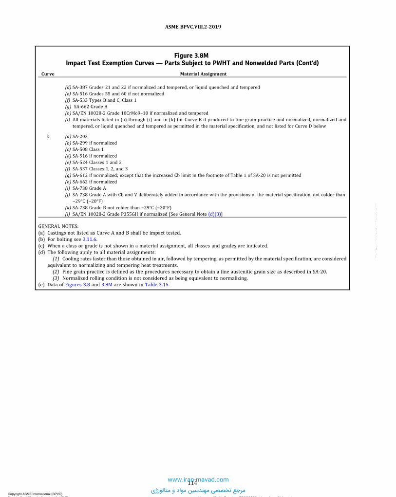
Figure 3.8MImpact Test Exemption Curves — Parts Subject to PWHT and Nonwelded Parts (Cont'd)
Curve Material Assignment
(d) SA-387 Grades 21 and 22 if normalized and tempered, or liquid quenched and tempered(e) SA-516 Grades 55 and 60 if not normalized(f) SA-533 Types B and C, Class 1(g) SA-662 Grade A(h) SA/EN 10028-2 Grade 10CrMo9–10 if normalized and tempered(i) All materials listed in (a) through (i) and in (k) for Curve B if produced to fine grain practice and normalized, normalized and
tempered, or liquid quenched and tempered as permitted in the material specification, and not listed for Curve D below
D (a) SA-203(b) SA-299 if normalized(c) SA-508 Class 1(d) SA-516 if normalized(e) SA-524 Classes 1 and 2(f) SA-537 Classes 1, 2, and 3(g) SA-612 if normalized; except that the increased Cb limit in the footnote of Table 1 of SA-20 is not permitted(h) SA-662 if normalized(i) SA-738 Grade A(j) SA-738 Grade A with Cb and V deliberately added in accordance with the provisions of the material specification, not colder than
−29°C (−20°F)(k) SA-738 Grade B not colder than −29°C (−20°F)(l) SA/EN 10028-2 Grade P355GH if normalized [See General Note (d)(3)]
GENERAL NOTES:(a) Castings not listed as Curve A and B shall be impact tested.(b) For bolting see 3.11.6.(c) When a class or grade is not shown in a material assignment, all classes and grades are indicated.(d) The following apply to all material assignments:
(1) Cooling rates faster than those obtained in air, followed by tempering, as permitted by the material specification, are consideredequivalent to normalizing and tempering heat treatments.(2) Fine grain practice is defined as the procedures necessary to obtain a fine austenitic grain size as described in SA-20.(3) Normalized rolling condition is not considered as being equivalent to normalizing.
(e) Data of Figures 3.8 and 3.8M are shown in Table 3.15.
114
ASME BPVC.VIII.2-2019
Copyright ASME International (BPVC) Provided by IHS under license with ASME Licensee=Khalda Petroleum/5986215001, User=Amer, Mohamed
Not for Resale, 07/02/2019 14:07:58 MDTNo reproduction or networking permitted without license from IHS
--`,```,,,,,````,`,``,,`,,`,`-`-`,,`,,`,`,,`---
www.iran-mavad.com
مرجع تخصصی مهندسین مواد و متالورژی

Figure 3.9Typical Vessel Details Illustrating the Governing Thickness
(a) Butt-Welded Components
2
(b) Welded Connection With or Without a Reinforcing Plate
Section X-X
X
X
1
1
2
3
tb
ta
tc
tg1 = ta
tg2 = ta (seamless) or tb (welded)
tbta
tc
tbta
tc
tbta
tg1 = min. (ta, tc) tg2 = min. (tb, tc) tg3 = min. (ta, tb)
115
ASME BPVC.VIII.2-2019
Copyright ASME International (BPVC) Provided by IHS under license with ASME Licensee=Khalda Petroleum/5986215001, User=Amer, Mohamed
Not for Resale, 07/02/2019 14:07:58 MDTNo reproduction or networking permitted without license from IHS
--`,```,,,,,````,`,``,,`,,`,`-`-`,,`,,`,`,,`---
www.iran-mavad.com
مرجع تخصصی مهندسین مواد و متالورژی

Figure 3.10Typical Vessel Details Illustrating the Governing Thickness
Groove
1
2
Groove1
2
(a) Bolted Flat Head or Tubesheet and Flange (b) Integral Flat Head or Tubesheet [Note (1)]
Groove1
2
(c) Flat Head or Tubesheet With a Corner Joint [Note (1)]
A
tata
tg2 = tc
tg1 = ta /4 (for welded or nonwelded)
tc
tg2 = tb
tg1 = ta /4 (for welded or nonwelded)
tg2 = min. (ta, tb)
tg1 = ta /4 (for welded or nonwelded)
tb
ta
tb
NOTE:(1) The governing thickness of the integral flat head or tubesheet is max(tg1 , tg2). The governing thickness of the shell is tg2 .
116
ASME BPVC.VIII.2-2019
Copyright ASME International (BPVC) Provided by IHS under license with ASME Licensee=Khalda Petroleum/5986215001, User=Amer, Mohamed
Not for Resale, 07/02/2019 14:07:58 MDTNo reproduction or networking permitted without license from IHS
--`,```,,,,,````,`,``,,`,,`,`-`-`,,`,,`,`,,`--- www.iran-mavad.com
مرجع تخصصی مهندسین مواد و متالورژی

Figure 3.11Typical Vessel Details Illustrating the Governing Thickness
(a) Welded Attachments
1
Pressure-containing part Pressure-containing part
1 1
1
(b) Integrally Reinforced Welded Connection
tb
tb
ta ta
tg1 = min. (ta, tb)
tatc
tg1 = min. (ta, tc)
117
ASME BPVC.VIII.2-2019
Copyright ASME International (BPVC) Provided by IHS under license with ASME Licensee=Khalda Petroleum/5986215001, User=Amer, Mohamed
Not for Resale, 07/02/2019 14:07:58 MDTNo reproduction or networking permitted without license from IHS
--`,```,,,,,````,`,``,,`,,`,`-`-`,,`,,`,`,,`---
www.iran-mavad.com
مرجع تخصصی مهندسین مواد و متالورژی

Figure 3.12Reduction in the MDMT Without Impact Testing — Parts Not Subject to PWHT
Temperature Reduction, TR, °F
0.0
0.1
0.2
0.3
0.4
0.5
0.6
0.7
0.8
0.9
1.0
� 50 ksi
> 50 ksi, � 65 ksi
0 20 40 60 80 100
Str
ess
Rat
io, R
ts
For Class 1 [Note (1)]
For Class 2 [Note (1)]
GENERAL NOTES:(a) Interpolation between yield strength values is permitted.(b) The reduction in MDMT shall not exceed 55°C (100°F), except as permitted by 3.11.2.5(a), Step 5(b).(c) Data of Figures 3.12 and 3.12M are shown in Table 3.16.
NOTE:(1) See 3.11.2.5(a), Step 5(a) when Rts is less than or equal to 0.3 for Class 1, or 0.24 for Class 2.
118
ASME BPVC.VIII.2-2019
Copyright ASME International (BPVC) Provided by IHS under license with ASME Licensee=Khalda Petroleum/5986215001, User=Amer, Mohamed
Not for Resale, 07/02/2019 14:07:58 MDTNo reproduction or networking permitted without license from IHS
--`,```,,,,,````,`,``,,`,,`,`-`-`,,`,,`,`,,`---
www.iran-mavad.com
مرجع تخصصی مهندسین مواد و متالورژی

Figure 3.12MReduction in the MDMT Without Impact Testing — Parts Not Subject to PWHT
Temperature Reduction, TR, °C
0.0
0.1
0.2
0.3
0.4
0.5
0.6
0.7
0.8
0.9
1.0
345 MPa,
345 MPa
0 10 20 30 40 50 60
450 MPa
Str
ess
Rat
io, R
ts
For Class 1 [Note (1)]
For Class 2 [Note (1)]
GENERAL NOTES:(a) Interpolation between yield strength values is permitted.(b) The reduction in MDMT shall not exceed 55°C (100°F), except as permitted by 3.11.2.5(a), Step 5(b).(c) Data of Figures 3.12 and 3.12M are shown in Table 3.16.
NOTE:(1) See 3.11.2.5(a), Step 5(a) when Rts is less than or equal to 0.3 for Class 1, or 0.24 for Class 2.
119
ASME BPVC.VIII.2-2019
Copyright ASME International (BPVC) Provided by IHS under license with ASME Licensee=Khalda Petroleum/5986215001, User=Amer, Mohamed
Not for Resale, 07/02/2019 14:07:58 MDTNo reproduction or networking permitted without license from IHS
--`,```,,,,,````,`,``,,`,,`,`-`-`,,`,,`,`,,`---
www.iran-mavad.com
مرجع تخصصی مهندسین مواد و متالورژی

Figure 3.13Reduction in the MDMT Without Impact Testing — Parts Subject to PWHT and Nonwelded Parts
Temperature Reduction, TR, °F
0.0
0.1
0.2
0.3
0.4
0.5
0.6
0.7
0.8
0.9
1.0
� 50 ksi
> 50 ksi, � 65 ksi
0 20 40 60 80 100
Str
ess
Rat
io, R
ts
For Class 1 [Note (1)]
For Class 2 [Note (1)]
GENERAL NOTES:(a) Interpolation between yield strength values is permitted.(b) The reduction in MDMT shall not exceed 55°C (100°F), except as permitted by 3.11.2.5(a), Step 5(b).(c) Data of Figures 3.13 and 3.13M are shown in Table 3.17.
NOTE:(1) See 3.11.2.5(a), Step 5(a) when Rts is less than or equal to 0.3 for Class 1, or 0.24 for Class 2.
120
ASME BPVC.VIII.2-2019
Copyright ASME International (BPVC) Provided by IHS under license with ASME Licensee=Khalda Petroleum/5986215001, User=Amer, Mohamed
Not for Resale, 07/02/2019 14:07:58 MDTNo reproduction or networking permitted without license from IHS
--`,```,,,,,````,`,``,,`,,`,`-`-`,,`,,`,`,,`---
www.iran-mavad.com
مرجع تخصصی مهندسین مواد و متالورژی

Figure 3.13MReduction in the MDMT Without Impact Testing — Parts Subject to PWHT and Nonwelded Parts
0.0
0.1
0.2
0.3
0.4
0.5
0.6
0.7
0.8
0.9
1.0
Temperature Reduction, TR, °C
345 MPa
Str
ess
Rat
io, R
ts
345 MPa, 450 MPa
0 10 20 30 40 50 60
For Class 1 [Note (1)]
For Class 2 [Note (1)]
GENERAL NOTES:(a) Interpolation between yield strength values is permitted.(b) The reduction in MDMT shall not exceed 55°C (100°F), except as permitted by 3.11.2.5(a), Step 5(b).(c) Data of Figures 3.13 and 3.13M are shown in Table 3.17.
NOTE:(1) See 3.11.2.5(a), Step 5(a) when Rts is less than or equal to 0.3 for Class 1, or 0.24 for Class 2.
121
ASME BPVC.VIII.2-2019
Copyright ASME International (BPVC) Provided by IHS under license with ASME Licensee=Khalda Petroleum/5986215001, User=Amer, Mohamed
Not for Resale, 07/02/2019 14:07:58 MDTNo reproduction or networking permitted without license from IHS
--`,```,,,,,````,`,``,,`,,`,`-`-`,,`,,`,`,,`---
www.iran-mavad.com
مرجع تخصصی مهندسین مواد و متالورژی

Figure 3.14Orientation and Location of Transverse Charpy V-Notch Specimens
(a) Charpy V-Notch Specimens From Plate
Rollingdirection
(b) Charpy V-Notch Specimens From Pipe
(b-1) (b-2)
(c) Charpy V-Notch Specimens From Forgings
Direction ofmajor working
GENERAL NOTE: The transverse Charpy V-Notch specimen orientation in the pipe shall be as shown in sketch (b-1). If this transverse spe-cimen cannot be obtained from the pipe geometry, then the alternate orientation shown in sketch (b-2) shall be used.
122
ASME BPVC.VIII.2-2019
Copyright ASME International (BPVC) Provided by IHS under license with ASME Licensee=Khalda Petroleum/5986215001, User=Amer, Mohamed
Not for Resale, 07/02/2019 14:07:58 MDTNo reproduction or networking permitted without license from IHS
--`,```,,,,,````,`,``,,`,,`,`-`-`,,`,,`,`,,`---
www.iran-mavad.com
مرجع تخصصی مهندسین مواد و متالورژی

Figure 3.15Weld Metal Delta Ferrite Content
Creq = Cr + Mo + 0.7Nb
18 20 22 24 26 28 30
iN
qeu
C 52.0 + N 02+
C 53 + iN =
10
12
14
16
18
0
2
4
68
10
21 4116
81 20
22 42 2682 30
53
40 5450
55 06
65 0775
8085
9095
100
Ferri
etn um
ber (
F)N
Figure 3.16HAZ Impact Specimen Removal
½t
Middle ½tt
Weld metal
Base metal
HAZ
Weld surface
Root surface
¼t
¼t
123
ASME BPVC.VIII.2-2019
Copyright ASME International (BPVC) Provided by IHS under license with ASME Licensee=Khalda Petroleum/5986215001, User=Amer, Mohamed
Not for Resale, 07/02/2019 14:07:58 MDTNo reproduction or networking permitted without license from IHS
--`,```,,,,,````,`,``,,`,,`,`-`-`,,`,,`,`,,`---
www.iran-mavad.com
مرجع تخصصی مهندسین مواد و متالورژی

ANNEX 3-AALLOWABLE DESIGN STRESSES
(Normative)
3-A.1 ALLOWABLE STRESS BASIS — ALL MATERIALS EXCEPT BOLTING
3-A.1.1
The materials that may be used in this Division for all product forms except bolting are shown below.(a) Carbon Steel and Low Alloy Steel – Table 3-A.1(b) Quenched and Tempered High Strength Steels – Table 3-A.2(c) High Alloy Steel – Table 3-A.3(d) Aluminum and Aluminum Alloys – Table 3-A.4(e) Copper and Copper Alloys – Table 3-A.5(f) Nickel and Nickel Alloys – Table 3-A.6(g) Titanium and Titanium Alloys – Table 3-A.7
3-A.1.2
The allowable stresses to be used in this Division for all product forms except bolting are provided in the followingtables of Section II, Part D.(a) Carbon Steel and Low Alloy Steel
(1) Class 1 – Section II, Part D, Subpart 1, Table 2A(2) Class 2 – Section II, Part D, Subpart 1, Table 5A
(b) Quenched and Tempered High Strength Steels(1) Class 1 – Section II, Part D, Subpart 1, Table 2A(2) Class 2 – Section II, Part D, Subpart 1, Table 5A
(c) High Alloy Steel(1) Class 1 – Section II, Part D, Subpart 1, Table 2A(2) Class 2 – Section II, Part D, Subpart 1, Table 5A
(d) Aluminum and Aluminum Alloys(1) Class 1 – Section II, Part D, Subpart 1, Table 2B(2) Class 2 – Section II, Part D, Subpart 1, Table 5B
(e) Copper and Copper Alloys(1) Class 1 – Section II, Part D, Subpart 1, Table 2B(2) Class 2 – Section II, Part D, Subpart 1, Table 5B
(f) Nickel and Nickel Alloys(1) Class 1 – Section II, Part D, Subpart 1, Table 2B(2) Class 2 – Section II, Part D, Subpart 1, Table 5B
(g) Titanium and Titanium Alloys(1) Class 1 – Section II, Part D, Subpart 1, Table 2B(2) Class 2 – Section II, Part D, Subpart 1, Table 5B
3-A.2 ALLOWABLE STRESS BASIS — BOLTING MATERIALS
3-A.2.1
The materials that may be used in this Division for bolting are shown below.(a) Ferrous Bolting Materials for Design in Accordance With Part 4 of this Division – Table 3-A.8
124
ASME BPVC.VIII.2-2019
Copyright ASME International (BPVC) Provided by IHS under license with ASME Licensee=Khalda Petroleum/5986215001, User=Amer, Mohamed
Not for Resale, 07/02/2019 14:07:58 MDTNo reproduction or networking permitted without license from IHS
--`,```,,,,,````,`,``,,`,,`,`-`-`,,`,,`,`,,`---
www.iran-mavad.com
مرجع تخصصی مهندسین مواد و متالورژی

ð19Þ
(b) Aluminum Alloy and Copper Alloy Bolting Materials for Design in Accordance With Part 4 of this Division –Table3-A.9
(c) Nickel and Nickel Alloy Bolting Materials Bolting Materials for Design in Accordance With Part 4 of this Division –Table 3-A.10
(d) Bolting Materials for Design in Accordance With Part 5 of this Division – Table 3-A.11
3-A.2.2The allowable stresses to be used in this Division for bolting are provided in the following tables of Section II, Part D.(a) Ferrous Bolting Materials for Design in Accordance With Part 4 of this Division – Section II, Part D, Subpart 1,
Table 3(b) Aluminum Alloy and Copper Alloy Bolting Materials for Design in Accordance With Part 4 of this Division – Section
II, Part D, Subpart 1, Table 3(c) Nickel and Nickel Alloy Bolting Materials Bolting Materials for Design in Accordance With Part 4 of this Division –
Section II, Part D, Subpart 1, Table 3(d) Bolting Materials for Design in Accordance With Part 5 of this Division – Section II, Part D, Subpart 1, Table 4
3-A.3 TABLES
Table 3-A.1Carbon Steel and Low Alloy Materials
Material Specification Type/Grade/Class UNS No. Nominal Composition Product Form
SA-36 … K02600 Carbon steel Str. plateSA-105 … K03504 Carbon steel ForgingsSA-106 A K02501 Carbon steel Smls. pipeSA-106 B K03006 Carbon steel Smls. pipeSA-106 C K03501 Carbon steel Smls. pipe
SA-178 C K03503 Carbon steel Wld. tubeSA-181 60 K03502 Carbon steel ForgingsSA-181 70 K03502 Carbon steel ForgingsSA-182 F1 K12822 C–1/2Mo ForgingsSA-182 F2 K12122 1/2Cr–
1/2Mo Forgings
SA-182 F3VCb K31390 3Cr–1Mo–1/4V–Cb–Ca ForgingsSA-182 F3V K31830 3Cr–1Mo–1/4V–Ti–B ForgingsSA-182 F5 K41545 5Cr–1/2Mo ForgingsSA-182 F5a K42544 5Cr–1/2Mo ForgingsSA-182 F9 K90941 9Cr–1Mo Forgings
SA-182 F12, Cl. 1 K11562 1Cr–1/2Mo ForgingsSA-182 F12, Cl. 2 K11564 1Cr–1/2Mo ForgingsSA-182 F11, Cl. 1 K11597 11/4Cr–
1/2Mo–Si ForgingsSA-182 F11, Cl. 2 K11572 11/4Cr–
1/2Mo–Si ForgingsSA-182 F21 K31545 3Cr–1Mo Forgings
SA-182 F22, Cl. 1 K21590 21/4Cr–1Mo ForgingsSA-182 F22, Cl. 3 K21590 21/4Cr–1Mo ForgingsSA-182 F22V K31835 21/4Cr–1Mo–1/4V ForgingsSA-182 F91 K90901 9Cr–1Mo–V ForgingsSA-182 FR K22035 2Ni–1Cu Forgings
SA-203 A K21703 2 1/2Ni PlateSA-203 B K22103 2 1/2Ni PlateSA-203 D K31718 31/2Ni PlateSA-203 E K32018 31/2Ni PlateSA-203 F … 31/2Ni Plate
SA-204 A K11820 C–1/2Mo PlateSA-204 B K12020 C–1/2Mo PlateSA-204 C K12320 C–1/2Mo PlateSA-209 T1 K11522 C–1/2Mo Smls. tube
125
ASME BPVC.VIII.2-2019
Copyright ASME International (BPVC) Provided by IHS under license with ASME Licensee=Khalda Petroleum/5986215001, User=Amer, Mohamed
Not for Resale, 07/02/2019 14:07:58 MDTNo reproduction or networking permitted without license from IHS
--`,```,,,,,````,`,``,,`,,`,`-`-`,,`,,`,`,,`---
www.iran-mavad.com
مرجع تخصصی مهندسین مواد و متالورژی

Table 3-A.1Carbon Steel and Low Alloy Materials (Cont'd)
Material Specification Type/Grade/Class UNS No. Nominal Composition Product Form
SA-209 T1a K12023 C–1/2Mo Smls. tube
SA-209 T1b K11422 C–1/2Mo Smls. tubeSA-210 A-1 K02707 Carbon steel Smls. tubeSA-210 C K03501 Carbon steel Smls. tubeSA-213 T2 K11547 1/2Cr–
1/2Mo Smls. tubeSA-213 T5 K41545 5Cr–1/2Mo Smls. tube
SA-213 T5b K41545 5Cr–1/2Mo–Si Smls. tubeSA-213 T5c K41245 5Cr–1/2Mo–Ti Smls. tubeSA-213 T9 K90941 9Cr–1Mo Smls. tubeSA-213 T11 K11597 11/4Cr–
1/2Mo–Si Smls. tubeSA-213 T12 K11562 1Cr–1/2Mo Smls. tube
SA-213 T21 K31545 3Cr–1Mo Smls. tubeSA-213 T22 K21590 21/2Cr–1Mo Smls. tubeSA-213 T91 K90901 9Cr–1Mo–V Smls. tubeSA-216 WCA J02502 Carbon steel CastingsSA-216 WCB J03002 Carbon steel Castings
SA-216 WCC K02503 Carbon steel CastingsSA-217 C5 J42045 5Cr–1/2Mo CastingsSA-217 C12 J82090 9Cr–1Mo CastingsSA-217 WC1 J12524 C–1/2Mo CastingsSA-217 WC4 J12082 1Ni–1/2Cr–
1/2Mo Castings
SA-217 WC5 J22000 3/4Ni–1Mo–3/4Cr CastingsSA-217 WC6 J12072 11/4Cr–
1/2Mo CastingsSA-217 WC9 J21890 21/4Cr–1Mo CastingsSA-225 C K12524 Mn–1/2Ni–V PlateSA-234 WPB K03006 Carbon steel Fittings
SA-234 WPC K03501 Carbon steel FittingsSA-234 WP1 K12821 C–1/2Mo FittingsSA-234 WP5 K41515 5Cr–1/2Mo FittingsSA-234 WP9 K90941 9Cr–1Mo FittingsSA-234 WP11, Cl. 1 … 11/4Cr–
1/2Mo–Si Fittings
SA-234 WP12, Cl. 1 K12062 1Cr–1/2Mo FittingsSA-234 WP22, Cl. 1 K21590 21/4Cr–1Mo FittingsSA-266 1 K03506 Carbon steel ForgingsSA-266 2 K03506 Carbon steel ForgingsSA-266 3 K05001 Carbon steel Forgings
SA-266 4 K03017 Carbon steel ForgingsSA-283 B … Carbon steel Str. plateSA-283 D … Carbon steel Str. plateSA-285 A K01700 Carbon steel PlateSA-285 B K02200 Carbon steel Plate
SA-285 C K02801 Carbon steel PlateSA-299 A K02803 Carbon steel PlateSA-299 [Note (1)] B K02803 Carbon steel PlateSA-302 A K12021 Mn–1/2Mo PlateSA-302 B K12022 Mn–1/2Mo Plate
SA-302 C K12039 Mn–1/2Mo–1/2Ni PlateSA-302 D K12054 Mn–1/2Mo–3/4Ni PlateSA-333 1 K03008 Carbon steel Smls. pipeSA-333 3 K31918 31/2Ni Smls. pipeSA-333 4 K11267 3/4Cr–
3/4Ni–Cu–Al Smls. pipe
SA-333 6 K03006 Carbon steel Smls. pipeSA-333 9 K22035 2Ni–1Cu Smls. pipe
126
ASME BPVC.VIII.2-2019
Copyright ASME International (BPVC) Provided by IHS under license with ASME Licensee=Khalda Petroleum/5986215001, User=Amer, Mohamed
Not for Resale, 07/02/2019 14:07:58 MDTNo reproduction or networking permitted without license from IHS
--`,```,,,,,````,`,``,,`,,`,`-`-`,,`,,`,`,,`---
www.iran-mavad.com
مرجع تخصصی مهندسین مواد و متالورژی

Table 3-A.1Carbon Steel and Low Alloy Materials (Cont'd)
Material Specification Type/Grade/Class UNS No. Nominal Composition Product Form
SA-333 1 K03008 Carbon steel Wld. pipeSA-334 1 K03008 Carbon steel Wld. tubeSA-334 1 K03008 Carbon steel Smls. tube
SA-334 3 K31918 31/2Ni Smls. tubeSA-334 9 K22035 2Ni–1Cu Smls. tubeSA-335 P1 K11522 C–1/2Mo Smls. pipeSA-335 P2 K11547 1/2Cr–
1/2Mo Smls. pipeSA-335 P5 K41545 5Cr–1/2Mo Smls. pipe
SA-335 P5b K51545 5Cr–1/2Mo–Si Smls. pipeSA-335 P5c K41245 5Cr–1/2Mo–Ti Smls. pipeSA-335 P9 K90941 9Cr–1Mo Smls. pipeSA-335 P11 K11597 11/4Cr–
1/2Mo–Si Smls. pipeSA-335 P12 K11562 1Cr–1/2Mo Smls. pipe
SA-335 P21 K31545 3Cr–1Mo Smls. pipeSA-335 P22 K21590 21/4Cr–1Mo Smls. pipeSA-335 P91 K90901 9Cr–1Mo–V Smls. pipeSA-336 F1 K11564 1Cr–1/2Mo ForgingsSA-336 F3VCb K31390 3Cr–1Mo–1/4V–Cb–Ca Forgings
SA-336 F3V K31830 3Cr–1Mo–1/4V–Ti–B ForgingsSA-336 F5 K41545 5Cr–1Mo ForgingsSA-336 F5A K42544 5Cr–1Mo ForgingsSA-336 F9 K90941 9Cr–1Mo ForgingsSA-336 F11, Cl. 2 K11572 11/4Cr–
1/2Mo–Si Forgings
SA-336 F11, Cl. 3 K11572 11/4Cr–1/2Mo–Si Forgings
SA-336 F12 K11564 1Cr–1/2Mo ForgingsSA-336 F21, Cl. 1 K31545 3Cr–1Mo ForgingsSA-336 F21, Cl. 3 K31545 3Cr–1Mo ForgingsSA-336 F22, Cl. 1 K21590 21/4Cr–1Mo Forgings
SA-336 F22, Cl. 3 K21590 21/4Cr–1Mo ForgingsSA-336 F22V K31835 21/4Cr–1Mo–1/4V ForgingsSA-336 [Note (1)] F91 K90901 9Cr–1Mo–V ForgingsSA-350 LF1 K03009 Carbon steel ForgingsSA-350 LF2 K03011 Carbon steel Forgings
SA-350 LF3 K32025 31/2Ni ForgingsSA-350 LF9 K22036 2Ni–1Cu ForgingsSA-352 LCB J03003 Carbon steel CastingsSA-352 LC1 J12522 C–1/2Mo CastingsSA-352 LC2 J22500 21/2Ni Castings
SA-352 LC3 J31550 31/2Ni CastingsSA-369 FP1 K11522 C–1/2Mo Forged pipeSA-369 FP2 K11547 1/2Cr–
1/2Mo Forged pipeSA-369 FP5 K41545 5Cr–1/2Mo Forged pipeSA-369 FP9 K90941 9Cr–1Mo Forged pipe
SA-369 FP11 K11597 11/4Cr–1/2Mo–Si Forged pipe
SA-369 FP12 K11562 1Cr–1/2Mo Forged pipeSA-369 FP21 K31545 3Cr–1Mo Forged pipeSA-369 FP22 K21590 21/4Cr–1Mo Forged pipeSA-372 A K03002 Carbon steel Forgings
SA-372 B K04001 Carbon steel ForgingsSA-372 C K04801 Carbon steel ForgingsSA-372 D K10508 Mn–1/4Mo ForgingsSA-387 2, Cl. 1 K12143 1/2Cr–
1/2Mo PlateSA-387 2, Cl. 2 K12143 1/2Cr–
1/2Mo Plate
127
ASME BPVC.VIII.2-2019
Copyright ASME International (BPVC) Provided by IHS under license with ASME Licensee=Khalda Petroleum/5986215001, User=Amer, Mohamed
Not for Resale, 07/02/2019 14:07:58 MDTNo reproduction or networking permitted without license from IHS
--`,```,,,,,````,`,``,,`,,`,`-`-`,,`,,`,`,,`---
www.iran-mavad.com
مرجع تخصصی مهندسین مواد و متالورژی

Table 3-A.1Carbon Steel and Low Alloy Materials (Cont'd)
Material Specification Type/Grade/Class UNS No. Nominal Composition Product Form
SA-387 5, Cl. 1 K41545 5Cr–1/2Mo PlateSA-387 5, Cl. 2 K41545 5Cr–1/2Mo PlateSA-387 11, Cl. 1 K11789 11/4Cr–
1/2Mo–Si PlateSA-387 11, Cl. 2 K11789 11/4Cr–
1/2Mo–Si PlateSA-387 12, Cl. 1 K11757 1Cr–1/2Mo Plate
SA-387 12, Cl. 2 K11757 1Cr–1/2Mo PlateSA-387 21, Cl. 1 K31545 3Cr–1Mo PlateSA-387 21, Cl. 2 K31545 3Cr–1Mo PlateSA-387 22, Cl. 1 K21590 21/4Cr–1Mo PlateSA-387 22, Cl. 2 K21590 21/4Cr–1Mo Plate
SA-387 91 K90901 9Cr–1Mo–V PlateSA-420 WPL3 … 31/2Ni FittingsSA-420 WPL6 … Carbon steel FittingsSA-420 WPL9 K22035 2Ni–Cu FittingsSA-423 1 K11535 1/4Cr–
1/2Ni–Cu Smls. tube
SA-423 2 K11540 3/4Ni–3/4Cu–Mo Smls. tube
SA-487 1, Cl. A J13002 Mn–V CastingsSA-487 4, Cl. A J13047 1/2Ni–
1/2Cr–1/4Mo–V Castings
SA-487 8, Cl. A J22091 21/2Cr–1Mo CastingsSA-508 1 K13502 Carbon steel Forgings
SA-508 1A K13502 Carbon steel ForgingsSA-508 2, Cl. 1 K12766 3/4Ni–
1/2Mo–1/3Cr–V ForgingsSA-508 2, Cl. 2 K12766 3/4Ni–
1/2Mo–1/3Cr–V ForgingsSA-508 3, Cl. 1 K12042 3/4Ni–
1/2Mo–Cr–V ForgingsSA-508 3, Cl. 2 K12042 3/4Ni–
1/2Mo–Cr–V Forgings
SA-508 3VCb K31390 3Cr–1Mo–1/4V–Cb–Ca ForgingsSA-508 3V K31830 3Cr–1Mo–1/4V–Ti–B ForgingsSA-508 4N, Cl. 3 K22375 31/2Ni–1
3/4Cr–1/2Mo–V Forgings
SA-508 22, Cl. 3 K215909 21/4Cr–1Mo ForgingsSA-515 60 K02401 Carbon steel Plate
SA-515 65 K02800 Carbon steel PlateSA-515 70 K03101 Carbon steel PlateSA-516 55 K01800 Carbon steel PlateSA-516 60 K02100 Carbon steel PlateSA-516 65 K02403 Carbon steel Plate
SA-516 70 K02700 Carbon steel PlateSA-524 I K02104 Carbon steel Smls. pipeSA-524 II K02104 Carbon steel Smls. pipeSA-533 A, Cl. 1 K12521 Mn–1/2Mo PlateSA-533 A, Cl. 2 K12521 Mn–1/2Mo Plate
SA-533 B, Cl. 1 K12539 Mn–1/2Mo–1/2Ni PlateSA-533 B, Cl. 2 K12539 Mn–1/2Mo–1/2Ni PlateSA-533 C, Cl. 1 K12554 Mn–1/2Mo–3/4Ni PlateSA-533 C, Cl. 2 K12554 Mn–1/2Mo–3/4Ni PlateSA-533 D, Cl. 2 K12529 Mn–1/2Mo–1/4Ni Plate
SA-533 [Note (1)] E, Cl. 1 K12554 Mn–1/2Mo–3/4Ni PlateSA-533 [Note (1)] E, Cl. 2 K12554 Mn–1/2Mo–3/4Ni PlateSA-537 Cl. 1 K12437 Carbon steel PlateSA-537 Cl. 2 K12437 Carbon steel PlateSA-537 Cl. 3 K12437 Carbon steel Plate
SA-541 1 K03506 Carbon steel ForgingsSA-541 1A K03020 Carbon steel ForgingsSA-541 2, Cl. 1 K12765 3/4Ni–
1/2Mo–1/3Cr–V Forgings
128
ASME BPVC.VIII.2-2019
Copyright ASME International (BPVC) Provided by IHS under license with ASME Licensee=Khalda Petroleum/5986215001, User=Amer, Mohamed
Not for Resale, 07/02/2019 14:07:58 MDTNo reproduction or networking permitted without license from IHS
--`,```,,,,,````,`,``,,`,,`,`-`-`,,`,,`,`,,`---
www.iran-mavad.com
مرجع تخصصی مهندسین مواد و متالورژی

Table 3-A.1Carbon Steel and Low Alloy Materials (Cont'd)
Material Specification Type/Grade/Class UNS No. Nominal Composition Product Form
SA-541 2, Cl. 2 K12765 3/4Ni–1/2Mo–1/3Cr–V Forgings
SA-541 3, Cl. 1 K12045 1/2Ni–1/2Mo–V Forgings
SA-541 3, Cl. 2 K12045 1/2Ni–1/2Mo–V Forgings
SA-541 3VCb K31390 3Cr–1Mo–1/4V–Cb–Ca ForgingsSA-541 3V K31830 3Cr–1Mo–1/4V–Ti–B ForgingsSA-541 22, Cl. 3 K21390 21/4Cr–1Mo ForgingsSA-541 22V K31835 21/4Cr–1Mo–1/4V Forgings
SA-542 B, Cl. 4 … 21/4Cr–1Mo PlateSA-542 E, Cl. 4a K31390 3Cr–1Mo–1/4V–Cb–Ca PlateSA-542 C, Cl. 4a … 3Cr–1Mo–1/4V–Ti–B PlateSA-542 D, Cl. 4a … 21/4Cr–1Mo–1/4V PlateSA-612 … K02900 Carbon steel Plate
SA-662 A K10701 Carbon steel PlateSA-662 B K02203 Carbon steel PlateSA-662 C K02007 Carbon steel PlateSA-675 45 … Carbon steel Bar, shapesSA-675 50 … Carbon steel Bar, shapes
SA-675 55 … Carbon steel Bar, shapesSA-675 60 … Carbon steel Bar, shapesSA-675 65 … Carbon steel Bar, shapesSA-675 70 … Carbon steel Bar, shapesSA-727 … K02506 Carbon steel Forgings
SA-737 B K12001 C–Mn–Si–Cb PlateSA-737 C K12202 C–Mn–Si–V PlateSA-738 A K12447 Carbon steel PlateSA-738 B K12007 Carbon steel PlateSA-738 C … Carbon steel Plate
SA-739 B11 K11797 11/4Cr–1/2Mo Bar
SA-739 B22 K21390 21/4Cr–1Mo BarSA-765 I K03046 Carbon steel ForgingsSA-765 II K03047 Carbon steel ForgingsSA-765 III K32026 31/2Ni Forgings
SA-765 IV K02009 Carbon steel ForgingsSA-832 23V K31390 3Cr–1Mo–1/4V–Cb–Ca PlateSA-832 21V K31830 3Cr–1Mo–1/4V–Ti–B PlateSA-832 22V K31835 21/4Cr–1Mo–V PlateSA-841 [Note (1)] A, Cl. 1 … Carbon steel Plate
SA-841 [Note (1)] B, Cl. 2 … Carbon steel PlateSA/EN 10028-2 [Note (1)] P355GH … Carbon steel PlateSA/EN 10028-2 [Note (1)] 13CrMo4–5 … 1Cr–1/2Mo PlateSA/EN 10028-2 [Note (1)] 10CrMo9–10 … 21/4Cr–1Mo PlateSA/EN 10028-2 [Note (1)] 13CrMoSi5–5 +QT … 11/4Cr–
1/2Mo–Si Plate
SA/EN 10222-2 [Note (1)] P280GH … Carbon steel ForgingsSA/EN 10222-2 [Note (1)] P30SGH … Carbon steel ForgingsSA/EN 10222-2 [Note (1)] 13CrMo4–5 … 1Cr–1/2Mo ForgingsSA/EN 10222-2 [Note (1)] 11CrMo9–10 … 21/4Cr–1Mo ForgingsSA/NF A36-215 [Note (1)] P440 NJ4 … Mn–V Plate
NOTE:(1) For Class 2 construction only.
129
ASME BPVC.VIII.2-2019
Copyright ASME International (BPVC) Provided by IHS under license with ASME Licensee=Khalda Petroleum/5986215001, User=Amer, Mohamed
Not for Resale, 07/02/2019 14:07:58 MDTNo reproduction or networking permitted without license from IHS
--`,```,,,,,````,`,``,,`,,`,`-`-`,,`,,`,`,,`---
www.iran-mavad.com
مرجع تخصصی مهندسین مواد و متالورژی

ð19Þ Table 3-A.2Quenched and Tempered High Strength Steels
Material Specification Type/Grade/Class UNS No. Nominal Composition Product Form
SA-333 8 K81340 9Ni Smls. pipeSA-334 8 K81340 9Ni Smls. tubeSA-353 … K81340 9Ni PlateSA-372 D K14508 Mn–1/4Mo ForgingsSA-372 E, Cl. 70 K13047 1Cr–1/5Mo Forgings
SA-372 F, Cl. 70 G41350 1Cr–1/5Mo ForgingsSA-372 G, Cl. 70 K13049 1/2Cr–
1/5Mo ForgingsSA-372 H, Cl. 70 K13547 1/2Cr–
1/5Mo ForgingsSA-372 J, Cl. 70 K13548 1Cr–1/5Mo ForgingsSA-372 J, Cl. 110 G41370 1Cr–1/5Mo Forgings
SA-420 WPL8 K81340 9Ni Smls. pipeSA-508 4N, Cl. 1 K22375 31/2Ni–1
3/4Cr–1/2Mo–V Forgings
SA-508 4N, Cl. 2 K22375 31/2Ni–13/4Cr–
1/2Mo–V ForgingsSA-517 A K11856 1/2Cr–
1/4Mo–Si PlateSA-517 B K11630 1/2Cr–
1/5Mo–V Plate
SA-517 E K21604 13/4Cr–1/2Mo–Ti Plate
SA-517 F K11576 3/4Ni–1/2Cr–
1/2Mo–V PlateSA-517 J K11625 C–1/2Mo PlateSA-517 P K21650 11/4Ni–1Cr–
1/2Mo PlateSA-522 I K81340 9Ni Forgings
SA-533 B, Cl. 3 K12554 Mn–1/2Mo–3/4Ni PlateSA-533 D, Cl. 3 K12529 Mn–1/2Mo–1/4Ni PlateSA-543 B, Cl. 1 K42339 3Ni–13/4Cr–
1/2Mo PlateSA-543 B, Cl. 2 K42339 3Ni–13/4Cr–
1/2Mo PlateSA-543 B, Cl. 3 K42339 3Ni–13/4Cr–
1/2Mo Plate
SA-543 C, Cl. 1 … 23/4Ni–11/2Cr–
1/2Mo PlateSA-543 C, CL. 2 … 23/4Ni–1
1/2Cr–1/2Mo Plate
SA-543 C, CL. 3 … 23/4Ni–11/2Cr–
1/2Mo PlateSA-553 I K81340 9Ni PlateSA-553 III K61365 7Ni Plate
SA-592 A K11856 1/2Cr–1/4Mo–Si Forgings
SA-592 E K11695 13/4Cr–1/2Mo–Cu Forgings
SA-592 F K11576 3/4Ni–1/2Cr–
1/2Mo–V ForgingsSA-645 A K41583 5Ni–1/4Mo PlateSA-723 1, Cl. 1 K23550 2Ni–11/2Cr–
1/4Mo–V Forgings
SA-723 1, Cl. 2 K23550 2Ni–11/2Cr–1/4Mo–V Forgings
SA-723 2, Cl. 1 K34035 23/4Ni–11/2Cr–
1/2Mo–V ForgingsSA-723 2, Cl. 2 K34035 23/4Ni–1
1/2Cr–1/2Mo–V Forgings
SA-723 3, Cl. 1 K44045 4Ni–11/2Cr–1/2Mo–V Forgings
SA-723 3, Cl. 2 K44045 4Ni–11/2Cr–1/2Mo–V Forgings
SA-724 A K11831 Carbon steel PlateSA-724 B K12031 Carbon steel PlateSA-724 C K12037 Carbon steel Plate
130
ASME BPVC.VIII.2-2019
Copyright ASME International (BPVC) Provided by IHS under license with ASME Licensee=Khalda Petroleum/5986215001, User=Amer, Mohamed
Not for Resale, 07/02/2019 14:07:58 MDTNo reproduction or networking permitted without license from IHS
--`,```,,,,,````,`,``,,`,,`,`-`-`,,`,,`,`,,`---www.iran-mavad.com
مرجع تخصصی مهندسین مواد و متالورژی

ð19ÞTable 3-A.3High Alloy Steel
Material Specification Type/Grade/Class UNS No. Nominal Composition Product Form
SA-182 FXM-11 S21904 21Cr–6Ni–9Mn ForgingsSA-182 FXM-19 S20910 22Cr–13Ni–5Mn ForgingsSA-182 F6a, Cl. 1 S41000 13Cr ForgingsSA-182 F6a, Cl. 2 S41000 13Cr ForgingsSA-182 F51 S31803 22Cr–5Ni–3Mo–N Forgings
SA-182 F58 S31266 24Cr–22.5Ni–5.7Mo–Cu–W ForgingsSA-182 [Note (1)] F60 S32205 22Cr–5.5Ni–3Mo–N ForgingsSA-182 F304 S30400 18Cr–8Ni ForgingsSA-182 F304H S30409 18Cr–8Ni ForgingsSA-182 F304L S30403 18Cr–8Ni Forgings
SA-182 F310 S31000 25Cr–20Ni ForgingsSA-182 [Note (1)] F310MoLN S31050 25Cr–22Ni–2Mo–N ForgingsSA-182 F316 S31600 16Cr–12Ni–2Mo ForgingsSA-182 F316H S31609 16Cr–12Ni–2Mo ForgingsSA-182 F316L S31603 16Cr–12Ni–2Mo Forgings
SA-182 F321 S32100 18Cr–10Ni–Ti ForgingsSA-182 F321H S32109 18Cr–10Ni–Ti ForgingsSA-182 F347 S34700 18Cr–10Ni–Cb ForgingsSA-182 F347H S34909 18Cr–10Ni–Cb ForgingsSA-182 F348 S34800 18Cr–10Ni–Cb Forgings
SA-182 F348H S34809 18Cr–10Ni–Cb ForgingsSA-213 TP304 S30400 18Cr–8Ni Smls. tubeSA-213 TP304H S30409 18Cr–8Ni Smls. tubeSA-213 TP304L S30403 18Cr–8Ni Smls. tubeSA-213 TP304N S30451 18Cr–8Ni–N Smls. tube
SA-213 TP309Cb S30940 23Cr–12Ni–Cb Smls. tubeSA-213 TP309H S30909 23Cr–12Ni Smls. tubeSA-213 TP309S S30908 23Cr–12Ni Smls. tubeSA-213 TP310H S31009 25Cr–20Ni Smls. tubeSA-213 TP310MoLN S31050 25Cr–22Ni–2Mo–N Smls. tube
SA-213 TP310S S31008 25Cr–20Ni Smls. tubeSA-213 TP316 S31600 16Cr–12Ni–2Mo Smls. tubeSA-213 TP316H S31609 16Cr–12Ni–2Mo Smls. tubeSA-213 TP316L S31603 16Cr–12Ni–2Mo Smls. tubeSA-213 TP316N S31651 16Cr–12Ni–2Mo–N Smls. tube
SA-213 TP321 S32100 18Cr–10Ni–Ti Smls. tubeSA-213 TP321H S32109 18Cr–10Ni–Ti Smls. tubeSA-213 TP347 S34700 18Cr–10Ni–Cb Smls. tubeSA-213 TP347H S34709 18Cr–10Ni–Cb Smls. tubeSA-213 TP348 S34800 18Cr–10Ni–Cb Smls. tube
SA-213 TP348H S34809 18Cr–10Ni–Cb Smls. tubeSA-213 XM-15 S38100 18Cr–18Ni–2Si Smls. tubeSA-217 CA15 J91150 13Cr CastingsSA-240 XM-15 S38100 18Cr–18Ni–2Si PlateSA-240 XM19 S20910 22Cr–13Ni–5Mn Plate
SA-240 XM-29 S24000 18Cr–3Ni–12Mn PlateSA-240 XM-29 S24000 18Cr–3Ni–12Mn Sheet and stripSA-240 201LN S20153 16Cr–4Ni–6Mn PlateSA-240 [Note (1)] 255 S32550 25Cr–5Ni–3Mo–2Cu PlateSA-240 302 S30200 18Cr–8Ni Plate
131
ASME BPVC.VIII.2-2019
Copyright ASME International (BPVC) Provided by IHS under license with ASME Licensee=Khalda Petroleum/5986215001, User=Amer, Mohamed
Not for Resale, 07/02/2019 14:07:58 MDTNo reproduction or networking permitted without license from IHS
--`,```,,,,,````,`,``,,`,,`,`-`-`,,`,,`,`,,`---
www.iran-mavad.com
مرجع تخصصی مهندسین مواد و متالورژی

Table 3-A.3High Alloy Steel (Cont'd)
Material Specification Type/Grade/Class UNS No. Nominal Composition Product Form
SA-240 304 S30400 18Cr–8Ni PlateSA-240 304H S30409 18Cr–8Ni PlateSA-240 304L S30403 18Cr–8Ni PlateSA-240 304N S30451 18Cr–8Ni–N PlateSA-240 … S30601 17.5Cr–17.5Ni–5.3Si Plate
SA-240 … S31266 24Cr–22.5Ni–5.7Mo–Cu–W PlateSA-240 309Cb S30940 23Cr–12Ni–Cb PlateSA-240 309H S30909 23Cr–12Ni PlateSA-240 309S S30908 23Cr–12Ni PlateSA-240 310H S31009 25Cr–20Ni Plate
SA-240 310MoLN S31050 25Cr–22Ni–2Mo–N PlateSA-240 310S S31008 25Cr–20Ni PlateSA-240 316 S31600 16Cr–12Ni–2Mo PlateSA-240 316L S31603 16Cr–12Ni–2Mo PlateSA-240 316N S31651 16Cr–12Ni–2Mo–N Plate
SA-240 317 S31700 18Cr–13Ni–3Mo PlateSA-240 317L S31703 18Cr–13Ni–3Mo PlateSA-240 321 S32100 18Cr010Ni–Ti PlateSA-240 321H S32109 18Cr–10Ni–Ti PlateSA-240 347 S34700 18Cr–10Ni–Cb Plate
SA-240 347H S34709 18Cr–10Ni–Cb PlateSA-240 348 S34800 18Cr–10Ni–Cb PlateSA-240 405 S40500 13Cr–1Al PlateSA-240 410 S41000 13Cr PlateSA-240 410S S41008 13Cr Plate
SA-240 429 S42900 15Cr PlateSA-240 430 S43000 17Cr PlateSA-240 … S31803 22Cr–5Ni–3Mo–N PlateSA-240 [Note (1)] 2205 S32205 22Cr–5.5Ni–3Mo–N PlateSA-240 26-3-3 S44660 26Cr–3Ni–3Mo Plate
SA-240 [Note (1)] … S32906 29Cr–6.5Ni–2Mo–N Plate, sheet, and stripSA-249 TPXM-15 S38100 18Cr–18Ni–2Si Wld. tubeSA-249 TPXM-19 S20910 22Cr–13Ni–5Mn Wld. tubeSA-249 TP304 S30400 18Cr–8Ni Wld. tubeSA-249 TP304H S30409 18Cr–8Ni Wld. tube
SA-249 TP304L S30403 18Cr–8Ni Wld. tubeSA-249 TP304N S30451 18Cr–8Ni–N Wld. tubeSA-249 TP309Cb S30940 23Cr–12Ni–Cb Wld. tubeSA-249 TP309H S30909 23Cr–12Ni Wld. tubeSA-249 TP309S S30908 23Cr–12Ni Wld. tube
SA-249 TP310Cb S31040 25Cr–20Ni–Cb Wld. tubeSA-249 TP310H S31009 23Cr–12Ni Wld. tubeSA-249 TP310MoLN S31050 25Cr–22Ni–2Mo–N Wld. tubeSA-249 TP310S S31008 23Cr–12Ni Wld. tubeSA-249 TP316 S31600 16Cr–12Ni–2Mo Wld. tube
SA-249 TP316H S31609 16Cr–12Ni–2Mo Wld. tubeSA-249 TP316L S31603 16Cr–12Ni–2Mo Wld. tubeSA-249 TP316N S31651 16Cr–12Ni–2Mo–N Wld. tubeSA-249 TP317 S31700 18Cr–3Ni–3Mo Wld. tubeSA-249 TP321 S32100 18Cr–10Ni–Ti Wld. tube
132
ASME BPVC.VIII.2-2019
Copyright ASME International (BPVC) Provided by IHS under license with ASME Licensee=Khalda Petroleum/5986215001, User=Amer, Mohamed
Not for Resale, 07/02/2019 14:07:58 MDTNo reproduction or networking permitted without license from IHS
--`,```,,,,,````,`,``,,`,,`,`-`-`,,`,,`,`,,`---
www.iran-mavad.com
مرجع تخصصی مهندسین مواد و متالورژی

Table 3-A.3High Alloy Steel (Cont'd)
Material Specification Type/Grade/Class UNS No. Nominal Composition Product Form
SA-249 TP321H S32109 18Cr–10Ni–Ti Wld. tubeSA-249 TP347 S34700 18Cr–10Ni–Cb Wld. tubeSA-249 TP347H S34709 18Cr–10Ni–Cb Wld. tubeSA-249 TP348 S34800 18Cr–10Ni–Cb Wld. tubeSA-249 TP348H S34809 18Cr–10Ni–Cb Wld. tube
SA-268 TP405 S40500 12Cr–1Al Smls. tubeSA-268 TP410 S41000 13Cr Smls. tubeSA-268 TP429 S42900 15Cr Smls. tubeSA-268 TP430 S43000 17Cr Smls. tubeSA-268 26-3-3 S44660 26Cr–3Ni–3Mo Smls. tube
SA-268 26-3-3 S44660 26Cr–3Ni–3Mo Wld. tubeSA-312 TPXM-11 S21904 21Cr–6Ni–9Mn Smls. pipeSA-312 TPXM-15 S38100 18Cr–18Ni–2Si Smls. pipeSA-312 TPXM-19 S20910 22Cr–13Ni–5Mn Smls. pipeSA-312 TP304 S30400 18Cr–8Ni Smls. pipe
SA-312 TP304H S30409 18Cr–8Ni Smls. pipeSA-312 TP304L S30403 18Cr–8Ni Smls. pipeSA-312 TP304N S30451 18Cr–8Ni–N Smls. pipeSA-312 TP309Cb S30940 23Cr–12Ni–Cb Smls. pipeSA-312 TP309H S30909 23Cr–12Ni Smls. pipe
SA-312 TP309S S30908 23Cr–12Ni Smls. pipeSA-312 TP310H S31009 23Cr–12Ni Smls. pipeSA-312 TP310S S31008 23Cr–12Ni Smls. pipeSA-312 TP316 S31600 16Cr–12Ni–2Mo Smls. pipeSA-312 TP316H S31609 16Cr–12Ni–2Mo Smls. pipe
SA-312 TP316L S31603 16Cr–12Ni–2Mo Smls. pipeSA-312 TP316N S31651 16Cr–12Ni–2Mo–N Smls. pipeSA-312 TP317 S31700 18Cr–3Ni–3Mo Smls. pipeSA-312 TP321 S32100 18Cr–10Ni–Ti Smls. pipeSA-312 TP321 S32100 18Cr–10Ni–Ti Smls. pipe
SA-312 TP321H S32109 18Cr–10Ni–Ti Smls. pipeSA-312 TP321H S32109 18Cr–10Ni–Ti Smls. pipeSA-312 TP347 S34700 18Cr–10Ni–Cb Smls. pipeSA-312 TP347H S34709 18Cr–10Ni–Cb Smls. pipeSA-312 TP348 S34800 18Cr–10Ni–Cb Smls. pipe
SA-312 TP348H S34809 18Cr–10Ni–Cb Smls. pipeSA-312 TPXM-11 S21904 21Cr–6Ni–9Mn Wld. pipeSA-312 TPXM-15 S38100 18Cr–18Ni–2Si Wld. pipeSA-312 TPXM-19 S20910 22Cr–13Ni–5Mn Wld. pipeSA-312 TP304 S30400 18Cr–8Ni Wld. pipe
SA-312 TP304H S30409 18Cr–8Ni Wld. pipeSA-312 TP304L S30403 18Cr–8Ni Wld. pipeSA-312 TP304N S30451 18Cr–8Ni–N Wld. pipeSA-312 TP309Cb S30940 23Cr–12Ni–Cb Wld. pipeSA-312 TP309H S30909 23Cr–12Ni Wld. pipe
SA-312 TP309S S30908 23Cr–12Ni Wld. pipeSA-312 TP310Cb S31040 25Cr–20Ni–Cb Wld. pipeSA-312 TP310H S31009 23Cr–12Ni Wld. pipeSA-312 TP310MoLN S31050 25Cr–22Ni–2Mo–N Wld. pipeSA-312 TP310MoLN S31050 25Cr–22Ni–2Mo–N Wld. pipe
133
ASME BPVC.VIII.2-2019
Copyright ASME International (BPVC) Provided by IHS under license with ASME Licensee=Khalda Petroleum/5986215001, User=Amer, Mohamed
Not for Resale, 07/02/2019 14:07:58 MDTNo reproduction or networking permitted without license from IHS
--`,```,,,,,````,`,``,,`,,`,`-`-`,,`,,`,`,,`---
www.iran-mavad.com
مرجع تخصصی مهندسین مواد و متالورژی

Table 3-A.3High Alloy Steel (Cont'd)
Material Specification Type/Grade/Class UNS No. Nominal Composition Product Form
SA-312 TP310S S31008 23Cr–12Ni Wld. pipeSA-312 TP316 S31600 16Cr–12Ni–2Mo Wld. pipeSA-312 TP316H S31609 16Cr–12Ni–2Mo Wld. pipeSA-312 TP316L S31603 16Cr–12Ni–2Mo Wld. pipeSA-312 TP316N S31651 16Cr–12Ni–2Mo–N Wld. pipe
SA-312 TP317 S31700 18Cr–3Ni–3Mo Wld. pipeSA-312 TP321 S32100 18Cr–10Ni–Ti Wld. pipeSA-312 TP321H S32109 18Cr–10Ni–Ti Wld. pipeSA-312 TP347 S34700 18Cr–10Ni–Cb Wld. pipeSA-312 TP347H S34709 18Cr–10Ni–Cb Wld. pipe
SA-312 TP348 S34800 18Cr–10Ni–Cb Wld. pipeSA-312 TP348H S34809 18Cr–10Ni–Cb Wld. pipeSA-336 FXM-11 S21904 21Cr–6Ni–9Mn ForgingsSA-336 FXM-19 S20910 22Cr–13Ni–5Mn ForgingsSA-336 F6 S41000 13Cr Forgings
SA-336 F304 S30400 18Cr–8Ni ForgingsSA-336 F304H S30409 18Cr–8Ni ForgingsSA-336 F304L S30403 18Cr–8Ni ForgingsSA-336 F304N S30451 18Cr–8Ni–N ForgingsSA-336 F310 S31000 25Cr–20Ni Forgings
SA-336 F316 S31600 16Cr–12Ni–2Mo ForgingsSA-336 F316H S31609 16Cr–12Ni–2Mo ForgingsSA-336 F316L S31603 16Cr–12Ni–2Mo ForgingsSA-336 F316N S31651 16Cr–12Ni–2Mo–N ForgingsSA-336 F321 S32100 18Cr–10Ni–Ti Forgings
SA-336 F321H S32109 18Cr–10Ni–Ti ForgingsSA-336 F347 S34700 18Cr–10Ni–Cb ForgingsSA-336 F347H S34709 18Cr–10Ni–Cb ForgingsSA-351 CF3 J92500 18Cr–8Ni CastingsSA-351 CF8 J92600 18Cr–8Ni Castings
SA-351 CF8C J92710 18Cr–10Ni–Cb CastingsSA-351 CF8M J92900 18Cr–12Ni–2Mo CastingsSA-351 CF10 J92590 19Cr–9Ni–0.5Mo CastingsSA-351 CH8 J93400 25Cr–12Ni CastingsSA-351 CH20 J93402 25Cr–12Ni Castings
SA-351 CK20 J94202 25Cr–20Ni CastingsSA-376 TP304 S30400 18Cr–8Ni Smls. pipeSA-376 TP304H S30409 18Cr–8Ni Smls. pipeSA-376 TP304N S30451 18Cr–8Ni–N Smls. pipeSA-376 TP316 S31600 16Cr–12Ni–2Mo Smls. pipe
SA-376 TP316H S31609 16Cr–12Ni–2Mo Smls. pipeSA-376 TP316N S31651 16Cr–12Ni–2Mo–N Smls. pipeSA-376 TP321 S32100 18Cr–10Ni–Ti Smls. pipeSA-376 TP321 S32100 18Cr–10Ni–Ti Smls. pipeSA-376 TP321H S32109 18Cr–10Ni–Ti Smls. pipe
SA-376 TP321H S32109 18Cr–10Ni–Ti Smls. pipeSA-376 TP347 S34700 18Cr–10Ni–Cb Smls. pipeSA-376 TP347H S34709 18Cr–10Ni–Cb Smls. pipeSA-376 TP348 S34800 18Cr–10Ni–Cb Smls. pipeSA-403 XM-19 S20910 22Cr–13Ni–5Mn Fittings
134
ASME BPVC.VIII.2-2019
Copyright ASME International (BPVC) Provided by IHS under license with ASME Licensee=Khalda Petroleum/5986215001, User=Amer, Mohamed
Not for Resale, 07/02/2019 14:07:58 MDTNo reproduction or networking permitted without license from IHS
--`,```,,,,,````,`,``,,`,,`,`-`-`,,`,,`,`,,`---
www.iran-mavad.com
مرجع تخصصی مهندسین مواد و متالورژی

Table 3-A.3High Alloy Steel (Cont'd)
Material Specification Type/Grade/Class UNS No. Nominal Composition Product Form
SA-403 304 S30400 18Cr–8Ni FittingsSA-403 304H S30409 18Cr–8Ni FittingsSA-403 304L S30403 18Cr–8Ni FittingsSA-403 304N S30451 18Cr–8Ni–N FittingsSA-403 309 S30900 23Cr–12Ni Fittings
SA-403 310 S31000 25Cr–20Ni FittingsSA-403 316 S31600 16Cr–12Ni–2Mo FittingsSA-403 316L S31603 16Cr–12Ni–2Mo FittingsSA-403 316N S31651 16Cr–12Ni–2Mo–N FittingsSA-403 317 S31700 18Cr–13Ni–3Mo Fittings
SA-403 317L S31700 18Cr–13Ni–3Mo FittingsSA-403 321 S32100 18Cr–10Ni–Ti FittingsSA-403 321H S32109 18Cr–10Ni–Ti FittingsSA-403 347 S34700 18Cr–10Ni–Cb FittingsSA-403 347H S34709 18Cr–10Ni–Cb Fittings
SA-403 348 S34800 18Cr–10Ni–Cb FittingsSA-403 348H S34809 18Cr–10Ni–Cb FittingsSA-403 XM-19 S20910 22Cr–13Ni–5Mn Wld. fittingsSA-403 304 S30400 18Cr–8Ni Wld. fittingsSA-403 304H S30409 18Cr–8Ni Wld. fittings
SA-403 304N S30451 18Cr–8Ni–N Wld. fittingsSA-403 309 S30900 23Cr–12Ni Wld. fittingsSA-403 310 S31000 25Cr–20Ni Wld. fittingsSA-403 316L S31603 16Cr–12Ni–2Mo Wld. fittingsSA-403 316N S31651 16Cr–12Ni–2Mo–N Wld. fittings
SA-403 321 S32100 18Cr–10Ni–Ti Wld. fittingsSA-403 321H S32109 18Cr–10Ni–Ti Wld. fittingsSA-403 347 S34700 18Cr–10Ni–Cb Wld. fittingsSA-403 347H S34709 18Cr–10Ni–Cb Wld. fittingsSA-403 348 S34800 18Cr–10Ni–Cb Wld. fittings
SA-403 348H S34809 18Cr–10Ni–Cb Wld. fittingsSA-479 [Note (1)] … S32906 29Cr–6.5Ni–2Mo–N BarSA-479 XM-19 S20910 22Cr–13Ni–5Mn BarSA-479 309H S30909 23Cr–12Ni BarSA-564 630 S17400 17Cr–4Ni–4Cu Bar
SA-666 XM-11 S21904 21Cr–6Ni–9Mn PlateSA-688 TP304 S30400 18Cr–8Ni Wld. tubeSA-688 TP304L S30403 18Cr–8Ni Wld. tubeSA-688 TP316 S31600 16Cr–12Ni–2Mo Wld. tubeSA-688 TP316L S31603 16Cr–12Ni–2Mo Wld. tube
SA-693 630 S17400 17Cr–4Ni–4Cu Plate, sheet, and stripSA-705 630 S17400 17Cr–4Ni–4Cu ForgingsSA-789 … S31500 18Cr–5Ni–3Mo–N Smls. tubeSA-789 … S31803 22Cr–5Ni–3Mo–N Smls. tubeSA-789 … S31500 18Cr–5Ni–3Mo–N Wld. tube
SA-789 … S31803 22Cr–5Ni–3Mo–N Wld. tubeSA-789 [Note (1)] … S32205 22Cr–5.5Ni–3Mo–N Smls. tubeSA-789 [Note (1)] … S32205 22Cr–5.5Ni–3Mo–N Wld. tubeSA-789 [Note (1)] … S32906 29Cr–6.5Ni–2Mo–N Smls. tubeSA-790 [Note (1)] … S32205 22Cr–5.5Ni–3Mo–N Smls. tube
135
ASME BPVC.VIII.2-2019
Copyright ASME International (BPVC) Provided by IHS under license with ASME Licensee=Khalda Petroleum/5986215001, User=Amer, Mohamed
Not for Resale, 07/02/2019 14:07:58 MDTNo reproduction or networking permitted without license from IHS
--`,```,,,,,````,`,``,,`,,`,`-`-`,,`,,`,`,,`---
www.iran-mavad.com
مرجع تخصصی مهندسین مواد و متالورژی

Table 3-A.3High Alloy Steel (Cont'd)
Material Specification Type/Grade/Class UNS No. Nominal Composition Product Form
SA-790 [Note (1)] … S32205 22Cr–5.5Ni–3Mo–N Wld. pipeSA-790 [Note (1)] … S32906 29Cr–6.5Ni–2Mo–N Smls. tubeSA-790 … S31500 18Cr–5Ni–3Mo–N Smls. pipeSA-790 … S31803 22Cr–5Ni–3Mo–N Smls. pipeSA-790 … S31500 18Cr–5Ni–3Mo–N Wld. pipe
SA-790 … S31803 22Cr–5Ni–3Mo–N Wld. pipeSA-790 … S32906 29Cr–6.5Ni–2Mo–N Smls. pipeSA-803 26-3-3 S44660 26Cr–3Ni–3Mo Wld. tubeSA-813 TP309Cb S30940 23Cr–12Ni–Cb Wld. pipeSA-813 TP309S S30908 23Cr–12Ni Wld. pipe
SA-813 TP310Cb S31040 25Cr–20Ni–Cb Wld. pipeSA-813 TP310S S31008 25Cr–20Ni Wld. pipeSA-814 TP309Cb S30940 23Cr–12Ni–Cb Wld. pipeSA-814 TP309S S30908 23Cr–12Ni Wld. pipeSA-814 TP310Cb S31040 25Cr–20Ni–Cb Wld. pipe
SA-814 TP310S S31008 25Cr–20Ni Wld. pipeSA-965 FXM-11 S21904 21Cr–6Ni–9Mn ForgingsSA-965 FXM-19 S20910 22Cr–13Ni–5Mn ForgingsSA-965 F6 S41000 13Cr ForgingsSA-965 F304 S30400 18Cr–8Ni Forgings
SA-965 F304H S30409 18Cr–8Ni ForgingsSA-965 [Note (1)] F304L S30403 18Cr–8Ni ForgingsSA-965 F304N S30451 18Cr–8Ni–N ForgingsSA-965 F310 S31000 25Cr–20Ni ForgingsSA-965 F316 S31600 16Cr–12Ni–2Mo Forgings
SA-965 F316H S31609 16Cr–12Ni–2Mo ForgingsSA-965 F316L S31603 16Cr–12Ni–2Mo ForgingsSA-965 F316N S31651 16Cr–12Ni–2Mo–N ForgingsSA-965 F321 S32100 18Cr–10Ni–Ti ForgingsSA-965 F321H S32109 18Cr–10Ni–Ti Forgings
SA-965 F347 S34700 18Cr–10Ni–Cb ForgingsSA-965 F347H S34909 18Cr–10Ni–Cb ForgingsSA/EN 10028-7 [Note (2)] X2CrNi18-9 … 18Cr– 8Ni Plate and stripSA/EN 10028-7 [Note (2)] X2CrNiMo17-12-2 … 16Cr–12Ni–2Mo Plate and stripSA/EN 10028-7 [Note (2)] X2CrNiMoN17-11-2 … 16Cr–12Ni–2Mo–N Plate and strip
SA/EN 10028-7 [Note (2)] X2CrNiMoN17-13-3 … 16Cr–12Ni–2Mo–N Plate and stripSA/EN 10028-7 [Note (2)] X2CrNiN18-10 … 18Cr–8Ni–N Plate and stripSA/EN 10028-7 [Note (2)] X5CrNi18-10 … 18Cr–8Ni Plate and stripSA/EN 10028-7 [Note (2)] X5CrNiMo17-12-2 … 16Cr–12Ni–2Mo Plate and stripSA/EN 10028-7 [Note (2)] X5CrNiN19-9 … 18Cr–8Ni–N Plate and stripSA/EN 10028-7 [Note (2)] X6CrNiTi18-10 … 18Cr-8Ni-Ti Plate and strip
NOTES:(1) For Class 2 construction only.(2) SA/EN 10028-7 materials shall be considered as SA-240 materials with the following corresponding grades:
(a) Grade X2CrNi18-9 shall be considered as Type 304L.(b)Grade X2CrNiMo17-12-2 shall be considered as Type 316L.(c) Grades X2CrNiMoN17-11-2 and X2CrNiMoN17-13-3 shall be considered as Type 316LN.(d)Grade X2CrNiN18-10 shall be considered as Type 304LN.(e)Grade X5CrNi18-10 shall be considered as Type 304.(f) Grade X5CrNiMo17-12-2 shall be considered as Type 316.(g)Grade X5CrNiN19-9 shall be considered as Type 304N.(h) Grade X6CrNiTi18-10 shall be considered as Type 321.
136
ASME BPVC.VIII.2-2019
Copyright ASME International (BPVC) Provided by IHS under license with ASME Licensee=Khalda Petroleum/5986215001, User=Amer, Mohamed
Not for Resale, 07/02/2019 14:07:58 MDTNo reproduction or networking permitted without license from IHS
--`,```,,,,,````,`,``,,`,,`,`-`-`,,`,,`,`,,`---
www.iran-mavad.com
مرجع تخصصی مهندسین مواد و متالورژی

Table 3-A.4Aluminum Alloys
Material Specification Type/Grade/Class UNS No. Nominal Composition Product Form
SB-209 3003 A93003 Al–Mn–Cu Plate, sheetSB-209 3004 A93004 Al–Mn–Mg Plate, sheetSB-209 5052 A95052 Al–2.5Mg Plate, sheetSB-209 5083 A95083 Al–4.4Mg–Mn Plate, sheetSB-209 5086 A95086 Al–4.0Mg–Mn Plate, sheet
SB-209 5454 A95454 Al–2.7Mg–Mn Plate, sheetSB-209 6061 A96061 Al–Mg–Si–Cu Plate, sheetSB-210 Allclad 3003 … Al–Mn–Cu Smls. drawn tubeSB-210 3003 A93003 Al–Mn–Cu Smls. drawn tubeSB-210 6061 A96061 Al–Mg–Si–Cu Smls. drawn tube
SB-210 6063 A96063 Al–Mg–Si Smls. drawn tubeSB-221 3003 A93003 Al–Mn–Cu Bar, rod, shapesSB-221 5083 A95083 Al–4.4Mg–Mn Bar, rod, shapesSB-221 5454 A95454 Al–2.7Mg–Mn Bar, rod, shapesSB-221 6061 A96061 Al–Mg–Si–Cu Bar, rod, shapes
SB-221 6063 A96063 Al–Mg–Si Bar, rod, shapesSB-241 Allclad 3003 … Al–Mn–Cu Smls. extr. tubeSB-241 3003 A93003 Al–Mn–Cu Smls. extr. tubeSB-241 3003 A93003 Al–Mn–Cu Smls. pipeSB-241 5083 A95083 Al–4.4Mg–Mn Smls. extr. tube
SB-241 5454 A95454 Al–2.7Mg–Mn Smls. extr. tubeSB-241 6061 A96061 Al–Mg–Si–Cu Smls. extr. tube/pipeSB-241 6061 A96061 Al–Mg–Si–Cu Smls. drawn pipeSB-241 6063 A96063 Al–Mg–Si Smls. extr. tube/pipeSB-308 6061 A96061 Al–Mg–Si–Cu Shapes
137
ASME BPVC.VIII.2-2019
Copyright ASME International (BPVC) Provided by IHS under license with ASME Licensee=Khalda Petroleum/5986215001, User=Amer, Mohamed
Not for Resale, 07/02/2019 14:07:58 MDTNo reproduction or networking permitted without license from IHS
--`,```,,,,,````,`,``,,`,,`,`-`-`,,`,,`,`,,`---
www.iran-mavad.com
مرجع تخصصی مهندسین مواد و متالورژی

Table 3-A.5Copper Alloys
Material Specification Type/Grade/Class UNS No. Nominal Composition Product Form
SB-96 … C65500 97Cu–3.3Si Plate, sheetSB-98 … C65100 98.5Cu–1.5Si Rod, bar & shapesSB-98 … C65500 97Cu–3Si Rod, bar & shapesSB-98 … C66100 94Cu–3Si Rod, bar & shapesSB-111 … C28000 60Cu–20Zn Smls. tube
SB-111 … C44300 71Cu–28Zn–1Sn–0.06As Smls. tubeSB-111 … C44400 71Cu–28Zn–1Sn–0.06Sb Smls. tubeSB-111 … C44500 71Cu–28Zn–1Sn–0.06P Smls. tubeSB-111 … C60800 95Cu–5Al Smls. tubeSB-111 … C70600 90Cu–10Ni Cond. tube
SB-111 … C71500 70Cu–30Ni Cond. tubeSB-169 … C61400 90Cu–7Al–3Fe Plate, sheetSB-171 … C46400 60Cu–39Zn–Sn PlateSB-171 … C70600 90Cu–10Ni PlateSB-171 … C71500 70Cu–30Ni Plate
SB-187 … C10200 99.95Cu–P Rod & barSB-187 … C11000 99.9Cu Rod & barSB-395 … C70600 90Cu–10Ni Smls. U–bend tubeSB-395 … C71500 70Cu–30Ni Smls. U–bend tube
Table 3-A.6Nickel and Nickel Alloys
Material Specification Type/Grade/Class UNS No. Nominal Composition Product Form
SB-127 … N04400 67Ni–30Cu PlateSB-160 … N02200 99Ni Bar, rodSB-160 … N02201 99Ni–Low C Bar, rodSB-161 … N02200 99Ni Smls. pipe & tubeSB-161 … N02201 99Ni–Low C Smls. pipe & tube
SB-162 … N02200 99Ni Plate, sheet, stripSB-162 … N02201 99Ni–Low C Plate, sheet, stripSB-163 … N02200 99Ni Smls. tubeSB-163 … N02201 99Ni–Low C Smls. tubeSB-163 … N04400 67Ni–30Cu Smls. tube
SB-163 … N06600 72Ni–15Cr–8Fe Smls. tubeSB-163 … N08800 33Ni–42Fe–21Cr Smls. tubeSB-163 … N08810 33Ni–42Fe–21Cr Smls. tubeSB-163 … N08825 42Ni–21.5Cr–3Mo–2.3Cu Smls. tubeSB-164 … N04400 67Ni–30Cu Bar, rod
SB-164 … N04405 67Ni–30Cu–S Bar, rodSB-165 … N04400 67Ni–30Cu Smls. pipe & tubeSB-166 … N06600 72Ni–15Cr–8Fe Bar, rodSB-167 … N06600 72Ni–15Cr–8Fe Smls. pipe & tubeSB-168 … N06600 72Ni–15Cr–8Fe Plate
SB-333 … N10001 62Ni–28Mo–5Fe Plate, stripSB-333 … N10665 65Ni–28Mo–2Fe Plate, stripSB-335 … N10001 62Ni–28Mo–5Fe RodSB-335 … N10665 65Ni–28Mo–2Fe Rod
138
ASME BPVC.VIII.2-2019
Copyright ASME International (BPVC) Provided by IHS under license with ASME Licensee=Khalda Petroleum/5986215001, User=Amer, Mohamed
Not for Resale, 07/02/2019 14:07:58 MDTNo reproduction or networking permitted without license from IHS
--`,```,,,,,````,`,``,,`,,`,`-`-`,,`,,`,`,,`---
www.iran-mavad.com
مرجع تخصصی مهندسین مواد و متالورژی

Table 3-A.6Nickel and Nickel Alloys (Cont'd)
Material Specification Type/Grade/Class UNS No. Nominal Composition Product Form
SB-366 … N06022 55Ni–21Cr–13.5Mo Smls. & wld. fittings
SB-366 … N06059 59Ni–23Cr–16Mo Smls. fittingsSB-366 … N10276 54Ni–16Mo–15Cr Smls. fittingsSB-366 … N10665 65Ni–28Mo–2Fe Smls. fittingsSB-366 … N06059 59Ni–23Cr–16Mo Wld. fittingsSB-366 … N10276 54Ni–16Mo–15Cr Wld. fittings
SB-366 … N10665 65Ni–28Mo–2Fe Wld. fittingsSB-407 … N08800 33Ni–42Fe–21Cr Smls. pipe & tubeSB-407 … N08810 33Ni–42Fe–21Cr Smls. pipe & tubeSB-408 … N08800 33Ni–42Fe–21Cr Bar, rodSB-408 … N08810 33Ni–42Fe–21Cr Bar, rod
SB-409 … N08800 33Ni–42Fe–21Cr PlateSB-409 … N08810 33Ni–42Fe–21Cr PlateSB-423 … N08825 42Ni–21.5Cr–3Mo–2.3Cu Smls. pipe & tubeSB-424 … N08825 42Ni–21.5Cr–3Mo–2.3Cu Plate, sheet, stripSB-425 … N08825 42Ni–21.5Cr–3Mo–2.3Cu Bar, rod
SB-434 … N10003 70Ni–16Mo–7Cr–5Fe Plate, sheet, stripSB-435 … N06002 47Ni–22Cr–9Mo–18Fe SheetSB-435 … N06002 47Ni–22Cr–9Mo–18Fe PlateSB-462 … N06022 55Ni–21Cr–13.5Mo ForgingsSB-462 … N06059 59Ni–23Cr–16Mo Forgings
SB-462 … N10276 54Ni–16Mo–15Cr ForgingsSB-462 … N10665 65Ni–28Mo–2Fe ForgingsSB-511 … N08330 35Ni–19Cr–1.25Si BarSB-514 … N08800 33Ni–42Fe–21Cr Welded pipeSB-514 … N08810 33Ni–42Fe–21Cr Welded pipe
SB-515 … N08800 33Ni–42Fe–21Cr Welded tubeSB-515 … N08810 33Ni–42Fe–21Cr Welded tubeSB-516 … N06600 72Ni–15Cr–8Fe Welded tubeSB-517 … N06600 72Ni–15Cr–8Fe Welded tubeSB-535 … N08330 35Ni–19Cr–11/4Si Smls. & welded pipe
SB-536 … N08330 35Ni–19Cr–11/4Si Plate, sheet, stripSB-564 … N04400 67Ni–30Cu ForgingsSB-564 … N06022 55Ni–21Cr–13.5Mo ForgingsSB-564 … N06059 59Ni–23Cr–16Mo ForgingsSB-564 … N06600 72Ni–15Cr–8Fe Forgings
SB-564 … N08800 33Ni–42Fe–21Cr ForgingsSB-564 … N08810 33Ni–42Fe–21Cr ForgingsSB-564 [Note (1)] … N08825 42Ni–21.5Cr–3Mo–2.3Cu ForgingsSB-572 … N06002 47Ni–22Cr–9Mo–18Fe RodSB-573 … N10003 70Ni–16Mo–7Cr–5Fe RodSB-574 … N06022 55Ni–21Cr–13.5Mo Rod
SB-574 … N06059 59Ni–23Cr–16Mo RodSB-574 … N06455 61Ni–16Mo–16Cr RodSB-574 … N10276 54Ni–16Mo–15Cr RodSB-575 … N06022 55Ni–21Cr–13.5Mo Plate, sheet & stripSB-575 … N06059 59Ni–23Cr–16Mo Plate, sheet & strip
SB-575 … N06455 61Ni–16Mo–16Cr Plate, sheet & stripSB-575 … N10276 54Ni–16Mo–15Cr Plate, sheet & stripSB-581 … N06007 47Ni–22Cr–19Fe–6Mo RodSB-582 … N06007 47Ni–22Cr–19Fe–6Mo Plate, sheet, strip
139
ASME BPVC.VIII.2-2019
Copyright ASME International (BPVC) Provided by IHS under license with ASME Licensee=Khalda Petroleum/5986215001, User=Amer, Mohamed
Not for Resale, 07/02/2019 14:07:58 MDTNo reproduction or networking permitted without license from IHS
--`,```,,,,,````,`,``,,`,,`,`-`-`,,`,,`,`,,`---
www.iran-mavad.com
مرجع تخصصی مهندسین مواد و متالورژی

Table 3-A.6Nickel and Nickel Alloys (Cont'd)
Material Specification Type/Grade/Class UNS No. Nominal Composition Product Form
SB-619 … N06002 47Ni–22Cr–9Mo–18Fe Welded pipe
SB-619 … N06007 47Ni–22Cr–19Fe–6Mo Welded pipeSB-619 … N06022 55Ni–21Cr–13.5Mo Welded pipeSB-619 … N06059 59Ni–23Cr–16Mo Welded pipeSB-619 … N06455 61Ni–16Mo–16Cr Welded pipeSB-619 … N10001 62Ni–28Mo–5Fe Welded pipe
SB-619 … N10276 54Ni–16Cr–16Mo–5.5Fe Welded pipeSB-619 … N10665 65Ni–28Mo–2Fe Welded pipeSB-622 … N06002 47Ni–22Cr–9Mo–18Fe Smls. pipe & tubeSB-622 … N06007 47Ni–22Cr–19Fe–6Mo Smls. pipe & tubeSB-622 … N06022 55Ni–21Cr–13.5Mo Smls. pipe & tube
SB-622 … N06059 59Ni–23Cr–16Mo Smls. pipe & tubeSB-622 … N06455 61Ni–16Mo–16Cr Smls. pipe & tubeSB-622 … N10001 62Ni–28Mo–5Fe Smls. pipe & tubeSB-622 … N10276 54Ni–16Cr–16Mo–5.5Fe Smls. pipe & tubeSB-622 … N10665 65Ni–28Mo–2Fe Smls. pipe & tube
SB-626 … N06002 47Ni–22Cr–9Mo–18Fe Welded tubeSB-626 … N06007 47Ni–22Cr–19Fe–6Mo Welded tubeSB-626 … N06022 55Ni–21Cr–13.5Mo Welded tubeSB-626 … N06059 59Ni–23Cr–16Mo Welded tubeSB-626 … N06455 61Ni–16Mo–16Cr Welded tubeSB-626 … N10001 62Ni–28Mo–5Fe Welded tubeSB-626 … N10276 54Ni–16Cr–16Mo–5.5Fe Welded tubeSB-626 … N10665 65Ni–28Mo–2Fe Welded tube
NOTE:(1) For Class 2 construction only.
Table 3-A.7Titanium and Titanium Alloys
Material Specification Type/Grade/Class UNS No. Nominal Composition Product Form
SB-265 1 R50250 Ti Plate, sheet, stripSB-265 2 R50400 Ti Plate, sheet, stripSB-265 3 R50550 Ti Plate, sheet, stripSB-265 7 R52400 Ti–Pd Plate, sheet, stripSB-265 16 R52402 Ti–Pd Plate, sheet, strip
SB-265 12 R53400 Ti–0.3Mo–0.8Ni Plate, sheet, stripSB-338 1 R50250 Ti Smls. tubeSB-338 2 R50400 Ti Smls. tubeSB-338 3 R50550 Ti Smls. tubeSB-338 7 R52400 Ti–Pd Smls. tube
SB-338 [Note (1)] 16 R52402 Ti–Pd Smls. tubeSB-338 12 R53400 Ti–0.3Mo–0.8Ni Smls. tubeSB-338 1 R50250 Ti Wld. tubeSB-338 2 R50400 Ti Wld. tubeSB-338 3 R50550 Ti Wld. tube
SB-338 7 R52400 Ti–Pd Wld. tubeSB-338 [Note (1)] 16 R52402 Ti–Pd Wld. tubeSB-338 12 R53400 Ti–0.3Mo–0.8Ni Wld. tubeSB-348 1 R50250 Ti Bar, billet
140
ASME BPVC.VIII.2-2019
Copyright ASME International (BPVC) Provided by IHS under license with ASME Licensee=Khalda Petroleum/5986215001, User=Amer, Mohamed
Not for Resale, 07/02/2019 14:07:58 MDTNo reproduction or networking permitted without license from IHS
--`,```,,,,,````,`,``,,`,,`,`-`-`,,`,,`,`,,`---
www.iran-mavad.com
مرجع تخصصی مهندسین مواد و متالورژی

Table 3-A.7Titanium and Titanium Alloys (Cont'd)
Material Specification Type/Grade/Class UNS No. Nominal Composition Product Form
SB-348 2 R50400 Ti Bar, billet
SB-348 3 R50550 Ti Bar, billetSB-348 7 R52400 Ti–Pd Bar, billetSB-348 [Note (1)] 16 R52402 Ti–Pd Bar, billetSB-348 12 R53400 Ti–0.3Mo–0.8Ni Bar, billetSB-381 F1 R50250 Ti Forgings
SB-381 F2 R50400 Ti ForgingsSB-381 F3 R50550 Ti ForgingsSB-381 F7 R52400 Ti–Pd ForgingsSB-381 [Note (1)] F16 R52402 Ti–Pd ForgingsSB-381 F12 R53400 Ti–0.3Mo–0.8Ni Forgings
SB-861 1 R50250 Ti Smls. pipeSB-861 2 R50400 Ti Smls. pipeSB-861 3 R50550 Ti Smls. pipeSB-861 7 R52400 Ti–Pd Smls. pipeSB-861 12 R53400 Ti–0.3Mo–0.8Ni Smls. pipe
SB-862 1 R50250 Ti Wld. pipeSB-862 2 R50400 Ti Wld. pipeSB-862 3 R50550 Ti Wld. pipeSB-862 7 R52400 Ti–Pd Wld. pipeSB-862 12 R53400 Ti–0.3Mo–0.8Ni Wld. pipe
NOTE:(1) For Class 2 construction only.
Table 3-A.8Ferrous Bolting Materials for Design in Accordance With Part 4
Material Specification Type/Grade/Class UNS No. Nominal Composition Product Form
Low Alloy Steel Bolts
SA-193 B5 K50100 5Cr –1/2Mo BoltingSA-193 B7 G41400 1Cr–1/5Mo BoltingSA-193 B7M G41400 1Cr–1/5Mo BoltingSA-193 B16 K14072 1Cr–1/2Mo–V BoltingSA-320 L7 G41400 1Cr–1/5Mo Bolting
SA-320 L7A G40370 C–1/4Mo BoltingSA-320 L7M G41400 1Cr–1/5Mo BoltingSA-320 L43 G43400 13/4Ni–
3/4Cr–1/4Mo Bolting
SA-325 1 K02706 Carbon steel BoltingSA-354 BC K04100 Carbon steel Bolting
SA-354 BD K04100 Carbon steel BoltingSA-437 B4B K91352 12Cr–1Mo–V–W BoltingSA-437 B4C K91352 12Cr–1Mo–V–W BoltingSA-449 … K04200 Carbon steel BoltingSA-449 … K04200 Carbon steel Bolting
SA-449 … K04200 Carbon steel BoltingSA-508 5, Cl. 2 K42365 31/2Ni–1
3/4Cr–1/2Mo–V Bolting
SA-540 B21, Cl. 1 K14073 1Cr–1/2Mo–V BoltingSA-540 B21, Cl. 2 K14073 1Cr–1/2Mo–V BoltingSA-540 B21, Cl. 3 K14073 1Cr–1/2Mo–V Bolting
141
ASME BPVC.VIII.2-2019
Copyright ASME International (BPVC) Provided by IHS under license with ASME Licensee=Khalda Petroleum/5986215001, User=Amer, Mohamed
Not for Resale, 07/02/2019 14:07:58 MDTNo reproduction or networking permitted without license from IHS
--`,```,,,,,````,`,``,,`,,`,`-`-`,,`,,`,`,,`---
www.iran-mavad.com
مرجع تخصصی مهندسین مواد و متالورژی

Table 3-A.8Ferrous Bolting Materials for Design in Accordance With Part 4 (Cont'd)
Material Specification Type/Grade/Class UNS No. Nominal Composition Product Form
Low Alloy Steel Bolts (Cont'd)
SA-540 B21, Cl. 4 K14073 1Cr–1/2Mo–V BoltingSA-540 B21, Cl. 5 K14073 1Cr–1/2Mo–V BoltingSA-540 B23, Cl. 1 H43400 2Ni–3/4Cr–
1/4Mo BoltingSA-540 B23, Cl. 2 H43400 2Ni–3/4Cr–
1/4Mo BoltingSA-540 B23, Cl. 3 H43400 2Ni–3/4Cr–
1/4Mo Bolting
SA-540 B23, Cl. 4 H43400 2Ni–3/4Cr–1/4Mo Bolting
SA-540 B23, Cl. 5 H43400 2Ni–3/4Cr–1/4Mo Bolting
SA-540 B24, Cl. 1 K24064 2Ni–3/4Cr–1/3Mo Bolting
SA-540 B24, Cl. 2 K24064 2Ni–3/4Cr–1/3Mo Bolting
SA-540 B24, Cl. 3 K24064 2Ni–3/4Cr–1/3Mo Bolting
SA-540 B24, Cl. 4 K24064 2Ni–3/4Cr–1/3Mo Bolting
SA-540 B24, Cl. 5 K24064 2Ni–3/4Cr–1/3Mo Bolting
SA-540 B24V, Cl. 3 K24070 2Ni–3/4Cr–1/3Mo–V Bolting
Low Alloy Steel Nuts
SA-194 2 … … NutsSA-194 2H … … NutsSA-194 2HM … … NutsSA-194 3 … … NutsSA-194 4 … … Nuts
SA-194 7 … … NutsSA-194 7M … … NutsSA-194 16 … … NutsSA-540 B21 … … NutsSA-540 B23 … … NutsSA-540 B24 … … NutsSA-540 B24V … … Nuts
High Alloy Steel Bolts
SA-193 B6 S41000 13Cr BoltingSA-193 B8, Cl. 1 S30400 18Cr–8Ni BoltingSA-193 B8, Cl. 2 S30400 18Cr–8Ni BoltingSA-193 B8C, Cl. 1 S34700 18Cr–10Ni–Cb BoltingSA-193 B8C, Cl. 2 S34700 18Cr–10Ni–Cb Bolting
SA-193 B8M, Cl. 1 S31600 16Cr–12Ni–2Mo BoltingSA-193 B8M2 S31600 16Cr–12Ni–2Mo BoltingSA-193 B8M2 S31600 16Cr–12Ni–2Mo BoltingSA-193 B8M2 S31600 16Cr–12Ni–2Mo BoltingSA-193 B8MNA, Cl. 1A S31651 16Cr–12Ni–2Mo–N Bolting
SA-193 B8NA, Cl. 1A S30451 18Cr–8Ni–N BoltingSA-193 B8P, Cl. 1 S30500 18Cr–11Ni BoltingSA-193 B8P, Cl. 2 S30500 18Cr–11Ni BoltingSA-193 B8S S21800 18Cr–8Ni–4Si–N BoltingSA-193 B8SA S21800 18Cr–8Ni–4Si–N Bolting
SA-193 B8T, Cl. 1 S32100 18Cr–10Ni–Ti BoltingSA-193 B8T, Cl. 2 S32100 18Cr–10Ni–Ti BoltingSA-320 B8, Cl. 1 S30400 18Cr–8Ni BoltingSA-320 B8, Cl. 2 S30400 18Cr–8Ni BoltingSA-320 B8A, Cl. 1A S30400 18Cr–8Ni Bolting
SA-320 B8C, Cl. 1 S34700 18Cr–10Ni–Cb BoltingSA-320 B8C, Cl. 2 S34700 18Cr–10Ni–Cb BoltingSA-320 B8CA, Cl. 1A S34700 18Cr–10Ni–Cb BoltingSA-320 B8F, Cl. 1 S30323 18Cr–8Ni–S Bolting
142
ASME BPVC.VIII.2-2019
Copyright ASME International (BPVC) Provided by IHS under license with ASME Licensee=Khalda Petroleum/5986215001, User=Amer, Mohamed
Not for Resale, 07/02/2019 14:07:58 MDTNo reproduction or networking permitted without license from IHS
--`,```,,,,,````,`,``,,`,,`,`-`-`,,`,,`,`,,`---
www.iran-mavad.com
مرجع تخصصی مهندسین مواد و متالورژی

Table 3-A.8Ferrous Bolting Materials for Design in Accordance With Part 4 (Cont'd)
Material Specification Type/Grade/Class UNS No. Nominal Composition Product Form
High Alloy Steel Bolts (Cont'd)
SA-320 B8FA, Cl. 1A S30323 18Cr–8Ni–S Bolting
SA-320 B8M, Cl. 1 S31600 16Cr–12Ni–2Mo BoltingSA-320 B8M, Cl. 2 S31600 16Cr–12Ni–2Mo BoltingSA-320 B8MA, Cl. 1A S31600 16Cr–12Ni–2Mo BoltingSA-320 B8T, Cl. 1 S32100 18Cr–10Ni–Ti BoltingSA-320 B8T, CL. 2 S32100 18Cr–10Ni–Ti Bolting
SA-320 B8TA, Cl. 1A S32100 18Cr–10Ni–Ti BoltingSA-453 651, Cl. A S63198 19Cr–9Ni–Mo–W BoltingSA-453 651, Cl. B S63198 19Cr–9Ni–Mo–W BoltingSA-453 660, Cl. A S66286 25Ni–15Cr–2Ti BoltingSA-453 660, Cl. B S66286 25Ni–15Cr–2Ti BoltingSA-479 XM–19 S20910 22Cr–13Ni–5Mn BoltingSA-564 630 S17400 17Cr–4Ni–4Cu BoltingSA-705 630 S17400 17Cr–4Ni–4Cu Bolting
Table 3-A.9Aluminum Alloy and Copper Alloy Bolting Materials for Design in Accordance With Part 4
Material Specification Type/Grade/Class UNS No. Nominal Composition Product Form
SB-211 2014 A92014 … BoltingSB-211 2024 A92024 … BoltingSB-211 6061 A96061 … BoltingSB-98 … C65100 98.5Cu–1.5Si RodSB-98 … C65500 97Cu–3Si Rod
SB-98 … C66100 94Cu–3Si RodSB-150 … C61400 90Cu–7Al–3Fe Bar,SB-150 … C61400 90Cu–7Al–3Fe RodSB-150 … C62300 81Cu–10Al–5Ni–3Fe BarSB-150 … C63000 81Cu–10Al–5Ni–3Fe Rod
SB-150 … C63000 81Cu–10Al–5Ni–3Fe BarSB-150 … C64200 91Cu–7Al–2Si BarSB-150 … C64200 91Cu–7Al–2Si RodSB-187 … C10200 99.95Cu–P RodSB-187 … C11000 99.9Cu Rod
143
ASME BPVC.VIII.2-2019
Copyright ASME International (BPVC) Provided by IHS under license with ASME Licensee=Khalda Petroleum/5986215001, User=Amer, Mohamed
Not for Resale, 07/02/2019 14:07:58 MDTNo reproduction or networking permitted without license from IHS
--`,```,,,,,````,`,``,,`,,`,`-`-`,,`,,`,`,,`---
www.iran-mavad.com
مرجع تخصصی مهندسین مواد و متالورژی

Table 3-A.10Nickel and Nickel Alloy Bolting Materials for Design in Accordance With Part 4
Material Specification Type/Grade/Class UNS No. Nominal Composition Product Form
SB-160 … N02200 99 Ni BoltingSB-160 … N02201 99Ni–Low C BoltingSB-164 … N04400 67Ni–30Cu BoltingSB-164 … N04405 67Ni–30Cu BoltingSB-166 … N06600 72Ni–15Cr–8Fe Bolting
SB-335 … N10001 62Ni–28Mo–5Fe BoltingSB-335 … N10665 65Ni–28Mo–2Fe BoltingSB-408 … N08800 33Ni–42Fe–21Cr BoltingSB-408 … N08810 33Ni–42Fe–21Cr BoltingSB-425 … N08825 42Ni–21.5Cr–3Mo–2.3Cu Bolting
SB-446 1 N06625 60Ni–22Cr–9Mo–3.5Cb BoltingSB-572 … N06002 47Ni–22Cr–9Mo–18Fe BoltingSB-572 … R30556 21Ni–30Fe–22Cr–18Co–
3Mo–3WBolting
SB-573 … N10003 70Ni–16Mo–7Cr–5Fe BoltingSB-574 … N06022 55Ni–21Cr–13.5Mo Bolting
SB-574 … N06455 61Ni–16Mo–16Cr BoltingSB-574 … N10276 54Ni–16Mo–15Cr BoltingSB-581 … N06007 47Ni–22Cr–19Fe–6Mo BoltingSB-581 … N06030 40Ni–29Cr–15Fe–5Mo BoltingSB-581 … N06975 49Ni–25Cr–18Fe–6Mo BoltingSB-621 … N08320 26Ni–43Fe–22Cr–5Mo BoltingSB-637 … N07718 53Ni–19Cr–19Fe–Cb–Mo BoltingSB-637 2 N07750 70Ni–16Cr–7Fe–Ti–Al Bolting
Table 3-A.11Bolting Materials for Design in Accordance With Part 5
Material Specification Type/Grade/Class UNS No. Nominal Composition Product Form
Low Alloy Steel Bolts
SA-193 B5 K50100 5Cr –1/2Mo BoltingSA-193 B7 G41400 1Cr–1/5Mo BoltingSA-193 B7M G41400 1Cr–1/5Mo BoltingSA-193 B16 K14072 1Cr–1/2Mo–V BoltingSA-320 L43 G43400 13/4Ni–
3/4Cr–1/4Mo Bolting
SA-437 B4B K91352 12Cr–1Mo–V–W BoltingSA-437 B4C K91352 12Cr–1Mo–V–W BoltingSA-540 B21 Cl. 1 K14073 1Cr–1/2Mo–V BoltingSA-540 B21 Cl. 2 K14073 1Cr–1/2Mo–V BoltingSA-540 B21 Cl. 3 K14073 1Cr–1/2Mo–V Bolting
SA-540 B21 Cl. 4 K14073 1Cr–1/2Mo–V BoltingSA-540 B21 Cl. 5 K14073 1Cr–1/2Mo–V BoltingSA-540 B22 Cl. 1 K41420 1Cr–1Mn–1/4Mo BoltingSA-540 B22 Cl. 2 K41420 1Cr–1Mn–1/4Mo BoltingSA-540 B22 Cl. 3 K41420 1Cr–1Mn–1/4Mo Bolting
SA-540 B22 Cl. 4 K41420 1Cr–1Mn–1/4Mo BoltingSA-540 B22 Cl. 5 K41420 1Cr–1Mn–1/4Mo BoltingSA-540 B23 Cl. 1 H43400 2Ni–3/4Cr–
1/4Mo BoltingSA-540 B23 Cl. 2 H43400 2Ni–3/4Cr–
1/4Mo Bolting
144
ASME BPVC.VIII.2-2019
Copyright ASME International (BPVC) Provided by IHS under license with ASME Licensee=Khalda Petroleum/5986215001, User=Amer, Mohamed
Not for Resale, 07/02/2019 14:07:58 MDTNo reproduction or networking permitted without license from IHS
--`,```,,,,,````,`,``,,`,,`,`-`-`,,`,,`,`,,`---
www.iran-mavad.com
مرجع تخصصی مهندسین مواد و متالورژی

Table 3-A.11Bolting Materials for Design in Accordance With Part 5 (Cont'd)
Material Specification Type/Grade/Class UNS No. Nominal Composition Product Form
Low Alloy Steel Bolts (Cont'd)
SA-540 B23 Cl. 3 H43400 2Ni–3/4Cr–1/4Mo Bolting
SA-540 B23 Cl. 4 H43400 2Ni–3/4Cr–1/4Mo Bolting
SA-540 B23 Cl. 5 H43400 2Ni–3/4Cr–1/4Mo Bolting
SA-540 B24 Cl. 1 K24064 2Ni–3/4Cr–1/3Mo Bolting
SA-540 B24 Cl. 2 K24064 2Ni–3/4Cr–1/3Mo Bolting
SA-540 B24 Cl. 3 K24064 2Ni–3/4Cr–1/3Mo Bolting
SA-540 B24 Cl. 4 K24064 2Ni–3/4Cr–1/3Mo Bolting
SA-540 B24 Cl. 5 K24064 2Ni–3/4Cr–1/3Mo Bolting
SA-540 B24V Cl. 3 K24070 2Ni–3/4Cr–1/3Mo–V Bolting
High Alloy Steel Bolts
SA-193 B6 S41000 13Cr BoltingSA-193 B8 Cl. 1 S30400 18Cr–8Ni BoltingSA-193 B8C Cl. 1 S34700 18Cr–10Ni–Cb BoltingSA-193 B8M Cl. 1 S31600 16Cr–12Ni–2Mo BoltingSA-193 B8MNA Cl. 1A S31651 16Cr–12Ni–2Mo–N Bolting
SA-193 B8NA Cl. 1A S30451 18Cr–8Ni–N BoltingSA-193 B8S S21800 18Cr–8Ni–4Si–N BoltingSA-193 B8SA S21800 18Cr–8Ni–4Si–N BoltingSA-193 B8T Cl. 1 S32100 18Cr–10Ni–Ti BoltingSA-193 B8R, Cl. 1C S20910 22Cr–13Ni–5Mn Bolting
SA-193 B8RA S20910 22Cr–13Ni–5Mn BoltingSA-453 651 Cl. A S63198 19Cr–9Ni–Mo–W BoltingSA-453 651 Cl. B S63198 19Cr–9Ni–Mo–W BoltingSA-453 660 Cl. A S66286 25Ni–15Cr–2Ti BoltingSA-453 660 Cl. B S66286 25Ni–15Cr–2Ti Bolting
SA-564 630 S17400 17Cr–4Ni–4Cu BoltingSA-564 Temper H1100 S17400 17Cr–4Ni–4Cu BoltingSA-705 630 S17400 17Cr–4Ni–4Cu BoltingSA-705 Temper H1100 S17400 17Cr–4Ni–4Cu Bolting
Nickel Alloy Bolts
SB-164 … N04400 67Ni–30Cu BoltingSB-164 … N04405 67Ni–30Cu–S BoltingSB-637 … N07718 53Ni–19Cr–19Fe–Cb–Mo BoltingSB-637 2 N07750 70Ni–16Cr–7Fe–Ti–Al Bolting
145
ASME BPVC.VIII.2-2019
Copyright ASME International (BPVC) Provided by IHS under license with ASME Licensee=Khalda Petroleum/5986215001, User=Amer, Mohamed
Not for Resale, 07/02/2019 14:07:58 MDTNo reproduction or networking permitted without license from IHS
--`,```,,,,,````,`,``,,`,,`,`-`-`,,`,,`,`,,`---
www.iran-mavad.com
مرجع تخصصی مهندسین مواد و متالورژی

ANNEX 3-BREQUIREMENTS FOR MATERIAL PROCUREMENT
(Currently Not Used)
146
ASME BPVC.VIII.2-2019
Copyright ASME International (BPVC) Provided by IHS under license with ASME Licensee=Khalda Petroleum/5986215001, User=Amer, Mohamed
Not for Resale, 07/02/2019 14:07:58 MDTNo reproduction or networking permitted without license from IHS
--`,```,,,,,````,`,``,,`,,`,`-`-`,,`,,`,`,,`---
www.iran-mavad.com
مرجع تخصصی مهندسین مواد و متالورژی

ANNEX 3-CISO MATERIAL GROUP NUMBERS
(Currently Not Used)
147
ASME BPVC.VIII.2-2019
Copyright ASME International (BPVC) Provided by IHS under license with ASME Licensee=Khalda Petroleum/5986215001, User=Amer, Mohamed
Not for Resale, 07/02/2019 14:07:58 MDTNo reproduction or networking permitted without license from IHS
--`,```,,,,,````,`,``,,`,,`,`-`-`,,`,,`,`,,`---
www.iran-mavad.com
مرجع تخصصی مهندسین مواد و متالورژی

ANNEX 3-DSTRENGTH PARAMETERS
(Normative)
3-D.1 YIELD STRENGTH
Values for the yield strength as a function of temperature are provided in Section II, Part D, Subpart 1, Table Y-1.
3-D.2 ULTIMATE TENSILE STRENGTH
Values for the ultimate tensile strength as a function of temperature are provided in Section II, Part D, Subpart 1,Table U.
3-D.3 STRESS STRAIN CURVE
The following model for the stress–strain curve shall be used in design calculations where required by this Divisionwhen the strain hardening characteristics of the stress–strain curve are to be considered. The yield strength and ulti-mate tensile strength in 3-D.1 and 3-D.2 may be used in this model to determine a stress–strain curve at a specifiedtemperature.
ð3D:1Þ
where
ð3D:2Þ
ð3D:3Þ
ð3D:4Þ
ð3D:5Þ
ð3D:6Þ
ð3D:7Þ
148
ASME BPVC.VIII.2-2019
Copyright ASME International (BPVC) Provided by IHS under license with ASME Licensee=Khalda Petroleum/5986215001, User=Amer, Mohamed
Not for Resale, 07/02/2019 14:07:58 MDTNo reproduction or networking permitted without license from IHS
--`,```,,,,,````,`,``,,`,,`,`-`-`,,`,,`,`,,`---
www.iran-mavad.com
مرجع تخصصی مهندسین مواد و متالورژی

ð3D:8Þ
ð3D:9Þ
ð3D:10Þ
ð3D:11Þ
ð3D:12ÞThe parametersm2 , and ɛp are provided in Table 3-D.1. The development of the stress strain curve should be limited
to a value of true ultimate tensile stress at true ultimate tensile strain. The stress strain curve beyond this point shouldbe perfectly plastic. The value of true ultimate tensile stress at true ultimate tensile strain is calculated as follows:
ð3D:13Þ
3-D.4 CYCLIC STRESS STRAIN CURVE
The cyclic stress–strain curve of a material (i.e., strain amplitude versus stress amplitude) may be represented by eq.(3-D.14). The material constants for this model are provided in Table 3-D.2.
ð3D:14Þ
The hysteresis loop stress–strain curve of a material (i.e., strain range versus stress range) obtained by scaling thecyclic stress–strain curve by a factor of two is represented by eq. (3-D.15). The material constants provided in Table3-D.2 are also used in this equation.
ð3D:15Þ
3-D.5 TANGENT MODULUS
3-D.5.1 TANGENT MODULUS BASED ON THE STRESS–STRAIN CURVE MODEL
The tangent modulus based on the stress–strain curve model in 3-D.3 is given by the following equation.
ð3D:16Þ
where
ð3D:17Þ
ð3D:18Þ
149
ASME BPVC.VIII.2-2019
Copyright ASME International (BPVC) Provided by IHS under license with ASME Licensee=Khalda Petroleum/5986215001, User=Amer, Mohamed
Not for Resale, 07/02/2019 14:07:58 MDTNo reproduction or networking permitted without license from IHS
--`,```,,,,,````,`,``,,`,,`,`-`-`,,`,,`,`,,`---
www.iran-mavad.com
مرجع تخصصی مهندسین مواد و متالورژی

ð3D:19Þ
ð3D:20Þ
The parameter K is given by eq. (3-D.12).
3-D.5.2 TANGENT MODULUS BASED ON EXTERNAL PRESSURE CHARTS
An acceptable alternative for calculating the Tangent Modulus is to use the External Pressure charts in Section II, PartD, Subpart 3, including the notes to Subpart 3. The appropriate chart for the material under consideration is assigned inthe column designated External Pressure Chart Number given in Table 5A or 5B. The tangent modulus, Et , is equal to2B/A , where A is the strain given on the abscissa and B is the stress value on the ordinate of the chart.
3-D.6 NOMENCLATURE
A = Section II, Part D, Subpart 3 external pressure chart A-value.A1 = curve fitting constant for the elastic region of the stress–strain curve.A2 = curve fitting constant for the plastic region of the stress–strain curve.B = Section II, Part D, Subpart 3 external pressure chart B-value.
D1 = coefficient used in the tangent modulus.D2 = coefficient used in the tangent modulus.D3 = coefficient used in the tangent modulus.D4 = coefficient used in the tangent modulus.ɛp = stress–strain curve fitting parameter.ɛ t = total true strainɛ t a = total true strain amplitude.ɛ t r = total true strain range.ɛy s = 0.2% engineering offset strain.ɛ1 = true plastic strain in the micro-strain region of the stress–strain curve.ɛ2 = true plastic strain in the macro-strain region of the stress–strain curve.Et = tangent modulus of elasticity evaluated at the temperature of interest.Ey = modulus of elasticity evaluated at the temperature of interest, see Annex 3-E.γ1 = true strain in the micro-strain region of the stress–strain curve.γ2 = true strain in the macro-strain region of the stress–strain curve.H = stress–strain curve fitting parameter.K = material parameter for stress–strain curve model
Kcs s = material parameter for the cyclic stress–strain curve model.m1 = curve fitting exponent for the stress–strain curve equal to the true strain at the proportional limit and the strain
hardening coefficient in the large strain region.m2 = curve fitting exponent for the stress–strain curve equal to the true strain at the true ultimate stress.ncs s = material parameter for the cyclic stress–strain curve model.σa = total stress amplitude.σ r = total stress range.σ t = true stress at which the true strain will be evaluated, may be a membrane, membrane plus bending, or mem-
brane, membrane plus bending plus peak stress depending on the application.σy s = engineering yield stress evaluated at the temperature of interest, see 3-D.1.σu t s = engineering ultimate tensile stress evaluated at the temperature of interest, see 3-D.2.
σu t s , t = true ultimate tensile stress evaluated at the true ultimate tensile strainR = engineering yield to engineering tensile ratio.
150
ASME BPVC.VIII.2-2019
Copyright ASME International (BPVC) Provided by IHS under license with ASME Licensee=Khalda Petroleum/5986215001, User=Amer, Mohamed
Not for Resale, 07/02/2019 14:07:58 MDTNo reproduction or networking permitted without license from IHS
--`,```,,,,,````,`,``,,`,,`,`-`-`,,`,,`,`,,`---www.iran-mavad.com
مرجع تخصصی مهندسین مواد و متالورژی

3-D.7 TABLES
Table 3-D.1Stress–Strain Curve Parameters
Material Temperature Limit m2 ɛp
Ferritic Steel 480°C (900°F) 0.60 (1.00 − R) 2.0E-5Stainless Steel and Nickel Base Alloys 480°C (900°F) 0.75 (1.00 − R) 2.0E-5Duplex Stainless Steel 480°C (900°F) 0.70 (0.95 − R) 2.0E-5Precipitation Hardenable Nickel Base 540°C (1,000°F) 1.09 (0.93 − R) 2.0E-5Aluminum 120°C (250°F) 0.52 (0.98 − R) 5.0E-6Copper 65°C (150°F) 0.50 (1.00 − R) 5.0E-6Titanium and Zirconium 260°C (500°F) 0.50 (0.98 − R) 2.0E-5
Table 3-D.2Cyclic Stress–Strain Curve Data
Material Description Temperature, °F ncss Kcss , ksi
Carbon Steel (0.75 in. — base metal) 70 0.128 109.8390 0.134 105.6570 0.093 107.5750 0.109 96.6
Carbon Steel (0.75 in. — weld metal) 70 0.110 100.8390 0.118 99.6570 0.066 100.8750 0.067 79.6
Carbon Steel (2 in. — base metal) 70 0.126 100.5390 0.113 92.2570 0.082 107.5750 0.101 93.3
Carbon Steel (4 in. — base metal) 70 0.137 111.0390 0.156 115.7570 0.100 108.5750 0.112 96.9
1Cr–1/2Mo (0.75 in. — base metal) 70 0.116 95.7390 0.126 95.1570 0.094 90.4750 0.087 90.8
1Cr–1/2Mo (0.75 in. — weld metal) 70 0.088 96.9390 0.114 102.7570 0.085 99.1750 0.076 86.9
1Cr–1/2Mo (0.75 in. — base metal) 70 0.105 92.5390 0.133 99.2570 0.086 88.0750 0.079 83.7
1Cr–1Mo–1/4V 70 0.128 156.9750 0.128 132.3930 0.143 118.2
1,020 0.133 100.51,110 0.153 80.6
151
ASME BPVC.VIII.2-2019
Copyright ASME International (BPVC) Provided by IHS under license with ASME Licensee=Khalda Petroleum/5986215001, User=Amer, Mohamed
Not for Resale, 07/02/2019 14:07:58 MDTNo reproduction or networking permitted without license from IHS
--`,```,,,,,````,`,``,,`,,`,`-`-`,,`,,`,`,,`---
www.iran-mavad.com
مرجع تخصصی مهندسین مواد و متالورژی

Table 3-D.2Cyclic Stress–Strain Curve Data (Cont'd)
Material Description Temperature, °F ncss Kcss , ksi
21/4Cr–1/2Mo 70 0.100 115.5
570 0.109 107.5750 0.096 105.9930 0.105 94.6
1,110 0.082 62.1
9Cr–1Mo 70 0.177 141.4930 0.132 100.5
1,020 0.142 88.31,110 0.121 64.31,200 0.125 49.7
Type 304 70 0.171 178.0750 0.095 85.6930 0.085 79.8
1,110 0.090 65.31,290 0.094 44.4
Type 304 (Annealed) 70 0.334 330.0
800H 70 0.070 91.5930 0.085 110.5
1,110 0.088 105.71,290 0.092 80.21,470 0.080 45.7
Aluminum (Al–4.5Zn–0.6Mn) 70 0.058 65.7
Aluminum (Al–4.5Zn–1.5Mg) 70 0.047 74.1
Aluminum (1100-T6) 70 0.144 22.3
Aluminum (2014-T6) 70 0.132 139.7
Aluminum (5086) 70 0.139 96.0
Aluminum (6009-T4) 70 0.124 83.7
Aluminum (6009-T6) 70 0.128 91.8
Copper 70 0.263 99.1
152
ASME BPVC.VIII.2-2019
Copyright ASME International (BPVC) Provided by IHS under license with ASME Licensee=Khalda Petroleum/5986215001, User=Amer, Mohamed
Not for Resale, 07/02/2019 14:07:58 MDTNo reproduction or networking permitted without license from IHS
--`,```,,,,,````,`,``,,`,,`,`-`-`,,`,,`,`,,`---
www.iran-mavad.com
مرجع تخصصی مهندسین مواد و متالورژی

Table 3-D.2MCyclic Stress–Strain Curve Data
Material Description Temperature, °C ncss Kcs s , MPa
Carbon Steel (20 mm — base metal) 20 0.128 757200 0.134 728300 0.093 741400 0.109 666
Carbon Steel (20 mm — weld metal) 20 0.110 695200 0.118 687300 0.066 695400 0.067 549
Carbon Steel (50 mm — base metal) 20 0.126 693200 0.113 636300 0.082 741400 0.101 643
Carbon Steel (100 mm — base metal) 20 0.137 765200 0.156 798300 0.100 748400 0.112 668
1Cr–1/2Mo (20 mm — base metal) 20 0.116 660200 0.126 656300 0.094 623400 0.087 626
1Cr–1/2Mo (20 mm — weld metal) 20 0.088 668200 0.114 708300 0.085 683400 0.076 599
1Cr–1/2Mo (50 mm — base metal) 20 0.105 638200 0.133 684300 0.086 607400 0.079 577
1Cr–1Mo–1/4V 20 0.128 1082400 0.128 912500 0.143 815550 0.133 693600 0.153 556
21/4Cr–1/2Mo 20 0.100 796
300 0.109 741400 0.096 730500 0.105 652600 0.082 428
9Cr–1Mo 20 0.117 975500 0.132 693550 0.142 609600 0.121 443650 0.125 343
Type 304 20 0.171 1227400 0.095 590500 0.085 550600 0.090 450700 0.094 306
Type 304 (Annealed) 20 0.334 2275
153
ASME BPVC.VIII.2-2019
Copyright ASME International (BPVC) Provided by IHS under license with ASME Licensee=Khalda Petroleum/5986215001, User=Amer, Mohamed
Not for Resale, 07/02/2019 14:07:58 MDTNo reproduction or networking permitted without license from IHS
--`,```,,,,,````,`,``,,`,,`,`-`-`,,`,,`,`,,`---
www.iran-mavad.com
مرجع تخصصی مهندسین مواد و متالورژی

Table 3-D.2MCyclic Stress–Strain Curve Data (Cont'd)
Material Description Temperature, °C ncss Kcss , MPa
800H 20 0.070 631500 0.085 762600 0.088 729700 0.092 553800 0.080 315
Aluminum (Al–4.5Zn–0.6Mn) 20 0.058 453
Aluminum (Al–4.5Zn–1.5Mg) 20 0.047 511
Aluminum (1100-T6) 20 0.144 154
Aluminum (2014-T6) 20 0.132 963
Aluminum (5086) 20 0.139 662
Aluminum (6009-T4) 20 0.124 577
Aluminum (6009-T6) 20 0.128 633
Copper 20 0.263 683
154
ASME BPVC.VIII.2-2019
Copyright ASME International (BPVC) Provided by IHS under license with ASME Licensee=Khalda Petroleum/5986215001, User=Amer, Mohamed
Not for Resale, 07/02/2019 14:07:58 MDTNo reproduction or networking permitted without license from IHS
--`,```,,,,,````,`,``,,`,,`,`-`-`,,`,,`,`,,`---
www.iran-mavad.com
مرجع تخصصی مهندسین مواد و متالورژی

ANNEX 3-EPHYSICAL PROPERTIES
(Normative)
3-E.1 YOUNG’S MODULUS
Values for the Young’s Modulus as a function of temperature are provided in Section II, Part D.
3-E.2 THERMAL EXPANSION COEFFICIENT
Values for the thermal expansion coefficient as a function of temperature are provided in Section II, Part D.
3-E.3 THERMAL CONDUCTIVITY
Values for the thermal conductivity as a function of temperature are provided in Section II, Part D.
3-E.4 THERMAL DIFFUSIVITY
Values for the thermal diffusivity as a function of temperature are provided in Section II, Part D.
155
ASME BPVC.VIII.2-2019
Copyright ASME International (BPVC) Provided by IHS under license with ASME Licensee=Khalda Petroleum/5986215001, User=Amer, Mohamed
Not for Resale, 07/02/2019 14:07:58 MDTNo reproduction or networking permitted without license from IHS
--`,```,,,,,````,`,``,,`,,`,`-`-`,,`,,`,`,,`---
www.iran-mavad.com
مرجع تخصصی مهندسین مواد و متالورژی

ð19Þ
ANNEX 3-FDESIGN FATIGUE CURVES
(Normative)
3-F.1 SMOOTH BAR DESIGN FATIGUE CURVES
3-F.1.1
Fatigue analysis performed through direct interpretation of the smooth bar fatigue curves found in 3-F.5 requires thecalculated stress amplitude, Sa , be corrected for temperature by the ratio of the modulus of elasticity of the given fatiguecurve to the value used in the analysis. The equations used to correct Sa for the temperature effect based upon the dif-ferent material fatigue curves are provided in Table 3-F.1. The temperature-corrected stress amplitude, Sac , is then usedto enter the smooth bar fatigue curves to determine the number of allowable cycles, N .
NOTES:
(1) For Carbon, Low Alloy, Series 4XX, High Alloy, and High Tensile Strength Steels for temperatures not exceeding 371°C (700°F), the fa-tigue curve values may be interpolated for intermediate values of the ultimate tensile strength.(2) For Wrought 70–30 Copper–Nickel for temperatures not exceeding 371°C (700°F), the fatigue curve values may be interpolated for in-
termediate values of the minimum specified yield strength.
3-F.1.2
Fatigue analysis performed using smooth bar fatigue curve models in equation form is provided below. The fatiguecurves and the associated equations for different materials are also shown below.
(a) Carbon, Low Alloy, Series 4XX, High Alloy, and High Tensile Strength Steels for temperatures not exceeding 371°C(700°F). The fatigue curve values may be interpolated for intermediate values of the ultimate tensile strength.
ð3F:1Þ
(1) For σu t s ≤ 552 MPa (80 ksi) (see Figures 3-F.1M and 3-F.1) and for 48 MPa (7 ksi) ≤ Sa ≤ 3 999 MPa (580 ksi)
ð3F:2Þ
ð3F:3Þ
(2) For σu t s = 793 MPa to 892 MPa (115 ksi to 130 ksi) (see Figures 3-F.2M and 3-F.2) and for 77.2 MPa (11.2 ksi) ≤Sa ≤ 2 896 MPa (420 ksi)
ð3F:4Þ
ð3F:5Þ
(b) Series 3XX High Alloy Steels, Nickel–Chromium–Iron Alloy, Nickel–Iron–Chromium Alloy, and Nickel–Copper Alloyfor temperatures not exceeding 427°C (800°F) (see Figures 3-F.3M and 3-F.3) and for 93.7 MPa (13.6 ksi) ≤ Sa ≤ 6 000MPa (870 ksi)
156
ASME BPVC.VIII.2-2019
Copyright ASME International (BPVC) Provided by IHS under license with ASME Licensee=Khalda Petroleum/5986215001, User=Amer, Mohamed
Not for Resale, 07/02/2019 14:07:58 MDTNo reproduction or networking permitted without license from IHS
--`,```,,,,,````,`,``,,`,,`,`-`-`,,`,,`,`,,`---
www.iran-mavad.com
مرجع تخصصی مهندسین مواد و متالورژی

ð3F:6Þ
ð3F:7Þ
ð3F:8Þ
(c) Wrought 70–30 Copper–Nickel for temperatures not exceeding 371°C (700°F). The fatigue curve values may beinterpolated for intermediate values of the minimum specified yield strength.
ð3F:9Þ
(1) For σy s ≤ 134 MPa (18 ksi) (see Figures 3-F.4M and 3-F.4) and for 83 MPa (12 ksi) ≤ Sa ≤ 1 793 MPa (260 ksi)
ð3F:10Þ
(2) For σy s = 207 MPa (30 ksi) (see Figures 3-F.5M and 3-F.5) and for 62 MPa (9 ksi) ≤ Sa ≤ 1 793 MPa (260 ksi)
ð3F:11Þ
ð3F:12Þ
(3) For σy s = 310 MPa (45 ksi) (see Figures 3-F.6M and 3-F.6) and for 34 MPa (5 ksi) ≤ Sa ≤ 1 793 MPa (260 ksi)
ð3F:13Þ
ð3F:14Þ
(d) Nickel–Chromium–Molybdenum–Iron, Alloys X, G, C-4, and C-276 for temperatures not exceeding 427°C (800°F)(see Figures 3-F.7M and 3-F.7) and for 103 MPa (15 ksi) ≤ Sa ≤ 4 881 MPa (708 ksi)
ð3F:15Þ
ð3F:16Þ
ð3F:17Þ
(e) High strength bolting for temperatures not exceeding 371°C (700°F)
ð3F:18Þ
(1) For a maximum nominal stress ≤ 2.7SM (see Figures 3-F.8M and 3-F.8) and for 93 MPa (13.5 ksi) ≤ Sa ≤ 7 929MPa (1,150 ksi)
ð3F:19Þ
157
ASME BPVC.VIII.2-2019
Copyright ASME International (BPVC) Provided by IHS under license with ASME Licensee=Khalda Petroleum/5986215001, User=Amer, Mohamed
Not for Resale, 07/02/2019 14:07:58 MDTNo reproduction or networking permitted without license from IHS
--`,```,,,,,````,`,``,,`,,`,`-`-`,,`,,`,`,,`---
www.iran-mavad.com
مرجع تخصصی مهندسین مواد و متالورژی

(2) For a maximum nominal stress > 2.7SM (see Figures 3-F.9M and 3-F.9) and for 37 MPa (5.3 ksi) ≤ Sa ≤ 7 929MPa (1,150 ksi)
ð3F:20Þ
3-F.1.3
The design number of design cycles, N , can be computed from eq. (3-F.21) based on the parameter X calculated for theapplicable material.
ð3F:21Þ
3-F.2 WELDED JOINT DESIGN FATIGUE CURVES
3-F.2.1
Subject to the limitations of 5.5.5, the welded joint design fatigue curves in 3-F.5 can be used to evaluate welded jointsfor the following materials and associated temperature limits:(a) Carbon, Low Alloy, Series 4XX, High Alloy, and High Tensile Strength Steels for temperatures not exceeding 371°C
(700°F)(b) Series 3XX High Alloy Steels, Nickel–Chromium–Iron Alloy, Nickel–Iron–Chromium Alloy, and Nickel–Copper Alloy
for temperatures not exceeding 427°C (800°F)(c) Wrought 70 Copper–Nickel for temperatures not exceeding 371°C (700°F)(d) Nickel–Chromium–Molybdenum–Iron, Alloys X, G, C-4, and C-276 for temperatures not exceeding 427°C (800°F)(e) Aluminum Alloys
3-F.2.2
The number of allowable design cycles for the welded joint fatigue curve shall be computed as follows.(a) The design number of allowable design cycles, N , can be computed from eq. (3-F.22) based on the equivalent struc-
tural stress range parameter, ΔSes s , k , determined in accordance with 5.5.5 of this Division. The constants C and h foruse in eq. (3-F.22) are provided in Table 3-F.2. The lower 99% Prediction Interval (−3σ) shall be used for design unlessotherwise agreed to by the Owner-User and the Manufacturer.
ð3F:22Þ
(b) If a fatigue improvement method is performed that exceeds the fabrication requirements of this Division, then afatigue improvement factor, f I , may be applied. The fatigue improvement factors shown below may be used. An alter-native factor determined may also be used if agreed to by the user or user’s designated agent and the Manufacturer.
(1) For burr grinding in accordance with Figure 6.2
ð3F:23Þ
(2) For TIG dressing
ð3F:24Þ
(3) For hammer peening
ð3F:25Þ
In the above equations, the parameter is given by the following equation:
ð3F:26Þ
158
ASME BPVC.VIII.2-2019
Copyright ASME International (BPVC) Provided by IHS under license with ASME Licensee=Khalda Petroleum/5986215001, User=Amer, Mohamed
Not for Resale, 07/02/2019 14:07:58 MDTNo reproduction or networking permitted without license from IHS
--`,```,,,,,````,`,``,,`,,`,`-`-`,,`,,`,`,,`---
www.iran-mavad.com
مرجع تخصصی مهندسین مواد و متالورژی

(c) The design fatigue cycles given by eq. (3-F.22) do not include any allowances for corrosive conditions and may bemodified to account for the effects of environment other than ambient air that may cause corrosion or subcritical crackpropagation. If corrosion fatigue is anticipated, a factor should be chosen on the basis of experience or testing by whichthe calculated design fatigue cycles (fatigue strength) should be reduced to compensate for the corrosion. The environ-mental modification factor, fE , is typically a function of the fluid environment, loading frequency, temperature, and ma-terial variables such as grain size and chemical composition. The environmental modification factor, fE , shall be specifiedin the User’s Design Specification.
(d) A temperature adjustment is required to the fatigue curve for materials other than carbon steel and/or for tem-peratures above 21°C (70°F). The temperature adjustment factor is given by eq. (3-F.27).
ð3F:27Þ
3-F.3 NOMENCLATURE
Cusm = conversion factor, Cusm = 1.0 for units of stress in ksi and Cusm = 14.148299 for units of stress in MPaEACS = modulus of elasticity of carbon steel at ambient temperature or 21°C (70°F)ET = modulus of elasticity of the material under evaluation at the average temperature of the cycle being evaluatedfE = environmental correction factor to the welded joint fatigue curvef I = fatigue improvement method correction factor to the welded joint fatigue curve
fMT = material and temperature correction factor to the welded joint fatigue curveq = parameter used to determine the effect equivalent structural stress range on the fatigue improvement factorN = number of allowable design cyclesSa = computed stress amplitude from Part 5Sac = temperature-corrected stress amplitudeX = exponent used to compute the permissible number of cyclesY = stress amplitude temperature correction factor used to compute X
ΔSes s , k = computed equivalent structural stress range parameter from Part 5σu t s = minimum specified ultimate tensile strength
3-F.4 TABLES
Table 3-F.1Smooth Bar Fatigue Curve Stress Amplitude Correction Equations
Fatigue Curve
Temperature-Corrected Stress Amplitude, Sac
MPa ksi
Figure 3-F.1Figure 3-F.2Figure 3-F.3
Figure 3-F.4Figure 3-F.5Figure 3-F.6
Figure 3-F.7
Figure 3-F.8
Figure 3-F.9
159
ASME BPVC.VIII.2-2019
Copyright ASME International (BPVC) Provided by IHS under license with ASME Licensee=Khalda Petroleum/5986215001, User=Amer, Mohamed
Not for Resale, 07/02/2019 14:07:58 MDTNo reproduction or networking permitted without license from IHS
--`,```,,,,,````,`,``,,`,,`,`-`-`,,`,,`,`,,`---
www.iran-mavad.com
مرجع تخصصی مهندسین مواد و متالورژی

Table 3-F.2Coefficients for the Welded Joint Fatigue Curves
Statistical Basis
Ferritic and Stainless Steels Aluminum
C h C h
Mean Curve 1,408.7 0.31950 247.04 0.27712Upper 68% Prediction Interval (+1σ) 1,688.3 0.31950 303.45 0.27712Lower 68% Prediction Interval (−1σ) 1,175.4 0.31950 201.12 0.27712Upper 95% Prediction Interval (+2σ) 2,023.4 0.31950 372.73 0.27712Lower 95% Prediction Interval (−2σ) 980.8 0.31950 163.73 0.27712Upper 99% Prediction Interval (+3σ) 2,424.9 0.31950 457.84 0.27712Lower 99% Prediction Interval (−3σ) 818.3 0.31950 133.29 0.27712
GENERAL NOTE: In U.S. Customary units, the equivalent structural stress range parameter, ΔSes s , k , in 3-F.2.2 and the structural stresseffective thickness, te s s , defined in 5.5.5 are in ksi/(inches)(2 −mss )/2mss and inches, respectively. The parameter mss is defined in 5.5.5.
Table 3-F.2MCoefficients for the Welded Joint Fatigue Curves
Statistical Basis
Ferritic and Stainless Steels Aluminum
C h C h
Mean Curve 19 930.2 0.31950 3 495.13 0.27712Upper 68% Prediction Interval (+1σ) 23 885.8 0.31950 4 293.19 0.27712Lower 68% Prediction Interval (−1σ) 16 629.7 0.31950 2 845.42 0.27712Upper 95% Prediction Interval (+2σ) 28 626.5 0.31950 5 273.48 0.27712Lower 95% Prediction Interval (−2σ) 13 875.7 0.31950 2 316.48 0.27712Upper 99% Prediction Interval (+3σ) 34 308.1 0.31950 6 477.60 0.27712Lower 99% Prediction Interval (−3σ) 11 577.9 0.31950 1 885.87 0.27712
GENERAL NOTE: In SI units, the equivalent structural stress range parameter, ΔSes s , k , in 3-F.2.2 and the structural stress effective thick-ness, te s s , defined in 5.5.5 are in MPa/(mm)(2 − mss )/2mss and millimeters, respectively. The parameter mss is defined in 5.5.5.
160
ASME BPVC.VIII.2-2019
Copyright ASME International (BPVC) Provided by IHS under license with ASME Licensee=Khalda Petroleum/5986215001, User=Amer, Mohamed
Not for Resale, 07/02/2019 14:07:58 MDTNo reproduction or networking permitted without license from IHS
--`,```,,,,,````,`,``,,`,,`,`-`-`,,`,,`,`,,`---
www.iran-mavad.com
مرجع تخصصی مهندسین مواد و متالورژی

3-F.5 FIGURES
Figure 3-F.1Fatigue Curve for Carbon, Low Alloy, Series 4XX, High Alloy, and High Tensile Strength Steels for
Temperatures Not Exceeding 700°F — σuts ≤ 80 ksi
1
10
100
1,000
1.00 E+01 1.00 E+02 1.00 E+03 1.00 E+04 1.00 E+05 1.00 E+06 1.00 E+07 1.00 E+08 1.00 E+09 1.00 E+10 1.00 E+11
Str
ess A
mp
litu
de
, k
si
Cycles
Figure 3-F.1MFatigue Curve for Carbon, Low Alloy, Series 4XX, High Alloy, and High Tensile Strength Steels for
Temperatures Not Exceeding 371°C — σuts ≤ 552 MPa
10
100
1 000
10 000
1.00 E+01 1.00 E+02 1.00 E+03 1.00 E+04 1.00 E+05 1.00 E+06 1.00 E+07 1.00 E+08 1.00 E+09 1.00 E+10 1.00 E+11
Str
ess A
mp
litu
de
, M
Pa
Cycles
161
ASME BPVC.VIII.2-2019
Copyright ASME International (BPVC) Provided by IHS under license with ASME Licensee=Khalda Petroleum/5986215001, User=Amer, Mohamed
Not for Resale, 07/02/2019 14:07:58 MDTNo reproduction or networking permitted without license from IHS
--`,```,,,,,````,`,``,,`,,`,`-`-`,,`,,`,`,,`---
www.iran-mavad.com
مرجع تخصصی مهندسین مواد و متالورژی

Figure 3-F.2Fatigue Curve for Carbon, Low Alloy, Series 4XX, High Alloy, and High Tensile Strength Steels for
Temperatures Not Exceeding 700°F — σuts = 115 ksi to 130 ksi
1
10
100
1,000
1.00 E+01 1.00 E+02 1.00 E+03 1.00 E+04 1.00 E+05 1.00 E+06 1.00 E+07 1.00 E+08 1.00 E+09 1.00 E+10 1.00 E+11
Str
ess A
mp
litu
de
, k
si
Cycles
Figure 3-F.2MFatigue Curve for Carbon, Low Alloy, Series 4XX, High Alloy, and High Tensile Strength Steels for
Temperatures Not Exceeding 371°C — σuts = 793 MPa to 892 MPa
10
100
1 000
10 000
1.00 E+01 1.00 E+02 1.00 E+03 1.00 E+04 1.00 E+05 1.00 E+06 1.00 E+07 1.00 E+08 1.00 E+09 1.00 E+10 1.00 E+11
Str
ess A
mp
litu
de
, M
Pa
Cycles
162
ASME BPVC.VIII.2-2019
Copyright ASME International (BPVC) Provided by IHS under license with ASME Licensee=Khalda Petroleum/5986215001, User=Amer, Mohamed
Not for Resale, 07/02/2019 14:07:58 MDTNo reproduction or networking permitted without license from IHS
--`,```,,,,,````,`,``,,`,,`,`-`-`,,`,,`,`,,`---
www.iran-mavad.com
مرجع تخصصی مهندسین مواد و متالورژی

Figure 3-F.3Fatigue Curve for Series 3XX High Alloy Steels, Nickel–Chromium–Iron Alloy, Nickel–Iron–Chromium
Alloy, and Nickel–Copper Alloy for Temperatures Not Exceeding 800°F
1
10
100
1,000
1.00 E+01 1.00 E+02 1.00 E+03 1.00 E+04 1.00 E+05 1.00 E+06 1.00 E+07 1.00 E+08 1.00 E+09 1.00 E+10 1.00 E+11
Str
ess A
mp
litu
de
, k
si
Cycles
Figure 3-F.3MFatigue Curve for Series 3XX High Alloy Steels, Nickel–Chromium–Iron Alloy, Nickel–Iron–Chromium
Alloy, and Nickel–Copper Alloy for Temperatures Not Exceeding 427°C
10
100
1 000
10 000
1.00 E+01 1.00 E+02 1.00 E+03 1.00 E+04 1.00 E+05 1.00 E+06 1.00 E+07 1.00 E+08 1.00 E+09 1.00 E+10 1.00 E+11
Str
ess A
mp
litu
de,
MP
a
Cycles
163
ASME BPVC.VIII.2-2019
Copyright ASME International (BPVC) Provided by IHS under license with ASME Licensee=Khalda Petroleum/5986215001, User=Amer, Mohamed
Not for Resale, 07/02/2019 14:07:58 MDTNo reproduction or networking permitted without license from IHS
--`,```,,,,,````,`,``,,`,,`,`-`-`,,`,,`,`,,`---
www.iran-mavad.com
مرجع تخصصی مهندسین مواد و متالورژی

Figure 3-F.4Fatigue Curve for Wrought 70–30 Copper–Nickel for Temperatures Not Exceeding 700°F— σys ≤ 18 ksi
1
10
100
1,000
1.00 E+01 1.00 E+02 1.00 E+03 1.00 E+04 1.00 E+05 1.00 E+06
Str
ess A
mp
litu
de
, k
si
Cycles
Figure 3-F.4MFatigue Curve for Wrought 70–30 Copper–Nickel for Temperatures Not Exceeding 371°C — σys ≤ 134
MPa
10
100
1 000
10 000
1.00 E+01 1.00 E+02 1.00 E+03 1.00 E+04 1.00 E+05 1.00 E+06
Str
ess A
mp
litu
de
, M
Pa
Cycles
164
ASME BPVC.VIII.2-2019
Copyright ASME International (BPVC) Provided by IHS under license with ASME Licensee=Khalda Petroleum/5986215001, User=Amer, Mohamed
Not for Resale, 07/02/2019 14:07:58 MDTNo reproduction or networking permitted without license from IHS
--`,```,,,,,````,`,``,,`,,`,`-`-`,,`,,`,`,,`---
www.iran-mavad.com
مرجع تخصصی مهندسین مواد و متالورژی

Figure 3-F.5Fatigue Curve for Wrought 70–30 Copper–Nickel for Temperatures Not Exceeding 700°F— σys = 30 ksi
1
10
100
1,000
1.00 E+01 1.00 E+02 1.00 E+03 1.00 E+04 1.00 E+05 1.00 E+06
Str
ess A
mp
litu
de
, k
si
Cycles
Figure 3-F.5MFatigue Curve for Wrought 70–30 Copper–Nickel for Temperatures Not Exceeding 371°C — σys = 207
MPa
10
100
1 000
10 000
1.00 E+01 1.00 E+02 1.00 E+03 1.00 E+04 1.00 E+05 1.00 E+06
Str
ess A
mp
litu
de
, M
Pa
Cycles
165
ASME BPVC.VIII.2-2019
Copyright ASME International (BPVC) Provided by IHS under license with ASME Licensee=Khalda Petroleum/5986215001, User=Amer, Mohamed
Not for Resale, 07/02/2019 14:07:58 MDTNo reproduction or networking permitted without license from IHS
--`,```,,,,,````,`,``,,`,,`,`-`-`,,`,,`,`,,`---
www.iran-mavad.com
مرجع تخصصی مهندسین مواد و متالورژی

Figure 3-F.6Fatigue Curve for Wrought 70–30 Copper–Nickel for Temperatures Not Exceeding 700°F— σys = 45 ksi
1
10
100
1,000
1.00 E+01 1.00 E+02 1.00 E+03 1.00 E+04 1.00 E+05 1.00 E+06
Str
ess A
mp
litu
de
, k
si
Cycles
Figure 3-F.6MFatigue Curve for Wrought 70–30 Copper–Nickel for Temperatures Not Exceeding 371°C — σys = 310
MPa
10
100
1 000
10 000
1.00 E+01 1.00 E+02 1.00 E+03 1.00 E+04 1.00 E+05 1.00 E+06
Str
ess A
mp
litu
de
, M
Pa
Cycles
166
ASME BPVC.VIII.2-2019
Copyright ASME International (BPVC) Provided by IHS under license with ASME Licensee=Khalda Petroleum/5986215001, User=Amer, Mohamed
Not for Resale, 07/02/2019 14:07:58 MDTNo reproduction or networking permitted without license from IHS
--`,```,,,,,````,`,``,,`,,`,`-`-`,,`,,`,`,,`---
www.iran-mavad.com
مرجع تخصصی مهندسین مواد و متالورژی

Figure 3-F.7Fatigue Curve for Nickel–Chromium–Molybdenum–Iron, Alloys X, G, C-4, and C-276 for Temperatures
Not Exceeding 800°F
1
10
100
1,000
1.00 E+01 1.00 E+02 1.00 E+03 1.00 E+04 1.00 E+05 1.00 E+06 1.00 E+07 1.00 E+08
Str
ess A
mp
litu
de
, k
si
Cycles
Figure 3-F.7MFatigue Curve for Nickel–Chromium–Molybdenum–Iron, Alloys X, G, C-4, and C-276 for Temperatures
Not Exceeding 427°C
10
100
1 000
10 000
1.00 E+01 1.00 E+02 1.00 E+03 1.00 E+04 1.00 E+05 1.00 E+06 1.00 E+07 1.00 E+08
Str
ess A
mp
litu
de
, M
Pa
Cycles
167
ASME BPVC.VIII.2-2019
Copyright ASME International (BPVC) Provided by IHS under license with ASME Licensee=Khalda Petroleum/5986215001, User=Amer, Mohamed
Not for Resale, 07/02/2019 14:07:58 MDTNo reproduction or networking permitted without license from IHS
--`,```,,,,,````,`,``,,`,,`,`-`-`,,`,,`,`,,`---
www.iran-mavad.com
مرجع تخصصی مهندسین مواد و متالورژی

Figure 3-F.8Fatigue Curve for High Strength Bolting for Temperatures Not Exceeding 700°F — Maximum Nominal
Stress ≤ 2.7SM
1
10
100
1,000
10,000
1.00 E+01 1.00 E+02 1.00 E+03 1.00 E+04 1.00 E+05 1.00 E+06
Str
ess A
mp
litu
de
, k
si
Cycles
Figure 3-F.8MFatigue Curve for High Strength Bolting for Temperatures Not Exceeding 371°C — Maximum Nominal
Stress ≤ 2.7SM
10
100
1 000
10 000
1.00 E+01 1.00 E+02 1.00 E+03 1.00 E+04 1.00 E+05 1.00 E+06
Str
ess A
mp
litu
de
, M
Pa
Cycles
168
ASME BPVC.VIII.2-2019
Copyright ASME International (BPVC) Provided by IHS under license with ASME Licensee=Khalda Petroleum/5986215001, User=Amer, Mohamed
Not for Resale, 07/02/2019 14:07:58 MDTNo reproduction or networking permitted without license from IHS
--`,```,,,,,````,`,``,,`,,`,`-`-`,,`,,`,`,,`---
www.iran-mavad.com
مرجع تخصصی مهندسین مواد و متالورژی

Figure 3-F.9Fatigue Curve for High Strength Bolting for Temperatures Not Exceeding 700°F — Maximum Nominal
Stress > 2.7SM
1
10
100
1,000
10,000
1.00 E+01 1.00 E+02 1.00 E+03 1.00 E+04 1.00 E+05 1.00 E+06
Str
ess A
mp
litu
de
, k
si
Cycles
Figure 3-F.9MFatigue Curve for High Strength Bolting for Temperatures Not Exceeding 371°C — Maximum Nominal
Stress > 2.7SM
10
100
1 000
10 000
1.00 E+01 1.00 E+02 1.00 E+03 1.00 E+04 1.00 E+05 1.00 E+06
Str
ess A
mp
litu
de
, M
Pa
Cycles
169
ASME BPVC.VIII.2-2019
Copyright ASME International (BPVC) Provided by IHS under license with ASME Licensee=Khalda Petroleum/5986215001, User=Amer, Mohamed
Not for Resale, 07/02/2019 14:07:58 MDTNo reproduction or networking permitted without license from IHS
--`,```,,,,,````,`,``,,`,,`,`-`-`,,`,,`,`,,`---
www.iran-mavad.com
مرجع تخصصی مهندسین مواد و متالورژی

ð19Þ
PART 4DESIGN BY RULE REQUIREMENTS
4.1 GENERAL REQUIREMENTS
4.1.1 SCOPE4.1.1.1 The basic requirements for application of the design-by-rules methods of this Division are described in 4.1.
The requirements of Part 4 provide design rules for commonly used pressure vessel shapes under pressure loading and,within specified limits, rules or guidance for treatment of other loadings.
4.1.1.2 Part 4 does not provide rules to cover all loadings, geometries, and details. See Part 2 for User Responsibil-ities and User’s Design Specification.
4.1.1.2.1 Class 1.When design rules are not provided in Part 4 for a vessel or vessel part, the Manufacturer shalleither perform a stress analysis in accordance with Part 5 considering all of the loadings specified in the User’s DesignSpecification, or, with acceptance by the Authorized Inspector, use a recognized and accepted design-by-rule methodthat meets the applicable design allowable stress criteria given in 4.1.6. If the design cannot be performed using Part5 or a design-by-rule method (e.g., creep-fatigue), a design method consistent with the overall design philosophy of Class1 and acceptable to the Authorized Inspector shall be used.
4.1.1.2.2 Class 2.When design rules are not provided for a vessel or vessel part, the Manufacturer shall perform astress analysis in accordance with Part 5 considering all of the loadings specified in the User’s Design Specification.
4.1.1.3 The design procedures in Part 4 may be used if the allowable stress at the design temperature is governed bytime-independent or time-dependent properties unless otherwise noted in a specific design procedure. When the vesselis operating at a temperature where the allowable stress is governed by time dependent properties, the effects of jointalignment (see 6.1.6.1) and weld peaking (see 6.1.6.3) in shells and heads shall be considered.
4.1.1.4 A screening criterion shall be applied to all vessel parts designed in accordance with this Division to deter-mine if a fatigue analysis is required. The fatigue screening criterion shall be performed in accordance with 5.5.2. If theresults of this screening indicate that a fatigue analysis is required, then the analysis shall be performed in accordancewith 5.5.2. If the allowable stress at the design temperature is governed by time-dependent properties, then a fatiguescreening analysis based on experience with comparable equipment shall be satisfied (see 5.5.2.2).
4.1.1.5 See 4.1.1.5.1 and 4.1.1.5.2.
4.1.1.5.1 Class 1. Rules in Part 5 shall not be used in lieu of rules in Part 4.
4.1.1.5.2 Class 2. A design-by-analysis in accordance with Part 5 may be used to establish the design thicknessand/or configuration (i.e., nozzle reinforcement configuration) in lieu of the design-by-rules in Part 4 for any geometryor loading conditions (see 4.1.5.1). Components of the same pressure vessel may be designed (thickness and configura-tion) using a combination of Part 4 design‐by‐rules or any of the three methods of Part 5 design‐by‐analysis in 5.2.1.1.Each component shall be evaluated for all of the applicable failure modes in 5.1.1.2 using the methodology of Part 4 orPart 5. If the failure mode is not addressed in Part 4 (e.g., ratcheting), then the analysis shall be in accordance with Part 5.Structural interactions between components shall be considered.
4.1.2 MINIMUM THICKNESS REQUIREMENTS
Except for the special provisions listed below, the minimum thickness permitted for shells and heads, after formingand regardless of product form and material, shall be 1.6 mm (0.0625 in.) exclusive of any corrosion allowance. Excep-tions are:(a) This minimum thickness does not apply to heat transfer plates of plate-type heat exchangers.(b) This minimum thickness does not apply to the inner pipe of double pipe heat exchangers nor to pipes and tubes
that are enclosed and protected by a shell, casing or ducting, where such pipes or tubes are DN 150 (NPS 6) and less. Thisexemption applies whether or not the outer pipe or shell is constructed to Code rules. All other pressure parts of theseheat exchangers that are constructed to Code rules must meet the 1.6 mm (0.0625 in.) minimum thicknessrequirements.
170
ASME BPVC.VIII.2-2019
Copyright ASME International (BPVC) Provided by IHS under license with ASME Licensee=Khalda Petroleum/5986215001, User=Amer, Mohamed
Not for Resale, 07/02/2019 14:07:58 MDTNo reproduction or networking permitted without license from IHS
--`,```,,,,,````,`,``,,`,,`,`-`-`,,`,,`,`,,`---
www.iran-mavad.com
مرجع تخصصی مهندسین مواد و متالورژی

(c) Theminimum thickness of shells and heads used in compressed air service, steam service, and water service, madefrom carbon or low alloy steel materials shall be 2.4 mm (0.0938 in.) exclusive of any corrosion allowance.
(d) This minimum thickness does not apply to the tubes in air cooled and cooling tower heat exchangers if all of thefollowing provisions are met:
(1) The tubes shall be protected by fins or other mechanical means.(2) The tube outside diameter shall be a minimum of 10 mm (0.375 in.) and a maximum of 38 mm (1.5 in.).(3) The minimum thickness used shall not be less than that calculated by the equations given in 4.3 and in no case
less than 0.5 mm (0.022 in.).
4.1.3 MATERIAL THICKNESS REQUIREMENTS4.1.3.1 Allowance for Fabrication. The selected thickness of material shall be such that the forming, heat treatment,
and other fabrication processes will not reduce the thickness of the material at any point below the minimum requiredthickness.
4.1.3.2 Mill Undertolerance. Plate material shall be ordered not thinner than the design thickness. Vessels made ofplate furnished with an undertolerance of not more than the smaller value of 0.3 mm (0.01 in.) or 6% of the orderedthickness may be used at the full maximum allowable working pressure for the thickness ordered. If the specificationto which the plate is ordered allows a greater undertolerance, the ordered thickness of the materials shall be sufficientlygreater than the design thickness so that the thickness of the material furnished is not more than the smaller of 0.3 mm(0.01 in.) or 6% under the design thickness.
4.1.3.3 Pipe Undertolerance. If pipe or tube is ordered by its nominal wall thickness, the manufacturing underto-lerance on wall thickness shall be taken into account. After the minimum wall thickness is determined, it shall be in-creased by an amount sufficient to provide the manufacturing undertolerance allowed in the pipe or tube specification.
4.1.4 CORROSION ALLOWANCE IN DESIGN EQUATIONS4.1.4.1 The dimensional symbols used in all design equations and figures throughout this Division represent dimen-
sions in the corroded condition.
4.1.4.2 The term corrosion allowance as used in this Division is representative of loss of metal by corrosion, erosion,mechanical abrasion, or other environmental effects and shall be accounted for in the design of vessels or parts whenspecified in the User’s Design Specification.
4.1.4.3 The user shall determine the required corrosion allowance over the life of the vessel and specify such in theUser’s Design Specification. The Manufacturer shall add the required allowance to all minimum required thicknesses inorder to arrive at the minimum ordered material thickness. The corrosion allowance need not be the same for all parts ofa vessel. If corrosion or other means of metal loss do not exist, then the user shall specify in the User’s Design Specifi-cation that a corrosion allowance is not required.
4.1.5 DESIGN BASIS4.1.5.1 Design Thickness. The design thickness of the vessel part shall be determined using the rules specified in
4.1.5.1.1 or 4.1.5.1.2 and shall not be less than the minimum thickness specified in 4.1.2 plus any corrosion allowancerequired by 4.1.4.
4.1.5.1.1 Class 1. The design-by-rule methods of Part 4 shall be applied using the load and load case combinationsspecified in 4.1.5.3 except when design rules are not provided in Part 4 (see 4.1.1.2).
4.1.5.1.2 Class 2. The design-by-rule methods of Part 4 shall be applied using the load and load case combina-tions specified in 4.1.5.3. Alternatively, the design thickness may be established using the design-by-analysis proceduresin Part 5, even if this thickness is less than that established using Part 4 design-by-rule methods.
4.1.5.2 Definitions. The following definitions shall be used to establish the design basis of the vessel. Each of theseparameters shall be specified in the User’s Design Specification.
(a) Design Pressure -The pressure used in the design of a vessel component together with the coincident design metaltemperature, for the purpose of determining the minimum permissible thickness or physical characteristics of the dif-ferent zones of the vessel. Where applicable, static head and other static or dynamic loads shall be included in addition tothe specified design pressure [2.2.3.1(d)(1)] in the determination of the minimum permissible thickness or physicalcharacteristics of a particular zone of the vessel.
(b)Maximum Allowable Working Pressure -The maximum gage pressure permissible at the top of a completed vesselin its normal operating position at the designated coincident temperature for that pressure. This pressure is the least ofthe values for the internal or external pressure to be determined by the rules of this Division for any of the pressure
171
ASME BPVC.VIII.2-2019
Copyright ASME International (BPVC) Provided by IHS under license with ASME Licensee=Khalda Petroleum/5986215001, User=Amer, Mohamed
Not for Resale, 07/02/2019 14:07:58 MDTNo reproduction or networking permitted without license from IHS
--`,```,,,,,````,`,``,,`,,`,`-`-`,,`,,`,`,,`---
www.iran-mavad.com
مرجع تخصصی مهندسین مواد و متالورژی

boundary parts, considering static head thereon, using nominal thicknesses exclusive of allowances for corrosion andconsidering the effects of any combination of loadings specified in the User’s Design Specification at the designated co-incident temperature. It is the basis for the pressure setting of the pressure-relieving devices protecting the vessel. Thespecified design pressure may be used in all cases in which calculations are not made to determine the value of the max-imum allowable working pressure.
(c) Test Pressure -The test pressure is the pressure to be applied at the top of the vessel during the test. This pressureplus any pressure due to static head at any point under consideration is used in the applicable design equations to checkthe vessel under test conditions.
(d) Design Temperature and Coincident Pressure - The design temperature for any component shall not be less thanthe mean metal temperature expected coincidentally with the corresponding maximum pressure (internal and, if spe-cified, external). If necessary, the mean metal temperature shall be determined by computations using accepted heattransfer procedures or by measurements from equipment in service under equivalent operating conditions. In no caseshall the metal temperature anywhere within the wall thickness exceed the maximum temperature limit in (1).
(1) A design temperature greater than the maximum temperature listed for a material specification in Annex 3-A isnot permitted. In addition, if the design includes external pressure (see 4.4), then the design temperature shall not ex-ceed the temperature limits specified in Table 4.4.1.
(2) The maximum design temperature marked on the nameplate shall not be less than the expected mean metaltemperature at the corresponding MAWP.
(3)When the occurrence of different mean metal temperatures and coincident pressures during operation can beaccurately predicted for different zones of a vessel, the design temperature for each of these zones may be based on thepredicted temperatures. These additional design metal temperatures with their corresponding MAWP, may be markedon the nameplate as required.
(e) Minimum Design Metal Temperature and Coincident Pressure - The minimum design metal temperature (MDMT)shall be the coldest expected in normal service, except when colder temperatures are permitted by 3.11. The MDMT shallbe determined by the principles described in (d). Considerations shall include the coldest operating temperature, opera-tional upsets, auto refrigeration, atmospheric temperature, and any source of cooling.
(1) The MDMT marked on the nameplate shall correspond to a coincident pressure equal to the MAWP.
(2)When there are multiple MAWP, the largest value shall be used to establish the corresponding MDMTmarked onthe nameplate.
(3)When the occurrence of different MDMT and coincident pressures during operation can be accurately predictedfor different zones of a vessel, the MDMT for each of these zones may be based on the predicted temperatures. Theseadditional MDMT together with their corresponding MAWP, may be marked on the nameplate as required.
4.1.5.3 Design Loads and Load Case Combinations. All applicable loads and load case combinations shall be con-sidered in the design to determine the minimum required wall thickness for a vessel part.
(a) The loads that shall be considered in the design shall include, but not be limited to, those shown in Table 4.1.1 andshall be included in the User’s Design Specification.
(b) The load combinations that shall be considered shall include, but not be limited to, those shown in Table 4.1.2,except when a different recognized standard for wind loading is used. In that case, the User’s Design Specification shallcite the Standard to be applied and provide suitable load factors if different from ASCE/SEI 7-10. The factors for windloading,W , in Table 4.1.2, Design Load Combinations, are based on ASCE/SEI 7-10 wind maps and probability of occur-rence. If a different recognized standard for earthquake loading is used, the User’s Design Specification shall cite theStandard to be applied and provide suitable load factors if different from ASCE/SEI 7.
(c) When analyzing a loading combination, the value of allowable stress shall be evaluated at the coincidenttemperature.
(d) Combinations of loads that result in a maximum thickness shall be evaluated. In evaluating load cases involving thepressure term, P , the effects of the pressure being equal to zero shall be considered. For example, the maximum differ-ence in pressure that may exist between the inside and outside of the vessel at any point or between two chambers of acombination unit or, the conditions of wind loading with an empty vertical vessel at zero pressure may govern thedesign.
(e) The applicable loads and load case combinations shall be specified in the User’s Design Specification.
(f) If the vessel or part is subject to cyclic operation and a fatigue analysis is required (see 4.1.1.4), then a pressurecycle histogram and corresponding thermal cycle histogram shall be provided in the User’s Design Specification.
172
ASME BPVC.VIII.2-2019
Copyright ASME International (BPVC) Provided by IHS under license with ASME Licensee=Khalda Petroleum/5986215001, User=Amer, Mohamed
Not for Resale, 07/02/2019 14:07:58 MDTNo reproduction or networking permitted without license from IHS
--`,```,,,,,````,`,``,,`,,`,`-`-`,,`,,`,`,,`---
www.iran-mavad.com
مرجع تخصصی مهندسین مواد و متالورژی

ð19Þ
ð19Þ
4.1.6 DESIGN ALLOWABLE STRESS4.1.6.1 Design Condition. The allowable stresses for all permissible materials of construction are provided in Annex
3-A. The wall thickness of a vessel computed by the rules of Part 4 for any combination of loads (see 4.1.5) that induceprimary stress (see definition of primary stress in 5.12) and are expected to occur simultaneously during operation shallsatisfy the equations shown below.
ð4:1:1Þ
ð4:1:2Þ
4.1.6.2 Test Condition. The allowable stress for the selected test pressure, PT , shall be established by the followingrequirements. In the case where the stress limit is exceeded, the selected test pressure shall be reduced, but no lowerthan the minimum test pressure as established in Part 8.
(a) Primary Membrane Stress. A calculated Pm shall not exceed the applicable limit given below, where βT shall beobtained from Table 4.1.3 for the appropriate test medium (hydrostatic or pneumatic) and the applicable class.
ð4:1:3Þ
(b) Primary Membrane Stress Plus Primary Bending Stress. A calculated Pm + Pb shall not exceed the applicable limitgiven below, where βT and γmin shall be obtained from Table 4.1.3 for the appropriate test medium (hydrostatic orpneumatic) and the applicable class.
(1) For Pm ≤ 11:5Sy
ð4:1:4Þ
(2) For 11:5Sy < Pm ≤ βTSy
ð4:1:5Þ
4.1.6.3 Primary Plus Secondary Stress. The allowable primary plus secondary stress at the design temperatureshall be computed as follows:
ð4:1:6Þ
However, SPS shall be limited to 3S if either(a) the room temperature ratio of the minimum specified yield strength from Annex 3-D to the ultimate tensile
strength from Annex 3-D exceeds 0.70; or,(b) the allowable stress from Annex 3-A is governed by time-dependent properties.
4.1.6.4 Shear Stress. The maximum shear stress in restricted shear, such as dowel bolts or similar construction inwhich the shearing member is so restricted that the section under consideration would fail without a reduction of area,shall be limited to 0.80 times the values in Section II, Part D, Subpart 1, Table 3.
4.1.6.5 Bearing Stress. Maximum bearing stress shall be limited to 1.60 times the values in Section II, Part D, Sub-part 1, Table 3.
4.1.7 MATERIALS IN COMBINATION
Except as specifically prohibited by the rules of this Division, a vessel may be designed for and constructed of anycombination of materials listed in Part 3. For vessels operating at temperatures other than ambient temperature, theeffects of differences in coefficients of thermal expansion of dissimilar materials shall be considered.
4.1.8 COMBINATION UNITS4.1.8.1 Combination Unit. A combination unit is a pressure vessel that consists of more than one independent or
dependent pressure chamber, operating at the same or different pressures and temperatures. The parts separating eachpressure chamber are the common elements. Each element, including the common elements, shall be designed for at
173
ASME BPVC.VIII.2-2019
Copyright ASME International (BPVC) Provided by IHS under license with ASME Licensee=Khalda Petroleum/5986215001, User=Amer, Mohamed
Not for Resale, 07/02/2019 14:07:58 MDTNo reproduction or networking permitted without license from IHS
--`,```,,,,,````,`,``,,`,,`,`-`-`,,`,,`,`,,`---www.iran-mavad.com
مرجع تخصصی مهندسین مواد و متالورژی

least the most severe condition of coincident pressure and temperature expected in normal operation. Only the cham-bers that come within the scope of this Division need be constructed in compliance with its provisions. Additional designrequirements for chambers classified as jacketed vessels are provided in 4.11.
4.1.8.2 Common Element Design. It is permitted to design each common element for a differential pressure lessthan the maximum of the design pressures of its adjacent chambers (differential pressure design) or a mean metal tem-perature less than the maximum of the design temperatures of its adjacent chambers (mean metal temperature design),or both, only when the vessel is to be installed in a system that controls the common element operating conditions.(a) Differential Pressure Design (Dependent Pressure Chamber). When differential pressure design is permitted, the
common element design pressure shall be the maximum differential design pressure expected between the adjacentchambers. The common element and its corresponding differential pressure shall be indicated in the “Remarks” sectionof the Manufacturer’s Data Report (see 2.3.4) and marked on the vessel (see Annex 2-F). The differential pressure shallbe controlled to ensure the common element design pressure is not exceeded.(b) Mean Metal Temperature Design (Dependent Pressure Chamber). When mean metal temperature design is used, the
maximum common element design temperature determined in accordance with 4.1.5.2(d) may be less than the greaterof the maximum design temperatures of its adjacent chambers; however, it shall not be less than the lower of the max-imum design temperatures of its adjacent chambers. The common element and its corresponding design temperatureshall be indicated in the “Remarks” section of the Manufacturer’s Data Report (see 2.3.4) and marked on the vessel(see Annex 2-F). The fluid temperature, flow and pressure, as required, shall be controlled to ensure the common ele-ment design temperature is not exceeded.
4.1.9 CLADDING AND WELD OVERLAY4.1.9.1 The design calculations for integrally clad plate or overlay weld clad plate may be based on a thickness equal
to the nominal thickness of the base plate plus SC/SB times the nominal thickness of the cladding, less any allowanceprovided for corrosion, provided all of the following conditions are met.(a) The clad plate conforms to one of the specifications listed in the tables in Part 3 or is overlay weld clad plate con-
forming to Part 3.(b) The joints are completed by depositing corrosion resisting weld metal over the weld in the base plate to restore
the cladding.(c) The allowable stress of the weaker material is at least 70% of the allowable stress of the stronger material.
4.1.9.2 When SC is greater than SB , the multiplier SC/SB shall be taken equal to unity.
4.1.10 INTERNAL LININGSCorrosion resistant or abrasion resistant linings are those not integrally attached to the vessel wall, i.e., they are inter-
mittently attached or not attached at all. In either case, such linings shall not be given any credit when calculating thethickness of the vessel wall.
4.1.11 FLANGES AND PIPE FITTINGS4.1.11.1 The following standards covering flanges and pipe fittings are acceptable for use under this Division in ac-
cordance with the requirements of Part 1.(a) ASME B16.5, Pipe Flanges and Flanged Fittings(b) ASME B16.9, Factory-Made Wrought Steel Butt-welding Fittings(c) ASME B16.11, Forged Fittings, Socket- Welding and Threaded(d) ASME B16.15, Cast Bronze Threaded Fittings, Classes 125 and 250(e) ASME B16.20, Metallic Gaskets for Pipe Flanges - Ring-Joint, Spiral-Wound, and Jacketed(f) ASME B16.24, Cast Copper Alloy Pipe Flanges and Flanged Fittings, Class 150, 300, 400, 600, 900, 1500, and 2500(g) ASME B16.47, Large Diameter Steel Flanges, NPS 26 Through NPS 60
4.1.11.2 Pressure–temperature ratings shall be in accordance with the applicable standard except that thepressure–temperature ratings for ASME B16.9 and ASME B16.11 fittings shall be calculated as for straight seamless pipein accordance with the rules of this Division including the maximum allowable stress for the material.
4.1.11.3 A forged nozzle flange (i.e., long weld neck flange) may be designed using the ASME B16.5/B16.47pressure–temperature ratings for the flange material being used, provided all of the following are met.(a) For ASME B16.5 applications, the forged nozzle flange shall meet all dimensional requirements of a flanged fitting
given in ASME B16.5 with the exception of the inside diameter. The inside diameter of the forged nozzle flange shall notexceed the inside diameter of the same size and class lap joint flange given in ASME B16.5. For ASME B16.47 applica-tions, the inside diameter shall not exceed the weld hub diameter “A” given in the ASME B16.47 tables.
174
ASME BPVC.VIII.2-2019
Copyright ASME International (BPVC) Provided by IHS under license with ASME Licensee=Khalda Petroleum/5986215001, User=Amer, Mohamed
Not for Resale, 07/02/2019 14:07:58 MDTNo reproduction or networking permitted without license from IHS
--`,```,,,,,````,`,``,,`,,`,`-`-`,,`,,`,`,,`---
www.iran-mavad.com
مرجع تخصصی مهندسین مواد و متالورژی

ð19Þ
(b) For ASME B16.5 applications, the outside diameter of the forged nozzle neck shall be at least equal to the hub dia-meter of the same size and class ASME B16.5 lap joint flange. For ASME B16.47 applications, the outside diameter of thehub shall at least equal the “X” diameter given in the ASME B16.47 tables. Larger hub diameters shall be limited to nutstop diameter dimensions (see 4.16).
4.1.12 VESSELS IN ELEVATED TEMPERATURE SERVICEThe user and Manufacturer are cautioned that certain fabrication details allowed by this Division may result in crack-
ing at welds and associated heat-affected zone (HAZ) for vessels designed for use at elevated temperature.
NOTE: WRC Bulletin 470, “Recommendations for Design of Vessels for Elevated Temperature Service,” has information that may prove helpfulto the vessel designer. WRC Bulletin 470 contains recommended design details for use at elevated temperature service, which is for the pur-poses of this Division, when the allowable stresses in Section II, Part D are based on time-dependent properties. The use of these details doesnot relieve the Manufacturer of design responsibility with regard to primary, secondary, and peak stresses associated with both steady-stateconditions and transient events, such as startup, shutdown, intermittent operation, thermal cycling, etc., as defined in the User’s DesignSpecification.
4.1.13 NOMENCLATURE
Pb = primary bending stress (see Part 5)Pm = general primary membrane stress (see Part 5)PT = selected hydrostatic or pneumatic test pressure [see 8.2.1(c)]S = allowable stress from Annex 3-A at the design temperature
SB = allowable stress from Annex 3-A at the design temperature for the base plate at the design temperatureSC = allowable stress from Annex 3-A at the design temperature for the cladding or, for the weld overlay, the allow-
able stress of the wrought material whose chemistry most closely approximates that of the cladding at the de-sign temperature
SPS = allowable primary plus secondary stress at the design temperatureSy = yield strength at the test temperature evaluated in accordance with Annex 3-Dβ = elastic–plastic load factor for Class 1 or Class 2 construction (see Table 4.1.3)
βT = test condition load factor for hydrostatic or pneumatic test and for Class 1 or Class 2 construction (see Table4.1.3)
γmin = minimum test condition load factor for hydrostatic or pneumatic test and for Class 1 or Class 2 construction(see Table 4.1.3)
γS t / S = test condition load factor considering the ratio of the allowable stress at the test condition to the allowablestress at the design condition for hydrostatic or pneumatic test and for Class 1 or Class 2 construction (seeTable 4.1.3)
ΩP = load factor for pressure when combined with occasional load L , Ss ,W , or E (see Table 4.1.1 for load parameterdefinitions)
= 1.0 unless otherwise specified in the User’s Design Specification [see 2.2.3.1(e)]ΩPP = maximum anticipated operating pressure (internal or external) acting simultaneously with occasional load L ,
Ss , W , or E
175
ASME BPVC.VIII.2-2019
Copyright ASME International (BPVC) Provided by IHS under license with ASME Licensee=Khalda Petroleum/5986215001, User=Amer, Mohamed
Not for Resale, 07/02/2019 14:07:58 MDTNo reproduction or networking permitted without license from IHS
--`,```,,,,,````,`,``,,`,,`,`-`-`,,`,,`,`,,`---
www.iran-mavad.com
مرجع تخصصی مهندسین مواد و متالورژی

ð19Þ
ð19Þ
4.1.14 TABLES
Table 4.1.1Design Loads
Design Load Parameter Description
P Internal or external specified design pressure (see 4.1.5.2(a))
PS Static head from liquid or bulk materials (e.g., catalyst)
D Deadweight of the vessel, contents, and appurtenances at the location of interest, including the following:• Weight of vessel including internals, supports (e.g., skirts, lugs, saddles, and legs), and appurtenances(e.g., platforms, ladders, etc.)
• Weight of vessel contents under design and test conditions• Refractory linings, insulation• Static reactions from the weight of attached equipment, such as motors, machinery, other vessels, andpiping
• Transportation loads (the static forces obtained as equivalent to the dynamic loads experienced duringnormal operation of a transport vessel [see 1.2.1.3(b)])
L • Appurtenance live loading• Effects of fluid flow, steady state or transient• Loads resulting from wave action
E Earthquake loads [see 4.1.5.3(b)]
W Wind loads [see 4.1.5.3(b)]
Ss Snow loads
F Loads due to deflagration
Table 4.1.2Design Load Combinations
Design Load Combination [Note (1)], [Note (2)] General Primary Membrane Allowable Stress [Note (3)]
(1) P + Ps + D S(2) P + Ps + D + L S(3) P + Ps + D + Ss S(4) ΩPP + Ps + D + 0.75L + 0.75Ss S(5) ΩPP + Ps + D + (0.6W or 0.7E) S(6) ΩPP + Ps + D + 0.75(0.6W or 0.7E) + 0.75L + 0.75Ss S(7) 0.6D + (0.6W or 0.7E) [Note (4)] S(8) Ps + D + F See Annex 4-D(9) Other load combinations as defined in the User's Design
SpecificationS
NOTES:(1) The parameters used in the Design Load Combination column are defined in Table 4.1.1.(2) See 4.1.5.3 for additional requirements.(3) S is the allowable stress for the load case combination [see 4.1.5.3(c)].(4) This load combination addresses an overturning condition for foundation design. It does not apply to design of anchorage (if any)
to the foundation. Refer to ASCE/SEI 7-10, 2.4.1 Exception 2 for an additional reduction to W that may be applicable.
176
ASME BPVC.VIII.2-2019
Copyright ASME International (BPVC) Provided by IHS under license with ASME Licensee=Khalda Petroleum/5986215001, User=Amer, Mohamed
Not for Resale, 07/02/2019 14:07:58 MDTNo reproduction or networking permitted without license from IHS
--`,```,,,,,````,`,``,,`,,`,`-`-`,,`,,`,`,,`---www.iran-mavad.com
مرجع تخصصی مهندسین مواد و متالورژی

Table 4.1.3Load Factor, β , and Pressure Test Factors, βT , γmin, and γSt/S , for Class 1 and Class 2
Construction and Hydrostatic or Pneumatic Testing
Class β
βT γmin γS t/S
Hydrostatic Pneumatic Hydrostatic Pneumatic Hydrostatic Pneumatic
1 3.0 0.95 0.8 1.5βT 1.5βT 1.25 1.152 2.4 0.95 0.8 1.5βT 1.5βT 1.25 1.15
4.2 DESIGN RULES FOR WELDED JOINTS
4.2.1 SCOPEDesign requirements for weld joints are provided in 4.2. Acceptable weld joint details are provided for most common
configurations. Alternative details may be used if they can be qualified by a design procedure using Part 5. Rules forsizing welds are also provided.
4.2.2 WELD CATEGORYThe term weld category defines the location of a joint in a vessel, but not the weld joint type. The weld categories
established by this paragraph are for use elsewhere in this Division in specifying special requirements regarding jointtype and degree of examination for certain welded pressure joints. Since these special requirements that are based onthickness do not apply to every welded joint, only those joints to which special requirements apply are included in ca-tegories. The weld categories are defined in Table 4.2.1 and shown in Figure 4.2.1. Welded joints not defined by the cat-egory designations include but are not limited to Table 4.11.1, jacket-closure-to-shell welds; Figure 4.19.11, groove andfillet welds; and Figure 4.20.1, sketches (a), (c), and (d) corner joints. Unless limited elsewhere in this Division, 4.2.5permissible weld joint types may be used with welded joints that are not assigned a category.
4.2.3 WELD JOINT TYPEThe weld joint type defines the type of weld between pressure and/or nonpressure parts. The definitions for the weld
joint types are shown in Table 4.2.2.
4.2.4 WELD JOINT EFFICIENCYThe weld joint efficiency of a welded joint is expressed as a numerical quantity and is used in the design of a joint as a
multiplier of the appropriate allowable stress value taken from Annex 3-A. The weld joint efficiency shall be determinedfrom Table 7.2.
4.2.5 TYPES OF JOINTS PERMITTED4.2.5.1 Definitions
(a) Butt Joint - A butt joint is a connection between the edges of two members with a full penetration weld. The weld isa double sided or single sided groove weld that extends completely through both of the parts being joined.
(b) Corner Joint - A corner joint is a connection between two members at right angles to each other in the form of an Lor T that is made with a full or partial penetration weld, or fillet welds. Welds in full penetration corner joints shall begroove welds extending completely through at least one of the parts being joined and shall be completely fused to eachpart.
(c) Angle Joint - An angle joint is a connection between the edges of two members with a full penetration weld withone of the members consisting of a transition of diameter. The weld is a double sided or single sided groove weld thatextends completely through both of the parts being joined.
(d) Spiral Weld - a weld joint having a helical seam.(e) Fillet Weld - A fillet weld is a weld that is approximately triangular in cross section that joins two surfaces at ap-
proximately right angles to each other.(f) Gross Structural Discontinuity - A gross structural discontinuity is a source of stress or strain intensification which
affects a relatively large portion of a structure and has a significant effect on the overall stress or strain pattern or on thestructure as a whole. Examples of gross structural discontinuities are head-to-shell and flange-to-shell junctions, nozzles,and junctions between shells of different diameters or thicknesses.
177
ASME BPVC.VIII.2-2019
Copyright ASME International (BPVC) Provided by IHS under license with ASME Licensee=Khalda Petroleum/5986215001, User=Amer, Mohamed
Not for Resale, 07/02/2019 14:07:58 MDTNo reproduction or networking permitted without license from IHS
--`,```,,,,,````,`,``,,`,,`,`-`-`,,`,,`,`,,`---www.iran-mavad.com
مرجع تخصصی مهندسین مواد و متالورژی

ð19Þ
(g) Lightly Loaded Attachments - Weld stress due to mechanical loads on attached member not over 25% of allowablestress for fillet welds and temperature difference between shell and attached member not expected to exceed 14°C(25°F) shall be considered lightly loaded.(h)Minor Attachments - Parts of small size, less than or equal to 10 mm (0.375 in.) thick or 82 cm3 (5 in.3) in volume,
that carry no load or an insignificant load such that a stress calculation in designer’s judgment is not required; examplesinclude nameplates, insulation supports, and locating lugs.(i) Major Attachments - Parts that are not minor or lightly loaded as described above.
4.2.5.2 Category A Locations(a) All joints of Category A shall be Type No. 1 butt joints.(b) Acceptable Category A welds are shown in Tables 4.2.4 and 4.2.5.(c) Transition Joints Between Sections of Unequal Thickness - Unless the requirements of Part 5 are shown to be sa-
tisfied, a tapered transition shall be provided at joints between sections that differ in thickness by more than one-fourthof the thickness of the thinner section or by more than 3 mm (0.125 in.). The transition may be formed by any processthat will provide a uniform taper. When Part 5 is not used, the following additional requirements shall also apply.
(1)When a taper is required on any shell section intended for butt-welded attachment, the transition geometryshall be in accordance with Table 4.2.4, Details 4, 5, and 6.
(2)When a taper is required on a hemispherical head intended for butt-welded attachment, the transition geometryshall be in accordance with Table 4.2.5, Details 2, 3, 4 and 5.
(3) A hemispherical head which has a greater thickness than a cylinder of the same inside diameter may be ma-chined to the outside diameter of the cylinder, provided the remaining thickness is at least as great as that requiredfor a shell of the same diameter.
(4)When the transition is formed by adding additional weld metal beyond what would otherwise be the edge of theweld, such additional weld metal buildup shall be subject to the requirements of Part 6. The butt weld may be partly orentirely in the tapered section.
(5) The requirements of this paragraph do not apply to flange hubs.
4.2.5.3 Category B Locations(a) The joints of Category B may be any of the following types:
(1) Type No. 1 butt joints,(2) Type No. 2 butt joints except as limited in 4.2.5.7,(3) Type No. 3 butt joints may only be used for shells having a thickness of 16 mm (0.625 in.) or less and a diameter
of 610 mm (or 24 in.) and less.(b) Acceptable Category B welds are shown in Tables 4.2.4 and 4.2.5.(c) Backing strips shall be removed from Type No. 2 butt joints unless access conditions prevent their removal. If a
fatigue analysis of Type No. 2 butt joints with a backing strip in place is required, then a stress concentration factor of 2.0for membrane stresses and of 2.5 for bending stress shall be applied.(d) Transition joints between shell sections of unequal thickness shall meet the requirements of 4.2.5.2(c) and shall be
in accordance with Table 4.2.4 and Table 4.2.5. An ellipsoidal head which has a greater thickness than a cylinder of thesame inside diameter may be machined to the outside diameter of the cylinder, provided the remaining thickness is atleast as great as that required for a shell of the same diameter.(e) Transition joints between nozzle necks and attached piping of unequal thickness shall be in accordance with
4.2.5.9.(f) When butt joints are required elsewhere in this Division for Category B, an angle joint connecting a transition in
diameter to a cylinder shall be considered as meeting this requirement, provided the requirements of Type No. 1 buttjoints are met. All requirements pertaining to the butt joint shall apply to the angle joint.
4.2.5.4 Category C Locations(a) The joints of Category C may be any of the following types:
(1) Type No. 1 butt joints,(2) Full penetration corner joints except as limited in 4.2.5.7.(3) Fillet welded joints for the attachment of loose type flanges shown in Table 4.2.9, with the following limitations:(-a) The materials of the flange and the part it is welded to are Type 1 Materials (see Table 4.2.3).(-b) The minimum specified yield strength of both materials is less than 552 MPa (80 ksi).(-c) The minimum elongation of both materials is 12% in 50 mm (2 in.) gauge length.(-d) The thickness of the materials to which the flange is welded does not exceed 32 mm (1.25 in.).
178
ASME BPVC.VIII.2-2019
Copyright ASME International (BPVC) Provided by IHS under license with ASME Licensee=Khalda Petroleum/5986215001, User=Amer, Mohamed
Not for Resale, 07/02/2019 14:07:58 MDTNo reproduction or networking permitted without license from IHS
--`,```,,,,,````,`,``,,`,,`,`-`-`,,`,,`,`,,`---
www.iran-mavad.com
مرجع تخصصی مهندسین مواد و متالورژی

(-e) The fillet weld dimensions satisfy the requirements shown in Table 4.2.9.(-f)A fatigue-screening criterion shall be performed in accordance with 5.5.2 to determine if a fatigue analysis is
required. If the results of this screening indicate that a fatigue analysis is required, then the analysis shall be performedin accordance with 5.5.2.
(-g) Loose type flanges that do not conform to ASME B16.5 are only permitted when both of the following re-quirements are satisfied.
(-1) The material of construction for the flange satisfies the following equation.
ð4:2:1Þ
(-2) The component is not in cyclic service, i.e., a fatigue analysis is not required in accordance with 4.1.1.4.(b) Acceptable Category C welds are shown in the following tables.(1) Table 4.2.4 - Some acceptable weld joints for shell seams.(2) Table 4.2.6 - Some acceptable weld joints for unstayed flat heads, tubesheets without a bolting flange, and side
plates of rectangular pressure vessels(3) Table 4.2.7 - Some acceptable weld joints with butt weld hubs.(4) Table 4.2.8 - Some acceptable weld joints for attachment of tubesheets with a bolting flange(5) Table 4.2.9 - Some acceptable weld joints for flange attachments.
(c) Flat Heads, Lap Joint Stub Ends, and Tubesheets with Hubs for Butt Joints(1) Hubs for butt welding to the adjacent shell, head, or other pressure parts such as tubesheets and flat heads as
shown in Table 4.2.7 shall be forged or machined from flat plate. Forged hubs shall be forged in such a manner as toprovide in the hub the full minimum tensile strength and elongation specified for the material in the direction parallelto the axis of the vessel. Proof of this shall be furnished by a tension test specimen (subsize, if necessary) taken in thisdirection and as close to the hub as practical. Hubs machined from flat plates should satisfy the requirements of 3.9.
(2) Flanges with hubs as shown in Table 4.2.9, Details 6, 7, and 8 shall not be machined from plate.(d) Corner Joints - If shells, heads, or other pressure parts are welded to a forged or rolled plate to form a corner joint
as shown in Table 4.2.6 and Table 4.2.8, then the welds shall meet the following requirements.(1) On the cross section through the welded joint, the line between the weld metal and the forged or rolled plate
being attached shall be projected on planes both parallel to and perpendicular to the surface of the plate being attached,in order to determine the dimensions a and b, respectively.
(2) The dimensional requirements on a and b shall meet the applicable requirements in Tables 4.2.6 and 4.2.8.(3)Weld joint details that have a dimension through the joint that is less than the thickness of the shell, head, or
other pressure part, or that provide attachment eccentric thereto are not permitted.(4) If an integral tubesheet is located between two shells, heads, or other pressure parts, then a weld attachment
detail as shown in Table 4.2.6 shall be used for each attachment.
4.2.5.5 Category D Locations(a) The joints of Category D may be any of the following types.(1) Type No. 1 butt joints(2) Full penetration corner joints except as limited in 4.2.5.7(3) Full penetration corner joints at the nozzle neck or fillet welds, or both(4) Partial penetration corner joint at the nozzle neck
(b) Acceptable Category D welds are shown in the following tables.(1) Table 4.2.4 - Some acceptable weld joints for shell seams(2) Table 4.2.10 - Some acceptable full penetration welded nozzle attachments not readily radiographable(3) Table 4.2.11 - Some acceptable pad welded nozzle attachments and other connections to shells(4) Table 4.2.12 - Some acceptable fitting-type welded nozzle attachments and other connections to shells(5) Table 4.2.13 - Some acceptable welded nozzle attachments that are readily radiographable(6) Table 4.2.14 - Some acceptable partial penetration nozzle attachments
(c) Requirements for nozzle welds are shown below.(1) Type No. 1 butt joints or full penetration joints shall be used when the opening in a shell is 64 mm (2.5 in.) or
more in thickness.
179
ASME BPVC.VIII.2-2019
Copyright ASME International (BPVC) Provided by IHS under license with ASME Licensee=Khalda Petroleum/5986215001, User=Amer, Mohamed
Not for Resale, 07/02/2019 14:07:58 MDTNo reproduction or networking permitted without license from IHS
--`,```,,,,,````,`,``,,`,,`,`-`-`,,`,,`,`,,`---www.iran-mavad.com
مرجع تخصصی مهندسین مواد و متالورژی

ð19Þ
(2) Nozzle Neck Abutting the Vessel Wall Without Reinforcement - Nozzle necks abutting the vessel wall withoutadded reinforcing element shall be attached by a full penetration groove weld. Backing strips shall be used with weldsdeposited from only one side or when complete joint penetration cannot be verified by visual inspection. Backing strips,when used, shall be removed after welding. Permissible types of weld attachments are shown in Table 4.2.10, Details 1,2, and 7.
(3) Insert Nozzle Necks Without Reinforcement - Nozzle necks without added reinforcing elements inserted par-tially into or through a hole cut in the vessel wall shall be attached by a full penetration groove weld. Backing strips,when used, shall be removed after welding. Permissible types of weld attachments are shown in Table 4.2.10, Details3, 4, 5, 6, and 8.
(4) Insert Nozzle Necks With Reinforcement - Inserted type necks having added reinforcement in the form of one ormore separate reinforcing plates shall be attached by continuous welds at the outer edge of the reinforcement plate andat the nozzle neck periphery. A fatigue-screening criterion shall be applied to nozzles with separate reinforcement andnon-integral attachment designs. The welds attaching the neck to the vessel wall and to the reinforcement shall be fullpenetration groove welds. Permissible types of weld attachments are shown in Table 4.2.11, Details 1, 2, and 3. [Also, see(d).]
(5) Studded Pad Type Connections - Studded connections that may have externally imposed loads shall be attachedusing full penetration welds in accordance with Table 4.2.11, Detail 5. Studded pad type connections on which there areessentially no external loads, such as manways and handholes used only as inspection openings, thermowell connec-tions, etc., may be attached using fillet weld in accordance with Table 4.2.11, Detail 4.
(6) Fittings With Internal Threads - Internally threaded fittings shall be limited to NPS 2 or smaller. Permissibletypes of weld attachments are shown in Table 4.2.12.
(7) Nozzles With Integral Reinforcement - Nozzles having integral reinforcement may be attached using butt weldsof Type No.1. Nozzles or other connections with integral reinforcement that are attached with corner welds shall be at-tached by means of full penetration corner welds. Permissible types of weld attachments are shown in Table 4.2.13.
(8) Nozzle Attached With Partial Penetration Welds - Partial penetration welds may be used only for nozzle attach-ments, such as instrumentation openings, inspection openings, etc., on which there are essentially no external mechan-ical loadings and on which there will be no thermal stresses greater than in the vessel itself. Permissible types of weldattachments are shown in Table 4.2.14. If Table 4.2.14, Details 3 and 4 are used, then the material in the neck shall not beincluded in the reinforcement area calculation (see 4.5).(d) Except for nozzles at small ends of cones reinforced in accordance with the requirements of 4.3.11, 4.3.12, 4.4.13,
and 4.4.14, as applicable, added reinforcement in the form of separate reinforcing plates or pads may be used, providedthe vessel and nozzles meet all of the following requirements.
(1) The materials of the nozzle, pad, and vessel wall conform to those listed in Section IX, Table QW/QB-422 forMaterial Types 1 and 4 shown in Table 4.2.3.
(2) The specified minimum tensile strength of the nozzle, pad, and vessel wall materials does not exceed 550 MPa(80 ksi).
(3) The minimum elongation of the nozzle, pad, and vessel wall materials is 12% in 50 mm (2 in.).(4) The thickness of the added reinforcement does not exceed 1.5 times the vessel wall thickness.(5) The requirements of 5.5 for pads, i.e., non-integral construction, in cyclic service are met.
4.2.5.6 Category E Locations(a)Method of Attachment - Attachment of nonpressure parts shall be in accordance with the following requirements.
(1) Nonpressure parts, supports, lugs, brackets, and stiffeners may be attached to the inside or outside wall usingbutt welds, full penetration groove welds, partial penetration welds, fillet welds, or stud welds as limited in the subse-quent paragraphs.
(2) Resistance-welded studs may be used for minor attachments to nonpressure parts for all materials except thoseincluded in Material Type 3 (see Table 4.2.3).
(3) Supports, lugs, brackets, stiffeners, and other attachments may be attached with stud bolts to the outside or in-side of a vessel wall (see 4.15.5).
(4) All attachments shall conform to the curvature of the shell to which they are to be attached.(5) All welds joining minor attachments [see 4.2.5.1(g)] to pressure parts may be continuous or non-continuous for
Material Types 1, 2, and 4 (see Table 4.2.3).(6) All welds joining nonpressure parts to pressure parts shall be continuous for Material Type 3 (see Table 4.2.3).(7) Some acceptable types of attachment weld and associated minimum weld sizes are shown in Figure 4.2.2, see
(e) and (f) for limitations.(8) Some acceptable methods of attaching stiffening rings are shown in Figure 4.2.3, see (e) and (f) for limitations.
180
ASME BPVC.VIII.2-2019
Copyright ASME International (BPVC) Provided by IHS under license with ASME Licensee=Khalda Petroleum/5986215001, User=Amer, Mohamed
Not for Resale, 07/02/2019 14:07:58 MDTNo reproduction or networking permitted without license from IHS
--`,```,,,,,````,`,``,,`,,`,`-`-`,,`,,`,`,,`---
www.iran-mavad.com
مرجع تخصصی مهندسین مواد و متالورژی

(b)Materials for Major Attachments to Pressure Parts - Attachments welded directly to pressure parts shall be of amaterial listed in Annex 3-A.
(1) The material and the deposited weld metal shall be compatible with that of the pressure part.(2) For Material Type 3 (see Table 4.2.3), all permanent structural attachments other than minor attachments de-
scribed in (c) below [see 3.5.3.3 and 4.2.5.1(h)] that are welded directly to pressure parts shall be made of materialswhose specified minimum yield strength is within ±20% of that of the material to which they are attached. An exceptionto this requirement is that lightly loaded attachments of non-hardenable austenitic stainless steels conforming toSA-240, SA-312, or SA-479 are permitted to be fillet welded to pressure parts conforming to SA-353; SA-553 Types I,II, and III; or SA-645.
(c) Materials for Minor Attachments to Pressure Parts - Except as limited by (b) or for forged fabrication (see 6.7),minor attachments made from material that does not conform to a material specification permitted in this Divisionmay be used and may be welded directly to the pressure part, provided the requirements shown below are satisfied.
(1) The material is identified and is suitable for welding in accordance with 3.2.1.3.(2) The material is compatible insofar as welding is concerned with that to which the attachment is to be made.(3) The welds are postweld heat treated when required in Part 6.
(d)Materials for Attachments Welded to Nonpressure Parts - Attachments welded to nonpressure parts made frommaterial that does not conform to a material specification permitted in this Division may be used, provided the materialis identified, is suitable for welding, and is compatible with the material to which attachment is made.
(e) Attachment Welds to Pressure Parts of Material Types 1 and 4 (see Table 4.2.3) - Welds attaching nonpressureparts or stiffeners to pressure parts shall be one of the following:
(1) A fillet weld not over 13 mm (0.5 in.) leg dimension and the toe of the weld not closer than from a gross
structural discontinuity(2) A partial penetration weld plus fillet weld; this is limited to the attachment of parts not exceeding 38 mm
(1.5 in.) in thickness(3) A full penetration groove weld plus a fillet weld on each side(4) A full penetration butt weld; the prior deposition of weld metal to provide a boss for the butt weld is permis-
sible, provided it is checked for soundness by suitable nondestructive examination. Heat treatment for the weld build-upregion shall be considered.
(5) For attachment of support skirts or other supports involving similar attachment orientation, in addition to theweld types of (3) and (4), welds of greater effective throat dimension than 90 deg fillet welds, as obtained by increasedleg dimension or angle and bevel of parts joined, may be used where the effective throat is ta (see Figure 4.2.4); how-ever, the limitation on thickness in (2) shall apply.
(6) Stiffening rings may be stitch welded when the material of construction satisfies Eq. (4.2.1) and the componentis not in cyclic service, i.e., a fatigue analysis is not required in accordance with 4.1.1.4.
(f) Attachment Welds to Pressure Parts of Material Types 2 and 3 (see Table 4.2.3) - Welds attaching nonpressureparts or stiffeners to pressure parts shall be one of the following:
(1) Except as permitted in (2), fillet welds are permissible only for seal welds or for lightly loaded attachments with
a weld size not over 10 mm (0.375 in.) leg dimension and the toe of the weld shall not be located closer than from
a gross structural discontinuity.(2) For materials SA-333 Grade 8, SA-334 Grade 8, SA-353, SA-522, SA-553, and SA-645, fillet welds are permissible,
provided that the fillet weld leg dimension does not exceed 13 mm (0.5 in.) and the toe of the weld shall not be located
closer than from another gross structural discontinuity.
(3) A partial penetration weld plus fillet weld; limited to the attachment of parts not exceeding 19 mm (0.75 in.) inthickness.
(4) A full penetration groove weld plus a fillet weld on each side.(5) Full penetration butt weld (see (e)(4) for boss requirements).(6) For attachment of support skirts or other supports involving similar attachment orientation, in addition to
welds permitted by (5) above, welds of greater effective throat dimension than 90 deg fillet welds may be used wherethe throat is a minimum of ta (see Figure 4.2.4). The details in this figure are limited to attachment of parts not exceeding19 mm (0.75 in.) in thickness unless the attachment weld is double welded.
(g) Stress Values For Weld Material - Attachment weld strength shall be based on the nominal weld area and the al-lowable stress values in Annex 3-A for the weaker of the two materials joined, multiplied by the reduction factors, Wr ,shown below.
(1) Full penetration butt or groove welds -Wr = 1.0; the nominal weld area is the depth of the weld times the lengthof weld.
(2) Partial penetration groove or partial penetration groove plus fillet welds -Wr = 0.75; the nominal weld area is:
181
ASME BPVC.VIII.2-2019
Copyright ASME International (BPVC) Provided by IHS under license with ASME Licensee=Khalda Petroleum/5986215001, User=Amer, Mohamed
Not for Resale, 07/02/2019 14:07:58 MDTNo reproduction or networking permitted without license from IHS
--`,```,,,,,````,`,``,,`,,`,`-`-`,,`,,`,`,,`---
www.iran-mavad.com
مرجع تخصصی مهندسین مواد و متالورژی

ð19Þ
(-a) Groove welds - the depth of penetration times the length of weld.(-b) Groove welds with fillet welds - the combined throat and depth of penetration, exclusive of reinforcement,
times the length of weld.(3) Fillet welds - Wr = 0.5; the nominal weld area is the throat area.
(h)Weld Overlay and Clad Construction(1) Attachments may be welded directly to weld overlay deposits without restriction.(2) For clad construction where design credit is taken is taken for cladding thickness, attachment welds may be
made directly to the cladding based for loadings not producing primary stress in the attachment weld not exceeding10% of the design allowable stress value of the attachment or the cladding material, whichever is less. As an alternative,local regions of weld overlay can be located within the cladding to provide an attachment location.
(3) For applied linings, attachments should be made directly to the base metal unless an analysis, tests, or both canbe performed to establish the adequacy and reliability of an attachment made directly to the lining. Note that successfulexperience with similar linings in comparable service may provide a basis for judgment.(i) PWHT Requirements - For heat treatment after welding, the fabrication requirements of the vessel base metal
apply.(j) Evaluation of Need For Fatigue Analysis - In applying the fatigue screening analysis in 5.5.2, fillet welds and non-
full-penetration welds shall be considered to be nonintegral attachments, except that the following welds need not beconsidered because of the limitations of their use:
(1)Welds covered by (c), (e)(1), (f)(1) and (f)(2)(2)Welds covered by (e)(5) and (f)(6) may be considered integral
4.2.5.7 Special Limitations for Joints in Quenched and Tempered High Strength Steels(a) In vessels and vessel parts constructed of quenched and tempered high strength steels (see Table 3-A.2) except as
permitted in (b), all joints of Categories A, B, and C, and all other welded joints between parts of the pressure-containingenclosure that are not defined by the category designation shall be Type No. 1.
(1) If the shell plate thickness is 50 mm (2 in.) or less, then all Category D welds shall be Type No. 1 in accordancewith Table 4.2.13.
(2) If the shell plate thickness is greater than 50 mm (2 in.), then the weld detail may be as permitted for nozzles inTable 4.2.10 or Table 4.2.13.(b) For materials SA-333 Grade 8, SA-334 Grade 8, SA-353, SA-522, SA-553, and SA-645 the weld joints shall be as
follows:(1) All joints of Category A shall be Type No. 1.(2) All joints of Category B shall be Type No. 1 or Type No. 2.(3) All joints of Category C shall be full penetration welds extending through the entire section at the joint.(4) All joints of Category D attaching a nozzle neck to the vessel wall and to a reinforcing pad, if used, shall be full
penetration groove welds.
4.2.5.8 Tube-to-Tubesheet WeldsRequirements for tube-to-tubesheet welds are given in 4.18.
4.2.5.9 Nozzle-Neck-to-Piping WeldsIn the case of nozzle necks that attach to piping of a lesser wall thickness [see 1.2.3(a)(1)], a tapered transition from
the weld end of the nozzle may be provided to match the piping thickness although that thickness is less than otherwiserequired by the rules of this Division (see Table 4.2.15).
4.2.5.10 Special Criteria for Corner Welds in Flexible Shell Element Expansion JointsEach corner joint shall be a full penetration corner weld with a covering fillet and no backing strip. The covering fillet
shall be located on the inside of the corner and shall have a throat per Table 4.2.16. Note that a fatigue evaluation mayrequire a larger weld. It is permitted for the corner weld to be full penetration through either element being joined.
4.2.6 NOMENCLATURE
a = geometry parameter used to determine the length requirements for a thickness transition or a required weldsize, applicable
b = geometry parameter used to determine the length requirements for a thickness transition or a required weldsize, applicable
c = weld size parameter
182
ASME BPVC.VIII.2-2019
Copyright ASME International (BPVC) Provided by IHS under license with ASME Licensee=Khalda Petroleum/5986215001, User=Amer, Mohamed
Not for Resale, 07/02/2019 14:07:58 MDTNo reproduction or networking permitted without license from IHS
--`,```,,,,,````,`,``,,`,,`,`-`-`,,`,,`,`,,`---
www.iran-mavad.com
مرجع تخصصی مهندسین مواد و متالورژی

R = mean radius of the shell or headSyT = minimum specified yield strength from Annex 3-D at the design temperatureSu = minimum specified ultimate tensile strength from Annex 3-Dt = nominal thickness of the flexible element of a flexible shell element expansion jointta = thickness of the attached membertc = throat dimension of a corner weldte = thickness of the reinforcing elementth = nominal thickness of the headtn = nominal thickness of the shell or nozzle, as applicableto = nominal thickness of the outer shell element of a flexible shell element expansion jointtp = distance from the outside surface of a flat head, flange, or other part to either the edge or center of a weld
tpipe = minimum wall thickness of the connecting pipetr = required thickness of the shell in accordance with the requirements of this Division
trn = required thickness of seamless nozzle wall in accordance with the requirements of this Divisiont s = nominal thickness of the shellt sh = nominal thickness of shell, t s , or head, thtw = depth of penetration of the weldt x = two times the thickness g0 (see 4.16) when the design is calculated as an integral flange or two times the nozzle
thickness of the shell nozzle wall required for internal pressure when the design is calculated as a loose flange,but in no case less than 6 mm (0.25 in.)
T = minimum thickness of a flat head, cover, flange, or tubesheet, as applicableWr = weld type reduction factor
4.2.7 TABLES
Table 4.2.1Definition of Weld Categories
Weld Category Description
A • Longitudinal and spiral welded joints within the main shell, communicating chambers [Note (1)], transitions in diameter, ornozzles
• Any welded joint within a sphere, within a formed or flat head, or within the side plates [Note (2)] of a flat-sided vessel• Any butt-welded joint within a flat tubesheet• Circumferential welded joints connecting hemispherical heads to main shells, to transitions in diameter, to nozzles, or tocommunicating chambers
B • Circumferential welded joints within the main shell, communicating chambers [Note (1)], nozzles or transitions in diameterincluding joints between the transition and a cylinder at either the large or small end
• Circumferential welded joints connecting formed heads other than hemispherical to main shells, to transitions in diameter,to nozzles, or to communicating chambers
C • Welded joints connecting flanges, Van Stone laps, tubesheets or flat heads to main shell, to formed heads, to transitions indiameter, to nozzles, or to communicating chambers [Note (1)]
• Any welded joint connecting one side plate [Note (2)] to another side plate of a flat-sided vessel
D • Welded joints connecting communicating chambers [Note (1)] or nozzles to main shells, to spheres, to transitions indiameter, to heads, or to flat-sided vessels
• Welded joints connecting nozzles to communicating chambers [Note (1)] (for nozzles at the small end of a transition indiameter see Category B)
E • Welded joints attaching nonpressure parts and stiffeners
NOTES:(1) Communicating chambers are defined as appurtenances to the vessel that intersect the shell or heads of a vessel and form an integral part
of the pressure-containing enclosure, e.g., sumps.(2) Side plates of a flat-sided vessel are defined as any of the flat plates forming an integral part of the pressure-containing enclosure.
183
ASME BPVC.VIII.2-2019
Copyright ASME International (BPVC) Provided by IHS under license with ASME Licensee=Khalda Petroleum/5986215001, User=Amer, Mohamed
Not for Resale, 07/02/2019 14:07:58 MDTNo reproduction or networking permitted without license from IHS
--`,```,,,,,````,`,``,,`,,`,`-`-`,,`,,`,`,,`---
www.iran-mavad.com
مرجع تخصصی مهندسین مواد و متالورژی

Table 4.2.2Definition of Weld Joint Types
Weld Joint Type Description
1 Butt joints and angle joints where the cone half-apex angle is less than or equal to 30 deg produced by double welding or by othermeans which produce the same quality of deposited weld metal on both inside and outside weld surfaces. Welds using backingstrips which remain in place do not qualify as Type No. 1 butt joints.
2 Butt joints produced by welding from one side with a backing strip that remains in place3 Butt joints produced by welding from one side without a backing strip7 Corner joints made with full penetration welds with or without cover fillet welds8 Angle joints made with a full penetration weld where the cone half-apex angle is greater than 30 deg9 Corner joints made with partial penetration welds with or without cover fillet welds
10 Fillet welds
Table 4.2.3Definition of Material Types for Welding and Fabrication Requirements
Material Type Description
1 • P-No. 1 Groups 1, 2, and 3• P-No. 3 Group 3 except SA-302• P-No. 4, Group 1, SA-387 Grade 12, and SA/EN 10028-2 Grade 13CrMo4–5• P-No. 8, Groups 1 and 2• P-No. 9A Group 1
2 Materials not included in material Types 1, 3, and 4
3 Quenched and tempered high strength steels (see Table 3-A.2) except SA-372 Grade D and Class 70 of Grades E, F, G, H, and Jwhen used for forged bottles
4 • P-No. 21 through P-No. 25 inclusive• P-No. 31 through P-No. 35 inclusive• P-No. 41 through P-No. 45 inclusive
Table 4.2.4Some Acceptable Weld Joints for Shell Seams
DetailJointType
JointCategory Design Notes Figure
1 1 A, B, C, D
2 2 B
184
ASME BPVC.VIII.2-2019
Copyright ASME International (BPVC) Provided by IHS under license with ASME Licensee=Khalda Petroleum/5986215001, User=Amer, Mohamed
Not for Resale, 07/02/2019 14:07:58 MDTNo reproduction or networking permitted without license from IHS
--`,```,,,,,````,`,``,,`,,`,`-`-`,,`,,`,`,,`---
www.iran-mavad.com
مرجع تخصصی مهندسین مواد و متالورژی

Table 4.2.4Some Acceptable Weld Joints for Shell Seams (Cont'd)
DetailJointType
JointCategory Design Notes Figure
3 3 B
4 1 A, B, C, D • α ≥ 3b• The length of the taper, a , may include theweld
• Joint Types 2 and 3 may be permissible, see4.2.5.2 through 4.2.5.6 for limitations b
a
WeldTaper eitherinside or outside
5 1 A, B, C, Da
b
6 1 A, B, C, Da
b
Weld
7 1 B • α ≤ 30 deg• see 4.2.5.3(f)• Joint Types 2 and 3 may be permissible, see4.2.5.2 through 4.2.5.6 for limitations
CL
tv
tc
8 8 B • α > 30 deg
9 1 B • α ≤ 30 deg• see 4.2.5.3(f)• Joint Types 2 and 3 may be permissible, see4.2.5.2 through 4.2.5.6 for limitations
CL
tv
tc
10 8 B • α > 30 deg
185
ASME BPVC.VIII.2-2019
Copyright ASME International (BPVC) Provided by IHS under license with ASME Licensee=Khalda Petroleum/5986215001, User=Amer, Mohamed
Not for Resale, 07/02/2019 14:07:58 MDTNo reproduction or networking permitted without license from IHS
--`,```,,,,,````,`,``,,`,,`,`-`-`,,`,,`,`,,`---www.iran-mavad.com
مرجع تخصصی مهندسین مواد و متالورژی

Table 4.2.5Some Acceptable Weld Joints for Formed Heads
DetailJointType
JointCategory Design Notes Figure
1 1 A, B • Joint Types 2 and 3 may be permissible, see4.2.5.2 through 4.2.5.6 for limitations ts
th
2 1 A, B • α ≥ 3b when th exceeds t s .• to f f ≤ 0.5 (th − t s)• The skirt minimum length is min[3th , 38 mm(1.5 in.)] except when necessary to providethe required taper length
• If th ≤ 1.25t s , then the length of the skirt shallbe sufficient for any required taper
• The length of the taper a may include thewidth of the weld.
• The shell plate center line may be on eitherside of the head plate center line
• Joint Types 2 and 3 may be permissible, see4.2.5.2 through 4.2.5.6 for limitations
thts
toff
b
Thinner part Tangent line
a
3 1 A, Bth
b
ts
toff
Thinner part Tangent line
a
4 1 A, B • a ≥ 3b• to f f ≤ 0.5(t s − th)• The length of the taper a may include thewidth of the weld.
• The shell plate center line may be on eitherside of the head plate center line
• Joint Types 2 and 3 may be permissible, see4.2.5.2 through 4.2.5.6 for limitations
Thinner part
b
th
toff
tsa
186
ASME BPVC.VIII.2-2019
Copyright ASME International (BPVC) Provided by IHS under license with ASME Licensee=Khalda Petroleum/5986215001, User=Amer, Mohamed
Not for Resale, 07/02/2019 14:07:58 MDTNo reproduction or networking permitted without license from IHS
--`,```,,,,,````,`,``,,`,,`,`-`-`,,`,,`,`,,`---
www.iran-mavad.com
مرجع تخصصی مهندسین مواد و متالورژی

Table 4.2.5Some Acceptable Weld Joints for Formed Heads (Cont'd)
DetailJointType
JointCategory Design Notes Figure
5 1 A, B • See Detail 4
Thinner part
toffth
ts ab
6 2 B • Butt weld and, if used, fillet weld shall bedesigned to take a shear load at 1.5 timesthe design differential pressure
• a ≥ min[2th , 25 mm (1 in.)]• b , 13 mm (0.5 in.) minimum• The shell thicknesses t s 1 and t s 2 may bedifferent
• α , 15 deg ≤ α ≤ 20 deg
th
Seal or fillet weld
Butt weld
Tangent point aab
ts2ts1
ID
7 1 A, B • r1 ≥ 2r2• r2 ≥ min[t s , th]
Forged part
r2
th
r1
ts
187
ASME BPVC.VIII.2-2019
Copyright ASME International (BPVC) Provided by IHS under license with ASME Licensee=Khalda Petroleum/5986215001, User=Amer, Mohamed
Not for Resale, 07/02/2019 14:07:58 MDTNo reproduction or networking permitted without license from IHS
--`,```,,,,,````,`,``,,`,,`,`-`-`,,`,,`,`,,`---
www.iran-mavad.com
مرجع تخصصی مهندسین مواد و متالورژی

Table 4.2.6Some Acceptable Weld Joints for Unstayed Flat Heads, Tubesheets Without a Bolting Flange, and
Side Plates of Rectangular Pressure Vessels
DetailJointType
JointCategory Design Notes Figure
1 7 C • a ≥ 2t s• tw ≥ t s
tstwa
2 7 C • a + b ≥ 2t s• tw ≥ t s• tp ≥ min[t s , 6 mm (0.25 in.)]• The dimension b is produced by the weldpreparation and shall be verified after fit-upand before welding
tstwa
b
tp
3 7 C • a + b ≥ 2t s• b = 0 is permissible• The dimension b is produced by the weldpreparation and shall be verified after fit-upand before welding
ts
a
bThis weld metal may be deposited before completing the joint
188
ASME BPVC.VIII.2-2019
Copyright ASME International (BPVC) Provided by IHS under license with ASME Licensee=Khalda Petroleum/5986215001, User=Amer, Mohamed
Not for Resale, 07/02/2019 14:07:58 MDTNo reproduction or networking permitted without license from IHS
--`,```,,,,,````,`,``,,`,,`,`-`-`,,`,,`,`,,`---
www.iran-mavad.com
مرجع تخصصی مهندسین مواد و متالورژی
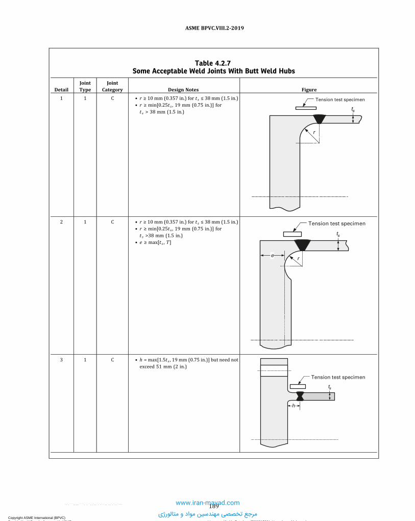
Table 4.2.7Some Acceptable Weld Joints With Butt Weld Hubs
DetailJointType
JointCategory Design Notes Figure
1 1 C • r ≥ 10 mm (0.357 in.) for t s ≤ 38 mm (1.5 in.)• r ≥ min[0.25t s , 19 mm (0.75 in.)] fort s > 38 mm (1.5 in.)
r
Tension test specimen
ts
2 1 C • r ≥ 10 mm (0.357 in.) for t s ≤ 38 mm (1.5 in.)• r ≥ min[0.25t s , 19 mm (0.75 in.)] fort s >38 mm (1.5 in.)
• e ≥ max[ts , T]
r
Tension test specimen
ts
e
3 1 C • h = max[1.5t s , 19 mm (0.75 in.)] but need notexceed 51 mm (2 in.)
Tension test specimen
ts
h
189
ASME BPVC.VIII.2-2019
Copyright ASME International (BPVC) Provided by IHS under license with ASME Licensee=Khalda Petroleum/5986215001, User=Amer, Mohamed
Not for Resale, 07/02/2019 14:07:58 MDTNo reproduction or networking permitted without license from IHS
--`,```,,,,,````,`,``,,`,,`,`-`-`,,`,,`,`,,`--- www.iran-mavad.com
مرجع تخصصی مهندسین مواد و متالورژی

Table 4.2.8Some Acceptable Weld Joints for Attachment of Tubesheets With a Bolting Flange
DetailJointType
JointCategory Design Notes Figure
1 7 C • a + b ≥ 2t s• b = 0 is permissible• The dimension b is produced by the weldpreparation and shall be verified after fit-upand before welding
• c ≥ min[0.7ts , 1.4t r] ts
a
b
c
Table 4.2.9Some Acceptable Weld Joints for Flange Attachments
DetailJointType
JointCategory Design Notes Figure
1 10 C • Loose Type Flange• t c ≥ 0.7tn• c ≤ tn + 6 mm (0.25 in.) maximum• r ≥ max[0.25g1 , 5 mm (0.1875 in.)]
T
r
c
tc tc
tn
190
ASME BPVC.VIII.2-2019
Copyright ASME International (BPVC) Provided by IHS under license with ASME Licensee=Khalda Petroleum/5986215001, User=Amer, Mohamed
Not for Resale, 07/02/2019 14:07:58 MDTNo reproduction or networking permitted without license from IHS
--`,```,,,,,````,`,``,,`,,`,`-`-`,,`,,`,`,,`---
www.iran-mavad.com
مرجع تخصصی مهندسین مواد و متالورژی

Table 4.2.9Some Acceptable Weld Joints for Flange Attachments (Cont'd)
DetailJointType
JointCategory Design Notes Figure
2 10 C • Loose Type Flange• tc ≥ 0.7tn• c ≤ tn + 6 mm (0.25 in.) maximum
ctc
T
tn
3 7 C • Loose Type Flange• tc ≥ 0.7tn• c ≤ 0.5t maximum• r ≥ max[0.25g1 , 5 mm (0.1875 in.)]
T
r
c tc
4 7 C • Loose Type Flange• tc ≥ 0.7tn• c ≤ 0.5t maximum
ctc
T
5 7 C • Loose Type Flange• tc ≥ 0.7tn• t l ≥ tn + 5 mm (0.1875 in.)
Gasket
Full penetration weld, single or double. The full penetration weld may be through the lap (tl) or through the wall (tn).
This weld may be machined to a corner radius to suit standard lap joint flanges.
T
tn
tl
tc
191
ASME BPVC.VIII.2-2019
Copyright ASME International (BPVC) Provided by IHS under license with ASME Licensee=Khalda Petroleum/5986215001, User=Amer, Mohamed
Not for Resale, 07/02/2019 14:07:58 MDTNo reproduction or networking permitted without license from IHS
--`,```,,,,,````,`,``,,`,,`,`-`-`,,`,,`,`,,`---
www.iran-mavad.com
مرجع تخصصی مهندسین مواد و متالورژی

Table 4.2.9Some Acceptable Weld Joints for Flange Attachments (Cont'd)
DetailJointType
JointCategory Design Notes Figure
6 1 C • Integral Type Flange• c ≥ 1.5g0 minimum• r ≥ max[0.25g1 , 5 mm (0.1875 in.)]
g1
T
g0
r
Slope 1:3 max.
c
7 1 C • Integral Type Flange• c ≥ 1.5g0 minimum
g0
Slope exceeds 1:3
c
8 1 C • Integral Type Flange• c ≥ 1.5g0 minimum
g0
Slope exceeds 1:3
c C weldL
Slope 1:3 max.
9 7 C • Integral Type Flange• c ≥ min[0.25g0 , 6 mm (0.25 in.)] T
tn
c
192
ASME BPVC.VIII.2-2019
Copyright ASME International (BPVC) Provided by IHS under license with ASME Licensee=Khalda Petroleum/5986215001, User=Amer, Mohamed
Not for Resale, 07/02/2019 14:07:58 MDTNo reproduction or networking permitted without license from IHS
--`,```,,,,,````,`,``,,`,,`,`-`-`,,`,,`,`,,`---
www.iran-mavad.com
مرجع تخصصی مهندسین مواد و متالورژی

Table 4.2.9Some Acceptable Weld Joints for Flange Attachments (Cont'd)
DetailJointType
JointCategory Design Notes Figure
10 7 C • Integral Type Flange• a + b ≥ 3tn• tp ≥ min[tn , 6 mm (0.25 in.)]• c ≥ min[tn , 6 mm (0.25 in.)]
cb
tp
T
a
tn
Table 4.2.10Some Acceptable Full Penetration Welded Nozzle Attachments Not Readily Radiographable
DetailJointType
JointCategory Design Notes Figure
1 7 D • tc ≥ min[0.7tn , 6 mm (0.25 in.)]• r1 ≥ min[0.25t , 3 mm (0.125 in.)]
r1
tn
tct
Optional backing strip shall be removed after welding
2 7 D • tc ≥ min[0.7tn , 6 mm (0.25 in.)]• r1 ≥ min[0.25t , 3 mm (0.125 in.)]
r1
t
tn
tc
193
ASME BPVC.VIII.2-2019
Copyright ASME International (BPVC) Provided by IHS under license with ASME Licensee=Khalda Petroleum/5986215001, User=Amer, Mohamed
Not for Resale, 07/02/2019 14:07:58 MDTNo reproduction or networking permitted without license from IHS
--`,```,,,,,````,`,``,,`,,`,`-`-`,,`,,`,`,,`---
www.iran-mavad.com
مرجع تخصصی مهندسین مواد و متالورژی

Table 4.2.10Some Acceptable Full Penetration Welded Nozzle Attachments Not Readily Radiographable
(Cont'd)
DetailJointType
JointCategory Design Notes Figure
3 7 D • t c ≥ min[0.7tn , 6 mm (0.25 in.)]• r1 ≥ min[0.25t , 3 mm (0.125 in.)]
r1
t
tn
tc
Optional backing strip shall be removed after welding
4 7 D • t c ≥ min[0.7tn , 6 mm (0.25 in.)]• r1 ≥ min[0.25t , 3 mm (0.125 in.)]
r1
t
tn
tc
5 7 D • t c ≥ min[0.7tn , 6 mm (0.25 in.)]• r3 ≥ min[0.25t , 3 mm (0.125 in.)]alternatively, a chamfer ofr3 ≥ min[0.25t , 3 mm (0.125 in.)] at 45 deg
r3t
tn
tc
r3
tc
6 7 D • t c ≥ min[0.7tn , 6 mm (0.25 in.)]• r1 ≥ min[0.25t , 3 mm (0.125 in.)]
t
tn
tc
r1
194
ASME BPVC.VIII.2-2019
Copyright ASME International (BPVC) Provided by IHS under license with ASME Licensee=Khalda Petroleum/5986215001, User=Amer, Mohamed
Not for Resale, 07/02/2019 14:07:58 MDTNo reproduction or networking permitted without license from IHS
--`,```,,,,,````,`,``,,`,,`,`-`-`,,`,,`,`,,`---
www.iran-mavad.com
مرجع تخصصی مهندسین مواد و متالورژی

Table 4.2.10Some Acceptable Full Penetration Welded Nozzle Attachments Not Readily Radiographable
(Cont'd)
DetailJointType
JointCategory Design Notes Figure
7 7 D • tc ≥ min[0.7tn , 6 mm (0.25 in.)]• r1 ≥ min[0.25t , 3 mm (0.125 in.)]
Optional backing strip shall be removed after welding
t tn min.
tc
r1
tn
Table 4.2.11Some Acceptable Pad Welded Nozzle Attachments and Other Connections to Shells
DetailJointType
JointCategory Design Notes Figure
1 7 D • tc ≥ min[0.7tn , 6 mm (0.25 in.)]• t f1 ≥ min[0.6te , 0.6t]• r3 ≥ min[0.25t , 3 mm (0.125 in.)]alternatively, a chamfer ofr3 ≥ min[0.25t , 3 mm (0.125 in.)] at 45 deg
t
tc
r3
tn
tc
te
tf1
2 7 D • tc ≥ min[0.7tn , 6 mm (0.25 in.)]• t f1 ≥ min[0.6te , 0.6t]• r1 ≥ min[0.25t , 3 mm (0.125 in.)]
tf1
t
tn
tc
te
r1
195
ASME BPVC.VIII.2-2019
Copyright ASME International (BPVC) Provided by IHS under license with ASME Licensee=Khalda Petroleum/5986215001, User=Amer, Mohamed
Not for Resale, 07/02/2019 14:07:58 MDTNo reproduction or networking permitted without license from IHS
--`,```,,,,,````,`,``,,`,,`,`-`-`,,`,,`,`,,`---
www.iran-mavad.com
مرجع تخصصی مهندسین مواد و متالورژی

Table 4.2.11Some Acceptable Pad Welded Nozzle Attachments and Other Connections to Shells (Cont'd)
DetailJointType
JointCategory Design Notes Figure
3 7 D • t c ≥ min[0.7tn , 6 mm (0.25 in.)]• t f1 ≥ min[0.6te , 0.6t]• r3 ≥ min[0.25t , 3 mm (0.125 in.)]alternatively, a chamfer ofr3 ≥ min[0.25t , 3 mm (0.125 in.)] at 45 deg
tf1
tf1te
te
tc
tc
t
r3
tn
4 10 D • t f2 ≥ min[0.7te , 0.7t]
tf2tf2
t
te
w
5 7 D • t f2 ≥ min[0.7te , 0.7t]• r1 ≥ min[0.25t , 3 mm (0.125 in.)]
tf2t
te
r1
w
196
ASME BPVC.VIII.2-2019
Copyright ASME International (BPVC) Provided by IHS under license with ASME Licensee=Khalda Petroleum/5986215001, User=Amer, Mohamed
Not for Resale, 07/02/2019 14:07:58 MDTNo reproduction or networking permitted without license from IHS
--`,```,,,,,````,`,``,,`,,`,`-`-`,,`,,`,`,,`---
www.iran-mavad.com
مرجع تخصصی مهندسین مواد و متالورژی

Table 4.2.12Some Acceptable Fitting-Type Welded Nozzle Attachments and Other Connections to Shells
DetailJointType
JointCategory Design Notes Figure
1 7 D • Limited to DIN 50 (NPS 2) and smaller• tc ≥ min[0.7tn , 6 mm (0.25 in.)]
CLtc
2 7 D • Limited to DIN 50 (NPS 2) and smaller• tc ≥ min[0.7tn , 6 mm (0.25 in.)] tc
CL
tc
3 7 D • Limited to DIN 50 (NPS 2) and smaller• tc ≥ min[0.7tn , 6 mm (0.25 in.)]
tc
CL
4 10 D • Limited to DIN 50 (NPS 2) and smaller• tc ≥ min[0.7tn , 6 mm (0.25 in.)]• t f2 ≥ min[0.7te , 0.7t]
tf2
tf2tet
5 9 D • Limited to DIN 50 (NPS 2) maximum• The groove weld tg shall not be less than thethickness of Schedule 160
• t c ≥ min[0.7tn , 6 mm (0.25 in.)]tg
tc
197
ASME BPVC.VIII.2-2019
Copyright ASME International (BPVC) Provided by IHS under license with ASME Licensee=Khalda Petroleum/5986215001, User=Amer, Mohamed
Not for Resale, 07/02/2019 14:07:58 MDTNo reproduction or networking permitted without license from IHS
--`,```,,,,,````,`,``,,`,,`,`-`-`,,`,,`,`,,`---www.iran-mavad.com
مرجع تخصصی مهندسین مواد و متالورژی

Table 4.2.13Some Acceptable Welded Nozzle Attachments That Are Readily Radiographable
DetailJointType
JointCategory Design Notes Figure
1 1 D • r1 ≥ min[0.25t , 3 mm (0.125 in.)]• r2 ≥ min[0.25tn , 19 mm (0.75 in.)] tn
t
r2
r1
a
31
2 1 D • r1 ≥ min[0.25t , 3 mm (0.125 in.)]• r2 ≥ min[0.25tn , 19 mm (0.75 in.)]
t
r1
tnr2
r2 45° max.
30° max.
1.5t min.
3 1 D • r1 ≥ min[0.25t , 3 mm (0.125 in.)]• r2 ≥ min[0.25tn , 19 mm (0.75 in.)]• t3 + t4 ≤ 0.2t• a1 + a2 ≤ 18.5 deg
tnr2
t3
t
30° min.
13 mm (0.5 in.) min.
t4
r2a 1
a2
4 1 D • r1 ≥ min[0.25t , 3 mm (0.125 in.)]• r2 ≥ min[0.25tn , 19 mm (0.75 in.)]
tntn
A
A
45° max.
r2
30° max.
r2
r1
tt
r1
45° max.
r2
r2
18.5° max.30° max.
Section A-A
Sections Perpendicular and Parallel to the
Cylindrical Vessel Axis
0.2t max.
198
ASME BPVC.VIII.2-2019
Copyright ASME International (BPVC) Provided by IHS under license with ASME Licensee=Khalda Petroleum/5986215001, User=Amer, Mohamed
Not for Resale, 07/02/2019 14:07:58 MDTNo reproduction or networking permitted without license from IHS
--`,```,,,,,````,`,``,,`,,`,`-`-`,,`,,`,`,,`---
www.iran-mavad.com
مرجع تخصصی مهندسین مواد و متالورژی

Table 4.2.13Some Acceptable Welded Nozzle Attachments That Are Readily Radiographable (Cont'd)
DetailJointType
JointCategory Design Notes Figure
5 1 D • r1 ≥ min[0.25tn , 3 mm (0.125 in.)]• r2 ≥ min[0.25tn , 19 mm (0.75 in.)]
tn
t
r2
r1
6 1 D • r1 ≥ min[0.25tn , 3 mm (0.125 in.)]• r2 ≥ min[0.25tn , 19 mm (0.75 in.)]
t
r2
tn
Optional backing strip shall be removed after welding
r1
7 7 D • tc ≥ min[0.7tn , 6 mm (0.25 in.)]• r1 ≥ min[0.25t , 3 mm (0.125 in.)]• r2 ≥ 19 mm (0.75 in.)• r4 ≥ 6 mm (0.25 in.)
Sections Perpendicular and Parallel to the
Cylindrical Vessel Axis
t
r2r2
tn
tcr1
r4
r4
t
tn
45° min.
r1
tctc
A
A Section A-A
199
ASME BPVC.VIII.2-2019
Copyright ASME International (BPVC) Provided by IHS under license with ASME Licensee=Khalda Petroleum/5986215001, User=Amer, Mohamed
Not for Resale, 07/02/2019 14:07:58 MDTNo reproduction or networking permitted without license from IHS
--`,```,,,,,````,`,``,,`,,`,`-`-`,,`,,`,`,,`---
www.iran-mavad.com
مرجع تخصصی مهندسین مواد و متالورژی

ð19Þ Table 4.2.14Some Acceptable Partial Penetration Nozzle Attachments
DetailJointType
JointCategory Design Notes Figure
1 9 D • t c ≥ min[0.7tn , 6 mm (0.25 in.)]• tw ≥ 1.25tn
tn1.5 mm (0.0625 in.)
recess
tw
tc
2 9 D • t c ≥ min[0.7tn , 6 mm (0.25 in.)]• tw ≥ 1.25tn
tn
1.5 mm (0.0625 in.) recess
Section A-A
twtctn
tc
A
A
3 9 D • r1 ≥ min[0.25t , 3 mm (0.125 in.)]Cmax defined as follows:0.25 mm, Do ≤ 25 mm0.51 mm, 25 mm < Do ≤ 102 mm
• 0.76 mm, Do > 102 mm0.01 in., Do ≤ 1 in.0.02 in., 1 in. < Do ≤ 4 in.0.03 in., Do > 4 in.
Cmax
tn
DoOutside
r1
1.25tn min.t
4 9 D • t f2 ≥ min[0.7te , 0.7t]r1 ≥ min[0.25t , 3 mm (0.125 in.)]Cmax defined as follows:0.25 mm, Do ≤ 25 mm0.51 mm, 25 mm < Do ≤ 102 mm
• 0.76 mm, Do > 102 mm0.01 in., Do ≤ 1 in.0.02 in., 1 in. < Do ≤ 4 in.0.03 in., Do > 4 in.
1.25tn
r1
t
1.25tn min.te
Do
tn
Cmax
w
tf2
200
ASME BPVC.VIII.2-2019
Copyright ASME International (BPVC) Provided by IHS under license with ASME Licensee=Khalda Petroleum/5986215001, User=Amer, Mohamed
Not for Resale, 07/02/2019 14:07:58 MDTNo reproduction or networking permitted without license from IHS
--`,```,,,,,````,`,``,,`,,`,`-`-`,,`,,`,`,,`---
www.iran-mavad.com
مرجع تخصصی مهندسین مواد و متالورژی

Table 4.2.15Nozzle Necks Attached to Piping of Lesser Wall Thickness
DetailJointType
JointCategory Design Notes Figure
1 1 Notapplicable
• The weld bevel is shown for illustration only• t1 ≥ max[0.8trn , tp ipe]• α ≤ 30 deg• β , 14 deg ≤ β ≤ 18.5 deg• r , 6 mm (0.25 in.) min. radius• Joint Types 2 and 3 may be permissible; see4.2.5.2 through 4.2.5.6 for limitations
β
rα
tn
trn t1
2 1 Notapplicable
• t1 ≥ max[0.8trn , tp ipe]• α ≤ 30 deg• β , 14 deg ≤ β ≤ 18.5 deg• r , 6 mm (0.25 in.) min. radius• Joint Types 2 and 3 may be permissible; see4.2.5.2 through 4.2.5.6 for limitations
r
r
tntrn t1
Table 4.2.16Corner Welds for Flexible Shell Element Expansion Joints
DetailJointType
JointCategory Design Notes Figure
1 7 Notapplicable
t c ≥ min[0.7t , 0.7to , 6 mm (0.25 in.)]Full penetration
Fillet weld required on this side of corner
Flexible element
Outer shell elementto
tc
t
2 7 Notapplicable
t c ≥ min[0.7t , 0.7to , 6 mm (0.25 in.)]Full penetration
Fillet weld required on this side of corner
Flexible element
Outer shell elementto
tc
t
3 7 Notapplicable
t c ≥ min[0.7t , 0.7t s , 6 mm (0.25 in.)]
Full penetration
Fillet weld required on this side of corner Flexible element
Shellts
tc
t
201
ASME BPVC.VIII.2-2019
Copyright ASME International (BPVC) Provided by IHS under license with ASME Licensee=Khalda Petroleum/5986215001, User=Amer, Mohamed
Not for Resale, 07/02/2019 14:07:58 MDTNo reproduction or networking permitted without license from IHS
--`,```,,,,,````,`,``,,`,,`,`-`-`,,`,,`,`,,`---
www.iran-mavad.com
مرجع تخصصی مهندسین مواد و متالورژی

Table 4.2.16Corner Welds for Flexible Shell Element Expansion Joints (Cont'd)
DetailJointType
JointCategory Design Notes Figure
4 7 Notapplicable
t c ≥ min[0.7t , 0.7t s , 6 mm (0.25 in.)]
Full penetration
Fillet weld required on this side of corner Flexible element
Shellts
tc
t
202
ASME BPVC.VIII.2-2019
Copyright ASME International (BPVC) Provided by IHS under license with ASME Licensee=Khalda Petroleum/5986215001, User=Amer, Mohamed
Not for Resale, 07/02/2019 14:07:58 MDTNo reproduction or networking permitted without license from IHS
--`,```,,,,,````,`,``,,`,,`,`-`-`,,`,,`,`,,`---
www.iran-mavad.com
مرجع تخصصی مهندسین مواد و متالورژی

4.2.8 FIGURES
Figure 4.2.1Weld Joint Locations Typical of Categories A, B, C, D, and E
B
DC
�
EA
BA
A
A
A
A
E
BA A
A
B
B AD
B
D
A
C
C
DC
C
B
D
Figure 4.2.2Some Bracket, Lug, and Stiffener Attachment Weld Details
(d) (e) (f)
(a) (b) (c)
A A B
Continuous ContinuousContinuous Acceptable
Preferred
BB
AAAA
A A B
Continuous Continuous Continuous
203
ASME BPVC.VIII.2-2019
Copyright ASME International (BPVC) Provided by IHS under license with ASME Licensee=Khalda Petroleum/5986215001, User=Amer, Mohamed
Not for Resale, 07/02/2019 14:07:58 MDTNo reproduction or networking permitted without license from IHS
--`,```,,,,,````,`,``,,`,,`,`-`-`,,`,,`,`,,`---
www.iran-mavad.com
مرجع تخصصی مهندسین مواد و متالورژی

Figure 4.2.2Some Bracket, Lug, and Stiffener Attachment Weld Details (Cont'd)
Weld buildup
Section A-A
3 mm (0.25 in.) max.
t a
ta
a
t
b
t
Round corners on pads
Round corners on pads
b
tb
Section B-B
GENERAL NOTES:(a) Attachment weld size: a ≥ 0.25t and b ≥ 0.5t .(b) Vents holes shall be considered for continuously attached pads.(c) For design (e) above, a minimum of 50% of the web must be welded, evenly spaced around the circumference of the shell.
204
ASME BPVC.VIII.2-2019
Copyright ASME International (BPVC) Provided by IHS under license with ASME Licensee=Khalda Petroleum/5986215001, User=Amer, Mohamed
Not for Resale, 07/02/2019 14:07:58 MDTNo reproduction or networking permitted without license from IHS
--`,```,,,,,````,`,``,,`,,`,`-`-`,,`,,`,`,,`---
www.iran-mavad.com
مرجع تخصصی مهندسین مواد و متالورژی

ð19ÞFigure 4.2.3Some Acceptable Methods of Attaching Stiffening Rings
50 mm (2 in.) min.
S [Notes (1) and (2)]
S [Notes (1) and (2)]
50 mm (2 in.) min.
50 mm (2 in.) min.
24t max.
w twtw
tw
t
tw
t
w
w
tw
Shell
Stiffener
Continuous full penetration weld
In-Line
Intermittent Weld
Staggered
Intermittent Weld
Continuous Fillet Weld
One Side, Intermittent Other Side
(a) (b) (c)
(d) (e)
GENERAL NOTE: See 4.2.5.6(e) for limitations.
NOTES:(1) For external stiffeners, S ≤ 8t .(2) For internal stiffeners, S ≤ 12t .
205
ASME BPVC.VIII.2-2019
Copyright ASME International (BPVC) Provided by IHS under license with ASME Licensee=Khalda Petroleum/5986215001, User=Amer, Mohamed
Not for Resale, 07/02/2019 14:07:58 MDTNo reproduction or networking permitted without license from IHS
--`,```,,,,,````,`,``,,`,,`,`-`-`,,`,,`,`,,`---
www.iran-mavad.com
مرجع تخصصی مهندسین مواد و متالورژی

Figure 4.2.4Some Acceptable Skirt Weld Details
ta ta
c c
Double welded
Forging
(a) (b) (c)
(d) (e) (f)
c
Weld metal
ta
GENERAL NOTES:(a) All welds are continuous.(b) c is the minimum thickness of the weld metal from the root to the face of the weld.(c) Attachment weld size: c ≥ ta .
206
ASME BPVC.VIII.2-2019
Copyright ASME International (BPVC) Provided by IHS under license with ASME Licensee=Khalda Petroleum/5986215001, User=Amer, Mohamed
Not for Resale, 07/02/2019 14:07:58 MDTNo reproduction or networking permitted without license from IHS
--`,```,,,,,````,`,``,,`,,`,`-`-`,,`,,`,`,,`---
www.iran-mavad.com
مرجع تخصصی مهندسین مواد و متالورژی

4.3 DESIGN RULES FOR SHELLS UNDER INTERNAL PRESSURE
4.3.1 SCOPE4.3.1.1 4.3 provides rules for determining the required wall thickness of cylindrical, conical, spherical, torispherical,
and ellipsoidal shells and heads subject to internal pressure. In this context, internal pressure is defined as pressureacting on the concave side of the shell.
4.3.1.2 The effects of supplemental loads are not included in design equations for shells and heads included in 4.3.3to 4.3.7. Supplemental loads shall be defined in the User’s Design Specification and their effects that result in combinedloadings shall be evaluated in a separate analysis performed in accordance with the methods in 4.3.10.
4.3.1.3 Rules are provided for the design of cylindrical-to-conical shell transition junctions in 4.3.11 and 4.3.12. Tofacilitate the use of these rules, the shell wall thickness and stiffener configuration, as applicable, shall be designed usingthe rules in 4.3.3 through 4.3.7. After an initial design is determined, this design should then be checked and modified asrequired using the rules of 4.3.12 and 4.3.13.
4.3.2 SHELL TOLERANCES4.3.2.1 The shell of a completed vessel shall satisfy the following requirements.(a) The difference between the maximum and minimum inside diameters at any cross section shall not exceed 1% of
the nominal diameter at the cross section under consideration. The diameters may be measured on the inside or outsideof the vessel. If measured on the outside, the diameters shall be corrected for the plate thickness at the cross sectionunder consideration.
(b)When the cross section passes through an opening or within one inside diameter of the opening measured fromthe center of the opening, the permissible difference in inside diameters given above may be increased by 2% of theinside diameter of the opening. When the cross section passes through any other location normal to the axis of the ves-sel, including head-to-shell junctions, the difference in diameters shall not exceed 1%.
4.3.2.2 Tolerances for formed heads shall satisfy the following requirements.(a) The inner surface of torispherical, toriconical, hemispherical, or ellipsoidal heads shall not deviate outside of the
specified shape by more than 1.25% of D nor inside the specified shape by more than 0.625% of D , where D is the nom-inal inside diameter of the vessel shell at the point of attachment. Such deviations shall be measured perpendicular to thespecified shape and shall not be abrupt. The knuckle radius shall not be less than that specified
(b)Measurements for determining the deviations specified in (a) shall be taken from the surface of the base metal andnot from welds.
(c) When the straight flange of any unstayed formed head is machined to make a lap joint connection to a shell, thethickness shall not be reduced to less than 90% of that required for a blank head or the thickness of the shell at the pointof attachment. When so machined, the transition from the machined thickness to the original thickness of the head shallnot be abrupt but shall be tapered for a distance of at least three times the difference between the thicknesses.
4.3.2.3 Shells that do not meet the tolerance requirements of this paragraph may be evaluated using 4.14.
4.3.3 CYLINDRICAL SHELLS4.3.3.1 Required Thickness. The minimum required thickness of a cylindrical shell subjected to internal pressure
shall be determined using the following equation.
ð4:3:1Þ
4.3.3.2 Combined Loadings. Cylindrical shells subject to internal pressure and other loadings shall satisfy the re-quirements of 4.3.10.
4.3.4 CONICAL SHELLS4.3.4.1 Required Thickness. The minimum required thickness of a conical shell (see Figure 4.3.1) subjected to in-
ternal pressure shall be determined using the following equation.
ð4:3:2Þ
207
ASME BPVC.VIII.2-2019
Copyright ASME International (BPVC) Provided by IHS under license with ASME Licensee=Khalda Petroleum/5986215001, User=Amer, Mohamed
Not for Resale, 07/02/2019 14:07:58 MDTNo reproduction or networking permitted without license from IHS
--`,```,,,,,````,`,``,,`,,`,`-`-`,,`,,`,`,,`---
www.iran-mavad.com
مرجع تخصصی مهندسین مواد و متالورژی

4.3.4.2 Offset Transitions. The cylinders for an offset cone shall have parallel centerlines that are offset from eachother by a distance no greater than the difference of their minimum radii, as shown in Figure 4.3.2. Configurations thatdo not satisfy this requirement shall be evaluated per Part 5. The offset cone shall be designed as a concentric cone usingthe angle, α , as defined in eq. (4.3.3).
ð4:3:3Þ
4.3.4.3 Combined Loadings. Conical shells subject to external pressure and other loadings shall satisfy the require-ments of 4.3.10.
4.3.5 SPHERICAL SHELLS AND HEMISPHERICAL HEADS4.3.5.1 The minimum required thickness of spherical shells and hemispherical heads shall be determined using the
following equation:
ð4:3:4Þ
4.3.5.2 Combined Loadings. Spherical shells and hemispherical heads subject to internal pressure and other load-ings shall satisfy the requirements of 4.3.10.
4.3.6 TORISPHERICAL HEADS4.3.6.1 Torispherical Heads With the Same Crown and Knuckle Thicknesses. The minimum required thickness of a
torispherical head (see Figure 4.3.3) subjected to internal pressure shall be calculated using the following procedure.Step 1. Determine the inside diameter, D , and assume values for the crown radius, L , the knuckle radius, r , and the wall
thickness t .Step 2. Compute the head L/D , r/D , and L/tratios and determine if the following equations are satisfied. If the equa-
tions are satisfied, then proceed to Step 3; otherwise, the head shall be designed in accordance with Part 5.
ð4:3:5Þ
ð4:3:6Þ
ð4:3:7Þ
Step 3. Calculate the following geometric constants:
ð4:3:8Þ
ð4:3:9Þ
ð4:3:10Þ
ð4:3:11Þ
208
ASME BPVC.VIII.2-2019
Copyright ASME International (BPVC) Provided by IHS under license with ASME Licensee=Khalda Petroleum/5986215001, User=Amer, Mohamed
Not for Resale, 07/02/2019 14:07:58 MDTNo reproduction or networking permitted without license from IHS
--`,```,,,,,````,`,``,,`,,`,`-`-`,,`,,`,`,,`---
www.iran-mavad.com
مرجع تخصصی مهندسین مواد و متالورژی

Step 4. Compute the coefficients C1 and C2 using the following equations.
ð4:3:12Þ
ð4:3:13Þ
ð4:3:14Þ
ð4:3:15Þ
Step 5. Calculate the value of internal pressure expected to produce elastic buckling of the knuckle.
ð4:3:16Þ
Step 6. Calculate the value of internal pressure that will result in a maximum stress in the knuckle equal to the materialyield strength.
ð4:3:17Þ
If the allowable stress at the design temperature is governed by time-independent properties, then C3 is the materialyield strength at the design temperature, or C3 = Sy . If the allowable stress at the design temperature is governed bytime-dependent properties, then C3 is determined as follows.
(a) If the allowable stress is established based on 90% yield criterion, then C3 is the material allowable stress at thedesign temperature multiplied by 1.1, or C3 = 1.1S .
(b) If the allowable stress is established based on 67% yield criterion, then C3 is the material allowable stress at thedesign temperature multiplied by 1.5, or C3 = 1.5S .
Step 7. Calculate the value of internal pressure expected to result in a buckling failure of the knuckle.
ð4:3:18Þ
ð4:3:19Þ
where
ð4:3:20Þ
Step 8. Calculate the allowable pressure based on a buckling failure of the knuckle.
ð4:3:21Þ
209
ASME BPVC.VIII.2-2019
Copyright ASME International (BPVC) Provided by IHS under license with ASME Licensee=Khalda Petroleum/5986215001, User=Amer, Mohamed
Not for Resale, 07/02/2019 14:07:58 MDTNo reproduction or networking permitted without license from IHS
--`,```,,,,,````,`,``,,`,,`,`-`-`,,`,,`,`,,`---
www.iran-mavad.com
مرجع تخصصی مهندسین مواد و متالورژی

Step 9. Calculate the allowable pressure based on rupture of the crown.
ð4:3:22Þ
Step 10. Calculate the maximum allowable internal pressure.
ð4:3:23Þ
Step 11. If the allowable internal pressure computed from Step 10 is greater than or equal to the design pressure, thenthe design is complete. If the allowable internal pressure computed from Step 10 is less than the design pressure, thenincrease the head thickness and repeat Steps 2 through 10. This process is continued until an acceptable design isachieved.
4.3.6.2 Torispherical Heads With Different Crown and Knuckle Thicknesses. A torispherical head formed fromseveral welded components as shown in Figure 4.3.4 may have a smaller thickness in the spherical crown than inthe knuckle region. The transition in thickness shall be located on the inside surface of the thicker part, and shall havea taper not exceeding 1:3.(a) The minimum required thickness of the spherical dome of the head shall be determined in accordance with 4.3.5.(b) The minimum required thickness of the knuckle region of the head shall be determined in accordance with
4.3.6.1, Step 2.
4.3.6.3 Combined Loadings. Torispherical heads subject to internal pressure and other loadings shall satisfy therequirements of 4.3.10. In this calculation, the torispherical head shall be approximated as an equivalent spherical shellwith a radius equal to L .
4.3.7 ELLIPSOIDAL HEADS4.3.7.1 Required Thickness. The minimum required thickness of an ellipsoidal head (see Figure 4.3.5) subjected to
internal pressure shall be calculated using the equations in 4.3.6 with the following substitutions for r and L .
ð4:3:24Þ
ð4:3:25Þ
where
ð4:3:26Þ
The rules in this paragraph are applicable for elliptical heads that satisfy eq. (4.3.27). Elliptical heads that do not sa-tisfy this equation shall be designed using Part 5.
ð4:3:27Þ
4.3.7.2 Combined Loadings. ellipsoidal heads subject to internal pressure and other loadings shall satisfy the re-quirements of 4.3.10. In this calculation, the ellipsoidal head shall be approximated as an equivalent spherical shell witha radius equal to L .
4.3.8 LOCAL THIN AREAS4.3.8.1 Local Thin Areas. Rules for the evaluation of Local Thin Areas are covered in 4.14.
4.3.8.2 Local Thin Band in Cylindrical Shells. A complete local circumferential band of reduced thickness at a weldjoint in a cylindrical shell as shown in Figure 4.3.6 is permitted providing all of the following requirements are met.(a) The design of the local reduced thickness band is evaluated by limit-load or elastic–plastic analysis in accordance
with Part 5. All other applicable requirements of Part 5 for stress analysis and fatigue analysis shall be satisfied.
210
ASME BPVC.VIII.2-2019
Copyright ASME International (BPVC) Provided by IHS under license with ASME Licensee=Khalda Petroleum/5986215001, User=Amer, Mohamed
Not for Resale, 07/02/2019 14:07:58 MDTNo reproduction or networking permitted without license from IHS
--`,```,,,,,````,`,``,,`,,`,`-`-`,,`,,`,`,,`---
www.iran-mavad.com
مرجع تخصصی مهندسین مواد و متالورژی

(b) The cylinder geometry shall satisfy Rm/t ≥ 10.(c) The thickness of the reduced shell region shall not be less than two-thirds of the cylinder required thickness de-
termined in accordance with 4.3.3.(d) The reduced thickness region shall be on the outside of the vessel shell with a minimum taper transition of 3:1 in
the base metal. The transition between the base metal and weld shall be designed to minimize stress concentrations.
(e) The total longitudinal length of each local thin region shall not exceed (see Figure 4.3.6).
(f) The minimum longitudinal distance from the thicker edge of the taper to an adjacent structural discontinuity shall
be the greater of or the distance required to assure that overlapping of areas where the primary membrane
stress intensity exceeds 1.1S does not occur.
4.3.9 DRILLED HOLES NOT PENETRATING THROUGH THE VESSEL WALL4.3.9.1 Design requirements for partially drilled holes that do not penetrate completely through the vessel wall are
provided in this paragraph. These rules are not applicable for studded connections or telltale holes.
4.3.9.2 Partially drilled radial holes in cylindrical and spherical shells may be used, provided the following require-ments are satisfied.
(a) The drilled hole diameter is less than or equal to 50 mm (2 in.).(b) The shell inside diameter to thickness ratio is greater than or equal to 10.(c) The centerline distance between any two partially drilled holes or between a partially drilled hole and an unrein-
forced opening shall satisfy the requirements of 4.5.13.(d) Partially drilled holes shall not be placed within the limits of reinforcement of a reinforced opening.(e) The outside edge of the hole shall be chamfered. For flat bottom holes, the inside bottom corner of the hole shall
have a minimum radius, rhr of the following:
ð4:3:28Þ
(f) The minimum acceptable remaining wall thickness, t rw at the location of a partially drilled hole shall be deter-mined as follows:
ð4:3:29Þ
where,
ð4:3:30Þ
(g) The calculated average shear stress, as determined below shall not exceed 0.8S .
ð4:3:31Þ
4.3.10 COMBINED LOADINGS AND ALLOWABLE STRESSES4.3.10.1 General. The rules of this paragraph shall be used to determine the acceptance criteria for stresses devel-
oped in cylindrical, spherical, and conical shells subjected to internal pressure plus supplemental loads of applied netsection axial force, bending moment, and torsional moment, as shown in Figure 4.3.7. The rules in this paragraph areonly applicable to cylindrical, spherical, and conical shells where the wall thickness is determined using the rules in4.3.3 through 4.3.5, respectively. These rules are applicable if the requirements shown below are satisfied. If all of theserequirements are not satisfied, the shell section shall be designed per Part 5.
(a) The rules are applicable for regions of shells that are from any gross structural discontinuity.(b) These rules do not take into account the action of shear forces, since these loads generally can be disregarded.(c) The ratio of the shell inside radius to thickness is greater than 3.0.
211
ASME BPVC.VIII.2-2019
Copyright ASME International (BPVC) Provided by IHS under license with ASME Licensee=Khalda Petroleum/5986215001, User=Amer, Mohamed
Not for Resale, 07/02/2019 14:07:58 MDTNo reproduction or networking permitted without license from IHS
--`,```,,,,,````,`,``,,`,,`,`-`-`,,`,,`,`,,`---
www.iran-mavad.com
مرجع تخصصی مهندسین مواد و متالورژی

ð19Þ 4.3.10.2 The following procedure shall be used to determine the acceptance criteria for stresses developed in cy-lindrical, spherical, and conical shells subjected to internal pressure plus supplemental loads of applied net section axialforce, bending moment, and torsional moment.Step 1. Calculate the membrane stress.(a) For cylindrical shells:
ð4:3:32Þ
ð4:3:33Þ
ð4:3:34Þ
(b) For spherical shells for 0 deg < ϕ < 180 deg:
ð4:3:35Þ
ð4:3:36Þ
ð4:3:37Þ
(c) For conical shells for α ≤ 60 deg:
ð4:3:38Þ
ð4:3:39Þ
ð4:3:40Þ
Step 2. Calculate the principal stresses.
ð4:3:41Þ
212
ASME BPVC.VIII.2-2019
Copyright ASME International (BPVC) Provided by IHS under license with ASME Licensee=Khalda Petroleum/5986215001, User=Amer, Mohamed
Not for Resale, 07/02/2019 14:07:58 MDTNo reproduction or networking permitted without license from IHS
--`,```,,,,,````,`,``,,`,,`,`-`-`,,`,,`,`,,`---
www.iran-mavad.com
مرجع تخصصی مهندسین مواد و متالورژی

ð19Þ
ð4:3:42Þ
ð4:3:43Þ
Step 3. At any point on the shell, the following limit shall be satisfied.
ð4:3:44Þ
Step 4. For cylindrical and conical shells, if the axial membrane stress, σ sm , is compressive, then eq. (4.3.45) shall besatisfied where Fxa is evaluated using 4.4.12.2 with λ = 0.15. For spherical shells, the allowable compressive stress cri-teria in 4.4.12.4 shall be satisfied. Note that the controlling condition for this case may be the combined loadings withoutinternal pressure.
ð4:3:45Þ
4.3.11 CYLINDRICAL-TO-CONICAL SHELL TRANSITION JUNCTIONS WITHOUT A KNUCKLE4.3.11.1 The following rules are applicable for the design of conical transitions or circular cross-sections that do not
have a knuckle at the large end or flare at the small end under loadings of internal pressure and applied net section axialforce and bending moment. Acceptable conical transition details are shown in Figure 4.3.8. Design rules for a knuckle atthe large end or flare at the small end are provided in 4.3.12.
4.3.11.2 Design rules are provided for the cylinder-to-cone junction details shown in Figure 4.3.9. Details with astiffening ring at the cylinder-to-cone junction, or other details that differ from the ones shown in this figure shall bedesigned in accordance with Part 5.
4.3.11.3 The length of the conical shell, measured parallel to the surface of the cone shall be equal to or greater thanthe following value.
ð4:3:46Þ
4.3.11.4 The procedure that shall be used to design the large end of a cylinder-to-cone junction without a knuckle isdescribed below.
Step 1. Compute the required thickness of the cylinder at the large end of the cone-to-cylinder junction using 4.3.3,and select the nominal thickness, tL .
Step 2. Determine the cone half-apex angle, α ; compute the required thickness of the cone at the large end of the cone-to-cylinder junction using 4.3.4; and select the nominal thickness, tC .
Step 3. Proportion the cone geometry such that eq. (4.3.46) and the following equations are satisfied. If all of theseequations are not satisfied, then the cylinder-to-cone junction shall be designed in accordance with Part 5. In the calcu-lations, if 0 deg < α ≤ 10 deg, then use α = 10 deg.
ð4:3:47Þ
ð4:3:48Þ
ð4:3:49Þ
213
ASME BPVC.VIII.2-2019
Copyright ASME International (BPVC) Provided by IHS under license with ASME Licensee=Khalda Petroleum/5986215001, User=Amer, Mohamed
Not for Resale, 07/02/2019 14:07:58 MDTNo reproduction or networking permitted without license from IHS
--`,```,,,,,````,`,``,,`,,`,`-`-`,,`,,`,`,,`---
www.iran-mavad.com
مرجع تخصصی مهندسین مواد و متالورژی

ð19Þ
Step 4. Determine the net section axial force, FL , and bending moment,ML , applied to the conical transition. The thrustload due to pressure shall not be included as part of the axial force, FL . Determine an equivalent, XL , using eq. (4.3.50).
ð4:3:50Þ
Step 5. Compute the junction transition design parameters. For calculated values of n other than those presented inTables 4.3.3 and 4.3.4, linear interpolation of the equation coefficients, Ci , is permitted.
ð4:3:51Þ
ð4:3:52Þ
ð4:3:53Þ
Step 6. Compute the stresses in the cylinder and cone at the junction using the equations in Table 4.3.1. The allowablestress criterion for a tensile stress is provided in Table 4.3.1. If either the hoop membrane stress, σθm , or axial mem-brane stress, σ sm , at the junction is compressive, then the condition of local buckling shall be considered. Local bucklingis not a concern if the limits given in eqs. (4.3.54) and (4.3.55) are satisfied. Fha is evaluated using 4.4.5.1, but substitut-
ing . Fxa is evaluated using 4.4.12.2(b) with λ = 0.15. If the stresses of the acceptance criteria are satisfied,
the design of the junction is complete.
ð4:3:54Þ
ð4:3:55Þ
Step 7. If the stress acceptance criterion in Step 6 is satisfied, then the design is complete. If the stress acceptance cri-terion in Step 6 is not satisfied, the cylinder thickness or cone thickness near the junction may be increased until thestress acceptance criterion is satisfied. The section of increased thickness for the cylinder and cone shall extend a mini-mum distance from the junction as shown in Figure 4.3.9. Proceed to Step 3 to repeat the calculation with the new wallthickness.
4.3.11.5 The procedure that shall be used to design the small end of a cylinder-to-cone junction without a flare isdescribed below.Step 1. Compute the required thickness of the cylinder at the small end of the cone-to-cylinder junction using 4.3.3,
and select the nominal thickness, tS .Step 2. Determine the cone half-apex angle, α ; compute the required thickness of the cone at the small end of the cone-
to-cylinder junction using 4.3.4; and select the nominal thickness, tC .Step 3. Proportion the cone geometry such that eq. (4.3.46) and the following equations are satisfied. If all of these
equations are not satisfied, then the cylinder-to-cone junction shall be designed in accordance with Part 5. In the calcu-lations, if 0 deg < α ≤ 10 deg, then use α = 10 deg.
ð4:3:56Þ
ð4:3:57Þ
214
ASME BPVC.VIII.2-2019
Copyright ASME International (BPVC) Provided by IHS under license with ASME Licensee=Khalda Petroleum/5986215001, User=Amer, Mohamed
Not for Resale, 07/02/2019 14:07:58 MDTNo reproduction or networking permitted without license from IHS
--`,```,,,,,````,`,``,,`,,`,`-`-`,,`,,`,`,,`---
www.iran-mavad.com
مرجع تخصصی مهندسین مواد و متالورژی

ð19Þ
ð4:3:58Þ
Step 4. Determine the net section axial force, FS , and bending moment,Ms , applied to the conical transition. The thrustload due to pressure shall not be included as part of the axial force, FS . Determine an equivalent, Xs , line using eq.(4.3.59).
ð4:3:59Þ
Step 5. Compute the junction transition design parameters. For calculated values of n other than those presented inTables 4.3.5 and 4.3.6, linear interpolation of the equation coefficients, Ci , is permitted.
ð4:3:60Þ
ð4:3:61Þ
ð4:3:62ÞStep 6. Compute the stresses in the cylinder and cone at the junction using the equations in Table 4.3.2. The allowable
stress criterion for a tensile stress is provided in Table 4.3.2. If either the hoop membrane stress, σθm , or axial mem-brane stress, σ sm , at the junction is compressive, then the condition of local buckling shall be considered. Local bucklingis not of concern if the limits given in eqs. (4.3.54) and (4.3.55) are satisfied, using the procedure provided in4.3.11.4, Step 6. If the stresses of the acceptance criteria are satisfied, the design of the junction is complete.
Step 7. If the stress acceptance criterion in Step 6 is satisfied, then the design is complete. If the stress acceptance cri-terion in Step 6 is not satisfied, the cylinder thickness or cone thickness near the junction may be increased until thestress acceptance criterion is satisfied. The section of increased thickness for the cylinder and cone shall extend a mini-mum distance from the junction as shown in Figure 4.3.9. Proceed to Step 3 to repeat the calculation with the new wallthickness.
4.3.12 CYLINDRICAL-TO-CONICAL SHELL TRANSITION JUNCTIONS WITH A KNUCKLE4.3.12.1 General. The following rules are applicable for the design of conical transitions of circular cross-section
with a knuckle at the large end or flare at the small end under loadings of internal pressure and applied net section axialforce and bending moment. Acceptable conical transition details are shown in Figure 4.3.10. Design rules for transitionjunctions without a knuckle at the large end or flare at the small end are provided in 4.3.11.
4.3.12.2 The procedure that shall be used to design the large end of a cylinder-to-cone junction with a knuckle isdescribed below.
Step 1. Compute the required thickness of the cylinder at the large end of the cone-to-cylinder junction using 4.3.3,and select the nominal thickness, tL .
Step 2. Determine the cone half-apex angle, α ; compute the required thickness of the cone at the large end of the cone-to-cylinder junction using 4.3.4; and select the nominal thickness, tC .
Step 3. Proportion the transition geometry by assuming a value for the knuckle radius, rk , and knuckle thickness, tk ,such that the following equations are satisfied. If all of these equations cannot be satisfied, then the cylinder-to-conejunction shall be designed in accordance with Part 5.
ð4:3:63Þ
ð4:3:64Þ
ð4:3:65Þ
215
ASME BPVC.VIII.2-2019
Copyright ASME International (BPVC) Provided by IHS under license with ASME Licensee=Khalda Petroleum/5986215001, User=Amer, Mohamed
Not for Resale, 07/02/2019 14:07:58 MDTNo reproduction or networking permitted without license from IHS
--`,```,,,,,````,`,``,,`,,`,`-`-`,,`,,`,`,,`---
www.iran-mavad.com
مرجع تخصصی مهندسین مواد و متالورژی

ð19Þ
ð4:3:66Þ
Step 4. Determine the net section axial force, FL , and bending moment, ML , applied to the conical transition at the lo-cation of the knuckle. The thrust load due to pressure shall not be included as part of the axial force, FL .Step 5. Compute the stresses in the cylinder, knuckle, and cone at the junction using the equations in Table 4.3.7. The
allowable stress criterion for a tensile stress is provided in Table 4.3.7. If either the hoop membrane stress, σθm , or axialmembrane stress, σ sm , at the junction is compressive, then the condition of local buckling shall be considered. Localbuckling is not a concern if the limits given in eqs. (4.3.67) and (4.3.68) are satisfied. Fha is evaluated using 4.4.5.1,
but substituting . Fxa is evaluated using 4.4.12.2(b) with λ = 0.15. If the stresses of the acceptance criteria
are satisfied, the design of the junction is complete.
ð4:3:67Þ
ð4:3:68ÞStep 6. If the stress acceptance criterion in Step 5 is satisfied, then the design is complete. If the stress acceptance cri-
terion in Step 5 is not satisfied, the knuckle thickness, cylinder thickness, or cone thickness near the junction may beincreased until the stress acceptance criterion is satisfied. If the cylinder or cone thickness is increased, the sectionof increased thickness shall extend a length given by eqs. (4.3.69) and (4.3.70), respectively. Proceed to Step 3 to repeatthe calculation with the new wall thicknesses.
ð4:3:69Þ
ð4:3:70Þ
4.3.12.3 The procedure that shall be used to design the small end of a cylinder-to-cone junction with a flare is de-scribed below.Step 1. Compute the required thickness of the cylinder at the small end of the cone-to-cylinder junction using 4.3.3,
and select the nominal thickness, tS .Step 2. Determine the cone half-apex angle, α ; compute the required thickness of the cone at the small end of the cone-
to-cylinder junction using 4.3.4; and select the nominal thickness, tC .Step 3. Proportion the transition geometry by assuming a value for the flare radius, r f , and flare thickness, t f , such that
the following equations are satisfied. If all of these equations cannot be satisfied, then the cylinder-to-cone junction shallbe designed in accordance with Part 5.
ð4:3:71Þ
ð4:3:72Þ
ð4:3:73Þ
ð4:3:74Þ
Step 4. Determine the net section axial force, FS , and bending moment, MS , applied to the conical transition at the lo-cation of the knuckle. The thrust load due to pressure shall not be included as part of the axial force, FS .
216
ASME BPVC.VIII.2-2019
Copyright ASME International (BPVC) Provided by IHS under license with ASME Licensee=Khalda Petroleum/5986215001, User=Amer, Mohamed
Not for Resale, 07/02/2019 14:07:58 MDTNo reproduction or networking permitted without license from IHS
--`,```,,,,,````,`,``,,`,,`,`-`-`,,`,,`,`,,`---www.iran-mavad.com
مرجع تخصصی مهندسین مواد و متالورژی

ð19Þ
Step 5. Compute the stresses in the cylinder, flare, and cone at the junction using the equations in Table 4.3.8. The al-lowable stress criterion for a tensile stress is provided in Table 4.3.8. If either the hoop membrane stress, σθm , or axialmembrane stress, σ sm , at the junction is compressive, then the condition of local buckling shall be considered. Localbuckling is not of concern if the limits given in eqs. (4.3.67) and (4.3.68) are satisfied, using the procedure providedin 4.3.12.2, Step 5. If the stresses of the acceptance criteria are satisfied, the design of the junction is complete.
Step 6. If the stress acceptance criterion in Step 5 is satisfied, then the design is complete. If the stress acceptance cri-terion in Step 5 is not satisfied, the knuckle thickness, cylinder thickness, or cone thickness near the junction may beincreased until the stress acceptance criterion is satisfied. If the cylinder or cone thickness is increased, the sectionof increased thickness shall extend a length given by eqs. (4.3.75) and (4.3.76), respectively. Proceed to Step 3 to repeatthe calculation with the new wall thicknesses.
ð4:3:75Þ
ð4:3:76Þ
4.3.13 NOMENCLATURE
AR = cross-sectional area of the stiffening ring at the junction.α = one-half of the apex angle of a conical shell.
α1 = cone angle in an offset transition.α2 = cone angle in an offset transition.B = curve-fit geometric constant.
β co = geometric factor for the cone.β cy = geometric factor for the cylinder.β f = angle used in the conical transition calculation when a flare is present.
β f1 = angle used in the conical transition calculation when a flare is present.β f2 = angle used in the conical transition calculation when a flare is present.βk = angle used in the conical transition calculation when a knuckle is present.
βk1 = angle used in the conical transition calculation when a knuckle is present.βk2 = angle used in the conical transition calculation when a knuckle is present.β t h = angle used in the torispherical head calculation.C1 = angle constant used in the torispherical head calculation.C2 = angle constant used in the torispherical head calculation.C3 = strength parameter used in the torispherical head calculation.d = diameter of a drilled hole that does not completely penetrate a shell.D = inside diameter of a shell or head. For conical shells, the inside diameter at the point under consideration, mea-
sured perpendicular to the longitudinal axis (see Figure 4.3.1).Do = outside diameter of a shell or head.ET = modulus of elasticity at maximum design temperature.
ERT = modulus of elasticity at room temperature.E = weld joint factor (see 4.2.4), the ligament efficiency (see 4.10.2), or the casting quality factor (see Part 3), as
applicable, for the weld seam being evaluated (i.e., longitudinal or circumferential).F = net-section axial force acting at the point of consideration, a positive force produces an axial tensile stress in the
cylinder.FL = net-section axial force acting on the large end cylindrical shell, a positive force produces an axial tensile stress in
the cylinder.FS = net-section axial force acting on the small end cylindrical shell, a positive force produces an axial tensile stress
in the cylinder.Fha = allowable compressive hoop membrane stress as given in 4.4.Fxa = allowable compressive axial membrane stress as given in 4.4.G = constant used in the torispherical head calculation.H = curve-fit geometric constant.h = height of the ellipsoidal head measured to the inside surface.IR = moment of inertia of the stiffening ring at the junction.
217
ASME BPVC.VIII.2-2019
Copyright ASME International (BPVC) Provided by IHS under license with ASME Licensee=Khalda Petroleum/5986215001, User=Amer, Mohamed
Not for Resale, 07/02/2019 14:07:58 MDTNo reproduction or networking permitted without license from IHS
--`,```,,,,,````,`,``,,`,,`,`-`-`,,`,,`,`,,`---
www.iran-mavad.com
مرجع تخصصی مهندسین مواد و متالورژی

j k = number of locations around the knuckle that shall be evaluated, used in the conical transition stress calculationwhen a non-compact knuckle is present.
j f = number of locations around the flare that shall be evaluated, used in the conical transition stress calculationwhen a non-compact flare is present.
k = angle constant used in the torispherical and elliptical head calculation.Km = length factor used in the conical transition calculation when a flare or knuckle is present.Kpc = cylinder-to-cone junction plasticity correction factor.
λ = compressive stress factor.L = inside crown radius of a torispherical head.Lc = length of the conical shell measured parallel to the surface of the cone.Lf = length used in the conical transition stress calculation when a flare is present.
L1 f = length used in the conical transition stress calculation when a flare is present.Lj
1 f = length used in the conical transition stress calculation when a flare is present.Lk = length used in the conical transition stress calculation when a knuckle is present.
L1 k = length used in the conical transition stress calculation when a knuckle is present.Lj
1 k = length used in the conical transition stress calculation when a knuckle is present.M = net-section bending moment acting at the point of consideration.
Mcs = total resultant meridional moment acting on the cone.McsP = cylinder-to-cone junction resultant meridional moment acting on the cone, due to internal pressure.McsX = cylinder-to-cone junction resultant meridional moment acting on the cone, due to an equivalent line load.Ms = total resultant meridional moment acting on the cylinder.
MsP = cylinder-to-cone junction resultant meridional moment acting on the cylinder, due to internal pressure.MsX = cylinder-to-cone junction resultant meridional moment acting on the cylinder, due to an equivalent line load.MsN = normalized curve-fit resultant meridional moment acting on the cylinder.ML = net-section bending moment acting at the large end cylindrical shell.MS = net-section bending moment acting at the small end cylindrical shell.Mt = net-section torsional moment acting on a shell section.Ncs = resultant meridional membrane force acting on the cone, due to pressure plus an equivalent line load.Ncθ = resultant circumferential membrane force acting on the cone, due to pressure plus an equivalent line load.Ns = resultant meridional membrane force acting on the cylinder, due to pressure plus an equivalent line load.Nθ = resultant circumferential membrane force acting on the cylinder, due to pressure plus an equivalent line load.n = ratio of the thickness of the cone to the thickness of the cylinder.P = internal design pressure.Pa = maximum allowable internal pressure of a torispherical head.Pac = allowable internal pressure of a torispherical head based on the rupture of the crown.Pak = allowable internal pressure of a torispherical head based on a buckling failure of the knuckle.Pck = value of internal pressure expected to result in a buckling failure of the knuckle in a torispherical head.Pe = equivalent design pressure used in the conical transition stress calculation when a knuckle or flare is present.Pe
j = equivalent design pressure at locations around the knuckle or flare, used in the conical transition stress calcu-lation when a knuckle or flare is present.
Peth = value of internal pressure expected to produce elastic buckling of the knuckle in a torispherical head.Py = value of the internal pressure expected to result in a maximum stress equal to the material yield strength in a
torispherical head.ϕ = angle to locate a circumferential section in a spherical shell.ϕ f = angle used in the conical transition calculation when a flare is present.ϕ j
f = angle used in the conical transition calculation when a non-compact flare is present.ϕe
f = angle used in the conical transition calculation when a non-compact flare is present.ϕ s
f = angle used in the conical transition calculation when a non-compact flare is present.ϕk = angle used in the conical transition calculation when a knuckle is present.ϕ j
k = angle used in the conical transition calculation when a non-compact knuckle is present.ϕe
k = angle used in the conical transition calculation when a non-compact knuckle is present.ϕ s
k = angle used in the conical transition calculation when a non-compact knuckle is present.ϕ t h = angle used in the torispherical head calculation.Q = total resultant shear force acting on the cylinder.Qc = total resultant shear force acting on the cone.QN = normalized curve-fit resultant shear force acting on the cylinder.QP = cylinder-to-cone junction resultant shear force acting on the cylinder, due to internal pressure.
218
ASME BPVC.VIII.2-2019
Copyright ASME International (BPVC) Provided by IHS under license with ASME Licensee=Khalda Petroleum/5986215001, User=Amer, Mohamed
Not for Resale, 07/02/2019 14:07:58 MDTNo reproduction or networking permitted without license from IHS
--`,```,,,,,````,`,``,,`,,`,`-`-`,,`,,`,`,,`---
www.iran-mavad.com
مرجع تخصصی مهندسین مواد و متالورژی

QX = cylinder-to-cone junction resultant shear force acting on the cylinder, due to an equivalent line load.RC = equivalent radius of the cone.Rf = radius to the center of curvature for the flare.Rk = radius to the center of curvature for the knuckle.RL = inside radius of the large end of a conical transition.Rm = mean radius of the cylinder.RS = inside radius of the small end of a conical transition.Rth = radius used in the torispherical head calculation.
r = inside knuckle radius used in torispherical head calculation.rhr = minimum hole radius.rk = inside knuckle radius of the large end of a toriconical transition.r f = inside flare radius of the small end of a toriconical transition.sR = distance measured along the cylinder from the centroid of the stiffening ring centroid to the intersection of the
cylinder and cone.S = allowable stress value from Annex 3-A evaluated at the design temperature.Sa = allowable stress amplitude.SPS = allowable primary plus secondary stress evaluated using 4.1.6.3 at the design temperature.Sy = yield strength from Annex 3-D evaluated at the design temperature.σ r = radial stress in a shell.σ s = axial (longitudinal) stress in a shell.
σ sm = axial (longitudinal) membrane stress in a shell.σ s b = axial (longitudinal) bending stress in a shell.σθ = hoop (circumferential) stress in a shell.
σθm = hoop (circumferential) membrane stress in a shell.σθb = hoop (circumferential) bending stress in a shell.σ1 = principal stress in the 1-direction.σ2 = principal stress in the 2-direction.σ3 = principal stress in the 3-direction.t = minimum required thickness of a shell.
tC = nominal thickness of the cone in a conical transition at the large end or small end as applicable.tL = nominal thickness of the large end cylinder in a conical transition.tS = nominal thickness of the small end cylinder in a conical transition.t j = thickness of the cylinder, knuckle, or flue, as applicable, at the junction of a toriconical transition, t j ≥ t and t j ≥
t c .t rw = remaining wall thickness at the location of a partially drilled hole.
trw1 = limit for the remaining wall thickness at the location of a partially drilled hole.τ = torsional shear stress in a shell.
τpd = average shear stress in a shell at the location of a partially drilled hole. location where stress is computed forshells subject to supplemental loads. A value of zero defines the location of maximum positive longitudinalstress from net-section bending moment.
v = Poisson’s ratio.XL = equivalent line load acting on the large end cylinder, due to an axial force and bending moment.XS = equivalent line load acting on the small end cylinder, due to an axial force and bending moment.
219
ASME BPVC.VIII.2-2019
Copyright ASME International (BPVC) Provided by IHS under license with ASME Licensee=Khalda Petroleum/5986215001, User=Amer, Mohamed
Not for Resale, 07/02/2019 14:07:58 MDTNo reproduction or networking permitted without license from IHS
--`,```,,,,,````,`,``,,`,,`,`-`-`,,`,,`,`,,`---
www.iran-mavad.com
مرجع تخصصی مهندسین مواد و متالورژی

4.3.14 TABLES
Table 4.3.1Large End Junction
Cylinder Cone
Stress Resultant Calculation
, see Table 4.3.3
MsX = XLtLMsN , see Table 4.3.4Ms = MsP + MsX
QP = PtLQN , see Table 4.3.3QX = XLQN , see Table 4.3.4Q = QP + Qx
Nθ = PRL + 2β cyRL(− Msβ cy + Q)Kpc = 1.0
McsP = MsP
McsX = MsX
Mcs = McsP + McsX
Qc = Q cos[α] + Nssin[α] [Note (1)]
Ncs = Nscos[α] − Qsin[α] [Note (2)]
Kcpc = 1.0
Stress Calculation
Acceptance Criteria
σ sm ≤ 1.5Sσ sm ± σ sb ≤ SPSσθm ≤ 1.5Sσθm ± σθb ≤ SPS
σ sm ≤ 1.5Sσ sm ± σ sb ≤ SPSσθm ≤ 1.5Sσθm ± σθb ≤ SPS
NOTES:(1) The Q and Ns values used to determine the resultant shear force in the cone, Qc , are the same as those defined for the cylinder.(2) The Q and Ns values used to determine the resultant meridional membrane force in the cone, Ncs , are the same as those defined for the
cylinder.
220
ASME BPVC.VIII.2-2019
Copyright ASME International (BPVC) Provided by IHS under license with ASME Licensee=Khalda Petroleum/5986215001, User=Amer, Mohamed
Not for Resale, 07/02/2019 14:07:58 MDTNo reproduction or networking permitted without license from IHS
--`,```,,,,,````,`,``,,`,,`,`-`-`,,`,,`,`,,`---
www.iran-mavad.com
مرجع تخصصی مهندسین مواد و متالورژی

Table 4.3.2Small End Junction
Cylinder Cone
Stress Resultant Calculation
, see Table 4.3.5
, see Table 4.3.6
, see Table 4.3.5
, see Table 4.3.6
[Note (1)]
[Note (2)]
Stress Calculation
Acceptance Criteria
NOTES:(1) The Q and Ns values used to determine the resultant shear force in the cone, Qc , are the same as those defined for the cylinder.(2) The Q and Ns values used to determine the resultant meridional membrane force in the cone, Ncs , are the same as those defined for the
cylinder.
Table 4.3.3Pressure Applied to Large End Junction
Equation Coefficients, Ci n = 1 n = 1.25 n = 1.5 n = 1.75 n = 2
Junction Moment Resultant, MsN [Note (1)]
1 −3.065534 −3.113501 −3.140885 −3.129850 −3.1157642 3.642747 3.708036 3.720338 3.674582 3.6239563 0.810048 0.736679 0.623373 0.490738 0.3609984 −0.221192 −0.239151 −0.241393 −0.224678 −0.2099635 −0.081824 −0.075734 −0.056744 −0.034581 −0.013613
6 0.035052 0.083171 0.157222 0.240314 0.3161847 0.025775 0.027432 0.027393 0.025163 0.0235088 −0.015413 −0.015659 −0.017311 −0.019456 −0.0217969 0.002102 0.000993 −0.004600 −0.011145 −0.017172
10 −0.005587 −0.013283 −0.025609 −0.039144 −0.050859
221
ASME BPVC.VIII.2-2019
Copyright ASME International (BPVC) Provided by IHS under license with ASME Licensee=Khalda Petroleum/5986215001, User=Amer, Mohamed
Not for Resale, 07/02/2019 14:07:58 MDTNo reproduction or networking permitted without license from IHS
--`,```,,,,,````,`,``,,`,,`,`-`-`,,`,,`,`,,`---
www.iran-mavad.com
مرجع تخصصی مهندسین مواد و متالورژی

Table 4.3.3Pressure Applied to Large End Junction (Cont'd)
Equation Coefficients, Ci n = 1 n = 1.25 n = 1.5 n = 1.75 n = 2
Junction Shear Force Resultant, QN [Note (1)]
1 −1.983852 −1.911375 −1.893640 −1.852083 −1.8166422 2.410703 2.292069 2.253430 2.184549 2.1264693 0.626443 0.478030 0.364794 0.251818 0.1524684 −0.119151 −0.079165 −0.075123 −0.059024 −0.0488765 −0.115841 −0.074658 −0.047032 −0.024214 −0.007486
6 0.122993 0.219247 0.282565 0.343492 0.3908397 0.012160 0.007250 0.007505 0.006116 0.0056328 −0.016987 −0.021607 −0.024667 −0.027144 −0.0291189 0.010919 −0.003818 −0.012439 −0.018971 −0.023076
10 −0.016653 −0.033814 −0.043500 −0.052435 −0.058417
NOTE:(1) The equation to determine MsN and QN is shown below.
Table 4.3.4Equivalent Line Load Applied to Large End Junction
Equation Coefficients, Ci n = 1 n = 1.25 n = 1.5 n = 1.75 n = 2
Junction Moment Resultant, MsN [Note (1)]
1 −5.697151 −5.727483 −5.893323 −6.159334 −6.5327482 0.003838 0.006762 0.012440 0.019888 0.0299273 0.476317 0.471833 0.466370 0.461308 0.4545504 −0.213157 −0.213004 −0.211065 −0.207037 −0.2004115 2.233703 2.258541 2.335015 2.449057 2.6065506 0.000032 0.000010 −0.000006 −0.000008 −0.000004
7 0.002506 0.003358 0.004949 0.007005 0.0097928 −0.001663 −0.002079 −0.003105 −0.004687 −0.0070179 −0.212965 −0.216613 −0.224714 −0.235979 −0.251220
10 0.000138 −0.000108 −0.000721 −0.001597 −0.00279711 −0.106203 −0.106269 −0.107142 −0.108733 −0.110901
Junction Shear Force Resultant, QN [Note (1)]
1 −4.774616 −5.125169 −5.556823 −6.113380 −6.8582002 0.000461 0.021875 0.049082 0.084130 0.1313743 −0.002831 −0.055928 −0.127941 −0.225294 −0.3618854 −0.197117 −0.196848 −0.196204 −0.194732 −0.1935885 1.982132 2.156708 2.378102 2.668633 3.0692696 0.000069 −0.000450 −0.001077 −0.001821 −0.002760
7 −0.000234 0.000188 0.000821 0.001694 0.0029588 −0.003536 −0.005341 −0.007738 −0.010934 −0.0150899 −0.202493 −0.223872 −0.251223 −0.287283 −0.337767
10 −0.000088 −0.002426 −0.005428 −0.009440 −0.01504511 0.001365 0.012698 0.027686 0.047652 0.075289
NOTE:(1) The equation to determine MsN and QN is shown below.
222
ASME BPVC.VIII.2-2019
Copyright ASME International (BPVC) Provided by IHS under license with ASME Licensee=Khalda Petroleum/5986215001, User=Amer, Mohamed
Not for Resale, 07/02/2019 14:07:58 MDTNo reproduction or networking permitted without license from IHS
--`,```,,,,,````,`,``,,`,,`,`-`-`,,`,,`,`,,`---www.iran-mavad.com
مرجع تخصصی مهندسین مواد و متالورژی

Table 4.3.4Equivalent Line Load Applied to Large End Junction (Cont'd)
NOTE (CONT'D):
Table 4.3.5Pressure Applied to Small End Junction
Equation Coefficients, Ci n = 1 n = 1.25 n = 1.5 n = 1.75 n = 2
Junction Moment Resultant, MsN [Note (1)]
1 −9.615764 −10.115298 −11.531005 −14.040332 −18.4577342 1.755095 1.858053 2.170806 2.762452 3.8598903 3.937841 4.222547 4.872664 5.973215 7.9232104 −0.043572 −0.053476 −0.080011 −0.131830 −0.2281465 −1.035596 −1.100505 −1.213287 −1.388782 −1.685101
6 −0.008908 −0.033941 −0.121942 −0.288589 −0.6120097 0.003984 0.004388 0.005287 0.006975 0.0100418 0.115270 0.121595 0.129218 0.139465 0.1543689 0.013712 0.015269 0.022097 0.034632 0.059879
10 −0.007031 −0.006067 −0.002848 0.003867 0.017109
Junction Shear Force Resultant, QN [Note (2)]
1 0.028350 0.207327 0.376538 0.532382 0.6824182 0.000020 0.000007 −0.000008 −0.000023 −0.0000403 0.001668 0.003856 0.005918 0.007947 0.0098814 0.002987 0.002885 0.002781 0.002709 0.0026325 0.001125 −0.000330 −0.001848 −0.002664 −0.0035426 0.000000 0.000000 0.000000 0.000000 0.000000
7 0.000001 −0.000001 −0.000003 −0.000005 −0.0000068 −0.000122 −0.000120 −0.000118 −0.000117 −0.0001169 −0.000181 −0.000139 −0.000106 −0.000090 −0.000079
10 0.000001 0.000001 0.000001 0.000001 0.00000111 −0.004724 −0.004417 −0.004128 −0.003847 −0.003570
NOTES:(1) The equation to determine MsN is shown below.
(2) The equation to determine QN is shown below.
223
ASME BPVC.VIII.2-2019
Copyright ASME International (BPVC) Provided by IHS under license with ASME Licensee=Khalda Petroleum/5986215001, User=Amer, Mohamed
Not for Resale, 07/02/2019 14:07:58 MDTNo reproduction or networking permitted without license from IHS
--`,```,,,,,````,`,``,,`,,`,`-`-`,,`,,`,`,,`---
www.iran-mavad.com
مرجع تخصصی مهندسین مواد و متالورژی

ð19Þ
Table 4.3.6Equivalent Line Load Applied to Small End Junction
Equation Coefficients, Ci n = 1 n = 1.25 n = 1.5 n = 1.75 n = 2
Junction Moment Resultant, MsN [Note (1)]
1 −0.000792 0.000042 0.002412 0.005766 0.0098682 −0.000627 −0.000327 −0.000033 0.000236 0.0004533 −0.001222 −0.001188 −0.001079 −0.000951 −0.0008604 0.142039 0.132463 0.125812 0.121877 0.1208145 0.010704 0.009735 0.009802 0.010465 0.0109286 0.000013 0.000006 −0.000002 −0.000009 −0.000015
7 −0.000006 −0.000001 −0.000006 −0.000008 −0.0000088 0.009674 0.008839 0.007580 0.006261 0.0050449 0.006254 0.005493 0.003701 0.001619 0.000381
10 −0.000046 0.000011 0.000088 0.000171 0.00023011 0.202195 0.208304 0.205169 0.197061 0.186547
Junction Shear Force Resultant, QN [Note (2)]
1 −0.460579 −0.444768 −0.428659 −0.412043 −0.3960462 −0.002381 0.006711 0.013388 0.019509 0.0262723 −0.400925 −0.376106 −0.353464 −0.331009 −0.3090464 0.001550 −0.000672 −0.002169 −0.003562 −0.0052665 −0.140077 −0.129459 −0.121074 −0.113195 −0.105461
6 0.000793 0.001950 0.002212 0.002168 0.0023107 −0.000219 −0.000023 0.000098 0.000215 0.0003748 −0.019081 −0.017115 −0.015814 −0.014699 −0.0136259 0.000384 0.000618 0.000739 0.000806 0.000860
10 0.000103 0.000006 0.000038 0.000102 0.000117
NOTES:(1) The equation to determine MsN is shown below.
(2) The equation to determine QN is shown below.
Table 4.3.7Stress Calculations — Knuckle — Large End Cylinder
Compact Knuckle:
224
ASME BPVC.VIII.2-2019
Copyright ASME International (BPVC) Provided by IHS under license with ASME Licensee=Khalda Petroleum/5986215001, User=Amer, Mohamed
Not for Resale, 07/02/2019 14:07:58 MDTNo reproduction or networking permitted without license from IHS
--`,```,,,,,````,`,``,,`,,`,`-`-`,,`,,`,`,,`---
www.iran-mavad.com
مرجع تخصصی مهندسین مواد و متالورژی

Table 4.3.7Stress Calculations — Knuckle — Large End Cylinder (Cont'd)
Stress Calculation
Acceptance Criteriaσθm ≤ Sσ sm ≤ S
Non-Compact Knuckle:
Stress Calculation at TL-1 Stress Calculation at TL-2
Stress Calculation in the Non-Compact Knuckle RegionNote: The number of locations around the knuckle that shall be evaluated is given by the following equation:
where
For ,..., j k , compute
where
225
ASME BPVC.VIII.2-2019
Copyright ASME International (BPVC) Provided by IHS under license with ASME Licensee=Khalda Petroleum/5986215001, User=Amer, Mohamed
Not for Resale, 07/02/2019 14:07:58 MDTNo reproduction or networking permitted without license from IHS
--`,```,,,,,````,`,``,,`,,`,`-`-`,,`,,`,`,,`---
www.iran-mavad.com
مرجع تخصصی مهندسین مواد و متالورژی

ð19Þ
Table 4.3.7Stress Calculations — Knuckle — Large End Cylinder (Cont'd)
Acceptance Criteria
Table 4.3.8Stress Calculations — Flare — Small End Cylinder
Compact Flare:
Stress Calculation
Acceptance Criteriaσθm ≤ Sσ sm ≤ S
Non-Compact Flare:
Stress Calculation at TL-3 Stress Calculation at TL-4
226
ASME BPVC.VIII.2-2019
Copyright ASME International (BPVC) Provided by IHS under license with ASME Licensee=Khalda Petroleum/5986215001, User=Amer, Mohamed
Not for Resale, 07/02/2019 14:07:58 MDTNo reproduction or networking permitted without license from IHS
--`,```,,,,,````,`,``,,`,,`,`-`-`,,`,,`,`,,`---
www.iran-mavad.com
مرجع تخصصی مهندسین مواد و متالورژی

Table 4.3.8Stress Calculations — Flare — Small End Cylinder (Cont'd)
Stress Calculation in the Non-Compact Flare Region
Note: The number of locations around the flare that shall be evaluated is given by the following equation:
where
For , . . . , j f , compute
where
Acceptance Criteria
227
ASME BPVC.VIII.2-2019
Copyright ASME International (BPVC) Provided by IHS under license with ASME Licensee=Khalda Petroleum/5986215001, User=Amer, Mohamed
Not for Resale, 07/02/2019 14:07:58 MDTNo reproduction or networking permitted without license from IHS
--`,```,,,,,````,`,``,,`,,`,`-`-`,,`,,`,`,,`---
www.iran-mavad.com
مرجع تخصصی مهندسین مواد و متالورژی

ð19Þ
4.3.15 FIGURES
Figure 4.3.1Conical Shell
D
t
Conical
�
Figure 4.3.2Offset Transition Detail
1
228
ASME BPVC.VIII.2-2019
Copyright ASME International (BPVC) Provided by IHS under license with ASME Licensee=Khalda Petroleum/5986215001, User=Amer, Mohamed
Not for Resale, 07/02/2019 14:07:58 MDTNo reproduction or networking permitted without license from IHS
--`,```,,,,,````,`,``,,`,,`,`-`-`,,`,,`,`,,`---
www.iran-mavad.com
مرجع تخصصی مهندسین مواد و متالورژی

Figure 4.3.3Torispherical Head of Uniform Thickness
D
t
Lr
Figure 4.3.4Torispherical Head of Different Thickness of Dome and Knuckle
D
L r
0.8D max.
tth
tsh
Figure 4.3.5Ellipsoidal Head
h
D
t
229
ASME BPVC.VIII.2-2019
Copyright ASME International (BPVC) Provided by IHS under license with ASME Licensee=Khalda Petroleum/5986215001, User=Amer, Mohamed
Not for Resale, 07/02/2019 14:07:58 MDTNo reproduction or networking permitted without license from IHS
--`,```,,,,,````,`,``,,`,,`,`-`-`,,`,,`,`,,`---
www.iran-mavad.com
مرجع تخصصی مهندسین مواد و متالورژی

Figure 4.3.6Local Thin Band in a Cylindrical Shell
t
T
t/2
Rm
weldCL
Reduced girth must be on O.D.
Rmt max.
230
ASME BPVC.VIII.2-2019
Copyright ASME International (BPVC) Provided by IHS under license with ASME Licensee=Khalda Petroleum/5986215001, User=Amer, Mohamed
Not for Resale, 07/02/2019 14:07:58 MDTNo reproduction or networking permitted without license from IHS
--`,```,,,,,````,`,``,,`,,`,`-`-`,,`,,`,`,,`---
www.iran-mavad.com
مرجع تخصصی مهندسین مواد و متالورژی

ð19ÞFigure 4.3.7Shells Subjected to Supplemental Loadings
Ri
Section considered
M
F
(a) Stresses Within a
Cylindrical Shell
(b) Stresses Within a
Spherical Shell
(c) Stresses Within a
Conical Shell
Section considered
M
F
M
F
t
�sm
��m
t �sm
��m
�sm
t
��m
�
���
Ri
Ri
Mt
Mt Mt
231
ASME BPVC.VIII.2-2019
Copyright ASME International (BPVC) Provided by IHS under license with ASME Licensee=Khalda Petroleum/5986215001, User=Amer, Mohamed
Not for Resale, 07/02/2019 14:07:58 MDTNo reproduction or networking permitted without license from IHS
--`,```,,,,,````,`,``,,`,,`,`-`-`,,`,,`,`,,`---
www.iran-mavad.com
مرجع تخصصی مهندسین مواد و متالورژی

ð19Þ Figure 4.3.8Conical Transition Details
� ��
(a) Cone Without a Knuckle at Large End
Without a Flare at the Small End
(b) Cone With a Knuckle at Large End
Without a Flare at the Small End
(c) Cone Without a Knuckle at Large End
With a Flare at the Small End(d) Cone With a Knuckle at Large End
With a Flare at the Small End
tLRL
RS
Lc
tS
tC
tLRL
RS
Lc
tS
tC
rk
�
�
�
tLRL
RS
Lc
tS
tC
rk
rf
tL
RL
RS
Lc
tS
tC
rf
�
232
ASME BPVC.VIII.2-2019
Copyright ASME International (BPVC) Provided by IHS under license with ASME Licensee=Khalda Petroleum/5986215001, User=Amer, Mohamed
Not for Resale, 07/02/2019 14:07:58 MDTNo reproduction or networking permitted without license from IHS
--`,```,,,,,````,`,``,,`,,`,`-`-`,,`,,`,`,,`---
www.iran-mavad.com
مرجع تخصصی مهندسین مواد و متالورژی

Figure 4.3.9Reinforcement Requirements for Conical Transition Junction
3030
CL
13
13
(c) Large End of Cone With Knuckle
CL
1
3
2.0
cos 1
3
CL
1
3
1
3
(a) Large End of Cone (b) Small End of Cone
CL
(d) Small End of Cone With Flare
3030
13
1
3
�
tL
RL
RS
tStC
rK rf
LKtj
LK
Lf
tC
tj
Lf �
��
tL
RLtj
RStC
2.0 RLtj
1.4 Rstj
�
1.4
cos �
RstjtC
tS
RL
tj
tj
tj
tj
233
ASME BPVC.VIII.2-2019
Copyright ASME International (BPVC) Provided by IHS under license with ASME Licensee=Khalda Petroleum/5986215001, User=Amer, Mohamed
Not for Resale, 07/02/2019 14:07:58 MDTNo reproduction or networking permitted without license from IHS
--`,```,,,,,````,`,``,,`,,`,`-`-`,,`,,`,`,,`---
www.iran-mavad.com
مرجع تخصصی مهندسین مواد و متالورژی

Figure 4.3.10Parameters for Knuckle and Flare Design
LC
Rk
TL-1
TL-2
tk
rf
TL-4
TL-3
tf
Rf
ts Rs
tL RL
tC
rk
4.4 DESIGN OF SHELLS UNDER EXTERNAL PRESSURE AND ALLOWABLE COMPRESSIVESTRESSES
4.4.1 SCOPE4.4.1.1 4.4 provides rules for determining the required wall thickness of cylindrical, conical, spherical, torispherical,
and ellipsoidal shells and heads subject to external pressure. In this context, external pressure is defined as pressureacting on the convex side of the shell.
4.4.1.2 The effects of supplemental loads are not included in the design equations for shells and heads included in4.4.5 through 4.4.9. The effects of supplemental loads that result in combined loadings shall be evaluated in a separateanalysis performed in accordance with the methods in 4.4.12.
4.4.1.3 Rules are also provided for the design of cylindrical-to-conical shell transition junctions in 4.4.13 and 4.4.14.To facilitate the use of these rules, it is recommended that the shell wall thickness and stiffener configuration, as applic-able, first be designed using the rules in 4.4.5 through 4.4.9. After an initial design is determined, this design should thenbe checked and modified as required using the rules of 4.4.13 and 4.4.14.
4.4.1.4 The equations in this paragraph are applicable for Do/t ≤ 2 000. If Do/t > 2 000, then the design shall be inaccordance with Part 5. In developing the equations in the paragraph, the shell section is assumed to be axisymmetricwith uniform thickness for unstiffened cylinders and formed heads. Stiffened cylinders and cones are also assumed to be
234
ASME BPVC.VIII.2-2019
Copyright ASME International (BPVC) Provided by IHS under license with ASME Licensee=Khalda Petroleum/5986215001, User=Amer, Mohamed
Not for Resale, 07/02/2019 14:07:58 MDTNo reproduction or networking permitted without license from IHS
--`,```,,,,,````,`,``,,`,,`,`-`-`,,`,,`,`,,`--- www.iran-mavad.com
مرجع تخصصی مهندسین مواد و متالورژی

ð19Þ
ð19Þ
of uniform thickness between stiffeners. Where nozzles with reinforcing plates or locally thickened shell sections exist,the thinnest uniform thickness in the applicable unstiffened or stiffened shell section shall be used for the calculation ofthe allowable compressive stress.
4.4.1.5 Special consideration shall be given to ends of components (shell sections) or areas of load applicationwhere stress distribution may be in the inelastic range and localized stresses may exceed those predicted by lineartheory.
4.4.1.6 When the localized stresses extend over a distance equal to one-half the length of the buckling mode (ap-
proximately ), the localized stresses shall be considered as a uniform stress for the design of the shell section.
4.4.1.7 The buckling strength formulations presented in this paragraph are based upon linear structural stabilitytheory which is modified by reduction factors which account for the effects of imperfections, boundary conditions, non-linearity of material properties and residual stresses. The reduction factors are determined from approximate lowerbound values of test data of shells with initial imperfections representative of the tolerance limits specified in thisparagraph.
4.4.2 DESIGN FACTORSThe allowable stresses are determined by applying a design factor, FS , to the predicted buckling stresses. The re-
quired values of FS are 2.0 when the buckling stress is elastic and 1.667 when the predicted buckling stress equalsthe minimum specified yield strength at the design temperature. A linear variation shall be used between these limits.The equations for FS are given below where Fic is the predicted inelastic buckling stress that is determined in 4.4.3. Forcombinations of design loads and earthquake loading or wind loading (see 4.1.5.3), the allowable stress for Fbha or Fba
in eqs. (4.4.85), (4.4.86), (4.4.87), (4.4.90), (4.4.91), and (4.4.92) may be increased by a factor of 1.2.
ð4:4:1Þ
ð4:4:2Þ
ð4:4:3Þ
4.4.3 MATERIAL PROPERTIES4.4.3.1 The equations for the allowable compressive stress are based on the materials as given in Part 3 and are
limited to the time‐independent region. The maximum temperature limit permitted for these materials is defined inTable 4.4.1. If the component as designed is in the time‐dependent region (i.e., creep is significant), the effects of time‐dependent behavior shall be considered.
4.4.3.2 The equations for the allowable compressive stress consider both the predicted elastic buckling stress andpredicted inelastic buckling stress. The predicted elastic buckling stress, Fhe , Fxe , and Fve , is determined based on thegeometry of the component and the loading under consideration as provided in subsequent applicable paragraphs. Thepredicted inelastic buckling stress, Fic , is determined using the following procedure:
Step 1. Calculate the predicted elastic buckling stress due to external pressure, Fhe ; axial compression, Fxe ; and shear,Fve , as applicable.
Step 2. Calculate the elastic buckling ratio factor, Ae , for the applicable loading condition.
ð4:4:4Þ
Step 3. Solve for the predicted inelastic buckling stress, Fic , through the determination of the material’s tangent mod-ulus, Et , based on the stress–strain curve model at the design temperature per 3-D.5.1. The value of Fi c is solved forusing an iterative procedure such that the following relationship is satisfied:
ð4:4:5Þ
When using the procedure of 3-D.5.1, the value of Fic is substituted for σ t .An example of an iterative solution to determine Fic is shown in Table 4.4.2.
235
ASME BPVC.VIII.2-2019
Copyright ASME International (BPVC) Provided by IHS under license with ASME Licensee=Khalda Petroleum/5986215001, User=Amer, Mohamed
Not for Resale, 07/02/2019 14:07:58 MDTNo reproduction or networking permitted without license from IHS
--`,```,,,,,````,`,``,,`,,`,`-`-`,,`,,`,`,,`---
www.iran-mavad.com
مرجع تخصصی مهندسین مواد و متالورژی

ð19Þ4.4.4 SHELL TOLERANCES4.4.4.1 Permissible Out-of-Roundness of Cylindrical and Conical Shells. The shell of a completed vessel subject to
external pressure shall meet the following requirements at any cross section.(a) The out-of-roundness requirements in 4.3.2.1 shall be satisfied.(b) The maximum plus or minus deviation from a true circle, e , measured from a segmental circular template having
the design inside or outside radius (depending on where the measurements are taken) and a chord length, Lec , shouldnot exceed the following value:
ð4:4:6Þwhere
ð4:4:7Þ
ð4:4:8Þ
ð4:4:9Þ
ð4:4:10Þ
ð4:4:11Þ
(c) The value of thickness, t , used in the above equations shall be determined as follows:(1) For vessels with butt joints, t is the nominal plate thickness less the corrosion allowance.(2) For vessels with lap joints, t is the nominal plate thickness and the permissible deviation is e + t .(3)Where the shell at any cross section is made from plates of different thicknesses t is the nominal plate thickness
of the thinnest plate less the corrosion allowance.(d) For cones and conical sections, t shall be determined using (c) except that t shall be replaced by t c .(e) Measurements for out-of-tolerances shall be taken on the surface of the base metal and not on welds or other
raised parts of the component.(f) The dimensions of a completed vessel may be brought within the requirements of this paragraph by any process
that will not impair the strength of the material.(g) Sharp bends and flats spots shall not be permitted unless provision is made for them in the design or they satisfy
the tolerances in 4.4.4.2 and 4.4.4.4.(h) Vessels fabricated of pipe may have permissible variations in the outside diameter in accordance with those per-
mitted under the specification covering its manufacture.
4.4.4.2 Cylindrical and Conical Shells Subject to Uniform Axial Compression and Axial Compression Due to aBending Moment. The tolerance requirements in 4.3.2.1 shall be satisfied. In addition, the local inward deviation froma straight line, e , measured along a meridian over gauge length, Lx , shall not exceed the maximum permissible deviation,ex , given below:
ð4:4:12Þ
and,
ð4:4:13Þ
236
ASME BPVC.VIII.2-2019
Copyright ASME International (BPVC) Provided by IHS under license with ASME Licensee=Khalda Petroleum/5986215001, User=Amer, Mohamed
Not for Resale, 07/02/2019 14:07:58 MDTNo reproduction or networking permitted without license from IHS
--`,```,,,,,````,`,``,,`,,`,`-`-`,,`,,`,`,,`---
www.iran-mavad.com
مرجع تخصصی مهندسین مواد و متالورژی

ð19Þ
ð19Þ
ð4:4:14Þ
ð4:4:15Þ
4.4.4.3 Cylindrical and Conical Shells Subject to External Pressure and Uniform Axial Compression and AxialCompression Due to a Bending Moment. All of the tolerance requirements in 4.4.4.1 and 4.4.4.2 shall be satisfied.
4.4.4.4 Spherical Shells and Formed Heads. The tolerance requirements in 4.3.2.2 shall be satisfied. In addition,the maximum local deviation from true circular form, e , for spherical shells and any spherical portion of a formed headshall not exceed the shell thickness. Measurements to determine the maximum local deviation shall be made with a tem-plate with a chord length, Les , given by the following equation.
ð4:4:16ÞFor spherical shells, the out-of-roundness requirements in 4.3.2.1 shall also be satisfied.
4.4.4.5 Shells that do not meet the tolerance requirements of this paragraph may be evaluated using 4.14.
4.4.5 CYLINDRICAL SHELL4.4.5.1 Required Thickness. The required thickness of a cylindrical shell subjected to external pressure loading
shall be determined using the following procedure.Step 1. Assume an initial thickness, t , and unsupported length, L (see Figures 4.4.1 and 4.4.2).Step 2. Calculate the predicted elastic buckling stress, Fhe .
ð4:4:17Þ
ð4:4:18Þ
ð4:4:19Þ
ð4:4:20Þ
ð4:4:21Þ
ð4:4:22ÞStep 3. Calculate the predicted inelastic buckling stress, Fic , per 4.4.3.Step 4. Calculate the value of design factor, FS , per 4.4.2.Step 5. Calculate the allowable external pressure, Pa .
ð4:4:23Þ
where,
ð4:4:24Þ
237
ASME BPVC.VIII.2-2019
Copyright ASME International (BPVC) Provided by IHS under license with ASME Licensee=Khalda Petroleum/5986215001, User=Amer, Mohamed
Not for Resale, 07/02/2019 14:07:58 MDTNo reproduction or networking permitted without license from IHS
--`,```,,,,,````,`,``,,`,,`,`-`-`,,`,,`,`,,`---www.iran-mavad.com
مرجع تخصصی مهندسین مواد و متالورژی

ð19Þ
Step 6. If the allowable external pressure, Pa , is less than the design external pressure, increase the shell thickness orreduce the unsupported length of the shell (i.e., by the addition of a stiffening rings) and go to Step 2. Repeat this processuntil the allowable external pressure is equal to or greater than the design external pressure.
4.4.5.2 Stiffening Ring Size. The following equations shall be used to determine the size of a stiffening ring.(a) Stiffening Ring Configuration - A combination of large and small stiffening rings may be used along the length of a
shell. If a single size stiffener is used, then it shall be sized as a small stiffener. Alternatively, a combination of large andsmall stiffeners can be used to reduce the size of the intermittent small stiffening rings. The large stiffening rings may besized to function as end stiffeners or bulkheads with small stiffeners spaced as required between end rings based on theshell thickness selected and loading combinations considered in the design.(b) Small Stiffening Ring -The required moment of inertia of the effective stiffening ring (i.e., actual stiffening ring plus
the effective length of shell, see Figure 4.4.3) shall satisfy eq. (4.4.25). The parameter Fhe shall be evaluated using the
equations in 4.4.5.1 with .
ð4:4:25Þ
where,
ð4:4:26Þ
The actual moment of inertia of the composite section comprised of the small stiffening ring and effective length of theshell about the centroidal axis shall be calculated using eq. (4.4.27):
ð4:4:27Þ
where,
ð4:4:28Þ
(c) Large Stiffening Ring or Bulkhead - The required moment of inertia of the effective stiffening ring (i.e., actual stif-fening ring plus the effective length of shell) shall satisfy eq. (4.4.29). The parameter Fhe f is the average value of the
hoop buckling stress, Fhe , over length LF evaluated using the equations in 4.4.5.1 with .
ð4:4:29Þ
The actual moment of inertia of the composite section comprised of the large stiffening ring and effective length of theshell about the centroidal axis shall be calculated using eq. (4.4.30):
ð4:4:30Þ
where,
238
ASME BPVC.VIII.2-2019
Copyright ASME International (BPVC) Provided by IHS under license with ASME Licensee=Khalda Petroleum/5986215001, User=Amer, Mohamed
Not for Resale, 07/02/2019 14:07:58 MDTNo reproduction or networking permitted without license from IHS
--`,```,,,,,````,`,``,,`,,`,`-`-`,,`,,`,`,,`---
www.iran-mavad.com
مرجع تخصصی مهندسین مواد و متالورژی

ð4:4:31Þ
(d) Local Stiffener Geometry Requirements for all Loading Conditions -The following equations shall be met to assurethe stability of a stiffening ring.
(1) Flat bar stiffener, flange of a tee section and the outstanding leg of an angle stiffener (see Figure 4.4.3)
ð4:4:32Þ
(2)Web of a tee stiffener or leg of an angle stiffener attached to the shell (see Figure 4.4.3).
ð4:4:33Þ
(e) Stiffener Size to Increase Allowable Longitudinal Compressive Stress - ring stiffeners can be used to increase theallowable longitudinal compressive stress for cylindrical or conical shells subject to uniform axial compression and axialcompression due to bending. The required size of the stiffener shall satisfy the following equations. In addition, the spa-cing of the stiffeners must result in a value of Ms ≤ 15 where Ms is given by eq. (4.4.37).
ð4:4:34Þ
ð4:4:35Þ
ð4:4:36Þ
ð4:4:37Þ
(f) Stiffener Size For Shear - The required size of the stiffener shall satisfy the following equation where Cv is eval-uated using eqs. (4.4.62) through (4.4.65) with Mx = Ms , Ms is given by eq. (4.4.37).
ð4:4:38Þ(g) Arrangement of Stiffening Rings(1) As shown in Figure 4.4.4, any joints between the ends or sections of such rings, at locations (A) and (B), and any
connection between adjacent portions of a stiffening ring lying inside or outside the shell, at location (C), shall be madeso that the required moment of inertia of the combined ring-shell section is maintained. For a section with a strut atlocation (D), the required moment of inertia shall be supplied by the strut alone.
(2) As shown in Figure 4.4.4, stiffening rings placed on the inside of a vessel may be arranged as shown at locations(E) and (F), provided that the required moment of inertia of the ring at location (E) or of the combined ring-shell sectionat location (F) is maintained within the sections indicated. Where the gap at locations (A) or (E) does not exceed eighttimes the thickness of the shell plate, the combined moment of inertia of the shell and stiffener may be used.
(3) Stiffening rings shall extend completely around the vessel except as provided below. Any gap in that portion of astiffening ring supporting the shell, as shown in Figure 4.4.4 at locations (D) and (E), shall not exceed the length of arcgiven in Figure 4.4.5 unless additional reinforcement is provided as shown at location (C), or unless all of the followingconditions are met:
(-a) only one unsupported shell arc is permitted per ring(-b) the length of unsupported shell arc does not exceed 90 deg(-c) the unsupported shell arcs in adjacent stiffening rings are staggered 180 deg(-d) the dimension L is taken as the larger of the distance between alternate stiffening rings or the distance from
the head-bend line to the second stiffening ring plus one-third of the head depth
239
ASME BPVC.VIII.2-2019
Copyright ASME International (BPVC) Provided by IHS under license with ASME Licensee=Khalda Petroleum/5986215001, User=Amer, Mohamed
Not for Resale, 07/02/2019 14:07:58 MDTNo reproduction or networking permitted without license from IHS
--`,```,,,,,````,`,``,,`,,`,`-`-`,,`,,`,`,,`---
www.iran-mavad.com
مرجع تخصصی مهندسین مواد و متالورژی

(4)When internal plane structures perpendicular to the longitudinal axis of the cylinder, such as bubble trays orbaffle plates, are used in a vessel, they may also be considered to act as stiffening rings, provided they are designedto function as such.
(5) Any internal stays or supports used shall bear against the shell of the vessel through the medium of a substan-tially continuous ring.(h) Attachment of Stiffening Rings - Stiffening rings shall be attached to either the outside or the inside of the vessel by
continuous welding, or if the component is not in cyclic service (i.e., a fatigue analysis is not required in accordance with4.1.1.4) intermittent welding. Where gaps occur in the stiffening ring, the attachment weld shall conform to the details in4.2.
4.4.5.3 Combined Loadings. Cylindrical shells subject to external pressure and other loadings shall satisfy the re-quirements of 4.4.12.
4.4.6 CONICAL SHELL4.4.6.1 Required Thickness. The required thickness of a conical shell subjected to external pressure loading shall be
determined using the equations for a cylinder by making the following substitutions:(a) The value of t c is substituted for t in the equations in 4.4.5.(b) For offset cones, the cone angle, α , shall satisfy the requirements of 4.3.4.(c) The value of 0.5(DL + DS)/cos[α] is substituted for Do in the equations in 4.4.5.(d) The value of Lce/cos[α] is substituted for L in the equations in 4.4.5 where Lce is determined as shown below.
(1) For sketches (a) and (e) in Figure 4.4.7
ð4:4:39Þ(2) For sketch (b) in Figure 4.4.7
ð4:4:40Þ(3) For sketch (c) in Figure 4.4.7
ð4:4:41Þ(4) For sketch (d) in Figure 4.4.7
ð4:4:42Þ
(e) Note that the half-apex angle of a conical transition can be computed knowing the shell geometry with the follow-ing equations. These equations were developed with the assumption that the conical transition contains a cone section,knuckle, or flare. If the transition does not contain a knuckle or flare, the radii of these components should be set to zerowhen computing the half-apex angle (see Figure 4.4.7).
(1) If (RL − rk) ≥ (RS +r f):
ð4:4:43Þ
ð4:4:44Þ
(2) If (RL − rk) < (RS +r f):
ð4:4:45Þ
ð4:4:46Þ
(3) In both cases shown above, the angle ϕ is given by the following equation.
ð4:4:47Þ
240
ASME BPVC.VIII.2-2019
Copyright ASME International (BPVC) Provided by IHS under license with ASME Licensee=Khalda Petroleum/5986215001, User=Amer, Mohamed
Not for Resale, 07/02/2019 14:07:58 MDTNo reproduction or networking permitted without license from IHS
--`,```,,,,,````,`,``,,`,,`,`-`-`,,`,,`,`,,`---
www.iran-mavad.com
مرجع تخصصی مهندسین مواد و متالورژی

ð19Þ
ð19Þ
4.4.6.2 Small Stiffening Rings. Intermediate circumferential stiffening rings within the conical transition shall besized using eq. (4.4.25) where Ls is determined from 4.4.6.1(d), and t c is the cone thickness at the ring location.
4.4.6.3 Combined Loadings. Conical shells subject to external pressure and other loadings shall satisfy the require-ments of 4.4.12.
4.4.7 SPHERICAL SHELL AND HEMISPHERICAL HEAD4.4.7.1 Required Thickness. The required thickness of a spherical shell or hemispherical head subjected to external
pressure loading shall be determined using the following procedure.Step 1. Assume an initial thickness, t for the spherical shell.Step 2. Calculate the predicted elastic buckling stress, Fhe .
ð4:4:48Þ
Step 3. Calculate the predicted inelastic buckling stress, Fic , per 4.4.3.Step 4. Calculate the value of design margin, FS , per 4.4.2.Step 5. Calculate the allowable external pressure, Pa
ð4:4:49Þ
where,
ð4:4:50Þ
Step 6. If the allowable external pressure, Pa , is less than the design external pressure, increase the shell thickness andgo to Step 2. Repeat this process until the allowable external pressure is equal to or greater than the design externalpressure.
4.4.7.2 Combined Loadings. Spherical shells and hemispherical heads subject to external pressure and other load-ings shall satisfy the requirements of 4.4.12.
4.4.8 TORISPHERICAL HEAD4.4.8.1 Required Thickness. The required thickness of a torispherical head subjected to external pressure loading
shall be determined using the equations for a spherical shell in 4.4.7 by substituting the outside crown radius for Ro .
4.4.8.2 Restrictions on Torispherical Head Geometry. The restriction of 4.3.6 shall apply.
4.4.8.3 Torispherical Heads With Different Dome and Knuckle Thicknesses. Heads with this configuration shall bedesigned in accordance with Part 5.
4.4.8.4 Combined Loadings. Torispherical heads subject to external pressure and other loadings shall satisfy therequirements of 4.4.12.
4.4.9 ELLIPSOIDAL HEAD4.4.9.1 Required Thickness. The required thickness of an elliptical head subjected to external pressure loading shall
be determined using the equations for a spherical shell in 4.4.7 by substituting Ko Do for Ro where Ko is given by thefollowing equation:
ð4:4:51Þ
4.4.9.2 Combined Loadings. Ellipsoidal heads subject to external pressure and other loadings shall satisfy the re-quirements of 4.4.12.
4.4.10 LOCAL THIN AREASRules for the evaluation of Local Thin Areas are covered in 4.14.
241
ASME BPVC.VIII.2-2019
Copyright ASME International (BPVC) Provided by IHS under license with ASME Licensee=Khalda Petroleum/5986215001, User=Amer, Mohamed
Not for Resale, 07/02/2019 14:07:58 MDTNo reproduction or networking permitted without license from IHS
--`,```,,,,,````,`,``,,`,,`,`-`-`,,`,,`,`,,`---
www.iran-mavad.com
مرجع تخصصی مهندسین مواد و متالورژی

ð19Þ
4.4.11 DRILLED HOLES NOT PENETRATING THROUGH THE VESSEL WALLDesign requirements for partially drilled holes that do not penetrate completely through the vessel wall are covered in
4.3.9.
4.4.12 COMBINED LOADINGS AND ALLOWABLE COMPRESSIVE STRESSES4.4.12.1 The rules in 4.4.2 through 4.4.11 are applicable for external pressure loading. The rules in this paragraph
provide allowable compressive stresses that shall be used for the design of shells subjected to supplemental loads thatresult in combined loadings. The allowable stresses of this paragraph shall also be used as the acceptance criteria forshells subjected to compressive stress evaluated using Part 5.
4.4.12.2 Cylindrical Shells. The allowable compressive stresses for cylindrical shells shall be computed using thefollowing rules that are based on loading conditions. The loading conditions are underlined for clarity in the followingparagraphs. Common parameters used in each of the loading conditions are given in (k).(a) External Pressure Acting Alone. The allowable hoop compressive membrane stress of a cylinder subject to external
pressure acting alone, Fha , is computed using the equations in 4.4.5.1.(b) Axial Compressive Stress Acting Alone. The allowable axial compressive membrane stress of a cylinder subject to an
axial compressive load acting alone, Fxa , is computed using the following equations.(1) For λ c ≤ 0.15 (Local Buckling):
Step 1. Calculate the predicted elastic buckling stress, Fxe .
ð4:4:52Þ
ð4:4:53Þ
ð4:4:54Þ
ð4:4:55Þ
ð4:4:56Þ
ð4:4:57ÞStep 2. Calculate the predicted inelastic buckling stress, Fic , per 4.4.3.Step 3. Calculate the factor of safety, FS , per 4.4.2.Step 4. Calculate the allowable axial compressive stress, Fxa , as follows:
ð4:4:58Þ(2) For λ c > 0.15 and KuLu/rg < 200 (Column Buckling):
ð4:4:59Þ
ð4:4:60Þ
(c) Compressive Bending Stress. The allowable axial compressive membrane stress of a cylindrical shell subject to abending moment acting across the full circular cross section Fba , shall be determined using the procedure in 4.4.12.2(b).(d) Shear Stress. The allowable shear stress of a cylindrical shell, Fva , is computed using the following equations.Step 1. Calculate the predicted elastic buckling stress, Fve .
ð4:4:61Þ
242
ASME BPVC.VIII.2-2019
Copyright ASME International (BPVC) Provided by IHS under license with ASME Licensee=Khalda Petroleum/5986215001, User=Amer, Mohamed
Not for Resale, 07/02/2019 14:07:58 MDTNo reproduction or networking permitted without license from IHS
--`,```,,,,,````,`,``,,`,,`,`-`-`,,`,,`,`,,`---
www.iran-mavad.com
مرجع تخصصی مهندسین مواد و متالورژی

ð4:4:62Þ
ð4:4:63Þ
ð4:4:64Þ
ð4:4:65Þ
ð4:4:66Þ
ð4:4:67Þ
Step 2. Calculate the predicted inelastic buckling stress, Fic , per 4.4.3.Step 3. Calculate the factor of safety, FS , per 4.4.2.Step 4. Calculate the allowable axial compressive stress, Fva , as follows:
ð4:4:68Þ(e) Axial Compressive Stress and Hoop Compression. The allowable compressive stress for the combination of uniform
axial compression and hoop compression, Fxha , is computed using the following equations:(1) For λ c ≤ 0.15, Fxha is computed using the following equation with Fha and Fxa evaluated using the equations in
(a) and (b)(1), respectively.
ð4:4:69Þ
ð4:4:70Þ
ð4:4:71Þ
ð4:4:72ÞThe parameters fa and fq are defined in (k).The values of FS are given in 4.4.2. The values of FS are to be determined independently for axial and hoop
directions.(2) For 0.15 < λ c < 1.2, Fxha is computed from the following equation with Fah1 = Fxha evaluated using the equa-
tions in (1) and Fah2 using the following procedure. The value of Fca used in the calculation of Fah2 is evaluated usingthe equations in (b)(2) with Fxa = Fxha as determined in (1). As noted, the load on the end of a cylinder due to externalpressure does not contribute to column buckling and therefore Fah1 is compared with fa rather than f x . The stress dueto the pressure load does, however, lower the effective yield stress and the quantity in (1 − f q/Sy) accounts for thisreduction.
ð4:4:73Þ
ð4:4:74Þ
243
ASME BPVC.VIII.2-2019
Copyright ASME International (BPVC) Provided by IHS under license with ASME Licensee=Khalda Petroleum/5986215001, User=Amer, Mohamed
Not for Resale, 07/02/2019 14:07:58 MDTNo reproduction or networking permitted without license from IHS
--`,```,,,,,````,`,``,,`,,`,`-`-`,,`,,`,`,,`---
www.iran-mavad.com
مرجع تخصصی مهندسین مواد و متالورژی

(3) For λ c ≤ 0.15, the allowable hoop compressive membrane stress, Fhxa , is given by the following equation:
ð4:4:75Þ
(4) For λ c ≥ 1.2, the rules in (e) do not apply.(f) Compressive Bending Stress and Hoop Compression. The allowable compressive stress for the combination of axial
compression due to a bending moment and hoop compression, Fbha , is computed using the following equations.(1) An iterative solution procedure is utilized to solve these equations for C3 with Fha and Fba evaluated using the
equations in (a) and (c), respectively.
ð4:4:76Þ
ð4:4:77Þ
ð4:4:78Þ
ð4:4:79Þ
(2) The allowable hoop compressive membrane stress, Fhba , is given by the following equation:
ð4:4:80Þ
(g) Shear Stress and Hoop Compression. The allowable compressive stress for the combination of shear, Fvha , and hoopcompression is computed using the following equations.
(1) The allowable shear stress is given by the following equation with Fha and Fva evaluated using the equations in(a) and (d), respectively.
ð4:4:81Þ
ð4:4:82Þ
(2) The allowable hoop compressive membrane stress, Fhva , is given by the following equation:
ð4:4:83Þ
(h) Axial Compressive Stress, Compressive Bending Stress, Shear Stress, and Hoop Compression. The allowable compres-sive stress for the combination of uniform axial compression, axial compression due to a bending moment, and shear inthe presence of hoop compression is computed using the following interaction equations.
(1) The shear coefficient is determined using the following equation with Fva from (d).
ð4:4:84Þ
(2) For λ c ≤ 0.15, the acceptability of a member subject to compressive axial and bending stresses, fa and fb , respec-tively, is determined using the following interaction equation with Fxha and Fbha evaluated using the equations in(e)(1) and (f)(1), respectively.
ð4:4:85Þ
244
ASME BPVC.VIII.2-2019
Copyright ASME International (BPVC) Provided by IHS under license with ASME Licensee=Khalda Petroleum/5986215001, User=Amer, Mohamed
Not for Resale, 07/02/2019 14:07:58 MDTNo reproduction or networking permitted without license from IHS
--`,```,,,,,````,`,``,,`,,`,`-`-`,,`,,`,`,,`---
www.iran-mavad.com
مرجع تخصصی مهندسین مواد و متالورژی

(3) For 0.15 < λ c ≤ 1.2, the acceptability of a member subject to compressive axial and bending stresses, fa and fb ,respectively, is determined using the following interaction equation with Fxha and fbha evaluated using the equations in(e)(2) and (f)(1), respectively.
ð4:4:86Þ
ð4:4:87Þ
ð4:4:88Þ
ð4:4:89Þ
(i) Axial Compressive Stress, Compressive Bending Stress, and Shear. The allowable compressive stress for the combi-nation of uniform axial compression, axial compression due to a bending moment, and shear in the absence of hoop com-pression is computed using the following interaction equations:
(1) The shear coefficient is determined using the equation in (h)(1) with Fva from (d).(2) For λc ≤ 0.15, the acceptability of a member subject to compressive axial and bending stresses fa and fb , respec-
tively, is determined using the following interaction equation with, Fxa and Fba evaluated using the equations in (b)(1)and (c), respectively.
ð4:4:90Þ
(3) For 0.15 < λ c ≤ 1.2, the acceptability of a member subject to compressive axial and bending stresses, fa and fb ,respectively, is determined using the following interaction equation with, Fca and Fba evaluated using the equations in(b)(2) and (c) respectively. The coefficient Δ is evaluated using the equations in (h)(3).
ð4:4:91Þ
ð4:4:92Þ
(j) The maximum deviation, e may exceed the value of ex given in 4.4.4.2 if the maximum axial stress is less than Fxa
for shells designed for axial compression only, or less than Fxha for shells designed for combinations of axial compres-sion and external pressure. The change in buckling stress, F;
xe, is given by eq. (4.4.93). The reduced allowable bucklingstress, Fxa ( r educed) , is determined using eq. (4.4.94) where e is the new maximum deviation, Fxa is determined usingeq. (4.4.58), and FSxa is the value of the stress reduction factor used to determine Fxa .
ð4:4:93Þ
ð4:4:94Þ
The quantity 0.286log[0.0005(e/ex)] in eq. (4.4.93) is an absolute number (i.e., the log of a very small number is ne-
gative). For example, if e = ex , then the change in the buckling stress computed using eq. (4.4.93) is .
(k) Section Properties, Stresses, Buckling Parameters. Equations for section properties, nominal shell stresses, andbuckling parameters that are used in (a) through (i) are provided below.
245
ASME BPVC.VIII.2-2019
Copyright ASME International (BPVC) Provided by IHS under license with ASME Licensee=Khalda Petroleum/5986215001, User=Amer, Mohamed
Not for Resale, 07/02/2019 14:07:58 MDTNo reproduction or networking permitted without license from IHS
--`,```,,,,,````,`,``,,`,,`,`-`-`,,`,,`,`,,`---
www.iran-mavad.com
مرجع تخصصی مهندسین مواد و متالورژی

ð19Þ
ð4:4:95Þ
ð4:4:96Þ
ð4:4:97Þ
ð4:4:98Þ
ð4:4:99Þ
ð4:4:100Þ
ð4:4:101Þ
ð4:4:102Þ
ð4:4:103Þ
ð4:4:104Þ
4.4.12.3 Conical Shells. Unstiffened conical transitions or cone sections between stiffening rings of conical shellswith a half-apex angle, α , less than 60 deg shall be evaluated as an equivalent cylinder using the equations in 4.4.12.2with the substitutions shown below. Both the shell tolerances and stress criteria in this paragraph shall be satisfied at allcross-sections along the length of the cone.(a) The value of t is substituted for t to determine the allowable compressive stress.(b) The value of D/cos α is substituted for Do to determine the allowable compressive stress where D is the outside
diameter of the cone at the point under consideration.(c) The value of Lc/cos α , is substituted for L where Lc is the distance along the cone axis between stiffening rings.
4.4.12.4 Spherical Shells and Formed Heads. The allowable compressive stresses are based on the ratio of thebiaxial stress state.(a) Equal Biaxial Stresses. The allowable compressive stress for a spherical shell subject to a uniform external pres-
sure, Fha , is given by the equations in 4.4.7.(b) Unequal Biaxial Stresses, Both Stresses Are Compressive. The allowable compressive stress for a spherical shell sub-
ject to unequal biaxial stresses, σ1 and σ2 , where both σ1 and σ2 are compressive stresses resulting from the appliedloads is given by the equations shown below. In these equations, Fha is determined using 4.4.7. F1a is the allowablecompressive stress in the direction of σ1 and is the F2a allowable compressive stress in the direction of σ2 .
ð4:4:105Þ
ð4:4:106Þ
ð4:4:107Þ
246
ASME BPVC.VIII.2-2019
Copyright ASME International (BPVC) Provided by IHS under license with ASME Licensee=Khalda Petroleum/5986215001, User=Amer, Mohamed
Not for Resale, 07/02/2019 14:07:58 MDTNo reproduction or networking permitted without license from IHS
--`,```,,,,,````,`,``,,`,,`,`-`-`,,`,,`,`,,`---www.iran-mavad.com
مرجع تخصصی مهندسین مواد و متالورژی

ð19Þ
(c) Unequal Biaxial Stresses, One Stress Is Compressive and the Other Is Tensile. The allowable compressive stress for aspherical shell subject to unequal biaxial stresses, σ1 and σ2 , where σ1 is compressive and σ2 is tensile, resulting fromthe applied loads is given by the equations shown below. In these equations, F1a is the allowable compressive stress inthe direction of σ1 , and is the value of Fha determined using 4.4.7 with Fhe computed using the following equations.
ð4:4:108Þ
ð4:4:109Þ
ð4:4:110Þ
ð4:4:111Þ
4.4.13 CYLINDRICAL-TO-CONICAL SHELL TRANSITION JUNCTIONS WITHOUT A KNUCKLE4.4.13.1 The design rules in 4.3.11 shall be satisfied. In these calculations, a negative value of pressure shall be used
in all applicable equations.
4.4.13.2 If a stiffening ring is provided at the cone-to-cylinder junction, the design shall be made in accordance withPart 5.
4.4.14 CYLINDRICAL-TO-CONICAL SHELL TRANSITION JUNCTIONS WITH A KNUCKLE4.4.14.1 The design rules in 4.3.12 shall be satisfied. In these calculations, a negative value of pressure shall be used
in all applicable equations.
4.4.14.2 If a stiffening ring is provided within the knuckle, the design shall be made in accordance with Part 5.
4.4.15 NOMENCLATURE
A = cross-sectional area of cylinder.AS = cross-sectional area of a small ring stiffener.AL = cross-sectional area of a large ring stiffener that acts as a bulkhead.α = one-half of the conical shell apex angle (degrees).
Cm = coefficient whose value is established as follows:
= 0.85 for compression members in frames subject to joint translation (sideway).= 0.6 – 0.4(M1/M2)for rotationally restrained members in frames braced against joint translation and
not subject to transverse loading between their supports in the plane of bending; in this equation, isthe ratio of the smaller to large bending moment at the ends of the portion of the member that isunbraced in the plane of bending under consideration M1/M2 is positive when the member is bentin reverse curvature and negative when the member is bent in single curvature).
= 0.85 for compression members in frames braced against joint translation and subject to transverseloading between support points, the member ends are restrained against rotation in the plane ofbending.
= 1.0 for compression members in frames braced against joint translation and subject to transverseloading between support points, the member ends are unrestrained against rotation in the planeof bending.
= 1.0 for an unbraced skirt supported vessel.
c = distance from the neutral axis to the point under consideration.Dc = diameter to the centroid of the composite ring section for an external ring; or the inside diameter for and
internal ring (see Figure 4.4.6)Di = Inside diameter of cylinder (including the effects of corrosion.Do = outside diameter of cylinder.
247
ASME BPVC.VIII.2-2019
Copyright ASME International (BPVC) Provided by IHS under license with ASME Licensee=Khalda Petroleum/5986215001, User=Amer, Mohamed
Not for Resale, 07/02/2019 14:07:58 MDTNo reproduction or networking permitted without license from IHS
--`,```,,,,,````,`,``,,`,,`,`-`-`,,`,,`,`,,`---
www.iran-mavad.com
مرجع تخصصی مهندسین مواد و متالورژی

De = outside diameter of an assumed equivalent cylinder for the design of cones or conical sections.DS = outside diameter of at the small end of the cone or conical section between lines of support.DL = outside diameter of at the large end of the cone or conical section between lines of support.Ey = modulus of elasticity of material at the design temperature from Part 3.Et = tangent modulus of elasticity of material at the design temperature from Part 3.F = applied net-section axial compression load.fa = axial compressive membrane stress resulting from applied axial load.fb = axial compressive membrane stress resulting from applied bending moment.fh = hoop compressive stress in the cylinder from external pressure.fq = axial compressive membrane stress resulting from the pressure load, Qp , on the end of the cylinder.f v = shear stress from applied loads.FS = design factor.Fba = allowable compressive membrane stress of a cylinder subject to a net-section bending moment in the
absence of other loads.Fca = allowable compressive membrane stress of a cylinder due to an axial compressive load with λ c > 0.15.
Fbha = allowable axial compressive membrane stress of a cylinder subject to bending in the presence of hoopcompression.
Fhba = allowable hoop compressive membrane stress of a cylinder in the presence of longitudinal compressiondue to net-section bending moment.
Fhe = elastic hoop compressive membrane failure stress of a cylinder or formed head subject to external pres-sure only.
Fha = allowable hoop compressive membrane stress of a cylinder or formed head subject to external pressureonly.
Fhe f = average value of the hoop buckling stress, Fhe , averaged over the length LF where Fhe is determinedfrom eq. (4.4.17).
Fhva = allowable hoop compressive membrane stress of a cylinder in the presence of shear stress.Fhxa = allowable hoop compressive membrane stress of a cylinder in the presence of axial compression.Fic = predicted inelastic buckling stress.Fta = allowable tensile stress from 3.8.Fva = allowable shear stress of a cylinder subject only to shear loads.Fve = elastic shear buckling stress of a cylinder subject only to shear loads.
Fvha = allowable shear stress of a cylinder subject to shear stress in the presence of hoop compression.Fxa = allowable compressive membrane stress of a cylinder due to an axial compressive load with λ c ≤ 0.15.Fxe = elastic axial compressive failure membrane stress (local buckling) of a cylinder in the absence of other
loads.Fxha = allowable axial compressive membrane stress of a cylinder in the presence of hoop compression for λ c ≤
0.15.γ = Buckling parameter.
ho = height of the elliptical head measured to the outside surface.h1 = length of a flat bar stiffener, or leg of an angle stiffener, or flange of a tee stiffener, as applicable.h2 = length of the angle leg or web of the stiffener, as applicable.I = moment of inertia of the cylinder or cone cross section.IL = actual moment of inertia of the large stiffening ring.ICL = actual moment of inertia of the composite section comprised of the large stiffening ring and effective
length of the shell about the centroidal axis.I s = actual moment of inertia of the small stiffening ring.I s
C = actual moment of inertia of the composite section comprised of the small stiffening ring and effectivelength of the shell about the centroidal axis.
Ko = elliptical head factor:Ku = coefficient based on end conditions of a member subject to axial compression:
= 2.10 for a member with one free end and the other end fixed. In this case, “member” is the unbracedcylindrical shell or cylindrical shell section as defined in the Nomenclature.
= 1.00 for a member with both ends pinned,= 0.80 for a member with one end pinned and the other end fixed,= 0.65 for a member with both ends fixed.
248
ASME BPVC.VIII.2-2019
Copyright ASME International (BPVC) Provided by IHS under license with ASME Licensee=Khalda Petroleum/5986215001, User=Amer, Mohamed
Not for Resale, 07/02/2019 14:07:58 MDTNo reproduction or networking permitted without license from IHS
--`,```,,,,,````,`,``,,`,,`,`-`-`,,`,,`,`,,`---
www.iran-mavad.com
مرجع تخصصی مهندسین مواد و متالورژی

L,L1 ,L2 ,... = design lengths of the unstiffened vessel sections between lines of support (see Figure 4.4.2). A line ofsupport is
(a) a circumferential line on a head (excluding conical heads) at one-third the depth of the head mea-sured from the tangent line
(b) a small stiffening ring that meets the requirements of 4.4.5.2(b), or(c) a tubesheet
LB,LB1 ,LB ,... = design lengths of the cylinder between bulkheads or large rings designated to act as bulkheads (seeFigure 4.4.2).
Lc = axial length of a cone or conical section for an unstiffened cone, or the length from the cone-to-cylinderjunction to the first stiffener in the cone for a stiffened cone (see Figures 4.4.6 and 4.4.7).
Ld = design length of an unsupported cylinder or conical shell (see Figure 4.4.5).Le = effective length of the shell.Lec = chord length of segmental circular template used to measure deviation from a true circle of a cylinder.Les = chord length of segmental circular template used to measure deviation from a true circle of a sphere.LF = one-half of the sum of the distances, LB , from the center line of a large ring to the next large ring of head
line of support on either side of the large ring.Ls = one-half of the sum of the distances from the centerline of a stiffening ring to the next line of support on
either side of the ring measured parallel to the axis of the cylinder. A line of support is defined in thedefinition of L .
Lt = overall length of the vessel.Lu = laterally unbraced length of cylindrical member that is subject to column buckling, equal to zero when
evaluating the shell of a vessel under external pressure only.λ c = slenderness factor for column buckling.M = applied net-section bending moment.Mx = shell parameter.P = applied external pressure.Pa = allowable external pressure in the absence of other loads.ϕ = angle measured around the circumference from the direction of the applied shear force to the point un-
der consideration.r f = inside radius of the flare.rg = radius of gyration.rk = inside radius of the knuckle.R = inside or outside radius of cylindrical, conical, and spherical shells, as applicable
Rm = radius to the centerline of the shell.Rc = radius to the centroid of the combined ring stiffener and effective length of the shell, Rc = R + Zc (see
Figure 4.4.3)RL = inside radius of the cylinder at the large end of a cone to cylinder junction.Ro = outside radius of a cylinder or spherical shell.RS = inside radius of the cylinder at the small end of a cone to cylinder junction.S = section modulus of the shell.Sy = minimum specified yield strength from Annex 3-D at specified design metal temperature.σ1 = principal compressive stress in the 1-direction.σ2 = principal compressive stress in the 2-direction.V = net-section shear force.t = shell thickness.t c = cone thickness.tL = shell thickness of large end cylinder at a conical transition.tS = shell thickness of small end cylinder at a conical transition.t1 = thickness of a flat bar stiffener, or leg of an angle stiffener, or flange of a tee stiffener, as applicable.t2 = thickness of the angle leg or web of the stiffener, as applicable.Zc = radial distance from the centerline of the shell to the combined section of the ring stiffener and effective
length of the shell.ZL = radial distance from the centerline of the shell to the centroid of the large ring stiffener.Zs = radial distance from the centerline of the shell to the centroid of the small ring stiffener.
249
ASME BPVC.VIII.2-2019
Copyright ASME International (BPVC) Provided by IHS under license with ASME Licensee=Khalda Petroleum/5986215001, User=Amer, Mohamed
Not for Resale, 07/02/2019 14:07:58 MDTNo reproduction or networking permitted without license from IHS
--`,```,,,,,````,`,``,,`,,`,`-`-`,,`,,`,`,,`---
www.iran-mavad.com
مرجع تخصصی مهندسین مواد و متالورژی

ð19Þ
4.4.16 TABLES
Table 4.4.1Maximum Metal Temperature for Compressive Stress Rules
Materials
Temperature Limit
°C °F
Carbon and Low Alloy Steels — Table 3-A.1 425 800High Alloy Steels — Table 3-A.3 425 800Quenched and Tempered Steels — Table 3-A.2 370 700Aluminum and Aluminum Alloys — Table 3-A.4 150 300Copper and Copper Alloys — Table 3-A.5 65 150Nickel and Nickel Alloys — Table 3-A.6 480 900Titanium and Titanium Alloys — Table 3-A.7 315 600
Table 4.4.2Algorithm for Computation of Predicted Inelastic Buckling Stress, Fic
GENERAL NOTES:(a) The variables are defined as follows:
Ae = elastic buckling ratio factorAi = inelastic buckling ratio factorE = modulus of elasticity of material at design temperature
Etg = value of tangent modulus (see 3-D.5.1 for intermediate calculations)Fe = predicted elastic buckling stressFic = value of predicted inelastic buckling stress that satisfies the iterative solutionFicg = value of true stress used to calculate the tangent modulus of elasticity, Etg
Fi c , l ow = lower bound guess for value Ficg
F i c ,up = upper bound guess for value Ficg
TOLAdi f f = tolerance on iterative solution
(b) This algorithm is only one possible means to determine the value of Fic . Other methods that produce similar results are acceptable.
NOTE:(1) See equations from 3-D.5.1.
250
ASME BPVC.VIII.2-2019
Copyright ASME International (BPVC) Provided by IHS under license with ASME Licensee=Khalda Petroleum/5986215001, User=Amer, Mohamed
Not for Resale, 07/02/2019 14:07:58 MDTNo reproduction or networking permitted without license from IHS
--`,```,,,,,````,`,``,,`,,`,`-`-`,,`,,`,`,,`---
www.iran-mavad.com
مرجع تخصصی مهندسین مواد و متالورژی

ð19Þ
4.4.17 FIGURES
Figure 4.4.1Lines of Support or Unsupported Length for Typical Vessel Configurations
Do
t
LL
h = depth of head
Do
tL h/3
(c) Typical Unsupported Length for Jacketed Vessels
(b) Typical Unsupported Length Between Flange Pairs
(a) Typical Unsupported Length Dimensions on Vessel Without Stiffeners
L
Do
h/3
h/3h/3
h/3
L
h
hh
LL
Note (1)h
NOTE:(1) It is assumed that both of the cone-to-cylinder junctions meet the requirements of 4.4.13.
251
ASME BPVC.VIII.2-2019
Copyright ASME International (BPVC) Provided by IHS under license with ASME Licensee=Khalda Petroleum/5986215001, User=Amer, Mohamed
Not for Resale, 07/02/2019 14:07:58 MDTNo reproduction or networking permitted without license from IHS
--`,```,,,,,````,`,``,,`,,`,`-`-`,,`,,`,`,,`---www.iran-mavad.com
مرجع تخصصی مهندسین مواد و متالورژی

Figure 4.4.2Lines of Support or Unsupported Length for Unstiffened and Stiffened Cylindrical Shells
h h
h/3
(b) Ring Stiffened(a) Unstiffened
L
L
LB1
0.5LB2
Lf
0.5L1
0.5L2
L1
L2
L
LB2
L
Lt
Head (effective as bulkhead)
Large ring (effective as bulkhead)
h/3
0.5LB3
LB3
L = Lt
DoDo
h
h/3
h
h/3
Head (effective as bulkhead)
LS
252
ASME BPVC.VIII.2-2019
Copyright ASME International (BPVC) Provided by IHS under license with ASME Licensee=Khalda Petroleum/5986215001, User=Amer, Mohamed
Not for Resale, 07/02/2019 14:07:58 MDTNo reproduction or networking permitted without license from IHS
--`,```,,,,,````,`,``,,`,,`,`-`-`,,`,,`,`,,`---
www.iran-mavad.com
مرجع تخصصی مهندسین مواد و متالورژی

Figure 4.4.3Stiffener Ring Parameters
(a) Sections Through Stiffening Rings
(b) Stiffener Variables for Local Buckling Calculation
R
t
Shell Shell Shell
(a-1) Stiffening Ring That
Acts as a Bulkhead
(a-2) Small Stiffening Ring
Rc = R + Zc Rc = R + Zc
t
R
ZcZc
Le Le
AL, IL
ZL Zs
As, Is
h1
t1
h1
t1
t2
h2
t1
t2
h2
2h1
253
ASME BPVC.VIII.2-2019
Copyright ASME International (BPVC) Provided by IHS under license with ASME Licensee=Khalda Petroleum/5986215001, User=Amer, Mohamed
Not for Resale, 07/02/2019 14:07:58 MDTNo reproduction or networking permitted without license from IHS
--`,```,,,,,````,`,``,,`,,`,`-`-`,,`,,`,`,,`---
www.iran-mavad.com
مرجع تخصصی مهندسین مواد و متالورژی

Figure 4.4.4Various Arrangements of Stiffening Rings for Cylindrical Vessels Subjected to External Pressure
This section shall have a moment of inertia required for the ring
Butt weld in ring
C
Type of construction when gap is greater than length of arc is permitted in 4.4.5.2(g)(3)
B
K
Unstiffenedcylinder
At
least120°
Support
This section shall have a moment of inertia required for the ring unless the requirements of 4.4.5.2(g)(2) are met
Gap
E
F
This section shall have a moment of inertia required for the ring
Length of any gap in unsupported shell not to exceed length of arc shown in Figure 4.4.5 [see 4.4.5.2(g)(3)]
Section 1-1
Gap in ring for drainage
Butt weld
D
Strut member
A Butt weld
Gap (not to exceed 8 times the thickness of the shell plate)
Shell
See 4.4.5.2(g)(3)
Butt weld in ring
1
1
254
ASME BPVC.VIII.2-2019
Copyright ASME International (BPVC) Provided by IHS under license with ASME Licensee=Khalda Petroleum/5986215001, User=Amer, Mohamed
Not for Resale, 07/02/2019 14:07:58 MDTNo reproduction or networking permitted without license from IHS
--`,```,,,,,````,`,``,,`,,`,`-`-`,,`,,`,`,,`---
www.iran-mavad.com
مرجع تخصصی مهندسین مواد و متالورژی

ð19ÞFigure 4.4.5Maximum Arc of Shell Left Unsupported Because of a Gap in the Stiffening Ring of a Cylindrical Shell
Under External Pressure
Design Length Divided by Outside Diameter, Ld/Do
0.01 0.02 0.04 0.06 0.1 0.2 0.4 0.6 1 2 3 4 5 6 8 10 2010
20
30
405060
80100
200
300
400500600
8001000
Ou
tsid
e D
iam
ete
r D
ivid
ed
by T
hic
kn
ess, D
o /
t
Arc
= 0
.300
D oA
rc =
0.3
90D o
Arc = 0.030Do
Arc = 0.035Do
Arc = 0.040Do
Arc = 0.045Do
Arc = 0.055Do
Arc = 0.065Do
Arc = 0.075Do
Arc = 0.085Do
Arc = 0.100Do
Arc = 0.125Do
Arc = 0.150Do
Arc = 0.175Do
Arc = 0.200Do
Arc = 0.250Do
GENERAL NOTES:(a) Cylindrical Shells - Ld is the unsupported length of the cylinder and Do is the outside diameter.(b) Conical Shells - Ld and Do are established using the following equations for any cross section having a diameter Dx . In these equations
DL and DS are the cone large end and small end outside diameters, respectively and L is the unsupported length of the conical sectionunder evaluation.
ð4:4:133Þ
ð4:4:134Þ
255
ASME BPVC.VIII.2-2019
Copyright ASME International (BPVC) Provided by IHS under license with ASME Licensee=Khalda Petroleum/5986215001, User=Amer, Mohamed
Not for Resale, 07/02/2019 14:07:58 MDTNo reproduction or networking permitted without license from IHS
--`,```,,,,,````,`,``,,`,,`,`-`-`,,`,,`,`,,`---
www.iran-mavad.com
مرجع تخصصی مهندسین مواد و متالورژی

Figure 4.4.6Lines of Support or Unsupported Length for Unstiffened and Stiffened Conical Shells
L1
t
(a) Stiffened
CL
Internaljunction ring
0.5Dc
External
Junction Ring
CL
0.5Do
Lc
tc
be
L1
Lc
L1
tc
t
t
be
be = 0.55[(Dot)½ + (Dotc /cos )½]
(b) Unstiffened
256
ASME BPVC.VIII.2-2019
Copyright ASME International (BPVC) Provided by IHS under license with ASME Licensee=Khalda Petroleum/5986215001, User=Amer, Mohamed
Not for Resale, 07/02/2019 14:07:58 MDTNo reproduction or networking permitted without license from IHS
--`,```,,,,,````,`,``,,`,,`,`-`-`,,`,,`,`,,`---www.iran-mavad.com
مرجع تخصصی مهندسین مواد و متالورژی

Figure 4.4.7Lines of Support or Unsupported Length for Unstiffened and Stiffened Conical Shell Transitions With or
Without a Knuckle
(a) Cone Without a Knuckle at Large End
Without a Flare at the Small End
(b) Cone With a Knuckle at Large End
Without a Flare at the Small End
(c) Cone Without a Knuckle at Large End
With a Flare at the Small End
(d) Cone With a Knuckle at Large End
With a Flare at the Small End
(e) Cone With Stiffening Rings
Lc tc
RS
RL
RStS
tLrk
tS
rf
Lce
RStS
rf
Lctc
tL
Lce
Lce = Lc tc
tLRL
RL
rk
RStS
Lc tc
tL
Lce
Lce = Lc
RL
257
ASME BPVC.VIII.2-2019
Copyright ASME International (BPVC) Provided by IHS under license with ASME Licensee=Khalda Petroleum/5986215001, User=Amer, Mohamed
Not for Resale, 07/02/2019 14:07:58 MDTNo reproduction or networking permitted without license from IHS
--`,```,,,,,````,`,``,,`,,`,`-`-`,,`,,`,`,,`---
www.iran-mavad.com
مرجع تخصصی مهندسین مواد و متالورژی

4.5 DESIGN RULES FOR OPENINGS IN SHELLS AND HEADS
4.5.1 SCOPEThe rules in 4.5 are applicable for the design of nozzles in shells and heads subjected to internal pressure, external
pressure, and external forces and moments from supplemental loads as defined in 4.1. Configurations, including dimen-sions and shape, and/or loading conditions that do not satisfy the rules of this 4.5 may be designed in accordance withPart 5.
4.5.2 DIMENSIONS AND SHAPE OF NOZZLES4.5.2.1 Nozzles shall be circular, elliptical, or of any other shape which results from the intersection of a circular or
elliptical cylinder with vessels of the shapes for which design equations are provided in 4.3 and 4.4. The design rules inthis paragraph shall be used only if the ratio of the inside diameter of the shell and the shell thickness is less than orequal to 400, except that the rules of 4.5.10 and 4.5.11 may be used without restriction on the ratio of the inside dia-meter to shell thickness. In addition, the ratio of the diameter along the major axis to the diameter along the minor axisof the finished nozzle opening shall be less than or equal to 1.5.
4.5.2.2 With the exception of studding outlet type flanges and the straight hubs of forged nozzle flanges (see4.1.11.3), bolted flange material within the limits of reinforcement shall not be considered to have reinforcement value.With the exception of material within an integral hub, no material in a tubesheet or flat head shall be credited as rein-forcement for an opening in an adjacent shell or head.
4.5.2.3 Nozzle openings that do not satisfy the criteria of 4.5.2.1 and other geometries shall be designed in accor-dance with Part 5.
4.5.3 METHOD OF NOZZLE ATTACHMENT4.5.3.1 Nozzles may be attached to the shell or head of a vessel by the following methods.(a)Welded Connections - Nozzles attachment by welding shall be in accordance with the requirements of 4.2.2. If
other details not included in this paragraph are required, the nozzle detail shall be designed using Part 5.(b) Studded Connections - Nozzles may bemade bymeans of studded pad type connections. The vessel shall have a flat
surface machined on the shell, or on a built-up pad, or on a properly attached plate or fitting. Drilled holes to be tappedshall not penetrate within one-fourth of the wall thickness from the inside surface of the vessel after deducting corrosionallowance, unless at least the minimum thickness required as above is maintained by adding metal to the inside surfaceof the vessel. Where tapped holes are provided for studs, the threads shall be full and clean and shall engage the stud fora length, L s t , defined by the following equations.
ð4:5:1Þ
where
ð4:5:2Þ
(c) Threaded Connections - Pipes, tubes, and other threaded connections that conform to the ANSI/ASME Standard forPipe Threads, General Purpose, Inch (ASME B1.20.1) may be screwed into a threaded hole in a vessel wall, provided theconnection size is less than or equal to DN 50 (NPS 2) and the pipe engages the minimum number of threads specified inTable 4.5.1 after allowance has been made for curvature of the vessel wall. The thread shall be a standard taper pipethread except that a straight thread of at least equal strength may be used if other sealing means to prevent leakageare provided. A built-up pad or a properly attached plate or fitting may be used to provide the metal thickness and num-ber of threads required in Table 4.5.1, or to furnish reinforcement when required.(d) Expanded Connections - A pipe, tube, or forging may be attached to the wall of a vessel by inserting through an
unreinforced opening and expanding into the shell, provided the diameter is not greater than DN 50 (NPS 2) pipe size.A pipe, tube, or forging not exceeding 150 mm (6 in.) in outside diameter may be attached to the wall of a vessel byinserting through a reinforced opening and expanding into the shell. The expanded connection shall be made usingone of the following methods:
(1) Firmly rolled in and beaded(2) Rolled in, beaded, and seal-welded around the edge of the bead
258
ASME BPVC.VIII.2-2019
Copyright ASME International (BPVC) Provided by IHS under license with ASME Licensee=Khalda Petroleum/5986215001, User=Amer, Mohamed
Not for Resale, 07/02/2019 14:07:58 MDTNo reproduction or networking permitted without license from IHS
--`,```,,,,,````,`,``,,`,,`,`-`-`,,`,,`,`,,`---
www.iran-mavad.com
مرجع تخصصی مهندسین مواد و متالورژی

(3) Expanded and flared not less than 3 mm (0.125 in.) over the diameter of the hole(4) Rolled, flared, and welded; or(5) Rolled and welded without flaring or beading, provided the ends extend at least 6 mm (0.25 in.), but no more
than 10 mm (0.375 in.), through the shell and the throat of the weld is at least 5 mm (0.1875 in.), but no more than 8 mm(0.3125 in.).
4.5.3.2 Additional requirements for nozzle connections are as follows.(a)When the tube or pipe does not exceed 38 mm (1.5 in.) in outside diameter, the shell may be chamfered or re-
cessed to a depth at least equal to the thickness of the tube or pipe and the tube or pipe may be rolled into placeand welded. In no case shall the end of the tube or pipe extend more than 10 mm (0.375 in.) beyond the inside diameterof the shell.
(b) Grooving of shell openings in which tubes and pipe are to be rolled or expanded is permissible.(c) Expanded connections shall not be used as a method of attachment to vessels used for the processing or storage of
flammable and/or noxious gases and liquids unless the connections are seal-welded.(d) Reinforcing plates and saddles attached to the outside of a vessel shall be provided with at least one vent hole
[maximum diameter 11 mm (7/16 in.)] that may be tapped with straight or tapered threads. These vent holes may be leftopen or may be plugged when the vessel is in service. If the holes are plugged, the plugging material used shall not becapable of sustaining pressure between the reinforcing plate and the vessel wall. Vent holes shall not be plugged duringheat treatment.
4.5.4 NOZZLE NECK MINIMUM THICKNESS REQUIREMENTS4.5.4.1 The minimum nozzle neck thickness for nozzles excluding access openings and openings for inspection shall
be determined for internal and external pressure using 4.3 and 4.4, as applicable. Corrosion allowance and the effects ofexternal forces and moments from supplemental loads shall be considered in these calculations. The resulting nozzleneck thickness shall not be less than the smaller of the shell thickness or the thickness given in Table 4.5.2. Corrosionallowance shall be added to the minimum nozzle neck thickness.
4.5.4.2 The minimum nozzle neck thickness for access openings and openings for inspection shall be determinedfor internal and external pressure using 4.3 and 4.4. Corrosion allowance shall be considered in these calculations.
4.5.5 RADIAL NOZZLE IN A CYLINDRICAL SHELL4.5.5.1 The procedure to design a radial nozzle in a cylindrical shell subject to pressure loading is shown below. The
parameters used in this design procedure are shown in Figures 4.5.1, 4.5.2, and 4.5.3 and shall be considered in the cor-roded condition.
Step 1. Determine the effective radius of the shell as follows:(a) For cylindrical shells:
ð4:5:3Þ(b) For conical shells Ref f is the inside radius of the conical shell at the nozzle centerline to cone junction. The radius is
measured normal to the longitudinal axis of the conical shell.Step 2. Calculate the limit of reinforcement along the vessel wall.(a) For integrally reinforced nozzles:
ð4:5:4Þ
ð4:5:5Þ
(b) For nozzles with reinforcing pads:
ð4:5:6Þ
ð4:5:7Þ
ð4:5:8Þ
259
ASME BPVC.VIII.2-2019
Copyright ASME International (BPVC) Provided by IHS under license with ASME Licensee=Khalda Petroleum/5986215001, User=Amer, Mohamed
Not for Resale, 07/02/2019 14:07:58 MDTNo reproduction or networking permitted without license from IHS
--`,```,,,,,````,`,``,,`,,`,`-`-`,,`,,`,`,,`---
www.iran-mavad.com
مرجع تخصصی مهندسین مواد و متالورژی

ð4:5:9Þ
ð4:5:10Þ
Step 3. Calculate the limit of reinforcement along the nozzle wall projecting outside the vessel surface.
ð4:5:11Þ
ð4:5:12Þ
ð4:5:13Þ
ð4:5:14Þ
ð4:5:15Þ
Step 4. Calculate the limit of reinforcement along the nozzle wall projecting inside the vessel surface, if applicable.
ð4:5:16Þ
ð4:5:17Þ
ð4:5:18Þ
ð4:5:19Þ
Step 5. Determine the total available area near the nozzle opening (see Figures 4.5.1 and 4.5.2). Do not include anyarea that falls outside of the limits defined by LH , LR , and LI . For variable thickness nozzles, see Figures 4.5.13 and4.5.14 for metal area definitions of A2 .
ð4:5:20Þ
ð4:5:21Þ
ð4:5:22Þ
ð4:5:23Þ
ð4:5:24Þ
ð4:5:25Þ
260
ASME BPVC.VIII.2-2019
Copyright ASME International (BPVC) Provided by IHS under license with ASME Licensee=Khalda Petroleum/5986215001, User=Amer, Mohamed
Not for Resale, 07/02/2019 14:07:58 MDTNo reproduction or networking permitted without license from IHS
--`,```,,,,,````,`,``,,`,,`,`-`-`,,`,,`,`,,`---
www.iran-mavad.com
مرجع تخصصی مهندسین مواد و متالورژی

ð4:5:26Þ
ð4:5:27Þ
ð4:5:28Þ
ð4:5:29Þ
ð4:5:30Þ
ð4:5:31Þ
ð4:5:32Þ
ð4:5:33Þ
ð4:5:34Þ
ð4:5:35Þ
ð4:5:36Þ
ð4:5:37Þ
ð4:5:38Þ
ð4:5:39Þ
ð4:5:40Þ
ð4:5:41Þ
ð4:5:42Þ
ð4:5:43Þ
ð4:5:44Þ
ð4:5:45Þ
261
ASME BPVC.VIII.2-2019
Copyright ASME International (BPVC) Provided by IHS under license with ASME Licensee=Khalda Petroleum/5986215001, User=Amer, Mohamed
Not for Resale, 07/02/2019 14:07:58 MDTNo reproduction or networking permitted without license from IHS
--`,```,,,,,````,`,``,,`,,`,`-`-`,,`,,`,`,,`---
www.iran-mavad.com
مرجع تخصصی مهندسین مواد و متالورژی

Step 6. Determine the applicable forces.
ð4:5:46Þ
ð4:5:47Þ
ð4:5:48Þ
ð4:5:49Þ
ð4:5:50Þ
ð4:5:51Þ
ð4:5:52Þ
Step 7. Determine the average local primary membrane stress and the general primary membrane stress at the nozzleintersection.
ð4:5:53Þ
ð4:5:54Þ
Step 8. Determine the maximum local primary membrane stress at the nozzle intersection:
ð4:5:55Þ
Step 9. The calculated maximum local primary membrane stress should satisfy eq. (4.5.56). If the nozzle is subjectedto internal pressure, then the allowable stress, Sa l l ow , is given by eq. (4.5.57). If the nozzle is subjected to external pres-sure, then the allowable stress is given by eq. (4.5.58) where Fha is evaluated in 4.4 for the shell geometry being eval-uated (e.g., cylinder, spherical shell, or formed head).
ð4:5:56Þwhere
ð4:5:57Þ
ð4:5:58ÞStep 10.Determine the maximum allowable working pressure at the nozzle intersection.
ð4:5:59Þ
ð4:5:60Þ
ð4:5:61Þ
262
ASME BPVC.VIII.2-2019
Copyright ASME International (BPVC) Provided by IHS under license with ASME Licensee=Khalda Petroleum/5986215001, User=Amer, Mohamed
Not for Resale, 07/02/2019 14:07:58 MDTNo reproduction or networking permitted without license from IHS
--`,```,,,,,````,`,``,,`,,`,`-`-`,,`,,`,`,,`---
www.iran-mavad.com
مرجع تخصصی مهندسین مواد و متالورژی

where
ð4:5:62Þ
4.5.5.2 If the nozzle is subject to external forces and moments from supplemental loads as defined in 4.1, then thelocal stresses at the nozzle-to-shell intersection shall be evaluated in accordance with 4.5.15.
4.5.6 HILLSIDE NOZZLE IN A CYLINDRICAL SHELLFor a hillside nozzle in a cylindrical shell (see Figure 4.5.4), the design procedure in 4.5.5 shall be used with the fol-
lowing substitution.
ð4:5:63Þ
where
ð4:5:64Þ
ð4:5:65Þ
ð4:5:66Þ
4.5.7 NOZZLE IN A CYLINDRICAL SHELL ORIENTED AT AN ANGLE FROM THE LONGITUDINAL AXISFor a nozzle in a cylindrical shell oriented at an angle from the longitudinal axis, the design procedure in 4.5.5 shall be
used with the following substitutions (see Figure 4.5.5):
ð4:5:67Þ
ð4:5:68Þ
ð4:5:69Þ
ð4:5:70Þ
4.5.8 RADIAL NOZZLE IN A CONICAL SHELLFor a radial nozzle in a conical shell (see Figure 4.5.6), the design procedure in 4.5.5 shall be used with the following
substitutions.
ð4:5:71Þ
ð4:5:72Þ
ð4:5:73Þ
263
ASME BPVC.VIII.2-2019
Copyright ASME International (BPVC) Provided by IHS under license with ASME Licensee=Khalda Petroleum/5986215001, User=Amer, Mohamed
Not for Resale, 07/02/2019 14:07:58 MDTNo reproduction or networking permitted without license from IHS
--`,```,,,,,````,`,``,,`,,`,`-`-`,,`,,`,`,,`---
www.iran-mavad.com
مرجع تخصصی مهندسین مواد و متالورژی

ð4:5:74Þ
ð4:5:75Þ
ð4:5:76Þ
ð4:5:77Þ
4.5.9 NOZZLE IN A CONICAL SHELL4.5.9.1 If a nozzle in a conical shell is oriented perpendicular to the longitudinal axis (see Figure 4.5.7), then the
design procedure in 4.5.8 shall be used with the following substitutions.
ð4:5:78Þ
ð4:5:79Þ
ð4:5:80Þ
ð4:5:81Þ
4.5.9.2 If a nozzle in a conical shell is oriented parallel to the longitudinal axis (see Figure 4.5.8), then the designprocedure in 4.5.8 shall be used with the following substitution.
ð4:5:82Þ
ð4:5:83Þ
ð4:5:84Þ
ð4:5:85Þ
4.5.10 RADIAL NOZZLE IN A SPHERICAL SHELL OR FORMED HEAD4.5.10.1 The procedure to design a radial nozzle in a spherical shell or formed head subject to pressure loading is
shown below. The parameters used in this design procedure are shown in Figures 4.5.1, 4.5.2, and 4.5.9 and shall beconsidered in the corroded condition.
Step 1. Determine the effective radius of the shell or formed head as follows.
(a) For spherical shells:
ð4:5:86Þ
264
ASME BPVC.VIII.2-2019
Copyright ASME International (BPVC) Provided by IHS under license with ASME Licensee=Khalda Petroleum/5986215001, User=Amer, Mohamed
Not for Resale, 07/02/2019 14:07:58 MDTNo reproduction or networking permitted without license from IHS
--`,```,,,,,````,`,``,,`,,`,`-`-`,,`,,`,`,,`---www.iran-mavad.com
مرجع تخصصی مهندسین مواد و متالورژی

(b) For ellipsoidal heads:
ð4:5:87Þ
(c) For torispherical heads:
ð4:5:88Þ
Step 2. Calculate the limit of reinforcement along the vessel wall.
(a) For integrally reinforced nozzles in spherical shells and ellipsoidal heads:
ð4:5:89Þ
ð4:5:90Þ
(b) For integrally reinforced nozzles in torispherical heads:
ð4:5:91Þ
ð4:5:92Þ
ð4:5:93Þ
ð4:5:94Þ
ð4:5:95Þ
ð4:5:96Þ
(c) For pad reinforced nozzles:
ð4:5:97Þ
ð4:5:98Þ
ð4:5:99Þ
ð4:5:100Þ
ð4:5:101Þ
Step 3. Calculate the limit of reinforcement along the nozzle wall projecting outside the vessel surface.
ð4:5:102Þ
265
ASME BPVC.VIII.2-2019
Copyright ASME International (BPVC) Provided by IHS under license with ASME Licensee=Khalda Petroleum/5986215001, User=Amer, Mohamed
Not for Resale, 07/02/2019 14:07:58 MDTNo reproduction or networking permitted without license from IHS
--`,```,,,,,````,`,``,,`,,`,`-`-`,,`,,`,`,,`---
www.iran-mavad.com
مرجع تخصصی مهندسین مواد و متالورژی

ð4:5:103Þ
(a) For spherical shells and heads:
ð4:5:104Þ
(b) For ellipsoidal and torispherical heads:
ð4:5:105Þ
ð4:5:106Þ
ð4:5:107Þ
(1) For ellipsoidal heads,
ð4:5:108Þ
ð4:5:109Þ
(2) For torispherical heads,
ð4:5:110Þ
θ is calculated using eqs. (4.5.92) through (4.5.94).
The parameter Cn is given by eq. (4.5.111).
ð4:5:111Þ
Step 4. Calculate the limit of reinforcement along the nozzle wall projecting inside the vessel surface, if applicable.
ð4:5:112Þ
Step 5. Determine the total available area near the nozzle opening (see Figures 4.5.1 and 4.5.2) where f rn and f rp aregiven by eqs. (4.5.21) and (4.5.22), respectively. Do not include any area that falls outside of the limits defined by LH , LR ,and LI . For variable thickness nozzles, see Figures 4.5.13 and 4.5.14 for metal area definitions of A2 .
ð4:5:113Þ
ð4:5:114Þ
ð4:5:115Þ
ð4:5:116Þ
ð4:5:117Þ
ð4:5:118Þ
266
ASME BPVC.VIII.2-2019
Copyright ASME International (BPVC) Provided by IHS under license with ASME Licensee=Khalda Petroleum/5986215001, User=Amer, Mohamed
Not for Resale, 07/02/2019 14:07:58 MDTNo reproduction or networking permitted without license from IHS
--`,```,,,,,````,`,``,,`,,`,`-`-`,,`,,`,`,,`---
www.iran-mavad.com
مرجع تخصصی مهندسین مواد و متالورژی

ð4:5:119Þ
ð4:5:120Þ
ð4:5:121Þ
ð4:5:122Þ
ð4:5:123Þ
ð4:5:124Þ
ð4:5:125Þ
ð4:5:126Þ
ð4:5:127Þ
ð4:5:128Þ
ð4:5:129Þ
ð4:5:130Þ
ð4:5:131Þ
ð4:5:132Þ
ð4:5:133Þ
Step 6. Determine the applicable forces.
ð4:5:134Þ
ð4:5:135Þ
ð4:5:136Þ
ð4:5:137Þ
267
ASME BPVC.VIII.2-2019
Copyright ASME International (BPVC) Provided by IHS under license with ASME Licensee=Khalda Petroleum/5986215001, User=Amer, Mohamed
Not for Resale, 07/02/2019 14:07:58 MDTNo reproduction or networking permitted without license from IHS
--`,```,,,,,````,`,``,,`,,`,`-`-`,,`,,`,`,,`---
www.iran-mavad.com
مرجع تخصصی مهندسین مواد و متالورژی

ð4:5:138Þ
ð4:5:139Þ
ð4:5:140Þ
ð4:5:141Þ
ð4:5:142Þ
Step 7. Determine the average local primary membrane stress and the general primary membrane stress in the vessel.
ð4:5:143Þ
ð4:5:144Þ
Step 8. Determine the maximum local primary membrane stress at the nozzle intersection.
ð4:5:145Þ
Step 9. The calculated maximum local primary membrane stress should satisfy eq. (4.5.146). If the nozzle is subjectedto internal pressure, then the allowable stress, Sa l l ow , is given by eq. (4.5.57). If the nozzle is subjected to external pres-sure, then the allowable stress is given by eq. (4.5.58).
ð4:5:146Þ
Step 10.Determine the maximum allowable working pressure of the nozzle.
ð4:5:147Þ
ð4:5:148Þ
ð4:5:149Þ
where
ð4:5:150Þ
4.5.10.2 If the nozzle is subject to external forces and moments from supplemental loads as defined in 4.1, then thelocal stresses at the nozzle-to-shell intersection shall be evaluated in accordance with 4.5.15.
268
ASME BPVC.VIII.2-2019
Copyright ASME International (BPVC) Provided by IHS under license with ASME Licensee=Khalda Petroleum/5986215001, User=Amer, Mohamed
Not for Resale, 07/02/2019 14:07:58 MDTNo reproduction or networking permitted without license from IHS
--`,```,,,,,````,`,``,,`,,`,`-`-`,,`,,`,`,,`---
www.iran-mavad.com
مرجع تخصصی مهندسین مواد و متالورژی

ð19Þ4.5.11 HILLSIDE OR PERPENDICULAR NOZZLE IN A SPHERICAL SHELL OR FORMED HEAD
4.5.11.1 If a hillside nozzle is located in a spherical shell or hemispherical head [see Figure 4.5.10, sketch (a)], thedesign procedure in 4.5.10 shall be used with Rnc = Rnc l , which is calculated using eqs. (4.5.64) through (4.5.66) bysubstituting DR for DX .
4.5.11.2 If a hillside or perpendicular nozzle is located in an ellipsoidal head or torispherical head [see Figure 4.5.10,sketch (b)], the design procedure in 4.5.10 shall be used with the following substitutions.
ð4:5:151Þ
ð4:5:152Þ
ð4:5:153Þ
For torispherical heads, θ is calculated using eqs. (4.5.92) through (4.5.94).
4.5.12 CIRCULAR NOZZLES IN A FLAT HEAD4.5.12.1 The procedure to design a nozzle in a flat head subject to pressure loading is shown below. The parameters
used in this design procedure are shown in Figures 4.5.1 and 4.5.2. As an alternative, a central nozzle in an integral flathead may be designed using the procedure in 4.6.4.
Step 1. Calculate the maximum unit moment at the nozzle intersection.
ð4:5:154Þ
ð4:5:155Þ
Step 2. Calculate the nozzle parameters.
ð4:5:156Þ
ð4:5:157Þ
ð4:5:158Þ
ð4:5:159Þ
ð4:5:160Þ
ð4:5:161Þ
ð4:5:162Þ
269
ASME BPVC.VIII.2-2019
Copyright ASME International (BPVC) Provided by IHS under license with ASME Licensee=Khalda Petroleum/5986215001, User=Amer, Mohamed
Not for Resale, 07/02/2019 14:07:58 MDTNo reproduction or networking permitted without license from IHS
--`,```,,,,,````,`,``,,`,,`,`-`-`,,`,,`,`,,`--- www.iran-mavad.com
مرجع تخصصی مهندسین مواد و متالورژی

ð19Þ
ð4:5:163Þ
ð4:5:164Þ
ð4:5:165Þ
Step 3. Determine the maximum local primary membrane stress in the nozzle at the intersection.
ð4:5:166Þ
Step 4. The maximum local primary membrane stress at the nozzle intersection shall satisfy eq. (4.5.167). The allow-able stress, Sa l l ow , is given by eq. (4.5.57).
ð4:5:167Þ
4.5.12.2 If the nozzle is subject to external forces and moments from supplemental loads as defined in 4.1, then thelocal stresses at the nozzle-to-shell intersection shall be evaluated in accordance with 4.5.15.
4.5.13 SPACING REQUIREMENTS FOR NOZZLES4.5.13.1 The limit of reinforcement, LR (see Figures 4.5.1 and 4.5.2), for a nozzle shall not overlap with a gross struc-
tural discontinuity (see 4.2.5.1). The limit of reinforcement, LS (see Figure 4.5.11), may be reduced from the maximumpermitted by other rules to allow closer placement of nozzles so long as all opening reinforcement requirements aresatisfied.
4.5.13.2 If the limits of reinforcement determined in accordance with 4.5.5 for nozzles in cylindrical or conical shellsor 4.5.10 for nozzles in spherical or formed heads, do not overlap, no additional analysis is required. If the limits of re-inforcement overlap, the following procedure shall be used or the design shall be evaluated in accordance with the de-sign by analysis rules of Part 5.
4.5.13.3 The maximum local primary membrane stress and the nozzle maximum allowable working pressure shallbe determined following 4.5.5 or 4.5.10, for each individual nozzle with the value of LR determined as follows.(a) For two openings with overlapping limits of reinforcement (see Figure 4.5.11):
ð4:5:168Þ
ð4:5:169Þ
(b) For three openings with overlapping limits of reinforcement (see Figure 4.5.12):
ð4:5:170Þ
ð4:5:171Þ
ð4:5:172Þ
(c) For more than three openings with overlapping limits of reinforcement, repeat the above procedure for each pairof adjacent nozzles.
270
ASME BPVC.VIII.2-2019
Copyright ASME International (BPVC) Provided by IHS under license with ASME Licensee=Khalda Petroleum/5986215001, User=Amer, Mohamed
Not for Resale, 07/02/2019 14:07:58 MDTNo reproduction or networking permitted without license from IHS
--`,```,,,,,````,`,``,,`,,`,`-`-`,,`,,`,`,,`---
www.iran-mavad.com
مرجع تخصصی مهندسین مواد و متالورژی

4.5.14 STRENGTH OF NOZZLE ATTACHMENT WELDS4.5.14.1 The strength of nozzle attachment welds shall be sufficient to resist the discontinuity force imposed by
pressure for nozzles attached to a cylindrical, conical, or spherical shell or formed head as determined in 4.5.14.2. Noz-zles attached to flat heads shall have their strength of attachment welds evaluated as determined in 4.5.14.3. The effectsof external forces and moments from supplemental loads shall be considered.
4.5.14.2 The procedure to evaluate attachment welds of nozzles in a cylindrical, conical, or spherical shell or formedhead subject to pressure loading is shown below.
Step 1. Determine the discontinuity force factor
(a) For set-on nozzles:
ð4:5:173Þ
(b) For set-in nozzles:
ð4:5:174Þ
Step 2. Calculate Weld Length Resisting Discontinuity Force
(a)Weld length of nozzle to shell weld
ð4:5:175Þ
ð4:5:176Þ
(b)Weld length of pad to shell weld
ð4:5:177Þ
ð4:5:178Þ
Step 3. Compute the weld throat dimensions, as applicable.
ð4:5:179Þ
ð4:5:180Þ
ð4:5:181Þ
Step 4. Determine if the weld sizes are acceptable.
(a) If the nozzle is integrally reinforced, and the computed shear stress in the weld given by eq. (4.5.182) satisfies eq.(4.5.183), then the design is complete. If the shear stress in the weld does not satisfy eq. (4.5.183), increase the weld sizeand return to Step 3. For nozzles on heads, A2 and A3 are to be calculated using Fp = 1.0, when computing fwelds usingeq. (4.5.184).
ð4:5:182Þ
ð4:5:183Þ
where,
271
ASME BPVC.VIII.2-2019
Copyright ASME International (BPVC) Provided by IHS under license with ASME Licensee=Khalda Petroleum/5986215001, User=Amer, Mohamed
Not for Resale, 07/02/2019 14:07:58 MDTNo reproduction or networking permitted without license from IHS
--`,```,,,,,````,`,``,,`,,`,`-`-`,,`,,`,`,,`---
www.iran-mavad.com
مرجع تخصصی مهندسین مواد و متالورژی

ð4:5:184Þ
(b) If the nozzle is pad reinforced, and the computed shear stresses in the welds given by eqs. (4.5.185) through(4.5.187) satisfy eq. (4.5.188), then the design is complete. If the shear stress in the weld does not satisfy eq.(4.5.188), increase the weld size and return to Step 3.
ð4:5:185Þ
ð4:5:186Þ
ð4:5:187Þ
ð4:5:188Þ
where,
ð4:5:189Þ
ð4:5:190Þ
4.5.14.3 The procedure to evaluate attachment welds of a nozzle in a flat head subject to pressure loading is shownbelow.
Step 1. Compute the weld throat dimensions, as applicable.
ð4:5:191Þ
ð4:5:192Þ
ð4:5:193Þ
Step 2. Determine if the weld sizes are acceptable.
(a) If the nozzle is integrally reinforced and set-in the flat head, and the computed shear stress in the welds given byeqs. (4.5.194) through (4.5.196) satisfy eq. (4.5.197), then the design is complete. If the shear stress in the welds doesnot satisfy eq. (4.5.197), increase the weld size and return to Step 1.
ð4:5:194Þ
ð4:5:195Þ
ð4:5:196Þ
ð4:5:197Þ
where
272
ASME BPVC.VIII.2-2019
Copyright ASME International (BPVC) Provided by IHS under license with ASME Licensee=Khalda Petroleum/5986215001, User=Amer, Mohamed
Not for Resale, 07/02/2019 14:07:58 MDTNo reproduction or networking permitted without license from IHS
--`,```,,,,,````,`,``,,`,,`,`-`-`,,`,,`,`,,`---
www.iran-mavad.com
مرجع تخصصی مهندسین مواد و متالورژی

ð4:5:198Þ
ð4:5:199Þ
ð4:5:200Þ
(b) If the nozzle is pad reinforced and set-in the flat head, and the computed shear stress in the welds given by eqs.(4.5.201) through (4.5.204) satisfy eq. (4.5.205), then the design is complete. If the shear stress in the welds does notsatisfy eq. (4.5.205), increase the weld size and return to Step 1.
ð4:5:201Þ
ð4:5:202Þ
ð4:5:203Þ
ð4:5:204Þ
ð4:5:205Þ
The parameter Vs is given by eq. (4.5.198).(c) If the nozzle is integrally reinforced and set-on the flat head, and the computed shear stress in the weld given by
eqs. (4.5.206) through (4.5.207) satisfies eq. (4.5.208), then the design is complete. If the shear stress in the weld doesnot satisfy eq. (4.5.208), increase the weld size and return to Step 1.
ð4:5:206Þ
ð4:5:207Þ
ð4:5:208Þ
4.5.15 LOCAL STRESSES IN NOZZLES IN SHELLS AND FORMED HEADS FROM EXTERNAL LOADS
Localized stresses at nozzle locations in shells and formed heads shall be evaluated using one of the method shownbelow. For each method, the acceptance criteria shall be in accordance with Part 5.
(a) Nozzles in cylindrical shells – stress calculations shall be in accordance with WRC 107 or WRC 297.(b) Nozzles in formed heads – stress calculations shall be in accordance with WRC 107.(c) For all configurations, and as an alternative to 4.5.15(a) and 4.5.15(b), the stress calculations may be performed
using a numerical analysis such as the finite element method.
4.5.16 INSPECTION OPENINGS4.5.16.1 All pressure vessels for use with compressed air and those subject to internal corrosion or having parts
subject to erosion or mechanical abrasion (see 4.1.4), except as permitted otherwise in this paragraph, shall be providedwith a suitable manhole, handhole, or other inspection opening(s) for examination and cleaning. Compressed air as usedin this paragraph is not intended to include air which has had moisture removed to provide an atmospheric dew point of−46°C (−50°F) or less.
273
ASME BPVC.VIII.2-2019
Copyright ASME International (BPVC) Provided by IHS under license with ASME Licensee=Khalda Petroleum/5986215001, User=Amer, Mohamed
Not for Resale, 07/02/2019 14:07:58 MDTNo reproduction or networking permitted without license from IHS
--`,```,,,,,````,`,``,,`,,`,`-`-`,,`,,`,`,,`---
www.iran-mavad.com
مرجع تخصصی مهندسین مواد و متالورژی

4.5.16.2 Inspection openings may be omitted in heat exchangers where the construction does not permit access tothe shell side, such as fixed tubesheet heat exchangers or U-tube and floating tubesheet heat exchangers with Configura-tion a, b, or c as shown in Figure 4.18.4 or Figure 4.18.11. When inspection openings are not provided, the Manufac-turer’s Data Report shall include one of the following notations under “Remarks”:(a) “4.5.16.2” when inspection openings are omitted in fixed tubesheet heat exchangers, or U-tube and floating tube-
sheet heat exchangers with Configuration a, b, or c as shown in Figure 4.18.4 or Figure 4.18.11;(b) “4.5.16.3”, “4.5.16.4”, “4.5.16.5” when provision for inspection is made in accordance with one of these paragraphs;(c) the statement “for noncorrosive service.”
4.5.16.3 Vessels over 300 mm (12 in.) inside diameter under air pressure which also contain, as an inherent re-quirement of their operation, other substances which will prevent corrosion need not have openings for inspection only,provided the vessel contains suitable openings through which inspection can be made conveniently, and provided suchopenings are equivalent in size and number to the requirements for inspection openings in 4.5.16.6.
4.5.16.4 For vessels 300 mm (12 in.) or less in inside diameter, openings for inspection only may be omitted if thereare at least two removable pipe connections not less than DN 20 (NPS 3/4).
4.5.16.5 Vessels less than 400 mm (16 in.) and over 300 mm (12 in.) inside diameter shall have at least two hand-holes or two threaded pipe plug inspection openings of not less than DN 40 (NPS 11/2) except as permitted by the fol-lowing: when vessels less than 400 mm (16 in.) and over 300 mm (12 in.) inside diameter are to be installed so thatinspection cannot be made without removing the vessel from the assembly, openings for inspection only may be omitted,provided there are at least two removable pipe connections of not less than DN 40 (NPS 11/2).
4.5.16.6 Vessels that require access or inspection openings shall be equipped as follows:(a) All vessels less than 450 mm (18 in.) and over 300 mm (12 in.) inside diameter shall have at least two handholes
or two plugged, threaded inspection openings of not less than DN 40 (NPS 11/2);(b) All vessels 450 mm (18 in.) to 900 mm (36 in.), inclusive, inside diameter shall have a manhole or at least two
handholes or two plugged, threaded inspection openings of not less than DN 50 (NPS 2);(c) All vessels over 900mm (36 in.) inside diameter shall have a manhole, except that those whose shape or use makes
one impracticable shall have at least two handholes 100 mm × 150 mm (4 in. × 6 in.) or two equal openings of equivalentarea;(d)When handholes or pipe plug openings are permitted for inspection openings in place of a manhole, one handhole
or one pipe plug opening shall be in each head or in the shell near each head service;(e) Openings with removable heads or cover plates intended for other purposes may be used in place of the required
inspection openings, provided they are equal at least to the size of the required inspection openings;(f) A single opening with removable head or cover plate may be used in place of all the smaller inspection openings,
provided it is of such size and location as to afford at least an equal view of the interior;(g) Flanged and/or threaded connections from which piping, instruments, or similar attachments can be removed
may be used in place of the required inspection openings, provided that:(1) The connections are at least equal to the size of the required openings; and(2) The connections are sized and located to afford at least an equal view of the interior as the required inspection
openings.
4.5.16.7 When inspection or access openings are required, they shall comply at least with the followingrequirements.(a) An elliptical or obround manhole shall be not less than 300 mm × 400mm (12 in. × 16 in.). A circular manhole shall
be not less than 400 mm (16 in.) inside diameter.(b) A handhole opening shall be not less than 50 mm × 75mm (2 in. × 3 in.), but should be as large as is consistent with
the size of the vessel and the location of the opening.
4.5.16.8 All access and inspection openings in a shell or unstayed head shall be designed in accordance with therules of this Part for openings.
4.5.16.9 When a threaded opening is to be used for inspection or cleaning purposes, the closing plug or cap shall beof a material suitable for the pressure and no material shall be used at a temperature exceeding the maximum tempera-ture allowed in Part 3 for that material. The thread shall be a standard taper pipe thread except that a straight thread ofat least equal strength may be used if other sealing means to prevent leakage are provided.
4.5.16.10 Manholes of the type in which the internal pressure forces the cover plate against a flat gasket shall have aminimum gasket bearing width of 17 mm (0.6875 in.).
274
ASME BPVC.VIII.2-2019
Copyright ASME International (BPVC) Provided by IHS under license with ASME Licensee=Khalda Petroleum/5986215001, User=Amer, Mohamed
Not for Resale, 07/02/2019 14:07:58 MDTNo reproduction or networking permitted without license from IHS
--`,```,,,,,````,`,``,,`,,`,`-`-`,,`,,`,`,,`---
www.iran-mavad.com
مرجع تخصصی مهندسین مواد و متالورژی

4.5.17 REINFORCEMENT OF OPENINGS SUBJECT TO COMPRESSIVE STRESS4.5.17.1 The reinforcement for openings in cylindrical and conical vessels subject to compressive stress that do not
exceed 25% of the cylinder diameter or 80% of the ring spacing into which the opening is placed may be designed inaccordance with the following rules. Openings in cylindrical and conical vessels that exceed these limitations shall bedesigned in accordance with Part 5.
4.5.17.2 Reinforcement for nozzle openings in cylindrical and conical vessels designed for external pressure aloneshall be in accordance with the requirements of 4.5.5 through 4.5.9, as applicable. The required thickness shall be de-termined in accordance with 4.5.4.
4.5.17.3 For cylindrical and conical vessels designed for axial compression (which includes axial load and/or bend-ing moment) without external pressure, the reinforcement of openings shall be in accordance with the following:
ð4:5:209Þ
ð4:5:210Þ
ð4:5:211Þ
where,
ð4:5:212Þ
4.5.17.4 The reinforcement shall be placed within a distance of from the edge of the opening. Reinforce-ment available from the nozzle neck shall be limited to a thickness not exceeding the shell plate thickness at the nozzle
attachment, and be placed within a limit measured normal to the outside surface of the vessel shell of , but
not exceeding 2.5tn .
4.5.17.5 For cylindrical and conical vessels designed for axial compression in combination with external pressure,the reinforcement shall be the larger of that required for external pressure alone, 4.5.17.2, or axial compression alone,4.5.17.3. Required reinforcement shall be placed within the limits described in 4.5.17.4.
4.5.18 NOMENCLATURE
A1 = area contributed by the vessel wall.A2 = area contributed by the nozzle outside the vessel wall.A2a = portion of area A2 for variable nozzle wall thickness, contributed by the nozzle wall within Lpr3 (see Figures
4.5.13 and 4.5.14).A2b = portion of area A2 for variable nozzle wall thickness, contributed by the nozzle wall outside of Lpr3 when LH ≤
Lx4 (see Figures 4.5.13 and 4.5.14).A2 c = portion of area A2 for variable nozzle wall thickness, contributed by the nozzle wall outside of Lpr3 when LH >
Lx4 (see Figures 4.5.13 and 4.5.14).A3 = area contributed by the nozzle inside the vessel wall.
A41 = area contributed by the outside nozzle fillet weld.A42 = area contributed by the pad to vessel fillet weld.A43 = area contributed by the inside nozzle fillet weld.A5 = area contributed by the reinforcing pad.A5 = area A5 contributed by the reinforcing pad when W ≤ LR .A5 = area A5 contributed by the reinforcing pad when W > LR .Ap = area resisting pressure, used to determine the nozzle opening discontinuity force.Ar = area of reinforcement required.
275
ASME BPVC.VIII.2-2019
Copyright ASME International (BPVC) Provided by IHS under license with ASME Licensee=Khalda Petroleum/5986215001, User=Amer, Mohamed
Not for Resale, 07/02/2019 14:07:58 MDTNo reproduction or networking permitted without license from IHS
--`,```,,,,,````,`,``,,`,,`,`-`-`,,`,,`,`,,`--- www.iran-mavad.com
مرجع تخصصی مهندسین مواد و متالورژی

AT = total area within the assumed limits of reinforcement.α = one-half of the apex angle of a conical shell.C1 = geometry-dependent coefficient of a flat head.C2 = geometry-dependent coefficient of a flat head.C3 = geometry-dependent coefficient of a flat head.C4 = geometry-dependent coefficient of a flat head.C7 = geometry-dependent coefficient of a flat head.C8 = geometry-dependent coefficient of a flat head.
C10 = geometry-dependent coefficient of a flat head.Ce = pad thickness credit factor of a flat head.CL = dimensionless scale factor of a flat head.
Cmd = thickness modification factor of a flat head.Cn = finite element analysis derived factor to modify the effective nozzle length LH .Cp = finite element analysis derived factor to modify the effective nozzle length LH .Ct = geometry-dependent coefficient of a flat head.Di = inside diameter of a shell or head.DR = distance from the head center line to the nozzle center line.DX = distance from the cylinder center line to the nozzle center line.d = inside diameter of the opening.
d s t = nominal diameter of the stud.E = weld joint factor (see 4.2);
= 1.0 if the nozzle does not intersect a weld seam.Fp = nozzle attachment factor.Fha = minimum value of the allowable compressive stress of the shell and nozzle material from 4.4, evaluated at the
design temperature.fN = force from internal pressure in the nozzle outside of the vessel.f rn = nozzle material factor.f rp = pad material factor.f S = force from internal pressure in the shell.
fwelds = overall discontinuity induced by existence of a nozzle.fwp = discontinuity force carried by welds tw2 and L43 .fY = discontinuity force from internal pressure.Fp = nozzle attachment factor.h = height of the ellipsoidal head measured to the inside surface.ky = discontinuity force factor that adjusts the discontinuity force to the nozzle outer diameter.L = inside crown radius of a torispherical head.
L41 = weld leg length of the outside nozzle fillet weld.L42 = weld leg length of the pad to vessel fillet weld.L43 = weld leg length of the inside nozzle fillet weld.
L41T = throat dimension of the outside nozzle fillet weld.L42T = throat dimension for the pad to vessel fillet weld.L43T = throat dimension for inside nozzle fillet weld.
Lc = effective length of the vessel wall from the central axis on the nozzle (see Figures 4.5.6 through 4.5.8).LH = effective length of nozzle wall outside the vessel.LI = effective length of nozzle wall inside the vessel.
Lpr1 = nozzle projection from the outside of the vessel wall.Lpr2 = nozzle projection from the inside of the vessel wall.Lpr3 = nozzle projection from the outside of the vessel wall for variable thickness nozzles within constant thickness
tn (see Figures 4.5.13 and 4.5.14.)Lpr4 = nozzle projection from the outside of the vessel wall for variable thickness nozzles to nozzle thickness tn2 (see
Figures 4.5.13 and 4.5.14.)LR = effective length of the vessel wall.LS = shortest distance between the outer surface of the two adjacent nozzle walls.Ls1 = shortest distance between the outer surface of nozzle A and nozzle B.Ls2 = shortest distance between the outer surface of nozzle A and nozzle C.Ls3 = shortest distance between the outer surface of nozzle B and nozzle C.Ls t = thread engagement length.
276
ASME BPVC.VIII.2-2019
Copyright ASME International (BPVC) Provided by IHS under license with ASME Licensee=Khalda Petroleum/5986215001, User=Amer, Mohamed
Not for Resale, 07/02/2019 14:07:58 MDTNo reproduction or networking permitted without license from IHS
--`,```,,,,,````,`,``,,`,,`,`-`-`,,`,,`,`,,`---
www.iran-mavad.com
مرجع تخصصی مهندسین مواد و متالورژی

Lt = effective length of the vessel wall from the inside corner of the nozzle-vessel intersection (see Figures 4.5.5through 4.5.8).
Lτ = weld length of the nozzle to shell weld.Lτp = weld length of the pad to shell weld.Lx3 = nozzle projection from the nozzle end for variable thickness nozzles within constant thickness, tn (see Figures
4.5.13 and 4.5.14).Lx4 = nozzle projection from nozzle end for variable thickness nozzles to nozzle thickness, tn2 (see Figures 4.5.13
and 4.5.14).λ = non-linearity parameter applied to the metal area A1 .
λn = nozzle scale factor of a flat head.Mo = maximum bending moment per unit length at the nozzle intersection.P = internal or external design pressure.
Pmax = maximum allowable pressure at the nozzle-shell intersection.Pmax1 = maximum allowable pressure in the nozzle.Pmax2 = maximum allowable pressure in the shell.
PL = maximum local primary membrane stress at the nozzle intersection.R = vessel inside radius.
Re f f = effective pressure radius.Rn = nozzle inside radius.
RnA = internal radius of nozzle A.RnB = internal radius of nozzle B.RnC = internal radius of nozzle C.Rnc = radius of the nozzle opening in the vessel along the long chord, for radial nozzles Rnc = Rn
Rnc l = radius of the nozzle opening in the vessel along the long chord for hillside nozzle (see Figure 4.5.4).Rnm = nozzle mean radius.Rxn = nozzle radius for force calculation.Rxs = shell radius for force calculation.rk = knuckle radius at the junction for torispherical heads.S = allowable stress from Annex 3-A for the vessel at the design temperature.
Sa l l ow = local allowable membrane stress at the nozzle intersection.Sn = allowable stress from Annex 3-A for the nozzle at the design temperature.Sp = allowable stress from Annex 3-A for the pad at the design temperature.Ss t = allowable stress from Annex 3-A of the stud material at the design temperature.Stp = allowable stress from Annex 3-A of the tapped material at the design temperature.
σavg = average primary membrane stress.σ c i r c = general primary membrane stress.
θ = angle between the nozzle center line and the vessel center line.θ1 = angle between the vessel horizontal axis and the hillside nozzle center line (see Figure 4.5.4).θ2 = angle between the vessel horizontal axis and the hillside nozzle inside radius at the nozzle to vessel intersec-
tion (see Figure 4.5.4).t = nominal thickness of the vessel wall.te = thickness of the reinforcing pad.
te f f = effective thickness used in the calculation of pressure stress near the nozzle opening.tn = nominal thickness of the nozzle wall.
tn2 = nominal wall thickness of the thinner portion of a variable thickness nozzle.tnx = wall thickness at the variable thickness portion of the nozzle, which is a function of position.t r = thickness of shell required for axial compression loads without external pressure.tr f = minimum required flat head thickness, exclusive of corrosion allowance, as required by 4.6.tw1 = nozzle to shell groove weld depth.tw2 = nozzle to reinforcing pad groove weld depth.
τ = average “effective” shear stress in welds due to pressure (includes joint efficiency).τ1 = shear stress through load path 1.τ2 = shear stress through load path 2.τ3 = shear stress through load path 3.τ4 = shear stress through load path 4.Vs = shear load per unit length.W = width of the reinforcing pad.
277
ASME BPVC.VIII.2-2019
Copyright ASME International (BPVC) Provided by IHS under license with ASME Licensee=Khalda Petroleum/5986215001, User=Amer, Mohamed
Not for Resale, 07/02/2019 14:07:58 MDTNo reproduction or networking permitted without license from IHS
--`,```,,,,,````,`,``,,`,,`,`-`-`,,`,,`,`,,`---
www.iran-mavad.com
مرجع تخصصی مهندسین مواد و متالورژی

Xo = distance from the nozzle outside diameter to the head center.xt = dimensions scale factor of a flat head.
4.5.19 TABLES
Table 4.5.1Minimum Number of Pipe Threads for Connections
Size of Pipe Threads Engaged Minimum Plate Thickness Required
DIN 15, 20 (NPS 0.5, 0.75 in.) 6 11 mm (0.43 in.)DIN 25, 32, 40 (NPS 1.0, 1.25, 1.5 in.) 7 16 mm (0.61 in.)DIN 50 (NPS 2 in.) 8 18 mm (0.70 in.)
Table 4.5.2Nozzle Minimum Thickness Requirements
Nominal Size
Minimum Thickness
mm in.
DN 6 (NPS 1/8) 1.51 0.060DN 8 (NPS 1/4) 1.96 0.077DN 10 (NPS 3/8) 2.02 0.080DN 15 (NPS 1/2) 2.42 0.095DN 20 (NPS 3/4) 2.51 0.099
DN 25 (NPS 1) 2.96 0.116DN 32 (NPS 11/4) 3.12 0.123DN 40 (NPS 11/2) 3.22 0.127DN 50 (NPS 2) 3.42 0.135DN 65 (NPS 21/2) 4.52 0.178
DN 80 (NPS 3) 4.80 0.189DN 90 (NPS 31/2) 5.02 0.198DN 100 (NPS 4) 5.27 0.207DN 125 (NPS 5) 5.73 0.226DN 150 (NPS 6) 6.22 0.245
DN 200 (NPS 8) 7.16 0.282DN 250 (NPS 10) 8.11 0.319≥ DN 300 (NPS 12) 8.34 0.328
GENERAL NOTE: For nozzles having a specified outside diameter not equal to the outside diameter of an equivalent standard DN(NPS) size, the DN (NPS) chosen from the table shall be one having an equivalent outside diameter larger than the actual nozzleoutside diameter.
278
ASME BPVC.VIII.2-2019
Copyright ASME International (BPVC) Provided by IHS under license with ASME Licensee=Khalda Petroleum/5986215001, User=Amer, Mohamed
Not for Resale, 07/02/2019 14:07:58 MDTNo reproduction or networking permitted without license from IHS
--`,```,,,,,````,`,``,,`,,`,`-`-`,,`,,`,`,,`---
www.iran-mavad.com
مرجع تخصصی مهندسین مواد و متالورژی

4.5.20 FIGURES
Figure 4.5.1Nomenclature for Reinforced Openings
For Set-On NozzlesFor Set-In Nozzles
fS
LH
Lpr1
LR
fS
Lpr1
fN
LR
fY fY
W
te
tw1
Leg43
t
Leg42
Ll Lpr2
tw1
tw2
R
CL
CL CL
Rn
tn
= A1 = area contributed by shell
Leg41
= A2 = area contributed by nozzle projecting outward
= A3 = area contributed by nozzle projecting inward
= A41 = area contributed by outward weld
= A42 = area contributed by pad to vessel weld
= A43 = area contributed by inward weld
= A5 = area contributed by reinforcing pad
AT = total area contributed
LH
fN
279
ASME BPVC.VIII.2-2019
Copyright ASME International (BPVC) Provided by IHS under license with ASME Licensee=Khalda Petroleum/5986215001, User=Amer, Mohamed
Not for Resale, 07/02/2019 14:07:58 MDTNo reproduction or networking permitted without license from IHS
--`,```,,,,,````,`,``,,`,,`,`-`-`,,`,,`,`,,`---
www.iran-mavad.com
مرجع تخصصی مهندسین مواد و متالورژی

Figure 4.5.2Nomenclature for Variable Thickness Openings
= A1 = area contributed by shell
= A2 = area contributed by nozzle projecting outward
= A3 = area contributed by nozzle projecting inward
= A41 = area contributed by outward weld
= A42 = area contributed by pad to vessel weld
= A43 = area contributed by pad to inward weld
= A5 = area contributed by reinforcing pad
AT = total area contributed
CL
For Set-On NozzlesFor Set-In Nozzles
CL CL
Lpr1
LH
fN
fY fY
tw1
Ll Lpr2
Rn
tn
LH
fN
Lpr1
LR
Leg43fS
t
R
tw1
tn2
fS
LR
Lpr4
Lpr3
L41
280
ASME BPVC.VIII.2-2019
Copyright ASME International (BPVC) Provided by IHS under license with ASME Licensee=Khalda Petroleum/5986215001, User=Amer, Mohamed
Not for Resale, 07/02/2019 14:07:58 MDTNo reproduction or networking permitted without license from IHS
--`,```,,,,,````,`,``,,`,,`,`-`-`,,`,,`,`,,`---
www.iran-mavad.com
مرجع تخصصی مهندسین مواد و متالورژی

Figure 4.5.3Radial Nozzle in a Cylindrical Shell
Di t
Rn
tn
281
ASME BPVC.VIII.2-2019
Copyright ASME International (BPVC) Provided by IHS under license with ASME Licensee=Khalda Petroleum/5986215001, User=Amer, Mohamed
Not for Resale, 07/02/2019 14:07:58 MDTNo reproduction or networking permitted without license from IHS
--`,```,,,,,````,`,``,,`,,`,`-`-`,,`,,`,`,,`---www.iran-mavad.com
مرجع تخصصی مهندسین مواد و متالورژی

Figure 4.5.4Hillside Nozzle in a Cylindrical Shell
DxRn
Rncl
Di
282
ASME BPVC.VIII.2-2019
Copyright ASME International (BPVC) Provided by IHS under license with ASME Licensee=Khalda Petroleum/5986215001, User=Amer, Mohamed
Not for Resale, 07/02/2019 14:07:58 MDTNo reproduction or networking permitted without license from IHS
--`,```,,,,,````,`,``,,`,,`,`-`-`,,`,,`,`,,`---
www.iran-mavad.com
مرجع تخصصی مهندسین مواد و متالورژی

Figure 4.5.5Nozzle in a Cylindrical Shell Oriented at an Angle From the Longitudinal Axis
R
�
� �
LR
fS
LH
fY
tnt
Lt
A2
A1
Rn
Rnc
fN
tn
t
283
ASME BPVC.VIII.2-2019
Copyright ASME International (BPVC) Provided by IHS under license with ASME Licensee=Khalda Petroleum/5986215001, User=Amer, Mohamed
Not for Resale, 07/02/2019 14:07:58 MDTNo reproduction or networking permitted without license from IHS
--`,```,,,,,````,`,``,,`,,`,`-`-`,,`,,`,`,,`---www.iran-mavad.com
مرجع تخصصی مهندسین مواد و متالورژی

Figure 4.5.6Radial Nozzle in a Conical Shell
LR
Rc
Rc1
Reffc
LH
fY
LtLc
Rn
fN
tn
fS
Reff
284
ASME BPVC.VIII.2-2019
Copyright ASME International (BPVC) Provided by IHS under license with ASME Licensee=Khalda Petroleum/5986215001, User=Amer, Mohamed
Not for Resale, 07/02/2019 14:07:58 MDTNo reproduction or networking permitted without license from IHS
--`,```,,,,,````,`,``,,`,,`,`-`-`,,`,,`,`,,`---
www.iran-mavad.com
مرجع تخصصی مهندسین مواد و متالورژی

Figure 4.5.7Nozzle in a Conical Shell Oriented Perpendicular to the Longitudinal Axis
LR
Rc
Rc1
Reffc
LH fY
LtLc
fN
fS
Reff
Rnc
A1
A2
285
ASME BPVC.VIII.2-2019
Copyright ASME International (BPVC) Provided by IHS under license with ASME Licensee=Khalda Petroleum/5986215001, User=Amer, Mohamed
Not for Resale, 07/02/2019 14:07:58 MDTNo reproduction or networking permitted without license from IHS
--`,```,,,,,````,`,``,,`,,`,`-`-`,,`,,`,`,,`---
www.iran-mavad.com
مرجع تخصصی مهندسین مواد و متالورژی

Figure 4.5.8Nozzle in a Conical Shell Oriented Parallel to the Longitudinal Axis
LR
Rc
Rc1
Reffc
fY
LtLc
fN
fS
Rnc
A1
A2 LH
286
ASME BPVC.VIII.2-2019
Copyright ASME International (BPVC) Provided by IHS under license with ASME Licensee=Khalda Petroleum/5986215001, User=Amer, Mohamed
Not for Resale, 07/02/2019 14:07:58 MDTNo reproduction or networking permitted without license from IHS
--`,```,,,,,````,`,``,,`,,`,`-`-`,,`,,`,`,,`---
www.iran-mavad.com
مرجع تخصصی مهندسین مواد و متالورژی

Figure 4.5.9Radial Nozzle in a Formed Head
LR
LH
fY
Rn tn
fS
fN
R
t
287
ASME BPVC.VIII.2-2019
Copyright ASME International (BPVC) Provided by IHS under license with ASME Licensee=Khalda Petroleum/5986215001, User=Amer, Mohamed
Not for Resale, 07/02/2019 14:07:58 MDTNo reproduction or networking permitted without license from IHS
--`,```,,,,,````,`,``,,`,,`,`-`-`,,`,,`,`,,`---
www.iran-mavad.com
مرجع تخصصی مهندسین مواد و متالورژی

Figure 4.5.10Hillside or Perpendicular Nozzle in a Spherical Shell or Formed Head
DR
Rn
DR
h
Di
DT
(b) Formed Heads Other Than Hemispherical Head
Rncl
1�
Reff
Rn DR
2�
Di
(a) Spherical Shell or Hemispherical Head
288
ASME BPVC.VIII.2-2019
Copyright ASME International (BPVC) Provided by IHS under license with ASME Licensee=Khalda Petroleum/5986215001, User=Amer, Mohamed
Not for Resale, 07/02/2019 14:07:58 MDTNo reproduction or networking permitted without license from IHS
--`,```,,,,,````,`,``,,`,,`,`-`-`,,`,,`,`,,`---
www.iran-mavad.com
مرجع تخصصی مهندسین مواد و متالورژی

Figure 4.5.11Example of Two Adjacent Nozzle Openings
Ls
Nozzle A
Nozzle B
Initial calculated limits of reinforcement
Modified limits of reinforcement
2RnB
2RnA
Figure 4.5.12Example of Three Adjacent Nozzle Openings
Nozzle A
Nozzle B
Nozzle C
Modified limits of reinforcement
Initial calculated limits of reinforcement
Initial calculated limits of reinforcement
Modified limits of reinforcement
Initial calculated limits of reinforcement
2RnA
LS2
2RnC
2RnB
LS1
LS3
289
ASME BPVC.VIII.2-2019
Copyright ASME International (BPVC) Provided by IHS under license with ASME Licensee=Khalda Petroleum/5986215001, User=Amer, Mohamed
Not for Resale, 07/02/2019 14:07:58 MDTNo reproduction or networking permitted without license from IHS
--`,```,,,,,````,`,``,,`,,`,`-`-`,,`,,`,`,,`---
www.iran-mavad.com
مرجع تخصصی مهندسین مواد و متالورژی

Figure 4.5.13Metal Area Definition for A2 With Variable Thickness of Set-in Nozzles
t
Lpr4
Lpr3
LH
A2a
A2b
A2c
tntn tn
A2a
tnxtn2tn2
LH
LH
A2a
Lx3
(a) LH � Lx3 (b) Lx3 � LH � Lx4 (c) LH � Lx4
Lx4
290
ASME BPVC.VIII.2-2019
Copyright ASME International (BPVC) Provided by IHS under license with ASME Licensee=Khalda Petroleum/5986215001, User=Amer, Mohamed
Not for Resale, 07/02/2019 14:07:58 MDTNo reproduction or networking permitted without license from IHS
--`,```,,,,,````,`,``,,`,,`,`-`-`,,`,,`,`,,`---
www.iran-mavad.com
مرجع تخصصی مهندسین مواد و متالورژی

Figure 4.5.14Metal Area Definition for A2 With Variable Thickness of Set-on Nozzles
(a) LH � Lx3 (b) Lx3 � LH � Lx4 (c) LH � Lx4
Lpr4
Lpr3
LH
A2a
A2b
A2c
tntn tn
A2a
tnxtn2tn2
LH
LH
A2a
Lx3
Lx4
4.6 DESIGN RULES FOR FLAT HEADS
4.6.1 SCOPE4.6.1.1 The minimum thickness of unstayed flat heads, cover plates and blind flanges shall conform to the require-
ments given in 4.6. These requirements apply to both circular and noncircular heads and covers. Some acceptable typesof flat heads and covers are shown in Table 4.6.1. In this table, the dimensions of the component parts and the dimen-sions of the welds are exclusive of extra metal required for corrosion allowance.
4.6.1.2 The design methods in this paragraph provide adequate strength for the design pressure. A greater thick-ness may be necessary if a deflection criterion is required for operation (e.g., leakage at threaded or gasketed joints).
4.6.1.3 For flat head types with a bolted flange connection where the gasket is located inside the bolt circle, calcula-tions shall be made for two design conditions, gasket seating and operating conditions. Details regarding computation ofdesign bolt loads for these two conditions are provided in 4.16.
4.6.2 FLAT UNSTAYED CIRCULAR HEADS4.6.2.1 Circular blind flanges conforming to any of the flange standards listed in Part 1 and the requirements of
4.1.11 are acceptable for the diameters and pressure–temperature ratings in the respective standard when the blindflange is of the types shown in Table 4.6.1, Detail 7.
4.6.2.2 The minimum required thickness of a flat unstayed circular head or cover that is not attached with boltingthat results in an edge moment shall be calculated by the following equation.
ð4:6:1Þ
291
ASME BPVC.VIII.2-2019
Copyright ASME International (BPVC) Provided by IHS under license with ASME Licensee=Khalda Petroleum/5986215001, User=Amer, Mohamed
Not for Resale, 07/02/2019 14:07:58 MDTNo reproduction or networking permitted without license from IHS
--`,```,,,,,````,`,``,,`,,`,`-`-`,,`,,`,`,,`---
www.iran-mavad.com
مرجع تخصصی مهندسین مواد و متالورژی

4.6.2.3 The minimum required thickness of a flat unstayed circular head, cover, or blind flange that is attached withbolting that results in an edge moment (see Table 4.6.1, Detail 7) shall be calculated by the equations shown below. Theoperating and gasket seating bolt loads, Wo and Wg , and the moment arm of this load, hG , in these equations shall becomputed based on the flange geometry and gasket material as described in 4.16.
ð4:6:2Þ
where
ð4:6:3Þ
ð4:6:4Þ
4.6.3 FLAT UNSTAYED NONCIRCULAR HEADS
4.6.3.1 The minimum required thickness of a flat unstayed noncircular head or cover that is not attached with bolt-ing that results in an edge moment shall be calculated by the following equation.
ð4:6:5Þ
where
ð4:6:6Þ
4.6.3.2 The minimum required thickness of a flat unstayed noncircular head, cover, or blind flange that is attachedwith bolting that results in an edge moment (see Table 4.6.1, Detail 7) shall be calculated by the equations shown below.The operating and gasket seating bolt loads,Wo andWg , and the moment arm of this load, hG , in these equations shall becomputed based on the flange geometry and gasket material as described in 4.16.
ð4:6:7Þ
where
ð4:6:8Þ
ð4:6:9Þ
The parameter Z is given by eq. (4.6.6).
292
ASME BPVC.VIII.2-2019
Copyright ASME International (BPVC) Provided by IHS under license with ASME Licensee=Khalda Petroleum/5986215001, User=Amer, Mohamed
Not for Resale, 07/02/2019 14:07:58 MDTNo reproduction or networking permitted without license from IHS
--`,```,,,,,````,`,``,,`,,`,`-`-`,,`,,`,`,,`---www.iran-mavad.com
مرجع تخصصی مهندسین مواد و متالورژی

4.6.4 INTEGRAL FLAT HEAD WITH A CENTRALLY LOCATED OPENING4.6.4.1 Flat heads which have a single, circular, centrally located opening that exceeds one-half of the head diameter
shall be designed in accordance with the rules which follow. A general arrangement of an integral flat head with or with-out a nozzle attached at the central opening is shown in Figure 4.6.1.
(a) The shell-to-flat head juncture shall be integral, as shown in Table 4.6.1, Details 1, 2, 3, and 4. Alternatively, a buttweld, or a full penetration corner weld similar to the joints shown in Table 4.6.1 Details 5 and 6 may be used.
(b) The central opening in the flat head may have a nozzle that is integral or integrally attached by a full penetrationweld, or a nozzle attached by non-integral welds (i.e.,: a double fillet or partial penetration weld, or may have an openingwithout an attached nozzle or hub. In the case of a nozzle attached by non-integral welds, the head is designed as a headwithout an attached nozzle or hub.
4.6.4.2 The head thickness does not have to meet the rules in 4.6.2 or 4.6.3. The flat head thickness and other geo-metry parameters need only satisfy the allowable stress limits in Table 4.6.3.
4.6.4.3 A procedure that can be used to design an integral flat head with a single, circular centrally located openingis shown below.
Step 1. Determine the design pressure and temperature of the flat head opening.Step 2. Determine the geometry of the flat head opening (see Figure 4.6.1).Step 3. Calculate the operating moment, Mo , using the following equation.
ð4:6:10Þ
where
ð4:6:11Þ
Step 4. Calculate F , V , and f based on Bn , g1n , g0n and hn using the equations in Table 4.16.4 and Table 4.16.5, des-ignate the resulting values as Fn , Vn , and fn .
Step 5. Calculate F , V , and f based on Bs , g1 s , g0 s and hs using the equations in Table 4.16.4 and Table 4.16.5, desig-nate the resulting values as Fs , Vs , and f s .
Step 6. Calculate Y , T , U , Z , L , e , and d based on K = A/Bn using the equations in Table 4.16.4.Step 7. Calculate the quantity (Eθ)* using one of the following equations:For an opening with an integrally attached nozzle:
ð4:6:12Þ
Where SH is evaluated using the equation in Table 4.6.2.For an opening without an attached nozzle or with a nozzle or hub attached with non-integral welds:
ð4:6:13Þ
Where ST is evaluated using the equation in Table 4.6.2.Step 8. Calculate the quantity MH using the following equation:
ð4:6:14Þ
Step 9. Calculate the quantity X1 using the following equation:
ð4:6:15Þ
293
ASME BPVC.VIII.2-2019
Copyright ASME International (BPVC) Provided by IHS under license with ASME Licensee=Khalda Petroleum/5986215001, User=Amer, Mohamed
Not for Resale, 07/02/2019 14:07:58 MDTNo reproduction or networking permitted without license from IHS
--`,```,,,,,````,`,``,,`,,`,`-`-`,,`,,`,`,,`---
www.iran-mavad.com
مرجع تخصصی مهندسین مواد و متالورژی

ð19Þ
Step 10. Calculate the stresses at the shell-to-flat head junction and opening-to-flat-head junction using Table 4.6.2.Step 11. Check the flange stress acceptance criteria in Table 4.6.3. If the stress criteria are satisfied, then the design is
complete. If the stress criteria are not satisfied, then re-proportion the flat head and/or opening dimensions and go toStep 3.
4.6.5 NOMENCLATURE
A = shell outside diameter.Bs = inside diameter of the shell.Bn = inside diameter of the opening.C = factor depending upon the method of attachment of head, shell dimensions, and other items as described in
Table 4.6.1.D = is the long span of noncircular heads or covers measured perpendicular to short span.d = diameter, or short span, measured as indicated in figure shown in Table 4.6.1.E = joint factor.e = flange stress factor.fn = hub stress correction factor for the nozzle opening-to-flat head junction.f s = hub stress correction factor the shell-to-flat head junctionE = weld joint factor (see 4.2).Fn = flange stress factor for the nozzle opening-to-flat head junction.Fs = flange stress factor for the shell-to-flat head junction
g1 s = hub thickness at the large end of the shell-to-flat head junction.g0n = hub thickness at the small end of the nozzle opening-to-flat head junction.g0 s = hub thickness at the small end of the shell-to-flat head junction.g1n = hub thickness at the large end of the nozzle opening-to-flat head junction.g1 s = hub thickness at the large end of the shell-to-flat head junction.hG = gasket moment arm (see Table 4.16.6).hn = hub length at the large end of the nozzle opening-to-flat head junction.hs = hub length at the large end of the shell-to-flat head junction.L = perimeter of a noncircular bolted head measured along the centers of the bolt holes, or the flange stress factor,
as applicable.Mo = operating moment.MH = moment acting at the shell-to-flat head junction.m = thickness ratio tr/t s .P = internal design pressure.r = inside corner radius on a head formed by flanging or forging.
Sho = allowable stress from Annex 3-A for the head evaluated at the design temperature.Shg = allowable stress from Annex 3-A for the head evaluated at the gasket seating condition.T = flange stress factor.t = minimum required thickness of the flat head or cover.tg = required thickness of the flat head or cover for the gasket seating condition.to = required thickness of the flat head or cover for the design operating condition.t f = nominal thickness of the flange on a forged head at the large end.th = nominal thickness of the flat head or cover.t r = required thickness of a seamless shell.t s = nominal thickness of the shell.t1 = throat dimension of the closure weldU = flange stress factor.Vn = flange stress factor for the nozzle opening-to-flat head junction.Vs = flange stress factor for the shell-to-flat head junctionWo = operating bolt load at the design operating condition.Wg = gasket seating bolt load at the design gasket seating condition.Y = length of the flange of a flanged head, measured from the tangent line of knuckle, or the flange stress factor, as
applicable.Z = factor for noncircular heads and covers that depends on the ratio of short span to long span, or the flange
stress factor, as applicable.Z1 = integral flat head stress parameter.
294
ASME BPVC.VIII.2-2019
Copyright ASME International (BPVC) Provided by IHS under license with ASME Licensee=Khalda Petroleum/5986215001, User=Amer, Mohamed
Not for Resale, 07/02/2019 14:07:58 MDTNo reproduction or networking permitted without license from IHS
--`,```,,,,,````,`,``,,`,,`,`-`-`,,`,,`,`,,`---
www.iran-mavad.com
مرجع تخصصی مهندسین مواد و متالورژی

(EӨ)* = slope of head with central opening or nozzle times the modulus of elasticity, disregarding the interaction of theintegral shell at the outside diameter of the head.
4.6.6 TABLES
Table 4.6.1C Parameter for Flat Head Designs
Detail Requirements Figure
1 • C = 0.17 for flanged circular and noncircular heads forged integral withor butt welded to the vessel with an inside corner radius not less thanthree times the required head thickness, with no special requirementwith regard to length of flange.
• C = 0.10 for circular heads, when the flange length for heads of the abovedesign is not less than:
• C = 0.10 for circular heads, when the flange length Y less than therequirements in the above equation but the shell thickness is not less
than: for a length of at least . When C =
0.10 is used, the taper shall be at least 1:3.• r = 3t minimum shall be used
Taper
Yts
Center of weld
t Tangent line
t
r
d
2 • C = 0.17 for forged circular and noncircular heads integral with or buttwelded to the vessel, where the flange thickness is not less than twotimes the shell thickness, the corner radius on the inside is not less thanthree times the flange thickness.
• r = 3t f minimum shall be used
tf
t
r
d
ts
3 • C = max[0.33m , 0.20] for forged circular and noncircular heads integralwith or butt welded to the vessel, where the flange thickness is not lessthan the shell thickness, the corner radius on the inside is not less thanthe following:
ts
t
d
r
295
ASME BPVC.VIII.2-2019
Copyright ASME International (BPVC) Provided by IHS under license with ASME Licensee=Khalda Petroleum/5986215001, User=Amer, Mohamed
Not for Resale, 07/02/2019 14:07:58 MDTNo reproduction or networking permitted without license from IHS
--`,```,,,,,````,`,``,,`,,`,`-`-`,,`,,`,`,,`---
www.iran-mavad.com
مرجع تخصصی مهندسین مواد و متالورژی

Table 4.6.1C Parameter for Flat Head Designs (Cont'd)
Detail Requirements Figure
4 • C = 0.13 for integral flat circular heads when:– the dimension d does not exceed 610 mm (24 in.)– the ratio of thickness of the head to the dimension d is not less than
0.05 or greater than 0.25– the head thickness th is not less than the shell thickness ts– the inside corner radius is not less than 0.25t– the construction is obtained by special techniques of upsetting and
spinning the end of the shell, such as employed in closing headerends.
• r = 3t minimum shall be used
t
t
r
d
5 C = 0.33 for circular plates welded to the end of the shell when t s is at least1.25t r and the weld details conform to the requirements of 4.2.
td
ts
See 4.2 for detail of weld joint, ts not less than 1.25 tr
6 C =max[0.33m , 0.20] for circular plates if an inside fillet weld with minimumthroat thickness of 0.7t s is used and the details of the outside weldconform to the requirements of 4.2.
td
ts
See 4.2 for details of weld joint
296
ASME BPVC.VIII.2-2019
Copyright ASME International (BPVC) Provided by IHS under license with ASME Licensee=Khalda Petroleum/5986215001, User=Amer, Mohamed
Not for Resale, 07/02/2019 14:07:58 MDTNo reproduction or networking permitted without license from IHS
--`,```,,,,,````,`,``,,`,,`,`-`-`,,`,,`,`,,`---
www.iran-mavad.com
مرجع تخصصی مهندسین مواد و متالورژی

Table 4.6.1C Parameter for Flat Head Designs (Cont'd)
Detail Requirements Figure
7 • C = 0.3 for circular and noncircular heads and covers bolted to the vesselas indicated in the figures.
• When the cover plate is grooved for a peripheral gasket, the net coverplate thickness under the groove or between the groove and the outeredge of the cover plate shall be not less than the following thickness.
For circular heads and covers:
For noncircular heads and covers:
td
hG
td
to
hG
8 C = 0.25 for circular covers bolted with a full-face gasket to shells andflanges.
t
d
297
ASME BPVC.VIII.2-2019
Copyright ASME International (BPVC) Provided by IHS under license with ASME Licensee=Khalda Petroleum/5986215001, User=Amer, Mohamed
Not for Resale, 07/02/2019 14:07:58 MDTNo reproduction or networking permitted without license from IHS
--`,```,,,,,````,`,``,,`,,`,`-`-`,,`,,`,`,,`--- www.iran-mavad.com
مرجع تخصصی مهندسین مواد و متالورژی

Table 4.6.1C Parameter for Flat Head Designs (Cont'd)
Detail Requirements Figure
9 C = 0.3 for a circular plate inserted into the end of a vessel and held in placeby a positive mechanical locking arrangement when all possible means offailure (either by shear, tension, compression, or radial deformation,including flaring, resulting from pressure and differential thermalexpansion) are resisted with a design factor of at least four. Seal weldingmay be used, if desired.
t
d
Retaining ring
t
d
Threaded ring
t
d
298
ASME BPVC.VIII.2-2019
Copyright ASME International (BPVC) Provided by IHS under license with ASME Licensee=Khalda Petroleum/5986215001, User=Amer, Mohamed
Not for Resale, 07/02/2019 14:07:58 MDTNo reproduction or networking permitted without license from IHS
--`,```,,,,,````,`,``,,`,,`,`-`-`,,`,,`,`,,`---
www.iran-mavad.com
مرجع تخصصی مهندسین مواد و متالورژی

Table 4.6.2Junction Stress Equations for an Integral Flat Head With Opening
Head/Shell Junction Stresses Opening/Head Junction Stresses
where
Note: for the case of an opening without a nozzle
Table 4.6.3Stress Acceptance Criteria for an Integral Flat Head With Opening
Head/Shell Junction Stresses Opening/Head Junction Stresses
299
ASME BPVC.VIII.2-2019
Copyright ASME International (BPVC) Provided by IHS under license with ASME Licensee=Khalda Petroleum/5986215001, User=Amer, Mohamed
Not for Resale, 07/02/2019 14:07:58 MDTNo reproduction or networking permitted without license from IHS
--`,```,,,,,````,`,``,,`,,`,`-`-`,,`,,`,`,,`---
www.iran-mavad.com
مرجع تخصصی مهندسین مواد و متالورژی

4.6.7 FIGURES
Figure 4.6.1Integral Flat Head With a Large Central Opening
t
h (shell)
g0 (nozzle)
Bs
A
This Half DepictsOpening With Nozzle
h (nozzle)
Juncture may or may not have taper
LC
g1 (nozzle)
g1 (nozzle)
Bn for nozzle
Bn without nozzle
This Half DepictsOpening Without Nozzle
g0 (shell)
4.7 DESIGN RULES FOR SPHERICALLY DISHED BOLTED COVERS
4.7.1 SCOPE4.7.1.1 Design rules for four configurations of circular spherically dished heads with bolting flanges are provided in
4.7. The four head types are shown in Figures 4.7.1, 4.7.2, 4.7.3, and 4.7.4. The design rules cover both internal and ex-ternal pressure, pressure that is concave and convex to the spherical head, respectively. The maximum value of the pres-sure differential shall be used in all of the equations.
4.7.1.2 For head types with a bolted flange connection where the gasket is located inside the bolt circle, calculationsshall be made for two design conditions, gasket seating and operating conditions. Details regarding computation of de-sign bolt loads and flange moments for these two conditions are provided in 4.16. If a flange moment is computed as anegative number, the absolute value of this moment shall be used in all of the equations.
4.7.1.3 Calculations shall be performed using dimensions in the corroded condition and the uncorroded condition,and the more severe case shall control.
300
ASME BPVC.VIII.2-2019
Copyright ASME International (BPVC) Provided by IHS under license with ASME Licensee=Khalda Petroleum/5986215001, User=Amer, Mohamed
Not for Resale, 07/02/2019 14:07:58 MDTNo reproduction or networking permitted without license from IHS
--`,```,,,,,````,`,``,,`,,`,`-`-`,,`,,`,`,,`---
www.iran-mavad.com
مرجع تخصصی مهندسین مواد و متالورژی

4.7.2 TYPE A HEAD THICKNESS REQUIREMENTS4.7.2.1 The thickness of the head and skirt for a Type A Head Configuration (see Figure 4.7.1) shall be determined in
accordance with the rules in 4.3 for internal pressure (pressure on the concave side), and 4.4 for external pressure (forpressure on the convex side). The skirt thickness shall be determined using the appropriate equation for cylindricalshells. The head radius, L , and knuckle radius, r , shall comply with the limitations given in these paragraphs.
4.7.2.2 The flange thickness of the head for a Type A Head Configuration shall be determined in accordance with therules of 4.16. When a slip-on flange conforming to the standards listed in Table 1.1 is used, design calculations per 4.16need not be done, provided the design pressure–temperature is within the pressure–temperature rating permitted inthe flange standard.
4.7.2.3 Detail (a) in Figure 4.7.1 is permitted if both of the following requirements are satisfied.(a) The material of construction satisfies the following equation.
ð4:7:1Þ
(b) The component is not in cyclic service, i.e., a fatigue analysis is not required in accordance with 4.1.1.4.
4.7.3 TYPE B HEAD THICKNESS REQUIREMENTS4.7.3.1 The thickness of the head for a Type B Head Configuration (see Figure 4.7.2) shall be determined by the
following equations.(a) Internal pressure (pressure on the concave side)
ð4:7:2Þ
(b) External pressure (pressure on the convex side) - the head thickness shall be determined in accordance with therules in 4.4.
4.7.3.2 The flange thickness of the head for a Type B Head Configuration shall be determined by the following equa-tions where the flange moments Mo and Mg for the operating and gasket seating conditions, respectively, are deter-mined from 4.16.
(a) Flange thickness for a ring gasket
ð4:7:3Þ
where
ð4:7:4Þ
ð4:7:5Þ
(b) Flange thickness for a full face gasket
ð4:7:6Þ
4.7.3.3 A Type B head may only be used if both of the requirements in 4.7.2.3 are satisfied.
4.7.4 TYPE C HEAD THICKNESS REQUIREMENTS4.7.4.1 The thickness of the head for a Type C Head Configuration (see Figure 4.7.3) shall be determined by the
following equations.(a) Internal pressure (pressure on the concave side) - the head thickness shall be determined using eq. (4.7.2).
301
ASME BPVC.VIII.2-2019
Copyright ASME International (BPVC) Provided by IHS under license with ASME Licensee=Khalda Petroleum/5986215001, User=Amer, Mohamed
Not for Resale, 07/02/2019 14:07:58 MDTNo reproduction or networking permitted without license from IHS
--`,```,,,,,````,`,``,,`,,`,`-`-`,,`,,`,`,,`---
www.iran-mavad.com
مرجع تخصصی مهندسین مواد و متالورژی

(b) External pressure (pressure on the convex side) - the head thickness shall be determined in accordance with therules in 4.4.
4.7.4.2 The flange thickness of the head for a Type C Head Configuration shall be determined by the following equa-tions where the flange moments Mo and Mg for the operating and gasket seating conditions, respectively, are deter-mined from 4.16.(a) Flange thickness for a ring gasket for heads with round bolting holes
ð4:7:7Þ
where
ð4:7:8Þ
ð4:7:9Þ
ð4:7:10Þ
(b) Flange thickness for ring gasket for heads with bolting holes slotted through the edge of the head
ð4:7:11Þ
where
ð4:7:12Þ
ð4:7:13Þ
ð4:7:14Þ
(c) Flange thickness for full-face gasket for heads with round bolting holes
ð4:7:15Þ
The parameter Q is given by eq. (4.7.10).(d) Flange thickness for full-face gasket for heads with bolting holes slotted through the edge of the head
ð4:7:16Þ
The parameter Q is given by eq. (4.7.14).
4.7.5 TYPE D HEAD THICKNESS REQUIREMENTS4.7.5.1 The thickness of the head for a Type D Head Configuration (see Figure 4.7.4) shall be determined by the
following equations.
302
ASME BPVC.VIII.2-2019
Copyright ASME International (BPVC) Provided by IHS under license with ASME Licensee=Khalda Petroleum/5986215001, User=Amer, Mohamed
Not for Resale, 07/02/2019 14:07:58 MDTNo reproduction or networking permitted without license from IHS
--`,```,,,,,````,`,``,,`,,`,`-`-`,,`,,`,`,,`---www.iran-mavad.com
مرجع تخصصی مهندسین مواد و متالورژی

(a) Internal pressure (pressure on the concave side) - the head thickness shall be determined using eq. (4.7.2).(b) External pressure (pressure on the convex side) - the head thickness shall be determined in accordance with the
rules in 4.4.
4.7.5.2 The flange thickness of the head for a Type D Head Configuration shall be determined by the followingequations.
ð4:7:17Þ
where
ð4:7:18Þ
ð4:7:19Þ
ð4:7:20Þ
When determining the flange design moment for the design condition, Mo , using 4.16, the following modifications shallbe made. The moment arm, hD , shall be computed using eq. (4.7.21). An additional moment term, Mr , computed usingeq. (4.7.22) shall be added to Mo as defined 4.16. The term Moe in the equation for Mo as defined 4.16 shall be set tozero in this calculation. Note that this term may be positive or negative depending on the orientation of tv , R , AR .
ð4:7:21Þ
ð4:7:22Þ
where
ð4:7:23Þ
4.7.5.3 As an alternative to the rules in 4.7.5.1 and 4.7.5.2, the following procedure can be used to determine therequired head and flange thickness of a Type D head. This procedure accounts for the continuity between the flange ringand the head, and represents a more accurate method of analysis.
Step 1. Determine the design pressure and temperature of the flange joint. If the pressure is negative, a negative valuemust be used for P in all of the equations of this procedure, and
ð4:7:24Þ
ð4:7:25ÞStep 2. Determine an initial Type D head configuration geometry (see Figure 4.7.5). The following geometry para-
meters are required:(a) The flange bore, B(b) The bolt circle diameter, C
303
ASME BPVC.VIII.2-2019
Copyright ASME International (BPVC) Provided by IHS under license with ASME Licensee=Khalda Petroleum/5986215001, User=Amer, Mohamed
Not for Resale, 07/02/2019 14:07:58 MDTNo reproduction or networking permitted without license from IHS
--`,```,,,,,````,`,``,,`,,`,`-`-`,,`,,`,`,,`---
www.iran-mavad.com
مرجع تخصصی مهندسین مواد و متالورژی

(c) The outside diameter of the flange, A
(d) Flange thickness, T
(e) Mean head radius, R
(f) Head thickness, t
(g) Inside depth of flange to the base of the head, q
Step 3. Select a gasket configuration and determine the location of the gasket reaction, G , and the design bolt loads forthe gasket seating, Wg , and operating conditions, Wo , using the rules of 4.16.
Step 4. Determine the geometry parameters.
ð4:7:26Þ
ð4:7:27Þ
ð4:7:28Þ
ð4:7:29Þ
ð4:7:30Þ
ð4:7:31Þ
ð4:7:32Þ
ð4:7:33Þ
ð4:7:34Þ
ð4:7:35Þ
Step 5. Determine the shell discontinuity geometry factors.
ð4:7:36Þ
ð4:7:37Þ
ð4:7:38Þ
ð4:7:39Þ
304
ASME BPVC.VIII.2-2019
Copyright ASME International (BPVC) Provided by IHS under license with ASME Licensee=Khalda Petroleum/5986215001, User=Amer, Mohamed
Not for Resale, 07/02/2019 14:07:58 MDTNo reproduction or networking permitted without license from IHS
--`,```,,,,,````,`,``,,`,,`,`-`-`,,`,,`,`,,`---
www.iran-mavad.com
مرجع تخصصی مهندسین مواد و متالورژی

Step 6. Determine the shell discontinuity load factors for the operating and gasket conditions.
ð4:7:40Þ
ð4:7:41Þ
ð4:7:42Þ
ð4:7:43Þ
Step 7. Determine the shell discontinuity force and moment for the operating and gasket conditions.
ð4:7:44Þ
ð4:7:45Þ
ð4:7:46Þ
ð4:7:47Þ
Step 8. Calculate the stresses in the head and at the head-to-flange junction using Table 4.7.1 and check the stress ac-ceptance criteria. If the stress criteria are satisfied, then the design is complete. If the stress criteria are not satisfied,then re-proportion the bolted head dimensions and go to Step 3.
4.7.6 NOMENCLATURE
A = flange outside diameter.B = flange inside diameter.β = angle formed by the tangent to the center line of the dished cover thickness at its point of intersection with the
flange ring, and a line perpendicular to the axis of the dished coverC = bolt circle diameter.
C1 = shell discontinuity geometry parameter for the Type D head alternative design procedure.C2 = shell discontinuity geometry parameter for the Type D head alternative design procedure.C3g = shell discontinuity load factor for the gasket seating condition for the Type D head alternative design
procedure.C3o = shell discontinuity load factor for the design operating condition for the Type D head alternative design
procedure.C4 = shell discontinuity geometry parameter for the Type D head alternative design procedure.C5 = shell discontinuity geometry parameter for the Type D head alternative design procedure.C6g = shell discontinuity load factor for the gasket seating condition for the Type D head alternative design
procedure.C6o = shell discontinuity load factor for the design operating condition for the Type D head alternative design
procedure.e = geometry parameter for the Type D head alternative design procedure.hr = moment arm of the head reaction force.h1 = geometry parameter for the Type D head alternative design procedure.h2 = geometry parameter for the Type D head alternative design procedure.k1 = geometry parameter for the Type D head alternative design procedure.k2 = geometry parameter for the Type D head alternative design procedure.K = geometry parameter for the Type D head alternative design procedure.
305
ASME BPVC.VIII.2-2019
Copyright ASME International (BPVC) Provided by IHS under license with ASME Licensee=Khalda Petroleum/5986215001, User=Amer, Mohamed
Not for Resale, 07/02/2019 14:07:58 MDTNo reproduction or networking permitted without license from IHS
--`,```,,,,,````,`,``,,`,,`,`-`-`,,`,,`,`,,`---
www.iran-mavad.com
مرجع تخصصی مهندسین مواد و متالورژی

L = inside crown radius.λ = geometry parameter for the Type D head alternative design procedure.
Mdg = shell discontinuity moment for the gasket seating condition.Mdo = shell discontinuity moment for design operating condition.Mg = flange design moment for the gasket seating condition determined using 4.16.Mo = flange design moment for the design condition determined using 4.16 (see 4.7.5.2 for exception)Mr = moment from the head reaction force.n = geometry parameter for the Type D head alternative design procedure.ν = Poisson’s ratio.P = design pressure.Pe = pressure factor to adjust the design rules for external pressure.ϕ = one-half central angle of the head for the Type D head alternative design procedure.q = inside depth of the flange to the base of the head.R = mean radius of a Type D head.r = inside knuckle radius. S f g allowable stress from Annex 3-A for the flange evaluated at the gasket seating
condition.Sfm = membrane stress in the flange.
Sfmb i = membrane plus bending stress on the inside surface of the flange.Sfmbo = membrane plus bending stress on the outside surface of the flange.
Sfo = allowable stress from Annex 3-A for the flange evaluated at the design temperature.Shb = bending stress at the head-to-flange junction.Shg = allowable stress from Annex 3-A for the head evaluated at the gasket seating condition.Shm = head membrane stress.Sh l = local membrane stress at the head-to-flange junction.
Sh lb i = local membrane plus bending stress at the head-to-flange junction on the inside surface of the head.Sh lbo = local membrane plus bending stress at the head-to-flange junction on the outside surface of the head.Sho = allowable stress from Annex 3-A for the head evaluated at the design temperature.SyT = yield strength from Annex 3-D evaluated at the design temperature.Su = minimum specified ultimate tensile strength from Annex 3-D.T = flange thickness.
T* = flange thickness for a Type C Head.Tg = required flange thickness for the gasket seating condition.To = required flange thickness for design operating condition.t = required head thickness.
Vdg = shell discontinuity shear force for the gasket seating condition.Vdo = shell discontinuity shear force for design operating condition.Wg = bolt load for the gasket seating condition.Wo = bolt load for design operating condition.
306
ASME BPVC.VIII.2-2019
Copyright ASME International (BPVC) Provided by IHS under license with ASME Licensee=Khalda Petroleum/5986215001, User=Amer, Mohamed
Not for Resale, 07/02/2019 14:07:58 MDTNo reproduction or networking permitted without license from IHS
--`,```,,,,,````,`,``,,`,,`,`-`-`,,`,,`,`,,`---
www.iran-mavad.com
مرجع تخصصی مهندسین مواد و متالورژی

4.7.7 TABLES
Table 4.7.1Junction Stress Equations and Acceptance Criteria for a Type D Head
Operating Conditions Gasket Seating Conditions
Sh lb i = Sh l + ShbSh lbo = Sh l − Shb
S fmbo = Sfm − SfbS fmb i = Sfm + Sfb
Shm = 0.0
Shlb i = Sh l + ShbSh lbo = Sh l − Shb
S fmbo = Sfm − SfbS fmb i = Sfm + Sfb
Acceptance Criteria
Shm ≤ ShoSh l ≤ 1.5ShoSh lb i ≤ 1.5ShoSh lbo ≤ 1.5ShoS fm ≤ SfoS fmbo ≤ 1.5SfoS fmb i ≤ 1.5Sfo
Shm ≤ ShgSh l ≤ 1.5ShgSh lb i ≤ 1.5ShgSh lbo ≤ 1.5ShgS fm ≤ SfgS fmbo ≤ 1.5SfgS fmb i ≤ 1.5Sfg
4.7.8 FIGURES
Figure 4.7.1Type A Dished Cover With a Bolting Flange
Tangent lineTangent line
Edge of weld shall not overlap knuckle
t
Gasket
Knuckle radius
(a) Loose Flange Type
L
Not less than 2t and in no case less than 13 mm (½ in.)
Gasket
(b) Integral Flange Type
LEllipsoidal or torispherical head
Ellipsoidal or torispherical head
Toriconical head
Flange
Skirt
t
t
Toriconical head
Hemispherical head
t
Skirt
tt
Knuckle radius
Hemispherical head
GENERAL NOTE: See Table 4.2.5, Details 2 and 3 for transition requirements for a head and skirt with different thicknesses.
307
ASME BPVC.VIII.2-2019
Copyright ASME International (BPVC) Provided by IHS under license with ASME Licensee=Khalda Petroleum/5986215001, User=Amer, Mohamed
Not for Resale, 07/02/2019 14:07:58 MDTNo reproduction or networking permitted without license from IHS
--`,```,,,,,````,`,``,,`,,`,`-`-`,,`,,`,`,,`---
www.iran-mavad.com
مرجع تخصصی مهندسین مواد و متالورژی

Figure 4.7.2Type B Spherically Dished Cover With a Bolting Flange
L
½A
½C
Preferably 2t min.
½B
Ring gasket shown
t
0.7t min.
T
t
Figure 4.7.3Type C Spherically Dished Cover With a Bolting Flange
½B
Ring gasket shown
t
L
½C
T*
T* T � t
Preferably 2t min.
308
ASME BPVC.VIII.2-2019
Copyright ASME International (BPVC) Provided by IHS under license with ASME Licensee=Khalda Petroleum/5986215001, User=Amer, Mohamed
Not for Resale, 07/02/2019 14:07:58 MDTNo reproduction or networking permitted without license from IHS
--`,```,,,,,````,`,``,,`,,`,`-`-`,,`,,`,`,,`---
www.iran-mavad.com
مرجع تخصصی مهندسین مواد و متالورژی

Figure 4.7.4Type D Spherically Dished Cover With a Bolting Flange
hrT
½B
½CUse any suitable type of gasket
Centroid
½A
¼(A + B)Point of HD action
Full penetration weld
t
L
Smooth as welded
Smooth weld both sides
HDHr
Figure 4.7.5Type D Head Geometry for Alternative Design Procedure
T
B/2
C/2
t
A/2
Rq
4.8 DESIGN RULES FOR QUICK-ACTUATING (QUICK-OPENING) CLOSURES
4.8.1 SCOPE4.8.1.1 Design requirements for quick-actuating or quick-opening closures are provided in 4.8. Specific calculation
methods are not provided. However, the rules of Part 4 and Part 5 can be used to qualify the design of a quick-actuatingor quick-opening closure.
4.8.2 DEFINITIONS4.8.2.1 Quick-actuating or quick-opening closures are those that permit substantially faster access to the contents
space of a pressure vessel than would be expected with a standard bolted flange connection (bolting through one or bothflanges). Closures with swing bolts are not considered quick actuating (quick opening).
4.8.2.2 Holding elements are structural members of the closure used to attach or hold the cover to the vessel, and/or to provide the load required to seal the closure. Hinge pins or bolts can be holding elements.
309
ASME BPVC.VIII.2-2019
Copyright ASME International (BPVC) Provided by IHS under license with ASME Licensee=Khalda Petroleum/5986215001, User=Amer, Mohamed
Not for Resale, 07/02/2019 14:07:58 MDTNo reproduction or networking permitted without license from IHS
--`,```,,,,,````,`,``,,`,,`,`-`-`,,`,,`,`,,`---
www.iran-mavad.com
مرجع تخصصی مهندسین مواد و متالورژی

4.8.2.3 Locking components are parts of the closure that prevent a reduction in the load on a holding element thatprovides the force required to seal the closure, or prevent the release of a holding element. Locking components mayalso be used as holding elements.
4.8.2.4 The locking mechanism or locking device consists of a combination of locking components.
4.8.2.5 The use of a multi-link component, such as a chain, as a holding element is not permitted.
4.8.3 GENERAL DESIGN REQUIREMENTS4.8.3.1 Quick-actuating closures shall be designed such that the locking elements will be engaged prior to or upon
application of the pressure and will not disengage until the pressure is released.
4.8.3.2 Quick-actuating closures shall be designed such that the failure of a single locking component while the ves-sel is pressurized (or contains a static head of liquid acting at the closure) will not:(a) Cause or allow the closure to be opened or leak; or(b) Result in the failure of any other locking component or holding element; or(c) Increase the stress in any other locking component or holding element by more than 50% above the allowable
stress of the component.
4.8.3.3 Quick-actuating closures shall be designed and installed such that it may be determined by visual externalobservation that the holding elements are in satisfactory condition.
4.8.3.4 Quick-actuating closures shall also be designed so that all locking components can be verified to be fullyengaged by visual observation or other means prior to the application of pressure to the vessel.
4.8.3.5 When installed, all vessels having quick-actuating closures shall be provided with a pressure-indicating de-vice visible from the operating area and suitable to detect pressure at the closure.
4.8.4 SPECIFIC DESIGN REQUIREMENTS4.8.4.1 Quick-actuating closures that are held in position by positive locking devices and that are fully released by
partial rotation or limited movement of the closure itself or the locking mechanism and any closure that is other thanmanually operated shall be so designed that when the vessel is installed the following conditions are met:(a) The closure and its holding elements are fully engaged in their intended operating position before pressure can be
applied in the vessel.(b) Pressure tending to force the closure open or discharge the contents clear of the vessel shall be released before the
closure can be fully opened for access.(c) In the event that compliance with (a) and (b) above is not inherent in the design of the closure and its holding
elements, provisions shall be made so that devices to accomplish this can be added when the vessel is installed.
4.8.4.2 The design rules of 4.16 of this code may not be applicable to design Quick-Actuating or Quick-Opening Clo-sures, see 4.16.1.4.
4.8.4.3 The designer shall consider the effects of cyclic loading, other loadings (see 4.1.5.3) and mechanical wear onthe holding and locking components.
4.8.4.4 It is recognized that it is impractical to write requirements to cover the multiplicity of devices used for quickaccess, or to prevent negligent operation or the circumventing of safety devices. Any device or devices that will providethe safeguards broadly described in 4.8.4.1(a), 4.8.4.1(b) and 4.8.4.1(c) above will meet the intent of this Division.
4.8.5 ALTERNATIVE DESIGNS FOR MANUALLY OPERATED CLOSURES4.8.5.1 Quick-actuating closures that are held in position by a locking mechanism designed for manual operation
shall be designed such that if an attempt is made to open the closure when the vessel is under pressure, the closure willleak prior to full disengagement of the locking components and release of the closure. The design of the closure andvessel shall be such that any leakage shall be directed away from the normal position of the operator.
4.8.5.2 Manually operated closures need not satisfy 4.8.4.1(a), 4.8.4.1(b) and 4.8.4.1(c), but such closures shall beequipped with an audible or visible warning device that will warn the operator if pressure is applied to the vessel beforethe holding elements and locking components are fully engaged in their intended position or if an attempt is made todisengage the locking mechanism before the pressure within the vessel is released.
4.8.6 SUPPLEMENTARY REQUIREMENTS FOR QUICK-ACTUATING (QUICK-OPENING) CLOSURESAnnex 4-B provides additional design information for the Manufacturer and provides installation, operational, and
maintenance requirements for the Owner.
310
ASME BPVC.VIII.2-2019
Copyright ASME International (BPVC) Provided by IHS under license with ASME Licensee=Khalda Petroleum/5986215001, User=Amer, Mohamed
Not for Resale, 07/02/2019 14:07:58 MDTNo reproduction or networking permitted without license from IHS
--`,```,,,,,````,`,``,,`,,`,`-`-`,,`,,`,`,,`---
www.iran-mavad.com
مرجع تخصصی مهندسین مواد و متالورژی

4.9 DESIGN RULES FOR BRACED AND STAYED SURFACES
4.9.1 SCOPE4.9.1.1 Design requirements for braced and stayed surfaces are provided in this paragraph. Requirements for the
plate thickness and requirements for the staybolt or stay geometry including size, pitch, and attachment details areprovided.
4.9.2 REQUIRED THICKNESS OF BRACED AND STAYED SURFACES4.9.2.1 The minimum thickness for braced and stayed flat plates and those parts that, by these rules, require staying
as flat plates with braces or staybolts of uniform diameter symmetrically spaced, shall be calculated by the followingequation.
ð4:9:1Þ
4.9.2.2 When stays are used to connect two plates, and only one of these plates requires staying, the value of C shallbe governed by the thickness of the plate requiring staying.
4.9.3 REQUIRED DIMENSIONS AND LAYOUT OF STAYBOLTS AND STAYS4.9.3.1 The required area of a staybolt or stay at its minimum cross section, usually located at the root of the thread,
exclusive of any corrosion allowance, shall be obtained by dividing the load on the staybolt computed in accordance with4.9.3.2 by the allowable tensile stress value for the staybolt material, multiplying the result by 1.10.
4.9.3.2 The area supported by a staybolt or stay shall be computed on the basis of the full pitch dimensions, with adeduction for the area occupied by the stay. The load carried by a stay is the product of the area supported by the stayand the maximum allowable working pressure. When a staybolt or stay for a shell is unsymmetrical because of inter-ference with other construction details, the area supported by the staybolt or stay shall be computed by taking the dis-tance from the center of the spacing on one side of the staybolt or stay to the center of the spacing on the other side.
4.9.3.3 When the edge of a flat stayed plate is flanged, the distance from the center of the outermost stays to theinside of the supporting flange shall not be greater than the pitch of the stays plus the inside radius of the flange.
4.9.4 REQUIREMENTS FOR WELDED-IN STAYBOLTS AND WELDED STAYS4.9.4.1 Welded-in staybolts may be used, provided the following requirements are satisfied.(a) The configuration is in accordance with the typical arrangements shown in Figure 4.9.1.(b) The required thickness of the plate shall not exceed 38 mm (1.5 in.).(c) The maximum pitch shall not exceed 15 times the diameter of the staybolt; however, if the required plate thickness
is greater than 19 mm (0.75 in.), the staybolt pitch shall not exceed 508 mm (20 in.).(d) The size of the attachment welds is not less than that shown in Figure 4.9.1.(e) The allowable load on the welds shall not exceed the product of the weld area (based on the weld dimension par-
allel to the staybolt), the allowable tensile stress of the material being welded, and a weld joint factor of 60%.
4.9.4.2 Welded stays may be used, provided the following requirements are satisfied.(a) The configuration is in accordance with the typical arrangements shown in Figure 4.9.1.(b) The pressure does not exceed 2 MPa (300 psi).(c) The required thickness of the plate does not exceed 13 mm (0.5 in.).(d) The size of the fillet welds is not less than the plate thickness requiring stay.(e) The inside welds are visually examined before the closing plates are attached.(f) The allowable load on the fillet welds shall not exceed the product of the weld area (based on the minimum leg
dimension), the allowable tensile stress of the material being welded, and a weld joint factor of 55%.(g) The maximum diameter or width of the hole in the plate shall not exceed 32 mm (1.25 in.).(h) The maximum pitch, ps , is determined by eq. (4.9.1) with C= 2.1 if either plate thickness is less than or equal to
11 mm (0.4375 in.) thick, and C= 2.2 for all other plate thicknesses.
4.9.5 NOMENCLATURE
C = stress factor for braced and stayed surfaces (see Table 4.9.1).P = design pressure.
311
ASME BPVC.VIII.2-2019
Copyright ASME International (BPVC) Provided by IHS under license with ASME Licensee=Khalda Petroleum/5986215001, User=Amer, Mohamed
Not for Resale, 07/02/2019 14:07:58 MDTNo reproduction or networking permitted without license from IHS
--`,```,,,,,````,`,``,,`,,`,`-`-`,,`,,`,`,,`---
www.iran-mavad.com
مرجع تخصصی مهندسین مواد و متالورژی

Ps = maximum pitch. The maximum pitch is the greatest distance between any set of parallel straight lines passingthrough the centers of staybolts in adjacent rows. Each of the three parallel sets running in the horizontal, the ver-tical, and the inclined planes shall be considered.
S = allowable stress from Annex 3-A evaluated at the design temperature.t = minimum required plate thickness.t s = nominal thickness of the thinner stayed plate (see Figure 4.9.1).
4.9.6 TABLES
Table 4.9.1Stress Factor for Braced and Stayed Surfaces
Braced and Stayed Surface Construction C
Welded stays through plates not over 11 mm (0.4375 in.) in thickness 2.1Welded stays through plates over 11 mm (0.4375 in.) in thickness 2.2
312
ASME BPVC.VIII.2-2019
Copyright ASME International (BPVC) Provided by IHS under license with ASME Licensee=Khalda Petroleum/5986215001, User=Amer, Mohamed
Not for Resale, 07/02/2019 14:07:58 MDTNo reproduction or networking permitted without license from IHS
--`,```,,,,,````,`,``,,`,,`,`-`-`,,`,,`,`,,`---
www.iran-mavad.com
مرجع تخصصی مهندسین مواد و متالورژی

ð19Þ
4.9.7 FIGURES
Figure 4.9.1Typical Forms of Welded Staybolts
ts min.
Complete penetration
Diameter used to satisfy 4.9.3
Diameter used to satisfy 4.9.3
(a) (b)
(c) (d)
(e) (f)
Complete penetration
Complete penetration
ts min.
ts min.ts
ts ts
8
GENERAL NOTE: t s is the nominal thickness of the thinner stayed plate.
4.10 DESIGN RULES FOR LIGAMENTS
4.10.1 SCOPE4.10.1.1 Rules for determining the ligament efficiency for hole patterns in cylindrical shells are covered in this para-
graph. The ligament efficiency or weld joint factor (see 4.10.3) is used in conjunction with the design equations for shellsin 4.3.
313
ASME BPVC.VIII.2-2019
Copyright ASME International (BPVC) Provided by IHS under license with ASME Licensee=Khalda Petroleum/5986215001, User=Amer, Mohamed
Not for Resale, 07/02/2019 14:07:58 MDTNo reproduction or networking permitted without license from IHS
--`,```,,,,,````,`,``,,`,,`,`-`-`,,`,,`,`,,`---
www.iran-mavad.com
مرجع تخصصی مهندسین مواد و متالورژی

4.10.2 LIGAMENT EFFICIENCY4.10.2.1 When a cylindrical shell is drilled for tubes in a line parallel to the axis of the shell for substantially the full
length of the shell as shown in Figures 4.10.1 through 4.10.3, the efficiency of the ligaments between the tube holes shallbe determined as follows.(a)When the pitch of the tube holes on every row is equal (see Figure 4.10.1), the ligament efficiency is:
ð4:10:1Þ
(b)When the pitch of tube holes on any one row is unequal (as in Figures 4.10.2 and 4.10.3), the ligament efficiency is:
ð4:10:2Þ
(c) When the adjacent longitudinal rows are drilled as described in (b), diagonal and circumferential ligaments shallalso be examined. The least equivalent longitudinal efficiency shall be used to determine the minimum required thick-ness and the maximum allowable working pressure.(d)When a cylindrical shell is drilled for holes so as to form diagonal ligaments, as shown in Figure 4.10.4, the effi-
ciency of these ligaments shall be determined by Figures 4.10.5 and 4.10.6. Figure 4.10.5 is used to determine the effi-ciency of longitudinal and diagonal ligaments with limiting boundaries where the condition of equal efficiency ofdiagonal and longitudinal ligaments form one boundary and the condition of equal efficiency of diagonal and circumfer-ential ligaments form the other boundary. Figure 4.10.6 is used for determining the equivalent longitudinal efficiency ofdiagonal ligaments. This efficiency is used in the equations for setting the minimum required thickness.
(1) Figure 4.10.5 is used when either or both longitudinal and circumferential ligaments exist with diagonal liga-ments. To use Figure 4.10.5, compute the value of p*/p1 and also the efficiency of the longitudinal ligament. Next findin the diagram, the vertical line corresponding to the longitudinal efficiency of the ligament and follow this line verticallyto the point where it intersects the diagonal line representing the ratio of p*/p1 . Then project this point horizontally tothe left, and read the diagonal efficiency of the ligament on the scale at the edge of the diagram. The minimum shell thick-ness and the maximum allowable working pressure shall be based on the ligament that has the lower efficiency.
(2) Figure 4.10.6 is used for holes that are not in-Iine, or holes that are placed longitudinally along a cylindrical shell.The diagram may be used for pairs of holes for all planes between the longitudinal plane and the circumferential plane.To use Figure 4.10.6, determine the angle θ between the longitudinal shell axis and the line between the centers of theopenings and compute the value of p*/d . Find in the diagram, the vertical line corresponding to the value of θ and followthis line vertically to the line representing the value of p*/d . Then project this point horizontally to the left, and read theequivalent longitudinal efficiency of the diagonal ligament. This equivalent longitudinal efficiency is used to determinethe minimum required thickness and the maximum allowable working pressure.(e) When tube holes in a cylindrical shell are arranged in symmetrical groups which extend a distance greater than the
inside diameter of the shell along lines parallel to the axis and the same spacing is used for each group, the efficiency forone of the groups shall be not less than the efficiency on which the maximum allowable working pressure is based.(f) The average ligament efficiency in a cylindrical shell, in which the tube holes are arranged along lines parallel to
the axis with either uniform or non-uniform spacing, shall be computed by the following rules and shall satisfy the re-quirements of both. These rules only apply to ligaments between tube holes and not to single openings. They may givelower efficiencies in some cases than those for symmetrical groups which extend a distance greater than the inside dia-meter of the shell as covered in (e). When this occurs, the efficiencies computed by the rules under (b) shall govern.
(1) For a length equal to the inside diameter of the shell for the position which gives the minimum efficiency, theefficiency shall be not less than that on which the maximum allowable working pressure is based. When the inside dia-meter of the shell exceeds 1 520 mm (60 in.), the length shall be taken as 1 520 mm (60 in.), in applying this rule.
(2) For a length equal to the inside radius of the shell for the position which gives the minimum efficiency, the effi-ciency shall be not less than 80% of that on which the maximum allowable working pressure is based. When the insideradius of the shell exceeds 760 mm (30 in.), the length shall be taken as 760 mm (30 in.), in applying this rule.
4.10.3 LIGAMENT EFFICIENCY AND THE WELD JOINT FACTOR
When ligaments occur in cylindrical shells made from welded pipe or tubes and their calculated efficiency is less than85% (longitudinal) or 50% (circumferential), the efficiency to be used in 4.3 to determine the minimum required thick-ness is the calculated ligament efficiency. In this case, the appropriate stress value in tension may be multiplied by thefactor 1.18.
314
ASME BPVC.VIII.2-2019
Copyright ASME International (BPVC) Provided by IHS under license with ASME Licensee=Khalda Petroleum/5986215001, User=Amer, Mohamed
Not for Resale, 07/02/2019 14:07:58 MDTNo reproduction or networking permitted without license from IHS
--`,```,,,,,````,`,``,,`,,`,`-`-`,,`,,`,`,,`---
www.iran-mavad.com
مرجع تخصصی مهندسین مواد و متالورژی

ð19Þ
ð19Þ
4.10.4 NOMENCLATURE
d = diameter of tube holesE = longitudinal ligament efficiency
E l ong = longitudinal ligament efficiency in percentp = longitudinal pitch of tube holes
p1 = unit length of ligamentp* = diagonal pitch of tube holesθ = angle of the diagonal pitch with respect to the longitudinal lines = longitudinal dimension of diagonal pitch, p* ·cosθn = number of tube holes in length p1
4.10.5 FIGURES
Figure 4.10.1Example of Tube Spacing With the Pitch of Holes Equal in Every Row
Longitudinal line
133 mm
133 mm
133 mm
133 mm
133 mm
133 mm
133 mm
GENERAL NOTE: 133 mm = 51/4 in.
Figure 4.10.2Example of Tube Spacing With the Pitch of Holes Unequal in Every Second Row
Longitudinal line
133
mm
171
mm
133
mm
171
mm
133
mm
171
mm
133
mm
(12 in.)
p1 = 305 mm
GENERAL NOTES:(a) 133 mm = 51/4 in.(b) 171 mm = 63/4 in.
315
ASME BPVC.VIII.2-2019
Copyright ASME International (BPVC) Provided by IHS under license with ASME Licensee=Khalda Petroleum/5986215001, User=Amer, Mohamed
Not for Resale, 07/02/2019 14:07:58 MDTNo reproduction or networking permitted without license from IHS
--`,```,,,,,````,`,``,,`,,`,`-`-`,,`,,`,`,,`---
www.iran-mavad.com
مرجع تخصصی مهندسین مواد و متالورژی

ð19Þ Figure 4.10.3Example of Tube Spacing With the Pitch of Holes Varying in Every Second and Third Row
Longitudinal line
171
mm
133
mm
171
mm
133
mm
133
mm
171
mm
133
mm
(29¼ in.)
133
mm
133
mm
p1 = 743 mm
GENERAL NOTES:(a) 133 mm = 51/4 in.(b) 171 mm = 63/4 in.
Figure 4.10.4Example of Tube Spacing With the Tube Holes on Diagonal Lines
Longitudinal line
146 mm (5¾ in.)
(11½ in.)
p* = 163 mm(6.42 in.)
p1 = 292 mm
316
ASME BPVC.VIII.2-2019
Copyright ASME International (BPVC) Provided by IHS under license with ASME Licensee=Khalda Petroleum/5986215001, User=Amer, Mohamed
Not for Resale, 07/02/2019 14:07:58 MDTNo reproduction or networking permitted without license from IHS
--`,```,,,,,````,`,``,,`,,`,`-`-`,,`,,`,`,,`---
www.iran-mavad.com
مرجع تخصصی مهندسین مواد و متالورژی

Figure 4.10.5Diagram for Determining the Efficiency of Longitudinal and Diagonal Ligaments Between Openings in
Cylindrical Shells
Longitudinal Efficiency, %
20 30 40 50 60 70 80 90
20
30
40
50
60
70
80
90
0.95
0.90
0.85
0.80
0.75
0.70
0.65
0.60
Circumferentialpitch
p1
d
p*
p1 = longitudinal pitch
p* = diagonal pitch
Dia
go
nal E
ffic
ien
cy, %
0.9
5
0.9
0
0.8
5
0.8
0
0.7
5
0.7
0
0.6
5
0.6
0
p*/p
1
GENERAL NOTES:(a) Equations are provided for the curve shown above, use of these equations is permitted for values beyond the values shown in this curve.(b)
Diagonal efficiency:
(c) The curve of condition of equal efficiency of diagonal and circumferential ligaments is given by:
(d)
317
ASME BPVC.VIII.2-2019
Copyright ASME International (BPVC) Provided by IHS under license with ASME Licensee=Khalda Petroleum/5986215001, User=Amer, Mohamed
Not for Resale, 07/02/2019 14:07:58 MDTNo reproduction or networking permitted without license from IHS
--`,```,,,,,````,`,``,,`,,`,`-`-`,,`,,`,`,,`---
www.iran-mavad.com
مرجع تخصصی مهندسین مواد و متالورژی

Figure 4.10.6Diagram for Determining the Equivalent Efficiency of Diagonal Ligaments Between Openings in
Cylindrical Shells
Angle of Diagonal With Longitudinal, , deg
0 5 10 15 20 25 30 35 40 45 50 55 60 65 70 75 80 85 900
5
10
15
20
25
30
35
40
45
50
55
60
65
70
75
80
85
90
95
100
p*/d = 1.2
20
10
5
4
3
2.5
2
1.5
1.3
1.4
1.6
1.7
1.8
d
p*
s
Shellaxis
p* = diagonal pitchd = diameter of tube hole
Eq
uiv
ale
nt
Lo
ng
itu
din
al E
ffic
ien
cy, %
GENERAL NOTES:(a) An equation is provided for the curve shown above, the use of this equation is permitted for values beyond the values shown in this
curve.(b)
Equivalent longitudinal efficiency:
318
ASME BPVC.VIII.2-2019
Copyright ASME International (BPVC) Provided by IHS under license with ASME Licensee=Khalda Petroleum/5986215001, User=Amer, Mohamed
Not for Resale, 07/02/2019 14:07:58 MDTNo reproduction or networking permitted without license from IHS
--`,```,,,,,````,`,``,,`,,`,`-`-`,,`,,`,`,,`---
www.iran-mavad.com
مرجع تخصصی مهندسین مواد و متالورژی

4.11 DESIGN RULES FOR JACKETED VESSELS
4.11.1 SCOPE4.11.1.1 The minimum requirements for the design of the jacketed portion of a pressure vessel shall conform to the
requirements given in 4.11. The jacketed portion of the vessel is defined as the inner and outer walls, the closure devicesand all other penetration or parts within the jacket that are subjected to pressure stress. Parts such as nozzle closuremembers and stay rings are included in this definition. For the purposes of this section, jackets are assumed to be in-tegral pressure chambers, attached to a vessel for one or more purposes, such as:
(a) To heat the vessel and its contents,(b) To cool the vessel and its contents, or(c) To provide a sealed insulation chamber for the vessel.
4.11.1.2 4.11 applies only to jacketed vessels having jackets over the shell or heads as illustrated in Figure 4.11.1,partial jackets as illustrated in Figure 4.11.2, and half-pipe jackets as illustrated in Figure 4.11.3.
4.11.1.3 The jacketed vessels shown in Figure 4.11.1 are categorized as five types shown below. For these types ofvessels, the jackets shall be continuous circumferentially for Type 1, 2, 4, or 5 and shall be circular in cross section forType 3. The use of any combination of the types shown is permitted on a single vessel, provided the individual require-ments for each are met. Nozzles or other openings in Type 1, 2, 4, or 5 jackets that also penetrate the vessel shell or headshall be designed in accordance with 4.5. 4.11 does not cover dimpled or embossed jackets.
(a) Type 1 - Jacket of any length confined entirely to the cylindrical shell(b) Type 2 - Jacket covering a portion of the cylindrical shell and one head(c) Type 3 - Jacket covering a portion of one head(d) Type 4 - Jacket with addition of stay or equalizer rings to the cylindrical shell portion to reduce the effective length(e) Type 5 - Jacket covering the cylindrical shell and any portion of either head.
4.11.1.4 4.11 does not contain rules to cover all details of design and construction. Jacket types defined in 4.11.1.3subject to general loading conditions (i.e., thermal gradients) or jacket types of different configurations subject to gen-eral loading conditions shall be designed using Part 5.
4.11.1.5 If the internal pressure is 100 kPa (15 psi) or less, and any combination of pressures and vacuum in thevessel and jacket will produce a total pressure greater than 100 kPa (15 psi) on the inner vessel wall, then the entirejacket is within the scope of 4.11.
4.11.2 DESIGN OF JACKETED SHELLS AND JACKETED HEADS4.11.2.1 Shell and head thickness shall be determined using 4.3 and 4.4 as applicable. In consideration of the load-
ings given in 4.1, particular attention shall be given to the effects of local internal and external pressure loads and dif-ferential thermal expansion (see 4.11.1.4). Where vessel supports are attached to the jacket, consideration shall be givento the transfer of the supported load of the inner vessel and contents.
4.11.2.2 The requirements for inspection openings in jackets shall be in accordance with 4.5.16 except that the max-imum size of inspection openings in the jacketed portion of the vessel need not exceed DN 50 (NPS 2) pipe for all dia-meter vessels.
4.11.2.3 The use of impingement plates or baffles at the jacket inlet connection to reduce erosion of the inner wallshall be considered for media where vapors are condensed (i.e., steam).
4.11.2.4 Flat plate regions of jacketed vessels may be designed as braced and stayed surfaces using the rules of 4.9.
4.11.3 DESIGN OF CLOSURE MEMBER OF JACKET TO VESSEL4.11.3.1 The design of jacket closure members shall be in accordance with Table 4.11.1 and the additional require-
ments of 4.11.3. Alternative geometries to those illustrated may be used in accordance with 4.11.1.4.
4.11.3.2 Any radial welds in closure members shall be butt-welded joints penetrating through the full thickness ofthe member and shall be ground flush where attachment welds are to be made.
4.11.3.3 Partial penetration and fillet welds are permitted when both of the following requirements are satisfied.(a) The material of construction satisfies the following equation.
ð4:11:1Þ
(b) The component is not in cyclic service, i.e., a fatigue analysis is not required in accordance with 4.1.1.4.
319
ASME BPVC.VIII.2-2019
Copyright ASME International (BPVC) Provided by IHS under license with ASME Licensee=Khalda Petroleum/5986215001, User=Amer, Mohamed
Not for Resale, 07/02/2019 14:07:58 MDTNo reproduction or networking permitted without license from IHS
--`,```,,,,,````,`,``,,`,,`,`-`-`,,`,,`,`,,`---
www.iran-mavad.com
مرجع تخصصی مهندسین مواد و متالورژی

4.11.3.4 Closures for any type of stay-bolted jacket may be designed in accordance with the requirements of Type 1jackets shown in Figure 4.11.1, provided the entire jacket is stay-bolted to compensate for pressure end forces.
4.11.4 DESIGN OF PENETRATIONS THROUGH JACKETS4.11.4.1 The design of openings through the jacket space shall be in accordance with the rules given in 4.5. Rein-
forcement of the opening in the jacket shall not be required for penetrations of the type shown in Table 4.11.2 sincethe opening is stayed by virtue of the nozzle or neck of the closure member.
4.11.4.2 Jacket penetration closure member designs shown in Table 4.11.2 shall conform to the following require-ments stipulated in this table and the following provisions. Alternative geometries to those illustrated may be used if thedesign is based on Part 5.(a) The jacket penetration closure member minimum thickness considers only pressure membrane loading. Axial
pressure loadings and secondary loadings given in 4.1 shall be considered in the design.(b) The design Details 2, 3, 4, 5 and 6 shown in Table 4.11.2 provide some flexibility. Only pressure membrane loading
is considered in establishing the minimum thickness of the penetration closure member. If the localized stresses at thepenetration detail need to be established, the methodology in Part 5 shall be used.(c) All radial welds in opening sealer membranes shall be butt-welded joints that penetrate through the full thickness
of the member.(d) Closure member welds shall be circular, elliptical, or obround in shape where possible. Rectangular member welds
are permissible, provided that corners are rounded to a suitable radius.(e) The requirements of 4.11.3.3 shall be satisfied.
4.11.5 DESIGN OF PARTIAL JACKETS4.11.5.1 Partial jackets include jackets that encompass less than the full circumference of the vessel. Some variations
are shown in Figure 4.11.2.
4.11.5.2 The rules for construction of jacketed vessels in the preceding paragraphs also apply to partial jackets, withthe following exceptions.(a) Stayed partial jackets shall be designed and constructed in accordance with 4.9 with closures designed in accor-
dance with 4.11.3.(b) Partial jackets that, by virtue of their service or configuration, do not lend themselves to staybolt construction may
be fabricated by other means, provided they are designed using Part 5.
4.11.6 DESIGN OF HALF-PIPE JACKETS4.11.6.1 The rules in this section are applicable for the design of half-pipe jackets constructed of NPS 2, 3 or 4 pipes
and subjected to internal pressure loading (see Figure 4.11.3). Configurations that do not satisfy the rules in 4.11.6.1may be designed in accordance with Part 5.
4.11.6.2 The fillet weld attaching the half-pipe jacket to the vessel shall have a throat thickness not less than thesmaller of the jacket or shell thickness. Consideration should be given to the selection of the half-pipe jacket pitch neededto provide welder access. In addition, the requirements of 4.11.3.3 shall be satisfied.
4.11.6.3 The minimum required thickness of a half pipe jacket is given by the following equation. For a design to beacceptable, the additional condition that Pj ≤ Pjpm where Pjpm is given by eq. (4.11.3) must also be satisfied.
ð4:11:2Þ
4.11.6.4 The maximum permissible pressure in the half-pipe jacket, Pjpm , shall be determine using the followingequation.
ð4:11:3Þ
where
320
ASME BPVC.VIII.2-2019
Copyright ASME International (BPVC) Provided by IHS under license with ASME Licensee=Khalda Petroleum/5986215001, User=Amer, Mohamed
Not for Resale, 07/02/2019 14:07:58 MDTNo reproduction or networking permitted without license from IHS
--`,```,,,,,````,`,``,,`,,`,`-`-`,,`,,`,`,,`---
www.iran-mavad.com
مرجع تخصصی مهندسین مواد و متالورژی

ð4:11:4Þ
ð4:11:5Þ
The coefficients for eq. (4.11.5) are provided in Table 4.11.3.
4.11.7 NOMENCLATURE
D = inside diameter of the inner vessel.Dpj = nominal pipe size of the half-pipe jacket.Kp = half-pipe jacket rating factor.Pj = design pressure in the jacket chamber.
Pjpm = permissible jacket pressure based on the jacket and shell geometry.j = jacket space defined as the inside radius of the jacket minus the outside radius of the inner vessel.L = length of the jacket.t c = nominal thickness of the closure member.t j = nominal thickness of the outer jacket wall.tn = nominal thickness of the nozzle.t s = nominal thickness of the shell inner wall.t r j = required minimum thickness of the outer jacket wall.t r c = required minimum thickness of the closure member.trp = required minimum thickness of the half-pipe jacket.Rj = inside radius of the jacket.Rp = radius of the opening in the jacket at the jacket penetrationRs = outside radius of the inner vessel.r = corner radius of torus closures.rp = inside radius of the half-pipe jacket.S = allowable stress of the inner shell from Annex 3-A at the design temperature.Sc = allowable stress of the jacket closure from Annex 3-A at the design temperature.S j = allowable stress of the jacket from Annex 3-A at the design temperature.
SyT = yield strength from Annex 3-D at the design temperature.Su = minimum specified ultimate tensile strength from Annex 3-D.S* = actual longitudinal tensile stress in the head or shell due to internal pressure and other axial forces; when axial
forces are negligible, S* = PD/4t s . If the combination of axial forces and pressure results in a negative value ofS* , then S* = 0.
321
ASME BPVC.VIII.2-2019
Copyright ASME International (BPVC) Provided by IHS under license with ASME Licensee=Khalda Petroleum/5986215001, User=Amer, Mohamed
Not for Resale, 07/02/2019 14:07:58 MDTNo reproduction or networking permitted without license from IHS
--`,```,,,,,````,`,``,,`,,`,`-`-`,,`,,`,`,,`---
www.iran-mavad.com
مرجع تخصصی مهندسین مواد و متالورژی

4.11.8 TABLES
Table 4.11.1Design of Closure Member of Jacket to Shell
Detail Requirements Figure
1 Closure details (a) and (b) shall only be used when therequirements of 4.11.3.3 are satisfied.
These closures may be used on Types 1, 2, and 4jacketed vessels as shown in Figure 4.11.1 and shallhave tr c of at least equal to t r j and corner radius rshall not be less than 3t c .
These closure designs are limited to a maximumthickness t r c of 16 mm (0.625 in.)
When this construction is used on Type 1 jacketedvessels, the weld dimension Y shall be not less than0.7t c ; and when used on Type 2 and 4 jacketedvessels, the weld dimension Y shall be not less than0.83t c .
Y
Min. 2tc but need not exceed 13 mm (0.5 in.)
j
r
r min. = 3tc
(a) Type 1 Jackets
(b) Types 2 and 4 Jackets
tc min.
30° max.
Min. throat dimension = tc
1.5tc(elongated to maintainmin. throat dimension)
tc
Y
tc min.
tc
ts
Rs
tj
Rj
tc
2 These closures shall have t r c at least equal to t r j . Inaddition for Detail (c), t r c shall be not less than thefollowing:
A groove weld attaching the closure to the inner vesseland fully penetrating the closure thickness t c may beused with any of the types of jacketed vessels shownin Figure 4.11.1. However, a fillet weld having aminimum throat dimension of 0.7t c may also be usedto join the closure of the inner vessel on Type 1jacketed vessels of Figure 4.11.1.
322
ASME BPVC.VIII.2-2019
Copyright ASME International (BPVC) Provided by IHS under license with ASME Licensee=Khalda Petroleum/5986215001, User=Amer, Mohamed
Not for Resale, 07/02/2019 14:07:58 MDTNo reproduction or networking permitted without license from IHS
--`,```,,,,,````,`,``,,`,,`,`-`-`,,`,,`,`,,`---
www.iran-mavad.com
مرجع تخصصی مهندسین مواد و متالورژی
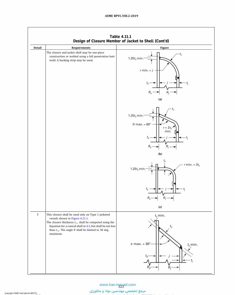
Table 4.11.1Design of Closure Member of Jacket to Shell (Cont'd)
Detail Requirements Figure
The closure and jacket shell may be one-piececonstruction or welded using a full penetration buttweld. A backing strip may be used.
1.25tc min.
max. = 60°
(c)
(b)
(a)
r min. = j
tc
Rs Rj
tjjts
1.25tc min.
1.25tc min.r min. = 3tc
RjRs
ts tjj
r = 2tc min.
tc
RjRs
ts tjj
tc
3 This closure shall be used only on Type 1 jacketedvessels shown in Figure 4.11.1.
The closure thickness t r c shall be computed using theEquation for a conical shell in 4.3, but shall be not lessthan t r j . The angle θ shall be limited to 30 degmaximum.
j
tc min.
max. = 30°
tc
tc min.
ts
Rs Rj
tj
�
323
ASME BPVC.VIII.2-2019
Copyright ASME International (BPVC) Provided by IHS under license with ASME Licensee=Khalda Petroleum/5986215001, User=Amer, Mohamed
Not for Resale, 07/02/2019 14:07:58 MDTNo reproduction or networking permitted without license from IHS
--`,```,,,,,````,`,``,,`,,`,`-`-`,,`,,`,`,,`---
www.iran-mavad.com
مرجع تخصصی مهندسین مواد و متالورژی

Table 4.11.1Design of Closure Member of Jacket to Shell (Cont'd)
Detail Requirements Figure
4 Closure details (a), (b), and (c) shall only be used whenthe requirements of 4.11.3.3 are satisfied.
These closures shall be used only on Type 1 jacketedvessels as shown in Figure 4.11.1 and with the furtherlimitation that t r j does not exceed 16 mm (0.625 in.).
The required minimum thickness for the closure barshall be equal to:
Fillet weld sizes shall be as follows:Y ≥ min[0.75t c , 0.75t s] and c = 0.7Y minZ ≥ t j and b = 0.7Z min
ts j
Rs Rj
Y
Y
Y
c
Y
c
tj
tc
b
Z Z
(a)
tc
tjts j
Rs Rj
b
ZY
Y
ZY
c
Y
c
Rs Rj
tjts j
Y
Y
Y
c
c
Y
tc
Z
Z
Rs Rj
tjts j
Backing strip may be used
Y
Y
Y
c
c
(b)
(c) (d)
5 Closure details (a), (b), and (c) shall only be used whenthe requirements of 4.11.3.3 are satisfied.
These closures may be used on any of the types ofjacketed vessels shown in Figure 4.11.1. For Type 1jacketed vessels, the required minimum closure barthickness shall be determined from the equations inTable 4.11.1, Detail 4. For all other types of jacketedvessels, the required minimum closure bar thicknessand the maximum allowable width of the jacket spaceshall be determined from the following equations:
Weld sizes connecting the closure bar to the inner vesselshall be as follows:
Y ≥ min[1.5t c , 1.5t s], and shall be measured as the sumof dimensions a and b as shown. In addition, a , b ≥min[6 mm (1/4 in.), t c , t s]
Z is equal to the minimum fillet size necessary whenused in conjunction with a groove weld or anotherfillet weld to maintain the minimum required Ydimension.
324
ASME BPVC.VIII.2-2019
Copyright ASME International (BPVC) Provided by IHS under license with ASME Licensee=Khalda Petroleum/5986215001, User=Amer, Mohamed
Not for Resale, 07/02/2019 14:07:58 MDTNo reproduction or networking permitted without license from IHS
--`,```,,,,,````,`,``,,`,,`,`-`-`,,`,,`,`,,`---
www.iran-mavad.com
مرجع تخصصی مهندسین مواد و متالورژی

Table 4.11.1Design of Closure Member of Jacket to Shell (Cont'd)
Detail Requirements Figure
tc
(a)
Rs
a
b
Z
Z
ZZ
Y = a + bts Y = a + b
Rs
ts
a
b
Z
Z
Z
Z
tc
a
b
ts
Z Z
Z
tc
Z
Y = a + b
Rs
(b)
(c)
6 Closure details (a), (b), and (c) shall only be used whenthe requirements of 4.11.3.3 are satisfied.
The jacket to closure bar attachment welds shown inDetails (a), (b) and (c) may be used on any of thetypes of jacketed vessels shown in Figure 4.11.1.
Attachment welds shown in Details (d), (e) and (f) maybe used on any of the types of jacketed vessels shownin Figure 4.11.1 where t r j does not exceed 16 mm(0.625 in.).
The required minimum closure bar thickness and themaximum allowable width of the jacket space shall bedetermined from the following equations:
325
ASME BPVC.VIII.2-2019
Copyright ASME International (BPVC) Provided by IHS under license with ASME Licensee=Khalda Petroleum/5986215001, User=Amer, Mohamed
Not for Resale, 07/02/2019 14:07:58 MDTNo reproduction or networking permitted without license from IHS
--`,```,,,,,````,`,``,,`,,`,`-`-`,,`,,`,`,,`---www.iran-mavad.com
مرجع تخصصی مهندسین مواد و متالورژی

Table 4.11.1Design of Closure Member of Jacket to Shell (Cont'd)
Detail Requirements Figure
(a)
See para. 4.2
tc
Backing strip may be used
45° min.
See para. 4.2
Not less than a
a
(elongated to maintainmin. throat dimension)
30° max.
min. throat dimension = tj
(c)
(b)
(d)
(e) (f)
See para. 4.2
tj
RjRj
tj min.
tc
Backing strip may be used
tj tj
tc
Rj
2tj min. tj min.
tc
Rj
0.7tj min.
1.5tj
tj min.
tc
tj
Rj
0.83tj min.
tj min.
tc
tj
Rj
tj
7 Closure details (a), (b), and (c) shall only be used whenthe requirements of 4.11.3.3 are satisfied.
These closures may be used on Type 3 jacketed vesselsshown in Figure 4.11.1 shall have attachment weldsin accordance with Details (a), (b) or (c). Thisconstruction is limited to jackets where t r j does notexceed 16 mm (0.625 in.).
For torispherical, ellipsoidal, and hemispherical heads,the outside diameter of jacket head shall not begreater than the outside diameter of the vessel head,or the inside diameter of the jacket head shall benominally equal to the outside diameter of vesselhead.
326
ASME BPVC.VIII.2-2019
Copyright ASME International (BPVC) Provided by IHS under license with ASME Licensee=Khalda Petroleum/5986215001, User=Amer, Mohamed
Not for Resale, 07/02/2019 14:07:58 MDTNo reproduction or networking permitted without license from IHS
--`,```,,,,,````,`,``,,`,,`,`-`-`,,`,,`,`,,`---
www.iran-mavad.com
مرجع تخصصی مهندسین مواد و متالورژی
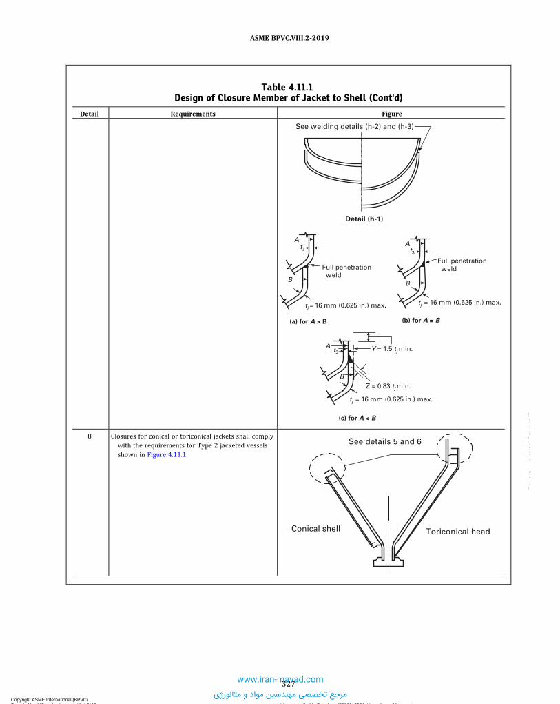
Table 4.11.1Design of Closure Member of Jacket to Shell (Cont'd)
Detail Requirements Figure
See welding details (h-2) and (h-3)
Detail (h-1)
A
tj = 16 mm (0.625 in.) max.
Z = 0.83 tj min.
Y = 1.5 tj min.
B
A
tj = 16 mm (0.625 in.) max.
B
A
(a) for A > B
Full penetration weld
Full penetration weld
tj = 16 mm (0.625 in.) max.
B
(b) for A = B
(c) for A < B
t3 t3
t3
8 Closures for conical or toriconical jackets shall complywith the requirements for Type 2 jacketed vesselsshown in Figure 4.11.1.
See details 5 and 6
Conical shell Toriconical head
327
ASME BPVC.VIII.2-2019
Copyright ASME International (BPVC) Provided by IHS under license with ASME Licensee=Khalda Petroleum/5986215001, User=Amer, Mohamed
Not for Resale, 07/02/2019 14:07:58 MDTNo reproduction or networking permitted without license from IHS
--`,```,,,,,````,`,``,,`,,`,`-`-`,,`,,`,`,,`---
www.iran-mavad.com
مرجع تخصصی مهندسین مواد و متالورژی

Table 4.11.2Design of Jacket Penetration Details
Detail Requirements Figure
1 This closure details shall only be used when therequirements of 4.11.3.3 are satisfied.
The nozzle wall may be used as the closure memberwhere the jacket is welded to the nozzle.
a = 2t j min and b = t j minVessel wall
Jacket wall
ts
b
t
Nozzle neck
a
nozzleCL
Backing strip may be used
tj
2 This closure details shall only be used when therequirements of 4.11.3.3 are satisfied.
The minimum required thickness, tr c , for thegeometries shall be calculated as a shell underexternal pressure in accordance with 4.4.
a = 2t j min and b = t j minAttachment A shall be made using details in Table 4.2.6.
a
Attachment A
Backing strip may be used
nozzleCL
tc
ts
tj
tn
tn
Rp
3 This closure details shall only be used when therequirements of 4.11.3.3 are satisfied.
The minimum required thickness, tr c , shall be equal tot r j .
Attachment A shall be made using details in Table 4.2.6.
Attachment A
r
r = 3tj min.
Backing strip may be used
nozzleCL
tn
tc
tn
tj
ts
328
ASME BPVC.VIII.2-2019
Copyright ASME International (BPVC) Provided by IHS under license with ASME Licensee=Khalda Petroleum/5986215001, User=Amer, Mohamed
Not for Resale, 07/02/2019 14:07:58 MDTNo reproduction or networking permitted without license from IHS
--`,```,,,,,````,`,``,,`,,`,`-`-`,,`,,`,`,,`---
www.iran-mavad.com
مرجع تخصصی مهندسین مواد و متالورژی

Table 4.11.2Design of Jacket Penetration Details (Cont'd)
Detail Requirements Figure
4 This closure details shall only be used when therequirements of 4.11.3.3 are satisfied.
The minimum required thickness, t r c , shall becalculated as a shell under external pressure inaccordance with 4.4.
Attachment A shall be made using details in Table 4.2.6.
Attachment A
Full penetration butt weld, backing strip may be used
nozzleL
tc
C
ts
tj
tn
Rp
5 This closure details shall only be used when therequirements 4.11.3.3 are satisfied.
The thickness required of the closure member attachedto the inner vessel, t r c1 , shall be calculated as a shellunder external pressure in accordance with 4.4. Therequired thickness of the flexible member, t r c2 , shallbe determined as follows:
When a tubular section does not exist between jacketand torus:
When a tubular section does exist between jacket andtorus:
a = 2t j , b = t j , and c = 1.25t c1Attachment A shall be made using details in Table 4.2.6.
Attachment A
b
c a
r
nozzleCL
nozzleCL
(a)
Attachment A
c
b
a
(b)
tj
ts
tj
tn
Rp
tn
Rp
Backing strip may be used
tc2
tc1
tc2
tc1
ts
329
ASME BPVC.VIII.2-2019
Copyright ASME International (BPVC) Provided by IHS under license with ASME Licensee=Khalda Petroleum/5986215001, User=Amer, Mohamed
Not for Resale, 07/02/2019 14:07:58 MDTNo reproduction or networking permitted without license from IHS
--`,```,,,,,````,`,``,,`,,`,`-`-`,,`,,`,`,,`---
www.iran-mavad.com
مرجع تخصصی مهندسین مواد و متالورژی

Table 4.11.2Design of Jacket Penetration Details (Cont'd)
Detail Requirements Figure
6 This closure detail shall only be used when therequirements of 4.11.3.3 are satisfied.
The minimum thickness, t rc , shall be calculated as ashell of radius Rp under external pressure inaccordance with 4.4.
a = 2t j and b = t jAttachment A shall be made using details in Table 4.2.6.
b
Attachment A
a
tc
nozzleCL
Rp
ts
tj
tn
Table 4.11.3Coefficients for Eq. (4.11.5)
Dpj Coefficients
Shell Thickness
5 mm (3/16 in.) 6 mm (1/4 in.) 10 mm (3/8 in.) 13 mm (1/2 in.)
DN50 (NPS 2) C1 −3.6674510 E+01 −1.8874043 E+04 4.0083779 E+02 −2.6447784 E+02C2 1.2306994 E+01 1.7869518 E+04 −5.7029108 E+02 1.8066952 E+02C3 3.5701684 E+00 −7.2846419 E+03 3.1989698 E+02 −4.9294965 E+01C4 −7.9516583 E−01 1.6723763 E+03 −9.4286208 E+01 7.1522422 E+00C5 5.8791041 E−02 −2.3648930 E+02 1.6391764 E+01 −5.7900069 E−01C6 −1.5365397 E−03 2.1101742 E+01 −1.7431218 E+00 2.4758486 E−02C7 0.0000000 E+00 −1.1608890 E+00 1.1160179 E−01 −4.3667599 E−04C8 0.0000000 E+00 3.6022711 E−02 −3.9549592 E−03 0.0000000 E+00C9 0.0000000 E+00 −4.8303253 E−04 5.9644209 E−05 0.0000000 E+00C10 0.0000000 E+00 0.0000000 E+00 0.0000000 E+00 0.0000000 E+00
DN80 (NPS 3) C1 −3.7588705 E+03 −1.2551406 E+04 −3.8104460 E+04 −1.4263782 E+04C2 2.9919870 E+03 1.2149900 E+04 4.0491537 E+04 1.6228077 E+04C3 −9.4177823 E+02 −5.0657776 E+03 −1.8844078 E+04 −8.0227888 E+03C4 1.5278500 E+02 1.1910361 E+03 5.0415301 E+03 2.2676555 E+03C5 −1.3452359 E+01 −1.7255075 E+02 −8.5435371 E+02 −4.0440980 E+02C6 6.1167422 E−01 1.5770136 E+01 9.5115501 E+01 4.7257835 E+01C7 −1.1235632 E−02 −8.8782173 E−01 −6.9588768 E+00 −3.6233229 E+00C8 −2.1465752 E−06 2.8148933 E−02 3.2277515 E−01 1.7597455 E−01C9 0.0000000 E+00 −3.8488963 E−04 −8.6172557 E−03 −4.9179021 E−03C10 0.0000000 E+00 0.0000000 E+00 1.0094910 E−04 6.0315412 E−05
DN100 (NPS 4) C1 −2.1336346 E+04 7.3995872 E+03 8.3115447 E+02 −4.0097574 E+02C2 1.5982068 E+04 −6.7592710 E+03 −7.6253222 E+02 4.2602525 E+02C3 −4.9936486 E+03 2.6131811 E+03 2.9500674 E+02 −1.7446665 E+02C4 8.4914220 E+02 −5.4873257 E+02 −6.1135935 E+01 3.7753845 E+01C5 −8.4931392 E+01 6.7571708 E+01 7.4233181 E+00 −4.6748939 E+00C6 5.0044853 E+00 −4.8769663 E+00 −5.2938127 E−01 3.3376011 E−01C7 −1.6105634 E−01 1.9112909 E−01 2.0558271 E−02 −1.2795569 E−02C8 2.1857714 E−03 −3.1412698 E−03 −3.3593696 E−04 2.0405896 E−04C9 0.0000000 E+00 0.0000000 E+00 0.0000000 E+00 0.0000000 E+00C10 0.0000000 E+00 0.0000000 E+00 0.0000000 E+00 0.0000000 E+00
330
ASME BPVC.VIII.2-2019
Copyright ASME International (BPVC) Provided by IHS under license with ASME Licensee=Khalda Petroleum/5986215001, User=Amer, Mohamed
Not for Resale, 07/02/2019 14:07:58 MDTNo reproduction or networking permitted without license from IHS
--`,```,,,,,````,`,``,,`,,`,`-`-`,,`,,`,`,,`---
www.iran-mavad.com
مرجع تخصصی مهندسین مواد و متالورژی

Table 4.11.3Coefficients for Eq. (4.11.5) (Cont'd)
Dpj Coefficients
Shell Thickness
19 mm (3/4 in.) 25 mm (1 in.) 50 mm (2 in.)
DN50 (NPS 2) C1 −4.0085121 E+02 3.6782666 E+00 1.0000000 E+00 …C2 3.5652906 E+02 −1.2669560 E+00 0.0000000 E+00 …C3 −1.3171601 E+02 4.5491492 E−01 0.0000000 E+00 …C4 2.6480374 E+01 −6.2883969 E−02 0.0000000 E+00 …C5 −3.1258388 E+00 3.9401350 E−03 0.0000000 E+00 …C6 2.1680455 E−01 −9.3433360 E−05 0.0000000 E+00 …C7 −8.1908188 E−03 0.0000000 E+00 0.0000000 E+00 …C8 1.3019970 E−04 0.0000000 E+00 0.0000000 E+00 …C9 0.0000000 E+00 0.0000000 E+00 0.0000000 E+00 …C10 0.0000000 E+00 0.0000000 E+00 0.0000000 E+00 …
DN80 (NPS 3) C1 −1.5045135 E+03 8.1206324 E+00 −3.2789303 E+03 …C2 1.4487653 E+03 −8.3943593 E+00 3.4419302 E+03 …C3 −5.9846696 E+02 3.7870074 E+00 −1.5852932 E+03 …C4 1.3910417 E+02 −7.0886182 E−01 4.2063167 E+02 …C5 −1.9888205 E+01 6.6972430 E−02 −7.0855807 E+01 …C6 1.7922925 E+00 −3.1488859 E−03 7.8593168 E+00 …C7 −9.9521276 E−02 5.8511141 E−05 −5.7415834 E−01 …C8 3.1164737 E−03 0.0000000 E+00 2.6647325 E−02 …C9 −4.2181627 E−05 0.0000000 E+00 −7.1319265 E−04 …C10 0.0000000 E+00 0.0000000 E+00 8.3899940 E−06 …
DN100 (NPS 4) C1 −3.5172282 E+00 −2.5016604 E+02 −5.3121462 E+00 …C2 4.3499616 E+00 1.7178270 E+02 3.4090615 E+00 …C3 −2.7157682 E−01 −4.6844914 E+01 −5.5605535 E−01 …C4 1.1186450 E−02 6.6874346 E+00 4.2156128 E−02 …C5 −7.1328067 E−04 −5.2507555 E−01 −1.2921987 E−03 …C6 2.2962890 E−05 2.1526948 E−02 6.6740230 E−06 …C7 0.0000000 E+00 −3.6091550 E−04 0.0000000 E+00 …C8 0.0000000 E+00 0.0000000 E+00 0.0000000 E+00 …C9 0.0000000 E+00 0.0000000 E+00 0.0000000 E+00 …C10 0.0000000 E+00 0.0000000 E+00 0.0000000 E+00 …
331
ASME BPVC.VIII.2-2019
Copyright ASME International (BPVC) Provided by IHS under license with ASME Licensee=Khalda Petroleum/5986215001, User=Amer, Mohamed
Not for Resale, 07/02/2019 14:07:58 MDTNo reproduction or networking permitted without license from IHS
--`,```,,,,,````,`,``,,`,,`,`-`-`,,`,,`,`,,`---
www.iran-mavad.com
مرجع تخصصی مهندسین مواد و متالورژی

4.11.9 FIGURES
Figure 4.11.1Types of Jacketed Vessels
L
Type 1
L
Type 2 Type 3
L
Type 4
L
Type 5
L
332
ASME BPVC.VIII.2-2019
Copyright ASME International (BPVC) Provided by IHS under license with ASME Licensee=Khalda Petroleum/5986215001, User=Amer, Mohamed
Not for Resale, 07/02/2019 14:07:58 MDTNo reproduction or networking permitted without license from IHS
--`,```,,,,,````,`,``,,`,,`,`-`-`,,`,,`,`,,`---
www.iran-mavad.com
مرجع تخصصی مهندسین مواد و متالورژی

Figure 4.11.2Types of Partial Jackets
Continuous Partial Jacket
Multiple or Pod-Type Jacket
333
ASME BPVC.VIII.2-2019
Copyright ASME International (BPVC) Provided by IHS under license with ASME Licensee=Khalda Petroleum/5986215001, User=Amer, Mohamed
Not for Resale, 07/02/2019 14:07:58 MDTNo reproduction or networking permitted without license from IHS
--`,```,,,,,````,`,``,,`,,`,`-`-`,,`,,`,`,,`---
www.iran-mavad.com
مرجع تخصصی مهندسین مواد و متالورژی

Figure 4.11.3Half Pipe Jackets
r
r
R
R
4.12 DESIGN RULES FOR NONCIRCULAR VESSELS
4.12.1 SCOPE4.12.1.1 The procedures in 4.12 cover the design requirements for single wall vessels having a rectangular or
obround cross section. The design rules cover the walls and parts of the vessels subject to pressure stresses includingstiffening, reinforcing and staying members. All other types of loadings shall be evaluated in accordance with the design-by-analysis rules of Part 5.
4.12.1.2 The design rules in this paragraph cover noncircular vessels of the types shown in Table 4.12.1. Vessel con-figurations other than Types 1 to 12, illustrated in Figures 4.12.1 through 4.12.13, may be used. However, in this case,the design-by-analysis rules of Part 5 shall be used.
334
ASME BPVC.VIII.2-2019
Copyright ASME International (BPVC) Provided by IHS under license with ASME Licensee=Khalda Petroleum/5986215001, User=Amer, Mohamed
Not for Resale, 07/02/2019 14:07:58 MDTNo reproduction or networking permitted without license from IHS
--`,```,,,,,````,`,``,,`,,`,`-`-`,,`,,`,`,,`---
www.iran-mavad.com
مرجع تخصصی مهندسین مواد و متالورژی
4.12.2 GENERAL DESIGN REQUIREMENTS4.12.2.1 In the noncircular vessel configurations covered in this paragraph, the walls of the vessel can have different
thicknesses. Therefore, the design of a noncircular vessel requires an iterative approach where the vessel configurationand wall thickness are initially set and the stresses at locations on the cross section are computed and compared to al-lowable values. If the allowable values are exceeded, the configuration and/or wall thickness are changed, and thestresses are revaluated. This process is continued until a final configuration including wall thickness is obtained whereall allowable stress requirements are satisfied.
4.12.2.2 In the design rules of this paragraph, both membrane and bending stresses shall be computed at locationson the cross section. The membrane stress is added algebraically to the bending stress at both the outermost surface ofthe shell plate or reinforcement (when used) and the innermost surface of the shell plate to obtain two values of totalstress. The total stresses at the section shall be compared to the allowable stress.
4.12.2.3 The total stresses (membrane plus bending) at the cross section of a vessel with and without reinforcementshall be calculated as follows.
(a) For a vessel without reinforcement, the total stresses shall be determined at the inside and outside surfaces of thecross section of the shell plate.
(b) For a vessel with reinforcement, when the reinforcing member has the same allowable stress as the vessel, thetotal stress shall be determined at the inside and outside surfaces of the composite cross section. The appropriate valueof c (the location from the neutral axis) for the composite section properties shall be used in the bending equations. Thetotal stresses at the inside and outside surfaces shall be compared to the allowable stress.
(c) For a vessel with reinforcement, when the reinforcing member does not have the same allowable stress as thevessel, the total stresses shall be determined at the inside and outside surfaces of each component of the composite crosssection. The appropriate value of c (the location from the neutral axis) for the composite section properties shall be usedin the bending equations considering location of desired stress with respect to the composite section neutral axis. Thetotal stresses at the inside and outside surfaces shall be compared to the allowable stress.
(1) For locations of stress below the neutral axis, the bending equation used to compute the stress shall be that con-sidered acting on the inside surface.
(2) For locations of stress above the neutral axis, the bending equation used to compute the stress shall be that con-sidered acting on the outside surface.
4.12.2.4 Particular attention shall be given to the effects of local internal and external loads and expansion differ-entials at design temperature, including reactions at supporting lugs, piping, and other types of attachments (see4.12.1.1).
4.12.2.5 Except as otherwise specified in 4.12.8, vessel parts of noncircular cross section subject to external pres-sure shall be designed in accordance with Part 5.
4.12.2.6 The end closures for noncircular vessels covered in this paragraph shall be designed in accordance with theprovisions of Part 5 except in cases where the ends are flat plates. For this case, the design rules of 4.6 shall be usedexcept that 0.20 shall be used for the value of the C factor in all of the calculations.
4.12.2.7 The design equations in this paragraph are based on vessels in which the ratio of the long side to short-sidelength is greater than four. These equations are conservatively applicable to vessels of aspect ratio less than four. Vesselside plates with aspect ratios less than four are strengthened by the interaction of the end closures and may be designedin accordance with the provisions of Part 5. Short unreinforced or unstayed vessels of rectangular cross section havingan aspect ratio smaller than two may be designed in accordance with 4.12.5.
4.12.2.8 Bolted full side or end plates and flanges may be provided for vessels of rectangular cross section. Manyacceptable configurations are possible. Therefore, rules for specific designs are not provided, and these parts shall bedesigned in accordance with Part 5. The analysis of the components shall consider thermal loads, gasket reactions, bolt-ing forces, and resulting moments, as well as pressure and other mechanical loading.
4.12.2.9 Openings may be provided in vessels of noncircular cross section as follows:(a) Openings in noncircular vessels do not require reinforcement other than that inherent in the construction, pro-
vided they meet the conditions given in 4.5.2.(b) Compensation for openings in noncircular vessels must account for the bending strength as well as the membrane
strength of the side with the opening. In addition, openings may significantly affect the stresses in adjacent sides. Be-cause many acceptable configurations are possible, rules for specific designs are not provided and the design shall bein accordance with Part 5.
335
ASME BPVC.VIII.2-2019
Copyright ASME International (BPVC) Provided by IHS under license with ASME Licensee=Khalda Petroleum/5986215001, User=Amer, Mohamed
Not for Resale, 07/02/2019 14:07:58 MDTNo reproduction or networking permitted without license from IHS
--`,```,,,,,````,`,``,,`,,`,`-`-`,,`,,`,`,,`---
www.iran-mavad.com
مرجع تخصصی مهندسین مواد و متالورژی

4.12.3 REQUIREMENTS FOR VESSELS WITH REINFORCEMENT
4.12.3.1 Design rules are provided for Types 4, 5, and 6 (see Table 4.12.1) where the welded on reinforcement mem-bers are in a plane perpendicular to the long axis of the vessel; however, the spacing between reinforcing members neednot be uniform. All reinforcement members attached to two opposite plates shall have the same moment of inertia. Thedesign for any other type of reinforced rectangular cross section vessel shall be in accordance with Part 5.
4.12.3.2 For a Type 4 vessel, when the side plate thicknesses are equal, the plates may be formed to a radius at thecorners. The analysis is, however, carried out in the same manner as if the corners were not rounded. For corners thatare cold formed, the provisions of Part 6 shall apply. For the special case where L1 = 0.0, the analysis methodology for aType 11 vessel shall be used.
4.12.3.3 A Type 5 vessel has rounded corners and non-continuous reinforcement. If continuous reinforcement isprovided that follows the contour of the vessel, the design requirements for a Type 4 vessel shall be used.
4.12.3.4 For a Type 6 vessel, the corner region consists of a flat, chamfered segment joined to the adjacent sides bycurved segments with constant radii. The chamfered segments shall be perpendicular to diagonal lines drawn throughthe points where the sides would intersect if they were extended.
4.12.3.5 Reinforcing members shall be placed on the outside of the vessel and shall be attached to the plates of thevessel by welding on each side of the reinforcing member. For continuous reinforcement, welding may be either con-tinuous or intermittent. The total length of intermittent welding on each side of the reinforcing member shall be not lessthan one-half the length being reinforced on the shell. Welds on opposite sides of the reinforcing member may be eitherstaggered or in-line and the distance between intermittent welds shall be no more than eight times the plate thickness ofthe plate being reinforced. For assuring the composite section properties, for non-continuous reinforcement, the weldsmust be capable of developing the necessary shear (see Manual of Steel Construction, AISC, American Institute of SteelConstruction).
4.12.3.6 The maximum distance between reinforcing members is computed as follows.
(a) The maximum distance between any reinforcing member centerlines is given by eq. (4.12.1). In the equations forcalculating stresses for reinforced noncircular vessels, the value of p shall be taken as the sum of one-half the distancesto the next reinforcing member on each side.
ð4:12:1Þ
where
ð4:12:2Þ
ð4:12:3Þ
ð4:12:4Þ
ð4:12:5Þ
ð4:12:6Þ
ð4:12:7Þ
336
ASME BPVC.VIII.2-2019
Copyright ASME International (BPVC) Provided by IHS under license with ASME Licensee=Khalda Petroleum/5986215001, User=Amer, Mohamed
Not for Resale, 07/02/2019 14:07:58 MDTNo reproduction or networking permitted without license from IHS
--`,```,,,,,````,`,``,,`,,`,`-`-`,,`,,`,`,,`---
www.iran-mavad.com
مرجع تخصصی مهندسین مواد و متالورژی

ð4:12:8Þ
ð4:12:9Þ
ð4:12:10Þ
ð4:12:11Þ
ð4:12:12Þ
ð4:12:13Þ
ð4:12:14Þ
ð4:12:15Þ
(b) The allowable effective widths of the shell plate, w1 and w2 , shall not be greater than the value given by eq.(4.12.16) or eq. (4.12.17) nor greater than the actual value of p if this value is less than that computed in (a). One-halfof w shall be considered to be effective on each side of the reinforcing member centerline, but the effective widths shallnot overlap. The effective width shall not be greater than the actual width available.
ð4:12:16Þ
ð4:12:17Þ
where
ð4:12:18Þ
(c) At locations, other than in the corner regions where the shell plate is in tension, the effective moments of inertiaI11 and I21 of the composite section (reinforcement and shell plate acting together) shall be computed based on thevalues of w1 and w2 computed in (b). The equations given in (b) do not include the effects of high-localized stresses.In the corner regions of some Type 4 configurations, the localized stresses may significantly exceed the calculated stress.Only a very small width of the shell plate may be effective in acting with the composite section in the corner region. Thelocalized stresses in this region shall be evaluated using the principles of Part 5.
4.12.4 REQUIREMENTS FOR VESSELS WITH STAYS4.12.4.1 Three types of stayed construction are considered, Types 7, 8, and 11. In these types of construction the
staying members may be plates welded to the side plates for the entire length of the vessel. In this case, the stay platesshall not be constructed so as to create pressure-containing partitions. Alternatively, the stays may be bars of circularcross section fastened to the side plates on a uniform pitch designed in accordance with 4.9.
337
ASME BPVC.VIII.2-2019
Copyright ASME International (BPVC) Provided by IHS under license with ASME Licensee=Khalda Petroleum/5986215001, User=Amer, Mohamed
Not for Resale, 07/02/2019 14:07:58 MDTNo reproduction or networking permitted without license from IHS
--`,```,,,,,````,`,``,,`,,`,`-`-`,,`,,`,`,,`---
www.iran-mavad.com
مرجع تخصصی مهندسین مواد و متالورژی

4.12.4.2 The Type 12 noncircular vessel is comprised of a cylindrical shell with a single-stay plate that divides thecylinder into two compartments. The design rules ensure that the various vessel members will not be overstressed whenthere is full pressure in both vessel compartments or when there is full pressure in one compartment and zero pressurein the other compartment. Stresses may be computed only at the shell-plate junction since this is the location of max-imum stress.
4.12.5 REQUIREMENTS FOR RECTANGULAR VESSELS WITH SMALL ASPECT RATIOS4.12.5.1 Type 1 and Type 2 noncircular vessels with aspect ratios of Lv/H or Lv/h between 1.0 and 2.0, and with flat
heads welded to the sides may be designed using the procedure in 4.12.7 except that the following plate parametersshall be utilized in the calculations.
ð4:12:19Þ
ð4:12:20Þ
ð4:12:21Þ
ð4:12:22Þ
where
ð4:12:23Þ
ð4:12:24Þ
Note in the above nomenclature, is defined as computing J2 s using the function J2(x) evaluated at
.
4.12.5.2 For vessels with aspect ratios of Lv/H or Lv/h less than 1.0, the axis of the vessel shall be rotated so thatthe largest dimension becomes the length Lv , and the new ratios Lv/H or Lv/h are greater than or equal to 1.0. Allstresses shall be recalculated using the new orientation.
4.12.6 WELD JOINT FACTORS AND LIGAMENT EFFICIENCY4.12.6.1 The stress calculations for the noncircular vessel shall include a weld joint factor for weld locations and
ligament efficiency for those locations containing holes. In the stress calculations two factors Em and Eb are used to ac-count for the weld joint factor and ligament efficiency that is to be applied to the membrane and bending stresses, re-spectively. The weld joint factor shall be determined from 4.2 and the ligament efficiency shall be determined from4.12.6.3. The correct combination of weld joint factor and ligament efficiencies to be used in the design is shown below.(a) If there is not a weld or a hole pattern at the stress calculation location, then:
ð4:12:25Þ
ð4:12:26Þ
338
ASME BPVC.VIII.2-2019
Copyright ASME International (BPVC) Provided by IHS under license with ASME Licensee=Khalda Petroleum/5986215001, User=Amer, Mohamed
Not for Resale, 07/02/2019 14:07:58 MDTNo reproduction or networking permitted without license from IHS
--`,```,,,,,````,`,``,,`,,`,`-`-`,,`,,`,`,,`---
www.iran-mavad.com
مرجع تخصصی مهندسین مواد و متالورژی

ð19Þ
(b) If there is a weld, and there is not a hole pattern at the stress calculation location, then:
ð4:12:27Þ
ð4:12:28Þ
(c) If there is not a weld, and there is a hole pattern at the stress calculation location, then:
ð4:12:29Þ
ð4:12:30Þ
(d) If there is a weld and a hole pattern at the stress calculation location, then:
(1) If em and eb are less than the joint efficiency, E , which would be used if there were no ligaments in the plate,then use eqs. (4.12.29) and (4.12.30).
(2) If em and eb are greater than the weld joint factor, E , which would be used if there were no ligaments in theplate, then use eqs. (4.12.27) and (4.12.28).
4.12.6.2 Cases may arise where application of a weld joint factor, E , at nonwelded locations results in unnecessarilyincreased plate thicknesses. If the butt weld occurs at one of the locations for which equations are provided in this para-graph, then no relief can be provided. However, if the weld occurs at some intermediate location, it is permissible tocalculate the bending stress at the weld location and compare it to the allowable stress considering the weld joint factorin the calculation. An alternate location for computing stresses is provided for some of the noncircular geometry types,and is identified as “Maximum Membrane and Bending Stresses - Defined Locations” in the stress calculation tables. Thevalue X of Y or to be used in the equations is the distance from the midpoint of the side to the location of the weld joint.
4.12.6.3 The ligament efficiency factors em and eb , for membrane and bending stresses, respectively, shall only beapplied to the calculated stresses for the plates containing the ligaments.
(a) For the case of uniform diameter holes, the ligament efficiency factors em and eb shall be the same and computedin accordance with 4.10.
(b) For the case of multi-diameter holes, the neutral axis of the ligament may no longer be at mid-thickness of theplate; the bending stress is higher at one of the plate surfaces than at the other surface. Therefore, for multi-diameterholes, the ligament efficiency factor shall be computed using the following equations.
(1) The ligament efficiency of plate with multi-diameter holes subject to membrane stress is computed as follows.
ð4:12:31Þ
where
ð4:12:32Þ
(2) The ligament efficiency and location from the neutral axis of a plate with multi-diameter holes (see Figure4.12.14) subject to bending stress is computed as follows.
ð4:12:33Þ
where
ð4:12:34Þ
339
ASME BPVC.VIII.2-2019
Copyright ASME International (BPVC) Provided by IHS under license with ASME Licensee=Khalda Petroleum/5986215001, User=Amer, Mohamed
Not for Resale, 07/02/2019 14:07:58 MDTNo reproduction or networking permitted without license from IHS
--`,```,,,,,````,`,``,,`,,`,`-`-`,,`,,`,`,,`---www.iran-mavad.com
مرجع تخصصی مهندسین مواد و متالورژی

ð4:12:35Þ
ð4:12:36Þ
where
ð4:12:37Þ
ð4:12:38Þ
ð4:12:39Þ
ð4:12:40Þ
ð4:12:41Þ
If To is measured from the inside surface, then
ð4:12:42Þ
ð4:12:43ÞIf To is measured from the outside surface, then
ð4:12:44Þ
ð4:12:45Þ(c) Rows of holes may be located in regions of relatively low bending moments to keep the required plate thickness to
a minimum. Therefore, it is permissible to calculate the stresses at the centerline of each row of holes closest to the loca-tions where the highest bending moments occurs (i.e., at the midpoint of the sides and at the corners). If the diameter ofall the holes is not the same, the stresses must be calculated for each set of em and eb values.(d) The applied gross area stresses may be calculated using the same procedure as for calculating the stresses at a
weld joint (see 4.12.3.2). The value of X or Y to be used in the equations is the distance from the midpoint of the sideto the plane containing the centerlines of the holes.
4.12.7 DESIGN PROCEDURE4.12.7.1 A procedure that can be used to design a noncircular vessel subject to internal pressure is shown below.Step 1. Determine the design pressure and temperature.Step 2. Determine the configuration of the noncircular vessel by choosing a Type from Table 4.12.1.Step 3. Determine the initial configuration (i.e., width, height, length, etc.) and wall thicknesses of the pressure-
containing plates.
340
ASME BPVC.VIII.2-2019
Copyright ASME International (BPVC) Provided by IHS under license with ASME Licensee=Khalda Petroleum/5986215001, User=Amer, Mohamed
Not for Resale, 07/02/2019 14:07:58 MDTNo reproduction or networking permitted without license from IHS
--`,```,,,,,````,`,``,,`,,`,`-`-`,,`,,`,`,,`---
www.iran-mavad.com
مرجع تخصصی مهندسین مواد و متالورژی

(a) If the vessel has stiffeners, then determine the spacing (see 4.12.3) and size of the stiffeners.
(b) If the vessel has stays, then determine the stay type and configuration (see 4.12.4), and check the stay plate weldsusing 4.2.
(c) If the vessel aspect ratio is less than two, then determine the plate parameters in 4.12.5.
Step 4. Determine the location of the neutral axis from the inside and outside surfaces.
(a) If the section under evaluation has stiffeners, then c i and co are determined from the cross section of the combinedplate and stiffener section using strength of materials concepts.
(b) If the section under evaluation has multi-diameter holes, then c i and co are determined from 4.12.6.3.
(c) If the section under evaluation does not have a stiffener, does not have holes, or has uniform diameter holes, thenc i = co = t/2 where t is the thickness of the plate.
Step 5. Determine the weld joint factor and ligaments efficiencies, as applicable (see 4.12.6), and determine the factorsEm or Eb .
Step 6. Complete the stress calculation for the selected noncircular vessel Type (see Table 4.12.1), and check the ac-ceptance criteria. If the criteria are satisfied, then the design is complete. If the criteria are not satisfied, then modify theplate thickness and/or stiffener size and go to Step 3 and repeat the calculation. Continue this process until a design isachieved that satisfies the acceptance criteria.
4.12.7.2 If the vessel is subject to external pressure, the additional requirements of 4.12.8 shall be satisfied.
4.12.8 NONCIRCULAR VESSELS SUBJECT TO EXTERNAL PRESSURE
4.12.8.1 Rectangular vessel Types 1 and 2 subject to external pressure shall meet the following requirements.
(a) The stresses shall be calculated in accordance with Tables 4.12.2 and 4.12.3 except that the design external pres-sure shall be substituted for P . These computed stresses shall meet the acceptance criteria defined in these tables.
(b) The four side plates and the two end plates shall be checked for stability in accordance with eq. (4.12.46). Therequired calculations for SmA , SmB , S*c rA , S**c rA , S*c rB and S** c rB are shown in Table 4.12.15. In the equations,the subscript A is used to identify stress or load acting in a direction parallel to the long dimension of the panel beingconsidered and the subscript B is used to identify stress or load acting in a direction parallel to the short dimension ofthe panel being considered. In the calculations, the plate thickness t shall be adjusted if the plate is perforated. This canbe accomplished by multiplying t by em in the equations for SmA and SmB . It is not necessary to make this adjustment inthe equations for ScrA and ScrB .
ð4:12:46Þ
where
ð4:12:47Þ
ð4:12:48Þ
ð4:12:49Þ
ð4:12:50Þ
(c) In addition to checking each of the four side plates and the two end plates for stability, the cross section shall bechecked for column stability using the following equations. eq. (4.12.52) applies to vessels where the long plate thick-nesses are equal. If the thicknesses are not equal, replace 2t2 with (t2 + t22) in the equation.
341
ASME BPVC.VIII.2-2019
Copyright ASME International (BPVC) Provided by IHS under license with ASME Licensee=Khalda Petroleum/5986215001, User=Amer, Mohamed
Not for Resale, 07/02/2019 14:07:58 MDTNo reproduction or networking permitted without license from IHS
--`,```,,,,,````,`,``,,`,,`,`-`-`,,`,,`,`,,`---
www.iran-mavad.com
مرجع تخصصی مهندسین مواد و متالورژی

ð4:12:51Þ
where
ð4:12:52Þ
ð4:12:53Þ
ð4:12:54Þ
ð4:12:55Þ
ð4:12:56Þ
ð4:12:57Þ
4.12.9 RECTANGULAR VESSELS WITH TWO OR MORE COMPARTMENTS OF UNEQUAL SIZE
Typical rectangular cross section vessels having unequal compartments are shown in Figure 4.12.15. These types ofvessels shall be qualified using either of the two methods shown below.(a) A design can be qualified by selecting the compartment having the maximum dimensions and analyzing the vessel
as a Type 7 for the case of a two-compartment vessel or Type 8 for the case of a vessel with more than two compart-ments. For example, if the vessel has two unequal compartments, use the geometry for a Type 7 with each compartmenthaving the maximum dimension of the actual vessel. For a vessel with more than two compartments, use the geometryfor a Type 8 with three compartments having the maximum dimensions of the actual vessel. Thus a five or six compart-ment vessel would be analyzed as if it had only three compartments.(b) The vessel can be designed in accordance with Part 5.
4.12.10 FABRICATION4.12.10.1 Provided the requirements of the applicable Parts of this Division are satisfied, fabrication methods other
than welding are permitted.
4.12.10.2 Category A joints may be of Type 3 when the thickness does not exceed 16 mm (0.625 in.).
4.12.11 NOMENCLATURE4.12.11.1 The nomenclature used in this paragraph is defined below except for computed stresses. The nomencla-
ture for computed stress is defined in 4.12.11.2.
342
ASME BPVC.VIII.2-2019
Copyright ASME International (BPVC) Provided by IHS under license with ASME Licensee=Khalda Petroleum/5986215001, User=Amer, Mohamed
Not for Resale, 07/02/2019 14:07:58 MDTNo reproduction or networking permitted without license from IHS
--`,```,,,,,````,`,``,,`,,`,`-`-`,,`,,`,`,,`---
www.iran-mavad.com
مرجع تخصصی مهندسین مواد و متالورژی

A1 = cross-sectional area of the reinforcing member associated with t1 .A2 = cross-sectional area of the reinforcing member associated with t2 .b = unit width per cross section. In the equations for the areas, moments of inertia, and bending moments for all
vessel configurations without external reinforcements are given for cross sections with a unit width.C = stress factor for braced and stayed surfaces (see Table 4.9.1).ce = location from the neutral axis to the outer most surface of a composite section associated tv , R , AR .c i = distance from the neutral axis to the inside surface of the shell or reinforcing member on the short side, long side,
curved element, or stay plate as applicable (e.g., for a plate with uniform holes without a stiffener, c = t/2 where tis the thickness of the plate); the sign of this parameter is always positive (the sign for the bending stress is in-cluded in the applicable equation).
co = distance from the neutral axis to the outside surface of the shell or reinforcing member on the short side, longside, curved element, or stay plate as applicable (e.g., for a plate with uniform holes without a stiffener, c = t/2where t is the thickness of the plate); the sign of this parameter is always positive (the sign for the bending stressis included in the applicable equation).
Δ = effective width coefficient (see Table 4.12.14)dj = hole diameter j th location.eb = bending stress ligament efficiency of a hole pattern.em = membrane stress ligament efficiency of a hole pattern.E = weld joint factor.Eb = factor applied to the bending stress to account for a ligament or weld joint factor.Em = factor applied to the membrane stress to account for a ligament or weld joint factor.Ey = Young’s Modulus from Annex 3-E at design temperature.Eya = Young’s Modulus from Annex 3-E at ambient temperature.H = inside length of the short side of a rectangular vessel. For Types 5 and 6, H = 2(L1 +L11) and for Type 10 H = 2R .
H1 = centroidal length of the reinforcing member on the short side of a rectangular vessel.h = inside length of the long side of a rectangular vessel. For Types 5 and 6, h = 2(L2 +L21) and for Type 10 H = 2L2 .
h1 = centroidal length of the reinforcing member on the long side of a rectangular vessel.I e = least moment of inertia of noncircular cross-section vessel.I1 = moment of inertia of strip thickness t1 .I2 = moment of inertia of strip thickness t2 .
I22 = moment of inertia of strip thickness t22 .I3 = moment of inertia of strip thickness t3 .
I11 = moment of inertia of combined reinforcing member and effective with of plate w of thickness t1 .I21 = moment of inertia of combined reinforcing member and effective with of plate w of thickness t2 .L1 = half-length of the short side of a rounded vessel without reinforcement or the half-length of reinforcement on the
short side for a reinforced rectangular vessel.L2 = half-length of the long side of a rounded vessel without reinforcement or the half-length of reinforcement on the
long side for a reinforced rectangular vessel.L3 = half-length dimension of the short side of Type 5 and Type 6 rectangular vessel.L4 = half-length dimension of the long side of Type 5 and Type 6 rectangular vessel.
L11 = length measured from the edge of the reinforcement to the end of the straight side of the short side of a Type 5and Type 6 rectangular vessel.
L21 = length measured from the edge of the reinforcement to the end of the straight side of the long side of a Type 5 andType 6 rectangular vessel.
Lv = length of the vessel.MA = bending moment at the mid-side of the long side, a positive sign indicates a compressive stress on the outside
surface of the plate.N = rectangular vessel parameter.P = internal design pressure.
P1 = internal design pressure of a two compartment vessel where P1 ≥ P2 .P2 = internal design pressure of a two compartment vessel where P1 ≥ P2 .p = distance between reinforcing members; plate width between edges of reinforcing membersph = pitch distance between holes.R = inside radius.
Rge = least radius of gyration of a noncircular cross-section vessel.r = radius to centroidal axis of reinforcement member on obround vessel.S = allowable stress from Annex 3-A at the design temperature.
343
ASME BPVC.VIII.2-2019
Copyright ASME International (BPVC) Provided by IHS under license with ASME Licensee=Khalda Petroleum/5986215001, User=Amer, Mohamed
Not for Resale, 07/02/2019 14:07:58 MDTNo reproduction or networking permitted without license from IHS
--`,```,,,,,````,`,``,,`,,`,`-`-`,,`,,`,`,,`---
www.iran-mavad.com
مرجع تخصصی مهندسین مواد و متالورژی

Sy = yield stress at the design temperature evaluated in accordance Annex 3-D.t = plate thickness.
t1 = thickness of the short-side plate.t2 = thickness of the long-side plate.t3 = thickness or diameter of staying member.t4 = thickness or diameter of staying member.t5 = thickness of end closure plate or head of vessel.
t22 = thickness of the thicker long-side plate.Tj = hole depth j th location.v = Poisson’s ratio.w = width of plate included in the moment of inertia calculation of the reinforced section.
= distance from geometric center of end plate to centroid of cross-sectional area of a rectangular vessel.
4.12.11.2 The nomenclature for all computed stress quantities is shown in the following tables and figures.(a) For Types 1, 4, 7, and 8 noncircular vessels see Tables 4.12.2, 4.12.5, 4.12.8, and 4.12.9 and Figures 4.12.1, 4.12.4,
4.12.8, and 4.12.9(b) For the Type 2 noncircular vessel, see Table 4.12.3 and Figure 4.12.2(c) For the Type 3 noncircular vessel, see Table 4.12.4 and Figure 4.12.3(d) For the Type 5 noncircular vessel, see Table 4.12.6 and Figure 4.12.5(e) For the Type 6 noncircular vessel, see Table 4.12.7 and Figures 4.12.6 and 4.12.7(f) For the Types 9, 10, and 11 noncircular vessels, see Tables 4.12.10, 4.12.11. and 4.12.12 and Figures 4.12.10,
4.12.11, and 4.12.12(g) For the Type 12 noncircular vessels, see Table 4.12.13 and Figure 4.12.13(h) For the compressive stress calculations for Type 1 and 2 see Table 4.12.15
4.12.12 TABLES
Table 4.12.1Noncircular Vessel Configurations and Types
Configuration Type Figure NumberTable Containing Design
Rules
Rectangular cross-section in which the opposite sides have the same wallthickness. Two opposite sides may have a wall thickness different than thatof the other two opposite sides. 1 4.12.1 4.12.2
Rectangular cross-section in which two opposite members have the samethickness and the other two members have two different thicknesses. 2 4.12.2 4.12.3
Rectangular cross section having uniform wall thickness and corners bent toa radius. For corners which are cold formed, the provisions Part 6 shallapply 3 4.12.3 4.12.4
Rectangular cross-section similar to Type 1 but reinforced by stiffenerswelded to the sides. 4 4.12.4 4.12.5
Rectangular cross-section similar to Type 3 but externally reinforced bystiffeners welded to the flat surfaces of the vessel. 5 4.12.5 4.12.6
Rectangular cross section with chamfered corner segments (octagonalcross-section) joined to the adjacent sides by small curved segments withconstant radii and reinforced by stiffeners welded to the flat surfaces of thevessel. 6 4.12.6, 4.12.7 4.12.7
Rectangular cross section similar to Type 1 but having two opposite sidesstayed at mid-length. 7 4.12.8 4.12.8
Rectangular cross section similar to Type 1 but having two opposite sidesstayed at the third points. 8 4.12.9 4.12.9
344
ASME BPVC.VIII.2-2019
Copyright ASME International (BPVC) Provided by IHS under license with ASME Licensee=Khalda Petroleum/5986215001, User=Amer, Mohamed
Not for Resale, 07/02/2019 14:07:58 MDTNo reproduction or networking permitted without license from IHS
--`,```,,,,,````,`,``,,`,,`,`-`-`,,`,,`,`,,`---
www.iran-mavad.com
مرجع تخصصی مهندسین مواد و متالورژی

Table 4.12.1Noncircular Vessel Configurations and Types (Cont'd)
Configuration Type Figure NumberTable Containing Design
Rules
Obround cross-section in which the opposite sides have the same wallthickness. The flat sidewalls may have a different thickness than thesemicylindrical parts. 9 4.12.10 4.12.10
Obround cross-section similar to Type 9 but reinforced by stiffeners weldedto the curved and flat surfaces of the vessel. 10 4.12.11 4.12.11
Obround cross-section similar to Type 9 but having the flat side plates stayedat mid-length. 11 4.12.12 4.12.12
Circular section with a single-stay plate 12 4.12.13 4.12.13
Table 4.12.2Stress Calculations and Acceptance Criteria for Type 1 Noncircular Vessels (Rectangular Cross
Section)
Membrane and Bending Stresses — Critical Locations of Maximum Stress
Membrane and Bending Stresses — Defined Locations for Stress Calculation
Equation Constants
J2 s = 1.0 (see 4.12.5 for exception)J3 s = 1.0 (see 4.12.5 for exception)J2 l = 1.0 (see 4.12.5 for exception)J3 l = 1.0 (see 4.12.5 for exception)
345
ASME BPVC.VIII.2-2019
Copyright ASME International (BPVC) Provided by IHS under license with ASME Licensee=Khalda Petroleum/5986215001, User=Amer, Mohamed
Not for Resale, 07/02/2019 14:07:58 MDTNo reproduction or networking permitted without license from IHS
--`,```,,,,,````,`,``,,`,,`,`-`-`,,`,,`,`,,`---
www.iran-mavad.com
مرجع تخصصی مهندسین مواد و متالورژی

Table 4.12.2Stress Calculations and Acceptance Criteria for Type 1 Noncircular Vessels (Rectangular Cross
Section) (Cont'd)
Acceptance Criteria — Critical Locations of Maximum Stress
Acceptance Criteria — Defined Locations for Stress Calculation
Nomenclature for Stress Results
= membrane stress in the short side.
= bending stress in the short side at point B on the inside and outside surfaces, respectively.
= bending stress in the short side at point C on the inside and outside surfaces, respectively.
= bending stress in the short side at a point defined by X on the inside and outside surfaces, respectively.
= membrane stress in the long side.
= bending stress in the long side at point B on the inside and outside surfaces, respectively.
= bending stress in the long side at point A on the inside and outside surfaces, respectively.
= bending stress in the long side at a point defined by Y on the inside and outside surfaces, respectively.
= membrane stress in the stay bar or plate, as applicable.
Table 4.12.3Stress Calculations and Acceptance Criteria for Type 2 Noncircular Vessels (Rectangular Cross
Section With Unequal Side Plate Thicknesses)
Membrane and Bending Stresses — Critical Locations of Maximum Stress
346
ASME BPVC.VIII.2-2019
Copyright ASME International (BPVC) Provided by IHS under license with ASME Licensee=Khalda Petroleum/5986215001, User=Amer, Mohamed
Not for Resale, 07/02/2019 14:07:58 MDTNo reproduction or networking permitted without license from IHS
--`,```,,,,,````,`,``,,`,,`,`-`-`,,`,,`,`,,`---
www.iran-mavad.com
مرجع تخصصی مهندسین مواد و متالورژی

Table 4.12.3Stress Calculations and Acceptance Criteria for Type 2 Noncircular Vessels (Rectangular Cross
Section With Unequal Side Plate Thicknesses) (Cont'd)
Membrane and Bending Stresses — Defined Locations for Stress Calculation
Equation Constants
J2 s = 1.0 (see 4.12.5 for exception)J3 s = 1.0 (see 4.12.5 for exception)J2 l = 1.0 (see 4.12.5 for exception)J3 l = 1.0 (see 4.12.5 for exception)
Acceptance Criteria — Critical Locations of Maximum Stress
Acceptance Criteria — Defined Locations for Stress Calculation
Not Applicable
Nomenclature for Stress Results
= membrane stress in the short side.
= bending stress in the short side at point B on the inside and outside surfaces, respectively.
= bending stress in the short side at point C on the inside and outside surfaces, respectively.
= membrane stress in the long side with thickness t2 .
= bending stress in the long side at point D on the inside and outside surfaces, respectively.
= bending stress in the long side at point C on the inside and outside surfaces, respectively.
= bending stress in the long side at a point defined by Y2 on the inside and outside surfaces, respectively.
= membrane stress in the long side with thickness t22 .
= bending stress in the long side at point A on the inside and outside surfaces, respectively.
= bending stress in the long side at point B on the inside and outside surfaces, respectively.
= bending stress in the long side at a point defined by Y22 on the inside and outside surfaces, respectively.
347
ASME BPVC.VIII.2-2019
Copyright ASME International (BPVC) Provided by IHS under license with ASME Licensee=Khalda Petroleum/5986215001, User=Amer, Mohamed
Not for Resale, 07/02/2019 14:07:58 MDTNo reproduction or networking permitted without license from IHS
--`,```,,,,,````,`,``,,`,,`,`-`-`,,`,,`,`,,`---
www.iran-mavad.com
مرجع تخصصی مهندسین مواد و متالورژی

Table 4.12.4Stress Calculations and Acceptance Criteria for Type 3 Noncircular Vessels (Chamfered
Rectangular Cross Section)
Membrane and Bending Stresses — Critical Locations of Maximum Stress
Membrane and Bending Stresses — Defined Locations for Stress Calculation
Equation Constants
Acceptance Criteria — Critical Locations of Maximum Stress
348
ASME BPVC.VIII.2-2019
Copyright ASME International (BPVC) Provided by IHS under license with ASME Licensee=Khalda Petroleum/5986215001, User=Amer, Mohamed
Not for Resale, 07/02/2019 14:07:58 MDTNo reproduction or networking permitted without license from IHS
--`,```,,,,,````,`,``,,`,,`,`-`-`,,`,,`,`,,`---
www.iran-mavad.com
مرجع تخصصی مهندسین مواد و متالورژی

Table 4.12.4Stress Calculations and Acceptance Criteria for Type 3 Noncircular Vessels (Chamfered
Rectangular Cross Section) (Cont'd)
Acceptance Criteria — Defined Locations for Stress Calculation
Not Applicable
Nomenclature for Stress Results
= membrane stress in the short side.
= bending stress in the short side at point C on the inside and outside surfaces, respectively.
= bending stress in the short side at point D on the inside and outside surfaces, respectively.
= bending stress in the short side at a point defined by X on the inside and outside surfaces, respectively.
= membrane stress in the long side.
= bending stress in the long side at point A on the inside and outside surfaces, respectively.
= bending stress in the long side at point B on the inside and outside surfaces, respectively.
= bending stress in the long side at a point defined by Y on the inside and outside surfaces, respectively.
= membrane stress in the circular arc between B and C.
= bending stress in the circular arc between B and C on the inside and outside surfaces, respectively.
Table 4.12.5Stress Calculations and Acceptance Criteria for Type 4 Noncircular Vessels (Reinforced
Rectangular Cross Section)
Membrane and Bending Stresses — Critical Locations of Maximum Stress
Membrane and Bending Stresses — Defined Locations for Stress Calculation
Equation Constants
349
ASME BPVC.VIII.2-2019
Copyright ASME International (BPVC) Provided by IHS under license with ASME Licensee=Khalda Petroleum/5986215001, User=Amer, Mohamed
Not for Resale, 07/02/2019 14:07:58 MDTNo reproduction or networking permitted without license from IHS
--`,```,,,,,````,`,``,,`,,`,`-`-`,,`,,`,`,,`---
www.iran-mavad.com
مرجع تخصصی مهندسین مواد و متالورژی

Table 4.12.5Stress Calculations and Acceptance Criteria for Type 4 Noncircular Vessels (Reinforced
Rectangular Cross Section) (Cont'd)
Acceptance Criteria — Critical Locations of Maximum Stress
Acceptance Criteria — Defined Locations for Stress Calculation
Nomenclature for Stress Results
= membrane stress in the short side.
= bending stress in the short side at point B on the inside and outside surfaces, respectively.
= bending stress in the short side at point C on the inside and outside surfaces, respectively.
= bending stress in the short side at a point defined by X on the inside and outside surfaces, respectively.
= membrane stress in the long side.
= bending stress in the long side at point B on the inside and outside surfaces, respectively.
= bending stress in the long side at point A on the inside and outside surfaces, respectively.
= bending stress in the long side at a point defined by Y on the inside and outside surfaces, respectively.
= membrane stress in the stay bar or plate, as applicable.
350
ASME BPVC.VIII.2-2019
Copyright ASME International (BPVC) Provided by IHS under license with ASME Licensee=Khalda Petroleum/5986215001, User=Amer, Mohamed
Not for Resale, 07/02/2019 14:07:58 MDTNo reproduction or networking permitted without license from IHS
--`,```,,,,,````,`,``,,`,,`,`-`-`,,`,,`,`,,`---
www.iran-mavad.com
مرجع تخصصی مهندسین مواد و متالورژی

Table 4.12.6Stress Calculations and Acceptance Criteria for Type 5 Noncircular Vessels (Reinforced
Rectangular Cross Section With Chamfered Corners)
Membrane and Bending Stresses — Critical Locations of Maximum Stress
Membrane and Bending Stresses — Defined Locations for Stress Calculation
351
ASME BPVC.VIII.2-2019
Copyright ASME International (BPVC) Provided by IHS under license with ASME Licensee=Khalda Petroleum/5986215001, User=Amer, Mohamed
Not for Resale, 07/02/2019 14:07:58 MDTNo reproduction or networking permitted without license from IHS
--`,```,,,,,````,`,``,,`,,`,`-`-`,,`,,`,`,,`---
www.iran-mavad.com
مرجع تخصصی مهندسین مواد و متالورژی

Table 4.12.6Stress Calculations and Acceptance Criteria for Type 5 Noncircular Vessels (Reinforced
Rectangular Cross Section With Chamfered Corners) (Cont'd)
Equation Constants
Acceptance Criteria — Critical Locations of Maximum Stress
Acceptance Criteria — Defined Locations for Stress Calculation
Not Applicable
352
ASME BPVC.VIII.2-2019
Copyright ASME International (BPVC) Provided by IHS under license with ASME Licensee=Khalda Petroleum/5986215001, User=Amer, Mohamed
Not for Resale, 07/02/2019 14:07:58 MDTNo reproduction or networking permitted without license from IHS
--`,```,,,,,````,`,``,,`,,`,`-`-`,,`,,`,`,,`---
www.iran-mavad.com
مرجع تخصصی مهندسین مواد و متالورژی

Table 4.12.6Stress Calculations and Acceptance Criteria for Type 5 Noncircular Vessels (Reinforced
Rectangular Cross Section With Chamfered Corners) (Cont'd)
Nomenclature for Stress Results
= membrane stress in the short side.
= bending stress in the short side at point E on the inside and outside surfaces, respectively.
= bending stress in the short side at point F on the inside and outside surfaces, respectively.
= bending stress in the short side at point G on the inside and outside surfaces, respectively.
= bending stress in the short side at a point defined by X on the inside and outside surfaces, respectively.
= membrane stress in the long side.
= bending stress in the long side at point A on the inside and outside surfaces, respectively.
= bending stress in the long side at point B on the inside and outside surfaces, respectively.
= bending stress in the long side at point C on the inside and outside surfaces, respectively.
= bending stress in the long side at a point defined by Y on the inside and outside surfaces, respectively.
= membrane stress in the circular arc between B and E.
= bending stress in the circular arc at point B on the inside and outside surfaces, respectively.
Table 4.12.7Stress Calculations and Acceptance Criteria for Type 6 Noncircular Vessels (Reinforced Octagonal
Cross Section With Chamfered Corners)
Membrane and Bending Stresses — Critical Locations of Maximum Stress
353
ASME BPVC.VIII.2-2019
Copyright ASME International (BPVC) Provided by IHS under license with ASME Licensee=Khalda Petroleum/5986215001, User=Amer, Mohamed
Not for Resale, 07/02/2019 14:07:58 MDTNo reproduction or networking permitted without license from IHS
--`,```,,,,,````,`,``,,`,,`,`-`-`,,`,,`,`,,`---
www.iran-mavad.com
مرجع تخصصی مهندسین مواد و متالورژی

Table 4.12.7Stress Calculations and Acceptance Criteria for Type 6 Noncircular Vessels (Reinforced Octagonal
Cross Section With Chamfered Corners) (Cont'd)
Membrane and Bending Stresses — Critical Locations of Maximum Stress
Membrane and Bending Stresses — Defined Locations for Stress Calculation
354
ASME BPVC.VIII.2-2019
Copyright ASME International (BPVC) Provided by IHS under license with ASME Licensee=Khalda Petroleum/5986215001, User=Amer, Mohamed
Not for Resale, 07/02/2019 14:07:58 MDTNo reproduction or networking permitted without license from IHS
--`,```,,,,,````,`,``,,`,,`,`-`-`,,`,,`,`,,`---
www.iran-mavad.com
مرجع تخصصی مهندسین مواد و متالورژی

Table 4.12.7Stress Calculations and Acceptance Criteria for Type 6 Noncircular Vessels (Reinforced Octagonal
Cross Section With Chamfered Corners) (Cont'd)
Equation Constants
355
ASME BPVC.VIII.2-2019
Copyright ASME International (BPVC) Provided by IHS under license with ASME Licensee=Khalda Petroleum/5986215001, User=Amer, Mohamed
Not for Resale, 07/02/2019 14:07:58 MDTNo reproduction or networking permitted without license from IHS
--`,```,,,,,````,`,``,,`,,`,`-`-`,,`,,`,`,,`--- www.iran-mavad.com
مرجع تخصصی مهندسین مواد و متالورژی

Table 4.12.7Stress Calculations and Acceptance Criteria for Type 6 Noncircular Vessels (Reinforced Octagonal
Cross Section With Chamfered Corners) (Cont'd)
Acceptance Criteria — Critical Locations of Maximum Stress
Acceptance Criteria — Defined Locations for Stress Calculation
Not Applicable
356
ASME BPVC.VIII.2-2019
Copyright ASME International (BPVC) Provided by IHS under license with ASME Licensee=Khalda Petroleum/5986215001, User=Amer, Mohamed
Not for Resale, 07/02/2019 14:07:58 MDTNo reproduction or networking permitted without license from IHS
--`,```,,,,,````,`,``,,`,,`,`-`-`,,`,,`,`,,`---
www.iran-mavad.com
مرجع تخصصی مهندسین مواد و متالورژی

Table 4.12.7Stress Calculations and Acceptance Criteria for Type 6 Noncircular Vessels (Reinforced Octagonal
Cross Section With Chamfered Corners) (Cont'd)
Nomenclature for Stress Results
= membrane stress at point A.
= bending stress at point A on the inside and outside surfaces, respectively.
= membrane stress at point B.
= bending stress at point B on the inside and outside surfaces, respectively.
= membrane stress at point C.
= bending stress at point C on the inside and outside surfaces, respectively.
= membrane stress at point M.
= bending stress at point M on the inside and outside surfaces, respectively.
= membrane stress at point D.
= bending stress at point D on the inside and outside surfaces, respectively.
= membrane stress at point U.
= bending stress at point U on the inside and outside surfaces, respectively.
= membrane stress at point E.
= bending stress at point E on the inside and outside surfaces, respectively.
= membrane stress at point N.
= bending stress at point N on the inside and outside surfaces, respectively.
= membrane stress at point F.
= bending stress at point F on the inside and outside surfaces, respectively.
= membrane stress at point G.
= bending stress at point G on the inside and outside surfaces, respectively.
= membrane stress at point H.
= bending stress at point H on the inside and outside surfaces, respectively.
= bending stress at a point defined by X on the inside and outside surfaces, respectively.
= bending stress at a point defined by Y on the inside and outside surfaces, respectively.
357
ASME BPVC.VIII.2-2019
Copyright ASME International (BPVC) Provided by IHS under license with ASME Licensee=Khalda Petroleum/5986215001, User=Amer, Mohamed
Not for Resale, 07/02/2019 14:07:58 MDTNo reproduction or networking permitted without license from IHS
--`,```,,,,,````,`,``,,`,,`,`-`-`,,`,,`,`,,`---
www.iran-mavad.com
مرجع تخصصی مهندسین مواد و متالورژی

Table 4.12.8Stress Calculations and Acceptance Criteria for Type 7 Noncircular Vessels (Rectangular Cross
Section With Single-Stay Plate or Multiple Bars)
Membrane and Bending Stresses — Critical Locations of Maximum Stress
Equation Constants
Acceptance Criteria — Critical Locations of Maximum Stress
Nomenclature for Stress Results
= membrane stress in the short side.
= bending stress in the short side at point B on the inside and outside surfaces, respectively.
= bending stress in the short side at point C on the inside and outside surfaces, respectively.
= bending stress in the short side at a point defined by X on the inside and outside surfaces, respectively.
= membrane stress in the long side.
= bending stress in the long side at point B on the inside and outside surfaces, respectively.
= bending stress in the long side at point A on the inside and outside surfaces, respectively.
= bending stress in the long side at a point defined by Y on the inside and outside surfaces, respectively.
= membrane stress in the stay bar or plate, as applicable.
358
ASME BPVC.VIII.2-2019
Copyright ASME International (BPVC) Provided by IHS under license with ASME Licensee=Khalda Petroleum/5986215001, User=Amer, Mohamed
Not for Resale, 07/02/2019 14:07:58 MDTNo reproduction or networking permitted without license from IHS
--`,```,,,,,````,`,``,,`,,`,`-`-`,,`,,`,`,,`---
www.iran-mavad.com
مرجع تخصصی مهندسین مواد و متالورژی

Table 4.12.9Stress Calculations and Acceptance Criteria for Type 8 Noncircular Vessels (Rectangular Cross
Section With Double-Stay Plate or Multiple Bars)
Membrane and Bending Stresses — Critical Locations of Maximum Stress
Equation Constants
Acceptance Criteria — Critical Locations of Maximum Stress
Nomenclature for Stress Results
= membrane stress in the short side.
= bending stress in the short side at point B on the inside and outside surfaces, respectively.
= bending stress in the short side at point C on the inside and outside surfaces, respectively.
= bending stress in the short side at a point defined by X on the inside and outside surfaces, respectively.
= membrane stress in the long side.
= bending stress in the long side at point B on the inside and outside surfaces, respectively.
= bending stress in the long side at point A on the inside and outside surfaces, respectively.
= bending stress in the long side at a point defined by Y on the inside and outside surfaces, respectively.
= membrane stress in the stay bar or plate, as applicable.
359
ASME BPVC.VIII.2-2019
Copyright ASME International (BPVC) Provided by IHS under license with ASME Licensee=Khalda Petroleum/5986215001, User=Amer, Mohamed
Not for Resale, 07/02/2019 14:07:58 MDTNo reproduction or networking permitted without license from IHS
--`,```,,,,,````,`,``,,`,,`,`-`-`,,`,,`,`,,`---
www.iran-mavad.com
مرجع تخصصی مهندسین مواد و متالورژی

Table 4.12.10Stress Calculations and Acceptance Criteria for Type 9 Noncircular Vessels (Obround Cross
Section)
Membrane and Bending Stresses — Critical Locations of Maximum Stress
(91) [Note (1)]
(94) [Note (1)]
(92) [Note (1)]
(95) [Note (1)]
(93) [Note (1)]
(96) [Note (1)]
(97) [Note (1)]
Membrane and Bending Stresses — Defined Locations for Stress Calculation
Equation Constants
Acceptance Criteria — Critical Locations of Maximum Stress
Acceptance Criteria — Defined Locations for Stress Calculation
Not Applicable
360
ASME BPVC.VIII.2-2019
Copyright ASME International (BPVC) Provided by IHS under license with ASME Licensee=Khalda Petroleum/5986215001, User=Amer, Mohamed
Not for Resale, 07/02/2019 14:07:58 MDTNo reproduction or networking permitted without license from IHS
--`,```,,,,,````,`,``,,`,,`,`-`-`,,`,,`,`,,`---
www.iran-mavad.com
مرجع تخصصی مهندسین مواد و متالورژی

Table 4.12.10Stress Calculations and Acceptance Criteria for Type 9 Noncircular Vessels (Obround Cross
Section) (Cont'd)
Nomenclature for Stress Results
= membrane stress in the circular arc at point B.
= bending stress in the circular arc at point B on the inside and outside surfaces, respectively.
= membrane stress in the circular arc at point C.
= bending stress in the circular arc at point C on the inside and outside surfaces, respectively.
= membrane stress in the long side.
= bending stress in the long side at point B on the inside and outside surfaces, respectively.
= bending stress in the long side at point A on the inside and outside surfaces, respectively.
= bending stress in the long side at a point defined by Y on the inside and outside surfaces, respectively.
= membrane stress in stay bar or plate, as applicable.
GENERAL NOTE: The variable b is the nominal width of the vessel flat section, usually corresponding to the vessel or header length. Itsvalue will cancel out in the above equation so the actual value selected is not critical. It is sometimes convenient to choose the pitch of multi-ple holes in a header application.
NOTE:(1) Equation numbers correspond to those in “Pressure Vessels of Noncircular Cross Section (Commentary on New Rules for ASME Code),”
J.P. Faupel, Journal of Pressure Vessel Technology, August 1979, vol. 101.
Table 4.12.11Stress Calculations and Acceptance Criteria for Type 10 Noncircular Vessels (Reinforced Obround
Cross Section)
Membrane and Bending Stresses — Critical Locations of Maximum Stress
Membrane and Bending Stresses — Defined Locations for Stress Calculation
Equation Constants
361
ASME BPVC.VIII.2-2019
Copyright ASME International (BPVC) Provided by IHS under license with ASME Licensee=Khalda Petroleum/5986215001, User=Amer, Mohamed
Not for Resale, 07/02/2019 14:07:58 MDTNo reproduction or networking permitted without license from IHS
--`,```,,,,,````,`,``,,`,,`,`-`-`,,`,,`,`,,`---
www.iran-mavad.com
مرجع تخصصی مهندسین مواد و متالورژی

Table 4.12.11Stress Calculations and Acceptance Criteria for Type 10 Noncircular Vessels (Reinforced Obround
Cross Section) (Cont'd)
Acceptance Criteria — Critical Locations of Maximum Stress
Acceptance Criteria — Defined Locations for Stress Calculation
Not Applicable
Nomenclature for Stress Results
= membrane stress in the circular arc at point B.
= bending stress in the circular arc at point B on the inside and outside surfaces, respectively.
= membrane stress in the circular arc at point C.
= bending stress in the circular arc at point C on the inside and outside surfaces, respectively.
= membrane stress in the long side.
= bending stress in the long side at point B on the inside and outside surfaces, respectively.
= bending stress in the long side at point A on the inside and outside surfaces, respectively.
= bending stress in the long side at a point defined by Y on the inside and outside surfaces, respectively.
= membrane stress in stay bar or plate, as applicable.
362
ASME BPVC.VIII.2-2019
Copyright ASME International (BPVC) Provided by IHS under license with ASME Licensee=Khalda Petroleum/5986215001, User=Amer, Mohamed
Not for Resale, 07/02/2019 14:07:58 MDTNo reproduction or networking permitted without license from IHS
--`,```,,,,,````,`,``,,`,,`,`-`-`,,`,,`,`,,`---www.iran-mavad.com
مرجع تخصصی مهندسین مواد و متالورژی

Table 4.12.12Stress Calculations and Acceptance Criteria for Type 11 Noncircular Vessels (Obround Cross
Section With Single-Stay Plate or Multiple Bars)
Membrane and Bending Stresses — Defined Locations for Stress Calculation
Equation Constants
Acceptance Criteria — Critical Locations of Maximum Stress
363
ASME BPVC.VIII.2-2019
Copyright ASME International (BPVC) Provided by IHS under license with ASME Licensee=Khalda Petroleum/5986215001, User=Amer, Mohamed
Not for Resale, 07/02/2019 14:07:58 MDTNo reproduction or networking permitted without license from IHS
--`,```,,,,,````,`,``,,`,,`,`-`-`,,`,,`,`,,`---
www.iran-mavad.com
مرجع تخصصی مهندسین مواد و متالورژی

Table 4.12.12Stress Calculations and Acceptance Criteria for Type 11 Noncircular Vessels (Obround Cross
Section With Single-Stay Plate or Multiple Bars) (Cont'd)
Nomenclature for Stress Results
= membrane stress in the circular arc at point B.
= bending stress in the circular arc at point B on the inside and outside surfaces, respectively.
= membrane stress in the circular arc at point C.
= bending stress in the circular arc at point C on the inside and outside surfaces, respectively.
= membrane stress in the long side.
= bending stress in the long side at point B on the inside and outside surfaces, respectively.
= bending stress in the long side at point A on the inside and outside surfaces, respectively.
= bending stress in the long side at a point defined by Y on the inside and outside surfaces, respectively.
= membrane stress in stay bar or plate, as applicable.
Table 4.12.13Stress Calculations and Acceptance Criteria for Type 12 Noncircular Vessels (Circular Cross Section
With Single-Stay Plate)
Membrane and Bending Stresses — Critical Locations of Maximum Stress
Equal Pressure Unequal Pressure
Equation Constants
364
ASME BPVC.VIII.2-2019
Copyright ASME International (BPVC) Provided by IHS under license with ASME Licensee=Khalda Petroleum/5986215001, User=Amer, Mohamed
Not for Resale, 07/02/2019 14:07:58 MDTNo reproduction or networking permitted without license from IHS
--`,```,,,,,````,`,``,,`,,`,`-`-`,,`,,`,`,,`---www.iran-mavad.com
مرجع تخصصی مهندسین مواد و متالورژی

Table 4.12.13Stress Calculations and Acceptance Criteria for Type 12 Noncircular Vessels (Circular Cross Section
With Single-Stay Plate) (Cont'd)
Acceptance Criteria — Critical Locations of Maximum Stress
Equal Pressure Unequal Pressure
Nomenclature for Stress Results
= membrane stress in the pipe.
= bending stress in the pipe.
= membrane stress in stay plate, as applicable.
= bending stress in the stay plate on the inside and outside surfaces, respectively.
Table 4.12.14Effective Width Coefficient
Material
Effective Width Coefficient, Δ
Carbon Steel 6,000 15 754Austenitic Stainless Steel 5,840 15 334Ni–Cr–Fe 6,180 16 229Ni–Fe–Cr 6,030 15 834Aluminum 3,560 9 348Nickel Copper 5,720 15 021Unalloyed Titanium 4,490 11 789
365
ASME BPVC.VIII.2-2019
Copyright ASME International (BPVC) Provided by IHS under license with ASME Licensee=Khalda Petroleum/5986215001, User=Amer, Mohamed
Not for Resale, 07/02/2019 14:07:58 MDTNo reproduction or networking permitted without license from IHS
--`,```,,,,,````,`,``,,`,,`,`-`-`,,`,,`,`,,`---
www.iran-mavad.com
مرجع تخصصی مهندسین مواد و متالورژی

Table 4.12.15Compressive Stress Calculations
Short-Side Plates Long-Side Plates End Plates
Nomenclature for Stress Results
= compressive stress applied to the short edge of the side panels due to external pressure on the end plates.
= compressive stress applied to the long edge of the side panels due to external pressure on the end plates.
= plate buckling stress when the panel is subjected to stress on the short edge.
= plate buckling stress when the panel is subjected to stress on the long edge.
GENERAL NOTES:(a) The equations for KA and KB are:
ð4:12:58Þ
ð4:12:59Þ
ð4:12:60Þ(b) The membrane equations for SmA in this table apply to vessels where the long plate thicknesses are equal. If the thicknesses are not
equal, replace with in the calculations.
(c) The membrane equation SmB in this table for the long-side plate applies to vessels where the long plate thicknesses are equal. If thethicknesses are not equal, the membrane stress for the long-side plates shall be determined in accordance with Table 4.12.3.
(d)Note in the above nomenclature, is defined as computing KA using the function evaluated at .
366
ASME BPVC.VIII.2-2019
Copyright ASME International (BPVC) Provided by IHS under license with ASME Licensee=Khalda Petroleum/5986215001, User=Amer, Mohamed
Not for Resale, 07/02/2019 14:07:58 MDTNo reproduction or networking permitted without license from IHS
--`,```,,,,,````,`,``,,`,,`,`-`-`,,`,,`,`,,`---
www.iran-mavad.com
مرجع تخصصی مهندسین مواد و متالورژی

4.12.13 FIGURES
Figure 4.12.1Type 1 Noncircular Vessels(Rectangular Cross Section)
X
B
A
H/2
Y
h/2
h/2
t2
t1
t2
C
t1
GENERAL NOTES:(a) Critical Locations of Maximum Stress are defined at points A, B, and C.(b) Defined Locations for Stress Calculations are determined using variables X and Y .
367
ASME BPVC.VIII.2-2019
Copyright ASME International (BPVC) Provided by IHS under license with ASME Licensee=Khalda Petroleum/5986215001, User=Amer, Mohamed
Not for Resale, 07/02/2019 14:07:58 MDTNo reproduction or networking permitted without license from IHS
--`,```,,,,,````,`,``,,`,,`,`-`-`,,`,,`,`,,`---
www.iran-mavad.com
مرجع تخصصی مهندسین مواد و متالورژی
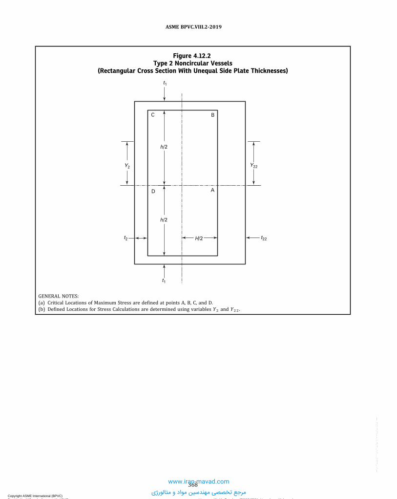
Figure 4.12.2Type 2 Noncircular Vessels
(Rectangular Cross Section With Unequal Side Plate Thicknesses)
BC
A
h/2
h/2
D
H/2
Y2
t2
t1
t1
Y22
t22
GENERAL NOTES:(a) Critical Locations of Maximum Stress are defined at points A, B, C, and D.(b) Defined Locations for Stress Calculations are determined using variables Y2 and Y22 .
368
ASME BPVC.VIII.2-2019
Copyright ASME International (BPVC) Provided by IHS under license with ASME Licensee=Khalda Petroleum/5986215001, User=Amer, Mohamed
Not for Resale, 07/02/2019 14:07:58 MDTNo reproduction or networking permitted without license from IHS
--`,```,,,,,````,`,``,,`,,`,`-`-`,,`,,`,`,,`---
www.iran-mavad.com
مرجع تخصصی مهندسین مواد و متالورژی

Figure 4.12.3Type 3 Noncircular Vessels
(Chamfered Rectangular Cross Section)
�D
R
YA
BX
L1 L1
C
t1
L2
L2
GENERAL NOTES:(a) Critical Locations of Maximum Stress are defined at points A, B, C, and D.(b) Defined Locations for Stress Calculations are determined using variables X and Y .
369
ASME BPVC.VIII.2-2019
Copyright ASME International (BPVC) Provided by IHS under license with ASME Licensee=Khalda Petroleum/5986215001, User=Amer, Mohamed
Not for Resale, 07/02/2019 14:07:58 MDTNo reproduction or networking permitted without license from IHS
--`,```,,,,,````,`,``,,`,,`,`-`-`,,`,,`,`,,`---
www.iran-mavad.com
مرجع تخصصی مهندسین مواد و متالورژی

Figure 4.12.4Type 4 Noncircular Vessels
(Reinforced Rectangular Cross Section)
Pitch distance to next reinforcing member
t1
h/2
H1
t2 H/2h/2
t1
t2
A
BCX
Yh1
GENERAL NOTES:(a) Critical Locations of Maximum Stress are defined at points A, B and C.(b) Defined Locations for Stress Calculations are determined using variables X and Y .
370
ASME BPVC.VIII.2-2019
Copyright ASME International (BPVC) Provided by IHS under license with ASME Licensee=Khalda Petroleum/5986215001, User=Amer, Mohamed
Not for Resale, 07/02/2019 14:07:58 MDTNo reproduction or networking permitted without license from IHS
--`,```,,,,,````,`,``,,`,,`,`-`-`,,`,,`,`,,`---
www.iran-mavad.com
مرجع تخصصی مهندسین مواد و متالورژی

Figure 4.12.5Type 5 Noncircular Vessels
(Reinforced Rectangular Cross Section With Chamfered Corners)
L21
L2
L2 t2
L21
L3
L4
Gt1 = t2
F
Xt
R
L11 L1 L1 L11
t1 = t2
ED
B
A
C
Y
�
t2
GENERAL NOTES:(a) Critical Locations of Maximum Stress are defined at points A, B, C, E, F, and G.(b) Defined Locations for Stress Calculations are determined using variables X and Y .
371
ASME BPVC.VIII.2-2019
Copyright ASME International (BPVC) Provided by IHS under license with ASME Licensee=Khalda Petroleum/5986215001, User=Amer, Mohamed
Not for Resale, 07/02/2019 14:07:58 MDTNo reproduction or networking permitted without license from IHS
--`,```,,,,,````,`,``,,`,,`,`-`-`,,`,,`,`,,`---
www.iran-mavad.com
مرجع تخصصی مهندسین مواد و متالورژی

ð19Þ Figure 4.12.6Type 6 Noncircular Vessels
(Reinforced Octagonal Cross Section With Chamfered Corners)
R [Note (1)]
P
L21
t2
L2
A
L2
D
E
U
t1
GF
BC
H
U1
CL
t2
L21
L11 L1
t1
GENERAL NOTE: Critical Locations of Maximum Stress are defined at points A, B, C, E, F, G, and H.
NOTE:(1) The radius must be the same at all eight corners.
372
ASME BPVC.VIII.2-2019
Copyright ASME International (BPVC) Provided by IHS under license with ASME Licensee=Khalda Petroleum/5986215001, User=Amer, Mohamed
Not for Resale, 07/02/2019 14:07:58 MDTNo reproduction or networking permitted without license from IHS
--`,```,,,,,````,`,``,,`,,`,`-`-`,,`,,`,`,,`---
www.iran-mavad.com
مرجع تخصصی مهندسین مواد و متالورژی

ð19ÞFigure 4.12.7Type 6 Noncircular Vessels
(Reinforced Octagonal Cross Section With Chamfered Corners — Details)
R [Note (1)]
�N
M
pla
te
A
MA
VA
L3
Y2
Y
L2
t2 = t1
B
M
M1
N1
C
D
G
L1L11
U1
U1/2
�ab
U
EN F
NAt1
X
MH
HH
Y1H
CL
�M
L21
L4
N
GENERAL NOTES:(a) Critical Locations of Maximum Stress are defined at points A, B, C, E, F, G, H, M, N, and U.(b) Defined Locations for Stress Calculations are determined using variables X and Y .
NOTE:(1) The radius must be the same at all eight corners.
373
ASME BPVC.VIII.2-2019
Copyright ASME International (BPVC) Provided by IHS under license with ASME Licensee=Khalda Petroleum/5986215001, User=Amer, Mohamed
Not for Resale, 07/02/2019 14:07:58 MDTNo reproduction or networking permitted without license from IHS
--`,```,,,,,````,`,``,,`,,`,`-`-`,,`,,`,`,,`---
www.iran-mavad.com
مرجع تخصصی مهندسین مواد و متالورژی
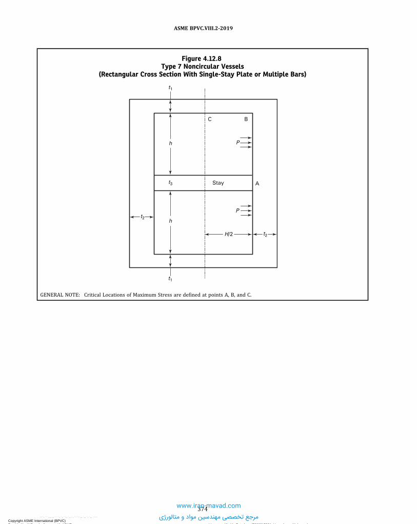
Figure 4.12.8Type 7 Noncircular Vessels
(Rectangular Cross Section With Single-Stay Plate or Multiple Bars)
t2h
t1
H/2
P
t2
AStay
P
C B
h
t3
t1
GENERAL NOTE: Critical Locations of Maximum Stress are defined at points A, B, and C.
374
ASME BPVC.VIII.2-2019
Copyright ASME International (BPVC) Provided by IHS under license with ASME Licensee=Khalda Petroleum/5986215001, User=Amer, Mohamed
Not for Resale, 07/02/2019 14:07:58 MDTNo reproduction or networking permitted without license from IHS
--`,```,,,,,````,`,``,,`,,`,`-`-`,,`,,`,`,,`---
www.iran-mavad.com
مرجع تخصصی مهندسین مواد و متالورژی

Figure 4.12.9Type 8 Noncircular Vessels
(Rectangular Cross Section With Double-Stay Plate or Multiple Bars)
H/2
Stay
Stay
t2
P
A
t2
t1
t4
h
h
t4
h
t1
P
A
P
C B
GENERAL NOTE: Critical Locations of Maximum Stress are defined at points A, B, and C.
375
ASME BPVC.VIII.2-2019
Copyright ASME International (BPVC) Provided by IHS under license with ASME Licensee=Khalda Petroleum/5986215001, User=Amer, Mohamed
Not for Resale, 07/02/2019 14:07:58 MDTNo reproduction or networking permitted without license from IHS
--`,```,,,,,````,`,``,,`,,`,`-`-`,,`,,`,`,,`---
www.iran-mavad.com
مرجع تخصصی مهندسین مواد و متالورژی

Figure 4.12.10Type 9 Noncircular Vessels(Obround Cross Section)
t2
B
t1
R
C
L2
L2
A
Y
GENERAL NOTES:(a) Critical Locations of Maximum Stress are defined at points A, B, and C.(b) Defined Locations for Stress Calculations are determined using variable Y .
376
ASME BPVC.VIII.2-2019
Copyright ASME International (BPVC) Provided by IHS under license with ASME Licensee=Khalda Petroleum/5986215001, User=Amer, Mohamed
Not for Resale, 07/02/2019 14:07:58 MDTNo reproduction or networking permitted without license from IHS
--`,```,,,,,````,`,``,,`,,`,`-`-`,,`,,`,`,,`---
www.iran-mavad.com
مرجع تخصصی مهندسین مواد و متالورژی

Figure 4.12.11Type 10 Noncircular Vessels
(Reinforced Obround Cross Section)
Y
A
C
L2
BR
Pitch distance to next reinforcing member
t1 = t2
L2
t2
GENERAL NOTES:(a) Critical Locations of Maximum Stress are defined at points A, B, and C.(b) Defined Locations for Stress Calculations are determined using variable Y .
377
ASME BPVC.VIII.2-2019
Copyright ASME International (BPVC) Provided by IHS under license with ASME Licensee=Khalda Petroleum/5986215001, User=Amer, Mohamed
Not for Resale, 07/02/2019 14:07:58 MDTNo reproduction or networking permitted without license from IHS
--`,```,,,,,````,`,``,,`,,`,`-`-`,,`,,`,`,,`---
www.iran-mavad.com
مرجع تخصصی مهندسین مواد و متالورژی

Figure 4.12.12Type 11 Noncircular Vessels
(Obround Cross Section With Single-Stay Plate or Multiple Bars)
t1
Stay A
P
P
C
BR
t2
t3
L2
L2
GENERAL NOTE: Critical Locations of Maximum Stress are defined at points A, B, and C.
378
ASME BPVC.VIII.2-2019
Copyright ASME International (BPVC) Provided by IHS under license with ASME Licensee=Khalda Petroleum/5986215001, User=Amer, Mohamed
Not for Resale, 07/02/2019 14:07:58 MDTNo reproduction or networking permitted without license from IHS
--`,```,,,,,````,`,``,,`,,`,`-`-`,,`,,`,`,,`---
www.iran-mavad.com
مرجع تخصصی مهندسین مواد و متالورژی

Figure 4.12.13Type 12 Noncircular Vessels
(Circular Cross Section With Single-Stay Plate)
R
P1
P2
Plate member A
t3
t1
GENERAL NOTE: Critical Locations of Maximum Stress are defined at point A.
Figure 4.12.14Multi-Diameter Holes
t
ph
To
do
d1
d2
T1
T2
379
ASME BPVC.VIII.2-2019
Copyright ASME International (BPVC) Provided by IHS under license with ASME Licensee=Khalda Petroleum/5986215001, User=Amer, Mohamed
Not for Resale, 07/02/2019 14:07:58 MDTNo reproduction or networking permitted without license from IHS
--`,```,,,,,````,`,``,,`,,`,`-`-`,,`,,`,`,,`---
www.iran-mavad.com
مرجع تخصصی مهندسین مواد و متالورژی

Figure 4.12.15Rectangular Vessels With Multiple Compartments
t1
h/2
h/2
t4
t1
t4
Stay
A
B
PStay
P
C
Stay
P
P
t2H/2t2
Stay
A
BStay
P
P
P
C
h/2
h/2
t4
t4
t2H/2t2
t4
t1
t1
GENERAL NOTE: Critical Locations of Maximum Stress are defined at points A, B, and C.
380
ASME BPVC.VIII.2-2019
Copyright ASME International (BPVC) Provided by IHS under license with ASME Licensee=Khalda Petroleum/5986215001, User=Amer, Mohamed
Not for Resale, 07/02/2019 14:07:58 MDTNo reproduction or networking permitted without license from IHS
--`,```,,,,,````,`,``,,`,,`,`-`-`,,`,,`,`,,`--- www.iran-mavad.com
مرجع تخصصی مهندسین مواد و متالورژی

4.13 DESIGN RULES FOR LAYERED VESSELS
4.13.1 SCOPEDesign rules for layered vessels are covered in 4.13. There are several manufacturing techniques used to fabricate
layered vessels, and these rules have been developed to cover most techniques used today for which there is extensivedocumented construction and operational data. Examples of acceptable layered shell and head types are shown inFigures 4.13.1 and 4.13.2.
4.13.2 DEFINITIONSThe following terms are used in this paragraph to define components of a layered vessel.(a) Layered Vessel - a vessel having a shell and/or heads made up of two or more separate layers.(b) Inner Shell - the inner cylinder that forms the pressure tight membrane.(c) Inner Head - the inner head that forms the pressure tight membrane.(d) Shell Layer - layers may be cylinders formed from plate, sheet, forgings, or the equivalent formed by coiling. This
does not include wire winding.(e) Head Layer - anyone of the head layers of a layered vessel except the inner head.(f) Overwraps - layers added to the basic shell or head thickness for the purpose of building up the thickness of a
layered vessel for reinforcing shell or head openings, or making a transition to thicker sections of the layered vessel.(g) Dummy Layer - a layer used as a filler between the inner shell (or inner head) and other layers, and not considered
as part of the required total thickness.
4.13.3 GENERAL4.13.3.1 The design for layered pressure vessels shall conform to the general design requirements given in 4.1.
4.13.3.2 A fatigue analysis in accordance with Part 5 shall be performed in all cases unless the fatigue analysisscreening based on experience with comparable equipment in accordance with 5.5.2.2 is satisfied.
4.13.3.3 The Manufacturer’s Quality Control System shall include the construction procedure that will outline thesequence and method of application of layers and measurement of layer gaps.
4.13.4 DESIGN FOR INTERNAL PRESSURE4.13.4.1 The total thickness of layered shells of revolution under internal pressure shall not be less than that com-
puted by the equations in 4.3.
4.13.4.2 An inner shell or inner head material that has a lower allowable design stress than the layer materials mayonly be included as credit for part of the total wall thickness if Si is not less than 0.5SL by considering its effective thick-ness to be:
ð4:13:1Þ
4.13.4.3 Layers in which the stress intensity value of the materials is within 20% of the other layers may be used byprorating the allowable stress from Annex 3-A evaluated at the design temperature of the layers in the thickness equa-tion, provided the materials are compatible in modulus of elasticity and coefficient of thermal expansion (see Part 3).
4.13.4.4 The minimum thickness of any layer shall not be less than 3.2 mm (0.125 in.).
4.13.5 DESIGN FOR EXTERNAL PRESSURE4.13.5.1 When layered shells are used for external pressure, the requirements of 4.4 shall be applied with the fol-
lowing additional requirements.(a) The thickness used for establishing external pressure applied to the outer layer shall be the thickness of the total
layers, except as given in (b). The design of the vent holes shall be such that the external pressure is not transmittedthrough the vent holes in the outer layer.
(b) The thickness used for establishing vacuum pressure shall be only the thickness of the inner shell or inner head.
4.13.5.2 Layered shells under axial compression shall be calculated in accordance with 4.4, utilizing the totallayered shell thickness.
4.13.6 DESIGN OF WELDED JOINTS4.13.6.1 The design of welded joints shall conform to the requirements given in 4.2 except as modified herein.
381
ASME BPVC.VIII.2-2019
Copyright ASME International (BPVC) Provided by IHS under license with ASME Licensee=Khalda Petroleum/5986215001, User=Amer, Mohamed
Not for Resale, 07/02/2019 14:07:58 MDTNo reproduction or networking permitted without license from IHS
--`,```,,,,,````,`,``,,`,,`,`-`-`,,`,,`,`,,`---
www.iran-mavad.com
مرجع تخصصی مهندسین مواد و متالورژی

4.13.6.2 Category A and B joints of inner shells and inner heads of layered sections shall be as follows.(a) Category A joints shall be Type No. 1 (see 4.2).(b) Category B joints shall be Type No. 1 or Type No. 2 (see 4.2).
4.13.6.3 Category A joints of layered sections shall be as follows.(a) Category A joints of layers over 22 mm (0.875 in.) in thickness shall be Type No. 1 (see 4.2).(b) Category A joints of layers 22 mm (0.875 in.) or less in thickness shall be of Type 1 or 2 (see 4.2), except the final
outside weld joint of spiral wrapped layered shells may be a single lap weld.
4.13.6.4 Category B joints of layered shell sections to layered shell sections, or layered shell sections to solid shellsections, shall be of Type 1 or 2 (see 4.2).(a) Category B joints of layered sections to layered sections of unequal thickness shall have transitions as shown in
Figure 4.13.3, sketch (a) or (b).(b) Category B joints of layered sections to solid sections of unequal thickness shall have transitions as shown in
Figure 4.13.3, sketch (c), (d), (e), or (f).(c) Category B joints of layered sections to layered sections of equal thickness shall be as shown in Figure 4.13.4,
sketch (b), (c), (d), (f), or (g).(d) Category B joints of layered sections to solid sections of equal thickness shall be as shown in Figure 4.13.4, sketch
(a) or (e).
4.13.6.5 Category A joints of solid hemispherical heads to layered shell sections shall be of Type 1 or 2 (see 4.2).(a) Transitions shall be as shown in Figure 4.13.5, sketch (a), (b-1), (b-2), or (b-3) when the hemispherical head thick-
ness is less than the thickness of the layered shell section and the transition is made in the layered shell section.(b) Transitions shall be as shown in Figure 4.13.5, sketch (c), (d-1), or (e) when the hemispherical head thickness is
greater than the thickness of the layered shell section and the transition is made in the layered shell section.(c) Transition shall be as shown in Figure 4.13.5, sketch (f) when the hemispherical head thickness is less than the
thickness of the layered shell section and the transition is made in the hemispherical head section.
4.13.6.6 Category B joints of solid elliptical, torispherical, or conical heads to layered shell sections shall be of Type1 or 2 (see 4.2). Transitions shall be as shown in Figure 4.13.5, sketch (c), (d-1), (d-2), (e), or (f).
4.13.6.7 Category C joints of solid flat heads and tube-sheets to layered shell sections shall be of Type 1 or 2 (see4.2) as indicated in Figure 4.13.6. Transitions, if applicable, shall be used as shown in Figure 4.13.3, sketch (c), (d), (e), or(f).
4.13.6.8 Category C joints attaching solid flanges to layered shell sections and layered flanges to layered shell sec-tions shall be of Type 1 or 2 (see 4.2) as indicated in Figure 4.13.7.
4.13.6.9 Category A joints of layered hemispherical heads to layered shell sections shall be of Type 1 or 2 (see 4.2)with transition as shown in Figure 4.13.8, sketch (a-1) or (a-2).
4.13.6.10 Category B joints of layered conical heads to layered shell sections shall be of Type 1 or 2 (see 4.2) withtransitions as shown in Figure 4.13.8, sketch (b).
4.13.6.11 Category B joints of layered shell sections to layered shell sections or layered shells to solid heads or shellsmay be butt joints as shown in Figure 4.13.4, sketches (c), (d), and (e), or step welds as shown in Figure 4.13.4, sketches(a), (b), (f), and (g).
4.13.6.12 Category D joints of solid nozzles, manholes, and other connections to layered shell or layered head sec-tions shall be full penetration welds as shown in Figure 4.13.9 except as permitted in sketch (i), (j), (k), or (I). Category Djoints between layered nozzles and shells or heads are not permitted.
4.13.6.13 When layers of Category A joints as shown in Figure 4.13.5, sketches (a), (b-1), (b-2), and (b-3) and Figure4.13.8, sketches (a-1) and (a-2) are welded with fillet welds having a taper less than 3:1, an analysis of the head-to-shelljunction shall be done in accordance with Part 5. Resistance due to friction shall not be considered in the analysis. Thelongitudinal load resisted by the weld shall consider the load transferred from the remaining outer layers.
4.13.7 NOZZLES AND NOZZLE REINFORCEMENT4.13.7.1 All openings, except as provided in 4.13.7.2 shall meet the requirements for reinforcing per 4.5. All rein-
forcements required for openings shall be integral with the nozzle or provided in the layered section or both. Additionallayers may be included for required reinforcement.
4.13.7.2 Openings, DN 50 (NPS 2) and smaller, need not be reinforced when installed in layered construction butmay be welded on the inside as shown in Figure 4.13.9, sketch (j). The nozzle nominal wall thickness shall not be lessthan Schedule 80 pipe as fabricated in addition to meeting the requirements of 4.5.5.
382
ASME BPVC.VIII.2-2019
Copyright ASME International (BPVC) Provided by IHS under license with ASME Licensee=Khalda Petroleum/5986215001, User=Amer, Mohamed
Not for Resale, 07/02/2019 14:07:58 MDTNo reproduction or networking permitted without license from IHS
--`,```,,,,,````,`,``,,`,,`,`-`-`,,`,,`,`,,`---
www.iran-mavad.com
مرجع تخصصی مهندسین مواد و متالورژی

4.13.7.3 Some acceptable nozzle geometries and attachments are shown in Figure 4.13.9.
4.13.7.4 Openings up to and including 6 in. nominal pipe size (DN 150) may be constructed as shown in Figure4.13.9, sketches (k) and (I). Such partial penetration weld attachments may only be used for instrumentation openings,inspection openings, etc. on which there are no external mechanical loadings, provided the following requirements aremet.
(a) The requirements for reinforcing specified in 4.13.7 apply except that the diameter of the finished openings in thewall shall be d* as specified in Figure 4.13.9, sketches (k) and (l), and the thickness tn is the required thickness of thelayered shells computed by the design requirements.
(b) Additional reinforcement, attached to the inside surface of the inner shell, may be included after the corrosion al-lowance is deducted from all exposed surfaces. The attachment welds shall comply with 4.2 and Figure 4.13.9, sketch (k)or (I).
(c) Metal in the nozzle neck available for reinforcement shall be limited by the boundaries specified in 4.5 except thatthe inner layer shall be considered the shell.
4.13.7.5 Openings greater than 51 mm (2 in.) may be constructed as shown in Figure 4.13.9, sketch (i). The require-ments for reinforcing specified in 4.13.7.4(a) apply except that:
(a) The diameter of the finished openings in the walls shall be d' as specified in Figure 4.13.9, sketch (i), and the thick-ness tn is the required thickness of the layered shells computed by the design requirements;(b) Additional reinforcement may be included in the solid hub section as shown in Figure 4.13.9, sketch (i);(c) Metal in the nozzle neck available for reinforcement shall be limited by the boundaries specified in 4.5, except that
the inner layer shall be considered the shell.
4.13.8 FLAT HEADS4.13.8.1 Design criteria shall meet the requirements of 4.6.
4.13.8.2 The design of welded joints shall be in accordance with 4.13.6.
4.13.9 BOLTED AND STUDDED CONNECTIONS4.13.9.1 Design criteria shall meet the requirements of 4.16.
4.13.9.2 The design of welded joints shall be in accordance with 4.13.6.
4.13.10 ATTACHMENTS AND SUPPORTS4.13.10.1 Supports for layered pressure vessels may be designed in accordance with 4.15. Examples of some accept-
able supports are shown in Figure 4.13.10.
4.13.10.2 When attaching supports or other connections to the outside or inside of layered pressure vessels, onlythe immediate layer shall be used in the calculation, except where provisions are made to transfer the load to otherlayers.
4.13.10.3 When jacketed closures are used, provisions shall be made for extending layer vents through the jacket(see 4.13.11.1). Partial jackets covering only a portion of the circumference are not permitted on layered shells.
4.13.11 VENT HOLES4.13.11.1 Vent holes shall be provided to detect leakage of the inner shell and to prevent buildup of pressure within
the layers as follows.
4.13.11.2 In each shell course or head segment, a layer may be made up of one or more plates. Each layer plate shallhave at least two vent holes 6 mm (0.25 in.) minimum diameter. Holes may be drilled radially through the multiplelayers or may be staggered in individual layer plates.
4.13.11.3 For continuous coil wrapped layers, each layered section shall have at least four vent holes 6 mm (0.25 in.)minimum diameter. Two of these vent holes shall be located near each end of the section and spaced approximately180 deg apart.
4.13.11.4 The minimum requirement for spirally wound strip layered construction shall be 6 mm (0.25 in.) mini-mum diameter vent holes drilled near both edges of the strip. They shall be spaced for the full length of the stripand shall be located a distance of approximately πR/tanθ from each other (where R is the mean radius of the shelland θ is the acute angle of spiral wrap measured from the longitudinal centerline, deg).
4.13.11.5 If a strip weld covers a vent hole, partially or totally, an additional vent hole shall be drilled on each side ofthe obstructed hole.
383
ASME BPVC.VIII.2-2019
Copyright ASME International (BPVC) Provided by IHS under license with ASME Licensee=Khalda Petroleum/5986215001, User=Amer, Mohamed
Not for Resale, 07/02/2019 14:07:58 MDTNo reproduction or networking permitted without license from IHS
--`,```,,,,,````,`,``,,`,,`,`-`-`,,`,,`,`,,`---
www.iran-mavad.com
مرجع تخصصی مهندسین مواد و متالورژی

ð19Þ
ð19Þ
4.13.11.6 In addition to the above, holes may be drilled radially through the multiple layers.
4.13.11.7 Vent holes shall not be obstructed. If a monitoring system is used, it shall be designed to prevent buildup ofpressure within the layers.
4.13.12 SHELL TOLERANCES4.13.12.1 Contact Between Layers. The following requirements shall be satisfied.(a) Category A weld joints shall be ground to ensure contact between the weld area and the succeeding layer, before
application of the layer.(b) Category A weld joints of layered shell sections shall be in an offset pattern so that the centers of the welded lon-
gitudinal joints of adjacent layers are separated circumferentially by a distance of at least five times the layer thickness.(c) Category A weld joints in layered heads may be in an offset pattern; if offset, the joints of adjacent layers shall be
separated by a distance of at least five times the layer thickness.(d) After weld preparation and before welding circumferential seams, the height of the radial gaps between any two
adjacent layers shall be measured at the ends of the layered shell section or layered head section at right angles to thevessel axis, and also the length of the relevant radial gap in inches shall be measured (neglecting radial gaps of less than0.25 mm (0.010 in.) as non relevant). The gap area, Ag , shall not exceed the thickness of a layer expressed in squareinches. An approximation of the area of the gap shall be calculated using eq. (4.13.2). The maximum length of anygap shall not exceed the inside diameter of the vessel. Where more than one gap exists between any two adjacent layers,the sum of the gap lengths shall not exceed the inside diameter of the vessel. The maximum height of any gap shall notexceed 4.8 mm (0.1875 in.). It is recognized that there may be vessels of dimensions wherein it would be desirable tocalculate a maximum permissible gap height and length, and also when cyclical service conditions require it. This pro-cedure is provided in 4.13.12.3 and may be used in lieu of the maximum gap area given above, (see Figure 4.13.12.3).
ð4:13:2Þ
(e) In the case of layered spheres or layered heads, if the gaps cannot be measured as required in (d), measurement ofgap heights shall be taken through vent holes in each layer course to assure that the height of layer gaps between anytwo layers does not exceed the gap permitted in (d). The spacing of the vent holes shall be such that gap lengths can bedetermined. In the event an excessive gap height is measured through a vent hole, additional vent holes shall be drilledas required to determine the gap length. There shall be at least one vent hole per layer segment.
4.13.12.2 Alternative to Measuring Contact Between Layers During Construction. As an alternative to4.13.12.1(d), the following measurements shall be taken at the time of the hydrostatic test to check on the contact be-tween successive layers, and the effect of gaps which may or may not be present between layers.(a) The circumference shall be measured at the midpoint between adjacent circumferential joints, or between a cir-
cumferential joint and any nozzle in a shell course. Measurements shall be taken at zero pressure and, following appli-cation of hydrostatic test pressure, at the design pressure. The difference in measurements shall be averaged for eachcourse in the vessel and the results recorded as average middle circumferential expansion, em .(b) The theoretical circumferential expansion of a solid vessel of the same dimensions and materials as the layered
vessel shall be calculated from eq. (4.13.3). The acceptance criterion for circumferential expansion at the design pres-sure is: em ≥ 0.5eth .
ð4:13:3Þ
4.13.12.3 Rules for Calculating Maximum Permissible Gaps. The maximum number and size of gaps permitted inany cross section of a layered vessel shall be limited by (a) and (b).(a) The maximum gap between any layers shall be evaluated as follows:
(1) The circumferential stress of the shell and the bending stress due to the gap can be calculated as
ð4:13:4Þ
ð4:13:5Þ
384
ASME BPVC.VIII.2-2019
Copyright ASME International (BPVC) Provided by IHS under license with ASME Licensee=Khalda Petroleum/5986215001, User=Amer, Mohamed
Not for Resale, 07/02/2019 14:07:58 MDTNo reproduction or networking permitted without license from IHS
--`,```,,,,,````,`,``,,`,,`,`-`-`,,`,,`,`,,`---
www.iran-mavad.com
مرجع تخصصی مهندسین مواد و متالورژی

ð19Þ
(2)When Sb ≥ 0.71S
ð4:13:6Þ(3)When Sb < 0.71S
ð4:13:7Þ(4) The stress amplitude for fatigue analysis at the gap is
ð4:13:8Þ
where
(5) The maximum gap shall be determined when the calculated number of fatigue cycles using Sag in eq. (4.13.8) isequal to or greater than the specified number of fatigue cycles.
(b)Maximum permissible number of gaps and their corresponding arc lengths at any cross section of a layered vesselshall be calculated as follows.
(1)Measure each gap and its corresponding length throughout the cross section.(2) Calculate the value of F for each of the gaps using the following equation:
ð4:13:9Þ
(3) The total sum of the calculated F values shall not exceed the quantity
ð4:13:10Þ
4.13.13 NOMENCLATURE
Ag = gap area.b = length of the gap between any two layers.C = equal to 3 mm (0.125 in.) radial clearance between the nozzle neck and vessel opening
d* = finished opening in the walleth = theoretical circumferential expansion.em = average middle recorded circumferential expansion.Ey = Modulus of Elasticity for the layer material from Part 3.F = gap value.
FT = total permissible gap value.h = gap height between any two layers.
Ke = fatigue penalty factor.m, n = material constants for the fatigue penalty factor used in the simplified elastic–plastic analysis (see Table 5.13).
P = design pressure of the vessel.Rg = outside radius of the layer above where the gap is located.Ri = inside radius of the vessel.Rm = mean radius of the vessel.Ro = outside radius of the vessel.S = shell circumferential stress.
385
ASME BPVC.VIII.2-2019
Copyright ASME International (BPVC) Provided by IHS under license with ASME Licensee=Khalda Petroleum/5986215001, User=Amer, Mohamed
Not for Resale, 07/02/2019 14:07:58 MDTNo reproduction or networking permitted without license from IHS
--`,```,,,,,````,`,``,,`,,`,`-`-`,,`,,`,`,,`---
www.iran-mavad.com
مرجع تخصصی مهندسین مواد و متالورژی

Sa = stress amplitude from the applicable fatigue curve for the layer material from Annex 3-F.Sag = calculated stress amplitude at the gap.Sb = bending stress due to gap between layered shell.Si = allowable stress for the inner layer from Annex 3-A at the design temperature.SL = allowable stress for the layers from Annex 3-A at the design temperature.Sm = allowable stress for the layer material from Annex 3-A at the design temperature.r1 = equal to min[0.25tn , 3 mm (0.125 in.)]r2 = equal to 6 mm (0.25 in.) minimumr3 = equal to min[0.25tn , 19 mm (0.75 in.)]t = actual thickness of the head or tubesheet or for nozzle details equal to min[tn , 19 mm (0.75 in.)] , as applicable.
tac t = actual thickness of inner shell or inner head.t c = equal to the larger of 6 mm (0.25 in.) or 0.7 min[tn , 19 mm (0.75 in.)]
te f f = effective thickness of inner shell or inner head.tH = thickness of the head at the head-to-cylinder joint.tL = thickness of the layer.tn = nominal thickness of the nozzle wall less corrosion allowancetS = total wall thickness of the layered vessel.Y = offset.
ΔSn = total stress range.v = Poisson’s ratio.
386
ASME BPVC.VIII.2-2019
Copyright ASME International (BPVC) Provided by IHS under license with ASME Licensee=Khalda Petroleum/5986215001, User=Amer, Mohamed
Not for Resale, 07/02/2019 14:07:58 MDTNo reproduction or networking permitted without license from IHS
--`,```,,,,,````,`,``,,`,,`,`-`-`,,`,,`,`,,`---
www.iran-mavad.com
مرجع تخصصی مهندسین مواد و متالورژی

ð19Þ
4.13.14 FIGURES
Figure 4.13.1Some Acceptable Layered Shell Types
(a) Concentric Wrapped
Note (1)
Note (2) Note (3)
(b) Coil Wound
Note (1)
Note (2)Note (3)
(c) Shrink Fit
Note (1)
Note (2) Note (3)
(d) Spiral Wrapped
Note (1)
Note (6)Note (3)
Note (5)
Note (4)
NOTES:(1) Inner shell(2) Layers(3) Dummy layer (if used)(4) Gap(5) Balance of layers(6) Shell layer (tapered)
387
ASME BPVC.VIII.2-2019
Copyright ASME International (BPVC) Provided by IHS under license with ASME Licensee=Khalda Petroleum/5986215001, User=Amer, Mohamed
Not for Resale, 07/02/2019 14:07:58 MDTNo reproduction or networking permitted without license from IHS
--`,```,,,,,````,`,``,,`,,`,`-`-`,,`,,`,`,,`---
www.iran-mavad.com
مرجع تخصصی مهندسین مواد و متالورژی

Figure 4.13.2Some Acceptable Layered Head Types
Note (1)
Segmental
Note (2)
Note (3)
Note (1)
Note (2)
Note (3)
(a)
Press Fit(c)
Note (1)
Note (2)
Note (3)
(b)
(d)
Note (1)
Note (2)
Note (3)
NOTES:(1) Inner head(2) Dummy layer (if used)(3) Head layers
388
ASME BPVC.VIII.2-2019
Copyright ASME International (BPVC) Provided by IHS under license with ASME Licensee=Khalda Petroleum/5986215001, User=Amer, Mohamed
Not for Resale, 07/02/2019 14:07:58 MDTNo reproduction or networking permitted without license from IHS
--`,```,,,,,````,`,``,,`,,`,`-`-`,,`,,`,`,,`---
www.iran-mavad.com
مرجع تخصصی مهندسین مواد و متالورژی

ð19ÞFigure 4.13.3Transitions of Layered Shell Sections
a
(b) Details of Taper for Layers 16 mm
(0.625 in.) or Less in Thickness
Weld Line (Category B)
(a) For Layers Over 16 mm (0.625 in.) Thickness
tL
Taper Line
Weld optional
0.7tL min.
Weld Line (Category B)
Optional Weld Line (Category B)
(d) For Layers 16 mm (0.625 in.) or Less
in Thickness
(c) For Layers Over 16 mm (0.625 in.) Thickness
(f) For Layers 16 mm (0.625 in.) or Less
in Thickness
(e) For Layers Over 16 mm (0.625 in.) Thickness
Weld optional
a
3:1 taper min. [see detail in sketch (b)]3:1 taper [see sketch (b)]
3:1 taper min.[Note (1)]
3:1 taper min.[Note (1)]
3tL min.tL or Y tL
GENERAL NOTES:(a) a ≥ 3Y where a is the required length of the taper and Y is the offset.(b) The length of the required taper may include the width of the weld.(c) The transition may be on either or both sides.
NOTE:(1) Taper may be inside or outside or both.
389
ASME BPVC.VIII.2-2019
Copyright ASME International (BPVC) Provided by IHS under license with ASME Licensee=Khalda Petroleum/5986215001, User=Amer, Mohamed
Not for Resale, 07/02/2019 14:07:58 MDTNo reproduction or networking permitted without license from IHS
--`,```,,,,,````,`,``,,`,,`,`-`-`,,`,,`,`,,`---
www.iran-mavad.com
مرجع تخصصی مهندسین مواد و متالورژی

Figure 4.13.4Some Acceptable Welded Joints of Layered-to-Layered and Layered-to-Solid Sections
Tack weldBacking strip
(g) Butt Girth Welds
Tack weldBacking strip
(e)
(f)
(d)(c)
Dummy layer
(b)(a)
Dummy insert
390
ASME BPVC.VIII.2-2019
Copyright ASME International (BPVC) Provided by IHS under license with ASME Licensee=Khalda Petroleum/5986215001, User=Amer, Mohamed
Not for Resale, 07/02/2019 14:07:58 MDTNo reproduction or networking permitted without license from IHS
--`,```,,,,,````,`,``,,`,,`,`-`-`,,`,,`,`,,`---
www.iran-mavad.com
مرجع تخصصی مهندسین مواد و متالورژی

ð19ÞFigure 4.13.5Some Acceptable Solid Head Attachments to Layered Shell Sections
a � 3Y
Taper line
Tangent Line
Y
(b-1) Details of Taper for
Layers 22 mm (0.875 in.) or Less in
Thickness [Note (1)]
(a) For Layers Over 16 mm (0.625 in.)
Thickness [Note (1)]
Weld
Butt Weld Line
(Category A)
tH
Y
(b-3) Details of Taper for
Layers 16 mm (0.625 in.) or Less in
Thickness [Note (1)]
(b-2) Details of Taper for
Layers 22 mm (0.875 in.) or Less
in Thickness [Note (1)]
Taper line
Butt Weld Line
(Category A)
Y
Tangent Line
Tangent Line
Y
Taper line
a � 3Y
tH
tS
tL
for chamfered layers
0.7tL min.3tL min.
tL
tS
3tL min.0.7tL min.
tL
tHtH
a � 3Y
tL
tS
0.7tL min.
3tL min.
tS
tL
a � 3Y
391
ASME BPVC.VIII.2-2019
Copyright ASME International (BPVC) Provided by IHS under license with ASME Licensee=Khalda Petroleum/5986215001, User=Amer, Mohamed
Not for Resale, 07/02/2019 14:07:58 MDTNo reproduction or networking permitted without license from IHS
--`,```,,,,,````,`,``,,`,,`,`-`-`,,`,,`,`,,`---
www.iran-mavad.com
مرجع تخصصی مهندسین مواد و متالورژی

Figure 4.13.5Some Acceptable Solid Head Attachments to Layered Shell Sections (Cont'd)
Y
Y
Tangent Line
Tangent Line
(d-1) Details of Taper for Layers Over
16 mm (0.625 in.) Thickness [Note (2)]
Inside
Inner Shell
(f) For Layers of Any Thickness [Note (2)]
Tangent Line
Tangent Line
Y
(e) For Layers 16 mm (0.625 in.) or Less
in Thickness [Note (2)]
(d-2) Permissible for Layers
22 mm (0.875 in.) or Less in Thickness
Weld Line
Welds optional
Taper line
YWelds optional
(c) For Layers Over 16 mm (0.625 in.)
Thickness [Note (2)]
0.7tL min.
3tL min.tS
a � 3Y
tL
tS
tL
a � 3Y
tS
tL
tH
tH
a � 3Y
tS
tL
tHa � 3Y
tS
tL
392
ASME BPVC.VIII.2-2019
Copyright ASME International (BPVC) Provided by IHS under license with ASME Licensee=Khalda Petroleum/5986215001, User=Amer, Mohamed
Not for Resale, 07/02/2019 14:07:58 MDTNo reproduction or networking permitted without license from IHS
--`,```,,,,,````,`,``,,`,,`,`-`-`,,`,,`,`,,`---
www.iran-mavad.com
مرجع تخصصی مهندسین مواد و متالورژی

Figure 4.13.5Some Acceptable Solid Head Attachments to Layered Shell Sections (Cont'd)
GENERAL NOTES:(a) In sketch (e), Y ≤ tL shall be satisfied; in sketch (f), Y ≤ 0.5t s shall be satisfied.(b) In all cases, a ≥ 3Y shall be satisfied. The shell centerline may be on either side of the head centerline by a maximum distance of 0.5(t s −
tH). The length of the required taper may include the width of the weld.(c) The actual thickness shall not be less than the theoretical head thickness.
NOTES:(1) Sketches (a) through (b-3) apply to hemispherical heads only.(2) Butt weld line may be at or below tangent line depending on Code requirement for type of head and weld.
393
ASME BPVC.VIII.2-2019
Copyright ASME International (BPVC) Provided by IHS under license with ASME Licensee=Khalda Petroleum/5986215001, User=Amer, Mohamed
Not for Resale, 07/02/2019 14:07:58 MDTNo reproduction or networking permitted without license from IHS
--`,```,,,,,````,`,``,,`,,`,`-`-`,,`,,`,`,,`---www.iran-mavad.com
مرجع تخصصی مهندسین مواد و متالورژی

Figure 4.13.6Some Acceptable Flat Heads and Tubesheets With Hubs Joining Layered Shell Sections
t
ts
t
e
r r
ts
t
(a) (b) (c)
ts
h
r
tt
t
(d) (e) (f)
tstf tstf
r
e
r
ts
394
ASME BPVC.VIII.2-2019
Copyright ASME International (BPVC) Provided by IHS under license with ASME Licensee=Khalda Petroleum/5986215001, User=Amer, Mohamed
Not for Resale, 07/02/2019 14:07:58 MDTNo reproduction or networking permitted without license from IHS
--`,```,,,,,````,`,``,,`,,`,`-`-`,,`,,`,`,,`---
www.iran-mavad.com
مرجع تخصصی مهندسین مواد و متالورژی

ð19ÞFigure 4.13.7Some Acceptable Flanges for Layered Shells
Weld line3
1
(a)(b) (c)
(d)
Weld line
31
31
Retaining ring
(e-1) [Notes (1) and (2)]
31
Weld overlay 15% bolt dia. min.but not less than 9 mm (0.375 in.)
(e) [Notes (1) and (2)] (f) [Notes (1) and (2)] (f-1) [Notes (1) and (2)]
Retaining ring
Weld line optional
(g) [Note (1)]
Retaining ring
Weld line optional
(g-1) [Note (1)] (e), (e-1), (f), (f-1), (g), (g-1) [Notes (1) and (2)]
Weld line optional
313
1
31
Weld line optional
Tapped holes
tsts ts
ts
NOTES:(1) The weld overlay shall tie the overlay, the overwraps, and layers together, and the bolt circle shall not exceed the outside diameter of the
shell.(2) The angle of the transition and size of the fillet welds are optional, and the bolt circle shall not exceed the outside diameter of the shell.
395
ASME BPVC.VIII.2-2019
Copyright ASME International (BPVC) Provided by IHS under license with ASME Licensee=Khalda Petroleum/5986215001, User=Amer, Mohamed
Not for Resale, 07/02/2019 14:07:58 MDTNo reproduction or networking permitted without license from IHS
--`,```,,,,,````,`,``,,`,,`,`-`-`,,`,,`,`,,`---
www.iran-mavad.com
مرجع تخصصی مهندسین مواد و متالورژی

ð19Þ Figure 4.13.8Some Acceptable Layered Head Attachments to Layered Shells
60° min.
(b)
Taper line
0.7tL min.
3tL min.
tL
Detail of Taper
0.7tL min.
3:1 taper
tL
tH
(a-1)
Butt Weld Line(Category A)
tL
tS (a-2)
tL
tS
tH
tL
Weld Line(Category B)
tL
tS
a � 3YtL
�½(tS � tH)
396
ASME BPVC.VIII.2-2019
Copyright ASME International (BPVC) Provided by IHS under license with ASME Licensee=Khalda Petroleum/5986215001, User=Amer, Mohamed
Not for Resale, 07/02/2019 14:07:58 MDTNo reproduction or networking permitted without license from IHS
--`,```,,,,,````,`,``,,`,,`,`-`-`,,`,,`,`,,`---
www.iran-mavad.com
مرجع تخصصی مهندسین مواد و متالورژی

Figure 4.13.9Some Acceptable Nozzle Attachments to Layered Shell Sections
(f) (g) (h)
3:1 taper min. 3:1 taper min.
Backing strip if used shall be removed
r1
(e)
(d)
(c-2)
(a) (b) (c-1)
Section A-A
A
A
Smooth surface
tS tS
tc
tn
r1
tc
tn
tSr1
tc
tn
tStS
tS
r1
r3
tn
tn
tSr1
r1 r1
r2
r2
r2
r2
r2
r2
tctc
tc
tntn
r3
r1
r2
tS tS
tn
r2
r2
r2
r1r1
tn
tn
397
ASME BPVC.VIII.2-2019
Copyright ASME International (BPVC) Provided by IHS under license with ASME Licensee=Khalda Petroleum/5986215001, User=Amer, Mohamed
Not for Resale, 07/02/2019 14:07:58 MDTNo reproduction or networking permitted without license from IHS
--`,```,,,,,````,`,``,,`,,`,`-`-`,,`,,`,`,,`---
www.iran-mavad.com
مرجع تخصصی مهندسین مواد و متالورژی

Figure 4.13.9Some Acceptable Nozzle Attachments to Layered Shell Sections (Cont'd)
(j)(i)
d*
C max.
Inner shell
d*
C max.
Solid hub with integral reinforcement
Inner shell
Vent for liner
1.25tn min.
d*
C max.
d*
C max.
Integral nozzle reinforcement
Chamfer
Reinforcing pad
Full circumferential reinforcement layers (overwraps)
13 (min.)
(k) (l)
tS
tS
r2
tn
1.25tn min.
r1
tc
r1
tn
tc
tL
r3
r2
r2
1.25tn min.
r1
tn tn
0.5tL min.
GENERAL NOTE: Provide a means, other than by seal welding, to prevent entry of external foreign matter into the annulus between thelayers and the nozzle neck outside diameter for sketches (i), (j), (k), and (l).
398
ASME BPVC.VIII.2-2019
Copyright ASME International (BPVC) Provided by IHS under license with ASME Licensee=Khalda Petroleum/5986215001, User=Amer, Mohamed
Not for Resale, 07/02/2019 14:07:58 MDTNo reproduction or networking permitted without license from IHS
--`,```,,,,,````,`,``,,`,,`,`-`-`,,`,,`,`,,`---
www.iran-mavad.com
مرجع تخصصی مهندسین مواد و متالورژی

ð19ÞFigure 4.13.10Some Acceptable Supports for Layered Vessels
Lug or ring (if necessary)
Hemispherical head
(b)
For Other Than Hemispherical Heads, SpecialConsideration Shall Be Given to the
Discontinuity Stress
Support ring (if necessary)
(a)
I.D.
Support lug or ring
Support lug or ring
Support layer or pad (if necessary)
I.D.
Typ.
(c) (d)
Skirt
Tangent Line
Complete or partial support band (if necessary)
Lug or ring (if necessary)
399
ASME BPVC.VIII.2-2019
Copyright ASME International (BPVC) Provided by IHS under license with ASME Licensee=Khalda Petroleum/5986215001, User=Amer, Mohamed
Not for Resale, 07/02/2019 14:07:58 MDTNo reproduction or networking permitted without license from IHS
--`,```,,,,,````,`,``,,`,,`,`-`-`,,`,,`,`,,`---
www.iran-mavad.com
مرجع تخصصی مهندسین مواد و متالورژی

ð19Þ
Figure 4.13.11Gap Between Vessel Layers
h 0.3 mm (0.010 in.) (nonrelevant gap)
b
t
Rg
0.3 mm (0.010 in.) (nonrelevant gap)
4.14 EVALUATION OF VESSELS OUTSIDE OF TOLERANCE
4.14.1 SHELL TOLERANCESIf agreed to by the user, the assessment procedures in Part 5 or in API 579-1/ASME FFS-1 may be used to qualify the
design of components that have shell tolerances that do not satisfy the fabrication tolerances in 4.3.2 and 4.4.4. If API579-1/ASME FFS-1 is used in the assessment, a Remaining Strength Factor of 0.95 shall be used in the calculations un-less another value is agreed to by the user. However, the Remaining Strength Factor shall not be less than 0.90. In addi-tion, a fatigue analysis shall be performed in accordance with API 579-1/ASME FFS-1 as applicable.
4.14.2 LOCAL THIN AREAS4.14.2.1 If agreed to by the user, the assessment procedures in Part 5 or in API 579-1/ASME FFS-1 may be used to
qualify the design of components that have a local thin area. A local thin area (LTA) is a region of metal loss on the sur-face of the component that has a thickness that is less than required by 4.3 and 4.4, as applicable. If API 579-1/ASMEFFS-1 is used in the assessment, a Remaining Strength Factor of 0.98 shall be used in the calculations unless anothervalue is agreed to by the user. However, the Remaining Strength Factor shall not be less than 0.90. In addition, a fatigueanalysis shall be performed in accordance with API 579-1/ASME FFS-1 as applicable.
4.14.2.2 The transition between the LTA and the thicker surface shall be made with a taper length not less thanthree times the LTA depth. The minimum bottom blend radius shall be equal to or greater than two times the LTA depth(see Figure 4.14.1)
4.14.3 MARKING AND REPORTSThe Manufacturer shall maintain records of all calculations including the location and extent of the fabrication toler-
ances outside the prescribed limits and/or LTAs that are evaluated using 4.14. This information shall be provided to theuser if requested and shall be included in the Manufacturer’s Design Report.
4.14.4 FIGURES
Figure 4.14.1LTA Blend Radius Requirements
Blend Grind Detail
LTA depth
s or c
Radius � 2(LTA depth)
Taper length � 3(LTA depth)
400
ASME BPVC.VIII.2-2019
Copyright ASME International (BPVC) Provided by IHS under license with ASME Licensee=Khalda Petroleum/5986215001, User=Amer, Mohamed
Not for Resale, 07/02/2019 14:07:58 MDTNo reproduction or networking permitted without license from IHS
--`,```,,,,,````,`,``,,`,,`,`-`-`,,`,,`,`,,`--- www.iran-mavad.com
مرجع تخصصی مهندسین مواد و متالورژی

ð19Þ
4.15 DESIGN RULES FOR SUPPORTS AND ATTACHMENTS
4.15.1 SCOPE
The rules in 4.15 cover requirements for the design of structural support system(s) for vessels. The structural supportsystemmay be, but not limited to, saddles for a horizontal vessel, a skirt for a vertical vessel, or lug and leg type supportsfor either of these vessel configurations.
4.15.2 DESIGN OF SUPPORTS4.15.2.1 Vessels shall be supported for all specified design conditions. The design conditions including load and load
case combinations defined in 4.1.5.3 shall be considered in the design of all vessel supports.
4.15.2.2 Unless otherwise defined in this paragraph, if a stress analysis of the vessel and support attachment con-figuration is performed, the stress results in the vessel and in the support within the scope of this Division shall satisfythe acceptance criteria in Part 5.
4.15.2.3 The vessel support attachment shall be subject to the fatigue screening criteria of 5.5.2. In this evaluation,supports welded to the vessel may be considered as integral attachments.
4.15.2.4 All supports shall be designed to prevent excessive localized stresses due to deformations produced by theinternal pressure or to thermal gradients in the vessel and support system.
4.15.2.5 Vessel support systems composed of structural steel shapes shall be designed in accordance with a recog-nized code or standard that cover structural design (e.g., Specification for Structural Steel Buildings published by theAmerican Institute of Steel Construction). If the support is at a temperature above ambient due to vessel operationand the recognized code or standard does not provide allowable stresses at temperatures above ambient conditions,then the allowable stress, yield strength, and ultimate tensile strength, as applicable, shall be determined from Annex3-A and Annex 3-D using a material with a similar minimum specified yield strength and ultimate tensile strength.
4.15.2.6 Attachment welds for structural supports shall be in accordance with 4.2.
4.15.2.7 Reinforcing plates and saddles attached to the outside of a vessel shall be provided with at least one venthole that may be tapped for a preliminary compressed air and soap solution (or equivalent) test for tightness of weldsthat seal the edge of the reinforcing plates and saddles. These vent holes may be left open or may be plugged when thevessel is in service. If the holes are plugged, the plugging material used shall not be capable of sustaining pressure be-tween the reinforcing plate and the vessel wall. Vent holes shall not be plugged during heat treatment.
4.15.2.8 If nonpressure parts such as support lugs, brackets, leg supports and saddles extend overpressure-retaining welds, then these welds shall be ground flush for the portion of weld that is covered, or the nonpres-sure parts shall be notched or coped to clear these welds.
4.15.3 SADDLE SUPPORTS FOR HORIZONTAL VESSELS4.15.3.1 Application of Rules.(a) Design Method - The design method in this paragraph is based on an analysis of the longitudinal stresses exerted
within the cylindrical shell by the overall bending of the vessel, considered as a beam on two single supports, the shearstresses generated by the transmission of the loads on the supports, and the circumferential stresses within the cylind-rical shell, the head shear and additional tensile stress in the head, and the possible stiffening rings of this shell, by thistransmission of the loads on the supports. The stress calculation method is based on linear elastic mechanics and coversmodes of failure by excessive deformation and elastic instability. Alternatively, saddle supports may be designed in ac-cordance with Part 5.
(b) Geometry - A typical horizontal vessel geometry is shown in Figure 4.15.1. Saddle supports for horizontal vesselsshall be configured to provide continuous support for at least one-third of the shell circumference, or θ ≥ 120 deg.
(c) Reinforcing Plates - If a reinforcing plate is included in the design to reduce the stresses in the cylindrical shell atthe saddle support, then the width of the reinforcing plate, b1 , shall satisfy eq. (4.15.1) and provide a supporting arclength that satisfies eq. (4.15.2). A typical reinforcing plate arrangement is shown in Figure 4.15.2.
ð4:15:1Þ
ð4:15:2Þ
401
ASME BPVC.VIII.2-2019
Copyright ASME International (BPVC) Provided by IHS under license with ASME Licensee=Khalda Petroleum/5986215001, User=Amer, Mohamed
Not for Resale, 07/02/2019 14:07:58 MDTNo reproduction or networking permitted without license from IHS
--`,```,,,,,````,`,``,,`,,`,`-`-`,,`,,`,`,,`---
www.iran-mavad.com
مرجع تخصصی مهندسین مواد و متالورژی

ð19Þ
(d) Stiffening Rings - Stiffening rings may be used at the saddle support location, on either the inside or outside of thecylindrical shell. The stiffening rings may be mounted in the plane of the saddle (see Figure 4.15.3) or two stiffeningrings may be mounted on each side of the saddle support equidistant from the saddle support (see Figure 4.15.4). Inthe later case, the spacing between the two stiffening rings, h , as shown in Figure 4.15.4 shall not be greater than
Rm . If as shown in Figure 4.15.3, sketch (c), then both of the stiffening rings shall be considered as a single
stiffening ring situated in the plane of the saddle in the stress calculations.
4.15.3.2 Moment and Shear Force.(a) If the vessel is composed of a cylindrical shell with a formed head (i.e., torispherical, elliptical, or hemispherical) at
each end that is supported by two saddle supports equally spaced and with a ≤ 0.25L , then the moment at the saddle,M1 , the moment at the center of the vessel, M2 , and the shear force at the saddle, T , may be computed using the follow-ing equations.
ð4:15:3Þ
ð4:15:4Þ
ð4:15:5Þ
(b) If the vessel supports are not symmetric, or more than two supports are provided, then the highest moment in thevessel, and the moment and shear force at each saddle location shall be evaluated. The moments and shear force may bedetermined using strength of materials (i.e., beam analysis with a shear and moment diagram). If the vessel is supportedby more than two supports, then differential settlement should be considered in the design.
4.15.3.3 Longitudinal Stress.(a) The longitudinal membrane plus bending stresses in the cylindrical shell between the supports are given by the
following equations.
ð4:15:6Þ
ð4:15:7Þ
(b) The longitudinal stresses in the cylindrical shell at the support location are given by the following equations. Thevalues of these stresses depend on the rigidity of the shell at the saddle support. The cylindrical shell may be consideredas suitably stiffened if it incorporates stiffening rings at, or on both sides of the saddle support, or if the support is suffi-ciently close defined as a ≤ 0.5Rm , to a torispherical or elliptical head (a hemispherical head is not considered a stiffen-ing element), a flat cover, or tubesheet.
(1) Stiffened Shell - The maximum values of longitudinal membrane plus bending stresses at the saddle support aregiven by the following equations.
ð4:15:8Þ
ð4:15:9Þ
(2) Unstiffened Shell - The maximum values of longitudinal membrane plus bending stresses at the saddle supportare given by the following equations. The coefficients K1 and K*
1 are given in Table 4.15.1.
402
ASME BPVC.VIII.2-2019
Copyright ASME International (BPVC) Provided by IHS under license with ASME Licensee=Khalda Petroleum/5986215001, User=Amer, Mohamed
Not for Resale, 07/02/2019 14:07:58 MDTNo reproduction or networking permitted without license from IHS
--`,```,,,,,````,`,``,,`,,`,`-`-`,,`,,`,`,,`---
www.iran-mavad.com
مرجع تخصصی مهندسین مواد و متالورژی

ð19Þ
ð4:15:10Þ
ð4:15:11Þ
(c) Acceptance Criteria
(1) The absolute value of σ1 , σ2 , and σ3 , σ4 or σ *3, σ
*4, as applicable shall not exceed SE .
(2) If the any of the stresses in (a) or (b) above are negative, the absolute value of the stress shall not exceed Sc thatis given by eq. (4.15.12) where K = 1.0 for normal operating conditions and K = 1.35 for exceptional operating or hy-drotest condition.
ð4:15:12Þ
4.15.3.4 Shear Stresses.(a) The shear stress in the cylindrical shell with a stiffening ring in the plane of the saddle support is a maximum at
Points C and D of Figure 4.15.5, sketch (b) and shall be computed using eq. (4.15.13).
ð4:15:13Þ
(b) The shear stress in the cylindrical shell with stiffening rings on both sides of the saddle support is a maximum atPoints E and F of Figure 4.15.5, sketch (c) and shall be computed using eq. (4.15.14). The coefficient K2 is given in Table4.15.1.
ð4:15:14Þ
(c) The shear stress in a cylindrical shell without stiffening ring(s) that is not stiffened by a formed head, flat cover, ortubesheet, (a > 0.5Rm) is also at Points E and F of Figure 4.15.5, sketch (c) and shall be computed using eq. (4.15.14).
(d) The shear stress in the cylindrical shell without stiffening ring(s) and stiffened by a torispherical or elliptical head,flat cover, or tubesheet, (a ≤ 0.5Rm) is a maximum at Points E and F of Figure 4.15.5, sketch (c) and shall be computedusing the equations shown below. In addition to the shear stress, the membrane stress in the formed head, if applicable,shall also be computed using the equations shown below.
(1) Shear stress, the coefficient K3 is given in Table 4.15.1.
ð4:15:15Þ
ð4:15:16Þ
(2)Membrane stress in a torispherical or elliptical head acting as a stiffener, the coefficient K4 is given in Table4.15.1.
ð4:15:17Þ
ð4:15:18Þ
ð4:15:19Þ
(e) Acceptance Criteria
(1) The absolute value of τ1 , τ2 , and τ3 , as applicable, shall not exceed min(0.8S , 0.533Sy).
(2) The absolute value of τ *3 shall not exceed min(0.8Sh , 0.533Shy).
(3) The absolute value of σ5 shall not exceed 1.25Sh .
403
ASME BPVC.VIII.2-2019
Copyright ASME International (BPVC) Provided by IHS under license with ASME Licensee=Khalda Petroleum/5986215001, User=Amer, Mohamed
Not for Resale, 07/02/2019 14:07:58 MDTNo reproduction or networking permitted without license from IHS
--`,```,,,,,````,`,``,,`,,`,`-`-`,,`,,`,`,,`---
www.iran-mavad.com
مرجع تخصصی مهندسین مواد و متالورژی

4.15.3.5 Circumferential Stress.(a)Maximum circumferential bending moment - the distribution of the circumferential bending moment at the saddle
support is dependent on the use of stiffeners at the saddle location.
(1) Cylindrical shell without a stiffening ring or with a stiffening ring in the plane of the saddle - the maximum cir-cumferential bending moment is shown in Figure 4.15.6, sketch (a) and shall be computed using eq. (4.15.20). The coef-ficient K7 is given in Table 4.15.1.
ð4:15:20Þ
(2) Cylindrical shell with stiffening rings on both side of the saddle - the maximum circumferential bending momentis shown in Figure 4.15.6, sketch (b) and shall be computed using eq. (4.15.21). The coefficient K10 is given in Table4.15.1.
ð4:15:21Þ
(b)Width of cylindrical shell - the width of the cylindrical shell that contributes to the strength of the cylindrical shellat the saddle location shall be determined using eq. (4.15.22). If the width x1 extends beyond the limits in Figures 4.15.2,4.15.3 or 4.15.4, as applicable, then the width x1 shall be reduced such as not to exceed this limit.
ð4:15:22Þ
(c) Circumferential stresses in the cylindrical shell without stiffening ring(s)
(1) The maximum compressive circumferential membrane stress in the cylindrical shell at the base of the saddlesupport shall be computed using eq. (4.15.23). The coefficient K5 is given in Table 4.15.1.
ð4:15:23Þ
(2) The circumferential compressive membrane plus bending stress at Points G and H of Figure 4.15.6, sketch (a) isdetermined as follows. The coefficient K7 is given in Table 4.15.1.
(-a) If L ≥ 8Rm , then the circumferential compressive membrane plus bending stress shall be computed using eq.(4.15.24).
ð4:15:24Þ
(-b) If L < 8Rm , then the circumferential compressive membrane plus bending stress shall be computed using eq.(4.15.25).
ð4:15:25Þ
(3) The stresses σ6 , σ7 , and σ * may be reduced by adding a reinforcement or wear plate at the saddle location thatis welded to the cylindrical shell that satisfies the requirements of 4.15.3.1(c). The stress can be computed using theequations shown below.
ð4:15:26Þ
ð4:15:27Þ
ð4:15:28Þ
where
404
ASME BPVC.VIII.2-2019
Copyright ASME International (BPVC) Provided by IHS under license with ASME Licensee=Khalda Petroleum/5986215001, User=Amer, Mohamed
Not for Resale, 07/02/2019 14:07:58 MDTNo reproduction or networking permitted without license from IHS
--`,```,,,,,````,`,``,,`,,`,`-`-`,,`,,`,`,,`---
www.iran-mavad.com
مرجع تخصصی مهندسین مواد و متالورژی

ð4:15:29Þ
(4) If t r > 2t , then the compressive membrane plus bending stress at the ends of the reinforcing plate [points G1 andH1 in Figure 4.15.2, sketch (b)] shall be computed using the equations shown below. In these equations, coefficient K7 ,1
is computed using the equation for K7 in Table 4.15.1 evaluated at the angle θ1 , see eq. (4.15.2).
(-a) If L ≥ 8Rm , then the circumferential compressive membrane plus bending stress shall be computed using eq.(4.15.30)
ð4:15:30Þ
(-b) If L < 8Rm , then the circumferential compressive membrane plus bending stress shall be computed using eq.(4.15.31).
ð4:15:31Þ
(d) Circumferential stresses in the cylindrical shell with a stiffening ring along the plane of the saddle support.
(1) The maximum compressive circumferential membrane stress in the cylindrical shell shall be computed using eq.(4.15.32). The coefficient K5 is given in Table 4.15.1.
ð4:15:32Þ
(2) The circumferential compressive membrane plus bending stress at Points G and H of Figure 4.15.6, sketch (a)for stiffening rings located on the inside of the shell are determined as follows. The coefficients K8 and K6 are given inTable 4.15.1.
ð4:15:33Þ
ð4:15:34Þ
(3) The circumferential compressive membrane plus bending stress at Points G and H of Figure 4.15.6, sketch (a)for stiffening rings located on the outside of the shell are determined as follows. The coefficients K8 and K6 are given inTable 4.15.1.
ð4:15:35Þ
ð4:15:36Þ
(e) Circumferential stresses in the cylindrical shell with stiffening rings on both sides of the saddle support
(1) The maximum compressive circumferential membrane stress in the cylindrical shell shall be computed using eq.(4.15.37). The coefficient K5 is given in Table 4.15.1.
ð4:15:37Þ
(2) The circumferential compressive membrane plus bending stress at Points I and J of Figure 4.15.6, sketch (b) forstiffening rings located on the inside of the shell are determined as follows. The coefficients K9 and K10 are given inTable 4.15.1.
ð4:15:38Þ
ð4:15:39Þ
405
ASME BPVC.VIII.2-2019
Copyright ASME International (BPVC) Provided by IHS under license with ASME Licensee=Khalda Petroleum/5986215001, User=Amer, Mohamed
Not for Resale, 07/02/2019 14:07:58 MDTNo reproduction or networking permitted without license from IHS
--`,```,,,,,````,`,``,,`,,`,`-`-`,,`,,`,`,,`---
www.iran-mavad.com
مرجع تخصصی مهندسین مواد و متالورژی

(3) The circumferential compressive membrane plus bending stress at Points I and J of Figure 4.15.6, sketch (b) forstiffening rings located on the outside of the shell are determined as follows. The coefficients K9 and K10 are given inTable 4.15.1.
ð4:15:40Þ
ð4:15:41Þ
(f) Acceptance Criteria
(1) The absolute value of σ6 or σ6 , r , as applicable, shall not exceed S .
(2) The absolute value of σ *6, as applicable, shall not exceed min[S , Sr].
(3) The absolute value of σ7 , σ*7, σ7 , r , σ
*7,r, σ7 ,1 , σ
*7,1, σ8 , σ
*8, σ10 , and σ *
10, as applicable, shall not exceed 1.25S .
(4) The absolute value of σ9 , σ*9, σ11 , and σ *
11, as applicable, shall not exceed 1.25Ss .
4.15.3.6 Saddle Support. The horizontal force at the minimum section at the low point of the saddle is given by eq.(4.15.42). The saddle shall be designed to resist this force.
ð4:15:42Þ
4.15.4 SKIRT SUPPORTS FOR VERTICAL VESSELS
4.15.4.1 The following shall be considered in the design of vertical vessels supported on skirts.
(a) The skirt reaction
(1) The weight of vessel and contents transmitted in compression to the skirt by the shell above the level of the skirtattachment;
(2) The weight of vessel and contents transmitted to the skirt by the weight in the shell below the level of skirtattachment;
(3) The load due to externally applied moments and forces when these are a factor, e.g., wind, earthquake, or pipingloads.
(b) Localized Stresses at The Skirt Attachment Location - High localized stresses may exist in the shell and skirt in thevicinity of the skirt attachment if the skirt reaction is not in line with the vessel wall. When the skirt is attached below thehead tangent line, localized stresses are introduced in proportion to the component of the skirt reaction which is normalto the head surface at the point of attachment. When the mean diameter of the skirt and shell approximately coincide(see Figure 4.15.7) and a minimum knuckle radius in accordance with 4.3 is used, the localized stresses are minimized.In other cases an investigation of local effects may be warranted depending on the magnitude of the loading, location ofskirt attachment, etc., and an additional thickness of vessel wall or compression rings may be necessary. Localizedstresses at the skirt attachment location may be evaluated by the design by analysis methods in Part 5.
(c) Thermal Gradients - Thermal gradients may produce high localized stresses in the vicinity of the vessel to skirtattachment. A “hot-box” detail (see Figure 4.15.8) shall be considered to minimize thermal gradients and localizedstresses at the skirt attachment to the vessel wall. If a hot-box is used, the thermal analysis shall consider convectionand thermal radiation in the hot-box cavity.
4.15.4.2 The rules of 4.3.10 shall be used to determine the thickness requirements for the skirt support. Alterna-tively, skirt supports may be designed using the design by analysis methods in Part 5.
4.15.5 LUG AND LEG SUPPORTS
4.15.5.1 Lug supports may be used on horizontal or vertical vessels.
406
ASME BPVC.VIII.2-2019
Copyright ASME International (BPVC) Provided by IHS under license with ASME Licensee=Khalda Petroleum/5986215001, User=Amer, Mohamed
Not for Resale, 07/02/2019 14:07:58 MDTNo reproduction or networking permitted without license from IHS
--`,```,,,,,````,`,``,,`,,`,`-`-`,,`,,`,`,,`---
www.iran-mavad.com
مرجع تخصصی مهندسین مواد و متالورژی

ð19Þ
4.15.5.2 The localized stresses at the lug support locations on the shell may be evaluated using one of the followingmethods. If an acceptance criterion is not provided, the results from this analysis shall be evaluated in accordance withPart 5.
(a) Part 5 of this Division.(b)Welding Research Council Bulletin Number 107, Local Stresses in Spherical and Cylindrical Shells Due to External
Loadings.(c) Welding Research Council Bulletin 198, Part 1, Secondary Stress Indices for Integral Structural Attachments to
Straight Pipes; Part 2, Stress Indices at Lug Supports on Piping Systems.(d)Welding Research Council Bulletin 353, Position Paper on Nuclear Plant Pipe Supports.(e) Welding Research Council Bulletin 448, Evaluation of Welded Attachments on Pipe and Elbows.(f) Other analytical methods contained in recognized codes and standards for pressure vessel construction (i.e., Brit-
ish Standard PD-5500, Specification for Fusion Welded Pressure Vessels (Advanced Design and Construction) for Use inthe Chemical, Petroleum, and Allied Industries).
4.15.5.3 If vessels are supported by lugs, legs, or brackets attached to the shell, then the supporting members underthese bearing attachments should be as close to the shell as possible to minimize local bending stresses in the shell.
4.15.5.4 Supports, lugs, brackets, stiffeners, and other attachments may be attached with stud bolts to the outside orinside of a vessel wall.
4.15.5.5 Lug and column supports should be located away from structural discontinuities (i.e., cone-to-cylinderjunctions) and Category A or B weld seams. If these supports are located within of these locations, then a stressanalysis shall be performed and the results from this analysis shall be evaluated in accordance with 4.15.5.2.
4.15.6 NOMENCLATURE
A = cross-sectional area of the stiffening ring(s) and the associated shell width used in the stress calculation.a = distance from the axis of the saddle support to the tangent line on the curve for a dished head or to the inner
face of a flat cover or tubesheet.b = width of contact surface of the cylindrical shell and saddle support.
b1 = width of the reinforcing plate welded to the cylindrical shell at the saddle locationc1 , c2 = distance to the extreme axes of the cylinder-stiffener cross section to the neutral axis of the cylinder-stiffener
cross-sectionEy = modulus of elasticity.E = weld joint efficiency (see 4.2.4) for the circumferential weld seam being evaluated.η = shell to reinforcing plate strength reduction factor.Fh = saddle horizontal force.h = spacing between two mounted stiffening rings placed on each side of the saddle support.
h2 = depth of the formed head.I = moment of inertia of cross-sectional area A in relation to its neutral axis that is parallel to the axis of the cy-
lindrical shell.k = factor to account for the vessel support condition; k = 1 is the vessel is resting on the support and k = 0.1 is the
vessel is welded to the support.K = factor to set the allowable compressive stress for the cylindrical shell material.L = length of the cylindrical shell measured from tangent line to tangent line for a vessel with dished heads or from
the inner face to inner face for vessels with flat covers or tubesheets.M1 = net-section maximum longitudinal bending moment at the saddle support; this moment is negative when it re-
sults in a tensile stress on the top of the shell.M2 = net-section maximum longitudinal bending moment between the saddle supports; this moment is positive
when it results in a compressive stress on the top of the shell.P = design pressure, positive for internal pressure and negative for external pressure.Q = maximum value of the reaction at the saddle support from weight and other loads as applicable.Ri = inside radius of the spherical dome or a torispherical head.Rm = mean radius of the cylindrical shell.S = allowable stress from Annex 3-A for the cylindrical shell material at the design temperature.Sc = allowable compressive stress for the cylindrical shell material at the design temperature.Sh = allowable stress from Annex 3-A for the head material at the design temperature.Shy = yield strength from Annex 3-A for the head material at the design temperature.Sr = allowable stress from Annex 3-A for the reinforcing plate material at the design temperature.
407
ASME BPVC.VIII.2-2019
Copyright ASME International (BPVC) Provided by IHS under license with ASME Licensee=Khalda Petroleum/5986215001, User=Amer, Mohamed
Not for Resale, 07/02/2019 14:07:58 MDTNo reproduction or networking permitted without license from IHS
--`,```,,,,,````,`,``,,`,,`,`-`-`,,`,,`,`,,`---
www.iran-mavad.com
مرجع تخصصی مهندسین مواد و متالورژی

Ss = allowable stress from Annex 3-A for the stiffener material at the design temperature.Sy = yield strength from Annex 3-A for the cylindrical shell material at the design temperature.t = cylindrical shell or shell thickness, as applicable.th = head thickness.t r = reinforcing plate thickness.T = maximum shear force at the saddle.θ = opening of the supported cylindrical shell arc.
θ1 = opening of the cylindrical shell arc engaged by a welded reinforcing plate.x1 ,x2 = width of cylindrical shell used in the circumferential normal stress strength calculation.
408
ASME BPVC.VIII.2-2019
Copyright ASME International (BPVC) Provided by IHS under license with ASME Licensee=Khalda Petroleum/5986215001, User=Amer, Mohamed
Not for Resale, 07/02/2019 14:07:58 MDTNo reproduction or networking permitted without license from IHS
--`,```,,,,,````,`,``,,`,,`,`-`-`,,`,,`,`,,`---
www.iran-mavad.com
مرجع تخصصی مهندسین مواد و متالورژی

4.15.7 TABLES
Table 4.15.1Stress Coefficients for Horizontal Vessels on Saddle Supports
Stress Coefficient
NOTES:(1)
(2)
(3)
(4) The relationship between ρ and θ is given byρ = tanρ [0.5 + (π − β)cotβ]Values for ρ for a specified θ are shown in the table below.
Relationship Between ρ and θ
θ 120° 130° 140° 150° 160° 170° 180°
ρ 93.667° 91.133° 87.833° 84.167° 79.667° 74° 66.933°
GENERAL NOTE:ρ = −158.58 + 7.8668θ − 8.8037(10)−2θ2 + 4.3011(10)−4θ3 − 8.0644(10)−7θ4 for all values of θ that satisfy120° ≤ θ ≤ 180°. This curve fit provides ρ in degrees.
(5) The angles Δ , θ , β , and ρ are in radians in the calculations.
409
ASME BPVC.VIII.2-2019
Copyright ASME International (BPVC) Provided by IHS under license with ASME Licensee=Khalda Petroleum/5986215001, User=Amer, Mohamed
Not for Resale, 07/02/2019 14:07:58 MDTNo reproduction or networking permitted without license from IHS
--`,```,,,,,````,`,``,,`,,`,`-`-`,,`,,`,`,,`---www.iran-mavad.com
مرجع تخصصی مهندسین مواد و متالورژی

4.15.8 FIGURES
Figure 4.15.1Horizontal Vessel on Saddle Supports
L
= =
==a
= =b
h2
410
ASME BPVC.VIII.2-2019
Copyright ASME International (BPVC) Provided by IHS under license with ASME Licensee=Khalda Petroleum/5986215001, User=Amer, Mohamed
Not for Resale, 07/02/2019 14:07:58 MDTNo reproduction or networking permitted without license from IHS
--`,```,,,,,````,`,``,,`,,`,`-`-`,,`,,`,`,,`---
www.iran-mavad.com
مرجع تخصصی مهندسین مواد و متالورژی
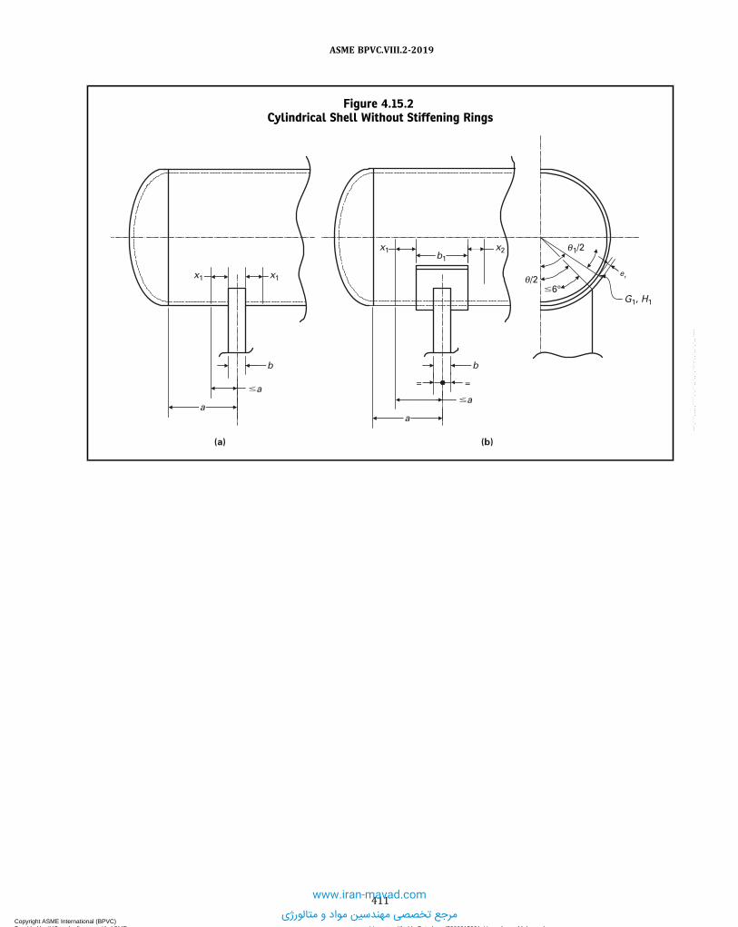
Figure 4.15.2Cylindrical Shell Without Stiffening Rings
�a�a
b
x1 x1
(a)
a
b
(b)
a
= =
b1
er
θ1/2
θ/2�6°
G1, H1
x1 x2
411
ASME BPVC.VIII.2-2019
Copyright ASME International (BPVC) Provided by IHS under license with ASME Licensee=Khalda Petroleum/5986215001, User=Amer, Mohamed
Not for Resale, 07/02/2019 14:07:58 MDTNo reproduction or networking permitted without license from IHS
--`,```,,,,,````,`,``,,`,,`,`-`-`,,`,,`,`,,`---
www.iran-mavad.com
مرجع تخصصی مهندسین مواد و متالورژی

Figure 4.15.3Cylindrical Shell With Stiffening Rings in the Plane of the Saddle
a
Y Y
e
a
Y Y
e
a
Y Y
e
(a)
a
Y Y
e
(b)
a
YC2
C1
�a
a
x1
Y
x2
h � 1.56 Rmt= =
(c)
t
C2
C1
x1 x2
�a�a
x1 x2
C2
C1
�a
x1 x2
C2
C1
�a
x1 x2
C2
C1
412
ASME BPVC.VIII.2-2019
Copyright ASME International (BPVC) Provided by IHS under license with ASME Licensee=Khalda Petroleum/5986215001, User=Amer, Mohamed
Not for Resale, 07/02/2019 14:07:58 MDTNo reproduction or networking permitted without license from IHS
--`,```,,,,,````,`,``,,`,,`,`-`-`,,`,,`,`,,`---
www.iran-mavad.com
مرجع تخصصی مهندسین مواد و متالورژی

Figure 4.15.4Cylindrical Shell With Stiffening Rings on Both Sides of the Saddle
a
Y Y
t
a
Y Y
t
= == =
a
Y Y
t
(a)
a
Y Y
t
(b)
= == =
C2
C1
C2
C1
�a
x1
�a
x2x2x1 x2
C2
C1
�a
x2x1
x2 x2 x2x1
x2 x2
1.56 Rmt � h � Rm
1.56 Rmt � h � Rm
C2
C1
�a
1.56 Rmt � h � Rm
1.56 Rmt � h � Rm
x1 x2 x2
413
ASME BPVC.VIII.2-2019
Copyright ASME International (BPVC) Provided by IHS under license with ASME Licensee=Khalda Petroleum/5986215001, User=Amer, Mohamed
Not for Resale, 07/02/2019 14:07:58 MDTNo reproduction or networking permitted without license from IHS
--`,```,,,,,````,`,``,,`,,`,`-`-`,,`,,`,`,,`---
www.iran-mavad.com
مرجع تخصصی مهندسین مواد و متالورژی

Figure 4.15.5Locations of Maximum Longitudinal Normal Stress and Shear Stress in the Cylinder
A B
E F
C D
(a) (b)
�
� = 0.95
(c)
/6
/20
� �
6 2
�
414
ASME BPVC.VIII.2-2019
Copyright ASME International (BPVC) Provided by IHS under license with ASME Licensee=Khalda Petroleum/5986215001, User=Amer, Mohamed
Not for Resale, 07/02/2019 14:07:58 MDTNo reproduction or networking permitted without license from IHS
--`,```,,,,,````,`,``,,`,,`,`-`-`,,`,,`,`,,`---
www.iran-mavad.com
مرجع تخصصی مهندسین مواد و متالورژی

Figure 4.15.6Locations of Maximum Circumferential Normal Stresses in the Cylinder
Maximum bending moment: shell stiffeners on both sides of the saddle
Maximum bending moment: shell without stiffeners or shell stiffeners in the plane of the saddle
G H
�
(a)
(b)
�
JI
415
ASME BPVC.VIII.2-2019
Copyright ASME International (BPVC) Provided by IHS under license with ASME Licensee=Khalda Petroleum/5986215001, User=Amer, Mohamed
Not for Resale, 07/02/2019 14:07:58 MDTNo reproduction or networking permitted without license from IHS
--`,```,,,,,````,`,``,,`,,`,`-`-`,,`,,`,`,,`---
www.iran-mavad.com
مرجع تخصصی مهندسین مواد و متالورژی

Figure 4.15.7Skirt Attachment Location on Vertical Vessels
Minimize this offset
Vessel head
Vessel skirt
416
ASME BPVC.VIII.2-2019
Copyright ASME International (BPVC) Provided by IHS under license with ASME Licensee=Khalda Petroleum/5986215001, User=Amer, Mohamed
Not for Resale, 07/02/2019 14:07:58 MDTNo reproduction or networking permitted without license from IHS
--`,```,,,,,````,`,``,,`,,`,`-`-`,,`,,`,`,,`---
www.iran-mavad.com
مرجع تخصصی مهندسین مواد و متالورژی

Figure 4.15.8A Typical Hot-Box Arrangement for Skirt Supported Vertical Vessels
Hot-box cavity — this space to be left free of insulation and vents
Typical segmented ring
Insulation
Typical vent
Optional fireproofing
Dimension established based on thermal stress analysis
Dimension established based on thermal stress analysis
417
ASME BPVC.VIII.2-2019
Copyright ASME International (BPVC) Provided by IHS under license with ASME Licensee=Khalda Petroleum/5986215001, User=Amer, Mohamed
Not for Resale, 07/02/2019 14:07:58 MDTNo reproduction or networking permitted without license from IHS
--`,```,,,,,````,`,``,,`,,`,`-`-`,,`,,`,`,,`---
www.iran-mavad.com
مرجع تخصصی مهندسین مواد و متالورژی

4.16 DESIGN RULES FOR FLANGED JOINTS
4.16.1 SCOPE4.16.1.1 The rules in 4.16 shall be used to design circular flanges subject to internal and/or external pressure. These
rules provide for hydrostatic end loads, gasket seating, and externally applied axial force and net-section bendingmoment.
4.16.1.2 The rules in 4.16 apply to the design of bolted flange connections with gaskets that are entirely locatedwithin the circle enclosed by the bolt holes. The rules do not cover the case where the gasket extends beyond the bolthole circle or where metal-metal contact is made outside of the bolt circle.
4.16.1.3 It is recommended that bolted flange connections conforming to the standards listed in 4.1.11 be used forconnections to external piping. These standards may be used for other bolted flange connections and dished covers with-in the limits of size in the standard and pressure–temperature ratings permitted in 4.1.11. The ratings in these standardsare based on the hub dimensions given or on the minimum specified thickness of flanged fittings of integral construction.Flanges fabricated from rings may be used in place of the hub flanges in these standards, provided that their strengthand rigidity, calculated by the rules in this paragraph, are not less than that calculated for the corresponding size of hubflange.
4.16.1.4 The rules of this paragraph should not be construed to prohibit the use of other types of flanged connec-tions, provided they are designed in accordance with Part 5.
4.16.2 DESIGN CONSIDERATIONS4.16.2.1 The design of a flange involves the selection of the flange type, gasket material, flange facing, bolting, hub
proportions, flange width, and flange thickness. The flange dimensions shall be selected such that the stresses in theflange and the flange rigidity satisfy the acceptability criteria of this paragraph.
4.16.2.2 In the design of a bolted flange connection, calculations shall be made for the following two design condi-tions, and the most severe condition shall govern the design of the flanged joint.(a) Operating Conditions. The conditions required to resist the hydrostatic end force of the design pressure and any
applied external forces and moments tending to part the joint at the design temperature.(b) Gasket Seating Condition. The conditions existing when the gasket or joint-contact surface is seated by applying an
initial load with the bolts during assembly of the joint, at atmospheric temperature and pressure.
4.16.2.3 Calculations shall be performed using dimensions of the flange in the corroded and uncorroded conditions.
4.16.2.4 In the design of flange pairs, each flange is designed for its particular design loads of pressure and gasketreactions. The bolt load used to design each flange, however, is that load common to the flange pair and equal to thelarger of the bolt loads calculated for each flange individually. No additional rules are required for design of flange pairs.After the loads for the most severe condition are determined, calculations shall be made for each flange following therules of this paragraph.
4.16.2.5 In the design of flange pairs where pass partitions with gaskets are used, the gasket loads from the parti-tion(s) shall be included in the calculation of bolt loads. Partition gaskets may have different gasket constants than thering gasket inside the bolt circle. In the design of flanges with noncircular gaskets or with partitions of any shape, gasketreactions from all surfaces with gaskets shall be included in calculating bolt loads.
4.16.3 FLANGE TYPES4.16.3.1 For the purpose of computation, there are two major categories of flanges:(a) Integral Type Flanges - This type covers designs where the flange is cast or forged integrally with the nozzle neck,
vessel or pipe wall, butt welded thereto, or attached by other forms of welding such that the flange and nozzle neck,vessel or pipe wall are structurally equivalent to integral construction. Integral flanges shall be designed consideringstructural interaction between the flange and the nozzle neck, vessel, or pipe wall, which the rules account for by con-sidering the neck or wall to act as a hub. Integral type flanges are referenced below. The design flange and bolt loads areshown in Figures 4.16.1 and 4.16.2.
(1) Integral type flanges - Figure 4.16.1, sketch (a) and Table 4.2.9, Details 9 and 10(2) Integral type flanges where g1 = go - Figure 4.16.1, sketch (b)(3) Integral type flanges with a hub - Figure 4.16.2 and Table 4.2.9, Details 6, 7, and 8(4) Integral type flanges with nut stops - Figure 4.16.3 and Figure 4.16.4
418
ASME BPVC.VIII.2-2019
Copyright ASME International (BPVC) Provided by IHS under license with ASME Licensee=Khalda Petroleum/5986215001, User=Amer, Mohamed
Not for Resale, 07/02/2019 14:07:58 MDTNo reproduction or networking permitted without license from IHS
--`,```,,,,,````,`,``,,`,,`,`-`-`,,`,,`,`,,`---
www.iran-mavad.com
مرجع تخصصی مهندسین مواد و متالورژی

ð19Þ
ð19Þ
ð19Þ
(b) Loose Type Flanges - This type covers those designs in which the flange has no substantial integral connection tothe nozzle neck, vessel, or pipe wall, and includes welded flange connections where the welds are not considered to givethe mechanical strength equivalent of an integral attachment. Loose type flanges are referenced below. The design flangeand bolt loads are shown in Figures 4.16.5 and 4.16.6.
(1) Loose type flanges - Figure 4.16.5 and Table 4.2.9, Details 1,2,3 and 4(2) Loose type lap joint flanges - Figure 4.16.6 and Table 4.2.9, Detail 5
4.16.3.2 The integral and loose type flanges described above can also be applied to reverse flange configurations.Integral and loose type reverse flanges are shown in Figure 4.16.7.
4.16.4 FLANGE MATERIALS4.16.4.1 Materials used in the construction of bolted flange connections, excluding gasket materials, shall comply
with the requirements given in Part 3.
4.16.4.2 Flanges made from ferritic steel shall be given a normalizing or full-annealing heat treatment when thethickness of the flange, t (see Figures 4.16.1 through 4.16.7), exceeds 75 mm (3 in.).
4.16.4.3 Flanges with hubs that are machined from plate, bar stock, or billet shall be in accordance with thefollowing:
(a) Flanges with hubs shall not be machined from plate or bar (except as permitted in 3.2.5.2) material unless thematerial has been formed into a ring and the following additional conditions are met:
(1) In a ring formed from plate, the original plate surfaces are parallel to the axis of the finished flange.(2) The joints in the ring are welded butt joints that conform to the requirements of Part 6. The thickness to be used
to determine postweld heat treatment and radiographic requirements shall be min[t , (A − B)/2].(3) The back of the flange and outer surface of the hub shall be examined by either the magnetic particle method or
the liquid penetrant method in accordance with Part 7.(b) Flanges with hubs, except as permitted in (a), shall not be machined from plate or bar stock material unless the
material has been formed into a ring, and further, provided that:(1) In a ring formed from plate, the original plate surfaces are parallel to the axis of the finished flange;(2) The joints in the ring are welded butt joints that conform to the requirements of Part 6. The thickness to be used
to determine postweld heat treatment and radiographic requirements shall be min[t , (A − B)/2].(c) The back of the flange and the outer surface of the hub shall be examined by either the magnetic particle method or
the liquid penetrant method in accordance with Part 7.
4.16.4.4 Bolts, studs, nuts, and washers shall comply with the requirements of Part 3 and referenced standards. It isrecommended that bolts and studs have a nominal diameter of not less than 12 mm (0.5 in.). If bolts or studs smallerthan 12 mm (0.5 in.) are used, then ferrous bolting material shall be of alloy steel. Precautions shall be taken to avoidoverstressing small-diameter bolts. When washers are used, they shall be through hardened to minimize the potentialfor galling.
4.16.5 GASKET MATERIALS4.16.5.1 The gasket constants for the design of the bolt load (m and y), are provided in Table 4.16.1. Other values
for the gasket constants may be used if based on actual testing or data in the literature, as agreed upon between designerand the user.
4.16.5.2 The minimum width of sheet and composite gaskets, N , is recommended to be no less than that given inTable 4.16.2.
NOTE: Gasket materials should be selected that are suitable for the design conditions. Corrosion, chemical attack, creep and thermal degrada-tion of gasket materials over time should be considered.
4.16.6 DESIGN BOLT LOADS4.16.6.1 The procedure to determine the bolt loads for the operating and gasket seating conditions is shown below.Step 1. Determine the design pressure and temperature of the flange joint.Step 2. Select a gasket and determine the gasket factorsm and y from Table 4.16.1, or other sources. The selected gas-
ket width should comply with the guidelines detailed in Table 4.16.2.Step 3. Determine the width of the gasket, N , basic gasket seating width, b0 , the effective gasket seating width, b , and
the location of the gasket reaction, G , based on the flange and gasket geometry, the information in Table 4.16.3 andFigure 4.16.8, and the equations shown below. Note that for lap joint flanges, G is equal to the midpoint of contact be-tween the flange and the lap, see Figure 4.16.6 and Figure 4.16.8.
419
ASME BPVC.VIII.2-2019
Copyright ASME International (BPVC) Provided by IHS under license with ASME Licensee=Khalda Petroleum/5986215001, User=Amer, Mohamed
Not for Resale, 07/02/2019 14:07:58 MDTNo reproduction or networking permitted without license from IHS
--`,```,,,,,````,`,``,,`,,`,`-`-`,,`,,`,`,,`---
www.iran-mavad.com
مرجع تخصصی مهندسین مواد و متالورژی

(a) For b0 ≤ 6 mm (0.25 in.), G is the mean diameter of the gasket contact face and
ð4:16:1Þ(b) For b0 > 6 mm (0.25 in.)
ð4:16:2Þ
ð4:16:3ÞStep 4. Determine the design bolt load for the operating condition.
ð4:16:4Þ
ð4:16:5ÞStep 5. Determine the design bolt load for the gasket seating condition.
ð4:16:6Þ
The parameter Ab is the actual total cross-sectional area of the bolts that is selected such that Ab ≥ Am , where:
ð4:16:7Þ
ð4:16:8Þ
ð4:16:9Þ
NOTE: Where significant axial force is required to compress the gasket during assembly of a joint containing a self-energizing gasket, the valueofWgs shall be taken as equal to that axial force. In addition, some self-energizing gaskets generate axial load due to their wedging action andthis load shall be considered in setting the value of Wgs .
4.16.7 FLANGE DESIGN PROCEDURE4.16.7.1 The procedure in this paragraph can be used to design circular integral, loose or reverse flanges, subject to
internal or external pressure, and external loadings. The procedure incorporates both a strength check and a rigiditycheck for flange rotation.
4.16.7.2 The procedure to design a flange is shown below.Step 1. Determine the design pressure and temperature of the flange joint, and the external net-section axial force, FA ,
and bending moment,ME . If the pressure is negative, the absolute value of the pressure should be used in this procedure.Step 2. Determine the design bolt loads for operating condition, Wo , and the gasket seating condition, Wg , and corre-
sponding actual bolt area, Ab , from 4.16.6.Step 3. Determine an initial flange geometry, in addition to the information required to determine the bolt load, the
following geometric parameters are required:(a) The flange bore, B(b) The bolt circle diameter, C(c) The outside diameter of the flange, A(d) The flange thickness, t(e) The thickness of the hub at the large end, g1
(f) The thickness of the hub at the small end, g0
(g) The hub length, hStep 4. Determine the flange stress factors using the equations in Tables 4.16.4 and 4.16.5.Step 5. Determine the flange forces.
420
ASME BPVC.VIII.2-2019
Copyright ASME International (BPVC) Provided by IHS under license with ASME Licensee=Khalda Petroleum/5986215001, User=Amer, Mohamed
Not for Resale, 07/02/2019 14:07:58 MDTNo reproduction or networking permitted without license from IHS
--`,```,,,,,````,`,``,,`,,`,`-`-`,,`,,`,`,,`---
www.iran-mavad.com
مرجع تخصصی مهندسین مواد و متالورژی

ð19Þ
ð4:16:10Þ
ð4:16:11Þ
ð4:16:12Þ
ð4:16:13ÞStep 6. Determine the flange moment for the operating condition using Equation (4.16.14) or Equation (4.16.15), as
applicable. When specified by the user or his designated agent, the maximum bolt spacing (Bsmax) and the bolt spacingcorrection factor (Bsc) shall be applied in calculating the flange moment for internal pressure using the equations inTable 4.16.11. The flange momentMo for the operating condition and flange momentMg for the gasket seating conditionwithout correction for bolt spacing Bsc = 1 is used for the calculation of the rigidity index in Step 10. In these equations,hD , hT , and hG are determined from Table 4.16.6. For integral and loose type flanges, the momentMoe is calculated usingEquation (4.16.16) where I and Ip in this equation are determined from Table 4.16.7. For reverse type flanges, the pro-cedure to determine Moe shall be agreed upon between the Designer and the Owner.
ð4:16:14Þ
ð4:16:15Þ
ð4:16:16Þ
Step 7. Determine the flange moment for the gasket seating condition using eq. (4.16.17) or (4.16.18), as applicable.
ð4:16:17Þ
ð4:16:18ÞStep 8. Determine the flange stresses for the operating and gasket seating conditions using the equations in Table
4.16.8.Step 9. Check the flange stress acceptance criteria. The two criteria shown below shall be evaluated. If the stress cri-
teria are satisfied, go to Step 10. If the stress criteria are not satisfied, re-proportion the flange dimensions and go to Step4.
(a) Allowable Normal Stress - The criteria to evaluate the normal stresses for the operating and gasket seating con-ditions are shown in Table 4.16.9.
(b) Allowable Shear Stresses - In the case of loose type flanges with lap, as shown in Figure 4.16.6 where the gasket isso located that the lap is subjected to shear, the shearing stress shall not exceed 0.8Sno or 0.8Sng , as applicable, for thematerial of the lap. In the case of welded flanges where the nozzle neck, vessel, or pipe wall extends near to the flangeface and may form the gasket contact face, the shearing stress carried by the welds shall not exceed 0.8Sno or 0.8Sng , asapplicable. The shearing stress shall be calculated for both the operating and gasket seating load cases. Similar situationswhere flange parts are subjected to shearing stresses shall be checked using the same requirement.
Step 10. Check the flange rigidity criterion in Table 4.16.10. If the flange rigidity criterion is satisfied, then the design iscomplete. If the flange rigidity criterion is not satisfied, then re-proportion the flange dimensions and go to Step 3. Theflange moment Mo for the operating condition (Step 6) and flange moment Mg for the gasket seating condition (Step 7)without correction for bolt spacing Bsc = 1 is used for the calculation of the rigidity index.
4.16.8 SPLIT LOOSE TYPE FLANGES
Loose flanges split across a diameter and designed under the rules given in this paragraph may be used under thefollowing provisions.
(a)When the flange consists of a single split flange or flange ring, it shall be designed as if it were a solid flange (with-out splits), using 200% of the total moment, Fs = 2.0.
421
ASME BPVC.VIII.2-2019
Copyright ASME International (BPVC) Provided by IHS under license with ASME Licensee=Khalda Petroleum/5986215001, User=Amer, Mohamed
Not for Resale, 07/02/2019 14:07:58 MDTNo reproduction or networking permitted without license from IHS
--`,```,,,,,````,`,``,,`,,`,`-`-`,,`,,`,`,,`---
www.iran-mavad.com
مرجع تخصصی مهندسین مواد و متالورژی

ð19Þ
ð19Þ
(b)When the flange consists of two split rings, each ring shall be designed as if it were a solid flange (without splits),using 75% of the total moment, Fs = 0.75. The pair of rings shall be assembled so that the splits in one ring are 90 degfrom the splits in the other ring.(c) The flange split locations should preferably be midway between bolt holes.(d) It is not a requirement that the flange rigidity rules of 4.6.10 be applied to split loose flanges.
4.16.9 NONCIRCULAR SHAPED FLANGES WITH A CIRCULAR BOREThe outside diameter, A , for a noncircular flange with a circular bore shall be taken as the diameter of the largest cir-
cle, concentric with the bore, inscribed entirely within the outside edges of the flange. The bolt loads, flange moments,and stresses shall be calculated in the samemanner as for a circular flange using a bolt circle whose size is established bydrawing a circle through the centers of the outermost bolts.
4.16.10 FLANGES WITH NUT STOPSWhen flanges are designed per 4.16, or are fabricated to the dimensions of ASME B16.5 or other acceptable standards,
except that the dimension 0.5(C − B) − g1 is decreased to provide a nut-stop, the fillet radius shall be as shown in Figures4.16.3 and 4.16.4 except that:(a) For flanges designed to this paragraph, the minimum thickness of the hub at the large end, g1 , shall be the smaller
of 2tn or 4ru , but not less than 12 mm (0.5 in.).(b) For ASME B16.5 or other standard flanges, the thickness of the hub at the small end, g0 , shall be increased as nec-
essary to provide a nut-stop.
4.16.11 JOINT ASSEMBLY PROCEDURESBolted joints should be assembled and bolted-up in accordance with a written procedure that has been demonstrated
to be acceptable for similar joint configurations in similar services. Further guidance can be found in ASME PCC-1, Guide-lines for Pressure Boundary Bolted Flange Joint Assembly.
4.16.12 EVALUATION OF EXTERNAL FORCES AND MOMENTS FOR FLANGED JOINTS WITH STANDARDFLANGES
External loads (forces and bending moments) may be evaluated for flanged joints with welding neck flanges chosen inaccordance with 4.1.11.1(a), 4.1.11.1(g), and 4.1.11.3, using the following requirements:(a) The vessel design pressure (corrected for the static head from liquid or bulk material acting on the flange) at the
design temperature cannot exceed the pressure−temperature rating of the flange.(b) The actual assembly bolt load (see 4.16.11) shall comply with ASME PCC-1, Nonmandatory Appendix O.(c) The bolt material shall have an allowable stress equal to or greater than SA-193 B8 Cl. 2 at the specified bolt size
and temperature.(d) The combination of vessel design pressure, P (corrected for the static head from liquid or bulk material acting on
the flange), with external moment and external axial force shall satisfy eq. (4.16.19). (The units of the variables in thisequation shall be consistent with the pressure rating.)
ð4:16:19Þ
4.16.13 NOMENCLATURE
A = outside diameter of the flange or, where slotted holes extend to the outside of the flange, the diameter to thebottom of the slots.
Ab = cross-sectional area of the bolts based on the smaller of the root diameter or the least diameter of the un-threaded portion.
Am = total minimum required cross-sectional area of the bolts.a = nominal bolt diameterB = inside diameter of the flange. When B < 20g1 , B1 may be used for B in the equation for the longitudinal stress.
B1 = B + g1 for loose type flanges and for integral type flanges that have a value of f less than 1.0, (although a mini-mum value of f = 1.0 is permitted). B1 is equal to B + g0 for integral type flanges when f ≥ 1.0.
B* = inside diameter of the reverse flange.Bs = bolt spacing, The bolt spacing may be taken as the bolt circle circumference divided by the number of bolts or
as the chord length between adjacent bolt locations.Bsmax = maximum bolt spacing
422
ASME BPVC.VIII.2-2019
Copyright ASME International (BPVC) Provided by IHS under license with ASME Licensee=Khalda Petroleum/5986215001, User=Amer, Mohamed
Not for Resale, 07/02/2019 14:07:58 MDTNo reproduction or networking permitted without license from IHS
--`,```,,,,,````,`,``,,`,,`,`-`-`,,`,,`,`,,`---
www.iran-mavad.com
مرجع تخصصی مهندسین مواد و متالورژی

Bsc = bolt spacing correction factorb = effective gasket contact width.
b0 = basic gasket seating width.C = bolt circle diameter.
Cul = conversion factor for length, Cul = 1.0 for U.S. Customary Units and Cul = 25.4 for Metric Units.d = flange stress factor.dr = flange stress factor d for a reverse type flange.
Eyg = Modulus of Elasticity at the gasket seating load case temperature.Eyo = Modulus of Elasticity at the operating load case temperature.
e = flange stress factor.er = flange stress factor e for a reverse type flange.F = flange stress factor for integral type flanges.
FA = value of the external tensile net-section axial force. Compressive net-section forces are to be neglected and forthat case, FA should be taken as equal to zero.
FL = flange stress factor for loose type flanges.FM = moment factor, in accordance with Table 4.16.12.Fs = moment factor used to design split rings (see 4.16.8), Fs = 1.0 for non-split rings.f = hub stress correction factor for integral flanges.G = diameter at the location of the gasket load reaction (see Figure 4.16.8).
Gavg = average of the hub thicknesses g1 and g0 .Gc = outside diameter of the gasket contact area (see Figure 4.16.8).g0 = thickness of the hub at the small end.
(a) for integral type flanges per Figure 4.16.1(a), g0 = tn(b) for other integral type flanges, g0 = the minimum of tn or the thickness of the hub at the small end
g1 = thickness of the hub at the large end.H = total hydrostatic end force.
HD = total hydrostatic end force on the area inside of the flange.HG = gasket load for the operating condition.HT = difference between the total hydrostatic end force and hydrostatic end force on the area inside the flange.h = hub length.ho = hub length parameter.hor = hub length parameter for a reverse flange.hD = moment arm for load HD .hG = moment arm for load HG .hT = moment arm for load HT .I = bending moment of inertia of the flange cross-section.Ip = polar moment of inertia of the flange cross-section.J = flange rigidity index.K = ratio of the flange outside diameter to the flange inside diameter.
KR = rigidity index factor.L = flange stress factor.Lr = flange stress factor L for a reverse type flange.ME = absolute value of the external net-section bending moment.Mg = flange design moment for the gasket seating condition.Mo = flange design moment for the operating condition.Moe = component of the flange design moment resulting from a net section bending moment and/or axial force.m = factor for the gasket operating condition.N = gasket contact width, N = 0.0 for self-energizing gaskets.P = design pressure.
PR = flange pressure rating at design temperature.r1 = radius to be at least 0.25g1 but not less than 5 mm (0.1875 in.).ru = radius of the undercut on a flange with nut stops.
Sbg = allowable stress from Annex 3-A for the bolt evaluated at the gasket seating temperature.Sbo = allowable stress from Annex 3-A for the bolt evaluated at the design temperature.Sfg = allowable stress from Annex 3-A for the flange evaluated at the gasket seating temperature.Sfo = allowable stress from Annex 3-A for the flange evaluated at the design temperature.
423
ASME BPVC.VIII.2-2019
Copyright ASME International (BPVC) Provided by IHS under license with ASME Licensee=Khalda Petroleum/5986215001, User=Amer, Mohamed
Not for Resale, 07/02/2019 14:07:58 MDTNo reproduction or networking permitted without license from IHS
--`,```,,,,,````,`,``,,`,,`,`-`-`,,`,,`,`,,`---www.iran-mavad.com
مرجع تخصصی مهندسین مواد و متالورژی

Sng = allowable stress from Annex 3-A for the nozzle neck, vessel, or pipe evaluated at the gasket seatingtemperature.
Sno = allowable stress from Annex 3-A for the nozzle neck, vessel, or pipe evaluated at the design temperature.SH = flange hub stress.SR = flange radial stress.ST = flange tangential stress.
ST1 = flange tangential stress at the outside diameter of a reverse flange.ST2 = flange tangential stress at the inside diameter of a reverse flange.T = flange stress factor.Tr = flange stress factor T for a reverse flange.t = flange thickness, including the facing thickness or the groove depth if either do not exceed 2 mm (0.0625 in.);
otherwise, the facing thickness or groove depth is not included in the overall flange thickness.tn = nominal thickness of the shell, pipe, or nozzle to which the flange is attached.t x = is 2go when the design is calculated as an integral flange, or two times the minimum required thickness of the
shell or nozzle wall when the design is based on a loose flange, but not less than 6 mm (0.25 in.).U = flange stress factor.Ur = flange stress factor U for a reverse type flange.V = flange stress factor for integral type flanges.VL = flange stress factor for loose type flanges.Wg = design bolt load for the gasket seating condition.Wo = design bolt load for the operating condition.w = width of the nubbin.y = factor for the gasket seating conditionY = flange stress factor.Yr = flange stress factor Y for a reverse type flange.Z = flange stress factor.
4.16.14 TABLES
Table 4.16.1Gasket Factors for Determining the Bolt Loads
Gasket MaterialGasket
Factor, mMin. Design SeatingStress, y , MPa (psi)
Column inTable 4.16.3
Facing Sketch inTable 4.16.3
Self-energizing types (O rings, metallic, elastomer, other gasket typesconsidered as self-sealing) 0 0 in. 0 … …
Elastomers without fabric or high percent of mineral fiber:
II(1a), (1b), (1c),(1d), (4), (5)
below 75 A Shore Durometer 0.50 075 A or higher Shore Durometer 1.00 0 1.4 (200)
Mineral fiber with suitable binder for operating conditions:2.00 11 (1,600)
II(1), (1b), (1c),(1d), (4), (5)
3.2 mm (1/8 in.) thick1.6 mm (1/16 in.) thick 2.75 26 (3,700)0.8 mm (1/32 in.) thick 3.50 45 (6,500)
Elastomers with cotton fabric insertion 1.25 2.8 (400) II (1a), (1b), (1c),(1d), (4), (5)
Elastomers with mineral fiber insertion (with or without wirereinforcement):
II(1), (1b), (1c),(1d), (5)
3-ply 2.25 15 (2,200)2-ply 2.50 20 (2,900)1-ply 2.75 26 (3,700)
Vegetable fiber 1.75 7.6 (1,100) II (1a), (1b), (1c),(1d), (4), (5)
Spiral-wound metal, mineral fiber filler:
II (1a), (1b)Carbon steel 2.50 69 (10,000)Stainless steel, Monel, and nickel-base alloy 3.00 69 (10,000)
424
ASME BPVC.VIII.2-2019
Copyright ASME International (BPVC) Provided by IHS under license with ASME Licensee=Khalda Petroleum/5986215001, User=Amer, Mohamed
Not for Resale, 07/02/2019 14:07:58 MDTNo reproduction or networking permitted without license from IHS
--`,```,,,,,````,`,``,,`,,`,`-`-`,,`,,`,`,,`---www.iran-mavad.com
مرجع تخصصی مهندسین مواد و متالورژی

Table 4.16.1Gasket Factors for Determining the Bolt Loads (Cont'd)
Gasket MaterialGasket
Factor, mMin. Design SeatingStress, y , MPa (psi)
Column inTable 4.16.3
Facing Sketch inTable 4.16.3
Corrugated metal, mineral fiber inserted, or corrugated metal, jacketedmineral fiber filled:
II (1a), (1b)
Soft aluminum 2.50 20 (2,900)Soft copper or brass 2.75 26 (3,700)Iron or soft steel 3.00 31 (4,500)Monel or 4%–6% chrome 3.25 38 (5,500)Stainless steels and nickel-base alloys 3.50 45 (6,500)
Corrugated metal:
II(1a), (1b), (1c),(1d)
Soft aluminum 2.75 26 (3,700)Soft copper or brass 3.00 31 (4,500)Iron or soft steel 3.25 38 (5,500)Monel or 4%–6% chrome 3.50 45 (6,500)Stainless steels and nickel-base alloys 3.75 52 (7,600)
Flat metal, jacketed mineral fiber filled:
II(1a), (1b), (1c),(1d), (2)
Soft aluminum 3.25 38 (5,500)Soft copper or brass 3.50 45 (6,500)Iron or soft steel 3.75 52 (7,600)Monel 3.50 55 (8,000)4%–6% chrome 3.75 62 (9,000)Stainless steels and nickel-base alloys 3.75 62 (9,000)
Grooved metal:
II(1a), (1b), (1c),(1d), (2), (3)
Soft aluminum 3.25 38 (5,500)Soft copper or brass 3.50 45 (6,500)Iron or soft steel 3.75 52 (7,600)Monel or 4%–6% chrome 3.75 62 (9,000)Stainless steels and nickel-base alloys 4.25 70 (10,100)
Sold flat metal:
I
(1a), (1b), (1c),(1d), (2), (3),(4), (5)
Soft aluminum 4.00 61 (8,800)Soft copper or brass 4.75 90 (13,000)Iron or soft steel 5.50 124 (18,000)Monel or 4%–6% chrome 6.00 150 (21,800)Stainless steels and nickel-base alloys 6.50 180 (26,000)
Ring joint:
I (6)
Iron or soft steel 5.50 124 (18,000)Monel or 4%–6% chrome 6.00 150 (21,800)Stainless steel and nickel-base alloys 6.50 180 (26,000)
GENERAL NOTE: This table gives a list of commonly used gasket materials and contact facings with suggested values of m and y that havegenerally proved satisfactory in actual service when using effective gasket seating width b. The design values and other details given in thistable are suggested only and are not mandatory.
Table 4.16.2Recommended Minimum Gasket Contact Width
Gasket Contact Width, N
Gasket Type
Gasket Outside Diameter
<150 mm(6 in.)
<300 mm(12 in.)
<600 mm(24 in.)
<900 mm(36 in.)
900 mm (36 in.)and Over
Sheet gaskets including laminated sheets gasketswith or without a metal core
9 mm(0.375 in.)
12 mm(0.5 in.)
16 mm(0.625 in.)
16 mm(0.625 in.)
19 mm(0.75 in.)
Preformed composite gaskets including spiralwound, jacketed, and solid flat metal gaskets
6 mm(0.25 in.)
9 mm(0.375 in.)
12 mm(0.5 in.)
16 mm(0.625 in.)
16 mm(0.625 in.)
425
ASME BPVC.VIII.2-2019
Copyright ASME International (BPVC) Provided by IHS under license with ASME Licensee=Khalda Petroleum/5986215001, User=Amer, Mohamed
Not for Resale, 07/02/2019 14:07:58 MDTNo reproduction or networking permitted without license from IHS
--`,```,,,,,````,`,``,,`,,`,`-`-`,,`,,`,`,,`---
www.iran-mavad.com
مرجع تخصصی مهندسین مواد و متالورژی

ð19Þ Table 4.16.3Effective Gasket Width for Determining the Bolt Loads
Facing Sketch Facing Sketch Detail (Exaggerated)
Basic Gasket Seating Width, bo
Column I Column II
1a
N N
1b
Note (1)
NN
1c
N
w
T w � N
1d
N
w
T w � NNote (1)
2
0.4 mm ( in.) nubbin
w � N/2
N
w
3
N
w
0.4 mm ( in.) nubbin
w � N/2
4
N
Note (1)
5
Note (1)
N
6 W
426
ASME BPVC.VIII.2-2019
Copyright ASME International (BPVC) Provided by IHS under license with ASME Licensee=Khalda Petroleum/5986215001, User=Amer, Mohamed
Not for Resale, 07/02/2019 14:07:58 MDTNo reproduction or networking permitted without license from IHS
--`,```,,,,,````,`,``,,`,,`,`-`-`,,`,,`,`,,`---
www.iran-mavad.com
مرجع تخصصی مهندسین مواد و متالورژی

Table 4.16.3Effective Gasket Width for Determining the Bolt Loads (Cont'd)
NOTES:(1) Where serrations do not exceed 0.4 mm (0.0156 in.) depth and 0.8 mm (0.0313 in.) width spacing, sketches (1b) and (1d) shall be
used.(2) The gasket factors listed in this table only apply to flanged joints in which the gasket is contained entirely within the inner edges of the
bolt holes.
427
ASME BPVC.VIII.2-2019
Copyright ASME International (BPVC) Provided by IHS under license with ASME Licensee=Khalda Petroleum/5986215001, User=Amer, Mohamed
Not for Resale, 07/02/2019 14:07:58 MDTNo reproduction or networking permitted without license from IHS
--`,```,,,,,````,`,``,,`,,`,`-`-`,,`,,`,`,,`---
www.iran-mavad.com
مرجع تخصصی مهندسین مواد و متالورژی

Table 4.16.4Flange Stress Factors Equations Involving Diameter
Flange Type Stress Factors Involving Diameter
Integral-type flange and loose-typeflange with a hub
428
ASME BPVC.VIII.2-2019
Copyright ASME International (BPVC) Provided by IHS under license with ASME Licensee=Khalda Petroleum/5986215001, User=Amer, Mohamed
Not for Resale, 07/02/2019 14:07:58 MDTNo reproduction or networking permitted without license from IHS
--`,```,,,,,````,`,``,,`,,`,`-`-`,,`,,`,`,,`---
www.iran-mavad.com
مرجع تخصصی مهندسین مواد و متالورژی

Table 4.16.4Flange Stress Factors Equations Involving Diameter (Cont'd)
Flange Type Stress Factors Involving Diameter
Reverse integral-type flange andreverse loose-type flanges with ahub
The parameters K , T , U , Y , and Z are determined using the equations for integral- and loose-type flanges with:
Then, the reverse flange parameters are computed as follows:
429
ASME BPVC.VIII.2-2019
Copyright ASME International (BPVC) Provided by IHS under license with ASME Licensee=Khalda Petroleum/5986215001, User=Amer, Mohamed
Not for Resale, 07/02/2019 14:07:58 MDTNo reproduction or networking permitted without license from IHS
--`,```,,,,,````,`,``,,`,,`,`-`-`,,`,,`,`,,`---www.iran-mavad.com
مرجع تخصصی مهندسین مواد و متالورژی

Table 4.16.5Flange Stress Factor Equations
Flange Type Stress Factors
Integral-type flange, reverseintegral-type flange
For
For
430
ASME BPVC.VIII.2-2019
Copyright ASME International (BPVC) Provided by IHS under license with ASME Licensee=Khalda Petroleum/5986215001, User=Amer, Mohamed
Not for Resale, 07/02/2019 14:07:58 MDTNo reproduction or networking permitted without license from IHS
--`,```,,,,,````,`,``,,`,,`,`-`-`,,`,,`,`,,`---
www.iran-mavad.com
مرجع تخصصی مهندسین مواد و متالورژی

Table 4.16.5Flange Stress Factor Equations (Cont'd)
Flange Type Stress Factors
Loose-type flange with a hub, reverseloose-type flange with a hub
For
For
For
For
431
ASME BPVC.VIII.2-2019
Copyright ASME International (BPVC) Provided by IHS under license with ASME Licensee=Khalda Petroleum/5986215001, User=Amer, Mohamed
Not for Resale, 07/02/2019 14:07:58 MDTNo reproduction or networking permitted without license from IHS
--`,```,,,,,````,`,``,,`,,`,`-`-`,,`,,`,`,,`---
www.iran-mavad.com
مرجع تخصصی مهندسین مواد و متالورژی

Table 4.16.6Moment Arms for Flange Loads for the Operating Condition
Flange Type hD hT hG
Integral-type flanges
Loose-type flanges, except lap joint flanges
Loose-type lap joint flanges
Reverse integral-type flanges
Reverse loose-type flanges
Table 4.16.7Flange Moments of Inertia
Flange Type I Ip
Integral-type flange with ahub
If
If
Loose-type flange with a hub
Loose-type flange without ahub
432
ASME BPVC.VIII.2-2019
Copyright ASME International (BPVC) Provided by IHS under license with ASME Licensee=Khalda Petroleum/5986215001, User=Amer, Mohamed
Not for Resale, 07/02/2019 14:07:58 MDTNo reproduction or networking permitted without license from IHS
--`,```,,,,,````,`,``,,`,,`,`-`-`,,`,,`,`,,`---www.iran-mavad.com
مرجع تخصصی مهندسین مواد و متالورژی

Table 4.16.8Flange Stress Equations
Flange Type
Stress Equations
Operating Condition Gasket Seating Conditions
Integral-type flange or loose-typeflange with a hub
Loose-type flange without a hub
Reverse integral-type flange orreverse loose-type flange with ahub
Reverse loose-type flange without ahub
Table 4.16.9Flange Stress Acceptance Criteria
Flange Type
Stress Acceptance Criteria
Operating Condition Gasket Seating Conditions
Integral-type flange or loose-typeflange with a hub
[Note (1)]
[Note (2)]
[Note (1)]
[Note (2)]
Loose-type flange without a hub
Reverse integral-type flange orreverse loose-type flange with ahub
Reverse loose-type flanges
433
ASME BPVC.VIII.2-2019
Copyright ASME International (BPVC) Provided by IHS under license with ASME Licensee=Khalda Petroleum/5986215001, User=Amer, Mohamed
Not for Resale, 07/02/2019 14:07:58 MDTNo reproduction or networking permitted without license from IHS
--`,```,,,,,````,`,``,,`,,`,`-`-`,,`,,`,`,,`---
www.iran-mavad.com
مرجع تخصصی مهندسین مواد و متالورژی

Table 4.16.9Flange Stress Acceptance Criteria (Cont'd)
NOTES:(1) For integral flanges with hubs welded to a nozzle neck, pipe, or vessel shell.(2) For loose type flanges with a hub.(3) Flanges made of non-ductile material, such as cast iron, are not addressed by this section.
Table 4.16.10Flange Rigidity Criterion
Flange Type
Rigidity Criterion
Operating Condition Gasket Seating Conditions
Integral-type flange
Loose-type flange with a hub
Reverse integral-type flange
Reverse loose-type flange with a hub
Loose-type and reverse loose-typeflange without a hub
GENERAL NOTES:(a) For an integral type flange, KR = 0.3 unless other values are specified by the user.(b) For a loose type flange with or without a hub, KR = 0.2 unless other values are specified by the user.
Table 4.16.11Bolt Spacing Equations
Flange Type Bolt Spacing Factors
All
434
ASME BPVC.VIII.2-2019
Copyright ASME International (BPVC) Provided by IHS under license with ASME Licensee=Khalda Petroleum/5986215001, User=Amer, Mohamed
Not for Resale, 07/02/2019 14:07:58 MDTNo reproduction or networking permitted without license from IHS
--`,```,,,,,````,`,``,,`,,`,`-`-`,,`,,`,`,,`---
www.iran-mavad.com
مرجع تخصصی مهندسین مواد و متالورژی

ð19ÞTable 4.16.12Moment Factor, FM
Standard Size Range
Flange Pressure Rating Class
150 300 600 900 1500 2500
ASME B16.5 ≤NPS 12 1.2 0.5 0.5 0.5 0.5 0.5>NPS 12 and ≤NPS 24 1.2 0.5 0.5 0.3 0.3 …
ASME B16.47Series A All 0.6 0.1 0.1 0.1 … …Series B <NPS 48 [Note (1)] [Note (1)] 0.13 0.13 … …
≥NPS 48 0.1 [Note (2)] … … … …
GENERAL NOTES:(a) The combinations of size ranges and flange pressure classes for which this Table gives nomoment factor value are outside the scope of
this Table.(b) The designer should consider reducing the moment factor if the loading is primarily sustained in nature and the bolted flange joint
operates at a temperature where gasket creep/relaxation will be significant.
NOTES:(1) FM = 0.1 + (48 – NPS)/56.(2) FM = 0.1 except NPS 60, Class 300, in which case FM = 0.03.
435
ASME BPVC.VIII.2-2019
Copyright ASME International (BPVC) Provided by IHS under license with ASME Licensee=Khalda Petroleum/5986215001, User=Amer, Mohamed
Not for Resale, 07/02/2019 14:07:58 MDTNo reproduction or networking permitted without license from IHS
--`,```,,,,,````,`,``,,`,,`,`-`-`,,`,,`,`,,`---
www.iran-mavad.com
مرجع تخصصی مهندسین مواد و متالورژی

4.16.15 FIGURES
Figure 4.16.1Integral Type Flanges
A
Gasket
t
W
ChD
h
B
G
hG
hT
HT HD
HG
g1 g1/2g0
A
Gasket
t
W
ChD
B
G
hGhT
HT
HD
HGg1 = g0
g1/2
r1
(a) Integral Flange Without a Hub
(b) Integral Flange With g0 = g1
436
ASME BPVC.VIII.2-2019
Copyright ASME International (BPVC) Provided by IHS under license with ASME Licensee=Khalda Petroleum/5986215001, User=Amer, Mohamed
Not for Resale, 07/02/2019 14:07:58 MDTNo reproduction or networking permitted without license from IHS
--`,```,,,,,````,`,``,,`,,`,`-`-`,,`,,`,`,,`---
www.iran-mavad.com
مرجع تخصصی مهندسین مواد و متالورژی
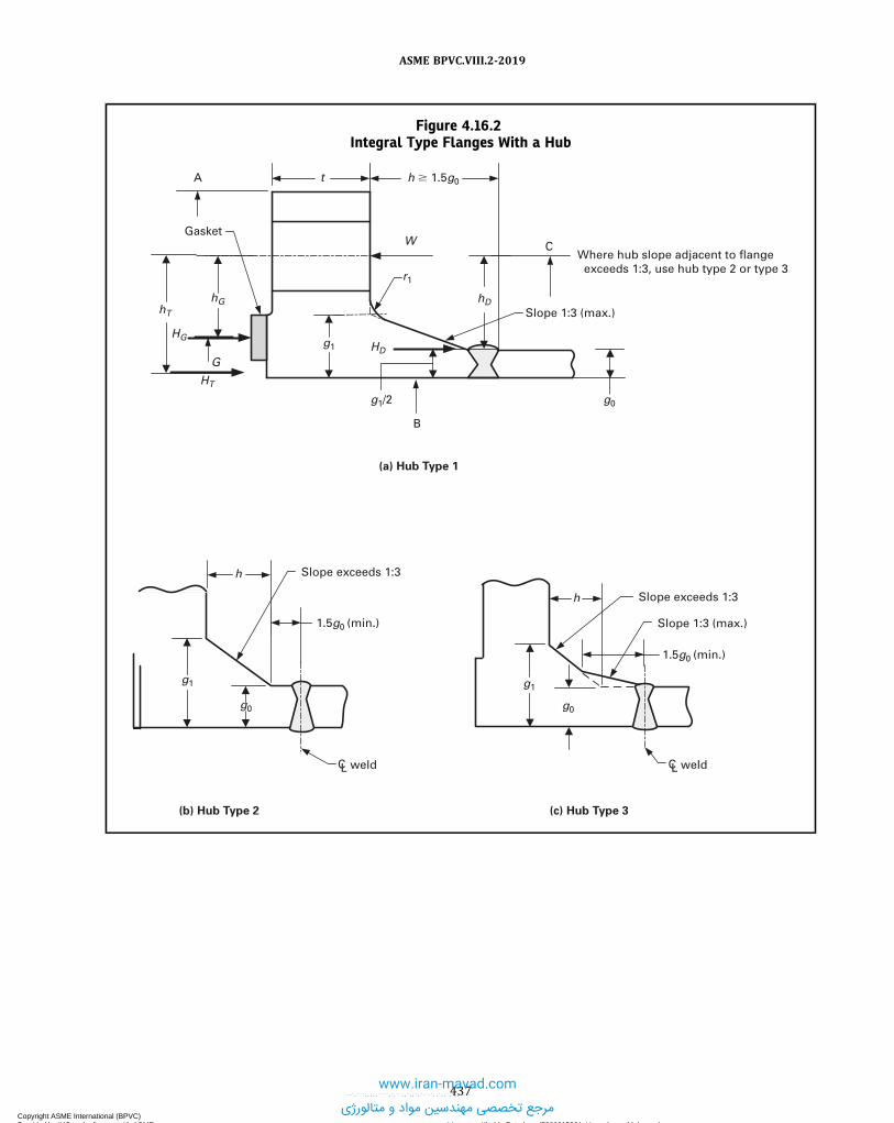
Figure 4.16.2Integral Type Flanges With a Hub
h
g1
g0g0
A
Gasket
t
W C
hD
B
G
hGhT
HT
HGHD
g1
g1/2 g0
r1
h � 1.5g0
Slope 1:3 (max.)
Where hub slope adjacent to flange exceeds 1:3, use hub type 2 or type 3
(a) Hub Type 1
(b) Hub Type 2 (c) Hub Type 3
Slope exceeds 1:3
1.5g0 (min.)
g1
h
1.5g0 (min.)
Slope 1:3 (max.)
Slope exceeds 1:3
CL weld CL weld
437
ASME BPVC.VIII.2-2019
Copyright ASME International (BPVC) Provided by IHS under license with ASME Licensee=Khalda Petroleum/5986215001, User=Amer, Mohamed
Not for Resale, 07/02/2019 14:07:58 MDTNo reproduction or networking permitted without license from IHS
--`,```,,,,,````,`,``,,`,,`,`-`-`,,`,,`,`,,`---
www.iran-mavad.com
مرجع تخصصی مهندسین مواد و متالورژی

Figure 4.16.3Integral Type Flanges With Nut Stops — Diameter Less Than or Equal to 450 mm (18 in.)
Inside diameter
ru = 6 mm (0.25 in.) ru = 6 mm (0.25 in.)5 mm (0.1875 in.)
Nut stop diameter
Nut stop diameter
(a) Detail A (b) Detail B
(c) Detail C (d) Detail D
For integrallyreinforced nozzles,
min. = nut height + 6 mm (0.25 in.)
g1 = g0 g1 = g0
g0
g1Inside diameter
5 mm (0.1875 in.)
Nut stop diameter
g0
g1
5 mm (0.1875 in.)
Inside diameter
ru = 6 mm (0.25 in.)
Nut stop diameter
5 mm (0.1875 in.)
ru = 6 mm (0.25 in.)
Inside diameter
438
ASME BPVC.VIII.2-2019
Copyright ASME International (BPVC) Provided by IHS under license with ASME Licensee=Khalda Petroleum/5986215001, User=Amer, Mohamed
Not for Resale, 07/02/2019 14:07:58 MDTNo reproduction or networking permitted without license from IHS
--`,```,,,,,````,`,``,,`,,`,`-`-`,,`,,`,`,,`---
www.iran-mavad.com
مرجع تخصصی مهندسین مواد و متالورژی

Figure 4.16.4Integral Type Flanges With Nut Stops — Diameter Greater Than 450 mm (18 in.)
g1
Inside diameter
ru = 10 mm (0.375 in.)
8 mm (0.3125 in.)
GENERAL NOTE: All other details per Figure 4.16.3.
439
ASME BPVC.VIII.2-2019
Copyright ASME International (BPVC) Provided by IHS under license with ASME Licensee=Khalda Petroleum/5986215001, User=Amer, Mohamed
Not for Resale, 07/02/2019 14:07:58 MDTNo reproduction or networking permitted without license from IHS
--`,```,,,,,````,`,``,,`,,`,`-`-`,,`,,`,`,,`---
www.iran-mavad.com
مرجع تخصصی مهندسین مواد و متالورژی

ð19Þ Figure 4.16.5Loose Type Flanges
W
ChD
G
hGhT
HT
HG
HD
g1 g0
r
Gasket
t
h
A
G
hGhT
HT
HG
Gasket
A
B
W
C
hD
HD
t
B
(a) Loose Flange With a Hub [Note (1)]
(b) Loose Flange Without a Hub
NOTE:(1) For hub tapers 6 deg or less, use g0 = g1 .
440
ASME BPVC.VIII.2-2019
Copyright ASME International (BPVC) Provided by IHS under license with ASME Licensee=Khalda Petroleum/5986215001, User=Amer, Mohamed
Not for Resale, 07/02/2019 14:07:58 MDTNo reproduction or networking permitted without license from IHS
--`,```,,,,,````,`,``,,`,,`,`-`-`,,`,,`,`,,`---
www.iran-mavad.com
مرجع تخصصی مهندسین مواد و متالورژی

ð19ÞFigure 4.16.6Loose-Type Lap Joint Type Flanges
W
ChD
G
HG + HT
HD
g1
g0
r1
Gasket
t h
A
hG or hT
Optional hub
To be taken at midpoint of contact between flange and lap, independent of gasket location
GENERAL NOTE: For hub tapers 6 deg or less, use g0 = g1 (loose-type flanges).
441
ASME BPVC.VIII.2-2019
Copyright ASME International (BPVC) Provided by IHS under license with ASME Licensee=Khalda Petroleum/5986215001, User=Amer, Mohamed
Not for Resale, 07/02/2019 14:07:58 MDTNo reproduction or networking permitted without license from IHS
--`,```,,,,,````,`,``,,`,,`,`-`-`,,`,,`,`,,`---www.iran-mavad.com
مرجع تخصصی مهندسین مواد و متالورژی

Figure 4.16.7Reverse Flanges
hTHT
W
C
hD
G
hG
HG
HD
g1
g1/2
g0
Shell
t
h
AB
B*
(a) Integral-Type Reverse Flange
t
W
hG
hD
Shell
A = B
C
G
B*HG
hT
HT
HD
(b) Loose-Type Reverse Flange
442
ASME BPVC.VIII.2-2019
Copyright ASME International (BPVC) Provided by IHS under license with ASME Licensee=Khalda Petroleum/5986215001, User=Amer, Mohamed
Not for Resale, 07/02/2019 14:07:58 MDTNo reproduction or networking permitted without license from IHS
--`,```,,,,,````,`,``,,`,,`,`-`-`,,`,,`,`,,`---
www.iran-mavad.com
مرجع تخصصی مهندسین مواد و متالورژی

Figure 4.16.8Location of Gasket Reaction Load Diameter
b
For b0 � 6 mm (0.25 in.) For b0 � 6 mm (0.25 in.)
CL
Gasket Face
O.D. of gasket
Self-Energizing Gaskets
To be taken at midpoint of contact between flange and lap, independent of gasket location HT + HG
hT or hG
hG
HG
GhG
HG
G
GG
Gc = O.D. contact face
Lap-Type Joints
443
ASME BPVC.VIII.2-2019
Copyright ASME International (BPVC) Provided by IHS under license with ASME Licensee=Khalda Petroleum/5986215001, User=Amer, Mohamed
Not for Resale, 07/02/2019 14:07:58 MDTNo reproduction or networking permitted without license from IHS
--`,```,,,,,````,`,``,,`,,`,`-`-`,,`,,`,`,,`---
www.iran-mavad.com
مرجع تخصصی مهندسین مواد و متالورژی

4.17 DESIGN RULES FOR CLAMPED CONNECTIONS
4.17.1 SCOPE
The rules in 4.17 apply specifically to the design of clamp connections for pressure vessels and vessel parts. Theserules shall not be used for the determination of thickness of tubesheets integral with a hub nor for the determinationof thickness of covers. These rules provide only for hydrostatic end loads, assembly, and gasket seating. Considerationshall be given to loads other than pressure, such as piping loads that may act upon the clamp connection (see 2.2.3.1).
4.17.2 DESIGN CONSIDERATIONS4.17.2.1 The design of a clamp connection involves the selection of the gasket, bolting, hub, and clamp geometry.
Connection dimensions shall be such that the calculated stresses in the clamp and the hub do not exceed the acceptabil-ity criteria of this paragraph.
4.17.2.2 In the design of a bolted flange connection, calculations shall be made for the following two design condi-tions, and the most severe condition shall govern the design of the flanged joint.(a) Operating Conditions - The conditions required to resist the hydrostatic end force of the design pressure and any
applied external forces and moments tending to part the joint, and to maintain on the gasket or joint-contact surfacesufficient compression to assure a joint that meets the required tightness, all at the design temperature.(b) Gasket Seating and Assembly Condition -The conditions existing when the gasket or joint-contact surface is seated
by applying an initial load with the bolts when assembling the joint, at atmospheric temperature and pressure.
4.17.2.3 Calculations shall be performed using dimensions of the flange in the corroded condition and the uncor-roded condition, and the more severe case shall control.
4.17.2.4 It is recommended that either a pressure energized and/or low seating load gasket be used to compensatefor possible non-uniformity in the gasket seating force distribution. Hub faces shall be designed such as to have metal-to-metal contact outside the gasket seal diameter. This may be provided by recessing the hub faces or by use of a metalspacer (see Figure 4.17.1). The contact area shall be sufficient to prevent yielding of either the hub face or spacer underboth operating and assembly loads.
4.17.2.5 It is recognized that there are clamp designs that do not utilize wedging action during assembly sinceclamping surfaces are parallel to the hub faces. Such designs are acceptable and shall satisfy the bolting and correspond-ing clamp and hub requirements of a clamp connection designed for a total included clamping angle of 10 degrees.
4.17.2.6 The design method used in this paragraph to calculate stresses, loads, and moments may also be used fordesigning clamp connections of shapes differing from those shown in Figures 4.17.1 and 4.17.2, and for clamps consist-ing of more than two circumferential segments. The design equations in this paragraph may be modified when designingclamp connections of shapes differing from those shown in Figures 4.17.1 and 4.17.2, provided that the basis for themodifications is in accordance with 1.1.1.2. The clamp connections designed in this manner shall be provided with a boltretainer. The retainer shall be designed such that in case of failure of the primary bolting, the retainer shall hold theclamps together independently under the operating loads. Multiple bolting (two or more bolts per lug) is an acceptablealternative for meeting this redundancy requirement. See 4.8.3.2 for additional requirements for bolt retainers and re-dundant bolting. No credit shall be taken for clamp hub friction toward satisfying the redundancy requirement.
4.17.3 FLANGE MATERIALS4.17.3.1 Materials used in the construction of clamp connections shall comply with the requirements given in Part 3.
4.17.3.2 Hubs made from ferritic steel and designed in accordance with the rules herein shall be given a normalizingor full-annealing heat treatment when the thickness of the hub neck section exceeds 76 mm (3 in.).
4.17.3.3 Cast steel hubs and clamps shall be examined and repaired, if required, in accordance with Part 3.
4.17.3.4 Hubs and clamps shall not be machined from plate.
4.17.3.5 Bolts, studs, nuts and washers shall comply with Part 3. The minimum bolt diameter shall be 13 mm(0.5 in.).
4.17.4 DESIGN BOLT LOADS4.17.4.1 During assembly of the clamp connection, the design bolt loadW is resolved into an effective clamp preload
We , which is a function of the clamp-to-hub taper angle ϕ and the friction angle μ . An appropriate friction angle shall beestablished by the manufacturer, based on test results for both assembly and operating conditions.
444
ASME BPVC.VIII.2-2019
Copyright ASME International (BPVC) Provided by IHS under license with ASME Licensee=Khalda Petroleum/5986215001, User=Amer, Mohamed
Not for Resale, 07/02/2019 14:07:58 MDTNo reproduction or networking permitted without license from IHS
--`,```,,,,,````,`,``,,`,,`,`-`-`,,`,,`,`,,`---
www.iran-mavad.com
مرجع تخصصی مهندسین مواد و متالورژی

4.17.4.2 The procedure to determine the bolt loads for the operating, and gasket seating and assembly conditionsare shown below.
Step 1. Determine the design pressure and temperature of the flange joint.Step 2. Select a gasket and determine the gasket factors m and y from Table 4.16.1.Step 3. Determine the width of the gasket, basic gasket seating width, the location of the gasket reaction, G , based on
the flange and gasket geometry and the information in Table 4.16.3.(a)When b0 ≤ 6 mm (0.25 in.), then G is the mean diameter of the gasket or joint contact face(b)When b0 > 6 mm (0.25 in.), then G is the outside diameter of the gasket contact face minus 2b .Step 4. Determine the flange forces for the bolt load calculation.
ð4:17:1Þ
ð4:17:2Þ
ð4:17:3Þ
ð4:17:4Þ
ð4:17:5ÞNote that where a significant axial force is required to compress the gasket during assembly of a joint containing a
self-energizing gasket, the value of Hm shall be taken as equal to that axial force.Step 5. Determine the design bolt load for the operating condition.
ð4:17:6Þ
Step 6. Determine the minimum required total bolt load for gasket seating and assembly conditions.
ð4:17:7Þ
ð4:17:8Þ
Step 7. Determine the design bolt load for the gasket seating and assembly condition.
ð4:17:9Þ
Alternatively, if controlled bolting (e.g., torque-control or bold tensioning) techniques are used to assemble the clamp,the assembly design bolt load shall be taken as
ð4:17:10Þ
NOTE: In addition, the Manufacturer shall provide to the User a copy of the bolting instructions that were used. It is recommended that theManufacturer refer to ASME PCC-1, Guidelines for Pressure Boundary Bolted Flange Joint Assembly. It is cautioned that bolt loads in excess ofthose calculated using eq. (4.17.10) can overstress the clamp.
The parameter Ab is the actual total cross-sectional area of the bolts that is selected such that Ab ≥ Am , where
ð4:17:11Þ
4.17.4.3 In eq. (4.17.6), credit for friction is allowed based on clamp connection geometry and experience, but thebolt load shall not be less than that determined using a value of (ϕ − μ) equal to 5 deg. Friction is also considered indetermining bolt loads by eqs. (4.17.7) and (4.17.8), but the μ factor used shall not be less than 5 deg.
4.17.5 FLANGE AND CLAMP DESIGN PROCEDUREThe procedure to design a clamp connection is shown below.Step 1. Determine the design pressure and temperature of the flange joint.
445
ASME BPVC.VIII.2-2019
Copyright ASME International (BPVC) Provided by IHS under license with ASME Licensee=Khalda Petroleum/5986215001, User=Amer, Mohamed
Not for Resale, 07/02/2019 14:07:58 MDTNo reproduction or networking permitted without license from IHS
--`,```,,,,,````,`,``,,`,,`,`-`-`,,`,,`,`,,`---www.iran-mavad.com
مرجع تخصصی مهندسین مواد و متالورژی

Step 2. Determine an initial flange and clamp geometry (see Figures 4.17.1 and 4.17.2).
Step 3. Determine the design bolt loads for operating condition, Wo , and the gasket seating and assembly condition,Wg , from 4.17.4.2.
Step 4. Determine the flange forces, H , Hp , and Hm from 4.17.4.2, Step 4, and
ð4:17:12Þ
ð4:17:13Þ
ð4:17:14Þ
Step 5. Determine the flange moment for the operating condition.
ð4:17:15Þ
where
ð4:17:16Þ
ð4:17:17Þ
ð4:17:18Þ
ð4:17:19Þ
ð4:17:20Þ
ð4:17:21Þ
ð4:17:22Þ
ð4:17:23Þ
ð4:17:24Þ
Step 6. Determine the flange moment for the gasket seating condition
ð4:17:25Þ
446
ASME BPVC.VIII.2-2019
Copyright ASME International (BPVC) Provided by IHS under license with ASME Licensee=Khalda Petroleum/5986215001, User=Amer, Mohamed
Not for Resale, 07/02/2019 14:07:58 MDTNo reproduction or networking permitted without license from IHS
--`,```,,,,,````,`,``,,`,,`,`-`-`,,`,,`,`,,`---
www.iran-mavad.com
مرجع تخصصی مهندسین مواد و متالورژی

Step 7. Determine the hub factors
ð4:17:26Þ
ð4:17:27Þ
ð4:17:28Þ
Step 8. Determine the reaction shear force at the hub neck for the operating condition.
ð4:17:29Þ
Step 9. Determine the reaction shear force at the hub neck for the gasket seating condition.
ð4:17:30Þ
Step 10.Determine the clamp factors.
ð4:17:31Þ
ð4:17:32Þ
ð4:17:33Þ
ð4:17:34Þ
ð4:17:35Þ
ð4:17:36Þ
ð4:17:37Þ
Step 11.Determine the hub stress correction factor, f , based on g1 , g0 , h , and B using the equations in Table 4.16.5and lm using the following equation.
ð4:17:38Þ
Step 12.Determine the flange and clamp stresses for the operating and gasket seating conditions using the equationsin Table 4.17.1.
Step 13. Check the flange stress acceptance criteria for the operating and gasket seating conditions are shown in Table4.17.2. If the stress criteria are satisfied, then the design is complete. If the stress criteria are not satisfied, then re-proportion the flange dimensions and go to Step 2.
4.17.6 NOMENCLATURE
A = outside diameter of the hub.Ab = total cross-sectional area of the bolts per lug based on the root diameter or the least diameter of the unthreaded
portion, if less.
447
ASME BPVC.VIII.2-2019
Copyright ASME International (BPVC) Provided by IHS under license with ASME Licensee=Khalda Petroleum/5986215001, User=Amer, Mohamed
Not for Resale, 07/02/2019 14:07:58 MDTNo reproduction or networking permitted without license from IHS
--`,```,,,,,````,`,``,,`,,`,`-`-`,,`,,`,`,,`---
www.iran-mavad.com
مرجع تخصصی مهندسین مواد و متالورژی

Ac = effective clamp cross-sectional area.Am = total minimum required cross-sectional area of the bolts per lug.A1 = partial clamp area.A2 = partial clamp area.A3 = partial clamp areaα = hub transition angle, maximum 45 deg.B = inside diameter of the hub.Bc = radial distance from connection center line to the center of the bolts.b = effective gasket contact width.
b0 = basic gasket seating width.C = diameter of effective clamp-hub reaction circle.Ci = inside diameter of clamp.Cg = effective clamp gap determined at diameter C .Ct = effective clamp thickness subject to the following condition Ct ≥ r .Cw = clamp width.eb = radial distance from center of the bolts to the centroid of the clamp cross sectionf = hub stress correction factor.
FH = factor relating total rotational moment to the reaction moment at the hub neckg0 = thickness of hub neck at small end.g1 = thickness of hub neck at intersection with hub shoulder.g2 = height of hub shoulder.ḡ = radial distance from the hub inside diameter B to the hub shoulder ring centroid.G = location of the gasket reaction.h = taper hub length.
hG = radial distance from effective clamp-hub reaction circle to the circle on which HG acts.h2 = average thickness of hub shoulderħ = axial distance from the hub face to the hub shoulder ring centroidH = total hydrostatic end force.
HD = hydrostatic end force on bore area.HG = difference between total effective axial clamping preload and the sum of total hydrostatic end force and total
joint contact surface compression.Hm = total axial gasket seating requirements for makeup.Hp = total joint contact surface compression load.HT = difference between total hydrostatic end force and hydrostatic end force on bore area.I c = moment of inertia of clamp relative to neutral axis of entire section.Ih = moment of inertia of hub shoulder relative to its neutral axisLa = distance from W to the point where the clamp lug joins the clamp body.Lh = clamp lug height.Lw = clamp lug width.l c = effective clamp lip length.lm = effective clamp lip moment arm.MD = moment due to HD .MF = offset moment.MG = moment due to HG .MP = pressure moment.MR = radial clamp equilibriating moment.MT = moment due to HT .Mo = flange design moment for the operating condition.Mg = flange design moment for the gasket seating condition.μ = friction angle.m = gasket factor.N = outside diameter of hub neck.m = gasket factor.P = design pressure.ϕ = clamp shoulder angle, maximum 40 deg.Qg = reaction shear force at the hub neck for the gasket seating condition.Qo = reaction shear force at the hub neck for the design operating condition.
448
ASME BPVC.VIII.2-2019
Copyright ASME International (BPVC) Provided by IHS under license with ASME Licensee=Khalda Petroleum/5986215001, User=Amer, Mohamed
Not for Resale, 07/02/2019 14:07:58 MDTNo reproduction or networking permitted without license from IHS
--`,```,,,,,````,`,``,,`,,`,`-`-`,,`,,`,`,,`---
www.iran-mavad.com
مرجع تخصصی مهندسین مواد و متالورژی

r = clamp or hub cross section corner radius.Sbg = allowable stress from Annex 3-A for the bolt evaluated at the gasket seating temperature.Sbo = allowable stress from Annex 3-A 3 for the bolt evaluated at the design temperature.Scg = allowable stress from Annex 3-A for the clamp evaluated at the gasket seating temperature.Sco = allowable stress from Annex 3-A for the clamp evaluated at the design temperature.Shg = allowable stress from Annex 3-A for the hub evaluated at the gasket seating temperature.Sho = allowable stress from Annex 3-A for the hub evaluated at the design temperature.S1g = hub longitudinal stress on outside at hub neck for the design gasket seating condition.S1o = hub longitudinal stress on outside at hub neck for the design operating condition.S2g = maximum Lame hoop stress at bore of hub for the design gasket seating condition.S2o = maximum Lame hoop stress at bore of hub for the design operating condition.S3g = maximum hub shear stress at shoulder for the design gasket seating condition.S3o = maximum hub shear stress at shoulder for the design operating condition.S4g = maximum radial hub shear stress in neck for the design gasket seating condition.S4o = maximum radial hub shear stress in neck for the design operating condition.S5g = clamp longitudinal stress at clamp body inner diameter for the design gasket seating condition.S5o = clamp longitudinal stress at clamp body inner diameter for the design operating condition.S6g = clamp tangential stress at clamp body outer diameter for the design gasket seating condition.S6o = clamp tangential stress at clamp body outer diameter for the design operating condition.S7g = maximum shear stress in clamp lips for the design gasket seating condition.S7o = maximum shear stress in clamp lips for the design operating condition.S8g = clamp lug bending stress for the design gasket seating condition.S8o = clamp lug bending stress for the design operating condition.S9g = effective bearing stress between clamp and hub for the design gasket seating condition.S9o = effective bearing stress between clamp and hub for the design operating condition.T = thickness of hub shoulder.
Wg = total clamp connection design bolt load on both lugs for the gasket seating and assembly condition.Wg1 = total clamp connection design bolt load on both lugs for the gasket seating condition.Wg2 = total clamp connection design bolt load on both lugs for the assembly condition.Wo = total clamp connection design bolt load on both lugs for the operating condition.X = clamp dimension to neutral axis.y = gasket seating stress.Z = clamp-hub taper angle.
449
ASME BPVC.VIII.2-2019
Copyright ASME International (BPVC) Provided by IHS under license with ASME Licensee=Khalda Petroleum/5986215001, User=Amer, Mohamed
Not for Resale, 07/02/2019 14:07:58 MDTNo reproduction or networking permitted without license from IHS
--`,```,,,,,````,`,``,,`,,`,`-`-`,,`,,`,`,,`---
www.iran-mavad.com
مرجع تخصصی مهندسین مواد و متالورژی

4.17.7 TABLES
Table 4.17.1Flange Stress Equations
Location
Stress Equations
Operating Condition Gasket Seating/Assembly Conditions
Flange
Clamp
450
ASME BPVC.VIII.2-2019
Copyright ASME International (BPVC) Provided by IHS under license with ASME Licensee=Khalda Petroleum/5986215001, User=Amer, Mohamed
Not for Resale, 07/02/2019 14:07:58 MDTNo reproduction or networking permitted without license from IHS
--`,```,,,,,````,`,``,,`,,`,`-`-`,,`,,`,`,,`---
www.iran-mavad.com
مرجع تخصصی مهندسین مواد و متالورژی

Table 4.17.2Flange Stress Acceptance Criteria
Location
Stress Acceptance Criteria
Operating Condition Gasket Seating/Assembly Conditions
Flange
Clamp
451
ASME BPVC.VIII.2-2019
Copyright ASME International (BPVC) Provided by IHS under license with ASME Licensee=Khalda Petroleum/5986215001, User=Amer, Mohamed
Not for Resale, 07/02/2019 14:07:58 MDTNo reproduction or networking permitted without license from IHS
--`,```,,,,,````,`,``,,`,,`,`-`-`,,`,,`,`,,`---
www.iran-mavad.com
مرجع تخصصی مهندسین مواد و متالورژی

ð19Þ
4.17.8 FIGURES
Figure 4.17.1Typical Hub and Clamp Configuration
r
NN
T
g1g0
Hub
h
A
B
(a)
Hub
(c)
(e) (f)
0.25 in. min. radius
g2
hn
�
�
r
T
g1g0
Hub
h
A
B
(b)
Hub
(d)
0.25 in. min. radius
g2
hn
�
�
N
G
B B
g1 = g0
C
AhT
T
hD
hn
hT
HT
HG
HD
We
Hp or Hm
Ng1 = g0
G
CA
T
hD
hn
HT
HG
We
Hp or HmHD
hG
Clamp
Neutral axis
Note (2)W/2
A
A
B
Bc
W/2
B [Note (1)]
Lh
La
Cj/2
eb
Clamp
Neutral axis
We
lm
Ci
Ctlc
Cw
CgC
X
Section A–A
NOTES:(1) See Figure 4.17.2 for section B–B.(2) Clamp may have spherical depressions at bolt holes to facilitate the use of spherical nuts.
452
ASME BPVC.VIII.2-2019
Copyright ASME International (BPVC) Provided by IHS under license with ASME Licensee=Khalda Petroleum/5986215001, User=Amer, Mohamed
Not for Resale, 07/02/2019 14:07:58 MDTNo reproduction or networking permitted without license from IHS
--`,```,,,,,````,`,``,,`,,`,`-`-`,,`,,`,`,,`---
www.iran-mavad.com
مرجع تخصصی مهندسین مواد و متالورژی

Figure 4.17.2Typical Clamp Lugs Configurations
(a)
(b)
(c)
Lw
La
Bc
Cw
Lw � Cw
Lw CwLw
LaBc
LaBc
Lw
4.18 DESIGN RULES FOR SHELL-AND-TUBE HEAT EXCHANGERS
4.18.1 SCOPE(a) The rules in 4.18 cover the minimum requirements for design, fabrication, and inspection of shell-and-tube heat
exchangers.(b) The rules in 4.18 cover the common types of shell-and-tube heat exchangers and their elements but are not in-
tended to limit the configurations or details to those illustrated or otherwise described herein. Designs that differ fromthose covered in 4.18 shall be in accordance with 4.1.1.2.
4.18.2 TERMINOLOGY(a) U-Tube Heat Exchanger - A heat exchanger with one stationary tubesheet attached to the shell and channel. The
heat exchanger contains a bundle of U-tubes attached to the tubesheet [see Figure 4.18.1, sketch (a)].(b) Fixed Tubesheet Heat Exchanger - A heat exchanger with two stationary tubesheets, each attached to the shell and
channel. The heat exchanger contains a bundle of straight tubes connecting both tubesheets [see Figure 4.18.1, sketch(b)].
453
ASME BPVC.VIII.2-2019
Copyright ASME International (BPVC) Provided by IHS under license with ASME Licensee=Khalda Petroleum/5986215001, User=Amer, Mohamed
Not for Resale, 07/02/2019 14:07:58 MDTNo reproduction or networking permitted without license from IHS
--`,```,,,,,````,`,``,,`,,`,`-`-`,,`,,`,`,,`---
www.iran-mavad.com
مرجع تخصصی مهندسین مواد و متالورژی

ð19Þ
ð19Þ
(c) Floating Tubesheet Heat Exchanger - A heat exchanger with one stationary tubesheet attached to the shell andchannel, and one floating tubesheet that can move axially. The heat exchanger contains a bundle of straight tubes con-necting both tubesheets [see Figure 4.18.1, sketch (c)].
4.18.3 GENERAL DESIGN CONSIDERATIONS
(a) The design of all components shall be in accordance with the applicable rules of all Parts of this Division.(b) The design of flanges shall consider the effects of pass partition gasketing in determining the minimum required
bolt loads, Wo and Wg , of 4.16. When the tubesheet is gasketed between the shell and channel flanges, the shell andchannel flange bolt loads are identical and shall be treated as flange pairs in accordance with 4.16.(c) Rules for U-tube heat exchangers are covered in 4.18.7.(d) Rules for fixed tubesheet heat exchangers are covered in 4.18.8.(e) Rules for floating tubesheet heat exchangers are covered in 4.18.9.(f) Distribution and vapor belts shall be designed in accordance with the following:
(1)Where the shell is not continuous across the belt, the design shall be in accordance with 4.18.12.(2)Where the shell is continuous across the belt, the design shall be in accordance with 4.11 for Type 1. The lon-
gitudinal stress in the shell section with openings (for flow into the shell) shall be based on the net area of the shell (theshell area less that removed by the openings) and shall not exceed the applicable allowable stress criteria. For U-tubeand floating head exchangers, the allowable axial stress is S (see 4.1.12) for the shell material, and for fixed tubesheetexchangers, the allowable stress is as defined in 4.18.8.4, Step 10.(g) Requirements for tubes shall be as follows.
(1) The allowable axial tube stresses in fixed and floating tubesheet heat exchangers shall be in accordance with4.18.8 and 4.18.9.
(2) The thickness of U-tubes after forming shall not be less than the design thickness.(h) Except as limited in (1) and (2), nozzles in cylindrical shells or cylindrical channels adjacent to integral tubesheets
(see Figure 4.18.19) may be located at any distance from the tubesheet (refer to 4.5.18 for nomenclature not defined inthis paragraph). These requirements do not apply to nozzles in shells or channels having tubesheets that are calculatedas simply supported (see 4.18.7.5, 4.18.8.8, and 4.18.9.7).
(1) For a circular nozzle with d greater than 30% of D , no part of d may be located within 1.8(Dt)1/2 of the adjacent
tubesheet face (see Figure 4.18.19).(2) For a noncircular nozzle, dmax (major axis) is defined as the maximum diameter of d , and dmin is defined as the
minimum diameter of d .(-a) For a noncircular nozzle having its major axis not parallel to the tubesheet face and dmax/D > 30%, d is
limited to the distance specified in (1).(-b) For a noncircular nozzle having its major axis parallel to the tubesheet face and dmax/D > 30%, no part of d
may be within 1.8(Dt)1/2 + (dmax − dmin)/2 of the adjacent tubesheet face.
(3) Nozzles subject to the limitations in (1) or (2) may have their required reinforcement located within 1.8(Dt)1/2 of
the adjacent tubesheet face.
NOTE: Tubesheet deflection, especially when the tubesheet thickness is less than the tube diameter, may contribute to tube-to-tubesheet jointleakage; likewise, deflection of a tubesheet or flat bolted cover may result in fluid leakage across a gasketed pass partition plate. Such leakagescan be detrimental to the thermal performance of the heat exchanger and deflection may need to be considered by the designer.
4.18.4 GENERAL CONDITIONS OF APPLICABILITY FOR TUBESHEETS
(a) The tubesheet shall be flat and circular.(b) The tubesheet shall be of uniform thickness, except that the thickness of a tubesheet extension as determined in
4.18.5 may differ from the center thickness as determined in 4.18.7, 4.18.8, and 4.18.9. The outside diameter A used forthe tubesheet calculations shall not exceed the diameter at which the thickness of the tubesheet extension is less thanthe minimum of 0.75h or h – 10 mm (h – 0.375 in.).(c) The tubesheet shall be uniformly perforated over a nominally circular area, in either equilateral triangular or
square patterns. However, untubed lanes for pass partitions are permitted.(d) The channel component integral with the tubesheet (Configurations a, e, f and A for U-Tube, Fixed, and Floating
Tubesheets) shall be either a cylinder or a hemispherical head (see Figure 4.18.15). The hemispherical head rules shallbe used when the head is attached directly to the tubesheet and there are no cylindrical straight sections between thehead and the tubesheet. If a hemispherical head is attached to the hub of a tubesheet, the hub may be considered part ofthe hemispherical head and not require an intervening cylinder, provided the hub complies with one of the following:
(1) It is shaped as a continuation of the head in accordance with Figure 4.18.15, sketch (b).(2) It meets the requirements of Figure 4.18.15, sketch (c).
454
ASME BPVC.VIII.2-2019
Copyright ASME International (BPVC) Provided by IHS under license with ASME Licensee=Khalda Petroleum/5986215001, User=Amer, Mohamed
Not for Resale, 07/02/2019 14:07:58 MDTNo reproduction or networking permitted without license from IHS
--`,```,,,,,````,`,``,,`,,`,`-`-`,,`,,`,`,,`---
www.iran-mavad.com
مرجع تخصصی مهندسین مواد و متالورژی

For both cases, the tangent line of the head is coincident with the adjacent face of the tubesheet.(e) The tube side and shell side pressures are assumed to be uniform. These rules do not cover weight loadings or
pressure drop.(f) For the design pressure-only conditions (design loading cases), the design pressure shall be used. For the operat-
ing thermal-pressure conditions (operating loading cases), either the operating pressure or design pressure shall beused.
(g) The design rules in 4.18.7, 4.18.8, and 4.18.9 are based on a fully assembled heat exchanger. If pressure is to beapplied to a partially assembled heat exchanger having a Configuration “d” tubesheet that is extended for bolting, specialconsideration, in addition to the rules in 4.18.5, 4.18.7, 4.18.8, and 4.18.9, shall be given to ensure that the tubesheet isnot overstressed for the condition considered.
4.18.5 TUBESHEET FLANGED EXTENSION4.18.5.1 Scope.(a) Tubesheet extensions, if present, may be extended as a flange (flanged) or not extended as a flange (unflanged).(1) Configuration a tubesheets may have no extension or an unflanged extension.(2) Configurations b, e, and B tubesheets have flanged extensions.(3) Configurations c, f, and C tubesheets have unflanged extensions.(4) Configuration d may have a flanged or unflanged tubesheet extension.(5) Configurations A and D do not have tubesheet extensions.
(b) These rules cover the design of tubesheet extensions that have loads applied to them.(c) The required thickness of the tubesheet extension may differ from that required for the interior of the tubesheet as
calculated in 4.18.7, 4.18.8, and 4.18.9.
4.18.5.2 Conditions of Applicability.(a) The general conditions of applicability given in 4.18.4 apply.(b) These rules do not apply to Configurations a, A, and D.(c) These rules apply to flanged extensions that have bolt loads applied to them (Configurations b, e, and B). This in-
cludes Configuration d, if the extension is flanged and there are bolt loads applied to the extension.(d) These rules apply to unflanged extensions (Configurations c, d, f, and C) and flanged extensions that have no bolt
loads applied to them (Configuration d), if the thickness of the extension is less than the tubesheet thickness, h . If thetubesheet extension is equal to or greater than the tubesheet thickness, h , no analysis is required.
4.18.5.3 Design Considerations.(a) The designer should take appropriate consideration of the stresses resulting from the pressure test required in
4.1.6.2 and Part 8. Special consideration shall be required for tubesheets that are gasketed on both sides when the pres-sure test in each chamber is conducted independently, and the bolt loading is only applied to the flanged extension dur-ing the pressure test.
(b) If the tubesheet is grooved for a peripheral gasket, the thinnest section of the flanged extension shall not be lessthan hr . Figure 4.18.16 depicts hr for some representative configurations
4.18.5.4 Calculation Procedure.(a) For flanged extensions that have bolt loads applied to them [Configurations b, d (extended for bolting), e, and B],
the procedure for calculating the minimum required thickness of the extension, hr , is as follows:
ð4:18:1aÞ
(b) For unflanged Configurations c and f, the minimum required thickness of the extension, hr , shall be calculated inaccordance with 4.16.7.2, Step 9(b), for loose type flanges with laps.
(c) For unflanged Configurations d and C and for flanged Configuration d having no bolt loads applied to the extension,the minimum required thickness of the extension, hr , shall be the maximum of the values determined for each designloading case as follows:
ð4:18:1bÞ
455
ASME BPVC.VIII.2-2019
Copyright ASME International (BPVC) Provided by IHS under license with ASME Licensee=Khalda Petroleum/5986215001, User=Amer, Mohamed
Not for Resale, 07/02/2019 14:07:58 MDTNo reproduction or networking permitted without license from IHS
--`,```,,,,,````,`,``,,`,,`,`-`-`,,`,,`,`,,`---www.iran-mavad.com
مرجع تخصصی مهندسین مواد و متالورژی

4.18.6 TUBESHEET CHARACTERISTICS4.18.6.1 Scope. These rules cover the determination of the ligament efficiencies, effective depth of the tube side
pass partition groove, and effective elastic constants to be used in the calculation of U-tube, fixed, and floatingtubesheets.
4.18.6.2 Conditions of Applicability. The general conditions of applicability given in 4.18.4 apply.
4.18.6.3 Design Considerations.(a) Elastic moduli and allowable stresses shall be taken at the design temperatures. However, for cases involving ther-
mal loading, it is permitted to use the operating metal temperatures instead of the design temperatures.(b)When the values calculated in this section are to be used for fixed tubesheets, they shall be determined in both the
corroded and uncorroded conditions.(c) The tube expansion depth ratio given by eq. (4.18.4) may be either calculated or chosen as a constant.
4.18.6.4 Calculation Procedure.(a) Determination of Effective Dimensions and Ligament Efficiencies - From the geometry (see Figures 4.18.2 and
4.18.3) and material properties of the exchanger, calculate the required parameters in accordance with (1) or (2).(1) For geometries where the tubes extend through the tubesheet [see Figure 4.18.2, sketch (b)], calculate the fol-
lowing parameters.
ð4:18:2Þ
ð4:18:3Þ
ð4:18:4Þ
ð4:18:5Þ
ð4:18:6Þ
ð4:18:7Þ
ð4:18:8Þ
(2) For tubes welded to the backside of the tubesheet [see Figure 4.18.2, sketch (d)], calculate the followingparameters.
ð4:18:9Þ
ð4:18:10Þ
ð4:18:11Þ
ð4:18:12Þ
ð4:18:13Þ
456
ASME BPVC.VIII.2-2019
Copyright ASME International (BPVC) Provided by IHS under license with ASME Licensee=Khalda Petroleum/5986215001, User=Amer, Mohamed
Not for Resale, 07/02/2019 14:07:58 MDTNo reproduction or networking permitted without license from IHS
--`,```,,,,,````,`,``,,`,,`,`-`-`,,`,,`,`,,`---
www.iran-mavad.com
مرجع تخصصی مهندسین مواد و متالورژی

ð19Þ
(b) Determination of Effective Elastic Properties - Determine the values for E*/E and v* based on μ* and h/p usingTable 4.18.1 (equilateral triangular pattern) or Table 4.18.2 (square pattern).
4.18.7 RULES FOR THE DESIGN OF U-TUBE TUBESHEETS4.18.7.1 Scope. These rules cover the design of tubesheets for U-tube heat exchangers. The tubesheet may have one
of the six configurations shown in Figure 4.18.4.(a) Configuration a - tubesheet integral with shell and channel.(b) Configuration b - tubesheet integral with shell and gasketed with channel, extended as a flange.(c) Configuration c - tubesheet integral with shell and gasketed with channel, not extended as a flange.(d) Configuration d - tubesheet gasketed with shell and channel, extended or not extended as a flange.(e) Configuration e - tubesheet gasketed with shell and integral with channel, extended as a flange.(f) Configuration f - tubesheet gasketed with shell and integral with channel, not extended as a flange.
4.18.7.2 Conditions of Applicability. The general conditions of applicability given in 4.18.4 apply.
4.18.7.3 Design Considerations.(a) The various loading conditions to be considered shall include, but not be limited to, normal operating, start-up,
shutdown, cleaning, and upset conditions, which may govern the design of the tubesheet.(1) For each of these conditions, the loading cases in Table 4.18.7 shall be considered.(2)When differential design pressure is specified by the user, the design shall be based only on Loading Case 3. If
the tube side is the higher-pressure side, Pt shall be the tube side design pressure and Ps shall be Pt less the differentialdesign pressure. If the shell side is the higher-pressure side, Ps shall be the shell side design pressure and Pt shall be Ps
less the differential design pressure.(3) The designer should take appropriate consideration of the stresses resulting from the pressure test required by
4.1.6.2 and Part 8.(b) As the calculation procedure is iterative, a value h shall be assumed for the tubesheet thickness to calculate and
check that the maximum stresses in tubesheet, shell, and channel are within the maximum permissible stress limits.(c) The designer may consider the tubesheet as simply supported in accordance with 4.18.7.5.
4.18.7.4 Calculation Procedure.Step 1. Determine Do , μ , μ* , and h ’
g from 4.18.6.4(a).Step 2. Calculate the diameter ratios ρ s and ρ c using the following equations.
ð4:18:14Þ
ð4:18:15Þ
ð4:18:16Þ
ð4:18:17Þ
For each loading case, calculate moment MTS due to pressures Ps and Pt acting on the unperforated tubesheet rim.
ð4:18:18Þ
Step 3. Calculate h/p . Determine E*/E and v* using 4.18.6.4(b). For Configurations a, b, c, e, and f, proceed to Step 4.For Configuration d, proceed to Step 5.
Step 4. Calculate the shell coefficients.(a) Configurations a, b, and c:
ð4:18:19Þ
457
ASME BPVC.VIII.2-2019
Copyright ASME International (BPVC) Provided by IHS under license with ASME Licensee=Khalda Petroleum/5986215001, User=Amer, Mohamed
Not for Resale, 07/02/2019 14:07:58 MDTNo reproduction or networking permitted without license from IHS
--`,```,,,,,````,`,``,,`,,`,`-`-`,,`,,`,`,,`---
www.iran-mavad.com
مرجع تخصصی مهندسین مواد و متالورژی

ð4:18:20Þ
ð4:18:21Þ
ð4:18:22Þ
ð4:18:23Þ
(b) Configurations a, e, and f:
ð4:18:24Þ
ð4:18:25Þ
ð4:18:26Þ
ð4:18:27Þ
ð4:18:28Þ
ð4:18:29Þ
Step 5. Calculate the diameter ratio, K , and the coefficient F .
ð4:18:30Þ
ð4:18:31Þ
ð4:18:32Þ
ð4:18:33Þ
ð4:18:34Þ
Step 6. For each loading case, calculate the moment M* acting on the unperforated tubesheet rim.
ð4:18:35Þ
458
ASME BPVC.VIII.2-2019
Copyright ASME International (BPVC) Provided by IHS under license with ASME Licensee=Khalda Petroleum/5986215001, User=Amer, Mohamed
Not for Resale, 07/02/2019 14:07:58 MDTNo reproduction or networking permitted without license from IHS
--`,```,,,,,````,`,``,,`,,`,`-`-`,,`,,`,`,,`---
www.iran-mavad.com
مرجع تخصصی مهندسین مواد و متالورژی

ð4:18:36Þ
ð4:18:37Þ
ð4:18:38Þ
ð4:18:40Þ
ð4:18:41Þ
Step 7. For each loading case, calculate the maximum bending moments acting on the tubesheet at the periphery, MP ,and at the center, Mo .
ð4:18:42Þ
ð4:18:43Þ
Determine the maximum bending moment M acting on the tubesheet.
ð4:18:44Þ
Step 8. For each loading case, check the tubesheet bending stress.
(a) Calculate the bending stress
ð4:18:45Þ
(b) Acceptance Criteria
If σ ≤ 2S , the assumed tubesheet thickness is acceptable for bending. Otherwise, increase the assumed tubesheetthickness h and return to Step 1.
Step 9. For each loading case, check the average shear stress in the tubesheet at the outer edge of the perforated re-gion, if required.
(a) Calculate the average shear stress.
If , the shear stress is not required to be calculated; proceed to (c) below.
Otherwise:
ð4:18:47Þ
(b) Acceptance Criteria
If τ ≤ min(0.8S , 0.533Sy), the assumed tubesheet thickness is acceptable for shear. Otherwise, increase the assumedtubesheet thickness h and return to Step 1.
(c) For Configurations a, b, c, e, and f, proceed to Step 10. For Configuration d, the calculation procedure is complete.
459
ASME BPVC.VIII.2-2019
Copyright ASME International (BPVC) Provided by IHS under license with ASME Licensee=Khalda Petroleum/5986215001, User=Amer, Mohamed
Not for Resale, 07/02/2019 14:07:58 MDTNo reproduction or networking permitted without license from IHS
--`,```,,,,,````,`,``,,`,,`,`-`-`,,`,,`,`,,`---
www.iran-mavad.com
مرجع تخصصی مهندسین مواد و متالورژی

Step 10. For each loading case, check the stresses in the shell and/or channel integral with the tubesheet.
(a) Configurations a, b, and c -The shell shall have a uniform thickness of t s for a minimum length of adjacent
to the tubesheet. Calculate the axial membrane stress, σ s ,m , the bending stress, σ s , b , and total axial stress, σ s , in the shellat its junction to the tubesheet.
ð4:18:48Þ
ð4:18:49Þ
ð4:18:50Þ
(b) Configurations a, e, and f - A cylindrical channel shall have a uniform thickness of t c or a minimum length of
adjacent to the tubesheet. Calculate the axial membrane stress, σ c ,m , the bending stress, σ c , b , and total axial
stress, σ c , in the channel at its junction to the tubesheet.
ð4:18:51Þ
ð4:18:52Þ
ð4:18:53Þ
(c) Acceptance Criteria(1) Configuration a - If σ s ≤ 1.5Ss and σc ≤ 1.5Sc , the shell and channel designs are acceptable and the calculation
procedure is complete. Otherwise, proceed to Step 11.(2) Configurations b and c - If σ s ≤ 1.5Ss , the shell design is acceptable and the calculation procedure is complete.
Otherwise, proceed to Step 11.(3) Configurations e and f - If σ c ≤ 1.5Sc , the channel design is acceptable and the calculation procedure is complete.
Otherwise, proceed to Step 11.Step 11. The design shall be reconsidered. One or a combination of the following three options may be used.(a) Option 1 - Increase the assumed tubesheet thickness h and return to Step 1.(b) Option 2 - Increase the integral shell and/or channel thickness as follows, and return to Step 2.
(1) Configurations a, b, and c - If σ s > 1.5Ss , increase the shell thickness t s(2) Configurations a, e, and f - If σ c > 1.5Sc , increase the channel thickness t c .
(c) Option 3 -Perform a simplified elastic–plastic calculation for each applicable loading case by using a reduced ef-fective modulus for the integral shell and/or channel to reflect the anticipated load shift resulting from plastic action atthe integral shell and/or channel-to-tubesheet junction. This may result in a higher tubesheet bending stress, σ . Thisoption shall not be used at temperatures where the time-dependent properties govern the allowable stress.
(1) Configuration a -This option may only be used when σ s ≤ SPS , s and σ c ≤ SPS , c . In Step 4, if σ s > 1.5Ss , replace Es
with and recalculate ks and λ s . If σ c > 1.5Sc , replace Ec with and recalculate kc and
λc .(2) Configurations b and c - This option may only be used when σ s ≤ S P S , s . In Step 4, replace E s with
and recalculate ks and λ s .
(3) Configurations e and f - This option may only be used when σ c ≤ S P S , c . In Step 4, replace E c with
and recalculate kc and λ c .
After making the above changes, perform Steps 5 and 7, and recalculate the tubesheet bending stress σ given inStep 8. If σ ≤ 2S , the assumed tubesheet thickness h is acceptable and the design is complete. Otherwise, the design shallbe reconsidered by using Option 1 or 2.
460
ASME BPVC.VIII.2-2019
Copyright ASME International (BPVC) Provided by IHS under license with ASME Licensee=Khalda Petroleum/5986215001, User=Amer, Mohamed
Not for Resale, 07/02/2019 14:07:58 MDTNo reproduction or networking permitted without license from IHS
--`,```,,,,,````,`,``,,`,,`,`-`-`,,`,,`,`,,`---
www.iran-mavad.com
مرجع تخصصی مهندسین مواد و متالورژی

4.18.7.5 Calculation Procedure for Simply Supported U-Tube Tubesheets.4.18.7.5.1 Scope. This procedure describes how to use the rules of 4.18.7.4 when the effect of the stiffness of the
integral channel and/or shell is not considered.
4.18.7.5.2 Conditions of Applicability. This calculation procedure applies only when the tubeheet is integral withthe shell or channel (Configurations a, b, c, e, and f).
4.18.7.5.3 Calculation Procedure. The calculation procedure outlined in 4.18.7.4 shall be performed accountingfor the following modifications.
(a) Perform 4.18.7.4, Steps 1 through 9.(b) Perform 4.18.7.4, Step 10 except as follows:(1) The shell (Configuration a, b, and c) is not required to meet a minimum length requirement.(2) The channel (Configurations a, e, and f) is not required to meet a minimum length requirements.(3) Acceptance Criteria
(-a) Configuration a: If σ s ≤ SPS , s and σ c ≤ SPS , c , then the shell and channel are acceptable. Otherwise increasethe thickness of the overstressed component(s) (shell and/or channel) and return to , 4.18.7.4, Step 1.
(-b) Configuration b and c: If σ s ≤ SPS , s then the shell is acceptable. Otherwise increase the thickness of the shelland return to 4.18.7.4, Step 1.
(-c) Configuration e and f: If σc ≤ SPS , c then the channel is acceptable. Otherwise increase the thickness of thechannel and return to 4.18.7.4, Step 1.
(c) Do not perform 4.18.7.4, Step 11.(d) Repeat 4.18.7.4, Steps 1 through 8 with the following changes until the tubesheet criteria have been met:(1) 4.18.7.4, Step 4
(-a) Configurations a, b, and c: β s = 0, ks = 0, λ s = 0, δ s = 0(-b) Configurations a, e, and f: β c = 0, kc = 0, λ c = 0, δ c = 0.
(2) 4.18.7.4, Step 7 M = |Mo |
4.18.8 RULES FOR THE DESIGN OF FIXED TUBESHEETS4.18.8.1 Scope. These rules cover the design of tubesheets for fixed tubesheet heat exchangers. The tubesheets may
have one of the four configurations shown in Figure 4.18.5.(a) Configuration a - tubesheet integral with shell and channel.(b) Configuration b - tubesheet integral with shell and gasketed with channel, extended as a flange.(c) Configuration c - tubesheet integral with shell and gasketed with channel, not extended as a flange.(d) Configuration d - tubesheet gasketed with shell and channel, extended or not extended as a flange.
4.18.8.2 Conditions of Applicability. The two tubesheets shall have the same thickness, material and edgeconditions.
4.18.8.3 Design Considerations.(a) It is generally not possible to determine, by observation, the most severe condition of coincident pressure, tem-
perature and differential thermal expansion. Thus, it is necessary to evaluate all the anticipated loading conditions toensure that the worst load combination has been considered in the design. The user shall specify all the conditions thatmay govern the design of the main components of the heat exchanger (i.e., tubesheets, tubes, shell, channel, tube-to-tubesheet joint). The loading conditions shall include, but not be limited to, normal operating, start-up, shutdown, clean-ing, and upset conditions.
(1) For each of these conditions, the following loading cases shall be considered to determine the effective pressurePe to be used in the design equations:
(-a) Design Loading Cases. Table 4.18.7 provides the load combinations required to evaluate the heat exchangerfor the design condition.
(-b) Operating Condition Cases. Table 4.18.8 provides the load combinations required to evaluate the heat exchan-ger for each operating condition x .
(2)When differential design pressure is specified by the user, the design shall be based only on design loading case3 and operating loading cases 3 and 4 for each specified operating condition. If the tube side is the higher-pressure side,Pt shall be the tube side design pressure and Ps shall be Pt less the differential design pressure. If the shell side is thehigher-pressure side, Ps shall be the shell side design pressure and Pt shall be Ps less the differential design pressure.For the operating loading cases, the differential pressure and the individual operating pressures shall not exceed thevalues used for design.
(3) The designer should take appropriate consideration of the stresses resulting from the pressure test required by4.1.6.2 and Part 8.
461
ASME BPVC.VIII.2-2019
Copyright ASME International (BPVC) Provided by IHS under license with ASME Licensee=Khalda Petroleum/5986215001, User=Amer, Mohamed
Not for Resale, 07/02/2019 14:07:58 MDTNo reproduction or networking permitted without license from IHS
--`,```,,,,,````,`,``,,`,,`,`-`-`,,`,,`,`,,`---
www.iran-mavad.com
مرجع تخصصی مهندسین مواد و متالورژی

ð19Þ
(b) The elastic moduli, yield strengths, and allowable stresses shall be taken at the design temperatures for the designloading cases and may be taken at the operating metal temperature of the component under consideration for operatingcondition x .
(c) As the calculation procedure is iterative, a value h shall be assumed for the tubesheet thickness to calculate andcheck that the maximum stresses in tubesheet, tubes, shell, and channel are within the maximum permissible stress lim-its and that the resulting tube-to-tubesheet joint load is acceptable.
(d) Because any increase of tubesheet thickness may lead to overstresses in the tubes, shell, channel, or tube-to-tubesheet joint, a final check shall be performed, using in the equations the nominal thickness of tubesheet, tubes, shell,and channel, in both corroded and uncorroded conditions.
(e) The designer shall consider the effect of radial differential thermal expansion between the tubesheet and integralshell or channel (Configurations a, b, and c) in accordance with 4.18.8.7.
(f) The designer may consider the tubesheet as simply supported in accordance with 4.18.8.8.
4.18.8.4 Calculation Procedure.Step 1. Determine Do , μ , μ* , and h ’
g from 4.18.6.4(a). For the operating loading cases, h ’g = 0. Calculate the following
quantities.
ð4:18:54Þ
ð4:18:55Þ
ð4:18:56Þ
ð4:18:57Þ
ð4:18:58Þ
ð4:18:59Þ
ð4:18:60Þ
ð4:18:61Þ
ð4:18:62Þ
Step 2. Calculate the following parameters.
(a) The shell axial stiffness and the tube axial stiffness.
ð4:18:63Þ
ð4:18:64Þ
(b) The stiffness factors.
ð4:18:65Þ
462
ASME BPVC.VIII.2-2019
Copyright ASME International (BPVC) Provided by IHS under license with ASME Licensee=Khalda Petroleum/5986215001, User=Amer, Mohamed
Not for Resale, 07/02/2019 14:07:58 MDTNo reproduction or networking permitted without license from IHS
--`,```,,,,,````,`,``,,`,,`,`-`-`,,`,,`,`,,`---
www.iran-mavad.com
مرجع تخصصی مهندسین مواد و متالورژی

ð4:18:66Þ
(c) The shell coefficients for Configurations a, b, and c.
ð4:18:67Þ
ð4:18:68Þ
ð4:18:69Þ
ð4:18:70Þ
For Configuration d, β s = ks = λ s = δ s = 0.
(d) The channel coefficients for Configuration a.
ð4:18:71Þ
ð4:18:72Þ
ð4:18:73Þ
ð4:18:74Þ
ð4:18:75Þ
For Configurations b, c, and d, β c = kc = λ c = δ c = 0.
Step 3. Calculate h/p . Determine E*/E and v* using 4.18.6.4(b). Calculate Xa .
ð4:18:76Þ
Using the calculated value of Xa enter either Table 4.18.3 or Figure 4.18.6 to determine Zd , Zv , Zw , and Zm .
Step 4. Calculate the following parameters
ð4:18:77Þ
ð4:18:78Þ
463
ASME BPVC.VIII.2-2019
Copyright ASME International (BPVC) Provided by IHS under license with ASME Licensee=Khalda Petroleum/5986215001, User=Amer, Mohamed
Not for Resale, 07/02/2019 14:07:58 MDTNo reproduction or networking permitted without license from IHS
--`,```,,,,,````,`,``,,`,,`,`-`-`,,`,,`,`,,`---
www.iran-mavad.com
مرجع تخصصی مهندسین مواد و متالورژی

ð4:18:79Þ
ð4:18:80Þ
ð4:18:81Þ
ð4:18:82Þ
ð4:18:83Þ
Step 5. Calculate the following quantities.(a) γ for the operating loading cases. For the design loading cases, γ = 0.
ð4:18:84Þ
(b) ω s , ω s*, ωc , and ωc*.
ð4:18:85Þ
ð4:18:86Þ
ð4:18:87Þ
ð4:18:88Þ
(c) γb
ð4:18:89Þ
ð4:18:90Þ
ð4:18:91Þ
ð4:18:92Þ
Step 6. For each loading case, calculate the effective pressure.
ð4:18:93Þ
where
ð4:18:94Þ
464
ASME BPVC.VIII.2-2019
Copyright ASME International (BPVC) Provided by IHS under license with ASME Licensee=Khalda Petroleum/5986215001, User=Amer, Mohamed
Not for Resale, 07/02/2019 14:07:58 MDTNo reproduction or networking permitted without license from IHS
--`,```,,,,,````,`,``,,`,,`,`-`-`,,`,,`,`,,`---
www.iran-mavad.com
مرجع تخصصی مهندسین مواد و متالورژی

ð4:18:95Þ
ð4:18:96Þ
ð4:18:97Þ
ð4:18:98Þ
Step 7. For each loading case check the bending stress.
(a) Calculate Q2
ð4:18:99Þ
(b) Calculate the tubesheet bending stress
(1) If Pe ≠ 0, calculate Q3
ð4:18:100Þ
For each loading case, determine coefficient Fm from either Table 4.18.3 or Figures 4.18.7 and 4.18.8. Calculate thetubesheet maximum bending stress
ð4:18:101Þ
(2) If Pe = 0, calculate the tubesheet maximum bending stress
ð4:18:102Þ
(c) Acceptance Criteria
For the design loading cases, if |σ | ≤ 1.5S , and for the operating loading cases, if |σ | ≤ SPS , the assumed tubesheetthickness is acceptable for bending. Otherwise, increase the assumed tubesheet thickness h and return to Step 1.
Step 8. For each loading case, check the average shear stress in the tubesheet at the outer edge of the perforated re-gion, if required.
(a) Calculate the average shear stress.
If , the shear stress is not required to be calculated; proceed to Step 9. Otherwise:
ð4:18:104Þ
(b) Acceptance Criteria
If |τ | ≤min(0.8S , 0.533Sy), the assumed tubesheet thickness is acceptable for shear. Otherwise, increase the assumedtubesheet thickness h and return to Step 1.
Step 9. Check the tube stress and tube-to-tubesheet joint design for each loading case.
(a) Check the axial tube stress.
(1) For each loading case, determine coefficients Ft ,m in and Ft ,max from Table 4.18.4 and calculate the two extremevalues of tube stress, σ t ,1 and σ t ,2 , σ t ,1 and σ t ,2 may be positive or negative.
465
ASME BPVC.VIII.2-2019
Copyright ASME International (BPVC) Provided by IHS under license with ASME Licensee=Khalda Petroleum/5986215001, User=Amer, Mohamed
Not for Resale, 07/02/2019 14:07:58 MDTNo reproduction or networking permitted without license from IHS
--`,```,,,,,````,`,``,,`,,`,`-`-`,,`,,`,`,,`---
www.iran-mavad.com
مرجع تخصصی مهندسین مواد و متالورژی

When Pe ≠ 0
ð4:18:105Þ
ð4:18:106Þ
When Pe = 0
ð4:18:107Þ
ð4:18:108Þ
(2) Determine σ t ,max
ð4:18:109Þ
(b) Acceptance CriteriaFor the design loading cases, if σ ,max > S , and for the operating loading cases, if σmax > 2S , reconsider the tube design
and return to Step 1.Otherwise, proceed to (c).(c) Check the tube-to-tubesheet joint design.
(1) Calculate the largest tube-to-tubesheet joint load, Wt
ð4:18:110Þ
(2) Determine the maximum allowable load for the tube-to-tubesheet joint design, Lmax . For tube-to-tubesheetjoints with full-strength welds, Lmax shall be determined in accordance with 4.18.10. For tube-to-tubesheet joints withpartial-strength welds, Lmax shall be determined in accordance with 4.18.10 or Annex 4-C, as applicable. For all othertube joints, Lmax shall be determined in accordance with Annex 4-C.
(3) Acceptance CriteriaIf Wt > Lmax , tube-to-tubesheet joint design shall be reconsidered.If Wt ≤ Lmax , tube-to-tubesheet joint design is acceptable. Proceed to (d).
(d) If σ t ,1 or σ t ,2 is negative, proceed to (f).(e) If σ t ,1 and σ t ,2 are positive, the tube design is acceptable. Proceed to Step 10.(f) Check the tubes for buckling.
(1) Calculate the largest equivalent unsupported buckling length of the tube l t considering the unsupported tubespans l and their corresponding method of support defined by the parameter k .
ð4:18:111Þ(2) Determine the maximum permissible buckling stress limit for the tubes.
ð4:18:112Þ
ð4:18:113Þ
466
ASME BPVC.VIII.2-2019
Copyright ASME International (BPVC) Provided by IHS under license with ASME Licensee=Khalda Petroleum/5986215001, User=Amer, Mohamed
Not for Resale, 07/02/2019 14:07:58 MDTNo reproduction or networking permitted without license from IHS
--`,```,,,,,````,`,``,,`,,`,`-`-`,,`,,`,`,,`---
www.iran-mavad.com
مرجع تخصصی مهندسین مواد و متالورژی

where
ð4:18:114Þ
ð4:18:115Þ
ð4:18:116Þ
When Pe ≠ 0
ð4:18:117Þ
When Pe = 0
ð4:18:118Þ
(3) Determine σ t ,min
ð4:18:119Þ
(4) Acceptance Criteria
If |σ t ,m in| > Stb , reconsider the tube design and return to Step 1.
If |σ t ,m in| ≤ Stb the tube design is acceptable. Proceed to Step 10.
Step 10. Perform this Step for each loading case.
(a) Calculate the axial membrane stress σ s ,m in each different shell section. For shell sections integral with the tube-sheet having a different material and/or thickness than the shell, refer to 4.18.8.5.
ð4:18:120Þ
(b) Acceptance Criteria
(1) For the design loading cases, if |σ s ,m | > SsEs ,w , and for the operating loading cases, if |σ s ,m | > SPS , s reconsiderthe shell design and return to Step 1.
(2) If σ s ,m is negative, proceed to (c) below.
(3) If σ s ,m is positive, the shell design is acceptable. Configurations a, b, and c: Proceed to Step 11. Configuration d:the calculation procedure is complete.
(c) Determine the maximum allowable longituidinal compressive stress, Ss , b(1) If |σ s ,m | > Ss ,b , reconsider the shell design and return to Step 1
(2) If |σ s ,m | ≤ Ss , b , the shell design is acceptable. Configuration a, b, and c: Proceed to Step 11. Configuration d: Thecalculation procedure is complete.
Step 11. For each loading case, check the stresses in the shell and/or channel when integral with the tubesheet (Con-figurations a, b, and c).
(a) Shell Stresses (Configurations a, b and c) - The shell shall have a uniform thickness of t s for a minimum length of
adjacent to the tubesheet. Calculate the axial membrane stress, σ s ,m , the bending stress, σ s , b , and total axial
stress, σ s , in the shell at its junction to the tubesheet.
ð4:18:121Þ
467
ASME BPVC.VIII.2-2019
Copyright ASME International (BPVC) Provided by IHS under license with ASME Licensee=Khalda Petroleum/5986215001, User=Amer, Mohamed
Not for Resale, 07/02/2019 14:07:58 MDTNo reproduction or networking permitted without license from IHS
--`,```,,,,,````,`,``,,`,,`,`-`-`,,`,,`,`,,`---
www.iran-mavad.com
مرجع تخصصی مهندسین مواد و متالورژی

ð4:18:122Þ
ð4:18:123Þ
ð4:18:124Þ
(b) Channel Stresses (Configuration a) - When the channel is cylindrical, it shall have a uniform thickness of t c for a
minimum length of adjacent to the tubesheet. Calculate the axial membrane stress, σ c ,m , the bending stress,
σc , b , and total axial stress, σc , in the channel at its junction to the tubesheet.
ð4:18:125Þ
ð4:18:126Þ
ð4:18:127Þ
(c) Acceptance Criteria(1) Configuration a - For the design loading cases, if σ s ≤ 1.5Ss and σc ≤ 1.5Sc , and for the operating loading cases, if
σ s ≤ SPS , s and σc ≤ SPS , c , the shell and channel designs are acceptable and the calculation procedure is complete. Other-wise, proceed to Step 12.
(2) Configurations b and c - For the design loading cases, if σ s ≤ 1.5Ss , and for the operating loading cases, if σ s ≤SPS , s , the shell design is acceptable and the calculation procedure is complete. Otherwise, proceed to Step 12.Step 12. The tubesheet design shall be reconsidered. One or a combination of the following three options may be used.(a) Option 1 - Increase the assumed tubesheet thickness h and return to Step 1.(b) Option 2 - Increase the integral shell and/or channel thickness as follows and return to Step 1.
(1) Configurations a, b, and c - If σ s > 1.5Ss , increase the shell thickness t s . It is permissible to increase the shellthickness adjacent to the tubesheet only (see Figure 4.18.9.)
(2) Configuration a - If σc > 1.5Sc , increase the channel thickness tc .(c) Option 3 - Perform the elastic–plastic calculation procedure as defined in 4.18.8.6 only when the conditions of ap-
plicability stated in 4.18.8.6(b) are satisfied.
4.18.8.5 Calculation Procedure for Effect of Different Shell Material and Thickness Adjacent to the Tubesheet.(a) Scope
(1) This procedure describes how to use the rules of 4.18.8.4 when the shell has a different thickness and/or a dif-ferent material adjacent to the tubesheet (see Figure 4.18.9).
(2) Use of this procedure may result in a smaller tubesheet thickness and should be considered when optimizationof the tubesheet thickness or shell stress is desired.(b) Conditions of Applicability - This calculation procedure applies only when the shell is integral with the tubesheet
(Configurations a, b, and c).(c) Calculation Procedure - The calculation procedure outlined in 4.18.8.4 shall be performed with the following
modifications.
(1) The shell shall have a thickness of t s ,1 for a minimum length of adjacent to the tubesheets.
(2) In 4.18.8.4, Step 2, replace the equation for Ks with
ð4:18:128Þ
468
ASME BPVC.VIII.2-2019
Copyright ASME International (BPVC) Provided by IHS under license with ASME Licensee=Khalda Petroleum/5986215001, User=Amer, Mohamed
Not for Resale, 07/02/2019 14:07:58 MDTNo reproduction or networking permitted without license from IHS
--`,```,,,,,````,`,``,,`,,`,`-`-`,,`,,`,`,,`---
www.iran-mavad.com
مرجع تخصصی مهندسین مواد و متالورژی

Calculate Ks , t and J , replacing Ks with Ks*, and calculate β s , ks , and δ s , replacing t s with t s ,1 and Es with Es ,1 .
(3) In 4.18.8.4, Step 5, replace the equation for γ with
ð4:18:129Þ
(4) In 4.18.8.4, Step 6, calculate Pγ , replacing γ with γ* .
(5) In 4.18.8.4, Step 10, calculate σ s ,m , replacing t s with t s ,1 . Replace S with Ss ,1 , and Ss ,b with Ss , b ,1 .
(6) In 4.18.8.4, Step 11, calculate σ s ,m and σ s , b , replacing t s with t s ,1 , and E with Es ,1 . Replace Ss with Ss ,1 , andSPS , s with SSP , s ,1 .
(7) If the elastic–plastic calculation procedure of 4.18.8.6 is being performed, replace Sy , s with Sy , s ,1 , SPS , s withSSP , s ,1 , and E with Es ,1 in this calculation.
(8) If the radial thermal expansion procedure of 4.18.8.7 is being performed, replace t s with t s ,1 , and E with Es ,1 inthis calculation.
4.18.8.6 Calculation Procedure for Effect of Plasticity at Tubesheet/Channel or Shell Joint.(a) Scope -This procedure describes how to use the rules of 4.18.8.4 when the effect of plasticity at the shell-tubesheet
and/or channel-tubesheet joint is to be considered.
(1) If the discontinuity stresses at the shell-tubesheet and/or channel-tubesheet joint exceed the allowable stresslimits, the thickness of the shell, channel, or tubesheet may be increased to meet the stress limits given in 4.18.8.4.As an alternative, when the calculated tubesheet stresses are within the allowable stress limits, but either or both ofthe calculated shell or channel total stresses exceed their allowable stress limits, one additional “elastic–plastic solution”calculation may be performed.
(2) This calculation permits a reduction of the shell and/or channel modulus of elasticity, where it affects the rota-tion of the joint, to reflect the anticipated load shift resulting from plastic action at the joint. The reduced effective mod-ulus has the effect of reducing the shell and/or channel stresses in the elastic–plastic calculation; however, due to loadshifting this usually leads to an increase in the tubesheet stress. In most cases, an elastic–plastic calculation using theappropriate reduced shell or channel modulus of elasticity results in a design where the calculated tubesheet stressesare within the allowable stress limits.
(b) Conditions of Applicability
(1) This procedure shall not be used at temperatures where the time-dependent properties govern the allowablestress.
(2) This procedure applies only for the design loading cases.
(3) This procedure applies to Configuration a when σ s ≤ SPS , s and σc ≤ SPS , c .
(4) This procedure applies to Configurations b and c when σ s ≤ SPS , s .
(5) This procedure may only be used once for each iteration of tubesheet, shell, and channel thickness and change ofmaterials.
(c) Calculation Procedure - After the calculation procedure given in 4.18.8.4 (Steps 1 through 11) has been performedfor the elastic solution, an elastic–plastic calculation using the referenced steps from 4.18.8.4 shall be performed in ac-cordance with the following procedure for each applicable loading case. Except for those quantities modified below, thequantities to be used for the elastic–plastic calculation shall be the same as those calculated for the corresponding elasticloading case.
(1) Define the maximum permissible bending stress limit in the shell and channel.
ð4:18:130Þ
ð4:18:131Þ
(2) Using bending stresses σ s , b and σ c , b calculated in Step 11 for the elastic solution, determine facts and factc asfollows.
ð4:18:132Þ
469
ASME BPVC.VIII.2-2019
Copyright ASME International (BPVC) Provided by IHS under license with ASME Licensee=Khalda Petroleum/5986215001, User=Amer, Mohamed
Not for Resale, 07/02/2019 14:07:58 MDTNo reproduction or networking permitted without license from IHS
--`,```,,,,,````,`,``,,`,,`,`-`-`,,`,,`,`,,`---
www.iran-mavad.com
مرجع تخصصی مهندسین مواد و متالورژی

ð4:18:133Þ
(3) For Configuration a, if facts = 1.0 and factc = 1.0, the design is acceptable, and the calculation procedure is com-plete. Otherwise, proceed to (4). For Configurations b and c, if facts = 1.0, the design is acceptable, and the calculationprocedure is complete. Otherwise, proceed to (4).
(4) Calculate reduced values of Es and Ec as follows:
ð4:18:134Þ
ð4:18:135Þ(5) In 4.18.8.4, Step 2, recalculate ks , and λ s by replacing Es with Es*, and kc and λ c by replacing Ec with Ec*.(6) In 4.18.8.4, Step 4, recalculate F , Φ, Q1 , QZ1 , QZ2 , and U .(7) In 4.18.8.4, Step 6, recalculate PW , P r im , and Pe .(8) In 4.18.8.4, Step 7, recalculate Q2 , Q3 , and Fm , as applicable, and the tubesheet bending stress σ . If |σ | ≤ 1.5S , the
design is acceptable and the calculation procedure is complete. Otherwise, the unit geometry shall be reconsidered.
4.18.8.7 Calculation Procedure for Effect of Radial Differential Thermal Expansion Adjacent to the Tubesheet.(a) Scope
(1) This procedure describes how to use the rules of 4.18.8.4 when the effect of radial differential thermal expan-sion between the tubesheet and integral shell or channel is to be considered.
(2) This procedure shall be used when cyclic or dynamic reactions due to pressure or thermal variations arespecified.
(3) This procedure shall be used when specified by the user. The user shall provide the Manufacturer with the datanecessary to determine the required tubesheet, channel, and shell metal temperatures.
(4) Optionally, the designer may use this procedure to consider the effect of radial differential thermal expansioneven when it is not required by (2) or (3).(b) Conditions of Applicability - This calculation procedure applies only when the tubesheet is integral with the shell
or channel (Configurations a, b, and c).(c) Calculation Procedure - The calculation procedure outlined in 4.18.8.4 and 4.18.8.5, if applicable, shall be per-
formed only for the operating loading cases, accounting for the following modifications.Table 4.18.9 provides the load combinations required to evaluate the heat exchanger for each operating condition x .
(1) Determine the average temperature of the unperforated rim Tr .
ð4:18:136Þ
ð4:18:137Þ
For conservative values of Ps* and Pc*, Tr = T ′ may be used.(2) Determine the average temperature of the shell Ts* and channel Tc* at their junction to the tubesheet using the
equations shown below.
ð4:18:138Þ
ð4:18:139Þ
For conservative values of Ps* and Pc*, and may be used.
(3) Calculate Ps* and Pc*.
ð4:18:140Þ
470
ASME BPVC.VIII.2-2019
Copyright ASME International (BPVC) Provided by IHS under license with ASME Licensee=Khalda Petroleum/5986215001, User=Amer, Mohamed
Not for Resale, 07/02/2019 14:07:58 MDTNo reproduction or networking permitted without license from IHS
--`,```,,,,,````,`,``,,`,,`,`-`-`,,`,,`,`,,`---
www.iran-mavad.com
مرجع تخصصی مهندسین مواد و متالورژی

ð4:18:141Þ
ð4:18:142Þ(4) Calculate Pω .
ð4:18:143Þ
(5) In 4.18.8.4, Step 6, replace the equation for Pe with:
ð4:18:144Þ
(6) In 4.18.8.4, Step 7, replace the equation for Q2 with:
ð4:18:145Þ
(7) In 4.18.8.4, Step 11, replace the equations for σ s , b and σ c , b with the following equations where H is given by eq.(4.18.122).
ð4:18:146Þ
ð4:18:147Þ
4.18.8.8 Calculation Procedure for Simply Supported Fixed Tubesheets.4.18.8.8.1 Scope. This procedure describes how to use the rules of 4.18.8.4 when the effect of the stiffness of the
integral channel and/or shell is not considered.
4.18.8.8.2 Conditions of Applicability. This calculation applies only when the tubesheet is integral with the shellor channel (Configurations a, b, and c).
4.18.8.8.3 Calculation Procedure. The calculation procedure outlined in 4.18.8.4 shall be performed accountingfor the following modifications;
(a) Perform 4.18.8.4, Steps 1 through 10.(b) Perform 4.18.8.4, Step 11 except as follows:(1) The shell (Configuration a, b, and c) is not required to meet a minimum length requirement. The shell is exempt
from the minimum length requirement in 4.18.8.5(c)(1).(2) The channel (Configuration a) is not required to meet a minimum length requirement.(3) Acceptance Criteria
(-a) Configuration a: If σ s ≤ SPS , s and σc ≤ SPS , c , then the shell and channel are acceptable. Otherwise increasethe thickness of the overstressed component(s) (shell and/or channel) and return to 4.18.8.4, Step 1.
(-b) Configuration b and c: If σ s ≤ SPS , s then the shell is acceptable. Otherwise increase the thickness of the shelland return to 4.18.8.4, Step 1.
(c) Do not perform 4.18.8.4, Step 12(d) Repeat 4.18.8.4, Steps 1 through 7 for the design loading cases, with the following changes to 4.18.8.4, Step 2 until
the tubesheet stress criteria have been met:(1) Configurations a, b, and c: β s = 0, ks = 0, λ s = 0, δ s = 0.(2) Configuration a: β c = 0, kc = 0, λ c = 0, δ c = 0.
4.18.8.9 Calculation Procedure for Kettle Shell Exchangers With Fixed Tubesheets.4.18.8.9.1 Scope. This procedure describes how to use the rules of 4.18.8.4 when an eccentric cone and small
cylinder exist between the large shell side cylinder and the tubesheet on both sides.
471
ASME BPVC.VIII.2-2019
Copyright ASME International (BPVC) Provided by IHS under license with ASME Licensee=Khalda Petroleum/5986215001, User=Amer, Mohamed
Not for Resale, 07/02/2019 14:07:58 MDTNo reproduction or networking permitted without license from IHS
--`,```,,,,,````,`,``,,`,,`,`-`-`,,`,,`,`,,`---
www.iran-mavad.com
مرجع تخصصی مهندسین مواد و متالورژی

4.18.8.9.2 Conditions of Applicability.(a) The two eccentric cones are identical in geometry and material.(b) The small shell cylinders adjacent to the tubesheet are identical in geometry and material. They shall meet the
length requirements of 4.18.8.4, Step 11(a) unless the simply supported rules of 4.18.8.8 are applied. The rules of4.18.8.5 shall not be used. The rules of 4.18.8.7 may be used only if the length requirements of 4.18.8.4, Step 11(a)are met by the small shell cylinders.(c) This procedure applies only when θecc ≤ 60 deg. This procedure accounts for the stiffness and loadings in the shell
of the eccentric cones used in the design of the tubesheet. This procedure does not evaluate the acceptability of the shell-to-cone transition. Other requirements in this Division pertaining to shell-to-cone transitions shall be satisfied [e.g.,4.2.5.3(f), 4.3.11, and 4.4.13].(d) This procedure applies only when
(e) This procedure applies only when Decc , L ≤ 2.17De cc , S .(f) These rules assume that an expansion joint, if present, is located in the small shell cylinder.(g) For cone-to-cylinder junctions, use the following for the design cases (pressure-only cases) in 4.3.11, 4.3.12,
4.4.13, or 4.4.14, as applicable. The cone-to-cylinder junctions do not need to be evaluated for the operating cases (casesincluding differential thermal expansion).
Substitute the following for eq. (4.3.50):
Substitute the following for eq. (4.3.59):
4.18.8.9.3 Calculation Procedure. The calculation procedure outlined in 4.18.8.4 shall be performed accountingfor the following modifications:
472
ASME BPVC.VIII.2-2019
Copyright ASME International (BPVC) Provided by IHS under license with ASME Licensee=Khalda Petroleum/5986215001, User=Amer, Mohamed
Not for Resale, 07/02/2019 14:07:58 MDTNo reproduction or networking permitted without license from IHS
--`,```,,,,,````,`,``,,`,,`,`-`-`,,`,,`,`,,`---
www.iran-mavad.com
مرجع تخصصی مهندسین مواد و متالورژی

(a) Perform 4.18.8.4, Step 2 with the following changes:
(b) Perform 4.18.8.4, Step 5 with the following change:
(c) Perform 4.18.8.4, Step 6 with the following changes; use ν s* instead of ν s :
(d) Perform 4.18.8.4, Step 10 with the following changes:
(1) Calculate the axial membrane stress for the small cylinder.
(2) Calculate the axial membrane stress for the eccentric cone at the small end.
(3) Calculate the axial membrane stress for the eccentric cone at the large end.
473
ASME BPVC.VIII.2-2019
Copyright ASME International (BPVC) Provided by IHS under license with ASME Licensee=Khalda Petroleum/5986215001, User=Amer, Mohamed
Not for Resale, 07/02/2019 14:07:58 MDTNo reproduction or networking permitted without license from IHS
--`,```,,,,,````,`,``,,`,,`,`-`-`,,`,,`,`,,`---
www.iran-mavad.com
مرجع تخصصی مهندسین مواد و متالورژی

(4) Calculate the axial membrane stress for the large cylinder.
(5) Acceptance Criteria(-a) Design loading case acceptance criteria: |σ s , m | ≤ S sE s , w and |σ e c c , S , m | ≤ S e c cE e c c , w and |σ e c c , L , m |
≤ SeccEec c ,w and |σ s , L ,m | ≤ Ss ,LEs ,L ,w
(-b) Operating loading case acceptance criteria: |σ s ,m | ≤ SPS , s and |σecc , S ,m | ≤ SPS ,ecc and |σecc , L ,m | ≤ SPS ,ec cand |σ s , L ,m | ≤ SPS , s , L
(-c) If axial membrane stress is negative (design and operating): |σ s ,m | ≤ S s , b and |σ e c c , S , m | ≤ S e c c , b and|σecc , L ,m | ≤ Secc , b and |σ s , L ,m | ≤ Ss , L , b
If the acceptance criteria is not satisfied, reconsider the design of the failing components and return to (a).
4.18.9 RULES FOR THE DESIGN OF FLOATING TUBESHEETS4.18.9.1 Scope.(a) These rules cover the design of tubesheets for floating tubesheet heat exchangers that have one stationary tube-
sheet and one floating tubesheet. Three types of floating tubesheet heat exchangers are covered as shown in Figure4.18.10.
(1) Sketch (a), immersed floating head;(2) Sketch (b), externally sealed floating head;(3) Sketch (c), internally sealed floating tubesheet.
(b) Stationary tubesheets may have one of the six configurations shown in Figure 4.18.11.(1) Configuration a: tubesheet integral with shell and channel;(2) Configuration b: tubesheet integral with shell and gasketed with channel, extended as a flange;(3) Configuration c: tubesheet integral with shell and gasketed with channel, not extended as a flange;(4) Configuration d: tubesheet gasketed with shell and channel, extended or not extended as a flange;(5) Configuration e: tubesheet gasketed with shell and integral with channel, extended as a flange;(6) Configuration f: tubesheet gasketed with shell and integral with channel, not extended as a flange.
(c) Floating tubesheets may have one of the four configurations shown in Figure 4.18.12.(1) Configuration A: tubesheet integral;(2) Configuration B: tubesheet gasketed, extended as a flange;(3) Configuration C: tubesheet gasketed, not extended as a flange;(4) Configuration D: tubesheet internally sealed.
4.18.9.2 Conditions of Applicability. The two tubesheets shall have the same thickness and material.
4.18.9.3 Design Considerations.(a) The calculation shall be performed for the stationary end and for the floating end of the exchanger. Since the edge
configurations of the stationary and floating tubesheets are different, the data may be different for each set of calcula-tions. However the conditions of applicability given in 4.18.9.2 must be maintained. For the stationary end, diameters A ,C , Ds , Dc , Gs , Gc , G1 and the thickness t c shall be taken from Figure 4.18.11. For the floating end, diameters A , C , Dc , Gc
and the thickness t c shall be taken from Figure 4.18.12, and the radial shell dimension as shall be taken equal to ac
(b) It is generally not possible to determine, by observation, the most severe condition of coincident pressure, tem-perature and radial differential thermal expansion. Thus, it is necessary to evaluate all the anticipated loading conditionsto ensure that the worst load combination has been considered in the design. The various loading conditions to be con-sidered shall include the normal operating conditions, the startup conditions, the shutdown conditions, and the upsetconditions, which may govern the design of the main components of the heat exchanger (i.e., tubesheets, tubes, shell,channel, tube-to-tubesheet joint).
(1) For each of these conditions, the following loading cases shall be considered to determine the effective pressurePe to be used in the design equations:
(-a) Design Loading Cases. Table 4.18.7 provides load combinations required to evaluate the heat exchanger forthe design condition.
(-b) Operating Loading Cases. The operating loading cases are only required when the effect of radial differentialthermal expansion is to be considered (see 4.18.9.6).
(2)When differential design pressure is specified by the user, the design shall be based only on design loading case3 and operating loading cases 3 and 4 for each specified operating condition. If the tube side is the higher-pressure side,Pt shall be the tube side design pressure and Ps shall be Pt less the differential design pressure. If the shell side is the
474
ASME BPVC.VIII.2-2019
Copyright ASME International (BPVC) Provided by IHS under license with ASME Licensee=Khalda Petroleum/5986215001, User=Amer, Mohamed
Not for Resale, 07/02/2019 14:07:58 MDTNo reproduction or networking permitted without license from IHS
--`,```,,,,,````,`,``,,`,,`,`-`-`,,`,,`,`,,`---
www.iran-mavad.com
مرجع تخصصی مهندسین مواد و متالورژی

ð19Þ
higher-pressure side, Ps shall be the shell side design pressure and Pt shall be Ps less the differential design pressure.For the operating loading cases, the differential pressure and the individual operating pressures shall not exceed thevalues used for design.
(3) The designer should take appropriate consideration of the stresses resulting from the pressure test required by4.1.6.2 and Part 8.
(c) The elastic moduli, yield strengths, and allowable stresses shall be taken at the design temperatures for the designloading cases and may be taken at the operating temperature of the component under consideration for operating con-dition x .
(d) As the calculation procedure is iterative, a value h shall be assumed for the tubesheet thickness to calculate andcheck that the maximum stresses in tubesheet, tubes, shell, and channel are within the maximum permissible stress lim-its and that the resulting tube-to-tubesheet joint load is acceptable.
(e) The designer shall consider the effect of radial differential thermal expansion between the tubesheet and integralshell or channel (Configurations a, b, c, e, f, and A) in accordance with 4.18.9.6.
(f) The designer may consider the tubesheet as simply supported in accordance with 4.18.9.7.
4.18.9.4 Calculation Procedure. The procedure for the design of tubesheets for a floating tubesheet heat exchangeris as follows. Calculations shall be performed for both the stationary tubesheet and the floating tubesheet.
Step 1. Determine Do , μ , μ* , and h ’g from 4.18.6.4(a). For the operating loading cases, Calculate the following
quantities.
ð4:18:148Þ
ð4:18:149Þ
ð4:18:150Þ
ð4:18:151Þ
ð4:18:152Þ
ð4:18:153Þ
ð4:18:154Þ
ð4:18:155Þ
ð4:18:156Þ
ð4:18:157Þ
ð4:18:158Þ
Step 2. Calculate the shell and channel coefficients.
(a) The shell coefficients for Configurations a, b and c.
475
ASME BPVC.VIII.2-2019
Copyright ASME International (BPVC) Provided by IHS under license with ASME Licensee=Khalda Petroleum/5986215001, User=Amer, Mohamed
Not for Resale, 07/02/2019 14:07:58 MDTNo reproduction or networking permitted without license from IHS
--`,```,,,,,````,`,``,,`,,`,`-`-`,,`,,`,`,,`---
www.iran-mavad.com
مرجع تخصصی مهندسین مواد و متالورژی

ð4:18:159Þ
ð4:18:160Þ
ð4:18:161Þ
ð4:18:162Þ
For Configurations d, e, f, A, B, C, and D, β s = ks = λ s = δ s = 0.
(b) The channel coefficients for Configurations a, e, f, and A.
ð4:18:163Þ
ð4:18:164Þ
ð4:18:165Þ
ð4:18:166Þ
ð4:18:167Þ
For Configurations b, c, d, B, C, and D, β c = kc = λ c = δ c = 0.
Step 3. Calculate h/p . Determine E*/E and v* using 4.18.6.4(b). Calculate Xa .
ð4:18:168Þ
Using the calculated value of Xa enter either Table 4.18.3 or Figure 4.18.6 to determine Zd , Zv , Zw , and Zm .
Step 4. Calculate the following parameters.
ð4:18:169Þ
ð4:18:170Þ
ð4:18:171Þ
476
ASME BPVC.VIII.2-2019
Copyright ASME International (BPVC) Provided by IHS under license with ASME Licensee=Khalda Petroleum/5986215001, User=Amer, Mohamed
Not for Resale, 07/02/2019 14:07:58 MDTNo reproduction or networking permitted without license from IHS
--`,```,,,,,````,`,``,,`,,`,`-`-`,,`,,`,`,,`---
www.iran-mavad.com
مرجع تخصصی مهندسین مواد و متالورژی

ð4:18:172Þ
Step 5. Calculate the following quantities.
(a) ω s , ω s*, ω c , and ω c*.
ð4:18:173Þ
ð4:18:174Þ
ð4:18:175Þ
ð4:18:176Þ
(b) γb .
ð4:18:177Þ
ð4:18:178Þ
ð4:18:179Þ
ð4:18:180Þ
ð4:18:181Þ
ð4:18:182Þ
Step 6. For each loading case, calculate the effective pressure Pe .
(a) For an exchanger with an immersed floating head [see Figure 4.18.10, sketch (a)]:
ð4:18:183Þ
(b) For an exchanger with an externally sealed floating head [see Figure 4.18.10, sketch (b)]:
ð4:18:184Þ
(c) For an exchanger with an internally sealed floating tubesheet [see Figure 4.18.10, sketch (c)]:
ð4:18:185Þ
Step 7. For each loading case check the bending stress.
(a) Calculate Q2 .
ð4:18:186Þ
477
ASME BPVC.VIII.2-2019
Copyright ASME International (BPVC) Provided by IHS under license with ASME Licensee=Khalda Petroleum/5986215001, User=Amer, Mohamed
Not for Resale, 07/02/2019 14:07:58 MDTNo reproduction or networking permitted without license from IHS
--`,```,,,,,````,`,``,,`,,`,`-`-`,,`,,`,`,,`---
www.iran-mavad.com
مرجع تخصصی مهندسین مواد و متالورژی

(b) Calculate the tubesheet bending stress.(1) If Pe ≠ 0, calculate Q3 .
ð4:18:187Þ
For each loading case, determine coefficient Fm from either Table 4.18.3 or Figures 4.18.7 and 4.18.8. Calculate themaximum tubesheet bending stress.
ð4:18:188Þ
(2) If Pe = 0, calculate the maximum tubesheet bending stress.
ð4:18:189Þ
(c) Acceptance CriteriaFor the design loading cases, if |σ | ≤ 1.5S , and for the operating loading cases, if |σ | ≤ SPS , the assumed tubesheet
thickness is acceptable for bending. Otherwise, increase the assumed tubesheet thickness h and return to Step 1.For Configurations a, b, c, d, e, and f, proceed to Step 8. For Configuration A, proceed to Step 10. For Configurations B,
C, and D, the calculation is complete.Step 8. For each loading case, check the average shear stress in the tubesheet at the outer edge of the perforated re-
gion, if required.(a) Calculate the average shear stress.
If , the shear stress is not required to be calculated; proceed to Step 9. Otherwise:
(b) Acceptance CriteriaIf τ ≤ min(0.8S , 0.533Sy), the assumed tubesheet thickness is acceptable for shear. Otherwise, increase the assumed
tubesheet thickness h and return to Step 1.Step 9. Check the tube stress and tube-to-tubesheet joint design for each loading case.(a) Check the axial tube stress.
(1) For each loading case, determine the coefficients Ft ,min and Ft ,max from Table 4.18.4 and calculate the two ex-treme values of tube stress, σ t ,1 and σ t ,2 . σ t ,1 and σ t ,2 may be positive or negative.
When Pe ≠ 0
ð4:18:192Þ
ð4:18:193Þ
When Pe = 0
ð4:18:194Þ
ð4:18:195Þ
(2) Determine σ t ,max
ð4:18:196Þ
478
ASME BPVC.VIII.2-2019
Copyright ASME International (BPVC) Provided by IHS under license with ASME Licensee=Khalda Petroleum/5986215001, User=Amer, Mohamed
Not for Resale, 07/02/2019 14:07:58 MDTNo reproduction or networking permitted without license from IHS
--`,```,,,,,````,`,``,,`,,`,`-`-`,,`,,`,`,,`---
www.iran-mavad.com
مرجع تخصصی مهندسین مواد و متالورژی

(b) Acceptance CriteriaFor the design loading cases, if σ t .max > St , and for the operating loading cases, if σ t .max > 2St reconsider the design
and return to Step 1.Otherwise, proceed to (c).(c) Check the tube-to-tubesheet joint design.(1) Calculate the largest tube-to-tubesheet joint load, Wt
ð4:18:197Þ(2) Determine the maximum allowable load for the tube-to-tubesheet joint design, Lmax . For tube-to-tubesheet
joints with full-strength welds, Lmax shall be determined in accordance with 4.18.10. For tube-to-tubesheet joints withpartial-strength welds, Lmax shall be determined in accordance with 4.18.10 or Annex 4-C, as applicable. For all othertube joints, Lmax shall be determined in accordance with Annex 4-C.
(3) Acceptance CriteriaIf Wt > Lmax , tube-to-tubesheet joint design shall be reconsidered.If Wt ≤ Lmax , tube-to-tubesheet joint design is acceptable. Proceed to (d).
(d) If σ t ,1 or σ2 ,1 is negative, proceed to (f).(e) If σ t ,1 and σ2 ,1 are positive, the tube design is acceptable. Proceed to Step 10.(f) Check the tubes for buckling.(1) Calculate the largest equivalent unsupported buckling length of the tube l t considering the unsupported tube
spans l and their corresponding method of support defined by the parameter k .
ð4:18:198Þ(2) Determine the maximum permissible buckling stress limit Stb for the tubes.
ð4:18:199Þ
ð4:18:200Þ
where
ð4:18:201Þ
ð4:18:202Þ
ð4:18:203Þ
ð4:18:204Þ
When Pe ≠ 0
ð4:18:205Þ
When Pe = 0
ð4:18:206Þ
479
ASME BPVC.VIII.2-2019
Copyright ASME International (BPVC) Provided by IHS under license with ASME Licensee=Khalda Petroleum/5986215001, User=Amer, Mohamed
Not for Resale, 07/02/2019 14:07:58 MDTNo reproduction or networking permitted without license from IHS
--`,```,,,,,````,`,``,,`,,`,`-`-`,,`,,`,`,,`---
www.iran-mavad.com
مرجع تخصصی مهندسین مواد و متالورژی

(3) Determine σ t ,min
ð4:18:207Þ
(4) Acceptance CriteriaIf |σ t ,m in| > Stb , reconsider the tube design and return to Step 1.If |σ t ,m in| ≤ Stb , the tube design is acceptable. Proceed to Step 10.
Step 10. For each loading case, check the stresses in the shell and/or channel integral with the tubesheet.
(a) Configurations a, b, and c -The shell shall have a uniform thickness of t s for a minimum length of adjacent
to the tubesheet. Calculate the axial membrane stress, σ s ,m , the bending stress, σ s , b , and total axial stress, σ s , in the shellat its junction to the tubesheet, where H is given by Eq. (4.18.123).
ð4:18:208Þ
ð4:18:209Þ
ð4:18:210Þ
(b) Configurations a, e, f, and A - A cylindrical channel shall have a uniform thickness of t c for a minimum length of
adjacent to the tubesheet. Calculate the axial membrane stress, σ c ,m , the bending stress, σ c , b , and total axial
stress, σ c , in the channel at its junction to the tubesheet, where H is given by Eq. (4.18.123).
ð4:18:211Þ
ð4:18:212Þ
ð4:18:213Þ
(c) Acceptance Criteria(1) Configuration a - For the design loading cases, if σ s ≤ 1.5Ss and σc ≤ 1.5Sc , and for the operating loading cases, if
σ s ≤ SPS , s and σc ≤ SPS , c , the shell and channel designs are acceptable and the calculation procedure is complete. Other-wise, proceed to Step 11.
(2) Configurations b and c - For the design loading cases, if σ s ≤ 1.5Ss , and for the operating loading cases, if σ s ≤SPS , s , the shell design is acceptable and the calculation procedure is complete. Otherwise, proceed to Step 11.
(3) Configurations e, f, and A - For the design loading cases, if σ c ≤ 1.5Sc , and for the operating loading cases, if σc ≤SPS , c , the channel design is acceptable and the calculation procedure is complete. Otherwise, proceed to Step 11.Step 11. The design shall be reconsidered. One or a combination of the following three options may be used.(a) Option 1 - Increase the assumed tubesheet thickness h and return to Step 1.(b) Option 2 - Increase the integral shell and/or channel thickness and return to Step 1.
(1) Configurations a, b, and c - If σ s ≤ 1.5Ss , increase the shell thickness t s .(2) Configurations a, e, f, and A - If σ c ≤ 1.5Sc , increase the channel thickness t c .
(c) Option 3 - Perform the elastic–plastic calculation procedure as defined in 4.18.9.5 only when the conditions of ap-plicability stated in 4.18.9.5(b) are satisfied.
4.18.9.5 Calculation Procedure for Effect of Plasticity at Tubesheet/Channel or Shell Joint.(a) Scope -This procedure describes how to use the rules of 4.18.9.4 when the effect of plasticity at the shell-tubesheet
and/or channel-tubesheet joint is to be considered.
480
ASME BPVC.VIII.2-2019
Copyright ASME International (BPVC) Provided by IHS under license with ASME Licensee=Khalda Petroleum/5986215001, User=Amer, Mohamed
Not for Resale, 07/02/2019 14:07:58 MDTNo reproduction or networking permitted without license from IHS
--`,```,,,,,````,`,``,,`,,`,`-`-`,,`,,`,`,,`---www.iran-mavad.com
مرجع تخصصی مهندسین مواد و متالورژی

(1)When the calculated tubesheet stresses are within the allowable stress limits, but either or both of the calculatedshell or channel total stresses exceed their allowable stress limits, an additional “elastic–plastic solution” calculationmay be performed.
(2) This calculation permits a reduction of the shell and/or channel modulus of elasticity, where it affects the rota-tion of the joint, to reflect the anticipated load shift resulting from plastic action at the joint. The reduced effective mod-ulus has the effect of reducing the shell and/or channel stresses in the elastic–plastic calculation; however, due to loadshifting this usually leads to an increase in the tubesheet stress. In most cases, an elastic–plastic calculation using theappropriate reduced shell or channel modulus of elasticity results in a design where the calculated tubesheet stressesare within the allowable stress limits.
(b) Conditions of Applicability
(1) This procedure shall not be used at temperatures where the time-dependent properties govern the allowablestress.
(2) This procedure applies only for the design loading cases.
(3) This procedure applies to Configuration a when σ s ≤ SPS , s and σc ≤ SPS , c .
(4) This procedure applies to Configurations b and c when σ s ≤ SPS , s .
(5) This procedure applies to Configurations e, f, and A when σ s ≤ SPS , c .
(6) This procedure may only be used once for each iteration of tubesheet, shell, and channel thickness and change ofmaterials.
(c) Calculation Procedure - After the calculation procedure given in 4.18.9.4 (Steps 1 through 10) has been performedfor the elastic solution, an elastic–plastic calculation using the referenced steps from 4.18.9.4 shall be performed in ac-cordance with the following procedure for each applicable loading case. Except for those quantities modified below, thequantities to be used for the elastic–plastic calculation shall be the same as those calculated for the corresponding elasticloading case.
(1) Define the maximum permissible bending stress limit in the shell and channel.
ð4:18:214Þ
ð4:18:215Þ
(2) Using bending stresses σ s , b and σ c , b calculated in Step 10 for the elastic solution, determine facts and factc asfollows.
ð4:18:216Þ
ð4:18:217Þ
(3) For Configuration a, if facts = 1.0 and factc = 1.0, the design is acceptable, and the calculation procedure is com-plete. Otherwise, proceed to 4.18.9.5(c)(4). For Configurations b and c, if facts = 1.0, the design is acceptable, and thecalculation procedure is complete. Otherwise, proceed to 4.18.9.5(c)(4).
(4) Calculate reduced values of Es and Ec as follows:
ð4:18:218Þ
ð4:18:219Þ
(5) In 4.18.8.4, Step 2, recalculate ks and λ s by replacing Es with Es*, and kc and λ c by replacing Ec with Ec*.
(6) In 4.18.8.4, Step 4, recalculate F , Φ, and Q1 .
(7) In 4.18.8.4, Step 7, recalculate Q2 , Q3 , Fm , as applicable, and the tubesheet bending stress σ . If |σ | ≤ 1.5S , thedesign is acceptable and the calculation procedure is complete. Otherwise, the unit geometry shall be reconsidered.
481
ASME BPVC.VIII.2-2019
Copyright ASME International (BPVC) Provided by IHS under license with ASME Licensee=Khalda Petroleum/5986215001, User=Amer, Mohamed
Not for Resale, 07/02/2019 14:07:58 MDTNo reproduction or networking permitted without license from IHS
--`,```,,,,,````,`,``,,`,,`,`-`-`,,`,,`,`,,`---
www.iran-mavad.com
مرجع تخصصی مهندسین مواد و متالورژی

4.18.9.6 Calculation Procedure for Effect of Radial Differential Thermal Expansion Adjacent to the Tubesheet.
(a) Scope
(1) This procedure describes how to use the rules of 4.18.9.4 when the effect of radial differential thermal expan-sion between the tubesheet and integral shell or channel is to be considered.
(2) This procedure shall be used when cyclic or dynamic reactions due to pressure or thermal variations arespecified.
(3) This procedure shall be used when specified by the user. The user shall provide the Manufacturer with the datanecessary to determine the required tubesheet, channel, and shell metal temperatures.
(4) Optionally, the designer may use this procedure to consider the effect of radial differential thermal expansioneven when it is not required by 4.18.9.6(a)(2) or 4.18.9.6(a)(3).
(b) Conditions of Applicability - This calculation procedure applies only when the tubesheet is integral with the shellor channel (Configurations a, b, c, e, f, and A).
(c) Calculation Procedure - The calculation procedure outlined in 4.18.9.4 shall be performed only for the operatingloading cases, accounting for the following modifications.
(1) Determine the average temperature of the unperforated rim Tr .
ð4:18:220Þ
ð4:18:221Þ
ð4:18:222Þ
For conservative values of Ps* and Pc*, Tr = T ′ may be used.
(2) Determine the average temperature of the shell Ts* and channel Tc* at their junction to the tubesheet using theequations shown below.
ð4:18:223Þ
ð4:18:224Þ
For conservative values of Ps* and Pc*, and may be used.
(3) Calculate Ps* and Pc*.
ð4:18:225Þ
ð4:18:226Þ
ð4:18:227Þ
ð4:18:228Þ
(4) In Step 7, replace the equation for Q2 with:
ð4:18:229Þ
482
ASME BPVC.VIII.2-2019
Copyright ASME International (BPVC) Provided by IHS under license with ASME Licensee=Khalda Petroleum/5986215001, User=Amer, Mohamed
Not for Resale, 07/02/2019 14:07:58 MDTNo reproduction or networking permitted without license from IHS
--`,```,,,,,````,`,``,,`,,`,`-`-`,,`,,`,`,,`---
www.iran-mavad.com
مرجع تخصصی مهندسین مواد و متالورژی

(5) In Step 10, replace the equations for σ s , b and σ c , b with the following equations, where H is given by eq.(4.18.122).
ð4:18:230Þ
ð4:18:231Þ
4.18.9.7 Calculation Procedure for Simply Supported Floating Tubesheets.4.18.9.7.1 Scope. This procedure describes how to use the rules of 4.18.9.4 when the effect of the stiffness of the
integral channel and/or shell is not considered.
4.18.9.7.2 Conditions of Applicability. This calculation applies only when the tubesheet is integral with the shellor channel (Configurations a, b, c, e, f, and A.)
4.18.9.7.3 Calculation Procedure. The calculation procedure outlined in 4.18.9.4 shall be performed accountingfor the following modifications;
(a) Perform Steps 1 through 9.(b) Perform Step 10 except as follows:(1) The shell (Configuration a, b, and c) is not required to meet a minimum length requirement.(2) The channel (Configurations a, e, f, and A) is not required to meet a minimum length requirement.(3) Acceptance Criteria
(-a) Configuration a: If σ s ≤ SPS , s and σc ≤ SPS , c , then the shell and channel are acceptable. Otherwise increasethe thickness of the overstressed component(s) (shell and/or channel) and return to Step 1.
(-b) Configuration b and c: If σ s ≤ SPS , s then the shell is acceptable. Otherwise increase the thickness of the shelland return to Step 1.
(-c) Configuration e, f and A: If σ c ≤ SPS , c , then the channel is acceptable. Otherwise increase the thickness of thechannel and return to Step 1.
(c) Do not perform Step 11(d) Repeat Steps 1 through 7 for the design loading cases, with the following changes to Step 2 until the tubesheet
stress criteria have been met:(1) Configurations a, b, and c: β s = 0, ks = 0, λ s = 0, δ s = 0.(2) Configurations a, e, f, and A: β c = 0, kc = 0, λ c = 0, δc = 0.
4.18.10 TUBE-TO-TUBESHEET WELDS4.18.10.1 Scope. These rules provide a basis for establishing weld sizes and allowable joint loads for full-strength
and partial-strength tube-to-tubesheet welds.
4.18.10.2 Definitions.(a) Full-StrengthWeld - A full-strength tube-to-tubesheet weld is one in which the design strength is equal to or great-
er than the axial tube strength, Ft . When the weld in a tube-to-tubesheet joint meets the requirements of 4.18.10.3, it is afull-strength weld and the joint does not require qualification by shear load testing. Such a weld also provides tube jointleak tightness.
(b) Partial-Strength Weld - A partial-strength weld is one in which the design strength is based on the mechanical andthermal axial tube loads (in either direction) that are determined from the actual design conditions. The maximum al-lowable axial load of this weld may be determined in accordance 4.18.10.4 or Annex 4-C. When the weld in a tube-to-tubesheet joint meets the requirements of 4.18.10.4, it is a partial-strength weld and the joint does not require qualifica-tion by shear load testing. Such a weld also provides tube joint leak tightness.
(c) Seal Weld - A tube-to-tubesheet seal weld is one used to supplement an expanded tube joint to ensure leak tight-ness. Its size has not been determined based on axial tube loading.
4.18.10.3 Full-Strength Welds. Full-strength welds shown in Figure 4.18.13 shall conform to the followingrequirements.
(a) The size of a full-strength weld shall be determined in accordance with 4.18.10.5.
483
ASME BPVC.VIII.2-2019
Copyright ASME International (BPVC) Provided by IHS under license with ASME Licensee=Khalda Petroleum/5986215001, User=Amer, Mohamed
Not for Resale, 07/02/2019 14:07:58 MDTNo reproduction or networking permitted without license from IHS
--`,```,,,,,````,`,``,,`,,`,`-`-`,,`,,`,`,,`---
www.iran-mavad.com
مرجع تخصصی مهندسین مواد و متالورژی

(b) The maximum allowable axial load in either direction on a tube-to-tubesheet joint with a full-strength weld shallbe determined as follows.
(1) For loads due to pressure-induced axial forces, Lmax = Ft .(2) For loads due to thermally-induced or pressure plus thermally induced axial forces:(-a) Lmax = Ft for welded tube-to-tubesheet joints where the thickness through the weld throat is less than the
nominal tube wall thickness t .(-b) Lmax = 2Ft for welded tube-to-tubesheet joints where the thickness through the weld throat is greater than
or equal to the nominal tube wall thickness t .
4.18.10.4 Partial-Strength Welds. Partial-strength welds shown in Figure 4.18.13 shall conform to the followingrequirements.(a) The size of a partial-strength weld shall be determined in accordance with 4.18.10.5.(b) The maximum allowable axial load in either direction on a tube-to-tubesheet joint with a partial-strength weld
shall be determined as follows.(1) For loads due to pressure-induced axial forces, Lmax = Ff + Fg , but not greater than Ft .(2) For loads due to thermally-induced or pressure plus thermally-induced axial forces:(-a) Lmax = Ff + Fg but not greater than Ft , for welded tube-to-tubesheet joints where the thickness through the
weld throat is less than the nominal tube wall thickness t .(-b) Lmax = 2(Ff + Fg) but not greater than 2Ft , for welded tube-to-tubesheet joints where the thickness through
the weld throat is greater than or equal to the nominal tube wall thickness t .
4.18.10.5 Weld Size Design Equations.(a) The size of tube-to-tubesheet strength welds shown in Figure 4.18.13 shall conform to the following requirements
(1) For fillet welds shown in Figure 4.18.13, sketch (a):(-a) Calculate the minimum required length of the fillet weld leg.
ð4:18:232Þ
(-b) For full-strength welds, af ≥ max[ar , t].(-c) For partial-strength welds, af ≥ ar .
(2) For groove welds shown in Figure 4.18.13, sketch (b):(-a) Calculate the minimum required length of the groove weld leg.
ð4:18:233Þ
(-b) For full-strength welds, ag ≥ max[ar , t].(-c) For partial-strength welds, ag ≥ ar .
(3) For combined groove and fillet welds shown in Figure 4.18.13, sketch (c) where af is equal to ag :(-a) Calculate the minimum required length of the combined weld legs.
ð4:18:234Þ
(-b) For full-strength welds, ac ≥ max[ar , t].(-c) For partial-strength welds, ac ≥ ar .(-d) Calculate af and ag using the following equations.
ð4:18:235Þ
ð4:18:236Þ
(4) For combined groove and fillet welds shown in Figure 4.18.13, sketch (d) where af is not equal to ag , ar shall bedetermined as follows:
(-a) Choose ag and calculate the minimum required length of the fillet weld leg.
ð4:18:237Þ
(-b) For full-strength welds ac ≥ max[(ar + ag), t].
484
ASME BPVC.VIII.2-2019
Copyright ASME International (BPVC) Provided by IHS under license with ASME Licensee=Khalda Petroleum/5986215001, User=Amer, Mohamed
Not for Resale, 07/02/2019 14:07:58 MDTNo reproduction or networking permitted without license from IHS
--`,```,,,,,````,`,``,,`,,`,`-`-`,,`,,`,`,,`--- www.iran-mavad.com
مرجع تخصصی مهندسین مواد و متالورژی

(-c) For partial-strength welds ac ≥ (ar + ag).
(-d) Calculate af using the following equation.
ð4:18:238Þ
(b) In weld strength factors used in (a) above shall be calculated using the following equations.
ð4:18:239Þ
ð4:18:240Þ
ð4:18:241Þ
ð4:18:242Þ
where
ð4:18:243Þ
ð4:18:244Þ
ð4:18:245Þ
4.18.11 BELLOWS EXPANSION JOINTS
Bellows expansion joints shall be designed in accordance with 4.19, as applicable. The expansion joint shall be de-signed for the axial displacement range over all load cases from one of the following equations for the axial displacementover the length of the thin-walled bellows element. Note that these may be used for flanged-and-flued or flanged-onlyexpansion joints when the expansion joint analysis method uses the displacement over the expansion element only [see4.18.12.1(c)].
(a) For heat exchangers with constant shell thickness and material, use the following equation:
(b) For heat exchangers that have a different shell thickness and/or material adjacent to the tubesheet per 4.18.8.5,use the following equation:
4.18.12 FLEXIBLE SHELL ELEMENT EXPANSION JOINTS4.18.12.1 Design.(a) Flexible shell element expansion joints shall be designed in accordance with 4.20, as applicable.
(b) The higher stress limits shown in Table 4.18.5 may be applied in lieu of those in 4.20.5(a). These limits allow theexpansion joint to yield, which decreases its stiffness. All calculations must be performed in both the corroded and un-corroded condition. To apply these limits it shall be shown that
485
ASME BPVC.VIII.2-2019
Copyright ASME International (BPVC) Provided by IHS under license with ASME Licensee=Khalda Petroleum/5986215001, User=Amer, Mohamed
Not for Resale, 07/02/2019 14:07:58 MDTNo reproduction or networking permitted without license from IHS
--`,```,,,,,````,`,``,,`,,`,`-`-`,,`,,`,`,,`---
www.iran-mavad.com
مرجع تخصصی مهندسین مواد و متالورژی

(1) the design of the other components of the heat exchanger (i.e., tubesheet, tubes, shell, channel, etc.) is acceptableconsidering the decreased stiffness of the expansion joint. This may be accomplished by performing an additional eva-luation of all of the components of the exchanger for design loading cases 1 through 4 (when Psd ,min and Ptd ,min areboth zero, design loading case 4 does not need to be considered) with zero expansion joint stiffness. In 4.18.8, this maybe accomplished by replacing the equation for Pe in 4.18.8.4, Step 6 with
(2) the rotational stiffness at the expansion joint corners and torus is not necessary to meet the stress limits forannular plates and straight flanges for the design loading cases shown in Table 4.18.5. This may be accomplished bymodeling the corners and torus as simply supported to determine the stress in the annular plates and straight flanges.(c) Displacements arising from pressure and differential thermal expansion shall be calculated for use in the expan-
sion joint analysis. The length over which the displacement is taken is dependent upon the expansion joint analysismethod. If the expansion joint analysis method utilizes displacements over the length of the expansion joint only, usethe appropriate equation from 4.18.11. If the expansion joint analysis method utilizes displacements over the length be-tween the inner tubesheet faces, L , use the appropriate equation from below.
(1) For heat exchangers with a constant shell thickness and material, use one of the following:(-a) If the expansion joint analysis includes thermal expansion effects
(-b) If the expansion joint analysis does not include thermal expansion effects
(2) For heat exchangers that have a different shell thickness and/or material adjacent to the tubesheet per 4.18.8.5,use one of the following:
(-a) If the expansion joint analysis includes thermal expansion effects
(-b) If the expansion joint analysis does not include thermal expansion effects
4.18.13 PRESSURE TEST REQUIREMENTS
(a) The shell side and the tube side of the heat exchanger shall be subjected to a pressure test in accordance with 4.1and Part 8.(b) Shipping bars on bellows expansion joints may be required to maintain assembly length during shipment and ves-
sel fabrication. Shipping bars shall not be engaged or otherwise provide any restraint of the expansion joint during ves-sel pressure testing and operation [see 4.19.3.1(c) and 4.19.3.1(d)].
4.18.14 HEAT EXCHANGER MARKING AND REPORTS4.18.14.1 Required Marking. The marking of heat exchangers shall be in accordance with Annex 2-F using the spe-
cific requirements for combination units (multi-chamber vessels). When the markings are grouped in one location andabbreviations for each chamber are used, they shall be as follows:(a) The chambers shall be abbreviated SHELL for shell side and TUBES for tube side. This abbreviation shall precede
the appropriate design data. For example, use the following for the shell side maximum allowable working pressure andfor the tube side maximum allowable working pressure:
(1) SHELL FV & 2 000 kPa (FV & 300 psi) at 280°C (500°F)(2) TUBES 1 000 kPa (150 psi) at 175°C (350°F)
486
ASME BPVC.VIII.2-2019
Copyright ASME International (BPVC) Provided by IHS under license with ASME Licensee=Khalda Petroleum/5986215001, User=Amer, Mohamed
Not for Resale, 07/02/2019 14:07:58 MDTNo reproduction or networking permitted without license from IHS
--`,```,,,,,````,`,``,,`,,`,`-`-`,,`,,`,`,,`---www.iran-mavad.com
مرجع تخصصی مهندسین مواد و متالورژی

ð19Þ
(b)When the markings are different for each chamber, the chambers shall be abbreviated with a S for shell side and Tfor the tube side. For example, use “F-T” for forged construction on the tube side.
4.18.14.2 Supplemental Marking. A supplemental tag or marking shall be supplied on the heat exchanger to cau-tion the user if there are any restrictions on the design, testing, or operation of the heat exchanger. The marking shallmeet the requirements of 2-F.7, except that height of the characters for the caution required by (b) shall be at least3 mm (1/8 in.) high. Supplemental marking shall be required for, but not limited to, the following:
(a) Common Elements - Shell-and-tube heat exchangers are combination units as defined in 4.1.8.1, and the tubes andtubesheets are common elements. The following marking is required when the common elements are designed for con-ditions less severe than the design conditions for which its adjacent chambers are stamped.
(1) Differential Pressure Design - When common elements such as tubes and tubesheets are designed for a differ-ential design pressure, the heat exchanger shall be marked “Differential Design” in addition to meeting the requirementsof 4.1.8.1. If the tubes and tubesheets are designed for a differential pressure of 150 psi, an example of the markingwould be:
DIFFERENTIAL DESIGN: TUBES & TUBESHEETS 150 psi(2)Mean Metal Temperature Design - When common elements such as tubes and tubesheets are designed for a
maximummean metal design temperature that is less than the maximum of the shell side and tube side design tempera-tures, the heat exchanger shall be marked “Max Mean Metal Temp” in addition to meeting the requirements of 4.1.8.1. Ifthe tubes are designed for a maximum mean metal temperature of 400°F, an example of the marking would be:
MAX MEAN METAL TEMP: TUBES 400°F(b) Fixed Tubesheet Heat Exchangers - Fixed tubesheet heat exchangers shall be marked with the following caution:“The heat exchanger design has been evaluated for the range of conditions listed on Form A-4 of the MDR. It shall be
reevaluated for conditions outside this range before being operated at them.”
4.18.14.3 Manufacturer’s Data Reports.(a) Common Elements. When common elements such as tubes and tubesheets are designed for a differential pressure
or a mean metal temperature, or both, that is less severe than the design conditions for which its adjacent chambers arestamped, the data for each common element that differs from the data for the corresponding chamber shall be indicatedas required in 4.1.8.2 in the “Remarks” section of the Manufacturer’s Data Report.
(b) Fixed Tubesheet Heat Exchangers. For each design and operating condition, the following information shall be in-dicated on Form A-4 of the Manufacturer’s Data Report Supplementary Sheet for Shell-and-Tube Heat Exchangers. Theoperating conditions may be combined on this formwhere they are bounded by the operating pressure range, maximummetal temperatures, and axial differential thermal expansion range.
(1) Name of Condition. The first condition shown shall be the design condition. If there is more than one design con-dition or a differential pressure design condition, multiple lines may be used. Each different operating condition or rangeof operating conditions shall be listed.
(2) Design/Operating Pressure Ranges. Range of shell side and tube side pressures for each condition listed.(3) Design/Operating Metal Temperatures. For each condition, the temperature at which the allowable stress was
taken for the shell, channel, tube, and tubesheet shall be listed. Any metal temperature between the MDMT and the listedtemperature is permitted, provided the resulting axial differential thermal expansion is within the listed range.
(4) Axial Differential Thermal Expansion Range. Theminimum andmaximum axial differential thermal expansion foreach operating condition listed. If the minimum value is positive, zero shall be used for the minimum value. If the max-imum value is negative, zero shall be used for the maximum value. Within the listed range of operating temperature andpressure, any combination of shell and tube axial mean metal temperatures is permitted, provided the resulting axialdifferential thermal expansion is within the listed range.
4.18.15 NOMENCLATURE
(a) Nomenclature for tubesheet extension (4.18.5).DE = maximum of the shell and channel gasket inside diameters, but not less than the maximum of the shell and
channel flange inside diametersG = diameter of gasket load reaction
= Gc for U-tube tubesheet Configuration b= Gs for U-tube tubesheet Configuration e= Gc for fixed tubesheet Configuration b= Gc for stationary tubesheet Configuration b of a floating tubesheet exchanger= Gs for stationary tubesheet Configuration e of a floating tubesheet exchanger= Gc for floating tubesheet Configuration B of a floating tubesheet exchanger
487
ASME BPVC.VIII.2-2019
Copyright ASME International (BPVC) Provided by IHS under license with ASME Licensee=Khalda Petroleum/5986215001, User=Amer, Mohamed
Not for Resale, 07/02/2019 14:07:58 MDTNo reproduction or networking permitted without license from IHS
--`,```,,,,,````,`,``,,`,,`,`-`-`,,`,,`,`,,`---
www.iran-mavad.com
مرجع تخصصی مهندسین مواد و متالورژی

= Gc or Gs for tubesheet Configuration d when applicable (eg. hydrotest)
hg = gasket moment arm, equal to the radial distance from the center line of the bolts to the line of the gasketreaction (see 4.16)
hr = minimum required thickness of the tubesheet extensionPs = shell side design pressure. For shell side vacuum, use a negative value for Ps
Pt = tube side design pressure. For tube side vacuum, use a negative value for Pt
Sa = allowable stress from Annex 3-A for the material of the tubesheet extension at ambient temperatureSfe = allowable stress from Annex 3-A for tubesheet extension material at tubesheet extension design
temperatureW = flange design bolt load
= Wg for gasket seating conditions= Wo for operating conditions
(b) Nomenclature for determining tubesheet characteristics (see 4.18.6)AL = total area of untubed lanes, AL = UL1LL1 + UL2LL2 + … + ULnLLn (limited to 4Dop)Ap = total area enclosed by Cp
ct = tubesheet corrosion allowance on the tube side, ct = 0 for the uncorroded conditionCp = perimeter of the tube layout measured stepwise in increments of one tube pitch from the center-to-center
of the outer most tubes (see Figure 4.18.14)Do = equivalent diameter of outer tube limit circled = diameter of tube holedt = nominal outside diameter of tubesd* = effective tube hole diameterE = modulus of elasticity for tubesheet material at tubesheet design temperature
EtT = modulus of elasticity for tube material at tubesheet design temperature, TE* = effective modulus of elasticity of tubesheet in perforated region, Th = tubesheet thicknesshg = tube side pass partition groove depthh ’
g = effective tube side pass partition groove depthLL1 ,LL2 ,. . . = length(s) of untubed lane(s)
l t x = expanded length of tube in tubesheet, 0 ≤ l t x ≤ h . An expanded tube-to-tubesheet joint is produced byapplying pressure inside the tube such that contact is established between the tube and tubesheet. In se-lecting an appropriate value of expanded length, the designer shall consider the degree of initial expan-sion, differences in thermal expansion, or other factors that could result in loosening of the tubes withinthe tubesheet
p = tube pitchp* = effective tube pitchro = radius to outermost tube hole centerS = allowable stress from Annex 3-A for tubesheet material at tubesheet design temperature,
StT = allowable stress from Annex 3-A for tube material at tubesheet design temperature,. For a welded tube orpipe, use the allowable stress for the equivalent seamless product. If the allowable stress for the equiva-lent seamless product is not available, then divide the allowable stress of the welded product by 0.85
T = tubesheet design temperaturet t = nominal tube wall thickness
UL1 ,LL2 ,. . . = center-to-center distance(s) between adjacent tube rows of untubed lane(s), but not to exceed 4pμ = basic ligament efficiency for shear
μ* = effective ligament efficiency for bendingv* = effective Poisson’s ratio in perforated region of tubesheetρ = tube expansion depth ratio
(c) Nomenclature for the design of U-tube tubesheets (see 4.18.7)A = outside diameter of tubesheet, except as limited by 4.18.4(b)C = bolt circle diameter (see 4.16)
Dc = inside channel diameterDs = inside shell diameterE = modulus of elasticity for tubesheet material at design temperature
488
ASME BPVC.VIII.2-2019
Copyright ASME International (BPVC) Provided by IHS under license with ASME Licensee=Khalda Petroleum/5986215001, User=Amer, Mohamed
Not for Resale, 07/02/2019 14:07:58 MDTNo reproduction or networking permitted without license from IHS
--`,```,,,,,````,`,``,,`,,`,`-`-`,,`,,`,`,,`---
www.iran-mavad.com
مرجع تخصصی مهندسین مواد و متالورژی

Ec = modulus of elasticity for channel material at design temperatureEs = modulus of elasticity for shell material at design temperatureG1 = midpoint of contact between flange and tubesheetGc = diameter of channel gasket load reaction (see 4.16)Gs = diameter of shell gasket load reaction (see 4.16)h = tubesheet thicknessPs = shell-side design pressure. For shell-side vacuum, use a negative value for Ps
Pt = tube side design pressure. For tube side vacuum, use a negative value for Pt
Ptd ,max = maximum tube side design pressurePtd ,min = minimum tube side design pressure (negative if vacuum is specified, otherwise zero)Psd ,max = maximum shell side design pressurePsd ,min = minimum shell side design pressure (negative if vacuum is specified, otherwise zero)
S = allowable stress from Annex 3-A for tubesheet material at tubesheet design temperatureSc = allowable stress from Annex 3-A for channel material at design temperature. For a welded tube or pipe,
use the allowable stress for the equivalent seamless product. If the allowable stress for the equivalentseamless product is not available, then divide the allowable stress of the welded product by 0.85
Ss = allowable stress from Annex 3-A for shell material at design temperature. For a welded tube or pipe, usethe allowable stress for the equivalent seamless product. If the allowable stress for the equivalent seam-less product is not available, then divide the allowable stress of the welded product by 0.85
Sy = yield strength from Annex 3-D for tubesheet material at tubesheet design temperatureSy , c = yield strength from Annex 3-D for channel material at design temperatureSy , s = yield strength from Annex 3-D for shell material at design temperature
SPS , c = allowable primary plus secondary stress evaluated using 4.1.6.3 for channel material at designtemperature
SPS , s = allowable primary plus secondary stress evaluated using 4.1.6.3 for shell material at design temperaturet c = channel thicknesst s = shell thickness
Wc = channel flange design bolt load for the gasket seating condition (see 4.16)Ws = shell flange design bolt load for the gasket seating condition (see 4.16)
Wmax = MAX[(Wc), (Ws)]Wdc = channel flange design bolt load (see Wo , 4.16)Wds = shell flange design bolt load (see Wo , 4.16)
Wd,max = MAX[(Wdc), (Wds)]W* = tubesheet design bold load determined in accordance with Table 4.18.6vc = Poisson’s ratio of channel materialvs = Poisson’s ratio of shell material
(d) Nomenclature for the design of fixed or floating tubesheets (see 4.18.8 and 4.18.9)A = outside diameter of tubesheet, except as limited by 4.18.4(b)ac = radial channel dimensionao = equivalent radius of outer tube limit circleas = radial shell dimensionC = bolt circle diameter (see 4.16)
Dc = inside channel diameterDec c , L = eccentric cone inside diameter at the large end (see Figure 4.18.17)De cc , S = eccentric cone inside diameter at the small end (see Figure 4.18.17)
DJ = inside diameter of the expansion joint at its convolution heightDs = inside shell diameter
Ds ,L = large cylinder inside diameter (see Figure 4.18.17)dt = nominal outside diameter of tubesE = modulus of elasticity for tubesheet material at TEc = modulus of elasticity for channel material at Tc
Eecc = modulus of elasticity for eccentric cone material at Ts
Eecc ,w = joint efficiency (longitudinal stress) for eccentric coneEs = modulus of elasticity for shell material at Ts
Es ,1 = modulus of elasticity for shell material adjacent to the tubesheet at Ts
Es ,L = modulus of elasticity for large cylinder material at Ts
489
ASME BPVC.VIII.2-2019
Copyright ASME International (BPVC) Provided by IHS under license with ASME Licensee=Khalda Petroleum/5986215001, User=Amer, Mohamed
Not for Resale, 07/02/2019 14:07:58 MDTNo reproduction or networking permitted without license from IHS
--`,```,,,,,````,`,``,,`,,`,`-`-`,,`,,`,`,,`---
www.iran-mavad.com
مرجع تخصصی مهندسین مواد و متالورژی

Es ,L ,w = joint efficiency (longitudinal stress) for large cylinderEs ,w = joint efficiency (longitudinal stress) for shellEt = modulus of elasticity for tube material at Tt
factc = factor used in the elastic–plastic analysis to account for any yielding of the channelfacts = factor used in the elastic–plastic analysis to account for any yielding of the shellG1 = midpoint of contact between flange and tubesheetGc = diameter of channel gasket load reaction (see 4.16)Gs = diameter of shell gasket load reaction (see 4.16)h = tubesheet thicknessJ = ratio of expansion joint to shell axial rigidity (J = 1.0 if no expansion joint)
Kj = axial rigidity of expansion joint, total force/elongationk = constant accounting for the method of support for the unsupported tube span under consideration
= 0.6 for unsupported spans between two tubesheets= 0.8 for unsupported spans between a tubesheet and a tube support= 1.0 for unsupported spans between two tube supports
l = unsupported tube span under considerationl1 , l
’1 = lengths of shell thickness t s ,1 adjacent to the tubesheetsL = tube length between inner tubesheet faces, L = Lt − 2h
Lecc = eccentric cone shortest length from small end to large end (see Figure 4.18.17)Ls = axial length of small cylinder (see Figure 4.18.17)
Ls , L = axial length of large cylinder (see Figure 4.18.17)Lt = tube length between outer tubesheet facesNt = number of tubesPe = effective pressure acting on tubesheetPs = shell side design or operating pressure, as applicable. For shell side vacuum, use a negative value for Ps
Psd ,max = maximum shell side design pressurePsd ,min = minimum shell side design pressure (negative if vacuum is specified, otherwise zero)
Psox ,max = max. (0, maximum shell-side operating pressure for operating condition x)Psox ,min = min. (0, minimum shell-side operating pressure for operating condition x)
Pt = tube side design or operating pressure, as applicable. For tube side vacuum, use a negative value for Pt
Ptd ,max = maximum tube side design pressurePtd ,min = minimum tube side design pressure (negative if vacuum is specified, otherwise zero)
Ptox ,max = max. (0, maximum tube-side operating pressure for operating condition x)Ptox ,min = min. (0, minimum tube-side operating pressure for operating condition x)
S = allowable stress from Annex 3-A for tubesheet material at TSc = allowable stress from Annex 3-A for channel material at Tc . For a welded tube or pipe, use the allowable
stress for the equivalent seamless product. If the allowable stress for the equivalent seamless product isnot available, then divide the allowable stress of the welded product by 0.85
Secc = allowable stress from Annex 3-A for eccentric cone material at Ts
Secc , b = maximum allowable longitudinal compressive stress in accordance with 4.4.12.3 for eccentric cone mate-rial at Ts
SPS = allowable primary plus secondary stress evaluated using 4.1.6.3 for tubesheet material at temperature TSPS , c = allowable primary plus secondary stress evaluated using 4.1.6.3 for channel material at temperature Tc
SPS ,ecc = allowable primary plus secondary stress evaluated using 4.1.6.3 for eccentric cone material at Ts
SPS , s = allowable primary plus secondary stress evaluated using 4.1.6.3 for shell material at temperature Ts
SPS , s ,1 = allowable primary plus secondary stress evaluated using 4.1.6.3 for shell material adjacent to the tube-sheet at temperature Ts
SPS , s , L = allowable primary plus secondary stress evaluated using 4.1.6.3 for large cylinder material at Ts
Ss = allowable stress from Annex 3-A for shell material at Ts . For a welded tube or pipe, use the allowablestress for the equivalent seamless product. If the allowable stress for the equivalent seamless productis not available, then divide the allowable stress of the welded product by 0.85
Ss ,1 = allowable stress from Annex 3-A for shell material adjacent to the tubesheets at Ts
Ss , b = maximum allowable longitudinal stress in accordance with 4.4.12.2 for the shellSs , b ,1 = maximum allowable longitudinal stress in accordance with 4.4.12.2 for the shell adjacent to the
tubesheetsSs , L = allowable stress from Annex 3-A for large cylinder material at Ts
490
ASME BPVC.VIII.2-2019
Copyright ASME International (BPVC) Provided by IHS under license with ASME Licensee=Khalda Petroleum/5986215001, User=Amer, Mohamed
Not for Resale, 07/02/2019 14:07:58 MDTNo reproduction or networking permitted without license from IHS
--`,```,,,,,````,`,``,,`,,`,`-`-`,,`,,`,`,,`---
www.iran-mavad.com
مرجع تخصصی مهندسین مواد و متالورژی

Ss ,L , b = maximum allowable longitudinal compressive stress in accordance with 4.4.12.2 for large cylinder mate-rial at Ts
St = allowable stress from Annex 3-A for tube material at Tt . For a welded pipe or tube, use the allowablestress from Annex 3-A for the equivalent seamless product. When the allowable stress for the equivalentseamless product is not available, divide the allowable stress of the welded product by 0.85
Sy = yield strength from Annex 3-D for tubesheet material at TSy , c = yield strength from Annex 3-D for channel material at Tc
Sy , s = yield strength from Annex 3-D for shell material at Ts
Sy , s ,1 = yield strength from Annex 3-D for shell material adjacent to the tubesheets at Ts
Sy , t = yield strength from Annex 3-D for tube material at Tt
T = tubesheet design temperature for the design condition or operating metal temperature for operating con-dition x , as applicable
T ′ = tubesheet metal temperature at the rim (see Figure 4.18.18)Ta = ambient temperature, 20°C (70°F)Tc = channel design temperature for the design condition or operating metal temperature for operating con-
dition x , as applicablet c = channel thickness
T ′ c = channel metal temperature at the tubesheetT ’
cx = channel metal temperature at the tubesheet for operating condition xtecc = eccentric cone wall thickness (see Figure 4.18.17)Ts = shell design temperature for the design condition or operating metal temperature for operating condition
x , as applicablet s = shell thickness
T ′ s = shell metal temperature at the tubesheett s ,1 = shell thickness adjacent to the tubesheetst s , L = large cylinder wall thickness (see Figure 4.18.17)Ts ,m = mean shell metal temperature along shell lengthTs ,mx = shell axial mean metal temperature for operating condition x , as applicableT ’
sx = shell metal temperature at the tubesheet for operating condition xTt = tube design temperature for the design condition or operating metal temperature for operating condition
x , as applicablet t = nominal tube wall thickness
Tt ,m = mean tube metal temperature along tube lengthTt ,mx = tube axial mean metal temperature for operating condition x , as applicable
T ‘x = tubesheet metal temperature at the rim for operating condition x
W* = tubesheet design bolt load determined in accordance with Table 4.18.6Wc = channel flange design bolt load for the gasket seating condition (see 4.16)Wdc = channel flange design bolt load (see Wo , 4.16)
Wdmax = MAX[(Wdc), (Wds)]Wds = shell flange design bolt load (see Wo , 4.16)
Wmax = MAX[(Wc), (Ws)]Ws = shell flange design bolt load for the gasket seating condition (see 4.16)Wt = tube-to-tubesheet joint loadx = 1,2,3,…n , integer denoting applicable operating condition under consideration, (e.g., normal operating,
start-up, shutdown, cleaning, upset)XL ′ = equivalent line load acting on the large end cylinder due to heat exchanger constraintXS ′ = equivalent line load acting on the small end cylinder due to heat exchanger constraintα ’ = mean coefficient of thermal expansion of tubesheet material at T ‘
α ’c = mean coefficient of thermal expansion of channel material at T ’
c
αecc ,m = mean coefficient of thermal expansion of eccentric cone material at Ts ,m
α ’s = mean coefficient of thermal expansion of shell material at T ’
s
α s ,m = mean coefficient of thermal expansion of shell material at Ts ,m
α s ,m ,1 = mean coefficient of thermal expansion of shell material adjacent to the tubesheets at Ts ,m
α s ,m ,L = mean coefficient of thermal expansion of large cylinder material at Ts ,m
α t ,m = mean coefficient of thermal expansion of tube material at Tt ,m
γ = axial differential thermal expansion between tubes and shellΔ J = axial displacement over the length of the thin-walled bellows element (see 4.18.11)
491
ASME BPVC.VIII.2-2019
Copyright ASME International (BPVC) Provided by IHS under license with ASME Licensee=Khalda Petroleum/5986215001, User=Amer, Mohamed
Not for Resale, 07/02/2019 14:07:58 MDTNo reproduction or networking permitted without license from IHS
--`,```,,,,,````,`,``,,`,,`,`-`-`,,`,,`,`,,`---
www.iran-mavad.com
مرجع تخصصی مهندسین مواد و متالورژی

Δ s = shell axial displacement over the length between the inner tubesheet faces, L [see 4.18.12.1(c)]θecc = eccentric cone half-apex angle, deg (see Figure 4.18.17)
v = Poisson’s ratio of tubesheet materialvc = Poisson’s ratio of channel material
vecc = Poisson’s ratio of eccentric cone materialvs = Poisson’s ratio of shell material
vs , L = Poisson’s ratio of large cylinder materialvt = Poisson’s ratio of tube material
(e) Nomenclature for tube-to-tubesheet welds (see 4.18.10)ac = length of the combined weld legs measured parallel to the longitudinal axis of the tube at its outside
diameteraf = fillet weld legag = groove weld legar = minimum required length of the weld leg(s) under considerationdo = nominal tube outside diameterfd = ratio of the design strength to the tube strengthf f = ratio of the fillet weld strength to the design strengthfw = weld strength factorFd = design strength, but not greater than Ft
Ff = fillet weld strength, but not greater than Ft
Fg = groove weld strength, but not greater than Ft
Ft = axial tube strengthLmax = maximum allowable axial load in either direction on the tube-to-tubesheet joint
t = nominal tube wall thicknessSa = allowable stress from Annex 3-A of the tubeSt = allowable stress from Annex 3-A of the material to which the tube is welded (see 3.3.7.4)Sw = allowable stress in weld, Sw = min[Sa , St]
4.18.16 TABLES
Table 4.18.1Effective Elastic Modulus and Poisson’s Ratio for a Perforated Plate With an Equilateral Triangular
Hole Patternh/p A0 A1 A2 A3 A4 B0 B1 B2 B3 B4
0.10 0.0353 1.2502 −0.0491 0.3604 −0.6100 −0.0958 0.6209 −0.8683 2.1099 −1.68310.15 … … … … … 0.8897 −9.0855 36.1435 −59.5425 35.82230.25 0.0135 0.9910 1.0080 −1.0498 0.0184 0.7439 −4.4989 12.5779 −14.2092 5.78220.50 0.0054 0.5279 3.0461 −4.3657 1.9435 0.9100 −4.8901 12.4325 −12.7039 4.42981.00 … … … … … 0.9923 −4.8759 12.3572 −13.7214 5.76292.00 −0.0029 0.2126 3.9906 −6.1730 3.4307 0.9966 −4.1978 9.0478 −7.9955 2.2398
GENERAL NOTES:(a) E*/E = A0 + A1μ* + A2(μ*)
2 + A3(μ*)3 + A4(μ*)
4
(b) v* = B0 + B1μ* + B2(μ*)2 + B3(μ*)
3 + B4(μ*)4
(c) These coefficients are only valid for 0.1 ≤ μ* ≤ 0.6. Data for the range 0.1 ≤ μ* ≤ 1.0 is provided in Annex 5-E.(d) If h/p < 0.1, use h/p = 0.1.(e) If h/p > 2.0, use h/p = 2.0.
492
ASME BPVC.VIII.2-2019
Copyright ASME International (BPVC) Provided by IHS under license with ASME Licensee=Khalda Petroleum/5986215001, User=Amer, Mohamed
Not for Resale, 07/02/2019 14:07:58 MDTNo reproduction or networking permitted without license from IHS
--`,```,,,,,````,`,``,,`,,`,`-`-`,,`,,`,`,,`---
www.iran-mavad.com
مرجع تخصصی مهندسین مواد و متالورژی

ð19Þ
Table 4.18.2Effective Elastic Modulus and Poisson’s Ratio for a Perforated Plate With a Square Hole Pattern
h/p A0 A1 A2 A3 A4 B0 B1 B2 B3 B4
0.10 0.0676 1.5756 −1.2119 1.7715 −1.2628 −0.0791 0.6008 −0.3468 0.4858 −0.36060.15 … … … … … 0.3345 −2.8420 10.9709 −15.8994 8.35160.25 0.0250 1.9251 −3.5230 6.9830 −5.0017 0.4296 −2.6350 8.6864 −11.5227 5.85440.50 0.0394 1.3024 −1.1041 2.8714 −2.3994 0.3636 −0.8057 2.0463 −2.2902 1.18621.00 … … … … … 0.3527 −0.2842 0.4354 −0.0901 −0.15902.00 0.0372 1.0314 −0.6402 2.6201 −2.1929 0.3341 0.1260 −0.6920 0.6877 −0.0600
GENERAL NOTES:(a) E*/E = A0 + A1μ* + A2(μ*)
2 + A3(μ*)3 + A4(μ*)
4
(b) v* = B0 + B1μ* + B2(μ*)2 + B3(μ*)
3 + B4(μ*)4
(c) These coefficients are only valid for 0.1 ≤ μ* ≤ 0.6. Data for the range 0.1 ≤ μ* ≤ 1.0 is provided in Annex 5-E.(d) If h/p < 0.1, use h/p = 0.1.(e) If h/p > 2.0, use h/p = 2.0.
Table 4.18.3Evaluation of Za , Zd , Zv , Zw , Zm , and Fm
Evaluation of Kelvin Functions ber , bei , ber ’, and bei ’ Relative to x [Note (1)]
Ψ i Functions for Determination of Za , Zd , Zv , Zw , Zm , and Fm Relative to x
493
ASME BPVC.VIII.2-2019
Copyright ASME International (BPVC) Provided by IHS under license with ASME Licensee=Khalda Petroleum/5986215001, User=Amer, Mohamed
Not for Resale, 07/02/2019 14:07:58 MDTNo reproduction or networking permitted without license from IHS
--`,```,,,,,````,`,``,,`,,`,`-`-`,,`,,`,`,,`---
www.iran-mavad.com
مرجع تخصصی مهندسین مواد و متالورژی

Table 4.18.3Evaluation of Za , Zd , Zv , Zw , Zm , and Fm (Cont'd)
Evaluation of Za , Zd , Zv , Zw , Zm at Xa
where
Za = bei ′ (Xa)ψ2(Xa) − ber ′ (Xa)ψ1(Xa)
Evaluation of Fm From 0→Xa
Calculate the functions Qm(x) and Qv(x) relative to x .
For each loading case (note that Q3 is a dependent on the load case being evaluated), calculate Fm(x) relative to x .
Fm is the maximum of the absolute value of Fm(x) as x varies from 0 → Xa such that 0 ≤ x ≤ Xa .
NOTE:(1) Use m = 4 + Xa/2 terms (rounded to the nearest integer) to obtain an adequate approximation of the Kelvin Functions and their
derivatives.
494
ASME BPVC.VIII.2-2019
Copyright ASME International (BPVC) Provided by IHS under license with ASME Licensee=Khalda Petroleum/5986215001, User=Amer, Mohamed
Not for Resale, 07/02/2019 14:07:58 MDTNo reproduction or networking permitted without license from IHS
--`,```,,,,,````,`,``,,`,,`,`-`-`,,`,,`,`,,`---
www.iran-mavad.com
مرجع تخصصی مهندسین مواد و متالورژی

Table 4.18.4Evaluation of Ft ,min and Ft ,max
Equations for the Determination of Ft ,min and Ft ,max
Calculate the Kelvin functions, the Ψ i functions and Za from Table 4.18.3.Calculate functions Zd(x) and Zw(x) relative to x .
For each loading case, calculate Ft(x) relative to x .When Pe ≠ 0
When Pe = 0
Calculate the minimum andmaximum values, Ft ,min and Ft ,max , of Ft(x) as x varies from 0→ Xa such that 0 ≤ x ≤ Xa . Ft ,min and Ft ,max may be positiveor negative.
Table 4.18.5Flexible Shell Element Expansion Joint Load Cases and Stress Limits
Loading CaseShell Side
Pressure, Ps
Tube SidePressure, Pt
DifferentialThermalExpansion
Maximum Stress
Membrane Membrane Plus Bending
Corners andTorus
Corners andTorus
AnnularPlates
StraightFlanges
Design 1 Psd ,min Ptd ,max No 1.5S SPS 1.5S 1.5S2 Psd ,max Ptd ,min No 1.5S SPS 1.5S 1.5S3 Psd ,max Ptd ,max No 1.5S SPS 1.5S 1.5S4 Psd ,min Ptd ,min No 1.5S SPS 1.5S 1.5S
Operating 1 None Ptox Yes SPS SPS SPS SPS2 Psox None Yes SPS SPS SPS SPS3 Psox Ptox Yes SPS SPS SPS SPS4 None None Yes SPS SPS SPS SPS
495
ASME BPVC.VIII.2-2019
Copyright ASME International (BPVC) Provided by IHS under license with ASME Licensee=Khalda Petroleum/5986215001, User=Amer, Mohamed
Not for Resale, 07/02/2019 14:07:58 MDTNo reproduction or networking permitted without license from IHS
--`,```,,,,,````,`,``,,`,,`,`-`-`,,`,,`,`,,`---
www.iran-mavad.com
مرجع تخصصی مهندسین مواد و متالورژی

Table 4.18.6Tubesheet Effective Bolt Load, W*
Configuration
Design Loading Case Operating Loading Case
1 2 3 4 1–4
a 0 0 0 0 0b Wdc 0 Wdc 0 Wc
c Wdc 0 Wdc 0 Wc
d Wdc Wds Wd max 0 Wmax
e 0 Wds Wds 0 Ws
f 0 Wds Wds 0 Ws
A 0 0 0 0 0B Wdc 0 Wdc 0 Wc
C Wdc 0 Wdc 0 Wc
D 0 0 0 0 0
Table 4.18.7Load Combinations Required to Evaluate the Heat Exchanger for the Design Condition
Design Loading Case Shell Side Design Pressure, Ps Tube Side Design Pressure, Pt
1 Psd ,min Ptd ,max
2 Psd ,max Ptd ,min
3 Psd ,max Ptd ,max
4 Psd ,min Ptd ,min
GENERAL NOTE: When Psd ,min and Ptd ,min are both zero, design loading case 4 does not need to be considered.
Table 4.18.8Load Combinations Required to Evaluate the Heat Exchanger for Each Operating Condition x
Operating Loading Case
Operating Pressure Axial Mean Metal Temperature
Shell Side, Ps Tube Side, Pt Tubes, Tt ,m Shell, Ts ,m
1 Psox , min Ptox , max Tt ,mx Ts ,mx
2 Psox , max Ptox , min Tt ,mx Ts ,mx
3 Psox , max Ptox , max Tt ,mx Ts ,mx
4 Psox , min Ptox , min Tt ,mx Ts ,mx
496
ASME BPVC.VIII.2-2019
Copyright ASME International (BPVC) Provided by IHS under license with ASME Licensee=Khalda Petroleum/5986215001, User=Amer, Mohamed
Not for Resale, 07/02/2019 14:07:58 MDTNo reproduction or networking permitted without license from IHS
--`,```,,,,,````,`,``,,`,,`,`-`-`,,`,,`,`,,`---
www.iran-mavad.com
مرجع تخصصی مهندسین مواد و متالورژی

Table 4.18.9Load Combinations Required to Evaluate the Heat Exchanger for Each Operating Condition x
OperatingLoading Case
Operating Pressure Axial Mean Metal Temperature Metal Temperature
Shell Side, Ps Tube Side, Pt Tubes, Tt ,m Shell, Ts ,m
Tubesheet atthe RIM, T ′
Channel atTubesheet, T ′c
Shell atTubesheet, T ′s
1 Psox , min Ptox , max Tt ,mx Ts ,mx T ′ x T ′ cx T ′ s x2 Psox , max Ptox , min Tt ,mx Ts ,mx T ′ x T ′ cx T ′ s x3 Psox , max Ptox , max Tt ,mx Ts ,mx T ′ x T ′ cx T ′ s x4 Psox , min Ptox , min Tt ,mx Ts ,mx T ′ x T ′ cx T ′ s x
497
ASME BPVC.VIII.2-2019
Copyright ASME International (BPVC) Provided by IHS under license with ASME Licensee=Khalda Petroleum/5986215001, User=Amer, Mohamed
Not for Resale, 07/02/2019 14:07:58 MDTNo reproduction or networking permitted without license from IHS
--`,```,,,,,````,`,``,,`,,`,`-`-`,,`,,`,`,,`---
www.iran-mavad.com
مرجع تخصصی مهندسین مواد و متالورژی

4.18.17 FIGURES
Figure 4.18.1Terminology of Heat Exchanger Components
8 2
(a) U-Tube Heat Exchanger
(c) Floating Tubesheet Heat Exchanger
(b) Fixed Tubesheet Heat Exchanger
1
2 3 5 7 8 9
4 6
2 3 5 7 15 16
9
21 3 5 7 8 9 10 11 12
13 1464
Legend:1 = channel cover (bolted flat cover)2 = channel3 = channel flange4 = pass partition5 = stationary tubesheet6 = shell flange7 = tubes8 = shell
9 = baffles or support plates10 = floating head backing device11 = floating tubesheet12 = floating head13 = floating head flange14 = shell cover15 = expansion joint16 = distribution or vapor belt
498
ASME BPVC.VIII.2-2019
Copyright ASME International (BPVC) Provided by IHS under license with ASME Licensee=Khalda Petroleum/5986215001, User=Amer, Mohamed
Not for Resale, 07/02/2019 14:07:58 MDTNo reproduction or networking permitted without license from IHS
--`,```,,,,,````,`,``,,`,,`,`-`-`,,`,,`,`,,`---
www.iran-mavad.com
مرجع تخصصی مهندسین مواد و متالورژی

ð19ÞFigure 4.18.2Tubesheet Geometry
hg
h
Do
ro
p
h
ιtx
tt
dt
tt
dt
h
d
(a) Tubesheet Layout
(c) Tube Side Pass Partition Groove Depth (d) Tubes Welded to Back Side of Tubesheet [Note (1)]
(b) Expanded Tube Joint
NOTE:(1) dt − 2t t ≤ d < dt
499
ASME BPVC.VIII.2-2019
Copyright ASME International (BPVC) Provided by IHS under license with ASME Licensee=Khalda Petroleum/5986215001, User=Amer, Mohamed
Not for Resale, 07/02/2019 14:07:58 MDTNo reproduction or networking permitted without license from IHS
--`,```,,,,,````,`,``,,`,,`,`-`-`,,`,,`,`,,`---
www.iran-mavad.com
مرجع تخصصی مهندسین مواد و متالورژی

Figure 4.18.3Typical Untubed Lane Configurations
(b) Two Lanes(a) One Lane
(c) Three Lanes
LL2
UL2
UL1
UL3
LL1
LL3
Do
LL2 LL1 � UL1
AL UL1LL1 � UL2LL2
AL UL1LL1
Do
UL1 UL1
UL2
Do
AL UL1LL1 � UL2LL2 � UL3LL3
LL1 LL1
500
ASME BPVC.VIII.2-2019
Copyright ASME International (BPVC) Provided by IHS under license with ASME Licensee=Khalda Petroleum/5986215001, User=Amer, Mohamed
Not for Resale, 07/02/2019 14:07:58 MDTNo reproduction or networking permitted without license from IHS
--`,```,,,,,````,`,``,,`,,`,`-`-`,,`,,`,`,,`---
www.iran-mavad.com
مرجع تخصصی مهندسین مواد و متالورژی

Figure 4.18.4U-Tube Tubesheet Configurations
h
PsDcPt Ps
A
(a) Configuration a:
Tubesheet Integral With Shell and Channel
C
h
(b) Configuration b:
Tubesheet Integral With Shell and Gasketed
With Channel, Extended as a Flange
h
(c) Configuration c:
Tubesheet Integral With Shell and Gasketed
With Channel, Not Extended as a Flange
A
CC
h
A(not extended)
A(extended)
(d) Configuration d:
Tubesheet Gasketed With Shell and Channel
Ch
tc
Gs
A
(e) Configuration e:
Tubesheet Gasketed With Shell and Integral With
Channel, Extended as a Flange
Ch
A
(f) Configuration f:
Tubesheet Gasketed With Shell and Integral With
Channel, Not Extended as a Flange
Ds
tstc
Pt
ts
Ds
Gc
GcDs
PsPt
PsPt
PsPt
Gs
ts
ts
Gc G1
Dc
G1 PsPt
Dc
tc
Gs
Ds
501
ASME BPVC.VIII.2-2019
Copyright ASME International (BPVC) Provided by IHS under license with ASME Licensee=Khalda Petroleum/5986215001, User=Amer, Mohamed
Not for Resale, 07/02/2019 14:07:58 MDTNo reproduction or networking permitted without license from IHS
--`,```,,,,,````,`,``,,`,,`,`-`-`,,`,,`,`,,`---
www.iran-mavad.com
مرجع تخصصی مهندسین مواد و متالورژی

Figure 4.18.5Fixed Tubesheet Configurations
hA
C hA
Ch
A C h
A(not extended)
(a) Configuration a:
Tubesheet Integral With Shell and Channel(b) Configuration b:
Tubesheet Integral With Shell and Gasketed
With Channel, Extended as a Flange
A(extended)
(c) Configuration c:
Tubesheet Integral With Shell and Gasketed
With Channel, Not Extended as a Flange
(d) Configuration d:
Tubesheet Gasketed With Shell and Channel
tstc
G1
PsPt PsPt
Dc
Ds
DJ
ts
Ds
ts
PsPtPsPt Gc
Ds
ts
DsGs
Gc
502
ASME BPVC.VIII.2-2019
Copyright ASME International (BPVC) Provided by IHS under license with ASME Licensee=Khalda Petroleum/5986215001, User=Amer, Mohamed
Not for Resale, 07/02/2019 14:07:58 MDTNo reproduction or networking permitted without license from IHS
--`,```,,,,,````,`,``,,`,,`,`-`-`,,`,,`,`,,`---
www.iran-mavad.com
مرجع تخصصی مهندسین مواد و متالورژی

Figure 4.18.6Zd , Zv , Zw , and Zm Versus Xa
GENERAL NOTES:(a) The curves for Zd , Zv , Zw , and Zm are valid for v* = 0.4. These curves are sufficiently accurate for other values of v* .(b) If Xa > 12, Zd , Zv , Zw , and Zm shall be calculated using Table 4.18.3.
503
ASME BPVC.VIII.2-2019
Copyright ASME International (BPVC) Provided by IHS under license with ASME Licensee=Khalda Petroleum/5986215001, User=Amer, Mohamed
Not for Resale, 07/02/2019 14:07:58 MDTNo reproduction or networking permitted without license from IHS
--`,```,,,,,````,`,``,,`,,`,`-`-`,,`,,`,`,,`---
www.iran-mavad.com
مرجع تخصصی مهندسین مواد و متالورژی

Figure 4.18.7Fm Versus Xa (0.0 ≤ Q3 ≤ 0.8)
0 2 4 6 8 10 12 14 16
0.0
0.1
0.2
0.3
0.4
0.5
0.6
0.7
Q3 = 0.8
Q3 = 0.7
Q3 = 0.6
Q3 = 0.5
Q3 = 0.4
Q3 = 0.3
Q3 = 0.2
Q3 = 0.1
Q3 = 0.0
Xa
Fm
GENERAL NOTES:(a) The curves for Fm are valid for v* = 0.4. These curves sufficiently accurate for other values of v* .(b) If Xa and Q3 are beyond the values in the curves, Fm shall be calculated using Table 4.18.3.
504
ASME BPVC.VIII.2-2019
Copyright ASME International (BPVC) Provided by IHS under license with ASME Licensee=Khalda Petroleum/5986215001, User=Amer, Mohamed
Not for Resale, 07/02/2019 14:07:58 MDTNo reproduction or networking permitted without license from IHS
--`,```,,,,,````,`,``,,`,,`,`-`-`,,`,,`,`,,`---
www.iran-mavad.com
مرجع تخصصی مهندسین مواد و متالورژی

ð19Þ
Figure 4.18.8Fm Versus Xa (−0.8 ≤ Q3 ≤ 0.0)
0 2 4 6 8 10 12 14 16
0.0
0.1
0.2
0.3
0.4
0.5
Q3 = –0.8
Q3 = –0.7
Q3 = –0.6
Q3 = –0.5
Q3 = –0.4
Q3 = –0.3
Q3 = –0.2
Q3 = –0.1
Q3 = 0.0
Xa
Fm
GENERAL NOTES:(a) The curves for Fm are valid for v* = 0.4. These curves sufficiently accurate for other values of v* .(b) If Xa and Q3 are beyond the values in the curves, Fm shall be calculated using Table 4.18.3.
Figure 4.18.9Different Shell Thickness and/or Material Adjacent to the Tubesheets
ts, 1
Lt
Configurationa, b, or c
tc
Dc Ds
h
Tub
esh
eet
Tub
esh
eet
h
Dc
Configurationa, b, or c
tc
L
ts, 1
ts
505
ASME BPVC.VIII.2-2019
Copyright ASME International (BPVC) Provided by IHS under license with ASME Licensee=Khalda Petroleum/5986215001, User=Amer, Mohamed
Not for Resale, 07/02/2019 14:07:58 MDTNo reproduction or networking permitted without license from IHS
--`,```,,,,,````,`,``,,`,,`,`-`-`,,`,,`,`,,`---
www.iran-mavad.com
مرجع تخصصی مهندسین مواد و متالورژی

Figure 4.18.10Floating Tubesheet Heat Exchangers
(a) Typical Floating Tubesheet Exchanger With an Immersed Floating Head
(b) Typical Floating Tubesheet Exchanger With an Externally Sealed Floating Head
(c) Typical Floating Tubesheet Exchanger With an Internally Sealed Floating Tubesheet
Stationary tubesheet, Configuration a, b, c, d, e, or f
Floating tubesheet, Configuration D
Stationary tubesheet, Configuration a, b, c, d, e, or f
Floating tubesheet, Configuration A
Floating tubesheet, Configuration A, B, or C
Stationary tubesheet, Configuration a, b, c, d, e, or f
506
ASME BPVC.VIII.2-2019
Copyright ASME International (BPVC) Provided by IHS under license with ASME Licensee=Khalda Petroleum/5986215001, User=Amer, Mohamed
Not for Resale, 07/02/2019 14:07:58 MDTNo reproduction or networking permitted without license from IHS
--`,```,,,,,````,`,``,,`,,`,`-`-`,,`,,`,`,,`---
www.iran-mavad.com
مرجع تخصصی مهندسین مواد و متالورژی

Figure 4.18.11Stationary Tubesheet Configurations
(a) Configuration a:
Tubesheet Integral With Shell and Channel (b) Configuration b:
Tubesheet Integral With Shell and Gasketed
With Channel, Extended as a Flange
(c) Configuration c:
Tubesheet Integral With Shell and Gasketed
With Channel, Not Extended as a Flange (d) Configuration d:
Tubesheet Gasketed With Shell And Channel
A(extended)
h
A
tstc
PsPtDc
DsC
ts
PsPtGc
Ds
Gs
h
ts
CPsPt
Gc h Ds
A(not extended)
C h
AG1
Ds
ts
GcPsPt
PsPt
tc
hGsDc
CA
A
Dc
G1 PsPt
h
tc
Gs C
(e) Configuration e:
Tubesheet Gasketed With Shell and Integral
With Channel, Extended as a Flange
(f) Configuration f:
Tubesheet Gasketed With Shell and Integral
With Channel, Not Extended as a Flange
507
ASME BPVC.VIII.2-2019
Copyright ASME International (BPVC) Provided by IHS under license with ASME Licensee=Khalda Petroleum/5986215001, User=Amer, Mohamed
Not for Resale, 07/02/2019 14:07:58 MDTNo reproduction or networking permitted without license from IHS
--`,```,,,,,````,`,``,,`,,`,`-`-`,,`,,`,`,,`---
www.iran-mavad.com
مرجع تخصصی مهندسین مواد و متالورژی

Figure 4.18.12Floating Tubesheet Configurations
(a) Configuration A:
Tubesheet Integral
(b) Configuration B:
Tubesheet Gasketed, Extended as a Flange
(d) Configuration D:
Tubesheet Internally Sealed
hA
tc
Ps Pt
Dc
AC
Ps Pt
Gc
h
Ps Pt
h
A
(c) Configuration C:
Tubesheet Gasketed, Not Extended as a Flange
hA
Ps Pt
Gc
G1
C
508
ASME BPVC.VIII.2-2019
Copyright ASME International (BPVC) Provided by IHS under license with ASME Licensee=Khalda Petroleum/5986215001, User=Amer, Mohamed
Not for Resale, 07/02/2019 14:07:58 MDTNo reproduction or networking permitted without license from IHS
--`,```,,,,,````,`,``,,`,,`,`-`-`,,`,,`,`,,`---
www.iran-mavad.com
مرجع تخصصی مهندسین مواد و متالورژی

Figure 4.18.13Some Acceptable Types of Tube-to-Tubesheet Strength Welds
(a) (b)
t
(c) (d)
ac
af
ag
af
ag do
ac = af + agaf = ag
t
ac
af
ag
af
ag do
ac = af + agaf � ag
t
ag
ag do
t
af
do
af
Clad material (if present) typical
509
ASME BPVC.VIII.2-2019
Copyright ASME International (BPVC) Provided by IHS under license with ASME Licensee=Khalda Petroleum/5986215001, User=Amer, Mohamed
Not for Resale, 07/02/2019 14:07:58 MDTNo reproduction or networking permitted without license from IHS
--`,```,,,,,````,`,``,,`,,`,`-`-`,,`,,`,`,,`---
www.iran-mavad.com
مرجع تخصصی مهندسین مواد و متالورژی

Figure 4.18.14Tube Layout Perimeter
(a) Equilateral Triangular Pattern
(b) Square Pattern
GENERAL NOTE: Cp (perimeter) is the length of the heavy line.
510
ASME BPVC.VIII.2-2019
Copyright ASME International (BPVC) Provided by IHS under license with ASME Licensee=Khalda Petroleum/5986215001, User=Amer, Mohamed
Not for Resale, 07/02/2019 14:07:58 MDTNo reproduction or networking permitted without license from IHS
--`,```,,,,,````,`,``,,`,,`,`-`-`,,`,,`,`,,`---
www.iran-mavad.com
مرجع تخصصی مهندسین مواد و متالورژی

ð19ÞFigure 4.18.15Integral Channels
(b) Hemispherical Channel [Note (2)]
(c) Hemispherical Channel With Tubesheet Hub Thicker Than Channel
(a) Cylindrical Channel [Note (1)]
tc
Dc
3:1 min. hub taper
Hemispherical shape fully within tubesheet hub
NOTES:(1) Length of the cylinder shall be ≥1.8 .
(2) Head shall be 180 deg with no intervening cylinders. These rules also apply to channels integral with tubesheets having extensions.
511
ASME BPVC.VIII.2-2019
Copyright ASME International (BPVC) Provided by IHS under license with ASME Licensee=Khalda Petroleum/5986215001, User=Amer, Mohamed
Not for Resale, 07/02/2019 14:07:58 MDTNo reproduction or networking permitted without license from IHS
--`,```,,,,,````,`,``,,`,,`,`-`-`,,`,,`,`,,`---
www.iran-mavad.com
مرجع تخصصی مهندسین مواد و متالورژی

Figure 4.18.16Some Representative Configurations Describing the Minimum Required Thickness of the Tubesheet
Flanged Extension, hr
(b) Grooved for Ring Gasket(a) Raised Face
hr
hr
Figure 4.18.17Kettle Shell
Ls Ls,L
Ds,L , ts,L
Lecc LsLecc
�
Decc,L , tecc
Decc,S , tecc
Ds , ts
�eccecc
512
ASME BPVC.VIII.2-2019
Copyright ASME International (BPVC) Provided by IHS under license with ASME Licensee=Khalda Petroleum/5986215001, User=Amer, Mohamed
Not for Resale, 07/02/2019 14:07:58 MDTNo reproduction or networking permitted without license from IHS
--`,```,,,,,````,`,``,,`,,`,`-`-`,,`,,`,`,,`---
www.iran-mavad.com
مرجع تخصصی مهندسین مواد و متالورژی

ð19Þ
4.19 DESIGN RULES FOR BELLOWS EXPANSION JOINTS
4.19.1 SCOPE
(a) The rules in 4.19 cover the minimum requirements for the design of bellows expansion joints used as an integralpart of heat exchangers or other pressure vessels. These rules apply to single or multiple layer bellows expansion joints,unreinforced, reinforced or toroidal, as shown in Figure 4.19.1, subject to internal or external pressure and cyclic dis-placement. The bellows shall consist of single or multiple identically formed convolutions. They may be as formed (notheat treated), or annealed (heat treated). The suitability of an expansion joint for the specified design pressure, tempera-ture, and axial displacement shall be determined by the methods described herein.
(b) The rules in 4.19 cover the common types of bellows expansion joints but are not intended to limit the configura-tions or details to those illustrated or otherwise described herein. Designs that differ from those covered in 4.19 [e.g.,asymmetric geometries or loadings, or temperatures exceeding those in 4.19.2(e)] shall be in accordance with 4.1.1.2.
4.19.2 CONDITIONS OF APPLICABILITY
The design rules of this paragraph are applicable only when the following conditions of applicability are satisfied:(a) The bellows length shall be such that: Nq ≤ 3Db .(b) The bellows nominal thickness shall be such that: nt ≤ 5 mm (0.2 in.).(c) The number of plies shall be such that: n ≤ 5.(d) The displacement shall be essentially axial. However angular and/or lateral deflection inherent in the fit-up of the
expansion joint to the pressure vessel is permissible, provided the amount is specified and is included in the expansionjoint design (see 4.19.3.1(d)).
(e) These rules are valid for design temperatures up to the temperatures shown in Table 4.19.1.(f) The fatigue equations given in Table 4.19.6, Table 4.19.8, and Table 4.19.11 are valid for austenitic chromium-
nickel steels, UNS N066XX and UNS N04400. For other materials, the fatigue evaluation shall meet the requirementsof 4.19.3.2(c).
ð19ÞFigure 4.18.18Location of Tubesheet Metal Temperature, T ʹ , at the Rim
Dc
Pt Ps
h
tc ts
Location of T ‘
513
ASME BPVC.VIII.2-2019
Copyright ASME International (BPVC) Provided by IHS under license with ASME Licensee=Khalda Petroleum/5986215001, User=Amer, Mohamed
Not for Resale, 07/02/2019 14:07:58 MDTNo reproduction or networking permitted without license from IHS
--`,```,,,,,````,`,``,,`,,`,`-`-`,,`,,`,`,,`---
www.iran-mavad.com
مرجع تخصصی مهندسین مواد و متالورژی

ð19Þ Figure 4.18.19Nozzles Adjacent to Tubesheets
t
D
d
(a)
No part of d can be located within this distance specified in 4.18.3(h)
t
D
d
(b)
No part of d can be located within this distance specified in 4.18.3(h)
514
ASME BPVC.VIII.2-2019
Copyright ASME International (BPVC) Provided by IHS under license with ASME Licensee=Khalda Petroleum/5986215001, User=Amer, Mohamed
Not for Resale, 07/02/2019 14:07:58 MDTNo reproduction or networking permitted without license from IHS
--`,```,,,,,````,`,``,,`,,`,`-`-`,,`,,`,`,,`---
www.iran-mavad.com
مرجع تخصصی مهندسین مواد و متالورژی

ð19Þ
(g) The length of the cylindrical shell on each side of the bellows shall not be less than . The length shall be
taken from the beginning of the end convolution (point A in Figure 4.19.2) except that for internally attached toroidalbellows, the length shall be taken from the extremity of the shell (point B in Figure 4.19.2).
4.19.3 DESIGN CONSIDERATIONS4.19.3.1 General.(a) Expansion joints shall be designed to provide flexibility for thermal expansion and also to function as a pressure-
containing element.(b) The vessel Manufacturer shall specify the design conditions and requirements for the detailed design and manu-
facture of the expansion joint. Use of Specification Sheet Form 4.19.1 or 4.19.2 is recommended.(c) In all vessels with integral expansion joints, the hydrostatic end force caused by pressure and/or the joint spring
force shall be resisted by adequate restraint elements (e.g., exchanger tubes or shell, external restraints, anchors, etc.).The primary stress in these restraining elements shall satisfy 4.1.6.1.
(d) The expansion joints shall be provided with bars or other suitable members for maintaining the proper overalllength dimension during shipment and vessel fabrication. During a heat exchanger pressure test, these bars or membersshall not carry load or limit expansion joint movement. Expansion bellows shall not be extended, compressed, rotated, orlaterally offset to accommodate connecting parts, which are not properly aligned, unless the design considers suchmovements (see 4.19.8). Care should be taken to ensure that any torsional loads applied to expansion joints are keptto a minimum to prevent high shear stresses that may be detrimental to their use. If torsional loads are present or ex-pected, they shall be considered in the design (see 4.19.3.3).
(e) The minimum thickness limitations of 4.1.2 do not apply to bellows designed to this paragraph.(f) Bellows longitudinal weld seams shall have a joint efficiency of 1.0.(g) Bellows circumferential attachment welds, shell or shell weld ends, and collars shall be in accordance with Figure
4.19.11, as applicable.(h) The elastic moduli, yield strength, and allowable stresses shall be taken at the design temperatures. However,
when performing the fatigue evaluation in accordance with 4.19.5.7 (unreinforced bellows), 4.19.6.7 (reinforced bel-lows) and 4.19.7.7 (toroidal bellows), it is permitted to use the operating metal temperature instead of the designtemperature.
4.19.3.2 Fatigue.(a) Cumulative Damage - If there are two or more types of stress cycles, which produce significant stresses, their cu-
mulative effect shall be evaluated as given below.(1) Procedure
(-a) Designate the specified number of times each type of stress cycle of types 1, 2, 3, etc., of stress range St1 , St2 ,St3 , etc., will be repeated during the life of the expansion joint as n1 , n2 , n3 , etc., respectively.
(-b) For each value St1 , St2 , St3 , etc., use the applicable design fatigue curve to determine the maximum numberof repetitions which would be allowable if this type of cycle were the only one acting. Call these values N1 , N2 , N3 , etc.
(-c) For each type of stress cycle, calculate the usage factors U1 , U2 , U3 etc., from U1 = n1/N1 , U2 = n2/N2 , U3 =n3/N3 , or for the ith type of stress cycle:
ð4:19:1Þ
(-d) Calculate the cumulative usage factor U by summing the individual factors, or U = U1 + U2 + U3 + … + Um .(-e) The cumulative usage factor U for the total number of stress cycles, m , shall not exceed 1.0, or
ð4:19:2Þ
(2) Cycle Counting. Stresses to be used for cycle counting shall be based on the total equivalent axial displacement ofeach convolution, Δqe or Δqc , at the top and bottom of each cycle, as determined in 4.19.8.5, not the range, Δq , deter-mined in 4.19.8.6. Only the displacements shall be taken into account; pressure shall be neglected. The total equivalentaxial displacement range, Δq , to be used for the calculation of the total stress range due to cyclic displacement, St , in thefatigue evaluation in 4.19.5.7, 4.19.6.7, or 4.19.7.7 shall be deduced from the stress range, Sq , obtained.
(-a) Concurrent Conditions. When determining n1 , n2 , n3 , etc., and Sq1 , Sq2 , Sq3 , etc., consideration shall be givento the superposition of cycles of various origins that produces a total stress range greater than the stress ranges of theindividual cycles. For example, if one type of stress cycle produces 1,000 cycles of a stress variation from −1,000 psi to+60,000 psi and another type of stress cycle produces 10,000 cycles of a stress variation from −1,000 psi to −50,000 psi,the two types of cycles to be considered are defined by the following parameters:
515
ASME BPVC.VIII.2-2019
Copyright ASME International (BPVC) Provided by IHS under license with ASME Licensee=Khalda Petroleum/5986215001, User=Amer, Mohamed
Not for Resale, 07/02/2019 14:07:58 MDTNo reproduction or networking permitted without license from IHS
--`,```,,,,,````,`,``,,`,,`,`-`-`,,`,,`,`,,`---
www.iran-mavad.com
مرجع تخصصی مهندسین مواد و متالورژی

(-1) Type 1 cycle: n1 = 1,000; Sq1 = |60,000 − (−1,000)| + |−50,000 − (−1,000)| = 110,000 psi(-2) Type 2 cycle: n2 = 10,000 − 1,000 = 9,000; Sq2 = |0| + |−50,000 − (−1,000)| = 49,000 psi
(-b) Independent Conditions. When no superposition of cycles can occur, cycle counting shall be simply based onthe stress ranges of the individual cycles. For example, if one type of stress cycle produces 1,000 cycles of a stress var-iation from −1,000 psi to +60,000 psi and another type of stress cycle produces 10,000 cycles of a stress variation from−1,000 psi to −50,000 psi, the two types of cycles to be considered are defined by the following parameters:
(-1) Type 1 cycle: n1 = 1,000; Sq1 = |60,000 − (−1,000)| = 61,000 psi(-2) Type 2 cycle: n2 = 10,000; Sq2 = |−50,000 − (−1,000)| = 49,000 psi
(-c) Alternatively, when the cyclic displacement history is known, cycle counting may be performed by the Rain-flow Method described in Annex 5-B or an equivalent method.
(-d) If only the overall number of cycles of each range is known, or in case of doubt, cycle counting shall be per-formed considering concurrent conditions.(b) Fatigue Correlation Testing - Fatigue curves in 4.19.5.7, 4.19.6.7, or 4.19.7.7 may be used to design a bellows only
if they have been correlated with actual bellows test results obtained by proof or strain gage testing (see Annex 5-F) bythe bellows Manufacturer to demonstrate predictability of cyclic life on a consistent series of bellows of the same basicdesign (convolution shape, reinforcement, number of plies, etc.) and forming process. Annealed and as-formed bellowsare considered as separate designs.
(1) The substantiation of the fatigue curves shall be based on data obtained from five separate tests on bellows ofthe same basic design. When substantiating bellows designs with more than two convolutions in series, the test datashall have been obtained from bellows with a minimum of three convolutions. The effect of pressure shall be consideredin the fatigue tests. For each test data pair (St , N), two results shall be computed and compared to the applicable fatiguecurve: one result with the number of cycles divided by a design factor of 2.6 (St , N/2.6) and the other result with theequivalent stress divided by a design factor of 1.25 (St/1.25, N). For a result to be accepted, it must be above the applic-able fatigue curve. If all the results meet the acceptance criterion, the substantiation shall be considered valid. If anyresult does not meet the acceptance criterion, a retest of five additional bellows shall be made. If all the results ofthe retest, including design factors, meet the acceptance criterion, the substantiation shall be considered valid. Other-wise, a specific fatigue curve shall be established as described in (c) and used for the fatigue design of the bellows.The original test and retest results shall be taken into account to establish the specific fatigue curve.
(2)When St along with the other appropriate factors are used in the cycle life equations in 4.19.5.7, 4.19.6.7, or4.19.7.7, the specified number of fatigue cycles, N spe , shall be less than the calculated number of cycles to failure basedon the data obtained by testing. The allowable number of fatigue cycles, Na lw , may not be increased above that obtainedfrom the equations in these paragraphs, regardless of the test results.
(3) The test results shall be available for review by the Inspector.(4) The substantiation of the fatigue curve used by the bellows Manufacturer for a bellows design having shown a
history of safe use can be waived, provided that the manufacturing process remains unchanged.(c) Fatigue Curves for Other Materials - For materials other than those specified in the applicable rules, 4.19.5.7,
4.19.6.7, or 4.19.7.7, specific fatigue curves shall be built. The Manufacturer shall determine the fatigue curve for thematerial intended for the bellows. This fatigue curve shall not be used for temperatures above the temperature shownin Table 4.19.1 for the tested material. Annealed and as-formed bellows shall be considered as being built with differentmaterials. Different forming methods may have either individual curves established for each method or a single curveestablished by incorporating test results obtained from at least two bellows formed by each different anticipated form-ing method. The procedure applied to determine the fatigue curve shall be as described in (1) through (4). The test re-sults with the subsequent calculations used to determine the fatigue curve shall be available for review by the Inspector.
(1) A minimum of 25 fatigue tests shall be carried out. Each bellows in the test group shall have a minimum of threeconvolutions and varying geometries, including inside diameter, convolution profile, and thickness. A minimum of threedifferent heats of the intended material shall be used.
(2) Each bellows in the test group shall be submitted to three to five different amplitudes of axial movement with aconstant internal pressure applied. To ensure that the equivalent fatigue stress, St , is due primarily to cyclic displace-ment and not to pressure, the pressure-induced component stress shall not be higher than 30% of the equivalent fatiguestress.
(3) The test results shall be obtained by proof or strain gage testing (see Annex 5-F) at room temperature.
516
ASME BPVC.VIII.2-2019
Copyright ASME International (BPVC) Provided by IHS under license with ASME Licensee=Khalda Petroleum/5986215001, User=Amer, Mohamed
Not for Resale, 07/02/2019 14:07:58 MDTNo reproduction or networking permitted without license from IHS
--`,```,,,,,````,`,``,,`,,`,`-`-`,,`,,`,`,,`---
www.iran-mavad.com
مرجع تخصصی مهندسین مواد و متالورژی

(4) The fatigue curves shall be determined as follows:
(-a) The best fit curve for the relation between the number of measured cycles to failure and the equivalent fa-tigue stress, St , calculated according to 4.19.5.7, 4.19.6.7, or 4.19.7.7, as applicable, shall be determined and expressedas
ð4:19:3Þ
(-b) The curve shall then be adjusted such that all the test results are on or above the curve. The curve is nowexpressed as
ð4:19:4Þ
(-c) The final fatigue curve shall be the lower bound curve of the curve obtained by applying a factor of 2.6 onnumbers of cycles, expressed as
ð4:19:5Þ
and of the curve obtained by applying a factor of 1.25 on stresses, expressed as
ð4:19:6Þ
where
K2 =
K ′2 = K ′1K3 =K ′3 = K ′1/1.25
4.19.3.3 Torsion. The shear stress due to torsion shall satisfy the criterion in (c) based either on the torsional loador the twist angle:
(a) The shear stress due to torsional load, Mz , is as follows:
ð4:19:7Þ
(b) The shear stress due to twist angle, θ z , expressed in radians is as follows:
ð4:19:8Þ
where
ð4:19:9Þ
For U-shaped bellows, Ldt = A /ntp with A and tp defined in Table 4.19.2.
(c) The shear stress shall satisfy the following equation:
ð4:19:10Þ
4.19.4 MATERIALS
Pressure-restraining component materials including the restraining elements covered by 4.19.3.1(c) shall complywith the requirements of Part 3.
517
ASME BPVC.VIII.2-2019
Copyright ASME International (BPVC) Provided by IHS under license with ASME Licensee=Khalda Petroleum/5986215001, User=Amer, Mohamed
Not for Resale, 07/02/2019 14:07:58 MDTNo reproduction or networking permitted without license from IHS
--`,```,,,,,````,`,``,,`,,`,`-`-`,,`,,`,`,,`---
www.iran-mavad.com
مرجع تخصصی مهندسین مواد و متالورژی
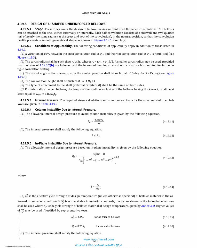
4.19.5 DESIGN OF U-SHAPED UNREINFORCED BELLOWS4.19.5.1 Scope. These rules cover the design of bellows having unreinforced U-shaped convolutions. The bellows
can be attached to the shell either externally or internally. Each half convolution consists of a sidewall and two quartertori of nearly the same radius (at the crest and root of the convolution), in the neutral position, so that the convolutionprofile presents a smooth geometrical shape as shown in Figure 4.19.1, sketch (a).
4.19.5.2 Conditions of Applicability. The following conditions of applicability apply in addition to those listed in4.19.2.(a) A variation of 10% between the crest convolution radius r i c and the root convolution radius r i r is permitted (see
Figure 4.19.3).(b) The torus radius shall be such that: r i ≥ 3t , where: r i = (r i c + r i r)/2. A smaller torus radius may be used, provided
that the rules of 4.19.3.2(b) are followed and the increased bending stress due to curvature is accounted for in the fa-tigue correlation testing.(c) The off-set angle of the sidewalls, α , in the neutral position shall be such that: −15 deg ≤ α ≤ +15 deg (see Figure
4.19.3).(d) The convolution height shall be such that: w ≤ Db/3.(e) The type of attachment to the shell (external or internal) shall be the same on both sides.(f) For internally attached bellows, the length of the shell on each side of the bellows having thickness t s shall be at
least equal to Lsm = .
4.19.5.3 Internal Pressure. The required stress calculations and acceptance criteria for U-shaped unreinforced bel-lows are given in Table 4.19.2.
4.19.5.4 Column Instability Due to Internal Pressure.(a) The allowable internal design pressure to avoid column instability is given by the following equation.
ð4:19:11Þ
(b) The internal pressure shall satisfy the following equation.
ð4:19:12Þ
4.19.5.5 In-Plane Instability Due to Internal Pressure.(a) The allowable internal design pressure based on in-plane instability is given by the following equation.
ð4:19:13Þ
where
ð4:19:14Þ
(b) is the effective yield strength at design temperature (unless otherwise specified) of bellows material in the as-
formed or annealed condition. If is not available in material standards, the values shown in the following equations
shall be used where Sy is the yield strength of bellows material at design temperature, given by Annex 3-D. Higher values
of may be used if justified by representative tests.
ð4:19:15Þ
ð4:19:16Þ
(c) The internal pressure shall satisfy the following equation.
518
ASME BPVC.VIII.2-2019
Copyright ASME International (BPVC) Provided by IHS under license with ASME Licensee=Khalda Petroleum/5986215001, User=Amer, Mohamed
Not for Resale, 07/02/2019 14:07:58 MDTNo reproduction or networking permitted without license from IHS
--`,```,,,,,````,`,``,,`,,`,`-`-`,,`,,`,`,,`--- www.iran-mavad.com
مرجع تخصصی مهندسین مواد و متالورژی

ð19Þ
ð4:19:17Þ
4.19.5.6 External Pressure Strength.(a) External pressure capacity - The rules of 4.19.5.3 shall be applied taking P as the absolute value of the external
pressure. When the expansion bellows is subjected to vacuum, the design shall be performed assuming that only theinternal ply resists the pressure. The pressure stress equations of 4.19.5.3 shall be applied with n = 1.
(b) Instability due to external pressure - The design shall be performed according to the rules of 4.4 by replacing thebellows with an equivalent cylinder, using an equivalent outside diameter, Deq , and an equivalent thickness, teq , givenby the following equations where I xx is the moment of inertia (see Figure 4.19.4).
ð4:19:18Þ
ð4:19:19Þ
(c) If Lt = 0, Ixx is given by the following equation.
ð4:19:20Þ
4.19.5.7 Fatigue Evaluation.(a) The meridional membrane and bending stresses due to the total equivalent axial displacement range Δq of each
convolution is given by the following equations.
ð4:19:21Þ
ð4:19:22Þ
Cf and Cd are evaluated using Tables 4.19.4 and 4.19.5, respectively.(b) The total stress range due to cyclic displacement is given by the following equation.
ð4:19:23Þ
(c) Calculation of allowable number of cycles(1) The specified number of cycles N spe shall be specified in consideration of the anticipated number of cycles ex-
pected to occur during the operating life of the bellows. The allowable number of cycles shall satisfy the followingequation.
ð4:19:24Þ(2) The allowable number of cycles, Na lw , shall be calculated using the equations in Table 4.19.6. These equations
are valid for:(-a) austenitic chromium-nickel stainless steels, UNS N066XX and UNS N04400, for metal temperatures not ex-
ceeding 425°C (800°F)(-b) U-shaped unreinforced bellows, as-formed or annealed(-c) basic designs and manufacturing processes that have successfully undergone fatigue correlation testing per
4.19.3.2(b)(3) For other materials, the allowable number of cycles, N a lw , shall be calculated using the equations in Table
4.19.6, replacing the constants with those of curves determined according to 4.19.3.2(c).(4) If the bellows is subjected to different cycles of pressure or displacement, such as those produced by start-up or
shutdown, their cumulative damage shall be considered as in 4.19.3.2(a).
4.19.5.8 Axial Stiffness. The theoretical axial stiffness of a bellows comprised of N convolutions may be evaluatedby the following equation. This equation is valid only in the elastic range. Outside of the elastic range lower values can beused, based upon Manufacturer’s experience or representative test results.
519
ASME BPVC.VIII.2-2019
Copyright ASME International (BPVC) Provided by IHS under license with ASME Licensee=Khalda Petroleum/5986215001, User=Amer, Mohamed
Not for Resale, 07/02/2019 14:07:58 MDTNo reproduction or networking permitted without license from IHS
--`,```,,,,,````,`,``,,`,,`,`-`-`,,`,,`,`,,`---
www.iran-mavad.com
مرجع تخصصی مهندسین مواد و متالورژی

ð4:19:25Þ
4.19.6 DESIGN OF U-SHAPED REINFORCED BELLOWS4.19.6.1 Scope. These rules cover the design of bellows having U-shaped convolutions with rings to reinforce the
bellows against internal pressure. The bellows shall be attached to the shell externally. Each half convolution consists ofa sidewall and two quarter tori of nearly the same radius (at the crest and root of the convolution), in the neutral posi-tion, so that the convolution profile presents a smooth geometrical shape as shown in Figure 4.19.1, sketch (b).
4.19.6.2 Conditions of Applicability. The conditions in 4.19.5.2 apply, with the exception of conditions 4.19.5.2(e)and 4.19.5.2(f).
4.19.6.3 Internal Pressure. The required stress calculations and acceptance criteria for U-shaped reinforced bel-lows are given in Table 4.19.7.
4.19.6.4 Column Instability Due to Internal Pressure.(a) The allowable internal design pressure to avoid column instability is given by the following equation.
ð4:19:26Þ
(b) The internal pressure shall satisfy the following equation.
ð4:19:27Þ
4.19.6.5 In-Plane Instability Due to Internal Pressure. Reinforced bellows are not prone to in-plane instability.
4.19.6.6 External Pressure Strength.(a) External pressure capacity - The rules of 4.19.5.3 relative to unreinforced bellows shall be applied taking P as the
absolute value of the external pressure. When the expansion bellows is subjected to vacuum, the design shall be per-formed assuming that only the internal ply resists the pressure. The pressure stress equations of 4.19.5.3 shall be ap-plied with n = 1.(b) Instability due to external pressure - The circumferential instability of a reinforced bellows shall be calculated in
the same manner as for unreinforced bellows (see 4.19.5.6(b))
4.19.6.7 Fatigue Evaluation.(a) The meridional membrane and bending stresses due to the total equivalent axial displacement range Δq of each
convolution are given by the following equations.
ð4:19:28Þ
ð4:19:29Þ
Cf and Cd are evaluated using Tables 4.19.4 and 4.19.5, respectively.(b) The total stress range due to cyclic displacement is given by eq. (4.19.23).(c) The fatigue evaluation of a reinforced bellows shall be calculated in the same manner as for unreinforced bellows
(see 4.19.5.7(c)), except that the allowable number of cycles shall be calculated using the equations in Table 4.19.8.
4.19.6.8 Axial Stiffness. The theoretical axial stiffness of a bellows comprised of N convolutions is given by thefollowing equation.
ð4:19:30Þ
This equation is valid only in the elastic range. Outside of the elastic range lower values can be used, based upon Man-ufacturer’s experience or representative test results.
520
ASME BPVC.VIII.2-2019
Copyright ASME International (BPVC) Provided by IHS under license with ASME Licensee=Khalda Petroleum/5986215001, User=Amer, Mohamed
Not for Resale, 07/02/2019 14:07:58 MDTNo reproduction or networking permitted without license from IHS
--`,```,,,,,````,`,``,,`,,`,`-`-`,,`,,`,`,,`---
www.iran-mavad.com
مرجع تخصصی مهندسین مواد و متالورژی

4.19.7 DESIGN OF TOROIDAL BELLOWS4.19.7.1 Scope. These rules cover the design of bellows having toroidal convolutions. The bellows can be attached to
the shell either externally or internally. Each convolution consists of a torus of radius r as shown in Figure 4.19.1, sketch(c).
4.19.7.2 Conditions of Applicability. The following conditions of applicability apply in addition to those listed in4.19.2:
(a) The type of attachment to the shell (external or internal) shall be the same on both sides.
(b) Distance Lg shall be less than 0.75r in the maximum extended position.
(c) For internally attached bellows, the length of the shell on each side of the bellows having thickness t s shall be at
least equal to .
4.19.7.3 Internal Pressure. The required stress calculations and acceptance criteria for toroidal bellows are given inTable 4.19.9.
4.19.7.4 Column Instability Due to Internal Pressure.(a) The allowable internal design pressure to avoid column instability is given by the following equation.
ð4:19:31Þ
(b) The internal pressure shall satisfy the following equation.
ð4:19:32Þ
4.19.7.5 In-Plane Instability Due to Internal Pressure. Toroidal bellows are not prone to in-plane instability.
4.19.7.6 External Pressure Strength.(a) Toroidal bellows designed per the rules of this Division are suitable for external design pressures up to 103 kPa
(15 psi) or full vacuum. For external design pressures greater than 103 kPa (15 psi), see 4.1.1.2.
(b) Instability due to external pressure is not covered by the present rules.
4.19.7.7 Fatigue Evaluation.(a) The meridional membrane and bending stresses due to the total equivalent axial displacement range Δq of each
convolution are given by the following equations.
ð4:19:33Þ
ð4:19:34Þ
B1 and B2 are evaluated using Table 4.19.10.
(b) The total stress range due to cyclic displacement is given by the following equation.
ð4:19:35Þ
(c) The fatigue evaluation of a toroidal bellows shall be calculated in the same manner as for unreinforced bellows[see 4.19.5.7(c)], except that the allowable number of cycles shall be calculated using the equations in Table 4.19.11.
4.19.7.8 Axial Stiffness. The theoretical axial stiffness of a bellows comprised of N convolutions is given by thefollowing equation.
ð4:19:36Þ
B3 is evaluated using Table 4.19.10. This equation is valid only in the elastic range. Outside of the elastic range lowervalues can be used, based upon Manufacturer’s experience or representative test results.
521
ASME BPVC.VIII.2-2019
Copyright ASME International (BPVC) Provided by IHS under license with ASME Licensee=Khalda Petroleum/5986215001, User=Amer, Mohamed
Not for Resale, 07/02/2019 14:07:58 MDTNo reproduction or networking permitted without license from IHS
--`,```,,,,,````,`,``,,`,,`,`-`-`,,`,,`,`,,`---
www.iran-mavad.com
مرجع تخصصی مهندسین مواد و متالورژی

4.19.8 BELLOWS SUBJECTED TO AXIAL, LATERAL, OR ANGULAR DISPLACEMENTS
4.19.8.1 General. The purpose of this paragraph is to determine the equivalent axial displacement of an expansionbellows subjected at its ends to:
(a) an axial displacement from the neutral position: x in extension (x > 0) or in compression (x < 0)
(b) a lateral deflection from the neutral position: y , (y > 0)
(c) an angular rotation from the neutral position: θ , (θ > 0)
4.19.8.2 Axial Displacement.
(a)When the ends of the bellows are subjected to an axial displacement x (see Figure 4.19.5), the equivalent axialdisplacement per convolution is given by the following equation. In this equation, x shall be taken as positive for exten-sion (x > 0) and negative for compression (x < 0). Values of x in extension and compression may be different.
ð4:19:37Þ
(b) The corresponding axial force Fx applied to the ends of the bellows is given by the following equation.
ð4:19:38Þ
4.19.8.3 Lateral Deflection.
(a)When the ends of the bellows are subjected to a lateral deflection y (see Figure 4.19.6), the equivalent axial dis-placement per convolution is given by the following equation where y shall be taken positive.
ð4:19:39Þ
(b) The corresponding lateral force Fy applied to the ends of the bellows is given by the following equation.
ð4:19:40Þ
(c) The corresponding moment My applied to the ends of the bellows is given by the following equation.
ð4:19:41Þ
4.19.8.4 Angular Rotation.
(a)When the ends of the bellows are subjected to an angular rotation θ (see Figure 4.19.7), the equivalent axial dis-placement per convolution is given by the following equation where θ , expressed in radians, shall be taken positive.
ð4:19:42Þ
(b) The corresponding moment Mθ applied to the ends of the bellows is given by the following equation.
ð4:19:43Þ
522
ASME BPVC.VIII.2-2019
Copyright ASME International (BPVC) Provided by IHS under license with ASME Licensee=Khalda Petroleum/5986215001, User=Amer, Mohamed
Not for Resale, 07/02/2019 14:07:58 MDTNo reproduction or networking permitted without license from IHS
--`,```,,,,,````,`,``,,`,,`,`-`-`,,`,,`,`,,`---
www.iran-mavad.com
مرجع تخصصی مهندسین مواد و متالورژی

ð19Þ
ð19Þ
4.19.8.5 Total Equivalent Axial Displacement Per Convolution. Axial displacement leads to uniform deformationof the convolutions. Lateral deflection and angular rotation lead to nonuniform deformation of the convolutions with oneside extended and the other side compressed as shown in Figures 4.19.6 and 4.19.7. The total equivalent axial displace-ments per convolution, on the extended side and the compressed side, are given by the following equations:
ð4:19:44Þ
ð4:19:45Þ
NOTE: In case of axial displacement only, Δqe = Δqc = Δqx .
4.19.8.6 Total Equivalent Axial Displacement Range Per Convolution.(a) Bellows installed without cold spring - If the bellows is subjected to displacements from the neutral position (x0 =
0, y0 = 0, θ0 = 0) to the operating position (x1 , y1 , θ1) (see Figure 4.19.8), the total equivalent axial displacements perconvolution, on the extended side and the compressed side, for the initial and operating positions and the total equiva-lent axial displacement range are given by the following equations:
Initial Position:
ð4:19:46Þ
ð4:19:47Þ
Operating Position:
ð4:19:48Þ
ð4:19:49Þ
Total Equivalent Axial Displacement Range:
ð4:19:50Þ
NOTE: In case of axial displacement only, Δq = |Δqx ,1|.
(b) Bellows installed with cold spring - If the bellows is subjected to displacements from an initial position (x0 , y0 , θ0),which is not the neutral position to the operating position (x1 , y1 , θ1) (see Figure 4.19.9), the total equivalent axial dis-placements per convolution, on the extended side and the compressed side, for the initial and operating positions andthe total equivalent axial displacement range are given by the following equations:
Initial Position:
ð4:19:51Þ
ð4:19:52Þ
Operating Position:
ð4:19:53Þ
ð4:19:54Þ
Total Equivalent Axial Displacement Range:
ð4:19:55Þ
Alternatively, if the neutral position for lateral deflection and angular rotation is not passed between the initial posi-tion and the operating position, the total equivalent axial displacement range may be written as
523
ASME BPVC.VIII.2-2019
Copyright ASME International (BPVC) Provided by IHS under license with ASME Licensee=Khalda Petroleum/5986215001, User=Amer, Mohamed
Not for Resale, 07/02/2019 14:07:58 MDTNo reproduction or networking permitted without license from IHS
--`,```,,,,,````,`,``,,`,,`,`-`-`,,`,,`,`,,`---
www.iran-mavad.com
مرجع تخصصی مهندسین مواد و متالورژی
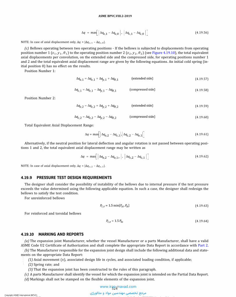
ð4:19:56Þ
NOTE: In case of axial displacement only, Δq = |Δqx ,1 – Δqx ,0|.
(c) Bellows operating between two operating positions - If the bellows is subjected to displacements from operatingposition number 1 (x1 , y1 , θ1) to the operating position number 2 (x2 , y2 , θ2) (see Figure 4.19.10), the total equivalentaxial displacements per convolution, on the extended side and the compressed side, for operating positions number 1and 2 and the total equivalent axial displacement range are given by the following equations. An initial cold spring (in-itial position 0) has no effect on the results.Position Number 1:
ð4:19:57Þ
ð4:19:58Þ
Position Number 2:
ð4:19:59Þ
ð4:19:60Þ
Total Equivalent Axial Displacement Range:
ð4:19:61Þ
Alternatively, if the neutral position for lateral deflection and angular rotation is not passed between operating posi-tions 1 and 2, the total equivalent axial displacement range may be written as
ð4:19:62Þ
NOTE: In case of axial displacement only, Δq = |Δqx ,2 – Δqx ,1|.
4.19.9 PRESSURE TEST DESIGN REQUIREMENTS
The designer shall consider the possibility of instability of the bellows due to internal pressure if the test pressureexceeds the value determined using the following applicable equation. In such a case, the designer shall redesign thebellows to satisfy the test condition.For unreinforced bellows
ð4:19:63Þ
For reinforced and toroidal bellows
ð4:19:64Þ
4.19.10 MARKING AND REPORTS
(a) The expansion joint Manufacturer, whether the vessel Manufacturer or a parts Manufacturer, shall have a validASME Code U2 Certificate of Authorization and shall complete the appropriate Data Report in accordance with Part 2.(b) The Manufacturer responsible for the expansion joint design shall include the following additional data and state-
ments on the appropriate Data Report:(1) Axial movement (±), associated design life in cycles, and associated loading condition, if applicable;(2) Spring rate; and(3) That the expansion joint has been constructed to the rules of this paragraph.
(c) A parts Manufacturer shall identify the vessel for which the expansion joint is intended on the Partial Data Report.(d)Markings shall not be stamped on the flexible elements of the expansion joint.
524
ASME BPVC.VIII.2-2019
Copyright ASME International (BPVC) Provided by IHS under license with ASME Licensee=Khalda Petroleum/5986215001, User=Amer, Mohamed
Not for Resale, 07/02/2019 14:07:58 MDTNo reproduction or networking permitted without license from IHS
--`,```,,,,,````,`,``,,`,,`,`-`-`,,`,,`,`,,`---
www.iran-mavad.com
مرجع تخصصی مهندسین مواد و متالورژی

ð19Þ4.19.11 NOMENCLATURE
A = cross-sectional metal area of one convolution.Af = cross-sectional metal area of one reinforcing fastenerAr = cross-sectional metal area of one bellows reinforcing member for U-shaped bellows and cross-sectional
metal area of one reinforcing collar for toroidal bellows based on length Lr
Ar t = cross-sectional metal area of one reinforcing collar for toroidal bellows based on overall lengthAtc = cross-sectional metal area of one tangent collarAts = cross-sectional metal area of shell based on length Ls
B1 , B2 , B3 = stress and stiffness coefficients used for toroidal bellows.C1 , C2 = coefficients used to determine the coefficients Cp , Cf , Cd
C3 = coefficient used to determine the coefficients B1 , B2 , B3
Cp , C f , Cd = stress coefficients for U-shaped convolutions.Cr = convolution height factor for reinforced bellows.
Cwc = longitudinal weld joint efficiency of tangent collar.Cwr = longitudinal weld joint efficiency of reinforcing member.Cws = longitudinal weld joint efficiency of shell.Db = inside diameter of bellows convolution and end tangents.Dc = mean diameter of tangent collar.
Deq = equivalent outside diameter.Dm = mean diameter of bellows convolution.Dr = mean diameter of reinforcing collar for toroidal bellows.Ds = inside diameter of cylindrical shell or weld end on which the bellows is attached.E0 = modulus of elasticity of bellows material at room temperature.Eb = modulus of elasticity of bellows material at design temperature.Ec = modulus of elasticity of collar material at design temperature.Ef = modulus of elasticity of reinforcing fastener material at design temperature.Er = modulus of elasticity of reinforcing ring member material at design temperature.Es = modulus of elasticity of shell or weld end material at design temperatureGb = modulus of rigidity of bellows material at design temperature.I xx = moment of inertia of one convolution cross section relative to the axis passing by the center of gravity and
parallel to the axis of the bellows.k = factor considering the stiffening effect of the attachment weld and the end convolution on the pressure
capacity of the end tangentK0 , K1 ,K2 , K3 = coefficients determined by best curve fit of bellows fatigue test data.
K ′0 , K ′1 ,K ′2 , K ′3 = coefficients determined by best curve fit of bellows fatigue test data.
Kb = bellows axial stiffness.Kf = forming method factor
= 1.0 for expanding mandrel or roll forming= 0.6 for hydraulic, elastomeric, or pneumatic tube forming
Kg = fatigue strength reduction factor.Lc = bellows collar length.Ld = length from attachment weld to the center of the first convolution for reinforced bellows and for exter-
nally attached toroidal bellows.Ldt = developed length of one convolution.Lf = effective length of one reinforcing fastener. Distance between mating face of the bolt head and mid-
thickness of the nut or distance between mid-thickness of the two nuts, as applicable.Lg = maximum distance across the inside opening of a toroidal convolution considering all movements.Lr = effective reinforcing collar length.
=
Lrt = overall length of reinforcing collar.Ls = effective shell length.
=
525
ASME BPVC.VIII.2-2019
Copyright ASME International (BPVC) Provided by IHS under license with ASME Licensee=Khalda Petroleum/5986215001, User=Amer, Mohamed
Not for Resale, 07/02/2019 14:07:58 MDTNo reproduction or networking permitted without license from IHS
--`,```,,,,,````,`,``,,`,,`,`-`-`,,`,,`,`,,`---
www.iran-mavad.com
مرجع تخصصی مهندسین مواد و متالورژی

Lsm = minimum required shell length having thickness t s .Lt = end tangent length.Mz = torsional load.N = number of convolutions.n = number of plies.
Na lw = allowable number of fatigue cycles.N spe = specified number of fatigue cycles.
P = design pressure.
NOTE: If the specified design pressure of the bellows is significantly greater than the required design pressure of the vessel,use of the larger specified design pressure may adversely affect the allowable number cycles that the bellows can experience.
Psc = allowable internal design pressure to avoid column instability.Ps i = allowable internal design pressure to avoid in-plane instability.q = convolution pitch as shown in Figure 4.19.1.r = mean radius of toroidal bellows convolution.R = ratio of the internal pressure force resisted by the bellows to the internal pressure force resisted by the
reinforcementr i = average internal torus radius of U-shaped bellows convolution (see 4.19.5.2).r i c = crest convolution internal radius.r i r = root convolution internal radius.rm = mean radius of U-shaped bellows convolution.S = allowable stress from Annex 3-A of bellows material at design temperature.
= effective yield strength of the bellows material at the design temperature.
S1 = circumferential membrane stress in bellows tangent, due to pressure P .S2 = circumferential membrane stress in bellows, due to pressure P .S3 = meridional membrane stress in bellows, due to pressure P .S4 = meridional bending stress in bellows, due to pressure P .S5 = meridional membrane stress in bellows, due to total equivalent axial displacement range Δq .S6 = meridional bending stress in bellows, due to total equivalent axial displacement range Δq .Sc = allowable stress from Annex 3-A of collar material at design temperature.Sf = allowable stress from Annex 3-A of reinforcing fastener material at design temperature.Sq = total stress range due to cyclic displacement.Sr = allowable stress from Annex 3-A of reinforcing ring member material at design temperature.Ss = allowable stress from Annex 3-A of shell material at design temperature.St = total stress range due to cyclic displacement corrected by internal pressure.Sy = yield strength of the bellows material at the design temperature.
= circumferential membrane stress in collar, due to pressure P .= circumferential membrane stress in shell, due to pressure P , for internally attached bellows.= circumferential membrane stress in reinforcing member, due to pressure P .= membrane stress in fastener, due to pressure P .
t = nominal thickness of one ply.t c = collar thickness.
teq = equivalent wall thicknesstp = thickness of one ply, corrected for thinning during forming.t r = reinforcing collar thickness.t s = nominal thickness of shell or weld end.U = usage factor.vb = Poisson’s ratio of bellows material.w = convolution height.
Ysm = yield strength multiplier depending upon material.Δq = total equivalent axial displacement range per convolution.ε f = bellows forming strain.α = offset angle of the U-shape bellows side-wall.θ z = twist angle between the two extreme points of the end convolutions.τz = shear stress due to torsional load or twist angle.
526
ASME BPVC.VIII.2-2019
Copyright ASME International (BPVC) Provided by IHS under license with ASME Licensee=Khalda Petroleum/5986215001, User=Amer, Mohamed
Not for Resale, 07/02/2019 14:07:58 MDTNo reproduction or networking permitted without license from IHS
--`,```,,,,,````,`,``,,`,,`,`-`-`,,`,,`,`,,`---
www.iran-mavad.com
مرجع تخصصی مهندسین مواد و متالورژی

4.19.12 TABLES
Table 4.19.1Maximum Design Temperatures for Application of the Rules of 4.19
Table in WhichMaterial Is Listed
Maximum Temperature
°C °F
3-A.3 425 8003-A.4 150 3003-A.6 425 8003-A.7 315 600
527
ASME BPVC.VIII.2-2019
Copyright ASME International (BPVC) Provided by IHS under license with ASME Licensee=Khalda Petroleum/5986215001, User=Amer, Mohamed
Not for Resale, 07/02/2019 14:07:58 MDTNo reproduction or networking permitted without license from IHS
--`,```,,,,,````,`,``,,`,,`,`-`-`,,`,,`,`,,`---
www.iran-mavad.com
مرجع تخصصی مهندسین مواد و متالورژی

Table 4.19.2Stress Calculations and Acceptability Criteria for U-Shaped Unreinforced Bellows Subject to
Internal Pressure
Stress Calculation
Circumferential membrane stress in end tangent for externally attached bellows
Circumferential membrane stress in collar for externally attached bellows
Circumferential membrane stress in shell for internally attached bellows
Circumferential membrane stress in bellows convolutions:for end convolutions of externally attached bellows when k is less than 1.0
for intermediate convolutions
Meridional membrane stress
Meridional bending stress
where
A =
rm =
Dc =
Dm =
k =
Acceptance Criteria
GENERAL NOTES:(a) Km = 1.5Ysm for as-formed bellows and Km = 1.5 for annealed bellows.(b) Ysm = 1 + 9.94(Kfε f) − 7.59(Kfε f)
2 − 2.4(Kfε f)3 + 2.21(Kfε f)
4 for austenitic stainless steel.
528
ASME BPVC.VIII.2-2019
Copyright ASME International (BPVC) Provided by IHS under license with ASME Licensee=Khalda Petroleum/5986215001, User=Amer, Mohamed
Not for Resale, 07/02/2019 14:07:58 MDTNo reproduction or networking permitted without license from IHS
--`,```,,,,,````,`,``,,`,,`,`-`-`,,`,,`,`,,`---
www.iran-mavad.com
مرجع تخصصی مهندسین مواد و متالورژی

Table 4.19.2Stress Calculations and Acceptability Criteria for U-Shaped Unreinforced Bellows Subject to
Internal Pressure (Cont'd)
GENERAL NOTES (CONT'D):Ysm = 1 + 6.8(Kfε f) − 9.11(Kfε f)
2 + 9.73(Kfε f)3 − 6.43(Kfε f)
4 for nickel alloys.Ysm = 1.0 for other materials.If Ysm is less than 1.0, then Ysm = 1.0 .If Ysm is greater than 2.0, then Ysm = 2.0 .
(c)for bellows formed from cylinders with an inside diameter of Db if forming is performed
100% to the outside of the initial cylinder.
for bellows formed from cylinders with an inside diameter of Dm if forming is performed
50% to the inside and 50% to the outside of the initial cylinder.(d) Cp is evaluated using Table 4.19.3.
Table 4.19.3Method to Determine Coefficient Cp
C2
C1 ≤ 0.3
α0 α1 α2 α3 α4 α5
0.2 1.001 −0.448 −1.244 1.932 −0.398 −0.2910.4 0.999 −0.735 0.106 −0.585 1.787 −1.0220.6 0.961 −1.146 3.023 −7.488 8.824 −3.6340.8 0.955 −2.708 7.279 14.212 −104.242 133.3331.0 0.95 −2.524 10.402 −93.848 423.636 −613.333
1.2 0.95 −2.296 1.63 16.03 −113.939 2401.4 0.95 −2.477 7.823 −49.394 141.212 −106.6671.6 0.95 −2.027 −5.264 48.303 −139.394 1602.0 0.95 −2.073 −3.622 29.136 −49.394 13.3332.5 0.95 −2.073 −3.622 29.136 −49.394 13.333
3.0 0.95 −2.073 −3.622 29.136 −49.394 13.3333.5 0.95 −2.073 −3.622 29.136 −49.394 13.3334.0 0.95 −2.073 −3.622 29.136 −49.394 13.333
C2
C1 > 0.3
α0 α1 α2 α3 α4 α5
0.2 1.001 −0.448 −1.244 1.932 −0.398 −0.2910.4 0.999 −0.735 0.106 −0.585 1.787 −1.0220.6 0.961 −1.146 3.023 −7.488 8.824 −3.6340.8 0.622 1.685 −9.347 18.447 −15.991 5.1191.0 0.201 2.317 −5.956 7.594 −4.945 1.299
1.2 0.598 −0.99 3.741 −6.453 5.107 −1.5271.4 0.473 −0.029 −0.015 −0.03 0.016 0.0161.6 0.477 −0.146 −0.018 0.037 0.097 −0.0672.0 0.935 −3.613 9.456 −13.228 9.355 −2.6132.5 1.575 −8.646 24.368 −35.239 25.313 −7.157
3.0 1.464 −7.098 17.875 −23.778 15.953 −4.2453.5 1.495 −6.904 16.024 −19.6 12.069 −2.9444.0 2.037 −11.037 28.276 −37.655 25.213 −6.716
GENERAL NOTES:(a)
529
ASME BPVC.VIII.2-2019
Copyright ASME International (BPVC) Provided by IHS under license with ASME Licensee=Khalda Petroleum/5986215001, User=Amer, Mohamed
Not for Resale, 07/02/2019 14:07:58 MDTNo reproduction or networking permitted without license from IHS
--`,```,,,,,````,`,``,,`,,`,`-`-`,,`,,`,`,,`---
www.iran-mavad.com
مرجع تخصصی مهندسین مواد و متالورژی

Table 4.19.3Method to Determine Coefficient Cp (Cont'd)
GENERAL NOTES (CONT'D):(b)
(c)
(d) A plot of Cp versus C1 and C2 is shown in Figure 4.19.12.
Table 4.19.4Method to Determine Coefficient Cf
C2 α0 α1 α2 α3 α4 α5
0.2 1.006 2.375 −3.977 8.297 −8.394 3.1940.4 1.007 1.82 −1.818 2.981 −2.43 0.870.6 1.003 1.993 −5.055 12.896 −14.429 5.8970.8 1.003 1.338 −1.717 1.908 0.02 −0.551.0 0.997 0.621 −0.907 2.429 −2.901 1.361
1.2 1 0.112 −1.41 3.483 −3.044 1.0131.4 1 −0.285 −1.309 3.662 −3.467 1.1911.6 1.001 −0.494 −1.879 4.959 −4.569 1.5432.0 1.002 −1.061 −0.715 3.103 −3.016 0.992.5 1 −1.31 −0.829 4.116 −4.36 1.55
3.0 0.999 −1.521 −0.039 2.121 −2.215 0.773.5 0.998 −1.896 1.839 −2.047 1.852 −0.6644.0 1 −2.007 1.62 −0.538 −0.261 0.249
GENERAL NOTES:(a)
(b)
(c)
(d) A plot of Cf versus C1 and C2 is shown in Figure 4.19.13.
Table 4.19.5Method to Determine Coefficient Cd
C2 α0 α1 α2 α3 α4 α5
0.2 1 1.151 1.685 −4.414 4.564 −1.6450.4 0.999 1.31 0.909 −2.407 2.273 −0.7060.6 1.003 2.189 −3.192 5.928 −5.576 2.070.8 1.005 1.263 5.184 −13.929 13.828 −4.831.0 1.001 0.953 3.924 −8.773 10.44 −4.749
1.2 1.002 0.602 2.11 −3.625 5.166 −2.3121.4 0.998 0.309 1.135 −1.04 1.296 −0.0871.6 0.999 0.12 0.351 −0.178 0.942 −0.1152.0 1 −0.133 −0.46 1.596 −1.521 0.8772.5 1 −0.323 −1.118 3.73 −4.453 2.055
3.0 1 −0.545 −0.42 1.457 −1.561 0.713.5 1 −0.704 −0.179 0.946 −1.038 0.4744.0 1.001 −0.955 0.577 −0.462 0.181 0.08
530
ASME BPVC.VIII.2-2019
Copyright ASME International (BPVC) Provided by IHS under license with ASME Licensee=Khalda Petroleum/5986215001, User=Amer, Mohamed
Not for Resale, 07/02/2019 14:07:58 MDTNo reproduction or networking permitted without license from IHS
--`,```,,,,,````,`,``,,`,,`,`-`-`,,`,,`,`,,`---
www.iran-mavad.com
مرجع تخصصی مهندسین مواد و متالورژی

ð19Þ
Table 4.19.5Method to Determine Coefficient Cd (Cont'd)
GENERAL NOTES:(a)
(b)
(c)
(d) A plot of Cd versus C1 and C2 is shown in Figure 4.19.14.
Table 4.19.6Allowable Number of Cycles for U-Shaped Unreinforced Bellows
Stress Range Criteria Allowable Number of Cycles
SI Units
U.S. Customary Units
GENERAL NOTES:(a) In the above equations, Kg is the fatigue strength reduction factor that accounts for geometrical stress concentration factors due to
thickness variations, weld geometries, surface notches, and other surface or environmental conditions. The range for Kg is
with its minimum value for smooth geometrical shapes and its maximum for 90 deg welded corners and fillet welds.
Fatigue strength reduction factors may be determined from theoretical, experimental, or photoelastic studies. A factor has already beenincluded in the above equations for N to account for normal effects of size, environment, and surface finish. If the expansion bellows
does not have circumferential welds and satisfies all of the design and examination requirements of this paragraph, a may be
used.(b) The allowable number of cycles given in this table includes a reasonable design margin (2.6 on cycles and 1.25 on stress) and represents
the maximum number of cycles for the operating condition considered. Therefore an additional design margin should not be applied. Anoverly conservative estimate of cycles can necessitate a greater number of convolutions and result in a bellows more prone toinstability.
531
ASME BPVC.VIII.2-2019
Copyright ASME International (BPVC) Provided by IHS under license with ASME Licensee=Khalda Petroleum/5986215001, User=Amer, Mohamed
Not for Resale, 07/02/2019 14:07:58 MDTNo reproduction or networking permitted without license from IHS
--`,```,,,,,````,`,``,,`,,`,`-`-`,,`,,`,`,,`---www.iran-mavad.com
مرجع تخصصی مهندسین مواد و متالورژی

Table 4.19.7Stress Calculations and Acceptability Criteria for U-Shaped Reinforced Bellows Subject to Internal
Pressure
Bellows Reinforcing Ring Member and Fastener
Stress Calculation
Circumferential membrane stress in end tangent
Circumferential membrane stress in collar
Circumferential membrane stress in convolutions
Meridional membrane stress
Meridional bending stress
where
Cr =
=
Circumferential membrane stress in ring member
where
R1 =
Membrane stress in fastener
where
R2 =
Acceptance Criteria
GENERAL NOTES:(a) k , A , Dc , Dm , tp , Km , and rm are evaluated using the equations in Table 4.19.2.(b) Cp is evaluated using Table 4.19.3.(c) R = R1 for integral reinforcing ring members and R2 for reinforcing ring members joined by fasteners.(d) In the case of reinforcing members which are made in sections, and joined by fasteners in tension, the equation for S2 assumes that the
structure used to retain the fastener does not bend so as to permit the reinforcing member to expand diametrically. In addition, the endreinforcing members must be restrained against the longitudinal annular pressure load of the bellows.
(e) In the case of equalizing rings, the equation for S ’2 provides only the simple membrane stress and does not include the bending stresscaused by the eccentric fastener location. Elastic analysis and/or actual tests can determine these stresses.
532
ASME BPVC.VIII.2-2019
Copyright ASME International (BPVC) Provided by IHS under license with ASME Licensee=Khalda Petroleum/5986215001, User=Amer, Mohamed
Not for Resale, 07/02/2019 14:07:58 MDTNo reproduction or networking permitted without license from IHS
--`,```,,,,,````,`,``,,`,,`,`-`-`,,`,,`,`,,`---
www.iran-mavad.com
مرجع تخصصی مهندسین مواد و متالورژی

ð19ÞTable 4.19.8Allowable Number of Cycles for U-Shaped Reinforced Bellows
Stress Range Criteria Allowable Number of Cycles
SI Units
U.S. Customary Units
GENERAL NOTES:(a) In the above equations, Kg is the fatigue strength reduction factor that accounts for geometrical stress concentration factors due to
thickness variations, weld geometries, surface notches, and other surface or environmental conditions. The range for Kg is 1.0 ≤ Kg
≤ 4.0 with its minimum value for smooth geometrical shapes and its maximum for 90 deg. welded corners and fillet welds. Fatiguestrength reduction factors may be determined from theoretical, experimental, or photoelastic studies. A factor has already been in-cluded in the above equations for N to account for normal effects of size, environment, and surface finish. If the expansion bellows doesnot have circumferential welds and satisfies all of the design and examination requirements of this paragraph, Kg = 1.0 may be used.
(b) The allowable number of cycles given in this table includes a reasonable design margin (2.6 on cycles and 1.25 on stress) and representsthe maximum number of cycles for the operating condition considered. Therefore an additional design margin should not be applied. Anoverly conservative estimate of cycles can necessitate a greater number of convolutions and result in a bellows more prone toinstability.
533
ASME BPVC.VIII.2-2019
Copyright ASME International (BPVC) Provided by IHS under license with ASME Licensee=Khalda Petroleum/5986215001, User=Amer, Mohamed
Not for Resale, 07/02/2019 14:07:58 MDTNo reproduction or networking permitted without license from IHS
--`,```,,,,,````,`,``,,`,,`,`-`-`,,`,,`,`,,`---
www.iran-mavad.com
مرجع تخصصی مهندسین مواد و متالورژی

Table 4.19.9Stress Calculations and Acceptability Criteria for Toroidal Bellows Subject to Internal Pressure
Stress Calculation
Circumferential membrane stress in end tangent
Circumferential membrane stress in tangent collar
Circumferential membrane stress in shell
Circumferential membrane stress in bellows convolutions
Circumferential membrane stress in reinforcing collar
Meridional membrane stress in bellows convolutions
where
Dc = Db + 2nt + t c
tp =
Acceptance Criteria
S1 ≤ S for externally attached bellows
for externally attached bellows
for internally attached bellows
S2 ≤ S
S3 ≤ S
534
ASME BPVC.VIII.2-2019
Copyright ASME International (BPVC) Provided by IHS under license with ASME Licensee=Khalda Petroleum/5986215001, User=Amer, Mohamed
Not for Resale, 07/02/2019 14:07:58 MDTNo reproduction or networking permitted without license from IHS
--`,```,,,,,````,`,``,,`,,`,`-`-`,,`,,`,`,,`---
www.iran-mavad.com
مرجع تخصصی مهندسین مواد و متالورژی

Table 4.19.10Stress and Axial Stiffness Coefficients for Toroidal Bellows
C3 B1 B2 B3
0 1.0 1.0 1.01 1.1 1.0 1.12 1.4 1.0 1.33 2.0 1.0 1.54 2.8 1.0 1.95 3.6 1.0 2.36 4.6 1.1 2.87 5.7 1.2 3.38 6.8 1.4 3.89 8.0 1.5 4.4
10 9.2 1.6 4.911 10.6 1.7 5.412 12.0 1.8 5.913 13.2 2.0 6.414 14.7 2.1 6.915 16.0 2.2 7.416 17.4 2.3 7.917 18.9 2.4 8.518 20.3 2.6 9.019 21.9 2.7 9.520 23.3 2.8 10.0
GENERAL NOTE: Equations for B1 , B2 , and B3 are shown below.
where
C3 =
535
ASME BPVC.VIII.2-2019
Copyright ASME International (BPVC) Provided by IHS under license with ASME Licensee=Khalda Petroleum/5986215001, User=Amer, Mohamed
Not for Resale, 07/02/2019 14:07:58 MDTNo reproduction or networking permitted without license from IHS
--`,```,,,,,````,`,``,,`,,`,`-`-`,,`,,`,`,,`---
www.iran-mavad.com
مرجع تخصصی مهندسین مواد و متالورژی

ð19Þ Table 4.19.11Allowable Number of Cycles for Toroidal Bellows
Stress Range Criteria Allowable Number of Cycles
SI Units
U.S. Customary Units
GENERAL NOTES:(a) In the above equations, Kg is the fatigue strength reduction factor that accounts for geometrical stress concentration factors due to
thickness variations, weld geometries, surface notches, and other surface or environmental conditions. The range for Kg is 1.0 ≤ Kg
≤ 4.0 with its minimum value for smooth geometrical shapes and its maximum for 90 deg welded corners and fillet welds. Fatiguestrength reduction factors may be determined from theoretical, experimental, or photoelastic studies. A factor has already been in-cluded in the above equations for N to account for normal effects of size, environment, and surface finish. If the expansion bellows doesnot have circumferential welds and satisfies all of the design and examination requirements of this paragraph, Kg = 1.0 may be used.
(b) The allowable number of cycles given in this table includes a reasonable design margin (2.6 on cycles and 1.25 on stress) and representsthe maximum number of cycles for the operating condition considered. Therefore an additional design margin should not be applied. Anoverly conservative estimate of cycles can necessitate a greater number of convolutions and result in a bellows more prone toinstability.
536
ASME BPVC.VIII.2-2019
Copyright ASME International (BPVC) Provided by IHS under license with ASME Licensee=Khalda Petroleum/5986215001, User=Amer, Mohamed
Not for Resale, 07/02/2019 14:07:58 MDTNo reproduction or networking permitted without license from IHS
--`,```,,,,,````,`,``,,`,,`,`-`-`,,`,,`,`,,`---
www.iran-mavad.com
مرجع تخصصی مهندسین مواد و متالورژی

4.19.13 FIGURES
Figure 4.19.1Typical Bellows Expansion Joints
Reinforcing collar
Shell
Art
tr
r
Lsm
Ls
ts
Dm
Ds
Lg
Lrt
Dr
q
Atc
tc
Collar
Shell
nt
Db
Ld
External Bellows Attachment
Internal Bellows Attachment
Reinforcing rings
Equalizing ring
End equalizing ring
View A AqA
A
Db
tcAr
Af
Lf
w
Arnt
Ld
Atc
(a) Unreinforced Bellows
(b) Reinforced Bellows
(c) Toroidal Bellows
ShellShell
Internal BellowsAttachment
External BellowsAttachment
nt DbDs
w
Ls
Lsm
Lt Nq
q Convolutions
Collar
Lc
tcts
537
ASME BPVC.VIII.2-2019
Copyright ASME International (BPVC) Provided by IHS under license with ASME Licensee=Khalda Petroleum/5986215001, User=Amer, Mohamed
Not for Resale, 07/02/2019 14:07:58 MDTNo reproduction or networking permitted without license from IHS
--`,```,,,,,````,`,``,,`,,`,`-`-`,,`,,`,`,,`---
www.iran-mavad.com
مرجع تخصصی مهندسین مواد و متالورژی

Figure 4.19.2Starting Points for the Measurement of the Length of Shell on Each Side of Bellows
Reinforcing collar
Shell
Collar
Shell
External Bellows Attachment
Internal Bellows Attachment
AB
(a) U-Shaped Bellows
(b) Toroidal Bellows
AShell
ShellA
Internal BellowsAttachment
External BellowsAttachment
538
ASME BPVC.VIII.2-2019
Copyright ASME International (BPVC) Provided by IHS under license with ASME Licensee=Khalda Petroleum/5986215001, User=Amer, Mohamed
Not for Resale, 07/02/2019 14:07:58 MDTNo reproduction or networking permitted without license from IHS
--`,```,,,,,````,`,``,,`,,`,`-`-`,,`,,`,`,,`---
www.iran-mavad.com
مرجع تخصصی مهندسین مواد و متالورژی

Figure 4.19.3Possible Convolution Profile in Neutral Position
�
�
ric ric
rir rir
Figure 4.19.4Dimensions to Determine Ixx
q
w
Gx x
539
ASME BPVC.VIII.2-2019
Copyright ASME International (BPVC) Provided by IHS under license with ASME Licensee=Khalda Petroleum/5986215001, User=Amer, Mohamed
Not for Resale, 07/02/2019 14:07:58 MDTNo reproduction or networking permitted without license from IHS
--`,```,,,,,````,`,``,,`,,`,`-`-`,,`,,`,`,,`---
www.iran-mavad.com
مرجع تخصصی مهندسین مواد و متالورژی

ð19Þ
Figure 4.19.5Bellows Subjected to an Axial Displacement x
Nq
Fx
–X +X
q
= point of application of external forces and moments
N convolutions
FxDm
Figure 4.19.6Bellows Subjected to a Lateral Deflection y
Nq
y
FxDmMyMy
Fy
Fx
�x
�x
Compressed side
Compressed side
Extended side
Extended side
= point of application of external forces and moments
540
ASME BPVC.VIII.2-2019
Copyright ASME International (BPVC) Provided by IHS under license with ASME Licensee=Khalda Petroleum/5986215001, User=Amer, Mohamed
Not for Resale, 07/02/2019 14:07:58 MDTNo reproduction or networking permitted without license from IHS
--`,```,,,,,````,`,``,,`,,`,`-`-`,,`,,`,`,,`---
www.iran-mavad.com
مرجع تخصصی مهندسین مواد و متالورژی

ð19ÞFigure 4.19.7Bellows Subjected to an Angular Rotation θ
Dm q
N convolutions
M�
M�
�
�
�
Compressed side
Extended side
= point of application of external forces and moments
541
ASME BPVC.VIII.2-2019
Copyright ASME International (BPVC) Provided by IHS under license with ASME Licensee=Khalda Petroleum/5986215001, User=Amer, Mohamed
Not for Resale, 07/02/2019 14:07:58 MDTNo reproduction or networking permitted without license from IHS
--`,```,,,,,````,`,``,,`,,`,`-`-`,,`,,`,`,,`---
www.iran-mavad.com
مرجع تخصصی مهندسین مواد و متالورژی

ð19Þ
ð19Þ
Figure 4.19.8Cyclic Displacements
0T 2T
(1)
(n)t
�q
�q1
�q
Legend:(1) = operating position, Δq1 (n) = neutral position
Figure 4.19.9Cyclic Displacements
0t
(1)
(n)
(0)
0
1
�q
�q
Legend:(0) = initial position, Δq0
(1) = operating position, Δq1
(n) = neutral position
542
ASME BPVC.VIII.2-2019
Copyright ASME International (BPVC) Provided by IHS under license with ASME Licensee=Khalda Petroleum/5986215001, User=Amer, Mohamed
Not for Resale, 07/02/2019 14:07:58 MDTNo reproduction or networking permitted without license from IHS
--`,```,,,,,````,`,``,,`,,`,`-`-`,,`,,`,`,,`---
www.iran-mavad.com
مرجع تخصصی مهندسین مواد و متالورژی

ð19ÞFigure 4.19.10Cyclic Displacements
0t
(2)
(n)
(0)
(1)
2
�q
�q
Legend:(0) = initial position 0(1) = operating position 1
(2) = operating position 2(n) = neutral position
543
ASME BPVC.VIII.2-2019
Copyright ASME International (BPVC) Provided by IHS under license with ASME Licensee=Khalda Petroleum/5986215001, User=Amer, Mohamed
Not for Resale, 07/02/2019 14:07:58 MDTNo reproduction or networking permitted without license from IHS
--`,```,,,,,````,`,``,,`,,`,`-`-`,,`,,`,`,,`---
www.iran-mavad.com
مرجع تخصصی مهندسین مواد و متالورژی

Figure 4.19.11Some Typical Expansion Bellows Attachment Welds
ConvolutionShell or weld end
Full fillet weld
nt
6 mm (¼ in.) max.
Full fillet weld
Convolution
Bolted or welded collar (if required)
ts
Db
Shell or weld end
Full penetration groove weld
nt
(c)
Convolution
(b)
(a)
tsrmin = 1.5 mm
Db
Shell or weld end
Full fillet weld
nt
tsrmin = 1.5 mm
Db
rmin = 1.5 mm
rmin = 1.5 mm
nt
Shell or weld end
Db
ts
tc
rmin = 1.5 mm
544
ASME BPVC.VIII.2-2019
Copyright ASME International (BPVC) Provided by IHS under license with ASME Licensee=Khalda Petroleum/5986215001, User=Amer, Mohamed
Not for Resale, 07/02/2019 14:07:58 MDTNo reproduction or networking permitted without license from IHS
--`,```,,,,,````,`,``,,`,,`,`-`-`,,`,,`,`,,`---
www.iran-mavad.com
مرجع تخصصی مهندسین مواد و متالورژی

Figure 4.19.12Cp Versus C1 and C2
545
ASME BPVC.VIII.2-2019
Copyright ASME International (BPVC) Provided by IHS under license with ASME Licensee=Khalda Petroleum/5986215001, User=Amer, Mohamed
Not for Resale, 07/02/2019 14:07:58 MDTNo reproduction or networking permitted without license from IHS
--`,```,,,,,````,`,``,,`,,`,`-`-`,,`,,`,`,,`---www.iran-mavad.com
مرجع تخصصی مهندسین مواد و متالورژی

Figure 4.19.13Cf Versus C1 and C2
546
ASME BPVC.VIII.2-2019
Copyright ASME International (BPVC) Provided by IHS under license with ASME Licensee=Khalda Petroleum/5986215001, User=Amer, Mohamed
Not for Resale, 07/02/2019 14:07:58 MDTNo reproduction or networking permitted without license from IHS
--`,```,,,,,````,`,``,,`,,`,`-`-`,,`,,`,`,,`---
www.iran-mavad.com
مرجع تخصصی مهندسین مواد و متالورژی

Figure 4.19.14Cd Versus C1 and C2
547
ASME BPVC.VIII.2-2019
Copyright ASME International (BPVC) Provided by IHS under license with ASME Licensee=Khalda Petroleum/5986215001, User=Amer, Mohamed
Not for Resale, 07/02/2019 14:07:58 MDTNo reproduction or networking permitted without license from IHS
--`,```,,,,,````,`,``,,`,,`,`-`-`,,`,,`,`,,`---
www.iran-mavad.com
مرجع تخصصی مهندسین مواد و متالورژی

ð19Þ
4.19.14 SPECIFICATION SHEETS
Date:_______/_________/__________ Applicable ASME Code Edition:____________________
1. Item Number:____________________ Vessel Manufacturer:_____________________________
Vessel Class:_____________________________
2. Drawing/Tag/Serial/Job Number:__________________
3. Quantity:____________________ Installation Location:_____________________________
4. Size: _________ OD __________ID mm Expansion Joint Overall Length:_________________ mm
5. Internal Pressure: Design _________ MPa
6. External Pressure: Design _________ MPa
7. Vessel Manufacturer Hydrotest Pressure Internal _________ MPa External _________ MPa
8. Temperature Design _________ °C Operating _________ °C Upset _________ °C
9. Vessel Rating MAWP _________ MPa MDMT _________ °C Installed Position: Horz. Vert.
11. Specified Number of Cycles: ______________
13. Shell Material: ______________ Bellows Material: ______________
14. Shell Thickness: ______________ mm Shell Corrosion Allowance: Internal:________ mm External:__________ mm
15. Shell Radiography: Spot / Full
16. End Preparation: Square Cut Outside Bevel Inside Bevel Double Bevel (Describe in Line 24 if special)
17. Heat Exchanger Tube Length Between Inner Tubesheet Faces: ________ mm
18. Maximum Bellows Spring Rate: No Yes – _________________________ N/mm
19. Internal Liner: No Yes – Material_______________________________
20. Drain Holes in Liner: No Yes – Quantity/Size:_________________________
21. Liner Flush with Shell ID: No Yes – Telescoping Liners? No Yes
22. External Cover: No Yes – Material:______________________________
23. Pre-Production Approvals Required: No Yes – Drawings / Bellows Calculations / Weld Procedures
24. Additional Recommendations (i.e., bellows pre-set, ultrasonic examination, etc.):
4.19.1 Metric Form Specification Sheet For ASME Section VIII, Division 2 Bellows Expansion Joints, Metric Units
(07/19)
12. Design Torsion: Moment ______________ N-mm Twist Angle: _________________ deg
Vessel Owner:__________________________________
or
NOTE:For multiple movements, design movements (line 10) can be replaced by operating movements and described under “Additional Recommendations” (line 24). For each one of them, axial compression or axial extension, lateral deflection and angular rotation at each extremity of cycle, together with the specified number of cycles, should be indicated. When known, the order of occurrence of the movements should also be indicated.
(1)
10. Design Movements [Note (1)]:
Axial Compression: (–) mm Axial Extension: (+) mm Lateral: mm Angular: deg
548
ASME BPVC.VIII.2-2019
Copyright ASME International (BPVC) Provided by IHS under license with ASME Licensee=Khalda Petroleum/5986215001, User=Amer, Mohamed
Not for Resale, 07/02/2019 14:07:58 MDTNo reproduction or networking permitted without license from IHS
--`,```,,,,,````,`,``,,`,,`,`-`-`,,`,,`,`,,`---
www.iran-mavad.com
مرجع تخصصی مهندسین مواد و متالورژی

ð19ÞDate:_______/_________/__________ Applicable ASME Code Edition:____________________
1. Item Number:____________________ Vessel Manufacturer:_____________________________
Vessel Class:_____________________________
2. Drawing/Tag/Serial/Job Number:__________________
3. Quantity:____________________ Installation Location:_____________________________
4. Size: _________ OD __________ID in. Expansion Joint Overall Length:_________________ in.
5. Internal Pressure: Design _________ psig
6. External Pressure: Design _________ psig
7. Vessel Manufacturer Hydrotest Pressure Internal _________ psig External _________ psig
8. Temperature Design _________ °F Operating _________ °F Upset _________ °F
9. Vessel Rating MAWP _________ psig MDMT _________ °F Installed Position: Horz. Vert.
11. Specified Number of Cycles: ______________
13. Shell Material: ______________ Bellows Material: ______________
14. Shell Thickness: ______________ in. Shell Corrosion Allowance: Internal: ________ in. External:__________ in.
15. Shell Radiography: Spot / Full
16. End Preparation: Square Cut Outside Bevel Inside Bevel Double Bevel (Describe in Line 24 if special)
17. Heat Exchanger Tube Length Between Inner Tubesheet Faces: ________ in.
18. Maximum Bellows Spring Rate: No Yes – _________________________ lb/in.
19. Internal Liner: No Yes – Material_______________________________
20. Drain Holes in Liner: No Yes – Quantity/Size:_________________________
21. Liner Flush with Shell ID: No Yes – Telescoping Liners? No Yes
22. External Cover: No Yes – Material:______________________________
23. Pre-Production Approvals Required: No Yes – Drawings/Bellows Calculations/Weld Procedures
24. Additional Recommendations (i.e., bellows pre-set, ultrasonic examination, etc.):
4.19.2 U.S. Customary Form Specification Sheet For ASME Section VIII, Division 2 Bellows Expansion Joints, U.S. Customary Units
12. Design Torsion: Moment ______________ in.-lb or Twist Angle: _________________ deg
Vessel Owner:__________________________________
10. Design Movements [Note (1)]:
Axial Compression: (–) in. Axial Extension: (+) in. Lateral: in. Angular: deg
(07/19)
NOTE:For multiple movements, design movements (line 10) can be replaced by operating movements and described under “Additional Recommendations” (line 24). For each one of them, axial compression or axial extension, lateral deflection and angular rotation at each extremity of cycle, together with the specified number of cycles, should be indicated. When known, the order of occurrence of the movements should also be indicated.
(1)
549
ASME BPVC.VIII.2-2019
Copyright ASME International (BPVC) Provided by IHS under license with ASME Licensee=Khalda Petroleum/5986215001, User=Amer, Mohamed
Not for Resale, 07/02/2019 14:07:58 MDTNo reproduction or networking permitted without license from IHS
--`,```,,,,,````,`,``,,`,,`,`-`-`,,`,,`,`,,`---www.iran-mavad.com
مرجع تخصصی مهندسین مواد و متالورژی

4.20 DESIGN RULES FOR FLEXIBLE SHELL ELEMENT EXPANSION JOINTS
4.20.1 SCOPE
(a) The rules in 4.20 cover the minimum requirements for the design of flexible shell element expansion joints used asan integral part of heat exchangers or other pressure vessels. These rules apply to single-layer flexible shell elementexpansion joints shown in Figure 4.20.1 and are limited to applications involving axial displacement only. The suitabilityof an expansion joint for the specified design pressure, temperature, and axial displacement shall be determined by themethods described herein.(b) The rules in 4.20 cover the common types of flexible shell element expansion joints but are not intended to limit
the configurations or details to those illustrated or otherwise described herein. Designs that differ from those covered in4.20 (e.g., multilayer, asymmetric geometries or loadings having a thick liner or other attachments) shall be in accor-dance with 4.1.1.2.
4.20.2 CONDITIONS OF APPLICABILITY
(a) For carbon and low-alloy steels, the minimum thickness, exclusive of corrosion allowance, shall be 3 mm (0.125in.) for all pressure-retaining components.(b) For high-alloy and nonferrous steels, the minimum thickness shall conform to the requirements of 4.1.2.(c) The knuckle radius, ra or rb , of any formed element shall not be less than three times the element thickness, t , as
shown in Figure 4.20.1.(d) Extended straight flanges between the inner torus and the shell and between both outer tori are permissible. An
outer shell element between the outer tori is permissible. Extended straight flanges between the inner torus and theshell, between the outer tori and an outer shell element, and between both outer tori that do not have an intermediate
outer shell element with lengths in excess of shall satisfy all the requirements of 4.3.3.
(e) Nozzles or other attachments located in the outer straight flange or outer shell element shall satisfy the axial spa-cing requirements of Figure 4.20.2.
4.20.3 DESIGN CONSIDERATIONS
(a) Expansion joints shall be designed to provide flexibility for thermal expansion and also to function as pressure-containing elements.(b) The vessel Manufacturer shall specify the design conditions and requirements for the detailed design and manu-
facture of the expansion joint.(c) Thinning of any flexible element as a result of forming operations shall be considered in the design and specifica-
tion of material thickness.(d) In all vessels with integral expansion joints, the hydrostatic end force caused by the pressure or the joint spring
force, or both, shall be resisted by adequate restraining elements (e.g., exchanger tubes, tubesheets or shell, externalrestraints, anchors, etc.). The primary stress in these restraining elements shall satisfy 4.1.6.1.(e) If expansion joint flexible elements are to be extended, compressed, rotated, or laterally offset to accommodate
connecting parts that are not properly aligned, such movements shall be considered in the design.(f) Elastic moduli, yield strengths, and allowable stresses shall be taken at the design temperatures. However, for
cases involving thermal loading, it is permitted to use the operating metal temperature instead of the designtemperature.
4.20.4 MATERIALS
Materials for pressure-retaining components shall comply with the requirements of Part 3.
4.20.5 DESIGN
The expansion joint design shall conform to the requirements of this Part and the additional requirements listedbelow.(a) Except as permitted by 4.18.12.1(b), the design of the expansion joint flexible elements shall satisfy the following
stress limits. These stress limits shall be met in both the corroded and uncorroded conditions.(b) Mechanical Loads Only. Mechanical loads include pressure and pressure-induced axial deflection. The maximum
stress in the expansion joint is limited to 1.5S .(c) Thermally Induced Displacements Only. The maximum stress in the expansion joint is limited to SPS .(d) Mechanical Loads Plus Thermally Induced Displacements. The maximum stress in the expansion joint is limited to
SPS .
550
ASME BPVC.VIII.2-2019
Copyright ASME International (BPVC) Provided by IHS under license with ASME Licensee=Khalda Petroleum/5986215001, User=Amer, Mohamed
Not for Resale, 07/02/2019 14:07:58 MDTNo reproduction or networking permitted without license from IHS
--`,```,,,,,````,`,``,,`,,`,`-`-`,,`,,`,`,,`---
www.iran-mavad.com
مرجع تخصصی مهندسین مواد و متالورژی

(e) The calculation of the individual stress components and their combination shall be performed by a method of
stress analysis that can be shown to be appropriate for expansion joints.
(f) The spring rate of the expansion joint assembly shall be determined either by calculation or by testing.
4.20.6 MARKING AND REPORTS
(a) The expansion joint Manufacturer, whether the vessel Manufacturer or a parts Manufacturer, shall have a valid
ASME Code U2 Certificate of Authorization and shall complete the appropriate Data Report in accordance with Part 2.
(b) The Manufacturer responsible for the expansion joint design shall include the following additional data and state-
ments on the appropriate Data Report:
(1) axial movement (±) and associated loading condition, if applicable
(2) new and corroded spring rates
(3) the expansion joint has been constructed to the rules of this paragraph
(c) A parts Manufacturer shall identify the vessel for which the expansion joint is intended on the Partial Data Report.
(d)Markings shall not be stamped on the flexible elements of the expansion joint.
4.20.7 NOMENCLATURE
R = uncorroded inside radius of expansion joint straight flange at the point of consideration= Ra at the inner torus= Rb at the outer torus
ra = outside radius of inner torusrb = inside radius of outer torusS = allowable stress from Annex 3-A for expansion joint material at temperature, T
SPS = allowable primary plus secondary stress evaluated using 4.1.6.3 for expansion joint material at temperature, TSy = allowable yield strength from Annex 3-D for expansion joint material at temperature, TT = expansion joint design temperaturet = thickness of expansion joint flexible elementt f = uncorroded thickness of expansion joint straight flangeto = uncorroded thickness of expansion joint outer shell element
551
ASME BPVC.VIII.2-2019
Copyright ASME International (BPVC) Provided by IHS under license with ASME Licensee=Khalda Petroleum/5986215001, User=Amer, Mohamed
Not for Resale, 07/02/2019 14:07:58 MDTNo reproduction or networking permitted without license from IHS
--`,```,,,,,````,`,``,,`,,`,`-`-`,,`,,`,`,,`---
www.iran-mavad.com
مرجع تخصصی مهندسین مواد و متالورژی

4.20.8 FIGURES
Figure 4.20.1Typical Flexible Shell Element Expansion Joints
Rb
rb
Straight flange (typical)
Outer torus (typical)
Annular plate (typical)
(b) Flanged and Flued(a) Flanged Only
Inner torus (typical)Inner corner
Rb
Ra
ra
rb
t
Ra
Butt joint (outer shell element permitted)
Butt joint (typical)Radius (typical) [Note (1)]
t
Butt joint (outer shell element permitted)
Inner corner
Radius (typical) [Note (1)]
Radius (typical) [Note (1)]
Rb
Ra
Butt joint (typical)
t
Annular plate (typical)
Outer corner (typical)
Outer shell element Radius (typical) [Note (1)]
t
ra
Rb
Ra
Inner torus (typical)
(c) Corner-Corner (d) Flued Only
Legend:Ra, Rb = inside radius of expansion joint straight flange, shell, or outer shell element
t = thickness of expansion joint flexible element
GENERAL NOTE: ra , rb ≥ 3t
NOTE:(1) Where the term “Radius” appears, provide a 3-mm (1/8-in.) minimum blend radius.
552
ASME BPVC.VIII.2-2019
Copyright ASME International (BPVC) Provided by IHS under license with ASME Licensee=Khalda Petroleum/5986215001, User=Amer, Mohamed
Not for Resale, 07/02/2019 14:07:58 MDTNo reproduction or networking permitted without license from IHS
--`,```,,,,,````,`,``,,`,,`,`-`-`,,`,,`,`,,`---
www.iran-mavad.com
مرجع تخصصی مهندسین مواد و متالورژی

Figure 4.20.2Typical Nozzle Attachment Details Showing Minimum Length of Straight Flange or Outer Shell
Element
Rb
tf
(b) Reinforced Nozzle on Straight Flange(a) Nonreinforced Nozzle on Straight Flange
Rb
tf
Rb
to
(c) Nonreinforced Nozzle on Outer Shell Element
o
o
Rb
to
(d) Reinforced Nozzle on Outer Shell Element
Legend:Rb = inside radius of expansion joint straight flanget f = uncorroded thickness of expansion joint straight flangeto = uncorroded thickness of expansion joint outer shell element
553
ASME BPVC.VIII.2-2019
Copyright ASME International (BPVC) Provided by IHS under license with ASME Licensee=Khalda Petroleum/5986215001, User=Amer, Mohamed
Not for Resale, 07/02/2019 14:07:58 MDTNo reproduction or networking permitted without license from IHS
--`,```,,,,,````,`,``,,`,,`,`-`-`,,`,,`,`,,`---
www.iran-mavad.com
مرجع تخصصی مهندسین مواد و متالورژی

ANNEX 4-A
(Currently Not Used)
554
ASME BPVC.VIII.2-2019
Copyright ASME International (BPVC) Provided by IHS under license with ASME Licensee=Khalda Petroleum/5986215001, User=Amer, Mohamed
Not for Resale, 07/02/2019 14:07:58 MDTNo reproduction or networking permitted without license from IHS
--`,```,,,,,````,`,``,,`,,`,`-`-`,,`,,`,`,,`---
www.iran-mavad.com
مرجع تخصصی مهندسین مواد و متالورژی

ANNEX 4-BGUIDE FOR THE DESIGN AND OPERATION OF QUICK-ACTUATING
(QUICK-OPENING) CLOSURES
(Informative)
4-B.1 INTRODUCTION
4-B.1.1 This Annex provides guidance in the form of recommendations for the installation, operation, and mainte-nance of quick-actuating closures. This guidance is primarily for the use of the Owner and the user. The safety of thequick-actuating closure is the responsibility of the user. This includes the requirement for the user to provide trainingfor all operating personnel, follow safety procedures, periodically inspect the closure, provide scheduled maintenance,and have all necessary repairs made in a timely fashion.
4-B.1.2 This Annex also contains guidance for use by the Designer. The rules specific to the design and constructionof quick-actuating closures are found in 4.8 of this division.
4-B.1.3 The Manufacturer should supply the Owner a copy(ies) of the Installation, Operational, and MaintenanceManual for the quick-actuating closure which should, as a minimum, address the requirements described in this Annex.The Owner should supply a copy of the Installation, Operational, and Maintenance Manual to the user.
4-B.2 RESPONSIBILITIES
4-B.2.1 It is the responsibility of the user to ensure that the sensing and safety devices and the equipment specifiedby the Manufacturer are properly installed before initial operation, and maintained during subsequent operation. Provi-sion of written operation and maintenance procedures and training of personnel are also the responsibility of the Owneror user.
4-B.2.2 The user must not remove any devices furnished or specified by the Manufacturer of the vessel, and anyrepairs or replacements must be the same as, or equal to, the original equipment furnished or specified by theManufacturer.
4-B.2.3 The rules of this Annex do not require these devices to be supplied by the Manufacturer of the vessel or ofthe quick-actuating closure.
4-B.3 DESIGN
4-B.3.1 Code rules cannot be written to address each specific design; therefore, engineering judgment exercised bya qualified designer with the necessary experience is required to achieve a safe design. Because of the multiple require-ments imposed on the design, it should be prepared by a designer with suitable experience and training in the design ofquick-actuating closures.
4-B.3.2 The design must be safe, reliable, and allow for quick and safe opening and closing. Therefore, sensing andsafety devices and equipment are integral and vitally important parts of the closure, and are to be furnished or specifiedby the Manufacturer of the vessel or quick-actuating closure. These devices must never be removed by the user.
4-B.3.3 It should be noted that there is a higher likelihood of personnel being close to the vessel and the closurewhen accidents during opening occur, especially those due to violations of operating procedures. An example is attempt-ing to pry open the closure when they believe the vessel has been depressurized and it may not be.
555
ASME BPVC.VIII.2-2019
Copyright ASME International (BPVC) Provided by IHS under license with ASME Licensee=Khalda Petroleum/5986215001, User=Amer, Mohamed
Not for Resale, 07/02/2019 14:07:58 MDTNo reproduction or networking permitted without license from IHS
--`,```,,,,,````,`,``,,`,,`,`-`-`,,`,,`,`,,`---
www.iran-mavad.com
مرجع تخصصی مهندسین مواد و متالورژی

4-B.3.4 The passive safety features described below can help to protect against such actions, but most can still besubverted. Protection against subversion of safety features is covered under Inspection, Training, and AdministrativeControls.
4-B.3.5 Structural Elements in the vessel and the closure require design margins. However, it is also important toprovide the suggested features listed below, for erroneous opening.(a) Passive Actuation - A passively actuated safety feature or device does not require the operator to take any action to
provide safety. An example is a pressure relief valve in a vessel or a pressure-actuated locking device in a quick-actuatingclosure.(b) Redundancy - A redundant safety feature or device is one of two or more features or devices that perform the same
safety function. Two pressure-actuated locking devices in parallel are an example application to quick-actuating clo-sures. Another example is two or more independent holding elements, the failure of one of which does not reducethe capability to withstand pressure loadings below an acceptable level.(c) Fail-Safe Behavior - If a device or element fails, it should fail in a safe mode. An example applicable to quick-
actuating closures is a normally-closed electrical interlock that stays locked if power fails.(d)Multiple Lines of Defense - This can consist of any combination of two or more items from the list above. They
should consist, at the very least, of warnings or alarms.
4-B.3.6 Pressure controls and sensors that operate well at 350 kPa to 700 kPa (50 psi to 100 psi) or at much greaterpressure do not operate well at very low pressure. For example, they may not sense a small, static head of hot fluid.Certain accidents can occur because of the release of hot fluid under static head alone, or under very low pressure.To protect against such accidents, separate controls and sensors may be used to maintain operating pressure on theone hand, and others may be required to prevent inappropriate opening at low pressures.
4-B.3.7 It may be necessary or desirable to utilize electrical or electronic devices and interlocks. If these are used,careful detailed installation, operating, and maintenance instructions (see following) shall be required.
4-B.3.8 The effects of repetitive loading shall be considered. There are two phenomena that are of major concern.The first is the wear produced by repetitive actuation of the mechanism. This can generally be mitigated by routinemaintenance. The second is fatigue damage produced in the vessel or in the closure by repetitive actuation of the me-chanism or by repetitive pressurization and depressurization.
4-B.3.9 The code does not provide explicit guidance for the evaluation or mitigation of wear. As well as propermaintenance, the selection of suitable materials for mating wear surfaces and control of contact stresses is necessaryduring the design process to properly control wear.
4-B.4 INSTALLATION
4-B.4.1 The manufacturer shall provide clear instructions for the installation of the quick-actuating closure itselfand any adjustments that are necessary in the field. An example is adjustment of wedges or clamps.
4-B.4.2 Instructions, preferably including schematics and drawings, shall be provided for the installation, adjust-ment, and checkout of interlocks and warning devices.
4-B.4.3 Maintenance
4-B.4.4 Vessels with quick-actuating closures are commonly installed in industrial environments subject to dirt,moisture, abrasive materials, etc. These environmental factors are detrimental to safe and reliable operation of mechan-ical, electrical and electronic sensors and safety devices. Therefore, the user should establish a suitable cleaning andmaintenance interval, and a means to verify that the equipment has been properly cleaned and maintained.
4-B.4.5 Accidents have occurred because gaskets have stuck, and have released suddenly when pried open. Manysoft gaskets (60-70 Shore A Scale) have a combined shelf life and operating life of as little as six months. Aging canchange the properties of the gasket material and change the gasket dimensions, impeding its proper function.
4-B.5 INSPECTION
4-B.5.1 It is recommended that the user inspect the completed installation including the pressure gauges before it ispermitted to operate. Records of this inspection should be retained.
4-B.5.2 It is recommended that the user establish and document a periodic in-service inspection program, and thatthis program be followed and the results documented.
556
ASME BPVC.VIII.2-2019
Copyright ASME International (BPVC) Provided by IHS under license with ASME Licensee=Khalda Petroleum/5986215001, User=Amer, Mohamed
Not for Resale, 07/02/2019 14:07:58 MDTNo reproduction or networking permitted without license from IHS
--`,```,,,,,````,`,``,,`,,`,`-`-`,,`,,`,`,,`---
www.iran-mavad.com
مرجع تخصصی مهندسین مواد و متالورژی

4-B.6 TRAINING
4-B.6.1 Many accidents involving quick-actuating closures have occurred because the operators have been unfami-liar with the equipment or its safety features. The greater safety inherent in current designs has sometimes been pro-duced by the use of sophisticated mechanical, electrical or electronic control devices. In order to make these featuresproduce the maximum safety, personnel should be properly trained in their operation and maintenance.
4-B.6.2 Note that accidents may occur because hot fluid remains present in the vessel at atmospheric pressure of15 kPa to 20 kPa (2 psig to 3 psig). If the vessel is forced open while under this pressure, then injuries may occur. Suchspecific accident sources should be guarded against by training and by administrative procedures. It is important thatsound written operating procedures, understandable by the operating personnel and multi-lingual if necessary, exist forthe quick-actuating closure, and that the operators be trained in the proper use of all interlocks, sensing devices, andmanual closure mechanisms.
4-B.6.3 Provision of written operation and maintenance procedures and training of personnel are the responsibilityof the user.
4-B.6.4 As part of the training program, testing should be performed to ensure that the trainee understands thematerial he or she is trained in. Records should be retained by the user.
4-B.7 ADMINISTRATIVE CONTROLS
The user should provide administrative controls covering training, cleanliness, operation, periodic inspection, andmaintenance of equipment with quick-actuating closures. Records should be retained by the user.
557
ASME BPVC.VIII.2-2019
Copyright ASME International (BPVC) Provided by IHS under license with ASME Licensee=Khalda Petroleum/5986215001, User=Amer, Mohamed
Not for Resale, 07/02/2019 14:07:58 MDTNo reproduction or networking permitted without license from IHS
--`,```,,,,,````,`,``,,`,,`,`-`-`,,`,,`,`,,`---
www.iran-mavad.com
مرجع تخصصی مهندسین مواد و متالورژی

ð19Þ
ANNEX 4-CBASIS FOR ESTABLISHING ALLOWABLE LOADS FOR TUBE-
TO-TUBESHEET JOINTS
(Normative)
4-C.1 GENERAL
4-C.1.1
This Annex provides a basis for establishing allowable tube-to-tubesheet joint loads, except for the following.(a) Tube-to-tubesheet joints having full-strength welds as defined in accordance with 4.18.10.2(a) shall be designed in
accordance with 4.18.10.3 and do not require shear load testing.(b) Tube-to-tubesheet joints having partial-strength welds as defined in accordance with 4.18.10.2(b) and designed in
accordance with 4.18.10.4 do not require shear load testing.
4-C.1.2
The rules of this Annex are not intended to apply to U-tube construction.
4-C.1.3
Tubes used in the construction of heat exchangers or similar apparatus may be considered to act as stays which sup-port or contribute to the strength of the tubesheets in which they are engaged. Tube-to-tubesheet joints shall be capableof transferring the applied tube loads. The design of tube-to-tubesheet joints depends on the type of joint, degree of ex-amination, and shear load tests, if performed. Some acceptable geometries and combinations of welded and mechanicaljoints are described in Table 4-C.1. Some acceptable types of welded joints are illustrated in Figure 4-C.1.(a) Geometries, including variations in tube pitch, fastening methods, and combinations of fastening methods, not de-
scribed or shown, may be used, provided qualification tests have been conducted and applied in compliance with theprocedures in 4-C.3 and 4-C.4.(b)Materials for welded tube-to-tubesheet joints which do not meet the requirements of Part 6, but in all other re-
spects meet the requirements of this Division, may be used if qualification tests of the tube-to- tubesheet joint have beenconducted and applied in compliance with the procedures in 4-C.3 and 4-C.4.
4-C.1.4
Some combinations of tube and tubesheet materials, when welded, result in welded joints having lower ductility thanrequired in the material specifications. Appropriate tube-to-tubesheet joint geometry, welding method, and/or heattreatment shall be used with these materials to minimize this effect.
4-C.1.5
In the selection of joint type, consideration shall be given to the mean metal temperature of the joint at operating tem-peratures and differential thermal expansion of the tube and tubesheet which may affect the joint integrity. The follow-ing provisions apply for establishing maximum operating temperature for tube-to-tubesheet joints.(a) Tube-to-tubesheet joints where the maximum allowable axial load is controlled by the weld shall be limited to the
maximum temperature for which there are allowable stresses for the tube or tubesheet material in Annex 3-A. Tube‐to‐tubesheet joints in this category are any of the following:
(1) those complying with 4-C.1.1(a) or 4-C.1.1(b) with or without expansion(2) those welded and expanded joints, such as Joint Types f, g, and h, where the maximum allowable axial load is
determined in accordance with 4-C.2 and is controlled by the weld
558
ASME BPVC.VIII.2-2019
Copyright ASME International (BPVC) Provided by IHS under license with ASME Licensee=Khalda Petroleum/5986215001, User=Amer, Mohamed
Not for Resale, 07/02/2019 14:07:58 MDTNo reproduction or networking permitted without license from IHS
--`,```,,,,,````,`,``,,`,,`,`-`-`,,`,,`,`,,`---
www.iran-mavad.com
مرجع تخصصی مهندسین مواد و متالورژی

ð19Þ
ð19Þ
(3) those welded-only joints, such as Joint Types a, b, b-1, and e, where the maximum allowable load is determinedin accordance with 4-C.2
(b) Tube-to-tubesheet joints where the maximum allowable axial load is determined in accordance with 4-C.2 consid-ering friction only, such as Joint Types i, j, and k, or is controlled by friction in welded and expanded joints, such as JointTypes f, g, and h, shall be limited to temperatures as determined by the following:
(1) The operating temperature of the tube-to-tubesheet joint shall be within the tube and tubesheet time indepen-dent properties as provided in Annex 3-A.
(2) The maximum operating temperature is based on the interface pressure that exists between the tube and tube-sheet. The maximum operating temperature is limited such that the interface pressure due to expanding the tube at jointfabrication plus the interface pressure due to differential thermal expansion, (Po + PT), does not exceed 58% of thesmaller of the tube or tubesheet yield strength in Annex 3-D at the operating temperature. If the tube or tubesheet yieldstrength is not listed in Annex 3-D, the operating temperature limit shall be determined as described in (4). The interfacepressure due to expanding the tube at fabrication or the interface pressure due to differential thermal expansion may bedetermined analytically or experimentally.
(3) Due to differential thermal expansion, the tube may expand less than the tubesheet. For this condition, the in-terfacial pressure, PT , is a negative number.
(4)When the maximum temperature is not determined by (2), or the tube expands less than or equal to the tube-sheet, joint acceptability shall be determined by shear load tests described in 4-C.3. Two sets of specimens shall betested. The first set shall be tested at the proposed operating temperature. The second set shall be tested at room tem-perature after heat soaking at the proposed operating temperature for 24 hr. The proposed operating temperature isacceptable if the provisions of 4-C.5 are satisfied.
4-C.1.6
The Manufacturer shall prepare written procedures for joints which are expanded (whether welded and expanded orexpanded only) for joint strength (see Annex 4-E). The Manufacturer shall establish the variables that affect joint repeat-ability in these procedures. The procedures shall provide detailed descriptions or sketches of enhancements, such asgrooves, serrations, threads, and coarse machining profiles. The Manufacturer shall make these written proceduresavailable to the Authorized Inspector.
4-C.2 MAXIMUM AXIAL LOADS
The maximum allowable axial load in either direction on tube-to-tubesheet joints shall be determined in accordancewith the following:
ð4C:1Þ
ð4C:2Þ
ð4C:3Þ
where
ð4C:4Þ
ð4C:5Þ
ð4C:6Þ
559
ASME BPVC.VIII.2-2019
Copyright ASME International (BPVC) Provided by IHS under license with ASME Licensee=Khalda Petroleum/5986215001, User=Amer, Mohamed
Not for Resale, 07/02/2019 14:07:58 MDTNo reproduction or networking permitted without license from IHS
--`,```,,,,,````,`,``,,`,,`,`-`-`,,`,,`,`,,`---
www.iran-mavad.com
مرجع تخصصی مهندسین مواد و متالورژی

The following equations may be used to calculate Po and PT :
ð4C:7Þ
ð4C:8Þ
ð4C:9Þ
ð4C:10Þ
4-C.3 SHEAR LOAD TEST
4-C.3.1Flaws in the specimen may affect results. If any test specimen develops flaws, the retest provisions of 4-C.3.11 shall
govern.
4-C.3.2If any test specimen fails because of mechanical reasons, such as failure of testing equipment or improper specimen
preparation, it may be discarded and another specimen taken from the same heat.
4-C.3.3The shear load test subjects a full-size specimen of the tube joint under examination to a measured load sufficient to
cause failure. In general, the testing equipment and methods are given in the Methods of Tension Testing of MetallicMaterials (ASTM E 8). Additional fixtures for shear load testing of tube-to- tubesheet joints are shown in Figure 4-C.2.
4-C.3.4The test block simulating the tubesheet may be circular, square or rectangular in shape, essentially in general confor-
mity with the tube pitch geometry. The test assembly shall consist of an array of tubes such that the tube to be tested is inthe geometric center of the array and completely surrounded by at least one row of adjacent tubes. The test block shallextend a distance of at least one tubesheet ligament beyond the edge of the peripheral tubes in the assembly.
4-C.3.5All tubes in the test block array shall be from the same heat and shall be installed using identical procedures.(a) The finished thickness of the test block may be less but not greater than the tubesheet it represents. For expanded
joints, made with or without welding, the expanded area of the tubes in the test block may be less but not greater thanthat for the production joint to be qualified.(b) The length of the tube used for testing the tube joint need only be sufficient to suit the test apparatus. The length of
the tubes adjacent to the tube joint to be tested shall not be less than the thickness of the test block to be qualified.
4-C.3.6The procedure used to prepare the tube-to-tubesheet joints in the test specimens shall be the same as used for
production.
4-C.3.7The tube-to-tubesheet joint specimens shall be loaded until mechanical failure of the joint or tube occurs. The essen-
tial requirement is that the load be transmitted axially.
560
ASME BPVC.VIII.2-2019
Copyright ASME International (BPVC) Provided by IHS under license with ASME Licensee=Khalda Petroleum/5986215001, User=Amer, Mohamed
Not for Resale, 07/02/2019 14:07:58 MDTNo reproduction or networking permitted without license from IHS
--`,```,,,,,````,`,``,,`,,`,`-`-`,,`,,`,`,,`---
www.iran-mavad.com
مرجع تخصصی مهندسین مواد و متالورژی

4-C.3.8
Any speed of testing may be used, provided load readings can be determined accurately.
4-C.3.9
The reading from the testing device shall be such that the applied load required to produce mechanical failure of thetube-to-tubesheet joint can be determined.
4-C.3.10
For determining f r , t e s t for joint types listed in Table 4-C.1, a minimum of three specimens shall constitute a test. Thevalue of f r , t e s t shall be calculated in accordance with 4-C.4.1 using the lowest value of L t e s t . In no case shall the value off r , t e s t using a three specimen test exceed the value of f r , t e s t given in Table 4-C.1. If the value of f r , t e s t so determined isless than the value for f r , t e s t given in Table 4-C.1, retesting shall be performed in accordance with 4-C.3.11, or a newthree specimen test shall be performed using a new joint configuration or fabrication procedure. All previous test datashall be rejected. To use a value of f r , t e s t greater than the value given in Table 4-C.1, a nine specimen test shall be per-formed in accordance with 4-C.3.11.
4-C.3.11
For joint types not listed in Table 4-C.1, to increase the value of f r , t e s t for joint types listed in Table 4-C.1, or to retestjoint types listed in Table 4-C.1, the tests to determine f r , t e s t shall conform to the following.
(a) A minimum of nine specimens from a single tube shall be tested. Additional tests of specimens from the same tubeare permitted, provided all test data are used in the determination of f r , t e s t . If a change in the joint design or its man-ufacturing procedure is necessary to meet the desired characteristics, complete testing of the modified joint shall beperformed.
(b) In determining the value of f r , t e s t , the mean value of L t e s t shall be determined and the standard deviation, sigma,about the mean shall be calculated. The value of f r , t e s t shall be calculated using the value of L t e s t corresponding to -2sigma, using the applicable equation in 4-C.4. In no case shall f r , t e s t exceed 1.0.
4-C.4 ACCEPTANCE STANDARDS FOR JOINT EFFICIENCY FACTOR DETERMINED BY TEST
4-C.4.1
The value of f r , t e s t determined by testing shall be calculated as follows.
ð4C:11Þ
ð4C:12Þ
4-C.4.2
The value of f r , t e s t shall be used for f r , t e s t in the equation for Lmax .
4-C.5 ACCEPTANCE STANDARDS FOR PROPOSED OPERATING TEMPERATURES DETERMINEDBY TEST
The proposed operating conditions shall be acceptable if both of the following conditions are satisfied.
ð4C:13Þ
ð4C:14Þ
561
ASME BPVC.VIII.2-2019
Copyright ASME International (BPVC) Provided by IHS under license with ASME Licensee=Khalda Petroleum/5986215001, User=Amer, Mohamed
Not for Resale, 07/02/2019 14:07:58 MDTNo reproduction or networking permitted without license from IHS
--`,```,,,,,````,`,``,,`,,`,`-`-`,,`,,`,`,,`---
www.iran-mavad.com
مرجع تخصصی مهندسین مواد و متالورژی

ð19Þ 4-C.6 NOMENCLATURE
At = tube cross-sectional area.di = nominal tube inside diameter.do = nominal tube outside diameter.E = modulus of elasticity for tubesheet material at T .Et = modulus of elasticity for tube material at T .f e = factor for the length of the expanded portion of the tube. f e = min[(l/do), 1.0] for tube joints made with ex-
panded tubes in tube holes without enhancement and f e = 1.0 for tube joints made with expanded tubes intube holes with enhancement. An expanded joint is a joint between the tube and tubesheet produced by ap-plying an expanding force inside the portion of the tube to be engaged in the tubesheet. The expanding forceshall be set to values necessary to effect sufficient residual interface pressure between the tube and hole forjoint strength.
f r = factor to define the efficiency of joint, set equal to the value of f r , t e s t or f r ,no t es t . f r , t e s t is equal to the valuecalculated from results of test in accordance with 4-C.4 or as tabulated in Table 4-C.1, whichever is less, ex-cept as permitted in 4-C.3.11. f r ,no t e s t is equal to maximum allowable value without qualification test inaccordance with Table 4-C.1.
f r , t e s t = factor to define the efficiency of joint established in a test.f r ,no t es t = factor to define the efficiency of joint established without a test.
f r e = factor for the overall efficiency of welded and expanded joints. This is the maximum of the efficiency of theweld alone, f r (b) , and the net efficiency of the welded and expanded joint.
= max[f e f r fy fT , f r (b)]fT = factor to account for the increase or decrease of tube joint strength due to radial differential thermal expan-
sion at the tube-to-tubesheet joint. Acceptable values of fT may range from 0 to greater than 1. When the fTvalue is negative, it shall be set to 0.
f y = factor for differences in the mechanical properties of tubesheet and tube materials. f y = min[(Sy , t s/Sy , t),1.0] for expanded joints. When f y is less than 0.60, qualification tests in accordance with 4-C.3 and 4-C.4are required.
k = tube load factor.=1.0 for loads due to pressure-induced axial forces=1.0 for loads due to thermally-induced or pressure plus thermally-induced axial forces on welded-onlyjoints where the thickness through the weld throat is less than the nominal tube wall thickness t .=2.0 for loads due to thermally-induced or pressure plus thermally-induced axial forces on all other tube-to-tubesheet joints.
l = expanded tube length.Lmax = maximum allowable axial load in either direction on the tube-to-tubesheet joint.L t e s t = axial load at which failure of the test specimens occur.
L1 , t e s t = lowest axial load at which failure occurs at operating temperature.L2 , t e s t = lowest axial load at which failure of heat soaked specimen tested at room temperature occurs.
Pe = tube expanding pressure.Po = interface pressure between the tube and tubesheet that remains after expanding the tube at fabrication. This
pressure may be established analytically or experimentally, but shall consider the effect of change in mate-rial strength at operating temperature.
PT = interface pressure between the tube and tubesheet due to differential thermal growth. This pressure may beestablished analytically or experimentally.
Rm = mean tube radius.ro = tube outside radius.S = allowable stress from Annex 3-A for the tube at the design temperature. For a welded tube, S is the equiva-
lent allowable stress for a seamless tube.Sa = modified tube allowable stress.
Sy , t = tube specified minimum yield strength at the design temperature from Annex 3-D.Sy , t s = tubesheet specified minimum yield strength at the design temperature from Annex 3-D.ST = tensile strength for tube material from the material test reportSu = tensile strength for tube material at operating temperature from Annex 3-D.Sua = tensile strength for tube material at room temperature from Annex 3-D.T = tubesheet design temperature.Ta = ambient temperature.
562
ASME BPVC.VIII.2-2019
Copyright ASME International (BPVC) Provided by IHS under license with ASME Licensee=Khalda Petroleum/5986215001, User=Amer, Mohamed
Not for Resale, 07/02/2019 14:07:58 MDTNo reproduction or networking permitted without license from IHS
--`,```,,,,,````,`,``,,`,,`,`-`-`,,`,,`,`,,`---
www.iran-mavad.com
مرجع تخصصی مهندسین مواد و متالورژی

ð19Þ
t = nominal tube wall thickness.α = mean coefficient of thermal expansion of tubesheet material at T .α t = mean coefficient of thermal expansion of tube material at T .
4-C.7 TABLES
Table 4-C.1Efficiencies for Welded and/or Expanded Tube-to-Tubesheet Joints
Joint Type Description [Note (1)] Notes fr , t e s t [Note (2)] fr ,no tes t
a Welded only, a ≥ 1.4t (3) 1.00 0.80
b Welded only, t ≤ a < 1.4t (3) 0.70 0.55
b-1 Welded only, a < t (4) 0.70 …
e Welded, a ≥ 1.4t , and expanded (3) 1.00 0.80
f Welded, a < 1.4t , and expanded (3), (5), (6), (7), (8) 0.95 0.75Enhanced with two or more grooves
g Welded, a < 1.4t , and expanded (3), (5), (6), (7), (8) 0.85 0.65Enhanced with single groove
h Welded, a < 1.4t , and expanded (3), (5), (6) 0.70 0.50Not enhanced
i Expanded (5), (6), (7), (8) 0.90 0.70Enhanced with two or more grooves
j Expanded (5), (6), (7), (8) 0.80 0.65Enhanced with single groove
k Expanded (5), (6) 0.60 0.50Not enhanced
NOTES:(1) For joint types involving more than one fastening method, the sequence used in the joint description does not necessarily indicate the
order in which the operations are performed.(2) The use of the f r , t e s t factor requires qualification in accordance with 4-C.3 and 4-C.4.(3) The value of f r , no tes t applies only to material combinations as provided for under Section IX. For material combinations not provided for
under Section IX, f r shall be determined by test in accordance with 4-C.3 and 4-C.4.(4) For f r , n o t e s t , refer to 4.18.10.2(b).(5) If do/(do − 2t) < 1.05 or do/(do − 2t) > 1.410, f r shall be determined by test in accordance with 4-C.3 and 4-C.4.(6) If the nominal pitch (center-to-center distance of adjacent tube holes) is less than do + 2t , f r shall be determined by test in accordance
with 4-C.3 and 4-C.4.(7) The Manufacturer may use other means to enhance the strength of expanded joints, provided however, that the joints are tested in ac-
cordance with 4-C.3 and 4-C.4.(8) For explosive and hydraulic expansion, grooves shall be a minimum of 1.1[(do − t)t]0.5 wide. For explosively or hydraulically expanded
joints with single grooves meeting this requirement, f r for Joint Type f may be used in lieu of that for Joint Type g, and f r for Joint Type imay be used in lieu of that for Joint Type j, as applicable.
563
ASME BPVC.VIII.2-2019
Copyright ASME International (BPVC) Provided by IHS under license with ASME Licensee=Khalda Petroleum/5986215001, User=Amer, Mohamed
Not for Resale, 07/02/2019 14:07:58 MDTNo reproduction or networking permitted without license from IHS
--`,```,,,,,````,`,``,,`,,`,`-`-`,,`,,`,`,,`---
www.iran-mavad.com
مرجع تخصصی مهندسین مواد و متالورژی

ð19Þ
4-C.8 FIGURES
Figure 4-C.1Some Acceptable Types of Tube-to-Tubesheet Joints
t
a
t
a
t
a
t
a
(a) Some Acceptable Weld Geometries Where a Is Greater Than or Equal to 1.4t
(b) Some Acceptable Weld Geometries Where a Is Less Than 1.4t
t
0 to t max.
a
t
a
t
a
t
a
t
a
(a-1) (a-2)
(a-3) (a-4)
(b-1) (b-2) (b-3)
(b-4) (b-5)
564
ASME BPVC.VIII.2-2019
Copyright ASME International (BPVC) Provided by IHS under license with ASME Licensee=Khalda Petroleum/5986215001, User=Amer, Mohamed
Not for Resale, 07/02/2019 14:07:58 MDTNo reproduction or networking permitted without license from IHS
--`,```,,,,,````,`,``,,`,,`,`-`-`,,`,,`,`,,`---
www.iran-mavad.com
مرجع تخصصی مهندسین مواد و متالورژی

Figure 4-C.2Typical Test Fixtures for Expanded or Welded Tube-to-Tubesheet Joints
Snap ring
Snap ring
Cylinder
N.P.T.
Test block
Test block
O-ring (typical)
Test apparatus plunger to apply load
Test block
Test block support
Stiffening ring
Sectional gripsAlternate Arrangement
for Nonweldable Tubes
Plunger
Hydraulic Method
565
ASME BPVC.VIII.2-2019
Copyright ASME International (BPVC) Provided by IHS under license with ASME Licensee=Khalda Petroleum/5986215001, User=Amer, Mohamed
Not for Resale, 07/02/2019 14:07:58 MDTNo reproduction or networking permitted without license from IHS
--`,```,,,,,````,`,``,,`,,`,`-`-`,,`,,`,`,,`---
www.iran-mavad.com
مرجع تخصصی مهندسین مواد و متالورژی

ANNEX 4-DGUIDANCE TO ACCOMMODATE LOADINGS PRODUCED BY
DEFLAGRATION
(Normative)
4-D.1 SCOPE
When an internal vapor-air or dust-air deflagration is defined by the user or his designated agent as a load conditionto be considered in the design, this Annex provides guidance for the designer to enhance the ability of a pressure vesselto withstand the forces produced by such conditions.
4-D.2 GENERAL
Deflagration is the propagation of a combustion zone at a velocity that is less than the speed of sound in the unreactedmedium, whereas detonation is the propagation of a combustion zone at a velocity that is greater than the speed ofsound in the unreacted medium. A detonation can produce significant dynamic effects in addition to pressure increasesof great magnitude and very short duration, and is outside the scope of this Annex. This Annex only addresses the lowerand slower loadings produced by deflagrations that propagate in a gas-phase.The magnitude of the pressure rise produced inside the vessel by a deflagration is predictable with reasonable cer-
tainty. Unvented deflagration pressures can be predicted with more certainty then vented deflagration pressures. Meth-ods are provided in the references listed in 4-D.5 to bound this pressure rise. Other methods may also be used todetermine pressure rise.
4-D.3 DESIGN LIMITATIONS
The limits of validity for deflagration pressure calculations are described in References [1] and [2].
4-D.4 DESIGN CRITERIA
4-D.4.1 SAFETY MARGIN
As described in NFPA-69, (see Reference [1]), a vessel may be designed to withstand the loads produced by adeflagration:(a)without significant permanent deformation; or(b) without rupture (see Reference [3]).A decision between these two design criteria should be made by the user or his designated agent based upon the like-
lihood of the occurrence and the consequences of significant deformation. It is noted that either (a) or (b) above willresult in stresses for a deflagration that are larger than the basic Code allowable stress listed in Section II, Part D. Be-cause of this, appropriate design details and nondestructive examination requirements shall be agreed upon betweenthe user and designer.These two criteria are very similar in principle to the Level C and Level D criteria, respectively, contained in Section III,
Subsection NB for use with Class 1 vessels, (see References [4] and [5]). The limited guidance in NFPA 69 requires theapplication of technical judgments made by knowledgeable designers experienced in the selection and design of appro-priate details. The Level C and Level D criteria in Section III provide the detailed methodology for design and analysis.The successful use of either NFPA 69 or Section III criteria for deflagration events requires the selection of materials forconstruction the will not fail because of brittle fracture during the deflagration pressure excursions.
566
ASME BPVC.VIII.2-2019
Copyright ASME International (BPVC) Provided by IHS under license with ASME Licensee=Khalda Petroleum/5986215001, User=Amer, Mohamed
Not for Resale, 07/02/2019 14:07:58 MDTNo reproduction or networking permitted without license from IHS
--`,```,,,,,````,`,``,,`,,`,`-`-`,,`,,`,`,,`---
www.iran-mavad.com
مرجع تخصصی مهندسین مواد و متالورژی

4-D.4.2 LIKELIHOOD OF OCCURRENCEFor vapor-air and dust-air combustion, various methods of reducing the likelihood of occurrence are described in Re-
ference [2]. It is good engineering practice to minimize the likelihood of occurrence of these events, regardless of thecapability of the vessel to withstand them.
4-D.4.3 CONSEQUENCES OF OCCURRENCEIn deciding between designing to prevent significant permanent deformation (see 4-D.4.1(a)) or designing to prevent
rupture (see 4-D.4.1(b)), the consequences of significant distortion of the pressure boundary should be considered.Either the aforementioned NFPA or Section III design criteria may be used: Each has been used successfully.
4-D.4.4 STRAIN CONCENTRATIONWhen developing a design to withstand either of the criteria sited above, the designer should avoid creating weak
sections in the vessel at which strain can be concentrated. Examples of design details to avoid are partial penetrationpressure boundary welds, cone to cylinder junctions without transition knuckles, large openings in heads or cylindricalshells which require special design consideration etc.
4-D.5 REFERENCES
[1] National Fire Protection Association (NFPA) 69, Standard on Explosion Prevention Systems, Chapter 5, DeflagrationPressure Containment, issue effective with the applicable Addenda of the ASME Boiler and Pressure Vessel Code.
[2] National Fire Protection Association (NFPA) 68, Guide for the Venting of Deflagrations, issue effective with the ap-plicable Addenda of the ASME Boiler and Pressure Vessel Code.
[3] B.F. Langer, PVRC Interpretive Report of Pressure Vessel Research, Section 1- Design Considerations, 1.4 BurstingStrength, Welding Research Council Bulletin 95, April 1964.
[4] ASME Boiler and Pressure Vessel Code, Section III, Division 1, NB-3224, Level C Service Limits.[5] ASME Boiler and Pressure Vessel Code, Section III, Division 1, NB-3225 and Appendix F, Level D Service Limits.
567
ASME BPVC.VIII.2-2019
Copyright ASME International (BPVC) Provided by IHS under license with ASME Licensee=Khalda Petroleum/5986215001, User=Amer, Mohamed
Not for Resale, 07/02/2019 14:07:58 MDTNo reproduction or networking permitted without license from IHS
--`,```,,,,,````,`,``,,`,,`,`-`-`,,`,,`,`,,`---
www.iran-mavad.com
مرجع تخصصی مهندسین مواد و متالورژی

ANNEX 4-ETUBE EXPANDING PROCEDURES AND QUALIFICATION
(Informative)
4-E.1 GENERAL
This Annex establishes requirements for procedure specifications for expanded tube‐to‐tubesheet joints(a) designed using the test joint efficiencies, fr (test), listed in Table 4-C.1;(b) designed using the no‐test joint efficiencies, fr (no test), listed in Table 4-C.1; and(c) used in tubesheets designed in accordance with the rules of 4.18 when the effective tube hole diameter depends
upon the expanded depth of the tube (ρ > 0).Leak tightness of expanded joints is not a consideration in 4.18 and Annex 4-C, and is therefore not considered in this
Annex.
4-E.2 SCOPE
The rules in this Annex apply to preparation and qualification of tube expanding procedures for the types of expandingprocesses permitted in this Annex.
4-E.3 TERMS AND DEFINITIONS
Some of the more common terms relating to tube expanding are as follows:
explosive expanding: uniform pressure expanding in which the force of an explosion is applied to the length of tube to beexpanded.
groove: an annular machined depression in a tube hole.
hybrid expanding: hydroexpanding or explosive expanding to a percent wall reduction that ensures maintenance of tube‐hole contact, followed by roller expanding to the final percent wall reduction.
hydroexpanding: uniform pressure expanding in which hydraulic pressure is applied to the length of tube to beexpanded.
near contact kinetic expanding: see explosive expanding.
parallel tube roller: tube rolling tool in which the taper angle of the mandrel and the taper angle of the hardened pins areapproximately equal and opposite, thereby causing the pins to bear uniformly on the tube surface.
percent wall reduction: reduction in tube wall thickness due to expanding, expressed as a percent of the measured thick-ness of the tube.
progressive rolling: step rolling in which the first step begins at or near the front face of the tubesheet and successivesteps progress toward the rear face.
prosser: see segmental expander.
prossering: expanding tubes with a segmental expander.
regressive rolling: step rolling in which the first step begins at or near the rear face of the tubesheet and successive stepsprogress toward the front face.
roller expanding: expanding by inserting a tube rolling tool into a tube aligned with a tube hole.
568
ASME BPVC.VIII.2-2019
Copyright ASME International (BPVC) Provided by IHS under license with ASME Licensee=Khalda Petroleum/5986215001, User=Amer, Mohamed
Not for Resale, 07/02/2019 14:07:58 MDTNo reproduction or networking permitted without license from IHS
--`,```,,,,,````,`,``,,`,,`,`-`-`,,`,,`,`,,`---
www.iran-mavad.com
مرجع تخصصی مهندسین مواد و متالورژی

segmental expander: thick‐walled, flanged cylinder with a tapered interior wall, cut axially into segments and held to-gether by bands. A mandrel with a reverse taper in contact with the taper of the interior of the cylinder is thrust forward,forcing the segments outward to contact and expand the tube. The flange bears against the tube end or tubesheet face tomaintain the position of the expander relative to the tube.
self‐feeding rolling tool: tube rolling tool with the slots in the cage at an angle with the tool centerline such that rotatingthe mandrel in a clockwise direction causes the tool to feed into the tube and reversing the direction causes it to backout.
serrations: parallel, narrow grooves machined in a tube hole or on the exterior of a tube end.
step rolling: tube rolling in which successive, overlapping applications of the tube roller are applied in order to roll tubesinto tubesheets thicker than approximately 2 in. (50 mm).
torque control: an electronic, hydraulic control or cam-operated reversing mechanism that causes a rolling tool driver toreverse direction when a preset level of torque is reached.
transition zone: region of an expanded joint in which the expanded part of the tube transitions to the unexpanded part.
tube end enhancement: treatment to that part of the tube O.D. to be expanded into a tubesheet hole to increase thestrength of the expanded tube‐to‐tubesheet joint.
tube expanding: process of expanding a tube to a fully plastic state into contact with the surrounding metal of a tube holethat creates residual interface pressure between the tube and tube hole when the expanding tool is withdrawn.
tube hole enhancement: treatment to the tube hole to increase the strength of an expanded tube‐to‐tubesheet joint. En-hancements may be by means of grooves or serrations.
tube rolling tool: tool consisting of a slotted cylindrical cage that holds hardened pins into which a hardened taperedmandrel is thrust and rotated, to expand the tube.
two‐stage expanding: explosive, hydraulic, or roller expanding in which in the first stage all the tubes are expanded intofirm contact with the holes, followed by a second stage of expanding to the final specified percent wall reduction.
uniform pressure expanding: tube expanding by applying force equally on the surfaces of the length of tube to beexpanded.
4-E.4 TUBE EXPANDING PROCEDURE SPECIFICATION (TEPS)
A TEPS is a written document that provides the tube expander operator with instructions for making production tube‐to‐tubesheet joint expansions in accordance with Code requirements (see Form TEXP-1). The Manufacturer is respon-sible for ensuring that production tube expanding is performed in accordance with a qualified TEPS that meets the re-quirements of 4-E.7.
NOTE: The instructions for completing Form TEXP-1 are provided in Table TEXP-1. The instructions are identified by parenthesized numberscorresponding to circled numbers in the form.
The TEPS shall address, as a minimum, the specific variables, both essential and nonessential, as provided in 4-E.7.1for each process to be used in production expanding.
4-E.5 TUBE EXPANDING PROCEDURE QUALIFICATION
The purpose for qualifying a TEPS is to demonstrate that the expanded joint proposed for construction will be suitablefor its intended application. The tube expanding procedure qualification establishes the suitability of the expanded joint,not the skill of the tube expander operator.
4-E.5.1 NO TEST QUALIFICATION
Tube expanding procedures not required to be qualified by 4-E.5.2 may be used for expanded tube joints meeting4-E.1(b) or 4-E.1(c) without a qualification test, provided the Manufacturer maintains records indicating that the tubejoints expanded using the tube expanding procedures were successfully tested in accordance with Part 8.
569
ASME BPVC.VIII.2-2019
Copyright ASME International (BPVC) Provided by IHS under license with ASME Licensee=Khalda Petroleum/5986215001, User=Amer, Mohamed
Not for Resale, 07/02/2019 14:07:58 MDTNo reproduction or networking permitted without license from IHS
--`,```,,,,,````,`,``,,`,,`,`-`-`,,`,,`,`,,`---
www.iran-mavad.com
مرجع تخصصی مهندسین مواد و متالورژی

4-E.5.2 TEST QUALIFICATIONTube expanding procedures to be used for expanded tube joints meeting 4-E.1(a) shall be qualified by the Manufac-
turer in accordance with the requirements of 4-C.1 and 4-C.3, and the qualification shall be documented in accordancewith 4-E.5.3.
4-E.5.3 TUBE EXPANDING PROCEDURE QUALIFICATION RECORD (TEPQR) FOR TEST JOINTEFFICIENCIES
The TEPQR documents what occurred during expanding the test specimen and the results of the testing in accordancewith the requirements of 4-C.1 and 4-C.3. In addition, the TEPQR shall document the essential variables and other spe-cific information identified in 4-E.7 for each process used.
4-E.6 TUBE EXPANDING PERFORMANCE QUALIFICATION (TEPQ)
The purpose of performing a TEPQ is to demonstrate that the operator of the equipment is qualified to make an ex-panded joint of the type specified in the TEPS.
4-E.6.1 NO TEST QUALIFICATIONA tube expander operator not required to be qualified by 4-E.6.2 is qualified to expand tube joints meeting 4-E.1(b) or
4-E.1(c), provided the Manufacturer maintains records indicating that tube joints expanded by the operator were suc-cessfully tested in accordance with Part 8.
4-E.6.2 TEST QUALIFICATIONA tube expander operator is qualified to expand tube joints using tube expanding procedures that have been qualified
in accordance with 4-E.5.2, provided the operator, under the direction of the Manufacturer, has prepared at least onespecimen that meets the requirements of 4-C.1 and 4-C.3 for the applicable procedure.
4-E.7 TUBE EXPANDING VARIABLES
Variables are subdivided into essential variables that apply to all expanding processes, and essential and nonessentialvariables that apply to each expanding process. Essential variables are those in which a change, as described in specificvariables, is considered to affect the mechanical properties of the expanded joint, and shall require requalification of theTEPS. Nonessential variables are those that may be changed at the Manufacturer’s discretion and are included in theTEPS for instruction purposes.
4-E.7.1 ESSENTIAL VARIABLES FOR ALL EXPANDING PROCESSESThe following essential variables shall be specified for all expanding processes. The Manufacturer may define addi-
tional essential variables.(a)method of measuring and controlling tube hole diameter(b) limit of percentage of tube holes that deviate from the specified diameter tolerance and maximum tolerance of
hole‐diameter deviation(c) limiting ratio of tube diameter to tube wall thickness(d)minimum ratio of tubesheet thickness to tube diameter(e) minimum ratio of drilling pitch to tube diameter(f) details of tube and/or tube hole treatments for joint strength enhancement, including surface finish of tube holes,
tube‐hole and tube end serrations, and tube hole annular grooves(g) tube‐to‐hole diametral clearance prior to expanding (fit)(h) range of modulus of elasticity of tube material(i) range of modulus of elasticity of tubesheet material(j) range of specified minimum tube yield stresses listed in Annex 3-D(k) maximum permissible increase of tube yield stress above the minimum yield stress specified in Annex 3-D(l) specified minimum tubesheet yield stress listed in Annex 3-D(m) minimum ratio of tubesheet to tube yield stress;2 a ratio below 0.6 requires shear load testing
2 Manufacturers are cautioned to calculate the minimum ratio based upon mill test values of the tube and tubesheet.
570
ASME BPVC.VIII.2-2019
Copyright ASME International (BPVC) Provided by IHS under license with ASME Licensee=Khalda Petroleum/5986215001, User=Amer, Mohamed
Not for Resale, 07/02/2019 14:07:58 MDTNo reproduction or networking permitted without license from IHS
--`,```,,,,,````,`,``,,`,,`,`-`-`,,`,,`,`,,`---
www.iran-mavad.com
مرجع تخصصی مهندسین مواد و متالورژی

(n)minimum and maximum percent wall reduction3
(o) for welded tube joints where tubes are to be expanded after welding, the method of fixing tube position beforewelding, the setback from the front face of the tubesheet to onset of expanding, the treatment of weld and tube‐endshrinkage before inserting the expanding mandrel, and any post‐expansion heat treatment
(p) for tubes to be expanded before welding, the procedure to be used to remove all traces of lubricants and moisturefrom the surfaces to be welded
(q) distance from front face of tubesheet to commencement of expanding(r) distance from rear face of tubesheet to end of expanding(s) unrolled length between front and rear expansion(t) lubrication and cooling of the expanding mandrel(u)measured actual amount of expansion(v) range of tube wall thickness
4-E.7.2 ESSENTIAL VARIABLES FOR ROLLER EXPANDING
The following are essential variables for roller expanding:(a) tool driver type (electrical, air, hydraulic), power or torque rating(b) number and length of overlapping steps(c) direction of rolling (progressive or regressive)(d) speed of rotation(e) tool type (parallel or nonparallel)(f) cage and pin length(g) number of pins in the cage(h) cage slot angle or tool manufacturer’s tool number(i) frequency of verifying percent wall reduction(j) for tubes to be expanded after welding, amount of setback before expanding mandrel insertion due to weld and
tube‐end shrinkage
4-E.7.3 ESSENTIAL VARIABLES FOR HYDRAULIC EXPANDING
The following are essential variables for hydraulic expanding:(a) hydraulic mandrel details or mandrel manufacturer’s mandrel number(s)(b) hydraulic expanding pressure(c) precision of pressure control(d) number of applications of hydraulic pressure(e) permissible + and − deviation from specified hydraulic expanding pressure
4-E.7.4 ESSENTIAL VARIABLES FOR EXPLOSIVE EXPANDING
The following are essential variables for explosive expanding:(a) number of applications of explosive force(b) number of tubes to be simultaneously expanded(c) tube supports in surrounding holes(d) post‐expanding tube‐end cleaning(e) size of the explosive load(f) buffer material(g) outside diameter of the buffer material(h) inside diameter of the buffer material(i) theoretical expanded O.D. of the tube based on original cross‐sectional area and expanded I.D. of the tube as com-
pared to the tubesheet hole diameter
3 The Manufacturer may correlate rolling torque, hydraulic expanding pressure, or explosive charge with shear load tests. For explosive ex-panding, the Manufacturer may correlate interference of fit.
571
ASME BPVC.VIII.2-2019
Copyright ASME International (BPVC) Provided by IHS under license with ASME Licensee=Khalda Petroleum/5986215001, User=Amer, Mohamed
Not for Resale, 07/02/2019 14:07:58 MDTNo reproduction or networking permitted without license from IHS
--`,```,,,,,````,`,``,,`,,`,`-`-`,,`,,`,`,,`---
www.iran-mavad.com
مرجع تخصصی مهندسین مواد و متالورژی

4-E.7.5 ESSENTIAL VARIABLES FOR HYBRID EXPANDINGThe essential variables for hybrid expanding are the variables listed in 4-E.7.4 for the initial explosive expanding or
4-E.7.3 for the initial hydraulic expanding and the following:(a) the range of percent wall reduction to be achieved by the initial expanding(b) the range of total percent wall reduction to be achieved by the initial expanding and final rolling
4-E.7.6 NONESSENTIAL VARIABLESThe Manufacturer shall specify nonessential variables for each process.
572
ASME BPVC.VIII.2-2019
Copyright ASME International (BPVC) Provided by IHS under license with ASME Licensee=Khalda Petroleum/5986215001, User=Amer, Mohamed
Not for Resale, 07/02/2019 14:07:58 MDTNo reproduction or networking permitted without license from IHS
--`,```,,,,,````,`,``,,`,,`,`-`-`,,`,,`,`,,`---
www.iran-mavad.com
مرجع تخصصی مهندسین مواد و متالورژی

FORM TEXP-1 TUBE EX P ANDING PROCEDURE SPECIFIC A TION (TEPS )
Company Name: T ube Expanding Procedur e Specification No.
Revision No. Expanding Process(es) (Rolling, Hydroexpanding, Explosive Expanding, Hybrid Expanding) (Electric, Ai r , Hydraulic, Hydroexpanded, Explosive )
Driver T ype (s) Date Date
By: Supporting TEPQR No.(s)
JOINTS
Measurement and Control of T ube Hol e
T ube Hole Diameter and T oleranc e
Ratio T ube Diameter/ T ube W all Thicknes s
Maximum % W all Reductio n Maximum Permissible Deviation from Specified Hole Diameter
Details of Tube End Hole Enhancement and/or Tube End Enhancement
Method of Fixing T ubes in Positio n
Method of Removing W eld Droo p
Setback from Front T ubesheet Fac e Before Start of Expanding
T ube Pitc h Maximum T ube to Hol e Clearance Before Expanding
Minimum Ratio Drilling Pitch/ T ube Diamete r
Minimum % W all Reductio n Maximum Permissible % of Holes that Deviate
Minimum Ratio T ubeshee t Thickness/ T ube Diamete r Length of Expansion
Setback from Rear T ubeshee t Face after Expanding
Method of T ube End and Hol e Cleaning
Other Joint Details:
EX P ANDING EQUIPMEN T
PROPE R TIE S
Manufacturer(s), Model No.(s), Range of T ube Diameters and Thicknesses, Maximum T orque Output or Pressure .
Expanding T ool Model and Descriptio n
Expanded Length per Application of Expanding Mandrel T orque or Pressure Calibration Syste m and Frequency
No. of Applications/ Expanded Length
Explosive Charge and No.(s) of Applications
Range of T ube Elasti c Modulus
Range of Plate Elastic Modulus
Range of T ube Y ield Stress (Mill T es t Report V alues )
Range of T ubesheet Y ield Stress (Mill T es t Report V alues )
Minimum T ubesheet Y ield Stress/ T ub e Y ield Stres s
Note: V alues below 0.6 require shear loa d testing
TUBES
Min.
Min.
Max.
Max.
TUBESHEETS
REMARKS
Diameter Range
Material Specifications
Thickness Range
Material Specifications
Thickness Range
Maximum Ratio T ub e Diameter/Thickness
Minimum Ratio of T ubeshee t Thickness to T ube Diamete r
(07/15)
573
ASME BPVC.VIII.2-2019
Copyright ASME International (BPVC) Provided by IHS under license with ASME Licensee=Khalda Petroleum/5986215001, User=Amer, Mohamed
Not for Resale, 07/02/2019 14:07:58 MDTNo reproduction or networking permitted without license from IHS
--`,```,,,,,````,`,``,,`,,`,`-`-`,,`,,`,`,,`--- www.iran-mavad.com
مرجع تخصصی مهندسین مواد و متالورژی

21
1
3
6
8
2
5 4
7
9
10
12
14
16
18
20
22
24
26
19
17
15
13
23
25
27
28
29
30
31
33
32
34
35
37
39
41
36
38
40
42
45
46
48
43 44
47
49 50 51
11
, ,
FORM TEXP-1 TUBE EXPANDING PROCEDURE SPECIFICATION (TEPS)
Company Name: T ube Expanding Procedur e Specification No.
Revision No.
Expanding Process(es) Driver T yp e(s)
Date
Date
By: Supporting TEPQR No.(s)
JOINTS
Measurement and Control of T ube Hol e
T ube Hole Diameter an d T oleranc e
Ratio T ube Diameter/ T ub e W all Thicknes s
Maximum % W all Reductio n Maximum Permissible Deviation from Specified Hole Diamete r
Details of T ube End Hole Enhancemen t and/or T ube End Enhancemen t Method of Fixing T ubes in Positio n
Method of Removing W el d Droop
Setback from Front T ubesheet Fac e Before Start of Expanding
Tube Pitch
Maximum T ube to Hol e Clearance Before Expanding
Minimum Ratio Drilling Pitch/ T ube Diamete r
Minimum % W all Reductio n Maximum Permissible % of Holes that Deviate
Minimum Ratio T ubeshee t Thickness/ T ube Diamete r Length of Expansion
Setback from Rear T ubeshee t Face After Expanding
Method of T ube End and Hol e Cleaning
Other Joint Details:
EX P ANDING EQUIPMEN T
PROPE R TIE S
Manufacturer(s), Model No.(s), Range of T ube Diameters and Thicknesses, Maximum T orque Output or Pressure .
Expanding T ool Model and Descriptio n
Expanded Length per Application of Expanding Mandrel T orque or Pressure Calibration Syste m and Frequency
No. of Applications/ Expanded Length
Explosive Charge and No.(s) of Applications
Range of T ub e Elastic Modulus
Range of Plate Elastic Modulus
Range of T ube Y ield Stress
Range of T ubesheet Y iel d Stress (mill test report values)
Minimum T ubesheet Y ield Stress/ T ub e Yield Stress
NOTE: Values below 0.6 require shear load testing.
TUBES
Min.
Min.
Max.
Max.
TUBESHEETS
REMARKS:
Diameter Range
Material Specifications
Thickness Range
Material Specifications
Thickness Range
Maximum Ratio T ub e Diameter/Thickness
Minimum Ratio of T ubeshee t Thickness to T ube Diamete r
10
1
2
3
4
5
6
7
8
9
11
12
13
14
15 16
17
18
19
20
21
22
23
24
25
26
27
(mill test report values)
(07/17)
574
ASME BPVC.VIII.2-2019
Copyright ASME International (BPVC) Provided by IHS under license with ASME Licensee=Khalda Petroleum/5986215001, User=Amer, Mohamed
Not for Resale, 07/02/2019 14:07:58 MDTNo reproduction or networking permitted without license from IHS
--`,```,,,,,````,`,``,,`,,`,`-`-`,,`,,`,`,,`---
www.iran-mavad.com
مرجع تخصصی مهندسین مواد و متالورژی

Table TEXP-1Instructions for Filling Out TEPS Form
Ref. to CircledNos. in Form
TEXP-1 Explanation of Information to Be Provided
(1) Show Manufacturer’s name and address.
(2) Show TEPS author’s names.
(3) Show Manufacturer’s TEPS number.
(4) Show applicable date of TEPS.
(5) Insert number of supporting Tube Expanding Procedure Qualification Record (TEPQR).
(6) Show revision number if any.
(7) Insert date of revision if any.
(8) Describe expanding process as torque‐controlled expanding, hydraulic expanding, or explosive expanding. If hybrid expanding is tobe performed, describe sequence, e.g., “hybrid expanding (hydraulic expanding to 3% wall reduction followed bytorque‐controlled roller expanding to 6% to 8% total wall reduction).”
(9) Describe as hydraulic, explosive, air‐driven torque controlled, electric torque controlled, or hydraulic torque controlled drive. Ifhybrid expanded, describe as hydraulic or explosive expanded + torque controlled air, torque controlled electric, or torquecontrolled hydraulic torque controlled drive.
(10) Describe measuring equipment, e.g., “go–no/go gage,” “internal 3 point micrometer,” or similar measuring device. All equipmentused for measurements shall be calibrated.
(11) Minimum centerline distance between tube holes.
(12) Show hole size and plus/minus tolerance.
(13) Show diametrical clearance, e.g., 0.014 in. (for minimum of 96%) and 0.022 in. (for maximum of 4%).
(14) Minimum and maximum ratio of tube O.D. to tube wall (O.D./t) for this TEPS.
(15) Fill in nominal ratio of drilling pitch to tube diameter.
(16) Fill in maximum percent wall reduction to which the TEPS applies.
(17) Fill in minimum percent wall reduction to which the TEPS applies.
(18) Enter maximum permissible deviation of hole from specified drilling size and tolerance, e.g., 0.01 in.
(19) Enter maximum percent of holes that may deviate by the amount shown in (18).
(20) Describe enhancements for joint strength, e.g., “two 1/8 in. wide × 1/64 in. grooves set 1 in. from inlet face with 1/2 in. land between.”
(21) Fill in the maximum and minimum ratios of tubesheet thickness to tube diameter.
(22) Describe how the tube will be fixed in position before expanding, e.g., “nose roll” or “hydraulically preset.”
(23) Fill in the length of tube end to be expanded into the hole, e.g., “tubesheet thickness - 3/16 in.” If hybrid expansion is to be performed,show length of expansion for each step.
(24) Fill in the distance from the front face of the tubesheet to the point where expanding will begin.
(25) Fill in the distance from the rear face of the tubesheet to the point where expanding will end.
(26) If tube is welded to front face of tubesheet, describe how any weld metal that impedes access of the expanding tool(s) will beremoved.
(27) Describe how tube ends will be cleaned before expanding, e.g., “solvent wash and clean with felt plugs.”
(28) Describe any other pertinent details, e.g., “tubes to be welded to front face of tubesheet before expanding.”
(29) Show expanding tool manufacturer, e.g., name hydraulic expanding system or model no., “range of tube diameters 1/2 in. to 2 in.,range of thicknesses 0.028 in. to 0.109 in., maximum hydraulic pressure 60,000 psi.”
(30) Fill in roller expanding tool or hydraulic mandrel number. If explosive expanding, fill in drawing number that describes the charges.If hybrid expanding, show this information for Steps 1 and 2.
(31) Describe expanded length per application, e.g., “2 in. (roller length).”
(32) Show number of applications of expanding tool, e.g., “two applications required for roll depth.” If hydraulic or explosive expanding,show length of expansion per application of hydraulic expanding pressure or explosive charge, e.g., “tubesheet thickness - 5/8 in.”
(33) Describe the system used to calibrate and control the rolling torque and frequency of verification. Alternatively, describe the use ofproduction control holes and expansions.
(34) Describe the explosive charge and whether it will be single‐ or two‐stage explosive expansion.
(35) List the minimum and maximum elastic modulus of the tubes for this TEPS.
(36) List the minimum and maximum elastic modulus of the tubesheet(s) for this TEPS.
(37) List minimum permissible tube yield stress.
575
ASME BPVC.VIII.2-2019
Copyright ASME International (BPVC) Provided by IHS under license with ASME Licensee=Khalda Petroleum/5986215001, User=Amer, Mohamed
Not for Resale, 07/02/2019 14:07:58 MDTNo reproduction or networking permitted without license from IHS
--`,```,,,,,````,`,``,,`,,`,`-`-`,,`,,`,`,,`---
www.iran-mavad.com
مرجع تخصصی مهندسین مواد و متالورژی

Table TEXP-1Instructions for Filling Out TEPS Form (Cont'd)
Ref. to CircledNos. in Form
TEXP-1 Explanation of Information to Be Provided
(38) List maximum permissible tube yield stress.
(39) List minimum permissible tubesheet yield stress.
(40) List maximum permissible tubesheet yield stress.
(41) Show the minimum ratio of tubesheet to tube yield stresses.
(42) List the range of tube diameters to which this TEPS applies.
(43) List the range of tube thicknesses to which this TEPS applies.
(44) Show the maximum ratio of tube diameter to thickness to which this TEPS applies.
(45) Show the tube specification number, e.g., “SA-688 TP304N.”
(46) Show the range of tubesheet thicknesses to which this TEPS applies, e.g., 1 in. to 5 in.
(47) Show the minimum ratio of tubesheet thickness to tube diameter to which this TEPS applies.
(48) Show the tubesheet material specification numbers, e.g., “SA-350 LF2.”
(49) Describe pertinent job‐specific information.
(50) Describe such things as bundle setup and sequence of expansion operation. Refer to drawing numbers and manufacturer’sstandards as appropriate.
(51) Refer to any attachment or supplement to the TEPS form.
576
ASME BPVC.VIII.2-2019
Copyright ASME International (BPVC) Provided by IHS under license with ASME Licensee=Khalda Petroleum/5986215001, User=Amer, Mohamed
Not for Resale, 07/02/2019 14:07:58 MDTNo reproduction or networking permitted without license from IHS
--`,```,,,,,````,`,``,,`,,`,`-`-`,,`,,`,`,,`---
www.iran-mavad.com
مرجع تخصصی مهندسین مواد و متالورژی

FORM TEXP-2 SUGGESTED FORMAT FOR TUBE-TO-TUBESHEET EXPANDING
PROCEDURE QUALIFICATION RECORD FOR TEST QUALIFICATION (TEPQR)
Company name
Procedure Qualification Record number Date
TEPS no.
Expanding process(es) (Rolling, hydroexpanding, explosive expanding, hybrid expanding)
Expanded tube length (If there is a gap in the expanded zone, record the total expanded length)
Driver types (Electric, ai r -driven, hydraulic, other)
T ube pitc h
Joints (Annex 4-E, 4-E.7)
Sketch of T est Arra y
T ubesheet Material(s )
Material spec. T ype or grad e
Diameter and thickness of test specimen Hole diameter and pitch arrangement
No. and location of joints to be tested
No. and description of annular grooves
Hole surface finish
Y ield stress (from mill test report )
Other
T esting Apparatu s (Manufacture r , type, calibration date )
Rate of loading to avoid impact [Maximum 1 / 2 in. (13 mm) per minute]
T ube Material(s )
Material spec. T ype or grad e
Diameter and thickness (min./avg.)
Y ield stress (from mill test report )
Other
(7/15)
577
ASME BPVC.VIII.2-2019
Copyright ASME International (BPVC) Provided by IHS under license with ASME Licensee=Khalda Petroleum/5986215001, User=Amer, Mohamed
Not for Resale, 07/02/2019 14:07:58 MDTNo reproduction or networking permitted without license from IHS
--`,```,,,,,````,`,``,,`,,`,`-`-`,,`,,`,`,,`---
www.iran-mavad.com
مرجع تخصصی مهندسین مواد و متالورژی

FORM TEXP-2 (Back)
Shear Load Test (See Annex 4-C, Figure 4-C.2)
Mean value of L 1 (test) Mean value of L 2 (test)
Standard deviation Standard deviation Satisfactory (see Annex 4-C, 4-C.5) f r (test) (see Annex 4-C, 4-C.4)
Operator ’ s name Clock no .
T ube No . Position in
Array Diamete r Thickness Cross-Sectional
Area L 1 (test) Manner of
Failure
T ube No . Position in
Array Cross-Sectional
Area L 2 (test) Manner of
Failure
Manufacturer
By Date
Remarks:
T est T emp .
Diamete r Thickness Ambient T emp .
07/15
578
ASME BPVC.VIII.2-2019
Copyright ASME International (BPVC) Provided by IHS under license with ASME Licensee=Khalda Petroleum/5986215001, User=Amer, Mohamed
Not for Resale, 07/02/2019 14:07:58 MDTNo reproduction or networking permitted without license from IHS
--`,```,,,,,````,`,``,,`,,`,`-`-`,,`,,`,`,,`---
www.iran-mavad.com
مرجع تخصصی مهندسین مواد و متالورژی

PART 5DESIGN BY ANALYSIS REQUIREMENTS
5.1 GENERAL REQUIREMENTS
5.1.1 SCOPE5.1.1.1 The design requirements for application of the design-by-analysis methodology of this Division are de-
scribed in Part 5. Detailed design procedures utilizing the results from a stress analysis are provided to evaluate com-ponents for plastic collapse, local failure, buckling, and cyclic loading. Supplemental requirements are provided for theanalysis of bolts, perforated plates and layered vessels. Procedures are also provided for design using the results from anexperimental stress analysis, and for fracture mechanics evaluations.
5.1.1.2 The design-by-analysis requirements are organized based on protection against the failure modes listed be-low. The component shall be evaluated for each applicable failure mode. If multiple assessment procedures are providedfor a failure mode, only one of these procedures must be satisfied to qualify the design of a component.
(a) Protection Against Plastic Collapse – these requirements apply to all components where the thickness and config-uration of the component is established using design-by-analysis rules.
(b) Protection Against Local Failure – these requirements apply to all components where the thickness and configura-tion of the component is established using design-by-analysis rules. It is not necessary to evaluate the protection againstlocal failure, 5.3, if the component design is in accordance with Part 4 (e.g., component wall thickness and weld detailper 4.2).
(c) Protection Against Collapse From Buckling – these requirements apply to all components where the thickness andconfiguration of the component is established using design-by-analysis rules and the applied loads result in a compres-sive stress field.
(d) Protection Against Failure From Cyclic Loading – these requirements apply to all components where the thicknessand configuration of the component is established using design-by-analysis rules and the applied loads are cyclic. In ad-dition, these requirements can also be used to qualify a component for cyclic loading where the thickness and size of thecomponent are established using the design-by-rule requirements of Part 4.
5.1.1.3 The design-by-analysis procedures in Part 5 may only be used if the allowable stress from Annex 3-A eval-uated at the design temperature is governed by time-independent properties unless otherwise noted in a specific designprocedure. If the allowable stress from Annex 3-A evaluated at the design temperature is governed by time-dependentproperties and the fatigue screening criteria of 5.5.2.2 are satisfied, the elastic stress analysis procedures in 5.2.2, 5.3.2,5.6, 5.7.1, 5.7.2, and 5.8 may be used.
5.1.1.3.1 Class 1. The design-by-analysis procedures in Part 5 shall not be used unless allowed by 4.1.1.2.1.
5.1.2 NUMERICAL ANALYSIS5.1.2.1 The design-by-analysis rules in Part 5 are based on the use of results obtained from a detailed stress analysis
of a component. Depending on the loading condition, a thermal analysis to determine the temperature distribution andresulting thermal stresses may also be required.
5.1.2.2 Procedures are provided for performing stress analyses to determine protection against plastic collapse, lo-cal failure, buckling, and cyclic loading. These procedures provide the necessary details to obtain a consistent result withregards to development of loading conditions, selection of material properties, post-processing of results, and compar-ison to acceptance criteria to determine the suitability of a component.
5.1.2.3 Recommendations on a stress analysis method, modeling of a component, and validation of analysis resultsare not provided. While these aspects of the design process are important and shall be considered in the analysis, a de-tailed treatment of the subject is not provided because of the variability in approaches and design processes. However,an accurate stress analysis including validation of all results shall be provided as part of the design.
5.1.2.4 The following material properties for use in the stress analysis shall be determined using the data and ma-terial models in Part 3.
579
ASME BPVC.VIII.2-2019
Copyright ASME International (BPVC) Provided by IHS under license with ASME Licensee=Khalda Petroleum/5986215001, User=Amer, Mohamed
Not for Resale, 07/02/2019 14:07:58 MDTNo reproduction or networking permitted without license from IHS
--`,```,,,,,````,`,``,,`,,`,`-`-`,,`,,`,`,,`---
www.iran-mavad.com
مرجع تخصصی مهندسین مواد و متالورژی

(a) Physical properties – Young’s Modulus, thermal expansion coefficient, thermal conductivity, thermal diffusivity,density, Poisson’s ratio(b) Strength Parameters – Allowable stress, minimum specified yield strength, minimum specified tensile strength(c) Monotonic stress–strain Curve – elastic perfectly plastic and elastic–plastic true stress–strain curve with strain
hardening(d) Cyclic stress–strain Curve – Stabilized true stress–strain amplitude curve
5.1.3 LOADING CONDITIONS5.1.3.1 All applicable applied loads on the component shall be considered when performing a design-by-analysis.
Supplemental loads shall be considered in addition to the applied pressure in the form of applicable load cases. If theload case varies with time, a loading histogram shall be developed to show the time variation of each specific load.The load case definition shall be included in the User’s Design Specification. An overview of the supplemental loadsand loading conditions that shall be considered in a design are shown in Table 5.1.
5.1.3.2 Load case combinations shall be considered in the analysis. Typical load descriptions are provided in Table5.2. Load case combinations for elastic analysis, limit-load analysis, and elastic–plastic analysis are shown in Tables 5.3,5.4, and 5.5, respectively. In evaluating load cases involving the pressure term, P , the effects of the pressure being equalto zero shall be considered. The applicable load case combinations shall be considered in addition to any other combi-nations defined in the User’s Design Specification. The factors for wind loading, W , in Table 5.3, Design Load Combina-tions, and in Tables 5.4 and 5.5, Required Factored Load Combinations, are based on ASCE/SEI 7-10 wind maps andprobability of occurrence. If a different recognized standard for wind loading is used, the User’s Design Specificationshall cite the Standard to be applied and provide suitable load factors if different from ASCE/SEI 7-10. If a different re-cognized standard for earthquake loading is used, the User’s Design Specification shall cite the Standard to be appliedand provide suitable load factors if different from ASCE/SEI 7.
5.1.3.3 If any of the loads vary with time, a loading histogram shall be developed to show the time variation of eachspecific load. The loading histogram shall include all significant operating temperatures, pressures, supplemental loads,and the corresponding cycles or time periods for all significant events that are applied to the component. The followingshall be considered in developing the loading histogram.(a) The number of cycles associated with each event during the operation life, these events shall include start-ups,
normal operation, upset conditions, and shutdowns.(b)When creating the histogram, the history to be used in the assessment shall be based on the anticipated sequence
of operation. When it is not possible or practical to develop a histogram based on the actual sequence of operation, ahistogram may be used that bounds the actual operation. Otherwise, the cyclic evaluation shall account for all possiblecombinations of loadings.(c) Applicable loadings such as pressure, temperature, supplemental loads such as weight, support displacements, and
nozzle reaction loadings.(d) The relationship between the applied loadings during the time history.
5.2 PROTECTION AGAINST PLASTIC COLLAPSE
5.2.1 OVERVIEW5.2.1.1 Three alternative analysis methods are provided for evaluating protection against plastic collapse. A brief
description of these analysis methodologies is provided below.(a) Elastic Stress Analysis Method – Stresses are computed using an elastic analysis, classified into categories, and lim-
ited to allowable values that have been conservatively established such that a plastic collapse will not occur.(b) Limit-Load Method – A calculation is performed to determine a lower bound to the limit load of a component. The
allowable load on the component is established by applying design factors to the limit load such that the onset of grossplastic deformations (plastic collapse) will not occur.(c) Elastic–Plastic Stress Analysis Method – A collapse load is derived from an elastic–plastic analysis considering both
the applied loading and deformation characteristics of the component. The allowable load on the component is estab-lished by applying design factors to the plastic collapse load.
5.2.1.2 For components with a complex geometry and/or complex loading, the categorization of stresses requiressignificant knowledge and judgment. This is especially true for three-dimensional stress fields. Application of the limit-load or elastic–plastic analysis methods in 5.2.3 and 5.2.4, respectively, is recommended for cases where the categoriz-ation process may produce ambiguous results.
580
ASME BPVC.VIII.2-2019
Copyright ASME International (BPVC) Provided by IHS under license with ASME Licensee=Khalda Petroleum/5986215001, User=Amer, Mohamed
Not for Resale, 07/02/2019 14:07:58 MDTNo reproduction or networking permitted without license from IHS
--`,```,,,,,````,`,``,,`,,`,`-`-`,,`,,`,`,,`---
www.iran-mavad.com
مرجع تخصصی مهندسین مواد و متالورژی

5.2.1.3 The use of elastic stress analysis combined with stress classification procedures to demonstrate structuralintegrity for heavy-wall (R/t ≤ 4) pressure-containing components, especially around structural discontinuities, mayproduce non-conservative results and is not recommended. The reason for the non-conservatism is that the nonlinearstress distributions associated with heavy wall sections are not accurately represented by the implicit linear stress dis-tribution utilized in the stress categorization and classification procedure. The misrepresentation of the stress distribu-tion is enhanced if yielding occurs. For example, in cases where calculated peak stresses are above yield over a throughthickness dimension which is more than five percent of the wall thickness, linear elastic analysis may give a non-conservative result. In these cases, the elastic–plastic stress analysis procedures in 5.2.3 or 5.2.4 shall be used.
5.2.1.4 The structural evaluation procedures based on elastic stress analysis in 5.2.2 provide an approximation ofthe protection against plastic collapse. A more accurate estimate of the protection against plastic collapse of a compo-nent can be obtained using elastic–plastic stress analysis to develop limit and plastic collapse loads. The limits on thegeneral membrane equivalent stress, local membrane equivalent stress and primary membrane plus primary bendingequivalent stress in 5.2.2 have been placed at a level which conservatively assures the prevention of collapse as deter-mined by the principles of limit analysis. These limits need not be satisfied if the requirements of 5.2.3 or 5.2.4 aresatisfied.
5.2.2 ELASTIC STRESS ANALYSIS METHOD5.2.2.1 Overview. To evaluate protection against plastic collapse, the results from an elastic stress analysis of the
component subject to defined loading conditions are categorized and compared to an associated limiting value. The basisof the categorization procedure is described below.
(a) A quantity known as the equivalent stress is computed at locations in the component and compared to an allow-able value of equivalent stress to determine if the component is suitable for the intended design conditions. The equiva-lent stress at a point in a component is a measure of stress, calculated from stress components utilizing a yield criterion,which is used for comparison with the mechanical strength properties of the material obtained in tests under uniaxialload.
(b) The maximum distortion energy yield criterion shall be used to establish the equivalent stress. In this case, theequivalent stress is equal to the von Mises equivalent stress given by eq. (5.1)
ð5:1Þ
5.2.2.2 Stress Categorization. The three basic equivalent stress categories and associated limits that are to be sa-tisfied for plastic collapse are defined below. The terms general primary membrane stress, local primary membranestress, primary bending stress, secondary stress, and peak stress used for elastic analysis are defined in the followingparagraphs. The design loads to be evaluated and the allowable stress limits are provided in Table 5.3.
(a) General Primary Membrane Equivalent Stress (Pm)(1) The general primary membrane equivalent stress (see Figure 5.1) is the equivalent stress, derived from the
average value across the thickness of a section, of the general primary stresses produced by the design internal pressureand other specified mechanical loads but excluding all secondary and peak stresses.
(2) Examples of this stress category for typical pressure vessel components are shown in Table 5.6.(b) Local Primary Membrane Equivalent Stress (PL)(1) The local primary membrane equivalent stress (see Figure 5.1) is the equivalent stress, derived from the aver-
age value across the thickness of a section, of the local primary stresses produced by the design pressure and specifiedmechanical loads but excluding all secondary and peak stresses. A region of stress in a component is considered as localif the distance over which the equivalent stress exceeds 1.1S does not extend in the meridional direction more than .
(2) Regions of local primary membrane stress that exceed 1.1S shall be separated in the meridional direction by a
distance greater than or equal to . Discrete regions of local primary membrane stress, such as
those resulting from concentrated loads on support brackets, where the membrane stress exceeds 1.1S , shall be spacedso that there is not an overlapping area in which the membrane stress exceeds 1.1S .
(3) Examples of this stress category for typical pressure vessel components are shown in Table 5.6.(c) Primary Membrane (General or Local) Plus Primary Bending Equivalent Stress (PL + Pb)(1) The Primary Membrane (General or Local) Plus Primary Bending Equivalent Stress (see Figure 5.1) is the
equivalent stress, derived from the highest value across the thickness of a section, of the linearized general or local pri-mary membrane stresses plus primary bending stresses produced by design pressure and other specified mechanicalloads but excluding all secondary and peak stresses.
(2) Examples of this stress category for typical pressure vessel components are shown in Table 5.6.
581
ASME BPVC.VIII.2-2019
Copyright ASME International (BPVC) Provided by IHS under license with ASME Licensee=Khalda Petroleum/5986215001, User=Amer, Mohamed
Not for Resale, 07/02/2019 14:07:58 MDTNo reproduction or networking permitted without license from IHS
--`,```,,,,,````,`,``,,`,,`,`-`-`,,`,,`,`,,`---
www.iran-mavad.com
مرجع تخصصی مهندسین مواد و متالورژی

5.2.2.3 Linearization of Stress Results for Stress Classification. Results from an elastic stress analysis can be usedto compute the equivalent linearized membrane and bending stresses for comparison to the limits in 5.2.2.4 using themethods described in Annex 5-A.
5.2.2.4 Assessment Procedure. To determine the acceptability of a component, the computed equivalent stressesgiven in 5.2.2.2 for a component subject to loads shall not exceed the specified allowable values. A schematic illustratingthe categorization of equivalent stresses and their corresponding allowable values is shown in Figure 5.1. The followingprocedure is used to compute and categorize the equivalent stress at a point in a component (see 5.2.2.3), and to deter-mine the acceptability of the resulting stress state.Step 1. Determine the types of loads acting on the component. In general, separate load cases are analyzed to evaluate
“load-controlled” loads such as pressure and externally applied reactions due to weight effects and “strain-controlled”loads resulting from thermal gradients and imposed displacements. The loads to be considered in the design shall in-clude, but not be limited to, those given in Table 5.1. The load combinations that shall be considered for each loadingcondition shall include, but not be limited to those given in Table 5.3.Step 2. At the point on the vessel that is being investigated, calculate the stress tensor (six unique components of
stress) for each type of load. Assign each of the computed stress tensors to one or to a group of the categories definedbelow. Assistance in assigning each stress tensor to an appropriate category for a component can be obtained by usingFigure 5.1 and Table 5.6. Note that the equivalent stresses Q and F do not need to be determined to evaluate protectionagainst plastic collapse. However, these components are needed for fatigue and ratcheting evaluations that are based onelastic stress analysis (see 5.5.3 and 5.5.6, respectively).(a) General primary membrane equivalent stress – Pm
(b) Local primary membrane equivalent stress – PL
(c) Primary bending equivalent stress – Pb
(d) Secondary equivalent stress – Q(e) Additional equivalent stress produced by a stress concentration or a thermal stress over and above the nominal (P
+ Q) stress level – FStep 3. Sum the stress tensors (stresses are added on a component basis) assigned to each equivalent stress category.
The final result is a stress tensor representing the effects of all the loads assigned to each equivalent stress category.Note that in applying STEPs in this paragraph, a detailed stress analysis performed using a numerical method suchas finite element analysis typically provides a combination of PL + Pb and PL + Pb + Q + F directly.(a) If a load case is analyzed that includes only “load-controlled” loads (e.g., pressure and weight effects), the com-
puted equivalent stresses shall be used to directly represent the Pm , PL + Pb , or PL + Pb + Q . For example, for a vesselsubject to internal pressure with an elliptical head; Pm equivalent stresses occur away from the head to shell junction,and PL and PL + Pb + Q equivalent stresses occur at the junction.(b) If a load case is analyzed that includes only “strain-controlled” loads (e.g., thermal gradients), the computed
equivalent stresses represent Q alone; the combination PL + Pb + Q shall be derived from load cases developed fromboth “load-controlled” and “strain-controlled” loads.(c) If the stress in category F is produced by a stress concentration or thermal stress, the quantity F is the additional
stress produced by the stress concentration in excess of the nominal membrane plus bending stress. For example, if aplate has a nominal primary membrane equivalent stress of Se , and has a fatigue strength reduction characterized by afactor Kf , then: Pm = Se , Pb = 0, Q = 0, and F = Pm(Kf − 1). The total equivalent stress is Pm + F .Step 4. Determine the principal stresses of the sum of the stress tensors assigned to the equivalent stress categories,
and compute the equivalent stress using Eq. (5.1).Step 5. To evaluate protection against plastic collapse, compare the computed equivalent stress to their corresponding
allowable values (see 5.2.2.2).The allowable limit on local primary membrane and local primary membrane plus bending, SPL , is computed as the
larger of the quantities shown below.(a) 1.5 times the tabulated allowable stress for the material from Annex 3-A(b) Sy for the material from Annex 3-A, except that the value from (a) shall be used when the ratio of the minimum
specified yield strength to ultimate tensile strength exceeds 0.70, or the value of S is governed by time-dependent prop-erties as indicated in Annex 3-A
ð5:2Þ
ð5:3Þ
ð5:4Þ
582
ASME BPVC.VIII.2-2019
Copyright ASME International (BPVC) Provided by IHS under license with ASME Licensee=Khalda Petroleum/5986215001, User=Amer, Mohamed
Not for Resale, 07/02/2019 14:07:58 MDTNo reproduction or networking permitted without license from IHS
--`,```,,,,,````,`,``,,`,,`,`-`-`,,`,,`,`,,`---
www.iran-mavad.com
مرجع تخصصی مهندسین مواد و متالورژی

ð19Þ
ð19Þ
ð19Þ
5.2.2.5 Test Condition for Components Designed Using Elastic Stress Analysis Method. The test condition forcomponents designed using the elastic stress analysis method, for a selected test pressure, PT , greater than or equalto the minimum test pressure, shall be evaluated using Design Load Combination (18) from Table 5.3 and the limitslisted in 4.1.6.2. It is not required to evaluate any stress categories not listed in 4.1.6.2 (e.g., primary local, secondary,or peak) in the test condition. In the case where the limits in 4.1.6.2 are not achieved, the selected test pressure shallbe reduced, but no lower than the minimum test pressure. The requirements of 5.4 shall be satisfied for the test con-dition at the selected test pressure, PT .
5.2.3 LIMIT-LOAD ANALYSIS METHOD5.2.3.1 Overview.(a) Limit-load analysis addresses the failure modes of ductile rupture and the onset of gross plastic deformation (plas-
tic collapse) of a structure. As defined in the following paragraphs, it provides one option to protect a vessel or compo-nent from plastic collapse. It is to be applied to single or multiple static loading, applied in any specified order. Limit-loadanalysis provides an alternative to elastic analysis and stress linearization and the satisfaction of primary stress limits in5.2.2.2.
(b) Displacements and strains indicated by a limit analysis solution have no physical meaning. If the User’s DesignSpecification requires a limit on such variables, the procedures in 5.2.4 shall be used to satisfy these requirements.
(c) Protection against plastic collapse using limit-load analysis is based on the theory of limit analysis that defines alower bound to the limit load of a structure as the solution of a numerical model with the following properties:
(1) The material model is elastic-perfectly plastic with a specified yield strength.(2) The strain-displacement relations are those of small displacement theory.(3) Equilibrium is satisfied in the undeformed configuration.
5.2.3.2 Limitations. The following limitations apply equally to limit-load analysis and to primary stress limits of5.2.2.
(a) The effect of strain-controlled loads resulting from prescribed non-zero displacements and temperature fields isnot considered.
(b) Components that experience reduction in stiffness with deformation, e.g., a pipe elbow under in-plane bending,shall be evaluated using 5.2.4.
5.2.3.3 Numerical Analysis. The limit load is the load that causes overall structural instability. In practice, an es-timate of the limit load is obtained using a numerical analysis technique (e.g., finite element method) by incorporating anelastic-perfectly-plastic material model and small displacement theory to obtain a solution. The estimated limit load isthe maximum load before overall structural instability occurs. Structural instability is indicated by the inability toachieve an equilibrium solution for a small increase in load (i.e., the solution will not converge).
5.2.3.4 Acceptance Criteria. The acceptability of a component using a limit-load analysis is determined by satisfy-ing the following two criteria.
(a) Global Criteria –The estimated global plastic collapse load is established by performing a limit-load analysis of thecomponent subject to the specified loading conditions. The estimated plastic collapse load is taken as the maximum loadbefore overall structural instability occurs. The concept of Load and Resistance Factor Design (LRFD) is used as an alter-native to the rigorous computation of a plastic collapse load to design a component. In this procedure, factored loads thatinclude a design factor to account for uncertainty, and the resistance of the component to these factored loads is deter-mined using a limit-load analysis (see Table 5.4).
(b) Service Criteria – Service criteria as provided by the Owner/User that limit the potential for unsatisfactory per-formance shall be satisfied at every location in the component when subject to the design loads. The service criteria shallsatisfy the requirements of 5.2.4.3(b) using the procedures in 5.2.4.
5.2.3.5 Assessment Procedure. The following assessment procedure is used to determine the acceptability of acomponent using a limit-load analysis.
Step 1. Develop a numerical model of the component including all relevant geometry characteristics. The model usedfor the analysis shall be selected to accurately represent the component geometry, boundary conditions, and appliedloads. The model need not be accurate for small details, such as small holes, fillets, corner radii, and other stress raisers,but should otherwise correspond to commonly accepted practice.
Step 2. Define all relevant loads and applicable load cases. The loads to be considered in the analysis shall include, butnot be limited to, those given in Table 5.1.
Step 3. An elastic perfectly plastic material model with small displacement theory shall be used in the analysis. The vonMises yield function and associated flow rule should be utilized. The yield strength defining the plastic limit shall equal1.5S .
583
ASME BPVC.VIII.2-2019
Copyright ASME International (BPVC) Provided by IHS under license with ASME Licensee=Khalda Petroleum/5986215001, User=Amer, Mohamed
Not for Resale, 07/02/2019 14:07:58 MDTNo reproduction or networking permitted without license from IHS
--`,```,,,,,````,`,``,,`,,`,`-`-`,,`,,`,`,,`---
www.iran-mavad.com
مرجع تخصصی مهندسین مواد و متالورژی

ð19Þ
ð19Þ
Step 4. Determine the load case combinations to be used in the analysis using the information from Step 2 in conjunc-tion with Table 5.4. Each of the indicated load cases shall be evaluated. The effects of one or more loads not acting shallbe investigated. Additional load cases for special conditions not included in Table 5.4 shall be considered, as applicable.Step 5. Perform a limit-load analysis for each of the load case combinations defined in Step 4. If convergence is
achieved, the component is stable under the applied loads for this load case. Otherwise, the component configuration(i.e., thickness) shall be modified or applied loads reduced and the analysis repeated. Note that if the applied loadingresults in a compressive stress field within the component, buckling may occur, and the effects of imperfections, espe-cially for shell structures, should be considered in the analysis (see 5.4).
5.2.3.6 Test Condition for Components Designed Using Limit-Load Analysis Method. The test condition for com-ponents designed using the limit-load analysis method, for a selected test pressure, PT , greater than or equal to the mini-mum test pressure, shall be evaluated by following the Test Condition, Required Factored Load Combination given inTable 5.4, where βT shall be obtained from Table 4.1.3 for the appropriate test medium (hydrostatic or pneumatic)and the applicable class. In the case where the analysis does not converge (see 5.2.3.5, Step 5), the selected test pressureshall be reduced, but no lower than the minimum test pressure. The requirements of 5.4 shall be satisfied for the testcondition at the selected test pressure, PT .
5.2.4 ELASTIC–PLASTIC STRESS ANALYSIS METHOD5.2.4.1 Overview.(a) Protection against plastic collapse is evaluated by determining the plastic collapse load of the component using an
elastic–plastic stress analysis. The allowable load on the component is established by applying a design factor to thecalculated plastic collapse load.(b) Elastic–plastic stress analysis provides a more accurate assessment of the protection against plastic collapse of a
component relative to the criteria in 5.2.2 and 5.2.3 because the actual structural behavior is more closely approximated.The redistribution of stress that occurs as a result of inelastic deformation (plasticity) and deformation characteristics ofthe component are considered directly in the analysis.
5.2.4.2 Numerical Analysis. The plastic collapse load is the load that causes overall structural instability. In prac-tice, an estimate of the plastic collapse load can be obtained using a numerical analysis technique (e.g., finite elementmethod) by incorporating an elastic–plastic material model to obtain a solution. The effects of non-linear geometry shallbe considered in this analysis. The estimated plastic collapse load is the maximum load before overall structural instabil-ity occurs. Structural instability is indicated by the inability to achieve an equilibrium solution for a small increase inload (i.e., the solution will not converge).
5.2.4.3 Acceptance Criteria. The acceptability of a component using an elastic–plastic analysis is determined bysatisfying the following two criteria.(a) Global Criteria –The estimated global plastic collapse load is established by performing an elastic–plastic analysis
of the component subject to the specified loading conditions. The estimated plastic collapse load is taken as the maxi-mum load before overall structural instability occurs. The concept of Load and Resistance Factor Design (LRFD) is usedas an alternate to the rigorous computation of a plastic collapse load to design a component. In this procedure, factoredloads that include a design factor to account for uncertainty, and the resistance of the component to these factored loadsare determined using an elastic–plastic analysis (see Table 5.5).(b) Service Criteria – Service criteria that limit the potential for unsatisfactory performance shall be satisfied at every
location in the component when subject to the design loads (see Table 5.5). Examples of service criteria are limits on therotation of a mating flange pair to avoid possible flange leakage concerns and limits on tower deflection that may causeoperational concerns. In addition, the effect of deformation of the component on service performance shall be evaluatedat the design load combinations. This is especially important for components that experience an increase in resistance(geometrically stiffen) with deformation under applied loads such as elliptical or torispherical heads subject to internalpressure loading. The plastic collapse criteria may be satisfied but the component may have excessive deformation at thederived design conditions. In this case, the design loads may have to be reduced based on a deformation criterion. Ex-amples of some of the considerations in this evaluation are the effect of deformation on:
(1) piping connections or,(2)misalignment of trays, platforms and other internal or external appurtenances, and(3) interference with adjacent structures and equipment.
If applicable, the service criteria shall be specified in the User’s Design Specification.
5.2.4.4 Assessment Procedure. The following assessment procedure is used to determine the acceptability of acomponent using an elastic–plastic stress analysis.
584
ASME BPVC.VIII.2-2019
Copyright ASME International (BPVC) Provided by IHS under license with ASME Licensee=Khalda Petroleum/5986215001, User=Amer, Mohamed
Not for Resale, 07/02/2019 14:07:58 MDTNo reproduction or networking permitted without license from IHS
--`,```,,,,,````,`,``,,`,,`,`-`-`,,`,,`,`,,`---
www.iran-mavad.com
مرجع تخصصی مهندسین مواد و متالورژی

Step 1. Develop a numerical model of the component including all relevant geometry characteristics. The model usedfor the analysis shall be selected to accurately represent the component geometry, boundary conditions, and appliedloads. In addition, refinement of the model around areas of stress and strain concentrations shall be provided. The anal-ysis of one or more numerical models may be required to ensure that an accurate description of the stress and strains inthe component is achieved.
Step 2. Define all relevant loads and applicable load cases. The loads to be considered in the design shall include, butnot be limited to, those given in Table 5.1.
Step 3. An elastic plastic material model shall be used in the analysis. The von Mises yield function and associated flowrule should be utilized if plasticity is anticipated. A material model that includes hardening or softening, or an elastic-perfectly plastic model may be utilized. A true stress–strain curve model that includes temperature dependent harden-ing behavior is provided in Annex 3-D. When using this material model, the hardening behavior shall be included up tothe true ultimate stress and perfect plasticity behavior (i.e., the slope of the stress–strain curves is zero) beyond thislimit. The effects of non-linear geometry shall be considered in the analysis.
Step 4. Determine the load case combinations to be used in the analysis using the information from Step 2 in conjunc-tion with Table 5.5. Each of the indicated load cases shall be evaluated. The effects of one or more loads not acting shallbe investigated. Additional load cases for special conditions not included in Table 5.5 shall be considered, as applicable.
Step 5. Perform an elastic–plastic analysis for each of the load cases defined in Step 4. If convergence is achieved, thecomponent is stable under the applied loads for this load case. Otherwise, the component configuration (i.e., thickness)shall be modified or applied loads reduced and the analysis repeated. Note that if the applied loading results in a com-pressive stress field within the component, buckling may occur, and an evaluation in accordance with 5.4 may berequired.
5.2.4.5 Test Condition for Components Designed Using Elastic–Plastic Stress Analysis Method. The test condi-tion for components designed using the elastic–plastic stress analysis method, for a selected test pressure, PT , greaterthan or equal to the minimum test pressure, shall be evaluated by following the Test Condition, Required Factored LoadCombination given in Table 5.5, where βT shall be obtained from Table 4.1.3 for the appropriate test medium (hydro-static or pneumatic) and the applicable class. In the case where the analysis does not converge (see 5.2.4.4, Step 5), theselected test pressure shall be reduced, but no lower than the minimum test pressure. The requirements of 5.4 shall besatisfied for the test condition.
5.3 PROTECTION AGAINST LOCAL FAILURE
5.3.1 OVERVIEW5.3.1.1 In addition to demonstrating protection against plastic collapse as defined in 5.2, the applicable local failure
criteria below shall be satisfied for a component. These requirements apply to all components where the thickness andconfiguration of the component are established by using design-by-analysis rules. It is not necessary to evaluate protec-tion against local failure (5.3), if the component design is in accordance with Part 4 (e.g., component wall thickness andweld detail per 4.2).
5.3.1.2 Two analysis methodologies are provided for evaluating protection against local failure under applied de-sign loads. When protection against plastic collapse is satisfied by the method in 5.2.3, either method listed below isacceptable.
(a) The analysis procedures in 5.3.2 provide an approximation of the protection against local failure based on the re-sults of an elastic analysis.
(b) A more accurate estimate of the protection against local failure of a component can be obtained using the elastic–plastic stress analysis procedures in 5.3.3.
5.3.2 ELASTIC ANALYSIS — TRIAXIAL STRESS LIMIT
The algebraic sum of the three linearized primary principal stresses from Design Load Combination (1) of Table 5.3shall be used for checking this criterion.
ð5:5Þ
5.3.3 ELASTIC–PLASTIC ANALYSIS — LOCAL STRAIN LIMIT5.3.3.1 The following procedure shall be used to evaluate protection against local failure for a sequence of applied
loads.
585
ASME BPVC.VIII.2-2019
Copyright ASME International (BPVC) Provided by IHS under license with ASME Licensee=Khalda Petroleum/5986215001, User=Amer, Mohamed
Not for Resale, 07/02/2019 14:07:58 MDTNo reproduction or networking permitted without license from IHS
--`,```,,,,,````,`,``,,`,,`,`-`-`,,`,,`,`,,`---
www.iran-mavad.com
مرجع تخصصی مهندسین مواد و متالورژی

ð19Þ
Step 1. Perform an elastic–plastic stress analysis based on the load case combinations for the local criteria given inTable 5.5. The effects of non-linear geometry shall be considered in the analysis.
Step 2. For each point in the component, determine the principal stresses, σ1 , σ2 , σ2 , the equivalent stress, σe , usingEq. (5.1) and the equivalent plastic strain, ɛpeq .Step 3. Determine the limiting triaxial strain, ɛL , using eq. (5.6) where ɛLu ,m2 , and α s l are determined from Table 5.7.
ð5:6Þ
Step 4. Determine the forming strain ɛ c f based on the material and fabrication method in accordance with Part 6. Ifheat treatment is performed in accordance with Part 6, the forming strain may be assumed to be zero.
Step 5. Determine if the strain limit is satisfied. The component is acceptable for the specified load case if eq. (5.7) issatisfied for each point.
ð5:7Þ
5.3.3.2 If a specific loading sequence is to be evaluated in accordance with the User’s Design Specification, a strainlimit damage calculation procedure may be required. This procedure may also be used in lieu of the procedure in 5.3.3.1.In this procedure, the loading path is divided into k load increments and the principal stresses, σ1 , k , σ2 , k , σ3k , equiva-lent stress, Δe , k , and change in the equivalent plastic strain from the previous load increment, Δɛpeq , k , are calculated foreach load increment. The strain limit for the Δkth load increment, ɛL , k , is calculated using eq. (5.8) where ɛLu , m2 , andα s l are determined from Table 5.7. The strain limit damage for each load increment is calculated using eq. (5.9) and thestrain limit damage from forming, D ɛ f o rm , is calculated using eq. (5.10). If heat treatment is performed in accordancewith Part 6, the strain limit damage from forming is assumed to be zero. The accumulated strain limit damage is calcu-lated using eq. (5.11). The location in the component is acceptable for the specified loading sequence if this equation issatisfied.
ð5:8Þ
ð5:9Þ
ð5:10Þ
ð5:11Þ
5.4 PROTECTION AGAINST COLLAPSE FROM BUCKLING
5.4.1 DESIGN FACTORS5.4.1.1 In addition to evaluating protection against plastic collapse as defined in 5.2, a design factor for protection
against collapse from buckling shall be satisfied to avoid buckling of components with a compressive stress field underapplied design loads.
5.4.1.2 The design factor to be used in a structural stability assessment is based on the type of buckling analysisperformed. The following design factors shall be the minimum values for use with shell components when the bucklingloads are determined using a numerical solution (i.e., bifurcation buckling analysis or elastic–plastic collapse analysis).
(a) Type 1 – If a bifurcation buckling analysis is performed using an elastic stress analysis without geometric nonli-nearities in the solution to determine the pre-stress in the component, a minimum design factor of ΦB = 2/Bcr shall beused (see 5.4.1.3). In this analysis, the pre-stress in the component is established based on Design Load Combinations(1) through (9) in Table 5.3.
586
ASME BPVC.VIII.2-2019
Copyright ASME International (BPVC) Provided by IHS under license with ASME Licensee=Khalda Petroleum/5986215001, User=Amer, Mohamed
Not for Resale, 07/02/2019 14:07:58 MDTNo reproduction or networking permitted without license from IHS
--`,```,,,,,````,`,``,,`,,`,`-`-`,,`,,`,`,,`---
www.iran-mavad.com
مرجع تخصصی مهندسین مواد و متالورژی

(b) Type 2 – If a bifurcation buckling analysis is performed using an elastic–plastic stress analysis with the effects ofnon-linear geometry in the solution to determine the pre-stress in the component, a minimum design factor of ΦB =1.667/β c r shall be used (see 5.4.1.3). In this analysis, the pre-stress in the component is established based on DesignLoad Combinations (1) through (9) in Table 5.3.
(c) Type 3 – If a collapse analysis is performed in accordance with 5.2.4, and imperfections are explicitly considered inthe analysis model geometry, the design factor is accounted for in the factored load combinations in Table 5.5. It shouldbe noted that a collapse analysis can be performed using elastic or plastic material behavior. If the structure remainselastic when subject to the applied loads, the elastic–plastic material model will provide the required elastic behavior,and the collapse load will be computed based on this behavior.
5.4.1.3 The capacity reduction factors, β c r , shown below shall be used unless alternative factors can be developedfrom published information.
(a) For unstiffened or ring stiffened cylinders and cones under axial compression
ð5:12Þ
ð5:13Þ
(b) For unstiffened and ring stiffened cylinders and cones under external pressure
ð5:14Þ
(c) For spherical shells and spherical, torispherical, elliptical heads under external pressure
ð5:15Þ
5.4.2 Numerical Analysis. If a numerical analysis is performed to determine the buckling load for a component, allpossible buckling mode shapes shall be considered in determining the minimum buckling load for the component. Careshould be taken to ensure that simplification of the model does not result in exclusion of a critical buckling mode shape.For example, when determining the minimum buckling load for a ring-stiffened cylindrical shell, both axisymmetric andnon-axisymmetric buckling modes shall be considered in determination of the minimum buckling load.
5.5 PROTECTION AGAINST FAILURE FROM CYCLIC LOADING
5.5.1 OVERVIEW5.5.1.1 A fatigue evaluation shall be performed if the component is subject to cyclic operation. The evaluation for
fatigue is made on the basis of the number of applied cycles of a stress or strain range at a point in the component. Theallowable number of cycles should be adequate for the specified number of cycles as given in the User’s DesignSpecification.
5.5.1.2 Screening criteria are provided in 5.5.2 that can be used to determine if fatigue analysis is required as part ofa design. If the component does not satisfy the screening criteria, a fatigue evaluation shall be performed using the tech-niques in 5.5.3, 5.5.4 or 5.5.5.
5.5.1.3 Fatigue curves are typically presented in two forms: fatigue curves that are based on smooth bar test speci-mens and fatigue curves that are based on test specimens that include weld details of quality consistent with the fab-rication and inspection requirements of this Division.
(a) Smooth bar fatigue curves may be used for components with or without welds. The welded joint curves shall onlybe used for welded joints.
(b) The smooth bar fatigue curves are applicable up to the maximum number of cycles given on the curves. Thewelded joint fatigue curves do not exhibit an endurance limit and are acceptable for all cycles.
(c) If welded joint fatigue curves are used in the evaluation, and if thermal transients result in a through-thicknessstress difference at any time that is greater than the steady-state difference, the number of design cycles shall be deter-mined as the smaller of the number of cycles for the base metal established using either 5.5.3 or 5.5.4, and for the weldestablished in accordance with 5.5.5.
587
ASME BPVC.VIII.2-2019
Copyright ASME International (BPVC) Provided by IHS under license with ASME Licensee=Khalda Petroleum/5986215001, User=Amer, Mohamed
Not for Resale, 07/02/2019 14:07:58 MDTNo reproduction or networking permitted without license from IHS
--`,```,,,,,````,`,``,,`,,`,`-`-`,,`,,`,`,,`---
www.iran-mavad.com
مرجع تخصصی مهندسین مواد و متالورژی

5.5.1.4 Stresses and strains produced by any load or thermal condition that does not vary during the cycle need notbe considered in a fatigue analysis if the fatigue curves utilized in the evaluation are adjusted for mean stresses andstrains. The design fatigue curves referenced in 5.5.3 and 5.5.4 are based on smooth bar test specimens and are adjustedfor the maximum possible effect of mean stress and strain; therefore, an adjustment for mean stress effects is not re-quired. The fatigue curves referenced in 5.5.5 are based on welded test specimens and include explicit adjustmentsfor thickness and mean stress effects.
5.5.1.5 Under certain combinations of steady-state and cyclic loadings there is a possibility of ratcheting. A rigorousevaluation of ratcheting normally requires an elastic–plastic analysis of the component; however, under a limited num-ber of loading conditions, an approximate analysis can be utilized based on the results of an elastic stress analysis, see5.5.6.
5.5.1.6 Protection against ratcheting shall be considered for all operating loads listed in the User’s Design Specifi-cation and shall be performed even if the fatigue screening criteria are satisfied (see 5.5.2). Protection against ratchetingis satisfied if one of the following three conditions is met:(a) The loading results in only primary stresses without any cyclic secondary stresses.(b) Elastic Stress Analysis Criteria – Protection against ratcheting is demonstrated by satisfying the rules of 5.5.6.(c) Elastic–Plastic Stress Analysis Criteria – Protection against ratcheting is demonstrated by satisfying the rules of
5.5.7.
5.5.1.7 If a fatigue analysis is required, the effects of joint alignment (see 6.1.6.1) and weld peaking (see 6.1.6.3) inshells and heads shall be considered in the determination of the applicable stresses.
5.5.2 SCREENING CRITERIA FOR FATIGUE ANALYSIS5.5.2.1 Overview.(a) The provisions of this paragraph can be used to determine if a fatigue analysis is required as part of the vessel
design. The screening options to determine the need for fatigue analysis are described below. If any one of the screeningoptions is satisfied, then a fatigue analysis is not required as part of the vessel design.
(1) Provisions of 5.5.2.2, Experience with comparable equipment operating under similar conditions.(2) Provisions of 5.5.2.3, Method A based on the materials of construction (limited applicability), construction de-
tails, loading histogram, and smooth bar fatigue curve data.(3) Provisions of 5.5.2.4, Method B based on the materials of construction (unlimited applicability), construction
details, loading histogram, and smooth bar fatigue curve data.(b) The fatigue exemption in accordance with this paragraph is performed on a component or part basis. One compo-
nent (integral) may be exempt, while another component (non-integral) is not exempt. If any one component is not ex-empt, then a fatigue evaluation shall be performed for that component.(c) If the specified number of cycles is greater than (10)6, then the screening criteria are not applicable and a fatigue
analysis is required.
5.5.2.2 Fatigue Analysis Screening Based on Experience With Comparable Equipment. If successful experienceover a sufficient time frame is obtained with comparable equipment subject to a similar loading histogram and ad-dressed in the User’s Design Specification (see 2.2.3.1(f)), then a fatigue analysis is not required as part of the vesseldesign. When evaluating experience with comparable equipment operating under similar conditions as related to thedesign and service contemplated, the possible harmful effects of the following design features shall be evaluated.(a) The use of non-integral construction, such as the use of pad type reinforcements or of fillet welded attachments, as
opposed to integral construction(b) The use of pipe threaded connections, particularly for diameters in excess of 70 mm (2.75 in.)(c) The use of stud bolted attachments(d) The use of partial penetration welds(e) Major thickness changes between adjacent members(f) Attachments and nozzles in the knuckle region of formed heads
5.5.2.3 Fatigue Analysis Screening, Method A. The following procedure can only be used for materials with a spe-cified minimum tensile strength that is less than or equal to 552 MPa (80,000 psi).Step 1. Determine a load history based on the information in the User’s Design Specification. The load history should
include all cyclic operating loads and events that are applied to the component.Step 2. Based on the load history in Step 1, determine the expected (design) number of full-range pressure cycles in-
cluding startup and shutdown, and designate this value as NΔFP .
588
ASME BPVC.VIII.2-2019
Copyright ASME International (BPVC) Provided by IHS under license with ASME Licensee=Khalda Petroleum/5986215001, User=Amer, Mohamed
Not for Resale, 07/02/2019 14:07:58 MDTNo reproduction or networking permitted without license from IHS
--`,```,,,,,````,`,``,,`,,`,`-`-`,,`,,`,`,,`---
www.iran-mavad.com
مرجع تخصصی مهندسین مواد و متالورژی

Step 3. Based on the load history in Step 1, determine the expected number of operating pressure cycles in which therange of pressure variation exceeds 20% of the design pressure for integral construction or 15% of the design pressurefor non-integral construction, and designate this value as NΔPO . Pressure cycles in which the pressure variation does notexceed these percentages of the design pressure and pressure cycles caused by fluctuations in atmospheric conditionsdo not need to be considered in this evaluation.
Step 4. Based on the load history in Step 1, determine the effective number of changes in metal temperature differencebetween any two adjacent points, ΔTE , as defined below, and designate this value as NΔTE . The effective number of suchchanges is determined by multiplying the number of changes in metal temperature difference of a certain magnitude bythe factor given in Table 5.8, and by adding the resulting numbers. In calculating the temperature difference betweenadjacent points, conductive heat transfer shall be considered only through welded or integral cross sections with no al-lowance for conductive heat transfer across un-welded contact surfaces (i.e., vessel shell and reinforcing pad).
(a) For surface temperature differences, points are considered to be adjacent if they are within the distance L com-puted as follows: for shells and dished heads in the meridional or circumferential directions,
ð5:16Þand for flat plates,
ð5:17Þ(b) For through-the-thickness temperature differences, adjacent points are defined as any two points on a line normal
to any surface on the component.Step 5. Based on the load history in Step 1, determine the number of temperature cycles for components involving
welds between materials having different coefficients of thermal expansion that causes the value of (α1 − α2)ΔT to ex-ceed 0.00034, and designate this value as NΔTα .
Step 6. If the expected number of operating cycles from Steps 2, 3, 4 and 5 satisfy the criterion in Table 5.9, then afatigue analysis is not required as part of the vessel design. If this criterion is not satisfied, then a fatigue analysis is re-quired as part of the vessel design. Examples of non-integral attachments are: screwed-on caps, screwed-in plugs, shearring closures, fillet welded attachments, and breech lock closures.
5.5.2.4 Fatigue Analysis Screening, Method B. The following procedure can be used for all materials.Step 1. Determine a load history based on the information in the User’s Design Specification. The load histogram
should include all significant cyclic operating loads and events that the component will be subjected. Note, in eq.(5.18), the number of cycles from the applicable design fatigue curve (see Annex 3-F) evaluated at a stress amplitudeof Se is defined as N(Se ) . Also in eqs. (5.19) through (5.23), the stress amplitude from the applicable design fatiguecurve (see Annex 3-F) evaluated at N cycles is defined as Sa (N) .
Step 2. Determine the fatigue screening criteria factors, C1 and C2 , based on the type of construction in accordancewith Table 5.10, see 4.2.5.6(j).
Step 3. Based on the load histogram in Step 1, determine the design number of full-range pressure cycles includingstartup and shutdown, NΔFP . If the following equation is satisfied, proceed to Step 4; otherwise, a detailed fatigue anal-ysis of the vessel is required.
ð5:18Þ
Step 4. Based on the load histogram in Step 1, determine the maximum range of pressure fluctuation during normaloperation, excluding startups and shutdowns, ΔPN , and the corresponding number of significant cycles, NΔP . Significantpressure fluctuation cycles are defined as cycles where the pressure range exceeds Sas/C1S times the design pressure. Ifthe following equation is satisfied, proceed to Step 5; otherwise, a detailed fatigue analysis of the vessel is required.
ð5:19Þ
Step 5. Based on the load histogram in Step 1, determine the maximum temperature difference between any two ad-jacent points of the vessel during normal operation, and during startup and shutdown operation, ΔTN , and the corre-sponding number of cycles, NΔTN . If the following equation is satisfied, proceed to Step 6; otherwise, a detailedfatigue analysis of the vessel is required.
ð5:20Þ
589
ASME BPVC.VIII.2-2019
Copyright ASME International (BPVC) Provided by IHS under license with ASME Licensee=Khalda Petroleum/5986215001, User=Amer, Mohamed
Not for Resale, 07/02/2019 14:07:58 MDTNo reproduction or networking permitted without license from IHS
--`,```,,,,,````,`,``,,`,,`,`-`-`,,`,,`,`,,`---
www.iran-mavad.com
مرجع تخصصی مهندسین مواد و متالورژی

Step 6. Based on the load histogram in Step 1, determine the maximum range of temperature difference fluctuation,ΔTR , between any two adjacent points (see 5.5.2.3, Step 4) of the vessel during normal operation, excluding startups andshutdowns, and the corresponding number of significant cycles, ΔNΔTR . Significant temperature difference fluctuationcycles for this Step are defined as cycles where the temperature range exceeds Sas/C2Eymα . If the following equation issatisfied, proceed to Step 7; otherwise, a detailed fatigue analysis of the vessel is required.
ð5:21Þ
Step 7. Based on the load histogram in Step 1, determine the range of temperature difference fluctuation between anytwo adjacent points (see 5.5.2.3, Step 4) for components fabricated from different materials of construction during nor-mal operation, ΔTM , and the corresponding number of significant cycles, NΔTM . Significant temperature difference fluc-tuation cycles for this Step are defined as cycles where the temperature range exceeds Sas/[C2(Ey1α1 − Ey2α2)]. If thefollowing equation is satisfied, proceed to Step 8; otherwise, a detailed fatigue analysis of the vessel is required.
ð5:22Þ
Step 8. Based on the load histogram in Step 1, determine the equivalent stress range computed from the specified fullrange of mechanical loads, excluding pressure but including piping reactions, ΔSML , and the corresponding number ofsignificant cycles, NΔS . Significant mechanical load range cycles for this Step are defined as cycles where the stress rangeexceeds Sas . If the total specified number of significant load fluctuations exceeds the maximum number of cycles definedon the applicable fatigue curve, the Sas value corresponding to the maximum number of cycles defined on the fatiguecurve shall be used. If the following equation is satisfied a fatigue analysis is not required; otherwise, a detailed fatigueanalysis of the vessel is required.
ð5:23Þ
5.5.3 FATIGUE ASSESSMENT — ELASTIC STRESS ANALYSIS AND EQUIVALENT STRESSES5.5.3.1 Overview.(a) An effective total equivalent stress amplitude is used to evaluate the fatigue damage for results obtained from a
linear elastic stress analysis. The controlling stress for the fatigue evaluation is the effective total equivalent stress am-plitude, defined as one-half of the effective total equivalent stress range (PL + Pb + Q + F) calculated for each cycle in theloading histogram.(b) The primary plus secondary plus peak equivalent stress (see Figure 5.1) is the equivalent stress, derived from the
highest value across the thickness of a section, of the combination of all primary, secondary, and peak stresses producedby specified operating pressures and other mechanical loads and by general and local thermal effects and including theeffects of gross and local structural discontinuities. Examples of load case combinations for this stress category for ty-pical pressure vessel components are shown in Table 5.3.
5.5.3.2 Assessment Procedure. The following procedure can be used to evaluate protection against failure due tocyclic loading based on the effective total equivalent stress amplitude.Step 1. Determine a load history based on the information in the User’s Design Specification and the methods in Annex
5-B. The load history should include all significant operating loads and events that are applied to the component. If theexact sequence of loads is not known, alternatives should be examined to establish the most severe fatigue damage, seeStep 6.Step 2. For a location in the component subject to a fatigue evaluation, determine the individual stress–strain cycles
using the cycle counting methods in Annex 5-B. Define the total number of cyclic stress ranges in the histogram as M .Step 3. Determine the equivalent stress range for the kth cycle counted in Step 2.(a) If the effective alternating equivalent stress is computed using eq. (5.30), then determine the stress tensor at the
start and end points (time points m t and n t, respectively) for the kth cycle counted in Step 2, Determine the local ther-mal stress at time points m t and n t, mσLTij,k and
nσLTij,k, respectively, as described in Annex 5-C. The component stressranges between time points m t and n t and the effective equivalent stress ranges for use in eq. (5.30) are calculated usingeqs. (5.24) through (5.27).
ð5:24Þ
590
ASME BPVC.VIII.2-2019
Copyright ASME International (BPVC) Provided by IHS under license with ASME Licensee=Khalda Petroleum/5986215001, User=Amer, Mohamed
Not for Resale, 07/02/2019 14:07:58 MDTNo reproduction or networking permitted without license from IHS
--`,```,,,,,````,`,``,,`,,`,`-`-`,,`,,`,`,,`---
www.iran-mavad.com
مرجع تخصصی مهندسین مواد و متالورژی

ð5:25Þ
ð5:26Þ
ð5:27Þ
(b) If the effective alternating equivalent stress is computed using eq. (5.36), then determine the stress tensor at thestart and end points (time points m t and n t, respectively) for the k th cycle counted in Step 2, The component stressranges between time points m t and n t, and the effective equivalent stress range for use in eq. (5.36) are given byeqs. (5.28) and (5.29), respectively.
ð5:28Þ
ð5:29Þ
Step 4. Determine the effective alternating equivalent stress amplitude for the kth cycle using the results from Step 3.
ð5:30Þ
(a) If the local notch or effect of the weld is accounted for in the numerical model, then Kf = 1.0 in eqs. (5.30) and(5.36). If the local notch or effect of the weld is not accounted for in the numerical model, then a fatigue strength reduc-tion factor, Kf , shall be included. Recommended values for fatigue strength reduction factors for welds are provided inTables 5.11 and 5.12.
(b) The fatigue penalty factor, Ke , k , in eqs. (5.30) and (5.36) is evaluated using the following equations where theparameters and are determined from Table 5.13 and SPS and ΔSn , k are defined in 5.5.6.1. For Ke ,k values greater than1.0, the simplified elastic–plastic criteria of 5.5.6.2 shall be satisfied.
ð5:31Þ
ð5:32Þ
ð5:33Þ
(c) The Poisson correction factor, Kv ,k in eq. (5.30) is computed using eq. (5.34).
ð5:34Þ
where
ð5:35Þ
(d) The Poisson correction factor, Kv ,k , in eq. (5.34) need not be used if the fatigue penalty factor, Ke ,k , is used for theentire stress range (including ΔSLT , k). In this case, eq. (5.30) becomes:
ð5:36Þ
Step 5. Determine the permissible number of cycles, Nk , for the alternating equivalent stress computed in Step 4. Fa-tigue curves based on the materials of construction are provided in Annex 3-F, 3-F.1.
591
ASME BPVC.VIII.2-2019
Copyright ASME International (BPVC) Provided by IHS under license with ASME Licensee=Khalda Petroleum/5986215001, User=Amer, Mohamed
Not for Resale, 07/02/2019 14:07:58 MDTNo reproduction or networking permitted without license from IHS
--`,```,,,,,````,`,``,,`,,`,`-`-`,,`,,`,`,,`---
www.iran-mavad.com
مرجع تخصصی مهندسین مواد و متالورژی

Step 6. Determine the fatigue damage for the kth cycle, where the actual number of repetitions of the kth cycle is nk .
ð5:37Þ
Step 7. Repeat Steps 3 through 6 for all stress ranges, M , identified in the cycle counting process in Step 2.Step 8. Compute the accumulated fatigue damage using the following equation. The location in the component is ac-
ceptable for continued operation if this equation is satisfied.
ð5:38Þ
Step 9. Repeat Steps 2 through 8 for each point in the component subject to a fatigue evaluation.
5.5.3.3 In Step 4 of 5.5.3.2, Ke ,k may be calculated using one of the following methods.(a)Method 1 – The equivalent total strain range from elastic–plastic analysis and the equivalent total strain range
from elastic analysis for the point of interest as given below.
ð5:39Þ
where
ð5:40Þ
ð5:41Þ
ð5:42Þ
The stress range ΔSP , k is given by eq. (5.29) and is the elastic–plastic value in eq. (5.40) and the elastic value in eq.(5.41). The component stress and plastic strain ranges (differences between the components at the start and end pointsof the cycle) for the kth cycle are designated as Δσ i j , k and Δpi j , k , respectively. eq. (5.42) is a special form of the effectiveplastic strain equation based on engineering shear strains (typical FEA output and twice the tensorial shear strainvalues).(b)Method 2 – The alternate plasticity adjustment factors and alternating equivalent stress may be computed using
Annex 5-C.
5.5.3.4 In lieu of a detailed stress analysis, stress indices may be used to determine peak stresses around a nozzleopening in accordance with Annex 5-D.
5.5.4 FATIGUE ASSESSMENT — ELASTIC–PLASTIC STRESS ANALYSIS AND EQUIVALENT STRAINS5.5.4.1 Overview.(a) The Effective Strain Range is used to evaluate the fatigue damage for results obtained from an elastic–plastic stress
analysis. The Effective Strain Range is calculated for each cycle in the loading histogram using either cycle-by-cycle anal-ysis or the Twice Yield Method. For the cycle-by-cycle analysis, a cyclic plasticity algorithm with kinematic hardeningshall be used.(b) Twice Yield Method is an elastic–plastic stress analysis performed in a single loading step, based on a specified
stabilized cyclic stress range-strain range curve and a specified load range representing a cycle. Stress and strain rangesare the direct output from this analysis. This method is performed in the same manner as a monotonic analysis and doesnot require cycle-by-cycle analysis of unloading and reloading. The Twice Yield Method can be used with an analysisprogram without cyclic plasticity capability.(c) For the calculation of the stress range and strain range of a cycle at a point in the component, a stabilized cyclic
stress–strain curve and other material properties shall be used based on the average temperature of the cycle beingevaluated for each material of construction. The cyclic curve may be that obtained by test for the material, or that whichis known to have more conservative cyclic behavior to the material that is specified. Cyclic stress–strain curves are alsoprovided in 3-D.4 of Annex 3-D for certain materials and temperatures. Other cyclic stress–strain curves may be usedthat are known to be either more accurate for the application or lead to more conservative results.
592
ASME BPVC.VIII.2-2019
Copyright ASME International (BPVC) Provided by IHS under license with ASME Licensee=Khalda Petroleum/5986215001, User=Amer, Mohamed
Not for Resale, 07/02/2019 14:07:58 MDTNo reproduction or networking permitted without license from IHS
--`,```,,,,,````,`,``,,`,,`,`-`-`,,`,,`,`,,`---
www.iran-mavad.com
مرجع تخصصی مهندسین مواد و متالورژی

5.5.4.2 Assessment Procedure. The following procedure can be used to evaluate protection against failure due tocyclic loading using elastic–plastic stress analysis.
Step 1. Determine a load history based on the information in the User’s Design Specification and the methods in Annex5-B. The load history should include all significant operating loads and events that are applied to the component.
Step 2. For a location in the component subject to a fatigue evaluation, determine the individual stress–strain cyclesusing the cycle counting methods in Annex 5-B. Define the total number of cyclic stress ranges in the histogram as M .
Step 3. Determine the loadings at the start and end points of the kth cycle counted in Step 2. Using these data, deter-mine the loading ranges (differences between the loadings at the start and end points of the cycle).
Step 4. Perform elastic–plastic stress analysis for the kth cycle. For cycle-by-cycle analysis, constant-amplitude loadingis cycled using cyclic stress amplitude-strain amplitude curve (5.5.4.1). For the Twice Yield Method, the loading at thestart point of the cycle is zero and the loading at the end point is the loading range determined in Step 3. The cyclic stressrange-strain range curve is used (5.5.4.1). For thermal loading, the loading range in Twice-Yield Method may be appliedby specifying the temperature field at the start point for the cycle as an initial condition, and applying the temperaturefield at the end point for the cycle in a single loading step.
Step 5. Calculate the Effective Strain Range for the kth cycle.
ð5:43Þ
where the stress range ΔSp , k is given by eq. (5.29) and ΔƐpeq , k is given by eq. (5.42).The component stress and plastic strain ranges (differences between the components at the start and end points of the
cycle) for the kth cycle are designated as Δσ i j , k and Δpi j , k , respectively. However, since a range of loading is applied in asingle load step with the Twice Yield Method, the calculated maximum equivalent plastic strain range, Δɛpeq , k and thevon Mises equivalent stress range ΔSp , k defined above are typical output variables that can be obtained directly from astress analysis.
Step 6. Determine the effective alternating equivalent stress for the kth cycle.
ð5:44Þ
Step 7. Determine the permissible number of cycles, Nk , for the alternating equivalent stress computed in Step 6. Fa-tigue curves based on the materials of construction are provided in Annex 3-F, 3-F.1,
Step 8. Determine the fatigue damage for the kth cycle, where the actual number of repetitions of the kth cycle is nk .
ð5:45Þ
Step 9. Repeat Steps 3 through 8 for all stress ranges, M , identified in the cycle counting process in Step 2.Step 10. Compute the accumulated fatigue damage using the following equation. The location in the component is ac-
ceptable for continued operation if this equation is satisfied.
ð5:46Þ
Step 11. Repeat Steps 2 through 10 for each point in the component subject to a fatigue evaluation.
5.5.5 FATIGUE ASSESSMENT OF WELDS — ELASTIC ANALYSIS AND STRUCTURAL STRESS5.5.5.1 Overview.(a) An equivalent structural stress range parameter is used to evaluate the fatigue damage for results obtained from a
linear elastic stress analysis. The controlling stress for the fatigue evaluation is the structural stress that is a function ofthe membrane and bending stresses normal to the hypothetical crack plane. This method is recommended for evaluationof welded joints that have not been machined to a smooth profile. Weld joints with controlled smooth profiles may beevaluated using 5.5.3 or 5.5.4.
(b) Fatigue cracks at pressure vessel welds are typically located at the toe of a weld. For as-welded and weld jointssubject to post weld heat treatment, the expected orientation of a fatigue crack is along the weld toe in thethrough-thickness direction, and the structural stress normal to the expected crack is the stress measure used to cor-relate fatigue life data. For fillet welded components, fatigue cracking may occur at the toe of the fillet weld or the weldthroat, and both locations shall be considered in the assessment. It is difficult to accurately predict fatigue life at the weldthroat due to variability in throat dimension, which is a function of the depth of the weld penetration. It is recommendedto perform sensitivity analysis where the weld throat dimension is varied.
593
ASME BPVC.VIII.2-2019
Copyright ASME International (BPVC) Provided by IHS under license with ASME Licensee=Khalda Petroleum/5986215001, User=Amer, Mohamed
Not for Resale, 07/02/2019 14:07:58 MDTNo reproduction or networking permitted without license from IHS
--`,```,,,,,````,`,``,,`,,`,`-`-`,,`,,`,`,,`---
www.iran-mavad.com
مرجع تخصصی مهندسین مواد و متالورژی

ð19Þ 5.5.5.2 Assessment Procedure. The following procedure can be used to evaluate protection against failure due tocyclic loading using the equivalent structural stress range.
Step 1. Determine a load history based on the information in the User’s Design Specification and the histogram devel-opment methods in Annex 5-B. The load history should include all significant operating loads and events that are appliedto the component.
Step 2. For a location at a weld joint subject to a fatigue evaluation, determine the individual stress–strain cycles usingthe cycle counting methods in Annex 5-B. Define the total number of cyclic stress ranges in the histogram as M .
Step 3. Determine the elastically calculated membrane and bending stress normal to the assumed hypothetical crackplane at the start and end points (time points mt and nt, respectively) for the kth cycle counted in Step 2. Using this data,calculate the membrane and bending stress ranges between time points mt and nt, and the maximum, minimum andmean stress.
ð5:47Þ
ð5:48Þ
ð5:49Þ
ð5:50Þ
ð5:51Þ
Step 4. Determine the elastically calculated structural stress range for the kth cycle, Δσek, using eq. (5.52).
ð5:52Þ
Step 5. Determine the elastically calculated structural strain, , from the elastically calculated structural stress, ,
using eq. (5.53)
ð5:53Þ
The corresponding local nonlinear structural stress and strain ranges, Δσk and Δɛk , respectively, are determined bysimultaneously solving Neuber’s Rule, eq. (5.54), and a model for the material hysteresis loop stress–strain curve givenby eq. (5.55), see Annex 3-D, 3-D.4.
ð5:54Þ
ð5:55Þ
The structural stress range computed solving eqs. (5.54) and (5.55) is subsequently modified for low-cycle fatigueusing eq. (5.56).
ð5:56Þ
594
ASME BPVC.VIII.2-2019
Copyright ASME International (BPVC) Provided by IHS under license with ASME Licensee=Khalda Petroleum/5986215001, User=Amer, Mohamed
Not for Resale, 07/02/2019 14:07:58 MDTNo reproduction or networking permitted without license from IHS
--`,```,,,,,````,`,``,,`,,`,`-`-`,,`,,`,`,,`---
www.iran-mavad.com
مرجع تخصصی مهندسین مواد و متالورژی

NOTE: The modification for low-cycle fatigue should always be performed because the exact distinction between high-cycle fatigue and low-cycle fatigue cannot be determined without evaluating the effects of plasticity which is a function of the applied stress range and cyclic stress–strain curve. For high cycle fatigue applications, this procedure will provide correct results, i.e., the elastically calculated structural stress willnot be modified.
Step 6. Compute the equivalent structural stress range parameter for the kth cycle using the following equations. Ineq. (5.57), for SI Units, the thickness, t , stress range, Δσk , and the equivalent structural stress range parameter, ΔSes s , k ,are in mm, MPa, and MPa/(mm)(2 − mss )/2mss , respectively, and for U.S. Customary Units, the thickness, t , stress range,Δσk , and the equivalent structural stress range parameter, ΔSe s s , k , are in ksi, ksi, and in ksi/(inches)(2 − ms s )/2ms s ,respectively.
ð5:57Þ
where
ð5:58Þ
ð5:59Þ
ð5:60Þ
ð5:61Þ
ð5:62Þ
ð5:63Þ
ð5:64Þ
ð5:65Þ
ð5:66Þ
Step 7. Determine the permissible number of cycles, Nk , based on the equivalent structural stress range parameter forthe kth cycle computed in Step 6. Fatigue curves for welded joints are provided in Annex 3-F, 3-F.2.
Step 8. Determine the fatigue damage for the kth cycle, where the actual number of repetitions of the kth cycle is nk .
ð5:67Þ
Step 9. Repeat Steps 6 through 8 for all stress ranges, M , identified in the cycle counting process in Step 3.Step 10. Compute the accumulated fatigue damage using the following equation. The location along the weld joint is
suitable for continued operation if this equation is satisfied.
ð5:68Þ
Step 11. Repeat Steps 5 through 10 for each point along the weld joint that is subject to a fatigue evaluation.
5.5.5.3 Assessment Procedure Modifications. The assessment procedure in 5.5.5.2 may be modified as shownbelow.
595
ASME BPVC.VIII.2-2019
Copyright ASME International (BPVC) Provided by IHS under license with ASME Licensee=Khalda Petroleum/5986215001, User=Amer, Mohamed
Not for Resale, 07/02/2019 14:07:58 MDTNo reproduction or networking permitted without license from IHS
--`,```,,,,,````,`,``,,`,,`,`-`-`,,`,,`,`,,`---
www.iran-mavad.com
مرجع تخصصی مهندسین مواد و متالورژی

ð19Þ
(a)Multiaxial Fatigue – If the structural shear stress range is not negligible, i.e., Δτk > Δσk/3, a modification should bemade when computing the equivalent structural stress range. Two conditions need to be considered:
(1) If Δσk and Δτk are out of phase, the equivalent structural stress range ΔSes s , k in eq. (5.57) should be replacedby:
ð5:69Þ
where
ð5:70Þ
ð5:71Þ
ð5:72Þ
ð5:73Þ
ð5:74Þ
In eq. (5.69), F(δ) is a function of the out-of-phase angle between Δσk and Δτk if both loading modes can be de-scribed by sinusoidal functions, or:
ð5:75Þ
A conservative approach is to ignore the out-of-phase angle and recognize the existence of a minimum possible value forF(δ) in eq. (5.75) given by:
ð5:76Þ
(2) If Δσk and Δτk are in-phase the equivalent structural stress range ΔSes s , k is given by eq. (5.69) with F(δ) = 1.0.(b)Weld Quality – If a defect exists at the toe of a weld that can be characterized as a crack-like flaw, i.e., undercut, and
this defect exceeds the value permitted by Part 7, then a reduction in fatigue life shall calculated by substituting the valueof in Eq. (5.62) with the value given by eq. (5.77). In this equation, a is the depth of the crack-like flaw at the weld
toe. eq. (5.77) is valid only when a/t ≤ 0.1.
ð5:77Þ
5.5.6 RATCHETING ASSESSMENT — ELASTIC STRESS ANALYSIS5.5.6.1 Elastic Ratcheting Analysis Method.(a) To evaluate protection against ratcheting the following limit shall be satisfied.
ð5:78Þ
596
ASME BPVC.VIII.2-2019
Copyright ASME International (BPVC) Provided by IHS under license with ASME Licensee=Khalda Petroleum/5986215001, User=Amer, Mohamed
Not for Resale, 07/02/2019 14:07:58 MDTNo reproduction or networking permitted without license from IHS
--`,```,,,,,````,`,``,,`,,`,`-`-`,,`,,`,`,,`---
www.iran-mavad.com
مرجع تخصصی مهندسین مواد و متالورژی

(b) The primary plus secondary equivalent stress range, ΔSn , k , is the equivalent stress range, derived from the highestvalue across the thickness of a section, of the combination of linearized general or local primary membrane stresses plusprimary bending stresses plus secondary stresses (PL + Pb + Q), produced by specified operating pressure and otherspecified mechanical loads and by general thermal effects. The effects of gross structural discontinuities but not of localstructural discontinuities (stress concentrations) shall be included. Examples of this stress category for typical pressurevessel components are shown in Table 5.6. Load case combinations to be considered for this stress category for typicalpressure vessel components are shown in Table 5.3.
(c) The maximum range of this equivalent stress is limited to SPS . The quantity SPS represents a limit on the primaryplus secondary equivalent stress range and is defined in (d). In the determination of the maximum primary plus second-ary equivalent stress range, it may be necessary to consider the effects of multiple cycles where the total stress rangemay be greater than the stress range of any of the individual cycles. In this case, the value of SPS may vary with thespecified cycle, or combination of cycles, being considered since the temperature extremes may be different in each case.Therefore, care shall be exercised to assure that the applicable value of SPS for each cycle, or combination of cycles, isused (see 5.5.3).
(d) The allowable limit on the primary plus secondary stress range, SPS , is computed as the larger of the quantitiesshown below.
(1) Three times the average of the S values for the material from Annex 3-A at the highest and lowest temperaturesduring the operational cycle.
(2) Two times the average of the Sy values for the material from Annex 3-D at the highest and lowest temperaturesduring the operational cycle, except that the value from (1) shall be used when the ratio of the minimum specified yieldstrength to ultimate tensile strength exceeds 0.70 or the value of S is governed by time-dependent properties as indi-cated in Annex 3-A.
5.5.6.2 Simplified Elastic–Plastic Analysis. The equivalent stress limit on the range of primary plus secondaryequivalent stress in 5.5.6.1 may be exceeded, provided all of the following are true:
(a) The range of primary plus secondary membrane plus bending equivalent stress, excluding thermal stress, is lessthan SPS .
(b) The value of the alternating stress range in 5.5.3.2, Step 4 is multiplied by the factor Ke ,k (see eqs. (5.31) through(5.33), or 5.5.3.3).
(c) The material of the component has a ratio of the specified minimum yield strength to specified minimum tensilestrength of less than or equal to 0.80.
(d) The component meets the secondary equivalent stress range requirements of 5.5.6.3.
5.5.6.3 Thermal Stress Ratcheting Assessment. The allowable limit on the secondary equivalent thermal stressrange to prevent ratcheting, when applied in conjunction with a steady-state general or local primary membrane equiva-lent stress, is determined below. This procedure can only be used with an assumed linear or parabolic distribution of asecondary stress range (e.g., thermal stress).
Step 1. Determine the ratio of the primary membrane stress to the specified minimum yield strength from Annex 3-D,at the average temperature of the cycle.
ð5:79Þ
Step 2. Compute the secondary membrane equivalent stress range, ΔQm , using elastic analysis methods.Step 3. Compute the secondary membrane plus bending equivalent thermal stress range, ΔQmb , using elastic analysis
methods.Step 4. Determine the allowable limit on the secondary membrane plus bending equivalent thermal stress range,
SQmb .(a) For a secondary equivalent thermal stress range with a linear variation through the wall thickness
ð5:80Þ
ð5:81Þ
(b) For a secondary equivalent stress range from thermal loading with a parabolic constantly increasing or decreasingvariation through the wall thickness
597
ASME BPVC.VIII.2-2019
Copyright ASME International (BPVC) Provided by IHS under license with ASME Licensee=Khalda Petroleum/5986215001, User=Amer, Mohamed
Not for Resale, 07/02/2019 14:07:58 MDTNo reproduction or networking permitted without license from IHS
--`,```,,,,,````,`,``,,`,,`,`-`-`,,`,,`,`,,`---
www.iran-mavad.com
مرجع تخصصی مهندسین مواد و متالورژی

ð5:82Þ
ð5:83Þ
Step 5. Determine the allowable limit on the secondary membrane equivalent thermal stress range, SQm .
ð5:84Þ
Step 6. To demonstrate protection against ratcheting, the following two criteria shall be satisfied:
ð5:85Þ
ð5:86Þ
5.5.6.4 Progressive Distortion of Non-Integral Connections. Screwed-on caps, screwed-in plugs, shear ring clo-sures, and breech lock closures are examples of non-integral connections that are subject to failure by bell-mouthingor other types of progressive deformation. If any combination of applied loads produces yielding, such joints are subjectto ratcheting because the mating members may become loose at the end of each complete operating cycle and may startthe next cycle in a new relationship with each other, with or without manual manipulation. Additional distortion mayoccur in each cycle so that interlocking parts, such as threads, can eventually lose engagement. Therefore primary plussecondary equivalent stresses that produce slippage between the parts of a non-integral connection in which disengage-ment could occur as a result of progressive distortion, shall be limited to the minimum specified yield strength at tem-perature, Sy , or evaluated using the procedure in 5.5.7.2.
5.5.7 RATCHETING ASSESSMENT — ELASTIC–PLASTIC STRESS ANALYSIS5.5.7.1 Overview. To evaluate protection against ratcheting using elastic–plastic analysis, an assessment is per-
formed by application, removal and re application of the applied loadings. If protection against ratcheting is satisfied,it may be assumed that progression of the stress–strain hysteresis loop along the strain axis cannot be sustained withcycles and that the hysteresis loop will stabilize. A separate check for plastic shakedown to alternating plasticity is notrequired. The following assessment procedure can be used to evaluate protection against ratcheting using elastic–plasticanalysis.
5.5.7.2 Assessment Procedure.Step 1. Develop a numerical model of the component including all relevant geometry characteristics. The model used
for analysis shall be selected to accurately represent the component geometry, boundary conditions, and applied loads.Step 2. Define all relevant loads and applicable load cases (see Table 5.1).Step 3. An elastic perfectly plastic material model shall be used in the analysis. The von Mises yield function and as-
sociated flow rule should be utilized. The yield strength defining the plastic limit shall be the minimum specified yieldstrength at temperature from Annex 3-D. The effects of non-linear geometry shall be considered in the analysis.Step 4. Perform an elastic–plastic analysis for the applicable loading from Step 2 for a number of repetitions of a load-
ing event (see Annex 5-B), or, if more than one event is applied, of two events that are selected so as to produce thehighest likelihood of ratcheting.Step 5. The ratcheting criteria below shall be evaluated after application of a minimum of three complete repetitions of
the cycle. Additional cycles may need to be applied to demonstrate convergence. If any one of the following conditions ismet, the ratcheting criteria are satisfied. If the criteria shown below are not satisfied, the component configuration (i.e.,thickness) shall be modified or applied loads reduced and the analysis repeated.(a) There is no plastic action (i.e., zero plastic strains incurred) in the component.(b) There is an elastic core in the primary-load-bearing boundary of the component.(c) There is not a permanent change in the overall dimensions of the component. This can be demonstrated by devel-
oping a plot of relevant component dimensions versus time between the last and the next to the last cycles.
5.6 SUPPLEMENTAL REQUIREMENTS FOR STRESS CLASSIFICATION IN NOZZLE NECKS
The following classification of stresses shall be used for stress in a nozzle neck. The classification of stress in the shellshall be in accordance with 5.2.2.2.
598
ASME BPVC.VIII.2-2019
Copyright ASME International (BPVC) Provided by IHS under license with ASME Licensee=Khalda Petroleum/5986215001, User=Amer, Mohamed
Not for Resale, 07/02/2019 14:07:58 MDTNo reproduction or networking permitted without license from IHS
--`,```,,,,,````,`,``,,`,,`,`-`-`,,`,,`,`,,`---
www.iran-mavad.com
مرجع تخصصی مهندسین مواد و متالورژی

(a)Within the limits of reinforcement given by 4.5, whether or not nozzle reinforcement is provided, the followingclassification shall be applied.
(1) A Pm classification is applicable to equivalent stresses resulting from pressure-induced general membranestresses as well as stresses, other than discontinuity stresses, due to external loads and moments including those attri-butable to restrained free end displacements of the attached pipe.
(2) A PL classification shall be applied to local primary membrane equivalent stresses derived from discontinuityeffects plus primary bending equivalent stresses due to combined pressure and external loads and moments includingthose attributable to restrained free end displacements of the attached pipe.
(3) A PL + Pb + Q classification (see 5.5.2) shall apply to primary plus secondary equivalent stresses resulting froma combination of pressure, temperature, and external loads and moments, including those due to restrained free enddisplacements of the attached pipe.
(b) Outside of the limits of reinforcement given in 4.5, the following classification shall be applied.(1) A Pm classification is applicable to equivalent stresses resulting from pressure-induced general membrane
stresses as well as the average stress across the nozzle thickness due to externally applied nozzle axial, shear, and tor-sional loads other than those attributable to restrained free end displacement of the attached pipe.
(2) A PL + Pb classification is applicable to the equivalent stresses resulting from adding those stresses classified asPm to those due to externally applied bending moments except those attributable to restrained free end displacement ofthe pipe.
(3) A PL + Pb + Q classification (see 5.5.2) is applicable to equivalent stresses resulting from all pressure, tempera-ture, and external loads and moments, including those attributable to restrained free end displacements of the attachedpipe.
(c) Beyond the limits of reinforcement, the SPS limit on the range of primary plus secondary equivalent stress may beexceeded as provided in 5.5.6.2, except that in the evaluation of the range of primary plus secondary equivalent stress,PL + Pb + Q , stresses resulting from the restrained free end displacements of the attached pipe may also be excluded.The range of membrane plus bending equivalent stress attributable solely to the restrained free end displacements ofthe attached piping shall be less than SPS .
5.7 SUPPLEMENTAL REQUIREMENTS FOR BOLTS
5.7.1 DESIGN REQUIREMENTS
(a) The number and cross-sectional area of bolts required to resist the design pressure shall be determined in accor-dance with the procedures of 4.16. The allowable bolt stress shall be obtained from Part 3.
(b)When sealing is effected by a seal weld instead of a gasket, the gasket factor, m , and the minimum gasket seatingstress, y , may be taken as zero.
(c) When gaskets are used for pre-service testing only, the design is satisfactory if the above requirements are satis-fied form and y factors equal to zero, and the requirements of 5.7.1 and 5.7.2 are satisfied when the appropriatem and yfactors are used for the test gasket.
5.7.2 SERVICE STRESS REQUIREMENTS
Actual service stress in bolts, such as those produced by the combination of preload, pressure, and differential expan-sion, may be higher than the allowable stress values given in Annex 3-A.
(a) The maximum value of service stress, averaged across the bolt cross section and neglecting stress concentrations,shall not exceed two times the allowable stress values in 3-A.2.2 of Annex 3-A.
(b) The maximum value of service stress, except as restricted by 5.7.3.1(b) at the periphery of the bolt cross sectionresulting from direct tension plus bending and neglecting stress concentrations, shall not exceed three times the allow-able stress values in 3-A.2 of Annex 3-A. When the bolts are tightened by methods other than heaters, stretchers, or othermeans which minimize residual torsion, the stress measure used in the evaluation shall be the equivalent stress as de-fined in eq. (5.1).
5.7.3 FATIGUE ASSESSMENT OF BOLTS5.7.3.1 The suitability of bolts for cyclic operation shall be determined in accordance with the following procedures
unless the vessel on which they are installed meets all the conditions of 5.5.2 (a fatigue analysis is not required).(a) Bolts made of materials which have minimum specified tensile strengths of less than 689 MPa (100,000 psi) shall
be evaluated for cyclic operation using the method in 5.5.3, using the applicable design fatigue curves (see Annex 3-F),and, unless it can be shown by analysis or test that a lower value is appropriate, the fatigue strength reduction factorused in the evaluation shall not be less than 4.0.
599
ASME BPVC.VIII.2-2019
Copyright ASME International (BPVC) Provided by IHS under license with ASME Licensee=Khalda Petroleum/5986215001, User=Amer, Mohamed
Not for Resale, 07/02/2019 14:07:58 MDTNo reproduction or networking permitted without license from IHS
--`,```,,,,,````,`,``,,`,,`,`-`-`,,`,,`,`,,`---
www.iran-mavad.com
مرجع تخصصی مهندسین مواد و متالورژی

(b) High strength alloy steel bolts and studs shall be evaluated for cyclic operation using the methodology in 5.5.3 withthe applicable design fatigue curve of Annex 3-F, provided all of the following are true:
(1) The material is one of the following: SA-193 Grade B7 or B16, SA-320 Grade L43, SA-540 Grades B23 and B24,heat treated in accordance with Section 5 of SA-540.
(2) The maximum value of the service stress at the periphery of the bolt cross section (resulting from direct tensionplus bending and neglecting stress concentrations) shall not exceed 2.7S , if the higher of the two fatigue design curvesfor high strength bolting given in Annex 3-F is used (the 2S limit for direct tension is unchanged).
(3) The threads shall be of a V-Type, having a minimum thread root radius no smaller than 0.076 mm (0.003 in.).(4) The fillet radii at the end of the shank shall be such that the ratio of fillet radius to shank diameter is not less than
0.060.(5) The fatigue strength reduction factor used in the evaluation shall not be less than 4.0.
5.7.3.2 The bolts shall be acceptable for the specified cyclic operation application of loads and thermal stresses,provided the fatigue damage fraction, Df , is less than or equal to 1.0 (see 5.5.3).
5.8 SUPPLEMENTAL REQUIREMENTS FOR PERFORATED PLATES
Perforated plates may be analyzed using any of the procedures in this Part if the holes are explicitly included in thenumerical model used for the stress analysis. An elastic stress analysis option utilizing the concept of an effective solidplate is described Annex 5-E.
5.9 SUPPLEMENTAL REQUIREMENTS FOR LAYERED VESSELS
The equations developed for solid wall cylindrical shells, spherical shells, or heads as expressed in this Part may beapplied to layered cylindrical shells, spherical shells or heads, provided that in-plane shear force on each layer is ade-quately supported by the weld joint. In addition, consideration shall be given to the construction details in the zones ofload application. In order to assure solid wall equivalence for layered cylindrical shells, spherical shells, or heads as de-scribed above, all cylindrical shells, spherical shells, or heads subjected to radial forces and/or longitudinal bending mo-ments due to discontinuities or externally applied loads shall have all layers adequately bonded together to resist anylongitudinal shearing forces resulting from the radial forces and/or longitudinal bending moments acting on the sec-tions. For example, the use of the girth weld to bond layers together is shown in Figures 5.2, 5.3, and 5.4. The requiredwidth of the attachment weld at the midpoint of the weld depth is given by eq. (5.87).
ð5:87Þ
In eq. (5.87), the parameter Mo is the longitudinal bending moment per unit length of circumference existing at theweld junction of a layered cylindrical shells, spherical shells, or head. This parameter is determined from a stress anal-ysis considering the pressure loading and all externally applied loads such as M1 , Q1 , and F1 .
5.10 EXPERIMENTAL STRESS ANALYSIS
Requirements for determining stresses in parts using experimental stress analysis are provided in Annex 5-F.
5.11 FRACTURE MECHANICS EVALUATIONS
Fracture mechanics evaluations performed to determine the MDMT in accordance with 3.11.2.8 shall be in accordancewith API/ASME FFS-1. Residual stresses resulting from welding shall be considered along with primary and secondarystresses in all fracture mechanics calculations.
5.12 DEFINITIONS
1. Bending Stress: The variable component of normal stress, the variation may or may not be linear across the sectionthickness.
2. Bifurcation Buckling: The point of instability where there is a branch in the primary load versus displacement path fora structure.
600
ASME BPVC.VIII.2-2019
Copyright ASME International (BPVC) Provided by IHS under license with ASME Licensee=Khalda Petroleum/5986215001, User=Amer, Mohamed
Not for Resale, 07/02/2019 14:07:58 MDTNo reproduction or networking permitted without license from IHS
--`,```,,,,,````,`,``,,`,,`,`-`-`,,`,,`,`,,`---
www.iran-mavad.com
مرجع تخصصی مهندسین مواد و متالورژی

3. Event: The User’s Design Specification may include one or more events that produce fatigue damage. Each event con-sists of loading components specified at a number of time points over a time period and is repeated a specified numberof times. For example, an event may be the startup, shutdown, upset condition, or any other cyclic action. The sequenceof multiple events may be specified or random.
4. Cycle: A cycle is a relationship between stress and strain that is established by the specified loading at a location in avessel or component. More than one stress–strain cycle may be produced at a location, either within an event or in tran-sition between two events, and the accumulated fatigue damage of the stress–strain cycles determines the adequacy forthe specified operation at that location. This determination shall be made with respect to the stabilized stress–straincycle.
5. Cyclic Loading: A service in which fatigue becomes significant due to the cyclic nature of the mechanical and/or ther-mal loads. A screening criteria is provided in 5.5.2 that can be used to determine if a fatigue analysis should be includedas part of the vessel design.
6. Fatigue: The conditions leading to fracture under repeated or fluctuating stresses having a maximum value less thanthe tensile strength of the material.
7. Fatigue Endurance Limit: The maximum stress below which a material can undergo 1011 alternating stress cycleswithout failure.
8. Fatigue Strength Reduction Factor: A stress intensification factor which accounts for the effect of a local structural dis-continuity (stress concentration) on the fatigue strength. It is the ratio of the fatigue strength of a component without adiscontinuity or weld joint to the fatigue strength of that same component with a discontinuity or weld joint. Values forsome specific cases are empirically determined (e.g., socket welds). In the absence of experimental data, the stress in-tensification factor can be developed from a theoretical stress concentration factor derived from the theory of elasticityor based on the guidance provided in Tables 5.11 and 5.12.
9. Fracture Mechanics: An engineering discipline concerned with the behavior of cracks in materials. Fracture mechanicsmodels provide mathematical relationships for critical combinations of stress, crack size and fracture toughness thatlead to crack propagation. Linear Elastic Fracture Mechanics (LEFM) approaches apply to cases where crack propagationoccurs during predominately elastic loading with negligible plasticity. Elastic–Plastic Fracture Mechanics (EPFM) meth-ods are suitable for materials that undergo significant plastic deformation during crack propagation.
10. Gross Structural Discontinuity: A source of stress or strain intensification that affects a relatively large portion of astructure and has a significant effect on the overall stress or strain pattern or on the structure as a whole. Examples ofgross structural discontinuities are head-to-shell and flange-to-shell junctions, nozzles, and junctions between shells ofdifferent diameters or thicknesses.
11. Local Primary Membrane Stress: Cases arise in which a membrane stress produced by pressure, or other mechanicalloading associated with a primary and/or a discontinuity effect would, if not limited, produce excessive distortion in thetransfer of load to other portions of the structure. Conservatism requires that such a stress be classified as a local pri-mary membrane stress even though it has some characteristics of a secondary stress.
12. Local Structural Discontinuity: A source of stress or strain intensification which affects a relatively small volume ofmaterial and does not have a significant effect on the overall stress or strain pattern, or on the structure as a whole.Examples are small fillet radii, small attachments, and partial penetration welds.
13. Membrane Stress: The component of normal stress that is uniformly distributed and equal to the average value ofstress across the thickness of the section under consideration.
14. Normal Stress: The component of stress normal to the plane of reference. Usually the distribution of normal stress isnot uniform through the thickness of a part.
15. Operational Cycle: An operational cycle is defined as the initiation and establishment of new conditions followed by areturn to the conditions that prevailed at the beginning of the cycle. Three types of operational cycles are considered: thestartup-shutdown cycle, defined as any cycle which has atmospheric temperature and/or pressure as one of its extremesand normal operating conditions as its other extreme; the initiation of, and recovery from, any emergency or upset con-dition or pressure test condition that shall be considered in the design; and the normal operating cycle, defined as anycycle between startup and shutdown which is required for the vessel to perform its intended purpose.
601
ASME BPVC.VIII.2-2019
Copyright ASME International (BPVC) Provided by IHS under license with ASME Licensee=Khalda Petroleum/5986215001, User=Amer, Mohamed
Not for Resale, 07/02/2019 14:07:58 MDTNo reproduction or networking permitted without license from IHS
--`,```,,,,,````,`,``,,`,,`,`-`-`,,`,,`,`,,`---
www.iran-mavad.com
مرجع تخصصی مهندسین مواد و متالورژی

16. Peak Stress: The basic characteristic of a peak stress is that it does not cause any noticeable distortion and is objec-tionable only as a possible source of a fatigue crack or a brittle fracture. A stress that is not highly localized falls into thiscategory if it is of a type that cannot cause noticeable distortion. Examples of peak stress are: the thermal stress in theaustenitic steel cladding of a carbon steel vessel, the thermal stress in the wall of a vessel or pipe caused by a rapidchange in temperature of the contained fluid, and the stress at a local structural discontinuity.
17. Primary Stress: A normal or shear stress developed by the imposed loading which is necessary to satisfy the laws ofequilibrium of external and internal forces and moments. The basic characteristic of a primary stress is that it is notself-limiting. Primary stresses which considerably exceed the yield strength will result in failure or at least in gross dis-tortion. A thermal stress is not classified as a primary stress. Primary membrane stress is divided into general and localcategories. A general primary membrane stress is one that is distributed in the structure such that no redistribution ofload occurs as a result of yielding. Examples of primary stress are general membrane stress in a circular cylindrical or aspherical shell due to internal pressure or to distributed live loads and the bending stress in the central portion of a flathead due to pressure. Cases arise in which a membrane stress produced by pressure or other mechanical loading andassociated with a primary and/or a discontinuity effect would, if not limited, produce excessive distortion in the transferof load to other portions of the structure. Conservatism requires that such a stress be classified as a local primary mem-brane stress even though it has some characteristics of a secondary stress. Finally a primary bending stress can be de-fined as a bending stress developed by the imposed loading which is necessary to satisfy the laws of equilibrium ofexternal and internal forces and moments.
18. Ratcheting: A progressive incremental inelastic deformation or strain that can occur in a component subjected tovariations of mechanical stress, thermal stress, or both (thermal stress ratcheting is partly or wholly caused by thermalstress). Ratcheting is produced by a sustained load acting over the full cross section of a component, in combination witha strain controlled cyclic load or temperature distribution that is alternately applied and removed. Ratcheting causescyclic straining of the material, which can result in failure by fatigue and at the same time produces cyclic incrementalgrowth of a structure, which could ultimately lead to collapse.
19. Secondary Stress: A normal stress or a shear stress developed by the constraint of adjacent parts or by self-constraintof a structure. The basic characteristic of a secondary stress is that it is self-limiting. Local yielding and minor distortionscan satisfy the conditions that cause the stress to occur and failure from one application of the stress is not to be ex-pected. Examples of secondary stress are a general thermal stress and the bending stress at a gross structuraldiscontinuity.
20. Shakedown: Caused by cyclic loads or cyclic temperature distributions which produce plastic deformations in someregions of the component when the loading or temperature distribution is applied, but upon removal of the loading ortemperature distribution, only elastic primary and secondary stresses are developed in the component, except in smallareas associated with local stress (strain) concentrations. These small areas shall exhibit a stable hysteresis loop, withno indication of progressive deformation. Further loading and unloading, or applications and removals of the tempera-ture distribution shall produce only elastic primary and secondary stresses.
21. Shear Stress: The component of stress tangent to the plane of reference.
22. Stress Concentration Factor: The ratio of the maximum stress to the average section stress or bending stress.
23. Stress Cycle: A stress cycle is a condition in which the alternating stress difference goes from an initial value throughan algebraic maximum value and an algebraic minimum value and then returns to the initial value. A single operationalcycle may result in one or more stress cycles.
24. Thermal Stress: A self-balancing stress produced by a non-uniform distribution of temperature or by differing ther-mal coefficients of expansion. Thermal stress is developed in a solid body whenever a volume of material is preventedfrom assuming the size and shape that it normally should under a change in temperature. For the purpose of establishingallowable stresses, two types of thermal stress are recognized, depending on the volume or area in which distortiontakes place. A general thermal stress that is associated with distortion of the structure in which it occurs. If a stressof this type, neglecting stress concentrations, exceeds twice the yield strength of the material, the elastic analysismay be invalid and successive thermal cycles may produce incremental distortion. Therefore this type is classified asa secondary stress. Examples of general thermal stress are: the stress produced by an axial temperature distributionin a cylindrical shell, the stress produced by the temperature difference between a nozzle and the shell to which It isattached, and the equivalent linear stress produced by the radial temperature distribution in a cylindrical shell. A Localthermal stress is associated with almost complete suppression of the differential expansion and thus produces no sig-nificant distortion. Such stresses shall be considered only from the fatigue standpoint and are therefore classified as local
602
ASME BPVC.VIII.2-2019
Copyright ASME International (BPVC) Provided by IHS under license with ASME Licensee=Khalda Petroleum/5986215001, User=Amer, Mohamed
Not for Resale, 07/02/2019 14:07:58 MDTNo reproduction or networking permitted without license from IHS
--`,```,,,,,````,`,``,,`,,`,`-`-`,,`,,`,`,,`---
www.iran-mavad.com
مرجع تخصصی مهندسین مواد و متالورژی
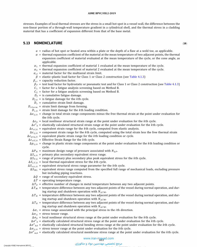
ð19Þ
stresses. Examples of local thermal stresses are the stress in a small hot spot in a vessel wall, the difference between thenon-linear portion of a through-wall temperature gradient in a cylindrical shell, and the thermal stress in a claddingmaterial that has a coefficient of expansion different from that of the base metal.
5.13 NOMENCLATURE
a = radius of hot spot or heated area within a plate or the depth of a flaw at a weld toe, as applicable.α = thermal expansion coefficient of the material at the mean temperature of two adjacent points, the thermal
expansion coefficient of material evaluated at the mean temperature of the cycle, or the cone angle, asapplicable.
α1 = thermal expansion coefficient of material 1 evaluated at the mean temperature of the cycle.α2 = thermal expansion coefficient of material 2 evaluated at the mean temperature of the cycle.α s l = material factor for the multiaxial strain limit.β = elastic–plastic load factor for Class 1 or Class 2 construction (see Table 4.1.3)
β c r = capacity reduction factor.βT = test load factor for hydrostatic or pneumatic test and for Class 1 or Class 2 construction (see Table 4.1.3)C1 = factor for a fatigue analysis screening based on Method B.C2 = factor for a fatigue analysis screening based on Method B.Df = is cumulative fatigue damage.
Df , k = is fatigue damage for the kth cycle.D ε = cumulative strain limit damage.
D ε f o rm = strain limit damage from forming.D ε , k = strain limit damage for the kth loading condition.
Δe i j , k = change in total strain range components minus the free thermal strain at the point under evaluation forthe kth cycle.
Δεk = local nonlinear structural strain range at the point under evaluation for the kth cycle.Δεek = elastically calculated structural strain range at the point under evaluation for the kth cycle.
Δεe l , k = equivalent strain range for the kth cycle, computed from elastic analysis.Δε i j , k = component strain range for the kth cycle, computed using the total strain less the free thermal strain
Δεpeq , k = equivalent plastic strain range for the kth loading condition or cycle.Δεe f f , k = Effective Strain Range for the kth cycle.Δpi j , k = change in plastic strain range components at the point under evaluation for the kth loading condition or
cycle.ΔPN = maximum design range of pressure associated with NΔP .
ΔSn , k = primary plus secondary equivalent stress range.ΔSP , k = range of primary plus secondary plus peak equivalent stress for the kth cycle.
ΔSLT , k = local thermal equivalent stress for the kth cycle.ΔSes s , k = equivalent structural stress range parameter for the kth cycle.ΔSML = equivalent stress range computed from the specified full range of mechanical loads, excluding pressure
but including piping reactions.ΔQ = range of secondary equivalent stress.ΔT = operating temperature range.
ΔTE = effective number of changes in metal temperature between any two adjacent points.ΔTM = temperature difference between any two adjacent points of the vessel during normal operation, and dur-
ing startup and shutdown operation with NΔTM .ΔTN = temperature difference between any two adjacent points of the vessel during normal operation, and dur-
ing startup and shutdown operation with NΔTM .ΔTR = temperature difference between any two adjacent points of the vessel during normal operation, and dur-
ing startup and shutdown operation with NΔTM .Δσ i = stress range associated with the principal stress in the ith direction.Δσ i j = stress tensor range.Δσk = local nonlinear structural stress range at the point under evaluation for the k th cycle.Δσe
k = elastically calculated structural stress range at the point under evaluation for the kth cycle.Δσe
b,k = elastically calculated structural bending stress range at the point under evaluation for the kth cycle.Δσ i j , k = stress tensor range at the point under evaluation for the kth cycle.Δσe
m,k = elastically calculated structural membrane stress range at the point under evaluation for the kth cycle.
603
ASME BPVC.VIII.2-2019
Copyright ASME International (BPVC) Provided by IHS under license with ASME Licensee=Khalda Petroleum/5986215001, User=Amer, Mohamed
Not for Resale, 07/02/2019 14:07:58 MDTNo reproduction or networking permitted without license from IHS
--`,```,,,,,````,`,``,,`,,`,`-`-`,,`,,`,`,,`---
www.iran-mavad.com
مرجع تخصصی مهندسین مواد و متالورژی

Δτk = structural shear stress range at the point under evaluation for the kth cycle.Δτeb,k = elastically calculated bending component of the structural shear stress range at the point under evalua-
tion for the kth cycle.Δτem,k = elastically calculated membrane component of the structural shear stress range at the point under eva-
luation for the kth cycle.δ = out-of-phase angle between Δσk and Δτ k
for the kth cycle.Ey = unmodified Young’s modulus for plate material.Ey f = value of modulus of elasticity on the fatigue curve being utilized.
Eya , k = value of modulus of elasticity of the material at the point under consideration, evaluated at the mean tem-perature of the kth cycle.
Ey1 = Young’s Modulus of material 1 evaluated at the mean temperature of the cycle.Ey2 = Young’s Modulus of material 2 evaluated at the mean temperature of the cycle.Eym = Young’s Modulus of the material evaluated at the mean temperature of the cycle.ε c f = cold forming strain.εLu = uniaxial strain limit.εL , k = limiting triaxial strain.fM ,k = mean stress correction factor for the kth cycle.
F = additional stress produced by the stress concentration over and above the nominal stress level resultingfrom operating loadings.
F1 = externally applied axial force.F(δ) = a fatigue modification factor based on the out-of-phase angle between Δσk and Δτ k
.I = correction factor used in the structural stress evaluation.Iτ = correction factor used in the structural shear stress evaluation.
Kcs s = material parameter for the cyclic stress–strain curve model.Ke ,k = fatigue penalty factor for the kth cycle.Kv ,k = plastic Poisson’s ratio adjustment for local thermal and thermal bending stresses for the kth cycle.Kf = fatigue strength reduction factor used to compute the cyclic stress amplitude or range.KL = equivalent stress load factor.Km = ratio of peak stress in reduced ligament to the peak stress in normal ligament.M = total number of stress ranges at a point derived from the cycle counting procedure.Mo = longitudinal bending moment per unit length of circumference existing at the weld junction of layered
spherical shells or heads due to discontinuity or external loads.M1 = externally applied bending moment.m = material constant used for the fatigue knock-down factor used in the simplified elastic–plastic analysis.
mij = mechanical strain tensor, mechanical strain is defined as the total strain minus the free thermal strain.mss = exponent used in a fatigue analysis based on the structural stress.
n = material constant used for the fatigue knock-down factor used in the simplified elastic–plastic analysisnk = actual number of repetitions of the kth cycle.
ncs s = material parameter for the cyclic stress–strain curve model.Nk = permissible number of cycles for the kth cycle.
N(C1 S) = number of cycles from the applicable design fatigue curve (see Annex 3-F, 3-F.1.3) evaluated at a stressamplitude of C1S .
N(Se) = number of cycles from the applicable design fatigue curve (see Annex 3-F, 3-F.1.3) evaluated at a stressamplitude of Se .
NΔFP = design number of full-range pressure cycles including startup and shutdown.NΔP = number of significant cycles associated with ΔPN .
NΔPO = expected number of operating pressure cycles in which the range of pressure variation exceeds 20% ofthe design pressure for integral construction or 15% of the design pressure for non-integral construction.
NΔS = number of significant cycles associated with ΔSML , significant cycles are those for which the range in tem-perature exceeds Sas .
NΔT = number of cycles associated with ΔTN .NΔTE = number of cycles associated with ΔTE .NΔTM = number of significant cycles associated with ΔTM .NΔTR = number of significant cycles associated with ΔTR .NΔTa = number of temperature cycles for components involving welds between materials having different coeffi-
cients of expansion.v = Poisson’s ratio.
604
ASME BPVC.VIII.2-2019
Copyright ASME International (BPVC) Provided by IHS under license with ASME Licensee=Khalda Petroleum/5986215001, User=Amer, Mohamed
Not for Resale, 07/02/2019 14:07:58 MDTNo reproduction or networking permitted without license from IHS
--`,```,,,,,````,`,``,,`,,`,`-`-`,,`,,`,`,,`---
www.iran-mavad.com
مرجع تخصصی مهندسین مواد و متالورژی

ΩP = load factor for pressure when combined with occasional load L , Ss , W , or E (see Table 5.2 for load para-meter definitions).
= 1.0 unless otherwise specified in the User's Design Specification [see 2.2.2.1(e)].ΩPP = maximum anticipated operating pressure (internal or external) acting simultaneously with occasional
load L , Ss , W , or E .P = specified design pressure.Pb = primary bending equivalent stress.PL = local primary membrane equivalent stress.Pm = general primary membrane equivalent stress.PT = selected hydrostatic or pneumatic test pressure [see 8.2.1(c)].
mPk = component crack face pressure at time point mt for the kth cycle. The crack face pressure should be spe-cified if the maximum value of the membrane plus bending stress used in the analysis occurs on a surfacethat is exposed to the fluid pressure. A conservative approach is to always specify the crack face pressure.The crack face pressure is based on the actual or operating pressure defined in the loading time history.
nPk = component crack face pressure at time point nt for the kth cycle. The crack face pressure should be spe-cified if the maximum value of the membrane plus bending stress used in the analysis occurs on a surfacethat is exposed to the fluid pressure. A conservative approach is to always specify the crack face pressure.The crack face pressure is based on the actual or operating pressure defined in the loading time history.
ΦB = design factor for buckling.Q = secondary equivalent stress resulting from operating loadings.
Q1 = externally applied shear force.R = inside radius measured normal to the surface from the mid-wall of the shell to the axis of revolution, or
the ratio of the minimum stress in the kth cycle to the maximum stress in the kth cycle, as applicable.Rk = stress ratio for the kth cycle.
Rb ,k = ratio of the bending stress to the membrane plus bending stress.Rbτ , k = ratio of the bending component of the shear stress to the membrane plus bending component of the shear
stress.RSF = computed remaining strength factor.R1 = mid-surface radius of curvature of region 1 where the local primary membrane stress exceeds 1.1S .R2 = mid-surface radius of curvature of region 2 where the local primary membrane stress exceeds 1.1S .S = allowable stress based on the material of construction and design temperature.Sa = alternating stress obtained from a fatigue curve for the specified number of operating cycles.Sas = stress amplitude from the applicable design fatigue curve (see Annex 3-F, 3-F.1.3) evaluated at 1E6
cycles.Se = computed equivalent stress.SQ = allowable limit on the secondary stress range.SPL = allowable limit on the local primary membrane and local primary membrane plus bending stress cate-
gories (see 5.2.2.4.)SPS = allowable limit on the primary plus secondary stress range (see 5.5.6.)Sy = minimum specified yield strength at the design temperature.SLy = specified plastic limit for limit-load analysis.Sa , k = value of alternating stress obtained from the applicable design fatigue curve for the specified number of
cycles of the kth cycle.Sa l t , k = alternating equivalent stress for the kth cycle.Sy , k = yield strength of the material evaluated at the mean temperature of the kth cycle.
Sa (N) = stress amplitude from the applicable design fatigue curve (see Annex 3-F, 3-F.1.3) evaluated at N cycles.Sa (NΔP) = stress amplitude from the applicable design fatigue curve (see Annex 3-F, 3-F.1.3) evaluated at NΔP
cycles.Sa (NΔS) = stress amplitude from the applicable design fatigue curve (see Annex 3-F, 3-F.1.3) evaluated at NΔ S
cycles.Sa (NΔTN) = stress amplitude from the applicable design fatigue curve (see Annex 3-F, 3-F.1.3) evaluated at NΔTN
cycles.Sa (NΔTM) = stress amplitude from the applicable design fatigue curve (see Annex 3-F, 3-F.1.3) evaluated at NΔTM
cycles.Sa(NΔTR) = stress amplitude from the applicable design fatigue curve (see Annex 3-F, 3-F.1.3) evaluated at NΔTR
cycles.mσeb,k = elastically calculated bending stress at the point under evaluation for the kth cycle at the m point.
605
ASME BPVC.VIII.2-2019
Copyright ASME International (BPVC) Provided by IHS under license with ASME Licensee=Khalda Petroleum/5986215001, User=Amer, Mohamed
Not for Resale, 07/02/2019 14:07:58 MDTNo reproduction or networking permitted without license from IHS
--`,```,,,,,````,`,``,,`,,`,`-`-`,,`,,`,`,,`---
www.iran-mavad.com
مرجع تخصصی مهندسین مواد و متالورژی

nσeb,k = elastically calculated bending stress at the point under evaluation for the kth cycle at the n point.σe = von Mises stress.
σe , k = von Mises stress for the kth loading condition.σ i = are the principal stress components.
σ i j , k = stress tensor at the point under evaluation for the kth cycle at the m point.mσij,k = stress tensor at the point under evaluation for the kth cycle at the m point.nσij,k = stress tensor at the point under evaluation for the kth cycle at the n point.
σLTij,k = stress tensor due to local thermal stress at the location and time point under evaluation for the kth cycle.
mσem,k = elastically calculated membrane stress at the point under evaluation for the kth cycle at the m point.nσem,k = elastically calculated membrane stress at the point under evaluation for the kth cycle at the n point.
σmax , k = maximum stress in the kth cycle.σmean , k = mean stress in the kth cycle.σmin , k = minimum stress in the kth cycle.
σ1 = principal stress in the 1-direction.σ2 = principal stress in the 2-direction.σ3 = principal stress in the 3-direction.
σ1 , k = principal stress in the 1-direction for the kth loading condition.σ2 , k = principal stress in the 2-direction for the kth loading condition.σ3 , k = principal stress in the 3-direction for the kth loading condition.
t = minimum wall thickness in the region under consideration, or the thickness of the vessel, as applicable.te s s = structural stress effective thickness.t1 = minimum wall thickness associated with R1 .t2 = minimum wall thickness associated with R2 .
mτeb,k = elastically calculated bending component of shear stress distribution at the point under evaluation for thekth cycle at the m point.
nτeb,k = elastically calculated bending component of shear stress distribution at the point under evaluation for thekth cycle at the n point.
mτem,k = elastically calculated membrane component of shear stress distribution at the point under evaluation forthe kth cycle at the m point.
nτem,k = elastically calculated membrane component of shear stress distribution at the point under evaluation forthe kth cycle at the n point.
UTS = minimum specified ultimate tensile strength at room temperature.w = required with of attachment.X = maximum general primary membrane stress divided by the yield strength.
YS = minimum specified yield strength at room temperature.
606
ASME BPVC.VIII.2-2019
Copyright ASME International (BPVC) Provided by IHS under license with ASME Licensee=Khalda Petroleum/5986215001, User=Amer, Mohamed
Not for Resale, 07/02/2019 14:07:58 MDTNo reproduction or networking permitted without license from IHS
--`,```,,,,,````,`,``,,`,,`,`-`-`,,`,,`,`,,`---
www.iran-mavad.com
مرجع تخصصی مهندسین مواد و متالورژی

5.14 TABLES
Table 5.1Loads and Load Cases to Be Considered in a Design
Loading Condition Design Loads
Pressure testing (1) Dead load of component plus insulation, fireproofing, installed internals, platforms, andother equipment supported from the component in the installed position
(2) Piping loads including pressure thrust(3) Applicable live loads excluding vibration and maintenance live loads(4) Pressure and fluid loads (water) for testing and flushing equipment and piping unless a
pneumatic test is specified(5) Wind loads
Normal operation (1) Dead load of component plus insulation, refractory, fireproofing, installed internals,catalyst, packing, platforms, and other equipment supported from the component inthe installed position
(2) Piping loads including pressure thrust(3) Applicable live loads(4) Pressure and fluid loading during normal operation(5) Thermal loads
Normal operation plus occasional [Note (1)] (1) Dead load of component plus insulation, refractory, fireproofing, installed internals,catalyst, packing, platforms, and other equipment supported from the component inthe installed
(2) Piping loads including pressure thrust(3) Applicable live loads(4) Pressure and fluid loading during normal operation(5) Thermal loads(6) Wind, earthquake, or other occasional loads, whichever is greater(7) Loads due to wave action
Abnormal or start-up operation plus occasional [Note(1)]
(1) Dead load of component plus insulation, refractory, fireproofing, installed internals,catalyst, packing, platforms, and other equipment supported from the component inthe installed position
(2) Piping loads including pressure thrust(3) Applicable live loads(4) Pressure and fluid loading associated with the abnormal or start-up conditions(5) Thermal loads(6) Wind loads
NOTE:(1) Occasional loads are usually governed by wind and earthquake; however, other load types such as snow and ice loads may govern, see
ASCE-7.
607
ASME BPVC.VIII.2-2019
Copyright ASME International (BPVC) Provided by IHS under license with ASME Licensee=Khalda Petroleum/5986215001, User=Amer, Mohamed
Not for Resale, 07/02/2019 14:07:58 MDTNo reproduction or networking permitted without license from IHS
--`,```,,,,,````,`,``,,`,,`,`-`-`,,`,,`,`,,`---
www.iran-mavad.com
مرجع تخصصی مهندسین مواد و متالورژی

ð19Þ Table 5.2Load Combination Parameters
Design Load ParameterOperating Load Parameter
[Note (1)] Description
P Po Internal and external specified design or operating pressure
PS PSoDesign or operating static head from liquid or bulk materials (e.g.,catalyst)
PT …Selected hydrostatic or pneumatic test pressure [see 8.2.1(d) or 8.3.1].Used only in the pressure test load combinations.
D Do
Deadweight of the vessel, contents, and appurtenances at the locationof interest, including the following:• weight of vessel including internals, supports (e.g., skirts, lugs,saddles, and legs), and appurtenances (e.g., platforms, ladders, etc.)
• weight of vessel contents design, operating, and test conditions• refractory linings, insulation• static reactions from the weight of attached equipment, such asmotors, machinery, other vessels, and piping
• transportation loads (the static forces obtained as equivalent to thedynamic loads experienced during normal operation of a transportvessel [see 1.2.1.3(b)]
L Lo
• Appurtenance live loading• Effects of fluid momentum, steady state, and transient• Loads resulting from wave action
E
Same as design parameter
Earthquake loads (see 5.1.3.2)
W Wind loads (see 5.1.3.2)
Wpt
The pressure test wind load case. The design wind speed for this caseshall be specified by the Owner-User. Used only in the pressure testload combinations.
Ss Snow loads
T To
The self-restraining load case (i.e., thermal loads, applieddisplacements). This load case does not typically affect the collapseload, but should be considered in cases where elastic follow-upcauses stresses that do not relax sufficiently to redistribute the loadwithout excessive deformation.
NOTE:(1) The operating load parameters do not necessarily represent single quantities, but rather each operating load parameter may represent
multiple operating conditions as specified in the User’s Design Specification [see 2.2.1.1(e) and 2.2.1.1(f)].
608
ASME BPVC.VIII.2-2019
Copyright ASME International (BPVC) Provided by IHS under license with ASME Licensee=Khalda Petroleum/5986215001, User=Amer, Mohamed
Not for Resale, 07/02/2019 14:07:58 MDTNo reproduction or networking permitted without license from IHS
--`,```,,,,,````,`,``,,`,,`,`-`-`,,`,,`,`,,`---
www.iran-mavad.com
مرجع تخصصی مهندسین مواد و متالورژی

ð19ÞTable 5.3Load Case Combinations and Allowable Stresses for an Elastic Analysis
Load Combinations [Note (1)]
Stress Assessment and Allowable Stress [Note (2)]
GeneralPrimary
MembraneLocal PrimaryMembrane
Local PrimaryMembrane Plus
Bending
Range ofPrimary PlusSecondary
Range ofPrimary PlusSecondary Plus
Peak
Pm PL PL + Pb PL + Pb + Q PL + Pb + Q + F
Design
(1) P + Ps + D
S SPL SPL Not applicable
(2) P + Ps + D + L(3) P + Ps + D + L + T(4) P + Ps + D + Ss(5) 0.6D + (0.6W or 0.7E) [Note (3)](6) ΩpP + Ps + D + (0.6W or 0.7E) [Note (4)](7) ΩpP + Ps + D + 0.75(L + T) + 0.75Ss [Note (4)](8) ΩpP + Ps + D + 0.75(0.6W or 0.7E) + 0.75L +
0.75Ss [Note (4)](9) Other design load combinations as defined in
the User's Design Specification
Operating
(10) Po + PSo + Do
Not applicable SPS 2Sa (see 5.5.1.4)
(11) Po + PSo + Do + Lo
(12) Po + PSo + Do + Lo + To
(13) Po + PSo + Do + Ss(14) Po + PSo + Do + (0.6W or 0.7E)(15) Po + PSo + Do + 0.75(Lo + To) + 0.75Ss(16) Po + PSo + Do + 0.75(0.6W or 0.7E) + 0.75Lo +
0.75Ss(17) Other operating load combinations as defined
in the User’s Design Specification
Pressure Test
(18) PT + PS + D + 0.6Wpt See 5.2.2.5 Not applicable See 5.2.2.5 Not applicable
GENERAL NOTE: Loads listed herein shall be considered to act in the combinations described above; whichever produces the most unfavor-able effect in the component being considered. Effects of one or more loads not acting shall be considered.
NOTES:(1) The parameters used in the Load Combinations column are defined in Table 5.2.(2) See Figure 5.1 for additional guidance on stress categories and limits on equivalent stress.(3) This load combination addresses an overturning condition for foundation design. It does not apply to design of anchorage (if any) to the
foundation. Refer to ASCE/SEI 7-10, 2.4.1, Exception 2 for an additional reduction to W that may be applicable.(4) The product of ΩPP is used in lieu of the design pressure, P , for evaluation of Pm , PL , and PL + Pb stress assessments since it is unlikely the
occasional loads would occur at the same time as the maximum design pressure, P .
609
ASME BPVC.VIII.2-2019
Copyright ASME International (BPVC) Provided by IHS under license with ASME Licensee=Khalda Petroleum/5986215001, User=Amer, Mohamed
Not for Resale, 07/02/2019 14:07:58 MDTNo reproduction or networking permitted without license from IHS
--`,```,,,,,````,`,``,,`,,`,`-`-`,,`,,`,`,,`---
www.iran-mavad.com
مرجع تخصصی مهندسین مواد و متالورژی

ð19Þ
Table 5.4Load Case Combinations and Load Factors for a Limit-Load Analysis
Criteria Required Factored Load Combinations
Design Conditions
Global (1) 1.5(P + Ps + D)(2) 1.3(P + Ps + D + T) + 1.7L + 0.54Ss(3) 1.3(P + Ps + D) + 1.7Ss + (1.1L or 0.54W)(4) 1.3(P + Ps + D) + 1.1W + 1.1L +0.54Ss(5) 1.3(P + Ps + D) + 1.1E + 1.1L +0.21Ss)
Local See 5.3.1.2Serviceability Per User’s Design Specification, if applicable; see Table 5.5
Test Condition
Global
Serviceability Per User’s Design Specification, if applicable
GENERAL NOTES:(a) The parameters used in the Design Load Combination column are defined in Table 5.2.(b) See 5.2.3.4 for descriptions of global and serviceability criteria.(c) S is the allowable membrane stress at the design temperature.(d) ST is the allowable membrane stress at the pressure test temperature.(e) Loads listed herein shall be considered to act in the combinations described above; whichever produces the most unfavorable effect
in the component being considered. Effects of one or more loads not acting shall be considered.
Table 5.5Load Case Combinations and Load Factors for an Elastic–Plastic Analysis
Criteria Required Factored Load Combinations
Design Conditions
Global (1) β(P + Ps + D)(2) 0.88β(P + PS + D + T) + 1.13βL + 0.36βSS(3) 0.88β(P + PS + D) + 1.13βSs + 0.71βL or 0.36βW(4) 0.88β(P + PS + D) + 0.71βW + 0.71βL + 0.36βSS(5) 0.88β(P + PS + D) + 0.71βE + 0.71βL + 0.14βSS
Local
Serviceability Per User’s Design Specification, if applicable; see 5.2.4.3(b)
Test Condition
Global
Serviceability Per User’s Design Specification, if applicable
GENERAL NOTES:(a) The parameters used in the Design Load Combination column are defined in Table 5.2.(b) See 5.2.4.3 for descriptions of global and serviceability criteria.(c) S is the allowable membrane stress at the design temperature.(d) ST is the allowable membrane stress at the pressure test temperature.(e) Loads listed herein shall be considered to act in the combinations described above; whichever produces the most unfavorable effect
in the component being considered. Effects of one or more loads not acting shall be considered.
610
ASME BPVC.VIII.2-2019
Copyright ASME International (BPVC) Provided by IHS under license with ASME Licensee=Khalda Petroleum/5986215001, User=Amer, Mohamed
Not for Resale, 07/02/2019 14:07:58 MDTNo reproduction or networking permitted without license from IHS
--`,```,,,,,````,`,``,,`,,`,`-`-`,,`,,`,`,,`---
www.iran-mavad.com
مرجع تخصصی مهندسین مواد و متالورژی

Table 5.6Examples of Stress Classification
Vessel Component Location Origin of Stress Type of Stress Classification
Any shell including cylinders,cones, spheres, and formedheads
Shell plate remote fromdiscontinuities
Internal pressure General membrane Pm
Gradient through platethickness
Q
Axial thermal gradient Membrane Q
Bending
Near nozzle or otheropening
Net-section axial force and/or bending momentapplied to the nozzle,and/or internal pressure
Local membrane PL
Bending Q
Peak (fillet or corner) F
Any location Temperature differencebetween shell and head
Membrane Q
Bending
Shell distortions such asout-of-roundness anddents
Internal pressure Membrane Pm
Bending Q
Cylindrical or conical shell Any section across entirevessel
Net-section axial force,bending moment appliedto the cylinder or cone,and/or internal pressure
Membrane stress averagedthrough the thickness,remote fromdiscontinuities; stresscomponent perpendicularto cross section
Pm
Bending stress through thethickness; stresscomponent perpendicularto cross section
Pb
Junction with head or flange Internal pressure Membrane PL
Bending Q
Dished head or conical head Crown Internal pressure Membrane Pm
Bending Pb
Knuckle or junction to shell Internal pressure Membrane PL [Note (1)]
Bending Q
Flat head Center region Internal pressure Membrane Pm
Bending Pb
Junction to shell Internal pressure Membrane PL
Bending Q [Note (2)]
Perforated head or shell Typical ligament in auniform pattern
Pressure Membrane (averagedthrough cross section)
Pm
Bending (averaged throughwidth of ligament., butgradient through plate)
Pb
Peak F
Isolated or atypical ligament Pressure Membrane Q
Bending F
Peak
611
ASME BPVC.VIII.2-2019
Copyright ASME International (BPVC) Provided by IHS under license with ASME Licensee=Khalda Petroleum/5986215001, User=Amer, Mohamed
Not for Resale, 07/02/2019 14:07:58 MDTNo reproduction or networking permitted without license from IHS
--`,```,,,,,````,`,``,,`,,`,`-`-`,,`,,`,`,,`---
www.iran-mavad.com
مرجع تخصصی مهندسین مواد و متالورژی

Table 5.6Examples of Stress Classification (Cont'd)
Vessel Component Location Origin of Stress Type of Stress Classification
Nozzle (see 5.6) Within the limits ofreinforcement given by4.5
Pressure and external loadsand moments, includingthose attributable torestrained free enddisplacements of attachedpiping
General membrane Pm
Bending (other than grossstructural discontinuitystresses) averagedthrough nozzle thickness
Outside the limits ofreinforcement given by4.5
Pressure and external axial,shear, and torsionalloads, including thoseattributable to restrainedfree end displacements ofattached piping
General membrane Pm
Pressure and external loadsand moments, excludingthose attributable torestrained free enddisplacements of attachedpiping
Membrane PL
Bending Pb
Pressure and all externalloads and moments
Membrane PL
Bending Q
Peak F
Nozzle wall Gross structuraldiscontinuities
Membrane PL
Bending Q
Peak F
Differential expansion Membrane Q
Bending
Peak F
Cladding Any Differential expansion Membrane F
Bending
Any Any Radial temperaturedistribution [Note (3)]
Equivalent linear stress[Note (4)]
Q
Nonlinear portion of stressdistribution
F
Any Any Any Stress concentration (notcheffect)
F
NOTES:(1) Consideration shall be given to the possibility of wrinkling and excessive deformation in vessels with large diameter-to-thickness ratio.(2) If the bending moment at the edge is required to maintain the bending stress in the center region within acceptable limits, the edge
bending is classified as Pb ; otherwise, it is classified as Q .(3) Consider possibility of thermal stress ratchet.(4) Equivalent linear stress is defined as the linear stress distribution that has the same net bending moment as the actual stress
distribution.
612
ASME BPVC.VIII.2-2019
Copyright ASME International (BPVC) Provided by IHS under license with ASME Licensee=Khalda Petroleum/5986215001, User=Amer, Mohamed
Not for Resale, 07/02/2019 14:07:58 MDTNo reproduction or networking permitted without license from IHS
--`,```,,,,,````,`,``,,`,,`,`-`-`,,`,,`,`,,`---www.iran-mavad.com
مرجع تخصصی مهندسین مواد و متالورژی

ð19ÞTable 5.7Uniaxial Strain Limit for Use in Multiaxial Strain Limit Criterion
Material Maximum Temperature
Uniaxial Strain Limit, εLu [Note (1)], [Note (2)], [Note (3)]
α s lm2 Elongation SpecifiedReduction of Area
Specified
Ferritic steel 480°C (900°F) 0.60(1.00 − R) 2.2
Stainless steel and nickelbase alloys
480°C (900°F) 0.75(1.00 − R) 0.6
Duplex stainless steel 480°C (900°F) 0.70(0.95 − R) 2.2
Precipitation hardenablenickel base alloys
540°C (1,000°F) 1.09(0.93 − R) 2.2
Aluminum 120°C (250°F) 0.52(0.98 − R) 2.2
Copper 65°C (150°F) 0.50(1.00 − R) 2.2
Titanium and zirconium 260°C (500°F) 0.50(0.98 − R) 2.2
NOTES:(1) If the elongation and reduction in area are not specified, then εLu =m2 . If the elongation or reduction in area is specified, then εLu is the
maximum number computed from columns 3, 4, or 5, as applicable.(2) R is the ratio of the minimum specified yield strength divided by the minimum specified ultimate tensile strength.(3) E is the % elongation and RA is the % reduction in area determined from the applicable material specification.
Table 5.8Temperature Factors for Fatigue-Screening Criteria
Metal Temperature Differential
Temperature Factor for Fatigue-Screening Criteria°C °F
28 or less 50 or less 029 to 56 51 to 100 157 to 83 101 to 150 284 to 139 151 to 250 4140 to 194 251 to 350 8195 to 250 351 to 450 12
Greater than 250 Greater than 450 20
GENERAL NOTES:(a) If the weld metal temperature differential is unknown or cannot be established, a value of 20 shall be used.(b) As an example illustrating the use of this table, consider a component subject to metal temperature differentials for the following num-
ber of thermal cycles:
Temperature DifferentialTemperature Factor Basedon Temperature Differential Number of Thermal Cycles
28°C (50°F) 0 1,00050°C (90°F) 1 250222°C (400°F) 12 5
The effective number of thermal cycles due to changes in metal temperature is: NΔTE = 1,000(0) + 250(1) + 5(12) = 310 cycles
613
ASME BPVC.VIII.2-2019
Copyright ASME International (BPVC) Provided by IHS under license with ASME Licensee=Khalda Petroleum/5986215001, User=Amer, Mohamed
Not for Resale, 07/02/2019 14:07:58 MDTNo reproduction or networking permitted without license from IHS
--`,```,,,,,````,`,``,,`,,`,`-`-`,,`,,`,`,,`---
www.iran-mavad.com
مرجع تخصصی مهندسین مواد و متالورژی

Table 5.9Fatigue-Screening Criteria for Method A
Type of Construction Component Description Fatigue-Screening Criteria
Integral construction Attachments and nozzles in the knuckle region of formed heads NΔFP + NΔPO + NΔTE + NΔTα ≤ 350All other components NΔFP + NΔPO + NΔTE + NΔTα ≤ 1,000
Nonintegral construction Attachments and nozzles in the knuckle region of formed heads NΔFP + NΔPO + NΔTE + NΔTα ≤ 60All other components NΔFP + NΔPO + NΔTE + NΔTα ≤ 400
Table 5.10Fatigue-Screening Criteria Factors for Method B
Type of Construction Component Description
Fatigue-Screening Criteria Factor
C1 C2
Integral construction Attachments and nozzles in the knuckle region of formed heads 4 2.7All other components 3 2
Nonintegral construction Attachments and nozzles in the knuckle region of formed heads 5.3 3.6All other components 4 2.7
Table 5.11Weld Surface Fatigue-Strength-Reduction Factors
Weld Condition Surface Condition
Quality Levels (See Table 5.12)
1 2 3 4 5 6 7
Full penetration Machined 1.0 1.5 1.5 2.0 2.5 3.0 4.0As-welded 1.2 1.6 1.7 2.0 2.5 3.0 4.0
Partial penetration Final surface machined NA 1.5 1.5 2.0 2.5 3.0 4.0Final surface as-welded NA 1.6 1.7 2.0 2.5 3.0 4.0Root NA NA NA NA NA NA 4.0
Fillet Toe machined NA NA 1.5 NA 2.5 3.0 4.0Toe as-welded NA NA 1.7 NA 2.5 3.0 4.0Root NA NA NA NA NA NA 4.0
Table 5.12Weld Surface Fatigue-Strength-Reduction Factors
Fatigue-Strength-Reduction Factor Quality Level Definition
1.0 1 Machined or ground weld that receives a full volumetric examination, and a surface thatreceives MT/PT examination and a VT examination
1.2 1 As-welded weld that receives a full volumetric examination, and a surface that receivesMT/PT and VT examination
1.5 2 Machined or ground weld that receives a partial volumetric examination, and a surfacethat receives MT/PT examination and VT examination
1.6 2 As-welded weld that receives a partial volumetric examination, and a surface thatreceives MT/PT and VT examination
614
ASME BPVC.VIII.2-2019
Copyright ASME International (BPVC) Provided by IHS under license with ASME Licensee=Khalda Petroleum/5986215001, User=Amer, Mohamed
Not for Resale, 07/02/2019 14:07:58 MDTNo reproduction or networking permitted without license from IHS
--`,```,,,,,````,`,``,,`,,`,`-`-`,,`,,`,`,,`---
www.iran-mavad.com
مرجع تخصصی مهندسین مواد و متالورژی

Table 5.12Weld Surface Fatigue-Strength-Reduction Factors (Cont'd)
Fatigue-Strength-Reduction Factor Quality Level Definition
1.5 3 Machined or ground weld surface that receives MT/PT examination and a VTexamination (visual), but the weld receives no volumetric examination inspection
1.7 3 As-welded surface that receives MT/PT examination and a VT examination (visual), butthe weld receives no volumetric examination inspection
2.0 4 Weld has received a partial or full volumetric examination, and the surface has receivedVT examination, but no MT/PT examination
2.5 5 VT examination only of the surface; no volumetric examination nor MT/PT examination
3.0 6 Volumetric examination only
4.0 7 Weld backsides that are nondefinable and/or receive no examination
GENERAL NOTES:(a) Volumetric examination is RT or UT in accordance with Part 7.(b) MT/PT examination is magnetic particle or liquid penetrant examination in accordance with Part 7.(c) VT examination is visual examination in accordance with Part 7.(d) See WRC Bulletin 432 for further information.
Table 5.13Fatigue Penalty Factors for Fatigue Analysis
Material
Ke [Note (1)] Tmax [Note (2)]
m n °C °F
Low alloy steel 2.0 0.2 371 700Martensitic stainless steel 2.0 0.2 371 700Carbon steel 3.0 0.2 371 700Austenitic stainless steel 1.7 0.3 427 800Nickel-chromium-iron 1.7 0.3 427 800Nickel-copper 1.7 0.3 427 800
NOTES:(1) Fatigue penalty factor.(2) The fatigue penalty factor should be used only if all of the following are satisfied:
• The component is not subject to thermal ratcheting.• The maximum temperature in the cycle is within the value in the table for the material.
615
ASME BPVC.VIII.2-2019
Copyright ASME International (BPVC) Provided by IHS under license with ASME Licensee=Khalda Petroleum/5986215001, User=Amer, Mohamed
Not for Resale, 07/02/2019 14:07:58 MDTNo reproduction or networking permitted without license from IHS
--`,```,,,,,````,`,``,,`,,`,`-`-`,,`,,`,`,,`---
www.iran-mavad.com
مرجع تخصصی مهندسین مواد و متالورژی

ð19Þ
5.15 FIGURES
Figure 5.1Stress Categories and Limits of Equivalent Stress
Pm
Pm PL Pb
PL + Pb
PL + Pb + Q
PL
S
Use design loads
Use operating loads
Primary
GeneralMembrane
LocalMembrane
Bending
SecondaryMembrane
plus BendingPeak
StressCategory
Symbol Q
SPL
SPL
SPS
PL + Pb + Q + F 2Sa
Description (For examples, see Table 5.2.)
Average primary stress across solid section. Excludes discontinuities and concentrations. Produced only by mechanical loads.
Average stress across any solid section. Considers discontinuities but not concentrations. Produced only by mechanical loads.
Component of primary stress proportional to distance from centroid of solid section. Excludes discontinuities and concentrations. Produced only by mechanical loads.
Self-equilibratingstress necessary to satisfy continuity of structure. Occurs at structural disconti-nuities. Can be caused by mechani-cal load or by differential thermal expansion. Excludes local stress concentrations.
1. Increment added to primary or secondary stress by a concentra- tion (notch).
2. Certain thermal stresses that may cause fatigue but not distortion of vessel shape.
F
[Note (1)]
NOTE:(1) See 5.5.3.
616
ASME BPVC.VIII.2-2019
Copyright ASME International (BPVC) Provided by IHS under license with ASME Licensee=Khalda Petroleum/5986215001, User=Amer, Mohamed
Not for Resale, 07/02/2019 14:07:58 MDTNo reproduction or networking permitted without license from IHS
--`,```,,,,,````,`,``,,`,,`,`-`-`,,`,,`,`,,`---
www.iran-mavad.com
مرجع تخصصی مهندسین مواد و متالورژی

Figure 5.2Example of Girth Weld Used to Tie Layers for Solid Wall Equivalence
CL
t
w
M1
Girth weld
External Loads ActingCircumferentially AroundShell
F1
Figure 5.3Example of Circumferential Butt Weld Attachment Between Layered Sections in Zone of Discontinuity
t
w
Conical section
CL
617
ASME BPVC.VIII.2-2019
Copyright ASME International (BPVC) Provided by IHS under license with ASME Licensee=Khalda Petroleum/5986215001, User=Amer, Mohamed
Not for Resale, 07/02/2019 14:07:58 MDTNo reproduction or networking permitted without license from IHS
--`,```,,,,,````,`,``,,`,,`,`-`-`,,`,,`,`,,`---
www.iran-mavad.com
مرجع تخصصی مهندسین مواد و متالورژی

Figure 5.4An Example of Circle Weld Used to Tie Layers for Solid Wall Equivalence
tH
CLCircle weld
w
External Loads ActingAround Circle of
Spherical Shell
M1
Q1
F1
618
ASME BPVC.VIII.2-2019
Copyright ASME International (BPVC) Provided by IHS under license with ASME Licensee=Khalda Petroleum/5986215001, User=Amer, Mohamed
Not for Resale, 07/02/2019 14:07:58 MDTNo reproduction or networking permitted without license from IHS
--`,```,,,,,````,`,``,,`,,`,`-`-`,,`,,`,`,,`---
www.iran-mavad.com
مرجع تخصصی مهندسین مواد و متالورژی

ð19ÞANNEX 5-ALINEARIZATION OF STRESS RESULTS FOR STRESS
CLASSIFICATION
(Informative)
5-A.1 SCOPE
This Annex provides recommendations for post-processing of the results from an elastic finite element stress analysisfor comparison to the limits in 5.2.2.
5-A.2 GENERAL
(a) In the finite element method, when continuum elements are used in an analysis, the total stress distribution isobtained. Therefore, to produce membrane and bending stresses, the total stress distribution shall be linearized on astress component basis and used to calculate the equivalent stresses. If shell elements (shell theory) are used, thenthe membrane and bending stresses shall be obtained directly from shell stress resultants.
(b)Membrane and bending stresses are developed on cross sections through the thickness of a component. These sec-tions are called stress classification planes (SCPs). In a planar geometry, a Stress Classification Line (SCL) is obtained byreducing two opposite sides of a SCP to an infinitesimal length. SCPs are flat planes that cut through a section of a com-ponent and SCLs are straight lines that cut through a section of a component. SCLs are surfaces when viewed in an ax-isymmetric or planar geometry. Examples of an SCP and SCL are given in Figure 5-A.1 and Figure 5-A.2.
(c) The following three approaches are provided for linearization of finite element results.
(1) Stress Integration Method – This method can be used to linearize stress results from continuum finite elementmodels [Ref. WRC-429].
(2) Structural Stress Method Based on Nodal Forces – This method is based on processing of nodal forces, and hasbeen shown to be mesh insensitive and correlate well with welded fatigue data [Ref. WRC-474].
(3) Structural Stress Method Based on Stress Integration – This method utilizes the Stress Integration Method, butrestricts the set of elements that contribute to the line of nodes being processed.
(d) The Structural Stress Method based on Stress Integration is recommended unless another method can be shown toproduce a more accurate assessment for the given component and loading condition. This method matches the Struc-tural Stress Method Based on Nodal Forces, which is insensitive to mesh refinement. In addition, this method can beperformed with post-processing tools typically provided by commercial finite element analysis software.
5-A.3 SELECTION OF STRESS CLASSIFICATION LINES
(a) Pressure vessels usually contain structural discontinuity regions where abrupt changes in geometry, material orloading occur. These regions are typically the locations of highest stress in a component. For the evaluation of failuremodes of plastic collapse and ratcheting, Stress Classification Lines (SCLs) are typically located at gross structural dis-continuities. For the evaluation of local failure and fatigue, SCLs are typically located at local structural discontinuities.
(b) For SCLs that span a material discontinuity (e.g., base metal with cladding), the SCL should include all materialsand associated loadings. If one of the materials, such as cladding, is neglected for strength calculations, then only thebase metal thickness should be used to calculate the membrane and bending stresses from the linearized forces andmoments across the full section for the evaluation of plastic collapse.
619
ASME BPVC.VIII.2-2019
Copyright ASME International (BPVC) Provided by IHS under license with ASME Licensee=Khalda Petroleum/5986215001, User=Amer, Mohamed
Not for Resale, 07/02/2019 14:07:58 MDTNo reproduction or networking permitted without license from IHS
--`,```,,,,,````,`,``,,`,,`,`-`-`,,`,,`,`,,`---
www.iran-mavad.com
مرجع تخصصی مهندسین مواد و متالورژی
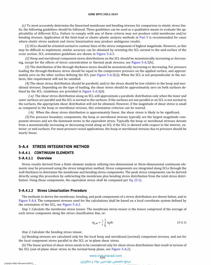
(c) To most accurately determine the linearized membrane and bending stresses for comparison to elastic stress lim-its, the following guidelines should be followed. These guidelines can be used as a qualitative means to evaluate the ap-plicability of different SCLs. Failure to comply with any of these criteria may not produce valid membrane and/orbending stresses. Application of the limit-load or elastic–plastic analysis methods in Part 5 is recommended for caseswhere elastic stress analysis and stress linearization may produce ambiguous results.
(1) SCLs should be oriented normal to contour lines of the stress component of highest magnitude. However, as thismay be difficult to implement, similar accuracy can be obtained by orienting the SCL normal to the mid-surface of thecross section. SCL orientation guidelines are shown in Figure 5-A.3.
(2) Hoop and meridional component stress distributions on the SCL should be monotonically increasing or decreas-ing, except for the effects of stress concentration or thermal peak stresses, see Figure 5-A.3(b).
(3) The distribution of the through-thickness stress should be monotonically increasing or decreasing. For pressureloading the through-thickness stress should be equal to the compressive pressure on the applied surface, and approxi-mately zero on the other surface defining the SCL (see Figure 5-A.3(c)). When the SCL is not perpendicular to the sur-faces, this requirement will not be satisfied.
(4) The shear stress distribution should be parabolic and/or the stress should be low relative to the hoop and mer-idional stresses. Depending on the type of loading, the shear stress should be approximately zero on both surfaces de-fined by the SCL. Guidelines are provided in Figure 5-A.3(d).
(-a) The shear stress distribution along an SCL will approximate a parabolic distribution only when the inner andouter surfaces are parallel and the SCL is normal to the surfaces. If the surfaces are not parallel or an SCL is not normal tothe surfaces, the appropriate shear distribution will not be obtained. However, if the magnitude of shear stress is smallas compared to the hoop or meridional stresses, this orientation criterion can be waived.
(-b) When the shear stress distribution is approximately linear, the shear stress is likely to be significant.
(5) For pressure boundary components, the hoop or meridional stresses typically are the largest magnitude com-ponent stresses and are the dominant terms in the equivalent stress. Typically the hoop or meridional stresses deviatefrom a monotonically increasing or decreasing trend along an SCL if the SCL is skewed with respect to the interior, ex-terior, or mid surfaces. For most pressure vessel applications, the hoop or meridional stresses due to pressure should benearly linear.
5-A.4 STRESS INTEGRATION METHOD
5-A.4.1 CONTINUUM ELEMENTS5-A.4.1.1 Overview
Stress results derived from a finite element analysis utilizing two-dimensional or three-dimensional continuum ele-ments may be processed using the stress integration method. Stress components are integrated along SCLs through thewall thickness to determine the membrane and bending stress components. The peak stress components can be deriveddirectly using this procedure by subtracting the membrane plus bending stress distribution from the total stress distri-bution. Using these components, the equivalent stress shall be computed per Eq. (5.1).
5-A.4.1.2 Stress Linearization Procedure
The methods to derive the membrane, bending, and peak components of a stress distribution are shown below, and inFigure 5-A.4. The component stresses used for the calculations shall be based on a local coordinate system defined bythe orientation of the SCL, see Figure 5-A.2.
Step 1. Calculate the membrane stress tensor. The membrane stress tensor is the tensor comprised of the average ofeach stress component along the stress classification line, or:
ð5A:1Þ
Step 2. Calculate the bending stress tensor.
(a) Bending stresses are calculated only for the local hoop and meridional (normal) component stresses, and not forthe local component stress parallel to the SCL or in-plane shear stress.
(b) The linear portion of shear stress needs to be considered only for shear stress distributions that result in torsion ofthe SCL (out-of-plane shear stress in the normal-hoop plane, see Figure 5-A.2).
620
ASME BPVC.VIII.2-2019
Copyright ASME International (BPVC) Provided by IHS under license with ASME Licensee=Khalda Petroleum/5986215001, User=Amer, Mohamed
Not for Resale, 07/02/2019 14:07:58 MDTNo reproduction or networking permitted without license from IHS
--`,```,,,,,````,`,``,,`,,`,`-`-`,,`,,`,`,,`---
www.iran-mavad.com
مرجع تخصصی مهندسین مواد و متالورژی

(c) The bending stress tensor is comprised of the linear varying portion of each stress component along the stressclassification line, or:
ð5A:2Þ
Step 3. Calculate the peak stress tensor. The peak stress tensor is the tensor whose components are equal to:
ð5A:3Þ
ð5A:4Þ
Step 4. Calculate the three principal stresses at the ends of the SCL based on components of membrane and membraneplus bending stresses.
Step 5. Calculate the equivalent stresses using eq. (5.1) at the ends of the SCL based on components of membrane andmembrane plus bending stresses.
5-A.4.2 SHELL ELEMENTS5-A.4.2.1 Overview
Stress results derived from a finite element analysis utilizing two-dimensional or three-dimensional shells are ob-tained directly from the analysis results. Using the component stresses, the equivalent stress shall be computed pereq. (5.1).
5-A.4.2.2 Stress Linearization Procedure
The methods to derive the membrane, bending, and peak components of a stress distribution are shown below.
(a) The membrane stress tensor is the tensor comprised of the average of each stress component along the stress clas-sification line, or:
ð5A:5Þ
(b) The bending stress tensor is the tensor comprised of the linear varying portion of each stress component along thestress classification line, or:
ð5A:6Þ
(c) The peak stress tensor is the tensor whose components are equal to:
ð5A:7Þ
5-A.5 STRUCTURAL STRESS METHOD BASED ON NODAL FORCES
5-A.5.1 OVERVIEW
Stress results derived from a finite element analysis utilizing continuum or shell elements may be processed using theStructural Stress Method based on nodal forces. The mesh-insensitive structural stress method provides a robust pro-cedure for capturing the membrane and bending stresses and can be directly utilized in fatigue design of welded joints.With this method, the structural stress normal to a hypothetical cracked plane at a weld is evaluated. For typical pres-sure vessel component welds, the choice of possible crack orientations is straightforward (e.g., toe of fillet weld). Twoalternative calculation procedures for the structural stress method are presented for continuum elements; a procedurebased on nodal forces and a procedure based on stress integration. A typical finite element continuum model and stressevaluation line for this type of analysis is shown in Figure 5-A.5.
621
ASME BPVC.VIII.2-2019
Copyright ASME International (BPVC) Provided by IHS under license with ASME Licensee=Khalda Petroleum/5986215001, User=Amer, Mohamed
Not for Resale, 07/02/2019 14:07:58 MDTNo reproduction or networking permitted without license from IHS
--`,```,,,,,````,`,``,,`,,`,`-`-`,,`,,`,`,,`---
www.iran-mavad.com
مرجع تخصصی مهندسین مواد و متالورژی

5-A.5.2 CONTINUUM ELEMENTS
(a) Stress results derived from a finite element analysis utilizing two-dimensional or three-dimensional continuumelements may be processed using the structural stress method and nodal forces as described below. The membraneand bending stresses can be computed from element nodal internal forces using the equations provided in Table5-A.1. The process is illustrated in Figure 5-A.6. This method is recommended when internal force results can be ob-tained as part of the finite element output because the results are insensitive to the mesh density.(b)When using three-dimensional continuum elements, forces and moments must be summed with respect to the
mid-thickness of a member from the forces at nodes in the solid model at a through-thickness cross section of interest.For a second order element, three summation lines of nodes are processed along the element faces through the wallthickness. The process is illustrated in Figure 5-A.7.(c) For a symmetric structural stress range, the two weld toes have equal opportunity to develop fatigue cracks.
Therefore, the structural stress calculation involves establishing the equilibrium equivalent membrane and bendingstress components with respect to one-half of the plate thickness. The equivalent structural stress calculation procedurefor a symmetric stress state is illustrated in Figure 5-A.8.
5-A.5.3 SHELL ELEMENTS
(a) Stress results derived from a finite element analysis utilizing shell elements may be processed using the structuralstress method and nodal forces. The membrane and bending stresses can be computed from element nodal internalforces using the equations provided in Table 5-A.2. A typical shell model is illustrated in Figure 5-A.9.(b)When using three-dimensional shell elements, forces and moments with respect to the mid-thickness of a member
must be obtained at a cross section of interest. The process is illustrated in Figure 5-A.10.
5-A.6 STRUCTURAL STRESS METHOD BASED ON STRESS INTEGRATION
As an alternative to the nodal force method above, stress results derived from a finite element analysis utilizing two-dimensional or three-dimensional continuum elements may be processed using the Structural Stress Method Based onStress Integration. This method utilizes the Stress Integration Method of 5-A.3, but restricts the set of elements that con-tribute to the line of nodes being processed. The elements applicable to the SCL for the region being evaluated shall beincluded in the post-processing, as is illustrated in Figure 5-A.11.
5-A.7 NOMENCLATURE
σ s = structural stressΔσ s = structural stress range.
f i = line force at element location position i .NFj = nodal force at node j , normal to the section.NFi j = nodal force at node j , normal to the section, for element location position i .NMj = in-plane nodal moment at node j , normal to the section, for a shell element.
Fi = nodal force resultant for element location position i .Kf = fatigue strength reduction factor used to compute the cyclic stress amplitude or range.mi = line moment at element location position i .n = number of nodes in the through-wall thickness direction.
Mi = nodal moment resultant for element location position i .σm = membrane stress.σb = bending stress.σ i j = stress tensor at the point under evaluation.
σ i j ,m = membrane stress tensor at the point under evaluation.σ i j , b = bending stress tensor at the point under evaluation.σ i j , F = peak stress component.σ i j , i n = stress tensor on the inside surface of the shell.
σ i j ,ou t = stress tensor on the outside surface of the shell.σmi = membrane stress for element location position i .σb i = bending stress for element location position i .r j = radial coordinate of node j for an axisymmetric element.
622
ASME BPVC.VIII.2-2019
Copyright ASME International (BPVC) Provided by IHS under license with ASME Licensee=Khalda Petroleum/5986215001, User=Amer, Mohamed
Not for Resale, 07/02/2019 14:07:58 MDTNo reproduction or networking permitted without license from IHS
--`,```,,,,,````,`,``,,`,,`,`-`-`,,`,,`,`,,`---
www.iran-mavad.com
مرجع تخصصی مهندسین مواد و متالورژی

s j = local coordinate, parallel to the stress classification line, that defines the location of nodal force ‘NFj relative tothe mid-thickness of the section.
P = primary equivalent stress.Q = secondary equivalent stress.XL = local X axis, oriented parallel to the stress classification line.YL = local Y axis, oriented normal to the stress classification line.Xg = global X axis.Yg = global Y axis.t = minimum wall thickness in the region under consideration, or the thickness of the vessel, as applicable.w = width of the element to determine structural stresses from Finite Element Analysis.x = through-wall thickness coordinate.
5-A.8 TABLES
Table 5-A.1Structural Stress Definitions for Continuum Finite Elements
Element Type Membrane Stress Bending Stress
Two-dimensionalaxisymmetric secondorder (8-node)continuum elements
Two-dimensional secondorder plane stress orplane strain (8-node)continuum elements
Three-dimensional secondorder (20-node)continuum elements
[Note (1)] [Note (2)]
NOTES:(1) f i represents the line force corresponding to the element location positions (i = 1, 2, 3) along the element width, w ; position i = 2 cor-
responds to the midside of the element (see Figure 5-A.7).
In the above, F1 , F2 , and F3 are the nodal force resultants (producing normal membrane stress to Section A-A) through the thicknessand along the width, w , of the group of elements F i = ΣNF i j summed over the nodes from j = 1, n (number of nodes in thethrough-thickness direction) at Section A-A (see Figure 5-A.7).
(2) mi represents the line moment corresponding to the element location positions (i = 1, 2, 3) along the element width, w ; position i = 2corresponds to the midside of the element (see Figure 5-A.7).
623
ASME BPVC.VIII.2-2019
Copyright ASME International (BPVC) Provided by IHS under license with ASME Licensee=Khalda Petroleum/5986215001, User=Amer, Mohamed
Not for Resale, 07/02/2019 14:07:58 MDTNo reproduction or networking permitted without license from IHS
--`,```,,,,,````,`,``,,`,,`,`-`-`,,`,,`,`,,`---
www.iran-mavad.com
مرجع تخصصی مهندسین مواد و متالورژی

Table 5-A.1Structural Stress Definitions for Continuum Finite Elements (Cont'd)
NOTES (CONT'D):In the above, M1 , M2 , and M3 are the nodal moment resultants (producing normal bending stress to Section A-A) calculated based onnodal forces with respect to the mid-thickness Sj along the width, w , of the group of elements Mi = ΣNFi j ⋅ Sj summed over the nodesfrom j = 1, n (number of nodes in the through-thickness direction) at Section A-A (see Figure 5-A.7).
Table 5-A.2Structural Stress Definitions for Shell or Plate Finite Elements
Element Type Membrane Stress Bending Stress
Three-dimensional secondorder (8-node) shellelements
[Note (1)] [Note (2)]
Three-dimensional first order(4-node) shell elements
[Note (3)] [Note (4)]
Axisymmetric linear andparabolic shell finiteelement
NOTES:(1) f i represents the force corresponding to the element location positions (i = 1, 2, 3) along the element width, w ; position i = 2 corre-
sponds to the midside of the element (see Figure 5-A.10).
In the above, NF1 , NF2 , and NF3 are the internal nodal forces (in the direction normal to Section A-A) from the shell model along aweld (see Figure 5-A.10).
(2) mi represents the moment corresponding to the element location positions (i = 1, 2, 3) along the element width, w ; position i = 2corresponds to the midside of the element (see Figure 5-A.10).
In the above, NM1 , NM2 , and NM3 are the internal nodal moments (producing normal bending stresses to Section A-A) from the shellmodel along a weld (see Figure 5-A.10).
(3) f i represents the force corresponding to the element corner node location positions (i = 1, 2) along the element width, w .
(4) mi represents the moment corresponding to the element corner node location positions (i 0= 1, 2) along the element width, w .
624
ASME BPVC.VIII.2-2019
Copyright ASME International (BPVC) Provided by IHS under license with ASME Licensee=Khalda Petroleum/5986215001, User=Amer, Mohamed
Not for Resale, 07/02/2019 14:07:58 MDTNo reproduction or networking permitted without license from IHS
--`,```,,,,,````,`,``,,`,,`,`-`-`,,`,,`,`,,`---
www.iran-mavad.com
مرجع تخصصی مهندسین مواد و متالورژی

Table 5-A.2Structural Stress Definitions for Shell or Plate Finite Elements (Cont'd)
NOTES (CONT'D):
625
ASME BPVC.VIII.2-2019
Copyright ASME International (BPVC) Provided by IHS under license with ASME Licensee=Khalda Petroleum/5986215001, User=Amer, Mohamed
Not for Resale, 07/02/2019 14:07:58 MDTNo reproduction or networking permitted without license from IHS
--`,```,,,,,````,`,``,,`,,`,`-`-`,,`,,`,`,,`---
www.iran-mavad.com
مرجع تخصصی مهندسین مواد و متالورژی

5-A.9 FIGURES
Figure 5-A.1Stress Classification Line (SCL) and Stress Classification Plane (SCP)
SCL
SCP
626
ASME BPVC.VIII.2-2019
Copyright ASME International (BPVC) Provided by IHS under license with ASME Licensee=Khalda Petroleum/5986215001, User=Amer, Mohamed
Not for Resale, 07/02/2019 14:07:58 MDTNo reproduction or networking permitted without license from IHS
--`,```,,,,,````,`,``,,`,,`,`-`-`,,`,,`,`,,`---
www.iran-mavad.com
مرجع تخصصی مهندسین مواد و متالورژی
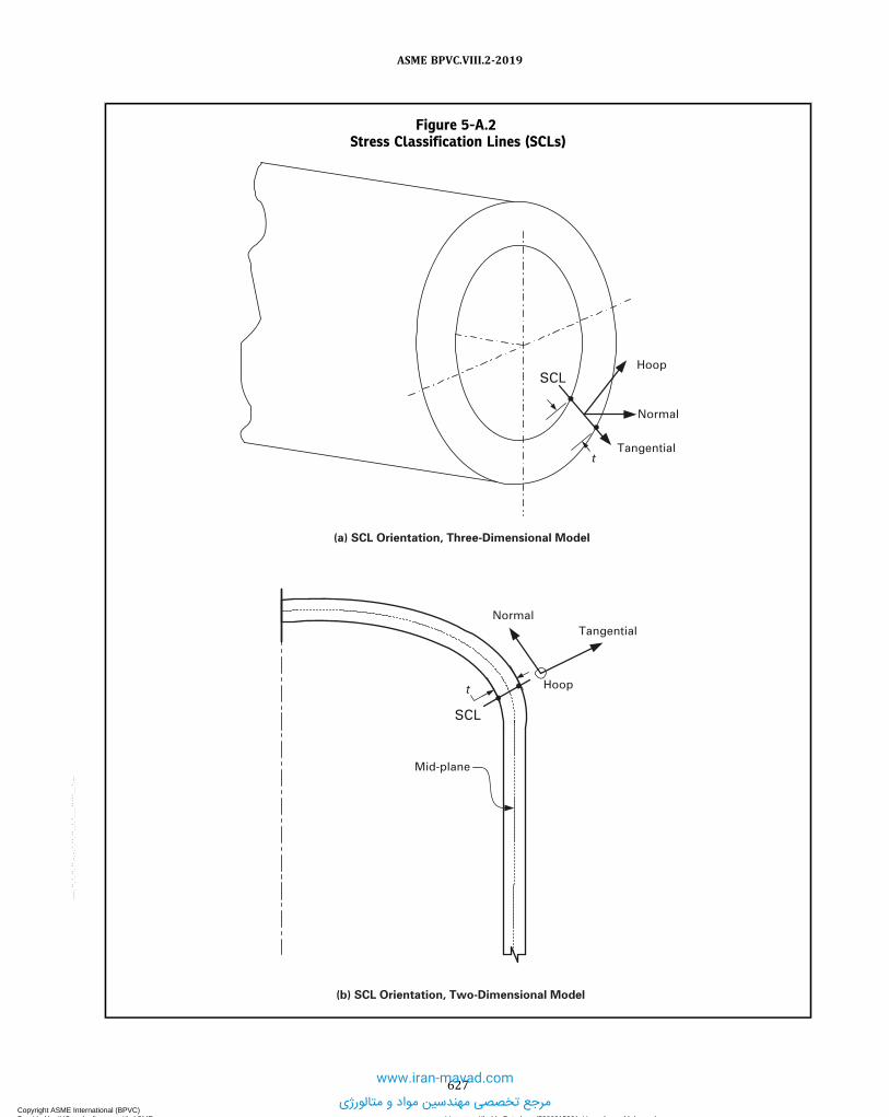
Figure 5-A.2Stress Classification Lines (SCLs)
Normal
Tangential
Hoop
t
SCL
Mid-plane
NormalTangential
Hoop
SCL
t
(a) SCL Orientation, Three-Dimensional Model
(b) SCL Orientation, Two-Dimensional Model
627
ASME BPVC.VIII.2-2019
Copyright ASME International (BPVC) Provided by IHS under license with ASME Licensee=Khalda Petroleum/5986215001, User=Amer, Mohamed
Not for Resale, 07/02/2019 14:07:58 MDTNo reproduction or networking permitted without license from IHS
--`,```,,,,,````,`,``,,`,,`,`-`-`,,`,,`,`,,`---
www.iran-mavad.com
مرجع تخصصی مهندسین مواد و متالورژی

Figure 5-A.3Stress Classification Line Orientation and Validity Guidelines
Largest stress
SCL normal to maximum stress
SCL normal to mid-surface Monotonically
increasing or decreasing example
Non-monotonic example
(b) Hoop and Meridional Stress
Conditions
(a) Example of SCL Orientation
(d) Shear Stress Conditions(c) Through-Thickness Stress
Conditions
628
ASME BPVC.VIII.2-2019
Copyright ASME International (BPVC) Provided by IHS under license with ASME Licensee=Khalda Petroleum/5986215001, User=Amer, Mohamed
Not for Resale, 07/02/2019 14:07:58 MDTNo reproduction or networking permitted without license from IHS
--`,```,,,,,````,`,``,,`,,`,`-`-`,,`,,`,`,,`---
www.iran-mavad.com
مرجع تخصصی مهندسین مواد و متالورژی

Figure 5-A.4Computation of Membrane and Bending Equivalent Stresses by the Stress Integration Method Using the
Results From a Finite Element Model With Continuum Elements
Stress distribution transformed to yL direction
y L
Peak
Ben
ding
Mem
bran
e
x L
xg
yg
629
ASME BPVC.VIII.2-2019
Copyright ASME International (BPVC) Provided by IHS under license with ASME Licensee=Khalda Petroleum/5986215001, User=Amer, Mohamed
Not for Resale, 07/02/2019 14:07:58 MDTNo reproduction or networking permitted without license from IHS
--`,```,,,,,````,`,``,,`,,`,`-`-`,,`,,`,`,,`---
www.iran-mavad.com
مرجع تخصصی مهندسین مواد و متالورژی

Figure 5-A.5Continuum Finite Element Model Stress Classification Line for the Structural Stress Method
630
ASME BPVC.VIII.2-2019
Copyright ASME International (BPVC) Provided by IHS under license with ASME Licensee=Khalda Petroleum/5986215001, User=Amer, Mohamed
Not for Resale, 07/02/2019 14:07:58 MDTNo reproduction or networking permitted without license from IHS
--`,```,,,,,````,`,``,,`,,`,`-`-`,,`,,`,`,,`---www.iran-mavad.com
مرجع تخصصی مهندسین مواد و متالورژی

Figure 5-A.6Computation of Membrane and Bending Equivalent Stresses by the Structural Stress Method Using
Nodal Force Results From a Finite Element Model With Continuum Elements
Elements orthogonal to stress evaluation line
Internal nodal forces (NFj) transformed to local coordinate system
(Element width for 3Dcontinuum)
w
A
A
y L
x L
xg
ygSj
631
ASME BPVC.VIII.2-2019
Copyright ASME International (BPVC) Provided by IHS under license with ASME Licensee=Khalda Petroleum/5986215001, User=Amer, Mohamed
Not for Resale, 07/02/2019 14:07:58 MDTNo reproduction or networking permitted without license from IHS
--`,```,,,,,````,`,``,,`,,`,`-`-`,,`,,`,`,,`---
www.iran-mavad.com
مرجع تخصصی مهندسین مواد و متالورژی

Figure 5-A.7Processing Nodal Force Results With the Structural Stress Method Using the Results From a Finite
Element Model With Three-Dimensional Second Order Continuum Elements
Elemental nodal internal forces
See Detail A
EL1
A
A
i = 1
i = 1, 2, 3 following weld toe
i = 1
Section A-A
Detail A
i = 2 i = 3
t
i = 2 i = 3
EL1
EL2
EL3
EL4
EL2
EL3
EL4
Sj
632
ASME BPVC.VIII.2-2019
Copyright ASME International (BPVC) Provided by IHS under license with ASME Licensee=Khalda Petroleum/5986215001, User=Amer, Mohamed
Not for Resale, 07/02/2019 14:07:58 MDTNo reproduction or networking permitted without license from IHS
--`,```,,,,,````,`,``,,`,,`,`-`-`,,`,,`,`,,`---
www.iran-mavad.com
مرجع تخصصی مهندسین مواد و متالورژی

Figure 5-A.8Processing Structural Stress Method Results for a Symmetric Structural Stress Range
tt/2
Structural Stress Structural Stress Range
Structural Stress Range
Tension
Bending
(a) Symmetric Structural Stress State (Symmetric Joint and Symmetric Loading)
(b) Antisymmetric Structural Stress State (Symmetric Joint and Antisymmetric Loading)
(c) Example of Symmetric Joint (Double Plate Lap Fillet Weld)
F
F
F
SCL at fillet weld toe (extends across one-half of the thickness)
�s
tt/2
t/2
Structural Stress
�s
t tt/2
t/2t
�s�
�s�
633
ASME BPVC.VIII.2-2019
Copyright ASME International (BPVC) Provided by IHS under license with ASME Licensee=Khalda Petroleum/5986215001, User=Amer, Mohamed
Not for Resale, 07/02/2019 14:07:58 MDTNo reproduction or networking permitted without license from IHS
--`,```,,,,,````,`,``,,`,,`,`-`-`,,`,,`,`,,`---
www.iran-mavad.com
مرجع تخصصی مهندسین مواد و متالورژی

Figure 5-A.9Computation of Membrane and Bending Equivalent Stresses by the Structural Stress Method Using the
Results From a Finite Element Model With Shell Elements
CL
Head thickness
Nozzle thicknessWeld leg
Weld throat thickness [see Note (1)]
Shell model at mean radius of nozzle and shell
Stress evaluation point
NOTE:(1) The thickness and material properties of the shell element used to model the fillet weld should be established based on producing an
equivalent stiffness of the actual fillet weld.
634
ASME BPVC.VIII.2-2019
Copyright ASME International (BPVC) Provided by IHS under license with ASME Licensee=Khalda Petroleum/5986215001, User=Amer, Mohamed
Not for Resale, 07/02/2019 14:07:58 MDTNo reproduction or networking permitted without license from IHS
--`,```,,,,,````,`,``,,`,,`,`-`-`,,`,,`,`,,`---
www.iran-mavad.com
مرجع تخصصی مهندسین مواد و متالورژی

Figure 5-A.10Processing Nodal Force Results With the Structural Stress Method Using the Results From a Finite
Element Model With Three-Dimensional Second Order Shell Elements
A
NF1 EL1
w
i = 1 i = 2 i = 3
NF2 NF3
Weld toe
YL
NF1-NF3 transformed to YL direction
Detail A
A
See Detail A
635
ASME BPVC.VIII.2-2019
Copyright ASME International (BPVC) Provided by IHS under license with ASME Licensee=Khalda Petroleum/5986215001, User=Amer, Mohamed
Not for Resale, 07/02/2019 14:07:58 MDTNo reproduction or networking permitted without license from IHS
--`,```,,,,,````,`,``,,`,,`,`-`-`,,`,,`,`,,`---
www.iran-mavad.com
مرجع تخصصی مهندسین مواد و متالورژی

Figure 5-A.11Element Sets for Processing Finite Element Nodal Stress Results With the Structural Stress Method
Based on Stress Integration
Nozzle NeckSCL
Shell SCL
Element setprocessed for
shell SCL
Element setprocessed fornozzle SCL
ThinPlateSCL
ThickPlateSCL
Element setprocessed for
thick plate SCL
Element setprocessed forthin plate SCL
636
ASME BPVC.VIII.2-2019
Copyright ASME International (BPVC) Provided by IHS under license with ASME Licensee=Khalda Petroleum/5986215001, User=Amer, Mohamed
Not for Resale, 07/02/2019 14:07:58 MDTNo reproduction or networking permitted without license from IHS
--`,```,,,,,````,`,``,,`,,`,`-`-`,,`,,`,`,,`---
www.iran-mavad.com
مرجع تخصصی مهندسین مواد و متالورژی

ð19ÞANNEX 5-BHISTOGRAM DEVELOPMENT AND CYCLE COUNTING FOR
FATIGUE ANALYSIS
(Informative)
5-B.1 GENERAL
This Annex contains cycle counting procedures required to perform a fatigue assessment for irregular stress or strainversus time histories. These procedures are used to break the loading history down into individual cycles that can beevaluated using the fatigue assessment rules of Part 5. Two cycle counting methods are presented in this Annex. An al-ternative cycle counting method may be used if agreed to by the Owner-User.
5-B.2 DEFINITIONS
The definitions used in this Annex are shown below.(a) Event –The User’s Design Specification may include one or more events that produce fatigue damage. Each event
consists of loading components specified at a number of time points over a time period and is repeated a specified num-ber of times. For example, an event may be the startup, shutdown, upset condition, or any other cyclic action. The se-quence of multiple events may be specified or random.
(b) Cycle – A cycle is a relationship between stress and strain that is established by the specified loading at a locationin a vessel or component. More than one stress–strain cycle may be produced at a location, either within an event or intransition between two events, and the accumulated fatigue damage of the stress–strain cycles determines the adequacyfor the specified operation at that location. This determination shall be made with respect to the stabilized stress–straincycle.
(c) Proportional Loading – During constant amplitude loading, as the magnitudes of the applied stresses vary withtime, the size of Mohr’s circle of stress also varies with time. In some cases, even though the size of Mohr’s circle variesduring cyclic loading, if the orientation of the principal axes remains fixed, the loading is called proportional. An exampleof proportional loading is a shaft subjected to in-phase torsion and bending, where the ratio of axial and torsional stressremains constant during cycling.
(d) Non-Proportional Loading – If the orientation of the principal axes are not fixed, but change orientation duringcyclic loading, the loading is called non-proportional. An example of non-proportional loading is a shaft subjected toout-of-phase torsion and bending, where the ratio of axial and torsional stress varies continuously during cycling.
(e) Peak –The point at which the first derivative of the loading or stress histogram changes from positive to negative.(f) Valley –The point at which the first derivative of the loading or stress histogram changes from negative to positive.
5-B.3 HISTOGRAM DEVELOPMENT
5-B.3.1
The loading histogram should be determined based on the specified loadings provided in the User’s Design Specifi-cation. The loading histogram should include all significant operating loads and events that are applied to the compo-nent. The following should be considered in developing the loading histogram.
(a) The number of repetitions of each event during the operation life.(b) The sequence of events during the operation life, if applicable.(c) Applicable loadings such as pressure, temperature, supplemental loads such as weight, support displacements, and
nozzle reaction loadings.(d) The relationship between the applied loadings during the time history.
637
ASME BPVC.VIII.2-2019
Copyright ASME International (BPVC) Provided by IHS under license with ASME Licensee=Khalda Petroleum/5986215001, User=Amer, Mohamed
Not for Resale, 07/02/2019 14:07:58 MDTNo reproduction or networking permitted without license from IHS
--`,```,,,,,````,`,``,,`,,`,`-`-`,,`,,`,`,,`---
www.iran-mavad.com
مرجع تخصصی مهندسین مواد و متالورژی

5-B.4 CYCLE COUNTING USING THE RAINFLOW METHOD
5-B.4.1The Rainflow Cycle Counting Method (ASTM Standard No. E1049) is recommended to determine the time points rep-
resenting individual cycles for the case of situations where the variation in time of loading, stress, or strain can be rep-resented by a single parameter. This cycle counting method is not applicable for non-proportional loading. Cyclescounted with the Rainflow Method correspond to closed stress–strain hysteresis loops, with each loop representing acycle.
5-B.4.2 RECOMMENDED PROCEDUREStep 1. Determine the sequence of peaks and valleys in the loading histogram. If multiple loadings are applied, it may
be necessary to determine the sequence of peaks and valleys using a stress histogram. If the sequence of events is un-known, the worst case sequence should be chosen.Step 2. Re-order the loading histogram to start and end at either the highest peak or lowest valley, so that only full
cycles are counted. Determine the sequence of peaks and valleys in the loading history. Let Χ denote the range underconsideration, and let Υ denote the previous range adjacent to Χ .Step 3. Read the next peak or valley. If out of data, go to Step 8.Step 4. If there are less than 3 points, go to Step 3; If not, form ranges Χ and Υ using the three most recent peaks and
valleys that have not been discarded.Step 5. Compare the absolute values of ranges Χ and Υ.(a) If Χ < Υ go to Step 3(b) If Χ ≥ Υ go to Step 6Step 6. Count range as one cycle; discard the peak and valley of Υ. Record the time points and loadings or component
stresses, as applicable, at the starting and ending time points of the cycle.Step 7. Return to Step 4 and repeat Steps 4 to 6 until no more time points with stress reversals remain.Step 8. Using the data recorded for the counted cycles perform fatigue assessment in accordance with Part 5.
5-B.5 CYCLE COUNTING USING MAX–MIN CYCLE COUNTING METHOD
5-B.5.1 OVERVIEWThe Max-Min Cycle Counting Method is recommended to determine the time points representing individual cycles for
the case of non-proportional loading. The cycle counting is performed by first constructing the largest possible cycle,using the highest peak and lowest valley, followed by the second largest cycle, etc., until all peak counts are used.
5-B.5.2 RECOMMENDED PROCEDUREStep 1. Determine the sequence of peaks and valleys in the loading history. If some events are known to follow each
other, group them together but otherwise arrange the random events in any order.Step 2. Calculate the elastic stress components σ i j produced by the applied loading at every point in time during each
event at a selected location of a vessel. All stress components must be referred to the same global coordinate system. Thestress analysis must include peak stresses at local discontinuities.Step 3. Scan the interior points of each event and delete the time points at which none of the stress components in-
dicate reversals (peaks or valleys).Step 4. Using the stress histogram from Step 2, determine the time point with the highest peak or lowest valley. Des-
ignate the time point as mt, and the stress components as mσij.Step 5. If time point mt is a peak in the stress histogram, determine the component stress range between time point mt
and the next valley in the stress histogram. If time point mt is a valley, determine the component stress range betweentime point mt and the next peak. Designate the next time point as nt, and the stress components as nσij. Calculate thestress component ranges and the von Mises equivalent stress range between time points mt and nt.
ð5B:1Þ
ð5B:2Þ
Step 6. Repeat Step 5, for the current time point, mt and the time point of the next peak or valley in the sequence of thestress histogram. Repeat this process for every remaining time point in the stress histogram.
638
ASME BPVC.VIII.2-2019
Copyright ASME International (BPVC) Provided by IHS under license with ASME Licensee=Khalda Petroleum/5986215001, User=Amer, Mohamed
Not for Resale, 07/02/2019 14:07:58 MDTNo reproduction or networking permitted without license from IHS
--`,```,,,,,````,`,``,,`,,`,`-`-`,,`,,`,`,,`---www.iran-mavad.com
مرجع تخصصی مهندسین مواد و متالورژی

Step 7. Determine the maximum von Mises equivalent stress range obtained in Step 5 and record the time points mt
and nt that define the start and end points of the k th cycle.
Step 8. Determine the event or events to which the time points mt and nt belong and record their specified number of
repetitions as mN and nN, respectively.
Step 9. Determine the number of repetitions of the kth cycle.
(a) If mN < nN: Delete the time point mt from those considered in Step 4, and reduce the number of repetitions at time
point nt from nN to nN − mN.
(b) If mN > nN: Delete the time point nt from those considered in Step 4, and reduce the number of repetitions at time
point mt from mN to mN − nN.
(c) If mN = nN: Delete both time points mt and nt from those considered in Step 4.
Step 10. Return to Step 4 and repeat Steps 4 to 10 until no more time points with stress reversals remain.
Step 11. Using the data recorded for the counted cycles, perform fatigue assessment in accordance with Part 5. Note
that an elastic–plastic fatigue assessment (see 5.5.4) may be applied if nmΔSrange exceeds the yield point of the cyclic
stress range-strain range curve of the material.
5-B.6 NOMENCLATURE
mnΔSrange = von Mises equivalent stress range between time points mt and nt.σ i j = stress tensor at the point under evaluation.
mσij = stress tensor at the point under evaluation at time point mt.nσij = stress tensor at the point under evaluation at time point nt.
mnΔσij = stress component range between time points mt and nt.mnΔσ11 = stress range associated with the normal stress component in the 1-direction between time points mt and nt.mnΔσ22 = stress range associated with the normal stress component in the 2-direction between time points mt and nt.mnΔσ33 = stress range associated with the normal stress component in the 3-direction between time points mt and nt.mnΔσ12 = stress range associated with the shear stress component in the 1-direction between time points mt and nt.mnΔσ13 = stress range associated with the shear stress component in the 2-direction between time points mt and nt.mnΔσ23 = stress range associated with the shear stress component in the 3-direction between time points mt and nt.
mt = time point under consideration with the highest peak or lowest valley.nt = time point under consideration that forms a range with time point mt.
mN = specified number of repetitions of the event associated with time point mt.nN = specified number of repetitions of the event associated with time point nt.X = absolute value of the range (load or stress) under consideration using the Rainflow Cycle Counting Method.Y = absolute value of the adjacent range (load or stress) to previous X using the Rainflow Cycle Counting
Method.
639
ASME BPVC.VIII.2-2019
Copyright ASME International (BPVC) Provided by IHS under license with ASME Licensee=Khalda Petroleum/5986215001, User=Amer, Mohamed
Not for Resale, 07/02/2019 14:07:58 MDTNo reproduction or networking permitted without license from IHS
--`,```,,,,,````,`,``,,`,,`,`-`-`,,`,,`,`,,`---
www.iran-mavad.com
مرجع تخصصی مهندسین مواد و متالورژی

ANNEX 5-CALTERNATIVE PLASTICITY ADJUSTMENT FACTORS ANDEFFECTIVE ALTERNATING STRESS FOR ELASTIC FATIGUE
ANALYSIS
(Normative)
5-C.1 SCOPE
5-C.1.1 This Annex contains procedures for the determination of plasticity correction factors and effective alternat-ing equivalent stress for elastic fatigue analysis. These procedures include amodified Poisson’s ratio adjustment for localthermal and thermal bending stresses, a notch plasticity adjustment factor that is applied to thermal bending stresses,and a nonlocal plastic strain redistribution adjustment that is applied to all stresses except local thermal and thermalbending stresses. These procedures are an alternative to effective alternating stress calculations in Step 4 of 5.5.3.2.
5-C.2 DEFINITIONS
5-C.2.1 Thermal Bending Stress. Thermal bending stress is caused by the linear portion of the through-wall tem-perature gradient. Such stresses shall be classified as secondary stresses.
5-C.2.2 Local Thermal Stress. Local thermal stress is associated with almost complete suppression of the differ-ential expansion and thus produces no significant distortion. Such stresses shall be considered only from the fatiguestandpoint and are therefore classified as peak stresses. Examples of local thermal stresses are the stress in a smallhot spot in a vessel wall, the non-linear portion of a through-wall temperature gradient in a cylindrical shell, and thethermal stress in a cladding material that has a coefficient of expansion different from that of the base metal. Local ther-mal stresses are characterized by having two principal stresses that are approximately equal.
5-C.3 EFFECTIVE ALTERNATING STRESS FOR ELASTIC FATIGUE ANALYSIS
5-C.3.1 The effective total equivalent stress amplitude is used to evaluate the fatigue damage for results obtainedfrom a linear elastic stress analysis. The controlling stress for the fatigue evaluation is the effective total equivalentstress amplitude, defined as one-half of the effective total equivalent stress range (PL + Pb + Q + F) calculated for eachcycle in the loading histogram.
5-C.3.2 The following procedure shall be used to determine plasticity correction factors for elastic fatigue analysisand the effective alternating equivalent stress.Step 1. At the point of interest, determine the following stress tensors and associated equivalent stresses at the start
and end points (time points mt and nt, respectively) for the kth cycle counted in Step 2 of 5.5.3.2.(a) Calculate the component stress range between time points mt and nt and compute an equivalent stress range due
to primary plus secondary plus peak stress as given below.
ð5C:1Þ
ð5C:2Þ
(b) Using the linearized stress results due to primary plus secondary stresses, compute the component stress rangeusing eq. (5-C.1). Compute the equivalent stress range using eq. (5-C.2) and designate this quantity as ΔSn ,k .
640
ASME BPVC.VIII.2-2019
Copyright ASME International (BPVC) Provided by IHS under license with ASME Licensee=Khalda Petroleum/5986215001, User=Amer, Mohamed
Not for Resale, 07/02/2019 14:07:58 MDTNo reproduction or networking permitted without license from IHS
--`,```,,,,,````,`,``,,`,,`,`-`-`,,`,,`,`,,`---www.iran-mavad.com
مرجع تخصصی مهندسین مواد و متالورژی

(c) Determine the stress tensor due to local thermal and thermal bending stresses at the start and end points for thekth cycle. It may be difficult to calculate the local thermal stress from stress distributions obtained from numerical meth-ods. If this is the case, the procedure below can be used to calculate the local thermal and thermal bending stresses dueto a non-linear temperature distribution. This method is based on calculating a thermal stress difference range asso-ciated with the linearized temperature distribution along the SCL for the time steps of interest. Consistent with thatmethod, consider the distribution of the temperature from numerical method as a function of the local through thicknessdirection. The temperature distribution for each time step can be separated into three parts.
(1) A constant temperature equal to the average of the temperature distribution
ð5C:3Þ
(2) The linearly varying portion of the temperature distribution
ð5C:4Þ
(3) The non-linear portion of the temperature distribution
ð5C:5Þ
By assuming full suppression of the differential expansion of the cross-section, the associated local thermal stress par-allel to the surface for each time step may be calculated as given below where Tp is given by eq. (5-C.5).
ð5C:6Þ
ð5C:7Þ
Using eqs. (5-C.6) and (5-C.7), determine the local thermal component stress ranges using eq. (5-C.1) and designatethis quantity as ΔσLT
ij,k. The thermal bending component stress range, ΔσTBij,k is determined by linearizing the through-
wall stress distribution due to thermal effects only.
(d) Compute the equivalent stress ranges due to primary plus secondary plus peak stress minus the local thermalstress using eqs. (5-C.8) and (5-C.9).
ð5C:8Þ
ð5C:9Þ
(e) Compute the equivalent stress ranges due to local thermal plus thermal bending stress using eqs. (5-C.10) and(5-C.11).
ð5C:10Þ
ð5C:11Þ
(f) If required, see eq. (5-C.32), compute the stress tensor due to nonthermal effects (all loadings except local thermaland thermal bending), σNT
ij,k, at the start and end points for the kth cycle.
Step 2. Determine the Poisson’s ratio adjustment, Kv ,k to adjust local thermal and thermal bending stresses for the kthcycle based on the equivalent stress ranges in Step 1 using the following equations, (SPS is defined in 5.5.6.1):
ð5C:12Þ
641
ASME BPVC.VIII.2-2019
Copyright ASME International (BPVC) Provided by IHS under license with ASME Licensee=Khalda Petroleum/5986215001, User=Amer, Mohamed
Not for Resale, 07/02/2019 14:07:58 MDTNo reproduction or networking permitted without license from IHS
--`,```,,,,,````,`,``,,`,,`,`-`-`,,`,,`,`,,`---
www.iran-mavad.com
مرجع تخصصی مهندسین مواد و متالورژی

ð5C:13Þ
ð5C:14Þ
Step 3. Determine the nonlocal plastic strain redistribution adjustment, Knl , k to adjust all stresses except local thermaland thermal bending for the kth cycle. In these equations, the parameters m and n are defined in Table 5.13.
ð5C:15Þ
ð5C:16Þ
ð5C:17Þ
Step 4. Determine the notch plasticity adjustment factor, Knp , k based on the equivalent stress ranges in Step 1 to ad-just thermal bending stresses to account for additional local strain concentration due to a geometric stress riser for thekth cycle. In these equations, the parameters n are defined in Table 5.13.For numerical results used directly:
ð5C:18Þ
ð5C:19Þ
ð5C:20Þ
ð5C:21Þ
For numerical results that are adjusted with a stress concentration factor (SCF):
ð5C:22Þ
ð5C:23Þ
ð5C:24Þ
ð5C:25Þ
Note that the SCF and Knp , k values may be dependent upon the component stress direction.
Step 5. Apply the plasticity adjustment factors to the component stresses at the start and end points for the k th cycle.
(a) Compute the component stresses including plastic Poisson’s ratio and notch plasticity adjustments as given belowfor time points mt and nt. For numerical results used directly:
ð5C:26Þ
642
ASME BPVC.VIII.2-2019
Copyright ASME International (BPVC) Provided by IHS under license with ASME Licensee=Khalda Petroleum/5986215001, User=Amer, Mohamed
Not for Resale, 07/02/2019 14:07:58 MDTNo reproduction or networking permitted without license from IHS
--`,```,,,,,````,`,``,,`,,`,`-`-`,,`,,`,`,,`---
www.iran-mavad.com
مرجع تخصصی مهندسین مواد و متالورژی

ð5C:27Þ
For numerical results that are adjusted with a stress concentration factor (SCF):
ð5C:28Þ
ð5C:29Þ
(b) Compute the component stresses including nonlocal plastic strain redistribution adjustment as given below fortime points mt and nt. For numerical results used directly:
ð5C:30Þ
ð5C:31Þ
For numerical results that are adjusted with a stress concentration factor (SCF):
ð5C:32Þ
Step 6. Compute the adjusted component stress ranges between time points mt and nt as given below.
ð5C:33Þ
Step 7. Compute the effective equivalent stress range using the adjusted component stress ranges from Step 6 and Eq.(5-C.2). Designate the adjusted effective equivalent stress range as (ΔSP , k)adj.
Step 8. Compute the effective alternating equivalent stress for the kth cycle as given below.
ð5C:34Þ
5-C.4 NOMENCLATURE
α = thermal expansion coefficient of the material at the point under consideration, evaluated at the mean tem-perature of the kth cycle.
ΔSn , k = primary plus secondary equivalent stress range for the kth cycle.ΔSP , k = range of primary plus secondary plus peak equivalent stress for the kth cycle.
ΔSLT , k = primary plus secondary plus peak equivalent stress range due to local thermal effects for the k th cycle.ΔSTB , k = primary plus secondary plus peak equivalent stress range due to thermal bending effects for the kth cycle.ΔSNT ,k = primary plus secondary plus peak equivalent stress range due to nonthermal effects for the kth cycle.
(ΔSP ,k)adj = adjusted range of primary plus secondary plus peak equivalent stress, including nonlocal strain redistri-bution, notch plasticity, and plastic Poisson’s ratio adjustments for the kth cycle.
Δσ i j , k = stress component range between time points mt and nt for the kth cycle.ΔσLT
ij,k = stress component range due to local thermal stress between time point mt and nt for the kth cycle.ΔσTB
ij,k = stress component range due to thermal bending stress between time points mt and nt for the k th cycle.adjusted stress tensor, including nonlocal strain redistribution, notch plasticity, and plastic Poisson’s ratioadjustments at the location and time point under evaluation for the kth cycle.
E = Young’s Modulus of the material evaluated at the mean temperature of the cycle.K1 = parameter used to compute Knp , k .K2 = parameter used to compute Knp , k .
Knl , k = nonlocal strain redistribution adjustment factor for the kth cycle.Knp , k = notch plasticity adjustment factor for the kth cycle.
643
ASME BPVC.VIII.2-2019
Copyright ASME International (BPVC) Provided by IHS under license with ASME Licensee=Khalda Petroleum/5986215001, User=Amer, Mohamed
Not for Resale, 07/02/2019 14:07:58 MDTNo reproduction or networking permitted without license from IHS
--`,```,,,,,````,`,``,,`,,`,`-`-`,,`,,`,`,,`---
www.iran-mavad.com
مرجع تخصصی مهندسین مواد و متالورژی

Kv ,k = plastic Poisson’s ratio adjustment factor for the k th cycle.m = material constant used for the nonlocal strain redistribution adjustment factor, per Table 5.13.n = material constant used for the nonlocal strain redistribution adjustment factor, per Table 5.13.v = Poisson’s ratio.
Sa l t , k = alternating equivalent stress for the kth cycle.SPS = allowable limit on the primary plus secondary stress range.SCF = stress concentration factor.
SCFLT = stress concentration factor applicable for local thermal stress.SCFNUM = stress concentration factor determined from the numerical model.
σLTij,k = stress tensor due to local thermal stress at the location and time point under evaluation for the kth cycle.
σNTij,k = stress tensor due to nonthermal stress at the location and time point under evaluation for the kth cycle.
σTBij,k = stress tensor due to thermal bending stress due to the linearly varying portion of the temperature distri-
bution at the location and time point under evaluation for the kth cycle.mσij,k = stress tensor at the point under evaluation at time point mt for the kth cycle.nσij,k = stress tensor at the point under evaluation at time point nt for the kth cycle.
mσLTij,k = stress tensor due to local thermal stress at the location under evaluation at time point mt for the kth cycle.nσLTij,k = stress tensor due to local thermal stress at the location under evaluation at time point nt for the kth cycle.mσTBij,k = stress tensor due to thermal bending stress at the location under evaluation at time point mt for the kth
cycle.nσTBij,k = stress tensor due to thermal bending stress at the location under evaluation at time point nt for the k th
cycle.(σLT
ij)adj = adjusted stress tensor due to local thermal stress at the location and time point under evaluation for thekth cycle.
(σNTij)adj = adjusted stress tensor due to nonthermal stress at the location and time point under evaluation for the kth
cycle.(σTB
ij)adj = adjusted stress tensor due to thermal bending stress at the location and time point under evaluation for thekth cycle.
t = wall thickness.mt = time point under consideration with the highest peak or lowest valley.nt = time point under consideration that forms a range with time point mt.T = temperature distribution.
Tavg = average temperature component of temperature distribution T .Tb = equivalent linear temperature component of temperature distribution T .Tp = peak temperature component of temperature distribution T .x = position through the wall thickness.z = local coordinate for the temperature distribution.
644
ASME BPVC.VIII.2-2019
Copyright ASME International (BPVC) Provided by IHS under license with ASME Licensee=Khalda Petroleum/5986215001, User=Amer, Mohamed
Not for Resale, 07/02/2019 14:07:58 MDTNo reproduction or networking permitted without license from IHS
--`,```,,,,,````,`,``,,`,,`,`-`-`,,`,,`,`,,`---
www.iran-mavad.com
مرجع تخصصی مهندسین مواد و متالورژی

ð19ÞANNEX 5-DSTRESS INDICES
(Normative)
5-D.1 GENERAL
5-D.1.1 In lieu of a detailed stress analysis, stress indices may be used to determine peak stresses around a nozzleopening.
5-D.1.2 The term stress index, is defined as the numerical ratio of the stress components σ t , σn , and σ r under con-sideration to the computed membrane hoop stress in the unreinforced vessel material; however, the material which in-creases the thickness of a vessel wall locally at the nozzle shall not be included in the calculation of these stresscomponents. These stress directions are defined in Figure 5-D.1. When the thickness of the vessel wall is increased overthat required to the extent provided hereinafter, the values of r1 and r2 in Figure 5-D.2 shall be referred to the thickenedsection.
5-D.1.3 The stress indices in these tables provide only the maximum stresses at certain general locations due tointernal pressure. In the evaluation of stresses in or adjacent to vessel openings and connections, it is often necessaryto consider the effect of stresses due to external loadings or thermal stresses. In such cases, the combined stress at agiven point may be determined by superposition. In the case of combined stresses due to internal pressure and nozzleloading, the maximum stresses for a given location should be considered as acting at the same point and added algeb-raically unless positive evidence is available to the contrary.
5-D.2 STRESS INDICES FOR RADIAL NOZZLES
5-D.2.1 The stress indices for radial nozzles in spherical shells and spherical portions of formed heads in Table5-D.1 and for nozzles in cylindrical shells in Table 5-D.2 may be used if all of the items listed below are true.
(a) The opening is for a circular nozzle whose axis is normal to the vessel wall. If the axis of the nozzle makes an angleθ with the normal to the vessel wall, an estimate of the σn index on the inside may be obtained from the equationsshown below provided dn i/Di ≤ 0.15. In these equations, K1 is the σn stress index for a radial connection and K2 isthe σn stress index for a non-radial connection.
ð5D:1Þ
ð5D:2Þ
(b) The arc distance measured between the centerlines of adjacent nozzles along the inside surface of the shell is notless than three times the sum of their inside radii for openings in a head or along the longitudinal axis of a shell and is notless than two times the sum of their radii for openings along the circumference of a cylindrical shell.
(c) For nozzles in cylindrical shells, the following dimensional limitations shown below are satisfied. In addition, thetotal nozzle reinforcement area on the transverse plane of the nozzle including any outside of the reinforcement limitsshall not exceed 200% of that required for the longitudinal plane unless a tapered transition section is incorporated intothe reinforcement and the shell.
ð5D:3Þ
645
ASME BPVC.VIII.2-2019
Copyright ASME International (BPVC) Provided by IHS under license with ASME Licensee=Khalda Petroleum/5986215001, User=Amer, Mohamed
Not for Resale, 07/02/2019 14:07:58 MDTNo reproduction or networking permitted without license from IHS
--`,```,,,,,````,`,``,,`,,`,`-`-`,,`,,`,`,,`---
www.iran-mavad.com
مرجع تخصصی مهندسین مواد و متالورژی

ð5D:4Þ
ð5D:5Þ
(d) For nozzles in spherical shells, the following dimensional limitations shown below are satisfied. In addition, atleast 40% of the reinforcement is located on the outside surface of the nozzle-shell juncture.
ð5D:6Þ
ð5D:7Þ
ð5D:8Þ
(e) For nozzles in cylindrical and spherical shells, the following local geometry details shall be satisfied.(1) The inside corner radius r1 (see Figure 5-D.2) is one-eighth to one-half of the shell thickness t .(2) The outer corner radius r2 (see Figure 5-D.2) is large enough to provide a smooth transition between the noz-
zles and the shell. In addition, for nozzle diameters greater than 1.5 shell thicknesses in cylindrical shells and 2:1 ellip-soidal heads, or for nozzle diameters greater than 3 shell thicknesses in spherical shells, the value of r2 shall satisfy thefollowing:
ð5D:9Þ
(3) The value of r3 shall satisfy the following:
ð5D:10Þ
5-D.2.2 Stress indices for radial nozzles in spherical shells and spherical portions of formed heads and nozzle incylindrical shells may be developed by stress analysis techniques consistent with the elastic design analysis methodsof Part 5, or obtained for other sources.
5-D.3 STRESS INDICES FOR LATERALS
5-D.3.1 The stress indices for laterals in cylindrical shells in Table 5-D.3 may be used when all of the following con-ditions are satisfied:(a) The angle θ equals 45 deg; these indices may be used for angles of θ less than 45 deg (see Figure 5-D.3).(b) The nozzle is of circular cross section and has an axis that intersects the axis of the cylindrical vessel.(c) The design of the nozzle reinforcement is in accordance with the applicable rules of 4.5.(d) The following dimensional ratios are satisfied.
ð5D:11Þ
ð5D:12Þ
ð5D:13Þ
(a) The nominal pressure membrane stress to be used with the pressure indices is determined using the followingequations.
646
ASME BPVC.VIII.2-2019
Copyright ASME International (BPVC) Provided by IHS under license with ASME Licensee=Khalda Petroleum/5986215001, User=Amer, Mohamed
Not for Resale, 07/02/2019 14:07:58 MDTNo reproduction or networking permitted without license from IHS
--`,```,,,,,````,`,``,,`,,`,`-`-`,,`,,`,`,,`---
www.iran-mavad.com
مرجع تخصصی مهندسین مواد و متالورژی

ð5D:14Þ
ð5D:15Þ
5-D.3.2 Stress indices for laterals in cylindrical shells may be developed by stress analysis techniques consistentwith the elastic design analysis methods of Part 5, or obtained for other sources.
5-D.4 NOMENCLATURE
Di = inside vessel diameter.dn i = inside nozzle diameter.p = pressure.r1 = local nozzle radius, see Figure 5-D.2.r2 = local nozzle radius, see Figure 5-D.2.r3 = local nozzle radius, see Figure 5-D.2.σ r = stress component normal to the boundary of the section.σ t = stress component in the plane of the section under consideration and parallel to the boundary of the section.σn = stress component normal to the plane of the section (ordinarily the circumferential stress around the hole in the
shell.t = minimum wall thickness in the region under consideration, or the thickness of the vessel, as applicable.tp = thickness of perforated plate, or the thickness of the pipe portion of a nozzle, as applicable.θ = angle between the axis of the nozzle and the normal to the vessel.
5-D.5 TABLES
Table 5-D.1Stress Indices for Nozzles in Spherical Shells and Portions of Formed Heads
Stress Inside Corner Outside Corner
σn 2.0 2.0σ t –0.2 2.0σ r 0.0
σ 2.2 2.0
Table 5-D.2Stress Indices for Nozzles in Cylindrical Shells
Material
Longitudinal Plane Transverse Plane
Inside Corner Outside Corner Inside Corner Outside Corner
σn 3.1 1.2 1.0 2.1σ t –0.2 1.0 –0.2 2.6σ r 0.0 0.0
σ 3.3 1.2 1.2 2.6
647
ASME BPVC.VIII.2-2019
Copyright ASME International (BPVC) Provided by IHS under license with ASME Licensee=Khalda Petroleum/5986215001, User=Amer, Mohamed
Not for Resale, 07/02/2019 14:07:58 MDTNo reproduction or networking permitted without license from IHS
--`,```,,,,,````,`,``,,`,,`,`-`-`,,`,,`,`,,`---
www.iran-mavad.com
مرجع تخصصی مهندسین مواد و متالورژی

Table 5-D.3Stress Indices for Laterals
Load Stress
Region 1 Region 2 Region 3
Inside[Note (1)]
Outside[Note (1)] Inside Outside Inside Outside
Pressure σmax 5.5 0.8 3.3 0.7 1.0 1.0S 5.75 0.8 3.5 0.75 1.2 1.1
In-plane branch moment,MB
σmax 0.1 0.1 0.5 0.5 1.0 1.6S 0.1 0.1 0.5 0.5 1.0 1.6
Vessel moments,MR or MRT
σmax 2.4 2.4 0.6 1.8 0.2 0.2S 2.7 2.7 0.7 2.0 0.3 0.3
Out-of-plane branchmoment, MBT
σmax 0.13 NA 0.06 NA NA 2.5[Note (2)]
S 0.22 NA 0.07 NA NA 2.5[Note (2)]
NOTES:(1) Inside/outside refers to inside corner (pressure side)/outside fillet and in the plane of symmetry as shown in Figure 5-D.3.(2) Maximum stress/stress intensity in Region 3 for transverse moment MBT occurs 90 deg away from in-plane moment.
648
ASME BPVC.VIII.2-2019
Copyright ASME International (BPVC) Provided by IHS under license with ASME Licensee=Khalda Petroleum/5986215001, User=Amer, Mohamed
Not for Resale, 07/02/2019 14:07:58 MDTNo reproduction or networking permitted without license from IHS
--`,```,,,,,````,`,``,,`,,`,`-`-`,,`,,`,`,,`---
www.iran-mavad.com
مرجع تخصصی مهندسین مواد و متالورژی

5-D.6 FIGURES
Figure 5-D.1Direction of Stress Components
�r
�n
�t
�r
�n
�t
649
ASME BPVC.VIII.2-2019
Copyright ASME International (BPVC) Provided by IHS under license with ASME Licensee=Khalda Petroleum/5986215001, User=Amer, Mohamed
Not for Resale, 07/02/2019 14:07:58 MDTNo reproduction or networking permitted without license from IHS
--`,```,,,,,````,`,``,,`,,`,`-`-`,,`,,`,`,,`---
www.iran-mavad.com
مرجع تخصصی مهندسین مواد و متالورژی

Figure 5-D.2Nozzle Nomenclature and Dimensions
Shell thickness
x
t
r3
r
� � 45°
Offset
2
Offset
� = 90°
tn
tp
r2
r1
tn
rm
tp
tn
r3
r
t
2
r2
r1
tn
rm
� � 45°
t
r
2
tn' = tp + 0.667x
tp
r1
tn
rm = r + 0.5t'n
r3
tn, tp
r2
r
rm
tr1
r2
650
ASME BPVC.VIII.2-2019
Copyright ASME International (BPVC) Provided by IHS under license with ASME Licensee=Khalda Petroleum/5986215001, User=Amer, Mohamed
Not for Resale, 07/02/2019 14:07:58 MDTNo reproduction or networking permitted without license from IHS
--`,```,,,,,````,`,``,,`,,`,`-`-`,,`,,`,`,,`---
www.iran-mavad.com
مرجع تخصصی مهندسین مواد و متالورژی
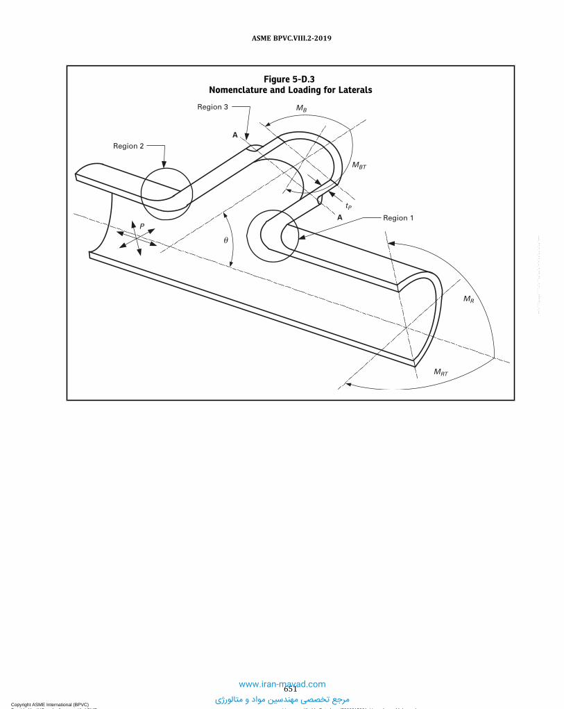
Figure 5-D.3Nomenclature and Loading for Laterals
Region 1
Region 3
A
A
Region 2
P
�
tP
MBT
MB
MRT
MR
651
ASME BPVC.VIII.2-2019
Copyright ASME International (BPVC) Provided by IHS under license with ASME Licensee=Khalda Petroleum/5986215001, User=Amer, Mohamed
Not for Resale, 07/02/2019 14:07:58 MDTNo reproduction or networking permitted without license from IHS
--`,```,,,,,````,`,``,,`,,`,`-`-`,,`,,`,`,,`---
www.iran-mavad.com
مرجع تخصصی مهندسین مواد و متالورژی

ANNEX 5-EDESIGN METHODS FOR PERFORATED PLATES BASED ON
ELASTIC STRESS ANALYSIS
(Normative)
5-E.1 OVERVIEW
5-E.1.1 This paragraph contains a method of analysis for flat perforated plates subjected to applied loads or loadingsresulting from structural interaction with adjacent members. This method applies to perforated plates that satisfy thefollowing conditions:(a) The holes are in an equilateral triangular or square penetration pattern.(b) The holes are circular and the axis of the hole is perpendicular to the surface of the plate.(c) There are 19 or more holes.(d) The effective ligament efficiency satisfies the following criteria in 5-E.4.
5-E.1.2 Rolling or pressure expansion of tubes into a tubesheet will result in compression on the inside diameter ofthe tubesheet perforation and the tube itself. Thermal transients that occur during operation may result in thermal dif-ferential between the tube and the tubesheet resulting in a loss of the compression obtained during fabrication. Fortubes that are also welded, such thermal cycling can cause fatigue of the weld joining the tube to the tubesheet. For tubesthat are not welded, thermal cycling can cause the tube to loose contact resulting in leakage. A transient thermal andstress analysis can determine the magnitude of cyclic stress in the tube weld. For small ligaments, the pressure expan-sion of tubes can cause significant ligament deformation and stresses.
5-E.2 STRESS ANALYSIS OF THE EQUIVALENT SOLID PLATE
5-E.2.1 The analysis method for perforated plates presented in this paragraph is based on the concept of an effectivesolid plate. In this method, the material properties of the actual perforated plate are replaced by material properties ofan effective solid plate that approximate the stiffness of the actual perforated plate. A stress analysis is then performedwhere the effective solid plate is used in the model that is geometrically similar to the perforated plate, and subject to theactual loading conditions. After completion of the stress analysis, the values of the stresses in the actual perforated plateare obtained by applying stress multiplying factors to the stress results computed for the effective solid plate.
5-E.2.2 An accurate model of the overall tubesheet behavior may be achieved by employing the concept of anequivalent elastic material of anisotropic properties. For triangular penetration patterns the in-plane behavior of thetubesheet is isotropic and the anisotropy of the equivalent material must only be considered for stresses in the thicknessdirection. The tubesheet can be analyzed using an axisymmetric solid numerical analysis with the effective elastic matrix[E] to simulate the anisotropic behavior. For square penetration patterns the equivalent material properties depend onthe orientation of the loading with respect to the symmetry axes of the pattern. The tubesheet can be analyzed using anaxisymmetric solid numerical analysis with the effective average elastic matrix [E] for in-plane loading to simulate theanisotropic behavior. When the tubesheet loading is not axisymmetric (e.g., channels with divider plates), a three-dimensional solid numerical analysis may be required.
652
ASME BPVC.VIII.2-2019
Copyright ASME International (BPVC) Provided by IHS under license with ASME Licensee=Khalda Petroleum/5986215001, User=Amer, Mohamed
Not for Resale, 07/02/2019 14:07:58 MDTNo reproduction or networking permitted without license from IHS
--`,```,,,,,````,`,``,,`,,`,`-`-`,,`,,`,`,,`---
www.iran-mavad.com
مرجع تخصصی مهندسین مواد و متالورژی

5-E.3 STIFFNESS EFFECTS OF THE TUBES
5-E.3.1 The in-plane stiffening effect of the tubes in the perforations may be included in the analysis. The extent towhich the tubes stiffen the perforated plate depends on the materials, the manufacturing processes, operating condi-tions, and degree of corrosion. This stiffening effect may be included in the calculations by including part or all of thetube walls in the ligament efficiency used to obtain the effective elastic constants of the plate. Such stiffening may eitherincrease or decrease stresses in the plate itself and in the attached shells.
5-E.3.2 Where applicable, the stiffening effect resulting from the staying action of the tubes should be incorporatedinto the numerical analysis. For fixed-fixed type exchangers, the axial stiffness of the tubes shall be included in the anal-ysis. When including the tube stiffness, the difference in axial strain due to pressure between the shell and tubes (Pois-son’s effect) as well as differential thermal expansion between tubes and shell should also be included in the numericalanalysis.
5-E.4 EFFECTIVE MATERIAL PROPERTIES FOR THE EQUIVALENT SOLID PLATE
5-E.4.1 The effective elastic constants of the perforated plate are determined as a function of the effective ligamentefficiency μ * that is computed in accordance with 4.18.6.4.
5-E.4.2 If the hole pattern is irregular or has isolated thin ligaments in a uniform hole pattern, the calculated elasticconstants shall represent the average ligament size over the entire modeled plate in order to capture the global re-sponse. The stress multipliers used for the fatigue assessment of 5-E.7.2 shall be computed considering the appropriateligament efficiency for the location of interest.
5-E.4.3 The effective elastic constants of the perforated plate material are determined based on the hole pattern andthickness of the plate. Either one of the following two options may be used in the analysis.
(a) Option A –The effective elastic constants are provided below. Elastic constants are provided for the effective elas-tic modulus and effective Poisson’s ratio. A value for the effective shear modulus, which is required in the analysis meth-od in this annex, is not provided. The effective shear modulus shall be evaluated using Option B.
(1) Triangular Hole Pattern –The effective elastic modulus and effective Poisson’s ratio are provided in Tables 5-E.1and 5-E.2, respectively.
(2) Square Hole Pattern – The effective elastic modulus and effective Poisson’s ratio are provided in Tables 5-E.3and 5-E.4, respectively. The effective elastic modulus and Poisson’s ratio represent an equivalent isotropic value consid-ering the values of the pitch and diagonal properties.
(3) Range of Applicability – The range of applicability in terms of the effective tube pitch is 0.1 ≤ μ* ≤ 1.0. The ef-fective elastic constants E* and v* can be used for in-plane loading and bending loading of all values of h/p .
(4) The value of the in-plane shear modulus is given by eq. (5-E.1). The value of the out-of-plane shear modulus G*z
shall be computed using Option B.
ð5E:1Þ
(b) Option B – The effective elastic constants for plane stress and generalized plane strain are provided below.(1) Triangular Hole Pattern –The effective elastic modulus and effective Poisson’s ratio are provided in Table 5-E.5(2) Square Hole Pattern – The effective elastic modulus and effective Poisson’s ratio for the pitch and diagonal di-
rections are provided in Tables 5-E.6 and 5-E.7, respectively.(3) Effects of Poisson’s Ratio –The effective material constants in Tables 5-E.5, 5-E.6, and 5-E.7 are based on a Pois-
son’s ratio of v = 0.3. The material constants can be determined for other values of Poisson’s ratio using the followingprocedure.
(-a) For a given value of μ * , determine E* and v* using the equations in Tables 5-E.5, 5-E.6, and 5-E.7, as applic-able. These values correspond to v=0.3.
(-b) Determine F0 using the following equation:
ð5E:2Þ
(-c) Determine F1 using the following equation:
ð5E:3Þ
653
ASME BPVC.VIII.2-2019
Copyright ASME International (BPVC) Provided by IHS under license with ASME Licensee=Khalda Petroleum/5986215001, User=Amer, Mohamed
Not for Resale, 07/02/2019 14:07:58 MDTNo reproduction or networking permitted without license from IHS
--`,```,,,,,````,`,``,,`,,`,`-`-`,,`,,`,`,,`---www.iran-mavad.com
مرجع تخصصی مهندسین مواد و متالورژی

(-d) The value of v* for any value of the Poisson’s ratio, v , is:
ð5E:4Þ(-e) With the value of v*(v) determined above, the effective elastic modulus and shear modulus can be deter-
mined for any value of the Poisson’s ratio by using the equations in Tables 5-E.5, 5-E.6, and 5-E.7, as applicable.(4) Range of Applicability –The range of applicability in terms of the effective tube pitch is . The range
of applicability in terms of is:
(-a) The effective elastic constants and can be used for in-plane loading and bending loading when h/p ≥2.0.
(-b) The effective elastic constants E* and v* can be used for in-plane loading when h/p < 2.0. The effective con-stants in Option A can be used for bending loading when h/p < 2.0.
(-c) The effective elastic constants G* , G*p, G
*d, and G*
z can be used for in-plane loading and bending loading forall values of h/p .
(-d) The effective elastic constants for plane stress shall be used when h/p < 2.0, and the effective elastic con-stants for generalized plane strain shall be used when h/p ≥ 2.0.(c) Option C –The effective elastic constants for the geometry being evaluated can be derived by stress analysis. In this
case, the tube layout geometry is modeled and loads are applied to introduce normal and shear stresses. The effectiveelastic constants can be derived from the stress and strain results from the stress analysis.
5-E.4.4 The elasticity matrix [E] for the triangular and square patterns that are used in the stress analysis of theeffective solid plate are provided in Tables 5-E.8 and 5-E.9, respectively.
5-E.5 PRESSURE EFFECTS IN TUBESHEET PERFORATIONS
5-E.5.1 The effect of pressure in the perforations is not directly included in the stress analyses of the effective solidplate. Pressure in the tubesheet perforations tends to expand the perforated portion of the plate. This expansion is re-sisted by the solid rim and by the ligaments themselves. The effect of this pressure on the local stresses in the ligamentscan be included in the stress analysis results by use of the superposition principle.
5-E.5.2 In order to include the effect of pressure, an additional analysis needs to be performed. In this analysis, theboundary conditions are shown in Figure 5-E.2, sketch (c). These boundary conditions can be achieved by superposingthe results from the boundary conditions shown in Figure 5-E.2, sketches (a) and (b), respectively. The solution for the
hydrostatic compression boundary condition case, see Figure 5-E.2, sketch (a) is for tubes welded on
the tubeside or for tubes welded on the shellside. The solution for the boundary conditions of Figure
5-E.2, sketch (b) can be obtained from the stress analyses considering the loading conditions shown.
5-E.5.3 A further modification to the boundary conditions used in 5-E.2 can be used to obtain more exact results.The modified boundary conditions are shown in Figure 5-E.3.
5-E.5.4 The stress results obtained using the boundary conditions shown in Figures 5-E.2 and 5-E.3 must be super-posed before Pm , PL + Pb , and PL + Pb + Q stresses are evaluated and before transforming the cylindrical coordinatestresses to the local x-y-z coordinate system for computing PL + Pb + Q + F stresses.
5-E.6 PROTECTION AGAINST PLASTIC COLLAPSE
5-E.6.1 Uniform Hole Pattern. The following equations shall be used for a perforated plate with a uniform holepattern. The equivalent stresses Pm , PL + Pb , and PL + Pb + Q are determined from the in-plane stress components de-termined by stress analysis of the equivalent solid plate. The loads to be considered in the design shall include, but not belimited to, those given in Table 4.1.1. The load combinations that shall be considered for each loading condition shallinclude, but not be limited to those given in Table 4.1.2.(a) General Primary Membrane Equivalent Stress Pm – evaluate the through thickness stress distribution from the
numerical analysis of the equivalent plate for mechanical plus pressure loading. The membrane stress is determinedby linearization of the through thickness stress distribution. The maximum stress intensity, Pm , shall satisfy thefollowing:
ð5E:5Þ
654
ASME BPVC.VIII.2-2019
Copyright ASME International (BPVC) Provided by IHS under license with ASME Licensee=Khalda Petroleum/5986215001, User=Amer, Mohamed
Not for Resale, 07/02/2019 14:07:58 MDTNo reproduction or networking permitted without license from IHS
--`,```,,,,,````,`,``,,`,,`,`-`-`,,`,,`,`,,`---
www.iran-mavad.com
مرجع تخصصی مهندسین مواد و متالورژی

(b) Primary Membrane (General or Local) Plus Primary Bending Equivalent Stress (PL + PB) – determine the linear-ized surface stresses from the numerical analysis of the equivalent plate for mechanical plus pressure loading. The max-imum stress intensity, (PL + Pb), shall satisfy the following:
ð5E:6Þ
ð5E:7Þ
ð5E:8Þ
5-E.6.2 Primary Membrane (General or Local) Plus Primary Bending Plus Secondary Equivalent Stress, PL + PB
+ Q . If a fatigue analysis is required, determine the linearized surface stresses from the numerical analysis of the equiva-lent plate for mechanical, pressure, and thermal loading. The maximum primary plus secondary equivalent stress,PL + PB + Q , shall satisfy the following where KPS is computed using Eq. (5-E.7).
ð5E:9Þ
5-E.7 PROTECTION AGAINST CYCLIC LOADING
5-E.7.1 Stress Components From the Equivalent Plate. The stress components σ *x, σ
*y, σ
*z, τ
*xy, τ
*xz, and τ * yz, are
determined from the stress analysis of the equivalent solid plate.
(a) Triangular Hole Pattern – For material constants evaluated using Option A, B, or C (see 5-E.4.3), the perforatedplate displacements and stresses are minimally affected by the orientation with respect to the hole pattern. Therefore,the numerical stress results can be used directly in the evaluation.
(b) Square Hole Pattern – The determination of the stress results depends on the material property model.
(1) For material constants evaluated using Option A or Option C (see 5-E.4.3), the perforated plate displacementsand stresses are minimally affected by the orientation with respect to the hole pattern. Therefore, the numerical stressresults can be used directly in the evaluation.
(2) For material constants evaluated using Option B, the square pattern displacements do not dependent stronglyon the orientation with respect to the hole pattern; therefore, the axisymmetric approximation provides sufficiently ac-curate strain results. However, the stress components have directional dependence with the stiffness properties. There-fore, the stress components shall be determined using the equations in Table 5-E.10 where the elasticity matrix isdependent on the orientation of the hole pattern with respect to the equivalent plate cylindrical coordinate system.Using the axisymmetric strains in the plate, the non-axisymmetric nominal stresses in the pitch and diagonal directionsfor the square pattern perforations can be obtained from the equations below:
ð5E:10Þ
ð5E:11Þ
ð5E:12Þ
ð5E:13Þ
ð5E:14Þ
655
ASME BPVC.VIII.2-2019
Copyright ASME International (BPVC) Provided by IHS under license with ASME Licensee=Khalda Petroleum/5986215001, User=Amer, Mohamed
Not for Resale, 07/02/2019 14:07:58 MDTNo reproduction or networking permitted without license from IHS
--`,```,,,,,````,`,``,,`,,`,`-`-`,,`,,`,`,,`---
www.iran-mavad.com
مرجع تخصصی مهندسین مواد و متالورژی

ð5E:15Þ
(c) For both the triangular and square pattern perforated plates, the hydrostatic compression stress must be super-posed prior to transformation to the x-y-z Cartesian coordinate system (see Figure 5-E.4 or Figure 5-E.5) for computingthe peak stresses.
5-E.7.2 Stress Components for Fatigue Assessment. The stress components for the fatigue assessment are com-puted using the following equations.
(a) Stress Results in the Perforated Region of the Plate – the stress multipliers Kx , Ky , Kxy , Kxz , and Kyz for triangularand square hole patterns are given in Tables 5-E.11 through 5-E.15 and Tables 5-E.16 through 5-E.18, respectively. Thestress orientation associated with the stress multipliers for triangular and square hole patterns are shown in Figures5-E.4 and 5-E.5, respectively. The stress results in 5-E.7.1 must be transformed to the local x-y-z Cartesian coordinatesystem before the stress multipliers can be applied.
ð5E:16Þ
ð5E:17Þ
ð5E:18Þ
At the tubeside surface of the plate,
ð5E:19Þ
At the shellside surface of the plate,
ð5E:20Þ
Between the surfaces of the plate through the thickness,
ð5E:21Þ
and
ð5E:22Þ
ð5E:23Þ
(b) Stress Results at the Rim – the region of the perforated plate outside the diameter Do is called the plate rim (seeFigure 5-E.1). The stress components for the fatigue assessment at the outer most hole shall be computed using the fol-lowing equations. The stress results in 5-E.7.1 must be transformed to the local x-y-z Cartesian coordinate system beforethe stress multipliers can be applied
ð5E:24Þ
ð5E:25Þ
ð5E:26Þ
At the tubeside surface of the plate,
ð5E:27Þ
At the shellside surface of the plate,
ð5E:28Þ
656
ASME BPVC.VIII.2-2019
Copyright ASME International (BPVC) Provided by IHS under license with ASME Licensee=Khalda Petroleum/5986215001, User=Amer, Mohamed
Not for Resale, 07/02/2019 14:07:58 MDTNo reproduction or networking permitted without license from IHS
--`,```,,,,,````,`,``,,`,,`,`-`-`,,`,,`,`,,`---
www.iran-mavad.com
مرجع تخصصی مهندسین مواد و متالورژی

Between the surfaces of the plate through the thickness,
ð5E:29Þ
and
ð5E:30Þ
ð5E:31ÞThe stress multipliers are computed using the information in Tables 5-E.11 through 5-E.18, as applicable, with the
following modifications.
ð5E:32Þ
ð5E:33Þ
ð5E:34Þ(c) Thermal Skin Stresses – the temperature gradient through the thickness of a perforated plate can be closely ap-
proximated by a step change in the metal temperature near the surface of the plate. Significant thermal stresses developonly in the skin layer of the plate at the surface where the temperature change occurs and the thermal stresses in theremainder of the plate are negligible. The thermal skin stresses at any location on the surface of the equivalent solidplate are given by eq. (5-E.35). The thermal skin stresses should be added to the stresses determined from the numericalanalysis
ð5E:35Þ
with
ð5E:36Þ
(d) Stress Results In The Solid Rim and Other Locations – the stress components from the solid rim and other locationsthat do not contain perforations can be used directly in the fatigue assessment.
5-E.7.3 Stress Range for Fatigue Assessment. The stress range to be used in the fatigue assessment is determinedin accordance with 5.5.
5-E.8 NOMENCLATURE
A = unit cell areaA0 = tube open areaα = coefficient of thermal expansionβ = biaxiality stress factord* = effective tube hole diameterdt = nominal outside diameter of tubesDo = equivalent diameter of outer tube limit circleE = modulus of elasticity for tubesheet material at tubesheet design temperatureEt = modulus of elasticity for tube material at tube design temperatureE* = effective Young’s modulus for the perforated plate for a triangular hole patternE*
p = effective Young’s modulus for the perforated plate for a square hole pattern – pitch directionE*
d = effective Young’s modulus for the perforated plate for a square hole pattern – diagonal directionE*
z = effective Young’s modulus for thickness direction loading for perforated plateE11 = coefficient of the elasticity matrixE12 = coefficient of the elasticity matrixE13 = coefficient of the elasticity matrix
657
ASME BPVC.VIII.2-2019
Copyright ASME International (BPVC) Provided by IHS under license with ASME Licensee=Khalda Petroleum/5986215001, User=Amer, Mohamed
Not for Resale, 07/02/2019 14:07:58 MDTNo reproduction or networking permitted without license from IHS
--`,```,,,,,````,`,``,,`,,`,`-`-`,,`,,`,`,,`---
www.iran-mavad.com
مرجع تخصصی مهندسین مواد و متالورژی

E21 = coefficient of the elasticity matrixE22 = coefficient of the elasticity matrixE23 = coefficient of the elasticity matrixE31 = coefficient of the elasticity matrixE32 = coefficient of the elasticity matrixE33 = coefficient of the elasticity matrixE44 = coefficient of the elasticity matrixE55 = coefficient of the elasticity matrixE66 = coefficient of the elasticity matrixF0 = Poisson’s ratio factorF1 = Poisson’s ratio factorG = shear modulus for the perforated plate, G = E/2(1 + v)G* = effective shear modulus for the perforated plate for a triangular hole patternG*
p = effective shear modulus for the perforated plate for a square hole pattern – pitch directionG*
d = effective shear modulus for the perforated plate for a square hole pattern – diagonal directionG*
z = effective Shear modulus for transverse shear loading for perforated plate.h = tubesheet thickness
KL = stress intensity load factor (see Part 5)KPS = stress multiplier applied to surface stresses to determine local membrane plus bending primary stress aver-
aged across the width of the ligament but not through the thickness.Ksk in = stress multiplier for the thermal skin stress
Kx = Local Stress Multiplier for perforated materialKy = Local Stress Multiplier for perforated materialKxy = Local Stress Multiplier for perforated materialKxz = Local Stress Multiplier for perforated materialKyz = Local Stress Multiplier for perforated material
Kr , r im = Local Stress Multiplier for solid rim plateKrz , r im = Local Stress Multiplier for solid rim plateKθ , r im = Local Stress Multiplier for solid rim plate
l t x = expanded length of tube in tubesheet (0.0 ≤ l t x ≤ 1.0. An expanded tube-to-tubesheet joint is produced byapplying pressure inside the tube such that contact is established between the tube and tubesheet. In select-ing an appropriate value of expanded length, the designer shall consider the degree of initial expansion, dif-ferences in thermal expansion, or other factors that could result in loosening of the tubes within thetubesheet [see Figure 4.18.2, sketch (b)].
μ = ligament efficiencyμ * = effective ligament efficiencyv = Poisson’s ratio for the perforated platev* = effective Poisson’s ratio for the perforated plate for a triangular hole patternv*p = effective Poisson’s ratio for the perforated plate for a square hole pattern – pitch directionv*d = effective Poisson’s ratio for the perforated plate for a square hole pattern – diagonal directionPb = primary bending stress intensity.Pm = general primary membrane stress intensity.PL = local primary membrane stress intensity.p = tube pitchp* = effective tube pitchps = shellside pressure acting on the surface of the platept = tubeside pressure acting on the surface of the plateph = pressure acting in the hole of the platep1 = tubeside pressure acting on the surface of the platep2 = shellside pressure acting on the surface of the platep3 = shellside pressure acting on the surface of the rimp4 = pressure acting on the shellp5 = tubeside pressure acting on the surface of the rimQ = secondary stress intensity.ro = radius to outermost tube hole centerρ = tube expansion depth ratio; 0.0 ≤ ρ ≤ 1.0
Sm = allowable stress intensity for the perforated plate material at the design temperature
658
ASME BPVC.VIII.2-2019
Copyright ASME International (BPVC) Provided by IHS under license with ASME Licensee=Khalda Petroleum/5986215001, User=Amer, Mohamed
Not for Resale, 07/02/2019 14:07:58 MDTNo reproduction or networking permitted without license from IHS
--`,```,,,,,````,`,``,,`,,`,`-`-`,,`,,`,`,,`---
www.iran-mavad.com
مرجع تخصصی مهندسین مواد و متالورژی

SPS = allowable limit on the primary plus secondary stress range.Stm = allowable stress intensity for the tube material at the design temperatureɛ * r = calculated radial strain from the stress analysis of a equivalent perforated plateɛ *θ = calculated circumferential strain from the stress analysis of a equivalent perforated plateɛ * z = calculated axial strain from the stress analysis of a equivalent perforated plateγ * rθ = calculated shear strain from the stress analysis of a equivalent perforated plateγ * rz = calculated shear strain from the stress analysis of a equivalent perforated plateγ * zθ = calculated shear strain from the stress analysis of a equivalent perforated plateσ11 = normal stress in the 1-directionσ12 = shear stress in the 1-direction on the 2-planeσ13 = shear stress in the 1-direction on the 3-planeσ22 = normal stress in the 2-directionσ23 = shear stress in the 2-direction on the 3-planeσ33 = stress in the 3-direction
σ11 , r im = normal stress in the 1-direction at the rimσ12 , r im = shear stress in the 1-direction on the 2-plane at the rimσ13 , r im = shear stress in the 1-direction on the 3-plane at the rimσ22 , r im = normal stress in the 2-direction at the rimσ23 , r im = shear stress in the 2-direction on the 3-plane at the rimσ33 , r im = stress in the 3-direction at the rim
σ *r = normal radial stress calculated from the stress analysis of a equivalent perforated plate
σ *θ = normal circumferential stress calculated from the stress analysis of a equivalent perforated plate
σ *z = normal axial stress calculated from the stress analysis of a equivalent perforated plate
τ * rθ = normal shear stress calculated from the stress analysis of a equivalent perforated plateτ * rz = normal shear stress calculated from the stress analysis of a equivalent perforated plateτ * zθ = normal shear stress calculated from the stress analysis of a equivalent perforated plate
(σ *r)a = normal radial stress from the stress analysis of the equivalent plate
(σ *θ)a = normal circumferential stress from the stress analysis of the equivalent plate
(σ *r)d = normal radial stress computed from the elasticity matrix for the square hole pattern in the diagonal direction
(σ *θ)d = normal circumferential stress computed from the elasticity matrix for the square hole pattern in the diagonal
direction(σ *
r)p = normal radial stress computed from the elasticity matrix for the square hole pattern in the pitch direction(σ *
θ)p = normal circumferential stress computed from the elasticity matrix for the square hole pattern in the pitchdirection
σ *r = normal radial stress at the perforated plate to solid ring interface calculated from the stress analysis
σ *θ = normal circumferential stress at the perforated plate to solid ring interface calculated from the stress
analysisτ * rz = shear stress at the perforated plate to solid ring interface calculated from the stress analysist t = nominal tube wall thickness
Tm = mean temperature averaged through the thickness of the plateTs = temperature at the surface of the plateUL = largest center-to-center distance between adjacent tube rows, but not to exceed 4pθ = orientation for the stress calculation in the referenced to the local Cartesian coordinate system (see Figures
5-E.4 and 5-E.5)
5-E.9 TABLES
Table 5-E.1Values of E* for Perforated Tubesheets With an Equilateral Triangular Pattern
Coefficients
h/p
0.1 0.25 0.5 2.0
A0 1.496410 E−05 6.352630 E−06 −1.333850 E−03 7.285910 E−04A1 6.620641 E+01 1.151132 E+03 −2.556960 E+00 −7.005325 E−01A2 4.301938 E+00 1.275654 E+01 6.777985 E−01 1.151695 E−01A3 −3.393999 E+01 −1.643137 E+03 3.994838 E+00 2.440697 E+00
659
ASME BPVC.VIII.2-2019
Copyright ASME International (BPVC) Provided by IHS under license with ASME Licensee=Khalda Petroleum/5986215001, User=Amer, Mohamed
Not for Resale, 07/02/2019 14:07:58 MDTNo reproduction or networking permitted without license from IHS
--`,```,,,,,````,`,``,,`,,`,`-`-`,,`,,`,`,,`---
www.iran-mavad.com
مرجع تخصصی مهندسین مواد و متالورژی

Table 5-E.1Values of E* for Perforated Tubesheets With an Equilateral Triangular Pattern (Cont'd)
Coefficients
h/p
0.1 0.25 0.5 2.0
A4 7.672133 E+01 1.202564 E+03 1.550319 E−01 4.439786 E+00
A5 1.497235 E+00 1.257743 E+03 −4.396305 E+00 −5.840415 E+00A6 −3.012851 E+01 −9.998214 E+02 −2.431697 E+00 −8.312674 E+00A7 1.613346 E+01 −5.511521 E+02 2.177133 E+00 4.123150 E+00A8 0.0 0.0 1.819010 E+00 4.780299 E+00
GENERAL NOTES:(a)
(b) These coefficients are valid for 0 ≤ μ* ≤ 1.0; data for μ* = 2.0 is provided for information only.(c) If h/p < 0.1, then use h/p = 0.1.(d) If h/p > 2.0, then use h/p = 2.0.
Table 5-E.2Values of v* for Perforated Tubesheets With an Equilateral Triangular Pattern
Coefficients
h/p
0.1 0.15 0.25 0.5 1.0 2.0
B0 1.722338 E−02 −7.248304 E−01 3.824487 E+02 2.860400 E+00 1.483591 E+00 9.823512 E−01B1 −3.203150 E+01 −3.180156 E+01 1.539472 E+04 5.679314 E+01 1.504975 E+01 9.655558 E−01B2 1.765880 E+00 1.599207 E+01 2.264094 E+03 4.717135 E−01 −1.976814 E+00 −2.811381 E+00B3 2.321240 E+02 2.859222 E+02 −4.175812 E+04 −2.166572 E+02 −6.193608 E+01 4.633821 E+00B4 −2.593198 E+01 −9.517465 E+01 −1.461539 E+04 −3.787845 E+01 −7.869233 E+00 5.917858 E+00
B5 −2.171148 E+02 −1.388896 E+02 7.152697 E+04 3.226507 E+02 1.094078 E+02 7.097756 E+00B6 9.357422 E+01 2.547347 E+02 2.981678 E+04 8.368412 E+01 2.733155 E+01 0.0B7 1.107294 E+02 7.201617 E+01 1.387188 E+04 0.0 0.0 0.0B8 −4.095396 E+01 −1.182527 E+02 0.0 0.0 0.0 0.0
GENERAL NOTES:(a)
(b) These coefficients are valid for 0 ≤ μ* ≤ 1.0 except if h/p = 0.1, then 0.184 ≤ μ* ≤ 1.0; data for μ* = 2.0 is provided for information only.(c) If h/p < 0.1, then use h/p = 0.1.(d) If h/p > 2.0, then use h/p = 2.0.
Table 5-E.3Values of E* for Perforated Tubesheets With a Square Pattern
Coefficients
h/p
0.1 0.25 0.5 2.0
A0 −4.085600 E−05 −4.828500 E−04 8.925870 E−05 1.589308 E−03A1 5.231431 E+02 8.372334 E+00 1.783577 E+01 1.814855 E+01A2 −6.376136 E+00 2.947067 E+00 2.896931 E+00 2.693793 E+00A3 7.857623 E+03 −9.963856 E+00 −1.945644 E+01 −2.374421 E+01A4 2.284635 E+03 3.710254 E+00 1.377083 E+01 9.002308 E+00A5 −7.366960 E+03 7.250874 E+00 8.840783 E+00 1.627106 E+01A6 4.844156 E+03 0.0 −8.457560 E+00 0.0A7 6.092597 E+03 0.0 0.0 0.0
660
ASME BPVC.VIII.2-2019
Copyright ASME International (BPVC) Provided by IHS under license with ASME Licensee=Khalda Petroleum/5986215001, User=Amer, Mohamed
Not for Resale, 07/02/2019 14:07:58 MDTNo reproduction or networking permitted without license from IHS
--`,```,,,,,````,`,``,,`,,`,`-`-`,,`,,`,`,,`---
www.iran-mavad.com
مرجع تخصصی مهندسین مواد و متالورژی

Table 5-E.3Values of E* for Perforated Tubesheets With a Square Pattern (Cont'd)
GENERAL NOTES:(a)
(b) These coefficients are valid for 0 ≤ μ* ≤ 1.0, data for μ* = 2.0 is provided for information only.(c) If h/p < 0.1, then use h/p = 0.1.(d) If h/p > 2.0, then use h/p = 2.0.
Table 5-E.4Values of v* for Perforated Tubesheets With a Square Pattern
Coefficients
h/p
0.1 0.15 0.25 0.5 1.0 2.0
B0 −7.288894 E−02 2.089015 E+00 1.397869 E+03 4.915542 E−01 3.475156 E−01 3.337833 E−01B1 −1.127111 E+01 1.199162 E+02 8.678686 E+04 2.202591 E+01 −1.094083 E+00 2.923681 E+00B2 1.325618 E+00 −1.535964 E+01 5.003924 E+03 4.392312 E+00 −5.737278 E−01 1.132010 E+00B3 3.949776 E+01 −7.543170 E+02 −1.857192 E+05 −5.969066 E+01 4.985966 E+00 −1.209380 E+01B4 −8.530838 E+00 6.129051 E+01 −2.174219 E+04 −1.407781 E+01 1.875825 E+00 −4.921427 E+00
B5 −2.359313 E+01 1.921504 E+03 2.363003 E+05 6.022030 E+01 6.108286 E−01 1.656896 E+01B6 2.130422 E+01 −1.346693 E+02 5.674145 E+04 1.627461 E+01 0.0 6.722375 E+00B7 5.916208 E+00 −1.921418 E+03 0.0 0.0 0.0 2.496675 E+00B8 −1.056089 E+01 1.808025 E+02 0.0 0.0 0.0 0.0B9 0.0 9.465777 E+02 0.0 0.0 0.0 0.0
GENERAL NOTES:(a)
(b) These coefficients are valid for 0 ≤ μ* ≤ 1.0, data for μ* = 2.0 is provided for information only.(c) If h/p < 0.1, then use h/p = 0.1.(d) If h/p > 2.0, then use h/p = 2.0.
Table 5-E.5Effective Elastic Modulus, Poisson’s Ratio, and Shear Modulus for a Perforated Plate With a
Triangular Hole Pattern
Plane Stress
661
ASME BPVC.VIII.2-2019
Copyright ASME International (BPVC) Provided by IHS under license with ASME Licensee=Khalda Petroleum/5986215001, User=Amer, Mohamed
Not for Resale, 07/02/2019 14:07:58 MDTNo reproduction or networking permitted without license from IHS
--`,```,,,,,````,`,``,,`,,`,`-`-`,,`,,`,`,,`---www.iran-mavad.com
مرجع تخصصی مهندسین مواد و متالورژی

Table 5-E.5Effective Elastic Modulus, Poisson’s Ratio, and Shear Modulus for a Perforated Plate With a
Triangular Hole Pattern (Cont'd)
Generalized Plane Strain
Plane Stress and Generalized Plane Strain
GENERAL NOTE: These coefficients are only valid for 0.1 ≤ μ* ≤ 1.0.
Table 5-E.6Effective Elastic Modulus, Poisson’s Ratio, and Shear Modulus for a Perforated Plate With a Square
Hole Pattern — Pitch Direction
Plane Stress
Generalized Plane Strain
662
ASME BPVC.VIII.2-2019
Copyright ASME International (BPVC) Provided by IHS under license with ASME Licensee=Khalda Petroleum/5986215001, User=Amer, Mohamed
Not for Resale, 07/02/2019 14:07:58 MDTNo reproduction or networking permitted without license from IHS
--`,```,,,,,````,`,``,,`,,`,`-`-`,,`,,`,`,,`---
www.iran-mavad.com
مرجع تخصصی مهندسین مواد و متالورژی

Table 5-E.6Effective Elastic Modulus, Poisson’s Ratio, and Shear Modulus for a Perforated Plate With a Square
Hole Pattern — Pitch Direction (Cont'd)
Plane Stress and Generalized Plane Strain
GENERAL NOTES:(a) These coefficients are only valid for 0.1 ≤ μ* ≤ 1.0.(b) The constants and can be determined using the equations in Table 5-E.7.
Table 5-E.7Effective Elastic Modulus, Poisson’s Ratio, and Shear Modulus for a Perforated Plate With a Square
Hole Pattern — Diagonal Direction
Plane Stress
Generalized Plane Strain
Plane Stress and Generalized Plane Strain
GENERAL NOTES:(a) These coefficients are only valid for 0.1 ≤ μ* ≤ 1.0.(b) The constants and can be determined using the equations in Table 5-E.6.
663
ASME BPVC.VIII.2-2019
Copyright ASME International (BPVC) Provided by IHS under license with ASME Licensee=Khalda Petroleum/5986215001, User=Amer, Mohamed
Not for Resale, 07/02/2019 14:07:58 MDTNo reproduction or networking permitted without license from IHS
--`,```,,,,,````,`,``,,`,,`,`-`-`,,`,,`,`,,`---
www.iran-mavad.com
مرجع تخصصی مهندسین مواد و متالورژی

Table 5-E.8Orthotropic Effective Elasticity Matrix for a Perforated Plate With an Equilateral Triangular Hole
Pattern
where
H =
664
ASME BPVC.VIII.2-2019
Copyright ASME International (BPVC) Provided by IHS under license with ASME Licensee=Khalda Petroleum/5986215001, User=Amer, Mohamed
Not for Resale, 07/02/2019 14:07:58 MDTNo reproduction or networking permitted without license from IHS
--`,```,,,,,````,`,``,,`,,`,`-`-`,,`,,`,`,,`---
www.iran-mavad.com
مرجع تخصصی مهندسین مواد و متالورژی

Table 5-E.9Orthotropic Effective Elasticity Matrix for a Perforated Plate With a Square Hole Pattern
where
H =
GENERAL NOTE: The effective constants in diagonal directions , , can be equivalently used instead of pitch direction constants , ,
in the elasticity matrix shown above.
665
ASME BPVC.VIII.2-2019
Copyright ASME International (BPVC) Provided by IHS under license with ASME Licensee=Khalda Petroleum/5986215001, User=Amer, Mohamed
Not for Resale, 07/02/2019 14:07:58 MDTNo reproduction or networking permitted without license from IHS
--`,```,,,,,````,`,``,,`,,`,`-`-`,,`,,`,`,,`---
www.iran-mavad.com
مرجع تخصصی مهندسین مواد و متالورژی

Table 5-E.10Equations for Determining Stress Components Based on the Results From an Equivalent Plate
Analysis for an Equilateral Rectangular Hole Pattern
GENERAL NOTES:(a) The constants , , , , H , and v are evaluated from Tables 5-E.5 through 5-E.9.
(b) The angle θ defines the orientation of the radial direction in the equivalent solid plate with respect to the pitch direction of the squarehole pattern.
Table 5-E.11Stress Factor Kx Coefficients — Triangular Hole Pattern
μ * C1 C2 C3 C4 C5
0.05 −2.48810 E−03 0.00000 E+00 2.29959 E−04 0.00000 E+00 −8.60430 E−070.1 −4.15591 E−03 0.00000 E+00 3.99110 E−04 0.00000 E+00 −1.66750 E−060.15 9.71786 E−03 0.00000 E+00 2.27507 E−04 0.00000 E+00 −2.02240 E−060.2 2.44173 E−02 −2.05029 E−03 −1.50600 E−04 2.92198 E−06 2.80179 E−080.25 4.97018 E−03 −4.07320 E−04 −4.68940 E−04 1.34485 E−05 −7.98040 E−08
0.3 −4.38107 E−02 1.63067 E−03 −6.65130 E−04 1.92456 E−05 −1.14750 E−070.333 −9.22413 E−02 3.29146 E−03 −6.93000 E−04 2.32530 E−05 −2.12050 E−070.4 −2.09998 E−01 6.59092 E−03 −5.32060 E−04 1.63467 E−05 −1.04550 E−07
666
ASME BPVC.VIII.2-2019
Copyright ASME International (BPVC) Provided by IHS under license with ASME Licensee=Khalda Petroleum/5986215001, User=Amer, Mohamed
Not for Resale, 07/02/2019 14:07:58 MDTNo reproduction or networking permitted without license from IHS
--`,```,,,,,````,`,``,,`,,`,`-`-`,,`,,`,`,,`---
www.iran-mavad.com
مرجع تخصصی مهندسین مواد و متالورژی

Table 5-E.11Stress Factor Kx Coefficients — Triangular Hole Pattern (Cont'd)
μ * C1 C2 C3 C4 C5
0.5 −4.01999 E−01 −3.94910 E−04 2.45399 E−04 −1.44260 E−05 1.19709 E−060.6 −5.75989 E−01 −1.66130 E−04 5.74246 E−04 −4.90600 E−06 3.73271 E−07
0.7 −7.14696 E−01 −8.35510 E−05 8.53270 E−04 −7.23000 E−06 5.22499 E−070.8 −8.19200 E−01 −8.61900 E−04 1.26476 E−03 −3.60460 E−05 2.33690 E−060.9 −9.07202 E−01 −3.10980 E−04 1.16915 E−03 −6.47650 E−06 2.87057 E−071 −1.00000 E+00 −6.01550 E−04 1.40134 E−03 −2.02820 E−05 1.00488 E−06
μ * C6 C7 C8 C9 C10
0.05 0.00000 E+00 3.79570 E−10 0.00000 E+00 −5.00380 E−14 0.00000 E+00
0.1 0.00000 E+00 7.52024 E−10 0.00000 E+00 −9.80750 E−14 0.00000 E+000.15 0.00000 E+00 9.96594 E−10 0.00000 E+00 −1.38990 E−13 0.00000 E+000.2 −3.48070 E−10 0.00000 E+00 0.00000 E+00 0.00000 E+00 0.00000 E+000.25 0.00000 E+00 0.00000 E+00 0.00000 E+00 0.00000 E+00 0.00000 E+000.3 −6.26280 E−11 0.00000 E+00 0.00000 E+00 0.00000 E+00 0.00000 E+00
0.333 4.79506 E−10 0.00000 E+00 0.00000 E+00 0.00000 E+00 0.00000 E+000.4 0.00000 E+00 0.00000 E+00 0.00000 E+00 0.00000 E+00 0.00000 E+000.5 −3.91660 E−08 8.96544 E−10 −1.42550 E−11 1.38091 E−13 −7.22820 E−160.6 −1.21420 E−08 2.55297 E−10 −3.89990 E−12 3.65760 E−14 −1.81670 E−160.7 −2.46600 E−08 6.39236 E−10 −1.03660 E−11 1.01715 E−13 −5.48690 E−160.8 −9.59670 E−08 2.34704 E−09 −3.58780 E−11 3.34855 E−13 −1.74180 E−150.9 −1.57740 E−08 4.06586 E−10 −6.50940 E−12 6.42221 E−14 −3.52630 E−161 −3.55490 E−08 6.67355 E−10 −7.22950 E−12 4.25909 E−14 −1.05160 E−16
μ * C11 C12 C13 C14 C15
0.05 2.03746 E−18 0.00000 E+00 −1.02414 E−03 0.00000 E+00 6.61817 E−070.1 4.37065 E−18 0.00000 E+00 −6.92440 E−04 0.00000 E+00 6.50223 E−07
0.15 7.88278 E−18 0.00000 E+00 5.49459 E−07 0.00000 E+00 2.94340 E−070.2 0.00000 E+00 −7.40767 E−02 2.51869 E−03 −4.42910 E−05 3.93678 E−070.25 0.00000 E+00 −5.46478 E−02 1.59424 E−03 −2.61460 E−05 2.33088 E−070.3 0.00000 E+00 −3.98100 E−02 1.04897 E−03 −1.75510 E−05 1.75088 E−070.333 0.00000 E+00 −3.57930 E−02 8.10224 E−04 −1.19240 E−05 1.11006 E−07
0.4 0.00000 E+00 −3.13608 E−02 7.61981 E−04 −1.15130 E−05 1.06015 E−070.5 1.57382 E−18 0.00000 E+00 0.00000 E+00 0.00000 E+00 0.00000 E+000.6 3.65531 E−19 0.00000 E+00 0.00000 E+00 0.00000 E+00 0.00000 E+000.7 1.24975 E−18 0.00000 E+00 0.00000 E+00 0.00000 E+00 0.00000 E+000.8 3.86817 E−18 0.00000 E+00 0.00000 E+00 0.00000 E+00 0.00000 E+000.9 8.21600 E−19 0.00000 E+00 0.00000 E+00 0.00000 E+00 0.00000 E+001 0.00000 E+00 0.00000 E+00 0.00000 E+00 0.00000 E+00 0.00000 E+00
μ * C16 C17 C18 C19
0.05 0.00000 E+00 −2.21770 E−10 3.53954 E−14 −1.97610 E−180.1 0.00000 E+00 −2.34390 E−10 3.92678 E−14 −2.04780 E−180.15 0.00000 E+00 −8.74970 E−11 1.41889 E−14 −6.43590 E−20
0.2 −1.36300 E−09 0.00000 E+00 0.00000 E+00 0.00000 E+000.25 −8.31760 E−10 0.00000 E+00 0.00000 E+00 0.00000 E+000.3 −7.17880 E−10 0.00000 E+00 0.00000 E+00 0.00000 E+000.333 −4.62140 E−10 0.00000 E+00 0.00000 E+00 0.00000 E+000.4 −4.07500 E−10 0.00000 E+00 0.00000 E+00 0.00000 E+00
0.5 0.00000 E+00 0.00000 E+00 0.00000 E+00 0.00000 E+000.6 0.00000 E+00 0.00000 E+00 0.00000 E+00 0.00000 E+000.7 0.00000 E+00 0.00000 E+00 0.00000 E+00 0.00000 E+000.8 0.00000 E+00 0.00000 E+00 0.00000 E+00 0.00000 E+000.9 0.00000 E+00 0.00000 E+00 0.00000 E+00 0.00000 E+001 0.00000 E+00 0.00000 E+00 0.00000 E+00 0.00000 E+00
667
ASME BPVC.VIII.2-2019
Copyright ASME International (BPVC) Provided by IHS under license with ASME Licensee=Khalda Petroleum/5986215001, User=Amer, Mohamed
Not for Resale, 07/02/2019 14:07:58 MDTNo reproduction or networking permitted without license from IHS
--`,```,,,,,````,`,``,,`,,`,`-`-`,,`,,`,`,,`---
www.iran-mavad.com
مرجع تخصصی مهندسین مواد و متالورژی

Table 5-E.11Stress Factor Kx Coefficients — Triangular Hole Pattern (Cont'd)
GENERAL NOTES:(a)
(b) See Figure 5-E.4 for definition of Kx and θ (θ is in degrees, 0 ≤ θ ≤ 90).(c) Valid range is 0.1 ≤ μ* ≤ 1.0; data for μ* = 0.05 is provided for information only.
Table 5-E.12Stress Factor Ky Coefficients — Triangular Hole Pattern
μ * C1 C2 C3 C4 C5
0.05 1.03339 E+00 0.00000 E+00 −2.84109 E−03 0.00000 E+00 4.19314 E−060.1 1.07512 E+00 0.00000 E+00 −2.27215 E−03 0.00000 E+00 3.65504 E−060.15 1.10022 E+00 0.00000 E+00 −1.22107 E−03 0.00000 E+00 2.78469 E−060.2 1.11688 E+00 −8.46125 E−02 2.79641 E−03 −2.96440 E−05 −2.88860 E−080.25 1.16107 E+00 −5.62139 E−02 1.52480 E−03 −5.12960 E−06 −2.84200 E−07
0.3 1.23266 E+00 −7.01751 E−02 2.10035 E−03 −2.92840 E−05 1.38335 E−070.333 1.29302 E+00 0.00000 E+00 9.21649 E−04 0.00000 E+00 1.47528 E−070.4 1.44919 E+00 −5.25533 E−02 1.13847 E−03 −1.51710 E−05 7.22991 E−080.5 1.71400 E+00 −2.27180 E−05 −2.32310 E−04 5.53814 E−07 −2.02130 E−070.6 1.98420 E+00 2.88144 E−04 −6.45880 E−04 9.50408 E−06 −5.54150 E−07
0.7 2.24001 E+00 −2.21010 E−04 −7.35030 E−04 −1.06590 E−05 7.63943 E−070.8 2.47998 E+00 −9.56630 E−06 −9.88900 E−04 2.31615 E−07 1.03079 E−070.9 2.72430 E+00 −6.11640 E−05 −1.11908 E−03 3.82662 E−06 −2.21980 E−071 3.00000 E+00 6.01553 E−04 −1.40134 E−03 2.02817 E−05 −1.00490 E−06
μ * C6 C7 C8 C9 C10
0.05 0.00000 E+00 −1.64540 E−09 0.00000 E+00 2.29250 E−13 0.00000 E+00
0.1 0.00000 E+00 −1.39530 E−09 0.00000 E+00 1.83217 E−13 0.00000 E+000.15 0.00000 E+00 −1.06820 E−09 0.00000 E+00 1.44899 E−13 0.00000 E+000.2 9.69984 E−10 0.00000 E+00 0.00000 E+00 0.00000 E+00 0.00000 E+000.25 2.10463 E−09 0.00000 E+00 0.00000 E+00 0.00000 E+00 0.00000 E+000.3 0.00000 E+00 0.00000 E+00 0.00000 E+00 0.00000 E+00 0.00000 E+00
0.333 0.00000 E+00 −1.56830 E−10 0.00000 E+00 1.06849 E−14 0.00000 E+000.4 0.00000 E+00 0.00000 E+00 0.00000 E+00 0.00000 E+00 0.00000 E+000.5 4.62233 E−09 −1.14270 E−10 2.12833 E−12 −1.80180 E−14 5.56084 E−170.6 1.65435 E−08 −2.97480 E−10 3.50182 E−12 −2.37960 E−14 7.59107 E−170.7 −2.78200 E−08 6.69142 E−10 −9.94040 E−12 8.96030 E−14 −4.52210 E−160.8 −1.72350 E−09 7.31083 E−11 −1.64730 E−12 1.93694 E−14 −1.18190 E−160.9 1.52399 E−08 −4.17110 E−10 6.84700 E−12 −6.81690 E−14 3.74951 E−161 3.55493 E−08 −6.67360 E−10 7.22950 E−12 −4.25910 E−14 1.05163 E−16
μ * C11 C12 C13 C14 C15
0.05 2.03746 E−18 0.00000 E+00 −1.02414 E−03 0.00000 E+00 6.61817 E−070.05 −1.10020 E−17 0.00000 E+00 −1.30100 E−04 0.00000 E+00 1.62821 E−07
0.1 −8.94190 E−18 0.00000 E+00 −4.43300 E−04 0.00000 E+00 5.47099 E−070.15 −1.02870 E−17 0.00000 E+00 9.13766 E−05 0.00000 E+00 1.17503 E−070.2 0.00000 E+00 −7.50744 E−02 2.84658 E−03 −5.41970 E−05 5.06334 E−070.25 0.00000 E+00 −4.84213 E−02 1.54856 E−03 −2.82640 E−05 2.81005 E−070.3 0.00000 E+00 −5.72395 E−02 1.69354 E−03 −2.71490 E−05 2.33083 E−07
0.333 0.00000 E+00 0.00000 E+00 5.88781 E−04 0.00000 E+00 −2.31450 E−080.4 0.00000 E+00 −3.63267 E−02 7.41010 E−04 −8.51480 E−06 5.71068 E−080.5 −7.05120 E−21 0.00000 E+00 0.00000 E+00 0.00000 E+00 0.00000 E+000.6 −6.43060 E−20 0.00000 E+00 0.00000 E+00 0.00000 E+00 0.00000 E+00
668
ASME BPVC.VIII.2-2019
Copyright ASME International (BPVC) Provided by IHS under license with ASME Licensee=Khalda Petroleum/5986215001, User=Amer, Mohamed
Not for Resale, 07/02/2019 14:07:58 MDTNo reproduction or networking permitted without license from IHS
--`,```,,,,,````,`,``,,`,,`,`-`-`,,`,,`,`,,`---
www.iran-mavad.com
مرجع تخصصی مهندسین مواد و متالورژی

Table 5-E.12Stress Factor Ky Coefficients — Triangular Hole Pattern (Cont'd)
μ * C11 C12 C13 C14 C15
0.7 9.79922 E−19 0.00000 E+00 0.00000 E+00 0.00000 E+00 0.00000 E+000.8 2.94832 E−19 0.00000 E+00 0.00000 E+00 0.00000 E+00 0.00000 E+000.9 −8.72370 E−19 0.00000 E+00 0.00000 E+00 0.00000 E+00 0.00000 E+001.0 0.00000 E+00 0.00000 E+00 0.00000 E+00 0.00000 E+00 0.00000 E+00
μ * C16 C17 C18 C19
0.05 0.00000 E+00 −1.12070 E−10 2.48827 E−14 −1.26920 E−180.1 0.00000 E+00 −2.01280 E−10 3.33735 E−14 −1.26370 E−18
0.15 0.00000 E+00 2.78911 E−11 −1.41260 E−14 3.28174 E−180.2 −1.68980 E−09 0.00000 E+00 0.00000 E+00 0.00000 E+000.25 −1.01320 E−09 0.00000 E+00 0.00000 E+00 0.00000 E+000.3 −8.14480 E−10 0.00000 E+00 0.00000 E+00 0.00000 E+000.333 0.00000 E+00 2.63945 E−11 −7.08690 E−16 0.00000 E+00
0.4 −1.57550 E−10 0.00000 E+00 0.00000 E+00 0.00000 E+000.5 0.00000 E+00 0.00000 E+00 0.00000 E+00 0.00000 E+000.6 0.00000 E+00 0.00000 E+00 0.00000 E+00 0.00000 E+000.7 0.00000 E+00 0.00000 E+00 0.00000 E+00 0.00000 E+000.8 0.00000 E+00 0.00000 E+00 0.00000 E+00 0.00000 E+000.9 0.00000 E+00 0.00000 E+00 0.00000 E+00 0.00000 E+001 0.00000 E+00 0.00000 E+00 0.00000 E+00 0.00000 E+00
GENERAL NOTES:(a)
(b) See Figure 5-E.4 for definition of Ky and θ (θ is in degrees, 0 ≤ θ ≤ 90).(c) Valid range is 0.1 ≤ μ* ≤ 1.0; data for μ* = 0.05 is provided for information only.
Table 5-E.13Stress Factor Kxy Coefficients — Triangular Hole Pattern
μ * C1 C2 C3 C4 C5
0.05 −7.39914 E−03 −1.08535 E+00 8.22248 E−02 −2.38787 E−03 3.01315 E−050.1 1.01945 E−03 −5.69877 E−01 4.14104 E−02 −1.17352 E−03 1.45770 E−050.15 6.42492 E−04 −3.76414 E−01 2.49867 E−02 −6.82750 E−04 8.40611 E−060.2 2.06985 E−04 −2.82692 E−01 3.19868 E−03 −1.11430 E−04 3.35540 E−050.25 8.93706 E−05 −2.26878 E−01 1.27974 E−03 2.90909 E−05 1.42069 E−05
0.3 4.18418 E−05 −1.91445 E−01 6.07889 E−04 4.80215 E−05 7.84724 E−060.333 −6.40560 E−06 −1.73543 E−01 5.82276 E−03 −6.51600 E−05 2.43193 E−070.4 3.27439 E−06 −1.49979 E−01 3.96703 E−03 −2.72410 E−05 −6.26590 E−080.5 9.56664 E−07 −1.27747 E−01 4.80727 E−05 4.22320 E−05 5.50887 E−070.6 2.03447 E−06 −1.15912 E−01 −9.13650 E−06 3.52216 E−05 −3.00780 E−08
0.7 −5.55990 E−06 −1.13285 E−01 8.09445 E−05 1.53690 E−05 8.34663 E−070.8 1.24527 E−05 −1.17560 E−01 3.80773 E−05 2.14282 E−05 1.42560 E−070.9 5.89104 E−06 −1.26273 E−01 −1.97790 E−04 4.88674 E−05 −1.39820 E−061 −5.06060 E−06 −1.39930 E−01 7.41931 E−05 2.11002 E−05 3.89961 E−07
μ * C6 C7 C8 C9 C10
0.05 −1.36240 E−07 0.00000 E+00 0.00000 E+00 0.00000 E+00 0.00000 E+00
0.1 −6.52070 E−08 0.00000 E+00 0.00000 E+00 0.00000 E+00 0.00000 E+000.15 −3.76500 E−08 0.00000 E+00 0.00000 E+00 0.00000 E+00 0.00000 E+000.2 −1.81580 E−06 4.43342 E−08 −5.67960 E−10 3.77794 E−12 −1.10280 E−140.25 −8.15470 E−07 1.95441 E−08 −2.39950 E−10 1.46392 E−12 −3.30050 E−150.3 −4.62740 E−07 1.13561 E−08 −1.49140 E−10 1.05550 E−12 −3.56840 E−15
669
ASME BPVC.VIII.2-2019
Copyright ASME International (BPVC) Provided by IHS under license with ASME Licensee=Khalda Petroleum/5986215001, User=Amer, Mohamed
Not for Resale, 07/02/2019 14:07:58 MDTNo reproduction or networking permitted without license from IHS
--`,```,,,,,````,`,``,,`,,`,`-`-`,,`,,`,`,,`---
www.iran-mavad.com
مرجع تخصصی مهندسین مواد و متالورژی

Table 5-E.13Stress Factor Kxy Coefficients — Triangular Hole Pattern (Cont'd)
μ * C6 C7 C8 C9 C10
0.333 0.00000 E+00 0.00000 E+00 0.00000 E+00 0.00000 E+00 0.00000 E+000.4 9.03506 E−10 0.00000 E+00 0.00000 E+00 0.00000 E+00 0.00000 E+000.5 −3.69530 E−08 7.98203 E−10 −1.17410 E−11 1.14039 E−13 −6.19170 E−160.6 −4.53810 E−09 8.45235 E−12 2.94347 E−13 3.60809 E−16 −2.58250 E−170.7 −3.67350 E−08 8.44596 E−10 −1.27320 E−11 1.19515 E−13 −6.25560 E−160.8 −4.81590 E−09 2.63934 E−11 2.41904 E−13 −5.36000 E−15 3.73993 E−170.9 4.84996 E−08 −1.11690 E−09 1.57464 E−11 −1.35440 E−13 6.54802 E−161 −1.46850 E−08 2.79200 E−10 −3.87640 E−12 3.48700 E−14 −1.78540 E−16
μ * C11 C12 C13 C14 C15
0.05 0.00000 E+00 −6.11957 E−02 4.96171 E−03 −1.55160 E−04 1.81866 E−060.1 0.00000 E+00 −5.41190 E−02 2.12818 E−03 −4.49070 E−05 4.21399 E−07
0.15 0.00000 E+00 −5.41630 E−02 1.83445 E−03 −2.83810 E−05 1.56135 E−070.2 6.17870 E−18 0.00000 E+00 0.00000 E+00 0.00000 E+00 0.00000 E+000.25 −1.74160 E−18 0.00000 E+00 0.00000 E+00 0.00000 E+00 0.00000 E+000.3 3.78562 E−18 0.00000 E+00 0.00000 E+00 0.00000 E+00 0.00000 E+000.333 0.00000 E+00 −3.32979 E−02 9.89014 E−04 −2.00760 E−05 2.13657 E−07
0.4 0.00000 E+00 −2.63120 E−02 6.77611 E−04 −1.18360 E−05 1.19749 E−070.5 1.39801 E−18 0.00000 E+00 0.00000 E+00 0.00000 E+00 0.00000 E+000.6 9.98442 E−20 0.00000 E+00 0.00000 E+00 0.00000 E+00 0.00000 E+000.7 1.39 E−18 0.00000 E+00 0.00000 E+00 0.00000 E+00 0.00000 E+000.8 −9.40150 E−20 0.00000 E+00 0.00000 E+00 0.00000 E+00 0.00000 E+000.9 −1.36400 E−18 0.00000 E+00 0.00000 E+00 0.00000 E+00 0.00000 E+001 3.96745 E−19 0.00000 E+00 0.00000 E+00 0.00000 E+00 0.00000 E+00
μ * C16
0.05 −6.24160 E−090.1 −9.84060 E−100.15 2.71970 E−10
0.2 0.00000 E+000.25 0.00000 E+000.3 0.00000 E+000.333 −8.79980 E−100.4 −4.63550 E−10
0.5 0.00000 E+000.6 0.00000 E+000.7 0.00000 E+000.8 0.00000 E+000.9 0.00000 E+001 0.00000 E+00
GENERAL NOTES:(a)
(b) See Figure 5-E.4 for definition of Kxy and θ (θ is in degrees, 0 ≤ θ ≤ 90).(c) Valid range is 0.1 ≤ μ* ≤ 1.0; data for μ* = 0.05 is provided for information only.
670
ASME BPVC.VIII.2-2019
Copyright ASME International (BPVC) Provided by IHS under license with ASME Licensee=Khalda Petroleum/5986215001, User=Amer, Mohamed
Not for Resale, 07/02/2019 14:07:58 MDTNo reproduction or networking permitted without license from IHS
--`,```,,,,,````,`,``,,`,,`,`-`-`,,`,,`,`,,`---
www.iran-mavad.com
مرجع تخصصی مهندسین مواد و متالورژی

Table 5-E.14Stress Factor Kxz Coefficients — Triangular Hole Pattern
μ * C1 C2 C3 C4 C5
0.05 −9.29310 E−06 −2.40230 E−05 5.42804 E−06 −1.72080 E−06 3.22669 E−080.1 −9.93840 E−06 −8.18720 E−04 1.65045 E−05 −4.11550 E−06 8.28294 E−080.15 −6.53010 E−06 −3.54095 E−03 1.29674 E−04 −1.15250 E−05 2.09898 E−070.2 −3.61560 E−06 −7.06114 E−03 2.25220 E−04 −1.50590 E−05 2.53461 E−070.25 2.74788 E−06 −1.06818 E−02 −8.15910 E−06 −6.69010 E−06 −1.84370 E−07
0.3 1.04406 E−06 −1.36716 E−02 −4.17830 E−05 −2.20820 E−07 −3.72820 E−070.333 −1.38930 E−06 −1.55881 E−02 5.74404 E−05 2.27610 E−06 −1.01860 E−080.4 3.13558 E−06 −1.85694 E−02 1.62032 E−05 −3.46980 E−06 9.27417 E−080.5 −3.16530 E−06 −2.18793 E−02 2.88419 E−05 −3.40110 E−06 2.55929 E−070.6 5.79860 E−06 −2.42588 E−02 −9.32380 E−06 3.04863 E−06 −1.99940 E−07
0.7 9.28851 E−06 −2.60522 E−02 −1.68180 E−04 2.26662 E−05 −1.42040 E−060.8 −2.46430 E−06 −2.92418 E−02 8.80912 E−05 −8.59660 E−06 5.62546 E−070.9 −9.50950 E−07 −3.19965 E−02 9.74574 E−05 −9.48760 E−06 6.50771 E−071 7.19047 E−05 −3.65095 E−02 5.74262 E−04 −6.81290 E−05 4.06484 E−06
μ * C6 C7 C8 C9 C10
0.05 −1.69180 E−10 0.00000 E+00 0.00000 E+00 0.00000 E+00 0.00000 E+00
0.1 −4.76560 E−10 0.00000 E+00 0.00000 E+00 0.00000 E+00 0.00000 E+000.15 −1.18870 E−09 0.00000 E+00 0.00000 E+00 0.00000 E+00 0.00000 E+000.2 −1.43010 E−09 0.00000 E+00 0.00000 E+00 0.00000 E+00 0.00000 E+000.25 1.57697 E−08 −4.29970 E−10 7.54160 E−12 −8.49970 E−14 5.28050 E−160.3 1.85814 E−08 −4.27470 E−10 6.37333 E−12 −6.30240 E−14 3.60467 E−16
0.333 −3.88610 E−11 0.00000 E+00 0.00000 E+00 0.00000 E+00 0.00000 E+000.4 −1.95120 E−09 6.35820 E−11 −1.12390 E−12 9.39092 E−15 −3.50260 E−170.5 −1.10830 E−08 3.19647 E−10 −5.61770 E−12 5.80545 E−14 −3.26310 E−160.6 1.00071 E−08 −2.81100 E−10 4.70851 E−12 −4.66620 E−14 2.51901 E−160.7 5.53414 E−08 −1.32840 E−09 1.98654 E−11 −1.80260 E−13 9.07814 E−160.8 −1.75270 E−08 3.17054 E−10 −3.27550 E−12 1.70610 E−14 −2.46830 E−170.9 −2.27660 E−08 5.02323 E−10 −7.09120 E−12 6.20570 E−14 −3.06570 E−161 −1.31660 E−07 2.53689 E−09 −2.94940 E−11 1.99428 E−13 −6.98860 E−16
μ * C11 C12 C13 C14 C15
0.05 0.00000 E+00 −8.88523 E−02 3.57223 E−03 −7.14600 E−05 6.88731 E−070.1 0.00000 E+00 −6.91433 E−02 2.51059 E−03 −4.68590 E−05 4.27074 E−07
0.15 0.00000 E+00 −4.77362 E−02 1.62971 E−03 −2.86370 E−05 2.42889 E−070.2 0.00000 E+00 −3.67894 E−02 1.24346 E−03 −2.08690 E−05 1.72584 E−070.25 −1.34680 E−18 0.00000 E+00 0.00000 E+00 0.00000 E+00 0.00000 E+000.3 −8.76600 E−19 0.00000 E+00 0.00000 E+00 0.00000 E+00 0.00000 E+000.333 0.00000 E+00 −2.49274 E−03 −6.12320 E−04 1.55087 E−05 −1.58170 E−07
0.4 4.17428 E−20 0.00000 E+00 0.00000 E+00 0.00000 E+00 0.00000 E+000.5 7.71866 E−19 0.00000 E+00 0.00000 E+00 0.00000 E+00 0.00000 E+000.6 −5.70300 E−19 0.00000 E+00 0.00000 E+00 0.00000 E+00 0.00000 E+000.7 −1.94600 E−18 0.00000 E+00 0.00000 E+00 0.00000 E+00 0.00000 E+000.8 −7.44600 E−20 0.00000 E+00 0.00000 E+00 0.00000 E+00 0.00000 E+000.9 6.53218 E−19 0.00000 E+00 0.00000 E+00 0.00000 E+00 0.00000 E+001 9.11009 E−19 0.00000 E+00 0.00000 E+00 0.00000 E+00 0.00000 E+00
μ * C16
0.05 −2.49920 E−090.1 −1.42360 E−090.15 −6.24940 E−10
0.2 −3.32030 E−100.25 0.00000 E+000.3 0.00000 E+00
671
ASME BPVC.VIII.2-2019
Copyright ASME International (BPVC) Provided by IHS under license with ASME Licensee=Khalda Petroleum/5986215001, User=Amer, Mohamed
Not for Resale, 07/02/2019 14:07:58 MDTNo reproduction or networking permitted without license from IHS
--`,```,,,,,````,`,``,,`,,`,`-`-`,,`,,`,`,,`---
www.iran-mavad.com
مرجع تخصصی مهندسین مواد و متالورژی

Table 5-E.14Stress Factor Kxz Coefficients — Triangular Hole Pattern (Cont'd)
μ * C16
0.333 5.79203 E−100.4 0.00000 E+00
0.5 0.00000 E+000.6 0.00000 E+000.7 0.00000 E+000.8 0.00000 E+000.9 0.00000 E+001 0.00000 E+00
GENERAL NOTES:(a)
(b) See Figure 5-E.4 for definition of Kxz and Kyz and θ (θ is in Degrees, 0 ≤ θ ≤ 90)(c) Valid range is 0.1 ≤ μ* ≤ 1.0; data for μ* = 0.05 is provided for information only.
Table 5-E.15Stress Factor Kyz Coefficients — Triangular Hole Pattern
μ * C1 C2 C3 C4 C5
0.05 1.01759 E+00 −3.05131 E−02 −2.78780 E−04 2.03038 E−05 −1.95910 E−070.1 1.03660 E+00 0.00000 E+00 −4.75940 E−04 0.00000 E+00 1.16120 E−070.15 1.05819 E+00 0.00000 E+00 −2.90970 E−04 0.00000 E+00 9.78866 E−080.2 1.08253 E+00 0.00000 E+00 −2.23930 E−04 0.00000 E+00 1.07827 E−070.25 1.10950 E+00 4.96099 E−05 −5.02180 E−04 −1.98140 E−06 5.75502 E−07
0.3 1.14000 E+00 −2.73920 E−05 −3.62530 E−04 −6.23200 E−06 6.95315 E−070.333 1.16250 E+00 −2.10030 E−04 −2.75170 E−04 −8.95280 E−06 7.13417 E−070.4 1.21360 E+00 −2.84640 E−04 −1.95400 E−04 −9.99600 E−06 7.08864 E−070.5 1.30250 E+00 −1.43900 E−04 −2.00590 E−04 −2.55510 E−06 1.10218 E−070.6 1.40640 E+00 1.24641 E−04 −2.51630 E−04 2.42722 E−06 −8.75060 E−08
0.7 1.52461 E+00 3.88729 E−05 −2.36130 E−04 9.04305 E−07 −1.24720 E−070.8 1.66000 E+00 −3.42500 E−04 −1.40620 E−04 −1.24210 E−05 6.95292 E−070.9 1.81620 E+00 2.57972 E−04 −3.23520 E−04 5.03588 E−06 −3.24240 E−071 1.99998 E+00 −4.08690 E−04 −1.78600 E−04 −1.48060 E−05 9.30412 E−07
μ * C6 C7 C8 C9 C10
0.05 3.45278 E−10 0.00000 E+00 0.00000 E+00 0.00000 E+00 0.00000 E+00
0.1 0.00000 E+00 6.24853 E−11 0.00000 E+00 −1.80420 E−14 0.00000 E+000.15 0.00000 E+00 3.81940 E−11 0.00000 E+00 −8.05400 E−15 0.00000 E+000.2 0.00000 E+00 9.71070 E−12 0.00000 E+00 −2.67240 E−15 0.00000 E+000.25 −1.94130 E−08 4.82249 E−10 −8.70230 E−12 9.41449 E−14 −5.33350 E−160.3 −2.45770 E−08 6.01127 E−10 −1.00750 E−11 1.02627 E−13 −5.62150 E−16
0.333 −2.28300 E−08 4.99708 E−10 −7.60450 E−12 7.21191 E−14 −3.73300 E−160.4 −2.43360 E−08 5.54380 E−10 −8.38470 E−12 7.82984 E−14 −4.03120 E−160.5 −2.17130 E−10 −6.35380 E−11 1.67167 E−12 −2.03770 E−14 1.26185 E−160.6 1.65579 E−09 8.28289 E−12 −8.55000 E−13 1.42028 E−14 −1.02380 E−160.7 7.97510 E−09 −2.53680 E−10 4.60393 E−12 −4.82230 E−14 2.71723 E−160.8 −2.18310 E−08 4.14476 E−10 −4.70290 E−12 3.00729 E−14 −9.16970 E−170.9 1.33468 E−08 −3.36510 E−10 5.33822 E−12 −5.18350 E−14 2.81329 E−161 −3.45480 E−08 8.17163 E−10 −1.23080 E−11 1.14381 E−13 −5.97320 E−16
μ * C11 C12 C13 C14 C15
0.05 0.00000 E+00 −3.04984 E−02 2.88546 E−03 −1.07790 E−04 1.51472 E−060.1 1.13734 E−18 0.00000 E+00 9.03802 E−04 0.00000 E+00 −5.17010 E−07
672
ASME BPVC.VIII.2-2019
Copyright ASME International (BPVC) Provided by IHS under license with ASME Licensee=Khalda Petroleum/5986215001, User=Amer, Mohamed
Not for Resale, 07/02/2019 14:07:58 MDTNo reproduction or networking permitted without license from IHS
--`,```,,,,,````,`,``,,`,,`,`-`-`,,`,,`,`,,`---
www.iran-mavad.com
مرجع تخصصی مهندسین مواد و متالورژی

Table 5-E.15Stress Factor Kyz Coefficients — Triangular Hole Pattern (Cont'd)
μ * C11 C12 C13 C14 C15
0.15 2.65237 E−19 0.00000 E+00 5.85740 E−04 0.00000 E+00 −1.71680 E−070.2 0.00000 E+00 0.00000 E+00 3.96930 E−04 0.00000 E+00 −5.73760 E−080.25 1.22126 E−18 0.00000 E+00 0.00000 E+00 0.00000 E+00 0.00000 E+000.3 1.27005 E−18 0.00000 E+00 0.00000 E+00 0.00000 E+00 0.00000 E+000.333 8.01462 E−19 0.00000 E+00 0.00000 E+00 0.00000 E+00 0.00000 E+00
0.4 8.72462 E−19 0.00000 E+00 0.00000 E+00 0.00000 E+00 0.00000 E+000.5 −3.18710 E−19 0.00000 E+00 0.00000 E+00 0.00000 E+00 0.00000 E+000.6 2.82046 E−19 0.00000 E+00 0.00000 E+00 0.00000 E+00 0.00000 E+000.7 −6.38360 E−19 0.00000 E+00 0.00000 E+00 0.00000 E+00 0.00000 E+000.8 7.44602 E−20 0.00000 E+00 0.00000 E+00 0.00000 E+00 0.00000 E+000.9 −6.53220 E−19 0.00000 E+00 0.00000 E+00 0.00000 E+00 0.00000 E+001 1.33972 E−18 0.00000 E+00 0.00000 E+00 0.00000 E+00 0.00000 E+00
μ * C16 C17 C18 C19
0.05 −6.83930 E−09 0.00000 E+00 0.00000 E+00 0.00000 E+000.1 0.00000 E+00 1.70274 E−10 −1.81320 E−14 4.14493 E−190.15 0.00000 E+00 7.75559 E−11 −6.99310 E−15 3.38942 E−19
0.2 0.00000 E+00 3.85892 E−11 −3.13170 E−15 2.30988 E−190.25 0.00000 E+00 0.00000 E+00 0.00000 E+00 0.00000 E+000.3 0.00000 E+00 0.00000 E+00 0.00000 E+00 0.00000 E+000.333 0.00000 E+00 0.00000 E+00 0.00000 E+00 0.00000 E+000.4 0.00000 E+00 0.00000 E+00 0.00000 E+00 0.00000 E+00
0.5 0.00000 E+00 0.00000 E+00 0.00000 E+00 0.00000 E+000.6 0.00000 E+00 0.00000 E+00 0.00000 E+00 0.00000 E+000.7 0.00000 E+00 0.00000 E+00 0.00000 E+00 0.00000 E+000.8 0.00000 E+00 0.00000 E+00 0.00000 E+00 0.00000 E+000.9 0.00000 E+00 0.00000 E+00 0.00000 E+00 0.00000 E+001 0.00000 E+00 0.00000 E+00 0.00000 E+00 0.00000 E+00
GENERAL NOTES:(a)
(b) See Figure 5-E.4 for definition of Ky and θ (θ is in degrees, 0 ≤ θ ≤ 90).(c) Valid range is 0.1 ≤ μ* ≤ 1.0; data for μ* = 0.05 is provided for information only.
Table 5-E.16Stress Factors Kx and Ky Coefficients — Rectangular Hole Pattern
μ * C1 C2 C3 C4 C5
0.05 −1.47580 E−05 1.87249 E−03 −7.61080 E−04 1.08786 E−04 −7.15640 E−060.1 9.61530 E−05 1.49451 E−03 −6.65180 E−04 1.10521 E−04 −8.80780 E−060.15 4.52677 E−04 7.25376 E−04 −3.88940 E−04 6.22683 E−05 −5.84370 E−060.2 −4.59662 E−03 4.14890 E−04 −3.50340 E−04 3.59267 E−05 −3.37600 E−060.25 −2.32447 E−02 1.14393 E−04 −2.62490 E−04 1.07287 E−05 −9.18750 E−07
0.3 −5.81960 E−02 9.31334 E−05 −2.19360 E−04 6.95148 E−06 −2.82680 E−070.4 −1.67582 E−01 0.00000 E+00 7.67000 E−06 0.00000 E+00 3.12582 E−070.5 −3.04997 E−01 2.44227 E−04 2.90749 E−04 1.03388 E−05 −6.09000 E−070.6 −4.51190 E−01 1.82289 E−04 5.63428 E−04 5.55595 E−06 −3.11900 E−070.7 −5.99893 E−01 −1.25650 E−04 7.97795 E−04 3.53441 E−06 −4.01310 E−070.8 −7.47205 E−01 4.48376 E−04 8.14352 E−04 1.59400 E−05 −1.01130 E−060.9 −8.84697 E−01 −5.33590 E−05 1.07553 E−03 5.57335 E−06 −6.58380 E−071 −1.00000 E+00 −6.01550 E−04 1.40134 E−03 −2.02820 E−05 1.00488 E−06
673
ASME BPVC.VIII.2-2019
Copyright ASME International (BPVC) Provided by IHS under license with ASME Licensee=Khalda Petroleum/5986215001, User=Amer, Mohamed
Not for Resale, 07/02/2019 14:07:58 MDTNo reproduction or networking permitted without license from IHS
--`,```,,,,,````,`,``,,`,,`,`-`-`,,`,,`,`,,`---www.iran-mavad.com
مرجع تخصصی مهندسین مواد و متالورژی

Table 5-E.16Stress Factors Kx and Ky Coefficients — Rectangular Hole Pattern (Cont'd)
μ * C6 C7 C8 C9 C10
0.05 2.33550 E−07 −3.74710 E−09 2.27673 E−11 1.04903 E−13 −2.01210 E−150.1 3.52872 E−07 −7.55790 E−09 8.91862 E−11 −5.51610 E−13 1.43371 E−15
0.15 2.70724 E−07 −6.52480 E−09 8.77846 E−11 −6.62150 E−13 2.58130 E−150.2 1.75074 E−07 −4.56500 E−09 6.55342 E−11 −5.31400 E−13 2.28801 E−150.25 6.90285 E−08 −2.06050 E−09 3.07767 E−11 −2.48780 E−13 1.04292 E−150.3 3.61104 E−08 −1.24330 E−09 1.96093 E−11 −1.63430 E−13 7.05734 E−160.4 0.00000 E+00 −2.94550 E−11 0.00000 E+00 0.00000 E+00 0.00000 E+00
0.5 2.93634 E−08 −8.08080 E−10 1.21405 E−11 −1.02700 E−13 4.65426 E−160.6 9.48432 E−09 −1.97890 E−10 2.10909 E−12 −9.14970 E−15 −5.90480 E−180.7 1.46249 E−08 −3.61090 E−10 5.25001 E−12 −4.39820 E−14 1.97926 E−160.8 3.05689 E−08 −6.27430 E−10 8.21919 E−12 −6.62010 E−14 3.01974 E−160.9 2.64004 E−08 −7.20270 E−10 1.19106 E−11 −1.16290 E−13 6.21431 E−161 −3.55490 E−08 6.67355 E−10 −7.22950 E−12 4.25909 E−14 −1.05160 E−16
μ * C11 C12 C13 C14 C15
0.05 7.12847 E−18 0.00000 E+00 0.00000 E+00 0.00000 E+00 0.00000 E+000.1 −2.92300 E−19 0.00000 E+00 0.00000 E+00 0.00000 E+00 0.00000 E+000.15 −3.93740 E−18 0.00000 E+00 0.00000 E+00 0.00000 E+00 0.00000 E+000.2 −4.06880 E−18 0.00000 E+00 0.00000 E+00 0.00000 E+00 0.00000 E+00
0.25 −1.77570 E−18 0.00000 E+00 0.00000 E+00 0.00000 E+00 0.00000 E+000.3 −1.25400 E−18 0.00000 E+00 0.00000 E+00 0.00000 E+00 0.00000 E+000.4 0.00000 E+00 3.66644 E−04 1.39889 E−08 4.71280 E−12 −9.52780 E−160.5 −8.85620 E−19 0.00000 E+00 0.00000 E+00 0.00000 E+00 0.00000 E+000.6 1.17895 E−19 0.00000 E+00 0.00000 E+00 0.00000 E+00 0.00000 E+00
0.7 −3.69860 E−19 0.00000 E+00 0.00000 E+00 0.00000 E+00 0.00000 E+000.8 −6.00950 E−19 0.00000 E+00 0.00000 E+00 0.00000 E+00 0.00000 E+000.9 −1.40370 E−18 0.00000 E+00 0.00000 E+00 0.00000 E+00 0.00000 E+001 0.00000 E+00 0.00000 E+00 0.00000 E+00 0.00000 E+00 0.00000 E+00
GENERAL NOTES:(a)
(b) See Figure 5-E.4 for definition of Kx and Ky and θ (θ is in degrees, 0 ≤ θ ≤ 90).(c) Valid range is 0.1 ≤ μ* ≤ 1.0; data for μ* = 0.05 is provided for information only.
Table 5-E.17Stress Factor Kxy — Square Hole Pattern
μ * C1 C2 C3 C4 C5
0.05 4.10628 E−04 −1.03092 E+00 −2.60562 E−02 1.42763 E−02 −1.13154 E−030.1 −1.82830 E−04 −4.93550 E−01 −1.94314 E−02 4.90571 E−03 −2.95940 E−040.15 −5.94810 E−05 −3.51560 E−01 −4.36757 E−03 1.34861 E−03 −5.37530 E−050.2 5.45892 E−04 −2.81094 E−01 1.23677 E−02 −2.05420 E−04 1.14121 E−060.25 1.32829 E−05 −2.22708 E−01 −2.00720 E−04 2.29490 E−04 1.05088 E−06
0.3 6.15483 E−06 −1.89244 E−01 2.07521 E−04 9.47928 E−05 5.03027 E−060.4 1.66864 E−06 −1.48510 E−01 4.61787 E−05 6.25567 E−05 9.48205 E−070.5 −1.20220 E−06 −1.28243 E−01 2.58038 E−03 −2.56740 E−05 1.42611 E−070.6 −4.63660 E−06 −1.19644 E−01 −3.38840 E−05 3.23761 E−05 −2.36380 E−070.7 4.34520 E−06 −1.18318 E−01 3.89048 E−05 1.89838 E−05 4.09430 E−070.8 6.30422 E−06 −1.21221 E−01 1.89750 E−06 2.05803 E−05 4.80584 E−070.9 −4.40310 E−07 −1.28514 E−01 9.10516 E−05 1.44325 E−05 7.77422 E−071 −5.06060 E−06 −1.39930 E−01 7.41931 E−05 2.11002 E−05 3.89961 E−07
674
ASME BPVC.VIII.2-2019
Copyright ASME International (BPVC) Provided by IHS under license with ASME Licensee=Khalda Petroleum/5986215001, User=Amer, Mohamed
Not for Resale, 07/02/2019 14:07:58 MDTNo reproduction or networking permitted without license from IHS
--`,```,,,,,````,`,``,,`,,`,`-`-`,,`,,`,`,,`--- www.iran-mavad.com
مرجع تخصصی مهندسین مواد و متالورژی

Table 5-E.17Stress Factor Kxy — Square Hole Pattern (Cont'd)
μ * C6 C7 C8 C9 C10
0.05 4.58608 E−05 −1.11640 E−06 1.69499 E−08 −1.57290 E−10 8.16374 E−130.1 9.90563 E−06 −2.11290 E−07 2.94076 E−09 −2.59170 E−11 1.31470 E−13
0.15 1.01724 E−06 −1.01090 E−08 3.65386 E−11 2.29882 E−13 −2.45460 E−150.2 0.00000 E+00 0.00000 E+00 0.00000 E+00 0.00000 E+00 0.00000 E+000.25 −3.33450 E−07 9.60689 E−09 −1.41310 E−10 1.24782 E−12 −6.33550 E−150.3 −3.62510 E−07 9.01762 E−09 −1.24960 E−10 1.06743 E−12 −5.33570 E−150.4 −8.06470 E−08 1.46557 E−09 −1.09650 E−11 2.84023 E−14 1.52304 E−17
0.5 0.00000 E+00 0.00000 E+00 0.00000 E+00 0.00000 E+00 0.00000 E+000.6 4.87650 E−09 −2.33200 E−10 5.13313 E−12 −5.70940 E−14 3.17302 E−160.7 −1.81480 E−08 3.88068E−10 −5.54280E−12 4.99395E−14 −2.55870E−160.8 −2.62660E−08 6.99127E−10 −1.15610E−11 1.13080 E−13 −5.99740 E−160.9 −3.24290 E−08 7.59367 E−10 −1.16550 E−11 1.09684 E−13 −5.72670 E-161 −1.46850 E-08 2.79200 E-10 −3.87640 E-12 3.48700 E-14 −1.78540 E-16
μ * C11 C12 C13 C14 C15
0.05 −1.81420 E-15 0.00000 E+00 0.00000 E+00 0.00000 E+00 0.00000 E+000.1 −2.92160 E−16 0.00000 E+00 0.00000 E+00 0.00000 E+00 0.00000 E+000.15 5.45478 E−18 0.00000 E+00 0.00000 E+00 0.00000 E+00 0.00000 E+000.2 0.00000 E+00 –3.78601 E−02 1.24548 E−03 –1.83300 E−05 1.01840 E−07
0.25 1.40788 E−17 0.00000 E+00 0.00000 E+00 0.00000 E+00 0.00000 E+000.3 1.18572 E−17 0.00000 E+00 0.00000 E+00 0.00000 E+00 0.00000 E+000.4 −3.38450 E−20 0.00000 E+00 0.00000 E+00 0.00000 E+00 0.00000 E+000.5 0.00000 E+00 −2.00096 E−02 4.98896 E−04 −6.14640 E−06 3.41459 E−080.6 −7.05110 E−19 0.00000 E+00 0.00000 E+00 0.00000 E+00 0.00000 E+00
0.7 5.68605 E−19 0.00000 E+00 0.00000 E+00 0.00000 E+00 0.00000 E+000.8 1.33276 E−18 0.00000 E+00 0.00000 E+00 0.00000 E+00 0.00000 E+000.9 1.27259 E−18 0.00000 E+00 0.00000 E+00 0.00000 E+00 0.00000 E+001 3.96745 E−19 0.00000 E+00 0.00000 E+00 0.00000 E+00 0.00000 E+00
GENERAL NOTES:(a)
(b) See Figure 5-E.4 for definition of Kxy and θ (θ is in degrees, 0 ≤ θ ≤ 90).(c) Valid range is 0.1 ≤ μ* ≤ 1.0; data for μ* = 0.05 is provided for information only.
Table 5-E.18Stress Factors Kxz and Kyz — Square Hole Pattern
μ * C1 C2 C3 C4 C5
0.05 −8.65900 E−05 0.00000 E+00 3.39079 E−06 0.00000 E+00 −9.00340 E−080.1 −9.16630 E−06 1.70502 E−04 −2.18240 E−04 3.03915 E−05 −2.60740 E−060.15 −7.50710 E−06 −1.70443 E−03 6.97716 E−06 −6.04360 E−06 8.60699 E−080.2 5.53257 E−07 −3.89704 E−03 −1.93130 E−05 −2.30990 E−06 −3.09000 E−070.25 3.23710 E−07 −6.44426 E−03 −6.52400 E−05 2.93245 E−06 −5.32400 E−07
0.3 −6.76800 E−07 −9.59777 E−03 3.72356 E−05 −8.93710 E−06 3.33448 E−070.4 2.53798 E−06 −1.47723 E−02 −2.99370 E−05 2.92311 E−06 −3.37840 E−070.5 8.12376 E−06 −1.93888 E−02 2.78977 E−05 −3.32890 E−06 2.15640 E−070.6 3.52335 E−06 −2.25507 E−02 −1.01380 E−04 1.34464 E−05 −8.10840 E−070.7 7.44733 E−06 −2.58912 E−02 −2.05060 E−05 4.19794 E−06 −2.12710 E−070.8 1.25243 E−05 −2.86525 E−02 4.06228 E−06 −3.16500 E−06 5.12292 E−070.9 −9.44320 E−06 −3.16364 E−02 −3.74000 E−05 8.62779 E−06 −5.59110 E−071 −1.97550 E−05 −3.43965 E−02 −1.45890 E−04 1.85432 E−05 −1.03270 E−06
675
ASME BPVC.VIII.2-2019
Copyright ASME International (BPVC) Provided by IHS under license with ASME Licensee=Khalda Petroleum/5986215001, User=Amer, Mohamed
Not for Resale, 07/02/2019 14:07:58 MDTNo reproduction or networking permitted without license from IHS
--`,```,,,,,````,`,``,,`,,`,`-`-`,,`,,`,`,,`---
www.iran-mavad.com
مرجع تخصصی مهندسین مواد و متالورژی

Table 5-E.18Stress Factors Kxz and Kyz — Square Hole Pattern (Cont'd)
μ * C6 C7 C8 C9 C10
0.05 0.00000 E+00 1.39181 E−11 0.00000 E+00 −2.65320 E−15 0.00000 E+000.1 1.08751 E−07 −2.67100 E−09 4.13442 E−11 −4.00270 E−13 2.20859 E−15
0.15 −5.10320 E−10 0.00000 E+00 0.00000 E+00 0.00000 E+00 0.00000 E+000.2 1.60946 E−08 −3.29790 E−10 3.54744 E−12 −2.20680 E−14 8.74181 E−170.25 2.31330 E−08 −4.96950 E−10 6.17680 E−12 −4.62380 E−14 2.01806 E−160.3 −1.09310 E−08 3.01384 E−10 −5.42280 E−12 5.71883 E−14 −3.19690 E−160.4 1.47598 E−08 −3.45240 E−10 4.84820 E−12 −4.08380 E−14 1.90865 E−16
0.5 −8.79080 E−09 2.38954 E−10 −4.04210 E−12 4.10517 E−14 −2.29180 E−160.6 2.96526 E−08 −6.57410 E−10 9.03011 E−12 −7.49820 E−14 3.44094 E−160.7 8.54418 E−09 −2.09120 E−10 3.16043 E−12 −2.87240 E−14 1.43406 E−160.8 −2.58810 E−08 7.24790 E−10 −1.20140 E−11 1.17377 E−13 −6.25690 E−160.9 2.39629 E−08 −6.08270 E−10 9.39984 E−12 −8.70290 E−14 4.43996 E−161 3.80915 E−08 −8.85470 E−10 1.30648 E−11 −1.18880 E−13 6.08423 E−16
μ * C11 C12 C13 C14 C15
0.05 1.37550 E−19 0.00000 E+00 1.79422 E−05 0.00000 E+00 4.15212 E−070.1 −5.25320 E−18 0.00000 E+00 0.00000 E+00 0.00000 E+00 0.00000 E+000.15 0.00000 E+00 2.23725 E−03 −9.03060 E−04 3.77631 E−05 −5.40970 E−070.2 −1.98940 E−19 0.00000 E+00 0.00000 E+00 0.00000 E+00 0.00000 E+00
0.25 −4.09670 E−19 0.00000 E+00 0.00000 E+00 0.00000 E+00 0.00000 E+000.3 7.31063 E−19 0.00000 E+00 0.00000 E+00 0.00000 E+00 0.00000 E+000.4 −3.82080 E−19 0.00000 E+00 0.00000 E+00 0.00000 E+00 0.00000 E+000.5 5.40118 E−19 0.00000 E+00 0.00000 E+00 0.00000 E+00 0.00000 E+000.6 −6.68450 E−19 0.00000 E+00 0.00000 E+00 0.00000 E+00 0.00000 E+00
0.7 −3.01410 E−19 0.00000 E+00 0.00000 E+00 0.00000 E+00 0.00000 E+000.8 1.40496 E−18 0.00000 E+00 0.00000 E+00 0.00000 E+00 0.00000 E+000.9 −9.60370 E−19 0.00000 E+00 0.00000 E+00 0.00000 E+00 0.00000 E+001 −1.33970 E−18 0.00000 E+00 0.00000 E+00 0.00000 E+00 0.00000 E+00
μ * C16 C17 C18 C19
0.05 0.00000 E+00 −9.82930 E−11 7.22485 E−15 −6.39790 E−20
0.1 0.00000 E+00 0.00000 E+00 0.00000 E+00 0.00000 E+000.15 2.68316 E−09 0.00000 E+00 0.00000 E+00 0.00000 E+000.2 0.00000 E+00 0.00000 E+00 0.00000 E+00 0.00000 E+000.25 0.00000 E+00 0.00000 E+00 0.00000 E+00 0.00000 E+000.3 0.00000 E+00 0.00000 E+00 0.00000 E+00 0.00000 E+00
0.4 0.00000 E+00 0.00000 E+00 0.00000 E+00 0.00000 E+000.5 0.00000 E+00 0.00000 E+00 0.00000 E+00 0.00000 E+000.6 0.00000 E+00 0.00000 E+00 0.00000 E+00 0.00000 E+000.7 0.00000 E+00 0.00000 E+00 0.00000 E+00 0.00000 E+000.8 0.00000 E+00 0.00000 E+00 0.00000 E+00 0.00000 E+000.9 0.00000 E+00 0.00000 E+00 0.00000 E+00 0.00000 E+001 0.00000 E+00 0.00000 E+00 0.00000 E+00 0.00000 E+00
GENERAL NOTES:(a)
(b) See Figure 5-E.4 for definition of Kxz and Kyz and θ (θ is in degrees, 0 ≤ θ ≤ 90).(c) Valid range is 0.1 ≤ μ* ≤ 1.0; data for μ* = 0.05 is provided for information only.
676
ASME BPVC.VIII.2-2019
Copyright ASME International (BPVC) Provided by IHS under license with ASME Licensee=Khalda Petroleum/5986215001, User=Amer, Mohamed
Not for Resale, 07/02/2019 14:07:58 MDTNo reproduction or networking permitted without license from IHS
--`,```,,,,,````,`,``,,`,,`,`-`-`,,`,,`,`,,`---
www.iran-mavad.com
مرجع تخصصی مهندسین مواد و متالورژی

Table 5-E.19Boundary Conditions for the Numerical Analysis (See Figure 5-E.3)
Pressure Region Applied Pressure
p1
p2
p3
p4
p5
Definitions
Tube Expansion IntoTubesheet
Tube-to-TubesheetWeld Location p*
t p*s p*
h
Unexpanded
Tubeside ps
Shellside pt
Expanded
Tubeside
Shellside pt
GENERAL NOTES:(a) q = 0 (for the U-tube design)(b) q = 1 (for the Fixed Tubesheet design)(c)
(d)
(e)
(f)
677
ASME BPVC.VIII.2-2019
Copyright ASME International (BPVC) Provided by IHS under license with ASME Licensee=Khalda Petroleum/5986215001, User=Amer, Mohamed
Not for Resale, 07/02/2019 14:07:58 MDTNo reproduction or networking permitted without license from IHS
--`,```,,,,,````,`,``,,`,,`,`-`-`,,`,,`,`,,`---
www.iran-mavad.com
مرجع تخصصی مهندسین مواد و متالورژی

5-E.10 FIGURES
Figure 5-E.1Perforated Plate Geometry Details
Solid rim
Do
ro
UL
dt
p
678
ASME BPVC.VIII.2-2019
Copyright ASME International (BPVC) Provided by IHS under license with ASME Licensee=Khalda Petroleum/5986215001, User=Amer, Mohamed
Not for Resale, 07/02/2019 14:07:58 MDTNo reproduction or networking permitted without license from IHS
--`,```,,,,,````,`,``,,`,,`,`-`-`,,`,,`,`,,`---
www.iran-mavad.com
مرجع تخصصی مهندسین مواد و متالورژی

Figure 5-E.2Perforated Plate Geometry Details
(a) Hydrostatic Compression
(c) Desired Loading Condition With Holes Under Shell Pressure
(b) Finite Element Analysis Boundary Condition
Ps
Pt
Ps
Ps
Pt – Ps
–Ps
Pt
Ps
Ps
679
ASME BPVC.VIII.2-2019
Copyright ASME International (BPVC) Provided by IHS under license with ASME Licensee=Khalda Petroleum/5986215001, User=Amer, Mohamed
Not for Resale, 07/02/2019 14:07:58 MDTNo reproduction or networking permitted without license from IHS
--`,```,,,,,````,`,``,,`,,`,`-`-`,,`,,`,`,,`---
www.iran-mavad.com
مرجع تخصصی مهندسین مواد و متالورژی

Figure 5-E.3Boundary Conditions for Numerical Analysis
p2
Solid rim
Shell
Head or channel
Equivalent solid perforated plate
Outermost tube
Shellside
Tubeside
p3
p4
p5 p1
GENERAL NOTE: See Table 5-E.19 of boundary conditions.
680
ASME BPVC.VIII.2-2019
Copyright ASME International (BPVC) Provided by IHS under license with ASME Licensee=Khalda Petroleum/5986215001, User=Amer, Mohamed
Not for Resale, 07/02/2019 14:07:58 MDTNo reproduction or networking permitted without license from IHS
--`,```,,,,,````,`,``,,`,,`,`-`-`,,`,,`,`,,`---
www.iran-mavad.com
مرجع تخصصی مهندسین مواد و متالورژی

Figure 5-E.4Stress Orientations for Perforated Plate With Triangular Pattern Holes
y
x
(a) Uniaxial Loading Along X-Direction (b) Uniaxial Loading Along Y-Direction
(c) Pure Shear Loading (d) Transverse Shear Loading
(e) Transverse Shear Loading
y
y yy
y
x
y
x
681
ASME BPVC.VIII.2-2019
Copyright ASME International (BPVC) Provided by IHS under license with ASME Licensee=Khalda Petroleum/5986215001, User=Amer, Mohamed
Not for Resale, 07/02/2019 14:07:58 MDTNo reproduction or networking permitted without license from IHS
--`,```,,,,,````,`,``,,`,,`,`-`-`,,`,,`,`,,`---
www.iran-mavad.com
مرجع تخصصی مهندسین مواد و متالورژی

Figure 5-E.5Stress Orientations for Perforated Plate With Square Pattern Holes
y y�( )y
y
y
yxy
(b) Pure Shear Loading(a) Uniaxial Loading in Pitch Direction
y
z
y
x
z
x
(c) Transverse Shear Loading
682
ASME BPVC.VIII.2-2019
Copyright ASME International (BPVC) Provided by IHS under license with ASME Licensee=Khalda Petroleum/5986215001, User=Amer, Mohamed
Not for Resale, 07/02/2019 14:07:58 MDTNo reproduction or networking permitted without license from IHS
--`,```,,,,,````,`,``,,`,,`,`-`-`,,`,,`,`,,`---
www.iran-mavad.com
مرجع تخصصی مهندسین مواد و متالورژی

ANNEX 5-FEXPERIMENTAL STRESS AND FATIGUE ANALYSIS
(Normative)
5-F.1 OVERVIEW
5-F.1.1 The critical or governing stresses in parts may be substantiated by experimental stress analysis. Experimen-tal analysis may be used to determine governing stresses by strain measurement, and to evaluate the adequacy of a partfor cyclic loading.
5-F.1.2 The test procedures followed and the interpretation of the results shall be such as to discount the effects ofmaterial added to the thickness of members, such as corrosion allowance or other material that cannot be considered ascontributing to the strength of the part.
5-F.1.3 Re-evaluation is not required for configurations for which there are available detailed experimental resultsthat are consistent with the requirements of this Annex.
5-F.1.4 The use of this Annex requires the approval of the user or an agent acting on behalf of the user and theacceptance of its use shall be documented in the Manufacturer’s Design Report.
5-F.2 STRAIN MEASUREMENT TEST PROCEDURE FOR STRESS COMPONENTS
5-F.2.1 Permissible types of tests for the determination of governing stresses are strain measurement and photo-elastic tests. Either two-dimensional or three-dimensional photoelastic techniques may be used as long as the modelrepresents the structural effects of the loading.
5-F.2.2 Strain gages used may be of any type capable of indicating strains to 0.00005 in./in. (0.005%). It is recom-mended that the gage length be such that the maximum strain within the gage length does not exceed the average strainwithin the gage length by more than 10%. Instrumentation shall be such that both surface principal stresses may bedetermined at each gage location in the elastic range of material behavior at that gage location. A similar numberand orientation of gages at each gage location are required to be used in tests beyond the elastic range of material be-havior. The strain gages and cements that are used shall be shown to be reliable for use on the material surface finish,test temperature, and configuration considered to strain values at least 50% higher than those expected.
5-F.2.3 Strain gage data may be obtained from the actual component or from a model component of any scale thatmeets the gage length requirements defined in 5-F.2.2. The model material need not be the same as the component ma-terial but shall have an elastic modulus that is either known or has been measured at the test conditions. The require-ments of dimensional similitude shall be met.
5-F.2.4 Sufficient locations on the vessel shall be investigated to ensure that measurements are taken at the mostcritical areas. The location of the critical areas and the optimum orientation of test gages may be determined by a brittlecoating test.
5-F.2.5 Pressure gages shall meet the requirements of Part 8.
5-F.2.6 The internal pressure or mechanical load shall be applied in such increments that the variation of strainwith load can be plotted so as to establish the ratio of stress to load in the elastic range. If the first loading results instrains that are not linearly proportional to the load, then it is permissible to unload and reload successively untilthe linear proportionality has been established. When frozen stress photoelastic techniques are used, only one load val-ue can be applied in which case the load shall not be so high as to result in deformations that invalidate the test results.After all instrumentation has been deemed acceptable, the test should be continued on a strain or displacement con-trolled basis with adequate time permitted between load changes for all metal flow to be completed.
683
ASME BPVC.VIII.2-2019
Copyright ASME International (BPVC) Provided by IHS under license with ASME Licensee=Khalda Petroleum/5986215001, User=Amer, Mohamed
Not for Resale, 07/02/2019 14:07:58 MDTNo reproduction or networking permitted without license from IHS
--`,```,,,,,````,`,``,,`,,`,`-`-`,,`,,`,`,,`---
www.iran-mavad.com
مرجع تخصصی مهندسین مواد و متالورژی

5-F.2.7 Linear elastic theory shall be used to determine the design load stresses from the strain gage data. The cal-culations shall be performed under the assumption that the material is elastic. The elastic constants used in the evalua-tion of experimental data shall be those applicable to the test material at the test temperature.
5-F.2.8 The extent of experimental stress analysis performed shall be sufficient to determine the governing stress-es. When possible, combined analytical and experimental methods shall be used to distinguish between primary, second-ary, and peak stresses.
5-F.2.9 Stress determined by experimental results shall be evaluated for protection against plastic collapse usingthe criterion in 5.2.2. Protection against cyclic loading shall be evaluated in accordance with 5.5.3 or 5-F.3.
5-F.2.10 Tests conducted in accordance with this paragraph do not need to be witnessed by the Inspector. However,a detailed report of the test procedure and the results obtained shall be included with the Design Report. The Reportshall show that the instrumentation used was within calibration.
5-F.3 PROTECTION AGAINST CYCLIC LOADING
5-F.3.1 The adequacy of a vessel or part to withstand cyclic loading may be demonstrated by means of a fatigue testin lieu of the methods of 5.5.3. The fatigue test shall not be used, however, as justification for exceeding the allowablevalues of primary or primary plus secondary stresses. This procedure shall not be used when the design temperatureexceed the maximum temperature allowed for the fatigue curves as given in Annex 3-F. This procedure shall not be usedwhen the number of design cycles exceed 50,000.
5-F.3.2 When a fatigue test is used to demonstrate the adequacy of a component to withstand cyclic loading, a de-scription of the test shall be included in the Manufacturer’s Design Report. This description shall contain sufficient detailto show compliance with the requirements of this Annex.
5-F.3.3 The test component or portion thereof shall be constructed of material having the same composition andsubjected to mechanical working and heat treatment that result in mechanical properties equivalent to those of the ma-terial in the prototype component. Geometrical similarity must be maintained, at least in those portions whose ability towithstand cyclic loading is being investigated and in those adjacent areas which affect the stresses in the portion undertest.
5-F.3.4 The test component or portion thereof shall withstand the number of cycles as set forth in 5-F.3.5 beforefailure occurs. Failure is herein defined as a propagation of a crack through the entire thickness, such as would produce ameasurable leak in a pressure-retaining member.
5-F.3.5 The minimum number of cycles, NT , which the component must withstand, and the magnitude of the load-ing, LT , to be applied to the component during test, shall be determined by multiplying the design service cycles ND by aspecified factor KTN and the design service loads LD by a specified factor KTN . Values of these factors shall be deter-mined by means of the test parameter ratio diagram, the construction of which is as follows and is shown in Figure 5-F.1.(a) Project a vertical line from the design service cycles, ND , on the abscissa of the Sa versus N diagram, until the line
intersects the fatigue design curve, label this point SaD . Determine the value of Ks · SaD to establish point A. The para-meter KS is determined using 5-F.3.9.(b) Extend a horizontal line through the point D from the ordinate axis to an abscissa value of Kn times ND . Label this
point B. This parameter Kn is determined using 5-F.3.9.(c) Connect the points A and B. The segment AB embraces all the allowable combinations of KTS and KTN . Any point C
on this segment may be chosen. The factors KTS and KTN are defined by the following equations (see Figure 5-F.1).
ð5F:1Þ
ð5F:2Þ
Therefore
ð5F:3Þ
ð5F:4Þ
684
ASME BPVC.VIII.2-2019
Copyright ASME International (BPVC) Provided by IHS under license with ASME Licensee=Khalda Petroleum/5986215001, User=Amer, Mohamed
Not for Resale, 07/02/2019 14:07:58 MDTNo reproduction or networking permitted without license from IHS
--`,```,,,,,````,`,``,,`,,`,`-`-`,,`,,`,`,,`---
www.iran-mavad.com
مرجع تخصصی مهندسین مواد و متالورژی

5-F.3.6 It should be noted that if the test article is not a full size component but a geometrically similar model, thevalue LT would have to be adjusted by the appropriate scale factor, to be determined from structural similitude prin-ciples, if the loading is other than pressure. The number of cycles that the component must withstand during this testwithout failure must not be less than NT , while subjected to a cyclic test loading LT which shall be adjusted, if required,using model similitude principles if the component is not full size.
5-F.3.7 Accelerated fatigue testing (test cycles NT are less than design cycles ND) may be conducted if the designcycles ND are greater than 104 and the testing conditions are determined by the following procedures which are illu-strated in Figure 5-F.2. In this figure, the points A, B, and D correspond to similar labeled points in Figure 5-F.1.
(a) The minimum number of test cycles NTmin is given by eq. (5-F.5). Project a vertical line through NTmin on theabscissa of the Sa versus N diagram such that it intersects and extends beyond the fatigue design curve.
ð5F:5Þ
(b) Project a vertical line from the design service cycles, ND , on the abscissa of the Sa versus N diagram, until the lineintersects the fatigue design curve, label this point SaD . Determine the value of Ks · SaD to establish point A. The para-meter KS is determined using 5-F.3.9.
(c) Construct a curve through the point A by multiplying all of the ordinate values (Sa values) on the fatigue designcurve by the factor ND . Label the intersection of this curve and a vertical line projection of ND as A'.
(d) Any point C on the segment A’, A, B determines the allowable combinations of KTS and KTN . The factors KTS andKTN are obtained in the same manner as in 5-F.3.5.
5-F.3.8 In certain instances, it may be desirable (or possible) in performing the test to increase only the loading ornumber of cycles, but not both, in which event two special cases of interest result from the above general case.
(a) Case 1 (Factor Applied to Cycles Only) – In this case KTS = 1 and the value of KTN is determined by eq. (5-F.6). Thenumber of test cycles that the component shall withstand during this test shall not be less than given by eq. (5-F.7) whilesubjected to the cyclic design service loading, adjusted as required, if a geometrically similar model is used.
ð5F:6Þ
ð5F:7Þ
(b) Case 2 (Factor Applied to Loading Only) – In this case KTN = 1 and the value of KTS is determined by eq. (5-F.8).The component shall withstand a number of cycles at least equal to the number of design service cycles given by eq.(5-F.9) while subjected to a cyclic test loading again adjusted as required, if a geometrically similar model is used.
ð5F:8Þ
ð5F:9Þ
5-F.3.9 The values of Kn and Ks are the multiples of factors which account for the effects of size, surface finish, cyclicrate, temperature, and the number of replicate tests performed. They shall be determined as follows:
ð5F:10Þ
ð5F:11Þ
where:
ð5F:12Þ
ð5F:13Þ
685
ASME BPVC.VIII.2-2019
Copyright ASME International (BPVC) Provided by IHS under license with ASME Licensee=Khalda Petroleum/5986215001, User=Amer, Mohamed
Not for Resale, 07/02/2019 14:07:58 MDTNo reproduction or networking permitted without license from IHS
--`,```,,,,,````,`,``,,`,,`,`-`-`,,`,,`,`,,`---
www.iran-mavad.com
مرجع تخصصی مهندسین مواد و متالورژی

ð5F:14Þ
ð5F:15Þ
ð5F:16Þ
5-F.3.10 Experimental determination of fatigue strength reduction factors shall be in accordance with the followingprocedures.(a) The test part shall be fabricated from a material within the same P-Number grouping, and shall be subjected to the
same heat treatment as the component.(b) The stress level in the specimen shall be such that the equivalent stress satisfies eq. (5-F.17).
ð5F:17Þ
(c) The configuration, surface finish, and stress state of the specimen shall closely simulate those expected in the com-ponents. In particular, the stress gradient shall not be less abrupt than that expected in the component.(d) The cyclic rate shall be such that appreciable heating of the specimen does not occur.(e) The fatigue strength reduction factor shall preferably be determined by performing tests on notched and un-
notched specimens, and calculated as the ratio of the unnotched stress to the notched stress for failure.
5-F.4 NOMENCLATURE
Kn = multiplier to design cycles that accounts for the effects of size, surface finish, cyclic rate, temperature, andthe number of replicate tests performed.
Ks = multiplier to design allowable stress that accounts for the effects of size, surface finish, cyclic rate, tempera-ture, and the number of replicate tests performed.
Ksc = factor for differences in design fatigue curves at various temperatures.Ks f = factor for the effect of surface finish.
K sk in = stress multiplier for thermal skin stress.Ksl = factor for the effect of size on fatigue life.KTN = multiplier for test cycles.KTS = multiplier for test loading.Kss = factor for the statistical variation in test results.Kst = factor for the effect of test temperature.LD = design service loading.LT = cyclic test loading.NB = fatigue cycles at point B.NC = fatigue cycles at point C.ND = design cycles.NRT = number of replicate tests.NT = test cycles.
NTmin = minimum number of test cycles.Pb = primary bending stress intensity.PL = local primary membrane stress intensity.Q = secondary stress intensity.
RLP = ratio of model linear size to the linear size of the fabricated partRSF = ratio of model surface finish to surface finish of the fabricated partSa = alternating stress obtained from a fatigue curve for the specified number of operating cycles.
SaA = alternating stress at point A.SaC = alternating stress at point C.SaD = alternating stress at point D.
Sa(N,TC) = stress amplitude from the applicable design fatigue curve (see Annex 3-F) for N cycles evaluated at TC .
686
ASME BPVC.VIII.2-2019
Copyright ASME International (BPVC) Provided by IHS under license with ASME Licensee=Khalda Petroleum/5986215001, User=Amer, Mohamed
Not for Resale, 07/02/2019 14:07:58 MDTNo reproduction or networking permitted without license from IHS
--`,```,,,,,````,`,``,,`,,`,`-`-`,,`,,`,`,,`---
www.iran-mavad.com
مرجع تخصصی مهندسین مواد و متالورژی

Sa(N,TD) = stress amplitude from the applicable design fatigue curve (see Annex 3-F) for N cycles evaluated at the de-sign temperature, TD .
Sa(N,TT) = stress amplitude from the applicable design fatigue curve (see Annex 3-F) for N cycles evaluated at the testtemperature, TT .
Sae(TC) = stress amplitude from the applicable design fatigue curve (see Annex 3-F) at the maximum number of cyclesdefined on the curve (possibly the endurance limit) evaluated at TC .
Sas(TT) = stress amplitude from the applicable design fatigue curve (see Annex 3-F) at the maximum number of cyclesdefined on the curve (possibly the endurance limit) evaluated at the test temperature, TT .
Sas = stress from the applicable design fatigue curve (see Annex 3-F). If the design cycles is greater than 106, thenSas is determined from the fatigue curve at 106 cycles; otherwise, Sas is taken as the stress associated withthe maximum number of cycles on the design fatigue curve.
TC = component temperature.TD = design temperature.TT = test temperature.
687
ASME BPVC.VIII.2-2019
Copyright ASME International (BPVC) Provided by IHS under license with ASME Licensee=Khalda Petroleum/5986215001, User=Amer, Mohamed
Not for Resale, 07/02/2019 14:07:58 MDTNo reproduction or networking permitted without license from IHS
--`,```,,,,,````,`,``,,`,,`,`-`-`,,`,,`,`,,`---
www.iran-mavad.com
مرجع تخصصی مهندسین مواد و متالورژی

5-F.5 FIGURES
Figure 5-F.1Construction of the Testing Parameter Ratio Diagram
B
C
A
D
Number of Cycles, N
Design fatigue curve
For point C
ND NC NB
KnND
KsSaD
SaD
SaC
SaA
Valu
e o
f S
a, p
si (k
Pa)
KTS = SaC
SaD
KTN = NC
ND
688
ASME BPVC.VIII.2-2019
Copyright ASME International (BPVC) Provided by IHS under license with ASME Licensee=Khalda Petroleum/5986215001, User=Amer, Mohamed
Not for Resale, 07/02/2019 14:07:58 MDTNo reproduction or networking permitted without license from IHS
--`,```,,,,,````,`,``,,`,,`,`-`-`,,`,,`,`,,`---www.iran-mavad.com
مرجع تخصصی مهندسین مواد و متالورژی
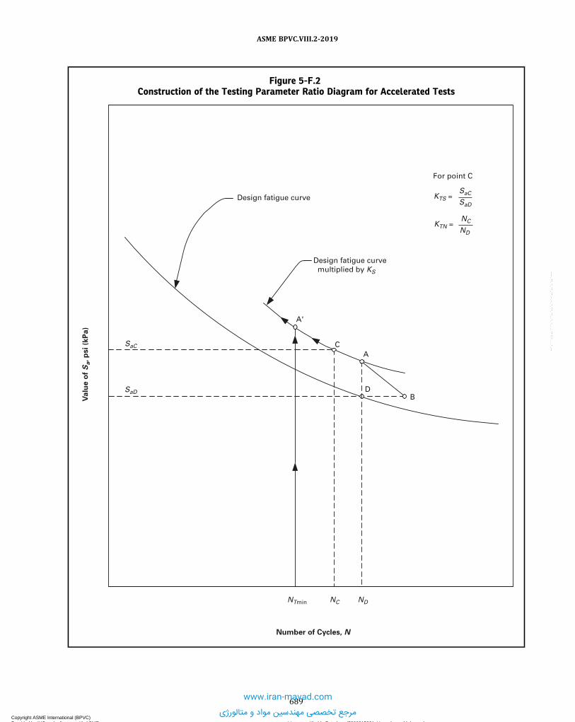
Figure 5-F.2Construction of the Testing Parameter Ratio Diagram for Accelerated Tests
B
C
A'
D
A
Number of Cycles, N
NTmin NC ND
Design fatigue curve
For point C
SaD
SaC
Valu
e o
f S
a, p
si (k
Pa)
KTS = SaC
KTN = NC
ND
Design fatigue curve multiplied by KS
SaD
689
ASME BPVC.VIII.2-2019
Copyright ASME International (BPVC) Provided by IHS under license with ASME Licensee=Khalda Petroleum/5986215001, User=Amer, Mohamed
Not for Resale, 07/02/2019 14:07:58 MDTNo reproduction or networking permitted without license from IHS
--`,```,,,,,````,`,``,,`,,`,`-`-`,,`,,`,`,,`---
www.iran-mavad.com
مرجع تخصصی مهندسین مواد و متالورژی

PART 6FABRICATION REQUIREMENTS
6.1 GENERAL FABRICATION REQUIREMENTS
6.1.1 MATERIALS6.1.1.1 Documentation of Material Treatments, Tests, and Examination. The vessel Manufacturer shall document
compliance with the special requirements of Part 3 for any of the treatments, tests, or examinations specified thereinthat are performed. The documentation shall include reports of the results of all tests and examinations performedon the materials by the vessel Manufacturer.
6.1.1.2 Material Identification.(a)Material Marking – Material for pressure parts should be laid out so that when the vessel is completed, one com-
plete set of the original identification markings required in the specifications for the material will be plainly visible. Incase the original identification markings are unavoidably cut out or the material is divided into two or more parts, oneset shall either be accurately transferred prior to cutting by the pressure vessel Manufacturer to a location where themarkings will be visible on the completed vessel, or a coded marking, acceptable to the Inspector, shall be used to assureidentification of each piece of material during fabrication and subsequent identification of the markings on the com-pleted vessel. In either case an as-built sketch or a tabulation of materials shall be made, identifying each piece of ma-terial with the test report or Certificate of Compliance and the coded marking. Except as indicated in (b), material maybe marked by any method acceptable to the Inspector. The Inspector need not witness the transfer of the marks but shallsatisfy himself that it has been correctly done.(b)Method of Transferring Markings –Where the service conditions prohibit die stamping for material identification,
and when so specified by the user, the required data shall be marked on the plates in a manner that will allow positiveidentification upon delivery. The markings must be recorded so that each plate will be positively identified in its positionin the finished vessel to the satisfaction of the Inspector. Transfer of markings for material that is to be divided shall bedone in accordance with (a).(c) Transfer of Markings by Other than the Manufacturer – If the material is formed into shapes by anyone other than
the Manufacturer of the completed pressure vessel and the original markings as required by the applicable materialspecification are unavoidably cut out, or the material is divided into two or more parts, then the manufacturer of theshape shall either:
(1) Transfer the original identification markings to another location on the shape; or(2) Provide for identification by the use of a coded marking traceable to the original required marking, using a
marking method agreed upon and described in the Quality Control System of the Manufacturer of the completed pres-sure vessel.(d) The material test report for this material, in conjunction with the above modified marking requirements, shall be
considered sufficient to identify these shapes. Manufacturer’s Partial Data Reports and parts stamping are not a require-ment unless there has been fabrication to the shapes that includes welding beyond that exempted by 3.2.8.2.
6.1.1.3 Repair of Defective Materials. Defects may be removed and the material repaired by the vessel Manufac-turer or, unless prohibited by the material specification, may also be repaired by the material manufacturer with theapproval of the vessel Manufacturer. Material repairs that exceed those permitted by the material specification shallbe made to the satisfaction of the Inspector. All repairs shall be in accordance with the following paragraphs.(a) Examination of Defective Areas – Areas from which defects have been removed shall be examined by either the
magnetic particle or by the liquid penetrant method in accordance with Part 7 to ensure complete removal of the defect.(b) Repair by Welding – For the repair of materials by welding, the procedures and welds must be qualified in accor-
dance with Section IX of the Code. If the base metal requires impact testing in accordance with 3.11, then a proceduretest plate shall be welded and the deposited weld metal impact tested in accordance with 3.11 and shall meet the sameminimum requirements as established for the base material. The repaired material shall be heat treated in accordancewith the postweld heat treatment requirements of 6.4.2 when required.(c) Examination of Finished Weld-Repaired Surfaces
690
ASME BPVC.VIII.2-2019
Copyright ASME International (BPVC) Provided by IHS under license with ASME Licensee=Khalda Petroleum/5986215001, User=Amer, Mohamed
Not for Resale, 07/02/2019 14:07:58 MDTNo reproduction or networking permitted without license from IHS
--`,```,,,,,````,`,``,,`,,`,`-`-`,,`,,`,`,,`---
www.iran-mavad.com
مرجع تخصصی مهندسین مواد و متالورژی

ð19Þ
(1) The finished surface of the weld repair shall be prepared and inspected by either the magnetic particle or by theliquid penetrant method in accordance with Part 7.
(2) The area repaired by welding shall be examined by radiography in accordance with Part 7 if the depth of theweld deposit exceeds either 10 mm (3/8 in.) or one-half the material thickness.
(d) All repairs to materials shall be documented (see 2.3.5).
6.1.2 FORMING6.1.2.1 Forming Shell Sections and Heads.(a) All materials for shell sections and for heads shall be formed to the required shape by any process that will not
unduly impair the mechanical properties of the material.(b) Limits are provided on cold working of all carbon and low alloy steels, nonferrous alloys, high alloy steels, and
ferritic steels with tensile properties enhanced by heat treatment (see 6.1.2.2, 6.1.2.4, 6.1.2.5, and 6.6.3). Forming strainsor extreme fiber elongation shall be determined by the equations in Table 6.1.
6.1.2.2 Thickness for Forming.(a) The selected thickness shall be such that the forming processes will not reduce the thickness of the material at any
point below the minimum value required by the design computation.(b) A reduction in weld thickness due to a forming operation is acceptable, provided all of the following conditions are
met:(1) Prior to the forming operation, the weld(s) are verified to comply with 6.2.4.1(b)(1) and 6.2.4.1(b)(2) by the
Manufacturer and the Inspector.(2) The reduced weld thickness, at any point, shall not be less than the minimum required thickness of the
component.(3) The reduction in thickness shall not exceed 1 mm (1/32 in.) or 10% of the nominal thickness of the adjoining sur-
face, whichever is less.
6.1.2.3 Forming of Carbon and Low Alloy Material Parts.(a) Plates shall not be formed cold by blows.(b) Plates may be formed by blows at a forging temperature, provided the plate is subsequently heat treated per the
PWHT requirements of this Division.(c) Except as addressed in (d) and for materials exempted below, the cold-formed areas of vessel shell sections, heads,
and other pressure parts shall be heat treated if the resulting extreme fiber elongation determined by the equations inTable 6.1 exceeds 5% from the supplied condition. Heat treatment shall be applied in accordance with 6.4.2, except thatalternative heating and cooling rates and hold times may be applied to formed pipe and tube having a nominal thicknessof 6 mm (1/4 in.) or less when the heat treatment method is demonstrated to achieve a thorough heating of the pipe ortube.
(1) Cold-formed or bent P-No. 1 pipe and tube material having a nominal thickness not greater than 19 mm (3/4 in.)does not require post-forming heat treatment.
(2) For P-No. 1, Group Nos. 1 and 2 materials other than those addressed by (1), post-forming heat treatment isrequired when the extreme fiber elongation exceeds 40% or if the extreme fiber elongation exceeds 5% and any ofthe following conditions exist:
(-a) The MDMT determined in accordance with 3.11 requires that the material be impact tested.(-b) The reduction by cold forming from the as-rolled thickness is more than 10% at any location where the ex-
treme fiber elongation exceeds 5%.(-c) The temperature of the material during forming is in the range of 250°F to 900°F (120°C to 480°C).(-d) The thickness of the part before cold forming exceeds 16 mm (5/8 in.).
(3) Cold-formed or bent P‐Nos. 3 through 5 C pipe and tube materials having an outside diameter not greater thanNPS 4 (DN 100) and a nominal thickness not greater than 13 mm (1/2 in.) do not require a post-forming heat treatment.
(d) Forming of Creep Strength Enhanced Ferritic Steels (P-No. 15E Materials). The cold-formed areas of vessel shell sec-tions, heads, and other pressure boundary parts of the creep strength enhanced ferritic steels shall be heat treated whenthe design metal temperature and the forming strains exceed the limits shown in Table 6.2.A. Heat treatment shall beperformed according to the requirements in Table 6.2.A. Cold forming is defined as any method that is performed at atemperature below 705°C (1,300°F) and produces permanent strain in the material. Hot forming is defined as any meth-od that is performed at a temperature at or above 705°C (1,300°F) and produces permanent strain in the material. Form-ing strains shall be determined by the equations in Table 6.1.
(1)When the forming strains cannot be calculated as shown in Table 6.1, the Manufacturer shall have the respon-sibility to determine the maximum forming strain.
691
ASME BPVC.VIII.2-2019
Copyright ASME International (BPVC) Provided by IHS under license with ASME Licensee=Khalda Petroleum/5986215001, User=Amer, Mohamed
Not for Resale, 07/02/2019 14:07:58 MDTNo reproduction or networking permitted without license from IHS
--`,```,,,,,````,`,``,,`,,`,`-`-`,,`,,`,`,,`---
www.iran-mavad.com
مرجع تخصصی مهندسین مواد و متالورژی

ð19Þ
ð19Þ
(2) For cold-formed flares, swages, or upsets in tubing and pipe, normalizing and tempering in accordance withNote (1) of Table 6.2.A shall apply, regardless of the amount of strain.
(3) For any hot-formed product form, normalizing and tempering in accordance with Note (1) of Table 6.2.A shallapply, regardless of the amount of strain.(e) When vessel shell sections, heads, or other pressure parts of carbon or low alloy steel are cold formed by other
than the Manufacturer of the vessel, the required certification for the part shall indicate whether or not the part has beenheat treated.
6.1.2.4 Forming High Alloy Material Parts. If the following conditions prevail, the cold formed areas ofpressure-retaining parts manufactured of austenitic alloys shall be solution annealed by heating at the temperaturesgiven in Table 6.2.B for 0.8 min/mm (20 min/in.) of thickness, followed by rapid cooling.(a) The finishing-forming temperature is below the minimum heat-treating temperature given in Table 6.2.B; and(b) The design metal temperature and the forming strains exceed the limits shown in Table 6.2.B. The forming strains
shall be calculated using the equations in Table 6.1. If the forming strains cannot be calculated as shown in this table, theManufacturer shall determine the maximum forming strain.(c) For flares, swages, or upsets, heat treatment in accordance with Table 6.2.B shall apply regardless of the amount of
strain.
6.1.2.5 Forming Nonferrous Material Parts.(a) A shell section that has been formed by rolling may be brought true-to-round for its entire length by pressing or
rolling.(b) If the following conditions prevail, the cold formed areas of pressure-retaining parts manufactured of the alloys
listed in Table 6.3 shall be solution annealed by heating at the temperatures given in Table 6.3 for 0.8 min/mm (20min/in.) of thickness, followed by rapid cooling.
(1) The finishing-forming temperature is below the minimum heat-treating temperature given in Table 6.3; and(2) The design metal temperature and the forming strains exceed the limits shown in Table 6.3. The Forming strains
shall be calculated using the equations in Table 6.1. If the forming strains cannot be calculated as shown in this table,then the Manufacturer shall have the responsibility to determine the maximum forming strain.(c) For flares, swages, or upsets, heat treatment in accordance with Table 6.3 shall apply regardless of the amount of
strain.
6.1.2.6 Preliminary Shaping of Edges of Plates to Be Rolled. If the plates are to be rolled, the adjoining edges oflongitudinal joints of cylindrical vessels shall first be shaped to the proper curvature by preliminary rolling or forming inorder to avoid having objectionable flat spots along the completed joints (see 6.1.2.7).
6.1.2.7 Forming Tolerances for vessel parts shall be in accordance with the following requirements.(a) Shells and Heads Subject to Internal Pressure – tolerances for shells and heads fabricated from plate that are sub-
ject to internal pressure are stipulated in 4.3.2.(b) Shells and Heads Subject to External Pressure – tolerances for shells and heads fabricated from plate that are sub-
ject to external pressure are stipulated in 4.4.4.(c) Tolerances for Shells Fabricated from Pipe – vessel shells fabricated from pipe, meeting all other requirements of
this Part, may have variations of diameter permitted by the specification for such pipe.(d) Tolerances for Heads Fabricated from Pipe Caps – vessel heads fabricated from pipe caps, meeting all other re-
quirements of this Part, may have variations of shape permitted by the applicable product specification.
6.1.2.8 Lugs and Fitting Attachments. All lugs, brackets, saddle type nozzles, manhole frames, reinforcementaround openings, and other appurtenances shall be formed and fitted to conform to the curvature of the shell or surfaceto which they are attached.(a) If pressure parts, such as saddle type nozzles, manhole frames, and reinforcement around openings, extend over
pressure-retaining welds, these welds shall be ground flush for the portion of the weld to be covered.(b) If nonpressure parts, such as lugs, brackets, and support legs and saddles, extend over pressure-retaining welds,
these welds shall be ground flush as described in (a) above, or such parts shall be notched or coped to clear those welds.
6.1.2.9 Spin-Holes. Spin-holes are permitted within heads or segments thereof to facilitate forming. Spin-holes witha diameter less than or equal to 60 mm (23/8 in.)may be closed with a full-penetration weld using either a welded plug orweld metal. The thickness of the weld and plug shall be greater than or equal to the thickness of the head material ad-jacent to the spin-hole. The finished weld shall be examined by the magnetic particle or liquid penetrant method in ac-cordance with Part 7. Full volumetric inspection of the weld in accordance with Part 7 shall be performed in addition toany examinations required by the material specification.
692
ASME BPVC.VIII.2-2019
Copyright ASME International (BPVC) Provided by IHS under license with ASME Licensee=Khalda Petroleum/5986215001, User=Amer, Mohamed
Not for Resale, 07/02/2019 14:07:58 MDTNo reproduction or networking permitted without license from IHS
--`,```,,,,,````,`,``,,`,,`,`-`-`,,`,,`,`,,`---
www.iran-mavad.com
مرجع تخصصی مهندسین مواد و متالورژی
6.1.3 BASE METAL PREPARATION6.1.3.1 Examination of Materials.(a) All materials to be used in constructing a pressure vessel shall be examined before fabrication for the purpose of
detecting, as far as possible, discontinuities that will affect the safety of the vessel. As fabrication progresses, the vesselManufacturer shall carefully examine the edges of base materials (including the edges of openings cut through the thick-ness) to detect defects that have been uncovered during fabrication, and they shall be repaired in accordance with6.1.1.3.
(b) Except as required in (c), cut edges in base materials with thicknesses over 38 mm (11/2 in.) that are to be weldedshall be examined for discontinuities by the magnetic particle or liquid penetrant method in accordance with Part 7.
(c) For openings, cut edges in base materials in all thicknesses shall be examined for discontinuities as specified belowusing the magnetic particle method or liquid penetrant method in accordance with Part 7. Additional testing of materialsprior to fabrication should be considered by the purchaser (i.e., ultrasonic testing of plate to SA-435 or SA-578, and offorgings to SA-388) for those services in which laminar discontinuities may be harmful.
(1) Examination is required for openings shown in Table 4.2.10, Details 1, 2, and 7.(2) For other types of openings, this examination is not required for the cut edges of openings 75 mm (3 in.) in dia-
meter or smaller.(3) Discontinuities that have been detected by magnetic particle or liquid penetrant examination shall be investi-
gated by ultrasonic examination to confirm they are laminar. Non-laminar discontinuities (having length not parallelto the material surface) shall be removed.
(4) Discontinuities parallel to the surface, such as inclusions, which are disclosed by either method, are acceptablewithout repair if they do not exceed 25 mm (1 in.) in length.
(d) If a pressure part is to be welded to a flat plate thicker than 13 mm (1/2 in.) to form a corner joint in accordancewith 4.2.5.4(d), then the weld joint preparation and the peripheral edges of the flat plate forming a corner joint shall beexamined as described below before welding by either the magnetic particle or liquid penetrant method in accordancewith Part 7. After welding, the peripheral edge of the flat plate and any remaining exposed surface of the weld joint pre-paration shall be reexamined as specified below.
(1) The weld edge preparation of typical joint preparations in flat plate as shown in Table 4.2.6, Details 1 through 3and Table 4.2.8, Detail 1.
(2) The outside peripheral edge of the flat plate after welding as shown in Table 4.2.6, Details 1 and 2(3) The outside peripheral edge of the flat plate after welding as shown in Table 4.2.6, Details 3, if the distance from
the edge of the completed weld to the peripheral edge of the flat plate is less than the thickness of the flat plate.(4) The inside peripheral surface of the flat plate after welding as shown in Table 4.2.9, Details 3 and 4.
6.1.3.2 Cutting Plates and Other Stock.(a) Plates, edges of heads, and other parts may be cut to shape and size by mechanical means such as machining,
shearing, and grinding; or by thermal cutting. After thermal cutting, all slag and detrimental discoloration of material,which has been molten shall be removed by mechanical means prior to further fabrication or use. When thermal cuttingis used, the effect on mechanical properties shall be taken into consideration. The edges to be welded shall be uniformand smooth.
(b) In general, nonferrous materials cannot be cut by the conventional oxyfuel equipment commonly used for steels.They may be melted and cut by oxyfuel powder cutting, carbon arc, oxygen arc, and other means. When such thermalmeans for cutting are employed, a shallow contaminated area adjacent to the cut results. This contamination shall beremoved by grinding, machining, or other mechanical means after thermal cutting and prior to use or further fabrication.
6.1.3.3 Shearing of Nozzles and Manhole Necks. The ends of nozzles or manhole necks that are to remain un-welded in the completed vessel may be cut by shearing, provided sufficient additional material is removed by any othermethod that produces a smooth finish. The cut edges shall be examined by the magnetic particle or liquid penetrantmethod in accordance with Part 7.
6.1.4 FITTING AND ALIGNMENT6.1.4.1 Parts that are being welded shall be fitted, aligned, and retained in position during the welding operation. If
two parts are joined by the inertia and continuous drive friction welding processes, then one of the two parts must beheld in a fixed position and the other part rotated. The two faces to be joined must be essentially symmetrical with re-spect to the axis of rotation. Some of the basic types of applicable joints are solid round to solid round, tube to tube, solidround to tube, solid round to plate, and tube to plate.
693
ASME BPVC.VIII.2-2019
Copyright ASME International (BPVC) Provided by IHS under license with ASME Licensee=Khalda Petroleum/5986215001, User=Amer, Mohamed
Not for Resale, 07/02/2019 14:07:58 MDTNo reproduction or networking permitted without license from IHS
--`,```,,,,,````,`,``,,`,,`,`-`-`,,`,,`,`,,`---
www.iran-mavad.com
مرجع تخصصی مهندسین مواد و متالورژی

6.1.4.2 Means for Maintaining Alignment During Welding. Bars, jacks, clamps, tack welds, or other appropriatemeans may be used to maintain the alignment of the edges to be welded. Tack welds, if used to maintain alignment, shalleither be removed completely when they have served their purpose, or their stopping and starting ends shall be prop-erly prepared by grinding or other suitable means so that they may be satisfactorily incorporated into the final weld.Tack welds shall be made by qualified procedures and welders, shall be examined visually for defects, and, if foundto be defective, shall be removed. If the work is done under the provisions of 2.3, then it is not necessary that a subcon-tractor making such tack welds for a vessel or parts manufacturer be a holder of a Code Certificate of Authorization. Therequirements of 2.3.8.4 do not apply to such tack welds. Temporary tack welds used to secure the shape of a componentduring handling or transportation are not required to be deposited by a holder of a Code Certificate of Authorization,provided they will be completely removed and will not be incorporated into the final weld. In addition, the areas shallbe examined by the magnetic particle or liquid penetrant methods in accordance with Part 7.
6.1.4.3 Aligning Edges of Butt Joints. The edges of butt joints shall be held during welding so that the tolerances in6.1.6 are not exceeded in the joint. When fitted girth joints have deviations exceeding the permitted tolerances, the heador shell ring, whichever is out-of-tolerance, shall be reformed until the allowable limits (see 6.1.6.1(a)) are satisfied.
6.1.4.4 Removal of Temporary Attachments. The areas from which temporary attachments have been removedshall be dressed smooth and shall be examined by the magnetic particle method or liquid penetrant method in accor-dance with Part 7. Defects shall be removed and the material shall be inspected to ensure that the defects have beenremoved. If weld repairs are necessary, then the repairs shall be made using qualified welding procedures and welders,and the repairs shall be examined in accordance with 6.1.1.3(c).
6.1.5 CLEANING OF SURFACES TO BE WELDED6.1.5.1 The surfaces to be welded shall be clean and free of scale, rust, oil, grease, slag, detrimental oxides, and other
deleterious foreign material. The method and extent of cleaning should be determined based on the material to bewelded and the contaminants to be removed. When weld metal is to be deposited over a previously welded surface,all slag shall be removed by a roughing tool, chisel, chipping hammer, or other suitable means so as to prevent inclusionof impurities in the weld.
6.1.5.2 Cast surfaces to be welded shall be machined, chipped, or ground to remove foundry scale and to exposesound metal.
6.1.5.3 The requirements in 6.1.5.1 and 6.1.5.2 above are not intended to apply to any process of welding by whichproper fusion and penetration are otherwise obtained and by which the weld remains free from defects.
6.1.6 ALIGNMENT TOLERANCES FOR EDGES TO BE BUTT WELDED6.1.6.1 Alignment of sections at edges to be butt welded shall be such that the maximum offset is not greater than
shown below. Alternatively, offsets greater than those permitted below are allowable, provided that the maximum offsetis acceptable to the Inspector prior to welding and the requirements of 4.14 or Part 5, and the requirements of 6.1.6.2are satisfied. If the vessel is operating at a temperature where the allowable stress is governed by time-dependent prop-erties (see 4.1.1.3), or if a fatigue analysis is required (see 4.1.1.4), the alignment of sections shall be considered in thedesign.(a) Cylindrical Shells – The maximum allowable offset in welded joints in cylindrical shells shall be as given in Table
6.4(b) Spherical Shells and for Hemispherical Heads Welded to Cylindrical Shells – Joints in spherical vessels, joints with-
in heads, and joints between cylindrical shells and hemispherical heads shall meet the requirements in Table 6.4.(c) Alignment tolerances at edges to be butt welded for quenched and tempered high strength steels shall be in ac-
cordance with 6.6.5.4.
6.1.6.2 Fairing of Offsets Within Allowable Tolerances. Any offset within the allowable tolerance provided aboveshall be faired at a 3:1 taper over the width of the finished weld or, if necessary, by adding additional weld metal beyondwhat would have been the edge of the weld. If additional weld metal buildup is used, then it shall satisfy the require-ments of 6.2.4.9.
6.1.6.3 Peaking of Welds in Shells and Heads for Internal Pressure.(a) If the vessel is operating at a temperature where the allowable stress is governed by time dependent properties,
see 4.1.1.3, or if a fatigue analysis is required, see 4.1.1.4, then the peaking height, dp , at Category A weld joints shall bemeasured by either an inside or outside template, as appropriate (see Figure 6.1). As an alternative, the peaking anglemay be determined using the procedure described in Part 8 of API 579-1/ASME FFS-1.
694
ASME BPVC.VIII.2-2019
Copyright ASME International (BPVC) Provided by IHS under license with ASME Licensee=Khalda Petroleum/5986215001, User=Amer, Mohamed
Not for Resale, 07/02/2019 14:07:58 MDTNo reproduction or networking permitted without license from IHS
--`,```,,,,,````,`,``,,`,,`,`-`-`,,`,,`,`,,`---
www.iran-mavad.com
مرجع تخصصی مهندسین مواد و متالورژی

(b) The chord length of the template shall be the larger of D/6 or 300 mm (12 in.), but need not exceed 900 mm(36 in.). If the weld joint is in a torispherical or an ellipsoidal head, the inside diameter, D , shall be equal to the diameterof the spherical portion of the head. If the weld joint is in a 2:1 ellipsoidal head, D shall be equal to 1.8 times the nominalinside diameter of the attached cylindrical shell.
(c) If the vessel is operating at a temperature where the allowable stress is governed by time dependent properties, orif a fatigue analysis is required, the allowable value of dp shall be determined using 4.14 and shall be shown in the Man-ufacturer’s Design Report.
6.2 WELDING FABRICATION REQUIREMENTS
6.2.1 WELDING PROCESSES6.2.1.1 See below.(a) The welding processes that may be used in the construction of vessels under this Part are limited to those accepted
by Section IX with the additional restrictions shown in Table 6.5.(b) Other than pressure inherent to the welding processes, no mechanical pressure or blows shall be applied except as
permitted for peening in 6.2.5.3
6.2.1.2 Welding of titanium, zirconium, and their alloys is to be by gas tungsten arc welding (GTAW), gas metal arcwelding (GMAW), plasma arc welding (PAW), electron beam welding (EBW), laser beam welding (LBW), or the resis-tance welding process meeting the requirements of Section IX. All processes are as defined in Section IX.
6.2.2 WELDING QUALIFICATIONS AND RECORDS6.2.2.1 Manufacturer’s Responsibility.(a) Each Manufacturer or parts manufacturer is responsible for the welding done by his organization. The Manufac-
turer or parts manufacturer shall establish the procedure and be responsible for the tests required in Section IX with anyadditional tests required by this Division to qualify the welding procedures and the performance of welders and weldingoperators who apply these procedures.
(b) Nonmandatory Guidelines for Welding Material Selections. The Manufacturer is responsible for the selection ofwelding consumables and welding processes. These nonmandatory guidelines for welding material selections are in-tended to achieve suitable vessel performance for the intended service conditions, but may not be appropriate for everycondition in the absence of specific technical reasons to do otherwise. The user or his designated agent should inform theManufacturer when a specific filler metal selection is necessary to achieve satisfactory vessel performance for the in-tended service conditions.
(1) The tensile strength of the weld should equal or exceed that of the base metals to be joined. When base metals ofdifferent strengths are to be joined by welding, the tensile strength of the weld metal should equal or exceed that of theweaker of the two base metals.
(2)When considerations such as corrosion resistance, toughness, or fatigue resistance require selecting weldingconsumables or processes that produce weld joints of a lesser strength than either of the base metals, the strength ofthe resulting joint should be reviewed and the design adjusted as appropriate for the intended service conditions.
(3)When welding materials of like composition, the nominal composition of the weld metal should be analogous tothe nominal composition of the base metal, except when creep or corrosion performance is an overriding consideration.
(4)When welding materials of different nominal composition, the nominal composition of the weld metal should beanalogous to one of the base metals, or be of an acceptable alternative composition.
(5)When joining nonferrous base metals, filler metal selections should follow the recommendations of the manu-facturer of the nonferrous metal or applicable industry associations.
(c) The Manufacturer (Certificate Holder) may engage individuals by contract or agreement for their services aswelders at the shop location shown on the Certificate of Authorization and at field sites (if allowed by the Certificateof Authorization) for the construction of pressure vessels or vessel parts, provided all of the following conditions aremet:
(1) All Code construction shall be the responsibility of the Manufacturer.(2) All welding shall be performed in accordance with the Manufacturer’s Welding Procedure Specifications, in ac-
cordance with the requirements of Section IX.(3) All welders shall be qualified by the Manufacturer in accordance with the requirements of Section IX.(4) The Manufacturer’s Quality Control System shall include the following as a minimum:
(-a) a requirement for complete and exclusive administrative and technical supervision of all welders by theManufacturer
695
ASME BPVC.VIII.2-2019
Copyright ASME International (BPVC) Provided by IHS under license with ASME Licensee=Khalda Petroleum/5986215001, User=Amer, Mohamed
Not for Resale, 07/02/2019 14:07:58 MDTNo reproduction or networking permitted without license from IHS
--`,```,,,,,````,`,``,,`,,`,`-`-`,,`,,`,`,,`--- www.iran-mavad.com
مرجع تخصصی مهندسین مواد و متالورژی
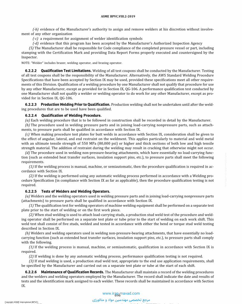
(-b) evidence of the Manufacturer’s authority to assign and remove welders at his discretion without involve-ment of any other organization
(-c) a requirement for assignment of welder identification symbols(-d) evidence that this program has been accepted by the Manufacturer’s Authorized Inspection Agency
(5) The Manufacturer shall be responsible for Code compliance of the completed pressure vessel or part, includingstamping with the Certification Mark and providing Data Report Forms properly executed and countersigned by theInspector.
NOTE: ”Welder” includes brazer, welding operator, and brazing operator.
6.2.2.2 Qualification Test Limitations.Welding of all test coupons shall be conducted by the Manufacturer. Testingof all test coupons shall be the responsibility of the Manufacturer. Alternatively, the AWS Standard Welding ProcedureSpecifications that have been accepted by Section IX may be used, provided these specifications meet all other require-ments of this Division. Qualification of a welding procedure by one Manufacturer shall not qualify that procedure for useby any other Manufacturer, except as provided for in Section IX, QG-106. A performance qualification test conducted byone Manufacturer shall not qualify a welder or welding operator to do work for any other Manufacturer, except as pro-vided for in Section IX, QG-106.
6.2.2.3 Production Welding Prior to Qualification. Production welding shall not be undertaken until after the weld-ing procedures that are to be used have been qualified.
6.2.2.4 Qualification of Welding Procedure.(a) Each welding procedure that is to be followed in construction shall be recorded in detail by the Manufacturer.(b) The procedure used in welding pressure parts and in joining load-carrying nonpressure parts, such as attach-
ments, to pressure parts shall be qualified in accordance with Section IX.(c) When making procedure test plates for butt welds in accordance with Section IX, consideration shall be given to
the effect of angular, lateral, and end restraint on the weldment. This applies particularly to material and weld metalwith an ultimate tensile strength of 550 MPa (80,000 psi) or higher and thick sections of both low and high tensilestrength material. The addition of restraint during the welding may result in cracking that otherwise might not occur.(d) The procedure used in welding non-pressure-bearing attachments, which have essentially no load-carrying func-
tion (such as extended heat transfer surfaces, insulation support pins, etc.), to pressure parts shall meet the followingrequirements.
(1) If the welding process is manual, machine, or semiautomatic, then the procedure qualification is required in ac-cordance with Section IX.
(2) If the welding is performed using any automatic welding process performed in accordance with a Welding pro-cedure Specification (in compliance with Section IX as far as applicable), then the procedure qualification testing is notrequired.
6.2.2.5 Tests of Welders and Welding Operators.(a)Welders and the welding operators used in welding pressure parts and in joining load-carrying nonpressure parts
(attachments) to pressure parts shall be qualified in accordance with Section IX.(1) The qualification test for welding operators of machine welding equipment shall be performed on a separate test
plate prior to the start of welding or on the first work piece.(2)When stud welding is used to attach load-carrying studs, a production stud weld test of the procedure and weld-
ing operator shall be performed on a separate test plate or tube prior to the start of welding on each work shift. Thisweld test shall consist of five studs, welded and tested in accordance with either the bend or torque stud weld testingdescribed in Section IX.(b)Welders and welding operators used in welding non-pressure-bearing attachments, that have essentially no load-
carrying function (such as extended heat transfer surfaces, insulation support pins, etc.), to pressure parts shall complywith the following.
(1) If the welding process is manual, machine, or semiautomatic, qualification in accordance with Section IX isrequired.
(2) If welding is done by any automatic welding process, performance qualification testing is not required.(3) If stud welding is used, a production stud weld test, appropriate to the end use application requirements, shall
be specified by the Manufacturer and carried out on a separate test plate or tube at the start of each shift.
6.2.2.6 Maintenance of Qualification Records. The Manufacturer shall maintain a record of the welding proceduresand the welders and welding operators employed by the Manufacturer. The record shall indicate the date and results oftests and the identification mark assigned to each welder. These records shall be maintained in accordance with SectionIX.
696
ASME BPVC.VIII.2-2019
Copyright ASME International (BPVC) Provided by IHS under license with ASME Licensee=Khalda Petroleum/5986215001, User=Amer, Mohamed
Not for Resale, 07/02/2019 14:07:58 MDTNo reproduction or networking permitted without license from IHS
--`,```,,,,,````,`,``,,`,,`,`-`-`,,`,,`,`,,`---
www.iran-mavad.com
مرجع تخصصی مهندسین مواد و متالورژی

6.2.3 PRECAUTIONS TO BE TAKEN BEFORE WELDING6.2.3.1 Identification, Handling, and Storing of Electrodes and Other Welding Materials. The Manufacturer is re-
sponsible for control of the welding electrodes and other materials which are to be used in the fabrication of the vessel.Suitable identification, storage, and handling of electrodes, flux, and other welding materials shall be maintained. Pre-cautions shall be taken to minimize absorption of moisture by electrodes and flux. The methods used shall be documen-ted in the Manufacturer’s Quality Control System.
6.2.3.2 Lowest Permissible Minimum Temperature for Welding. No welding of any kind shall be done when thetemperature of the metal is lower than −20°C (0°F). If the temperature is between 0°C (32°F) and −20°C (0°F), thenthe surface of all areas within 75 mm (3 in.) of the point where a weld is to be started shall be heated to a temperatureat least warm to the hand [estimated to be above 15°C (60°F)] before welding is started. No welding shall be done whensurfaces are wet or covered with ice, when snow is falling on the surfaces to be welded, or during periods of high windunless the welders or welding operators and the work are properly protected.
6.2.4 SPECIFIC REQUIREMENTS FOR WELDED JOINTS6.2.4.1 Type No. 1 Butt Joints.(a) Definition – Type No. 1 butt joints are defined in 4.2.5.1(a) and Table 4.2.2.(b)Weld Penetration and Reinforcement(1) Butt-welded joints shall have complete penetration and full fusion. As-welded surfaces are permitted; however,
the surface of the welds shall be sufficiently free from coarse ripples, grooves, overlaps, and abrupt ridges and valleys topermit proper interpretation of radiographic and other required nondestructive examinations. If it is suspected that anindication on a radiograph is due to the surface condition of the weld, the radiograph shall be compared to the actualweld surface to aid in interpretation.
(2) A reduction in thickness due to the welding process is acceptable, provided all of the following conditions aremet. Note that it is not the intent of this paragraph to require measurement of reductions in thickness due to the weldingprocess. If a disagreement between the Manufacturer and the Inspector exists as to the acceptability of any reduction inthickness, the depth shall be verified by actual measurement.
(-a) The reduction in thickness shall not reduce the material of the adjoining surfaces below the minimum re-quired thickness at any point.
(-b) The reduction in thickness shall not exceed 0.8 mm (1/32 in.) or 10% of the nominal thickness of the adjoiningsurface, whichever is less.
(c) Examination Requirements – Examination requirements shall be in accordance with Part 7.(d)Weld Reinforcement – to assure that the weld grooves are completely filled so that the surface of the weld metal at
any point does not fall below the surface of the adjoining base materials, weld metal may be added as reinforcement oneach face of the weld. The thickness of the weld reinforcement on each face shall not exceed that shown in Table 6.6.Concavity due to the welding process on the root side of a single-welded circumferential butt weld is permitted whenthe resulting thickness of the weld is at least equal to the thickness of the thinner member of the two sections beingjoined and the contour of the concavity is smooth.
6.2.4.2 Type No. 2 Butt Joints.(a) Definitions – Type No. 2 butt joints are defined in 4.2.5.1(a) and Table 4.2.2.(b) Penetration and Reinforcement – If Type No. 2 butt joints are used, then particular care shall be taken in aligning
and separating the components to be joined so that there will be complete penetration and fusion at the bottom of thejoints for their full length. However, for assuring complete filling of the weld grooves, weld reinforcement in accordancewith the limits specified in 6.2.4.1(d) need be supplied only on the side opposite the backing strip.
(c) Class 2: Backing Strips – Backing strips shall be continuous and any splices shall be butt welded. Circumferentialsingle-welded butt joints with one plate offset to form a backing strip are prohibited.
(d) Examination Requirements – Examination requirements shall be in accordance with Part 7.
6.2.4.3 Full Penetration Corner Joints.(a) Definition – Full penetration corner joints are joints defined in 4.2.5.1(c).(b) Penetration and Fusion – Welds in full penetration corner joints shall be groove welds extending completely
through at least one of the parts being joined and shall be fully fused to each part.(c) Examination Requirements – Examination requirements shall be in accordance with Part 7.
6.2.4.4 Partial Penetration Corner Joints for Nozzle Attachments.(a) Definition – Partial penetration corner joints are defined in 4.2.5.5(c)(8) and Table 4.2.14.(b) Penetration Requirements – Partial penetration welds shall have a minimum depth of penetration equal to that
required by Table 4.2.14.
697
ASME BPVC.VIII.2-2019
Copyright ASME International (BPVC) Provided by IHS under license with ASME Licensee=Khalda Petroleum/5986215001, User=Amer, Mohamed
Not for Resale, 07/02/2019 14:07:58 MDTNo reproduction or networking permitted without license from IHS
--`,```,,,,,````,`,``,,`,,`,`-`-`,,`,,`,`,,`---
www.iran-mavad.com
مرجع تخصصی مهندسین مواد و متالورژی

(c) Examination Requirements – Examination requirements shall be in accordance with Part 7.
6.2.4.5 Fillet Welded Joints.(a) Definition – Fillet welded joints are defined in 4.2.5.1(d) and Table 4.2.2.(b) Quality Requirements –The weld metal for a fillet weld shall be deposited in such a way that adequate penetration
into the base metal at the root of the weld is secured. The reduction of the thickness of the base metal due to the weldingprocess at the edges of the fillet weld shall meet the same requirements as for butt welds. [see 6.2.4.1(b)](c) Examination Requirements – Examination requirements shall be in accordance with Part 7.
6.2.4.6 Welds Attaching Nozzles and Other Connections. The design requirements for welds attaching nozzlenecks and other connections are given in 4.2.5.5.
6.2.4.7 Welds Attaching Nonpressure Parts and Stiffeners.(a) The design requirements for welds attaching nonpressure parts and stiffeners to pressure parts are given in
4.2.5.6.(b) Examination Requirements – Examination requirements shall be in accordance with Part 7.
6.2.4.8 Austenitic Chromium–Nickel Alloy Steel Welds. All austenitic chromium–nickel alloy steel welds, both buttand fillet, in parts with a shell thickness that exceeds 19 mm (0.75 in.) shall be examined by the liquid penetrant methodin accordance with Part 7. This examination shall be made following heat treatment, if heat treatment is performed. Allcracks shall be repaired.
6.2.4.9 Surface Weld Metal Buildup.(a) Construction in which deposits of weld metal are applied to the surface of base metal for the purpose of restoring
the thickness of the base metal or modifying the configuration of weld joints in order to provide the tapered transitionrequirements of 4.2 shall be performed in accordance with (b) and (c).(b) Procedure Qualification – A butt welding procedure qualification in accordance with the provisions of Section IX
shall be performed for the thickness of weld metal deposited, prior to production welding.(c) Examination Requirements
(1) All weld metal build-up shall be examined over the full surface of the deposit by the magnetic particle or liquidpenetrant method in accordance with Part 7. This requirement does not apply to weld overlay.
(2)When such surface weld metal buildup is used in welded joints that require radiographic examination in accor-dance with Part 7, the weld metal buildup shall be included in this examination.
6.2.5 MISCELLANEOUS WELDING REQUIREMENTS6.2.5.1 Preparation of Reverse Side of Double-Welded Joints. The reverse side of double-welded joints shall be
prepared by chipping, grinding, or melting out, so as to secure sound metal at the base of the weld metal first depositedbefore applying weld metal from the reverse side. These requirements are not intended to apply to any process of weld-ing by which proper fusion and penetration are otherwise obtained and by which the base of the weld remains free fromimpurities.
6.2.5.2 Aligning and Separating Components of Single-Welded Joints. If single-welded joints are used, the com-ponents to be joined shall be aligned and separated so that there will be complete penetration and fusion at the bottomof the joint for its full length.
6.2.5.3 Peening.(a)Weld metal and heat-affected zones may be peened by manual, electric, or pneumatic means when it is deemed
necessary or helpful to control distortion, to relieve residual stresses, improve fatigue life, or to improve the qualityof the weld. Peening shall not be used on the initial (root) layer of weld metal or on the final (face) layer unless the weldis subsequently postweld heat treated. In no case, however, is peening to be performed in lieu of any postweld heat treat-ment required by these rules.(b) Controlled shot peening and other similar methods, which are intended only to enhance surface proper- ties of the
vessel or vessel parts, shall be performed after any nondestructive examinations and pressure tests required by theserules.
6.2.5.4 Identification Markings or Records for Welders and Welding Operators.(a) Each welder and welding operator shall stamp or mark the identifying number, letter, or symbol assigned by the
Manufacturer on or adjacent to and at intervals of not more than 0.9 m (3 ft) along the welds they make in plates asspecified below.
(1) For steel plates 6 mm (1/4 in.) and over in thickness and for nonferrous plates 13 mm (1/2 in.) and over in thick-ness, weld identification markings shall be stamped.
698
ASME BPVC.VIII.2-2019
Copyright ASME International (BPVC) Provided by IHS under license with ASME Licensee=Khalda Petroleum/5986215001, User=Amer, Mohamed
Not for Resale, 07/02/2019 14:07:58 MDTNo reproduction or networking permitted without license from IHS
--`,```,,,,,````,`,``,,`,,`,`-`-`,,`,,`,`,,`---
www.iran-mavad.com
مرجع تخصصی مهندسین مواد و متالورژی

ð19Þ
(2) For identifying welds on vessels in which the wall thickness is less than 6 mm (1/4 in.) for steel material and lessthan 13 mm (1/2 in.) for nonferrous material, suitable stencil or other surface markings shall be used, or a stamp may beused provided the vessel part is not deformed and the following additional requirements are met.
(-a) For Ferrous Materials(-1) The materials shall be limited to P‐No. 1, Groups 1 and 2.(-2) The nominal plate thickness shall be 5 mm (3/16 in.) or greater, or the nominal pipe wall thickness shall be
3.91 mm (0.154 in.) or greater.(-3) The minimum design metal temperature shall be no colder than −29°C (−20°F).
(-b) For Nonferrous Materials(-1) The materials shall be limited to aluminum as follows: SB-209 Alloys 3003, 5083, 5454, and 6061; SB-241
Alloys 3003, 5083, 5086, 5454, 6061, and 6063; and SB-247 Alloys 3003, 5083, and 6061.(-2) The nominal plate thickness shall be 6 mm (1/4 in.) or greater, or the nominal pipe thickness shall be 3.37
mm (0.133 in.) or greater.Alternatively, a record shall be kept by the Manufacturer of those employed on welding each joint that shall be made
available to the Inspector.(b) If a multiple number of permanent nonpressure part load-bearing attachment welds, non-load-bearing welds, such
as stud welds, or special welds, such as tube-to-tubesheet welds, are made on a vessel, the Manufacturer need not iden-tify the welder or welding operator that welded each individual joint, provided:
(1) The Manufacturer’s Quality Control System includes a procedure that will identify the welders or welding op-erators that made such welds on each vessel so that the Inspector can verify that the welders or welding operators wereall properly qualified; and
(2) The welds in each category are all of the same type and configuration and are welded with the same WeldingProcedure Specification.
(c) Permanent identification of welders or welding operators making tack welds that become part of the final pressureweld is not required, provided the Manufacturer’s Quality Control System includes a procedure to permit the Inspectorto verify that such tack welds were made by qualified welders or welding operators.
6.2.5.5 Friction Welding Visual Examination. The welded joint between two members joined by the inertia andcontinuous drive friction welding processes shall be a full penetration weld. Visual examination of the as-welded flashroll of each weld shall be made as an in-process check. The weld upset shall meet the specified amount within ±10%. Theflash shall be removed to sound metal.
6.2.5.6 Capacitor Discharge Welding. Capacitor discharge welding may be used for welding temporary attach-ments and permanent nonstructural attachments without postweld heat treatment, provided the following require-ments are met.
(a) The Welding Procedure Specification shall be prepared in accordance with Section IX, insofar as possible describ-ing the capacitor discharge equipment, the combination of materials to be joined, and the technique of application. Qua-lification of the Welding Procedure is not required.
(b) The energy output shall be limited to 125 W-sec.
6.2.5.7 Burr Grinding of Completed Weld Joints. Burr grinding of weld joints to improve fatigue life performanceshall be in accordance with Figure 6.2 when specified in the User’s Design Specification. The remaining ligament afterburr grinding (i.e., t – g , see Figure 6.2) shall be greater than or equal to the minimum required wall thickness for thecomponent obtained using Part 4 or Part 5, as applicable.
6.2.5.8 Corrosion Resistance of Alloy Welds. Alloy welds that are exposed to the corrosive action or environmentaldegradation of the contents of the vessel should have a resistance to corrosion that is not substantially less than that ofthe base metal. The use of filler metal that will deposit weld metal with practically the same composition as the materialjoined is recommended. Alternatively, filler metal of a different composition may be used, provided the strength of theweld metal at the operating temperature is not appreciably less than that of the high alloy material to be welded, and theuser or an agent acting on behalf of the user is satisfied that its resistance to corrosion is satisfactory for the intendedservice. The columbium content of weld metal shall not exceed 1.00%, except that ENiCrMo-3, ERNiCrMo-3, andENiCrMo-12 weld filler metal made to SFA-5.11 and SFA-5.14 may be used to weld S31254, S31603, S31703,S31725, S31726, and any Table 3-A.6 material to a maximum design temperature of 480°C (900°F).
6.2.6 SUMMARY OF JOINTS PERMITTED AND THEIR EXAMINATION6.2.6.1 Types of Joints Permitted. The types of weld joints permitted for each Weld Category are given in 4.2.
6.2.6.2 Examination Requirements. Examination requirements shall be in accordance with Part 7.
699
ASME BPVC.VIII.2-2019
Copyright ASME International (BPVC) Provided by IHS under license with ASME Licensee=Khalda Petroleum/5986215001, User=Amer, Mohamed
Not for Resale, 07/02/2019 14:07:58 MDTNo reproduction or networking permitted without license from IHS
--`,```,,,,,````,`,``,,`,,`,`-`-`,,`,,`,`,,`---
www.iran-mavad.com
مرجع تخصصی مهندسین مواد و متالورژی

6.2.7 REPAIR OF WELD DEFECTS6.2.7.1 Removal of Unacceptable Defects. Unacceptable defects detected visually or by the examinations in Part 7,
and defects detected by leakage tests, shall be removed by mechanical means or by thermal gouging processes.
6.2.7.2 Rewelding of Areas to Be Repaired. The areas to be repaired shall be rewelded by qualified welders usingqualified welding procedures.
6.2.7.3 Examination of Repaired Welds. Repaired welds shall be reexamined by the methods of the original exam-ination of the weld. The repaired weld shall not be accepted unless the examination shows the repair to be satisfactory.
6.2.7.4 Postweld Heat Treatment of Repaired Welds. The postweld heat treatment rules in 6.4 shall apply to allweld repairs.
6.2.8 SPECIAL REQUIREMENTS FOR WELDING TEST PLATES FOR TITANIUM MATERIALS6.2.8.1 If a vessel of welded titanium contains Category A or B weld joints, then a production test plate of the same
specification, grade, and thickness shall be made of sufficient size to provide at least one face and one root bend speci-men or two-side bend specimens dependent upon plate thickness. Where longitudinal joints are involved, the test plateshall be attached to one end of the longitudinal joint and welded continuously with the joint. Where circumferentialjoints only are involved, the test plate need not be attached but shall be welded along with the joint, and each welderor welding operator shall deposit weld metal in the test plate at the location and proportional to that deposited in theproduction weld.
6.2.8.2 Test plates shall represent each welding process or combination of processes or a change from machine tomanual or vice versa. At least one test plate is required for each vessel, provided not over 30 m (100 ft) of Category A orB joints are involved. An additional test plate, meeting the same requirements as outlined above, shall be made for eachadditional 30 m (100 ft) of Category A or B joints involved. The bend specimens shall be prepared and tested in accor-dance with Section IX, QW-160. Failure of either bend specimen constitutes rejection of the weld.
6.3 SPECIAL REQUIREMENTS FOR TUBE-TO-TUBESHEET WELDS
6.3.1 MATERIAL REQUIREMENTSTubes may be attached to tubesheets by welding, provided the tubes and tubesheets or tubesheet facings are of weld-
able materials covered by this Division.
6.3.2 HOLES IN TUBESHEETS6.3.2.1 Preparing Holes in Tubesheets. Tube holes in tubesheets shall be produced by any process that does not
impair the properties of the material and produces a tube hole with a finish meeting the requirements of 6.3.2.3.
6.3.2.2 Clearance between Tubes and Tube Holes. The clearance between the outside surface of the tubes and theinside surfaces of the tube holes shall not exceed the clearance specified by the welding procedure qualification tests.
6.3.2.3 Finish of Holes. The edges of the tubesheet at the tube holes on the side to be welded shall be free of burrs,and the edges of the tubesheet at the tube hole on the side opposite the weld shall have sharp corners removed. Thesurfaces of tube holes in tubesheets shall have a workmanship-like finish.
6.3.3 WELD DESIGN AND JOINT PREPARATIONThe weld dimensions and weld detail, and joint preparation, if used, shall comply with the details included in the
Welding Procedure Specification.
6.3.4 QUALIFICATION OF WELDING PROCEDURETube-to-tubesheet welding procedure specifications shall be qualified in accordance with the requirements of Section
IX, QW-193.
6.4 PREHEATING AND HEAT TREATMENT OF WELDMENTS
6.4.1 REQUIREMENTS FOR PREHEATING OF WELDS6.4.1.1 The Welding Procedure Specification for the material being welded shall specify the minimum preheating
requirements in accordance with the weld procedure qualification requirements of Section IX. Where preheating isnot required by the welding procedure, preheating may be employed during welding to assist in completion of the
700
ASME BPVC.VIII.2-2019
Copyright ASME International (BPVC) Provided by IHS under license with ASME Licensee=Khalda Petroleum/5986215001, User=Amer, Mohamed
Not for Resale, 07/02/2019 14:07:58 MDTNo reproduction or networking permitted without license from IHS
--`,```,,,,,````,`,``,,`,,`,`-`-`,,`,,`,`,,`---
www.iran-mavad.com
مرجع تخصصی مهندسین مواد و متالورژی

ð19Þ
welded joint. The need for and temperature of preheat are dependent on a number of factors, such as the chemical anal-ysis, degree of restraint of the parts being joined, elevated-temperature physical properties, and material thicknesses.Mandatory rules for preheating are, therefore, not given in this Division, except for those that provide for exemptions topostweld heat treatment as noted in Tables 6.8 through 6.15.
6.4.1.2 Guidelines for preheating are provided in Table 6.7 for the materials listed by P-Numbers of Section IX. It iscautioned that the preheating parameters shown in this table do not necessarily ensure satisfactory completion of thewelded joint, and requirements for individual materials for the P-Number listing may have preheating requirements thatare more restrictive.
6.4.2 REQUIREMENTS FOR POSTWELD HEAT TREATMENT6.4.2.1 Before applying the detailed requirements and exemptions in these paragraphs, satisfactory qualification of
the welding procedures to be used shall be performed in accordance with all the variables of Section IX and 6.3.4, in-cluding conditions of postweld heat treatment or its omission, and the restrictions listed in this paragraph.
6.4.2.2 Postweld heat treatment requirements for all materials of construction are shown below.(a) Postweld heat treatment requirements for quenched and tempered high strength steel materials listed in Table
3-A.2 are covered in 6.6.6.(b) Postweld heat treatment requirements for nonferrous materials are covered in 6.4.6.(c) 21/4Cr–1Mo–1/4V and 3Cr–1Mo–1/4V–B Materials – The final postweld heat treatment shall be in accordance with
the requirements of this Division for P-No. 5C materials.(d) 21/4Cr–1Mo Materials – The final postweld heat treatment temperature shall be in accordance with the require-
ments of this Division for P-No. 5A materials, except that, for the materials listed in Table 3.1, the permissible minimumnormal holding temperature is 650°C (1200°F) and the holding time shall be 2.5 min/mm (1 hr/in.). For thicknessesover 125 mm (5 in.), the holding time shall be 5 hr plus 0.6 min for each additional mm (15 min for each additional inch)over 125 mm (5 in.).
(e) Postweld heat treatment requirements for all other materials are covered in the tables listed below. Except asotherwise provided in these tables, all welds in pressure vessels or pressure vessel parts shall be given a postweld heattreatment at a temperature not less than that specified in the applicable table based on the nominal thickness as definedin 6.4.2.7. The materials shown below are identified by P-Numbers and Group Numbers in accordance with Section IX,Table QW/QB-422 and are provided in Annex 3-A. for each material specification. When there is a conflict in P-Numberor Group Number, the numbers in Section IX govern.
(1) Table 6.8 – Materials P-No. 1, Group 1, 2, 3(2) Table 6.9 – Materials P-No. 3, Group 1, 2, 3(3) Table 6.10 – Materials P-No. 4, Group 1, 2.(4) Table 6.11 – Materials P-No. 5A, P-No. 5B Group 1, and P-No. 5C Group 1, P-No. 15E Group 1(5) Table 6.12 – Materials P-No. 6, Group 1, 2, 3(6) Table 6.13 – Materials P-No. 7, Group 1, 2 and P-No. 8(7) Table 6.14 – Materials: P-No. 9A, Group 1 and P-No. 9B, Group 1(8) Table 6.15 – Materials: P-No. 10A, Group 1; P-No. 10C, Group 1; P-No. 10H, Group 1; P-No. 10I, Group 1; P-No.
10K, Group 1; and P-No. 45(9) Table 6.16 – Alternative Postweld Heat Treatment Requirements For Carbon and Low Alloy Steels
6.4.2.3 Additional postweld heat treatment requirements, other than those cited in 6.4.2.2(e), may be mandatorybased on the requirements of 3.11.
6.4.2.4 The exemptions from postweld heat treatment permitted in 6.4.2.2 are not permitted when postweld heatteatment is a service requirement as set forth in 3.11.2.9, when welding ferritic materials greater than 3 mm (1/8 in.)thick with the electron beam welding process, or when welding P-No. 3, P-No. 4, P-No. 5A, P-No. 5B, P-No. 15E, P-No.5C, P-No. 6, P-No. 7 (except for Type 405 and Type 410S), and P-No. 10 materials using the inertia and continuous drivefriction welding process.
6.4.2.5 When Holding Temperatures and Times May Be Exceeded. Except where prohibited in 6.4.2.2, holding tem-peratures and/or holding times in excess of the minimum values given in these tables may be used. used. Intermediatepostweld heat treatments need not conform to the requirements of 6.4.2.2. A time-temperature recording of all postweldheat treatments shall be provided for review by the Inspector. The holding time at temperature specified in the tablereferences of 6.4.2.2 need not be continuous. It may be an accumulation of time of multiple postweld heat treat cycles.
701
ASME BPVC.VIII.2-2019
Copyright ASME International (BPVC) Provided by IHS under license with ASME Licensee=Khalda Petroleum/5986215001, User=Amer, Mohamed
Not for Resale, 07/02/2019 14:07:58 MDTNo reproduction or networking permitted without license from IHS
--`,```,,,,,````,`,``,,`,,`,`-`-`,,`,,`,`,,`---
www.iran-mavad.com
مرجع تخصصی مهندسین مواد و متالورژی

ð19Þ 6.4.2.6 Heat Treatment of Pressure Parts Consisting of Different P-Number Groups.When pressure parts of twodifferent P-Number groups are joined by welding, engineering judgment shall be applied when selecting the postweldheat treatment temperature and holding time to produce material properties suitable for the intended service. Alterna-tives such as welding with buttering as described in Section IX, QW-283 may be considered. When nonpressure parts arewelded to pressure parts, the postweld heat treatment temperature of the pressure part shall control.
6.4.2.7 Definition of Nominal Thickness Governing Postweld Heat Treatment. The nominal thickness as used inthis paragraph is the thickness of the welded joint as defined below. For pressure vessels or parts of pressure vesselsbeing postweld heat treated in a furnace charge, it is the greatest weld thickness for all weld types as defined in (a)through (g) below in any vessel or vessel part that has not previously been postweld heat treated.(a)When the welded joint connects parts of the same thickness, using a full penetration butt weld, the nominal thick-
ness is the total depth of the weld exclusive of any permitted weld reinforcement.(b) For groove welds, the nominal thickness is the depth of the groove. For single- or double-sided groove welds, the
nominal thickness is the total depth of the groove.(c) For fillet welds, the nominal thickness is the throat dimension. If a fillet weld is used in conjunction with a groove
weld, the nominal thickness is the depth of the groove or the throat dimension, whichever is greater.(d) For stud welds, the nominal thickness shall be the diameter of the stud.(e) When a welded joint connects parts of unequal thicknesses, the nominal thickness shall be the following:
(1) the thinner of two adjacent butt-welded parts, including head-to-shell connections(2) the thickness of the shell or the fillet weld, whichever is greater, in connections to intermediate heads of the type
shown in Table 4.2.5, Detail 6(3) the thickness of the shell in connections to tubesheets, flat heads, covers, flanges (except for welded parts shown
in Table 4.2.9, Detail 9, where the thickness of the weld shall govern), or similar constructions(4) for nozzles, the thickness of the weld across the nozzle neck or shell or head or reinforcing pad or attachment
fillet weld, whichever is the greater(5) the thickness of the nozzle neck at the joint in nozzle neck to flange connections(6) the thickness of the weld at the point of attachment when a nonpressure part is welded to a pressure part(7) the thickness of the tube in tube-to-tubesheet connections
(f) For repairs, the nominal thickness is the depth of the repair weld.(g) The thickness of the weld metal overlay when weld metal overlay is the only welding applied.(h) The thickness of the head, shell, nozzle neck, or other parts as used in (a) through (g) above shall be the wall thick-
ness of the part at the welded joint under consideration. For plate material, the thickness as shown on the Material TestReport or material Certificate of Compliance before forming may be used, at the Manufacturer’s option, in lieu of mea-suring the wall thickness at the welded joint.
6.4.2.8 Heat Treatment of Electroslag Welds in Ferritic Materials. Electroslag welds in ferritic materials over38 mm (11/2 in.) in thickness at the joint shall be given a grain refining (austenitizing) heat treatment. For P-No.1 ma-terials only, the heating and cooling rate restrictions of 6.4.4(b) and 6.4.4(e) do not apply when the heat treatment fol-lowing welding is in the austenitizing range.
6.4.2.9 Nonmandatory Guideline for Relaxation Cracking. Relaxation cracking4 can occur in P-No. 8 materials notonly in cold-formed areas but also in welds where high-level residual tensile stress exists. Unless one or more of thefollowing conditions are satisfied, PWHT at the temperature listed in Table 6.2.B for the specific material grade maybe advisable to avoid relaxation cracking:(a) The design temperature does not exceed 540°C (1,000°F).(b) The welding is limited to the following (singularly or in combination):
(1) circumferential butt welds in pressure parts with a nominal base metal thickness of 13 mm (1/2 in.) or less at theweld
(2) circumferential fillet welds with a throat thickness of 13 mm (1/2 in.) or less, and combination groove and filletwelds with a weld thickness of 13 mm (1/2 in.) or less
(3) attaching extended heat-absorbing fins to pipe and tube materials by electric resistance welding, provided thefollowing requirements are met:
(-a) a maximum pipe or tube size of DN 100 (NPS 4)(-b) a maximum specified carbon content (SA material specification carbon content, except when further limited
by the purchaser to a value within the specification limits) of not more that 0.15%(-c) a maximum fin thickness of 3 mm (1/8 in.)
4 See Section II, Part D, Nonmandatory Appendix A, A-206.
702
ASME BPVC.VIII.2-2019
Copyright ASME International (BPVC) Provided by IHS under license with ASME Licensee=Khalda Petroleum/5986215001, User=Amer, Mohamed
Not for Resale, 07/02/2019 14:07:58 MDTNo reproduction or networking permitted without license from IHS
--`,```,,,,,````,`,``,,`,,`,`-`-`,,`,,`,`,,`--- www.iran-mavad.com
مرجع تخصصی مهندسین مواد و متالورژی

In addition, prior to using the welding procedure, the Manufacturer shall demonstrate that the heat-affected zone doesnot encroach upon the minimum wall thickness.
(4) attaching non-load-carrying studs not exceeding 13 mm (1/2 in.) in diameter when using an automatic arc studwelding or automatic resistance stud welding process
(5) attaching bare-wire thermocouples by capacitor discharge welding or electric resistance welding under the re-quirements of 6.4.5.3 with a nominal base metal thickness not less than 5 mm (0.2 in.)
6.4.3 PROCEDURES FOR POSTWELD HEAT TREATMENT6.4.3.1 The postweld heat treatment shall be performed in accordance with one of the procedures of 6.4.3.1 through
6.4.3.7. In the procedures that follow, the soak band is defined as the volume of metal required to meet or exceed theminimum PWHT temperatures required in 6.4.2.2. As a minimum, the soak band shall contain the weld, heat-affectedzone, and a portion of base metal adjacent to the weld being heat treated. The minimum width of this volume is thewidest width of weld plus the nominal thickness defined in 6.4.2.7 or 50 mm (2 in.), whichever is less, on each sideor end of the weld. For additional detail recommendations regarding implementation and performance of these proce-dures refer to Welding Research Council (WRC) Bulletin 452, June 2000, “Recommended Practices for Local Heating ofWelds in Pressure Vessels”.
6.4.3.2 Heating Vessel in a Furnace in One Heat. Postweld heat treatment is performed by heating the vessel as awhole in a closed furnace. This procedure is preferable and should be used whenever practicable.
6.4.3.3 Heating Vessel Portions in a Furnace in More Than One Heat. Postweld heat treatment is performed byheating the vessel in more than one heat in a furnace, provided the overlap of the heated sections of the vessel is at least1.5 m (5 ft). When this procedure is used, the portion outside of the furnace shall be shielded so that the temperaturegradient is not harmful. The cross section where the vessel projects from the furnace shall not intersect a nozzle or otherstructural discontinuity.
6.4.3.4 Heating Shell Sections, Heads, and Other Portions Before Joining. Postweld heat treatment is performedby heating of shell sections, heads, and/or portions of vessels for postweld heat treatment of longitudinal joints or com-plicated welded details before joining to make the completed vessel. If it is not practical to postweld heat treat the com-plete vessel as a whole or in two or more heats as provided in 6.4.3.3, then any circumferential joints not previouslypostweld heat treated may be locally postweld heat treated by any appropriate means that will assure the required uni-formity. For such local heating, the soak band shall extend around the full circumference. The portion outside the soakband shall be protected so that the temperature gradient is not harmful. This procedure may also be used to postweldheat treat portions of new vessels after repairs subject to the owner/user’s approval.
6.4.3.5 Heating Vessel Internally. Postweld heat treatment is performed by internally heating the vessel. The in-ternal heating may be provided by any appropriate means. Adequate indicating and recording temperature devices shallbe utilized to aid in the control and maintenance of a uniform distribution of temperature in the vessel wall. Previous tothis operation, the vessel shall be fully enclosed with insulating material, or the permanent insulation may be installedprovided it is suitable for the required temperature. In this procedure, the internal pressure should be kept as low aspracticable but shall not exceed 50% of the maximum allowable working pressure at the highest metal temperature ex-pected during the postweld heat treatment period.
6.4.3.6 Local Heating of Nozzles to Vessels and External Attachments.(a) Local heating of nozzles and attachments shall be performed by heating a circumferential band containing nozzles
or other welded attachments that require postweld heat treatment in such a manner that the entire band shall bebrought up uniformly to the required temperature and held for the specified time. Except as modified in the paragraphbelow, the soak band shall extend around the entire vessel and shall include the nozzle or welded attachment.
(1) The portion of the vessel outside of the circumferential soak band shall be protected so that the temperaturegradient is not harmful; this procedure may also be used for local heat treatment of circumferential joints in pipe, tubing,or nozzle necks. In the latter case, proximity to the shell increases thermal restraint, and the designer should provideadequate length to permit heat treatment without harmful gradients at the nozzle attachment, or heat a full circumfer-ential band around the shell, including the nozzle.
(2) The circumferential soak band width may be varied away from the nozzle or attachment weld requiring PWHT,provided the required soak band around the nozzle or attachment weld is heated to the required temperature and heldfor the required time. As an alternative to varying the soak band width, the temperature within the circumferential bandaway from the nozzle or attachment may be varied and need not reach the required temperature, provided the requiredsoak band around the nozzle or attachment weld is heated to the required temperature, held for the required time, andthe temperature gradient is not harmful throughout the heating and cooling cycle. The portion of the vessel outside ofthe circumferential soak band shall be protected so that the temperature gradient is not harmful.
703
ASME BPVC.VIII.2-2019
Copyright ASME International (BPVC) Provided by IHS under license with ASME Licensee=Khalda Petroleum/5986215001, User=Amer, Mohamed
Not for Resale, 07/02/2019 14:07:58 MDTNo reproduction or networking permitted without license from IHS
--`,```,,,,,````,`,``,,`,,`,`-`-`,,`,,`,`,,`---
www.iran-mavad.com
مرجع تخصصی مهندسین مواد و متالورژی

(b) The procedure in (a) may also be used to postweld heat treat portions of vessels after repairs.
6.4.3.7 Local Area Heating of Double Curvature Heads or Shells. Postweld heat treatment is performed by heatinga local area around nozzles or welded attachments in the larger radius sections of a double curvature head or a sphericalshell or head in such a manner that the area is brought up uniformly to the required temperature and held for the spe-cified time. The soak band shall include the nozzle or welded attachment. The minimum soak band size shall be a circlewhose radius is the widest width of the weld attaching the nozzle, reinforcing plate, or structural attachment to the shell,plus the nominal thickness as defined in 6.4.2.7, or 50 mm (2 in.), whichever is less. The portion of the vessel outside ofthe soak band shall be protected so that the temperature gradient is not harmful.
6.4.3.8 Heating of Other Configurations. Postweld heat treatment performed by local area heating of other con-figurations such as “spot” or bulls eye” local heating not addressed in 6.4.3.2 through 6.4.3.7 is permitted, provided thatother measures (based upon sufficiently similar documented experience or evaluation) are taken that consider the effectof thermal gradients, all significant structural discontinuities (such as nozzles, attachments, head-to-shell junctions), andany mechanical loads which may be present during PWHT. The portion of the vessel outside of the soak band shall beprotected so that the temperature gradient is not harmful. The soak band shall include a circle that extends beyond theedges of the attachment weld in all directions by a minimum of the nominal thickness defined in 6.4.2.7 or 50 mm (2 in.),whichever is less.
6.4.4 OPERATION OF POSTWELD HEAT TREATMENT
The operation of postweld heat treatment shall be carried out by one of the procedures given in 6.4.3 in accordancewith the following requirements.(a)When postweld heat treatment is performed in a furnace (see 6.4.3.2), the temperature of the furnace shall not
exceed 425°C (800°F) at the time the vessel or part is placed in it.(b) Above 425°C (800°F), the rate of heating shall be not more than 220°C/hr (400°F/hr) divided by the maximum
metal thickness of the shell or head plate in inches, but in no case more than 220°C/hr (400°F/hr) and in no case needit be less than 55°C/hr (100°F/hr). During the heating period there shall not be a greater variation in temperaturethroughout the portion of the vessel being heated than 140°C (250°F) within any 4.6 m (15 ft) interval.(c) The vessel or vessel part shall be held at or above the temperature specified in 6.4.2 for the period of time specified
in this paragraph. During the holding period, there shall not be a difference greater than 85°C (150°F) between the high-est and lowest temperatures throughout the portion of the vessel being heated, except where the range is further limitedin 6.4.2.(d)When post weld heat treatment is performed in a furnace (see 6.4.3.2), during the heating and holding periods, the
furnace atmosphere shall be so controlled as to avoid excessive oxidation of the surface of the vessel. The furnace shallbe of such design as to prevent direct impingement of the flame on the vessel.(e) Above 425°C (800°F), cooling shall be done at a rate not greater than 280°C/hr (500°F/hr) divided by the max-
imum metal thickness of the shell or head plate in inches, but in no case need it be less than 55°C/hr (100°F/hr). Attemperatures above 425°C (800°F), temperature variations within the heated portion during the cooling phase shallnot be greater than 140°C (250°F) within any 4.6 m (15 ft) interval. From 425°C (800°F), the vessel may be cooledin still air.
6.4.5 POSTWELD HEAT TREATMENT AFTER REPAIRS6.4.5.1 Except as permitted in 6.4.5.2 below, vessels or parts of vessels that have been postweld heat treated in
accordance with the requirements of 6.4 shall again be postweld heat treated after welded repairs have been made.
6.4.5.2 Weld Repairs Made After Postweld Heat Treatment. Weld repairs to P-No.1 Gr. Nos. 1-3 materials and toP-No. 3 Gr. Nos. 1-3 materials, and to the weld metals used to join these materials, may be made after the final PWHT butprior to the final hydrostatic test without additional PWHT, provided that all the requirements below are satisfied. Thewelded repairs shall meet the requirements shown below. These requirements do not apply when the welded repairsare minor restorations of the material surface such as those required after the removal of construction fixtures and pro-vided that the surface is not exposed to the vessel contents.(a) PWHT is not a service requirement defined by the user.(b) The material is not required to be impact tested to qualify toughness properties in accordance with 3.11.(c) The Manufacturer shall give prior notification of the repair to the user or to his designated agent and shall not
proceed until acceptance has been obtained. Such repairs shall be recorded on the Data Report.(d) The total repair depth shall not exceed 38 mm (11/2 in.) for P-No. 1 Gr. Nos. 1-3 materials and 16 mm (5/8 in.) for
P-No. 3 Gr. Nos. 1-3 materials. The total depth of a weld repair shall be taken as the sum of the depths for repairs madefrom both sides of a weld at a given location.
704
ASME BPVC.VIII.2-2019
Copyright ASME International (BPVC) Provided by IHS under license with ASME Licensee=Khalda Petroleum/5986215001, User=Amer, Mohamed
Not for Resale, 07/02/2019 14:07:58 MDTNo reproduction or networking permitted without license from IHS
--`,```,,,,,````,`,``,,`,,`,`-`-`,,`,,`,`,,`---
www.iran-mavad.com
مرجع تخصصی مهندسین مواد و متالورژی

ð19Þ
(e) After removal of the defect, the groove shall be examined, using either the magnetic particle or liquid penetrantexamination methods in accordance with Part 7.
(f) In addition to the requirements of Section IX for qualification of Welding Procedure Specifications for groovewelds, the following requirements shall apply.
(1) The weld shall be deposited by the manual shielded metal arc process using low hydrogen electrodes. The elec-trodes shall be properly conditioned in accordance with Section II, Part C, SFA-5.1, Annex A, A6.11, or SFA-5.5, Annex A,A6.12. The maximum bead width shall be 4 times the electrode core diameter.
(2) For P-No. 1 Gr. Nos. 1-3 materials, the repair area shall be preheated and maintained at a minimum temperatureof 95°C (200°F) during welding.
(3) For P-No. 3 Gr. Nos. 1-3 materials, the repair weld method shall be limited to the SMAW half bead weld repairand weld temper bead reinforcement technique. The repair area shall be preheated and maintained at a minimum tem-perature of 175°C (350°F) during welding. The maximum interpass temperature shall be 230°C (450°F). The initial layerof weld metal shall be deposited over the entire area using 3 mm (1/8 in.) maximum diameter electrodes. Approximatelyone-half the thickness of this layer shall be removed by grinding before depositing subsequent layers. The subsequentweld layers shall be deposited using 4 mm (5/32 in.) maximum diameter electrodes in such a manner as to ensure tem-pering of the prior weld beads and their heat-affected zones. A final temper bead weld shall be applied to a level abovethe surface being repaired without contacting the base material but close enough to the edge of the underlying weldbead to ensure tempering of the base material heat-affected zone. After completing all welding, the repair area shallbe maintained at a temperature of 205°C (400°F) to 260°C (500°F) for a minimum of 4 hr. The final temper bead rein-forcement layer shall be removed substantially flush with the surface of the base material.
(g) After the finished repair weld has reached ambient temperature, it shall be examined using the magnetic particleor liquid penetrant examination methods in accordance with Part 7. If the examination is by magnetic particle method,only the alternating current yoke type is acceptable. For P-No. 3 Gr. No.3 materials, the examination shall be made afterthe material has been at ambient temperature for a minimum period of 48 hr to determine the presence of possible de-layed cracking of the weld. In addition, welded repairs greater than 10 mm (3/8 in.) deep in materials, and in welds thatare required to be examined using the radiographic method in accordance with Part 7, shall be examined using theradiographic method in accordance with Part 7.
(h) The vessel shall be hydrostatically tested after making the welded repair.
6.4.5.3 Capacitor discharge or electric resistance welding may be used for attaching bare wire thermocouples, with-out subsequent postweld heat treatment, provided the energy output for welding is limited to a maximum 125 W-sec,and any requirements specified in the applicable notes as found in Tables 6.8 through 6.15 shall apply. A welding pro-cedure specification shall be prepared and the content shall describe, as a minimum, the capacitor discharge equipment,the combination of materials to be joined, and the technique of application. Qualification of the welding procedure is notrequired.
6.4.6 POSTWELD HEAT TREATMENT OF NONFERROUS MATERIALS6.4.6.1 Postweld heat treatment of nonferrous materials is normally not necessary nor is it desirable. Except as re-
quired in 6.4.6.2 and 6.4.6.3, postweld heat treatment shall not be performed except by agreement between the purcha-ser and the Manufacturer. The temperature, time and method of heat treatment shall be covered by agreement.
6.4.6.2 Within 14 days after welding, all products of zirconium Grade R60705 shall be heat treated at 500°Cto 610°C (1,000°F to 1,100°F) for a minimum of 1 hr for thicknesses up to 25 mm (1 in.) plus 0.5 hr for each additional25 mm (1 in.) of thickness. Above 425°C (800°F) cooling shall be done at a rate not greater than 280°C/hr (500°F/hr)divided by the maximum metal thickness of the shell or head plate in inches but in no case more than 280°C/hr (500°F/hr). From 425°C (800°F), the vessel may be cooled in still air.
6.4.6.3 Postweld Heat Treatment of UNS Numbers N08800, N08810, and N08811 Alloys.(a) Pressure boundary welds and welds to pressure boundaries in vessels with design temperatures above 540°C
(1,000°F) fabricated from UNS No. N08800 (Alloy 800), UNS No. N08810 (Alloy 800H), or UNS No. N08811 (Alloy800HT) shall be postweld heat treated. The postweld heat treatment shall consist of heating to a minimum temperatureof 885°C (1,625°F) for 1.5 hr for thicknesses up to 25 mm (1 in.), and for 1.5 hr plus 0.04 hr/mm (1 hr/in.) of thicknessfor thicknesses in excess of 25 mm (1 in.). Cooling and heating rates shall be by agreement between the purchaser andManufacturer. As an alternative, solution annealing in accordance with the material specification is acceptable. Postweldheat treatment of tube-to-tubesheet and expansion bellows attachment welds is neither required nor prohibited.
(b) Except as permitted in (c), vessels or parts of vessels that have been postweld heat treated in accordance with therequirements of this paragraph shall again be postweld heat treated after welded repairs have been made.
705
ASME BPVC.VIII.2-2019
Copyright ASME International (BPVC) Provided by IHS under license with ASME Licensee=Khalda Petroleum/5986215001, User=Amer, Mohamed
Not for Resale, 07/02/2019 14:07:58 MDTNo reproduction or networking permitted without license from IHS
--`,```,,,,,````,`,``,,`,,`,`-`-`,,`,,`,`,,`---
www.iran-mavad.com
مرجع تخصصی مهندسین مواد و متالورژی

(c) Weld repairs to the weld metal and heat-affected zone in welds joining these materials may be made after the finalPWHT, but prior to the final hydrostatic test, without additional PWHT. The weld repairs shall meet the requirementsshown below.
(1) The Manufacturer shall give prior notification of the repair to the user or to his designated agent and shall notproceed until acceptance has been obtained.
(2) The total repair depth shall not exceed 13 mm (1/2 in.) or 30% of the material thickness, whichever is less. Thetotal depth of a weld repair shall be taken as the sum of the depths for repairs made from both sides of a weld at a givenlocation.
(3) After removal of the defect, the groove shall be examined. The weld repair area must also be examined using theliquid penetrant method in accordance with Part 7.
(4) The vessel shall be hydrostatically tested after making the welded repair.
6.4.6.4 Postweld heat treatment of UNS R31233 is required prior to cold forming when the cold-forming bend ra-dius at the weld is less than 4 times the thickness of the component. Postweld heat treatment shall consist of annealing at1 120°C (2,050°F) minimum, immediately followed by water quenching.
6.5 SPECIAL REQUIREMENTS FOR CLAD OR WELD OVERLAY LININGS, AND LINED PARTS
6.5.1 MATERIALS6.5.1.1 Integral or Weld Metal Overlay Clad Base Material or Parts. Integral or weld metal overlay clad base ma-
terial or parts having applied corrosion resistant linings shall conform to the requirements of 3.3.6. For the purposes ofthis Paragraph, the term corrosion resistant includes, but is not limited to, cladding, weld overlay, hard facing, etc.,where welding is used to deposit the material.
6.5.1.2 Inserted Strips in Clad Materials. The nominal thickness of inserted strips used to restore cladding at jointsshall be equal to the nominal thickness of cladding specified for the plates, backed if necessary with corrosion resistantweld metal deposited in the groove to bring the insert flush with the surface of the adjacent cladding. When insert stripsare used, the cladding shall not be considered part of the shell for strength purposes.
6.5.1.3 Weld Metal Composition.Welds that are exposed to the corrosive action of the contents of the vessel shouldhave a resistance to corrosion that is not substantially less than that of the corrosion resistant integral or weld metaloverlay cladding or lining. The use of filler metal that will deposit weld metal with practically the same compositionas the material joined is recommended. By agreement between the user and Manufacturer, a weld metal of differentcomposition may be used, provided it has better mechanical properties and its resistance to corrosion is satisfactoryfor the intended service.
6.5.2 JOINTS IN CORROSION RESISTANT CLAD OR WELD METAL OVERLAY LININGS
(a) The types of joints and welding procedures used shall be selected to minimize the formation of brittle weld com-position that may result from the mixture of the corrosion resistant alloy and base material.(b)When a shell, head, or other pressure part is welded to form a corner joint, as in Table 4.2.6, the weld shall be made
between the base materials either by removing the clad material prior to welding the joint or by using weld proceduresthat will ensure the base materials are fused. The corrosion resistance of the joint may be provided by using corrosion-resistant and compatible weld filler material or may be restored by any other appropriate means.
NOTE: Because of the different thermal coefficients of expansion of dissimilar metals, caution should be exercised in design and constructionunder provisions of these paragraphs in order to avoid difficulties in service under extreme temperature conditions or with unusual restraintof parts such as may occur at points of stress concentration.
6.5.3 WELDING PROCEDURES
Welding procedures for corrosion resistant clad and weld overlay linings shall be prepared and qualified in accor-dance with the requirements of Section IX.
6.5.4 METHODS TO BE USED IN ATTACHING APPLIED LININGS
Applied linings may be attached to the base material and other parts by any method and process of welding that is notexcluded by the rules of this Division.
706
ASME BPVC.VIII.2-2019
Copyright ASME International (BPVC) Provided by IHS under license with ASME Licensee=Khalda Petroleum/5986215001, User=Amer, Mohamed
Not for Resale, 07/02/2019 14:07:58 MDTNo reproduction or networking permitted without license from IHS
--`,```,,,,,````,`,``,,`,,`,`-`-`,,`,,`,`,,`--- www.iran-mavad.com
مرجع تخصصی مهندسین مواد و متالورژی

6.5.5 POSTWELD HEAT TREATMENT OF CLAD AND LINED WELDMENTS6.5.5.1 Requirements When Base Metal Must Be Postweld Heat Treated.(a) Vessels or parts of vessels constructed of corrosion resistant integral or weld metal overlay clad, or applied corro-
sion resistant lining material shall be postweld heat treated when the base material is required to be postweld heattreated.
(b)When the thickness of the base material requires postweld heat treatment, it shall be performed after the applica-tion of corrosion resistant weld metal overlay cladding or applied corrosion resistant lining unless exempted by 6.4.2.2.
6.5.5.2 Requirements When Base Metal or Lining Is Chromium Alloy Steel. Vessels or parts of vessels constructedof chromium alloy stainless steel clad base material and those lined with chromium alloy stainless steel applied liningsshall be postweld heat treated in all thicknesses, except that vessels clad or lined with Type 405 or Type 410S andwelded with an austenitic electrode or non-air-hardening nickel-chromium-iron electrode need not be postweld heattreated unless required by 6.5.5.1.
6.5.6 REQUIREMENTS FOR BASE MATERIAL WITH CORROSION RESISTANT INTEGRAL OR WELD METALOVERLAY CLADDING
6.5.6.1 Procedure Qualification for Groove Welds in Base Material With Corrosion Resistant Integral or Weld Me-tal Overlay Cladding. The requirements in Section IX, for procedure qualification shall be followed.
6.5.6.2 When the Integral or Weld Metal Overlay Cladding Thickness is Included in Design Thickness. The weld-ing procedure for groove welds in integral or weld overlay shall be qualified as provided in 6.2.2.4 when any part of thecladding thickness of the clad base material is included in the design calculations in accordance with 4.1.9.
6.5.6.3 When the Integral or Weld Metal Overlay Cladding Thickness Is Not Included in Design Thickness.Whenthe cladding thickness is not included in the design calculations (see 6.5.6.2), the procedure for groove welds in integralor weld overlay shall be qualified as in 6.5.3. Alternatively, the weld in the base joint or cladding joint may be qualifiedby itself with the rules in Section IX.
6.5.6.4 Performance Qualification for Groove Welds in Base Material With Corrosion Resistant Integral or WeldMetal Overlay Cladding.Welders and welding operators shall be qualified in accordance with the requirements of Sec-tion IX.
6.5.7 EXAMINATION REQUIREMENTS
Examination requirements for vessels with clad or weld metal overlay linings are located in 7.4.8.1 and 7.4.8.2.
6.5.8 INSPECTION AND TESTS
Inspection and testing requirements for vessels with clad or weld metal overlay linings are located in 7.4.8.3 and Part8, respectively.
6.5.9 STAMPING AND REPORTS
The provisions for stamping and reports in Part 2 shall apply to vessels that have clad or weld overlay corrosion re-sistant linings. The Manufacturer’s Data Reports shall include the specification and type of lining material and the ap-plicable paragraph under which the shell and heads were designed.
6.6 SPECIAL REQUIREMENTS FOR TENSILE PROPERTY ENHANCED Q&T FERRITIC STEELS
6.6.1 GENERAL
The following supplemental rules are applicable to steels suitable for welded vessel parts where the tensile propertiesthat have been enhanced by the quenching and tempering heat treatments shown in Table 6.17 and Table 3-A.2. Thesesupplemental rules shall be used in conjunction with the general requirements for fabrication in Part 6, as applicable.The provisions of 3.10.5.2(d) shall also apply to materials whose tensile properties are enhanced by quenching and tem-pering heat treatment. The heat treatment may be applied to the individual parts of a vessel prior to assembly by weld-ing, to partially fabricated components, or to an entire vessel after completion of welding. The rules of this Part are notintended to cover integrally forged vessels, quenched and tempered, that do not contain welded seams.
707
ASME BPVC.VIII.2-2019
Copyright ASME International (BPVC) Provided by IHS under license with ASME Licensee=Khalda Petroleum/5986215001, User=Amer, Mohamed
Not for Resale, 07/02/2019 14:07:58 MDTNo reproduction or networking permitted without license from IHS
--`,```,,,,,````,`,``,,`,,`,`-`-`,,`,,`,`,,`---www.iran-mavad.com
مرجع تخصصی مهندسین مواد و متالورژی

6.6.2 MARKING ON PLATES AND OTHER MATERIALS
Any steel stamping shall be done with “low stress” stamps, as commercially available. Steel stamping of all types maybe omitted on material below 13mm (1/2 in.) in thickness. Requirements for the use of other markings in lieu of stampingare covered in 6.1.1.2(b).
6.6.3 REQUIREMENTS FOR HEAT TREATING AFTER FORMING
(a) Pieces that are formed after quenching and tempering at a temperature lower than the final tempering tempera-ture shall be heat treated in accordance with Table 6.17 when the extreme fiber elongation from forming exceeds 5% asdetermined by the lesser of the applicable equations in Table 6.1.(b) Pieces formed at temperatures equal to or higher than the original tempering temperature shall be re-quenched
and tempered in accordance with the applicable material specifications either before or after welding into the vessel.
6.6.4 MINIMUM THICKNESS AFTER FORMING
The minimum thickness after forming of any section subject to pressure shall be 1.6 mm (1/16 in.).
6.6.5 WELDING REQUIREMENTS6.6.5.1 Qualification of Welding Procedures and Welders. The qualification of the welding procedure and the
welders shall conform to the requirements of Section IX and such qualification tests shall be performed on postweldheat-treated specimens when a postweld heat treatment is used.
6.6.5.2 Additional Welding Requirements.(a) Filler metal containing more than 0.06% vanadium shall not be used for weldments subject to postweld heat
treatment.(b) The materials in Table 6.18 are exempt from production impact tests of the weld metal in accordance with 3.11
under the conditions given below:(1) One of the high nickel alloy filler metals in Table 6.19 is used.(2) All required impact tests shall be performed as part of the procedure qualification tests as specified in 3.11.(3) Production impact tests of the heat-affected zone shall be performed in accordance with 3.11.(4) The welding processes are limited to gas metal arc, shielded metal arc, and gas tungsten arc.(5) The minimum design metal temperature of the vessel shall be not colder than −195°C (−320°F).
(c) Class 2(1) The filler metals for welding the 9Ni, 8Ni, and 5Ni–1/4Mo materials listed in Table 6.18 shall meet the additional
requirements in (2) if any of the following are true:(-a) The filler metal has an unspecified yield strength.(-b) The specified minimum yield or ultimate tensile strength is below the specified minimums for the base
metal.(-c) The welding procedure qualification test shows that the deposited weld metal tensile test strength is lower
than the specified minimum ultimate tensile strength of the base metal.(2)When any of the conditions of (1) are true, the following additional requirements shall apply and shall be met in
the procedure qualification tests:(-a) One all-weld-metal tension test specimen that conforms to the dimensional standards of Section II, Part C,
SFA-5.11, 12.1 shall be tested to determine the minimum ultimate tensile strength and yield strength.(-b) The weld metals for welding the 8Ni and 9Ni materials listed in Table 6.18 shall meet 690 MPa (100 ksi)
minimum ultimate tensile strength and 430 MPa (62.5 ksi) minimum yield strength.(-c) The weld metals for welding the 5Ni–1/4Mo steel SA-645 Grade A material shall meet 655 MPa (95 ksi) mini-
mum ultimate tensile strength and 405 MPa (59 ksi) minimum yield strength. These weld metals may also be used forwelding the 8Ni and 9Ni materials listed in Table 6.18 when the allowable design stresses in Section II, Part D, Subpart 1,Table 5A do not exceed those for ultimate tensile strength of 655 MPa (95 ksi) (see Section II, Part D, Subpart 1, Table 5A,Note W4).(d) For SA-508 and SA-543 materials, the following, in addition to the variables in Section IX, QW-250, shall be con-
sidered as essential variables requiring requalification of the welding procedure.(1) A change in filler metal SFA classification or to weld metal not covered by an SFA specification.(2) An increase in the maximum interpass temperature or a decrease in the minimum specified preheat tempera-
ture. The specified range between the preheat temperature and the interpass temperature shall not exceed 85°C(150°F).
708
ASME BPVC.VIII.2-2019
Copyright ASME International (BPVC) Provided by IHS under license with ASME Licensee=Khalda Petroleum/5986215001, User=Amer, Mohamed
Not for Resale, 07/02/2019 14:07:58 MDTNo reproduction or networking permitted without license from IHS
--`,```,,,,,````,`,``,,`,,`,`-`-`,,`,,`,`,,`---
www.iran-mavad.com
مرجع تخصصی مهندسین مواد و متالورژی

(3) A change in the heat treatment (procedure qualification tests shall be subjected to heat treatment essentiallyequivalent to that encountered in fabrication of the vessel or vessel parts, including the maximum total aggregate timeat temperature or temperatures and cooling rates).
(4) A change in the type of current (AC or DC), polarity, or a change in the specified range for amp, volt, or travelspeed.
(5) A change in the thickness, t , of the welding procedure qualification test plate as follows:(-a) For welded joints that are quenched and tempered after welding, any increase in thickness. The minimum
thickness qualified in all cases is 6 mm (1/4 in.).(-b) For welded joints with a thickness, t , less than 16 mm (5/8 in.) that are not quenched and tempered after
welding, for any decrease in thickness. The maximum thickness qualified is 2t .(-c) For welded joints with a thickness, t , greater than or equal to 16 mm (5/8 in.) that are not quenched and tem-
pered after welding, for any departure from the range of 16 mm (5/8 in.) to 2t .(6) Consumables control, drying, storage, and exposure requirements shall be in accordance with the following.
(-a) Due consideration shall be given to protection of electrodes, rods, and fluxes for all welding processes in or-der to minimize moisture absorption and surface contamination. When low-alloy steel electrodes and filler metals areused, the classification shall include an H4 supplemental diffusible hydrogen designator (4 ml of hydrogen max. per 100g of weld metal).
(-b) Once electrodes, rods, and fluxes are opened, storage and handling shall be controlled so as to minimize ab-sorption of moisture from the ambient atmosphere. The practice used for controlling the moisture content shall be de-veloped by the vessel Manufacturer or that recommended by the electrode manufacturer.
(7) The minimum preheat temperature is a function of the material thickness, t , as shown below. The preheat tem-perature shall be maintained for a minimum of 2 hr after completion of the weld joint.
(-a) 40°C (100°F) for t ≤ 13 mm (1/2 in.)(-b) 95°C (200°F) for 13 mm (1/2 in.) < t ≤ 38 mm (11/2 in.)(-c) 150°C (300°F) for t > 38 mm (11/2 in.)(-d) For SA-517and SA-592 materials, the requirements of (1) through (4) and (6) in addition to the variables in
Section IX, QW-250, shall be considered as essential variables requiring requalification of the welding procedure.(8) The postweld heat treatment temperature as required by Table 6.17 may be waived for SA-517 and SA-592 ma-
terials with a nominal thickness, t , such that, 15 mm (9/16 in.) < t ≤ 32 mm (11/4 in.) provided all of the following con-ditions are met:
(-a) A minimum preheat of 95°C (200°F) and a maximum interpass of 205°C (400°F) are used.(-b) After completion of welding and without allowing the weldment to cool below the minimum preheat tem-
perature, the temperature of the weldment is raised to a minimum of 205°C (400°F) and maintained at that temperaturefor at least 4 hr; and
(-c) All welds are examined by nondestructive examination in accordance with the provisions of this Part.
6.6.5.3 Preparation of Base Metal. The preparation of plate edges, welding bevels, and chamfers and similar op-erations involving the removal of metal shall be by machining, chipping, or grinding, by gas cutting or gouging. If metalremoval is accomplished by methods involving melting, such as gas cutting or arc air gouging, the metal removal shall bedone with appropriate precautions to avoid cracking. When thermal cutting is used, the effect on mechanical propertiesshall be taken into consideration. The edges to be welded shall be uniform and smooth.
6.6.5.4 Joint Alignment.(a) Longitudinal Joint Alignment – In lieu of 6.1.6.1, the longitudinal joint misalignment for quenched and tempered
steels shall not exceed 20% of the nominal plate thickness or 2.5 mm (3/32 in.).(b) Circumferential Joint Alignment – In lieu of 6.1.6.1, the circumferential joint misalignment for quenched and tem-
pered steels shall not exceed the following values.(1) If t ≤ 24 mm (15/16 in.), then the tolerance is 20% of the plate thickness.(2) If 24 mm (15/16 in.) < t ≤ 38 mm (11/2 in.), then the tolerance is 5 mm (3/16 in.).(3) If t > 38 mm (11/2 in.), then the tolerance is 12.5% of the nominal plate thickness but not more than 6 mm
(1/4 in.).
6.6.5.5 Weld Finish. The requirements of 6.2.4.1 and 7.5.2 shall be met, except that the maximum weld reinforce-ment shall not exceed 10% of the plate thickness or 3 mm (1/8 in.), whichever is less. The edge of the weld deposits shallmerge smoothly into the base metal without undercuts or abrupt transitions. This requirement shall apply to fillet andgroove welds as well as to butt welds.
709
ASME BPVC.VIII.2-2019
Copyright ASME International (BPVC) Provided by IHS under license with ASME Licensee=Khalda Petroleum/5986215001, User=Amer, Mohamed
Not for Resale, 07/02/2019 14:07:58 MDTNo reproduction or networking permitted without license from IHS
--`,```,,,,,````,`,``,,`,,`,`-`-`,,`,,`,`,,`---www.iran-mavad.com
مرجع تخصصی مهندسین مواد و متالورژی

6.6.5.6 Attachment and Temporary Welds.(a)Material for Structural Attachments and Stiffening Rings – Except as permitted by 4.2.5.6, all permanent structural
attachments and stiffening rings that are welded directly to pressure parts shall be made of material whose specifiedminimum yield strength is within ±20% of that of the material to which they are attached.(b) Fabrication of Structural and Temporary Welds –Welds for pads, lifting lugs, and other nonpressure parts, as well
as temporary lugs for alignment, shall be made by qualified welders in full compliance with a qualified welding proce-dure. The type of welds used shall conform to the requirements of 4.2.5.6. Examination requirements for these welds arecovered in 6.6.8.(c) Removal of Temporary Welds – Temporary welds shall be removed and the metal surface shall be restored to a
smooth contour. The area shall be examined by a magnetic particle or liquid penetrant method for the detection andelimination of cracks or crack-like defects. If repair welding is required, it shall be in accordance with a qualified pro-cedure, and the finished weld surface shall be examined in accordance with Part 7. Temporary welds and repair weldsshall be considered the same as all other welds insofar as requirements for qualified welders and welding proceduresand for heat treatment are concerned.
6.6.6 POSTWELD HEAT TREATMENT6.6.6.1 Vessels or parts of vessels constructed of quenched and tempered steels shall be postweld heat treated
when required in Table 6.17, when welding ferritic materials greater than 3 mm (1/8 in.) thick with the electron beamwelding process, and when welding materials of all thicknesses using the inertia and continuous drive friction weldingprocesses. The total thickness of the base material shall be used as the thickness used to determine postweld heat treat-ment requirements for clad or weld overlayed parts.
6.6.6.2 Requirements for Postweld Heat Treatment.(a) Postweld heat treatment shall be performed in accordance with 6.4, as modified by the requirements of Table 6.17
and 6.6.6. In no case shall the PWHT temperature exceed the tempering temperature. PWHT and tempering may be ac-complished concurrently. The maximum cooling rate established in 6.4.4(e) need not apply. Where accelerated coolingfrom the tempering temperature is required by the material specification, the same minimum cooling rate shall apply toPWHT.(b) Except for local heating, such as cutting and welding, heating of SA-841, Grades A and B above 649°C (1,200°F)
during fabrication is prohibited.
6.6.6.3 Postweld Heat Treatment of Connections and Attachments. All welding of connections and attachmentsshall be postweld heat treated whenever required by Table 6.17 based on the greatest thickness of material at the pointof attachment to the head or shell (see 6.4.2.5 and 6.4.2.6).
6.6.6.4 Heat Treatment Procedure.(a) Heating Furnace – Furnaces for heating and for quenching and tempering shall be provided with suitable equip-
ment for the automatic recording of temperatures. The metal temperature of the vessel or vessel part during the holdingperiod shall be recorded and shall be controlled within ±15°C (±25°F).(b) Liquid Quenching of Flat Plates or Parts – Liquid quenching of flat plates and individual parts shall be done as re-
quired by the applicable material specifications.(c) Quenching of Shell Sections or Heads – Formed plates for shell sections and heads may be quenched by sprays or
immersion.(d) Quenching of Entire Vessels – Entire vessels, after completion of all welding operations, may be quenched by
sprays or immersion.
6.6.6.5 Design and Operation of Quenching Equipment. The design and operation of spray equipment and the sizeof tanks and provision for forced circulation shall be selected to produce a severity of quench in the quenched item suf-ficient to meet, in representative test specimens after tempering, the requirements of the material specifications.
6.6.7 HEAT TREATMENT CERTIFICATION TESTS6.6.7.1 Heat Treatment Verification Tests. Tests shall be made to verify that the quenching and tempering heat
treatments and subsequent thermal treatments, performed by the Manufacturer, have produced the required properties.The requirements of 6.6.7.2(b) and 6.6.7.2(c) shall be taken as minimum steps toward these objectives.
6.6.7.2 Certification Test Procedure.(a) One or more test coupons representative of the material and the welding in each vessel or vessel component shall
be heat treated with the vessel or vessel component.
710
ASME BPVC.VIII.2-2019
Copyright ASME International (BPVC) Provided by IHS under license with ASME Licensee=Khalda Petroleum/5986215001, User=Amer, Mohamed
Not for Resale, 07/02/2019 14:07:58 MDTNo reproduction or networking permitted without license from IHS
--`,```,,,,,````,`,``,,`,,`,`-`-`,,`,,`,`,,`---
www.iran-mavad.com
مرجع تخصصی مهندسین مواد و متالورژی

(b) One or more test coupons from each lot of material in each vessel (see (e)) shall be quenched with the vessel orvessel component. A lot is defined as material from the same heat, quenched or normalized simultaneously and whosethicknesses are within ±20% or 13 mm (1/2 in.) of nominal thickness, whichever is smaller. The test coupons shall be soproportioned that tensile and impact tests may be taken from the same locations relative to thickness as are required bythe applicable material specifications. Weld metal and heat-affected zone impact test specimens shall be taken from lo-cations relative to coupon thickness in accordance with 3.11.8.2. The gage length of tensile specimens and the middlethird of the length of impact specimens must be located at a minimum distance of 1t from the quenched edge and/or endof the test coupon, where t is the thickness of the material that the test coupon represents. If desired, the effect of thisdistance may be achieved by temporary attachment of suitable thermal buffers. The effectiveness of such buffers shall bedemonstrated by tests.
(c) In cases where the test coupon is not attached to the part being treated, it shall be quenched from the same heattreatment charge and under the same conditions as the part which it represents (see 3.10.5). It shall be so proportionedthat test specimens may be taken from the locations prescribed in (b).
(d) Tempering Requirements
(1) Attached Test Coupons –The test coupons shall remain attached to the vessel or vessel component during tem-pering, except that any thermal buffers may be removed after quenching. After the tempering operation and after re-moval from the component, the coupon shall be subjected to the same thermal treatment(s), if any, to which thevessel or vessel component will be later subjected. The holding time at temperature shall not be less than that appliedto the vessel or vessel component (except that the total time at each temperature may be applied in one heating cycle)and the cooling rate shall be no faster.
(2) Separate Test Coupons – Test coupons that are quenched separately, as described in (c), shall be tempered si-milarly and simultaneously with the vessel or component that they represent. The conditions for subjecting the test cou-pons to subsequent thermal treatment(s) shall be as described in (b).
(e) Number of Tests – For base materials, one tensile and one impact test shall be made on material from couponsrepresenting each heat-treated lot of material in each vessel or vessel component. A lot is defined as material fromthe same heat quenched simultaneously and whose thicknesses are within ±20% or 13 mm (1/2 in.) of nominal thickness,whichever is smaller.
(1) Coupons not containing welds shall meet the complete tensile requirements of the material specification andimpact requirements of this Part.
(2) Coupons containing weld metal shall be tested across the weld and shall meet the ultimate tensile strength re-quirements of the material specifications; in addition, the minimum impact requirements shall be met by samples withnotches in the weld metal. The form and dimension of the tensile test specimen shall conform to Section IX, FigureQW-462.1(a) or Figure QW-462.1(d). The yield strength and elongation are not a requirement of this test. Charpy impacttesting shall be in accordance with the requirements of 3.11.
6.6.8 EXAMINATION REQUIREMENTS
Examination requirements for vessels and vessel parts constructed of quenched and tempered steels are located in7.4.9.
6.6.9 INSPECTION AND TESTS
The provisions for inspection and testing in Part 7 and Part 8, respectively, shall apply to vessels and vessel partsconstructed of quenched and tempered steels.
6.6.10 STAMPING AND REPORTS
The provisions for stamping and reports in Part 2 shall apply to pressure vessels constructed in whole or in part ofquenched and tempered steels, except that the use of nameplates is mandatory for shell thicknesses below 13 mm(1/2 in.). Nameplates are preferred on vessels of quenched and tempered steels in thicknesses above 13 mm (1/2 in.) in-stead of stamping. In addition to the required marking, the letters QT shall be applied below the Certification Mark andDesignator.
711
ASME BPVC.VIII.2-2019
Copyright ASME International (BPVC) Provided by IHS under license with ASME Licensee=Khalda Petroleum/5986215001, User=Amer, Mohamed
Not for Resale, 07/02/2019 14:07:58 MDTNo reproduction or networking permitted without license from IHS
--`,```,,,,,````,`,``,,`,,`,`-`-`,,`,,`,`,,`---
www.iran-mavad.com
مرجع تخصصی مهندسین مواد و متالورژی

6.7 SPECIAL REQUIREMENTS FOR FORGED FABRICATION
6.7.1 GENERALThe rules in the following paragraphs apply specifically to vessels, main sections of vessels and other vessel parts, and
to liquid quenched and tempered, integrally forged vessels without welded joints, and shall be used to supplement theapplicable requirements for fabrication given in 6.1. For high alloy steel forged vessels, the applicable paragraphs of Part3 shall also apply.
6.7.2 ULTRASONIC EXAMINATIONUltrasonic examination requirements for vessels and vessel parts constructed from forged fabrication are located in
7.4.10.1.
6.7.3 TOUGHNESS REQUIREMENTS(a) For vessels constructed of SA-372 Grade J, Class 110, and SA-372 Grade L materials, transverse impact tests shall
be made at the minimum allowable temperature in accordance with 3.11, except that in no case shall the test tempera-ture be warmer than −30°C (−20°F). 3.11.2.1(b) and 3.11.3.3 are not applicable. Certification is required.(b) For vessels constructed of SA-723 Class 1, Grades 1, 2, and 3, or SA-723 Class 2, Grades 1, 2, and 3 materials, the
impact requirements of 3.11.3 shall be met when tested at 4°C (40°F) maximum.
6.7.4 TOLERANCES ON CYLINDRICAL FORGINGS6.7.4.1 Localized Thin Areas. Forgings are permitted to have small areas thinner than required if the adjacent areas
surrounding each has sufficient thickness to satisfy the provisions of Part 5.
6.7.4.2 Tolerances on Body Forgings.(a) Correction of Surface Irregularities to Meet TolerancesIrregularities in the surface under consideration may be corrected by welding or other means to meet these toler-
ances. If welding is done, then it shall meet the requirements of 6.7.7.(b) Use of Out-of-Round Forgings for Lower PressureIf out-of-roundness exceeds the limit in 6.1.2.7 and the condition cannot be corrected, then the forging shall be re-
jected, except that if the out-of-roundness does not exceed 3%, the forging may be certified for a reduced pressure,P* , calculated using eqs. (6.1) and (6.2). The measurements used in this equation shall be corrected for the specifiedcorrosion allowance.
ð6:1Þ
ð6:2Þ
ð6:3Þ
ð6:4Þ
ð6:5Þ
6.7.5 METHODS OF FORMING FORGED HEADS6.7.5.1 Heads shall be made as separate forgings or by closing the extremities of a hollow forged body to such shape
and dimensions as may be required to produce the final form desired.
6.7.5.2 Tolerances on Head Forgings.(a) Tolerances shall meet the requirements of 6.1.2.7.(b) Forged heads shall be as true as it is practicable to make them to the shape shown on the design drawings. Any
deviations therefrom shall merge smoothly into the general shape of the head and shall not evidence a decrease ofstrength for the sections as required by the equations for design.
712
ASME BPVC.VIII.2-2019
Copyright ASME International (BPVC) Provided by IHS under license with ASME Licensee=Khalda Petroleum/5986215001, User=Amer, Mohamed
Not for Resale, 07/02/2019 14:07:58 MDTNo reproduction or networking permitted without license from IHS
--`,```,,,,,````,`,``,,`,,`,`-`-`,,`,,`,`,,`---
www.iran-mavad.com
مرجع تخصصی مهندسین مواد و متالورژی

6.7.5.3 Correction of Surface Irregularities to Meet Tolerances. Irregularities may be corrected in accordance with6.7.4.2(a).
6.7.6 HEAT TREATMENT REQUIREMENTS FOR FORGED FABRICATION6.7.6.1 Heat Treatment When Vessels Are Fabricated by Welding.(a) Vessels fabricated by welding of forged parts requiring heat treatment shall be heat treated in accordance with the
applicable material specification, as follows:(1) after all welding is completed, or(2) prior to welding, followed by postweld heat treatment of the finished weld in accordance with 6.4.2
(b)When the welding involves only minor nonpressure attachments to vessels having carbon content exceeding0.35% but not exceeding 0.50% by ladle analysis, requirements of 6.7.7.2 shall govern.
6.7.6.2 Heat Treatment When Material Is to Be Normalized or Annealed. After all forging is completed, each vesselor forged part fabricated without welding shall be heat treated in accordance with the applicable material specification.When irregularities are corrected by welding, subsequent heat treatment shall be in accordance with 6.7.8.3(b).
6.7.6.3 Heat Treatment of Quenched and Tempered Ferritic Material. Vessels fabricated of SA-372 forging mate-rial to be liquid quenched and tempered shall be subjected to this heat treatment in accordance with the applicable ma-terial specifications after all forging and welding is completed, except for seal welding of threaded openings, which maybe performed either before or after final heat treatment.
(a) Examination of Quenched and Tempered Vessels – After the final heat treatment, quenched and tempered vesselsshall be examined for the presence of cracks on the outside surface of the shell and heads and on the inside surfacewhere practicable. This examination shall be made by the liquid penetrant or a magnetic particle method in accordancewith Part 7.
(b) Check of Heat Treatment by Hardness Testing – After the final heat treatment, liquid quenched and tempered forg-ings, except those made of austenitic steels, shall be subjected to Brinnell hardness tests at 1.5 m (5 ft) intervals with aminimum of four readings at each of not less than three different locations representing approximately the center andeach end of the heat-treated forgings. The average of the individual Brinnell hardness numbers at each location shall benot more than 10% below or more than 25% above the number corresponding to the specified minimum tensilestrength of the material. The highest average hardness number shall not exceed the lowest average value on an indivi-dual vessel by more than 40. Other hardness testing methods may be used and converted to Brinnell numbers by meansof the table in ASTM E140.
(c) For vessels that are integrally forged, having an overall length less than 1.5 m (5 ft) and a nominal thickness notexceeding 13 mm (1/2 in.), the requirements of (b) above may be modified by taking a minimum of two hardness readingsat each end of the vessel. These four hardness readings shall satisfy the requirements of (b) above as if the four hard-nesses were applicable to one section.
6.7.6.4 Heat Treatment of Austenitic Material. In the case of austenitic steels, the heat treatment procedures fol-lowed shall be in accordance with 6.4.
6.7.6.5 Ferrous Material Not Requiring PWHT. Postweld heat treatment of vessels fabricated by welding of forgedparts not requiring heat treatment shall meet the requirements of 6.4.
6.7.7 WELDING FOR FABRICATION6.7.7.1 All welding used in connection with the fabrication of forged vessels or components shall comply with the
applicable requirements of 6.2 except as modified in 6.7.7.2. Procedure qualification in accordance with Section IX shallbe performed with the heat treatment condition of the base metal and weld metal as in 6.7.6 as contemplated for theactual work.
6.7.7.2 Restrictions on Ferrous Materials With Carbon Content Exceeding 0.35%.When the carbon content of thematerial exceeds 0.35% by heat analysis, the vessel shall be fabricated without welding, except for repairs in accordancewith 6.7.8.2, for minor nonpressure attachments and seal welding of threaded openings limited to fillet welds of not over6 mm (1/4 in.) throat dimension, and for adding reinforcement to threaded, flanged, or studded openings. Such weldingshall be allowed under the following conditions:
(a) The suitability of the electrode and procedure, including preheat and post-heat, shall be established by making agroove weld specimen as shown in Section IX, Figures QW-461.2 and QW-461.3 in material of the same analysis and ofthickness in conformance with Section IX, Tables QW-451.1 and QW-451.2. The specimen before welding shall be in thesame condition of heat treatment as the work it represents, and after welding the specimen shall be subjected to heattreatment equivalent to that contemplated for the work. Tension and bend specimens, as shown in Section IX, Figures
713
ASME BPVC.VIII.2-2019
Copyright ASME International (BPVC) Provided by IHS under license with ASME Licensee=Khalda Petroleum/5986215001, User=Amer, Mohamed
Not for Resale, 07/02/2019 14:07:58 MDTNo reproduction or networking permitted without license from IHS
--`,```,,,,,````,`,``,,`,,`,`-`-`,,`,,`,`,,`---
www.iran-mavad.com
مرجع تخصصی مهندسین مواد و متالورژی

QW-462.1(a) through QW-462.1(e), Figure QW-462.2, and Figure QW-462.3(a), shall be made. These tests shall meet therequirements of Section IX, QW-150 and QW-160. The radius of the mandrel used in the guided bend test shall be asshown in Table 6.20.(b)Welders shall be qualified for minor nonpressure attachments, seal welds, and for fillet welds specified by making
and testing a specimen in accordance with Section IX, QW-180 and Figure QW-462.4(b). Welders shall be qualified foradding weld reinforcement for openings and for repair welding by making a test plate in accordance with Section IX,QW-461, from which the bend tests outlined in Section IX, Tables QW-452.1(a) and QW-452.1(b) shall be made. Theelectrode used in making these tests shall be of the same AWS classification as that specified in the procedure. The ma-terial for these tests can be carbon steel plate or pipe, provided the test specimens are preheated, welded, and postweldheat treated in accordance with the procedure specification for the type of electrode involved.(c) The finished welds shall be postweld heat treated or given a further heat treatment as required by the applicable
material specification. The welding permitted in 6.7.7.2 shall be performed prior to final heat treatment except for sealwelding of threaded openings, which may be performed either before or after final heat treatment.(d) The finished welds shall be examined after postweld heat treatment by the liquid penetrant method or magnetic
particle method in accordance with Part 7.
6.7.8 REPAIR OF DEFECTS IN MATERIAL6.7.8.1 Removal of Surface Defects. Surface imperfections such as chip marks, blemishes, or other irregularities
may be removed by grinding or machining, and the surface exposed shall be blended smoothly into the adjacent surfacewhen sufficient wall thickness permits thin areas in compliance with the requirements of 6.7.4.1.
6.7.8.2 Repair of Defects by Welding. Thinning to remove defects may be repaired by welding only after approvalby the Inspector. Defects shall be removed to sound metal and verified using an acid etch or any other suitable method ofexamination. The welding shall meet the requirements of 6.7.8.3 and 6.7.8.4.
6.7.8.3 Weld Repairs of Material Containing 0.35% Carbon or Less. Material having carbon content of 0.35% orless (by heat analysis) may be repaired by welding, provided the requirements of 6.7 are met.(a) Qualification of Welding Procedure and Welders –The welding procedure and welders shall be qualified in accor-
dance with Section IX.(b) Postweld Heat Treatment – Postweld heat treatment after welding shall be governed as follows.
(1) All welding shall be postweld heat treated if required by 6.4.2.(2) Fillet welds need not be postweld heat treated unless required by (1) or unless the fillet welds exceed the limits
given in 6.4.2, in which case they shall be heat treated in accordance with the requirements of 6.4.2.(3) Repair welding shall be postweld heat treated when required by (1), if it exceeds 3780 mm2 (6 in.2) at any spot,
or if the maximum depth exceeds 6 mm (1/4 in.).(c) Examination of Weld Repairs – See 7.4.10.2(a).
6.7.8.4 Weld Repairs of Material Containing More Than 0.35% Carbon. Material having carbon content over0.35% (by heat analysis) may be repaired by welding when the requirements of this paragraph are met.(a) Qualification of Welding Procedure and Welders –The welding procedure and welders shall be qualified in accor-
dance with Section IX and the additional requirements of 6.7.7.2.(b) Postweld Heat Treatment –The finished repair welds shall be postweld heat treated or given a further heat treat-
ment as required by the applicable material specification.(c) Examination of Weld Repairs – see 7.4.10.2(b).
6.7.8.5 Repair of Weld Defects.(a) The repair of welds in forgings having carbon content not exceeding 0.35% by heat analysis shall follow the re-
quirements of 6.2.7.(b) The repair of welds in forgings having a carbon content exceeding 0.35% by heat analysis shall follow the require-
ments of 6.7.8.4.
6.7.9 THREADED CONNECTIONS TO VESSEL WALLS, FORGED NECKS, AND HEADS6.7.9.1 Requirements for Straight Threaded Openings. Straight threaded openings shall meet the rules governing
openings and reinforcements in 4.5, except as limited in 6.7.9.2. The length of thread engagement shall be calculated forthe opening design, but shall not be less than that shown in Table 4.5.1.
6.7.9.2 Location and Maximum Size of Straight Threaded Openings. Straight threaded center openings in inte-grally forged heads with nozzle extensions shall not exceed the smaller of one-half the vessel diameter or DN 200(NPS 8) as shown in Figure 6.3.
714
ASME BPVC.VIII.2-2019
Copyright ASME International (BPVC) Provided by IHS under license with ASME Licensee=Khalda Petroleum/5986215001, User=Amer, Mohamed
Not for Resale, 07/02/2019 14:07:58 MDTNo reproduction or networking permitted without license from IHS
--`,```,,,,,````,`,``,,`,,`,`-`-`,,`,,`,`,,`---
www.iran-mavad.com
مرجع تخصصی مهندسین مواد و متالورژی

6.7.9.3 Requirements for Tapered Threaded Openings. Tapered threaded openings shall meet the limitations andrequirements of 4.5.3.1(c).
6.7.9.4 Seal Welding of Threaded Openings. When piping or fittings are installed in threaded openings and sealwelding is employed, the work shall be performed and examined at the vessel Manufacturer’s plant and included inthe certification. Seal welding shall comply with 6.7.7.
6.7.10 INSPECTION, EXAMINATION, AND TESTING6.7.10.1 The rules in the following paragraphs apply specifically to the inspection, examination, and testing of forged
vessels and their component parts. These rules shall be used to supplement the applicable requirements and examina-tion in Part 7.
(a) All forged vessels shall be examined as manufacturing proceeds to ensure freedom from loose scale, gouges orgrooves, and cracks or seams. After fabrication has passed the machining stage, the vessel body shall be measured atsuitable intervals along its length to get a record of variations in wall thickness, and the nozzles for connecting pipingand other important details shall be checked for conformity to the design dimensions.
(b) Surfaces that are not to be machined shall be carefully examined for visible defects such as seams, laps, or folds. Onsurfaces to be machined, the examination shall be made after machining. Regions from which defective material hasbeen removed shall be examined after removal and again after any necessary repair.
6.7.10.2 Forged Parts.(a) Partial Data Reports Required –When welding is used in the fabrication of forged parts completed elsewhere, the
manufacturer of the forged parts shall furnish a Partial Data Report, Form A-2.
(b) Identification and Certification – All parts forgings completed elsewhere shall be marked with the forging manu-facturer’s name and the forging identification, including material designation. Should identifying marks be obliterated inthe fabrication process, and for small parts, other means of identification shall be used. The forging manufacturer shallfurnish reports of chemical and mechanical properties of the material and certification that each forging conforms to allrequirements of Part 3.
(c) Welded Repairs and Their Certification –Welded repairs to parts forgings need not be inspected by an AuthorizedInspector at the plant of the forging manufacturer, but the forging manufacturer shall obtain the approval of the vesselManufacturer and furnish a report of the extent and location of such repairs, together with certification that they weremade in accordance with all other requirements of 6.7.8.4, as applicable. If desired, welding repairs of forgings madeelsewhere may be made, examined, and tested at the shop of the vessel Manufacturer.
6.7.10.3 Check of Heat Treatment and Postweld Heat Treatment. The Inspector shall check the provisions madefor heat treatment to ensure that the heat treatment is carried out in accordance with the provisions of 6.7.6. The In-spector shall also ensure that postweld heat treatment is done after repair welding when required under the rules of6.7.8.3(b).
6.7.10.4 Inspection of Test Specimens and Witnessing Tests.(a) Test Specimens –When test specimens are to be taken under the applicable material specifications, the Inspector
may witness the selection, identifying stamping, and testing of these specimens.
(b) Tests and Retests – Tests and retests shall be made in accordance with the requirements of the materialspecification.
6.7.11 STAMPING AND REPORTS FOR FORGED VESSELS6.7.11.1 Stamping Requirements. The rules of Part 2 shall apply to forged vessels as far as practicable. Vessels con-
structed of liquid quenched and tempered material, other than austenitic steels, shall be stamped on the thickened head,using low stress stamps as commercially available unless a nameplate is used.
6.7.11.2 Information Required on Data Reports for Integrally Forged Vessels. Data reports for integrally forgedvessels shall include the heat number or numbers of the metal in the ingot from which the vessel was forged and thetest results obtained for the forging.
6.7.12 PRESSURE RELIEF DEVICES
The provisions for pressure relief devices of Part 9 shall apply without supplement.
715
ASME BPVC.VIII.2-2019
Copyright ASME International (BPVC) Provided by IHS under license with ASME Licensee=Khalda Petroleum/5986215001, User=Amer, Mohamed
Not for Resale, 07/02/2019 14:07:58 MDTNo reproduction or networking permitted without license from IHS
--`,```,,,,,````,`,``,,`,,`,`-`-`,,`,,`,`,,`---
www.iran-mavad.com
مرجع تخصصی مهندسین مواد و متالورژی

6.8 SPECIAL FABRICATION REQUIREMENTS FOR LAYERED VESSELS
6.8.1 GENERAL
The rules in the following paragraphs apply specifically to layered shells, layered heads, and layered transition sec-tions and shall be used to supplement, or be used in lieu of, the applicable requirements given in 6.1 through 6.6. Whererequirements differ from those of 6.2, 6.4, and 6.6, they are specifically delineated.
6.8.2 GENERAL FABRICATION REQUIREMENTS
Requirements shall be in accordance with 6.1. For layered vessels, the minimum thickness permitted for layers is3 mm (1/8 in.).
6.8.3 WELDING FABRICATION REQUIREMENTS
The welding fabrication shall be in accordance with 6.2, except that the welding procedure qualification requirementsare modified for layered construction as given in 6.8. Also the specified requirements are modified for welded joints in4.13 and for nondestructive examination in 6.8.6.
6.8.4 WELDING QUALIFICATION AND RECORDS6.8.4.1 Requirements for welding qualification and records shall be in accordance with 6.2.2, except that the layered
test plate welding procedure qualification of Section IX in 6.2.2.1 and 6.2.2.4 shall be as modified in 6.8.4.2.
6.8.4.2 Welding Procedure Qualification.(a) The minimum and maximum thicknesses qualified by procedure qualification test plates shall be as shown in Sec-
tion IX, Tables QW-451.1 through QW-451.4, except that:(1) For the longitudinal joints of the layer section of the shell, the qualification shall be based upon the thickness of
the thickest individual layer exclusive of the inner shell or inner head.(2) For circumferential joint procedure qualification, the thickness of the layered test plate need not exceed 75 mm
(3 in.), shall consist of at least 2 layers, but shall not be less than 50 mm (2 in.) in thickness.(3) For circumferential weld joints made individually for single layers and spaced at least one layer thickness apart,
the procedure qualification for the longitudinal joint applies.(b) The longitudinal weld joint of the inner shell or inner head and the longitudinal weld joint of the layer shell or layer
head shall be qualified separately except if of the same P-Number material. The weld gap of the longitudinal layer weldjoint shall be the minimum width used in the procedure qualification for layers 22 mm (7/8 in.) and less in thickness.(c) The circumferential weld joint of the layer to layer shell or to layer head shall be qualified with a simulated layer
test plate as shown in Figure 6.4 for layer thicknesses 22 mm (7/8 in.) and under. A special type of joint tensile specimenshall be made from the layer test coupon as shown in Figure 6.5. Face and root bend specimens shall be made of both theinner and outer weld to the thickness of the layer by cutting the weld to the layer thickness.(d) The circumferential weld joint of the layer shell for layer thicknesses 22 mm (7/8 in.) and under to the solid head,
flange, or end closure shall be qualified with a simulated layer test coupon as shown in Figure 6.4, wherein one side ofthe test coupon is solid throughout its entire thickness. A special type of joint tensile specimen shall be made from thetest coupon as shown in Figure 6.5. Face and root bend specimens shall be made of both the inner and outer weld to thethickness of the layer by slicing the weld and solid portion to the layer thickness.
6.8.4.3 Welding Performance Qualification. Welding shall be performed only by welders and welding operatorswho have been qualified in accordance with Section IX. The minimum andmaximum thicknesses qualified by any weldertest plate shall be as shown in Section IX, Tables QW-452.1(a) and QW-452.1(b).
6.8.5 SPECIFIC REQUIREMENTS FOR WELDED JOINTS6.8.5.1 The rules of the following paragraphs shall be used in lieu of 6.2.4 and 6.2.6.
6.8.5.2 Welding of Joints. 4.13.6 covers the types of joints permitted, according to location, in layered vessels andtheir components. 4.13.7 covers rules for attaching nozzles and other pressure connections by welding. 4.2.5.6 and4.13.10 provide rules for attaching nonpressure parts and stiffeners. Examination requirements are summarized inTable 7.4.
6.8.5.3 Type No. 1 Butt Joints.(a) Type No. 1 butt joints are defined in 4.2.3 and Table 4.2.2.
716
ASME BPVC.VIII.2-2019
Copyright ASME International (BPVC) Provided by IHS under license with ASME Licensee=Khalda Petroleum/5986215001, User=Amer, Mohamed
Not for Resale, 07/02/2019 14:07:58 MDTNo reproduction or networking permitted without license from IHS
--`,```,,,,,````,`,``,,`,,`,`-`-`,,`,,`,`,,`---
www.iran-mavad.com
مرجع تخصصی مهندسین مواد و متالورژی

(b) Type No. 1 butt joints shall have complete joint penetration and full fusion and shall be free from undercuts, over-laps, or abrupt ridges or valleys (see Table 7.6, No. 6). To assure that the weld grooves are completely filled so that thesurface of the weld metal at any point does not fall below the surface of the adjoining plate, weld metal may be built up asreinforcement on both sides of the plate. The thickness of the reinforcement on each side of the plate shall not exceed thelimits specified in 6.2.4.1(d).
6.8.5.4 Type No. 2 Butt Joints.(a) Type No. 2 butt joints are defined in 4.2.3 and Table 4.2.2.(b)When Type No. 2 butt joints are used, the components to be joined shall be aligned and separated so that there will
be complete penetration and fusion at the bottom of the joints for their full length. However, for assuring complete fillingof the weld grooves, weld reinforcement need be supplied only on the side opposite the backing strip. Weld reinforce-ment need not be provided on welds which are subsequently ground flush.
(c) Backing strips shall be continuous and any splices shall be butt welded. Circumferential single-welded butt jointswith one plate offset to form a backing strip are prohibited.
6.8.5.5 Fillet Welded Joints.(a) Fillet welded joints are defined in 4.2.5.1(d) and Table 4.2.2.(b) The surface of fillet welds shall be free from coarse ripples or grooves, undercuts, overlaps, and abrupt ridges or
valleys, and shall merge smoothly with the surfaces joined.
6.8.5.6 Welds Attaching Nonpressure Parts and Stiffeners. The rules governing the types of welds which may beused to join supports, lugs, brackets, stiffeners, and other attachments to the vessel wall are set forth in 4.2.5.6.
6.8.5.7 Surface Weld Metal Buildup.(a) Construction in which deposits of weld metal are applied to the surface of base metal for the purpose of restoring
the thickness of the base metal for strength consideration or modifying the configuration of weld joints in order to pro-vide the tapered transition requirements of 4.2 or 6.1.6.2 in solid wall sections shall be performed in accordance withthe requirements of 6.2.4.9. Details for using layers as transitions are covered in 4.13.
(b) A butt welding procedure qualification in accordance with the provisions of Section IX shall be per- formed for thethickness of weld metal deposited, prior to production welding.
6.8.6 NONDESTRUCTIVE EXAMINATION OF WELDED JOINTS
Nondestructive examination requirements for layered vessels are located in 7.4.11.
6.8.7 WELDED JOINT EFFICIENCYIf the nondestructive examination outlined in 6.8.6 is complied with, the weld joint efficiency for design purposes shall
be 100%.
6.8.8 CONTACT BETWEEN LAYERS6.8.8.1 Requirements for contact between layers are covered in 4.13.12.1.
6.8.8.2 Alternative to Measuring Contact Between Layers During Construction. An alternative to measuring thecontact between layers during construction is provided in 4.13.12.2.
6.8.8.3 Rules for Calculating Maximum Permissible Gaps. Rules for computing permissible gaps are provided in4.13.12.3.
6.8.9 VENT HOLESVent holes shall be provided to detect leakage of the inner shell and to prevent buildup of pressure within the layers as
follows.(a) In each shell course or head segment, a layer may be made up of one or more plates. Each layer plate shall have at
least two vent holes 6 mm (1/4 in.) minimum diameter. The vents holes may be drilled radially through the multiplelayers or may be staggered in individual layer plates.
(b) For continuous coil wrapped layers, each layered section shall have at least four vent holes 6 mm (1/4 in.) minimumdiameter. Two of these vent holes shall be located near each end of the section and spaced approximately 180 deg apart.
(c) The minimum requirement for spirally wound strip layered construction shall be 6 mm (1/4 in.) minimum diametervent holes drilled near both edges of the strip. These vent holes shall be spaced for the full length of the strip and shall belocated a distance of approximately πRm/tanθ . If a strip weld covers a vent hole, partially or totally, an additional venthole shall be drilled on each side of the obstructed hole. In addition to the above, holes may be drilled radially throughthe multiple layers.
717
ASME BPVC.VIII.2-2019
Copyright ASME International (BPVC) Provided by IHS under license with ASME Licensee=Khalda Petroleum/5986215001, User=Amer, Mohamed
Not for Resale, 07/02/2019 14:07:58 MDTNo reproduction or networking permitted without license from IHS
--`,```,,,,,````,`,``,,`,,`,`-`-`,,`,,`,`,,`---
www.iran-mavad.com
مرجع تخصصی مهندسین مواد و متالورژی

(d) Vent holes shall not be obstructed. If a monitoring system is used, it shall be designed to prevent buildup of pres-sure within the layers.
6.8.10 HEAT TREATMENT OF WELDMENTS
(a)When required, pressure parts shall be postweld heat treated in accordance with 6.4 and 6.6; however, the com-pleted layered vessels or layered vessel sections need not be postweld heat treated, provided the requirements of (b)are satisfied.(b) Unless required by 6.4.2, completed layered vessels or layered vessel sections need not be postweld heat treated
when welded joints connect a layered section to a layered section, or a layered section to a solid wall, provided all of thefollowing conditions are met.
(1) The thickness referred to in 6.4.2.7 or 6.6.6 is the thickness of one layer. Should more than one layer be used, thethickness of the thickest layer shall govern.
(2) The finished joint preparation of a solid section or solid nozzle that is required to be postweld heat treated un-der the provisions of 6.4.2.6 or 6.6.6 shall be provided with a buttered layer (i.e., built-up overlay welding) of at least3 mm (1/8 in.) thick of weld not requiring postweld heat treatment. Solid sections constructed of P-No. 1 materials neednot have this buttered layer. Postweld heat treatment of the buttered solid section shall then be performed prior to at-taching to the layered sections. Postweld heat treatment following attachment to the layered section is not required un-less the layered section is required to be postweld heat treated.
(3) The multipass welding technique is used and the weld layer thickness is limited to 10 mm (3/8 in.) maximum.When quenched and tempered materials are used (see Table 3-A.4), the last pass shall be completed using a temper beadwelding technique, except for 5%, 8%, and 9% nickel steels. The temper bead welding treatment is done when the finalbeads of welding are made over-flush, deposited only on previous beads of welding for tempering purposes withoutmaking contact with the base metal, and then removing these final beads.(c) The postweld heat treating rules in 6.8.10 shall apply to all weld repairs.
6.9 SPECIAL FABRICATION REQUIREMENTS FOR EXPANSION JOINTS
6.9.1 BELLOWS EXPANSION JOINTS
(a) Longitudinal weld seams shall be butt-type full penetration welds; Type 1 welds of Table 4.2.4.(b) Circumferential welds attaching the bellows to the shell or weld end elements shall be full penetration groove
welds or full fillet welds as shown in Figure 4.19.11.(c) Other than the attachment welds, no circumferential welds are permitted in the fabrication of bellows
convolutions.(d) U-shaped unreinforced and reinforced bellows shall be manufactured to the tolerances listed in Table 6.21.(e) Toroidal bellows shall be manufactured to the tolerances shown in Figure 6.6.
6.9.2 FLEXIBLE SHELL ELEMENT EXPANSION JOINTS
(a) The flexible element is the flanged-only head, the flanged-and-flued head, the annular plate, or the flued-only head,as appropriate to the expansion joint configuration per Figure 4.20.1. The flexible element may be fabricated from a sin-gle plate (without welds) or from multiple plates or shapes welded together. When multiple plates or shapes are used tofabricate the flexible element, the following requirements apply:
(1)Welds shall be butt-type full penetration welds; Type 1 welds of Table 4.2.4.(2)Welds shall be ground flush and smooth on both sides. For flexible elements to be formed, this shall be done
prior to forming.(b) The circumferential weld attaching the flexible element to the shell, mating flexible element, or outer shell element,
as appropriate to the expansion joint configuration per Figure 4.20.1, shall be as follows:(1) Butt joints shall be full penetration welds; Type 1 welds of Table 4.2.4.(2) Corner joints shall be full penetration welds; Type 7 welds of Table 4.2.16.
(c) Nozzles, backing strips, clips, or other attachments shall not be located in highly stressed areas of the expansionjoint, i.e., inner torus, annular plate, and outer torus. As an exception, a thin cylindrical liner, having approximately theshell inside diameter, may be attached to an inner torus or an annular plate inside corner. A liner is considered thinwhen its thickness is no more than t/3; however, it need not be thinner than 1.6 mm (1/16 in.). This liner shall be attachedto only one side. The weld attaching the liner shall have a maximum dimension (groove depth or either fillet leg) nolarger than the liner thickness.
718
ASME BPVC.VIII.2-2019
Copyright ASME International (BPVC) Provided by IHS under license with ASME Licensee=Khalda Petroleum/5986215001, User=Amer, Mohamed
Not for Resale, 07/02/2019 14:07:58 MDTNo reproduction or networking permitted without license from IHS
--`,```,,,,,````,`,``,,`,,`,`-`-`,,`,,`,`,,`---
www.iran-mavad.com
مرجع تخصصی مهندسین مواد و متالورژی

(d) The welds within the shell courses adjacent to flexible elements shall be butt-type full penetration welds, Type 1 of
Table 4.2.4, for a distance of , where R is Ra or Rb , and t is the thickness of the shell or outer shell element, as
applicable.
6.10 NOMENCLATURE
D = inside diameterd = original inside diameter
D1 = maximum inside diameterD2 = minimum inside diameterDb = diameter of the blank plate or the diameter of the intermediate productDf = final outside diameter of component after formingdf = final inside diameterdp = peaking dimensionEy = modulus of elasticity at the service temperature, see Annex 3-Dg = depth of blend grindL = initial lengthLf = final lengthP = design pressureP* = reduced operating pressure due to out-of-roundnessr = nominal outside radius of pipe or tube or blend grind radius
R1 = average inside radius at critical sectionRa = average radius to middle of the shell wall at critical sectionRf = final mean radiusRo = original mean radius, equal to infinity for a flat plateS = allowable stress from Annex 3-A evaluated at the design temperatureSb = bending stress at the service temperature due to out-of-roundnesst = nominal thickness of the plate, pipe, or tube before forming
tA = measured average wall thickness of pipe or tubetB = measured minimum wall thickness of the extrados of the bendt f = final thickness after formingε f = calculated forming strainεL = longitudinal contractionεT = tangential contractionθ = acute angle of the spiral wrap measured from the longitudinal centerline
6.11 TABLES
Table 6.1Equations for Calculating Forming Strains
Type of Part Being Formed Forming Strain
For all one-piece, double-curved circumferential products,formed by any process that includes dishing or coldspinning (for example, dished heads or cold spun heads)
Cylinders formed from plate
For heads that are assembled from formed segments (forexample, spherical dished shell plates or dished segmentsof elliptical or torispherical heads)
Tube and pipe bends
719
ASME BPVC.VIII.2-2019
Copyright ASME International (BPVC) Provided by IHS under license with ASME Licensee=Khalda Petroleum/5986215001, User=Amer, Mohamed
Not for Resale, 07/02/2019 14:07:58 MDTNo reproduction or networking permitted without license from IHS
--`,```,,,,,````,`,``,,`,,`,`-`-`,,`,,`,`,,`---
www.iran-mavad.com
مرجع تخصصی مهندسین مواد و متالورژی

ð19Þ Table 6.2.APost-Cold-Forming Strain Limits and Heat-Treatment Requirements for P-No. 15E Materials
GradeUNS
Number
Limitations in Lower Temperature RangeLimitations in HigherTemperature Range
Required HeatTreatment When Design
Temperature andForming Strain Limits
Are Exceeded
For Design Temperature
AndFormingStrains
For DesignTemperatureExceeding
AndFormingStrains
ExceedingBut Less Than or
Equal to
°C °F °C °F °C °F
91 K90901 540 1,000 600 1,115
>25%
600 1,115
>20%Normalize and temper[Note (1)]
>5 to ≤25% >5 to ≤20% Post-forming heattreatment [Note (2)],[Note (3)], [Note (4)]
GENERAL NOTE: The limits shown are for cylinders formed from plates, spherical or dished heads formed from plate, and tube and pipebends. The forming strain limits tabulated above shall be divided by 2 if the equation, from Table 6.1, for one-piece, double-curved circum-ferential products is applied.
NOTES:(1) Normalization and tempering shall be performed in accordance with the requirements of the base material specification and shall not
be performed locally. The material shall either be heat treated in its entirety or the cold-strained area (including the transition to theunstrained portion) shall be cut away from the balance of the tube or component and heat treated separately, or replaced.
(2) Post-forming heat treatments shall be performed at 730°C to 780°C (1,350°F to 1,435°F) for 1 h/25 mm (1 hr/in.) or 30 min, minimum.Alternatively, a normalization and temper in accordance with the requirements in the base metal specification may be performed.
(3) For materials with greater than 5% strain, but less than or equal to 25% strain with design temperatures less than or equal to 600°C(1,115°F), if a portion of the component is heated above the heat treatment temperature allowed in [Note (2)], one of the followingactions shall be performed:
(a) The component in its entirety shall be renormalized and tempered.(b)The allowable stress shall be that for Grade 9 material (i.e., SA-213 T9, SA-335 P9, or equivalent product specification) at the de-
sign temperature, provided that portion of the component that was heated to a temperature exceeding the maximum holding tempera-ture is subjected to a final heat treatment within the temperature range and for the time required in [Note (2)] above. The use of thisprovision shall be noted on the Manufacturer’s Data Report.
(4) If a longitudinal weld is made to a portion of the material that is cold strained, that portion shall be normalized and tempered, prior toor following welding. This normalizing and tempering shall not be performed locally.
Table 6.2.BPost-Fabrication Strain Limits and Required Heat Treatment for High Alloy Materials
Grade Number
Limitations in Lower Temperature Range
Limitations in HigherTemperature Range
Minimum Heat-TreatmentTemperature, °C (°F), WhenDesign Temperature Limitsand Forming Strain Limits
Are Exceeded[Note (1)] [Note (2)]
For Design Temperature,°C (°F)
And FormingStrains, %,ExceedingExceeding
And Less Thanor Equal to
For DesignTemperature,
°C (°F),Exceeding
And FormingStrains, %,Exceeding
201-1 S20100 heads All All All All All 1 065 (1,950)201-1 S20100 all other All All 4 All 4 1 065 (1,950)201-2 S20100 heads All All All All All 1 065 (1,950)201-2 S20100 all other All All 4 All 4 1 065 (1,950)
201LN S20153 heads All All All All All 1 065 (1,950)201LN S20153 all other All All 4 All 4 1 065 (1,950)204 S20400 heads All All All All All 1 065 (1,950)204 S20400 all other All All 4 All 4 1 065 (1,950)
304 S30400 580 (1,075) 675 (1,250) 20 675 (1,250) 10 1 040 (1,900)
720
ASME BPVC.VIII.2-2019
Copyright ASME International (BPVC) Provided by IHS under license with ASME Licensee=Khalda Petroleum/5986215001, User=Amer, Mohamed
Not for Resale, 07/02/2019 14:07:58 MDTNo reproduction or networking permitted without license from IHS
--`,```,,,,,````,`,``,,`,,`,`-`-`,,`,,`,`,,`---www.iran-mavad.com
مرجع تخصصی مهندسین مواد و متالورژی

ð19Þ
Table 6.2.BPost-Fabrication Strain Limits and Required Heat Treatment for High Alloy Materials (Cont'd)
Grade Number
Limitations in Lower Temperature Range
Limitations in HigherTemperature Range
Minimum Heat-TreatmentTemperature, °C (°F), WhenDesign Temperature Limitsand Forming Strain Limits
Are Exceeded[Note (1)] [Note (2)]
For Design Temperature,°C (°F)
And FormingStrains, %,ExceedingExceeding
And Less Thanor Equal to
For DesignTemperature,
°C (°F),Exceeding
And FormingStrains, %,Exceeding
304H S30409 580 (1,075) 675 (1,250) 20 675 (1,250) 10 1 040 (1,900)304L S30403 580 (1,075) 675 (1,250) 20 675 (1,250) 10 1 040 (1,900)304N S30451 580 (1,075) 675 (1,250) 15 675 (1,250) 10 1 040 (1,900)
309S S30908 580 (1,075) 675 (1,250) 20 675 (1,250) 10 1 095 (2,000)310H S31009 580 (1,075) 675 (1,250) 20 675 (1,250) 10 1 095 (2,000)310S S31008 580 (1,075) 675 (1,250) 20 675 (1,250) 10 1 095 (2,000)316 S31600 580 (1,075) 675 (1,250) 20 675 (1,250) 10 1 040 (1,900)
316H S31609 580 (1,075) 675 (1,250) 20 675 (1,250) 10 1 040 (1,900)316N S31651 580 (1,075) 675 (1,250) 15 675 (1,250) 10 1 040 (1,900)321 S32100 595 (1,100) 675 (1,250) 15 [Note (3)] 675 (1,250) 10 1 040 (1,900)321H S32109 595 (1,100) 675 (1,250) 15 [Note (3)] 675 (1,250) 10 1 095 (2,000)
347 S34700 595 (1,100) 675 (1,250) 15 675 (1,250) 10 1 040 (1,900)347H S34709 595 (1,100) 675 (1,250) 15 675 (1,250) 10 1 095 (2,000)347LN S34751 595 (1,100) 675 (1,250) 15 675 (1,250) 10 1 040 (1,900)348 S34800 595 (1,100) 675 (1,250) 15 675 (1,250) 10 1 040 (1,900)348H S34809 595 (1,100) 675 (1,250) 15 675 (1,250) 10 1 095 (2,000)
GENERAL NOTE: The limits shown are for cylinders formed from plates, spherical or dished heads formed from plate, and tube and pipebends.
NOTES:(1) The rate of cooling from heat-treatment temperature is not subject to specific control limits.(2) While minimum heat-treatment temperatures are specified, it is recommended that the heat-treatment temperature range be limited to
85°C (150°F) above that minimum. The range can be extended to 140°C (250°F) above the maximum temperature range for 347, 347H,347LN, 348, and 348H.
(3) For simple bends of tubes or pipes whose outside diameter is less than 90 mm (31/2 in.), this limit is 20%.
Table 6.3Post-Fabrication Strain Limits and Required Heat Treatment for Nonferrous Materials
Grade UNS Number
Limitations in Lower Temperature Range
Limitations in HigherTemperature Range
Minimum Heat-TreatmentTemperature, °C (°F),
When DesignTemperature Limits andForming Strain Limits Are
Exceeded [Note (1)],[Note (2)]
For Design Temperature,°C (°F)
And FormingStrain, %,ExceedingExceeding
And Less Thanor Equal to
For DesignTemperature,
°C (°F),Exceeding
And FormingStrain, %,Exceeding
… N06002 540 (1,000) 675 (1,250) 15 675 (1,250) 10 1 105 (2,025)… N06022 580 (1,075) 675 (1,250) 15 … … 1 120 (2,050)… N06059 580 (1,075) 675 (1,250) 15 675 (1,250) 10 1 120 (2,050)… N06230 595 (1,100) 760 (1,400) 15 760 (1,400) 10 1 205 (2,200)600 N06600 580 (1,075) 650 (1,200) 20 650 (1,200) 10 1 040 (1,900)617 N06617 540 (1,000) 675 (1,250) 15 675 (1,250) 10 1 150 (2,100)625 N06625 540 (1,000) 675 (1,250) 15 675 (1,250) 10 1 095 (2,000)… N08330 595 (1,100) 675 (1,250) 15 675 (1,250) 10 1 040 (1,900)800 N08800 595 (1,100) 675 (1,250) 15 675 (1,250) 10 985 (1,800)800H N08810 595 (1,100) 675 (1,250) 15 675 (1,250) 10 1 120 (2,050)
721
ASME BPVC.VIII.2-2019
Copyright ASME International (BPVC) Provided by IHS under license with ASME Licensee=Khalda Petroleum/5986215001, User=Amer, Mohamed
Not for Resale, 07/02/2019 14:07:58 MDTNo reproduction or networking permitted without license from IHS
--`,```,,,,,````,`,``,,`,,`,`-`-`,,`,,`,`,,`--- www.iran-mavad.com
مرجع تخصصی مهندسین مواد و متالورژی

Table 6.3Post-Fabrication Strain Limits and Required Heat Treatment for Nonferrous Materials (Cont'd)
Grade UNS Number
Limitations in Lower Temperature Range
Limitations in HigherTemperature Range
Minimum Heat-TreatmentTemperature, °C (°F),
When DesignTemperature Limits andForming Strain Limits Are
Exceeded [Note (1)],[Note (2)]
For Design Temperature,°C (°F)
And FormingStrain, %,ExceedingExceeding
And Less Thanor Equal to
For DesignTemperature,
°C (°F),Exceeding
And FormingStrain, %,Exceeding
800HT N08811 595 (1,100) 675 (1,250) 15 675 (1,250) 10 1 150 (2,100)… N10003 595 (1,100) 675 (1,250) 15 675 (1,250) 10 1 175 (2,150)… N10276 565 (1,050) 675 (1,250) 15 675 (1,250) 10 1 120 (2,050)… R30556 595 (1,100) 675 (1,250) 15 675 (1,250) 10 1 175 (2,150)
GENERAL NOTE: The limits shown are for cylinders formed from plates, spherical or dished heads formed from plate, and tube andpipe bends.
NOTES:(1) The rate of cooling from heat-treatment temperature is not subject to specific control limits.(2) The temperature indicated is the minimum furnace set point, and the load temperatures as much as 15°C (25°F) below the set tem-
perature are acceptable.
Table 6.4Maximum Allowable Offset in Welded Joints
Section Thickness Category A Joints Category B, C, D Joints
13 mm (1/2 in.) ≤ t t/4 t/4
13 mm (1/2 in.) < t ≤ 19 mm (3/4 in.) 3 mm (1/8 in.) t/4
19 mm (3/4 in.) < t ≤ 38 mm (11/2 in.) 3 mm (1/8 in.) 5 mm (3/16 in.)
38 mm (11/2 in.) < t ≤ 50 mm (2 in.) 3 mm (1/8 in.) t/8
t > 50 mm (2 in.) min [t/16, 10 mm (3/8 in.)] min [t/8, 19 mm (3/4 in.)]
GENERAL NOTE: t is the nominal thickness of the thinner section at the weld joint.
Table 6.5Acceptable Welding Process and Limitations
Welding Process Application/Limitation Special Heat-Treatment Requirement
Gas metal arc All material NoneGas tungsten arcPlasma arcLaser beam
Electron beam All material Exceptions for postweld heat treatment as provided in6.4.2 are not permitted when welding of ferriticmaterials greater than 3 mm (1/8 in.) in thickness.
Shielded metal arc All material except titanium and zirconium NoneSubmerged arcExplosive weldingInduction
722
ASME BPVC.VIII.2-2019
Copyright ASME International (BPVC) Provided by IHS under license with ASME Licensee=Khalda Petroleum/5986215001, User=Amer, Mohamed
Not for Resale, 07/02/2019 14:07:58 MDTNo reproduction or networking permitted without license from IHS
--`,```,,,,,````,`,``,,`,,`,`-`-`,,`,,`,`,,`---
www.iran-mavad.com
مرجع تخصصی مهندسین مواد و متالورژی

Table 6.5Acceptable Welding Process and Limitations (Cont'd)
Welding Process Application/Limitation Special Heat-Treatment Requirement
Electrogas Except for SA-841 and SA/NF A 36-215 Grade P440 NJ4,butt weld only in ferritic steel and the followingaustenitic steels:• SA-240 – TP304, TP304L, TP316, TP316L• SA-182 – F304, F304L, TP316, TP316L,• SA-351 – CF3,CF3A, CF3M, CF8, CF8A, CF8M
For electroslag welding in ferritic materials over38mm (11/2 in.) in thickness at the joint or electrogaswelding with a single pass greater than 38 mm(11/2 in.), the joint shall be given a grain-refining(austenitizing) heat treatment.
Electroslag
Inertia Materials assigned a P-Number in Section IX excludingrimmed, semikilled steel, or titanium and zirconium
Exceptions for post weld heat treatment as provided in6.4.2 are not permitted when welding P-Nos. 3, 4, 5A,5B, 15E, 5C, 6, 7 (except TP405 and TP410S), and 10
Continuous drive friction
Arc stud Nonpressure parts having a load- or non-load-carryingfunction except for quenched and temperedhigh-strength steels (see Table 3-A.4), provided that, inthe case of ferrous materials, heat treatmentrequirements of 6.4.1 and 6.4.2 for the materials used inthe vessel are met.
Stud shall be limited to 25 mm (1 in.) diameter for roundstuds and an equivalent cross section area for studs withother shapes.
In case of ferrous material, heat treatmentrequirements of 6.4.3.6 and 6.6.6.3 for the materialsused in the vessel shall be met.
Resistance stud
Table 6.6Maximum Reinforcement for Welded Joints
Section Thickness Circumferential Joints in Pipe and Tubing Other Welds
t < 2.5 mm (3/32 in.) 2.5 mm (3/32 in.) 0.8 mm (1/32 in.)2.5 mm (3/32 in.) ≤ t < 5 mm (3/16 in.) 2.5 mm (3/32 in.) 1.5 mm (1/16 in.)5 mm (3/16 in.) ≤ t < 13 mm (1/2 in.) 3 mm (1/8 in.) 2.5 mm (3/32 in.)13 mm (1/2 in.) ≤ t < 25 mm (1 in.) 4.0 mm (5/32 in.) 2.5 mm (3/32 in.)25 mm (1 in.) ≤ t < 50 mm (2 in.) 4.0 mm (5/32 in.) 3 mm (1/8 in.)50 mm (2 in.) ≤ t < 76 mm (3 in.) 4.0 mm (5/32 in.) 4.0 mm (5/32 in.)76 mm (3 in.) ≤ t < 100 mm (4 in.) 5.5 mm (7/32 in.) 5.5 mm (7/32 in.)100 mm (4 in.) ≤ t < 125 mm (5 in.) 6 mm (1/4 in.) 6 mm (1/4 in.)
t ≥ 125 mm (5 in.) 8 mm (5/16 in.) 8 mm (5/16 in.)
GENERAL NOTE: t is the nominal thickness of the thinner section at the weld joint.
Table 6.7Minimum Preheat Temperatures for Welding
P-No. Minimum Preheat Temperature
1 80°C (175°F) for a material that has a specified maximum carbon content in excess of 0.30% and a thickness at thejoint excess of 25 mm (1 in.)
10°C (50°F) for all other materials
3 80°C (175°F) for a material that has either a specified minimum tensile strength in excess of 480 MPa (70,000 psi)or a thickness at the joint in excess of 16 mm (5/8 in.)
10°C (50°F) for all other materials
4 120°C (250°F) for a material that has either a specified minimum tensile strength in excess of 410 MPa (60,000 psi)or a thickness at the joint in excess of 13 mm (1/2 in.)
10°C (50°F) for all other materials
723
ASME BPVC.VIII.2-2019
Copyright ASME International (BPVC) Provided by IHS under license with ASME Licensee=Khalda Petroleum/5986215001, User=Amer, Mohamed
Not for Resale, 07/02/2019 14:07:58 MDTNo reproduction or networking permitted without license from IHS
--`,```,,,,,````,`,``,,`,,`,`-`-`,,`,,`,`,,`---
www.iran-mavad.com
مرجع تخصصی مهندسین مواد و متالورژی
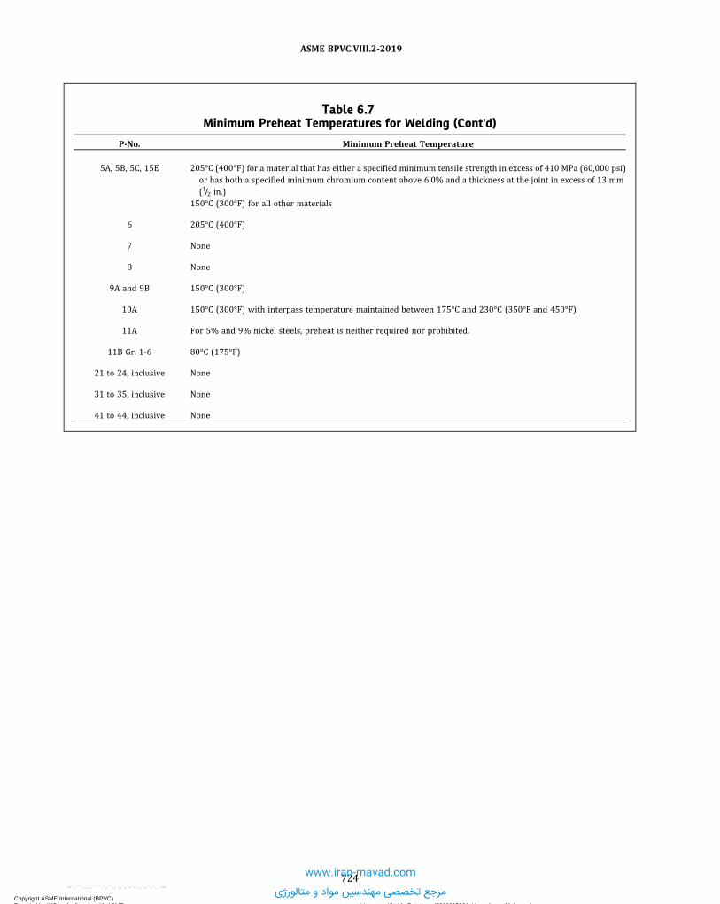
Table 6.7Minimum Preheat Temperatures for Welding (Cont'd)
P-No. Minimum Preheat Temperature
5A, 5B, 5C, 15E 205°C (400°F) for a material that has either a specified minimum tensile strength in excess of 410 MPa (60,000 psi)or has both a specified minimum chromium content above 6.0% and a thickness at the joint in excess of 13 mm(1/2 in.)
150°C (300°F) for all other materials
6 205°C (400°F)
7 None
8 None
9A and 9B 150°C (300°F)
10A 150°C (300°F) with interpass temperature maintained between 175°C and 230°C (350°F and 450°F)
11A For 5% and 9% nickel steels, preheat is neither required nor prohibited.
11B Gr. 1-6 80°C (175°F)
21 to 24, inclusive None
31 to 35, inclusive None
41 to 44, inclusive None
724
ASME BPVC.VIII.2-2019
Copyright ASME International (BPVC) Provided by IHS under license with ASME Licensee=Khalda Petroleum/5986215001, User=Amer, Mohamed
Not for Resale, 07/02/2019 14:07:58 MDTNo reproduction or networking permitted without license from IHS
--`,```,,,,,````,`,``,,`,,`,`-`-`,,`,,`,`,,`---
www.iran-mavad.com
مرجع تخصصی مهندسین مواد و متالورژی

Table 6.8Requirements for Postweld Heat Treatment (PWHT) of Pressure Parts and Attachments for
Materials: P-No. 1, Group 1, 2, 3
PWHT RequirementsHolding Temperature and Time Based on the
Nominal Thickness
(a) PWHT is mandatory for the following conditions:(1) for welded joints over 38 mm (11/2 in.) nominal thickness.(2) for welded joints over 32 mm (11/4 in.) through 38 mm (11/2 in.) nominal
thickness unless a 95°C (200°F) minimum preheat is applied during welding. Thispreheat need not be applied to SA-841, Grades A and B, provided that the carboncontent and carbon equivalent (CE) for the plate material, by heat analysis, do notexceed 0.14% and 0.40%, respectively, where
(3) for pressure parts subject to direct firing when the thickness at welded jointsexceeds 16 mm (5/8 in.), except under the following conditions:
(-a) for groove welds not over 13 mm (1/2 in.) in size and fillet welds with athroat not over 13 mm (1/2 in.) that attach nozzle connections that have a finishedinside diameter not greater than 50 mm (2 in.), provided the connections do not formligaments that require an increase in shell or head thickness, and preheat to a minimumtemperature of 95°C (200°F) is applied.
(-b) for groove welds not over 13 mm (1/2 in.) in size or fillet welds with a throatthickness of 13 mm (1/2 in.) or less that attach tubes to a tubesheet when the tubediameter does not exceed 50 mm (2 in.). A preheat of 95°C (200°F) minimum must beapplied when the carbon content of the tubesheet exceeds 0.22%.
(-c) for groove welds not over 13 mm (1/2 in.) in size or fillet welds with a throatthickness of 13 mm (1/2 in.) or less used for attaching nonpressure parts to pressureparts, provided preheat to a minimum temperature of 200°F (95°C) is applied when thethickness of the pressure part exceeds 32 mm (11/4 in.).
(-d) for studs welded to pressure parts, provided preheat to a minimumtemperature of 95°C (200°F) is applied when the thickness of the pressure partexceeds 32 mm (11/4 in.).
(-e) for corrosion-resistant weld metal overlay cladding or for welds attachingcorrosion-resistant applied lining, provided preheat to a minimum temperature of95°C (200°F) is maintained during application of the first layer when the thickness ofthe pressure part exceeds 32 mm (11/4 in.).(b) When it is impractical to perform PWHT at the temperatures specified in this
Table, it is permissible to carry out PWHT at lower temperatures for longer periodsof time in accordance with Table 6.16.
SI Units• For t n ≤ 50 mm: 595°C, 0.04 h/mm, 15 minminimum
• For 50 mm < tn ≤ 125 mm: 595°C, 2 h plus 0.6 minfor each additional millimeter over 50 mm
• For tn > 125 mm: 595°C, 2 h plus 0.6 min for eachadditional millimeter over 50 mm
U.S. Customary Units• For tn ≤ 2 in.: 1,100°F, 1 hr/in., 15 min minimum• For 2 in. < tn ≤ 5 in.: 1,100°F, 2 hr plus 15 min foreach additional inch over 2 in.
• For t n > 5 in.: 1,100°F, 2 hr plus 15 min for eachadditional inch over 2 in.
725
ASME BPVC.VIII.2-2019
Copyright ASME International (BPVC) Provided by IHS under license with ASME Licensee=Khalda Petroleum/5986215001, User=Amer, Mohamed
Not for Resale, 07/02/2019 14:07:58 MDTNo reproduction or networking permitted without license from IHS
--`,```,,,,,````,`,``,,`,,`,`-`-`,,`,,`,`,,`---
www.iran-mavad.com
مرجع تخصصی مهندسین مواد و متالورژی

Table 6.9Requirements for Postweld Heat Treatment (PWHT) of Pressure Parts and Attachments for
Materials: P-No. 3, Group 1, 2, 3
PWHT RequirementsHolding Temperature and Time Based on the
Nominal Thickness
(a) PWHT is mandatory for P-No. 3, Gr. No. 3 material in all thicknesses.(b) Except for the exemptions in (c), PWHT is mandatory under the following conditions for
other P number Group Number combinations:(1) on P-No. 3, Gr. No. 1 and P-No. 3, Gr. No. 2 material over 16 mm (5/8 in.) nominal
thickness. For these materials, PWHT is mandatory on material up to and including 16 mm(5/8 in.) nominal thickness unless a welding procedure qualification described in 6.2.2.4 hasbeen made for equal or greater thickness than the production weld.
(2) if for pressure parts subject to direct firing.(c) Except for P-No. 3, Gr. No. 3, for welding connections and attachments to pressure parts,
PWHT is not mandatory under the conditions specified below:(1) for attaching to pressure parts that have a specified maximum carbon content of not
more than 0.25% (SA material specification carbon content, except when further limited bythe Purchaser to a value within the specification limits) or to non-pressure parts with groovewelds not over 13 mm (1/2 in.) size or fillet welds having a throat thickness of 13 mm (1/2 in.)or less, provided preheat to a minimum temperature of 95°C (200°F) is applied
(2) for circumferential butt welds in pipe or tube where the pipe or tube has both anominal wall thickness of 13 mm (1/2 in.) or less and a specified maximum carbon contentof not more than 0.25% (SA material specification carbon content, except when furtherlimited by the Purchaser to a value within the specification limits)
(3) for studs welded to pressure parts that have a specified maximum carbon content ofnot more than 0.25% (SA material specification carbon content, except when further limitedby the Purchaser to a value within the specification limits), provided preheat to a minimumtemperature of 95°C (200°F) is applied
(4) for corrosion-resistant weld metal overlay cladding or for welds attachingcorrosion-resistant applied lining when welded to pressure parts that have a specifiedmaximum carbon content of not more than 0.25% (SA material specification carbon content,except when further limited by the Purchaser to a value within the specification limits),provided preheat to a minimum temperature of 95°C (200°F) is maintained duringapplication of the first layer
(5) for tubes or pressure-retaining handhole and inspection plugs or fittings that aresecured by mechanical means (tube expansion, shoulder construction, machine threads,etc.) and seal welded, provided the seal weld has a throat thickness of 10 mm (3/8 in.) or less,and preheat to a minimum temperature of 95°C (200°F) is applied when the thickness ofeither part exceeds 16 mm (5/8 in.)
(d) If during the holding period of PWHT, the maximum time or temperature of any vesselcomponent exceeds the provisions of 3.4.3, additional test coupons shall be made and tested.
(e) When it is impractical to perform PWHT at the temperatures specified in this Table, it ispermissible to carry out PWHT at lower temperatures for longer periods of time in accordancewith Table 6.16. When PWHT is performed in accordance with this provision, the vessel testplate required by 6.5.4 shall receive the same heat treatment.
SI Units• For t n ≤ 50 mm: 595°C, 0.04 h/mm, 15 minminimum
• For: 50 mm < tn ≤ 125 mm: 595°C, 2 h plus 0.6min for each additional millimeter over 50 mm
• For t n > 125 mm: 595°C, 2 h plus 0.6 min foreach additional millimeter over 50 mm
U.S. Customary Units• For tn ≤ 2 in.: 1,100°F, 1 hr/in,, 15 min minimum• For 2 in. < tn ≤ 5 in.: 1,100°F, 2 hr plus 15 min foreach additional inch over 2 in.
• For tn > 5 in.: 1,100°F, 2 hr plus 15 min for eachadditional inch over 2 in.
726
ASME BPVC.VIII.2-2019
Copyright ASME International (BPVC) Provided by IHS under license with ASME Licensee=Khalda Petroleum/5986215001, User=Amer, Mohamed
Not for Resale, 07/02/2019 14:07:58 MDTNo reproduction or networking permitted without license from IHS
--`,```,,,,,````,`,``,,`,,`,`-`-`,,`,,`,`,,`---
www.iran-mavad.com
مرجع تخصصی مهندسین مواد و متالورژی

Table 6.10Requirements for Postweld Heat Treatment (PWHT) of Pressure Parts and Attachments for
Materials: P-No. 4, Group 1, 2
PWHT RequirementsHolding Temperature and Time Based on the
Nominal Thickness
(a) PWHT is mandatory under the following conditions:(1) on material of all thicknesses for pressure parts subject to direct firing(2) on all other P-No. 4 Gr. Nos. 1 and 2 materials
(b) PWHT is not mandatory under the conditions specified below:(1) for circumferential butt welds in pipe or tube of P-No. 4 materials where the pipe or
tubes comply with all of the following conditions:(-a) a maximum nominal thickness of 16 mm (5/8 in.)(-b) maximum specified carbon content of not more than 0.15% (SA material
specification carbon content, except when further limited by the Purchaser to a valuewithin the specification limits)
(-c) a minimum preheat of 120°C (250°F)(2) for P-No. 4 pipe or tube materials meeting the requirements of (a)(1) and (a)(2)
above, having nonpressure attachments fillet welded to them, provided(-a) the fillet welds have a maximum throat thickness of 13 mm (1/2 in.)(-b) a minimum preheat temperature of 120°C (250°F) is applied
(3) for P-No. 4 pipe or tube materials meeting the requirements of (a)(1) and (a)(2)above, having studs welded to them, provided a minimum preheat temperature of 120°C(250°F) is applied
(4) for P‐No. 4 pipe or tube materials meeting the requirements of (a)(1) and (a)(2)above, having extended heat-absorbing fins electrically resistance‐welded to them, provided
(-a) the fins have a maximum thickness of 3 mm (1/8 in.)(-b) prior to using the welding procedure, the Manufacturer shall demonstrate that the
heat‐affected zone does not encroach upon the minimum pipe or tube wall thickness(5) for tubes or pressure-retaining handhole and inspection plugs or fittings that are
secured by mechanical means (tube expansion, shoulder construction, machine threads,etc.) and seal welded, provided the seal weld has a throat thickness of 10 mm (3/8 in.) or less,and preheat to a minimum temperature of 120°C (250°F) is applied when the thickness ofeither part exceeds 16 mm (5/8 in.)(c) If during the holding period of PWHT, the maximum time or temperature of any vessel
component exceeds the provisions of 3.4.3, additional test coupons shall be made and tested.
SI Units• For t n ≤ 50 mm: 650°C, 0.04 h/mm, for thefollowing holding times:(a) Class 1: 15 min minimum(b) Class 2: 1 h minimum
• For 50 mm < tn ≤ 125 mm: 650°C, 0.04 h/mm• For tn > 125 mm: 650°C, 5 h plus 0.6 min for eachadditional millimeter over 125 mm
U.S. Customary Units• For tn ≤ 2 in.: 1,200°F, 1 hr/in., for the followingholding times:(a) Class 1: 15 min minimum(b) Class 2: 1 hr minimum
• For 2 in. < tn ≤ 5 in.: 1,200°F, 1 hr/in.• For tn > 5 in.: 1,200°F, 5 hr plus 15 min for eachadditional inch over 5 in.
727
ASME BPVC.VIII.2-2019
Copyright ASME International (BPVC) Provided by IHS under license with ASME Licensee=Khalda Petroleum/5986215001, User=Amer, Mohamed
Not for Resale, 07/02/2019 14:07:58 MDTNo reproduction or networking permitted without license from IHS
--`,```,,,,,````,`,``,,`,,`,`-`-`,,`,,`,`,,`---
www.iran-mavad.com
مرجع تخصصی مهندسین مواد و متالورژی

Table 6.11Requirements for Postweld Heat Treatment (PWHT) of Pressure Parts and Attachments for
Materials: P-No. 5A; P-No. 5B, Group 1; and P-No. 5C, Group 1
PWHT RequirementsHolding Temperature and Time Based on the
Nominal Thickness
(a) Except under the following conditions, PWHT is mandatory:(1) for circumferential butt welds in pipe or tubes where the pipe or tubes comply with
all of the following conditions:(-a) a maximum specified chromium content of 3.0%(-b) a maximum nominal thickness of 16 mm (5/8 in.)(-c) a maximum specified carbon content of not more than 0.15% (SA material
specification carbon content, except when further limited by the Purchaser to a valuewithin the specification limits)
(-d) a minimum preheat of 150°C (300°F) is applied(2) for pipe or tube materials meeting the requirements of (1)(-a), (1)(-b), and (1)(-c)
having nonpressure attachments fillet welded to them, provided(-a) the fillet welds have a maximum throat thickness of 13 mm (1/2 in.)(-b) a minimum preheat temperature of 150°C (300°F) is applied
(3) for pipe or tube materials meeting the requirements of (1)(-a), (1)(-b), and (1)(-c)having studs welded to them, provided a minimum preheat temperature of 150°C (300°F)is applied
(4) for pipe or tube materials meeting the requirements of (1)(-a) and (1)(-c) above,having extended heat-absorbing fins electrically resistance‐welded to them, provided
(-a) the fins have a maximum thickness of 3 mm (1/8 in.)(-b) prior to using the welding procedure, the Manufacturer shall demonstrate that the
heat‐affected zone does not encroach upon the minimum pipe or tube wall thickness(5) for tubes or pressure-retaining handhole and inspection plugs or fittings in P-No. 5A
materials with a specified maximum chromium content of 6% that are secured by mechanicalmeans (tube expansion, shoulder construction, machine threads, etc.) and seal welded,provided the seal weld has a throat thickness of 10 mm (3/8 in.) or less, and preheat to aminimum temperature of 150°C (300°F) is applied when the thickness of either part exceeds16 mm (5/8 in.)(b) If during the holding period of PWHT, the maximum time or temperature of any vessel
component exceeds the provisions of 3.4.3, additional test coupons shall be made and tested.(c) When it is impractical to postweld heat treat P-No. 5A; P-No. 5B, Group No. 1; and P-No.
5C, Group No. 1 materials at the temperature specified in this Table, it is permissible toperform the PWHT at 650°C (1,200°F) minimum provided that, for material up to 50 mm(2 in.) nominal thickness, the holding time is increased to the greater of 4 h minimum or 9.6min/mm (4 hr/in.) of thickness; for thickness over 50 mm (2 in.), the specified holding timesare multiplied by 4. The requirements in 3.4.3 must be accommodated in this reduction inPWHT.(d) Postweld heat treatment is not mandatory for attaching bare wire thermocouples by
capacitor discharge welding or electric resistance welding, provided(1) the requirements of 6.4.5.3 are met(2) the maximum carbon content of the base material is restricted to 0.15%(3) the minimum wall thickness shall be 5.0 mm (0.20 in.)
SI Units• For t n ≤ 50 mm: 675°C, 0.04 h/mm, for thefollowing holding times:(a) Class 1: 15 min minimum(b) Class 2: 1 h minimum
• For: 50 mm < tn ≤ 125 mm: 675°C, 0.04 h/mm• For tn > 125 mm: 675°C, 5 h plus 0.6 min for eachadditional millimeter over 125 mm
U.S. Customary Units• For tn ≤ 2 in.: 1,250°F, 1 hr/in., for the followingholding times:(a) Class 1: 15 min minimum(b) Class 2: 1 hr minimum
• For 2 in. < tn ≤ 5 in.: 1,250°F, 1 hr/in.• For tn > 5 in.: 1,250°F, 5 hr plus 15 min for eachadditional inch over 5 in.
728
ASME BPVC.VIII.2-2019
Copyright ASME International (BPVC) Provided by IHS under license with ASME Licensee=Khalda Petroleum/5986215001, User=Amer, Mohamed
Not for Resale, 07/02/2019 14:07:58 MDTNo reproduction or networking permitted without license from IHS
--`,```,,,,,````,`,``,,`,,`,`-`-`,,`,,`,`,,`---
www.iran-mavad.com
مرجع تخصصی مهندسین مواد و متالورژی

ð19ÞTable 6.11.ARequirements for Postweld Heat Treatment (PWHT) of Pressure Parts and Attachments for
Materials: P-No. 15E, Group 1
PWHT RequirementsHolding Temperature and Time Based on the
Nominal Thickness
(a) If the nominal thickness is ≤13 mm (1/2 in.), the minimum holding temperature is 675°C(1,250°F).
(b) For dissimilar metal welds (i.e., welds made between a P-No.15 E, Group 1 and anotherlower chromium ferritic, austenitic, or nickel-based steel), if the filler metal chromium contentis less than 3.0% or if the filler metal is nickel-based or austenitic, the minimum holdingtemperature shall be 705°C (1,300°F).
(c) For welds made with matching Grade 91 filler metal (e.g., AWS A.5.5 E90xx-B91 and ISOEN CrMo91), the maximum holding temperature shall be determined as follows:
(1) If the Ni + Mn content of the filler metal is less than or equal to 1.0%, the maximumPWHT temperature shall be 790°C (1,455°F).
(2) If the Ni + Mn content of the filler metal is greater than 1.0% but less than or equal to1.2%, the maximum PWHT temperature shall be 780°C (1,435°F).
(3) If the Ni + Mn content of the filler metal is greater than 1.2%, the maximum PWHTtemperature shall be at least 10°C (20°F) below the lower critical transformation temperature(Ac1) as determined by measurement of that temperature for the specific heat (or heats) offiller metal to be used in accordance with ASTM A1033; in such case, the following additionalrestrictions will apply:
(-a) The Ac1 temperature of the filler metal as measured in accordance with ASTMA1033 shall be included in the Manufacturer’s construction records.
(-b) The maximum operating temperature for any vessel constructed using filler metalwith a Ni + Mn content in excess of 1.2% shall be 525°C (975°F).
(4) If multiple welds made with matching Grade 91 filler metal in a pressure part orpressure vessel are to be postweld heat treated at the same time, the maximum PWHTtemperature shall be determined based on the weld with the highest Ni + Mn content.
The lower transformation temperature for matching filler material is affected by alloycontent, primarily the total Ni + Mn. The maximum holding temperature has been set to avoidheat treatment in the intercritical zone.
(d) If a portion of the component is heated above the heat-treatment temperature allowedabove, one of the following actions shall be performed:
(1) The component in its entirety must be renormalized and tempered.(2) If the maximum holding temperature in (c) is exceeded, but does not exceed 800°C
(1,470°F), the weld metal shall be removed and replaced.(3) The portion of the component heated above 800°C (1,470°F) and at least 75 mm
(3 in.) on either side of the overheated zone must be removed and be renormalized andtempered, or replaced.
(4) The allowable stress shall be that for Grade 9 material (i.e., SA-213-T9, SA-335-P9, orequivalent product specification) at the design temperature, provided that the portion of thecomponent heated to a temperature greater than the allowed above is reheat treated withinthe temperature range specified above. To apply the provisions of this paragraph, theManufacturer shall have qualified a WPS with representative test specimens that accuratelysimulate the thermal history of the production part. Specifically, the qualification specimensshall first be heat treated at a similar temperature for a similar time that violated themaximum holding temperature limit and then shall receive a final heat treatment for therequired time within the temperature range specified by this Table. The use of this provisionshall be noted in the Manufacturer’s Data Report.
SI Units• For t n ≤ 125 mm: 705°C min., 0.04 h/mm, 30min minimum
• For tn > 125 mm: 705°C min., 5 h plus 0.6 minfor each additional millimeter over 125 mm
U.S. Customary Units• For t n ≤ 5 in.: 1,300°F min., 1 hr/in., 30 minminimum.
• For tn > 5 in.: 1,300°F min., 5 hr plus 15 min foreach additional inch over 5 in.
729
ASME BPVC.VIII.2-2019
Copyright ASME International (BPVC) Provided by IHS under license with ASME Licensee=Khalda Petroleum/5986215001, User=Amer, Mohamed
Not for Resale, 07/02/2019 14:07:58 MDTNo reproduction or networking permitted without license from IHS
--`,```,,,,,````,`,``,,`,,`,`-`-`,,`,,`,`,,`---
www.iran-mavad.com
مرجع تخصصی مهندسین مواد و متالورژی

Table 6.11.ARequirements for Postweld Heat Treatment (PWHT) of Pressure Parts and Attachments for
Materials: P-No. 15E, Group 1 (Cont'd)
PWHT RequirementsHolding Temperature and Time Based on the
Nominal Thickness
(e) Postweld heat treatment is not mandatory for electric resistance welds used to attachextended heat-absorbing fins to pipe and tube materials provided the followingrequirements are met:
(1) a maximum pipe or tube size of 100 DN (NPS 4)(2) a maximum specified carbon content (SA material specification carbon content,
except when further limited by the Purchaser to a value within the specification limits) ofnot more than 0.15 %
(3) a maximum fin thickness of 3 mm (1/8 in.)(4) prior to using the welding procedure, the Manufacturer shall demonstrate that the
heat-affected zone does not encroach upon the minimum wall thickness.(f) Postweld heat treatment is not mandatory for attaching bare wire thermocouples by
capacitor discharge welding or electric resistance welding, provided(1) the requirements of 6.4.5.3 are met(2) the maximum carbon content of the base material is restricted to 0.15%(3) the minimum wall thickness shall be 5.0 mm (0.20 in.)
Table 6.12Requirements for Postweld Heat Treatment (PWHT) of Pressure Parts and Attachments for
Materials: P-No. 6, Group 1, 2, 3
PWHT RequirementsHolding Temperature and Time Based on the
Nominal Thickness
(a) PWHT is not required for vessels constructed of Type 410 material with carbon contentnot to exceed 0.08% and welded with electrodes that produce an austenitic chromium–nickelweld deposit or a non-air-hardening nickel-chromium–iron weld deposit, provided thenominal thickness does not exceed 10 mm (3/8 in.), and for thicknesses over 10 mm (3/8 in.) to38 mm (11/2 in.) provided a preheat of 230°C (450°F) is maintained during welding and thatthe joints are completely radiographed.(b) If during the holding period of PWHT the maximum time or temperature of any vessel
component exceeds the provisions of 3.4.3, additional test coupons shall be made and tested.
SI Units• For t n ≤ 50 mm: 760°C, 0.04 h/mm, for thefollowing holding times:(a) Class 1: 15 min minimum(b) Class 2: 1 h minimum
• For: 50 mm < tn ≤ 125 mm: 760°C, 2 h plus 0.6min for each additional millimeter over 50 mm
• For tn > 125 mm: 760°C, 2 h plus 0.6 min for eachadditional millimeter over 50 mm
U.S. Customary Units• For tn ≤ 2 in.: 1,400°F, 1 hr/in., for the followingholding times:(a) Class 1: 15 min minimum(b) Class 2: 1 hr minimum
• For 2 in. < tn ≤ 5 in.: 1,400°F, 2 hr plus 15 min foreach additional inch over 2 in.
• For tn > 5 in.: 1,400°F, 2 hr plus 15 min for eachadditional inch over 2 in.
730
ASME BPVC.VIII.2-2019
Copyright ASME International (BPVC) Provided by IHS under license with ASME Licensee=Khalda Petroleum/5986215001, User=Amer, Mohamed
Not for Resale, 07/02/2019 14:07:58 MDTNo reproduction or networking permitted without license from IHS
--`,```,,,,,````,`,``,,`,,`,`-`-`,,`,,`,`,,`---
www.iran-mavad.com
مرجع تخصصی مهندسین مواد و متالورژی

ð19ÞTable 6.13Requirements for Postweld Heat Treatment (PWHT) of Pressure Parts and Attachments for
Materials: P-No. 7, Group 1, 2; and P-No. 8
PWHT RequirementsHolding Temperature and Time Based on the
Nominal Thickness
Materials: P-No. 7, Group 1, 2
(a) PWHT shall be performed as prescribed in 6.2.6 except that the cooling rate shall be amaximum of 55°C/h (100°F/hr) in the range above 650°C (1,200°F), after which the coolingrate shall be sufficiently rapid to prevent embrittlement. PWHT is not required for vesselsconstructed of Type 405 and Type 410S material with carbon content not to exceed 0.08%,welded with electrodes that produce an austenitic chromium-nickel weld deposit or a non-air-hardening nickel–chromium–iron weld deposit, provided the nominal thickness does notexceed 3 mm (1/8 in.), and for thicknesses over 3 mm (1/8 in.) to 38 mm (11/2 in.) provided apreheat of 230°C (450°F) is maintained during welding and that the joints are completelyradiographed.
(b) If during the holding period of PWHT, the maximum time or temperature of any vesselcomponent exceeds the provisions of 3.4.3, additional test coupons shall be made and tested.
SI Units• For t n ≤ 50 mm: 730°C, 0.04 h/mm, for thefollowing holding times:(a) Class 1: 15 min minimum(b) Class 2: 1 h minimum
• For: 50 mm < tn ≤ 125 mm: 730°C, 2 h plus 0.6min for each additional millimeter over 50 mm
• For tn > 125 mm: 730°C, 2 h plus 0.6 min for eachadditional millimeter over 50 mm
U.S. Customary Units• For tn ≤ 2 in.: 1,350°F, 1 hr/in., for the followingholding times:(a) Class 1: 15 min minimum(b) Class 2: 1 hr minimum
• For 2 in. < tn ≤ 5 in.: 1,350°F, 2 hr plus 15 min foreach additional inch over 2 in.
• For tn > 5 in.: 1,350°F, 2 hr plus 15 min for eachadditional inch over 2 in.
Materials: P-No. 8
(a) PWHT is neither required nor prohibited.(b) If postweld heat treatment is performed for P-No. 8 materials, the Manufacturer shall
consider the steps necessary to avoid embrittlement, sensitization, and the precipitation ofdeleterious phases. See Section II, Part D, Nonmandatory Appendix A, A-207 through A-210.
…
731
ASME BPVC.VIII.2-2019
Copyright ASME International (BPVC) Provided by IHS under license with ASME Licensee=Khalda Petroleum/5986215001, User=Amer, Mohamed
Not for Resale, 07/02/2019 14:07:58 MDTNo reproduction or networking permitted without license from IHS
--`,```,,,,,````,`,``,,`,,`,`-`-`,,`,,`,`,,`---
www.iran-mavad.com
مرجع تخصصی مهندسین مواد و متالورژی

Table 6.14Requirements for Postweld Heat Treatment (PWHT) of Pressure Parts and Attachments for
Materials: P-No. 9A, Group 1, and P-No. 9B, Group 1
PWHT RequirementsHolding Temperature and Time Based on the
Nominal Thickness
Materials: P-No. 9A, Group 1
(a) PWHT is mandatory under the following conditions:(1) on material of all thicknesses if required by the User's Design Specification.(2) on material over 16 mm (5/8 in.) nominal thickness. For material up to and including
16 mm (5/8 in.) nominal thickness, postweld heat treatment is mandatory unless a weldingprocedure qualification described in 6.2.1.1 has been made in equal or greater thickness than theproduction weld.
(3) if for pressure parts subject to direct firing.(b) PWHT is not mandatory under the conditions specified below:(1) for circumferential butt welds in pipe or tubes where the pipe or tubes comply with all
of the following conditions:(-a) a maximum nominal outside diameter of 100 mm (4 in.)(-b) a maximum nominal thickness of 13 mm (1/2 in.)(-c) a maximum specified carbon content of not more than 0.15% (SA material
specification carbon content, except when further limited by the Purchaser to a value withinthe specification limits)
(-d) a minimum preheat of 120°C (250°F)(2) for pipe or tube materials meeting the requirements of (1)(-a), (1)(-b), and (1)(-c)
above, having attachments fillet welded to them, provided:(-a) the fillet welds have a throat thickness of 13 mm (1/2 in.) or less(-b) the material is preheated to 120°C (250°F) minimum. A lower preheating
temperature may be used provided specifically controlled procedures necessary to producesound welded joints are used. Such procedures shall include but not be limited to the following:
(-1) The throat thickness of fillet welds shall be 13 mm (1/2 in.) or less.(-2) The maximum continuous length of fillet welds shall be not over 100 mm (4 in.).(-3) The thickness of the test plate used in making the welding procedure qualification
of Section IX shall not be less than that of the material to be welded.(3) for attaching nonpressure parts to pressure parts with groove welds not over 13 mm
(1/2 in.) in size or fillet welds that have a throat thickness of 13 mm (1/2 in.) or less, providedpreheat to a minimum temperature of 95°C (200°F) is applied
(4) for studs welded to pressure parts, provided preheat to a minimum temperature of 95°C(200°F) is applied
(5) for corrosion-resistant weld metal overlay cladding or for welds attachingcorrosion-resistant applied lining, provided preheat to a minimum temperature of 95°C(200°F) is maintained during application of the first layer(c) If during the holding period of PWHT the maximum time or temperature of any vessel
component exceeds the provisions of 3.4.3, additional test coupons shall be made and tested.(d) When the heating rate is less than 30°C/h (50°F/hr) between 425°C (800°F) and the
holding temperature, the additional 0.6 min/mm (15 min/in.) holding time is not required.Additionally, where the Manufacturer can provide evidence that the minimum temperature hasbeen achieved throughout the thickness, the additional 0.60 min/mm (15min/in.) holding time isnot required.(e) When it is impractical to postweld heat treat at the temperature specified in this Table, it is
permissible to carry out the PWHT at lower temperatures 540°C (1,000°F minimum) for longerperiods of time in accordance with Table 6.16. When PWHT is performed in accordance with thisprovision, the vessel test plate required by 3.4.3 shall receive the same heat treatment.
SI Units595°C: 1 h minimum, plus 0.6 min/mm for
thickness over 25 mmU.S. Customary Units1,100°F: 1 hr minimum, plus 15 min/in. for
thickness over 1 in.
732
ASME BPVC.VIII.2-2019
Copyright ASME International (BPVC) Provided by IHS under license with ASME Licensee=Khalda Petroleum/5986215001, User=Amer, Mohamed
Not for Resale, 07/02/2019 14:07:58 MDTNo reproduction or networking permitted without license from IHS
--`,```,,,,,````,`,``,,`,,`,`-`-`,,`,,`,`,,`---
www.iran-mavad.com
مرجع تخصصی مهندسین مواد و متالورژی

Table 6.14Requirements for Postweld Heat Treatment (PWHT) of Pressure Parts and Attachments for
Materials: P-No. 9A, Group 1, and P-No. 9B, Group 1 (Cont'd)
PWHT RequirementsHolding Temperature and Time Based on the
Nominal Thickness
Materials: P-No. 9B, Group 1
(a) PWHT is mandatory under the following conditions:(1) on material over 16 mm (5/8 in.) nominal thickness. For material up to and including
16 mm (5/8 in.) nominal thickness, PWHT is mandatory unless a welding procedure qualificationdescribed in 6.2.2.4 has been made in equal or greater thickness than the production weld.
(2) on pressure parts subject to direct firing(b) PWHT is not mandatory under the conditions specified below:(1) for attaching nonpressure parts to pressure parts with groove welds not over 13 mm
(1/2 in.) in size or fillet welds that have a throat thickness of 13 mm (1/2 in.) or less, providedpreheat to a minimum temperature of 95°C (200°F) is applied;
(2) for studs welded to pressure parts, provided preheat to a minimum temperature of 95°C(200°F) is applied;
(3) for corrosion-resistant weld metal overlay cladding or for welds attachingcorrosion-resistant applied lining (see 6.5.5.1), provided preheat to a minimum temperature of95°C (200°F) is maintained during application of the first layer.
(c) The holding temperature for PWHT shall not exceed 635°C (1,175°F).(d) If during the holding period of PWHT, the maximum time or temperature of any vessel
component exceeds the provisions of 3.4.3, additional test coupons shall be made and tested.(e) When the heating rate is less than 30°C/h (50°F/hr) between 425°C (800°F) and the
holding temperature, the additional 0.6 min/mm (15 min/in.) holding time is not required.Additionally, where the Manufacturer can provide evidence that the minimum temperature hasbeen achieved throughout the thickness, the additional 0.6 min/mm (15 min/in.) holding time isnot required.
(f) When it is impractical to postweld heat treat at the temperature specified in this Table, it ispermissible to carry out the PWHT at lower temperatures 540°C (1,000°F) minimum for longerperiods of time in accordance with Table 6.16. When PWHT is performed in accordance with thisprovision, the vessel test plate required by 3.4.3 shall receive the same heat treatment.
SI Units595°C: 1 h minimum, plus 0.6 min/mm forthickness over 25 mm
U.S. Customary Units1,100°F: 1 hr minimum, plus 15 min/in. forthickness over 1 in.
733
ASME BPVC.VIII.2-2019
Copyright ASME International (BPVC) Provided by IHS under license with ASME Licensee=Khalda Petroleum/5986215001, User=Amer, Mohamed
Not for Resale, 07/02/2019 14:07:58 MDTNo reproduction or networking permitted without license from IHS
--`,```,,,,,````,`,``,,`,,`,`-`-`,,`,,`,`,,`---
www.iran-mavad.com
مرجع تخصصی مهندسین مواد و متالورژی

ð19Þ Table 6.15Requirements for Postweld Heat Treatment (PWHT) of Pressure Parts and Attachments for
Materials: P-No. 10A, Group 1; P-No. 10C, Group 1; P-No. 10H, Group 1; P-No. 10I, Group 1; P-No.10K, Group 1; and P-No. 45
PWHT RequirementsHolding Temperature and Time Based On the
Nominal Thickness
Materials: P-No. 10A, Group 1
(a) Postweld heat treatment is mandatory under the following conditions:(1) on all thicknesses of SA-487 Cl. 1A and Cl. 1B material(2) on all other P-No. 10A materials over 16 mm (5/8 in.) nominal thickness. For these
materials, postweld heat treatment is mandatory on material up to and including 16 mm(5/8 in.) nominal thickness, unless a welding procedure qualification described in 6.2.2.4 has beenmade in equal or greater thickness than the production weld.
(3) on pressure parts subject to direct firing.(b) Postweld heat treatment is not mandatory under the conditions specified below:(1) for attaching to pressure parts that have a specified maximum carbon content of not
more than 0.25% (SA material specification carbon content, except when further limited bythe Purchaser to a value within the specification limits) or to nonpressure parts with groovewelds not over 13 mm (1/2 in.) in size or fillet welds having a throat thickness of 13 mm (1/2 in.) orless, provided preheat to a minimum temperature of 95°C (200°F) is applied
(2) for circumferential butt welds in pipes or tube where the pipe or tube has both anominal wall thickness of 13 mm (1/2 in.) or less and a specified maximum carbon content ofnot more than 0.25% (SA material specification carbon content, except when further limited bythe Purchaser to a value within the specification limits), provided preheat to a minimumtemperature of 95°C (200°F) is applied
(3) for studs welded to pressure parts that have a specified maximum carbon content of notmore than 0.25% (SA material specification carbon content, except when further limited by thePurchaser to a value within the specification limits), provided preheat to a minimum temperatureof 95°C (200°F) is applied
(4) for corrosion-resistant weld metal overlay cladding or for welds attachingcorrosion-resistant applied lining (see 6.5.5.1) when welded to pressure parts that have aspecified maximum carbon content of not more than 0.25% (SA material specification carboncontent, except when further limited by the Purchaser to a value within the specification limits),provided preheat to a minimum temperature of 95°C (200°F) is maintained during application ofthe first layer(c) Consideration should be given for possible embrittlement of materials containing up to
0.15% vanadium when postweld heat treatment is performed at the minimum temperatureand at lower temperatures for longer holding times.(d) If during the holding period of PWHT the maximum time or temperature of any vessel
component exceeds the provisions of 3.11.8.4, additional test coupons shall be made and tested.(e) When the heating rate is less than 30°C/h (50°F/hr) between 425°C (800°F) and the
holding temperature, the additional 0.6 min/mm (15 min/in.) holding time is not required.Additionally, where the Manufacturer can provide evidence that the minimum temperature hasbeen achieved throughout the thickness, the additional 0.6 min/mm (15 min/in.) holding time isnot required.(f) When it is impractical to postweld heat treat at the temperature specified in this Table, it is
permissible to carry out the postweld heat treatment at lower temperatures for longer periods oftime in accordance with Table 6.16. When postweld heat treatment is performed in accordancewith this Note, the vessel test plate required by 3.11.8.4 shall receive the same heat treatment.(g) If postweld heat treatment is performed for P-No. 45 materials, the Manufacturer shall
consider the steps necessary to avoid embrittlement, sensitization, and the precipitation ofdeleterious phases. See Section II, Part D, Nonmandatory Appendix A, A-207 through A-210.
SI Units595°C: 1 h minimum, plus 0.6 min/mm for
thickness over 25 mm530°C to 560°C: 1/2 hr for thickness up to 20 mm for
SA/NF A36-215 Grade P440 NJ4U.S. Customary Units1,100°F: 1 hr minimum, plus 15 min/in. for
thickness over 1 in.985°F to 1,040°F: 1/2 hr for thickness up to 0.79 in.
for SA/NF A36-215 Grade P440 NJ4
734
ASME BPVC.VIII.2-2019
Copyright ASME International (BPVC) Provided by IHS under license with ASME Licensee=Khalda Petroleum/5986215001, User=Amer, Mohamed
Not for Resale, 07/02/2019 14:07:58 MDTNo reproduction or networking permitted without license from IHS
--`,```,,,,,````,`,``,,`,,`,`-`-`,,`,,`,`,,`---
www.iran-mavad.com
مرجع تخصصی مهندسین مواد و متالورژی

Table 6.15Requirements for Postweld Heat Treatment (PWHT) of Pressure Parts and Attachments for
Materials: P-No. 10A, Group 1; P-No. 10C, Group 1; P-No. 10H, Group 1; P-No. 10I, Group 1; P-No.10K, Group 1; and P-No. 45 (Cont'd)
PWHT RequirementsHolding Temperature and Time Based On the
Nominal Thickness
Materials: P-No. 10C, Group 1
(a) Postweld heat treatment is mandatory under the following conditions:(1) for welded joints over 38 mm (11/2 in.) nominal thickness(2) for welded joints over 32 mm (11/4 in.) through 38 mm (11/2 in.) nominal thickness
unless a 95°C (200°F) minimum preheat is applied during welding(3) on pressure parts subject to direct firing
(b) Postweld heat treatment is not mandatory under the conditions specified below:(1) for groove welds not over 13 mm (1/2 in.) in size and fillet welds with throat not over
13 mm (1/2 in.) that attach nozzle connections that have a finished inside diameter not greaterthan 50 mm (2 in.), provided the connections do not form ligaments that require an increase inshell or head thickness and preheat to a minimum temperature of 95°C (200°F) is applied
(2) for groove welds not over 13 mm (1/2 in.) in size or fillet welds having throat thickness of13 mm (1/2 in.) or less used for attaching nonpressure parts to pressure parts and preheat to aminimum temperature of 95°C (200°F) is applied when the thickness of the pressure partexceeds 32 mm (11/4 in.)
(3) for studs welded to pressure parts, provided preheat to a minimum temperature of 95°C(200°F) is applied when the thickness of the pressure part exceeds 32 mm (11/4 in.)
(4) for corrosion resistant weld metal overlay cladding or for welds attachingcorrosion-resistant applied lining (see 6.5.5.1), provided preheat to a minimum temperature of95°C (200°F) is maintained during application of the first layer when the thickness of thepressure part exceeds 32 mm (11/4 in.)
(c) When the heating rate is less than 30°C/h (50°F/hr) between 425°C (800°F) and theholding temperature, the additional 0.6 min/mm (15 min/in.) holding time is not required.Additionally, where the Manufacturer can provide evidence that the minimum temperature hasbeen achieved throughout the thickness, the additional 0.6 min/mm (15 min/in.) holding time isnot required.
(d) When it is impractical to postweld heat treat at the temperature specified in this Table, it ispermissible to carry out the postweld heat treatment at lower temperatures for longer periods oftime in accordance with Table 6.16.
SI Units540°C: 1 h minimum, plus 0.6 min/mm forthickness over 25 mm
U.S. Customary Units1,000°F: 1 hr minimum, plus 15 min/in. forthickness over 1 in.
Materials: P-No. 10H, Group 1
For the austenitic-ferritic wrought or cast duplex stainless steels listed below, PWHT is neitherrequired nor prohibited. However, if heat treatment is performed, it shall be performed aslisted below and followed by liquid quenching or rapid cooling by other means:
PWHT Temperature
Alloy °C °F
J93345 1 120 minimum 2,050 minimumS31200 1 040 minimum 1,900 minimumS31260 1 020–1 100 1,870–2,010S31500 975–1 025 1,785–1,875S31803, S32205 1 040 minimum 1,900 minimumS32202 980–1 080 1,800–1,975S32304 980 minimum 1,800 minimumS32550 1 040 minimum 1,900 minimumS32750 1 025–1 125 1,880–2,060S32760 1 100–1 140 2,010–2,085S32900 (0.08 max. C) 940–970 1,725–1,775S32950 995–1 025 1,825–1,875S39274 1 050–1 150 1,925–2,100
…
735
ASME BPVC.VIII.2-2019
Copyright ASME International (BPVC) Provided by IHS under license with ASME Licensee=Khalda Petroleum/5986215001, User=Amer, Mohamed
Not for Resale, 07/02/2019 14:07:58 MDTNo reproduction or networking permitted without license from IHS
--`,```,,,,,````,`,``,,`,,`,`-`-`,,`,,`,`,,`---
www.iran-mavad.com
مرجع تخصصی مهندسین مواد و متالورژی

Table 6.15Requirements for Postweld Heat Treatment (PWHT) of Pressure Parts and Attachments for
Materials: P-No. 10A, Group 1; P-No. 10C, Group 1; P-No. 10H, Group 1; P-No. 10I, Group 1; P-No.10K, Group 1; and P-No. 45 (Cont'd)
PWHT RequirementsHolding Temperature and Time Based On the
Nominal Thickness
Materials: P-No. 10I, Group 1
(a) The cooling rate shall be a maximum of 55°C/h (100°F/hr) in the range above 650°C(1,200°F) after which the cooling rate shall be rapid to prevent embrittlement.(b) PWHT is neither required nor prohibited for a thickness of 13 mm (1/2 in.) or less.(c) For alloy S44635, the rules for ferritic chromium stainless steel shall apply, except that
PWHT is neither prohibited nor required. If heat treatment is performed after forming orwelding, it shall be performed at 1 010°C (1,850°F) minimum followed by rapid cooling to below425°C (800°F).(d) If during the holding period of PWHT the maximum time or temperature of any vessel
component exceeds the provisions of 3.11.8.4, additional test coupons shall be made and tested.(e) When the heating rate is less than 30°C/h (50°F/hr) between 425°C (800°F) and the
holding temperature, the additional 0.6 min/mm (15 min/in.) holding time is not required.Additionally, where the Manufacturer can provide evidence that the minimum temperature hasbeen achieved throughout the thickness, the additional 0.6 min/mm (15 min/in.) holding time isnot required.
SI Units730°C:
(a) Class 1: 0.04 h/mm, 15 min minimum(b) Class 2: 1 h minimum, plus 0.6 min/mm for
thickness over 25 mmU.S. Customary Units1,350°F:
(a) Class 1: 1 hr/in., 15 min minimum(b) Class 2: 1 hr minimum, plus 15 min/in. for
thickness over 1 in.
Materials: P-No. 10K, Group 1
(a) For alloy S44660, the rules for ferritic chromium stainless steel shall apply, except thatPWHT is neither required nor prohibited. If heat treatment is performed after forming orwelding, it shall be performed at 815°C (1,500°F) to 1 065°C (1,950°F) for a period not to exceed10 min followed by rapid cooling.(b) If during the holding period of PWHT the maximum time or temperature of any vessel
component exceeds the provisions of 3.11.8.4, additional test coupons shall be made and tested.
…
Materials: P-No. 45 [See 6.4]
(a) Postweld heat treatment is neither required nor prohibited for joints between austeniticstainless steels of the P-No. 45 group.(b) Cooling Requirements: Liquid quenching or rapid cooling by other means.
PWHT Temperature
Alloy °C °F
S31266 1 140 –1 170 2,085–2,138
…
Table 6.16Alternative Postweld Heat Treatment Requirements
Decrease in Temperature BelowMinimum SpecifiedTemperature, °C (°F)
Minimum Holding Time at DecreasedTemperature, h
[Note (1)]
30 (50) 255 (100) 485 (150) [Note (2)] 10
110 (200) [Note (2)] 20
GENERAL NOTE: Applicable only when permitted by Tables 6.8 through 6.15.
NOTES:(1) Minimum holding time for 25 mm (1 in.) thickness or less. Add 0.6 min/mm (15 min/in.) of thickness for thicknesses greater than
25 mm (1 in.)(2) These lower postweld heat-treat temperatures are permitted only for P-No 1, Group 1 and Group 2 materials.
736
ASME BPVC.VIII.2-2019
Copyright ASME International (BPVC) Provided by IHS under license with ASME Licensee=Khalda Petroleum/5986215001, User=Amer, Mohamed
Not for Resale, 07/02/2019 14:07:58 MDTNo reproduction or networking permitted without license from IHS
--`,```,,,,,````,`,``,,`,,`,`-`-`,,`,,`,`,,`---
www.iran-mavad.com
مرجع تخصصی مهندسین مواد و متالورژی

ð19ÞTable 6.17Postweld Heat Treatment Requirements for Quenched and Tempered Materials in Table 3-A.2
Specification Grade or TypeP-No. andGroup No.
(Nominal)Thickness
Requiring PWHT,mm (in.)
PostweldHeat-TreatmentTemp., °C (°F)
Holding Time,h/mm (hr/in.)
Minimum HoldingTime, h
Plate Steels
SA-353 9Ni 11A Gr. 1 Over 50 (2) 550–585(1,025–1,085)
1 2
SA-517 Grade A 11B Gr. 1 Over 15 (0.58)[Note (1)]
540–595(1,000–1,100)
1 1/4
SA-517 Grade B 11B Gr. 4 Over 15 (0.58)[Note (1)]
540–595(1,000–1,100)
1 1/4
SA-517 Grade E 11B Gr. 2 Over 15 (0.58)[Note (1)]
540–595(1,000–1,100)
1 1/4
SA-517 Grade F 11B Gr. 3 Over 15 (0.58)[Note (1)]
540–595(1,000–1,100)
1 1/4
SA-517 Grade P 11B Gr. 8 Over 15 (0.58)[Note (1)]
540–595(1,000–1,100)
1 1/4
SA-533 Grades B and D, CI. 3 11A Gr. 4 Over 15 (0.58) 540–565(1,000–1,050)
1/21/2
SA-543 Types B and C, CI. 1 11A Gr. 5 [Note (2)] 540–565(1,000–1,050)
1 1
SA-543 Types B and C, CI. 2 11A Gr. 10 [Note (2)] 540–565(1,000–1,050)
1 1
SA-543 Types B and C, CI. 3 3 Gr. 3 [Note (2)] 540–565(1,000–1,050)
1 1
SA-553 Types I, II, and III 11A Gr. 1 Over 50 (2) 550–585(1,025–1,085)
1 2
SA-645 Grade A 11A Gr. 2 Over 50 (2) 550–585(1,025–1,085)
1 2
SA-724 Grades A and B 1 Gr. 4 None NA NA NASA-724 Grade C 1 Gr. 4 Over 38 (11/2) 565–620
(1,050–1,150)1 1/2
Pipes and Tubes
SA-333 Grade 8 11A Gr. 1 Over 50 (2) 550–585(1,025–1,085)
1 2
SA-334 Grade 8 11A Gr. 1 Over 50 (2) 550–585(1,025–1,085)
1 2
Forgings
SA-372 Grade D … See 6.7.6.3 and SA-372 for heat-treating requirements …SA-372 Grade E, CI. 70 … See 6.7.6.3 and SA-372 for heat-treating requirements …SA-372 Grade F, CI. 70 … See 6.7.6.3 and SA-372 for heat-treating requirements …SA-372 Grade G, CI. 70 … See 6.7.6.3 and SA-372 for heat-treating requirements …SA-372 Grade H, CI. 70 … See 6.7.6.3 and SA-372 for heat-treating requirements …SA-372 Grade J, CI. 70 … See 6.7.6.3 and SA-372 for heat-treating requirements …SA-372 Grade J, CI. 110 … See 6.7.6.3 and SA-372 for heat-treating requirements …SA-508 Grade 4N, CI. 1 11A Gr. 5 [Note (2)] 540–565
(1,000–1,050)1 1
SA-508 Grade 4N, Cl. 2 11B Gr. 10 [Note (2)] 540–565(1,000–1,050)
1 1
SA-522 Type 1 11A Gr. 1 Over 50 (2) 550–585(1,025–1,085)
1 2
SA-592 Grade A 11B Gr. 1 Over 15 (0.58)[Note (1)]
540–595(1,000–1,100)
1 1/4
SA-592 Grade E 11B Gr. 2 Over 15 (0.58)[Note (1)]
540–595(1,000–1,100)
1 1/4
SA-592 Grade F 11B Gr. 3 Over 15 (0.58)[Note (1)]
540–595(1,000–1,100)
1 1/4
GENERAL NOTE: NA indicates not applicable.
737
ASME BPVC.VIII.2-2019
Copyright ASME International (BPVC) Provided by IHS under license with ASME Licensee=Khalda Petroleum/5986215001, User=Amer, Mohamed
Not for Resale, 07/02/2019 14:07:58 MDTNo reproduction or networking permitted without license from IHS
--`,```,,,,,````,`,``,,`,,`,`-`-`,,`,,`,`,,`---
www.iran-mavad.com
مرجع تخصصی مهندسین مواد و متالورژی

ð19Þ
Table 6.17Postweld Heat Treatment Requirements for Quenched and Tempered Materials in Table 3-A.2
(Cont'd)
NOTES:(1) See 6.6.5.2(d)(8).(2) PWHT is neither required nor prohibited. Consideration should be given to the possibility of temper embrittlement. The cooling
rate from PWHT, when used, shall not be slower than that obtained by cooling in still air.
Table 6.18Quench and Tempered Steels Conditionally Exempt From Production Impact Tests
Specification UNS P-No./Group No.
SA-333, Grade 8 K81340 11A/1SA-334, Grade 8 K81340 11A/1SA-420, Grade WPL8 K81340 11A/1SA-353 K81340 11A/1SA-522, Type I K81340 11A/1SA-553, Type I K81340 11A/1SA-553, Type II K71340 11A/1SA-553, Type III K61365 11A/1SA-645, Grade A K41583 11A/2
Table 6.19High Nickel Alloy Filler for Quench and Tempered Steels
Specification Classification F-Number
SFA-5.11 ENiCrFe-2 43SFA-5.11 ENiCrFe-3 43SFA-5.11 ENiCrMo-3 43SFA-5.11 ENiCrMo-6 43SFA-5.14 ERNiCr-3 43SFA-5.14 ERNiCrFe-6 43SFA-5.14 ERNiCrMo-3 43SFA-5.14 ERNiCrMo-4 43
Table 6.20Mandrel Radius for Guided Bend Tests for Forged Fabrication
Specimen Thickness Radius of Mandrel, B [Note (1)] Radius of Die, D [Note (1)]
10 mm (3/8 in.) 32 mm (11/4 in.) 42 mm (111/16 in.)t
NOTE:(1) The dimension corresponds to dimensions B and D for P-No. 11 material in Section IX, Figure QW-466.1 and other dimensions to be in
proportion.
738
ASME BPVC.VIII.2-2019
Copyright ASME International (BPVC) Provided by IHS under license with ASME Licensee=Khalda Petroleum/5986215001, User=Amer, Mohamed
Not for Resale, 07/02/2019 14:07:58 MDTNo reproduction or networking permitted without license from IHS
--`,```,,,,,````,`,``,,`,,`,`-`-`,,`,,`,`,,`---
www.iran-mavad.com
مرجع تخصصی مهندسین مواد و متالورژی

Table 6.21U-Shaped Unreinforced and Reinforced Bellows Manufacturing Tolerances
Bellows Dimension [Note (1)] Manufacturing Tolerance
Convolution pitch, q≤12.7 mm (≤0.5 in.) ±1.6 mm (±0.063 in)>12.7 mm to 25.4 mm (>0.5 in. to 1.0 in.) ±3.2 mm (±0.125 in.)>25.4 mm to 38.1 mm (>1.0 in. to 1.5 in.) ±4.7 mm (±0.188 in.)>38.1 mm to 50.8 mm (>1.5 in. to 2.0 in.) ±6.4 mm (±0.250 in.)>50.8 mm (>2.0 in.) ±7.9 mm (±0.313 in.)
Convolution height, w≤12.7 mm (≤0.5 in.) ±0.8 mm (±0.031 in.)>12.7 mm to 25.4 mm (>0.5 in. to 1.0 in.) ±1.6 mm (±0.063 in.)>25.4 mm to 38.1 mm (>1.0 in. to 1.5 in.) ±2.4 mm (±0.094 in.)>38.1 mm to 50.8 mm (>1.5 in. to 2.0 in.) ±3.2 mm (±0.125 in.)>50.8 mm to 63.5 mm (>2.0 in. to 2.5 in.) ±4.0 mm (±0.156 in.)>63.5 mm to 76.2 mm (>2.5 in. to 3.0 in.) ±4.7 mm (±0.188 in.)>76.2 mm to 88.9 mm (>3.0 in. to 3.5 in.) ±5.6 mm (±0.219 in.)>88.9 mm to 101.6 mm (>3.5 in. to 4.0 in.) ±6.4 mm (±0.250 in.)>101.6 mm (>4.0 in.) ±7.1 mm (±0.281 in.)
Convolution inside diameter, Db
≤219 mm (≤8.625 in.) ±1.6 mm (±0.063 in.)>219 mm to 610 mm (>8.625 in. to 24.0 in.) ±3.2 mm (±0.125 in.)>610 mm to 1 219 mm (>24.0 in. to 48.0 in.) ±4.7 mm (±0.188 in.)>1 219 mm to 1 524 mm (>48.0 in. to 60.0 in.) ±6.4 mm (±0.250 in.)>1 524 mm (>60.0 in.) –±7.9 mm (±0.313 in.)
NOTE:(1) See Figure 4.19.1 for the definitions of dimensions q , w , and Db .
739
ASME BPVC.VIII.2-2019
Copyright ASME International (BPVC) Provided by IHS under license with ASME Licensee=Khalda Petroleum/5986215001, User=Amer, Mohamed
Not for Resale, 07/02/2019 14:07:58 MDTNo reproduction or networking permitted without license from IHS
--`,```,,,,,````,`,``,,`,,`,`-`-`,,`,,`,`,,`--- www.iran-mavad.com
مرجع تخصصی مهندسین مواد و متالورژی

ð19Þ
6.12 FIGURES
Figure 6.1Peaking Height at a Category A Joint
(a)
dpTemplate
D
(b)
Template
D
dp
Figure 6.2Weld Toe Dressing
r
g
tApplied stress
GENERAL NOTE: g = 0.5 mm (0.02 in.) below undercut; r ≥ 0.25t ≥ 4g .
740
ASME BPVC.VIII.2-2019
Copyright ASME International (BPVC) Provided by IHS under license with ASME Licensee=Khalda Petroleum/5986215001, User=Amer, Mohamed
Not for Resale, 07/02/2019 14:07:58 MDTNo reproduction or networking permitted without license from IHS
--`,```,,,,,````,`,``,,`,,`,`-`-`,,`,,`,`,,`---
www.iran-mavad.com
مرجع تخصصی مهندسین مواد و متالورژی

Figure 6.3Forged Bottle Construction
741
ASME BPVC.VIII.2-2019
Copyright ASME International (BPVC) Provided by IHS under license with ASME Licensee=Khalda Petroleum/5986215001, User=Amer, Mohamed
Not for Resale, 07/02/2019 14:07:58 MDTNo reproduction or networking permitted without license from IHS
--`,```,,,,,````,`,``,,`,,`,`-`-`,,`,,`,`,,`---
www.iran-mavad.com
مرجع تخصصی مهندسین مواد و متالورژی

Figure 6.4Solid-to-Layer and Layer-to-Layer Test Plates
These items are required at layered portions of test plates only — typical
Clamp layered stack for hold down during welding. Number and location of clamps are at discretion of fabricator.
Weld — typical for layered stacks
After the specimen location is laid out, the outer edgesof layered stack shall be welded together in this location
in order to prevent layers from separating.
Plan View of Solid-to-Layered and Layered-to-Layered Test Plates
Layered-to-Solid Test Plate
Layered-to-Layered Test Plate
742
ASME BPVC.VIII.2-2019
Copyright ASME International (BPVC) Provided by IHS under license with ASME Licensee=Khalda Petroleum/5986215001, User=Amer, Mohamed
Not for Resale, 07/02/2019 14:07:58 MDTNo reproduction or networking permitted without license from IHS
--`,```,,,,,````,`,``,,`,,`,`-`-`,,`,,`,`,,`---
www.iran-mavad.com
مرجع تخصصی مهندسین مواد و متالورژی

Figure 6.5Tensile Specimens for Layered Vessel Construction
356 mm (14 in.) approximate
t
For t > 25 mm (1 in.), multiple specimens per Section IX, QW-151.1 may be used
t
(a)
Specimen A
(b)
Grip length102 mm (4 in.) min.
25 mm (1 in.) min. radius
Weld reinforcement to be machined flush with base metal
Grip surface
13 mm (½ in.) approximate
Parallel length = maximum weld width plus 25 mm (1 in.)
Weld — both ends for (a), layer side only for (b)
Grip surface Grip surface
Weld — four places typical for (a), two places (layer side only) typical for (b)
Specimen B (Alternate Specimen)
For t > 25 mm (1 in.), multiple specimens per Section IX, QW-151.1 may be used
13 mm (½ in.) approximate
743
ASME BPVC.VIII.2-2019
Copyright ASME International (BPVC) Provided by IHS under license with ASME Licensee=Khalda Petroleum/5986215001, User=Amer, Mohamed
Not for Resale, 07/02/2019 14:07:58 MDTNo reproduction or networking permitted without license from IHS
--`,```,,,,,````,`,``,,`,,`,`-`-`,,`,,`,`,,`---
www.iran-mavad.com
مرجع تخصصی مهندسین مواد و متالورژی

Figure 6.6Toroidal Bellows Manufacturing Tolerances
h
a
a
2h
744
ASME BPVC.VIII.2-2019
Copyright ASME International (BPVC) Provided by IHS under license with ASME Licensee=Khalda Petroleum/5986215001, User=Amer, Mohamed
Not for Resale, 07/02/2019 14:07:58 MDTNo reproduction or networking permitted without license from IHS
--`,```,,,,,````,`,``,,`,,`,`-`-`,,`,,`,`,,`---
www.iran-mavad.com
مرجع تخصصی مهندسین مواد و متالورژی

ANNEX 6-APOSITIVE MATERIAL IDENTIFICATION PRACTICE
(Informative)
6-A.1 INTRODUCTION
6-A.1.1 When required by the User’s Design Specification (UDS), a Manufacturer may be required to perform posi-tive material identification (PMI) of a specific material, component, or weld. This may include components used by theManufacturer for the fabrication of pressure-retaining parts and supports, raw material covered by ASME material spe-cifications, overlay deposits, or components of fabricated vessels. This Annex is provided as a guide for use by the Man-ufacturer in developing a PMI procedure that may be used to test the rawmaterial, component, vessel, or other item, andto evaluate the results.
6-A.1.2 The reader is cautioned that the use of this Annex does not ensure that the materials or welds have beenprocessed correctly or that they have the appropriate mechanical properties for the intended service.
6-A.2 REFERENCES
The following standards and practices are referenced in this practice.• ASME Section II, Part A — Ferrous Material Specifications• ASME Section II, Part B — Nonferrous Material Specifications• ASME Section II, Part C — Specifications for Welding Rods, Electrodes, and Filler Metals• ASTM A751 — Standard Test Methods, Practices, and Terminology for Chemical Analysis of Steel Products• ASTM E353— Standard Test Methods for Chemical Analysis of Stainless, Heat-Resisting, Maraging, and Other Sim-ilar Chromium-Nickel-Iron Alloys
• ASTM E354 — Standard Test Methods for Chemical Analysis of High-Temperature, Electrical, Magnetic, and OtherSimilar Iron, Nickel, and Cobalt Alloys
6-A.3 DEFINITIONS
Some commonly used terms relating to this practice are defined below.
100% positive material identification (PMI): for components, the collection of at least two tests from each component(valve, pipe, or fitting). For welded components, such as a valve with a ferrule connection welded to it, at least two testsmust be made on each heat number comprising the component, including the weld. Each test should meet the applicablecriteria. This term does not apply to clad surfaces.
AV: an acronym for “Alloy Verified,” used for marking material indicating that it has been analyzed by PMI using the in-strument in alloy identification mode.
calibration check (instrument performance): a quantitative verification against a known standard to verify the accuracyof the measuring instrument.
inspection lot: a group of components or welding consumables of the same product form and heat number or combina-tion of heat numbers, received in a single shipment, except when otherwise defined by the user or Manufacturer.
PMIV: an acronym for “PMI Verified,” used for marking material indicating that it has been analyzed by PMI using theinstrument in analysis mode.
positive material identification (PMI): a process used to verify that materials other than carbon steels have the specifiedamount of alloying elements that are detectable by portable X-ray fluorescent techniques.
745
ASME BPVC.VIII.2-2019
Copyright ASME International (BPVC) Provided by IHS under license with ASME Licensee=Khalda Petroleum/5986215001, User=Amer, Mohamed
Not for Resale, 07/02/2019 14:07:58 MDTNo reproduction or networking permitted without license from IHS
--`,```,,,,,````,`,``,,`,,`,`-`-`,,`,,`,`,,`--- www.iran-mavad.com
مرجع تخصصی مهندسین مواد و متالورژی

qualification: demonstrated training, skill, knowledge, and experience required for personnel to perform the duties of aspecific job.
representative sampling: PMI testing of a sample of two or more pieces (components), selected at random, from an in-spection lot.
XRF: X-ray fluorescence.
6-A.4 SCOPE
6-A.4.1 The scope of this practice is limited to alloy verification of metals used for the construction of vessels andpressure parts to the requirements of this Division. The primary basis for this practice is the application of portableX-ray fluorescence (XRF) instruments or optical emission spectrometers (OES). When carbon steels are to be analyzed,portable OES may be used to measure carbon and other elements (e.g., silicon) not readily detectable by XRF.
6-A.4.2 This Positive Material Identification Practice (PMIP) addresses important aspects of the methods for alloyverification, materials marking, and the written procedure by which PMI should be conducted.
6-A.4.3 The materials that are covered in this PMIP include low alloy steels, creep-strength enhanced ferritic steels,high alloy steels, nickel-based alloys, and any other alloys having important alloying elements whose presence is criticalto the performance of the material and can be detected by the specified instrument. Carbon steels do not normally re-quire PMI controls or testing. However, for some services in which microalloying content or restricted chemical com-positions are necessary to ensure that the pressure vessel will perform suitably in service, PMI of carbon steels maybe specified.
6-A.4.4 This PMIP does not provide absolute confirmation of all mandatory elements listed in the materials spec-ification in the same sense as laboratory methods such as wet chemistry, optical emission spectroscopy, energy disper-sive spectroscopy, combustion/infrared spectroscopy, atomic absorption spectroscopy, etc., which provide detailedanalysis including analysis of interstitial elements. Nevertheless, when coupled with other documentation, such as a millor material test report (MTR), a Certificate of Compliance (COC), or material marking, this PMIP can establish a highdegree of confidence that the material in question contains the required amount of important alloying elements.
6-A.4.5 PMI shall be performed as specified by the User’s Design Specification (see 2.2.3.2). The extent of samplingshall be a matter of mutual contractual agreement between the user or his designated agent and the Manufacturer or theentity providing PMI testing. For cases where sampling rates are not specified, 6-A.5 of this Annex provides recommend-ed sampling rates.
6-A.5 RECOMMENDED SAMPLING RATES
6-A.5.1 The following items should be considered for 100% PMI:(a) all pressure-retaining welds. For double-welded joints, both weld caps, inside and outside, shall be inspected,
when accessible. A minimum of two tests are recommended for each weld. Depending on the length of weld to be tested,more tests may be necessary. The number of tests is a matter of contractual agreement between user and Manufacturer.(b) all pressure-containing tubing and piping components (includes fittings, valves, thermowells, instrument mani-
folds, etc.).(c) pressure-retaining components of heat exchangers (to include the plates for plate and frame heat exchangers, ex-
cept components exempted by 6-A.5.4) and other pressure vessels. Two tests are recommended for each component.For welded components, two tests are recommended for each subcomponent and each weld.(d) plate, forgings, castings, and other rawmaterial fromwhich pressure-retaining components are to be fabricated. At
least two tests are recommended for each piece of raw material.(e) external valve components (body, flanges, bonnet, plugs and vents, and associated welds). See (a) for the number
of tests for pressure-retaining welds.(f) expansion joints and bellows in pressure-retaining service. A minimum of two tests per joint or bellows is
recommended.(g) air-cooled heat exchanger tubes (air fin tubes). A minimum of two tests per set of tubes is recommended.(h) load-bearing attachments. A minimum of two tests per attachment is recommended.(i) any other components or materials specifically designated for PMI on the purchase specification.(j) materials with no alloy type identification (i.e., permanent marking), except for non-pressure-retaining bolts. See
(a) for number of tests.
746
ASME BPVC.VIII.2-2019
Copyright ASME International (BPVC) Provided by IHS under license with ASME Licensee=Khalda Petroleum/5986215001, User=Amer, Mohamed
Not for Resale, 07/02/2019 14:07:58 MDTNo reproduction or networking permitted without license from IHS
--`,```,,,,,````,`,``,,`,,`,`-`-`,,`,,`,`,,`---
www.iran-mavad.com
مرجع تخصصی مهندسین مواد و متالورژی

6-A.5.2 Unless specifically exempted by the purchase specification, the following products used in fabrication ofequipment should be considered for PMI on a representative sampling basis, as a minimum, in conjunction with anMTR or other documentation:
(a) tubular products used in the fabrication of equipment such as heat exchangers and boilers.(b) heat exchanger and boiler internals (tube hangers, tube supports, and tubesheets).(c) all fasteners greater than 1/2 in. (13 mm) in diameter.(d) ring joint flange and clamp type connector flange gaskets.(e) insert rings used for tube or pipe welding. Since these usually have no markings, they must be tested by sampling
them in groups taken from the bag containing the identification.
6-A.5.3 The following items should be considered for internal metallic lining/cladding and weld overlay cladding:(a) Integral cladding: Measurements should be made at the nodes defined by a rectangular grid with suitable
dimensions(b)Weld overlay, back cladding, and linings applied by other methods such as co-extrusion, roll-bond or explosively
bond clad: Measurements should be made at the nodes defined by a rectangular grid with suitable dimensions.
6-A.5.4 The following items are exempt, unless specifically designated for PMI on the purchase specification:(a) non-pressure-retaining welds(b) all gaskets, except as required by 6-A.5.2(d) or the user or his designated agent’s representative, based on criti-
cality of service(c) internal non-pressure-retaining parts
6-A.6 GENERAL REQUIREMENTS
6-A.6.1 PMI, as defined in 6-A.4.1 of this Annex, shall not be used in lieu of a real chemical composition analysis. It isnot capable of, nor should it be used for, determining whether a material or component is in compliance with the ma-terial specification to which it was ordered.
6-A.6.2 PMI is limited to alloy verification, to the extent that materials, components, or welds can be analyzed todetermine whether they contain the required amounts of specific alloying elements. This should be accomplished byreviewing the PMI data, as described in this Annex, along with the requirements of the applicable purchase order,the applicable material specification, and the MTR or other documentation supplied with the item in question.
6-A.6.3 The Manufacturer, or any organization charged with performing PMI, shall provide a written procedure forPMI that complies with the requirements of the User’s Design Specification and this Annex.
6-A.6.4 The alloying elements to be tested shall be either those necessary to identify the alloy in question or thosehaving a significant effect on the performance characteristics of the material. This may be a matter of agreement be-tween the user and the organization performing the PMI. The instrument employed shall be capable of detecting thealloying elements of interest.
6-A.6.5 Records of PMI results shall be provided to the user or his designated agent as part of the as-built docu-mentation for new construction.
(a) For fabricated or assembled equipment, these records shall include an itemized list of all components, includingthe heat numbers of components made from more than one heat, and welds, or the equivalent thereof.
(b) Tabulation of tested items shall be keyed to as-built drawings through the use of reference numbers.(c) Positively identified materials shall be traceable to the heat numbers in material documentation, such as MTRs.(d) Shop-fabricated equipment or assemblies that have been PMI tested in the Supplier’s shop may be verified again in
the field. The Supplier’s report of alloy verification shall also be submitted to the user or his designated agent after theequipment has been fabricated.
6-A.6.6 Materials requiring PMI (see 6-A.5.1 through 6-A.5.3) shall be analyzed using an acceptable method as de-fined in this Annex.
(a) XRF instruments may be used in the analysis mode. Measured values shall be evaluated against the requirementsin the applicable material specification using the appropriate product analysis tolerance combined with the as-displayedaccuracy tolerance.
(b) XRF instruments may be used in an alloy identification (alloy matching) mode, when approved by the user or hisdesignated agent.
(c) When permitted by the user or his designated agent, follow-up and/or referee analysis may be required when theresults of PMI testing do not meet the specified requirements. See 6-A.6.8(e) and 6-A.7.3.
6-A.6.7 Acceptance criteria for PMI data shall be as follows:
747
ASME BPVC.VIII.2-2019
Copyright ASME International (BPVC) Provided by IHS under license with ASME Licensee=Khalda Petroleum/5986215001, User=Amer, Mohamed
Not for Resale, 07/02/2019 14:07:58 MDTNo reproduction or networking permitted without license from IHS
--`,```,,,,,````,`,``,,`,,`,`-`-`,,`,,`,`,,`---
www.iran-mavad.com
مرجع تخصصی مهندسین مواد و متالورژی

(a) In the analysis mode, the PMI instrument will produce chemical composition data, including an accuracy tolerance,for each alloying element of interest. This will result in a range of values for each alloying element. These ranges shall fallwithin or overlap the corresponding chemical composition ranges in the applicable material specification as modified bythe product (check) analysis tolerances in the material specification incorporated by reference.(b)When used in the alloy identification (alloy matching) mode, the instrument shall confirm that the tested material
is identified as, or at least is consistent with, the alloy specified in the purchase specification. When using this mode, theuser is cautioned that any alloy identified by the PMI instrument is defined by a single material specification whosechemical composition ranges may not coincide with those in the material specification invoked in the purchase speci-fication. As a result, the user of the PMI instrument must take into consideration potential differences between the ma-terial specification loaded into the PMI library and that specified on the purchase specification.(c) Test results shall be properly identified and documented (see 6-A.9). Materials shall be identified in accordance
with the user or his designated agent’s specification, and marked in accordance with 6-A.8.
6-A.6.8 The Manufacturer may reject or replace any material, component, or weld for which PMI data does not meetthe requirements of 6-A.6.7. The following shall apply:(a)Whenever materials or welds are identified as not meeting the required chemical composition, a rejection notice
shall be issued indicating that materials have failed to meet specified chemical composition requirements.(b) The Manufacturer shall be responsible for performing PMI.(c) Material rejected by PMI shall be marked to designate rejection using techniques specified in the applicable Man-
ufacturer’s Quality Control System. The rejected items shall be held in a designated area to prohibit their use.(d) If the PMI test results fall outside the acceptable range using the techniques described in this Annex, a quantitative
analysis may be performed by an independent testing laboratory, when permitted by the user or his designated agent. Ifno referee method is referenced in the applicable material specification, an appropriate method of chemical analysis,mutually agreeable to the material supplier, Manufacturer, and user, shall be used. Results of this analysis shall govern.(e) Any material, component, or weld whose rejection by PMI is confirmed by the mutually agreed upon referee meth-
od shall be replaced by the supplier.
6-A.6.9 When 100% PMI is required, inspection shall be performed according to one of the following:(a) On raw materials, each piece shall be subject to PMI testing. Multiple tests of each piece are recommended (see
6-A.5.1).(b) On all components, including welded components, PMI testing may be performed before or after PWHT. Each heat
number of a component having more than one heat number shall be tested, i.e., a valve having ferrules or tube stubswelded onto it. A minimum of two tests of each heat number are recommended.(c) For welded components, PMI units having special nozzles with reduced port sizes shall be used for testing welds to
ensure that no base metal is inadvertently included in the analysis. Multiple tests are recommended for each weld. Ac-ceptance criteria for the measured weld metal composition shall be established by mutual agreement between the Man-ufacturer and user prior to testing.(d) On individual components, PMI may be performed prior to fabrication, as long as the component is clearly marked
in accordance with 6-A.8.1. Following fabrication, when required by the user, all welds shall be PMI inspected in accor-dance with 6-A.6.11.
6-A.6.10 Where multiples of the same rawmaterial or component are used in construction, representative samplingmay be used when allowed by the user. In this case, material may be tested upon receipt. Such pieces shall be markedPMIV (Positive Materials Identification Verified) or AV (Alloy Verified). Items from the same lot that are not tested shallbe marked to indicate that their alloy identity has been verified based on the representative sampling described herein.Marking shall be in accordance with the applicable Quality Control System.(a) A minimum of two items from each inspection lot should be PMI tested.(b) If any piece from the representative sample is unacceptable, all items in that inspection lot shall be PMI tested.(c) When a lot is found to contain unacceptable pieces, 100% of the next two inspection lots from the same supplier
shall be examined. If both lots are acceptable, or when two successive lots are acceptable, the representative samplingprocedure may be resumed.
6-A.6.11 All welds requiring PMI shall be PMI inspected, identified in the documentation applicable for that job, andmarked PMIV or AV. Due to variations in dilution within a single weld and from weld to weld, it may be very difficult todetermine by PMI testing if the proper filler metal has been used. Prior to heat treatment, painting, or insulating, the useror his designated agent shall verify that materials have been installed in accordance with the purchase specification.Welds requiring PMI should be inspected according to the following:(a) automatic welds — a minimum of one sample from each girth or long seam weld. One sample per every 900 mm
(36 in.) of weld, but no more than five per weld. One sample should be taken on each side of any start/stop location.
748
ASME BPVC.VIII.2-2019
Copyright ASME International (BPVC) Provided by IHS under license with ASME Licensee=Khalda Petroleum/5986215001, User=Amer, Mohamed
Not for Resale, 07/02/2019 14:07:58 MDTNo reproduction or networking permitted without license from IHS
--`,```,,,,,````,`,``,,`,,`,`-`-`,,`,,`,`,,`---www.iran-mavad.com
مرجع تخصصی مهندسین مواد و متالورژی
(b)manual welds — two samples from each girth section ≥ 600 mm (24 in.) diameter. Each welder’s work must besampled.
(c) manual welds — one sample from each girth seam < 600 mm (24 in.) diameter. Each welder’s work must besampled.
(d) autogenously welded pipe and fittings — PMI verification of only the base metal.
6-A.6.12 The user of this Annex is cautioned that the surface chemical composition data obtained by PMI testingmay not be characteristic of the bulk composition. Surface cleaning techniques, particularly those involving acids, cor-rosive attack, or other surface treatments may significantly alter the surface composition. A metallurgist who has experi-ence with PMI data and is also familiar with the material’s history should be consulted to review the PMI data if theseconditions exist.
6-A.7 WRITTEN PRACTICE
6-A.7.1 PMI shall be conducted following a written procedure. The written procedure shall define the following:(a) the instrument to be used(b) the mode in which the instrument is to be operated(c) sampling plan definitions for each material(d)material, component, or surface to be inspected(e) documentation requirements(f) material identification requirements(g) frequency of instrument calibration and instrument calibration checks(h) personnel qualification requirements(i) control of rejected material
6-A.7.2 This procedure may include segregation procedures for tested material, marking, and small percentage ran-dom sampling. When representative sampling is identified in the written procedure, conditions for progressive samplingwhen some material in an inspection lot is rejected shall be addressed.
6-A.7.3 The organization charged with performing the PMI shall be responsible for selecting the instrument to beused and it shall be identified in the their written procedure.
(a)While this PMI does not endorse specific XRF instruments, the objective is to use instruments that identify theelements necessary for the alloy to be positively identified.
(b) The user or his designated agent may specify or exclude specific instruments based upon demonstrated and docu-mented performance testing.
(c) Analytical laboratories using XRF spectrometry, optical emission spectroscopy, energy dispersive spectroscopy,combustion/infrared spectroscopy, atomic absorption spectroscopy, and/or wet chemical analysis may be used for re-feree (arbitration) in cases where PMI test results are indeterminate or in question.
(d) The user or his designated agent may approve PMI methods other than portable XRF (e.g., magnetic techniques)for austenitic stainless steel weld metal or base metal in cryogenic (and noncorrosive) service.
6-A.7.4 All testing shall be performed according to the alloy analyzer manufacturer’s operating instructions. Theuser or his designated agent shall approve any modification of these operating instructions.
6-A.7.5 When using XRF, the written procedure shall also define whether the analysis mode or the alloy identifica-tion mode shall be used.
(a)When the results of data obtained using the alloy identification mode are indeterminate or in question, as an alter-native, testing may be performed in the analysis mode, producing recordable elemental composition results.
(b) As an alternative, methods of arbitration, as identified in 6-A.7.3(c), may be used when permitted by the user or hisdesignated agent.
6-A.7.6 The written procedure shall state the requirements for the qualifications of individuals performing PMI. Theorganization performing PMI shall maintain a record of the qualifications of individuals performing PMI. The qualifica-tions shall be acceptable to the Manufacturer and user or his designated agent.
6-A.7.7 Individuals performing PMI shall be trained and qualified. The training shall address the following, as aminimum:
(a)minimum exposure times for adequate data collection(b) proper activation of the analyzer window shutter to ensure that it opens completely during exposure and data
collection(c) ensuring that the surface to be analyzed completely covers the analyzer window
749
ASME BPVC.VIII.2-2019
Copyright ASME International (BPVC) Provided by IHS under license with ASME Licensee=Khalda Petroleum/5986215001, User=Amer, Mohamed
Not for Resale, 07/02/2019 14:07:58 MDTNo reproduction or networking permitted without license from IHS
--`,```,,,,,````,`,``,,`,,`,`-`-`,,`,,`,`,,`---
www.iran-mavad.com
مرجع تخصصی مهندسین مواد و متالورژی

(d) precautions to take when using the alloy analyzer on curved or contoured surfaces(e) special instructions or ancillary equipment needed for analyzing welds(f) demonstration of capabilities, if required by the user
6-A.7.8 The written procedure shall require that each analyzer shall be calibrated according to the operatinginstructions.(a) Units shall be calibrated on an annual basis, as a minimum. The calibration tests shall be documented, although the
specific data does not need to be recorded.(b) At the beginning and end of each shift, the instrument shall be checked at least three times against a known stan-
dard for each alloy category to be inspected during the shift, using the method to be used during the shift. This checkshall be performed under environmental conditions similar to that of the test location.
6-A.7.9 The written procedure shall ensure that tests are conducted on clean surfaces fromwhich all paint, rust, andother coatings have been removed. Light grinding or other similar techniques, when permitted by this Division, may beused for this purpose.
6-A.7.10 Test results shall be documented in a manner acceptable to the Manufacturer.
6-A.7.11 Acceptable material shall be marked in accordance with this Annex.
6-A.7.12 Rejected material shall be marked and stored in a manner specified by the Manufacturer.
6-A.8 MARKING
6-A.8.1 Each component (or weld) shall be marked immediately after PMI inspection and acceptance. Markingsshall be permanent and readily visible. These markings shall be in addition to markings required by this Divisionand the requirements of the applicable material specifications. The technique to be used shall be consistent with theManufacturer’s Quality Control System.
6-A.8.2 Each component or weld analyzed shall be marked with the “PMIV” or “AV” code letter symbol, using alow-stress stamp or other marking approved by the Manufacturer, user, or his designated agent. This identificationmay include color coding, low-stress stamping, or documentation showing the PMI location and test results. A perma-nent dye or paint may be used to mark bolts and tubing. The marking shall be placed as follows:(a) Pipe shall have two marks, 180 deg apart, 75 mm (3 in.) from each end of each length on the outer surface of the
pipe.(b)Welds shall be marked using marks placed adjacent to the welder’s mark, directly on the weld. Welds on tubes
used for heat transfer shall not be stamped, but marked by either stenciling or vibro-etching.(c) Fittings and forgings shall be marked adjacent to the supplier’s markings.(d) Valves shall be marked adjacent to the supplier’s markings on the valve body.(e) Plates shall be marked adjacent to the heat numbers.(f) Castings shall be marked adjacent to the supplier’s markings and heat numbers.(g) Tubes for heat transfer service shall be stenciled, not stamped, 300 mm (12 in.) from each end.
(1) The marking shall be done with a water-insoluble material that contains no harmful substances, such as metallicelements [aluminum (Al), lead (Pb), zinc (Zn), sulfur (S), or chlorides], that would attack or harmfully affect austenitic ornickel alloy steels at ambient or elevated temperatures.
(2) The chloride and sulfur content of water-insoluble materials shall be limited to 1% or less as determined byASME SEC V B SD-808 and ASME SEC V B SD-129, or equivalent.
(3) The supplier shall submit an analysis of the marking material to the purchaser to demonstrate, by chemical anal-ysis and history of use, that the marking material meets the requirements.(h) Bolting shall be marked on one end.(i) Nuts shall be marked on one flat.(j) When material is cut after PMI testing and identification, the PMI marking shall be transferred to each piece of cut
material in accordance with the Manufacturer’s Quality Control System.
6-A.8.3 If the material or item is too thin, too small, or cannot otherwise be stamped, vibro-etching, color-coding, orother techniques permitted by the Manufacturer’s Quality Control System shall be used. The technique shall be noted onthe Technical Data Sheet or other acceptable documentation.
6-A.8.4 When heat treatment is performed after material verification, the identification marking shall be recogniz-able after such heat treatments. If the marking is unrecognizable, PMI testing shall be repeated.
6-A.8.5 When an alloy pipe or plate is cut after PMI testing and marking, the PMI marking shall be transferred ontothe unmarked section as described in this Annex.
750
ASME BPVC.VIII.2-2019
Copyright ASME International (BPVC) Provided by IHS under license with ASME Licensee=Khalda Petroleum/5986215001, User=Amer, Mohamed
Not for Resale, 07/02/2019 14:07:58 MDTNo reproduction or networking permitted without license from IHS
--`,```,,,,,````,`,``,,`,,`,`-`-`,,`,,`,`,,`---
www.iran-mavad.com
مرجع تخصصی مهندسین مواد و متالورژی

6-A.9 DOCUMENTATION
6-A.9.1 The Manufacturer shall document the results of PMI testing, as required by the user or his designated agent.
6-A.9.2 For fabricated or assembled equipment, these records shall include an itemized list of all components andwelds tested, by heat number. The Technical Data Sheet in Table 6-A.9.2-1 is supplied as an aide.
6-A.9.3 Tabulation of tested items shall be keyed to drawings through the use of reference numbers.
6-A.9.4 Positively identified materials shall be traceable to the heat numbers on required material documentation,such as MTRs.
6-A.9.5 The Manufacturer’s records of alloy verification shall be available for review upon completion of the fab-rication of the equipment.
751
ASME BPVC.VIII.2-2019
Copyright ASME International (BPVC) Provided by IHS under license with ASME Licensee=Khalda Petroleum/5986215001, User=Amer, Mohamed
Not for Resale, 07/02/2019 14:07:58 MDTNo reproduction or networking permitted without license from IHS
--`,```,,,,,````,`,``,,`,,`,`-`-`,,`,,`,`,,`---
www.iran-mavad.com
مرجع تخصصی مهندسین مواد و متالورژی

Table 6-A.9.2-1Technical Data Sheet for PMI
Technical Data Sheet Positive Material Identification
Analysis Mode Data Sheet
Fabricator: Date:
Location: PMI Service Vendor:
Job Title: Operators:
Job Number: Analyzer Model Number:
Drawing Number: Analyzer Serial Number:
Purchase Order No.: Cd-109 Source Age:
Material Specification/Grade: Fe-55 Source Age:
ALLOY CONTENT, WT%
Specification Min.
Range Max. Accept Reject
Standard I.D.
Component*
* "Component" refers to the specific elbow fitting, pipe segment, plate, etc. being inspected.
Revision Log
noitpircseDlvrpAetaDveRnoitpircseDetaDveR
1 4
2 5
3 Dwg. No.:
Heat # Cr Mo Ni Nb Ti Cu W Al V
(07/13)
752
ASME BPVC.VIII.2-2019
Copyright ASME International (BPVC) Provided by IHS under license with ASME Licensee=Khalda Petroleum/5986215001, User=Amer, Mohamed
Not for Resale, 07/02/2019 14:07:58 MDTNo reproduction or networking permitted without license from IHS
--`,```,,,,,````,`,``,,`,,`,`-`-`,,`,,`,`,,`---
www.iran-mavad.com
مرجع تخصصی مهندسین مواد و متالورژی

ð19Þ
PART 7INSPECTION AND EXAMINATION REQUIREMENTS
7.1 GENERAL
The requirements for examination including Nondestructive Examination (NDE) during fabrication of pressure ves-sels of welded construction to be marked with Certification Mark are provided in this Part. The requirements for exam-ination of materials are provided in Part 3.
7.2 RESPONSIBILITIES AND DUTIES
7.2.1 RESPONSIBILITIES AND DUTIES OF THE MANUFACTURER AND INSPECTORResponsibilities and duties of the Manufacturer and Inspector are covered in Annex 7-A.
7.2.2 ACCESS FOR INSPECTORThe Manufacturer of the vessel shall arrange for the Inspector to have free access to such parts of all plants as are
concerned with the supply or manufacture of materials for the vessel, when so requested. The Inspector shall be per-mitted free access, at all times while work on the vessel is being performed, to all parts of the Manufacturer’s shop thatconcern the construction of the vessel and to the site of field erected vessels during the period of assembly and testing ofthe vessel.
7.2.3 NOTIFICATION OF WORK PROGRESSThe Manufacturer shall notify the Inspector of the progress of all work associated with the design, fabrication, inspec-
tion and examination, and testing of the pressure vessel. In addition, the Manufacturer shall notify the Inspector reason-ably in advance when any required tests or inspections are to be performed.
7.3 QUALIFICATION OF NONDESTRUCTIVE EXAMINATION PERSONNEL
Personnel performing nondestructive examinations in accordance with 7.5.3, 7.5.4, 7.5.5, 7.5.6, 7.5.7, or 7.5.8 shall bequalified and certified in accordance with the requirements of Section V, Article 1, T-120(e), T-120(f), T-120(g), T-120(i),T-120(j), or T-120(k), as applicable.
7.4 EXAMINATION OF WELDED JOINTS
7.4.1 NONDESTRUCTIVE EXAMINATION REQUIREMENTS7.4.1.1 All finished welds shall be subject to visual examination in accordance with 7.5.2.
7.4.1.2 All finished welds shall be subject to nondestructive examination depending on Examination Group selectedin 7.4.2 and the Joint Category and Weld Type as defined in 4.2.
7.4.1.3 All welding shall be subject to in-process examination by visual examination at the fit-up stage and duringback gouging.
7.4.2 EXAMINATION GROUPS FOR PRESSURE VESSELS7.4.2.1 Definition of Examination Groups.(a) Table 7.1 defines the Examination Groups assigned to welded joints based on the manufacturing complexity of the
material group, the maximum thickness, the welding process, and the selected joint efficiency. Nondestructive examina-tion of welded joints shall be performed as indicated for each Examination Group. Each of the Examination Groups arefurther subdivided into sub-groups “a” and “b” to reflect the crack sensitivity of the material.
(b) Table 7.2 indicates the required NDE, joint category designation, joint efficiency, and acceptable joint types foreach Examination Group.
753
ASME BPVC.VIII.2-2019
Copyright ASME International (BPVC) Provided by IHS under license with ASME Licensee=Khalda Petroleum/5986215001, User=Amer, Mohamed
Not for Resale, 07/02/2019 14:07:58 MDTNo reproduction or networking permitted without license from IHS
--`,```,,,,,````,`,``,,`,,`,`-`-`,,`,,`,`,,`---
www.iran-mavad.com
مرجع تخصصی مهندسین مواد و متالورژی

(c) The governing welded joint as used in 7.4.2.2 below is that welded joint within a given vessel section (e.g., shellcourse or head) that, as a result of the selected joint efficiency, determines the thickness of that vessel section.
7.4.2.2 Multiple Examination Groups.(a)When more than one governing welded joint is located in a pressure vessel, a combination of Examination Groups
is permitted, provided that the requirements of Table 7.1 are satisfied.(b) If a combination of Examination Groups are used in a single vessel, the following requirements shall be met:
(1) In each vessel section, the Examination Group of the governing welded joint shall be applied to all welds withinthat vessel section, including nozzle attachment welds.
(2)Welds connecting two welded sections that are assigned to different Examination Groups shall be assigned tothe Examination Group with the greater extent of examination.
(3)Welds connecting a welded section to a seamless section, or welds connecting two seamless sections, shall beassigned to an Examination Group based upon available thickness (thickness at the weld less tolerances and corrosionallowance). When the available thickness is greater than 1.18 (derived from 1/0.85) times the minimum required thick-ness, Examination Group 3 may be assigned. When the available thickness is less than 1.18 times the minimum requiredthickness, the Examination Group shall be assigned per Table 7.1.
7.4.3 EXTENT OF NONDESTRUCTIVE EXAMINATION7.4.3.1 The extents of examination given in Table 7.2 are percentages of the total lengths of the welded joints under
consideration. The extents of examination shown in Table 7.2 are minimum requirements and do not supersede supple-mentary examination requirements specified elsewhere in this Division.
7.4.3.2 The examination requirements in Table 7.2 pertain to all butt-welded joints.
7.4.3.3 The following welds shall be examined over their entire length per the requirements of Table 7.2 and if aradiographic examination was performed, the following welds shall also be ultrasonically examined per 7.5.4 or 7.5.5:(a)Welds made by the electron beam welding process, if the following conditions are not satisfied:
(1) The nominal thickness at the welded joint does not exceed 6 mm (1/4 in.).(2) For ferromagnetic materials, the welds are examined either by the magnetic particle examination technique in
accordance with 7.5.6 or by the liquid penetrant examination technique in accordance with 7.5.7.(3) For nonferromagnetic materials, the welds are examined by the liquid penetrant examination technique in ac-
cordance with 7.5.7.(b)Welds made by the continuous drive friction welding process.
7.4.3.4 The following welds shall be radiographically examined per 7.5.3 and ultrasonically examined per 7.5.4 or7.5.5 over their entire length per the requirements of Table 7.2. The ultrasonic examinations shall be done following thegrain refining (austenitizing) heat treatment or PWHT:(a)Welds made by the electroslag welding process, and(b)Welds made by the electrogas welding process with any single pass thickness greater than 38 mm (1-1/2 in.) in
ferritic materials.
7.4.3.5 If the required extent of examination is less than 100%, the extent and location of nondestructive examina-tion shall be determined by the criteria shown below.(a) For shells, formed heads, communicating chambers and jackets the following requirements apply.
(1) Nondestructive examination shall be performed at all intersections of longitudinal and circumferential buttjoints. A minimum length of 150 mm (6 in.) of the longitudinal seam(s) at these intersections shall be examined. Wherethe inclusion of all intersections exceeds the percentage in Table 7.2 then this higher value shall apply.
(2) If additional examination is required to obtain the percentages required in Table 7.2, additional locations on thebutt-welded joint selected by the Inspector shall be subject to nondestructive examination.
(3) A sufficient number of examinations shall be taken to examine the welding of each welder or welding operator.Under conditions where two or more welders or welding operators make weld layers in a joint, or on the two sides of adouble-welded butt joint, one spot may represent the work of all welders or welding operators who performed weldingat the location of the spot.
(4)When openings are placed within main welds (longitudinal or circumferential) or within a distance of 13 mm(1/2 in.) from the main welds, then the main weld shall be examined for a length of not less than the diameter of the open-ing on each side of the edge of the openings. These welds shall be included as an addition to the percentage in Table 7.2.(b) Nozzles and Branches Attached to The Vessels - To determine the extent of nondestructive examination, the com-
pleted circumferential and longitudinal butt joints of at least one nozzle or branch in each group or partial group shall beexamined as shown below.
(1) If the extent of examination is 100%, each individual nozzle and branch shall be examined.
754
ASME BPVC.VIII.2-2019
Copyright ASME International (BPVC) Provided by IHS under license with ASME Licensee=Khalda Petroleum/5986215001, User=Amer, Mohamed
Not for Resale, 07/02/2019 14:07:58 MDTNo reproduction or networking permitted without license from IHS
--`,```,,,,,````,`,``,,`,,`,`-`-`,,`,,`,`,,`---
www.iran-mavad.com
مرجع تخصصی مهندسین مواد و متالورژی

ð19Þ
(2) If the extent of examination is 25%, then one complete nozzle or branch for each group of 4 shall be examined.(3) If the extent of examination is 10%, then one complete nozzle or branch for each group of 10 shall be examined.
(c) If the inclusion of the number of complete circumferential and longitudinal butt welds or nozzles exceeds the per-centage in Table 7.2, then the higher value shall apply.
7.4.3.6 Thickness. When cited in the acceptance criteria of the various examination methods in 7.5 and Table 7.2,the thickness t is defined as the thickness of the weld, excluding any allowable reinforcement [see 6.2.4.1(d)]. For a buttweld joining two members having different thicknesses at the weld, t is the thinner of these two thicknesses. If a full-penetration weld includes a fillet weld, the thickness of the throat of the fillet shall be included in t .
7.4.4 SELECTION OF EXAMINATION METHOD FOR INTERNAL (VOLUMETRIC) FLAWS
The selection of the examination method for internal flaws (radiographic or ultrasonic) shall be in accordance withTable 7.3. The basis of the selection is the most suitable method to the relevant application in relation to the materialtype and thickness, as well as any additional NDE requirements specified in the User’s Design Specification [see2.2.3.2(a)].
NOTE: Considerations such as joint geometry or sensitivity of the material to cracking in the welding process may have an overriding influence,indicating that a method different from that in Table 7.3 should be used. In exceptional cases or where the design or load-bearing properties ofthe joint are critical (particularly for partial penetration joints), it may be necessary to employ both methods from Table 7.3 on the same jointor weld.
7.4.5 SELECTION OF EXAMINATION METHOD FOR SURFACE FLAWS
For nonferromagnetic or partially magnetic materials, or magnetic materials welded with nonferromagnetic or par-tially ferromagnetic filler metals, Liquid Penetrant Examination in accordance with 7.5.7 shall be used. For magneticsteels, Magnetic Particle Examination or Liquid Penetrant Examination, in accordance with 7.5.6 and 7.5.7 respectively,shall be used as applicable.
7.4.6 SURFACE CONDITION AND PREPARATION
The examination surface shall be prepared as necessary so that no surface irregularities or foreign matter interferewith the performance or interpretation of the applicable NDE method.
7.4.7 SUPPLEMENTAL EXAMINATION FOR CYCLIC SERVICE
Category A and B welds in vessels for which fatigue analysis is mandatory per 5.5.2 shall be subject to 100% exam-ination in accordance with the methods specified in Table 7.3. Category C, D, and E welds shall be examined by the mag-netic particle or liquid penetrant methods in accordance with 7.5.6 and 7.5.7, respectively.
7.4.8 EXAMINATION AND INSPECTION OF VESSELS WITH PROTECTIVE LININGS AND CLADDING7.4.8.1 Examination of Chromium Alloy Cladding or Lining. The joints between chromium alloy cladding layers or
liner sheets shall be examined for cracks as follows.(a) Joints welded with straight chromium alloy filler metal shall be examined throughout their full length. Chromium
alloy welds in continuous contact with the welds in the base metal shall be examined by the radiographic or ultrasonicmethods. Liner welds that are attached to the base metal, but merely cross the seams in the base metal, may be examinedby any method that will disclose surface cracks.
(b) Joints welded with austenitic chromium-nickel steel filler metal or non-air-hardening nickel-chromium- iron fillermetal shall be given a radiographic or ultrasonic spot examination in accordance with the methods described in 7.5.3and 7.5.4. For lined construction, at least one spot examination shall include a portion of the liner weld that contactsweld metal in the base plate. One spot examination shall be completed for every 15 m (50 ft) of weld.
7.4.8.2 Examination of Vessels and Parts.(a) Vessels or parts of vessels constructed of clad or weld overlay base material shall have welded joints examined
using the radiographic or ultrasonic methods as required in 7.4.1 through 7.4.7. The material thickness specified underthese rules shall be the total material thickness for clad construction and the base material thickness for applied-liningconstruction, except as provided in (c) below.
(b) Examination of Base Plates Protected by a Strip Covering - If the base material weld in integral or weld metal over-lay clad or lined construction is protected by a covering strip or sheet of corrosion resistant material applied over theweld in the base material to complete the cladding or lining, then any radiographic or ultrasonic examination requiredby 7.4.1 through 7.4.7 may be made on the completed weld in the base plate before the covering is attached.
755
ASME BPVC.VIII.2-2019
Copyright ASME International (BPVC) Provided by IHS under license with ASME Licensee=Khalda Petroleum/5986215001, User=Amer, Mohamed
Not for Resale, 07/02/2019 14:07:58 MDTNo reproduction or networking permitted without license from IHS
--`,```,,,,,````,`,``,,`,,`,`-`-`,,`,,`,`,,`---
www.iran-mavad.com
مرجع تخصصی مهندسین مواد و متالورژی

ð19Þ
(c) Examination of Base Plates Protected by an Alloy Weld - The radiographic or ultrasonic examination required by7.4.1 through 7.4.7 shall be made after the joint, including the corrosion resistant layer, is complete, except that theradiographic or ultrasonic examination may be made on the weld in the base material before the alloy cover weld isdeposited, provided the following requirements are met:
(1) The thickness of the base material at the welded joint is not less than that required by the design calculation.(2) The corrosion resistant alloy weld deposit is non-air-hardening.(3) The completed alloy weld deposit is examined by liquid penetrant examination in accordance with 7.5.7.(4) The thickness of the base material is used in determining the radiography requirement in (a) above.
7.4.8.3 Inspection and Tests.(a) General Requirements - The rules in the following paragraphs apply specifically to the inspection and testing of
vessels that have clad or weld overlay corrosion resistant linings, and shall be used in conjunction with the general re-quirements for inspection and testing in Parts 7 and 8, respectively.(b) Tightness of Applied Lining
(1) A test for pressure tightness of the applied lining that will be appropriate for the intended service is recom-mended, but the details of the test shall be as specified in the User’s Design Specification. NOTE: The test should be suchas to assure freedom from damage to the load-carrying base material.
(2) Inspection of Vessel Interior after Test for Tightness - Following the hydrostatic pressure test the interior of thevessel shall be visually examined to determine if there is any seepage of the test fluid through the joints in the lining.
(3) Requirements When Seepage Is Detected - In cases where seepage behind the applied liner is detected, the ves-sel shall be heated slowly for a sufficient time to drive out all test fluid from behind the applied liner without damage tothe liner. After the test fluid is driven out, the lining shall be repaired by welding. The Inspector shall determine if re-petition of the radiography, the heat treatment, or the hydrostatic test of the vessel after lining repairs is required todetermine whether the repair welds may have caused defects that penetrate into the base material.
7.4.9 EXAMINATION AND INSPECTION OF TENSILE PROPERTY ENHANCED Q&T VESSELSThe following paragraphs are applicable only to vessels constructed of ferritic materials, listed in Table 3-A.2, where
the yield and ultimate tensile strength have been enhanced by quenching and tempering.
7.4.9.1 Type No.1 Welded Joint. 100% examination per Table 7.3 is required. The examination shall be done afterall corrosion resistant alloy cover welding has been deposited.
7.4.9.2 Nozzle Attachment Welds.Nozzle attachment welds as provided for in Table 4.2.13 shall be examined usingthe radiographic or ultrasonic method in accordance with 7.5.3 or 7.5.4 or 7.5.5 (see Table 7.2 and Table 7.3). Nozzleattachment welds in shells over 50 mm (2 in.) in thickness in accordance with Table 4.2.10 shall be examined by theradiographic or ultrasonic methods in accordance with 7.5.3 or 7.5.4, except that for nozzles having an inside diameterof 50 mm (2 in.) or less, the radiographic or ultrasonic examination may be omitted. The required radiographic exam-ination shall be made after all corrosion resistant alloy cover weld has been deposited.
7.4.9.3 Weld Examination.(a) Except as permitted in (b), all welds, including welds for attaching nonpressure parts to quenched and tempered
steel, shall be examined on all exposed surfaces, after pressure tests, by the magnetic particle method in accordance with7.5.6. A magnetization method shall be used that will avoid arc strikes. Crack-like flaws are unacceptable and shall beremoved or repaired. The vessel shall be retested in accordance with Part 8 following the repair, and the welds re-examined. For nozzle attachments shown in Table 4.2.10, Details 1, 2, and 7, the exposed cross section of the vessel wallat the opening shall be included in the examination.(b) Alternative Use of Liquid Penetrant Method - As an acceptable alternative to magnetic particle examination or
when magnetic particle methods are not feasible because of the nonferromagnetic character of the weld deposits, a li-quid penetrant method shall be used, see 7.5.7. For vessels constructed of SA-333 Grade 8; SA-334 Grade 8; SA-353;SA-522; SA-553 Types I, II, and III; and SA-645 Grade A material, the surface examination required in Table 7.2 shallbe by the liquid penetrant method either before or after the pressure test. Crack-like flaws are unacceptable and shallbe removed or repaired. The vessel shall be retested in accordance with Part 8 following the repair, and the repair weldsre-examined.
7.4.9.4 Examination of Corrosion Resistant Overlay Weld Metal. Corrosion resistant overlay weld metal shall beexamined by a liquid penetrant method in accordance with 7.5.7. Crack-like flaws are unacceptable and shall be removedor repaired.
7.4.10 EXAMINATION AND INSPECTION OF INTEGRALLY FORGED VESSELSThe rules of the following paragraphs apply specifically to the nondestructive examination of integrally forged vessels.
756
ASME BPVC.VIII.2-2019
Copyright ASME International (BPVC) Provided by IHS under license with ASME Licensee=Khalda Petroleum/5986215001, User=Amer, Mohamed
Not for Resale, 07/02/2019 14:07:58 MDTNo reproduction or networking permitted without license from IHS
--`,```,,,,,````,`,``,,`,,`,`-`-`,,`,,`,`,,`---
www.iran-mavad.com
مرجع تخصصی مهندسین مواد و متالورژی

ð19Þ
7.4.10.1 Ultrasonic Examination.(a) If the vessel is constructed of SA-372 Grade J, Class 110material, the completed vessel after heat treatment shall be
examined ultrasonically in accordance with 3.3.3 and 3.3.4. The reference specimen shall have the same nominal thick-ness, composition, and heat treatment as the vessel it represents. The angle beam examination shall be calibrated with anotch of a depth equal to 5% of the nominal section thickness, a length of approximately 25 mm (1 in.), and a width notgreater than twice its depth.
(b) If the vessel is constructed of SA-723 Class 1, Grades 1, 2, and 3, and SA-723 Class 2, Grades 1, 2, and 3 materials,then the completed vessel shall be examined in accordance with 3.3.4 regardless of thickness.
(c) A vessel is unacceptable if examination results show one or more discontinuities that produce indications exceed-ing in amplitude the indication from the calibrated notch. Round bottom surface indications such as pits, scores, andconditioned areas exceeding the amplitude of the calibrated notch shall be acceptable if the thickness below the indica-tion is not less than the design wall thickness of the vessel, and its sides are faired to a ratio of not less than three to one.
7.4.10.2 Examination of Weld Repairs.(a) For weld repairs of material containing 0.35% Carbon or less, all weld repairs shall be examined by radiography,
by a magnetic particle method, or by a liquid penetrant method, in accordance with the requirements of 7.5.3, 7.5.6, or7.5.7. Weld repairs shall be radiographed when the depth of weld repair exceeds 10 mm (3/8 in.) or one-half the materialthickness whichever is less. The acceptability of the repair welds shall be determined by the acceptance standards setforth in the applicable paragraph.
(b) For weld repairs of material containing more than 0.35% Carbon:(1) The examination of weld repairs in other than quenched and tempered materials shall meet the requirements of
(a), except that radiography shall be required when the depth of weld repair exceeds 6 mm (1/4 in.) or one-half the ma-terial thickness whichever is less.
(2) Examination of weld repairs in material that is to be or has been liquid quenched and tempered shall meet therequirements of (a), except that radiography shall be required regardless of the depth of weld deposit.
7.4.10.3 Inspection of Test Specimens and Witnessing Tests. When test specimens are to be taken under the ap-plicable material specifications, the Inspector at his option may witness the selection, identifying stamping, and testingof these specimens. Tests and retests shall be made in accordance with the requirements of the material specification.
7.4.11 EXAMINATION AND INSPECTION OF FABRICATED LAYERED VESSELS7.4.11.1 The rules of the following paragraphs apply specifically to the nondestructive examination of pressure ves-
sels and vessel parts that are fabricated using layered construction. The examination requirements for layered vesselconstruction are shown in Table 7.4. The rules of 7.4.1 through 7.4.7 with Examination Group 1 or 2, whichever is ap-plicable, shall apply for the non-layered parts that are integral with the layered vessel.
7.4.11.2 Inner Shells and Inner Heads. Category A and B joints in the inner shells of layered shell sections and in theinner heads of layered heads before application of the layers shall be examined throughout their entire length by theradiographic or ultrasonic method in accordance with 7.5.3 or 7.5.5 (see Table 7.3).
7.4.11.3 Layers — Welded Joints.(a) Category A joints in layers 3 mm through 8 mm (1/8 in. through
5/16 in.) in thickness welded to the previous surfaceshall be examined for 100% of their length by the magnetic particle method using direct current in accordance with7.5.6 only when the material is ferromagnetic. The liquid penetrant method in accordance with 7.5.7 shall be used whenthe material is nonferromagnetic..
(b) Category A joints in layers over 8 mm through 16 mm (5/16 in. through5/8 in.) in thickness welded to the previous
surface shall be examined for 100% of their length by the magnetic particle method using direct current in accordancewith 7.5.6 only when the material is ferromagnetic. The liquid penetrant method in accordance with 7.5.7 shall be usedwhen the material is nonferromagnetic. In addition, these joints shall be examined for 10% of their length at randomusing the ultrasonic method in accordance with 7.5.4, except that for the bottom 10% of the weld thickness the distanceamplitude correction curve or reference level may be raised by 6 dB. The random spot examination shall be performedas specified in 7.4.11.10.
(c) Category A joints in layers over 16 mm through 22 mm (5/8 in. through7/8 in.) in thickness welded to the previous
layer shall be examined for 100% of their length using the ultrasonic method in accordance with 7.5.4, except that forthe bottom 10% of the weld thickness the distance amplitude correction curve or reference level may be raised by 6 dB.
(d) Category A joints in layers not welded to the previous surface shall be examined before assembly for 100% of theirlength by radiographic or ultrasonic method in accordance with 7.5.3, 7.5.4 or 7.5.5 (see Table 7.3).
(e) Welds in spirally wound strip construction with a winding (spiral angle) of 75 deg or less measured from the ves-sel axial centerline shall be classified as Category A joints and examined accordingly.
757
ASME BPVC.VIII.2-2019
Copyright ASME International (BPVC) Provided by IHS under license with ASME Licensee=Khalda Petroleum/5986215001, User=Amer, Mohamed
Not for Resale, 07/02/2019 14:07:58 MDTNo reproduction or networking permitted without license from IHS
--`,```,,,,,````,`,``,,`,,`,`-`-`,,`,,`,`,,`---
www.iran-mavad.com
مرجع تخصصی مهندسین مواد و متالورژی

ð19Þ 7.4.11.4 Layers — Step Welded Girth Joints.(a) Category B joints in layers 3 mm through 8 mm (1/8 in. through
5/16 in.) in thickness shall be examined for 10% oftheir length by the magnetic particle method (direct current only) in accordance with 7.5.6. The random spot examina-tion shall be performed as specified in 7.4.11.10.(b) Category B joints in layers over 8 mm through 16 mm (5/16 in. through
5/8 in.) in thickness shall be examined for100% of their length by the magnetic particle method (using direct current only) in accordance with 7.5.6 only when thematerial is ferromagnetic. The liquid penetrant method in accordance with 7.5.7 shall be used when the material isnonferromagnetic.(c) Category B joints in layers over 16 mm through 22 mm (5/8 in. through
7/8 in.) in thickness shall be examined for100% of their length by the magnetic particle method (using direct current only) in accordance with 7.5.6 only when thematerial is ferromagnetic. The liquid penetrant method in accordance with 7.5.7 shall be used when the material is non-ferromagnetic. In addition these joints shall be examined for 10% of their length by the ultrasonic method in accordancewith 7.5.4, except that for the bottom 10% of the weld thickness the distance amplitude correction curve or referencelevel may be raised by 6 dB. The random spot examination shall be performed as specified in 7.4.11.10.(d) Category B joints in layers over 22 mm (7/8 in.) in thickness shall be examined for 100% of their length by the ul-
trasonic method in accordance with 7.5.4, except that for the bottom 10% of the weld thickness, the distance amplitudecorrection curve or reference level may be raised by 6 dB.
7.4.11.5 Butt Joints.(a) Full thickness welding of solid sections to layered sections. Category A, B, and D joints attaching a solid section to a
layered section of any of the layered thicknesses given in 7.4.11.2 shall be examined by the radiographic method for theirentire length in accordance with 7.5.3.(b) It is recognized that layer wash or acceptable gaps (see 6.8.8.3) may show as indications difficult to distinguish
from slag on the radiograph. Layer wash is defined as the indications resulting from slight weld penetration at the layerinterfaces. Acceptance shall be based on reference to the weld geometry as shown in Figure 7.1. As an alternative, anangle radiographic technique, as shown in Figure 7.2, may be used to locate individual gaps in order to determinethe acceptability of the indication. Category A and B joints attaching a layered section to a layered section need notbe radiographed after being fully welded when the Category A hemispherical head and Category B welded joints ofthe inner shell or inner head made after application of the layers have been radiographed in accordance with 7.5.3.(c) The inner shell or inner head thicknesses need not be radiographed in thicknesses over 22 mm (0.875 in.) if the
completed joint is radiographed. Weld joints in the inner shell or inner head welded after application of the layers of theinner shell or inner head weld joints shall be radiographed throughout their entire length and meet the requirements of7.4.11.2.
7.4.11.6 Flat Head and Tubesheet Weld Joints. Category C joints attaching layered shell, or layered heads to flatheads and tubesheets as shown in Figure 4.13.6, shall be examined to the same requirements as specified in 7.4.11.4for Category B joints.
7.4.11.7 Nozzle and Communicating Chambers Weld Joints. Category D weld joints in layered shells or layeredheads that do not require radiographic examination shall be examined by the magnetic particle or liquid penetrantmethod in accordance with 7.5.6 or 7.5.7. The partial penetration weld joining liner type nozzle to layer vessel shellsor layer heads, as shown in Figure 4.13.9, shall be examined by magnetic particle or liquid penetrant in accordance with7.5.6 or 7.5.7.
7.4.11.8 Welds Attaching Nonpressure Parts and Stiffeners.(a) All welds attaching supports, lugs, brackets, stiffeners, and other nonpressure attachments to pressure parts shall
be examined on all exposed surfaces by the magnetic particle or liquid penetrant method in accordance with 7.5.6 or7.5.7.(b) The examination required in 6.2.4.7 shall be made after postweld heat treatment for nonpressure parts and stiffen-
ers attached to Material Type 2 parts, see Table 4.2.3.
7.4.11.9 Transition Welds.(a) All weld metal buildup in solid wall sections or fillet welds in layered transitions shall be examined over the full
surface of the deposit by either the magnetic particle or liquid penetrant method in accordance with 7.5.6 or 7.5.7.(b)When such surface weld metal buildup is used in welded joints that require radiographic examination, the weld
metal buildup shall be included in the examination.
7.4.11.10 Random Spot Examination and Repair of Welds. The random ultrasonic examination of 7.4.11.3(b) and7.4.11.4(c), and random magnetic particle examination of 7.4.11.4(a) shall be performed as follows.
758
ASME BPVC.VIII.2-2019
Copyright ASME International (BPVC) Provided by IHS under license with ASME Licensee=Khalda Petroleum/5986215001, User=Amer, Mohamed
Not for Resale, 07/02/2019 14:07:58 MDTNo reproduction or networking permitted without license from IHS
--`,```,,,,,````,`,``,,`,,`,`-`-`,,`,,`,`,,`---
www.iran-mavad.com
مرجع تخصصی مهندسین مواد و متالورژی

(a) The location of the random spot shall be chosen by the Inspector, except that when the Inspector has been dulynotified in advance and cannot be present or otherwise make the selection, the fabricator may exercise his own judg-ment in selecting the random spot or spots. The minimum length of a spot shall be 150 mm (6 in.).
(b)When any random spot examination discloses welding which does not comply with the minimum quality require-ments of 7.4.11.3(b) and 7.4.11.4(a) and 7.4.11.4(c), two additional spots of equal length shall be examined in the sameweld unit at locations away from the original spot. The locations of these additional spots shall be determined by theInspector or fabricator as provided for in the original spot examination.
(c) If either of the two additional spots examined shows welding that does not comply with the minimum quality re-quirements of 7.4.11.3(b) and 7.4.11.4(a) and 7.4.11.4(c) the entire unit of weld represented shall be rejected. The entirerejected weld shall be removed and the joint shall be re-welded or, at the fabricator’s option, the entire unit of weldrepresented shall be completely examined and defective welding only need be corrected.
(d) Repair welding shall be performed using a qualified procedure and in a manner acceptable to the Inspector. There-welded joint or the weld repaired areas shall be random spot examined at one location in accordance with the re-quirements of 7.4.11.3(b) and 7.4.11.4(a) and 7.4.11.4(c).
7.4.12 EXAMINATION AND INSPECTION OF EXPANSION JOINTS7.4.12.1 Bellows Expansion Joints.(a) Expansion joint flexible elements shall be visually examined and found free of unacceptable surface conditions,
such as notches, crevices, material buildup or upsetting, and weld spatter, which may serve as points of local stress con-centration. Suspect surface areas shall be further examined by the liquid penetrant method.
(b) Bellows butt-type welds shall be examined 100% on both sides by the liquid penetrant method before forming.This examination shall be repeated after forming to the maximum extent possible considering the physical and visualaccess to the weld surfaces after forming.
(c) The circumferential attachment welds between the bellows and the weld ends shall be examined 100% by the li-quid penetrant method.
(d) Liquid penetrant examinations shall be in accordance with 7.5.7, except that linear indications shall be consideredrelevant if the dimension exceeds 0.25tm , but not less than 0.25 mm (0.010 in.), where tm is the minimum bellows wallthickness before forming.
7.4.12.2 Flexible Shell Element Expansion Joints.(a) Expansion joint flexible elements shall be visually examined and found free of unacceptable surface conditions,
such as notches, crevices, and weld spatter, which may serve as points of local stress concentration. Suspect surfaceareas shall be further examined by the magnetic particle or liquid penetrant method in accordance with 7.5.6 or 7.5.7.
(b)Welds within the flexible element shall be 100% radiographed in accordance with 7.5.3. These welds shall be ex-amined 100% on both sides by the magnetic particle or liquid penetrant method in accordance with 7.5.6 or 7.5.7 afterforming. For flexible elements to be formed, this surface inspection shall be after forming.
(c) The circumferential welds attaching the flexible element to the shell, mating flexible element, or outer shell ele-ment, as appropriate to the expansion joint configuration per Figure 4.20.1, shall be examined 100% on both sides,where accessible, by the magnetic particle or liquid penetrant method in accordance with 7.5.6 or 7.5.7. The accessibilityof welds shall be subject to the acceptance of the Inspector.
7.5 EXAMINATION METHOD AND ACCEPTANCE CRITERIA
7.5.1 GENERAL
Nondestructive Examination (NDE) techniques used in this Division and their associated acceptance criteria areshown in Table 7.5.
7.5.2 VISUAL EXAMINATION7.5.2.1 Examination Method. All accessible welds for pressure-retaining parts shall be visually examined. Person-
nel performing visual examinations shall have vision, with correction if necessary, to read a Jaeger Type No. 2 StandardChart at a distance of not less than 300 mm (12 in.), and be capable of distinguishing and differentiating contrast be-tween colors used. Compliance with this requirement shall be demonstrated annually.
759
ASME BPVC.VIII.2-2019
Copyright ASME International (BPVC) Provided by IHS under license with ASME Licensee=Khalda Petroleum/5986215001, User=Amer, Mohamed
Not for Resale, 07/02/2019 14:07:58 MDTNo reproduction or networking permitted without license from IHS
--`,```,,,,,````,`,``,,`,,`,`-`-`,,`,,`,`,,`---
www.iran-mavad.com
مرجع تخصصی مهندسین مواد و متالورژی

ð19Þ
7.5.2.2 Acceptance Criteria. Welds that are observed to have indications exceeding the criteria given in Table 7.6are unacceptable. Unacceptable indications shall be removed or reduced to an indication of acceptable size. Whenever anindication is removed by chipping or grinding and subsequent repair by welding is not required, the area shall beblended into the surrounding surface so as to avoid notches, crevices, or corners. Where welding is required after re-moval of indications, the repair shall be done in accordance with 6.2.7.
7.5.2.3 Examination of Hidden Weld Seams. Weld seams that will be hidden in the final vessel configuration shallbe visually examined for workmanship prior to final assembly, see 8.2.5(a)(3).
7.5.3 RADIOGRAPHIC EXAMINATION7.5.3.1 Examination Method. All welded joints to be radiographed shall be examined and documented in accor-
dance with Section V, Article 2 except as specified below.(a) A complete set of radiographs and records, as described in Section V, Article 2, T-291 and T-292, for each vessel or
vessel part shall be retained by the Manufacturer in accordance with 2.3.5.(b) Personnel performing and evaluating radiographic examinations required by this Division shall be qualified and
certified in accordance with 7.3.(c) Evaluation of radiographs shall only be performed by RT Level II or III personnel.(d) Demonstration of density and Image Quality Indicator (IQI) image requirements on production or technique radio-
graphs shall be considered satisfactory evidence of compliance with Section V, Article 2.(e) Final acceptance of radiographs shall be based on the ability to see the prescribed hole (IQI) image and the spe-
cified hole or the designated wire of a wire IQI.(f) Ultrasonic examination of SAW welds in 21/4Cr–1Mo–1/4V vessels in accordance with 7.5.4.1(e) is required.
7.5.3.2 Acceptance Criteria. Indications shown on the radiographs of welds and characterized as defects are unac-ceptable under the conditions listed in this paragraph and shall be repaired as provided in 6.2.7. Repaired welds shall bere-examined, either by radiography in accordance with this paragraph or, at the option of the Manufacturer, ultrasoni-cally in accordance with 7.5.4 or 7.5.5 and the standards specified in this paragraph. Should ultrasonic examination beperformed, this examination method shall be noted under remarks on the Manufacturer’s Data Report Form.(a) Linear Indications
(1) TerminologyThickness t - see 7.4.3.6.(2) Acceptance/Rejection Criteria(-a) Any crack or zone of incomplete fusion or lack of penetration(-b) Any other linear indication that has a length greater than:
(-1) 6 mm (1/4 in.) for t less than or equal to 19 mm (3/4 in.),(-2) t/3 for t greater than 19 mm (3/4 in.) and less than or equal to 57 mm (21/4 in.),(-3) 19 mm (3/4 in.) for t greater than 57 mm (21/4 in.).
(-c) Any group of indications in line that has an aggregate length greater than t in a length of except when thedistance between the successive imperfections exceeds , where L is the length of the longest imperfection in thegroup;
(-d) Internal root weld conditions are acceptable when the density or image brightness change as indicated in theradiograph is not abrupt. Linear indications on the radiograph at either edge of such conditions shall be evaluated inaccordance with the other sections of this paragraph.(b) Rounded Indications
(1) Terminology(-a) Rounded Indications - indications with a maximum length of three times the width or less on the radiograph
are defined as rounded indications. These indications may be circular, elliptical, conical, or irregular in shape and mayhave tails. When evaluating the size of an indication, the tail shall be included.
(-b) Aligned Indications - a sequence of four or more rounded indications shall be considered to be aligned whenthey touch a line parallel to the length of the weld drawn through the center of the two outer rounded indications.
(-c) Thickness t - see 7.4.3.6.(2) Acceptance Criteria(-a) Rounded Indication Charts - relevant rounded indications characterized as imperfections shall not exceed
those shown in Figures 7.5 through 7.10, which illustrate various types of assorted, randomly dispersed and clusteredrounded indications for different weld thicknesses greater than 3 mm (1/8 in.). The charts for each thickness range re-present full-scale 150 mm (6 in.) radiographs, and shall not be enlarged or reduced. The distributions shown are notnecessarily the patterns that may appear on the radiograph, but are typical of the concentration and size of indicationspermitted.
760
ASME BPVC.VIII.2-2019
Copyright ASME International (BPVC) Provided by IHS under license with ASME Licensee=Khalda Petroleum/5986215001, User=Amer, Mohamed
Not for Resale, 07/02/2019 14:07:58 MDTNo reproduction or networking permitted without license from IHS
--`,```,,,,,````,`,``,,`,,`,`-`-`,,`,,`,`,,`---
www.iran-mavad.com
مرجع تخصصی مهندسین مواد و متالورژی

ð19Þ
(-b) Relevant Indications (see Table 7.7 for examples) - only those rounded indications that exceed the followingdimensions shall be considered relevant and compared to the acceptance charts for disposition.
(-1) t/10 for t less than 3 mm (1/8 in.)(-2) 0.4 mm (1/64 in.) for t greater than or equal to 3 mm (1/8 in.) and less than or equal to 6 mm (1/4 in.)(-3) 0.8 mm (1/32 in.) for t greater than 6 mm (1/4 in.) and less than or equal to 50 mm (2 in.)(-4) 1.5 mm (1/16 in.) for t greater than 50 mm (2 in.)(-5) Maximum Size of Rounded Indication - the maximum permissible size of any indication shall be t/4 or
4 mm (5/32 in.), whichever is smaller; except that an isolated indication separated from an adjacent indication by25 mm (1 in.) or more may be t/3, or 6 mm (1/4 in.), whichever is less. For t greater than 50 mm (2 in.) the maximumpermissible size of an isolated indication shall be increased to 10 mm (3/8 in.).
(-6) Aligned Rounded Indications - aligned rounded indications are acceptable when the summation of the dia-meters of the indications is less than t in a length of 12t (see Figure 7.3). The length of groups of aligned rounded in-dications and the spacing between the groups shall meet the requirements of Figure 7.4.
(-7) Clustered Indications - the illustrations for clustered indications show up to four times as many indica-tions in a local area, as that shown in the illustrations for random indications. The length of an acceptable cluster shallnot exceed the lesser of 25 mm (1 in.) or 2t . Where more than one cluster is present, the sum of the lengths of the clus-ters shall not exceed 25 mm (1 in.) in a 150 mm (6 in.) length weld.
(-8) Weld Thickness t less than 3 mm (1/8 in.) - for t less than 3 mm (1/8 in.) the maximum number of roundedindications shall not exceed 12 in a 150 mm (6 in.) length of weld. A proportionally fewer number of indications shall bepermitted in welds less than 150 mm (6 in.) in length.
(-c) Image Density - density or image brightness within the image of the indication may vary and is not a criter-ion for acceptance or rejection.
(-d) Spacing - the distance between adjacent rounded indications is not a factor in determining acceptance orrejection, except as required for isolated indications or groups of aligned indications.
7.5.4 ULTRASONIC EXAMINATION7.5.4.1 All welded joints whose joint efficiency is not determined by ultrasonic examinations may be examined and
documented in accordance with Section V, Article 4 except as specified below:(a) A complete set of records, as described in Section V, Article 4, T-491 and T-492, for each vessel or vessel part shall
be retained by the Manufacturer in accordance with 2-C.3. In addition, a record of repaired areas shall be noted as wellas the results of the reexamination of the repaired areas. The Manufacturer shall also maintain a record from uncor-rected areas having responses that exceed 50% of the reference level. This record shall locate each area, the responselevel, the dimensions, the depth below the surface, and the classification.
(b) Personnel performing and evaluating ultrasonic examinations required by this Division shall be qualified and cer-tified in accordance with 7.3.
(c) Flaw evaluations shall only be performed by UT Level II or III personnel.(d) Ultrasonic examination shall be performed in accordance with a written procedure certified by the Manufacturer
to be in accordance with the requirements of Section V, Article 1, T-150.(e) SAW welds in 21/4Cr–1Mo–1/4V vessels require ultrasonic examination using specialized techniques beyond those
required by this Division (see 2.2.3.2). Annex A of API Recommended Practice 934-A may be used as a guide in the se-lection of the examination specifics.
7.5.4.2 Acceptance Criteria. These standards shall apply unless other standards are specified for specific applica-tions within this Division. All imperfections that produce an amplitude greater than 20% of the reference level shall beinvestigated to the extent that the operator can determine the shape, identity, and location of all such imperfections andevaluate them in terms of the acceptance standards given in (a) and (b) below.
(a) Imperfections that are interpreted to be cracks, lack of fusion, or incomplete penetration are unacceptable regard-less of length.
(b) All other linear type imperfections are unacceptable if the amplitude exceeds the reference level and the length ofthe imperfection exceeds the following:
(1) 6 mm (1/4 in.) for t less than 19 mm (3/4 in.)(2) t/3 for t greater than or equal to 19 mm (3/4 in.) and less than or equal to 57 mm (21/4 in.)(3) 19 mm (3/4 in.) for t greater than 57 mm (21/4 in.)
In the above criteria, t is as defined in 7.4.3.6.
761
ASME BPVC.VIII.2-2019
Copyright ASME International (BPVC) Provided by IHS under license with ASME Licensee=Khalda Petroleum/5986215001, User=Amer, Mohamed
Not for Resale, 07/02/2019 14:07:58 MDTNo reproduction or networking permitted without license from IHS
--`,```,,,,,````,`,``,,`,,`,`-`-`,,`,,`,`,,`---
www.iran-mavad.com
مرجع تخصصی مهندسین مواد و متالورژی

ð19Þ7.5.5 ULTRASONIC EXAMINATION USED IN LIEU OF RADIOGRAPHIC EXAMINATION7.5.5.1 When used in lieu of the radiographic examination requirements of 7.5.3, automated or semi-automated ul-
trasonic examination shall be performed in accordance with a written procedure conforming to the requirements of Sec-tion V, Article 4, Mandatory Appendix VIII or Mandatory Appendix XI, as applicable, and the following additionalrequirements. For SAW welds in 21/4Cr–1Mo–1/4V vessels, additional ultrasonic examination is required and shall bein accordance with 7.5.4.1(e).(a) The ultrasonic examination area shall include the volume of the weld, plus 50 mm (2 in.) on each side of the weld
for material thickness greater than 200 mm (8 in.). For material thickness 200 mm (8 in.) or less, the ultrasonic exam-ination area shall include the volume of the weld, plus the lesser of 25 mm (1 in.) or t on each side of the weld. Alter-natively, examination volume may be reduced to include the actual heat-affected zone (HAZ) plus 6 mm (1/4 in.) of basematerial beyond the heat-affected zone on each side of the weld, provided the following requirements are met:
(1) The extent of the weld HAZ is measured and documented during the weld qualification process; and(2) The ultrasonic transducer positioning and scanning device is controlled using a reference mark (paint or low
stress stamp adjacent to the weld) to ensure that the actual HAZ plus an additional 6 mm (0.25 in.) of base metal isexamined.(b) The initial straight beam material examination (Section V, Article 4, T-472) for reflectors that could interfere with
the angle beam examination shall be performed:(1)Manually,(2) As part of a previous manufacturing process, or(3) During the automated or semi-automated UT examination, provided detection of these reflectors is
demonstrated.(c) Personnel performing and evaluating UT examinations shall be qualified and certified in accordance with 7.3. Only
UT Level II or or Level III personnel shall analyze the data or interpret the results. In addition, UT personnel shall meetthe requirements of Section V, Article 4, Mandatory Appendix VIII, VIII-423 prior to performing production scans.(d) Contractor qualification records of certified personnel shall be approved by the Certificate Holder and maintained
by their employer.(e) Qualification of the procedure shall be performed per Section V, Article 1, T-150(d), and Section V, Article 4, Man-
datory Appendix VIII, VIII-421.2.(f) Application of automated or semi-automated ultrasonic examinations shall be noted on the Manufacturer’s Data
Report, as well as the extent of its use.
NOTE: Sectorial scans (S-scans) with phased arrays may be used for the examination of welds, provided they are qualified satisfactorily inaccordance with (e). S-scans provide a fan beam from a single emission point, which covers part or all of the weld, depending on transducersize, joint geometry, and section thickness. While S-scans can demonstrate good detectability from side drilled holes, because they are omni-directional reflectors, the beams can be mis-oriented for planar reflectors (e.g., lack of fusion and cracks.) This is particularly true for thickersections, and it is recommended that multiple linear passes with S-scans be utilized for components greater than 25 mm (1 in.) thick. An ade-quate number of flaws should be used in the demonstration block to ensure detectability for the entire weld volume.
7.5.5.2 Flaw Sizing. The dimensions of the flaw shall be determined by the rectangle that fully contains the area ofthe flaw, and the flaw shall be classified as either a surface or subsurface flaw (see Figures 7.11 through 7.15).(a) The length, l , of the flaw shall be drawn parallel to the inside pressure-retaining surface of the component.(b) The measured flaw through-wall dimension shall be drawn normal to the inside pressure-retaining surface and
shall be defined as a for a surface flaw or 2a for a subsurface flaw.(c) Subsurface flaw(s) close to a surface shall be considered surface flaw(s) if the distance between the flaw and the
nearest surface is equal to or less than one-half the flaw through-wall dimension, as shown in Figures 7.11 through 7.15.
7.5.5.3 Flaw Evaluation and Acceptance Criteria. Flaws shall be evaluated for acceptance using the applicable cri-teria of Tables 7.8, 7.9, 7.10, or 7.11, and with the following additional requirements. Unacceptable flaws shall be re-paired and the repaired welds shall be re-evaluated for acceptance.(a) For surface connected flaws, the measured through-wall dimension, a , shall be compared to the value of a as de-
termined from the applicable flaw acceptance criteria table.(b) For subsurface flaws, the measured through-wall dimension, 2a , shall be compared to twice the value of a as de-
termined from the applicable flaw acceptance criteria table.(c) Surface Flaws - Flaws identified as surface flaws during the UT examination may or may not be surface connected,
as shown in Figures 7.11 through 7.15. Therefore, unless the UT data analysis confirms that the flaw is not surface con-nected, it shall be considered surface connected or a flaw open to the surface, and is unacceptable unless surface exam-ination is performed. If the flaw is surface connected, the requirements above still apply. However, in no case shall theflaw length, l , exceed the acceptance criteria in this Division. Acceptance surface examination techniques are as follows:
(1)Magnetic particle examination (MT) in accordance with 7.5.6,
762
ASME BPVC.VIII.2-2019
Copyright ASME International (BPVC) Provided by IHS under license with ASME Licensee=Khalda Petroleum/5986215001, User=Amer, Mohamed
Not for Resale, 07/02/2019 14:07:58 MDTNo reproduction or networking permitted without license from IHS
--`,```,,,,,````,`,``,,`,,`,`-`-`,,`,,`,`,,`---
www.iran-mavad.com
مرجع تخصصی مهندسین مواد و متالورژی

(2) Liquid penetrant examination (PT) in accordance with 7.5.7,(3) Eddy Current examination (ET) in accordance with 7.5.8.
(d)Multiple Flaws(1) Discontinuous flaws shall be considered a singular planar flaw if the distance between adjacent flaws is equal to
or less than the dimension S as shown in Figure 7.12.(2) Discontinuous flaws that are oriented primarily in parallel planes shall be considered a singular planar flaw if
the distance between the adjacent planes is equal to or less than 13 mm (1/2 in.) (see Figure 7.13).(3) Discontinuous flaws that are coplanar and nonaligned in the through-wall thickness direction of the component
shall be considered a singular planar flaw if the distance between adjacent flaws is equal to or less than S as shown inFigure 7.14.
(4) Discontinuous flaws that are coplanar in the through-wall direction within two parallel planes 13 mm (1/2 in.)apart (i.e., normal to the pressure-retaining surface of the component) are unacceptable if the additive flaw depth di-mension of the flaws exceeds those shown in Figure 7.15.
(e) Subsurface Flaws - the flaw length, l , shall not exceed 4t.
7.5.6 MAGNETIC PARTICLE EXAMINATION (MT)7.5.6.1 All magnetic particle examinations shall be performed and documented in accordance with Section V, Article
7 except as specified below:(a) A complete set of records, as described in Section V, Article 7, T-790, for each vessel or vessel part shall be retained
by the Manufacturer until the Manufacturer’s Data Report has been signed by the Inspector.(b) Personnel performing and evaluating magnetic particle examinations required by this Division shall be qualified
and certified in accordance with 7.3. Evaluation of magnetic particle examination shall only be performed by MT Level IIor III personnel.
(c) Magnetic particle examination shall be performed in accordance with a written procedure, certified by the Man-ufacturer to be in accordance with the requirements of Section V, Article 1, T-150.
(d) Indications will be revealed by retention of magnetic particles. All such indications are not necessarily imperfec-tions, however, since excessive surface roughness, magnetic permeability variations (such as the edge of heat-affectedzones), etc., may produce similar indications. An indication of an imperfection may be larger than the imperfection thatcauses it; however, the size of the indication is the basis for acceptance evaluation. Only indications which have any di-mension greater than 1.5 mm (1/16 in.) shall be considered relevant.
(1) A linear indication is one having a length greater than three times the width.(2) A rounded indication is one of circular or elliptical shape with a length equal to or less than three times its width.(3) Any questionable or doubtful indications shall be reexamined to determine whether or not they are relevant.
7.5.6.2 Acceptance Criteria. The following acceptance standards shall apply unless other more restrictive stan-dards are specified for specific material or applications within this Division. Unacceptable indications shall be removedor reduced to an indication of acceptable size. Whenever an indication is removed by chipping or grinding and subse-quent repair by welding is not required, the excavated area shall be blended into the surrounding surface so as to avoidnotches, crevices, or corners. Where welding is required after removal of indications, the repair shall be done in accor-dance with 6.2.7.
(a) All surfaces to be examined shall be free of:(1) Relevant linear indications(2) Relevant rounded indications greater than 5 mm (3/16 in.)(3) Four or more relevant rounded indications in a line separated by 1.5 mm (1/16 in.) or less, edge-to-edge
(b) Crack like indications detected, irrespective of surface conditions, are unacceptable.
7.5.7 LIQUID PENETRANT EXAMINATION (PT)7.5.7.1 All liquid penetrant examinations shall be performed and documented in accordance with Section V, Article
6 except as specified below:(a) A complete set of records, as described in Section V, Article 6, T-691 and T-692, for each vessel or vessel part shall
be retained by the Manufacturer until the Manufacturer’s Data Report has been signed by the Inspector.(b) Personnel performing and evaluating liquid penetrant examinations required by this Division shall be qualified
and certified in accordance with 7.3. Evaluation of liquid penetrant examination shall only be performed by PT LevelII or III personnel.
(c) Liquid penetrant examination shall be performed in accordance with a written procedure, certified by the Manu-facturer to be in accordance with the requirements of Section V, Article 1, T-150.
763
ASME BPVC.VIII.2-2019
Copyright ASME International (BPVC) Provided by IHS under license with ASME Licensee=Khalda Petroleum/5986215001, User=Amer, Mohamed
Not for Resale, 07/02/2019 14:07:58 MDTNo reproduction or networking permitted without license from IHS
--`,```,,,,,````,`,``,,`,,`,`-`-`,,`,,`,`,,`---
www.iran-mavad.com
مرجع تخصصی مهندسین مواد و متالورژی

(d) An indication of an imperfection may be larger than the imperfection that causes it; however, the size of the in-dication is the basis for acceptance evaluation. Only indications with major dimensions greater than 1.5 mm (1/16 in.)shall be considered relevant.
(1) A linear indication is one having a length greater than three times the width.(2) A rounded indication is one of circular or elliptical shape with a length equal to or less than three times its width.(3) Any questionable or doubtful indications shall be reexamined to determine whether or not they are relevant.
7.5.7.2 Acceptance Criteria. The following acceptance standards shall apply unless other more restrictive stan-dards are specified for specific material or applications within this Division. Unacceptable indications shall be removedor reduced to an indication of acceptable size. Whenever an indication is removed by chipping or grinding and subse-quent repair by welding is not required, the excavated area shall be blended into the surrounding surface so as to avoidnotches, crevices, or corners. Where welding is required after removal of indications, the repair shall be done in accor-dance with 6.2.7.(a) All surfaces to be examined shall be free of:
(1) Relevant linear indications(2) Relevant rounded indications greater than 5 mm (3/16 in.)(3) Four or more relevant rounded indications in a line separated by 1.5 mm (1/16 in.) or less, edge-to-edge
(b) Crack like indications detected, irrespective of surface conditions, are unacceptable
7.5.8 EDDY CURRENT SURFACE EXAMINATION PROCEDURE REQUIREMENTS (ET)7.5.8.1 All eddy current examinations shall be performed and documented as described in this section:(a) A complete set of records for each vessel or vessel part shall be retained by the Manufacturer until the Manufac-
turer’s Data Report has been signed by the Inspector.(b) Personnel performing and evaluating eddy current examinations required by this Division shall be qualified and
certified in accordance with 7.3. Evaluation of eddy current examination shall only be performed by ET Level II or IIIpersonnel.(c) Eddy current examinations shall be performed in accordance with a written procedure, certified by the Manufac-
turer to be in accordance with the requirements of Section V, Article 1, T-150.
7.5.8.2 Procedure Requirements. The procedure shall provide a statement of scope that specifically defines the lim-its of procedure applicability (e.g., material specification, grade, type, or class). The procedure shall reference a tech-nique specification, delineating the essential variables, qualified in accordance with the requirements below.
7.5.8.3 Procedure Specifications.(a) The eddy current procedure shall specify the following regarding data acquisition:
(1) instrument or system, including manufacturer’s name and model(2) size and type of probe, including manufacturer’s name and part number(3) analog cable type and length(4) examination frequencies, or minimum and maximum range, as applicable(5) coil excitation mode (e.g., absolute or differential)(6)minimum data to be recorded(7)method of data recording(8)minimum digitizing rate (samples per inch) or maximum scanning speed (for analog systems), as applicable(9) scan pattern, when applicable (e.g., helical pitch and direction, rectilinear rotation, length, scan index, or
overlap)(10)magnetic bias technique, when applicable(11)material type(12) coating type and thickness, when applicable
(b) The eddy current procedure shall define the following regarding data analysis:(1)method of calibration (e.g., phase angle or amplitude adjustments)(2) channel and frequencies used for analysis(3) extent or area of the component evaluated(4) data review requirements (e.g., secondary data review, computer screening)(5) reporting requirements (i.e., signal-to-noise threshold, voltage threshold, flaw depth threshold)(6)methods of identifying flaw indications and distinguishing them from nonrelevant indications, such as indica-
tions from probe lift-off or conductivity and permeability changes in weld material(7)manufacturer and model of eddy current data analysis equipment, as applicable(8)manufacturer, title, and version of data analysis software, as applicable
764
ASME BPVC.VIII.2-2019
Copyright ASME International (BPVC) Provided by IHS under license with ASME Licensee=Khalda Petroleum/5986215001, User=Amer, Mohamed
Not for Resale, 07/02/2019 14:07:58 MDTNo reproduction or networking permitted without license from IHS
--`,```,,,,,````,`,``,,`,,`,`-`-`,,`,,`,`,,`---
www.iran-mavad.com
مرجع تخصصی مهندسین مواد و متالورژی

(c) The procedure shall address requirements for system calibration. Calibration requirements include those actionsrequired to ensure that the sensitivity and accuracy of the signal amplitude and time outputs of the examination system,whether displayed, recorded, or automatically processed, are repeatable and correct. Any process of calibrating the sys-tem is acceptable; a description of the calibration process shall be included in the procedure.
(d) Data acquisition and analysis procedures may be combined or separate, provided the above requirements are met.
7.5.8.4 Additional Personnel Requirements.(a) Personnel performing data acquisition shall have received specific training and shall be qualified by examination,
in accordance with the employer’s written practice, in the operation of the equipment, applicable techniques, and re-cording of examination results.
(b) Personnel performing analysis of data shall have received additional specific training in the data analysis tech-niques used in the procedure qualification and shall successfully complete the procedure qualification described below.
(c) Qualification and certification of examination personnel shall be performed in accordance with the requirementsof 7.3.
(d) Personnel qualifications may be combined, provided all requirements are met.
7.5.8.5 Procedure Qualification.(a) Data sets for detection and sizing shall meet requirements shown below.(b) The eddy current procedure and equipment shall be considered qualified upon successful completion of the pro-
cedure qualification.(c) Essential Variables - an essential variable is a procedure, software, or hardware item that, if changed, could result
in erroneous examination results. Further, any item that could decrease the signal to noise ratio to less than 2:1 shall beconsidered an essential variable.
(d) Any two procedures with the same essential variables are considered equivalent. Equipment with essential vari-ables that vary within the demonstrated ranges identified in the Data Acquisition Procedure Specification shall be con-sidered equivalent. When the procedure allows more than one value or range for an essential variable, the qualificationtest shall be repeated at the minimum and maximum value for each essential variable with all other variables remainingat their nominal values. Changing essential variables may be accomplished during successive procedure qualificationsinvolving different personnel; each data analyst need not demonstrate qualification over the entire range of every es-sential variable.
7.5.8.6 Qualification Requirements.(a) Specimens to be used in the qualification test shall meet the requirements listed herein unless a set of test speci-
mens is designed to accommodate specific limitations stated in the scope of the examination procedure (e.g., surfaceroughness or contour limitations). The same specimens may be used to demonstrate both detection and sizing qualifica-tion. For examination of vessels with coated surfaces, Section V, Article 8 shall apply.
(b) Specimens shall be fabricated from the same base material nominal composition (UNS Number) and heat treat-ment (e.g., solution annealed, precipitation hardened, solution heat treated and aged) as those to be examined.
(c) Specimen surface roughness and contour shall be generally representative of the surface roughness and contour ofthe component surface to be examined. The examination surface curvature need not be simulated if the ratio of the com-ponent diameter to the coil diameter exceeds 20:1.
(d)Welding shall be performed with the same filler material AWS classification, and postweld heat treatment (e.g., aswelded, solution annealed, stress relieved) as the welds to be examined.
(e) Defect Conditions(1) The qualification flaws shall be cracks or notches.(2) The length of cracks or notches open to the surface shall not exceed 3.2 mm (0.125 in.).(3) The maximum depth of a crack or compressed notch shall be 1.02 mm (0.040 in.).(4)Machined notches shall have a maximum width of 0.25 mm (0.010 in.) and a maximum depth of 0.51 mm
(0.020 in.).(f) Demonstration Specimens - the demonstration specimen shall include one crack or notch at each of the following
locations:(1) on the weld(2) in the heat-affected zone(3) at the fusion line of the weld(4) in the base material
(g) Procedure Qualification Acceptance Criteria. All flaws in each of the four identified areas shall be detected with aminimum 2:1 signal-to-noise ratio at the maximum digitization rate (for digital systems) or maximum scanning speed(for analog systems) permitted by the procedure.
765
ASME BPVC.VIII.2-2019
Copyright ASME International (BPVC) Provided by IHS under license with ASME Licensee=Khalda Petroleum/5986215001, User=Amer, Mohamed
Not for Resale, 07/02/2019 14:07:58 MDTNo reproduction or networking permitted without license from IHS
--`,```,,,,,````,`,``,,`,,`,`-`-`,,`,,`,`,,`---www.iran-mavad.com
مرجع تخصصی مهندسین مواد و متالورژی

7.5.8.7 Evaluation of Eddy Current Results. Eddy current results shall be evaluated in accordance with the qual-ified procedure described in 7.5.8.3(b). If a flaw is determined by ET to be surface connected it shall comply with theAcceptance Criteria in 7.5.8.8 below.
7.5.8.8 Acceptance Standards. These acceptance standards apply unless other more restrictive standards are spe-cified for specific materials or applications within this Division. All surfaces examined shall be free of relevant ET surfaceflaw indications.
7.5.9 EVALUATION AND RETEST FOR PARTIAL EXAMINATION
The locations selected under 7.4.3.5(a) and 7.4.3.5(b) shall be deemed to be representative of the welds examined. Animperfection detected on the circumferential seam shall be considered as representing the condition of the whole cir-cumferential seam. An imperfection detected on the longitudinal seam shall be considered as representing the conditionof the whole longitudinal seam. An imperfection detected on a nozzle or branch shall be considered as representing thecondition of the group of nozzles or branches. According to the imperfections type, retesting shall be as follows:(a)When a percentage of the weld, defined in Table 7.2, is examined and meets the minimum quality requirements of
7.5.3.2, 7.5.4.2, or 7.5.5.3, as applicable, the entire weld length represented by this examination is acceptable.(b)When a percentage of weld, as defined in Table 7.2, is examined and discloses welding that does not comply with
the minimum quality requirements of 7.5.3.2, 7.5.4.2, or 7.5.5.3, as applicable, two additional welds deposited by thesame welder that are of the same type and category and were not previously examined shall be examined. The additionalwelds to be examined shall be selected by the Inspector or fabricator under the same criteria applied to the originalexamination.
(1) If the two additional welds examined are acceptable in accordance with the minimum quality requirements of7.5.3.2, 7.5.4.2, or 7.5.5.3, as applicable, the entire weld increment represented by the examinations is acceptable, pro-vided the unacceptable indications disclosed by examinations are removed, repaired, and reexamined.
(2) If either of the two additional welds examined do not comply with the minimum quality requirements of 7.5.3.2,7.5.4.2, or 7.5.5.3, as applicable, the entire increment of weld represented shall be repaired and reexamined; or, at thefabricator’s option, the entire increment of weld represented by the unacceptable examinations shall be completely re-examined and all unacceptable indications repaired and reexamined.
(3) Repair welding shall be performed using a qualified procedure and deposited by a qualified welder. The re-welded joint, or the weld repaired areas, shall be spot examined at one location as provided for in Table 7.2.
7.6 FINAL EXAMINATION OF VESSEL
7.6.1 SURFACE EXAMINATION AFTER HYDROTEST
If a fatigue analysis is required for a part of a vessel, then all of the internal and external surfaces of pressure boundaryand attachment welds for that part shall be examined by wet magnetic particle method (if nonferromagnetic) or by li-quid penetrant method (if nonferromagnetic) after hydrotest, unless accessibility prevents meaningful interpretationand characterization of imperfections. The acceptance criteria shall be 7.5.6 and 7.5.7.
7.6.2 INSPECTION OF LINED VESSEL INTERIOR AFTER HYDROTEST
When it is observed that the test fluid seeps behind the applied liner during or after hydrotest, the fluid shall be drivenout and the lining shall be repaired by welding in accordance with 7.4.8.3(b)(3).
7.7 LEAK TESTING
When specified in the User’s Design Specification, leak testing shall be carried out in accordance with Section V, Article10 in addition to hydrostatic test or pneumatic test as per 8.2.
7.8 ACOUSTIC EMISSION
If specified in the User’s Design Specification, acoustic emission examination shall be carried out in accordance withSection V, Article 12 during the hydrostatic test or pneumatic test. The acceptance criteria shall be as stated in the User’sDesign Specification.
766
ASME BPVC.VIII.2-2019
Copyright ASME International (BPVC) Provided by IHS under license with ASME Licensee=Khalda Petroleum/5986215001, User=Amer, Mohamed
Not for Resale, 07/02/2019 14:07:58 MDTNo reproduction or networking permitted without license from IHS
--`,```,,,,,````,`,``,,`,,`,`-`-`,,`,,`,`,,`---
www.iran-mavad.com
مرجع تخصصی مهندسین مواد و متالورژی

ð19Þ
7.9 TABLES
Table 7.1Examination Groups for Pressure Vessels
Parameter
Examination Group [Note (1)]
1a 1b 2a 2b 3a 3b
Permitted material[Note (1)] [Note(2)] [Note (3)]
All materialsin Annex 3-A
Groups 1.1, 1.2,8.1, 11.1
Groups 8.2, 9.1, 9.2,9.3, 10
Groups 1.1, 1.2,8.1, 11.1
Groups 8.2, 9.1, 9.2,10
Groups 1.1, 1.2,8.1, 11.1
Maximum thicknessof governingwelded joints
Unlimited [Note (4)] 30 mm (13/16 in.)for Groups 9.1,9.2
16 mm (5/8 in.) forGroups 8.2 [Note(5)], 9.3, 10
50 mm (2 in.) forGroups 1.1, 8.1,11.1
35 mm (13/8 in.)for Group 1.2
30 mm (13/16 in.)for Groups 9.1and 9.2
16 mm (5/8 in.)for Groups 8.2[Note (5)], 10
50 mm (2 in.) forGroups 1.1, 8.1,11.1
30 mm (13/16 in.)for Group 1.2
Welding process Unrestricted [Note (4)] Mechanized welding only [Note (6)] Unrestricted [Note (4)]
Design basis[Note (7)]
Part 4 or Part 5 of this Division Part 4 or Part 5 of this Division Part 4 of this Division
NOTES:(1) All Examination Groups require 100% visual examination to the maximum extent possible.(2) See Part 3 for permitted material.(3) Material group numbers provided in this Table are based on ISO 15608. Cross-references between specific materials and the ISO
material group may be found in Section IX, Table QW/QB-422. The ISO material groups are intended for use in determining NDErequirements and are not to be used for purposes of establishing welding procedure qualifications. Anymaterial that does not havean ISO material group assigned in Section IX, Table QW/QB-422 shall be assigned to Examination Group 1a.
(4) Unrestricted with respect to weld application modes as set forth in this Table.(5) See Table 7.2 for NDE, joint category, and permissible weld joint details that differ between Examination Groups 1a and 1b.(6) Mechanized means machine and/or automatic welding methods.(7) The design basis is the analysis method used to establish the wall thickness.
767
ASME BPVC.VIII.2-2019
Copyright ASME International (BPVC) Provided by IHS under license with ASME Licensee=Khalda Petroleum/5986215001, User=Amer, Mohamed
Not for Resale, 07/02/2019 14:07:58 MDTNo reproduction or networking permitted without license from IHS
--`,```,,,,,````,`,``,,`,,`,`-`-`,,`,,`,`,,`---
www.iran-mavad.com
مرجع تخصصی مهندسین مواد و متالورژی

ð19Þ Table 7.2Nondestructive Examination
Examination Group 1a 1b 2a 2b 3a 3b
Permitted MaterialsAll Materialsin Annex 3-A
Groups 1.1,1.2, 8.1, 11.1
Groups 8.2,9.1, 9.2, 9.3,
10Groups 1.1,1.2, 8.1, 11.1
Groups 8.2,9.1, 9.2, 10
Groups 1.1,1.2, 8.1, 11.1
Weld Joint Efficiency 1.0 1.0 1.0 1.0 0.85 0.85
JointCategory Type of Weld (see Table 4.2.2)
Type ofNDE
[Note (1)] Extent of NDE [Note (2)] [Note (3)]
A Full penetration butt weld(see Table 4.2.4 andTable 4.2.5)
1 Longitudinal joints RT or UT 100% 100% 100% 100% 25% 10%
MT or PT 10% 10% [Note (4)] 10% 0 0 0
B 1 Circumferential joints on a shell,including circumferential jointsbetween a shell and anon‐hemispherical head
RT or UT 25% 10% 25% 10% 10% 5% [Note (5)]
MT or PT 10% 10% [Note (4)] 10% 0 0 0
B 2, 3 Circumferential joints on a shell,including circumferential jointsbetween a shell and anon‐hemispherical head, withbacking strip (as limited by4.2.5.3)
RT NP 100% NP 25% NP 25%
MT or PT NP 10% NP 10% NP 10%
B 1 Circumferential joints on a nozzlewhere d > 150 mm (6 in.) andtn > 16 mm (5/8 in.)
RT or UT 25% 10% 25% 10% 10% 5% [Note (5)]
MT or PT 10% 10% [Note (4)] 10% 10% [Note (4)] 10% 10% [Note (4)]
B 2, 3 Circumferential joints on a nozzlewhere d > 150 mm (6 in.) andtn > 16 mm (5/8 in.) withbacking strip (as limited by4.2.5.3)
RT NP 100% NP 100% NA 25%
MT or PT NP 10% NP 10% 100% 10%
B 1 Circumferential joints on a nozzlewhere d ≤ 150 mm (6 in.) ortn ≤ 16 mm (5/8 in.)
RT or UT NA NA NA NA NA NA
MT or PT 25% 10% 25% 10% 10% 5%
A 1 All welds in spheres, heads, andhemispherical heads to shells
RT or UT 100% 100% 100% 100% 25% 10%
MT or PT 10% 10% [Note (4)] 10% 0 0 0
A 1 All butt welds in flat tubesheets RT or UT 100% 100% 100% 100% 100% 100%
B 1 Attachment of a conical shell witha cylindrical shell without aknuckle (large end of the cone)[Note (6)] [Note (7)]
RT or UT 100% 25% 100% 25% 10% 10%
MT or PT 100% 100% 100% 100% 100% 100%
768
ASM
EBPVC.VIII.2
-2019
Copyright A
SM
E International (B
PV
C)
Provided by IH
S under license w
ith AS
ME
Licensee=
Khalda P
etroleum/5986215001, U
ser=A
mer, M
ohamed
Not for R
esale, 07/02/2019 14:07:58 MD
TN
o reproduction or networking perm
itted without license from
IHS
--`,```,,,,,````,`,``,,`,,`,`-`-`,,`,,`,`,,`---www.iran-mavad.com
مرجع تخصصی مهندسین مواد و متالورژی

Table 7.2Nondestructive Examination (Cont'd)
Examination Group 1a 1b 2a 2b 3a 3b
Permitted MaterialsAll Materialsin Annex 3-A
Groups 1.1,1.2, 8.1, 11.1
Groups 8.2,9.1, 9.2, 9.3,
10Groups 1.1,1.2, 8.1, 11.1
Groups 8.2,9.1, 9.2, 10
Groups 1.1,1.2, 8.1, 11.1
Weld Joint Efficiency 1.0 1.0 1.0 1.0 0.85 0.85
JointCategory Type of Weld (see Table 4.2.2)
Type ofNDE
[Note (1)] Extent of NDE [Note (2)] [Note (3)]
B Full penetration butt weld(see Table 4.2.4 andTable 4.2.5) (Cont’d)
8 Attachment of a conical shell witha cylindrical shell without aknuckle (small end of the cone)
RT or UT 100% 25% 100% 25% 10% 10%
MT or PT 10% 10% [Note (4)] 10% 10% [Note (4)] 10% 10% [Note (4)]
B Circumferential lappedjoints
… General application shell to head RT or UT NP NP NP NP NP NP
MT or PT NP NP NP NP NP NP
… Bellows to shell, t ≤ 8 mm (5/16 in.) RT or UT NA NA NA NA NA NA
MT or PT 100% 100% 100% 100% 100% 100%
C Assembly of a flat head ortubesheet, with acylindrical shellorAssembly of a flange or acollar with a shell (seeTable 4.2.6, Table 4.2.7,or Table 4.2.8)
1, 2, 3, 7 With full penetration RT or UT 25% 10% 25% 10% 10% 5%
MT or PT 10% 10% [Note (4)] 10% 10% [Note (4)] 10% 10% [Note (4)]
C 9, 10 With partial penetration if a >16 mm (5/8 in.) (See Figure7.16)
UT NP NA NA NA NA NA
MT or PT NP 100% 100% 100% 100% 10%
C 9, 10 With partial penetration if a ≤16 mm (5/8 in.) (See Figure7.16)
UT NP NA NA NA NA NA
MT or PT NP 100% 100% 100% 10% 10%
C Assembly of a flangeor a collarwith a nozzle (see Table4.2.9)
1, 2, 3, 7 With full penetration RT or UT 25% 10% 25% 10% 10% 5%
MT or PT 10% 10% [Note (4)] 10% 10% [Note (4)] 10% 10% [Note (4)]
C 9, 10 With partial penetration RT or UT NP NA NA NA NA NA
MT or PT NP 100% 100% 10% 100% 10%
C 9, 10 With full or partial penetrationd ≤ 150 mm (6 in.) andtn ≤ 16 mm (5/8 in.)
RT or UT NA NA NA NA NA NA
MT or PT 10% 10% [Note (4)] 10% 10% [Note (4)] 10% 10%
769
ASM
EBPVC.VIII.2
-2019
Copyright A
SM
E International (B
PV
C)
Provided by IH
S under license w
ith AS
ME
Licensee=
Khalda P
etroleum/5986215001, U
ser=A
mer, M
ohamed
Not for R
esale, 07/02/2019 14:07:58 MD
TN
o reproduction or networking perm
itted without license from
IHS
--`,```,,,,,````,`,``,,`,,`,`-`-`,,`,,`,`,,`---
www.iran-mavad.com
مرجع تخصصی مهندسین مواد و متالورژی

Table 7.2Nondestructive Examination (Cont'd)
Examination Group 1a 1b 2a 2b 3a 3b
Permitted MaterialsAll Materialsin Annex 3-A
Groups 1.1,1.2, 8.1, 11.1
Groups 8.2,9.1, 9.2, 9.3,
10Groups 1.1,1.2, 8.1, 11.1
Groups 8.2,9.1, 9.2, 10
Groups 1.1,1.2, 8.1, 11.1
Weld Joint Efficiency 1.0 1.0 1.0 1.0 0.85 0.85
JointCategory Type of Weld (see Table 4.2.2)
Type ofNDE
[Note (1)] Extent of NDE [Note (2)] [Note (3)]
D Nozzle or branch [Note (8)] 1, 2, 3, 7 With full penetration d > 150 mm(6 in.) (as shown in Table4.2.13)
RT or UT 25% 10% 25% 10% 10% 5%
MT or PT 10% 10% [Note (4)] 10% 10% [Note (4)] 10% 10% [Note (4)]
D 1, 2, 3, 7 With full penetration d ≤ 150 mm(6 in.) (or as shown in Table4.2.10 or Table 4.2.11)
RT or UT NA NA NA NA NA NA
MT or PT 100% 10% 100% 10% 10% 10%
D 7, 9, 10 With full or partial penetration forany d ; a > 16 mm (5/8 in.) (asshown in Table 4.2.12. SeeFigure 7.17)
RT or UT NA NA NA NA NA NA
MT or PT 100% 10% 100% 10% [Note (4)] 10% 10% [Note (4)]
D 7, 9, 10 With full or partial penetrationd > 150 mm (6 in.)a ≤ 16 mm (5/8 in.) (as shown inTable 4.2.12. See Figure 7.17)
RT or UT NP NP NP NP NA NA
MT or PT NP NP NP NP 10% 10%
D 7, 9, 10 With full or partial penetrationd ≤ 150 mm (6 in.)a ≤ 16 mm (5/8 in.)
RT or UT NA NA NA NA NA NA
MT or PT 100% 10% 100% 10% 10% 10%
D … With reinforcing pads [Note (9)] MT or PT 25% 10% 10% 10% 10% 5%
D … Weld joint in reinforcing pads[Note (10)]
RT or UT 100% 100% 100% 100% 25% 10%
MT or PT 100% 10% 10% [Note (4)] 10% 0 0
D Tube-to-tubesheet welds See Figure 4.18.13 and Figure 4-C.1 MT or PT 100% 100% 100% 100% 25% 10%
E Permanent attachments[Note (11)]
1, 7, 9,10
With full penetration or partialpenetration (RT is onlyapplicable for full penetrationbutt welds)
MT or PT 100% 10% 100% 10% 10% 10% [Note (4)]
NA Pressure-retaining areasafter removal ofattachments
NA … MT or PT 100% 100% 100% 100% 100% 100%
… Cladding by welding … … RT or UT See 7.4.8.1 for detailed examination requirements.
MT or PT 100% 100% 100% 100% 100% 100%
770
ASM
EBPVC.VIII.2
-2019
Copyright A
SM
E International (B
PV
C)
Provided by IH
S under license w
ith AS
ME
Licensee=
Khalda P
etroleum/5986215001, U
ser=A
mer, M
ohamed
Not for R
esale, 07/02/2019 14:07:58 MD
TN
o reproduction or networking perm
itted without license from
IHS
--`,```,,,,,````,`,``,,`,,`,`-`-`,,`,,`,`,,`---
www.iran-mavad.com
مرجع تخصصی مهندسین مواد و متالورژی

Table 7.2Nondestructive Examination (Cont'd)
Examination Group 1a 1b 2a 2b 3a 3b
Permitted MaterialsAll Materialsin Annex 3-A
Groups 1.1,1.2, 8.1, 11.1
Groups 8.2,9.1, 9.2, 9.3,
10Groups 1.1,1.2, 8.1, 11.1
Groups 8.2,9.1, 9.2, 10
Groups 1.1,1.2, 8.1, 11.1
Weld Joint Efficiency 1.0 1.0 1.0 1.0 0.85 0.85
JointCategory Type of Weld (see Table 4.2.2)
Type ofNDE
[Note (1)] Extent of NDE [Note (2)] [Note (3)]
… Repairs [Note (12)] … … RT or UT 100% 100% 100% 100% 100% 100%
MT or PT 100% 100% 100% 100% 100% 100%
GENERAL NOTE: NA = not applicable; NP = not permitted.
NOTES:(1) RT is not applicable to Types 7, 9, and 10 weld joints. UT is not applicable to Types 2, 9, and 10 weld joints.(2) The percentage of surface examination refers to the percentage of length of the accessible welds both on the inside and the outside.(3) Both volumetric and surface examinations shall be performed to the extent shown. All examination groups require 100% visual examination to the maximum extent possible.(4) 10% if t > 35 mm (13/8in.), 0% if t ≤ 35 mm (13/8 in.), with t as defined in 7.4.3.6.(5) 2% if t ≤ 35 mm (13/8 in.) and same weld procedure specification as longitudinal, for steel of material groups 1.1, 8.1, and 11.1, with t as defined in 7.4.3.6.(6) Unless the design is such that the thickness at the weld exceeds 1.4tC (see 4.3.11), in which case use NDE requirements for Category B, Type 1 circumferential joints on a shell.(7) For connections with a knuckle, use NDE requirements for Category B, Type 1 circumferential joints on a shell.(8) Percentage in the table refers to the aggregate weld length of all the nozzle attachment welds; see 7.4.3.5(b).(9) In the column associated with specified examination percentages for this type of weld, the joint efficiencies indicated are not applicable.(10) RT or UT is not required when the shell itself is used as backing, or the weld is oriented at least 45 deg from the longitudinal axis of the cylinder.(11) RT or UT is not required for weld thicknesses ≤ 16 mm (5/8 in.).(12) The percentage of examination refers only to the repair weld, which shall be examined using the original examination methods. See 6.2.7.3.
771
ASM
EBPVC.VIII.2
-2019
Copyright A
SM
E International (B
PV
C)
Provided by IH
S under license w
ith AS
ME
Licensee=
Khalda P
etroleum/5986215001, U
ser=A
mer, M
ohamed
Not for R
esale, 07/02/2019 14:07:58 MD
TN
o reproduction or networking perm
itted without license from
IHS
--`,```,,,,,````,`,``,,`,,`,`-`-`,,`,,`,`,,`---
www.iran-mavad.com
مرجع تخصصی مهندسین مواد و متالورژی

Table 7.3Selection of Nondestructive Testing Method for Full Penetration Joints
Type of Joint
Shell thickness, t
t < 13 mm (1/2 in.) t ≥ 13 mm (1/2 in.)
1, 2, 3 RT RT or UT per 7.5.57, 8 NA UT per 7.5.4 or 7.5.5
Table 7.4Nondestructive Examination of Layered Vessels
Joint Category Weld Joint Description Type of NDE Extent
A, B Category A and B joint in the inner shell and in the inner head RT or UT 100%
MT or PT NA
A Category A joints in layer 3 mm through 8 mm (1/8 in. through5/16 in.)
in thickness welded to previous surfaceRT or UT NA
MT (or PT) 100%
A Category A joints in layer 8 mm through 16 mm (5/16 in. through5/8 in.)
in thickness welded to previous surfaceUT 10%
MT (or PT) 100%
A Category A joints in layer 16 mm through 22 mm (5/8 in.through 7/8 in.) in thickness welded to previous surface
UT 100%
MT (or PT) NA
A Category A joints in layers not welded to previous surface RT or UT 100%
B Category B step welded girth joints in layer 3 mm through 8 mm(1/8 in. through
5/16 in.) in thicknessRT NA
MT (or PT) 10%
B Category B step welded girth joints in layer 8 mm through 16 mm(5/16 in. through 5/8 in.) in thickness
RT or UT NA
MT (or PT) 100%
B Category B step welded girth joints in layer 16 mm through 22 mm(5/8 in. through
7/8 in.) in thicknessRT NA
UT 10%
MT (or PT) 100%
B Category B step welded girth joints in layer over 22 mm (7/8 in.) inthickness
UT 100%
MT or PT NA
A, B, D Category A, B, D full thickness butt welding of solid section to layeredsection
RT 100%
MT (or PT) NA
C Flat head and tube sheet weld joints of step welded girth joint Same as Category B step welded girth joint
D Nozzle and communicating chamber to layered shell or layered head MT (or PT) 100%
772
ASME BPVC.VIII.2-2019
Copyright ASME International (BPVC) Provided by IHS under license with ASME Licensee=Khalda Petroleum/5986215001, User=Amer, Mohamed
Not for Resale, 07/02/2019 14:07:58 MDTNo reproduction or networking permitted without license from IHS
--`,```,,,,,````,`,``,,`,,`,`-`-`,,`,,`,`,,`---
www.iran-mavad.com
مرجع تخصصی مهندسین مواد و متالورژی

Table 7.4Nondestructive Examination of Layered Vessels (Cont'd)
Joint Category Weld Joint Description Type of NDE Extent
E Attachment welds to the pressure boundary MT (or PT) 100%
… All weld metal buildup in solid weld sections or fillet weld in layeredtransitions
MT (or PT) 100%
Table 7.5NDE Techniques, Method, Characterization, Acceptance Criteria
NDT Technique MethodParagraph Reference for Characterization
and Acceptance Criteria
Visual examination (VT) … 7.5.2Radiographic examination (RT) Section V, Article 2 7.5.3Ultrasonic examination(UT) Section V, Article 4 7.5.4Ultrasonic examination (when used in lieu
of RT) [Note (1)]Section V, Article 4 and 7.5.5 7.5.5
Magnetic particle examination (MT) Section V, Article 7 7.5.6Liquid penetrant examination (PT) Section V, Article 6 7.5.7Eddy current examination (ET) 7.5.8 7.5.8
NOTE:(1) For SAW welds in 21/4Cr-1Mo-1/4V vessels, ultrasonic examination in accordance with 7.5.4.1(e) is required.
Table 7.6Visual Examination Acceptance Criteria
No. Type of Imperfection [Note (1)] Acceptance Criteria
1 Cracks (all) … Not permitted.
2 Gas cavity (all)
d h
Not permitted.Shrinkage cavity (all)
3 Slag inclusions (all)
…
Not permitted when occurring at the surface [Note (2)].Flux inclusions (all)Oxide inclusions (all)Metallic inclusions (all)
4 Incomplete fusion (all)
Incompletefusion
Not permitted.
773
ASME BPVC.VIII.2-2019
Copyright ASME International (BPVC) Provided by IHS under license with ASME Licensee=Khalda Petroleum/5986215001, User=Amer, Mohamed
Not for Resale, 07/02/2019 14:07:58 MDTNo reproduction or networking permitted without license from IHS
--`,```,,,,,````,`,``,,`,,`,`-`-`,,`,,`,`,,`---
www.iran-mavad.com
مرجع تخصصی مهندسین مواد و متالورژی

Table 7.6Visual Examination Acceptance Criteria (Cont'd)
No. Type of Imperfection [Note (1)] Acceptance Criteria
5 Lack of penetration Not permitted if a complete penetration weld isrequired.
6 Undercut
h
h
t
t
t2
h2
h1
Refer to 6.2.4.1(b)(2) for acceptable undercut.Requirements in 7.5.3.2 to permit proper interpretationof radiography shall also be satisfied.
7 Weld reinforcement
hb
h
b
Acceptable weld reinforcement in butt welding jointsshall be in accordance with 6.2.4.1(d). A smoothtransition is required.
8 Joint offset … Refer to 6.1.6 for acceptable offset in butt-welded joints.
9 Peaking…
Refer to 6.1.6 for acceptable peaking in butt weldingjoints.
10 Stray flash or arc strike … Not permitted [Note (2)].
11 Spatter … Spatter shall be minimized [Note (2)].
12 Torn surface…
Not permitted [Note (2)].Grinding markChipping mark
13 Concavityh
t
Refer to 6.2.4.1(d) for acceptable concavity.
NOTES:(1) The following symbols are used in this Table:
a = nominal fillet weld throat thicknessb = width of weld reinforcementd = diameter of poreh = height of imperfectionst = wall or plate thickness
(2) These imperfections may be removed by blend grinding.
774
ASME BPVC.VIII.2-2019
Copyright ASME International (BPVC) Provided by IHS under license with ASME Licensee=Khalda Petroleum/5986215001, User=Amer, Mohamed
Not for Resale, 07/02/2019 14:07:58 MDTNo reproduction or networking permitted without license from IHS
--`,```,,,,,````,`,``,,`,,`,`-`-`,,`,,`,`,,`---
www.iran-mavad.com
مرجع تخصصی مهندسین مواد و متالورژی

Table 7.7Radiographic Acceptance Standards for Rounded Indications (Examples Only)
Thickness, t
Maximum Size of Acceptable Rounded Indication Maximum Size ofNonrelevant IndicationsRandom Isolated
Less than 3 mm (1/8 in.)1/4t
1/3t1/10t
3 mm (1/8 in.) 0.8 mm (1/32 in.) 1.1 mm (3/64 in.) 0.4 mm (1/64 in.)5 mm (3/16 in.) 1.2 mm (3/64 in.) 1.5 mm (1/16 in.) 0.4 mm (1/64 in.)6 mm (1/4 in.) 1.5 mm (1/16 in.) 2.1 mm (3/32 in.) 0.4 mm (1/64 in.)8 mm (5/16 in.) 2.0 mm (5/64 in.) 2.6 mm (7/64 in.) 0.8 mm (1/32 in.)
10 mm (3/8 in.) 2.5 mm (3/32 in.) 3 mm (1/8 in.) 0.8 mm (1/32 in.)11 mm (7/16 in.) 2.8 mm (7/64 in.) 3.7 mm (5/32 in.) 0.8 mm (1/32 in.)13 mm (1/2 in.) 3 mm (1/8 in.) 4.3 mm (11/64 in.) 0.8 mm (1/32 in.)14 mm (9/16 in.) 3.6 mm (5/64 in.) 5 mm (3/16 in.) 0.8 mm (1/32 in.)16 mm (5/8 in.) 4.0 mm (5/32 in.) 5.3 mm (7/32 in.) 0.8 mm (1/32 in.)
17 mm (11/16 in.) 4.0 mm (5/32 in.) 5.8 mm (15.64 in.) 0.8 mm (1/32 in.)19 mm (3/4 in.) to 50 mm (2 in.), inclusive 4.0 mm (5/32 in.) 6.4 mm (1/4 in.) 0.8 mm (1/32 in.)Over 50 mm (2 in.) 4.0 mm (5/32 in.) 10 mm (3/8 in.) 1.5 mm (1/16 in.)
Table 7.8Flaw Acceptance Criteria for Welds With Thicknesses Between 6 mm (1/4 in.) and Less Than 13 mm
(1/2 in.)
a
Thickness, t Surface Flaw Subsurface Flaw l
6 mm (1/4 in.) 0.95 mm (0.040 in.) 0.48 mm (0.020 in.) ≤ 6.4 mm (1/4 in.)10 mm (3/8 in.) 1.04 mm (0.042 in.) 0.52 mm (0.021 in.) ≤ 6.4 mm (1/4 in.)< 13 mm (1/2 in.) 1.13 mm (0.044 in.) 0.57 mm (0.022 in.) ≤ 6.4 mm (1/4 in.)
GENERAL NOTES:(a) The parameter t is the thickness of the weld excluding any allowable reinforcement, and the parameter l is the length of the
flaw. For a butt weld joining twomembers having different thicknesses at the weld, t is the thinner of these two thicknesses. Ifa full penetration weld includes a fillet weld, then the thickness of the throat of the fillet weld shall be included in t .
(b) The acceptance limits specified here are based upon workmanship considerations and are not necessarily intended for use inevaluating flaws identified after the vessel has gone into service.
(c) a and l are as defined in 7.5.5.2.(d) For intermediate thicknesses t [6 mm (1/4 in.) < t < 13 mm (1/2 in.)], linear interpolation is permissible.(e) The criteria for < 13 mm (1/2 in.) is for interpolation of intermediate thicknesses only. See Table 7.9 for 13 mm (1/2 in.)
thickness.(f) A subsurface indication shall be considered as a surface flaw if the separation (S in Figure 7.11) of the indication from the
nearest surface of the component is equal to or less than half the through dimension [2d in Figure 7.11, sketch (b)] of thesubsurface indication.
775
ASME BPVC.VIII.2-2019
Copyright ASME International (BPVC) Provided by IHS under license with ASME Licensee=Khalda Petroleum/5986215001, User=Amer, Mohamed
Not for Resale, 07/02/2019 14:07:58 MDTNo reproduction or networking permitted without license from IHS
--`,```,,,,,````,`,``,,`,,`,`-`-`,,`,,`,`,,`---
www.iran-mavad.com
مرجع تخصصی مهندسین مواد و متالورژی

Table 7.9Flaw Acceptance Criteria for Welds With Thicknesses Between 13 mm (1/2 in.) and Less Than 25 mm
(1 in.)
Flaw Type a/t l
Surface flaw ≤ 0.087 ≤ 6.4 mm (1/4 in.)Subsurface flaw ≤ 0.143 ≤ 6.4 mm (1/4 in.)
GENERAL NOTES:(a) The parameter t is the thickness of the weld excluding any allowable reinforcement, and the parameter l is the length of the flaw.
For a butt weld joining two members having different thickness at the weld, t is the thinner of these two thicknesses. If a fullpenetration weld includes a fillet weld, then the thickness of the throat of the fillet weld shall be included in t .
(b) A subsurface indication shall be considered as a surface flaw if the separation (S in Figure 7.11) of the indication from the near-est surface of the component is equal to or less than half the through dimension [2d in Figure 7.11, sketch (b)] of the subsurfaceindication.
(c) The acceptance limits specified here are based upon workmanship considerations and are not necessarily intended for use inevaluating flaws identified after the vessel has gone into service.
(d) a and l are as defined in 7.5.5.2.
Table 7.10Flaw Acceptance Criteria for Welds With Thicknesses Between 25 mm (1 in.) and Less Than or Equal
to 300 mm (12 in.)
FlawAspect Ratio,
a/l
25 mm (1 in.) ≤ t < 64 mm (21/2 in.) 100 mm (4 in.) ≤ t ≤ 300 mm (12 in.)
Surface Flaw,a/t
Subsurface Flaw,a/t
Surface Flaw,a/t
Subsurface Flaw,a/t
0.00 0.031 0.034 0.019 0.0200.05 0.033 0.038 0.020 0.0220.10 0.036 0.043 0.022 0.0250.15 0.041 0.054 0.025 0.0290.20 0.047 0.066 0.028 0.034
0.25 0.055 0.078 0.033 0.0400.30 0.064 0.090 0.038 0.0470.35 0.074 0.103 0.044 0.0540.40 0.083 0.116 0.050 0.0610.45 0.085 0.129 0.051 0.0690.50 0.087 0.143 0.052 0.076
GENERAL NOTES:(a) The parameter t is the thickness of the weld excluding any allowable reinforcement, and the parameter l is the length of the
flaw. For a butt weld joining two members having different thickness at the weld, t is the thinner of these two thicknesses. If afull penetration weld includes a fillet weld, then the thickness of the throat of the fillet weld shall be included in t .
(b) A subsurface indication shall be considered as a surface flaw if the separation (S in Figure 7.11) of the indication from the near-est surface of the component is equal to or less than half the through dimension [2d in Figure 7.11, sketch (b)] of the subsurfaceindication.
(c) The acceptance limits specified here are based upon workmanship considerations and are not necessarily intended for use inevaluating flaws identified after the vessel has gone into service.
(d) For intermediate flaw aspect ratio a/l and thickness t [64 mm (21/2 in.) < t < 100mm (4 in.)], linear interpolation is permissible.(e) If the acceptance criteria in this table results in a flaw length, l , less than 6.4 mm (0.25 in.), a value of 6.4 mm (0.25 in.) may be
used.(f) For materials exceeding 655 MPa (95 ksi) ultimate tensile strength, the use of this table is limited to a thickness of 200 mm
(8 in.).
776
ASME BPVC.VIII.2-2019
Copyright ASME International (BPVC) Provided by IHS under license with ASME Licensee=Khalda Petroleum/5986215001, User=Amer, Mohamed
Not for Resale, 07/02/2019 14:07:58 MDTNo reproduction or networking permitted without license from IHS
--`,```,,,,,````,`,``,,`,,`,`-`-`,,`,,`,`,,`---
www.iran-mavad.com
مرجع تخصصی مهندسین مواد و متالورژی

Table 7.11Flaw Acceptance Criteria for Welds With Thicknesses Greater Than 300 mm (12 in.)
Aspect Ratio,a/l
Surface Flaw,a
Subsurface Flaw,a
0.00 5.8 mm (0.228 in.) 6.1 mm (0.240 in.)0.05 6.1 mm (0.240 in.) 6.7 mm (0.264 in.)0.10 6.7 mm (0.264 in.) 7.6 mm (0.300 in.)0.15 7.6 mm (0.300 in.) 8.8 mm (0.348 in.)0.20 8.5 mm (0.336 in.) 10.1 mm (0.396 in.)
0.25 10.1 mm (0.396 in.) 11.6 mm (0.456 in.)0.30 11.6 mm (0.456 in.) 13.4 mm (0.528 in.)0.35 13.4 mm (0.528 in.) 15.5 mm (0.612 in.)0.40 15.2 mm (0.600 in.) 17.7 mm (0.696 in.)0.45 15.5 mm (0.612 in.) 20.4 mm (0.804 in.)0.50 15.8 mm (0.624 in.) 23.2 mm (0.912 in.)
GENERAL NOTES:(a) The parameter t is the thickness of the weld excluding any allowable reinforcement, and the parameter l is the length of the flaw.
For a butt weld joining two members having different thickness at the weld, t is the thinner of these two thicknesses. If a fullpenetration weld includes a fillet weld, then the thickness of the throat of the fillet weld shall be included in t .
(b) A subsurface indication shall be considered as a surface flaw if the separation (S in Figure 7.11) of the indication from the nearestsurface of the component is equal to or less than half the through dimension [2d in Figure 7.11, sketch (b)] of the subsurfaceindication.
(c) The acceptance limits specified here are based upon workmanship considerations and are not necessarily intended for use inevaluating flaws identified after the vessel has gone into service.
(d) Linear interpolation is permissible for intermediate values of the flaw aspect ratio a/l .(e) This table is not applicable for materials exceeding 655 MPa (95 ksi) ultimate tensile strength.
777
ASME BPVC.VIII.2-2019
Copyright ASME International (BPVC) Provided by IHS under license with ASME Licensee=Khalda Petroleum/5986215001, User=Amer, Mohamed
Not for Resale, 07/02/2019 14:07:58 MDTNo reproduction or networking permitted without license from IHS
--`,```,,,,,````,`,``,,`,,`,`-`-`,,`,,`,`,,`---
www.iran-mavad.com
مرجع تخصصی مهندسین مواد و متالورژی

7.10 FIGURES
Figure 7.1Examination of Layered Vessels
Not judged
Judged Any indication not in line with layer interface shall be interpreted in accordance with 7.4.11.2
Layered section Solid-wall section
Typical indication of layer wash
See 7.4.11.5
778
ASME BPVC.VIII.2-2019
Copyright ASME International (BPVC) Provided by IHS under license with ASME Licensee=Khalda Petroleum/5986215001, User=Amer, Mohamed
Not for Resale, 07/02/2019 14:07:58 MDTNo reproduction or networking permitted without license from IHS
--`,```,,,,,````,`,``,,`,,`,`-`-`,,`,,`,`,,`---
www.iran-mavad.com
مرجع تخصصی مهندسین مواد و متالورژی

Figure 7.2Examination of Layered Vessels
Film or other recording media
Fusion line
Source
12
Approximate Location of Radiation Source for Angle Shot
Film or other recording media
Possible Superimposed Condition(Indication)
779
ASME BPVC.VIII.2-2019
Copyright ASME International (BPVC) Provided by IHS under license with ASME Licensee=Khalda Petroleum/5986215001, User=Amer, Mohamed
Not for Resale, 07/02/2019 14:07:58 MDTNo reproduction or networking permitted without license from IHS
--`,```,,,,,````,`,``,,`,,`,`-`-`,,`,,`,`,,`---
www.iran-mavad.com
مرجع تخصصی مهندسین مواد و متالورژی

Figure 7.3Aligned Rounded Indications
L1
L2
Lx
GENERAL NOTE: The sum of L1 to Lx shall be less than t in a length of 12t .
Figure 7.4Groups of Aligned Rounded Indications
L1 3L2 L2 3L3 L3 3L3 L4
GENERAL NOTE: The sum of the group of lengths shall be less than t in a length of 12t .Maximum Group Length Minimum Group Spacing
L = 6 mm (1/4 in.) for t < 19 mm (3/4 in.) 3L where L is the length of the longest adjacent group beingevaluatedL = t/3 for 19 mm (3/4 in.) ≤ t ≤ 57 mm (21/4 in.)
L = 19 mm (3/4 in.) for t > 57 mm (21/4 in.)
780
ASME BPVC.VIII.2-2019
Copyright ASME International (BPVC) Provided by IHS under license with ASME Licensee=Khalda Petroleum/5986215001, User=Amer, Mohamed
Not for Resale, 07/02/2019 14:07:58 MDTNo reproduction or networking permitted without license from IHS
--`,```,,,,,````,`,``,,`,,`,`-`-`,,`,,`,`,,`---
www.iran-mavad.com
مرجع تخصصی مهندسین مواد و متالورژی

Figure 7.5Charts for 3 mm (1/8 in.) to 6 mm (1/4 in.) Wall Thickness, Inclusive
(a) Random Rounded Indications [Note (1)]
(b) Isolated Indication [Note (2)]
(c) Cluster25 mm (1 in.) 25 mm (1 in.)
NOTES:(1) Typical concentration and size permitted in any 150 mm (6 in.) length of weld(2) Maximum size per Table 7.7
Figure 7.6Charts for Over 6 mm (1/4 in.) to 10 mm (3/8 in.) Wall Thickness, Inclusive
(b) Isolated Indication [Note (2)]
(c) Cluster25 mm (1 in.) 25 mm (1 in.)
(a) Random Rounded Indications [Note (1)]
NOTES:(1) Typical concentration and size permitted in any 150 mm (6 in.) length of weld(2) Maximum size per Table 7.7
781
ASME BPVC.VIII.2-2019
Copyright ASME International (BPVC) Provided by IHS under license with ASME Licensee=Khalda Petroleum/5986215001, User=Amer, Mohamed
Not for Resale, 07/02/2019 14:07:58 MDTNo reproduction or networking permitted without license from IHS
--`,```,,,,,````,`,``,,`,,`,`-`-`,,`,,`,`,,`---
www.iran-mavad.com
مرجع تخصصی مهندسین مواد و متالورژی

Figure 7.7Charts for Over 10 mm (3/8 in.) to 19 mm (3/4 in.) Wall Thickness, Inclusive
(a) Random Rounded Indications [Note (1)]
(b) Isolated Indication [Note (2)]
(c) Cluster
25 mm (1 in.)25 mm (1 in.)
NOTES:(1) Typical concentration and size permitted in any 150 mm (6 in.) length of weld(2) Maximum size per Table 7.7
782
ASME BPVC.VIII.2-2019
Copyright ASME International (BPVC) Provided by IHS under license with ASME Licensee=Khalda Petroleum/5986215001, User=Amer, Mohamed
Not for Resale, 07/02/2019 14:07:58 MDTNo reproduction or networking permitted without license from IHS
--`,```,,,,,````,`,``,,`,,`,`-`-`,,`,,`,`,,`---
www.iran-mavad.com
مرجع تخصصی مهندسین مواد و متالورژی

Figure 7.8Charts for Over 19 mm (3/4 in.) to 50 mm (2 in.) Wall Thickness, Inclusive
(a) Random Rounded Indications [Note (1)]
(b) Isolated Indication [Note (2)]
(c) Cluster
25 mm (1 in.)25 mm (1 in.)
NOTES:(1) Typical concentration and size permitted in any 150 mm (6 in.) length of weld(2) Maximum size per Table 7.7
783
ASME BPVC.VIII.2-2019
Copyright ASME International (BPVC) Provided by IHS under license with ASME Licensee=Khalda Petroleum/5986215001, User=Amer, Mohamed
Not for Resale, 07/02/2019 14:07:58 MDTNo reproduction or networking permitted without license from IHS
--`,```,,,,,````,`,``,,`,,`,`-`-`,,`,,`,`,,`---
www.iran-mavad.com
مرجع تخصصی مهندسین مواد و متالورژی

Figure 7.9Charts for Over 50 mm (2 in.) to 100 mm (4 in.) Wall Thickness, Inclusive
(a) Random Rounded Indications [Note (1)]
(b) Isolated Indication [Note (2)]
(c) Cluster
25 mm (1 in.)25 mm (1 in.)
NOTES:(1) Typical concentration and size permitted in any 150 mm (6 in.) length of weld(2) Maximum size per Table 7.7
784
ASME BPVC.VIII.2-2019
Copyright ASME International (BPVC) Provided by IHS under license with ASME Licensee=Khalda Petroleum/5986215001, User=Amer, Mohamed
Not for Resale, 07/02/2019 14:07:58 MDTNo reproduction or networking permitted without license from IHS
--`,```,,,,,````,`,``,,`,,`,`-`-`,,`,,`,`,,`---
www.iran-mavad.com
مرجع تخصصی مهندسین مواد و متالورژی

Figure 7.10Charts for Over 100 mm (4 in.) Wall Thickness
(a) Random Rounded Indications [Note (1)]
(b) Isolated Indication [Note (2)]
(c) Cluster
25 mm (1 in.)25 mm (1 in.)
NOTES:(1) Typical concentration and size permitted in any 150 mm (6 in.) length of weld(2) Maximum size per Table 7.7
785
ASME BPVC.VIII.2-2019
Copyright ASME International (BPVC) Provided by IHS under license with ASME Licensee=Khalda Petroleum/5986215001, User=Amer, Mohamed
Not for Resale, 07/02/2019 14:07:58 MDTNo reproduction or networking permitted without license from IHS
--`,```,,,,,````,`,``,,`,,`,`-`-`,,`,,`,`,,`---
www.iran-mavad.com
مرجع تخصصی مهندسین مواد و متالورژی

Figure 7.11Single Indications
S a
(b) Surface Indication
a
l l
(a) Surface Indication
t t
2d
2a
l
t
S
(c) Subsurface Indications
S � a
S � d
786
ASME BPVC.VIII.2-2019
Copyright ASME International (BPVC) Provided by IHS under license with ASME Licensee=Khalda Petroleum/5986215001, User=Amer, Mohamed
Not for Resale, 07/02/2019 14:07:58 MDTNo reproduction or networking permitted without license from IHS
--`,```,,,,,````,`,``,,`,,`,`-`-`,,`,,`,`,,`---
www.iran-mavad.com
مرجع تخصصی مهندسین مواد و متالورژی

Figure 7.12Multiple Planar Flaws Oriented in a Plane Normal to the Pressure-Retaining Surface
Surface Flaw #1
a
d1
Unclad surface
(whicheveris greater)
2a
Surface Flaw #2
Surface Flaw #3
Clad surface
2d3
2a
Pressure-retaining surface of unclad component or clad-base metal interface of clad component
Surface Flaw #5
2d1 d2
a
Surface Flaw #4
2d2 S � 0.4d2
� = 2a
2a
��
�
�
S � 0.4d1
S � 2d1 or 2d2 (whichever is greater)
S � 2d1 or d2 (whichever is greater)
S � 0.4d3
S � 2d1 or 2d2 (whichever is greater)
S � 0.4d1
2d2
2d1
2d3
S � 2d3 or 2d2 (whichever is greater)
2d2
S � 0.4a
2d1
d2
S � 2d1 or 2d2
(whicheveris greater)
S � 2d1 or 2d2
S � 2d2 or 2d3 (whichever is greater)
2d1
d, d1, d2, d3,2d1, 2d2, 2d3 depths ofindividual flaws
787
ASME BPVC.VIII.2-2019
Copyright ASME International (BPVC) Provided by IHS under license with ASME Licensee=Khalda Petroleum/5986215001, User=Amer, Mohamed
Not for Resale, 07/02/2019 14:07:58 MDTNo reproduction or networking permitted without license from IHS
--`,```,,,,,````,`,``,,`,,`,`-`-`,,`,,`,`,,`---
www.iran-mavad.com
مرجع تخصصی مهندسین مواد و متالورژی

Figure 7.13Surface and Subsurface Flaws
Surface Flawsa
Flaw#2
plane
S � ½ in. (13 mm)
t2a
�
�
2d1
2d2
d4
d3
S � ½ in. (13 mm)
Flaw #3 plane
Flaw #4 plane
Flaw #1 plane
Subsurface
Flaws
788
ASME BPVC.VIII.2-2019
Copyright ASME International (BPVC) Provided by IHS under license with ASME Licensee=Khalda Petroleum/5986215001, User=Amer, Mohamed
Not for Resale, 07/02/2019 14:07:58 MDTNo reproduction or networking permitted without license from IHS
--`,```,,,,,````,`,``,,`,,`,`-`-`,,`,,`,`,,`---
www.iran-mavad.com
مرجع تخصصی مهندسین مواد و متالورژی

Figure 7.14Nonaligned Coplanar Flaws in a Plane Normal to the Pressure-Retaining Surface
A - B - C - DSurface Flaw #1
d1
t
Clad surface
a
Unclad surface
E - F - G - HSurface Flaw #2
AB
CD
H
E F
�
�
Pressure-retaining surface of unclad component or clad-base metal interface of clad component
S3 � 2d1 or 2d2 (whichever is greater)
S2 � d1 or 2d2
(whichever is greater)
S � 0.4d3
2d1
2d2
2d3
2d2
2a
S � 0.4d1
S4 � 2d2 or 2d3 (whichever is greater)
S2 � 2d2 or 2d3 (whichever is greater)
d1, 2d1, 2d2, 2d3 depths of individual flaws
S � d1 or 2d2
(whichever is greater)
S1 � 2d1 or 2d2 (whichever is greater)
G
789
ASME BPVC.VIII.2-2019
Copyright ASME International (BPVC) Provided by IHS under license with ASME Licensee=Khalda Petroleum/5986215001, User=Amer, Mohamed
Not for Resale, 07/02/2019 14:07:58 MDTNo reproduction or networking permitted without license from IHS
--`,```,,,,,````,`,``,,`,,`,`-`-`,,`,,`,`,,`---www.iran-mavad.com
مرجع تخصصی مهندسین مواد و متالورژی

Figure 7.15Multiple Aligned Planar Flaws
A
Parallel planesbounding
aligned flaws
Clad surface
½ in. (13 mm)
Unclad surface
Section T-T
A'
t
BT T
B'
C C'
D D'
E E'SurfaceFlaws
[Note (3)]F'F
G'G
a2
H'H
�1
�1
�1 �3
�2
�2
2a3
�2
a1
SurfaceFlaws
[Note (2)]2a2
2a1
a2
a1SurfaceFlaws
[Note (1)]
a2
a1
Pressure-retaining surface of unclad component or clad-base metal interface of clad component
NOTES:(1) This illustration indicates two surface flaws. The first, a 1 , is on the outer surface, and the second, a 2 , is on the inner surface:
within planes
(2) This illustration indicates two subsurface flaws: within planes
(3) This illustration indicates two surface flaws and one subsurface flaw.
790
ASME BPVC.VIII.2-2019
Copyright ASME International (BPVC) Provided by IHS under license with ASME Licensee=Khalda Petroleum/5986215001, User=Amer, Mohamed
Not for Resale, 07/02/2019 14:07:58 MDTNo reproduction or networking permitted without license from IHS
--`,```,,,,,````,`,``,,`,,`,`-`-`,,`,,`,`,,`---www.iran-mavad.com
مرجع تخصصی مهندسین مواد و متالورژی

Figure 7.15Multiple Aligned Planar Flaws (Cont'd)
NOTES (CONT'D):
within planes
within planes
within planes
Figure 7.16Dimension a for Partial Penetration and Fillet Welds
a
a
a
a
791
ASME BPVC.VIII.2-2019
Copyright ASME International (BPVC) Provided by IHS under license with ASME Licensee=Khalda Petroleum/5986215001, User=Amer, Mohamed
Not for Resale, 07/02/2019 14:07:58 MDTNo reproduction or networking permitted without license from IHS
--`,```,,,,,````,`,``,,`,,`,`-`-`,,`,,`,`,,`---
www.iran-mavad.com
مرجع تخصصی مهندسین مواد و متالورژی

Figure 7.17Dimensions a and d for a Partial Penetration Corner Weld
a
a
d
792
ASME BPVC.VIII.2-2019
Copyright ASME International (BPVC) Provided by IHS under license with ASME Licensee=Khalda Petroleum/5986215001, User=Amer, Mohamed
Not for Resale, 07/02/2019 14:07:58 MDTNo reproduction or networking permitted without license from IHS
--`,```,,,,,````,`,``,,`,,`,`-`-`,,`,,`,`,,`---
www.iran-mavad.com
مرجع تخصصی مهندسین مواد و متالورژی

ð19ÞANNEX 7-ARESPONSIBILITIES AND DUTIES FOR INSPECTION AND
EXAMINATION ACTIVITIES
(Normative)
7-A.1 GENERAL
The responsibilities and duties for inspection and examination including nondestructive examination during construc-tion of pressure vessels are provided in this Annex. The responsibilities and duties for these activities as related to thespecific duties of the Manufacturer and Inspector are covered for vessels to be marked with the Certification Mark.
7-A.2 MANUFACTURER’S RESPONSIBILITY
7-A.2.1 THE MANUFACTURER
(a) The Manufacturer who completes any vessel has the responsibility of complying with all the requirements of thisDivision and, through proper certification, of ensuring that any work done by others also complies with all requirementsof this Division.
(b) The Manufacturer has the responsibility of assuring that the quality control, the detailed examinations, and thetests required by this Division are performed at the stages of construction to permit them to be meaningful. The Man-ufacturer shall provide to the Inspector, at the appropriate time, the information necessary to enable him to perform hisspecified duties.
7-A.2.2 INSPECTION AND EXAMINATION DUTIES
(a) Overview of Duties –The Manufacturer shall perform his specified duties. Some, but not all of duties pertaining toinspection and examination, which are defined in this Division, that are to be performed by the Manufacturer are sum-marized in Table 7-A.1.
(b) Certification of Competence of Magnetic Particle, Liquid Penetrant, and Eddy Current Examiner – the Manufacturershall certify that each examiner meets the requirements of their written practice.
7-A.3 INSPECTOR’S RESPONSIBILITY
7-A.3.1 THE INSPECTOR
(a) All references to the Inspectors throughout this Division mean the Authorized Inspector as defined in this para-graph. All inspections required by this Division shall be:
(1) By an Inspector regularly employed by an ASME accredited Authorized Inspection Agency, except that(2) Inspections may be by the regularly employed user’s Inspector in the case of a User-Manufacturer which man-
ufactures pressure vessels exclusively for its own use and not for resale.Except as permitted in (2), the Inspector shall not be in the employ of the Manufacturer. All Inspectors shall have
been qualified by a written examination under the rules of any state of the United States, province of Canada, or anyother jurisdiction that has adopted the Code.
(b)Whenever Authorized Inspection Agency or AlA is used in this Division, it shall mean an Authorized InspectionAgency accredited by ASME in accordance with the requirements in the latest edition of ASME QAI-1, Qualificationsfor Authorized Inspection.
793
ASME BPVC.VIII.2-2019
Copyright ASME International (BPVC) Provided by IHS under license with ASME Licensee=Khalda Petroleum/5986215001, User=Amer, Mohamed
Not for Resale, 07/02/2019 14:07:58 MDTNo reproduction or networking permitted without license from IHS
--`,```,,,,,````,`,``,,`,,`,`-`-`,,`,,`,`,,`---
www.iran-mavad.com
مرجع تخصصی مهندسین مواد و متالورژی

7-A.3.2 INSPECTION AND EXAMINATION DUTIES7-A.3.2.1 General
(a) The Inspector shall make all inspections specifically required by the rules of this Division plus such other inspec-tions the Inspector believes that are necessary to enable the Inspector to certify that the vessel to be stamped with theCertification Mark has been designed and constructed in accordance with the requirements of this Division.(b) Some, but not all, of the required inspections and verifications that are defined in the rules of this Division are
summarized in Table 7-A.1.
7-A.3.2.2 Manufacturer’s Quality Control System
In addition to the duties specified, the Inspector has the duty to monitor the Manufacturer’s Quality Control System.
7-A.3.2.3 Inspection of Materials
(a) Compliance of Materials With Requirements – the Inspector shall assure himself that all materials used comply inall respects with the requirements of this Division. The Manufacturer shall submit to the Inspector certification of ma-terials compliance. The Inspector shall examine test reports or Certificates of Compliance for the materials used, exceptas otherwise provided for in the material specification or in this Division.(b)Marking onMaterials – the Inspector shall inspect materials used in the construction to see that they bear the iden-
tification required by the applicable material specification, except as otherwise provided in Part 3 of this Division.Should the identifying marks be obliterated or the material be divided into two or more parts, the marks shall be prop-erly transferred by the Manufacturer as provided in 6.1.1.2.
7-A.3.2.4 Dimensional Check of Component Parts
(a) The Inspector shall satisfy himself that:(1) Head and shell sections conform to the prescribed shape and meet the thickness requirements after forming;(2) Nozzles, manhole frames, reinforcement around openings, and other appurtenances to be attached to the inside
or outside of the vessel fit properly to the curvature of the vessel surface; and(3) The dimensional requirements have been met, include making such dimensional measurements as the Inspector
considers necessary.(b) Use of Templates– if required by the Inspector, the Manufacturer of the vessel shall furnish accurately formed tem-
plates for his use.
7-A.3.2.5 Check of Heat Treatment Practice
The Inspector shall satisfy himself that the Manufacturer has conducted all heat treatment operations required by thisDivision. Certificates furnished by the Manufacturer may be accepted as evidence that the heat treatment operationswere correctly carried out.
7-A.3.2.6 Inspection of Welding
(a) Check of Welding Procedure Specifications – the Inspector shall verify that the welding procedures employed inconstruction have been qualified under the provisions of Section IX and as specified in this Division. The Manufacturershall submit evidence to the Inspector that those requirements have been met. When there is a specific reason to ques-tion a welding procedure, the Inspector may require re-qualification as a requirement for the procedure to be used onwork subject to his inspection.(b) Check of Welder and Welding Operator Performance Qualification – the Inspector shall verify that all welding is
done by welders or welding operators qualified under the provisions of Section IX. The Manufacturer shall make avail-able to the Inspector a certified copy of the record of performance qualification tests of each welder and welding opera-tor as evidence that these requirements have beenmet. When there is a specific reason to question the ability of a welderor welding operator to make welds that meet the requirements of the Welding Procedure Specification, the Inspectormay require re-qualification as a requirement for the welder or welding operator to continue welding on work subjectto his inspection.(c) Check of Nondestructive Examination Methods – the Inspector shall verify that the nondestructive examination
methods of Part 7 which are used follow the techniques specified therein, that the examinations are performed by op-erators who are certified by the Manufacturer as being qualified in the techniques of the methods employed and in theinterpretation and evaluation of the results, and that the Manufacturer has met the requirements of all of the rules of this
794
ASME BPVC.VIII.2-2019
Copyright ASME International (BPVC) Provided by IHS under license with ASME Licensee=Khalda Petroleum/5986215001, User=Amer, Mohamed
Not for Resale, 07/02/2019 14:07:58 MDTNo reproduction or networking permitted without license from IHS
--`,```,,,,,````,`,``,,`,,`,`-`-`,,`,,`,`,,`---
www.iran-mavad.com
مرجع تخصصی مهندسین مواد و متالورژی

Division. If there is a specific reason to question an operator’s qualifications, the Inspector has the right to require proofof the operator’s ability to perform and interpret the examinations specified. The Inspector may witness nondestructiveexaminations at his discretion.
7-A.3.2.7 Witness of Pressure TestThe Inspector shall witness the hydrostatic test or pneumatic test required by Part 8 of this Division.
7-A.4 TABLES
Table 7-A.1Inspection and Examination Activities and Responsibilities/Duties
Inspection and ExaminationActivities
Time ofExamination
Paragraph Reference
Manufacturer’sResponsibilities Inspector’s DutiesProcedure
AcceptanceCriteria
The Certificate ofAuthorization from ASMEBoiler and Pressure VesselCommittee
Before start of allwork
Annex 2-G,Annex 2-E
NA Obtain the Certificate andmaintain QualityControl System
Verify the validity of Certificateand that Quality ControlSystem is in place and beingfollowed
Manufacturers Quality ControlSystem
2.3.5, Annex2-E
7-A.3.2.2 Maintain and QualityControl System
Verify that Quality ControlSystem is in place; monitor theQuality Control System duringfabrication
The applicable drawings anddocuments
Beforefabrication
NA 2.2.3, Part 4,Part 5
Prepare applicable DesignReport, User’s DesignSpecification (ifapplicable), drawings,and related documents
Verify that applicable DesignReport, User’s DesignSpecification, drawings, andrelated documents areavailable
Compliance of all material usedin the fabrication of thevessel or part includingsample test coupons
Beforefabrication
Part 3 Part 3,7-A.3.2.3
Make certain that materialused complies with therequirements of Part 3
Verify compliance of materialwith the requirements of Part3
Repair of material defects Beforefabrication
6.1.1.3 6.1.1.3 Make certain that materialdefects repaired bywelding are acceptablyrepaired andreexamined
Verify that material defectsrepaired by welding areacceptably repaired andreexamined
Traceability of the materialidentification
During cutting ofmaterial
3.2.7.2 NA Make certain that thematerial identificationnumbers have beenproperly transferred
Make examinations to confirmthat the materialidentification numbers havebeen properly transferred
Proper thickness anddimensional check of vesselcomponents
Before welding 6.1.2.2, 6.1.2.7,6.1.2.8
6.2, 7-A.3.2.4 Examine to confirm theyhave been properlyformed to shape withintolerances
Verify that the thickness anddimensions are withintolerances
Qualification of weldingprocedure
Before welding 6.2.2.4, Sec. IX,6.3.4, 6.5.3,6.5.6, 6.6.5,6.7.7.1,6.7.7.2, 6.8.3,6.8.4.2
7-A.3.2.6(a),Sec. IX
Perform and maintainqualification
Verify that all weldingprocedures have beenqualified
795
ASME BPVC.VIII.2-2019
Copyright ASME International (BPVC) Provided by IHS under license with ASME Licensee=Khalda Petroleum/5986215001, User=Amer, Mohamed
Not for Resale, 07/02/2019 14:07:58 MDTNo reproduction or networking permitted without license from IHS
--`,```,,,,,````,`,``,,`,,`,`-`-`,,`,,`,`,,`---www.iran-mavad.com
مرجع تخصصی مهندسین مواد و متالورژی

Table 7-A.1Inspection and Examination Activities and Responsibilities/Duties (Cont'd)
Inspection and ExaminationActivities
Time ofExamination
Paragraph Reference
Manufacturer’sResponsibilities Inspector’s DutiesProcedure
AcceptanceCriteria
Qualification of welders andwelding operators
Before welding 6.2.2.5, Sec. IX,6.6.5.1,6.5.6.4,6.7.7.2,6.8.4.3
7-A.3.2.6(b),Sec. IX
Perform and maintainqualification
Verify that all welders andwelding operators have beenqualified
Repair of material cut edgedefects
Duringfabrication
6.1.3.1 7.4.4, 7.4.5,7.4.6
Make certain that materialedge defects repairedby welding areacceptably repaired andreexamined
Verify that material cut edgedefects repaired by weldingare acceptably repaired andreexamined
Proper fitting and cleaning ofparts for welding
Before welding 6.1.3, 6.1.4,6.1.5, 6.1.6,6.1.2.8
7-A.3.2.4 Examine all parts to makecertain they have beenproperly fitted/alignedand the surfaces to bejoined have beencleaned for welding
Verify that all parts have beenproperly fitted/aligned andthe surfaces to be jointed havebeen cleaned for welding
Any repairs for defects bywelding
Duringfabrication
6.2.7 7.4.2 through7.4.6
Make certain that welddefects are acceptablyrepaired andreexamined
Verify that weld defects areacceptably repaired andreexamined
Control for required heattreatments
Duringfabrication
6.4, 6.1.2.3(b),6.1.2.3(c),6.1.2.4,6.1.2.5(b),6.1.2.5(c),6.5.5, 6.6.3,6.6.6, 6.7.6,6.8.10
7-A.3.2.5 Control to ensure that allrequired heattreatments areperformed
Verify that the heat treatments,including PWHT, have beenperformed properly
Impact tests for welds asproduction test
After welding 3.11.8 3.11.8 Perform tests and providerecords
Verify that impact tests havebeen performed and that theresults are acceptable
Certification of qualification ofnondestructiveradiographic, ultrasonic,magnetic particle, liquidpenetrant, and eddy currenttest examiners
After welding 7-A.3.2.4 7-A.3.2.6(c) Certify that each operatormeets requirements ofthis Division
Verify that each operator meetsrequirements of the Division
Nondestructive examinations After welding 7.4,7-A.3.2.6(c)
2.3.1.2,2.3.8.2,7.4.3, 7.4.4,7.4.5, 7.4.6,7.4.7
Perform examinations,document acceptance ofexamination results,and provide records,including retainingradiographs and UTscans
Verify that requirednondestructive examinationshave been performed and thatthe results are acceptable
Visual examinations After welding 7.5.2 Table 7.6 Perform visualexaminations
Make a visual inspection of thevessel to confirm that thereare no welding anddimensional defects
796
ASME BPVC.VIII.2-2019
Copyright ASME International (BPVC) Provided by IHS under license with ASME Licensee=Khalda Petroleum/5986215001, User=Amer, Mohamed
Not for Resale, 07/02/2019 14:07:58 MDTNo reproduction or networking permitted without license from IHS
--`,```,,,,,````,`,``,,`,,`,`-`-`,,`,,`,`,,`---
www.iran-mavad.com
مرجع تخصصی مهندسین مواد و متالورژی

Table 7-A.1Inspection and Examination Activities and Responsibilities/Duties (Cont'd)
Inspection and ExaminationActivities
Time ofExamination
Paragraph Reference
Manufacturer’sResponsibilities Inspector’s DutiesProcedure
AcceptanceCriteria
Hydrostatic or pneumatic testwith required inspectionduring such test
After fabrication Part 8 Part 8,7-A.3.2.7
Perform inspection andtest
Perform inspections and witnessthe hydrostatic or pneumatictests
Stamping and/or nameplate tothe vessel
After fabrication Annex 2-F NA Apply the requiredstamping and/ornameplate to the vessel
Verify that the requiredmarking, including stamping,is provided and that any nameplate has been attached
Manufacturer’s Data Report After fabrication Annex 2-D NA Prepare, certify, andprovide to the Inspectorfor certification
Sign the Certificate of Inspection
Manufacturer’s Data Reportand records specified by thisDivision
After delivery Annex 2-C NA Maintain proper recordsand distribute thedocumentation package
Verify that the Manufacturer hasmaintained proper recordsduring vessel manufacture
797
ASME BPVC.VIII.2-2019
Copyright ASME International (BPVC) Provided by IHS under license with ASME Licensee=Khalda Petroleum/5986215001, User=Amer, Mohamed
Not for Resale, 07/02/2019 14:07:58 MDTNo reproduction or networking permitted without license from IHS
--`,```,,,,,````,`,``,,`,,`,`-`-`,,`,,`,`,,`---
www.iran-mavad.com
مرجع تخصصی مهندسین مواد و متالورژی

ð19Þ
ð19Þ
PART 8PRESSURE TESTING REQUIREMENTS
8.1 GENERAL REQUIREMENTS
8.1.1 SELECTION OF PRESSURE TEST METHODS
(a) Except as otherwise permitted in (b) and (c), a completed vessel designed for internal pressure shall be subjectedto a hydrostatic test performed in accordance with 8.2. Pressure tests of vessels designed for vacuum or partial vacuumonly shall be tested in accordance with 8.1.3.1. A vessel shall be considered a completed vessel after:
(1) All fabrication has been completed, except for operations that could not be performed prior to the test such asweld end preparation, or cosmetic grinding on the base material that does not affect the required thickness includingcorrosion allowance.
(2) All examinations have been performed, except those required after the test.(b) Subject to the limitations and additional nondestructive weld examination requirements that may be imposed
elsewhere in this Division, a pneumatic test performed in accordance with 8.2 may be substituted for a hydrostatic testif any of the following are true.
(1) The vessel is constructed and supported such that the weight of the hydrostatic test fluid could cause permanentvisible distortion.
(2) The vessel cannot be readily dried and is to be used in services where traces of the testing liquid cannot betolerated.
(3) The vessel is so constructed that brittle fracture is not a credible mode of failure at the pressure test conditions.(4) The pneumatic test is monitored by acoustic emission examination in accordance with Section V, Article 12.
(c) Combined hydrostatic–pneumatic tests may be substituted in cases where it is desirable to test a vessel partiallyfilled with liquid. Combined hydrostatic–pneumatic tests shall be performed in accordance with 8.3.1.
8.1.2 PRECAUTIONS
(a) Pressure tests shall be carried out under controlled conditions with appropriate safety precautions andequipment.(b) Vents shall be provided at all high points of the vessel in the position in which it is to be tested to allow purging
possible air pocket locations while the vessel is filled for hydrostatic testing. Attention shall be given to nozzle protru-sions and vessel internals.(c) When performing a pneumatic test, particular care shall be taken to avoid brittle fracture given the potential ha-
zards of the energy stored in the compressed gas. In this regard, the decision to perform a pneumatic test shall be con-sidered during the design of the vessel so that the minimum design temperature/coincident pressure conditions for allpressure-boundary components, including any reduction in temperature and to a coincident reduction in pressure of theservice fluid as the design pressure is released (auto-refrigeration), are considered when selecting the materials ofconstruction.(d) Air or gas is hazardous when used as a testing medium. It is therefore recommended that the vessel be tested in
such a manner as to ensure personnel safety from a release of the total internal energy of the vessel. See also ASMEPCC-2, Article 501, Mandatory Appendix 501-II, “Stored Energy Calculations for Pneumatic Pressure Test,” and Manda-tory Appendix 501-III, “Safe Distance Calculations for Pneumatic Pressure Test.” Liquid test media may also present ha-zards due to the stored energy in the compressed liquid and strain energy stored in the vessel material.(e) Unless permitted by the user or an agent acting on behalf of the user, pressure-retaining welds of vessels shall not
be painted or otherwise coated either internally or externally prior to the pressure test.(1) The user or an agent acting on behalf of the user shall state in the User’s Design Specification [see 2.2.3.2(h)(6)]
if painting or coating prior to a pressure test is permitted.(2)When painting or coating is permitted or when internal nonmetallic linings are to be applied, the welds shall
first be leak tested in accordance with Section V, Article 10. Such a test may be waived with the approval of the useror an agent acting on behalf of the user.
798
ASME BPVC.VIII.2-2019
Copyright ASME International (BPVC) Provided by IHS under license with ASME Licensee=Khalda Petroleum/5986215001, User=Amer, Mohamed
Not for Resale, 07/02/2019 14:07:58 MDTNo reproduction or networking permitted without license from IHS
--`,```,,,,,````,`,``,,`,,`,`-`-`,,`,,`,`,,`---
www.iran-mavad.com
مرجع تخصصی مهندسین مواد و متالورژی

ð19Þ8.1.3 REQUIREMENTS FOR VESSELS OF SPECIFIC CONSTRUCTION
8.1.3.1 Vessels Designed for Vacuum or Partial Vacuum Only. Vessels designed for vacuum or partial vacuum onlyand chambers of multi-chamber vessels designed for vacuum or partial vacuum only shall be subjected to a pressure testin accordance with 8.1.1. The internal test pressure shall not be less than γS t / S times the difference between normalatmospheric pressure and the minimum design internal absolute pressure.
8.1.3.2 Jacketed Vessels.(a) For jacketed portions of vessels where the internal vessel is designed to operate at atmospheric pressure or vac-
uum conditions only, the pressure test need only be applied to the jacket volume. In such cases, the MAWP shall be set asthe differential pressure between the jacket and the internal vessel for the purposes of determining the test pressure.
(b) If the jacket is designed to operate under vacuum conditions, it shall be tested in accordance with 8.1.3.1.(c) If the jacket is designed to operate under both pressure and vacuum conditions, then it shall be tested at the great-
er of the pressures determined in accordance with (a) or (b).
8.1.3.3 Combination Units. Combination units shall be tested by one of the following methods(a) Independent Pressure Chambers. Pressure chambers of combination units that have been designed to operate in-
dependently shall be hydrostatically tested as separate vessels; that is, each chamber shall be tested without pressure inthe adjacent chamber. If the common elements of a combination unit are designed for a larger differential design pres-sure than the higher maximum allowable working pressure to be marked on the adjacent chambers, the hydrostatic testshall subject the common elements to at least their design differential pressure, corrected for temperature as describedin 8.2.1(b), as well as meet the requirements of 8.2.1(a) or 8.2.1(e) for each independent chamber.
(b) Dependent Pressure Chambers. When pressure chambers of combination units have their common elements de-signed for the maximum differential pressure that can possibly occur during startup, operation (including upset condi-tions) and shutdown, and the differential pressure is less than the higher pressure in the adjacent chambers, then thecommon elements shall be subjected to a hydrostatic test pressure calculated using Equation (8.2) where the MAWP isthe differential pressure to be marked on the unit.
(1) Following the test of common elements as required in (a), and their inspection, the adjacent chambers shall besimultaneously tested at the test pressure required for internal pressure. Care must be taken to limit the differentialpressure between the chambers to the pressure used when testing common elements.
(2) The vessel stamping and vessel Data Report shall describe the common elements and their limiting differentialpressure.
8.1.3.4 Lined Vessels.(a) For lined vessels, a test is recommended for the pressure tightness of the applied lining that is appropriate for the
intended service. Details of the test shall be a matter for agreement between the user and the Manufacturer. The testshould be such as to ensure freedom from damage to the load-carrying base material. When corrosion of the base ma-terial is to be expected from contact with the contents of the vessel, particular care should be taken in devising and ex-ecuting the tightness test.
(b) Following the hydrostatic pressure test, the interior of the vessel shall be inspected to determine if there is anyseepage of the test fluid through the joints in the lining.
(c) When the test fluid seeps behind the applied liner, there is danger that the fluid will remain in place until the vesselis put in service. In cases where the operating temperature of the vessel is above the boiling point of the test fluid, thevessel should be heated slowly for a sufficient time to drive out all test fluid from behind the applied liner without dam-age to the liner. This heating operation shall be performed at the vessel manufacturing plant. After the test fluid is drivenout, the lining should be repaired as required. Repetition of the radiography, the heat treatment, or the hydrostatic testof the vessel after lining repairs is not required except when there is reason to suspect that the repair welds may havedefects that penetrate into the base material, in which case an Inspector shall decide which one or more shall berepeated.
(d) As an alternative to the procedure in 8.1.3.4(c), it is recommended that consideration be given to adding a weephole at a low point in each pressure boundary component that is protected by a liner panel that is seal welded all aroundthe panel to the pressure boundary component. These weep holes should be monitored for leakage during both testingand operation and will minimize pressure build-up behind the panels, a circumstance that could cause the panel tobuckle upon release of the internal pressure in the vessel.
8.1.3.5 Layered Vessels. Pneumatic testing is not permitted when using the procedures of 4.13.12.2 to measure thecontact between layers during construction.
8.1.3.6 Expansion Joints.(a) The completed expansion joint shall be pressure tested. The pressure testing may be performed as part of the final
vessel pressure test, provided the joint is accessible for inspection during pressure testing.
799
ASME BPVC.VIII.2-2019
Copyright ASME International (BPVC) Provided by IHS under license with ASME Licensee=Khalda Petroleum/5986215001, User=Amer, Mohamed
Not for Resale, 07/02/2019 14:07:58 MDTNo reproduction or networking permitted without license from IHS
--`,```,,,,,````,`,``,,`,,`,`-`-`,,`,,`,`,,`---
www.iran-mavad.com
مرجع تخصصی مهندسین مواد و متالورژی

ð19Þ
(b) Expansion joint restraining elements shall also be pressure tested as a part of the initial expansion joint pressuretest or as part of the final vessel pressure test after installation of the joint.(c) In addition to inspecting the expansion joint for leaks or structural integrity during the pressure test, expansion
joints shall be inspected before, during, and after the pressure test for visible permanent distortion.
8.1.4 PRESSURE GAGES
(a) Pressure gages used in testing vessels shall be indicating pressure gages and shall be connected directly to thevessel. If the indicating gage is not readily visible to the operator controlling the pressure applied from a safe location,an additional indicating gage shall be provided where it will be visible to the operator and Inspector throughout theduration of the test. It is recommended that a recording gage be used in addition to the indicating gage.(b) Dial indicating pressure gages used in testing shall be graduated over a range of about two times the maximum
intended test pressure, but in no case shall the range be less than one and one-half times nor more than four timesthe intended test pressure. Digital reading pressure gages having a wider range may be used, provided the readings givethe same or a greater degree of accuracy than obtained with dial pressure gages.(c) All gages shall be calibrated against a standard deadweight tester or a calibrated master gage at least every 6
months or at any time there is a reason to believe that they are in error.
8.2 TESTING
8.2.1 TEST PRESSURE
(a) Except as noted for vessels of specific construction identified in 8.1.3, or enameled vessels whose test pressureshall be at least the MAWP to be marked on the vessel, the minimum test pressure shall be computed from eq. (8.1),where γS t /S shall be obtained from Table 4.1.3 for the applicable test medium and class.
ð8:1Þ
(b) The ratio St/S in eq. (8.1) shall be the lowest ratio for the pressure-boundary materials, excluding bolting materi-als, of which the vessel is constructed.(c) The requirement of (a) represents the minimum required test pressure. The upper limits of the test pressure shall
be determined using the method in 4.1.6.2, 5.2.2.5, 5.2.3.6, or 5.2.4.5. Any intermediate value of pressure may be used.(d) The test pressure is the pressure to be applied at the top of the vessel during the test. This pressure plus hydro-
static head, if applicable, is used in the applicable design equations to check the vessel under test conditions, 4.1.6.2.(e) A pressure test based on a calculated pressure may be used by agreement between the user and the Manufacturer.
The test pressure at the top of the vessel shall be the minimum of the test pressures calculated by multiplying the basisfor the calculated test pressure for each pressure element as shown in eq. (8.1) and reducing this value by the hydro-static head on that element. The basis for this calculated test pressure is the highest permissible internal pressure, asdetermined by the design equations, for each element of the vessel using the nominal thicknesses, including corrosionallowance, and the allowable stress values given in Annex 3-A for the temperature of the test. When this pressure is used,it shall be as set forth in the Manufacturer’s Design Report.
8.2.2 PREPARATION FOR TESTING
Prior to testing, test equipment shall be examined to ensure that it is tight and all filling lines and other appurtenancesthat should not be subjected to the test pressure have been disconnected or isolated by valves or other suitable means.
8.2.3 TEST FLUID
(a) Any liquid, nonhazardous at any temperature, may be used for hydrostatic testing if below its boiling point. Com-bustible liquids having a flash point less than 45°C (110°F) such as petroleum distillates, may be used only for atmo-spheric temperature tests.(b) Any pressurizing medium used in pneumatic testing shall be nonflammable and nontoxic. When compressed air is
used for a pressure test, the following should be considered:(1) Use only clean, dry, oil-free air meeting the requirements of Class 1, Class 2, or Class 3 air per ISO 8573-1.(2) The dew point of the air should be between −20°C and −70°C (−4°F and −94°F).(3) Verify that there is no hydrocarbon contamination or other organic residue within the vessel since such contam-
ination could result in the formation of an explosive mixture.
800
ASME BPVC.VIII.2-2019
Copyright ASME International (BPVC) Provided by IHS under license with ASME Licensee=Khalda Petroleum/5986215001, User=Amer, Mohamed
Not for Resale, 07/02/2019 14:07:58 MDTNo reproduction or networking permitted without license from IHS
--`,```,,,,,````,`,``,,`,,`,`-`-`,,`,,`,`,,`---
www.iran-mavad.com
مرجع تخصصی مهندسین مواد و متالورژی

ð19Þ
8.2.4 TEST PROCEDURES
(a) The metal temperature during a pressure test shall be maintained at least 17°C (30°F) above the minimum designmetal temperature of the vessel, but need not exceed 50°C (120°F), to minimize the risk of brittle fracture.
(b) The test pressure shall not be applied until the vessel and the test fluid are at about the same temperature.(c) The test pressure shall be gradually increased until the test pressure has been reached. For pneumatic tests, the
test pressure shall be gradually increased until one-half of the test pressure is reached, after which the test pressureshall be increased in steps of approximately one-tenth of the test pressure until the test pressure has been reached.The pressure shall then be reduced to a value not less than the test pressure divided by γS t /S before examining for leak-age in accordance with 8.2.5.
8.2.5 TEST EXAMINATION AND ACCEPTANCE CRITERIA
(a) Following the reduction of the test pressure to the level indicated in 8.2.4(c), a visual examination for leakage shallbe made by the Inspector of all joints and connections and of all regions of high stress such as knuckles of formed heads,cone-to-cylinder junctions, regions around openings, and thickness transitions. Visual examination of the vessel may bewaived, provided all of the following requirements are satisfied:
(1) A suitable gas leak test is applied, 8.3.2.(2) Substitution of the gas leak test is by agreement between the Manufacturer and Inspector.(3) All welded seams that will be hidden by assembly are given a visual examination for workmanship prior to
assembly.(b) Any leaks that are present, except for that leakage that may occur at temporary test closures for those openings
intended for welded connections, shall be corrected and the vessel shall be retested.(c) The Inspector shall reserve the right to reject the vessel if there are any visible signs of permanent distortion.
8.3 ALTERNATIVE PRESSURE TESTING
8.3.1 HYDROSTATIC–PNEUMATIC TESTS
In cases where it is desirable to pressure test a vessel partially filled with liquid, the requirements of 8.2 shall be met,except the pneumatic pressure applied above the liquid level shall at no point result in a total pressure that causes thegeneral membrane stress to exceed 80% of the specified minimum yield strength of the material at test temperature.
8.3.2 LEAK TIGHTNESS TESTING
(a) Leak tightness tests include a variety of methods of sufficient sensitivity to allow for the detection of leaks in pres-sure elements, including, but not limited to the use of direct pressure and vacuum bubble test methods, and various gasdetection tests.
(b) The selection of a leak tightness test to be employed should be based on the suitability of the test for the particularpressure element being tested.
(c) The metal temperature for leak tightness tests shall be in accordance with 8.2.4(a). Additionally, the temperatureshall be maintained within the specified range for the test equipment being used.
(d) Leak tightness tests shall be performed in accordance with Section V, Article 10.
8.4 DOCUMENTATION
For all pressure tests, as a minimum, the following data shall be recorded by the Manufacturer and shall be issued aspart of the vessel’s Data Report:
(a) Vessel Manufacturer and identification of the pressure vessel(b) Name of Authorized Inspection Agency(c) Type of test (hydrostatic, pneumatic, hydrostatic–pneumatic)(d) Test pressure at the top of the vessel in the test position(e) Position of the vessel (horizontal, vertical, normal operating)(f) Test fluid and temperature(g) Date of pressure test(h) If a written pressure test procedure is followed, reference shall be made to this procedure.
801
ASME BPVC.VIII.2-2019
Copyright ASME International (BPVC) Provided by IHS under license with ASME Licensee=Khalda Petroleum/5986215001, User=Amer, Mohamed
Not for Resale, 07/02/2019 14:07:58 MDTNo reproduction or networking permitted without license from IHS
--`,```,,,,,````,`,``,,`,,`,`-`-`,,`,,`,`,,`---
www.iran-mavad.com
مرجع تخصصی مهندسین مواد و متالورژی

ð19Þ 8.5 NOMENCLATURE
MAWP = maximum allowable working pressure.PT = minimum test pressure.S = allowable stress from Annex 3-A evaluated at the design temperature.St = allowable stress from Annex 3-A evaluated at the test temperature.βT = test load factor for hydrostatic or pneumatic test and for Class 1 or Class 2 construction (see Table 4.1.3)
γS t /S = test load factor considering the ratio of the allowable stress at the test condition to the allowable stress at thedesign condition for hydrostatic or pneumatic test and for Class 1 or Class 2 construction (see Table 4.1.3)
802
ASME BPVC.VIII.2-2019
Copyright ASME International (BPVC) Provided by IHS under license with ASME Licensee=Khalda Petroleum/5986215001, User=Amer, Mohamed
Not for Resale, 07/02/2019 14:07:58 MDTNo reproduction or networking permitted without license from IHS
--`,```,,,,,````,`,``,,`,,`,`-`-`,,`,,`,`,,`---
www.iran-mavad.com
مرجع تخصصی مهندسین مواد و متالورژی

PART 9PRESSURE VESSEL OVERPRESSURE PROTECTION
9.1 GENERAL REQUIREMENTS
(a) This Part provides the requirements for pressure relief devices used to protect against overpressure in pressurevessels constructed to the requirements of this Division. It establishes the type, quantity, and settings of acceptable de-vices and the relieving capacity requirements for the applicable pressure vessels. Also provided are the requirements forcapacity certification testing, as well as for obtaining and using the Certification Mark for pressure relief devices. In ad-dition, this Part provides the requirements for installation of these pressure relief devices.
(b) Unless otherwise defined in this Division, the definitions relating to pressure relief devices in Section 2 of ASMEPTC 25 shall apply.
9.1.1 PROTECTION AGAINST OVERPRESSURE
(a) All pressure vessels within the scope of this Division, irrespective of size or pressure, shall be provided with pro-tection against overpressure in accordance with the requirements of this Part.
(b) The vessel Manufacturer need not supply pressure relief devices or other overpressure protection. It is the respon-sibility of the user to ensure that the required pressure relief devices and/or overpressure protection are properly in-stalled and in place prior to initial operation.
(c) Pressure relief devices for vessels that are to operate completely filled with liquid shall be designed for liquid ser-vice, unless the vessel is otherwise protected against overpressure.
(d) The protective devices provided in accordance with (a) need not be installed directly on a pressure vessel whenthe source of pressure is external to the vessel and is under such positive control that the pressure in the vessel cannotexceed the maximum allowable working pressure (MAWP) at the operating temperature except as permitted in SectionVIII, Division 1. Note that pressure-reducing valves and similar mechanical or electrical control instruments, except forpilot-operated pressure relief valves, are not considered as sufficiently positive in action to prevent excess pressuresfrom being developed.
(e) Pressure-relieving devices shall be constructed, located, and installed so that they are readily accessible for testing,inspection, replacement, and repair and so that they cannot be readily rendered inoperative (see Annex 9.A for the use ofstop valves), and should be selected on the basis of their intended service.
(f) It is the responsibility of the user or his/her designated agent to size and select the pressure relief device(s) oroverpressure protection provisions based on its intended service. Intended service considerations shall include, butnot necessarily be limited to the following:
(1) Normal operating and upset conditions(2) Fluids(3) Fluid phases
9.1.2 TYPES OF OVERPRESSURE PROTECTION
(a) All pressure relief devices listed in Section VIII, Division 1 and bearing either the Certification Mark with the UV orUD Designator are permissible.
(b) Pressure relief valves certified for a steam discharging capacity under the provisions of Section I, and bearing theofficial Certification Mark of Section I for safety valves, may be used on pressure vessels constructed to this Division. Therated capacity in terms of other fluids shall be determined by the method of conversion given in Section VIII, Division 1,Appendix 11.
(c) Where overpressure protection is provided by means other than the use of pressure relief devices, the require-ments of 9.7 shall be followed.
9.1.3 REQUIRED RELIEVING CAPACITY AND ALLOWABLE OVERPRESSURE
(a) Relieving capacity and allowable overpressure shall be in accordance with the requirements specified in SectionVIII, Division 1.
803
ASME BPVC.VIII.2-2019
Copyright ASME International (BPVC) Provided by IHS under license with ASME Licensee=Khalda Petroleum/5986215001, User=Amer, Mohamed
Not for Resale, 07/02/2019 14:07:58 MDTNo reproduction or networking permitted without license from IHS
--`,```,,,,,````,`,``,,`,,`,`-`-`,,`,,`,`,,`---
www.iran-mavad.com
مرجع تخصصی مهندسین مواد و متالورژی

(b)Where overpressure protection is provided by means other than the use of pressure relief devices, the require-ments of 9.7 shall be followed and the allowable overpressure (accumulation) shall not exceed the maximum allowableworking pressure.
9.1.4 PRESSURE SETTING OF PRESSURE RELIEF DEVICES
All pressure relief devices shall follow all requirements of Section VIII, Division 1 for pressure setting includingtolerances.
9.2 PRESSURE RELIEF VALVES
Except as permitted by 9.1.2(b), safety, safety relief, relief and pilot-operated pressure relief valves shall be as definedin Section VIII, Division 1, and shall meet all requirements of Section VIII, Division 1.
9.3 NONRECLOSING PRESSURE RELIEF DEVICES
9.3.1 RUPTURE DISK DEVICES
Rupture disk devices and rupture disk holders shall be as defined in Section VIII, Division 1, and shall meet all require-ments for application, burst pressure, certification and installation of Section VIII, Division 1.
9.3.2 BREAKING PIN DEVICES9.3.2.1 General
Breaking pin devices and breaking pin housings shall be as defined in Section VIII, Division 1, and shall meet all re-quirements for application, break pressure and certification of flow capacity of Section VIII, Division 1.
9.3.2.2 Determination of Rated Flow Capacity
The capacity of a pressure relief valve and breaking pin combination based on an in-service fluid or in-service con-ditions different from those of the certification tests shall be calculated using the conversion methods provided in Sec-tion VIII, Division 1, Appendix 11.
9.3.3 SPRING LOADED NONRECLOSING PRESSURE RELIEF DEVICES
Spring loaded nonreclosing pressure relief devices shall be as defined in Section VIII, Division 1, and shall meet allrequirements for application, set pressure, capacity certification and tolerance of Section VIII, Division 1.
9.4 CALCULATION OF RATED CAPACITY FOR DIFFERENT RELIEVING PRESSURES AND/ORFLUIDS
9.4.1 GENERAL
Determination of rated capacity of a pressure relief device at relieving pressures other than 110% of set pressure shallbe performed in accordance with the requirements of Section VIII, Division 1.
9.4.2 PRORATING OF CERTIFIED CAPACITY FOR DIFFERENT PRESSURES
Determination of the relieving capacity of a pressure relief device for in-service fluids other than steam or air shall bedetermined by the conversion method of Section VIII, Division 1, Appendix 11.
9.4.3 CONVERSION OF CERTIFIED CAPACITY FOR DIFFERENT IN-SERVICE FLUIDS
The relieving capacity of a pressure relief device for in-service fluids other than steam or air shall be determined bythe method of conversion given in Section VIII, Division 1, Mandatory Appendix 11.
9.5 MARKING AND STAMPING
Except as permitted by 9.1.2(b), all pressure relief devices used shall be marked and stamped in accordance with therequirements of Section VIII, Division 1.
804
ASME BPVC.VIII.2-2019
Copyright ASME International (BPVC) Provided by IHS under license with ASME Licensee=Khalda Petroleum/5986215001, User=Amer, Mohamed
Not for Resale, 07/02/2019 14:07:58 MDTNo reproduction or networking permitted without license from IHS
--`,```,,,,,````,`,``,,`,,`,`-`-`,,`,,`,`,,`---
www.iran-mavad.com
مرجع تخصصی مهندسین مواد و متالورژی

9.6 PROVISIONS FOR INSTALLATION OF PRESSURE-RELIEVING DEVICES
9.6.1 GENERALPressure relief device Installation shall comply with Section VIII, Division 1.
9.6.2 INLET PIPING FOR PRESSURE RELIEF DEVICESThe design of inlet piping for pressure relief devices shall be in accordance with the requirements of Section VIII, Di-
vision 1. Additional guidance is provided in Annex 9.A.
9.6.3 DISCHARGE LINES FROM PRESSURE RELIEF DEVICESThe design of discharge piping from pressure relief devices shall be in accordance with the requirements of Section
VIII, Division 1. Additional guidance is provided in Annex 9.A.
9.6.4 PRESSURE DROP, NONRECLOSING PRESSURE RELIEF DEVICESPiping, valves and fittings, and vessel components comprising part of a nonreclosing device pressure-relieving system
shall be sized to prevent the vessel pressure from rising above the allowable overpressure.
9.7 OVERPRESSURE PROTECTION BY DESIGN
A pressure vessel may be provided with overpressure protection by system design in lieu of a pressure relief device orpressure relief devices if all provisions of Section VIII, Division 1, UG-140 are satisfied.
805
ASME BPVC.VIII.2-2019
Copyright ASME International (BPVC) Provided by IHS under license with ASME Licensee=Khalda Petroleum/5986215001, User=Amer, Mohamed
Not for Resale, 07/02/2019 14:07:58 MDTNo reproduction or networking permitted without license from IHS
--`,```,,,,,````,`,``,,`,,`,`-`-`,,`,,`,`,,`---
www.iran-mavad.com
مرجع تخصصی مهندسین مواد و متالورژی

ANNEX 9-ABEST PRACTICES FOR THE INSTALLATION AND OPERATION OF
PRESSURE RELIEF DEVICES
(Informative)
9-A.1 INTRODUCTION
This Annex provides additional guidance for design of pressure relief device installations. This Annex is a supplementto the installation requirements provided in Part 9. Note that there may be jurisdictional requirements related to theinstallation of pressure relief devices.
9-A.2 PROVISIONS FOR THE INSTALLATION OF STOP VALVES IN THE RELIEF PATH
9-A.2.1 GENERAL
The general provisions for the installation of pressure-relieving devices are covered in 9.6. The following paragraphscontain requirements for system and stop valve design when stop valves are to be located within the relief path. Thesestop valves are sometimes necessary for the continuous operation of processing equipment of such a complex naturethat shutdown of any part of it is not feasible or not practical. The requirements cover stop valves provided upstreamand downstream of pressure relief valves, provided in the relief path where there is normally a process flow and in arelief path where fire is the only potential source of overpressure.
9-A.2.2 STOP VALVES LOCATED IN THE RELIEF PATH9-A.2.2.1 General
(a) A stop valve(s) located within the relief path is not allowed except as permitted by 9-A.2.2.5, 9-A.2.2.6, 9-A.2.2.7and 9-A.2.2.8 below, and only when specified by the user. The responsibilities of the user are summarized in 9-A.2.2.3.The specific requirements of 9-A.2.2.5, 9-A.2.2.6, 9-A.2.2.7 and 9-A.2.2.8 are not intended to allow for operation abovethe maximum allowable working pressure.(b) The pressure relief path shall be designed such that the pressure in the equipment being protected does not exceed
the maximum allowable working pressure before the pressure at the pressure relief device reaches its set pressure andthe pressure does not exceed the allowable overpressure limits of Section VIII, Division 1.
9-A.2.2.2 Definitions
(a) Administrative Controls are procedures that, in combination with mechanical locking elements, are intended toensure that personnel actions do not compromise the overpressure protection of the equipment. They include, as aminimum:
(1) Documented Operation and Maintenance Procedures,(2) Operator and Maintenance Personnel Training in the above procedures.
(b) The Pressure Relief Path consists of all equipment, pipe, fittings and valves in the flow path between any protectedequipment item and its pressure-relieving device and the pressure-relieving device and the discharge point of the re-lieving stream. Stop valves within a pressure relief path include, but are not limited to, those located directly upstreamand downstream of the pressure relief device that may be provided exclusively for pressure relief device maintenance.(c) Valve Operation Controls are devices used to ensure that stop valves within the pressure relief path are in their
proper (open/closed) position. They include the following:(1)Mechanical Interlocks which are designed to prevent valve operations which could result in the blocking of a
pressure relief path before an alternative pressure relief path is put into service.
806
ASME BPVC.VIII.2-2019
Copyright ASME International (BPVC) Provided by IHS under license with ASME Licensee=Khalda Petroleum/5986215001, User=Amer, Mohamed
Not for Resale, 07/02/2019 14:07:58 MDTNo reproduction or networking permitted without license from IHS
--`,```,,,,,````,`,``,,`,,`,`-`-`,,`,,`,`,,`---
www.iran-mavad.com
مرجع تخصصی مهندسین مواد و متالورژی

(2) Instrumented Interlocks which function similar to mechanical interlocks, except that instrument permissivesand/or overrides are used instead of mechanical linkages/devices to prevent valve positions that block the pressurerelief path.
(3) Three-way valves designed to prevent a flow path from being blocked without another flow path being simul-taneously opened.
(d) Valve Failure Controls are measures taken in valve design, configuration, and/or orientation of the stop valve withthe purpose of preventing an internal failure of a stop valve from closing and blocking the pressure relief path. An ex-ample of valve failure controls is the installation of gate valves with the stem oriented at or below the horizontalposition.
(e) A Full Area Stop Valve is a valve in which the flow area of the valve is equal to or larger than the inlet flow area ofthe pressure relief device.
(f) Mechanical Locking Elements are elements that when installed on a stop valve, provide a physical barrier to theoperation of the stop valve, such that the stop valve is not capable of being operated unless a deliberate action is taken toremove or disable the element. Such elements when used in combination with administrative controls, ensure that theequipment overpressure protection is not compromised by personnel actions. Examples of mechanical locking elementsinclude locks (with or without chains) on the stop valve handwheels, levers, or actuators, and plastic or metal straps (carseals) that are secured to the valve in such a way that the strap must be broken to operate the stop valve.
(g) A Management System is the collective application of administrative controls, valve operation controls, and valvefailure controls, in accordance with the applicable requirements of this Division.
9-A.2.2.3 Responsibilities
The user has the responsibility to establish and maintain a management system that ensures that a vessel is not op-erated without overpressure protection. These responsibilities include, but are not limited to, the following:
(a) Deciding and specifying if the overpressure protection system will allow the use of stop valve(s) located in therelief path.
(b) Establishing the pressure relief philosophy and the administrative controls requirements.(c) Establishing the required level of reliability, redundance, and maintenance of instrumented interlocks, if used.(d) Establishing procedures to ensure that the equipment is adequately protected against overpressure.(e) Ensuring that authorization to operate indentified valves is clear and that personnel are adequately trained for the
task.(f) Establishing management systems to ensure that administrative controls are effective.(g) Establishing the analysis procedures and basis to be used in determining the potential levels of pressure if the stop
valve(s) is closed.(h) Ensuring that the analysis described in (g) is conducted by personnel who are qualified and experienced with the
analysis procedure.(i) Ensuring that the other system components are acceptable for the potential levels of pressure established in (g).(j) Ensuring that the results of the analysis described in (g) are documented and reviewed and accepted in writing by
the individual responsible for the operation of the vessel and valves.(k) Ensuring that the administrative controls are reviewed and accepted in writing by the individual responsible for
operation of the vessel and valves.
9-A.2.2.4 Requirements of Procedures/Management Systems
(a) Procedures shall specify that valves requiring mechanical locking elements and/or valve operation controls and/or valve failure controls shall be documented and clearly identified as such.
(b) The Management System shall document the administrative controls (training and procedures), the valve controls,and the performance of the administrative controls in an auditable form for management review.
9-A.2.2.5 Stop Valves Provided in Systems for Which the Pressure Originates Exclusively From anOutside Source
A vessel or system for which the pressure originates from an outside source exclusively may have individualpressure-relieving devices on each vessel, or connected to any point on the connecting piping, or on any one of the ves-sels to be protected. Under such an arrangement, there may be stop valve(s) between any vessel and thepressure-relieving devices, and these stop valve(s) need not have any administrative controls, valve operation controls,or valve failure controls, provided that the stop valves also isolate the vessel from the source of pressure.
807
ASME BPVC.VIII.2-2019
Copyright ASME International (BPVC) Provided by IHS under license with ASME Licensee=Khalda Petroleum/5986215001, User=Amer, Mohamed
Not for Resale, 07/02/2019 14:07:58 MDTNo reproduction or networking permitted without license from IHS
--`,```,,,,,````,`,``,,`,,`,`-`-`,,`,,`,`,,`---www.iran-mavad.com
مرجع تخصصی مهندسین مواد و متالورژی

9-A.2.2.6 Stop Valves Provided Upstream or Downstream of the Pressure Relief Device Exclusively forMaintenance of That Device
Full area stop valve(s) may be provided upstream and/or downstream of the pressure-relieving device for the pur-pose of inspection, testing and repair of the pressure relief device or discharge header isolation, provided that, as a mini-mum, the following requirements are complied with:(a) Administrative controls are provided to prevent unauthorized valve operation.(b) Valves are provided with mechanical locking elements.(c) Valve failure controls are provided to prevent accidental valve closure due to mechanical failure.(d) Procedures are in place to provide pressure relief protection during the time when the system is isolated from its
pressure relief path. These procedures shall ensure that when the system is isolated from its pressure relief path, anauthorized person shall continuously monitor the pressure conditions of the vessel and shall be capable of respondingpromptly with documented, pre-defined actions, either stopping the source of overpressure or opening alternativemeans of pressure relief. This authorized person shall be dedicated to this task and shall have no other duties whenperforming this task.(e) The system shall be isolated from its pressure relief path for only the time required to test, repair, and/or replace
the pressure relief device.
9-A.2.2.7 Stop Valves Provided in the Pressure Relief Path Where There Is Normally Process Flow
Stop valve(s), excluding remotely operated valves, may be provided in the relief path where there is normally processflow, provided the requirements in (a) and (b), as a minimum, are complied with. These requirements are based on theoverpressure scenarios involving accidental closure of a single stop valve within the relief path [see 9-A.2.2.3(g)]. Theaccidental closure of these stop valve(s) in the pressure relief system need not be considered in the determination of thespecified design pressure in Part 2 of this Division.(a) The flow resistance of the valve in the full open position does not reduce the relieving capacity below that required
by 9.1.3.(b) The closure of the valve will be readily apparent to the operators such that corrective action, in accordance with
documented operating procedures, is required and:(1) If the pressure due to closure of the valve cannot exceed 116% of the maximum allowable working pressure,
then no administrative controls, or valve failure controls are required, or(2) If the pressure due to closure of the valve cannot exceed the following:(-a) the documented test pressure, multiplied by the ratio of stress value at the design temperature to the stress
value at the test temperature, or(-b) if the test pressure is calculated per 8.2.1(e), in addition to the stress ratio specified in (-a), the test pressure
shall also be multiplied by the ratio of the nominal thickness minus the corrosion allowance to the nominal thicknessthen, as a minimum, administrative controls and mechanical locking elements are required, or
(3) If the pressure due to closure of the valve could exceed the pressure in (2), then the user shall either:(-a) eliminate the stop valve, or(-b) apply administrative controls, mechanical locking elements, valve failure controls, and valve operation con-
trols, or(-c) provide a pressure relief device to protect the equipment that could be overpressured due to closure of the
stop valve.
9-A.2.2.8 Stop Valves Provided in the Relief Path of Equipment Where Fire Is the Only Potential Sourceof Overpressure
Full area stop valves located in the relief path of equipment where fire is the only potential source of overpressure donot require mechanical locking elements, valve operation controls, or valve failure controls, provided the user has docu-mented operating procedures requiring the equipment isolated from its pressure relief path is depressured and free ofall liquids.
9-A.3 INLET PIPING PRESSURE DROP FOR PRESSURE RELIEF VALVES
For pressure relief valves, the flow characteristics of the upstream system shall be such that the cumulative total of allnon-recoverable inlet losses shall not exceed 3% of the valve set pressure. The inlet pressure losses shall be determinedaccounting for all fittings in the upstream system, including rupture disks installed in the pressure relief valve inlet pip-ing, and shall be based on the valve nameplate capacity corrected for the characteristics of the flowing fluid.
808
ASME BPVC.VIII.2-2019
Copyright ASME International (BPVC) Provided by IHS under license with ASME Licensee=Khalda Petroleum/5986215001, User=Amer, Mohamed
Not for Resale, 07/02/2019 14:07:58 MDTNo reproduction or networking permitted without license from IHS
--`,```,,,,,````,`,``,,`,,`,`-`-`,,`,,`,`,,`---www.iran-mavad.com
مرجع تخصصی مهندسین مواد و متالورژی

9-A.4 DISCHARGE LINES FROM PRESSURE RELIEF DEVICES
(a)Where it is feasible, the use of a short discharge pipe or vertical riser, connected through long-radius elbows fromeach individual device, blowing directly to the atmosphere, is recommended. For pressure relief valves, such dischargepipes shall be at least of the same size as the valve outlet. Where the nature of the discharge permits, telescopic (some-times called “broken”) discharge lines, whereby condensed vapor in the discharge line, or rain, is collected in a drip panand piped to a drain, are recommended. This construction has the further advantage of not transmitting discharge pipestrains to the pressure relief device. In these types of installations, the backpressure effect will be negligible, and no un-due influence upon normal operation of the pressure relief device can result.
(b)When discharge lines are long, or where outlets of two or more pressure relief devices are connected into a com-mon line, the effect of the back pressure on pressure relief device operation and capacity shall be considered. The sizingof any section of a common discharge header downstream from each of the two or more pressure relief devices that mayreasonably be expected to discharge simultaneously shall be based on the total of their outlet areas, with due allowancefor the pressure drop in all downstream sections. Use of specially designed devices suitable for use on high or variablebackpressure service should be considered.
(c) The flow characteristics of the discharge system of high lift, top guided direct spring loaded pressure relief valvesor pilot-operated pressure relief valves in compressible fluid service shall be such that the static pressure developed atthe discharge flange of a conventional direct spring loaded pressure relief valve will not exceed 10% of the set pressurewhen flowing at rated capacity. Other valve types exhibit various degrees of tolerance to back pressure and the Manu-facturer’s recommendation should be followed.
(d) All discharge lines shall be run as directly as practicable to the point of final release for disposal. For the longerlines, due consideration shall be given to the advantage of long-radius elbows, avoidance of close-up fittings, minimizingline strains and using well-known means of support to minimize line sway and vibration under operating conditions.
(e) Provisions should be made in all cases for adequate drainage of discharge lines.(f) It is recognized that no simple rule can be applied generally to fit the many installation requirements. Installations
vary from simple short lines that discharge directly to the atmosphere to the extensive manifold discharge piping sys-tems where the quantity and rate of the product to be disposed of requires piping to a distant safe place.
9-A.5 CAUTIONS REGARDING PRESSURE RELIEF DEVICE DISCHARGE INTO A COMMONHEADER
Because of the wide variety of types and kinds of pressure relief devices, it is not considered advisable to attempt adescription of the effects produced by discharging them into a common header. Several different types of pressure reliefdevices may conceivably be connected into the same discharge header and the effect of backpressure on each type maybe radically different. Data compiled by the Manufacturers of each type of pressure relief device used should be con-sulted for information relative to its performance under the conditions anticipated.
9-A.6 PRESSURE DIFFERENTIALS (OPERATING MARGIN) FOR PRESSURE RELIEF VALVES
9-A.6.1 GENERAL
(a) Due to the variety of service conditions and the various designs of pressure relief valves, only general guidance canbe given regarding the differential between the set pressure of the pressure relief valve and the operating pressure of thevessel.
(b) Providing an adequate pressure differential for the application will minimize operating difficulty. The following isgeneral advisory information on the characteristics of the intended service and of the pressure relief valves that maybear on the proper pressure differential selection for a given application. These considerations should be reviewed earlyin the system design since they may dictate the maximum allowable working pressure of the system.
9-A.6.2 CONSIDERATIONS FOR ESTABLISHING THE OPERATING MARGIN9-A.6.2.1 Process Conditions
(a) To minimize operational problems, the user should consider not only normal operating conditions of fluids, pres-sures, and temperatures, but also start-up and shutdown conditions, process upsets, anticipated ambient conditions, in-strument response times, pressure surges due to quick closing valves, etc.
(b)When such conditions are not considered, the pressure relief valve may become, in effect, a pressure controller, aduty for which it is not designed.
809
ASME BPVC.VIII.2-2019
Copyright ASME International (BPVC) Provided by IHS under license with ASME Licensee=Khalda Petroleum/5986215001, User=Amer, Mohamed
Not for Resale, 07/02/2019 14:07:58 MDTNo reproduction or networking permitted without license from IHS
--`,```,,,,,````,`,``,,`,,`,`-`-`,,`,,`,`,,`---
www.iran-mavad.com
مرجع تخصصی مهندسین مواد و متالورژی

(c) Additional consideration should be given to hazard and pollution associated with the release of the fluid. Largerdifferentials may be appropriate for fluids that are toxic, corrosive, or exceptionally valuable.
9-A.6.2.2 Pressure Relief Valve Characteristics
(a) The blowdown characteristic and capability is the first consideration in selecting a compatible pressure reliefvalve and operating margin. After a self-actuated release of pressure, the pressure relief valve must be capable of reclos-ing above the normal operating pressure. For example, if the pressure relief valve is set at 690 kPa (100 psig) with a 7%blowdown, it will close at 641 kPa (93 psig). The operating pressure must be maintained below 641 kPa (93 psig) inorder to prevent leakage or flow from a partially open valve.(b) Users should exercise caution regarding the blowdown adjustment of large spring-loaded valves. Test facilities,
whether owned by Manufacturers, repair houses, or users, may not have sufficient capacity to accurately verify the blow-down setting. The settings cannot be considered accurate unless made in the field on the actual installation.(c) Pilot-operated valves represent a special case from the standpoints of both blowdown and tightness. The pilot por-
tion of some pilot-operated valves can be set at blowdowns as short as 2%. This characteristic is not, however, reflectedin the operation of the main valve in all cases. The main valve can vary considerably from the pilot depending on thelocation of the two components in the system. If the pilot is installed remotely from the main valve, significant timeand pressure lags can occur, but reseating of the pilot assures reseating of the main valve. The pressure drop in the con-necting piping between the pilot and the main valve must not be excessive; otherwise, the operation of the main valvewill be adversely affected. The tightness of the main valve portion of these combinations is considerably improved abovethat of conventional valves by pressure loading the main disk or by the use of soft seats or both. Despite the apparentadvantages of pilot-operated valves, users should be aware that they should not be employed in abrasive or dirty service,in applications where coking, polymerization, or corrosion of the wetted pilot parts can occur, or where freezing or con-densation of the fluid at ambient temperatures is possible. For all applications, the pressure relief valve Manufacturershould be consulted prior to selecting a valve of this type.(d) Tightness capability is another factor affecting valve selection, whether spring loaded or pilot operated. It varies
somewhat depending on whether metal or resilient seats are specified, and also on such factors as corrosion or tempera-ture. The required tightness and test method should be specified to comply at a pressure no lower than the normal op-erating pressure of the process. A recommended procedure and acceptance standard is given in API Standard 527, SeatTightness of Pressure Relief Valves. It should also be noted that any degree of tightness obtained should not be consid-ered permanent. Service operation of a valve almost invariably reduces the degree of tightness.(e) Application of special designs such as O-rings or resilient seats should be reviewed with the pressure relief valve
Manufacturer.(f) The anticipated behavior of the pressure relief valves includes allowance for a plus-or-minus tolerance on set pres-
sure that varies with the pressure level. Installation conditions, such as backpressure, variations, and vibrations influ-ence selection of special designs and may require an increase in the differential pressure (operating margin).
9-A.6.2.3 General Recommendations for Pressure Differentials (Operating Margin)
The following pressure differentials are recommended unless the pressure relief valve has been designed or tested ina specific or similar service, and a smaller differential has been recommended by the Manufacturer.(a) A minimum difference of 35 kPa (5 psi) is recommended for set pressures to 485 kPa (70 psi). In this category, the
set pressure tolerance is +13.8 kPa (+2 psi), and the differential to the leak test pressure is 10% or 35 kPa (5 psi), which-ever is greater.(b) A minimum differential of 10% is recommended for set pressures from 490 kPa to 6 900 kPa (71 psi to 1,000 psi).
In this category, the set pressure tolerance is +3% and the differential to the leak test pressure is 10%.(c) A minimum differential of 7% is recommended for set pressures above 6 900 kPa (1,000 psi). In this category, the
set pressure tolerance is +3% and the differential to the leak test pressure is 5%.(d) Pressure relief valves having small seat sizes will require additional maintenance when the pressure differential
approaches these recommendations.
9-A.7 PRESSURE RELIEF VALVE ORIENTATION
Spring-loaded pressure relief valves normally should be installed in the upright position with the spindle vertical.Where space or piping configuration preclude such an installation, the valve may be installed in other than the verticalposition, provided that:(a) The pressure relief valve design is satisfactory for such position and is acceptable to the Manufacturer of the valve,(b) The media is such that solid material will not accumulate at the inlet of the pressure relief valve, and
810
ASME BPVC.VIII.2-2019
Copyright ASME International (BPVC) Provided by IHS under license with ASME Licensee=Khalda Petroleum/5986215001, User=Amer, Mohamed
Not for Resale, 07/02/2019 14:07:58 MDTNo reproduction or networking permitted without license from IHS
--`,```,,,,,````,`,``,,`,,`,`-`-`,,`,,`,`,,`---www.iran-mavad.com
مرجع تخصصی مهندسین مواد و متالورژی

(c) Drainage of the discharge side of the pressure relief valve body and discharge piping prevents collection of liquidon the valve disk or in the discharge piping.
9-A.8 REACTION FORCES AND EXTERNALLY APPLIED PIPING LOADS
(a) The discharge of a pressure relief device imposes reactive flow forces on the device and associated piping. Thedesign of the installation may require computation of the bending moments and stresses in the piping and vessel nozzle.There are momentum effects and pressure effects at steady-state flow as well as transient dynamic loads caused byopening.
(b)Mechanical forces may be applied to the pressure relief device by discharge piping as a result of thermal expan-sion, movement away from anchors, and weight of any unsupported piping. The resultant bending moments on a closedpressure relief device may cause leakage, device damage, and excessive stress in inlet piping. The design of the installa-tion should consider these possibilities.
9-A.9 SIZING OF PRESSURE RELIEF DEVICES FOR FIRE CONDITIONS
(a) Excessive pressure may develop in pressure vessels by vaporization of the liquid contents and/or expansion ofvapor content due to heat influx from the surroundings, particularly from a fire.
(b) Pressure relief systems for fire conditions are usually intended to release only the quantity of product necessary tolower the pressure to a predetermined safe level, without releasing an excessive quantity. This control is especially im-portant in situations where release of the contents generates a hazard because of flammability or toxicity.
(c) Under fire conditions, consideration must also be given to the possibility that the safe pressure level for the vesselwill be reduced due to heating of the vessel material, with a corresponding loss of strength.
(d) Several equations have evolved over the years for calculating the pressure relief capacity required under fire con-ditions. The major differences involve heat flux rates. There is no single equation yet developed which takes into accountall of the many factors that could be considered in making this determination. When fire conditions are a considerationin the design of a pressure vessel, the following references which provide recommendations for specific installationsmay be used:
(1) API Recommended Practice 520, Sizing, Selection, and Installation of Pressure-Relieving Systems in Refineries,Part 1 - Sizing and Selection, Seventh Edition, January 2000, American Petroleum Institute, Washington, DC.
(2) API Standard 521, Pressure-Relieving and Depressuring Systems, Fifth Edition, Jan. 2007, American PetroleumInstitute, Washington, DC.
(3) API Standard 2000, Venting Atmospheric and Low-Pressure Tanks (Nonrefrigerated and Refrigerated), Fifthedition, April 1998, American Petroleum Institute, Washington, DC
(4) AAR Standard M-1002, Specifications for Tank Cars, 1978, Association of American Railroads, Washington, DC.
(5) Safety Relief Device Standards: S-l.l, Cylinders for Compressed Gases; S-1.2, Cargo and Portable Tanks; and S-1.3,Compressed Gas Storage Containers, Compressed Gas Association, Arlington, VA.
(6) NFPA Code Nos. 30, 58, 59, and 59A, National Fire Protection Association, 1 Batterymarch Park, Quincy, MA,02169-7471.
(7) Pressure-Relieving Systems for Marine Cargo Bulk Liquid Containers, 1973, National Academy of Sciences, Wa-shington, DC.
9-A.10 USE OF PRESSURE-INDICATING DEVICES TO MONITOR PRESSURE DIFFERENTIAL
If a pressure-indicating device is provided to monitor the vessel pressure at or near the set pressure of the pressurerelief device, one should be selected that spans the set pressure of the pressure relief device and is graduated with anupper limit that is neither less than 1.25 times the set pressure of the pressure relief device nor more than twice themaximum allowable working pressure of the vessel. Additional devices may be installed if desired.
811
ASME BPVC.VIII.2-2019
Copyright ASME International (BPVC) Provided by IHS under license with ASME Licensee=Khalda Petroleum/5986215001, User=Amer, Mohamed
Not for Resale, 07/02/2019 14:07:58 MDTNo reproduction or networking permitted without license from IHS
--`,```,,,,,````,`,``,,`,,`,`-`-`,,`,,`,`,,`---www.iran-mavad.com
مرجع تخصصی مهندسین مواد و متالورژی

ASME Boiler andPressure Vessel CodeAN I N T E R N A T I O N A L C O D E
• referenced standards• related standards and guidelines• conformity assessment programs• personnel certification programs• learning and development solutions• ASME Press books and journals
You gain unrivaled insight direct from the BPVC source, along with the professional quality and real-world solutions you have come to expect from ASME.
For additional information and to order:Phone: 1.800.THE.ASME (1.800.843.2763)Email: [email protected]: go.asme.org/bpvc
2019Since its first issuance in 1914, the ASME Boiler and Pressure Vessel Code (BPVC) has been a flagship for modern international standards development. Each new edition reaffirms ASME’s commitment to enhance public safety and encourage technological advancement to meet the needs of a changing world. Sections of the BPVC have been incorporated into law in the United States and Canada, and are used in more than 100 countries. The BPVC has long been considered essential within the electric power generation, petrochemical, and transportation industries, among others. ASME also provides BPVC users with integrated suites of related offerings, including
Copyright ASME International (BPVC) Provided by IHS under license with ASME Licensee=Khalda Petroleum/5986215001, User=Amer, Mohamed
Not for Resale, 07/02/2019 14:07:58 MDTNo reproduction or networking permitted without license from IHS
--`,```,,,,,````,`,``,,`,,`,`-`-`,,`,,`,`,,`---