Applications of the Petite Amateur Navy Satellite (PANSAT)
115
Calhoun: The NPS Institutional Archive Theses and Dissertations Thesis Collection 1992-09 Applications of the Petite Amateur Navy Satellite (PANSAT) Payne, Robert Andrew, Jr. Monterey, California. Naval Postgraduate School http://hdl.handle.net/10945/37410
-
Upload
khangminh22 -
Category
Documents
-
view
0 -
download
0
Transcript of Applications of the Petite Amateur Navy Satellite (PANSAT)

Calhoun: The NPS Institutional Archive
Theses and Dissertations Thesis Collection
1992-09
Applications of the Petite Amateur Navy Satellite (PANSAT)
Payne, Robert Andrew, Jr.
Monterey, California. Naval Postgraduate School
http://hdl.handle.net/10945/37410


DUDLEY KNOX LIBRARYNAVAL POSTGRADUATE SCHOOLMONTEREY CA 93943-5101


Approved for public release; distribution is unlimited
APPUCATIONS OF THE PETITEAMATEUR NA VY SATELUTE
(PANSAT)
by
Robert Andrew Payne Jr.
Captain(P), United States ArmyBachelor of Science, West Point, 1981
Submitted in partial fulfillment of the
requirements for the degree of
MASTER OF SCIENCE IN SYSTEMS TECHNOLOGY(SPACE SYSTEMS OPERATIONS)
from the
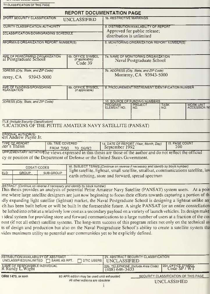
TY CLASSIFICATION OF THIS PAGE
REPORT DOCUMENTATION PAGELPORT SECURITY CLASSIFICATION UNCLASSIFIED 1b. RESTRICTIVE MARKINGS
CURITY CLASSIFICATION AUTHORITY
"CLASSIFICATION/DOWNGRADING SCHEDULE
3. DISTRIBUTION/AVAILABILITY OF REPORTApproved for public release;
distribution is unlimited
RFORMING ORGANIZATION REPORT NUMBER(S) 5. MONITORING ORGANIZATION REPORT NUMBER(S)
AME OF PERFORMING ORGANIZATIONal Postgraduate School
6b. OFFICE SYMBOL(if applicable)
Code 39
7a. NAME OF MONITORING ORGANIZATIONNaval Postgraduate School
DDRESS (City, State, and ZIP Code)
iterey, CA 93943-5000
7b. ADDRESS (City, State, and ZIP Code)
Monterey, CA 93943-5000
AME OF FUNDING/SPONSORINGRGANIZATION
8b. OFFICE SYMBOL(if applicable)
9. PROCUREMENT INSTRUMENT IDENTIFICATION NUMBER
DDRESS (City, State, and ZIP Code) 10. SOURCE OF FUNDING NUMBERSPROGRAMELEMENT NO.
PROJECTNO.
TASKNO.
WORK UNITACCESSION N(
ITLE (Include Security Classification)
PLICATIONS OF THE PETITE AMATEUR NAVY SATELLITE (PANSAT)
ERSONAL AUTHOR(S)»ert Andrew Payne Jr.
TYPE OF REPORT;ter s Thesis
13b. TIME COVEREDFROM ,7/9Q TO Q9/92
14. DATE OF REPORT (Year, Month, Day)
September 199215. PAGE COUNT
100
upplementary NOTATioifhe views expressed in this thesis are those of the author and do not reflect the official
cy or position of the Department of Defense or the United States Government.
COSATI CODES 18. SUBJECT TERMS (Continue on reverse if necessary and identify by block number)
light satellite, lightsat, small satellite, smallsat, communications satellite, lovELD GROUP SUB-GROUP
earth orbiting, store and forward, spread spectrum
-
—
ABSTRACT (Continue on reverse if necessary and identify by block number)
This thesis provides an analysis of potential Petite Amateur Navy Satellite (PANSAT) system users. At a poin
ime where large satellite designers are just now beginning to focus their efforts towards capturing a portion of thr
idly expanding light satellite (lightsat) market, the Naval Postgraduate School is designing a lightsat unlike an;
ch has been built before or will be built in the foreseeable future. A single PANSAT (or an entire constellation
be lofted into orbit at a relatively low cost as a secondary payload on a variety of launch vehicles. Its design make
i ideal system for providing store and forward communications to a large number of users at a fraction of the cos
nost (if not all other) satellite systems. The long-term success of this program relies not only on the technical as
ts of design and production but also on the Naval Postgraduate School's ability to create a satellite system tha
vides maximum utility to potential user communities yet to be explicitly defined.
)ISTRIBUTION/AVAILABIUTY OF ABSTRACTUNCLASSIFIED/UNLIMITED
[~JSAME AS RPT. [] DTIC USERS
21. ABSTRACT SECURITY CLASSIFICATION
UNCLASSIFIEDNAME OF RESPONSIBLE INDIVIDUAL 22b. TELEPHONEi/nc/ude/Area Code)
(408) 646-340322c, FFICE
ode 5
ORM 1473, 84 MAR 83 APR edition may be used until exhausted
All other editions are obsolete
SECURITY CLASSIFICATION OF THIS PAGE
UNCLASSIFIED
ABSTRACT
This thesis provides an analysis of potential Petite Amateur Navy Satellite
(PANSAT) system users. At a point in time where large satellite designers are just
now beginning to focus their efforts towards capturing a portion of the rapidly
expanding light satellite (lightsat) market, the Naval Postgraduate School is
designing a lightsat unlike any which has been built before or will be built in the
foreseeable future. A single PANSAT (or an entire constellation) can be lofted into
orbit at a relatively low cost as a secondary payload on a variety of launch vehicles.
Its design makes it an ideal system for providing store and forward communications
to a large number of users at a fraction of the cost of most (if not all other) satellite
systems. The long-term success of this program relies not only on the technical
aspects of design and production but also on the Naval Postgraduate School's ability
to create a satellite system that provides maximum utility to potential user
communities yet to be explicitly defined.
in

TABLE OF CONTENTS
I. INTRODUCTION 1
A. GENERAL 1
B. OBJECTIVES 2
C. PROBLEM STATEMENT 2
D. CURRENT PANSAT DESIGN 3
1. Hardware Configuration 3
2. Communications Parameters 3
3. Ground and User Stations 4
4. Security Considerations 4
E. RESEARCH QUESTIONS 5
1. General 5
2. Possible Design Modifications 5
F. SCOPE OF THESIS 6
II. BACKGROUND 7
A. WHY LIGHT SATELLITES? 7
1. Cost 7
2. Utility 8
3. Function 9
B. WHY PANSAT? 10
1. Overall Objectives 10
2. Engineering Objectives 11
3. Design Objectives 11
4. System Design Timeline Objectives 12
5. Funding Objectives 12
IV

DUDLEY KNOX LIBRARY
NAVAL POSTGRADUATE SCHOOLMONTEREY CA 93943-5101
C. OTHER UHF LIGHT SATELLITES .„„..... 13
1. Civilian 13
2. Military 15
III. POTENTIAL NON-MILITARY PANSAT APPLICATIONS 20
A. GENERAL 20
B. AMATEUR RADIO 20
1. A Brief History 20
2. Amateur Radio Satellite Users 22
3. Additional Amateur Radio Satellite User Contributions 23
C. AIRCRAFT SEARCH AND RESCUE 24
1
.
Search and Rescue Satellite Aided Tracking (SARSAT) 24
2. Search and Rescue Tracking - PANSAT 25
3. Conclusion 27
D. REMOTE FIELD SITE COMMUNICATIONS 29
E. THE DEPARTMENT OF AGRICULTURE 29
F. FEDERAL EMERGENCY MANAGEMENT AGENCY 30
IV. POTENTIAL MILITARY APPLICATIONS OF PANSAT 31
A. GENERAL 31
1. Use of Military Frequencies 31
2. Assumptions 31
3. Spread Spectrum Limitations 32
B. ARMY SPACE RELATED AGENCIES 32
1. ASTRO - Technological Demonstrations 33
2. ASI - Conceptual Demonstrations 33
3. ARSPACE - Performs Tactical Demonstrations 34
C. LIGHTSAT COMMUNICATIONS REQUIREMENTS 35
1. Fast Moving Combat Scenarios 36
2. Deployment of Special Teams 36
3. Civil Relief Operations 37

D. SPECIAL OPERATIONS UNITS 37
E. U.S. COAST GUARD 39
F. NAVAL SUPPORT FORCES ANTARCTICA 40
G. U.S. NAVAL ACADEMY 40
V. PROPOSED PANSAT MODIFICATIONS 41
A. GENERAL 41
B. BACKGROUND 42
C. MILITARY FREQUENCY APPROVAL 43
1. System Allocation 43
2. Frequency Assignment 44
D. PRELIMINARY RESULTS 44
1. General 44
2. Search and Rescue Systems 45
3. US Army LEO Satellite Systems 46
E. RECOMMENDED MODIFICATIONS 46
1. PANSAT System With No Modifications 47
2. Create an Emergency Location Rescue System (ELRS) 47
3. Provide Experimental Store and Forward Capability 49
4. Provide Experimental SOTM Capability 49
F. DESIGN LIMITATIONS 50
1. PANSAT Power Constraints 50
2. PANSAT Antenna Optimization 51
3. PANSAT Volume and Weight Restrictions 52
G. FUTURE CONSIDERATIONS 53
1
.
PANSAT with Modifications 53
2. PANSAT Follow-on Satellites at NPS 54
VI. CONCLUSIONS AND RECOMMENDATIONS 55
A. CONCLUSIONS 55
VI

B. RECOMMENDATIONS 57
1. Submit Request for Military Frequency Use 57
2. Conduct Technical Investigations 58
3. Coordinate ELRS Project 59
4. Increase Involvement with Military Space Agencies 59
APPENDIX A: PANSAT LAUNCH VEHICLES 61
APPENDIX B: AMATEUR RADIO LINK LAYER PROTOCOL 74
APPENDIX C: SEARCH AND RESCUE SATELLITE (SARSAT) 78
LIST OF REFERENCES 83
VITA 87
INITIAL DISTRIBUTION LIST 88
Vll
ACKNOWLEDGEMENTS
Numerous individuals assisted me in completing this thesis through their advice, encouragement,
technical expertise and proofreading skills. To each of you who so generously shared your time and made this
thesis possible, many thanks.
To CDR Randy Wight, my thesis advisor, and Professor Ed Euler, my second reader: thank-
you for your unfailing support and technical expertise; for keeping me on track and on time; and for always
being available whenever I needed you.
To Professor Rudy Panholzer and Dan Sakoda: thank-you for taking the time to stop, listen
and motivate me in the face of many obstacles; for believing in me; and for sharing my enthusiasm and vision
for making PANSAT a larger contribution to the military.
To Dr. Bill Howard: thank-you for listening and for reaching out to make a difference by supporting
me in my quest to make PANSAT a viable, experimental satellite for use by the United Sates Army.
To COL. David Jackson and Ron Dickennan of ASTRO: thank-you for your visionary quest
to provide the best education possible at NPS; for fostering maximum growth and development for the future
of Army Space; and for including me in that future.
To Bob Steel, Mike Freeman, Ray Crough, Bob Bruninga and Chris McCormick:
thank-you for your friendship and for so freely sharing your time, energy and resources in support of nearly
every aspect of this thesis. Your contributions were invaluable to this work.
To Brian Dean, Gwyn Reedy, Walter Daniels and Bill Foster, thank-you for your
friendship, ideas and for your adamant desire to create lasting and significant contributions for everyone.
To MAJ Mary Kaura, MAJ David Quals and CPT. J. C. Chin: thank-you for assisting me in
bridging the gap between academics and "the real world" - between graduate student and Army officer.
To Paul Newcomb, Brain Schreve, Wayne Fornwalt, Bob Buaas, Bill Cook,
Warren Chu, Richard Lancaster and Carol Causy: thank-you for educating me in your own field
of expertise. Much of your contribution lives in the future of this and follow-on projects.
To my Father, Robert (St.), Linda Payne and Dana Estrada: thankyou for your unfailing
patience, understanding and love; and for supporting me in making this work a larger contribution.
And finally to my lovely mother, Anna Dean (deceased): thank-you for always encouraging me to
"Follow My Dreams" - because of you - 1 always will.
vin
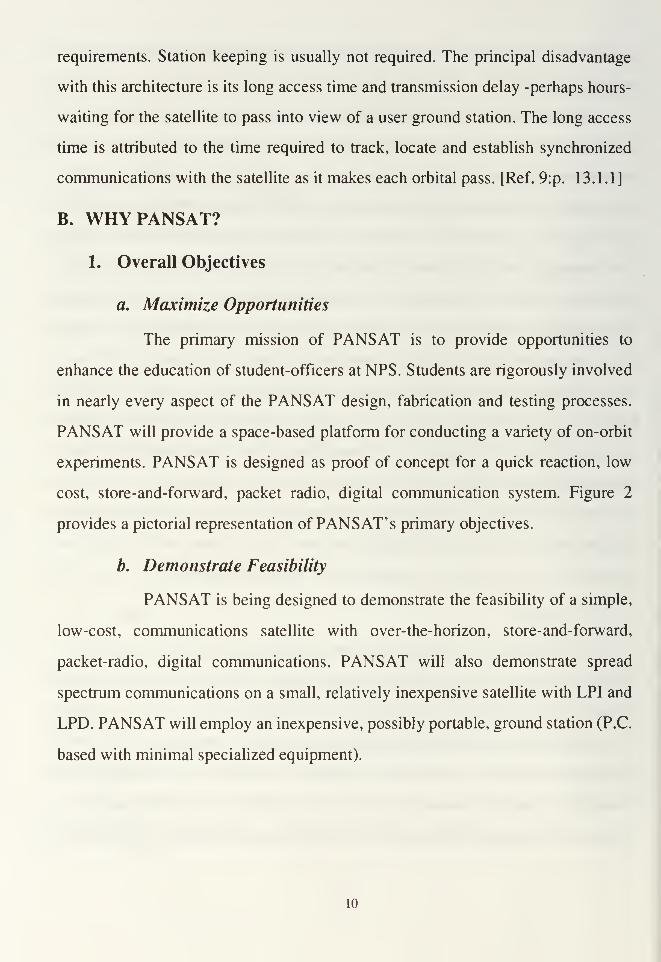
I. INTRODUCTION
A. GENERAL
The Naval Postgraduate School (NPS) is currently developing the Petite
Amateur Navy Satellite (PANSAT) in collaboration with the amateur radio
community. PANSAT is an experiment in low-earth orbit (LEO), small satellite
communications. It is a proof of concept design for digital, spread spectrum, store-
and-forward, packet radio, personal computer based satellite communications.
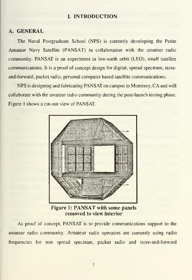
NPS is designing and fabricating PANSAT on campus in Monterey, CA and will
collaborate with the amateur radio community during the post-launch testing phase.
Figure 1 shows a cut-out view of PANSAT.
Figure 1: PANSAT with some panels
removed to view interior
As proof of concept, PANSAT is to provide communications support to the
amateur radio community. Amateur radio operators are currently using radio
frequencies for non spread spectrum, packet radio and store-and-forward
communications. Spread spectrum modulation provides the advantages of Low
Probability of Intercept (LPI), Low Probability of Detection (LPD), resistance to
jamming, and low probability of interference (to and from other users in the band).
An example of military application to this type of communication would be the
transmission of logistical requests from the sands of Saudi Arabia to the United
States (as done during Operation Desert Shield/Desert Storm).
PANSAT' s focus could be enhanced if a need and capability which extended
beyond the amateur radio community could be established. The major issue for this
thesis involves identifying potential PANSAT system users and comparing their
communication requirements with the current PANSAT design approach to
determine what changes to PANSAT would be required to support these users.
Other factors such as increased satellite cost and complexity must be quantified
before implementing any recommended changes.
B. OBJECTIVES
The primary objective of this thesis was to define potential operational uses for
the NPS's PANSAT. This objective was accomplished by reviewing the current
PANSAT design and comparing and contrasting projected capabilities with
potential military and non-military PANSAT system users. The secondary objective
was to recommend changes to the current design concept and/or possible follow-on
NPS satellites. This objective was accomplished by examining the user requested
capabilities which could not be fulfilled with the current PANSAT design.
C. PROBLEM STATEMENT
Given that the design, testing, deployment and operation of PANSAT's current
configuration is successful, what type of utility does PANSAT provide for what
types of users? If specific modifications to the current design are made to
accommodate other potential users, who are those users, what changes could be
made, and what are the possible trade-offs for making such changes?
D. CURRENT PANSAT DESIGN
1. Hardware Configuration
PANSAT is a light satellite (lightsat) designed to weigh 150 lbs. It is 19" in
diameter and 18.5" high in the longitudinal axis. This size will enable PANSAT to
be launched by one of the Space Shuttle's free flyer Get Away Special (GAS) launch
canisters. Because of its small size, PANSAT could also be launched by Pegasus,
Scout, and as a secondary payload by Delta II, Titan II and Taurus launch vehicles.
See Appendix A for a summary of possible U.S. military, PANSAT launch vehicles.
PANSAT is a 26-sided polyhedron with 18 square panels (17 solar panels and
one launch vehicle interface) and eight triangular panels (four of which are antenna
mounts and four of which may be used for experiments). It will not have an attitude
control system and will slowly tumble. As such, the satellite's antennas must be
omni-directional. Because antenna orientations are not known, the antennas are
circular polarized.
2. Communications Parameters
PANSAT will serve as a store-and-forward data relay experiment for NPS
and other selected users in the amateur radio community. It will utilize spread
spectrum modulation as a proof of concept for small satellite communications. It
will be able to operate with simple Bipolar Phase Shift Keying (BPSK) modulation
as a backup in case of a spread spectrum modulation system failure.
PANSAT will operate in a full-duplex mode, allowing simultaneous, two-
way signalling. This type of operation maximizes user-satellite interaction speed
and has the advantage of being able to provide communication in both directions at
once. [Ref. l:p. 8-17]
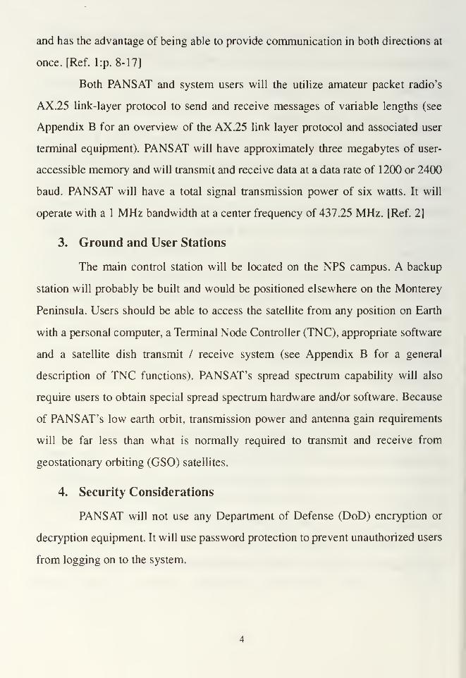
Both PANSAT and system users will the utilize amateur packet radio's
AX.25 link-layer protocol to send and receive messages of variable lengths (see
Appendix B for an overview of the AX.25 link layer protocol and associated user
terminal equipment). PANSAT will have approximately three megabytes of user-
accessible memory and will transmit and receive data at a data rate of 1200 or 2400
baud. PANSAT will have a total signal transmission power of six watts. It will
operate with a 1 MHz bandwidth at a center frequency of 437.25 MHz. [Ref. 2]
3. Ground and User Stations
The main control station will be located on the NPS campus. A backup
station will probably be built and would be positioned elsewhere on the Monterey
Peninsula. Users should be able to access the satellite from any position on Earth
with a personal computer, a Terminal Node Controller (TNC), appropriate software
and a satellite dish transmit / receive system (see Appendix B for a general
description of TNC functions). PANSAT's spread spectrum capability will also
require users to obtain special spread spectrum hardware and/or software. Because
of PANSAT's low earth orbit, transmission power and antenna gain requirements
will be far less than what is normally required to transmit and receive from
geostationary orbiting (GSO) satellites.
4. Security Considerations
PANSAT will not use any Department of Defense (DoD) encryption or
decryption equipment. It will use password protection to prevent unauthorized users
from logging on to the system.
E. RESEARCH QUESTIONS
1. General
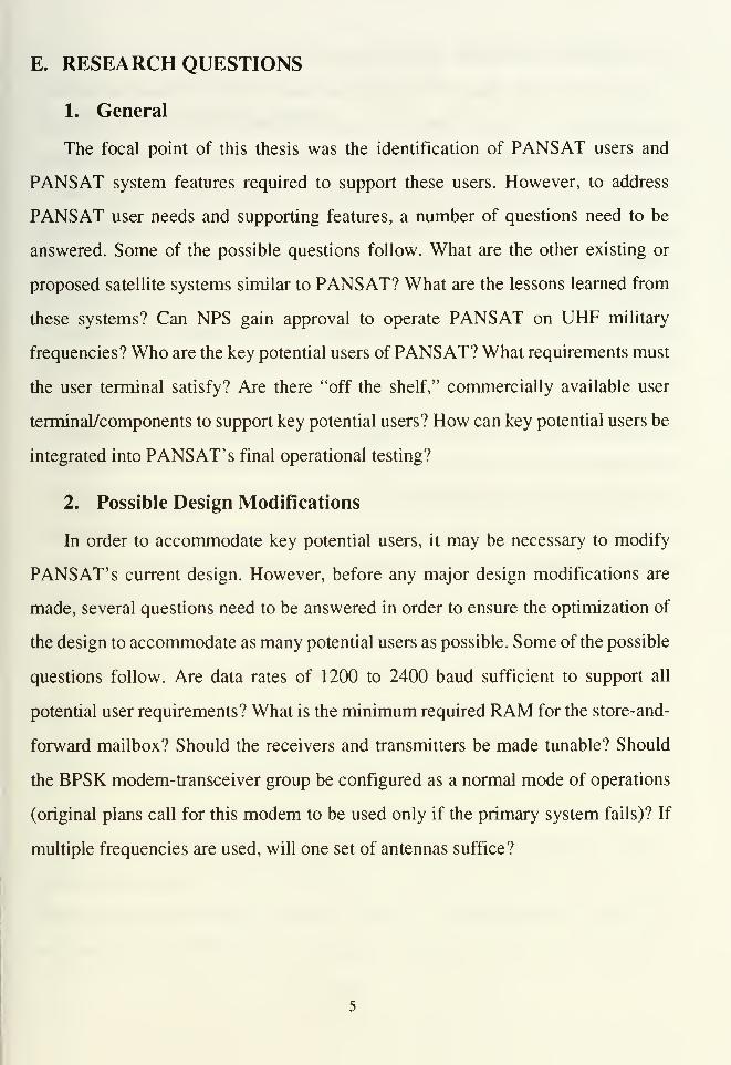
The focal point of this thesis was the identification of PANSAT users and
PANSAT system features required to support these users. However, to address
PANSAT user needs and supporting features, a number of questions need to be
answered. Some of the possible questions follow. What are the other existing or
proposed satellite systems similar to PANSAT? What are the lessons learned from
these systems? Can NPS gain approval to operate PANSAT on UHF military
frequencies? Who are the key potential users of PANSAT? What requirements must
the user terminal satisfy? Are there "off the shelf," commercially available user
terminal/components to support key potential users? How can key potential users be
integrated into PANSAT' s final operational testing?
2. Possible Design Modifications
In order to accommodate key potential users, it may be necessary to modify
PANSAT' s current design. However, before any major design modifications are
made, several questions need to be answered in order to ensure the optimization of
the design to accommodate as many potential users as possible. Some of the possible
questions follow. Are data rates of 1200 to 2400 baud sufficient to support all
potential user requirements? What is the minimum required RAM for the store-and-
forward mailbox? Should the receivers and transmitters be made tunable? Should
the BPSK modem-transceiver group be configured as a normal mode of operations
(original plans call for this modem to be used only if the primary system fails)? If
multiple frequencies are used, will one set of antennas suffice?
F. SCOPE OF THESIS
The scope of this thesis was to determine potential user communities (military
and non-military) of the NPS PANSAT communication system and their associated
communication requirements. Areas for investigation included projected users of
current commercial and military communications light satellite systems (in use or
under development), applicable military and government agencies demonstrating an
interest in capabilities offered by the PANSAT communication system,
identification of key potential user(s) and required modification(s) to PANSAT'
s
current design to support these user(s). Chapter II discusses lightsats with respect to
PANSAT and other commercial and military lightsat systems (past, present and
future). Chapter III addresses possible non-military user applications for PANSAT
and proposes a new method for rapidly locating downed airmen. Chapter IV
addresses a variety of military user applications for PANSAT, while Chapter V
addresses PANSAT modifications required to support user applications suggested
in Chapters III and IV. Finally, Chapter VI summarizes thesis conclusions and
provides recommendations for implementing modifications proposed in Chapter V.

n. BACKGROUND
A. WHY LIGHT SATELLITES?
1. Cost
A new trend is emerging in both the military and the commercial satellite
market. This trend is driven by many factors: a need to lower up-front development
cost and a need to reduce satellite launch and operations cost. Current U.S. military
satellites are too costly to build and launch in an era of tight budgets. According to
U.S. Navy Vice Admiral Richard Macke, director of Command, Control,
Communication and Computers (C4) for the Joint Chiefs of Staff (JCS) and former
Commander of the U.S. Naval Space Command:
We've got to do space cheaper. One billion dollars for a satellite can't be
affordable. One hundred million dollars for a satellite can't be affordable.
Military planners may have to settle for fielding satellites with less capability
or with less reliability... Moving to small satellites may also be in the cards.
Smaller may not be the whole answer, but it's a part. [Ref. 3:p. 2]
The cost required to build, launch and operate a small, medium and large
geostationary satellite are $89, $135 and $248 million, respectively, according to
James Stuart (a light satellite consultant in Boulder, CO). The average small satellite
generally weighs between 500 pounds and 1000 pounds and costs from several
million dollars to less than $20 million dollars. [Ref. 4:p. 6] The total system cost
for placing a small constellation of LEO lightsats in orbit could cost less than
launching and maintaining a single geostationary satellite.
Another significant advantage of lightsats over their heavier counter-parts is
that they may be mass produced, thus further reducing satellite system costs. "Many
small satellite builders believe the industry is on the verge of mass production of
frames with interchangeable payloads." [Ref. 6:p. 7] Reducing the satellite's size
and placing it into LEO not only lowers production and launch cost but reduces the

power required to transmit and receive from the satellite, when compared to a
geostationary satellite. This power reduction is due to the shorter distance a signal
must propagate to reach a lightsat in LEO (500-1000 km for a LEO satellite vs.
40,000 km for a geostationary satellite). Along with reduced transmit power comes
a reduction in the size and power of ground station equipment required to
communicate with the satellite. These reductions can result in significant savings to
satellite system users and operators.
Many hurdles remain before lightsats become common place in the satellite
market. Small satellites will not proliferate in Europe, for example, without a
suitable rocket, and rocket builders will not invest in new launchers without proof
of adequate demand [Ref. 5:p. 6]. Today, most lightsats ride into space as a
secondary payload, and are placed into a predefined orbit consistent with the
primary payload' s mission. While piggy-backing as a secondary payload can
substantially reduce launch costs, predefined orbits are generally not optimized for
the lightsat. Mass and volume restrictions placed upon the lightsat as a secondary
payload can further complicate satellite design and development. Massive, potential
cost savings will be a key factor in overcoming today's obstacles to fully realizing
the benefits available from lightsats.
2. Utility
Due to reduced weight and volume, a small constellation of communication
lightsats could be placed into orbit by a variety of launch vehicles, rapidly providing
increased communications capability to any location in the world. This scenario
assumes that a constellation of lightsats are preconfigured for contingency purposes.
These lightsats would always be on standby to provide or augment regional
communications in the event of natural disasters, military special operations or other
emergency type situations.These lightsats would be stored fully integrated with their
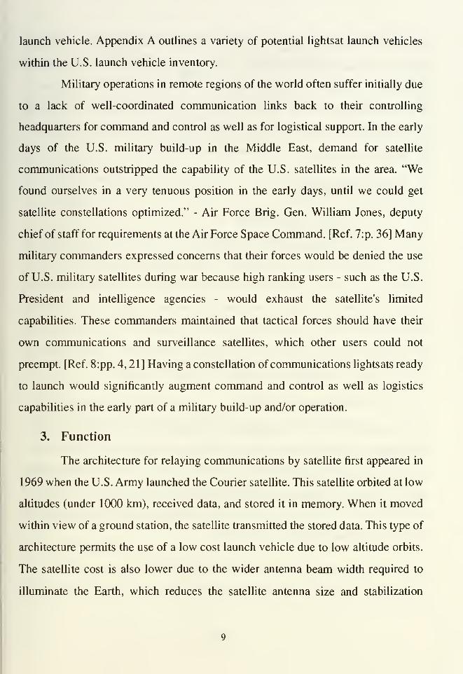
launch vehicle. Appendix A outlines a variety of potential lightsat launch vehicles
within the U.S. launch vehicle inventory.
Military operations in remote regions of the world often suffer initially due
to a lack of well-coordinated communication links back to their controlling
headquarters for command and control as well as for logistical support. In the early
days of the U.S. military build-up in the Middle East, demand for satellite
communications outstripped the capability of the U.S. satellites in the area. "We
found ourselves in a very tenuous position in the early days, until we could get
satellite constellations optimized." - Air Force Brig. Gen. William Jones, deputy
chief of staff for requirements at the Air Force Space Command. [Ref. 7:p. 36] Many
military commanders expressed concerns that their forces would be denied the use
of U.S. military satellites during war because high ranking users - such as the U.S.
President and intelligence agencies - would exhaust the satellite's limited
capabilities. These commanders maintained that tactical forces should have their
own communications and surveillance satellites, which other users could not
preempt. [Ref. 8:pp. 4, 21] Having a constellation of communications lightsats ready
to launch would significantly augment command and control as well as logistics
capabilities in the early part of a military build-up and/or operation.
3. Function
The architecture for relaying communications by satellite first appeared in
1969 when the U.S. Army launched the Courier satellite. This satellite orbited at low
altitudes (under 1000 km), received data, and stored it in memory. When it moved
within view of a ground station, the satellite transmitted the stored data. This type of
architecture permits the use of a low cost launch vehicle due to low altitude orbits.
The satellite cost is also lower due to the wider antenna beam width required to
illuminate the Earth, which reduces the satellite antenna size and stabilization
requirements. Station keeping is usually not required. The principal disadvantage
with this architecture is its long access time and transmission delay -perhaps hours-
waiting for the satellite to pass into view of a user ground station. The long access
time is attributed to the time required to track, locate and establish synchronized
communications with the satellite as it makes each orbital pass. [Ref. 9:p. 13.1.1]
B. WHYPANSAT?
1. Overall Objectives
a. Maximize Opportunities
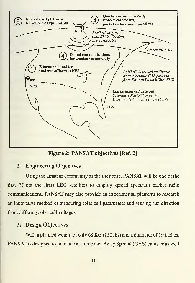
The primary mission of PANSAT is to provide opportunities to
enhance the education of student-officers at NPS. Students are rigorously involved
in nearly every aspect of the PANSAT design, fabrication and testing processes.
PANSAT will provide a space-based platform for conducting a variety of on-orbit
experiments. PANSAT is designed as proof of concept for a quick reaction, low
cost, store-and-forward, packet radio, digital communication system. Figure 2
provides a pictorial representation of PANSAT' s primary objectives.
b. Demonstrate Feasibility
PANSAT is being designed to demonstrate the feasibility of a simple,
low-cost, communications satellite with over-the-horizon, store-and-forward,
packet-radio, digital communications. PANSAT will also demonstrate spread
spectrum communications on a small, relatively inexpensive satellite with LPI and
LPD. PANSAT will employ an inexpensive, possibly portable, ground station (P.C.
based with minimal specialized equipment).
10
Space-based platform
for on-orbit experiments
©Quick-reaction, low cost,
store-and-forward,
packet radio communications
PANSAT launched on Shuttle
as an ejectable GAS payload
from Eastern Launch Site (ELS)
Can be launched as Scout
Secondary Payload or other
Expendable Launch Vehicle (ELV)
Figure 2: PANSAT objectives [Ref. 2]
2. Engineering Objectives
Using the amateur community as the user base, PANSAT will be one of the
first (if not the first) LEO satellites to employ spread spectrum packet radio
communications. PANSAT may also provide an experimental platform to research
an innovative method of measuring solar cell parameters and sensing sun direction
from differing solar cell voltages.
3. Design Objectives
With a planned weight of only 68 KG (150 lbs) and a diameter of 19 inches,
PANSAT is designed to fit inside a shuttle Get-Away Special (GAS) canister as well
11
as numerous other Expendable Launch Vehicles (ELV). Additionally, it and will
demonstrate a low-cost design using military and selected radiation-hard
components.
PANSAT's communication payload specifications require PANSAT to
operate in a full duplex, direct sequence spread spectrum mode with a center
frequency of 437.25 MHz and data rates of 1200 and 2400 baud or higher.
4. System Design Timeline Objectives
PANSAT has several milestones to facilitate the timely development and
integration of its various subsystems into a cohesive, well functioning satellite. To
prepare for a proposed, late 1995 launch date, the following system design time line
has been established:
• Oct. 1992 - System Design Review• Feb. 1993 - Finalize Design Plan
• Mar. 1993 - Critical Design Review• Mar. 1994 - Begin Integration Testing
• Apr. 1995 - Hardware Flight Delivery Date
Design modifications discussed in Chapter V of this thesis must be further reviewed
to determine absolute power, weight, volume and communication systems
compatibility with PANSAT prior to the February 1993, the design finalization
review.
5. Funding Objectives
PANSAT is a low cost program on a limited budget. The Army Space,
Technology and Research Office (ASTRO) is supporting PANSAT and several other
academic efforts at NPS. PANSAT has received approximately $150,000 in funding
to date and has a total projected future funding of $418,000 from ASTRO and NPS.
Implementing modifications suggested in Chapter V of this thesis may require
additional sponsors and/or funding sources.
12

C. OTHER UHF LIGHT SATELLITES
1. Civilian
The scramble to build lightsats and related systems represents a shift by the
space industry to no longer ignore this potentially lucrative field.
As the customers emerge for small satellites, we see the big guys trying to
move in and build them, said Jeff Manber, Executive director of the Space
Foundation, Washington. Jill Stern, a partner with the Washington law firm
Miller and Holbrooke said... what was once seen as an off-beat garage type of
business by amateurs making tiny things has now changed. [Ref. 4:pp. 6,12]
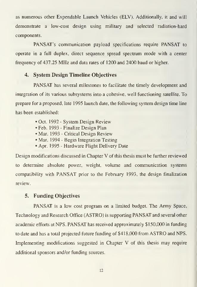
Table 1 lists the most recently proposed commercial communication
satellite systems. These systems (often referred to as "Big Leo" systems for the large
numbers of satellites employed in multiple orbital planes in low to medium altitude
orbits) are designed to open the way for handsets that would be only slightly more
powerful than current cellular telephones.
Of the systems noted in Table 1 , Aries, Orbcomm and Starsys will use a
simple repeater/bent pipe configuration while Globalstar, Odessy, and Ellipso will
use Code-Division-Multiple-Access (CDMA) spread spectrum as well as simple
repeate^ent pipe configurations.
They would link a mobile user with a gateway Earth terminal that would
connect into a public telephone system to reach the intended recipient. A user
handset would transmit to the satellite at L-Band (1.6 GHz) and receive at S-
band (2.5 GHz). Communications between satellite and gateway stations
would be at C-band (5-66 GHz) or Ka band (30 GHz). [Ref. 10:p. 61]
The major difference between Iridium and other competing systems is that the
Iridium system will have cross links between satellites and thus be capable of
bypassing terrestrial telephone and cable services, linking the calling party to the
gateway station nearest the party being called.
13
TABLE 1: PROPOSED COMMERCIAL "BIG LEO" SYSTEMS
Developer Orbit #Sats Inc. Purpose
Constellation Commu-nication Corp's "Aries"
[Ref. 10:pp. 60,61]
635m 48 90° World wide, simple
repeater/bent-pipe commu-nications (uses 4 orbital
planes)
Ellipsat's "Ellipso"
[Ref. 10:pp. 60, 611
HEO 24 63.4° World wide, spread spec-
trum (CDMA) communi-
cations satellite in a Highly
Elliptical Orbit (HEO)
Leosat's "Starsys"
[Ref. ll:p. 2]
LEO 24 ? World wide, relay of short
messages
Loral & Qualcomm's
"Globalstar"
[Ref. 4:pp. 6,12]
750 nm 24-48 50° World wide, spread spec-
trum (CDMA) communi-
cations satellite; can locate
a user to within 1000 feet
Motorola's "Iridium"
[Ref. 12:pp. 1,36]
500 nm 66 90° World wide, mobile, public
telephone service, TDMA,relay stations on L-band
Orbital's "Orbcomm"
and "Starnet"
[Ref. 13:pp. 6,10]
LEO 24 ? World wide relay of short
messages such as distress
signals
Russia's "SmolSat"
[Ref. 14:p. 15]
LEO 36 ? World wide, store-and-for-
ward medical information
TRW's "Odessy"
[Ref. 10:pp. 60,61]
6,400
nm12 55° World wide, spread spec-
trum (CDMA) in MediumEarth Orbit (MEO)
The frequency spectrum for this new kind of communications satellite
service was authorized at the 1992 World Administrative Radio Conference (WARC-
92) in Spain. WARC-92 authorized two frequency spectrums centered at 1.6 GHz.
(L-band) and 2.5 GHz. (S-band) for systems capable of providing both voice and
high speed data service. The conference also authorized a frequency spectrum for
14

little LEOs in the very high frequency (VHF) and ultra high frequency (UHF) bands.
[Ref. 10:p. 60]
2. Military
At the direction of the Defense Advanced Research Projects Agency
(DARPA) two UHF light satellite systems were developed, flown and tested. Each
of these systems were built by Defense Systems Incorporated (DSI). These systems
each proved the functional utility of the lightsat concept for the military in a variety
of ways. The first of these two systems was the Multiple Access Communications
Satellite (MACSAT) and the second was Microsat.
a. MACSAT
In May, 1990, two 136 pound MACSATs were launched by a scout
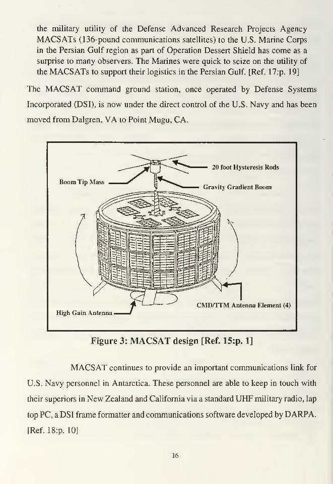
ELV at Vandenburg AFB into a 400 nautical mile, polar orbit. Figure 3 depicts a
MACSAT in its deployed configuration. MACSAT records data or imagery
messages from a transmitting station on the ground with a 1200 or 2400 baud data
rate and rebroadcast the message later when the spacecraft passed over the recipient.
Even small Multi-Spectral-Image (MSI) files (<32 kilobytes) were successfully
transmitted to the satellite (uplinked) and received from the satellite (down linked)
during system tests. MACSAT is stabilized by a 20 foot gravity gradient boom with
a five pound tip mass [Ref. 15:pp. 161-230]. With 1.2 megabytes of mailbox RAM,
MACSAT provides store-and-forward digital data communications to a variety of
military users.
The Marines used MACSAT 's store-and-forward capability during
Operation Desert Storm for the ordering of aircraft parts. [Ref. 16:p. 12] Two
MACSAT user ground terminals were positioned in the Middle East and one in
Spain. In a November 1990 interview, Dr. William Howard, former Technical
Director of the Naval Space Command, stated that
15
the military utility of the Defense Advanced Research Projects Agency
MACSATs (136-pound communications satellites) to the U.S. Marine Corps
in the Persian Gulf region as part of Operation Dessert Shield has come as a
surprise to many observers. The Marines were quick to seize on the utility of
the MACSATs to support their logistics in the Persian Gulf. [Ref. 17:p. 19]
The MACSAT command ground station, once operated by Defense Systems
Incorporated (DSI), is now under the direct control of the U.S. Navy and has been
moved from Dalgren, VA to Point Mugu, CA.
Boom Tip Mass
20 foot Hysteresis Rods
Gravity Gradient Boom
CMD/TTM Antenna Element (4)
High Gain Antenna
Figure 3: MACSAT design [Ref. 15:p. 1]
MACSAT continues to provide an important communications link for
U.S. Navy personnel in Antarctica. These personnel are able to keep in touch with
their superiors in New Zealand and California via a standard UHF military radio, lap
top PC, a DSI frame formatter and communications software developed by DARPA.
[Ref. 18:p. 10]
16

b. Microsat
Microsats are a group of seven lightsats built by Defense Systems Inc.
for DARPA to demonstrate the use of small, UHF communications satellites for the
U.S. military in tactical land and naval operations. Figure 4 shows the Microsat
constellation in a polar orbit.
Figure 4: Microsat Logo and Constellation [Ref. 20]
Plans had called for the seven satellites to be spaced evenly along their
orbit so any given location in central Europe would have continuous coverage.
Ideally, each Microsat would form UHF voice and data "bent pipe links," providing
real time relay between two users within the satellite's view. The Microsats used an
analog system for voice communications and a digital regenerative transponder for
messages, facsimile and low data rate images. Each Microsat had 32 kilobytes of
RAM for limited store-and-forward purposes. [Ref. 19:p. 3] Each satellite was spin-
17
stabilized at three revolutions per minute and was also equipped with a cold gas
thrust/maneuver system for initial positioning and station keeping operations.
In July, 1991, a Pegasus carried these seven, 50 pound satellites into a
near polar orbit inclined at 81 degrees. The Pegasus payload faring malfunctioned,
causing the lightsats to deploy far short of their intended 389 nautical miles LEO
orbit. The orbit achieved ranged from 192 to 245 nautical miles. Due to the Pegasus
malfunction, the lifetime of the Microsat constellation was reduced from three years
to six months. At the planned orbit, the Microsats would have been arranged to
provide nearly continuous communications for designated users. As one Microsat
moved out of a user's range, another would have moved into place, with a one
minute gap between coverage. [Ref. 21:pp. 4, 21]
Even though the orbit of each Microsat eventually decayed, DARPA
successfully tested the transponders and the limited store-and-forward capabilities
of the Microsat constellation with the Air Force, Army and Navy forces in the
United States and Panama.
c. Future U.S. Military Lightsats
The U.S. Navy and Army each plan to field lightsat satellites later this
decade to provide extra communications in tactical military situations as diverse as
a submarine beneath the Arctic or a land battle in a remote site. Rear Admiral
Thomas Betterton, the former Assistant Commander for Space and Technology at
the Navy's Space and Naval Warfare System's Command, said that
the Navy plans to field a constellation of six UHF satellites in polar orbits, and
the Army is developing a small EHF communications satellite that could be
orbited quickly during a war... The Navy's so-called Arcticsat system is
intended to provide satellite communications for Navy ships and submarines
operating north of 70 degrees latitude. [Ref. 22:p. 22]
18
Areas north of 70° latitude can not be easily ranged with GSO satellites, making the
smaller, polar-orbiting LEO satellites an attractive "gap filler" to provide
communications to Arctic bound U.S. Navy submarines.
Currently being designed for the Army is the Multiple Pass UHF
Beyond Line of Sight (MUBL) satellite system. MUBL is a spread spectrum, bent
pipe satellite system with satellites in 400 nautical mile orbits. This system will use
multiple communication paths via ground-based repeaters and space-based relays.
These projects will allow DARPA to assess the usefulness of small
satellites for augmenting conventional large communications satellites and to
provide the capacity to handle surges in communication requirements.
19
III. POTENTIAL NON-MILITARY PANSAT APPLICATIONS
A. GENERAL
Current PANSAT designs call for operations only on the assigned amateur
frequency of 437.25 MHz. The use of amateur radio frequencies is governed by a
complex hierachy of rules and regulations.
By FCC regulation, no use is to be made of amateur frequency bands by any
business, government agency or group other than duly licensed amateurs.
These regulations are made to protect AMSAT's (Radio Amateur Satellite
Corporation) use of assigned frequency bands. AMSAT can allow other users
if system design includes AMSAT inputs. [Ref. 23:pp. 3,4]
Rules and regulations directed at the amateur satellite service are attributed in part
to the International Telecommunications Union (ITU), the Federal Communications
Commission (FCC) and the International Amateur Radio Union (IARU). ITU
member nations meet aperiodically at World Administrative Radio Conferences
(WARCs) to consider changes to existing regulations. PANSAT system users must
possess an Amateur Extra Class operator license and be in compliance with all
appropriate rules and regulations. [Ref. 24:p. F-l] Accordingly, any government
employee transmitting over PANSAT' s assigned amateur frequencies must be a
licensed amateur radio operator. A possible exception to this rule is the use of
PANSAT for civil emergency purposes. Additionally, these rules and regulations
prohibit the use of amateur frequencies for non-emergency military or commercial
purposes.
B. AMATEUR RADIO
1. A Brief History
Around 1 9 1 4, the American Amateur Radio League (AARL) was organized
to establish routes of amateur radio communication and serve the public interest
20
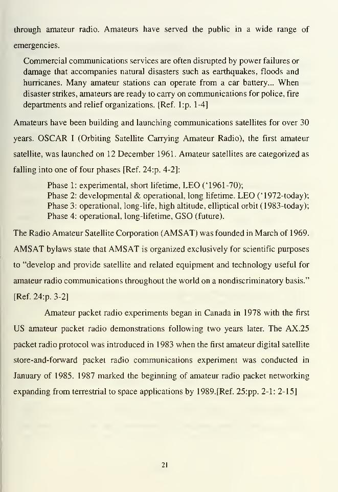
through amateur radio. Amateurs have served the public in a wide range of
emergencies.
Commercial communications services are often disrupted by power failures or
damage that accompanies natural disasters such as earthquakes, floods and
hurricanes. Many amateur stations can operate from a car battery... Whendisaster strikes, amateurs are ready to carry on communications for police, fire
departments and relief organizations. [Ref. l:p. 1-4]
Amateurs have been building and launching communications satellites for over 30
years. OSCAR I (Orbiting Satellite Carrying Amateur Radio), the first amateur
satellite, was launched on 12 December 1961. Amateur satellites are categorized as
falling into one of four phases [Ref. 24:p. 4-2]:
Phase 1: experimental, short lifetime, LEO ('1961-70);
Phase 2: developmental & operational, long lifetime. LEO ('1972-today);
Phase 3: operational, long-life, high altitude, elliptical orbit (1983-today);
Phase 4: operational, long-lifetime, GSO (future).
The Radio Amateur Satellite Corporation (AMSAT) was founded in March of 1969.
AMSAT bylaws state that AMSAT is organized exclusively for scientific purposes
to "develop and provide satellite and related equipment and technology useful for
amateur radio communications throughout the world on a nondiscriminatory basis."
[Ref. 24:p. 3-2]
Amateur packet radio experiments began in Canada in 1978 with the first
US amateur packet radio demonstrations following two years later. The AX.25
packet radio protocol was introduced in 1983 when the first amateur digital satellite
store-and-forward packet radio communications experiment was conducted in
January of 1985. 1987 marked the beginning of amateur radio packet networking
expanding from terrestrial to space applications by 1989. [Ref. 25:pp. 2-1:2-15]
21
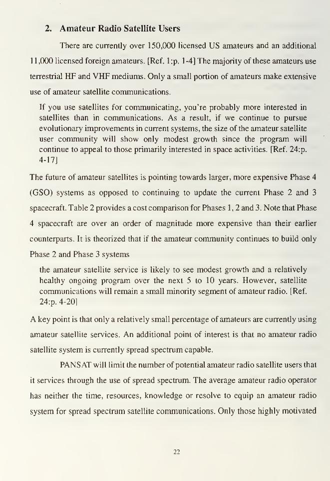
2. Amateur Radio Satellite Users
There are currently over 150,000 licensed US amateurs and an additional
1 1 ,000 licensed foreign amateurs. [Ref. 1 :p. 1 -4] The majority of these amateurs use
terrestrial HF and VHF mediums. Only a small portion of amateurs make extensive
use of amateur satellite communications.
If you use satellites for communicating, you're probably more interested in
satellites than in communications. As a result, if we continue to pursue
evolutionary improvements in current systems, the size of the amateur satellite
user community will show only modest growth since the program will
continue to appeal to those primarily interested in space activities. [Ref. 24:p.
4-17]
The future of amateur satellites is pointing towards larger, more expensive Phase 4
(GSO) systems as opposed to continuing to update the current Phase 2 and 3
spacecraft. Table 2 provides a cost comparison for Phases 1 , 2 and 3. Note that Phase
4 spacecraft are over an order of magnitude more expensive than their earlier
counterparts. It is theorized that if the amateur community continues to build only
Phase 2 and Phase 3 systems
the amateur satellite service is likely to see modest growth and a relatively
healthy ongoing program over the next 5 to 10 years. However, satellite
communications will remain a small minority segment of amateur radio. [Ref.
24:p. 4-20]
A key point is that only a relatively small percentage of amateurs are currently using
amateur satellite services. An additional point of interest is that no amateur radio
satellite system is currently spread spectrum capable.
PANSAT will limit the number of potential amateur radio satellite users that
it services through the use of spread spectrum. The average amateur radio operator
has neither the time, resources, knowledge or resolve to equip an amateur radio
system for spread spectrum satellite communications. Only those highly motivated
22
amateurs interested in experimenting with a spread spectrum satellite system will
have the determination to undertake such a project.
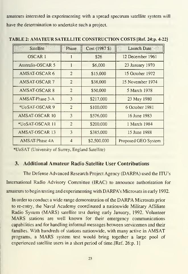
TABLE 2: AMATEUR SATELLITE CONSTRUCTION COSTS fRef. 24:p. 4-22]
Satellite Phase Cost (1987 $) Launch Date
OSCAR 1 1 $26 12 December 1961
Australis-OSCAR 5 1 $6,000 23 January 1970
AMSAT-OSCAR 6 2 $15,000 15 October 1972
AMSAT-OSCAR 7 2 $38,000 15 November 1974
AMSAT-OSCAR 8 2 $50,000 5 March 1978
AMSAT-Phase 3-A 3 $217,000 23 May 1980
HJoSAT-OSCAR 9 2 $100,000 6 October 1981
AMSAT-OSCAR 10 3 $576,000 16 June 1983
*UoSAT-OSCAR 1
1
2 $200,000 1 March 1984
AMSAT-OSCAR 13 3 $385,000 15 June 1988
AMSAT-Phase 4A 4 $2,500,000 Proposed GEO System
*UoSAT (University of Surrey, England Satellite)
3. Additional Amateur Radio Satellite User Contributions
The Defense Advanced Research Project Agency (DARPA) used the ITU's
International Radio Advisory Committee (IRAC) to announce authorization for
amateurs to begin testing and experimenting with DARPA's Microsats in early 1992.
In order to conduct a wide range demonstration of the DARPA Microsats prior
to re-entry, the Naval Academy coordinated a nationwide Military Affiliate
Radio System (MARS) satellite test during early January, 1992. Volunteer
MARS stations are well known for their emergency communications
capabilities and for handling informal messages between servicemen and their
families. With hundreds of stations nationwide, with many active in AMSATprograms, a MARS system test would bring together a large pool of
experienced satellite users in a short period of time.[Ref. 26:p. 1]
23

As a result, almost all the successful Microsat experiments were performed by
amateur radio operators. All MARS frequencies are in the military band. Having an
experimental DoD satellite operating in the military band does not necessarily
prevent amateur radio satellite enthusiast from making use of these systems.
C. AIRCRAFT SEARCH AND RESCUE
The National Aviation Safety Management Office is contained within the
Bureau of Land Management. A prime concern of the National Aviation Safety
Manager is the timely rescue of downed aircraft survivors.
1. Search and Rescue Satellite Aided Tracking (SARSAT)
SARSAT receivers (flown on two Russian Cosmos satellites and the
National Oceanographic and Atmospheric Administration's NOAA-11 satellite)
provide the world with a unique type of search and rescue capability to locate
downed aircraft that can not readily be found via terrestrial means. The distress
signal from downed aircraft originates from an Emergency Locator Transmitter
(ELT) which transmits over one of three frequencies (121.5 or 243.0 for older
transmitters and 406.1 MHz for newer ones). Appendix C provides an in-depth
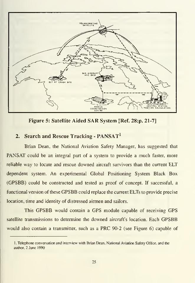
summary of the SARSAT system capabilities and limitations. Figure 5 depicts the
Search and Rescue (SAR) system as it was designed to relay a continuous beacon
from ELTs (via satellite) back to SAR forces.
From 1982 until 1988 SARSAT has been credited with saving over 1,150
lives (596 individuals involved in aviation accidents, 506 sailors involved in
maritime mishaps and 47 individuals lost on land when their distress signals were
relayed via satellite). The US Coast Guard requires all ocean fishing vessels to
acquire and maintain a 406 MHz ELT by 1 994 (another name commonly used for
an ELT is Emergency Position Indicating Radio Beacons (EPIRB)). [Ref. 27:pp.
43,45]
24
RESCUECOORDINATION
CENTRE
\>, \~ CENTRAL STATION/ ( \ POSIT ON CALCULATION
Figure 5: Satellite Aided SAR System [Ref. 28:p. 21-7]
2. Search and Rescue Tracking - PANSAT 1
Brian Dean, the National Aviation Safety Manager, has suggested that
PANSAT could be an integral part of a system to provide a much faster, more
reliable way to locate and rescue downed aircraft survivors than the current ELT
dependent system. An experimental Global Positioning System Black Box
(GPSBB) could be constructed and tested as proof of concept. If successful, a
functional version of these GPSBB could replace the current ELTs to provide precise
location, time and identity of distressed airmen and sailors.
This GPSBB would contain a GPS module capable of receiving GPS
satellite transmissions to determine the downed aircraft's location. Each GPSBB
would also contain a transmitter, such as a PRC 90-2 (see Figure 6) capable of
1. Telephone conversation and interview with Brian Dean, National Aviation Safety Office, and the
author, 2 June 1990
25
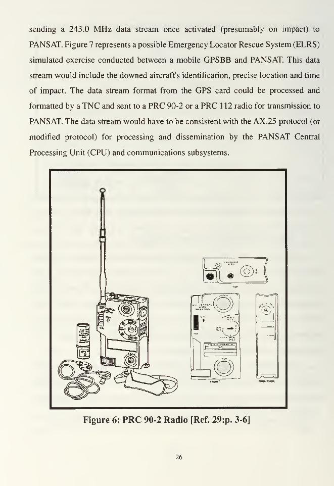
sending a 243.0 MHz data stream once activated (presumably on impact) to
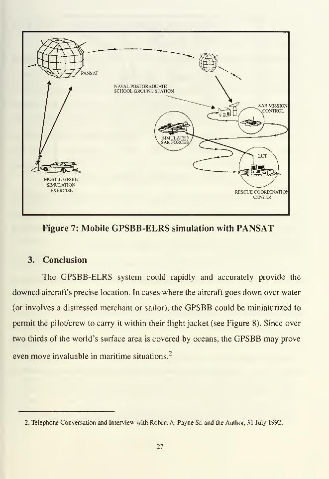
PANSAT. Figure 7 represents a possible Emergency Locator Rescue System (ELRS)
simulated exercise conducted between a mobile GPSBB and PANSAT. This data
stream would include the downed aircraft's identification, precise location and time
of impact. The data stream format from the GPS card could be processed and
formatted by a TNC and sent to a PRC 90-2 or a PRC 112 radio for transmission to
PANSAT. The data stream would have to be consistent with the AX.25 protocol (or
modified protocol) for processing and dissemination by the PANSAT Central
Processing Unit (CPU) and communications subsystems.
—SK ,
"'V\ JJr»p* BATING \~^*~~^ J
I~^ZjA
cmc
_J
C®)
Figure 6: PRC 90-2 Radio [Ref. 29:p. 3-6]
26
PANSAT
NAVAL POSTGRADUATESCHOOL GROUND STATION
SAR MISSIONCONTROL
MOBILE GPSBBSIMULATIONEXERCISE RESCUE COORDINATION
CENTER
Figure 7: Mobile GPSBB-ELRS simulation with PANSAT
3. Conclusion
The GPSBB-ELRS system could rapidly and accurately provide the
downed aircraft's precise location. In cases where the aircraft goes down over water
(or involves a distressed merchant or sailor), the GPSBB could be miniaturized to
permit the pilot/crew to carry it within their flight jacket (see Figure 8). Since over
two thirds of the world's surface area is covered by oceans, the GPSBB may prove
even move invaluable in maritime situations.2
2. Telephone Conversation and Interview with Robert A. Payne Sr. and the Author, 31 July 1992.
27
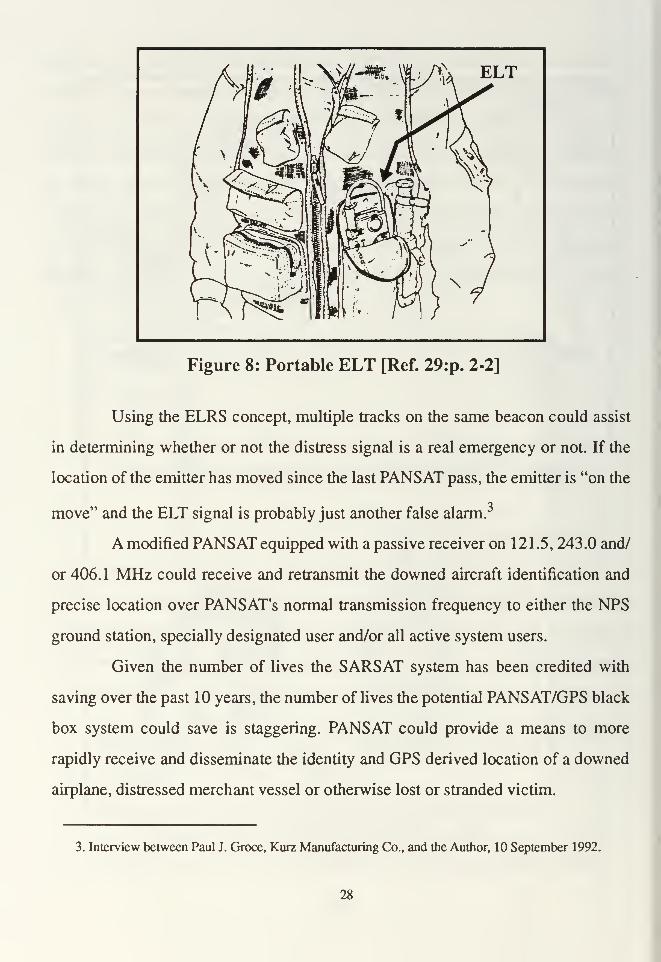
Figure 8: Portable ELT [Ref. 29:p. 2-2]
Using the ELRS concept, multiple tracks on the same beacon could assist
in determining whether or not the distress signal is a real emergency or not. If the
location of the emitter has moved since the last PANSAT pass, the emitter is "on the
move" and the ELT signal is probably just another false alarm.
A modified PANSAT equipped with a passive receiver on 121 .5, 243.0 and/
or 406.1 MHz could receive and retransmit the downed aircraft identification and
precise location over PANSAT's normal transmission frequency to either the NPS
ground station, specially designated user and/or all active system users.
Given the number of lives the SARSAT system has been credited with
saving over the past 10 years, the number of lives the potential PANSAT/GPS black
box system could save is staggering. PANSAT could provide a means to more
rapidly receive and disseminate the identity and GPS derived location of a downed
airplane, distressed merchant vessel or otherwise lost or stranded victim.
3. Interview between Paul J. Groce, Kurz Manufacturing Co., and the Author, 10 September 1992.
28

D. REMOTE FIELD SITE COMMUNICATIONS
The Bureau of Land Management has field teams comprised of over 1 1 ,000
people spread out over the 12 western states. Due to resource limitations and remote
locations, these teams do not have the ability to communicate with anyone. They do
not even have any emergency communications capability. Each team depends upon
biweekly "air dropped" resupplies for logistical support. Mr. Dean has suggested
the possibility of using and/or modifying a small hand held computer, TNC, and
associated UHF receiver/transmitter to enable field teams to use PANSAT's store
and forward capability to enable them to communicate with their parent
headquarters.
The Bureau of Land Management represents only one of the nine bureaus
within the Department of Interior. Each of these bureaus has field work parties and
most have requirements to communicate from the field to their headquarters. The
possibility exits for PANSAT to provide an important service to each of these teams.
However to use PANSAT, they would have to become licensed amateur radio
operators.
E. THE DEPARTMENT OF AGRICULTURE
The Department of Agriculture has long had a need to receive daily
responses from sensors located all over the Rocky Mountains. These are remote
locations where it is not practical and/or possible for personnel to gather such
information.
Since 1978, the U.S. Department of Agriculture's Snotel system has used
meteor burst rate to relate snow cover, temperature and river level data from
about 550 remote sensors in the Rocky Mountains. In Alaska, meteor burst is
used by the Air Force for remote pipeline monitoring and for obtaining remote
weather data at isolated air strips...The maximum distance a single meteor
burst signal can travel is approximately 1200 miles, and is a function of the
meteor trail height and the curvature of the earth. Transmitters using meteor
29

burst must use relatively high power (several hundred watts...) and receivers
must be very sensitive to enable continuous reception of data while the signal
weakens from the vanishing meteor trail. [Ref. 30:p. ]
Instead of using meteor burst transmission, these sensors could potentially be
programed and equipped to transmit their data when the senor was in PANSAT'
s
field of view. This data could be stored and later retrieved from PANSAT by the
Department of Agriculture's master ground station. Questions ranging from what
frequency to use to other technical and regulatory challenges would have to be
addressed before PANSAT could adequately support this mission.
F. FEDERAL EMERGENCY MANAGEMENT AGENCY
The Federal Emergency Management Agency (FEMA) coordinates efforts of
the National Guard, Army Special Forces Command (ARSOF) and other federal
agency disaster relief efforts. Amateur radio operators are often the first to attain
long haul communications immediately after the occurrence of natural disasters.
FEMA encourages amateur radio support in providing a means to augment or
replace damaged terrestrial communications after natural disasters such as
hurricanes, typhoons, tornadoes and earthquakes. PANSAT would be available to
provide a vital communication link to communities temporarily isolated by a natural
disaster such as Florida's August 1992 Hurricane Andrew. These communication
links could be used to coordinate emergency relief efforts as well as a host of other
requirements.
30
IV. POTENTIAL MILITARY APPLICATIONS OF PANSAT
A. GENERAL
With PANSAT' s original design plan, the only military personnel authorized to
use PANSAT are those who are licenced, amateur radio operators. This chapter
looks at potential military users. In order for PANSAT to work well with its users,
it is imperative that these users become intimately involved with the satellite
communications protocol development. These protocols should be developed with
primary user needs given foremost consideration. Facilitating a close working
relationship between system designers, builders and users will assure the most user-
friendly and capable communications system is developed.
1. Use of Military Frequencies
A PANSAT approved to operate within the military's 225-400 MHz
frequency band could support non-tactical military users similar to the way
MACSAT supported U.S. Marine logistical traffic throughout much of Operation
Desert Storm. A PANSAT with real time, bent pipe communications capabilities
could be extremely useful to the tactical military.
2. Assumptions
To facilitate the exploration of PANSAT possibilities for military users,
several assumptions have been made. The first assumption is that military UHF
frequencies will be approved for PANSAT use. This assumption holds in all cases
addressed in this chapter and is elaborated on more fully in Chapter V of this thesis.
The second assumption is that PANSAT will provide an experimental store-and-
forward capability on UHF military frequencies. The third assumption is that
PANSAT will provide an experimental, Satellite Communications On The Move
(SOTM) capability to UHF military users. The second assumption is assumed valid
31
for non-tactical military users while the third assumption is assumed valid for both
tactical and non-tactical military users. This chapter is not intended to be a
comprehensive listing of all possible military users of PANSAT, but rather a
sampling of various communities.
3. Spread Spectrum Limitations
Direct sequence, Pseudo Random Noise (PRN) code spread spectrum
systems do not work well in areas saturated with multiple users unless numerous
PRN codes are used. This situation is improved by separation of users having the
same PRN codes, however, another problem may occur: the near-far problem. The
near-far-problem results when a nearer user transmits at the same approximate time
a far away user transmits. In this situation, the signal that gets through is the stronger
of the two. Signal strength is a function of many variables. However, transmission
power and free space loss, which is inversely proportional to the square of the
distance between the user and the satellite, combine to form two of the most
influential factors. Thus, in an area saturated by spread spectrum system users with
the same PRN coding sequence, a significant amount of interference could result
(the near-far problem).
Another draw back to spread spectrum systems is a reduced information
transfer rate as compared to non-spread spectrum type systems. The LPI and LPD
that spread spectrum systems gain results in reduced data rates. There are no UHF
spread spectrum receivers/transmitters in the current Army inventory.
B. ARMY SPACE RELATED AGENCIES
The three primary Army agencies investigated were the Army Space
Technology and Research Office (ASTRO), the Army Space Institute (ASI), and the
Army Space Command (ARSPACE).
32

1. ASTRO - Technological Demonstrations
ASTRO invests time and resources into promising technologies for the
future. ASTRO has been instrumental in providing resources and support necessary
to permit the successful development of PANSAT as an experimental satellite
providing a maximum amount of educational opportunities to NPS student-officers.
2. ASI - Conceptual Demonstrations
ASI is interested in military, UHF, LEO satellite communications that are
both spread and non-spread spectrum, digital and analog. PANSAT as a possible
resource for interacting with a new program of doctrine-guided technology
development. This program is the Army Training and Doctrine Command's
(TRADOC's) Battle Lab. During the cold war, it took 10 to 15 years to develop a
weapon system from concept to operational fielding. One of the primary focuses of
the TRADOC's Battle Lab is to cut acquisition time from 10-15 years to 4-6 years.
Battle Labs are designed to
• provide a streamlined institutional, low cost means for defining
requirements;
• furnish an organized, established setting for soldiers to experiment with
new ideas and technologies;
• allow for refining user requirements with the developer;
• enable examination of emerging doctrine, training technologies and
leadership methods, organizations and material; and
• create a responsive institutionalized link between technological
opportunity and war fighting concepts.
Battle Labs may develop capabilities for a force projection Army that begins where
battle appears to be changing and encourages experimentation via simulations or
virtual prototyping to determine technology insertion or new requirements. The
Command and Control (C^) Battle Lab is one of six labs in TRADOC which test
new technologies to gauge how well they provide for Army communications needs.
[Ref.31:pp. 32,34]
33
3. ARSPACE - Performs Tactical Demonstrations
ARSPACE introduces new technologies to tactical units in field training
environments to assess the utility of these systems. ARSPACE is fundamentally
interested in many aspects of LEO, UHF, military communications as well as many
others. ARSPACE planners are particularly interested in experimenting with LEO
lightsats which offer a variety of capabilities such as:4
• Store-and-forward;
• Bent Pipe and/or regenerative transponder for SOTM;• Spread verses non-spread spectrum;
• Assured access (guaranteed system availability);
• Ability to command the satellite into switching modes of operation;
• Voice transmission capabilities;
• Satellite development and operational costs; and
• Compatibility with existing military UHF systems (e.g. LST-5 radios and
AN/PSC-3 (TACSAT) radios).
For non-spread spectrum operations, PANSAT must be compatible with the LST-5
and the AN/ PSC-3 radios. These radios employ 5 kHz as well as 25 kHz selectable
bandwidths. By 1994 all military UHF radios must modified to provide 5 kHz
bandwidth and by 1996 must all be Demand Assigned Multiple Access (DAMA)
compatible.
Figure 9 depicts a lightweight, deployable UHF SATCOM suitcase system
(fully equipped with a LST-5C, an encryptor and ancillary equipment to provide
worldwide wide and narrow band voice and data communications). This figure also
depicts a portable computer (called a GRID computer) and lightweight, UHF
antenna (manufactured by Dome and Margolin, Incorporated). Table 3 depicts the
distribution of AN/PSC-3 and LST-5 UHF radios in the U.S. Armed Forces.
4. Telephone conversation and interview with CPT J.C. Chin, ARSPACE, and the author, 14 August
1992.
34

Figure 9: Light, Deployable, UHF SATCOM Suitcase [Ref. 34:p. 2]
TABLE 3: AN/PSC-3 AND LST-5 UHF RADIO DISTRIBUTION [Ref. 32]
Radio Army AF Navy MC CINC Other Total
AN/PSC-3 477 61 160 148 56 6 908
LST-5B/C 524 817 170 25 74 1390 3000
C. LIGHTSAT COMMUNICATIONS REQUIREMENTS
Operation Desert Storm provided the opportunity for the Army to begin
realizing the full value of satellite communications for the tactical commander in a
fast paced, ever changing combat environment.
Small satellites in low Earth orbit can provide voice channels to tactical units
deployed over large areas; these channels enhance the communications that
are required for maneuver warfare. A low Earth orbit allows the use of low-
power transmitters and simple antennas that are small and lightweight. Lowpower transmissions are difficult to locate, so the risk of exposing positions by
communication is greatly reduced. [Ref. 33 :p. 1]
35

LEO satellites should allow for lower power transmitters and smaller, lightweight
antennas for the user than GSO satellites. However, this is not always the case.
Satellite antenna gain and transmission power are two important factors determining
the required user transmission power, antenna size and pointing requirements.
1. Fast Moving Combat Scenarios
The offensive mobility demonstrated during the Army's 24 Infantry
Division (Mechanized) Desert Storm operations resulted in tactical units moving as
much as 100 kilometers per day. [Ref. 31:p. 15] Standard terrestrial communication
systems could not keep abreast of this fast pace to provide adequate communication
links between forward deployed units and their associated headquarters.
Prior to Desert Storm, the low priority of the tactical users at theater and below
resulted in minimal use of MILSATCOM for peacetime training or operational
situations. In Desert Shield/Storm, the tactical user priority was recognized
and MILSATCOM service was provided from all available resources.
However, due to the extensive satellite communications requirements,
MILSATCOM and commercial services could not satisfy the multitude of
requirements.... Intra-theater satellite communications were especially
important because of the vast operational areas in which there did not already
exist a communications infrastructure.... [Ref. 35:pp. 1,3]
A possible measure of effectiveness for a SOTM system is the ability to
communicate on a tactical vehicle's UHF radio to another tactical vehicle's UHF
radio over distances spanning from Washington DC to Ohio. SOTM is receiving a
considerable amount of attention and R&D study.
2. Deployment of Special Teams5
The 106th Signal Brigade (stationed in Panama) is frequently tasked to
support multiple deployments of small teams throughout South America. These
5. Telephone conversation and interview with Major David Quals, ARSPACE, and the author, 16
May 1992.
36

teams seldom have the priority to obtain access to satellite transponder frequencies
nor do they have the assigned assets to allow deployed forces to maintain
communication links with their headquarters in Panama. For these teams, PANSAT
would be a welcomed asset.
The 6th Infantry Division successfully tested both MACSAT and Microsat
systems when they deployed Engineer and Special Forces Medical Teams to the
Philippines in 1991. These teams used one of the two orbiting MACSATs to
communicate with their headquarters in Alaska. MACSAT communications proved
to be more reliable than Autovon. The Microsat constellation was used to provide
real time communications with forces deployed in country.
3. Civil Relief Operations
Quite often teams from the Army Corps of Engineers and Army Medical
Service Corps are sent on missions into remote areas where no terrestrial means to
communicate with their headquarters exist. These users do not have the priority to
gain access to FLTSATCOM or TACSAT channels and are too far away from
supporting US Embassies to establish viable communications channels. PANSAT
could provide a reliable communication link between deployed forces and their
headquarters. Enhanced communications via PANSAT could improve civil relief
operations, mission planning and execution.
D. SPECIAL OPERATIONS UNITS
Many lower level military users are given missions without the priority or
means to establish and maintain communications with their headquarters. Other
users may have logistical and / or routine maintenance requirements which could be
automated through the use of a system like PANSAT.
While tactical military command requires real-time communications, tactical
control requirements may be satisfied by a satellite store-and-forward systems as
37

demonstrated by MACSAT during Operation Desert Storm. Store-and-forward
satellite systems could also provide communication support for special operational
units from the Delta Forces, Navy Seals, Army Ranger Regiment, Civil Affairs
Battalions, Psychological Operations units and ARSOF. These units have missions
which do not necessarily require real time reporting of information.
Many Special Operations Units communicate with their higher headquarters on
a routine basis. Teams from the 1st Special Forces have been able to satisfy their
communication requirements of passing situation updates to higher headquarters
several times a day using one of the two orbiting MACSATs last year. KG84
encryption devices were used to encrypt signals before transmitting to MACSAT
and to decrypt messages after downloading.
Other possible special forces implementations of PANSAT include providing
company through group commanders an administrative/intelligence net for non-
critical traffic. The present configuration of ARSOF relies heavily on TACSAT to
exchange critical message traffic. Removing non-critical information from this net
would ease the burden on over-utilized real-time systems such as TACSAT.
PANSAT could be more reliable than HF Multi-channel systems fielded to provide
a means to reduce TACSAT system usage. Because ARSOF does not rely
exclusively on a single communications medium, the additional capability offered
by PANSAT would serve to reduce usage or replace other systems which are less
reliable and/or more difficult to obtain assured access to.7
ARSOF has mission requirements to conduct a wide range of missions in all
types of terrain and environments. Command and control is supported by numerous
communications systems using HF, VHF, UHF and SHF mediums. The backbone
6. Telephone conversation and interview with Maj. David Quals, ARSPACE, and the author, 16
May 1992.
7. Conversation and interview with SFC Daniel Barringer, USA ARSOF, Ft. Bragg, NC, and the
author, 15 September 1992.
38
of ARSOF communications is HF-AM using analog burst devices (often with
encryption). ARSOF units work for the Commander-in-Chief (CINC) through
theater level tactical commanders and can be tailored to support any commander at
any level. PANSAT could prove effective in supporting ARSOF in most Primary
Missions and Collateral Activities.
ARSOF Primary Missions:
• Unconventional Warfare- WWII, Vietnam, with limited applicability to
Operation Desert Storm (ODS);
• Direct Action- Grenada, Panama's Operation Just Cause (OJC), ODS;• Special Reconnaissance- Strategic, operational and tactical in Grenada,
OJC and ODS; and
• Counter-terrorism- ongoing support of CINCs.
ARSOF Collateral Activities
• Humanitarian Assistance- OJC, post ODS (Kurds), and disaster relief
efforts (Florida's August 1992 hurricane Andrew);
• Counter-narcotics - ongoing;
• Security' assistance- ongoing; and
• Search and Rescue-ODS with respect to downed air crew members and
peace time efforts (natural disasters: earth quakes and hurricanes).
Because many of these missions do not rely heavily on real-time reporting
requirements, a system such as PANSAT would be invaluable in circumstances
where no other reliable communications medium is readily available.
E. U.S. COAST GUARD
The Coast Guard has buoys positioned up and down both the Atlantic and
Pacific coasts of the United States. The health status of each of these buoys is
checked by physically inspecting each buoy. The buoy health status includes
checking each buoy's battery charge and light bulb status. Each buoy contains seven
light bulbs. There is a desire to centralize and automate the monitoring of buoy
8. Conversation and interview between SFC Daniel Barringer, USA ARSOF, Ft. Bragg, NC, and
the author, 16 September 1992.
39
health status. A small, GPS equipped transmitter could be attached to each buoy to
routinely send out buoy location, battery and light bulb status to PANSAT. That
information could then be downloaded to a buoy control center.9
F. NAVAL SUPPORT FORCES ANTARCTICA 10
The Navy conducts research work for the National Science foundation in
support of the U.S. Antarctic program. Many scientific missions could be facilitated
by PANSAT' s store-and-forward capability. Scientist deployed to Antarctica have
used transponders on a variety of satellites:
• the Lincoln Experimental Satellite-9 (LES-9) at 303 MHz• the International Maritime Organizations C (INMARSAT-C) Satellite
As noted in Chapter II, MACSAT also supports the U.S. Antarctic Program.
G. U.S. NAVAL ACADEMY
The U.S. Naval Academy has been an active participant in amateur satellite
communications experiments as well as DARPA's Microsat program.
During the last two years the U.S. Naval Academy has performed a number of
satellite communications experiments including tests with a packet radio
network for communications with its boats during the summer cruises along
the East Coast. The Academy is fortunate to have obtained the 12 meter dish
antenna from NASA in 1989... During the life of the Microsats, periodic
beacons on the satellite uplink frequency were relayed to Annapolis via any
[Microsat] satellite that was in view. [Ref. 36:p. 2]
The U.S. Naval Academy has demonstrated that its students will maximize utility
for every satellite communications system made available.
9. Telephone conversation and interview with CDR James John, Coast Guard Research and Devel-
opment Center, and the author, 2 June 1992.
10. Telephone conversation and interview with LTCDR Chris Rhone, Naval Support Force Antarc-
tica, and the author, 1 1 September 1992.
40

V. PROPOSED PANSAT MODIFICATIONS
A. GENERAL
Since 1988 NPS has been engaged in developing PANSAT. Due to the
difficulty in obtaining authorization forUHF military frequencies, NPS turned to the
amateur radio community for frequency authorization/allocation.
While conducting research for this thesis, it became clear that unless PANSAT
was modified, the only possible applications of PANSAT would be those accessible
only to properly licensed, amateur radio operators. In a 19 August 1992 letter to the
Chair of the NPS Space Systems Academic Group, Dr. Rudolph Panholzer, Robert
Bruninga, Director of the U.S. Naval Academy's Satellite Earth Station Facility,
wrote:
we are very excited about your PANSAT, but I personally feel that very few
amateurs will actually use it. Even the leading edge spread-spectrum
experimenters that I know will talk a blue streak about how neat it is, but they
will just keep dabbling in more and more digital signal processing. Many will
work hard to get a signal into or out of PANSAT, but once having done that,
their interests are not in satellite operations, but in playing with the next
challenge. ..[Ref. 37:p. 1]
If Mr. Bruninga is correct, then a PANSAT designed to only interact with the
amateur radio community would be vastly under utilized. A PANSAT designed to
incorporate a primary and at least one secondary mission stands a far greater chance
of providing tangible returns on the many thousands of man hours and dollars
invested in PANSAT.
Because PANSAT is being built and funded by military organizations, the
authorization to use military frequencies would allow the PANSAT design team the
option of implementing various satellite modifications which could contribute to
41
military experiments pertaining to store-and-forward and/or SOTM
communications.
B. BACKGROUND
The potential availability of UHF military frequencies for PANSAT is due in
part to DARPA's success in obtaining frequencies for MACSAT and Microsat.
Microsat shared some of the same frequencies with the U.S. Navy's FLTSATCOM
satellites. Microsat' s transponders had an uplink frequency 41 MHz lower than their
downlink frequency. The U.S. Navy's FLTSATCOM transponders have an uplink
frequency 41 MHz higher than their downlink frequency. [Ref. 38:p. 3] Both
Microsat' s and FLTSATCOM' s diametrically opposed up and downlink
frequencies made it possible for both systems to share the same frequencies at the
same time with minimal interference.
As previously described in Chapter II, the Microsat constellation consisted of
seven LEO satellites with each providing digital and analog regenerative
transponder (sometimes referred to as "bent pipe") capabilities to system users. Due
to various factors, an eighth Microsat was built, but never launched. When
DARPA's MACSAT and Microsat contracts expired, the control and use of most
remaining hardware was designated for transfer to Naval Space Command and Air
Force Space Division. Naval Space Command received both ground control stations
for MACSAT while the Air Force was designated to receive most other items
(including the eighth Microsat).
42
C. MILITARY FREQUENCY APPROVAL
Gaining approval for using UHF frequencies in the Military band (225-400
MHz) for mobile users of satellites is a function of many variables. Mobile military
satellite frequency approval is more likely to be granted to satellites which are:
• Experimental
• Store-and-forward,
• Burst packetized,
• Spread spectrum
Satellites which exhibit these features cause the least interference to other users and
therefore, have the highest probability of being granted use of frequencies in the
mobile military satellite bands. "The bands 235-322 MHz and 335.4-399.9 MHz
are... allocated on a primary basis to the mobile- satellite services, limited to military
operations." (italicized emphasis provided by the author) [Ref. 39:p. 4-96] To
obtain use of military frequencies, NPS must work through a fairly involved set of
procedures. The process of obtaining military frequency approval is a two step
process. The first step, system allocation, takes about six months to complete and
the second step, frequency assignment, takes three to six months to complete.
1. System Allocation
The first step towards attaining Military frequency approval is
accomplished through submission of DD Form 1494 for all associated satellite and
ground station communications equipment. These forms are reviewed and approved
by the United States Military Communications Electronics Board (MCEB) and the
National Telecommunications Information Agency (NTIA). A subcommittee of
NTIA is the Spectrum Planning Satellite subcommittee (SPS). The SPS includes
representatives from about 20 government agencies including the Federal
Communications Commission, the National Sciences Foundation, the Federal
Aviation Administration and representatives from each branch of the Armed Forces.
43

Copies of the MACSAT and Microsat DD Form 1494 have been made available to
NPS by Bob Steel of the Space Applications Corporation. Copies of the RADCAL
DD Form 1494 have been made available by the RADCAL Program Manager.
Having access to DD Form 1494 for MACSAT, Microsat and RADCAL should
greatly simplify the process for completing these forms for PANSAT. Once approval
for PANSAT's Military communications system has been granted, PANSAT will be
assigned a four digit J12 number. This number is required to proceed the next step.
2. Frequency Assignment
The second step includes submission of a proposal for military operational
frequencies using NTP-6(C) (Naval Telecommunications Publication) and the
Standard Frequency Action Format (SFAF). This proposal must be sent to the Naval
Frequency coordinator for the Western U.S. at Point Mugu, CA where proposal
format verification and local coordination is performed. The proposal will then be
sent to the National level to the Naval Electromagnetic Spectrum Center
(NAVEMSCEN) for national level coordination. National level coordination will be
accomplished and the proposal will be submitted for National Level Approval. This
processes can take from 90 to 120 days before authority to transmit is received.
D. PRELIMINARY RESULTS
1 . General
Preliminary research results indicate that PANSAT could potentially be
modified to have the following capabilities:
• Provide proof of concept for a low cost, GPS, Emergency Rescue
Location System (ERLS);
• Provide proof of concept for AX.25, spread and/or non-spread spectrum,
military store-and-forward satellite communications; and
• Provide proof of concept for military SOTM through the integration of
the eighth Microsat.
44
Given adequate time and resources, PANSAT could undergo a vast number of
programmatic modifications to accomplish a wide variety of tasks. NPS is not likely
to apply modifications to PANSAT which provide redundant functions readily
available on other systems. Only by reviewing other existing and/or planned satellite
systems, can the utility for a modified PANSAT be estimated.
2. Search and Rescue Systems
a. Existing System
As referenced previously, the only global search and rescue system is
several LEO "bent pipe" Search and Rescue Satellite Aided Tracking (SARSAT)
transceivers and many widely dispersed Local User (ground) Terminals (LUTs).
This system monitors distressed stations (downed aircraft or ocean vessel)
transmission beacons on 121.5, 243.0 or 406.1 MHz. SARSAT must receive this
beacon and relay it to the nearest LUT a minimum of three times (once each orbit)
before the LUT can determine the approximate location of the distressed station.
Computational procedures are cited more fully in Appendix C. This process takes a
minimum of several hours to complete and provides location accuracy from two to
12 nautical miles.
b. Future Systems11
The Air Force Space and Missile Systems Center is developing a
Combat Survivor / Evader Locator (CSEL) system to enable downed pilots in
combat to securely transmit their location to friendly forces. This system is being
designed as a military/government system to aid in the location and recovery of
downed pilots. As conceptualized, this program could provide a means to locate and
11. Telephone conversation and interview with Major Charles Banning, Air Force Space and Mis-
sile Systems Center, and the author, 19 August 1992.
45
rescue combat survivors that is far superior to the method of homing in on the ELT's
signal. CSEL will use advanced methods for determining the downed aviator's
location which may or may not include standard GPS position locating techniques.
Bent pipe transponders may be located on Defense Satellite Communications
System (DSCS) III satellites and/or GPS satellites. The earliest this system could
begin fielding is 1996.
3. US Army LEO Satellite Systems
a. Current Systems
Today the Army has no SOTM, store-and-forward experimental or
operational satellite communication systems.
b. Future Systems
The USAF's Radar Calibration satellite (RADCAL) is scheduled for
launch in May of 1993 and uses similar packet radio protocols developed for
MACSAT. This effort may provide the Army with "assured access" to store-and-
forward communications capability. RADCAL may also provide experimental
SOTM communications capability. Unlike PANSAT (which will operate full
duplex with the AX.25 packet radio protocol and have virtually no scheduling
requirements) RADCAL (like MACSAT) may operate half duplex, with no error
checking, no user acknowledgment and require rigorous scheduling coordination.
E. RECOMMENDED MODIFICATIONS
These modification proposals are analyzed at the systems application level as
opposed to the systems design technical level. An in-depth technical study is
required to determine the feasibility of each proposal. Figure 10 graphically
represents modification proposals 1 through 4.
46

1
.
PANSAT System With No Modifications
Many complex factors beyond the scope of this thesis must be evaluated
before any PANSAT design modifications are implemented. The shaded area
marked #1 located in the upper right hand portion of Figure 10 represents the current
PANSAT system design.
2. Create an Emergency Location Rescue System (ELRS)
PANSAT could be used as an integral part in developing and testing an
experimental ELRS. The triangular box marked #2 located in the upper right hand
portion of Figure 10 represents PANSAT's ELRS receiver. Working with the
National Aviation Safety Office, a GPS module manufacturer (such as Rockwell
International or Magellan), and the PacComm Corporation, NPS would initiate an
experiment which could revolutionize the way distressed pilots, seaman and those
lost on land are found and rescued. This experimental system would use a new GPS
"Black Box" (GPSBB - created from the integration of a tiny GPS module, a tiny
PacComm TNC and a PRC 90-2 or PRC 112 radio) and a 243.0 MHz satellite
receiver located on PANSAT. The world-wide applicability of an operational system
like this has the potential of saving thousands of lives over the next 10 to 20 years.
Conceivably, the GPS location of a distressed airman/seaman could be
provided to rescue parties within minutes of transmitting a distress signal. The GPS
module, PacComm TNC and PRC-90-2 each cost approximately $300-$400 (the
PRC-112 cost is approximately $4,500-$5,50012
). Using a PRC-90-2, total
hardware cost for a prototype GPSBB could be as low as $1,000. Cost for
constructing a 243.0 MHz satellite receiver is undetermined. NASA-Goddard has
built SARSAT receivers in the past and may be able to provide some assistance.
12. Telephone conversation and interview with Major Charles Banning, Air Force Space and Mis-
sile Systems Center, and the author, 19 August, 1992.
47


3. Provide Experimental Store and Forward Capability
PANSAT is being designed to have a total of three megabytes of mail box
RAM. The shaded area marked #3 located near the center portion of Figure 10
represents both PANSAT's store-and-forward, and spread and non-spread spectrum
digital transceivers. With military frequency allocation/assignment, a pair of
transceivers could potentially be built and installed on PANSAT to provide military
spread and/or non-spread spectrum, store-and-forward capability.
4. Provide Experimental SOTM Capability
NPS could potentially integrate the eighth Microsat's receiver, transmitter,
synthesizer and diplexer, controlling each subsystem either by PANSAT's CPU or
by a PacComm TNC.
a. PANSAT's CPU as the Controller
The shaded area marked #4a located in the lower, center portion of
Figure 10 represents the eighth Microsat's components controlled by PANSAT's
CPU. Using PANSAT's CPU would save on power, volume and weight
requirements, but may only provide store-and-forward capability and would also
share PANSAT's 3 megabytes of RAM with the amateur communication sub-
system.
b. PacComm 's TNC as the Controller
The shaded area marked #4b located in the lower left portion of Figure
10 represents the eighth Microsat's components controlled by a PacComm TNC.
Using the PacComm TNC could possibly allow the eighth Microsat's components
to function as a separate payload on PANSAT (PacComm payload). Appendix B
lists many of the features common to AX.25 TNCs. Using the PacComm TNC
option, the PacComm payload would share power and serial command gateways
49
between itself and PANSAT' s communications payload. In addition to serving as
analog and digital, regenerative transponders, PacComm's payload provides limited
amounts of store-and-forward capability in addition to PANSAT' s three megabytes
of mail box RAM.
F. DESIGN LIMITATIONS
Any modifications to PANSAT must be analyzed on a case by case bases from
a power, volume and weight perspective. Each perspective is addressed briefly in
the following paragraphs. Further research is required to determine how
recommended modifications #2 through #4 would impact upon PANSAT' s power,
weight and volume design limitations.
1. PANSAT Power Constraints
A major concern of the PANSAT design team is power utilization. Due to
PANSAT's limited surface area, a relatively small number of solar cells can be
mounted to provide operational power.
The PANSAT power subsystem will consist of a 12 volt unregulated bus
supplied by solar cells and batteries. The planned solar cell set uses 1 7 exposed
solar cell panels attached to the rectangular satellite surfaces (except the base).
Each solar cell panel will use 256 cm2 of solar cells for energy collection. The
battery assembly will consist of a sealed container housing six battery packs of
lead-acid batteries with six two-volt batteries per battery pack. The total
energy storage capacity of the battery assembly will be 360 watt-hours. When
the satellite is in the sunlight, the solar cells will provide power for operations
and for recharging the batteries. When the satellite is in the dark, the batteries
will provide all power requirements. [Ref. 40:p. 68]
The precise amount of power available to PANSAT subsystems as well as power
required to run those subsystems has yet to be empirically determined. Actual power
requirements will be determined once the designs for each of the various subsystems
are completed.
50
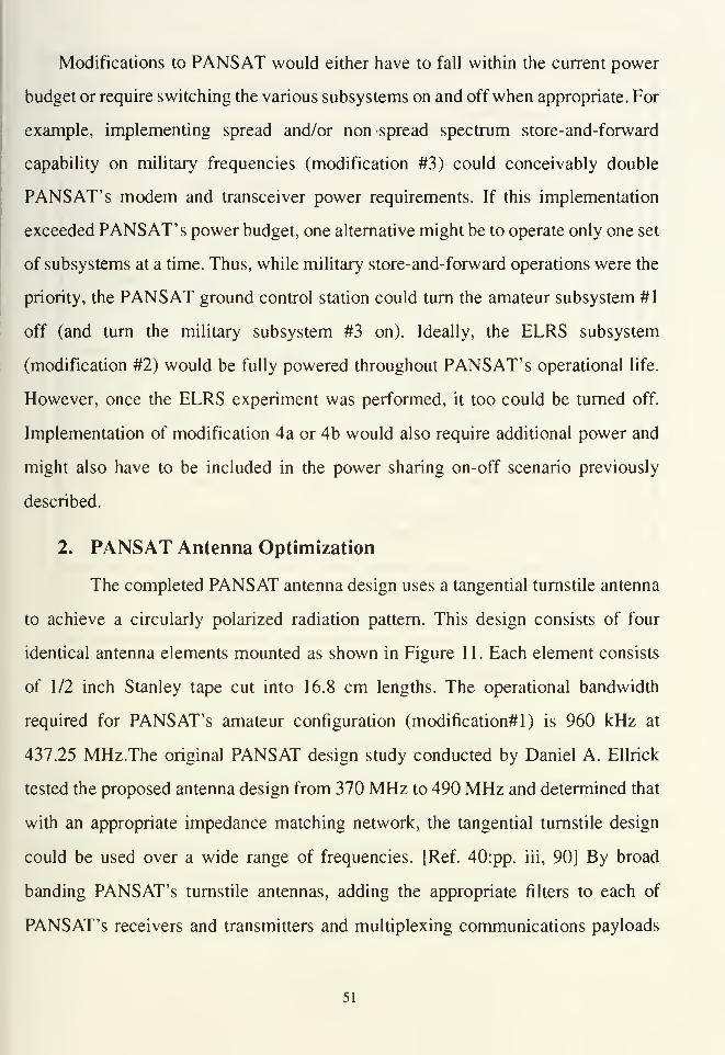
Modifications to PANSAT would either have to fall within the current power
budget or require switching the various subsystems on and off when appropriate. For
example, implementing spread and/or non spread spectrum store-and-forward
capability on military frequencies (modification #3) could conceivably double
PANSAT' s modem and transceiver power requirements. If this implementation
exceeded PANSAT' s power budget, one alternative might be to operate only one set
of subsystems at a time. Thus, while military store-and-forward operations were the
priority, the PANSAT ground control station could turn the amateur subsystem #1
off (and turn the military subsystem #3 on). Ideally, the ELRS subsystem
(modification #2) would be fully powered throughout PANSAT' s operational life.
However, once the ELRS experiment was performed, it too could be turned off.
Implementation of modification 4a or 4b would also require additional power and
might also have to be included in the power sharing on-off scenario previously
described.
2. PANSAT Antenna Optimization
The completed PANSAT antenna design uses a tangential turnstile antenna
to achieve a circularly polarized radiation pattern. This design consists of four
identical antenna elements mounted as shown in Figure 1 1 . Each element consists
of 1/2 inch Stanley tape cut into 16.8 cm lengths. The operational bandwidth
required for PANSAT's amateur configuration (modification^) is 960 kHz at
437.25 MHz.The original PANSAT design study conducted by Daniel A. Ellrick
tested the proposed antenna design from 370 MHz to 490 MHz and determined that
with an appropriate impedance matching network, the tangential turnstile design
could be used over a wide range of frequencies. [Ref. 40:pp. iii, 90] By broad
banding PANSAT's turnstile antennas, adding the appropriate filters to each of
PANSAT's receivers and transmitters and multiplexing communications payloads
51
together, it may be possible to support modifications #1-4 from an antenna design
perspective. Further studies are required for conceptual and empirical verification.
TOP VIEW
SIDE VIEW
z
44 Theta =45'
^ r
Figure 11: PANSAT's Tangential Turnstile
Antenna design [Ref. 40:p. 40]
3. PANSAT Volume and Weight Restrictions
Figure 12 provides an approximation of PANSAT's internal structural
layout. Although this is an approximate design, many members of the PANSAT
design team indicate PANSAT has enough volume to accommodate other additional
payloads. PANSAT's maximum allowable weight is 150 pounds. The total estimated
weight of all planned subsystems for the original design is less than 100 pounds.
52

Solar Panels (17)with 256 sqcm area
Dipole Antennas
Experiment Payload
Battery Box
Power Control Electronics
Structure is anAluminum Frame,Modular in design
CommunicationsTransceiver
Computer Subsystem
Cylindrical Structure Support
Baseplate Panel 1 /1 6 In thlck aluminum 6061 -T6
Figure 12: PANSAT's Internal PayloadConfiguration [Ref. 41]
G. FUTURE CONSIDERATIONS
1 . PANSAT with Modifications
The exploration and/or implementation of the previously proposed
modifications could provide a number additional of thesis opportunities to student-
officers at NPS and could eventually result in extended communications service to
a wide variety of users.
53

2. PANSAT Follow-on Satellites at NPS
Even if the modifications proposed in this chapter are not be implemented
on PANSAT, opportunities exist to apply these modifications to the next NPS
follow-on satellite. The Radiant Teak Experiment (RATE) is one potential, PANSAT
follow-on satellite. The RATE satellite structure (see Figure 13) and various
subsystems have been given to NPS for future satellite endeavors. If military
frequency allocation/assignment is requested and approved for PANSAT and
PANSAT is later determined unable to support military payloads suggested in
modifications #3 or #4, those approved frequencies could become the baseline for
the design of next NPS satellite system.
OO
-r=
"-T"
Figure 13: RATE [Ref. 42]
54

VI. CONCLUSIONS AND RECOMMENDATIONS
A. CONCLUSIONS
The experimental use of PANSAT strictly on amateur frequencies should
provide a tremendous service to the amateur radio community. However, a
significant opportunity to exploit an even larger user base exists within the
military's UHF frequency domain. Additional experiments with the Emergency
Locator Rescue System (ELRS) on 243.0 MHz could improve the way distressed
airman and sailors are located and rescued. Experimental Satellite Communications
On The Move (SOTM) capability could be attained through the successful
integration of the eighth Microsat's tunable receiver/transmitter group. Resources
required to support these and other modifications could be provided by agencies
interested in participating in unique experiments and/or obtaining assured access
with PANSAT once it became operationally available.
A large proportion of potential PANSAT system users have either no secure
transmission requirements and/or have no access to spread spectrum radio
equipment. Most of these users are looking for the most reliable, simple to operate
systems they can gain access to. With the availability of numerous, UHF, non spread
spectrum military radios and keen interest in PANSAT' s store-and-forward
capability, designers should consider making PANSAT both spread and non-spread
spectrum system capable.
The PANSAT design team has set February 1993 as the time when PANSAT
designs will be finalized (no more modifications permitted). Design modifications
cited in this thesis must be further developed from a technical perspective in the first
quarter of Fiscal Year 1993 (if they are to be further considered for PANSAT).
There is moderate military interest in participating in PANSAT operational
testing. There is definite military interest in PANSAT as a proven product. Systems
55
like PANSAT are drastically needed to provide services to ease strains placed on
tactical, real time communications systems. Revised military doctrine calls for less
logistical support to accompany initial and subsequent deployment of tactical forces.
Tactical units will deploy forward, leaving the bulk of logistical units in the rear to
deliver supplies forward when requested. Warehouses and administrative services
are likely to remain in the U.S. The demand for "PANSAT type" systems will
continue to grow.
In the future, an initial constellation of lightsats could inexpensively be placed
in orbit as a secondary load on one of many possible launch vehicles. A constellation
of three PANSATs could provide as much as 72 minutes per day of uplink /
downlink transmission time [Ref. 43:p. 35]. Lightsats may provide surge type
communications during the early mobilization phase of military operations as well
as replace non-functional terrestrial systems in the aftermath of hurricanes and other
natural disasters. Lightsat have the potential to provide a quick response, satellite
communications system. To realize this potential, an appropriate number of
preconfigured satellites and launch vehicles must be prepared and set aside for
contingency purposes.
The addition of a military UHF capability and/or an ELRS experiment on
PANSAT should improve PANSAT' s Space Test Program (STP) ranking. Last
year, PANSAT was ranked only 29 out of 35 military experiments scheduled for
STP launch.
No matter how many communication assets are available, more will be desired.
The ability to move non-critical traffic from command to alternate nets may provide
as much operational utility as the command nets themselves since the operational
value of a saturated command net is marginal at best. The basic rule of
communications: you can never have enough. In times of crisis, every
communication asset will be used.
56
B. RECOMMENDATIONS
The following recommendations are listed in priority order. In an austere
resource environment, funding for future NPS satellites may be contingent upon
providing tangible services to financial sponsors (which may in turn require military
frequency band utilization). Thus, gaining approval for use of frequencies in the
mobile satellite, military band is of paramount importance to current and future NPS
satellites. Experience gained as a result of requesting military frequency access for
PANSAT would simplify efforts required for future NPS, experimental satellite
systems. Most of the PANSAT modifications addressed in this thesis require further
technical study prior to implementation or rejection. The ELRS project requires
continuous coordination between the PANSAT design team, the National Aviation
Safety Office and PacComm Corporation. Continued coordination with other
Department of Defense, space related agencies should provide NPS with access to
the latest user requirements and technical information. For PANSAT to effectively
support system users, these users must be identified early on and encouraged to
work with the PANSAT design team to create a functional, user friendly operator
interface. In all cases, steps taken towards future design changes must begin now.
1. Submit Request for Military Frequency Use
Desires to operate PANSAT within the military's UHF spectrum are
considerable. Use MACSAT, Microsat and RADCAL DD Form 1494 as a baseline
for PANSAT UHF, mobile, military satellite frequency requests. In particular,
process all military frequency requests through the Naval Electromagnetic
Spectrum Center. Provide copies of these request to the Army's Electromagnetic
Spectrum Center to facilitate coordination of Army/Navy efforts for attaining
PANSAT military frequency approval.
57

If the military frequency approval request is initiated by January 1993,
system allocation could be granted as early as June 1993 and frequency assignment
could be granted as early as October 1 993 (two years prior to the late 1 995 projected
launch).
If military frequency requests are approved, integrate the operational
military tests into the final phases of PANSAT system testing to generate military
interest and support for follow-on systems.
2. Conduct Technical Investigations
Continue to exploit lessons learned from DARPA's MACSAT and Microsat
programs. Consult with MACSAT and Microsat engineers and users to create the
most effective, user friendly PANSAT interface possible.
Consult with DSI for requirements to integrate the eighth Microsat's basic
communications components (receiver, transmitter, synthesizer and diplexer) with
PANSAT. Determine microsat power, volume, and weight parameters.
Consider broad-banding PANSAT's tangential turnstile antenna design to
encompass military UHF frequencies in addition to the amateur band already
approved. Also consider making primary receivers and transmitters "tunable" to
increase satellite utility.
Consider maximizing the system data rate and RAM to increase PANSAT
user capabilities and future system utility.
Consider making PANSAT capable of switching between the spread and
non- spread spectrum BPSK modems to potentially make PANSAT available to non
spread spectrum users on both amateur and military frequencies.
Consider adding an additional receiver to increase satellite utility. PANSAT
may be approved to transmit on 437.25 MHz, but it can passively receive on any
frequency. Ideally, this additional receiver could be tunable to any frequency within
58

the 225 to 440 MHz range. This would allow PANSAT to exploit other missions yet
to be defined.
Consider making PANSAT's non-spread spectrum modem compatible with
existing military, UHF, satellite, communication radios. Current Army UHF radios
are non spread spectrum systems which have narrow bandwidths of 5 and 25 kHz.
Consider using "off the shelf' lap tops and/or software for user terminal
design to reduce cost and increase functionality. Consider using small hand held
devices like Atari's palm top computer. This computer could be used in conjunction
with a TNC and a small hand held UHF radio to send and receive data from
PANSAT.
3. Coordinate ELRS Project
Work with the National Aviation Safety Office and PacComm to outline
technical requirements and outline milestones for the ELRS Project.
Consider requesting NASA's Goddard Space Center assistance in
developing an experimental, NPS, Emergency Locator Rescue System by providing
the SARSAT 243.0 MHz receiver designs flown on several NOAA satellites.
Consult with Army Communication Electronic Command (CECOM) and
possibly with Fort Ord Aviation Units with respect to attaining a PRC 90-2 or PRC
112 (with batteries) for use in the GPSBB unit addressed in Chapter III.
4. Increase Involvement with Military Space Agencies
Invite key lightsat advocates from ASTRO, A.S.I., ARSPACE and DARPA
to future PANSAT design reviews.
Enroll PANSAT in the Annual Army Space Exploration Demonstration
Program (AASEDP). This program is designed to show how new products make use
of space to resolve tactical and non-tactical Army problems. This program also
shows how new systems meet Army requirements.
59
Consult with DARPA, the Army's CECOM, Naval Space Command and
amateur radio systems manufacturers to determine current and future UHF, spread
spectrum modem and/or radio systems.
Consult with DARPA and SDIO for the latest, lightweight satellite
components such as solar cells and computer processors. DARPA's Advanced Space
Technology program is a potential source for new lightweight systems for
spacecraft. SDIO has fostered miniaturized technologies as part of a drive to reduce
cost of strategic defense employment.
60
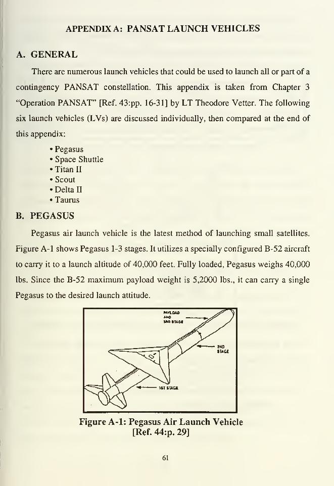
APPENDIX A: PANSAT LAUNCH VEHICLES
A. GENERAL
There are numerous launch vehicles that could be used to launch all or part of a
contingency PANSAT constellation. This appendix is taken from Chapter 3
"Operation PANSAT" [Ref. 43:pp. 16-31] by LT Theodore Vetter. The following
six launch vehicles (LVs) are discussed individually, then compared at the end of
this appendix:
• Pegasus
• Space Shuttle
•Titan II
• Scout
• Delta II
•Taurus
B. PEGASUS
Pegasus air launch vehicle is the latest method of launching small satellites.
Figure A-l shows Pegasus 1-3 stages. It utilizes a specially configured B-52 aircraft
to carry it to a launch altitude of 40,000 feet. Fully loaded, Pegasus weighs 40,000
lbs. Since the B-52 maximum payload weight is 5,2000 lbs., it can carry a single
Pegasus to the desired launch attitude.
}H0
tUCE
1ST SUCE
Figure A-l: Pegasus Air Launch Vehicle
[Ref. 44:p. 29]
61
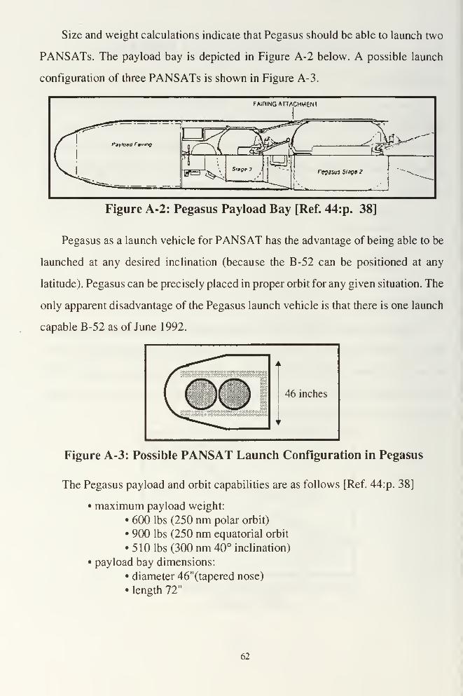
Size and weight calculations indicate that Pegasus should be able to launch two
PANSATs. The payload bay is depicted in Figure A-2 below. A possible launch
configuration of three PANSATs is shown in Figure A-3.
F AIDING ATl/VCHMENT
'1
revasvs Singe 2
Figure A-2: Pegasus Payload Bay [Ref. 44:p. 38]
Pegasus as a launch vehicle for PANSAT has the advantage of being able to be
launched at any desired inclination (because the B-52 can be positioned at any
latitude). Pegasus can be precisely placed in proper orbit for any given situation. The
only apparent disadvantage of the Pegasus launch vehicle is that there is one launch
capable B-52 as of June 1992.
Figure A-3: Possible PANSAT Launch Configuration in Pegasus
The Pegasus payload and orbit capabilities are as follows [Ref. 44:p. 38]
• maximum payload weight:
• 600 lbs (250 nm polar orbit)
• 900 lbs (250 nm equatorial orbit
• 510 lbs (300 nm 40° inclination)
• payload bay dimensions:
• diameter 46"(tapered nose)
• length 72"
62
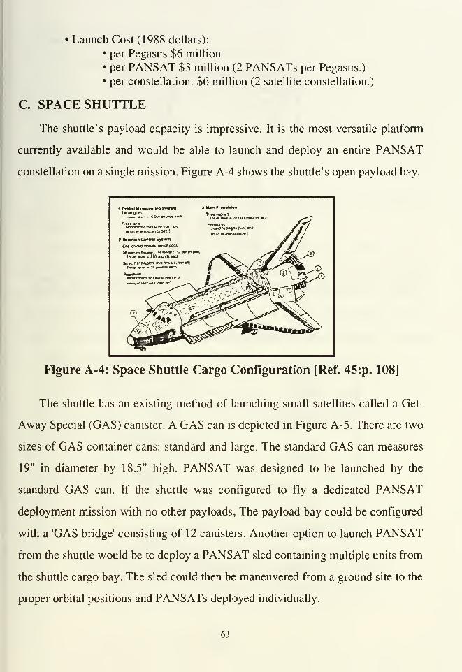
• Launch Cost (1988 dollars):
• per Pegasus $6 million
• per PANSAT $3 million (2 PANSATs per Pegasus.)
• per constellation: $6 million (2 satellite constellation.)
C. SPACE SHUTTLE
The shuttle's payload capacity is impressive. It is the most versatile platform
currently available and would be able to launch and deploy an entire PANSAT
constellation on a single mission. Figure A-4 shows the shuttle's open payload bay.
1*c«n0ines• twvtl »~ - 6.00C KMXVS HO
3 Main PrrjpwMon
Tft»«»nQin««•
PrcM4WUMormme.TivinyOiUTwOua'l *^C
mroflK tnooor loi-iuet)
PrnOM>*-««
3 (Miction Control Syslurt
Ow hrware moo**, two fA poos
IhtjO mm 870 carA Mrtown doc
r.SL^®Sii «rrucr tnrusiet (two tomaia. tour «hj
Tfw«i ***> • 2b pmmi wen
frpuihnli i
5uK
^^&^^ ^^5
Figure A-4: Space Shuttle Cargo Configuration [Ref. 45:p. 108]
The shuttle has an existing method of launching small satellites called a Get-
Away Special (GAS) canister. A GAS can is depicted in Figure A-5. There are two
sizes of GAS container cans: standard and large. The standard GAS can measures
19" in diameter by 18.5" high. PANSAT was designed to be launched by the
standard GAS can. If the shuttle was configured to fly a dedicated PANSAT
deployment mission with no other payloads, The payload bay could be configured
with a 'GAS bridge' consisting of 12 canisters. Another option to launch PANSAT
from the shuttle would be to deploy a PANSAT sled containing multiple units from
the shuttle cargo bay. The sled could then be maneuvered from a ground site to the
proper orbital positions and PANSATs deployed individually.
63
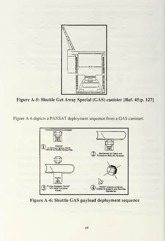
Figure A-5: Shuttle Get Away Special (GAS) canister [Ref. 45:p. 127]
Figure A-6 depicts a PANSAT deployment sequence from a GAS canister:
Wa t\ )
CD.PANSAT
1
In Get Awsy Special (GAS)Canister In Shuttle Pevioad Bay
@Mechanical Lie Opens and
Pyrotechnic Bolts are Released
I J
@ Plunoer ReleaseswrthDelta-Vot
4fVWC.
PANSATabout <D
P̂ANSAT Deploys Antennas,Checks its Systems and Becomes
Operational.
Figure A-6: Shuttle GAS pay load deployment sequence
64

Space Shuttle payload statistics:
• Maximum payload weight:
• 30000 lbs (300 nm / 28.1° inclination)
• 18000 lbs (300 nm / 57° inclination)
• 3000 lbs (260 nm / 98° inclination)
• payload bay dimensions:
•diameter: 15 feet.
• length: 60 feet.
•Launch Cost ($1988):
• dedicated: $3000 per lb.
• secondary: $65 per lb
• Endeavor's maiden flight for Intelsat 6 recovery cost >$3.5xl06
D. Titan II
The Titan series of launch vehicles was first designed to launch ICBMs. NASA
used Titan II for the Gemini manned space program. In 1987 the Titan II ICBMs
were deactivated. In 1988 there were 55 Titan lis remaining [Ref. 45 :p. 137]. When
converted for non-ICBM use, they are designated as Titan II SLV (Space Launch
Vehicle). Figure A-7 shows a schematic of the Titan II launch vehicle.
Titan II SLV /payload statistics are shown below and in Figure A-8:
• maximum payload weight:
• 3200 lbs (450 nm / 99° inclination / direct insertion)
• 4500 lbs (450 nm / 99° inclination / split insertion)
• maximum payload dimensions:
• 20' faring
diameter: 111"
length: 240"•25' faring
diameter: 111"
length: 300"•30' faring
diameter: 111"
length: 360"• Launch Cost (1988 Dollars):
• per Titan II: $43 million
• per PANSAT: $4.3 million (10 PANSATs per Titan II)
• per constellation: $43 million (10 satellite constellation)
65
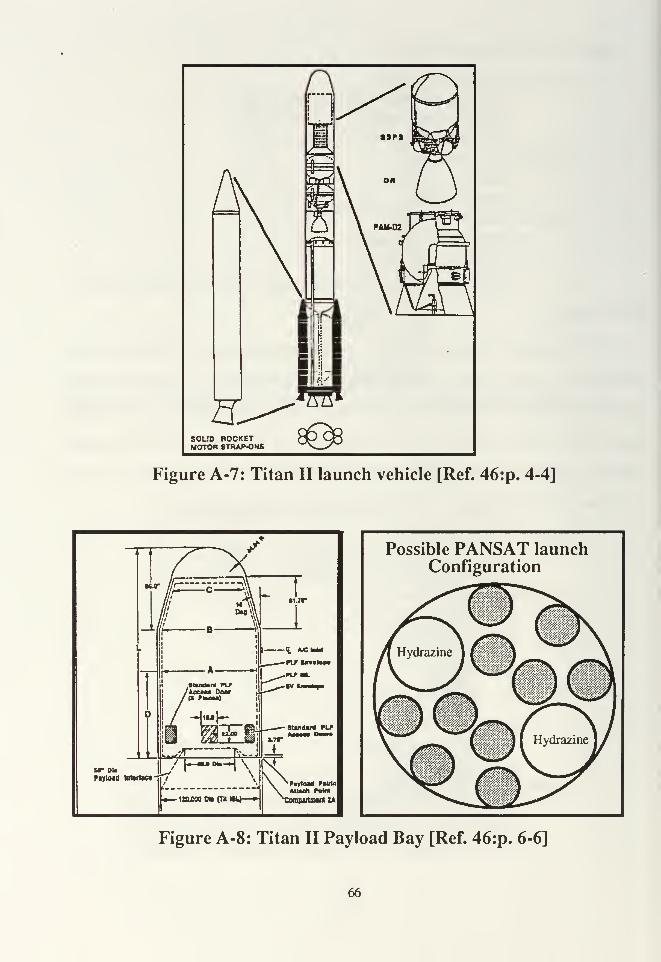
SOLID POCKETMOTOR 8TRAP-OMS
Figure A-7: Titan II launch vehicle [Ref. 46:p. 4-4]
sr dl.
Ptyloid lotorlac*
- itc.MO on cm
Possible PANSAT launchConfiguration
Figure A-8: Titan II Payload Bay [Ref. 46:p. 6-6]
66

E. Scout
The Scout was designed for orbital, probe and reentry experimental missions. It
became operational in 1963. The improved Scout was introduced in 1986. It is a four
staged, solid propellant system. Scout was designed for the smaller payloads and fits
PANSAT launch requirements well. According to Lyons, in 1988 there were only
10 scout launchers remaining and each of them were committed to specific tasks.
Figure A-9 shows a Scout launch vehicle on its tilted launcher. Figure A- 10 shows
a cut-a-way of both the original and improve Scout payload bays.
PAYLOAD UMBILICALCABLE
SCOUTVEHICLE
Figure A-9: Scout launch vehicle on tilted launcher [Ref. 45:p. 221]
67

Figure A-10: Original (left) and Improved Scout (right) Payload Bay[Ref. 45:pp. 229, 230]
Figure A-ll: Possible PANSAT configuration for the original (left)
and the improved (right) Scout [Ref. 43:p. 25]
68

Scout Payload statistics:
Original Scout:
• maximum payload weight: 480 lbs
• payload bay dimensions:
• diameter: 30"
• length: 59"
• Launch Cost ($1988 millions):
• per Scout: $9 million
•per PANSAT: $4.5 million (2 PANSATs per scout)
•per constellation: $9 million (2 satellites per constellation)
Improved Scout (change only)
• payload bay dimensions:
• diameter: 38"
• length: 61"
F. Delta II
General: The Delta are three stage rockets. The first stage is solid and the last
two stages are liquid propellant. There are currently three delta vehicles available.
From smallest to largest they are: 3920 / PAM, 6925 (two and three stage) and 7925
(two and three stage). The Delta vehicles were designed to put very heavy loads into
very high orbits. (Examples: 5660 lbs to 450 nm 98.7 degree inclination sun
synchronous orbit or 2120 lbs to 63.4 degree Molniya orbit.)
Delta II Payload Capabilities:
3920 / PAM (8" fairing)
• maximum payload weight:
•7610 lbs
• payload bay dimensions:
• diameter: 86"
•length: 184"
6925 (9.5' fairing)
• maximum payload weight:
• 8780 lbs
• payload bay dimensions:
• diameter: 100"
69
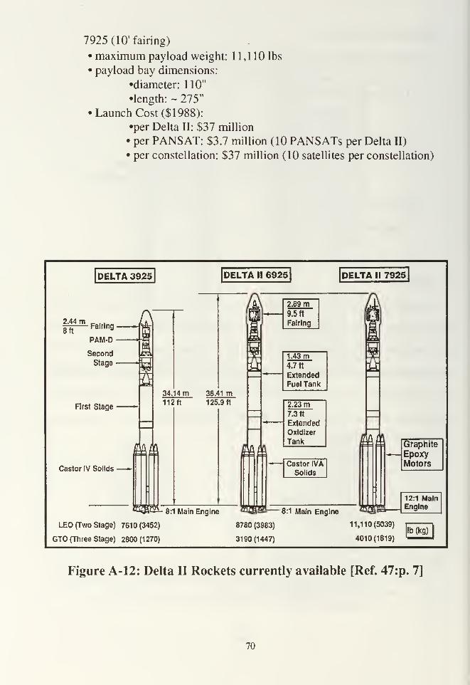
7925 (10" fairing)
• maximum payload weight: 1 1,1 10 lbs
• payload bay dimensions:
•diameter: 110"
•length: ~ 275"
•Launch Cost ($1988):
•per Delta II: $37 million
• per PANSAT: $3.7 million (10 PANSATs per Delta II)
• per constellation: $37 million (10 satellites per constellation)
DELTA 3925 DELTA II 6925 DELTA II 7925J
^Fairing- ^8tt
PAM-D
Second
Stage
First Stage
Castor IV Solids
ffl
34.14 m112ft
38.41 m125.9 ft
m
<8ZgP&- 8:1 Main Engine &&&£— 8:1 Main Engine
MaM
2.89 m9.5 ft
Fairing
1.43 m4.7 ft
Extended
Fuel Tank
2.23 m7.3 ft
Extended
Oxidizer
Tank
Castor IVA
Solids
ffiA
mlg
M
^a
Graphite
EpoxyMotors
12:1 MainEngine
LEO (Two Stage) 7610(3452)
GTO (Three Stage) 2800 (1270)
8780 (3983)
3190(1447)
11,110(5039)
4010(1819)
Figure A-12: Delta II Rockets currently available [Ref. 47:p. 7]
70
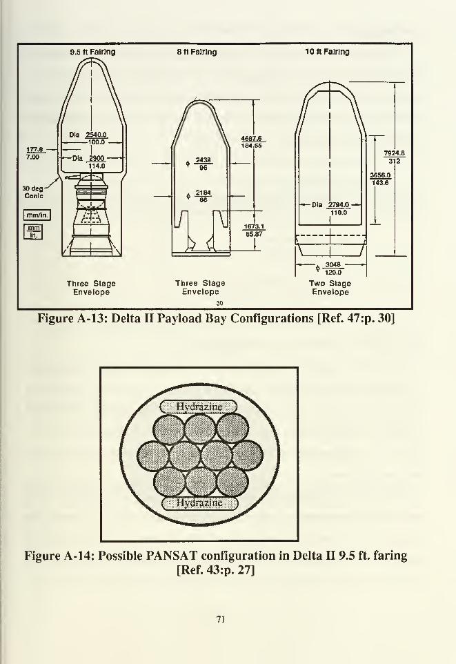
9.5 ft Fairing 8 ft Fairing 10 ft Fairing
177.B -—7.00
30deg-Conlc
Dia 2540.0i 100.0
-Dia 2900114.0
243896
218486
If]
kAM
4687.6184.55
1673.1
65.87
_L
Ola 2794.0 -»»
110.0
t
Three StageEnvelope
Three StageEnvelope
30
—A 3048 —9 120.0
Two StageEnvelope
7924.8
312
3656.0
143.6
Figure A-13: Delta II Payload Bay Configurations [Ref. 47:p. 30]
Figure A- 14: Possible PANSAT configuration in Delta II 9.5 ft. faring
[Ref. 43:p. 27]
71
G. Taurus
Taurus is a newly developed expendable launch vehicle. It is a combination
of a Peacekeeper missile and Pegasus air launch vehicle.Taurrus will have a flexible
launch siting because it will have a transportable launch assembly and launch stand
that will not require permanent launch pads. DARPA is the main backer and
controller of this launch vehicle. [Ref. 48:p. 66]
Taurus payload statistics:
• maximum payload weight:
3200 lbs (100nm/28° inclination)
2600 lbs (100 nm / 90° inclination)
830 lbs (GEO)• payload bay dimensions:
• diameter:4.8 ft.
•length: 21.7 ft.
• Launch cost: (1988 dollars)
• per Taurus: $10.9 million
per PANSAT: $1.9 million (10 PANSATs per Taurus)
•per constellation: $10.9 million (10 satellites per constellation)•i
H. LAUNCH VEHICAL COMPARISONS
PANSAT is currently planned to be completed and launched in late 1995.
Assuming that PANSAT, as an experimental satellite, proves to be a reliable and
useful communication asset, it is conceivable that a constellation of PANSAT
follow-on satellites could be built and held in reserve for contingency purposes.
Table A- 1 compares some of the more common elements of the launch vehicles
previously addressed.
The size of the contingency constellation need would determine the launch
vehicle, deployment system, method of storage and time required to launch. For
example, if a two satellite constellation was required, then a two satellite Pegasus
launch vehicle configuration could be prepared and assembled complete with two
PANSATs mounted in the payload area and stored until needed. Prior to launch, the
72

PANSATs could be computer tested, the launch vehicle fueled and farings attached.
The Pegasus would then be moved to the waiting B-52 and subsequently deployed.
If a 10 PANSAT constellation was required, either 10 PANSAT GAS cans
could be removed from storage and launched on a shuttle mission, or a previously
manufactured deployment sled with 10 PANSATs could be loaded into the Shuttle
bay. Given the Shuttle's protracted payload schedule and time between launches,
this scenario does not lend itself to a short notice missions.
TABLE A-l: LAUNCH VEHICLE COMPARISONS
Pegasus Shuttle Titan II Scout Delta II Taurus
Proposed
Weight
510 lbs 450-900
lbs
2500 lbs 480 lbs 2500 lbs 3200 lbs
altitude 300 nmi 300nmi 300nmi 300 nmi 300 nmi lOOnmi
inclination 40deg 57deg 99deg 28deg
MaxInclination
90deg 98deg 99deg 90deg
weight 600 lbs 3000 lbs 4500 lbs 2600 lbs
altitude 250 nmi 260 nmi 450 nmi 100 nmi
Cost/PAN-
SAT~$3
million
variable* 4.3
million
~$4.5
million
$3.7
million
$1.8
million
Availability indefinite indefinite indefinite ?????? ?????? 1993?
Other secondary
payload
available
secondary
payload
available
830 lbs
toGSO
* Shuttle mission cost depends upon a number of factors. Purchasing an entire Space
Shuttle mission for launching a PANSAT constellation would cost DoD $115
million. [Ref. 48:p. 44] A single GAS launch could cost between $10,000 and
$30,000.
73
APPENDIX B: AMATEUR RADIO LINK LAYER PROTOCOL
A. GENERAL
AX.25 specifies the content and format of an amateur packet radio frame and
how that frame is handled by packet radio stations. AX.25 works equally well in
either half-duplex or full-duplex radio environments. The intent in this appendix is
to provide an overview of basic AX.25 link-layer protocol features of critical
importance to PANSAT and PANSAT system users. This appendix is
predominantly a summary from Chapter 3 of Stan Horzepa's book entitled Your
Gateway to Packet Radio, (American Radio Relay League, 1989).
1. AX.25 Frames and Fields
An AX.25 transmission consist of three types of information blocks called
frames: Information (I-frame), Supervisory (S -frame) and Unnumbered frame (U-
frame), s. Tables B-l and B-2 each depict various AX.25 frame and field formats.
An I-frame contains the user data while an S-frame acknowledges receipt of I-
frames and/or request retransmission of I-frames. U-frames provide additional
control not relevant to a general overview and will not be further defined.
Each frame is subdivided into smaller blocks called fields. Field lengths are
measured in octets (an octet is equivalent to a byte or eight bits). Each frame
contains a start and stop flag field, an address field and a frame check sequence
(FCS) field. The flag field marks the beginning and ending frame. The address field
contains the call sign of the source and destination of the frame. AX.25 protocol
permits the use of up to eight relay stations (these stations are referred to as
digipeaters). The control field indicates the frame type (I, S or U frame). The FCS
field is used for fame error checking. The FCS field is recalculated by the receiving
station. If the recalculated FCS number (a 16 bit number) does not match the
74
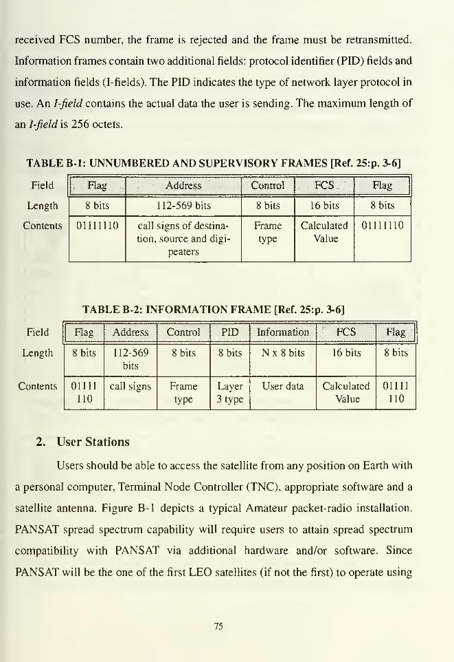
received FCS number, the frame is rejected and the frame must be retransmitted.
Information frames contain two additional fields: protocol identifier (PID) fields and
information fields (I-fields). The PID indicates the type of network layer protocol in
use. An I-field contains the actual data the user is sending. The maximum length of
an I-field is 256 octets.
TABLE B-l: UNNUMBERED AND SUPERVISORY FRAMES [Ref. 25:p. 3-6]
Field
Length
Contents
Flag Address Control FCS Flag
8 bits 112-569 bits 8 bits 16 bits 8 bits
01111110 call signs of destina-
tion, source and digi-
peaters
Frame
type
Calculated
Value
01111110
TABLE B-2: INFORMATION FRAME [Ref. 25:]p. 3-6]
Field Flag Address Control PID Information FCS Bag
Length 8 bits 112-569
bits
8 bits 8 bits N x 8 bits 16 bits 8 bits
Contents 01111
nocall signs Frame
type
Layer
3 type
User data Calculated
Value
01111
110
2. User Stations
Users should be able to access the satellite from any position on Earth with
a personal computer, Terminal Node Controller (TNC), appropriate software and a
satellite antenna. Figure B-l depicts a typical Amateur packet-radio installation.
PANSAT spread spectrum capability will require users to attain spread spectrum
compatibility with PANSAT via additional hardware and/or software. Since
PANSAT will be the one of the first LEO satellites (if not the first) to operate using
75

spread spectrum, new software and/or hardware will have to be developed to permit
spread spectrum operations.
Originally, the Terminal Node Controller (TNC) was strictly a packet
assembler-dissassembler (PAD). A PAD accepts data from the computer and formats
it into AX.25 frames for transmission. It also accepts packet frames via the radio's
receiver and modem. A modern TNC includes both PAD and modem functions.
Figures B-2 and B-3 each respectively depict a block diagram for a typical Amateur
radio TNC and modem.
Audio Output
Push to Talk
Ground
Serial Port
Audio Input
Ground
TNC
Audio Input
Push to Talk Ant
Ground XMTR
Audio Output
GroundAnt
RCVR
AntennaSwitch
TRANSCEIVERSenal Interface
Figure B-l: Wiring diagram for a packet-radio system [Ref. 25:p. 5-9]
Primary components in a typical Amateur TNC are the microprocessor and the
HDLC (High Level Data Link Control procedure). The HDLC controller
formats data from the microprocessor into frames that are transmitted over the
air and it extracts data from each received frame for transfer to the
microprocessor... The HDLC also calculates the FCS when a frame is
assembled in preparation for transmission and recalculates the FCS for each
frame received over the air to check its integrity. [Ref. 25:pp. 3-9:3-12]
In most applications, the TNC connects to the computer via a serial
interface that is compatible with RS-232-C specifications. Some TNCs provide a
76
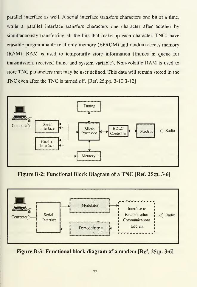
parallel interface as well. A serial interface transfers characters one bit at a time,
while a parallel interface transfers characters one character after another by
simultaneously transferring all the bits that make up each character. TNCs have
erasable programmable read only memory (EPROM) and random access memory
(RAM). RAM is used to temporarily store information (frames in queue for
transmission, received frame and system variable). Non-volatile RAM is used to
store TNC parameters that may be user defined. This data will remain stored in the
TNC even after the TNC is turned off. [Ref. 25:pp. 3-10:3-12]
—<^ Radio
Timing
]"""i
J ^^^_i
BComputer>
—
Serial
Interface
4<-
4-
MicroProcessor 4— HDLC
Controller4—
»
Modem;
Parallel
Interface
1j
!Memory
1
Figure B-2: Functional Block Diagram of a TNC [Ref. 25:p. 3-6]
•-— J-,
Computer^
Modulator
:«"«"»"•*
Serial
Interface
Nt Interface to ,
t Radio or other\
tCommunications
J
DemodulatorL t medium
4!
Radio
Figure B-3: Functional block diagram of a modem [Ref. 25:p. 3-6]
77

APPENDIX C: SEARCH AND RESCUE SATELLITE (SARSAT)
A. GENERAL
Today, the world depends exclusively upon Search and Rescue Satellite Aided
Tracking (SARSAT) receivers in Russian Cosmos and U.S. NOAA satellites to
locate downed aircraft that can not readily be found via terrestrial means. The
purpose of this appendix is to describe the current search and rescue system's
functions and shortfalls so a better appreciation of the potential contribution of the
Emergency Locator Rescue System(ELRS) proposed in Chapters HI and V can be
more fully appreciated.
B. THE SARSAT SYSTEM
Downed aircraft distress signals originate from the aircraft's "black box" and
are transmitted over three frequencies (121 .5, 243.0 for older transmitters and 406.1
MHz for newer transmitters).
Many aircraft and ships carry small [Emergency Locator Transmitters (ELT)]
transmitters that may be used to broadcast emergency signals. However,
because of their limited power, they have a short range. Thus, in most cases,
rescue organizations must be alerted to the emergency by other means and
home in on the transmitted signal only after they reach the vicinity of the
emergency. Since satellites see a large portion of the Earth, they have a much
better chance of receiving these emergency signals. [Ref. 49:p. 295]
The U.S. SARSAT contribution was developed by NASA's Goddard Space Flight
Center. These satellites are in a polar, low earth orbit between 400 and 550 nmi. The
Russian SARSAT receiver is called COSPAS (from the Russian words for Space
System for the Search of Distressed Vessels). These distress signals must be
received a minimum of three times by a Local User Terminal (LUT) before an
approximate location of the distress signal can be determined. The ELTs emit a non-
directional beacon. Figure C-l depicts the ELT signal's reception requirement for
78
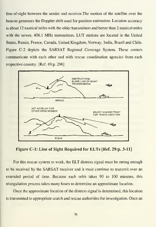
line-of-sight between the sender and receiver.The motion of the satellite over the
beacon generates the Doppler shift used for position estimation. Location accuracy
is about 12 nautical miles with the older transmitters and better than 2 nautical miles
with the newer, 406.1 MHz transmitters. LUT stations are located in the United
States, Russia, France, Canada, United Kingdom, Norway, India, Brazil and Chile.
Figure C-2 depicts the SARSAT Regional Coverage System. These centers
communicate with each other and with rescue coordination agencies from each
respective country. [Ref. 49:p. 296]
OBSTRUCTIONSBLOCK LINE OF SIGHTTRANSMISSIONS -*«
-S^a.WRONG
ACT AS RELAY FOROTHER CREW MEMBER SELECT HIGHEST POINT
FOR RADIO LOCATION
RIGHT
Figure C-l: Line of Sight Required for ELTs [Ref. 29:p. 3-11]
For this rescue system to work, the ELT distress signal must be strong enough
to be received by the SARSAT receiver and it must continue to transmit over an
extended period of time. Because each orbit takes 90 to 100 minutes, this
triangulation process takes many hours to determine an approximate location.
Once the approximate location of the distress signal is determined, this location
is transmitted to appropriate search and rescue authorities for investigation. Once an
79
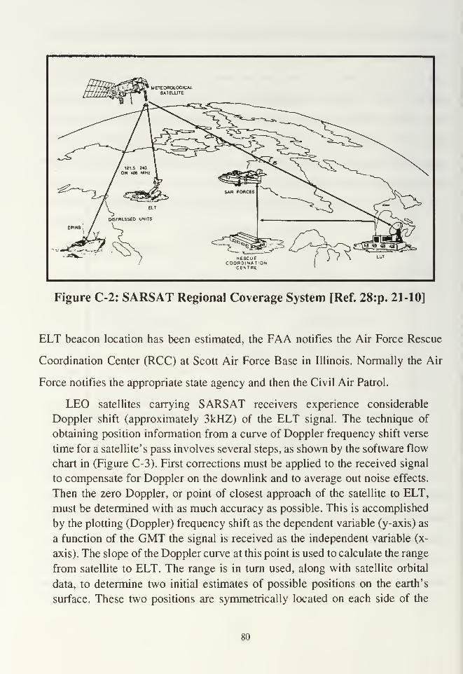
RESCUECOORDINATION
CENTRE
Figure C-2: SARSAT Regional Coverage System [Ref. 28:p. 21-10]
ELT beacon location has been estimated, the FAA notifies the Air Force Rescue
Coordination Center (RCC) at Scott Air Force Base in Illinois. Normally the Air
Force notifies the appropriate state agency and then the Civil Air Patrol.
LEO satellites carrying SARSAT receivers experience considerable
Doppler shift (approximately 3kHZ) of the ELT signal. The technique of
obtaining position information from a curve of Doppler frequency shift verse
time for a satellite's pass involves several steps, as shown by the software flow
chart in (Figure C-3). First corrections must be applied to the received signal
to compensate for Doppler on the downlink and to average out noise effects.
Then the zero Doppler, or point of closest approach of the satellite to ELT,
must be determined with as much accuracy as possible. This is accomplished
by the plotting (Doppler) frequency shift as the dependent variable (y-axis) as
a function of the GMT the signal is received as the independent variable (x-
axis). The slope of the Doppler curve at this point is used to calculate the range
from satellite to ELT. The range is in turn used, along with satellite orbital
data, to determine two initial estimates of possible positions on the earth's
surface. These two positions are symmetrically located on each side of the
80
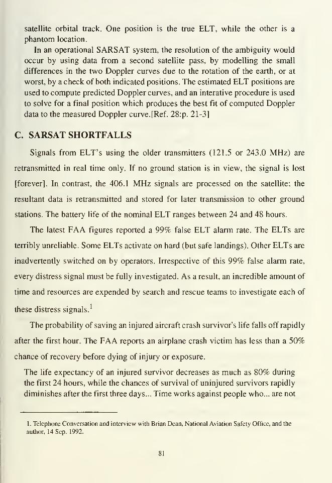
satellite orbital track. One position is the true ELT, while the other is a
phantom location.
In an operational SARSAT system, the resolution of the ambiguity would
occur by using data from a second satellite pass, by modelling the small
differences in the two Doppler curves due to the rotation of the earth, or at
worst, by a check of both indicated positions. The estimated ELT positions are
used to compute predicted Doppler curves, and an interative procedure is used
to solve for a final position which produces the best fit of computed Doppler
data to the measured Doppler curve. [Ref. 28:p. 21-3]
C. SARSAT SHORTFALLS
Signals from ELT's using the older transmitters (121.5 or 243.0 MHz) are
retransmitted in real time only. If no ground station is in view, the signal is lost
[forever]. In contrast, the 406.1 MHz signals are processed on the satellite; the
resultant data is retransmitted and stored for later transmission to other ground
stations. The battery life of the nominal ELT ranges between 24 and 48 hours.
The latest FAA figures reported a 99% false ELT alarm rate. The ELTs are
terribly unreliable. Some ELTs activate on hard (but safe landings). Other ELTs are
inadvertently switched on by operators. Irrespective of this 99% false alarm rate,
every distress signal must be fully investigated. As a result, an incredible amount of
time and resources are expended by search and rescue teams to investigate each of
these distress signals.1
The probability of saving an injured aircraft crash survivor's life falls off rapidly
after the first hour. The FAA reports an airplane crash victim has less than a 50%
chance of recovery before dying of injury or exposure.
The life expectancy of an injured survivor decreases as much as 80% during
the first 24 hours, while the chances of survival of uninjured survivors rapidly
diminishes after the first three days... Time works against people who... are not
1. Telephone Conversation and interview with Brian Dean, National Aviation Safety Office, and the
author, 14 Sep. 1992.
81
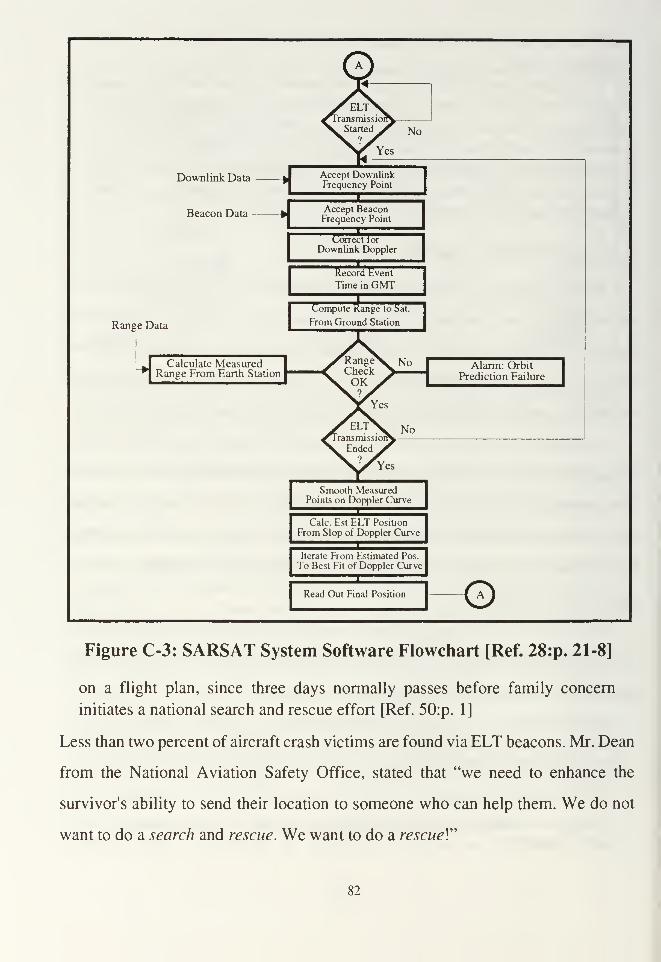
No
ownlink Data hAccept DownlinkFrequency Point
Accept BeaconFrequency Point
Correct tor
Downlink Doppler
Record Event
Time in GMT
Range Data
Ranee to S,Compute Range to Sat.
From Ground Station
Calculate MeasuredRange From Earth Station
RangeCheckOK9
'Yes
transmission1
Ended9
Yes
Smooth MeasuredPoints on Doppler Curve
Calc. Est ELT Position
From Slop of Doppler Curve
Iterate From Estimated Pos.
To Best Fit of Doppler Curve
Read Out Final Position
^No Alarm: Orbit
Prediction Failure
No
Figure C-3: SARSAT System Software Flowchart [Ref. 28:p. 21-8]
on a flight plan, since three days normally passes before family concern
initiates a national search and rescue effort [Ref. 50:p. 1]
Less than two percent of aircraft crash victims are found via ELT beacons. Mr. Dean
from the National Aviation Safety Office, stated that "we need to enhance the
survivor's ability to send their location to someone who can help them. We do not
want to do a search and rescue. We want to do a rescued
82

LIST OF REFERENCES
[I] Hutchinson, Charles L. and Kleinman, Joel P., editors, The ARRLHandbook for the Radio Amateur, The American Radio League,
Newton, CT, 1992.
[2] Sakoda, Daniel J., "PANSAT Space-Based Communications
Experiment Baseline Report," Naval Postgraduate School, Monterey,
CA, 1988.
[3] "Macke: Military Space Too Pricy," Space News, 20-26 Apr. 92.
[4] Boyer, William, "Cost, Utility Stir Interest in Small Satellites," Space
News, 5-18 Aug. 1991.
[5] de Selding, Peter, "Europe's Launcher Availability Stall Lightsat
Development," Space News, 17-23 Aug. 1992.
[6] Tucci, Liz, "Industry Split on Benefits of Small Satellites," Space
News, 17-23 Aug. 1992.
[7] Kiernan, Vincent, "War Test Satellite's Prowess," Space News, 21 Jan.-
3Feb.l9 91.
[8] Kiernan, Vincent, "Bigger TACSATs Endorsed," Space News, 8-14
Oct. 1990.
[9] Wertz, J.and Larson W., Space Mission Analysis And Design, Klower
Academic Publishers, 1991.
[10] Klass, Philip J., "Low Earth Orbit Communications Satellites Compete
For Investors And U.S. Approval," Aviation Week and Space
Technology, 18 May 1992.
[II] "Everybody's After LEO," Space News, 1-7 Oct. 1990.
[12] Marcus, Daniel J., "Motorola Seeks High Ante from Partners," Space
News, 21 Jan. - 3 Feb. 1991.
[13] Marcus, Daniel J., "Message Market Evolves," Space News, 8-14 Jul.
1991.
[14] Marcus, Daniel J., "Russians Seek Spectrum for Medical Networks,"
Space News, 2-8 Mar 1992.
83
[15] Concept of Operations for the Multiple Access Communications
Satellite (MACSAT), Nov. 1989.
[ 1 6] Kiernan, Vincent, "Military Lightsats Pioneering Smaller Technology,"
Space News, 5-18 Aug. 1991. -
[17] Howard, William, "Navy Space Research Needs a Boost", Space
News, 5-11 Nov. 1990.
[18] "Macsat Provides Antarctic Link for Navy Personnel," Space News,
11-17 Feb.1991.
[19] Kiernan, Vincent, "Flight Two for Pegasus Approaches," Space News,
3-9 Jun. 1991.
[20] Defense Sciences Inc.,"Microsat Information and Data Sheet."
[21] Kiernan, Vincent and Marcus, Daniel J., "Microsats Given Year In
Orbit," Space News, 29 July - 4 Aug. 1991.
[22] Kiernan, Vincent,"U.S. Army, Navy Plan New Small Satellites for
Tactical Support," Space News, 24 Jun. - 7 Jul. 1991.
[23] OP-941F, "Options and Band Study for the US Naval Postgraduate
School's PANSAT," Oct. 1988.
[24] Davidoff, Martin, The Satellite Experimenter's Handbook, The
American Radio Relay League, 1990.
[25] Horzepa, Stan, Your Gateway to Packet Radio, The American Radio
League, Newton, Connecticut, 1989.
[26] Bruninga, Bob, "U.S. Naval Academy Summary Report: Lightsat
Demonstration for the Military Affiliate Radio System," United States
Naval Academy, Annapolis, MD, 13 Feb. 1992.
[27] Henderson, Breck W., "New NOAA-11 Will Monitor Ozone, Aid
Search-and-Rescue Operations," Aviation Week and Space Technology,
10 Oct. 1988.
[28] Werstiuk, H.L. and Winter, A.E., "The Search and Rescue Satellite
System Project," Operational Modelling of the Aerospace Propagation
Environment, AGARD, 1978.
84

[29] U.S. Army TM 55-1680-351-10, Operator's Manual for SRU-21/P
Army Vest, Survival, 22 Apr. 1987.
[30] Schworer, William Joseph III, Nationwide Mobile Communication
Systems, M.S. Thesis, Naval Postgraduate School, Monterey, CA, Jun.
1990.
[31] Combined Arms Command Combat Developments, Force Projection
Army Command and Control: Getting Therefrom Here, briefing charts,
23 Sep. 1992.
[32] SATCOM's Program Manager for TACSAT, UHF GMF Satellite
Communications Briefing Slides, 1 Oct. 1991.
[33] Daniel, Walter K., Gavino, Rivas, Bruninga, "Marine Corps Tactical
Satellite Communications," paper presented to the AIAA/USUConference on Small Satellites, Logan Utah, 21-23 Sep. 92.
[34] Motorola Inc. Government Electrons Group, The New LST-5C, 1990.
[35] Freeman Michael W. and Cotton, Randy M., Army Tactical Satellite
Communications," paper presented at the DARPA/IEEE Tactical
Communications Conference "Technology in Transition," Fort Wayne,
Indiana, 30 Apr. 1992.
[36] Bruninga, Bob, "Naval Academy SATCOM Packet Radio
Experiments," undated, unpublished paper.
[37] Bruninga, Robert E., Letter: Chairman of NPS Space System
Academic Group (Dr. Panholzer), Subject: PANSAT, 19 Aug. 1992.
[38] Daniel, Walter K. and Bruninga, Robert E., "Navy/Marine Corps
Demonstrations of the DARPA Microsats," paper presented to the
AIAA/USU Conference on Small Satellites, Logan Utah, 21-23 Sep.
92.
[39] US Department of Commerce National Telecommunications and
Information Administration, Manual of Regulations and Procedures
for Federal Radio Frequency Management, May 1992.
[40] Ellrick, Daniel A., An Antenna Design for PANSAT using NEC, M.S.
Thesis, Naval Postgraduate School, Monterey, CA, Jun. 1991.
85

[41] Sakoda, Daniel J., Structural Design and Modal Analysis of the Petite
Amateur Navy Satellite (PANSAT), M.S. Thesis, Naval Postgraduate
School, Monterey, CA, Sep. 1992.
[42] "Radiant Teak Experiment Critical Design Review," Naval Research
Lab, Washington, DC, Apr. 1990.
[43] Tinsley, Phillip M., Payne, Robert A. Jr., and Vetter, Theodore A.,
"Operation PANSAT," paper presented to Naval Post Graduate School
PANSAT design team, Monterey, CA, Jun. 1992.
[44] Repper, R., OMV Payload Support Concept For Pegasus Boosted
Payloads, M.S. Thesis, Naval Postgraduate School, Monterey, CA,1989.
[45] Lyon, David C. and Cipollone, Lawrence V., Space Launch Vehicle
Alternatives For Small Satellites And The Current Commercial,
Political And Physical Environments, M.S. Thesis, Naval Postgraduate
School, Monterey, CA, Sep. 1988.
[46] Martin Marietta Corp., Titan II Space Launch Vehicle Payload User
Guide, Martin Marietta, 1986.
[47] Hampton, W., The Delta II Launch Vehicle, M.S. Thesis, Naval
Postgraduate School, Monterey, CA, 1989.
[48] General Accounting Office report number B-238277, Military Space
Programs: An Unclassified Overview of Defense Satellite Programs
and Launch Vehicles, 29 Jun. 1990.
[49] Martin, Donald H., Communications Satellites 1958-1992, The
Aerospace Corporation, 1991.
[50] Chamberlain, Dean, "Lost and How to be Found," NORCAL Aviation
Review, Sep. 1992.
86
VITA
Captain (P) Robert A. Payne Jr. was born on 27 January 1959 in Bryan, Texas.
He graduated from high school in 1977 from Arlington High School in Arlington,
Texas. He graduated from the United States Military Academy (West Point) in May
of 1981 with a Bachelor of Science degree in Mechanical Engineering and a
commission in the United States Army. Upon graduation, he attended the Field
Artillery Officer Basic Course at Fort Sill, Oklahoma.
In December of 1981 , he was assigned to the 1st Battalion, 21st Field Artillery,
First Cavalry Division, Fort Hood, Texas where he served as a Fire Support Team
Chief, Battery Fire Direction Officer, Battery Executive Officer and Battalion Fire
Direction Officer. In June of 1985 he was reassigned to Headquarters Battery,
Division Artillery, First Cavalry Division, as Division Artillery's Fire Direction
Officer. From July 1986 until February 1987 he attended the Field Artillery Officer
Advanced and Cannon Officers Course at Fort Sill, Oklahoma.
In March of 1987 he was assigned to the 7th Battalion, 8th Field Artillery, 25th
Infantry Division (Light), Schofield Barracks, Hawaii where he served as the
Battalion Targeting Officer, Battalion Plans and Operations Officer and Battery
Commander of a 105mm (towed) firing battery. Upon successful completion of a 19
month command, he was reassigned to Headquarters Company, 25th Infantry
Division (Light) as a Division Plans and Exercises Officer.
In July of 1990, he reported to the Space Sciences Curriculum at the Naval
Postgraduate School in Monterey, California to pursue a Masters of Science degree
in Systems Technology (Space Systems Operations).
Permanent address:
1407 Baker Dr.
Cedar Hill, TX 75104
87

INITIAL DISTRIBUTION LIST
Defense Technical Information Center
Cameron Station
Alexandria, VA 221314
Dudley Knox Library
Code 0142
Naval Postgraduate School
Monterey, CA 93943
Director of Research Administration
Code 012
Naval Postgraduate School
Monterey, CA 93943
Chairman, Code SP
Space Systems Academic Group
Naval Postgraduate School
Monterey, CA 93943
CDR Randy L. Wight
Code SPAVt
Naval Postgraduate School
Monterey, CA 93943
Professor E.A. Euler
Code SP/Eu
Naval Postgraduate School
Monterey, CA 93943
Dr. William Howard
Director of Army Space and Strategic Technology for the Secretary of the Army1653 Quail Hollow Court
McLean, VA 22101-3234
DARPA / ASTOATTN: LTC Bonometti
3701 N.Fairfax Dr.
Arlington, VA 22203-1714
88

U.S. Army TECATTN: Army Space, Technology and Research Organization (Mr. Ron Dickerman)
Ft. Belvoir, VA 22060-5546
U.S. Army Combined Arms CommandATTN: ATZL-CDE-B / Mr. Mike Freeman
Ft Leavenworth, KS 66027
U.S. Army Space CommandATTN: MOSC-00 (Major David Quals)
1670 North Newport Road
Colorado Springs, CO 80916
U.S. Army Space CommandATTN: MOSC-0P (Major Mary Kaura)
1670 North Newport Road
Colorado Springs, CO 80916
Commander
U.S. Army Signal Center
ATTN: ATZH-CD (Mr. Lee Leyda)
Ft. Gordon, GA 30905
Commander CECOMATTN: AMSEL-RD-C3-EM-F / Mr. Paul Majors
Fort Monmouth, NJ 07703-5203
Commander, U.S. Army Special Forces Operations Center
ATTN: AOIM-THFt. Bragg, NC 28307-5200
Space Systems Directorate
Building 911
ATTN: Mr. Thorn Nelson
AMSEL-RD-SS-ST-SPFort Monmouth, NJ 07724-5208
Department of the Navy
Chief of Naval Operations -N60T
ATTN: Mr. Bill CookPentagon
Washington, D.C. 20350-2000
89
Communications Officer
Naval Support Force Antarctica (Code 20)
651 Lyons St.
Port Hueneme, CA 93904-4345
NAVEMSCENATTN: Mr. Warren Chu
Building 166, 3rd Floor, South Wing
Washington Navy Yard
Washington, D.C. 20374-5073
Satellite Earth Station Facility
ATTN: Mr. Bob Bruninga
U.S. Naval Academy lib
Annapolis, MD 21402
HQ Air Force
Frequency Management Agency / FEATTN: Mr. Roger Porter
Washington, D.C. 20330-6340
Los Angeles Air Force Base
SMC/CULM ATTN: LT Dave Spackman
Los Angeles, CA 90009-2960
Air Force Space and Missile Systems Center
ATTN: Major Charles Banning
P.O. Box 92960
Los Angeles, CA 90009-2960
U.S. Coast Guard R&D Center
ATTN: CDR James John
1082 Shennecossett Road
Gristen, CT 06340
Space Applications Corporation
ATTN: Mr. Bob Steel
4001 North Fairfax Road, Suite 250
Arlington, VA 22203
Buaas Corporation
10044 Adams Ave. Suite#108
Huntington Beach, CA 92646
90

Boise Interagency Fire Center
ATTN: Mr. Brian Dean, Aviation Safety Manager
3905 Vista Ave.
Boise, ID 83705
Defense Systems Incorporated
ATTN: Mr. Ray Crough
1521 Westbranch Drive
McLean, VA 22101-3201
Newcomb Communications Inc.
ATTN: Mr. Paul Newcomb670 North Commercial St.
Manchester, NH 03101
Spectrum ASTROATTN: Mr. Chris McCormick
1440 North Fiesta Blvd.
Gilbert, AZ 85234
PacComm Packet Radio Systems Inc.
ATTN: Mr. Gwyn Reedy
4413 N. Hesperides Street
Tampa, FL 33614-7618
Mr. Louis Vettese
Program Manager for Advanced Technology Programs
Rockwell International
3009 Dorn Court
Laguna Beach, CA 92651
91


DUDLEY KNOX LIBRARYNAVAL POSTGRADUATE SCHOOLMONTEREY CA 93943-5101
GAYLORD S