Application for selecting Vamp products based on user ...
57
Application for selecting Vamp products based on user specification Dennis Lindstedt Bachelor’s thesis Electrical Engineering Vaasa 2010
-
Upload
khangminh22 -
Category
Documents
-
view
7 -
download
0
Transcript of Application for selecting Vamp products based on user ...

Application for selecting Vamp products
based on user specification
Dennis Lindstedt
Bachelor’s thesis
Electrical Engineering
Vaasa 2010

BACHELOR’BACHELOR’BACHELOR’BACHELOR’S THES THES THES THESISISISISSSS
Author: Dennis Lindstedt
Degree programme: Electrical Engineering, Vaasa
Specialization: Power engineering
Supervisor: Martti Hokkanen
Title: Application for selecting Vamp products based on user specification
_____________________________________________________________
Date 03.12.2010 Number of pages 47 Appendices 2
____________________________________________________________
SummarySummarySummarySummary
This thesis deals with two topics, protection functions used in protection relays for the electrical power industry and the development of an application designed for Windows operating systems. The purpose of the application was to use it in Vamp’s sales network as a helping tool by selecting the functions required for a situation and give a result of the products that are consistent with these selections. With the application it is also possible to get information about each product’s product codes and accessories. In order to develop software that deals with protection relays for the electrical power industry. It was also necessary to get a deeper understanding of the protection functions and what the differences between different product types were. The software used to develop this application was Visual Studio 2008. The application was aimed to be used on computers on which Windows was installed. The programming language is based on .Net framework and the Windows Forms was used as the graphical user interface. The final result was a desktop application working in Windows environment with the functionality to find an accurate product based on a user specification.
_____________________________________________________________
Language: English Key words: application, protection relay, Vamp
_____________________________________________________________
Filed at: Tritonia Academic Library, Vaasa

EXAMENSARBETEEXAMENSARBETEEXAMENSARBETEEXAMENSARBETE
Författare: Dennis Lindstedt
Utbildningsprogram och ort: Elektroteknik, Vasa
Inriktningsalternativ: Elkraftsteknik
Handledare: Martti Hokkanen
Titel: Applikation för att välja Vamp produkter baserad på användarens
specifikation
_____________________________________________________________
Datum 03.12.2010 Sidantal 47 Bilagor 2
_____________________________________________________________
SammanfattningSammanfattningSammanfattningSammanfattning
Det här examensarbetet behandlar två ämnen, dessa är skyddsfunktioner som används i skyddsreläer inom elkraftsbranschen och utvecklingen av en applikation för Windows operativsystem. Syftet med applikationen är att den skall användas inom Vamps försäljningsnätverk som ett hjälpmedel. Applikationen fungerar genom att man väljer vilka funktioner som situationen kräver och som resultat visas produkter som stämmer överens med valen. Via applikationen får man även information om produktkoder och tillbehör. För att utveckla mjukvara som behandlar skyddsreläer för elkraftsbranschen krävs det även en djupare förståelse för skyddsfunktioner och vad som skiljer sig mellan olika produkttyper. Denna information blir som grund för applikationen. Programmet som användes för att utveckla applikationen var Visual Studio 2008. Applikation skall användas på datorer med Windows operativsystem. Programmeringen baserar sig på ramverket .Net som användes för att underlätta arbetsflödet och som det grafiska användargränssnittet användes Windows Forms. Resultatet blev en skrivbordsapplikation för Windows operativsystem med funktionerna att sortera ut produkter baserade på användarens kravspecifikation. _____________________________________________________________
Språl: Engelska Nyckelord: applikation, skyddsrelä, Vamp
_____________________________________________________________
Förvaras: Tritonia veteskapliga bibliotek, Vasa
Table of contents
Summary
Sammanfattning
Table of contents
List of terms and acronyms
1 Introduction ................................................................................................................... 1
1.1 Objective and purpose ............................................................................................ 2
1.2 Structure .................................................................................................................. 3
1.3 Vamp ....................................................................................................................... 4
2 Protection relays specifications and differences ............................................................ 5
2.1 Background information of digital relaying ........................................................... 6
2.2 Principles of digital relaying ................................................................................... 7
2.3 Measurement ........................................................................................................... 8
2.4 Type of products and their main protection functions .......................................... 10
2.4.1 Arc flash protection ....................................................................................... 11
2.4.2 Feeder protection ........................................................................................... 14
2.4.3 Transformer protection .................................................................................. 15
2.4.4 Generator protection ...................................................................................... 17
2.4.5 Motor protection ............................................................................................ 19
2.4.6 Measurement and monitoring ........................................................................ 20
2.5 Communication ..................................................................................................... 21
2.6 Control options ..................................................................................................... 22
2.7 Selection table and main protect functions ........................................................... 22
3 Technologies and tools ................................................................................................ 27
3.1 Developing environment ....................................................................................... 27
3.2 Programming language ......................................................................................... 28
3.2.1 .Net Framework ............................................................................................. 28
3.2.2 Visual Basic ................................................................................................... 30
3.2.3 Visual C# ....................................................................................................... 30
3.2.4 C++/CLI Language ........................................................................................ 30
3.3 Deployment tools .................................................................................................. 30
3.4 Information management ...................................................................................... 31
3.5 User interface ........................................................................................................ 35
3.5.1 Windows Forms ............................................................................................. 35

3.5.2 Windows Presentation Foundation ................................................................ 35
4 Application .................................................................................................................. 36
4.1 Application functionality ...................................................................................... 36
4.2 Graphical application user interface ..................................................................... 41
4.3 Developing application ......................................................................................... 42
5 Results ......................................................................................................................... 44
6 Discussion and conclusions ......................................................................................... 45
7 Sources ........................................................................................................................ 47
Appendices
Selection table
Communication table

List of terms and acronyms
.Net A framework used when developing for Windows environment
ANSI American National Standards Institute
API Application Programming Interface
C# A Programming language developed by Microsoft
C++ A popular programming language
CLI Common Language Interface
ClickOnce Technology for deploying Windows Forms or Windows Presentation
Foundation-based software
Code editor Text editor program designed specifically for editing for developing
software
Debugger Computer program used to test and debug soft wares
FFT Fast Fourier Transformation
GUI Graphical application user interface
HMI Human-machine interaction
IDE Development environment
IEC International electrical commission
IEEE Institute of Electrical and Electronics Engineers
Linux An open source operating system
Modbus A serial communication protocol
Mono An open source implementation of the Common Language Infrastructure
OLE DB Object Linking and Embedding, Database
PLC Programmable Logic Controller
RTU Remote Terminal unite
SCADA Supervisory Control and Data Acquisition
SDK Software Developing Kit
Vampset Software for programming Vamp products
Windows Software operating system
Windows Forms Graphical application programming interface in Windows-based
applications
WPF Graphical subsystem for rendering user interfaces in Windows-based
applications

1 Introduction
The digital protection relay system is a relatively new business. It was first tested in the
early 1970s when the first microprocessor was developing, but it would last until the 1990s
before they became a leading system to protect electrical systems.
The modern society is very dependent on a solid generation and distribution of electricity.
If the increasing consumption of electricity shall stay reliable, it is important that the
electricity is supplied in an uninterrupted way. Our industries and power distributors have
their high technological development levels and they are very dependent on a safe, reliable
and economic supply of electrical power and energy. If power outages occur, big losses in
the production will be caused for the company. For the regular consumer it may create a
non reliable power supply and lead to disturbances in the communication systems and
transportation, which could lead to big losses in the national economy.
With today’s fast developing rate the future protection devices will get faster, smarter and
more accurate. The result of power grid development will lead to a safer power grid, but
likewise the newer power grid will also need to withstand more demanding situations. The
increasing numbers of apparatus containing electronics e.g. modern compact fluorescent
lamps are causing disturbances on the power grid. The disturbances result in a lower
quality of power distribution and can cause failure in apparatuses sensitive to variations in
power distributions. To prevent any damages caused by disturbances it is possible through
digital protection relays to monitor the power grid and detect any disturbances.
In a modern power grid, where power is going to be produced in several individual smaller
power plants (e.g. wind power or sun power) there is also the need to change in order to
suit a smarter way of managing individual power suppliers. The current power grids have
their main foundations based on power being produced in big power plants. The power is
delivered through a main power grid network not adapted to small power plants. With new
products depending on a safe power supply, it will be even more important to protect the
distribution and generating. This new consumption behaviour of power will produce more
power grids to monitor and new products to protect. Therefore also more protection
equipment is going to be developed for more specific purposes.

2
For a company that produces protection relays including many protection functions and
different specifications, it is important to select a correct product that will suit the needs of
the situation. With a growing number of products with different options, the choice is
getting harder and harder.
For companies it is important to have a good marketing strategy and therefore any helpful
tool to select the right products will be very useful. One way of making the product
overview more productive is to use some sort of product selectors. These are embedded in
their digital marketing tools, such as web sites or business applications.
By using a helping tool for the selecting process the user will get a simpler method to
familiarise himself with the products. This will give a more accurate and faster choice of
the right product. Depending on what type of products companies are selling, the selection
process often works in a similar way. The user gives an input of different demands and
specifications and then the selection application sorts out the products that match up.
1.1 Objective and purpose
The main objective for this thesis work was to develop a software based application to
simplify the selection process. The selection would be based on a number of options that
the user selects depending on what the intention is. He will then get a result showing the
right product that corresponds to the user specification. The application will be used within
Vamp’s sales and marketing sections.
The other objective was to get a deeper insight into Vamp’s product range. I have studied
the protection relays and got a basic knowledge of what their functionalities and
differences are depending on what protection system they are aimed for. The products are
often used in power electrical systems like distribution, transmission and generating
systems, therefore it was required to get a general idea of how these function. Before
developing an application to handle these systems it was necessary to get knowledge of the
fundamental technologies used in protection systems. Based on the knowledge of the
products and their characteristics I was able to develop a helping tool for selecting the right
products based on the different criteria.

3
1.2 Structure
The focus of this thesis work is mainly divided into two parts. The first part deals with
protection relays and the second part describes the tools needed for developing the
application. The first three chapters start with providing the information of the protection
systems in different sections of electrical power systems.
Chapter 2 describes the protection functions based on the type of product. Some
differences between product types and common faults that may happen within distributions
systems are also mentioned here. The chapter also gives basic knowledge that needs to be
considered when choosing the correct protection relay for the right occasion. This chapter
provides an overview of different product types and their functionalities.
Chapters 3 and 4 describe the tools and technology for what is going to be needed for
developing the application. Chapter 3 describes the technologies that were used in
developing the application and it is also mentioned why these software are most suitable
for this kind of application development. Chapter 4 describes and explains about the
development process including planning, design and programming and testing.
The final chapters present a conclusion of this work and list some of the problems that
occurred. A little is also said about the learning process that was needed to complete this
project and my own thoughts about the software that was used are presented.

4
1.3 Vamp
The commissioning body for this thesis is Vamp. The main customers are companies
within power distribution project. Typical markets where Vamp’s products are found are
wind farms, industrial applications, power generation infrastructure projects and marine
and offshore applications.
The company is specialized in arc protection and protection relays and it also offers expert
services for the market. Vamp’s sub-transmission and medium voltage protection relays
are products that can be used in many various applications like overhead line feeders,
substations, power plants and other industrial power systems. Vamp products are built
based on a certified quality system according to ISO 9001:2000, and meet the standards
and regulations of international qualification.
Vamp was founded in 1994 and has its headquarters in Vaasa, Finland. They have a
current staff of 40 employees. By the end of 2009 Vamp belonged to Vaasa electronics
group. From 2010 the France Company Areva became the main shareholder. Vamp in
Vaasa reports to the unit of Areva T&D substation automation solutions. Vamp’s brand
and products will remain. Vamp is an international company and has an international
network with subcontractors and partners. With the agreement with Areva, Vamp’s sales
network was reinforced.
5
2 Protection relays specifications and differences
A digital protection relay is defined and described as a device based on a microprocessor
with software based protection algorithms. The algorithms are based on mathematical
expressions created to detect faults within electrical systems. A protection relay can
sometimes also be called a numerical relay. Protection relay’s general features are often
listed as follows:
• Fully digital signal handling through a microprocessor.
• The relay has an analogue to digital conversion technique for the incoming voltages
and currents.
• The relay analyzes voltages and currents through a sampling process.
• The relay is able to use advanced logic to decide if it should disengage the
equipment.
• The relay has communication and metering protocol ports, such as SCADA.
• It includes a wide settings range for protection functions of various settings to
configure the relay.
The basic idea of all protection systems is to identify faults or detect when the operating
conditions are acting abnormal. The protection system shall provide a necessary action to
minimize possible damage of the equipment in the system. A protection system can be
seen in figure 1 which shows a typical layout of a power grid. Protection relays must be
able to gather a lot of parameters and evaluate them correctly, and launch the correct
protection action if a fault is detected. A protection relay itself cannot prevent the error but
it will protect the equipment from getting unnecessary damage which could have led to
difficult repair work and be very expensive to fix.

6
Figure 1. A protection system for a power grid network (12).
2.1 Background information of digital relaying
Digital relaying had its beginning in the late 1960s and the early 1970s with the high cost
of those early computers which could only perform simple calculations and were very
slow, the result was that they couldn’t compete with the current protection systems. But in
those early stages the products were only in an experimental stage and over time when
minicomputers became faster, smaller and cheaper combined with improved algorithms,
the developing process for digital relaying continued to move forward.
Digital relaying became more popular during the early 1980s when companies like
AREVA, ABB’s forerunner Asea and SEL introduced digital relaying based on number
technologies. With the benefits of what a modern microprocessor could provide, the digital
relaying technology could develop the work even more efficiently and replace the older
systems that were based on analogue protection. The older systems were using old methods
like solid state and electromechanical relay and couldn’t compete with modern computers.
One of the many abilities that digital relaying has, is that it could perform a self-monitoring
function, which means that the digital systems are continuously active. The function
provides a self-diagnosis to detect failures within the system. This way the relays could

7
protect themselves from working incorrectly. This was a clear advantage over the earlier
technologies used in protection systems.
By the mid 1990s the digital relays in transmission line and generator systems had now
almost replaced the older analogue protection. They were more economic, safer and had
more flexibility. When new constructions were built they were often preferred. In other
areas, the introduction of a newer system was not quite as efficient, but new products were
still under development and after a few years digital relays were very competitive in most
areas.
The microprocessor revolution created a situation where digital relaying was the best
choice in an economical view, because when the cost of microprocessor went down the
other type of analogue protection system became more expensive to install. The digital
protection system was more space saving in substations and didn’t need as many panels as
an analogue system. The amount of wiring work was also smaller and in the end it was
more economical and valuable than other systems. (3)
2.2 Principles of digital relaying
The basic principles for digital protection relay is based on a microprocessor with designed
software that runs mathematical protection algorithms. These algorithms create functions
that make it possible to detect potential fault which could damage the system.
The devices are designed to use some type of numerical technology which means that all
signal filtering, protection and control functions are implemented through digital
processing.
A protection relay uses the power system’s voltages and currents to gather data. Because of
the fact that these signals appear in analogue values and microprocessors can only work
with digital data it is necessary to create a digital representation of these signals. This is
done by sampling the analogue signals, and using an appropriate algorithm to create
suitable digital representations of the signals.
Digital relaying is depends on the sampling process, which gathers data at a fixed rate
according to the electrical power system’s nominal frequency. The sampling process is an
essential part of the protection relay and is needed to be able to create data required for
different protection functions to perform its necessary calculations. Different numerical
8
technologies can be used for this purpose and for example in Vamp’s products this
sampling process is based on an adapted Fast Fourier Transformation (FFT). The Fast
Fourier Transformation technology reduces the information size, which make the number
of calculations stay on a reasonable level.
The data can be managed through different communication technologies that are built in
the relays. Modern relays can provide connection options in a wide range of selections like
SCADA, DCS or SA systems. Protection relays can for example provide fault location
information through any of these communications and send it forward to a monitoring
station to help locating the fault. (3) (13)
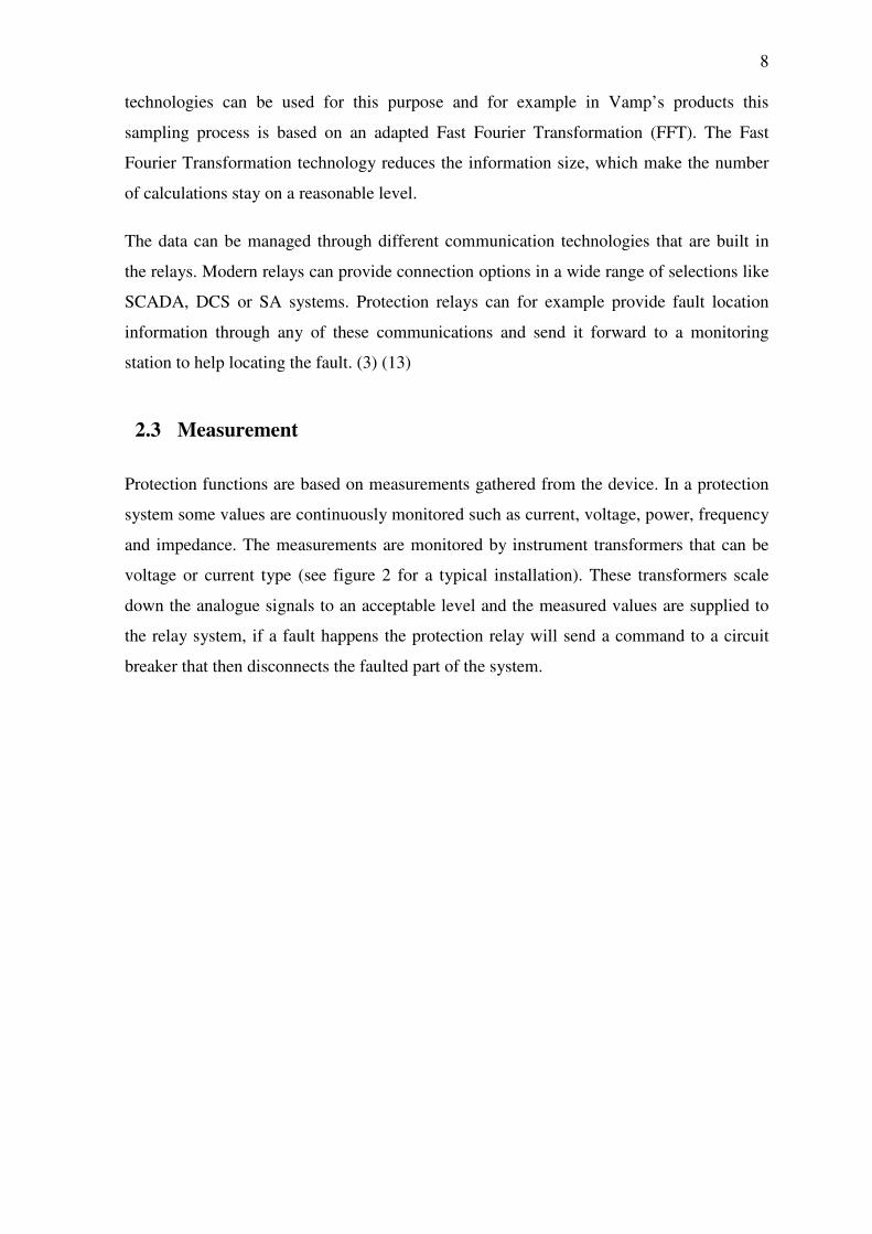
2.3 Measurement
Protection functions are based on measurements gathered from the device. In a protection
system some values are continuously monitored such as current, voltage, power, frequency
and impedance. The measurements are monitored by instrument transformers that can be
voltage or current type (see figure 2 for a typical installation). These transformers scale
down the analogue signals to an acceptable level and the measured values are supplied to
the relay system, if a fault happens the protection relay will send a command to a circuit
breaker that then disconnects the faulted part of the system.

9
Figure 2. A typical installation for Vamp 255, measuring the necessary values. (13)
Different diagrams can be created from the measurement. An example of a phasor diagram
is shown in figure 3. The diagram shows the characteristics of a directional earth fault
protection.
Figure 3 Examples of phase diagram showing the characteristic of an earth fault
protection. (13)
Some protection function also needs a symmetrical component. The symmetrical
components are used to simplify analysis of imbalance in three phase power systems. The
symmetrical components are the linear transformation on voltage and currents of three
phase network

10
Figure 4. Positive sequence voltage phasors, (b) negative sequence voltage phasors, (c)
zero sequence voltage phasors. (1)
The ideas of symmetrical components can be applied to current in the same manner. By
help of these it is possible for the protection relay to calculate and get the positive, negative
and zero phase sequence components. These are of importance in analyzing imbalance in
three phase networks. (1)
2.4 Type of products and their main protection functions
The most important part of a protection relay is the underlying algorithm that is designed
to perform the main protection functions such as overcurrent detection or differential
protection. These protection functions are essential for the device to give a comprehensive
protection for a specific device or system.
In this thesis protection functions are generally described only by their basic
functionalities. The details about the theory behind them are beyond the scope of this
thesis.
All protection functions are not described here but many functions have a similar
behaviour to those described. Many of the Vamp products are similar but a few are
designed to operate in more specific situations.

11
The entire product range for Vamp consists of:
• Vamp 120
• Vamp 121
• Vamp 221
• Vamp 220
• Vamp 40
• Vamp 50
• Vamp 51
• Vamp 52
• Vamp 135
• Vamp 140
• Vamp 230
• Vamp 245
• Vamp 255
• Vamp 257
• Vamp 259
• Vamp 150
• Vamp 210
• Vamp 265
2.4.1 Arc flash protection
Arc protection relay is a protection device to increase the personal safety and avoid
possible damage to the equipment caused by an arc flash fault. Traditional protection
function based on voltage and current measurements are not optimized to deliver a fast
enough protection in case of arc flash fault. Therefore a special designed arc protection
system is necessary.
In a typical arc fault the burning time of an arc should be limited to less than 100 ms to
avoid damage caused of the arc fault high current. Higher times than that will most
certainly increase damage to the equipment. In a switchgear installation an arc fault would
lead to high repair cost and unnecessary interruption of the power distribution.

12
The function of arc flash protection relay works by measuring the fault current, and if the
arc option is available in the Vamp relay and is in use, the device will measure light from a
possible arc through one or several separate light sensors.
If a fault is detected by the arc flash protection system, it will prevent it and essential
apparatus will be disconnected as quickly as possible. This function prevents further
damage and isolates further spreading of the arc fault.
A typical situation where an arc fault could happen is where a high-impedance earth fault
may cause extended operation time of an earth fault relay and causes a big release of
energy in a typical electrical arc.
Arc flash protection is needed everywhere where high currents common and personal
safety or equipment protection are of importance. Different market segments require
different types of protection and so the protection system is optimized depending on the
power system it will be used for.
The arc protection can be implemented in four different ways (see figure 5 to get an
example of the different systems implementations). The different systems are:
• Central unit based system
• Arc protection system implemented with other protection relay
• Arc protection system with combination of a central unit and protection relays
• System based only on light detection

13
Figure 5. Examples of four different ways to implement an arc protection system. (11)
The product range for Vamp’s arc protection are:
• Vamp 120
• Vamp 121
• Vamp 221
• Vamp 220
(12)
14
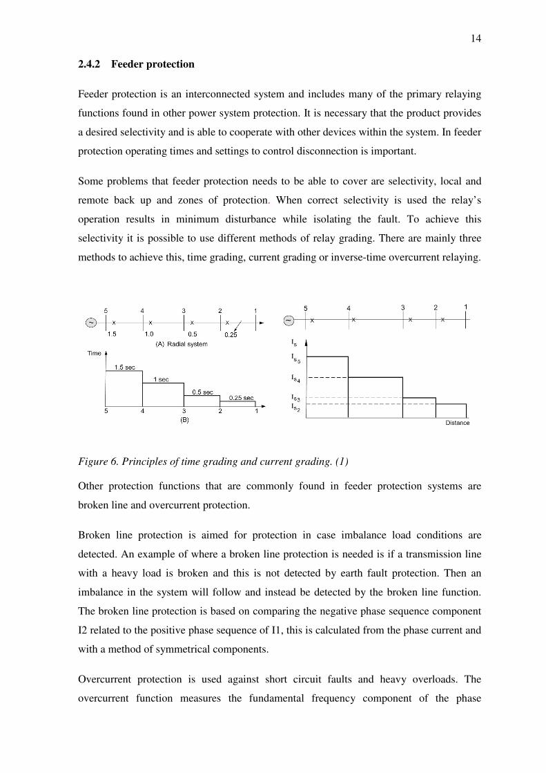
2.4.2 Feeder protection
Feeder protection is an interconnected system and includes many of the primary relaying
functions found in other power system protection. It is necessary that the product provides
a desired selectivity and is able to cooperate with other devices within the system. In feeder
protection operating times and settings to control disconnection is important.
Some problems that feeder protection needs to be able to cover are selectivity, local and
remote back up and zones of protection. When correct selectivity is used the relay’s
operation results in minimum disturbance while isolating the fault. To achieve this
selectivity it is possible to use different methods of relay grading. There are mainly three
methods to achieve this, time grading, current grading or inverse-time overcurrent relaying.
Figure 6. Principles of time grading and current grading. (1)
Other protection functions that are commonly found in feeder protection systems are
broken line and overcurrent protection.
Broken line protection is aimed for protection in case imbalance load conditions are
detected. An example of where a broken line protection is needed is if a transmission line
with a heavy load is broken and this is not detected by earth fault protection. Then an
imbalance in the system will follow and instead be detected by the broken line function.
The broken line protection is based on comparing the negative phase sequence component
I2 related to the positive phase sequence of I1, this is calculated from the phase current and
with a method of symmetrical components.
Overcurrent protection is used against short circuit faults and heavy overloads. The
overcurrent function measures the fundamental frequency component of the phase

15
currents. Whenever this value exceeds the user's setting, a signal is sent to protect the
system. The overcurrent protection can be adjusted for three different stages to protect
different zones and get selectivity.
Short circuit fault location means that an algorithm can locate a short circuit in a network.
The fault location is given in a reactance value. The fault location is normally used in the
incoming bay of the substation.
Products suitable for feeder protection are:
• Vamp 40
• Vamp 50
• Vamp 51
• Vamp 52
• Vamp 135
• Vamp 140
• Vamp 230
• Vamp 245
• Vamp 255
• Vamp 257
• Vamp 259
The following product is especially suitable for transmission line protection:
• Vamp 259
(16)
2.4.3 Transformer protection
A number of fault conditions that can arise within a transformer are earth fault, core faults
or phase-to-phase fault. Protection functions that are often found in transformer to protect
against these conditions are overcurrent, differential, over excitation, imbalance and
thermal protection.
The overcurrent protection function provides the same protection as for power fuses but is
able to be more sensitive than fuses. It is used against short circuit fault and heavy

16
overloads. The overcurrent function measures the fundamental frequency components of
the phase currents.
Figure 7. Basic overview for differential protection (1).
Differential protection function is the main scheme for transformer protection. It is based
on the winding currents. The currents on each side of the protected transformer are
measured and compared in a differential circuit. If current values flowing in and out from
the transformer windings are different, the protection function will operate the relay. The
differential protection function enhances the total transformer protection and is one of the
most usual protection functions for transformers.
Figure 8. Transformer windings and measurement (1).
Current imbalance protection function is based on the negative sequence current and
protects the transformer against imbalance in phase current and single phasing.
Earth fault protection function is a non directional earth fault protection used for earth fault
in low impedance networks and can be used as a backup protection.

17
Thermal overload protection protects the transformer against excessive temperatures in the
windings. Measurement is based on calculated RMS values of phase currents.
Product suitable for transformer protection is:
• Vamp 265
(15)
2.4.4 Generator protection
The generator protection system is a special class of all the equipment, because faults in
the systems are very rare but when they happen, the destruction of one fault can be very
huge. A fault could lead to high repair costs for the damaged equipment. For the protection
system it is also important to avoid unnecessary tripping error which could remove the
generator. When a generator is removed in an unplanned way it could damage the whole
power grid by decreasing the stability. If the generator is not operating the user will be
losing out on non produced energy. Therefore a protection system for generators needs to
be top notch and only remove the generator if it is an absolute requirement.
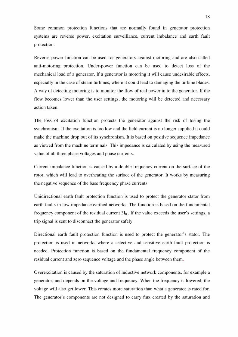
Figure 9. Vamp 210 used for generator protection. (14)
18
Some common protection functions that are normally found in generator protection
systems are reverse power, excitation surveillance, current imbalance and earth fault
protection.
Reverse power function can be used for generators against motoring and are also called
anti-motoring protection. Under-power function can be used to detect loss of the
mechanical load of a generator. If a generator is motoring it will cause undesirable effects,
especially in the case of steam turbines, where it could lead to damaging the turbine blades.
A way of detecting motoring is to monitor the flow of real power in to the generator. If the
flow becomes lower than the user settings, the motoring will be detected and necessary
action taken.
The loss of excitation function protects the generator against the risk of losing the
synchronism. If the excitation is too low and the field current is no longer supplied it could
make the machine drop out of its synchronism. It is based on positive sequence impedance
as viewed from the machine terminals. This impedance is calculated by using the measured
value of all three phase voltages and phase currents.
Current imbalance function is caused by a double frequency current on the surface of the
rotor, which will lead to overheating the surface of the generator. It works by measuring
the negative sequence of the base frequency phase currents.
Unidirectional earth fault protection function is used to protect the generator stator from
earth faults in low impedance earthed networks. The function is based on the fundamental
frequency component of the residual current 3I0 . If the value exceeds the user’s settings, a
trip signal is sent to disconnect the generator safely.
Directional earth fault protection function is used to protect the generator’s stator. The
protection is used in networks where a selective and sensitive earth fault protection is
needed. Protection function is based on the fundamental frequency component of the
residual current and zero sequence voltage and the phase angle between them.
Overexcitation is caused by the saturation of inductive network components, for example a
generator, and depends on the voltage and frequency. When the frequency is lowered, the
voltage will also get lower. This creates more saturation than what a generator is rated for.
The generator’s components are not designed to carry flux created by the saturation and

19
therefore this could lead to thermal or dielectric damage. The over excitation function
protects the generator from this type of damages.
Overvoltage protection function measures the fundamental frequency component of the
line-to-line voltage. The function trips whenever any of these three line-to-line voltages
exceeds the user's pick-up setting of a particular stage.
The thermal overload protection function protects the generator stator windings from
getting overheated. By using a thermal model and the RMS values of phase currents, the
temperature of the windings can then be calculated and protected.
Voltage restrained overcurrent function is used for generator short circuit protection in a
generator application, where the static excitation system of the generator is fed only from
the generator terminals.
Products for generator protection are:
• Vamp 210
• Vamp 265
(11)
2.4.5 Motor protection
Motor protection is similar to generator protection and includes many of the same
protection functions. Some protection functions that are considered to be important for
protecting a motor are imbalance, stall protection and overheating.
Current imbalance stage function protects when a motor is causing double frequency
currents in the rotor, which leads to overheating the surface of the rotor. The thermal
capacity of the rotor is much more sensitive than the whole motor and needs its own
protection function.
Incorrect phase sequence protection function protects the motor from running in the wrong
direction. The function works by checking the ratio between the negative and positive
sequence currents.

20
Stall protection function protects the motor against delayed start caused by a stalled rotor.
It works by measuring the start current and if a fault occurs, the motor is disconnected
within a given time set by the user.
Frequent start protection function protects the motor from overheating caused by too many
repeated starts. When a motor starts, the start current is significantly higher than the rated
current in normal use. This will lead to overheating the windings in the stator. This
function works by counting the number of starts and if it exceeds the recommended
number for the specific motor, the relay will prevent the motor from starting.
Products suitable for motor protection are:
• Vamp 40
• Vamp 52
• Vamp 150
• Vamp 210
• Vamp 230
• Vamp 245
• Vamp 255
• Vamp 257
• Vamp 265
(13)
2.4.6 Measurement and monitoring
By using numerical signal processing in the products, measurements and monitoring tasks
can be included in the devices. The devices especially designed for monitoring and
measurement can produce a large range of different important information. The function
list is different for these devices, as they don’t include any protection functions but only
functions that are necessary for monitoring and measurement purpose. Some common
protection functions for these products are disturbance recorder and power quality
monitoring.
The disturbance recorder can be used to record all the measured signals, which may be
currents, voltages and the status information of digital inputs and digital outputs.

21
Voltage sags and swells monitoring is one of the more important power quality functions.
They can be used to evaluate, monitor and alarm on the basis of the quality of the power
grid.
The device includes a function to detect voltage interruptions. The function calculates the
number of voltage interruptions and the total time of the voltage-off time within a given
calendar period.
Product suitable for measurement and monitoring is:
• Vamp 260
(14)
2.5 Communication
Protection relays can handle a wide range of communication using different
communication protocols like SCADA, RTU’s, PLC’s, gateway tec. The Vamp products
cover many of these common industrial and utility standard open communication
protocols.
Figure 10. Communication options (13).

22
The communication options for a relay depend on their main features but also accessories
that are possible to add in the relay. These can be installed as external option modules.
The different communication media for Vamp relays are:
• Fibre optic
• RS-485
• Ethernet/RS-485
• Profibus
• Ethernet
• IEC 61850
(13)
2.6 Control options
The control functions consist of output relays, analogue output and a couple of controllable
objects. The output relays are also called digital outputs. The number of control options
depends on the product and whether it has optional modules installed. The inputs and
outputs are configurable and can be controlled by control function in the devices.
With a specific control option it is possible to control different objectives, for example
circuit breakers, disconnectors and earth connection switches. Controlling these objects is
possible through one of the following options:
• Through the local HMI
• Through a remote communication
• Through a digital input.
2.7 Selection table and main protect functions
All the protection functions and other functions explained earlier are all included in a table
called “Selection table for Vamp protection products”. The table is mainly for marketing
purpose and is also included in the company’s brochures for the customer to get a quick
overview of all products and protection functions (see figure 11 for a quick view and for
the entire table look in the appendices).

23
A part of the current selection process is based on a printed table on two pages. For persons
familiar with Vamp products and what the table contains, they can quite easily use it to see
what products have what functions, but for those that are not familiar with the products it
could lead to some difficulties in sorting out the accurate product.
Figure 11. Selection table including all functions and products. (17)
In the selection table it is possible to get the protection function’s IEEE Device number,
the IEC symbol, the name of the function and in which product the function is included. If
a function is included in a product, the mark “x” is found in the product column. The same
symbols and numbers are often used in one line diagrams to simplify which protection
function that is being used. The row where function is described starts with which type of
functions it is, followed by the IEEE device number.
The IEEE contains the symbols created by the Institute of Electrical and Electronics
Engineers or IEEE. The symbols are often used in the designing of electrical power
systems. The IEEE device number is indicated with a standardized number which denotes
what features the protection device supports. The device number can be followed by a
suffix letter, for example suffix N means that the device is connected to a neutral wire and
suffix G stands for ground. The device numbers may also be combined if the device
supports multiple functions (see figure 12 for an example). (1)

24
Figure 12. Column in the selection table showing IEEE device number. (17)
Next on the function row are the IEC symbols. These symbols are published by
International Electrotechnical Commission which is an international standard organization.
The IEC symbol gives a more describing image of what the function does, because it
includes numbers, letters and also symbols you can figure out what it means (see figure
13). The IEEE number only contains “random” numbers and maybe a letter. It can be hard
to know the meaning of it without looking in a table. (1)
Figure 13. The selection table showing IEC symbols. (17)

25
The usage of either IEEE or IEC symbols depends on who the user is. Customers from
North America use the IEEE symbols and Europeans use the IEC symbols.
All functions are divided into six different categories depending on if it is a type of fault,
measurement and monitoring, control option or communication. Each of these categories is
then divided and sorted so that similar functions are in one place. The table starts with the
main protection functions with a “type of fault” heading which explains the protection
function, divided into five categories depending on which product type they are. The
categories are:
• Short circuit
• Earth fault
• Overload
• Voltage
• Arc protection
These are followed by other protection functions than measurement, control,
communication and finally general functions.
The protection products in the selection table are shown in the first row and are divided
into three different categories:
• Feeder protection
• Machine protection
• Others
If a product has any of the functions mentioned above it is marked with “x” or some other
information, depending on the function alternative.
The selection table is most useful for marketing purposes and is a little bit limited in terms
of the control and communication overview. The selection table does not include a
sufficient amount of information about accessories and specific product information like a
product's code. To complement the selection table you need to add one table including
each product’s product code definition and its accessories. Figures 14 and 15 show
examples of the printed product code table and communication table.

26
Figure 14. Product code and accessories. (13)
Figure 15. Communication and control option. (17)

27
3 Technologies and tools
The technologies and tools described here are mostly only explained by their structure and
functionality. Their usage is partially covered in chapter 4. Most of the tools are created by
Microsoft, as the application is mainly intended for Windows operating system. The
Microsoft software and the technologies behind them are very popular, which gives them a
huge advantage in term of teaching material and supporter’s forum.
3.1 Developing environment
To develop an application the main tool needed is a software developing kit (SDK). To
ease up the software development and make the work more pleasant you need a modern
integrated development environment (IDE). Most IDE include many helpful tools to speed
up the developing time and give support to the developer with smart tools. It includes a
code editor, compiler and a debugger to make it easier for the developer to manage the
sometimes quite complex programming code.
Microsoft Visual Studio is an integrated development environment created by Microsoft. It
is a common tool to develop application for console, web application and graphical user
interface application for desktop environment. Visual studio built-in languages are Visual
C++, Visual C# and Visual Basic.
Visual Studio’s code editor supports a function called Intellisense which helps the user to
find errors written by the user. Intellisense also helps the user to speed up the programming
work by completing a started code segment and showing the available option for the
written text as a pop up textbox. Visual studio includes a debugger that can be run on
machine-level and source-level. The debugger can be run through the program step-by-step
and in that way it makes it easier to spot errors in the code when or if the application
crashes.
Microsoft provides free editions of Visual Studio 2008 and these are divided according to
the programming language you prefer to use. The different softwares are Visual Basic,
Visual C# and Visual C++. The full edition of Visual Studio 2008 supports all these
languages from start and a lot more built-in functions than the free editions have.

28
3.2 Programming language
This chapter provides some basic information about what is available in the Visual Studio
2008. With Visual studio it is possible to create an entire application and below is a short
description of the technologies used for .Net framework including programming languages
and user interfaces.
3.2.1 .Net Framework
.Net framework is a software framework that makes it possible to install an application on
a computer with Windows XP or a newer operating system. It includes a large library of
ready-edited code solutions. The application code runs on an installed virtual machine
through the operating system that managed the code. The .Net framework’s main feature is
to provide a common language platform that can communicate with many different
programming languages such as Visual basic, C# and C++/CLI.
After .Net framework was introduced it became very popular throughout the entire
Windows product world. Today you could say that it is integrated in all Windows
application that is developed with Visual Studio. The .Net was from the start a platform
independent product, but it became a platform most connected with Windows systems.
.Net framework is strongly adapted to Windows systems and you could say that .NET and
Windows are synonyms.
If you want to run an application based on .Net it requires that you have the .Net
framework installed on the computer you are using. Microsoft Windows Vista and newer
operating systems have these included from start. Older Windows XP Service pack 2 and
later it can be installed separately through Windows updates. In general the user doesn’t
need to install anything else than the application itself, because most computers have been
updated to support .Net framework.
Software developed for .Net should be platform independent but it needs the .Net
framework installed. If the user uses a computer with Mac Os x or a Linux based operating
system, the operating system needs to have a software called Mono software installed,
which is a free open source project led by Novell.
The .Net framework includes a graphical interface manager, which makes developing
software for many different computer operating systems much simpler. Thanks to this it

29
speeds up the developing process, when there is no need to learn each system’s graphical
management process. With the .Net framework installed the application doesn’t need do
know about all different specifications for each computer it is used on. All the visual
controllers and the functionality go through the .Net framework which then communicates
with the computer’s hardware. The graphical interface tools in .Net framework are very
similar independent of the programming languages used.
When Windows Vista was released, the framework got a bigger update with the newer
version .Net framework 3.0, which included many features to increase developer
productivity and produce more functional applications.(18) (10) (6).
Figure 16. Structure of the .Net framework. (18)

30
3.2.2 Visual Basic
The first version of Visual Basic .NET was released in 2002 along with .NET Framework.
Visual Basic was designed to increase productivity development work and was easier to
learn than other programming languages but it did not offer the same performance as C#
and C++ offer. (4)
3.2.3 Visual C#
C# is a programming language created by Microsoft in 2000 and is included in the .Net
framework. C# is one of the programming languages which were designed to run in a
Common Language Infrastructure. The programming language was intended to be a
simple, modern, and object-oriented programming language. (5)
3.2.4 C++/CLI Language
C++/CLI stands for common language infrastructure and is a Microsoft Language
specification to replace the older managed extension for C++. C++/CLI was developed for
a better communication with the other languages within the common language
infrastructure. This makes it easier to develop applications for people with different
favourite programming languages. The C++/CLI is available in Visual Studio 2005 and
more recent versions, and is also included in express editions. (18)
3.3 Deployment tools
A Windows based application can be deployed by using ClickOnce or Windows Installer.
The ClickOnce was available from .Net 2.0 and later and was first implemented in Visual
Studio version 2005. The differences compared to other methods are in general the
ClickOnce deployment, which simplifies the process for installing and updating an
application. The ClickOnce deployment tool can be used as a publish wizard to package
the application and make it easy to deploy. The ClickOnce is mainly designed for
installation from a web location but it is also possible to install from a storage device.

31
Figure 17. ClickOnce security request.
The security in ClickOnce relies in Authenticode certificates to determine if an application
should be installed. When installed with ClickOnce the application is automatically placed
in the uninstall software on a Windows computer and it is easy to remove from the
computer. (7)
3.4 Information management
The information from an Excel file can be imported to the application with help of a
method named OLE DB which is a part of the .Net framework. The import function makes
it easier for the programmer to create an application that can import and export data from
different files. The database management code is implemented into Visual Studio which
eases up the workload that the programmer needs to put in.
The import of information from the Excel file to the application was managed with the use
of OLE DB (Object Linking and Embedding, Database) which is an API design by
Microsoft for accessing data from many different sources. OLE DB is able to connect to
direct to a non-database, for example a spreadsheet page in a Microsoft Excel file (see
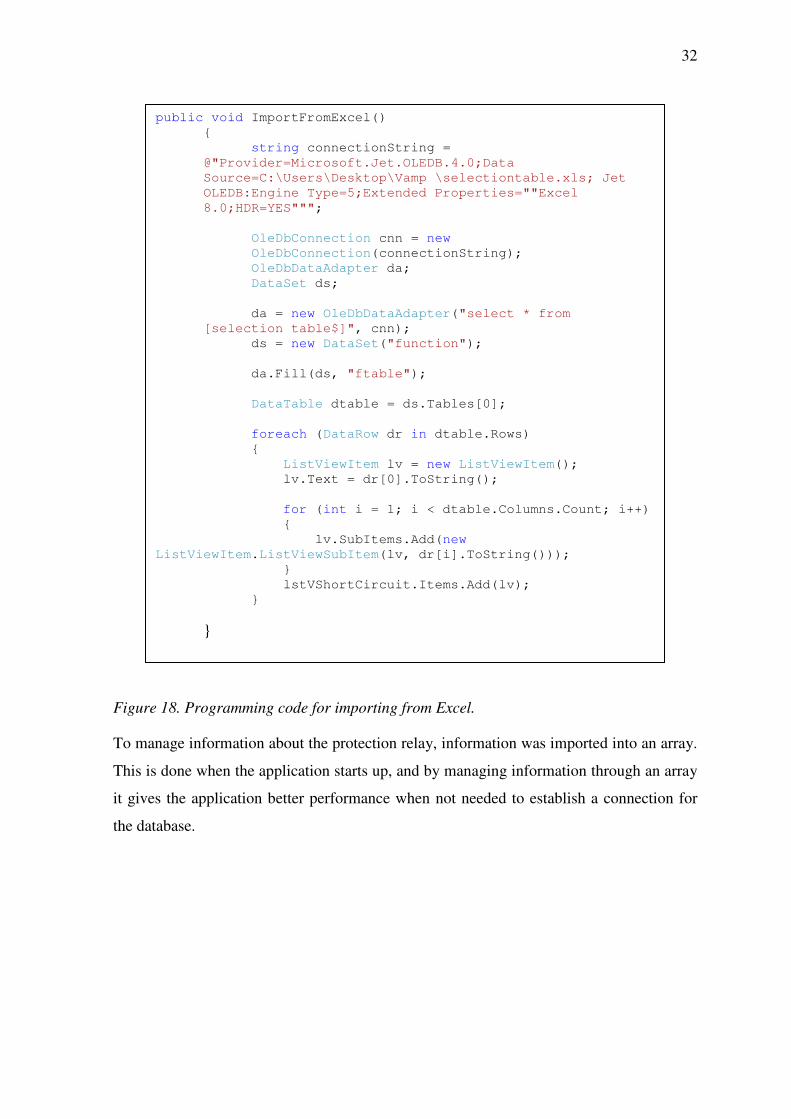
figure 18 for an example of importing data from an Excel file).
32
Figure 18. Programming code for importing from Excel.
To manage information about the protection relay, information was imported into an array.
This is done when the application starts up, and by managing information through an array
it gives the application better performance when not needed to establish a connection for
the database.
public void ImportFromExcel()
{
string connectionString =
@"Provider=Microsoft.Jet.OLEDB.4.0;Data
Source=C:\Users\Desktop\Vamp \selectiontable.xls; Jet
OLEDB:Engine Type=5;Extended Properties=""Excel
8.0;HDR=YES""";
OleDbConnection cnn = new
OleDbConnection(connectionString);
OleDbDataAdapter da;
DataSet ds;
da = new OleDbDataAdapter("select * from
[selection table$]", cnn);
ds = new DataSet("function");
da.Fill(ds, "ftable");
DataTable dtable = ds.Tables[0];
foreach (DataRow dr in dtable.Rows)
{
ListViewItem lv = new ListViewItem();
lv.Text = dr[0].ToString();
for (int i = 1; i < dtable.Columns.Count; i++)
{
lv.SubItems.Add(new
ListViewItem.ListViewSubItem(lv, dr[i].ToString()));
}
lstVShortCircuit.Items.Add(lv);
}
}

33
Figure 19. Creating a product vector with information:
When using the application the sorting process uses an” if” statement combined with some
loops to compare specification from product to the selected functions that the user has
chosen
string[] arrVampRelay;
arrVampRelay = new string[lstV40.Items.Count];
for (int i = 0; i < arrVampRelay.Length; i++)
{
arrVampRelay[i] = lstV40.Items[i].ToString();
}

34
Figure 20. Compare User specification with product specification.
The comparing process is done every time the user selects a function and is automatically
updated every time a function is being clicked. This gives instant view over product
matches.
do
{
spec = arrVampRelay [j3].ToString();
if (lstSelectedFunctions.Items.Count == 0)
break;
if (lstSelectedFunctions.Items.Count >= 0)
{
chosen =
lstSelectedFunctions.Items[selectedIndex3].ToString();
j3++;
if (chosen == spec && (feeder || motor))
{
ProductCheck = true;
if (selectedIndex3 < countLstSF3 - 1)
{
selectedIndex3++;
j3 = 1;
}
else
break;
}
else
ProductCheck = false;
}
}
while (j3 <= countLstVR3 - 1);
if (ProductCheck == true)
lstProductMatch.Items.Add(arrVampRelay[0].ToString());
else
{
string IndexOf = valdProduct;
int indx =
lstProductMatch.Items.IndexOf(IndexOf);
if (indx >= 0)
lstProductMatch.Items.RemoveAt(indx);
}

35
3.5 User interface
The different graphical user interfaces which are most often used in software developing
are included in Visual Studio 2008. These are Windows Forms and Windows Presentation
Foundation. They are designed to be used for .Net framework. The graphical user
interfaces included may be different depending on which version of Visual Studio you are
running, the free version or the professional version.
3.5.1 Windows Forms
A Windows form is a graphical application programming interface (API) and is a very
popular interface. The interface includes many of the common controls used in Windows
applications. This API is often used for business application and tools built for the
Windows platform. Windows Forms application can be connected to web services, data
sources etc.. Windows Forms was created to replace the older and more complex MFC
which is based entirely on C++ and is not included in .Net. (19) (8)
3.5.2 Windows Presentation Foundation
WPF is the next generation platform for building visual applications. WPF is similar to
Windows Forms but handles the graphics in a different way. The layout is xml-based
which gives support for scalable controls and can handle 3d- 2d graphics. Animation is
much better in WPF than Windows Forms. WPF combines Windows forms, xaml, smart
client, and 3d graphics. This allows the user to create a more graphic rich interface and
includes more functions for the application. (9) (2)

36
4 Application
In this chapter the application development is described as well as the programming
language and the user interface and why they were chosen. The earlier chapters function as
a foundation for what is needed to know when developing the application’s functionality
and designing its layout. The basic idea behind this application was to create a user
friendly application that could perform a selecting process based on a requirement
specification and finally give a result showing a product and its accessories and product
codes.
During the development stage the application evolved and got more functions and some
changes were made to create a better user experience and be more efficient. This is a
common approach when software applications are created. From the beginning there was
one idea and over time it developed to many more. The information management was also
improved so it could handle more information about the product’s code, accessories, and
communication.
The goal was to create an application where a product’s functionality, specifications and
accessories were all accessible from a database connected to the application. The database
would still be easy to update and was able to connect to the current information database
that excited in a form of an Excel file. The result would be a data file with the specification
which could be printed or emailed or be just as an answer to the user specification enquiry.
4.1 Application functionality
The most important application function is that it would sort out products based on the user
specification. The selection process should work in a similar way as the existing tables do,
this would suit the regular user that is used to using the existing tables. The application
should also show a reasonable amount of information to the user and give an easy
overview of the product range.
The information management can be made in different ways. It deals with how the
application handles the data. The main software used for this purpose is Microsoft Excel.
The existing information the application would use was already written in several different
Excel files and are used and edited by many people.

37
The Excel files are a specification for the application itself and should be possible to
configure if the data is old or need to be replaced. This makes it possible to change the
application specification without making any changes from the application itself. The
changes in the database cannot be changed from the application itself. Therefore a separate
database software needs to be installed, in this case Microsoft Excel can handle the
existing data files which are in the form of Excel spreadsheets.
Another option was to use Microsoft Access and make a complete new database of the
information that the application should handle. This gives more import/export options in
the .Net framework and is suitable for large information management. This would have
increased the work and learning that were needed to manage databases in Microsoft
Access.
A third option was to implement all necessary information into the application itself and
create a database within the code. This may give a stronger structure to the application.
This option would lead to more work, because an additional part to the application
handling databases should have to been created. Handling these types of databases could
be challenging if the information increases or changes over time. This option creates no
alternative to handle data from outside the application and this makes it harder to control
that the correct information is used in the application
Figure 21. The main window with first tab showing

38
The application layout should be presented in a similar look as a “wizard”, the main
window includes tabs for each type of information and should work as one question at a
time divided into separate parts. The user should start with the product type, then choose to
sort out products that don’t match up with that product range, and then you make a more
specific choice based on protection functions, communication and accessories.
Figure 22. Selected function and matching products.
The protection functions that are partially explained in chapter 2 are chosen and the
products that don’t have the specific functions are sorted out from the Products list. The
Products list shows only available products that correspond with the current user
specifications which are shown in the Selected functions list (see figure 23 on the right side
on the main window).

39
Figure 23. Main window’s second tab showing protection functions
The main window works by adding functions you choose and adds these to the list of
Selected functions. When a function is added the sorting out process tries to find suitable
products matching with selection. The tab where you select the control option you want
differs from the others and shows all available control options based on the products that
match the earlier choices (see figure 24). The options not available are dimmed out and
cannot be selected.
Figure 24. Control options tab.

40
The application consists of two windows, one main window and one smaller which is the
Product code window and where one is able to specify the product code and then choose
product accessories. In the main windows most of the selections are made and the product
range is cut down and as a result of the selection a list of the products that match up with
all selections is made.
In the list you choose one product to get more specific information about the product. By
clicking the product it becomes marked and then you click the product code button. The
information is shown in a “popup“ window that allows the user to specify the product code
(see figure 25).
Figure 25. Product code window.
In the same window there is also the product accessory list which may change depending
on the communication or control options that are chosen in the main window. In this
window it is possible to get more specific information you may want about the products
that match up with the user specifications. This information can be shown directly on the
screen, but it is also possible to save the information on a project file. This is one of the
bigger advantages with this application, it gives you a quick access to all product codes and
accessories, which was possible before only from looking in many different tables in
manuals or data files.

41
Figure 26. Project file window.
The project file is a file where it is possible to save information about many products and
their different product specification. This file would work as a helping tool for handling
project specific applications where many products are involved. The project file is a printer
friendly file which is also possible to email and save on the computer and is saved as a text
file.
4.2 Graphical application user interface
Chapter 3 was about different graphical user interface Windows forms , WPF and MFC,
their benefits and functionalities. This application is a type of business application and
because of Windows forms is often used in business. The Windows Forms was for that
reason a preferred GUI over other options and was chosen to manage the visual part.
MFC based on the complex C++ language is starting to get old and was not included in the
free version of Visual tools.
The WPF is a more modern version and is going to be more common in the future. WPF is
still rather new and does not offer the same support on web forums and literature.
Windows Form has been on the market for a few years and has many developers using it,
this creates wide documentation selection. For this application the Windows Forms was
chosen because it is very straight forward to use and has many familiar controllers
included.

42
The graphical user interface was created in Visual Studio where it is installed as a template
for creating a Windows Forms application. The component used for this application was
the standard component included with Windows forms. The main components that were
uses were:
• Radio buttons
• List
• Listview
• Checkbox
Designing the graphical user interface in Visual Studio works with a “drop and drag”
method. The controls are placed where you want them on the window. Depending on what
functions you want to have on the controls, different specifications for the controls can be
modified directly in a properties windows instead of changing the programming code.
Windows Forms is based on the .Net framework and supports all the programming
languages included for .Net. From start it was meant to be developed in the more complex
C++ programming language modified to suit CLI and .Net framework. But with
difficulties to find literature and support for this technique, it was ideal to use C# instead.
This application was developed exclusively for .Net and this language worked better for
the development. The programming codes created for .Net framework can communicate
with each other and for the application functionality it would work in the same way,
regardless of the programming language you use. This is one benefit of using the .Net
framework as a foundation for an application.
4.3 Developing application
This sub-chapter deals with the planning process from start to finish and gives an overview
of the entire project according to what has been explained in earlier chapters.
The overall planning is a very important part in all projects. In order to make a successful
project it was divided into several parts. The project was divided mainly in these different
parts:
• Planning the requirement specification
• Designing graphical user interface
• Programming the functionality for the application

43
• Developing necessary functions
• Testing stage
This creates a structure for the project, which you can find beneficial in the early stages
and it gives a preview of what needs to be done and in what order the approach should be.
From the start the learning process was not included for what would be needed to be
learned. This is hard to estimate because in some area you need to go more into the depth
of that subject. But some parts were given more time, due to the fact that a learning process
was needed e.g. structure of the programming languages and the functionality for the
application.
At first some guidelines were drawn to get a feeling what needed to be developed. All the
current information files and tables were overviewed to know what information was
available. An example of a typical selecting process was replicated to show how the final
application would work.
To create a graphical user interface for the application, four different prototype layouts
were designed. The different designs had similar functionality but with different layouts.
The functionality was not embedded into the application yet and concepts were only shown
as images. From these four layouts one was chosen that had the main window with similar
functions as a Wizard and two smaller ones that gave a quick view of the products and
selected functions. This layout was considered to be the most user friendly and gave a good
information overview in comparison to other layouts.
In the developing stage of the application it was often necessary to switch between
different parts mentioned in the planning. To get a function to work properly you often
needed to change things in the design or the programming code in order to get the
functions right. In the testing stage problems were sometimes found and it was necessary
to go back and change something in the function or programming code.
44
5 Results
One goal with this thesis project was to create a working application for selecting Vamp
products and to use it as a helping tool for the sales department. The final result for this
application was to develop a business application suited for Windows desktop environment
with functionalities to ease up the selection process. During the development the
application got more functions than planned in the beginning, but this only resulted in a
better functionality and a better user experience.
The other goal was to get a deeper insight into the technologies that Vamp protection
relays use. Similar technologies used in Vamp products are also used in many other
products within the electrical power industry and this insight gave me a very good all-
round knowledge.
In the future this application can be used by people both in the sales, marketing and
product departments. The application can also be useful for customers and work as a
marketing tool.
As further development it was discussed to create a new better information database
including more data about the products and accessories and be united in one database
instead of many. This database would be more suitable to communicate with the
application and manage changes in the product specifications better.

45
6 Discussion and conclusions
When the ideas for this project started it sounded like a possible challenge, which would
give me a very good insight into product technologies used for protection systems. The
product range at Vamp is rather wide and touches many segments in the industry. This
would give me a lot of knowledge about many products and their main customers.
To begin with, the application that would be made for this purpose did not seem as
challenging as it was going to be. The idea behind this function was well-reasoned and on
paper it looked very good. The existing selecting process which was to choose products
from a printed Excel table was not effective enough and did not make a precise enough
selection of the product range. For a person that is not too familiar with the products, too
much time was needed to sort out the right products. When the product range or function
list grew it would take even more time to go through pages of information. The need of this
kind of helping tool was obvious. A tool for selecting products seems to be popular these
days and is often found in a company’s digital marketing material, either as a web site or as
an application. But these are rarely user-friendly and can sometimes be very hard to use.
Therefore I wanted to create an application with a nice looking user interface which would
be effective in sorting out a product from a wide range of options and functions.
The learning process that this project required was quite demanding. Software used for
developing applications was pretty much new to me. But my own interest in these software
and technologies was huge and therefore the necessary learning required was not an
obstacle in my opinion. The biggest part that required most learning was to get into the
way of working with programming application.
The product that the application would select was for the most part known to me as were
most of the protection functions and technologies that they use. I just had to get a deeper
insight into the product range and get an understanding of the products and their
specifications, accessories and the product codes from their documentation.
The hardest part in developing the application was to establish a working connection to the
Excel file and be able to import the data without getting it all wrong.

46
My work with this project took a lot more time than I could ever have imagined at the start.
My understanding about protection relays and their principles was okay, but my
knowledge of how to produce a working application from scratch was very basic in the
beginning.
To develop a working application was a challenging but very interesting task and I learned
a lot about developing software applications during the entire project.
47
7 Sources
1. El-Hawary, M. E. (2000). Electrical Energy Systems. New York: CRC Press.
2. Greene, A. S. (2008). Head first C#. California: O'Reily Media.
3. Grigsby, L. L. (2007). Electric Power Engineering Handbook, Second Edition.
Boca Raton: Taylor & Francis Group.
4. Halvorson, M. (2008). Visual Basic 2008 - Step by step. Washington: Microsoft
Press.
5. Jesse Liberty, D. X. (2008). Programming C# 3.0, Fifth edition. California:
O`Reilly Media.
6. Mono project. (n.d.). Retrieved April 25, 2010, from http://www.mono-
project.com/about
7. MSDN Library. (n.d.). Retrieved April 25, 2010, from .NET Framework
Developer's Guide: http://msdn.microsoft.com/en-
us/library/142dbbz4(v=VS.90).aspx
8. MSDN Library. (n.d.). Retrieved April 25, 2010, from Windows Forms
Programming: http://msdn.microsoft.com/en-us/library/8bxxy49h(VS.80).aspx
9. MSDN Library. (n.d.). Retrieved April 25, 2010, from Introduction to WPF:
http://msdn.microsoft.com/en-us/library/aa970268.aspx
10. Skansholm, J. (2008). Skarp programmering med C# (Vol. I). Studentlitteratur.
11. VAMP 210 Manual. (2008, Mars 18). VAMP 210 - Generator protection relay .
12. VAMP 220/220RManual. (2005, April 13). VAMP 220/220R - Arc protection
system .
13. VAMP 255/245/230 Manual. (2008, February 27). VAMP 255/245/230 - Feeder
and motor managers .
14. VAMP 260 Manual. (2008, May 30). Vamp 260 - Powe monitoring unit .
15. VAMP 265 Manual. (2008, February 7). VAMP 265 - Transformer, generator and
motor differential protection relay .
16. VAMP 50/51/52 Manual. (2009, April 20). VAMP 50 / VAMP 51 Overcurrent &
earthfault protection relay, VAMP 52 Feeder and motor protection relay .
17. Vamp customers journal. (January 2009). Protection Control .
18. Wikipedia. (n.d.). Retrieved May 3, 2010, from Cli:
http://en.wikipedia.org/wiki/C%2B%2B/CLI
19. Wikipedia. (n.d.). Retrieved April 28, 2010, from Winforms:
http://en.wikipedia.org/wiki/Winforms

Appendices
Selection table
Communication table
Selection table

å.9å-E
HE:€fio E,i e fi E * å
iC ,^,*4E å ; E $. å
å; åäåä$Eå E;F å åå :E,1 åååååå3;äåcå å€Eåå, r:.äE! EE äååäåää ååå €E;å å eåuå*;ååågå: EE å3äs5ss :å; ;åe0 E iEEEååfrE#;E: ** ååååååE ååå -倀He: :;Eg;eåsesi: åå cgECgeF EtE å;eEäEgååå*;*ic!I3E3 is EEEEEEF EsE åE##$ågteEFäegE;sE
tr-==:EtrTffii
t--It-I
--'.
OOOOONNNN<$Sb6NNNN
.E oPo .:=
ö gi€P969;5€as:oo:Fy==a;
=;x=.
Eii=>ij?"=> --=: -
J-=::=
E aa3=:6F:F::P ;=+==cx::=:: !:!:=.C Y - Y::
€o:a:=
i++9--& E3E::Y Eii: EÄ FFFFF
3A
ooLcoar+rUortsoLo.o.EoLortso-oo+co
OI#Uoo
3t7
lv^ L b .åäråäi lit Yv x
^ 6 r,! iili$v: i55 vv ;i
å, i-i.-,:-,,'l rr 5:+i55: I:* å:"ir.\:; iirs;lllt!OOOzzzno6OOOEEE o uQOOO O@@@N@N@FN@SOON*O-ooQ N@s+{$ooo@@@sioN6@
TEp=
a-ö
o
aou
oo
F6
9 zzzz zz.t 0060 60,2 ZZZZ ZZä 3333 zzzz7?,O X:::r+ QQE2222 222222==iloooNFNNFOOOONNOO=oon@@@@Noo66@o60
t6-9
o
.p
U
xxxxxxx
xxxxxxxx
xxxxxxxx
xxxxxx
xxxxtxi
26 /Proleclion&Conhol
Appendix 1 1(2)

=Ettooliq
E
!
E
-q
E
;Og
.
aaoo
F
c.9
3€eoo-:AQ
öo9o90g6-3>c=c 9.9 v
:gEE Ec?ggE; EäAä= o ! = o !>Y 9I =-g I3öFFx,F€eqäö;8,=E!ig5ä:E:FF5 : åi H'E; 8:?åE=.,€dEl0af>aa@6
I I*I. iI l=J,:s å
E2ö
åå Eg'åå l *g, * *€ gE ä ' ääg Eå 5E !E € E ä6 E€ -aF" Eä iE i ,4 a ää 5[ e -F; IP EE E E"q € g
E E; € EE ;€ ää P ^z: ': Ezn =ä F ä3 et+tt å*€Iä E,E aee gra*gåp .orå E:äåå EtEgE ää.8fr;EfiEFgfigåoåååE,lqäcE s='€E'5e .;*å,äEEEf åEFg:E0eåiööLExE.-H':.? €ttgtE
=;Ff g
+aEEåtsiooe:i5fi9+iiAE$ uöb;b* E!äåbeeö:åspsEååEåä$å;:$åå E55å5ä EEr;e
,{:l=
- i -.-= S ;;* * . o , i å t - ' = ? Q
.9
o
o>>r- E*cod
o .= !
E ho
ö I F--ö ä >EE E c u \vrE 9. .9dE3+ i e= E;< - o,9 O:c g+P:.=E sg=3ä; ö3Ege
o.9
.9
.9
EEoo
oEI
* 9e A
t ,€q EE" s €e ä:t EqB E q
g E öää "iE;E EE E+? ;E' t = s.dd e9. qb9 E ä; !s"i.+P" F
F AP fiq Hf E -et *ig s= Rä= :dåetx 3oå ie; a aE $aa t;: n:E €g 'ts'[! FBFE::l;åF ;gF f; F+ iä€ 53å ä!€ 5;' äeB ,iE-HEE;ä$8
Jt
9\*-
x x xm x x xxxxxx
xxxxxxx
xxxxxxx
xxxxxxx
xxxxxxx
xxxxxxxx
xxxxxxxxx:
xxxxxxxxxx
Qoo xo x
!<o xo
DN6 X@ X
xo x x x x x x x x x x x x x
x x x xo x x x x x x x x x x x x x
x x x xo x
x x x xo x x x x x x x x x x x x x
X X x xF x x X X X X X X X
.9
E
o
Proleclion &Conhol / 27
Appendix 1 2(2)
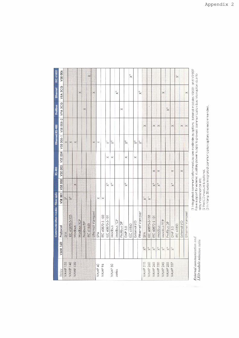
N
LUOv)+)crc \-/
-oXnLU l)u) l->öö.s5o
--L.)X
-.=v-v-- a)n\.:(l.,
+L.xl =r-
a-Uq a- /\
XO c)v /\ L
ä* 0)s-LA!"c)v@>q^;.
=n\ ^- vv (,
! a') LI
E> c>tz(J..1L,\U q ()L.=
vd\Lo>Jd\>-vila-Ja\!-
L
a\ >. \Jv ! 1\-^c.vT!X =ots\, xYv-vm,\
^ '- vr.v Y.:ä ClLLY ;1o7- ".!(-+-q,^C X nr'- X{-d\vn\v> v t\ v.-
^ !
- --l d\x o x* yv* Y x^
-+LVvHhotrLoUv+-^+a)-^!2!:4LtULftl.-)--lö/ll"'La'\iar-v''-v^--L>ni-L
- L)7lnrm
'ui ,!
at ,
O!!RNL) 'N
CR\öFSU\\xNV
hni3xa|{'lr-\ \
rI
t-
t:
!l
E
\oooII|at,
X t2X ><
oU(9
tll
X X I><
!2>< >< ><
oU(9
o-
T14)ooIIJt/l
rf)ooTIJa/,
{oolrJa/,
><
>< >< X
X )< ><
>< >< X >< >< ><
>< ><!2X
!2><
!2><
9><
X >< >< ><
(9oollltt1
>< >< >< ><
c.{oot!an
>< !2><
!2><
I>< X >< X
ootlrv,
L.X X >< >< >< ><
ouooo-
ö-</)
CY)
troI
N@:Ö
LU
U'
a\coä
o_
t*t/l
4nv't?
_oF
Yo-
Otr)@\oULU
+()a\
C
'Foc()-c#tU
o_</)
C9
I
LO
|-\
\or'lLU
I
LoI
|-\
\o
LU
(nlr)c
o_OFt/)l-oco
o_ort'>
f_o
L
c"jo_zo
tr)
\oOtrl
15
cC)+X
I.JJ
bt/)otrL(J
+()cC)-cil L
</)
c)
LO
\\o
LLI
I
LO
f.-@\oOLU
af
_oco
o_Ot/)l
_ooo
o-CI(/)fö
iFou
;zo
ir-
LO@\oOL!
r]CC)
XuJ
+o6oCL
o+c)C()c-Ill I
o.o
=!!><
!L><
s'.!
X X X
oC)M
LOOO(f) .<N Lo
o* o* 0-:ä
o_ o_ o_
O\oOs cF. La)
ON0*
(-).oC\lI-
tr)v)C\0_
2
losNo_
roLOc\o_
|t\LOC.lo_
Appendix 2