App No: 2020071203 - Amazon AWS
78
App No: 2020071203 Application Type Minor Modification Applicant Name NB+C Site Id 279 Address 9420 Key West Ave, Rockville City Rockville Zoning LSC‐1.0 Latitude 39.102939 Longitude ‐77.193847 Ground Elevation 470 Site Owner Key West III LP Structure Owner Key West III LLC / DANAC Carrier T‐Mobile Structure Type Building Solution Type Macro Lease Status In Process Carrier Site Name 7WAN094C County Site Name Phillips Office Building Existing Existing Existing Structure Height 54 Justification of why this site was selected: Existing Telecommunications Facility Will site be used to support government telecommunications facilities or other equipment for government use? No Gvt. Use Desc. Updated 7/1/2020 Ann. Plan? Yes Application Description T‐Mobile proposes removing (3) antennas, (3) RRUs, and (1) Cabinet, and installing (3) antennas, (3) RRUs, and (1) cabinet at the existing telecommunications facility. NearbySites (New, Replacement Apps Only): Provide the proposed height of the replacement structure without any antenna (New, Replacement Apps Only) Distance to Residential Property (New, Replacement, Colocation Only) Distance to Commercial Property (New, Replacement, Colocation Only) Does the structure require an antenna structure registration under FCC Title 47 No Application General Infomation Site Infomation Thursday, July 2, 2020 8:12:15 AM Revised 7.20.20- JR
-
Upload
khangminh22 -
Category
Documents
-
view
0 -
download
0
Transcript of App No: 2020071203 - Amazon AWS

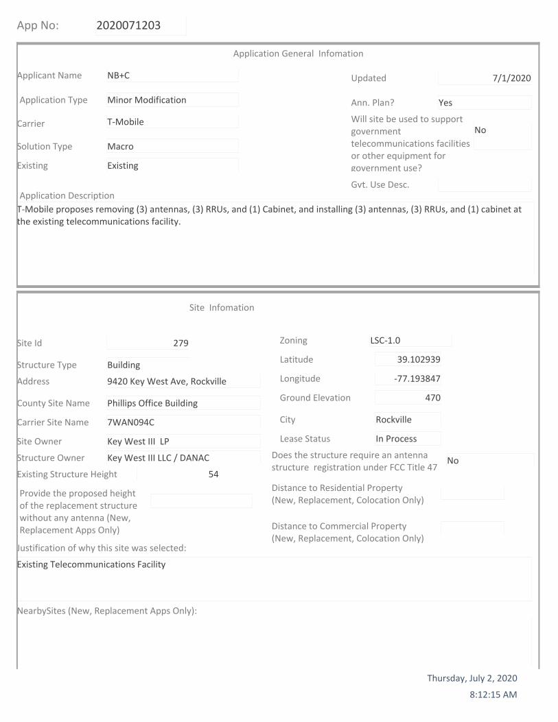
App No: 2020071203
Application Type Minor Modification
Applicant Name NB+C
Site Id 279
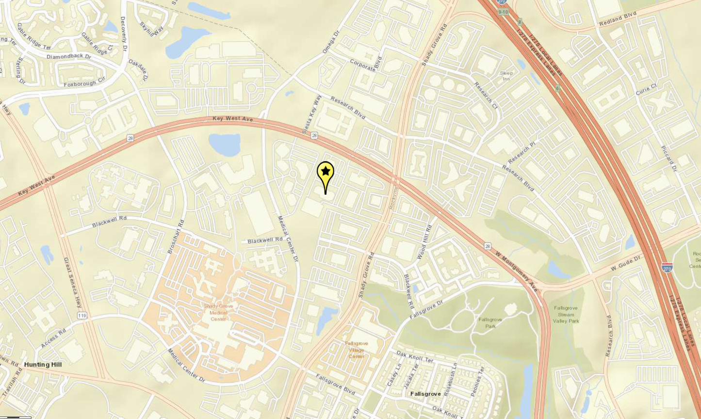
Address 9420 Key West Ave, Rockville
City Rockville
Zoning LSC‐1.0
Latitude 39.102939
Longitude ‐77.193847
Ground Elevation 470
Site Owner Key West III LP
Structure Owner Key West III LLC / DANAC
Carrier T‐Mobile
Structure Type Building
Solution Type Macro
Lease Status In Process
Carrier Site Name 7WAN094C
County Site Name Phillips Office Building
Existing Existing
Existing Structure Height 54
Justification of why this site was selected:
Existing Telecommunications Facility
Will site be used to support government telecommunications facilities or other equipment for government use?
No
Gvt. Use Desc.
Updated 7/1/2020
Ann. Plan? Yes
Application Description
T‐Mobile proposes removing (3) antennas, (3) RRUs, and (1) Cabinet, and installing (3) antennas, (3) RRUs, and (1) cabinet at the existing telecommunications facility.
NearbySites (New, Replacement Apps Only):
Provide the proposed height of the replacement structure without any antenna (New, Replacement Apps Only)
Distance to Residential Property (New, Replacement, Colocation Only)
Distance to Commercial Property (New, Replacement, Colocation Only)
Does the structure require an antenna structure registration under FCC Title 47
No
Application General Infomation
Site Infomation
Thursday, July 2, 2020
8:12:15 AM
Revised 7.20.20- JR
kblackwood
Cross-Out
kblackwood
Typewritten text
TMAs
App No: 2020071203
Screening considerations(New, Colocations, Replacement Apps Only):
Thursday, July 2, 2020
8:12:19 AM
App No: 2020071203
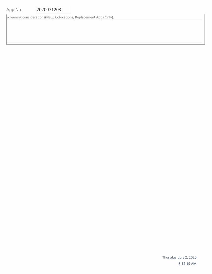
Does this qualify as a 6409 application? (Minor Mod, Colocations Only) Yes
PROW? No
ROW width
Pole Number
For towers outside the public ROW will the proposed installation increase the height of the structure by: (1) more than 10% or (2) more than 20 feet, whichever is greater?
No
For towers outside the public ROW will the proposed installation increase the width by adding appurtenance to the body of the structure that would protrude from the edge of the structure by more than 20 feet?
No
Will the proposed installation increase the height of the structure by: (1) more than 10% or (2) more than 10 feet, whichever is greater?
No
Will the proposed installation increase the width by adding appurtenance to the body of the structure that would protrude from the edge of the structure by more than 6 feet?
No
More than four Equipment Cabinets? YN No
Will the proposed installation require excavation or expansion outside the current boundaries of the site?
No
6409 Questions
Small Wireless Facility Questions Small Wireless Facility? No
Does the structure or current installation have concealment elements/measures?
No
If yes, describe how the proposed installation does not defeat the existing concealment.
Tribal Lands? No
Is the structure 10% taller than adjacent structures?
Please list adjacent structure heights
ROW owner
Cumulative volume of the proposed wireless equipment(s) exclusive of antennas in cubic feet
0
Cumulative volume of the proposed antenna antenna(s) exclusive of equipment
ROW Information
Small Wireless Facility Informatio
Thursday, July 2, 2020
8:12:19 AM

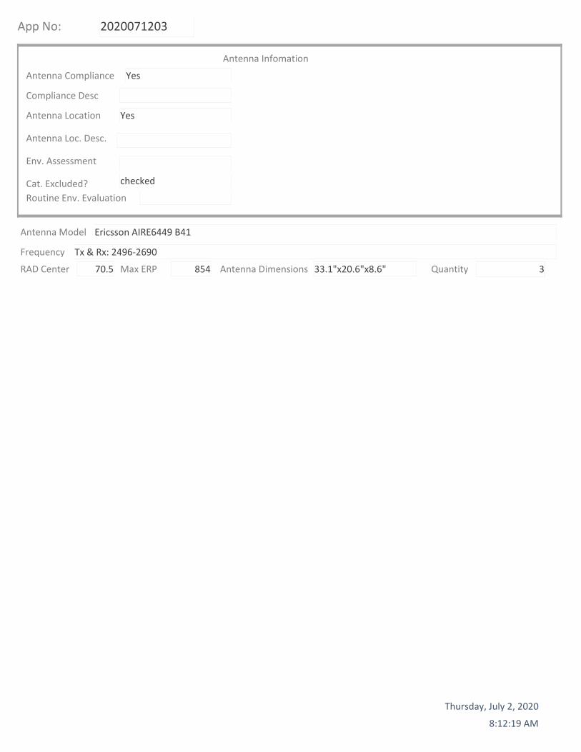
App No: 2020071203
Antenna Compliance Yes
Compliance Desc
Antenna Location Yes
Antenna Loc. Desc.
Env. Assessment
Cat. Excluded? checked
Routine Env. Evaluation
Antenna Infomation
RAD Center 70.5
Antenna Model Ericsson AIRE6449 B41
Frequency Tx & Rx: 2496‐2690
Max ERP 854 Antenna Dimensions 33.1"x20.6"x8.6" Quantity 3
Thursday, July 2, 2020
8:12:19 AM


PA1 | 2020-03-03 | Open | Commercial in Confidence | Page 1
March 2020
ericsson.com/5G-switch
Radio PortfolioB41 Products for T-Mobile

PA1 | 2020-03-03 | Open | Commercial in Confidence | Page 2
AIR 6488, B41
— Advanced Antenna System (AAS)
— 64TX/64RX with 128 AE
— Support operation frequency range 2496-2690 MHz
— Support output power up to 200W
— Support 100 MHz IBW & CBW
— Support NR and NR+LTE in split mode
— 3 x 10 Gbps eCPRI
— Power consumption < 1290W
— Weight: 58 kg
— Size (H x W x D): 884x520x183 mm
— -48 VDC (3-wire or 2-wire)
— -40 to +55 ̊C
— Multi-layer MU MIMO
— DL/UL: 16/8

PA1 | 2020-03-03 | Open | Commercial in Confidence | Page 3
AIR 6488, B41M
— Advanced Antenna System (AAS)
— 64TX/64RX with 128 AE
— Support operation frequency range 2590-2690 MHz
— Support output power up to 200W
— Support 100 MHz IBW & CBW
— Support NR and NR+LTE in split mode
— 3 x 10 Gbps eCPRI
— Power consumption < 1290W
— Weight: 58 kg
— Size (H x W x D): 884x520x183 mm
— -48 VDC (3-wire or 2-wire)
— -40 to +55 ̊C
— Multi-layer MU MIMO
— DL/UL: 16/8

PA1 | 2020-03-03 | Open | Commercial in Confidence | Page 4
2496MHz
AIR 6488M for New York CityBand 41M support
2568 MHz
Public Safety
2690MHz
2590MHz
B4
Not used
Radio Passband
2558MHz
filter rejection
Roll off BW
B41 in New York City currently has a UMTS Public Safety Network that requires OOBE interference protection from New T-Mobile Network
PA1 | 2020-03-03 | Open | Commercial in Confidence | Page 5
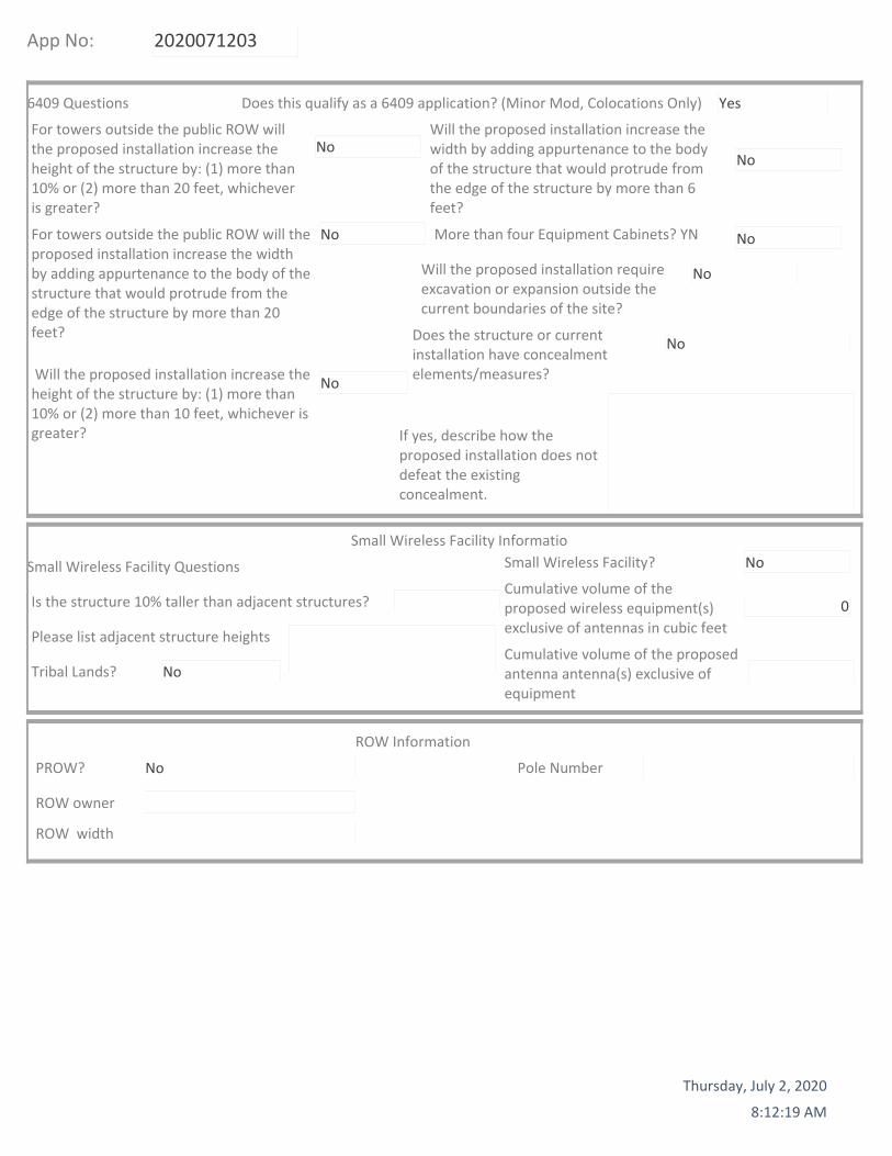
— 192 antenna elements, 3:1 subarray
— Up to 300W
— Up to 200 MHz Operating BW & Carrier BW
— Two 25 Gb/s SFP(C2) and Two 10 Gb/s QSFP(C1FD and C2 backup)
— -48V 45 A Two wire and three wire versions
— APC light connector and Self test push button
— Sensor support but undefined
— Size B41:
— 841 x 521 x 217 mm (H x W x D)
— Volume: 95 liter
— Weight: 47 kg
AIR 6449
PRA: July 2020
Preliminary

PA1 | 2020-03-03 | Open | Commercial in Confidence | Page 6
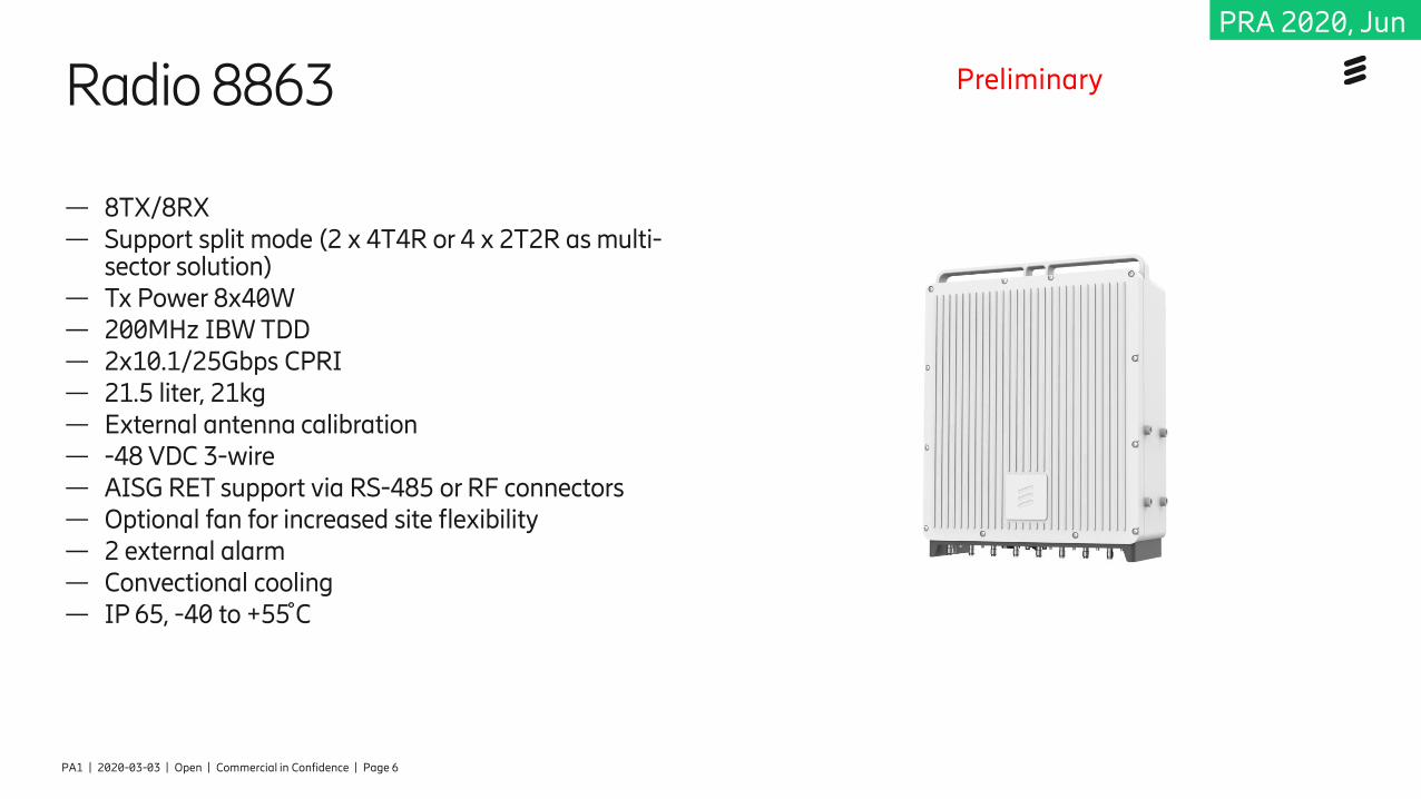
— 8TX/8RX — Support split mode (2 x 4T4R or 4 x 2T2R as multi-
sector solution)— Tx Power 8x40W — 200MHz IBW TDD — 2x10.1/25Gbps CPRI— 21.5 liter, 21kg — External antenna calibration— -48 VDC 3-wire — AISG RET support via RS-485 or RF connectors— Optional fan for increased site flexibility— 2 external alarm— Convectional cooling— IP 65, -40 to +55 ̊C
Radio 8863 Preliminary
PRA 2020, Jun
PA1 | 2020-03-03 | Open | Commercial in Confidence | Page 7
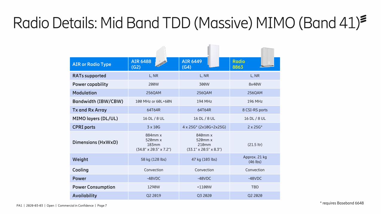
Radio Details: Mid Band TDD (Massive) MIMO (Band 41)
AIR or Radio TypeAIR 6488 (G2)
AIR 6449 (G4)
Radio 8863
RATs supported L, NR L, NR L, NR
Power capability 200W 300W 8x40W
Modulation 256QAM 256QAM 256QAM
Bandwidth (IBW/CBW) 100 MHz or 60L+60N 194 MHz 196 MHz
Tx and Rx Array 64T64R 64T64R 8 CSI-RS ports
MIMO layers (DL/UL) 16 DL / 8 UL 16 DL / 8 UL 16 DL / 8 UL
CPRI ports 3 x 10G 4 x 25G* (2x10G+2x25G) 2 x 25G*
Dimensions (HxWxD)
884mm x 520mm x 183mm
(34.8” x 20.5” x 7.2”)
840mm x 520mm x 210mm
(33.1” x 20.5” x 8.3”)(21.5 ltr)
Weight 58 kg (128 lbs) 47 kg (103 lbs)Approx. 21 kg
(46 lbs)
Cooling Convection Convection Convection
Power -48VDC -48VDC -48VDC
Power Consumption 1290W <1100W TBD
Availability Q2 2019 Q3 2020 Q2 2020
* requires Baseband 6648

PA1 | 2020-03-03 | Open | Commercial in Confidence | Page 8
Radio 4408 B41
— 4TX/4RX TDD
— 4x5W
— IBW up to 150 MHz CBW
— Up to 6 LTE carriers
— 2x 2.5/5/9.8/10.1Gbps CPRI
— 4 liter, less than 5kg incl bracket and cover
— AC or -48 VDC
— Integrated or external antenna
— 2 external alarm
— IP 65
— -40 to +55 C̊
PRA 2020, Q4


© Copyright 2011 T-Mobile USA, Inc. All rights reserved.Confidential and proprietary information of T-Mobile USA, Inc. Not for distribution outside T-Mobile.
Ericsson 6230 Design SpecificationThe methods for configuring the 6230 for field deployment arepresented.
The following are responsible for this project document:
Chad Au MTS, 425-435-8506Juan Cornejo Manager, 925-395-3033
Project Design Spec Revision Last Date: 7/16/19
Final doc URL (~Dnnnnn):Location Use the InfoRouter Search (Advanced) putting the Document ID (nnnnnn without the
D) to find the location of the master document.Template URL: http://docs.eng.t-mobile.com/InfoRouter/docs/~D423750
Ericsson 6230 Design Specification
T-Mobile USA, INC. Confidential Rev. 2 of 14
Table of Contents
1 Introduction / Project Summary......................................................................................................... 31.1 Purpose of Project 31.2 Product Description 31.3 Assumptions 3
2 General Equipment Overview ............................................................................................................ 33 6230 Placement ................................................................................................................................... 64 Baseline Capacity................................................................................................................................ 65 Provisioning for Deployment ............................................................................................................. 7
5.1 Prerequisite Grounding 75.2 AC Power Feed 85.3 Rectifier Dimensioning 85.4 DC Breaker/LLVD Assignment 85.5 SPD Function 105.6 ENM Integration 115.7 External Alarm Integration 14
6 Battery Backup Integration .............................................................................................................. 146.1 Battery Terminals & Breakers 146.2 Battery Temperature Sensor and Compensation 14

Ericsson 6230 Design Specification
T-Mobile USA, INC. Confidential Rev. 3 of 14
1 Introduction / Project Summary1.1 Purpose of Project
The methods for configuring the Ericsson Power 6230 DC power system for field deployment arepresented. These include AC power feed, load assignment to DC power distribution and breakers,load management relative to low voltage disconnect, populating the power system, convention formounting equipment to the user equipment rack, and HCS management.
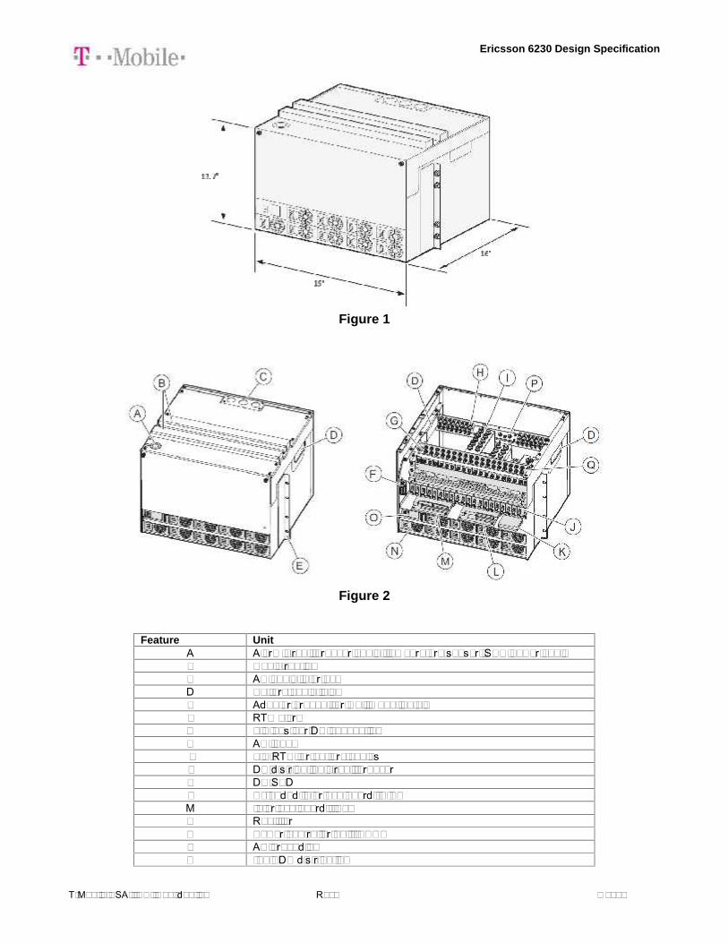
1.2 Product DescriptionThe Ericsson Power 6230 (Figure 1, 2), which can be considered a higher capacity update to currentindoor power systems such as the Ericsson PBC 6200, is the same DC power system used insidethe Ericsson 6160 site support cabinet, though without the enclosure. This DC power solution isconfigured by T-Mobile primarily for indoor macro cell deployments, or Alternative CoverageSolutions (ACS), as well as small cell, applications.
1.3 AssumptionsThe design methodology presented assumes an indoor deployment. The Power 6230 will comestandard with the battery rack, which accommodates up to 4 strings of 190 Ahr batteries (Figure 3).
2 General Equipment OverviewThe general specifications for the 6230 DC power system are as follows:
Mechanical SpecificationWeight 52.8 lbs.Dimensions (H x W x D) 13.7” x 19” x 16”Mounting position On top of battery rackColor Gray, NCS 2002-B (RAL 7035)
Power SystemInput voltage 3W+N+PE: 346/200-415/240 VAC
2W+N+PE: 208/120-220/127 VAC1W+N+PE: 200-250 VACRange 85 – 300 VAC
Line frequency 45 – 65 HzMaximum input current 155 A (load and batteries)
103 A (load only)Input power <33 kWOutput load (-48 VDC) 24 kWTotal capacity (-48 VDC) 31.5 kWDC Output voltage Nominal: -48 VDC; Range: -42.3 to -57.6 VDCDC Output power 24 kW to load, 7.5 kW to batteriesAC SPD Class 2 / Type 2PSU slots 9Rectifier efficiency 96%Priority load disconnect 8 circuit breakersLow voltage disconnect 1 6 circuit breakersLow voltage disconnect 2 6 circuit breakersAvail Circuit breaker ratings 3A, 5A, 10A, 15A, 20A, 25A, 30A, 40A, 50A, 60A, 80A, 100A, 200ABattery interface 2 circuit breakersBattery circuit breaker rating 125 A 2 pol (200 A)PSU capacity 3500 watts
Operating Environmental
Ericsson 6230 Design Specification
T-Mobile USA, INC. Confidential Rev. 4 of 14
Operation -40°C to +55°C; 0-90% non-condensing relative humidityTransportation -40°C to +70°C; 0-90% non-condensing relative humidityStorage -40°C to +55°C; 0-90% non-condensing relative humidity
Acoustic NoiseMax @ +45°F ambient < 65 dB
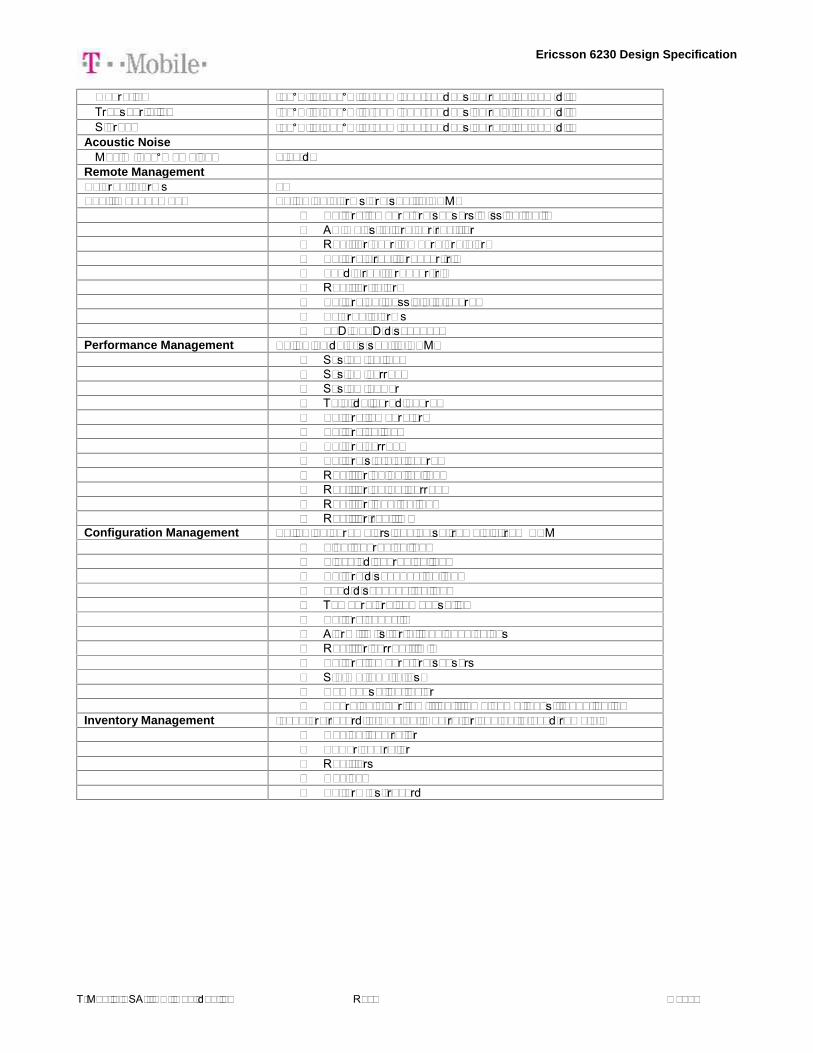
Remote ManagementExternal alarms 32Fault management Following alarms are sent to ENM:
- Battery temperature sensors missing/faulty- AC mains failure per rectifier- Rectifier over temperature alarm- Battery circuit breaker trip- Load circuit breaker trip- Rectifier failure- Battery not possible to charge- External alarms- LVD/BLVD disconnect
Performance Management Following data is sent to ENM:- System voltage- System current- System power- Total delivered energy- Battery temperature- Battery voltage- Battery current- Battery state of charge- Rectifier output voltage- Rectifier output current- Rectifier input voltage- Rectifier run time
Configuration Management Following parameters can be set remotely from ENM- Float charge voltage- Elevated charge voltage- Battery disconnect voltage- Load disconnect voltage- Temperature compensation- Battery capacity- Alarm limits for all analogue values- Rectifier current limit- Battery temperature sensors- State of health test- Compensation factor- Charging algorithm, float, temp comp, boost, equalization
Inventory Management Inventory record in Cabinet Controller can be fetched remotely- Cabinet controller- Power controller- Rectifiers- Cabinet- Battery test record

Ericsson 6230 Design Specification
T-Mobile USA, INC. Confidential Rev. 5 of 14
Figure 1
Figure 2
Feature UnitA Alarm circuit breaker cable, temperature sensor, SCU power cableB Cable routingC AC cable interfaceD Battery cable inletE Adaptor bracket for wall mounting kitF RTN alarmG 0 V bus bar DC connectionH AC inputI 0 V/RTN for battery cablesJ DC distribution circuit breakerK DC SPDL Extended interface board (EIB)M Interface board (IB2)N RectifierO Power controller unit (PCU)P AC groundingQ -48 VDC distribution

Ericsson 6230 Design Specification
T-Mobile USA, INC. Confidential Rev. 6 of 14
3 6230 PlacementThe 6230 arrives mounted on top of the prescribed Ericsson battery rack (Figure 3), which is to bebolted down onto the floor. Clearance at the top shall be provided to enable cabling for AC feed, DCloads, SPD, and battery cables. Front clearance shall allow work space for loading/unloading of 190Ahr batteries (22”x5”x12” each). If desired, any of the battery shelves can be converted for userequipment by installing optional rack kit to provide up to 8U each.
Figure 3
4 Baseline CapacityThe default 6230 BOM equips the power sub rack with a baseline set of circuit breakers, rectifiers,and fuses, as well as the Support Control Unit (SCU), as the starting configuration for generaldeployment use. These include:

Ericsson 6230 Design Specification
T-Mobile USA, INC. Confidential Rev. 7 of 14
Product Number Description Qty Comment
BMG 907 157/1 6230 indoor Power rack 1Power Unit and Battery Rack. Identity Label SVF191 040/1 included
KDU 127 170/3 SCU 09 01, Support Control Unit 1SXK 109 1052/1 SCU/SAU Holder 2RPM 777 143/00500 Signal cable SCU - power system 1RPM 777 080/01000 Power Cable -> SCU 1KET 109 70/2 Temp sensor 10m 1 One included as standardSXK 109 2011/7 SCU/SAU bracket extender 2 To attach SCU/SAU holder toBML 901 450/1 Rectifier 3,5 kW HE 4 4 Rectifiers in base configurationSXA 114 8381/1 Dummy plate Rectifier 5NFS 899 001/200 Bullet CB, 200A 2 For bulk feed of SPD boxes for regular radiosNFS 899 001/050 Bullet CB, 50A 3 For higher pc radios like AIR3246, AIR6488NFS 899 001/030 Bullet CB, 30A 1NFS 899 001/010 Bullet CB, 10A 5BAF 903 46/1 6230 indoor Battery rack 1SXK 109 2010/2 Power Unit Mounting battery rack 1
NTB 101 0646/2 Battery power cable to 3rd shelf 1Support for 3rd battery string. Kit for two batterystrings always included in BMG 907157/1
NTB 101 0637/1 Battery CB Connection box 1For 3rd battery shelf. x2 included in BMG. 300Aincluded
SXK 109 2011/6 19inch adaption plate 8U 1 Convert first battery shelf to 19-inch spaceNTB 101 0558/3 Adjustable bracket 170Ah-200Ah 3ZHY 601 19/1 SAU 02 01 1SXA 134 5524/3 Cable Ladder 19 inch 1NTB 101 0429/1 Quantity package (for SAU) 1RPM 777 405/01000 Signal and Power Cable SCU to SAU 1NFD 302 34/08 OVP-ALM 8 2RPM 777 143/01000 Signal Cable SAU - OVP 4 Length adapted to mounting of OVP in 19'' rackNTM 503 019 DIN bar (19") 1 For OVPs in the 19" adaption plate 8U option.NTB 101 0693/2 35mm², 6m GND cable kit, dual-lug 1
For specific RAN configurations needs that may exceed the baseline provisions in quantity and/orcapacity, additional components can be ordered and/or up-sized with the proper rating as needed tofunction properly, i.e., increase the number of rectifiers, breaker current rating, SPD rating, cables,etc. Reference manufacturers’ specification for load equipment power consumption data incalculating total current draw on the 6160 DC power supply.
5 Provisioning for Deployment
5.1 Prerequisite GroundingGrounding must be properly implemented for lightning/surge protection from cables connected toRRUs/AIRs that are exposed to the outdoor environment. The shielding of HCS and conventionalcoax feeder cables routed into the indoor space shall be grounded. Note that the chassis of Ericssonbase band units are automatically grounded when mounted to the 19” equipment rack, and so no

Ericsson 6230 Design Specification
T-Mobile USA, INC. Confidential Rev. 8 of 14
additional ground strap is needed for proper grounding. Check with the manufacturer of any otheruser equipment to determine whether an external cable is necessary to ground them.
The DC power rack and battery shelf shall be grounded to the site ground at any one of the MainEarthing Terminals (MET). Copper conductor of 35 mm2 (6.544 mm diameter, 2AWG) minimum crosssection terminated with a double lug shall be used.
5.2 AC Power FeedThe higher AC service for T-Mobile sites is 200 A. Sufficiently large wire size capable of carryingsuch currents must be used for the installed distance between the 6160 and the Power ProtectionCabinet. For example, copper wire with a minimum cross-sectional area of 85 mm2 (10.405 mmdiameter, AWG 3/0). Reference Figure 3 for feed and breaker locations.
Fuse recommendations for AC input:
Number of Rectifiers Input Current (A) Recommended AC Fuses (A)1 18 252 36 503 54 804 72 1005 90 1256 108 1257 126 1508 144 1759 162 200
5.3 Rectifier DimensioningThe standard BOM configuration comes with 4 units of 3.5 kW rectifiers occupying slots 1-4 for a totalof 14 kW initial capacity, with dummy plates over remaining 5 slots (Figure 6) available for futureexpansion as needed. Should the total power consumption of the loads to be powered by the 6230exceed this capacity, additional rectifier(s) are required for proper operation. As typical in N+1implementation, the maximum operating capacity is 28 kW from 8 rectifiers, with the other rectifier inhot-standby mode.
Figure 6
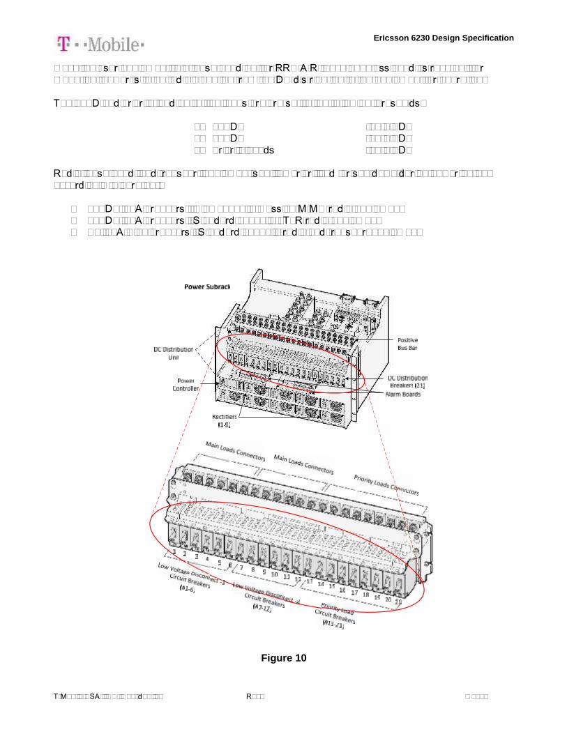
5.4 DC Breaker/LLVD AssignmentThe DC power sub rack has rectifiers, breakers, load low voltage disconnects (LLVD), and connectionpoints (Figure 8). The 18 breakers supplied in the baseline configuration comes in ratings of 10A (5x),30A (11x), 50A (3x). These are distributed in the power sub rack per Figure 10.
Ericsson 6230 Design Specification
T-Mobile USA, INC. Confidential Rev. 9 of 14
Once the user equipment, e.g. base band unit or RRU/AIR, have been assigned its rack unit formounting, power is to be fed via cabling from the DC distribution to the equipment for operation.
The LLVD and priority load cut-off voltages are pre-set to the following thresholds:
1. LLVD1 -47.0 VDC2. LLVD2 -45.1 VDC3. Priority Loads -43.2 VDC
Radio, base band, and transport equipment shall be prioritized for shutdown during power outageaccordingly (Figure 11):
- LLVD1, 50A breakers: High capacity massive-MIMO radio equipment- LLVD2, 30A breakers: Standard capacity 4T4R radio equipment- PL, 30A & 10 breakers: Standard capacity radio and transport equipment
Figure 10

Ericsson 6230 Design Specification
T-Mobile USA, INC. Confidential Rev. 10 of 14
Figure 11
Note: The use of the 200A breaker is driven by the available SPD solution’s bulk-feed circuit. SeeSec. 5.5 for details.
5.5 SPD FunctionUnlike outdoor sites, indoor applications would have the SPDs contained within its own DF-OVPframe (rather than on DIN rails) that is either wall or rack mounted and is ordered separately. It is theonly available solution currently that can handle the higher power RRU/AIR radios configurable with50A SPD units within (Figure 12).
Figure 12

Ericsson 6230 Design Specification
T-Mobile USA, INC. Confidential Rev. 11 of 14
5.6 ENM IntegrationFor remote management, fault detection, and monitoring, the site controller unit (Figure 13) can beremotely connected via the IP interface. This enables:
Fault Management:- Battery temp sensors missing/faulty- AC Mains failure per rectifier- Rectifier over temperature alarm- Battery CB trip- Load CB trip- Rectifier failure- Battery not possible to charge
Configuration Management:- Float Charge Voltage- Elevated Charge Voltage- Battery Disconnect Voltage- Load Disconnect Voltage- Temperature Compensation- Battery Capacity- Alarm limits for all analogue values- Rectifier Current Limit- Battery temperature sensors- State of health test- Compensation factor- Charging algorithm, float, temperature compensation, boost and equalization
Inventory Management- Cabinet Controller- Power Controller- Rectifiers- Cabinet- Battery Test Record
Per T-Mobile BOM, an Ethernet cable is supplied with each cabinet. Reference Ericsson ENMintegration manual for procedure.
Figure 13

Ericsson 6230 Design Specification
T-Mobile USA, INC. Confidential Rev. 12 of 14
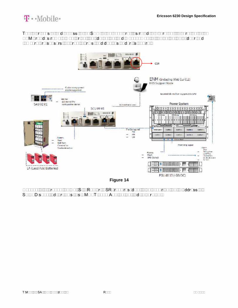
The interfaces of and access to the SCU in the 6160 are illustrated in Figure 14. Integration to theENM provides remote monitoring, fault detection, and management of the collection of door andtemperature sensors, external alarms, and devices under its control.
Figure 14
Connectivity through the Cell Site Router (CSR) requires identifying/acquiring the IP address viaSLIPED specified for the site’s NMNET Local Application field (Figure 15).

Ericsson 6230 Design Specification
T-Mobile USA, INC. Confidential Rev. 13 of 14
Figure 15
The CSR may be one of several that are in the T-Mobile network (Figure 16), which shows theappropriate physical port to which the SCU shall be connected to at the CSR.
SAR-M w/extension only 1/3/2
SAR-A 1/1/11
SAS-MxP 1/1/23
(No port assigned in the SAR-M without expansion card, SAR-Wx, SAR-F)Figure 16

Ericsson 6230 Design Specification
T-Mobile USA, INC. Confidential Rev. 14 of 14
5.7 External Alarm IntegrationExternal alarms can also be setup for the monitoring of passive devices and 3rd party equipment(Figure 13). Up to 32 external alarms can be supported, each configurable to be normally ‘open’ or‘closed’ as preferred. Reference Ericsson manual for external alarm integration.
6 Battery Backup Integration6.1 Battery Terminals & BreakersThe 6230 supports battery charging and monitoring to supply backup DC power during an AC mainsoutage to the rectifiers. Associated battery breaker is rated at 300A each. For copper wires thatsupport this much current, it must have a diameter of at least 11.684 mm. It is best to locate the twocabinets adjacent to each other to minimize cable length,
6.2 Battery Temperature Sensor and CompensationThe backup batterie’ temperature is monitored by the power system controller to ensure it is operatingwithin set limits during charging/discharging, outside of which the 6230 will adjust compensate. Atemperature sensor (Figure 15) is supplied and is to be routed from the controller to the battercompartment. Additional wire length can be spliced in as needed to reach the battery cabinet.
Figure 15

T-1
TITLE SHEET
SITE
VICINITY MAP
DIRECTIONS
CODE COMPLIANCEAPPLICANT:
PROJECT MANAGEMENT FIRM:
ENGINEERING FIRM:
T-MOBILE NORTHEAST LLC12050 BALTIMORE AVENUEBELTSVILLE, MD 20705OFFICE: (240) 264-8600FAX: (240) 264-8610
NETWORK BUILDING + CONSULTING, LLC.6095 MARSHALEE DRIVE, SUITE 300ELKRIDGE, MD 21075(410) 712-7092
NB+C ENGINEERING SERVICES, LLC.6095 MARSHALEE DRIVE, SUITE 300ELKRIDGE, MD 21075(410) 712-7092MARCO [email protected](410)712-7092 - EXT 1556
T-MOBILE NORTHEAST LLC
PROJECT TEAM
SITE INFORMATION
9420 KEY WEST AVENUEROCKVILLE, MD 20850
MONTGOMERY COUNTY
FROM: 12050 BALTIMORE AVENUE, BELTSVILLE, MD 20705.DEPART US-1 / BALTIMORE AVE TOWARD RITZ WAY. TURN LEFT ONTO RITZ WAY. TURN RIGHT ONTO VIRGINIAMANOR RD. KEEP STRAIGHT ONTO KONTERRA DR. TAKE RAMP LEFT FOR MD-200 W / MD-200 TOLL. ROADNAME CHANGES TO I-370 W. ROAD NAME CHANGES TO SAM EIG HWY. TURN LEFT ONTO MD-119 E / GREATSENECA HWY. TURN LEFT ONTO MD-28 E / KEY WEST AVE. ARRIVE AT MD-28 E / KEY WEST AVE.
SCOPE OF WORK:
PROJECT DESIGN:
SITE ID NUMBER:
911 SITE ADDRESS:
LATITUDE (NAD 83):LONGITUDE (NAD 83):
JURISDICTION:ZONING:
TAX ACCOUNT NUMBER:PARCEL AREA:PARCEL OWNER:
ADDRESS:
GROUND ELEVATION:
STRUCTURE TYPE:
STRUCTURE HEIGHT:
PROJECT CONSISTS OF THE FOLLOWING TO THE EXISTINGWIRELESS TELECOMMUNICATIONS FACILITY:REMOVING:(3) EXISTING ANTENNAS(3) EXISTING TMAS(12) EXISTING COAX(1) EXISTING CABINET
INSTALLING:(3) PROPOSED ANTENNAS(3) PROPOSED RRUS(1) PROPOSED P6230 CABINET(3) PROPOSED 6X12 HYBRID CABLES(1) PROPOSED 19" RACK
4SEC-67D5A997DBA INDOOR (AS IDENTIFIED ON RFDS)
7WAN094C
9420 KEY WEST AVENUEROCKVILLE, MD 20850
39.103055°-77.193888°
MONTGOMERY COUNTYLSC-1.0/H-110T
09-023443373.62± ACRESKEY WEST III LTD PTNSHPC/O DANAC, LLC5404 WISCONSIN AVENUE #301CHEVY CHASE, MD 20815
470.0' (AMSL)
ROOFTOP
54.0' (AGL)
THESE DRAWINGS ARE FORMATTED TO BE FULL-SIZE AT 22"X34".CONTRACTOR SHALL VERIFY ALL PLANS AND EXISTING DIMENSIONS ANDCONDITIONS ON THE JOB SITE AND SHALL IMMEDIATELY NOTIFY THEDESIGNER / ENGINEER IN WRITING OF ANY DISCREPANCIES BEFOREPROCEEDING WITH THE WORK OR MATERIAL ORDERS OR BE RESPONSIBLEFOR THE SAME. CONTRACTOR SHALL USE BEST MANAGEMENT PRACTICE TOPREVENT STORM WATER POLLUTION DURING CONSTRUCTION.
DRAWING INDEX
DO NOT SCALE DRAWINGS
T-1
GN-1
SP-1
C-1
C-2
A-1
A-2
A-3
A-4
E-1
G-1
TITLE SHEET
GENERAL NOTES
SITE PLAN
ROOFTOP & EQUIPMENT PLAN
ELEVATION
ANTENNA PLANS & ANTENNA SCHEDULE
ANTENNA SPECIFICATIONS & DETAILS
ANTENNA & RRU MOUNTING DETAILS
CABLING DETAIL & PLUMBING DIAGRAM
ELECTRICAL DETAILS
GROUNDING DETAILS
R
SITE NUMBER: 7WAN094CSITE NAME: KEY WEST - ROCKVILLE
T-MOBILE ANCHOR INSTALLATION, DESIGN 4SEC-67D5A997DBA INDOOR
ALL WORK AND MATERIALS SHALL BE PERFORMED AND INSTALLED IN ACCORDANCE WITH THE CURRENTEDITIONS OF THE FOLLOWING CODES AS ADOPTED BY THE LOCAL GOVERNING AUTHORITIES. NOTHING IN THESEPLANS IS TO BE CONSTRUED TO PERMIT WORK NOT CONFORMING TO THE LATEST EDITIONS OF THE FOLLOWINGCODES.
· ANSI/TIA-222-G
· TIA 607
· INSTITUTE FOR ELECTRICAL & ELECTRONICSENGINEER 81
· IEEE C2 NATIONAL ELECTRIC SAFETY CODE LATESTEDITION
· TELECORDIA GR-1275
· ANSI/T 311
· 2015 INTERNATIONAL BUILDING CODE
· 2014 NATIONAL ELECTRICAL CODE
· 2015 NFPA 101, LIFE SAFETY CODE
· AMERICAN CONCRETE INSTITUTE
· AMERICAN INSTITUTE OF STEEL CONSTRUCTION
· MANUAL OF STEEL CONSTRUCTION 13TH EDITION
7WAN094CKEYWEST - ROCKVILLE
9420 KEY WEST AVENUEROCKVILLE, MD 20850
MONTGOMERY COUNTY
ENG
INEE
RD
ESIG
NRE
CO
RDPR
OFE
SSIO
NAL
STAM
PSI
TEIN
FORM
ATIO
NSH
EET
TITL
ESH
EET
NU
MBE
R
REVISIONS
DESCRIPTIONDATEREV BY
6095 MARSHALEE DRIVE, SUITE 300ELKRIDGE, MD 21075
(410) 712-7092
NB+C ENGINEERING SERVICES, LLC.
ENG
INEE
R
12050 BALTIMORE AVENUEBELTSVILLE, MD 20705OFFICE: (240) 264-8600
FAX: (240) 264-8610
T-MOBILE NORTHEAST LLC
APPL
ICAN
T
0 06/29/2020 FINAL CDs CAR
PROFESSIONAL CERTIFICATION. I HEREBY CERTIFY THAT THESE DOCUMENTSWERE PREPARED OR APPROVED BY ME, AND THAT I AM A DULY LICENSEDPROFESSIONAL ENGINEER UNDER THE LAWS OF THE STATE OF MARYLAND,LICENSE NO. 55491, EXPIRATION DATE 01/08/2022
TRENT TRAVIS SNARR, P.E.MARYLAND PROFESSIONAL ENGINEER
LICENSE #55491
07/13/20
1 07/13/2020 REV PER COMMENTS DH

GN-1
GENERAL NOTES
7WAN094CKEYWEST - ROCKVILLE
9420 KEY WEST AVENUEROCKVILLE, MD 20850
MONTGOMERY COUNTY
ENG
INEE
RD
ESIG
NRE
CO
RDPR
OFE
SSIO
NAL
STAM
PSI
TEIN
FORM
ATIO
NSH
EET
TITL
ESH
EET
NU
MBE
R
REVISIONS
DESCRIPTIONDATEREV BY
6095 MARSHALEE DRIVE, SUITE 300ELKRIDGE, MD 21075
(410) 712-7092
NB+C ENGINEERING SERVICES, LLC.
ENG
INEE
R
12050 BALTIMORE AVENUEBELTSVILLE, MD 20705OFFICE: (240) 264-8600
FAX: (240) 264-8610
T-MOBILE NORTHEAST LLC
APPL
ICAN
T
0 06/29/2020 FINAL CDs CAR
PROFESSIONAL CERTIFICATION. I HEREBY CERTIFY THAT THESE DOCUMENTSWERE PREPARED OR APPROVED BY ME, AND THAT I AM A DULY LICENSEDPROFESSIONAL ENGINEER UNDER THE LAWS OF THE STATE OF MARYLAND,LICENSE NO. 55491, EXPIRATION DATE 01/08/2022
TRENT TRAVIS SNARR, P.E.MARYLAND PROFESSIONAL ENGINEER
LICENSE #55491
07/13/20
1 07/13/2020 REV PER COMMENTS DH

SP-1
SITE PLAN
GRAPHIC SCALE040 20 40 80 160
1 INCH = 40 FEET (22X34)1 INCH = 80 FEET (11X17)
GRAPHIC SCALE
SCALE: 1" = 40' (22X34)SCALE: 1" = 80' (11X17)
1
SP-1
SITE PLAN
7WAN094CKEYWEST - ROCKVILLE
9420 KEY WEST AVENUEROCKVILLE, MD 20850
MONTGOMERY COUNTY
ENG
INEE
RD
ESIG
NRE
CO
RDPR
OFE
SSIO
NAL
STAM
PSI
TEIN
FORM
ATIO
NSH
EET
TITL
ESH
EET
NU
MBE
R
REVISIONS
DESCRIPTIONDATEREV BY
6095 MARSHALEE DRIVE, SUITE 300ELKRIDGE, MD 21075
(410) 712-7092
NB+C ENGINEERING SERVICES, LLC.
ENG
INEE
R
12050 BALTIMORE AVENUEBELTSVILLE, MD 20705OFFICE: (240) 264-8600
FAX: (240) 264-8610
T-MOBILE NORTHEAST LLC
APPL
ICAN
T
0 06/29/2020 FINAL CDs CAR
PROFESSIONAL CERTIFICATION. I HEREBY CERTIFY THAT THESE DOCUMENTSWERE PREPARED OR APPROVED BY ME, AND THAT I AM A DULY LICENSEDPROFESSIONAL ENGINEER UNDER THE LAWS OF THE STATE OF MARYLAND,LICENSE NO. 55491, EXPIRATION DATE 01/08/2022
TRENT TRAVIS SNARR, P.E.MARYLAND PROFESSIONAL ENGINEER
LICENSE #55491
07/13/20
1 07/13/2020 REV PER COMMENTS DH
X X
NOTES:
1) SITE PLAN IS NOT THE RESULT OF A SURVEY. IT IS BASED ON FIELDMEASUREMENTS AND SCALED ASSESSORS MAPS AVAILABLE. ALL INFORMATIONSHOWN IS APPROXIMATE ONLY AND SUBJECT TO ANY CONDITION THAT A SURVEYMAY REVEAL.
2) ALL SETBACKS SHOWN ARE FROM EXISTING BUILDING TO EXISTING PROPERTYLINES.
JURISDICTION:
DIMENSION
FRONT YARD SETBACK:
SIDE YARD SETBACK:
REAR YARD SETBACK:
(ALL MEASUREMENTS ARE IN FEET ± UNLESS OTHERWISE NOTED)
EXISTING ± PROPOSED ±
256' NO CHANGE
59' NO CHANGE
91' NO CHANGE
MONTGOMERY COUNTY
ZONING: LSC-1.0/H-110T
LOT AREA: 3.62 ± ACRES
KEY WEST III LTD PTNSHP 5404 WISCONSIN AVE #301CHEVY CHASE, MD 20815
TAX ACCOUNT #: 09-02344337ZONING: LSC-1.0/H-11OT
AREA: 3.62 ± ACRES

C-1
ROOFTOP &
EQUIPMENT PLAN
GRAPHIC SCALE
010 5 10 20 40
1 INCH = 10 FEET (22X34)
1 INCH = 20 FEET (11X17)
GRAPHIC SCALE
SCALE: 1" = 10' (22X34)
SCALE: 1" = 20' (11X17)
1
C-1
PARTIAL ROOFTOP PLAN
7WAN094C
KEYWEST - ROCKVILLE
9420 KEY WEST AVENUE
ROCKVILLE, MD 20850
MONTGOMERY COUNTY
ENG
INEE
RDE
SIG
N R
ECO
RDPR
OFE
SSIO
NAL
STA
MP
SITE
INFO
RMAT
ION
SHEE
T TITL
ESH
EET N
UMBE
R
REVISIONS
DESCRIPTIONDATEREV BY
6095 MARSHALEE DRIVE, SUITE 300
ELKRIDGE, MD 21075
(410) 712-7092
NB+C ENGINEERING SERVICES, LLC.
ENG
INEE
R
12050 BALTIMORE AVENUE
BELTSVILLE, MD 20705
OFFICE: (240) 264-8600
FAX: (240) 264-8610
T-MOBILE NORTHEAST LLC
APPL
ICAN
T
0 06/29/2020 FINAL CDs CAR
PROFESSIONAL CERTIFICATION. I HEREBY CERTIFY THAT THESE DOCUMENTSWERE PREPARED OR APPROVED BY ME, AND THAT I AM A DULY LICENSEDPROFESSIONAL ENGINEER UNDER THE LAWS OF THE STATE OF MARYLAND,LICENSE NO. 55491, EXPIRATION DATE 01/08/2022
TRENT TRAVIS SNARR, P.E.
MARYLAND PROFESSIONAL ENGINEER
LICENSE #55491
07/13/20
1 07/13/2020 REV PER COMMENTS DH
GRAPHIC SCALE
1/4 INCH = 1 FOOT (22X34)
1/8 INCH = 1 FOOT (11X17)
0 4 848 21
SCALE: 1/4" = 1' (22X34)
SCALE: 1/8" = 1' (11X17)
2
C-1
EQUIPMENT PLAN
NB+C PROJECT #: 100595.
STRUCTURAL NOTE:REFER TO THE PASSING STRUCTURAL ANALYSIS OF THE EXISTING BUILDINGWITH THE EXISTING AND PROPOSED LOADS PERFORMED BY NB+C.
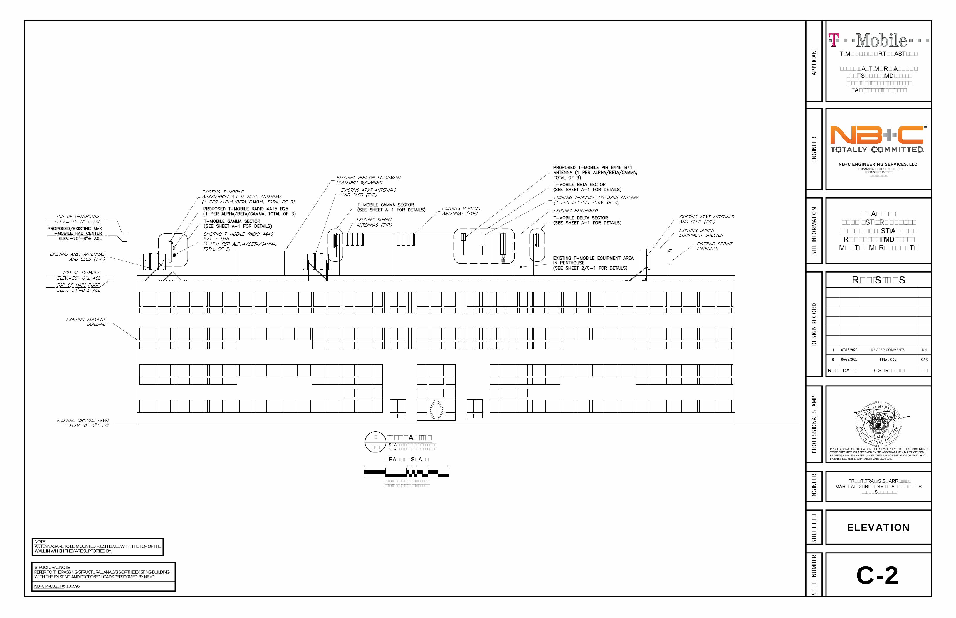
C-2
ELEVATION
GRAPHIC SCALE
3/32 INCH = 1 FOOT (22X34)3/64 INCH = 1 FOOT (11X17)
0 4 8 16816 21
SCALE: 3/32" = 1' (22X34)SCALE: 3/64" = 1' (11X17)
1
C-2
ELEVATION
7WAN094CKEYWEST - ROCKVILLE
9420 KEY WEST AVENUEROCKVILLE, MD 20850
MONTGOMERY COUNTY
ENG
INEE
RD
ESIG
NRE
CO
RDPR
OFE
SSIO
NAL
STAM
PSI
TEIN
FORM
ATIO
NSH
EET
TITL
ESH
EET
NU
MBE
R
REVISIONS
DESCRIPTIONDATEREV BY
6095 MARSHALEE DRIVE, SUITE 300ELKRIDGE, MD 21075
(410) 712-7092
NB+C ENGINEERING SERVICES, LLC.
ENG
INEE
R
12050 BALTIMORE AVENUEBELTSVILLE, MD 20705OFFICE: (240) 264-8600
FAX: (240) 264-8610
T-MOBILE NORTHEAST LLC
APPL
ICAN
T
0 06/29/2020 FINAL CDs CAR
PROFESSIONAL CERTIFICATION. I HEREBY CERTIFY THAT THESE DOCUMENTSWERE PREPARED OR APPROVED BY ME, AND THAT I AM A DULY LICENSEDPROFESSIONAL ENGINEER UNDER THE LAWS OF THE STATE OF MARYLAND,LICENSE NO. 55491, EXPIRATION DATE 01/08/2022
TRENT TRAVIS SNARR, P.E.MARYLAND PROFESSIONAL ENGINEER
LICENSE #55491
07/13/20
1 07/13/2020 REV PER COMMENTS DH
NB+C PROJECT #: 100595.
STRUCTURAL NOTE:REFER TO THE PASSING STRUCTURAL ANALYSIS OF THE EXISTING BUILDINGWITH THE EXISTING AND PROPOSED LOADS PERFORMED BY NB+C.
NOTE:ANTENNAS ARE TO BE MOUNTED FLUSH LEVEL WITH THE TOP OF THEWALL IN WHICH THEY ARE SUPPORTED BY.

ANTENNA INFORMATION
SECTOR STATUS ANTENNAMANUFACTURER ANTENNA MODEL
ANTENNADIMENSIONS
(HxWxD)
MECHANICALDOWN TILT
ELECTRICALDOWN TILT
RADCENTER AZIMUTH TMA/RRU QUANTITY & MODEL CABLE QUANTITY & TYPE CABLE
LENGTH
-
A-1
ANTENNA PLANS& ANTENNASCHEDULE
EXISTING ANTENNA ORIENTATION PLANNTS
1
A-1
PROPOSED ANTENNA ORIENTATION PLANNTS
2
A-1
7WAN094CKEYWEST - ROCKVILLE
9420 KEY WEST AVENUEROCKVILLE, MD 20850
MONTGOMERY COUNTY
ENG
INEE
RD
ESIG
NRE
CO
RDPR
OFE
SSIO
NAL
STAM
PSI
TEIN
FORM
ATIO
NSH
EET
TITL
ESH
EET
NU
MBE
R
REVISIONS
DESCRIPTIONDATEREV BY
6095 MARSHALEE DRIVE, SUITE 300ELKRIDGE, MD 21075
(410) 712-7092
NB+C ENGINEERING SERVICES, LLC.
ENG
INEE
R
12050 BALTIMORE AVENUEBELTSVILLE, MD 20705OFFICE: (240) 264-8600
FAX: (240) 264-8610
T-MOBILE NORTHEAST LLC
APPL
ICAN
T
0 06/29/2020 FINAL CDs CAR
PROFESSIONAL CERTIFICATION. I HEREBY CERTIFY THAT THESE DOCUMENTSWERE PREPARED OR APPROVED BY ME, AND THAT I AM A DULY LICENSEDPROFESSIONAL ENGINEER UNDER THE LAWS OF THE STATE OF MARYLAND,LICENSE NO. 55491, EXPIRATION DATE 01/08/2022
TRENT TRAVIS SNARR, P.E.MARYLAND PROFESSIONAL ENGINEER
LICENSE #55491
07/13/20
1 07/13/2020 REV PER COMMENTS DHNB+C PROJECT #: 100595.
STRUCTURAL NOTE:REFER TO THE PASSING STRUCTURAL ANALYSIS OF THE EXISTING BUILDINGWITH THE EXISTING AND PROPOSED LOADS PERFORMED BY NB+C.
NOTE:ANTENNAS ARE TO BE MOUNTED FLUSH LEVEL WITH THE TOP OF THEWALL IN WHICH THEY ARE SUPPORTED BY.

ERICSSON ANTENNA DETAILSCALE: NTS
1
A-2
ERICSSON REMOTE RADIO UNIT (RRU)NTS
2
A-2
ERICSSON 6230 CABINET DETAILNTS
3
A-2
A-2
ANTENNASPECIFICATIONS
& DETAILS
7WAN094CKEYWEST - ROCKVILLE
9420 KEY WEST AVENUEROCKVILLE, MD 20850
MONTGOMERY COUNTY
ENG
INEE
RD
ESIG
NRE
CO
RDPR
OFE
SSIO
NAL
STAM
PSI
TEIN
FORM
ATIO
NSH
EET
TITL
ESH
EET
NU
MBE
R
REVISIONS
DESCRIPTIONDATEREV BY
6095 MARSHALEE DRIVE, SUITE 300ELKRIDGE, MD 21075
(410) 712-7092
NB+C ENGINEERING SERVICES, LLC.
ENG
INEE
R
12050 BALTIMORE AVENUEBELTSVILLE, MD 20705OFFICE: (240) 264-8600
FAX: (240) 264-8610
T-MOBILE NORTHEAST LLC
APPL
ICAN
T
0 06/29/2020 FINAL CDs CAR
PROFESSIONAL CERTIFICATION. I HEREBY CERTIFY THAT THESE DOCUMENTSWERE PREPARED OR APPROVED BY ME, AND THAT I AM A DULY LICENSEDPROFESSIONAL ENGINEER UNDER THE LAWS OF THE STATE OF MARYLAND,LICENSE NO. 55491, EXPIRATION DATE 01/08/2022
TRENT TRAVIS SNARR, P.E.MARYLAND PROFESSIONAL ENGINEER
LICENSE #55491
07/13/20
1 07/13/2020 REV PER COMMENTS DH

RRU MOUNTING (ALPHA & BETA) DETAILNTS
1
A-3
ANTENNA MOUNTING DETAILNTS
3
A-3
RRU TRIPOD MOUNTING DETAIL (GAMMA)NTS
2
A-3
A-3
ANTENNA &RRU MOUNTING
DETAILS
7WAN094CKEYWEST - ROCKVILLE
9420 KEY WEST AVENUEROCKVILLE, MD 20850
MONTGOMERY COUNTY
ENG
INEE
RD
ESIG
NRE
CO
RDPR
OFE
SSIO
NAL
STAM
PSI
TEIN
FORM
ATIO
NSH
EET
TITL
ESH
EET
NU
MBE
R
REVISIONS
DESCRIPTIONDATEREV BY
6095 MARSHALEE DRIVE, SUITE 300ELKRIDGE, MD 21075
(410) 712-7092
NB+C ENGINEERING SERVICES, LLC.
ENG
INEE
R
12050 BALTIMORE AVENUEBELTSVILLE, MD 20705OFFICE: (240) 264-8600
FAX: (240) 264-8610
T-MOBILE NORTHEAST LLC
APPL
ICAN
T
0 06/29/2020 FINAL CDs CAR
PROFESSIONAL CERTIFICATION. I HEREBY CERTIFY THAT THESE DOCUMENTSWERE PREPARED OR APPROVED BY ME, AND THAT I AM A DULY LICENSEDPROFESSIONAL ENGINEER UNDER THE LAWS OF THE STATE OF MARYLAND,LICENSE NO. 55491, EXPIRATION DATE 01/08/2022
TRENT TRAVIS SNARR, P.E.MARYLAND PROFESSIONAL ENGINEER
LICENSE #55491
07/13/20
1 07/13/2020 REV PER COMMENTS DH
NOTE:ANTENNAS ARE TO BE MOUNTED FLUSH LEVEL WITH THE TOP OF THEWALL IN WHICH THEY ARE SUPPORTED BY.
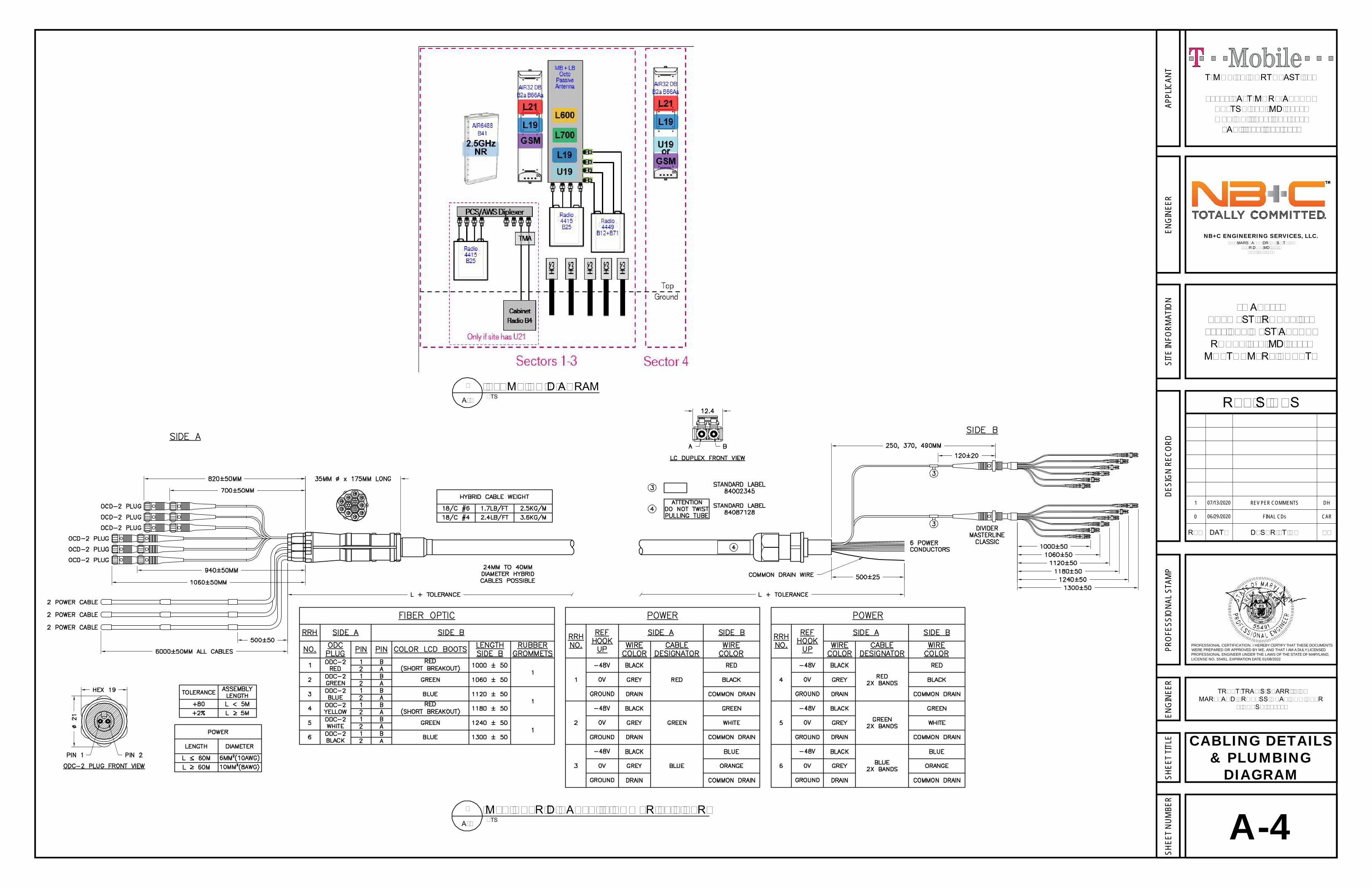
MLE HYBRID CABLE (6 POWER/12 FIBER)NTS
2
A-3 A-4
CABLING DETAILS& PLUMBING
DIAGRAM
7WAN094CKEYWEST - ROCKVILLE
9420 KEY WEST AVENUEROCKVILLE, MD 20850
MONTGOMERY COUNTY
ENG
INEE
RD
ESIG
NRE
CO
RDPR
OFE
SSIO
NAL
STAM
PSI
TEIN
FORM
ATIO
NSH
EET
TITL
ESH
EET
NU
MBE
R
REVISIONS
DESCRIPTIONDATEREV BY
6095 MARSHALEE DRIVE, SUITE 300ELKRIDGE, MD 21075
(410) 712-7092
NB+C ENGINEERING SERVICES, LLC.
ENG
INEE
R
12050 BALTIMORE AVENUEBELTSVILLE, MD 20705OFFICE: (240) 264-8600
FAX: (240) 264-8610
T-MOBILE NORTHEAST LLC
APPL
ICAN
T
0 06/29/2020 FINAL CDs CAR
PROFESSIONAL CERTIFICATION. I HEREBY CERTIFY THAT THESE DOCUMENTSWERE PREPARED OR APPROVED BY ME, AND THAT I AM A DULY LICENSEDPROFESSIONAL ENGINEER UNDER THE LAWS OF THE STATE OF MARYLAND,LICENSE NO. 55491, EXPIRATION DATE 01/08/2022
TRENT TRAVIS SNARR, P.E.MARYLAND PROFESSIONAL ENGINEER
LICENSE #55491
07/13/20
1 07/13/2020 REV PER COMMENTS DH
PLUMBING DIAGRAMNTS
1
A-3
POWER DIAGRAM
NTS
3
G-1
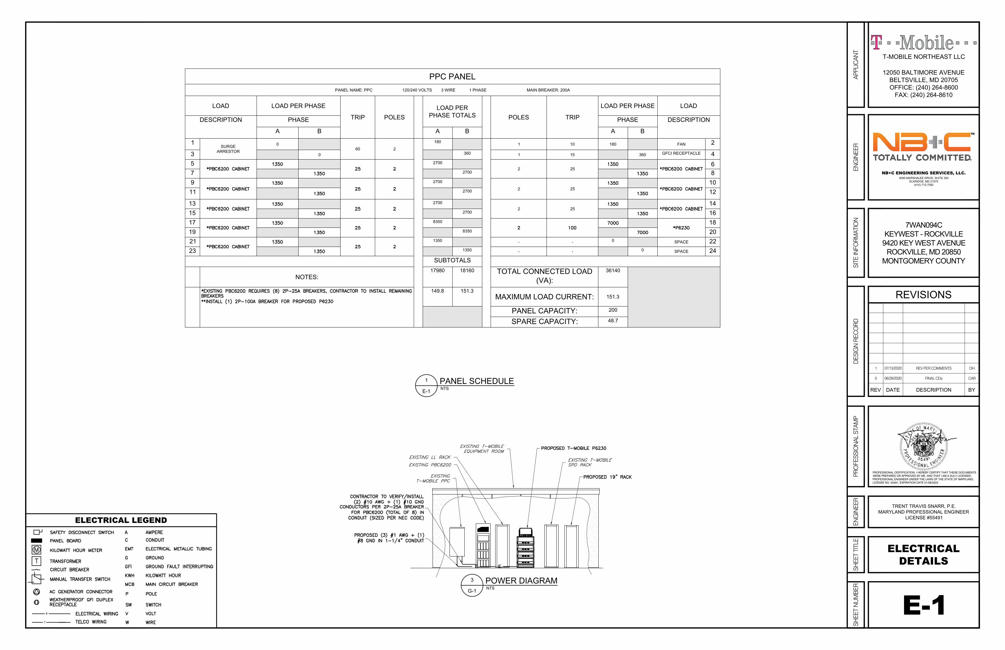
PPC PANEL
PANEL NAME: PPC 120/240 VOLTS 3 WIRE 1 PHASE MAIN BREAKER: 200A
LOAD LOAD PER PHASE
TRIP POLES
LOAD PER
PHASE TOTALS
POLES TRIP
LOAD PER PHASE LOAD
DESCRIPTION PHASE PHASE DESCRIPTION
A B A B A B
1
SURGE
ARRESTOR
0
60 2
180
1 10 180 FAN
2
3 0
360
1 15 360
GFCI RECEPTACLE
4
5
2700
2 25
6
7
2700
8
9
2700
2 25
10
11
2700
12
13
2700
2 25
14
15
2700
16
17
8350
18
19
8350
20
21
1350
- -
0
SPACE 22
23
1350
- -
0
SPACE 24
SUBTOTALS
NOTES:
17980 18160
TOTAL CONNECTED LOAD
(VA):
36140
149.8 151.3
MAXIMUM LOAD CURRENT:
151.3
PANEL CAPACITY:
200
SPARE CAPACITY:
48.7
E-1
ELECTRICAL
DETAILS
PANEL SCHEDULE
NTS
1
E-1
E
T
ELECTRICAL LEGEND
7WAN094C
KEYWEST - ROCKVILLE
9420 KEY WEST AVENUE
ROCKVILLE, MD 20850
MONTGOMERY COUNTY
ENG
INEE
RDE
SIG
N R
ECO
RDPR
OFE
SSIO
NAL
STA
MP
SITE
INFO
RMAT
ION
SHEE
T TITL
ESH
EET N
UMBE
R
REVISIONS
DESCRIPTIONDATEREV BY
6095 MARSHALEE DRIVE, SUITE 300
ELKRIDGE, MD 21075
(410) 712-7092
NB+C ENGINEERING SERVICES, LLC.
ENG
INEE
R
12050 BALTIMORE AVENUE
BELTSVILLE, MD 20705
OFFICE: (240) 264-8600
FAX: (240) 264-8610
T-MOBILE NORTHEAST LLC
APPL
ICAN
T
0 06/29/2020 FINAL CDs CAR
PROFESSIONAL CERTIFICATION. I HEREBY CERTIFY THAT THESE DOCUMENTSWERE PREPARED OR APPROVED BY ME, AND THAT I AM A DULY LICENSEDPROFESSIONAL ENGINEER UNDER THE LAWS OF THE STATE OF MARYLAND,LICENSE NO. 55491, EXPIRATION DATE 01/08/2022
TRENT TRAVIS SNARR, P.E.
MARYLAND PROFESSIONAL ENGINEER
LICENSE #55491
07/13/20
1 07/13/2020 REV PER COMMENTS DH

ANTENNA GROUNDING DETAILNTS
1
G-1
ALPHA BETA GAMMA DELTA
GROUNDING BAR CONNECTIONSNTS
3
G-1
CADWELD GROUNDING CONNECTION DETAILSNTS
2
G-1
G-1
GROUNDINGDETAILSGROUNDING LEGEND
7WAN094CKEYWEST - ROCKVILLE
9420 KEY WEST AVENUEROCKVILLE, MD 20850
MONTGOMERY COUNTY
ENG
INEE
RD
ESIG
NRE
CO
RDPR
OFE
SSIO
NAL
STAM
PSI
TEIN
FORM
ATIO
NSH
EET
TITL
ESH
EET
NU
MBE
R
REVISIONS
DESCRIPTIONDATEREV BY
6095 MARSHALEE DRIVE, SUITE 300ELKRIDGE, MD 21075
(410) 712-7092
NB+C ENGINEERING SERVICES, LLC.
ENG
INEE
R
12050 BALTIMORE AVENUEBELTSVILLE, MD 20705OFFICE: (240) 264-8600
FAX: (240) 264-8610
T-MOBILE NORTHEAST LLC
APPL
ICAN
T
0 06/29/2020 FINAL CDs CAR
PROFESSIONAL CERTIFICATION. I HEREBY CERTIFY THAT THESE DOCUMENTSWERE PREPARED OR APPROVED BY ME, AND THAT I AM A DULY LICENSEDPROFESSIONAL ENGINEER UNDER THE LAWS OF THE STATE OF MARYLAND,LICENSE NO. 55491, EXPIRATION DATE 01/08/2022
TRENT TRAVIS SNARR, P.E.MARYLAND PROFESSIONAL ENGINEER
LICENSE #55491
07/13/20
1 07/13/2020 REV PER COMMENTS DH
App No: 2020071203
Application Type Minor Modification
Applicant Name NB+C
Site Id 279
Address 9420 Key West Ave, Rockville
City Rockville
Zoning LSC‐1.0
Latitude 39.102939
Longitude ‐77.193847
Ground Elevation 470
Site Owner Key West III LP
Structure Owner Key West III LLC / DANAC
Carrier T‐Mobile
Structure Type Building
Solution Type Macro
Lease Status In Process
Carrier Site Name 7WAN094C
County Site Name Phillips Office Building
Existing Existing
Existing Structure Height 54
Justification of why this site was selected:
Existing Telecommunications Facility
Will site be used to support government telecommunications facilities or other equipment for government use?
No
Gvt. Use Desc.
Updated 7/1/2020
Ann. Plan? Yes
Application Description
T‐Mobile proposes removing (3) antennas, (3) RRUs, and (1) Cabinet, and installing (3) antennas, (3) RRUs, and (1) cabinet at the existing telecommunications facility.
NearbySites (New, Replacement Apps Only):
Provide the proposed height of the replacement structure without any antenna (New, Replacement Apps Only)
Distance to Residential Property (New, Replacement, Colocation Only)
Distance to Commercial Property (New, Replacement, Colocation Only)
Does the structure require an antenna structure registration under FCC Title 47
No
Application General Infomation
Site Infomation
Thursday, July 2, 2020
8:12:15 AM

App No: 2020071203
Screening considerations(New, Colocations, Replacement Apps Only):
Thursday, July 2, 2020
8:12:19 AM

App No: 2020071203
Does this qualify as a 6409 application? (Minor Mod, Colocations Only) Yes
PROW? No
ROW width
Pole Number
For towers outside the public ROW will the proposed installation increase the height of the structure by: (1) more than 10% or (2) more than 20 feet, whichever is greater?
No
For towers outside the public ROW will the proposed installation increase the width by adding appurtenance to the body of the structure that would protrude from the edge of the structure by more than 20 feet?
No
Will the proposed installation increase the height of the structure by: (1) more than 10% or (2) more than 10 feet, whichever is greater?
No
Will the proposed installation increase the width by adding appurtenance to the body of the structure that would protrude from the edge of the structure by more than 6 feet?
No
More than four Equipment Cabinets? YN No
Will the proposed installation require excavation or expansion outside the current boundaries of the site?
No
6409 Questions
Small Wireless Facility Questions Small Wireless Facility? No
Does the structure or current installation have concealment elements/measures?
No
If yes, describe how the proposed installation does not defeat the existing concealment.
Tribal Lands? No
Is the structure 10% taller than adjacent structures?
Please list adjacent structure heights
ROW owner
Cumulative volume of the proposed wireless equipment(s) exclusive of antennas in cubic feet
0
Cumulative volume of the proposed antenna antenna(s) exclusive of equipment
ROW Information
Small Wireless Facility Informatio
Thursday, July 2, 2020
8:12:19 AM
App No: 2020071203
Antenna Compliance Yes
Compliance Desc
Antenna Location Yes
Antenna Loc. Desc.
Env. Assessment
Cat. Excluded? checked
Routine Env. Evaluation
Antenna Infomation
RAD Center 70.5
Antenna Model Ericsson AIRE6449 B41
Frequency Tx & Rx: 2496‐2690
Max ERP 854 Antenna Dimensions 33.1"x20.6"x8.6" Quantity 3
Thursday, July 2, 2020
8:12:19 AM

PA1 | 2020-03-03 | Open | Commercial in Confidence | Page 1
March 2020
ericsson.com/5G-switch
Radio PortfolioB41 Products for T-Mobile

PA1 | 2020-03-03 | Open | Commercial in Confidence | Page 2
AIR 6488, B41
— Advanced Antenna System (AAS)
— 64TX/64RX with 128 AE
— Support operation frequency range 2496-2690 MHz
— Support output power up to 200W
— Support 100 MHz IBW & CBW
— Support NR and NR+LTE in split mode
— 3 x 10 Gbps eCPRI
— Power consumption < 1290W
— Weight: 58 kg
— Size (H x W x D): 884x520x183 mm
— -48 VDC (3-wire or 2-wire)
— -40 to +55 ̊C
— Multi-layer MU MIMO
— DL/UL: 16/8

PA1 | 2020-03-03 | Open | Commercial in Confidence | Page 3
AIR 6488, B41M
— Advanced Antenna System (AAS)
— 64TX/64RX with 128 AE
— Support operation frequency range 2590-2690 MHz
— Support output power up to 200W
— Support 100 MHz IBW & CBW
— Support NR and NR+LTE in split mode
— 3 x 10 Gbps eCPRI
— Power consumption < 1290W
— Weight: 58 kg
— Size (H x W x D): 884x520x183 mm
— -48 VDC (3-wire or 2-wire)
— -40 to +55 ̊C
— Multi-layer MU MIMO
— DL/UL: 16/8

PA1 | 2020-03-03 | Open | Commercial in Confidence | Page 4
2496MHz
AIR 6488M for New York CityBand 41M support
2568 MHz
Public Safety
2690MHz
2590MHz
B4
Not used
Radio Passband
2558MHz
filter rejection
Roll off BW
B41 in New York City currently has a UMTS Public Safety Network that requires OOBE interference protection from New T-Mobile Network

PA1 | 2020-03-03 | Open | Commercial in Confidence | Page 5
— 192 antenna elements, 3:1 subarray
— Up to 300W
— Up to 200 MHz Operating BW & Carrier BW
— Two 25 Gb/s SFP(C2) and Two 10 Gb/s QSFP(C1FD and C2 backup)
— -48V 45 A Two wire and three wire versions
— APC light connector and Self test push button
— Sensor support but undefined
— Size B41:
— 841 x 521 x 217 mm (H x W x D)
— Volume: 95 liter
— Weight: 47 kg
AIR 6449
PRA: July 2020
Preliminary
PA1 | 2020-03-03 | Open | Commercial in Confidence | Page 6
— 8TX/8RX — Support split mode (2 x 4T4R or 4 x 2T2R as multi-
sector solution)— Tx Power 8x40W — 200MHz IBW TDD — 2x10.1/25Gbps CPRI— 21.5 liter, 21kg — External antenna calibration— -48 VDC 3-wire — AISG RET support via RS-485 or RF connectors— Optional fan for increased site flexibility— 2 external alarm— Convectional cooling— IP 65, -40 to +55 ̊C
Radio 8863 Preliminary
PRA 2020, Jun

PA1 | 2020-03-03 | Open | Commercial in Confidence | Page 7
Radio Details: Mid Band TDD (Massive) MIMO (Band 41)
AIR or Radio TypeAIR 6488 (G2)
AIR 6449 (G4)
Radio 8863
RATs supported L, NR L, NR L, NR
Power capability 200W 300W 8x40W
Modulation 256QAM 256QAM 256QAM
Bandwidth (IBW/CBW) 100 MHz or 60L+60N 194 MHz 196 MHz
Tx and Rx Array 64T64R 64T64R 8 CSI-RS ports
MIMO layers (DL/UL) 16 DL / 8 UL 16 DL / 8 UL 16 DL / 8 UL
CPRI ports 3 x 10G 4 x 25G* (2x10G+2x25G) 2 x 25G*
Dimensions (HxWxD)
884mm x 520mm x 183mm
(34.8” x 20.5” x 7.2”)
840mm x 520mm x 210mm
(33.1” x 20.5” x 8.3”)(21.5 ltr)
Weight 58 kg (128 lbs) 47 kg (103 lbs)Approx. 21 kg
(46 lbs)
Cooling Convection Convection Convection
Power -48VDC -48VDC -48VDC
Power Consumption 1290W <1100W TBD
Availability Q2 2019 Q3 2020 Q2 2020
* requires Baseband 6648

PA1 | 2020-03-03 | Open | Commercial in Confidence | Page 8
Radio 4408 B41
— 4TX/4RX TDD
— 4x5W
— IBW up to 150 MHz CBW
— Up to 6 LTE carriers
— 2x 2.5/5/9.8/10.1Gbps CPRI
— 4 liter, less than 5kg incl bracket and cover
— AC or -48 VDC
— Integrated or external antenna
— 2 external alarm
— IP 65
— -40 to +55 C̊
PRA 2020, Q4

© Copyright 2011 T-Mobile USA, Inc. All rights reserved.Confidential and proprietary information of T-Mobile USA, Inc. Not for distribution outside T-Mobile.
Ericsson 6230 Design SpecificationThe methods for configuring the 6230 for field deployment arepresented.
The following are responsible for this project document:
Chad Au MTS, 425-435-8506Juan Cornejo Manager, 925-395-3033
Project Design Spec Revision Last Date: 7/16/19
Final doc URL (~Dnnnnn):Location Use the InfoRouter Search (Advanced) putting the Document ID (nnnnnn without the
D) to find the location of the master document.Template URL: http://docs.eng.t-mobile.com/InfoRouter/docs/~D423750

Ericsson 6230 Design Specification
T-Mobile USA, INC. Confidential Rev. 2 of 14
Table of Contents
1 Introduction / Project Summary......................................................................................................... 31.1 Purpose of Project 31.2 Product Description 31.3 Assumptions 3
2 General Equipment Overview ............................................................................................................ 33 6230 Placement ................................................................................................................................... 64 Baseline Capacity................................................................................................................................ 65 Provisioning for Deployment ............................................................................................................. 7
5.1 Prerequisite Grounding 75.2 AC Power Feed 85.3 Rectifier Dimensioning 85.4 DC Breaker/LLVD Assignment 85.5 SPD Function 105.6 ENM Integration 115.7 External Alarm Integration 14
6 Battery Backup Integration .............................................................................................................. 146.1 Battery Terminals & Breakers 146.2 Battery Temperature Sensor and Compensation 14

Ericsson 6230 Design Specification
T-Mobile USA, INC. Confidential Rev. 3 of 14
1 Introduction / Project Summary1.1 Purpose of Project
The methods for configuring the Ericsson Power 6230 DC power system for field deployment arepresented. These include AC power feed, load assignment to DC power distribution and breakers,load management relative to low voltage disconnect, populating the power system, convention formounting equipment to the user equipment rack, and HCS management.
1.2 Product DescriptionThe Ericsson Power 6230 (Figure 1, 2), which can be considered a higher capacity update to currentindoor power systems such as the Ericsson PBC 6200, is the same DC power system used insidethe Ericsson 6160 site support cabinet, though without the enclosure. This DC power solution isconfigured by T-Mobile primarily for indoor macro cell deployments, or Alternative CoverageSolutions (ACS), as well as small cell, applications.
1.3 AssumptionsThe design methodology presented assumes an indoor deployment. The Power 6230 will comestandard with the battery rack, which accommodates up to 4 strings of 190 Ahr batteries (Figure 3).
2 General Equipment OverviewThe general specifications for the 6230 DC power system are as follows:
Mechanical SpecificationWeight 52.8 lbs.Dimensions (H x W x D) 13.7” x 19” x 16”Mounting position On top of battery rackColor Gray, NCS 2002-B (RAL 7035)
Power SystemInput voltage 3W+N+PE: 346/200-415/240 VAC
2W+N+PE: 208/120-220/127 VAC1W+N+PE: 200-250 VACRange 85 – 300 VAC
Line frequency 45 – 65 HzMaximum input current 155 A (load and batteries)
103 A (load only)Input power <33 kWOutput load (-48 VDC) 24 kWTotal capacity (-48 VDC) 31.5 kWDC Output voltage Nominal: -48 VDC; Range: -42.3 to -57.6 VDCDC Output power 24 kW to load, 7.5 kW to batteriesAC SPD Class 2 / Type 2PSU slots 9Rectifier efficiency 96%Priority load disconnect 8 circuit breakersLow voltage disconnect 1 6 circuit breakersLow voltage disconnect 2 6 circuit breakersAvail Circuit breaker ratings 3A, 5A, 10A, 15A, 20A, 25A, 30A, 40A, 50A, 60A, 80A, 100A, 200ABattery interface 2 circuit breakersBattery circuit breaker rating 125 A 2 pol (200 A)PSU capacity 3500 watts
Operating Environmental

Ericsson 6230 Design Specification
T-Mobile USA, INC. Confidential Rev. 4 of 14
Operation -40°C to +55°C; 0-90% non-condensing relative humidityTransportation -40°C to +70°C; 0-90% non-condensing relative humidityStorage -40°C to +55°C; 0-90% non-condensing relative humidity
Acoustic NoiseMax @ +45°F ambient < 65 dB
Remote ManagementExternal alarms 32Fault management Following alarms are sent to ENM:
- Battery temperature sensors missing/faulty- AC mains failure per rectifier- Rectifier over temperature alarm- Battery circuit breaker trip- Load circuit breaker trip- Rectifier failure- Battery not possible to charge- External alarms- LVD/BLVD disconnect
Performance Management Following data is sent to ENM:- System voltage- System current- System power- Total delivered energy- Battery temperature- Battery voltage- Battery current- Battery state of charge- Rectifier output voltage- Rectifier output current- Rectifier input voltage- Rectifier run time
Configuration Management Following parameters can be set remotely from ENM- Float charge voltage- Elevated charge voltage- Battery disconnect voltage- Load disconnect voltage- Temperature compensation- Battery capacity- Alarm limits for all analogue values- Rectifier current limit- Battery temperature sensors- State of health test- Compensation factor- Charging algorithm, float, temp comp, boost, equalization
Inventory Management Inventory record in Cabinet Controller can be fetched remotely- Cabinet controller- Power controller- Rectifiers- Cabinet- Battery test record
Ericsson 6230 Design Specification
T-Mobile USA, INC. Confidential Rev. 5 of 14
Figure 1
Figure 2
Feature UnitA Alarm circuit breaker cable, temperature sensor, SCU power cableB Cable routingC AC cable interfaceD Battery cable inletE Adaptor bracket for wall mounting kitF RTN alarmG 0 V bus bar DC connectionH AC inputI 0 V/RTN for battery cablesJ DC distribution circuit breakerK DC SPDL Extended interface board (EIB)M Interface board (IB2)N RectifierO Power controller unit (PCU)P AC groundingQ -48 VDC distribution

Ericsson 6230 Design Specification
T-Mobile USA, INC. Confidential Rev. 6 of 14
3 6230 PlacementThe 6230 arrives mounted on top of the prescribed Ericsson battery rack (Figure 3), which is to bebolted down onto the floor. Clearance at the top shall be provided to enable cabling for AC feed, DCloads, SPD, and battery cables. Front clearance shall allow work space for loading/unloading of 190Ahr batteries (22”x5”x12” each). If desired, any of the battery shelves can be converted for userequipment by installing optional rack kit to provide up to 8U each.
Figure 3
4 Baseline CapacityThe default 6230 BOM equips the power sub rack with a baseline set of circuit breakers, rectifiers,and fuses, as well as the Support Control Unit (SCU), as the starting configuration for generaldeployment use. These include:

Ericsson 6230 Design Specification
T-Mobile USA, INC. Confidential Rev. 7 of 14
Product Number Description Qty Comment
BMG 907 157/1 6230 indoor Power rack 1Power Unit and Battery Rack. Identity Label SVF191 040/1 included
KDU 127 170/3 SCU 09 01, Support Control Unit 1SXK 109 1052/1 SCU/SAU Holder 2RPM 777 143/00500 Signal cable SCU - power system 1RPM 777 080/01000 Power Cable -> SCU 1KET 109 70/2 Temp sensor 10m 1 One included as standardSXK 109 2011/7 SCU/SAU bracket extender 2 To attach SCU/SAU holder toBML 901 450/1 Rectifier 3,5 kW HE 4 4 Rectifiers in base configurationSXA 114 8381/1 Dummy plate Rectifier 5NFS 899 001/200 Bullet CB, 200A 2 For bulk feed of SPD boxes for regular radiosNFS 899 001/050 Bullet CB, 50A 3 For higher pc radios like AIR3246, AIR6488NFS 899 001/030 Bullet CB, 30A 1NFS 899 001/010 Bullet CB, 10A 5BAF 903 46/1 6230 indoor Battery rack 1SXK 109 2010/2 Power Unit Mounting battery rack 1
NTB 101 0646/2 Battery power cable to 3rd shelf 1Support for 3rd battery string. Kit for two batterystrings always included in BMG 907157/1
NTB 101 0637/1 Battery CB Connection box 1For 3rd battery shelf. x2 included in BMG. 300Aincluded
SXK 109 2011/6 19inch adaption plate 8U 1 Convert first battery shelf to 19-inch spaceNTB 101 0558/3 Adjustable bracket 170Ah-200Ah 3ZHY 601 19/1 SAU 02 01 1SXA 134 5524/3 Cable Ladder 19 inch 1NTB 101 0429/1 Quantity package (for SAU) 1RPM 777 405/01000 Signal and Power Cable SCU to SAU 1NFD 302 34/08 OVP-ALM 8 2RPM 777 143/01000 Signal Cable SAU - OVP 4 Length adapted to mounting of OVP in 19'' rackNTM 503 019 DIN bar (19") 1 For OVPs in the 19" adaption plate 8U option.NTB 101 0693/2 35mm², 6m GND cable kit, dual-lug 1
For specific RAN configurations needs that may exceed the baseline provisions in quantity and/orcapacity, additional components can be ordered and/or up-sized with the proper rating as needed tofunction properly, i.e., increase the number of rectifiers, breaker current rating, SPD rating, cables,etc. Reference manufacturers’ specification for load equipment power consumption data incalculating total current draw on the 6160 DC power supply.
5 Provisioning for Deployment
5.1 Prerequisite GroundingGrounding must be properly implemented for lightning/surge protection from cables connected toRRUs/AIRs that are exposed to the outdoor environment. The shielding of HCS and conventionalcoax feeder cables routed into the indoor space shall be grounded. Note that the chassis of Ericssonbase band units are automatically grounded when mounted to the 19” equipment rack, and so no

Ericsson 6230 Design Specification
T-Mobile USA, INC. Confidential Rev. 8 of 14
additional ground strap is needed for proper grounding. Check with the manufacturer of any otheruser equipment to determine whether an external cable is necessary to ground them.
The DC power rack and battery shelf shall be grounded to the site ground at any one of the MainEarthing Terminals (MET). Copper conductor of 35 mm2 (6.544 mm diameter, 2AWG) minimum crosssection terminated with a double lug shall be used.
5.2 AC Power FeedThe higher AC service for T-Mobile sites is 200 A. Sufficiently large wire size capable of carryingsuch currents must be used for the installed distance between the 6160 and the Power ProtectionCabinet. For example, copper wire with a minimum cross-sectional area of 85 mm2 (10.405 mmdiameter, AWG 3/0). Reference Figure 3 for feed and breaker locations.
Fuse recommendations for AC input:
Number of Rectifiers Input Current (A) Recommended AC Fuses (A)1 18 252 36 503 54 804 72 1005 90 1256 108 1257 126 1508 144 1759 162 200
5.3 Rectifier DimensioningThe standard BOM configuration comes with 4 units of 3.5 kW rectifiers occupying slots 1-4 for a totalof 14 kW initial capacity, with dummy plates over remaining 5 slots (Figure 6) available for futureexpansion as needed. Should the total power consumption of the loads to be powered by the 6230exceed this capacity, additional rectifier(s) are required for proper operation. As typical in N+1implementation, the maximum operating capacity is 28 kW from 8 rectifiers, with the other rectifier inhot-standby mode.
Figure 6
5.4 DC Breaker/LLVD AssignmentThe DC power sub rack has rectifiers, breakers, load low voltage disconnects (LLVD), and connectionpoints (Figure 8). The 18 breakers supplied in the baseline configuration comes in ratings of 10A (5x),30A (11x), 50A (3x). These are distributed in the power sub rack per Figure 10.

Ericsson 6230 Design Specification
T-Mobile USA, INC. Confidential Rev. 9 of 14
Once the user equipment, e.g. base band unit or RRU/AIR, have been assigned its rack unit formounting, power is to be fed via cabling from the DC distribution to the equipment for operation.
The LLVD and priority load cut-off voltages are pre-set to the following thresholds:
1. LLVD1 -47.0 VDC2. LLVD2 -45.1 VDC3. Priority Loads -43.2 VDC
Radio, base band, and transport equipment shall be prioritized for shutdown during power outageaccordingly (Figure 11):
- LLVD1, 50A breakers: High capacity massive-MIMO radio equipment- LLVD2, 30A breakers: Standard capacity 4T4R radio equipment- PL, 30A & 10 breakers: Standard capacity radio and transport equipment
Figure 10

Ericsson 6230 Design Specification
T-Mobile USA, INC. Confidential Rev. 10 of 14
Figure 11
Note: The use of the 200A breaker is driven by the available SPD solution’s bulk-feed circuit. SeeSec. 5.5 for details.
5.5 SPD FunctionUnlike outdoor sites, indoor applications would have the SPDs contained within its own DF-OVPframe (rather than on DIN rails) that is either wall or rack mounted and is ordered separately. It is theonly available solution currently that can handle the higher power RRU/AIR radios configurable with50A SPD units within (Figure 12).
Figure 12

Ericsson 6230 Design Specification
T-Mobile USA, INC. Confidential Rev. 11 of 14
5.6 ENM IntegrationFor remote management, fault detection, and monitoring, the site controller unit (Figure 13) can beremotely connected via the IP interface. This enables:
Fault Management:- Battery temp sensors missing/faulty- AC Mains failure per rectifier- Rectifier over temperature alarm- Battery CB trip- Load CB trip- Rectifier failure- Battery not possible to charge
Configuration Management:- Float Charge Voltage- Elevated Charge Voltage- Battery Disconnect Voltage- Load Disconnect Voltage- Temperature Compensation- Battery Capacity- Alarm limits for all analogue values- Rectifier Current Limit- Battery temperature sensors- State of health test- Compensation factor- Charging algorithm, float, temperature compensation, boost and equalization
Inventory Management- Cabinet Controller- Power Controller- Rectifiers- Cabinet- Battery Test Record
Per T-Mobile BOM, an Ethernet cable is supplied with each cabinet. Reference Ericsson ENMintegration manual for procedure.
Figure 13
Ericsson 6230 Design Specification
T-Mobile USA, INC. Confidential Rev. 12 of 14
The interfaces of and access to the SCU in the 6160 are illustrated in Figure 14. Integration to theENM provides remote monitoring, fault detection, and management of the collection of door andtemperature sensors, external alarms, and devices under its control.
Figure 14
Connectivity through the Cell Site Router (CSR) requires identifying/acquiring the IP address viaSLIPED specified for the site’s NMNET Local Application field (Figure 15).

Ericsson 6230 Design Specification
T-Mobile USA, INC. Confidential Rev. 13 of 14
Figure 15
The CSR may be one of several that are in the T-Mobile network (Figure 16), which shows theappropriate physical port to which the SCU shall be connected to at the CSR.
SAR-M w/extension only 1/3/2
SAR-A 1/1/11
SAS-MxP 1/1/23
(No port assigned in the SAR-M without expansion card, SAR-Wx, SAR-F)Figure 16

Ericsson 6230 Design Specification
T-Mobile USA, INC. Confidential Rev. 14 of 14
5.7 External Alarm IntegrationExternal alarms can also be setup for the monitoring of passive devices and 3rd party equipment(Figure 13). Up to 32 external alarms can be supported, each configurable to be normally ‘open’ or‘closed’ as preferred. Reference Ericsson manual for external alarm integration.
6 Battery Backup Integration6.1 Battery Terminals & BreakersThe 6230 supports battery charging and monitoring to supply backup DC power during an AC mainsoutage to the rectifiers. Associated battery breaker is rated at 300A each. For copper wires thatsupport this much current, it must have a diameter of at least 11.684 mm. It is best to locate the twocabinets adjacent to each other to minimize cable length,
6.2 Battery Temperature Sensor and CompensationThe backup batterie’ temperature is monitored by the power system controller to ensure it is operatingwithin set limits during charging/discharging, outside of which the 6230 will adjust compensate. Atemperature sensor (Figure 15) is supplied and is to be routed from the controller to the battercompartment. Additional wire length can be spliced in as needed to reach the battery cabinet.
Figure 15

T-1
TITLE SHEET
SITE
VICINITY MAP
DIRECTIONS
CODE COMPLIANCE
APPLICANT:
PROJECT MANAGEMENT FIRM:
ENGINEERING FIRM:
T-MOBILE NORTHEAST LLC
12050 BALTIMORE AVENUE
BELTSVILLE, MD 20705
OFFICE: (240) 264-8600
FAX: (240) 264-8610
NETWORK BUILDING + CONSULTING, LLC.
6095 MARSHALEE DRIVE, SUITE 300
ELKRIDGE, MD 21075
(410) 712-7092
NB+C ENGINEERING SERVICES, LLC.
6095 MARSHALEE DRIVE, SUITE 300
ELKRIDGE, MD 21075
(410) 712-7092
MARCO GROTTI
(410)712-7092 - EXT 1556
T-MOBILE NORTHEAST LLC
PROJECT TEAM
SITE INFORMATION
9420 KEY WEST AVENUE
ROCKVILLE, MD 20850
MONTGOMERY COUNTY
FROM: 12050 BALTIMORE AVENUE, BELTSVILLE, MD 20705.
DEPART US-1 / BALTIMORE AVE TOWARD RITZ WAY. TURN LEFT ONTO RITZ WAY. TURN RIGHT ONTO VIRGINIA
MANOR RD. KEEP STRAIGHT ONTO KONTERRA DR. TAKE RAMP LEFT FOR MD-200 W / MD-200 TOLL. ROAD
NAME CHANGES TO I-370 W. ROAD NAME CHANGES TO SAM EIG HWY. TURN LEFT ONTO MD-119 E / GREAT
SENECA HWY. TURN LEFT ONTO MD-28 E / KEY WEST AVE. ARRIVE AT MD-28 E / KEY WEST AVE.
SCOPE OF WORK:
PROJECT DESIGN:
SITE ID NUMBER:
911 SITE ADDRESS:
LATITUDE (NAD 83):
LONGITUDE (NAD 83):
JURISDICTION:
ZONING:
TAX ACCOUNT NUMBER:
PARCEL AREA:
PARCEL OWNER:
ADDRESS:
GROUND ELEVATION:
STRUCTURE TYPE:
STRUCTURE HEIGHT:
PROJECT CONSISTS OF THE FOLLOWING TO THE EXISTING
WIRELESS TELECOMMUNICATIONS FACILITY:
REMOVING:
(3) EXISTING ANTENNAS
(3) EXISTING TMAS
(12) EXISTING COAX
(1) EXISTING CABINET
INSTALLING:
(3) PROPOSED ANTENNAS
(3) PROPOSED RRUS
(1) PROPOSED P6230 CABINET
(3) PROPOSED 6X12 HYBRID CABLES
(1) PROPOSED 19" RACK
4SEC-67D5A997DBA INDOOR (AS IDENTIFIED ON RFDS)
7WAN094C
9420 KEY WEST AVENUE
ROCKVILLE, MD 20850
39.103055°
-77.193888°
MONTGOMERY COUNTY
LSC-1.0/H-110T
09-02344337
3.62± ACRES
KEY WEST III LTD PTNSHP
C/O DANAC, LLC
5404 WISCONSIN AVENUE #301
CHEVY CHASE, MD 20815
470.0' (AMSL)
ROOFTOP
54.0' (AGL)
THESE DRAWINGS ARE FORMATTED TO BE FULL-SIZE AT 22"X34".
CONTRACTOR SHALL VERIFY ALL PLANS AND EXISTING DIMENSIONS AND
CONDITIONS ON THE JOB SITE AND SHALL IMMEDIATELY NOTIFY THE
DESIGNER / ENGINEER IN WRITING OF ANY DISCREPANCIES BEFORE
PROCEEDING WITH THE WORK OR MATERIAL ORDERS OR BE RESPONSIBLE
FOR THE SAME. CONTRACTOR SHALL USE BEST MANAGEMENT PRACTICE TO
PREVENT STORM WATER POLLUTION DURING CONSTRUCTION.
DRAWING INDEX
DO NOT SCALE DRAWINGS
T-1
GN-1
SP-1
C-1
C-2
A-1
A-2
A-3
A-4
E-1
G-1
TITLE SHEET
GENERAL NOTES
SITE PLAN
ROOFTOP & EQUIPMENT PLAN
ELEVATION
ANTENNA PLANS & ANTENNA SCHEDULE
ANTENNA SPECIFICATIONS & DETAILS
ANTENNA & RRU MOUNTING DETAILS
CABLING DETAIL & PLUMBING DIAGRAM
ELECTRICAL DETAILS
GROUNDING DETAILS
Know what's below. Call before you dig.
R
SITE NUMBER: 7WAN094C
SITE NAME: KEY WEST - ROCKVILLE
T-MOBILE ANCHOR INSTALLATION, DESIGN 4SEC-67D5A997DBA INDOOR
ALL WORK AND MATERIALS SHALL BE PERFORMED AND INSTALLED IN ACCORDANCE WITH THE CURRENT
EDITIONS OF THE FOLLOWING CODES AS ADOPTED BY THE LOCAL GOVERNING AUTHORITIES. NOTHING IN THESE
PLANS IS TO BE CONSTRUED TO PERMIT WORK NOT CONFORMING TO THE LATEST EDITIONS OF THE FOLLOWING
CODES.
· ANSI/TIA-222-G
· TIA 607
· INSTITUTE FOR ELECTRICAL & ELECTRONICS
ENGINEER 81
· IEEE C2 NATIONAL ELECTRIC SAFETY CODE LATEST
EDITION
· TELECORDIA GR-1275
· ANSI/T 311
· 2015 INTERNATIONAL BUILDING CODE
· 2014 NATIONAL ELECTRICAL CODE
· 2015 NFPA 101, LIFE SAFETY CODE
· AMERICAN CONCRETE INSTITUTE
· AMERICAN INSTITUTE OF STEEL CONSTRUCTION
· MANUAL OF STEEL CONSTRUCTION 13TH EDITION
7WAN094C
KEYWEST - ROCKVILLE
9420 KEY WEST AVENUE
ROCKVILLE, MD 20850
MONTGOMERY COUNTY
ENGIN
EER
DESIG
N REC
ORD
PROF
ESSIO
NAL S
TAM
PSIT
E INFO
RMAT
IONSH
EET T
ITLE
SHEE
T NUM
BER
REVISIONS
DESCRIPTIONDATEREV BY
6095 MARSHALEE DRIVE, SUITE 300
ELKRIDGE, MD 21075
(410) 712-7092
NB+C ENGINEERING SERVICES, LLC.
ENGIN
EER
12050 BALTIMORE AVENUE
BELTSVILLE, MD 20705
OFFICE: (240) 264-8600
FAX: (240) 264-8610
T-MOBILE NORTHEAST LLC
APPL
ICANT
0 06/29/2020 FINAL CDs CAR
PROFESSIONAL CERTIFICATION. I HEREBY CERTIFY THAT THESE DOCUMENTSWERE PREPARED OR APPROVED BY ME, AND THAT I AM A DULY LICENSEDPROFESSIONAL ENGINEER UNDER THE LAWS OF THE STATE OF MARYLAND,LICENSE NO. 55491, EXPIRATION DATE 01/08/2022
TRENT TRAVIS SNARR, P.E.
MARYLAND PROFESSIONAL ENGINEER
LICENSE #55491
06/29/20
GN-1
GENERAL NOTES
7WAN094C
KEYWEST - ROCKVILLE
9420 KEY WEST AVENUE
ROCKVILLE, MD 20850
MONTGOMERY COUNTY
ENG
INEE
RDE
SIG
N R
ECO
RDPR
OFE
SSIO
NAL
STA
MP
SITE
INFO
RMAT
ION
SHEE
T TITL
ESH
EET N
UMBE
R
REVISIONS
DESCRIPTIONDATEREV BY
6095 MARSHALEE DRIVE, SUITE 300
ELKRIDGE, MD 21075
(410) 712-7092
NB+C ENGINEERING SERVICES, LLC.
ENG
INEE
R
12050 BALTIMORE AVENUE
BELTSVILLE, MD 20705
OFFICE: (240) 264-8600
FAX: (240) 264-8610
T-MOBILE NORTHEAST LLC
APPL
ICAN
T
0 06/29/2020 FINAL CDs CAR
PROFESSIONAL CERTIFICATION. I HEREBY CERTIFY THAT THESE DOCUMENTSWERE PREPARED OR APPROVED BY ME, AND THAT I AM A DULY LICENSEDPROFESSIONAL ENGINEER UNDER THE LAWS OF THE STATE OF MARYLAND,LICENSE NO. 55491, EXPIRATION DATE 01/08/2022
TRENT TRAVIS SNARR, P.E.
MARYLAND PROFESSIONAL ENGINEER
LICENSE #55491
06/29/20

SP-1
SITE PLAN
GRAPHIC SCALE
040 20 40 80 160
1 INCH = 40 FEET (22X34)
1 INCH = 80 FEET (11X17)
GRAPHIC SCALE
SCALE: 1" = 40' (22X34)
SCALE: 1" = 80' (11X17)
1
SP-1
SITE PLAN
7WAN094C
KEYWEST - ROCKVILLE
9420 KEY WEST AVENUE
ROCKVILLE, MD 20850
MONTGOMERY COUNTY
ENG
INEE
RDE
SIG
N R
ECO
RDPR
OFE
SSIO
NAL
STA
MP
SITE
INFO
RMAT
ION
SHEE
T TITL
ESH
EET N
UMBE
R
REVISIONS
DESCRIPTIONDATEREV BY
6095 MARSHALEE DRIVE, SUITE 300
ELKRIDGE, MD 21075
(410) 712-7092
NB+C ENGINEERING SERVICES, LLC.
ENG
INEE
R
12050 BALTIMORE AVENUE
BELTSVILLE, MD 20705
OFFICE: (240) 264-8600
FAX: (240) 264-8610
T-MOBILE NORTHEAST LLC
APPL
ICAN
T
0 06/29/2020 FINAL CDs CAR
PROFESSIONAL CERTIFICATION. I HEREBY CERTIFY THAT THESE DOCUMENTSWERE PREPARED OR APPROVED BY ME, AND THAT I AM A DULY LICENSEDPROFESSIONAL ENGINEER UNDER THE LAWS OF THE STATE OF MARYLAND,LICENSE NO. 55491, EXPIRATION DATE 01/08/2022
TRENT TRAVIS SNARR, P.E.
MARYLAND PROFESSIONAL ENGINEER
LICENSE #55491
06/29/20
X X
NOTES:
1) SITE PLAN IS NOT THE RESULT OF A SURVEY. IT IS BASED ON FIELD
MEASUREMENTS AND SCALED ASSESSORS MAPS AVAILABLE. ALL INFORMATION
SHOWN IS APPROXIMATE ONLY AND SUBJECT TO ANY CONDITION THAT A SURVEY
MAY REVEAL.
2) ALL SETBACKS SHOWN ARE FROM EXISTING BUILDING TO EXISTING PROPERTY
LINES.
JURISDICTION:
DIMENSION
FRONT YARD SETBACK:
SIDE YARD SETBACK:
REAR YARD SETBACK:
(ALL MEASUREMENTS ARE IN FEET ± UNLESS OTHERWISE NOTED)
EXISTING ± PROPOSED ±
256' NO CHANGE
59' NO CHANGE
91' NO CHANGE
MONTGOMERY COUNTY
ZONING: LSC-1.0 / H-100T
LOT AREA: 3.62 ± ACRES
KEY WEST III LTD PTNSHP
5404 WISCONSIN AVE #301
CHEVY CHASE, MD 20815
TAX ACCOUNT #: 09-02344337
ZONING: LSC-1.0/H-110T
AREA: 3.62 ± ACRES
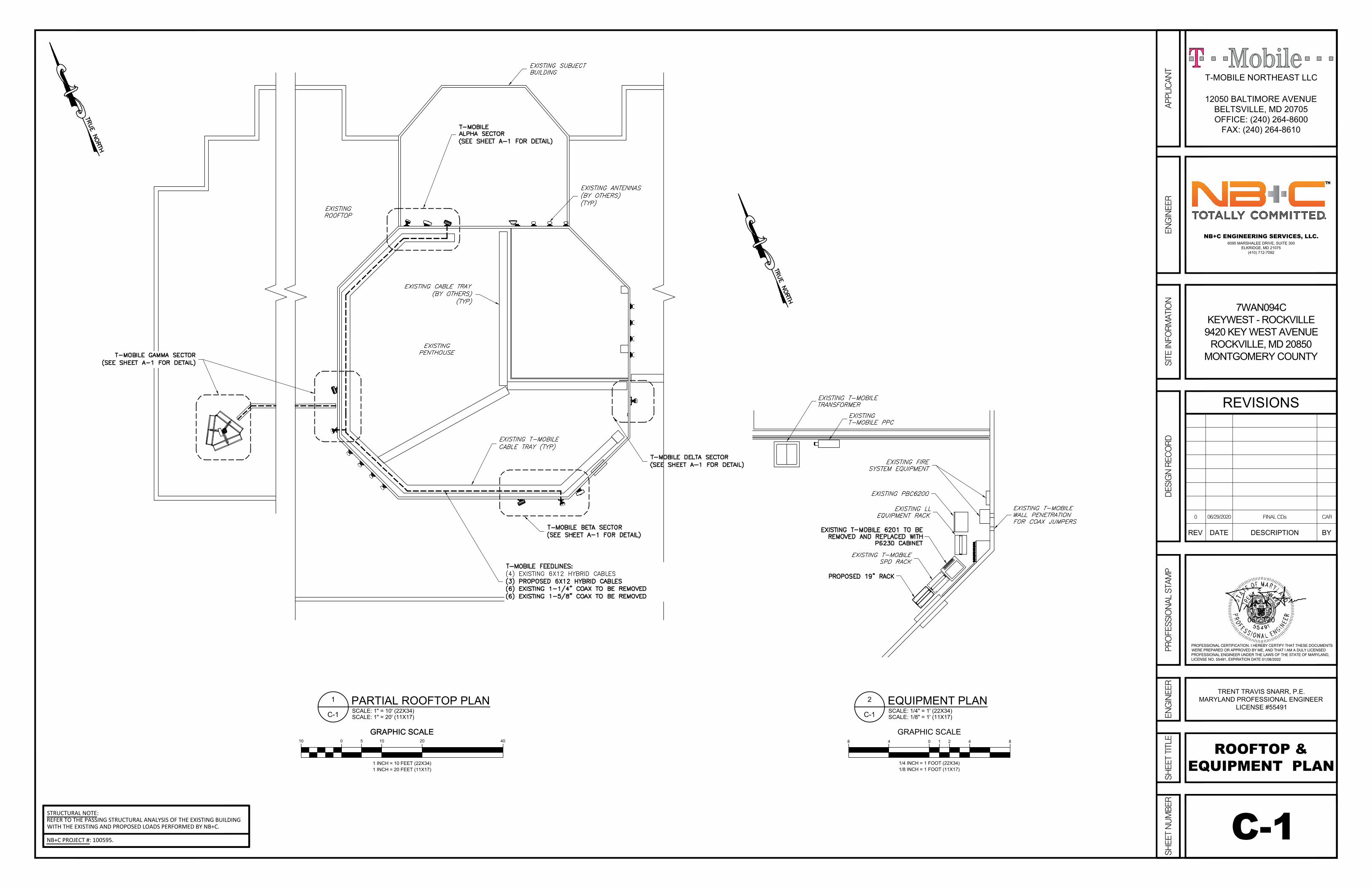
C-1
ROOFTOP &
EQUIPMENT PLAN
GRAPHIC SCALE
010 5 10 20 40
1 INCH = 10 FEET (22X34)
1 INCH = 20 FEET (11X17)
GRAPHIC SCALE
SCALE: 1" = 10' (22X34)
SCALE: 1" = 20' (11X17)
1
C-1
PARTIAL ROOFTOP PLAN
7WAN094C
KEYWEST - ROCKVILLE
9420 KEY WEST AVENUE
ROCKVILLE, MD 20850
MONTGOMERY COUNTY
ENG
INEE
RDE
SIG
N R
ECO
RDPR
OFE
SSIO
NAL
STA
MP
SITE
INFO
RMAT
ION
SHEE
T TITL
ESH
EET N
UMBE
R
REVISIONS
DESCRIPTIONDATEREV BY
6095 MARSHALEE DRIVE, SUITE 300
ELKRIDGE, MD 21075
(410) 712-7092
NB+C ENGINEERING SERVICES, LLC.
ENG
INEE
R
12050 BALTIMORE AVENUE
BELTSVILLE, MD 20705
OFFICE: (240) 264-8600
FAX: (240) 264-8610
T-MOBILE NORTHEAST LLC
APPL
ICAN
T
0 06/29/2020 FINAL CDs CAR
PROFESSIONAL CERTIFICATION. I HEREBY CERTIFY THAT THESE DOCUMENTSWERE PREPARED OR APPROVED BY ME, AND THAT I AM A DULY LICENSEDPROFESSIONAL ENGINEER UNDER THE LAWS OF THE STATE OF MARYLAND,LICENSE NO. 55491, EXPIRATION DATE 01/08/2022
TRENT TRAVIS SNARR, P.E.
MARYLAND PROFESSIONAL ENGINEER
LICENSE #55491
06/29/20
GRAPHIC SCALE
1/4 INCH = 1 FOOT (22X34)
1/8 INCH = 1 FOOT (11X17)
0 4 848 21
SCALE: 1/4" = 1' (22X34)
SCALE: 1/8" = 1' (11X17)
2
C-1
EQUIPMENT PLAN
NB+C PROJECT #: 100595.
STRUCTURAL NOTE:REFER TO THE PASSING STRUCTURAL ANALYSIS OF THE EXISTING BUILDINGWITH THE EXISTING AND PROPOSED LOADS PERFORMED BY NB+C.

C-2
ELEVATION
GRAPHIC SCALE
1/8 INCH = 1 FOOT (22X34)
1/16 INCH = 1 FOOT (11X17)
0 4 8 16816 21
SCALE: 1/8" = 1' (22X34)
SCALE: 1/16" = 1' (11X17)
1
C-2
ELEVATION
7WAN094C
KEYWEST - ROCKVILLE
9420 KEY WEST AVENUE
ROCKVILLE, MD 20850
MONTGOMERY COUNTY
ENG
INEE
RDE
SIG
N R
ECO
RDPR
OFE
SSIO
NAL
STA
MP
SITE
INFO
RMAT
ION
SHEE
T TITL
ESH
EET N
UMBE
R
REVISIONS
DESCRIPTIONDATEREV BY
6095 MARSHALEE DRIVE, SUITE 300
ELKRIDGE, MD 21075
(410) 712-7092
NB+C ENGINEERING SERVICES, LLC.
ENG
INEE
R
12050 BALTIMORE AVENUE
BELTSVILLE, MD 20705
OFFICE: (240) 264-8600
FAX: (240) 264-8610
T-MOBILE NORTHEAST LLC
APPL
ICAN
T
0 06/29/2020 FINAL CDs CAR
PROFESSIONAL CERTIFICATION. I HEREBY CERTIFY THAT THESE DOCUMENTSWERE PREPARED OR APPROVED BY ME, AND THAT I AM A DULY LICENSEDPROFESSIONAL ENGINEER UNDER THE LAWS OF THE STATE OF MARYLAND,LICENSE NO. 55491, EXPIRATION DATE 01/08/2022
TRENT TRAVIS SNARR, P.E.
MARYLAND PROFESSIONAL ENGINEER
LICENSE #55491
06/29/20
NB+C PROJECT #: 100595.
STRUCTURAL NOTE:REFER TO THE PASSING STRUCTURAL ANALYSIS OF THE EXISTING BUILDINGWITH THE EXISTING AND PROPOSED LOADS PERFORMED BY NB+C.
NOTE:ANTENNAS ARE TO BE MOUNTED FLUSH LEVEL WITH THE TOP OF THEWALL IN WHICH THEY ARE SUPPORTED BY.
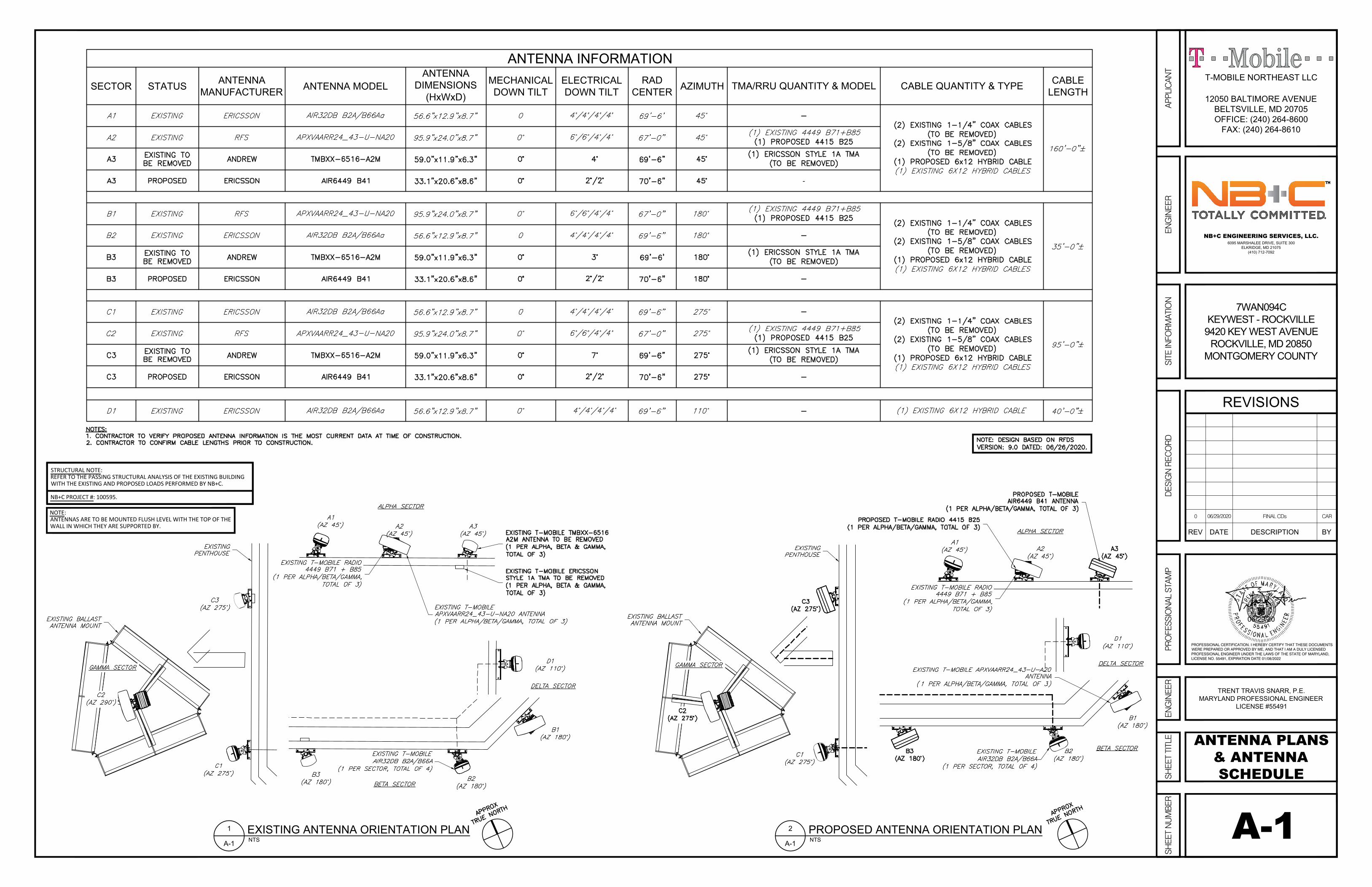
ANTENNA INFORMATION
SECTOR STATUS
ANTENNA
MANUFACTURER
ANTENNA MODEL
ANTENNA
DIMENSIONS
(HxWxD)
MECHANICAL
DOWN TILT
ELECTRICAL
DOWN TILT
RAD
CENTER
AZIMUTH TMA/RRU QUANTITY & MODEL CABLE QUANTITY & TYPE
CABLE
LENGTH
-
A-1
ANTENNA PLANS
& ANTENNA
SCHEDULE
EXISTING ANTENNA ORIENTATION PLAN
NTS
1
A-1
PROPOSED ANTENNA ORIENTATION PLAN
NTS
2
A-1
7WAN094C
KEYWEST - ROCKVILLE
9420 KEY WEST AVENUE
ROCKVILLE, MD 20850
MONTGOMERY COUNTY
ENG
INEE
RDE
SIG
N R
ECO
RDPR
OFE
SSIO
NAL
STA
MP
SITE
INFO
RMAT
ION
SHEE
T TITL
ESH
EET N
UMBE
R
REVISIONS
DESCRIPTIONDATEREV BY
6095 MARSHALEE DRIVE, SUITE 300
ELKRIDGE, MD 21075
(410) 712-7092
NB+C ENGINEERING SERVICES, LLC.
ENG
INEE
R
12050 BALTIMORE AVENUE
BELTSVILLE, MD 20705
OFFICE: (240) 264-8600
FAX: (240) 264-8610
T-MOBILE NORTHEAST LLC
APPL
ICAN
T
0 06/29/2020 FINAL CDs CAR
PROFESSIONAL CERTIFICATION. I HEREBY CERTIFY THAT THESE DOCUMENTSWERE PREPARED OR APPROVED BY ME, AND THAT I AM A DULY LICENSEDPROFESSIONAL ENGINEER UNDER THE LAWS OF THE STATE OF MARYLAND,LICENSE NO. 55491, EXPIRATION DATE 01/08/2022
TRENT TRAVIS SNARR, P.E.
MARYLAND PROFESSIONAL ENGINEER
LICENSE #55491
06/29/20
NB+C PROJECT #: 100595.
STRUCTURAL NOTE:REFER TO THE PASSING STRUCTURAL ANALYSIS OF THE EXISTING BUILDINGWITH THE EXISTING AND PROPOSED LOADS PERFORMED BY NB+C.
NOTE:ANTENNAS ARE TO BE MOUNTED FLUSH LEVEL WITH THE TOP OF THEWALL IN WHICH THEY ARE SUPPORTED BY.

ERICSSON ANTENNA DETAIL
SCALE: NTS
1
A-2
ERICSSON REMOTE RADIO UNIT (RRU)
NTS
2
A-2
ERICSSON 6230 CABINET DETAIL
NTS
3
A-2
A-2
ANTENNA
SPECIFICATIONS
& DETAILS
7WAN094C
KEYWEST - ROCKVILLE
9420 KEY WEST AVENUE
ROCKVILLE, MD 20850
MONTGOMERY COUNTY
ENG
INEE
RDE
SIG
N R
ECO
RDPR
OFE
SSIO
NAL
STA
MP
SITE
INFO
RMAT
ION
SHEE
T TITL
ESH
EET N
UMBE
R
REVISIONS
DESCRIPTIONDATEREV BY
6095 MARSHALEE DRIVE, SUITE 300
ELKRIDGE, MD 21075
(410) 712-7092
NB+C ENGINEERING SERVICES, LLC.
ENG
INEE
R
12050 BALTIMORE AVENUE
BELTSVILLE, MD 20705
OFFICE: (240) 264-8600
FAX: (240) 264-8610
T-MOBILE NORTHEAST LLC
APPL
ICAN
T
0 06/29/2020 FINAL CDs CAR
PROFESSIONAL CERTIFICATION. I HEREBY CERTIFY THAT THESE DOCUMENTSWERE PREPARED OR APPROVED BY ME, AND THAT I AM A DULY LICENSEDPROFESSIONAL ENGINEER UNDER THE LAWS OF THE STATE OF MARYLAND,LICENSE NO. 55491, EXPIRATION DATE 01/08/2022
TRENT TRAVIS SNARR, P.E.
MARYLAND PROFESSIONAL ENGINEER
LICENSE #55491
06/29/20
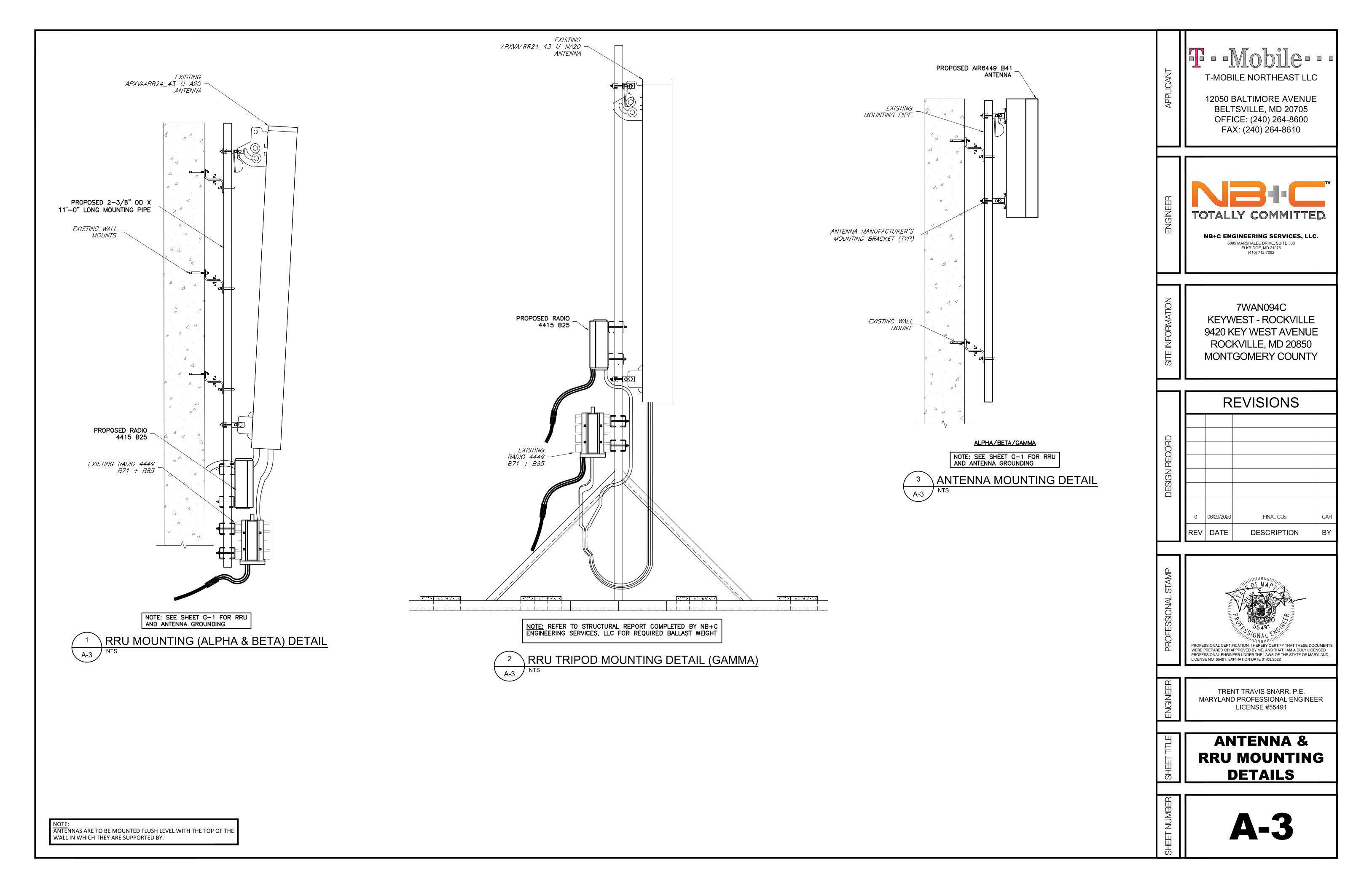
RRU MOUNTING (ALPHA & BETA) DETAIL
NTS
1
A-3
ANTENNA MOUNTING DETAIL
NTS
3
A-3
RRU TRIPOD MOUNTING DETAIL (GAMMA)
NTS
2
A-3
A-3
ANTENNA &
RRU MOUNTING
DETAILS
7WAN094C
KEYWEST - ROCKVILLE
9420 KEY WEST AVENUE
ROCKVILLE, MD 20850
MONTGOMERY COUNTY
ENG
INEE
RDE
SIG
N R
ECO
RDPR
OFE
SSIO
NAL
STA
MP
SITE
INFO
RMAT
ION
SHEE
T TITL
ESH
EET N
UMBE
R
REVISIONS
DESCRIPTIONDATEREV BY
6095 MARSHALEE DRIVE, SUITE 300
ELKRIDGE, MD 21075
(410) 712-7092
NB+C ENGINEERING SERVICES, LLC.
ENG
INEE
R
12050 BALTIMORE AVENUE
BELTSVILLE, MD 20705
OFFICE: (240) 264-8600
FAX: (240) 264-8610
T-MOBILE NORTHEAST LLC
APPL
ICAN
T
0 06/29/2020 FINAL CDs CAR
PROFESSIONAL CERTIFICATION. I HEREBY CERTIFY THAT THESE DOCUMENTSWERE PREPARED OR APPROVED BY ME, AND THAT I AM A DULY LICENSEDPROFESSIONAL ENGINEER UNDER THE LAWS OF THE STATE OF MARYLAND,LICENSE NO. 55491, EXPIRATION DATE 01/08/2022
TRENT TRAVIS SNARR, P.E.
MARYLAND PROFESSIONAL ENGINEER
LICENSE #55491
06/29/20
NOTE:ANTENNAS ARE TO BE MOUNTED FLUSH LEVEL WITH THE TOP OF THEWALL IN WHICH THEY ARE SUPPORTED BY.

MLE HYBRID CABLE (6 POWER/12 FIBER)
NTS
2
A-3
A-4
CABLING DETAILS
& PLUMBING
DIAGRAM
7WAN094C
KEYWEST - ROCKVILLE
9420 KEY WEST AVENUE
ROCKVILLE, MD 20850
MONTGOMERY COUNTY
ENG
INEE
RDE
SIG
N R
ECO
RDPR
OFE
SSIO
NAL
STA
MP
SITE
INFO
RMAT
ION
SHEE
T TITL
ESH
EET N
UMBE
R
REVISIONS
DESCRIPTIONDATEREV BY
6095 MARSHALEE DRIVE, SUITE 300
ELKRIDGE, MD 21075
(410) 712-7092
NB+C ENGINEERING SERVICES, LLC.
ENG
INEE
R
12050 BALTIMORE AVENUE
BELTSVILLE, MD 20705
OFFICE: (240) 264-8600
FAX: (240) 264-8610
T-MOBILE NORTHEAST LLC
APPL
ICAN
T
0 06/29/2020 FINAL CDs CAR
PROFESSIONAL CERTIFICATION. I HEREBY CERTIFY THAT THESE DOCUMENTSWERE PREPARED OR APPROVED BY ME, AND THAT I AM A DULY LICENSEDPROFESSIONAL ENGINEER UNDER THE LAWS OF THE STATE OF MARYLAND,LICENSE NO. 55491, EXPIRATION DATE 01/08/2022
TRENT TRAVIS SNARR, P.E.
MARYLAND PROFESSIONAL ENGINEER
LICENSE #55491
06/29/20
PLUMBING DIAGRAM
NTS
1
A-3
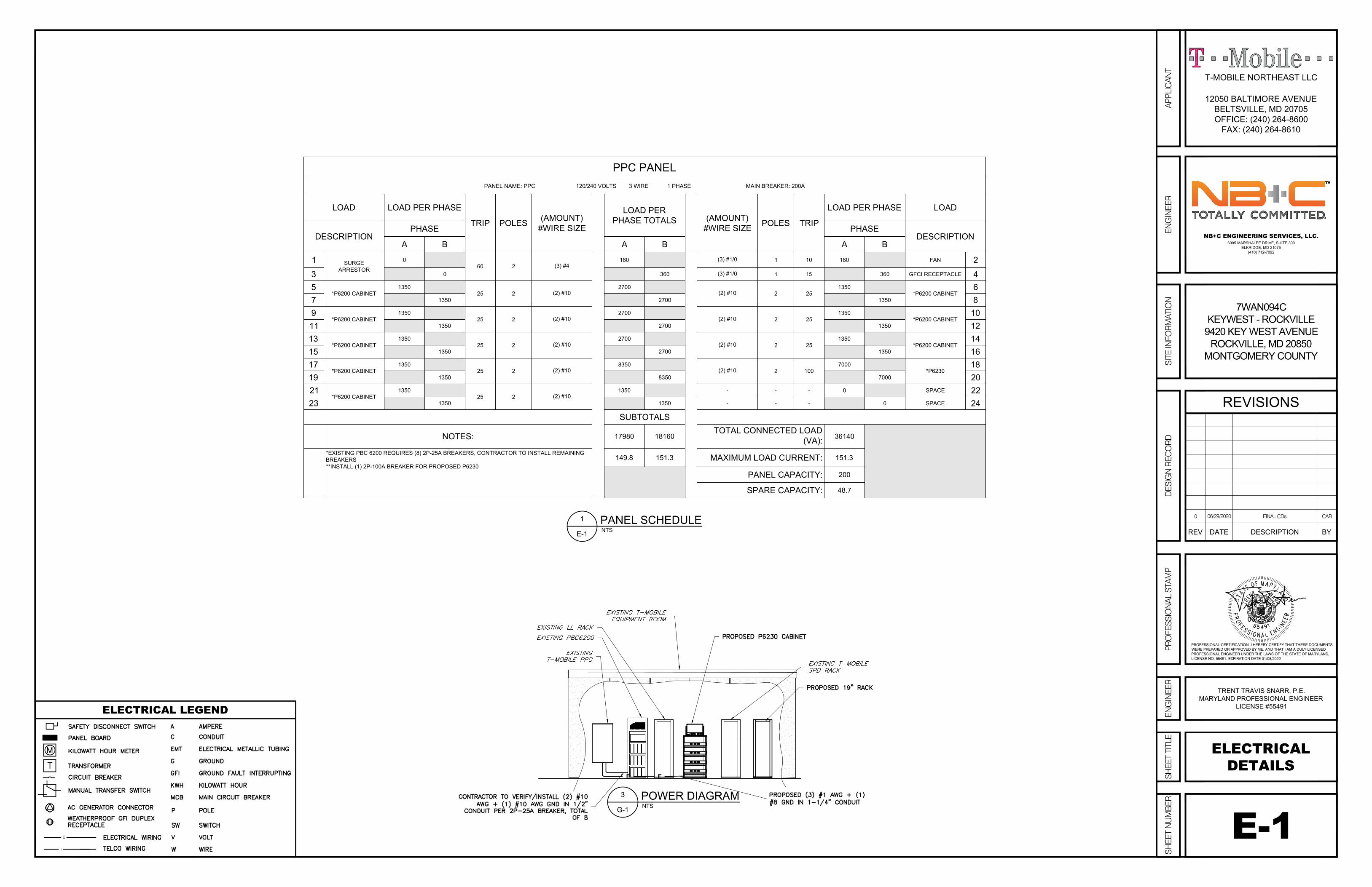
PPC PANEL
PANEL NAME: PPC 120/240 VOLTS 3 WIRE 1 PHASE MAIN BREAKER: 200A
LOAD LOAD PER PHASE
TRIP POLES
(AMOUNT)
#WIRE SIZE
LOAD PER
PHASE TOTALS
(AMOUNT)
#WIRE SIZE
POLES TRIP
LOAD PER PHASE LOAD
DESCRIPTION
PHASE PHASE
DESCRIPTION
A B A B A B
1
SURGE
ARRESTOR
0
60 2
(3) #4
180
(3) #1/0
1 10 180 FAN
2
3
0 360
(3) #1/01 15 360 GFCI RECEPTACLE
4
5
*P6200 CABINET
1350
25 2
(2) #10
2700
(2) #10
2 25
1350
*P6200 CABINET
6
7
1350 2700 1350
8
9
*P6200 CABINET
1350
25 2
(2) #10
2700
(2) #10
2 25
1350
*P6200 CABINET
10
11
1350 2700 1350
12
13
*P6200 CABINET
1350
25 2
(2) #10
2700
(2) #10
2 25
1350
*P6200 CABINET
14
15
1350 2700 1350
16
17
*P6200 CABINET
1350
25 2
(2) #10
8350
(2) #10
2 100
7000
*P6230
18
19
1350 8350 7000
20
21
*P6200 CABINET
1350
25 2
(2) #10
1350 - - - 0 SPACE
22
23
1350 1350 - - - 0 SPACE
24
SUBTOTALS
NOTES:17980 18160
TOTAL CONNECTED LOAD
(VA):
36140
*EXISTING PBC 6200 REQUIRES (8) 2P-25A BREAKERS, CONTRACTOR TO INSTALL REMAINING
BREAKERS
**INSTALL (1) 2P-100A BREAKER FOR PROPOSED P6230
149.8 151.3MAXIMUM LOAD CURRENT:
151.3
PANEL CAPACITY:200
SPARE CAPACITY:48.7
POWER DIAGRAM
NTS
3
G-1
E-1
ELECTRICAL
DETAILS
PANEL SCHEDULE
NTS
1
E-1
E
T
ELECTRICAL LEGEND
7WAN094C
KEYWEST - ROCKVILLE
9420 KEY WEST AVENUE
ROCKVILLE, MD 20850
MONTGOMERY COUNTY
ENG
INEE
RDE
SIG
N R
ECO
RDPR
OFE
SSIO
NAL
STA
MP
SITE
INFO
RMAT
ION
SHEE
T TITL
ESH
EET N
UMBE
R
REVISIONS
DESCRIPTIONDATEREV BY
6095 MARSHALEE DRIVE, SUITE 300
ELKRIDGE, MD 21075
(410) 712-7092
NB+C ENGINEERING SERVICES, LLC.
ENG
INEE
R
12050 BALTIMORE AVENUE
BELTSVILLE, MD 20705
OFFICE: (240) 264-8600
FAX: (240) 264-8610
T-MOBILE NORTHEAST LLC
APPL
ICAN
T
0 06/29/2020 FINAL CDs CAR
PROFESSIONAL CERTIFICATION. I HEREBY CERTIFY THAT THESE DOCUMENTSWERE PREPARED OR APPROVED BY ME, AND THAT I AM A DULY LICENSEDPROFESSIONAL ENGINEER UNDER THE LAWS OF THE STATE OF MARYLAND,LICENSE NO. 55491, EXPIRATION DATE 01/08/2022
TRENT TRAVIS SNARR, P.E.
MARYLAND PROFESSIONAL ENGINEER
LICENSE #55491
06/29/20

ANTENNA GROUNDING DETAIL
NTS
1
G-1
ALPHA BETA GAMMA DELTA
GROUNDING BAR CONNECTIONS
NTS
3
G-1
CADWELD GROUNDING CONNECTION DETAILS
NTS
2
G-1
G-1
GROUNDING
DETAILSGROUNDING LEGEND
7WAN094C
KEYWEST - ROCKVILLE
9420 KEY WEST AVENUE
ROCKVILLE, MD 20850
MONTGOMERY COUNTY
ENG
INEE
RDE
SIG
N R
ECO
RDPR
OFE
SSIO
NAL
STA
MP
SITE
INFO
RMAT
ION
SHEE
T TITL
ESH
EET N
UMBE
R
REVISIONS
DESCRIPTIONDATEREV BY
6095 MARSHALEE DRIVE, SUITE 300
ELKRIDGE, MD 21075
(410) 712-7092
NB+C ENGINEERING SERVICES, LLC.
ENG
INEE
R
12050 BALTIMORE AVENUE
BELTSVILLE, MD 20705
OFFICE: (240) 264-8600
FAX: (240) 264-8610
T-MOBILE NORTHEAST LLC
APPL
ICAN
T
0 06/29/2020 FINAL CDs CAR
PROFESSIONAL CERTIFICATION. I HEREBY CERTIFY THAT THESE DOCUMENTSWERE PREPARED OR APPROVED BY ME, AND THAT I AM A DULY LICENSEDPROFESSIONAL ENGINEER UNDER THE LAWS OF THE STATE OF MARYLAND,LICENSE NO. 55491, EXPIRATION DATE 01/08/2022
TRENT TRAVIS SNARR, P.E.
MARYLAND PROFESSIONAL ENGINEER
LICENSE #55491
06/29/20