antennna paper
6
A Novel Fixed Multiband Antenna Design For New Generation Wireless Communication Systems Navin M George Department of Electronics and Communication Karunya University Coimbatore, India E - mail:[email protected] Abstract - This paper presents the design of a fixed antenna of multiple frequency bands. The antenna proposed here will be used in new generation wireless communication devices. This antenna has the ability to radiate multiple bandwidths with a less return loss and improved antenna gain. This model is highly compact and cost effective one. The fixed model is simulated and implemented in hardware and the results are compared. Keywords – fixed multiband antenna; wireless communication; return loss; antenna gain I. INTRODUCTION Antennas for mobile and wireless terminals supporting several standards simultaneously are currently receiving a lot of interest. Therefore, there is an increasing demand for multiband antennas, which can be easily integrated, in a wireless device supporting multiple standards. The term fixed means that the operating frequencies, radiation patterns and polarization are fixed upon the designer goal and once the antenna is fabricated and placed in the system, the performances of the antenna cannot be changed. Printed antennas, monopole antennas and Planar Inverted-F Antennas (PIFA) [1] are the most suitable antennas to be used in wireless systems due to their low profile, low fabrication cost, and simple feeding structures. Modern wireless devices or systems are getting smaller and thinner in addition to the increase in the number of services required to be integrated in one device. Therefore, antennas are required to fulfill these needs with multiple bands capabilities and with small and slim overall size [2]. Different techniques have investigated to achieve multiband operation for printed antennas and for PIFA as discussed earlier. In PIFA, the ground plane can play an important role to enhance the performance of the antenna. For example, for low frequency operation such as for the GSM 900/800 bands, the ground plane has to be used as a radiating part. However, if the ground plane also acts as a radiating part, the effect of the user’s hand is likely to degrade the antenna performance when the antenna is S Merlin Gilbert Raj Department of Electronics and Communication Karunya University Coimbatore, India E - mail:[email protected] fitted inside the mobile phone. It causes several practical engineering
-
Upload
independent -
Category
Documents
-
view
0 -
download
0
Transcript of antennna paper
A Novel Fixed Multiband Antenna Design For New GenerationWireless
Communication Systems
Navin M GeorgeDepartment of Electronics and
CommunicationKarunya UniversityCoimbatore, India
E - mail:[email protected]
Abstract - This paper presents the design ofa fixed antenna of multiple frequencybands. The antenna proposed here will beused in new generation wirelesscommunication devices. This antenna has theability to radiate multiple bandwidths witha less return loss and improved antennagain. This model is highly compact and costeffective one. The fixed model is simulatedand implemented in hardware and the resultsare compared.
Keywords – fixed multiband antenna; wireless communication; return loss; antenna gain
I. INTRODUCTION
Antennas for mobile and wirelessterminals supporting several standardssimultaneously are currently receivinga lot of interest. Therefore, there isan increasing demand for multibandantennas, which can be easilyintegrated, in a wireless devicesupporting multiple standards. The termfixed means that the operatingfrequencies, radiation patterns andpolarization are fixed upon thedesigner goal and once the antenna isfabricated and placed in the system,the performances of the antenna cannotbe changed. Printed antennas, monopoleantennas and Planar Inverted-F Antennas(PIFA) [1] are the most suitable
antennas to be used in wireless systemsdue to their low profile, lowfabrication cost, and simple feedingstructures.
Modern wireless devices orsystems are getting smaller andthinner in addition to the increasein the number of services requiredto be integrated in one device.Therefore, antennas are required tofulfill these needs with multiple bandscapabilities and with small and slimoverall size [2]. Different techniqueshave investigated to achieve multibandoperation for printed antennas and forPIFA as discussed earlier. In PIFA,the ground plane can play animportant role to enhance theperformance of the antenna. Forexample, for low frequency operationsuch as for the GSM 900/800 bands, theground plane has to be used as aradiating part.
However, if the ground plane alsoacts as a radiating part, the effect ofthe user’s hand is likely to degradethe antenna performance when theantenna is
S Merlin Gilbert RajDepartment of Electronics and
CommunicationKarunya UniversityCoimbatore, India
E - mail:[email protected]
fitted inside the mobile phone. Itcauses several practical engineering
problems. In some designs, the locationof the antenna on the substrate is alsoan important factor to be considered asit can enhance the bandwidth of theantenna by few more percentages.
This paper includes the design ofa multi band antenna for new generationwireless communication [1]. This designbasically has a patch, substrate andground plane. The patches are ofdifferent types such as rectangularpatch, rectangular patch withtriangular slots, and rectangular patchwith c slots. The patches are givenindividual feed lines with the help ofa main feed line.
The fixed multiband antennas canwidely be used in different systems ordevices and they are not reliable toaccept new services as compared withreconfigurable antennas. These antennascan be considered as one of themajor elements in future wirelesscommunication systems. The microstripreconfigurable antenna has the abilityto operate in multiple bands where thetotal antenna size can be reused andfurther reducing the overall size. NewGeneration wireless communicationsystems relying on multibandreconfigurable antennas are becomingmore popular for their ability to servemultiple standards. Devices using asingle compact antenna allow reductionin the dimensions of the device andmore space to integrate otherelectronic components.
This paper is a further study of[1]. This further study includes thedesign methodology, frequency settingin the fixed design, and independenttuning in the reconfigurable design[2]. It also includes the radiationpatterns for the reconfigurable design,and the efficiency and gain comparison
for the fixed and reconfigurabledesigns.
II. PROPOSED ANTENNA DESIGN
A. Antenna Design
The designed fixed antenna is ahybrid structure [2], [3], [5] of fivepatch antennas given a single feed.Each patch has been further modified inorder to achieve multiple frequencybands [2]. The frequency of operationof the microstrip patch antenna isdetermined by the length L. The centerfrequency can be given by the relation.
fc≈ c
2L√εr
= 12L√εoεrε0
For microstrip antennas, the width W and length L of the radiating patch andthe effective permittivity of themicrostrip structureεℜwhich support the operation at the required resonant frequency or the free-space wavelength λ0 can be designed as follows.
W=1
2fr√μ0ε0×√ 2
εr+1
L=1
2fr√εeff √μ0ε0
−2∆L
εeff=εr+12
+εr−1
2√1+12 hw
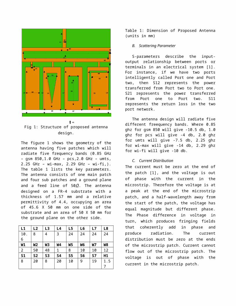
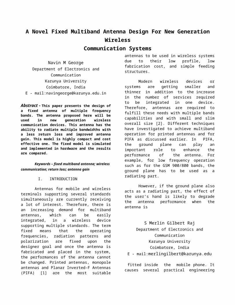
Fig 1: Structure of proposed antennadesign.
The figure 1 shows the geometry of theantenna having five patches which willradiate five frequency bands (0.85 GHz– gsm 850,1.0 GHz – pcs,2.0 GHz – umts,2.25 GHz – wi-max, 2.29 GHz – wi-fi,).The table 1 lists the key parameters.The antenna consists of one main patchand four sub patches and a ground planeand a feed line of 50Ω. The antennadesigned on a FR-4 substrate with athickness of 1.57 mm and a relativepermittivity of 4.4, occupying an areaof 45.6 X 50 mm on one side of thesubstrate and an area of 50 X 50 mm forthe ground plane on the other side.
L1 L2 L3 L4 L5 L6 L7 L810.6
8 4 3 24 24 24 24
W1 W2 W3 W4 W5 W6 W7 W82 50 48 1 8 10 10 12S1 S2 S3 S4 S5 S6 S7 H18 20 8 20 10 9 19 1.5
7
Table 1: Dimension of Proposed Antenna(units in mm)
B. Scattering Parameter
S-parameters describe the input-output relationship between ports orterminals in an electrical system [1].For instance, if we have two portsintelligently called Port one and Porttwo, then S12 represents the powertransferred from Port two to Port one.S21 represents the power transferredfrom Port one to Port two. S11represents the return loss in the twoport network.
The antenna design will radiate fivedifferent freequency bands. Where 0.85ghz for gsm 850 will give -10.5 db, 1.0ghz for pcs will give -4 db, 2.0 ghzfor umts will give -7.5 db, 2.25 ghzfor wi-max will give -14 db, 2.29 ghzfor wi-fi will give -10 db.
C. Current DistributionThe current must be zero at the end ofthe patch [1], and the voltage is outof phase with the current in themicrostrip. Therefore the voltage is ata peak at the end of the microstrippatch, and a half-wavelength away fromthe start of the patch, the voltage hasequal magnitude but different phase.The Phase difference in voltage inturn, which produces fringing fieldsthat coherently add in phase andproduce radiation. The currentdistribution must be zero at the endsof the microstrip patch. Current cannotflow out of the microstrip patch. Thevoltage is out of phase with thecurrent in the microstrip patch.
W4
W3L2
H1
S7
S5
S6
W8
L8S4
S3
W7
L7
S2
S1
W6
L6W5L5
W2
L3
L4
L1W1
The Surface Distribution Currentat .85 GHz is along the main patch andalong the sub feeds. For the frequency1 GHz the distribution is along mainpatch sub feeds 2, 3 and triangularslot. For frequency 2 GHz thedistribution is along main patch and cslot. For frequency 2.25 GHz thedistribution is along c slot. For 2.95GHz the current distribution is alongthe rectangular slot, c slot and mainpatch. The rectangular patch will actas a supporting patch for the currentdistribution in the rest of the fivepatches in the fixed antenna design.
III. SIMULATION RESULTS
A. Scattering Parameter S11
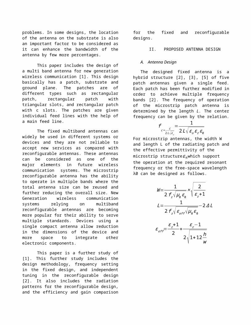
Figure 2: Return Loss of the proposeddesign
The Scattering parameter has beenanalyzed in the simulation. The returnloss of the fixed multi band antenna isstudied for the proposed model. Anantenna should have minimum return lossin order to have a better efficiency.The proposed design is having a veryminimum return loss as mentioned.
The antenna design will radiate fivedifferent freequency bands. Where 0.85ghz for gsm 850 will give -10.5 db, 1.0ghz for pcs will give -4 db, 2.0 ghzfor umts will give -7.5 db, 2.25 ghzfor wi-max will give -14 db, 2.29 ghzfor wi-fi will give -10 db.
B. Voltage Standing wave Ratio
Figure 3: VSWR of the proposed design
Voltage Standing Wave Ratio is afunction of a reflection coefficient;this describes the power reflected fromthe antenna. The reflection coefficientis given byΓ. The VSWR is always areal and positive number for microstripantennas. The smaller the VSWR is, thebetter the microstrip antenna ismatched to the transmission line andthe more power is delivered to themicrostrip antenna. The minimum VSWR is1.0. Here no power is reflected fromthe ideal microstrip antenna.
In this design the antenna is givinga VSWR of range 1.0. So there is nopower reflected from the antenna.Therefore the antenna is matched totransmission line and more power isdelivered from the antenna.
C. Radiation Pattern
A radiation pattern defines thevariation of the power radiated by anantenna as a function of the directionaway from the microstrip antenna. Thepower variation as a function of thearrival angle is observed in theantenna's far field.
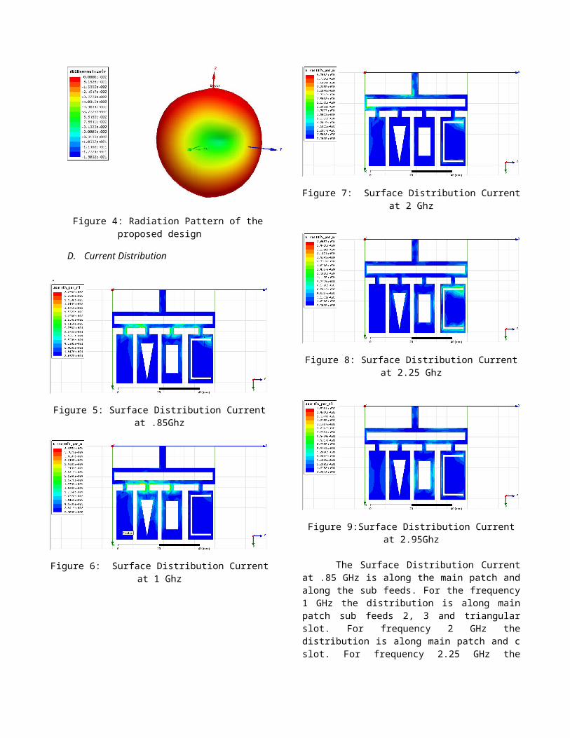
Figure 4: Radiation Pattern of theproposed design
D. Current Distribution
.
Figure 5: Surface Distribution Currentat .85Ghz
Figure 6: Surface Distribution Currentat 1 Ghz
Figure 7: Surface Distribution Currentat 2 Ghz
Figure 8: Surface Distribution Currentat 2.25 Ghz
Figure 9:Surface Distribution Currentat 2.95Ghz
The Surface Distribution Currentat .85 GHz is along the main patch andalong the sub feeds. For the frequency1 GHz the distribution is along mainpatch sub feeds 2, 3 and triangularslot. For frequency 2 GHz thedistribution is along main patch and cslot. For frequency 2.25 GHz the
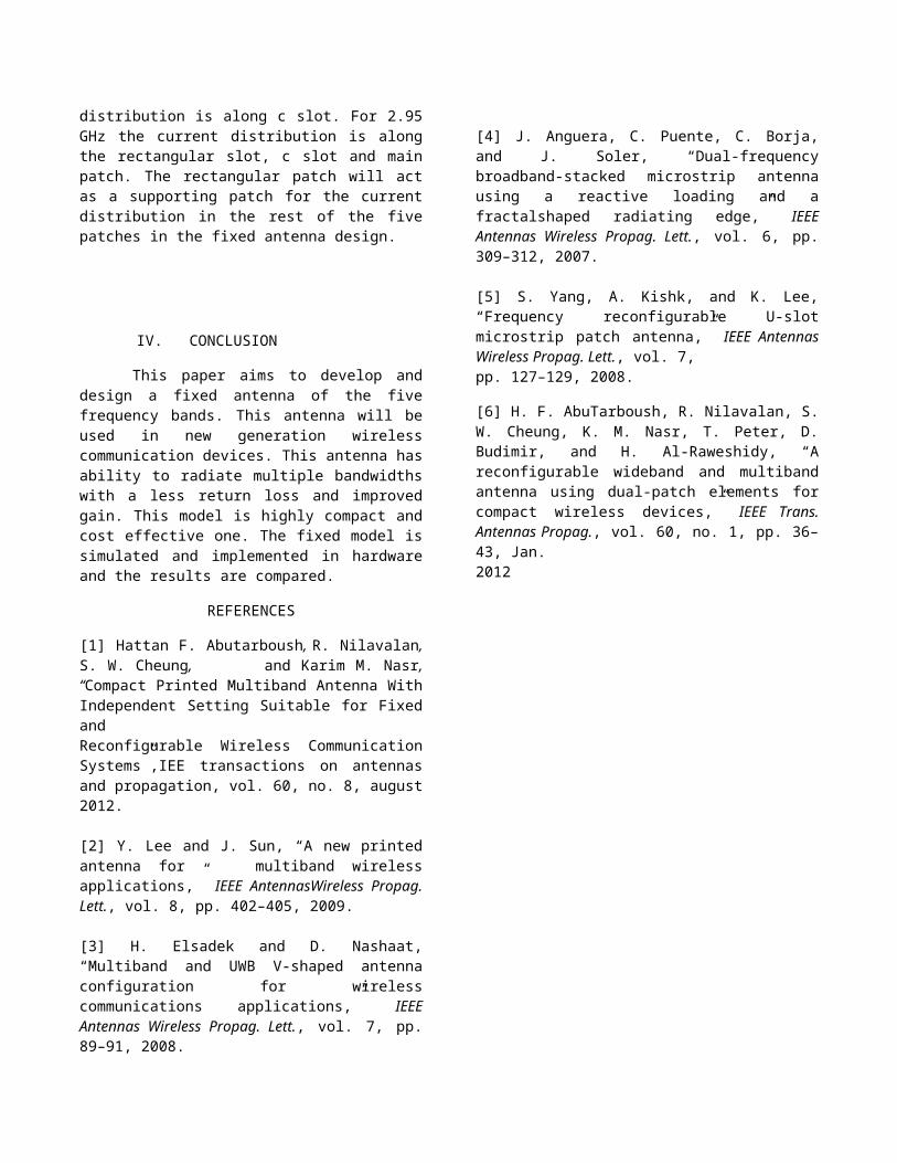
distribution is along c slot. For 2.95GHz the current distribution is alongthe rectangular slot, c slot and mainpatch. The rectangular patch will actas a supporting patch for the currentdistribution in the rest of the fivepatches in the fixed antenna design.
IV. CONCLUSION
This paper aims to develop anddesign a fixed antenna of the fivefrequency bands. This antenna will beused in new generation wirelesscommunication devices. This antenna hasability to radiate multiple bandwidthswith a less return loss and improvedgain. This model is highly compact andcost effective one. The fixed model issimulated and implemented in hardwareand the results are compared.
REFERENCES
[1] Hattan F. Abutarboush, R. Nilavalan,S. W. Cheung, and Karim M. Nasr,“Compact Printed Multiband Antenna WithIndependent Setting Suitable for FixedandReconfigurable Wireless CommunicationSystems”,IEE transactions on antennasand propagation, vol. 60, no. 8, august2012.
[2] Y. Lee and J. Sun, “A new printedantenna for multiband wirelessapplications,” IEEE AntennasWireless Propag.Lett., vol. 8, pp. 402–405, 2009.
[3] H. Elsadek and D. Nashaat,“Multiband and UWB V-shaped antennaconfiguration for wirelesscommunications applications,” IEEEAntennas Wireless Propag. Lett., vol. 7, pp.89–91, 2008.
[4] J. Anguera, C. Puente, C. Borja,and J. Soler, “Dual-frequencybroadband-stacked microstrip antennausing a reactive loading and afractalshaped radiating edge,” IEEEAntennas Wireless Propag. Lett., vol. 6, pp.309–312, 2007.
[5] S. Yang, A. Kishk, and K. Lee,“Frequency reconfigurable U-slotmicrostrip patch antenna,” IEEE AntennasWireless Propag. Lett., vol. 7,pp. 127–129, 2008.
[6] H. F. AbuTarboush, R. Nilavalan, S.W. Cheung, K. M. Nasr, T. Peter, D.Budimir, and H. Al-Raweshidy, “Areconfigurable wideband and multibandantenna using dual-patch elements forcompact wireless devices,” IEEE Trans.Antennas Propag., vol. 60, no. 1, pp. 36–43, Jan.2012