Post-Earnings-Announcement Drift Among Newly ... - DukeSpace
Upload
khangminh22Category
view
1download
0
DOE F 241.3 (2-01) p.1 of 2 UNITED STATES DEPARTMENT OF ENERGY (DOE) OMB CONTROL NO.
Announcement of Scientific and Technical Information (STI) 1910-1400
(For Use By Financial Assistance Recipients and Non-M&O/M&I Contractors) PART I: STI PRODUCT DESCRIPTION
(To be completed by Recipient/Contractor)
A. STI Product Identifiers 1. REPORT/PRODUCT NUMBER(s) None 2. DOE AWARD/CONTRACT NUMBER(s) DE-FC36-97ID13554 3. OTHER IDENTIFYING NUMBER(s) None B. Recipient/Contractor Missouri University of Science and Technology, 215 ME Annex, 1870 Miner Circle, Rolla, MO 65409-1330 C. STI Product Title Geological Sequestration of CO2 by Hydrous Carbonate Formation with Reclaimed Slag D. Author(s) Von L. Richards Kent Peaslee Jeffrey Smith E-mail Address(es): [email protected] E. STI Product Issue Date/Date of Publication
F. STI Product Type (Select only one) X 1. TECHNICAL REPORT X Final Other (specify)
2. CONFERENCE PAPER/PROCEEDINGS Conference Information (title, location, dates)
3. JOURNAL ARTICLE
a. TYPE: Announcement Citation Only Preprint Postprint b. JOURNAL NAME c. VOLUME d. ISSUE e. SERIAL IDENTIFIER (e.g. ISSN or CODEN)
4. OTHER, SPECIFY G. STI Product Reporting Period Thru
H. Sponsoring DOE Program Office Office of Industrial Technologies (OIT)(EE20) I. Subject Categories (list primary one first) 32 Energy Conservation, Consumption and Utilization Keywords: CO2 Sequestration, Reclaimed Slag J. Description/Abstract The concept of this project is to develop a process that improves the kinetics of the hydrous carbonate formation reaction enabling steelmakers to directly remove CO2 from their furnace exhaust gas. It is proposed to bring the furnace exhaust stream containing CO2 in contact with reclaimed steelmaking slag in a reactor that has an environment near the unit activity of water resulting in the production of carbonates. The CO2 emissions from the plant would be reduced by the amount sequestered in the formation of carbonates. The main raw materials for the process are furnace exhaust gases and specially prepared slag. K. Intellectual Property/Distribution Limitations (must select at least one; if uncertain contact your Contracting Officer (CO)) X 1. UNLIMITED ANNOUNCEMENT (available to U.S. and non-U.S. public; the Government assumes no liability for disclosure of such data)
2. COPYRIGHTED MATERIAL: Are there any restrictions based on copyright? Yes No. If yes, list the restrictions as contained in your award document
3. PATENTABLE MATERIAL: THERE IS PATENTABLE
MATERIAL IN THE DOCUMENT. INENTION DISCLOSURE SUBMITTED TO DOE: DOE Docket Number: S- (Sections are marked as restricted distribution pursuant to 35 USC 205)
4. PROTECTED DATA: CRADA Other, specify Release date (required) no more than 5 years from date listed in Part I.E. above
5. SMALL BUSINESS INNOVATION RESEARCH (SBIR) DATA Release date (required) no more than 4 years from date listed in Part I.E. above
6. SMALL BUSINESS TECHNOLOGY TRANSFER RESEARCH (STTR) DATA Release date (required) no more than 4 years from date listed in Part I.E. above
7. OFFICE OF NUCLEAR ENERGY APPLICED TECHNOLOGY L. Recipient/Contract Point of Contact Contact for additional information (contact or organization name To be included in published citations and who would Receive any external questions about the content of the STI Product or the research contained herein) Dr. Von L. Richards Name and/or Position [email protected] (573) 341-4730 E-mail Phone Dept. of Metallurgical Engineering, Missouri University of Science and Technology, Rolla, MO
M M D D Y Y Y Y
M M D D Y Y Y Y
M M D D Y Y Y Y
02 06 2008 M M D D Y Y Y Y
03 17 2005 M M D D Y Y Y Y
02 06 2008 M M D D Y Y Y Y
DOE F 241.3 (2-01) p.2 of 2 UNITED STATES DEPARTMENT OF ENERGY (DOE) OMB CONTROL NO.
Announcement of Scientific and Technical Information (STI) 1910-1400
(For Use By Financial Assistance Recipients and Non-M&O/M&I Contractors)
PART II: STI PRODUCT MEDIA/FORMAT and LOCATION/TRANSMISSION
(To be completed by Recipient/Contractor)
A. Media/Format Information: 1. MEDIUM OF STI PRODUCT IS: X Electronic Document Computer Medium Audiovisual Material Paper No Full-text 2. SIZE OF STI PRODUCT 303 Pages, 7726 KB 3. SPECIFY FILE FORMAT OF ELECTRONIC DOCUMENT BEING TRANSMITTED, INDICATE: SGML HTML XML XPDF Normal PDF Image TIFFG4 WP-indicate Version (5.0 or greater) Platform/operation system MS-indicate Version (5.0 or greater) Platform/operation system Postscript 4. IF COMPUTER MEDIUM OR AUDIOVISUAL MATERIAL: a. Quantity/type (specify) b. Machine compatibility (specify) c. Other information about product format a user needs to know: B. Transmission Information: 1. STI PRODUCT IS BEING TRANSMITTED: X a. Electronically via E-Link b. Via mail or shipment to address indicated in award document (Paper product, CD-ROM, diskettes, video cassettes, etc.) 2. INFORMATION PRODUCT FILE NAME X (of transmitted electronic format) TRP9955NonPropFinalReport
PART III: STI PRODUCT REVIEW/RELEASE INFORMATION
(To be completed by DOE)
A. STI Product Reporting Requirements Review. 1. THIS DELIVERABLE COMPLETES ALL REQUIRED DELIVERABLES FOR THIS AWARD 2. THIS DELIVERABLE FULFILLS A TECHNICAL INFORMATION REPORTING REQUIREMENT, BUT SHOULD NOT BE DISSEMINATED BEYOND DOE. B. Award Office Is the Source of STI Product Availability THE STI PRODUCT IS NOT AVAILABLE IN AN ELECTRONIC MEDIUM. THE AWARDING OFFICE WILL SERVE AS THE INTERIM SOURCE OF AVAILABILITY. C. DOE Releasing Official 1. I VERIFY THAT ALL NECESSARY REVIEWS HAVE BEEN COMPLETED AS DESCRIBED IN DOE G 241.1-1A, PART II, SECTION 3.0 AND THAT THE STI PRODUCT SHOULD BE RELEASED IN ACCORDANCE WITH THE INTELLECTUAL PROPERTY/DISTRIBUTION LIMITATION ABOVE. Release by (name) Date E-Mail Phone
M M D D Y Y Y Y
REPORT DOCUMENTATION PAGE
Title and Subtitle: AISI/DOE Technology Roadmap Program for the Steel Industry TRP 9955: Geological Sequestration of CO2 by Hydrous Carbonate Formation With Reclaimed Slag Authors: Dr. Von L. Richards Performing Organization Missouri University of Science and Technology (Formerly University of Missouri - Rolla 215 ME Annex 1870 Miner Circle Rolla, MO 65409-1330 Abstract The objective of this project is to develop and demonstrate a process for sequestering CO2 from steel making in either a BOF or an EAF by forming carbonates with the alkaline earth component of used slag for beneficial reuse in other applications. Background: It is well known that hydrous carbonates can form readily at the surfaces of alkaline earth, rare earth and manganese oxide in the presence of water and ambient CO2 activity such as in aqueous suspensions (Richards 1990, 1992). The concept of this project is to develop a process that improves the kinetics of the hydrous carbonate formation reaction enabling steelmakers to directly remove CO2 from their furnace exhaust gas. It is proposed to bring the furnace exhaust stream containing CO2 in contact with reclaimed steelmaking slag in a reactor that has an environment near the unit activity of water resulting in the production of carbonates. The CO2 emissions from the plant would be reduced by the amount sequestered in the formation of carbonates. The main raw materials for the process are furnace exhaust gases and specially prepared slag.
DOCUMENT AVAILABILITY
Reports are available free via the U.S. Department of Energy (DOE) Information Bridge: Website: http://www.osti.gov/bridge Reports are available to DOE employees, DOE contractors, Energy Technology Data Exchange (ETDE) representatives, and Informational Nuclear Information System (INIS) representatives from the following source: Office of Scientific and Technical Information
P.O. Box 62 Oak Ridge, TN 37831 Tel: (865) 576-8401 Fax: (865) 576-5728 E-mail: [email protected] Website: http://www.osti.gov/contract.html
Acknowledgement: "This report is based upon work supported by the U.S. Department of Energy under Cooperative Agreement No. DE-FC36-97ID13554." Disclaimer: "Any findings, opinions, and conclusions or recommendations expressed in this report are those of the author(s) and do not necessarily reflect the views of the Department of Energy."

American Iron and Steel Institute Technology Roadmap Program
CO2 Breakthrough Program Phase I: Geological Sequestration of CO2 by Hydrous Carbonate Formation with Reclaimed Slag
Final Report
TRP # 9955 Award Number: DE-FC36-97ID13554 Project Period: 3/2005 - 12/2007 Recipient: Missouri University of Science and Technology (MST)
( formerly University of Missouri-Rolla) 215 ME Annex, 1870 Miner Circle, Rolla, MO 65409-1330
Principal Investigator : Von L. Richards, Ph.D. Associate Professor of Metallurgical Engineering 573-341-4730 [email protected]
Co-PI: Kent Peaslee, Ph.D., P.E. Professor of Metallurgical Engineering 573-341-4714 [email protected]
Jeffrey D. Smith, Ph.D.
Associate Professor of Ceramic Engineering 573-341-4447 [email protected]
Other Partners: ArcelorMittal - Dofasco, TerniumHylsa, Ipsco, Praxair, US Steel,
Gallatin Steel, ArcelorMittal, Nucor, Timken
January 2008

2
CONTENT
Page 1. Project Summary 3 2. Project Plan 4 3. Progress Toward Achieving Specified Tasks 5 4. Result of Work (Summary of Reports and Publication) 10 5. Attachments 17
A. Survey Report (13 pages) B. Literature Review (103 pages) C. Published Articles (88 pages) D. Articles Accepted for Publication (28 pages) E. Articles Submitted for Publication (36 pages) F. Industrial Reactor Modeling Report (18 pages)
3
1. Project Summary
The objective of this project is to develop and demonstrate a process for sequestering CO2 from steel making in either a BOF or an EAF by forming carbonates with the alkaline earth component of used slag for beneficial reuse in other applications. Background: It is well known that hydrous carbonates can form readily at the surfaces of alkaline earth, rare earth and manganese oxide in the presence of water and ambient CO2 activity such as in aqueous suspensions (Richards 1990, 1992). The concept of this project is to develop a process that improves the kinetics of the hydrous carbonate formation reaction enabling steelmakers to directly remove CO2 from their furnace exhaust gas. It is proposed to bring the furnace exhaust stream containing CO2 in contact with reclaimed steelmaking slag in a reactor that has an environment near the unit activity of water resulting in the production of carbonates. The CO2 emissions from the plant would be reduced by the amount sequestered in the formation of carbonates. The main raw materials for the process are furnace exhaust gases and specially prepared slag. A number of tasks were identified during the initial kick-off meeting and each was completed. Scientific and practical results of the work are presented in Attachments and included; Literature Review, 5 published articles, and 3 submitted for publication articles, as well as one Industrial Reactor Modeling Report.
4
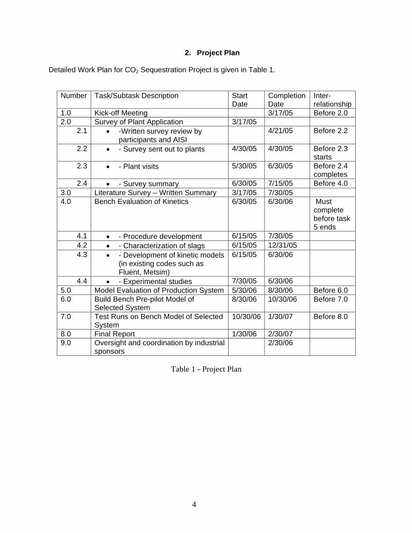
2. Project Plan Detailed Work Plan for CO2 Sequestration Project is given in Table 1.
Number Task/Subtask Description Start Date
Completion Date
Inter-relationship
1.0 Kick-off Meeting 3/17/05 Before 2.0 2.0 Survey of Plant Application 3/17/05
2.1 • -Written survey review by participants and AISI
4/21/05 Before 2.2
2.2 • - Survey sent out to plants 4/30/05 4/30/05 Before 2.3 starts
2.3 • - Plant visits 5/30/05 6/30/05 Before 2.4 completes
2.4 • - Survey summary 6/30/05 7/15/05 Before 4.0 3.0 Literature Survey – Written Summary 3/17/05 7/30/05 4.0 Bench Evaluation of Kinetics 6/30/05 6/30/06 Must
complete before task 5 ends
4.1 • - Procedure development 6/15/05 7/30/05 4.2 • - Characterization of slags 6/15/05 12/31/05 4.3 • - Development of kinetic models
(in existing codes such as Fluent, Metsim)
6/15/05 6/30/06
4.4 • - Experimental studies 7/30/05 6/30/06 5.0 Model Evaluation of Production System 5/30/06 8/30/06 Before 6.0 6.0 Build Bench Pre-pilot Model of
Selected System 8/30/06 10/30/06 Before 7.0
7.0 Test Runs on Bench Model of Selected System
10/30/06 1/30/07 Before 8.0
8.0 Final Report 1/30/06 2/30/07 9.0 Oversight and coordination by industrial
sponsors 2/30/06
Table 1 - Project Plan

5
3. Progress Toward Achieving Specified Tasks Task 1 - Kickoff meeting with potential industrial sponsors A number of tasks were identified during the initial kick-off meeting for the program and are included in the following paragraphs. Descriptions of the Tasks and the results are given below. This meeting served to build the components of the industrial site survey and get input on any reshaping of Task 3, Literature Survey, based on plant situations in which the sequestration process could be applied. Task 2 - Industrial site application survey This provides a basis on practical knowledge on application parameters such as:
• Slag compositions and temperatures at which the slag could be delivered to the process • The gas temperatures and compositions available to input to the process • The logistics of delivering the input streams to the process • Reactor site situation and plant engineering restrictions surrounding potential sites
Data collection included generation and distribution of a participant survey (Attachment A). The survey focused on slag handling practices and CO2 sources. An initial survey was distributed on June 10, 2005, and re-distributed on June 29, 2005 in a more focused format. Additionally representatives from UMR visited Nucor, Gallatin, ArcelorMittal, USS, and Ipsco plants in the mid-west U.S. to gather first-hand data on slag handling and CO2 sources, as well as samples of steel making slag. Slag samples were obtained from four of the plant and returned to UMR for analysis and testing. Further data collection focused on a literature search to obtain published work to support the test program. Task 3 - Literature survey The literature search has yielded 87 relevant publications and 17 relevant patents (U.S. and worldwide). The Literature Review (Attachment B) contained information about: - Methodology of research - Slag production, handling, and uses - Slag Characterization (physical and chemical properties, mineralogy, thermodynamic of stabilization) - CO2 capture and geological sequestration - Offgas emission in steelmaking - Carbonate formation in steelmaking slag - Intellectual capital for geological sequestration - Bibliography Task 4 - Bench evaluation of kinetics This task included subtasks: 4.1 Procedure development. Two types of experimental procedure for kinetics studies were performed. Gas-solid reactions. The first stage of equipment set-up was focused on the construction of a large scale thermogravimetric analysis (TGA) device. This includes a vertical tube furnace (2" diameter, 1000°C capability) over which a balance is mounted. The balance can hold samples
6
of 410 g net weight (0.001 mg accuracy). A gas distribution system has been set-up to introduce dry and wet gases (Ar, N2, CO2, and air) at the bottom of the furnace flowing upward through the suspended samples. A basic data acquisition system has been set-up to collect time, temperature, and weight measurements. Gas-solid-liquid reactions. A bench scale system was built to study slurry process kinetics with pH monitoring. Three synthetic slags were produced and used in addition to participant slags in bench testing of wet processes. The preliminary results of reaction carbonization in water solution were obtained:
- steel making slags have potential of CO2 sequestration by mineral carbonization of calcium and magnesium phases
- the maximum possible degree of calcium carbonization ranged from zero to 60% and significantly depended upon slag composition, structure and history of formation (thermal history and formulation sequence)
- correlations between slag composition and the possible degree of carbonization were obtained.
4.2 Characterization of slags. The characterization of slag obtained from industry and 3 types of synthetic slags included:
a. Physical Properties of Aggregate i. Particle Size ii. Density/Porosity iii. Specific surface (BET method)
b. Chemical/Phase Make-up i. X-ray Powder Diffraction ii. Chemical Analysis iii. Light Microscopy iv. Scanning Electron Microscopy
Data was used for thermodynamic calculation, kinetics of selective reactions study, and metal liberation. In addition, samples from dicalcium silicate were made and characterized. 4.3.- 4.4. Experimental Study and Development of Kinetic Models. Kinetics of two types of CO2 sequestration processes by steelmaking slag (slag-gas and slag-gas-water) was experimentally and theoretically studied. TGA method was used for "dry" process study. It was shown, that gas humidification accelerated reaction kinetics. Modeled materials (lime, mechanical mixture CaO-SiO2 and dicalcium silicate) were tested at different temperature with using unidirectional reaction pass. Slurry process was studied using EAF and LMF slag of different particle size. Kinetics of two processes was identified. The first one included calcium leaching from slag and the second one included direct carbonization of slag particles. Slag-water slurries were reacted with CO2 in laboratory flask tests showing that the degree of carbonization (formation of carbonate) is time and particle size dependent. The modified shrinking core model was used for description of experimentally measured kinetics with taking into account changing density and diffusivity of product layer of carbonized slag particles. The model fit well to experimental data and was used for industrial process design. The results were published in the following papers:
7
- "Sequestration of CO2 from Steelmaking Offgas by Carbonate Formation with Slag.” by C. Hank Rawlins, Von L. Richards, Kent D. Peaslee, and Simon N. Lekakh, Proceedings of AISTech 2006 (Attachment C1). - “Steelmaking Slag as a Permanent Sequestration Sink for Carbon Dioxide” by C.H. Rawlins, Von L. Richards, K.D. Peaslee, and S.N. Lekakh, p25-28 of the October 2006 of Steel Times International. (Attachment C2). Task 5 - Model evaluation of potential production systems The proposed concept for an industrial system consisted of two reactors interconnected with a solution exchange loop which could be incorporated into existing industrial streams of slag and off gas. This system was modeled and experimentally verified. Fundamental kinetic data of carbonate sequestration by steel making slag in aqueous solution from previous tasks was adapted for a computational model. The aqueous phase contacts with the slag in Reactor 1 where it could leach calcium ions. When the aqueous phase contacts the offgas in Reactor 2 it will dissolve CO2 and there will be a number of the possible scenarios for CaCO3 precipitation. The carbon sequestration process was modeled using the METSIM software under different possible scenarios. Two of the more important scenarios are listed below:
• Scenario 1: Fresh water is supplied to leach the slag in Reactor 1; water enriched with calcium ions is pumped to Reactor 2, where calcium carbonate would be formed and precipitated; and then the water (containing some residual dissolved CO2) would be discarded or recirculated after deep de-gassing;
• Scenario 2: The water to Reactor 1 would be recirculated from Reactor 2 without de-gassing and the possible reactions depend on the reaction kinetics as well as process parameters.
The block diagram of METSIM model consisted of two blocks, which represented Reactor 1 and Reactor 2 connected by streams. The model allowed the different scenarios to be studied. The model was verified by using experimental data for carbonization kinetics and Ca leaching reactions. The results were published: - Rawlins, C.H, Richards, V.L., Peaslee, K.D., and Lekakh, S.N., “Experimental Study of CO2 Sequestration by Steelmaking Slag,” TMS2007 Materials Process Fundamentals, Edited by P. Anyalebechi, TMS, Mar. 2007, pp. 193-202. (Attachment C3) - Rawlins, C.H., Lekakh, S.N., Richards, V.L., and Peaslee, K.D., “The Use of Steelmaking Slag for Mineralogical Sequestration of Carbon Dioxide-Aqueous Processing,” AISTech 2007, Vol. II, May 2007. (Attachment C4) Task 6 - Build bench pre-pilot model of selected system For experimental verification of the different scenarios a lab scale apparatus consisting of two connected reactors was tested, with recirculation of the aqueous phase with and without partial degassing by argon bubbling. Reactor 1 contained up to 2 kg of slag mechanically stirred with 20 liters of aqueous solution. The aqueous liquor was pumped at varying rates to Reactor 2, which had a two-liter volume. A bottle grade CO2 was bubbled through a diffuser in the bottom of Reactor 2 to generate a distribution of fine gas bubbles and to allow intimate mixing between the gas and alkaline solution. A multi-channel pH meter was used to measure the pH level in

8
both reactors. At the completion of each test, a sample of the slurry mixture from Reactor 1 was filtered, dried, and analyzed for carbonization. Task 7 - Evaluation runs on bench scale system The experiments were done by using a two stage slurry reactor where slag reacted with aqueous solution and a gas bubbling reactor where CO2 gas reacted with aqueous solution. The system also included a pump which exchanged solutions between the two stages and a pH monitoring device. Two groups of parameters were studied. The first group included the main process parameters, in particular, the ratio between volume of slag and aqueous solution, rate of CO2 bubbling as well as the rate of solution exchange. These parameters were studied using pure lime because this material has well known reaction kinetic parameters. The second group of parameters was slag composition and particle size. These experiments were done under constant values of first group parameters. The obtained experimental data was compared to METSIM modeled results and was used for process parameter optimization. The industrial system applicable for 1,000,000 ton steel annual production was investigated. Data is presented in Attachment F "Industrial Reactor Modeling" The results were also published in the article: - Rawlins, C.H., Lekakh, S.N., Richards, V.L., and Peaslee, K.D., “Mineralogical Sequestration of Carbon Dioxide through Aqueous Processing of Steelmaking Slag,” MS&T’07 Energy Materials and Technologies II, Sep. 2007, pp. 225-237. (Attachment C5)
Task 8 - Final report The achieved result presented in the final report Task 9 - Coordination for industrial oversight by sponsors – once per year - The program, task plan, and results were annually reviewed by industrial sponsors: - 7th AISI/DOE Industry Briefing Session on September 21, 2005
- 8th AISI / DOE TRP Industry Briefing Session on October 10-11, 2006 - 9th AISI/DOE Industry Briefing Session on October 10, 2007 - The results were presented and discussed in conferences: - AISTech (2006) - TMS (2007) - AISTech (2007) - MS&T’07 (2007) - The results were revealed in reports: - Industrial Survey - Literature review - Industrial Reactor Modeling Report
9
- The results were published/submitted for publication in articles:
Published: 1. Rawlins, C.H., Richards, V.L., Peaslee, K.D., and Lekakh, S.N., “Sequestration of CO2 from Steelmaking Offgas by Carbonate Formation with Slag,” AISTech 2006 Proceedings, Vol. II, May 2006, pp. 1133-1144. 2. Rawlins, C.H., Richards, V.L., Peaslee, K.D., and Lekakh, S.N., “Sequestration of CO2 from Steelmaking Offgas by Carbonate Formation with Slag,” AISTech 2006 Proceedings, Vol. II, May 2006, pp. 1133-1144. 3. Rawlins, C.H, Richards, V.L., Peaslee, K.D., and Lekakh, S.N., “Experimental Study of CO2 Sequestration by Steelmaking Slag,” TMS2007 Materials Process Fundamentals, Edited by P. Anyalebechi, TMS, Mar. 2007, pp. 193-202. 4. Rawlins, C.H., Lekakh, S.N., Richards, V.L., and Peaslee, K.D., “The Use of Steelmaking Slag for Mineralogical Sequestration of Carbon Dioxide-Aqueous Processing,” AISTech 2007, Vol. II, May 2007. 5. Rawlins, C.H., Lekakh, S.N., Richards, V.L., and Peaslee, K.D., “Mineralogical Sequestration of Carbon Dioxide through Aqueous Processing of Steelmaking Slag,” MS&T’07 Energy Materials and Technologies II, Sep. 2007, pp. 225-237.
Articles accepted for publication
1. Lekakh, S.N., Rawlins, C.H., Robertson, D.R., Richards, V.L., and Peaslee, K.D., “Aqueous Leaching and Carbonization of Steelmaking Slag for Geological Sequestration of Carbon Dioxide,” Metallurgical and Materials Transactions B, accepted for publication October 2007. 2. Richards, V.L., Rawlins, C.H., Lekakh, S.N., and Peaslee, K.D., “Sequestration of Carbon Dioxide by Steelmaking Slag: Process Phenomena and Reactor Study,” submitted for TMS 2008 CO2 Reduction Metallurgy Symposium, Ed. by N. R. Neelameggham, Mar. 2008.
Articles submitted for publication
1. Lekakh, S.N., Robertson, D.G.C., Rawlins, C.H., Richards, V.L., and Peaslee, K.D., “Two-Stage Reactor for Geological Sequestration of Carbon Dioxide Using Steelmaking Slag,” Metallurgical and Materials Transactions B, submitted for publication October 2007. 2. Peaslee, K.D., Richards, V.L., Rawlins, C.H., and Lekakh, S.N., "Carbon Dioxide Sequestration with Steelmaking Slag: Process Feasibility and Reactor Design", AISTech 2008
10
4. Result of Work (Summary of Reports and Publication)
4.1 Literature Review “CO2 SEQUESTRATION BREAKTHROUGH PROGRAM PHASE I: GEOLOGICAL SEQUESTRATION OF CO2 BY HYDROUS CARBONATE FORMATION WITH RECLAIMED SLAG” by Rawlins, C.H.
The objective of this project is to develop and demonstrate a process for sequestering CO2 generated from steel production (BOF/EAF) by forming carbonates with the alkaline earth components in slag, generating a higher value slag co-product. The net project result will be the design of a reactor to treat steelmaking exhaust gas rich in CO2 with raw or minimally processed slag. To achieve this result, the core research focus is to improve the process kinetics of the hydrous carbonate formation reaction, enabling direct removal of CO2 from steelmaking exhaust. The net plant CO2 emissions will be reduced by the amount sequestered in the carbonate formation, and the resulting slag product increases in value due to immediate stabilization allowing direct use in a wider range of construction or other applications. In addition, the reaction will produce low-grade sensible heat that can be recuperated for in-plant services. Project research will proceed in the stepwise manner detailed in AISI project contract TRP9955: “CO2 Sequestration Breakthrough Program Phase I: Geological Sequestration of CO2 by Hydrous Carbonate Formation with Reclaimed Slag.” Key tasks include industrial site application survey and visit, literature search, slag characterization, bench evaluation of kinetic factors, and bench scale prototype reactor design. This document serves as the literature search review, and will cover published information pertaining to slag production and characterization, carbonate mineral sequestration, CO2 capture in slag, and intellectual capital (research knowledge base and patents). The results of the literature review will be used to define the thermodynamic and kinetic test boundary parameters, compare thermodynamic, kinetic, and characterization results, and as idea feedstock for CO2/slag reactor design.
4.2 Published Articles 1. Rawlins, C.H., Richards, V.L., Peaslee, K.D., and Lekakh, S.N., “Steelmaking Slag as a Permanent Sequestration Sink for Carbon Dioxide,” Steel Times International, Vol. 30, No. 7, October 2006, pp. 25-28.
This research has demonstrated that a new process to react steelmaking slag with the off-gas from steelmaking has the potential of capturing 6-11% of the CO2 emissions from integrated mills and 35-45% from scrap-based steelmakers. In addition to the positive environmental impact of this new technology, the resulting slag product will have better properties, increasing its sustainable value through the rapid conversion of CaO and MgO to carbonates. This will open up new markets for slag products and eliminate the current storage time and space requirements.
11
2. Rawlins, C.H., Richards, V.L., Peaslee, K.D., and Lekakh, S.N., “Sequestration of CO2 from Steelmaking Offgas by Carbonate Formation with Slag,” AISTech 2006 Proceedings, Vol. II, May 2006, pp. 1133-1144. The alkaline earth-containing phases in steelmaking slag can form carbonates thus sequestering carbon dioxide from the surrounding atmosphere. Work has been undertaken to improve the carbonate formation kinetics, enabling steelmakers to directly remove CO2 from furnace offgas with slag, which in turn reduces the slag stabilization time. A study of basic oxygen furnace (BOF) and electric arc furnace (EAF) slags is reported in conjunction with their carbonate formation thermodynamics and capacities, yielding an overall slag CO2 capture potential. Preliminary results are presented from bench-top “wet” and “dry” slag carbonation tests on industrial slags using a slurry reactor and large-scale thermogravimetric analysis (TGA). The results of bench-scale CO2 sequestration tests by steelmaking slags is presented in this paper. In the “dry” process, the rate of reaction of solid lime or slag increases proportional to the reactor temperature. However, an upper boundary condition exists, defined by a thermodynamic phase stability diagram that must be identified for each phase in the slag. Tests results showed that the addition of water vapor (humidification) to the CO2 gas significantly accelerated the carbonation reaction of pure lime. The mechanism of this catalytic effect is possibly defined by the formation of intermediate calcium hydrate gel on the solid particle surface. A “wet” process, which includes the interaction between three phases (water-solid slag-CO2 gas), has a much higher carbonation reaction rate when compared to “dry” process. The percent of carbonation statistically correlated to the CaO contents of industrial slags. This data will be used to determine the design parameters for a lab-scale reactor for CO2 sequestration by steelmaking slags. 3. Rawlins, C.H, Richards, V.L., Peaslee, K.D., and Lekakh, S.N., “Experimental Study of CO2 Sequestration by Steelmaking Slag,” TMS2007 Materials Process Fundamentals, Edited by P. Anyalebechi, TMS, Mar. 2007, pp. 193-202. Steelmaking processes intensively use carbon-containing materials and generate a significant amount of carbon dioxide emissions. The U.S. steel industry produces ~1.75 tons CO2 for every ton of steel shipped. At the same time, steelmaking processes use calcium and magnesium oxide containing minerals for slag formation, which are excellent CO2 capture agents. The goal of this investigation was to experimentally study carbon dioxide sequestration by steelmaking slag with simultaneous acceleration of the slag stabilization processes in preparation for re-use as a construction material. Thermogravimetric methods and a slurry reactor were used to study reaction kinetics. The degree of slag carbonization was evaluated for industrial and synthetic slags in dry and wet and processes.
In the packed bed process, the rate of reaction of solid lime or slag increases proportional to the reactor temperature. However, an upper boundary condition exists, defined by a thermodynamic phase stability diagram that must be identified for each phase in the slag. Tests results showed that the addition of water vapor (humidification) to the CO2 gas significantly accelerated the carbonation reaction of pure lime. The mechanism of this catalytic effect is possibly defined by the formation of intermediate calcium hydrate gel on the solid particle surface. A slurry process, which includes the interaction between three phases (water-solid slag-CO2 gas), has a much higher carbonation reaction rate when compared to packed bed process.
12
4. Rawlins, C.H., Lekakh, S.N., Richards, V.L., and Peaslee, K.D., “The Use of Steelmaking Slag for Mineralogical Sequestration of Carbon Dioxide-Aqueous Processing,” AISTech 2007, Vol. II, May 2007. Carbon dioxide is generated directly from the furnaces used in iron and steel production, or indirectly from supply systems such as coal-burning power plants providing electric power to the plant. Steelmaking CO2 emissions vary by geographic region and the production method. For example, integrated steel mills generate more CO2 per ton of steel than mini-mills generate due to the use of coke and iron-making pre-processes. In 2000, U.S. integrated mills emitted 33.5 million tons of CO2 in carbon equivalent (CE) units, of which 64% was generated through the production and use of coke. During the same year, U.S. mini-mills generated 13.7 million tons of CO2 CE, where 80% was generated from the supply power plants. On average, in 2000 the U.S. steel industry produced 0.42 tons of CO2 CE per ton of steel shipped. Table I compares the rates of CO2 emissions in the U.S. with several European countries and Japan. Most countries are approaching the theoretical production limit of 0.40 tons of CO2 CE per ton of steel shipped, indicating that emission reductions from technological changes in production methods will have less of an impact in the future.
The aim of this project is to develop a functional sequestration technology using steelmaking slag to permanently capture carbon dioxide produced and currently emitted by steelmaking operations. A parallel benefit of slag-based CO2 sequestration is chemical stabilization of slag minerals, thus rendering the slag immune to end-use swelling or leaching and eliminating the need for stockpile aging prior to commercial use. The potential of steelmaking slag to react with CO2 to form permanent carbonate minerals is derived from slag’s high concentration of alkaline earth metal oxides. The two most important oxides are CaO (lime) and MgO (magnesia), which range from 30-50% and 10-12% of the slag mass, respectively. Both lime and magnesia readily form hydroxides or carbonate compounds under atmospheric conditions, with the carbonate compounds forming the most thermodynamically stable phase.
Previous work has shown that the slag produced during steelmaking has the potential of sequestering 5.0-10% of the BF-BOF CO2 emissions and 28-34% of EAF carbon dioxide emissions. In addition, the estimated 15-20 kg of LMF slag produced per ton of steel has the potential of capturing an additional 1.0-1.3% of BOF and 7.8-10.4% of EAF CO2 emissions. Thus, the total sequestration potential for steelmaking slag is 6-11% of the CO2 emitted from integrated mills and 35-45% emitted from scrap-based steelmakers. A furnace offgas CO2 capture and sequestration system will most likely be installed after the baghouse to prevent contamination of the slag with baghouse dust. At this point offgas conditions at this point have been estimated to be 90-150°C, with a peak CO2 concentration of 10-11 vol.% and an average of 4-5 vol.%.
Two different designs are being tested for a slag-offgas reactor. The first design is a dry process using a plug flow or rotary reactor as detailed previously. The second design is the focus of the current study and includes a wet process whereby slag is mixed with water to form a slurry through which offgas is bubbled. A two-stage system allows for aqueous dissolution of the alkaline oxides in the first stage, followed by a reaction of the resultant aqueous liquor with CO2 in a separate vessel or location. Compared with a dry system, wet processing has a much higher CO2 reaction rate, thus allowing for a smaller reactor vessel. In addition, catalytic agents such as carbonic anhydrase may be added to form an aqueous biomimetic process that has been shown to provide more tan two orders of magnitude increase in mineral carbonate formation in experiments for wet industrial CO2 scrubbers.
13
Sequestration of carbon dioxide by steelmaking slag was studied for a three-phase system of industrial slag, water, and CO2 gas. Slag-water slurries were reacted with CO2 in laboratory flask tests showing that the degree of carbonization (formation of carbonate) is time- and particle size-dependent. The rate of carbonization fits well to the shrinking core model, showing that diffusion through the carbonate product layer is the rate limiting step with the reaction rate proportional to (time)0.5. Testing in a two-stage wet reactor showed that degree of carbonization is proportional to slag alkaline content and particle surface area (i.e., reduction in particle size). The testing of a bench-scale reactor prototype revealed the main process control parameters and will be used for industrial process scale-up. 5. Rawlins, C.H., Lekakh, S.N., Richards, V.L., and Peaslee, K.D., “Mineralogical Sequestration of Carbon Dioxide through Aqueous Processing of Steelmaking Slag,” MS&T’07 Energy Materials and Technologies II, Sep. 2007, pp. 225-237. Sequestration of carbon dioxide by steelmaking slag was studied for a three-phase system of industrial slag, water, and CO2 gas. Slag-water slurries were reacted with CO2 in laboratory batch tests showing that the degree of carbonization (formation of carbonate) is time and particle size-dependent. The rate of carbonization fits well to the shrinking core model, showing that diffusion through the carbonate product layer is the rate limiting step with the reaction rate proportional to the square root of time. The calcium carbonate product layer consists of overlapping plates that increase in density with time. Testing in a two-stage wet reactor showed that degree of carbonization is dependent upon the slag alkaline content and particle surface area (i.e., reduction in particle size). Testing in a two-stage wet reactor showed that degree of carbonization is proportional to slag alkaline content and particle surface area (i.e., reduction in particle size).The testing of a bench-scale reactor prototype allows the study of leaching and carbonation independently for scale-up to an industrial process model.
4.3 Articles Accepted for Publication 1. Lekakh, S.N., Rawlins, C.H., Robertson, D.R., Richards, V.L., and Peaslee, K.D., “Aqueous Leaching and Carbonization of Steelmaking Slag for Geological Sequestration of Carbon Dioxide,” Metallurgical and Materials Transactions B, accepted for publication October 2007. Sequestration of carbon dioxide by steelmaking slag was studied in an atmospheric three-phase system containing industrial slag particles, water, and CO2 gas. Batch-type reactors were used measure the rate of aqueous alkaline leaching and slag particle carbonization independently. Four sizes of slag particles were tested for Ca leaching rate in deionized water at a constant 7.5 pH in an argon atmosphere, and for carbonate conversion with CO2 bubbled through an aqueous suspension. Conversion data (fraction of Ca leached or converted to carbonate) were evaluated to determine the rate-limiting step based on the shrinking core model. For Ca-leaching, the chemical reaction is the controlling mechanism during the initial period of time, which then switches to diffusion through the developed porous layer as the rate limiting step. Carbonate conversion proceeded much slower than leaching conversion and was found to be limited by diffusion through the product calcium carbonate layer. The calculated value of diffusivity was found to be 5x10⁻⁹ cm2/sec, which decreased by an order of magnitude with increasing carbonization conversion as a result of changing density of the product layer. The experimental data fit the shrinking core model well after correction for the particle specific surface area.
14
The reaction rates of aqueous Ca-leaching and direct carbonization were quantified independently to yield the reaction parameters and rate-limiting mechanisms as listed below.
- The specific surface area of slag particles is increased by leaching or carbonization. Selective dissolution of the Ca-bearing phase results in increased surface porosity, while carbonization produces overlapping plates of CaCO3 product layer that created a highly irregular surface. - Both Ca-leaching and carbonization were analyzed using the shrinking core model. The experimental data for both processes fit this model well, after correction for effective particle size, which is based on the measured specific surface area. - Analysis of Ca-leaching shows a linear proportionality to particle size during the initial stage (to 0.30 conversion) supporting a chemical reaction controlled model (CaO dissolution). The later stage of leaching is controlled by diffusion of the Ca2+ ions through the resulting porous surface layer, as shown by square-root proportionality of reaction time to particle size. - Increasing the leachate temperature from 20 to 60°C (at atmospheric pressure) enhanced the Ca-leaching rate during the initial period time, however the terminal amount of Ca leached after 24 hours did not differ greatly (47% vs. 50%). - Carbonate conversion is heavily dependent on particle size and the reaction is limited by product layer diffusion. The calculated value of diffusivity decreased by an order of magnitude from the initial value of 5x10⁻⁹ cm2/sec, as a result of changing density of product layer. - Carbonate conversion proceeded slower than leaching conversion however both processes are inhibited by the calcium carbonate product layer. 2. Richards,V.L., Rawlins, C.H., Lekakh, S.N., and Peaslee, K.D., “Sequestration of Carbon Dioxide by Steelmaking Slag: Process Phenomena and Reactor Study,” submitted for TMS 2008 CO2 Reduction Metallurgy Symposium, Ed. by N. R. Neelameggham, Mar. 2008. Steel-making processes generate carbon dioxide air emissions and a slag co-product. The aim of this project was to develop a functional sequestration system using steelmaking slag to permanently capture carbon dioxide emitted in steelmaking offgas. A possible parallel benefit of this process would be rapid chemical stabilization of the slag minerals with reducing swelling or leaching. This paper summarizes the original results of the project, including mineralogical and structural features of carbon sequestration with steel making slag, mathematical modeling of reaction phenomena using a modified shrinking core model, METSIM modeling of several possible industrial applications, a thermo-gravimetrical study of the reaction between slags and different gases, and design and testing for a lab scale apparatus consisted of two reactors. - Carbon dioxide sequestration with steelmaking slag was studied in a two-phase (gas-solid) and three-phase (gas-liquid-solid) systems containing industrial CO2 gas, water, and slag, at ambient temperature and pressure. The reaction rates of aqueous Ca-leaching and direct carbonization were quantified independently to yield the reaction parameters and rate-limiting mechanisms as listed below. - The reaction kinetics was described with modified shrinking core model. The model reflected the morphology of product layer formation. The obtained experimental data and kinetic parameters were used for modeling an industrial prototype reactor. - The concept of apparatus consisted of two interconnected reactors was proposed for industrial application of carbon dioxide sequestration by steel making slag. The design allows
15
incorporating the sequestration system into existing streams of slag and off-gasses containing CO2. METSIM process simulator was used to model of carbon dioxide sequestration using steelmaking slag. - A comparison of several scenarios shows that continuous calcium leaching by fresh water in the first reactor has the advantage of preventing the formation of a carbonate product layer on the slag particles and accelerating the reaction kinetics. In addition, this scenario could produce pure calcium carbonate. However, the water requirement in a continuous system is much higher than a recirculated system. - To minimize the fresh water make-up, the spent aqueous liquor from the second reactor could be recirculated to the first reactor without a degassing step. The dissolved carbonic acid results in the formation of a calcium carbonate layer on the slag particles, which inhibits leaching of calcium ions. The product layer blinding effect could be partially overcome by increasing the slag surface area (i.e. decreasing the particle size), and increasing the residence time in the first reactor. The METSIM model showed that these two factors greatly assisted the amount of calcium that could be carbonized. The developed METSIM model can be used for the design of an optimized CO2 sequestration reactor system based on different slag fractions and compositions.
4.4 Articles Submitted for Publication
1. Lekakh, S.N., Robertson, D.G.C., Rawlins, C.H., Richards, V.L., and Peaslee, K.D., “Two-Stage Reactor for Geological Sequestration of Carbon Dioxide Using Steelmaking Slag,” Metallurgical and Materials Transactions B, submitted for publication October 2007. Hydrous carbonate sequestration of CO2 using steelmaking slag was studied using a METSIM process model for analysis of experimental data and determination of reactor design parameters. A two-stage system with water/slag contact in Reactor 1 and alkaline-leachate/CO2 contact in Reactor 2 was analyzed for several possible operating scenarios including batch versus continuous processing and fresh water versus recirculation. The METSIM leaching and carbonization models were verified with results obtained from previous slag sequestration experiments. Fresh water additions to Reactor 1 allowed the highest leaching efficiency and resulted in excellent carbonization in Reactor 2, however, a continuous system has a high water demand. Recirculation of the spent leachate minimizes the fresh water addition but produces a calcium carbonate product layer on the slag particles in Reactor 1 which inhibits the leaching process. Increasing the slag surface area, slag/solution ratio, or reactor residence time partially overcomes product layer blinding. The optimal residence time was defined for different process parameters and slag particle size. It was shown that the METSIM model is a useful tool for designing and optimizing CO2 sequestration reactor systems based on different slag fractions and compositions.
2. Peaslee, K.D., Richards, V.L., Rawlins, C.H., and Lekakh, S.N., "Carbon Dioxide Sequestration with Steelmaking Slag: Process Feasibility and Reactor Design", AISTech 2008 The goal of this research is to develop a functional sequestration process using steelmaking slag to permanently capture carbon dioxide emitted from steelmaking offgas. A parallel benefit of this process is rapid chemical stabilization of the slag minerals with reducing swelling or leaching potential. This paper summarizes the results of the project, including mineralogical
16
features of carbonate formation in steelmaking slag, study of the reaction mechanisms, thermogravimetrical analysis of the reaction between solid-state slag and different gases, design and testing of a two-stage lab scale reactor system, METSIM modeling of several possible reactor designs, and exploration of the economic feasibility of the process based on process operating costs, metals recovery and credit for CO2 sequestration.
4.5 Report “Carbon Dioxide Sequestration by Steel Making Slag - Industrial Process Modeling”
METSIM process simulation software was used to model several reactor scenarios for hydrous carbonate sequestration of CO2 using steelmaking slag. A two-stage reactor design was modeled. The process allowed introducing water and slag into the first reactor and carbon dioxide into the second reactor, with the possibility of recirculation of solution. A comparison of the scenarios shows that continuous calcium leaching by fresh water in the first reactor has the advantage of preventing the formation of a carbonate product layer on the slag particles, which could reduce the leaching efficiency. However, the water requirement in a continuous system is much higher than a recirculated system. To minimize the fresh water make-up, the spent aqueous liquor from the second reactor could be recirculated to the first reactor. The drawback to this system is that the residual absorbed CO2 in the recirculated water results in the direct formation of a calcium carbonate later on the slag particles, which inhibits leaching of calcium ions. The product layer blinding effect could be partially overcome by increasing the slag surface area (i.e. decreasing the particle size), and increasing the residence time in the first reactor. The METSIM model showed that these two factors greatly assisted the amount of calcium that could be carbonized. It was shown that the METSIM model is a useful tool for designing and optimizing CO2 sequestration reactor systems based on different slag fractions and compositions. The industrial carbon dioxide sequestration process by steel making slag was modeled for one industrial case (1 million tons of EAF steel production) with different process parameters and slag conditions.
17
5. Attachments
A. Survey (13 pages) B. Literature Review (103 pages) C. Published Articles (88 pages) C1. Rawlins, C.H., Richards, V.L., Peaslee, K.D., and Lekakh, S.N“ Steelmaking Slag as a Permanent Sequestration Sink for Carbon Dioxide,” Steel Times International, Vol. 30, No. 7, October 2006, pp. 25-28. C2. Rawlins, C.H., Richards, V.L., Peaslee, K.D., and Lekakh, S.N., “Sequestration of CO2 from Steelmaking Offgas by Carbonate Formation with Slag,” AISTech 2006 Proceedings, Vol. II, May 2006, pp. 1133-1144. C3. Rawlins, C.H, Richards, V.L., Peaslee, K.D., and Lekakh, S.N., “Experimental Study of CO2 Sequestration by Steelmaking Slag,” TMS2007 Materials Process Fundamentals, Edited by P. Anyalebechi, TMS, Mar. 2007, pp. 193-202. C4. Rawlins, C.H., Lekakh, S.N., Richards, V.L., and Peaslee, K.D., “The Use of Steelmaking Slag for Mineralogical Sequestration of Carbon Dioxide-Aqueous Processing,” AISTech 2007, Vol. II, May 2007. C5. Rawlins, C.H., Lekakh, S.N., Richards, V.L., and Peaslee, K.D., “Mineralogical Sequestration of Carbon Dioxide through Aqueous Processing of Steelmaking Slag,” MS&T’07 Energy Materials and Technologies II, Sep. 2007, pp. 225-237. D. Articles Accepted for Publication (28 pages) D1. Lekakh, S.N., Rawlins, C.H., Robertson, D.R., Richards, V.L., and Peaslee, K.D., “Aqueous Leaching and Carbonization of Steelmaking Slag for Geological Sequestration of Carbon Dioxide,” Metallurgical and Materials Transactions B, accepted for publication October 2007. D2. Richards,V.L., Rawlins, C.H., Lekakh, S.N., and Peaslee, K.D., “Sequestration of Carbon Dioxide by Steelmaking Slag: Process Phenomena and Reactor Study,” submitted for TMS 2008 CO2 Reduction Metallurgy Symposium, Ed. by N. R. Neelameggham, Mar. 2008. E. Articles Submitted for Publication (36 pages) E1. Lekakh, S.N., Robertson, D.G.C., Rawlins, C.H., Richards, V.L., and Peaslee, K.D., “Two-Stage Reactor for Geological Sequestration of Carbon Dioxide Using Steelmaking Slag,” Metallurgical and Materials Transactions B, submitted for publication October 2007. E2. Peaslee, K.D., Richards, V.L., Rawlins, C.H., and Lekakh, S.N., "Carbon Dioxide Sequestration with Steelmaking Slag: Process Feasibility and Reactor Design", AISTech 2008 F. Industrial Reactor Modeling Report (18 pages)
American Iron and Steel Institute Technology Roadmap Program
CO2 Breakthrough Program Phase I: Geological Sequestration of CO2 by Hydrous Carbonate Formation with Reclaimed Slag
Final Report - Attachment A
Industry Survey Report
January 2008

CO2 SEQUESTRATION BREAKTHROUGH PROGRAM PHASE I: GEOLOGICAL SEQUESTRATION OF CO2 BY HYDROUS CARBONATE FORMATION WITH RECLAIMED SLAG
AISI PROJECT TRP9955
INDUSTRIAL APPLICATION SURVEY RESULTS
by
C. Hank Rawlins Graduate Research
Department of Material Science & Engineering University of Missouri-Rolla
March 2006

2
1. INTRODUCTION
1.1 PURPOSE OF SURVEY Task 2.0 of this project comprises of a written survey of applicable plant processes by the
project participants. The purpose of the survey is to provide a basis of practical knowledge on application parameters such as:
• Composition and temperature at which the slag could be delivered to the process • Gas temperature and composition available as input to the process • The logistics of delivering the input streams to the process • Reactor site situation and plant engineering restrictions surrounding potential sites • Ensure that any process developed has applicability in a plant situation A written survey was generated at UMR and sent to the industrial oversight committee for
review before implementation, to insure that the correct topics are adequately covered. All survey data was returned to UMR for analysis.
1.2 SURVEY FORM A copy of the completed survey form is included with this report for reference. The file is
entitled “AISI_IndustrialSlagSurvey.doc”.
1.3 DESIGNATION OF SURVEY PARTICIPANTS All data supplied by the industrial participants is kept anonymous in this report by use of a
reference code. Table 1 details the reference code and the corresponding information supplied by the participant.
Reference Code for Project Participants
Company Plant Location
Completed Survey
Slag Sample Type and Age
Other Information Supplied
A
1 Yes α-EAF, <24 hrs β-EAF, 1 week γ-LMF, 1 week
B 1 No α-BOF, 2-3 days Slag production rate data supplied by 3rd party
C 1 No α-BOF, 1 week D 1 Yes α-EAF, 1-2 days
β-EAF, at pour One month slag chemistry, Process flow diagram
E 1 Yes α-EAF, 2-3 days E 2 No α-EAF, 2-3 days E 3 No --- CO2 emissions data F 1 Yes ---
3
2. PLANT VISITS
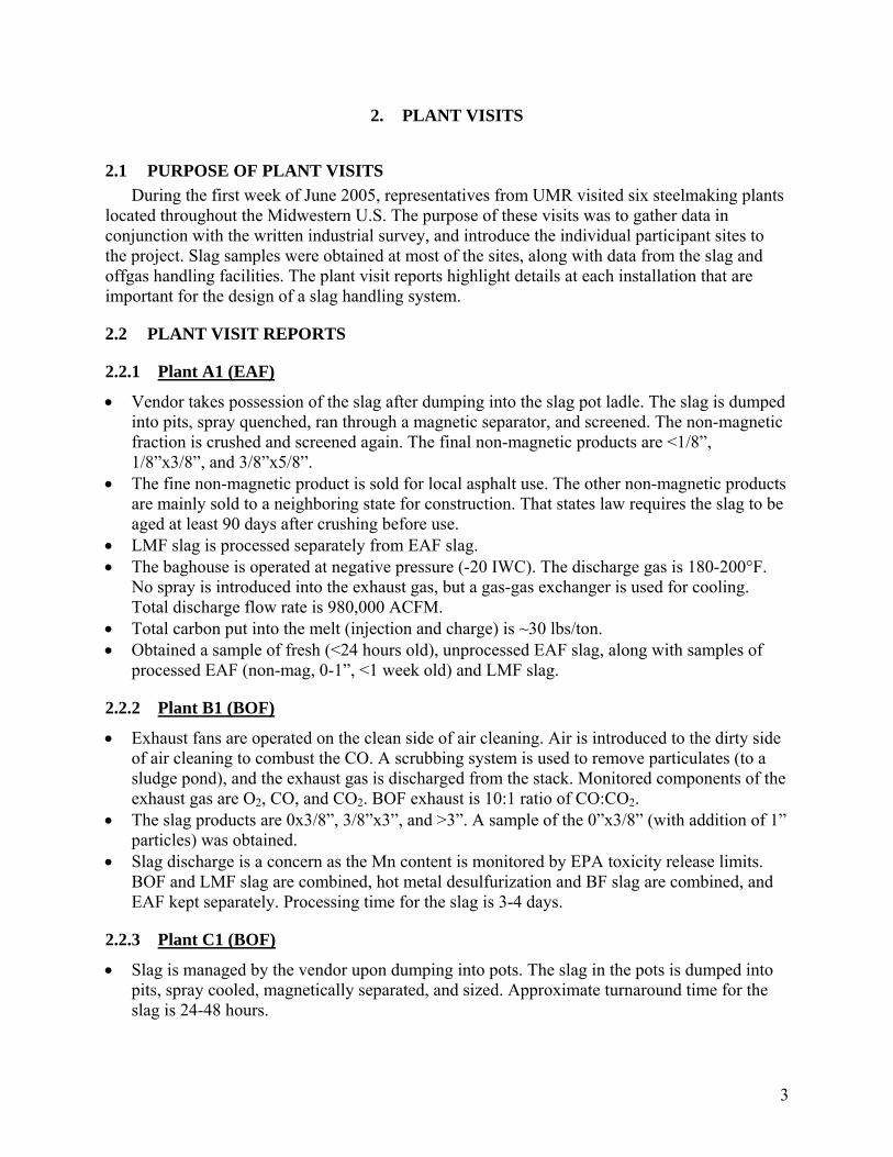
2.1 PURPOSE OF PLANT VISITS During the first week of June 2005, representatives from UMR visited six steelmaking plants
located throughout the Midwestern U.S. The purpose of these visits was to gather data in conjunction with the written industrial survey, and introduce the individual participant sites to the project. Slag samples were obtained at most of the sites, along with data from the slag and offgas handling facilities. The plant visit reports highlight details at each installation that are important for the design of a slag handling system.
2.2 PLANT VISIT REPORTS
2.2.1 Plant A1 (EAF)
• Vendor takes possession of the slag after dumping into the slag pot ladle. The slag is dumped into pits, spray quenched, ran through a magnetic separator, and screened. The non-magnetic fraction is crushed and screened again. The final non-magnetic products are <1/8”, 1/8”x3/8”, and 3/8”x5/8”.
• The fine non-magnetic product is sold for local asphalt use. The other non-magnetic products are mainly sold to a neighboring state for construction. That states law requires the slag to be aged at least 90 days after crushing before use.
• LMF slag is processed separately from EAF slag. • The baghouse is operated at negative pressure (-20 IWC). The discharge gas is 180-200°F.
No spray is introduced into the exhaust gas, but a gas-gas exchanger is used for cooling. Total discharge flow rate is 980,000 ACFM.
• Total carbon put into the melt (injection and charge) is ~30 lbs/ton. • Obtained a sample of fresh (<24 hours old), unprocessed EAF slag, along with samples of
processed EAF (non-mag, 0-1”, <1 week old) and LMF slag.
2.2.2 Plant B1 (BOF)
• Exhaust fans are operated on the clean side of air cleaning. Air is introduced to the dirty side of air cleaning to combust the CO. A scrubbing system is used to remove particulates (to a sludge pond), and the exhaust gas is discharged from the stack. Monitored components of the exhaust gas are O2, CO, and CO2. BOF exhaust is 10:1 ratio of CO:CO2.
• The slag products are 0x3/8”, 3/8”x3”, and >3”. A sample of the 0”x3/8” (with addition of 1” particles) was obtained.
• Slag discharge is a concern as the Mn content is monitored by EPA toxicity release limits. BOF and LMF slag are combined, hot metal desulfurization and BF slag are combined, and EAF kept separately. Processing time for the slag is 3-4 days.
2.2.3 Plant C1 (BOF)
• Slag is managed by the vendor upon dumping into pots. The slag in the pots is dumped into pits, spray cooled, magnetically separated, and sized. Approximate turnaround time for the slag is 24-48 hours.

4
• The slag is separated into A, B, and C metallic and A, B, and C non-metallic. The A&B metallic goes back into steel production, while the C metallic goes into BF feed or sinter. The A&B non-metallic goes into BF feed or sinter, while the C non-metallic has no marketable use yet. C non-metallic is 0”x3/8”.
• Exhaust gas is combusted, spray quenched (cooling and 1st stage particulate removal), scrubbed (2nd stage particulate removal), cooled, and then exits through the fans and stack.
• The gas temperature after the fans is 150°F, at a 360,000 ACFM flow rate • Each heat is 230 tons and produces about 45,000 pounds of slag per heat. • A sample of grade C non-magnetic slag was obtained.
2.2.4 Plant D1 (EAF)
• The steel is primarily Al killed, however some Si is used in the LMF. Burnt lime is used as the fluxing agent. Each heat is 180 short tons (liquid), with 15 tons slag produced at the EAF and 3 tons slag at the LMF.
• The primary furnace requires dumping the pot every heat, but the LMF requires dumping the pot every three heats. A vendor takes the slag once it is dumped into the pots. The molten slag is removed from the melt shop and transported to a separate enclosed building where it is dumped onto a pad. The slag pad is enclosed to control dust.
• The slag is spray quenched, magnetically separated, and the non-mag fraction screened at three sizes: <1”, 1”x3”, and >3”. Approximately 90% of the slag product goes to asphalt production, with the remainder for straight aggregate use. Total processing time of the slag is less than one week. Demand for the slag is 100%. A slag bucket sample was taken from the <1” pile, and a sample of “raw” slag was taken from the pour (cooled and placed into a can). No falling slag is present. Data on slag composition for May 2005 was provided.
• Gas from the melt shop is collected both directly from the furnace (one per furnace) and overhead canopy (two ports). A combustion gap is located at the direct furnace takeoff, and the gas is naturally cooled. At the furnace CO, O2, and SO2 are monitored, while at the baghouse CO and NOx are monitored. No CO2 monitoring is done. The gas is removed with dirty fans, processed at the baghouse, and baghouse discharged with no stack. Gas parameters are ~40-50 PPM CO average (at baghouse), with 1.3 million ACFM flow. Gas temperature at the baghouse ranges from 125-180°F in winter and 150-250°F in summer. A process flow diagram of the exhaust gas system was provided, along with a PLC strip chart printout.
2.2.5 Plant E1 (EAF)
• Slag is collected by vendor in pots, dumped into pits, and spray quenched. After cooling, it is loaded into the processing system for magnetic separation, screening, and crushing (oversize). Four slag products are made: <1”, 1”x2”, 2”x8”, and >8”. The LMF and EAF slag are treated together, and used bricks are processed separately. Total processing time for slag is one day to one week. The slag exhibits “falling” characteristic. The slag was sold in 1996 at $5/ton, while current price is $2/ton. Road aggregate (stone) is sold at $10-14/ton.
• The baghouse runs at 350°F. • Most CO2 discharged from the furnace comes from carbon combustion in their foamy slag
practice, than from steel refining.
5
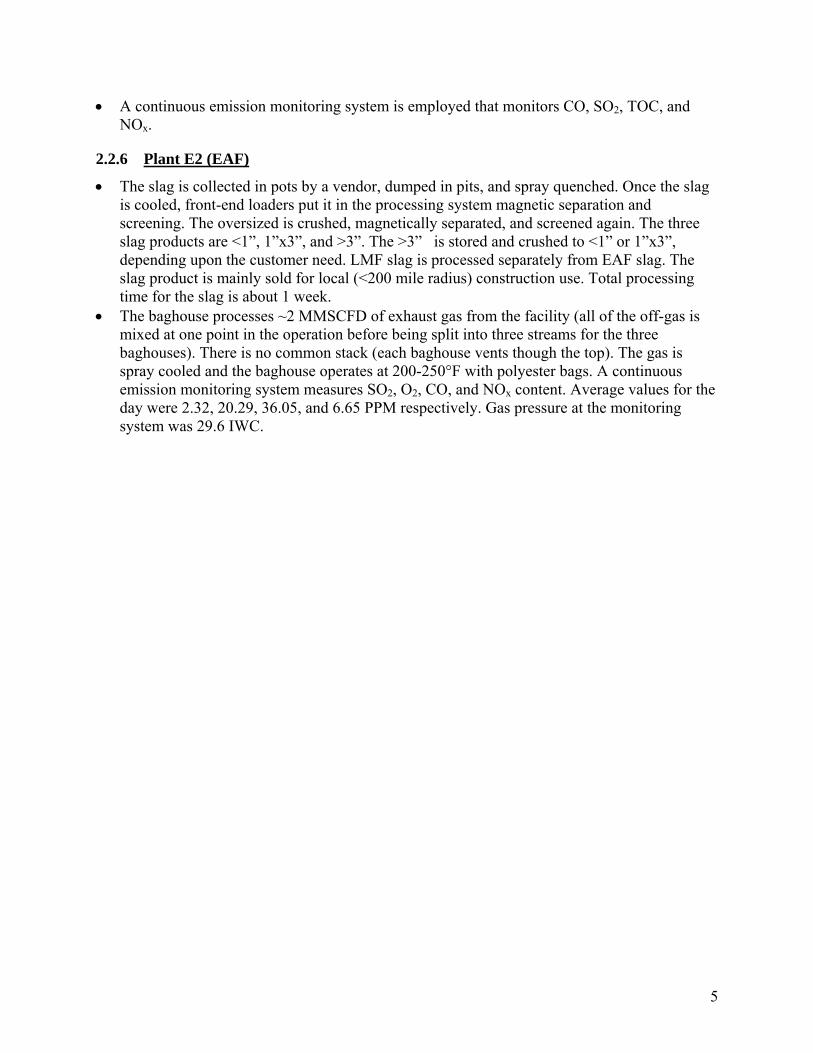
• A continuous emission monitoring system is employed that monitors CO, SO2, TOC, and NOx.
2.2.6 Plant E2 (EAF)
• The slag is collected in pots by a vendor, dumped in pits, and spray quenched. Once the slag is cooled, front-end loaders put it in the processing system magnetic separation and screening. The oversized is crushed, magnetically separated, and screened again. The three slag products are <1”, 1”x3”, and >3”. The >3” is stored and crushed to <1” or 1”x3”, depending upon the customer need. LMF slag is processed separately from EAF slag. The slag product is mainly sold for local (<200 mile radius) construction use. Total processing time for the slag is about 1 week.
• The baghouse processes ~2 MMSCFD of exhaust gas from the facility (all of the off-gas is mixed at one point in the operation before being split into three streams for the three baghouses). There is no common stack (each baghouse vents though the top). The gas is spray cooled and the baghouse operates at 200-250°F with polyester bags. A continuous emission monitoring system measures SO2, O2, CO, and NOx content. Average values for the day were 2.32, 20.29, 36.05, and 6.65 PPM respectively. Gas pressure at the monitoring system was 29.6 IWC.
6
3. SURVEY RESULTS
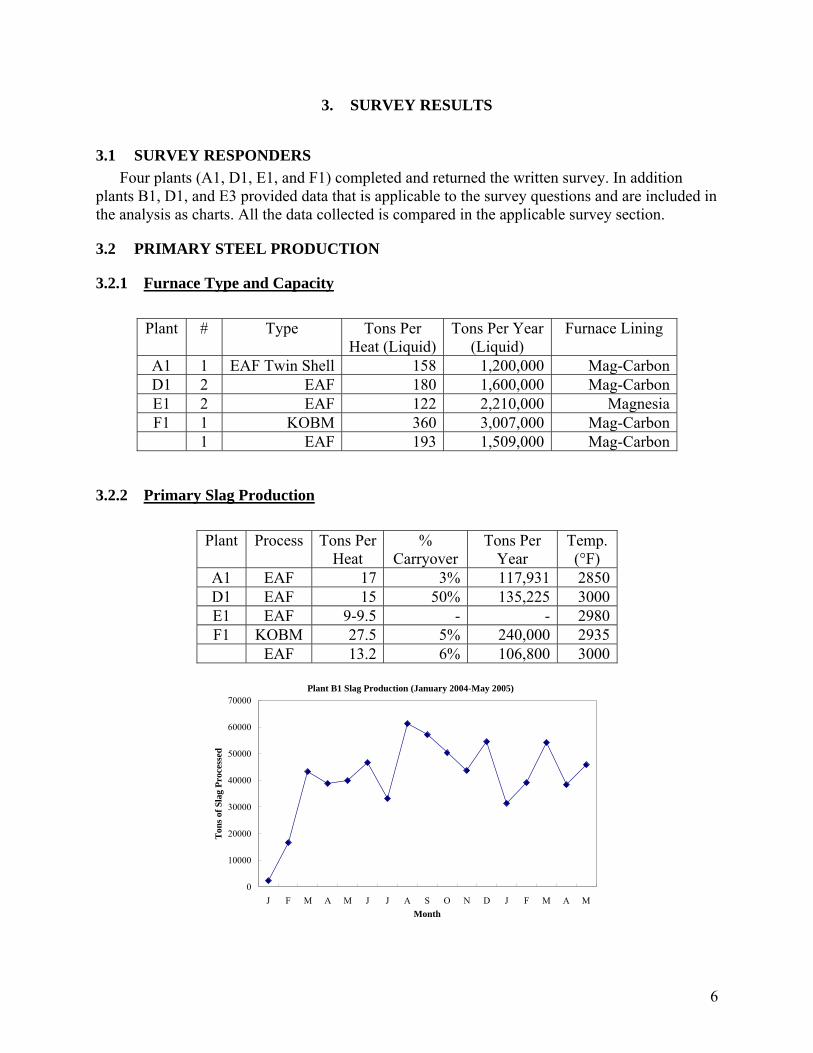
3.1 SURVEY RESPONDERS Four plants (A1, D1, E1, and F1) completed and returned the written survey. In addition
plants B1, D1, and E3 provided data that is applicable to the survey questions and are included in the analysis as charts. All the data collected is compared in the applicable survey section.
3.2 PRIMARY STEEL PRODUCTION
3.2.1 Furnace Type and Capacity
Plant # Type Tons Per Heat (Liquid)
Tons Per Year (Liquid)
Furnace Lining
A1 1 EAF Twin Shell 158 1,200,000 Mag-CarbonD1 2 EAF 180 1,600,000 Mag-CarbonE1 2 EAF 122 2,210,000 MagnesiaF1 1 KOBM 360 3,007,000 Mag-Carbon
1 EAF 193 1,509,000 Mag-Carbon
3.2.2 Primary Slag Production
Plant Process Tons Per Heat
% Carryover
Tons Per Year
Temp. (°F)
A1 EAF 17 3% 117,931 2850 D1 EAF 15 50% 135,225 3000 E1 EAF 9-9.5 - - 2980 F1 KOBM 27.5 5% 240,000 2935
EAF 13.2 6% 106,800 3000
Plant B1 Slag Production (January 2004-May 2005)
0
10000
20000
30000
40000
50000
60000
70000
J F M A M J J A S O N D J F M A MMonth
Ton
s of S
lag
Proc
esse
d
7
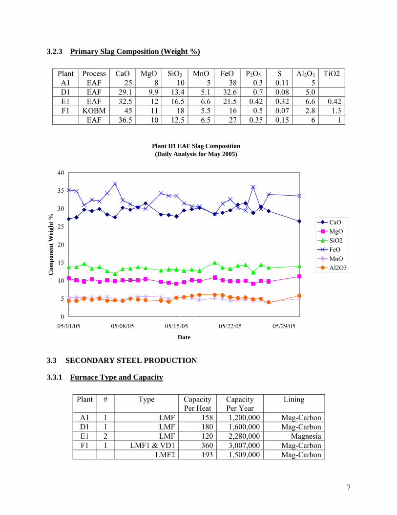
3.2.3 Primary Slag Composition (Weight %) Plant Process CaO MgO SiO2 MnO FeO P2O5 S Al2O3 TiO2 A1 EAF 25 8 10 5 38 0.3 0.11 5 D1 EAF 29.1 9.9 13.4 5.1 32.6 0.7 0.08 5.0 E1 EAF 32.5 12 16.5 6.6 21.5 0.42 0.32 6.6 0.42F1 KOBM 45 11 18 5.5 16 0.5 0.07 2.8 1.3
EAF 36.5 10 12.5 6.5 27 0.35 0.15 6 1
3.3 SECONDARY STEEL PRODUCTION
3.3.1 Furnace Type and Capacity
Plant # Type Capacity Per Heat
Capacity Per Year
Lining
A1 1 LMF 158 1,200,000 Mag-CarbonD1 1 LMF 180 1,600,000 Mag-CarbonE1 2 LMF 120 2,280,000 MagnesiaF1 1 LMF1 & VD1 360 3,007,000 Mag-Carbon
LMF2 193 1,509,000 Mag-Carbon
Plant D1 EAF Slag Composition(Daily Analysis for May 2005)
0
5
10
15
20
25
30
35
40
05/01/05 05/08/05 05/15/05 05/22/05 05/29/05
Date
Com
pone
nt W
eigh
t % CaOMgOSiO2FeOMnOAl2O3
8
3.3.2 Secondary Slag Production
Plant Process Tons Per Heat
Tons Per Year
Temp. (°F)
A1 LMF 3.35 25,443 2840 D1 LMF 3 27,045 2800
Tundish R11 15 lbs. 67.6 2750 Tundish R17 60 lbs. 270.5 2750
E1 LMF 0.98 18,700 2800 F1 LMF1 5.2 47,632 2880
LMF2 4.2 36,619 2880
3.3.3 Secondary Slag Composition
Plant Process CaO MgO SiO2 MnO FeO P2O5 S Al2O3 TiO2 A1 LMF 35 7 1 <1 1 <0.15 1 15 Tundish 50 11 6 <1 4 <0.15 1.5 30 D1 LMF 51.0 10.1 5.4 0.19 0.65 0.02 0.99 29.4 Tundish
R11 43.2 28.5 17.0 <0.5 <0.5 0.1
Tundish R17
36.5 14.2 10.8 <0.5 <0.5 24.6
F1 LMF1 50.2 6.6 5.1 1.2 2.6 0.01 0.18 31.5 0.6 LMF2 49.9 8.4 3.8 0.06 0.8 0.002 1.002 33.3 0.6
3.4 SLAG PROCESSING
3.4.1 Slag Cooling, Handling, and Storage
Plant Slag Vendor
Dump Location
Removal Frequency
Cooling Method
Primary/Secondary Mixed or Separate
Storage
A1 MultiServe Pot to ground
1 per heat Water Spray
Separate Outside Stockpile
D1 MultiServe Pot to Pad
1 per heat Air/Spray Separate Outside Stockpile
E1 MultiServe Pot to ground
1 per heat Spray Mixed Outside Stockpile
F1 MultiServe Pot to ground
42 pots per day (total)
Air/Spray - Outside Stockpile
9
3.4.2 Processing and End Use
Processing End Use for Slag (Non-Mag) Plant Ageing Time
Sizing & Sep.
Metallic Recovery
Other Blast Furnace
Aggregate Construction
A1 6 months Yes Yes Yes Yes D1 - Yes Yes Yes E1 Varies Yes Yes Yes Yes F1 2 months Yes Yes Yes Yes
3.5 OFFGAS PROCESSING
3.5.1 OFFGAS PROCESS PARAMETERS
Plant Location Volume Flow (ACFM)
Pressure (IWC)
Temp. (°F)
A1 EAF (3/10/05) 721385 -0.5 190 EAF (4/28/05) 626646 -0.5 157 EAF (10/14/02) 582887 -0.5 187 EAF (7/15/04) 784175 -0.5 188 Reheat (1/9/02) 128050 -0.25 708 F1 KOBM Scrubber 120,000 140 KOBM Stack 110,000 100 EAF Booster 350,000 -9 570 EAF Stack 1,200,000 -1 150
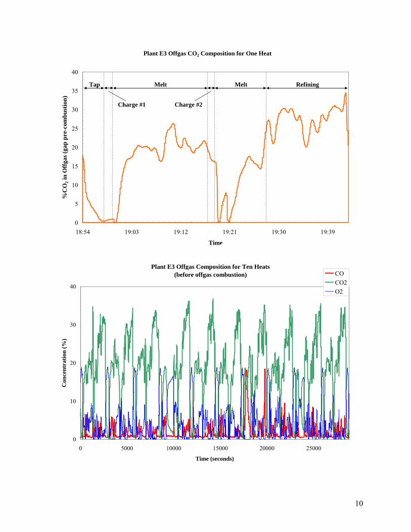
3.5.2 OFFGAS COMPOSITION Plant Location CO2
% CO
PPM O2 %
SO2 PPM
N2 %
Monitoring Method
A1 EAF 0.5 48-75 20.5 5-18 79 Periodic test Reheat 2.5 0 17.5 - - Periodic test
F1 KOBM Scrubber 17 46% 7 30 Periodic test KOBM Stack 18 47% 4 31 EAF Booster 10 0 19 71 EAF Stack 2 0 21 77
10
Plant E3 Offgas CO2 Composition for One Heat
0
5
10
15
20
25
30
35
40
18:54 19:03 19:12 19:21 19:30 19:39
Time
%C
O2 i
n O
ffga
s (ga
p pr
e-co
mbu
stio
n)
Tap
Charge #1
Melt Refining
Charge #2
Melt
Plant E3 Offgas Composition for Ten Heats(before offgas combustion)
0
10
20
30
40
0 5000 10000 15000 20000 25000
Time (seconds)
Con
cent
ratio
n (%
)
COCO2O2
11
4. SLAG TESTING AND ANALYSIS
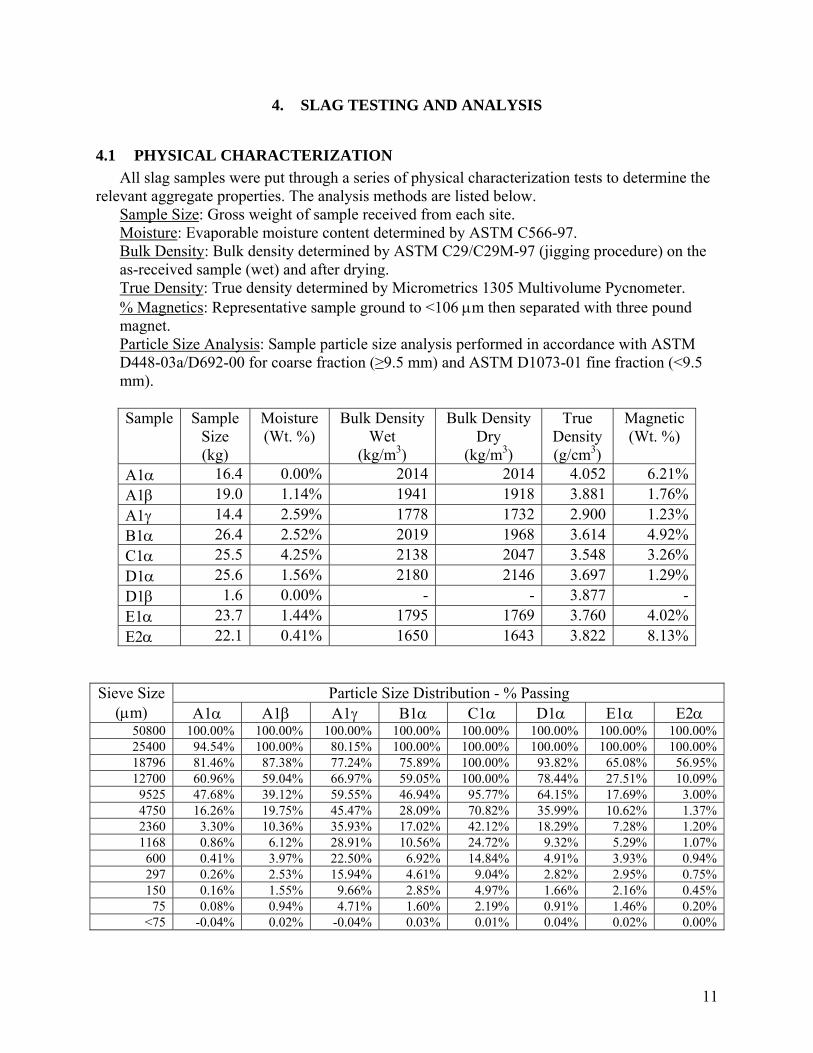
4.1 PHYSICAL CHARACTERIZATION All slag samples were put through a series of physical characterization tests to determine the
relevant aggregate properties. The analysis methods are listed below. Sample Size: Gross weight of sample received from each site. Moisture: Evaporable moisture content determined by ASTM C566-97. Bulk Density: Bulk density determined by ASTM C29/C29M-97 (jigging procedure) on the as-received sample (wet) and after drying. True Density: True density determined by Micrometrics 1305 Multivolume Pycnometer. % Magnetics: Representative sample ground to <106 μm then separated with three pound magnet. Particle Size Analysis: Sample particle size analysis performed in accordance with ASTM D448-03a/D692-00 for coarse fraction (≥9.5 mm) and ASTM D1073-01 fine fraction (<9.5 mm). Sample Sample
Size (kg)
Moisture (Wt. %)
Bulk Density Wet
(kg/m3)
Bulk Density Dry
(kg/m3)
True Density (g/cm3)
Magnetic (Wt. %)
A1α 16.4 0.00% 2014 2014 4.052 6.21%A1β 19.0 1.14% 1941 1918 3.881 1.76%A1γ 14.4 2.59% 1778 1732 2.900 1.23%B1α 26.4 2.52% 2019 1968 3.614 4.92%C1α 25.5 4.25% 2138 2047 3.548 3.26%D1α 25.6 1.56% 2180 2146 3.697 1.29%D1β 1.6 0.00% - - 3.877 -E1α 23.7 1.44% 1795 1769 3.760 4.02%E2α 22.1 0.41% 1650 1643 3.822 8.13%
Particle Size Distribution - % Passing Sieve Size (μm) A1α A1β A1γ B1α C1α D1α E1α E2α
50800 100.00% 100.00% 100.00% 100.00% 100.00% 100.00% 100.00% 100.00% 25400 94.54% 100.00% 80.15% 100.00% 100.00% 100.00% 100.00% 100.00% 18796 81.46% 87.38% 77.24% 75.89% 100.00% 93.82% 65.08% 56.95% 12700 60.96% 59.04% 66.97% 59.05% 100.00% 78.44% 27.51% 10.09%
9525 47.68% 39.12% 59.55% 46.94% 95.77% 64.15% 17.69% 3.00% 4750 16.26% 19.75% 45.47% 28.09% 70.82% 35.99% 10.62% 1.37% 2360 3.30% 10.36% 35.93% 17.02% 42.12% 18.29% 7.28% 1.20% 1168 0.86% 6.12% 28.91% 10.56% 24.72% 9.32% 5.29% 1.07% 600 0.41% 3.97% 22.50% 6.92% 14.84% 4.91% 3.93% 0.94% 297 0.26% 2.53% 15.94% 4.61% 9.04% 2.82% 2.95% 0.75% 150 0.16% 1.55% 9.66% 2.85% 4.97% 1.66% 2.16% 0.45% 75 0.08% 0.94% 4.71% 1.60% 2.19% 0.91% 1.46% 0.20%
<75 -0.04% 0.02% -0.04% 0.03% 0.01% 0.04% 0.02% 0.00%
12
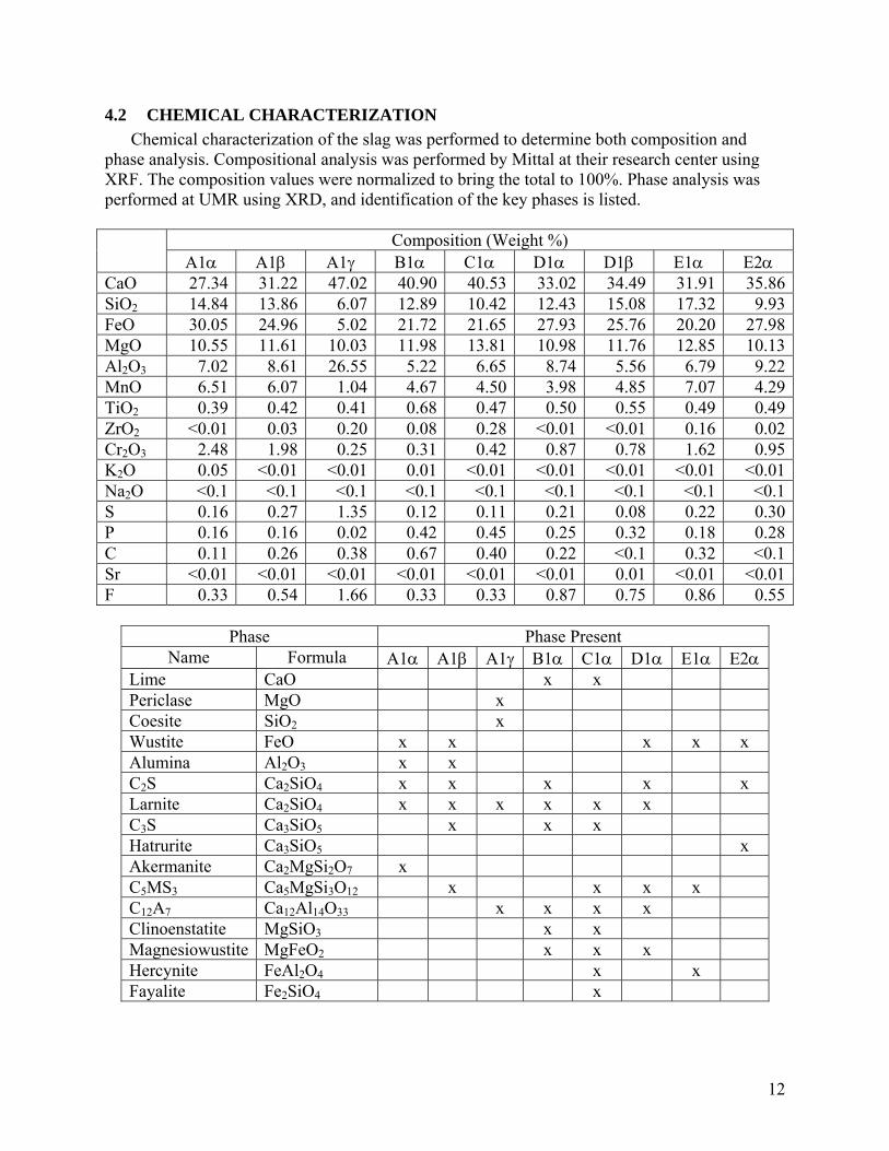
4.2 CHEMICAL CHARACTERIZATION Chemical characterization of the slag was performed to determine both composition and
phase analysis. Compositional analysis was performed by Mittal at their research center using XRF. The composition values were normalized to bring the total to 100%. Phase analysis was performed at UMR using XRD, and identification of the key phases is listed.
Composition (Weight %)
A1α A1β A1γ B1α C1α D1α D1β E1α E2α CaO 27.34 31.22 47.02 40.90 40.53 33.02 34.49 31.91 35.86SiO2 14.84 13.86 6.07 12.89 10.42 12.43 15.08 17.32 9.93FeO 30.05 24.96 5.02 21.72 21.65 27.93 25.76 20.20 27.98MgO 10.55 11.61 10.03 11.98 13.81 10.98 11.76 12.85 10.13Al2O3 7.02 8.61 26.55 5.22 6.65 8.74 5.56 6.79 9.22MnO 6.51 6.07 1.04 4.67 4.50 3.98 4.85 7.07 4.29TiO2 0.39 0.42 0.41 0.68 0.47 0.50 0.55 0.49 0.49ZrO2 <0.01 0.03 0.20 0.08 0.28 <0.01 <0.01 0.16 0.02Cr2O3 2.48 1.98 0.25 0.31 0.42 0.87 0.78 1.62 0.95K2O 0.05 <0.01 <0.01 0.01 <0.01 <0.01 <0.01 <0.01 <0.01Na2O <0.1 <0.1 <0.1 <0.1 <0.1 <0.1 <0.1 <0.1 <0.1S 0.16 0.27 1.35 0.12 0.11 0.21 0.08 0.22 0.30P 0.16 0.16 0.02 0.42 0.45 0.25 0.32 0.18 0.28C 0.11 0.26 0.38 0.67 0.40 0.22 <0.1 0.32 <0.1Sr <0.01 <0.01 <0.01 <0.01 <0.01 <0.01 0.01 <0.01 <0.01F 0.33 0.54 1.66 0.33 0.33 0.87 0.75 0.86 0.55
Phase Phase Present
Name Formula A1α A1β A1γ B1α C1α D1α E1α E2αLime CaO x x Periclase MgO x Coesite SiO2 x Wustite FeO x x x x x Alumina Al2O3 x x C2S Ca2SiO4 x x x x x Larnite Ca2SiO4 x x x x x x C3S Ca3SiO5 x x x Hatrurite Ca3SiO5 x Akermanite Ca2MgSi2O7 x C5MS3 Ca5MgSi3O12 x x x x C12A7 Ca12Al14O33 x x x x Clinoenstatite MgSiO3 x x Magnesiowustite MgFeO2 x x x Hercynite FeAl2O4 x x Fayalite Fe2SiO4 x

American Iron and Steel Institute Technology Roadmap Program
CO2 Breakthrough Program Phase I: Geological Sequestration of CO2 by Hydrous Carbonate Formation with Reclaimed Slag
Final Report - Attachment B
Literature Review
January 2008

CO2 SEQUESTRATION BREAKTHROUGH PROGRAM PHASE I: GEOLOGICAL SEQUESTRATION OF CO2 BY HYDROUS CARBONATE FORMATION WITH RECLAIMED SLAG
AISI PROJECT TRP9955
LITERATURE REVIEW
by
C. Hank Rawlins Graduate Research
Department of Material Science & Engineering University of Missouri-Rolla
January 2006

iii
TABLE OF CONTENTS
Page
LIST OF ILLUSTRATIONS............................................................................................. vi
LIST OF TABLES............................................................................................................ vii
1. INTRODUCTION...................................................................................................... 1
1.1. PROJECT PURPOSE ......................................................................................... 1
1.2. METHODOLOGY FOR RESEARCH............................................................... 1
2. SLAG PRODUCTION, HANDLING, AND USES .................................................. 2
2.1. SLAG PRODUCTION ....................................................................................... 2
2.1.1. Slag Sources. ............................................................................................ 2
2.1.2. Tonnage & Value. .................................................................................... 2
2.2. SLAG HANDLING............................................................................................ 4
2.2.1. Physical Handling..................................................................................... 4
2.2.2. Slag Processing......................................................................................... 4
2.2.3. Slag Stabilization...................................................................................... 4
2.3. USES................................................................................................................... 5
2.3.1. Recycling Into Blast Furnace. .................................................................. 6
2.3.2. High Quality Mineral Aggregate.............................................................. 6
2.3.3. Portland Cement. ...................................................................................... 7
2.3.4. Unconfined Construction. ........................................................................ 7
2.3.5. Soil Conditioning. .................................................................................... 7
2.3.6. Environmental pH Neutralization. ........................................................... 7
3. SLAG CHARACTERIZATION ................................................................................ 8
3.1. PHYSICAL PROPERTIES ................................................................................ 8
3.1.1. Specific Gravity and Bulk Density........................................................... 8
3.1.2. Hardness/Toughness................................................................................. 8
3.1.3. Particle Shape. .......................................................................................... 9
3.1.4. Surface Texture. ....................................................................................... 9
3.1.5. Mechanical Swelling. ............................................................................. 10
3.2. CHEMICAL PROPERTIES ............................................................................. 13
3.2.1. Elemental Chemical Composition.......................................................... 13
iv
3.2.2. Toxicity Potential.. ................................................................................. 14
3.2.3. Chemical Compounds. ........................................................................... 15
3.2.4. Neutralization Potential. ......................................................................... 17
3.3. MINERALOGY................................................................................................ 17
3.3.1. Minerals Present in Steel Slag................................................................ 17
3.3.2. Metastable Minerals Subject to Stabilization. ........................................ 19
3.4. THERMODYNAMICS OF STABILIZATION............................................... 20
3.4.1. Hydroxide Formation. ............................................................................ 20
3.4.2. Carbonate Formation. ............................................................................. 22
3.4.2.1 Dry Carbonate Formation. ..........................................................23
3.4.2.2 Hydrous Carbonate Formation....................................................25
3.4.3. Mineral Modification for Slag Stabilization. ......................................... 27
4. CO2 CAPTURE AND GEOLOGICAL SEQUESTRATION.................................. 29
4.1. OVERVIEW OF CO2 CAPTURE.................................................................... 29
4.1.1. Implications of CO2 Control in the Steel Industry. ................................ 29
4.1.2. Industrial CO2 Capture (Non-Geological).............................................. 30
4.2. GEOLOGICAL METHODS FOR SEQUESTRATION.................................. 30
4.2.1. Minerals for Solid Carbonate Sequestration. ......................................... 32
4.2.2. Solid Carbonate Capture Chemistry....................................................... 33
4.2.3. Thermodynamic Stability. ...................................................................... 34
4.2.4. Formation of Solid Carbonates from Natural Minerals.......................... 34
4.2.4.1 Silicates (Calcium and Magnesium).. .........................................35
4.2.4.2 Oxides (Calcium and Magnesium). ............................................48
4.2.4.3 Cement Minerals. ........................................................................50
4.2.4.4 Other Mineral Based Processes. .................................................52
4.2.4.5 Biomimetic Processes. ................................................................53
5. OFFGAS GAS CO2 SEQUESTRATION IN SLAG ............................................... 54
5.1. CO2 EMISSIONS IN STEELMAKING........................................................... 54
5.1.1. Amounts. ................................................................................................ 54
5.1.2. Offgas Composition. .............................................................................. 59
5.1.3. CO2 Emission Reduction........................................................................ 60
v
5.2. CARBONATE FORMATION IN STEELMAKING SLAG ........................... 62
5.2.1. Current Slag Sequestration Research. .................................................... 62
6. INTELLECTUAL CAPITAL FOR GEOLOGICAL SEQUESTRATION ............. 71
6.2. PATENTS......................................................................................................... 71
6.2.1. U.S. Patents and Applications. ............................................................... 71
6.2.2. Foreign Patents and Applications........................................................... 73
BIBLIOGRAPHY............................................................................................................. 80
vi
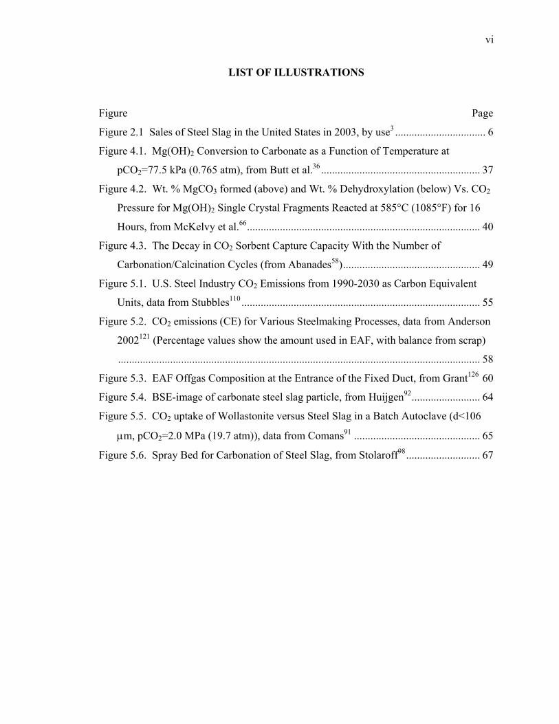
LIST OF ILLUSTRATIONS
Figure Page
Figure 2.1 Sales of Steel Slag in the United States in 2003, by use3 ................................. 6
Figure 4.1. Mg(OH)2 Conversion to Carbonate as a Function of Temperature at
pCO2=77.5 kPa (0.765 atm), from Butt et al.36 .......................................................... 37
Figure 4.2. Wt. % MgCO3 formed (above) and Wt. % Dehydroxylation (below) Vs. CO2
Pressure for Mg(OH)2 Single Crystal Fragments Reacted at 585°C (1085°F) for 16
Hours, from McKelvy et al.66..................................................................................... 40
Figure 4.3. The Decay in CO2 Sorbent Capture Capacity With the Number of
Carbonation/Calcination Cycles (from Abanades58).................................................. 49
Figure 5.1. U.S. Steel Industry CO2 Emissions from 1990-2030 as Carbon Equivalent
Units, data from Stubbles110 ....................................................................................... 55
Figure 5.2. CO2 emissions (CE) for Various Steelmaking Processes, data from Anderson
2002121 (Percentage values show the amount used in EAF, with balance from scrap)
.................................................................................................................................... 58
Figure 5.3. EAF Offgas Composition at the Entrance of the Fixed Duct, from Grant126 60
Figure 5.4. BSE-image of carbonate steel slag particle, from Huijgen92......................... 64
Figure 5.5. CO2 uptake of Wollastonite versus Steel Slag in a Batch Autoclave (d<106
µm, pCO2=2.0 MPa (19.7 atm)), data from Comans91 .............................................. 65
Figure 5.6. Spray Bed for Carbonation of Steel Slag, from Stolaroff98........................... 67
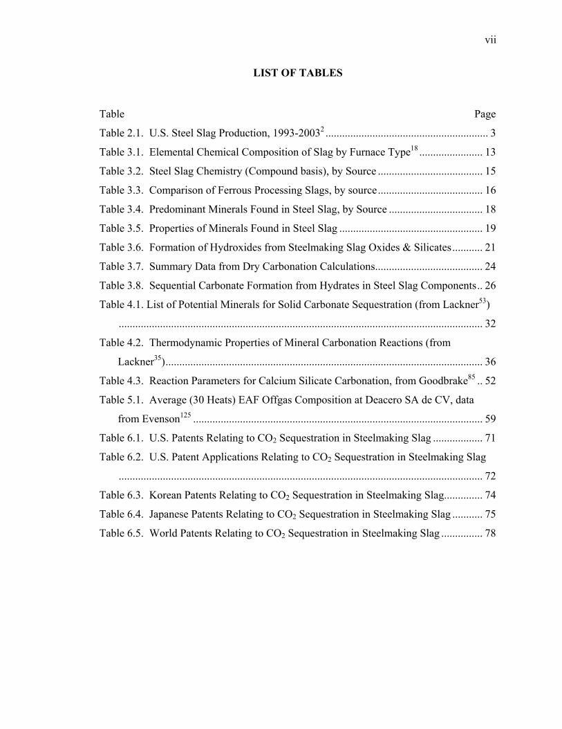
vii
LIST OF TABLES
Table Page
Table 2.1. U.S. Steel Slag Production, 1993-20032 ........................................................... 3
Table 3.1. Elemental Chemical Composition of Slag by Furnace Type18 ....................... 13
Table 3.2. Steel Slag Chemistry (Compound basis), by Source ...................................... 15
Table 3.3. Comparison of Ferrous Processing Slags, by source...................................... 16
Table 3.4. Predominant Minerals Found in Steel Slag, by Source .................................. 18
Table 3.5. Properties of Minerals Found in Steel Slag .................................................... 19
Table 3.6. Formation of Hydroxides from Steelmaking Slag Oxides & Silicates........... 21
Table 3.7. Summary Data from Dry Carbonation Calculations....................................... 24
Table 3.8. Sequential Carbonate Formation from Hydrates in Steel Slag Components.. 26
Table 4.1. List of Potential Minerals for Solid Carbonate Sequestration (from Lackner53)
.................................................................................................................................... 32
Table 4.2. Thermodynamic Properties of Mineral Carbonation Reactions (from
Lackner35)................................................................................................................... 36
Table 4.3. Reaction Parameters for Calcium Silicate Carbonation, from Goodbrake85 .. 52
Table 5.1. Average (30 Heats) EAF Offgas Composition at Deacero SA de CV, data
from Evenson125 ......................................................................................................... 59
Table 6.1. U.S. Patents Relating to CO2 Sequestration in Steelmaking Slag .................. 71
Table 6.2. U.S. Patent Applications Relating to CO2 Sequestration in Steelmaking Slag
.................................................................................................................................... 72
Table 6.3. Korean Patents Relating to CO2 Sequestration in Steelmaking Slag.............. 74
Table 6.4. Japanese Patents Relating to CO2 Sequestration in Steelmaking Slag ........... 75
Table 6.5. World Patents Relating to CO2 Sequestration in Steelmaking Slag ............... 78
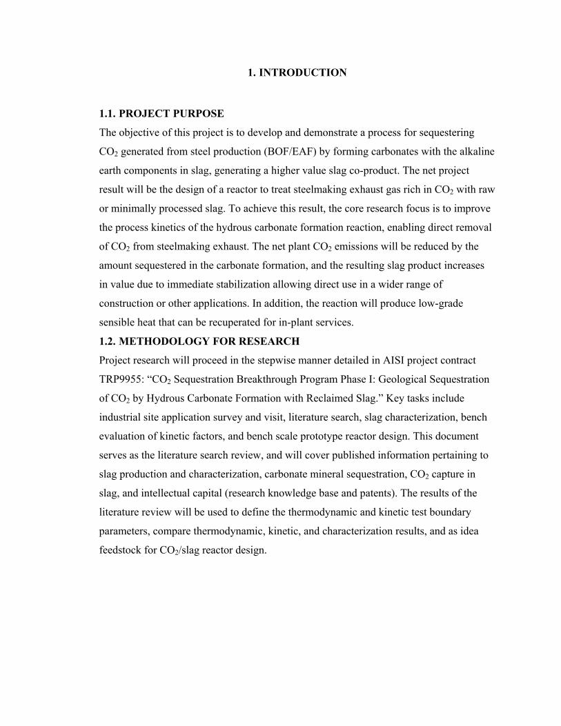
1. INTRODUCTION
1.1. PROJECT PURPOSE
The objective of this project is to develop and demonstrate a process for sequestering
CO2 generated from steel production (BOF/EAF) by forming carbonates with the alkaline
earth components in slag, generating a higher value slag co-product. The net project
result will be the design of a reactor to treat steelmaking exhaust gas rich in CO2 with raw
or minimally processed slag. To achieve this result, the core research focus is to improve
the process kinetics of the hydrous carbonate formation reaction, enabling direct removal
of CO2 from steelmaking exhaust. The net plant CO2 emissions will be reduced by the
amount sequestered in the carbonate formation, and the resulting slag product increases
in value due to immediate stabilization allowing direct use in a wider range of
construction or other applications. In addition, the reaction will produce low-grade
sensible heat that can be recuperated for in-plant services.
1.2. METHODOLOGY FOR RESEARCH
Project research will proceed in the stepwise manner detailed in AISI project contract
TRP9955: “CO2 Sequestration Breakthrough Program Phase I: Geological Sequestration
of CO2 by Hydrous Carbonate Formation with Reclaimed Slag.” Key tasks include
industrial site application survey and visit, literature search, slag characterization, bench
evaluation of kinetic factors, and bench scale prototype reactor design. This document
serves as the literature search review, and will cover published information pertaining to
slag production and characterization, carbonate mineral sequestration, CO2 capture in
slag, and intellectual capital (research knowledge base and patents). The results of the
literature review will be used to define the thermodynamic and kinetic test boundary
parameters, compare thermodynamic, kinetic, and characterization results, and as idea
feedstock for CO2/slag reactor design.
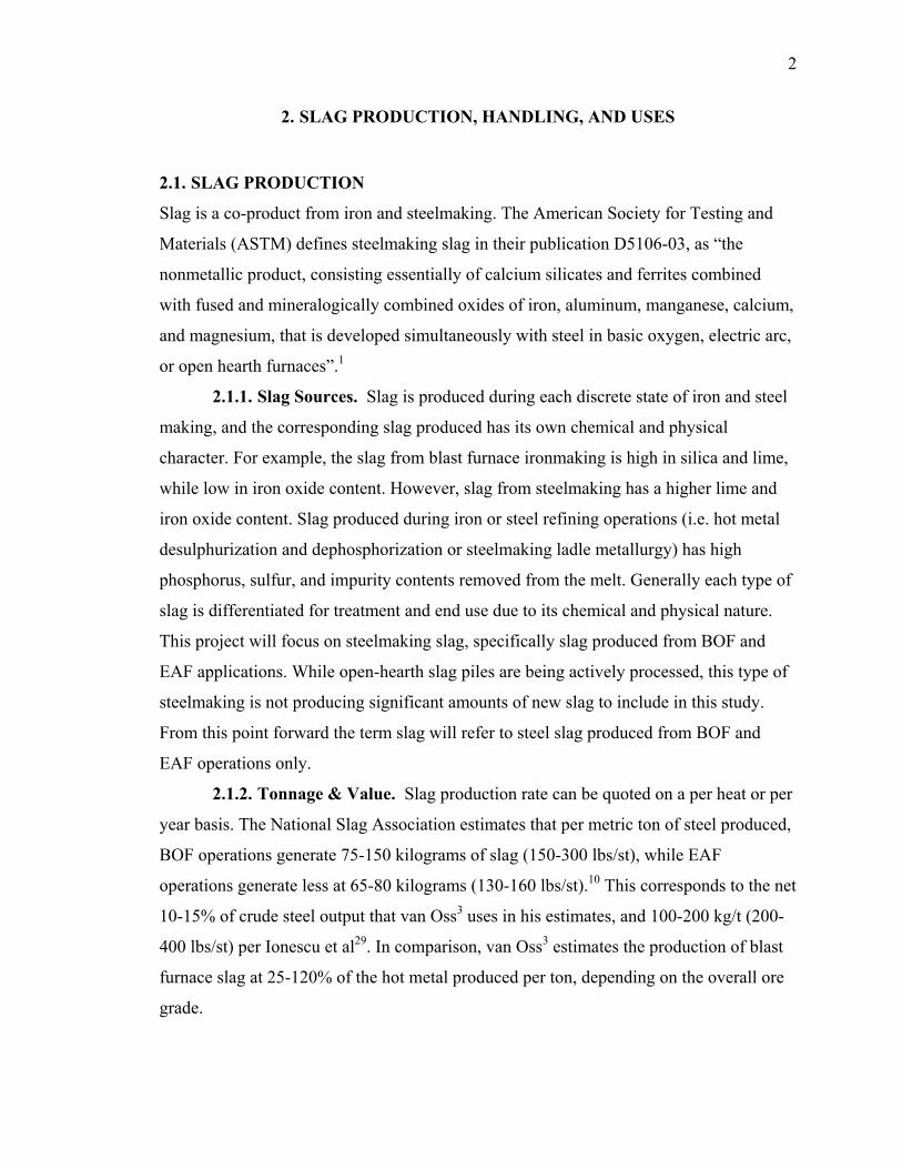
2
2. SLAG PRODUCTION, HANDLING, AND USES
2.1. SLAG PRODUCTION
Slag is a co-product from iron and steelmaking. The American Society for Testing and
Materials (ASTM) defines steelmaking slag in their publication D5106-03, as “the
nonmetallic product, consisting essentially of calcium silicates and ferrites combined
with fused and mineralogically combined oxides of iron, aluminum, manganese, calcium,
and magnesium, that is developed simultaneously with steel in basic oxygen, electric arc,
or open hearth furnaces”.1
2.1.1. Slag Sources. Slag is produced during each discrete state of iron and steel
making, and the corresponding slag produced has its own chemical and physical
character. For example, the slag from blast furnace ironmaking is high in silica and lime,
while low in iron oxide content. However, slag from steelmaking has a higher lime and
iron oxide content. Slag produced during iron or steel refining operations (i.e. hot metal
desulphurization and dephosphorization or steelmaking ladle metallurgy) has high
phosphorus, sulfur, and impurity contents removed from the melt. Generally each type of
slag is differentiated for treatment and end use due to its chemical and physical nature.
This project will focus on steelmaking slag, specifically slag produced from BOF and
EAF applications. While open-hearth slag piles are being actively processed, this type of
steelmaking is not producing significant amounts of new slag to include in this study.
From this point forward the term slag will refer to steel slag produced from BOF and
EAF operations only.
2.1.2. Tonnage & Value. Slag production rate can be quoted on a per heat or per
year basis. The National Slag Association estimates that per metric ton of steel produced,
BOF operations generate 75-150 kilograms of slag (150-300 lbs/st), while EAF
operations generate less at 65-80 kilograms (130-160 lbs/st).10 This corresponds to the net
10-15% of crude steel output that van Oss3 uses in his estimates, and 100-200 kg/t (200-
400 lbs/st) per Ionescu et al29. In comparison, van Oss3 estimates the production of blast
furnace slag at 25-120% of the hot metal produced per ton, depending on the overall ore
grade.
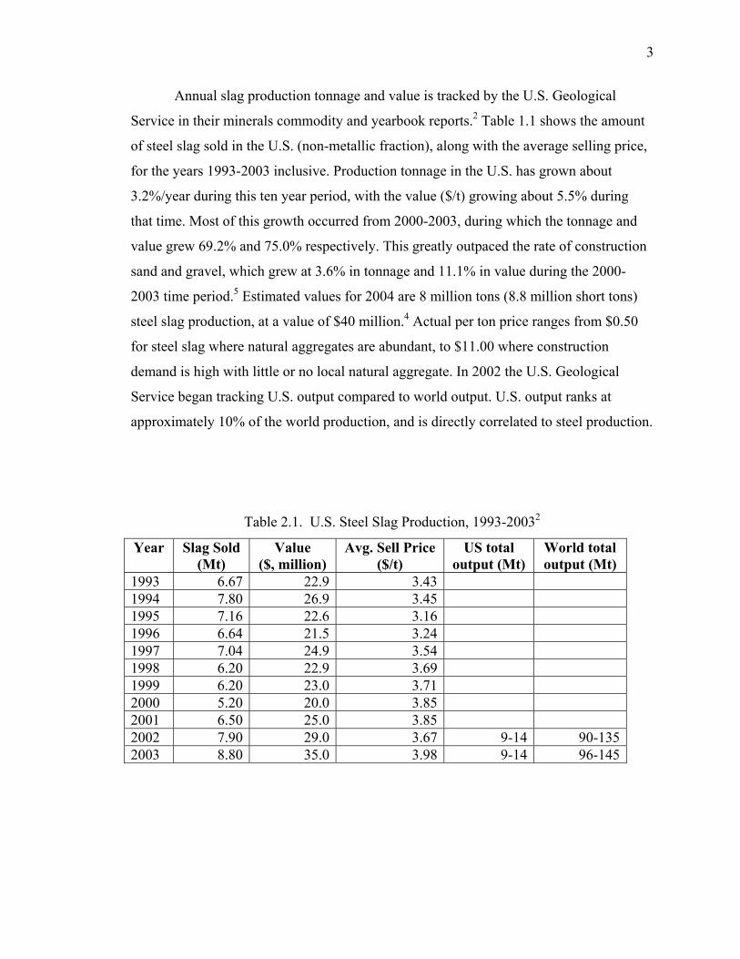
3
Annual slag production tonnage and value is tracked by the U.S. Geological
Service in their minerals commodity and yearbook reports.2 Table 1.1 shows the amount
of steel slag sold in the U.S. (non-metallic fraction), along with the average selling price,
for the years 1993-2003 inclusive. Production tonnage in the U.S. has grown about
3.2%/year during this ten year period, with the value ($/t) growing about 5.5% during
that time. Most of this growth occurred from 2000-2003, during which the tonnage and
value grew 69.2% and 75.0% respectively. This greatly outpaced the rate of construction
sand and gravel, which grew at 3.6% in tonnage and 11.1% in value during the 2000-
2003 time period.5 Estimated values for 2004 are 8 million tons (8.8 million short tons)
steel slag production, at a value of $40 million.4 Actual per ton price ranges from $0.50
for steel slag where natural aggregates are abundant, to $11.00 where construction
demand is high with little or no local natural aggregate. In 2002 the U.S. Geological
Service began tracking U.S. output compared to world output. U.S. output ranks at
approximately 10% of the world production, and is directly correlated to steel production.
Table 2.1. U.S. Steel Slag Production, 1993-20032
Year Slag Sold (Mt)
Value ($, million)
Avg. Sell Price ($/t)
US total output (Mt)
World total output (Mt)
1993 6.67 22.9 3.43 1994 7.80 26.9 3.45 1995 7.16 22.6 3.16 1996 6.64 21.5 3.24 1997 7.04 24.9 3.54 1998 6.20 22.9 3.69 1999 6.20 23.0 3.71 2000 5.20 20.0 3.85 2001 6.50 25.0 3.85 2002 7.90 29.0 3.67 9-14 90-1352003 8.80 35.0 3.98 9-14 96-145
4
2.2. SLAG HANDLING
Slag handling is not heavily documented, mostly because it is not a process requiring a
high degree of technology. After cooling to ambient temperature, slag is processed
similar to bulk aggregate (sizing, separation, and transport). Other than storage
requirements to achieve stabilization, limited literature exists detailing the physical
handling of slag from the furnace to end-use. Steel producers have not documented the
process in detail, as the most common business approach is to subcontract slag handling
and processing to a specialist handling company.
2.2.1. Physical Handling. Physical handling of slag is carried out similar to
gravel aggregate. One slag processor (MultiServ) lists the handling steps on their
website.6 In their business model the contractor takes possession of the slag as it is tapped
from the furnace (under furnace removal) into transport pots. The contractor transports
the slag to a pour pit or pad where it is dumped and allowed to cool naturally or by spray
quenching. The cooled slag is dug out of the pit with a front loader and brought to the
processing station.
2.2.2. Slag Processing. Slag processing typically consists of crushing, screening,
and magnetic separation.6,9 Magnetic separation may be followed by screening. The
oversized material may be crushed and sent back through the process again. Magnetic
recovered material is sold back to the steel mill for furnace feed. Van Oss3 estimates that
up to 50% of the slag volume is recovered as magnetic (entrained metal) for return to the
furnace. The non-magnetic material is graded by size, and stockpiled for sale.
2.2.3. Slag Stabilization. The end use destination will dictate storage time in the
stockpile. This is because slag must go through an ageing period to reach stabilization.
During ageing, compounds in the slag (initially free lime) will react with water and
carbon dioxide from the air to form hydroxides and carbonates. Formation of these
compounds results in a volume change or “swelling” of the slag, and converts these
compounds to a more stable form. Stabilization in a stockpile prevents end use in-situ
swelling or leaching. Details on the swelling mechanism are discussed in subsequent
sections.
Slag swelling is a concern when the slag is used as construction aggregate.
Crawford and Burns document the case of an office building on the Canadian side of the
5
international bridge at Sault Ste. Marie, Michigan that experienced wall buckling and
floor heave due to swelling of steel slag foundation fill.23 This was open hearth slag that
generated 9% vertical lift on the building floor slab upon in-situ swelling. To prevent in-
situ swelling, many state governments now require steelmaking slag to be aged before
use. For example, the Missouri Department of Transportation requires slag used in
asphaltic concrete to be aged for at least three months after crushing and screening7,
while the Pennsylvania Department of Transportation requires slag to be tested for
expansion after six months stockpile curing.16
An additional problem that may occur with the use of raw slag is leaching of
alkaline materials into the surface water. While testing on slag shows the leachate
reporting to the surface water is non-hazardous18, it may be perceived as a problem by the
public. For example, slag used in the Cleveland airport runway produced a “milky white,
sulfuric runoff”.8 While analysis showed that free lime leaching into the surface water
precipitated calcium carbonate (milky white), which is stable and non-hazardous, the
perception led to a project delay and negative publicity for the use of slag in construction.
2.3. USES
The National Slag Association (NSA) employs promotional and research efforts to
identify and develop innovative applications for steel slag’s unique chemical and/or
physical properties. The key uses the NSA have identified are as a source of iron and flux
materials into blast furnace operations, high quality mineral aggregate, Portland cement,
unconfined construction applications, soil conditioning, and environmental pH
neutralization of abandoned mines and contaminated sites.10,11 In 2003, the U.S.
Geological survey listed the breakdown of use as shown in Figure 2.1, which supports
these same categories.3 High quality mineral aggregate (asphaltic concrete, road bases,
and surfaces) account for more than 63% of the steel slag sold. The next largest use is
unconfined construction (fill), which accounts for approximately 12-13%, followed by
clinker feed at 5.4%. The “other” category accounts for railroad ballast, roofing, mineral
wool, and soil conditioning. Unspecified use is not detailed but probably accounts for
recycling into iron making and environmental neutralization.
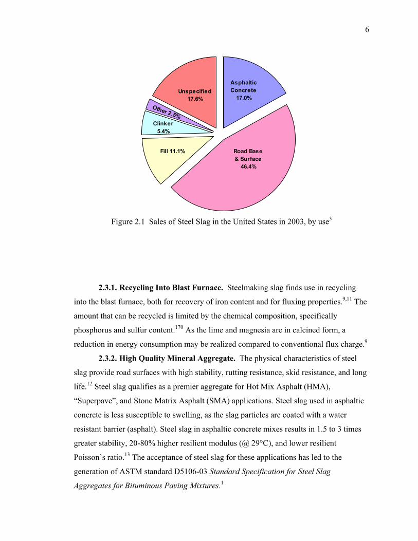
6
Figure 2.1 Sales of Steel Slag in the United States in 2003, by use3
2.3.1. Recycling Into Blast Furnace. Steelmaking slag finds use in recycling
into the blast furnace, both for recovery of iron content and for fluxing properties.9,11 The
amount that can be recycled is limited by the chemical composition, specifically
phosphorus and sulfur content.170 As the lime and magnesia are in calcined form, a
reduction in energy consumption may be realized compared to conventional flux charge.9
2.3.2. High Quality Mineral Aggregate. The physical characteristics of steel
slag provide road surfaces with high stability, rutting resistance, skid resistance, and long
life.12 Steel slag qualifies as a premier aggregate for Hot Mix Asphalt (HMA),
“Superpave”, and Stone Matrix Asphalt (SMA) applications. Steel slag used in asphaltic
concrete is less susceptible to swelling, as the slag particles are coated with a water
resistant barrier (asphalt). Steel slag in asphaltic concrete mixes results in 1.5 to 3 times
greater stability, 20-80% higher resilient modulus (@ 29°C), and lower resilient
Poisson’s ratio.13 The acceptance of steel slag for these applications has led to the
generation of ASTM standard D5106-03 Standard Specification for Steel Slag
Aggregates for Bituminous Paving Mixtures.1
Asphaltic Concrete
17.0%
Road Base & Surface
46.4%
Unspecified 17.6%
Fill 11.1%
Other 2.5%Clinker
5.4%
7
2.3.3. Portland Cement. Steel slag is similar enough in chemical composition
and character to Portland cement raw materials that it can be used as a cost effective feed
additive.10 The beneficial features of steel slag result from exposure to high furnace
temperatures thus eliminating heat of decarbonation, reducing CO2 and volatile
emissions, and reducing total raw material moisture contents when used in clinker
feedstock. Production increases with moderate additions (8-11%) of steel slag can be
almost proportionate to the amount utilized.10 An improved slag for clinker use can be
generated by first oxidizing the FeO in the slag to Fe2O3, then quenching with water.170
2.3.4. Unconfined Construction. Steel slag finds excellent application as an
aggregate in unconfined construction resulting in very high stability. Unpaved shoulders,
bases, or parking lots, erosion control, and railroad ballast all find improved life and
stability compared to standard mineral aggregates.10,11 As the slag may expand with time,
confined applications such as bases under pavements and structures are generally avoided
unless the slag is stabilized prior to use.
2.3.5. Soil Conditioning. Steel slag utilization for agricultural purposes was first
introduced in North America in 1916 by United States Steel.9,10 Used first as a lime and
phosphate amendment, other trace minerals such as Fe, Mn, Mg, Zn, and Mo have been
shown to provide beneficial crop growth. Traditionally, use has been for corn and
soybean crops, but sugar cane and rice crops are now being treated.
2.3.6. Environmental pH Neutralization. The free lime and magnesia content
of steel slag has led to the investigation of steel slag as a pH neutralizer for acid
containing wastes. Specifically steel slag has proven beneficial use in acid mine drainage
where it serves as a fill material, bulk filter, and pH neutralizer. Research by the National
Mine Reclamation Center in West Virginia on several Appalachian coal mines and
Canadian pyrite mines, show that additions of steel slag is a more effective acid discharge
neutralizer than lime or limestone, as it provides pH control during a longer period of
time, and has no hazardous leachate by products.14, 15

8
3. SLAG CHARACTERIZATION
3.1. PHYSICAL PROPERTIES
Steel slag’s unique physical properties result both from its chemical composition and its
production method. Comparison to standard construction aggregates show a higher bulk
density and specific gravity, higher hardness/toughness, coarser surface texture, and
darker color.
3.1.1. Specific Gravity and Bulk Density. The bulk density and specific gravity
of steelmaking slag is higher than blast furnace slag and natural aggregates due to the
increased content of iron and manganese. Specific gravity values for steel slag averages
3.1-3.7 for BOF and 3.2-3.8 for EAF, in comparison to 2.1-2.5 for air cooled blast
furnace slag and 2.85 for dolomite.13,19,21,38 The resultant bulk density values are 1770-
2500 kg/m3 (156.1 lbs/ft3), in comparison to 1440-1600 kg/m3 (89.9-99.9 lbs/ft3) for
dolomite.16,19 Beaver Valley Slag, a slag processing subcontractor, lists as-sold bulk
densities of steel slag from 1410-1930 kg/m3 (88.0-120.5 lbs/ft3) depending upon the
degree of compaction.17
3.1.2. Hardness/Toughness. Mineral hardness can be defined as the resistance to
breakage, and toughness is a relative factor indicating the ease of breakage. Of
importance for determining the processing and end use for slag is a quantitative factor to
determine the amount of work required to break the particles. High toughness and
hardness is beneficial for end use of the slag as it provides a more stable material. In
construction applications it is desirable for the aggregate to maintain its shape, and resist
breaking down into smaller particles. However the higher hardness and toughness, the
more energy required to break the slag into desired particle sizes during initial processing
(crushing). Estimated Moh’s hardness for steel slag is 6-7 compared to 3-4 for
dolomite.21 Crushing work index and grinding work index provide comparison values for
crushing (breakage down to 1-2 cm) and grinding (breakage below 1-2 cm) operations
respectively. The crushing work index for dolomite is 12.8, which is the same for slag.19
However, the grinding work index (ball mill) for dolomite is 13.9 versus 17.2 for slag.19
Work index has the units of kWh/ton, and a comparison shows it takes about 24% more
energy to grind steel slag compared to dolomite. Steel slag has the double benefit of
9
requiring about the same energy for crushing as dolomite, but being more resistant to in-
situ dust and fine generation. In using slag for asphaltic cement or road surfaces, the slag
is more resistant to breakdown during application (mixing and lay down) and for the life
of the constructed surface.
3.1.3. Particle Shape. The shape of crushed slag qualifies it as a premier
aggregate for road construction applications. The shape of crushed slag is described as
cubical, in comparison to dolomite which is rounded or limestone which is flat and
elongated.10 The cubical nature, along with rough surface texture, allows for greater
aggregate shear resistance, compared to round or flat particles, which resists rutting of
asphalt surfaces. As an estimate to quantify the shape for comparison, the angle of repose
can be compared. The angle of repose for slag is 45-50°, while that of crushed dolomite is
37°, indicating it has higher particle-particle resistance when stacked.20,21
3.1.4. Surface Texture. The surface texture and hardness of slag provides
outstanding skid resistance, a highly sought after feature in pavement construction. The
surface texture of slag is primarily a result of its cooling method. Most steel slags are air-
cooled under ambient conditions, with final cooling accelerated with a water spray. The
solidified material has a vesicular nature from gases entrained during the melt and
generated upon cooling. The pores increase the surface roughness and area allowing for
higher coefficient of friction and binder affinity. Slag resists polishing during the
application life, as the new surfaces generated by impact or wear contain pores which
renew the friction resistance. The two terms that quantify skid resistance are polished
stone values (PSV, high values desirable) and aggregate abrasion values (AAV, low
values desirable). The PSV for BOF slag is 54-57 and EAF slag is 58-63, compared to 53
for dolomite and 41-45 for limestone.13,38 Likewise the AAV or steel slag is 2-4
compared to 4 for sandy dolomite and 8 for limestone.13 Another quantification of
abrasion resistance is the Los Angeles Abrasion Test, specified by ASTM C131-03
Standard Test Method for Resistance to Degradation of Small-Size Coarse Aggregate by
Abrasion and Impact in the Los Angeles Machine.47 This test measures the degradation,
as percent loss, due to abrasion in a rotating grinding drum. Steel slag has an exhibited
value of 9-18% for BOF and 8-15% for EAF compared to 35-40% loss for air-cooled
blast furnace slag and dolomite.21,38
10
3.1.5. Mechanical Swelling. The mechanical swelling of steel slag is a result of
hydration and carbonation of some of the compounds present in the matrix. Details of the
chemical nature of hydration and carbonation are discussed in subsequent sections, while
this section will focus on the mechanical effects from swelling.
Quantification of slag expansion was undertaken by Tsuchiya et al. in 1980 by
studying the expansion characteristics of slag during the water immersion test.22 The
method of their test was to measure the rate and total volume of expansion of four LD
slags. Employing a constant-temperature-water-immersion test with molds used for
measuring California Bearing ratio, data was obtained on expansion with time. Expansion
ratios of 2-13% were achieved at one year, with the ultimate expansion reaching 2.0-
35.9% (time not given). A comparison between the final expansion ratio and the chemical
composition suggests a proportional relationship with the amount of free lime (f-CaO).
Slags A, D, B, and C had 3.5%, 6.1%, 8.9%, and 9.2% f-CaO respectively, and a
corresponding ultimate volume ratio of 2.0%, 2.6%, 35.9%, and 19.3%. A comparison of
the other chemical constituent did not show a proportional correlation. It is assumed that
primarily hydrates were formed (as opposed to carbonates), since the slags were
subjected to water immersion testing in a closed mold and not exposed to atmospheric
carbon dioxide. No characterization was undertaken on the final aged slags.
A second round of tests was conducted on the highest expanding slag (B), where
the slag was allowed to field age at zero, one, three, and six months before undergoing
the immersion test. Field aging had the effect of significantly reducing the ultimate
expansion ratio of the slag. At zero months field aging 35.9% expansion was exhibited,
but this dropped to 18.2% expansion at one month field aging and 6.4% expansion at six
months of field aging. Field aging and shortened the time needed to complete expansion,
but lessened the ultimate expansion value. Qualitatively, these results show that the
processes occurring in the field aging and water immersion are different. It is suggested
that the free lime in field aging is subject to competing hydration and carbonation
reactions from the H2O and CO2 in the air. Ultimately some carbonate forms, reducing
the available free lime for hydration in the immersion tests. The hypothesis for reducing
the time to complete the reaction is that carbonate formation during field aging increases
11
crack formation and propagation, allowing greater surface area for hydration during the
immersion tests.
Tsuchiya et al. found that most free lime in LD slag is present in unassimilated
lumps, not distributed in solid solution.171 The free lime lumps are several mm in
diameter at a density of one per cm3, and are observed as white to brown color in a
blackish slag matrix.
In 1997 Kandhal and Hoffman published the results from a 1982 feasibility study
of using cured steel slag fine aggregate in HMA mixtures.16 They noted that for raw slag,
the unslaked lime will hydrate, causing large volume expansions in a few weeks, while
the magnesium oxide hydrates more slowly causing volume changes that may occur after
several years. Prior to their work, the Pennsylvania Department of Transportation
required that raw steel slag be moist cured under sprayed water conditions in a controlled
stockpile for six months to alleviate expansion potential. Even with this requirement,
several failures occurred where aged steel slag used as structure backfill expanded 3-6%.
As a result, the Pennsylvania Testing Method (PTM) 130 was produced to better
characterize expansion characteristics of steel slag. This method was used to generate
ASTM D4792-00 Standard Test Method for Potential Expansion of Aggregates from
Hydration Reactions.48 Their research focused on the use of fine steel slag for hot-mix
asphalt. Because the asphalt binder coats the aggregate particles and seals of the
hydration route, this application serves as a better use for steel slag than unbound
aggregate. Of use in their research is the evaluation of swelling potential from 10 slag
sources. All samples were from Pennsylvania, with three from uncured stockpiles, and
seven from stockpiles aged at six months or longer. Expansion tests were undertaken
according to PTM-130, which uses a six-inch diameter mold filled with compacted slag
and submerged in water at 71°C (160° F) for seven days. After seven days the sample is
removed from the water bath, but kept saturated by adding water daily. Expansion
measurements continue an additional seven days for a total of 14 days. A dial gauge
measures vertical expansion from the initial height of 116.4 mm (4.584 in). Expansion
values of 1.1-2.8% were observed for uncured slag, and 0.0-0.3% for cured slag. Further
tests were undertaken to determine the particle size effect on expansion potential.
Samples from the four highest expanders of the original ten stockpiles were graded at 4.8
12
mm (0.185 in). The undersize (<4.8 mm) and oversize (4.8-50.8 mm) particles were then
subjected to PTM-130 testing. Coarse particles showed 1.13-2.83% and 0.27-0.67%
expansion for uncured and cured respectively. Fine particles showed 0.87-2.7% and 0.03-
0.23% expansion for uncured and cured respectively. These results indicate homogeneity
in expansion potential versus particle size.
The testing time range for Tsuchiya et al. and Kandhal et al. was significantly
different (>400 days vs. 14 days). However, a comparison of data from both sources at 14
days gives an average expansion on uncured slag of 0.7% for Tsuchiya and 1.9% for
Kandhal. The difference lies in both the sample source (Tsuchiya was LD slag and
Kandhal was unspecified), and that the Kandhal testing allowed the second half of the
testing to have contact with air. The higher expansion rate may be a result of carbonation
expansion taking place in addition to hydration expansion. Insufficient data was available
from Tsuchiya to compare the cured slag expansion.
The literature sources reviewed have stated several times that the primary
constituents in slag that lead to swelling are free lime (CaO) and free magnesia (MgO).
However in the slag mechanical swelling studies reviewed16,22, no characterization work
was undertaken to compare the phases before and after the swelling test. The volume
increase contribution of free oxides alone versus other phases could not be determined. A
comparison of the molar volumes of lime and magnesia to that of their corresponding
hydroxides and carbonates provides an estimate of their individual expansion capacities.
Lime has a molar volume of 16.76 cm3 (1.022 in3), and upon hydration this increases
97% to 33.08 cm3 (2.019 in3). The formation of calcium carbonate leads to 120% growth
(36.89 cm3 (2.251 in3)) from the oxide. Magnesia shows similar dramatic change,
growing from 11.25 cm3 (0.6865 in3) to 24.63 cm3 (1.503 in3) upon hydration (119%
increase), and to 28.03 cm3 (1.710 in3) upon carbonation (149% expansion) from the dry
state. Other compounds in the slag (primarily silicates of the alkaline earth metals) also
show a volume increase during hydrate and carbonate formation. A thermodynamic
review of these minerals, including molar volume change, is covered in Section 3.4.
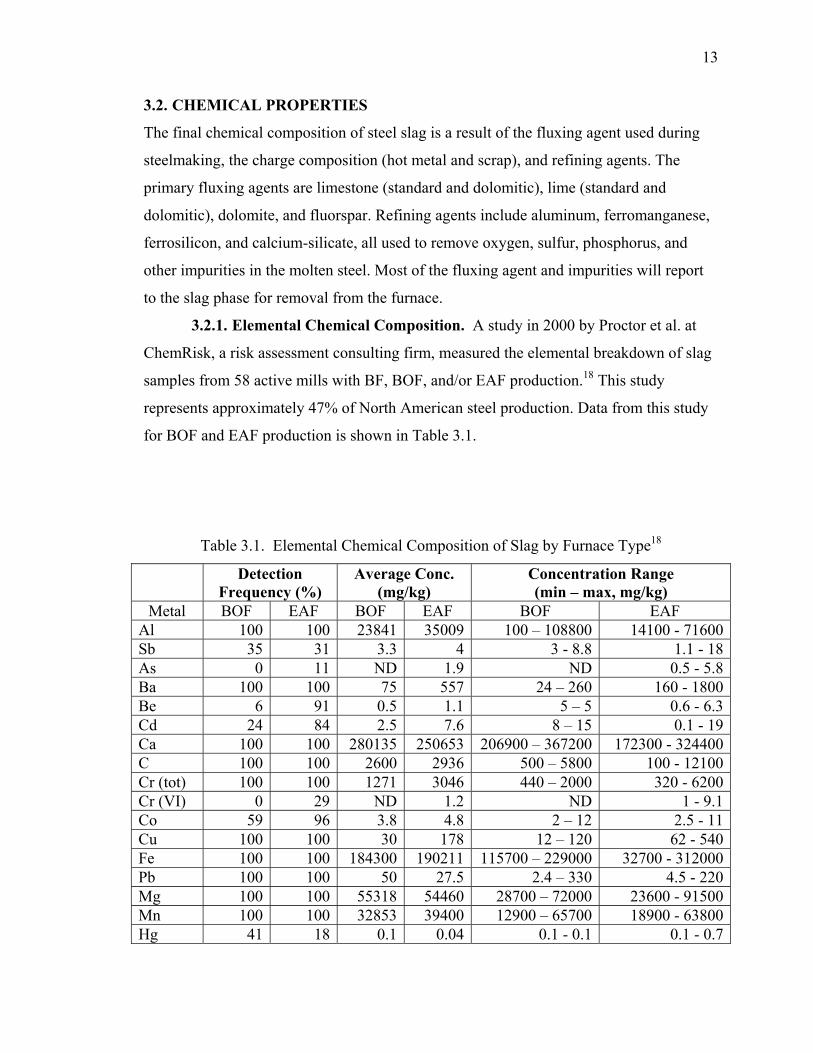
13
3.2. CHEMICAL PROPERTIES
The final chemical composition of steel slag is a result of the fluxing agent used during
steelmaking, the charge composition (hot metal and scrap), and refining agents. The
primary fluxing agents are limestone (standard and dolomitic), lime (standard and
dolomitic), dolomite, and fluorspar. Refining agents include aluminum, ferromanganese,
ferrosilicon, and calcium-silicate, all used to remove oxygen, sulfur, phosphorus, and
other impurities in the molten steel. Most of the fluxing agent and impurities will report
to the slag phase for removal from the furnace.
3.2.1. Elemental Chemical Composition. A study in 2000 by Proctor et al. at
ChemRisk, a risk assessment consulting firm, measured the elemental breakdown of slag
samples from 58 active mills with BF, BOF, and/or EAF production.18 This study
represents approximately 47% of North American steel production. Data from this study
for BOF and EAF production is shown in Table 3.1.
Table 3.1. Elemental Chemical Composition of Slag by Furnace Type18
Detection Frequency (%)
Average Conc. (mg/kg)
Concentration Range (min – max, mg/kg)
Metal BOF EAF BOF EAF BOF EAF Al 100 100 23841 35009 100 – 108800 14100 - 71600Sb 35 31 3.3 4 3 - 8.8 1.1 - 18As 0 11 ND 1.9 ND 0.5 - 5.8Ba 100 100 75 557 24 – 260 160 - 1800Be 6 91 0.5 1.1 5 – 5 0.6 - 6.3Cd 24 84 2.5 7.6 8 – 15 0.1 - 19Ca 100 100 280135 250653 206900 – 367200 172300 - 324400C 100 100 2600 2936 500 – 5800 100 - 12100Cr (tot) 100 100 1271 3046 440 – 2000 320 - 6200Cr (VI) 0 29 ND 1.2 ND 1 - 9.1Co 59 96 3.8 4.8 2 – 12 2.5 - 11Cu 100 100 30 178 12 – 120 62 - 540Fe 100 100 184300 190211 115700 – 229000 32700 - 312000Pb 100 100 50 27.5 2.4 – 330 4.5 - 220Mg 100 100 55318 54460 28700 – 72000 23600 - 91500Mn 100 100 32853 39400 12900 – 65700 18900 - 63800Hg 41 18 0.1 0.04 0.1 - 0.1 0.1 - 0.7
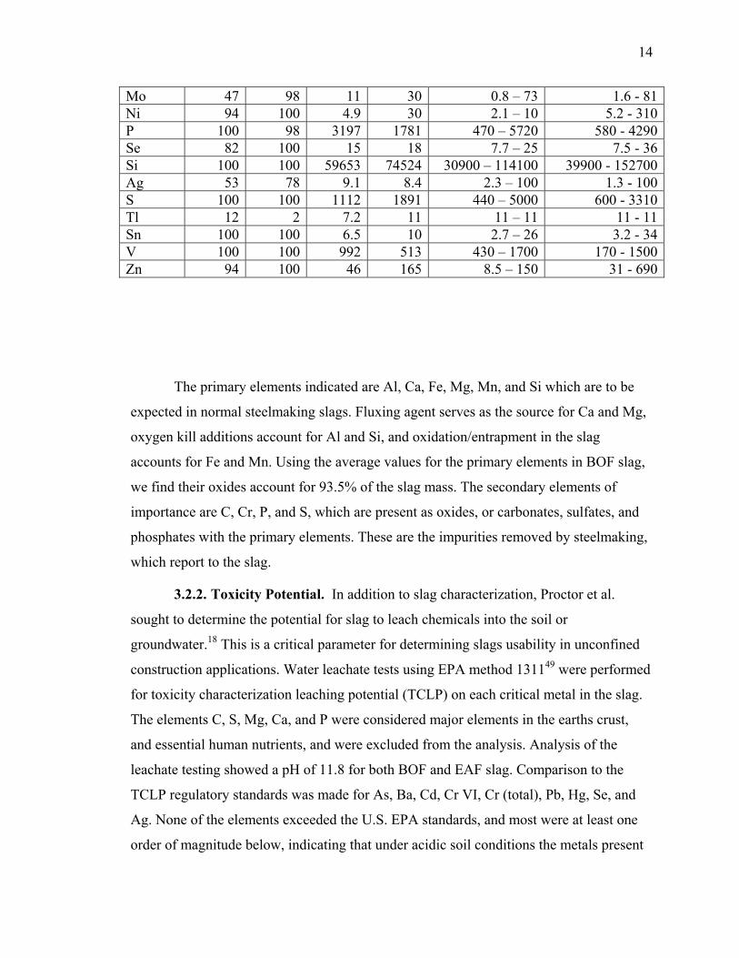
14
Mo 47 98 11 30 0.8 – 73 1.6 - 81Ni 94 100 4.9 30 2.1 – 10 5.2 - 310P 100 98 3197 1781 470 – 5720 580 - 4290Se 82 100 15 18 7.7 – 25 7.5 - 36Si 100 100 59653 74524 30900 – 114100 39900 - 152700Ag 53 78 9.1 8.4 2.3 – 100 1.3 - 100S 100 100 1112 1891 440 – 5000 600 - 3310Tl 12 2 7.2 11 11 – 11 11 - 11Sn 100 100 6.5 10 2.7 – 26 3.2 - 34V 100 100 992 513 430 – 1700 170 - 1500Zn 94 100 46 165 8.5 – 150 31 - 690
The primary elements indicated are Al, Ca, Fe, Mg, Mn, and Si which are to be
expected in normal steelmaking slags. Fluxing agent serves as the source for Ca and Mg,
oxygen kill additions account for Al and Si, and oxidation/entrapment in the slag
accounts for Fe and Mn. Using the average values for the primary elements in BOF slag,
we find their oxides account for 93.5% of the slag mass. The secondary elements of
importance are C, Cr, P, and S, which are present as oxides, or carbonates, sulfates, and
phosphates with the primary elements. These are the impurities removed by steelmaking,
which report to the slag.
3.2.2. Toxicity Potential. In addition to slag characterization, Proctor et al.
sought to determine the potential for slag to leach chemicals into the soil or
groundwater.18 This is a critical parameter for determining slags usability in unconfined
construction applications. Water leachate tests using EPA method 131149 were performed
for toxicity characterization leaching potential (TCLP) on each critical metal in the slag.
The elements C, S, Mg, Ca, and P were considered major elements in the earths crust,
and essential human nutrients, and were excluded from the analysis. Analysis of the
leachate testing showed a pH of 11.8 for both BOF and EAF slag. Comparison to the
TCLP regulatory standards was made for As, Ba, Cd, Cr VI, Cr (total), Pb, Hg, Se, and
Ag. None of the elements exceeded the U.S. EPA standards, and most were at least one
order of magnitude below, indicating that under acidic soil conditions the metals present
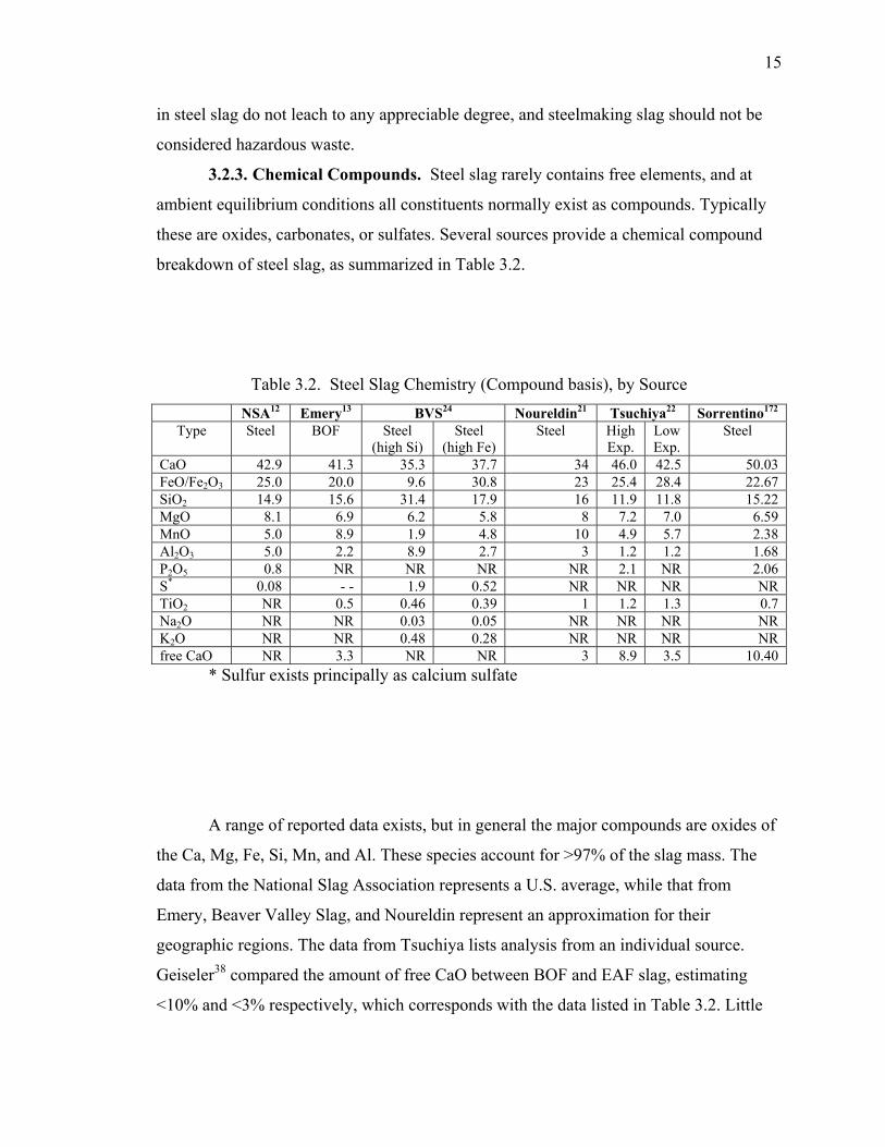
15
in steel slag do not leach to any appreciable degree, and steelmaking slag should not be
considered hazardous waste.
3.2.3. Chemical Compounds. Steel slag rarely contains free elements, and at
ambient equilibrium conditions all constituents normally exist as compounds. Typically
these are oxides, carbonates, or sulfates. Several sources provide a chemical compound
breakdown of steel slag, as summarized in Table 3.2.
Table 3.2. Steel Slag Chemistry (Compound basis), by Source NSA12 Emery13 BVS24 Noureldin21 Tsuchiya22 Sorrentino172
Type Steel BOF Steel (high Si)
Steel (high Fe)
Steel High Exp.
Low Exp.
Steel
CaO 42.9 41.3 35.3 37.7 34 46.0 42.5 50.03 FeO/Fe2O3 25.0 20.0 9.6 30.8 23 25.4 28.4 22.67 SiO2 14.9 15.6 31.4 17.9 16 11.9 11.8 15.22 MgO 8.1 6.9 6.2 5.8 8 7.2 7.0 6.59 MnO 5.0 8.9 1.9 4.8 10 4.9 5.7 2.38 Al2O3 5.0 2.2 8.9 2.7 3 1.2 1.2 1.68 P2O5 0.8 NR NR NR NR 2.1 NR 2.06 S* 0.08 - - 1.9 0.52 NR NR NR NR TiO2 NR 0.5 0.46 0.39 1 1.2 1.3 0.7 Na2O NR NR 0.03 0.05 NR NR NR NR K2O NR NR 0.48 0.28 NR NR NR NR free CaO NR 3.3 NR NR 3 8.9 3.5 10.40
* Sulfur exists principally as calcium sulfate
A range of reported data exists, but in general the major compounds are oxides of
the Ca, Mg, Fe, Si, Mn, and Al. These species account for >97% of the slag mass. The
data from the National Slag Association represents a U.S. average, while that from
Emery, Beaver Valley Slag, and Noureldin represent an approximation for their
geographic regions. The data from Tsuchiya lists analysis from an individual source.
Geiseler38 compared the amount of free CaO between BOF and EAF slag, estimating
<10% and <3% respectively, which corresponds with the data listed in Table 3.2. Little
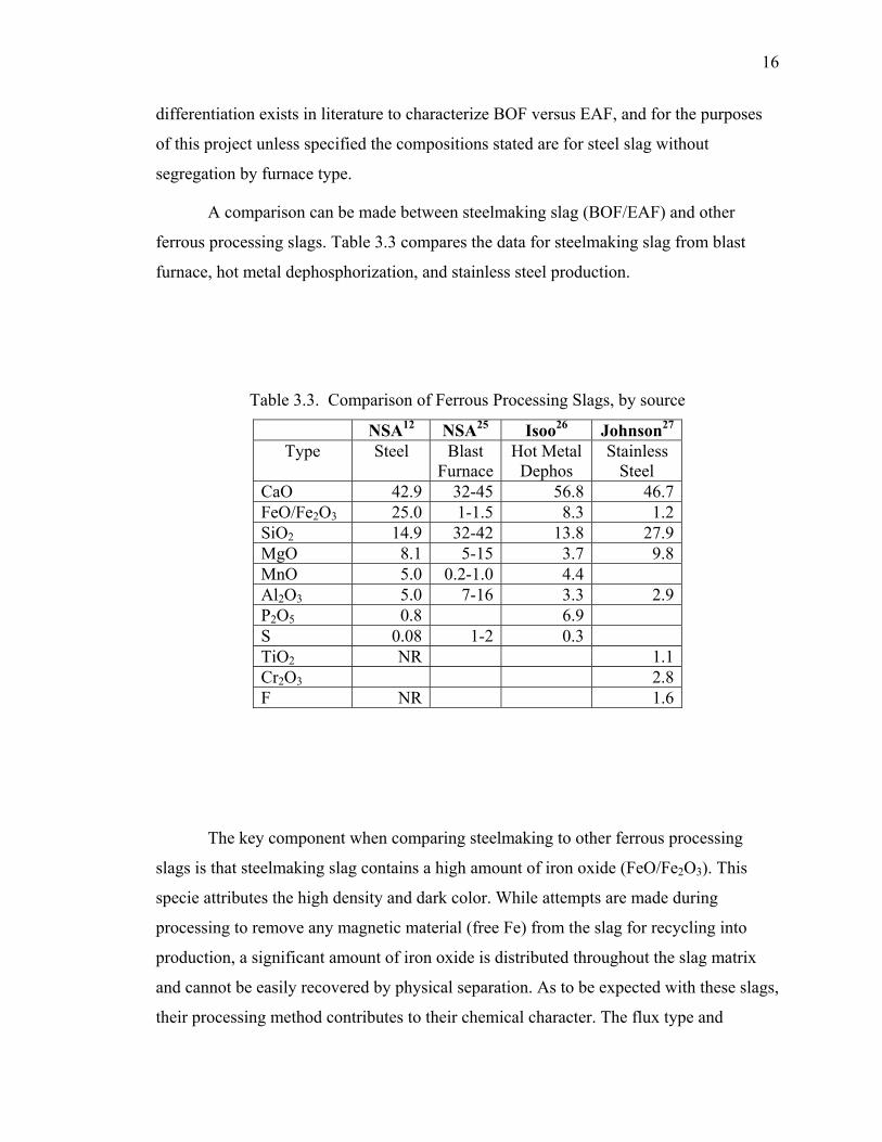
16
differentiation exists in literature to characterize BOF versus EAF, and for the purposes
of this project unless specified the compositions stated are for steel slag without
segregation by furnace type.
A comparison can be made between steelmaking slag (BOF/EAF) and other
ferrous processing slags. Table 3.3 compares the data for steelmaking slag from blast
furnace, hot metal dephosphorization, and stainless steel production.
Table 3.3. Comparison of Ferrous Processing Slags, by source
NSA12 NSA25 Isoo26 Johnson27 Type Steel Blast
FurnaceHot Metal
Dephos Stainless
Steel CaO 42.9 32-45 56.8 46.7 FeO/Fe2O3 25.0 1-1.5 8.3 1.2 SiO2 14.9 32-42 13.8 27.9 MgO 8.1 5-15 3.7 9.8 MnO 5.0 0.2-1.0 4.4 Al2O3 5.0 7-16 3.3 2.9 P2O5 0.8 6.9 S 0.08 1-2 0.3 TiO2 NR 1.1 Cr2O3 2.8 F NR 1.6
The key component when comparing steelmaking to other ferrous processing
slags is that steelmaking slag contains a high amount of iron oxide (FeO/Fe2O3). This
specie attributes the high density and dark color. While attempts are made during
processing to remove any magnetic material (free Fe) from the slag for recycling into
production, a significant amount of iron oxide is distributed throughout the slag matrix
and cannot be easily recovered by physical separation. As to be expected with these slags,
their processing method contributes to their chemical character. The flux type and
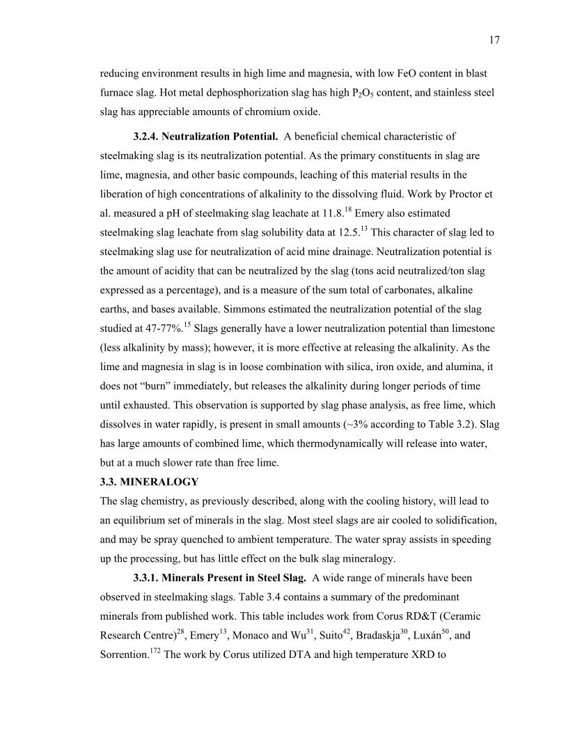
17
reducing environment results in high lime and magnesia, with low FeO content in blast
furnace slag. Hot metal dephosphorization slag has high P2O5 content, and stainless steel
slag has appreciable amounts of chromium oxide.
3.2.4. Neutralization Potential. A beneficial chemical characteristic of
steelmaking slag is its neutralization potential. As the primary constituents in slag are
lime, magnesia, and other basic compounds, leaching of this material results in the
liberation of high concentrations of alkalinity to the dissolving fluid. Work by Proctor et
al. measured a pH of steelmaking slag leachate at 11.8.18 Emery also estimated
steelmaking slag leachate from slag solubility data at 12.5.13 This character of slag led to
steelmaking slag use for neutralization of acid mine drainage. Neutralization potential is
the amount of acidity that can be neutralized by the slag (tons acid neutralized/ton slag
expressed as a percentage), and is a measure of the sum total of carbonates, alkaline
earths, and bases available. Simmons estimated the neutralization potential of the slag
studied at 47-77%.15 Slags generally have a lower neutralization potential than limestone
(less alkalinity by mass); however, it is more effective at releasing the alkalinity. As the
lime and magnesia in slag is in loose combination with silica, iron oxide, and alumina, it
does not “burn” immediately, but releases the alkalinity during longer periods of time
until exhausted. This observation is supported by slag phase analysis, as free lime, which
dissolves in water rapidly, is present in small amounts (~3% according to Table 3.2). Slag
has large amounts of combined lime, which thermodynamically will release into water,
but at a much slower rate than free lime.
3.3. MINERALOGY
The slag chemistry, as previously described, along with the cooling history, will lead to
an equilibrium set of minerals in the slag. Most steel slags are air cooled to solidification,
and may be spray quenched to ambient temperature. The water spray assists in speeding
up the processing, but has little effect on the bulk slag mineralogy.
3.3.1. Minerals Present in Steel Slag. A wide range of minerals have been
observed in steelmaking slags. Table 3.4 contains a summary of the predominant
minerals from published work. This table includes work from Corus RD&T (Ceramic
Research Centre)28, Emery13, Monaco and Wu31, Suito42, Bradaskja30, Luxán50, and
Sorrention.172 The work by Corus utilized DTA and high temperature XRD to

18
characterize the solidification sequence of steelmaking slag (type not specified). Emery’s
findings were based on literature review, while the work by Monaco and Wu was based
on K-OBM slag. The LD converter slag studied by Suito et al. is listed in Table 3.4;
however, their data on phosphorus enriched synthetic slags is not included. Bradaskja et
al. studied minerals in EAF and VOD slags. Only the predominant minerals from EAF
slag are listed. Luxán et al. carried out a study of EAF black slags in Spain, which are
defined as a lime content <40% resulting from the cold loading of scrap.
Table 3.4. Predominant Minerals Found in Steel Slag, by Source Mineral Monaco31 Corus28 Emery13 Suito42 Bradaskja30 Luxán50 Sorrentino172 Lime X X X X Periclase X X X X Hatrurite X X X X Larnite X X X X X X X Srebrodolskite X X X X Brownmillerite X X Wustite X X X X X X Calcium Ferrite X X X X Gehlenite X Bredigite X Magnetite X Magnesioferrite X Manganese Oxides
X
Good agreement exists between researchers on the predominate minerals found in
steelmaking slag. These are alkaline earth metal oxides (lime and periclase), calcium-
silicate combinations (hatrurite and larnite), iron oxide (wustite), and calcium-ferrite
combinations (calcium ferrite and dicalcium ferrite). Many other species are present, all
of them solid solutions or complex combinations of the oxides of calcium, magnesium,
iron, aluminum, and silicon. This work will focus on the predominant minerals listed and
not an exhaustive analysis of all species contained.
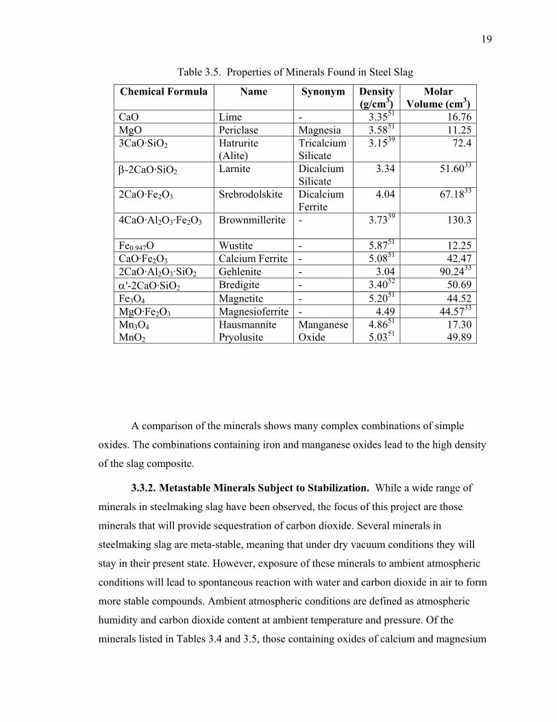
19
Table 3.5. Properties of Minerals Found in Steel Slag
Chemical Formula Name Synonym Density (g/cm3)
Molar Volume (cm3)
CaO Lime - 3.3551 16.76MgO Periclase Magnesia 3.5851 11.253CaO·SiO2 Hatrurite
(Alite) Tricalcium Silicate
3.1539 72.4
β-2CaO·SiO2 Larnite Dicalcium Silicate
3.34 51.6033
2CaO·Fe2O3 Srebrodolskite Dicalcium Ferrite
4.04 67.1833
4CaO·Al2O3·Fe2O3
Brownmillerite - 3.7339 130.3
Fe0.947O Wustite - 5.8751 12.25CaO·Fe2O3 Calcium Ferrite - 5.0851 42.472CaO·Al2O3·SiO2 Gehlenite - 3.04 90.2433
α'-2CaO·SiO2 Bredigite - 3.4052 50.69Fe3O4 Magnetite - 5.2051 44.52MgO·Fe2O3 Magnesioferrite - 4.49 44.5733
Mn3O4 MnO2
Hausmannite Pryolusite
Manganese Oxide
4.8651 5.0351
17.3049.89
A comparison of the minerals shows many complex combinations of simple
oxides. The combinations containing iron and manganese oxides lead to the high density
of the slag composite.
3.3.2. Metastable Minerals Subject to Stabilization. While a wide range of
minerals in steelmaking slag have been observed, the focus of this project are those
minerals that will provide sequestration of carbon dioxide. Several minerals in
steelmaking slag are meta-stable, meaning that under dry vacuum conditions they will
stay in their present state. However, exposure of these minerals to ambient atmospheric
conditions will lead to spontaneous reaction with water and carbon dioxide in air to form
more stable compounds. Ambient atmospheric conditions are defined as atmospheric
humidity and carbon dioxide content at ambient temperature and pressure. Of the
minerals listed in Tables 3.4 and 3.5, those containing oxides of calcium and magnesium

20
are meta-stable in the raw slag, and will sequester carbon dioxide under ambient
atmospheric conditions in the formation of more stable compounds. A thermodynamic
analysis provides insight to the mechanism of these reactions.
3.4. THERMODYNAMICS OF STABILIZATION
Stabilization is the process that slag goes through to transform from the raw to most
stable state. The basis of this study is the naturally occurring process that involves
exposure of the raw slag to ambient atmospheric conditions (temperature, pressure, air
composition, and humidity). Under these conditions, specific minerals in the slag will
react spontaneously, and release heat as a result (exothermic). As the slag is subject to
both water and carbon dioxide, competition exists between hydroxide and carbonate
formation of each compound. A thermodynamic review will determine both the heat
released in each reaction, and the final stable state of each compound (hydroxide or
carbonate).
The key minerals identified for carbon dioxide sequestration are the free oxides
and silicates of calcium and magnesium. These minerals form both hydroxides and
carbonates, and determination of their respective Gibbs free energy of formation at
ambient conditions (G°) will determine the final stable state. The subsequent analysis
concerns spontaneous reactions to form hydroxides and carbonates at ambient
temperature of 25°C (77°F). An increase in temperature pushes the system away from
forming hydroxides/carbonates, and ultimately, a temperature will be reached in which
the reaction goes backwards (decomposition). Hydroxide formation will be studied
discretely and as a step in the formation of carbonate, while carbonate formation will be
studied in both dry and wet processes.
3.4.1. Hydroxide Formation. The reaction of water with alkaline earth metal
oxides and silicates in the slag will lead to the formation of hydroxides. This water can be
sequestered either from the air (ambient humidity) or from liquid form (submersion), and
the concentration available will play a role in the rate of the reaction (covered in
subsequent section). A study of the reaction thermodynamics will provide the state of the
equilibrium products and any heat produced. A review of the literature provides this
information for CaO, MgO, 2CaO·SiO2, and 3CaO·SiO2 at standard conditions (298°K, 1
atm.).
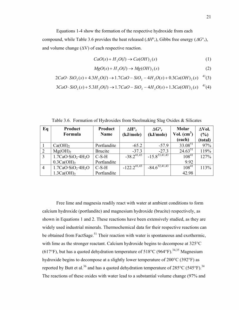
21
Equations 1-4 show the formation of the respective hydroxide from each
compound, while Table 3.6 provides the heat released (∆H°r), Gibbs free energy (∆G°r),
and volume change (∆V) of each respective reaction.
)()()()( 22 sOHCalOHsCaO →+ (1)
)()()()( 22 sOHMglOHsMgO →+ (2)
)()(3.0)(47.1)(3.4)(2 22222 sOHCasOHSiOCaOlOHsSiOCaO +−−→+⋅ 41(3)
)()(3.1)(47.1)(3.5)(3 22222 sOHCasOHSiOCaOlOHsSiOCaO +−−→+⋅ 41(4)
Table 3.6. Formation of Hydroxides from Steelmaking Slag Oxides & Silicates
Eq Product Formula
Product Name
∆H°r (kJ/mole)
∆G°r (kJ/mole)
Molar Vol. (cm3)
(each)
∆Vol. (%)
(total) 1 Ca(OH)2 Portlandite -65.2 -57.9 33.0851 97%2 Mg(OH)2 Brucite -37.3 -27.3 24.6351 119%3 1.7CaO·SiO2·4H2O
0.3Ca(OH)2 C-S-H Portlandite
-38.241,43 -15.833,41,43
10841
9.92127%
4 1.7CaO·SiO2·4H2O 1.3Ca(OH)2
C-S-H Portlandite
-122.241,43 -84.632,41,43
10841
42.98113%
Free lime and magnesia readily react with water at ambient conditions to form
calcium hydroxide (portlandite) and magnesium hydroxide (brucite) respectively, as
shown in Equations 1 and 2. These reactions have been extensively studied, as they are
widely used industrial minerals. Thermochemical data for their respective reactions can
be obtained from FactSage.51 Their reaction with water is spontaneous and exothermic,
with lime as the stronger reactant. Calcium hydroxide begins to decompose at 325°C
(617°F), but has a quoted dehydration temperature of 518°C (964°F).34,35 Magnesium
hydroxide begins to decompose at a slightly lower temperature of 200°C (392°F) as
reported by Butt et al.36 and has a quoted dehydration temperature of 285°C (545°F).34
The reactions of these oxides with water lead to a substantial volume change (97% and
22
119% respectively), which is why they are listed as key compounds in slag swelling
studies.
The hydration of calcium silicates has been studied in cement chemistry, as they
are key components in the manufacture of cement and concrete. Dicalcium silicate and
tricalcium silicate together account for approximately 75% of ordinary Portland cement
(OPC) by weight.44 The hydration of dicalcium silicate and tricalcium silicate is
documented by Tennis and Jennings39, Bentz41, and Fuji and Kondo.43 Their work
provides the reactions listed in Equation 3 and 4. Their hydration route is similar in that
they both form calcium silicate hydrate and calcium hydroxide (in varying ratios). More
than 30 crystalline phases of calcium silicate hydrate (C-S-H) are known. The preparation
of C-S-H from dicalcium silicate and tricalcium silicate forms a C-S-H gel, which may
vary in composition (as indicated by the dashes in the chemical formula). The hydrate
reaction path for these minerals used by Bentz and Tennis and Jennings has been adopted
for cement modeling and studied to provide thermochemical data. A ratio of 1.7:1
CaO:SiO2 is adopted by the researchers listed; however, the amount of water varies.
Thermochemical data for heat of formation and molar volume are obtained from Bentz,
and data for free energy of formation is obtained from Fujii and Kondo. Fujii and Kondo
use 2.62 moles of water for C-S-H, as opposed to four moles by Bentz, which provides
different listed heats of formation. However, normalizing both to the same hydration
level (4 moles) gives the same heat of formation for C-S-H (-3288 kJ/mole for Fujii and -
3283 kJ/mole for Bentz). The hydration of tricalcium silicate is the strongest listed,
providing nearly twice as much heat as the slaking of lime. Both dicalcium silicate and
tricalcium silicate will spontaneously react with water at ambient conditions. The change
in volume by the hydration provides a significant volume increase (127% and 113%
respectively), indicating that they are a significant contributor to slag swelling.
3.4.2. Carbonate Formation. Formation of carbonates in slag can occur either
dry (from non-hydrated minerals) or wet (from hydrated minerals). The ambient
conditions (amount of water and length of time present) will determine if the slag forms
carbonates from the dry state, or if hydroxides are formed as an intermediate step. A
study of the reaction thermodynamics reveals the energy released, as well as the
equilibrium reached between hydroxides and carbonates.
23
3.4.2.1 Dry Carbonate Formation. Carbonates of calcium and magnesium
oxide will form directly if no water is present. Dry carbonation of lime occurs to form
calcium carbonate (calcite) as shown in Equation 5.
)()()( 32 sCaCOgCOsCaO →+ (5)
This reaction is significantly more exothermic than the hydroxide formation, and with a
lower free energy, this is a more stable compound. The dissociation (calcining)
temperature of calcium carbonate depends on the partial pressure of CO2 (pCO2) in the
surrounding atmosphere. It can range as low as 650°C (1202°F) at pCO2 near zero, to
898°C (1648°F) for pCO2 at unity.20 Cement kilns normally operate in the 950-1100°C
(1742-2012°F) range to increase the decomposition rate.
Dry carbonation of magnesia occurs to form magnesium carbonate (magnesite) as
shown in Equation 6.
)()()( 32 sMgCOgCOsMgO →+ (6)
As with calcium carbonate formation, this reaction is significantly more exothermic than
the corresponding hydroxide formation, and with a lower free energy this is a more stable
compound. Butt et al. report the dissociation temperature of magnesium carbonate ranges
from 320°C (608°F) at pCO2 near zero to 410°C (770°F) at pCO2 near unity.36
An alternate dry reaction may occur utilizing both CaO and MgO to reform
dolomite (CaMg(CO3)2) as shown in Equation 7.
)()()(2)()( 232 sCOCaMggCOsMgOsCaO =++ (7)
As the formation free energy reveals, dolomite is even a more stable form for CaO and
MgO conversion than conversion to their respective carbonates. However, dolomite
formation requires the intimate association of both CaO and MgO molecules, and as slag
is a heterogeneous mixture, the formation of dolomite may be more difficult to achieve
than the respective single carbonate compounds. Dolomite in its pure state has a
dissociation temperature of approximately 600°C (1112°F), which is expected, as it is a
combination of calcium and magnesium carbonate.37
The dry formation of carbonates from dicalcium silicate and tricalcium silicate are
given by Goto et al.45 Respectively, they will form carbonates according to the dry
reactions shown in Equations 8 and 9.
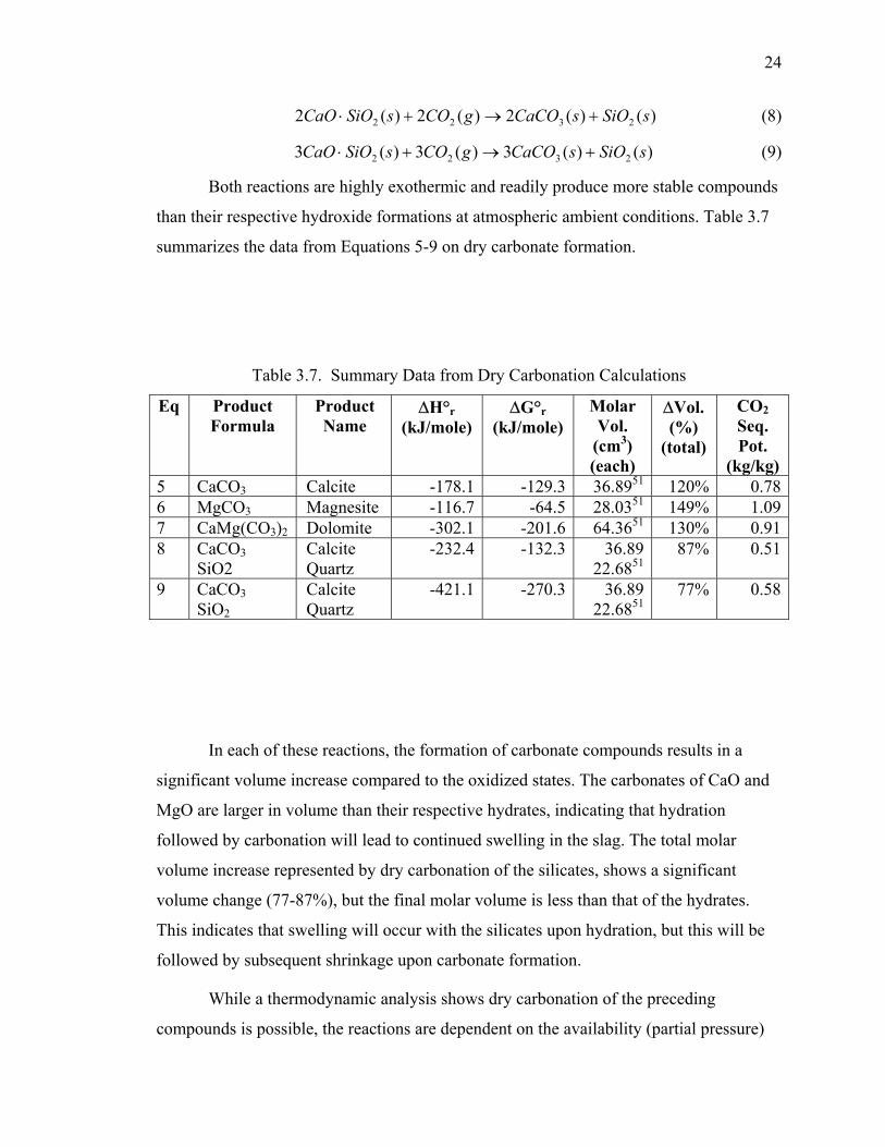
24
)()(2)(2)(2 2322 sSiOsCaCOgCOsSiOCaO +→+⋅ (8)
)()(3)(3)(3 2322 sSiOsCaCOgCOsSiOCaO +→+⋅ (9)
Both reactions are highly exothermic and readily produce more stable compounds
than their respective hydroxide formations at atmospheric ambient conditions. Table 3.7
summarizes the data from Equations 5-9 on dry carbonate formation.
Table 3.7. Summary Data from Dry Carbonation Calculations
Eq Product Formula
Product Name
∆H°r (kJ/mole)
∆G°r (kJ/mole)
Molar Vol.
(cm3) (each)
∆Vol. (%)
(total)
CO2 Seq. Pot.
(kg/kg) 5 CaCO3 Calcite -178.1 -129.3 36.8951 120% 0.786 MgCO3 Magnesite -116.7 -64.5 28.0351 149% 1.097 CaMg(CO3)2 Dolomite -302.1 -201.6 64.3651 130% 0.918 CaCO3
SiO2 Calcite Quartz
-232.4 -132.3 36.89 22.6851
87% 0.51
9 CaCO3 SiO2
Calcite Quartz
-421.1 -270.3 36.89 22.6851
77% 0.58
In each of these reactions, the formation of carbonate compounds results in a
significant volume increase compared to the oxidized states. The carbonates of CaO and
MgO are larger in volume than their respective hydrates, indicating that hydration
followed by carbonation will lead to continued swelling in the slag. The total molar
volume increase represented by dry carbonation of the silicates, shows a significant
volume change (77-87%), but the final molar volume is less than that of the hydrates.
This indicates that swelling will occur with the silicates upon hydration, but this will be
followed by subsequent shrinkage upon carbonate formation.
While a thermodynamic analysis shows dry carbonation of the preceding
compounds is possible, the reactions are dependent on the availability (partial pressure)
25
of CO2, which is low at atmospheric ambient conditions (pCO2~33.4 Pa (3.30x10⁻⁴ atm)).
Research in Finland (Zevenhoven et al.46) is concentrating on dry mineral carbonation
primarily with magnesium oxides and silicates. They concluded that a catalyst will be
required (and possibly elevated temperature and pressure) to achieve reaction rates for
dry carbonation in a reasonable time. The highest reaction rates occurred in the presence
of humid (water saturated) gas. Hydrates should form more readily due to the higher
availability of water in normal ambient air. The partial pressure of water vapor in air
ranges from pH2O=3141 Pa (3.10x10⁻² atm) for saturated air at standard conditions to
pH2O=0.1 MPa (1 atm) when rain falls on the slag. It is anticipated that hydrates will
form more readily, due to availability of water then convert to the more stable carbonate
compounds.
In Equations 5-9, oxides and silicates in the slag are combining with ambient CO2
to form more stable carbonates. The CO2 sequestration potential for each compound
indicates the mass of CO2 captured per mass of reactant (kg CO2/kg reactant). The CO2
sequestration potentials for each compound are listed in Table 3.7. The oxides have a
higher sequestration potential than the silicates, indicating that if the slag cooling can be
controlled to favor more lime and magnesia, then more CO2 can be sequestered per mass
of slag. The CO2 sequestration potential is to grow in proportion to the mineral volume
change associated with carbonation. This indicates a correlation may be obtained between
the slag expansion potential and the CO2 capture amount.
3.4.2.2 Hydrous Carbonate Formation. While dry carbonation can take place,
the most likely scenario for the hydroxide and carbonation reactions to take place
simultaneously. This would be the case for slag exposure to ambient air, which contains
water and CO2. A simplification for understanding is the sequential reaction of hydration
followed by carbonation. In practicality, this may be the case of raw slag that is
submerged in water (e.g. water quench granulation of blast furnace slag), where the
assumption is that due to the small slag particle size, and immediate contact with water
hydration takes place both immediately and to completion. Once the slag is removed
from the quench tank and exposed to air, carbonation can take place. The hydroxides
formed upon quenching are meta-stable in that given time they will sequester CO2 to
form carbonates by the following reactions. Equations 10-14 show the hydroxide to
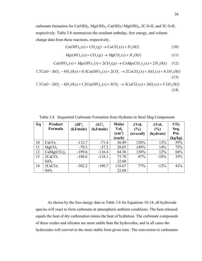
26
carbonate formation for Ca(OH)2, Mg(OH)2, Ca(OH)2+Mg(OH)2, 2C-S-H, and 3C-S-H,
respectively. Table 3.8 summarizes the resultant enthalpy, free energy, and volume
change data from these reactions, respectively.
)()()()()( 2322 lOHsCaCOgCOsOHCa +→+ (10)
)()()()()( 2322 lOHsMgCOgCOsOHMg +→+ (11)
)(2)()()(2)()()()( 223222 lOHsCOCaMggCOsOHMgsOHCa +→++ (12)
)(3.4)()(22)()(3.0)(47.1 2232222 lOHsSiOsCaCOCOsOHCasOHSiOCaO ++→++−− (13)
)(3.5)()(33)()(3.1)(47.1 2232222 lOHsSiOsCaCOCOsOHCasOHSiOCaO ++→++−−(14)
Table 3.8. Sequential Carbonate Formation from Hydrates in Steel Slag Components
Eq Product Formula
∆H°r (kJ/mole)
∆G°r (kJ/mole)
Molar Vol.
(cm3) (each)
∆Vol. (%)
(overall)
∆Vol. (%)
(hydrate)
CO2 Seq. Pot.
(kg/kg) 10 CaCO3 -112.7 -71.4 36.89 120% 12% 59%11 MgCO3 -79.3 -37.2 28.03 149% 14% 75%12 CaMg(CO3)2 -199.6 -116.4 64.36 130% 12% 66%13 2CaCO3
SiO2 -188.6 -118.1 73.78
22.6887% -18% 35%
14 3CaCO3 SiO2
-302.2 -190.7 110.6722.68
77% -12% 41%
As shown by the free energy data in Table 3.8 for Equations 10-14, all hydroxide
species will react to form carbonate at atmospheric ambient conditions. The heat released
equals the heat of dry carbonation minus the heat of hydration. The carbonate compounds
of these oxides and silicates are more stable than the hydroxides, and in all cases the
hydroxides will convert to the more stable form given time. The conversion to carbonates
27
leads to a small volume increase in the case of the oxides, leading to further slag
swelling. The conversion of the silicate hydrates to carbonates leads to a volume
decrease. The competing increase and decrease of hydration and carbonation of the
various components, will lead to cracking of the slag during the stabilization period. The
cracking will produce smaller slag particles (proportional to the amount of oxides and
silicates available to react with water and carbon dioxide), and open new surfaces for
reaction in the slag matrix, thus increasing the overall slag stabilization rate. This is the
phenomena observed by Tsuchiya et al.22 in their slag swelling study. The CO2
sequestration potential is lower for the hydroxide compounds compared to dry
carbonation due to the extra mass of water in each hydroxide. The amount of carbon
dioxide captured for a given mass of slag is thus maximized under dry conditions.
3.4.3. Mineral Modification for Slag Stabilization. An alternative to time-
based hydrate and carbonate stabilization involves modification of the slag mineralogy to
produce phases less susceptible to swelling. Mineralogical modification seeks to
eliminate formation of free lime, which is viewed as the primary source of slag swelling.
Dippenaar lists two alternative methods that eliminate the need for stockpile
stabilization.170 Both methods involve chemical additions to the molten slag to inhibit
precipitation of free lime during solidification upon cooling. The first method (Reeves
and Lu) adds fayalite (Fe2SiO4), and the second method (Hiltunen) injects oxygen and
silica. Further details on each method are not provided.
Sorrentino et al. has researched the mineralogical modifications that occur upon
cooling from addition of silica and alumina to the slag melt.172 Their work is an extension
of an oxidation treatment proposed to stabilize slag. The oxidation treatment injects
oxygen and silica into the molten slag. During oxidation, divalent iron oxide (wustite and
magnesiowustite), and iron metal oxidize to produce Fe2O3. The reaction is exothermic
and produces sufficient energy to dissolve the added silica. Upon crystallization the
added silica combines with free lime to produce calcium silicates, thus eliminating the
free lime.
The experimental work by Sorrentino et al. submitted industrial slag to oxidation
only, oxidation with silica addition, and oxidation with alumina addition. Untreated slag
28
contained a solid solution of dicalcium silicates, magnesiowustite, calcium ferrite, and
free lime (~10%). Oxidation treatment at 1500°C eliminated magnesiowustite to
precipitate magnesium oxide (periclase) and ferric oxide (hematite). The main phases
after oxidation are dicalcium ferrite, formed from the free lime and ferric oxide,
dicalcium silicate solution, and periclase, with the free lime amount dropping to ~1%.
After oxidation with silica addition the main phases are dicalcium silicate surrounded by
a solution of iron oxide and an unidentified eutectoid precipitate. In the case of slag
oxidized with addition of alumina, calcium aluminate, dicalcium silicate, and calcium
ferrite are formed. The free lime amount dropped to less than 0.5%.
29
4. CO2 CAPTURE AND GEOLOGICAL SEQUESTRATION
4.1. OVERVIEW OF CO2 CAPTURE
4.1.1. Implications of CO2 Control in the Steel Industry. The driving factors
for CO2 sequestration are extremely complex and involve political, economic, and
scientific factors. There is uncertainty or disagreement about almost every aspect of the
anthropogenic greenhouse gas theory, and it is extremely unlikely that anyone in
government, or indeed possibly in science, is able to command a comprehensive view of
the whole situation.128 Regardless of personal, corporate, or governmental views of the
anthropogenic greenhouse gas theory, a binding agreement for the industrial countries
was put forward at the world summit in Kyoto, Japan in 1997. This agreement, called the
Kyoto Protocol, proposes the industrial nations to cut their collective emissions of
specific gases (CO2, CH4, NOx, SF6, hydrofluorocarbon’s, and perfluorocarbon’s) by an
average of 5.2% below the 1990 levels by 2012. This agreement came into force
February 2005 and is currently supported by 156 countries.
The industries working in the countries that have signed the Kyoto Protocol have
the responsibility to work within the scope of their respective legislation in reducing
emissions of the gases listed. The iron and steel industry is highly reliant on carbon based
fuels both directly (coke for iron oxide reduction) and indirectly (EAF use of electricity
from coal burning power plant). The emission of CO2 has been targeted most heavily by
the supporting countries, with the net result that the iron and steel industries will need to
make changes in operation and methodology to meet this cutback. Long-term changes
may require the development of carbon-free steelmaking, but that is many years in the
future. Short-term goals can be achieved by reducing the carbon intensity of iron and
steelmaking. These include injecting hydrogen rich fuel in the blast furnace (natural gas
instead of coke), alternative ironmaking technologies (DRI, ITmk3, COREX, etc.),
maximizing scrap recovery and use in steelmaking, and optimizing energy use in all areas
of ferrous processing. Medium-term goals for the iron and steel industry should include
greater industrial symbiosis, such as limestone replacement by slag cement clinker, and
the use of byproduct gas and heat for power generation and industrial heating.128
Permanent sequestration of CO2 from industrial sources is being investigated as a

30
medium to long term option, and if developed properly may provide a commercially
favorable route.
4.1.2. Industrial CO2 Capture (Non-Geological). Carbon dioxide capture from
gaseous streams is a commercial technology, although this technology is not set up for
permanent sequestration CO2. The natural gas industry commonly uses liquid amine
based chemicals (monoethanolamine (MEA) and diethanolamine (DEA)) in a stripping
tower or polymer membranes (polyimide, polyamides, and cellulose acetate) to sweeten
raw natural gas by the removal of carbon dioxide. These technologies operate at high
pressures and large flow rates, but may not optimized for the high temperatures that may
be seen in blast furnace or steelmaking furnace exhaust ducts. Each of these technologies
removes carbon dioxide from the natural gas stream to form a concentrate, but
subsequently exhausts the concentrate to the atmosphere. Permanent sequestration in a
non-gaseous form must be added as a separate process.
Other non-geologic technologies are being researched for use in the steel and
power industries for capture of CO2 from the offgas. Gielen presents the results of a study
using SelexolTM (dimethyl ether of polyethylene glycol made by Union Carbide) to
remove CO2 from blast furnace offgas.120 The estimated capture cost is 16.7-18.8 US$/t
of CO2 for conventional blast furnace (2003 basis), and could reduce Japanese emissions
by 6.5% (80 Mt/yr) if implemented. Solid regenerable carbonates can be used at a
potentially lower cost than liquid amine systems. Work by Green et al.129 and Corti130
with sodium and potassium bicarbonate, and Robertson131 with magnesium carbonate,
shows solid carbonates have a high CO2 capture potential (~80%) with a short cycle (<5
minutes), are easier to regenerate than liquid-amines which require steam stripping to
remove the CO2, and require a small reactor size. As with amine systems, a sequestration
system must be added to this cost of each system to provide permanent disposal of CO2.
4.2. GEOLOGICAL METHODS FOR SEQUESTRATION
Geological sequestration of carbon dioxide is actively being researched as it provides a
permanent disposal source, as opposed to biomass uptake that will eventually release the
captured CO2 again to the atmosphere. The two significant geological bodies available to
permanently capture increased amounts of CO2 from the atmosphere are the oceans and
mineral bodies in the earths crust.
31
Natural neutralization of projected CO2 emissions by marine sediments in ocean
bodies would result in an estimated sequestration of 70-80% of the carbon dioxide;
however, the process may take several centuries to 1500 years to complete.53,62 Injection
of liquefied carbon dioxide into deep ocean zones to eliminate the millennium required
for natural equilibrium is an active research area. Alternatively the liquefied CO2 can be
injected into subterranean formations, as researched by the Pacific Northwest National
Laboratory.169 While these methods greatly speed up the reaction of carbon dioxide with
seawater or geologic formations, they both require technologies for capture, liquefaction,
transport, and injection. To date these methods have proven prohibitively expensive for
common industrial use.
Solid based CO2 sequestration holds great potential for industrial operations, as a
wide variety of minerals are available to form permanent carbonates sinks. The
distribution of the mineral body in relation to the locality of the CO2 generation source
will be the primary cost hurdle. The design of a system that can accomplish a reaction of
the mineral with gaseous CO2 will simplify the unit process by eliminating gas based
capture and liquefaction systems. Transport of the CO2 to the mineral body or of the
prepared mineral to the CO2 source becomes the driving economic factor, providing the
reaction rate is sufficiently fast.
Three classes of mineral carbonate disposal strategies have been proposed.53 The
first approach mimics the natural weathering process whereupon mineral alkalinity
neutralizes carbonic acid. Natural carbonate weathering generates bicarbonates that go
into surface or ground water solution, eventually reporting to the ocean as the final
geological sink. Natural silicate weathering extracts alkalinity (e.g. Ca+ or Mg+) into
surface water, which in turn combines with bicarbonate (HCO3-) in the ocean to
precipitating solid carbonates (e.g. CaCO3 or MgCO3). A strategy to accelerate the two
steps of this process provides a permanent ocean-based disposal of bicarbonate salts. The
second strategy is similar, but the carbonate or bicarbonate brines are injected into an
underground reservoir, as opposed to ocean disposal. The third strategy involves the
formation of solid carbonates for surface or underground disposal. The latter strategy is
most similar to the current research involving slag-CO2 sequestration.

32
4.2.1. Minerals for Solid Carbonate Sequestration. The most common
minerals studied for solid carbonate sequestration are based on the alkali or alkaline earth
metals. Respectively, the base ions are monovalent sodium and potassium, or divalent
calcium and magnesium. Table 4.1 lists many of the potential minerals readily available
for solid carbonate sequestration.
Table 4.1. List of Potential Minerals for Solid Carbonate Sequestration (from Lackner53)
Mineral Chemical Formula
Resource Size (1000 Gt)
Chemical Preprocess
Disposal Form
Lime CaO Synthetic None CaCO3 Brucite Mg(OH)2 Small/Synthetic None MgCO3 Calcium hydroxide
Ca(OH)2 Synthetic None CaCO3
Periclase MgO Small None MgCO3 Wollastonite CaSiO3 Small None CaCO3 Peridotite Extraction of MgO or
Mg(OH)2 MgCO3
Serpentine Mg3Si2O5(OH)4 100,000 Acid dissolution leading to MgO or Mg(OH)2
MgCO3
Olivine (Mg,Fe)2SiO4 100,000 Acid dissolution leading to MgO or Mg(OH)2
MgCO3
Forsterite Mg2SiO4 Pure deposits are very small
Acid dissolution leading to MgO or Mg(OH)2
MgCO3
Potassium feldspar
KAlSi3O8 Very large Dissolution in water or brine K2CO3
Sodium feldspar
NaAlSi3O8 Very large Extraction of sodium alkalinity
Na2CO3
As the disposal source of this study is a solid carbonate, the source of alkaline
ions cannot be a carbonate (which require aqueous discharge), but will most likely be a
silicate mineral rich in magnesium or calcium, thus the bicarbonate forming minerals
listed in Lackner are precluded from Table 4.1. Significant sources of magnesium and
33
calcium silicates are available on all continents, some of which are feasible for use in
industrial systems.53 Magnesium ions can be extracted from serpentine or olivine rock,
and periodite deposits containing these minerals are widespread. Total estimates are
several hundred thousand gigatons. Simple oxide minerals, such as lime, periclase, or
their hydroxides are not readily available in natural mineral form and can only be used
where these compounds are synthetically produced. Weathering of feldspars is a natural
phenomenon that captures CO2, but extraction of sodium and potassium from these
minerals has not been widely studied.
4.2.2. Solid Carbonate Capture Chemistry. Carbon sequestration on a geologic
scale requires neutralization of carbonic acid. Divalent metal oxides or hydroxides (such
as Mg or Ca) would react with carbonic acid as shown in Equations 15-18 as given by
Lackner.53
OHMeCOCOHMeO 2332 +→+ (15)
OHMeCOCOHOHMe 23322 2)( +→+ (16)
OHHCOMeCOHMeO 22332 )(2 +→+ (17)
OHHCOMeCOHOHMe 223322 2)(2)( +→+ (18)
While these equations show the thermodynamic possibility of carbonate capture
with metal oxides and hydroxides, the availability of these minerals are very limited. A
more appropriate route would be direct carbonate formation from the silicates as shown
in Equations 19-20 from Lackner.53
)())(( 223322 SiOmOHMeCOCOHSiOMeO m ++→+ (19)
)()(2))(( 2223322 SiOmOHHCOMeCOHSiOMeO m ++→+ (20)
The formation of a bicarbonate salt in solution allows for the use of carbonate
minerals as shown in Equation 21.
23323 )(HCOMeCOHMeCO →+ (21)
This reaction is shown for academic interest only, as this route produces a
bicarbonate salt requiring aqueous or oceanic disposal, which is counter to the goal of
this research to bind CO2 into a solid slag product. Lackner states that it is easier to
transform carbonates into bicarbonates than it is to drive silicic acid out of its minerals,
34
and that in forming bicarbonates from silicates, only half as much silicate is required
compared to carbonate formation only.53 The first statement is not supported
thermodynamically as, for example, the free energy of formation of the carbonate from
forsterite (Mg2SiO4) is -230.2 kJ/mole, while bicarbonate formation from magnesium
carbonate +221.2 kJ/mole. His observations also suggest that bicarbonates may represent
a more convenient form of sequestration. However, as bicarbonates readily dissolve in
water, they require dilution into the environment. The ocean is large enough to accept the
bicarbonates formed, but the practical and environmental logistics of this route are not
well defined. Solid carbonate formation, however, provides a specific and well-defined
capture method not subject to the same geologic intrusion. The environmental impact
from solid disposal is confined to the smallest possible region.
4.2.3. Thermodynamic Stability. Mineral carbonate formation is a highly
thermodynamically stable route for disposal of carbon dioxide. Solid carbonate formation
is exothermic; thus, it will be difficult to decompose these minerals under natural
atmospheric conditions. Carbon dioxide can be released through a reaction with a strong
acid, such as sulfuric; however, under natural conditions even that produced from burning
sulfur rich coal is insufficient to free sequestered carbon dioxide. Alternatively, carbon
dioxide may be released through natural calcination, which may take place upon mineral
heating through volcanic action. The amount of carbon dioxide released through this
method on a global scale will be very limited. The thermodynamic stability of solid
carbonates eliminates the need for long-term monitoring and continued maintenance of
the disposal site.53
4.2.4. Formation of Solid Carbonates from Natural Minerals. Several
methods are currently being researched to produce a viable large-scale industrial solid
carbonate disposal method. These methods primarily focus on the silicate minerals, with
magnesium ores favored more than calcium ores, as magnesium silicates are usually
more reactive than the calcium silicates. Some work has been done on simple oxides, but
they are less naturally abundant. Cement chemistry can provide valuable insight to
mineral carbonation, as can a study of biological carbonate forming processes. The
information discussed in this section focuses mainly on the carbonation of natural
minerals, which are minerals obtained from ore bodies for the primary purpose of
35
reaction with carbon dioxide. Carbonation of “derived” minerals (industrial co-products
such as slags and ash) will be covered in the section on carbonate formation in
steelmaking slag. The methods researched for carbonation of virgin minerals have a
direct impact on work to do the same with slags, as the chemical reactions are the same.
4.2.4.1 Silicates (Calcium and Magnesium). A consortium managed by the U.S.
Department of Energy – National Energy Technology Laboratory (NETL) has done the
largest amount of work with solid mineral sequestration. This group, comprised of
NETL, Los Alamos National Laboratory, Arizona State University, and Albany Research
Centre (ARC), has extensively researched the mechanisms and applications of using
silicate based minerals for permanent carbon dioxide sequestration. Other groups at the
University of Ohio, University of Pennsylvania, and Helsinki University of Technology
have added to the knowledge of mineral silicate-to-carbonate formation through research
of their own.
Butt, Lackner, and Wendt at Los Alamos National Laboratory have carried out
extensive research on carbon dioxide disposal in carbonate minerals.35,36,63,64 Their initial
research focused on the carbonation of calcium and magnesium silicate minerals. The
reactions are exothermic, therefore chemically stable; however, the main constraint for
cost implementation is the reaction speed. Two approaches were researched to improve
the reaction rate: solid-gas reaction at high-temperature and reactions in aqueous
solutions.
The focus of solid-gas reactions was to determine the maximum temperature for
stable formation of the carbonate from silicate. Calculations were made for a variety of
common minerals to determine the maximum carbonation temperature in an atmosphere
where pCO2=0.1 MPa (0.99 atm). The results are shown in Table 4.2. In all cases the
reaction products are the alkaline earth metal carbonate plus free silicate/aluminate/water,
where applicable.
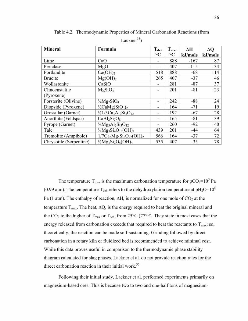
36
Table 4.2. Thermodynamic Properties of Mineral Carbonation Reactions (from
Lackner35)
Mineral Formula Tdeh °C
Tmax °C
∆H kJ/mole
∆Q kJ/mole
Lime CaO - 888 -167 87Periclase MgO - 407 -115 34Portlandite Ca(OH)2 518 888 -68 114Brucite Mg(OH)2 265 407 -37 46Wollastonite CaSiO3 - 281 -87 37Clinoenstatite (Pyroxene)
MgSiO3 - 201 -81 23
Forsterite (Olivine) ½Mg2SiO4 - 242 -88 24Diopside (Pyroxene) ½CaMg(SiO3)2 - 164 -71 19Grossular (Garnet) ⅓1/3Ca3Al2Si3O12 - 192 -67 28Anorthite (Feldspar) CaAl2Si2O8 - 165 -81 39Pyrope (Garnet) ⅓Mg3Al2Si3O12 - 260 -92 40Talc ⅓Mg3Si4O10(OH)2 439 201 -44 64Tremolite (Ampibole) 1/7Ca2Mg5Si8O22(OH)2 566 164 -37 72Chrysotile (Serpentine) ⅓Mg3Si2O5(OH)4 535 407 -35 78
The temperature Tmax is the maximum carbonation temperature for pCO2=105 Pa
(0.99 atm). The temperature Tdeh refers to the dehydroxylation temperature at pH2O=105
Pa (1 atm). The enthalpy of reaction, ∆H, is normalized for one mole of CO2 at the
temperature Tmax. The heat, ∆Q, is the energy required to heat the original mineral and
the CO2 to the higher of Tmax or Tdeh, from 25°C (77°F). They state in most cases that the
energy released from carbonation exceeds that required to heat the reactants to Tmax; so,
theoretically, the reaction can be made self-sustaining. Grinding followed by direct
carbonation in a rotary kiln or fluidized bed is recommended to achieve minimal cost.
While this data proves useful in comparison to the thermodynamic phase stability
diagram calculated for slag phases, Lackner et al. do not provide reaction rates for the
direct carbonation reaction in their initial work.35
Following their initial study, Lackner et al. performed experiments primarily on
magnesium-based ores. This is because two to two and one-half tons of magnesium-
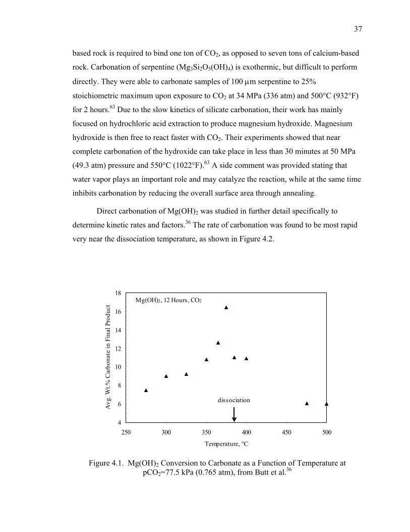
37
based rock is required to bind one ton of CO2, as opposed to seven tons of calcium-based
rock. Carbonation of serpentine (Mg3Si2O5(OH)4) is exothermic, but difficult to perform
directly. They were able to carbonate samples of 100 µm serpentine to 25%
stoichiometric maximum upon exposure to CO2 at 34 MPa (336 atm) and 500°C (932°F)
for 2 hours.63 Due to the slow kinetics of silicate carbonation, their work has mainly
focused on hydrochloric acid extraction to produce magnesium hydroxide. Magnesium
hydroxide is then free to react faster with CO2. Their experiments showed that near
complete carbonation of the hydroxide can take place in less than 30 minutes at 50 MPa
(49.3 atm) pressure and 550°C (1022°F).63 A side comment was provided stating that
water vapor plays an important role and may catalyze the reaction, while at the same time
inhibits carbonation by reducing the overall surface area through annealing.
Direct carbonation of Mg(OH)2 was studied in further detail specifically to
determine kinetic rates and factors.36 The rate of carbonation was found to be most rapid
very near the dissociation temperature, as shown in Figure 4.2.
Figure 4.1. Mg(OH)2 Conversion to Carbonate as a Function of Temperature at pCO2=77.5 kPa (0.765 atm), from Butt et al.36
4
6
8
10
12
14
16
18
250 300 350 400 450 500
Temperature, °C
Avg
. Wt.%
Car
bona
te in
Fin
al P
rodu
ct
dissociation
Mg(OH)2, 12 Hours, CO2
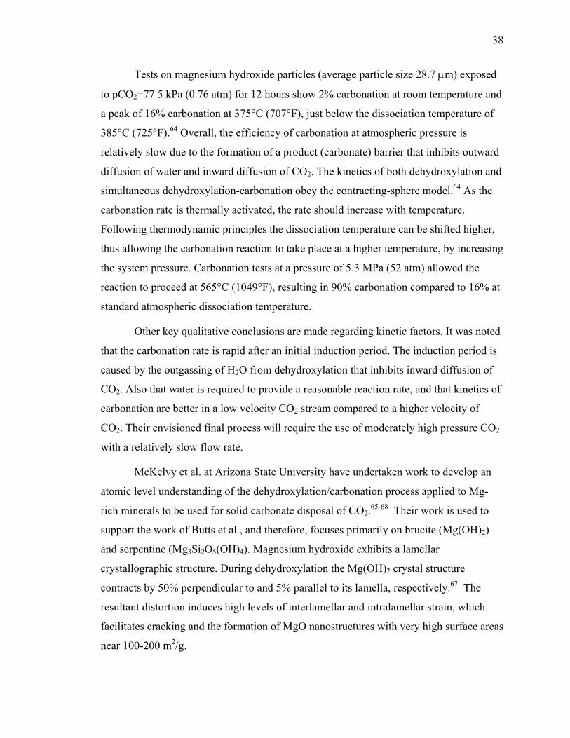
38
Tests on magnesium hydroxide particles (average particle size 28.7 µm) exposed
to pCO2=77.5 kPa (0.76 atm) for 12 hours show 2% carbonation at room temperature and
a peak of 16% carbonation at 375°C (707°F), just below the dissociation temperature of
385°C (725°F).64 Overall, the efficiency of carbonation at atmospheric pressure is
relatively slow due to the formation of a product (carbonate) barrier that inhibits outward
diffusion of water and inward diffusion of CO2. The kinetics of both dehydroxylation and
simultaneous dehydroxylation-carbonation obey the contracting-sphere model.64 As the
carbonation rate is thermally activated, the rate should increase with temperature.
Following thermodynamic principles the dissociation temperature can be shifted higher,
thus allowing the carbonation reaction to take place at a higher temperature, by increasing
the system pressure. Carbonation tests at a pressure of 5.3 MPa (52 atm) allowed the
reaction to proceed at 565°C (1049°F), resulting in 90% carbonation compared to 16% at
standard atmospheric dissociation temperature.
Other key qualitative conclusions are made regarding kinetic factors. It was noted
that the carbonation rate is rapid after an initial induction period. The induction period is
caused by the outgassing of H2O from dehydroxylation that inhibits inward diffusion of
CO2. Also that water is required to provide a reasonable reaction rate, and that kinetics of
carbonation are better in a low velocity CO2 stream compared to a higher velocity of
CO2. Their envisioned final process will require the use of moderately high pressure CO2
with a relatively slow flow rate.
McKelvy et al. at Arizona State University have undertaken work to develop an
atomic level understanding of the dehydroxylation/carbonation process applied to Mg-
rich minerals to be used for solid carbonate disposal of CO2.65-68 Their work is used to
support the work of Butts et al., and therefore, focuses primarily on brucite (Mg(OH)2)
and serpentine (Mg3Si2O5(OH)4). Magnesium hydroxide exhibits a lamellar
crystallographic structure. During dehydroxylation the Mg(OH)2 crystal structure
contracts by 50% perpendicular to and 5% parallel to its lamella, respectively.67 The
resultant distortion induces high levels of interlamellar and intralamellar strain, which
facilitates cracking and the formation of MgO nanostructures with very high surface areas
near 100-200 m2/g.
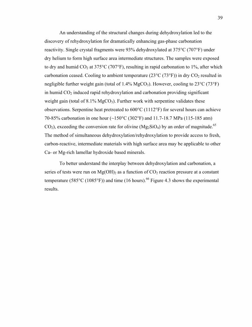
39
An understanding of the structural changes during dehydroxylation led to the
discovery of rehydroxylation for dramatically enhancing gas-phase carbonation
reactivity. Single crystal fragments were 93% dehydroxylated at 375°C (707°F) under
dry helium to form high surface area intermediate structures. The samples were exposed
to dry and humid CO2 at 375°C (707°F), resulting in rapid carbonation to 1%, after which
carbonation ceased. Cooling to ambient temperature (23°C (73°F)) in dry CO2 resulted in
negligible further weight gain (total of 1.4% MgCO3). However, cooling to 23°C (73°F)
in humid CO2 induced rapid rehydroxylation and carbonation providing significant
weight gain (total of 8.1% MgCO3). Further work with serpentine validates these
observations. Serpentine heat pretreated to 600°C (1112°F) for several hours can achieve
70-85% carbonation in one hour (~150°C (302°F) and 11.7-18.7 MPa (115-185 atm)
CO2), exceeding the conversion rate for olivine (Mg2SiO4) by an order of magnitude.65
The method of simultaneous dehydroxylation/rehydroxylation to provide access to fresh,
carbon-reactive, intermediate materials with high surface area may be applicable to other
Ca- or Mg-rich lamellar hydroxide based minerals.
To better understand the interplay between dehydroxylation and carbonation, a
series of tests were run on Mg(OH)2 as a function of CO2 reaction pressure at a constant
temperature (585°C (1085°F)) and time (16 hours).66 Figure 4.3 shows the experimental
results.
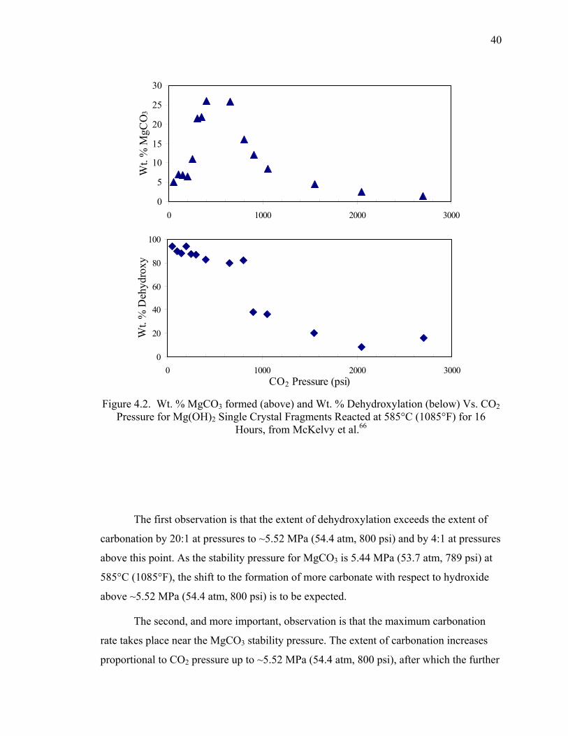
40
Figure 4.2. Wt. % MgCO3 formed (above) and Wt. % Dehydroxylation (below) Vs. CO2 Pressure for Mg(OH)2 Single Crystal Fragments Reacted at 585°C (1085°F) for 16
Hours, from McKelvy et al.66
The first observation is that the extent of dehydroxylation exceeds the extent of
carbonation by 20:1 at pressures to ~5.52 MPa (54.4 atm, 800 psi) and by 4:1 at pressures
above this point. As the stability pressure for MgCO3 is 5.44 MPa (53.7 atm, 789 psi) at
585°C (1085°F), the shift to the formation of more carbonate with respect to hydroxide
above ~5.52 MPa (54.4 atm, 800 psi) is to be expected.
The second, and more important, observation is that the maximum carbonation
rate takes place near the MgCO3 stability pressure. The extent of carbonation increases
proportional to CO2 pressure up to ~5.52 MPa (54.4 atm, 800 psi), after which the further
0
5
10
15
20
25
30
0 1000 2000 3000
Wt.
% M
gCO
3
0
20
40
60
80
100
0 1000 2000 3000CO2 Pressure (psi)
Wt.
% D
ehyd
roxy
41
increase of CO2 pressure decreases the carbonation rate significantly. Investigation
revealed that carbonation was occurring at reaction temperature/pressure in the high-
pressure region, but carbonation took place upon sample cooling in the low-pressure
region (normally samples were cooled ~30 minutes to ambient temperature in a CO2
atmosphere). This was confirmed by quenching and evacuating samples from the high-
and low-pressure regions immediately after reaction. Quenched samples in the high-
pressure region showed the same carbonation as those undergoing normal cooling, while
quenched samples in the low-pressure region showed negligible carbonation. The
extensive dehydroxylation of the samples in the low-pressure region under normal
cooling (80-95%) resulted in formation of high surface area materials produced from
lattice cracking, delamination, and morphological reconstruction. Upon cooling,
substantially enhanced carbonation was exhibited. This phenomenon can be harnessed to
engineer better sequestration materials. The high-pressure decrease in CO2 reactivity is a
result of a passivated carbonate layer slowing diffusion of the water and carbon dioxide
species, combined with a high external CO2 pressure slowing the outgassing of H2O
which is necessary to free up sites for carbonation.
To achieve reaction rates suitable for industrial processes (<1 hr), pretreatment
activation is required for the alkaline-earth-metal-based silicate minerals. Serpentine as a
hydroxide can be activated by dehydroxylation as detailed previously. Olivine (Mg2SiO4)
is hydroxide free and is only susceptible to mechanical activation (via intense grinding).
Olivine is of interest as it is similar to the phases observed in steelmaking slag. McKelvy
et al. studied the mechanism of olivine carbonation under aqueous mineral carbonation.68
Olivine samples (<37 µm) were reacted at 185°C (365°F) with 15.2 MPa (150 atm) CO2
in a solution of 0.64 M NaHCO3 and 1.0 M NaCl at 1000-2000 rpm stirring speeds.
Without pretreatment activation 30-50% carbonation was achieved within one hour.
Conditions such as these are unrealistic for bulk treatment of slag and show the stability
of Mg-silicates even though thermodynamically the carbonation is exothermic.
Field emission scanning electron microscopy and energy dispersive spectroscopy
were used to understand the barrier to rapid carbonation in olivine. An amorphous SiO2
rich passivating layer forms on the olivine surface that is very effective at locally
42
hindering carbonation. The volume contraction from silica formation from olivine can
disrupt and crack the silica-rich surface layer, allowing the carbonation reaction to
proceed, albeit slowly. Mechanical stirring was found to be effective at exfoliating the
cracked silica surface layer thus exposing fresh olivine for carbonation. Particle-particle
and particle-wall interaction are able to abrade the silica surface layer, as found through
studies of slurry-flow dynamics. An order of magnitude increase in carbonation was
observed through the use of a flow-loop compared to a batch reactor. A further ~50%
increase was observed by incorporating flow mixers in the flow-loop. Enhanced
carbonation can be correlated to increased turbulence.
O’Connor et al. at the Albany Research Center (ARC) have been conducting
research to optimize the process conditions for direct aqueous carbonation of silicate
minerals.69-74 The process uses an aqueous slurry of fine particles reacted with CO2 in a
stirred autoclave. The concentration of solids ranges from 15-30 wt.%. Additions of
NaHCO3 and NaCl to the solution were found to improve the reaction rate dramatically.
The bicarbonate ion is not consumed in the reaction, but found to act as a catalyst. The
addition of NaCl may provide a complexing ion (Cl-), which combines with the Mg2+
cations, thus reducing the activity in solution and increasing the solubility from
magnesium silicate.88 Experiments were carried out at elevated temperature and pressure
(155-185°C (311-365°F) and 11.7-18.7 MPa (115-185 atm), respectively). The following
key conclusions can be drawn from the analysis.69
• Conversion of silicate to carbonate requires mineral dissolution into the aqueous
phase. The mineral dissolution reaction is surface controlled.
• The primary mechanism for carbonate formation is precipitation
• Chemically bonded water in serpentine prevents rapid carbonation. Every 1% loss on
ignition amount of material reduces effective carbonation potential by ~7%
• Heat-treated serpentine has 10 times the surface area compared to natural olivine (~70
m2/g versus ~7 m2/g), resulting in the higher reactivity. Olivine pretreatment should
focus on increasing the mineral surface area.
43
Size-by-size analysis showed that a sharp demarcation by particle size exists for
carbonation. More than 99% of the CO2 reported to the <500 mesh (<25 µm) product.
The >25 µm particles are primarily magnesium silicate (>99%) and the <25 µm particles
are primarily magnesite (>75%).
Further work was undertaken to characterize the carbonation process and
determine rate parameters.70 The rate controlling parameter for the direct carbonation of
olivine and serpentine were chemical kinetics and diffusion through the product layer
respectively. The rate constant for direct conversion of olivine is of the order of 10-7
cm/s, while the diffusivity coefficient in serpentine is of the order of 10-10 cm2/s. The
diffusivity value is much lower than that of CO2 into water (2x10⁻⁵ cm2/s), but similar to
helium into silica (2.4-5-5x10⁻¹⁰ cm2/s), suggesting the pores are not filled with water
and/or the process is controlled by the diffusion of other components.
Mechanical agitation, primarily through attrition grinding to less than 10 µm, was
found to be an effective activation method for olivine (non-hydroxide) material.71
Comparison tests were conducted at 15% solids, in a 0.64M NaHCO3 + 1M NaCl
aqueous solution at 155°C (311°F) and pCO2=15.2 MPa (150 atm) for one hour. Standard
feed olivine (<75 µm, no pretreatment) achieved 47% stoichiometric conversion at a rate
of 0.010 gMg/m2/h (grams of Mg converted to carbonate per m2 of surface area per hour
of reaction time). Dry attrition grinding to <10 µm increased the stoichiometric
conversion to 82% and rate to 0.045 gMg/m2/h. Wet attrition grinding further increased
the stoichiometric conversion amount to 100%, but reduced the rate to 0.006 gMg/m2/h.
Activation mechanisms are size reduction to increase surface area (wet grinding) and
destruction of the crystal lattice to form an amorphous material (dry grinding).
The initial work at ARC focused on the use of a batch autoclave to achieve the
high pressure and temperature required for suitable reaction rates.74 Scale-up estimates to
a full size plant revealed the batch autoclave as too costly for industrial use. A high-
pressure high-temperature (HPHT) slurry flow loop reactor was designed to mimic a plug
flow reactor with 100% recycle. The reactor can handle multiphase slurry
(gas/liquid/solid) to 200°C (392°F) and 17.24 MPa (170.1 atm). Carbonation rates
achieved were similar to the batch autoclave for the attrition ground material; however,
44
the coarse mineral feed achieved a much higher extent of reaction. During autoclave
batch testing, <400 mesh (<37 µm) olivine showed an extent of reaction at 4.2%, where
in the HPHT flow loop, an extent of 72.0% was shown. In addition, coarser feed at <200
mesh (<75 µm) achieved 67-78% extent of reaction. It is thought that the turbulent
environment in the slurry reactor resulted in high particle-to-particle interaction, therefore
continually exposing fresh surfaces to reaction.
Park et al. at the University of Ohio investigated carbonation of olivine and
serpentine similar to the work of O’Connor et al.75 Direct (dry) carbonation on <125 µm
particles of olivine, serpentine, and magnesia was carried out in pure CO2 for 24 hours at
350°C (662°F) and total pressure from 0.1-2.5 MPa (1-25 atm). Quantitative data is not
provided, but the discussion states that the degree of direct carbonation was negligible for
all materials. Surface area measurements from BET analysis showed the presence of
micropores between 20-50 Å. It was suggested that the pores were plugging up very fast
at the beginning of the reaction resulting in a low carbonate conversion. Aqueous
carbonation studied were carried out from 100-200°C (212-392°F), 1.5-2.5 MPa (15-25
atm), and 2-10 wt.% solids, with NaHCO3 and NaCl additives. Again, quantitative results
are not given; however, qualitatively increasing temperature and pressure increased
carbonation rate, as did increasing NaHCO3 concentration to1M and NaCl concentration
to 2M.
Kutcha et al. at the University of Pennsylvania investigated the activation of
serpentine minerals for enhanced CO2 sequestration.76,80 Focusing on various chemical
and mechanical means for activation, he was able to demonstrate that the surface area of
raw serpentine, which is ~8m2/g, can be increased to >330 m2/g. The pretreatment routes
studied include particle comminution, magnetic separation, acid treatment, and HCl
extraction. The extent of carbonation is significantly affected by particle size. Under
identical test conditions, olivine particles in the 106-150 µm size range achieved 10.6%
conversion, while particles <37 µm achieved 91.5% conversion. Magnetic separation was
undertaken to remove the magnetite fraction from serpentine after grinding (to <37 µm).
During heat treatment in air, magnetite naturally present in serpentine will oxidize to
form hematite that forms a passive layer on the mineral surface and inhibits carbonation.
45
Magnetite removal did not increase carbonation conversion, but allowed the serpentine to
be pre-heated in air, as opposed to a CO2 non-oxidizing environment, thus simplifying
the pretreatment process. Heat treatment results were similar to those presented earlier by
McKelvy et al. Acid pre-treatment was conducted with HNO3, H2SO4, HCl, and a
combination of orthophosphoric acid, oxalic acid, and EDTA. Sulfuric acid proved the
most effective acid for chemical activation, resulting in a surface area >330 m2/g.
However, all acids extracted Mg2+ from serpentine, therefore reducing the sequestration
potential of the solid mineral. Molten salt extraction was studied using HCl to extract
magnesium to a hydrated magnesium chloride which can be used to produce magnesium
hydroxide. The process is energy and chemical intensive.
Zevenhoven et al. at Helsinki University of Technology has also focused on the
capture of CO2 emissions through direct dry mineral carbonation of magnesium silicate
minerals.46 Their approach is to optimize the kinetics of dry carbonation from serpentine
or olivine in order to simplify the process (compared to a wet chemistry route). Tests on
50 µm particles of serpentine at 200°C (392°F) for 3 hours at 0.1 MPa (0.99 atm) and 1.5
MPa (14.8 atm) in N2/CO2 dry and wet gas mixtures showed no measurable carbonation.
Heating the same serpentine to 1000°C (1832°F) for 10 minutes then cooling to 200°C
(392°F) in a N2/CO2 dry atmosphere at 0.1 MPa (0.99 atm) also resulted in no measurable
carbonation. Tests on 20 µm pure Mg(OH)2 involved heating to 1000°C (1832°F) for 10
minutes, followed by cooling at 10°C/min to 200°C (392°F) at 0.1 MPa (0.99 atm) in
various atmospheres of N2, CO2, O2, and H2O. All tests showed a conversion to MgCO3,
at an increasing rate below 300°C (572°F). A catalytic effect of water in the gas stream
was seen on the carbonation amount, and no influence of oxygen content could be
discerned.
A theoretical kinetic model was setup and applied to the results obtained. The
forward rate constant (k+) can be expressed by Equation 22.
RTE
p
act
ekdtdX
KXZpCOX
k−
+ =⋅
−−= 0
2)1(
β (22)
46
Where β is the heating rate (°K/s), X is the fractional conversion of MgO to
MgCO3, pCO2 is the partial pressure of CO2 (bar), Z is the molar mass ratio
MMgCO3/MMgO (2.0918), Kp is the equilibrium constant, dX/dt is the change of conversion
X with time t, R is the gas constant, and T is the temperature (°K). The Arrhenius
constant parameters k0 and Eact must be calculated for each test. The equilibrium constant
(Kp) can be obtained from Equation 23 relating the temperature (°K) and partial pressure
of CO2.
2ln219.2011839ln pCOT
K p −=−= (23)
Equation 23 was applied to the test results to determine the effect of temperature
on the rate constant. Each test condition resulted in an increase in rate constant up to
~320°C (608°F), then a rate decrease with increasing temperature. The temperature of
320°C (608°F) was identified as the turnover temperature, and corresponds to the
maximum thermodynamic stability temperature given by Equation 24.
Further tests were undertaken to determine the effect of solid and gaseous
catalysts, as well as operating pressure. Separate tests were conducting with 1 wt.%
NaCl, NaHCO3, or Al2O3 mixed into the Mg(OH)2, and 500 PPM (vol.) SO2 mixed into
the gas phase. Following the same heat-up and cooling pattern of the previous tests, no
discernable effect of these catalytic materials on carbonation rate was observed. The
effect of pressure at 1.5 or 2.5 MPa (14.8 or 19.7 atm) total could not be accurately
quantified due to competing dehydroxylation and carbonation reactions and limitations of
the testing apparatus.
Teir et al. also at the Helsinki University of Technology studied the production of
precipitated calcium carbonate (PCC) in the Finnish paper industry as a model for carbon
dioxide sequestration using calcium silicate based minerals.77-78 Calcium carbonate is
produced in the paper industry as a filler and coating, and is produced by reacting lime
with exhaust gas. The synthetic calcium carbonate has a higher purity than natural
limestone due to purification during processing. The production of lime releases CO2
from calcining and combustion heating; therefore, even though the subsequent
sequestration from exhaust gas reduces CO2 emissions; the net process is a CO2

47
generator. If PCC can be produced from calcium silicate (e.g. wollastonite), the
production of CO2 can be significantly reduced.
PCC is primarily produced through carbonation of slaked lime. Limestone is
calcined at 1000˚C (1832°F) produced dry CaO. The dry lime is mixed with water at 30-
50˚C (86-122°F) to form a slurry at 20 weight %. The slurry is screened to remove
impurities from the original limestone. A high shear mixer maintains suspension of the
slurry in a stirred tank reactor where it is reacted with CO2 from an exhaust gas source
(after scrubbing). The particle size, shape, and surface properties of the PCC are
controlled through the carbonation temperature. The pH of the lime slurry is near 12 at
the beginning of the process but drops to approximately eight at equilibrium. The reaction
rate is greater with increasing pressure, and the PCC reactors normally operate at 0.2-0.3
MPa (2.0-3.0 atm).
Wollastonite was investigated in a process model as an alternative feedstock to
the production of PCC to calculate the net CO2 reduction. The chemical composition of
pure wollastonite is CaSiO3, and it is normally found with limestone deposits. A review
of published research was undertaken to ascertain the most promising methods for the
process modeling. Direct dry and aqueous carbonation of wollastonite has been tested at
25°C (77°F) and atmospheric pressure for 0-600 hours and found to be too slow for
further investigation. Indirect carbonation with hydrochloric or acetic acid, where the
acid is used to extract Ca2+ ions for subsequent reaction with CO2, was selected for
further study. The carbonation of wollastonite in a batch autoclave was studied by the
Albany Research Center. Carbonate conversion of 70% could be achieved, but required
attrition grinding to 2-4 µm and a high pressure high temperature batch reactor (185°C
(365°F) and 15.2 MPa (150 atm)), followed by separation from the SiO2. This process
was discarded from further study due to complexity. A detailed process model was setup
with Aspen Plus 12.1® and Outokumpu HSC-4 software for the standard PCC process in
comparison to acid extraction. Using the acetic acid process, a net 0.34 t CO2 could be
sequestered per ton of PCC produced; however, the processing cost is several times
higher than sales of the CO2 emissions credits would return, notwithstanding the fact that
three to five times more rock would have to be mined and transported, which was not
48
taken into account in the process model. Naturally occurring calcium silicates do not
represent a feasible source for industrial carbonate fixation.
4.2.4.2 Oxides (Calcium and Magnesium). The simple oxides of calcium and
magnesium are more effective for sequestering carbon dioxide than their respective
silicates, however due to their high reactivity they are rarely found in nature. These
oxides do occur in slag, and work by researchers in Spain on the natural form of these
minerals is valuable for better understanding sequestration of carbon dioxide in slag.
Abanades et al. at the Instituto de Carboquímica (CSIC) in Spain have done
extensive research on the use of CaO as a sorbent to capture CO2 from industrial
combustion processes, primarily for large-scale power generation systems54-60. His work
is partially funded by the European Coal and Steel Community (7220-PR-125). This
work has focused on the characteristics of CaO to serve as a regenerative sorbent, and the
design of a fluidized bed capture system to effectively use this sorbent. The reaction of
carbon dioxide with lime is very simple and proceeds strongly exothermically as detailed
previously. The equilibrium limit in terms of CO2 capture efficiency from gas phase in a
lime carbonation-calcination reaction is shown by the reaction in Equation 24, where T is
expressed in °K55. This equation was developed from data by Baker.61
)19130exp(10462.1 11
,2 TTxC eqCO
−= (24)
The work by Abanades et al. has focused on a reactor operating at 650°C
(1202°F) and atmospheric pressure. Using coal combustion flue gases at 12-15 vol. %
CO2 capture efficiencies higher than 90% have been exhibited. Although the initial
capture rates of CO2 are high, the regenerative performance of CaO as a sorbent drops
rapidly upon cycling through the carbonation-calcination process as shown in Figure 4.1.
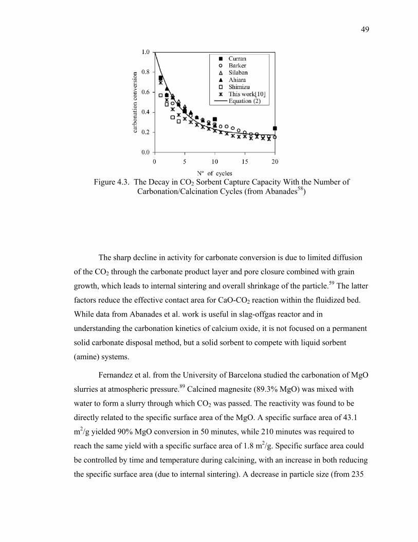
49
Figure 4.3. The Decay in CO2 Sorbent Capture Capacity With the Number of Carbonation/Calcination Cycles (from Abanades58)
The sharp decline in activity for carbonate conversion is due to limited diffusion
of the CO2 through the carbonate product layer and pore closure combined with grain
growth, which leads to internal sintering and overall shrinkage of the particle.59 The latter
factors reduce the effective contact area for CaO-CO2 reaction within the fluidized bed.
While data from Abanades et al. work is useful in slag-offgas reactor and in
understanding the carbonation kinetics of calcium oxide, it is not focused on a permanent
solid carbonate disposal method, but a solid sorbent to compete with liquid sorbent
(amine) systems.
Fernandez et al. from the University of Barcelona studied the carbonation of MgO
slurries at atmospheric pressure.89 Calcined magnesite (89.3% MgO) was mixed with
water to form a slurry through which CO2 was passed. The reactivity was found to be
directly related to the specific surface area of the MgO. A specific surface area of 43.1
m2/g yielded 90% MgO conversion in 50 minutes, while 210 minutes was required to
reach the same yield with a specific surface area of 1.8 m2/g. Specific surface area could
be controlled by time and temperature during calcining, with an increase in both reducing
the specific surface area (due to internal sintering). A decrease in particle size (from 235

50
µm to 40 µm), increase in CO2 partial pressure (from 0.05 to 0.1 MPa (0.5 to 1.0 atm)),
increase in solid-liquid ratio (5-50 g/l), increase in CO2 flow rate (90-690 cm3/min), and
increase in temperature (5-45°C (41-113°F)) were all beneficial in speeding up the
reaction rate. The kinetic relation expressed by Equation 25 was found to be valid for
MgO slurry carbonation for the first 10 minutes.
ktX MgO =−− 31
)1(1 (25)
XMgO is the fraction carbonated; k is the rate constant (min-1), and t is time (min).
A plot of the rate constant versus temperature yields an activation energy of 29.1 kJ/mol.
Studies of the reaction mechanisms indicate that the process is mixing controlled and
chemical reaction controlled, with reaction of the magnesium carbonate on the particle
surface with CO2 to form magnesium bicarbonate as the rate-determining step.
4.2.4.3 Cement Minerals. A study of cement can provide valuable insight to slag
carbonation, as they have many of the same mineral phases. Cement and slag both
contain calcium silicates, calcium aluminates, and calcium ferrites. While cement
chemists are primarily concerned with the hydraulic activity of these phases, work has
been undertaken to understand long-term carbonate formation and the corresponding
structural and physical changes that take place.
Berger et al. studied the carbonation of calcium silicates and calcium aluminates
in their research of cement chemistry.81-86 Even though this work was undertaken for
accelerated curing of cement, the chemistry involved pertains directly to geological CO2
sequestration. Initial work tested the compressive strength of pure cement minerals
carbonated after hydration. Pure Ca3SiO5, β-Ca2SiO4, Ca3Al2O6, and C12Al14O33, were
mixed with water at 92 wt.% solids for five minutes then compacted to 5.86 MPa (57.8
atm) in a cylinder and exposed to CO2 at 0.39 MPa (3.8 atm) for five minutes. The
Ca3SiO5 and β-Ca2SiO4 minerals produced an appreciable temperature rise upon reaction
and the resultant strength was similar to standard cement. The aluminate samples showed
no appreciable temperature rise or increase in strength from carbonation.
The carbonation of tricalcium and β-dicalcium silicate was studied further to
understand the process chemistry. Powdered Ca3SiO5 (3300 cm2/g) and β-Ca2SiO4 (4500
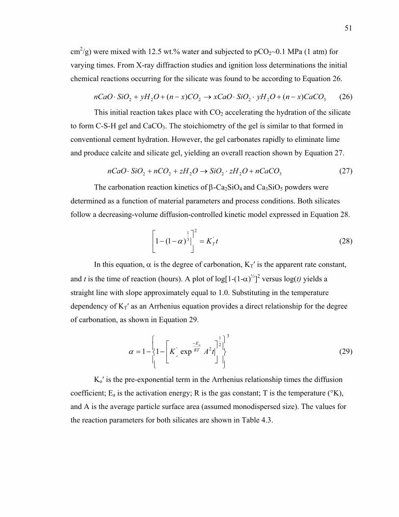
51
cm2/g) were mixed with 12.5 wt.% water and subjected to pCO2~0.1 MPa (1 atm) for
varying times. From X-ray diffraction studies and ignition loss determinations the initial
chemical reactions occurring for the silicate was found to be according to Equation 26.
322222 )()( CaCOxnOyHSiOxCaOCOxnOyHSiOnCaO −+⋅⋅→−++⋅ (26)
This initial reaction takes place with CO2 accelerating the hydration of the silicate
to form C-S-H gel and CaCO3. The stoichiometry of the gel is similar to that formed in
conventional cement hydration. However, the gel carbonates rapidly to eliminate lime
and produce calcite and silicate gel, yielding an overall reaction shown by Equation 27.
322222 nCaCOOzHSiOOzHnCOSiOnCaO +⋅→++⋅ (27)
The carbonation reaction kinetics of β-Ca2SiO4 and Ca3SiO5 powders were
determined as a function of material parameters and process conditions. Both silicates
follow a decreasing-volume diffusion-controlled kinetic model expressed in Equation 28.
tKT'
2
31
)1(1 =
−− α (28)
In this equation, α is the degree of carbonation, KT′ is the apparent rate constant,
and t is the time of reaction (hours). A plot of log[1-(1-α)⅓]2 versus log(t) yields a
straight line with slope approximately equal to 1.0. Substituting in the temperature
dependency of KT′ as an Arrhenius equation provides a direct relationship for the degree
of carbonation, as shown in Equation 29.
3
21
2' exp11
−−=
−
tAK RTEa
oα (29)
Ko′ is the pre-exponential term in the Arrhenius relationship times the diffusion
coefficient; Ea is the activation energy; R is the gas constant; T is the temperature (°K),
and A is the average particle surface area (assumed monodispersed size). The values for
the reaction parameters for both silicates are shown in Table 4.3.
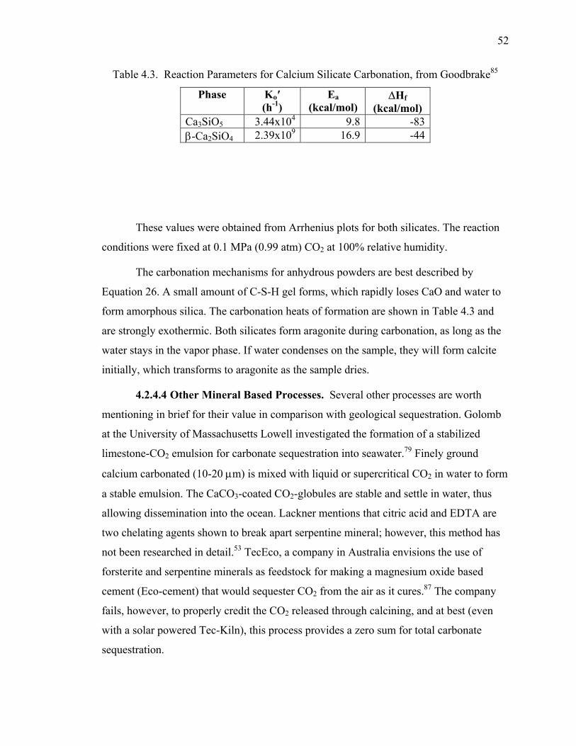
52
Table 4.3. Reaction Parameters for Calcium Silicate Carbonation, from Goodbrake85
Phase Ko′ (h-1)
Ea (kcal/mol)
∆Hf (kcal/mol)
Ca3SiO5 3.44x10⁴ 9.8 -83 β-Ca2SiO4 2.39x10⁹ 16.9 -44
These values were obtained from Arrhenius plots for both silicates. The reaction
conditions were fixed at 0.1 MPa (0.99 atm) CO2 at 100% relative humidity.
The carbonation mechanisms for anhydrous powders are best described by
Equation 26. A small amount of C-S-H gel forms, which rapidly loses CaO and water to
form amorphous silica. The carbonation heats of formation are shown in Table 4.3 and
are strongly exothermic. Both silicates form aragonite during carbonation, as long as the
water stays in the vapor phase. If water condenses on the sample, they will form calcite
initially, which transforms to aragonite as the sample dries.
4.2.4.4 Other Mineral Based Processes. Several other processes are worth
mentioning in brief for their value in comparison with geological sequestration. Golomb
at the University of Massachusetts Lowell investigated the formation of a stabilized
limestone-CO2 emulsion for carbonate sequestration into seawater.79 Finely ground
calcium carbonated (10-20 µm) is mixed with liquid or supercritical CO2 in water to form
a stable emulsion. The CaCO3-coated CO2-globules are stable and settle in water, thus
allowing dissemination into the ocean. Lackner mentions that citric acid and EDTA are
two chelating agents shown to break apart serpentine mineral; however, this method has
not been researched in detail.53 TecEco, a company in Australia envisions the use of
forsterite and serpentine minerals as feedstock for making a magnesium oxide based
cement (Eco-cement) that would sequester CO2 from the air as it cures.87 The company
fails, however, to properly credit the CO2 released through calcining, and at best (even
with a solar powered Tec-Kiln), this process provides a zero sum for total carbonate
sequestration.
53
4.2.4.5 Biomimetic Processes. Several biological processes form calcium
carbonate from (dissolved) calcium oxide. These processes (e.g. shellfish exoskeletons)
use a natural catalyst to increase the formation rate compared to a geologic process. The
use of carbonic anhydrase catalyst to mimic the biological process (biomimetic) for
industrial scale carbon dioxide sequestration has been proposed by Bond, Medina, and
Simsek-Ege.163-166 Carbonic anhydrase, a zinc metalloenzyme, increases the hydration of
CO2 to form carbonic acid, which is defined as the rate-limiting step of the fixation of
carbon dioxide into calcium carbonate in aqueous solution. The overall objective of their
research is to develop an industrial CO2 scrubber using carbonic anhydrase to catalyze
the rate of CO2 hydration for subsequent fixation into stable mineral carbonates. Bovine
carbonic anhydrase (BCA) was tested in a laboratory scale exhaust-seawater contactor
and found to reduce the time for calcium carbonate precipitation from 20 minutes to less
than 10 seconds. This process was repeated 15 times with the same catalyst (BCA
immobilized on alginate beads) and exhibited less than 1% loss in experimental yield.
BCA was also found to be stable to 70°C and resistant to SOx and NOx inhibition at
levels expected in normal power plant exhaust gas.
54
5. OFFGAS GAS CO2 SEQUESTRATION IN SLAG
5.1. CO2 EMISSIONS IN STEELMAKING
The primary direct source of carbon dioxide emissions in the steel industry is the
production of iron followed by the production of steel. Traditional ironmaking
technology, based on blast furnace production, is a large producer of CO2 emissions. To
achieve a net reduction in carbon dioxide emissions, three different areas are being
investigated for the iron and steel making industries: energy conservation, alternative iron
and steel making technologies, and CO2 sequestration. These three areas are listed in
order of immediate effectiveness and cost impact. Energy conservation can be
implemented immediately in all plants, and both reduces the net amount of CO2
generated (directly and indirectly) and results in a cost reduction to the manufacturing
plant. Many alternative iron and steel making technologies are available or in
development. Most focus on cost reduction for the production of iron and steel, primarily
through energy or material requirement reductions. A serendipitous side benefit is the
reduction in energy or raw material correlate to a reduction in CO2 generation. Both the
energy conservation and alternative production technology areas will provide the bulk of
CO2 reduction in the iron and steelmaking industries. Sequestration technologies will
provide a direct reduction in CO2 emissions, but generally do not provide a direct
commercial benefit to the steel producer at the present time. If CO2 regulations develop
to the point where emission credits are bought and sold, the cost-benefit of installing a
sequestration technology versus emissions penalty will be undertaken. This section will
primarily focus on carbon dioxide emissions from steelmaking (BOF, EAF, and other),
which is reflected in the data presented subsequently.
5.1.1. Amounts. Carbon dioxide production in the steel industry has been well
studied both by geographic region and technology, mainly to establish a baseline amount
for meeting future regulations.
Research by Stubbles research in 2001 shows the historical trends of U.S.
domestic steel production, energy use, and CO2 emissions.110 Advances in technology,
such as replacement of OH production with BOF and EAF, mini-mills, continuous
casting, and thin slab casting have reduced U.S. steel industry required energy per ton
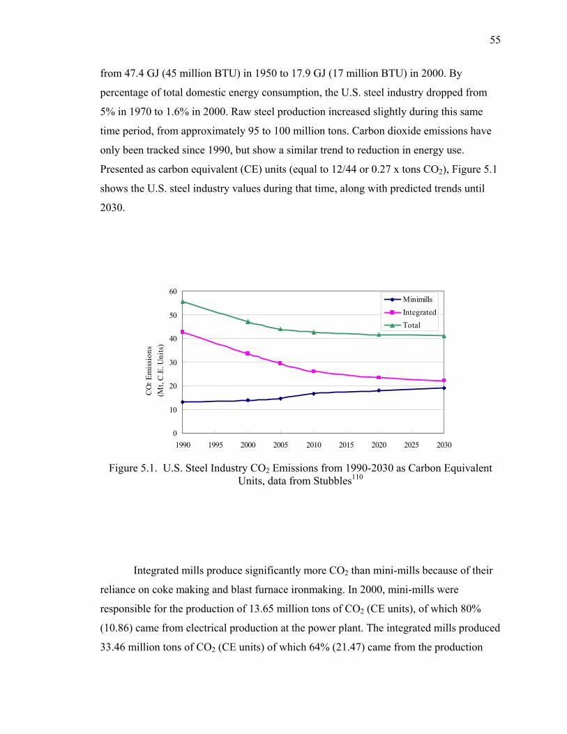
55
from 47.4 GJ (45 million BTU) in 1950 to 17.9 GJ (17 million BTU) in 2000. By
percentage of total domestic energy consumption, the U.S. steel industry dropped from
5% in 1970 to 1.6% in 2000. Raw steel production increased slightly during this same
time period, from approximately 95 to 100 million tons. Carbon dioxide emissions have
only been tracked since 1990, but show a similar trend to reduction in energy use.
Presented as carbon equivalent (CE) units (equal to 12/44 or 0.27 x tons CO2), Figure 5.1
shows the U.S. steel industry values during that time, along with predicted trends until
2030.
Figure 5.1. U.S. Steel Industry CO2 Emissions from 1990-2030 as Carbon Equivalent Units, data from Stubbles110
Integrated mills produce significantly more CO2 than mini-mills because of their
reliance on coke making and blast furnace ironmaking. In 2000, mini-mills were
responsible for the production of 13.65 million tons of CO2 (CE units), of which 80%
(10.86) came from electrical production at the power plant. The integrated mills produced
33.46 million tons of CO2 (CE units) of which 64% (21.47) came from the production
0
10
20
30
40
50
60
1990 1995 2000 2005 2010 2015 2020 2025 2030
CO2
Em
issi
ons
(Mt,
C.E
. Uni
ts)
MinimillsIntegratedTotal
56
and use of coke. Based on the 2000 steel production rate, the steel industry on an average
produced ~0.4 carbon equivalent tons of CO2 per ton of steel shipped. Reduction in
electrical use in the mini-mill and reduction of coke production/use in the integrated mill
represent the largest factor that can affect CO2 generation in these types of plants,
respectively.
On a domestic and global scale, steel industry production represents only a small
fraction of anthropomorphic CO2 emissions. The U.S. steel CO2 emissions in 2000 was
43 million metric tons (CE units), which ranks as 2.9% of the U.S. total output (1500
million tons) and 0.6% of the world output (7000 million tons). Even the total world
anthropomorphic output of 7 billion tons (CE units) is but a small fraction of the natural
amount produced, which is estimated at 190 billion tons annually. Most of the CO2
produced annually (total) is taken up by the oceans or biomass. An estimated net positive
2-3 billion tons per year is being added to the 750 billion tons in atmospheric storage.110
Worrell et al. has also evaluated the U.S. domestic steel industry for the purpose
of identifying energy and carbon dioxide emission reduction opportunities.111 A
comparison can be made using the data for iron and steelmaking only (part of Worrell’s
data set includes ferroalloy and ferrous foundry productions). In 1994, the primary energy
used for integrated steelmaking was about three times greater than that used in secondary
steelmaking (1439 PJ compared to 425 PJ). The energy intensity, expressed as energy per
metric ton of steel produced, of production was 26.0 GJ/t and 11.8 GJ/t, respectively, for
the integrated and secondary route. The total sector primary energy intensity is 20.4 GJ/t
for 1994, which compares favorably to 20.9 GJ/t from Stubbles estimate. Total carbon
dioxide emissions from steelmaking in 1994 were 34.4 million metric tons CE, which is
27% less than Stubbles estimate of 47.2 million metric tons CE (52 million short tons).
Carbon dioxide emission intensity for the whole steelmaking sector averaged 0.38 tons
CE per ton steel produced, which compares to about 0.52 tons CE per ton steel produced.
Afonin provides similar data for the steelmaking sector in Russia.113 Based on
1998 data, the total CO2 emissions from the integrated steelmaking sector stand at 48.6
million tons carbon equivalent, which is 8.5% of all Russian CO2 emissions. On an
intensity basis, this equals 1.4 tons CE per ton steel produced. Russia produces more CO2
57
emissions than the U.S. (total tons equivalent) in steelmaking, but produces about one-
third the amount of steel, which accounts for the higher CO2 intensity output.
Birat et al. has studied iron and steelmaking in the French and European sectors to
understand the best CO2 mitigation route.114-118 In 1989, the French steel industry
produced a total of 26.3 million metric tons CO2 total, at an intensity of 0.42 tons CE per
ton steel, based on integrated steelmaking. This is comparable to U.S. emission rates of
2000. By 1994, the CO2 intensity had dropped to 0.40 tons CE per ton steel, which is
approaching the theoretical limit. France has an extremely low CO2 emission rate of 0.03
tons CO2 per ton steel based on EAF with 100% scrap due to their high reliance on
nuclear power. Recycling is being researched as the most powerful method of reducing
CO2 emissions for the material community as a whole. This includes use of the steel in
the EAF and use of the slag to offset limestone used in cement production.
Carbon dioxide generation data from the steel industries of other countries has not
been studied as in-depth, but some information is available from the literature. Holappa
reports data from Finnish ironmaking that can be used to estimate the carbon dioxide
intensity for that region, which is approximately 0.53 tons CE per ton steel for integrated
steelmaking.118 Data from Emi119 and Gielen120 show the 2005 carbon intensity rate for
Japanese integrated steelmaking is 0.46 tons CE per ton steel.
Anderson et al. reported the results of a thorough study comparing the carbon
dioxide emissions and energy requirements for 30 different steelmaking routes.121 To the
BF/BOF baseline of 89% hot metal/11% scrap, they have compared standard
ironmaking/steelmaking (DRI/EAF) and alternative iron sources/steelmaking routes, such
as FASTMET, FASTEEL, ITmk3, COREX, and HIsmelt. The amount of material from
alternative iron sources was compared at 80%, 50%, and 30%. The carbon dioxide
emission data from this publication is shown in Figure 5.2. This data was published in
2002.
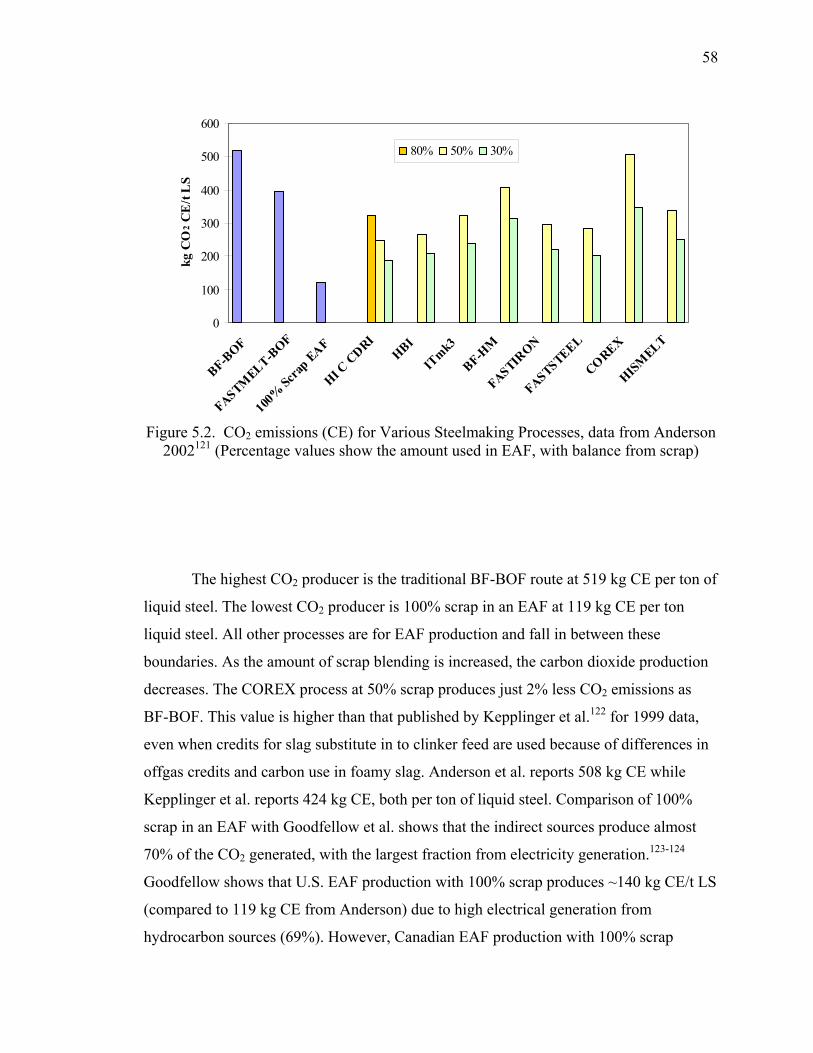
58
Figure 5.2. CO2 emissions (CE) for Various Steelmaking Processes, data from Anderson 2002121 (Percentage values show the amount used in EAF, with balance from scrap)
The highest CO2 producer is the traditional BF-BOF route at 519 kg CE per ton of
liquid steel. The lowest CO2 producer is 100% scrap in an EAF at 119 kg CE per ton
liquid steel. All other processes are for EAF production and fall in between these
boundaries. As the amount of scrap blending is increased, the carbon dioxide production
decreases. The COREX process at 50% scrap produces just 2% less CO2 emissions as
BF-BOF. This value is higher than that published by Kepplinger et al.122 for 1999 data,
even when credits for slag substitute in to clinker feed are used because of differences in
offgas credits and carbon use in foamy slag. Anderson et al. reports 508 kg CE while
Kepplinger et al. reports 424 kg CE, both per ton of liquid steel. Comparison of 100%
scrap in an EAF with Goodfellow et al. shows that the indirect sources produce almost
70% of the CO2 generated, with the largest fraction from electricity generation.123-124
Goodfellow shows that U.S. EAF production with 100% scrap produces ~140 kg CE/t LS
(compared to 119 kg CE from Anderson) due to high electrical generation from
hydrocarbon sources (69%). However, Canadian EAF production with 100% scrap
0
100
200
300
400
500
600
BF-BOF
FASTMELT-B
OF
100%
Scrap EAF
HI C CDRI
HBI
ITmk3
BF-HM
FASTIRON
FASTSTEEL
COREX
HISMELT
kg C
O2 C
E/t
LS
80% 50% 30%
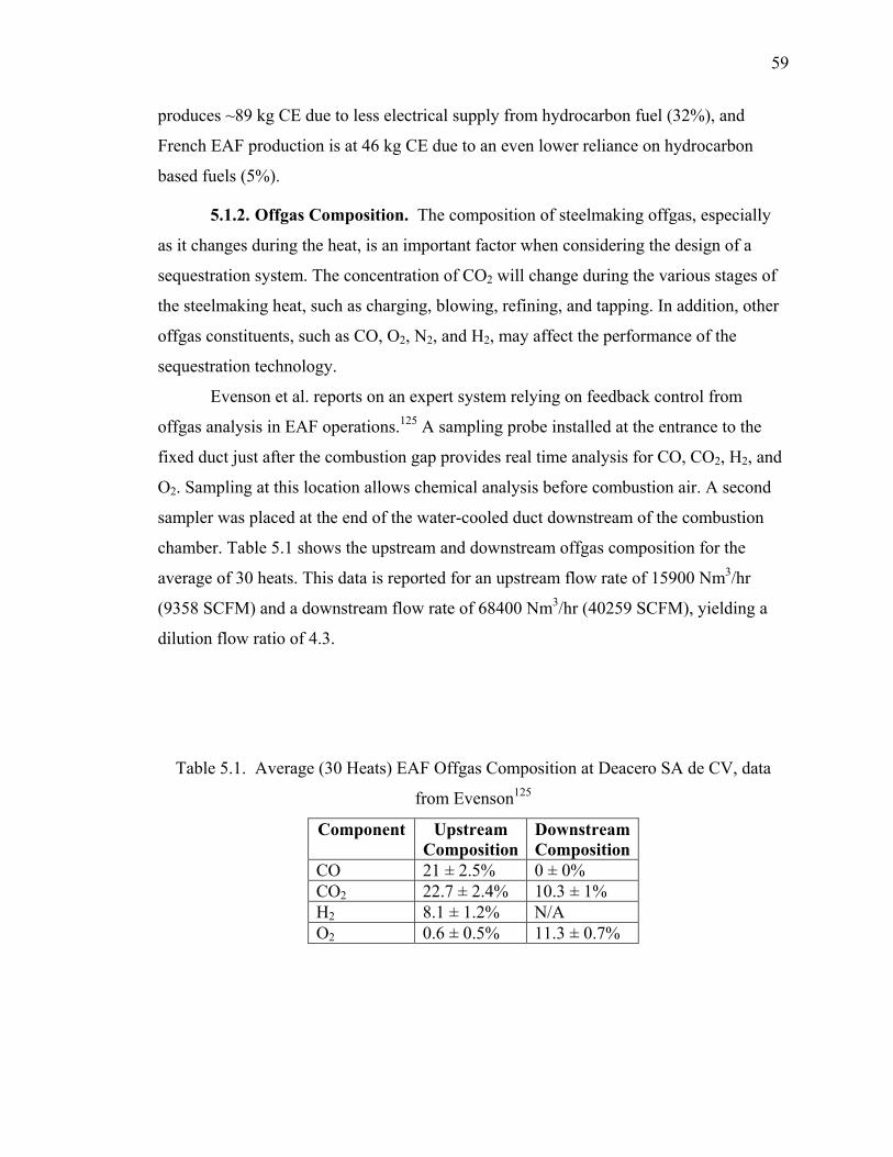
59
produces ~89 kg CE due to less electrical supply from hydrocarbon fuel (32%), and
French EAF production is at 46 kg CE due to an even lower reliance on hydrocarbon
based fuels (5%).
5.1.2. Offgas Composition. The composition of steelmaking offgas, especially
as it changes during the heat, is an important factor when considering the design of a
sequestration system. The concentration of CO2 will change during the various stages of
the steelmaking heat, such as charging, blowing, refining, and tapping. In addition, other
offgas constituents, such as CO, O2, N2, and H2, may affect the performance of the
sequestration technology.
Evenson et al. reports on an expert system relying on feedback control from
offgas analysis in EAF operations.125 A sampling probe installed at the entrance to the
fixed duct just after the combustion gap provides real time analysis for CO, CO2, H2, and
O2. Sampling at this location allows chemical analysis before combustion air. A second
sampler was placed at the end of the water-cooled duct downstream of the combustion
chamber. Table 5.1 shows the upstream and downstream offgas composition for the
average of 30 heats. This data is reported for an upstream flow rate of 15900 Nm3/hr
(9358 SCFM) and a downstream flow rate of 68400 Nm3/hr (40259 SCFM), yielding a
dilution flow ratio of 4.3.
Table 5.1. Average (30 Heats) EAF Offgas Composition at Deacero SA de CV, data
from Evenson125
Component Upstream Composition
Downstream Composition
CO 21 ± 2.5% 0 ± 0% CO2 22.7 ± 2.4% 10.3 ± 1% H2 8.1 ± 1.2% N/A O2 0.6 ± 0.5% 11.3 ± 0.7%
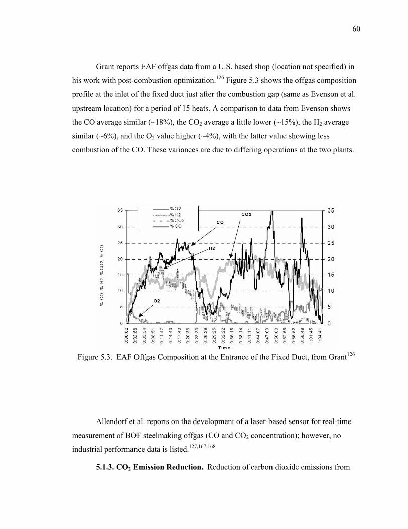
60
Grant reports EAF offgas data from a U.S. based shop (location not specified) in
his work with post-combustion optimization.126 Figure 5.3 shows the offgas composition
profile at the inlet of the fixed duct just after the combustion gap (same as Evenson et al.
upstream location) for a period of 15 heats. A comparison to data from Evenson shows
the CO average similar (~18%), the CO2 average a little lower (~15%), the H2 average
similar (~6%), and the O2 value higher (~4%), with the latter value showing less
combustion of the CO. These variances are due to differing operations at the two plants.
Figure 5.3. EAF Offgas Composition at the Entrance of the Fixed Duct, from Grant126
Allendorf et al. reports on the development of a laser-based sensor for real-time
measurement of BOF steelmaking offgas (CO and CO2 concentration); however, no
industrial performance data is listed.127,167,168
5.1.3. CO2 Emission Reduction. Reduction of carbon dioxide emissions from

61
steelmaking is being studied directly in Europe and Japan, and indirectly in the U.S. as an
offshoot of energy conservation.
The Europeans and Japanese have undertaken proactive research initiatives for the
purpose of reducing carbon dioxide emissions, and in some cases, to develop carbon-free
steelmaking. Most of the research involves the use of new technologies to replace or
augment the traditional blast furnace ironmaking. Emi lists pulverized coal, plastic, and
LNG injection, increased blast temperature, and decreasing moisture as current
technologies to reduce CO2 emissions by up to 23% in Japanese iron making.119
Alternative iron technologies, such as ITmk3, HIsmelt, and Tecnored may provide 20-
25% reduction but are still in development. Birat lists several carbon free technologies
being proposed, but they are many years from large-scale commercial development.117
These technologies include hydrogen reduction and direct electrolytic production of iron.
Both technologies require a source of electricity that is not carbon based to provide a net
reduction in CO2 emissions. In both European and Japanese markets, recycling was
identified as the powerful method with immediate implementation to provide a net
reduction of CO2 emissions. Life cycle analysis, such as detailed by Holappa, take into
account all products from the steelmaking hub (steel, slag, offgas, wastewater, scrap,
waste heat, dust, etc.) and determine a use or recycling role that each can serve.118
Regulations and methods should be sought to increase the scrap usage in these countries.
Work in the U.S. has focused on energy reduction as the primary goal, which will,
in turn, reduce CO2 emissions. These reductions will mostly be realized from indirect
sources as the U.S. relies heavily on hydrocarbon fuels for electrical generation (~69%).
Worrell et al. investigated 47 energy efficient practices and technologies, which
can directly impact energy consumption and CO2 emissions.111 All practices were
evaluated according to fuel, electricity, and primary energy savings per ton, annual
operating costs, retrofit capital costs, carbon dioxide emission reductions, and percentage
of production to which the measure can be applied nationally. Ranking the measures for
cost of conserved energy shows continuous casting, natural gas injection (into BF), and
increasing bed depth (in BF) were the three best methods of improvement for integrated
manufacturing. For secondary steelmaking oxy-fuel burners, scrap preheating, and post-
combustion were the three best methods of improvement. If all measures identified were
62
implemented, a net 18% in energy savings and 19% reduction in carbon dioxide
emissions would be realized. The data from this study was implemented into a
spreadsheet model by Molburg and Thimmapuram for quicker evaluation in the future.112
Stubbles provides the history of energy reduction in the U.S. steel industry. The
drive towards near net shape final product has provided the largest gains. Continuous
casting and thin slab casting have reduced energy consumption 36.9 GJ/t to 21.1 GJ/t (35
million BTU/t to 20 million BTU/t). The move towards strip casting and closure of
inefficient facilities should drop the industry amount to ~14.8 GJ/t (14 million BTU/t) by
2010.110
The data from Anderson et al. clearly shows that steel production from scrap
provides the lowest amount of CO2 emissions (and energy requirement). The U.S.
automotive scrap market is running near the 100% recycling rate, and it is doubtful with
increasing scrap demand from China that the U.S. can improve much in this area.121
5.2. CARBONATE FORMATION IN STEELMAKING SLAG
Steelmaking slag can be considered a mineral source, thus the work accomplished for
geological sequestration is applicable for understanding the mechanisms for sequestration
of carbon dioxide. Steel slag, however, is a derived mineral, in that it contains a mixture
of many minerals found in nature, but it is not naturally produced. Because it is an
industrial co-product, it is subject to environmental regulations and controls not imposed
on natural minerals containing the same phases. The high content of CaO, MgO, and
SiO2 in slag leads to the formation of silicates, which are similar to those minerals studied
under geological sequestration (olivine and wollastonite). The presence of high iron oxide
content, however, leads to phases not as widely studied for geological sequestration, and
gives rise to unique work with steelmaking slags.
5.2.1. Current Slag Sequestration Research. Several groups of researchers are
investigating the carbonation of steelmaking slag for use as an industrial sequestration
reagent. This research has focused on a wide variety of carbonation routes from aqueous
dissolution to exposure to supercritical carbon dioxide to steam-CO2 reactors. The
majority of the processes focus on using slag as a sequestering agent. Some of the
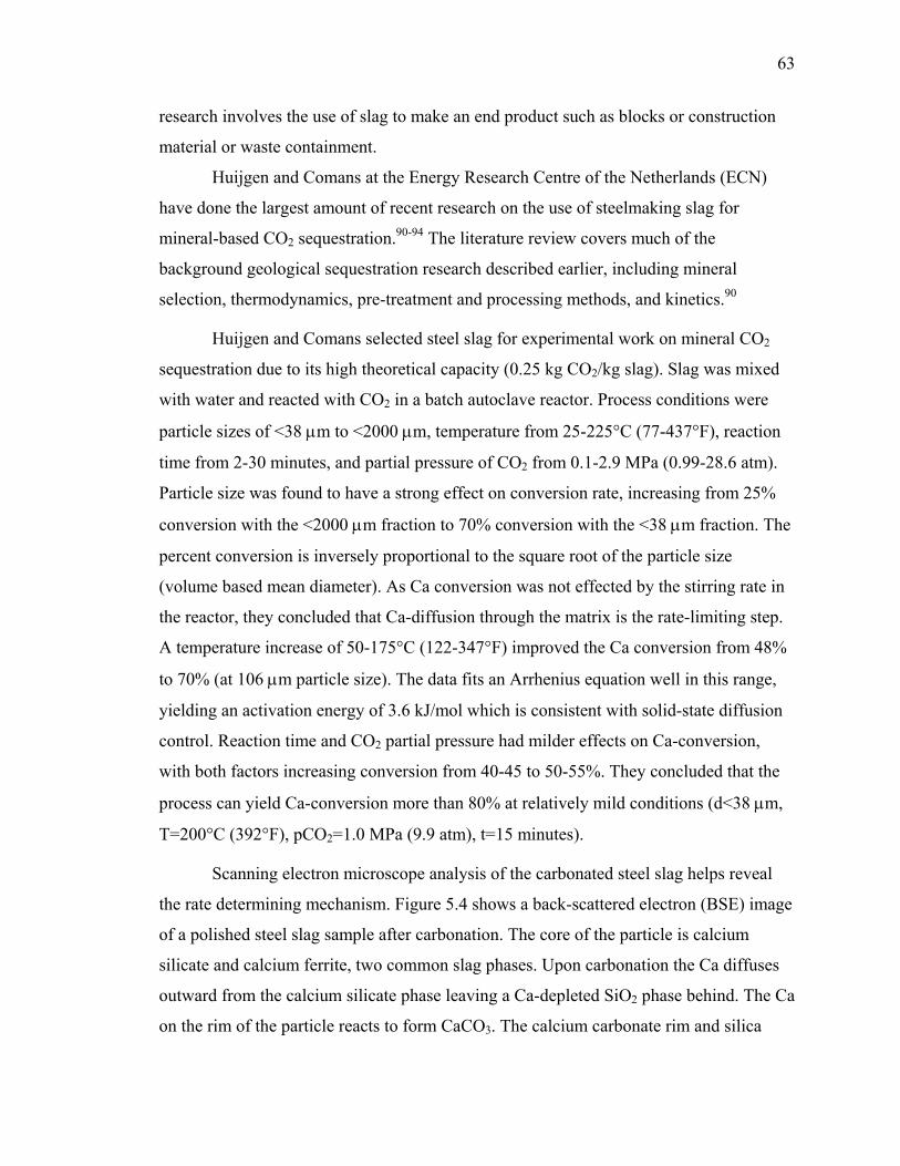
63
research involves the use of slag to make an end product such as blocks or construction
material or waste containment.
Huijgen and Comans at the Energy Research Centre of the Netherlands (ECN)
have done the largest amount of recent research on the use of steelmaking slag for
mineral-based CO2 sequestration.90-94 The literature review covers much of the
background geological sequestration research described earlier, including mineral
selection, thermodynamics, pre-treatment and processing methods, and kinetics.90
Huijgen and Comans selected steel slag for experimental work on mineral CO2
sequestration due to its high theoretical capacity (0.25 kg CO2/kg slag). Slag was mixed
with water and reacted with CO2 in a batch autoclave reactor. Process conditions were
particle sizes of <38 µm to <2000 µm, temperature from 25-225°C (77-437°F), reaction
time from 2-30 minutes, and partial pressure of CO2 from 0.1-2.9 MPa (0.99-28.6 atm).
Particle size was found to have a strong effect on conversion rate, increasing from 25%
conversion with the <2000 µm fraction to 70% conversion with the <38 µm fraction. The
percent conversion is inversely proportional to the square root of the particle size
(volume based mean diameter). As Ca conversion was not effected by the stirring rate in
the reactor, they concluded that Ca-diffusion through the matrix is the rate-limiting step.
A temperature increase of 50-175°C (122-347°F) improved the Ca conversion from 48%
to 70% (at 106 µm particle size). The data fits an Arrhenius equation well in this range,
yielding an activation energy of 3.6 kJ/mol which is consistent with solid-state diffusion
control. Reaction time and CO2 partial pressure had milder effects on Ca-conversion,
with both factors increasing conversion from 40-45 to 50-55%. They concluded that the
process can yield Ca-conversion more than 80% at relatively mild conditions (d<38 µm,
T=200°C (392°F), pCO2=1.0 MPa (9.9 atm), t=15 minutes).
Scanning electron microscope analysis of the carbonated steel slag helps reveal
the rate determining mechanism. Figure 5.4 shows a back-scattered electron (BSE) image
of a polished steel slag sample after carbonation. The core of the particle is calcium
silicate and calcium ferrite, two common slag phases. Upon carbonation the Ca diffuses
outward from the calcium silicate phase leaving a Ca-depleted SiO2 phase behind. The Ca
on the rim of the particle reacts to form CaCO3. The calcium carbonate rim and silica
64
phases both provide a hindrance for further carbonation by limiting the diffusion rate of
Ca to the surface.
Figure 5.4. BSE-image of carbonate steel slag particle, from Huijgen92
A comparison of wollastonite with steel slag shows the latter to have a higher
reactivity to sequester CO2. Figure 4.5 shows the comparison of steel slag and
wollastonite for a range of temperatures.
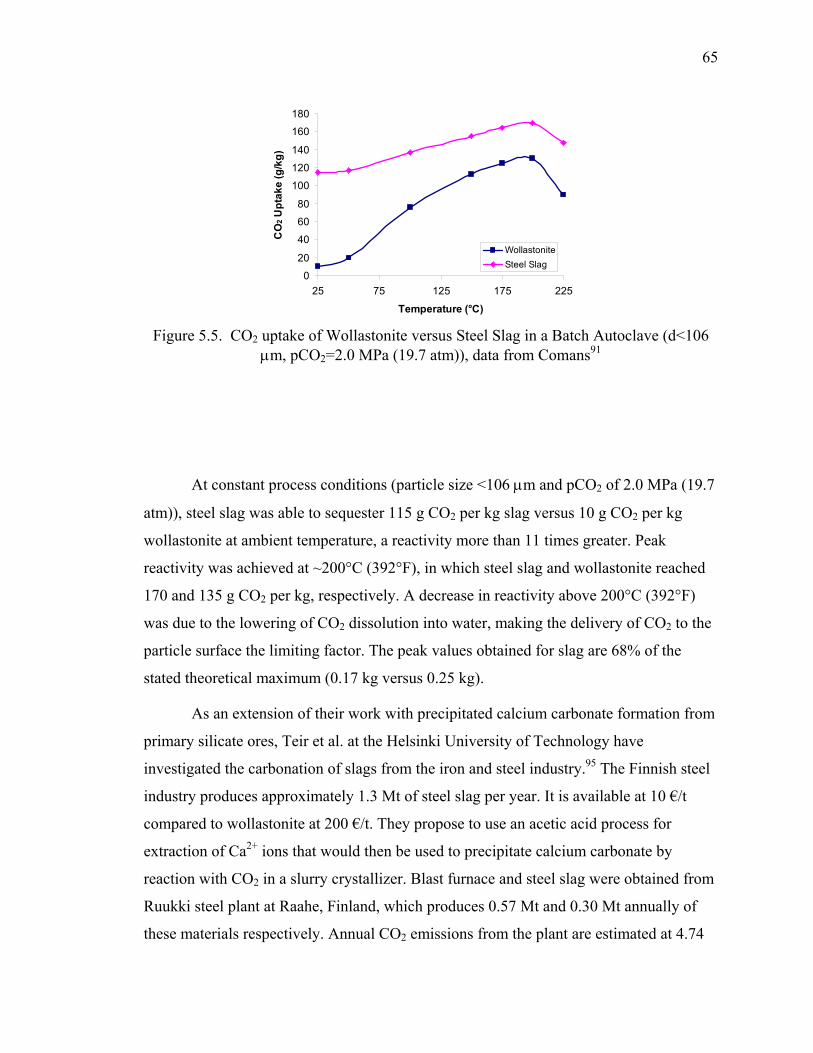
65
Figure 5.5. CO2 uptake of Wollastonite versus Steel Slag in a Batch Autoclave (d<106 µm, pCO2=2.0 MPa (19.7 atm)), data from Comans91
At constant process conditions (particle size <106 µm and pCO2 of 2.0 MPa (19.7
atm)), steel slag was able to sequester 115 g CO2 per kg slag versus 10 g CO2 per kg
wollastonite at ambient temperature, a reactivity more than 11 times greater. Peak
reactivity was achieved at ~200°C (392°F), in which steel slag and wollastonite reached
170 and 135 g CO2 per kg, respectively. A decrease in reactivity above 200°C (392°F)
was due to the lowering of CO2 dissolution into water, making the delivery of CO2 to the
particle surface the limiting factor. The peak values obtained for slag are 68% of the
stated theoretical maximum (0.17 kg versus 0.25 kg).
As an extension of their work with precipitated calcium carbonate formation from
primary silicate ores, Teir et al. at the Helsinki University of Technology have
investigated the carbonation of slags from the iron and steel industry.95 The Finnish steel
industry produces approximately 1.3 Mt of steel slag per year. It is available at 10 €/t
compared to wollastonite at 200 €/t. They propose to use an acetic acid process for
extraction of Ca2+ ions that would then be used to precipitate calcium carbonate by
reaction with CO2 in a slurry crystallizer. Blast furnace and steel slag were obtained from
Ruukki steel plant at Raahe, Finland, which produces 0.57 Mt and 0.30 Mt annually of
these materials respectively. Annual CO2 emissions from the plant are estimated at 4.74
0
20
40
60
80
100
120
140
160
180
25 75 125 175 225
Temperature (°C)
CO
2 Upt
ake
(g/k
g)
WollastoniteSteel Slag

66
Mt. Blast furnace slag showed rapid extraction of Ca2+, with 97% extracted in 20 minutes
at 60°C (140°F) compared to 38% extraction achieved with wollastonite under the same
conditions. Further work is planned with this process.
Stolaroff et al. proposed to form dilute aqueous alkali-metal solution formed from
steel slag or concrete that can be used to extract CO2 from ambient air.96-99 Steel slag at
three different size fractions (45-74 µm, 74-300 µm, and 300-600 µm) was leached with
de-ionized water and a pH buffer at ambient temperature to measure the amount of Ca2+
extracted. The initial rate and extend of calcium dissolution is higher for smaller particle
sizes and lower pH. Approximately 50% of the Ca2+ is leached within the first minute,
and 80% within the first hour. A process reaching near terminal concentration of Ca2+
may be reached in a few hours.
Their recommended industrial process uses the slag in a water spray bed, as
shown in Figure 5.6. In this method, slag is heaped on concrete pads. Water is sprayed on
the slag, leaching Ca2+ and forming Ca(OH)2. The water is collected and pumped back
through the sprayers. As the solution falls through the air, it captures CO2 from the
atmosphere creating CaCO3, which is deposited on the slag. A calculation of CO2
absorption into the aqueous solution shows that a 0.8 mm (0.03 inch) droplet falling from
10m (33 ft) height will utilize 84% of the Ca in solution in forming carbonate. Estimates
are made of water use, pumping energy, and materials flow to yield 32000 tons of CO2
sequestered per year for 140000 tons of slag, at an average cost of $8/ton-CO2.
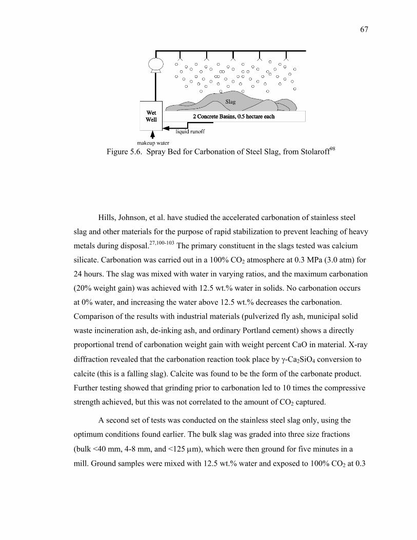
67
Figure 5.6. Spray Bed for Carbonation of Steel Slag, from Stolaroff98
Hills, Johnson, et al. have studied the accelerated carbonation of stainless steel
slag and other materials for the purpose of rapid stabilization to prevent leaching of heavy
metals during disposal.27,100-103 The primary constituent in the slags tested was calcium
silicate. Carbonation was carried out in a 100% CO2 atmosphere at 0.3 MPa (3.0 atm) for
24 hours. The slag was mixed with water in varying ratios, and the maximum carbonation
(20% weight gain) was achieved with 12.5 wt.% water in solids. No carbonation occurs
at 0% water, and increasing the water above 12.5 wt.% decreases the carbonation.
Comparison of the results with industrial materials (pulverized fly ash, municipal solid
waste incineration ash, de-inking ash, and ordinary Portland cement) shows a directly
proportional trend of carbonation weight gain with weight percent CaO in material. X-ray
diffraction revealed that the carbonation reaction took place by γ-Ca2SiO4 conversion to
calcite (this is a falling slag). Calcite was found to be the form of the carbonate product.
Further testing showed that grinding prior to carbonation led to 10 times the compressive
strength achieved, but this was not correlated to the amount of CO2 captured.
A second set of tests was conducted on the stainless steel slag only, using the
optimum conditions found earlier. The bulk slag was graded into three size fractions
(bulk <40 mm, 4-8 mm, and <125 µm), which were then ground for five minutes in a
mill. Ground samples were mixed with 12.5 wt.% water and exposed to 100% CO2 at 0.3

68
MPa (3 atm) for 1 hour. The theoretical maximum uptake capacity following carbonation
can be calculated from the original chemical composition by Equation 30.
OKONaSOCaOCO 2232 93.009.1)7.0(785.0% ++−= (30)
This calculation was developed for cement chemistry and does not take into
account the MgO amount, which averaged about 9.8% in this slag. Results calculated by
Johnson show a theoretical capacity of 45-50% depending upon the size fraction. This
compares to an actual measured capacity of ~18%, showing that one-hour reaction time
was insufficient to reach carbonation equilibrium. Grinding the slag prior to carbonation
again showed a 10-fold increase in compressive strength.
The carbonation reaction steps and mechanisms have been studied extensively for
cementitious materials, which can be applied directly for the same process in slags.103
CO2 from the air permeates through the solid, which is the diffusion controlled rate-
limiting step. The presence of water solvates CO2 and a high surface area favors transport
of the CO2 to the solid surface. CO2 hydrates to H2CO3, which is then ionized to H+,
HCO3-, and CO3
2-. The pH drops approximately three units, typically from 11 to eight.
The cementitious phases Ca3SiO5 and Ca2SiO4 are dissolved. The calcium silicate grains
are covered by a calcium silicate hydrate gel, which quickly dissolves releasing Ca2+ and
SiO44- ions. Calcium carbonate and calcium silicate hydrate nucleates, which is favored
by slightly high temperatures and finely divided material which acts like nuclei. Vaterite
and aragonite can precipitate, but ultimately all carbonate takes the form of calcite. A
calcium silicate hydrate gel forms and is progressively decalcified converting ultimately
to silica hydrate and CaCO3.
Several key factors are found to influence the carbonation process of cementitious
materials. Increasing the Ca content and Ca/Si ratio favor effective carbonation. Ferrite
and Ca3AlO6 promote the formation of ettringite (Ca6(Al,Cr,Fe,Mn,Si)2(SO4)3(OH)12-
26H2O), which readily decomposes to calcium carbonate in the presence of CO2. The
heavy metals Pb, Cd, and Ni increase the susceptibility of carbonation of cementitious
materials by 40%. Organics will adversely affect carbonation. Water is necessary to
promote carbonation, but too much blocks the pores and limits the reaction. Higher
microporosity, surface area, and permeability all enhance carbonation rate. The rate of

69
carbonation is directly proportional to the concentration of CO2 in the gas phase.
Carbonation peaks at 50-70% relative humidity and 60˚C (140°F). Above or below these
ranges carbonation is less favorable.
Microstructural changes to the parent material due to carbonation include
increased susceptibility to hydration, higher compressive strength, reduced porosity
(initial pores fill up with CaCO3), lower tortuosity, decrease in pore size distribution
(large pores filled but micro-cracks occur due to carbonate volume expansion). Chemical
changes induced by carbonation include reduced leachability of Zn, Pb, Ni, Cd, Co, Ba,
Sr, Cl-, increased leachability of Cu, Mn, NO3-, and SO42-, and no change in leachability
of Hg, As, Cr.
Different methods of carbonation have been tried in the search for a commercially
favorable route. Exposing solids to dry CO2 under pressure leads to dehydration, causing
water starvation of the carbonation reaction. At low pressures a dynamic system is
favored to a static system as the flowing CO2 helps remove the water vapor produced by
the reaction. At elevated pressures larger amounts of CO2 are introduced throughout the
sample before pore closure occurs, aiding carbonation. Vacuum carbonation in the
presence of a desiccant has shown more complete carbonation, due to diminished
resistance of water transport from the carbonating solid leaving an open pore network.
Supercritical carbon dioxide penetrates into fine pores displacing water and replacing
structurally bound water with CO2. A pilot plant was operated to contain Galligu (a
calcium sulfide waste from soap manufacture) through an accelerated carbonation
process. Galligu was mixed with a cement binder and reacted with gaseous CO2 in an
enclosed rotary chamber (similar to a rotary kiln). A continuous process is available for
50 t/hr throughput from Forkers, Ltd.103
Several Japanese researchers have focused on the carbonation of steelmaking slag
for the purpose of ocean farming. Isoo, Takahashi, et al. at NKK Corporation have
developed a process to make large blocks from steelmaking slag that are used as growth
sites for marine life.26,104-105 This grew out of work from Germany who produced bricks
from blast furnace slag and exhaust gas in the 1940s. Dephosphorization slag (56.8%
CaO and 13.8% SiO2) was ground to a median diameter of 0.61 mm. Exposure to the
70
atmosphere led to the formation of 0.9% Ca(OH)2 and 2.5% CaCO3 after one month. The
slag was placed in large (1m x 1m x 1.2m) molds and reacted with CO2 saturated with
water vapor (~0.1 MPa (1 atm)) for 12 days. The block center temperature was measured
at 70°C (158°F). The main carbonate product was calcite, and approximately 6% by
weight CO2 was reacted (~20% of theoretical amount). Blocks weighing 2.4 tons (1m3)
contain about 130-160 kg CO2. The blocks were placed on the ocean floor near
Hiroshima, Japan for 22 months and exhibited great nucleation sites for seaweed growth.
The amount of CO2 in the slag blocks placed in air or sea did not change during a three-
year period. Tonomura et al. from Nippon Steel carried out a study to scatter ground
dephosphorization slag particles in the ocean as fertilizer for plankton growth.106 The
increase in plankton growth was correlated to carbon dioxide uptake. Tamari proposes an
accelerated stabilization technology for EAF/LMF slag with steam aging in pits.107 A
reduction in stockpile aging time from six to two months can be achieved by passing
110°C (230°F) steam through the slag; however, this only produces hydrates, and no
work was done to optimize the carbonation process.
Two university projects have focused on the use of steel slag to sequester CO2
either from industrial or atmospheric sources. Students at Clarkson University won the
15th Annual Environmental Design Contest sponsored by WERC at the University of
New Mexico with their process of using steel slag to extract carbon dioxide from a coal-
burning power plant.108 No technical details were provide. Researchers at the University
of New Hampshire have investigated the use of carbon sequestering carbon materials in
highway construction, including steel slag.109 A report is not available from the project
web site; however, they are sponsoring a conference entitled “Accelerated Carbonation
for Environmental and Materials Engineering” to be held June 12-14, 2006 in London,
England.
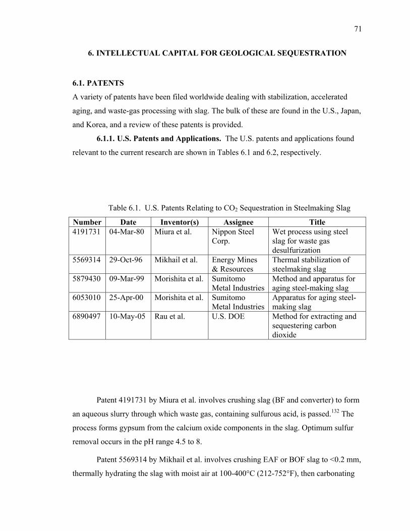
71
6. INTELLECTUAL CAPITAL FOR GEOLOGICAL SEQUESTRATION
6.1. PATENTS
A variety of patents have been filed worldwide dealing with stabilization, accelerated
aging, and waste-gas processing with slag. The bulk of these are found in the U.S., Japan,
and Korea, and a review of these patents is provided.
6.1.1. U.S. Patents and Applications. The U.S. patents and applications found
relevant to the current research are shown in Tables 6.1 and 6.2, respectively.
Table 6.1. U.S. Patents Relating to CO2 Sequestration in Steelmaking Slag
Number Date Inventor(s) Assignee Title 4191731 04-Mar-80 Miura et al. Nippon Steel
Corp. Wet process using steel slag for waste gas desulfurization
5569314 29-Oct-96 Mikhail et al. Energy Mines & Resources
Thermal stabilization of steelmaking slag
5879430 09-Mar-99 Morishita et al. Sumitomo Metal Industries
Method and apparatus for aging steel-making slag
6053010 25-Apr-00 Morishita et al. Sumitomo Metal Industries
Apparatus for aging steel-making slag
6890497 10-May-05 Rau et al. U.S. DOE Method for extracting and sequestering carbon dioxide
Patent 4191731 by Miura et al. involves crushing slag (BF and converter) to form
an aqueous slurry through which waste gas, containing sulfurous acid, is passed.132 The
process forms gypsum from the calcium oxide components in the slag. Optimum sulfur
removal occurs in the pH range 4.5 to 8.
Patent 5569314 by Mikhail et al. involves crushing EAF or BOF slag to <0.2 mm,
thermally hydrating the slag with moist air at 100-400°C (212-752°F), then carbonating
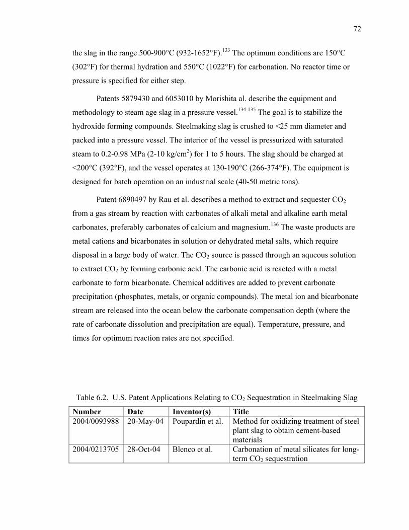
72
the slag in the range 500-900°C (932-1652°F).133 The optimum conditions are 150°C
(302°F) for thermal hydration and 550°C (1022°F) for carbonation. No reactor time or
pressure is specified for either step.
Patents 5879430 and 6053010 by Morishita al. describe the equipment and
methodology to steam age slag in a pressure vessel.134-135 The goal is to stabilize the
hydroxide forming compounds. Steelmaking slag is crushed to <25 mm diameter and
packed into a pressure vessel. The interior of the vessel is pressurized with saturated
steam to 0.2-0.98 MPa (2-10 kg/cm2) for 1 to 5 hours. The slag should be charged at
<200°C (392°F), and the vessel operates at 130-190°C (266-374°F). The equipment is
designed for batch operation on an industrial scale (40-50 metric tons).
Patent 6890497 by Rau et al. describes a method to extract and sequester CO2
from a gas stream by reaction with carbonates of alkali metal and alkaline earth metal
carbonates, preferably carbonates of calcium and magnesium.136 The waste products are
metal cations and bicarbonates in solution or dehydrated metal salts, which require
disposal in a large body of water. The CO2 source is passed through an aqueous solution
to extract CO2 by forming carbonic acid. The carbonic acid is reacted with a metal
carbonate to form bicarbonate. Chemical additives are added to prevent carbonate
precipitation (phosphates, metals, or organic compounds). The metal ion and bicarbonate
stream are released into the ocean below the carbonate compensation depth (where the
rate of carbonate dissolution and precipitation are equal). Temperature, pressure, and
times for optimum reaction rates are not specified.
Table 6.2. U.S. Patent Applications Relating to CO2 Sequestration in Steelmaking Slag
Number Date Inventor(s) Title 2004/0093988 20-May-04 Poupardin et al. Method for oxidizing treatment of steel
plant slag to obtain cement-based materials
2004/0213705 28-Oct-04 Blenco et al. Carbonation of metal silicates for long-term CO2 sequestration
73
Patent application 2004/0093988 by Poupardin et al. describes a process to treat
raw steel industry slag for conversion to a hydraulic binder equivalent to Portland cement
clinker.137 Steel industry slag is subjected to an oxidizing treatment, with oxygen or air, at
0.1-1.5 MPa (0.99-14.8 atm) at a temperature from 1450-1650°C (2642-3002°F). The
raw slag should have at least 45 wt.% CaO and <30 wt. % Fe2O3. If necessary, mineral
additives are added to the slag in the form of lime (CaO or CaCO3, <30 wt. % added),
alumina (bauxite, 0-10 wt. % added), or silica (0-5 wt. % added). These minerals are
added in proportion to ensure that the converted slag has >13 wt. % Fe2O3, >40 wt. %
3CaO·SiO2, >10 wt. % 2CaO·Fe2O3 and/or 4CaO·Al2O3·Fe2O3, and <2% free CaO.
Patent application 2004/0213705 by Blenco et al. relates to work sponsored by the
U.S. DOE at UT-Battelle.138 The process involves reacting a metal silicate with a caustic
alkali-metal hydroxide to produce a hydroxide of the metal formerly in the silicate,
reacting carbon dioxide with the alkali metal hydroxide or alkali metal silicate to form an
alkali metal carbonate or bicarbonate, and reacting the metal hydroxide originally
produced with the alkali metal carbonate or bicarbonate to produce a carbonate of the
metal originally contained in the silicate. An example of this process using olivine
(Mg2SiO4) is show in Equations 31-34.
)()()(2)())((2)( 32224 aqSiONaOHMglOHaqOHNasMgSiO +↓→++ (31)
)()(2)()(2)( 232232 ↓+→++ SiOaqNaHCOlOHgCOaqSiONa (32)
)(2)(2)(2)(2)()(2 2332 lOHaqNaOHMgCOaqNaHCOsOHMg ++↓→+ (33)
23242 22: SiOMgCOCOSiOMgNet +→+ (34)
The metal silicates identified are calcium-based (wollastonite, calcic plagioclase,
basalt, and montmorillonite), magnesium based (olivine and serpentine), and iron based
(fayalite). The reactions take place at a pressure near 5.0 MPa (49.3 atm) in an aqueous
caustic solution containing NaOH, KOH, LiOH, or mixtures thereof. Fly ash and waste
concrete are listed as a mineral source, but slag is not mentioned.
6.1.2. Foreign Patents and Applications. The foreign patents and applications
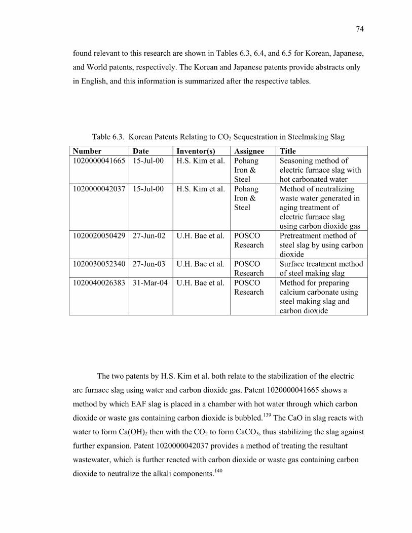
74
found relevant to this research are shown in Tables 6.3, 6.4, and 6.5 for Korean, Japanese,
and World patents, respectively. The Korean and Japanese patents provide abstracts only
in English, and this information is summarized after the respective tables.
Table 6.3. Korean Patents Relating to CO2 Sequestration in Steelmaking Slag
Number Date Inventor(s) Assignee Title 1020000041665 15-Jul-00 H.S. Kim et al. Pohang
Iron & Steel
Seasoning method of electric furnace slag with hot carbonated water
1020000042037 15-Jul-00 H.S. Kim et al. Pohang Iron & Steel
Method of neutralizing waste water generated in aging treatment of electric furnace slag using carbon dioxide gas
1020020050429 27-Jun-02 U.H. Bae et al. POSCO Research
Pretreatment method of steel slag by using carbon dioxide
1020030052340 27-Jun-03 U.H. Bae et al. POSCO Research
Surface treatment method of steel making slag
1020040026383 31-Mar-04 U.H. Bae et al. POSCO Research
Method for preparing calcium carbonate using steel making slag and carbon dioxide
The two patents by H.S. Kim et al. both relate to the stabilization of the electric
arc furnace slag using water and carbon dioxide gas. Patent 1020000041665 shows a
method by which EAF slag is placed in a chamber with hot water through which carbon
dioxide or waste gas containing carbon dioxide is bubbled.139 The CaO in slag reacts with
water to form Ca(OH)2 then with the CO2 to form CaCO3, thus stabilizing the slag against
further expansion. Patent 1020000042037 provides a method of treating the resultant
wastewater, which is further reacted with carbon dioxide or waste gas containing carbon
dioxide to neutralize the alkali components.140
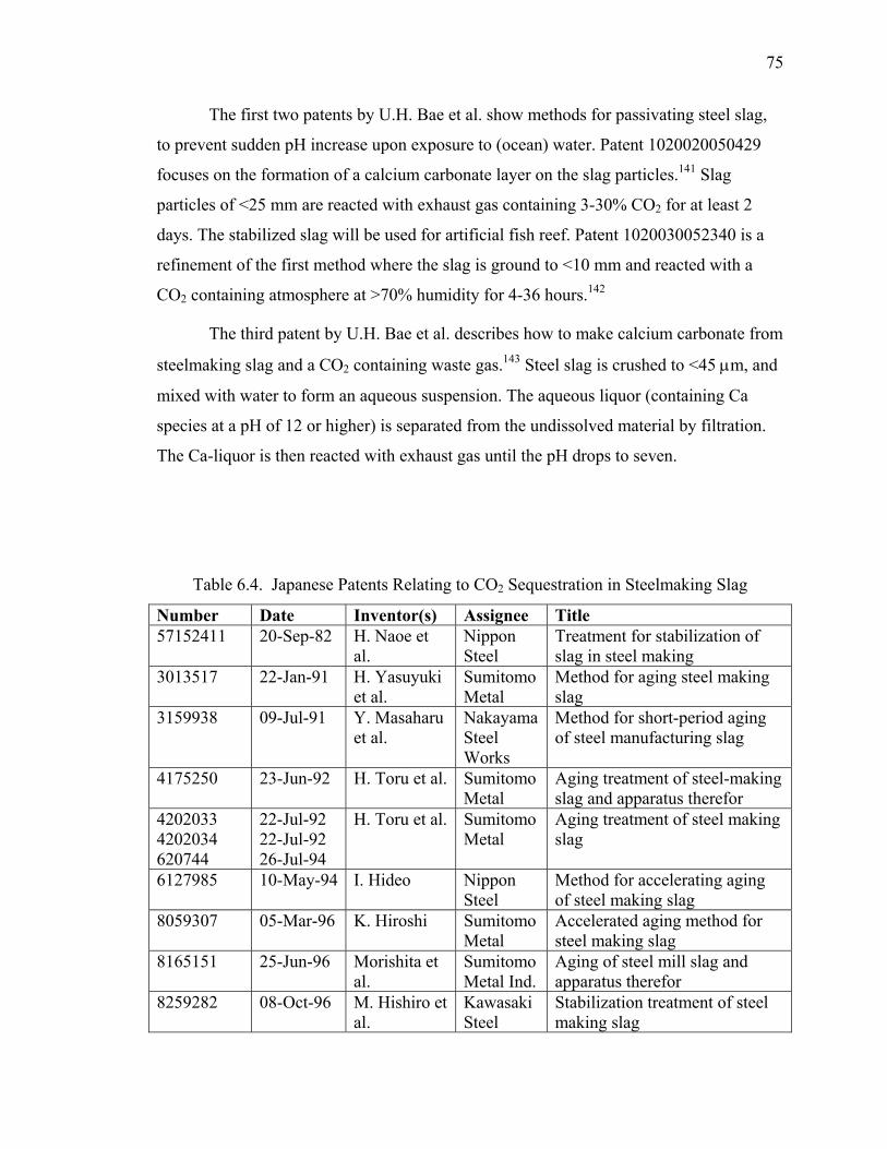
75
The first two patents by U.H. Bae et al. show methods for passivating steel slag,
to prevent sudden pH increase upon exposure to (ocean) water. Patent 1020020050429
focuses on the formation of a calcium carbonate layer on the slag particles.141 Slag
particles of <25 mm are reacted with exhaust gas containing 3-30% CO2 for at least 2
days. The stabilized slag will be used for artificial fish reef. Patent 1020030052340 is a
refinement of the first method where the slag is ground to <10 mm and reacted with a
CO2 containing atmosphere at >70% humidity for 4-36 hours.142
The third patent by U.H. Bae et al. describes how to make calcium carbonate from
steelmaking slag and a CO2 containing waste gas.143 Steel slag is crushed to <45 µm, and
mixed with water to form an aqueous suspension. The aqueous liquor (containing Ca
species at a pH of 12 or higher) is separated from the undissolved material by filtration.
The Ca-liquor is then reacted with exhaust gas until the pH drops to seven.
Table 6.4. Japanese Patents Relating to CO2 Sequestration in Steelmaking Slag
Number Date Inventor(s) Assignee Title 57152411 20-Sep-82 H. Naoe et
al. Nippon Steel
Treatment for stabilization of slag in steel making
3013517 22-Jan-91 H. Yasuyuki et al.
Sumitomo Metal
Method for aging steel making slag
3159938 09-Jul-91 Y. Masaharu et al.
Nakayama Steel Works
Method for short-period aging of steel manufacturing slag
4175250 23-Jun-92 H. Toru et al. Sumitomo Metal
Aging treatment of steel-making slag and apparatus therefor
4202033 4202034 620744
22-Jul-92 22-Jul-92 26-Jul-94
H. Toru et al. Sumitomo Metal
Aging treatment of steel making slag
6127985 10-May-94 I. Hideo Nippon Steel
Method for accelerating aging of steel making slag
8059307 05-Mar-96 K. Hiroshi Sumitomo Metal
Accelerated aging method for steel making slag
8165151 25-Jun-96 Morishita et al.
Sumitomo Metal Ind.
Aging of steel mill slag and apparatus therefor
8259282 08-Oct-96 M. Hishiro et al.
Kawasaki Steel
Stabilization treatment of steel making slag
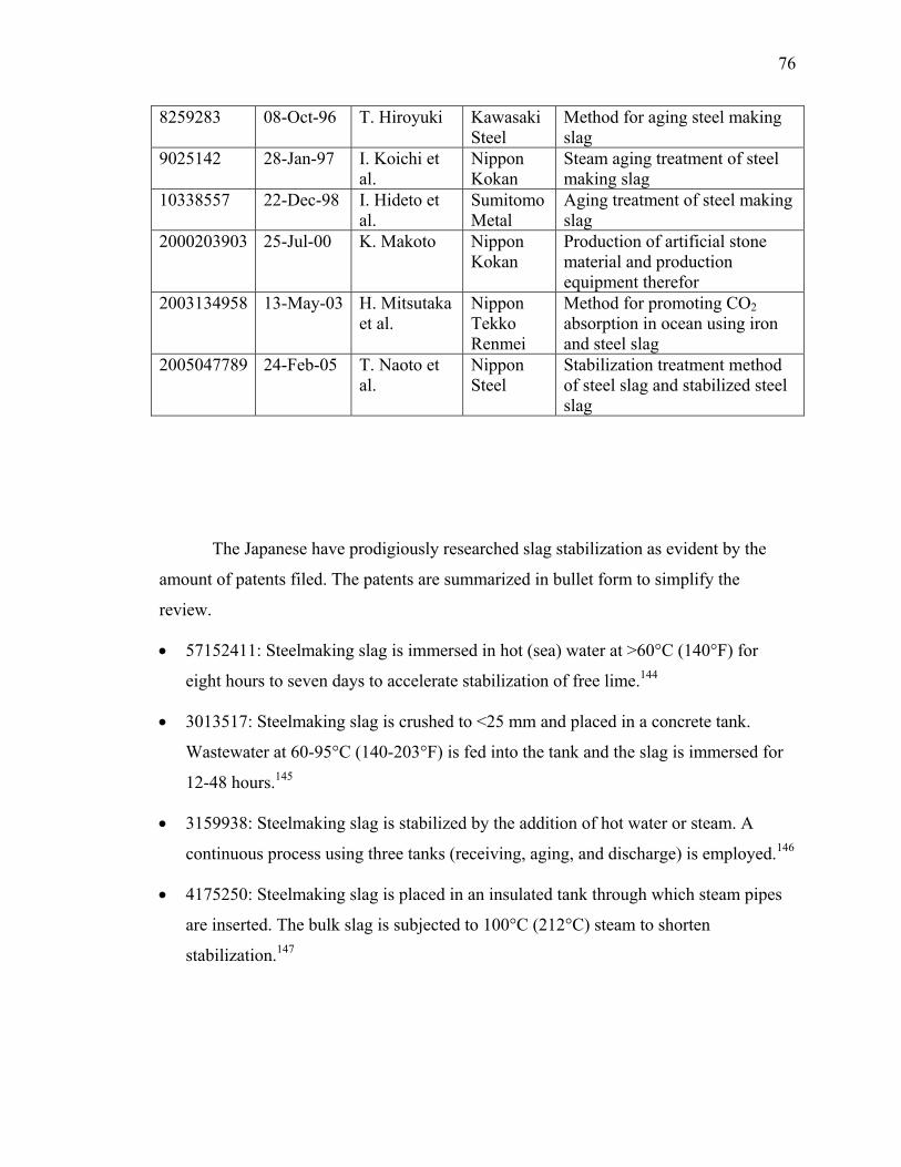
76
8259283 08-Oct-96 T. Hiroyuki Kawasaki Steel
Method for aging steel making slag
9025142 28-Jan-97 I. Koichi et al.
Nippon Kokan
Steam aging treatment of steel making slag
10338557 22-Dec-98 I. Hideto et al.
Sumitomo Metal
Aging treatment of steel making slag
2000203903 25-Jul-00 K. Makoto Nippon Kokan
Production of artificial stone material and production equipment therefor
2003134958 13-May-03 H. Mitsutaka et al.
Nippon Tekko Renmei
Method for promoting CO2 absorption in ocean using iron and steel slag
2005047789 24-Feb-05 T. Naoto et al.
Nippon Steel
Stabilization treatment method of steel slag and stabilized steel slag
The Japanese have prodigiously researched slag stabilization as evident by the
amount of patents filed. The patents are summarized in bullet form to simplify the
review.
• 57152411: Steelmaking slag is immersed in hot (sea) water at >60°C (140°F) for
eight hours to seven days to accelerate stabilization of free lime.144
• 3013517: Steelmaking slag is crushed to <25 mm and placed in a concrete tank.
Wastewater at 60-95°C (140-203°F) is fed into the tank and the slag is immersed for
12-48 hours.145
• 3159938: Steelmaking slag is stabilized by the addition of hot water or steam. A
continuous process using three tanks (receiving, aging, and discharge) is employed.146
• 4175250: Steelmaking slag is placed in an insulated tank through which steam pipes
are inserted. The bulk slag is subjected to 100°C (212°C) steam to shorten
stabilization.147
77
• 4202033: Optimization of the steam addition in 4175250 by layering crushed slag on
a steam pipe and covering the slag with a vinyl sheet. Steam rate feedback control is
used.148
• 4202034: Same as 4202033, but the slag is allowed to natural age for three months
before the introduction of steam.149
• 6127985: Steelmaking slag is screened to provide two to four size fractions (<1 mm,
1-30 mm, and >30 mm) and is put into separate stockpiles. It is claimed that this
method improves the air permeability and water retaining properties since the surface
area to volume ratio increases for each size, thus shortening the natural aging
process.150
• 6206744: Each steelmaking slag batch is chemically analyzed to determine the
basicity (CaO/SiO2). Slag with a basicity >4 is crushed, graded, and aged with
steam.151
• 8059307: A cylindrical hermetic vessel is designed to house the slag and react it with
steam under reduced pressure. The vessel is portable and truck mounted, allowing
transportation of the slag to stations (loading, steaming, and disposal).152
• 8165151: Steelmaking slag is crushed to <25 mm and placed in a pressure vessel.
Steam at 0.20-0.98 MPa (1.9-9.7 atm) is introduced for 1-5 hours. The vessel is top
loading and bottom unloading.153
• 8259282: Steelmaking slag is treated with steam at atmospheric pressure, then held
for >1 hour in a steam/CO2 mixture to prevent subsequent leaching of Ca and Mg.154
• 8259283: Steelmaking slag is aged in an atmosphere at >80°C (176°F) and >60%
relative humidity for a time (t). The time is determined by the concentration of
CaO+MgO in the slag.155
• 9025142: Steelmaking slag is held in steam for >1 hour, then force cooled and
reheated. At least two cycles of heating/cooling are used in the claim to reduce steam
consumption.156
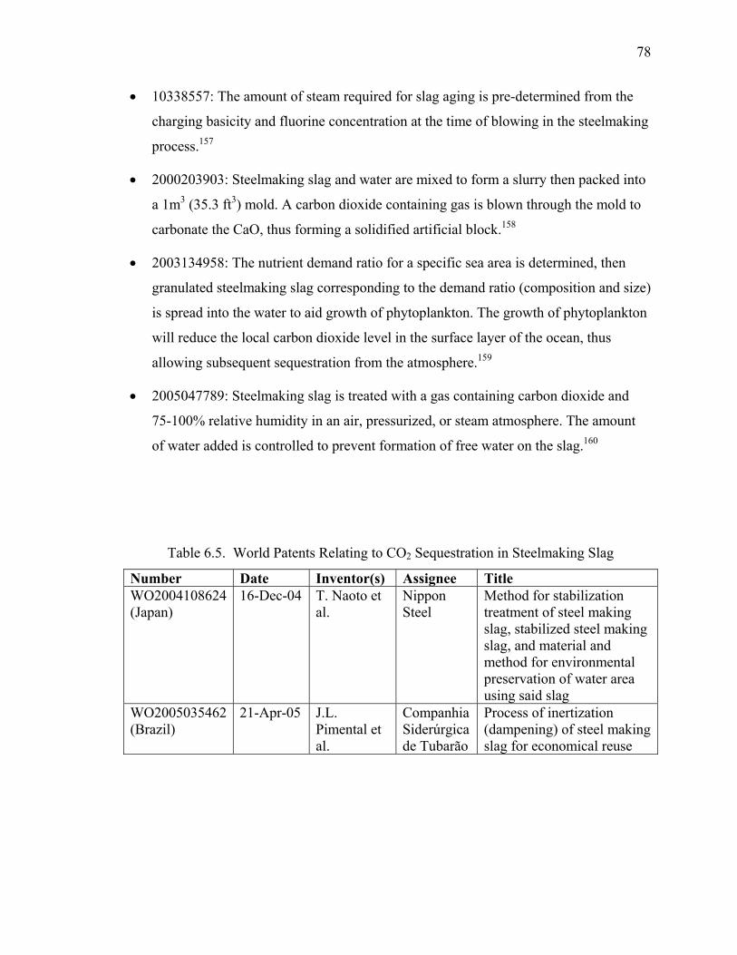
78
• 10338557: The amount of steam required for slag aging is pre-determined from the
charging basicity and fluorine concentration at the time of blowing in the steelmaking
process.157
• 2000203903: Steelmaking slag and water are mixed to form a slurry then packed into
a 1m3 (35.3 ft3) mold. A carbon dioxide containing gas is blown through the mold to
carbonate the CaO, thus forming a solidified artificial block.158
• 2003134958: The nutrient demand ratio for a specific sea area is determined, then
granulated steelmaking slag corresponding to the demand ratio (composition and size)
is spread into the water to aid growth of phytoplankton. The growth of phytoplankton
will reduce the local carbon dioxide level in the surface layer of the ocean, thus
allowing subsequent sequestration from the atmosphere.159
• 2005047789: Steelmaking slag is treated with a gas containing carbon dioxide and
75-100% relative humidity in an air, pressurized, or steam atmosphere. The amount
of water added is controlled to prevent formation of free water on the slag.160
Table 6.5. World Patents Relating to CO2 Sequestration in Steelmaking Slag
Number Date Inventor(s) Assignee Title WO2004108624 (Japan)
16-Dec-04 T. Naoto et al.
Nippon Steel
Method for stabilization treatment of steel making slag, stabilized steel making slag, and material and method for environmental preservation of water area using said slag
WO2005035462 (Brazil)
21-Apr-05 J.L. Pimental et al.
Companhia Siderúrgica de Tubarão
Process of inertization (dampening) of steel making slag for economical reuse
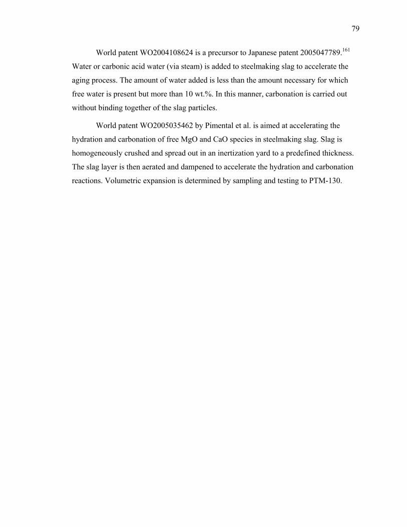
79
World patent WO2004108624 is a precursor to Japanese patent 2005047789.161
Water or carbonic acid water (via steam) is added to steelmaking slag to accelerate the
aging process. The amount of water added is less than the amount necessary for which
free water is present but more than 10 wt.%. In this manner, carbonation is carried out
without binding together of the slag particles.
World patent WO2005035462 by Pimental et al. is aimed at accelerating the
hydration and carbonation of free MgO and CaO species in steelmaking slag. Slag is
homogeneously crushed and spread out in an inertization yard to a predefined thickness.
The slag layer is then aerated and dampened to accelerate the hydration and carbonation
reactions. Volumetric expansion is determined by sampling and testing to PTM-130.
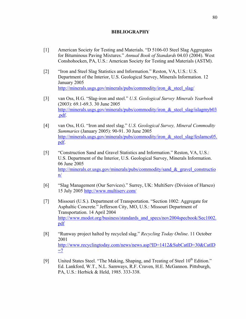
80
BIBLIOGRAPHY
[1] American Society for Testing and Materials. “D 5106-03 Steel Slag Aggregates for Bituminous Paving Mixtures.” Annual Book of Standards 04.03 (2004). West Conshohocken, PA, U.S.: American Society for Testing and Materials (ASTM).
[2] “Iron and Steel Slag Statistics and Information.” Reston, VA, U.S.: U.S. Department of the Interior, U.S. Geological Survey, Minerals Information. 12 January 2005 http://minerals.usgs.gov/minerals/pubs/commodity/iron_&_steel_slag/
[3] van Oss, H.G. “Slag-iron and steel.” U.S. Geological Survey Minerals Yearbook (2003): 69.1-69.3. 30 June 2005 http://minerals.usgs.gov/minerals/pubs/commodity/iron_&_steel_slag/islagmyb03.pdf.
[4] van Oss, H.G. “Iron and steel slag.” U.S. Geological Survey, Mineral Commodity Summaries (January 2005): 90-91. 30 June 2005 http://minerals.usgs.gov/minerals/pubs/commodity/iron_&_steel_slag/feslamcs05.pdf.
[5] “Construction Sand and Gravel Statistics and Information.” Reston, VA, U.S.: U.S. Department of the Interior, U.S. Geological Survey, Minerals Information. 06 June 2005 http://minerals.er.usgs.gov/minerals/pubs/commodity/sand_&_gravel_construction/
[6] “Slag Management (Our Services).” Surrey, UK: MultiServ (Division of Harsco) 15 July 2005 http://www.multiserv.com/
[7] Missouri (U.S.). Department of Transportation. “Section 1002: Aggregate for Asphaltic Concrete.” Jefferson City, MO, U.S.: Missouri Department of Transportation. 14 April 2004 http://www.modot.org/business/standards_and_specs/nov2004specbook/Sec1002.pdf
[8] “Runway project halted by recycled slag.” Recycling Today Online. 11 October 2001 http://www.recyclingtoday.com/news/news.asp?ID=1412&SubCatID=30&CatID=7
[9] United States Steel. “The Making, Shaping, and Treating of Steel 10th Edition.” Ed. Lankford, W.T., N.L. Samways, R.F. Craven, H.E. McGannon. Pittsburgh, PA, U.S.: Herbick & Held, 1985. 333-338.
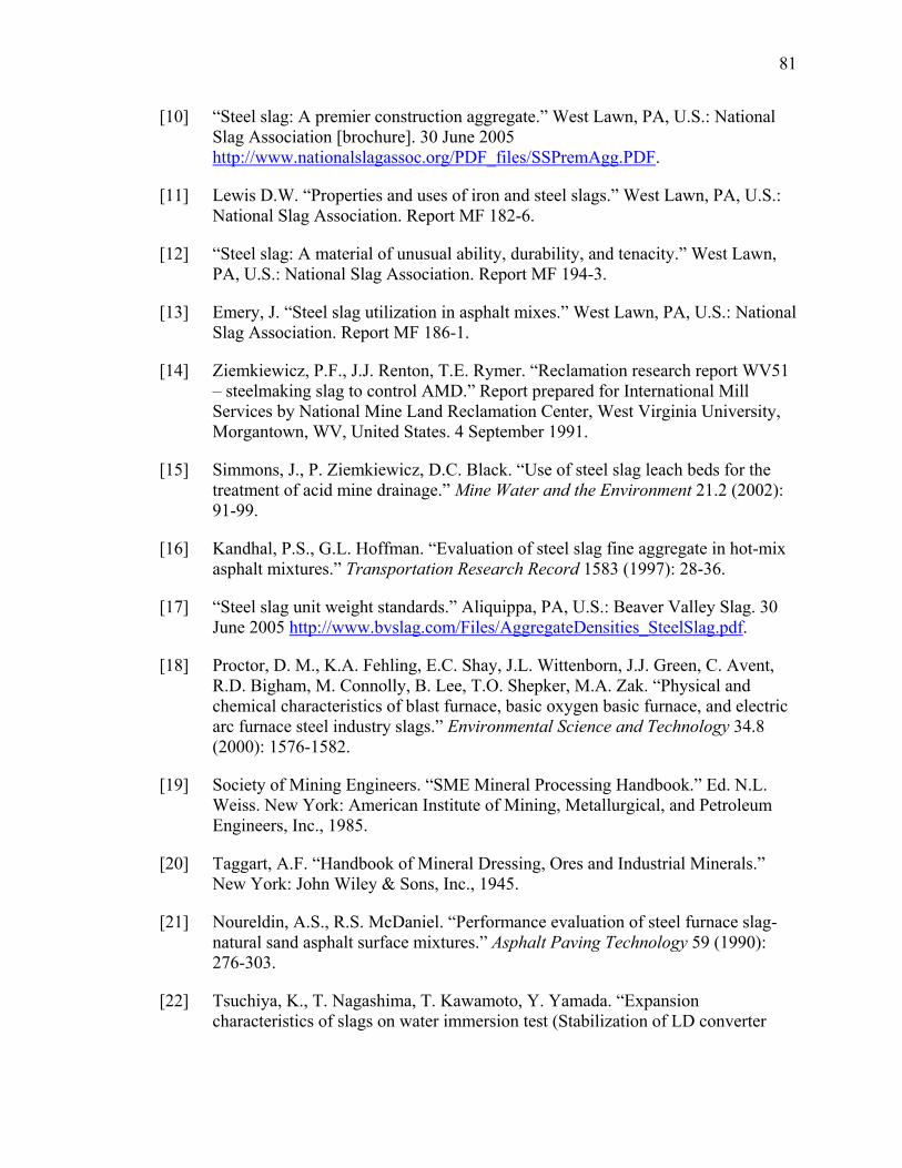
81
[10] “Steel slag: A premier construction aggregate.” West Lawn, PA, U.S.: National Slag Association [brochure]. 30 June 2005 http://www.nationalslagassoc.org/PDF_files/SSPremAgg.PDF.
[11] Lewis D.W. “Properties and uses of iron and steel slags.” West Lawn, PA, U.S.: National Slag Association. Report MF 182-6.
[12] “Steel slag: A material of unusual ability, durability, and tenacity.” West Lawn, PA, U.S.: National Slag Association. Report MF 194-3.
[13] Emery, J. “Steel slag utilization in asphalt mixes.” West Lawn, PA, U.S.: National Slag Association. Report MF 186-1.
[14] Ziemkiewicz, P.F., J.J. Renton, T.E. Rymer. “Reclamation research report WV51 – steelmaking slag to control AMD.” Report prepared for International Mill Services by National Mine Land Reclamation Center, West Virginia University, Morgantown, WV, United States. 4 September 1991.
[15] Simmons, J., P. Ziemkiewicz, D.C. Black. “Use of steel slag leach beds for the treatment of acid mine drainage.” Mine Water and the Environment 21.2 (2002): 91-99.
[16] Kandhal, P.S., G.L. Hoffman. “Evaluation of steel slag fine aggregate in hot-mix asphalt mixtures.” Transportation Research Record 1583 (1997): 28-36.
[17] “Steel slag unit weight standards.” Aliquippa, PA, U.S.: Beaver Valley Slag. 30 June 2005 http://www.bvslag.com/Files/AggregateDensities_SteelSlag.pdf.
[18] Proctor, D. M., K.A. Fehling, E.C. Shay, J.L. Wittenborn, J.J. Green, C. Avent, R.D. Bigham, M. Connolly, B. Lee, T.O. Shepker, M.A. Zak. “Physical and chemical characteristics of blast furnace, basic oxygen basic furnace, and electric arc furnace steel industry slags.” Environmental Science and Technology 34.8 (2000): 1576-1582.
[19] Society of Mining Engineers. “SME Mineral Processing Handbook.” Ed. N.L. Weiss. New York: American Institute of Mining, Metallurgical, and Petroleum Engineers, Inc., 1985.
[20] Taggart, A.F. “Handbook of Mineral Dressing, Ores and Industrial Minerals.” New York: John Wiley & Sons, Inc., 1945.
[21] Noureldin, A.S., R.S. McDaniel. “Performance evaluation of steel furnace slag-natural sand asphalt surface mixtures.” Asphalt Paving Technology 59 (1990): 276-303.
[22] Tsuchiya, K., T. Nagashima, T. Kawamoto, Y. Yamada. “Expansion characteristics of slags on water immersion test (Stabilization of LD converter

82
slags by field aging-I)” Transactions of the Iron and Steel Institute of Japan 20.9 (1980): B-367.
[23] Crawford, C.B., K.N. Burn. “Building damage from expansive steel slag backfill.” Journal of the Soil Mechanics and Foundations Division, Proceedings of the American Society for Civil Engineers 95.SM6 (1969): 1325-1334.
[24] “Steel slag chemistry.” Aliquippa, PA, U.S.: Beaver Valley Slag. 30 June 2005 http://www.bvslag.com/Files/SteelSlag-Chemistry.pdf.
[25] “Blast furnace slag: The construction material of choice.” West Lawn, PA, U.S.: National Slag Association [brochure]. 30 June 2005 http://www.nationalslagassoc.org/PDF_files/NSABlastFurn.PDF.
[26] Isoo, T., T. Takahashi, M. Fukuhara. “Using carbonated steelmaking slag blocks to help reduce CO2.” American Ceramic Society Bulletin 80.1 (2001): 73-75.
[27] Johnson, D. C., C.L. MacLeod, P.J. Carey, C.D. Hills. “Solidification of stainless steel slag by accelerated carbonation.” Environmental Technology 24.6 (2003): 671-678.
[28] “Mineralogy Applied to Steel Slag.” Ijmuiden, The Netherlands: Corus RD&T Ceramic Research Centre. 25 July 2005 http://www.ceramics-research.com/index_tmp.html?pid=12
[29] Ionescu, D., T.R. Meadowcroft, P.V. Barr. “Early-age hydration kinetics of steel slags.” Advances in Cement Research 13.1 (2001): 21-30.
[30] Bradaskja, B., J. Triplat, M. Dobnikar, B. Mirtic. “Mineralogical characterization of steel-making slags.” Materiali in Tehnologije 38.3-4 (2004): 205-208. (Slovenian)
[31] Monaco, A., W-K. Wu. “The effect of cooling conditions on the mineralogical characterization of steel slag.” In: Proceedings of the International Symposium on Resource Conservation and Environmental Technologies in Metallurgical Industries; 20-25 August 1994; Toronto, Ontario, Canada. Editors: P. Mahant, C. Pickles, W-K. Lu. Montreal, Quebec, Canada: Canadian Institute of Mining, Metallurgy, and Petroleum; 1994. 107-116.
[32] Barin, I., F. Sauert, E. Schultze-Rhonhof, W.S. Sheng. Thermochemical data of pure substances. New York: VCH Publishers, 1989.
[33] Robie, R.A., B.S. Hemingway, J.R. Fisher, Eds. Thermodynamic properties of minerals and related substances at 298.15 K and 1 Bar (105 Pascals) pressure and higher temperatures. United States Department of the Interior; U.S. Geological Survey; Bulletin 1452. 1984.
83
[34] Mu, J., D.D. Perlmutter. “Thermal decomposition of carbonates, carboxylates, oxalates, acetates, formates, and hydroxides.” Thermochimica Acta 49.2-3 (1981): 207-18.
[35] Lackner, K.S., C.H. Wendt, D.P. Butt, E.L. Joyce, D.H. Sharp. “Carbon dioxide disposal in carbonate minerals.” Energy 20.11 (1995): 1153-70.
[36] Butt, D.P., K.S. Lackner, C.H. Wendt, R. Vaidya, D.L. Pile, Y. Park, T. Holesinger, D.M. Harradine, K. Nomura. “The kinetics of binding carbon dioxide in magnesium carbonate.” In: Proceedings of the 23rd International Technical Conference on Coal Utilization & Fuel Systems; 9-13 March 1998; Clearwater, FL, United States. Editor, B.A. Sakkestad. Gaithersburg, MD: Coal Technology Association; 1998. 583-591.
[37] Kelleher, I.J., S.A.T. Redfern. “Hydrous calcium magnesium carbonate, a possible precursor to the formation of sedimentary dolomite.” Molecular Simulation 28.6-7 (2002): 557-572.
[38] Geiseler, J. “Steel slag – generation, processing, and utilization.” In: Proceedings of the International Symposium on Resource Conservation and Environmental Technologies in Metallurgical Industries; 20-25 August 1994; Toronto, Ontario, Canada. Editors: P. Mahant, C. Pickles, W-K. Lu. Montreal, Quebec, Canada: Canadian Institute of Mining, Metallurgy, and Petroleum; 1994. 87-95.
[39] Tennis, P.D., H.M. Jennings. “A model for two types of calcium silicate hydrate in the microstructure of Portland cement pastes.” Cement and Concrete Research 30 (2000): 855-863.
[40] Murphy, J.N. “Recycling steel slag as a cement additive.” [M.S. thesis]. University of British Columbia, Vancouver, Canada. 1995.
[41] Bentz, D.P. “A three dimensional cement hydration and microstructure program. I. Hydration rate, heat of hydration, and chemical shrinkage.” Gaithersburg, MD, U.S.: U.S. Department of Commerce; National Institute of Standards and Technology. Report NISTIR 5756. 1995.
[42] Suito, H., Y. Hayashia, Y. Takahashi. “Mineralogical study of LD converter slags.” Tetsu to Hagne 63.8 (1977): 1252-1259. (Japanese)
[43] Fujii, K., W. Kondo. “Estimation of thermochemical data for calcium silicate hydrate (C-S-H).” Journal of the American Ceramic Society 66 (1983): C220-221.
[44] Chen, J.J., J.J. Thomas, H.F.W. Taylor, H.M. Jennings. “Solubility and structure of calcium silicate hydrate.” Cement and Concrete Research 34 (2004): 1499-1519.
[45] Goto, S., K. Suenaga, T. Kado, M. Fukuhara. “Calcium silicate carbonation products.” Journal of the American Ceramic Society 78.11 (1995): 2867-72.
84
[46] Zevenhoven, R., J. Kohlmann, A.B. Mukherjee. “Direct dry mineral carbonation for CO2 emissions reduction in Finland.” In: Proceedings of the 27th International Technical Conference on Coal Utilization & Fuel Systems; 4-7 March 2002; Clearwater, FL, United States. Editor, B.A. Sakkestad. Gaithersburg, MD: Coal Technology Association; 2002. 743-754.
[47] American Society for Testing and Materials. “C 131-03 Standard Test Method for Resistance to Degradation of Small-Size Coarse Aggregate by Abrasion and Impact in the Los Angeles Machine.” Annual Book of Standards 04.02 (2004). West Conshohocken, PA, U.S.: American Society for Testing and Materials (ASTM).
[48] American Society for Testing and Materials. “D 4792-00 Standard Test Method for Potential Expansion of Aggregates from Hydration Reactions.” Annual Book of Standards 04.03 (2004). West Conshohocken, PA, U.S.: American Society for Testing and Materials (ASTM).
[49] “Method 1311-Toxicity characteristic leaching procedure. Revision 0.” Washington, D.C., U.S.: U.S. Environmental Protection Agency. July 1992. http://www.epa.gov/epaoswer/hazwaste/test/pdfs/1311.pdf
[50] Luxán, M.P., R. Sotolongo, F. Dorrego, E. Herrero. “Characteristics of the slags produced in the fusion of scrap steel by electric arc furnace.” Cement and Concrete Research 30 (2000): 517-519.
[51] FactSage. Version 5.3.1. Centre for Research in Computational Thermochemistry, École Polytechnique, Montreal, Quebec, Canada. 2004.
[52] Lea, F.M. The Chemistry of Cement and Concrete, 3rd Ed. New York: Chemical Publishing Company, 1971.
[53] Lackner, K.S. “Carbonate chemistry for sequestering fossil carbon.” Annual Review of Energy and the Environment 27 (2002): 193-232.
[54] Abanades, J.C., E.J. Anthony, J. Wang, J.E. Oakey. “Fluidized Bed Combustion Systems Integrating CO2 Capture with CaO.” Environmental Science and Technology 39.8 (2005): 2861-2866.
[55] Abanades, J.C., E.J. Anthony, D.Y. Lu, C. Salvador, D. Alvarez. “Capture of CO2 from combustion gases in a fluidized bed of CaO.” AIChE Journal 50.7 (2004): 1614-1622.
[56] Abanades, J.C., D. Alvarez. “Conversion Limits in the Reaction of CO2 with Lime.” Energy & Fuels 17.2 (2003): 308-315.
[57] Abanades, J.C. “The maximum capture efficiency of CO2 using a carbonation/calcination cycle of CaO/CaCO3.” Chemical Engineering Journal 90.3 (2002): 303-306.
85
[58] Abanades, J.C., J.E. Oakey, D. Alvarez, J. Hämäläinen. “Novel combustion cycles incorporating capture of CO2 with CaO.” In: Proceedings of the 6th International Conference on Greenhouse Gas Control Technologies; 1-4 October 2002; Kyoto, Japan. Editors, John Gale and Yoichi Kaya. Oxford, UK: Elsevier Ltd.; 2003. 181-186.
[59] Alvarez, D., J.C. Abanades. “Pore-size and shape effects on the recarbonation performance of calcium oxide submitted to repeated calcination/recarbonation cycles.” Energy & Fuels 19.1 (2005): 270-278.
[60] Salvador, C., D. Lu, E.J. Anthony, J.C. Abanades. Enhancement of CaO for CO2 capture in an FBC environment.” Chemical Engineering Journal 96.1-3 (2003): 187-195.
[61] Baker, E.H. “The calcium oxide-carbon dioxide system in the pressure range 1-300 atmospheres.” Journal of the Chemical Society (1962): 464-470.
[62] Broecker, W.S., T. Takahashi. “Neutralization of fossil fuel carbon dioxide by marine calcium carbonate.” Marine Science 6 (1977): 213-41.
[63] Lackner, K.S., D.P. Butt, C.H. Wendt. “Magnesite disposal of carbon dioxide.” In: Proceedings of the 22nd International Technical Conference on Coal Utilization & Fuel Systems; 16-19 March 1997; Clearwater, FL, United States. Editor, B.A. Sakkestad. Gaithersburg, MD: Coal Technology Association; 1997. 419-430.
[64] Butt, D.P., K.S. Lackner, C.H. Wendt, S.D. Conzone, H. Kung, Y.-C. Lu, J.K. Bremser. “Kinetics of thermal dehydroxylation and carbonation of magnesium hydroxide.” Journal of the American Ceramic Society 79.7 (1996): 1892-1898.
[65] Chizmeshya, A.V. G., M.J. McKelvy, O.F. Sankey, G.H. Wolf, R. Sharma, H. Bearat, J. Diefenbacher, R.W. Carpenter. “Atomic-level understanding of CO2 mineral carbonation mechanisms from advanced computational modeling.” In: Proceedings of the 27th International Technical Conference on Coal Utilization & Fuel Systems; 4-7 March 2002; Clearwater, FL, United States. Editor, B.A. Sakkestad. Gaithersburg, MD: Coal Technology Association; 2002. 803-814.
[66] McKelvy, M.J., A.V.G. Chizmeshya, H. Bearat, R. Sharma, R.W. Carpenter. “Developing a mechanistic understanding of CO2 mineral sequestration reaction processes.” In: Proceedings of the 26th International Technical Conference on Coal Utilization & Fuel Systems; 4-8 March 2001; Clearwater, FL, United States. Editor, B.A. Sakkestad. Gaithersburg, MD: Coal Technology Association; 2001. 777-788.
[67] McKelvy, M.J., A.V.G. Chizmeshya, H. Bearat, R. Sharma, R.W. Carpenter. “Developing an atomic-level understanding to enhance CO2 mineral sequestration reaction processes via materials and reaction engineering.” In: Proceedings of the 17th Annual International Pittsburgh Coal Conference; 11-15 September 2000;
86
Pittsburgh, PA, United States. Pittsburgh, PA: University of Pittsburgh School of Engineering; 2000. 1161-1173.
[68] McKelvy, M.J., A.V.G. Chizmeshya, J. Diefenbacher, H. Béarat, R.W. Carpenter, G. Wolf, D. Gormley. “Developing an atomic-level understanding of the mechanisms that govern CO2 sequestration mineral carbonation reaction processes.” In: EPD Congress 2005, Proceedings of Sessions and Symposia held during the TMS Annual Meeting; 13-17 February 2005; San Francisco, CA, United States. Editor, M.E. Schlesinger. Warrendale, PA: Minerals, Metals & Materials Society; 2005. 1133-1147.
[69] O’Connor, W.K., R.P. Walters, D.C. Dahlin, G.E. Rush, D.N. Nilsen, P.C. Turner. “Carbon dioxide sequestration by direct aqueous mineral carbonation.” In: Proceedings of the 26th International Technical Conference on Coal Utilization & Fuel Systems; 4-8 March 2001; Clearwater, FL, United States. Editor, B.A. Sakkestad. Gaithersburg, MD: Coal Technology Association; 2001. 765-776.
[70] Ityokumbul, M. T., S. Chander, W.K. O'Connor, D.C. Dahlin, S.J. Gerdemann. “Reactor design considerations in mineral sequestration of carbon dioxide.” In: Proceedings of the 18th Annual International Pittsburgh Coal Conference; 3-7 December 2001; Newcastle, New South Wales, Australia. Pittsburgh, PA: University of Pittsburgh School of Engineering; 2001. 843-852.
[71] O'Connor, W. K., D.C. Dahlin, D.N. Nilsen, S.J. Gerdemann, G.E. Rush, L.R. Penner, R.P. Walters, P.C. Turner. “Continuing studies on direct aqueous mineral carbonation for CO2 sequestration.” In: Proceedings of the 27th International Technical Conference on Coal Utilization & Fuel Systems; 4-7 March 2002; Clearwater, FL, United States. Editor, B.A. Sakkestad. Gaithersburg, MD: Coal Technology Association; 2002. 819-830.
[72] O'Connor, W. K., D.C. Dahlin, G.E. Rush, C.L. Dahlin, W.K. Collins. “Carbon dioxide sequestration by direct mineral carbonation: process mineralogy of feed and products.” Minerals & Metallurgical Processing 19.2 (2002): 95-101.
[73] Penner, L.R., S.J. Gerdemann, D.C. Dahlin, W.K. O’Connor, D.N. Nilsen. “Progress on continuous processing for mineral carbonation using a prototype flow loop reactor.” Proceedings of the 28th International Technical Conference on Coal Utilization & Fuel Systems; 10-13 March 2003; Clearwater, FL, United States. Editor, B.A. Sakkestad. Gaithersburg, MD: Coal Technology Association; 2003. 353-364.
[74] Gerdemann, S. J., D.C. Dahlin, W.K. O'Connor, L.R. Penner, G.E. Rush. “Factors affecting ex-situ aqueous mineral carbonation using calcium and magnesium silicate minerals.” In: Proceedings of the 29th International Technical Conference on Coal Utilization & Fuel Systems; 18-22 April 2004; Clearwater, FL, United

87
States. Editor, B.A. Sakkestad. Gaithersburg, MD: Coal Technology Association; 2004. 11-22.
[75] Park, A.-H, R.A. Jadhav, L.-S. Fan. “CO2 mineral sequestration through carbonation of Mg-bearing minerals.” In: Proceedings of the Annual Meeting of AIChE, Session 257-Risk Assessment and Management; 4-9 November 2001; Reno, NV, United States. New York, NY: American Institute of Chemical Engineers; 2001. Paper 257a.
[76] Kuchta, M.E. “Mineral carbonation: activation of serpentine minerals for enhanced CO2 sequestration.” [M.S. thesis]. The Pennsylvania State University, USA. 2003.
[77] Teir, S., S. Eloneva, R. Zevenhoven. “Production of precipitated calcium carbonate from calcium silicates and carbon dioxide.” Energy Conversion and Management 46.18-19 (2005): 2954-2979.
[78] Teir, S., S. Eloneva, R. Zevenhoven. “Reduction of CO2 emissions by calcium carbonate production from calcium silicates.” 8th Conference on Process Integration, Modeling and Optimisation for Energy Saving and Pollution Reduction (PRES’05); 15-18 May 2005; Giardini Naxos, Italy. 30 June 2005 http://www.aidic.it/pres05/webpapers/80%20Teir.doc.
[79] Golomb, D.S. “Carbon dioxide/limestone/water emulsion for ocean and geologic sequestration of CO2.” In: Proceedings of the 6th International Conference on Greenhouse Gas Control Technologies; 1-4 October 2002; Kyoto, Japan. Editors, John Gale and Yoichi Kaya. Oxford, UK: Elsevier Ltd.; 2003. 683-688.
[80] Maroto-Valer, M.M., M.E. Kuchta, Y. Zhang, J.M. Andrésen. “Integrated carbonation: a novel concept to develop a CO2 sequestration module for power plants.” In: Proceedings of the 6th International Conference on Greenhouse Gas Control Technologies; 1-4 October 2002; Kyoto, Japan. Editors, John Gale and Yoichi Kaya. Oxford, UK: Elsevier Ltd.; 2003. 1729-1734.
[81] Berger, R. L., W.A. Klemm. “Accelerated curing of cementitious systems by carbon dioxide. II. Hydraulic calcium silicates and aluminates.” Cement and Concrete Research 2.6 (1972): 647-52.
[82] Berger, R. L., J.F. Young, K. Leung. “Acceleration of hydration of calcium silicates by carbon dioxide treatment.” Nature Physical Science 240.97 (1972): 16-18.
[83] Young, J. F., R.L. Berger, J. Breese. “Accelerated curing of compacted calcium silicate mortars on exposure to CO2.” Journal of the American Ceramic Society 57.9 (1974): 394-7.
88
[84] Bukowski, J. M., R.L. Berger. “Reactivity and strength development of carbon dioxide activated non-hydraulic calcium silicates.” Cement and Concrete Research 9.1 (1979): 57-68.
[85] Goodbrake, C. J., J.F. Young, R.L. Berger. “Reaction of beta-dicalcium silicate and tricalcium silicate with carbon dioxide and water vapor.” Journal of the American Ceramic Society 62.3-4 (1979): 168-71.
[86] Goodbrake, C. J., J.F. Young, R.L. Berger. “Kinetics of the reaction of β-C2S and C3S with CO2 and water vapor. Reply.” Journal of the American Ceramic Society 63.1-2 (1980): 114-115.
[87] “Combining mineral and geological sequestration using TecEco Tec and Eco-Cements and TecEco Tec-Kiln technology.” Glenorchy, Tasmania, Australia: TecEco Pty. Ltd. 30 June 2005 http://www.tececo.com/files/Political_Documents/MineralandGeologicalSequestrationCombined231004.pdf
[88] Fauth, D.J., J.P. Baltrus, J.P. Knoer, Y. Soong, B.H. Howard, W.J. Graham, M. M. Maroto-Valer, J.M. Andresen. “Conversion of silicate minerals with carbon dioxide producing environmentally benign and stable carbonates.” Preprints of Symposia - American Chemical Society, Division of Fuel Chemistry 46.1 (2001): 278-279.
[89] Fernandez, A. I.; J.M. Chimenos, M. Segarra, M.A. Fernández, F. Espiell. “Kinetic study of carbonation of MgO slurries.” Hydrometallurgy 53.2 (1999): 155-167.
[90] Huijgen, W.J.J., R.N.J. Comans. “Carbon dioxide sequestration by mineral carbonation: literature review.” Petten, The Netherlands: Energy Research Centre of the Netherlands (ECN); February 2003. ECN-C—03-016. 30 June 2005 http://www.ecn.nl/docs/library/report/2003/c03016.pdf.
[91] Comans, R.N.J., W.J.J. Huijgen. “Carbonation of alkaline waste materials and its application to mineral CO2-sequestration.” In: Proceedings of the 32nd International Geological Congress, Session G15.05; Florence, Italy; 23 August 2004. Petten, The Netherlands: Energy Research Centre of the Netherlands (ECN); March 2005. ECN-RX—05-0088. 30 June 2005 http://www.ecn.nl/docs/library/report/2005/rx05088.pdf.
[92] Huijgen, W.J.J., R.N.J. Comans, G.J. Witkamp. “CO2 sequestration by mineral carbonation.” Poster presented at the 4th Netherlands Process Technology Symposium (NPS4); 26-27 October 2004; Veldhoven, The Netherlands. The Netherlands: Energy Research Centre of the Netherlands (ECN); March 2005. ECN-RX—05-089. 06 December 2005 http://www.ecn.nl/docs/library/report/2005/rx05089.pdf
89
[93] Huijgen, W., G.J. Witkamp, R. Comans. “Mineral CO2 sequestration in alkaline solid residues.” Petten, The Netherlands: Energy Research Centre of the Netherlands (ECN); December 2004. ECN-RX—04-079. 30 June 2005 http://www.ecn.nl/docs/library/report/2004/rx04079.pdf.
[94] Huijgen, W.J.J., G.-J Witkamp, R.N.J. Comans. “Mineral CO2 sequestration by steel slag carbonation.” Environmental Science and Technology 39.24 (2005): 9676-9682.
[95] Eloneva, S., S. Teir, C.-J. Fogleholm, R. Zevenhoven. ”Carbonation of slags from iron-and steel industry.” In: Proceedings of the 4th Nordic Minisymposium on Carbon Dioxide Capture and Storage; 8-9 September 2005; Espoo, Finland. Otaniemi, Espoo, Finland: Laboratory of Energy, Engineering and Environmental Protection; Helsinki University of Technology. 1-14. 06 December 2005 http://eny.tkk.fi/minisymposium/proceedings/Eloneva-presentation.pdf
[96] Stolaroff, J.K., G.V. Lowry, D.W. Keith. “CO2 extraction from ambient air using alkali-metal hydroxide solutions derived from concrete waste and steel slag.” In: EOS Trans. AGU, 84(46), Fall Meeting; 8-12 December 2003; San Francisco, CA, United States. Washington, DC: American Geophysical Union. Abstract GC32A-0207. 30 June 2005 http://www.agu.org/meetings/fm03/fm03-pdf/fm03-GC52A.pdf.
[97] Lowry, G.V., J. Stolaroff, D. Keith. “CO2 extraction from ambient air using alkali-metal hydroxide solutions: niche markets to industrial scale implementation.” Preprints of Papers - American Chemical Society, Division of Fuel Chemistry 49.1 (2004): 362-363.
[98] Stolaroff, J.K., G.V. Lowry, D.W. Keith. “Using CaO- and MgO-rich industrial waste streams for carbon sequestration.” Energy Conversion and Management 46.5 (2005): 687-699.
[99] Lowry, G.V. “Carbon management: geochemical CO2 sequestration using industrial wastes.” Pittsburgh, PA, U.S.: Carnegie Mellon Civil and Environmental Engineering web page. 30 June 2005 http://www.ce.cmu.edu/~glowry/Projects/CarbonSequestration/captureabstract.htm
[100] Sweeney, R. E. H., C.D. Hills, N.R. Buenfeld. “Investigation into the carbonation of stabilized/solidified synthetic waste.” Environmental Technology 19.9 (1998): 893-902.
[101] Johnson, D.C. “Accelerated carbonation of waste calcium silicate materials.” SCI Lecture Papers Series 108 (2000): 1-10. 30 June 2005 http://www.soci.org/SCI/publications/2001/pdf/pb76.pdf.
90
[102] Johnson, D. C., C.L. MacLeod, C.D. Hills. “Acid neutralisation capacity of accelerated carbonated stainless steel slag.” Environmental Technology 24.5 (2003): 545-551.
[103] Fernández Bertos, M., S.J.R. Simons, C.D. Hills, P.J. Carey. “A review of accelerated carbonation technology in the treatment of cement-based materials and sequestration of CO2.” Journal of Hazardous Materials 112.3 (2004): 193-205.
[104] Isoo, T., T. Takahasi, N. Okamoto, M. Fukuhara. “Development of large steelmaking slag blocks using a new carbonation process.” Advances in Cement Research 12.3 (2000): 97-101.
[105] Takahashi, T., M. Fukuhara. “Production of steelmaking slag blocks by carbon dioxide and their durability in the sea.” Key Engineering Materials 206-213(7th Conference of the European Ceramic Society) (2002): 879-882.
[106] Tonomura, S., S. Tabuchi. “Logistic study on CO2 sequestration using steelmaking slags.” Tetsu-to-Hagane 89.4 (2003): 401-406.
[107] Tamari, O., Y. Fukumoto, H. Hojokai, S. Takeuchi. “Development of stabilization technology for arc furnace slag.” Tetsu to Hagane 78.12 (1992): T225-T228. (Japanese)
[108] “Students Design System for Removing Carbon from Power Plant Emissions.” Newswise. 15 April 2005 http://www.newswise.com/p/articles/view/511159/.
[109] “Project 35: Sustainable Highways Through the Use of Carbon Sequestering Construction Materials.” Durham, NH, U.S.: University of New Hampshire Recycled Materials Resource Center. 30 June 2005 http://www.rmrc.unh.edu/research/rprojects/project35/project35.asp.
[110] Stubbles, J.R. “Carbon dioxide emissions from the U.S. steel industry.” In: Proceedings of the International Symposium on Greenhouse Gases in the Metallurgical Industries: Policies, Abatement and Treatment; 26-29 August, 2001; Toronto, ON, Canada. Editor: C.A. Pickles. Montreal, Quebec, Canada: Canadian Institute of Mining, Metallurgy and Petroleum. 103-116.
[111] Worrell, E., L. Price, N. Martin. “Energy efficiency and carbon dioxide emissions reduction opportunities in the US iron and steel sector.” Energy 26.5 (2001): 513-536.
[112] Molburg, J.C., P.R. Thimmapuram. “Estimating carbon dioxide emissions reductions resulting from energy efficiency improvements in iron and steel manufacturing: the role of an integrated model.” In: Proceedings of the International Symposium on Greenhouse Gases in the Metallurgical Industries: Policies, Abatement and Treatment; 26-29 August, 2001; Toronto, ON, Canada.
91
Editor: C.A. Pickles. Montreal, Quebec, Canada: Canadian Institute of Mining, Metallurgy and Petroleum. 203-214.
[113] Afonin, S.Z., Y.S. Yusfin, P.I. Chernousev, S.V. Murinets. “Energy conservation in ferrous metallurgy.” Metallurgist 42.7-8 (1999): 292-296.
[114] Birat, J.P., M. Antoine, A. Dubs, H. Gaye, Y. de Lassat, R. Nicolle, J.L. Roth. “Towards a carbon-free steel production route?” La Revue de Metallurgie-CIT 90.3 (1993): 411-421.
[115] Birat, J.-P, J.-M. Delbecq, E. Hess, D. Huin. “Slag, steel and greenhouse gases.” La Revue de Métallurgie-CIT 99.1 (2002): 13-21.
[116] Birat, J.-P., F. Hanrot, G. Danloy. “CO2 mitigation technologies in the steel industry: a benchmarking study based on process calculations.” Stahl und Eisen 123.9 (2003): 69-72.
[117] Birat, J.-P. “CO2 emissions and the steel industry’s available responses to the greenhouse effect.” In: Proceedings of the 59th Ironmaking Conference; 26-29 March 2000; Pittsburgh, PA, U.S. Warrendale, PA, U.S.: Association for Iron and Steel Technology; 2000. 409-420.
[118] Holappa, L.E.K. “Impact of energy and environment on the development of metallurgical processes.” In: Proceedings of the 2nd International Symposium on Metallurgical Processes for the Year 2000 and Beyond; 1994; San Diego, CA, U.S. Editor: H.Y. Sohn. Warrendale, PA, U.S.: The Minerals, Metals, and Materials Society. 641-660.
[119] Emi, T. “Changing paradigm of metal separation technology for steel production.” Scandinavian Journal of Metallurgy 34.2 (2005): 79-88.
[120] Gielen, D. “CO2 removal in the iron and steel industry.” Energy Conversion and Management 44.7 (2003): 1027-1037.
[121] Anderson, S.H., G.E. Metius, J. M. McClelland. “Future green steelmaking technologies.” In: Proceedings of the 60th Electric Furnace Conference; 10-13 November 2002; San Antonio, TX, U.S. Warrendale, PA, U.S.: Association for Iron and Steel Technology; 2002. 175-191.
[122] Kepplinger, W.L., R. Millner, G. Schrey. “CO2-minimized iron and steel production.” In: Proceedings of the International Symposium on Greenhouse Gases in the Metallurgical Industries: Policies, Abatement and Treatment; 26-29 August, 2001; Toronto, ON, Canada. Editor: C.A. Pickles. Montreal, Quebec, Canada: Canadian Institute of Mining, Metallurgy and Petroleum. 179-185.
[123] Goodfellow, H.D., M. Thomson, L. Cibert, P. Morere, E. Evenson. “Overview global warming issues and EAF production.” In: Proceedings of the 56th Electric
92
Furnace Conference; 15-18 November 1998, New Orleans, LA, U.S. Warrendale, PA, U.S.: Association for Iron and Steel Technology; 1998. 623-627.
[124] Thomson, M.J., E.J. Evenson, M.J. Kempe, H.D. Goodfellow. “Control of greenhouse gas emissions from electric arc furnace steelmaking: evaluation methodology with case studies.” Ironmaking and Steelmaking 27.4 (2000): 273-279.
[125] Evenson, E.J., H.D. Goodfellow, M.J. Kempe. “EAF process optimization through offgas analysis and closed-loop process control at Deacero, Saltillo, Mexico.” Iron & Steelmaker 28.5 (2001): 53-58.
[126] Grant, M.G. “Principles and strategy of EAF post-combustion.” In: Proceedings of the 58th Electric Furnace Conference; 12-15 November 2000; Orlando, FL, United States. Warrendale, PA, U.S.: Association for Iron and Steel Technology; 2000. 15-28.
[127] Allendorf, S.W., D.K. Ottesen, D.R. Hardesty, D. Goldstein, C.W. Smith, A.P. Malcolmson. “Laser-based sensor for real-time measurement of offgas composition and temperature in BOF steelmaking.” Iron and Steel Engineer 75.4 (1998): 31-35.
[128] Fitzgerald, F. “Global warming: a cool view.” Ironmaking and Steelmaking 31.3 (2004): 191-191-198.
[129] Green, D.A., B.S. Turk, R.P. Gupta, J.W. Portzer, W.J. McMichael, D.P. Harrison. “Capture of carbon dioxide from flue gas using solid regenerable sorbents.” International Journal of Environmental Technology and Management 4.1/2 (2004): 53-67.
[130] Corti, A. “Thermoeconomic evaluation of CO2 alkali absorption system applied to semi-closed gas turbine combined cycle.” Energy 29.3 (2004): 415-426.
[131] Robertson, D. “Old is new.” The Chemical Engineer 597 (1995): 40-3.
[132] Miura, Yoshiaki, Masataka Kaneyasu, Akira Okamoto. “Wet process using steel slag for waste gas desulfurization.” US Patent 4191731. 4 March 1980.
[133] Mikhail, Shaheer, Ann-Marie Turcotte. “Thermal stabilization of steelmaking slag.” US Patent 5569314. 29 October 1996.
[134] Morishita, Shigeru, Hiroshi Koide, Keiichi Komai, Yoshitaka Kinugawa, Yosuke Suezawa, Kazunari Teramae. “Method and apparatus for aging steel-making slag.” US Patent 5879430. 9 March 1999.
[135] Morishita, Shigeru, Hiroshi Koide, Keiichi Komai, Yoshitaka Kinugawa, Yosuke Suezawa, Kazunari Teramae. “Apparatus for aging steel-making slag.” US Patent 6053010. 25 April 2000.
93
[136] Rau, Gregory H., Kenneth G. Caldeira. “Method for extracting and sequestering carbon dioxide.” US Patent 6890497. 10 May 2005.
[137] Poupardin, Valerie Michaud, Francois Sorrentino. “Method for oxidizing treatment of steel plant slag to obtain cement-based materials.” US Patent Application Publication 20040093988. 20 May 2004.
[138] Blenco, James G., Donald A. Palmer, Lawrence M. Anovitz, James S. Beard. “Carbonation of metal silicates for long-term CO2 sequestration.” US Patent Application Publication 2040213705. 28 October 2004.
[139] Kim, Hyeong Seok, U Hyeon Bae, Tae Bong Byun, Hak Bong Lee, Gi Hyeon Han. “Seasoning method of electric furnace slag with hot carbonated water.” Korean Patent 1020000041665. 15 July 2000. (Korean)
[140] Kim, Hyeong Seok, U Hyeon Bae, Tae Bong Byun, Hak Bong Lee, Gi Hyeon Han. “Method of neutralizing waste water generating in aging treatment of electric furnace slag using carbon dioxide gas.” Korean Patent 1020000042037. 15 July 2000. (Korean)
[141] Bae, U Hyeon, Tae Bong Byun, Gi Hyeon Han, Hyeong Seok Kim, Hak Bong Lee. “Pretreatment method of steel slag by using carbon dioxide.” Korean Patent 1020020050429. 27 June 2002 (Korean)
[142] Bae, U Hyeon, Tae Bong Byun, Gi Hyeon Han, Hyeong Seok Kim, Hak Bong Lee. “Surface treatment method of steel making slag.” Korean Patent 1020030052340. 27 June 2003. (Korean)
[143] Bae, U Hyeon, Tae Bong Byun, Gi Hyeon Han, Hyeong Seok Kim, Hak Bong Lee. “Method for preparing calcium carbonate using steel making slag and carbon dioxide.” Korean Patent 1020040026383. 31 March 2004. (Korean)
[144] Naoe, Hirai, Nagao Yoshiichi, Kubo Shigeto, Narutomi Yoshiyasu, Ono Mototsugu, Ijichi Kenji. “Treatment for stabilization of slag in steel making.” Japanese Patent 57152411. 20 September 1982. (Japanese)
[145] Yasuyuki, Honda, Hashimoto Toru. “Method for aging steel making slag.” Japanese Patent 3013517. 22 January 1991. (Japanese)
[146] Masaharu, Yoshitani, Nakanishi Takeshi, Fujita Seiichi. “Method for short-period aging of steel manufacturing slag.” Japanese Patent 3159938. 09 July 1991. (Japanese)
[147] Toru, Hashimoto, Yokoyama Masaaki, Honda Yasuyuki, Aoki Yukio, Komatsu Toru, Kawasaki Osamu. “Aging treatment of steel-making slag and apparatus therefor.” Japanese Patent 4175250. 23 June 1992. (Japanese)

94
[148] Toru, Hashimoto, Yokoyama Masaaki, Honda Yasuyuki, Komatsu Toru, Toyama Noriaki. “Aging treatment of steel making slag.” Japanese Patent 4202033. 22 July 1992. (Japanese)
[149] Toru, Hashimoto, Yokoyama Masaaki, Honda Yasuyuki. “Aging treatment of steel making slag.” Japanese Patent 4202034. 22 July 1992. (Japanese)
[150] Hideo, Ide. “Method for accelerating aging of steel making slag.” Japanese Patent 6127985. 10 May 1994. (Japanese)
[151] Toru, Hashimoto, Hiwatari Junichi, Kuninaga Yoshitada, Wakiyama Seiji. “Aging treatment of steel-making slag.” Japanese Patent 6206744. 26 July 1994 (Japanese)
[152] Hiorshi, Koide. “Accelerated aging method for steel making slag.” Japanese Patent 8059307. 05 March 1996. (Japanese)
[153] Shigeru, Morishita, Koide Hiroshi, Komai Keiichi, Kinukawa Yoshitaka. “Aging of steel mill slag and apparatus therefor.” Japanese Patent 8165151. 25 June 1996. (Japanese)
[154] Hisahiro, Matsunaga, Toubou Hiroyuki, Kumagai Masato. “Stabilization treatment of steel making slag.” Japanese Patent 8259282. 08 October 1996. (Japanese)
[155] Hiroyuki, Toubou, Matsunaga Hisahiro, Kumagai Masato, Taguchi Seiji, Sato Yukio. “Method for aging steel making slag.” Japanese Patent 8259283. 10 August 1996. (Japanese)
[156] Koichi, Ichikawa, Hoshi Hideaki, Suzuki Tomoo, Kato Makoto. “Steam aging treatment of steel making slag.” Japanese Patent 9025142. 28 January 1997. (Japanese)
[157] Hideto, Ishino, Yusa Kazumi, Tsuruta Jiyouji. “Aging treatment of steel making slag.” Japanese Patent 10338557. (Japanese)
[158] Makoto, Kato, Takahashi Tatsuto, Nakajima Hirohisa, Isoo Norio, Yamamoto Shinichi. “Production of artificial stone material and production equipment therefor.” Japanese Patent Abstract 2000203903. 25 July 2000. (Japanese)
[159] Mitsutaka, Hino, Taniguchi Akira, Yamamoto Tamiji, Namikawa Masao. “Method for promoting CO2 absorption in ocean using iron and steel slag.” Japanese Patent Abstract 2003134958. 13 May 2003. (Japanese)
[160] Naoto, Tsutsumi, Aoki Riichi, Tanaka Makoto, Sado Tatsuya, Tazaki Tomoaki, Yokoo Masayoshi. “Stabilization treatment of steel slag and stabilized steel slag.” Japanese Patent Abstract 2005047789. 24 February 2005. (Japanese)
95
[161] Naoto, Tsutsumi, Mukawa Susumu, Tanaka Makoto, Aoki Toshikazu, Sado Tatsuya, Tasaki Tomoaki, Yokoo Masayoshi, Kiso Eiji, Nakagawa Masao. “Method for stabilization treatment of steel making slag, stabilized steel making slag, and material and method for environmental preservation of water area using said slag.” World Patent 2004108624. 16 December 2004. (Japanese)
[162] Pimental Joao Luiz, De Almeida Melo E Silva Marcos, Da Silveria Noci Oliveria, De Mendonca Lascourt Ronaldo, De Mendonca Carvalho Marcio, Queres Qindeler Joao. “Process of inertization (dampening) of steel making slag for economical reuse.” World Patent 2005035461. 21 April 2005.
[163] Bond, G.M., J. Stringer, D.K. Brandvold, F.A. Simsek, M.-G. Medina, G. Egeland. “Development of integrated system for biomimetric CO2 sequestration using the enzyme carbonic anhydrase.” American Chemical Society, Division of Fuel Chemistry 45.4 (2000): 713-717.
[164] Medina, M.-G., G.M. Bond, S. Rogelj. “Comparison of carbonic anhydrase isozymes for use as a catalyst in carbon sequestration process.” In: Proceedings of the Air & Waste Management Association’s 93rd Annual Meeting & Exhibition; 18-22 June 2000; Salt Lake City, UT, U.S. Pittsburgh, PA., U.S.: Air & Waste Management Association; 2000. 5996-6013.
[165] Simsek-Ege, F.A., G.M. Bond, J. Stringer. “A biomimetic route to environmentally friendly CO2 sequestration: catalyst immobilization.” Electrochemical Society Proceedings 2000-20 (2001): 162-170.
[166] Bond, G.M., M.-G. Medina, J. Stringer, F.A. Simsek-Ege. “CO2 capture from coal-fired utility generation plant exhausts, and sequestration by a biomimetic route based on enzymatic catalysis-current status.” In: Proceedings of the 1st National Conference on Carbon Sequestration; 14-17 May 2001; Washington, DC, USA. Washington, DC, USA, U.S. Department of Energy, National Energy Technology Laboratory. http://www.netl.doe.gov/publications/proceedings/01/carbon_seq/5a5.pdf
[167] Ottensen, D., S. Allendorf, P. Ludowise, D. Hardesty, D. Goldstein, T. Miller, C. Smith, M. Bonin. “A laser-based sensor for measurement of off-gas composition and temperature in basic oxygen steelmaking.” Scandinavian Journal of Metallurgy 28.3 (1999): 131-137.
[168] Ottesen, D., S. Allendorf, P. Ludowise, D. Hardesty, T. Miller, D. Goldstein, C. Smith, M. Bonin. “A laser-based sensor for measurement of off-gas composition and temperature in basic oxygen steelmaking.” In: Proceedings of the International Symposium on Advanced Sensors for Metals Processing; 23-25 August 1998; Quebec City, Quebec, Canada. Editors: B. Brusey, J.F. Bussière, M. Dubois, A. Moreau. Montreal, Quebec, Canada: Canadian Institute of Mining, Metallurgy and Petroleum. 253-264.
96
[169] “Carbon dioxide storage rocks!” Environmental Technology Directorate at PNNL 15 December 2005 http://environment.pnl.gov/accompprodline/prodline_detail.asp?id=505
[170] Dippenaar, R. “Industrial uses of slag (the use and re-use of iron and steelmaking slags).” Ironmaking and Steelmaking 32.1 (2005): 35-46.
[171] Tsuchiya, K., T. Nagashima, M. Fujishima, T. Kawamoto, T. Hinonishi, Y. Yamada. “Reduction of lumps of lime in slags (Stabilization of LD converter slags by field aging-II)” Transactions of the Iron and Steel Institute of Japan 20.9 (1980): B-368.
[172] Sorentino, F., M. Giminez. “Mineralogy of modified steel slags.” In: Proceedings of the 11th International Congress on the Chemistry of Cement (ICCC); 11-16 May 2003; Durban, South Africa. Editors: G. Grieve and G. Owens. Midrand, Gauteng, South Africa: The Cement and Concrete Institute of South Africa. 2139-2147.
American Iron and Steel Institute Technology Roadmap Program
CO2 Breakthrough Program Phase I: Geological Sequestration of CO2 by Hydrous Carbonate Formation with Reclaimed Slag
Final Report - Attachment C
Published Articles
January 2008
October 2006VOL 30 No7
www.steeltimesint.com
STEEL TIMES INTERNATIONAL OCTOBER 2006 VOL30 NO7
� NEWS � ENVIRONMENT � AUTOMOTIVE STEELS � CONFERENCE REPORTS �
cover october 29/9/06 09:58 Page 1
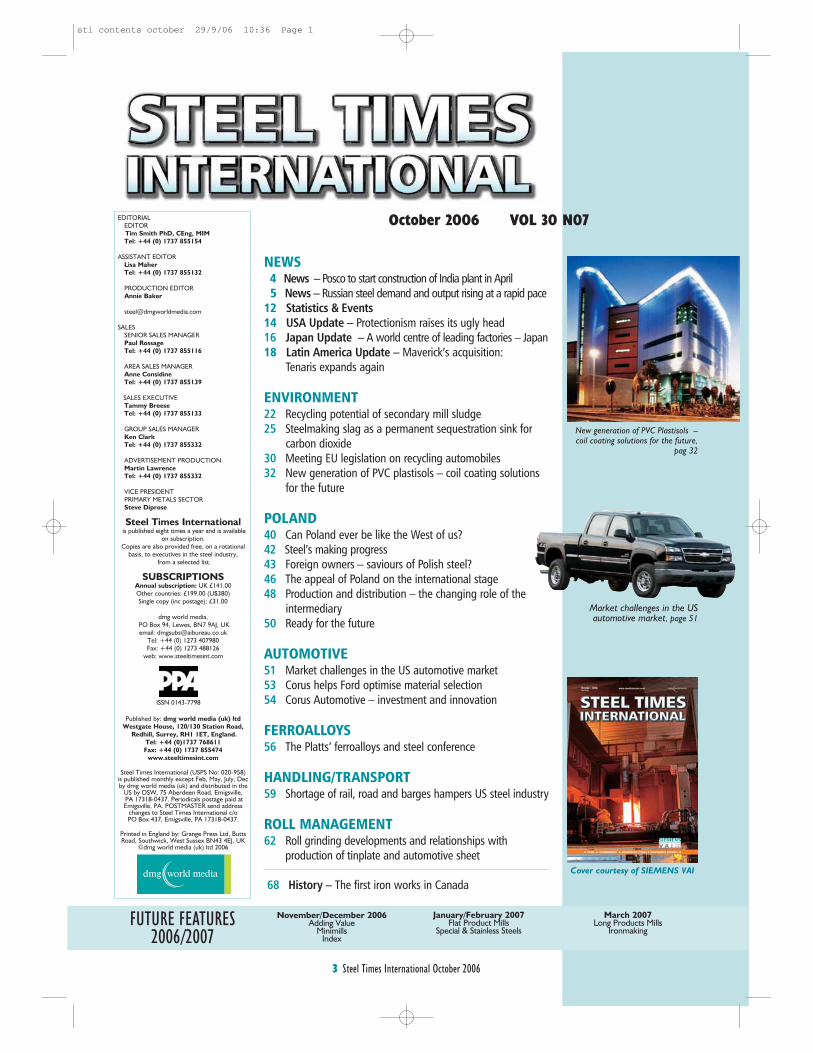
FUTURE FEATURES2006/2007
November/December 2006Adding Value
MinimillsIndex
January/February 2007Flat Product Mills
Special & Stainless Steels
March 2007Long Products Mills
Ironmaking
3 Steel Times International October 2006
EDITORIALEDITORTim Smith PhD, CEng, MIMTel: +44 (0) 1737 855154
ASSISTANT EDITORLisa Maher Tel: +44 (0) 1737 855132
PRODUCTION EDITORAnnie Baker
SALESSENIOR SALES MANAGERPaul RossageTel: +44 (0) 1737 855116
AREA SALES MANAGERAnne ConsidineTel: +44 (0) 1737 855139
SALES EXECUTIVETammy BreeseTel: +44 (0) 1737 855133
GROUP SALES MANAGERKen ClarkTel: +44 (0) 1737 855332
ADVERTISEMENT PRODUCTIONMartin LawrenceTel: +44 (0) 1737 855332
VICE PRESIDENT PRIMARY METALS SECTORSteve Diprose
Steel Times Internationalis published eight times a year and is available
on subscription.Copies are also provided free, on a rotational
basis, to executives in the steel industry,from a selected list.
SUBSCRIPTIONSAnnual subscription: UK £141.00Other countries: £199.00 (U$380)Single copy (inc postage): £31.00
dmg world media,PO Box 94, Lewes, BN7 9AJ, UKemail: [email protected]
Tel: +44 (0) 1273 407980Fax: +44 (0) 1273 488126
web: www.steeltimesint.com
Published by: dmg world media (uk) ltdWestgate House, 120/130 Station Road,
Redhill, Surrey, RH1 1ET, England.Tel: +44 (0)1737 768611Fax: +44 (0) 1737 855474
www.steeltimesint.com
Steel Times International (USPS No: 020-958)is published monthly except Feb, May, July, Decby dmg world media (uk) and distributed in the
US by DSW, 75 Aberdeen Road, Emigsville,PA 17318-0437. Periodicals postage paid atEmigsville, PA. POSTMASTER send address
changes to Steel Times International c/o PO Box 437, Emigsville, PA 17318-0437.
Printed in England by: Grange Press Ltd, ButtsRoad, Southwick, West Sussex BN43 4EJ, UK
©dmg world media (uk) ltd 2006
NEWS4 News – Posco to start construction of India plant in April5 News – Russian steel demand and output rising at a rapid pace
12 Statistics & Events 14 USA Update – Protectionism raises its ugly head 16 Japan Update – A world centre of leading factories – Japan 18 Latin America Update – Maverick’s acquisition:
Tenaris expands again
ENVIRONMENT22 Recycling potential of secondary mill sludge 25 Steelmaking slag as a permanent sequestration sink for
carbon dioxide30 Meeting EU legislation on recycling automobiles 32 New generation of PVC plastisols – coil coating solutions
for the future
POLAND40 Can Poland ever be like the West of us?42 Steel’s making progress43 Foreign owners – saviours of Polish steel? 46 The appeal of Poland on the international stage48 Production and distribution – the changing role of the
intermediary50 Ready for the future
AUTOMOTIVE51 Market challenges in the US automotive market53 Corus helps Ford optimise material selection54 Corus Automotive – investment and innovation
FERROALLOYS56 The Platts’ ferroalloys and steel conference
HANDLING/TRANSPORT59 Shortage of rail, road and barges hampers US steel industry
ROLL MANAGEMENT62 Roll grinding developments and relationships with
production of tinplate and automotive sheet
68 History – The first iron works in Canada
Market challenges in the USautomotive market, page 51
Cover courtesy of SIEMENS VAI
ISSN 0143-7798
New generation of PVC Plastisols –coil coating solutions for the future,
pag 32
October 2006 VOL 30 N07
sti contents october 29/9/06 10:36 Page 1
WORLD NEWS
4 Steel Times International October 2006
DGCX to launch steel futures in 2007Dubai Gold and Commodities
Exchange (DGCX) will launch a
steel futures contract, early next
year. The company’s CEO said the
launch of steel futures would give
the company two innovative
products (the other is a fuel oil
contract, to be launched on
October 30).
TK sells minority shareholding inWickeder Westfalenstahl Wickeder Westfalenstahl GmbH,
based in Wickede (Ruhr,
Germany), has bought back the
25.1% share in its capital held by
ThyssenKrupp Steel AG.
Wickeder is an SME focussed on
the production of cold-rolled strip,
clad materials and components for
CRT monitors – not a core activity
for ThyssenKrupp Steel.
However, the companies’ long-
standing business partnership for
starting material supplies and
intensive exchange of know-how
will continue.
www.thyssenkrupp-steel.de
Maverick/Tenaris merger approved
The Colombian Superintendence
of Industry and Commerce has
completed its review and has
cleared the proposed merger
without conditions; the Colombian
condition precedent in the merger
agreement with Tenaris is now
satisfied. The proposed merger
has now been cleared by
competition authorities in all those
jurisdictions in which it was a
prerequisite. Maverick’s special
meeting of stockholders – to vote
on the proposed merger – was
scheduled for October 2, 2006
(see page 18).
New Chinese contracts for DanieliDanieli Wean United recently
signed a contract for a new
continuous hot dip galvanising line
for the Tianjin Tiantie
Metallurgical Steel Plate Co Ltd
and another with the Changshu
Everbright Material Technology
Co, Ltd (China) for two new
continuous hot dip galvanising
lines.
IN BRIEF
Following delays in land
acquisition for Posco’s proposed
steel plant in Orissa, India, the
company has changed its plans
and hopes to begin construction
work from April 2007.
The company has decided to
begin construction with partial
acquisition of land; of a total 4000
acres, around 3500 acres is
Government-owned, the rest is
tribal land.
Posco India’s chairman/
managing director, Mr Cho Soung-
Sik said recently that there had
been resistance to the project,
particularly on land acquisition.
“There were 6000 objections of
which around 2500 have been
heard with another 3,500
objections due to be heard in the
next two months. After that,
negotiations for compensation can
start.”
Regarding the Orissa
government’s proposal that Posco
use Paradip port to meet its
requirements instead of setting up
a captive port of its own, Mr Cho
said there were two points: “Orissa
definitely needs more ports. So
why object. Secondly, all the top
steel plants have their own ports –
it is necessary to be competitive.”
On the issue of iron ore export,
he noted that the company would
be exchanging 30% of its 600Mt
iron ore location. “We will send
Orissan ore with 4.5% alumina
content to our Korean plant and
replace the same amount with
0.6% alumina content Brazilian
ore. This blending is necessary for
large size blast furnaces,” he said.
Source: The Hindu Business Line
Posco to start construction of India plant in April
The Italian steel producer Acciaieria
Arvedi SpA (Cremona) will build the
world’s first Arvedi ESP (Endless
Strip Production) plant which will
continuously produce finished steel
strip from liquid steel in an endless
process. The combination of
different and, till now, separate
process steps in a single production
process will enable the direct and
continuous production of high
quality steel strip and so result in
significantly lower production costs.
Arvedi’s partner for this is Siemens
VAI; they have established a joint
venture company, Cremona
Engineering srl, to be responsible
for development and design of the
new plant and to market this
technology on a worldwide basis in
the future. The first plant is already
scheduled for start-up in 2008 in
Cremona.
(A full technical article will appear in the
November issue of Steel Times
International.)
Arvedi, Siemens to build world’s first steel ESP plant
In an unusual move, during a recent
visit to Beijing a senior official of
Japan’s Economy, Trade and
Industry Ministry (METI) asked
China to cut its steel production
capacity.
Tetsuhiro Hosono, director
general of METI’s Manufacturing
Industries Bureau, made the
request directly to Liu Tienan,
director of the Industry Department
of China’s National Development
and Reform Commission, which is
in charge of economic policy.
Liu expressed a willingness to
make efforts to cut China’s steel
output capacity, which has
expanded exponentially as the
country gears up for the Beijing
Olympics in 2008.
The Japanese government
decided that China's crude steel
Japan asks China to reduce steel capacity
Hazira picks ABB to equip South Asia’s largest plate millABB has won an order from Hazira
Plate Ltd, part of India’s Essar
Group, to support construction of
the largest plate mill in South Asia.
ABB’ scope of supply for the hot
rolling mill includes plant design,
dimensioning, supply and
commissioning of low-voltage and
medium-voltage motors and drive
systems.
The new Hazira hot rolling mill,
scheduled to begin operation in
early 2008, will be the largest of its
type in India and the South Asia
region. ABB orders for hot rolling
mill applications in India have
exceeded $25M so far in 2006.
output could cause steel prices to
plunge across the world, adversely
affecting Japan’s economy.
Therefore, Hosono asked the
Chinese government to abolish
small blast furnaces with a
capacity of 300m3 or less. In
exchange, Japan would help scrap
the facilities and offer
environmental protection
assistance and energy-saving
technologies via major Japanese
steelmakers.
Sinosteel Corp may construct its
first steel plant in India, building its
planned 3Mt/y plant in the states of
Orissa, Jharkhand or West Bengal,
competing with ventures planned
by Mittal Steel Co and Posco. The
company may initially invest
US$500M in the venture and is
seeking rights to mine 5Mt/y of iron
ore for up to two decades. it will
decide on a location once its study
is completed.
Sinosteel to build Indian plantFor further news stories and
updates visitwww.steeltimesint.com
click on the ‘News’ button to seethe full list of news and features
STI NEWS october 28/9/06 12:09 Page 1

WORLD NEWS
5 Steel Times International October 2006
Resita Works renamed
At an Extraordinary general
shareholders meeting of SC CSR
SA (Resita, Romania), a
subsidiary of Russian steelmaker
TMK, a decision was adopted to
rename the plant SC TMK-Resita
SA. The decision was adopted to
strengthen the single TMK
corporate brand, following TMK’s
acquisition in March 2006 of
Sinara Handel GmbH, which
owned the controlling stake in two
Romanian companies SC TMK-
Artrom SA Pipe Plant (Slatina) and
SC TMK-Resita SA Metallurgical
Works (Resita).
While TMK-Artrom specialises in
the production of seamless pipes,
the Resita works has 500kt/y
capacity for EAF steel and 700kt/y
capacity for rolled steel.
Novolipetsk Steel profit to rise to$3.7bn/y by 2011
Novolipetsk Steel expects its
average operating income to
increase to $3.7bn/y by 2011.
Operating income in H1 2006 fell
16% to US$925.3M.
Novolipetsk, one of Russia's biggest
steel and rolled stock producers,
plans to raise steel output by 40%
to 12.4Mt/y and rolled stock
production to 9.5Mt/y, including
3.5Mt to be produced abroad.
It also said its purchase of the
Urals-based private steel maker
VIZ-stal in August 2006 has
already produced savings of
$180M.
BlueScope moves to blockSmorgon merger
According to various reports,
BlueScope Steel, the largest steel
company in Australia, acquired a
19.9% block of shares in Smorgon
Steel to ensure that the pending
OneSteel/Smorgon merger could
not proceed in its currently
proposed form. BlueScope
expressed its concern that the
combination of the two companies
would create competition
problems. It does not plan to
increase its stake prior to any
merger.
IN BRIEF
In the year ending March 2006,
JFE Steel managed to secure a high
level of earnings on the back of
brisk demand in the manufacturing
industry, especially in the
automotive sector.
Iran’s steel industry has registered
a 5% growth during the first five
months of its current year (the
Iranian year started on March 21,
2006). The industry had shown a
growth of about 2.5% during the
previous 16 months.
Exports of steel products
increased by about 4% this year
despite the fact that, due to market
regulatory measures taken by the
Iranian government, no semis were
exported during that time.
Supplying the earthquake-
stricken regions of Iran with
products has meant steel plants
operating at full capacity; a new
steel production plant will be
launched within the next four
months.
Steel consumption in the Russian
Federation is growing strongly: the
country’s mills are cutting exports
as higher prices are available in the
home market.
Since it touched a low point of
14.6Mt in 1998, Russian steel
consumption has increased by an
average of 10% annually. However,
in H1 2006, that rate of growth has
more than doubled to 21%,
according to preliminary estimates
by the Ministry for Industry and
Energy. Annual consumption of
finished steel has now increased to
more than 35Mt.
Gross domestic product rose by
more than 6% in 2005; this year’s
projection is 4-5%. High global
prices for fuels – Russia’s largest
industry by value – are promoting
strong levels of investment in new
installations for the production and
transport of oil and gas.
Source: MEPS – European SteelReview
JFE’s year end results
Operating results (in ¥bn)
Year ending
31 March 2005 2006
Consolidatednet sales 2421.7 2753.8Consolidatedoperating income 456.3 513.8
Consolidatedordinary income 450.3 510.7
Consolidated crude steel output
decreased to 30.15Mt as
production, especially regarding
thin sheet in the domestic and
Asian markets, was adjusted to
improve the demand/supply
balance. Net sales increased to
¥2753.8bn (US$23.6bn),
reflecting flexible management of
production and sales according to
market trends.
Ordinary income increased to
¥510.7bn (US$4.38bn) –
attributed to accelerated sales of
high value-added products and
further reductions in costs. Its
subsidiaries also did comparatively
well, offsetting the impact of
increased raw material prices.
The company expects demand
for high end products to remain
robust in the year to March 2007.
Russian steel demand and output rising at a rapid pace
Iran’s steel industry registers 5%growth in five months
Chinese steelmakers may need to
be sued for dumping processed
steel on the Vietnam market at
excessively low prices, steel
industry experts commented at
recent talks, held by the Market
Control Department and the
Vietnam Steelmakers Association,
on strengthening controls over
imported steel.
Although the cost of producing
steel from steel semis adds US$30-
35/t to the cost of processed steel,
processed steel imported from China
was currently entering Vietnam at a
price that failed to reflect this
processing cost, said experts.
Processed steel from China was
currently priced at about $400-
409/t. According to the Steelmakers
Association, an additional $30-35/t
and a 10% import duty should be
factored onto this cost.
According to the Steelmakers
Association, 5kt of rolled steel were
recently imported into Vietnam and
about 10kt more would be imported
in the near future.
The Steelmakers Association has
requested that domestic steel
producers cut production costs and
seek lower-priced sources of semis
in order to lower steel prices.
Monthly demand for rolled steel in
the country’s northern region is
around 30kt.
Source: Daily “Vietnam News”
Vietnam considers anti-dumping actionagainst Chinese steel makers
Essar Steel is facing serious
environmental challenges in its
quest to construct a US$1.2bn steel
plant in Central Trinidad.
The Pranz Village Development
Community is protesting the
company’s decision to construct the
plant, citing environmental, health
and social issues. The community
plans to go to court on the matter.
In response, the company has
proposed a green belt with trees as
high as 30’ (9.14m). ‘The plant
would have gas extraction
Essar Steel faces challenges in Trinidad mechanisms to collect and recycle
gases back into the processing
system,’ the company said in a
statement.
It also said that it would import iron
ore, which will be transported from
the Point Lisas Port, adding that the
company was subject to a certificate
of environmental clearance.
STI NEWS october 28/9/06 12:09 Page 2
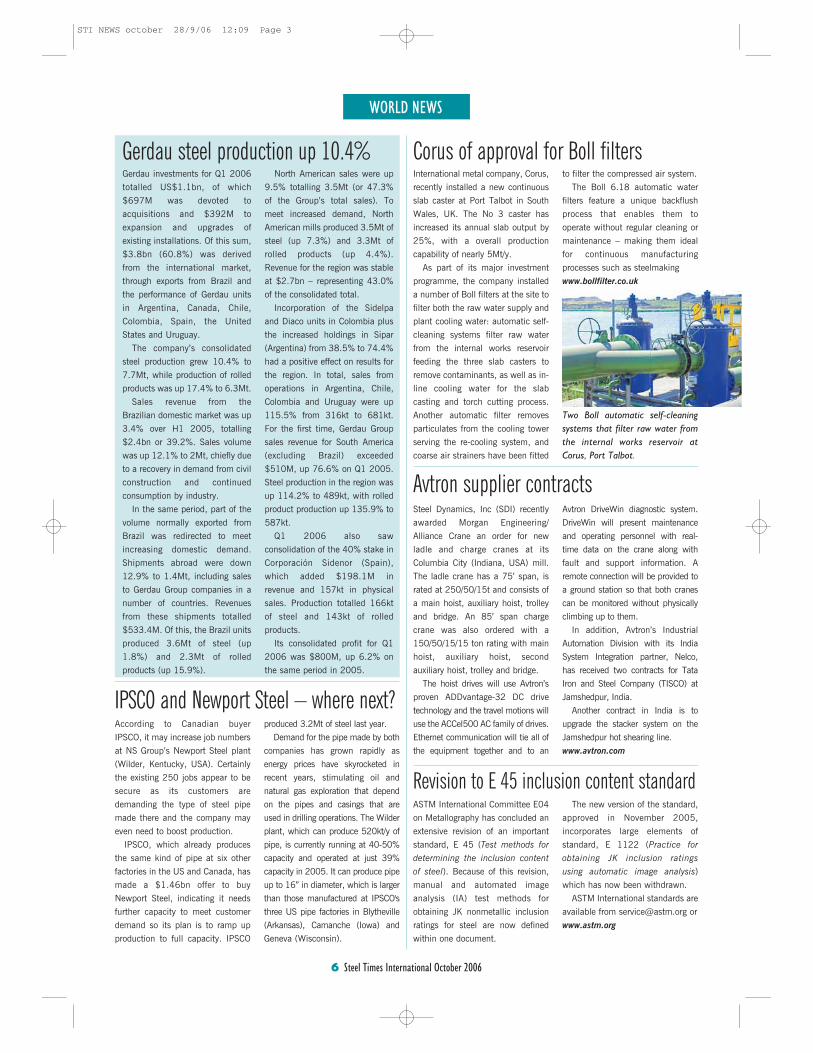
WORLD NEWS
6 Steel Times International October 2006
Gerdau investments for Q1 2006
totalled US$1.1bn, of which
$697M was devoted to
acquisitions and $392M to
expansion and upgrades of
existing installations. Of this sum,
$3.8bn (60.8%) was derived
from the international market,
through exports from Brazil and
the performance of Gerdau units
in Argentina, Canada, Chile,
Colombia, Spain, the United
States and Uruguay.
The company’s consolidated
steel production grew 10.4% to
7.7Mt, while production of rolled
products was up 17.4% to 6.3Mt.
Sales revenue from the
Brazilian domestic market was up
3.4% over H1 2005, totalling
$2.4bn or 39.2%. Sales volume
was up 12.1% to 2Mt, chiefly due
to a recovery in demand from civil
construction and continued
consumption by industry.
In the same period, part of the
volume normally exported from
Brazil was redirected to meet
increasing domestic demand.
Shipments abroad were down
12.9% to 1.4Mt, including sales
to Gerdau Group companies in a
number of countries. Revenues
from these shipments totalled
$533.4M. Of this, the Brazil units
produced 3.6Mt of steel (up
1.8%) and 2.3Mt of rolled
products (up 15.9%).
North American sales were up
9.5% totalling 3.5Mt (or 47.3%
of the Group’s total sales). To
meet increased demand, North
American mills produced 3.5Mt of
steel (up 7.3%) and 3.3Mt of
rolled products (up 4.4%).
Revenue for the region was stable
at $2.7bn – representing 43.0%
of the consolidated total.
Incorporation of the Sidelpa
and Diaco units in Colombia plus
the increased holdings in Sipar
(Argentina) from 38.5% to 74.4%
had a positive effect on results for
the region. In total, sales from
operations in Argentina, Chile,
Colombia and Uruguay were up
115.5% from 316kt to 681kt.
For the first time, Gerdau Group
sales revenue for South America
(excluding Brazil) exceeded
$510M, up 76.6% on Q1 2005.
Steel production in the region was
up 114.2% to 489kt, with rolled
product production up 135.9% to
587kt.
Q1 2006 also saw
consolidation of the 40% stake in
Corporación Sidenor (Spain),
which added $198.1M in
revenue and 157kt in physical
sales. Production totalled 166kt
of steel and 143kt of rolled
products.
Its consolidated profit for Q1
2006 was $800M, up 6.2% on
the same period in 2005.
Gerdau steel production up 10.4%
Revision to E 45 inclusion content standardASTM International Committee E04
on Metallography has concluded an
extensive revision of an important
standard, E 45 (Test methods for
determining the inclusion content
of steel). Because of this revision,
manual and automated image
analysis (IA) test methods for
obtaining JK nonmetallic inclusion
ratings for steel are now defined
within one document.
The new version of the standard,
approved in November 2005,
incorporates large elements of
standard, E 1122 (Practice for
obtaining JK inclusion ratings
using automatic image analysis)
which has now been withdrawn.
ASTM International standards are
available from [email protected] or
www.astm.org
International metal company, Corus,
recently installed a new continuous
slab caster at Port Talbot in South
Wales, UK. The No 3 caster has
increased its annual slab output by
25%, with a overall production
capability of nearly 5Mt/y.
As part of its major investment
programme, the company installed
a number of Boll filters at the site to
filter both the raw water supply and
plant cooling water: automatic self-
cleaning systems filter raw water
from the internal works reservoir
feeding the three slab casters to
remove contaminants, as well as in-
line cooling water for the slab
casting and torch cutting process.
Another automatic filter removes
particulates from the cooling tower
serving the re-cooling system, and
coarse air strainers have been fitted
Corus of approval for Boll filtersto filter the compressed air system.
The Boll 6.18 automatic water
filters feature a unique backflush
process that enables them to
operate without regular cleaning or
maintenance – making them ideal
for continuous manufacturing
processes such as steelmaking
www.bollfilter.co.uk
Two Boll automatic self-cleaningsystems that filter raw water fromthe internal works reservoir atCorus, Port Talbot.
According to Canadian buyer
IPSCO, it may increase job numbers
at NS Group’s Newport Steel plant
(Wilder, Kentucky, USA). Certainly
the existing 250 jobs appear to be
secure as its customers are
demanding the type of steel pipe
made there and the company may
even need to boost production.
IPSCO, which already produces
the same kind of pipe at six other
factories in the US and Canada, has
made a $1.46bn offer to buy
Newport Steel, indicating it needs
further capacity to meet customer
demand so its plan is to ramp up
production to full capacity. IPSCO
produced 3.2Mt of steel last year.
Demand for the pipe made by both
companies has grown rapidly as
energy prices have skyrocketed in
recent years, stimulating oil and
natural gas exploration that depend
on the pipes and casings that are
used in drilling operations. The Wilder
plant, which can produce 520kt/y of
pipe, is currently running at 40-50%
capacity and operated at just 39%
capacity in 2005. It can produce pipe
up to 16” in diameter, which is larger
than those manufactured at IPSCO's
three US pipe factories in Blytheville
(Arkansas), Camanche (Iowa) and
Geneva (Wisconsin).
IPSCO and Newport Steel – where next?
Steel Dynamics, Inc (SDI) recently
awarded Morgan Engineering/
Alliance Crane an order for new
ladle and charge cranes at its
Columbia City (Indiana, USA) mill.
The ladle crane has a 75’ span, is
rated at 250/50/15t and consists of
a main hoist, auxiliary hoist, trolley
and bridge. An 85’ span charge
crane was also ordered with a
150/50/15/15 ton rating with main
hoist, auxiliary hoist, second
auxiliary hoist, trolley and bridge.
The hoist drives will use Avtron’s
proven ADDvantage-32 DC drive
technology and the travel motions will
use the ACCel500 AC family of drives.
Ethernet communication will tie all of
the equipment together and to an
Avtron DriveWin diagnostic system.
DriveWin will present maintenance
and operating personnel with real-
time data on the crane along with
fault and support information. A
remote connection will be provided to
a ground station so that both cranes
can be monitored without physically
climbing up to them.
In addition, Avtron’s Industrial
Automation Division with its India
System Integration partner, Nelco,
has received two contracts for Tata
Iron and Steel Company (TISCO) at
Jamshedpur, India.
Another contract in India is to
upgrade the stacker system on the
Jamshedpur hot shearing line.
www.avtron.com
Avtron supplier contracts
STI NEWS october 28/9/06 12:09 Page 3
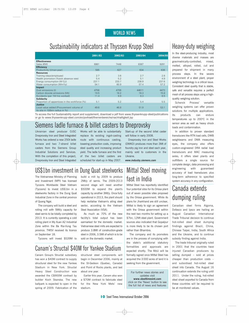
WORLD NEWS
10 Steel Times International October 2006
In the steel-producing industry, most
diverse materials and masses are
gravimetrically-controlled, mixed,
melted, alloyed, rolled, cut and
prepared for shipment in many
process steps. In the severe
environment of a steel plant, proper
weighing technology is a critical issue.
Consistent steel quality that is stable,
safe and versatile requires a perfect
mesh of all process steps using a high-
quality weighing solution.
Schenck Process’ versatile
weighing systems can offer proven
solutions for multiple applications.
Its products can endure
temperatures up to 200°C in the
sensor area as well as heavy shock
loads and contamination.
In addition to proven standard
transducers like RTN load cells, DWB
weighbeams and DMA measuring
eyes, the company also offers
custom-engineered DRA radial load
transducers and MAC measuring
axles; it offers steel plants and
outfitters a single source for
complete design, data processing and
engineering with guaranteed
accuracy of load transducers plus
long-term adherence to specified
system accuracy in any configuration.
Ukrainian steel producer OJSC
Dneprovsky Iron and Steel Integrated
Works has ordered a new 250t ladle
furnace and two 7-strand billet
casters from the Siemens Group
Industrial Solutions and Services.
With the completion of this project,
Dneprovsky Iron and Steel Integrated
Works will be able to substantially
replace its existing ingot-casting
route with continuous casting,
lowering production costs, improving
steel quality and increasing product
yield. The ladle furnace and the first
of the two billet casters are
scheduled for start-up in May 2007.
Start-up of the second billet caster
will follow in early 2008.
Dneprovsky Iron and Steel Works
(DMKD) produces more than 3Mt of
foundry pig iron and steel each year,
mainly sold to customers in the
Ukraine.
www.industry.siemens.com
Siemens ladle furnace & billet casters to Dneprovsky
Heavy-duty weighingSustainability indicators at Thyssen Krupp Steel2001/02 2002/03 2003/04 2004/05
EffectivenessSales (€M) 6861 7448 8387 9291EfficiencyProductivity (t/man-year) 585 627 634 636ResourcesTraining (days/employee) 2.7 3.6 2.7 2.8Health promotion (%sick absence rate) 5.4 5.2 5.1 4.9Energy consumption (M GJ) 237.1 233.7 238.9 237.6Water consumption (Mm3/y) 54.1 60.9 57.4 57.2ImpactDust emissions (t) 4756 4706 44611 4473Carbon dioxide emissions (Mt) 19.5 18.2 16.3 15.8Accidents (per 1M hrs worked) 11.4 9.9 8.3 8.5SolidarityProportion of appentices in the workforce (%) 5.1 5.2 5.4 5.5JusticeLocal value added (Procurement volume of 49.6 46.8 51.9 53.1its site in 100km radius in %)
To access the full Sustainability report and supplement, download a pdf from www.thyssenkrupp-steel/publicationsor go to www.thyssenkrupp-steel.com/en/portraet/themenbereiche/nachhaltigkeit.jsp
The Vietnamese Ministry of Planning
and Investment (MPI) has licensed
Tycoons Worldwide Steel Vietnam
(Tycoons) to invest US$1bn in a
steelworks factory in the Dung Quat
Industrial Zone in the central province
of Quang Ngai.
The company will build a steel and
rolling mill with 5Mt/y capacity for
steel semis to be totally completed by
2013. It is currently operating a cold
rolling plant in My Xuan A2 Industrial
Zone within the Ba Ria-Vung Tau
province. TWSV received its licence
on September 18.
Tycoons will invest $539M to
build a mill by 2009 to produce
2Mt/y of semis. The 2009-2013
second stage will need another
$500M to expand the plant's
capacity by another 3Mt/y. Once fully
operational in 2013, the plant should
help revitalise Vietnam's ailing steel
sector, according to the Vietnam
Steel Association (VSA).
As much as 70% of the new
facility’s total output has been
earmarked for the domestic market.
Vietnamese steel mills are expected to
produce 3.8Mt of construction-grade
steel in 2006, 3.5Mt of which is to be
sold on the domestic market.
US$1bn investment in Dung Quat steelworks
Canam Group's Structal subsidiary
has won a $40M contract to supply
structural steel for the new Yankee
Stadium in New York. Structal
Heavy Steel Construction was
awarded the C$900M contract by
builder Koch Skanska. The new
ballpark is expected to open in the
spring of 2009. Fabrication of the
structural steel components will
begin in December 2006, mainly at
the St-Gedeon (Quebec, Canada)
and Point of Rocks plants, and last
about one year.
Earlier this year, Canam also won
a $70M contract to fabricate steel
for the New York Mets’ new
stadium.
Canam’s Structal $40M for Yankee Stadium
Mittal Steel has reportedly identified
four potential sites for its Orissa plant
out of seven possible sites proposed
by the Orissa government. While its
plans for Jharkhand are still unclear,
Mittal is likely to sign an agreement
with the Orissa government within
the next two months for setting up a
$7bn, 12Mt steel plant. Government
sources also indicated that Gopalpur
is more likely to be its chosen port
rather than Bhambra.
The company and its promoters
are in the process of complying with
the state’s additional statutory
formalities and approvals are
expected shortly. The MoU will be
formally signed once Mittal Steel has
acquired the 3 000 acres of land it is
seeking from the government.
Mittal Steel movingfast in India
Canadian steel firms Algoma,
Dofasco and Ipsco are hailing an
August Canadian International
Trade Tribunal decision to continue
hot-rolled steel sheet dumping
findings against Brazil, China,
Chinese Taipei, India, South Africa
and the Ukraine, and to continue
subsidy finding against India.
The trade tribunal originally ruled
in 2001 that the countries have
injured Canadian producers by
selling dumped – sold at prices
cheaper than production costs –
and subsidised hot-rolled steel
sheet into Canada. The August 16
continuation extends the ruling until
2011. Under the ruling, hot-rolled
steel sheet exported to Canada from
these countries will be required to
be at monitored values.
Canada extendsdumping ruling
For further news stories andupdates visit
www.steeltimesint.comclick on the ‘News’ button to seethe full list of news and features
STI NEWS october 28/9/06 12:09 Page 4
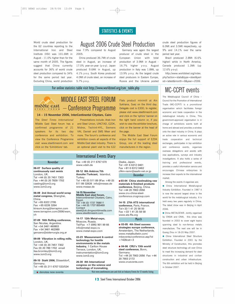
STATISTICS & EVENTS
12 Steel Times International October 2006
06-07 Surface quality ofcontinuously cast semisLondon, UK.Tel +44 (0) 20 7451 7303Fax +44 (0) 20 7839 [email protected]
06-08 2nd Annual world scrapmetal congress, Shanghai,China.Tel +65 6322 2795Fax +65 6226 [email protected]/2006/wsm_ch
07-09 16th Rolling conference,San Nicolas, Argentina. Tel +54 3461 460803Fax +54 3461 [email protected]
09-09 Vibration in rolling mills,London, UK.Tel +44 (0) 20 7451 7302 Fax (0) 20 789 1702 [email protected]
09-10 Stahl 2006, Düsseldorf,Germany.Tel +49 (0) 211 6707 533/534
Fax +49 (0) 211 6767 670www.vdeh.de
09-12 8th Ankiros/7thAnnofer/Turkcast, Istambul,Turkey.Tel +49 (0) 511 89 0Fax +49 (0)511 89 32626 [email protected]
14-15 NovemberMiddle East steel forum,Intercontinental Citystars, Cairo, Egypt.Tel +44 (0) 1737 768611Fax +44 (0) 1737 [email protected]
14-17 12th Metal-expo,Moscow, Russia.Tel/Fax +7 (095) 901 99 [email protected]
22-23 Measurement & controltechnology for hostileenvironments in the metalsindustry, 1 Carlton HouseTerrace, London, [email protected]
26-30 4th Internationalcongress on the science andtechnology of ironmaking,
Osaka, Japan.Tel +81 6 6312 0461Fax +81 6 6312 0462 [email protected]
� 03-04 China steelmaking rawmaterials & finished productsconference, Beijing, China.Tel +44 20 7903 2056www.cru-china-steel-conference.crugroup.com
14-15 27th ATS internationalconference, Paris, France.Tel+33 1 41 25 58 00Fax +33 1 41 25 58 58www.ats-ffa.org
� 03-05 4th Steel successstrategies europe conference,Amsterdam, The Netherlands.www.metalbulletin.com/mbevents/conference.asp?id=142&cat=3
� 04-06 CRU’s 13th worldsteel conference, Bonn,Germany.Tel +44 20 7903 2056 Fax +4420 7903 2172www.cruevents.com
December
March
November
Visit www.steeltimesint.com and click on Industry Events for 12 months listing
International Events Diary
� denotes new events
For online statistics table visit http://www.worldsteel.org/csm_table.php
The Steel Times International
Middle East Steel forum has a
confirmed programme of 21
speakers for its two day
conference and exhibition. To
view the Conference Programme
visit www.steeltimesint.com and
click on the ‘Exhibitions’ tab.
Presentations include: Arab Iron
and Steel Union, UNCTAD, EZDK,
Midrex, Techint-HYL, Siemens
VAI, Danieli and SMS Meer and
more. The forum’s conference and
exhibition covers all aspects of the
Middle East steel industry. There is
an optional plant visit to the EZZ
MIDDLE EAST STEEL FORUM – Conference Programme
14 – 15 November 2006, InterContinental Citystars, Cairo
The Metallurgical Council of China –
Council for the Promotion of International
Trade (MC-CCPIT) is a promotional
organisation which facilitates foreign
economic and trade cooperation in the
metallurgical industry in China. This
government-approved organisation is in
charge of exhibitions events both at
home and abroad and provides a window
onto the steel industry in China. It plays
an active role in various economic and
trade cooperation and technical
exchanges, participates in top exhibition
and conference events, organises
overseas delegations and assists with
visa applications, surveys and industry
investigations. It also holds a series of
training and professional events,
provides a useful information service and
encourages Chinese enterprises to
increase their exports to the international
market.
Among the events it organises are:
� China International Metallurgical
Industry Exhibition. Founded in 1987 it
is now the second largest show in the
world for the metallurgical industry. It is
held every two years regularly in China.
The latest show was in Beijing in April
2006.
� China METALSFAIR. Jointly organised
by CNSIA and CNIA, this show was
founded in 2003 to cover eight topics
spanning steel to non-ferrous metals
manufacture. The next one will be in
Guang Zhou in 18-20 May 2007.
� China International Steel Structure
Exhibition. Founded in 2001 by the
Ministry of Construction, this promotes
steel structure technology all over China
to meet the increasing demand for steel
structures in industrial and civilian
construction and urban infrastructure.
The 6th exhibition will be held in Beijing
in October 2007.
MC-CCPIT events
World crude steel production for
the 62 countries reporting to the
International Iron and Steel
Institute (IISI) was 101.6Mt in
August - 11.0% higher than for the
same month of 2005. The figures
suggest that China currently
accounts for 36% of world crude
steel production compared to 34%
for the same period last year.
Excluding China, world production
August 2006 Crude Steel Productionrose 7.9% compared to August
2005.
China produced 36.7Mt of crude
steel in August, an increase of
17.0% year-on-year (y-o-y). Japan
produced 9.6Mt in August, up
4.1% y-o-y. South Korea produced
4.0Mt of crude steel, an increase of
5.7% y-o-y.
Germany was again the largest
producer of crude steel in the
European Union with total
production of 3.9Mt in August -
16.7% higher y-o-y. August
production in Italy was 1.8Mt, up
13.9% y-o-y. As the largest crude
steel producers in Eastern Europe,
Russia and the Ukraine posted
crude steel production figures of
6.0Mt and 3.5Mt respectively, up
9% and 14.1% over the same
period last year.
Brazil produced 2.8Mt (6.6%
higher) while in North America,
Canada produced 1.3Mt (up
12.6% y-o-y).
http://www.worldsteel.org/index.
php?action=stats&type=steel&peri
od=latest&month=8&year=2006
Flats product minimill at Ain
Sukhana, Suez on the third day.
Delegate cost is £300; to register,
please visit www.steeltimesint.com
and click on the ‘sphinx’ banner on
the right hand column or, if you
wish to view the exhibitor brochure,
click on the banner at the head of
the page.
The Middle East Steel Forum
enjoys the full support of EZDK
Group, one of the leading steel
manufacturers in the region.
STI NEWS october 28/9/06 12:09 Page 5
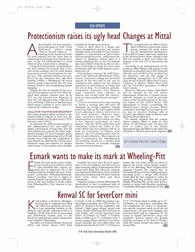
A sked whether US steel manufac-turers will again cry ‘wolf’ a NewYork-based analyst quips“They’ve already begun to …”,referring to the unease felt in the
US steel industry over the latest data onrising imports of foreign steel and the pres-sure on the US administration to crackdown on what is perceived as dumping.
Using the latest statistics as ammunition,the steel industry has warned that, if cur-rent trends continue, the US could shatterits previous record in steel imports in a sin-gle year. This ominous forecast was rein-forced by the American Iron and SteelInstitute (AISI), a Washington DC-basedinterest group representing the US steelindustry, which is also campaigning againstdumping.
During the first six months of the year,overall steel imports rose by 33% while fin-ished steel product imports were up by32% over the previous year. However, inJune the US imported some 3.4Mt net ofsteel, including 2.9Mt net of finished steel,which meant a decline of 14.4% and 9.2%respectively compared to May.
CALLS FOR TIGHTER ENFORCEMENTTwo major products which recorded a sub-stantial jump in imports in June over theprevious month were tin plate steel (+53%)and wire rods (+50%).
As expected, the AISI reacted strongly tothis ‘unprecedented rise’ and called fortighter enforcement of trade laws. The USsteel industry has rejected the belief, wide-spread amongst US steel consumer indus-tries, that steel manufacturing in the US willbecome more efficient and competitive ifsteel imports are allowed; the US steel man-ufacturers argue that imports are cheaperonly because of the massive state subsidies
provided by foreign governments. China is often cited as a classic case
where manipulated currency and massivesubsidies make it possible for that country’ssuppliers to ship products at prices lowerthan the production costs – which meets thecriteria of ‘dumping’. Indeed, there is astrong underlying fear in the US industrythat, once China’s domestic needs are satis-fied, it will begin to dump the excess steelproduction onto the world markets, partic-ularly the US.
Voicing these concerns, the AISI chair-man Louis Schorsch (Mittal Steel USA),issued a statement linking the increasedimports in the first half of the year tocontinued state support for the massiveexpansion of steel capacity in China andthe rest of Asia. “A revitalised, globally-competitive American steel industryurges continued close vigilance ofimports and strong trade law enforce-ment to ensure market-based outcomes,”he said.
US steel executives have been meetingto devise a strategy that will ward off‘dumping’ by foreign suppliers, thoughmany see China as the main culprit whichis not adhering to what is referred to as‘fair trade practices’. However, thesesame executives know that the USadministration received a black eye whenit last imposed restrictions on steelimports, with the WTO ruling that suchrestrictions violated the tenets of freetrade. While the steel industry will try topush for restrictions on Chinese steelimports, the US administration will bewary of such initiatives. Most experts saythat, if pressurised, the administrationwill probably search for a ‘middle pathsolution’ between an outright stoppageand unrestricted imports.
USA UPDATE
14 Steel Times International October 2006
BY MANIK MEHTA, NEW YORKSTI
STI
STI
STI
Protectionism raises its ugly head The reorganisation at Mittal Steel’s
plant in Weirton caused some initialunease amongst the trade unionsbut the Independent Steelworkers
Union (ISU) leaders expressed confidencein the Weirton plant’s future, though it saidthat was waiting to hear more about thestrategy of the new VP of operations andCEO.
According to an announcement by thecompany, Mike Rippey will replace LouisSchorsch as president and CEO; Schorschwill take over as CEO of flat products forthe Americas, and will take charge ofstreamlining management for CST andVega do Sol in Brazil, Mittal Steel LazaroCardenas in Mexico, Mittal Steel USAand the flat-rolled operations of MittalSteel Canada.
However, Weirton’s future with Mittalwill be decided by the US JusticeDepartment, which has a consent decreewith the company to avoid an anti-trustaction on the tin-mill capacity in the east-ern region of the United States. TheDepartment is closely scrutinising theMittal/Arcelor merger because Mittalwould have developed an overcapacity fortin, due to Arcelor’s Dofasco unit inCanada, plus Mittal’s mills at Weirton andSparrows Point Maryland.
US analysts maintain that the consentdecree requires Mittal to make its ‘bestefforts’ to sell Dofosco and, if it does notwant or cannot sell it, the JusticeDepartment may ask Mittal to put either theMaryland or Weirton plant up for disposal.
Esmark, the steel service centre compa-ny, has recruited steel industry veteranV John Goodwill who, experts say,could play an important role if the
company achieves its hostile takeover of inte-grated steelmaker Wheeling-Pittsburgh.Indeed, Goodwin, now 62, is tipped tobecome Esmark’s vice president of mill oper-ations of the steel facilities it would acquirefrom Wheeling-Pitt, if the takeover is suc-cessful.
Goodwin has more than 40 years experi-ence in the steel industry, and last served aschief operating officer of International SteelGroup until April 2005 when the companywas acquired by Mittal Steel. Prior to that heheld senior positions with US Steel, NationalSteel Corp, Betal Steel and SteelConsultants.
Esmark is trying to convince Wheeling-Pittshareholders to elect its proposed slate ofdirectors to the steel company’s board; if suc-
cessful, the new board would be asked toapprove the service centre group’s acquisi-tion of the Wheeling, West Virginia-basedcompany. Esmark has argued that, asWheeling-Pitt has not been making adequateoperating profit, a merger with Esmarkwould allow the steel company to reduce itsoperating costs and, in effect, raise its prof-itability. Wheeling-Pitt, on the other hand, islooking to merge with Brazilian steelmakerCompanhia Siderurgica Nacional (CSN).
Changes at Mittal
Esmark wants to make its mark at Wheeling-Pitt
K enwal Steel, a Dearborn, Michigan-based group of companies providingflat rolled steel products and servic-es from processing facilities in the
Midwest and Canada, announced that it isbuilding a $15M state-of-the-art processingand distribution facility next to theSeverCorr minimill now under constructionnear Columbus, Mississippi.
The mill is a jv between Russia’s Severstal(80%) and former Nucor CEO John
Correnti; it will use SMS flat product cast-ing-rolling technology (see STI NovDec 05,pp22-23). Kenwal’s service capabilities willinclude a light gauge slitting system withsurface critical technology that will focus oncold rolled, and coated materials from0.010” (0.254mm) to 0.060” (1.524mm)thick in widths up to 72” (1829mm) wide; aheavier gauge system tailored to run unex-posed materials like hot-rolled black andpickled and oiled from 0.055” (1.397mm) to
Kenwal SC for SeverCorr mini0.375” (9.525mm) thick in widths up to 72”(1829mm); an automated packaging linewill complement the slitters to accommo-date specific customer needs on all slit coilrequirements; rail and truck shipping andreceiving docks will be supported by 44tcranes to handle SeverCorr’s large coilcapability. Kenwal expects the groundbreaking ceremony to be held in Octoberwhile the launch should take place in latespring 2006.
all 28/9/06 09:41 Page 1
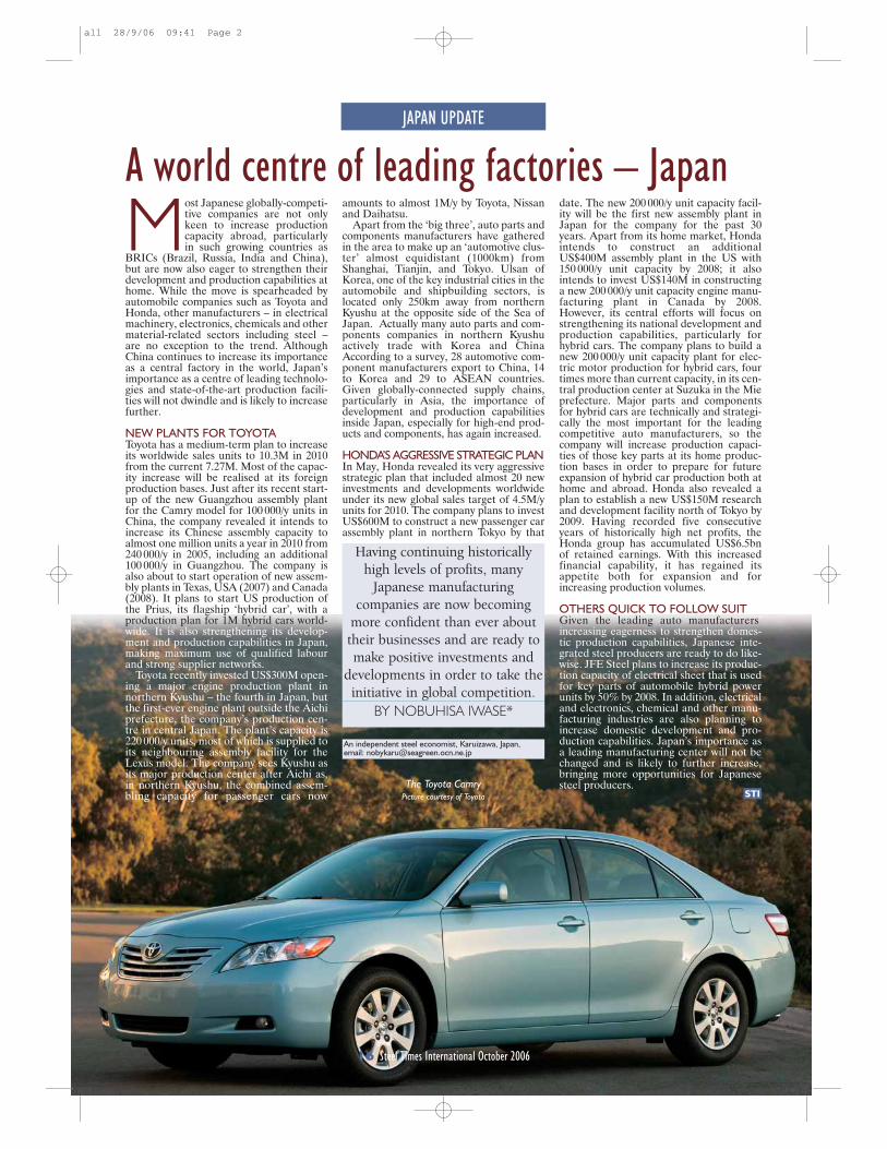
JAPAN UPDATE
An independent steel economist, Karuizawa, Japan,email: [email protected]
Having continuing historicallyhigh levels of profits, many
Japanese manufacturing companies are now becoming
more confident than ever abouttheir businesses and are ready tomake positive investments and
developments in order to take theinitiative in global competition.
BY NOBUHISA IWASE*
STI
Most Japanese globally-competi-tive companies are not onlykeen to increase productioncapacity abroad, particularlyin such growing countries as
BRICs (Brazil, Russia, India and China),but are now also eager to strengthen theirdevelopment and production capabilities athome. While the move is spearheaded byautomobile companies such as Toyota andHonda, other manufacturers – in electricalmachinery, electronics, chemicals and othermaterial-related sectors including steel –are no exception to the trend. AlthoughChina continues to increase its importanceas a central factory in the world, Japan’simportance as a centre of leading technolo-gies and state-of-the-art production facili-ties will not dwindle and is likely to increasefurther.
NEW PLANTS FOR TOYOTAToyota has a medium-term plan to increaseits worldwide sales units to 10.3M in 2010from the current 7.27M. Most of the capac-ity increase will be realised at its foreignproduction bases. Just after its recent start-up of the new Guangzhou assembly plantfor the Camry model for 100 000/y units inChina, the company revealed it intends toincrease its Chinese assembly capacity toalmost one million units a year in 2010 from240 000/y in 2005, including an additional100 000/y in Guangzhou. The company isalso about to start operation of new assem-bly plants in Texas, USA (2007) and Canada(2008). It plans to start US production ofthe Prius, its flagship ‘hybrid car’, with aproduction plan for 1M hybrid cars world-wide. It is also strengthening its develop-ment and production capabilities in Japan,making maximum use of qualified labourand strong supplier networks.
Toyota recently invested US$300M open-ing a major engine production plant innorthern Kyushu – the fourth in Japan, butthe first-ever engine plant outside the Aichiprefecture, the company’s production cen-tre in central Japan. The plant’s capacity is220 000/y units, most of which is supplied toits neighbouring assembly facility for theLexus model. The company sees Kyushu asits major production center after Aichi as,in northern Kyushu, the combined assem-bling capacity for passenger cars now
A world centre of leading factories – Japanamounts to almost 1M/y by Toyota, Nissanand Daihatsu.
Apart from the ‘big three’, auto parts andcomponents manufacturers have gatheredin the area to make up an ‘automotive clus-ter’ almost equidistant (1000km) fromShanghai, Tianjin, and Tokyo. Ulsan ofKorea, one of the key industrial cities in theautomobile and shipbuilding sectors, islocated only 250km away from northernKyushu at the opposite side of the Sea ofJapan. Actually many auto parts and com-ponents companies in northern Kyushuactively trade with Korea and ChinaAccording to a survey, 28 automotive com-ponent manufacturers export to China, 14to Korea and 29 to ASEAN countries.Given globally-connected supply chains,particularly in Asia, the importance ofdevelopment and production capabilitiesinside Japan, especially for high-end prod-ucts and components, has again increased.
HONDA’S AGGRESSIVE STRATEGIC PLANIn May, Honda revealed its very aggressivestrategic plan that included almost 20 newinvestments and developments worldwideunder its new global sales target of 4.5M/yunits for 2010. The company plans to investUS$600M to construct a new passenger carassembly plant in northern Tokyo by that
16 Steel Times International October 2006
The Toyota CamryPicture courtesy of Toyota
date. The new 200 000/y unit capacity facil-ity will be the first new assembly plant inJapan for the company for the past 30years. Apart from its home market, Hondaintends to construct an additionalUS$400M assembly plant in the US with150 000/y unit capacity by 2008; it alsointends to invest US$140M in constructinga new 200 000/y unit capacity engine manu-facturing plant in Canada by 2008.However, its central efforts will focus onstrengthening its national development andproduction capabilities, particularly forhybrid cars. The company plans to build anew 200 000/y unit capacity plant for elec-tric motor production for hybrid cars, fourtimes more than current capacity, in its cen-tral production center at Suzuka in the Mieprefecture. Major parts and componentsfor hybrid cars are technically and strategi-cally the most important for the leadingcompetitive auto manufacturers, so thecompany will increase production capaci-ties of those key parts at its home produc-tion bases in order to prepare for futureexpansion of hybrid car production both athome and abroad. Honda also revealed aplan to establish a new US$150M researchand development facility north of Tokyo by2009. Having recorded five consecutiveyears of historically high net profits, theHonda group has accumulated US$6.5bnof retained earnings. With this increasedfinancial capability, it has regained itsappetite both for expansion and forincreasing production volumes.
OTHERS QUICK TO FOLLOW SUITGiven the leading auto manufacturers’increasing eagerness to strengthen domes-tic production capabilities, Japanese inte-grated steel producers are ready to do like-wise. JFE Steel plans to increase its produc-tion capacity of electrical sheet that is usedfor key parts of automobile hybrid powerunits by 50% by 2008. In addition, electricaland electronics, chemical and other manu-facturing industries are also planning toincrease domestic development and pro-duction capabilities. Japan’s importance asa leading manufacturing center will not bechanged and is likely to further increase,bringing more opportunities for Japanesesteel producers.
all 28/9/06 09:41 Page 2
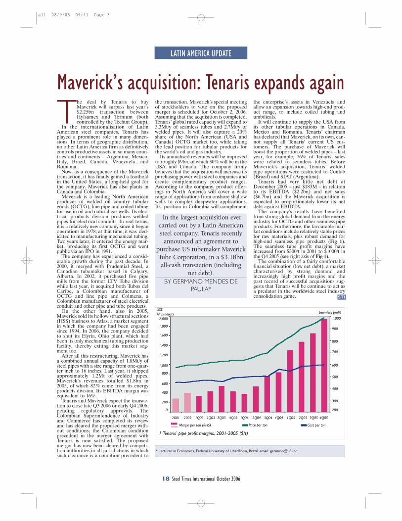
LATIN AMERICA UPDATE
18 Steel Times International October 2006
* Lecturer in Economics, Federal University of Uberlândia, Brazil. email: [email protected]
In the largest acquisition evercarried out by a Latin Americansteel company, Tenaris recently
announced an agreement to purchase US tubemaker MaverickTube Corporation, in a $3.18bnall-cash transaction (including
net debt).BY GERMANO MENDES DE
PAULA*STI
The deal by Tenaris to buyMaverick will surpass last year’s$2.25bn transaction betweenHylsamex and Ternium (bothcontrolled by the Techint Group).
In the internationalisation of LatinAmerican steel companies, Tenaris hasplayed a prominent role in many dimen-sions. In terms of geographic distribution,no other Latin America firm as definitivelycontrols productive assets in so many coun-tries and continents – Argentina, Mexico,Italy, Brazil, Canada, Venezuela, andRomania.
Now, as a consequence of the Mavericktransaction, it has finally gained a footholdin the United States, a long-held goal forthe company. Maverick has also plants inCanada and Colombia.
Maverick is a leading North Americanproducer of welded oil country tubulargoods (OCTG), line pipe and coiled tubingfor use in oil and natural gas wells. Its elec-trical products division produces weldedpipes for electrical conduits. In real terms,it is a relatively new company since it beganoperations in 1978; at that time, it was ded-icated to manufacturing mechanical tubing.Two years later, it entered the energy mar-ket, producing its first OCTG and wentpublic via an IPO in 1991.
The company has experienced a consid-erable growth during the past decade. In2000, it merged with Prudential Steel, aCanadian tubemaker based in Calgary,Alberta. In 2002, it purchased five pipemills from the former LTV Tube divisionwhile last year, it acquired both Tubos delCaribe, a Colombian manufacturer ofOCTG and line pipe and Colmena, aColombian manufacturer of steel electricalconduit and other pipe and tube products.
On the other hand, also in 2005,Maverick sold its hollow structural sections(HSS) business to Atlas, a market segmentin which the company had been engagedsince 1994. In 2006, the company decidedto shut its Elyria, Ohio plant, which hadbeen its only mechanical tubing productionfacility, thereby exiting this market seg-ment too.
After all this restructuring, Maverick hasa combined annual capacity of 1.8Mt/y ofsteel pipes with a size range from one-quar-ter inch to 16 inches. Last year, it shippedapproximately 1.2Mt of welded pipes.Maverick’s revenues totalled $1.8bn in2005, of which 82% came from its energyproducts division. Its EBITDA margin wasequivalent to 16%.
Tenaris and Maverick expect the transac-tion to close late Q3 2006 or early Q4 2006,pending regulatory approvals. TheColombian Superintendence of Industryand Commerce has completed its reviewand has cleared the proposed merger with-out conditions; the Colombian conditionprecedent in the merger agreement withTenaris is now satisfied. The proposedmerger has now been cleared by competi-tion authorities in all jurisdictions in whichsuch clearance is a condition precedent to
Maverick’s acquisition: Tenaris expands againthe transaction. Maverick’s special meetingof stockholders to vote on the proposedmerger is scheduled for October 2, 2006.Assuming that the acquisition is completed,Tenaris’ global rated capacity will expand to3.3Mt/y of seamless tubes and 2.7Mt/y ofwelded pipes. It will also capture a 20%share of the North American (USA andCanada) OCTG market too, while takingthe lead position for tubular products forthe world’s oil and gas industry.
Its annualised revenues will be improvedto roughly $9bn, of which 30% will be in theUSA and Canada. The company firmlybelieves that the acquisition will increase itspurchasing power with steel companies andcreate complementary product ranges.According to the company, product offer-ings in North America will cover a widerange of applications from onshore shallowwells to complex deepwater applications.Its position in Colombia will complement
the enterprise’s assets in Venezuela andallow an expansion towards high-end prod-uct range, to include coiled tubing andumbilicals.
It will continue to supply the USA fromits other tubular operations in Canada,Mexico and Romania. Tenaris’ chairmanhas declared that Maverick, on its own, can-not supply all Tenaris’ current US cus-tomers. The purchase of Maverick willboost the proportion of welded pipes – lastyear, for example, 76% of Tenaris’ saleswere related to seamless tubes. BeforeMaverick’s acquisition, Tenaris’ weldedpipe operations were restricted to Confab(Brazil) and SIAT (Argentina).
Tenaris had very little net debt atDecember 2005 – just $183M – in relationto its EBITDA ($2.2bn) and net sales($6.7bn) and the Maverick acquisition isexpected to proportionately lower its netdebt against EBIDTA.
The company’s results have benefitedfrom strong global demand from the energyindustry for OCTG and other seamless pipeproducts. Furthermore, the favourable mar-ket conditions include relatively stable pricesfor raw materials, plus robust demand forhigh-end seamless pipe products (Fig 1).The seamless tube profit margins haveincreased from $300/t in 2001 to $1000/t inthe Q4 2005 (see right axis of Fig 1).
The combination of a fairly comfortablefinancial situation (low net debt), a marketcharacterised by strong demand andincreasingly high profit margins and thepast record of successful acquisitions sug-gests that Tenaris will be continue to act asa predator in the worldwide steel industryconsolidation game.
US$All products Seamless profit
1,000
900
800
700
600
500
400
300
200
2,000
1,800
1,600
1,400
1,200
1,000
800
600
400
200
2001 2002 1Q03 2Q03 3Q03 4Q03 1Q04 2Q04 3Q04 4Q04 1Q05 2Q05 3Q05 4Q05
Margin per ton (RHS) Price per ton Cost per ton
1 Tenaris’ pipe profit margins, 2001-2005 ($/t)
0
all 28/9/06 09:41 Page 3
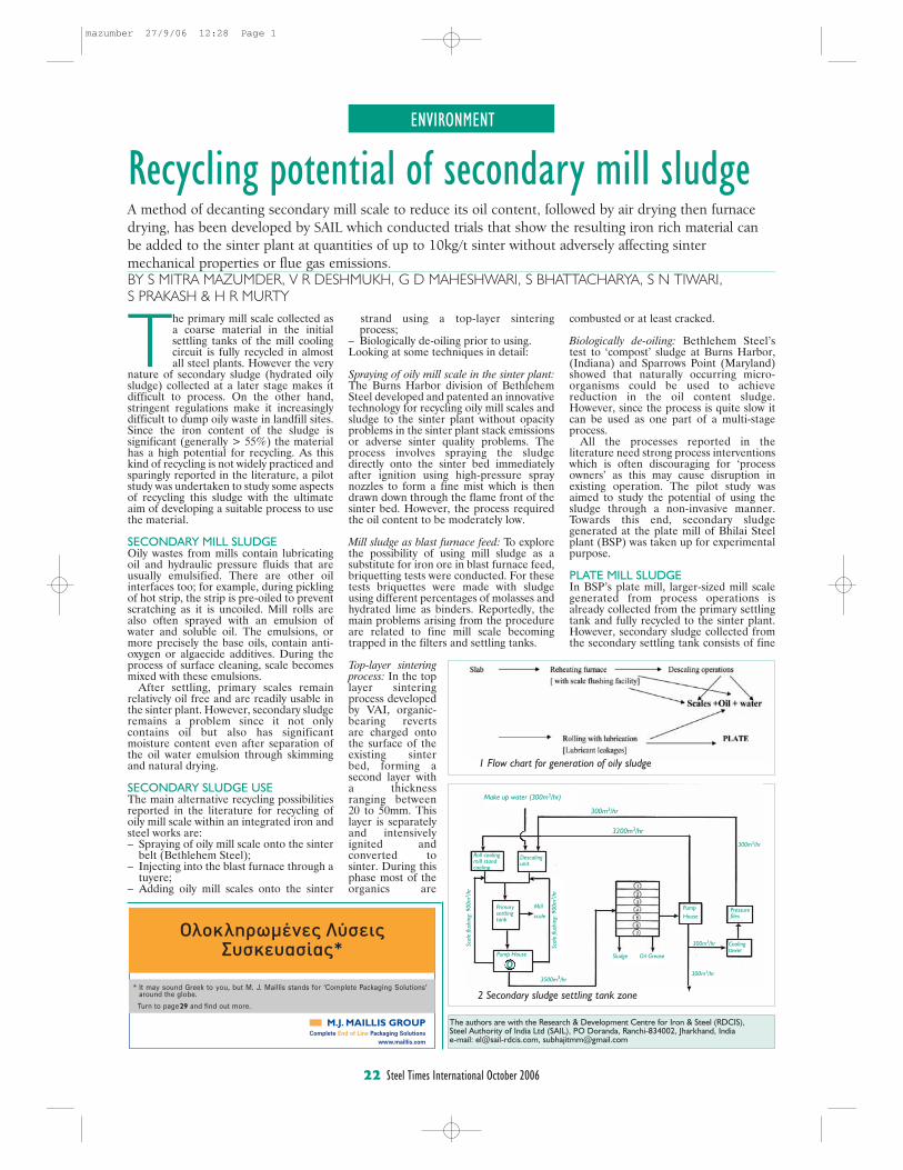
ENVIRONMENT
22 Steel Times International October 2006
The authors are with the Research & Development Centre for Iron & Steel (RDCIS),Steel Authority of India Ltd (SAIL), PO Doranda, Ranchi-834002, Jharkhand, India e-mail: [email protected], [email protected]
The primary mill scale collected asa coarse material in the initialsettling tanks of the mill coolingcircuit is fully recycled in almostall steel plants. However the very
nature of secondary sludge (hydrated oilysludge) collected at a later stage makes itdifficult to process. On the other hand,stringent regulations make it increasinglydifficult to dump oily waste in landfill sites.Since the iron content of the sludge issignificant (generally > 55%) the materialhas a high potential for recycling. As thiskind of recycling is not widely practiced andsparingly reported in the literature, a pilotstudy was undertaken to study some aspectsof recycling this sludge with the ultimateaim of developing a suitable process to usethe material.
SECONDARY MILL SLUDGEOily wastes from mills contain lubricatingoil and hydraulic pressure fluids that areusually emulsified. There are other oilinterfaces too; for example, during picklingof hot strip, the strip is pre-oiled to preventscratching as it is uncoiled. Mill rolls arealso often sprayed with an emulsion ofwater and soluble oil. The emulsions, ormore precisely the base oils, contain anti-oxygen or algaecide additives. During theprocess of surface cleaning, scale becomesmixed with these emulsions.
After settling, primary scales remainrelatively oil free and are readily usable inthe sinter plant. However, secondary sludgeremains a problem since it not onlycontains oil but also has significantmoisture content even after separation ofthe oil water emulsion through skimmingand natural drying.
SECONDARY SLUDGE USEThe main alternative recycling possibilitiesreported in the literature for recycling ofoily mill scale within an integrated iron andsteel works are:–..Spraying of oily mill scale onto the sinter....belt (Bethlehem Steel);–..Injecting into the blast furnace through a....tuyere;–..Adding oily mill scales onto the sinter
Recycling potential of secondary mill sludgeA method of decanting secondary mill scale to reduce its oil content, followed by air drying then furnacedrying, has been developed by SAIL which conducted trials that show the resulting iron rich material canbe added to the sinter plant at quantities of up to 10kg/t sinter without adversely affecting sintermechanical properties or flue gas emissions.BY S MITRA MAZUMDER, V R DESHMUKH, G D MAHESHWARI, S BHATTACHARYA, S N TIWARI, S PRAKASH & H R MURTY
....strand using a top-layer sintering
....process;–..Biologically de-oiling prior to using. Looking at some techniques in detail:
Spraying of oily mill scale in the sinter plant:The Burns Harbor division of BethlehemSteel developed and patented an innovativetechnology for recycling oily mill scales andsludge to the sinter plant without opacityproblems in the sinter plant stack emissionsor adverse sinter quality problems. Theprocess involves spraying the sludgedirectly onto the sinter bed immediatelyafter ignition using high-pressure spraynozzles to form a fine mist which is thendrawn down through the flame front of thesinter bed. However, the process requiredthe oil content to be moderately low.
Mill sludge as blast furnace feed: To explorethe possibility of using mill sludge as asubstitute for iron ore in blast furnace feed,briquetting tests were conducted. For thesetests briquettes were made with sludgeusing different percentages of molasses andhydrated lime as binders. Reportedly, themain problems arising from the procedureare related to fine mill scale becomingtrapped in the filters and settling tanks.
Top-layer sinteringprocess: In the toplayer sinteringprocess developedby VAI, organic-bearing revertsare charged ontothe surface of theexisting sinterbed, forming asecond layer witha thicknessranging between20 to 50mm. Thislayer is separatelyand intensivelyignited andconverted tosinter. During thisphase most of theorganics are
combusted or at least cracked.
Biologically de-oiling: Bethlehem Steel’stest to ‘compost’ sludge at Burns Harbor,(Indiana) and Sparrows Point (Maryland)showed that naturally occurring micro-organisms could be used to achievereduction in the oil content sludge.However, since the process is quite slow itcan be used as one part of a multi-stageprocess.
All the processes reported in theliterature need strong process interventionswhich is often discouraging for ‘processowners’ as this may cause disruption inexisting operation. The pilot study wasaimed to study the potential of using thesludge through a non-invasive manner.Towards this end, secondary sludgegenerated at the plate mill of Bhilai Steelplant (BSP) was taken up for experimentalpurpose.
PLATE MILL SLUDGEIn BSP’s plate mill, larger-sized mill scalegenerated from process operations isalready collected from the primary settlingtank and fully recycled to the sinter plant.However, secondary sludge collected fromthe secondary settling tank consists of fine
2 Secondary sludge settling tank zone
1 Flow chart for generation of oily sludge
Make up water (300m3/hr)
300m3/hr
3200m3/hr
Roll coolingmill standcooling
Descalingunit
Primarysettlingtank
Pump House
3500m3/hr
Sludge Oil Grease
300m3/hr
300m3/hr
PumpHouse
Pressurefiles
300m3/hr
Mill
scale
Scal
e flu
shin
g: 9
00m
3 /hr
Scal
e flu
shin
g: 9
00m
3 /hr
Coolingtower
�
o
Complete End of Line Packaging Solutionswww.maillis.com
* It may sound Greek to you, but M. J. Maillis stands for ‘Complete Packaging Solutions’around the globe.
Turn to page and find out more.29
mazumber 27/9/06 12:28 Page 1
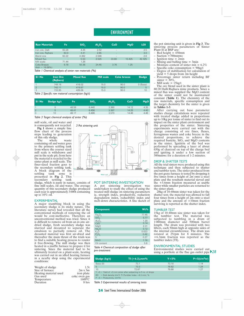
ENVIRONMENT
24 Steel Times International October 2006
mill scale, oil and water andis consequently not recycled.
Fig 1 shows a simple lineflow chart of the processsteps leading to generationof this oily sludge.
The whole wastecontaining oil and water goesto the primary settling tankfrom where the coarser sizedmill scale is withdrawn andput in the scale pit; from herethe material is recycled to thesinter plant as mill scale. Thefiner-sized fraction goes tothe secondary settling tank.A block diagram of thesettling tank zone ispresented in Fig 2. Thissecondary settling tanksludge, which is pasty in nature, consists offine mill scales, oil and water. The averagequantity of this secondary sludge producedeach year is approximately 3 000t containingup to 10% oil.
EXPERIMENTALA major stumbling block in using thesecondary sludge is its sticky nature. Theliterature survey had revealed that all theconventional methods of removing the oilwould be cost-ineffective. Therefore anunconventional method was tried. Since itis difficult to remove oil from an in-situ air-dried sludge, fresh secondary sludge wasslurried and decanted to separate theemulsion to partially remove oil. Thedecanted material was first air-dried andthereafter the main thrust of the trials wasto find a suitable heating process to renderit free-flowing. The mill sludge was thenheated in a muffle furnace to prepare it forsintering. Since the material had to beultimately treated on a plant-scale, heatingwas carried out in an idled heating furnacein a nearby shop using the experimentalconditions:
Weight of sludge 1.5tSize of furnace 2m x 3mHeating material used iron plateGas used coke oven gasTemperature 1600°CDuration 8 hrs
POT SINTERING INVESTIGATIONA pot sintering investigation wasundertaken to study the effect of using thetreated mill sludge on sintering parametersie, strength index, productivity, reductiondegradation index, reducibility index andmelt-down characteristics. A line sketch of
the pot sintering unit is given in Fig 3. Thesintering process parameters of SinterPlant II at BSP are:–..Bed height = 450mm–..Suction =700mmwc–..Ignition time = 2min–..Mixing and balling time = 3min–..Moisture content of sinter mix = 6.2%–..Specific coke consumption = 90kg/t–..Degree of stabilisation for calculation of....yield = 5 drops from 2m height –..Percentage sinter return including BF.. sinter = 30%, –..Mill scale = 15kg/t
The ore blend used in the sinter plant is80:20 Dalli:Rajhara mine products. Since amixed flux was supplied the MgO contentof the sinter could not be maintainedconstant (Table 1). The chemistry of theraw materials, specific consumption andthe target chemistry for the sinter is givenin Tables 1-3.
After carrying out base parameterstudies charge calculations were repeatedwith treated sludge added in proportionsup to 10kg per tonne of sinter to find out itsimpact on the sinter plant environment andthe properties of the sinter. Sinteringexperiments were carried out with thecharge consisting of ore fines, fluxes,ferruginous wastes and coke breeze in thedesired proportions, to achieve therequired basicity, SiO2 and MgO contentsin the sinter. Ignition of the bed wasperformed by spreading a layer of about650g of charcoal on top of the charge bedand igniting it under a low suction of500mmwc for a duration of 1-2 minutes.
DROP & SHATTER TESTSAll the trial sinters were produced using thistechnique and then subjected to shatterand tumbler tests. The sinter produced fromthe pot grate furnace is tested by dropping itfive times from a height of 2m onto a steelplate and the resultant material sieved andthe +5.6mm fraction measured as usablesinter while smaller particles are returned tothe sinter plant.
20kg of 10-40mm sinter was taken for theshatter test; the material was allowed to fallfour times from a height of 2m onto a steelplate and the amount of +10mm fractionsurviving is reported as the shatter index.
TUMBLER TEST15kg of 10-40mm size sinter was taken forthe tumbler test. The material wassubjected to tumbling in a drum of1 000mm diameter and 500mm barrellength. The drum was provided with twolifters, each 50mm high at opposite sides ofthe internal circumference. The drum wasrotated at 25rpm for 8 minutes. The+6.3mm fraction was reported as thetumbler index (TI).
ENVIRONMENTAL STUDIESEnvironmental studies were carried outusing a porthole at the flue gas outlet pipe
Raw Materials Fe SiO2
Al2O
3CaO MgO LOI
Iron ore, Dalli 63.28 4.35 2.52 - - 2.5Iron ore, Rajhara 63.0 4.41 2.65 - - 3.0Blend one 63.22 4.362 2.546 - 2.6Mixed flux - 5.53 2.525 33.80 10.425 42.425Mill scale 71.44 1.26Coke Breeze 9.78 50.36 24.45 3.76 1.25(Ash = 19.08%)
Table 1 Chemical analysis of sinter raw materials (%)
S1 No Iron Ore Mixed flux Mill scale Coke breeze Sludge
(Rajhara)
1 749.16 416.02 15.0 90.0 0 (Base)2 742.11 419.87 15.0 90.0 53 733.95 426.08 15.0 90.0 10
S1 No Sludge kg/t Fe SiO2
Al2O
3CaO MgO
1 0 48.59 6.440 3.360 14.12 4.352 5 48.41 6.456 3.387 14.25 4.403 10 48.17 6.486 3.570 14.46 4.46
Table 2 Specific raw material consumption (kg/t)
Table 3 Target chemical analysis of sinter (%)
Component Wt%
Fe2O3 77.45SiO2 5.77Al2O3 1.20CaO 0.14MgO 2.31Na2O 0.12
Table 4 Chemical composition of sludge afterpre-treatment
Sludge (kg/t) TI (+6.3),mm% Y+5% P+5(t/m2hr)
Base (0) 73.1 73.10 1.145 73.3 76.62 1.2410 72.67 78.68 1.27Y +5 = Yield of +5 mm sinter after subjecting to 5 no. of drops
BD = Bulk density (t/m3), TI (Tumbler Index +6.3 min), %P +5 = Productivity, t/m2/hr
Table 5 Experimental results of sintering tests
K2O 0.023P2O5 0.42S 0.27MnO 1.18Oil content 5.8
3 Pot sintering unit
Burner
Sinter pot
Wind box
Water inlet
Blower
Water seal
G.L. G.L.
Scrubber
�28
mazumber 27/9/06 12:28 Page 2
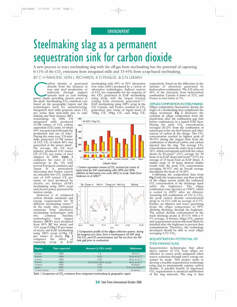
ENVIRONMENT
25 Steel Times International October 2006
Steelmaking slag as a permanentsequestration sink for carbon dioxide
Carbon dioxide is generateddirectly from the furnaces iniron and steel production, orindirectly through supportsystems such as coal burning
power plants providing electric power tothe plant. Steelmaking CO2 emissions varybased on the geographic region and thetechnologies used for manufacturing.Integrated steel mills generate more CO2per tonne than mini-mills due to cokemaking and blast furnace (BF)ironmaking. In 2000, USintegrated mills produced33.5M tonnes of CO2 carbonequivalent (CE) units, of which64% was generated through theproduction and use of coke1.During the same year, US mini-mills generated 13.7M tonnesof CO2 CE, of which 80% wasgenerated at the power plant1.On average, the US steelindustry produced 0.42 tonnesCE of CO2 per tonne of steelshipped in 2000. Table 1compares the rates of CO2emissions in the US withseveral European countries andJapan. It is particularlyinteresting that France reportsan extremely low CO2 emissionrate of 0.03 tonnes CE pertonne of steel produced byelectric arc furnace (EAF)steelmaking using 100% scrapand electric power generated bynuclear energy.
Anderson et al comparedcarbon dioxide emissions andenergy requirements for 30different steelmaking routes.10
In the study, they comparedemissions from alternativesteelmaking technologies withtwo common baselinetechnologies: basic oxygenfurnace (BOF) steel producedfrom 89% BF hot metal and11% scrap (519kg CE per tonneof steel); and EAF steelmakingusing 100% scrap (119kg CEper tonne of steel). Fig 1compares the effect ofreplacing scrap in EAF
steelmaking with 30% or 50% alternativeiron units (AIU) produced by a variety ofalternative technologies. Indirect sourcesof CO2 are responsible for the majority ofthe CO2 generated in EAF steelmakingusing scrap, with the largest fractioncoming from electricity generation11,12.EAF steelmaking using 100% scrap in theUS, Canada, and France resulted in CO2generation (per tonne of liquid steel) of140kg CE, 89kg CE, and 46kg CE,
respectively, based on the difference in theamount of electricity generated byhydrocarbon combustion. The US relies on69% of the electricity from hydrocarboncombustion, Canada is lower at 32%, andFrance is even lower at 5%.
OFFGAS COMPOSITION IN STEELMAKINGOffgas composition fluctuations during thestages of a steelmaking heat complicates theoffgas treatment. Fig 2 illustrates thevariation in offgas composition from thefourth-hole after the combustion gap (butbefore combustion) in a typical EAF heat.During the melt, CO2 concentrationaveraged 20-25% from the combustion ofnatural gas in the oxy-fuel burners and othersources of carbon in the charge. The CO2concentration reached its highest peak of30-35% during the oxygen blow from thecombustion of dissolved carbon and carboninjected into the slag. The average CO2concentration across the entire heat is about18%, which corresponds well with the valuesshown by Evenson13 (23% average for 30heats of an EAF shop) and Grant14 (15% foraverage of 15 heats from an EAF shop). Asimilar study of 10 heats showed similartrends with the peak CO2 concentrationaveraging 30-35% and an overall averagethroughout the heats of 18-20%.
Combining the composition data fromFig 2 with the temperature and flow profileof the offgas system yields the estimatedCO2 concentration at the discharge stack(after the baghouse). The offgascombustion zone operates at 1760°C, whichis cooled to 450°C after air dilution.Assuming full combustion of CO to CO2,the peak carbon dioxide concentrationdrops to 14-15% with an average of 6-7%.Further air dilution and water quenchingdrops the offgas temperature to 90°Callowing discharge through the baghouse.The carbon dioxide concentration in thestack discharge peaks at 10-11% with a 4-5% average. A furnace offgas CO2 captureand sequestration system will most likely beinstalled after the baghouse to prevent dustcontamination. Therefore, the technologydeveloped should be able to treat offgasaveraging 4-5% CO2.
SEQUESTRATION POTENTIAL OFSTEELMAKING SLAGSequestration technologies that allowdirect capture of CO2 from offgas areeffective as source point mitigation whensource reduction through lower energy usecannot be made. This project seeks todevelop a feasible sequestration technologyusing slag to permanently capture carbondioxide. A parallel benefit of slag-basedCO2 sequestration is chemical stabilisationof the slag minerals. The slag is thus
A new process to react steelmaking slag with the off-gas from steelmaking has the potential of capturing6-11% of the CO2 emissions from integrated mills and 35-45% from scrap-based steelmaking.
BY C H RAWLINS, VON L RICHARDS, K D PEASLEE, & S N LEKAKH
Region Year reported Amount (t CE/t steel) Reference
Russia 1998 1.4 Afonin2
France 1989 0.42 Birat et al.3-6
France 1994 0.40 Birat et al.3-6
France 1994 0.03 (EAF/100% scrap) Birat et al.3-6
Finland 1994 0.53 Holappa7
Japan 2005 0.46 Emi and Gielen8,9
United States 2000 0.42 Stubbles1
Table 1 Comparison of CO2 emissions from integrated steelmaking by geographic region
1 Carbon equivalent tonnes of CO2 emitted per tonne ofliquid steel for EAF steelmaking with 30% and 50%addition of alternative iron units (AIU) to scrap. Data fromAnderson et al 200210
2 Composition profile of the offgas collection system, duringthe progress of a heat, from a northeastern US EAF shop.The CO2 and CO concentrations (vol %) are from the 4thhole gap prior to combustion
Tap Charge 1 Melt 1 Charge 2 Melt 2 Refining
18:54 19:03 19:12 19:21 19:30 19:39Time
BF-BOF, 519kg CO2
100% Scrap EAF, 119kg CO2
mazumber 27/9/06 12:28 Page 3
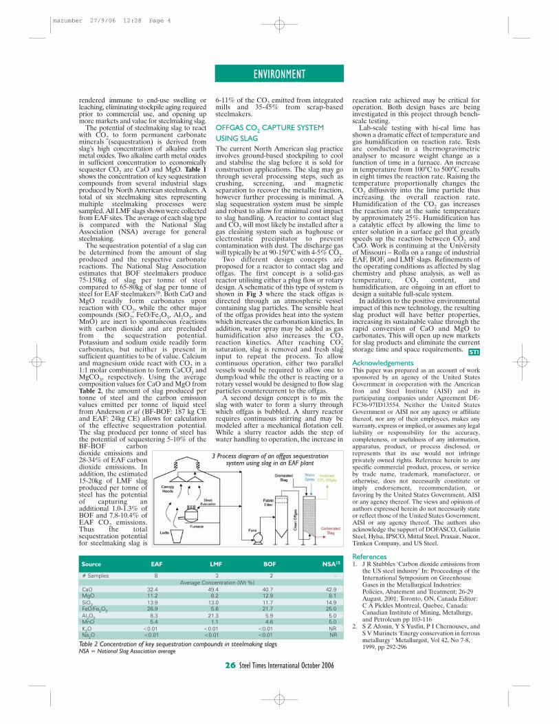
ENVIRONMENT
26 Steel Times International October 2006
rendered immune to end-use swelling orleaching, eliminating stockpile aging requiredprior to commercial use, and opening upmore markets and value for steelmaking slag.
The potential of steelmaking slag to reactwith CO2 to form permanent carbonateminerals (sequestration) is derived fromslag’s high concentration of alkaline earthmetal oxides. Two alkaline earth metal oxidesin sufficient concentration to economicallysequester CO2 are CaO and MgO. Table 1shows the concentration of key sequestrationcompounds from several industrial slagsproduced by North American steelmakers. Atotal of six steelmaking sites representingmultiple steelmaking processes weresampled. All LMF slags shown were collectedfrom EAF sites. The average of each slag typeis compared with the National SlagAssociation (NSA) average for generalsteelmaking.
The sequestration potential of a slag canbe determined from the amount of slagproduced and the respective carbonatereactions. The National Slag Associationestimates that BOF steelmakers produce75-150kg of slag per tonne of steelcompared to 65-80kg of slag per tonne ofsteel for EAF steelmakers16. Both CaO andMgO readily form carbonates uponreaction with CO2, while the other majorcompounds (SiO2, FeO/Fe2O3, Al2O3, andMnO) are inert to spontaneous reactionswith carbon dioxide and are precludedfrom the sequestration potential.Potassium and sodium oxide readily formcarbonates, but neither is present insufficient quantities to be of value. Calciumand magnesium oxide react with CO2 in a1:1 molar combination to form CaCO3 andMgCO3, respectively. Using the averagecomposition values for CaO and MgO fromTable 2, the amount of slag produced pertonne of steel and the carbon emissionvalues emitted per tonne of liquid steelfrom Anderson et al (BF-BOF: 187 kg CEand EAF: 24kg CE) allows for calculationof the effective sequestration potential.The slag produced per tonne of steel hasthe potential of sequestering 5-10% of theBF-BOF carbondioxide emissions and28-34% of EAF carbondioxide emissions. Inaddition, the estimated15-20kg of LMF slagproduced per tonne ofsteel has the potentialof capturing anadditional 1.0-1.3% ofBOF and 7.8-10.4% ofEAF CO2 emissions.Thus the totalsequestration potentialfor steelmaking slag is
6-11% of the CO2 emitted from integratedmills and 35-45% from scrap-basedsteelmakers.
OFFGAS CO2 CAPTURE SYSTEMUSING SLAGThe current North American slag practiceinvolves ground-based stockpiling to cooland stabilise the slag before it is sold forconstruction applications. The slag may gothrough several processing steps, such ascrushing, screening, and magneticseparation to recover the metallic fraction,however further processing is minimal. Aslag sequestration system must be simpleand robust to allow for minimal cost impactto slag handling. A reactor to contact slagand CO2 will most likely be installed after agas cleaning system such as baghouse orelectrostatic precipitator to preventcontamination with dust. The discharge gaswill typically be at 90-150°C with 4-5% CO2.
Two different design concepts areproposed for a reactor to contact slag andoffgas. The first concept is a solid-gasreactor utilising either a plug flow or rotarydesign. A schematic of this type of system isshown in Fig 3 where the stack offgas isdirected through an atmospheric vesselcontaining slag particles. The sensible heatof the offgas provides heat into the systemwhich increases the carbonation kinetics. Inaddition, water spray may be added as gashumidification also increases the CO2reaction kinetics. After reaching CO2saturation, slag is removed and fresh slaginput to repeat the process. To allowcontinuous operation, either two parallelvessels would be required to allow one todump/load while the other is reacting or arotary vessel would be designed to flow slagparticles countercurrent to the offgas.
A second design concept is to mix theslag with water to form a slurry throughwhich offgas is bubbled. A slurry reactorrequires continuous stirring and may bemodeled after a mechanical flotation cell.While a slurry reactor adds the step ofwater handling to operation, the increase in
reaction rate achieved may be critical foroperation. Both design bases are beinginvestigated in this project through bench-scale testing.
Lab-scale testing with hi-cal lime hasshown a dramatic effect of temperature andgas humidification on reaction rate. Testsare conducted in a thermogravimetricanalyser to measure weight change as afunction of time in a furnace. An increasein temperature from 100°C to 500°C resultsin eight times the reaction rate. Raising thetemperature proportionally changes theCO2 diffusivity into the lime particle thusincreasing the overall reaction rate.Humidification of the CO2 gas increasesthe reaction rate at the same temperatureby approximately 25%. Humidification hasa catalytic effect by allowing the lime toenter solution in a surface gel that greatlyspeeds up the reaction between CO2 andCaO. Work is continuing at the Universityof Missouri – Rolla on a range of industrialEAF, BOF, and LMF slags. Refinements ofthe operating conditions as affected by slagchemistry and phase analysis, as well astemperature, CO2 content, andhumidification, are ongoing in an effort todesign a suitable full-scale system.
In addition to the positive environmentalimpact of this new technology, the resultingslag product will have better properties,increasing its sustainable value through therapid conversion of CaO and MgO tocarbonates. This will open up new marketsfor slag products and eliminate the currentstorage time and space requirements.
AcknowledgementsThis paper was prepared as an account of worksponsored by an agency of the United StatesGovernment in cooperation with the AmericanIron and Steel Institute (AISI) and itsparticipating companies under Agreement DE-FC36-97ID13554. Neither the United StatesGovernment or AISI nor any agency or affiliatethereof, nor any of their employees, makes anywarranty, express or implied, or assumes any legalliability or responsibility for the accuracy,completeness, or usefulness of any information,apparatus, product, or process disclosed, orrepresents that its use would not infringeprivately owned rights. Reference herein to anyspecific commercial product, process, or serviceby trade name, trademark, manufacturer, orotherwise, does not necessarily constitute orimply endorsement, recommendation, orfavoring by the United States Government, AISIor any agency thereof. The views and opinions ofauthors expressed herein do not necessarily stateor reflect those of the United States Government,AISI or any agency thereof. The authors alsoacknowledge the support of DOFASCO, GallatinSteel, Hylsa, IPSCO, Mittal Steel, Praxair, Nucor,Timken Company, and US Steel.
References1. J R Stubbles ‘Carbon dioxide emissions from
the US steel industry’ In: Proceedings of theInternational Symposium on Greenhouse Gases in the Metallurgical Industries: Policies, Abatement and Treatment; 26-29 August, 2001; Toronto, ON, Canada Editor: C A Pickles Montreal, Quebec, Canada: Canadian Institute of Mining, Metallurgy, and Petroleum pp 103-116
2. S Z Afonin, Y S Yusfin, P I Chernousev, andS V Murinets ‘Energy conservation in ferrousmetallurgy ‘ Metallurgist, Vol 42, No 7-8, 1999, pp 292-296
Source EAF LMF BOF NSA15
# Samples 8 3 2 -Average Concentration (Wt %)
CaO 32.4 49.4 40.7 42.9MgO 11.2 6.2 12.9 8.1SiO2 13.9 13.0 11.7 14.9FeO/Fe2O3 26.9 5.6 21.7 25.0Al2O3 8.3 21.3 5.9 5.0MnO 5.4 1.1 4.6 5.0K2O <0.01 <0.01 <0.01 NRNa2O <0.01 <0.01 <0.01 NR
Table 2 Concentration of key sequestration compounds in steelmaking slags NSA = National Slag Association average
3 Process diagram of an offgas sequestrationsystem using slag in an EAF plant
STI
mazumber 27/9/06 12:28 Page 4
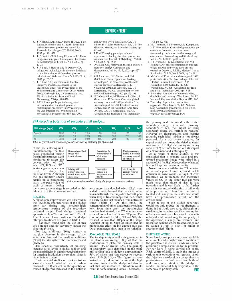
the primary scale is mixed with treatedsecondary sludge in a ratio primary:secondary of 6:1, the impact of usingsecondary sludge will further be reduced.However on transportation and logisticsgrounds, such ideal mixing is not alwayspractical. As a worst-case scenario, forexperimental purposes, the dried materialwas used up to 10kg/t (a primary:secondaryratio of 3:2) of sinter to find out its impacton environment and sinter quality.
As a result of these studies, it wasconcluded that if primary scale and pre-treated secondary sludge were mixed in aration of 3:1 (ie 5kg/t of secondary of sinter)it would improve the sinter quality.
No norms were available for CO emissionin the sinter plant. However, based on COemission in coke ovens (ie 3kg/t of cokeproduced as reference), the measuredvalues of CO in the sinter flue gas weremuch lower than those of blast furnaceoperation and it was likely to fall furtheronce this was mixed with primary mill scaleafter processing. Therefore the use oftreated mill sludge in the sinter line wouldhave no pronounced effect on theenvironment.
Such re-use of the sludge generatedwould not only reduce the requirement todump it but would also save, although in asmall way, in reducing specific consumptionof basic raw materials. In view of the resultsobtained and considering the simplicity ofthe operation, a sludge pre-treatment andutilisation scheme where treated sludge canbe added at up to 5kg/t of sinter isrecommended (Fig 4).
FURTHER WORKSince hardly any prior study was availableon a simple and straightforward solution tothe problem, the current study was aimedat finding a simple solution to the problem.Further work is being carried out in theR&D centre of SAIL to study the impact ofvarious unit operations on removal of oil;the objective is to develop a comprehensivepre-treatment method to reduce both oiland moisture content in the sludge torender the material fully recyclable in thesame way as primary scale.
ENVIRONMENT
28 Steel Times International October 2006
STI
of the pot sintering unit.Simultaneously, the fluegases generated duringthe sintering process weremonitored to assess theconcentration of CO,SO2, NO, H2S and NO2.A stack gas analyser wasused to study theemission levels. Althoughthe gas monitor showsresults on a continuousbasis, the peak value ofeach parameter duringthe whole process stage is recorded as thistakes care of the worst-case scenario.
RESULTSA remarkable improvement was observed inthe flowability characteristics of the sludgeafter air drying and medium-hightemperature heating of the secondarydecanted sludge. Fresh sludge containedapproximately 40% moisture and 10% oil.The chemical characteristics of the sludgeafter pre-treatment are given in table 4.
It has been found that the use of thisdried sludge does not adversely impact thesintering process.
For high additions (10kg/t sinter), amarginal decrease in the strength of thesinter was observed. For medium additions(5kg/t) the strength of the sinter increased(Table 5).
The specific productivity of sinteringincreases at all levels of sludge addition andthe material helps in slightly reducing the timefor sintering. In addition, the resultant sinter isricher in iron content.
Environmental studies on stack emissionsshowed a notable initial increase in carbonmonoxide (CO) content as the quantity oftreated sludge was increased in the sinter; it
Mill sludge (kg/t) CO CO2
O2
NO2
SO2
H2S NO
Base(0) 1850 0.3 20.9 90 130 180 905 2050 0.3 20.9 100 136 200 10010 > 3000 0.4 20.9 105 239 110 22
Table 6 Typical stack monitoring results at start of sintering (in ppm max)
4 A non-invasive method of oily sludge pre-treatment and use
were more than doubled when 10kg/t wereadded. It was observed that the CO contentwas initially high, reaching a level of 3 200ppmwhen 10kg of treated sludge was used, whichis nearly double that obtained from untreatedsinter (Table 6). At this time, theconcentration of other constituents remainedlow. Some time after the metallurgicalreaction had started, the CO concentrationreduced to a level of below 200ppm. Theconcentration of H2S, SO2, NO and NO2 alsoreduced to less than 10ppm at this stage.Addition of up to 5kg/t of sinter had nopronounced effect on the emitted flue gas.Other parameters show little or no variation.
AVAILABLE MILL SCALEThe total quantity of mill scale generated inthe plant is, on average, 80t/y; of that, thecontribution of plate mill primary scale isaround 10t/y or around 12%. The quantityof secondary scale deposited in the platemill settling tank as sludge is approximately3t/y, of which one can expect to recoverabout 50% (ie 1.5t/y). This figure has beenarrived at by taking into account the highmoisture content of the sludge and also thefact that any method of utilisation wouldresult in some handling losses. Therefore, if
3. J -P Birat, M Antoine, A Dubs, H Gaye, Y deLassat, R Nicolle, and J L Roth ‘Towards a carbon-free steel production route?’ La Revue de Métallurgie-CIT, Vol 90, No 3, 1993, pp 411-421
4. J -P Birat, J -M Delbecq, E Hess, and D Huin‘Slag, steel and greenhouse gases ‘ La Revuede Métallurgie-CIT, Vol 99, No 1, 2002, pp 13-21
5. J -P Birat, F Hanrot, and G Danloy ‘CO2mitigation technologies in the steel industry:a benchmarking study based on process calculations ‘ Stahl und Eisen, Vol 123, No 9,2003, pp 69-72
6. J -P Birat ‘CO2 emissions and the steel industry’s available responses to the greenhouse effect ‘ In: Proceedings of the 59th Ironmaking Conference; 26-29 March 2000; Pittsburgh, PA, US Warrendale, PA, US: Association for Iron and Steel Technology; 2000 pp 409-420
7. L E K Holappa ‘Impact of energy and environment on the development of metallurgical processes‘ In: Proceedings of the 2nd International Symposium on Metallurgical Processes for the Year 2000
and Beyond; 1994; San Diego, CA, US Editor: H Y Sohn Warrendale, PA, US: The Minerals, Metals, and Materials Society pp 641-660
8. T Emi ‘Changing paradigm of metal separation technology for steel production ‘ Scandinavian Journal of Metallurgy, Vol 34, No 2, 2005, pp 79-88
9. D Gielen ‘CO2 removal in the iron and steelindustry ‘ Energy Conversion and Management, Vol 44, No 7, 2003, pp 1027-1037
10. S H Anderson, G E Metius, and J M McClelland ‘Future green steelmaking technologies‘ In: Proceedings of the 60th Electric Furnace Conference; 10-13 November 2002; San Antonio, TX, US Warrendale, PA, US: Association for Iron and Steel Technology; 2002 pp 175-191
11. H D Goodfellow, M Thomson, L Cibert, P Morere, and E Evenson ‘Overview global warming issues and EAF production ‘ In: Proceedings of the 56th Electric Furnace Conference; 15-18 November 1998, New Orleans, LA, US Warrendale, PA, US: Association for Iron and Steel Technology;
1998 pp 623-627 12. M J Thomson, E J Evenson, M J Kempe, and
H D Goodfellow ‘Control of greenhouse gasemissions from electric arc furnace steelmaking: evaluation methodology with case studies ‘ Ironmaking and Steelmaking, Vol 27, No 4, 2000, pp 273-279
13. E J Evenson, H D Goodfellow, and M J Kempe ‘EAF process optimization through offgas analysis and closed-loop process control at Deacero, Saltillo, Mexico ‘ Iron &Steelmaker, Vol 28, No 5, 2001, pp 53-58
14. M G Grant ‘Principles and strategy of EAF post-combustion ‘ In: Proceedings of the 58thElectric Furnace Conference; 12-15 November 2000; Orlando, FL, US Warrendale, PA, US: Association for Iron and Steel Technology; 2000 pp 15-28
15. ‘Steel slag: A material of unusual ability, durability, and tenacity ‘ West Lawn, PA, US:National Slag Association Report MF 194-3
16. ‘Steel slag: A premier construction aggregate ‘ West Lawn, PA, US: National Slag Association [brochure] 30 June 2005 http://wwwnationalslagassocorg/PDF_files/SSPremAgg PDF
24�Recycling potential of secondary mill sludge...
mazumber 27/9/06 12:28 Page 5
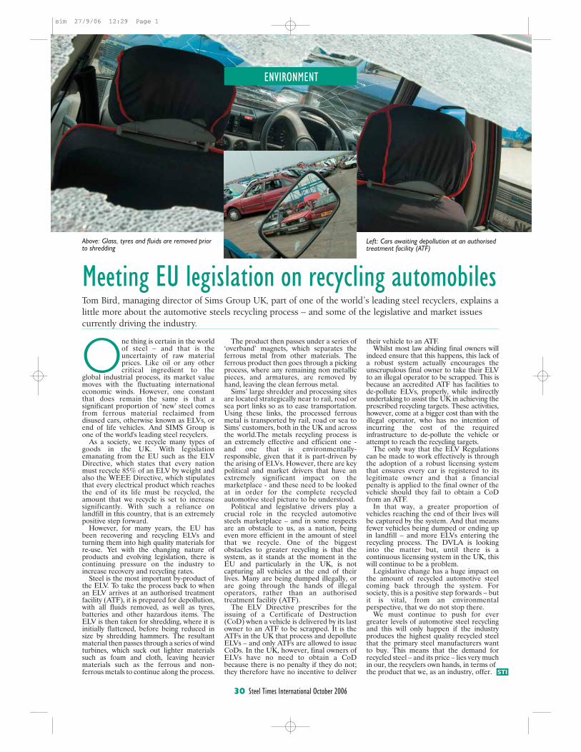
their vehicle to an ATF. Whilst most law abiding final owners will
indeed ensure that this happens, this lack ofa robust system actually encourages theunscrupulous final owner to take their ELVto an illegal operator to be scrapped. This isbecause an accredited ATF has facilities tode-pollute ELVs, properly, while indirectlyundertaking to assist the UK in achieving theprescribed recycling targets. These activities,however, come at a bigger cost than with theillegal operator, who has no intention ofincurring the cost of the requiredinfrastructure to de-pollute the vehicle orattempt to reach the recycling targets.
The only way that the ELV Regulationscan be made to work effectively is throughthe adoption of a robust licensing systemthat ensures every car is registered to itslegitimate owner and that a financialpenalty is applied to the final owner of thevehicle should they fail to obtain a CoDfrom an ATF.
In that way, a greater proportion ofvehicles reaching the end of their lives willbe captured by the system. And that meansfewer vehicles being dumped or ending upin landfill – and more ELVs entering therecycling process. The DVLA is lookinginto the matter but, until there is acontinuous licensing system in the UK, thiswill continue to be a problem.
Legislative change has a huge impact onthe amount of recycled automotive steelcoming back through the system. Forsociety, this is a positive step forwards – butit is vital, from an environmentalperspective, that we do not stop there.
We must continue to push for evergreater levels of automotive steel recyclingand this will only happen if the industryproduces the highest quality recycled steelthat the primary steel manufacturers wantto buy. This means that the demand forrecycled steel – and its price – lies very muchin our, the recyclers own hands, in terms ofthe product that we, as an industry, offer.
ENVIRONMENT
30 Steel Times International October 2006
STI
One thing is certain in the worldof steel – and that is theuncertainty of raw materialprices. Like oil or any othercritical ingredient to the
global industrial process, its market valuemoves with the fluctuating internationaleconomic winds. However, one constantthat does remain the same is that asignificant proportion of ‘new’ steel comesfrom ferrous material reclaimed fromdisused cars, otherwise known as ELVs, orend of life vehicles. And SIMS Group isone of the world's leading steel recyclers.
As a society, we recycle many types ofgoods in the UK. With legislationemanating from the EU such as the ELVDirective, which states that every nationmust recycle 85% of an ELV by weight andalso the WEEE Directive, which stipulatesthat every electrical product which reachesthe end of its life must be recycled, theamount that we recycle is set to increasesignificantly. With such a reliance onlandfill in this country, that is an extremelypositive step forward.
However, for many years, the EU hasbeen recovering and recycling ELVs andturning them into high quality materials forre-use. Yet with the changing nature ofproducts and evolving legislation, there iscontinuing pressure on the industry toincrease recovery and recycling rates.
Steel is the most important by-product ofthe ELV. To take the process back to whenan ELV arrives at an authorised treatmentfacility (ATF), it is prepared for depollution,with all fluids removed, as well as tyres,batteries and other hazardous items. TheELV is then taken for shredding, where it isinitially flattened, before being reduced insize by shredding hammers. The resultantmaterial then passes through a series of windturbines, which suck out lighter materialssuch as foam and cloth, leaving heaviermaterials such as the ferrous and non-ferrous metals to continue along the process.
Meeting EU legislation on recycling automobilesTom Bird, managing director of Sims Group UK, part of one of the world’s leading steel recyclers, explains alittle more about the automotive steels recycling process – and some of the legislative and market issuescurrently driving the industry.
The product then passes under a series of‘overband’ magnets, which separates theferrous metal from other materials. Theferrous product then goes through a pickingprocess, where any remaining non metallicpieces, and armatures, are removed byhand, leaving the clean ferrous metal.
Sims’ large shredder and processing sitesare located strategically near to rail, road orsea port links so as to ease transportation.Using these links, the processed ferrousmetal is transported by rail, road or sea toSims’ customers, both in the UK and acrossthe world.The metals recycling process isan extremely effective and efficient one -and one that is environmentally-responsible, given that it is part-driven bythe arising of ELVs. However, there are keypolitical and market drivers that have anextremely significant impact on themarketplace - and these need to be lookedat in order for the complete recycledautomotive steel picture to be understood.
Political and legislative drivers play acrucial role in the recycled automotivesteels marketplace – and in some respectsare an obstacle to us, as a nation, beingeven more efficient in the amount of steelthat we recycle. One of the biggestobstacles to greater recycling is that thesystem, as it stands at the moment in theEU and particularly in the UK, is notcapturing all vehicles at the end of theirlives. Many are being dumped illegally, orare going through the hands of illegaloperators, rather than an authorisedtreatment facility (ATF).
The ELV Directive prescribes for theissuing of a Certificate of Destruction(CoD) when a vehicle is delivered by its lastowner to an ATF to be scrapped. It is theATFs in the UK that process and depolluteELVs – and only ATFs are allowed to issueCoDs. In the UK, however, final owners ofELVs have no need to obtain a CoDbecause there is no penalty if they do not;they therefore have no incentive to deliver
Above: Glass, tyres and fluids are removed priorto shredding
Left: Cars awaiting depollution at an authorisedtreatment facility (ATF)
sim 27/9/06 12:29 Page 1
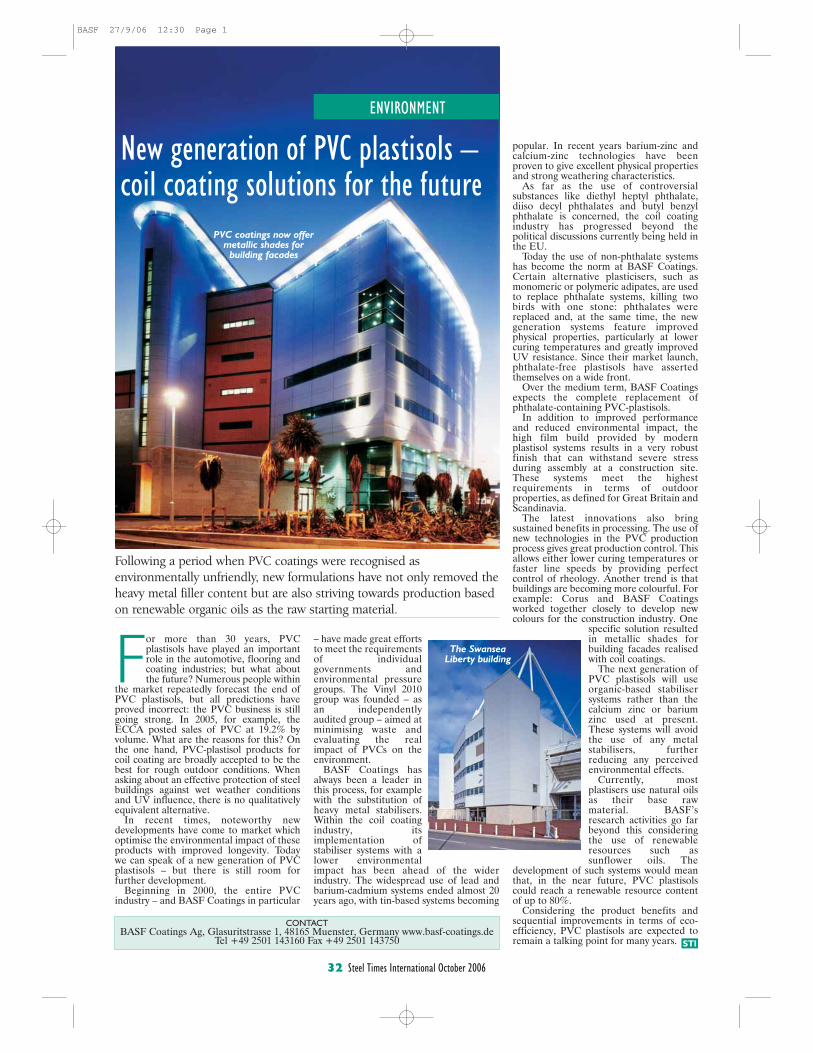
popular. In recent years barium-zinc andcalcium-zinc technologies have beenproven to give excellent physical propertiesand strong weathering characteristics.
As far as the use of controversialsubstances like diethyl heptyl phthalate,diiso decyl phthalates and butyl benzylphthalate is concerned, the coil coatingindustry has progressed beyond thepolitical discussions currently being held inthe EU.
Today the use of non-phthalate systemshas become the norm at BASF Coatings.Certain alternative plasticisers, such asmonomeric or polymeric adipates, are usedto replace phthalate systems, killing twobirds with one stone: phthalates werereplaced and, at the same time, the newgeneration systems feature improvedphysical properties, particularly at lowercuring temperatures and greatly improvedUV resistance. Since their market launch,phthalate-free plastisols have assertedthemselves on a wide front.
Over the medium term, BASF Coatingsexpects the complete replacement ofphthalate-containing PVC-plastisols.
In addition to improved performanceand reduced environmental impact, thehigh film build provided by modernplastisol systems results in a very robustfinish that can withstand severe stressduring assembly at a construction site.These systems meet the highestrequirements in terms of outdoorproperties, as defined for Great Britain andScandinavia.
The latest innovations also bringsustained benefits in processing. The use ofnew technologies in the PVC productionprocess gives great production control. Thisallows either lower curing temperatures orfaster line speeds by providing perfectcontrol of rheology. Another trend is thatbuildings are becoming more colourful. Forexample: Corus and BASF Coatingsworked together closely to develop newcolours for the construction industry. One
specific solution resultedin metallic shades forbuilding facades realisedwith coil coatings.
The next generation ofPVC plastisols will useorganic-based stabilisersystems rather than thecalcium zinc or bariumzinc used at present.These systems will avoidthe use of any metalstabilisers, furtherreducing any perceivedenvironmental effects.
Currently, mostplastisers use natural oilsas their base rawmaterial. BASF’sresearch activities go farbeyond this consideringthe use of renewableresources such assunflower oils. The
development of such systems would meanthat, in the near future, PVC plastisolscould reach a renewable resource contentof up to 80%.
Considering the product benefits andsequential improvements in terms of eco-efficiency, PVC plastisols are expected toremain a talking point for many years.
ENVIRONMENT
CONTACTBASF Coatings Ag, Glasuritstrasse 1, 48165 Muenster, Germany www.basf-coatings.de
Tel +49 2501 143160 Fax +49 2501 143750 STI
For more than 30 years, PVCplastisols have played an importantrole in the automotive, flooring andcoating industries; but what aboutthe future? Numerous people within
the market repeatedly forecast the end ofPVC plastisols, but all predictions haveproved incorrect: the PVC business is stillgoing strong. In 2005, for example, theECCA posted sales of PVC at 19.2% byvolume. What are the reasons for this? Onthe one hand, PVC-plastisol products forcoil coating are broadly accepted to be thebest for rough outdoor conditions. Whenasking about an effective protection of steelbuildings against wet weather conditionsand UV influence, there is no qualitativelyequivalent alternative.
In recent times, noteworthy newdevelopments have come to market whichoptimise the environmental impact of theseproducts with improved longevity. Todaywe can speak of a new generation of PVCplastisols – but there is still room forfurther development.
Beginning in 2000, the entire PVCindustry – and BASF Coatings in particular
New generation of PVC plastisols – coil coating solutions for the future
Following a period when PVC coatings were recognised asenvironmentally unfriendly, new formulations have not only removed theheavy metal filler content but are also striving towards production basedon renewable organic oils as the raw starting material.
– have made great effortsto meet the requirementsof individualgovernments andenvironmental pressuregroups. The Vinyl 2010group was founded – asan independentlyaudited group – aimed atminimising waste andevaluating the realimpact of PVCs on theenvironment.
BASF Coatings hasalways been a leader inthis process, for examplewith the substitution ofheavy metal stabilisers.Within the coil coatingindustry, itsimplementation ofstabiliser systems with alower environmentalimpact has been ahead of the widerindustry. The widespread use of lead andbarium-cadmium systems ended almost 20years ago, with tin-based systems becoming
PVC coatings now offermetallic shades for
building facades
The SwanseaLiberty building
32 Steel Times International October 2006
BASF 27/9/06 12:30 Page 1
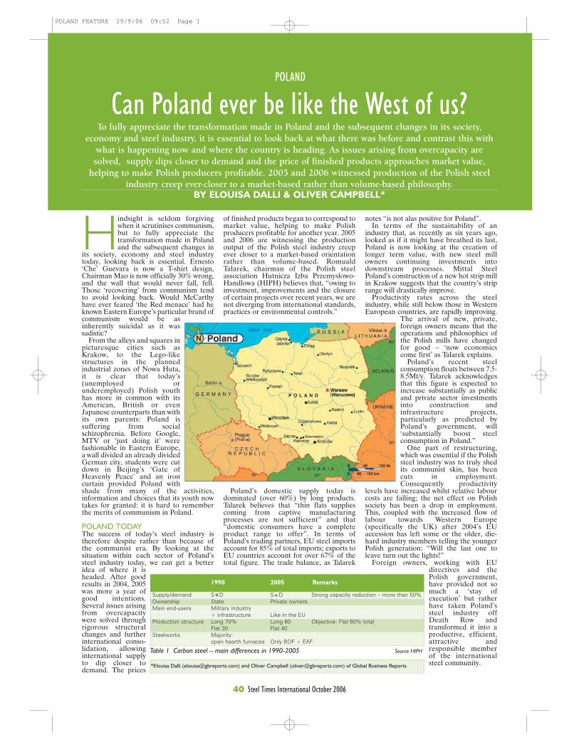
POLAND
40 Steel Times International October 2006
*Elouisa Dalli ([email protected]) and Oliver Campbell ([email protected]) of Global Business Reports
1990 2005 Remarks
Supply/demand S D S D Strong capacity reduction – more than 50%Ownership State Private ownersMain end-users Military industry
+ infrastructure Like in the EUProduction structure Long 70% Long 60 Objective: Flat 60% total
Flat 30 Flat 40Steelworks Majority:
open hearth furnaces Only BOF + EAF
Hindsight is seldom forgivingwhen it scrutinises communism,but to fully appreciate thetransformation made in Polandand the subsequent changes in
its society, economy and steel industrytoday, looking back is essential. Ernesto‘Che’ Guevara is now a T-shirt design,Chairman Mao is now officially 30% wrong,and the wall that would never fall, fell.Those ‘recovering’ from communism tendto avoid looking back. Would McCarthyhave ever feared ‘the Red menace’ had heknown Eastern Europe’s particular brand ofcommunism would be asinherently suicidal as it wassadistic?
From the alleys and squares inpicturesque cities such asKrakow, to the Lego-likestructures in the plannedindustrial zones of Nowa Huta,it is clear that today’s(unemployed orunderemployed) Polish youthhas more in common with itsAmerican, British or evenJapanese counterparts than withits own parents: Poland issuffering from socialschizophrenia. Before Google,MTV or ‘just doing it’ werefashionable in Eastern Europe,a wall divided an already dividedGerman city, students were cutdown in Beijing’s ‘Gate ofHeavenly Peace’ and an ironcurtain provided Poland withshade from many of the activities,information and choices that its youth nowtakes for granted: it is hard to rememberthe merits of communism in Poland.
POLAND TODAYThe success of today’s steel industry istherefore despite rather than because ofthe communist era. By looking at thesituation within each sector of Poland’ssteel industry today, we can get a betteridea of where it isheaded. After goodresults in 2004, 2005was more a year ofgood intentions.Several issues arisingfrom overcapacitywere solved throughrigorous structuralchanges and furtherinternational conso-lidation, allowinginternational supplyto dip closer todemand. The prices
To fully appreciate the transformation made in Poland and the subsequent changes in its society,economy and steel industry, it is essential to look back at what there was before and contrast this with
what is happening now and where the country is heading. As issues arising from overcapacity aresolved, supply dips closer to demand and the price of finished products approaches market value,
helping to make Polish producers profitable. 2005 and 2006 witnessed production of the Polish steelindustry creep ever-closer to a market-based rather than volume-based philosophy.
BY ELOUISA DALLI & OLIVER CAMPBELL*
Poland’s domestic supply today isdominated (over 60%) by long products.Talarek believes that “thin flats suppliescoming from captive manufacturingprocesses are not sufficient” and that“domestic consumers have a completeproduct range to offer”. In terms ofPoland’s trading partners, EU steel importsaccount for 85% of total imports; exports toEU countries account for over 67% of thetotal figure. The trade balance, as Talarek
Table 1 Carbon steel – main differences in 1990-2005 Source HIPH
notes “is not alas positive for Poland”. In terms of the sustainability of an
industry that, as recently as six years ago,looked as if it might have breathed its last,Poland is now looking at the creation oflonger term value, with new steel millowners continuing investments intodownstream processes. Mittal SteelPoland’s construction of a new hot strip millin Krakow suggests that the country’s striprange will drastically improve.
Productivity rates across the steelindustry, while still below those in WesternEuropean countries, are rapidly improving.
The arrival of new, private,foreign owners means that theoperations and philosophies ofthe Polish mills have changedfor good – ‘now economicscome first’ as Talarek explains.
Poland’s recent steelconsumption floats between 7.5-8.5Mt/y. Talarek acknowledgesthat this figure is expected toincrease substantially as publicand private sector investmentsinto construction andinfrastructure projects,particularly as predicted byPoland’s government, will‘substantially boost steelconsumption in Poland.”
One part of restructuring,which was essential if the Polishsteel industry was to truly shedits communist skin, has beencuts in employment.Consequently productivity
levels have increased whilst relative labourcosts are falling; the net effect on Polishsociety has been a drop in employment.This, coupled with the increased flow oflabour towards Western Europe(specifically the UK) after 2004’s EUaccession has left some or the older, die-hard industry members telling the youngerPolish generation: “Will the last one toleave turn out the lights!”
Foreign owners, working with EUdirectives and thePolish government,have provided not somuch a ‘stay ofexecution’ but ratherhave taken Poland’ssteel industry offDeath Row andtransformed it into aproductive, efficient,attractive andresponsible memberof the internationalsteel community.
Can Poland ever be like the West of us?
of finished products began to correspond tomarket value, helping to make Polishproducers profitable for another year. 2005and 2006 are witnessing the productionoutput of the Polish steel industry creepever closer to a market-based orientationrather than volume-based. RomualdTalarek, chairman of the Polish steelassociation Hutnicza Izba Przemyslowo-Handlowa (HIPH) believes that, “owing toinvestment, improvements and the closureof certain projects over recent years, we arenot diverging from international standards,practices or environmental controls.”
POLAND FEATURE 29/9/06 09:52 Page 1

POLAND
41 Steel Times International October 2006
Where 200 year’s
Experience Meet s Quality
Your Partner in a wide range of steel products for infrastructure (railway, underground, tramway), building-, shipyard- and mining industry.
Range of products: • rails • railway accessories • sections • merchant bars
In steel classes 1-5 according toPN, DIN, UIC, BS, ASTM, GOST.
Huta Królewska Sp. z o.o.Metalowców 13, 41-500 Chorzów, PolandPhone: +48 32 241 12 57, +48 32 241 37 30 Fax: +48 32 241 58 36E-mail: [email protected]: www.hutakrolewska.pl
HutaKrólewska Sp. z o.o. ISO 9001
What westerners call ‘steelworks’,the Czechs call ‘hut’, the Germanscall ‘hütte’, the Poles call ‘huta’.The construction of Nowa Huta(New Steelworks), showed thatPoland could add some muchneeded carbon to its iron curtain.Nowa Huta today, can only bedescribed as a city that wouldbring George Orwell to tears. Theconcept of Nowa Huta began in1949 as a separate town nearKraków on terrain repossessed bythe Communist Government fromthe former villages of Mogila,Pleszów and Krzeslawice. It wasplanned as a huge centre of heavyindustry. The town itself was tobecome an ideal town for thecommunist authorities, populatedmainly with industry workers. In1951 it was joined with Kraków asa separate district and thefollowing year tramwaycommunication was started. WorldWar II presented a particularly busyperiod for Polish steel production.The establishment of the People’sRepublic of Poland (as it becameknown after 1952) and theemergence of Krakow as a cityrelatively unscathed by the war(excluding the fact that Auschwitz
is a stone’s throw away) was acause of certain jealousy fromother areas of the Republic. TheCommunist authorities decidedthat the substantial resistancepresented to its regime frommiddle-class Krakovians could be‘corrected’. To "correct the classimbalance", the authoritiescommenced the building of thissatellite industrial town to attractpeople from lower socio-economicbackgrounds to the region, suchas peasants and the workingclasses.
Thanks to a series of politicaland economic changes made fromthe end of the 1980’s until now;streets formerly named after Leninand the Cuban Revolution havebeen renamed to honour PopeJohn Paul II and exiled leaderWladys Law Anders. In 2004 PlacCentralny, Nowa Huta's centralsquare which once was home to agiant statue of Lenin, was renamedRonald Reagan Square (PlacReagana). Today Nowa Huta isseen as much as a touristdestination to see the ‘novelty’ ofsteel production andmanufacturing under Communismas much as anything else.
AN IRONIC TURN – IRON CURTAIN RESTRUCTURED
STI
POLAND FEATURE 29/9/06 09:52 Page 2

To merely say that Poland todayis a different country to the placeit was 20 years ago would be to
do its economic and socialprogress an immense disservice.If we look at several indicators of
economic transformation overthe past 16 years we can see
almost polar changes.
crude steel made inPoland. Those millsspecifically contri-buted volumes tooverall sectorshipments which weredown from 62.2% in2004 to 57.9% in2005. Shipmentsthemselves werelower by 21.2% invalue terms whencompared to 2004.
IMAGE PROBLEM?To merely say thatPoland today is adifferent country tothe place it was 20years ago would be todo its economic and
social progress an immense disservice. If welook at several indicators of economictransfor-mation over the past 16 years we cansee almost polar changes, but these figuresalone do not demonstrate suffi-ciently theeffects of this progress on day to day life inPoland, let alone the extent and rate of changethat its steel industry has had to undergo.
Poland’s population has barely changedduring this period and remains at around38.5M. Poland’s GDP however has increasedfrom US$59bn in 1990 to $286bn today.
Through consolidation and responsibleplanning, crude steel production hasdropped from 18.6Mt/y to 9.6Mt/y whileapparent consumption (AC) has risen from7.3Mt/y to 8.6Mt/y in 2006. Steelconsumption per capita has increased from190kg in 1990 to 210kg in 2006; someoptimistic estimates suggest that, givenanother 15 years and pending the success ofvarious proposed infrastructure plans, thiscould climb as high as 300-400kg.
Between 1990 and 2004, a future for thesteel industry was by no means guaranteed.Looking back as recently as 2001, Poland’ssteel industry was described by the WarsawVoice as, “fragmented, ineptly restructured,burdened with depreciated assets and [with]its debt snowballing.” Deputy EconomyMinister at the time, Edward Nowakexplained that, “The financial liquidity ofPoland’s steel mills is deteriorating, andthey are rapidly losing their markets”. Heprophetically elaborated, “Privatisation andconsolidation may be the last chance forPoland’s steel mills.”
Back at the turn of the century, Poland wasitself trying to consolidate its fragmentedindustry and bundle it into packages thatwould entice the foreign investor. CzeslawZabinski of Huta Katowice WalcowniaBlach, looking back explains, “From ageneral point of view what happened was acrisis in the Polish steel working andmetallurgical industries. The ownership ofthe mills had to undergo some changes.Back then most of the steel producing millsused to belong to the government, who atthat time didn’t have the means to invest
sufficiently in thesector.”Tearing off theband-aid ofcommunism hascaused some pain in atransformation that ismainly attributable tothis turbo-charged‘healing’ process.
42 Steel Times International October 2006
1990 2005 Remarks
Steel distribution (SSC+SSH) Organised by state entreprise Direct sale to end users and via distributors
Ecology/Environment Secondary Became important Strong emission reductionEconomy Volumes over profits Profit and cash flow
Table 1 Poland – Main differences in 1990 and 2005 Source HIPH
0
20
40
60
80
100
20051990
1 Structure of Poland’s GDP Source: HIPH
Industry
%
Services Transport Agriculture
Construction
POLAND
Steel’s makingprogress
In considering the recent developmentsthat management and ownershipchanges have forced on the Polish ironand steel making industries, we see that2004 was actually a very good year for
Poland. 2005 saw Polish iron and steel turnout 21.2% less steel compared with thesame time the previous year. Outputfigures dropped in all steel ranges exceptpipes and tubes – the major attributablereasons being the overall domestic coolingof the Polish economy combined with adrop in the quantity of steel consumed. Theeffects of both of these factors werecompounded by changes in foreignexchange rates which began to favourimports, making life that bit harder forPolish steel producers. According to HIPH,2005 saw, as in 2004, positive after-taxprofits; which were however five timeslower than those in 2004.
All of these actions count for nothingwithout results. So what are the signs thatPoland’s steel industry is progressing and ishaving positive effects on the economy,society and environment without drainingfunds from elsewhere? As RomualdTalarek of HIPH explained, “Poland is nolonger a polluter. Steel in Poland is nolonger the unwanted industry. Of courseemployment is down, but the awareness haschanged: the role of the manufacturer isnot just to provide jobs, but to produce.”This reflects some of the harder actions anddecisions that the mills had to make andtake. Huta Krolweska and its GM MarianBanach explain; “We halted production ofa small section mill last year, mainly due tothe fact that the competition in Polandincreased. This mill was not as productiveor effective as our competitors’, so wedecided to close it down. These specificstructural changes were made due to thefact that economically, the small sectionmill was not competitive on the market andwas closed. We had to reduce (our labourforce) by some 120 people in order to savethe whole outfit and to make iteconomically stronger.” This ‘cruel to bekind’ attitude is understood across Polandas a necessary measure that will secure the
long-term future of the industry. As such,relations with the government and unionshas actually become stronger, “Thecooperation between us and the Unions isvery good due to the fact that theyunderstand that this is an old mill, and thatwe have to make some cuts in order to lowercosts. We meet with the Unions once aweek. We have a very good relationship andas far back as I can remember there hasnever been a conflict that could not beresolved.”It is easy for Talarek to beoptimistic about the current and futuresituation of Poland’s industry when hecompares it with where it was as recently assix years ago, “Given what has happened,we now have investors who have enabledthe restructuring of the sector and avertedthe bankruptcy of the industry, which was areal threat at the beginning of the century.”He elaborated on the shift in focusthroughout the industry: “The problem withlogistics was cured by consolidation as therewas no duplication or overlapping ofproduction. Everyone is now aware thatthey produce for the sake of the market andnot for the sake of production.” This iscertainly reflected in recent figures: in 2005the steel mills – as beneficiaries of such stateaid as is permitted under the restructuringprogrammes – turned out 62.7% of total
Krakow’s old town
STI
POLAND FEATURE 29/9/06 09:52 Page 3
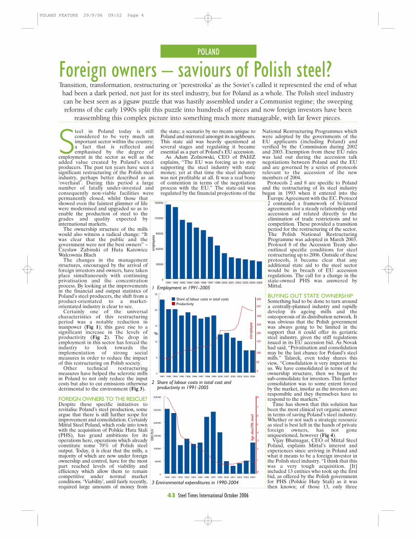
POLAND
43 Steel Times International October 2006
Steel in Poland today is stillconsidered to be very much animportant sector within the country;a fact that is reflected andemphasised by the degree of
employment in the sector as well as theadded value created by Poland’s steelproducers. The past ten years have seen asignificant restructuring of the Polish steelindustry, perhaps better described as an‘overhaul’. During this period a largenumber of fatally under-invested andconsequently non-viable facilities werepermanently closed, whilst those thatshowed even the faintest glimmer of lifewere modernised and upgraded so as toenable the production of steel to thegrades and quality expected byinternational markets.
The ownership structure of the millswould also witness a radical change: “Itwas clear that the public and thegovernment were not the best owners” –Czeslaw Zabinski of Huta KatowiceWalcownia Blach
The changes in the managementstructures, encouraged by the arrival offoreign investors and owners, have takenplace simultaneously with continuingprivatisation and the concentrationprocess. By looking at the improvementsin the financial and output statistics ofPoland’s steel producers, the shift from aproduct-orientated to a market-orientated industry is clear to see.
Certainly one of the universalcharacteristics of this restructuringperiod was a notable reduction inmanpower (Fig 1); this gave rise to asignificant increase in the levels ofproductivity (Fig 2). The drop inemployment in this sector has forced theindustry to look towards theimplementation of strong socialmeasures in order to reduce the impactof this restructuring on Polish society.
Other technical restructuringmeasures have helped the sclerotic millsin Poland to not only reduce the inputcosts but also to cut emissions otherwisedetrimental to the environment (Fig 3).
FOREIGN OWNERS TO THE RESCUE?Despite these specific initiatives torevitalise Poland’s steel production, someargue that there is still further scope forimprovement and consolidation. CertainlyMittal Steel Poland, which rode into townwith the acquisition of Polskie Huta Stali(PHS), has grand ambitions for itsoperations here, operations which alreadyconstitute some 70% of Polish steeloutput. Today, it is clear that the mills, amajority of which are now under foreignownership and control, have for the mostpart reached levels of viability andefficiency which allow them to remaincompetitive under normal marketconditions. ‘Viability’, until fairly recently,required large amounts of money from
Foreign owners – saviours of Polish steel?Transition, transformation, restructuring or ‘perestroika’ as the Soviet’s called it represented the end of whathad been a dark period, not just for its steel industry, but for Poland as a whole. The Polish steel industrycan be best seen as a jigsaw puzzle that was hastily assembled under a Communist regime; the sweepingreforms of the early 1990s split this puzzle into hundreds of pieces and now foreign investors have been
reassembling this complex picture into something much more manageable, with far fewer pieces.
National Restructuring Programmes whichwere adopted by the governments of theEU applicants (including Poland) andverified by the Commission during 2002and 2003. Exemption from these EU ruleswas laid out during the accession talknegotiations between Poland and the EUand are governed by a series of protocolsrelevant to the accession of the newmembers of 2004.
Protocols 2 and 8 are specific to Polandand the restructuring of its steel industrybegan in 1993 when it entered into the
Europe Agreement with the EC. Protocol2 contained a framework of bi-lateralagreements for a steady relationship untilaccession and related directly to theelimination of trade restrictions and tocompetition. These provided a transitionperiod for the restructuring of the sector.The Polish National RestructuringProgramme was adopted in March 2003.Protocol 8 of the Accession Treaty alsooutlined specific conditions for steelrestructuring up to 2006. Outside of theseprotocols, it became clear that anyadditional state aid to the steel sectorwould be in breach of EU accessionregulations. The call for a change in thestate-owned PHS was answered byMittal.
BUYING OUT STATE OWNERSHIPSomething had to be done to turn arounda centrally-planned industry and rapidlydevelop its ageing mills and theosteoporosis of its distribution network. Itwas obvious that the Polish governmentwas always going to be limited in thesupport that it could offer its geriatricsteel industry, given the stiff regulationsissued in its EU accession bid. As Novakhad said, “Privatisation and consolidationmay be the last chance for Poland’s steelmills.” Talarek, even today shares thisview, “Consolidation is very important tous. We have consolidated in terms of theownership structure, then we began tosub-consolidate for investors. This furtherconsolidation was to some extent forcedby the market, insofar as the investors areresponsible and they themselves have torespond to the markets.”
Time has shown that this solution hasbeen the most clinical yet organic answerin terms of saving Poland’s steel industry.Whether or not such a strategic resourceas steel is best left in the hands of privateforeign owners, has not goneunquestioned, however (Fig 4).
Vijay Bhatnagar, CEO of Mittal SteelPoland, explains Mittal’s interest andexperiences since arriving in Poland andwhat it means to be a foreign investor inthe Polish steel industry. “I think that thiswas a very tough acquisition. [It]included 13 entities who took up the firstbid, as offered by the Polish governmentfor PHS (Polskie Huty Stali) as it wasthen known; of those 13, only three
1 Employment in 1991-2005
0
5
10
15
20
25
200520042003200220012000199919981997199619951994199319921991
0
50000
100000
150000
200000
250000
300000
20042003200220012000199919971996199519941993199219911990
2 Share of labour costs in total cost and productivity in 1991-2005
3 Environmental expenditures in 1990-2004
8
0
6
7
1
2
3
4
5
kgs
dust
/Mt
stee
l
‘000
PLN
%
Share of labour costs in total costsProductivity
400
350
300
250
200
150
100
50
0
t/em
ploy
ee
0
30000
60000
90000
120000
150000
20052004200320022001200019981997199619951994199319921991
empl
oyee
s
the state; a scenario by no means unique toPoland and mirrored amongst its neighbours.This state aid was heavily questioned atseveral stages and regulating it becameessential as a part of Poland’s EU accession.
As Adam Zolnowski, CEO of PAIiIZexplains, “The EU was forcing us to stopsupporting the steel industry with statemoney; yet at that time the steel industrywas not profitable at all. It was a real boneof contention in terms of the negotiationprocess with the EU.” The state-aid wasregulated by the financial projections of the
POLAND FEATURE 29/9/06 09:52 Page 4
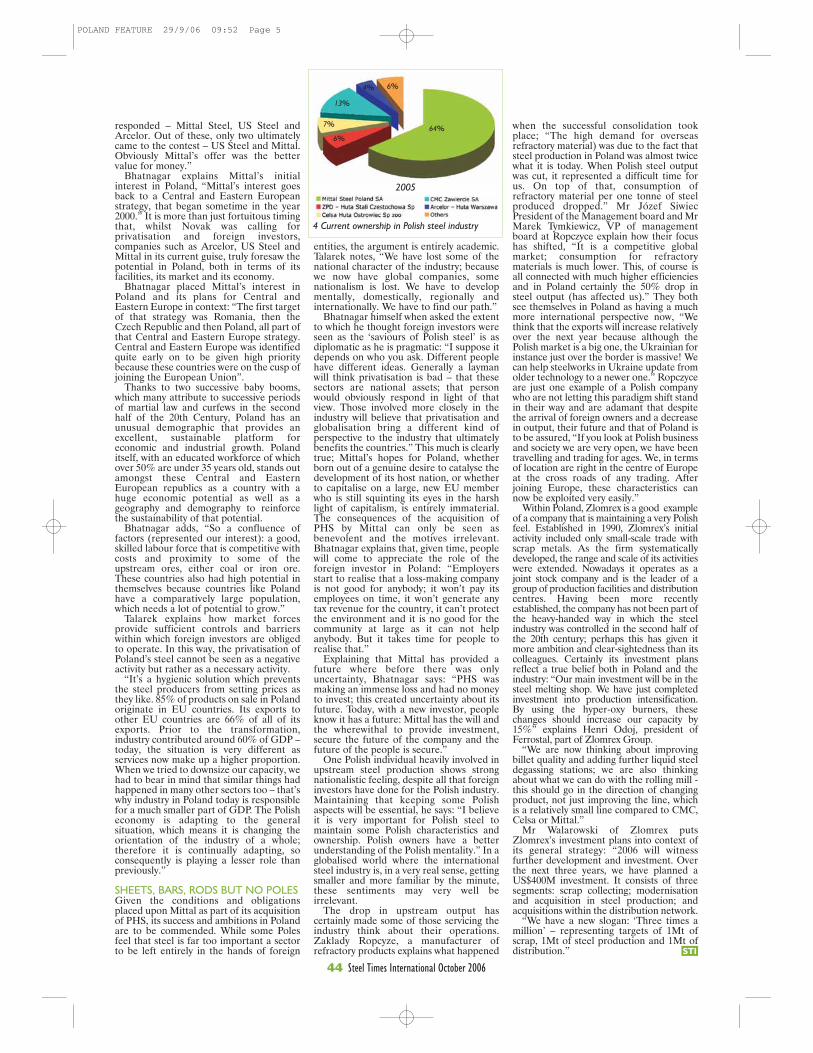
44 Steel Times International October 2006STI
responded – Mittal Steel, US Steel andArcelor. Out of these, only two ultimatelycame to the contest – US Steel and Mittal.Obviously Mittal’s offer was the bettervalue for money.”
Bhatnagar explains Mittal’s initialinterest in Poland, “Mittal’s interest goesback to a Central and Eastern Europeanstrategy, that began sometime in the year2000.” It is more than just fortuitous timingthat, whilst Novak was calling forprivatisation and foreign investors,companies such as Arcelor, US Steel andMittal in its current guise, truly foresaw thepotential in Poland, both in terms of itsfacilities, its market and its economy.
Bhatnagar placed Mittal’s interest inPoland and its plans for Central andEastern Europe in context: “The first targetof that strategy was Romania, then theCzech Republic and then Poland, all part ofthat Central and Eastern Europe strategy.Central and Eastern Europe was identifiedquite early on to be given high prioritybecause these countries were on the cusp ofjoining the European Union”.
Thanks to two successive baby booms,which many attribute to successive periodsof martial law and curfews in the secondhalf of the 20th Century, Poland has anunusual demographic that provides anexcellent, sustainable platform foreconomic and industrial growth. Polanditself, with an educated workforce of whichover 50% are under 35 years old, stands outamongst these Central and EasternEuropean republics as a country with ahuge economic potential as well as ageography and demography to reinforcethe sustainability of that potential.
Bhatnagar adds, “So a confluence offactors (represented our interest): a good,skilled labour force that is competitive withcosts and proximity to some of theupstream ores, either coal or iron ore.These countries also had high potential inthemselves because countries like Polandhave a comparatively large population,which needs a lot of potential to grow.”
Talarek explains how market forcesprovide sufficient controls and barrierswithin which foreign investors are obligedto operate. In this way, the privatisation ofPoland’s steel cannot be seen as a negativeactivity but rather as a necessary activity.
“It’s a hygienic solution which preventsthe steel producers from setting prices asthey like. 85% of products on sale in Polandoriginate in EU countries. Its exports toother EU countries are 66% of all of itsexports. Prior to the transformation,industry contributed around 60% of GDP –today, the situation is very different asservices now make up a higher proportion.When we tried to downsize our capacity, wehad to bear in mind that similar things hadhappened in many other sectors too – that’swhy industry in Poland today is responsiblefor a much smaller part of GDP. The Polisheconomy is adapting to the generalsituation, which means it is changing theorientation of the industry of a whole;therefore it is continually adapting, soconsequently is playing a lesser role thanpreviously.”
SHEETS, BARS, RODS BUT NO POLESGiven the conditions and obligationsplaced upon Mittal as part of its acquisitionof PHS, its success and ambitions in Polandare to be commended. While some Polesfeel that steel is far too important a sectorto be left entirely in the hands of foreign
when the successful consolidation tookplace; “The high demand for overseasrefractory material) was due to the fact thatsteel production in Poland was almost twicewhat it is today. When Polish steel outputwas cut, it represented a difficult time forus. On top of that, consumption ofrefractory material per one tonne of steelproduced dropped.” Mr Józef SiwiecPresident of the Management board and MrMarek Tymkiewicz, VP of managementboard at Ropczyce explain how their focushas shifted, “It is a competitive globalmarket; consumption for refractorymaterials is much lower. This, of course isall connected with much higher efficienciesand in Poland certainly the 50% drop insteel output (has affected us).” They bothsee themselves in Poland as having a muchmore international perspective now, “Wethink that the exports will increase relativelyover the next year because although thePolish market is a big one, the Ukrainian forinstance just over the border is massive! Wecan help steelworks in Ukraine update fromolder technology to a newer one.” Ropczyceare just one example of a Polish companywho are not letting this paradigm shift standin their way and are adamant that despitethe arrival of foreign owners and a decreasein output, their future and that of Poland isto be assured, “If you look at Polish businessand society we are very open, we have beentravelling and trading for ages. We, in termsof location are right in the centre of Europeat the cross roads of any trading. Afterjoining Europe, these characteristics cannow be exploited very easily.”
Within Poland, Zlomrex is a good exampleof a company that is maintaining a very Polishfeel. Established in 1990, Zlomrex’s initialactivity included only small-scale trade withscrap metals. As the firm systematicallydeveloped, the range and scale of its activitieswere extended. Nowadays it operates as ajoint stock company and is the leader of agroup of production facilities and distributioncentres. Having been more recentlyestablished, the company has not been part ofthe heavy-handed way in which the steelindustry was controlled in the second half ofthe 20th century; perhaps this has given itmore ambition and clear-sightedness than itscolleagues. Certainly its investment plansreflect a true belief both in Poland and theindustry: “Our main investment will be in thesteel melting shop. We have just completedinvestment into production intensification.By using the hyper-oxy burners, thesechanges should increase our capacity by15%” explains Henri Odoj, president ofFerrostal, part of Zlomrex Group.
“We are now thinking about improvingbillet quality and adding further liquid steeldegassing stations; we are also thinkingabout what we can do with the rolling mill -this should go in the direction of changingproduct, not just improving the line, whichis a relatively small line compared to CMC,Celsa or Mittal.”
Mr Walarowski of Zlomrex putsZlomrex’s investment plans into context ofits general strategy: “2006 will witnessfurther development and investment. Overthe next three years, we have planned aUS$400M investment. It consists of threesegments: scrap collecting; modernisationand acquisition in steel production; andacquisitions within the distribution network.
“We have a new slogan: ‘Three times amillion’ – representing targets of 1Mt ofscrap, 1Mt of steel production and 1Mt ofdistribution.”
2005
4 Current ownership in Polish steel industry
64%6%
7%
13%
4% 6%
entities, the argument is entirely academic.Talarek notes, “We have lost some of thenational character of the industry; becausewe now have global companies, somenationalism is lost. We have to developmentally, domestically, regionally andinternationally. We have to find our path.”
Bhatnagar himself when asked the extentto which he thought foreign investors wereseen as the ‘saviours of Polish steel’ is asdiplomatic as he is pragmatic: “I suppose itdepends on who you ask. Different peoplehave different ideas. Generally a laymanwill think privatisation is bad – that thesesectors are national assets; that personwould obviously respond in light of thatview. Those involved more closely in theindustry will believe that privatisation andglobalisation bring a different kind ofperspective to the industry that ultimatelybenefits the countries.” This much is clearlytrue; Mittal’s hopes for Poland, whetherborn out of a genuine desire to catalyse thedevelopment of its host nation, or whetherto capitalise on a large, new EU memberwho is still squinting its eyes in the harshlight of capitalism, is entirely immaterial.The consequences of the acquisition ofPHS by Mittal can only be seen asbenevolent and the motives irrelevant.Bhatnagar explains that, given time, peoplewill come to appreciate the role of theforeign investor in Poland: “Employersstart to realise that a loss-making companyis not good for anybody; it won’t pay itsemployees on time, it won’t generate anytax revenue for the country, it can’t protectthe environment and it is no good for thecommunity at large as it can not helpanybody. But it takes time for people torealise that.”
Explaining that Mittal has provided afuture where before there was onlyuncertainty, Bhatnagar says: “PHS wasmaking an immense loss and had no moneyto invest; this created uncertainty about itsfuture. Today, with a new investor, peopleknow it has a future: Mittal has the will andthe wherewithal to provide investment,secure the future of the company and thefuture of the people is secure.”
One Polish individual heavily involved inupstream steel production shows strongnationalistic feeling, despite all that foreigninvestors have done for the Polish industry.Maintaining that keeping some Polishaspects will be essential, he says: “I believeit is very important for Polish steel tomaintain some Polish characteristics andownership. Polish owners have a betterunderstanding of the Polish mentality.” In aglobalised world where the internationalsteel industry is, in a very real sense, gettingsmaller and more familiar by the minute,these sentiments may very well beirrelevant.
The drop in upstream output hascertainly made some of those servicing theindustry think about their operations.Zaklady Ropcyze, a manufacturer ofrefractory products explains what happened
POLAND FEATURE 29/9/06 09:52 Page 5
POLAND FEATURE 29/9/06 09:52 Page 6
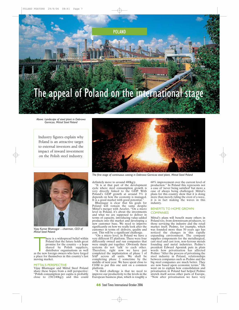
POLAND
46 Steel Times International October 2006
The appeal of Poland on the international stage
definitely move to around 400kg/y. “It is at that part of the development
cycle where steel consumption growth isvery directly linked to the GDP. WithPoland’s GDP growth at around 5% itdepends on how the economy is managed.It is a good market with good potential.”
Bhatnagar is clear that his goals forPoland will remain the same despiteMittel’s merger with Arcelor, “On a microlevel in Poland, it’s about the investmentsand what we are supposed to deliver interms of capacity, introducing value-addedproducts into the market and developing anew customer base. We need to improvesignificantly on how we really look after thecustomer in terms of: delivery, quality andcost. This will be a significant challenge.
“On a micro level, in Poland we have avery different IT platform. There were fourdifferently owned and run companies thatwere simply put together. Obviously thesesystems do not ‘talk’ to each other.Therefore, right now we have justcompleted the implantation of phase 1 ofSAP across all units. We shall becompleting phase 2 sometime by themiddle of next year. We have spent close to€10M to put this one unit on a commonplatform.
“A third challenge is that we need toimprove our productivity to the levels in theEuropean business plan, which is roughly a
60% improvement over the current level ofproduction.” In Poland this represents nota case of ‘never being satisfied’ but more acase of always being challenged. Mittal’splans for this country show that it is doingmore than merely riding the crest of a wave,it is in fact making the waves in thisindustry.
BENEFITS TO HOME GROWNCOMPANIES
Mittal’s plans will benefit many others inPoland too, from downstream producers, tothose servicing the industry and the retailmarket itself. Pedmo, for example, whichwas founded more than 50 years ago hasnoticed the changes in this rapidlyexpanding environment. The companysupplies components for the metallurgical,cast steel and cast iron, non-ferrous metalsfounding and metal industries. Pedmo’spresident Edward Aponiuk puts in plainwords how privatisation has affectedPedmo: “After the process of privatising thesteel industry in Poland, relationshipsbetween companies such as Pedmo and thebig steel companies are much better. Theyare now based upon economic terms.” Hewent on to explain how consolidation andprivatisation in Poland had helped Pedmostretch itself across other parts of Europe,“Now after privatisation we have very
There is a widespread belief withinPoland that the future holds greatpromise for the country – a hopeshared by Polish suppliers,distributor organisations as well
as the new foreign owners who have forgeda place for themselves in this country’s fastmoving market.
MITTAL’S PERSPECTIVEVijay Bhatnagar and Mittal Steel Polandshare these hopes from a mill perspective:“Polish consumption per capita is probablyclose to 230/240kg/y and this could
Industry figures explain whyPoland is an attractive targetto external investors and theimpact of inward investmenton the Polish steel industry.
Above: Landscape of steel plant in DabrowaGornicza, Mittal Steel Poland
Vijay Kumar Bhatnagar – chairman, CEO ofMittal Steel Poland
The first stage of continuous casting in Dabrowa Gornicza steel plant, Mittal Steel Poland
POLAND FEATURE 29/9/06 08:41 Page 7

POLAND
47 Steel Times International October 2006
simple and open rules: money comes in on time,deliveries are made on time. We cooperate withMittal steel all over Eastern Europe.” Oneaspect where Pedmo has reacted slightlydifferently from many Polish industry colleagueshas been its lack of focus on organisationalchange after EU accession and privatisation.“The structure of the company did not changemuch since privatisation; one focus that wasshifted was onto research. We are much morefocused on this and as a result, we can offer verynew products for our customers.” This is from acompany that has truly experienced some of themost varied times in Poland’s business history,and is coming to terms quickly with what itmeans to operate in a free market. “We areproducing auxiliary materials for the steelindustry, foundry industry, aluminium andcopper industry also refining and insulation. Wehave partners and customers all over Europe butat the time of privatisation Pedmo was onlyoperating in Poland.” Pedmo must surely beevidence of how the privatisation of theupstream industries has helped provide a futurefor those who service this industry and has alsohelped, in a short space of time, to explain thepossibilities for export into this global-town andEuropean-village.
COMING TO TERMS WITHCOMPETITIONBipromet is another organisation, like Pedmo,which has a long and intertwined history withPoland’s steel industry. Bipromet has seendecades of central planning and has had to veryquickly come to terms with competition, anailing industry and the necessity for marketing.Tadeusz Baj explains, “The first 40 yearsBipromet was a state owned design office,employing up to 1300 people designing thewhole Polish non ferrous metal industry. I thinkit is no exaggeration to say that all Polish copper,zinc, lead, aluminium smelters and processingplants were designed by Bipromet specialists.”
Baj is another industry individual whoacknowledges the benefits of privatisation andEU accession and elaborates as to how it hasobliged a change of focus on organisationalchange and reliance on markets: “The accessionof Poland to EU just made it easier for Biprometto offer its services abroad. Mainly electro filtersand fabrics filters are designed, delivered andassembled in many countries of the EU, the mostrecent filters being installed at a coke plant inBelgium. Some of the export activities worthmentioning were carried out in Thailand whereconverters were designed and delivered toRayong Copper Smelter. We also approachScandinavian and French markets; soundoubtedly, (EU accession) presented anopportunity and not a threat.”
He is clear that Polish companies such asBipromet will have the edge on competition formany years yet, thanks to lower prices, due tolower costs. “Polish engineering services are farless expensive then in western European orAmerican markets. I think many years will passbefore they reach parity. Many foreignengineering companies realise the difference, sosome mergers and acquisitions have occurred bysome well known corporations such as Lurgi,Fluor Daniel and many others.”
Baj goes on to add, “The most competitiveservices that we offer are most probably electro-filters and fabric-filters-due to these Europeandirectives limiting the air polluting tolerance.”He is hopeful that EU emissions directives willfocus on the services offered by the likes ofBipromet. STI
POLAND FEATURE 29/9/06 08:41 Page 8
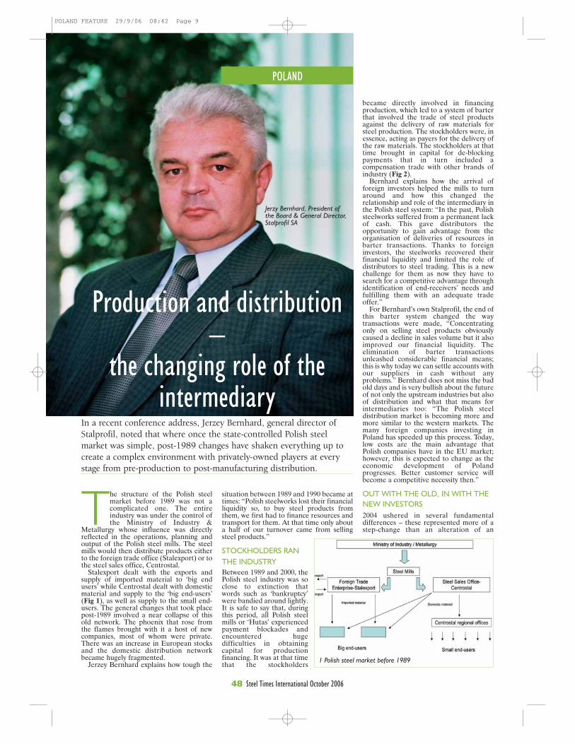
POLAND
48 Steel Times International October 2006
The structure of the Polish steelmarket before 1989 was not acomplicated one. The entireindustry was under the control ofthe Ministry of Industry &
Metallurgy whose influence was directlyreflected in the operations, planning andoutput of the Polish steel mills. The steelmills would then distribute products eitherto the foreign trade office (Stalexport) or tothe steel sales office, Centrostal.
Stalexport dealt with the exports andsupply of imported material to ‘big endusers’ while Centrostal dealt with domesticmaterial and supply to the ‘big end-users’(Fig 1), as well as supply to the small end-users. The general changes that took placepost-1989 involved a near collapse of thisold network. The phoenix that rose fromthe flames brought with it a host of newcompanies, most of whom were private.There was an increase in European stocksand the domestic distribution networkbecame hugely fragmented.
Jerzey Bernhard explains how tough the
situation between 1989 and 1990 became attimes: “Polish steelworks lost their financialliquidity so, to buy steel products fromthem, we first had to finance resources andtransport for them. At that time only abouta half of our turnover came from sellingsteel products.”
STOCKHOLDERS RANTHE INDUSTRYBetween 1989 and 2000, thePolish steel industry was soclose to extinction thatwords such as ‘bankruptcy’were bandied around lightly.It is safe to say that, duringthis period, all Polish steelmills or ‘Hutas’ experiencedpayment blockades andencountered hugedifficulties in obtainingcapital for productionfinancing. It was at that timethat the stockholders
became directly involved in financingproduction, which led to a system of barterthat involved the trade of steel productsagainst the delivery of raw materials forsteel production. The stockholders were, inessence, acting as payers for the delivery ofthe raw materials. The stockholders at thattime brought in capital for de-blockingpayments that in turn included acompensation trade with other brands ofindustry (Fig 2).
Bernhard explains how the arrival offoreign investors helped the mills to turnaround and how this changed therelationship and role of the intermediary inthe Polish steel system: “In the past, Polishsteelworks suffered from a permanent lackof cash. This gave distributors theopportunity to gain advantage from theorganisation of deliveries of resources inbarter transactions. Thanks to foreigninvestors, the steelworks recovered theirfinancial liquidity and limited the role ofdistributors to steel trading. This is a newchallenge for them as now they have tosearch for a competitive advantage throughidentification of end-receivers’ needs andfulfilling them with an adequate tradeoffer.”
For Bernhard’s own Stalprofil, the end ofthis barter system changed the waytransactions were made, “Concentratingonly on selling steel products obviouslycaused a decline in sales volume but it alsoimproved our financial liquidity. Theelimination of barter transactionsunleashed considerable financial means;this is why today we can settle accounts withour suppliers in cash without anyproblems.” Bernhard does not miss the badold days and is very bullish about the futureof not only the upstream industries but alsoof distribution and what that means forintermediaries too: “The Polish steeldistribution market is becoming more andmore similar to the western markets. Themany foreign companies investing inPoland has speeded up this process. Today,low costs are the main advantage thatPolish companies have in the EU market;however, this is expected to change as theeconomic development of Polandprogresses. Better customer service willbecome a competitive necessity then.”
OUT WITH THE OLD, IN WITH THENEW INVESTORS2004 ushered in several fundamentaldifferences – these represented more of astep-change than an alteration of an
In a recent conference address, Jerzey Bernhard, general director ofStalprofil, noted that where once the state-controlled Polish steelmarket was simple, post-1989 changes have shaken everything up tocreate a complex environment with privately-owned players at everystage from pre-production to post-manufacturing distribution.
Production and distribution–
the changing role of theintermediary
1 Polish steel market before 1989
Jerzy Bernhard, President ofthe Board & General Director,Stalprofil SA
POLAND FEATURE 29/9/06 08:42 Page 9

POLAND
49 Steel Times International October 2006
STI
unsustainable system. After the arrival offoreign investors into the upstream industry– namely Mittal Steel, CMC, Celsa andArcelor – it became clear that the oldnetwork was not going to be suitable for, orcompatible with, the newcomers.
Post-2004, there was a growing marketshare of steel stockholders and a limitedmarket share of intermediaries and otherenterprises treating steel as a method ofrecovering the debts of the mills. The roleof the standard intermediary continues todecrease as steel mills can now pay cash forraw materials and deliveries are purchaseddirectly from the producers. Cash is nowthe demanded payment for steel products.
At present, however, Polish producersstill do not have either their owndistribution network or, according toBernhard a ‘clear-cut concept of how itshould be organised in the future.” Asintermediaries search for supplements totheir core activities, adding value en routeto the customer (in the guise of servicecentres or an initial processing of steelproducts), it becomes clear that the futuredistribution model is in the hands of themain producers (Fig 3).
In Bernhard’s prediction for distributors,he sees a growing role of big stocks andservice centres: “Companies providingadded services (like steel products’ initialprocessing) and with adequate financialpotential and trade infrastructure are thefuture of the Polish steel distributionmarket. Small intermediaries will gradually
3 Future steel market?
disappear [from it].” Headds, “Distributors withoutsuitable trade infrastructurewill gradually disappearfrom the Polish market.Thanks to the investmentsmade many years before,Stalprofil now has large andmodern steel depots [Itscapacity reaches 80kt]providing competitiveadvantage to the company.Complex customer service isour objective and we want toachieve it by providing anextensive assortment and byadding value to steelproducts’ initial processing.Our exporting experienceand strong position in theEU market are notablereasons for our success.Today Stalprofil sells toabout 60 companies from 20European countries. Wegained the ‘Bull and Bear’prize for the best-managedcompany on the WarsawStock Exchange. With thestrength of a bull, weconstantly try to improveour competitiveness.”
2 Model of domestic steel products distribution networkbefore 2004
Fig 1, 2 and 3 are:"Information extracted from Jerzy Bernhard’s SBB Steel Markets Europe 2006 speech"
POLAND FEATURE 29/9/06 08:42 Page 10
POLAND
50 Steel Times International October 2006
Readyfor the future Poland has done all in its power to
drag its steel industry kicking andscreaming into the 21st century. Ithas dropped down in the worldrankings of international steel
producers because of the emphasis placednot only on responsible production and theelimination of cycles but also because of theimplications of being a market rather thana production-based economy. This hasmeant an obligation to invite foreigninvestors and owners to come and take alook around. Far from the mills being seenas a second-hand car or jumble saleantique, these facilities, when combinedwith the investments made by foreignowners and the young, low-cost labour; areshowing themselves to be truepowerhouses.
The efforts made to increase the gradeand varieties of steel produced have helpedthe development of all parts of the industry.Distribution networks have been upgradedas has the relationships between theproducers and the intermediaries. Theintermediaries are having to find new waysto process, initially and subsequently, thesteel to maintain some place between theproducer and the customer. With mills inPoland trying to get ever-closer to the STI
customers, and with investments focusingon downstream production; the spacebetween producer and end user is closingin. Companies such as Stalprofil focus onlarge stocks and service centres as well asciting the oft-used phrase, “one stop shop”to guarantee that its presence is welldeserved. The shift from a productionorientation to a market orientation hastaken place at a breakneck pace; theevidence in the value created by steel inPoland is clear in the changes inmanufacturing and service industries, as acomponent of GDP: Value, value, value.
All acknowledge that GDP growth is ahuge indicator and factor in steelconsumption, hopes that steel consumptioncould one day rise to 400kg are optimistic.But then so were hopes in 2000 that severalforeign companies could come and give thisindustry the adrenalin shot it needed. Asthe global steel industry becomes more andmore familiar and gets closer and closer tothe living rooms (Mittal Steel welcome youto Balice Airport in Krakow), theadvantages of having an educated,ambitious, populous, low-cost Europeannation as a manufacturing base, as well as avaluable sourcing destination become ever-clearer.
Acknowledgements:Global Business Reports would like to thank HIPH for its help and cooperation for thisreport on Poland
HIPH – The Polish Steel Association Tel +48 32 788 7777 www.hiph.com.pl
POLAND FEATURE 29/9/06 08:42 Page 11
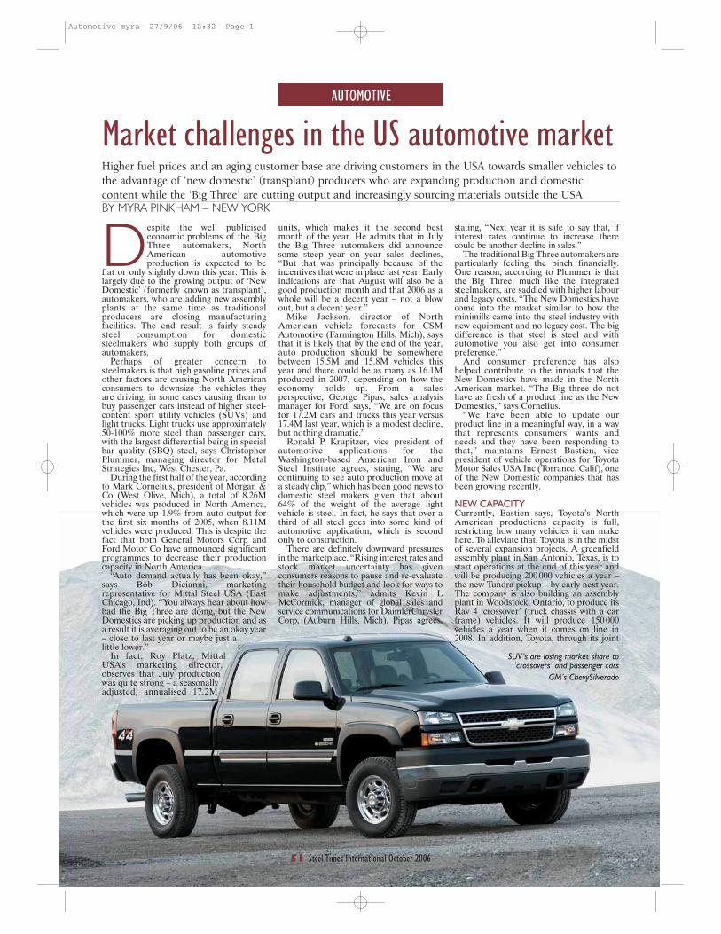
AUTOMOTIVE
51 Steel Times International October 2006
Despite the well publicisedeconomic problems of the BigThree automakers, NorthAmerican automotiveproduction is expected to be
flat or only slightly down this year. This islargely due to the growing output of ‘NewDomestic’ (formerly known as transplant),automakers, who are adding new assemblyplants at the same time as traditionalproducers are closing manufacturingfacilities. The end result is fairly steadysteel consumption for domesticsteelmakers who supply both groups ofautomakers.
Perhaps of greater concern tosteelmakers is that high gasoline prices andother factors are causing North Americanconsumers to downsize the vehicles theyare driving, in some cases causing them tobuy passenger cars instead of higher steel-content sport utility vehicles (SUVs) andlight trucks. Light trucks use approximately50-100% more steel than passenger cars,with the largest differential being in specialbar quality (SBQ) steel, says ChristopherPlummer, managing director for MetalStrategies Inc, West Chester, Pa.
During the first half of the year, accordingto Mark Cornelius, president of Morgan &Co (West Olive, Mich), a total of 8.26Mvehicles was produced in North America,which were up 1.9% from auto output forthe first six months of 2005, when 8.11Mvehicles were produced. This is despite thefact that both General Motors Corp andFord Motor Co have announced significantprogrammes to decrease their productioncapacity in North America.
“Auto demand actually has been okay,”says Bob Dicianni, marketingrepresentative for Mittal Steel USA (EastChicago, Ind). “You always hear about howbad the Big Three are doing, but the NewDomestics are picking up production and asa result it is averaging out to be an okay year– close to last year or maybe just alittle lower.”
In fact, Roy Platz, MittalUSA’s marketing director,observes that July productionwas quite strong – a seasonallyadjusted, annualised 17.2M
Market challenges in the US automotive marketHigher fuel prices and an aging customer base are driving customers in the USA towards smaller vehicles tothe advantage of ‘new domestic’ (transplant) producers who are expanding production and domesticcontent while the ‘Big Three’ are cutting output and increasingly sourcing materials outside the USA.BY MYRA PINKHAM – NEW YORK
units, which makes it the second bestmonth of the year. He admits that in Julythe Big Three automakers did announcesome steep year on year sales declines,“But that was principally because of theincentives that were in place last year. Earlyindications are that August will also be agood production month and that 2006 as awhole will be a decent year – not a blowout, but a decent year.”
Mike Jackson, director of NorthAmerican vehicle forecasts for CSMAutomotive (Farmington Hills, Mich), saysthat it is likely that by the end of the year,auto production should be somewherebetween 15.5M and 15.8M vehicles thisyear and there could be as many as 16.1Mproduced in 2007, depending on how theeconomy holds up. From a salesperspective, George Pipas, sales analysismanager for Ford, says, “We are on focusfor 17.2M cars and trucks this year versus17.4M last year, which is a modest decline,but nothing dramatic.”
Ronald P Krupitzer, vice president ofautomotive applications for theWashington-based American Iron andSteel Institute agrees, stating, “We arecontinuing to see auto production move ata steady clip,” which has been good news todomestic steel makers given that about64% of the weight of the average lightvehicle is steel. In fact, he says that over athird of all steel goes into some kind ofautomotive application, which is secondonly to construction.
There are definitely downward pressuresin the marketplace. “Rising interest rates andstock market uncertainty has givenconsumers reasons to pause and re-evaluatetheir household budget and look for ways tomake adjustments,” admits Kevin LMcCormick, manager of global sales andservice communications for DaimlerChryslerCorp, (Auburn Hills, Mich). Pipas agrees,
stating, “Next year it is safe to say that, ifinterest rates continue to increase therecould be another decline in sales.”
The traditional Big Three automakers areparticularly feeling the pinch financially.One reason, according to Plummer is thatthe Big Three, much like the integratedsteelmakers, are saddled with higher labourand legacy costs. “The New Domestics havecome into the market similar to how theminimills came into the steel industry withnew equipment and no legacy cost. The bigdifference is that steel is steel and withautomotive you also get into consumerpreference.”
And consumer preference has alsohelped contribute to the inroads that theNew Domestics have made in the NorthAmerican market. “The Big three do nothave as fresh of a product line as the NewDomestics,” says Cornelius.
“We have been able to update ourproduct line in a meaningful way, in a waythat represents consumers’ wants andneeds and they have been responding tothat,” maintains Ernest Bastien, vicepresident of vehicle operations for ToyotaMotor Sales USA Inc (Torrance, Calif), oneof the New Domestic companies that hasbeen growing recently.
NEW CAPACITY Currently, Bastien says, Toyota’s NorthAmerican productions capacity is full,restricting how many vehicles it can makehere. To alleviate that, Toyota is in the midstof several expansion projects. A greenfieldassembly plant in San Antonio, Texas, is tostart operations at the end of this year andwill be producing 200 000 vehicles a year –the new Tundra pickup – by early next year.The company is also building an assemblyplant in Woodstock, Ontario, to produce itsRav 4 ‘crossover’ (truck chassis with a carframe) vehicles. It will produce 150 000vehicles a year when it comes on line in2008. In addition, Toyota, through its joint
SUV’s are losing market share to‘crossovers’ and passenger cars
GM’s ChevySilverado
Automotive myra 27/9/06 12:32 Page 1
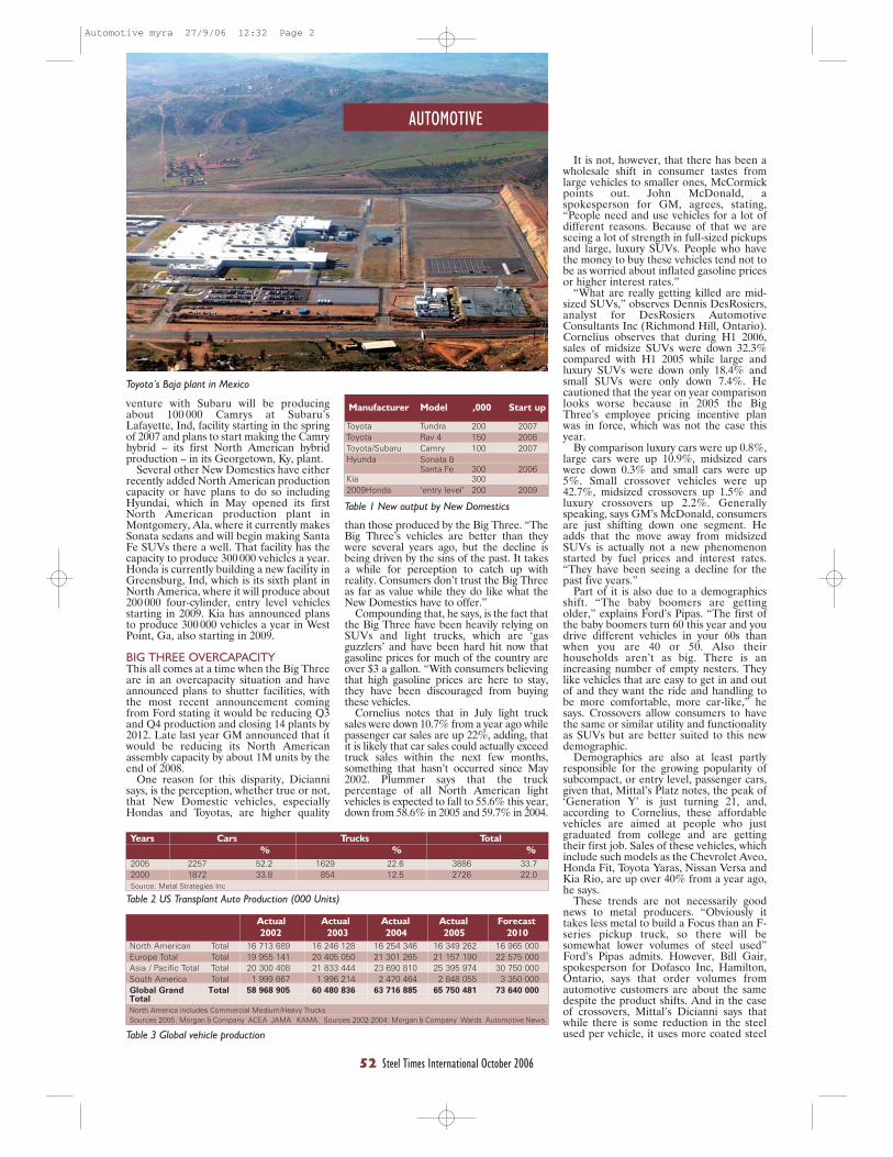
AUTOMOTIVE
52 Steel Times International October 2006
venture with Subaru will be producingabout 100 000 Camrys at Subaru’sLafayette, Ind, facility starting in the springof 2007 and plans to start making the Camryhybrid – its first North American hybridproduction – in its Georgetown, Ky, plant.
Several other New Domestics have eitherrecently added North American productioncapacity or have plans to do so includingHyundai, which in May opened its firstNorth American production plant inMontgomery, Ala, where it currently makesSonata sedans and will begin making SantaFe SUVs there a well. That facility has thecapacity to produce 300 000 vehicles a year.Honda is currently building a new facility inGreensburg, Ind, which is its sixth plant inNorth America, where it will produce about200 000 four-cylinder, entry level vehiclesstarting in 2009. Kia has announced plansto produce 300 000 vehicles a year in WestPoint, Ga, also starting in 2009.
BIG THREE OVERCAPACITYThis all comes at a time when the Big Threeare in an overcapacity situation and haveannounced plans to shutter facilities, withthe most recent announcement comingfrom Ford stating it would be reducing Q3and Q4 production and closing 14 plants by2012. Late last year GM announced that itwould be reducing its North Americanassembly capacity by about 1M units by theend of 2008.
One reason for this disparity, Diciannisays, is the perception, whether true or not,that New Domestic vehicles, especiallyHondas and Toyotas, are higher quality
than those produced by the Big Three. “TheBig Three’s vehicles are better than theywere several years ago, but the decline isbeing driven by the sins of the past. It takesa while for perception to catch up withreality. Consumers don’t trust the Big Threeas far as value while they do like what theNew Domestics have to offer.”
Compounding that, he says, is the fact thatthe Big Three have been heavily relying onSUVs and light trucks, which are ‘gasguzzlers’ and have been hard hit now thatgasoline prices for much of the country areover $3 a gallon. “With consumers believingthat high gasoline prices are here to stay,they have been discouraged from buyingthese vehicles.
Cornelius notes that in July light trucksales were down 10.7% from a year ago whilepassenger car sales are up 22%, adding, thatit is likely that car sales could actually exceedtruck sales within the next few months,something that hasn’t occurred since May2002. Plummer says that the truckpercentage of all North American lightvehicles is expected to fall to 55.6% this year,down from 58.6% in 2005 and 59.7% in 2004.
It is not, however, that there has been awholesale shift in consumer tastes fromlarge vehicles to smaller ones, McCormickpoints out. John McDonald, aspokesperson for GM, agrees, stating,“People need and use vehicles for a lot ofdifferent reasons. Because of that we areseeing a lot of strength in full-sized pickupsand large, luxury SUVs. People who havethe money to buy these vehicles tend not tobe as worried about inflated gasoline pricesor higher interest rates.”
“What are really getting killed are mid-sized SUVs,” observes Dennis DesRosiers,analyst for DesRosiers AutomotiveConsultants Inc (Richmond Hill, Ontario).Cornelius observes that during H1 2006,sales of midsize SUVs were down 32.3%compared with H1 2005 while large andluxury SUVs were down only 18.4% andsmall SUVs were only down 7.4%. Hecautioned that the year on year comparisonlooks worse because in 2005 the BigThree’s employee pricing incentive planwas in force, which was not the case thisyear.
By comparison luxury cars were up 0.8%,large cars were up 10.9%, midsized carswere down 0.3% and small cars were up5%. Small crossover vehicles were up42.7%, midsized crossovers up 1.5% andluxury crossovers up 2.2%. Generallyspeaking, says GM’s McDonald, consumersare just shifting down one segment. Headds that the move away from midsizedSUVs is actually not a new phenomenonstarted by fuel prices and interest rates.“They have been seeing a decline for thepast five years.”
Part of it is also due to a demographicsshift. “The baby boomers are gettingolder,” explains Ford’s Pipas. “The first ofthe baby boomers turn 60 this year and youdrive different vehicles in your 60s thanwhen you are 40 or 50. Also theirhouseholds aren’t as big. There is anincreasing number of empty nesters. Theylike vehicles that are easy to get in and outof and they want the ride and handling tobe more comfortable, more car-like,” hesays. Crossovers allow consumers to havethe same or similar utility and functionalityas SUVs but are better suited to this newdemographic.
Demographics are also at least partlyresponsible for the growing popularity ofsubcompact, or entry level, passenger cars,given that, Mittal’s Platz notes, the peak of‘Generation Y’ is just turning 21, and,according to Cornelius, these affordablevehicles are aimed at people who justgraduated from college and are gettingtheir first job. Sales of these vehicles, whichinclude such models as the Chevrolet Aveo,Honda Fit, Toyota Yaras, Nissan Versa andKia Rio, are up over 40% from a year ago,he says.
These trends are not necessarily goodnews to metal producers. “Obviously ittakes less metal to build a Focus than an F-series pickup truck, so there will besomewhat lower volumes of steel used”Ford’s Pipas admits. However, Bill Gair,spokesperson for Dofasco Inc, Hamilton,Ontario, says that order volumes fromautomotive customers are about the samedespite the product shifts. And in the caseof crossovers, Mittal’s Dicianni says thatwhile there is some reduction in the steelused per vehicle, it uses more coated steel
Years Cars Trucks Total
% % %
2005 2257 52.2 1629 22.6 3886 33.72000 1872 33.8 854 12.5 2726 22.0Source: Metal Strategies Inc
Table 2 US Transplant Auto Production (000 Units)
Actual Actual Actual Actual Forecast
2002 2003 2004 2005 2010
North American Total 16 713 689 16 246 128 16 254 346 16 349 262 16 965 000Europe Total Total 19 955 141 20 405 050 21 301 265 21 157 190 22 575 000Asia / Pacific Total Total 20 300 408 21 833 444 23 690 810 25 395 974 30 750 000South America Total 1 999 667 1 996 214 2 470 464 2 848 055 3 350 000Global Grand Total 58 968 905 60 480 836 63 716 885 65 750 481 73 640 000TotalNorth America includes Commercial Medium/Heavy TrucksSources 2005: Morgan & Company ACEA JAMA KAMA. Sources 2002-2004: Morgan & Company Wards Automotive News
Table 3 Global vehicle production
Manufacturer Model ,000 Start up
Toyota Tundra 200 2007Toyota Rav 4 150 2008Toyota/Subaru Camry 100 2007Hyunda Sonata &
Santa Fe 300 2006Kia 3002009Honda ‘entry level’ 200 2009
Table 1 New output by New Domestics
Toyota’s Baja plant in Mexico
Automotive myra 27/9/06 12:32 Page 2

AUTOMOTIVE
53 Steel Times International October 2006
STI
STI
and advanced high strength steels, so therereally isn’t that much reduction in demand.
Much of the impact on the steelmaker,CSM’s Jackson observes, has to do who theydo business with. The good news he says isthat, as the New Domestics expand, theirdomestic supply base also expands. Currently,Plummer says, the New Domestics have avery comparable and, in some cases, evenhigher domestic content as the Big Threesince they have been increasing theirdomestic content while, in some cases, theBig Three are outsourcing parts.
“Our growing presence in North Americaenables us to increase our domestic contentas it provides us with new marketingopportunities with North Americansuppliers,” says Toyota’s Bastien, adding thatthe automaker is especially able to increasedomestic content as it produces new modelshere. “For example, our new generationTundra will meet a new high level ofdomestic content.”
Plummer says that in 2005 New Domesticvehicles had an average of 58.2% domesticcontent, up from 42.4% in 1995, while thetraditional Big Three vehicles had 78.5%domestic content, down from 85.4% in 1995.
With fuel prices up, you would think thatautomakers would be taking a more seriouslook at lighter-weight materials, such asaluminium, but it appears that steel hasbeen holding its own. “Aluminium hasmade some inroads, but at a slow pace sincethe changeover cost is so prohibitivelyexpensive and there are a lot of otherbarriers to displacing steel,” Plummerdeclares. Also, AISI Krupitzer observes,“Steel itself can be used to lightweight avehicle, especially advanced high strengthsteels, which can provide 25% or moreweight savings.” Platz says that the steel
industry has been very successful indeveloping new materials that competewith alternative materials, noting that over50% of the steel specified today wasn’tavailable 10 years ago.
“Steel has some very good properties. Itis a very good material for safety and lightweight,” says Nick Twork, a Fordtechnology spokesman. Chris Naughton,spokesperson for American Honda MotorCo Inc (Torrance, Calif), agrees, statingthat as cars are redesigned Honda is usingmore high strength steels, as it allows for astrong, lightweight unibody structure. “Weuse a lot of aluminium as well,” says Twork.“It depends on which material offers thebest solution and the best cost for any givenapplication. Ford F-150’s lower control armis made from aluminium. Meanwhile thenew Mustang has a stamped steel control
arm that is actually lighter than if it wasmade from aluminium.”
While there are certain aluminiumintensive vehicles being produced inEurope, including by Ford’s Jaguarsubsidiary and by Audi, Twork says that isnot occurring in North America.
Also, Krupitzer notes that the steelindustry has been working to win backcertain auto applications that have beentaken by aluminium and other competingmaterials including wheels and fuel tanks.“Industry trends are driving steel to seeknew solutions, but we are technologically ingood shape to develop the products neededfor future needs.” Dicianni agrees, stating,“The long term fundamentals for the autoindustry are very good. The NorthAmerican market should be strong for thenext 20 years.
New Domestics have come into the market similar to the way in which the minimills came into thesteel industry with new equipment and no legacy costToyota Motor Manufacturing (TMM), plant in Indiana
Corus has been working closelywith Ford to help the carmakerdevelop and implement thelatest grades of high strengthsteels into several key
applications on the new Galaxy modelrange.
Today, the demand for high strengthsteels, including the latest dual-phasematerials, by vehicle manufacturers isincreasing because of the overall blend ofstructural, crash performance and weightbenefits they offer. The attraction of thesesteels is that they offer vehicle engineers agood balance between strength andformability. However, they do behavedifferently to traditional steel grades and
Corus helps Ford optimise material selection require significant expertise to implementsuccessfully.
The collaborative work has seen Coruscombine its material expertise andcomputer simulation techniques to helpFord identify areas where materialselection can be optimised for a number ofkey parts for the rear structure of the newFord Galaxy. Importantly, improvedapplication of high strength steels duringthe early design and engineering phase ofthe new Galaxy has provided opportunitiesto reduce development time and costs aswell as improve vehicle crash performance.
Working closely with Ford engineers atMerkenich, collaborative projectsundertaken by Corus on the new Galaxyincluded forming feasibility studies on therear-floor, rear-cross member and the heel-kick panels. The study on the rear-floor
panel looked at opportunities to reducethe gauge and, therefore, the weight
of the panel, whilst ensuring thatthe complex panel shape was
feasible to press. With thegrowing use of high-
tech steels in today'sautomotive pressshops, it is
increasingly important for carmakers tofully understand how a material will deformand flow during the pressing process inorder to ensure capability, quality andperformance of the finished component.
Corus was also involved in a detailedparts integration study of the rear-floorpanel. In this study, Corus showed that itwas possible to use just one part for thefloor panel instead of the originallyplanned two, allowing Ford to save ontooling, process and manufacturing costs.
For the heel-kick and rear-cross memberpanels, Corus again demonstrated that itwas possible to down-gauge in order toreduce weight, replacing High StrengthLow Alloy steels with dual-phase materialwhilst retaining the same impactperformance for these panels.
As part of its collaborative work, Corusalso employed its unique materials analysissimulation technique called Forming toCrash or F2C® to help Ford engineersevaluate the crash performance of key partssuch as the rear longitudinals made from itsdual-phase material. By using computercrash analysis techniques, Ford engineerswere able to optimise the design of theseparts during the Galaxy’s developmentprocess.
The Ford Galaxy
Automotive myra 27/9/06 12:32 Page 3
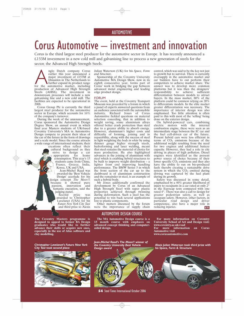
control, which was said to be the key not justto growth but to survival. There is currentlyoversupply in the automotive market andcar builders have to out perform theircompetitors to achieve market share. Theanswer was to develop more commonplatforms but it was then the designers’responsibility to achieve sufficientdifferentiation between models to attractbuyers. In the mass market, 80% of theplatform could be common relying on 20%to differentiate models. In the elite marketgreater differentiation was necessary. Theimportance of interior design was alsoemphasised. Too little attention is oftenpaid to this with most of the ‘selling’ beingdone on the exterior design.
On hybrid-powered cars, combiningelectric motors with the internalcombustion engine, these were seen as anintermediate stage between the IC car andthe fuel cell-driven car of the future.Present hybrid cars were less efficient interms of CO2 emissions because of theadditional weight resulting from the needfor two engines and additional batterycapacity. However, they had a role in citydriving in places of high pollution. Dieselengines were identified as the presentpower source of choice because of theirlower specific CO2 emissions and they alsohave the ability to run on bio-producedfuels thereby creating a sustainable drivesystem in which the CO2 emitted duringdriving was captured by the fuel plantduring its growth.
Safety was discussed in some detail,emphasised by a 40% greater likelihood ofinjury to occupants in a car rated at only 2*in the Eurocap tests compared with onerated 4*. There was also a call to design forgreater pedestrian safety, as well asoccupant safety. However, other factors, inparticular road design and drivercompetence, also have a major role inreducing injuries.
AUTOMOTIVE
Corus Automotive – investment and innovation
A nglo Dutch company Corusearlier this year announced amajor investment of £153M atIJmuiden in The Netherlands tofurther expand its product range
for the automotive market, includingproduction of Advanced High StrengthSteels (AHSS). The investment indownstream processes will include a newgalvanising line and a new cold mill. Thefacilities are expected to be operational in2008.
Corus Group Plc is currently the thirdlargest steel producer for the automotivesector in Europe, which accounts for 16%of the company’s turnover.
During the week of the announcement,Corus sponsored the Automotive DesignDegree Show, an annual event in whichfinal year Masters students of UK-basedCoventry University’s MA in AutomotiveDesign compete to present their ideas ofthe car of the future in the form of drawingsand a scale model. Since the course attractsa wide range of international students, their
creations often reflect theircultural background as they
strive to design a carappropriate for homeconsumption. This year’s 15students came from China,France, Greece, India,Korea, UK and USA.
Jean-Michel Raad wasawarded the ‘Best VehicleDesign’ accolade for his
design concept The Moov!!because it showed purepassion, innovation andfantastic execution, said the
judging panel.Second prize was
awarded to ChristopherLavelanet (USA) for hisFuture New York City Taxiand third prize to Alexis
Corus is the third largest steel producer for the automotive sector in Europe. It has recently announced a£153M investment in a new cold mill and galvanising line to process a new generation of steels for thesector, the Advanced High Strength Steels.
Julian Waterson (UK) for his Space, Formand Structure.
Sponsorship of the Coventry UniversityAutomotive MA Design Show, now in itseighth consecutive year, forms part ofCorus’ work in bridging the gap betweenadvanced metal engineering and leadingedge product design.
FORUMThe event, held at the Coventry TransportMuseum was preceded by a forum in whicha panel of experts answered questions froman audience associated with the automobileindustry. Richard Jones of CorusAutomotive fielded questions on materialselection conceding, that in addition toweight saving, some aluminium alloysoffered better crash protection than steeldue to a greater ability to absorb energy.However, aluminium’s higher costs anddifficulty of forming, joining and inreparability, along with the success of steelin light weighting the body in white by usingthinner gauge higher strength steels,hydroforming and laser welding, meantthat steel remains the material of choice formass production. He also highlightedadvances in the joining of aluminium withsteel which is enabling hybrid structures tobe built to improve weight distribution – alighter front end improving handlingperformance. The BMW Series 5 in whichthe front section of the car up to thedashboard is of aluminium constructionand the remainder in steel, is an example ofsuch a hybrid body.
Mr Jones additionally confirmed thedevelopment by Corus of an AdvancedHigh Strength Steel with super plasticproperties achieved through twinningduring deformation. Such a steel has thepotential to win back several applicationslost to plastic components.
Other matters discussed by the forumwere the importance of supply chain
The Coventry Masters programme isdesigned to appeal to former BA Designgraduates who would like to furtheradvance their skills or acquire new ones,especially in the use of Alias software andclay modelling.
The MA Automotive Design course is a15 month course with emphasis onadvanced concept thinking and computer-aided design.
Christopher Lavelanet’s Future New YorkCity Taxi took second place
Alexis Julian Waterson took third prize withhis Space, Form & Structure
AUTOMOTIVE DESIGN COURSESTI
For more information on CoventryUniversity School of Art and Design visit:www.coventry.ac.uk/csadFor more information on CorusAutomotive visitwww.corusautomotive.com
54 Steel Times International October 2006
Jean-Michel Raad’s The Moov!! winner ofthe Coventry University Best VehicleDesign award
CORUS 27/9/06 12:33 Page 1

FERROALLOYS
56 Steel Times International October 2006
*TN Consulting 614 May Lane, Mufreesboro, TN 37130, USA [email protected]
The May 16-17 conference wasorganised by the Platts company,(a member of the McGraw-Hillinformation and newsconglomerate) which tracks a
large number of non-ferrous, precious andminor metals as well as ferroalloys andstainless steel scrap, publishing its prices inMetals Week. The company has long been inthe business of organising conferences andsymposia. However, this was only its secondevent on steel and ferroalloys, which mayhave been the reason why it attracted nomore than 50 delegates. Platts is now in theprocess of systematically collecting andreviewing price data on a representativenumber of steel products which – asannounced on the first conference day –has already attracted a prominent client,the London Metals Exchange.
Anthony Poole, managing editor of PlattsMetals New York, made the openingremarks, acted as moderator throughoutthe event and spoke about the setting ofbenchmark prices.
Two sessions were scheduled for thefirst day, one addressing steel industrytopics and the other market prospectsfor various non-ferrous metals (Mn, Ti,FeCr, and Mo) and scrap. The thirdsession, held in the morning of thesecond day, offered presentationsabout the changing US automobileindustry, problems of bargetransportation and benchmark pricingmethodology.
Very likely, what most delegatescame to hear were the fivepresentations covering benchmarkingand ferroalloys. The rest, thoughinteresting in themselves, were notalways well-integrated with theferroalloys theme.
This is also the sequence that will befollowed in this review: firstbenchmarking, then ferroalloys andlast the steel-related topics, includingthis reviewer’s own presentation.
EXPERIENCE IN PRICE ASSESSMENTS‘Setting benchmark prices: the sciencebehind the numbers’ was what Poole setout to explain, relying heavily on theexperience gathered by the Platts MetalGroup over several decades, beginning35 years ago with MoO2 and FeMn andgradually encompassing manyferroalloys, metals and stainless scrap.The methodology was “an editorialprocess of gathering and analysinginformation”, which depended onhuman experience and judgment tosort out the data obtained fromtelephone contacts, narrow downtheir range and develop a system ofverification. The final assessmentsrepresented the most frequenttransactions, normalised for standardterms and conditions. They werenot a weighted average or index ofreported data (Fig 1).
The Platts’ ferroalloys and steel conferenceHot on the heels of the announcement that, starting 2007, the LME was to use Platts to monitor prices forthose commodity steels it plans to trade, was the second steel and ferroalloys conference organised by Platts.REPORT BY DR HANS MUELLER*
The methodology was regularly reviewedthrough internal audits to achievemaximum transparency. As an example of acompany having confidence in the Plattsassessments, Poole cited CarpenterTechnology which uses Platts to determineits Ti surcharge on the prices of certainspecial steels. He also provided furtherdetails concerning the announcement thatthe LME had made Platts its partner forassessing the price of selected steelproducts, including semifinished grades,HR coils and rebars. The step was taken, headded, in response to steel producersseeking more price transparency and steelusers wishing to reduce their price-riskexposure through the use of financialinstruments. He attributed the LME choiceto the company’s experience with ‘non-commoditicised’ markets featuringindustrial users, complex products andregional specifications/logistics.
FERROALLOYSManganese: Mr K Golovko of CRU lookedat the role that CIS countries, EasternEurope and China played in manganesealloys markets, specifically silico-manganese, high-carbon (HC) ferroalloysand refined ferromanganese. All three hadseen prices soar in 2004 (to $1800/t for HCFeMn), fall abruptly in 2005 ($600) andthen rise again in the current year ($800May; $1050 July1). The most widely used,SiMn, was again moving toward a marketsurplus, whereas HC FeMn was in tightsupply and refined FeMn in such shortsupply that additional price increases wereinevitable (Fig 2).
China produced enough Mn alloys tospare some for exports, although thesemight soon be restricted by the centralgovernment as the country is now theworld’s largest consumer of ferro alloys(Table 1). Ukraine and Kazakhstan, theworld’s low-cost producers of both SiMnand HC FeMn, would remain large
exporters of these alloys, Golovkopredicted. Most high-cost capacity inPoland, Romania and Slovakia wasidled following the ’05 decline in globalprices but might be restarted ifwarranted by higher global prices.
Titanium: Ti consumption by thecommercial aerospace industry waslikely to rise by leaps and bounds, MrR Borowski of Titanium MetalsCorporation told the audience.Although passenger aircraft orderswould remain at present levels, Ticonsumption per plane was rapidlygrowing. For example, whereas aBoeing 747 contained 45t of the metal,the 787 would use 91t because Ti ismore compatible than aluminium withthe composites widely used in thenewer aircraft. Airbus models showeda similar trend, though at a lessintensive pace.
Prices have been moving up,reaching $8/lb by the end of Q1 2006for ingot chips and nearly twice asmuch for Ti in ‘bulk weldable’ form.Not surprisingly, Ti-sponge producersin many countries plan capacityexpansions, especially in Russia(Avisma), Japan (Sumitomo and Toho)and the USA (Timet and ATI).Borowski looked forward to anexpansion of global Ti sponge capacity
from 108kt in 2005 to more than160kt by 2010-2011 (Table 2).
Ferrochrome: The global stainlesssteel industry consumed 84% offerrochrome, most of which ispurchased as high-carbon (HC)rather than the more costly low-carbon (LC), explained Ms J Ward,owner of Pennsylvania-based metalsdealer Reward Raw Materials. Shenoted that global FeCr demand was
relatively weak last year despite asurge in China’s requirements.Efforts made by major suppliers
SiMn HC FeMn Ref FeMn
2000 2007 2000 2007 2000 2007
China 15 45 24 37 11 29CIS 13 9 14 8 2 4E. Europe 3 2 4 2 0 2W. World 69 44 58 53 87 65World demandmln tonnes 3.6 7.4 3.2 3.9 0.7 15
2 Fe-Mn and Si-Mn price index (2000 = 1)K Golovko CRU London
Table 1 China is now the world’s largest consumer of ferro-alloysK Golovko CRU London
1 Monitoring of US ferrochrome price range by PlattsA Poole, Managing editor Platts Metals New York
Platts 27/9/06 12:34 Page 1
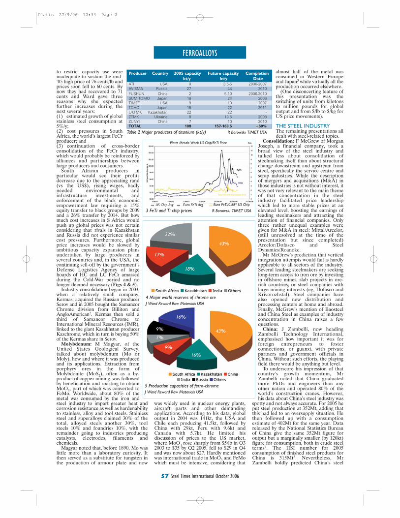
FERROALLOYS
57 Steel Times International October 2006
to restrict capacity use wereinadequate to sustain the mid-’05 high price of 76 cents/lb andprices soon fell to 60 cents. Bynow they had recovered to 71cents and Ward gave threereasons why she expectedfurther increases during thenext several years:(1)...estimated growth of globalstainless steel consumption at5%/y;(2)...cost pressures in SouthAfrica, the world’s largest FeCrproducer; and(3)...continuation of cross-borderconsolidation of the FeCr industry,which would probably be reinforced byalliances and partnerships betweenlarge producers and consumers.
South African producers inparticular would see their profitsdecrease due to the appreciating rand(vs the US$), rising wages, badlyneeded environmental andinfrastructure investments, andenforcement of the black economicempowerment law requiring a 15%equity transfer to black groups by 2009and a 26% transfer by 2014. But howmuch cost increases in S Africa wouldpush up global prices was not certainconsidering that rivals in Kazakhstanand Russia did not experience similarcost pressures. Furthermore, globalprice increases would be slowed byambitious capacity expansion plansundertaken by large producers inseveral countries and, in the USA, thecontinuing sell-off by the government’sDefense Logistics Agency of largehoards of HC and LC FeCr amassedduring the Cold-War period and nolonger deemed necessary (Figs 4 & 5).
Industry consolidation began in 2003,when a relatively small company,Kermas, acquired the Russian producerSerov and in 2005 bought the SamancorChrome division from Billiton andAngloAmerican2. Kermas then sold athird of Samancor Chrome toInternational Mineral Resources (IMR),linked to the giant Kazakhstan producerKazchrome, which in turn is buying 50%of the Kermas share in Serov.
Molybdenum: M Magyar, of theUnited States Geological Survey,talked about molybdenum (Mo orMoly), how and where it was producedand its applications. Extraction fromporphyry ores in the form ofMolybdonite (MoS2), often as a by-product of copper mining, was followedby beneficiation and roasting to obtainMoO3, part of which was converted toFeMo. Worldwide, about 80% of themetal was consumed by the iron andsteel industry to impart greater heat andcorrosion resistance as well as hardenabilityto stainless, alloy and tool steels. Stainlesssteel and superalloys claimed 30% of thetotal, alloyed steels another 30%, toolsteels 10% and foundries 10%, with theremainder going to industries producingcatalysts, electrodes, filaments andchemicals.
Magyar noted that, before 1890, Mo waslittle more than a laboratory curiosity. Itthen served as a substitute for tungsten inthe production of armour plate and now
was widely used in nuclear energy plants,aircraft parts and other demandingapplications. According to his data, globaloutput in 2004 was 141kt, the USA andChile each producing 41.5kt, followed byChina with 29kt, Peru with 9.6kt andCanada with 5.7kt. He limited hisdiscussion of prices to the US market,where MoO3 rose sharply from $5/lb in Q32003 to $35 by Q2 2005, fell to $29 in Q4and was now about $27. Hardly mentionedwas international trade in MoO3 and FeMowhich must be intensive, considering that
almost half of the metal wasconsumed in Western Europeand Japan3 while virtually all theproduction occurred elsewhere.
(One disconcerting feature ofthis presentation was theswitching of units from kilotonsto million pounds for globaloutput and from $/lb to $/kg forUS price movements).
THE STEEL INDUSTRYThe remaining presentations alldealt with steel-related topics.
Consolidation: F McGrew of MorganJoseph, a financial company, took abroad view of the steel industry andtalked less about consolidation ofsteelmaking itself than about structuralchange downstream and upstream fromsteel, specifically the service centre andscrap industries. While the descriptionof mergers and acquisitions (M&A) inthose industries is not without interest, itwas not very relevant to the main themeof that concentration in the steelindustry facilitated price leadershipwhich led to more stable prices at anelevated level, boosting the earnings ofleading steelmakers and attracting theattention of financial companies. Onlythree rather unequal examples weregiven for M&A in steel: Mittal/Arcelor,(still unresolved at the time of thepresentation but since completed)Arcelor/Dofasco and SteelDynamics/Roanoke.
Mr McGrew’s prediction that verticalintegration attempts would fail is hardlyapplicable to all sectors of the industry.Several leading steelmakers are seekinglong-term access to iron ore by investingin offshore mines, slab projects in ore-rich countries, or steel companies withlarge mining interests (eg, Dofasco andKrivorozhstal). Steel companies havealso opened new distribution andprocessing centers at home and abroad.Finally, McGrew’s mention of Baosteeland China Steel as examples of industryconcentration in China raises a fewquestions.
China: J Zambelli, now headingZambelli Technology International,emphasised how important it was forforeign entrepreneurs to fosterconnections, or guanxi, with privatepartners and government officials inChina. Without such efforts, the playingfield there would be anything but level.
To underscore his impression of thatcountry’s growth momentum, MrZambelli noted that China graduatedmore PhDs and engineers than anyother nation and operated 80% of theworld’s construction cranes. However,his data about China’s steel industry was
spotty and not always accurate. For 2005 heput steel production at 352Mt, adding thatthis had led to an oversupply situation. Hethen followed up with a consumptionestimate of 402Mt for the same year. Datareleased by the National Statistics Bureauof China give the same 352Mt figure foroutput but a marginally smaller (by 120kt)figure for consumption, both in crude steelterms4. The IISI number for 2005consumption of finished steel products forChina is 315Mt5. Nevertheless, MrZambelli boldly predicted China’s steel
Producer Country 2005 capacity Future capacity Completion
kt/y kt/y Date
ATI USA 0 3.5-5 2006-2007AVISMA Russia 27 44 2010FUSHUN China 2 5-10 2006-2010SUMITOMO Japan 18 24 2006TIMET USA 9 13 2007TOHO Japan 15 22 2011UKTMK Kazakhstan 22 22 -ZTMK Ukraine 8 13.5 2008ZUNYI China 7 10 2010TOTAL 108 157-163.5 +50%
Table 2 Major producers of titanium (kt/y) R Borowski TIMET USA
5 Production capacities of ferro-chromeJ Ward Reward Raw Materials USA
3 FeTi and Ti chip prices R Borowski TIMET USA
4 Major world reserves of chrome oreJ Ward Reward Raw Materials USA
43%
43%
16%
9%
7%
9%
16%
18%
17%
22%
Platts Metals Week US Chip/FeTi Price
US Chip Avg Euro FeTi Avg Euro FeTi/0.88* US Chip
Platts 27/9/06 12:34 Page 2
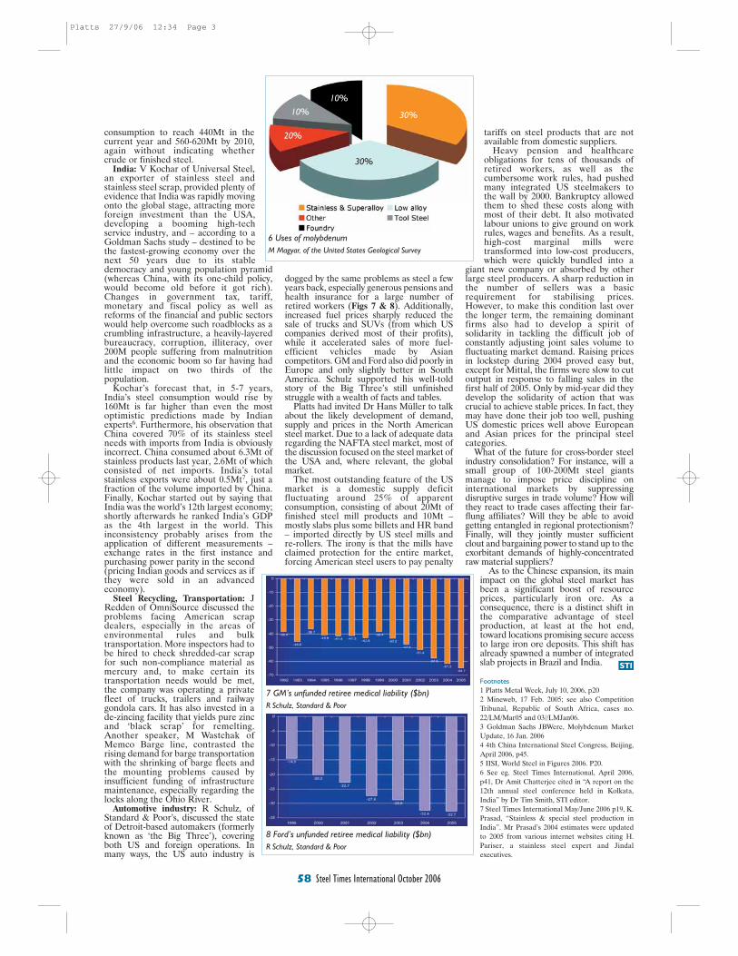
58 Steel Times International October 2006
STI
consumption to reach 440Mt in thecurrent year and 560-620Mt by 2010,again without indicating whethercrude or finished steel.
India: V Kochar of Universal Steel,an exporter of stainless steel andstainless steel scrap, provided plenty ofevidence that India was rapidly movingonto the global stage, attracting moreforeign investment than the USA,developing a booming high-techservice industry, and – according to aGoldman Sachs study – destined to bethe fastest-growing economy over thenext 50 years due to its stabledemocracy and young population pyramid(whereas China, with its one-child policy,would become old before it got rich).Changes in government tax, tariff,monetary and fiscal policy as well asreforms of the financial and public sectorswould help overcome such roadblocks as acrumbling infrastructure, a heavily-layeredbureaucracy, corruption, illiteracy, over200M people suffering from malnutritionand the economic boom so far having hadlittle impact on two thirds of thepopulation.
Kochar’s forecast that, in 5-7 years,India’s steel consumption would rise by160Mt is far higher than even the mostoptimistic predictions made by Indianexperts6. Furthermore, his observation thatChina covered 70% of its stainless steelneeds with imports from India is obviouslyincorrect. China consumed about 6.3Mt ofstainless products last year, 2.6Mt of whichconsisted of net imports. India’s totalstainless exports were about 0.5Mt7, just afraction of the volume imported by China.Finally, Kochar started out by saying thatIndia was the world’s 12th largest economy;shortly afterwards he ranked India’s GDPas the 4th largest in the world. Thisinconsistency probably arises from theapplication of different measurements –exchange rates in the first instance andpurchasing power parity in the second(pricing Indian goods and services as ifthey were sold in an advancedeconomy).
Steel Recycling, Transportation: JRedden of OmniSource discussed theproblems facing American scrapdealers, especially in the areas ofenvironmental rules and bulktransportation. More inspectors had tobe hired to check shredded-car scrapfor such non-compliance material asmercury and, to make certain itstransportation needs would be met,the company was operating a privatefleet of trucks, trailers and railwaygondola cars. It has also invested in ade-zincing facility that yields pure zincand ‘black scrap’ for remelting.Another speaker, M Wastchak ofMemco Barge line, contrasted therising demand for barge transportationwith the shrinking of barge fleets andthe mounting problems caused byinsufficient funding of infrastructuremaintenance, especially regarding thelocks along the Ohio River.
Automotive industry: R Schulz, ofStandard & Poor’s, discussed the stateof Detroit-based automakers (formerlyknown as ‘the Big Three’), coveringboth US and foreign operations. Inmany ways, the US auto industry is
dogged by the same problems as steel a fewyears back, especially generous pensions andhealth insurance for a large number ofretired workers (Figs 7 & 8). Additionally,increased fuel prices sharply reduced thesale of trucks and SUVs (from which UScompanies derived most of their profits),while it accelerated sales of more fuel-efficient vehicles made by Asiancompetitors. GM and Ford also did poorly inEurope and only slightly better in SouthAmerica. Schulz supported his well-toldstory of the Big Three’s still unfinishedstruggle with a wealth of facts and tables.
Platts had invited Dr Hans Müller to talkabout the likely development of demand,supply and prices in the North Americansteel market. Due to a lack of adequate dataregarding the NAFTA steel market, most ofthe discussion focused on the steel market ofthe USA and, where relevant, the globalmarket.
The most outstanding feature of the USmarket is a domestic supply deficitfluctuating around 25% of apparentconsumption, consisting of about 20Mt offinished steel mill products and 10Mt –mostly slabs plus some billets and HR band– imported directly by US steel mills andre-rollers. The irony is that the mills haveclaimed protection for the entire market,forcing American steel users to pay penalty
tariffs on steel products that are notavailable from domestic suppliers.
Heavy pension and healthcareobligations for tens of thousands ofretired workers, as well as thecumbersome work rules, had pushedmany integrated US steelmakers tothe wall by 2000. Bankruptcy allowedthem to shed these costs along withmost of their debt. It also motivatedlabour unions to give ground on workrules, wages and benefits. As a result,high-cost marginal mills weretransformed into low-cost producers,which were quickly bundled into a
giant new company or absorbed by otherlarge steel producers. A sharp reduction inthe number of sellers was a basicrequirement for stabilising prices.However, to make this condition last overthe longer term, the remaining dominantfirms also had to develop a spirit ofsolidarity in tackling the difficult job ofconstantly adjusting joint sales volume tofluctuating market demand. Raising pricesin lockstep during 2004 proved easy but,except for Mittal, the firms were slow to cutoutput in response to falling sales in thefirst half of 2005. Only by mid-year did theydevelop the solidarity of action that wascrucial to achieve stable prices. In fact, theymay have done their job too well, pushingUS domestic prices well above Europeanand Asian prices for the principal steelcategories.
What of the future for cross-border steelindustry consolidation? For instance, will asmall group of 100-200Mt steel giantsmanage to impose price discipline oninternational markets by suppressingdisruptive surges in trade volume? How willthey react to trade cases affecting their far-flung affiliates? Will they be able to avoidgetting entangled in regional protectionism?Finally, will they jointly muster sufficientclout and bargaining power to stand up to theexorbitant demands of highly-concentratedraw material suppliers?
As to the Chinese expansion, its mainimpact on the global steel market hasbeen a significant boost of resourceprices, particularly iron ore. As aconsequence, there is a distinct shift inthe comparative advantage of steelproduction, at least at the hot end,toward locations promising secure accessto large iron ore deposits. This shift hasalready spawned a number of integratedslab projects in Brazil and India.
Footnotes1 Platts Metal Week, July 10, 2006, p202 Mineweb, 17 Feb. 2005; see also CompetitionTribunal, Republic of South Africa, cases no.22/LM/Mar05 and 03//LMJan06.3 Goldman Sachs JBWere, Molybdenum MarketUpdate, 16 Jan. 20064 4th China International Steel Congress, Beijing,April 2006, p45.5 IISI, World Steel in Figures 2006. P20.6 See eg. Steel Times International, April 2006,p41, Dr Amit Chatterjee cited in “A report on the12th annual steel conference held in Kolkata,India” by Dr Tim Smith, STI editor.7 Steel Times International May/June 2006 p19, K.Prasad, “Stainless & special steel production inIndia”. Mr Prasad’s 2004 estimates were updatedto 2005 from various internet websites citing H.Pariser, a stainless steel expert and Jindalexecutives.
6 Uses of molybdenum M Magyar, of the United States Geological Survey
30%
20%
10%
10%
30%
7 GM’s unfunded retiree medical liability ($bn)R Schulz, Standard & Poor
8 Ford’s unfunded retiree medical liability ($bn)R Schulz, Standard & Poor
Platts 27/9/06 12:34 Page 3
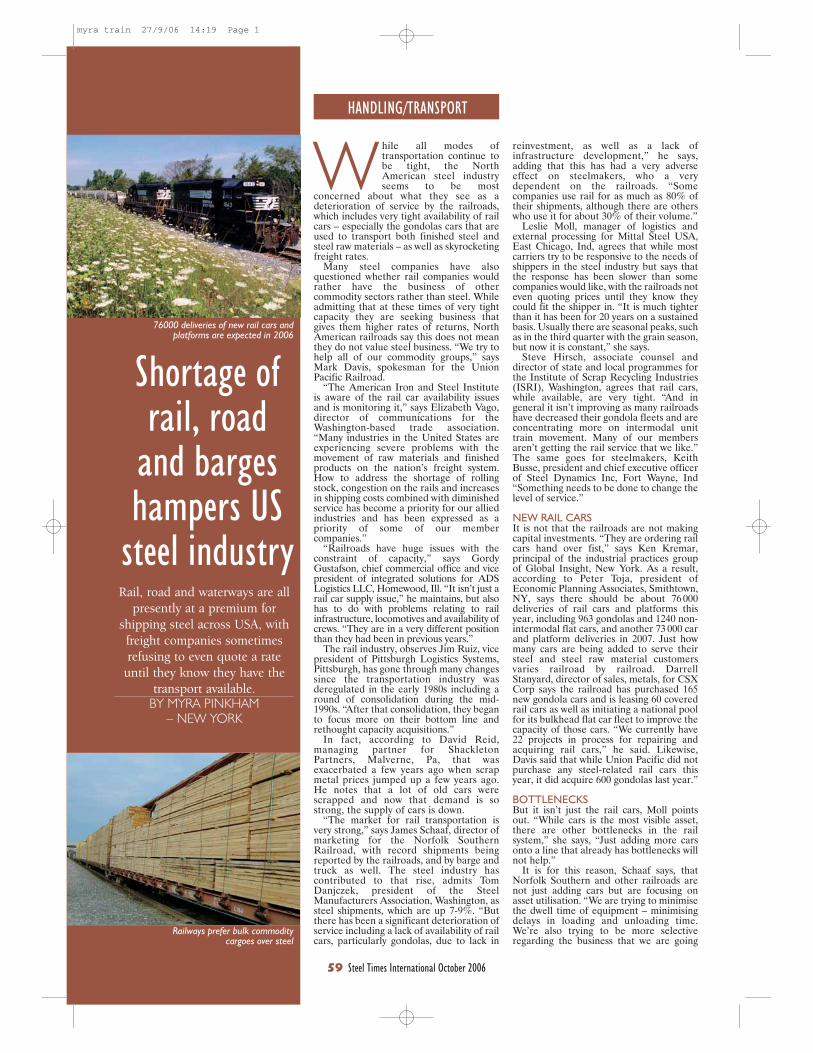
HANDLING/TRANSPORT
59 Steel Times International October 2006
W hile all modes oftransportation continue tobe tight, the NorthAmerican steel industryseems to be most
concerned about what they see as adeterioration of service by the railroads,which includes very tight availability of railcars – especially the gondolas cars that areused to transport both finished steel andsteel raw materials – as well as skyrocketingfreight rates.
Many steel companies have alsoquestioned whether rail companies wouldrather have the business of othercommodity sectors rather than steel. Whileadmitting that at these times of very tightcapacity they are seeking business thatgives them higher rates of returns, NorthAmerican railroads say this does not meanthey do not value steel business. “We try tohelp all of our commodity groups,” saysMark Davis, spokesman for the UnionPacific Railroad.
“The American Iron and Steel Instituteis aware of the rail car availability issuesand is monitoring it,” says Elizabeth Vago,director of communications for theWashington-based trade association.“Many industries in the United States areexperiencing severe problems with themovement of raw materials and finishedproducts on the nation’s freight system.How to address the shortage of rollingstock, congestion on the rails and increasesin shipping costs combined with diminishedservice has become a priority for our alliedindustries and has been expressed as apriority of some of our membercompanies.”
“Railroads have huge issues with theconstraint of capacity,” says GordyGustafson, chief commercial office and vicepresident of integrated solutions for ADSLogistics LLC, Homewood, Ill. “It isn’t just arail car supply issue,” he maintains, but alsohas to do with problems relating to railinfrastructure, locomotives and availability ofcrews. “They are in a very different positionthan they had been in previous years.”
The rail industry, observes Jim Ruiz, vicepresident of Pittsburgh Logistics Systems,Pittsburgh, has gone through many changessince the transportation industry wasderegulated in the early 1980s including around of consolidation during the mid-1990s. “After that consolidation, they beganto focus more on their bottom line andrethought capacity acquisitions.”
In fact, according to David Reid,managing partner for ShackletonPartners, Malverne, Pa, that wasexacerbated a few years ago when scrapmetal prices jumped up a few years ago.He notes that a lot of old cars werescrapped and now that demand is sostrong, the supply of cars is down.
“The market for rail transportation isvery strong,” says James Schaaf, director ofmarketing for the Norfolk SouthernRailroad, with record shipments beingreported by the railroads, and by barge andtruck as well. The steel industry hascontributed to that rise, admits TomDanjczek, president of the SteelManufacturers Association, Washington, assteel shipments, which are up 7-9%. “Butthere has been a significant deterioration ofservice including a lack of availability of railcars, particularly gondolas, due to lack in
Rail, road and waterways are allpresently at a premium for
shipping steel across USA, withfreight companies sometimesrefusing to even quote a rate
until they know they have thetransport available.
BY MYRA PINKHAM– NEW YORK
reinvestment, as well as a lack ofinfrastructure development,” he says,adding that this has had a very adverseeffect on steelmakers, who a verydependent on the railroads. “Somecompanies use rail for as much as 80% oftheir shipments, although there are otherswho use it for about 30% of their volume.”
Leslie Moll, manager of logistics andexternal processing for Mittal Steel USA,East Chicago, Ind, agrees that while mostcarriers try to be responsive to the needs ofshippers in the steel industry but says thatthe response has been slower than somecompanies would like, with the railroads noteven quoting prices until they know theycould fit the shipper in. “It is much tighterthan it has been for 20 years on a sustainedbasis. Usually there are seasonal peaks, suchas in the third quarter with the grain season,but now it is constant,” she says.
Steve Hirsch, associate counsel anddirector of state and local programmes forthe Institute of Scrap Recycling Industries(ISRI), Washington, agrees that rail cars,while available, are very tight. “And ingeneral it isn’t improving as many railroadshave decreased their gondola fleets and areconcentrating more on intermodal unittrain movement. Many of our membersaren’t getting the rail service that we like.”The same goes for steelmakers, KeithBusse, president and chief executive officerof Steel Dynamics Inc, Fort Wayne, Ind“Something needs to be done to change thelevel of service.”
NEW RAIL CARSIt is not that the railroads are not makingcapital investments. “They are ordering railcars hand over fist,” says Ken Kremar,principal of the industrial practices groupof Global Insight, New York. As a result,according to Peter Toja, president ofEconomic Planning Associates, Smithtown,NY, says there should be about 76 000deliveries of rail cars and platforms thisyear, including 963 gondolas and 1240 non-intermodal flat cars, and another 73 000 carand platform deliveries in 2007. Just howmany cars are being added to serve theirsteel and steel raw material customersvaries railroad by railroad. DarrellStanyard, director of sales, metals, for CSXCorp says the railroad has purchased 165new gondola cars and is leasing 60 coveredrail cars as well as initiating a national poolfor its bulkhead flat car fleet to improve thecapacity of those cars. “We currently have22 projects in process for repairing andacquiring rail cars,” he said. Likewise,Davis said that while Union Pacific did notpurchase any steel-related rail cars thisyear, it did acquire 600 gondolas last year.”
BOTTLENECKSBut it isn’t just the rail cars, Moll pointsout. “While cars is the most visible asset,there are other bottlenecks in the railsystem,” she says, “Just adding more carsonto a line that already has bottlenecks willnot help.”
It is for this reason, Schaaf says, thatNorfolk Southern and other railroads arenot just adding cars but are focusing onasset utilisation. “We are trying to minimisethe dwell time of equipment – minimisingdelays in loading and unloading time.We’re also trying to be more selectiveregarding the business that we are going
Shortage ofrail, road
and bargeshampers US
steel industry
Railways prefer bulk commoditycargoes over steel
76000 deliveries of new rail cars andplatforms are expected in 2006
myra train 27/9/06 14:19 Page 1
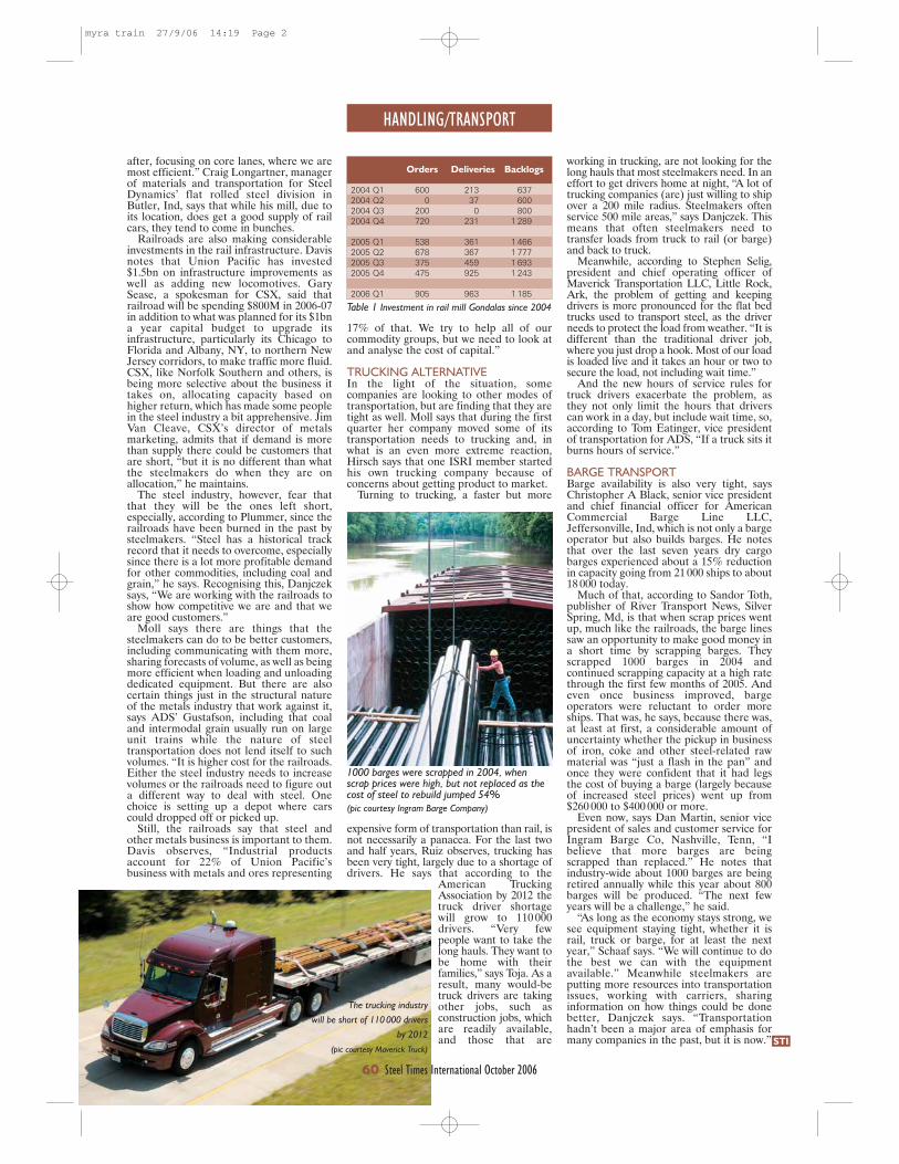
17% of that. We try to help all of ourcommodity groups, but we need to look atand analyse the cost of capital.”
TRUCKING ALTERNATIVEIn the light of the situation, somecompanies are looking to other modes oftransportation, but are finding that they aretight as well. Moll says that during the firstquarter her company moved some of itstransportation needs to trucking and, inwhat is an even more extreme reaction,Hirsch says that one ISRI member startedhis own trucking company because ofconcerns about getting product to market.
Turning to trucking, a faster but more
expensive form of transportation than rail, isnot necessarily a panacea. For the last twoand half years, Ruiz observes, trucking hasbeen very tight, largely due to a shortage ofdrivers. He says that according to the
American TruckingAssociation by 2012 thetruck driver shortagewill grow to 110 000drivers. “Very fewpeople want to take thelong hauls. They want tobe home with theirfamilies,” says Toja. As aresult, many would-betruck drivers are takingother jobs, such asconstruction jobs, whichare readily available,and those that are
HANDLING/TRANSPORT
STI
after, focusing on core lanes, where we aremost efficient.” Craig Longartner, managerof materials and transportation for SteelDynamics’ flat rolled steel division inButler, Ind, says that while his mill, due toits location, does get a good supply of railcars, they tend to come in bunches.
Railroads are also making considerableinvestments in the rail infrastructure. Davisnotes that Union Pacific has invested$1.5bn on infrastructure improvements aswell as adding new locomotives. GarySease, a spokesman for CSX, said thatrailroad will be spending $800M in 2006-07in addition to what was planned for its $1bna year capital budget to upgrade itsinfrastructure, particularly its Chicago toFlorida and Albany, NY, to northern NewJersey corridors, to make traffic more fluid.CSX, like Norfolk Southern and others, isbeing more selective about the business ittakes on, allocating capacity based onhigher return, which has made some peoplein the steel industry a bit apprehensive. JimVan Cleave, CSX’s director of metalsmarketing, admits that if demand is morethan supply there could be customers thatare short, “but it is no different than whatthe steelmakers do when they are onallocation,” he maintains.
The steel industry, however, fear thatthat they will be the ones left short,especially, according to Plummer, since therailroads have been burned in the past bysteelmakers. “Steel has a historical trackrecord that it needs to overcome, especiallysince there is a lot more profitable demandfor other commodities, including coal andgrain,” he says. Recognising this, Danjczeksays, “We are working with the railroads toshow how competitive we are and that weare good customers.”
Moll says there are things that thesteelmakers can do to be better customers,including communicating with them more,sharing forecasts of volume, as well as beingmore efficient when loading and unloadingdedicated equipment. But there are alsocertain things just in the structural natureof the metals industry that work against it,says ADS’ Gustafson, including that coaland intermodal grain usually run on largeunit trains while the nature of steeltransportation does not lend itself to suchvolumes. “It is higher cost for the railroads.Either the steel industry needs to increasevolumes or the railroads need to figure outa different way to deal with steel. Onechoice is setting up a depot where carscould dropped off or picked up.
Still, the railroads say that steel andother metals business is important to them.Davis observes, “Industrial productsaccount for 22% of Union Pacific’sbusiness with metals and ores representing
working in trucking, are not looking for thelong hauls that most steelmakers need. In aneffort to get drivers home at night, “A lot oftrucking companies (are) just willing to shipover a 200 mile radius. Steelmakers oftenservice 500 mile areas,” says Danjczek. Thismeans that often steelmakers need totransfer loads from truck to rail (or barge)and back to truck.
Meanwhile, according to Stephen Selig,president and chief operating officer ofMaverick Transportation LLC, Little Rock,Ark, the problem of getting and keepingdrivers is more pronounced for the flat bedtrucks used to transport steel, as the driverneeds to protect the load from weather. “It isdifferent than the traditional driver job,where you just drop a hook. Most of our loadis loaded live and it takes an hour or two tosecure the load, not including wait time.”
And the new hours of service rules fortruck drivers exacerbate the problem, asthey not only limit the hours that driverscan work in a day, but include wait time, so,according to Tom Eatinger, vice presidentof transportation for ADS, “If a truck sits itburns hours of service.”
BARGE TRANSPORTBarge availability is also very tight, saysChristopher A Black, senior vice presidentand chief financial officer for AmericanCommercial Barge Line LLC,Jeffersonville, Ind, which is not only a bargeoperator but also builds barges. He notesthat over the last seven years dry cargobarges experienced about a 15% reductionin capacity going from 21 000 ships to about18 000 today.
Much of that, according to Sandor Toth,publisher of River Transport News, SilverSpring, Md, is that when scrap prices wentup, much like the railroads, the barge linessaw an opportunity to make good money ina short time by scrapping barges. Theyscrapped 1000 barges in 2004 andcontinued scrapping capacity at a high ratethrough the first few months of 2005. Andeven once business improved, bargeoperators were reluctant to order moreships. That was, he says, because there was,at least at first, a considerable amount ofuncertainty whether the pickup in businessof iron, coke and other steel-related rawmaterial was “just a flash in the pan” andonce they were confident that it had legsthe cost of buying a barge (largely becauseof increased steel prices) went up from$260 000 to $400 000 or more.
Even now, says Dan Martin, senior vicepresident of sales and customer service forIngram Barge Co, Nashville, Tenn, “Ibelieve that more barges are beingscrapped than replaced.” He notes thatindustry-wide about 1000 barges are beingretired annually while this year about 800barges will be produced. “The next fewyears will be a challenge,” he said.
“As long as the economy stays strong, wesee equipment staying tight, whether it israil, truck or barge, for at least the nextyear,” Schaaf says. “We will continue to dothe best we can with the equipmentavailable.” Meanwhile steelmakers areputting more resources into transportationissues, working with carriers, sharinginformation on how things could be donebetter, Danjczek says. “Transportationhadn’t been a major area of emphasis formany companies in the past, but it is now.”
60 Steel Times International October 2006
The trucking industry will be short of 110 000 drivers
by 2012 (pic courtesy Maverick Truck)
1000 barges were scrapped in 2004, whenscrap prices were high, but not replaced as thecost of steel to rebuild jumped 54%
Table 1 Investment in rail mill Gondalas since 2004
Orders Deliveries Backlogs
2004 Q1 600 213 6372004 Q2 0 37 6002004 Q3 200 0 8002004 Q4 720 231 1 289
2005 Q1 538 361 1 4662005 Q2 678 367 1 7772005 Q3 375 459 1 6932005 Q4 475 925 1 243
2006 Q1 905 963 1 185
(pic courtesy Ingram Barge Company)
myra train 27/9/06 14:19 Page 2
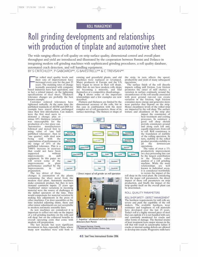
ROLL MANAGEMENT
62 Steel Times International October 2006
*SC Support Services, Canada, **Techint SpA, Roll Grinders Division, Italy
Flat rolled steel quality levels andtheir rate of improvement haveincreased every year for the past 25years. The stunning rates of changenormally associated with computer
based industries have had equivalent, andin fact a related impact, on the tighteningspecifications of steel sheet. Thicknesstolerance changes are probably the bestknown example.
Customer ordered tolerances havetightened radically. At the same time thepublished standards of ASTM and DIN forexample have stayed almost unchangedsince their first introduction. Can makerswere the first steel users todemand a change; plus orminus 10% thickness variationwas unacceptable for theproduction of a two piece can.Automotive manufacturersfollowed and moved first tousing value of ‘one halfpublished tolerances’, then to‘one quarter’, with steel nowbeing sold with theexpectations of performance inthe range of 10% of thepublished tolerance. This is a1000% increase in accuracythat could not have beensupported withoutimprovements in millequipment. In this paper wewill review some of theimprovements in plantperformance enabled by theimprovements in rollpreparation.
The key driver of thesechanges is automation of the plantsconsuming the sheet metal from themodern steel plant. Automatic machinesmake consistent product, but they in turndemand consistent inputs. 25 years ago‘traditional’ minor variations in incomingmaterial were the source of challenges tothe skilled operators of the time. Theywould compensate for material variation bymaking fine adjustments in the press orother machines. Car door assemblies at thetime included adjusting shims, these andother minor adjustments are not acceptableto modern automatic assembly lines.
As new machines are considered it isimportant to reflect not only on the impactof a roll grinding machine on the rolls androll shop, but on the collateral benefits tooverall operating costs that come withmodern roll preparation.
The last decade has seen significantinvestment in Asia, especially China, wheremany new machines were sold both to
Roll grinding developments and relationships with production of tinplate and automotive sheetThe wide ranging effects of roll quality on strip surface quality, dimensional control and overall plantthroughput and yield are introduced and illustrated by the cooperation between Pomini and Dofasco inintegrating modern roll grinding machines with sophisticated grinding procedures, a roll quality database,automated crack detection, and roll handling equipment.BY S CRITCHLEY*, P GABOARDI**, G BAVESTRELLI** & C TREVISAN**
existing and greenfield plants, and oldmachines were replaced or revamped.Major producers in Europe and the UShave begun to invest in their roll shops.Mills that do not have modern rolls shopsare becoming a minority, and findthemselves at a competitive disadvantage.
Fig 1 shows some of the importantrelationships and a few examples are nowdescribed.
Flatness and thickness are limited by thedimensional accuracy of the rolls, but inthis case in combination with the mostcomplex set of roll parameters, those of itssurface metrology. The flatness or shape of
the strip, in turn affects the speed,productivity and yield of many subsequentoperations.
The surface finish of the roll directlyimpacts rolling mill friction. Low frictionpromotes the onset of mill chatter, avariation in surface continuity around thecircumference of the roll usually associatedwith poor ground run-out can createvariation in the friction, high frictionconsumes more energy and generates morewear particles that deposit on the strip.Hence cleanliness levels of the rolled stripare impacted by the roll shop. The surfacetexture and cleanliness of the strip also
impact the consistency ofheat treatment and coatingprocesses. In summary agood roll shop shouldprovide consistency aroundand along each roll and,equally important, from rollto roll. Roll consistency isthe foundation of stabilityof the rolling operation. Inturn, stability in the rolledproduct provides stability toall the downstreamoperations.
The value of even a 1%productivity improvementon a key processing line canbe the largest contributionin the lifecycle valueanalysis of a roll grindingmachine. While the mainrelationships are wellknown in individual areas,it is considered worthwhileto review the impact of the
roll shop on the total plant. By consideringfirst the major roll parameters, the directimpact of these roll parameters on stripproduction, and finally the impact of thestrip quality itself on the overall plant canbe determined.
ROLL QUALITY PARAMETERS
ROLL SHOP SAFETY - DEFECT MANAGEMENTThe hardness requirements for mill rolls aresevere and push the capability of the rollmakers. The available hardness, wearresistance and toughness of roll materialshave developed over the last 25 years.Today's roll is a highly stressed piece of steelthat can explode if it is not handled with careand constantly monitored for cracks andother forms of damage. The thermal strainsof heat treatment leave major stresses in theroll that will result in catastrophic failure ifcracks or internal casting defects are allowedto develop into cracks. Progressive mills have
2 ‘Inspektor’ ultrasound and eddy currentdetectors from Pomini
1 Direct impact of roll grinder on mill operation
TECH 27/9/06 12:40 Page 1
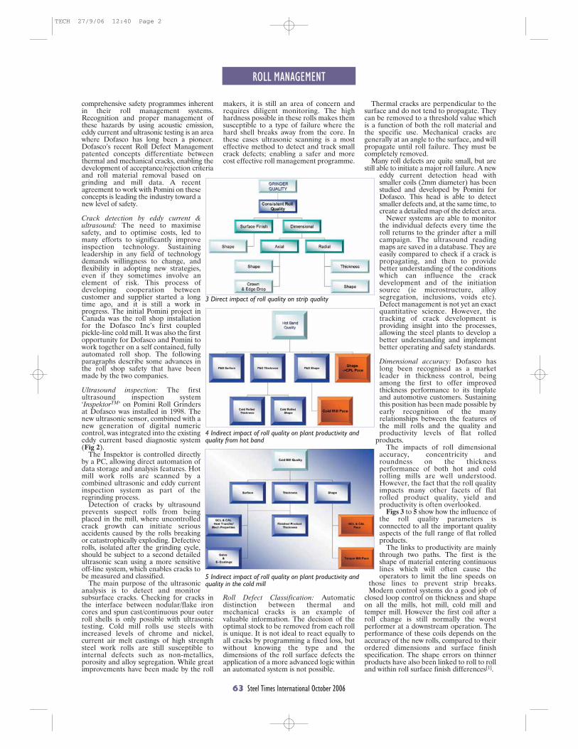
ROLL MANAGEMENT
63 Steel Times International October 2006
comprehensive safety programmes inherentin their roll management systems.Recognition and proper management ofthese hazards by using acoustic emission,eddy current and ultrasonic testing is an areawhere Dofasco has long been a pioneer.Dofasco’s recent Roll Defect Managementpatented concepts differentiate betweenthermal and mechanical cracks, enabling thedevelopment of acceptance/rejection criteriaand roll material removal based ongrinding and mill data. A recentagreement to work with Pomini on theseconcepts is leading the industry toward anew level of safety.
Crack detection by eddy current &ultrasound: The need to maximisesafety, and to optimise costs, led tomany efforts to significantly improveinspection technology. Sustainingleadership in any field of technologydemands willingness to change, andflexibility in adopting new strategies,even if they sometimes involve anelement of risk. This process ofdeveloping cooperation betweencustomer and supplier started a longtime ago, and it is still a work inprogress. The initial Pomini project inCanada was the roll shop installationfor the Dofasco Inc’s first coupledpickle-line cold mill. It was also the firstopportunity for Dofasco and Pomini towork together on a self contained, fullyautomated roll shop. The followingparagraphs describe some advances inthe roll shop safety that have beenmade by the two companies.
Ultrasound inspection: The firstultrasound inspection system‘InspektorTM’ on Pomini Roll Grindersat Dofasco was installed in 1998. Thenew ultrasonic sensor, combined with anew generation of digital numericcontrol, was integrated into the existingeddy current based diagnostic system(Fig 2).
The Inspektor is controlled directlyby a PC, allowing direct automation ofdata storage and analysis features. Hotmill work rolls are scanned by acombined ultrasonic and eddy currentinspection system as part of theregrinding process.
Detection of cracks by ultrasoundprevents suspect rolls from beingplaced in the mill, where uncontrolledcrack growth can initiate seriousaccidents caused by the rolls breakingor catastrophically exploding. Defectiverolls, isolated after the grinding cycle,should be subject to a second detailedultrasonic scan using a more sensitiveoff-line system, which enables cracks tobe measured and classified.
The main purpose of the ultrasonicanalysis is to detect and monitorsubsurface cracks. Checking for cracks inthe interface between nodular/flake ironcores and spun cast/continuous pour outerroll shells is only possible with ultrasonictesting. Cold mill rolls use steels withincreased levels of chrome and nickel,current air melt castings of high strengthsteel work rolls are still susceptible tointernal defects such as non-metallics,porosity and alloy segregation. While greatimprovements have been made by the roll
Roll Defect Classification: Automaticdistinction between thermal andmechanical cracks is an example ofvaluable information. The decision of theoptimal stock to be removed from each rollis unique. It is not ideal to react equally toall cracks by programming a fixed loss, butwithout knowing the type and thedimensions of the roll surface defects theapplication of a more advanced logic withinan automated system is not possible.
Thermal cracks are perpendicular to thesurface and do not tend to propagate. Theycan be removed to a threshold value whichis a function of both the roll material andthe specific use. Mechanical cracks aregenerally at an angle to the surface, and willpropagate until roll failure. They must becompletely removed.
Many roll defects are quite small, but arestill able to initiate a major roll failure. A new
eddy current detection head withsmaller coils (2mm diameter) has beenstudied and developed by Pomini forDofasco. This head is able to detectsmaller defects and, at the same time, tocreate a detailed map of the defect area.
Newer systems are able to monitorthe individual defects every time theroll returns to the grinder after a millcampaign. The ultrasound readingmaps are saved in a database. They areeasily compared to check if a crack ispropagating, and then to providebetter understanding of the conditionswhich can influence the crackdevelopment and of the initiationsource (ie microstructure, alloysegregation, inclusions, voids etc).Defect management is not yet an exactquantitative science. However, thetracking of crack development isproviding insight into the processes,allowing the steel plants to develop abetter understanding and implementbetter operating and safety standards.
Dimensional accuracy: Dofasco haslong been recognised as a marketleader in thickness control, beingamong the first to offer improvedthickness performance to its tinplateand automotive customers. Sustainingthis position has been made possible byearly recognition of the manyrelationships between the features ofthe mill rolls and the quality andproductivity levels of flat rolled
products.The impacts of roll dimensional
accuracy, concentricity androundness on the thicknessperformance of both hot and coldrolling mills are well understood.However, the fact that the roll qualityimpacts many other facets of flatrolled product quality, yield andproductivity is often overlooked.
Figs 3 to 5 show how the influence ofthe roll quality parameters isconnected to all the important qualityaspects of the full range of flat rolledproducts.
The links to productivity are mainlythrough two paths. The first is theshape of material entering continuouslines which will often cause theoperators to limit the line speeds on
those lines to prevent strip breaks.Modern control systems do a good job of
closed loop control on thickness and shapeon all the mills, hot mill, cold mill andtemper mill. However the first coil after aroll change is still normally the worstperformer at a downstream operation. Theperformance of these coils depends on theaccuracy of the new rolls, compared to theirordered dimensions and surface finishspecification. The shape errors on thinnerproducts have also been linked to roll to rolland within roll surface finish differences[1].
5 Indirect impact of roll quality on plant productivity andquality in the cold mill
3 Direct impact of roll quality on strip quality
4 Indirect impact of roll quality on plant productivity andquality from hot band
makers, it is still an area of concern andrequires diligent monitoring. The highhardness possible in these rolls makes themsusceptible to a type of failure where thehard shell breaks away from the core. Inthese cases ultrasonic scanning is a mosteffective method to detect and track smallcrack defects; enabling a safer and morecost effective roll management programme.
TECH 27/9/06 12:40 Page 2

ROLL MANAGEMENT
64 Steel Times International October 2006
ROLL SHOP COSTSThe cost of rolls and the associatedgrinding is usually second only to energycosts in a major rolling operation. Theobjective of roll grinding is to provide arefurbished dimensionally accurateworking surface, ensuring all componentsof a set of parameters lie within tightspecification, in the minimum time with theminimum cost.
‘Grind to Aim’ is a systematic approach toensure a first class roll being prepared forthe mill, while removing the minimummaterial in the minimum time.
The conventional three step process, toprepare a roll for the mill, is to:–..Remove a pre-determined depth of roll....surface material;–..Inspect the roll;–..Either return to the mill or initiate a....second grinding as in step 1.
This method is simple, but has majordeficiencies. It can never be optimal.Either one or more cracks will remain afterthe first grinding programme, or time androll material are wasted because more thanthe minimum material is removed. Thepotential risk for accidents involvingpersonnel, product and the plant, meansthat having defective rolls in the work areais not an option in today's steel processingenvironment. Therefore methods have tobe found to provide minimum stockremoval, prime production and at the sametime maintain the highest possibleconfidence that the roll is defect-free. Thisis best done with an independentlyprogrammable measuring carriage, onwhich the measuring calliper issupplemented with an eddy currentinspection system. During the rollroughing stage an optimising programmedetermines all the salient features of theroll, and generates a map of the roll. Thismap or matrix of information now providesinput to the grinding logic.
In the roll evaluation process three levelsof crack classification are used.�..The first is the upper or ‘critical ....threshold’. Cracks above this level are ....critical or very unusual and will require....operator intervention. These problems....should not normally be corrected in the....production machines: so the grinding....programme is paused and an alarm is set....for the operator.�..The second classification, ‘repairable’,....indicates that this defect can be....repaired using one of the....programmed sequences of the....machine.�..The third threshold is the ....maximum acceptable level: below....this level the roll.is released for ....use ....at the mill. A similarcycle....of checks ....is carried out for all....detected ....defects.
The system first removes eventualresidual magnetism that coulddeceive the eddy current system byindicating false positive results. Ifall the detected cracks arerepairable, the diagnostic programlocates the most severe one and themachine starts its repair phase.During this phase, the defects areremoved sequentially, alwaysworking on the heaviest remainingcrack. The diagnostic programmonitors the reduction in defect
level, and the machine keeps on grindinguntil all the measurements are below theminimum threshold. Then, the machinecompletes the normal grinding phases.
Recently developments of the PominiInspektor defect measurement systemhave allowed improved resolution in thedefect mapping processes, which are keyparts of the roll dressing logic system. Atthe same time the performance, size andspeed of today's digital systems hasincreased the capability and reliability ofthe data management systems. Oneoutcome of this is the ability of most recentsystems to detect and respond to smallerdefects. These cracks, which may actuallydevelop during, or be uncovered by thegrinding process itself, went undetected inthe past.
AUTOMATIC ROLL HANDLINGA multi-purpose roll handling cassettesystem was developed to both increaseoperator safety, and to reduce manpowercosts.
With the new Dofasco/Pomini rollmanagement system the rolls are nothandled one by one, but instead aregrouped in cassettes holding up to six rolls.This system can reduce roll-handling timeby 85%. The duty cycle on the overheadbuilding crane is reduced by a factor of six,and interference between the crane and theroll loader becomes insignificant.
For a relatively small steel plant, it is not
practical to separate and stream productsin separate facilities. Fast and flexible arevaluable features of the manufacturingorganisation and equipment. Dofasco rollgrinders must switch quickly and serviceseveral different rolling mills. The need forfast and frequent changeovers between theseveral roll types meant that new conceptsin equipment design had to be developedfor this project.
Dedicated cassettes were designed foreach roll type. Rolls are transportedbetween the mill and the roll grinder intheir cassettes (Fig 6).
When the cassette is positioned in theroll loader, a system of detectors confirmsthe identity of the roll type to the rollmanagement system.
The use of an automatic loader, fullyintegrated with the roll grinder, candramatically reduce the roll loading andunloading time, and at the same timereduce the chances of handling damage.Impacts obviously can damage the rolls, butmore important are the effects on thegrinding machine. They not only upset thecurrent alignment of the machine, but doincremental damage to the precision of theroll grinder components.
Multi level storage systems minimisetotal lifetime costs, and optimise the use ofspace. This is of value in both existingshops, where space is fixed and limited, andin new facilities where building costs oftenmatch the capital cost of the newequipment to be installed inside them.
The main advantage of an automaticloader integrated with the grindingmachine control system is the ability toautomatically organise the work sequence.In this way, starting from a programmedschedule, the integrated loader systemmoves the rolls and transfers thecorresponding set-up and grinding data setsto and from the grinder. At the end of thegrinding cycle the roll grinder requests theloader to change the roll.
There is also the potential for theintegrated system to re-match, or to re-mate work roll pairs based on the actualgrinding losses. Many mills have a tightlimit on the difference in diameter betweenthe two rolls in a work roll set. There arethree cases to consider:
First is the nominal case where nomatching activity is required. In this casethe diameter loss in both rolls maintains the
matching tolerance between thetwo rolls.
In the second situation, the firstroll of the pair is ground andsustains a diameter loss larger thanexpected. In this case, the mate(second roll of the pair) must havegood (ie excess) material removedto keep the diameters withintolerance.
In the third case, it is the secondroll that has excess loss, and the firstroll of the set has to be re-loadedinto the grinder to remove goodmaterial to match diameters. Timemoney and material are wasted bythis process.
If the automation system has dataon the entire roll inventory, then itis not difficult to envision a systemthat would automatically re-assign
roll pairings to minimise totalmaterial losses.
6 Moving rolls in cassettes reduces handlingtime by up to 85%
7 Patented automatic roll neck rest to aid positioning of roll ingrinder
TECH 27/9/06 12:40 Page 3
A round 60% of all steel packagingput on the European market wasrecycled in 2004. But in Centraland Eastern Europe, according to
the level of collection infrastructure inplace, recycling performances ranged from11% (metals) in Lithuania to 43% (steel) inHungary. The best progression in metalpackaging recycling was registered in theCzech Republic (37% vs 29% the yearbefore).
At a seminar organised by APEAL, theAssociation of European producers ofSteel for Packaging, 35 experts including
steel and can manufacturers, brand ownersand local packaging recovery organisationsdiscussed the economics and performanceof steel packaging recycling and sharedexperience on best practice in collectionand consumer education. The seminar wasorganised in the context of the ongoingbuild up of packaging collection schemesinitiated ten years ago in Eastern andCentral Europe in order to meet theobjectives introduced by the Packaging andPackaging Waste Directive. Expertsincluding Désirée Guissard, a packagingconsultant with more than 15 years
experience and Christian Pürschel, PublicAffairs and Recycling Manager fromRasselstein, discussed the pro’s and con’s ofthe different systems and the cost driversand calculations for packaging collectionschemes in Europe.
APEAL seminar launches ongoingcooperation In this context, the EuropeanSteel industry has made a concretecommitment to developing steel packagingmarkets in Eastern & Central Europe andoffered cooperation to packaging recoveryorganisations in optimising steel packagingrecovery schemes.
ROLL MANAGEMENT
66 Steel Times International October 2006
At the cold mill roll shop each roll typerequires that automation drives the loaderand machine components to accuratelyreconfigure to a new pre-programmedgeometry. The loader picks up a roll fromthe selected cassette; recognising its typethe loader then instructs the machine totranslate the neck rests and tailstock tomatch the selected roll. The CNC-controlled loader positions the roll over themachine and lowers it onto the rollpositioners attached to the side of thePomini patented steady rests. The bearingshoes, controlled by pneumatic motors,move to just touch the roll necks. Next thebearing shoes are clamped to hold the rollin place, then the roll positioning systemretracts and the roll remains properlypositioned on the neck rests in line with themachine axis. The last step in the loadingprocess has the loader releasing the roll,leaving the grinder area, and preparing forthe next series of moves (Fig 7).
Another challenge in grindingeconomically is the wide variety of rolls forthe roll driving system. It has to matchvariations both in the position, and in thedimensions of the driving flats. To do thiseffectively Techint-Pomini developed andpatented a new driving system whichautomatically matches the flats. Theavailable configurations of interchangeableplates enable effective connection to a widerange of different drive designs.
HOW MUCH TO REMOVE? There are several reasons to search for acomprehensive system to automaticallyanswer the question ‘How much should beground from this roll?’ Today leaving thisdecision to the experience of an operator isnot practical. Up until the late 1980s roll andwheel technologies had lifetimes thatevolved slowly over decades. The materialswould evolve slowly; and operator feel andexperience on manually controlled machineswas a practical way to keep up with theincremental changes. Today's automaticgrinders, and fast changing roll and wheel
materials mean that the adjusting andcompensating processes must also beautomatic.
The optimal grinding programme for aparticular roll depends not only on the basicroll properties, but also on the specifichistory of the roll. For example:–...Minor damage may be in the roll after.....the previous grinding operation;–...The roll may have been subjected to a.....strip break in the mill;–...The rolling campaign itself varies in time.....and severity.
Standard rules can be applied to the rollbased on a combination of its rolling historyand on the data collection during grinding. Itis not practical for today's operators to makethese decisions. Once again the two basicaims are: to reduce to a minimum the totalmaterial removed, without compromisingsafety, which remains the first priority, andto use human intervention only in extremecircumstances.
The first requirement is the collection of acomprehensive set of grinding data for eachroll. The roll data is first assembled in a localdatabase for immediate use, and transferredto a central location for subsequent use bythe supervisory systems. Workingprogrammes are stored on a database;where they can be easily edited, modifiedand downloaded to all the grinders in theshop.
This gathered data and associatedexperience led to further automation of thegrinding operation. The Crack ManagementSystem is a recent development by Dofascoand Pomini. It is based on the Dofascopatented Roll Management Process. Thissystem is being developed to make fullyautomatic decisions on how to grind a roll,based on the measured defects theautomatic defect classification(thermal/mechanical), the applicablethreshold (based on gathered experience),the history of the roll and its use in the mill.This system will enable consistent rollperformance with improvements in rollcosts, safety and mill performance.
OTHER STEPS FORWARDIn the last decade, there have been majorsteps forward in technology, coupled withan increasing awareness of quality. Majorsteps forward in internal processes formachine manufacturers has led toimproved quality of the machines andsurrounding systems, as documented byISO 9001 ISO 14001 (environment) andISO 18001 (safety).
The maintainability of the machines hasbeen greatly improved, new software nowadvises operators when maintenanceoperations are required. This is similar tomodern cars telling the drivers when theyneed to bring the car in for service.
Remote service is another area wheretechnology has made big steps forward. It isnow possible to connect directly to grindingmachines on the other side of the world.High speed internet connections are usedto drive the machine or diagnose theproblems quickly, and even see how themachine is working through the use of awireless camera, Similarly, operatortraining can be delivered via web-conferences with live video to explain howto change a board, to use an application orto repair mechanical damage.
Modern roll grinding machinemanufacturers, such as Pomini, are alsooffering complete Roll Shop ManagementSystems to keep track of location and use ofall the rolls, chocks, bearings, wheels andother items critical in the roll shop. Thesesystems are coupled with production datafrom mill computer systems, so that, forexample, it is possible to automaticallycalculate how much steel is produced permillimetre of roll wear, or to study the totalhistory of a specific roll or chock.
Reference[1] Improved Flatness of Double ReducedTinplate, D.D. Clifford, T. Lim, K.J. Balaz & K.Derayeh, 6th International Rolling Conference,Düsseldorf, Germany, June 20-22, 1994.
CONTACTPaolo Gaboardi Senior Vice President TECHINT Compagnia Tecnica Internazionale S.p.A. -
POMINI Roll Grinders Via Leonardo da Vinci, 20 (21053) Castellanza (VA)- ItalyTel +39 0331 444356 Mobile +39 335 6375477 Fax +39 0331 444390
e-mail: [email protected] mailto:[email protected] www.pomini.com
CONTACTJean-Pierre Taverne Environmental and Technical Affairs Manager APEAL - Avenue Louise, 89 BE-1050 Brussels Belgium
Tel: +32/2 535 72 05 Fax: +32/2 537 86 49 email: [email protected] www.apeal.org
STI
STI
Packaging recycling in Eastern Europe
TECH 27/9/06 12:40 Page 4
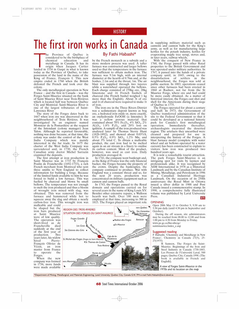
in supplying military material such ascannons and cannon balls for the King’sarmy, as well as for manufacturing largekettles for the potash industry, kettles forevaporating maple tree syrup, stoves and,in later years, railway wheels.
With the conquest of New France in1760, the Forge passed with other Royalproperties to the British Government andwas operated under military authorities. In1767, it passed into the hands of a privatecompany until, in 1845, owing to thedissatisfaction of settlers in theneighbourhood, the Forges was sold atpublic auction. In 1883, operations ceasedsince other furnaces had been erected in1860 at Radnor, not far from the StMaurice Forge, where ore and fuel couldbe more easily obtained. As a matter ofhistorical interest, the Forges cast shot andshell for the Americans during their siegeof Québec in 1775.
The Forges operated for about a centuryand half. In 1973, the Government ofQuébec transferred administration of thesite to the Federal Government so that itcould be developed as a national historicpark for Canada’s first metallurgicaloperation. Immediately thereafter,archaeologists excavated the desertedregion. The artefacts they unearthed werecleaned and prepared for use ininterpreting the history of the Forges. Ablast furnace model (complete with waterwheel and air bellows operated by a watercurrent) has been constructed to explain tovisitors how iron was produced twohundred years ago.
It is now a remarkable tourist attraction.The park Forges Saint-Maurice is anintriguing spot for visits by laymen andprofessionals alike. It was recognised byASM International in 1978 as a HistoricalLandmark and by the Canadian Institute ofMining, Metallurgy, and Petroleum in 1996as a Canadian Industrial HeritageLandmark. On the occasion of its 250thanniversary the Royal Mint in Ottawaissued a silver dollar in 1988 and PostCanada issued a commemorative stamp. In1998, a comprehensive fully illustratedvolume was published by Laval UniversityPress.
OPENINGOpen 2006 May 13 to October 9, 9:30 am to5:30 pm daily (until 4:30 pm in September andOctober).
During the off season, site administratorsmay be reached from 08.00 to 12.00 and from1:00 pm to 4:30 from Monday to Friday.www.pc.gc.ca/lhn-nhs/qc/saintmaurice/index_e.asp
Suggested readingF Habashi, ‘Chemistry and Metallurgy in NewFrance’, Chemistry in Canada 27(5), 25-27(1975)
R Samson, The Forges du Saint-Maurice. Beginnings of the Iron andSteel Industry in Canada 1730-1883,Les Presses de l’Université Laval, 500pages, Quebec City, Canada 1998. (Thebook is available in French andEnglish).
HISTORY
68 Steel Times International October 2006
STI
The first iron works in CanadaBy Fathi Habashi*The Province of Québec is
considered to be the birthplace ofchemical education andmetallurgy in Canada. It has itsorigin when Jacques Cartier
landed in 1534 in Gaspé in what is knowntoday as the Province of Québec, to takepossession of the land in the name of theKing of France, François I. This newempire ended in 1760 when the Britishdefeated the French and took over thecolony.
The only metallurgical operation in NewFrance – and the first in Canada – was theForges Saint-Maurice situated on the bankof Saint Maurice River near Trois-Rivièreswhich is located half way between QuébecCity and Montréal. Saint-Maurice River isone of the largest tributaries of Saint-Lawrence River
The story of the Forges dates back to1667 when iron ore was discovered in theneighbourhood of Trois Rivières. It wasinvestigated by an engineer namedMonsieur de la Pontardière at the requestof the Intendant (colony manager) JeanTalon. Although he reported favourably,nothing was done because, at that time, thecolony was under the control of the WestIndia Company which was mainlyinterested in the fur trade. In 1675 thecharter of the West India Company wassurrendered and, in 1730, the FrenchCanadian army doctor Michel Sarrazinexamined the deposits.
The first attempt at iron production inSaint Maurice was in 1733 by FrançoisPoulin de Francheville (1692-1733), a richFrench merchant from Montreal who sentthree smiths to New England to collectinformation for building a forge. Becauseof the limited funds available to him he wasforced to build a low furnace. This wasfuelled by charcoal and blown by smallbellows. The temperature was not enoughto melt the iron produced and thus a bloomof wrought iron mixed with slag, wasobtained. This was removed from thefurnace and hammered while hot tosqueeze away the slag and obtain a nearlycarbon-free iron. This wrought iron wasmalleable and couldbe shaped but theiron bars producedat Saint Mauricewere of low quality.The operation wasshort-lived as deFrancheville diedsuddenly at the endof the first year ofproduction. Twoyears later, his widowhired Pierre-François Olivier deVézin, an ironmaster from Franceto operate theForges.
When the newcompany was formedin 1736, more fundswere made available
by the French monarch as a subsidy and amore modern process was used. A tallerfurnace was constructed and larger bellowsused so that the temperature in the furnacewas sufficient to obtain molten iron. Thefurnace was 9.1m high, with an internaldiameter at the hearth of 0.76m and, at theboshes, 2.1m and at the throat, 1m. The airblast was supplied through two tuyereswhile a waterwheel operated the bellows.Each charge consisted of 270kg ore, 20kglimestone and 16 French bushels ofcharcoal (the French bushel weighed 1 kgmore than the English). About 3t of oreand 1t of charcoal were required to make 1tof iron.
The iron ore in the Three Rivers Districtwas a sedimentary deposit known as bogore, a hydrated iron oxide or, more exactly,an oxyhydroxide FeOOH (a limonite). Itwas a yellow porous material thatcontained about 70% Fe2O3, 4% SiO2, 2%Al2O3, 1.8% P2O5, and 20% loss onignition. A sample of the iron produced wasanalysed later by Thomas Sterry Hunt(1826-1892), and showed about 0.03%S,0.5% P2O5, 0.9% SiO2, 1.2% Mn, andabout 3% total C. To obtain a malleableproduct, the cast iron had to be meltedagain in an air stream in a finery to oxidiseits carbon content. Most of the product,however, was used as cast iron. Dailyproduction averaged 4t.
In 1741, the company went bankrupt and,as the King of France was the only financialbacker, the Forges became the property ofthe crown. Despite the bankruptcy, thecompany continued to produce. War withEngland was a constant threat and so, forthe next 20 years, production wasconcentrated on military equipment such ascannon and cannon balls.
In 1743, the Forges passed to the Royaldomain and operations carried on forseveral years in the name of King Louis XV.Besides other extensive repairs, a Walloonhearth was built. Over 180 men wereemployed at that time, increasing to 300 in1815. The Forges played an important role
Forges Grondin
Les Grais
Ste Etienne-des-Grès
St Thomas-de-Caxton
Cap-de-la-Madeleine
St-Maurice
Trois-Rivières
Pointe-du-Lac
Lac St-Pierrevers Montréal
Nicolet
Batiscan
Fleuve St-Laurent
Rivière St-Maurice
Ste-Genevièvede Batiscan
A view of Forges Saint-Maurice in the1970s and its location on the map
Radnor-des-Forges
REGION DES TROIS-RIVIERES SITUATION DES FORGES DU SAINT-MAURICE
St Michel-des-Forges (Forges du Saint-Maurice)
�
vers Québec
�
*Department of Mining, Metallurgical, and Materials Engineering, Laval University, Quebec City, Canada G1K 7P4 e-mail [email protected]
HISTORY OCTO 27/9/06 14:30 Page 1

Sequestration of CO2 from Steelmaking Offgas by Carbonate Formation with Slag
C. Hank Rawlins, Von L. Richards, Kent D. Peaslee, and Simon N. Lekakh University of Missouri-Rolla
Department of Material Science and Engineering 223 McNutt Hall Rolla, MO 65409
Tel.: 573-341-4711 Fax: 573-341-6934
E-mail: [email protected]
Key Words: Steelmaking Slag, Offgas, Carbon Dioxide, Sequestration, Phase Stability, Reaction Kinetics
INTRODUCTION
The alkaline earth-containing phases in steelmaking slag can form carbonates thus sequestering carbon dioxide from the surrounding atmosphere. Work has been undertaken to improve the carbonate formation kinetics, enabling steelmakers to directly remove CO2 from furnace offgas with slag, which in turn reduces the slag stabilization time. A study of basic oxygen furnace (BOF) and electric arc furnace (EAF) slags is reported in conjunction with their carbonate formation thermodynamics and capacities, yielding an overall slag CO2 capture potential. Preliminary results are presented from bench-top “wet” and “dry” slag carbonation tests on industrial slags using a slurry reactor and large-scale thermogravimetric analysis (TGA).
CO2 EMISSIONS IN STEELMAKING
In response to political demands, carbon dioxide has been targeted as a key industrial emission requiring regulation and control. As a key industrial sector relying on carbonaceous material for operation, the steel industry worldwide will be affected by these regulations. The regulation of carbon dioxide as an emission in the steel industry must be based on an understanding of the sources, amounts, and variations of the generation of this gas. Control methods can be put in place to target specific sources and sized to handle the amounts and variations involved. Carbon dioxide can be generated directly through iron or steel processes (blast furnace or BOF), or through indirect means (coke ovens or coal burning power plants providing electricity to EAF). Each of these sources requires a specific means for regulation and control, which also must be viewed in relation to the entire steelmaking route. A comparison of CO2 emissions based on geographic regions and steelmaking technologies can be made from published data. Stubbles provides trends of U.S. domestic steel industry energy use and CO2 emissions.1 Technological evolution has reduced the required energy per ton of steel from 47.4 GJ (45 million BTU) in 1950 to 17.9 GJ (17 million BTU) in 2000. Carbon dioxide emissions, stated in terms of carbon equivalent (CE) units (0.27 x tons CO2), have only been tracked since 1990, but they exhibit a similar trend to the reduction in energy use. Integrated mills produce more CO2 than mini-mills because of their reliance on coke making and blast furnace ironmaking. In the year 2000, integrated mills produced 33.46 million tons of CO2 (CE units), of which 64% (21.47 million tons) came from the production and use of coke. Mini-mills produced 13.65 million tons of CO2 (CE units), of which 80% (10.86 million tons) came from electrical production at the power plant. On average the U.S. steel industry produced 0.42 carbon equivalent tons of CO2 per ton of steel shipped in 2000. Carbon dioxide emission data from the steel industries of several other countries are available from the literature. Afonin provides data for the steelmaking sector in Russia.2 Based on 1998 data, the total CO2 emissions from integrated steelmaking stands at 48.6 million tons carbon equivalent, which is 8.5% of all Russian CO2 emissions. On an intensity basis, this equals 1.4 tons CE per ton of steel produced. Data from Birat et al. show that in 1989 the French integrated-steel industry produced a total of 26.3 million metric tons of
1133AISTech 2006 Proceedings - Volume II
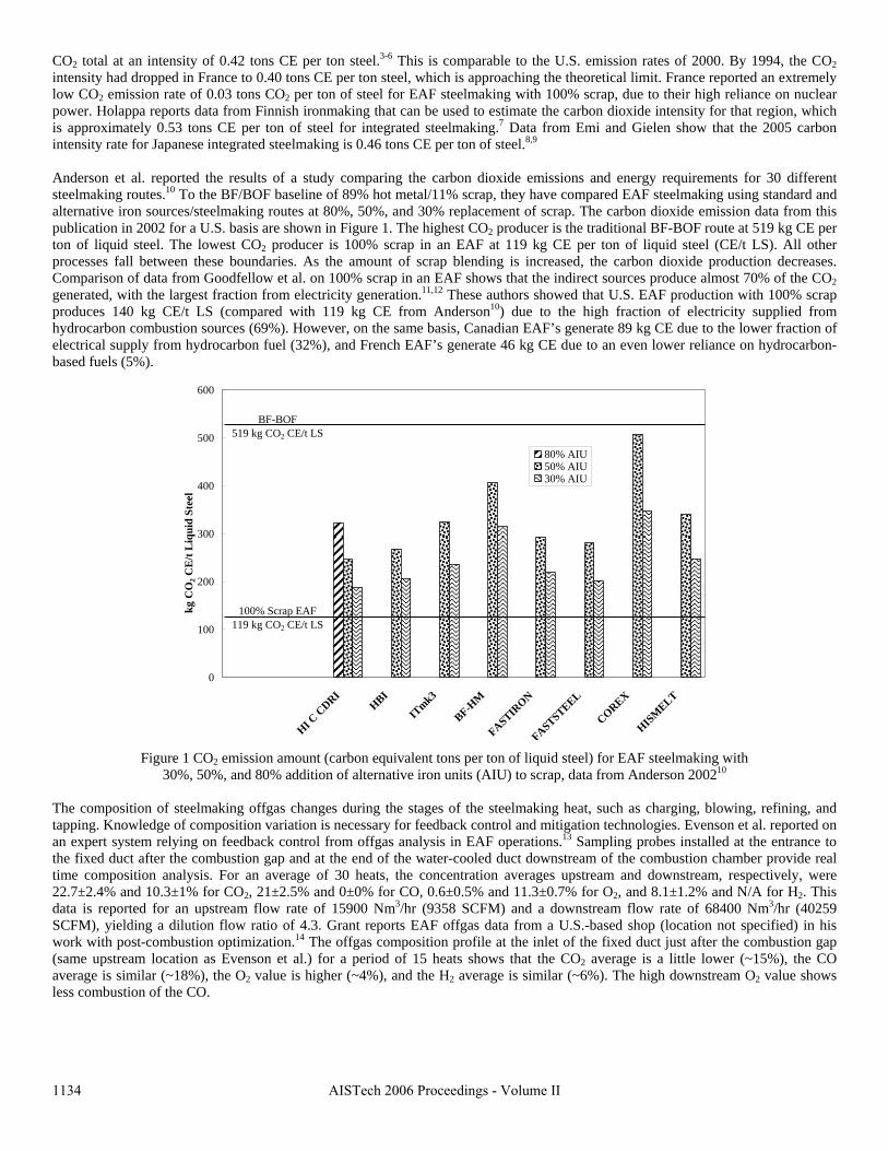
CO2 total at an intensity of 0.42 tons CE per ton steel.3-6 This is comparable to the U.S. emission rates of 2000. By 1994, the CO2 intensity had dropped in France to 0.40 tons CE per ton steel, which is approaching the theoretical limit. France reported an extremely low CO2 emission rate of 0.03 tons CO2 per ton of steel for EAF steelmaking with 100% scrap, due to their high reliance on nuclear power. Holappa reports data from Finnish ironmaking that can be used to estimate the carbon dioxide intensity for that region, which is approximately 0.53 tons CE per ton of steel for integrated steelmaking.7 Data from Emi and Gielen show that the 2005 carbon intensity rate for Japanese integrated steelmaking is 0.46 tons CE per ton of steel.8,9
Anderson et al. reported the results of a study comparing the carbon dioxide emissions and energy requirements for 30 different steelmaking routes.10 To the BF/BOF baseline of 89% hot metal/11% scrap, they have compared EAF steelmaking using standard and alternative iron sources/steelmaking routes at 80%, 50%, and 30% replacement of scrap. The carbon dioxide emission data from this publication in 2002 for a U.S. basis are shown in Figure 1. The highest CO2 producer is the traditional BF-BOF route at 519 kg CE per ton of liquid steel. The lowest CO2 producer is 100% scrap in an EAF at 119 kg CE per ton of liquid steel (CE/t LS). All other processes fall between these boundaries. As the amount of scrap blending is increased, the carbon dioxide production decreases. Comparison of data from Goodfellow et al. on 100% scrap in an EAF shows that the indirect sources produce almost 70% of the CO2 generated, with the largest fraction from electricity generation.11,12 These authors showed that U.S. EAF production with 100% scrap produces 140 kg CE/t LS (compared with 119 kg CE from Anderson10) due to the high fraction of electricity supplied from hydrocarbon combustion sources (69%). However, on the same basis, Canadian EAF’s generate 89 kg CE due to the lower fraction of electrical supply from hydrocarbon fuel (32%), and French EAF’s generate 46 kg CE due to an even lower reliance on hydrocarbon-based fuels (5%).
0
100
200
300
400
500
600
HI C C
DRIHBI
ITmk3
BF-HM
FASTIRON
FASTSTEEL
COREX
HISM
ELT
kg C
O2 C
E/t
Liq
uid
Stee
l
80% AIU50% AIU30% AIU
100% Scrap EAF119 kg CO2 CE/t LS
BF-BOF519 kg CO2 CE/t LS
Figure 1 CO2 emission amount (carbon equivalent tons per ton of liquid steel) for EAF steelmaking with 30%, 50%, and 80% addition of alternative iron units (AIU) to scrap, data from Anderson 200210
The composition of steelmaking offgas changes during the stages of the steelmaking heat, such as charging, blowing, refining, and tapping. Knowledge of composition variation is necessary for feedback control and mitigation technologies. Evenson et al. reported on an expert system relying on feedback control from offgas analysis in EAF operations.13 Sampling probes installed at the entrance to the fixed duct after the combustion gap and at the end of the water-cooled duct downstream of the combustion chamber provide real time composition analysis. For an average of 30 heats, the concentration averages upstream and downstream, respectively, were 22.7±2.4% and 10.3±1% for CO2, 21±2.5% and 0±0% for CO, 0.6±0.5% and 11.3±0.7% for O2, and 8.1±1.2% and N/A for H2. This data is reported for an upstream flow rate of 15900 Nm3/hr (9358 SCFM) and a downstream flow rate of 68400 Nm3/hr (40259 SCFM), yielding a dilution flow ratio of 4.3. Grant reports EAF offgas data from a U.S.-based shop (location not specified) in his work with post-combustion optimization.14 The offgas composition profile at the inlet of the fixed duct just after the combustion gap (same upstream location as Evenson et al.) for a period of 15 heats shows that the CO2 average is a little lower (~15%), the CO average is similar (~18%), the O2 value is higher (~4%), and the H2 average is similar (~6%). The high downstream O2 value shows less combustion of the CO.
1134 AISTech 2006 Proceedings - Volume II
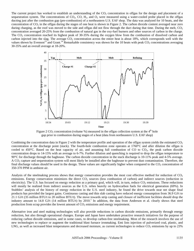
The current project has worked to establish an understanding of the CO2 concentration in offgas for the design and placement of a sequestration system. The concentrations of CO2, CO, H2, and O2 were measured using a water-cooled probe placed in the offgas ducting just after the combustion gap (pre-combustion) of a northeastern U.S. EAF shop. The data was analyzed for 10 heats, and the concentration of CO2 in the offgas during the stages of one heat is shown in Figure 2. The carbon dioxide content averaged near zero during charging, as the roof was moved to the side and offgas did not flow through the duct during that time. During the melt, CO2 concentration averaged 20-25% from the combustion of natural gas in the oxy-fuel burners and other sources of carbon in the charge. The CO2 concentration reached its highest peak of 30-35% during the oxygen blow from the combustion of dissolved carbon and carbon injected into the slag. The average CO2 concentration across the entire heat is about 18%, which corresponds well with the values shown by Evenson13 and Grant.14 Remarkable consistency was shown for the 10 heats with peak CO2 concentrations averaging 30-35% and an overall average at 18-20%.
0
5
10
15
20
25
30
35
40
18:54 19:03 19:12 19:21 19:30 19:39
Time
%C
O2 i
n O
ffga
s (ga
p pr
e-co
mbu
stio
n)
Tap
Charge #1
Melt Refining
Charge #2
Melt
Figure 2 CO2 concentration (volume %) measured in the offgas collection system at the 4th hole gap prior to combustion during stages of a heat (data from northeastern U.S. EAF shop)
Combining the concentration data in Figure 2 with the temperature profile and operation of the offgas system yields the estimated CO2 concentration at the discharge point (stack). The fourth-hole combustion zone operates at 1760°C and after dilution the offgas is cooled to 450°C. Based on the heat capacity of air, and assuming full combustion of CO to CO2, the peak carbon dioxide concentration drops to 14-15% with an average to 6-7%. Further dilution and quenching is required to drop the offgas temperature to 90°C for discharge through the baghouse. The carbon dioxide concentration in the stack discharge is 10-11% peak and 4-5% average. A CO2 capture and sequestration system will most likely be installed after the baghouse to prevent dust contamination. Therefore, the final discharge values should be used in the design. These values are significantly higher when compared to the CO2 concentration of 350-370 PPM in ambient air. Analysis of the steelmaking process shows that energy conservation provides the most cost effective method for reduction of CO2 emissions. Energy conservation minimizes the direct CO2 sources (less combustion of carbon) and indirect sources (reduction in electricity). The U.S. has focused on energy reduction as a primary goal, which will, in turn, reduce CO2 emissions. These reductions will mostly be realized from indirect sources as the U.S. relies heavily on hydrocarbon fuels for electrical generation (69%). In Stubbles’ analysis of the history of energy reduction in the U.S. steel industry, he found the drive towards near net shape final products has provided the largest gains. Continuous casting and thin slab casting have reduced energy consumption from 36.9 GJ/t to 21.1 GJ/t (35 million BTU/t to 20 million BTU/t). The move towards strip casting and closure of inefficient facilities should drop the industry amount to 14.8 GJ/t (14 million BTU/t) by 2010.1 In addition, the data from Anderson et al. clearly shows that steel production from scrap provides the lowest amount of CO2 emissions and energy requirement. Alternative iron and steel making technologies will also provide reductions in carbon dioxide emissions, primarily through energy reduction, but also through operational changes. Europe and Japan have undertaken proactive research initiatives for the purpose of reducing carbon dioxide emissions, and in some cases, to develop carbon-free steelmaking. Most of the research involves the use of new technologies to replace or augment the traditional blast furnace ironmaking. Emi lists injection of pulverized coal, plastic, and LNG, as well as increased blast temperatures and decreased moisture, as current technologies to reduce CO2 emissions by up to 23%
1135AISTech 2006 Proceedings - Volume II
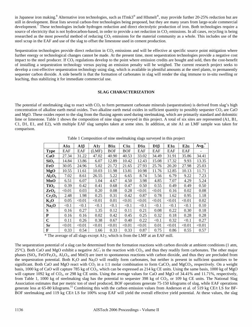
in Japanese iron making.8 Alternative iron technologies, such as ITmk3® and HIsmelt®, may provide further 20-25% reduction but are still in development. Birat lists several carbon-free technologies being proposed, but they are many years from large-scale commercial development.7 These technologies include hydrogen reduction and direct electrolytic production of iron. Both technologies require a source of electricity that is not hydrocarbon-based, in order to provide a net reduction in CO2 emissions. In all cases, recycling is being researched as the most powerful method of reducing CO2 emissions for the material community as a whole. This includes use of the steel scrap in the EAF and use of the slag to offset the limestone used in cement production. Sequestration technologies provide direct reduction in CO2 emissions and will be effective at specific source point mitigation where
SLAG CHARACTERIZATION
The potential of steelmaking slag to react with CO2 to form permanent carbonate minerals (sequestration) is derived from slag’s high
Table 1 Composition of nine steelmaking slags surveyed in this project
A1 α Avg.*
further energy or technological changes cannot be made. At the present time, most sequestration technologies provide a negative cost impact to the steel producer. If CO2 regulations develop to the point where emission credits are bought and sold, then the cost-benefit of installing a sequestration technology versus paying an emission penalty will be weighed. The current research project seeks to develop a cost-effective sequestration technology using slag, which is available in plentiful amounts at the steel plants, to permanently sequester carbon dioxide. A side benefit is that the formation of carbonates in slag will render the slag immune to in-situ swelling or leaching, thus stabilizing it for immediate commercial use.
concentration of alkaline earth metal oxides. Two alkaline earth metal oxides in sufficient quantity to possibly sequester CO2 are CaO and MgO. These oxides report to the slag from the fluxing agents used during steelmaking, which are primarily standard and dolomitic lime or limestone. Table 1 shows the composition of nine slags surveyed in this project. A total of six sites are represented (A1, B1, C1, D1, E1, and E2), with multiple EAF slag samples taken at some sites. In addition, at site A1 an LMF sample was taken for comparison.
α A1β A1γ B1α C1α D1α D1β E1α E2Ty e ( p EAF EAF LMF) BOF BOF EAF EAF EAF EAF - CaO 27.34 31.22 47.02 40.90 40.53 33.02 34.49 31.91 35.86 3 1 4.4SiO2 14.84 13.86 6.07 12.89 10.42 12.43 15.08 17.32 9.93 13.35 FeO 30.05 24.96 5.02 21.72 21.65 27.93 25.76 20.20 27.98 25.03 MgO 110.55 11.61 0.03 11.98 13.81 10.98 11.76 12.85 10.13 11.71 Al2O3 7.02 8.61 26.55 5.22 6.65 8.74 5.56 6.79 9.22 7.23 MnO 6.51 6.07 1.04 4.67 4.50 3.98 4.85 7.07 4.29 5.24 TiO2 0.39 0.42 0.41 0.68 0.47 0.50 0.55 0.49 0.49 0.50 ZrO2 < < <0.01 0.03 0.20 0.08 0.28 0.01 0.01 0.16 0.02 0.08 Cr2O3 2.48 1.98 0.25 0.31 0.42 0.87 0.78 1.62 0.95 1.18 K2O 0.05 < < < < < < <0.01 0.01 0.01 0.01 0.01 0.01 0.01 0.01 0.02 Na2O <0.1 <0.1 <0.1 <0.1 <0.1 <0.1 <0.1 <0.1 <0.1 0.10 S 0.16 0.27 1.35 0.12 0.11 0.21 0.08 0.22 0.30 0.18 P 0.16 0.16 0.02 0.42 0.45 0.25 0.32 0.18 0.28 0.28 C 0.11 0.26 0.38 0.67 0.40 0.22 <0.1 0.32 <0.1 0.27 Sr < < < < < < < < <0.01 0.01 0.01 0.01 0.01 0.01 0.01 0.01 0.01 0.01 F 0.33 0.54 1.66 0.33 0.33 0.87 0.75 0.86 0.55 0.57
* The avera ll xce γ, w is e t a m
he sequestration potential of a slag can be determined from the formation reactions with carbon dioxide at ambient conditions (1 atm,
ge of a slags e pt A1 hich from th LMF a n EAF ill.
T25°C). Both CaO and MgO exhibit a negative ΔG°
f in the reaction with CO2, and thus they readily form carbonates. The other major phases (SiO2, FeO/Fe2O3, Al2O3, and MnO) are inert to spontaneous reactions with carbon dioxide, and thus they are precluded from the sequestration potential. Both K2O and Na2O will readily form carbonates, but neither is present in sufficient quantities to be significant. Both CaO and MgO react with CO2 in a 1:1 molar combination to form CaCO3 and MgCO3, respectively. On a weight basis, 1000 kg of CaO will capture 785 kg of CO2, which can be expressed as 214 kg CE units. Using the same basis, 1000 kg of MgO will capture 1092 kg of CO2, or 298 kg CE units. Using the average values for CaO and MgO of 34.41% and 11.71%, respectively, from Table 1, 1000 kg of steelmaking slag has the potential to sequester 398 kg of CO2, or 109 kg CE units. The National Slag Association estimates that per metric ton of steel produced, BOF operations generate 75-150 kilograms of slag, while EAF operations generate less at 65-80 kilograms.15 Combining this with the carbon emission values from Anderson et al. of 519 kg CE/t LS for BF-BOF steelmaking and 119 kg CE/t LS for 100% scrap EAF will yield the overall effective yield potential. At these values, the slag
1136 AISTech 2006 Proceedings - Volume II
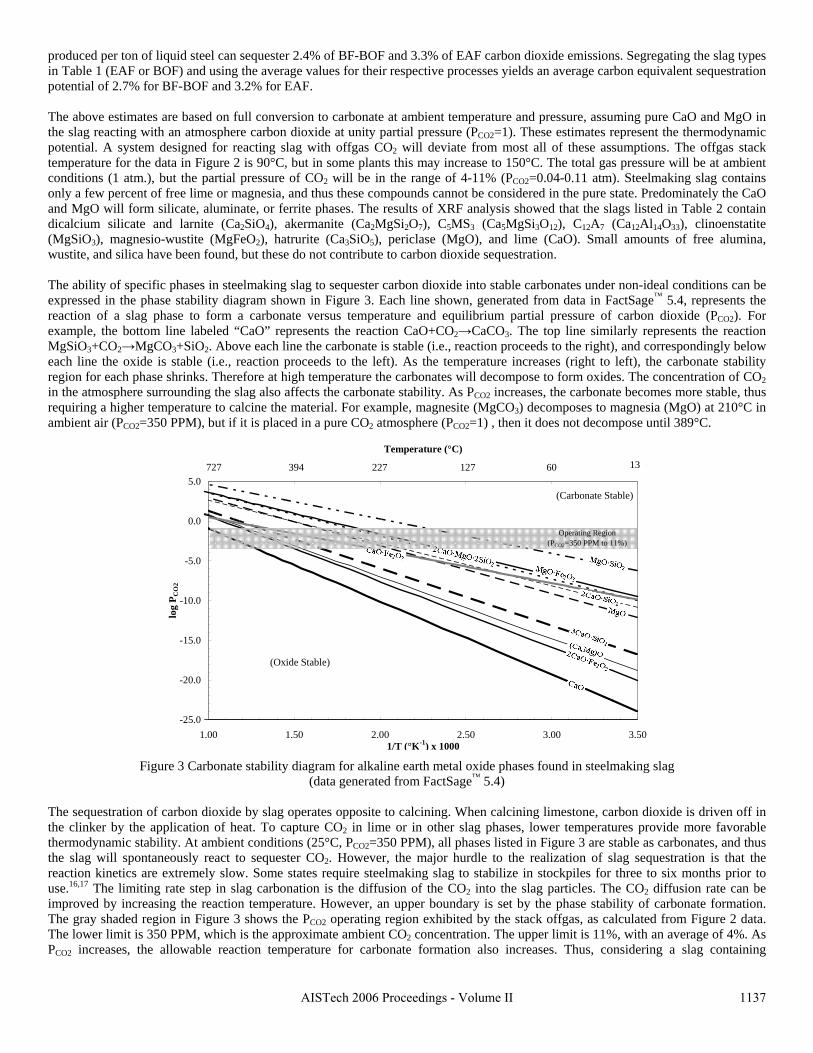
produced per ton of liquid steel can sequester 2.4% of BF-BOF and 3.3% of EAF carbon dioxide emissions. Segregating the slag types in Table 1 (EAF or BOF) and using the average values for their respective processes yields an average carbon equivalent sequestration potential of 2.7% for BF-BOF and 3.2% for EAF. The above estimates are based on full conversion to carbonate at ambient temperature and pressure, assuming pure CaO and MgO in
he ability of specific phases in steelmaking slag to sequester carbon dioxide into stable carbonates under non-ideal conditions can be
Figu slag
he sequestration of carbon dioxide by slag operates opposite to calcining. When calcining limestone, carbon dioxide is driven off in
PCO2 increases, the allowable reaction temperature for carbonate formation also increases. Thus, considering a slag containing
the slag reacting with an atmosphere carbon dioxide at unity partial pressure (PCO2=1). These estimates represent the thermodynamic potential. A system designed for reacting slag with offgas CO2 will deviate from most all of these assumptions. The offgas stack temperature for the data in Figure 2 is 90°C, but in some plants this may increase to 150°C. The total gas pressure will be at ambient conditions (1 atm.), but the partial pressure of CO2 will be in the range of 4-11% (PCO2=0.04-0.11 atm). Steelmaking slag contains only a few percent of free lime or magnesia, and thus these compounds cannot be considered in the pure state. Predominately the CaO and MgO will form silicate, aluminate, or ferrite phases. The results of XRF analysis showed that the slags listed in Table 2 contain dicalcium silicate and larnite (Ca2SiO4), akermanite (Ca2MgSi2O7), C5MS3 (Ca5MgSi3O12), C12A7 (Ca12Al14O33), clinoenstatite (MgSiO3), magnesio-wustite (MgFeO2), hatrurite (Ca3SiO5), periclase (MgO), and lime (CaO). Small amounts of free alumina, wustite, and silica have been found, but these do not contribute to carbon dioxide sequestration. Texpressed in the phase stability diagram shown in Figure 3. Each line shown, generated from data in FactSage™ 5.4, represents the reaction of a slag phase to form a carbonate versus temperature and equilibrium partial pressure of carbon dioxide (PCO2). For example, the bottom line labeled “CaO” represents the reaction CaO+CO2→CaCO3. The top line similarly represents the reaction MgSiO3+CO2→MgCO3+SiO2. Above each line the carbonate is stable (i.e., reaction proceeds to the right), and correspondingly below each line the oxide is stable (i.e., reaction proceeds to the left). As the temperature increases (right to left), the carbonate stability region for each phase shrinks. Therefore at high temperature the carbonates will decompose to form oxides. The concentration of CO2 in the atmosphere surrounding the slag also affects the carbonate stability. As PCO2 increases, the carbonate becomes more stable, thus requiring a higher temperature to calcine the material. For example, magnesite (MgCO3) decomposes to magnesia (MgO) at 210°C in ambient air (PCO2=350 PPM), but if it is placed in a pure CO2 atmosphere (PCO2=1) , then it does not decompose until 389°C.
Temperature (°C)
re 3 Carbonate stability diagram for alkaline earth metal oxide phases found in steelmaking(data generated from FactSage™ 5.4)
Tthe clinker by the application of heat. To capture CO2 in lime or in other slag phases, lower temperatures provide more favorable thermodynamic stability. At ambient conditions (25°C, PCO2=350 PPM), all phases listed in Figure 3 are stable as carbonates, and thus the slag will spontaneously react to sequester CO2. However, the major hurdle to the realization of slag sequestration is that the reaction kinetics are extremely slow. Some states require steelmaking slag to stabilize in stockpiles for three to six months prior to use.16,17 The limiting rate step in slag carbonation is the diffusion of the CO2 into the slag particles. The CO2 diffusion rate can be improved by increasing the reaction temperature. However, an upper boundary is set by the phase stability of carbonate formation. The gray shaded region in Figure 3 shows the PCO2 operating region exhibited by the stack offgas, as calculated from Figure 2 data. The lower limit is 350 PPM, which is the approximate ambient CO2 concentration. The upper limit is 11%, with an average of 4%. As
-25.0
-20.0
-15.0
-10.0
-5.0
0.0
5.0
1.00 1.50 2.00 2.50 3.00 3.501/T (°K-1) x 1000
log
P CO
2
1.00 1.50 2.00 2.50 3.00 3.5013727 394 227 127 60
(Carbonate Stable)
(Oxide Stable)
Operating Region(PCO2=350 PPM to 11%)
1137AISTech 2006 Proceedings - Volume II
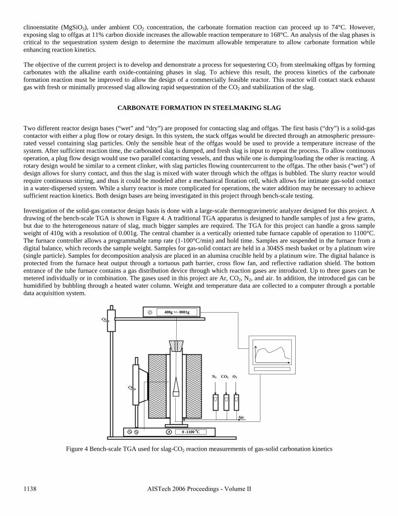
clinoenstatite (MgSiO3), under ambient CO2 concentration, the carbonate formation reaction can proceed up to 74°C. However, exposing slag to offgas at 11% carbon dioxide increases the allowable reaction temperature to 168°C. An analysis of the slag phases is critical to the sequestration system design to determine the maximum allowable temperature to allow carbonate formation while enhancing reaction kinetics. The objective of the current project is to develop and demonstrate a process for sequestering CO2 from steelmaking offgas by forming arbonates with the alkaline earth oxide-containing phases in slag. To achieve this result, the process kinetics of the carbonate
Two different reactor design bases (“ e first basis (“dry”) is a solid-gas contactor with either a plug flow or rotary design. In this system, the stack offgas would be directed through an atmospheric pressure-
ned for this project. A rawing of the bench-scale TGA is shown in Figure 4. A traditional TGA apparatus is designed to handle samples of just a few grams,
Figure 4 Be ion kinetics
cformation reaction must be improved to allow the design of a commercially feasible reactor. This reactor will contact stack exhaust gas with fresh or minimally processed slag allowing rapid sequestration of the CO2 and stabilization of the slag.
CARBONATE FORMATION IN STEELMAKING SLAG
wet” and “dry”) are proposed for contacting slag and offgas. Th
rated vessel containing slag particles. Only the sensible heat of the offgas would be used to provide a temperature increase of the system. After sufficient reaction time, the carbonated slag is dumped, and fresh slag is input to repeat the process. To allow continuous operation, a plug flow design would use two parallel contacting vessels, and thus while one is dumping/loading the other is reacting. A rotary design would be similar to a cement clinker, with slag particles flowing countercurrent to the offgas. The other basis (“wet”) of design allows for slurry contact, and thus the slag is mixed with water through which the offgas is bubbled. The slurry reactor would require continuous stirring, and thus it could be modeled after a mechanical flotation cell, which allows for intimate gas-solid contact in a water-dispersed system. While a slurry reactor is more complicated for operations, the water addition may be necessary to achieve sufficient reaction kinetics. Both design bases are being investigated in this project through bench-scale testing. Investigation of the solid-gas contactor design basis is done with a large-scale thermogravimetric analyzer desigdbut due to the heterogeneous nature of slag, much bigger samples are required. The TGA for this project can handle a gross sample weight of 410g with a resolution of 0.001g. The central chamber is a vertically oriented tube furnace capable of operation to 1100°C. The furnace controller allows a programmable ramp rate (1-100°C/min) and hold time. Samples are suspended in the furnace from a digital balance, which records the sample weight. Samples for gas-solid contact are held in a 304SS mesh basket or by a platinum wire (single particle). Samples for decomposition analysis are placed in an alumina crucible held by a platinum wire. The digital balance is protected from the furnace heat output through a tortuous path barrier, cross flow fan, and reflective radiation shield. The bottom entrance of the tube furnace contains a gas distribution device through which reaction gases are introduced. Up to three gases can be metered individually or in combination. The gases used in this project are Ar, CO2, N2, and air. In addition, the introduced gas can be humidified by bubbling through a heated water column. Weight and temperature data are collected to a computer through a portable data acquisition system.
400g +/- 0001g
Air
CO2 O2 N2
0 -1100 0C
nch-scale TGA used for slag-CO2 reaction measurements of gas-solid carbonat
1138 AISTech 2006 Proceedings - Volume II
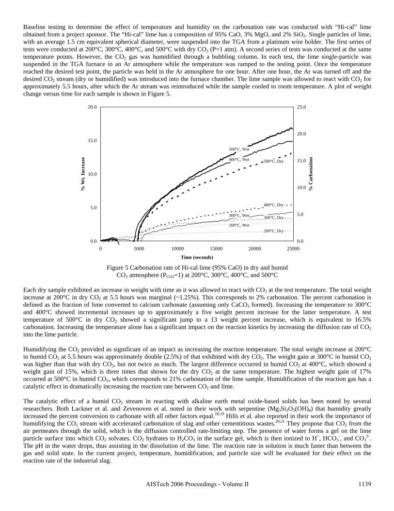
Baseline testing to determine the effect of temperature and hum dity on the carbonation rate was conducted with “Hi-cal” lime
ach dry sample exhibited an increase in weight with time as it was allowed to react with CO2 at the test temperature. The total weight
umidifying the CO2 provided as significant of an impact as increasing the reaction temperature. The total weight increase at 200°C
he catalytic effect of a humid CO2 stream in reacting with alkaline earth metal oxide-based solids has been noted by several
reaction rate of the industrial slag.
iobtained from a project sponsor. The “Hi-cal” lime has a composition of 95% CaO, 3% MgO, and 2% SiO2. Single particles of lime, with an average 1.5 cm equivalent spherical diameter, were suspended into the TGA from a platinum wire holder. The first series of tests were conducted at 200°C, 300°C, 400°C, and 500°C with dry CO2 (P=1 atm). A second series of tests was conducted at the same temperature points. However, the CO2 gas was humidified through a bubbling column. In each test, the lime single-particle was suspended in the TGA furnace in an Ar atmosphere while the temperature was ramped to the testing point. Once the temperature reached the desired test point, the particle was held in the Ar atmosphere for one hour. After one hour, the Ar was turned off and the desired CO2 stream (dry or humidified) was introduced into the furnace chamber. The lime sample was allowed to react with CO2 for approximately 5.5 hours, after which the Ar stream was reintroduced while the sample cooled to room temperature. A plot of weight change versus time for each sample is shown in Figure 5.
20.0
0.0
5.0
10.0
15.0
0 5000 10000 15000 20000 25000
Time
% W
t. In
crea
se
0.0
5.0
10.0
15.0
20.0
25.0
% C
arbo
natio
n
500°C, Wet
400°C, Wet 500°C, Dry
400°C, Dry
300°C, Wet 300°C, Dry
200°C, Wet200°C, Dry
(seconds)
Figure 5 Carbonation rate of Hi-cal lime (95% CaO) in dry and humid CO2 atmosphere (PCO2=1) at 200°C, 300°C, 400°C, and 500°C
Eincrease at 200°C in dry CO2 at 5.5 hours was marginal (~1.25%). This corresponds to 2% carbonation. The percent carbonation is defined as the fraction of lime converted to calcium carbonate (assuming only CaCO3 formed). Increasing the temperature to 300°C and 400°C showed incremental increases up to approximately a five weight percent increase for the latter temperature. A test temperature of 500°C in dry CO2 showed a significant jump to a 13 weight percent increase, which is equivalent to 16.5% carbonation. Increasing the temperature alone has a significant impact on the reaction kinetics by increasing the diffusion rate of CO2 into the lime particle. Hin humid CO2 at 5.5 hours was approximately double (2.5%) of that exhibited with dry CO2. The weight gain at 300°C in humid CO2 was higher than that with dry CO2, but not twice as much. The largest difference occurred in humid CO2 at 400°C, which showed a weight gain of 15%, which is three times that shown for the dry CO2 at the same temperature. The highest weight gain of 17% occurred at 500°C in humid CO2, which corresponds to 21% carbonation of the lime sample. Humidification of the reaction gas has a catalytic effect in dramatically increasing the reaction rate between CO2 and lime. Tresearchers. Both Lackner et al. and Zevenoven et al. noted in their work with serpentine (Mg3Si2O5(OH)4) that humidity greatly increased the percent conversion to carbonate with all other factors equal.18,19 Hills et al. also reported in their work the importance of humidifying the CO2 stream with accelerated carbonation of slag and other cementitious wastes.20,21 They propose that CO2 from the air permeates through the solid, which is the diffusion controlled rate-limiting step. The presence of water forms a gel on the lime particle surface into which CO2 solvates. CO2 hydrates to H2CO3 in the surface gel, which is then ionized to H+, HCO3
-, and CO32-.
The pH in the water drops, thus assisting in the dissolution of the lime. The reaction rate in solution is much faster than between the gas and solid state. In the current project, temperature, humidification, and particle size will be evaluated for their effect on the
1139AISTech 2006 Proceedings - Volume II

Investigation of the “wet” process, based on a water-solid-gas reactor design, was done with a bench-scale flotation cell using a two-
ter chamber with an internally rotated impeller. The rate of the carbonation reaction was studied under intensive mixing as shown in liFigure 6. The rate of slag reaction was compared with the rate of “Hi-cal” lime reaction under the same test conditions. For each test, 50g of solid material was crushed and graded to <106μm then mixed with two liters of tap water. Bottled CO2 was injected into the slurry at a rate of 1459 cm3/min for a total of two hours (lime only). Periodic slurry samples of 3-5g in size were taken, decanted through vacuum filtration, and then dried in an oven. Oven drying took place at 220°C for one hour, followed by calcium hydrate decomposition at 480°C for two hours and calcium carbonate decomposition at 920°C for two hours. These temperatures were chosen on the basis of thermodynamic equilibrium of the CaO-CO2-H2O system as determined by FactSage 5.4. Parallel samples were taken and subjected to analysis in the TGA.
Figure 6 Bench-scale slurry mixer with internally rotated i ller (left) and mixing process with slag-CO2-water (right)
Three t hetic ags produced from reagent grade material in an induction furnace. The compositions of the mixtures used to produce the three
Table 2 Mixture composition of synthetic slags used in slurry testing (by weight)
mpe
ypes of materials were tested in the slurry reactor: “Hi-cal” lime, eight of the industrial slags in Table 1, and three syntslsynthetic slags are shown in Table 2. The synthetic slag composition was selected to represent a low, medium, and high basicity in slag A, B, and C, respectively. Synthetic slags A and B exhibited a “falling” condition and self-disintegrated into a powder during cooling. This is a result of the β−γ polymorphic transformation of calcium disilicate. Slag C did not exhibit self-disintegration, and thus it was crushed after cooling to produce the same particle size as slags A and B. Each synthetic slag was screened to produce particles <106μm.
Component Slag A Slag B Slag C CaO 40% 49% 56% FeO 15% 15% 15% SiO2 26% 20% 15% MgO 10% 7% 5% Al2O3 5% 5% 5% MnO 4% 4% 4%
The test results with “Hi-cal” lime are shown re 7. Withi first two minut e pH rose from a background level of 5.8 in arbonated tap water to 12 after the addition of lime, indicating a relatively rapid dissolution of CaO and showing the gas-liquid-solid
ion rate in the slurry reactor. However, based on the rapid reaction f lime in this process, testing with the slag materials was conducted for only 60 minutes. As an initial comparison of reactivity
in Figu n the es, thcmixing process was very efficient. A sample taken at this time showed 47% carbonation of the lime and full utilization of the CO2. At six minutes, the pH stayed at 12 and the percent carbonation jumped to 84%. As the lime consumed the CO2, the pH and CO2 efficiency began to rapidly drop. By 20 minutes, both the pH and percent carbonation had stabilized, thus very little further CO2 was consumed causing the CO2 efficiency to rapidly drop. Samples taken at 120 minutes showed little change in the percent carbonation and pH, indicating the process had essentially reached completion. A similar procedure was used for the evaluation of the slag carbonatobetween the slags to lime, the change in pH with time is plotted in Figure 8. Slag A1γ (LMF slag) and lime proved to have similar reactivity dropping to just a few percent more than the background pH in five minutes, and reaching the background pH in 30 minutes. Slags D1α, A1α, and A(synthetic), respectively, exhibited decreasing initial pH values, however they all dropped to the same baseline
1140 AISTech 2006 Proceedings - Volume II
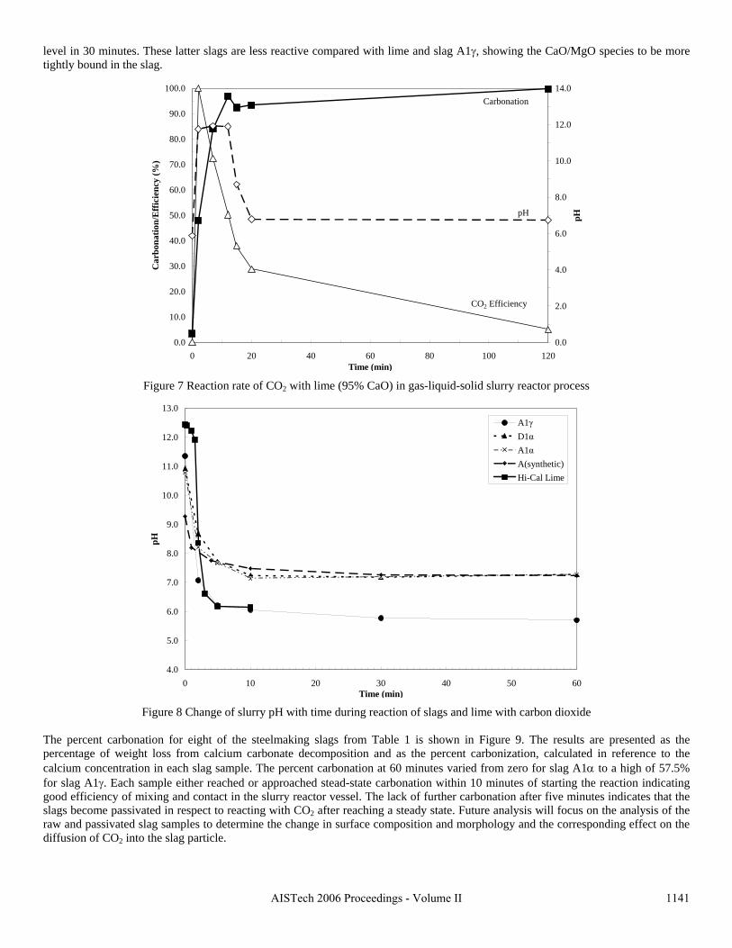
level in 30 minutes. These latter slags are less reactive compared with lime and slag A1γ, showing the CaO/MgO species to be more tightly bound in the slag.
100.0
Figure 7 Reaction rate of CO2 with lime (95% CaO) in gas-liquid-solid slurry reactor process
Figure 8 Change of slurry pH with time during reaction of slags and lime with carbon dioxide
he percent carbonat re presented as the
2
T ion for eight of the steelmaking slags from Table 1 is shown in Figure 9. The results apercentage of weight loss from calcium carbonate decomposition and as the percent carbonization, calculated in reference to the calcium concentration in each slag sample. The percent carbonation at 60 minutes varied from zero for slag A1α to a high of 57.5% for slag A1γ. Each sample either reached or approached stead-state carbonation within 10 minutes of starting the reaction indicating good efficiency of mixing and contact in the slurry reactor vessel. The lack of further carbonation after five minutes indicates that the slags become passivated in respect to reacting with CO2 after reaching a steady state. Future analysis will focus on the analysis of the raw and passivated slag samples to determine the change in surface composition and morphology and the corresponding effect on the diffusion of CO into the slag particle.
0.0
10.0
20.0
30.0
40.0
50.0
60.0
70.0
80.0
90.0
0 20 40 60 80 100 120Time
Car
bona
tion/
Eff
icie
ncy
(%)
0.0
2.0
4.0
6.0
8.0
10.0
12.0
14.0
pHpH
CO2 Efficienc
Carbonation
y
(min)
13.0
4.0
5.0
6.0
7.0
8.0
9.0
10.0
11.0
12.0
0 10 20 30 40 50 60Time
A1γD1αA1αA(synthetic)Hi-Cal Lime
pH
(min)
1141AISTech 2006 Proceedings - Volume II
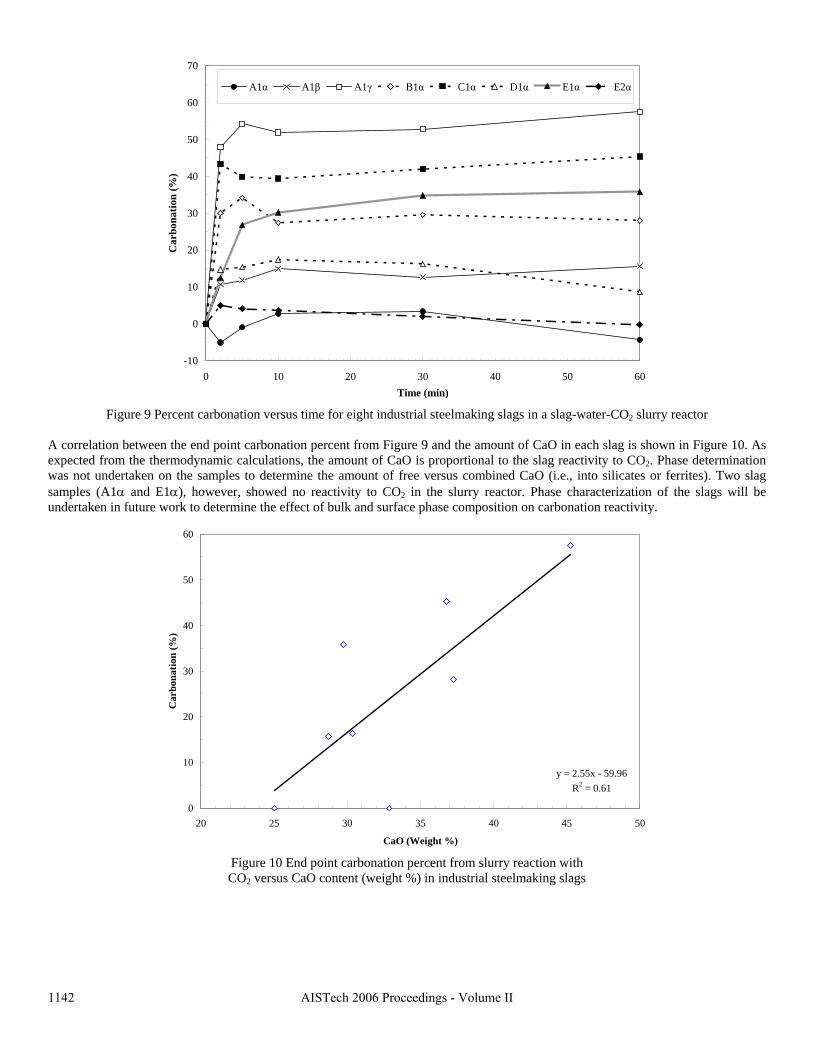
70
Figure 9 slurry reactor A correlat re 10. As xpected from the thermodynamic calculations, the amount of CaO is proportional to the slag reactivity to CO2. Phase determination
Percent carbonation versus time for eight industrial steelmaking slags in a slag-water-CO2
ion between the end point carbonation percent from Figure 9 and the amount of CaO in each slag is shown in Figuewas not undertaken on the samples to determine the amount of free versus combined CaO (i.e., into silicates or ferrites). Two slag samples (A1α and E1α), however, showed no reactivity to CO2 in the slurry reactor. Phase characterization of the slags will be undertaken in future work to determine the effect of bulk and surface phase composition on carbonation reactivity.
Figure 10 End point carbonation percent from slurry reaction with CO2 versus CaO content (weight %) in industrial steelmaking slags
-10
0
10
20
30
40
50
60
0 10 20 30 40 50 60Time
A1α A1β A1γ B1α C1α D1α
(min)
Car
bona
tion
(%)
E1α E2α
60
y = 2.55x - 59.96R2 = 0.61
0
10
20
30
40
50
20 25 30 35 40 45 50
CaO (Weight %)
Car
bona
tion
(%)
1142 AISTech 2006 Proceedings - Volume II
SUMMARY
The results of bench-scale CO2 sequestration tests by steelmaking slags are presented in this paper. In the “dry” process, the rate of reaction of solid lime or slag increases proportionally to the reactor temperature. However, an upper boundary condition exists, defined by a thermodynamic phase stability diagram, that must be identified for each phase in the slag. Tests results showed that the addition of water vapor (humidification) to the CO2 gas significantly accelerated the carbonation reaction of pure lime. The mechanism of this catalytic effect is possibly defined by the formation of intermediate calcium hydrate gel on the solid particle surface. A “wet” process, which includes the interaction between three phases (water-solid slag-CO2 gas), has a much higher carbonation reaction rate when compared with the “dry” process. The percent of carbonation statistically correlated to the CaO contents of industrial slags. This data will be used to determine the design parameters for a lab-scale reactor for CO2 sequestration by steelmaking slags.
ACKNOWLEDGEMENTS
The authors gratefully acknowledge the support of the U.S. Department of Energy and the American Iron and Steel Institute (AISI) in their direction of this project, and of the individual corporate sponsors—DOFASCO, Gallatin Steel, Hylsa, IPSCO, Mittal Steel, Praxair, Nucor, Timken Company, and US Steel—for their input and support. This paper was prepared as an account of work sponsored by an agency of the United States Government in cooperation with the American Iron and Steel Institute (AISI) and its participating companies under Agreement DE-FC36-97ID13554. Neither the United States Government or AISI nor any agency or affiliate thereof, nor any of their employees, makes any warranty, express or implied, or assumes any legal liability or responsibility for the accuracy, completeness, or usefulness of any information, apparatus, product, or process disclosed, or represents that its use would not infringe privately owned rights. Reference herein to any specific commercial product, process, or service by trade name, trademark, manufacturer, or otherwise, does not necessarily constitute or imply endorsement, recommendation, or favoring by the United States Government, AISI or any agency thereof. The views and opinions of authors expressed herein do not necessarily state or reflect those of the United States Government, AISI or any agency thereof.
REFERENCES
1. J.R. Stubbles. “Carbon dioxide emissions from the U.S. steel industry.” In: Proceedings of the International Symposium on Greenhouse Gases in the Metallurgical Industries: Policies, Abatement and Treatment; 26-29 August, 2001; Toronto, ON, Canada. Editor: C.A. Pickles. Montreal, Quebec, Canada: Canadian Institute of Mining, Metallurgy, and Petroleum. pp. 103-116.
2. S.Z. Afonin, Y.S. Yusfin, P.I. Chernousev, and S.V. Murinets. “Energy conservation in ferrous metallurgy.” Metallurgist, Vol. 42, No. 7-8, 1999, pp. 292-296.
3. J.-P. Birat, M. Antoine, A. Dubs, H. Gaye, Y. de Lassat, R. Nicolle, and J.L. Roth. “Towards a carbon-free steel production route?” La Revue de Metallurgie-CIT, Vol. 90, No.3, 1993, pp. 411-421.
4. J.-P. Birat, J.-M. Delbecq, E. Hess, and D. Huin. “Slag, steel and greenhouse gases.” La Revue de Métallurgie-CIT, Vol. 99, No.1, 2002, pp. 13-21.
5. J.-P. Birat, F. Hanrot, and G. Danloy. “CO2 mitigation technologies in the steel industry: a benchmarking study based on process calculations.” Stahl und Eisen, Vol. 123, No. 9, 2003, pp. 69-72.
6. J.-P. Birat. “CO2 emissions and the steel industry’s available responses to the greenhouse effect.” In: Proceedings of the 59th Ironmaking Conference; 26-29 March 2000; Pittsburgh, PA, U.S. Warrendale, PA, U.S.: Association for Iron and Steel Technology; 2000. pp. 409-420.
7. L.E.K. Holappa. “Impact of energy and environment on the development of metallurgical processes.” In: Proceedings of the 2nd International Symposium on Metallurgical Processes for the Year 2000 and Beyond; 1994; San Diego, CA, U.S. Editor: H.Y. Sohn. Warrendale, PA, U.S.: The Minerals, Metals, and Materials Society. pp. 641-660.
8. T. Emi. “Changing paradigm of metal separation technology for steel production.” Scandinavian Journal of Metallurgy, Vol. 34, No. 2, 2005, pp. 79-88.
9. D. Gielen. “CO2 removal in the iron and steel industry.” Energy Conversion and Management, Vol. 44, No.7, 2003, pp. 1027-1037.
10. S.H. Anderson, G.E. Metius, and J. M. McClelland. “Future green steelmaking technologies.” In: Proceedings of the 60th Electric Furnace Conference; 10-13 November 2002; San Antonio, TX, U.S. Warrendale, PA, U.S.: Association for Iron and Steel Technology; 2002. pp. 175-191.
11. H.D. Goodfellow, M. Thomson, L. Cibert, P. Morere, and E. Evenson. “Overview global warming issues and EAF production.” In: Proceedings of the 56th Electric Furnace Conference; 15-18 November 1998, New Orleans, LA, U.S. Warrendale, PA, U.S.: Association for Iron and Steel Technology; 1998. pp. 623-627.
1143AISTech 2006 Proceedings - Volume II
12. M.J. Thomson, E.J. Evenson, M.J. Kempe, and H.D. Goodfellow. “Control of greenhouse gas emissions from electric arc furnace steelmaking: evaluation methodology with case studies.” Ironmaking and Steelmaking, Vol. 27, No. 4, 2000, pp. 273-279.
13. E.J. Evenson, H.D. Goodfellow, and M.J. Kempe. “EAF process optimization through offgas analysis and closed-loop process control at Deacero, Saltillo, Mexico.” Iron & Steelmaker, Vol. 28, No. 5, 2001, pp. 53-58.
14. M.G. Grant. “Principles and strategy of EAF post-combustion.” In: Proceedings of the 58th Electric Furnace Conference; 12-15 November 2000; Orlando, FL, U.S. Warrendale, PA, U.S.: Association for Iron and Steel Technology; 2000. pp. 15-28.
15. “Steel slag: A premier construction aggregate.” West Lawn, PA, U.S.: National Slag Association [brochure]. 30 June 2005 http://www.nationalslagassoc.org/PDF_files/SSPremAgg.PDF.
16. Missouri (U.S.). Department of Transportation. “Section 1002: Aggregate for Asphaltic Concrete.” Jefferson City, MO, U.S.: Missouri Department of Transportation. 14 April 2004 http://www.modot.org/business/standards_and_specs/nov2004specbook/Sec1002.pdf.
17. P.S. Kandhal and G.L. Hoffman. “Evaluation of steel slag fine aggregate in hot-mix asphalt mixtures.” Transportation Research Record, No. 1583, 1997, pp. 28-36.
18. K.S. Lackner, D.P. Butt, C.H. Wendt. “Magnesite disposal of carbon dioxide.” In: Proceedings of the 22nd International Technical Conference on Coal Utilization & Fuel Systems; 16-19 March 1997; Clearwater, FL, United States. Editor, B.A. Sakkestad. Gaithersburg, MD: Coal Technology Association; 1997, pp. 419-430.
19. R. Zevenhoven, J. Kohlmann, A.B. Mukherjee. “Direct dry mineral carbonation for CO2 emissions reduction in Finland.” In: Proceedings of the 27th International Technical Conference on Coal Utilization & Fuel Systems; 4-7 March 2002; Clearwater, FL, United States. Editor, B.A. Sakkestad. Gaithersburg, MD: Coal Technology Association; 2002, pp. 743-754.
20. D.C. Johnson, C.L. MacLeod, P.J. Carey, C.D. Hills. “Solidification of stainless steel slag by accelerated carbonation.” Environmental Technology, Vol. 24, No.6, 2003, pp. 671-678.
21. M. Fernández Bertos, S.J.R. Simons, C.D. Hills, P.J. Carey. “A review of accelerated carbonation technology in the treatment of cement-based materials and sequestration of CO2.” Journal of Hazardous Materials, Vol. 112, No.3, 2004, pp. 193-205.
1144 AISTech 2006 Proceedings - Volume II
EXPERIMENTAL STUDY OF CO2 SEQUESTRATION BY STEELMAKING SLAG
C. Hank Rawlins, Von L. Richards, Kent D. Peaslee, and Simon N. Lekakh
University of Missouri-Rolla, Department of Material Science and Engineering 225 McNutt Hall, Rolla, MO 65409, Tel.: 573-341-6469, E-mail: [email protected]
Key Words: Steelmaking Slag, Carbon Dioxide, Sequestration
Abstract
Steelmaking processes intensively use carbon-containing materials and generate a significant amount of carbon dioxide emissions. The U.S. steel industry produces ~1.75 tons CO2 for every ton of steel shipped. At the same time, steelmaking processes use calcium and magnesium oxide containing minerals for slag formation, which are excellent CO2 capture agents. The goal of this investigation was to experimentally study carbon dioxide sequestration by steelmaking slag with simultaneous acceleration of the slag stabilization processes in preparation for re-use as a construction material. Thermogravimetric methods and a slurry reactor were used to study reaction kinetics. The degree of slag carbonization was evaluated for industrial and synthetic slags in dry and wet and processes.
Carbon Dioxide Emission In Steelmaking
Carbon dioxide is generated directly through iron or steel metallurgical processes (blast furnace, BOF or EAF), or through indirect means (coke ovens or coal burning power plant providing electricity to processes). A comparison of CO2 emissions according to geographic regions and steelmaking technologies was made from published data. Stubbles provides trends of U.S. domestic steel industry energy use and CO2 emissions.1 Technological evolution has reduced required energy per ton of steel from 47.4 GJ (45 million BTU) in 1950 to 17.9 GJ (17 million BTU) in 2000. Carbon dioxide emissions, stated in terms of carbon equivalent (CE) units (0.27 x tons CO2), have been tracked since 1990, but exhibit a similar trend to reduction in energy use. Integrated mills produce more CO2 than mini-mills because of their reliance on coke making and blast furnace ironmaking. In the year 2000, integrated mills produced 33.46 million tons of CO2 (CE units) of which 64% (21.47 million tons) came from the production and use of coke. Mini-mills produced 13.65 million tons of CO2 (CE units), of which 80% (10.86 million tons) came from electrical production at the power plant. The U.S. steel industry on an average produced ~0.42 carbon equivalent tons of CO2 per ton of steel shipped in 2000. Carbon dioxide emission data from the steel industries of several other countries is available from the literature. Afonin provides data for the steelmaking sector in Russia.2 Based on 1998 data, the total CO2 emissions from integrated steelmaking stand at 48.6 million tons carbon equivalent, which is 8.5% of all Russian CO2 emissions. On an intensity basis, this equals 1.4 tons CE per ton of steel produced. Data from Birat et al. shows that in 1989 the French integrated steel industry produced a total of 26.3 million metric tons CO2 total, at an intensity of 0.42 tons CE per ton steel.3-6 This is comparable to U.S. emission rates of 2000. By 1994, the CO2 intensity had dropped in France to 0.40 tons CE per ton steel, which is approaching the theoretical limit. France has an extremely low CO2 emission rate of 0.03 tons CO2 per ton steel considering EAF with 100% scrap, due to their high reliance on nuclear power. Holappa reports data from Finnish ironmaking that can be used to estimate the carbon dioxide intensity for that
193

region, which is approximately 0.53 tons CE per ton steel for integrated steelmaking.7 Data from Emi and Gielen show the 2005 carbon intensity rate for Japanese integrated steelmaking is 0.46 tons CE per ton of steel.8,9 Anderson et al. reported the results of a study comparing the carbon dioxide emissions and energy requirements for 30 different steelmaking routes.10 To the BF/BOF baseline of 89% hot metal/11% scrap, they have compared standard and alternative iron sources/steelmaking routes at 80%, 50%, and 30%. The carbon dioxide emission data from this publication in 2002 for a U.S. basis is shown in Figure 1. The highest CO2 producer is the traditional BF-BOF route at 519 kg CE per ton of liquid steel. The lowest CO2 producer is 100% scrap in an EAF at 119 kg CE per ton liquid steel (CE/t LS). All other processes are for EAF production and fall in between these boundaries. As the amount of scrap blending is increased, the carbon dioxide production decreases. Comparison of data from Goodfellow et al. on 100% scrap in an EAF shows that the indirect sources produce almost 70% of the CO2 generated, with the largest fraction from electricity generation.11,12 These authors showed that U.S. EAF production with 100% scrap produces ~140 kg CE/t LS (compared to 119 kg CE from Anderson10) due to high fraction of electricity supplied from hydrocarbon combustion sources (69%). However on the same basis, Canadian EAF generates 89 kg CE due to lower fraction of electrical supply from hydrocarbon fuel (32%) and French EAF generates 46 kg CE due to an even lower reliance on hydrocarbon-based fuels (5%).
The composition of steelmaking offgas is changed during the stages of the steelmaking heat, such as charging, blowing, refining, and tapping. Knowledge of composition variation is necessary for feedback control and mitigation technologies. Evenson et al. reported on an expert system relying on feedback control from offgas analysis in EAF operations.13 Sampling probes installed at the entrance to the fixed duct after the combustion gap and at the end of the water-cooled duct downstream of the combustion chamber provide real time composition analysis. For an average of 30 heats, the concentration averages upstream and downstream respectively were 22.7±2.4% and 10.3±1% for CO2, 21±2.5% and 0±0% for CO, 0.6±0.5% and 11.3±0.7% for O2, and 8.1±1.2% and N/A for H2. This data is reported for an upstream flow rate of 15900 Nm3/hr (9358 SCFM) and a downstream flow rate of 68400 Nm3/hr (40259 SCFM), yielding a dilution flow ratio of 4.3. Grant reports EAF offgas data from a U.S. based shop (location not specified) in his work with post-combustion optimization.14 The offgas composition profile at the inlet of the fixed duct just after the combustion gap (same as Evenson et al. upstream location) for a period of 15 heats shows the CO2 average a little lower (~15%), CO average similar (~18%), O2 value higher (~4%), and H2 average similar (~6%). The high downstream O2 value shows less combustion of the CO. Analysis of the steelmaking process shows that energy conservation provides both the most significant and cost effective method for reduction of CO2 emissions. Energy conservation minimizes the direct CO2 sources (less combustion of carbon) and indirect sources (reduction in electricity). The drive towards near net shape final product has provided the largest gains. Continuous casting and thin slab casting have reduced energy consumption from 36.9 GJ/t to 21.1 GJ/t (35 million BTU/t to 20 million BTU/t). The move towards strip casting and closure of inefficient facilities should drop the industry amount to ~14.8 GJ/t (14 million BTU/t) by 2010.1 In addition, steel production from scrap provides the lowest amount of CO2 emissions and energy requirement. Alternative iron and steel making technologies will also provide reductions in carbon dioxide emissions, primarily through energy reduction, but also through operational changes. Emi lists pulverized coal, plastic, and LNG injection, increased blast temperature, and decreasing moisture as current technologies to reduce CO2 emissions by up to 23% in Japanese iron making.8 Most of the research involves the use of new technologies to replace or augment the traditional blast furnace ironmaking. Alternative iron technologies, such as ITmk3® and
194
HIsmelt® may provide further 20-25% reduction but are still in development. Birat lists several carbon free technologies being proposed, but they are many years from large-scale commercial development.7 These technologies include hydrogen reduction and direct electrolytic production of iron. Both technologies require a source of electricity that is not hydrocarbon based, in order to provide a net reduction in CO2 emissions. In all cases recycling is being researched as the most powerful method of reducing CO2 emissions for the material community as a whole. This includes use of the steel scrap in the EAF and use of the slag to offset limestone used in cement production. Progress in steelmaking processes will decrease the total value of direct and indirect carbon dioxide emission but full elimination of this emission will be possible only with introduction of effective carbon dioxide sequestration processes. Unfortunately, at the present time, most sequestration technologies provide a negative cost impact to the steel producer. Moreover, some sequestration processes, which used high pressure/temperature apparatuses, require additional energy and have the low value of “global” efficiency when the direct and indirect balance is taken into account. The current research project seeks to develop a cost effective sequestration technology using slag, which is available in plentiful amounts at the steel plants, to permanently sequester carbon dioxide. A side benefit is that the formation of carbonates in slag will render the slag immune to in-situ swelling or leaching, thus stabilizing it for immediate commercial use.
CO2 Sequestration Possibility Of Steelmaking Slag
The potential of steelmaking slag to react with CO2 to form permanent carbonate minerals (sequestration) is derived from the high concentration of alkaline earth metal oxides. The alkaline earth metal oxides present in significant quantity in steelmaking slag are CaO and MgO. These oxides enter the slag from the fluxing agents used during steelmaking, which are primarily standard and dolomitic lime or limestone. Table 1 shows the composition of nine slags surveyed in this project. A total of six sites are represented (A1, B1, C1, D1, E1, and E2), with multiple EAF slag samples taken at some sites. In addition at site A1 an LMF sample was taken for comparison. The sequestration potential of a slag can be determined from the formation reactions with carbon dioxide at ambient conditions. Both CaO and MgO exhibit a negative ΔG°
f in the reaction with CO2, thus readily forming carbonates. The other major phases (SiO2, FeO/Fe2O3, Al2O3, and MnO) are inert to spontaneous reaction with carbon dioxide thus are precluded from the sequestration potential. Both K2O and Na2O will readily form carbonates, but are not present in sufficient quantities to be significant. Both CaO and MgO react with CO2 in a 1:1 molar combination to form CaCO3 and MgCO3 respectively. On a weight basis 1000 kg of CaO will capture 785 kg CO2, which can be expressed as 214 kg CE units. Using the same basis 1000 kg of MgO will capture 1092 kg CO2, or 298 kg CE units. Using the average values for CaO and MgO of 34.41% and 11.71% respectively from Table 1, 1000 kg of steelmaking slag has the potential to sequester 398 kg CO2, or 109 kg CE units. The National Slag Association estimates that per metric ton of steel produced, BOF operations generate 75-150 kilograms of slag, while EAF operations generate less at 65-80 kilograms.15 Combining this with the carbon emission values from Anderson et al of 519 kg CE/t LS for BF-BOF steelmaking and 119 kg CE/t LS for 100% scrap EAF will yield the overall potential sequestration capacity. At these values, the slag produced per ton of liquid steel can sequester 2.4% BF-BOF and 3.3% of EAF of total, direct and indirect, carbon dioxide emissions. Segregating the slag types in Table 1 (EAF or BOF) and using the average values for their respective processes yields an average carbon equivalent sequestration potential of 2.7% for BF-EAF and 3.2% for EAF. Significantly higher percentage of CO2, generated directly by EAF, could be captured by slag. Estimated volume of sequestrated by slag direct EAF CO2 emission could exceed 15%.
195
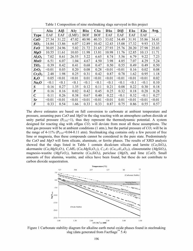
Table 1 Composition of nine steelmaking slags surveyed in this project
A1α A1β A1γ B1α C1α D1α D1β E1α E2α Avg. Type EAF EAF (LMF) BOF BOF EAF EAF EAF EAF - CaO 27.34 31.22 47.02 40.90 40.53 33.02 34.49 31.91 35.86 34.41SiO2 14.84 13.86 6.07 12.89 10.42 12.43 15.08 17.32 9.93 13.35FeO 30.05 24.96 5.02 21.72 21.65 27.93 25.76 20.20 27.98 25.03MgO 10.55 11.61 10.03 11.98 13.81 10.98 11.76 12.85 10.13 11.71Al2O3 7.02 8.61 26.55 5.22 6.65 8.74 5.56 6.79 9.22 7.23MnO 6.51 6.07 1.04 4.67 4.50 3.98 4.85 7.07 4.29 5.24TiO2 0.39 0.42 0.41 0.68 0.47 0.50 0.55 0.49 0.49 0.50ZrO2 <0.01 0.03 0.20 0.08 0.28 <0.01 <0.01 0.16 0.02 0.08Cr2O3 2.48 1.98 0.25 0.31 0.42 0.87 0.78 1.62 0.95 1.18K2O 0.05 <0.01 <0.01 0.01 <0.01 <0.01 <0.01 <0.01 <0.01 0.02Na2O <0.1 <0.1 <0.1 <0.1 <0.1 <0.1 <0.1 <0.1 <0.1 0.10S 0.16 0.27 1.35 0.12 0.11 0.21 0.08 0.22 0.30 0.18P 0.16 0.16 0.02 0.42 0.45 0.25 0.32 0.18 0.28 0.28C 0.11 0.26 0.38 0.67 0.40 0.22 <0.1 0.32 <0.1 0.27Sr <0.01 <0.01 <0.01 <0.01 <0.01 <0.01 0.01 <0.01 <0.01 <0.01F 0.33 0.54 1.66 0.33 0.33 0.87 0.75 0.86 0.55 0.57
The above estimates are based on full conversion to carbonate at ambient temperature and pressure, assuming pure CaO and MgO in the slag reacting with an atmosphere carbon dioxide at unity partial pressure (PCO2=1), thus they represent the thermodynamic potential. A system designed for reacting slag with offgas CO2 will deviate from most all these assumptions. The total gas pressure will be at ambient conditions (1 atm.), but the partial pressure of CO2 will be in the range of 4-11% (PCO2=0.04-0.11 atm). Steelmaking slag contains only a few percent of free lime or magnesia, thus these compounds cannot be considered in the pure state. Predominately the CaO and MgO will form silicate, aluminate, or ferrite phases. The results of XRD analysis showed that the slags listed in Table 1 contain dicalcium silicate and larnite (Ca2SiO4), akermanite (Ca2MgSi2O7), C5MS3 (Ca5MgSi3O12), C12A7 (Ca12Al14O33), clinoenstatite (MgSiO3), magnesio-wustite (MgFeO2), hatrurite (Ca3SiO5), periclase (MgO), and lime (CaO). Small amounts of free alumina, wustite, and silica have been found, but these do not contribute to carbon dioxide sequestration.
-25.0
-20.0
-15.0
-10.0
-5.0
0.0
5.0
1.00 1.50 2.00 2.50 3.00 3.501/T (°K-1) x 1000
log
P CO
2
1.00 1.50 2.00 2.50 3.00 3.50
Temperature (°C)
727 394 227 127 60 13
(Carbonate Stable)
(Oxide Stable)
Operating Region(PCO2=350 PPM to 11%)
Figure 1 Carbonate stability diagram for alkaline earth metal oxide phases found in steelmaking slag (data generated from FactSage™ 5.4)
196
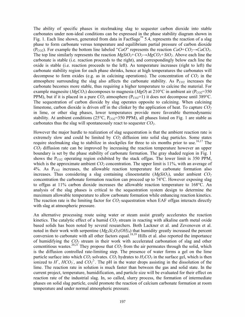
The ability of specific phases in steelmaking slag to sequester carbon dioxide into stable carbonates under non-ideal conditions can be expressed in the phase stability diagram shown in Fig. 1. Each line shown, generated from data in FactSage™ 5.4, represents the reaction of a slag phase to form carbonate versus temperature and equilibrium partial pressure of carbon dioxide (PCO2). For example the bottom line labeled “CaO” represents the reaction CaO+CO2→CaCO3. The top line similarly represents the reaction MgSiO3+CO2→MgCO3+SiO2. Above each line the carbonate is stable (i.e. reaction proceeds to the right), and correspondingly below each line the oxide is stable (i.e. reaction proceeds to the left). As temperature increases (right to left) the carbonate stability region for each phase shrinks, hence at high temperatures the carbonates will decompose to form oxides (e.g. as in calcining operations). The concentration of CO2 in the atmosphere surrounding the slag also affects the carbonate stability. As PCO2 increases the carbonate becomes more stable, thus requiring a higher temperature to calcine the material. For example magnesite (MgCO3) decomposes to magnesia (MgO) at 210°C in ambient air (PCO2=350 PPM), but if it is placed in a pure CO2 atmosphere (PCO2=1) it does not decompose until 389°C. The sequestration of carbon dioxide by slag operates opposite to calcining. When calcining limestone, carbon dioxide is driven off in the clinker by the application of heat. To capture CO2 in lime, or other slag phases, lower temperatures provide more favorable thermodynamic stability. At ambient conditions (25°C, PCO2=350 PPM), all phases listed on Fig. 1 are stable as carbonates thus the slag will spontaneously react to sequester CO2. However the major hurdle to realization of slag sequestration is that the ambient reaction rate is extremely slow and could be limited by CO2 diffusion into solid slag particles. Some states require steelmaking slag to stabilize in stockpiles for three to six months prior to use.16,17 The CO2 diffusion rate can be improved by increasing the reaction temperature however an upper boundary is set by the phase stability of carbonate formation. The gray shaded region in Fig. 1 shows the PCO2 operating region exhibited by the stack offgas. The lower limit is 350 PPM, which is the approximate ambient CO2 concentration. The upper limit is 11%, with an average of 4%. As PCO2 increases, the allowable reaction temperature for carbonate formation also increases. Thus considering a slag containing clinoenstatite (MgSiO3), under ambient CO2 concentration the carbonate formation reaction can proceed up to 74°C. However exposing slag to offgas at 11% carbon dioxide increases the allowable reaction temperature to 168°C. An analysis of the slag phases is critical to the sequestration system design to determine the maximum allowable temperature to allow carbonate formation while enhancing reaction kinetics. The reaction rate is the limiting factor for CO2 sequestration when EAF offgas interacts directly with slag at atmospheric pressure. An alternative processing route using water or steam assist greatly accelerates the reaction kinetics. The catalytic effect of a humid CO2 stream in reacting with alkaline earth metal oxide based solids has been noted by several researchers. Both Lackner et al. and Zevenoven et al. noted in their work with serpentine (Mg3Si2O5(OH)4) that humidity greatly increased the percent conversion to carbonate with all other factors equal.18,19 Hills et al. also reported the importance of humidifying the CO2 stream in their work with accelerated carbonation of slag and other cementitious wastes.20,21 They propose that CO2 from the air permeates through the solid, which is the diffusion controlled rate-limiting step. The presence of water forms a gel on the lime particle surface into which CO2 solvates. CO2 hydrates to H2CO3 in the surface gel, which is then ionized to H+, HCO3
-, and CO32-. The pH in the water drops assisting in the dissolution of the
lime. The reaction rate in solution is much faster than between the gas and solid state. In the current project, temperature, humidification, and particle size will be evaluated for their effect on reaction rate of the industrial slag. In, so called, slurry process, the formation of intermediate phases on solid slag particle, could promote the reaction of calcium carbonate formation at room temperature and under normal atmospheric pressure.
197
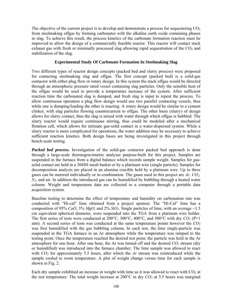
The objective of the current project is to develop and demonstrate a process for sequestering CO2 from steelmaking offgas by forming carbonates with the alkaline earth oxide containing phases in slag. To achieve this result, the process kinetics of the carbonate formation reaction must be improved to allow the design of a commercially feasible reactor. This reactor will contact stack exhaust gas with fresh or minimally processed slag allowing rapid sequestration of the CO2 and stabilization of the slag.
Experimental Study Of Carbonate Formation In Steelmaking Slag
Two different types of reactor design concepts (packed bed and slurry process) were proposed for contacting steelmaking slag and offgas. The first concept (packed bed) is a solid-gas contactor with either plug flow or rotary design. In this system the stack offgas would be directed through an atmospheric pressure rated vessel containing slag particles. Only the sensible heat of the offgas would be used to provide a temperature increase of the system. After sufficient reaction time the carbonated slag is dumped, and fresh slag is input to repeat the process. To allow continuous operation a plug flow design would use two parallel contacting vessels, thus while one is dumping/loading the other is reacting. A rotary design would be similar to a cement clinker, with slag particles flowing countercurrent to offgas. The other basis (slurry) of design allows for slurry contact, thus the slag is mixed with water through which offgas is bubbled. The slurry reactor would require continuous stirring, thus could be modeled after a mechanical flotation cell, which allows for intimate gas-solid contact in a water-dispersed system. While a slurry reactor is more complicated for operations, the water addition may be necessary to achieve sufficient reaction kinetics. Both design bases are being investigated in this project through bench-scale testing. Packed bed process. Investigation of the solid-gas contactor packed bed approach is done through a large-scale thermogravimetric analyzer purpose-built for this project. Samples are suspended in the furnace from a digital balance which records sample weight. Samples for gas-solid contact are held in a 304SS mesh basket or by a platinum wire (single particle). Samples for decomposition analysis are placed in an alumina crucible held by a platinum wire. Up to three gases can be metered individually or in combination. The gases used in this project are Ar, CO2, N2, and air. In addition the introduced gas can be humidified by bubbling through a heated water column. Weight and temperature data are collected to a computer through a portable data acquisition system. Baseline testing to determine the effect of temperature and humidity on carbonation rate was conducted with “Hi-cal” lime obtained from a project sponsor. The “Hi-Cal” lime has a composition of 95% CaO, 3% MgO, and 2% SiO2. Single particles of lime, with an average ~1.5 cm equivalent spherical diameter, were suspended into the TGA from a platinum wire holder. The first series of tests were conducted at 200°C, 300°C, 400°C, and 500°C with dry CO2 (P=1 atm). A second series of tests was conducted at the same temperature points however the CO2 was first humidified with the gas bubbling column. In each test, the lime single-particle was suspended in the TGA furnace in an Ar atmosphere while the temperature was ramped to the testing point. Once the temperature reached the desired test point, the particle was held in the Ar atmosphere for one hour. After one hour, the Ar was turned off and the desired CO2 stream (dry or humidified) was introduced into the furnace chamber. The lime sample was allowed to react with CO2 for approximately 5.5 hours, after which the Ar stream was reintroduced while the sample cooled to room temperature. A plot of weight change versus time for each sample is shown in Fig. 2. Each dry sample exhibited an increase in weight with time as it was allowed to react with CO2 at the test temperature. The total weight increase at 200°C in dry CO2 at 5.5 hours was marginal
198
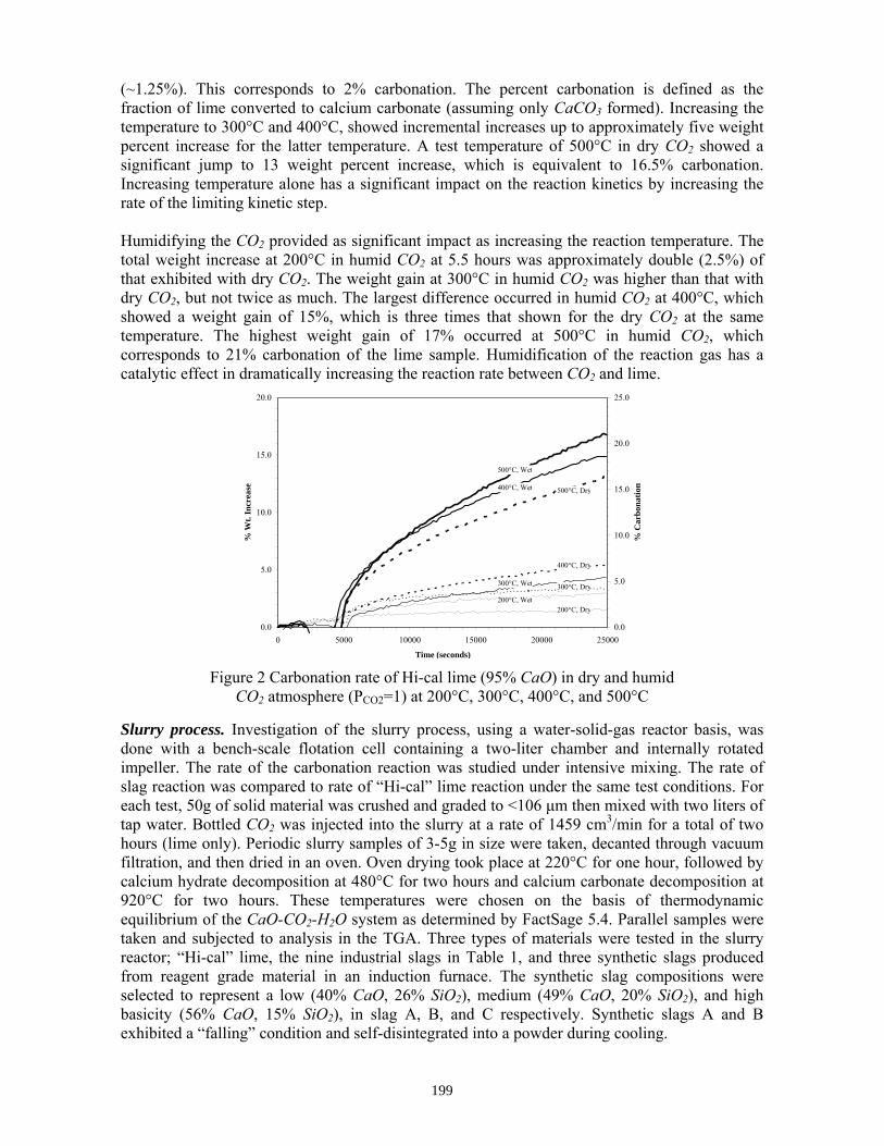
(~1.25%). This corresponds to 2% carbonation. The percent carbonation is defined as the fraction of lime converted to calcium carbonate (assuming only CaCO3 formed). Increasing the temperature to 300°C and 400°C, showed incremental increases up to approximately five weight percent increase for the latter temperature. A test temperature of 500°C in dry CO2 showed a significant jump to 13 weight percent increase, which is equivalent to 16.5% carbonation. Increasing temperature alone has a significant impact on the reaction kinetics by increasing the rate of the limiting kinetic step. Humidifying the CO2 provided as significant impact as increasing the reaction temperature. The total weight increase at 200°C in humid CO2 at 5.5 hours was approximately double (2.5%) of that exhibited with dry CO2. The weight gain at 300°C in humid CO2 was higher than that with dry CO2, but not twice as much. The largest difference occurred in humid CO2 at 400°C, which showed a weight gain of 15%, which is three times that shown for the dry CO2 at the same temperature. The highest weight gain of 17% occurred at 500°C in humid CO2, which corresponds to 21% carbonation of the lime sample. Humidification of the reaction gas has a catalytic effect in dramatically increasing the reaction rate between CO2 and lime.
0.0
5.0
10.0
15.0
20.0
0 5000 10000 15000 20000 25000
Time (seconds)
% W
t. In
crea
se
0.0
5.0
10.0
15.0
20.0
25.0
% C
arbo
natio
n
200°C, Dry
300°C, Dry
400°C, Dry
500°C, Dry
200°C, Wet
300°C, Wet
400°C, Wet
500°C, Wet
Figure 2 Carbonation rate of Hi-cal lime (95% CaO) in dry and humid CO2 atmosphere (PCO2=1) at 200°C, 300°C, 400°C, and 500°C
Slurry process. Investigation of the slurry process, using a water-solid-gas reactor basis, was done with a bench-scale flotation cell containing a two-liter chamber and internally rotated impeller. The rate of the carbonation reaction was studied under intensive mixing. The rate of slag reaction was compared to rate of “Hi-cal” lime reaction under the same test conditions. For each test, 50g of solid material was crushed and graded to <106 μm then mixed with two liters of tap water. Bottled CO2 was injected into the slurry at a rate of 1459 cm3/min for a total of two hours (lime only). Periodic slurry samples of 3-5g in size were taken, decanted through vacuum filtration, and then dried in an oven. Oven drying took place at 220°C for one hour, followed by calcium hydrate decomposition at 480°C for two hours and calcium carbonate decomposition at 920°C for two hours. These temperatures were chosen on the basis of thermodynamic equilibrium of the CaO-CO2-H2O system as determined by FactSage 5.4. Parallel samples were taken and subjected to analysis in the TGA. Three types of materials were tested in the slurry reactor; “Hi-cal” lime, the nine industrial slags in Table 1, and three synthetic slags produced from reagent grade material in an induction furnace. The synthetic slag compositions were selected to represent a low (40% CaO, 26% SiO2), medium (49% CaO, 20% SiO2), and high basicity (56% CaO, 15% SiO2), in slag A, B, and C respectively. Synthetic slags A and B exhibited a “falling” condition and self-disintegrated into a powder during cooling.
199
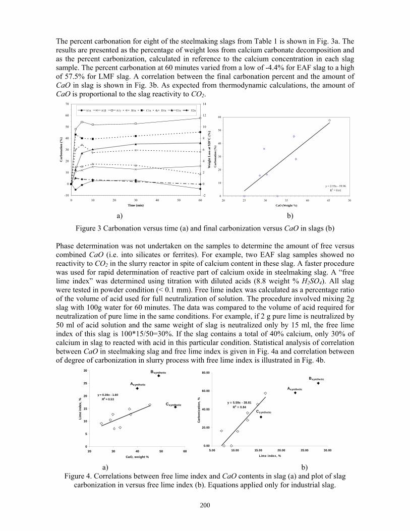
The percent carbonation for eight of the steelmaking slags from Table 1 is shown in Fig. 3a. The results are presented as the percentage of weight loss from calcium carbonate decomposition and as the percent carbonization, calculated in reference to the calcium concentration in each slag sample. The percent carbonation at 60 minutes varied from a low of -4.4% for EAF slag to a high of 57.5% for LMF slag. A correlation between the final carbonation percent and the amount of CaO in slag is shown in Fig. 3b. As expected from thermodynamic calculations, the amount of CaO is proportional to the slag reactivity to CO2.
-10
0
10
20
30
40
50
60
70
0 10 20 30 40 50 60Time (min)
Car
bona
tion
(%)
-2
0
2
4
6
8
10
12
14
Wei
ght L
oss a
t 920
°C (%
)
A1α A1β A1γ B1α C1α D1α E1α E2α
y = 2.55x - 59.96R2 = 0.61
0
10
20
30
40
50
60
20 25 30 35 40 45 50
CaO (Weight %)
Car
bona
tion
(%)
a) b)
Figure 3 Carbonation versus time (a) and final carbonization versus CaO in slags (b)
Phase determination was not undertaken on the samples to determine the amount of free versus combined CaO (i.e. into silicates or ferrites). For example, two EAF slag samples showed no reactivity to CO2 in the slurry reactor in spite of calcium content in these slag. A faster procedure was used for rapid determination of reactive part of calcium oxide in steelmaking slag. A “free lime index” was determined using titration with diluted acids (8.8 weight % H2SO4). All slag were tested in powder condition (< 0.1 mm). Free lime index was calculated as a percentage ratio of the volume of acid used for full neutralization of solution. The procedure involved mixing 2g slag with 100g water for 60 minutes. The data was compared to the volume of acid required for neutralization of pure lime in the same conditions. For example, if 2 g pure lime is neutralized by 50 ml of acid solution and the same weight of slag is neutralized only by 15 ml, the free lime index of this slag is 100*15/50=30%. If the slag contains a total of 40% calcium, only 30% of calcium in slag to reacted with acid in this particular condition. Statistical analysis of correlation between CaO in steelmaking slag and free lime index is given in Fig. 4a and correlation between of degree of carbonization in slurry process with free lime index is illustrated in Fig. 4b.
y = 0.39x - 1.60R2 = 0.53
0
5
10
15
20
25
30
20 30 40 50 60
CaO, weight %
Lim
e in
dex,
%
Asynthetic
Bsynthetic
Csyntheticy = 5.59x - 38.81
R2 = 0.84
0.00
20.00
40.00
60.00
80.00
5.00 10.00 15.00 20.00 25.00 30.00
Lime index, %
Carb
oniz
atio
n, %
Asynthetic
Bsynthetic
Csynthetic
a) b)
Figure 4. Correlations between free lime index and CaO contents in slag (a) and plot of slag carbonization in versus free lime index (b). Equations applied only for industrial slag.
200
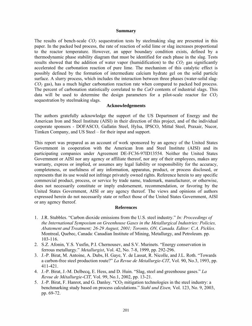
Summary
The results of bench-scale CO2 sequestration tests by steelmaking slag are presented in this paper. In the packed bed process, the rate of reaction of solid lime or slag increases proportional to the reactor temperature. However, an upper boundary condition exists, defined by a thermodynamic phase stability diagram that must be identified for each phase in the slag. Tests results showed that the addition of water vapor (humidification) to the CO2 gas significantly accelerated the carbonation reaction of pure lime. The mechanism of this catalytic effect is possibly defined by the formation of intermediate calcium hydrate gel on the solid particle surface. A slurry process, which includes the interaction between three phases (water-solid slag-CO2 gas), has a much higher carbonation reaction rate when compared to packed bed process. The percent of carbonation statistically correlated to the CaO contents of industrial slags. This data will be used to determine the design parameters for a pilot-scale reactor for CO2 sequestration by steelmaking slags.
Acknowledgements
The authors gratefully acknowledge the support of the US Department of Energy and the American Iron and Steel Institute (AISI) in their direction of this project, and of the individual corporate sponsors - DOFASCO, Gallatin Steel, Hylsa, IPSCO, Mittal Steel, Praxair, Nucor, Timken Company, and US Steel – for their input and support. This report was prepared as an account of work sponsored by an agency of the United States Government in cooperation with the American Iron and Steel Institute (AISI) and its participating companies under Agreement DE-FC36-97ID13554. Neither the United States Government or AISI nor any agency or affiliate thereof, nor any of their employees, makes any warranty, express or implied, or assumes any legal liability or responsibility for the accuracy, completeness, or usefulness of any information, apparatus, product, or process disclosed, or represents that its use would not infringe privately owned rights. Reference herein to any specific commercial product, process, or service by trade name, trademark, manufacturer, or otherwise, does not necessarily constitute or imply endorsement, recommendation, or favoring by the United States Government, AISI or any agency thereof. The views and opinions of authors expressed herein do not necessarily state or reflect those of the United States Government, AISI or any agency thereof.
References
1. J.R. Stubbles. “Carbon dioxide emissions from the U.S. steel industry.” In: Proceedings of the International Symposium on Greenhouse Gases in the Metallurgical Industries: Policies, Abatement and Treatment; 26-29 August, 2001; Toronto, ON, Canada. Editor: C.A. Pickles. Montreal, Quebec, Canada: Canadian Institute of Mining, Metallurgy, and Petroleum. pp. 103-116.
2. S.Z. Afonin, Y.S. Yusfin, P.I. Chernousev, and S.V. Murinets. “Energy conservation in ferrous metallurgy.” Metallurgist, Vol. 42, No. 7-8, 1999, pp. 292-296.
3. J.-P. Birat, M. Antoine, A. Dubs, H. Gaye, Y. de Lassat, R. Nicolle, and J.L. Roth. “Towards a carbon-free steel production route?” La Revue de Metallurgie-CIT, Vol. 90, No.3, 1993, pp. 411-421.
4. J.-P. Birat, J.-M. Delbecq, E. Hess, and D. Huin. “Slag, steel and greenhouse gases.” La Revue de Métallurgie-CIT, Vol. 99, No.1, 2002, pp. 13-21.
5. J.-P. Birat, F. Hanrot, and G. Danloy. “CO2 mitigation technologies in the steel industry: a benchmarking study based on process calculations.” Stahl und Eisen, Vol. 123, No. 9, 2003, pp. 69-72.
201
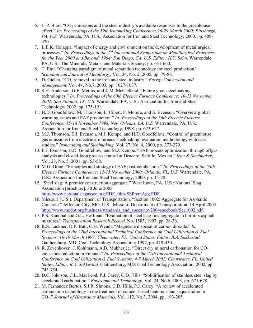
6. J.-P. Birat. “CO2 emissions and the steel industry’s available responses to the greenhouse effect.” In: Proceedings of the 59th Ironmaking Conference; 26-29 March 2000; Pittsburgh, PA, U.S. Warrendale, PA, U.S.: Association for Iron and Steel Technology; 2000. pp. 409-420.
7. L.E.K. Holappa. “Impact of energy and environment on the development of metallurgical processes.” In: Proceedings of the 2nd International Symposium on Metallurgical Processes for the Year 2000 and Beyond; 1994; San Diego, CA, U.S. Editor: H.Y. Sohn. Warrendale, PA, U.S.: The Minerals, Metals, and Materials Society. pp. 641-660.
8. T. Emi. “Changing paradigm of metal separation technology for steel production.” Scandinavian Journal of Metallurgy, Vol. 34, No. 2, 2005, pp. 79-88.
9. D. Gielen. “CO2 removal in the iron and steel industry.” Energy Conversion and Management, Vol. 44, No.7, 2003, pp. 1027-1037.
10. S.H. Anderson, G.E. Metius, and J. M. McClelland. “Future green steelmaking technologies.” In: Proceedings of the 60th Electric Furnace Conference; 10-13 November 2002; San Antonio, TX, U.S. Warrendale, PA, U.S.: Association for Iron and Steel Technology; 2002. pp. 175-191.
11. H.D. Goodfellow, M. Thomson, L. Cibert, P. Morere, and E. Evenson. “Overview global warming issues and EAF production.” In: Proceedings of the 56th Electric Furnace Conference; 15-18 November 1998, New Orleans, LA, U.S. Warrendale, PA, U.S.: Association for Iron and Steel Technology; 1998. pp. 623-627.
12. M.J. Thomson, E.J. Evenson, M.J. Kempe, and H.D. Goodfellow. “Control of greenhouse gas emissions from electric arc furnace steelmaking: evaluation methodology with case studies.” Ironmaking and Steelmaking, Vol. 27, No. 4, 2000, pp. 273-279.
13. E.J. Evenson, H.D. Goodfellow, and M.J. Kempe. “EAF process optimization through offgas analysis and closed-loop process control at Deacero, Saltillo, Mexico.” Iron & Steelmaker, Vol. 28, No. 5, 2001, pp. 53-58.
14. M.G. Grant. “Principles and strategy of EAF post-combustion.” In: Proceedings of the 58th Electric Furnace Conference; 12-15 November 2000; Orlando, FL, U.S. Warrendale, PA, U.S.: Association for Iron and Steel Technology; 2000. pp. 15-28.
15. “Steel slag: A premier construction aggregate.” West Lawn, PA, U.S.: National Slag Association [brochure]. 30 June 2005 http://www.nationalslagassoc.org/PDF_files/SSPremAgg.PDF.
16. Missouri (U.S.). Department of Transportation. “Section 1002: Aggregate for Asphaltic Concrete.” Jefferson City, MO, U.S.: Missouri Department of Transportation. 14 April 2004 http://www.modot.org/business/standards_and_specs/nov2004specbook/Sec1002.pdf.
17. P.S. Kandhal and G.L. Hoffman. “Evaluation of steel slag fine aggregate in hot-mix asphalt mixtures.” Transportation Research Record, No. 1583, 1997, pp. 28-36.
18. K.S. Lackner, D.P. Butt, C.H. Wendt. “Magnesite disposal of carbon dioxide.” In: Proceedings of the 22nd International Technical Conference on Coal Utilization & Fuel Systems; 16-19 March 1997; Clearwater, FL, United States. Editor, B.A. Sakkestad. Gaithersburg, MD: Coal Technology Association; 1997, pp. 419-430.
19. R. Zevenhoven, J. Kohlmann, A.B. Mukherjee. “Direct dry mineral carbonation for CO2 emissions reduction in Finland.” In: Proceedings of the 27th International Technical Conference on Coal Utilization & Fuel Systems; 4-7 March 2002; Clearwater, FL, United States. Editor, B.A. Sakkestad. Gaithersburg, MD: Coal Technology Association; 2002, pp. 743-754.
20. D.C. Johnson, C.L. MacLeod, P.J. Carey, C.D. Hills. “Solidification of stainless steel slag by accelerated carbonation.” Environmental Technology, Vol. 24, No.6, 2003, pp. 671-678.
21. M. Fernández Bertos, S.J.R. Simons, C.D. Hills, P.J. Carey. “A review of accelerated carbonation technology in the treatment of cement-based materials and sequestration of CO2.” Journal of Hazardous Materials, Vol. 112, No.3, 2004, pp. 193-205.
202
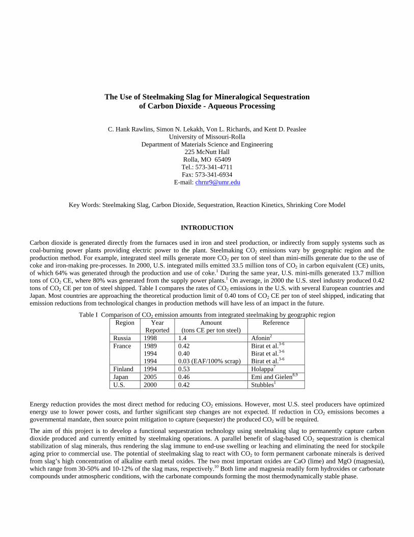
The Use of Steelmaking Slag for Mineralogical Sequestration of Carbon Dioxide - Aqueous Processing
C. Hank Rawlins, Simon N. Lekakh, Von L. Richards, and Kent D. Peaslee University of Missouri-Rolla
Department of Materials Science and Engineering 225 McNutt Hall Rolla, MO 65409
Tel.: 573-341-4711 Fax: 573-341-6934
E-mail: [email protected]
Key Words: Steelmaking Slag, Carbon Dioxide, Sequestration, Reaction Kinetics, Shrinking Core Model
INTRODUCTION Carbon dioxide is generated directly from the furnaces used in iron and steel production, or indirectly from supply systems such as coal-burning power plants providing electric power to the plant. Steelmaking CO2 emissions vary by geographic region and the production method. For example, integrated steel mills generate more CO2 per ton of steel than mini-mills generate due to the use of coke and iron-making pre-processes. In 2000, U.S. integrated mills emitted 33.5 million tons of CO2 in carbon equivalent (CE) units, of which 64% was generated through the production and use of coke.1 During the same year, U.S. mini-mills generated 13.7 million tons of CO2 CE, where 80% was generated from the supply power plants.1 On average, in 2000 the U.S. steel industry produced 0.42 tons of CO2 CE per ton of steel shipped. Table I compares the rates of CO2 emissions in the U.S. with several European countries and Japan. Most countries are approaching the theoretical production limit of 0.40 tons of CO2 CE per ton of steel shipped, indicating that emission reductions from technological changes in production methods will have less of an impact in the future.
Table I Comparison of CO2 emission amounts from integrated steelmaking by geographic region Region Year
Reported Amount
(tons CE per ton steel) Reference
Russia 1998 1.4 Afonin2
France 1989 0.42 Birat et al.3-6
1994 0.40 Birat et al.3-6
1994 0.03 (EAF/100% scrap) Birat et al.3-6
Finland 1994 0.53 Holappa7
Japan 2005 0.46 Emi and Gielen8,9
U.S. 2000 0.42 Stubbles1
Energy reduction provides the most direct method for reducing CO2 emissions. However, most U.S. steel producers have optimized energy use to lower power costs, and further significant step changes are not expected. If reduction in CO2 emissions becomes a governmental mandate, then source point mitigation to capture (sequester) the produced CO2 will be required.
The aim of this project is to develop a functional sequestration technology using steelmaking slag to permanently capture carbon dioxide produced and currently emitted by steelmaking operations. A parallel benefit of slag-based CO2 sequestration is chemical stabilization of slag minerals, thus rendering the slag immune to end-use swelling or leaching and eliminating the need for stockpile aging prior to commercial use. The potential of steelmaking slag to react with CO2 to form permanent carbonate minerals is derived from slag’s high concentration of alkaline earth metal oxides. The two most important oxides are CaO (lime) and MgO (magnesia), which range from 30-50% and 10-12% of the slag mass, respectively.10 Both lime and magnesia readily form hydroxides or carbonate compounds under atmospheric conditions, with the carbonate compounds forming the most thermodynamically stable phase.

Previous work has shown that the slag produced during steelmaking has the potential of sequestering 5.0-10% of the BF-BOF CO2 emissions and 28-34% of EAF carbon dioxide emissions. In addition, the estimated 15-20 kg of LMF slag produced per ton of steel has the potential of capturing an additional 1.0-1.3% of BOF and 7.8-10.4% of EAF CO2 emissions. Thus, the total sequestration potential for steelmaking slag is 6-11% of the CO2 emitted from integrated mills and 35-45% emitted from scrap-based steelmakers.11 A furnace offgas CO2 capture and sequestration system will most likely be installed after the baghouse to prevent contamination of the slag with baghouse dust. At this point offgas conditions at this point have been estimated to be 90-150°C, with a peak CO2 concentration of 10-11 vol.% and an average of 4-5 vol.%.10
Two different designs are being tested for a slag-offgas reactor. The first design is a dry process using a plug flow or rotary reactor as detailed previously.10 The second design is the focus of the current study and includes a wet process whereby slag is mixed with water to form a slurry through which offgas is bubbled. A two-stage system allows for aqueous dissolution of the alkaline oxides in the first stage, followed by a reaction of the resultant aqueous liquor with CO2 in a separate vessel or location. Compared with a dry system, wet processing has a much higher CO2 reaction rate, thus allowing for a smaller reactor vessel. In addition, catalytic agents such as carbonic anhydrase may be added to form an aqueous biomimetic process that has been shown to provide more tan two orders of magnitude increase in mineral carbonate formation in experiments for wet industrial CO2 scrubbers.12
EXPERIMENTAL METHOD
To assess the feasibility of carbon dioxide sequestration with steelmaking slag, a series of experiments was undertaken to measure the kinetic reaction rate in an aqueous system. Three industrial slag samples were obtained from the project partners. Table III lists the slag compositions as determined by X-ray fluorescence (XRF) spectroscopy. Slag #1 is from an EAF mill and contains 32.1% CaO. Slags #2 and #3 are LMF slags from EAF mills and contain higher CaO content plus a Al2O3/SiO2 in proportion to their respective steel deoxidation method. Steelmaking slag contains very little free lime (CaO) or free magnesia (MgO), thus these compounds cannot be considered in the pure state. Predominately CaO and MgO are present as silicate, aluminate, or ferrite phases. X-ray diffraction (XRD) phase analysis has shown that the slags listed in Table II contain primarily dicalcium silicate (Ca2SiO4) and tricalcium silicate (Ca3SiO5) with lesser amounts of akermanite (Ca2MgSi2O7), C12A7 (Ca12Al14O33), clinoenstatite (MgSiO3), and magnesio-wustite (MgFeO2), and a few percent periclase (MgO) and lime. Small amounts of free alumina (Al2O3), wustite (FeO), and silica (SiO2) have been found, but these do not contribute to carbon dioxide sequestration.
Table II Compositions of steelmaking slags used in the aqueous
kinetics tests (in wt.%) as determined by XRF spectroscopy Oxides #1 (EAF) #2 (LMF)
Al-Killed #3 (LMF) Si-Killed
CaO 32.1 49.9 51.3 SiO2 19.4 4.5 28.3 Al2O3 8.6 32.3 4.9 TiO2 0.4 0.3 0.3 MgO 9.4 4.3 4.3 MnO 6.8 0.8 1.3 Fe2O3 26.4 6.3 5.5 SO3 0.6 1.0 1.6 Vratio 1.7 1.4 1.5
All slag samples were obtained in 40-50 pound lots from steel plant stockpiles. The slags were obtained prior to on-site processing (<24 hours after production) in order to ensure minimal reaction with local ambient conditions. Slags #1 and #2 were crushed in a laboratory jaw crusher followed by a roll crusher to pass a 6-mesh sieve size (3.35 mm). Slag #3 is a falling slag, thus self-comminuted, and was used in the raw condition. Figure 1 shows the particle size analysis of slags #1 and #2 after crushing, along with Slag #3 in the raw state. Particle size analysis was obtained using a U.S. mesh series of 8” sieves on a vibratory shaker.
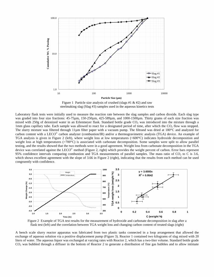
1.0
10.0
100.0
10 100 1000 10000
Particle Size (µm)
Cum
ulat
ive
Wt.
% P
assi
ng
Slag #1Slag #2Slag #3
Figure 1 Particle size analysis of crushed (slags #1 & #2) and raw
steelmaking slag (Slag #3) samples used in the aqueous kinetics tests Laboratory flask tests were initially used to measure the reaction rate between the slag samples and carbon dioxide. Each slag type was graded into four size fractions: 45-75µm, 150-250µm, 425-589µm, and 1000-1500µm. Thirty grams of each size fraction was mixed with 250g of deionized water in an Erlenmeyer flask. Standard bottle grade CO2 was introduced into the mixture through a 1mm glass capillary tube. Each sample was allowed to react for a designated period of time, after which the CO2 flow was stopped. The slurry mixture was filtered through 11µm filter paper with a vacuum pump. The filtrand was dried at 180°C and analyzed for carbon content with a LECO© carbon analyzer (combustion/IR) and/or a thermogravimetric analysis (TGA) device. An example of TGA analysis is given in Figure 2 (left), where weight loss at low temperatures (<600°C) indicates hydroxide decomposition and weight loss at high temperatures (>700°C) is associated with carbonate decomposition. Some samples were split to allow parallel testing, and the results showed that the two methods were in a good agreement. Weight loss from carbonate decomposition in the TGA device was correlated against the LECO© method (Figure 2, right) which provides the weight percent of carbon. Error bars represent 95% confidence intervals comparing combustion and TGA measurements of parallel samples. The mass ratio of CO2 to C is 3.6, which shows excellent agreement with the slope of 3.66 in Figure 2 (right), indicating that the results from each method can be used congruently with confidence.
-4.0
-3.5
-3.0
-2.5
-2.0
-1.5
-1.0
-0.5
0.0
0.5
1.0 1.5 2.0 2.5 3.0 3.5
Time (hr)
Wei
ght C
hang
e (%
)
300
400
500
600
700
800
900
1000
Tem
pera
ture
(°C)
Weight
Temperature
y = 3.6593xR2 = 0.9542
0
0.5
1
1.5
2
2.5
3
3.5
0 0.2 0.4 0.6 0.8
C (weight %)
TGA
wei
ght l
oss
(wei
ght %
)
1
Figure 2 Example of TGA test results for the measurement of hydroxide and carbonate decomposition in slag after a
flask test (left) and the correlation between TGA weight loss and changing carbon content of treated slags (right) A bench scale slurry reactor apparatus was fabricated from two plastic tanks connected in a loop arrangement that allowed the exchange of aqueous solution via a positive displacement pump (Figure 3). Reactor 1 contained two kilograms of slag mixed with 20 liters of water. The aqueous liquor was exchanged at varying rates with Reactor 2, which has a two-liter volume. Standard bottle grade CO2 was bubbled through a diffuser in the bottom of Reactor 2 to generate a distribution of fine gas bubbles and to allow intimate
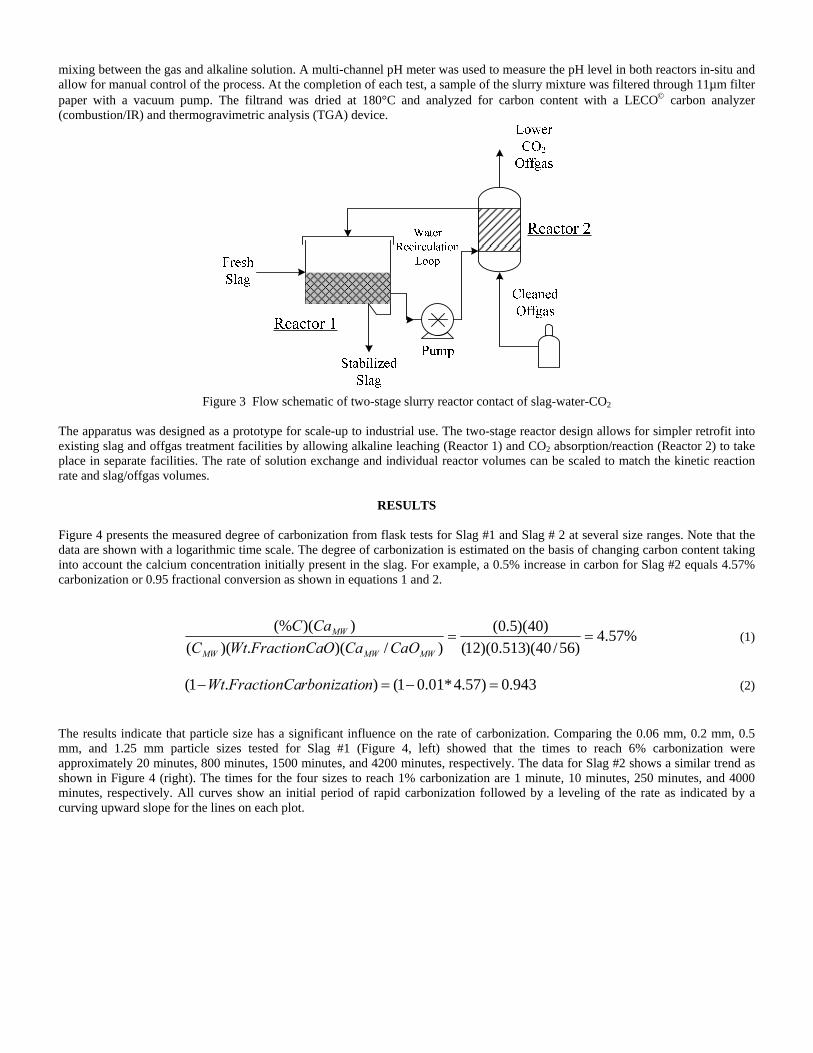
mixing between the gas and alkaline solution. A multi-channel pH meter was used to measure the pH level in both reactors in-situ and allow for manual control of the process. At the completion of each test, a sample of the slurry mixture was filtered through 11µm filter paper with a vacuum pump. The filtrand was dried at 180°C and analyzed for carbon content with a LECO© carbon analyzer (combustion/IR) and thermogravimetric analysis (TGA) device.
Figure 3 Flow schematic of two-stage slurry reactor contact of slag-water-CO2
The apparatus was designed as a prototype for scale-up to industrial use. The two-stage reactor design allows for simpler retrofit into existing slag and offgas treatment facilities by allowing alkaline leaching (Reactor 1) and CO2 absorption/reaction (Reactor 2) to take place in separate facilities. The rate of solution exchange and individual reactor volumes can be scaled to match the kinetic reaction rate and slag/offgas volumes.
RESULTS Figure 4 presents the measured degree of carbonization from flask tests for Slag #1 and Slag # 2 at several size ranges. Note that the data are shown with a logarithmic time scale. The degree of carbonization is estimated on the basis of changing carbon content taking into account the calcium concentration initially present in the slag. For example, a 0.5% increase in carbon for Slag #2 equals 4.57% carbonization or 0.95 fractional conversion as shown in equations 1 and 2.
%57.4)56/40)(513.0)(12(
)40)(5.0()/)(.)((
))((%==
MWMWMW
MW
CaOCaOFractionCaWtCCaC
(1)
943.0)57.4*01.01().1( =−=− nrbonizatioFractionCaWt (2)
The results indicate that particle size has a significant influence on the rate of carbonization. Comparing the 0.06 mm, 0.2 mm, 0.5 mm, and 1.25 mm particle sizes tested for Slag #1 (Figure 4, left) showed that the times to reach 6% carbonization were approximately 20 minutes, 800 minutes, 1500 minutes, and 4200 minutes, respectively. The data for Slag #2 shows a similar trend as shown in Figure 4 (right). The times for the four sizes to reach 1% carbonization are 1 minute, 10 minutes, 250 minutes, and 4000 minutes, respectively. All curves show an initial period of rapid carbonization followed by a leveling of the rate as indicated by a curving upward slope for the lines on each plot.
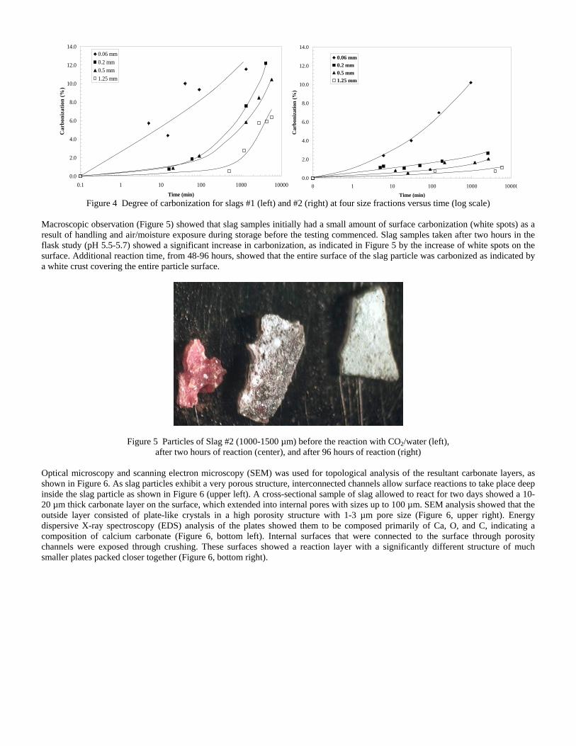
0.0
2.0
4.0
6.0
8.0
10.0
12.0
14.0
0.1 1 10 100 1000 10000
Time (min)
Car
boni
zatio
n (%
)0.06 mm0.2 mm0.5 mm1.25 mm
0.0
2.0
4.0
6.0
8.0
10.0
12.0
14.0
0 1 10 100 1000 10000Time (min)
Car
boni
zatio
n (%
)
0.06 mm0.2 mm0.5 mm1.25 mm
Figure 4 Degree of carbonization for slags #1 (left) and #2 (right) at four size fractions versus time (log scale)
Macroscopic observation (Figure 5) showed that slag samples initially had a small amount of surface carbonization (white spots) as a result of handling and air/moisture exposure during storage before the testing commenced. Slag samples taken after two hours in the flask study (pH 5.5-5.7) showed a significant increase in carbonization, as indicated in Figure 5 by the increase of white spots on the surface. Additional reaction time, from 48-96 hours, showed that the entire surface of the slag particle was carbonized as indicated by a white crust covering the entire particle surface.
Figure 5 Particles of Slag #2 (1000-1500 µm) before the reaction with CO2/water (left), after two hours of reaction (center), and after 96 hours of reaction (right)
Optical microscopy and scanning electron microscopy (SEM) was used for topological analysis of the resultant carbonate layers, as shown in Figure 6. As slag particles exhibit a very porous structure, interconnected channels allow surface reactions to take place deep inside the slag particle as shown in Figure 6 (upper left). A cross-sectional sample of slag allowed to react for two days showed a 10-20 µm thick carbonate layer on the surface, which extended into internal pores with sizes up to 100 µm. SEM analysis showed that the outside layer consisted of plate-like crystals in a high porosity structure with 1-3 µm pore size (Figure 6, upper right). Energy dispersive X-ray spectroscopy (EDS) analysis of the plates showed them to be composed primarily of Ca, O, and C, indicating a composition of calcium carbonate (Figure 6, bottom left). Internal surfaces that were connected to the surface through porosity channels were exposed through crushing. These surfaces showed a reaction layer with a significantly different structure of much smaller plates packed closer together (Figure 6, bottom right).

Figure 6 Optical image from Slag #2 (400-500 µm particle after 48 hours reaction time) showing the cross section of the internal pore structure (upper left), and SEM image showing the external surface carbonate layer (upper right)
along with EDS analysis (bottom left), and the internal surface (pore) carbonate layer (bottom right)
A shrinking core model for heterogeneous reactions was used for analysis of experimental flask data and to determine the rate-limiting mechanism.13 The three possible mechanisms include the reaction of the calcium at the slag surface with the aqueous carbonic acid ions (HCO3
- and CO32-), mass transport of the aqueous carbonic acid ions through the boundary layer, or diffusion through the porous
product layer (CaCO3) on the slag particle surface. Figure 7 shows the time required to achieve the same fractional conversion (8% carbonization) for different size fractions of Slag #1. The fractional conversion is heavily controlled by the particle size, and a linear approximation shows proportionality to the square root of time, indicating that product layer diffusion is the controlling rate step. The layer of calcium carbonate that forms on the surface retards the diffusion of both the alkaline ions to the slag particle surface and the carbonic acid ions into the slag particle. When the diffusion of the reactant through the product layer is limiting, Equations 3 shows the dependence on the molar transport of bulk fluid reactant A (-dNA/dt, mol/sec) through the product layer of a particle with surface area 4πr2 (r is radius in cm) and effective diffusivity De (cm²/s).13 The term CA (mol/cm³) is the concentration of the reactant, which is a function of radius. At the radius of the unreacted core CA is zero, while at the outer radius of the product layer (in contact with surrounding fluid), CA is the concentration of the reactant ions in the bulk fluid. The gradient can be assumed fixed as the volume of the bulk fluid is much more than that of the particle, and with stirring of the fresh fluid is constantly being delivered to the particle surface.
))(4( 2
drdCDr
dtdN A
eA −=
− π (3)
Given a constant gradient of bulk reactant A (carbonic acid ion) and constant effective diffusivity, the time to deliver a fixed number of moles of bulk reactant A (carbonic acid ion) through the product layer (CaCO3) is proportional to the square of the radius.
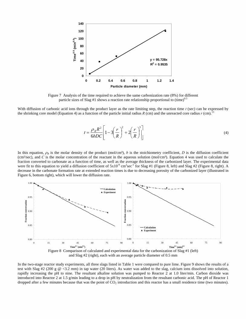
y = 95.728xR2 = 0.9535
0
20
40
60
80
100
120
140
0 0.2 0.4 0.6 0.8 1 1.2 1.4
Particle diameter (mm)
Tim
e0.5 (m
in0.
5 )
Figure 7 Analysis of the time required to achieve the same carbonization rate (8%) for different
particle sizes of Slag #1 shows a reaction rate relationship proportional to (time)0.5
With diffusion of carbonic acid ions through the product layer as the rate limiting step, the reaction time t (sec) can be expressed by the shrinking core model (Equation 4) as a function of the particle initial radius R (cm) and the unreacted core radius r (cm).13
⎥⎥⎦
⎤
⎢⎢⎣
⎡⎟⎠⎞
⎜⎝⎛+⎟
⎠⎞
⎜⎝⎛−=
322
2316 R
rRr
bDCRt Bρ (4)
In this equation, ρB is the molar density of the product (mol/cm³), b is the stoichiometry coefficient, D is the diffusion coefficient (cm²/sec), and C is the molar concentration of the reactant in the aqueous solution (mol/cm³). Equation 4 was used to calculate the fraction converted to carbonate as a function of time, as well as the average thickness of the carbonized layer. The experimental data were fit to this equation to yield a diffusion coefficient of 5x10⁻⁹ cm2sec-1 for Slag #1 (Figure 8, left) and Slag #2 (Figure 8, right). A decrease in the carbonate formation rate at extended reaction times is due to decreasing porosity of the carbonized layer (illustrated in Figure 6, bottom right), which will lower the diffusion rate.
0.80
0.85
0.90
0.95
1.00
0 15 30 45 60 75 90
Time0.5 (min0.5)
Frac
tion
conv
ersa
tion
CalculationExperiment
0.80
0.85
0.90
0.95
1.00
0 15 30 45 60 75 90
Time0.5 (min)0.5
Frac
tion
conv
ersa
tion
CalculationExperiment
Figure 8 Comparison of calculated and experimental data for the carbonization of Slag #1 (left)
and Slag #2 (right), each with an average particle diameter of 0.5 mm In the two-stage reactor study experiments, all three slags listed in Table 1 were compared to pure lime. Figure 9 shows the results of a test with Slag #2 (200 g @ <3.2 mm) in tap water (20 liters). As water was added to the slag, calcium ions dissolved into solution, rapidly increasing the pH to nine. The resultant alkaline solution was pumped to Reactor 2 at 1.0 liter/min. Carbon dioxide was introduced into Reactor 2 at 1.5 g/min leading to a drop in pH by neutralization from the resultant carbonic acid. The pH of Reactor 1 dropped after a few minutes because that was the point of CO2 introduction and this reactor has a small residence time (two minutes).
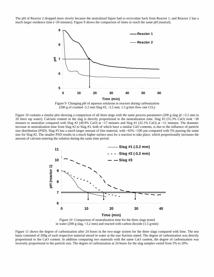
The pH of Reactor 2 dropped more slowly because the neutralized liquor had to recirculate back from Reactor 1, and Reactor 2 has a much larger residence time (~20 minutes). Figure 9 shows the comparison of times to reach the same pH (neutral).
5
6
7
8
9
0 10 20 30 40 50 6
Time (min)
pH
0
Reactor 1
Reactor 2
Figure 9 Changing pH of aqueous solutions in reactors during carbonization
(200 g of crushed -3.2 mm Slag #2, -3.2 mm, 1.5 g/min flow rate CO2) Figure 10 contains a similar plot showing a comparison of all three slags with the same process parameters (200 g slag @ <3.2 mm in 20 liters tap water). Calcium content in the slag is directly proportional to the neutralization time. Slag #3 (51.3% CaO) took ~30 minutes to neutralize compared with Slag #2 (49.9% CaO) at ~17 minutes and Slag #1 (32.1% CaO) at ~11 minutes. The dramatic increase in neutralization time from Slag #2 to Slag #3, both of which have a similar CaO contents, is due to the influence of particle size distribution (PSD). Slag #3 has a much larger amount of fine material, with ~65% <100 µm compared with 5% passing the same size for Slag #2. The smaller PSD results in a much higher surface area for a reaction to take place, which proportionally increases the amount of calcium entering the solution during the same time period.
6
7
8
9
10
11
0 10 20 30 4
Time (min)
pH (r
eact
or 1
)
0
Slag #1 (-3.2 mm)
Slag #2 (-3.2 mm)
Slag #3
Figure 10 Comparison of neutralization time for the three slags tested
in water (200 g slag, <3.2 mm) and reacted with carbon dioxide (1.5 g/min) Figure 11 shows the degree of carbonization after 24 hours in the two-stage system for the three slags compared with lime. The test basis consisted of 200g of each respective material mixed in water at the size fraction stated. The degree of carbonization was directly proportional to the CaO content. In addition comparing two materials with the same CaO content, the degree of carbonization was inversely proportional to the particle size. The degree of carbonization at 24 hours for the slag samples varied from 5% to 20%.
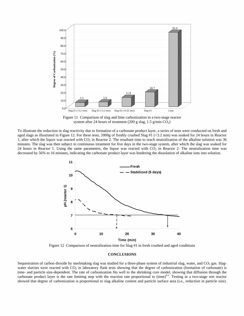
5.5 5.9
11.8
18.7
95.0
0.0
10.0
20.0
30.0
40.0
50.0
60.0
70.0
80.0
90.0
100.0
Deg
ree
of C
arbo
niza
tion
(%)
Slag #1 (<3.2 mm) Slag #2 (<3.2 mm) Slag #2 (<0.25 mm) Slag #3 Lime
Figure 11 Comparison of slag and lime carbonization in a two-stage reactor system after 24 hours of treatment (200 g slag, 1.5 g/min CO2)
To illustrate the reduction in slag reactivity due to formation of a carbonate product layer, a series of tests were conducted on fresh and aged slags as illustrated in Figure 12. For these tests, 2000g of freshly crushed Slag #1 (<3.2 mm) was soaked for 24 hours in Reactor 1, after which the liquor was reacted with CO2 in Reactor 2. The resultant time to reach neutralization of the alkaline solution was 36 minutes. The slag was then subject to continuous treatment for five days in the two-stage system, after which the slag was soaked for 24 hours in Reactor 1. Using the same parameters, the liquor was reacted with CO2 in Reactor 2. The neutralization time was decreased by 56% to 16 minutes, indicating the carbonate product layer was hindering the dissolution of alkaline ions into solution.
6
7
8
9
10
11
0 10 20 30 4
Time (min)
pH (r
eact
or 1
)
0
FreshStabilized (5 days)
Figure 12 Comparison of neutralization time for Slag #1 in fresh crushed and aged conditions
CONCLUSIONS
Sequestration of carbon dioxide by steelmaking slag was studied for a three-phase system of industrial slag, water, and CO2 gas. Slag-water slurries were reacted with CO2 in laboratory flask tests showing that the degree of carbonization (formation of carbonate) is time- and particle size-dependent. The rate of carbonization fits well to the shrinking core model, showing that diffusion through the carbonate product layer is the rate limiting step with the reaction rate proportional to (time)0.5. Testing in a two-stage wet reactor showed that degree of carbonization is proportional to slag alkaline content and particle surface area (i.e., reduction in particle size).
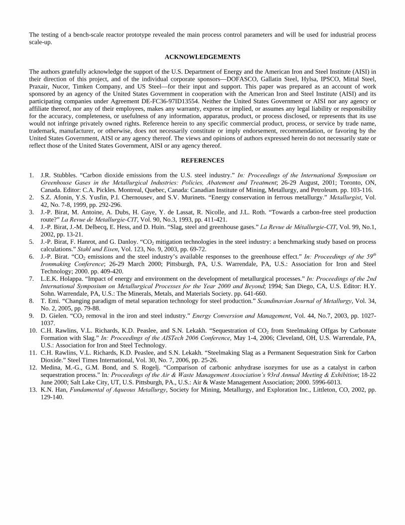
The testing of a bench-scale reactor prototype revealed the main process control parameters and will be used for industrial process scale-up.
ACKNOWLEDGEMENTS The authors gratefully acknowledge the support of the U.S. Department of Energy and the American Iron and Steel Institute (AISI) in their direction of this project, and of the individual corporate sponsors—DOFASCO, Gallatin Steel, Hylsa, IPSCO, Mittal Steel, Praxair, Nucor, Timken Company, and US Steel—for their input and support. This paper was prepared as an account of work sponsored by an agency of the United States Government in cooperation with the American Iron and Steel Institute (AISI) and its participating companies under Agreement DE-FC36-97ID13554. Neither the United States Government or AISI nor any agency or affiliate thereof, nor any of their employees, makes any warranty, express or implied, or assumes any legal liability or responsibility for the accuracy, completeness, or usefulness of any information, apparatus, product, or process disclosed, or represents that its use would not infringe privately owned rights. Reference herein to any specific commercial product, process, or service by trade name, trademark, manufacturer, or otherwise, does not necessarily constitute or imply endorsement, recommendation, or favoring by the United States Government, AISI or any agency thereof. The views and opinions of authors expressed herein do not necessarily state or reflect those of the United States Government, AISI or any agency thereof.
REFERENCES 1. J.R. Stubbles. “Carbon dioxide emissions from the U.S. steel industry.” In: Proceedings of the International Symposium on
Greenhouse Gases in the Metallurgical Industries: Policies, Abatement and Treatment; 26-29 August, 2001; Toronto, ON, Canada. Editor: C.A. Pickles. Montreal, Quebec, Canada: Canadian Institute of Mining, Metallurgy, and Petroleum. pp. 103-116.
2. S.Z. Afonin, Y.S. Yusfin, P.I. Chernousev, and S.V. Murinets. “Energy conservation in ferrous metallurgy.” Metallurgist, Vol. 42, No. 7-8, 1999, pp. 292-296.
3. J.-P. Birat, M. Antoine, A. Dubs, H. Gaye, Y. de Lassat, R. Nicolle, and J.L. Roth. “Towards a carbon-free steel production route?” La Revue de Metallurgie-CIT, Vol. 90, No.3, 1993, pp. 411-421.
4. J.-P. Birat, J.-M. Delbecq, E. Hess, and D. Huin. “Slag, steel and greenhouse gases.” La Revue de Métallurgie-CIT, Vol. 99, No.1, 2002, pp. 13-21.
5. J.-P. Birat, F. Hanrot, and G. Danloy. “CO2 mitigation technologies in the steel industry: a benchmarking study based on process calculations.” Stahl und Eisen, Vol. 123, No. 9, 2003, pp. 69-72.
6. J.-P. Birat. “CO2 emissions and the steel industry’s available responses to the greenhouse effect.” In: Proceedings of the 59th Ironmaking Conference; 26-29 March 2000; Pittsburgh, PA, U.S. Warrendale, PA, U.S.: Association for Iron and Steel Technology; 2000. pp. 409-420.
7. L.E.K. Holappa. “Impact of energy and environment on the development of metallurgical processes.” In: Proceedings of the 2nd International Symposium on Metallurgical Processes for the Year 2000 and Beyond; 1994; San Diego, CA, U.S. Editor: H.Y. Sohn. Warrendale, PA, U.S.: The Minerals, Metals, and Materials Society. pp. 641-660.
8. T. Emi. “Changing paradigm of metal separation technology for steel production.” Scandinavian Journal of Metallurgy, Vol. 34, No. 2, 2005, pp. 79-88.
9. D. Gielen. “CO2 removal in the iron and steel industry.” Energy Conversion and Management, Vol. 44, No.7, 2003, pp. 1027-1037.
10. C.H. Rawlins, V.L. Richards, K.D. Peaslee, and S.N. Lekakh. “Sequestration of CO2 from Steelmaking Offgas by Carbonate Formation with Slag.” In: Proceedings of the AISTech 2006 Conference, May 1-4, 2006; Cleveland, OH, U.S. Warrendale, PA, U.S.: Association for Iron and Steel Technology.
11. C.H. Rawlins, V.L. Richards, K.D. Peaslee, and S.N. Lekakh. “Steelmaking Slag as a Permanent Sequestration Sink for Carbon Dioxide.” Steel Times International, Vol. 30, No. 7, 2006, pp. 25-26.
12. Medina, M.-G., G.M. Bond, and S. Rogelj. “Comparison of carbonic anhydrase isozymes for use as a catalyst in carbon sequestration process.” In: Proceedings of the Air & Waste Management Association’s 93rd Annual Meeting & Exhibition; 18-22 June 2000; Salt Lake City, UT, U.S. Pittsburgh, PA., U.S.: Air & Waste Management Association; 2000. 5996-6013.
13. K.N. Han, Fundamental of Aqueous Metallurgy, Society for Mining, Metallurgy, and Exploration Inc., Littleton, CO, 2002, pp. 129-140.
Mineralogical Sequestration of Carbon Dioxide through Aqueous Processing
of Steelmaking Slag
C.H. Rawlins, S.N. Lekakh, V.L. Richards, and K.D. Peaslee
University of Missouri-Rolla
Department of Materials Science and Engineering
Rolla, MO USA
Keywords: Steelmaking Slag, CO2, Sequestration, Kinetics, Shrinking Core Model
Abstract
Sequestration of carbon dioxide by steelmaking slag was studied for a three-phase system
of industrial slag, water, and CO2 gas. Slag-water slurries were reacted with CO2 in laboratory
batch tests showing that the degree of carbonization (formation of carbonate) is time and particle
size-dependent. The rate of carbonization fits well to the shrinking core model, showing that
diffusion through the carbonate product layer is the rate limiting step with the reaction rate
proportional to the square root of time. Testing in a two-stage wet reactor showed that degree of
carbonization is proportional to slag alkaline content and particle surface area (i.e., reduction in
particle size).
Introduction
Carbon dioxide is generated directly from the furnaces used for iron and steel production,
and indirectly from the electrical supply source, such as coal-burning power plants, which
provide power to the mills. Steelmaking CO2 emissions vary based on the production method.
For example, integrated steel mills generate more CO2 per ton of steel than mini-mills due to the
use of coke and iron-making pre-processes. In 2000, U.S. integrated mills emitted 33.5 million
tons of CO2 in carbon equivalent (CE) units, of which 64% was generated through the production
and use of coke[1]. During the same year, U.S. mini-mills generated 13.7 million tons of CO2
CE, where 80% was generated from the supply power plants[1]. In 2000, the U.S. steel industry
produced an average of 0.42 tons of CO2 CE per ton of steel shipped approaching the theoretical
CO2 generation theoretical minimum of 0.40 tons CE per ton of steel. Energy reduction provides
the most direct method for reducing CO2 emissions. However, most U.S. steel producers have
optimized energy use to lower power costs, and further significant step changes are not expected.
If reduction in CO2 emissions becomes a governmental mandate, then source point mitigation to
capture (sequester) the produced CO2 will be required.
The aim of this project is to develop a functional sequestration system using steelmaking
slag to permanently capture carbon dioxide emitted in steelmaking offgas. A parallel benefit of
slag-based CO2 sequestration is chemical stabilization of the slag compounds subject to swelling.
The stabilized slag is rendered immune to end-use swelling or leaching, thus eliminating the
need for stockpile aging prior to commercial use.
The potential of steelmaking slag to react with CO2 to form permanent carbonate
compounds is derived from slag’s high concentration of alkaline earth metal oxides. The two
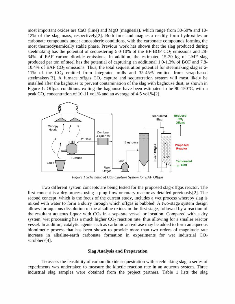
most important oxides are CaO (lime) and MgO (magnesia), which range from 30-50% and 10-
12% of the slag mass, respectively[2]. Both lime and magnesia readily form hydroxides or
carbonate compounds under atmospheric conditions, with the carbonate compounds forming the
most thermodynamically stable phase. Previous work has shown that the slag produced during
steelmaking has the potential of sequestering 5.0-10% of the BF-BOF CO2 emissions and 28-
34% of EAF carbon dioxide emissions. In addition, the estimated 15-20 kg of LMF slag
produced per ton of steel has the potential of capturing an additional 1.0-1.3% of BOF and 7.8-
10.4% of EAF CO2 emissions. Thus, the total sequestration potential for steelmaking slag is 6-
11% of the CO2 emitted from integrated mills and 35-45% emitted from scrap-based
steelmakers[3]. A furnace offgas CO2 capture and sequestration system will most likely be
installed after the baghouse to prevent contamination of the slag with baghouse dust, as shown in
Figure 1. Offgas conditions exiting the baghouse have been estimated to be 90-150°C, with a
peak CO2 concentration of 10-11 vol.% and an average of 4-5 vol.%[2].
Furnace
Ladle
Canopy
Hoods
4th Hole
Fans
Baghouse
Cle
an
Off
ga
s
Granulated
Slag
Reduced
CO2
Offgas
Carbonated
SlagRaw
Offgas
Combust
& Quench
Proposed
Reactor
Figure 1 Schematic of CO2 Capture System for EAF Offgas
Two different system concepts are being tested for the proposed slag-offgas reactor. The
first concept is a dry process using a plug flow or rotary reactor as detailed previously[2]. The
second concept, which is the focus of the current study, includes a wet process whereby slag is
mixed with water to form a slurry through which offgas is bubbled. A two-stage system design
allows for aqueous dissolution of the alkaline oxides in the first stage, followed by a reaction of
the resultant aqueous liquor with CO2 in a separate vessel or location. Compared with a dry
system, wet processing has a much higher CO2 reaction rate, thus allowing for a smaller reactor
vessel. In addition, catalytic agents such as carbonic anhydrase may be added to form an aqueous
biomimetic process that has been shown to provide more than two orders of magnitude rate
increase in alkaline-earth carbonate formation in experiments for wet industrial CO2
scrubbers[4].
Slag Analysis and Preparation
To assess the feasibility of carbon dioxide sequestration with steelmaking slag, a series of
experiments was undertaken to measure the kinetic reaction rate in an aqueous system. Three
industrial slag samples were obtained from the project partners. Table 1 lists the slag
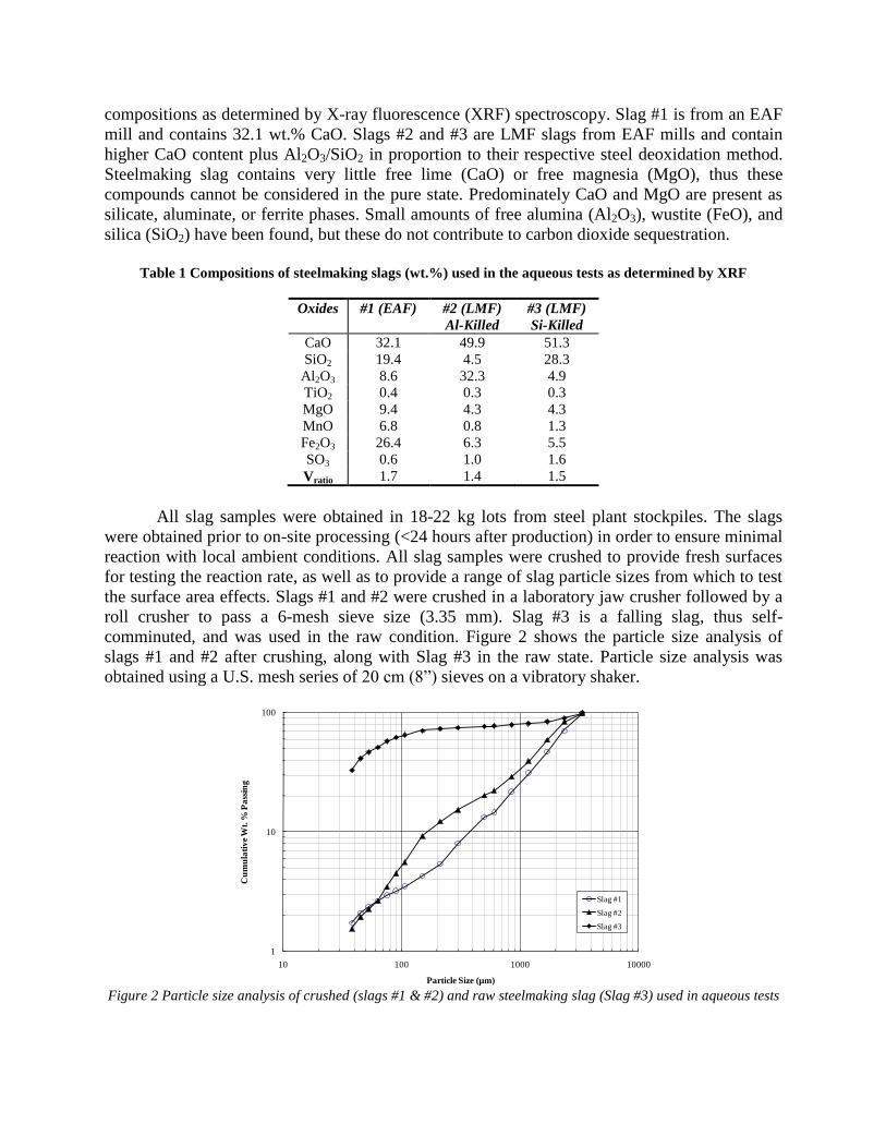
compositions as determined by X-ray fluorescence (XRF) spectroscopy. Slag #1 is from an EAF
mill and contains 32.1 wt.% CaO. Slags #2 and #3 are LMF slags from EAF mills and contain
higher CaO content plus Al2O3/SiO2 in proportion to their respective steel deoxidation method.
Steelmaking slag contains very little free lime (CaO) or free magnesia (MgO), thus these
compounds cannot be considered in the pure state. Predominately CaO and MgO are present as
silicate, aluminate, or ferrite phases. Small amounts of free alumina (Al2O3), wustite (FeO), and
silica (SiO2) have been found, but these do not contribute to carbon dioxide sequestration.
Table 1 Compositions of steelmaking slags (wt.%) used in the aqueous tests as determined by XRF
Oxides #1 (EAF) #2 (LMF)
Al-Killed
#3 (LMF)
Si-Killed
CaO 32.1 49.9 51.3
SiO2 19.4 4.5 28.3
Al2O3 8.6 32.3 4.9
TiO2 0.4 0.3 0.3
MgO 9.4 4.3 4.3
MnO 6.8 0.8 1.3
Fe2O3 26.4 6.3 5.5
SO3 0.6 1.0 1.6
Vratio 1.7 1.4 1.5
All slag samples were obtained in 18-22 kg lots from steel plant stockpiles. The slags
were obtained prior to on-site processing (<24 hours after production) in order to ensure minimal
reaction with local ambient conditions. All slag samples were crushed to provide fresh surfaces
for testing the reaction rate, as well as to provide a range of slag particle sizes from which to test
the surface area effects. Slags #1 and #2 were crushed in a laboratory jaw crusher followed by a
roll crusher to pass a 6-mesh sieve size (3.35 mm). Slag #3 is a falling slag, thus self-
comminuted, and was used in the raw condition. Figure 2 shows the particle size analysis of
slags #1 and #2 after crushing, along with Slag #3 in the raw state. Particle size analysis was
obtained using a U.S. mesh series of 20 cm (8”) sieves on a vibratory shaker.
1
10
100
10 100 1000 10000
Cu
mu
lati
ve
Wt.
% P
ass
ing
Particle Size (µm)
Slag #1
Slag #2
Slag #3
Figure 2 Particle size analysis of crushed (slags #1 & #2) and raw steelmaking slag (Slag #3) used in aqueous tests
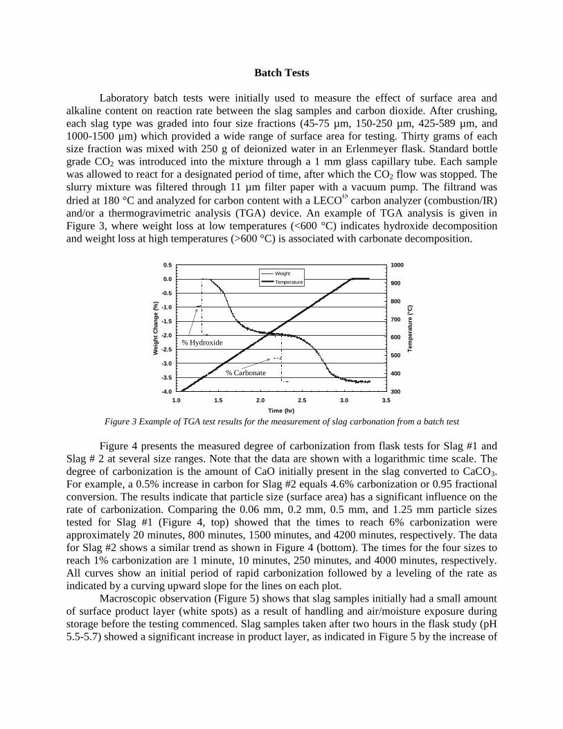
Batch Tests
Laboratory batch tests were initially used to measure the effect of surface area and
alkaline content on reaction rate between the slag samples and carbon dioxide. After crushing,
each slag type was graded into four size fractions (45-75 µm, 150-250 µm, 425-589 µm, and
1000-1500 µm) which provided a wide range of surface area for testing. Thirty grams of each
size fraction was mixed with 250 g of deionized water in an Erlenmeyer flask. Standard bottle
grade CO2 was introduced into the mixture through a 1 mm glass capillary tube. Each sample
was allowed to react for a designated period of time, after which the CO2 flow was stopped. The
slurry mixture was filtered through 11 µm filter paper with a vacuum pump. The filtrand was
dried at 180 °C and analyzed for carbon content with a LECO carbon analyzer (combustion/IR)
and/or a thermogravimetric analysis (TGA) device. An example of TGA analysis is given in
Figure 3, where weight loss at low temperatures (<600 °C) indicates hydroxide decomposition
and weight loss at high temperatures (>600 °C) is associated with carbonate decomposition.
Sample 100B3, 1.66 l/min Dry Ar, T=920°C, 5°C/min ramp rate
-4.0
-3.5
-3.0
-2.5
-2.0
-1.5
-1.0
-0.5
0.0
0.5
1.0 1.5 2.0 2.5 3.0 3.5
Time (hr)
Weig
ht
Ch
an
ge (
%)
300
400
500
600
700
800
900
1000
Tem
pera
ture
(°C
)
Weight
Temperature
% Hydroxide
% Carbonate
Figure 3 Example of TGA test results for the measurement of slag carbonation from a batch test
Figure 4 presents the measured degree of carbonization from flask tests for Slag #1 and
Slag # 2 at several size ranges. Note that the data are shown with a logarithmic time scale. The
degree of carbonization is the amount of CaO initially present in the slag converted to CaCO3.
For example, a 0.5% increase in carbon for Slag #2 equals 4.6% carbonization or 0.95 fractional
conversion. The results indicate that particle size (surface area) has a significant influence on the
rate of carbonization. Comparing the 0.06 mm, 0.2 mm, 0.5 mm, and 1.25 mm particle sizes
tested for Slag #1 (Figure 4, top) showed that the times to reach 6% carbonization were
approximately 20 minutes, 800 minutes, 1500 minutes, and 4200 minutes, respectively. The data
for Slag #2 shows a similar trend as shown in Figure 4 (bottom). The times for the four sizes to
reach 1% carbonization are 1 minute, 10 minutes, 250 minutes, and 4000 minutes, respectively.
All curves show an initial period of rapid carbonization followed by a leveling of the rate as
indicated by a curving upward slope for the lines on each plot.
Macroscopic observation (Figure 5) shows that slag samples initially had a small amount
of surface product layer (white spots) as a result of handling and air/moisture exposure during
storage before the testing commenced. Slag samples taken after two hours in the flask study (pH
5.5-5.7) showed a significant increase in product layer, as indicated in Figure 5 by the increase of
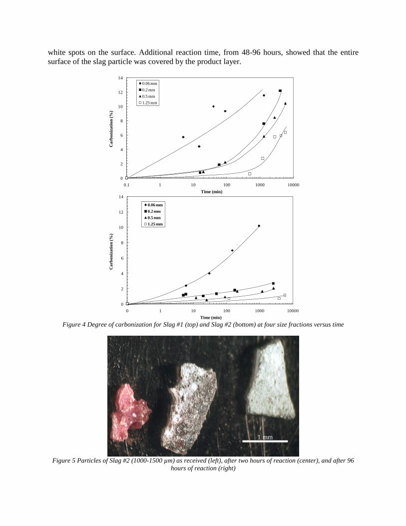
white spots on the surface. Additional reaction time, from 48-96 hours, showed that the entire
surface of the slag particle was covered by the product layer.
0
2
4
6
8
10
12
14
0.1 1 10 100 1000 10000
Ca
rbo
niz
ati
on
(%
)
Time (min)
0.06 mm
0.2 mm
0.5 mm
1.25 mm
0
2
4
6
8
10
12
14
0 1 10 100 1000 10000
Ca
rbo
niz
ati
on
(%
)
Time (min)
0.06 mm
0.2 mm
0.5 mm
1.25 mm
Figure 4 Degree of carbonization for Slag #1 (top) and Slag #2 (bottom) at four size fractions versus time
Figure 5 Particles of Slag #2 (1000-1500 µm) as received (left), after two hours of reaction (center), and after 96
hours of reaction (right)
1 mm
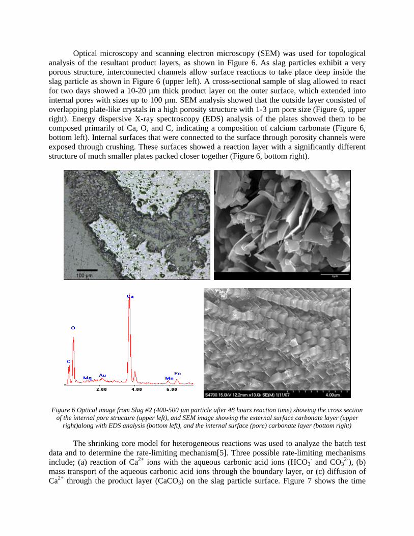
Optical microscopy and scanning electron microscopy (SEM) was used for topological
analysis of the resultant product layers, as shown in Figure 6. As slag particles exhibit a very
porous structure, interconnected channels allow surface reactions to take place deep inside the
slag particle as shown in Figure 6 (upper left). A cross-sectional sample of slag allowed to react
for two days showed a 10-20 µm thick product layer on the outer surface, which extended into
internal pores with sizes up to 100 µm. SEM analysis showed that the outside layer consisted of
overlapping plate-like crystals in a high porosity structure with 1-3 µm pore size (Figure 6, upper
right). Energy dispersive X-ray spectroscopy (EDS) analysis of the plates showed them to be
composed primarily of Ca, O, and C, indicating a composition of calcium carbonate (Figure 6,
bottom left). Internal surfaces that were connected to the surface through porosity channels were
exposed through crushing. These surfaces showed a reaction layer with a significantly different
structure of much smaller plates packed closer together (Figure 6, bottom right).
Figure 6 Optical image from Slag #2 (400-500 µm particle after 48 hours reaction time) showing the cross section
of the internal pore structure (upper left), and SEM image showing the external surface carbonate layer (upper
right)along with EDS analysis (bottom left), and the internal surface (pore) carbonate layer (bottom right)
The shrinking core model for heterogeneous reactions was used to analyze the batch test
data and to determine the rate-limiting mechanism[5]. Three possible rate-limiting mechanisms
include; (a) reaction of Ca2+
ions with the aqueous carbonic acid ions (HCO3- and CO3
2-), (b)
mass transport of the aqueous carbonic acid ions through the boundary layer, or (c) diffusion of
Ca2+
through the product layer (CaCO3) on the slag particle surface. Figure 7 shows the time
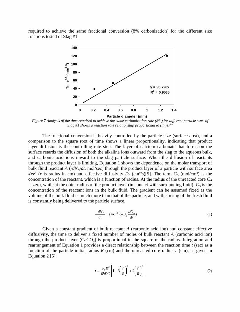
required to achieve the same fractional conversion (8% carbonization) for the different size
fractions tested of Slag #1.
y = 95.728x
R2 = 0.9535
0
20
40
60
80
100
120
140
0 0.2 0.4 0.6 0.8 1 1.2 1.4
Particle diameter (mm)
Tim
e0
.5 (
min
0.5
)
Figure 7 Analysis of the time required to achieve the same carbonization rate (8%) for different particle sizes of
Slag #1 shows a reaction rate relationship proportional to (time)0.5
The fractional conversion is heavily controlled by the particle size (surface area), and a
comparison to the square root of time shows a linear proportionality, indicating that product
layer diffusion is the controlling rate step. The layer of calcium carbonate that forms on the
surface retards the diffusion of both the alkaline ions outward from the slag to the aqueous bulk,
and carbonic acid ions inward to the slag particle surface. When the diffusion of reactants
through the product layer is limiting, Equation 1 shows the dependence on the molar transport of
bulk fluid reactant A (-dNA/dt, mol/sec) through the product layer of a particle with surface area
4πr2 (r is radius in cm) and effective diffusivity De (cm²/s)[5]. The term CA (mol/cm³) is the
concentration of the reactant, which is a function of radius. At the radius of the unreacted core CA
is zero, while at the outer radius of the product layer (in contact with surrounding fluid), CA is the
concentration of the reactant ions in the bulk fluid. The gradient can be assumed fixed as the
volume of the bulk fluid is much more than that of the particle, and with stirring of the fresh fluid
is constantly being delivered to the particle surface.
))(4( 2
dr
dCDr
dt
dN Ae
A (1)
Given a constant gradient of bulk reactant A (carbonic acid ion) and constant effective
diffusivity, the time to deliver a fixed number of moles of bulk reactant A (carbonic acid ion)
through the product layer (CaCO3) is proportional to the square of the radius. Integration and
rearrangement of Equation 1 provides a direct relationship between the reaction time t (sec) as a
function of the particle initial radius R (cm) and the unreacted core radius r (cm), as given in
Equation 2 [5].
322
2316 R
r
R
r
bDC
Rρt B (2)
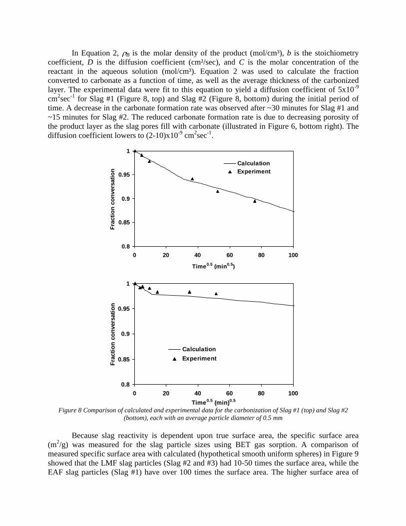
In Equation 2, B is the molar density of the product (mol/cm³), b is the stoichiometry
coefficient, D is the diffusion coefficient (cm²/sec), and C is the molar concentration of the
reactant in the aqueous solution (mol/cm³). Equation 2 was used to calculate the fraction
converted to carbonate as a function of time, as well as the average thickness of the carbonized
layer. The experimental data were fit to this equation to yield a diffusion coefficient of 5x10⁻⁹
cm2sec
-1 for Slag #1 (Figure 8, top) and Slag #2 (Figure 8, bottom) during the initial period of
time. A decrease in the carbonate formation rate was observed after ~30 minutes for Slag #1 and
~15 minutes for Slag #2. The reduced carbonate formation rate is due to decreasing porosity of
the product layer as the slag pores fill with carbonate (illustrated in Figure 6, bottom right). The
diffusion coefficient lowers to (2-10)x10-9
cm2sec
-1.
0.8
0.85
0.9
0.95
1
0 20 40 60 80 100
Time0.5 (min0.5)
Fra
cti
on
co
nvers
ati
on
Calculation
Experiment
0.8
0.85
0.9
0.95
1
0 20 40 60 80 100
Time0.5 (min)0.5
Fra
cti
on
co
nvers
ati
on
Calculation
Experiment
Figure 8 Comparison of calculated and experimental data for the carbonization of Slag #1 (top) and Slag #2
(bottom), each with an average particle diameter of 0.5 mm
Because slag reactivity is dependent upon true surface area, the specific surface area
(m2/g) was measured for the slag particle sizes using BET gas sorption. A comparison of
measured specific surface area with calculated (hypothetical smooth uniform spheres) in Figure 9
showed that the LMF slag particles (Slag #2 and #3) had 10-50 times the surface area, while the
EAF slag particles (Slag #1) have over 100 times the surface area. The higher surface area of
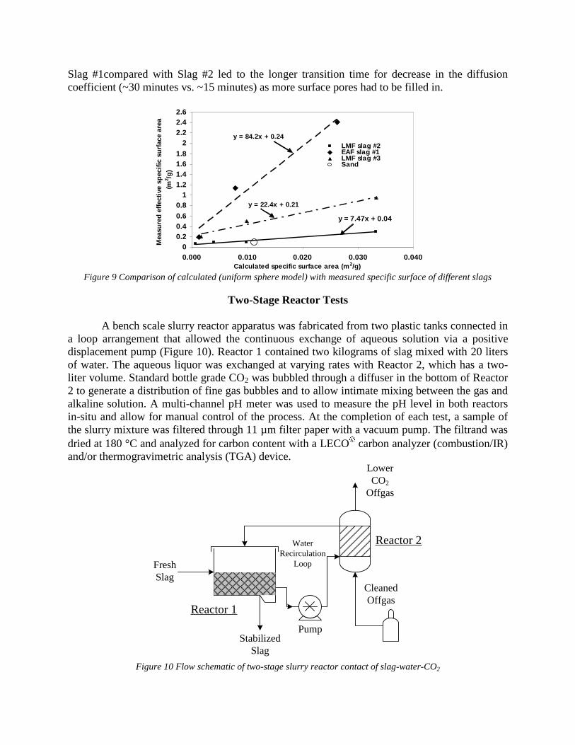
Slag #1compared with Slag #2 led to the longer transition time for decrease in the diffusion
coefficient (~30 minutes vs. ~15 minutes) as more surface pores had to be filled in.
y = 7.47x + 0.04
y = 84.2x + 0.24
y = 22.4x + 0.21
0
0.2
0.4
0.6
0.8
1
1.2
1.4
1.6
1.8
2
2.2
2.4
2.6
0.000 0.010 0.020 0.030 0.040
Calculated specific surface area (m2/g)
Measu
red
eff
ecti
ve s
pecif
ic s
urf
ace a
rea
(m2/g
)
LMF slag #2EAF slag #1LMF slag #3SandLinear (LMF slag #2)
Linear (LMF slag #3)
Figure 9 Comparison of calculated (uniform sphere model) with measured specific surface of different slags
Two-Stage Reactor Tests
A bench scale slurry reactor apparatus was fabricated from two plastic tanks connected in
a loop arrangement that allowed the continuous exchange of aqueous solution via a positive
displacement pump (Figure 10). Reactor 1 contained two kilograms of slag mixed with 20 liters
of water. The aqueous liquor was exchanged at varying rates with Reactor 2, which has a two-
liter volume. Standard bottle grade CO2 was bubbled through a diffuser in the bottom of Reactor
2 to generate a distribution of fine gas bubbles and to allow intimate mixing between the gas and
alkaline solution. A multi-channel pH meter was used to measure the pH level in both reactors
in-situ and allow for manual control of the process. At the completion of each test, a sample of
the slurry mixture was filtered through 11 µm filter paper with a vacuum pump. The filtrand was
dried at 180 °C and analyzed for carbon content with a LECO carbon analyzer (combustion/IR)
and/or thermogravimetric analysis (TGA) device.
Pump
Cleaned
Offgas
Reactor 2
Reactor 1
Stabilized
Slag
Fresh
Slag
Lower
CO2
Offgas
Water
Recirculation
Loop
Figure 10 Flow schematic of two-stage slurry reactor contact of slag-water-CO2
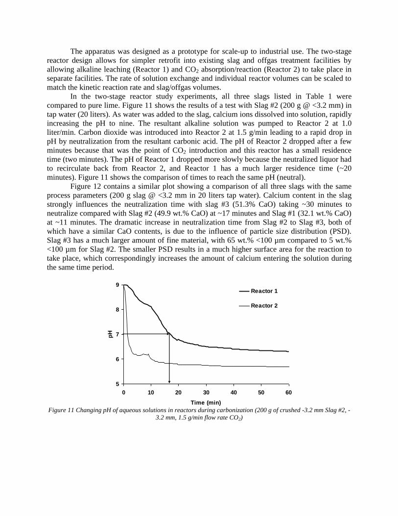
The apparatus was designed as a prototype for scale-up to industrial use. The two-stage
reactor design allows for simpler retrofit into existing slag and offgas treatment facilities by
allowing alkaline leaching (Reactor 1) and CO2 absorption/reaction (Reactor 2) to take place in
separate facilities. The rate of solution exchange and individual reactor volumes can be scaled to
match the kinetic reaction rate and slag/offgas volumes.
In the two-stage reactor study experiments, all three slags listed in Table 1 were
compared to pure lime. Figure 11 shows the results of a test with Slag #2 (200 g @ <3.2 mm) in
tap water (20 liters). As water was added to the slag, calcium ions dissolved into solution, rapidly
increasing the pH to nine. The resultant alkaline solution was pumped to Reactor 2 at 1.0
liter/min. Carbon dioxide was introduced into Reactor 2 at 1.5 g/min leading to a rapid drop in
pH by neutralization from the resultant carbonic acid. The pH of Reactor 2 dropped after a few
minutes because that was the point of CO2 introduction and this reactor has a small residence
time (two minutes). The pH of Reactor 1 dropped more slowly because the neutralized liquor had
to recirculate back from Reactor 2, and Reactor 1 has a much larger residence time (~20
minutes). Figure 11 shows the comparison of times to reach the same pH (neutral).
Figure 12 contains a similar plot showing a comparison of all three slags with the same
process parameters (200 g slag @ <3.2 mm in 20 liters tap water). Calcium content in the slag
strongly influences the neutralization time with slag #3 (51.3% CaO) taking ~30 minutes to
neutralize compared with Slag #2 (49.9 wt.% CaO) at ~17 minutes and Slag #1 (32.1 wt.% CaO)
at ~11 minutes. The dramatic increase in neutralization time from Slag #2 to Slag #3, both of
which have a similar CaO contents, is due to the influence of particle size distribution (PSD).
Slag #3 has a much larger amount of fine material, with 65 wt.% <100 µm compared to 5 wt.%
<100 µm for Slag #2. The smaller PSD results in a much higher surface area for the reaction to
take place, which correspondingly increases the amount of calcium entering the solution during
the same time period.
5
6
7
8
9
0 10 20 30 40 50 60
Time (min)
pH
Reactor 1
Reactor 2
Figure 11 Changing pH of aqueous solutions in reactors during carbonization (200 g of crushed -3.2 mm Slag #2, -
3.2 mm, 1.5 g/min flow rate CO2)
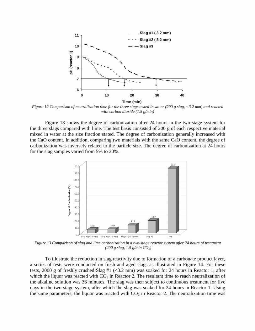
6
7
8
9
10
11
0 10 20 30 40
Time (min)
pH
(re
acto
r 1)
Slag #1 (-3.2 mm)
Slag #2 (-3.2 mm)
Slag #3
Figure 12 Comparison of neutralization time for the three slags tested in water (200 g slag, <3.2 mm) and reacted
with carbon dioxide (1.5 g/min)
Figure 13 shows the degree of carbonization after 24 hours in the two-stage system for
the three slags compared with lime. The test basis consisted of 200 g of each respective material
mixed in water at the size fraction stated. The degree of carbonization generally increased with
the CaO content. In addition, comparing two materials with the same CaO content, the degree of
carbonization was inversely related to the particle size. The degree of carbonization at 24 hours
for the slag samples varied from 5% to 20%.
5.5 5.9
11.8
18.7
95.0
0.0
10.0
20.0
30.0
40.0
50.0
60.0
70.0
80.0
90.0
100.0
Deg
ree o
f C
arb
on
iza
tio
n (
%)
Slag #1 (<3.2 mm) Slag #2 (<3.2 mm) Slag #2 (<0.25 mm) Slag #3 Lime
Figure 13 Comparison of slag and lime carbonization in a two-stage reactor system after 24 hours of treatment
(200 g slag, 1.5 g/min CO2)
To illustrate the reduction in slag reactivity due to formation of a carbonate product layer,
a series of tests were conducted on fresh and aged slags as illustrated in Figure 14. For these
tests, 2000 g of freshly crushed Slag #1 (<3.2 mm) was soaked for 24 hours in Reactor 1, after
which the liquor was reacted with CO2 in Reactor 2. The resultant time to reach neutralization of
the alkaline solution was 36 minutes. The slag was then subject to continuous treatment for five
days in the two-stage system, after which the slag was soaked for 24 hours in Reactor 1. Using
the same parameters, the liquor was reacted with CO2 in Reactor 2. The neutralization time was
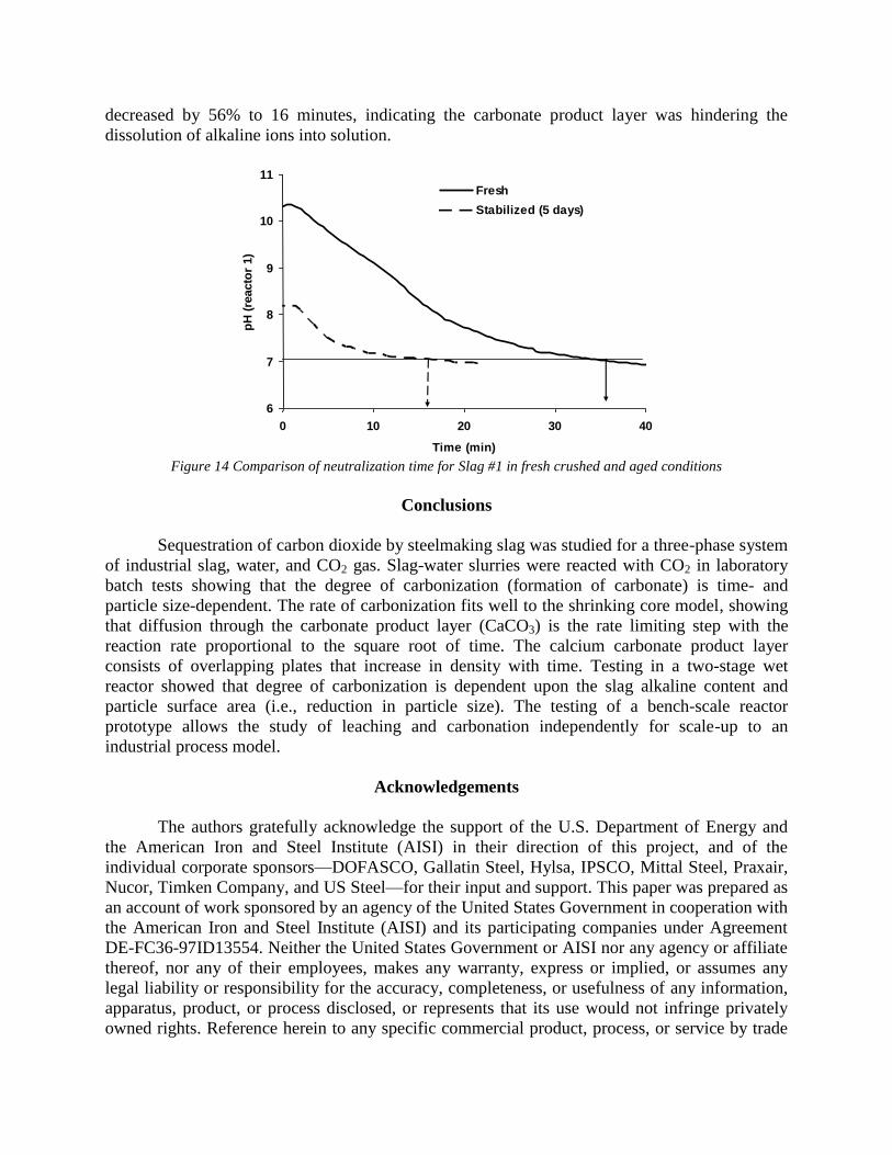
decreased by 56% to 16 minutes, indicating the carbonate product layer was hindering the
dissolution of alkaline ions into solution.
6
7
8
9
10
11
0 10 20 30 40
Time (min)
pH
(re
acto
r 1)
Fresh
Stabilized (5 days)
Figure 14 Comparison of neutralization time for Slag #1 in fresh crushed and aged conditions
Conclusions
Sequestration of carbon dioxide by steelmaking slag was studied for a three-phase system
of industrial slag, water, and CO2 gas. Slag-water slurries were reacted with CO2 in laboratory
batch tests showing that the degree of carbonization (formation of carbonate) is time- and
particle size-dependent. The rate of carbonization fits well to the shrinking core model, showing
that diffusion through the carbonate product layer (CaCO3) is the rate limiting step with the
reaction rate proportional to the square root of time. The calcium carbonate product layer
consists of overlapping plates that increase in density with time. Testing in a two-stage wet
reactor showed that degree of carbonization is dependent upon the slag alkaline content and
particle surface area (i.e., reduction in particle size). The testing of a bench-scale reactor
prototype allows the study of leaching and carbonation independently for scale-up to an
industrial process model.
Acknowledgements
The authors gratefully acknowledge the support of the U.S. Department of Energy and
the American Iron and Steel Institute (AISI) in their direction of this project, and of the
individual corporate sponsors—DOFASCO, Gallatin Steel, Hylsa, IPSCO, Mittal Steel, Praxair,
Nucor, Timken Company, and US Steel—for their input and support. This paper was prepared as
an account of work sponsored by an agency of the United States Government in cooperation with
the American Iron and Steel Institute (AISI) and its participating companies under Agreement
DE-FC36-97ID13554. Neither the United States Government or AISI nor any agency or affiliate
thereof, nor any of their employees, makes any warranty, express or implied, or assumes any
legal liability or responsibility for the accuracy, completeness, or usefulness of any information,
apparatus, product, or process disclosed, or represents that its use would not infringe privately
owned rights. Reference herein to any specific commercial product, process, or service by trade
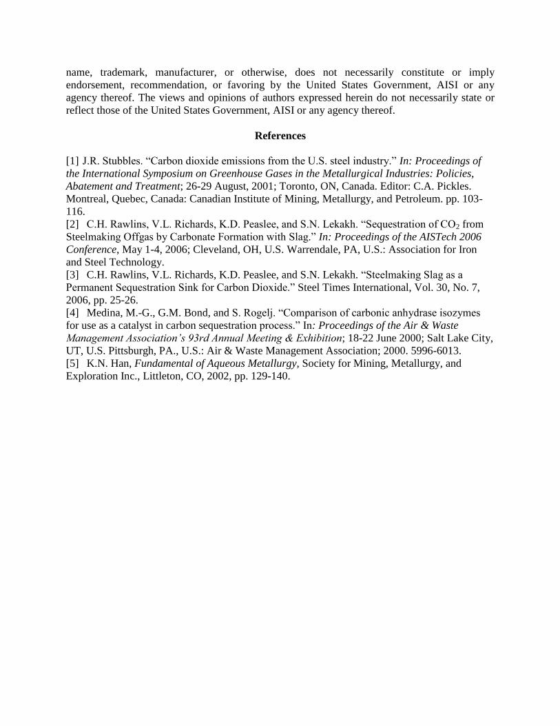
name, trademark, manufacturer, or otherwise, does not necessarily constitute or imply
endorsement, recommendation, or favoring by the United States Government, AISI or any
agency thereof. The views and opinions of authors expressed herein do not necessarily state or
reflect those of the United States Government, AISI or any agency thereof.
References
[1] J.R. Stubbles. “Carbon dioxide emissions from the U.S. steel industry.” In: Proceedings of
the International Symposium on Greenhouse Gases in the Metallurgical Industries: Policies,
Abatement and Treatment; 26-29 August, 2001; Toronto, ON, Canada. Editor: C.A. Pickles.
Montreal, Quebec, Canada: Canadian Institute of Mining, Metallurgy, and Petroleum. pp. 103-
116.
[2] C.H. Rawlins, V.L. Richards, K.D. Peaslee, and S.N. Lekakh. “Sequestration of CO2 from
Steelmaking Offgas by Carbonate Formation with Slag.” In: Proceedings of the AISTech 2006
Conference, May 1-4, 2006; Cleveland, OH, U.S. Warrendale, PA, U.S.: Association for Iron
and Steel Technology.
[3] C.H. Rawlins, V.L. Richards, K.D. Peaslee, and S.N. Lekakh. “Steelmaking Slag as a
Permanent Sequestration Sink for Carbon Dioxide.” Steel Times International, Vol. 30, No. 7,
2006, pp. 25-26.
[4] Medina, M.-G., G.M. Bond, and S. Rogelj. “Comparison of carbonic anhydrase isozymes
for use as a catalyst in carbon sequestration process.” In: Proceedings of the Air & Waste
Management Association’s 93rd Annual Meeting & Exhibition; 18-22 June 2000; Salt Lake City,
UT, U.S. Pittsburgh, PA., U.S.: Air & Waste Management Association; 2000. 5996-6013.
[5] K.N. Han, Fundamental of Aqueous Metallurgy, Society for Mining, Metallurgy, and
Exploration Inc., Littleton, CO, 2002, pp. 129-140.
American Iron and Steel Institute Technology Roadmap Program
CO2 Breakthrough Program Phase I: Geological Sequestration of CO2 by Hydrous Carbonate Formation with Reclaimed Slag
Final Report - Attachment D
Articles Accepted for Publication
January 2008
Ogvcfcvc"qh"vjg"ctvkeng"vjcv"yknn"dg"xkuwcnk¦gf"kp"QpnkpgHktuv
CtvkengVkvng Mkpgvkeu"qh"Cswgqwu"Ngcejkpi"cpf"Ectdqpk¦cvkqp"qh"Uvggnocmkpi"Unci
Ctvkeng"Uwd/Vkvng
Ctvkeng"Eqr{Tkijv"/"[gct VJG"OKPGTCNU."OGVCNU"("OCVGTKCNU"UQEKGV["cpf"CUO"KPVGTPCVKQPCN"422:*Vjku"yknn"dg"vjg"eqr{tkijv"nkpg"kp"vjg"hkpcn"RFH+
Lqwtpcn"Pcog Ogvcnnwtikecn"cpf"Ocvgtkcnu"Vtcpucevkqpu"D
Eqttgurqpfkpi"Cwvjqt Hcokn{"Pcog TcynkpuRctvkeng
Ikxgp"Pcog E0J0Uwhhkz
Fkxkukqp Fgrctvogpv"qh"Ocvgtkcnu"Uekgpeg"cpf"Gpikpggtkpi
Qticpk¦cvkqp Wpkxgtukv{"Qh"OkuuqwtkÎTqnnc
Cfftguu 8762;."Tqnnc."OQ."WUC
Gockn ejtpt;Bwot0gfw
Cwvjqt Hcokn{"Pcog NgmcmjRctvkeng
Ikxgp"Pcog U0P0Uwhhkz
Fkxkukqp Fgrctvogpv"qh"Ocvgtkcnu"Uekgpeg"cpf"Gpikpggtkpi
Qticpk¦cvkqp Wpkxgtukv{"Qh"OkuuqwtkÎTqnnc
Cfftguu 8762;."Tqnnc."OQ."WUC
Gockn
Cwvjqt Hcokn{"Pcog TqdgtvuqpRctvkeng
Ikxgp"Pcog F0I0E0Uwhhkz
Fkxkukqp Fgrctvogpv"qh"Ocvgtkcnu"Uekgpeg"cpf"Gpikpggtkpi
Qticpk¦cvkqp Wpkxgtukv{"Qh"OkuuqwtkÎTqnnc
Cfftguu 8762;."Tqnnc."OQ."WUC
Gockn
Cwvjqt Hcokn{"Pcog TkejctfuRctvkeng
Ikxgp"Pcog X0N0Uwhhkz
Fkxkukqp Fgrctvogpv"qh"Ocvgtkcnu"Uekgpeg"cpf"Gpikpggtkpi
Qticpk¦cvkqp Wpkxgtukv{"Qh"OkuuqwtkÎTqnnc
Cfftguu 8762;."Tqnnc."OQ."WUC
Gockn
Cwvjqt Hcokn{"Pcog RgcunggRctvkeng
Ikxgp"Pcog M0F0Uwhhkz
Fkxkukqp Fgrctvogpv"qh"Ocvgtkcnu"Uekgpeg"cpf"Gpikpggtkpi
Qticpk¦cvkqp Wpkxgtukv{"Qh"OkuuqwtkÎTqnnc
Cfftguu 8762;."Tqnnc."OQ."WUC
Gockn
Uejgfwng
Tgegkxgf
Tgxkugf
Ceegrvgf
Cduvtcev Ugswguvtcvkqp"qh"ectdqp"fkqzkfg"d{"uvggnocmkpi"unci"ycu"uvwfkgf"kp"cp"cvoqurjgtke"vjtgg/rjcug"u{uvgoeqpvckpkpi"kpfwuvtkcn"unci"rctvkengu."ycvgt."cpf"EQ4"icu0"Dcvej/v{rg"tgcevqtu"ygtg"wugf"vq"ogcuwtg"vjg"tcvg"qhcswgqwu"cnmcnkpg"ngcejkpi"cpf"unci"rctvkeng"ectdqpk¦cvkqp"kpfgrgpfgpvn{0"Hqwt"uk¦gu"qh"unci"rctvkengu"ygtgvguvgf"hqt"vjg"Ec"ngcejkpi"tcvg"kp"fgkqpk¦gf"ycvgt"cv"c"eqpuvcpv"907"rJ"kp"cp"ctiqp"cvoqurjgtg"cpf"hqt"ectdqpcvgeqpxgtukqp"ykvj"EQ4"dwddngf"vjtqwij"cp"cswgqwu"uwurgpukqp0"Eqpxgtukqp"fcvc"*htcevkqp"qh"Ec"ngcejgf"qteqpxgtvgf"vq"ectdqpcvg+"ygtg"gxcnwcvgf"vq"fgvgtokpg"vjg"tcvg/nkokvkpi"uvgr"dcugf"qp"vjg"ujtkpmkpi"eqtg"oqfgn0Hqt"Ec"ngcejkpi."vjg"ejgokecn"tgcevkqp"ku"vjg"eqpvtqnnkpi"ogejcpkuo"fwtkpi"vjg"kpkvkcn"rgtkqf"qh"vkog."yjkejvjgp"uykvejgu"vq"fkhhwukqp"vjtqwij"vjg"fgxgnqrgf"rqtqwu"nc{gt"cu"vjg"tcvg/nkokvkpi"uvgr0"Ectdqpcvg"eqpxgtukqprtqeggfgf"owej"unqygt"vjcp"ngcejkpi"eqpxgtukqp"cpf"ycu"hqwpf"vq"dg"nkokvgf"d{"fkhhwukqp"vjtqwij"vjg"rtqfwevecnekwo"ectdqpcvg"nc{gt0"Vjg"ecnewncvgf"xcnwg"qh"fkhhwukxkv{"ycu"hqwpf"vq"dg"7""'""32"&;""eo41u."yjkej"fgetgcugfd{"cp"qtfgt"qh"ocipkvwfg"ykvj"kpetgcukpi"ectdqpk¦cvkqp"eqpxgtukqp"cu"c"tguwnv"qh"ejcpikpi"fgpukv{"qh"vjgrtqfwev"nc{gt0"Vjg"gzrgtkogpvcn"fcvc"hkv"vjg"ujtkpmkpi"eqtg"oqfgn"ygnn"chvgt"eqttgevkqp"hqt"vjg"rctvkeng"urgekhkeuwthceg"ctgc0
Hqqvpqvg"Kphqtocvkqp Ocpwuetkrv"uwdokvvgf"Lwn{";."42290

Author Query Form
Dear Author,
During the preparation of your manuscript for typesetting, some questions have arisen. These are listed below. Please check your typeset proof carefully and mark any corrections in the margin of the proof or compile them as a separate list. This form should
then be returned with your marked proof/list of corrections to [email protected]
Disk use In some instances we may be unable to process the electronic file of your article and/or artwork. In that case we have, for
efficiency reasons, proceeded by using the hard copy of your manuscript. If this is the case the reasons are indicated below:
q Disk damaged q Incompatible file format q LaTeX file for non-LaTeX journal
q Virus infected q Discrepancies between electronic file and (peer-reviewed, therefore definitive) hard copy
q Other: .................................................................................................................................................................................
We have proceeded as follows:
q Manuscript scanned q Manuscript keyed in q Artwork scanned
q Files only partly used (parts processed differently: …………………………………………………………...………………..)
Bibliography If discrepancies were noted between the literature list and the text references, the following may apply:
q The references listed below were noted in the text but appear to be missing from your literature list. Please complete the list or remove the references from the text.
Uncited references: This section comprises references that occur in the reference list but not in the body of the text. Please position each reference in the text or delete it. Any reference not dealt with will be retained in this section.
Queries and/or remarks
Section/paragraph Details required Author’s response
Line no. 152 Location of vendor?
Line no. 165 Is the change to four correct to correspond with the
values provided?
Line no. 171 Vendor location?
Line no. 197 Please provide the location information for
PerkinElmer in the trademark footnote. Is
PerkinElmer correct as one word?
Line no. 210 Is “filtrand” okay?
Line no. 511 Is the preceding sentence okay as set?
Line no. 530 Is the preceding sentence okay as set?
Line no. 604 Location of National Slag Association?
Line no. 618 Year of publication?
Many thanks for your assistance
Journal: MMTB-11663 Article: 9112

UNCORRECTEDPROOF
1
2 Kinetics of Aqueous Leaching and Carbonization
3 of Steelmaking Slag4
5 S.N. LEKAKH, C.H. RAWLINS, D.G.C. ROBERTSON, V.L. RICHARDS,
6 and K.D. PEASLEE7
8 Sequestration of carbon dioxide by steelmaking slag was studied in an atmospheric three-phase9 system containing industrial slag particles, water, and CO2 gas. Batch-type reactors were used to
10 measure the rate of aqueous alkaline leaching and slag particle carbonization independently.11 Four sizes of slag particles were tested for the Ca leaching rate in deionized water at a constant12 7.5 pH in an argon atmosphere and for carbonate conversion with CO2 bubbled through an13 aqueous suspension. Conversion data (fraction of Ca leached or converted to carbonate) were14 evaluated to determine the rate-limiting step based on the shrinking core model. For Ca15 leaching, the chemical reaction is the controlling mechanism during the initial period of time,16 which then switches to diffusion through the developed porous layer as the rate-limiting step.17 Carbonate conversion proceeded much slower than leaching conversion and was found to be18 limited by diffusion through the product calcium carbonate layer. The calculated value of19 diffusivity was found to be 5 · 10-9 cm2/s, which decreased by an order of magnitude with20 increasing carbonization conversion as a result of changing density of the product layer. The21 experimental data fit the shrinking core model well after correction for the particle specific22 surface area.
23
24 DOI: 10.1007/s11663-007-9112-825 � The Minerals, Metals & Materials Society and ASM International 200826
27 I. INTRODUCTION
28 THE United States produces 9 to 14 Mt of29 steelmaking slag annually, which represents approxi-30 mately 10 to 15 wt pct of crude steel output.[1,2]
31 Primary uses for steelmaking slag include high-quality32 mineral aggregate, Portland cement, soil conditioning,33 and pH neutralization of abandoned mine drainage.[3,4]
34 The key factor prescribing slag use is the alkaline-earth35 metal (e.g., Ca and Mg) oxide contents, which con-36 tribute to overall basicity and cementitious strength.37 However, as-produced steelmaking slag is chemically38 unstable as these oxides readily form hydroxides and39 carbonates through reaction with atmospheric gases.40 Both hydroxide and carbonate formation produce41 substantial mechanical swelling, leading to heave fail-42 ure in confined construction applications; thus, many43 states dictate stockpile aging for 3 to 6 months prior to44 commercial use.[5,6]
45 Forced carbonation of steelmaking slag is a method to46 circumvent lengthy stockpile stabilization and provide47 the benefit of carbon dioxide sequestration. The conver-48 sion of CaO/MgO to carbonates serves both to stabilize
49the slag and to permanently capture and store the CO2.50Several research groups have started projects to deter-51mine the mechanisms involved in forced (accelerated)52carbonation of steelmaking slag with the goal of using53this material as a CO2 sequestering agent. This work is an54offshoot of a much larger-scale effort aimed at perma-55nent geological sequestration of carbon dioxide with56naturally occurring silicate or carbonate minerals.[7]
57Huijgen and Comans measured the carbonation of58steel slag in an autoclave reactor.[8,9] Particle size was59found to have a strong effect on the extent of carbon-60ation, while reactor temperature, reaction time, and CO2
61partial pressure had milder effects on Ca conversion.62Carbonation was unaffected by stirring rate in the63reactor, and Huijgen and Comans concluded that Ca64diffusion through the product layer was the rate-limiting65step. Huijgen and Comans concluded that their process66can yield an 80 pct carbonation at relatively mild67conditions (<38 lm, 200 �C, 1.0 MPa pCO2, 15 min-68utes). In comparison with naturally occurring wollas-69tonite (CaSiO3), steel slag was able to sequester 11 times70more CO2 at ambient temperature. Eloneva et al.71investigated acetic acid leaching of slag for extraction of72Ca2+ to be used in producing precipitated calcium73carbonate by reaction with CO2 in a slurry crystallizer.[10]
74Leaching of slag resulted in extraction of 97 pct of the75calcium ions compared to 38 pct extraction from wol-76lastonite under the same conditions. Stolaroff et al.77investigated the formation of dilute aqueous alkali-78metal solution from steel slag that can be used to extract79CO2 from ambient air.[11,12] The rate and extent of80calcium dissolution was found to be inversely related to
S.N. LEKAKH, Research Associate Professor of Metallurgical En-gineering C.H. RAWLINS, Graduate Researcher D.G.C. ROBERTSON,Professor ofMetallurgical EngineeringV.L. RICHARDS,RobertW.WolfProfessor of Metallurgical Engineering, and K.D. PEASLEE, F. KennethIverson Steelmaking Chair, are with the Department of Materials Scienceand Engineering, University Of MissouriRolla, Rolla, MO 65409. Contacte-mail: [email protected]
Manuscript submitted July 9, 2007.
METALLURGICAL AND MATERIALS TRANSACTIONS B xxx—1
Journal : MMTB_11663 Dispatch : 3-1-2008 Pages : 10
h LE h TYPESET
MS Code : 9112 h CP h DISK
UNCORRECTEDPROOF
81 particle size and pH, and near terminal concentration of82 Ca2+ may be reached in a few hours. Carbonation83 kinetics were not studied in this work; however, Huijgen84 and Comans suggest that Ca leaching and slag carbon-85 ation would occur simultaneously.86 Extraction of CO2 from steel manufacturing offgas87 using steelmaking slag is being studied to quantifying88 the extent and rate of carbonate formation under near-89 atmospheric aqueous conditions.[13] The value of CO2
90 sequestration using steelmaking slag arises from its total91 carbonation potential and its ready availability as a92 co-product in steel production. A survey of industrial93 slags has found the CaO and MgO contents of BOF and94 EAF slags to average 30 to 50 wt pct and 10 to95 12 wt pct, respectively.[13] Additionally, LMF slag con-96 tains 50 to 60 wt pct CaO and 10 to 12 wt pct MgO.97 The amount of slag produced per ton of steel is98 estimated at 75 to 150 kg for BOF, 65 to 80 kg for99 EAF, and 15 to 20 kg for LMF.[14] Production of a ton
100 of steel generates 519 kg CO2 carbon equivalent (CE)101 for BOF and 119 kg CO2 CE for EAF. Assuming full102 stoichiometric conversion of CaO and MgO to carbon-103 ate, steelmaking slag has the potential to sequester104 6 to 11 pct of the CO2 generated from BOF production105 and 35 to 45 pct of the CO2 generated from EAF106 production.[14]
107 While slag may contain a considerable fraction of108 CaO and MgO, these compounds are rarely present in109 pure form. The alkaline-earth metal oxides are primarily110 locked into silicate, aluminate, or ferrite phases. While111 the carbonation of these phases is highly exothermic112 (e.g., DH�r = -116.2 kJ/mole for CO2 + ½Ca2SiO4 fi
113 CaCO3 + ½SiO2), the reaction rates are very slow.114 Areas investigated to increase the reaction rate include115 fine grinding to increase surface area, increasing CO2
116 partial pressure, increasing reactor temperature, and117 catalysis. The current study aims to quantify the118 reaction rate of steelmaking slag with CO2 in aqueous119 systems operating at ambient pressure and temperature.120 Both the reaction rate of Ca leaching from slag into121 water and the direct carbonation of slag particles were122 investigated separately to understand the limiting mech-123 anisms for the overall sequestration reaction.
124 II. EXPERIMENTAL
125 Batch-reactor experiments were conducted to measure126 the reaction rate of industrial EAF and LMF slags with127 carbon dioxide in an aqueous system. The effect of slag128 particle surface area and alkaline earth metal oxide129 content on the extent of carbonization (wt pct CaO130 converted to CaCO3) were investigated. These two131 parameters were selected in order to determine the132 hydrometallurgical model that best fits aqueous-assisted133 carbonation of steelmaking slag.134 Three industrial slag samples (18 to 22 kg each) were135 studied: slag 1 was from an electric arc furnace (EAF),136 slag 2 from an Al-killed ladle metallurgy furnace137 (LMF), and slag 3 from a Si-killed LMF. The138 as-received slags 1 and 2 were gravel sized with most139 particles 2.5 to 7.5 cm in diameter, while slag 3 was a
140‘‘falling slag’’ present as a fine powder. The slags were141obtained within 24 hours of production and prior to on-142site crushing and magnetic separation in order to ensure143minimal reaction with the local atmosphere. Each slag144sample was stored in separate double sealed plastic bins145containing a bulk desiccant.
146A. Slag Characterization and Sample Preparation
147Prior to beginning the reactor experiments, the148chemical and physical characteristics of the slags were149determined. X-ray fluorescence (XRF) spectroscopy was150used to measure the elemental composition of each slag151and assumes all components are present as oxides. X-ray152diffraction (XRD) phase analysis (Scintag, Inc. PadX153with Cu source) was used to indicate the phase compo-154nents of the slag samples.155To obtain fresh particle surfaces and sufficient156amounts of slag particles across a range of size fractions,157slags 1 and 2 were crushed in a laboratory jaw crusher158followed by a roll crusher to pass a 6-mesh sieve size159(3.35 mm). Slag 3 contained a high fraction of dicalcium160silicate thus self-comminuted upon cooling and was used161in the raw condition. Particle size distribution (PSD)162was obtained using a United States mesh series of 8-in.-163diameter sieves on a vibratory shaker with ~700-g164samples produced by riffle splitting. After crushing and165particle size analysis, four size fractions—45 to 75 lm,166150 to 250 lm, 420 to 590 lm, and 2300 to1673300 lm—were chosen for subsequent testing. As the168slag-CO2 reaction may be governed by particle surface169area, the specific surface area (m2/g) was determined for170several fractions of the crushed slag samples using the171BET gas sorption method (Quantachrome Corp.,172NOVA 1000). Reflected light (RL) microscopy and173scanning electron microscopy (SEM) with energy dis-174persive spectrometry (EDS) were used to study the175surface topology, structure, and composition through-176out different stages of the testing.
177B. Reaction Kinetics
178Two sets of aqueous experiments were performed with179the batch-type reactors. The first set of tests involved a180simple stirred batch reactor to measure the leaching rate181of calcium from the different size fractions of the slags.182The leaching procedure was adopted from the work of183Stolaroff.[12] Each leaching test was done in a 500 mL184glass flask filled with 300 mL double de-ionized water185and pH buffer TES (2-[(2-hydroxy-1,1-bis(hydroxy-186methyl)ethyl)amino]ethanesulfonic acid). The buffer was187used to maintain the pH between 7.0 and 7.5. The188buffered water was degassed by Ar bubbling and sealed189under Ar positive pressure during the experiments. A190quantity of slag (400 mg) was added such that the191aqueous solution would be not saturated by Ca2+ in the192case of complete leaching. After a predetermined period193of time, a 10 mL sample of the solution was taken from194the reactor for each test and immediately filtered195through 0.45-lm syringe filters to remove any suspended
2—xxx METALLURGICAL AND MATERIALS TRANSACTIONS B
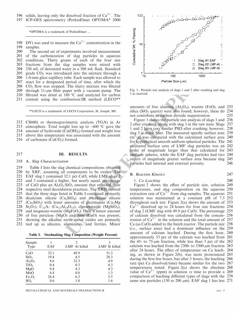
UNCORRECTEDPROOF
196 solids, leaving only the dissolved fraction of Ca2+. The197 ICP-OES spectrometry (PerkinElmer OPTIMA* 2000
198 DV) was used to measure the Ca2+ concentration in the199 samples.200 The second set of experiments involved measurement201 of the carbonization of slag particles in aqueous202 conditions. Thirty grams of each of the four size203 fractions from the slag samples were mixed with204 250 mL of deionized water in a 500 mL flask. Standard205 grade CO2 was introduced into the mixture through a206 1.0-mm glass capillary tube. Each sample was allowed to207 react for a designated period of time, after which the208 CO2 flow was stopped. The slurry mixture was filtered209 through 11-lm filter paper with a vacuum pump. The210 filtrand was dried at 180 �C and analyzed for carbon211 content using the combustion/IR method (LECO**
212 CS600) or thermogravimetric analysis (TGA) in Ar213 atmosphere. Total weight loss up to ~600 �C gave the214 amount of hydroxide (Ca(OH)2) formed and weight loss215 above this temperature was associated with the amount216 of carbonate (CaCO3) formed.
217 III. RESULTS
218 A. Slag Characterization
219 Table I lists the slag chemical compositions obtained220 by XRF, assuming all components to be oxides. The221 EAF slag 1 contained 32.1 pct CaO, while LMF slags 2222 and 3 contained a higher, but nearly equal, percentage223 of CaO plus an Al2O3/SiO2 amount that reflected their224 respective steel deoxidation practices. The XRD showed225 that the three slags listed in Table I contained primarily226 dicalcium silicate (Ca2SiO4) and tricalcium silicate227 (Ca3SiO5) with lesser amounts of akermanite (Ca2Mg228 Si2O7), C12A7 (Ca12Al14O33), clinoenstatite (MgSiO3),229 and magnesio-wustite (MgFeO2). Only a minor amount230 of free periclase (MgO) and lime (CaO) was present,231 showing the alkaline earth metal oxides are primarily232 tied up as silicates, aluminates, and ferrites. Minor
233amounts of free alumina (Al2O3), wustite (FeO), and234silica (SiO2 quartz) were also found; however, these do235not contribute to carbon dioxide sequestration.236Figure 1 shows the particle size analysis of slags 1 and2372 after crushing, along with slag 3 in the raw state. Slags2381 and 2 have very similar PSD after crushing; however,239slag 3 is much finer. The measured specific surface area240(m2/g) was compared with the calculated surface area241for hypothetical smooth uniform spherical particles. The242measured surface area of LMF slag particles was an243order of magnitude larger than that calculated for244uniform spheres, while the EAF slag particles had two245orders of magnitude greater surface area because slag246particles had internal and external porosity.
247B. Reaction Kinetics
2481. Ca Leaching249Figure 2 shows the effect of particle size, solution250temperature, and slag composition on the aqueous251extraction rate of Ca2+ from slag samples. The aqueous252solution was maintained at a constant pH of 7.5253throughout each test. Figure 2(a) shows the amount of254Ca2+ dissolved up to 24 hours for four size fractions255of slag 2 (LMF slag with 49.9 pct CaO). The percentage256of calcium dissolved was calculated from the concen-257tration of Ca2+ in the solution and the total amount of258Ca (as CaO) added to the batch reactor. The particle size259(i.e., surface area) had a dominant influence on the260amount of calcium leached. During the first hour,261approximately 33 pct of the calcium was leached from262the 45- to 75-lm fraction, while less than 5 pct of the263calcium was leached from the 2300- to 3300-lm fraction264after 24 hours. The effect of temperature on Ca leach-265ing, as shown in Figure 2(b), was more pronounced266during the first few hours, but after 3 hours, the leaching267rate (pct Ca dissolved/time) became similar for the two268temperatures tested. Figure 2(c) shows the absolute269value of Ca2+ (ppm) in solution vs time to provide a270comparison of leaching different types of slags with the271same size particles (150 to 200 lm). EAF slag 1 has less
Table I. Steelmaking Slag Composition (Weight Percent)
Sample 1 2 3Type EAF LMF Al killed LMF Si killed
CaO 32.1 49.9 51.3SiO2 19.4 4.5 28.3Al2O3 8.6 32.3 4.9TiO2 0.4 0.3 0.3MgO 9.4 4.3 4.3MnO 6.8 0.8 1.3FexOy 26.4 6.3 5.5SO3 0.6 1.0 1.6
Fig. 1—Particle size analysis of slags 1 and 2 after crushing and slag3 as received.
*OPTIMA is a trademark of PerkinElmer …
**LECO is a trademark of LECO Corporation, St. Joseph, MI.
METALLURGICAL AND MATERIALS TRANSACTIONS B xxx—3
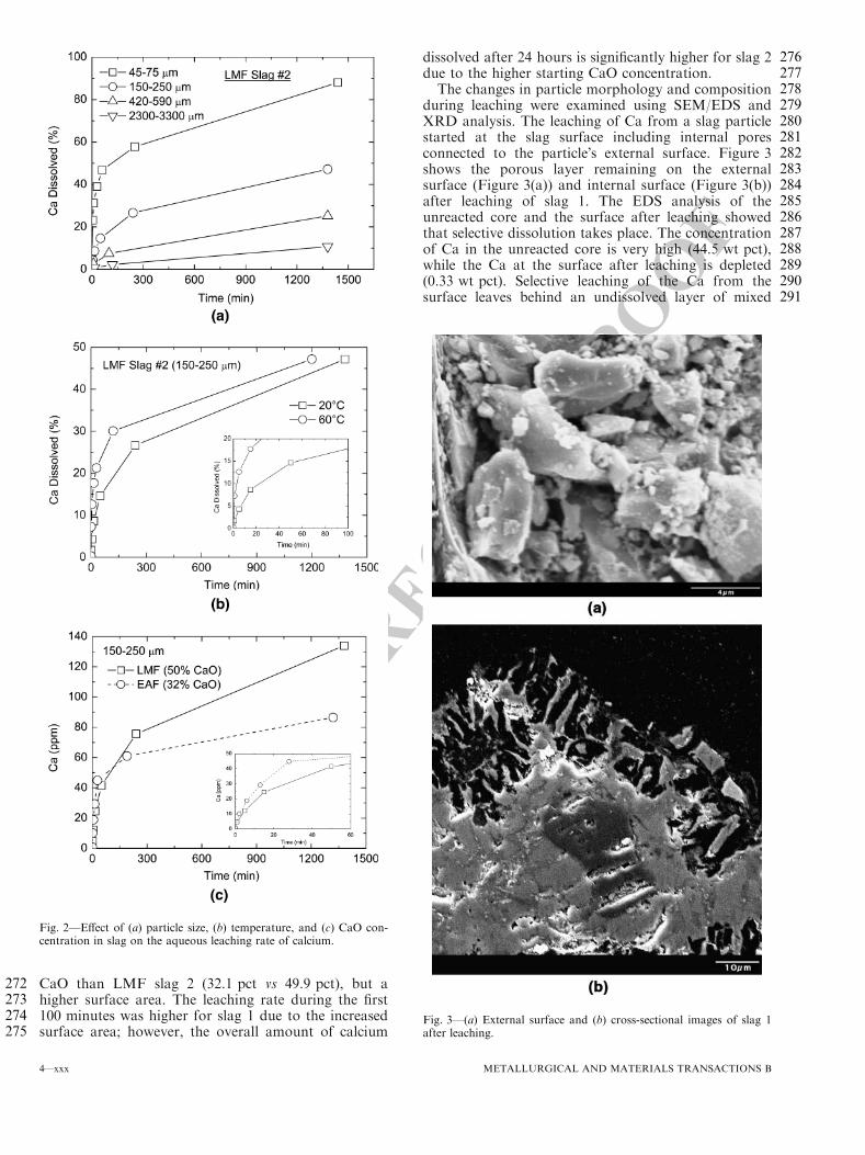
UNCORRECTEDPROOF
272 CaO than LMF slag 2 (32.1 pct vs 49.9 pct), but a273 higher surface area. The leaching rate during the first274 100 minutes was higher for slag 1 due to the increased275 surface area; however, the overall amount of calcium
276dissolved after 24 hours is significantly higher for slag 2277due to the higher starting CaO concentration.278The changes in particle morphology and composition279during leaching were examined using SEM/EDS and280XRD analysis. The leaching of Ca from a slag particle281started at the slag surface including internal pores282connected to the particle�s external surface. Figure 3283shows the porous layer remaining on the external284surface (Figure 3(a)) and internal surface (Figure 3(b))285after leaching of slag 1. The EDS analysis of the286unreacted core and the surface after leaching showed287that selective dissolution takes place. The concentration288of Ca in the unreacted core is very high (44.5 wt pct),289while the Ca at the surface after leaching is depleted290(0.33 wt pct). Selective leaching of the Ca from the291surface leaves behind an undissolved layer of mixed
Fig. 2—Effect of (a) particle size, (b) temperature, and (c) CaO con-centration in slag on the aqueous leaching rate of calcium.
Fig. 3—(a) External surface and (b) cross-sectional images of slag 1after leaching.
4—xxx METALLURGICAL AND MATERIALS TRANSACTIONS B
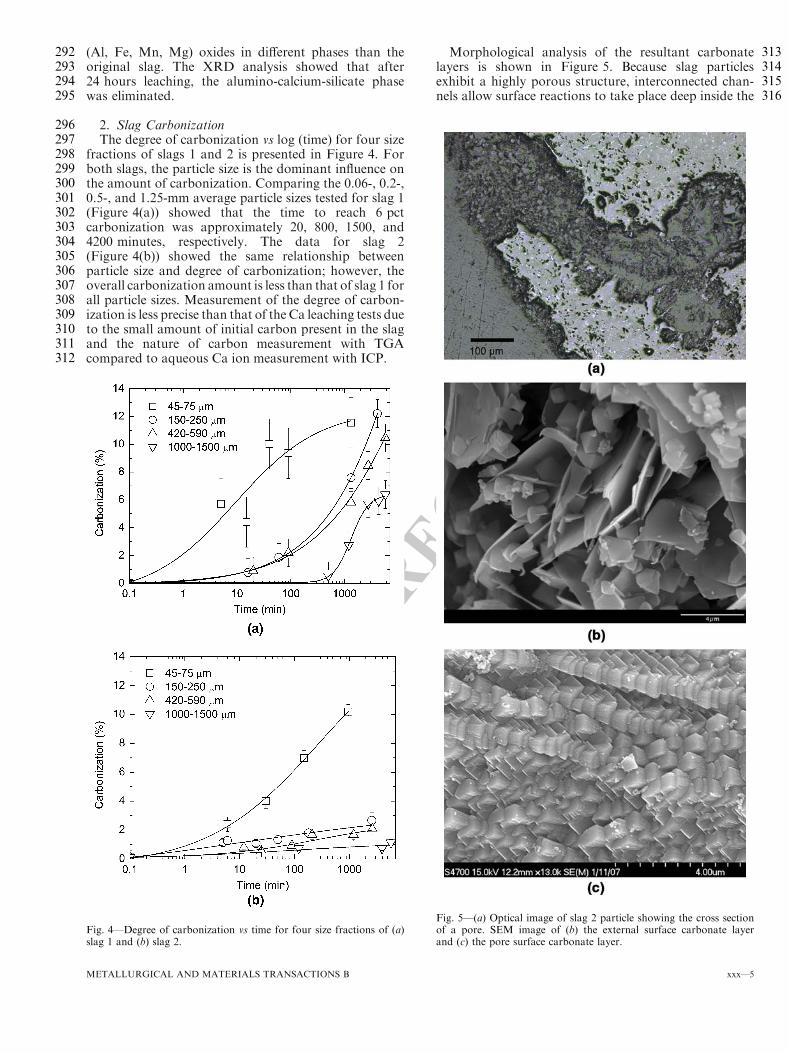
UNCORRECTEDPROOF
292 (Al, Fe, Mn, Mg) oxides in different phases than the293 original slag. The XRD analysis showed that after294 24 hours leaching, the alumino-calcium-silicate phase295 was eliminated.
296 2. Slag Carbonization297 The degree of carbonization vs log (time) for four size298 fractions of slags 1 and 2 is presented in Figure 4. For299 both slags, the particle size is the dominant influence on300 the amount of carbonization. Comparing the 0.06-, 0.2-,301 0.5-, and 1.25-mm average particle sizes tested for slag 1302 (Figure 4(a)) showed that the time to reach 6 pct303 carbonization was approximately 20, 800, 1500, and304 4200 minutes, respectively. The data for slag 2305 (Figure 4(b)) showed the same relationship between306 particle size and degree of carbonization; however, the307 overall carbonization amount is less than that of slag 1 for308 all particle sizes. Measurement of the degree of carbon-309 ization is less precise than that of the Ca leaching tests due310 to the small amount of initial carbon present in the slag311 and the nature of carbon measurement with TGA312 compared to aqueous Ca ion measurement with ICP.
313Morphological analysis of the resultant carbonate314layers is shown in Figure 5. Because slag particles315exhibit a highly porous structure, interconnected chan-316nels allow surface reactions to take place deep inside the
Fig. 4—Degree of carbonization vs time for four size fractions of (a)slag 1 and (b) slag 2.
Fig. 5—(a) Optical image of slag 2 particle showing the cross sectionof a pore. SEM image of (b) the external surface carbonate layerand (c) the pore surface carbonate layer.
METALLURGICAL AND MATERIALS TRANSACTIONS B xxx—5
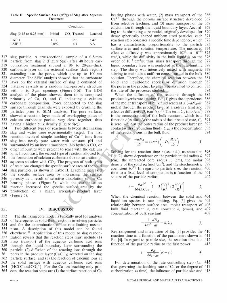
UNCORRECTEDPROOF
317 slag particle. A cross-sectional sample of a 0.5-mm318 particle from slag 2 (Figure 5(a)) after 48 hours car-319 bonization treatment showed a 10- to 20-lm-thick320 carbonate layer on the external surface (dark region)321 extending into the pores, which are up to 100-lm322 diameter. The SEM analysis showed that the carbonate323 layer on the external surface of slag 2 consisted of324 platelike crystals in a random high-porosity structure325 with 1- to 3-lm openings (Figure 5(b)). The EDS326 analysis of the plates showed them to be composed327 primarily of Ca, O, and C, indicating a calcium328 carbonate composition. Pores connected to the slag329 surface through channels were exposed by crushing the330 particles prior to SEM analysis. The pore surfaces331 showed a reaction layer made of overlapping plates of332 calcium carbonate packed very close together, thus333 having a higher bulk density (Figure 5(c)).334 Two different types of reactions between steelmaking335 slag and water were experimentally tested. The first336 reaction involved simple leaching of Ca2+ ions from337 slag into nearly pure water with constant pH and338 surrounded by an inert atmosphere. No hydrous CO2 or339 other impurities were present to react with the calcium340 ions. In contrast, the second type of reaction allowed for341 the formation of calcium carbonate due to saturation of342 aqueous solution with CO2. The progress of both types343 of reactions changed the specific surface area of the solid344 slag particles, as shown in Table II. Leaching increased345 the specific surface area by increasing the surface346 porosity as a result of selective dissolution of the Ca347 bearing phases (Figure 3), while the carbonization348 reaction increased the specific surface area by the349 production of a highly irregular product layer350 (Figure 5).
351 IV. DISCUSSION
352 The shrinking core model is typically used for analysis353 of heterogeneous solid-fluid reactions involving particles354 and for the determination of the rate-limiting mecha-355 nism. A description of this model can be found356 elsewhere.[15] Application of this model to slag carbon-357 ization reveals that the reaction steps must include (1)358 mass transport of the aqueous carbonic acid ions359 through the liquid boundary layer surrounding the360 particle, (2) diffusion of the reacting ions through the361 pores in the product layer (CaCO3) accreted on the slag362 particle surface, and (3) the reaction of calcium ions at363 the solid surface with aqueous carbonic acid ions364 HCO�
3 andCO2�3
� �
. For the Ca ion leaching-only pro-365 cess, the reaction steps are (1) the surface reaction of Ca
366bearing phases with water, (2) mass transport of the367Ca2+ through the porous surface structure developed368from selective leaching, and (3) mass transport of the369calcium ion through the liquid boundary layer. Accord-370ing to the shrinking core model, originally developed for371dense spherically shaped uniform sized particles, each372reaction step possesses a specific time dependence, which373has a characteristic proportionality to the particle374surface area and solution temperature. The measured375effective diffusivity was approximately 10-9 to 10-10
376cm2/s, while the diffusivity in the bulk liquid is on the377order of 10-5 cm2/s; thus, mass transport through the378liquid boundary layer was neglected as the rate-limiting379step. The slurry was intensively mixed with magnetic380stirring to maintain a uniform concentration in the bulk381solution. Therefore, the chemical reaction between the382solid and liquid-ionic species or diffusion through383the pores in the product layer can be assumed to control384the rate of the processes studied.385When the diffusion of the reactants through the386product layer is rate limiting, Eq. [1] gives the dependence387of the molar transport of bulk fluid reactant A (-dNA/dt,388mol/s) through the product layer at a radius r (cm) and389effective diffusivityDe (cm
2/s).[15] The term CA (mol/cm3)390is the concentration of the bulk reactant, which is a391function of radius. At the radius of the unreacted core,CA
392is zero, while at the outer radius of the product layer (in393contact with surrounding fluid), CAb is the concentration394of the reactant ions in the bulk fluid.
�dNA
dt¼ ð4pr2Þ �De
dCA
dr
� �
½1�
396396Solving for the reaction time t (seconds), as shown in397Eq. [2], shows dependence on the particle initial radius R398(cm), the unreacted core radius rc (cm), the molar399density of the solid qB (mol/cm3), and the stoichiometric400coefficient b.[15] In regard to particle size, the reaction401time to a fixed level of completion is a function of the402square of the particle radius.
t ¼qBR
2
6bDeCAb
1� 3rc
R
� �2
þ2rc
R
� �3� �
½2�
404404When the chemical reaction between the solid and405liquid-ion species is rate limiting, Eq. [3] gives the406relationship between surface area, molar transport of407bulk fluid reactant A, rate constant kr (cm/s), and408concentration of bulk reactant.
�1
4pr2dNA
dt¼ krCA ½3�
410410Rearrangement and integration of Eq. [3] provides the411reaction time as a function of the parameters shown in412Eq. [4]. In regard to particle size, the reaction time is a413function of the particle radius to the first power.
t ¼qB
bkrCAb
R� rcð Þ ½4�
415415416For determination of the rate controlling step (i.e.,417that governing the leaching rate of Ca or the degree of418carbonization vs time), the influence of particle size and
Table II. Specific Surface Area (m2/g) of Slag after AqueousTreatment
Slag (0.15 to 0.25 mm)
Condition
Initial CO2 Treated Leached
EAF 1 1.13 12.6 5.42LMF 2 0.092 4.4 NA
6—xxx METALLURGICAL AND MATERIALS TRANSACTIONS B
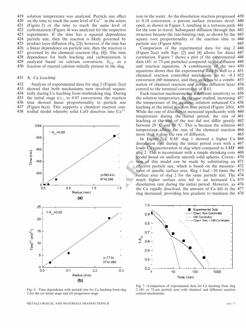
UNCORRECTEDPROOF
419 solution temperature was analyzed. Particle size effect420 on the time to reach the same level of Ca2+ in the solute421 (Figure 2) or the time to reach the same level of422 carbonization (Figure 4) was analyzed for the respective423 experiments. If the time has a squared dependence424 particle size, then the reaction is likely governed by425 product layer diffusion (Eq. [2]); however, if the time has426 a linear dependence on particle size, then the reaction is427 governed by the chemical reaction (Eq. [4]). The time428 dependence for both leaching and carbonization is429 analyzed based on calcium conversion, XCa, as a430 fraction of reacted calcium initially present in the slag.
431 A. Ca Leaching
432 Analysis of experimental data for slag 2 (Figure 2(a))433 showed that both mechanisms were involved sequen-434 tially during Ca leaching from steelmaking slag. During435 the initial stage (i.e., to 0.07 conversion), the reaction436 time showed linear proportionality to particle size437 (Figure 6(a)). This supports a chemical reaction con-438 trolled model whereby solid CaO dissolves into Ca2+
439ions in the water. As the dissolution reaction progressed440to 0.18 conversion, a porous surface structure devel-441oped, as shown in Figure 3, resulting in a tortuous path442for the ions to travel. Subsequent diffusion through this443structure became the rate-limiting step, as shown by the444square root proportionality of the reaction time to445particle size (Figure 6(b)).446Comparison of the experimental data for slag 2447(Figure 2(a)) with Eqs. [2] and [4] allows for direct448correlation. Figure 7 shows a plot of the experimental449data (45- to 75-lm particles) compared to the diffusion450and reaction equations. A combination of the two451equations shows that the experimental data fit well to a452chemical reaction controlled mechanism up to ~0.3453conversion (60 minutes), and then switches to a combi-454nation of chemical reaction and porous diffusion layer455control to the terminal conversion of 0.63.456Each reaction mechanism has a different sensitivity to457the solution temperature. In the case studied, increasing458the temperature of the aqueous solution enhanced Ca459leaching at the initial reaction time period (Figure 2(b)).460While the rate of dissolution increased significantly with461temperature during the initial period, the rate of462leaching at the end of the test did not differ greatly463between 20 �C and 60 �C. This is because the solution464temperature affects the rate of the chemical reaction465more than it does the rate of diffusion.466In Figure 2(c), EAF slag 1 showed a higher Ca467dissolution rate during the initial period even with a468lower Ca concentration in slag when compared to LMF469slag 2. This is inconsistent with a simple shrinking core470model based on uniform smooth solid spheres. Correc-471tion of this model can be made by substituting an472effective particle size, which is based on the measure-473ment of specific surface area. Slag 1 had ~10 times the474surface area of slag 2 for the same particle size. The475much higher surface area led to an increased Ca476dissolution rate during the initial period. However, as477the Ca rapidly dissolved, the amount of Ca left in the478slag decreased, providing less gradient to maintain the
Fig. 6—Time dependence with particle size for Ca leaching from slag2 for the (a) initial stage and (b) progressive stage.
Fig. 7—Comparison of experimental data for Ca leaching from slag2 (45- to 75-lm particle size) with chemical and diffusion reactioncontrol mechanisms.
METALLURGICAL AND MATERIALS TRANSACTIONS B xxx—7
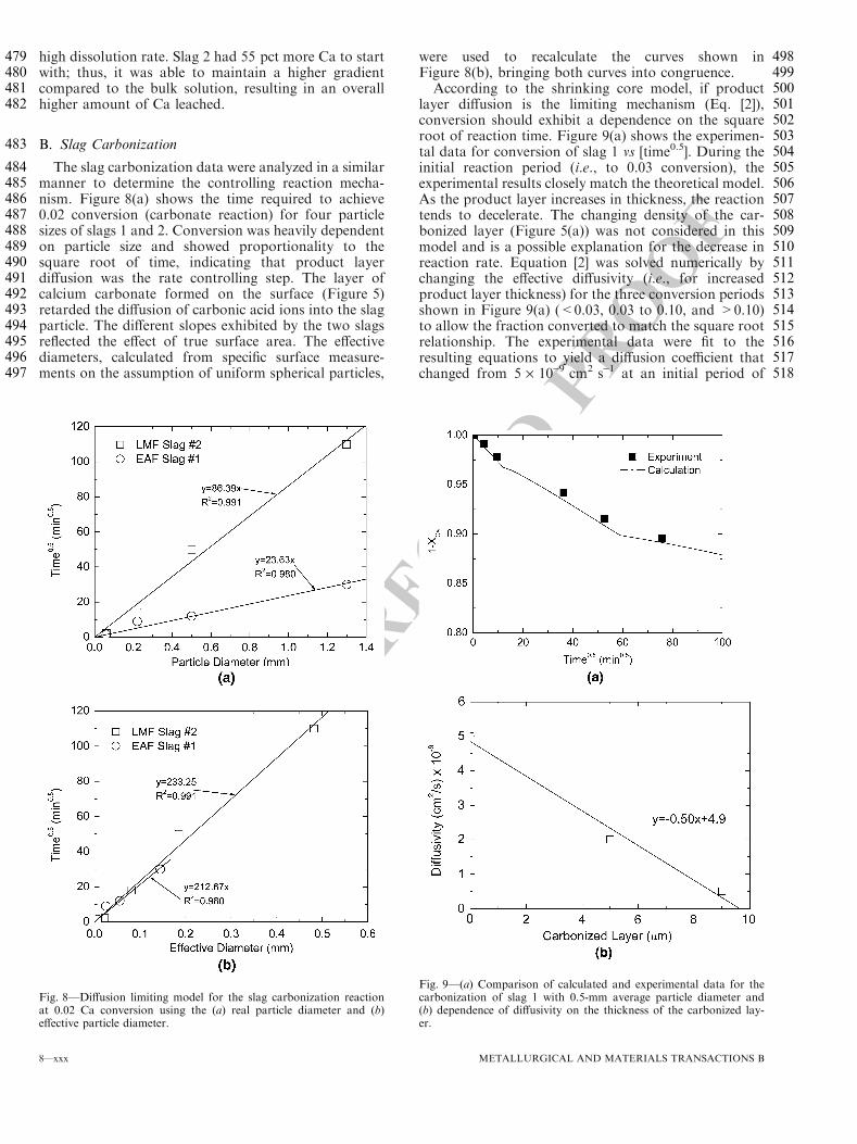
UNCORRECTEDPROOF
479 high dissolution rate. Slag 2 had 55 pct more Ca to start480 with; thus, it was able to maintain a higher gradient481 compared to the bulk solution, resulting in an overall482 higher amount of Ca leached.
483 B. Slag Carbonization
484 The slag carbonization data were analyzed in a similar485 manner to determine the controlling reaction mecha-486 nism. Figure 8(a) shows the time required to achieve487 0.02 conversion (carbonate reaction) for four particle488 sizes of slags 1 and 2. Conversion was heavily dependent489 on particle size and showed proportionality to the490 square root of time, indicating that product layer491 diffusion was the rate controlling step. The layer of492 calcium carbonate formed on the surface (Figure 5)493 retarded the diffusion of carbonic acid ions into the slag494 particle. The different slopes exhibited by the two slags495 reflected the effect of true surface area. The effective496 diameters, calculated from specific surface measure-497 ments on the assumption of uniform spherical particles,
498were used to recalculate the curves shown in499Figure 8(b), bringing both curves into congruence.500According to the shrinking core model, if product501layer diffusion is the limiting mechanism (Eq. [2]),502conversion should exhibit a dependence on the square503root of reaction time. Figure 9(a) shows the experimen-504tal data for conversion of slag 1 vs [time0.5]. During the505initial reaction period (i.e., to 0.03 conversion), the506experimental results closely match the theoretical model.507As the product layer increases in thickness, the reaction508tends to decelerate. The changing density of the car-509bonized layer (Figure 5(a)) was not considered in this510model and is a possible explanation for the decrease in511reaction rate. Equation [2] was solved numerically by512changing the effective diffusivity (i.e., for increased513product layer thickness) for the three conversion periods514shown in Figure 9(a) (<0.03, 0.03 to 0.10, and >0.10)515to allow the fraction converted to match the square root516relationship. The experimental data were fit to the517resulting equations to yield a diffusion coefficient that518changed from 5 · 10-9 cm2 s-1 at an initial period of
Fig. 8—Diffusion limiting model for the slag carbonization reactionat 0.02 Ca conversion using the (a) real particle diameter and (b)effective particle diameter.
Fig. 9—(a) Comparison of calculated and experimental data for thecarbonization of slag 1 with 0.5-mm average particle diameter and(b) dependence of diffusivity on the thickness of the carbonized lay-er.
8—xxx METALLURGICAL AND MATERIALS TRANSACTIONS B
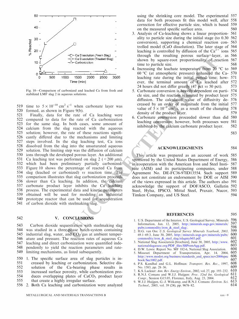
UNCORRECTEDPROOF
519 time to 5 · 10-10 cm2 s-1 when carbonate layer was520 formed, as shown in Figure 9(b).521 Finally, data for the rate of Ca leaching were522 compared to data for the rate of Ca carbonization523 for the same slag. In both cases, some amount of524 calcium from the slag reacted with the aqueous525 solution; however, the rate of these reactions signifi-526 cantly differed due to the mechanisms and limiting527 steps involved. In the slag leaching test, Ca ions528 dissolved from the slag into the unsaturated aqueous529 solution. The limiting step was the diffusion of calcium530 ions through the developed porous layer. An additional531 Ca leaching test was performed on slag 2 (<200 lm),532 which had been preliminary partially carbonized.533 Figure 10 shows the percentage of reacted Ca from534 slag (leached or carbonized) vs reaction time. The535 comparison illustrates that slag carbonization proceeds536 slower than Ca leaching. In addition, the calcium537 carbonate product layer inhibits the Ca leaching538 process. The experimental data and kinetic parameters539 obtained will be used for modeling an industrial540 prototype reactor that can be used for sequestration541 of carbon dioxide with steelmaking slag.
542 V. CONCLUSIONS
543 Carbon dioxide sequestration with steelmaking slag544 was studied in a three-phase batch-system containing545 industrial slag, water, and CO2 gas at ambient temper-546 ature and pressure. The reaction rates of aqueous Ca547 leaching and direct carbonization were quantified inde-548 pendently to yield the reaction parameters and rate-549 limiting mechanisms, as listed subsequently.
550 1. The specific surface area of slag particles is in-551 creased by leaching or carbonization. Selective dis-552 solution of the Ca-bearing phase results in553 increased surface porosity, while carbonization pro-554 duces overlapping plates of CaCO3 product layer555 that create a highly irregular surface.556 2. Both Ca leaching and carbonization were analyzed
557using the shrinking core model. The experimental558data for both processes fit this model well, after559correction for effective particle size, which is based560on the measured specific surface area.5613. Analysis of Ca-leaching shows a linear proportion-562ality to particle size during the initial stage (to 0.30563conversion), supporting a chemical reaction con-564trolled model (CaO dissolution). The later stage of565leaching is controlled by diffusion of the Ca2+ ions566through the resulting porous surface layer, as567shown by square-root proportionality of reaction568time to particle size.5694. Increasing the leachate temperature from 20 �C to57060 �C (at atmospheric pressure) enhanced the Ca-571leaching rate during the initial period time; how-572ever, the terminal amount of Ca leached after57324 hours did not differ greatly (47 pct vs 50 pct).5745. Carbonate conversion is heavily dependent on parti-575cle size, and the reaction is limited by product layer576diffusion. The calculated value of diffusivity de-577creased by an order of magnitude from the initial578value of 5 · 10-9 cm2/s, as a result of the changing579density of the product layer.5806. Carbonate conversion proceeded slower than did581leaching conversion; however, both processes were582inhibited by the calcium carbonate product layer.
583
584ACKNOWLEDGMENTS
585This article was prepared as an account of work586sponsored by the United States Department of Energy,587in cooperation with the American Iron and Steel Insti-588tute (AISI) and its participating companies, under589Agreement No. DE-FC36-97ID13554. Such support590does not constitute an endorsement by DOE or AISI591of the views expressed in this article. The authors also592acknowledge the support of DOFASCO, Gallatin593Steel, Hylsa, IPSCO, Mittal Steel, Praxair, Nucor,594Timken Company, and US Steel.
595REFERENCES
5961. U.S. Department of the Interior, U.S. Geological Survey, Minerals597Information, Jan. 12, 2005, http://minerals.usgs.gov/minerals/598pubs/commodity/iron_&_steel_slag/.5992. H.G. van Oss: U.S. Geological Survey Minerals Yearbook, 2003,60069.1–69.3, June 30, 2005, http://minerals.usgs.gov/minerals/pubs/601commodity/iron_&_steel_slag/islagmyb03.pdf.6023. National Slag Association [brochure], June 30, 2005, http://www.603nationalslagassoc.org/PDF_files/SSPremAgg.pdf.6044. D.W. Lewis: Report No. MF 182-6, National Slag Association.6055. Missouri Department of Transportation, Apr. 14, 2004,606http://www.modot.org/business/standards_and_specs/nov2004spec607book/Sec1002.pdf.6086. P.S. Kandhal and G.L. Hoffman: Transport. Res. Rec., 1997,609No. 1583, pp. 28–36.6107. K.S. Lackner:Ann. Rev. Energy Environ., 2002, vol. 27, pp. 193–232.6118. R.N.J. Comans and W.J.J. Huijgen: Proc. 32nd Int. Geological612Congr., Session G15.05, Florence, Italy, Aug. 23, 2004.6139. W.J.J. Huijgen, G.-J. Witkamp, and R.N.J. Comans: Environ. Sci.614Technol., 2005, vol. 39 (24), pp. 9676–82.
Fig. 10—Comparison of carbonized and leached Ca from fresh andstabilized LMF slag 2 in aqueous solutions.
METALLURGICAL AND MATERIALS TRANSACTIONS B xxx—9
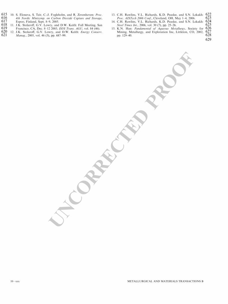
UNCORRECTEDPROOF
615 10. S. Eloneva, S. Teir, C.-J. Fogleholm, and R. Zevenhoven: Proc.616 4th Nordic Minisymp. on Carbon Dioxide Capture and Storage,617 Espoo, Finland, Sept. 8–9, 2005.618 11. J.K. Stolaroff, G.V. Lowry, and D.W. Keith: Fall Meeting, San619 Francisco, CA, Dec. 8–12 2003, EOS Trans. AGU, vol. 84 (46).620 12. J.K. Stolaroff, G.V. Lowry, and D.W. Keith: Energy Conserv.621 Manag., 2005, vol. 46 (5), pp. 687–99.
62213. C.H. Rawlins, V.L. Richards, K.D. Peaslee, and S.N. Lekakh:623Proc. AISTech 2006 Conf., Cleveland, OH, May 1–4, 2006.62414. C.H. Rawlins, V.L. Richards, K.D. Peaslee, and S.N. Lekakh:625Steel Times Int., 2006, vol. 30 (7), pp. 25–26.62615. K.N. Han: Fundamental of Aqueous Metallurgy, Society for627Mining, Metallurgy, and Exploration Inc, Littleton, CO, 2002,628pp. 129–40.
629
10—xxx METALLURGICAL AND MATERIALS TRANSACTIONS B
CO2 Reduction Metallurgy Symposium Edited: Neale R. Neelameggham & Ramana G. Reddy (The Minerals, metals & materials Society) TMS 2008
Sequestration of Carbon Dioxide by Steelmaking Slag:
Process Phenomena and Reactor Study
V.L. Richards, C.H. Rawlins, S.N. Lekakh, and K.D. Peaslee Department of Materials Science and Engineering at the University of Missouri-Rolla
Keywords: Steelmaking Slag, CO2, Sequestration, Kinetics, Reactor
Abstract Steel-making processes generate carbon dioxide air emissions and a slag co-product. The aim of this project was to develop a functional sequestration system using steelmaking slag to permanently capture carbon dioxide emitted in steelmaking offgas. A possible parallel benefit of this process would be rapid chemical stabilization of the slag minerals with reducing swelling or leaching. This paper summarizes the original results of the project, including mineralogical and structural features of carbon sequestration with steel making slag, mathematical modeling of reaction phenomena using a modified shrinking core model, METSIM modeling of several possible industrial applications, a thermo-gravimetrical study of the reaction between slags and different gases, and design and testing for a lab scale apparatus consisted of two reactors.

1. Introduction The U.S. produces 9-14 Mt of steelmaking slag annually, which represents approximately 10-15 wt. % of crude steel output.1,2 Primary uses for steelmaking slag include high quality mineral aggregate, Portland cement, unconfined fill, soil conditioning, and pH neutralization of abandoned mine drainage.3,4 The key factor prescribing slag use is the alkaline-earth metal (e.g. Ca and Mg) oxides content, which contribute to overall basicity and cementitious strength. However, as-produced steelmaking slag is chemically unstable. Calcium and magnesium oxides readily form hydroxides and carbonates through reaction with atmospheric gases. Both hydroxide and carbonate formation produce substantial mechanical swelling leading to heave failure in confined construction applications, thus many states dictate stockpile aging for 3-6 months prior to commercial use.5,6 Sequestration of carbon dioxide is a natural corollary to forced carbonation. The conversion of CaO/MgO to carbonates serves both to stabilize the slag, and permanently capture and store the CO2. Extraction of CO2 from steel manufacturing offgas with steelmaking slag for geological sequestration is being studied by quantifying the extent and rate of carbonate formation under near-atmospheric aqueous conditions.7 A survey of industrial slags has found the CaO and MgO contents of BOF and EAF slags to average 30-50 wt.% and 10-12 wt.%, respectively. Additionally, LMF slag contains 50-60 wt.% CaO and 10-12 wt.% MgO. The amount of slag produced per ton of steel is estimated at 75-150 kg for BOF, 65-80 kg for EAF, and 15-20 kg for LMF. Production of a ton of steel generates 519 kg CO2 carbon equivalent (CE) for BOF and 119 kg CO2 CE for EAF, respectively. Assuming full stoichiometric conversion of CaO and MgO to carbonate, steelmaking slag has the potential to sequester 6-11% of the CO2 generated from BOF production and 35-45% of the CO2 generated from EAF production8. This paper summarizes the original results7-9 of the project, including mineralogical and structural features of carbon sequestration with steel making slag, experimental study and modeling of reaction phenomena and prototype of industrial reactor. 2. Slag characterization Table I lists the slag chemical compositions obtained by XRF. EAF Slag #1 contained 32.1% CaO while LMF Slags #2 and #3 contained higher, but nearly equal, percentage of CaO plus an Al2O3/SiO2 amount that reflected their respective steel deoxidation practice.
Table 1. Steelmaking Slag Compositions (Wt Pct) Sample #1 #2 #3
Type EAF LMF Al-Killed LMF Si-Killed CaO 32.1 49.9 51.3 SiO2 19.4 4.5 28.3 Al2O3 8.6 32.3 4.9 TiO2 0.4 0.3 0.3 MgO 9.4 4.3 4.3 MnO 6.8 0.8 1.3 FexOy 26.4 6.3 5.5 SO3 0.6 1.0 1.6
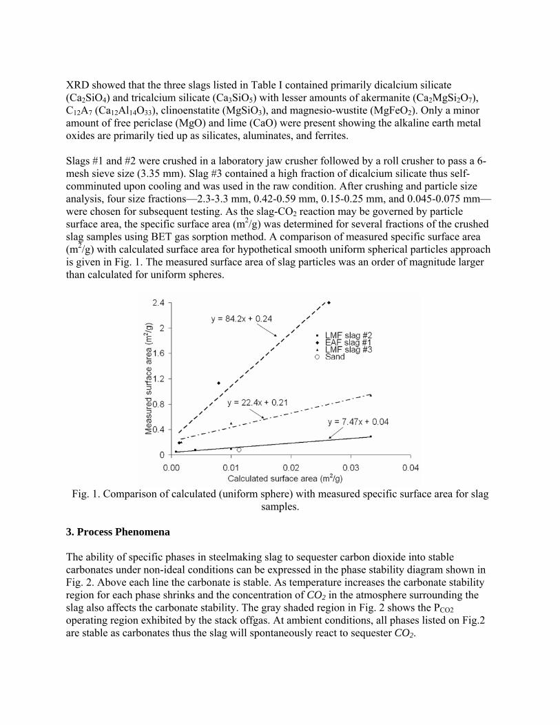
XRD showed that the three slags listed in Table I contained primarily dicalcium silicate (Ca2SiO4) and tricalcium silicate (Ca3SiO5) with lesser amounts of akermanite (Ca2MgSi2O7), C12A7 (Ca12Al14O33), clinoenstatite (MgSiO3), and magnesio-wustite (MgFeO2). Only a minor amount of free periclase (MgO) and lime (CaO) were present showing the alkaline earth metal oxides are primarily tied up as silicates, aluminates, and ferrites. Slags #1 and #2 were crushed in a laboratory jaw crusher followed by a roll crusher to pass a 6-mesh sieve size (3.35 mm). Slag #3 contained a high fraction of dicalcium silicate thus self-comminuted upon cooling and was used in the raw condition. After crushing and particle size analysis, four size fractions—2.3-3.3 mm, 0.42-0.59 mm, 0.15-0.25 mm, and 0.045-0.075 mm—were chosen for subsequent testing. As the slag-CO2 reaction may be governed by particle surface area, the specific surface area (m2/g) was determined for several fractions of the crushed slag samples using BET gas sorption method. A comparison of measured specific surface area (m2/g) with calculated surface area for hypothetical smooth uniform spherical particles approach is given in Fig. 1. The measured surface area of slag particles was an order of magnitude larger than calculated for uniform spheres.
Fig. 1. Comparison of calculated (uniform sphere) with measured specific surface area for slag
samples. 3. Process Phenomena The ability of specific phases in steelmaking slag to sequester carbon dioxide into stable carbonates under non-ideal conditions can be expressed in the phase stability diagram shown in Fig. 2. Above each line the carbonate is stable. As temperature increases the carbonate stability region for each phase shrinks and the concentration of CO2 in the atmosphere surrounding the slag also affects the carbonate stability. The gray shaded region in Fig. 2 shows the PCO2 operating region exhibited by the stack offgas. At ambient conditions, all phases listed on Fig.2 are stable as carbonates thus the slag will spontaneously react to sequester CO2.
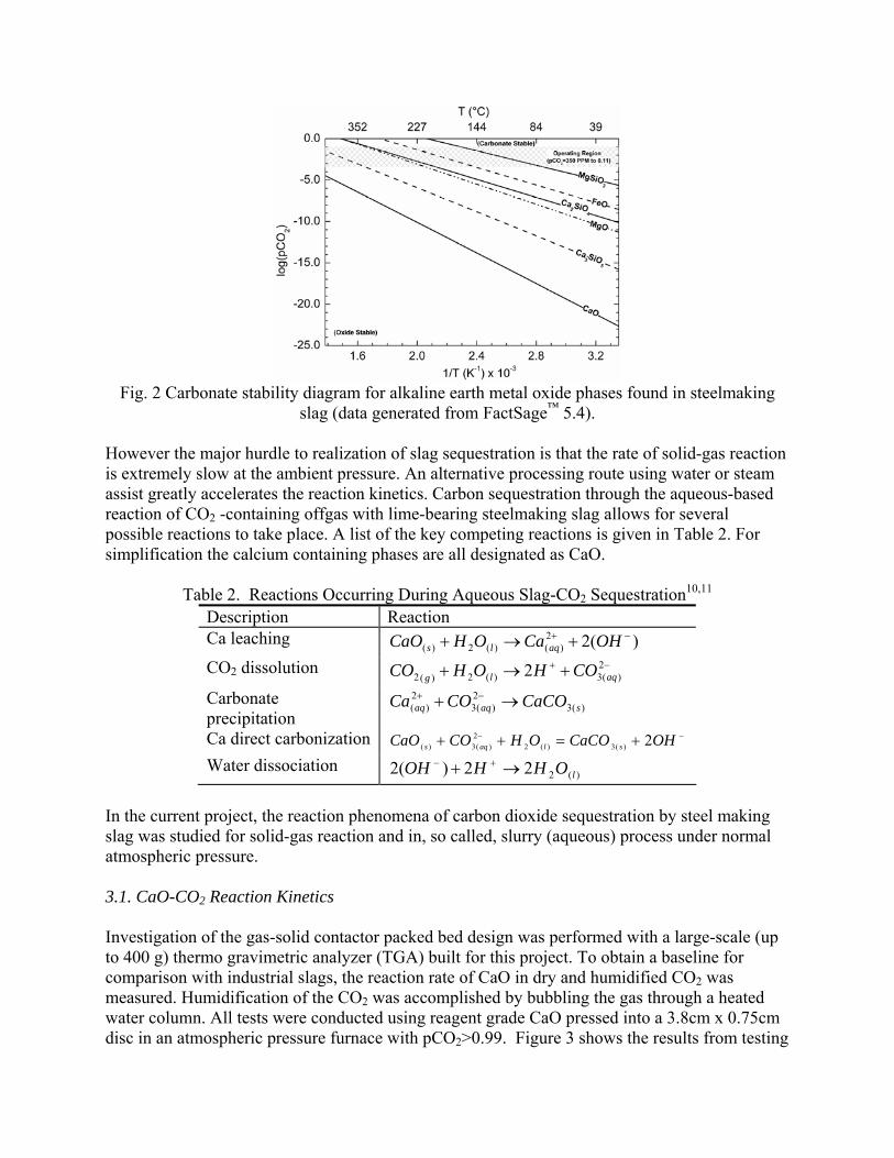
Fig. 2 Carbonate stability diagram for alkaline earth metal oxide phases found in steelmaking
slag (data generated from FactSage™ 5.4). However the major hurdle to realization of slag sequestration is that the rate of solid-gas reaction is extremely slow at the ambient pressure. An alternative processing route using water or steam assist greatly accelerates the reaction kinetics. Carbon sequestration through the aqueous-based reaction of CO2 -containing offgas with lime-bearing steelmaking slag allows for several possible reactions to take place. A list of the key competing reactions is given in Table 2. For simplification the calcium containing phases are all designated as CaO.
Table 2. Reactions Occurring During Aqueous Slag-CO2 Sequestration10,11 Description Reaction Ca leaching )(22
)()(2)(−+ +→+ OHCaOHCaO aqls
CO2 dissolution −+ +→+ 2)(3)(2)(2 2 aqlg COHOHCO
Carbonate precipitation
)(32
)(32
)( saqaq CaCOCOCa →+ −+
Ca direct carbonization −− +=++ OHCaCOOHCOCaO slaqs 2)(3)(22
)(3)( Water dissociation
)(222)(2 lOHHOH →+ +− In the current project, the reaction phenomena of carbon dioxide sequestration by steel making slag was studied for solid-gas reaction and in, so called, slurry (aqueous) process under normal atmospheric pressure. 3.1. CaO-CO2 Reaction Kinetics Investigation of the gas-solid contactor packed bed design was performed with a large-scale (up to 400 g) thermo gravimetric analyzer (TGA) built for this project. To obtain a baseline for comparison with industrial slags, the reaction rate of CaO in dry and humidified CO2 was measured. Humidification of the CO2 was accomplished by bubbling the gas through a heated water column. All tests were conducted using reagent grade CaO pressed into a 3.8cm x 0.75cm disc in an atmospheric pressure furnace with pCO2>0.99. Figure 3 shows the results from testing
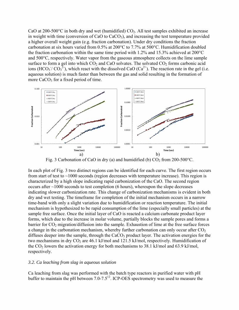
CaO at 200-500°C in both dry and wet (humidified) CO2. All test samples exhibited an increase in weight with time (conversion of CaO to CaCO3), and increasing the test temperature provided a higher overall weight gain (e.g. fraction carbonation). Under dry conditions the fraction carbonation at six hours varied from 0.5% at 200°C to 7.7% at 500°C. Humidification doubled the fraction carbonation within the same time period with 1.2% and 15.3% achieved at 200°C and 500°C, respectively. Water vapor from the gaseous atmosphere collects on the lime sample surface to form a gel into which CO2 and CaO solvates. The solvated CO2 forms carbonic acid ions (HCO3
-/ CO32-), which react with the dissolved CaO (Ca2+). The reaction rate in the gel (i.e.
aqueous solution) is much faster than between the gas and solid resulting in the formation of more CaCO3 for a fixed period of time.
0.001
0.010
0.100
10 100 1000 10000 100000
Fraction
Carbo
nated
Time (sec)
200°C Dry
300°C Dry
400°C Dry
500°C Dry
0.0001
0.0010
0.0100
0.1000
1.0000
10 100 1000 10000 100000
Fraction
Carbo
nated
Time (sec)
200°C Wet
300°C Wet
400°C Wet
500°C Wet
a) b)
Fig. 3 Carbonation of CaO in dry (a) and humidified (b) CO2 from 200-500°C. In each plot of Fig. 3 two distinct regions can be identified for each curve. The first region occurs from start of test to ~1000 seconds (region decreases with temperature increase). This region is characterized by a high slope indicating rapid carbonization of the CaO. The second region occurs after ~1000 seconds to test completion (6 hours), whereupon the slope decreases indicating slower carbonization rate. This change of carbonization mechanisms is evident in both dry and wet testing. The timeframe for completion of the initial mechanism occurs in a narrow time-band with only a slight variation due to humidification or reaction temperature. The initial mechanism is hypothesized to be rapid consumption of the lime (especially small particles) at the sample free surface. Once the initial layer of CaO is reacted a calcium carbonate product layer forms, which due to the increase in molar volume, partially blocks the sample pores and forms a barrier for CO2 migration/diffusion into the sample. Exhaustion of lime at the free surface forces a change in the carbonation mechanism, whereby further carbonation can only occur after CO2 diffuses deeper into the sample, through the CaCO3 product layer. The activation energies for the two mechanisms in dry CO2 are 46.1 kJ/mol and 121.5 kJ/mol, respectively. Humidification of the CO2 lowers the activation energy for both mechanisms to 38.1 kJ/mol and 63.9 kJ/mol, respectively. 3.2. Ca leaching from slag in aqueous solution Ca leaching from slag was performed with the batch type reactors in purified water with pH buffer to maintain the pH between 7.0-7.512. ICP-OES spectrometry was used to measure the
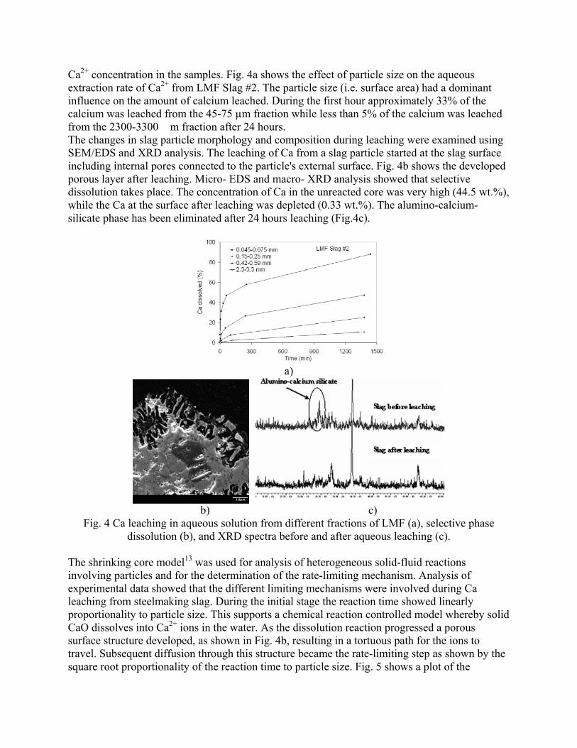
Ca2+ concentration in the samples. Fig. 4a shows the effect of particle size on the aqueous extraction rate of Ca2+ from LMF Slag #2. The particle size (i.e. surface area) had a dominant influence on the amount of calcium leached. During the first hour approximately 33% of the calcium was leached from the 45-75 µm fraction while less than 5% of the calcium was leached from the 2300-3300 �m fraction after 24 hours. The changes in slag particle morphology and composition during leaching were examined using SEM/EDS and XRD analysis. The leaching of Ca from a slag particle started at the slag surface including internal pores connected to the particle's external surface. Fig. 4b shows the developed porous layer after leaching. Micro- EDS and macro- XRD analysis showed that selective dissolution takes place. The concentration of Ca in the unreacted core was very high (44.5 wt.%), while the Ca at the surface after leaching was depleted (0.33 wt.%). The alumino-calcium-silicate phase has been eliminated after 24 hours leaching (Fig.4c).
a)
b) c)
Fig. 4 Ca leaching in aqueous solution from different fractions of LMF (a), selective phase dissolution (b), and XRD spectra before and after aqueous leaching (c).
The shrinking core model13 was used for analysis of heterogeneous solid-fluid reactions involving particles and for the determination of the rate-limiting mechanism. Analysis of experimental data showed that the different limiting mechanisms were involved during Ca leaching from steelmaking slag. During the initial stage the reaction time showed linearly proportionality to particle size. This supports a chemical reaction controlled model whereby solid CaO dissolves into Ca2+ ions in the water. As the dissolution reaction progressed a porous surface structure developed, as shown in Fig. 4b, resulting in a tortuous path for the ions to travel. Subsequent diffusion through this structure became the rate-limiting step as shown by the square root proportionality of the reaction time to particle size. Fig. 5 shows a plot of the
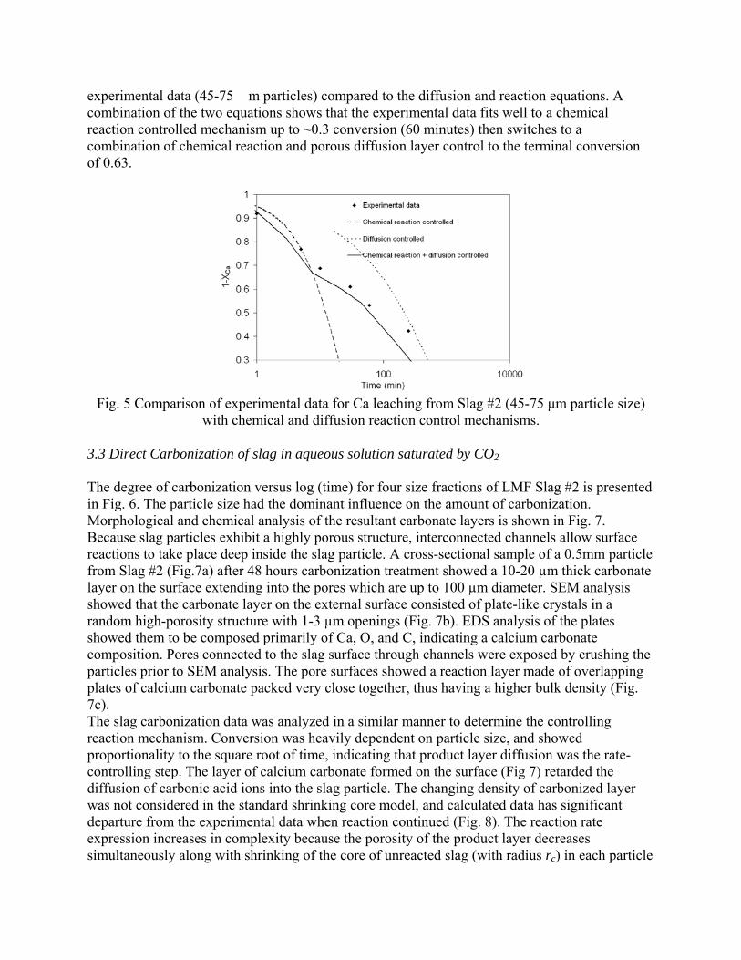
experimental data (45-75 �m particles) compared to the diffusion and reaction equations. A combination of the two equations shows that the experimental data fits well to a chemical reaction controlled mechanism up to ~0.3 conversion (60 minutes) then switches to a combination of chemical reaction and porous diffusion layer control to the terminal conversion of 0.63.
Fig. 5 Comparison of experimental data for Ca leaching from Slag #2 (45-75 μm particle size)
with chemical and diffusion reaction control mechanisms. 3.3 Direct Carbonization of slag in aqueous solution saturated by CO2
The degree of carbonization versus log (time) for four size fractions of LMF Slag #2 is presented in Fig. 6. The particle size had the dominant influence on the amount of carbonization. Morphological and chemical analysis of the resultant carbonate layers is shown in Fig. 7. Because slag particles exhibit a highly porous structure, interconnected channels allow surface reactions to take place deep inside the slag particle. A cross-sectional sample of a 0.5mm particle from Slag #2 (Fig.7a) after 48 hours carbonization treatment showed a 10-20 µm thick carbonate layer on the surface extending into the pores which are up to 100 µm diameter. SEM analysis showed that the carbonate layer on the external surface consisted of plate-like crystals in a random high-porosity structure with 1-3 µm openings (Fig. 7b). EDS analysis of the plates showed them to be composed primarily of Ca, O, and C, indicating a calcium carbonate composition. Pores connected to the slag surface through channels were exposed by crushing the particles prior to SEM analysis. The pore surfaces showed a reaction layer made of overlapping plates of calcium carbonate packed very close together, thus having a higher bulk density (Fig. 7c). The slag carbonization data was analyzed in a similar manner to determine the controlling reaction mechanism. Conversion was heavily dependent on particle size, and showed proportionality to the square root of time, indicating that product layer diffusion was the rate-controlling step. The layer of calcium carbonate formed on the surface (Fig 7) retarded the diffusion of carbonic acid ions into the slag particle. The changing density of carbonized layer was not considered in the standard shrinking core model, and calculated data has significant departure from the experimental data when reaction continued (Fig. 8). The reaction rate expression increases in complexity because the porosity of the product layer decreases simultaneously along with shrinking of the core of unreacted slag (with radius rc) in each particle
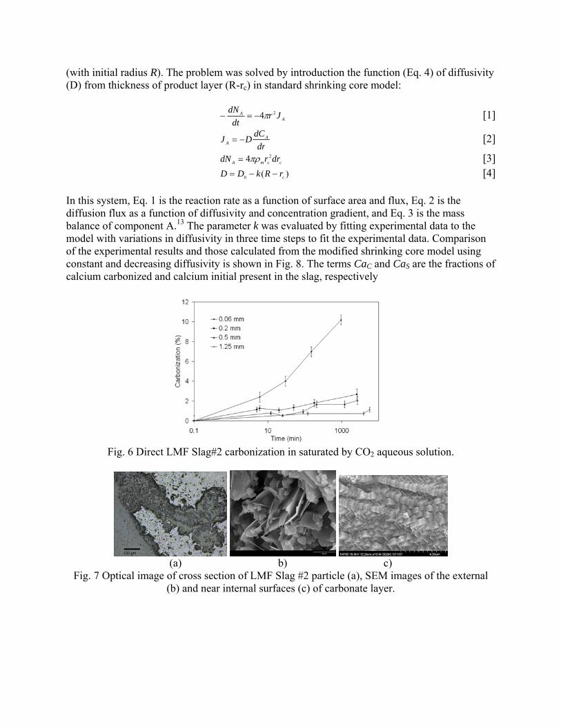
(with initial radius R). The problem was solved by introduction the function (Eq. 4) of diffusivity (D) from thickness of product layer (R-rc) in standard shrinking core model:
AA Jr
dtdN 24π−=− [1]
drdCDJ A
A −= [2]
ccmA drrdN 24πρ= [3] )(0 crRkDD −−= [4]
In this system, Eq. 1 is the reaction rate as a function of surface area and flux, Eq. 2 is the diffusion flux as a function of diffusivity and concentration gradient, and Eq. 3 is the mass balance of component A.13 The parameter k was evaluated by fitting experimental data to the model with variations in diffusivity in three time steps to fit the experimental data. Comparison of the experimental results and those calculated from the modified shrinking core model using constant and decreasing diffusivity is shown in Fig. 8. The terms CaC and CaS are the fractions of calcium carbonized and calcium initial present in the slag, respectively
Fig. 6 Direct LMF Slag#2 carbonization in saturated by CO2 aqueous solution.
(a) b) c)
Fig. 7 Optical image of cross section of LMF Slag #2 particle (a), SEM images of the external (b) and near internal surfaces (c) of carbonate layer.
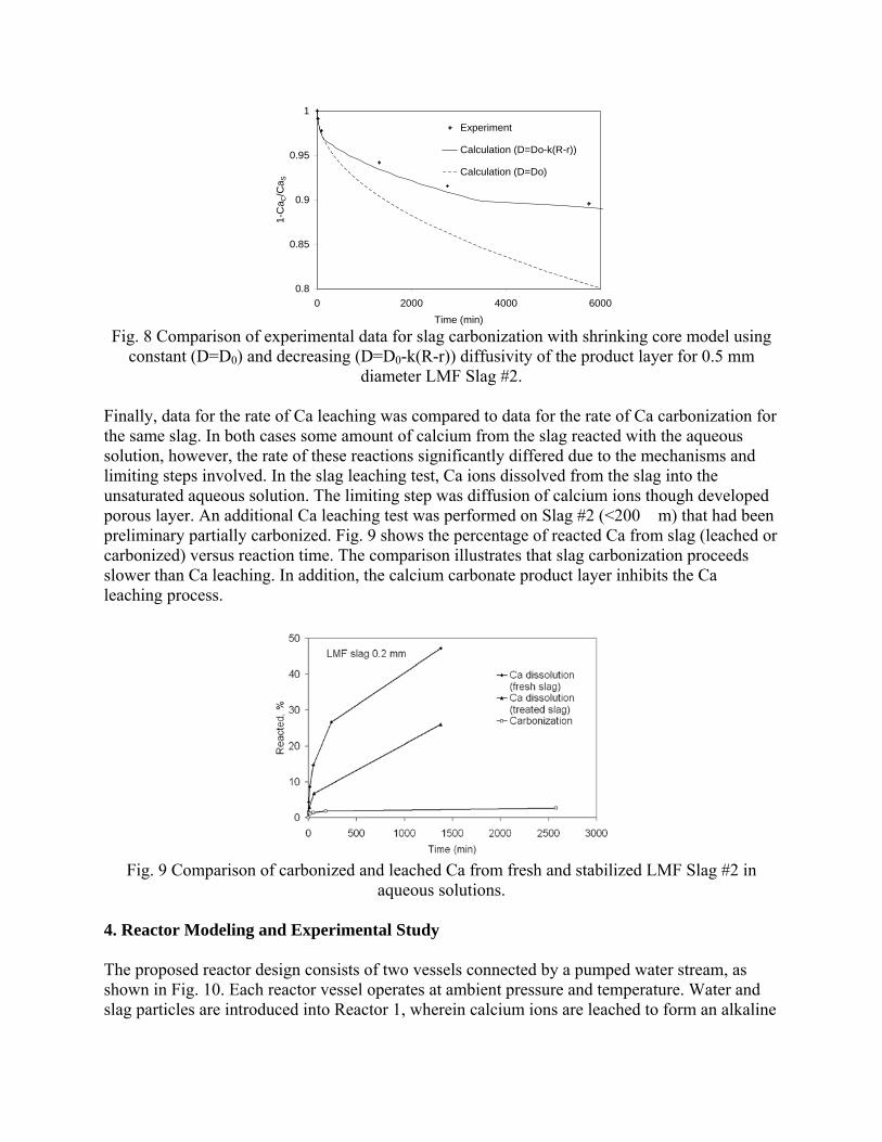
0.8
0.85
0.9
0.95
1
0 2000 4000 6000Time (min)
1-C
a C/C
a S
Experiment
Calculation (D=Do-k(R-r))
Calculation (D=Do)
Fig. 8 Comparison of experimental data for slag carbonization with shrinking core model using
constant (D=D0) and decreasing (D=D0-k(R-r)) diffusivity of the product layer for 0.5 mm diameter LMF Slag #2.
Finally, data for the rate of Ca leaching was compared to data for the rate of Ca carbonization for the same slag. In both cases some amount of calcium from the slag reacted with the aqueous solution, however, the rate of these reactions significantly differed due to the mechanisms and limiting steps involved. In the slag leaching test, Ca ions dissolved from the slag into the unsaturated aqueous solution. The limiting step was diffusion of calcium ions though developed porous layer. An additional Ca leaching test was performed on Slag #2 (<200 �m) that had been preliminary partially carbonized. Fig. 9 shows the percentage of reacted Ca from slag (leached or carbonized) versus reaction time. The comparison illustrates that slag carbonization proceeds slower than Ca leaching. In addition, the calcium carbonate product layer inhibits the Ca leaching process.
Fig. 9 Comparison of carbonized and leached Ca from fresh and stabilized LMF Slag #2 in
aqueous solutions. 4. Reactor Modeling and Experimental Study The proposed reactor design consists of two vessels connected by a pumped water stream, as shown in Fig. 10. Each reactor vessel operates at ambient pressure and temperature. Water and slag particles are introduced into Reactor 1, wherein calcium ions are leached to form an alkaline
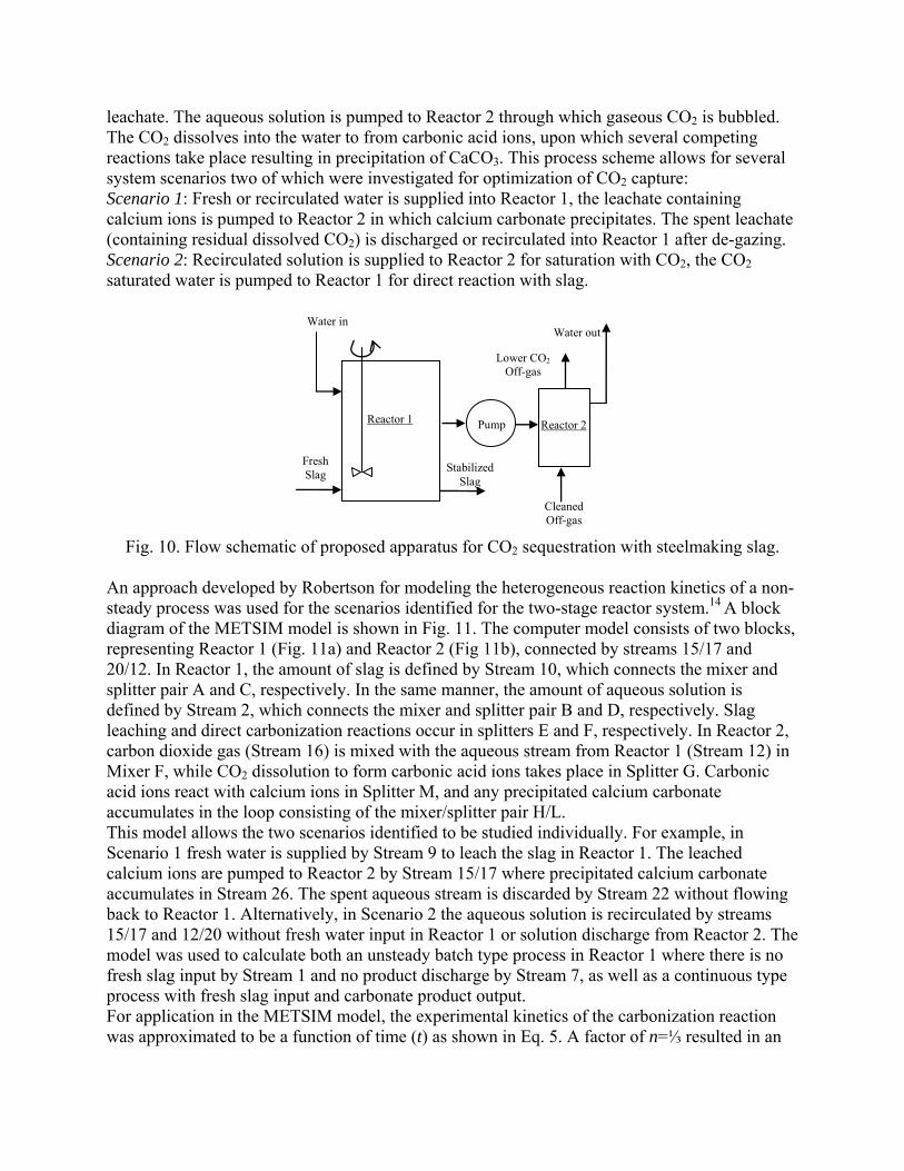
leachate. The aqueous solution is pumped to Reactor 2 through which gaseous CO2 is bubbled. The CO2 dissolves into the water to from carbonic acid ions, upon which several competing reactions take place resulting in precipitation of CaCO3. This process scheme allows for several system scenarios two of which were investigated for optimization of CO2 capture: Scenario 1: Fresh or recirculated water is supplied into Reactor 1, the leachate containing calcium ions is pumped to Reactor 2 in which calcium carbonate precipitates. The spent leachate (containing residual dissolved CO2) is discharged or recirculated into Reactor 1 after de-gazing. Scenario 2: Recirculated solution is supplied to Reactor 2 for saturation with CO2, the CO2 saturated water is pumped to Reactor 1 for direct reaction with slag.
Water out
Cleaned Off-gas
Reactor 2 Reactor 1
Fresh Slag Stabilized
Slag
Lower CO2 Off-gas
Pump
Water in
Fig. 10. Flow schematic of proposed apparatus for CO2 sequestration with steelmaking slag.
An approach developed by Robertson for modeling the heterogeneous reaction kinetics of a non-steady process was used for the scenarios identified for the two-stage reactor system.14 A block diagram of the METSIM model is shown in Fig. 11. The computer model consists of two blocks, representing Reactor 1 (Fig. 11a) and Reactor 2 (Fig 11b), connected by streams 15/17 and 20/12. In Reactor 1, the amount of slag is defined by Stream 10, which connects the mixer and splitter pair A and C, respectively. In the same manner, the amount of aqueous solution is defined by Stream 2, which connects the mixer and splitter pair B and D, respectively. Slag leaching and direct carbonization reactions occur in splitters E and F, respectively. In Reactor 2, carbon dioxide gas (Stream 16) is mixed with the aqueous stream from Reactor 1 (Stream 12) in Mixer F, while CO2 dissolution to form carbonic acid ions takes place in Splitter G. Carbonic acid ions react with calcium ions in Splitter M, and any precipitated calcium carbonate accumulates in the loop consisting of the mixer/splitter pair H/L. This model allows the two scenarios identified to be studied individually. For example, in Scenario 1 fresh water is supplied by Stream 9 to leach the slag in Reactor 1. The leached calcium ions are pumped to Reactor 2 by Stream 15/17 where precipitated calcium carbonate accumulates in Stream 26. The spent aqueous stream is discarded by Stream 22 without flowing back to Reactor 1. Alternatively, in Scenario 2 the aqueous solution is recirculated by streams 15/17 and 12/20 without fresh water input in Reactor 1 or solution discharge from Reactor 2. The model was used to calculate both an unsteady batch type process in Reactor 1 where there is no fresh slag input by Stream 1 and no product discharge by Stream 7, as well as a continuous type process with fresh slag input and carbonate product output. For application in the METSIM model, the experimental kinetics of the carbonization reaction was approximated to be a function of time (t) as shown in Eq. 5. A factor of n=⅓ resulted in an

appropriate fit for the reaction conversion (CaC/CaS) calculated from Equations 1-4, as well as the experimental data:
n
S
C tfCaCa )(1ln =⎟⎟
⎠
⎞⎜⎜⎝
⎛− [6]
a) b)
Fig. 11—Block diagrams of the METSIM model for Reactor 1 (a) and Reactor 2 (b), which are interconnected by streams 15/17 and 20/12.
Scenario 1 was modeled in which the slag was leached in Reactor 1 and the alkaline liquor was carbonized in Reactor 2. The basis for the model was fresh water feed to Reactor 1 at the same rate the spent liquor was discharged from Reactor 2. No water was recirculated from Reactor 2 to Reactor 1. The goal of this scenario was to analyze the influence of slag/solution ratio and solution residence time in Reactor 1 on the leaching result. The slag used in the model was the 0.2 mm fraction of LMF Slag #2, with 50 wt.% CaO. The model results show that both increasing the slag/solution ratio and the solution residence time in Reactor 1 produces a higher concentration of calcium ions in solution. Increasing the slag/solution ratio provides a diminishing increase in calcium ions in solution due to saturation of the aqueous phase (Fig. 12a). The fresh water throughput accelerates the leaching rate, which is dependent upon the residence time of Reactor 1 (Fig. 12b). The optimal residence time was defined by the maximum amount of leaching with minimal fresh water input. For slag with 0.2 mm particle diameter and 0.8% slag/solution ratio the optimal residence time was near 1 hour.
0
300
600
900
1200
0 500 1000 1500 2000Time (min)
Ca(
OH
) 2 (p
pm)
0.08% Slag/Solution0.8% Slag/Solution1.6% Slag/Solution
0.8% slag/liquid
0
300
600
900
1200
0 200 400 600 800 1000 1200 1400Time (min)
Ca(
OH
) 2 (p
pm)
5000 min 500 min5 minBatch
a) b)
Fig. 12 METSIM modeling of leaching LMF Slag #2 (0.2 mm diameter) at different slag/solution ratios in batch reactor without fresh water input (a) and increase of Ca leaching by
fresh water input into mix-flow type reactor with different solution residence time (b).
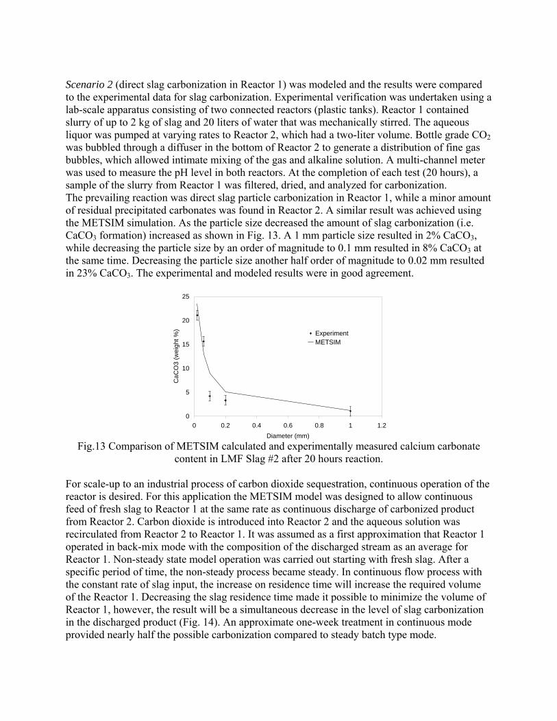
Scenario 2 (direct slag carbonization in Reactor 1) was modeled and the results were compared to the experimental data for slag carbonization. Experimental verification was undertaken using a lab-scale apparatus consisting of two connected reactors (plastic tanks). Reactor 1 contained slurry of up to 2 kg of slag and 20 liters of water that was mechanically stirred. The aqueous liquor was pumped at varying rates to Reactor 2, which had a two-liter volume. Bottle grade CO2 was bubbled through a diffuser in the bottom of Reactor 2 to generate a distribution of fine gas bubbles, which allowed intimate mixing of the gas and alkaline solution. A multi-channel meter was used to measure the pH level in both reactors. At the completion of each test (20 hours), a sample of the slurry from Reactor 1 was filtered, dried, and analyzed for carbonization. The prevailing reaction was direct slag particle carbonization in Reactor 1, while a minor amount of residual precipitated carbonates was found in Reactor 2. A similar result was achieved using the METSIM simulation. As the particle size decreased the amount of slag carbonization (i.e. CaCO3 formation) increased as shown in Fig. 13. A 1 mm particle size resulted in 2% CaCO3, while decreasing the particle size by an order of magnitude to 0.1 mm resulted in 8% CaCO3 at the same time. Decreasing the particle size another half order of magnitude to 0.02 mm resulted in 23% CaCO3. The experimental and modeled results were in good agreement.
0
5
10
15
20
25
0 0.2 0.4 0.6 0.8 1 1.2Diameter (mm)
CaC
O3
(wei
ght %
) ExperimentMETSIM
Fig.13 Comparison of METSIM calculated and experimentally measured calcium carbonate
content in LMF Slag #2 after 20 hours reaction. For scale-up to an industrial process of carbon dioxide sequestration, continuous operation of the reactor is desired. For this application the METSIM model was designed to allow continuous feed of fresh slag to Reactor 1 at the same rate as continuous discharge of carbonized product from Reactor 2. Carbon dioxide is introduced into Reactor 2 and the aqueous solution was recirculated from Reactor 2 to Reactor 1. It was assumed as a first approximation that Reactor 1 operated in back-mix mode with the composition of the discharged stream as an average for Reactor 1. Non-steady state model operation was carried out starting with fresh slag. After a specific period of time, the non-steady process became steady. In continuous flow process with the constant rate of slag input, the increase on residence time will increase the required volume of the Reactor 1. Decreasing the slag residence time made it possible to minimize the volume of Reactor 1, however, the result will be a simultaneous decrease in the level of slag carbonization in the discharged product (Fig. 14). An approximate one-week treatment in continuous mode provided nearly half the possible carbonization compared to steady batch type mode.
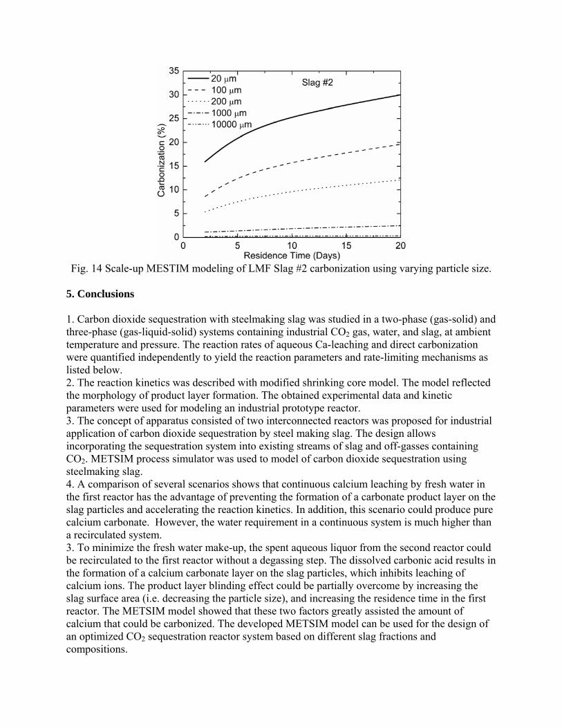
Fig. 14 Scale-up MESTIM modeling of LMF Slag #2 carbonization using varying particle size.
5. Conclusions 1. Carbon dioxide sequestration with steelmaking slag was studied in a two-phase (gas-solid) and three-phase (gas-liquid-solid) systems containing industrial CO2 gas, water, and slag, at ambient temperature and pressure. The reaction rates of aqueous Ca-leaching and direct carbonization were quantified independently to yield the reaction parameters and rate-limiting mechanisms as listed below. 2. The reaction kinetics was described with modified shrinking core model. The model reflected the morphology of product layer formation. The obtained experimental data and kinetic parameters were used for modeling an industrial prototype reactor. 3. The concept of apparatus consisted of two interconnected reactors was proposed for industrial application of carbon dioxide sequestration by steel making slag. The design allows incorporating the sequestration system into existing streams of slag and off-gasses containing CO2. METSIM process simulator was used to model of carbon dioxide sequestration using steelmaking slag. 4. A comparison of several scenarios shows that continuous calcium leaching by fresh water in the first reactor has the advantage of preventing the formation of a carbonate product layer on the slag particles and accelerating the reaction kinetics. In addition, this scenario could produce pure calcium carbonate. However, the water requirement in a continuous system is much higher than a recirculated system. 3. To minimize the fresh water make-up, the spent aqueous liquor from the second reactor could be recirculated to the first reactor without a degassing step. The dissolved carbonic acid results in the formation of a calcium carbonate layer on the slag particles, which inhibits leaching of calcium ions. The product layer blinding effect could be partially overcome by increasing the slag surface area (i.e. decreasing the particle size), and increasing the residence time in the first reactor. The METSIM model showed that these two factors greatly assisted the amount of calcium that could be carbonized. The developed METSIM model can be used for the design of an optimized CO2 sequestration reactor system based on different slag fractions and compositions.
6. References 1. U.S. Department of the Interior, U.S. Geological Survey, Minerals Information. 12 January 2005 http://minerals.usgs.gov/minerals/pubs/commodity/iron_&_steel_slag/ 2. H.G. van Oss: U.S. Geological Survey Minerals Yearbook (2003): 69.1-69.3. 30 June 2005 http://minerals.usgs.gov/minerals/pubs/commodity/iron_&_steel_slag/islagmyb03.pdf 3. National Slag Association [brochure]. 30 June 2005 http://www.nationalslagassoc.org/PDF_files/SSPremAgg.PDF. 4. D.W. Lewis: National Slag Association. Report MF 182-6. 5. Missouri Department of Transportation. 14 April 2004 http://www.modot.org/business/standards_and_specs/nov2004specbook/Sec1002.pdf 6. P.S. Kandhal and G.L. Hoffman: Transportation Research Record, 1997, no. 1583, pp. 28-36. 7. C.H. Rawlins, V.L. Richards, K.D. Peaslee, and S.N. Lekakh: Proceedings of the AISTech 2006 Conference, May 1-4, 2006; Cleveland, OH, U.S. 8. C.H. Rawlins, V.L. Richards, K.D. Peaslee, and S.N. Lekakh: Steel Times International, 2006, vol. 30, no. 7, pp. 25-26. 9. C.H. Rawlins, V.L. Richards, K.D. Peaslee, and S.N. Lekakh: TMS 2007, 136th Annual meeting Proceeding. Materials Processing Fundamentals, pp. 193-202 10. W. Huijgen, G-J. Witkamp, and R.N.J. Comans: Environ. Sci. Technol., 2005, vol. 39, no. 24, pp. 9676-9682. 11. Luigi Marini: Geological Sequestration of Carbon Dioxide; Thermodynamics, Kinetics, and Reaction Path Modeling, Elsevier B.V., Amsterdam, The Netherlands, 2007, pp. 88-91. 12. J.K. Stolaroff, G.V. Lowry, and D. W. Keith: Energy Conservation and Management, 2005, vol. 46, no. 5, pp. 687-699. 13. K.N. Han, Fundamental of Aqueous Metallurgy, Society for Mining, Metallurgy, and Exploration Inc., Littleton, CO, 2002, pp. 129-140. 14. D.G.C., Robertson D. G. C.: EPD Congress. 1995, Proc. Symposium. TMS Annual Meeting, 1995, pp. 347-61.
American Iron and Steel Institute Technology Roadmap Program
CO2 Breakthrough Program Phase I: Geological Sequestration of CO2 by Hydrous Carbonate Formation with Reclaimed Slag
Final Report - Attachment E
Articles Submitted for Publication
January 2008
Two-Stage Reactor for Geological Sequestration of Carbon Dioxide Using Steelmaking Slag
LEKAKH, S.N., ROBERTSON, D.G.C., RAWLINS, C.H., RICHARDS, V.L., PEASLEE, K.D.
ABSTRACT
Hydrous carbonate sequestration of CO2 using steelmaking slag was studied using a METSIM process model for
analysis of experimental data and determination of reactor design parameters. A two-stage system with water/slag
contact in Reactor 1 and alkaline-leachate/CO2 contact in Reactor 2 was analyzed for several possible operating
scenarios including batch versus continuous processing and fresh water versus recirculation. The METSIM leaching
and carbonization models were verified with results obtained from previous slag sequestration experiments. Fresh
water additions to Reactor 1 allowed the highest leaching efficiency and resulted in excellent carbonization in
Reactor 2, however, a continuous system has a high water demand. Recirculation of the spent leachate minimizes
the fresh water addition but produces a calcium carbonate product layer on the slag particles in Reactor 1 which
inhibits the leaching process. Increasing the slag surface area, slag/solution ratio, or reactor residence time partially
overcomes product layer blinding. The optimal residence time was defined for different process parameters and slag
particle size.
I. INTRODUCTION
Steelmaking slag contains a high fraction of alkaline-earth oxides which exothermically form carbonates thus
rendering this material as an excellent vehicle for capture and sequestration of carbon dioxide. Particulate-based slag
is readily available in plentiful quantities at steel mills. This material has been shown to have the potential to
sequester 35-45% of the CO2 generated from EAF production and 6-11% of the CO2 generated from BOF
production.1 Extraction of CO2 from steel manufacturing offgas with steelmaking slag for geological sequestration
was studied by quantifying the extent and rate of carbonate formation under near-atmospheric aqueous conditions.2
The natural carbonate formation kinetics are very slow, thus fine grinding to increase slag surface area, increasing
pCO2, increasing temperature, and aqueous catalysis are being investigated to increase the reaction rate suitable for
industrial use.3 The goal of this research is to design a reactor suitable for aqueous-based carbonization of
steelmaking slag for geological sequestration of carbon dioxide.
Several research groups have investigated the design of an aqueous reactor system for sequestration of carbon
dioxide using steelmaking slag. Huijgen et al.4, Eloneva et al.
5, and Stolaroff et al.
6 have worked with leaching and
carbonization of steelmaking slag under various conditions. They each found that the rate and extent of aqueous
leaching and carbonization was inversely related to particle size the primary factor, while pH, temperature and CO2
partial pressure had milder effects on Ca-conversion. In comparison with naturally occurring wollastonite (CaSiO3),
steel slag was able to sequester 11 times more CO2 at ambient temperature. Other consortiums have actively
researched methods of large-scale mineral-based sequestration of carbon dioxide. O’Connor et al. conducted
research to optimize the process conditions for direct aqueous carbonation of silicate minerals.7-9
Activation of the
minerals (serpentine or olivine) through attrition grinding or heat-treatment was necessary to achieve high levels of
carbonization. Additions of NaHCO3 and NaCl to the suspension were found to catalyze the reaction significantly.
Park et al. investigated carbonization of olivine and serpentine similar to the work of O’Connor et al.10
Aqueous
carbonation studies revealed that increasing the reactor temperature, pCO2, and NaHCO3/NaCl concentration
increased the carbonization rate. Fernandez et al. found the reactivity of magnesite slurries for carbonization
increases with decreasing particle size and increase with pCO2, temperature, and solid-liquid ratio.11
The current study capitalizes on the findings from many of these researchers as well as current experimental work
to model the design of a reactor for aqueous-based sequestration of carbon dioxide with steelmaking slag. The
current process uses a two-stage system in order to decouple the competing leaching and carbonization mechanisms
that occur simultaneously. The reaction rate of calcium leaching from slag into water and the direct carbonation of
slag particles were investigated separately to understand the limiting mechanisms for the overall sequestration
process. Areas modeled in this investigation to understand the reaction rate include particle size, reactor vessel
residence time, reaction time, and reactor flow sequencing.
II. REACTOR DESIGN AND MODELING PROCEDURE
A. CO2 Sequestration Reactor Design
Carbon sequestration through the aqueous-based reaction of CO2-containing offgas with lime-bearing
steelmaking slag allows for several possible reactions to take place. A list of the key competing reactions considered
is given in Table 1. For simplification the calcium containing phases are all designated as CaO.
The process design consists of two vessels connected by a pumped water stream, as shown in Figure 1. Each
reactor vessel operates at ambient pressure and temperature. Water and slag particles are introduced into Reactor 1,
wherein calcium ions are dissolved to form an alkaline leachate. The leachate is pumped to Reactor 2 through which
gaseous CO2 is bubbled. The CO2 dissolves into the water to from carbonic acid ions, upon which several competing
reactions take place resulting in precipitation of CaCO3. This process design allows for several system scenarios to
be investigated for optimization of CO2 capture.
Scenario 1: Fresh water is supplied into Reactor 1 and the leachate containing calcium ions is pumped to Reactor
2 where calcium carbonate precipitates. The spent leachate (containing residual dissolved CO2) is discharged.
Scenario 2: The same design as Scenario 1 except that the water supplied to Reactor 1 is recirculated from
Reactor 2 after complete degassing.
Scenario 3: Fresh water is supplied to Reactor 2 for saturation with CO2 then the CO2 saturated water is pumped
to Reactor 1 for direct reaction with slag. The spent water (containing residual dissolved CO2) is discarded.
Scenario 4: The water supplied to Reactor 1 is recirculated from Reactor 2 without degassing.
Experimental verification of the different scenarios was undertaken using lab-scale apparatus consisting of two
connected reactors (tanks). Recirculation of the aqueous stream took place both with and without partial degassing
by argon bubbling. Reactor 1 contained mechanically stirred slurry of 2 kg of slag in 20 liters of water. The aqueous
leachate was pumped at varying rates to Reactor 2, which had a two-liter volume. Bottle grade CO2 was bubbled
through a diffuser in the bottom of Reactor 2 to generate a distribution of fine gas bubbles to allow intimate mixing
of the gas and alkaline solution. A multi-channel pH meter was used to directly measure the pH level in both
reactors. At the completion of each test, a sample of the slurry from Reactor 1 was filtered, dried, and analyzed for
fraction carbonization as described in the previous work.3 Kinetic data from this previous work was used in the
studied scenarios, while METSIM process simulation software was used to perform the modeling calculations.13
B. METSIM Modeling Procedure
An approach developed by Robertson for modeling heterogeneous reaction kinetics of a non-steady-state process
was used for the two-stage reactor system.14
A block diagram of the METSIM model is shown in Figure 2. The
computer model consists of two blocks, representing Reactor 1 (Figure 2a) and Reactor 2 (Figure 2b), connected by
streams 15/17 and 20/12. In Reactor 1, the amount of input slag is defined by Stream 10 which connects the mixer
and splitter pair A and C, respectively. In the same manner, the amount of aqueous solution is defined by Stream 2
which connects the mixer and splitter pair B and D, respectively. Slag leaching and direct carbonization reactions
occur in splitters E and F, respectively. In Reactor 2, carbon dioxide gas (Stream 16) is mixed with the aqueous
stream from Reactor 1 (Stream 12) in Mixer F, while CO2 dissolution to form carbonic acid ions takes place in
Splitter G. Carbonic acid ions react with calcium ions in Splitter M, and any precipitated calcium carbonate
accumulates in the loop consisting of the mixer/splitter pair H/L.
This model allows the flexibility of studying each of the four scenarios individually. For example, in Scenario 1
fresh water is supplied by Stream 9 to leach the slag in Reactor 1. The leached calcium ions are pumped to Reactor 2
by Stream 15/17 where precipitated calcium carbonate accumulates in Stream 26. The spent aqueous stream is
discarded by Stream 22 without flowing back to Reactor 1. Alternatively, in Scenario 4 the aqueous solution is
recirculated by streams 15/17 and 12/20 without fresh water input in Reactor 1 or solution discharge from Reactor 2.
The model was used to calculate both a non-steady-state batch type process in Reactor 1 with no fresh slag input by
Stream 1 and no product discharge by Stream 7, as well as a steady-state continuous type process with fresh slag
input and carbonate product output.
C. Experimental Reaction Kinetics for METSIM Modeling
In the METSIM model, the reaction rate F is defined by Equation 1. The rate constant K is defined by the mass
flow rate (mi/∆t) from the mixer/splitter to the phase splitter where the reaction occurs with the particular value of
reaction extent (RE) at each time step (∆t). The experimentally measured kinetic parameters from earlier work for
leaching and carbonization were used to evaluate the factors listed in Equation 1.3
)(REKF [1]
Carbonization. Heterogeneous direct aqueous carbonization of slag particles was modeled for the batch case of
Scenario 4 in order to validate the results with the experimental data. In this scenario, the reaction rate is limited by
mass transfer through the carbonate product layer, and the reaction rate decreases with time as a result of increasing
thickness and density of carbonate layer.3 The reaction rate expression increases in complexity because the porosity
of the product layer decreases simultaneously along with shrinking of the core of unreacted slag (with radius rc) in
each particle (with initial radius R). Therefore, a modified shrinking core model was used with the assumption that
diffusivity (D) decreases as the reaction proceeded. This model is defined by Equations 2-5, where JA (moles/m2·s)
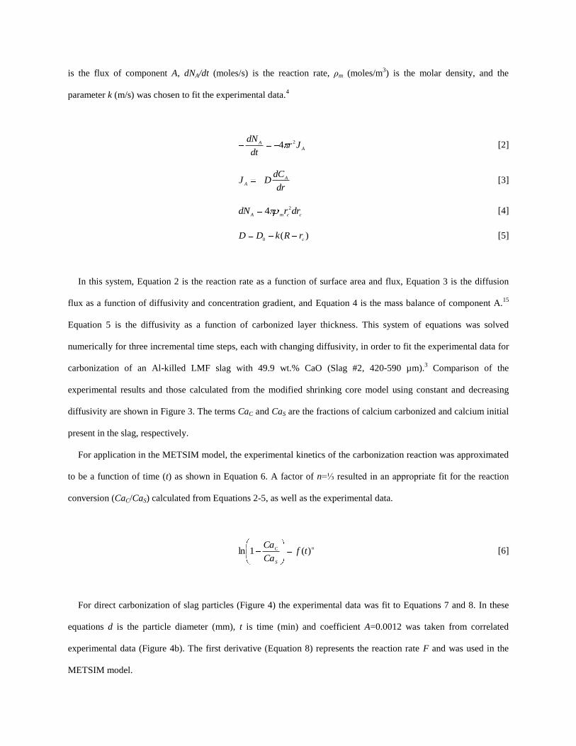
is the flux of component A, dNA/dt (moles/s) is the reaction rate, ρm (moles/m3) is the molar density, and the
parameter k (m/s) was chosen to fit the experimental data.4
A
A Jrdt
dN 24 [2]
dr
dCDJ A
A [3]
ccmAdrrdN 24 [4]
)(0 c
rRkDD [5]
In this system, Equation 2 is the reaction rate as a function of surface area and flux, Equation 3 is the diffusion
flux as a function of diffusivity and concentration gradient, and Equation 4 is the mass balance of component A.15
Equation 5 is the diffusivity as a function of carbonized layer thickness. This system of equations was solved
numerically for three incremental time steps, each with changing diffusivity, in order to fit the experimental data for
carbonization of an Al-killed LMF slag with 49.9 wt.% CaO (Slag #2, 420-590 µm).3 Comparison of the
experimental results and those calculated from the modified shrinking core model using constant and decreasing
diffusivity are shown in Figure 3. The terms CaC and CaS are the fractions of calcium carbonized and calcium initial
present in the slag, respectively.
For application in the METSIM model, the experimental kinetics of the carbonization reaction was approximated
to be a function of time (t) as shown in Equation 6. A factor of n=⅓ resulted in an appropriate fit for the reaction
conversion (CaC/CaS) calculated from Equations 2-5, as well as the experimental data.
n
S
C tfCa
Ca)(1ln [6]
For direct carbonization of slag particles (Figure 4) the experimental data was fit to Equations 7 and 8. In these
equations d is the particle diameter (mm), t is time (min) and coefficient A=0.0012 was taken from correlated
experimental data (Figure 4b). The first derivative (Equation 8) represents the reaction rate F and was used in the
METSIM model.
31
exp1 td
ACaCa
SC [7]
31
32
exp3
td
At
d
ACa
dt
dCaF SC [8]
Leaching. A similar analysis of the calcium leaching process was undertaken, with a set of reactions that
corresponds to Scenario 1. The reaction rate changes during the leaching process because the initial chemical
reaction limited mechanism is overtaken by slower diffusion through the porous surface layer developed during
treatment.3
The difference in Equation 9 for leaching when compared to carbonization (Equation 8) follows from the
necessity, due to batch test procedure, of taking into account the solution volume V (cm3), the calcium saturation
level Csat (wt. %) for solution in equilibrium with solid Ca(OH)2, and the total surface area S= 6W/ρd (cm2) of slag
particles with diameter d (cm), density ρ (g/cm3), and weight W (g) In Equation 9, CD is the concentration of
dissolved calcium in solution (wt. %) and the coefficient A=0.0004 was taken from a correlation of experimental
data shown in Figure 5.
31
32
31 exp AStStVAC
dt
dCF
sat
D [9]
The extent of calcium leaching from slag depends on the slag particle size and the particle surface conditions.
Calcium from fresh slag leached twice as fast when compared to the same slag in carbonized condition.3 Because
leaching and carbonization may occur simultaneously in Scenario 4 in the designed apparatus, the leaching reaction
rate (Equation 9) was linked to the current slag carbonization level during each calculation step.
III. RESULTS AND DISCUSSION
A. Model Validation With Batch Reactor
The METSIM model was first validated by comparing the calculated results with the experimental data obtained
from the batch reactor tests of the previous work.3
Leaching. The calcium leaching experiments were performed in a batch type reactor under protective argon
atmosphere with unsaturated aqueous solutions, which corresponds to Scenario 1 for Reactor 1. The METSIM
modeling of a batch type reactor was done by disconnecting Reactor 1 from Reactor 2 and disregarding the feed
streams. Figure 6 shows the comparison of calculated and experimental results for the concentration of calcium
leached (CD) from LMF Slag #2 (49.9 wt.% CaO) at two average particle sizes (60 µm and 200 µm). The calculated
leaching results were in good agreement with the experimental data.
Carbonization. Direct carbonization of the same slag was studied in a batch type reactor using aqueous solution
saturated by carbonic acid under CO2 at one atmosphere pressure.3 This process was modeled using batch type
Reactor 1 connected to Reactor 2 with continuously flowing CO2 gas saturating the aqueous solution. The transport
of calcium ions from Reactor 1 to Reactor 2 was prohibited. This approach modeled the experimental conditions of
Scenario 3. Figure 7 shows the experimental results for the amount of calcium carbonized (CaC) were in good
agreement compared to that predicted by the METSIM model for two different average particle sizes of LMF Slag
#2 (60 µm and 2800 µm).
B. Model Validation with Experimental Two-Stage Reactor
The METSIM model was further validated by comparing the calculated results with the experimental data
obtained from the two-stage reactor tests of the previous work.3 Scenario 4 was modeled (batch amount of slag with
recirculated, un-degassed water) and the results compared to the experimental data for slag carbonization. In the
experimental work, both Ca leaching and direct slag particle carbonization were monitored simultaneously in both
reactors. Reactor 1 contained 200 g LMF slag (<3.2 mm) in 20 liters of water, while Reactor 2 contained two liters
of solution through which 1.5 g/min CO2 was bubbled. A solution exchange rate of one liter per minute was used to
transfer the fluid between the two reactors. The experimental procedure included preliminary soaking of slag in
Reactor 1 for 20 minutes with solution recirculation but without CO2 input in Reactor 2. During this time, the pH
increased in both reactors as Ca(OH)2 was formed. Shortly after introducing CO2 into Reactor 2, the concentration
of calcium ions in solution decreased while concentration of carbonic acid increased. The rate of decrease in pH
(Figure 8) depended on the solution residence time in Reactor 1 (20 minutes) and Reactor 2 (2 min).
The reaction was allowed to proceed for 20 hours, after which the product was dried, sieved, and analyzed for
calcium carbonization. The prevailing reaction was direct slag particle carbonization in Reactor 1, while a minor
amount of residual precipitated carbonates was found in Reactor 2. A similar result was achieved using the

METSIM simulation. The model predicted carbonate precipitation in Reactor 2 during a short period of time
immediately after introducing CO2, after which direct carbonization of the slag in Reactor 1 took predominance. As
the particle size decreased the amount of slag carbonization (i.e. CaCO3 formation) increased as shown in the model
results in Figure 9a. A 1000 µm particle size resulted in 2% CaCO3 at 20 hours (1200 min), while decreasing the
particle size by an order of magnitude to 100 µm resulted in 8% CaCO3 at the same time. Decreasing the particle
size another half order of magnitude to 20 µm resulted in 23% CaCO3. A comparison of the experimental (Figure
9b) and modeled (Figure 9a) results for five particle sizes shows good agreement.
C. Industrial Process Modeling
The validated METSIM process model was used to study the four scenarios defined for the purpose of reactor
flow schematic optimization.
Scenario 1: Continuous and Batch Operation. The goal of this scenario was to analyze the influence of
slag/solution ratio and solution residence time in Reactor 1 on the extent of leaching only. In this model, slag was
leached in Reactor 1 and the alkaline leachate was carbonized in Reactor 2. The slag used was LMF Slag #2 with
49.9 wt.% CaO and a monosize 200 µm distribution. During continuous operation, fresh water was input into
Reactor 1, which contained a fixed amount of slag, while at the same rate the spent leachate was discharged from
Reactor 2, with no water recirculated to Reactor 1. For comparison, batch operation was studied in which there was
no water flow in or out of Reactor 1, only a fixed starting volume of water and slag was used.
The results of this model are presented in Figure 10 and show that both increasing the slag/solution ratio and the
solution residence time in Reactor 1 resulted in a higher concentration of calcium ions in solution. Increasing the
slag/solution ratio with zero water throughput (i.e. batch mode) provided a diminishing increase in calcium ions in
solution due to saturation of the aqueous phase (Figure 10a). For example, increasing the slag solution ratio by an
order of magnitude from 0.08% to 0.8% results in an increase of Ca(OH)2 from 150 PPM to 950 PPM at 10 hours,
while a further doubling of the slag/solution ratio to 1.6% results in a corresponding increase to 1100 PPM at the
same time. To overcome saturation of the aqueous phase, the feed water throughput in Reactor 1 can be increased,
which corresponds to decreasing the residence time (Figure 10b). At a fixed slag/solution ratio of 0.8%, 5000 minute
residence time approaches a batch system, which has a theoretical infinite residence time. As the residence time
decreases the resulting solution becomes less saturated and at five minutes the leachate is very under-saturated.
While minimizing the solution saturation provides increased driving force for Ca dissolution, it also requires a

significant increase in feed water. The total fraction of calcium leached from the slag (y-axis of Figure 10c) is equal
to the concentration of calcium in solution multiplied by the solution volume. The optimal residence time is
therefore a balance between maximizing the amount leached with minimizing fresh water input. For slag with 200
µm particle diameter (monosize) and 0.8% slag/solution ratio, the optimal residence time is near 1 hour (Figure
10c).
Scenario 2: This scenario minimizes fresh water input into the system by recirculating the leachate from Reactor
2 to Reactor 1. However, for this scenario to work properly the recirculated leachate must be fully degassed to
prevent carbonic acid from reporting to Reactor 1. Preliminary experiments with degassing the leachate by argon
bubbling showed that full leachate degassing is difficult to achieve and the residual content of carbonic acid will
provide direct carbonization of the slag particles in Reactor 1. This scenario is therefore covered by the study of
Scenario 4.
Scenario 3: This scenario inputs fresh water into Reactor 2 for saturation with CO2, then the CO2 saturated water
is pumped to Reactor 1 for direct reaction with slag. As this scenario requires a significant quantity of fresh water
input, it was not modeled in this analysis.
Scenario 4: Steady-State Continuous Operation. For scale-up to an industrial process of carbon dioxide
sequestration, continuous processing of slag through the system is desired. To meet this criteria a steady-state
METSIM model was setup to allow continuous feed of fresh slag to Reactor 1 at the same rate carbonized product
was discharged from Reactor 2. Carbon dioxide was introduced into Reactor 2 and the aqueous solution was
recirculated from Reactor 2 to Reactor 1. As a first approximation, Reactor 1 was assumed to operate in back-mix
mode with the composition of the discharged stream as an average for Reactor 1. The steady-state model was
compared to a batch processing model, and both cases used fresh slag (LMF Slag #2 with 49.9 wt.% CaO).
In batch processing mode, the amount of slag carbonization achieved increased steadily with reaction time, as
shown in Figure 11a. At seven days (10,800 min.) of processing in batch mode, ~8% carbonization was achieved
using a 200 μm particle. In steady-state processing mode, with a constant amount of slag throughput, the overall
amount of carbonization was dependent upon Reactor 1 slag residence time and particle size (Figure 11b). A 200
µm particle at seven days residence time achieved ~8% carbonization, while a 20 µm particle achieved ~22.5%
carbonization. The particle size is critical as a 1 mm particle achieved only ~2% carbonization at the same residence
time. Increasing the slag residence time of Reactor 1 results in a higher amount of carbonization achieved. For a 200
μm particle, two day residence time gave ~5% carbonization, while twenty day residence time gave ~12%
carbonization. While increasing the slag residence time in Reactor 1 results in a higher amount of carbonization, it
also requires a larger reactor volume. Decreasing the slag residence time makes it possible to minimize the volume
of Reactor 1, but result in a simultaneous decrease in the level of slag carbonization in the discharged product. A
balance can be realized between particle size and reactor residence time (volume). To achieve a specific amount of
carbonization, reducing the slag particle size allows for reduction in reactor residence time (e.g. volume).
IV. CONCLUSIONS
METSIM process simulation software was used to model several reactor design scenarios for hydrous carbonate
sequestration of CO2 using steelmaking slag. A two-stage reactor design was modeled in batch and continuous
mode. The process allowed introducing water and slag into the first reactor and carbon dioxide into the second
reactor, with the possibility of recirculation of the solution. A comparison of the scenarios shows that continuous
calcium leaching by fresh water in the first reactor has the advantage of preventing the formation of a carbonate
product layer on the slag particles, which could reduce the leaching efficiency. However, the water requirement in a
continuous system is much higher than a recirculated system. To minimize the fresh water make-up, the spent
aqueous liquor from the second reactor could be recirculated to the first reactor. The drawback to this system is that
the residual absorbed CO2 in the recirculated water results in the formation of a calcium carbonate later on the slag
particles, which inhibits leaching of calcium ions. The product layer blinding effect could be partially overcome by
increasing the slag surface area (i.e. decreasing the particle size), and increasing the residence time in the first
reactor. The METSIM model showed that these two factors greatly assisted the amount of calcium that could be
carbonized. It was shown that the METSIM model is a useful tool for designing and optimizing CO2 sequestration
reactor systems based on different slag fractions and compositions.
V. ACKNOWLEDGEMENTS
This paper was prepared as an account of work sponsored by the U.S. Department of Energy, in cooperation with
the American Iron and Steel Institute (AISI) and its participating companies, under Agreement DE-FC36-
97ID13554. Such support does not constitute an endorsement by DOE or AISI of the views expressed in the article.
The authors also acknowledge the support of DOFASCO, Gallatin Steel, Hylsa, IPSCO, Mittal Steel, Praxair,
Nucor, Timken Company, and US Steel.
VI. REFERENCES
1. C.H. Rawlins, V.L. Richards, K.D. Peaslee, and S.N. Lekakh: Steel Times Intern., 2006, vol. 30, no. 7, pp. 25-
26.
2. C.H. Rawlins, V.L. Richards, K.D. Peaslee, and S.N. Lekakh: Proc. AISTech 2006 Conf., May 1-4, 2006;
Cleveland, OH, U.S.
3. S.N. Lekakh, C.H. Rawlins, D.R. Robertson, V.L. Richards, and K.D. Peaslee: manuscript accepted by Metall.
Mater. Trans. B, 2007.
4. W. Huijgen, G-J. Witkamp, and R.N.J. Comans: Environ. Sci. Technol., 2005, vol. 39, no. 24, pp. 9676-9682.
5. S. Eloneva, S. Teir, C.-J. Fogleholm, and R. Zevenhoven: Proc. 4th
Nordic Minisymp. Carbon Dioxide Capture
and Storage.
6. J.K. Stolaroff, G.V. Lowry, and D. W. Keith: Energy Conserv. Manag., 2005, vol. 46, no. 5, pp. 687-699.
7. W.K. O’Connor, R.P. Walters, D.C. Dahlin, G.E. Rush, D.N. Nilsen, and P.C. Turner: Proc. 26th
Int. Tech.
Conf. Coal Utiliz. Fuel Syst., 2001, pp. 765-776.
8. M.T., Ityokumbul, S. Chander, W.K. O'Connor, D.C. Dahlin, and S.J. Gerdemann: Proc. 18th
Annu. Int.
Pittsburgh Coal Conf., 2001, pp. 843-852.
9. L.R. Penner, S.J. Gerdemann, D.C. Dahlin, W.K. O’Connor, and D.N. Nilsen: Proc. 28th
Int. Tech. Conf. Coal
Utiliz. Fuel Syst, 2003, pp. 353-364.
10. A.-H. Park, R.A. Jadhav, and L.-S. Fan: Proc. Annu. Meet. AIChE, 2001, paper 257a.
11. A.I., Fernandez, J.M. Chimenos, M. Segarra, M.A. Fernández, and F. Espiell: Hydromet., 1999, vol. 53.2, pp.
155-167.
12. Luigi Marini: Geological Sequestration of Carbon Dioxide; Thermodynamics, Kinetics, and Reaction Path
Modeling, Elsevier B.V., Amsterdam, The Netherlands, 2007, pp. 88-91.
13. METSIM™
Ver. 15.07, 2007.
14. D.G.C., Robertson D. G. C.: EPD Congr. 1995, Proc. Symp. TMS Annu. Meet., 1995, pp. 347-61.
15. Octave Levenspiel: Chemical Reaction Engineering, John Wiley & Sons, Hoboken, NJ, 1962, pp. 338-357.
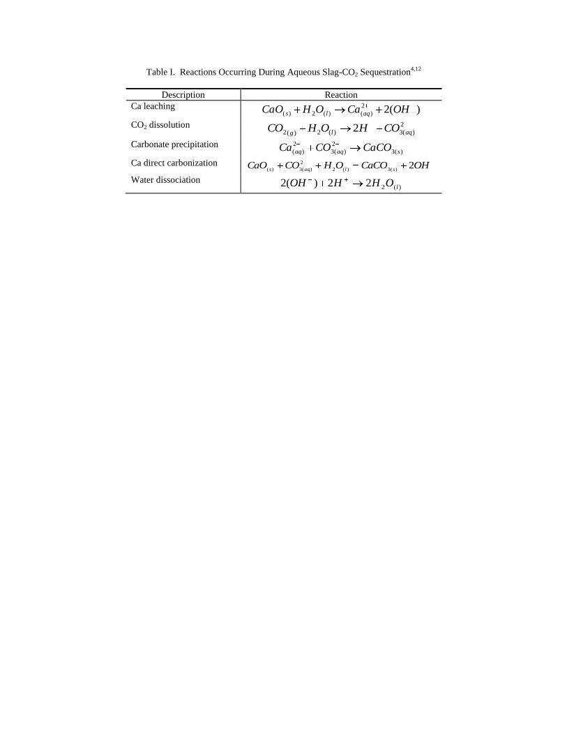
Table I. Reactions Occurring During Aqueous Slag-CO2 Sequestration4,12
Description Reaction
Ca leaching )(22
)()(2)( OHCaOHCaO aqls
CO2 dissolution 2
)(3)(2)(2 2 aqlgCOHOHCO
Carbonate precipitation )(3
2
)(3
2
)( saqaq CaCOCOCa
Ca direct carbonization OHCaCOOHCOCaOslaqs
2)(3)(2
2
)(3)(
Water dissociation )(222)(2 lOHHOH
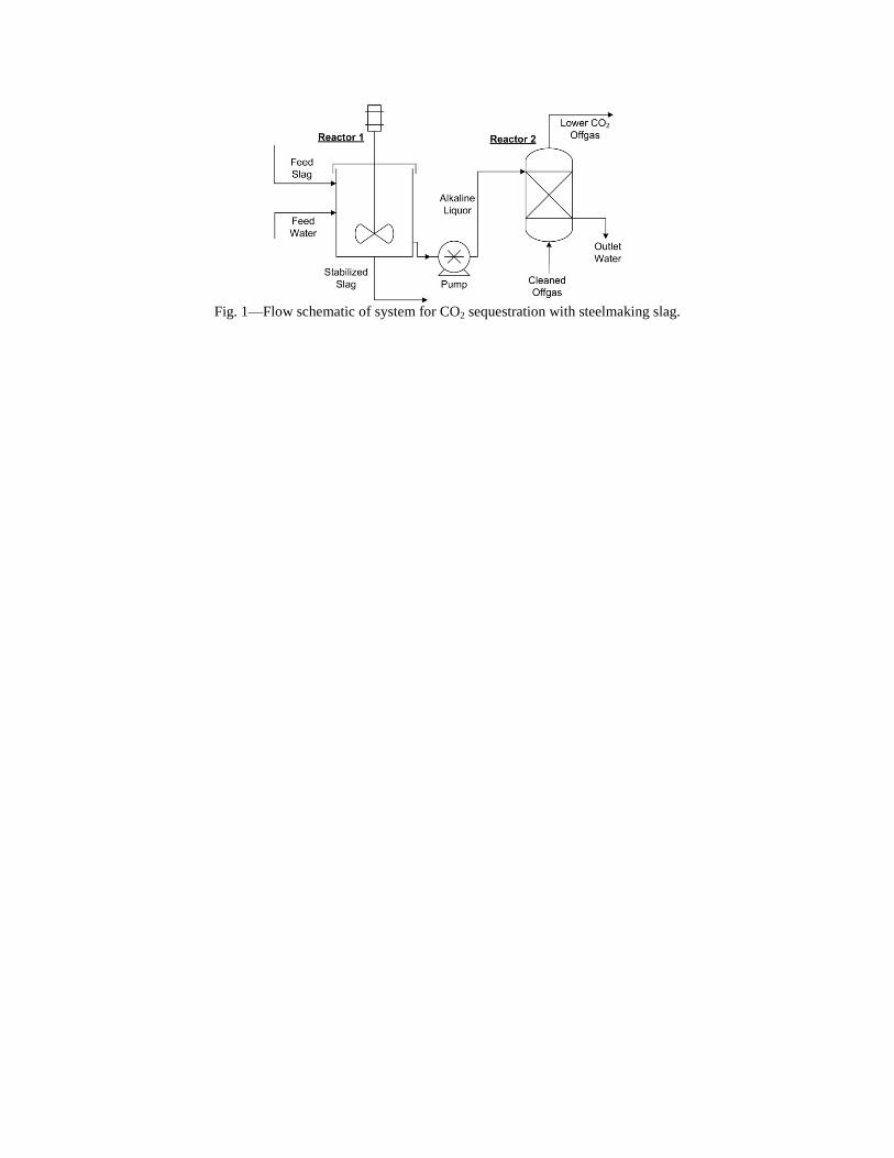
Fig. 1—Flow schematic of system for CO2 sequestration with steelmaking slag.
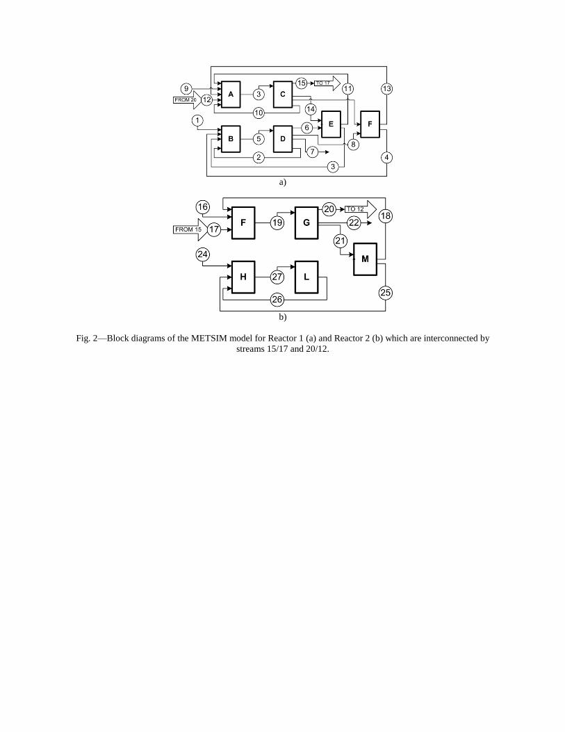
a)
b)
Fig. 2—Block diagrams of the METSIM model for Reactor 1 (a) and Reactor 2 (b) which are interconnected by
streams 15/17 and 20/12.
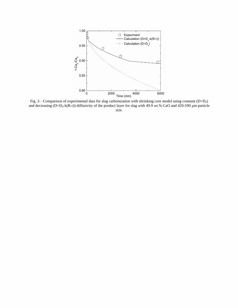
Fig. 3—Comparison of experimental data for slag carbonization with shrinking core model using constant (D=D0)
and decreasing (D=D0-k(R-r)) diffusivity of the product layer for slag with 49.9 wt.% CaO and 420-590 µm particle
size.

a)
b)
Fig. 4—Comparison of experimental data for slag carbonization with the parameters ln(1-CaC/CaS) (a) and d*ln(1-
CaC/CaS) (b) versus time1/3
.
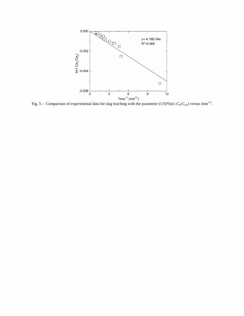
Fig. 5— Comparison of experimental data for slag leaching with the parameter (1/S)*ln(1-CD/Csat) versus time
1/3.
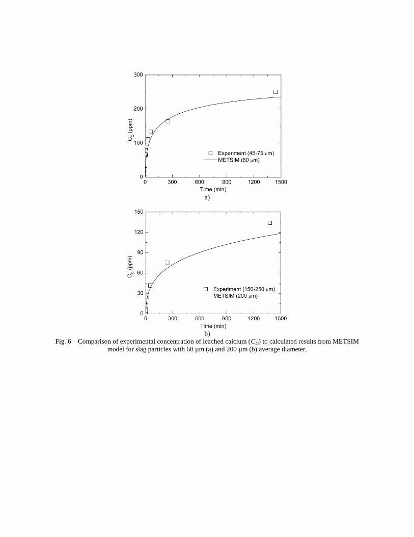
a)
b)
Fig. 6—Comparison of experimental concentration of leached calcium (CD) to calculated results from METSIM
model for slag particles with 60 µm (a) and 200 µm (b) average diameter.
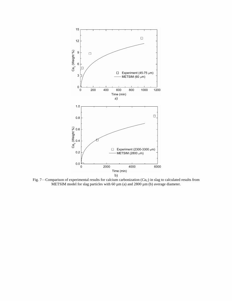
a)
b)
Fig. 7—Comparison of experimental results for calcium carbonization (CaC) in slag to calculated results from
METSIM model for slag particles with 60 µm (a) and 2800 µm (b) average diameter.

Fig. 8—Changing pH of aqueous solutions in reactors during carbonization (200 g of crushed <3.2 mm LMF Slag
#2, 1.5 g/min flow rate CO2) based on start of CO2 flow.

a)
b)
Fig.9—METSIM calculated kinetics of LMF slag carbonization for several particle sizes (a) and comparison of
calculated and experimentally measured calcium carbonate content after 20 hours reaction (b).
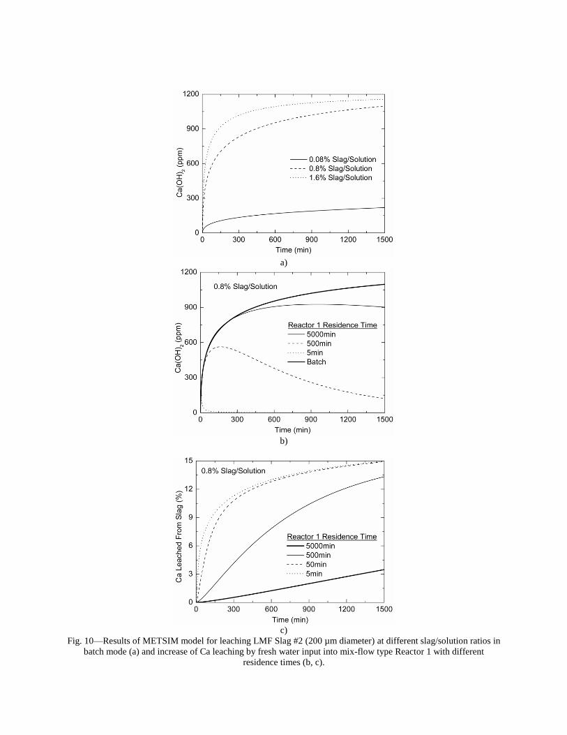
a)
b)
c)
Fig. 10—Results of METSIM model for leaching LMF Slag #2 (200 µm diameter) at different slag/solution ratios in
batch mode (a) and increase of Ca leaching by fresh water input into mix-flow type Reactor 1 with different
residence times (b, c).
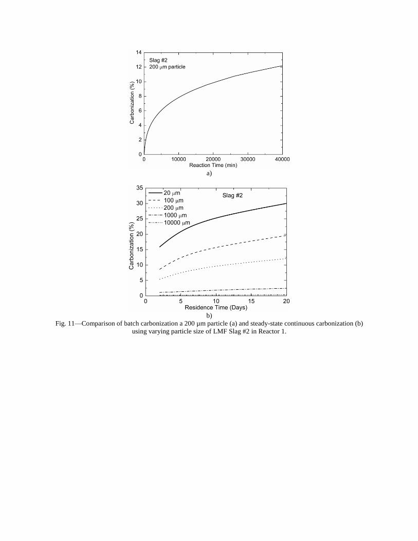
a)
b)
Fig. 11—Comparison of batch carbonization a 200 µm particle (a) and steady-state continuous carbonization (b)
using varying particle size of LMF Slag #2 in Reactor 1.
Carbon Dioxide Sequestration with Steelmaking Slag: Process Feasibility and Reactor Design
Kent D. Peaslee, Simon N. Lekakh, C. Hank Rawlins, Von L. Richards Missouri University of Science & Technology
Department of Materials Science and Engineering 225 McNutt Hall Rolla, MO 65409
Tel.: 573-341-4714 Fax: 573-341-6934
E-mail: [email protected]
Keywords: Steelmaking Slag, CO2, Sequestration, Metal Recovery, Reactor
ABSTRACT
The goal of this research is to develop a functional sequestration process using steelmaking slag for permanent capture of carbon dioxide emitted from steelmaking offgas. A parallel benefit of this process is rapid chemical stabilization of the slag minerals with reducing swelling or leaching potential. This paper summarizes the results of the project including mineralogical features of carbonate formation in steelmaking slag, study of the reaction mechanisms, thermogravimetric analysis of the reaction between solid-state slag and CO2, design and testing of a two-stage lab scale reactor system, METSIM modeling of possible reactor designs, and exploration of the economic feasibility of the process based on operating costs, metals recovery and credit for CO2 sequestration.
INTRODUCTION
Extraction of CO2 from steel manufacturing offgas with steelmaking slag is being studied by quantifying the extent and rate of carbonate formation under near-atmospheric aqueous conditions.1-3 Basic oxygen furnace (BOF) and electric arc furnace (EAF) slags typically average 30-50 wt.% CaO and 10-12 wt.% MgO and ladle metallurgy furnace (LMF) slags typically contain 50-60 wt.% CaO and 10-12 wt.% MgO. Slag production per ton is typically 75-150 kg for BOFs, 65-80 kg for EAFs, and 15-20 kg for LMFs. Production of a ton of steel generates on the average 519 kg CO2 carbon equivalent (CE) for BOFs and 119 kg CO2 CE for EAFs Assuming full stoichiometric conversion of CaO and MgO to carbonate, steelmaking slag has the potential to sequester 6-11% of the CO2 generated from BOF production and 35-45% of the CO2 generated from EAF production2.
The use of slag as an agent for capturing CO2 emissions has the potential of increasing the application and value of slag. Due to its high alkaline earth oxide content and immediate availability at the steel mill, steelmaking slag can serve as a unique source-point mitigation for CO2 sequestration. In order to achieve suitable efficiency for industrial-scale CO2 sequestration, the slag must be finely ground in order to provide sufficient surface area for rapid leaching of the alkaline-earth components and subsequent conversion to carbonates. Because mineral comminution is energy intensive, there are concerns that the energy required to grind the slag could exceed the CO2 sequestration benefit in both direct cost and indirect CO2 generation (e.g. CO2 emitted from the electric generation source). To characterize the comminution energy for steelmaking slag accurately, a separate study was conducted that determined the grindability of this slag using the Bond Work Index method.4 Work index is the comminution parameter that expresses the resistance of a mineral to crushing or grinding. This parameter permits calculation of the power expended in mineral crushing and grinding unit processes. The study also included size-by-size separation of the liberated magnetic fraction from the ground product. The results of the grindability study were used to develop a valuation model of the overall sequestration process.
This paper summarizes the mineralogical features of carbonate formation in steelmaking slag, reaction mechanisms, thermogravimetric analysis of the reaction between solid-state slag and CO2, design and testing of a two-stage lab scale reactor
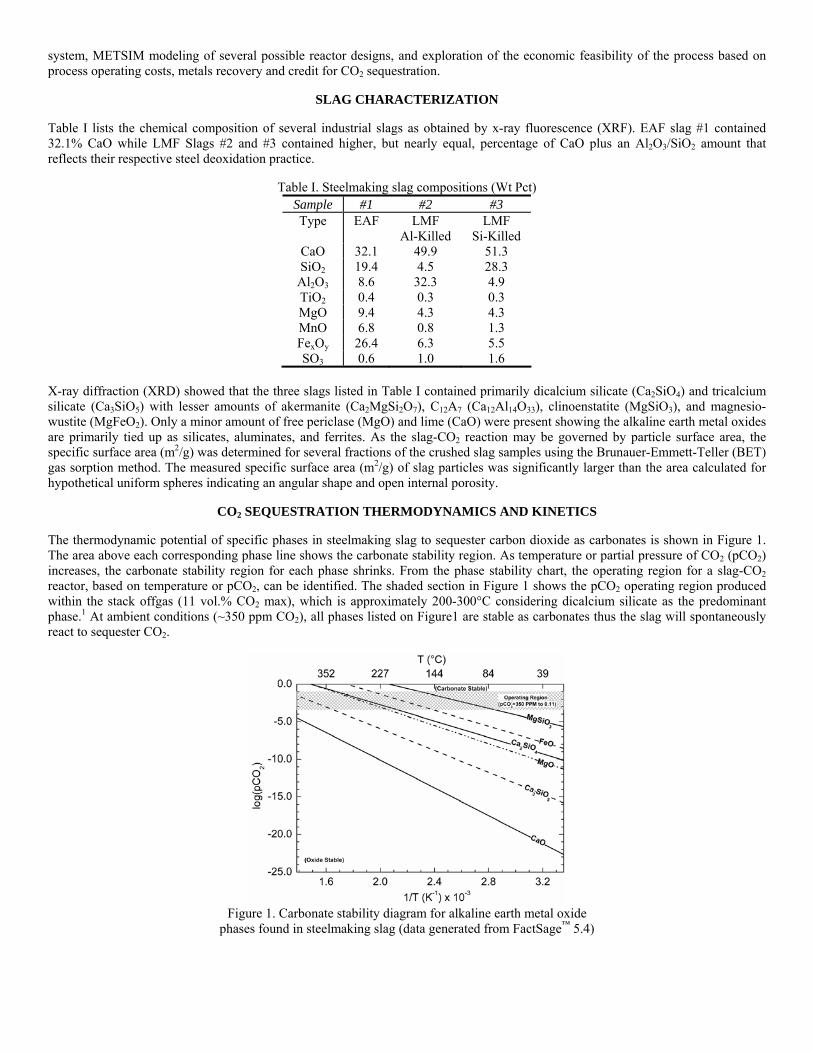
system, METSIM modeling of several possible reactor designs, and exploration of the economic feasibility of the process based on process operating costs, metals recovery and credit for CO2 sequestration.
SLAG CHARACTERIZATION
Table I lists the chemical composition of several industrial slags as obtained by x-ray fluorescence (XRF). EAF slag #1 contained 32.1% CaO while LMF Slags #2 and #3 contained higher, but nearly equal, percentage of CaO plus an Al2O3/SiO2 amount that reflects their respective steel deoxidation practice.
Table I. Steelmaking slag compositions (Wt Pct) Sample #1 #2 #3 Type EAF LMF
Al-Killed LMF
Si-Killed CaO 32.1 49.9 51.3 SiO2 19.4 4.5 28.3 Al2O3 8.6 32.3 4.9 TiO2 0.4 0.3 0.3 MgO 9.4 4.3 4.3 MnO 6.8 0.8 1.3 FexOy 26.4 6.3 5.5 SO3 0.6 1.0 1.6
X-ray diffraction (XRD) showed that the three slags listed in Table I contained primarily dicalcium silicate (Ca2SiO4) and tricalcium silicate (Ca3SiO5) with lesser amounts of akermanite (Ca2MgSi2O7), C12A7 (Ca12Al14O33), clinoenstatite (MgSiO3), and magnesio-wustite (MgFeO2). Only a minor amount of free periclase (MgO) and lime (CaO) were present showing the alkaline earth metal oxides are primarily tied up as silicates, aluminates, and ferrites. As the slag-CO2 reaction may be governed by particle surface area, the specific surface area (m2/g) was determined for several fractions of the crushed slag samples using the Brunauer-Emmett-Teller (BET) gas sorption method. The measured specific surface area (m2/g) of slag particles was significantly larger than the area calculated for hypothetical uniform spheres indicating an angular shape and open internal porosity.
CO2 SEQUESTRATION THERMODYNAMICS AND KINETICS
The thermodynamic potential of specific phases in steelmaking slag to sequester carbon dioxide as carbonates is shown in Figure 1. The area above each corresponding phase line shows the carbonate stability region. As temperature or partial pressure of CO2 (pCO2) increases, the carbonate stability region for each phase shrinks. From the phase stability chart, the operating region for a slag-CO2 reactor, based on temperature or pCO2, can be identified. The shaded section in Figure 1 shows the pCO2 operating region produced within the stack offgas (11 vol.% CO2 max), which is approximately 200-300°C considering dicalcium silicate as the predominant phase.1 At ambient conditions (~350 ppm CO2), all phases listed on Figure1 are stable as carbonates thus the slag will spontaneously react to sequester CO2.
Figure 1. Carbonate stability diagram for alkaline earth metal oxide
phases found in steelmaking slag (data generated from FactSage™ 5.4)

The primary obstacle to industrial-scale slag sequestration is the extremely slow solid-gas reaction rate at ambient pressure and temperature. Aqueous based processing has been found to accelerate the reaction kinetics. During aqueous based sequestration between CO2-containing offgas with CaO-bearing slag, there are several possible competing reactions (see Table II). For simplification, the calcium containing phases are all designated as CaO. The reaction kinetics of both calcium dissolution from slag and direct carbonation of slag were studied in a slurry (aqueous) reactor at atmospheric pressure.
Table II. Reactions occurring during aqueous slag-CO2 sequestration5,6 Description Reaction
Ca leaching )(22)()(2)(
−+ +→+ OHCaOHCaO aqls CO2 dissolution −+ +→+ 2
)(3)(2)(2 2 aqlg COHOHCO
Carbonate precipitation )(3
2)(3
2)( saqaq CaCOCOCa →+ −+
Ca direct carbonization −− +=++ OHCaCOOHCOCaO slaqs 2)(3)(22
)(3)( Water dissociation
)(222)(2 lOHHOH →+ +−
Calcium Leaching Calcium leaching from slag was performed using a batch-type reactor containing deionized water and a buffer to maintain the pH between 7.0-7.57. Inductively coupled plasma-optical emission spectroscopy (ICP-OES) was used to measure the Ca2+ concentration in slag samples leached with water. Figure 2a shows the effect of particle size on the extraction rate of Ca2+ from LMF slag #2. The particle size (i.e. surface area) had a significant influence on the amount of calcium leached. Leaching of Ca2+ from the slag particle starts at the slag surface, which includes many deep interconnected pores throughout the slag particle. Figure 2b shows a scanning electron microscope (SEM) image of the porous layer developed during leaching. XRD analysis showed that selective dissolution of the calcium containing phases takes place during aqueous leaching (Figure 2c).
a)
b) c)
Figure 2. Calcium leaching from slag in aqueous solution (a) from different size fractions of LMF slag, (b) selective phase dissolution leaving a porous structure and (c) XRD spectra before and after aqueous leaching
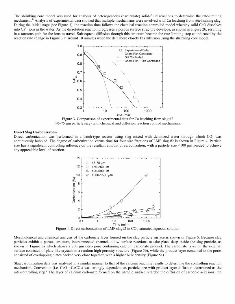
The shrinking core model was used for analysis of heterogeneous (particulate) solid-fluid reactions to determine the rate-limiting mechanism.8 Analysis of experimental data showed that multiple mechanisms were involved with Ca leaching from steelmaking slag. During the initial stage (see Figure 3), the reaction time follows the chemical reaction controlled model whereby solid CaO dissolves into Ca2+ ions in the water. As the dissolution reaction progresses a porous surface structure develops, as shown in Figure 2b, resulting in a tortuous path for the ions to travel. Subsequent diffusion through this structure became the rate-limiting step as indicated by the reaction rate change in Figure 3 at around 10 minutes when the data more closely fits diffusion using the shrinking core model.
Figure 3. Comparison of experimental data for Ca leaching from slag #2
(45-75 μm particle size) with chemical and diffusion reaction control mechanisms Direct Slag Carbonization Direct carbonization was performed in a batch-type reactor using slag mixed with deionized water through which CO2 was continuously bubbled. The degree of carbonization versus time for four size fractions of LMF slag #2 is shown in Figure 4. Particle size has a significant controlling influence on the resultant amount of carbonization, with a particle size <100 μm needed to achieve any appreciable level of reaction.
Figure 4. Direct carbonization of LMF slag#2 in CO2 saturated aqueous solution
Morphological and chemical analysis of the carbonate layer formed on the slag particle surface is shown in Figure 5. Because slag particles exhibit a porous structure, interconnected channels allow surface reactions to take place deep inside the slag particle, as shown in Figure 5a which shows a 700 μm deep pore containing calcium carbonate product. The carbonate layer on the external surface consisted of plate-like crystals in a random high-porosity structure (Figure 5b), while the product layer contained in the pores consisted of overlapping plates packed very close together, with a higher bulk density (Figure 5c).
Slag carbonization data was analyzed in a similar manner to that of the calcium leaching results to determine the controlling reaction mechanism. Conversion (i.e. CaO→CaCO3) was strongly dependent on particle size with product layer diffusion determined as the rate-controlling step.3 The layer of calcium carbonate formed on the particle surface retarded the diffusion of carbonic acid ions into
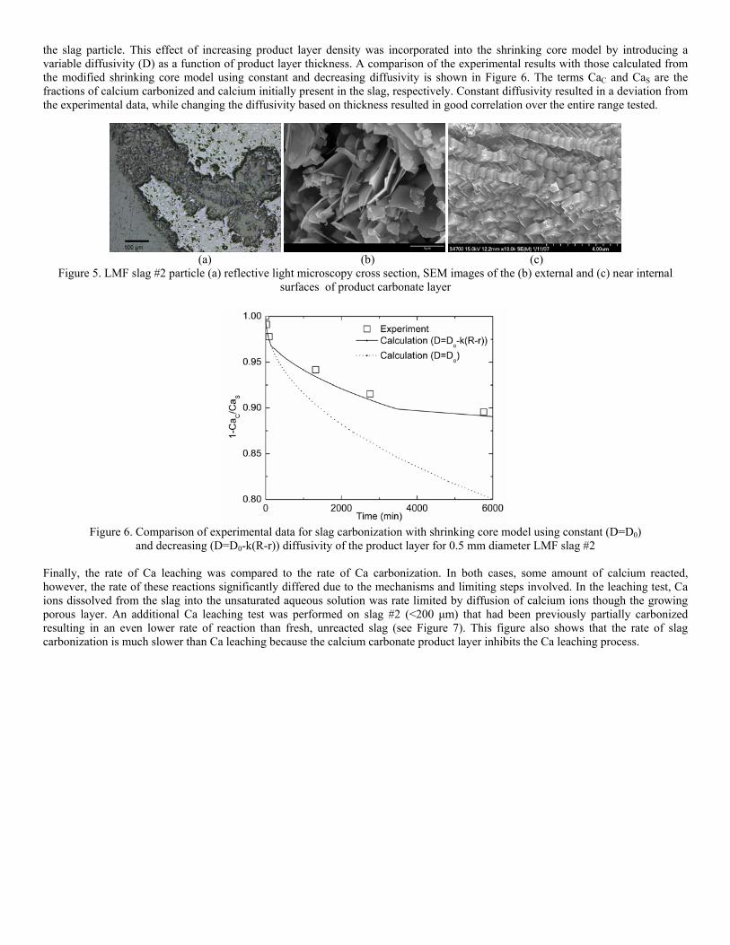
the slag particle. This effect of increasing product layer density was incorporated into the shrinking core model by introducing a variable diffusivity (D) as a function of product layer thickness. A comparison of the experimental results with those calculated from the modified shrinking core model using constant and decreasing diffusivity is shown in Figure 6. The terms CaC and CaS are the fractions of calcium carbonized and calcium initially present in the slag, respectively. Constant diffusivity resulted in a deviation from the experimental data, while changing the diffusivity based on thickness resulted in good correlation over the entire range tested.
(a) (b) (c)
Figure 5. LMF slag #2 particle (a) reflective light microscopy cross section, SEM images of the (b) external and (c) near internal surfaces of product carbonate layer
Figure 6. Comparison of experimental data for slag carbonization with shrinking core model using constant (D=D0)
and decreasing (D=D0-k(R-r)) diffusivity of the product layer for 0.5 mm diameter LMF slag #2 Finally, the rate of Ca leaching was compared to the rate of Ca carbonization. In both cases, some amount of calcium reacted, however, the rate of these reactions significantly differed due to the mechanisms and limiting steps involved. In the leaching test, Ca ions dissolved from the slag into the unsaturated aqueous solution was rate limited by diffusion of calcium ions though the growing porous layer. An additional Ca leaching test was performed on slag #2 (<200 μm) that had been previously partially carbonized resulting in an even lower rate of reaction than fresh, unreacted slag (see Figure 7). This figure also shows that the rate of slag carbonization is much slower than Ca leaching because the calcium carbonate product layer inhibits the Ca leaching process.
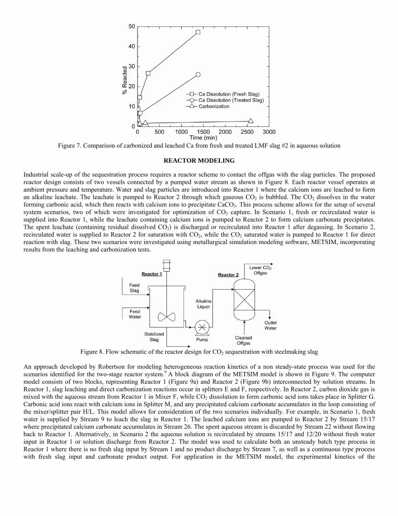
Figure 7. Comparison of carbonized and leached Ca from fresh and treated LMF slag #2 in aqueous solution
REACTOR MODELING
Industrial scale-up of the sequestration process requires a reactor scheme to contact the offgas with the slag particles. The proposed reactor design consists of two vessels connected by a pumped water stream as shown in Figure 8. Each reactor vessel operates at ambient pressure and temperature. Water and slag particles are introduced into Reactor 1 where the calcium ions are leached to form an alkaline leachate. The leachate is pumped to Reactor 2 through which gaseous CO2 is bubbled. The CO2 dissolves in the water forming carbonic acid, which then reacts with calcium ions to precipitate CaCO3. This process scheme allows for the setup of several system scenarios, two of which were investigated for optimization of CO2 capture. In Scenario 1, fresh or recirculated water is supplied into Reactor 1, while the leachate containing calcium ions is pumped to Reactor 2 to form calcium carbonate precipitates. The spent leachate (containing residual dissolved CO2) is discharged or recirculated into Reactor 1 after degassing. In Scenario 2, recirculated water is supplied to Reactor 2 for saturation with CO2, while the CO2 saturated water is pumped to Reactor 1 for direct reaction with slag. These two scenarios were investigated using metallurgical simulation modeling software, METSIM, incorporating results from the leaching and carbonization tests.
Figure 8. Flow schematic of the reactor design for CO2 sequestration with steelmaking slag
An approach developed by Robertson for modeling heterogeneous reaction kinetics of a non steady-state process was used for the scenarios identified for the two-stage reactor system.9 A block diagram of the METSIM model is shown in Figure 9. The computer model consists of two blocks, representing Reactor 1 (Figure 9a) and Reactor 2 (Figure 9b) interconnected by solution streams. In Reactor 1, slag leaching and direct carbonization reactions occur in splitters E and F, respectively. In Reactor 2, carbon dioxide gas is mixed with the aqueous stream from Reactor 1 in Mixer F, while CO2 dissolution to form carbonic acid ions takes place in Splitter G. Carbonic acid ions react with calcium ions in Splitter M, and any precipitated calcium carbonate accumulates in the loop consisting of the mixer/splitter pair H/L. This model allows for consideration of the two scenarios individually. For example, in Scenario 1, fresh water is supplied by Stream 9 to leach the slag in Reactor 1. The leached calcium ions are pumped to Reactor 2 by Stream 15/17 where precipitated calcium carbonate accumulates in Stream 26. The spent aqueous stream is discarded by Stream 22 without flowing back to Reactor 1. Alternatively, in Scenario 2 the aqueous solution is recirculated by streams 15/17 and 12/20 without fresh water input in Reactor 1 or solution discharge from Reactor 2. The model was used to calculate both an unsteady batch type process in Reactor 1 where there is no fresh slag input by Stream 1 and no product discharge by Stream 7, as well as a continuous type process with fresh slag input and carbonate product output. For application in the METSIM model, the experimental kinetics of the

carbonization reaction was approximated to be a function of time, (t)n. A factor of n=⅓ resulted in an appropriate fit for the reaction conversion (CaC/CaS) calculated from modified shrinking core model, as well as the experimental data.
a) b)
Figure 9. Block diagrams of the METSIM model for interconnected (a) Reactor 1 and (b) Reactor 2 Investigation of Scenario 1 included slag leaching in Reactor 1 and calcium carbonate precipitation in Reactor 2. In this model, fresh water was supplied in Reactor 1 while the leachate solution was pumped to Reactor 2. No water was recirculated from Reactor 2 to Reactor 1. The goal of this scenario was to analyze the influence of slag/solution ratio and solution residence time in Reactor 1 on the leaching result. The model used 200 μm particles of LMF slag #2 that contained 50 wt.% CaO. The results of the investigation (Figure 10) show that both increasing the slag/solution ratio and the solution residence time in Reactor 1 produces a higher concentration of calcium ions in solution. Increasing the slag/solution ratio provides a diminishing increase in calcium ions in solution due to saturation of the aqueous phase, as shown in Figure 10a. Fresh water throughput accelerates the leaching rate, which is dependent upon the residence time of Reactor 1 (Figure 10b). The optimum residence time was defined by the maximum amount of leaching with minimal fresh water input.
a) b)
Figure 10. METSIM model results of leaching slag at (a) different slag/solution ratios in batch reactor without fresh water input and (b) in mix-flow type reactor with fresh water input at different solution residence times
The results of Scenario 2 (direct slag carbonization in Reactor 1) were experimentally verified using a lab-scale apparatus consisting of two connected reactors (plastic tanks). Reactor 1 contained up to 2 kg of slag in 20 liters of water that was mechanically stirred. The aqueous liquor was pumped at varying rates to Reactor 2, which had a two-liter volume. Bottle grade CO2 was bubbled through a diffuser in the bottom of Reactor 2 to generate a distribution of fine gas bubbles, which allowed intimate mixing of the gas and alkaline solution. A multi-channel meter was used to measure the pH level in both reactors. At the completion of each test (20 hours), a sample of the slurry from Reactor 1 was filtered, dried, and analyzed for carbonization. The prevailing reaction was direct slag particle carbonization in Reactor 1, while a minor amount of residual precipitated carbonates was found in Reactor 2. Figure 11 shows that the METSIM model results are in good agreement with the experimental results and that the amount of slag carbonization increased with decreasing particle size. The amount of carbonate formation greatly increased at particle sizes smaller than 200 μm, indicating a certain minimal amount of grinding may be necessary to achieve practical carbonation rates.
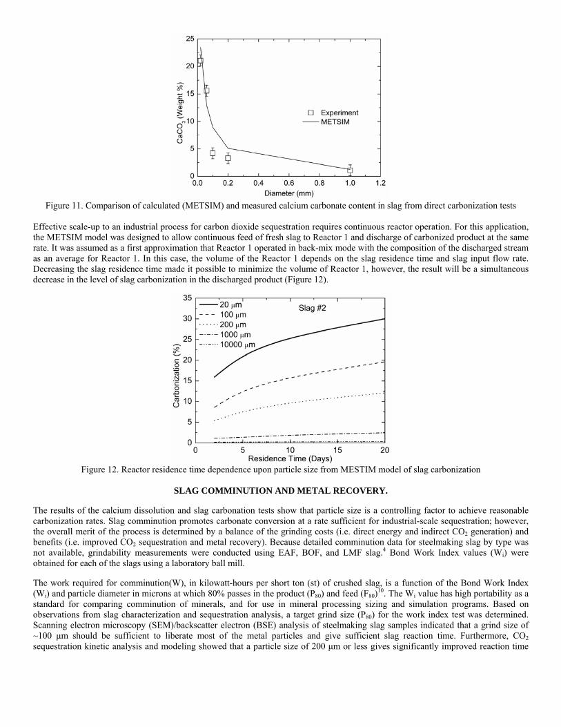
Figure 11. Comparison of calculated (METSIM) and measured calcium carbonate content in slag from direct carbonization tests
Effective scale-up to an industrial process for carbon dioxide sequestration requires continuous reactor operation. For this application, the METSIM model was designed to allow continuous feed of fresh slag to Reactor 1 and discharge of carbonized product at the same rate. It was assumed as a first approximation that Reactor 1 operated in back-mix mode with the composition of the discharged stream as an average for Reactor 1. In this case, the volume of the Reactor 1 depends on the slag residence time and slag input flow rate. Decreasing the slag residence time made it possible to minimize the volume of Reactor 1, however, the result will be a simultaneous decrease in the level of slag carbonization in the discharged product (Figure 12).
Figure 12. Reactor residence time dependence upon particle size from MESTIM model of slag carbonization
SLAG COMMINUTION AND METAL RECOVERY.
The results of the calcium dissolution and slag carbonation tests show that particle size is a controlling factor to achieve reasonable carbonization rates. Slag comminution promotes carbonate conversion at a rate sufficient for industrial-scale sequestration; however, the overall merit of the process is determined by a balance of the grinding costs (i.e. direct energy and indirect CO2 generation) and benefits (i.e. improved CO2 sequestration and metal recovery). Because detailed comminution data for steelmaking slag by type was not available, grindability measurements were conducted using EAF, BOF, and LMF slag.4 Bond Work Index values (Wi) were obtained for each of the slags using a laboratory ball mill.
The work required for comminution(W), in kilowatt-hours per short ton (st) of crushed slag, is a function of the Bond Work Index (Wi) and particle diameter in microns at which 80% passes in the product (P80) and feed (F80)10. The Wi value has high portability as a standard for comparing comminution of minerals, and for use in mineral processing sizing and simulation programs. Based on observations from slag characterization and sequestration analysis, a target grind size (P80) for the work index test was determined. Scanning electron microscopy (SEM)/backscatter electron (BSE) analysis of steelmaking slag samples indicated that a grind size of ~100 μm should be sufficient to liberate most of the metal particles and give sufficient slag reaction time. Furthermore, CO2 sequestration kinetic analysis and modeling showed that a particle size of 200 μm or less gives significantly improved reaction time
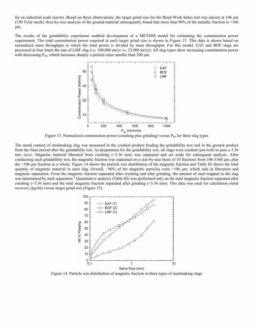
for an industrial scale reactor. Based on these observations, the target grind size for the Bond Work Index test was chosen at 106 μm (150 Tyler mesh). Size-by-size analysis of the ground material subsequently found that more than 90% of the metallic fraction is >106 μm.
The results of the grindability experiment enabled development of a METSIM model for estimating the comminution power requirement. The total comminution power required at each target grind size is shown in Figure 13. This data is shown based on normalized mass throughput in which the total power is divided by mass throughput. For this model, EAF and BOF slags are processed at four times the rate of LMF slag (i.e. 100,000 mt/yr vs. 25,000 mt/yr). All slag types show increasing comminution power with decreasing P80, which increases sharply a particle sizes smaller than 200 μm.
Figure 13. Normalized comminution power (crushing plus grinding) versus P80 for three slag types
The metal content of steelmaking slag was measured in the crushed product feeding the grindability test and in the ground product from the final period after the grindability test. As preparation for the grindability test, all slags were crushed (jaw/roll) to pass a 3.36 mm sieve. Magnetic material liberated from crushing (>3.36 mm) was separated and set aside for subsequent analysis. After conducting each grindability test, the magnetic fraction was separated on a size-by-size basis of 10 fractions from 106-3360 μm, plus the <106 μm fraction as a whole. Figure 14 shows the particle size distribution of the magnetic fraction and Table III shows the total quantity of magnetic material in each slag. Overall, ~90% of the magnetic particles were >106 μm, which aids in liberation and magnetic separation. From the magnetic fraction separated after crushing and after grinding, the amount of steel trapped in the slag was determined by melt separation.4 Quantitative analysis (Table III) was performed only on the total magnetic fraction separated after crushing (>3.36 mm) and the total magnetic fraction separated after grinding (<3.36 mm). This data was used for calculation metal recovery (kg/mt) versus target grind size (Figure 15).
Figure 14. Particle size distribution of magnetic fraction in three types of steelmaking slags

Table III. Quantity and quality of magnetic material in steelmaking slag
Wt.% Magnetic EAF BOF LMF >106 μm 8.61 8.81 5.92 <106 μm 1.14 0.67 0.17 Total 9.75 9.48 6.09
Wt.% Metallic >3.36 mm 86.1 88.1 95.5 <3.36 mm 60.7 71.9 72.0
Figure 15. Amount of recovered metal liberated from steelmaking slag by target grind P80
VALUATION ANALYSIS OF COMPLEX SLAG PROCESSING
The primary concern with slag grinding has been the issue of power (electric) consumption of the mill and corresponding CO2 generation (emission) at the electric supply source. Both terms can be quantified as input into an overall valuation model. The amount of CO2 captured by EAF and LMF slags for each P80 value was calculated from sequestration reactor modeling data. Figure 16 shows the resulting CO2 balance. Each graph shows the amount of CO2 captured by that slag, the amount of CO2 emitted by the electric supply source (as a negative sequestration value calculated from the comminution data), and the net CO2 sequestered, at each grind size (P80). The amount of CO2 captured by the slag and the amount released by the power source both increase with decreasing P80. The amount released by the power supplier is 15-40% of the amount captured depending on the slag type and size, resulting in a net positive amount of CO2 sequestered at all sizes.
a) b)
Figure 16. Net CO2 sequestered (slag capture-power source emission) for (a) EAF and (b) LMF slags versus grind size
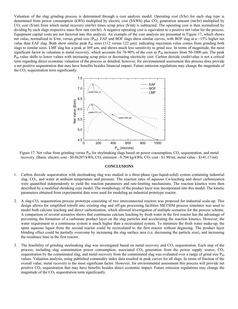
Valuation of the slag grinding process is determined through a cost analysis model. Operating cost ($/hr) for each slag type is determined from power consumption (kWh) multiplied by electric cost ($/kWh) plus CO2 generation amount (mt/hr) multiplied by CO2 cost ($/mt) from which metal recovery (mt/hr) times scrap price ($/mt) is subtracted. The operating cost is then normalized by dividing by each slags respective mass flow rate (mt/hr). A negative operating cost is equivalent to a positive net value for the process. Equipment capital costs are not factored into this analysis. An example of the cost analysis are presented in Figure 17, which shows net value, normalized to $/mt, versus grind size (P80). EAF and BOF slags show similar curves, with BOF slag at a ~15% higher net value than EAF slag. Both show similar peak P80 sizes (112 versus 122 μm); indicating maximum value comes from grinding both slags to similar sizes. LMF slag has a peak at 369 μm, and shows much less sensitivity to grind size. In terms of magnitude, the most significant factor in valuation is metal recovery, which accounts for 76-90% of the cost as P80 increases from 50-1000 μm. The peak P80 value shifts to lower values with increasing scrap price or decreasing electricity cost. Carbon dioxide credit/value is not a critical term regarding direct economic valuation of the process as detailed, however, for environmental assessment this process does provide a net positive sequestration that may have benefits besides financial impact. Future emission regulations may change the magnitude of the CO2 sequestration term significantly.
Figure 17. Net value from grinding versus P80 for steelmaking slags based on power consumption, CO2 sequestration, and metal recovery. (Basis: electric cost - $0.06207/kWh, CO2 emission - 0.704 kg/kWh, CO2 cost - $1.90/mt, metal value - $141.17/mt)
CONCLUSIONS
1. Carbon dioxide sequestration with steelmaking slag was studied in a three-phase (gas-liquid-solid) system containing industrial slag, CO2, and water at ambient temperature and pressure. The reaction rates of aqueous Ca-leaching and direct carbonization were quantified independently to yield the reaction parameters and rate-limiting mechanisms. The reaction kinetics were then described by a modified shrinking core model. The morphology of the product layer was incorporated into this model. The kinetic parameters obtained from experimental data were used for modeling an industrial prototype reactor.
2. A slag-CO2 sequestration process prototype consisting of two interconnected reactors was proposed for industrial scale-up. This design allows for simplified retrofit into existing slag and off-gas processing facilities METSIM process simulator was used to model both calcium leaching and direct carbonization, which allowed investigation of multiple scenarios for the process scheme. A comparison of several scenarios shows that continuous calcium leaching by fresh water in the first reactor has the advantage of preventing the formation of a carbonate product layer on the slag particles and accelerating the reaction kinetics. However, the water requirement in a continuous system is much higher than a recirculated system. To minimize the fresh water make-up, the spent aqueous liquor from the second reactor could be recirculated to the first reactor without degassing. The product layer blinding effect could be partially overcome by increasing the slag surface area (i.e. decreasing the particle size), and increasing the residence time in the first reactor.
3. The feasibility of grinding steelmaking slag was investigated based on metal recovery and CO2 sequestration. Each step of the process, including slag comminution power consumption, associated CO2 generation from the power supply source, CO2 sequestration by the comminuted slag, and metal recovery from the comminuted slag was evaluated over a range of grind size P80 values. Valuation analysis, using published commodity index data resulted in peak curves for all slags. In terms of fraction of the overall value, metal recovery is the most significant factor. However, for environmental assessment this process will provide net positive CO2 sequestration that may have benefits besides direct economic impact. Future emission regulations may change the magnitude of the CO2 sequestration term significantly.

ACKNOWLEDGEMENTS
This paper was prepared as an account of work sponsored by the U.S. Department of Energy, in cooperation with the American Iron and Steel Institute (AISI) and its participating companies, under Agreement DE-FC36-97ID13554. Such support does not constitute an endorsement by DOE or AISI of the views expressed in the article. The authors also acknowledge the support of DOFASCO, Gallatin Steel, Hylsa, IPSCO, Mittal Steel, Praxair, Nucor, Timken Company, and US Steel.
REFERENCES
1. C.H. Rawlins, V.L. Richards, K.D. Peaslee, and S.N. Lekakh, “Sequestration of CO2 from Steelmaking Offgas by Carbonate Formation with Slag,” Proceedings of the AISTech 2006 Conference, May 1-4, 2006, Cleveland, OH, U.S.
2. C.H. Rawlins, V.L. Richards, K.D. Peaslee, and S.N. Lekakh, “Steelmaking Slag as a Permanent Sequestration Sink for Carbon Dioxide,” Steel Times International, Vol. 30, No. 7, 2006, pp. 25-26.
3. C.H. Rawlins, V.L. Richards, K.D. Peaslee, and S.N. Lekakh, “Experimental Study of CO2 Sequestration by Steelmaking Slag,” TMS 2007 Materials Process Fundamentals, Ed. P. Anyalebechi, The Minerals, Metals, and Materials Society, Mar. 2007, pp. 193-202.
4. C.H. Rawlins, “Grindability Study of Steelmaking Slag for Size-by-Size Recovery of Free Metal,” 2008 SME Annual Meeting and Exhibit, Salt Lake City, UT, U.S., Feb. 2008..
5. W. Huijgen, G-J. Witkamp, and R.N.J. Comans, “Mineral CO2 Sequestration by Steel Slag Carbonation,” Environmental Science and Technology, Vol. 39, No. 24, 2005, pp. 9676-9682.
6. M. Luigi, “Geological Sequestration of Carbon Dioxide; Thermodynamics, Kinetics, and Reaction Path Modeling,” Elsevier B.V., Amsterdam, The Netherlands, 2007, pp. 88-91.
7. J.K. Stolaroff, G.V. Lowry, and D. W. Keith, “Using CaO- and MgO-rich Industrial Waste Streams for Carbon Sequestration,” Energy Conservation and Management, Vol. 46, No. 5, 2005, pp. 687-699.
8. K.N. Han, “Fundamental of Aqueous Metallurgy,” Society for Mining, Metallurgy, and Exploration Inc., Littleton, CO, 2002, pp. 129-140.
9. D.G.C., Robertson, “The Computation of the Kinetics of the Reactions Between Multiple Phases,” Proceedings of the EPD Congress, TMS Annual Meeting, 1995, pp. 347-61.
10. F.C. Bond, “Crushing & Grinding Calculations Part I,” British Chemical Engineering, Vol. 6, No. 6, June 1961, pp. 378-385.
American Iron and Steel Institute Technology Roadmap Program
CO2 Breakthrough Program Phase I: Geological Sequestration of CO2 by Hydrous Carbonate Formation with Reclaimed Slag
Final Report - Attachment F
Industrial Reactor Modeling Report
January 2008
Carbon Dioxide Sequestration by Steel Making Slag -
Industrial Process Modeling 1. REACTOR DESIGN AND MODELING PROCEDURE
1.1 CO2 Sequestration Reactor Design Carbon sequestration through the aqueous-based reaction of CO2-containing offgas with lime-bearing steelmaking slag allows for several possible reactions to take place. A list of the key competing reactions is given in Table 1. For simplification the calcium containing phases are all designated as CaO.
Table I. Reactions Occurring During Aqueous Slag-CO2 Sequestration
Description Reaction
Ca leaching )(22)()(2)(
−+ +→+ OHCaOHCaO aqls CO2 dissolution −+ +→+ 2
)(3)(2)(2 2 aqlg COHOHCO Carbonate precipitation
)(32
)(32
)( saqaq CaCOCOCa →+ −+
Ca direct carbonization −− +=++ OHCaCOOHCOCaO slaqs 2)(3)(22
)(3)( Water dissociation
)(222)(2 lOHHOH →+ +−
The reactor design consists of two vessels connected by a pumped water stream, as shown in Fig. 1. Each reactor vessel operates at ambient pressure and temperature. Water and slag particles are introduced into Reactor 1, wherein calcium ions are leached to form an alkaline leachate. The aqueous solution is pumped to Reactor 2 through which gaseous CO2 is bubbled. The CO2 dissolves into the water to from carbonic acid ions, upon which several competing reactions take place resulting in precipitation of CaCO3. This process scheme allows for several system scenarios to be investigated for optimization of CO2 capture. • Scenario 1: Fresh water is supplied into Reactor 1, the leachate containing calcium ions is
pumped to Reactor 2 in which calcium carbonate precipitates. The spent leachate (containing residual dissolved CO2) is discharged.
• Scenario 2: The same design as Scenario 1 except that the water supplied to Reactor 1 is recirculated from Reactor 2 after (complete or partial) degassing.
• Scenario 3: Fresh water is supplied to Reactor 2 for saturation with CO2, the CO2 saturated water is pumped to Reactor 1 for direct reaction with slag, after which the water (containing residual dissolved CO2) is discarded.
• Scenario 4: The water supplied to Reactor 1 is recirculated from Reactor 2 without degassing.
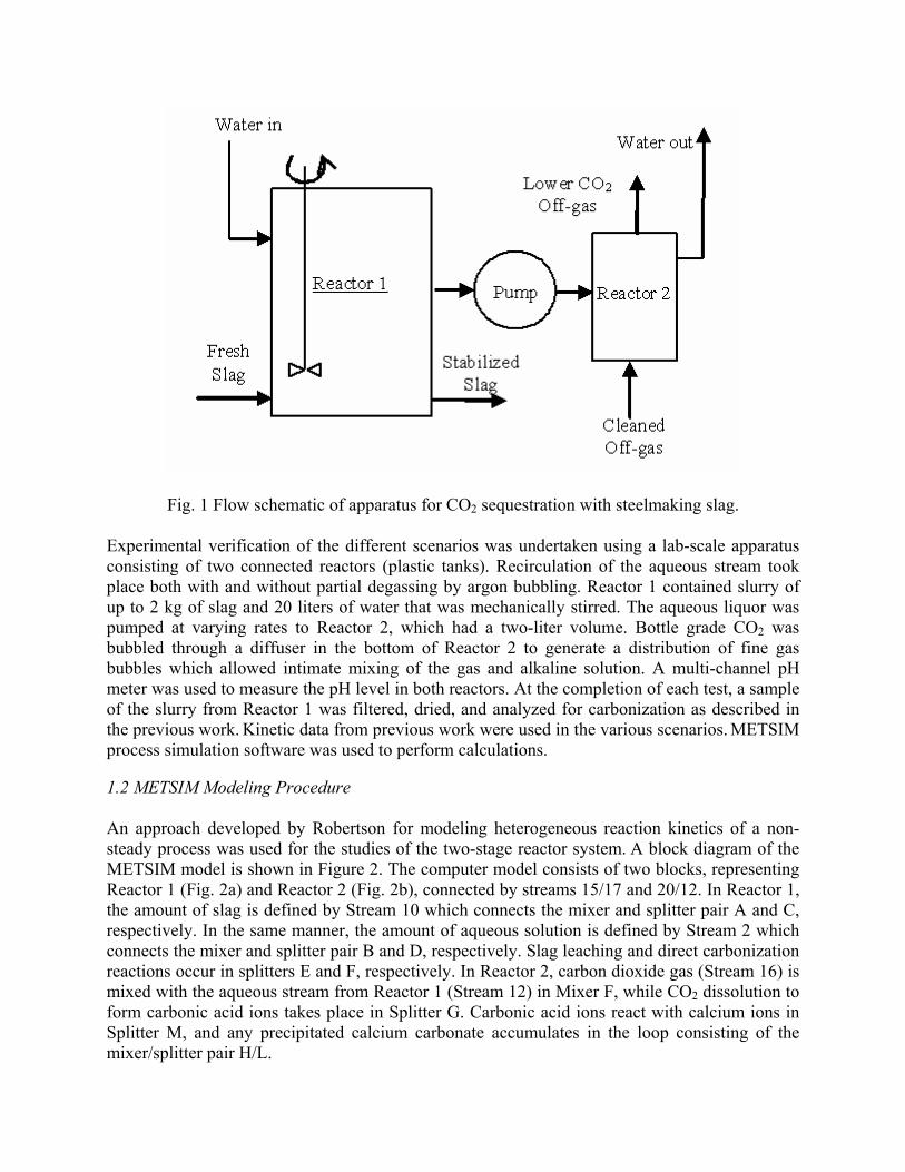
Fig. 1 Flow schematic of apparatus for CO2 sequestration with steelmaking slag.
Experimental verification of the different scenarios was undertaken using a lab-scale apparatus consisting of two connected reactors (plastic tanks). Recirculation of the aqueous stream took place both with and without partial degassing by argon bubbling. Reactor 1 contained slurry of up to 2 kg of slag and 20 liters of water that was mechanically stirred. The aqueous liquor was pumped at varying rates to Reactor 2, which had a two-liter volume. Bottle grade CO2 was bubbled through a diffuser in the bottom of Reactor 2 to generate a distribution of fine gas bubbles which allowed intimate mixing of the gas and alkaline solution. A multi-channel pH meter was used to measure the pH level in both reactors. At the completion of each test, a sample of the slurry from Reactor 1 was filtered, dried, and analyzed for carbonization as described in the previous work. Kinetic data from previous work were used in the various scenarios. METSIM process simulation software was used to perform calculations.
1.2 METSIM Modeling Procedure An approach developed by Robertson for modeling heterogeneous reaction kinetics of a non-steady process was used for the studies of the two-stage reactor system. A block diagram of the METSIM model is shown in Figure 2. The computer model consists of two blocks, representing Reactor 1 (Fig. 2a) and Reactor 2 (Fig. 2b), connected by streams 15/17 and 20/12. In Reactor 1, the amount of slag is defined by Stream 10 which connects the mixer and splitter pair A and C, respectively. In the same manner, the amount of aqueous solution is defined by Stream 2 which connects the mixer and splitter pair B and D, respectively. Slag leaching and direct carbonization reactions occur in splitters E and F, respectively. In Reactor 2, carbon dioxide gas (Stream 16) is mixed with the aqueous stream from Reactor 1 (Stream 12) in Mixer F, while CO2 dissolution to form carbonic acid ions takes place in Splitter G. Carbonic acid ions react with calcium ions in Splitter M, and any precipitated calcium carbonate accumulates in the loop consisting of the mixer/splitter pair H/L.
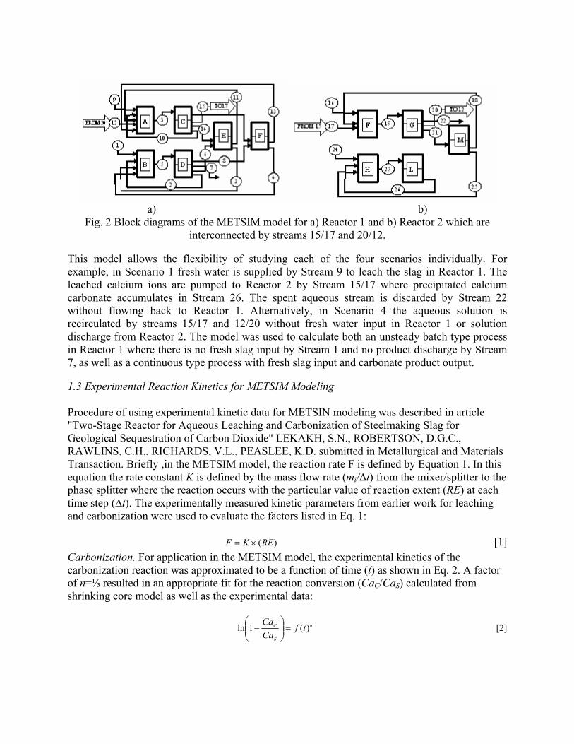
a) b)
Fig. 2 Block diagrams of the METSIM model for a) Reactor 1 and b) Reactor 2 which are interconnected by streams 15/17 and 20/12.
This model allows the flexibility of studying each of the four scenarios individually. For example, in Scenario 1 fresh water is supplied by Stream 9 to leach the slag in Reactor 1. The leached calcium ions are pumped to Reactor 2 by Stream 15/17 where precipitated calcium carbonate accumulates in Stream 26. The spent aqueous stream is discarded by Stream 22 without flowing back to Reactor 1. Alternatively, in Scenario 4 the aqueous solution is recirculated by streams 15/17 and 12/20 without fresh water input in Reactor 1 or solution discharge from Reactor 2. The model was used to calculate both an unsteady batch type process in Reactor 1 where there is no fresh slag input by Stream 1 and no product discharge by Stream 7, as well as a continuous type process with fresh slag input and carbonate product output.
1.3 Experimental Reaction Kinetics for METSIM Modeling Procedure of using experimental kinetic data for METSIN modeling was described in article "Two-Stage Reactor for Aqueous Leaching and Carbonization of Steelmaking Slag for Geological Sequestration of Carbon Dioxide" LEKAKH, S.N., ROBERTSON, D.G.C., RAWLINS, C.H., RICHARDS, V.L., PEASLEE, K.D. submitted in Metallurgical and Materials Transaction. Briefly ,in the METSIM model, the reaction rate F is defined by Equation 1. In this equation the rate constant K is defined by the mass flow rate (mi/∆t) from the mixer/splitter to the phase splitter where the reaction occurs with the particular value of reaction extent (RE) at each time step (∆t). The experimentally measured kinetic parameters from earlier work for leaching and carbonization were used to evaluate the factors listed in Eq. 1:
)(REKF ×= [1] Carbonization. For application in the METSIM model, the experimental kinetics of the carbonization reaction was approximated to be a function of time (t) as shown in Eq. 2. A factor of n=⅓ resulted in an appropriate fit for the reaction conversion (CaC/CaS) calculated from shrinking core model as well as the experimental data:
n
S
C tfCaCa )(1ln =⎟⎟
⎠
⎞⎜⎜⎝
⎛− [2]

For direct carbonization of slag particles (Fig. 3) the experimental data was fit to Eq. 3 and Eq. 4. In these equations d is the particle diameter (mm), t is time (min) and coefficient A=0.0012 was taken from correlated experimental data . The first derivative (Eq. 3) represents the reaction rate F and was used in the METSIM model.
⎟⎟⎠
⎞⎜⎜⎝
⎛⎟⎠⎞
⎜⎝⎛−−= 3
1exp1 t
dACaCa SC [3]
⎟⎠⎞
⎜⎝⎛−==
−3
13
2exp
3t
dAt
dACa
dtdCaF SC
[4]
a)
b)
Fig. 3 Comparison of experimental data for slag carbonization for parameters ln(1-CaC/CaS) (a) and d*ln(1-CaC/CaS) (b) versus time1/3.
Leaching. A similar analysis of the calcium leaching process was undertaken, in which this set of reactions corresponds to Scenario 1. The reaction rate changes during the leaching process because the initial chemical reaction limited mechanism is overtaken by slower diffusion through the porous surface layer developed during treatment. The difference in Eq. 5 for leaching when
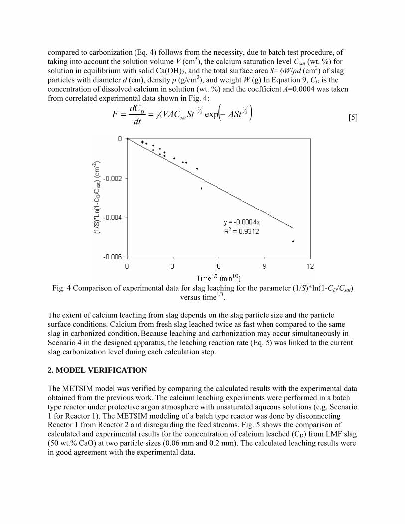
compared to carbonization (Eq. 4) follows from the necessity, due to batch test procedure, of taking into account the solution volume V (cm3), the calcium saturation level Csat (wt. %) for solution in equilibrium with solid Ca(OH)2, and the total surface area S= 6W/ρd (cm2) of slag particles with diameter d (cm), density ρ (g/cm3), and weight W (g) In Equation 9, CD is the concentration of dissolved calcium in solution (wt. %) and the coefficient A=0.0004 was taken from correlated experimental data shown in Fig. 4:
( )31
32
31 exp AStStVAC
dtdCF sat
D −==−
[5]
Fig. 4 Comparison of experimental data for slag leaching for the parameter (1/S)*ln(1-CD/Csat)
versus time1/3.
The extent of calcium leaching from slag depends on the slag particle size and the particle surface conditions. Calcium from fresh slag leached twice as fast when compared to the same slag in carbonized condition. Because leaching and carbonization may occur simultaneously in Scenario 4 in the designed apparatus, the leaching reaction rate (Eq. 5) was linked to the current slag carbonization level during each calculation step.
2. MODEL VERIFICATION The METSIM model was verified by comparing the calculated results with the experimental data obtained from the previous work. The calcium leaching experiments were performed in a batch type reactor under protective argon atmosphere with unsaturated aqueous solutions (e.g. Scenario 1 for Reactor 1). The METSIM modeling of a batch type reactor was done by disconnecting Reactor 1 from Reactor 2 and disregarding the feed streams. Fig. 5 shows the comparison of calculated and experimental results for the concentration of calcium leached (CD) from LMF slag (50 wt.% CaO) at two particle sizes (0.06 mm and 0.2 mm). The calculated leaching results were in good agreement with the experimental data.
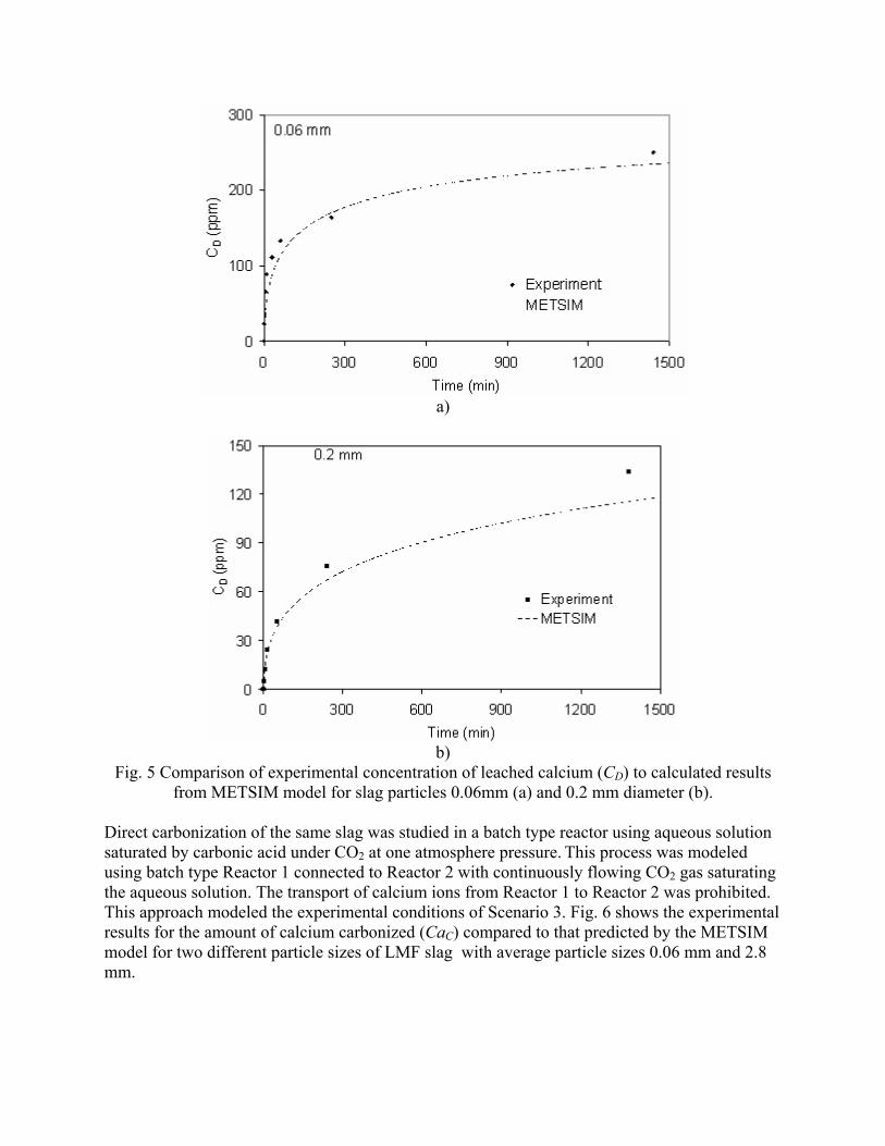
a)
b)
Fig. 5 Comparison of experimental concentration of leached calcium (CD) to calculated results from METSIM model for slag particles 0.06mm (a) and 0.2 mm diameter (b).
Direct carbonization of the same slag was studied in a batch type reactor using aqueous solution saturated by carbonic acid under CO2 at one atmosphere pressure. This process was modeled using batch type Reactor 1 connected to Reactor 2 with continuously flowing CO2 gas saturating the aqueous solution. The transport of calcium ions from Reactor 1 to Reactor 2 was prohibited. This approach modeled the experimental conditions of Scenario 3. Fig. 6 shows the experimental results for the amount of calcium carbonized (CaC) compared to that predicted by the METSIM model for two different particle sizes of LMF slag with average particle sizes 0.06 mm and 2.8 mm.

a)
b)
Fig. 6 Comparison of experimental results for calcium carbonization (CaC) in slag to calculated results from METSIM model for slag with average particle sizes 0.06 mm (a) and 2.8 mm (b)
diameter. Scenario 4 was modeled (water recirculation without degassing) and the results compared to the experimental data for slag carbonization. In the experimental work, both Ca leaching and direct slag particle carbonization were monitored simultaneously in both reactors. Reactor 1 contained 200 g LMF slag (<3.2 mm) in 20 liters of water, while Reactor 2 contained two liters of solution through which 1.5 g/min CO2 was bubbled. A solution exchange rate of one liter per minute was used to transfer the fluid between the two reactors. The experimental procedure included preliminary soaking of slag in Reactor 1 for 20 minutes, with solution recirculation but without CO2 input in Reactor 2. During this time, the pH increased in both reactors as Ca(OH)2 was formed. Shortly after introducing CO2 into Reactor 2, the concentration of calcium ions in solution decreased while concentration of carbonic acid increased. The rate of decrease in pH (Fig. 7) depended on the solution residence time in Reactor 1 (20 minutes) and Reactor 2 (2 min).
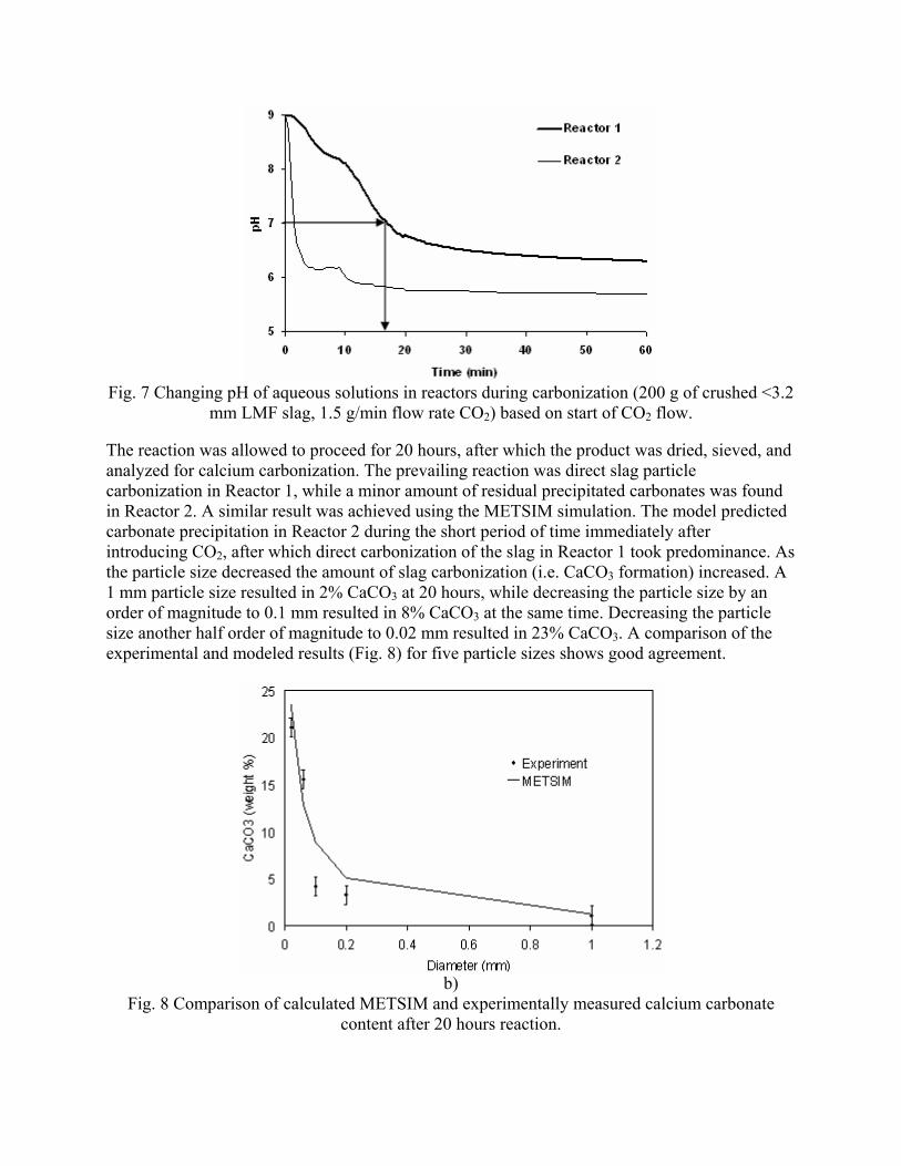
Fig. 7 Changing pH of aqueous solutions in reactors during carbonization (200 g of crushed <3.2
mm LMF slag, 1.5 g/min flow rate CO2) based on start of CO2 flow.
The reaction was allowed to proceed for 20 hours, after which the product was dried, sieved, and analyzed for calcium carbonization. The prevailing reaction was direct slag particle carbonization in Reactor 1, while a minor amount of residual precipitated carbonates was found in Reactor 2. A similar result was achieved using the METSIM simulation. The model predicted carbonate precipitation in Reactor 2 during the short period of time immediately after introducing CO2, after which direct carbonization of the slag in Reactor 1 took predominance. As the particle size decreased the amount of slag carbonization (i.e. CaCO3 formation) increased. A 1 mm particle size resulted in 2% CaCO3 at 20 hours, while decreasing the particle size by an order of magnitude to 0.1 mm resulted in 8% CaCO3 at the same time. Decreasing the particle size another half order of magnitude to 0.02 mm resulted in 23% CaCO3. A comparison of the experimental and modeled results (Fig. 8) for five particle sizes shows good agreement.
b)
Fig. 8 Comparison of calculated METSIM and experimentally measured calcium carbonate content after 20 hours reaction.
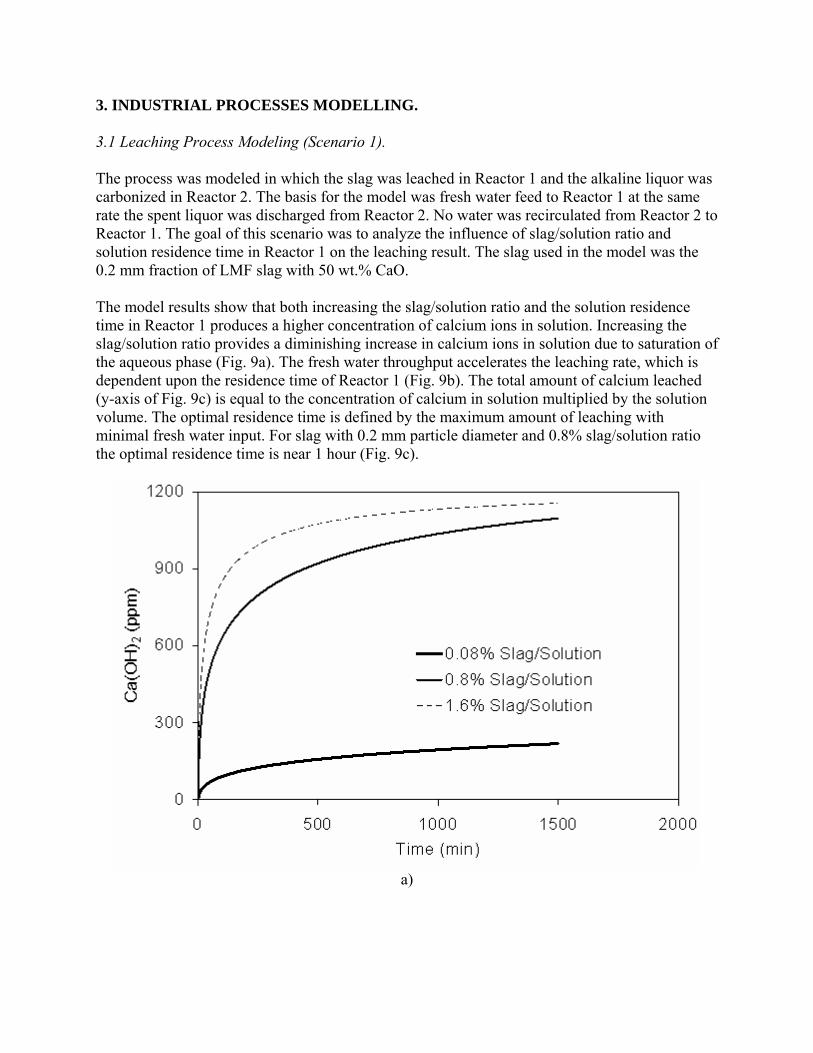
3. INDUSTRIAL PROCESSES MODELLING. 3.1 Leaching Process Modeling (Scenario 1). The process was modeled in which the slag was leached in Reactor 1 and the alkaline liquor was carbonized in Reactor 2. The basis for the model was fresh water feed to Reactor 1 at the same rate the spent liquor was discharged from Reactor 2. No water was recirculated from Reactor 2 to Reactor 1. The goal of this scenario was to analyze the influence of slag/solution ratio and solution residence time in Reactor 1 on the leaching result. The slag used in the model was the 0.2 mm fraction of LMF slag with 50 wt.% CaO. The model results show that both increasing the slag/solution ratio and the solution residence time in Reactor 1 produces a higher concentration of calcium ions in solution. Increasing the slag/solution ratio provides a diminishing increase in calcium ions in solution due to saturation of the aqueous phase (Fig. 9a). The fresh water throughput accelerates the leaching rate, which is dependent upon the residence time of Reactor 1 (Fig. 9b). The total amount of calcium leached (y-axis of Fig. 9c) is equal to the concentration of calcium in solution multiplied by the solution volume. The optimal residence time is defined by the maximum amount of leaching with minimal fresh water input. For slag with 0.2 mm particle diameter and 0.8% slag/solution ratio the optimal residence time is near 1 hour (Fig. 9c).
a)
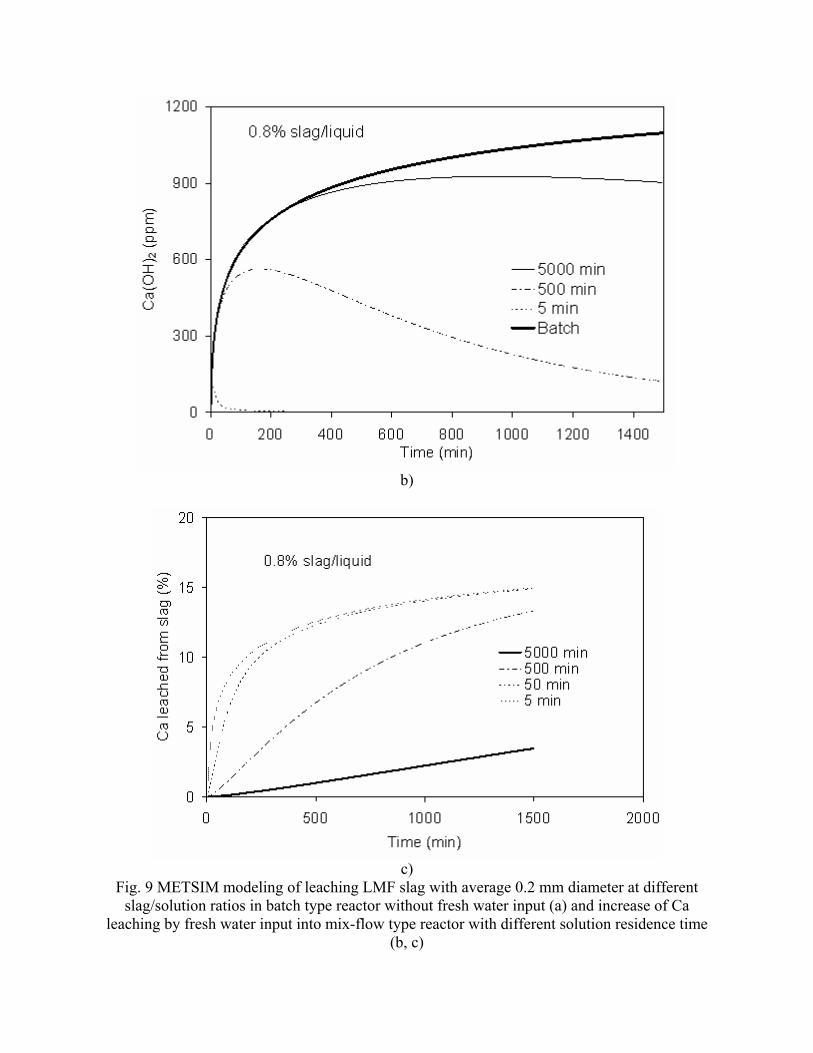
b)
c)
Fig. 9 METSIM modeling of leaching LMF slag with average 0.2 mm diameter at different slag/solution ratios in batch type reactor without fresh water input (a) and increase of Ca
leaching by fresh water input into mix-flow type reactor with different solution residence time (b, c)
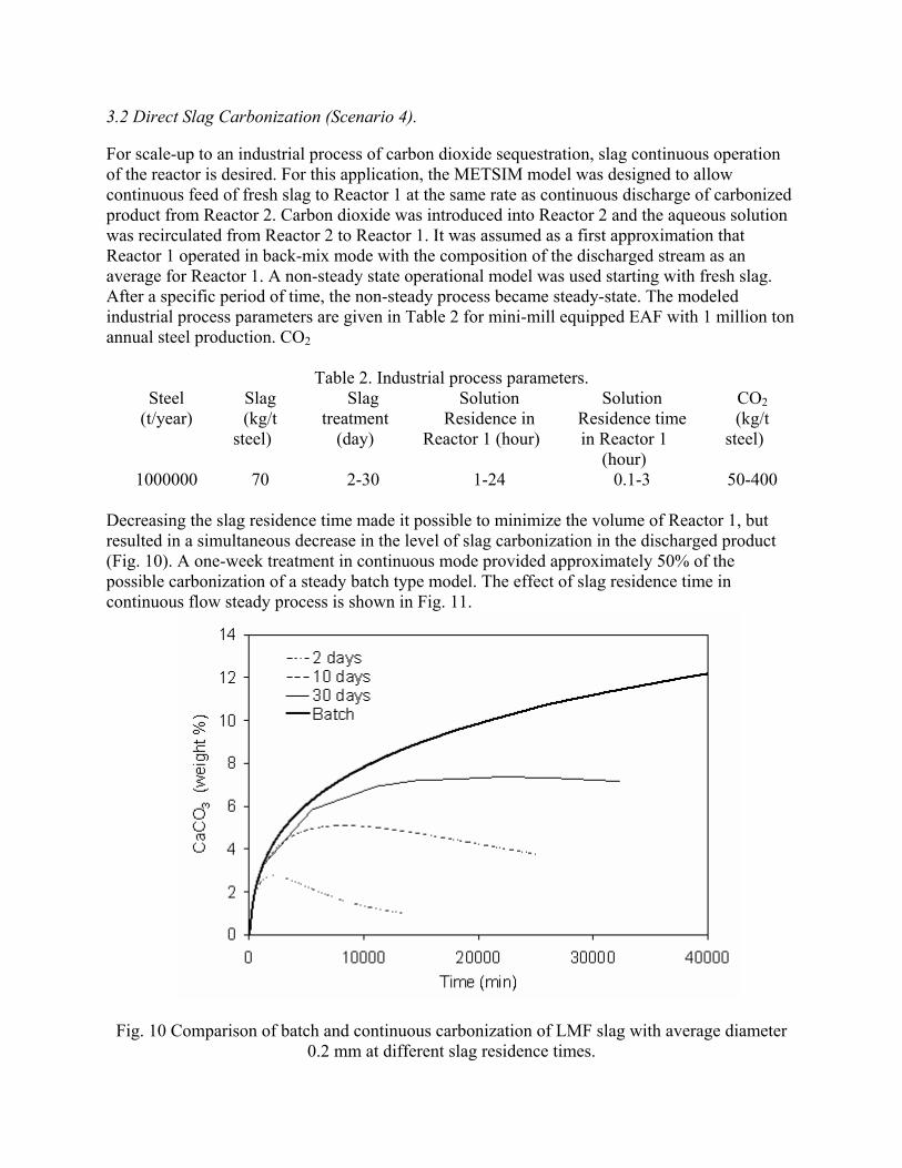
3.2 Direct Slag Carbonization (Scenario 4). For scale-up to an industrial process of carbon dioxide sequestration, slag continuous operation of the reactor is desired. For this application, the METSIM model was designed to allow continuous feed of fresh slag to Reactor 1 at the same rate as continuous discharge of carbonized product from Reactor 2. Carbon dioxide was introduced into Reactor 2 and the aqueous solution was recirculated from Reactor 2 to Reactor 1. It was assumed as a first approximation that Reactor 1 operated in back-mix mode with the composition of the discharged stream as an average for Reactor 1. A non-steady state operational model was used starting with fresh slag. After a specific period of time, the non-steady process became steady-state. The modeled industrial process parameters are given in Table 2 for mini-mill equipped EAF with 1 million ton annual steel production. CO2
Table 2. Industrial process parameters. Steel
(t/year) Slag (kg/t
steel)
Slag treatment
(day)
Solution Residence in
Reactor 1 (hour)
Solution Residence time in Reactor 1
(hour)
CO2 (kg/t
steel)
1000000 70 2-30 1-24 0.1-3 50-400
Decreasing the slag residence time made it possible to minimize the volume of Reactor 1, but resulted in a simultaneous decrease in the level of slag carbonization in the discharged product (Fig. 10). A one-week treatment in continuous mode provided approximately 50% of the possible carbonization of a steady batch type model. The effect of slag residence time in continuous flow steady process is shown in Fig. 11.
Fig. 10 Comparison of batch and continuous carbonization of LMF slag with average diameter 0.2 mm at different slag residence times.
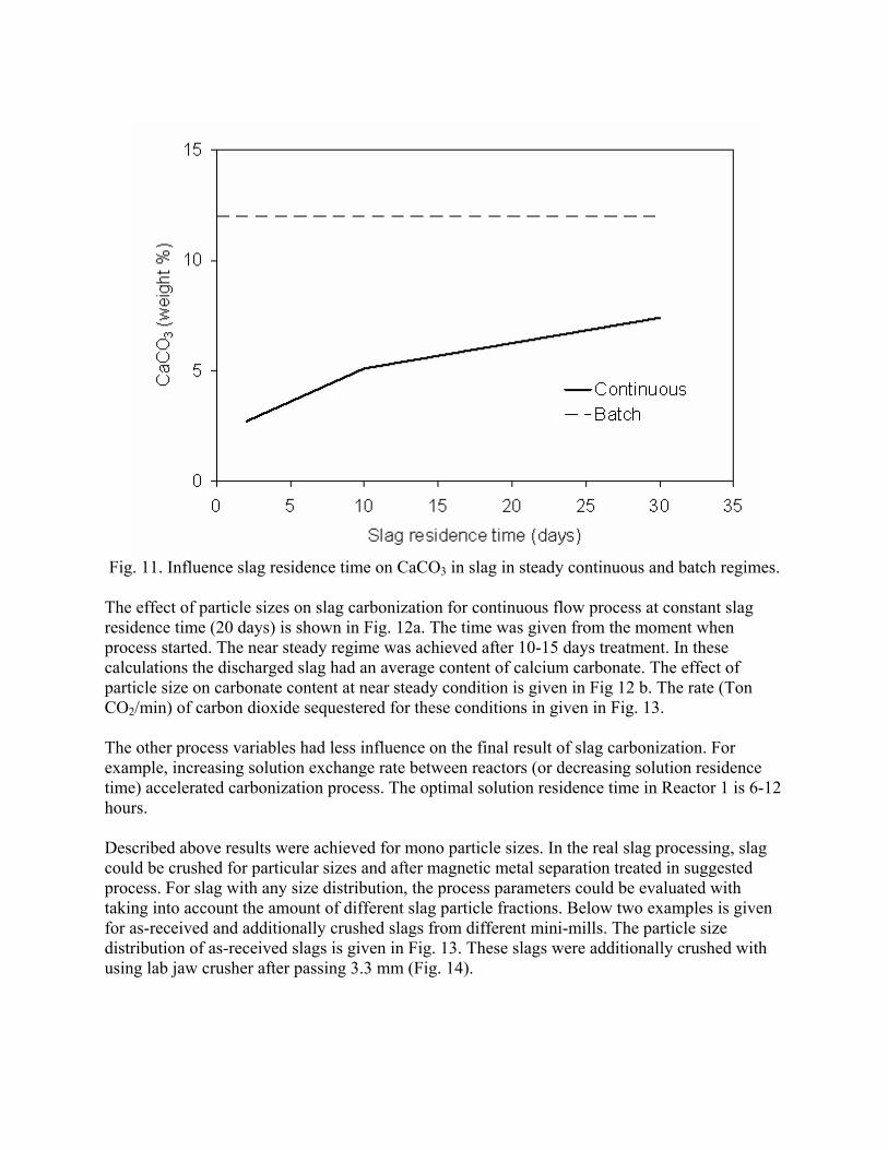
Fig. 11. Influence slag residence time on CaCO3 in slag in steady continuous and batch regimes.
The effect of particle sizes on slag carbonization for continuous flow process at constant slag residence time (20 days) is shown in Fig. 12a. The time was given from the moment when process started. The near steady regime was achieved after 10-15 days treatment. In these calculations the discharged slag had an average content of calcium carbonate. The effect of particle size on carbonate content at near steady condition is given in Fig 12 b. The rate (Ton CO2/min) of carbon dioxide sequestered for these conditions in given in Fig. 13. The other process variables had less influence on the final result of slag carbonization. For example, increasing solution exchange rate between reactors (or decreasing solution residence time) accelerated carbonization process. The optimal solution residence time in Reactor 1 is 6-12 hours.
Described above results were achieved for mono particle sizes. In the real slag processing, slag could be crushed for particular sizes and after magnetic metal separation treated in suggested process. For slag with any size distribution, the process parameters could be evaluated with taking into account the amount of different slag particle fractions. Below two examples is given for as-received and additionally crushed slags from different mini-mills. The particle size distribution of as-received slags is given in Fig. 13. These slags were additionally crushed with using lab jaw crusher after passing 3.3 mm (Fig. 14).
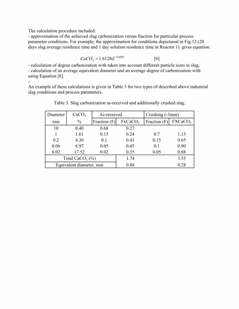
The calculation procedure included: - approximation of the achieved slag carbonization versus fraction for particular process parameter conditions. For example, the approximation for conditions depictured in Fig.12 (20 days slag average residence time and 1 day solution residence time in Reactor 1) gives equation:
6098.0
3 6128.1 −= dCaCO [6] - calculation of degree carbonization with taken into account different particle sizes in slag, - calculation of an average equivalent diameter and an average degree of carbonization with using Equation [6]. - An example of these calculations is given in Table 3 for two types of described above industrial slag conditions and process parameters.
Table 3. Slag carbonization as-received and additionally crushed slag.
Diameter CaCO3 As-received Crushing (-3mm)mm % Fraction (F) FxCaCO3 Fraction (F) FXCaCO3
10 0.40 0.68 0.271 1.61 0.15 0.24 0.7 1.13
0.2 4.30 0.1 0.43 0.15 0.650.06 8.97 0.05 0.45 0.1 0.900.02 17.52 0.02 0.35 0.05 0.88
Total CaCO3 (%) 1.74 3.55Equivalent diameter, mm 0.88 0.28
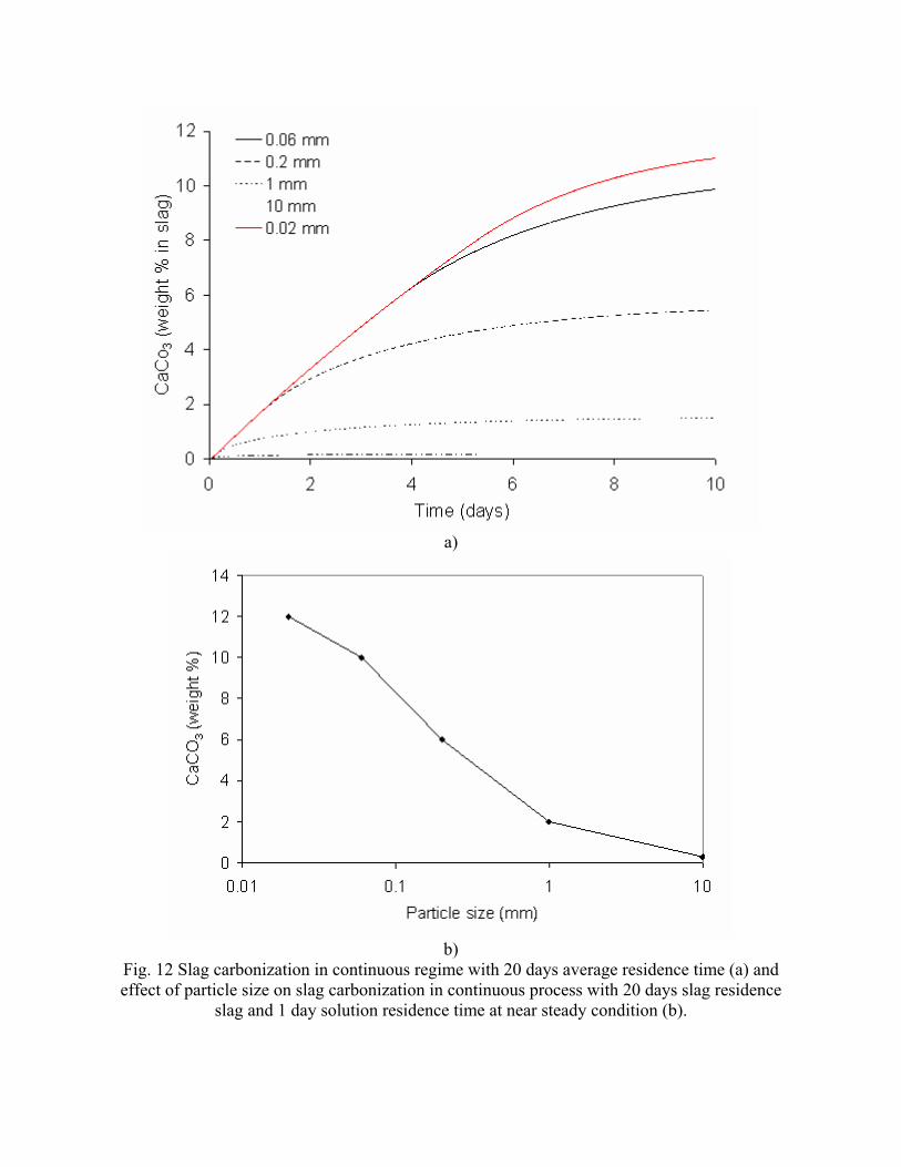
a)
b)
Fig. 12 Slag carbonization in continuous regime with 20 days average residence time (a) and effect of particle size on slag carbonization in continuous process with 20 days slag residence
slag and 1 day solution residence time at near steady condition (b).
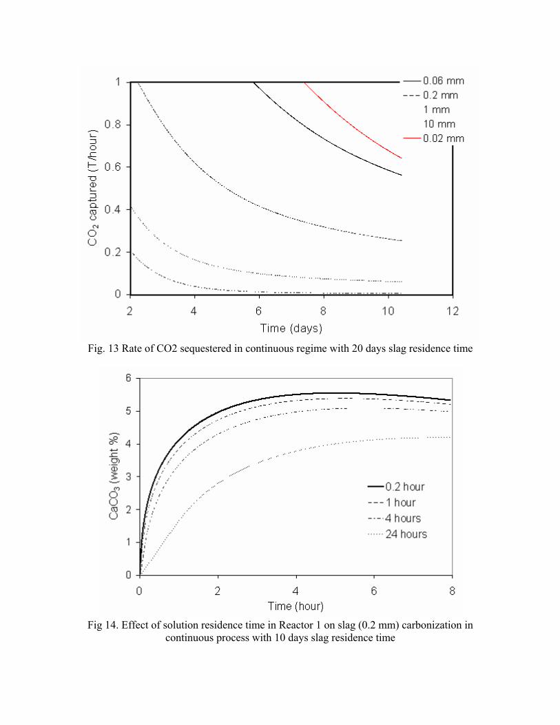
Fig. 13 Rate of CO2 sequestered in continuous regime with 20 days slag residence time
Fig 14. Effect of solution residence time in Reactor 1 on slag (0.2 mm) carbonization in
continuous process with 10 days slag residence time
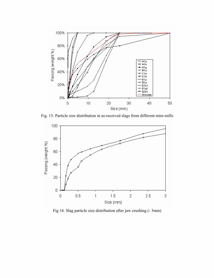
Fig. 15. Particle size distribution in as-received slags from different mini-mills
Fig 16. Slag particle size distribution after jaw crushing (- 3mm)
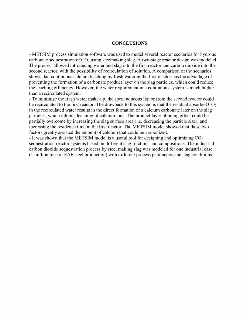
CONCLUSIONS - METSIM process simulation software was used to model several reactor scenarios for hydrous carbonate sequestration of CO2 using steelmaking slag. A two-stage reactor design was modeled. The process allowed introducing water and slag into the first reactor and carbon dioxide into the second reactor, with the possibility of recirculation of solution. A comparison of the scenarios shows that continuous calcium leaching by fresh water in the first reactor has the advantage of preventing the formation of a carbonate product layer on the slag particles, which could reduce the leaching efficiency. However, the water requirement in a continuous system is much higher than a recirculated system. - To minimize the fresh water make-up, the spent aqueous liquor from the second reactor could be recirculated to the first reactor. The drawback to this system is that the residual absorbed CO2 in the recirculated water results in the direct formation of a calcium carbonate later on the slag particles, which inhibits leaching of calcium ions. The product layer blinding effect could be partially overcome by increasing the slag surface area (i.e. decreasing the particle size), and increasing the residence time in the first reactor. The METSIM model showed that these two factors greatly assisted the amount of calcium that could be carbonized. - It was shown that the METSIM model is a useful tool for designing and optimizing CO2 sequestration reactor systems based on different slag fractions and compositions. The industrial carbon dioxide sequestration process by steel making slag was modeled for one industrial case (1 million tons of EAF steel production) with different process parameters and slag conditions.
Copyright © 2022 FDOKUMEN