ANNEXURE – 22 RISK ASSESSMENT REPORT
79
ANNEXURE – 22 RISK ASSESSMENT REPORT FOR PROPOSED CHANGE IN PRODUCT MIX FOR BULK DRUGS AND INTERMEDIATES MANUFACTURING UNIT AT KIADB Industrial Area, VILLAGE: JIGANI TALUK: ANEKAL DISTRICT: BENGALURU, URBAN STATE: KARNATAKA BY M/s. ACEBRIGHT (INDIA) PHARMA PVT LTD, (Project termed under schedule 5(f), Category ‘B’ Synthetic organic chemicals as per EIA Notification 2006 and its Amendments) REPORT PREPARED BY HUBERT ENVIRO CARE SYSTEMS (P) LTD CHENNAI November, 2016
-
Upload
khangminh22 -
Category
Documents
-
view
7 -
download
0
Transcript of ANNEXURE – 22 RISK ASSESSMENT REPORT
ANNEXURE – 22
RISK ASSESSMENT REPORT
FOR
PROPOSED CHANGE IN PRODUCT MIX FOR BULK DRUGS ANDINTERMEDIATES MANUFACTURING UNIT
AT
KIADB Industrial Area,VILLAGE: JIGANITALUK: ANEKAL
DISTRICT: BENGALURU, URBANSTATE: KARNATAKA
BY
M/s. ACEBRIGHT (INDIA) PHARMA PVT LTD,
(Project termed under schedule 5(f), Category ‘B’ Synthetic organic chemicals as per EIA Notification
2006 and its Amendments)
REPORT PREPARED BY
HUBERT ENVIRO CARE SYSTEMS (P) LTDCHENNAI
November, 2016
1
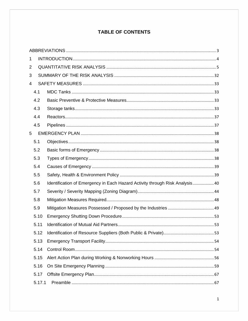
TABLE OF CONTENTS
ABBREVIATIONS ...................................................................................................................................... 3
1 INTRODUCTION ................................................................................................................................4
2 QUANTITATIVE RISK ANALYSIS .................................................................................................. 5
3 SUMMARY OF THE RISK ANALYSIS .........................................................................................32
4 SAFETY MEASURES .....................................................................................................................33
4.1 MDC Tanks ...............................................................................................................................33
4.2 Basic Preventive & Protective Measures..............................................................................33
4.3 Storage tanks............................................................................................................................33
4.4 Reactors.....................................................................................................................................37
4.5 Pipelines ....................................................................................................................................37
5 EMERGENCY PLAN .......................................................................................................................38
5.1 Objectives ..................................................................................................................................38
5.2 Basic forms of Emergency ......................................................................................................38
5.3 Types of Emergency ................................................................................................................38
5.4 Causes of Emergency .............................................................................................................39
5.5 Safety, Health & Environment Policy ....................................................................................39
5.6 Identification of Emergency in Each Hazard Activity through Risk Analysis ...................40
5.7 Severity / Severity Mapping (Zoning Diagram)....................................................................44
5.8 Mitigation Measures Required................................................................................................48
5.9 Mitigation Measures Possessed / Proposed by the Industries .........................................49
5.10 Emergency Shutting Down Procedure..................................................................................53
5.11 Identification of Mutual Aid Partners......................................................................................53
5.12 Identification of Resource Suppliers (Both Public & Private).............................................53
5.13 Emergency Transport Facility.................................................................................................54
5.14 Control Room ............................................................................................................................54
5.15 Alert Action Plan during Working & Nonworking Hours .....................................................56
5.16 On Site Emergency Planning .................................................................................................59
5.17 Offsite Emergency Plan...........................................................................................................67
5.17.1 Preamble ...............................................................................................................................67
2
5.17.2 Objective ................................................................................................................................68
5.17.3 Offsite Emergency Control..................................................................................................68
5.17.4 Emergency Instruction to the General Public...................................................................68
5.17.5 Category of Alarm Systems ................................................................................................69
5.17.6 Fire Fighting System ............................................................................................................69
5.17.7 General Instruction to the Public........................................................................................70
5.17.8 Security & Police ..................................................................................................................72
5.17.9 Medical facilities in case of emergency.............................................................................74
5.17.10 Mutual Aid..........................................................................................................................75
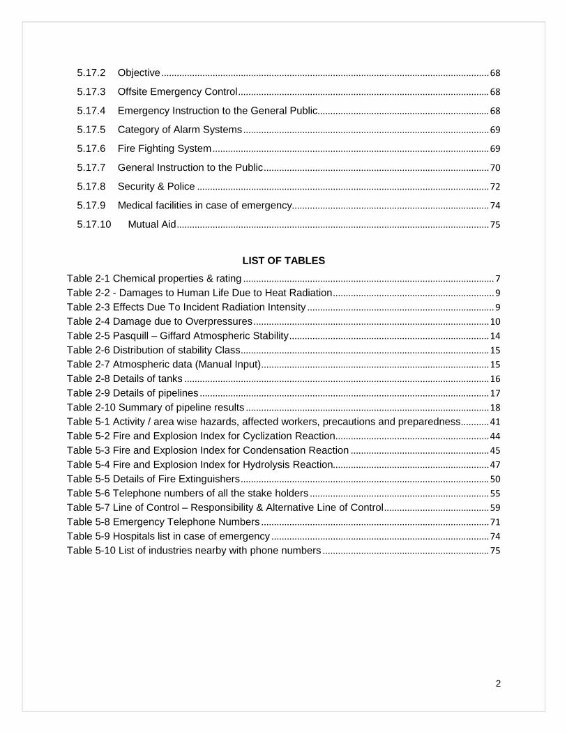
LIST OF TABLES
Table 2-1 Chemical properties & rating .................................................................................................. 7Table 2-2 - Damages to Human Life Due to Heat Radiation...............................................................9Table 2-3 Effects Due To Incident Radiation Intensity ......................................................................... 9Table 2-4 Damage due to Overpressures ............................................................................................10Table 2-5 Pasquill – Giffard Atmospheric Stability..............................................................................14Table 2-6 Distribution of stability Class.................................................................................................15Table 2-7 Atmospheric data (Manual Input).........................................................................................15Table 2-8 Details of tanks .......................................................................................................................16Table 2-9 Details of pipelines .................................................................................................................17Table 2-10 Summary of pipeline results ...............................................................................................18Table 5-1 Activity / area wise hazards, affected workers, precautions and preparedness...........41Table 5-2 Fire and Explosion Index for Cyclization Reaction............................................................44Table 5-3 Fire and Explosion Index for Condensation Reaction ......................................................45Table 5-4 Fire and Explosion Index for Hydrolysis Reaction.............................................................47Table 5-5 Details of Fire Extinguishers.................................................................................................50Table 5-6 Telephone numbers of all the stake holders ......................................................................55Table 5-7 Line of Control – Responsibility & Alternative Line of Control.........................................59Table 5-8 Emergency Telephone Numbers .........................................................................................71Table 5-9 Hospitals list in case of emergency .....................................................................................74Table 5-10 List of industries nearby with phone numbers .................................................................75
3
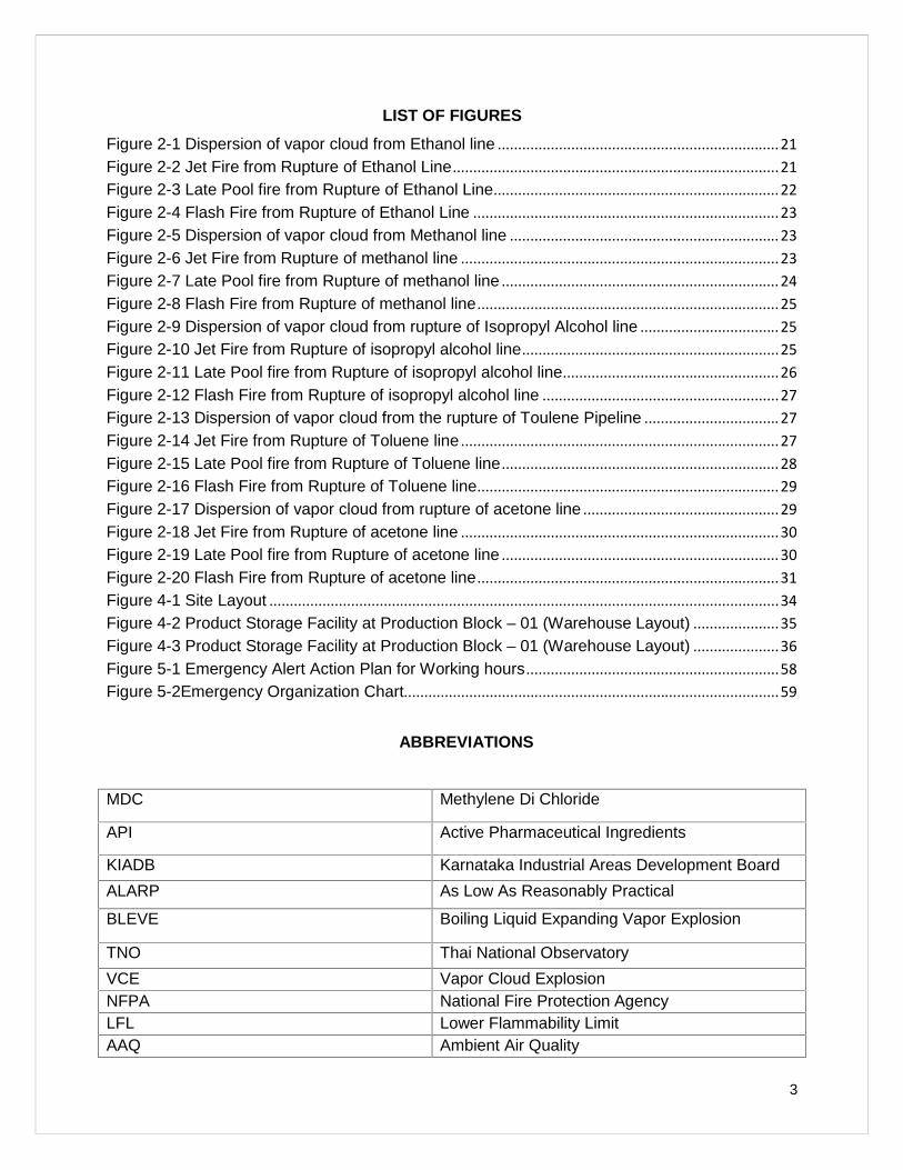
LIST OF FIGURES
Figure 2-1 Dispersion of vapor cloud from Ethanol line .....................................................................21Figure 2-2 Jet Fire from Rupture of Ethanol Line................................................................................21Figure 2-3 Late Pool fire from Rupture of Ethanol Line......................................................................22Figure 2-4 Flash Fire from Rupture of Ethanol Line ...........................................................................23Figure 2-5 Dispersion of vapor cloud from Methanol line ..................................................................23Figure 2-6 Jet Fire from Rupture of methanol line ..............................................................................23Figure 2-7 Late Pool fire from Rupture of methanol line ....................................................................24Figure 2-8 Flash Fire from Rupture of methanol line..........................................................................25Figure 2-9 Dispersion of vapor cloud from rupture of Isopropyl Alcohol line ..................................25Figure 2-10 Jet Fire from Rupture of isopropyl alcohol line...............................................................25Figure 2-11 Late Pool fire from Rupture of isopropyl alcohol line.....................................................26Figure 2-12 Flash Fire from Rupture of isopropyl alcohol line ..........................................................27Figure 2-13 Dispersion of vapor cloud from the rupture of Toulene Pipeline .................................27Figure 2-14 Jet Fire from Rupture of Toluene line ..............................................................................27Figure 2-15 Late Pool fire from Rupture of Toluene line....................................................................28Figure 2-16 Flash Fire from Rupture of Toluene line..........................................................................29Figure 2-17 Dispersion of vapor cloud from rupture of acetone line ................................................29Figure 2-18 Jet Fire from Rupture of acetone line ..............................................................................30Figure 2-19 Late Pool fire from Rupture of acetone line ....................................................................30Figure 2-20 Flash Fire from Rupture of acetone line..........................................................................31Figure 4-1 Site Layout .............................................................................................................................34Figure 4-2 Product Storage Facility at Production Block – 01 (Warehouse Layout) .....................35Figure 4-3 Product Storage Facility at Production Block – 01 (Warehouse Layout) .....................36Figure 5-1 Emergency Alert Action Plan for Working hours..............................................................58Figure 5-2Emergency Organization Chart............................................................................................59
ABBREV IATIONS
MDC Methylene Di Chloride
API Active Pharmaceutical Ingredients
KIADB Karnataka Industrial Areas Development Board
ALARP As Low As Reasonably Practical
BLEVE Boiling Liquid Expanding Vapor Explosion
TNO Thai National Observatory
VCE Vapor Cloud ExplosionNFPA National Fire Protection AgencyLFL Lower Flammability LimitAAQ Ambient Air Quality
4
1 INTRODUCTION
1.1 INTRODUCTION
M/s. Acebright (India) Pharma Pvt. Ltd. is positioned to become one of leading Pharmaceuticals
Manufacturing and Exporting Company in India.
In line with the Market Demand M/s. Acebright (India) Pharma Pvt. Ltd. Proposes for a change
of product mix, presently manufacturing 6 Nos. products in which 4 existing products will be
stopped and 2 Nos. existing products are continued and 25 new products will be included within
the existing premises with no overall change in production quantity of Active Pharmaceutical
Ingredients (APIs).
The Consequence Risk Analysis is been carried out for the Proposed change in product mix of
Acebright which is located in KIADB Industrial Area, Jigani village, Anekal Taluk, Bangalore
District and Karnataka State. Based on the available studies & plant layout the potential
scenarios which can cause significant consequences like fire and explosion scenarios were
identified. The consequences of the scenarios were assessed using the software PHAST 7.01
and analysis is carried by Hubert Enviro Care Systems Pvt Ltd, Chennai consultant.
The purpose of the study includes the following:
To identify and assess those hazards and risks with NFPA rating.
To eliminate or reduce to As Low As Reasonably Practical (ALARP) in terms of risk to
human health, risk of injury, risk of damage to plant, equipment and environment,
business interruption or loss etc.,
To Suggest On-site and Off-site mitigative Measures.
1.2 SCOPE OF STUDY
The main scope of the study is to carry out Quantitative Risk Analysis study as per The Indian
Standard IS 15656: Code of practice - Hazard Identification and Risk Analysis
- Identification of hazards
- Consequence Modelling
- Contour Mapping on Site Google Earth image
- Damage Distance identification & Quantification of risk
5
2 QUANTITATIVE RISK ANALYS IS
2.1 HAZARD IDENTIFICATION
Hazards will be identified based upon consideration of factors such as the physical & chemical
properties of the fluids being handled, the arrangement of equipment & maintenance
procedures and processing conditions.
2.1.1 Selection
The goal of selection is to limit the total number of incident outcome cases to be studied to a
manageable size. The purpose of incident outcome selection is to develop a set of incident
outcomes that must be studied for each incident included in the finalized incident study list.
Each incident needs to be considered separately. Using the list of incident outcomes the risk
analyst needs to determine which may result from each incident. While the analyst can decide
whether an incident involving the loss of a process chemical to the atmosphere needs to be
examined using dispersion analysis because of potential toxic gas effects, what happens if the
same material is immediately ignited on release. Based on the NFPA rating the chemicals
ranked 3 and 4 in the scale of 0-4 are selected for the consequence analysis.
2.1.2 Characterising t he Failures
Accidental release of flammable or toxic vapors can result in severe consequences. Delayed
ignition of flammable vapors can result in blast overpressures covering large areas. This may
lead to extensive loss of life and property. Toxic clouds may cover yet larger distances due to
the lower threshold values in relation to those in case of explosive clouds (the lower explosive
limits). In contrast, fires have localized consequences. Fires can be put out or contained in most
cases; there are few mitigating actions one can take once a vapor cloud gets released. Major
accident hazards arise, therefore, consequent upon the release of flammable or toxic vapors or
BLEVE in case of pressurized liquefied gases. In an industry, main hazard arises due to storage
and handling of hazardous chemicals. To formulate a structured approach to identification of
hazards and understanding of contributory factors is essential.
6
2.1.3 Blast Overpressures
Blast Overpressures depend upon the reactivity class of material and the amount of gas
between two explosive limits. The hydrocarbon that is expected to give rise to a vapor cloud on
release is pressurized gases.
2.1.4 Inventory
Inventory Analysis is commonly used in understanding the relative hazards and shortlisting of
release scenarios. Inventory plays an important role in regard to the potential hazard. Larger the
inventory of a vessel or a system, larger the quantity of potential release. A practice commonly
used to generate an incident list is to consider potential leaks and major releases from fractures
of pipelines and vessels containing sizable inventories. The potential vapor release (source
strength) depends upon the quantity of liquid release, the properties of the materials and the
operating conditions (pressure, temperature). If all these influencing parameters are combined
into a matrix and vapor source strength computed for each release case, a ranking should
become a credible exercise.
Loss of Containment
Liquid Release may be instantaneous. Failure of a vessel leading to an instantaneous outflow
assumes the sudden appearance of such a major crack that practically all of the contents above
the crack shall be released in a very short time.
The more likely event is the case of liquid release from a hole in a pipe connected to the vessel.
The flow rate will depend on the size of the hole as well as on the pressure in front of the hole,
prior to the accident. Such pressure is basically dependent on the pressure in the vessel.
The vaporization of released liquid depends on the vapor pressure and weather conditions.
Such consideration and others have been kept in mind both during the initial listing as well as
during the short listing procedure. Initial listing of all significant inventories in the process plants
was carried out. This ensured no omission through in advertence.
2.2 FACTORS CONSIDERED FOR IDENTIFICATION OF HAZARDS
The National Fire Protection Agency (NFPA) is responsible for 380 codes and standards that
are designed to minimize the risk and effects of fire by establishing criteria for building,
7
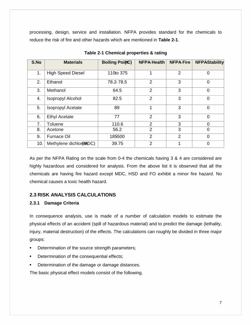
processing, design, service and installation. NFPA provides standard for the chemicals to
reduce the risk of fire and other hazards which are mentioned in Table 2-1.
Table 2-1 Chemical properties & rating
S.No. Materials Boiling Point(oC) NFPA- Health NFPA- Fire NFPA-Stability
1. High Speed Diesel 110to 375 1 2 0
2. Ethanol 78.2- 78.5 2 3 0
3. Methanol 64.5 2 3 0
4. Isopropyl Alcohol 82.5 2 3 0
5. Isopropyl Acetate 89 1 3 0
6. Ethyl Acetate 77 2 3 0
7. Toluene 110.6 2 3 08. Acetone 56.2 2 3 0
9. Furnace Oil 185-500 2 2 0
10. Methylene dichloride(MDC) 39.75 2 1 0
As per the NFPA Rating on the scale from 0-4 the chemicals having 3 & 4 are considered are
highly hazardous and considered for analysis. From the above list it is observed that all the
chemicals are having fire hazard except MDC, HSD and FO exhibit a minor fire hazard. No
chemical causes a toxic health hazard.
2.3 RISK ANALYSIS CALCULATIONS
2.3.1 Damage Criteria
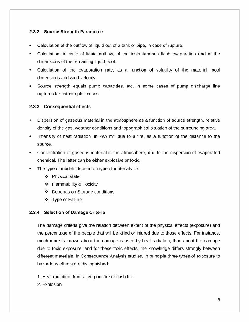
In consequence analysis, use is made of a number of calculation models to estimate the
physical effects of an accident (spill of hazardous material) and to predict the damage (lethality,
injury, material destruction) of the effects. The calculations can roughly be divided in three major
groups:
Determination of the source strength parameters;
Determination of the consequential effects;
Determination of the damage or damage distances.
The basic physical effect models consist of the following.
8
2.3.2 Source Strength Parameters
Calculation of the outflow of liquid out of a tank or pipe, in case of rupture.
Calculation, in case of liquid outflow, of the instantaneous flash evaporation and of the
dimensions of the remaining liquid pool.
Calculation of the evaporation rate, as a function of volatility of the material, pool
dimensions and wind velocity.
Source strength equals pump capacities, etc. in some cases of pump discharge line
ruptures for catastrophic cases.
2.3.3 Consequential effects
Dispersion of gaseous material in the atmosphere as a function of source strength, relative
density of the gas, weather conditions and topographical situation of the surrounding area.
Intensity of heat radiation [in kW/ m2] due to a fire, as a function of the distance to the
source.
Concentration of gaseous material in the atmosphere, due to the dispersion of evaporated
chemical. The latter can be either explosive or toxic.
The type of models depend on type of materials i.e.,
Physical state
Flammability & Toxicity
Depends on Storage conditions
Type of Failure
2.3.4 Selection of Damage Criteria
The damage criteria give the relation between extent of the physical effects (exposure) and
the percentage of the people that will be killed or injured due to those effects. For instance,
much more is known about the damage caused by heat radiation, than about the damage
due to toxic exposure, and for these toxic effects, the knowledge differs strongly between
different materials. In Consequence Analysis studies, in principle three types of exposure to
hazardous effects are distinguished:
1. Heat radiation, from a jet, pool fire or flash fire.
2. Explosion
9
3. Toxic effects, from toxic materials or toxic combustion products.
Heat Radiation
The consequence caused by exposure to heat radiation is a function of:
• The radiation energy onto the human body [kW/m2];
• The exposure duration [sec];
• The protection of the skin tissue (clothed or naked body).
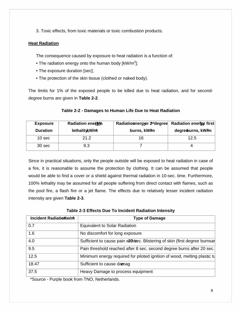
The limits for 1% of the exposed people to be killed due to heat radiation, and for second-
degree burns are given in Table 2-2.
Table 2-2 - Damages to Human Lif e Due to Heat Radiation
Exposure
Duration
Radiation energy(1%
lethality,kW/m2
Radiationenergyor 2nddegree
burns, kW/m2Radiation energyfor first
degreeburns, kW/m2
10 sec 21.2 16 12.5
30 sec 9.3 7 4
Since in practical situations, only the people outside will be exposed to heat radiation in case of
a fire, it is reasonable to assume the protection by clothing. It can be assumed that people
would be able to find a cover or a shield against thermal radiation in 10-sec. time. Furthermore,
100% lethality may be assumed for all people suffering from direct contact with flames, such as
the pool fire, a flash fire or a jet flame. The effects due to relatively lesser incident radiation
intensity are given Table 2-3.
Table 2-3 Effects Due To Incident Radiation Intensity
Incident Radiation–Kw/m2 Type of Damage
0.7 Equivalent to Solar Radiation
1.6 No discomfort for long exposure
4.0 Sufficient to cause pain within20 sec. Blistering of skin (first degree burnsare likely)
9.5 Pain threshold reached after 8 sec. second degree burns after 20 sec.
12.5 Minimum energy required for piloted ignition of wood, melting plastic tubing’s etc.,
18.47 Sufficient to cause damage
37.5 Heavy Damage to process equipment
*Source - Purple book from TNO, Netherlands.
10
Explosion
In case of vapour cloud explosion, two physical effects may occur:
Flash fire over the whole length of the explosive gas cloud;
A blast wave, with typical peak overpressures circular around ignition source.
As explained above, 100% lethality is assumed for all people who are present withinthe
cloud proper.
For the blast wave, the lethality criterion is based on:
Peak overpressure of 0.1 bar will cause serious damage to 10% of the
housing/structures.
Falling fragments will kill one of each eight persons in the destroyed buildings.
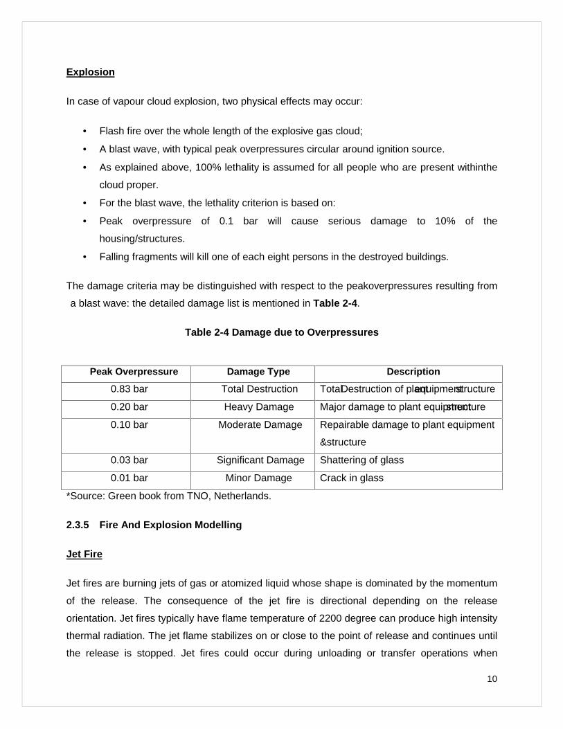
The damage criteria may be distinguished with respect to the peakoverpressures resulting from
a blast wave: the detailed damage list is mentioned in Table 2-4.
Table 2-4 Damage due to Overpressures
Peak Overpressure Damage Type Description
0.83 bar Total Destruction TotalDestruction of plantequipmentstructure
0.20 bar Heavy Damage Major damage to plant equipmentstructure
0.10 bar Moderate Damage Repairable damage to plant equipment
&structure
0.03 bar Significant Damage Shattering of glass
0.01 bar Minor Damage Crack in glass
*Source: Green book from TNO, Netherlands.
2.3.5 Fire And Explosion Modelling
Jet Fire
Jet fires are burning jets of gas or atomized liquid whose shape is dominated by the momentum
of the release. The consequence of the jet fire is directional depending on the release
orientation. Jet fires typically have flame temperature of 2200 degree can produce high intensity
thermal radiation. The jet flame stabilizes on or close to the point of release and continues until
the release is stopped. Jet fires could occur during unloading or transfer operations when
11
pressures are increased by compressors. Such fires could cause severe damage but will
generally affect only the local area.
If compressed or liquefied gases are related from storage tanks or pipelines, the materials
discharging through the hole will form a gas jet that entrains and mixes with the ambient air. If
the material encounters an ignition sources while it is in the flammable range, a jet fire may
occur. Jet fires could occur during unloading operations when pressures are increased by
pumping. Such fires could cause severe damage but will generally affect only the local area.
The effect of jet flame impingement is severe as it may cut through equipment, pipeline or
structure. The damage effect of thermal radiation is depended on both the level of thermal
radiation and duration of exposure.
Flash Fire
When a volatile, flammable material is released to the atmosphere, a vapor cloud forms and
disperses (mixes with air). If the resultant vapor cloud is ignited before the cloud is diluted below
its LFL, a flash fire may occur. The combustion normally occurs within only portions of the vapor
cloud (where mixed with air in flammable concentrations), rather than the entire cloud. A flash
fire may burn back to therelease point, resulting in a pool or jet fire but is unlikely to generate
damaging over pressures (explode) when unconfined.
A flash fire occurs when a cloud of vapor/gas burns without generating any significant
overpressure. The cloud is typically ignited on its edge, remote from the leak source. The
combustion zone moves through the cloud away from the ignition point. The duration of the
flash fire is relatively short but it may stabilize as a continuous jet fire from the leak source. For
flash fires, an approximate estimate for the extent of the total effect zone is the area over which
the cloud is above the LFL. It is assumed that this area is not increased by cloud expansion
during burning.
Fire Ball (BLEVE)
BLEVE stands for Boiling Liquid Expanding Vapor Explosion. Sometimes referred to as a
fireball, a BLEVE is a combination of fire and explosion with an intense radiant heat emission
within a relatively short time interval. As implied by the term, the phenomenon can occur within
a vessel or tank in which a liquefied gas is kept above its atmospheric boiling point.
12
It is the result of a liquid within a container reaching a temperature well above its boiling point at
atmospheric temperature, causing the vessel to rupture into two or more pieces. BLEVE can be
defined as a rapid failure of a container of flammable material under pressure during fire
engulfment. Failure is followed by a fireball or major fire which produces a powerful radiant-heat
flux.
BLEVE can occur when fire impinges on the tank shell at a point or points above the liquid level
of the contents of the tank. This impingement causes the metal to weaken and fail from the
internal pressure. A fireball is an intense spherical fire resulting from a sudden release of
pressurized gas which is immediately ignited, burning as it expand forming a ball of fire, rising in
the air. When this cloud is ignited, a fireball occurs, causing enormous heat-radiation intensity
within a few seconds. This heat intensity is sufficient to cause severe skin burns and deaths at
several hundred meters from the vessel, depending on the quantity of the gas involved. When a
BLEVE occurs, debris may travel hundreds of feet, with tremendous force, and the escaping
fuel can ignite causing an expanding fireball.
Explosions
Explosions are characterized by a shock-wave which can be heard as a bang and which can
cause damage to buildings, breaking windows and ejecting missiles over distances of several
hundred meters. The injuries and damage are in the first place caused by the shock-wave of the
explosion itself. People are blown over or knocked down and buried under collapsed buildings
or injured by flying glass. Although the effects of over-pressure can directly result in deaths, this
would be likely to involve only those working in the direct vicinity of the explosion. The history of
industrial explosions shows that the indirect effects of collapsing buildings, flying glass and
debris cause far more loss of life and severe injuries.
Vapor Cloud Explosion
Generally catastrophic gas explosions happen when considerable quantities of flammable
material are released and dispersed with air to form an explosive vapor cloud before ignition
takes place.
A Vapor Cloud Explosion (VCE) occurs if a cloud of flammable gas burns sufficiently quickly to
generate high overpressures (i.e., pressures in excess of ambient).
13
The following main types of explosion can be distinguished.
Confined explosions where the burning gas is largely confined, typically inside a largely
empty enclosed tank or building.
Semi-confined explosions where the gas is partly confined, typically in an offshore
process module therefore not considered for this study.
Unconfined explosions where the gas cloud is largely unconfined, typically on an
onshore installation, but there are sufficient obstacles to generate turbulence and start
the build-up of pressure.
Toxic gas release
In case of release of toxic gas, when a gas that is heavier than air is released, it initially behaves
very differently from a neutrally buoyant gas. The heavy gas will first "slump," or sink, because it
is heavier than the surrounding air. As the gas cloud moves downwind, gravity makes it spread;
this can cause some of the vapor to travel upwind of its release point. Farther downwind, as the
cloud becomes more diluted and its density approaches that of air, it begins behaving like a
neutrally buoyant gas.
This takes place when the concentration of heavy gas in the surrounding air drops below about
1 percent (10,000 parts per million). For many small releases, this will occur in the first few
yards (meters). For large releases, this may happen much further downwind.
2.3.6 Weather Data
For this study weather conditions pertaining to Acebright are considered as per the (IMD
Climatological for Bangalore Region 1971 – 2000), Predominant wind direction is West to East.
Wind Speed
The mean wind Speed is taken as around 1.4 to 4.6 m/s. (IMD Climatological for Bangalore
Region 1971 – 2000).
Temperature
The annual mean of maximum and minimum temperature are 34°C and 14.2°C respectively.
The annual average temperature is min 18.2 – max 29.4 °C (IMD Climatological for Bangalore
Region 1971 – 2000).
14
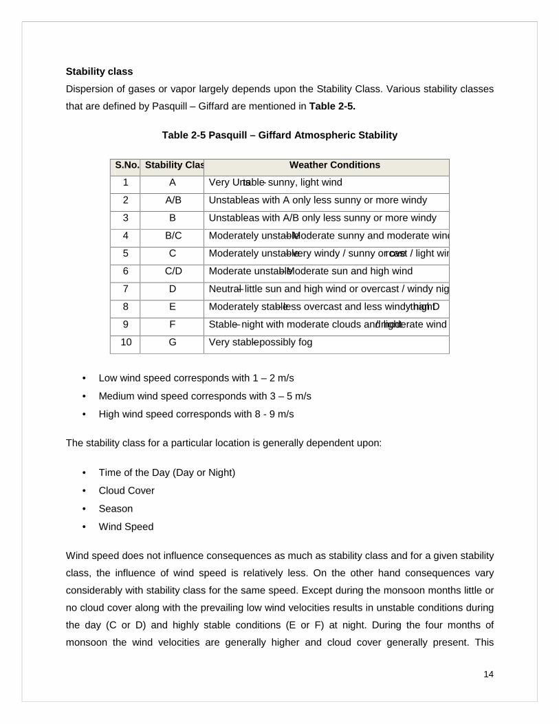
Stability class
Dispersion of gases or vapor largely depends upon the Stability Class. Various stability classes
that are defined by Pasquill – Giffard are mentioned in Table 2-5.
Table 2-5 Pasquill – Giffard Atmospheric Stability
S.No. Stability Class Weather Conditions
1 A Very Unstable- sunny, light wind
2 A/B Unstable- as with A only less sunny or more windy
3 B Unstable- as with A/B only less sunny or more windy
4 B/C Moderately unstable–Moderate sunny and moderate wind
5 C Moderately unstable–very windy / sunny or overcast / light wind
6 C/D Moderate unstable–Moderate sun and high wind
7 D Neutral– little sun and high wind or overcast / windy night
8 E Moderately stable– less overcast and less windy nightthan D
9 F Stable–night with moderate clouds and light/ moderate wind
10 G Very stable–possibly fog
Low wind speed corresponds with 1 – 2 m/s
Medium wind speed corresponds with 3 – 5 m/s
High wind speed corresponds with 8 - 9 m/s
The stability class for a particular location is generally dependent upon:
Time of the Day (Day or Night)
Cloud Cover
Season
Wind Speed
Wind speed does not influence consequences as much as stability class and for a given stability
class, the influence of wind speed is relatively less. On the other hand consequences vary
considerably with stability class for the same speed. Except during the monsoon months little or
no cloud cover along with the prevailing low wind velocities results in unstable conditions during
the day (C or D) and highly stable conditions (E or F) at night. During the four months of
monsoon the wind velocities are generally higher and cloud cover generally present. This
15
results instability class of D during the day and E or F during the night. The stability class
distribution over the year roughly works out as mentioned in Table 2-6:
Table 2-6 Distribution of stability Class
Stability Class Distribution (%)
A - B – C 17%
D 50%
E or F 33%
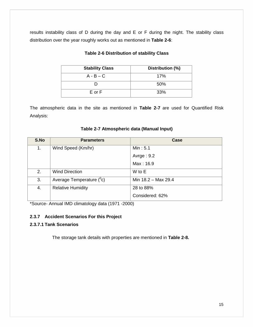
The atmospheric data in the site as mentioned in Table 2-7 are used for Quantified Risk
Analysis:
Table 2-7 Atmospheric data (Manual Input)
*Source- Annual IMD climatology data (1971 -2000)
2.3.7 Accident Scenarios For t his Project
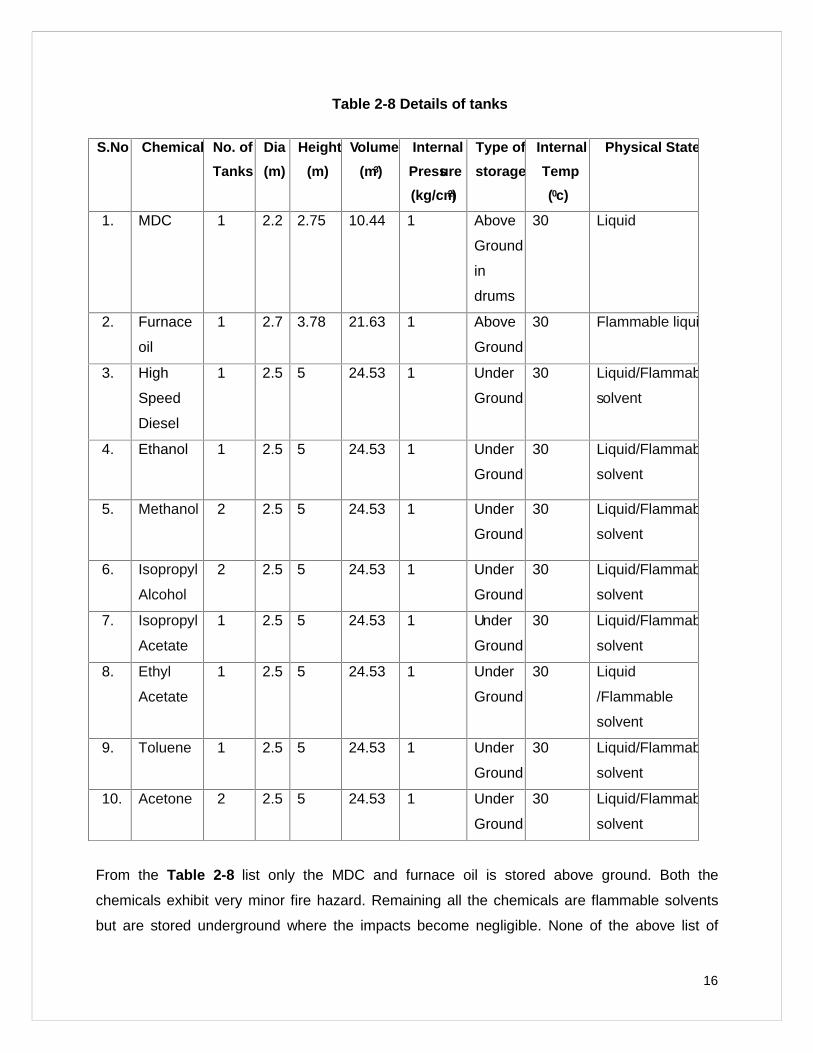
2.3.7.1 Tank Scenarios
The storage tank details with properties are mentioned in Table 2-8.
S.No Parameters Case
1. Wind Speed (Km/hr) Min : 5.1
Avrge : 9.2
Max : 16.9
2. Wind Direction W to E
3. Average Temperature (0c) Min 18.2 – Max 29.4
4. Relative Humidity 28 to 88%
Considered: 62%
16
Table 2-8 Details of tanks
S.No Chemical No. of
Tanks
Dia
(m)
Height
(m)
Volume
(m3)
Internal
Pressure
(kg/cm2)
Type of
storage
Internal
Temp
(0c)
Physical State
1. MDC 1 2.2 2.75 10.44 1 Above
Ground
in
drums
30 Liquid
2. Furnace
oil
1 2.7 3.78 21.63 1 Above
Ground
30 Flammable liquid
3. High
Speed
Diesel
1 2.5 5 24.53 1 Under
Ground
30 Liquid/Flammable
solvent
4. Ethanol 1 2.5 5 24.53 1 Under
Ground
30 Liquid/Flammable
solvent
5. Methanol 2 2.5 5 24.53 1 Under
Ground
30 Liquid/Flammable
solvent
6. Isopropyl
Alcohol
2 2.5 5 24.53 1 Under
Ground
30 Liquid/Flammable
solvent
7. Isopropyl
Acetate
1 2.5 5 24.53 1 Under
Ground
30 Liquid/Flammable
solvent
8. Ethyl
Acetate
1 2.5 5 24.53 1 Under
Ground
30 Liquid
/Flammable
solvent
9. Toluene 1 2.5 5 24.53 1 Under
Ground
30 Liquid/Flammable
solvent
10. Acetone 2 2.5 5 24.53 1 Under
Ground
30 Liquid/Flammable
solvent
From the Table 2-8 list only the MDC and furnace oil is stored above ground. Both the
chemicals exhibit very minor fire hazard. Remaining all the chemicals are flammable solvents
but are stored underground where the impacts become negligible. None of the above list of
17
chemicals exhibits toxic health hazard. Due to this reason none of the storage tanks are
considered for risk analysis.
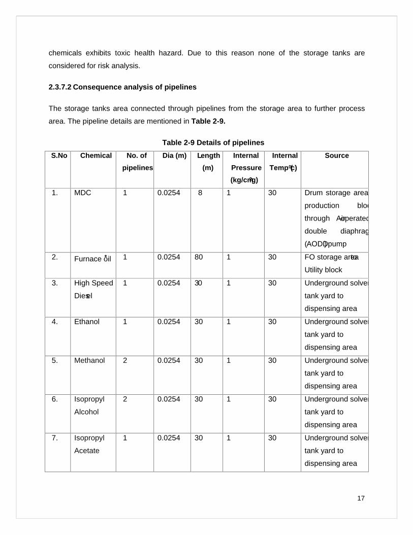
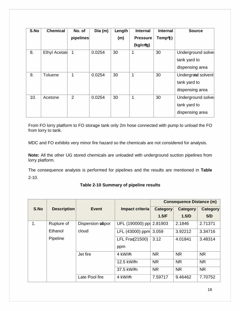
2.3.7.2 Consequence analysis of pipelines
The storage tanks area connected through pipelines from the storage area to further process
area. The pipeline details are mentioned in Table 2-9.
Table 2-9 Details of pipeline s
S.No Chemical No. of
pipelines
Dia (m) Length
(m)
Internal
Pressure
(kg/cm2g)
Internal
Temp (0c)
Source
1. MDC 1 0.0254 8 1 30 Drum storage area to
production block
through Air-operated
double diaphragm
(AODD) pump
2. Furnace oil* 1 0.0254 80 1 30 FO storage areato
Utility block
3. High Speed
Diesel
1 0.0254 30 1 30 Underground solvent
tank yard to
dispensing area
4. Ethanol 1 0.0254 30 1 30 Underground solvent
tank yard to
dispensing area
5. Methanol 2 0.0254 30 1 30 Underground solvent
tank yard to
dispensing area
6. Isopropyl
Alcohol
2 0.0254 30 1 30 Underground solvent
tank yard to
dispensing area
7. Isopropyl
Acetate
1 0.0254 30 1 30 Underground solvent
tank yard to
dispensing area
18
S.No Chemical No. of
pipelines
Dia (m) Length
(m)
Internal
Pressure
(kg/cm2g)
Internal
Temp (0c)
Source
8. Ethyl Acetate 1 0.0254 30 1 30 Underground solvent
tank yard to
dispensing area
9. Toluene 1 0.0254 30 1 30 Underground solvent
tank yard to
dispensing area
10. Acetone 2 0.0254 30 1 30 Underground solvent
tank yard to
dispensing area
From FO lorry platform to FO storage tank only 2m hose connected with pump to unload the FOfrom lorry to tank.
MDC and FO exhibits very minor fire hazard so the chemicals are not considered for analysis.
Note: All the other UG stored chemicals are unloaded with underground suction pipelines fromlorry platform.
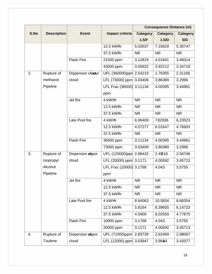
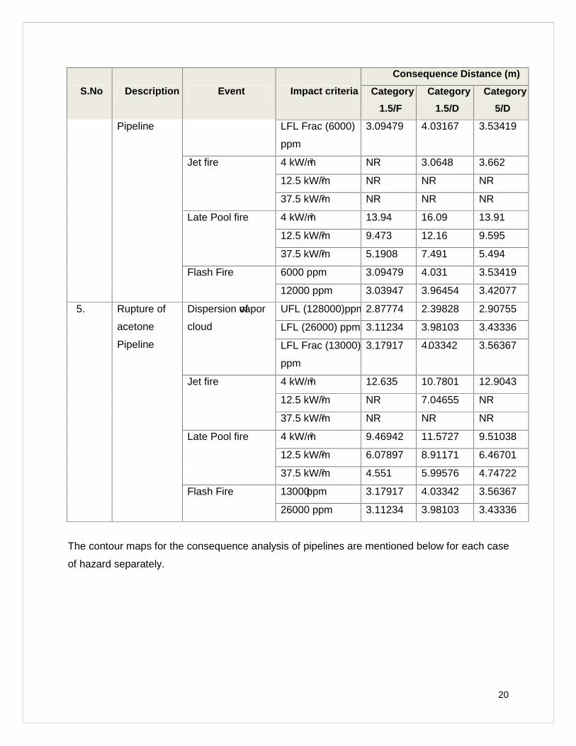
The consequence analysis is performed for pipelines and the results are mentioned in Table
2-10.
Table 2-10 Summary of pipeline results
S.No Description Event Impact criteria
Consequence Distance (m)
Category
1.5/F
Category
1.5/D
Category
5/D
1. Rupture of
Ethanol
Pipeline
Dispersion ofvapor
cloud
UFL (190000) ppm2.81903 2.1846 2.71371
LFL (43000) ppm 3.059 3.92212 3.34716
LFL Frac(21500)
ppm
3.12 4.01841 3.48314
Jet fire 4 kW/m2 NR NR NR
12.5 kW/m2 NR NR NR
37.5 kW/m2 NR NR NR
Late Pool fire 4 kW/m2 7.59717 9.46462 7.70752
19
S.No Description Event Impact criteria
Consequence Distance (m)
Category
1.5/F
Category
1.5/D
Category
5/D
12.5 kW/m2 5.02637 7.16629 5.35747
37.5 kW/m2 NR NR NR
Flash Fire 21500 ppm 3.12819 4.01841 3.48314
43000 ppm 3.05922 3.92212 3.34716
2. Rupture of
methanol
Pipeline
Dispersion of vapour
cloud
UFL (360000)ppm2.54219 1.76355 2.31166
LFL (73000) ppm 3.03409 3.86389 3.2996
LFL Frac (36500)
ppm
3.11134 4.00395 3.44961
Jet fire 4 kW/m2 NR NR NR
12.5 kW/m2 NR NR NR
37.5 kW/m2 NR NR NR
Late Pool fire 4 kW/m2 6.06409 7.82936 6.23523
12.5 kW/m2 4.57277 6.01647 4.76603
37.5 kW/m2 NR NR NR
Flash Fire 36500 ppm 3.11134 4.00395 3.44961
73000 ppm 3.03409 3.86389 3.2996
3. Rupture of
Isopropyl
Alcohol
Pipeline
Dispersion ofvapor
cloud
UFL (120000)ppm2.88432 2.49218 2.94748
LFL (20000) ppm 3.1171 4.00592 3.45713
LFL Frac (10000)
ppm
3.1768 4.043 3.5755
Jet fire 4 kW/m2 NR NR NR
12.5 kW/m2 NR NR NR
37.5 kW/m2 NR NR NR
Late Pool fire 4 kW/m2 8.64063 10.5834 8.68354
12.5 kW/m2 5.8164 8.39655 6.14723
37.5 kW/m2 4.5909 6.02559 4.77875
Flash Fire 10000 ppm 3.1768 4.043 3.5755
20000 ppm 3.1171 4.00592 3.45713
4. Rupture of
Toulene
Dispersion ofvapor
cloud
UFL (71000)ppm 2.83739 2.62469 2.98067
LFL (12000) ppm 3.03947 3.96454 3.42077
20
S.No Description Event Impact criteria
Consequence Distance (m)
Category
1.5/F
Category
1.5/D
Category
5/D
Pipeline LFL Frac (6000)
ppm
3.09479 4.03167 3.53419
Jet fire 4 kW/m2 NR 3.0648 3.662
12.5 kW/m2 NR NR NR
37.5 kW/m2 NR NR NR
Late Pool fire 4 kW/m2 13.94 16.09 13.91
12.5 kW/m2 9.473 12.16 9.595
37.5 kW/m2 5.1908 7.491 5.494
Flash Fire 6000 ppm 3.09479 4.031 3.53419
12000 ppm 3.03947 3.96454 3.42077
5. Rupture of
acetone
Pipeline
Dispersion ofvapor
cloud
UFL (128000)ppm2.87774 2.39828 2.90755
LFL (26000) ppm 3.11234 3.98103 3.43336
LFL Frac (13000)
ppm
3.17917 4.03342 3.56367
Jet fire 4 kW/m2 12.635 10.7801 12.9043
12.5 kW/m2 NR 7.04655 NR
37.5 kW/m2 NR NR NR
Late Pool fire 4 kW/m2 9.46942 11.5727 9.51038
12.5 kW/m2 6.07897 8.91171 6.46701
37.5 kW/m2 4.551 5.99576 4.74722
Flash Fire 13000ppm 3.17917 4.03342 3.56367
26000 ppm 3.11234 3.98103 3.43336
The contour maps for the consequence analysis of pipelines are mentioned below for each case
of hazard separately.
21
Scenario -1 Rupture of Ethanol line from UG Tank to Dispensing area
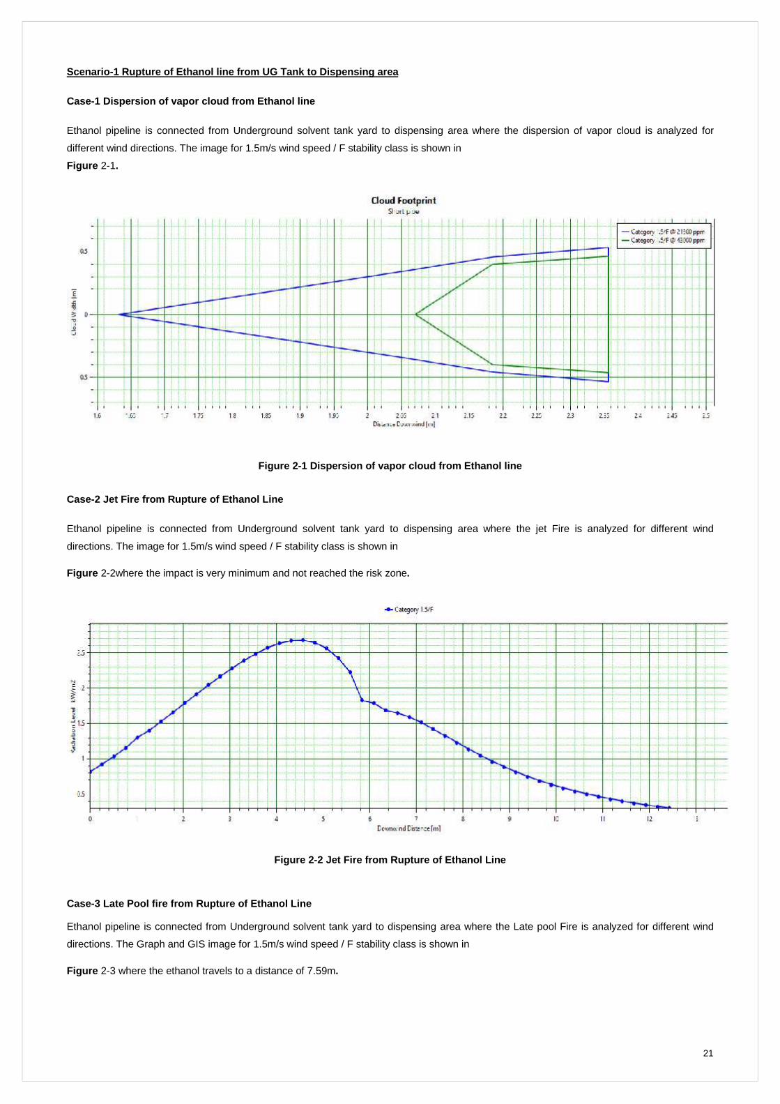
Case-1 Dispersion of vapor cloud from Ethanol line
Ethanol pipeline is connected from Underground solvent tank yard to dispensing area where the dispersion of vapor cloud is analyzed for
different wind directions. The image for 1.5m/s wind speed / F stability class is shown in
Figure 2-1.
Figure 2-1 Dispersion of vapor cloud from Ethanol line
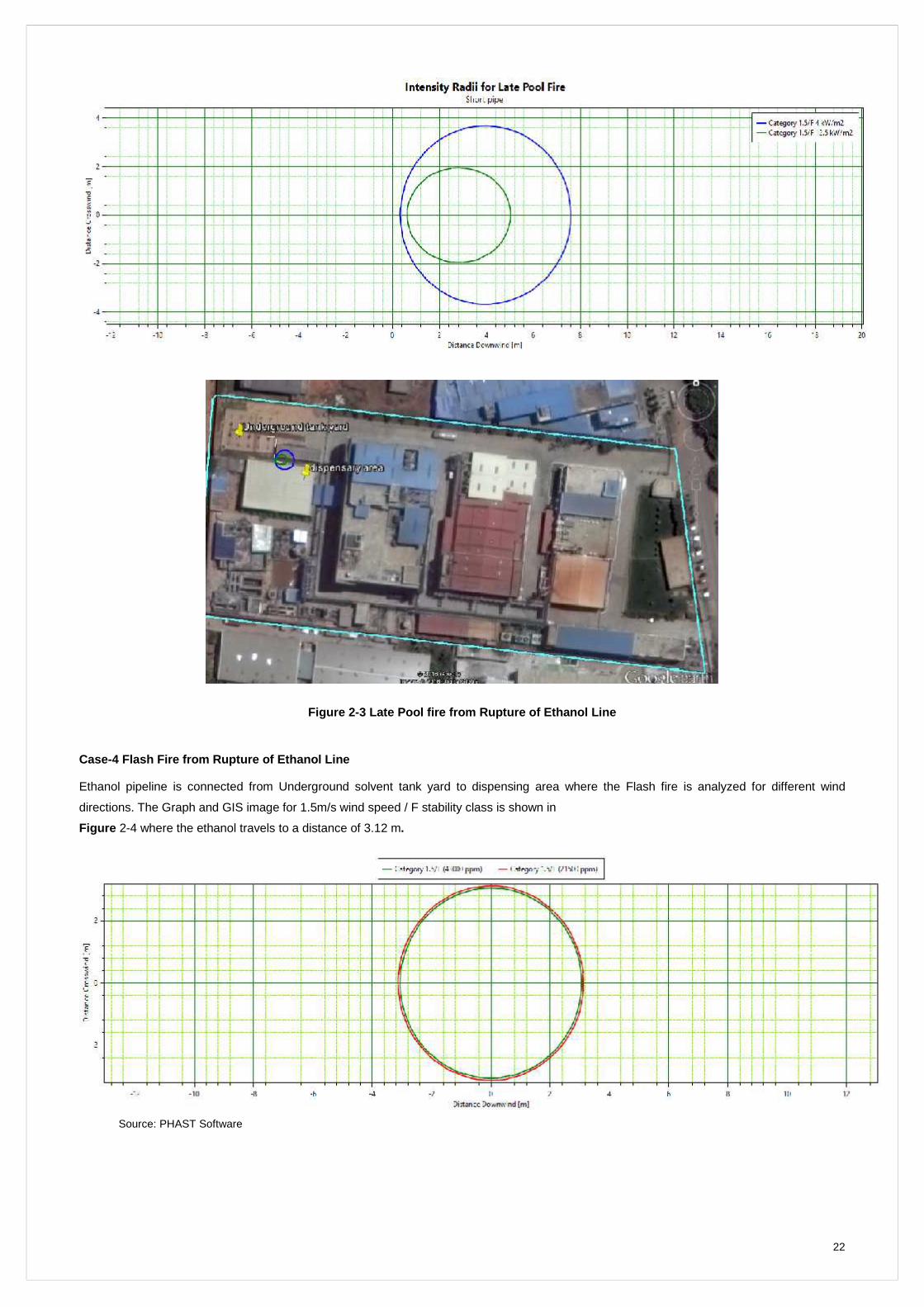
Case-2 Jet Fire from Rupture of Ethanol Line
Ethanol pipeline is connected from Underground solvent tank yard to dispensing area where the jet Fire is analyzed for different wind
directions. The image for 1.5m/s wind speed / F stability class is shown in
Figure 2-2where the impact is very minimum and not reached the risk zone.
Figure 2-2 Jet Fire from Rupture of Ethanol Line
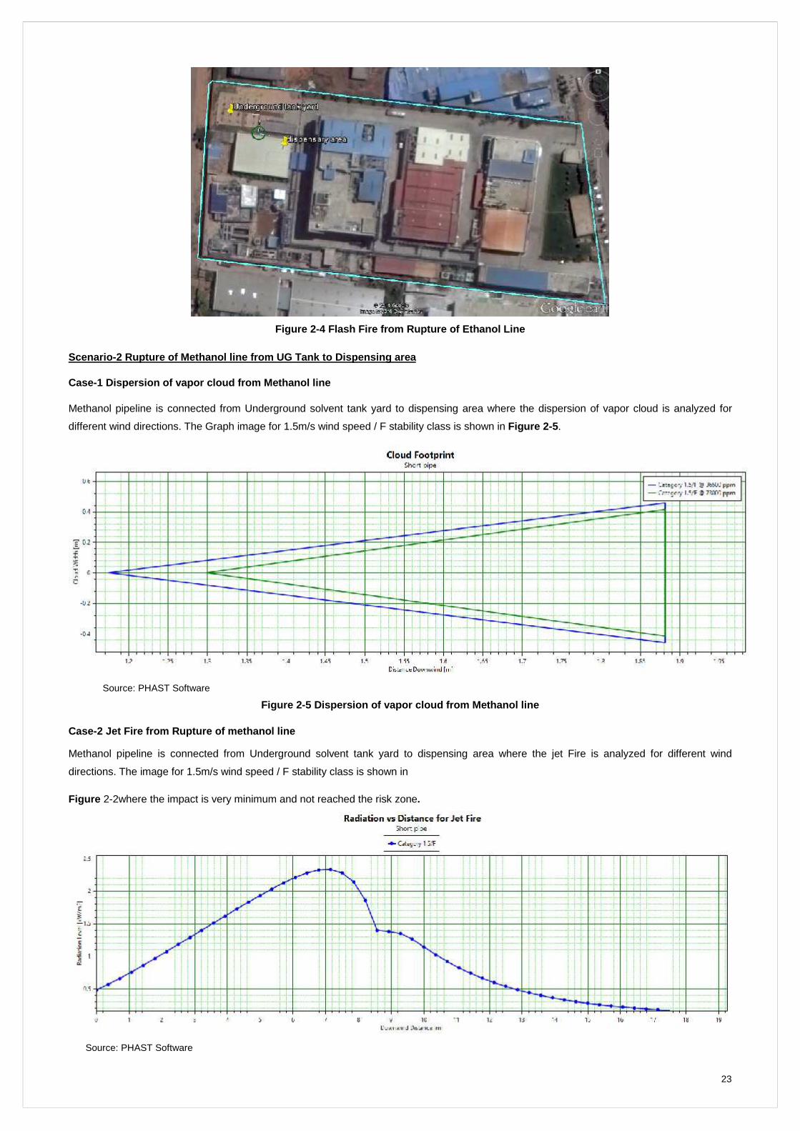
Case-3 Late Pool fire from Rupture of Ethanol Line
Ethanol pipeline is connected from Underground solvent tank yard to dispensing area where the Late pool Fire is analyzed for different wind
directions. The Graph and GIS image for 1.5m/s wind speed / F stability class is shown in
Figure 2-3 where the ethanol travels to a distance of 7.59m.
22
Figure 2-3 Late Pool fire from Rupture of Ethanol Line
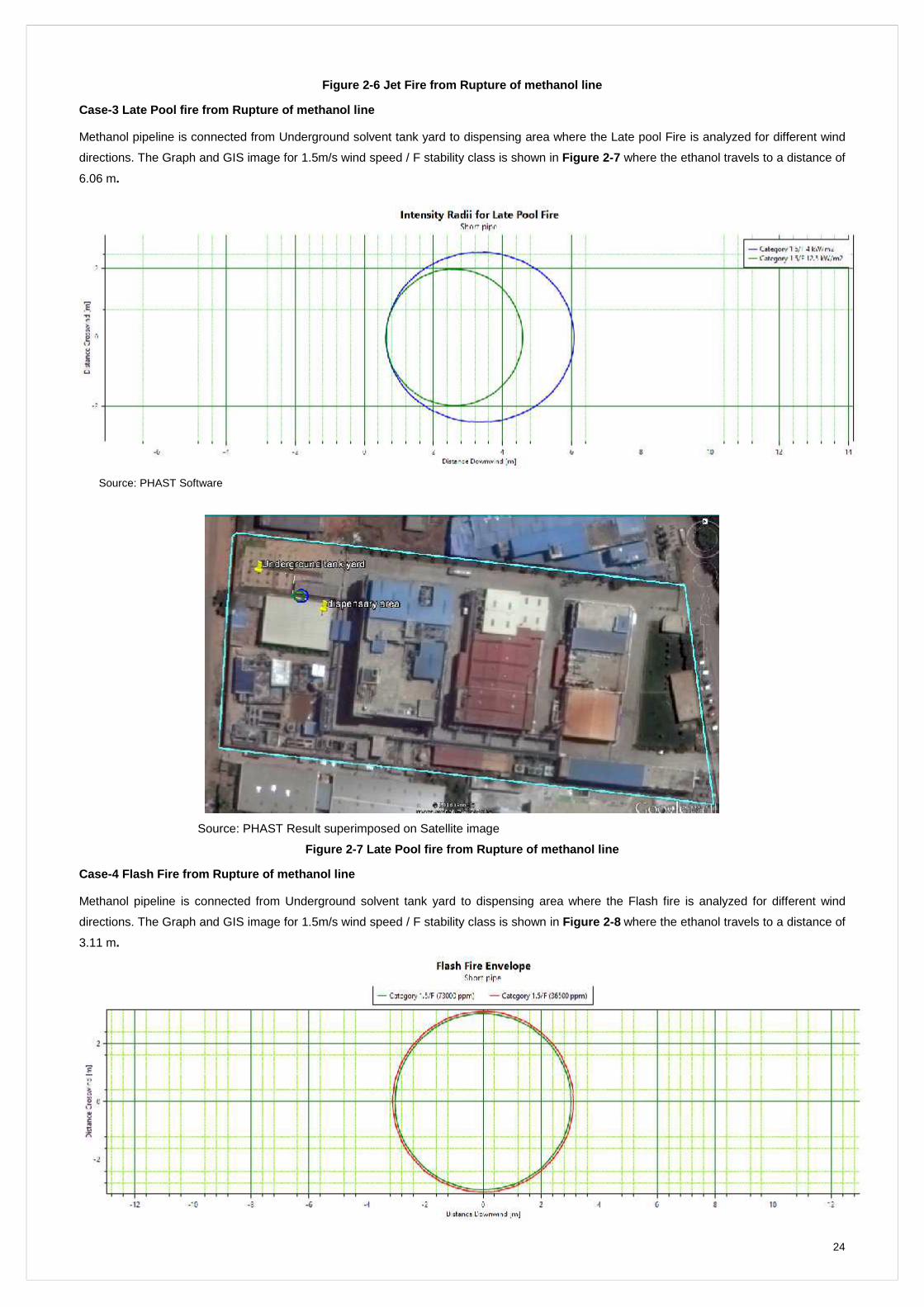
Case-4 Flash Fire from Rupture of Ethanol Line
Ethanol pipeline is connected from Underground solvent tank yard to dispensing area where the Flash fire is analyzed for different wind
directions. The Graph and GIS image for 1.5m/s wind speed / F stability class is shown in
Figure 2-4 where the ethanol travels to a distance of 3.12 m.
Source: PHAST Software
23
Figure 2-4 Flash Fire from Rupture of Ethanol Line
Scenario -2 Rupture of Methanol line from UG Tank to Dispensing area
Case-1 Dispersion of vapor cloud from Methanol line
Methanol pipeline is connected from Underground solvent tank yard to dispensing area where the dispersion of vapor cloud is analyzed for
different wind directions. The Graph image for 1.5m/s wind speed / F stability class is shown in Figure 2-5.
Source: PHAST Software
Figure 2-5 Dispersion of vapor cloud from Methanol line
Case-2 Jet Fire from Rupture of methanol line
Methanol pipeline is connected from Underground solvent tank yard to dispensing area where the jet Fire is analyzed for different wind
directions. The image for 1.5m/s wind speed / F stability class is shown in
Figure 2-2where the impact is very minimum and not reached the risk zone.
Source: PHAST Software
24
Figure 2-6 Jet Fire from Rupture of methanol line
Case-3 Late Pool fire from Rupture of methanol line
Methanol pipeline is connected from Underground solvent tank yard to dispensing area where the Late pool Fire is analyzed for different wind
directions. The Graph and GIS image for 1.5m/s wind speed / F stability class is shown in Figure 2-7 where the ethanol travels to a distance of
6.06 m.
Source: PHAST Software
Source: PHAST Result superimposed on Satellite image
Figure 2-7 Late Pool fire from Rupture of methanol line
Case-4 Flash Fire from Rupture of methanol line
Methanol pipeline is connected from Underground solvent tank yard to dispensing area where the Flash fire is analyzed for different wind
directions. The Graph and GIS image for 1.5m/s wind speed / F stability class is shown in Figure 2-8 where the ethanol travels to a distance of
3.11 m.
25
Figure 2-8 Flash Fire from Rupture of methanol line
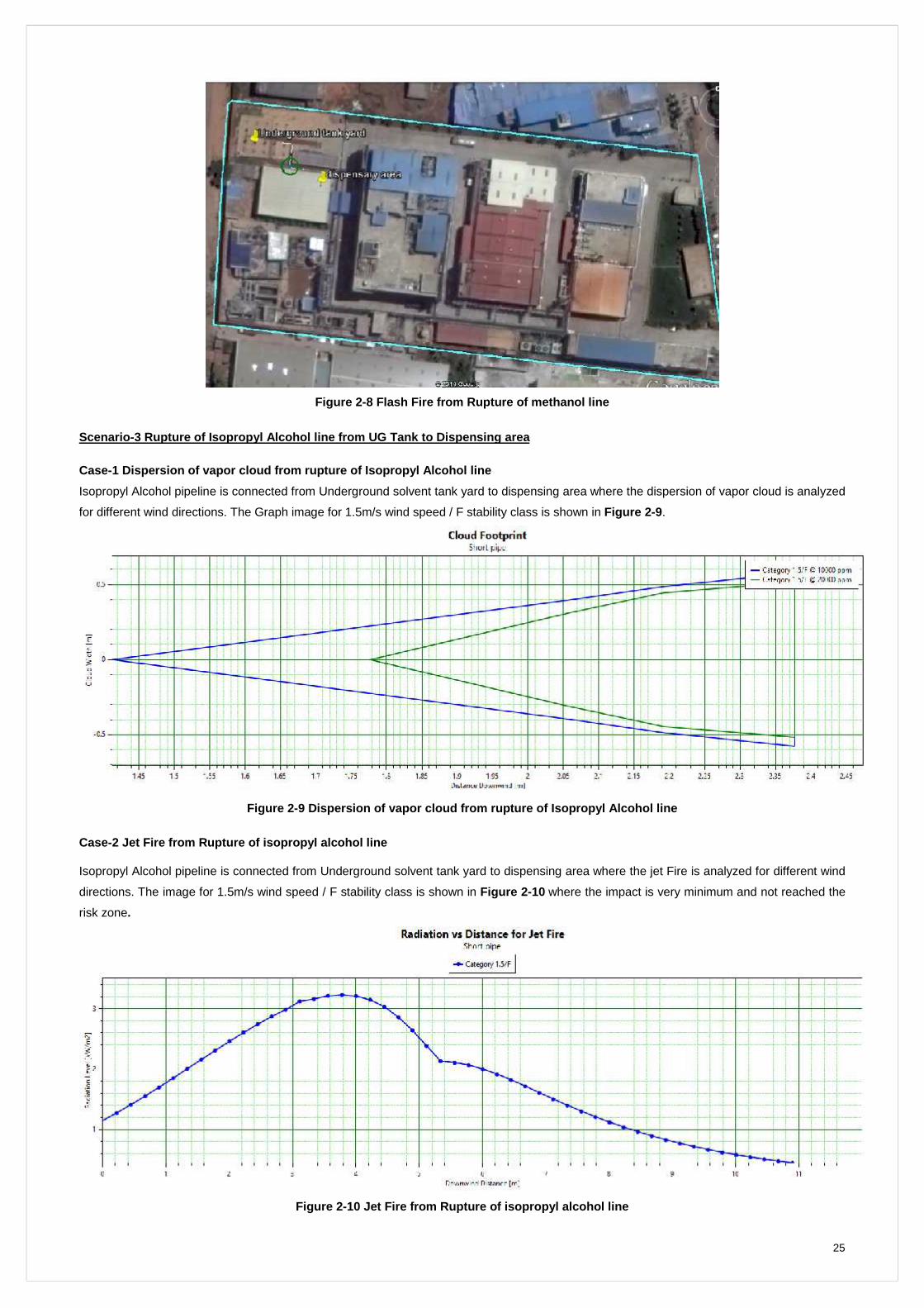
Scenario -3 Rupture of Isopropyl Alcohol line from UG Tank to Dispensing area
Case-1 Dispersion of vapor cloud from rupture of Isopropyl Alcohol line
Isopropyl Alcohol pipeline is connected from Underground solvent tank yard to dispensing area where the dispersion of vapor cloud is analyzed
for different wind directions. The Graph image for 1.5m/s wind speed / F stability class is shown in Figure 2-9.
Figure 2-9 Dispersion of vapor cloud from rupture of Isopropyl Alcohol line
Case-2 Jet Fire fr om Rupture of isopropyl alcohol line
Isopropyl Alcohol pipeline is connected from Underground solvent tank yard to dispensing area where the jet Fire is analyzed for different wind
directions. The image for 1.5m/s wind speed / F stability class is shown in Figure 2-10 where the impact is very minimum and not reached the
risk zone.
Figure 2-10 Jet Fire from Rupture of isopropyl alcohol line
26
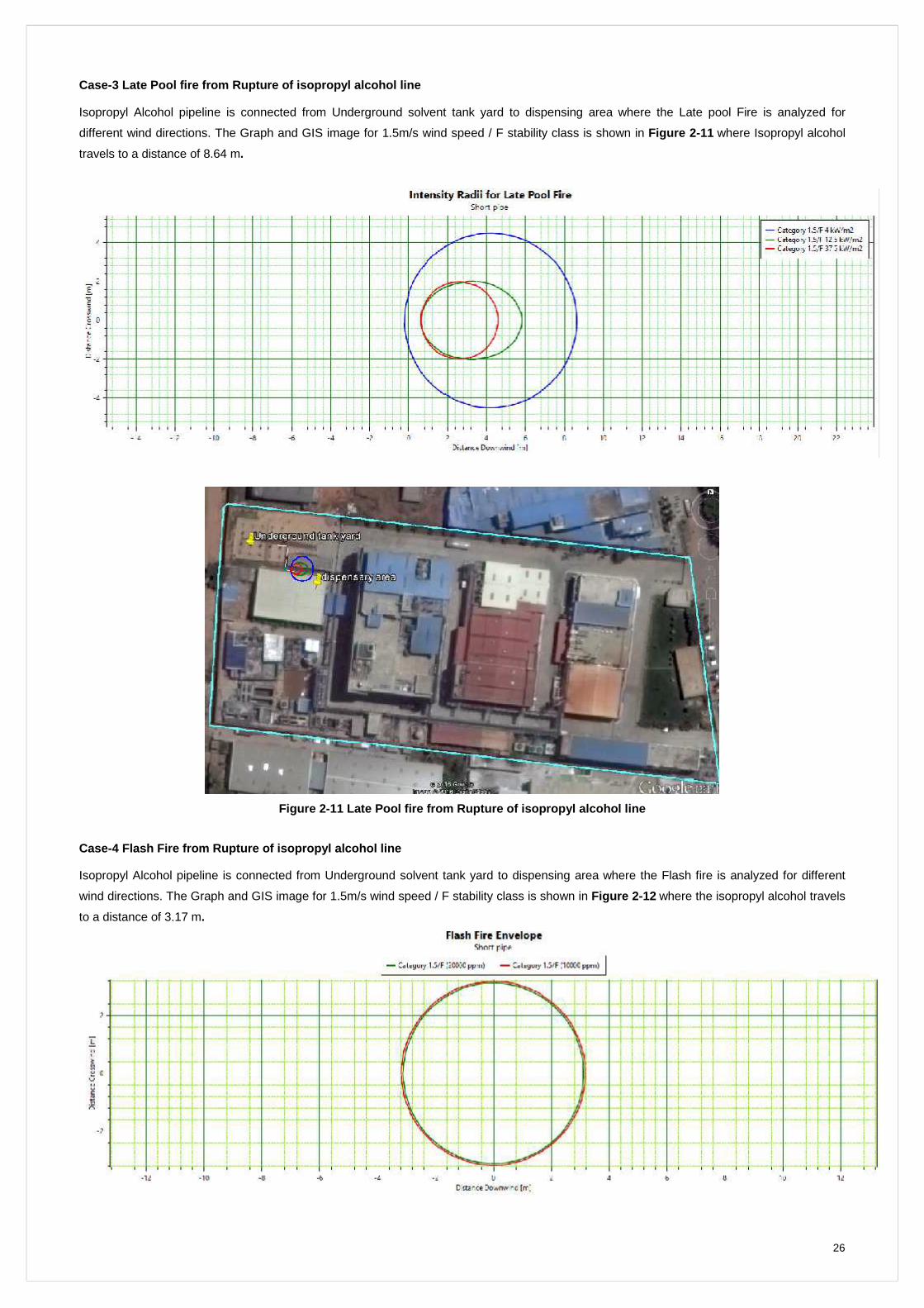
Case-3 Late Pool fire fro m Rupture of isopropyl alcohol line
Isopropyl Alcohol pipeline is connected from Underground solvent tank yard to dispensing area where the Late pool Fire is analyzed for
different wind directions. The Graph and GIS image for 1.5m/s wind speed / F stability class is shown in Figure 2-11 where Isopropyl alcohol
travels to a distance of 8.64 m.
Figure 2-11 Late Pool fire from Rupture of isopropyl alcohol line
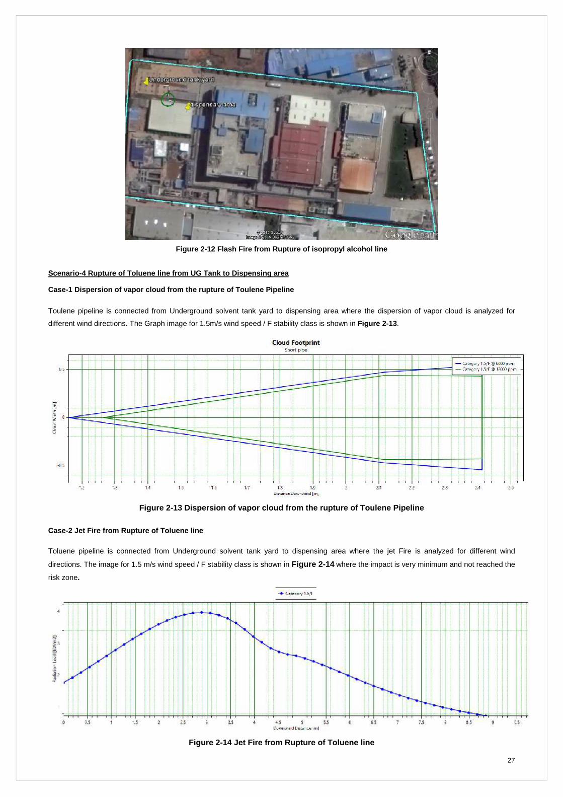
Case-4 Flash Fire from Rupture of isopropyl alcohol line
Isopropyl Alcohol pipeline is connected from Underground solvent tank yard to dispensing area where the Flash fire is analyzed for different
wind directions. The Graph and GIS image for 1.5m/s wind speed / F stability class is shown in Figure 2-12 where the isopropyl alcohol travels
to a distance of 3.17 m.
27
Figure 2-12 Flash Fire from Rupture of isopropyl alcohol line
Scenario -4 Rupture of Toluene line from UG Tank to Dispensing area
Case-1 Dispersion of vapor cloud from the rupture of Toulene Pipeline
Toulene pipeline is connected from Underground solvent tank yard to dispensing area where the dispersion of vapor cloud is analyzed for
different wind directions. The Graph image for 1.5m/s wind speed / F stability class is shown in Figure 2-13.
Figure 2-13 Dispersion of va por cloud from the rupture of Toulene Pipeline
Case-2 Jet Fire from Rupture of Toluene line
Toluene pipeline is connected from Underground solvent tank yard to dispensing area where the jet Fire is analyzed for different wind
directions. The image for 1.5 m/s wind speed / F stability class is shown in Figure 2-14 where the impact is very minimum and not reached the
risk zone.
Figure 2-14 Jet Fire from Rupture of T oluene line
28
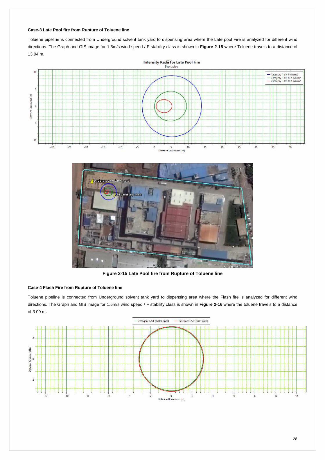
Case-3 Late Pool fire from Rupture of Toluene line
Toluene pipeline is connected from Underground solvent tank yard to dispensing area where the Late pool Fire is analyzed for different wind
directions. The Graph and GIS image for 1.5m/s wind speed / F stability class is shown in Figure 2-15 where Toluene travels to a distance of
13.94 m.
Figure 2-15 Late Pool fire from Rupture of Toluene line
Case-4 Flash Fire from Rupture of To luene line
Toluene pipeline is connected from Underground solvent tank yard to dispensing area where the Flash fire is analyzed for different wind
directions. The Graph and GIS image for 1.5m/s wind speed / F stability class is shown in Figure 2-16 where the toluene travels to a distance
of 3.09 m.
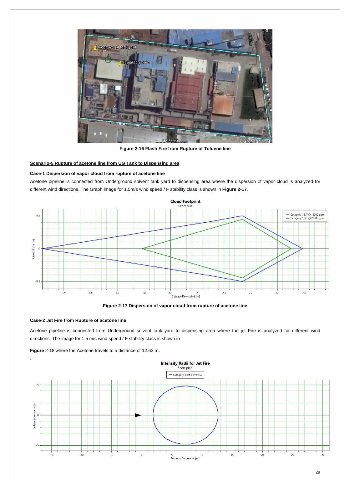
29
Figure 2-16 Flash Fire from Rupture of Toluene line
Scenario -5 Rupture of acetone line f rom UG Tank to Dispensing area
Case-1 Dispersion of vapor cloud from rupture of acetone line
Acetone pipeline is connected from Underground solvent tank yard to dispensing area where the dispersion of vapor cloud is analyzed for
different wind directions. The Graph image for 1.5m/s wind speed / F stability class is shown in Figure 2-17.
Figure 2-17 Dispersion of vapor cloud from rupture of acetone line
Case-2 Jet F ire from Rupture of acetone line
Acetone pipeline is connected from Underground solvent tank yard to dispensing area where the jet Fire is analyzed for different wind
directions. The image for 1.5 m/s wind speed / F stability class is shown in
Figure 2-18 where the Acetone travels to a distance of 12.63 m.
.
30
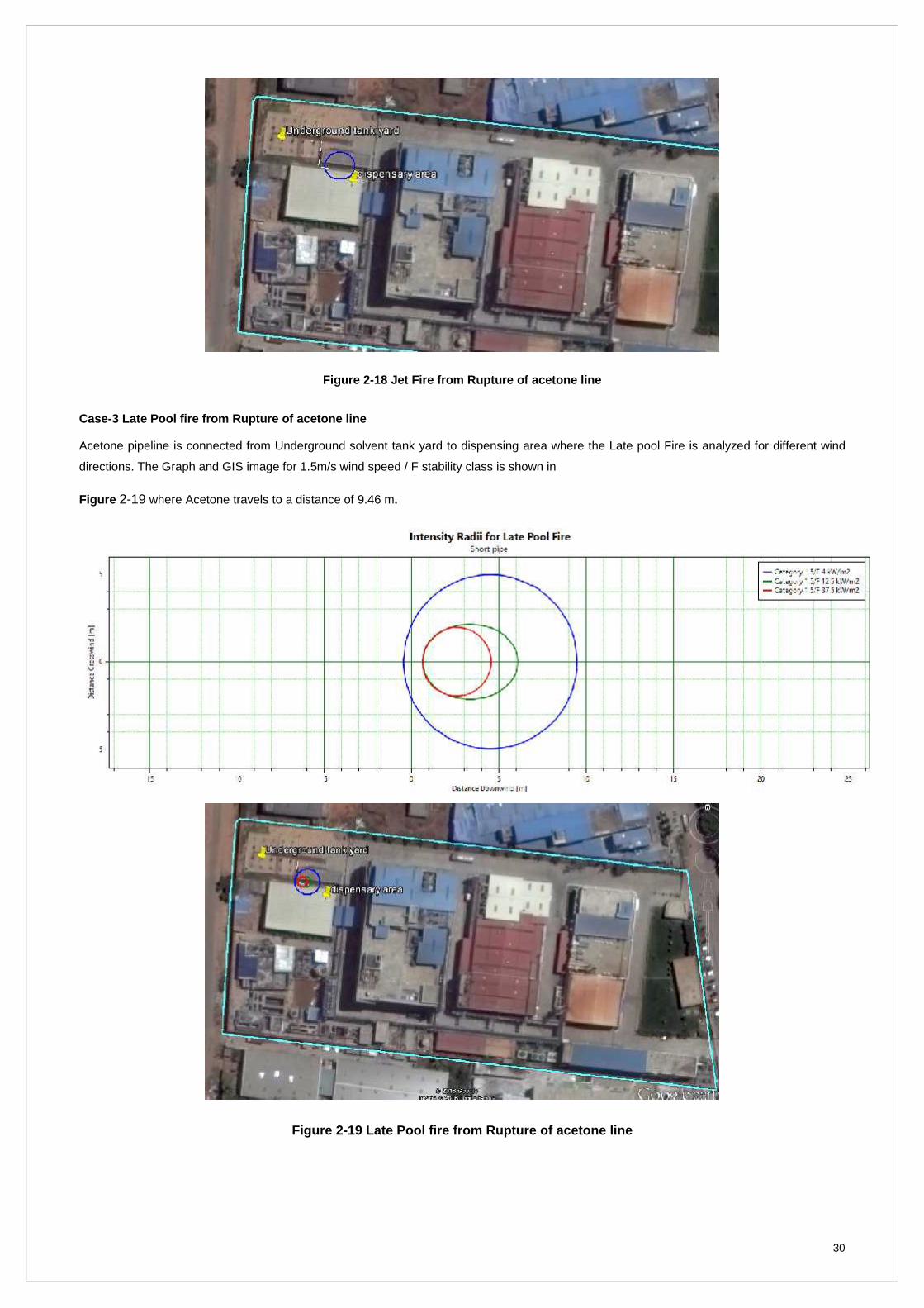
Figure 2-18 Jet Fire from Rupture of acetone line
Case-3 Late Pool fire from Rupture of acetone line
Acetone pipeline is connected from Underground solvent tank yard to dispensing area where the Late pool Fire is analyzed for different wind
directions. The Graph and GIS image for 1.5m/s wind speed / F stability class is shown in
Figure 2-19 where Acetone travels to a distance of 9.46 m.
Figure 2-19 Late Pool fire from Rupture of acetone line
31
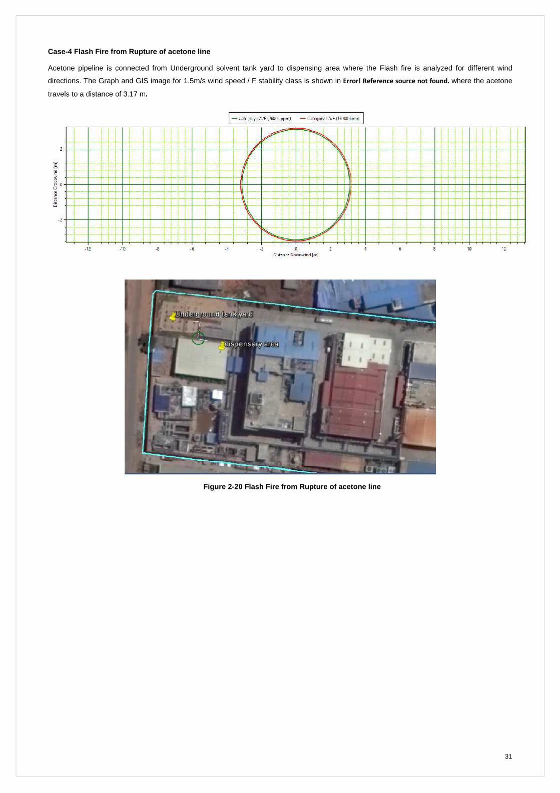
Case-4 Flash Fire from Rupture of acetone line
Acetone pipeline is connected from Underground solvent tank yard to dispensing area where the Flash fire is analyzed for different wind
directions. The Graph and GIS image for 1.5m/s wind speed / F stability class is shown in Error! Reference source not found. where the acetone
travels to a distance of 3.17 m.
Figure 2-20 Flash Fire from Rupture of acetone line
32
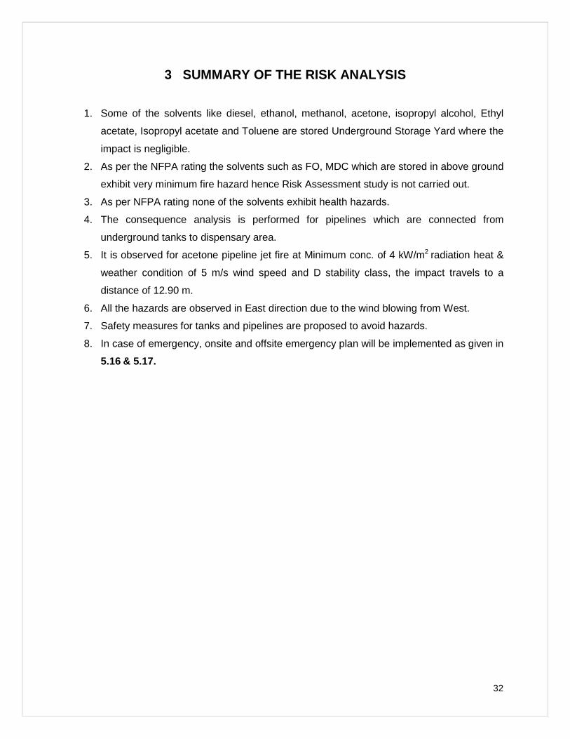
3 SUMMARY OF THE RISK ANALYSIS
1. Some of the solvents like diesel, ethanol, methanol, acetone, isopropyl alcohol, Ethyl
acetate, Isopropyl acetate and Toluene are stored Underground Storage Yard where the
impact is negligible.
2. As per the NFPA rating the solvents such as FO, MDC which are stored in above ground
exhibit very minimum fire hazard hence Risk Assessment study is not carried out.
3. As per NFPA rating none of the solvents exhibit health hazards.
4. The consequence analysis is performed for pipelines which are connected from
underground tanks to dispensary area.
5. It is observed for acetone pipeline jet fire at Minimum conc. of 4 kW/m2 radiation heat &
weather condition of 5 m/s wind speed and D stability class, the impact travels to a
distance of 12.90 m.
6. All the hazards are observed in East direction due to the wind blowing from West.
7. Safety measures for tanks and pipelines are proposed to avoid hazards.
8. In case of emergency, onsite and offsite emergency plan will be implemented as given in
5.16 & 5.17.
33
4 SAFETY MEASURES
4.1 MDC Tanks
1. If the leak in a tank, immediately transfer the content to another non leak tank.
2. Transferred tank should be compatible with the material.
3. After the material transferred, empty tank to be neutralized, washed and then taken for
service complying to work permit system.
4.2 Basic Preventive & Protective Measures
1. Adequate water supplies for fire protection. The amount/quantity of the water
requirement is based on rate of firewater required for the worst possible fire and the time
duration for which the fire will last
2. Structural design of vessels, piping, structural steel, etc.
3. Overpressure relief devices
4. Corrosion resistance and / or allowances
5. Segregation of reactive materials in process lines and equipment
6. Work permit system with strict compliance.
4.3 Storage tanks
1. Dedicated underground solvent storage area with flame proof electrical connections,
breather valve, enough jumpers and earthing & bonding facility to unload the solvent
from road tankers.
2. No ignitable zones are declared and marked so.
3. Dedicated chemical storage area with good ventilation and exhaust system and all
chemical are stored as per compatibility.
4. Dyke walls provided for the day storage chemical tanks.
5. Calibration is ensured for the gauges of pressure, temperature and vacuum.
6. Body earthing provided to all equipments involved in the process, electrical earthing,
static earthing and instrument earthing provided wherever required.
34
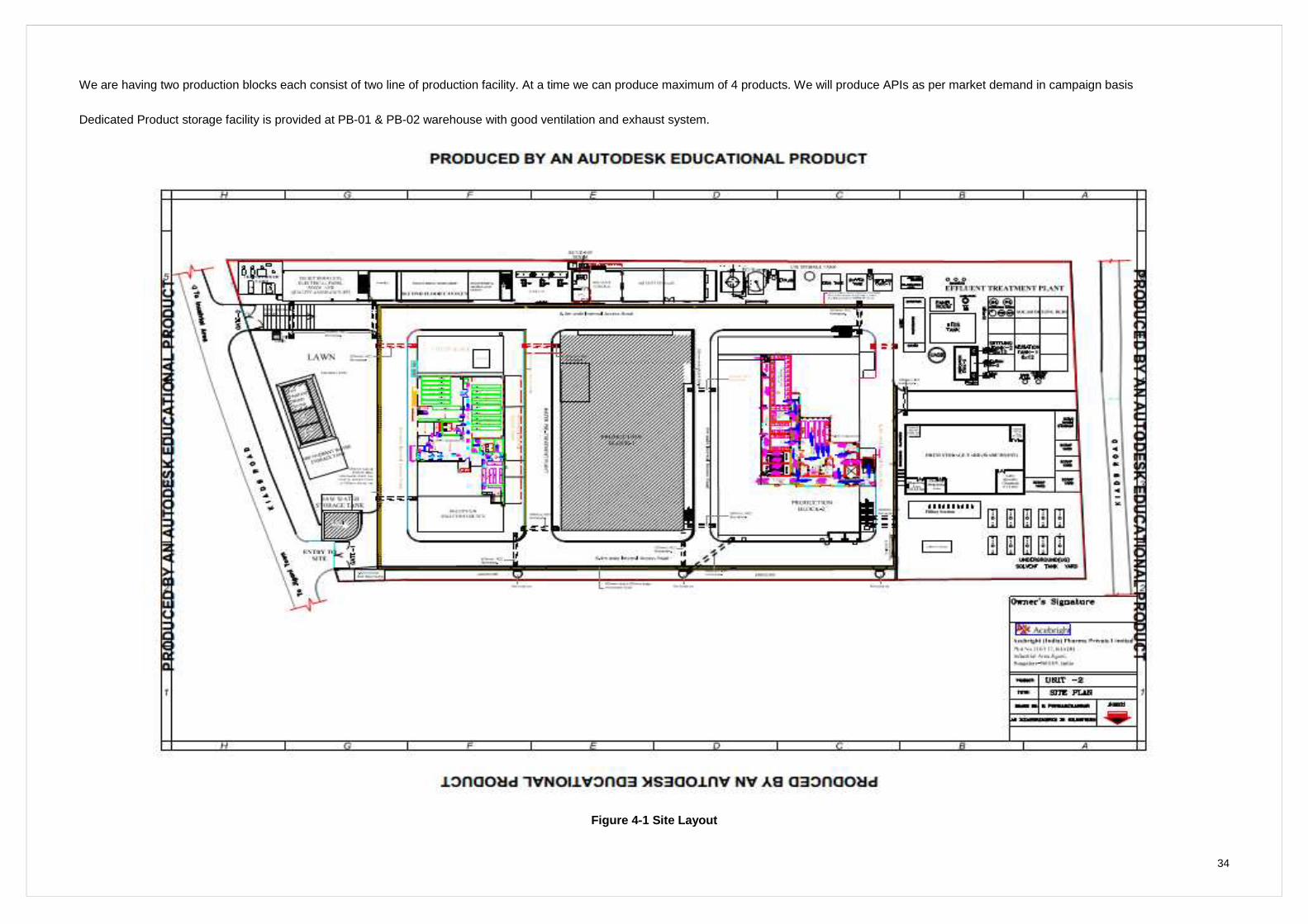
We are having two production blocks each consist of two line of production facility. At a time we can produce maximum of 4 products. We will produce APIs as per market demand in campaign basis
Dedicated Product storage facility is provided at PB-01 & PB-02 warehouse with good ventilation and exhaust system.
Figu re 4-1 Site Layout
35
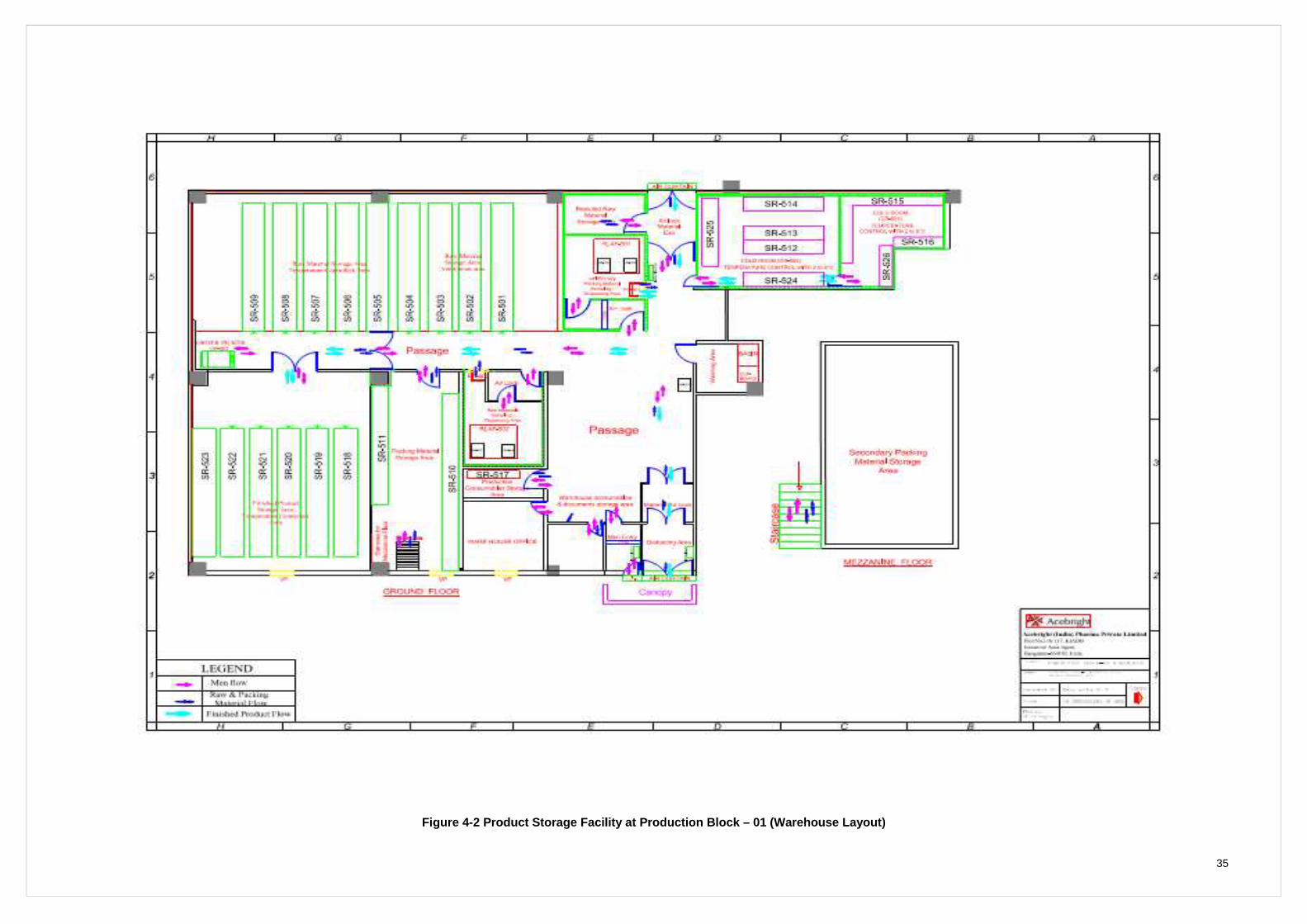
Figure 4-2 Product Storage Facility at Production Block – 01 (Warehouse Layout)
36
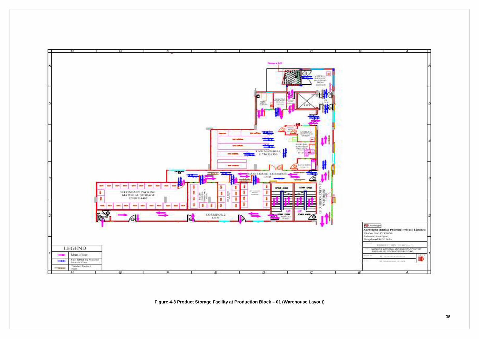
Figure 4-3 Product Storage Facility at Production Block – 01 (Warehouse Layout)
37
4.4 Reactors
1. All reactors will be hydro tested and certified by the competent person once in a year.
2. All reactors provided with safety valves followed by rupture discs and relief valve outlets
are extended.
3. Nitrogen provision provided to all reactors in view of providing nitrogen blanketing during
handling of flammables.
4. Process block zones are classified as per flameproof area zonal classification and
accordingly used the flameproof electrical fittings.
5. Scrubber system with lye circulation is installed to create vapor free work environment
and to release neutralized / nontoxic fumes to the environment.
6. Touch pads are provided in all prominent places to discharge our body static electricity.
7. Wrist bands are provided to use during charging of chemicals in to reactors to avoid
static electricity.
8. Zero interlock, proximity switch and nitrogen line provision provided to all centrifuge
system to avoid personal injury and fire hazard.
9. Safety relief valve and gate limit switch provided to all RCVDs to avoid explosion and
personal injury.
10. Air handling units (AHUs) with BIBO (Bag In Bag Out) are provided to keep the work
environment in controlled manner (air flow pattern, temperature and humidity) to reduce
the exposure to chemicals.
11. Ventilation air units (VAUs) and Exhaust air units (EAUs) and are provided to ensure
good ventilation in the work environment.
12. Isolators are provided to handle potent chemicals.
13. HAZOP studies will be carried for all chemicals.
4.5 Pipelines
1. If the leak in a pipe line, immediately stop the supply to corresponding pipe line.
38
5 EMERGENCY PLAN
5.1 Objectives
a. To establish a method of systematic, safe and orderly evacuation in the least
possible time, to a safe area or by the nearest safe means of way out.
b. Control the accidents.
c. Rapid control and containment of hazardous situation.
d. Rescue and treatment of casualties.
e. Safeguard people (both at site and neighbourhood).
f. Minimize damage to property and environment.
g. Identify casualties, notify their relatives and render necessary help to them.
h. Proper training of the concerned person.
i. Prevent recurrence.
j. Be capable of dealing with largest incident that can reasonably be foreseen.
k. Have sufficient flexibility with a view to handling the emergency efficiently and
avoiding unnecessary calling outside agencies like external fire brigade.
l. HAZOP study will carried out for all new product start up, change in process and
new equipment installation, SOP has been enclosed as Part A
5.2 Basic forms of Emergency
a. Fire
b. Explosion
c. Toxic release
d. Natural disaster (earth quake, flooding, tsunami etc.)
e. A combination of more than one
5.3 Types of Emergency
5.3.1 On-site Emergency
If an accident/ incident takes place in a factory, its effects are confined to the factory premises,
involving only the persons working in the factory and the property inside the factory it is called
as On-site Emergency.
39
It can be again classified as minor and major emergency based on severity of the incident.
Minor Emergency (Evacuation is not required)
In the case of minor emergency there will be no evacuation siren and the respective department
personnel will handle the same with assistance of Safety Squad.
Major Emergency (Evac uation is required)
In case of major emergency there will be emergency siren and situation is tackled as per the
plan.
5.3.2 Off -site Emergency
If the accident is such that it affects inside the factory are uncontrollable and it may spread
outside the factory premises, it is called as Off-site Emergency.
Assessment reveals that an Off-site emergency is a very remote possibility in our factory. If
there is a situation, first we shall avail the service of local police to warn and advice the local
public about things to do to save them from the effect of emergency situation. Moreover, the
factory is located in industrial area. Hence, there are no residential houses in factory
surrounding area.
The detailed offsite emergency plan is given 5.17.
5.4 Causes of Emergency
The emergency may caused by factors like failure of system, human error, sabotage and natural
calamities like earth quake, flooding etc. Irrespective of cause, the emergency will generally
manifest itself in one of the three basic forms i.e. fire, explosion and release of toxic substance.
5.5 Safety, Health & Environment Policy
Acebright Management firmly commits and obliges as below:
1. We, at Acebright (India) Pharma Pvt. Ltd. commit ourselves to provide and
maintain Safe & Healthy Environment to all our employees, contractors, and our
neighborhood.
2. Our endeavour is to ensure that all the applicable statutory Rules, Acts &
Regulations are complied.
40
3. Assurance of Safety, Protection of Health & Environment is prime function and
responsibility of the Management and the Management will inculcate the safety
behaviour down the line through exemplary behaviour.
4. All the employees are periodically trained & informed about the hazards to which
they are exposed & Safety measures to be taken including personal protective
equipment.
5. To provide the resources required for Safety, Health and Environment protection.
6. We affirm to reduce the wastages, recycle the resources and disposal of
wastages will be as per statutory norms.
7. All our facilities will be operated & maintained by the prescribed Standard
Operating Procedures covering routine & non-routine activities.
8. All the accidents / near-miss accidents will be investigated thoroughly for their
root cause to avoid recurrence. Corrective and preventive actions applicable for
the same will be enforced.
9. Health, Safety & Environmental performance is constantly measured through
periodic audits of facility for continuous improvements.
5.6 Identification of Emergency in Each Hazard Activity t hrough Risk Analysis
5.6.1 Method used for identification of Hazards
a. HAZOP Study
The detailed HAZOP study is mentioned in Table 5-1.
b. Internal Safety Audit
c. External Safety Audit
41
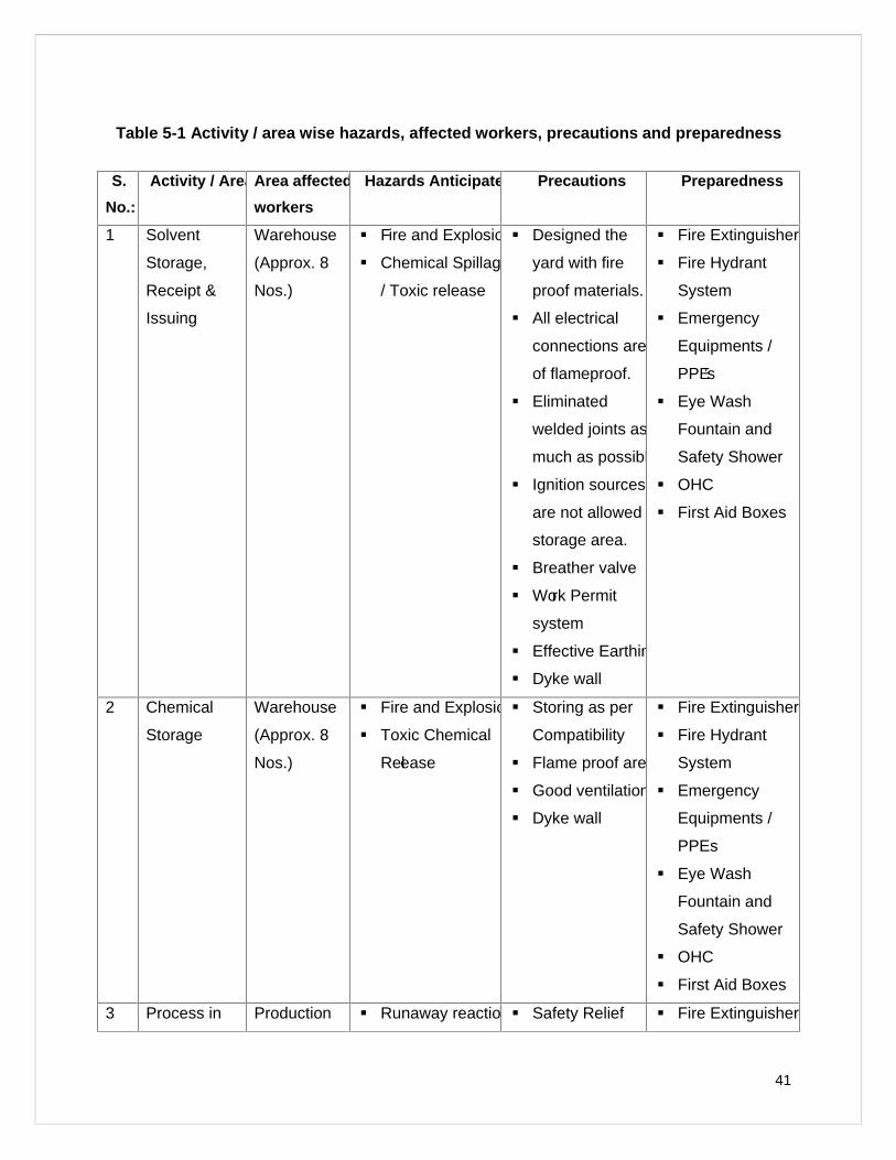
Table 5-1 Activity / area wise hazards, affected workers, precautions and preparedness
S.
No.:
Activity / Area Area affected
workers
Hazards Anticipated Precautions Preparedness
1 Solvent
Storage,
Receipt &
Issuing
Warehouse
(Approx. 8
Nos.)
Fire and Explosion
Chemical Spillage
/ Toxic release
Designed the
yard with fire
proof materials.
All electrical
connections are
of flameproof.
Eliminated
welded joints as
much as possible.
Ignition sources
are not allowed in
storage area.
Breather valve
Work Permit
system
Effective Earthing
Dyke wall
Fire Extinguisher
Fire Hydrant
System
Emergency
Equipments /
PPE’s
Eye Wash
Fountain and
Safety Shower
OHC
First Aid Boxes
2 Chemical
Storage
Warehouse
(Approx. 8
Nos.)
Fire and Explosion
Toxic Chemical
Release
Storing as per
Compatibility
Flame proof area
Good ventilation
Dyke wall
Fire Extinguisher
Fire Hydrant
System
Emergency
Equipments /
PPEs
Eye Wash
Fountain and
Safety Shower
OHC
First Aid Boxes
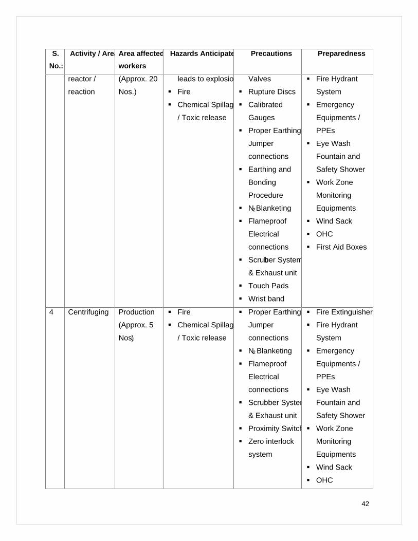
3 Process in Production Runaway reactions Safety Relief Fire Extinguisher
42
S.
No.:
Activity / Area Area affected
workers
Hazards Anticipated Precautions Preparedness
reactor /
reaction
(Approx. 20
Nos.)
leads to explosion
Fire
Chemical Spillage
/ Toxic release
Valves
Rupture Discs
Calibrated
Gauges
Proper Earthing&
Jumper
connections
Earthing and
Bonding
Procedure
N2Blanketing
Flameproof
Electrical
connections
Scrubber System
& Exhaust unit
Touch Pads
Wrist band
Fire Hydrant
System
Emergency
Equipments /
PPEs
Eye Wash
Fountain and
Safety Shower
Work Zone
Monitoring
Equipments
Wind Sack
OHC
First Aid Boxes
4 Centrifuging Production
(Approx. 5
Nos.)
Fire
Chemical Spillage
/ Toxic release
Proper Earthing&
Jumper
connections
N2 Blanketing
Flameproof
Electrical
connections
Scrubber System
& Exhaust unit
Proximity Switch
Zero interlock
system
Fire Extinguisher
Fire Hydrant
System
Emergency
Equipments /
PPEs
Eye Wash
Fountain and
Safety Shower
Work Zone
Monitoring
Equipments
Wind Sack
OHC
43
S.
No.:
Activity / Area Area affected
workers
Hazards Anticipated Precautions Preparedness
First Aid Boxes
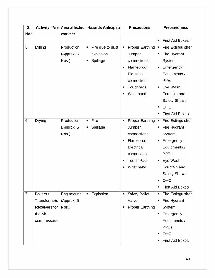
5 Milling Production
(Approx. 5
Nos.)
Fire due to dust
explosion
Spillage
Proper Earthing&
Jumper
connections
Flameproof
Electrical
connections
TouchPads
Wrist band
Fire Extinguisher
Fire Hydrant
System
Emergency
Equipments /
PPEs
Eye Wash
Fountain and
Safety Shower
OHC
First Aid Boxes
6 Drying Production
(Approx. 5
Nos.)
Fire
Spillage
Proper Earthing&
Jumper
connections
Flameproof
Electrical
connections
Touch Pads
Wrist band
Fire Extinguisher
Fire Hydrant
System
Emergency
Equipments /
PPEs
Eye Wash
Fountain and
Safety Shower
OHC
First Aid Boxes
7 Boilers /
Transformers/
Receivers for
the Air
compressors.
Engineering
(Approx. 5
Nos.)
Explosion Safety Relief
Valve
Proper Earthing
Fire Extinguisher
Fire Hydrant
System
Emergency
Equipments /
PPEs
OHC
First Aid Boxes
44
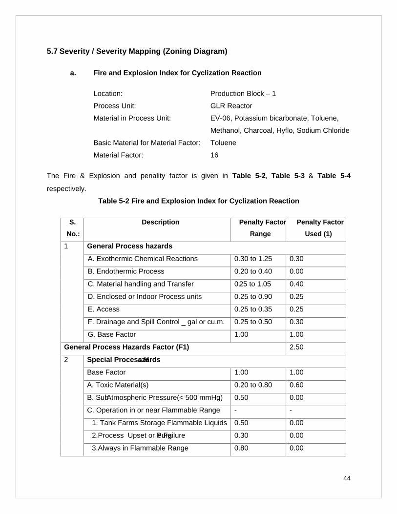
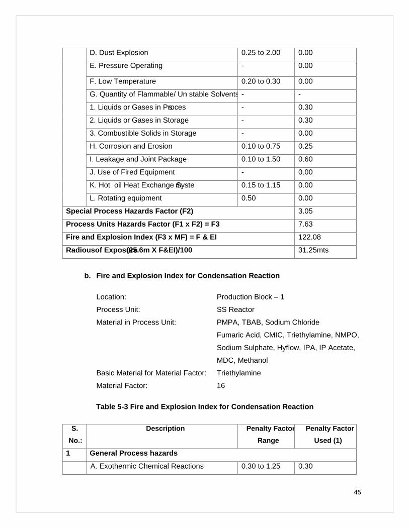
5.7 Severity / Severity Mapping (Zoning Diagram)
a. Fire and Explosion Index for Cyclization Reaction
Location: Production Block – 1
Process Unit: GLR Reactor
Material in Process Unit: EV-06, Potassium bicarbonate, Toluene,
Methanol, Charcoal, Hyflo, Sodium Chloride
Basic Material for Material Factor: Toluene
Material Factor: 16
The Fire & Explosion and penality factor is given in Table 5-2, Table 5-3 & Table 5-4
respectively.
Table 5-2 Fire and Explosion In dex for Cyclization Reaction
S.
No.:
Description Penalty Factor
Range
Penalty Factor
Used (1)
1 General Process hazards
A. Exothermic Chemical Reactions 0.30 to 1.25 0.30
B. Endothermic Process 0.20 to 0.40 0.00
C. Material handling and Transfer 0.25 to 1.05 0.40
D. Enclosed or Indoor Process units 0.25 to 0.90 0.25
E. Access 0.25 to 0.35 0.25
F. Drainage and Spill Control _ gal or cu.m. 0.25 to 0.50 0.30
G. Base Factor 1.00 1.00
General Process Hazards Factor (F1) 2.50
2 Special Process Hazards
Base Factor 1.00 1.00
A. Toxic Material(s) 0.20 to 0.80 0.60
B. Sub-Atmospheric Pressure(< 500 mmHg) 0.50 0.00
C. Operation in or near Flammable Range - -
1. Tank Farms Storage Flammable Liquids 0.50 0.00
2.Process Upset or Purge Failure 0.30 0.00
3.Always in Flammable Range 0.80 0.00
45
D. Dust Explosion 0.25 to 2.00 0.00
E. Pressure Operating - 0.00
F. Low Temperature 0.20 to 0.30 0.00
G. Quantity of Flammable/ Un stable Solvents - -
1. Liquids or Gases in Process - 0.30
2. Liquids or Gases in Storage - 0.30
3. Combustible Solids in Storage - 0.00
H. Corrosion and Erosion 0.10 to 0.75 0.25
I. Leakage and Joint Package 0.10 to 1.50 0.60
J. Use of Fired Equipment - 0.00
K. Hot oil Heat Exchange System 0.15 to 1.15 0.00
L. Rotating equipment 0.50 0.00
Special Process Hazards Factor (F2) 3.05
Process Units Hazards Factor (F1 x F2) = F3 7.63
Fire and Explosion Index (F3 x MF) = F & EI 122.08
Radiousof Exposure(25.6m X F&EI)/100 31.25mts
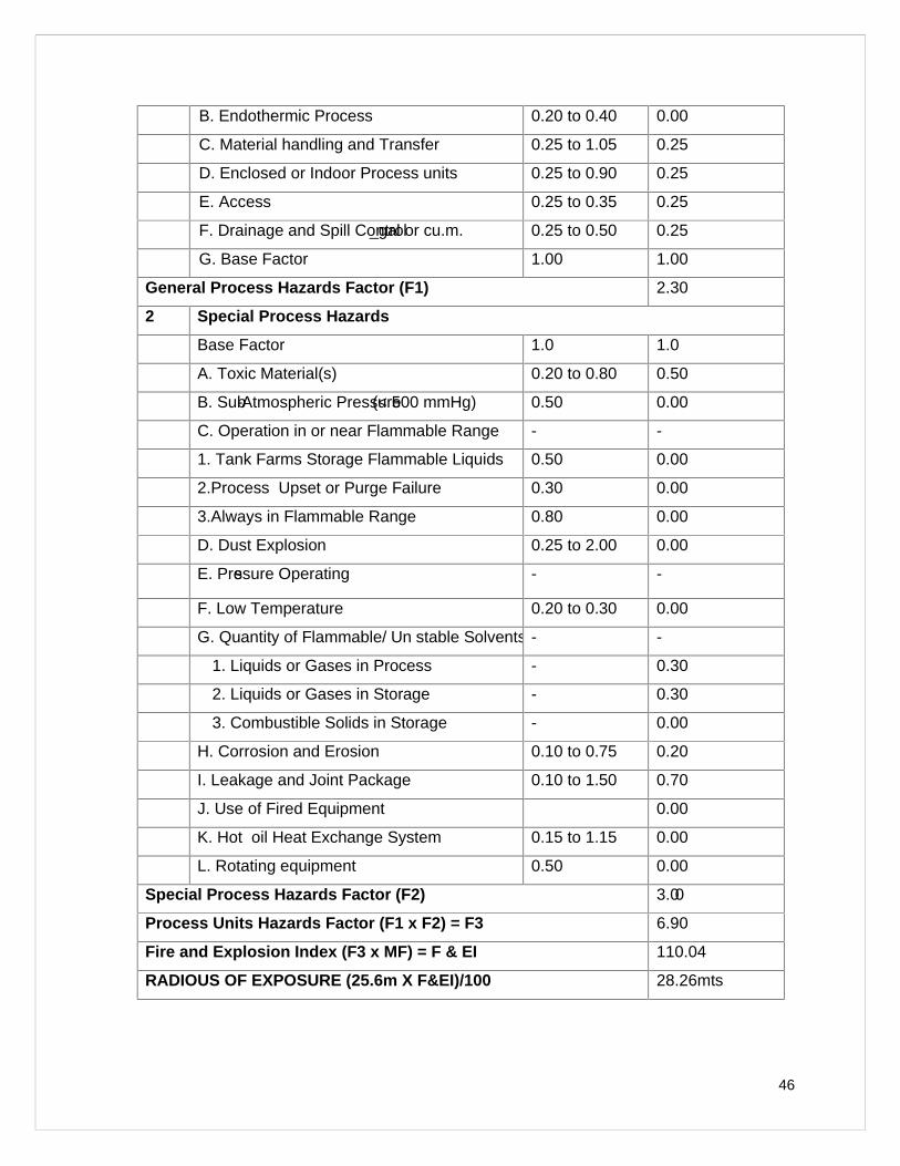
b. Fire an d Explosion Index for Condensation Reaction
Location: Production Block – 1
Process Unit: SS Reactor
Material in Process Unit: PMPA, TBAB, Sodium Chloride
Fumaric Acid, CMIC, Triethylamine, NMPO,
Sodium Sulphate, Hyflow, IPA, IP Acetate,
MDC, Methanol
Basic Material for Material Factor: Triethylamine
Material Factor: 16
Table 5-3 Fire and Explosion Index for Condensation Reaction
S.
No.:
Description Penalty Factor
Range
Penalty Factor
Used (1)
1 General Process hazards
A. Exothermic Chemical Reactions 0.30 to 1.25 0.30
46
B. Endothermic Process 0.20 to 0.40 0.00
C. Material handling and Transfer 0.25 to 1.05 0.25
D. Enclosed or Indoor Process units 0.25 to 0.90 0.25
E. Access 0.25 to 0.35 0.25
F. Drainage and Spill Control_gal or cu.m. 0.25 to 0.50 0.25
G. Base Factor 1.00 1.00
General Process Hazards Factor (F1) 2.30
2 Special Process Hazards
Base Factor 1.0 1.0
A. Toxic Material(s) 0.20 to 0.80 0.50
B. Sub-Atmospheric Pressure(< 500 mmHg) 0.50 0.00
C. Operation in or near Flammable Range - -
1. Tank Farms Storage Flammable Liquids 0.50 0.00
2.Process Upset or Purge Failure 0.30 0.00
3.Always in Flammable Range 0.80 0.00
D. Dust Explosion 0.25 to 2.00 0.00
E. Pressure Operating - -
F. Low Temperature 0.20 to 0.30 0.00
G. Quantity of Flammable/ Un stable Solvents - -
1. Liquids or Gases in Process - 0.30
2. Liquids or Gases in Storage - 0.30
3. Combustible Solids in Storage - 0.00
H. Corrosion and Erosion 0.10 to 0.75 0.20
I. Leakage and Joint Package 0.10 to 1.50 0.70
J. Use of Fired Equipment 0.00
K. Hot oil Heat Exchange System 0.15 to 1.15 0.00
L. Rotating equipment 0.50 0.00
Special Process Hazards Factor (F2) 3.00
Process Units Hazards Factor (F1 x F2) = F3 6.90
Fire and Explosion Index (F3 x MF) = F & EI 110.04
RADIOUS OF EXPOSURE (25.6m X F&EI)/100 28.26mts
47
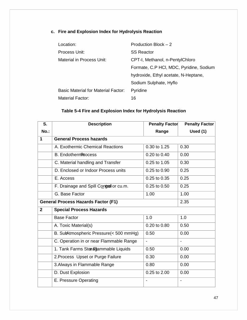
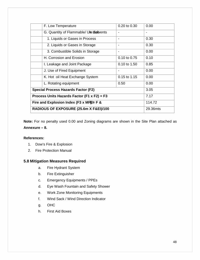
c. Fire and Explosion Index for Hydrolysis Reaction
Location: Production Block – 2
Process Unit: SS Reactor
Material in Process Unit: CPT-I, Methanol, n-PentylChloro
Formate, C.P HCl, MDC, Pyridine, Sodium
hydroxide, Ethyl acetate, N-Heptane,
Sodium Sulphate, Hyflo
Basic Material for Material Factor: Pyridine
Material Factor: 16
Table 5-4 Fire and Explosion Index for Hydrolysis Reaction
S.
No.:
Description Penalty Factor
Range
Penalty Factor
Used (1)
1 General Process hazards
A. Exothermic Chemical Reactions 0.30 to 1.25 0.30
B. EndothermicProcess 0.20 to 0.40 0.00
C. Material handling and Transfer 0.25 to 1.05 0.30
D. Enclosed or Indoor Process units 0.25 to 0.90 0.25
E. Access 0.25 to 0.35 0.25
F. Drainage and Spill Control_ gal or cu.m. 0.25 to 0.50 0.25
G. Base Factor 1.00 1.00
General Process Hazards Factor (F1) 2.35
2 Special Process Hazards
Base Factor 1.0 1.0
A. Toxic Material(s) 0.20 to 0.80 0.50
B. Sub-Atmospheric Pressure(< 500 mmHg) 0.50 0.00
C. Operation in or near Flammable Range - -
1. Tank Farms Storage Flammable Liquids 0.50 0.00
2.Process Upset or Purge Failure 0.30 0.00
3.Always in Flammable Range 0.80 0.00
D. Dust Explosion 0.25 to 2.00 0.00
E. Pressure Operating - -
48
F. Low Temperature 0.20 to 0.30 0.00
G. Quantity of Flammable/ Un stable Solvents - -
1. Liquids or Gases in Process - 0.30
2. Liquids or Gases in Storage - 0.30
3. Combustible Solids in Storage - 0.00
H. Corrosion and Erosion 0.10 to 0.75 0.10
I. Leakage and Joint Package 0.10 to 1.50 0.85
J. Use of Fired Equipment - 0.00
K. Hot oil Heat Exchange System 0.15 to 1.15 0.00
L. Rotating equipment 0.50 0.00
Special Process Hazards Factor (F2) 3.05
Process Units Hazards Factor (F1 x F2) = F3 7.17
Fire and Explosion Index (F3 x MF) = F &EI 114.72
RADIOUS OF EXPOSURE (25.6m X F&EI)/100 29.36mts
Note: For no penalty used 0.00 and Zoning diagrams are shown in the Site Plan attached as
Annexure – 8.
References:
1. Dow’s Fire & Explosion
2. Fire Protection Manual
5.8 Mitigation Measures Required
a. Fire Hydrant System
b. Fire Extinguisher
c. Emergency Equipments / PPEs
d. Eye Wash Fountain and Safety Shower
e. Work Zone Monitoring Equipments
f. Wind Sack / Wind Direction Indicator
g. OHC
h. First Aid Boxes
49
5.9 Mitigation Measures Possessed / Proposed by the Industries
5.9.1 Fire Hydrant System
Fire monitoring system at solvent storage facility
A pressurized (7 kg/cm2); automatically operated Fire Hydrant System has been installed in the
plant with rings and wet risers around all blocks to achieve maximum coverage. Water reservoir
of 600 m3 (Hydrant Tank) capacity is provided for approximately 4 hrfire fighting. Following are
the details of the system.
a. Jockey pump of 10.8 m3/hrs@70m head capacity with pressure switches
b. Main electrical pump of 136.8 m3/hrs@70m head capacity pressure switches and
delivers water at 7 kg/cm2
c. Standby arrangement-Diesel Generator of capacity same as Main electrical
pump with auto control panel.
d. Yard Hydrant points - 35 Nos.
e. Hose Boxes – 35 Nos. (Each Hose Box contains 2 Nos. of hoses and 1 No. of
Nozzle)
f. Hose Reel Drums – 20 Nos.
g. Foam Concentrate tank of capacity 1000 Lts – 1 No.
h. Water / foam Monitor – 1 No.
i. Mobile Foam Unit with 200 liters capacity – 1 No.
j. Two way fire brigade inlet – 1 No.
k. Four way fire brigade inlet – 1 No.
l. Automatic sprinkler system in chemical storage tank area.
5.9.2 Fire Extinguisher
The company has trained personnel for firefighting and intends to improve the firefighting skills
of employee by conducting frequent training on firefighting.
We have 218 Nos. of different types (CO2, ABC, Water Jet, Mechanical Foam and DCP) of
portable fire extinguishers placed in all prominent places of the factory. Extinguisher break-up
based on area is given in Table 5-5.
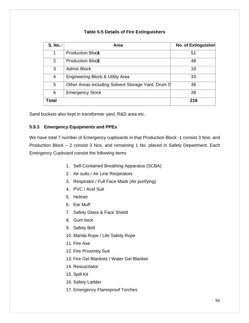
50
Table 5-5 Details of Fire Extinguishers
S. No.: Area No. of Extinguishers
1 Production Block- 1 51
2 Production Block- 2 48
3 Admin Block 19
4 Engineering Block & Utility Area 33
5 Other Areas including Solvent Storage Yard, Drum Sheds 39
6 Emergency Stock 28
Total 218
Sand buckets also kept in transformer yard, R&D area etc.
5.9.3 Emergency Equipments and PPEs
We have total 7 number of Emergency cupboards in that Production Block -1 consist 3 Nos. and
Production Block – 2 consist 3 Nos. and remaining 1 No. placed in Safety Department. Each
Emergency Cupboard consist the following items
1. Self-Contained Breathing Apparatus (SCBA)
2. Air suits / Air Line Respirators
3. Respirator / Full Face Mask (Air purifying)
4. PVC / Acid Suit
5. Helmet
6. Ear Muff
7. Safety Glass & Face Shield
8. Gum boot
9. Safety Belt
10. Manila Rope / Life Safety Rope
11. Fire Axe
12. Fire Proximity Suit
13. Fire Gel Blankets / Water Gel Blanket
14. Resuscitator
15. Spill Kit
16. Safety Ladder
17. Emergency Flameproof Torches
51
5.9.4 Eye Wash Fountain and Safety Shower
We have total 18 Nos. of Eye wash fountain / Safety showers in that Production Block -1 consist
6 Nos. and Production Block – 2 consist 9 Nos. and remaining 3 Nos. are existed at Solvent
Yard and Chemical Storage area.
5.9.5 Work Zone Monitoring Equipments
We have multi gas / toxic gas and oxygen detectors in that multi gas detector can be used to
check oxygen, LEL, VOC, CO and H2S concentration in atmosphere and also in confined
spaces like inside the reactor, overhead tanks, underground tanks, sump etc and oxygen
detector can be used for checking oxygen concentration in atmosphere and also in confined
spaces like inside the reactor, overhead tanks, underground tanks, sump etc.
Both the detectors are available in the Safety Department.
5.9.6 Wind Sack / Wind Direction Indic ator
It is a conical textile tube. It is used where there is a risk of gaseous leakage or fire. It shows the
direction of wind to fight fire. The employees should run perpendicular to the wind direction and
not against / along the wind direction during toxic leakage. Wind sacks are placed above the
Engineering Office and Administration Block buildings.
5.9.7 OHC
We have well equipped Occupational Health Centre and also have an agreement with Suhas
General & Charitable Hospital, Jigani for their valuable service during emergency along with
24/7 ambulance facility.
OHC consist the following items;
a. Single bed
b. Stretchers
c. BP Apparatus
d. Stethoscope
e. Pair of scissor
f. Sterilized cotton wool
g. Hot and Cold Pack
h. Resuscitator
52
i. Eye Wash Bottle
j. Triangular Bandage
k. Tourniquet
l. Splints
m. Safety Pins
n. Kidney Tray
5.9.8 First Aid Boxes
A first aid kit is a collection of supplies and equipment for use in giving first aid. First Aid boxes
are available in Security Room (ECC), Admin Block and at OHC. First Aid items will issue to
injure only by authorized persons. Following are the contents of First Aid Box,
a. Dettol – Antiseptic solution
b. Ciplox – Eye Drops
c. Soframycin – Skin ointment
d. Silverex – Burn ointment
e. Betadine – Microbicidal solution
f. Iodex – Pain reliever
g. Sterilized Cotton Wool
h. Adhesive Plaster
i. Surgical Paper Tape
j. Small Sterilized Dressings
k. Medium Sterilized Dressings
l. Large Sterilized Dressings
m. Sterilized Burn Dressings
n. Roller Bandage – 5 cm wide
o. Roller Bandage – 10cm wide
p. Band Aid
q. Crocin / Paracetamol Tablet
53
5.10 Emergency Shutting Down P rocedure
1. Critical operations will be shut down by the respective technician / operator upon
getting the necessary instruction from the shift in charge. An emergency shutdown
can be done after getting approval from Incident Controller / Site Controller.
2. Utility Controls will be shut off by maintenance personnel who will know the location
and operation of main controls for gas, solvent and electrical supply leading into the
building.
3. An emergency shutdown of computers should be accomplished in the event of a
severe electrical storm. If time permits, exit the program and shut off the computer
power supply.
5.11 Identification of Mutual Aid Partners
1. M/s. HIKAL Limited
#82/A, KIADB Industrial Area
Jigani, Bangalore – 560 105
Ph: 080 – 2782 6800
2. M/s. Kumar Organic Products Limited
#36, KIADB Industrial Area
Jigani, Bangalore – 560 105
Ph: 080 – 2782 5439, 080 – 2782 5376
5.12 Identification of Resource Suppliers (Both Public & Private)
1. M/s. HIKAL Limited
#82/A, KIADB Industrial Area
Jigani, Bangalore – 560 105
Ph: 080 – 2782 6800
2. M/s. Kumar Organic Products Limited
#36, KIADB Industrial Area
Jigani, Bangalore – 560 105
Ph: 080 – 2782 5439, 080 – 2782 5376
3. Suhas General & Charitable Hospital
Plot No. CA 3, Anekal Main Road
54
Jigani Industrial Area, AneklTaluk
Bangalore – 560 105
Ph: 080 - 27826145 / 144
4. Police Station – Jigani
Opposite to Santhe Market
Jigani, Bangalore – 560 105
Ph: 080 – 27825108
5. Fire Station – Electronic City
No. 101, Hosur Road
Behind KEB Office
1st Phase, Electronic City
Bangalore 560 100
Ph: 080 – 22971576
5.13 Emergency Transport Facility
a. We have memorandum of understanding with Suhas General & Charitable
Hospital for ambulance and emergency services.
b. We ensure a four wheeler presence inside the premises round the clock.
5.14 Control Room
Control Room also termed as Emergency Control Centre (ECC) is a place from which all the
decisions with regard to actions for control of emergency, rescue and medical treatment are
made. Security office is considered as emergency control centre. It contains the following
facilities.
a. Communication equipment
b. Copies of emergency management plan
c. Emergency escape route map
d. List of emergency contact numbers
e. Emergency light
f. Location of emergency supplies like PPEs / emergency equipments, layout
of fire fighting system, assembly point etc.
g. Emergency organization team details
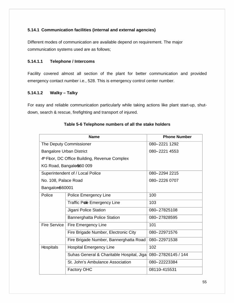
55
5.14.1 Communication facilities (internal and external agencies)
Different modes of communication are available depend on requirement. The major
communication systems used are as follows;
5.14.1.1 Telephone / Intercoms
Facility covered almost all section of the plant for better communication and provided
emergency contact number i.e., 528. This is emergency control center number.
5.14.1.2 Walky – Talky
For easy and reliable communication particularly while taking actions like plant start-up, shut-
down, search & rescue, firefighting and transport of injured.
Table 5-6 Telephone numbers of all the stake holders
Name Phone Number
The Deputy Commissioner
Bangalore Urban District
4th Floor, DC Office Building, Revenue Complex
KG Road, Bangalore–560 009
080–2221 1292
080–2221 4553
Superintendent of / Local Police
No. 108, Palace Road
Bangalore- 560001
080–2294 2215
080–2226 0707
Police Police Emergency Line 100
Traffic Police Emergency Line 103
Jigani Police Station 080–27825108
Bannerghatta Police Station 080–27828595
Fire Service Fire Emergency Line 101
Fire Brigade Number, Electronic City 080–22971576
Fire Brigade Number, Bannerghatta Road 080–22971538
Hospitals Hospital Emergency Line 102
Suhas General & Charitable Hospital, Jigani080–27826145 / 144
St. John’s Ambulance Association 080–22223384
Factory OHC 08110–415531
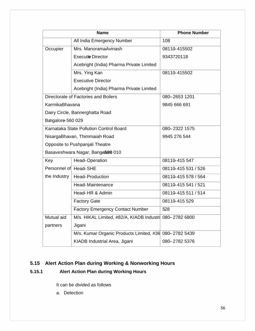
56
Name Phone Number
All India Emergency Number 108
Occupier Mrs. ManoramaAvinash
Executive Director
Acebright (India) Pharma Private Limited
08110–415502
9343720118
Mrs. Ying Kan
Executive Director
Acebright (India) Pharma Private Limited
08110–415502
Directorate of Factories and Boilers
KarmikaBhavana
Dairy Circle, Bannerghatta Road
Bangalore–560 029
080–2653 1201
9845 666 691
Karnataka State Pollution Control Board
NisargaBhavan, Thimmaiah Road
Opposite to Pushpanjali Theatre
Basaveshwara Nagar, Bangalore–560 010
080–2322 1575
9945 276 544
Key
Personnel of
the Industry
Head–Operation 08110–415 547
Head–SHE 08110–415 531 / 526
Head–Production 08110–415 578 / 564
Head–Maintenance 08110–415 541 / 521
Head–HR & Admin 08110–415 511 / 514
Factory Gate 08110–415 529
Factory Emergency Contact Number 528
Mutual aid
partners
M/s. HIKAL Limited, #82/A, KIADB Industrial Area,
Jigani
080–2782 6800
M/s. Kumar Organic Products Limited, #36,
KIADB Industrial Area, Jigani
080–2782 5439
080–2782 5376
5.15 Alert Action Plan during Working & Nonworking Hour s
5.15.1 Alert Action Plan during Working Hours
It can be divided as follows
a. Detection
57
b. Decision
c. Annunciation
d. Reaction
e. Recovery and Return to normal activities
a) Detection
The detection of any mishap like fire, explosion or toxic release is identified by either sensors or
by any person working in the plant. If detection by sensors, alarm system will get activated or if
it by a person, he will shout and / or break MCP to activate alarm system.
b) Decision
The Department Head / Shift in-charge (Incident Controller) has to assess the size and nature of
emergency and to decide whether it is a minor or major emergency and then to inform Site
Controller immediately.
c) Annunciation
Site Controller will get complete information of the incident, assess the incident and if require
pass an order to security to wail Emergency Siren through which every Department will come to
know about the emergency, then accordingly they will plan to evacuate from their respective
Departments.
Emergency Siren pattern,
This alarm will blow in the high pitch and low pitch level with interval of 15 sec between two
blows. The mechanism will be in the form of waves of high and low frequency for 3 minutes.
d) Reaction
After hearing the emergency siren, all should stop their activities in a safe manner. Except
Emergency Organization Team members, all should come to safe assemble area and stay there
for head count and for further instruction of Site Controller.
Emergency Organization Team members should act as per their pre- determined responsibility
to;
i. To localize the emergency and if possible to eliminate it
ii. Minimize the effects of accident on people and property
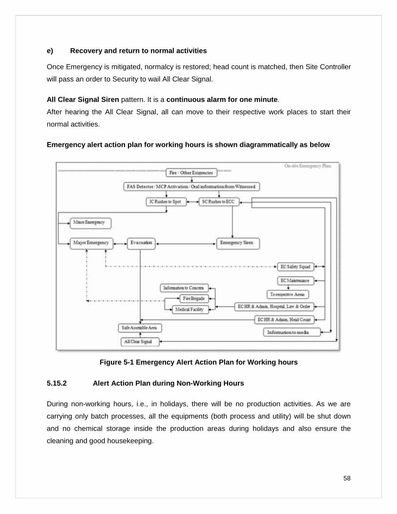
58
e) Recovery and return to normal activities
Once Emergency is mitigated, normalcy is restored; head count is matched, then Site Controller
will pass an order to Security to wail All Clear Signal.
All Clear Signal Siren pattern. It is a continuous alarm for one minute .
After hearing the All Clear Signal, all can move to their respective work places to start their
normal activities.
Emergency aler t action plan for working hours is shown diagrammaticall y as below
Figure 5-1 Emergency Alert Action Plan for Working hours
5.15.2 Alert Action Plan during Non -Working Hours
During non-working hours, i.e., in holidays, there will be no production activities. As we are
carrying only batch processes, all the equipments (both process and utility) will be shut down
and no chemical storage inside the production areas during holidays and also ensure the
cleaning and good housekeeping.
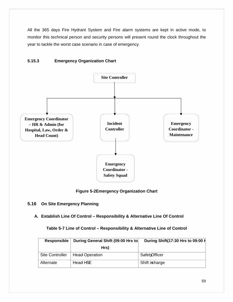
59
All the 365 days Fire Hydrant System and Fire alarm systems are kept in active mode, to
monitor this technical person and security persons will present round the clock throughout the
year to tackle the worst case scenario in case of emergency.
5.15.3 Emergency Organization Chart
Figure 5-2Emergency Organization Chart
5.16 On Site Emergency Planning
A. Establish Line Of Control – Responsibility & Alternative Line Of Control
Table 5-7 Line of Control – Responsibility & Alternative Line of Control
Responsible During General Shift (09:00 Hrs to 17:30
Hrs)
During Shift(17:30 Hrs to 09:00 Hrs)
Site Controller Head- Operation SafetyOfficer
Alternate Head- HSE Shift in-charge
Site Controller
IncidentController
Emergency Coordinator– HR & Admin (for
Hospital, Law, Order &Head Count)
EmergencyCoordinator -Safety Squad
EmergencyCoordinator -Maintenance
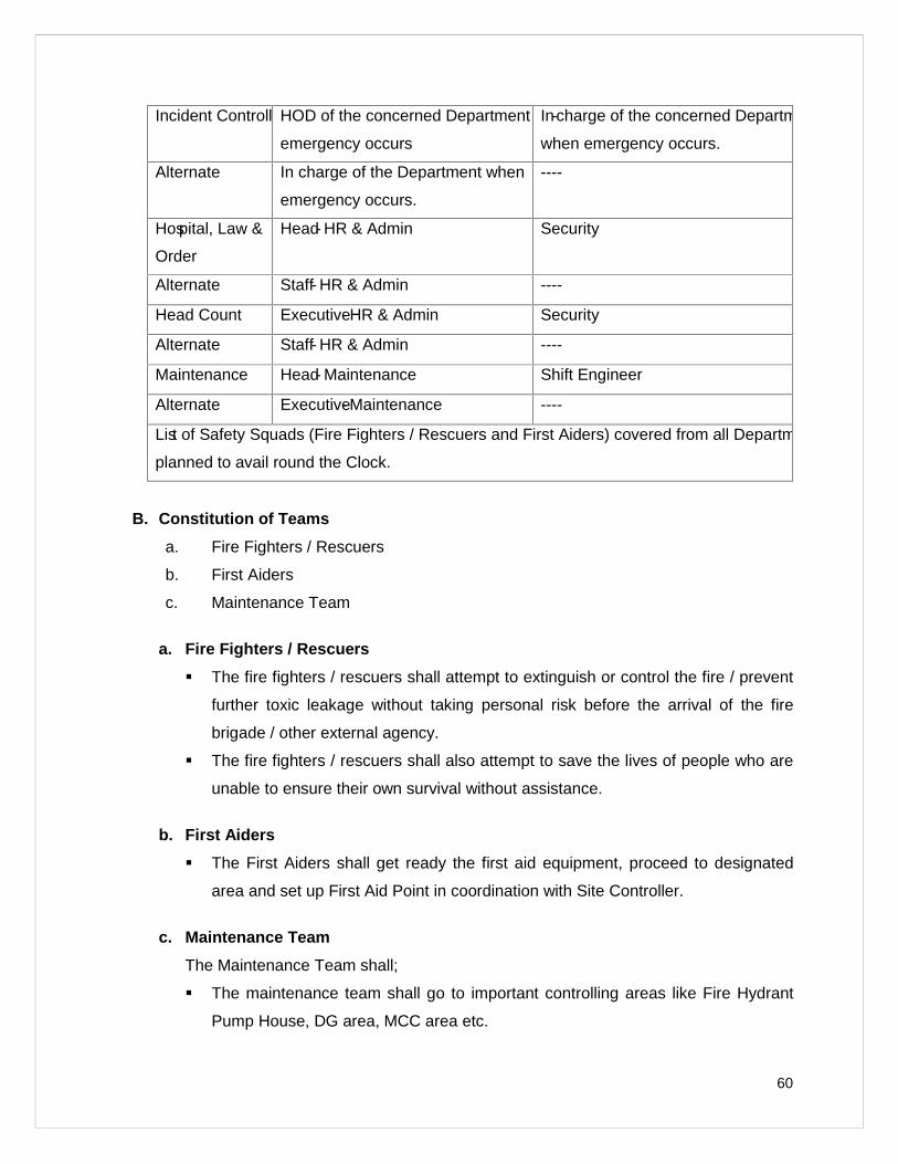
60
Incident ControllerHOD of the concerned Department when
emergency occurs
In-charge of the concerned Department
when emergency occurs.
Alternate In charge of the Department when
emergency occurs.
----
Hospital, Law &
Order
Head- HR & Admin Security
Alternate Staff- HR & Admin ----
Head Count Executive- HR & Admin Security
Alternate Staff- HR & Admin ----
Maintenance Head- Maintenance Shift Engineer
Alternate Executive- Maintenance ----
List of Safety Squads (Fire Fighters / Rescuers and First Aiders) covered from all Departments and
planned to avail round the Clock.
B. Constitution o f Teams
a. Fire Fighters / Rescuers
b. First Aiders
c. Maintenance Team
a. Fire Fighters / Rescuers
The fire fighters / rescuers shall attempt to extinguish or control the fire / prevent
further toxic leakage without taking personal risk before the arrival of the fire
brigade / other external agency.
The fire fighters / rescuers shall also attempt to save the lives of people who are
unable to ensure their own survival without assistance.
b. First Aiders
The First Aiders shall get ready the first aid equipment, proceed to designated
area and set up First Aid Point in coordination with Site Controller.
c. Maintenance Team
The Maintenance Team shall;
The maintenance team shall go to important controlling areas like Fire Hydrant
Pump House, DG area, MCC area etc.
61
C. Define Roles And Responsibilities In Brief
In the event of emergency, nominated individuals / teams are given specific
responsibilities; separate from their day to day activities.
The Emergency Organization Team consist,
a. Site Controller (SC)
b. Incident Controller (IC)
c. Emergency Co-ordinator – HR & Admin
i. Hospital, Law & Order
ii. Head Count
d. Emergency Co-ordinator Maintenance
e. Emergency Co-ordinator Safety Squad
i. Fire Fighters / Rescuer
ii. First Aider
C.1. Roles and responsibilities of Emergency Organization Team members
a. Site Controller (SC)
Site Controller is a person who has ultimate control over the affairs of the company
during emergencies inside the plant.His responsibilities include;
He should go to the Emergency Control Centre as soon as he is aware of
the emergency and take over the situation.
Get complete information of the incident.
Assess the incident and if require pass an order to security to wail
Emergency Siren.
Remain in ECC and establish the contact with Incident Controller and
guide him about the actions to be taken.
Arrange for additional help as requested by Incident Controller with the
help of Emergency Coordinators.
If required call outside services like fire brigade, medical facility, water
tankers, police etc with the help of Emergency Coordinators.
Guide and control the traffic movements in evacuation.
62
Establish communication and liaise with agencies like Department of
Factories and Boilers, Pollution Control Board, Police and other
Government Officials.
Inform Incident Controller about missed people if any, after head count
has been done.
To issue authorized statements to the news media.
Once situation is controlled, head count matched then instructs security
to wail ‘All Clear Signal’.
Rehabilitation of affected areas after the emergency.
b. Incident Controller (IC)
Incident Controller is a person who is responsible for incident control measures, rescue
operations and mitigation of emergency situation on Coordination with Site Controller.
His responsibilities include;
Proceed to the incident spot as information is received.
Assess the size and nature of emergency and communicate the same to
Site Controller and keep in touch with Site Controller till the emergency is
mitigated / controlled.
Start and direct all emergency control operations with the help of
Emergency Coordinator - Safety Squads.
Request Site Controller for additional help like Safety Squads from other
Departments, fire brigades etc.
Direct shut down of the processes / plants and also nearby plants.
Ensure evacuation of all personnel in coordination with Site Controller.
Once emergency is mitigated, normalcy is observed, instruct Site
Controller for the same.
c. Emergency Co -ordinator – HR & Admin
HR & Admin team consist two persons, one person will be stationed at the Emergency
Control Centre during the emergency to handle hospital, fire, police and other inquiries
under instruction of Site Controller and other person will carry out headcount at
assembly point and pass on the absentee information to the Site Controller.
63
i. Emergency Co -ordinator Hospital, Law & Order
His responsibilities shall include -
Proceed to the Emergency Control Centre and report to Site
Controller.
Ensure the gates are closed.
With the help of security, control crowd at gate as per instruction
from Site Controller.
Deploy one guard at main gate with instructions not to allow / send
any personnel, vehicles inside except fire tender and ambulance.
Keep ready the list of important telephone numbers and contact
numbers of police and other law and other agencies.
Inform other statutory departments, corporate office as per
instruction from Site Controller.
Inform relatives / contact persons of the injured accordingly.
Get hold of medical management procedure / list, hospital /
telephone numbers, accordingly.
Call the respective medical institute as per the instruction from Site
Controller.
Prepare a sequential report of the incident.
ii. Emergency Co -ordinator Head Count
His responsibilities shall include -
Proceed to the Emergency Control Centre and report to Site
Controller
Ensure carrying Master Attendance Copy.
Proceed to assembly point and collect attendance sheet from
respective department.
Compare the list and look for missing personnel if any.
Inform Site Controller about the same.
d. Emergency Co -ordinator Maintenance
Emergency Co-ordinator Maintenance will take care of emergency control systems like
Fire Hydrant System, DG units etc and also mobilize the tool and other emergency
equipments as per the instruction of Site Controller.
64
One of the co-ordinator will move to Fire Hydrant pump house and switch
on /off the pump as per the instruction of Site Controller.
One of the co-ordinator will move to Generator room and switch on / off
as per the instruction of Site Controller.
One of the co-ordinator will move to respective MCC of incident spot and
keep in touch with Site Controller.
One of the co-ordinator will be available on phone and act as per the
instruction of Site Controller.
e. Emergency Co -ordinator Safety Squad
Emergency Co-ordinator Safety Squads will fight the emergency to mitigate it and to
protect life, property.
i. Emergency Co -ordinator Fire Fighters / Rescuer
Proceed to the incident spot along with emergency equipments and
report to Incident Controller.
Set up emergency equipment.
Act as per the instruction of Incident Controller.
Make quick assessment of the injured and arrange to shift with the
help of Incident Controller to safer place for first aid.
Send one co-ordinator of the team along with injured.
Search for missed ones and do rescue operation for the needy.
ii. Emergency Co -ordinator First aider
Proceed to Emergency Control Centre along with team and report
to Site Controller.
Set up emergency equipments.
Be ready to receive and to provide first aid to victim and to help the
ambulance staff.
Make quick assessment of the injured and arrange to send victim to
hospital with the coordination of Site Controller.
Send one co-ordinator of the team to hospital along with injured with
medical management procedures.
65
C.2. Roles and responsibilities of persons other than Emergency Organization
Team members
Do not venture out for help.
Be available in the Department till evacuation is called.
After hearing the Emergency siren, all should stop their work in a safe manner
immediately.
All work permits will be cancelled automatically.
All should come to Safe Assembly Area (In front of Safety Office).
While coming to Safe Assemble Area,
Do not run, walk brisk.
Do not use lift, use only staircase.
Do not block staircase, use hand rail. Come in a line.
Do not obstruct / block the path to Emergency Organization Team
members.
Do not go back for your belongings.
Do not use telephone except for emergency purpose.
Follow instructions of Site Controller in Safe Assemble Area.
After All Clear Signal all can go back to their respective places / Departments.
D. Notification o f Emergency
The notification of any mishap like fire, explosion or toxic release is identified by either
sensors or by any person working in the plant. If detection by sensors, alarm system will get
activated or if it by a person, he will shout and / or break MCP to activate alarm system. As
soon as Incident Controller aware of the emergency, he will rush to incident spot and assess
the size and nature of emergency and communicate the same to Site Controller.
E. Declaration o f Emergency
Site Controller will be the person to decide whether the situation warrants evacuation of the
premises or is a localized incident. This individual will be termed as the declarer of
emergency. Immediately the declarer will make arrangements to give information to the
Executive Director.
Once an emergency requiring evacuation has been decided upon by the declarer, the
Emergency will be declared by putting on the Emergency Siren.
66
F. Evacuation o f Personnel
All Safety Squad co-ordinators from the Department where the incident has occurred and
from other Department will reach earliest to the point of incident. All other people working in
the factory will assemble at designated assembly point i.e., in front of Safety Department
after hearing the Emergency Siren.
The Emergency co-ordinators will assist in directing the individuals to the assembly point.
G. Acc ounting o f Personnel
The Emergency Co-ordinator HR & Admin, Head Count Person will conduct head count as
per particular days attendance record at the assembly point to account for persons working
inside the factory and also for visitors / vendors present inside the premises. Information on
missing persons will immediately convey to Site Controller.
H. Controlling o f Emergency
The Safety Squad member from the affected area and Safety Squad members from other
Departments will attempt to control / mitigate the emergency situation under the supervision
of Incident Controller and instruction of Site Controller.
I. Arrangements f or Medical Treatment
Any person injured in the incident and subsequently, will be treated by Emergency Co-
coordinator, First Aider. The designated vehicle will be kept ready to move the injured to
hospital, all the injured will be sent to Suhas General & Charitable Hospital, Jigani. First Aid
team member will accompany the injured to hospital. In the event of additional medical help,
the injured will be shift to recommended Hospital.
J. Information to t he Relatives of t he Injured
The relatives of injured will be informed by Emergency Coordinator HR & Admin for Hospital,
Law & Order. The communications to the relatives of injured will be through telecom or by a
messenger. The clear address of availability of the injured person (if hospitalized) will be
communicated to his relatives.
67
K. Information to t he Government Authorities
The Emergency Coordinator HR & Admin for Hospital, Law and Order is the person to
inform and get help from Fire Station, Police and other Government Hospitals in
coordinating with Site Controller.
L. Law & Order
Site Controller will take over and control emergency in coordination with Incident Controller
and other Emergency Coordinators.
The Executive Director will arrange to send information regarding the incident to the Director
of Factories, Government of Karnataka.
M. All Clear Signal
Once Emergency is mitigated, normalcy is restored; head count is matched, then Site
Controller will pass an order to Security to wail All Clear Signal.
After hearing the All Clear Signal, all can move to their respective work places to start their
normal activities.
5.17 Offsite Emergency Plan
5.17.1 Preamble
An offsite emergency arising out of chemical hazards in one, which has potential to cause
serious damage or loss of life beyond the plant boundary. In addition, Accidents during
transportation of hazardous chemicals by road, rail, pipeline etc. can cause offsite emergencies.
Emergency services such as Police, Fire, Medical etc., need to be prepared to handle such
situations promptly and effectively.
It is mandatory under Rule 16 of the Hazardous Chemical Rules for District authorities to
prepare an off-site emergency plan in respect of clusters of hazardous chemical industries or at
locations where accidents are likely to have an off-site adverse effect.
In order to be in a state of preparedness to respond to the accidents and minimize their adverse
impacts on the offsite population, requires an offsite emergency plan to be prepared by the
District Controller for every District or Industrial Areas as applicable.
68
5.17.2 Objective
The objective of the present assignment is to prepare an area specific Offsite Emergency Action
Plan for Jigani, Bangalore, Karnataka which can be practically implemented / activated at a
short notice to ensure minimal impact on life and property due to emergencies arising out of
Chemical Accidents or during Transportation of Hazardous Chemicals in the district.
The plan should be regularly updated when there are changes occurring in the Industrial set up,
Transportation Aspects, Key Manpower and Administrative Changes etc., Regular drills,
Training of key persons, increasing safety awareness etc is extremely important areas that must
be looked into for sound preparedness.
5.17.3 Offsite Emergency Control
As we all know that jigani is an industrial area having many industries of large, medium & small
scale. After the “Bhopal Gas Tragedy” (Methyl Isocyanides- MIC Poisonous and toxic gas
release Accident at Union Carbide, 1984) the Government felt an immediate need to be more
conscious about handling of Hazardous Chemicals.
Central control room Centre or Offsite Industrial Emergency Control Room “OIECR” should be
established by company. It should work under the Governing Council. The Governing Council
should be headed under the chairmanship by District Collector & Magistrate of jigani. The
Governing Council Members are the permanent Ex. Officio Members to manage the affairs of
the Emergency Control Room.
5.17.4 Emergency Instruction to the General Public
The Notification o f Emergency
The emergency can be declared by following media to alert or alarm the public ;
1. Public address system
2. Blow horns/Bells
3. Sirens / Hooters
4. Telephone message / Fax Messages / Hot lines/ Pager / E-mail / Mobile Phone /
Satellite system
5. Sending messages through a messenger
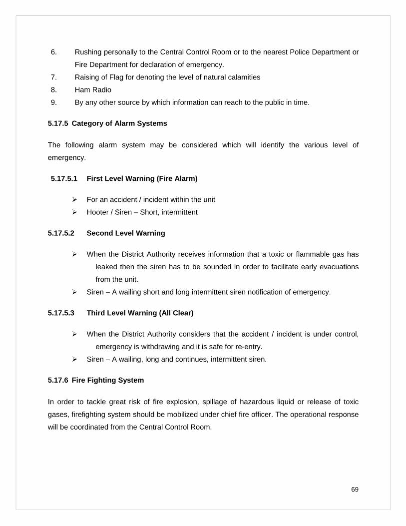
69
6. Rushing personally to the Central Control Room or to the nearest Police Department or
Fire Department for declaration of emergency.
7. Raising of Flag for denoting the level of natural calamities
8. Ham Radio
9. By any other source by which information can reach to the public in time.
5.17.5 Category of Alarm Systems
The following alarm system may be considered which will identify the various level of
emergency.
5.17.5.1 First Level Warning ( Fire Alarm)
For an accident / incident within the unit
Hooter / Siren – Short, intermittent
5.17.5.2 Second Level Warning
When the District Authority receives information that a toxic or flammable gas has
leaked then the siren has to be sounded in order to facilitate early evacuations
from the unit.
Siren – A wailing short and long intermittent siren notification of emergency.
5.17.5.3 Third Level Warning (All Clear)
When the District Authority considers that the accident / incident is under control,
emergency is withdrawing and it is safe for re-entry.
Siren – A wailing, long and continues, intermittent siren.
5.17.6 Fire Fighting System
In order to tackle great risk of fire explosion, spillage of hazardous liquid or release of toxic
gases, firefighting system should be mobilized under chief fire officer. The operational response
will be coordinated from the Central Control Room.
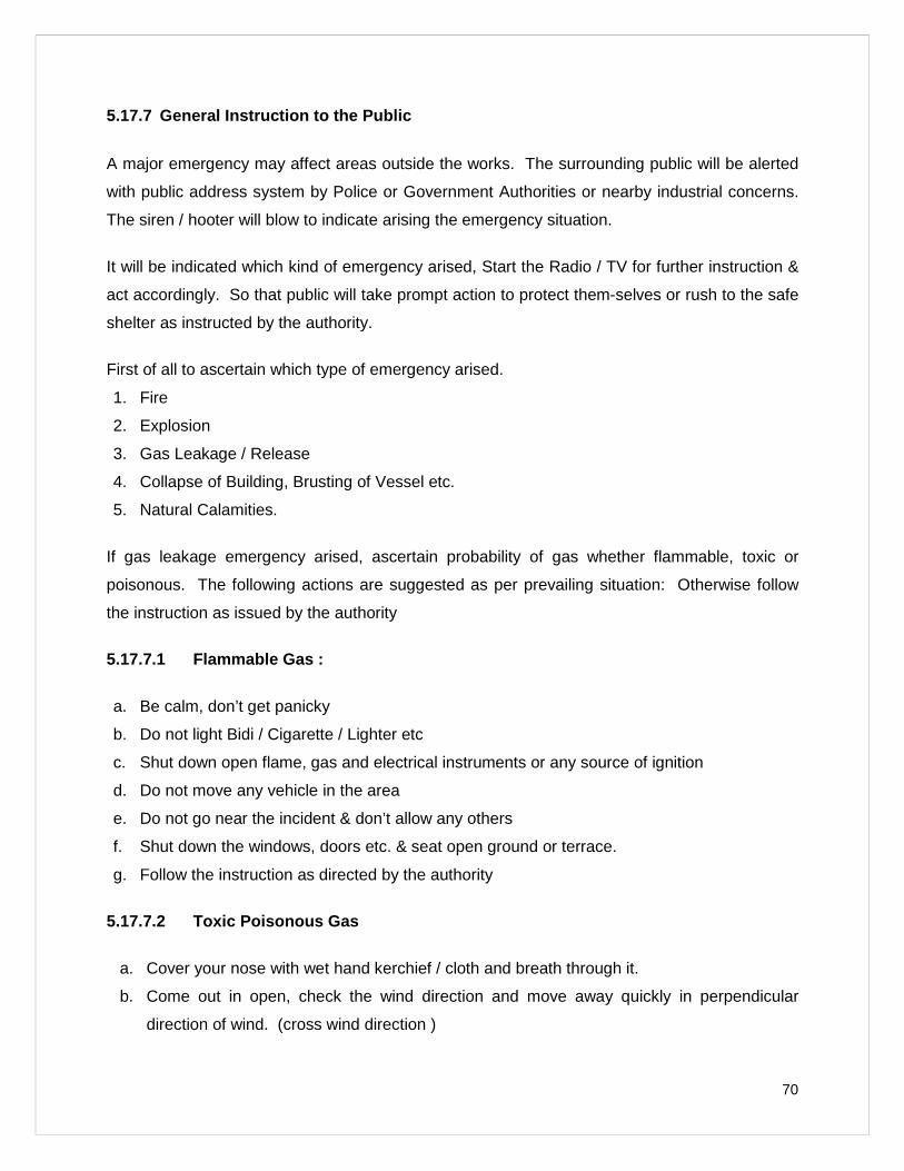
70
5.17.7 General Instruction to the Public
A major emergency may affect areas outside the works. The surrounding public will be alerted
with public address system by Police or Government Authorities or nearby industrial concerns.
The siren / hooter will blow to indicate arising the emergency situation.
It will be indicated which kind of emergency arised, Start the Radio / TV for further instruction &
act accordingly. So that public will take prompt action to protect them-selves or rush to the safe
shelter as instructed by the authority.
First of all to ascertain which type of emergency arised.
1. Fire
2. Explosion
3. Gas Leakage / Release
4. Collapse of Building, Brusting of Vessel etc.
5. Natural Calamities.
If gas leakage emergency arised, ascertain probability of gas whether flammable, toxic or
poisonous. The following actions are suggested as per prevailing situation: Otherwise follow
the instruction as issued by the authority
5.17.7.1 Flammable Gas :
a. Be calm, don’t get panicky
b. Do not light Bidi / Cigarette / Lighter etc
c. Shut down open flame, gas and electrical instruments or any source of ignition
d. Do not move any vehicle in the area
e. Do not go near the incident & don’t allow any others
f. Shut down the windows, doors etc. & seat open ground or terrace.
g. Follow the instruction as directed by the authority
5.17.7.2 Toxic Poisonous Gas
a. Cover your nose with wet hand kerchief / cloth and breath through it.
b. Come out in open, check the wind direction and move away quickly in perpendicular
direction of wind. (cross wind direction )
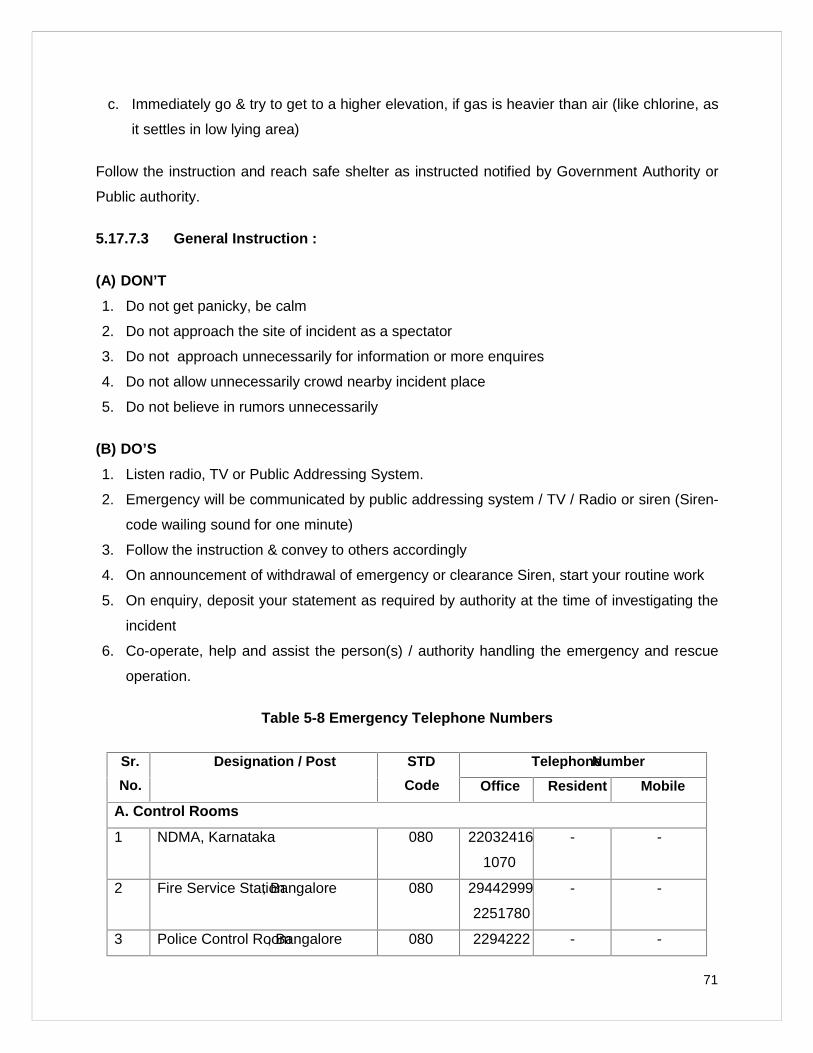
71
c. Immediately go & try to get to a higher elevation, if gas is heavier than air (like chlorine, as
it settles in low lying area)
Follow the instruction and reach safe shelter as instructed notified by Government Authority or
Public authority.
5.17.7.3 General Instruction :
(A) DON’T
1. Do not get panicky, be calm
2. Do not approach the site of incident as a spectator
3. Do not approach unnecessarily for information or more enquires
4. Do not allow unnecessarily crowd nearby incident place
5. Do not believe in rumors unnecessarily
(B) DO’S
1. Listen radio, TV or Public Addressing System.
2. Emergency will be communicated by public addressing system / TV / Radio or siren (Siren-
code wailing sound for one minute)
3. Follow the instruction & convey to others accordingly
4. On announcement of withdrawal of emergency or clearance Siren, start your routine work
5. On enquiry, deposit your statement as required by authority at the time of investigating the
incident
6. Co-operate, help and assist the person(s) / authority handling the emergency and rescue
operation.
Table 5-8 Emergen cy Telephone Numbers
Sr.
No.
Designation / Post STD
Code
TelephoneNumber
Office Resident Mobile
A. Control Rooms
1 NDMA, Karnataka 080 22032416/
1070
- -
2 Fire Service Station, Bangalore 080 29442999/
2251780
- -
3 Police Control Room, Bangalore 080 2294222 - -
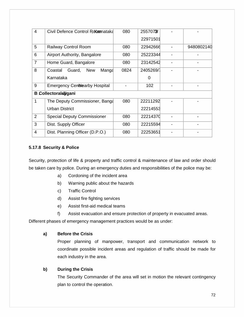
72
4 Civil Defence Control Room, Karnataka 080 25570733/
22971501
- -
5 Railway Control Room 080 22942666 - 9480802140
6 Airport Authority, Bangalore 080 25223344 - -
7 Home Guard, Bangalore 080 23142542 - -
8 Coastal Guard, New Mangalore,
Karnataka
0824 2405269/7
0
- -
9 Emergency Centre-Nearby Hospital - 102 - -
B .Collectoralay-Jigani
1 The Deputy Commissioner, Bangalore
Urban District
080 22211292/
22214553
- -
2 Special Deputy Commissioner 080 22214370 - -
3 Dist. Supply Officer 080 22215594 - -
4 Dist. Planning Officer (D.P.O.) 080 22253651 - -
5.17.8 Security & Police
Security, protection of life & property and traffic control & maintenance of law and order should
be taken care by police. During an emergency duties and responsibilities of the police may be:
a) Cordoning of the incident area
b) Warning public about the hazards
c) Traffic Control
d) Assist fire fighting services
e) Assist first-aid medical teams
f) Assist evacuation and ensure protection of property in evacuated areas.
Different phases of emergency management practices would be as under:
a) Before the Cri sis
Proper planning of manpower, transport and communication network to
coordinate possible incident areas and regulation of traffic should be made for
each industry in the area.
b) During the Crisis
The Security Commander of the area will set in motion the relevant contingency
plan to control the operation.
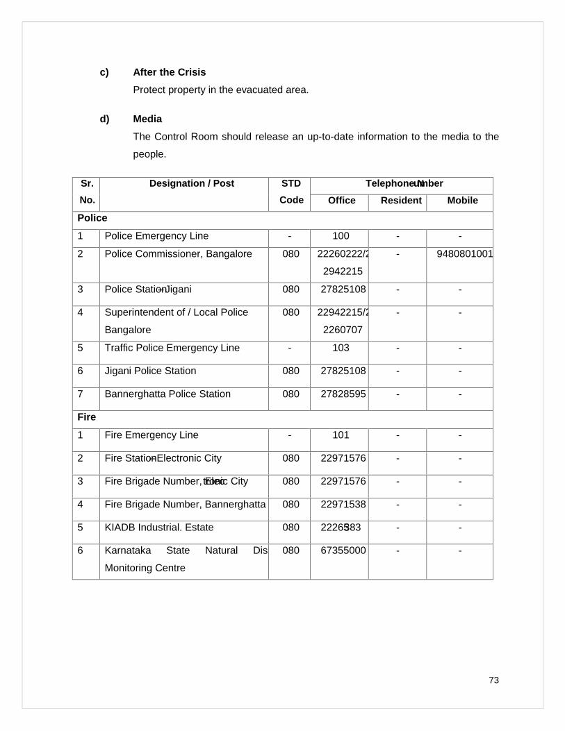
73
c) After the Crisis
Protect property in the evacuated area.
d) Media
The Control Room should release an up-to-date information to the media to the
people.
Sr.
No.
Designation / Post STD
Code
Telephone Number
Office Resident Mobile
Police
1 Police Emergency Line - 100 - -
2 Police Commissioner, Bangalore 080 22260222/2
2942215
- 9480801001
3 Police Station–Jigani 080 27825108 - -
4 Superintendent of / Local Police
Bangalore
080 22942215/2
2260707
- -
5 Traffic Police Emergency Line - 103 - -
6 Jigani Police Station 080 27825108 - -
7 Bannerghatta Police Station 080 27828595 - -
Fire
1 Fire Emergency Line - 101 - -
2 Fire Station–Electronic City 080 22971576 - -
3 Fire Brigade Number, Electronic City 080 22971576 - -
4 Fire Brigade Number, Bannerghatta Road080 22971538 - -
5 KIADB Industrial. Estate 080 22265383 - -
6 Karnataka State Natural Disaster
Monitoring Centre
080 67355000 - -
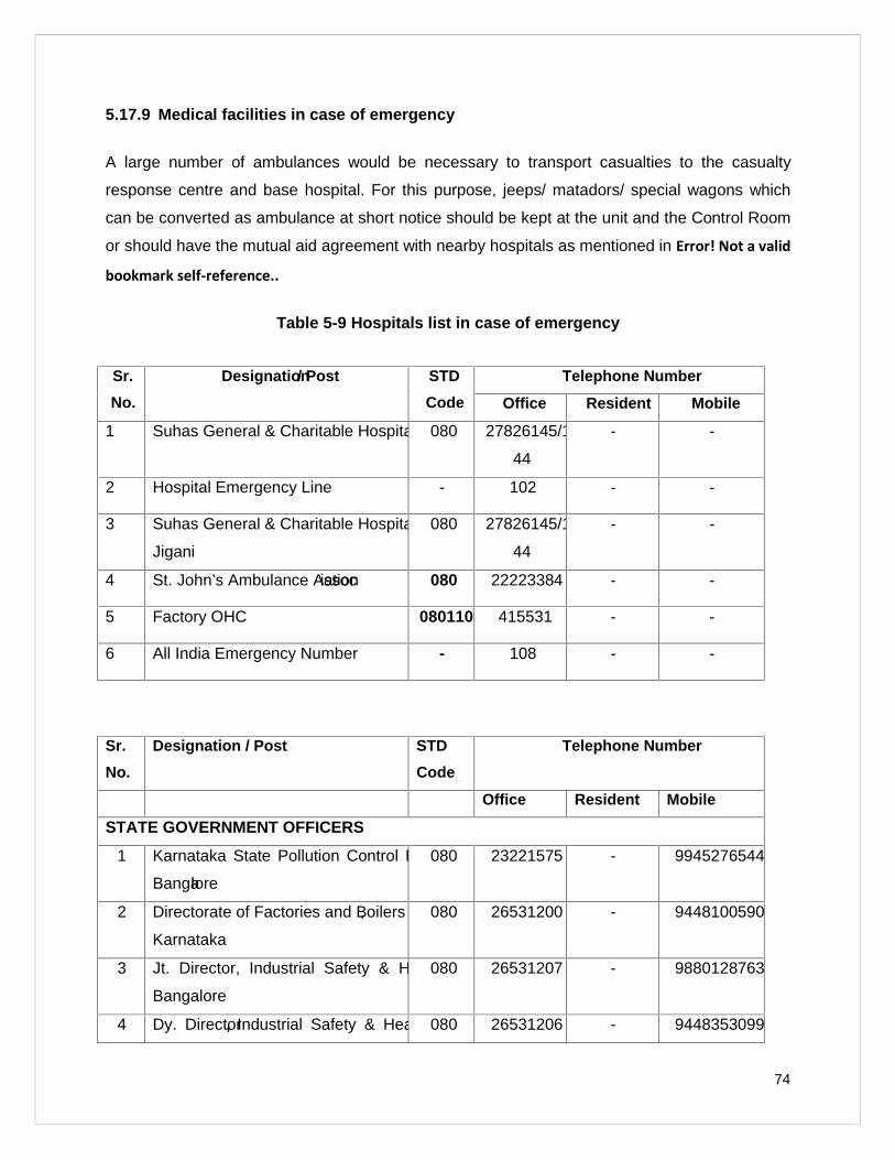
74
5.17.9 Medical facilities in case of emergency
A large number of ambulances would be necessary to transport casualties to the casualty
response centre and base hospital. For this purpose, jeeps/ matadors/ special wagons which
can be converted as ambulance at short notice should be kept at the unit and the Control Room
or should have the mutual aid agreement with nearby hospitals as mentioned in Error! Not a valid
bookmark self-reference..
Table 5-9 Hospitals list in case of emergency
Sr.
No.
Designation/ Post STD
Code
Telephone Number
Office Resident Mobile
1 Suhas General & Charitable Hospital 080 27826145/1
44
- -
2 Hospital Emergency Line - 102 - -
3 Suhas General & Charitable Hospital,
Jigani
080 27826145/1
44
- -
4 St. John’s Ambulance Association 080 22223384 - -
5 Factory OHC 080110 415531 - -
6 All India Emergency Number - 108 - -
Sr.
No.
Designation / Post STD
Code
Telephone Number
Office Resident Mobile
STATE GOVERNMENT OFFICERS
1 Karnataka State Pollution Control Board,
Bangalore
080 23221575 - 9945276544
2 Directorate of Factories and Boilers,
Karnataka
080 26531200 - 9448100590
3 Jt. Director, Industrial Safety & Health,
Bangalore
080 26531207 - 9880128763
4 Dy. Director, Industrial Safety & Health,080 26531206 - 9448353099
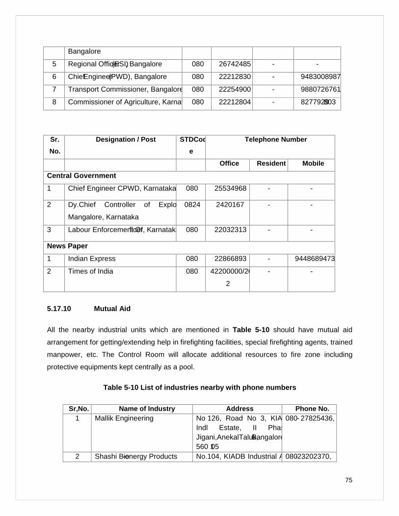
75
Bangalore
5 Regional Officer(ESI), Bangalore 080 26742485 - -
6 ChiefEngineer(PWD), Bangalore 080 22212830 - 9483008987
7 Transport Commissioner, Bangalore 080 22254900 - 9880726761
8 Commissioner of Agriculture, Karnataka080 22212804 - 8277929803
Sr.
No.
Designation / Post STDCod
e
Telephone Number
Office Resident Mobile
Central Government
1 Chief Engineer CPWD, Karnataka 080 25534968 - -
2 Dy.Chief Controller of Explosive,
Mangalore, Karnataka
0824 2420167 - -
3 Labour Enforcement Officer, Karnataka 080 22032313 - -
News Paper
1 Indian Express 080 22866893 - 9448689473
2 Times of India 080 42200000/20
2
- -
5.17.10 Mutual Aid
All the nearby industrial units which are mentioned in Table 5-10 should have mutual aid
arrangement for getting/extending help in firefighting facilities, special firefighting agents, trained
manpower, etc. The Control Room will allocate additional resources to fire zone including
protective equipments kept centrally as a pool.
Table 5-10 List of industries nearby with phone numbers
Sr,No. Name of Industry Address Phone No.1 Mallik Engineering No 126, Road No 3, KIADB
Indl Estate, II Phase,Jigani,AnekalTaluk,Bangalore560 105
080- 27825436,
2 Shashi Bio-energy Products No.104, KIADB Industrial Area,080-23202370,
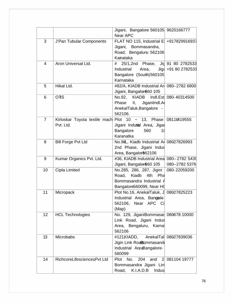
76
Jigani, Bangalore- 560105,Near APC
9620166777
3 J’Pan Tubular Components FLAT NO 115, Industrial EstateJigani, Bommasandra, FortRoad, Bengaluru- 562106,Karnataka
+917829916937
4 Aron Universal Ltd. # 25/1,2nd Phase, JiganiIndustrial Area, Jigani,Bangalore (South)– 560105,Karnataka
91 80 27825331/+91 80 27825315
5 Hikal Ltd. #82/A, KIADB Industrial AreaJigani, Bangalore–560 105
080–2782 6800
6 OTIS No.92, KIADB Indl.Estate,Phase II, JiganiIndl.Area,AnekalTaluk,Bangalore -562106.
080- 40314500
7 Kirloskar Toyota textile machineryPvt. Ltd.
Plot 10 ~ 13, Phase IIJigani Industrial Area, Jigani,Bangalore 560 105.Karanatka
08110-419555
8 Bill Forge Pvt Ltd No.98-L, Kiadb Industrial Area,2nd Phase, Jigani IndustrialArea, Bangalore- 562106
080-27826993
9 Kumar Organics Pvt. Ltd. #36, KIADB Industrial AreaJigani, Bangalore–560 105
080– 2782 5439,080–2782 5376
10 Cipla Limited No.285, 286, 287, Jigini LinkRoad, Kiadb 4th Phase,Bommasandra Industrial Area,Bangalore- 560099, Near HCL
080- 22059200
11 Micropack Plot No.16, AnekalTaluk, JiganiIndustrial Area, Bangalore -562106, Near APC Circle(Map)
080-27825223
12 HCL Technologies No. 129, JiganiBommasandra,Link Road, Jigani IndustrialArea, Bengaluru, Karnataka562106
080-678 10000
13 Microbabs #121,KIADD, AnekalTaluk,Jigin Link Road,BommasandraIndustrial Area, Bangalore-560099
080-27839036
14 RichcoreLifesciencesPvt Ltd Plot No. 204 and 237,Bommasandra- Jigani LinkRoad, K.I.A.D.B Industrial
081104 19777
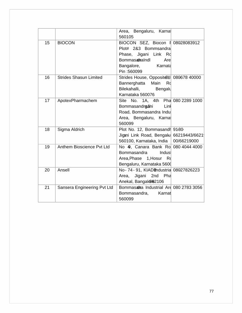
77
Area, Bengaluru, Karnataka560105
15 BIOCON BIOCON SEZ, Biocon ParkPlot# 2&3 Bommsandra IvPhase, Jigani Link Road,BommasandraIndl AreaBangalore, KarnatakaPin :560099
080-28083912
16 Strides Shasun Limited Strides House, Opposite IIM-B,Bannerghatta Main Road,Bilekahalli, Bengaluru,Karnataka 560076
080-678 40000
17 ApotexPharmachem Site No. 1A, 4th Phase,BommasandraJigani LinkRoad, Bommasandra IndustrialArea, Bengaluru, Karnataka560099
080 2289 1000
18 Sigma Aldrich Plot No. 12, Bommasandhara,Jigani Link Road, Bengaluru-560100, Karnataka, India
91-80-66219443/66219400/66219000
19 Anthem Bioscience Pvt Ltd No 49, Canara Bank Road,Bommasandra IndustrialArea,Phase 1,Hosur Road,Bengaluru, Karnataka 560099
080 4044 4000
20 Ansell No- 74 - 91, KIADBIndustrialArea, Jigani 2nd Phase,Anekal, Bangalore-562106
080-27826223
21 Sansera Engineering Pvt Ltd Bommasandra Industrial Area,Bommasandra, Karnataka560099
080 2783 3056

HUBERT ENVIRO CARE SYSTEMS (P) LTDCHENNAI
A-21, III Phase, Behind Lions Club School, Thiru Vi Ka IndustrialEstate, Guindy , Chennai – 600 032, Tamil Nadu, India