Anisotropic electrical conductivity of polymer composites with aligned carbon nanotubes
9
Anisotropic electrical conductivity of polymer composites with aligned carbon nanotubes S. Gong a , Z.H. Zhu a, * , S.A. Meguid b a Department of Earth and Space Science and Engineering, York University, 4700 Keele Street, Toronto, ON M3J 1P3, Canada b Department of Mechanical and Industrial Engineering, University of Toronto, 5 King's College Road, Toronto, ON M5S 3G8, Canada article info Article history: Received 28 September 2014 Received in revised form 13 November 2014 Accepted 16 November 2014 Available online 22 November 2014 Keywords: Carbon nanotube alignment Electrical conductivity Nanotube structural distortion abstract This paper studies the effect of carbon nanotube (CNT) alignment on anisotropy of electrical conductivity of CNT enhanced polymer composites. A new CNT percolation network model is developed by consid- ering structural distortion of CNT walls at crossed junctions. The structural distortion is modeled by a pseudo-potential energy that consists of the Lennard-Jones potential of Van der Waals interaction be- tween CNTs and the bending energy of CNT walls. Simulation results show better agreement with experimental data by the newly development. The current study reveals the anisotropy of electrical property of aligned CNT/polymer composites is mainly affected by the average conductive pathway density of CNTs, which depends heavily on CNT alignment structure. The study further identifies that the aligned CNT structure in polymer matrix effectively affects the contributions of each resistance com- ponents in the CNT networks to the total resistance. Finally, parametric studies are conducted to enable systematic exploration of designing multifunctional nanocomposites. © 2014 Elsevier Ltd. All rights reserved. 1. Introduction Carbon nanotubes (CNTs), after being dispersed into a polymer matrix, will connect each other through CNT junctions to form conductive networks for electrons and phonons, which in turn transform the insulating polymer into an electrical conductor. The electrically conductive CNT/polymer composites have great po- tential in many applications, such as electromagnetic interference shielding, sensors, batteries, antistatic devices, lightweight energy storages [1e4]. The early interest in the effect of CNT alignment on nanocomposites was presented by Ajayan et al. [5], whose findings revealed that the desired properties of CNT/polymer composites could be attained by dispersing and aligning CNTs in polymer matrices. The aligned CNTs could form effective conductive path- ways in CNT/polymer composites to improve the electrical prop- erties with lower CNT loadings than those of uniformly dispersed CNTs [6e8]. Since then, it is commonly accepted that the CNT alignment is a crucial structural parameter that controls the anisotropy of electrical properties of CNT/polymer composites, particularly when measured in directions parallel and perpendic- ular to the CNT alignment. Generally, the alignment of CNTs in polymer matrices can be achieved at different stages of the fabri- cation process. For instance, a uniform alignment of CNTs can be achieved by growing homogeneous CNT arrays on substrates using chemical vapor deposition [9e11] before the fabrication of CNT/ polymer composites. During the fabrication of CNT/polymer com- posites, the CNTs dispersed in polymers can be aligned by applying magnetic/electrical fields [12e21] or mechanical stretching and compression of polymers [22e30]. Other approaches achieve the controlled alignment structures of CNTs in polymers by adjusting draw ratio in stretching process [22e26] or field strength and curing times [12e18]. More details about the alignment techniques can be found in Ref. [31]. However, it is noted that well aligned CNT array grown on substrate may not be ideal to achieve the highest electrical conductivity by given CNT loadings [32]. Compared with the experimental approaches, the fundamental understanding of the relationships among processing, alignment and performance remains uncertain, largely due to limited efforts in theoretical and numerical investigations. Among all the theo- retical and numerical simulations, the statistics based percolation network theory is one of the most effective models [33e39]. Up to now, two main mechanisms of the electron conductance have been * Corresponding author. Tel.: þ1 416 736 2100x77729; fax: þ1 416 736 5817. E-mail address: [email protected] (Z.H. Zhu). Contents lists available at ScienceDirect Polymer journal homepage: www.elsevier.com/locate/polymer http://dx.doi.org/10.1016/j.polymer.2014.11.038 0032-3861/© 2014 Elsevier Ltd. All rights reserved. Polymer 56 (2015) 498e506
Transcript of Anisotropic electrical conductivity of polymer composites with aligned carbon nanotubes
lable at ScienceDirect
Polymer 56 (2015) 498e506
Contents lists avai
Polymer
journal homepage: www.elsevier .com/locate/polymer
Anisotropic electrical conductivity of polymer composites withaligned carbon nanotubes
S. Gong a, Z.H. Zhu a, *, S.A. Meguid b
a Department of Earth and Space Science and Engineering, York University, 4700 Keele Street, Toronto, ON M3J 1P3, Canadab Department of Mechanical and Industrial Engineering, University of Toronto, 5 King's College Road, Toronto, ON M5S 3G8, Canada
a r t i c l e i n f o
Article history:Received 28 September 2014Received in revised form13 November 2014Accepted 16 November 2014Available online 22 November 2014
Keywords:Carbon nanotube alignmentElectrical conductivityNanotube structural distortion
* Corresponding author. Tel.: þ1 416 736 2100x777E-mail address: [email protected] (Z.H. Zhu).
http://dx.doi.org/10.1016/j.polymer.2014.11.0380032-3861/© 2014 Elsevier Ltd. All rights reserved.
a b s t r a c t
This paper studies the effect of carbon nanotube (CNT) alignment on anisotropy of electrical conductivityof CNT enhanced polymer composites. A new CNT percolation network model is developed by consid-ering structural distortion of CNT walls at crossed junctions. The structural distortion is modeled by apseudo-potential energy that consists of the Lennard-Jones potential of Van der Waals interaction be-tween CNTs and the bending energy of CNT walls. Simulation results show better agreement withexperimental data by the newly development. The current study reveals the anisotropy of electricalproperty of aligned CNT/polymer composites is mainly affected by the average conductive pathwaydensity of CNTs, which depends heavily on CNT alignment structure. The study further identifies that thealigned CNT structure in polymer matrix effectively affects the contributions of each resistance com-ponents in the CNT networks to the total resistance. Finally, parametric studies are conducted to enablesystematic exploration of designing multifunctional nanocomposites.
© 2014 Elsevier Ltd. All rights reserved.
1. Introduction
Carbon nanotubes (CNTs), after being dispersed into a polymermatrix, will connect each other through CNT junctions to formconductive networks for electrons and phonons, which in turntransform the insulating polymer into an electrical conductor. Theelectrically conductive CNT/polymer composites have great po-tential in many applications, such as electromagnetic interferenceshielding, sensors, batteries, antistatic devices, lightweight energystorages [1e4]. The early interest in the effect of CNT alignment onnanocomposites was presented by Ajayan et al. [5], whose findingsrevealed that the desired properties of CNT/polymer compositescould be attained by dispersing and aligning CNTs in polymermatrices. The aligned CNTs could form effective conductive path-ways in CNT/polymer composites to improve the electrical prop-erties with lower CNT loadings than those of uniformly dispersedCNTs [6e8]. Since then, it is commonly accepted that the CNTalignment is a crucial structural parameter that controls theanisotropy of electrical properties of CNT/polymer composites,
29; fax: þ1 416 736 5817.
particularly when measured in directions parallel and perpendic-ular to the CNT alignment. Generally, the alignment of CNTs inpolymer matrices can be achieved at different stages of the fabri-cation process. For instance, a uniform alignment of CNTs can beachieved by growing homogeneous CNT arrays on substrates usingchemical vapor deposition [9e11] before the fabrication of CNT/polymer composites. During the fabrication of CNT/polymer com-posites, the CNTs dispersed in polymers can be aligned by applyingmagnetic/electrical fields [12e21] or mechanical stretching andcompression of polymers [22e30]. Other approaches achieve thecontrolled alignment structures of CNTs in polymers by adjustingdraw ratio in stretching process [22e26] or field strength andcuring times [12e18]. More details about the alignment techniquescan be found in Ref. [31]. However, it is noted that well aligned CNTarray grown on substrate may not be ideal to achieve the highestelectrical conductivity by given CNT loadings [32].
Compared with the experimental approaches, the fundamentalunderstanding of the relationships among processing, alignmentand performance remains uncertain, largely due to limited effortsin theoretical and numerical investigations. Among all the theo-retical and numerical simulations, the statistics based percolationnetwork theory is one of the most effective models [33e39]. Up tonow, twomain mechanisms of the electron conductance have been

S. Gong et al. / Polymer 56 (2015) 498e506 499
identified in the CNT percolation networks [36e41]: (i) the intrinsicconductance of CNTs and (ii) the intertube contact conductancefrom electron tunneling effect at crossed CNT junctions. Most ofexisting percolation network models [33e36] focuses on the bal-listic transport of CNTs with perfect honeycomb arrangement ofcarbon atoms. However, it is well recognized that CNTs experiencewall distortion in reality although they are stiff in the axial directionand hard to be stretched [42,43]. The Young's modules of bothMWCNTs (multi-walled carbon nanotubes) and SWCNTs (single-walled carbon nanotubes) in radial direction are in the same orderof that of polymers (several GPa). Experimental observation showsthe interactions of tubeetube or tubeematrix [43] could lead tolocalized kinks and bends as well as radial indentations of CNTwalls. These structural distortions of CNTs could substantially affectlocal electrical structure and act as a strong scatter to reduce theintrinsic conductance. On the other hand, the reduction of inter-tube distance at relaxed CNT junctions will result in a large overlapof wave functions, which favor electron tunneling and increase thecontact conductance. Study shows that the neglect of structuraldistortion of CNTs will result in gross overestimation of electricalconductivity of CNT percolation networks [37].
In this work, the anisotropic electrical conductivity of alignedCNT/polymer composites is investigated by considering the struc-tural distortion of CNT walls as well as the Van der Waals anddipoleedipole interactions at tubeetube junctions andtubeematrix interface. A new aligned CNT percolation networkmodel is proposed to include the resistance induced by the CNTstructural distortion in addition to the existing two mechanismsidentified in the CNT percolation networks [36e41]. In this model,the structural distortion of CNTs is determined self-consistently byminimizing the pseudo-potential energy at CNT crossed junctionsbased on the Lennard-Jones potential and the simulation of coarse-grained molecular dynamics [44]. The tunneling transport throughthe crossed CNT junctions is calculated by the Landauer-Büttikerformula with WentzeleKramerseBrillouin approximation, whilethework function of distorted CNTs is derived by empirical fitting ofthe first-principle calculation [45]. Monte Carlo simulations arecarried out to obtain the effective or mean electrical conductivity ofCNT/polymer composites with controlled CNT alignments.Furthermore, the fundamental mechanisms that cause the aniso-tropic electrical conductivity in aligned CNT/polymer compositesare investigated by analyzing the CNT alignment structures and thecomposition of total electrical resistivity of composites. Finally,parametric studies are carried out to investigate the effects of workfunction of polymers, electrical properties andmorphology of CNTs,and polymer property on the electrical conductivity in the alignedCNT/polymer composites to enable systematic exploration ofdesigning multifunctional nanocomposites.
Fig. 1. Schematic of aligned CNT net
2. Simulation procedure
2.1. Aligned CNT percolation networks in polymer matrix
Consider CNTs are dispersed randomly in a representative vol-ume cuboid (RVC) of CNT/polymer composites as shown in Fig. 1.The CNTs are assumed straight initially and their spatial positionscan be determined as.
8><>:
x1iy1iz1i
9>=>; ¼
8><>:
x0iy0iz0i
9>=>;þ li
8<:
sin qi cos bisin qi sin bi
cos qi
9=; (1)
where i is the index of i-th CNT, ðx0i ; y0i ; z0i Þ and ðx1i ; y1i ; z1i Þ are thestart and end points of the CNT, and li is the CNT length following aWeibull distribution based on experimental observations [46]. Theazimuthal and polar angles (bi, qi) of the CNT are uniformlydistributed within the ranges [0, 2p], [cosqmax, 1] and [�1,cos(p � qmax)], such that,
bi ¼ 2p� rand;
qi ¼
8>><>>:
p� 2qmax þ 2qmax
pcos�1ð2� rand� 1Þ 0� rand<0:5
2qmax
pcos�1ð2� rand� 1Þ 0:5� rand� 1
9>>=>>;(2)
where ‘rand’ denotes uniformly distributed random numbers2 [0,1] and qmax is the maximum CNT alignment angle2 [0, p/2], whichis used to describe the extent of alignment. Obviously, Eq. (2) showsthat the CNTs are uniformly dispersed in the RVC if qmax ¼ p/2 andperfectly aligned if qmax ¼ 0.
The CNT percolation networks generated by the Eqs. (1) and (2)may result in some CNTs extruded out of the RVC or CNT overlap atCNT junctions. The extruded CNTs are truncated by the RVC'sboundary planes and the truncated parts are moved back into theRVC as per [36]. In the latter case, the shortest distances (d) be-tween centerlines of CNT pairs are calculated to determine if thereis any CNT overlap. If overlap is detected, the walls of CNTs areallowed to distort (flatten) as per the experimental investigationreveals [42]. Considering the fact that the CNTs cannot becompletely flattened in the reality, they are assumed to bend afterthe radial deformation reached a certain limit in the percolationnetworks. The bending is simplified by replacing the bent CNT withtwo straight segments joint at the CNT junction with a kinkedsection. The kinked portion of CNT will be determined by
work (qmax < p/2) in 3D space.
S. Gong et al. / Polymer 56 (2015) 498e506500
minimizing a pseudo-potential energy described in the next sec-tion. The bending of CNTs changes the morphology as well as theeffective electrical resistance of CNT percolation networks. Oncethe CNT networks are revised to allow CNT structural distortion foroverlap avoidance at crossed junctions, all types of resistances canbe calculated as in the following section.
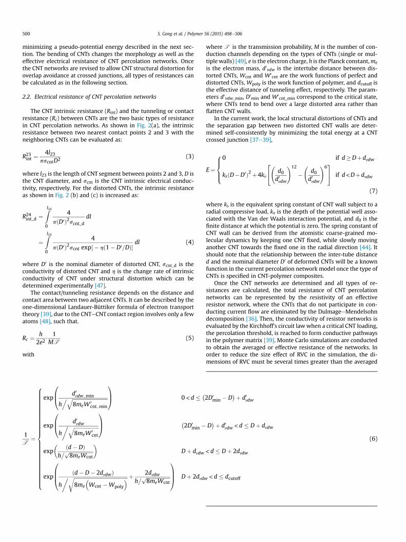
2.2. Electrical resistance of CNT percolation networks
The CNT intrinsic resistance (Rint) and the tunneling or contactresistance (Rc) between CNTs are the two basic types of resistancein CNT percolation networks. As shown in Fig. 2(a), the intrinsicresistance between two nearest contact points 2 and 3 with theneighboring CNTs can be evaluated as:
R23int ¼4l23
pscntD2 (3)
where l23 is the length of CNT segment between points 2 and 3, D isthe CNT diameter, and scnt is the CNT intrinsic electrical conduc-tivity, respectively. For the distorted CNTs, the intrinsic resistanceas shown in Fig. 2 (b) and (c) is increased as:
R24int_d ¼Zl240
4
pðD0Þ2scnt_ddl
¼Zl240
4
pðD0Þ2scnt exp½ � hð1� D0=DÞ�dl (4)
where D0 is the nominal diameter of distorted CNT, scnt_d is theconductivity of distorted CNT and h is the change rate of intrinsicconductivity of CNT under structural distortion which can bedetermined experimentally [47].
The contact/tunneling resistance depends on the distance andcontact area between two adjacent CNTs. It can be described by theone-dimensional Landauer-Büttiker formula of electron transporttheory [39], due to the CNTeCNT contact region involves only a fewatoms [48], such that.
Rc ¼ h2e2
$1
MT(5)
with
1T
¼
8>>>>>>>>>>>>>>>>>>>>>>>><>>>>>>>>>>>>>>>>>>>>>>>>:
exp
0B@ d0vdw min
h. ffiffiffiffiffiffiffiffiffiffiffiffiffiffiffiffiffiffiffiffiffiffiffiffiffiffiffiffi
8meW 0cnt min
q1CA 0<d � �
exp
0B@ d0vdw
h� ffiffiffiffiffiffiffiffiffiffiffiffiffiffiffiffiffiffiffiffi
8meW 0cnt
q1CA �
2D0min �
exp� ðd� DÞh� ffiffiffiffiffiffiffiffiffiffiffiffiffiffiffiffiffiffiffi
8meWcntp
�Dþ dvdw
exp
0BB@ ðd� D� 2dvdwÞh� ffiffiffiffiffiffiffiffiffiffiffiffiffiffiffiffiffiffiffiffiffiffiffiffiffiffiffiffiffiffiffiffiffiffiffiffiffiffiffiffiffiffiffi
8me
Wcnt �Wpoly
r þ 2dvdwh� ffiffiffiffiffiffiffiffiffiffiffiffiffiffiffiffiffiffiffi
8meWcntp
1CCA Dþ 2dvdw
where T is the transmission probability, M is the number of con-duction channels depending on the types of CNTs (single or mul-tiplewalls) [49], e is the electron charge, h is the Planck constant,me
is the electron mass, d0vdw is the intertube distance between dis-torted CNTs, Wcnt and W0
cnt are the work functions of perfect anddistorted CNTs, Wpoly is the work function of polymer, and dcutoff isthe effective distance of tunneling effect, respectively. The param-eters d0vdw_min, D0
min and W0cnt_min correspond to the critical state,
where CNTs tend to bend over a large distorted area rather thanflatten CNT walls.
In the current work, the local structural distortions of CNTs andthe separation gap between two distorted CNT walls are deter-mined self-consistently by minimizing the total energy at a CNTcrossed junction [37e39],
E¼
8>><>>:
0 if d�Dþdvdw
ksðD�D0Þ2þ4kv
24 d0
d0vdw
!12
�
d0d0vdw
!635 if d<Dþdvdw
(7)
where ks is the equivalent spring constant of CNT wall subject to aradial compressive load, kv is the depth of the potential well asso-ciated with the Van der Waals interaction potential, and d0 is thefinite distance at which the potential is zero. The spring constant ofCNT wall can be derived from the atomistic coarse-grained mo-lecular dynamics by keeping one CNT fixed, while slowly movinganother CNT towards the fixed one in the radial direction [44]. Itshould note that the relationship between the inter-tube distanced and the nominal diameter D0 of deformed CNTs will be a knownfunction in the current percolation network model once the type ofCNTs is specified in CNT-polymer composites.
Once the CNT networks are determined and all types of re-sistances are calculated, the total resistance of CNT percolationnetworks can be represented by the resistivity of an effectiveresistor network, where the CNTs that do not participate in con-ducting current flow are eliminated by the DulmageeMendelsohndecomposition [36]. Then, the conductivity of resistor networks isevaluated by the Kirchhoff's circuit lawwhen a critical CNT loading,the percolation threshold, is reached to form conductive pathwaysin the polymer matrix [39]. Monte Carlo simulations are conductedto obtain the averaged or effective resistance of the networks. Inorder to reduce the size effect of RVC in the simulation, the di-mensions of RVC must be several times greater than the averaged
2D0min � D
�þ d0vdw
D�þ d0vdw < d � Dþ dvdw
< d � Dþ 2dvdw
< d � dcutoff
(6)

Fig. 2. Typical CNT junctions formed by (a) straight CNTs, (b) flatten CNTs and (c) bent CNTs.
S. Gong et al. / Polymer 56 (2015) 498e506 501
CNT length. For instance, it has been found that an RVC of25 mm � 25 mm � 25 mm is sufficiently large for CNTs with anominal length of 5 mm [33]. In our work, the size of the RVC wasset as 10 times of the nominal CNT length and Monte Carlo simu-lation was carried 1000 times for every data point.
3. Results and discussion
3.1. Validation of new model of aligned CNT percolation network
Firstly, the newly proposed model of aligned CNT percolationnetwork is validated by experimental data of SWCNT/polymercomposites [50]. Fig. 3(a) shows the measured and simulatedelectrical conductivity of the SWCNT/polymer composites in thedirection parallel ‘jj’ to the CNT alignment. All the physical pa-rameters used in the analysis are shown in Fig. 3. The simulationresults of newlymodified percolation network model (MPNmodel)are in good agreement with the experimental data. As comparisons,the simulation results of existing percolation network model (PNmodel) are also plotted in Fig. 3. In PNmodel, CNTs were consideredeither as ‘‘soft-core” or “hard-core” [33e36]. The former led to aphysically incorrect CNT overlap or penetration at CNT junctions.The latter assumed CNTs as rigid and non-deformable tubes. Asshown in Fig. 3(b), all of these existing models ignored the effect ofCNT structural distortion at crossed-tube junctions. According toour results shown in Fig. 3(c), the structural distortion of CNTscould substantially increase the intrinsic resistance near junctions.On the other hand, the reduction of intertube distance at relaxedCNT junctions will result in a descent of contact resistance. For therelaxed SWCNT junctions, the total resistance near a structurallydistorted junction could be approximately two orders of magnitudehigher than that of a rigid junction, showing the importance of thestructural distortion at junctions on the electrical conductivity ofCNT/polymer composites.
Secondly, the new model of aligned CNT alignment is validatedby experimental data of SWCNT/polymer composites withdifferent CNT loadings in directions parallel ‘jj’ and perpendicular‘⊥’ to the CNT alignment. As shown in Fig. 4, the simulated elec-trical conductivity increases significantly around the CNT loading
of 0.5 wt.% in both two directions, which agrees well withexperimental data [51]. Higher conductivity is achieved in thiswell aligned (qmax ¼ 3�) CNT/polymer composite when measuredparallel to the alignment of CNTs. The electrical conductivity in theparallel direction is greater than that in the perpendicular direc-tion by at least three orders of magnitudes. This is because CNTsform conductive paths much easily in the CNT alignment directionthan the direction perpendicular to the alignment, where the CNTsare separated by insulated polymer, leading to lower electricalconductivity.
Finally, the numerical predictions of conductivities ofMWCNT/polymer composites with respect to CNT alignment atdifferent CNT loadings are shown in Fig. 5 together with exper-imental data [16]. Fig. 5(a) and (c) show the conductivitiesmeasured parallel and perpendicular to the alignment of CNTs,respectively. Fig. 5(b) and (d) are the corresponding 3D view oftotal conductivities as functions of maximum alignment angle(qmax) and CNT loading. Similar to the SWCNT/polymer com-posites, the main features shown in these figures can be sum-marized as follows:
(i) The electrical conductivity of CNT networks in the alignmentdirection shows a peak value for every CNT loading. Thesepeak values (dashed line in Fig. 5(a)) are higher than that ofuniformly distributed CNT networks (qmax ¼ 90�);
(ii) An inflection point (dotted line in Fig. 5(a)) appears on theconductivity curve measured parallel to the alignment ofCNTs at relatively lowmaximum alignment angles comparedto that of peak point;
(iii) The conductivity in the perpendicular direction increasessignificantly after reaching a certain maximum alignmentangle. This point is usually recognized as an alignment anglepercolation threshold (dashed line in Fig. 5c);
(iv) The peak and inflection points in the parallel direction, aswell as the alignment angle percolation threshold in theperpendicular direction, occur in the composites withsmaller qmax as the CNT loading increases,
(v) For a given qmax, higher CNT loading results in higher elec-trical conductivity in both two directions.

Fig. 4. Comparison of simulated electrical conductivity with experimental data [51]parallel and perpendicular to the alignment of CNTs.
Fig. 3. (a) Comparisons of experimental [50] and simulated electrical conductivitywith respect to CNT alignment angles. (b) Calculated intertube distance (dgap), diam-eter of distorted CNT (D0) and length of distorted tubes (l23) at junctions. (c) Calculatedcontact resistance (Rc) and intrinsic resistance (Rint) at junctions.
S. Gong et al. / Polymer 56 (2015) 498e506502
3.2. Mechanisms of anisotropic properties of aligned CNT/polymercomposites
The experimental data and analysis results in the previoussection show obviously the anisotropic electrical properties
between directions perpendicular and parallel to the alignment ofCNTs. Existing models [36] indicate that the conductive pathwayformed by CNTs and CNT junctions in the polymer matrix domi-nates the nanocomposite's electrical conductivity. Higher CNTloadings tend to generate more conductive pathway leading tohigher electrical conductivity of the nanocomposites. However,these indications are based on qualitative analysis, while the rela-tionship between the maximum alignment angle and conductivityare not shown fully.
In order to understand the mechanisms of the anisotropicproperties, the CNT percolation networks and its equivalent resis-tance networks are shown in Fig. 6. The resistance of CNT/polymercomposites is equal to the total resistance of the effective resistancenetworks. More importantly, the average conductive pathwaydensities of the cross sections in different directions can be quan-titatively calculated based on our new model of aligned CNTpercolation network, which provides an effectiveway to investigatethe mechanism of electrical conductivity properties.
For purpose of illustration, Fig. 7 shows the conductivity dataand the average conductive pathway densities of the compositeswith 1 wt.% CNT loading in both directions parallel and perpen-dicular to the CNTalignment. The range of themaximum alignmentangle (qmax) is from 0� to 90�. The insert in Fig. 7 shows the detailedresults for small alignment angles. The schematic structure of CNTnetwork and its effective resistance network at qmax ¼ 15� and 90�
are shown in Fig. 7(a) and (b), respectively. A lowest point, an in-flection point and a highest point appears on the conductivity curvein the parallel direction at qmax ¼ 5�, 30� and 60�, respectively. Themonotonous increase of conductivity in the perpendicular directionis observed in Fig. 7(a), and the alignment angle percolationthreshold is around qmax ¼ 20�. Compared Fig. 7(a) with Fig. 7(b), itshows clearly that the trend of conductive pathway density issimilar to that of electrical conductivity. The characteristic pointson the curves, included the lowest, inflection and highest points inthe parallel direction as well as the percolation threshold in theperpendicular direction, appear at the same maximum alignmentangles. The same phenomenon is also found for other CNT loadings.This indicates that the conductive pathway density is a keyparameter for the electrical conductivity of aligned CNT/polymercomposites. As such, it could be pointed out that the anisotropicelectrical conductivity of aligned CNT/polymer composites ismainly caused by the anisotropy of average conductive pathwaydensity, which varies with the CNT alignment state in thecomposites.
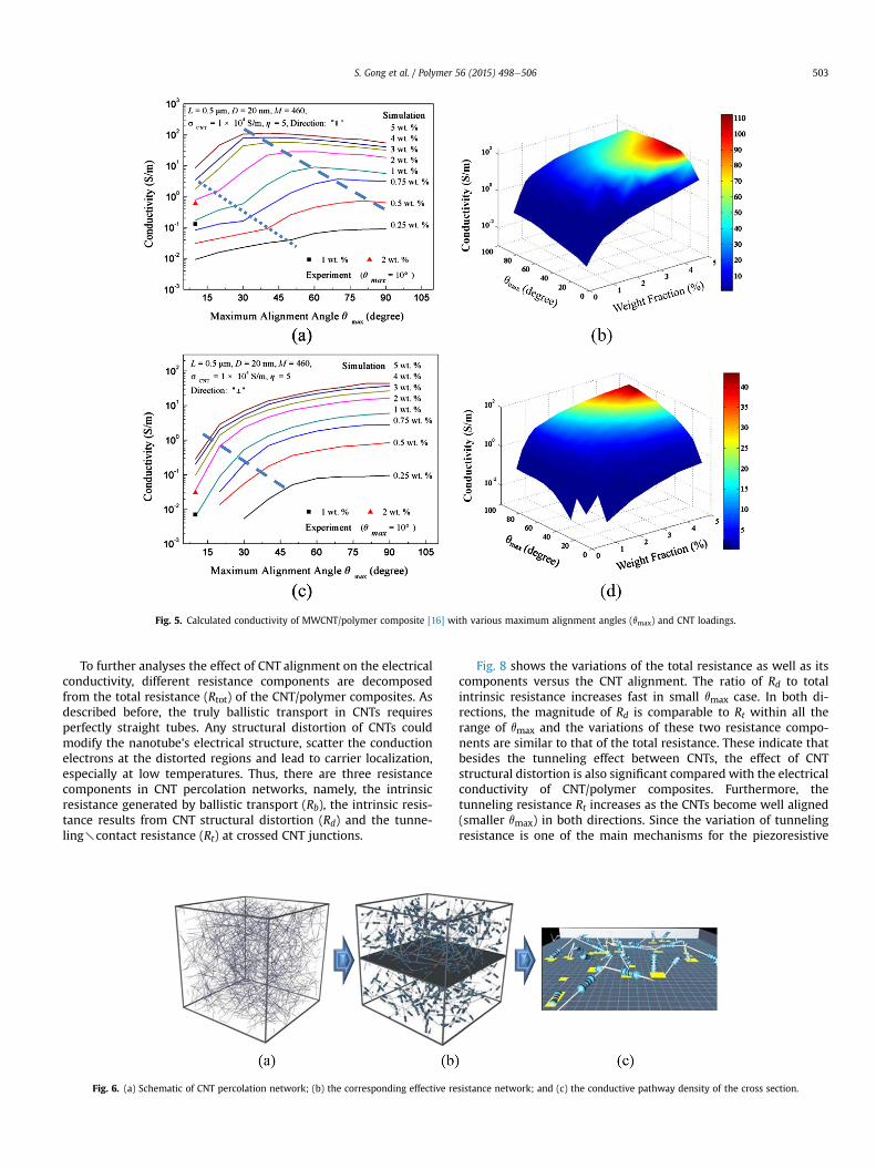
Fig. 5. Calculated conductivity of MWCNT/polymer composite [16] with various maximum alignment angles (qmax) and CNT loadings.
S. Gong et al. / Polymer 56 (2015) 498e506 503
To further analyses the effect of CNT alignment on the electricalconductivity, different resistance components are decomposedfrom the total resistance (Rtot) of the CNT/polymer composites. Asdescribed before, the truly ballistic transport in CNTs requiresperfectly straight tubes. Any structural distortion of CNTs couldmodify the nanotube's electrical structure, scatter the conductionelectrons at the distorted regions and lead to carrier localization,especially at low temperatures. Thus, there are three resistancecomponents in CNT percolation networks, namely, the intrinsicresistance generated by ballistic transport (Rb), the intrinsic resis-tance results from CNT structural distortion (Rd) and the tunne-lingycontact resistance (Rt) at crossed CNT junctions.
Fig. 6. (a) Schematic of CNT percolation network; (b) the corresponding effective re
Fig. 8 shows the variations of the total resistance as well as itscomponents versus the CNT alignment. The ratio of Rd to totalintrinsic resistance increases fast in small qmax case. In both di-rections, the magnitude of Rd is comparable to Rt within all therange of qmax and the variations of these two resistance compo-nents are similar to that of the total resistance. These indicate thatbesides the tunneling effect between CNTs, the effect of CNTstructural distortion is also significant compared with the electricalconductivity of CNT/polymer composites. Furthermore, thetunneling resistance Rt increases as the CNTs become well aligned(smaller qmax) in both directions. Since the variation of tunnelingresistance is one of the main mechanisms for the piezoresistive
sistance network; and (c) the conductive pathway density of the cross section.
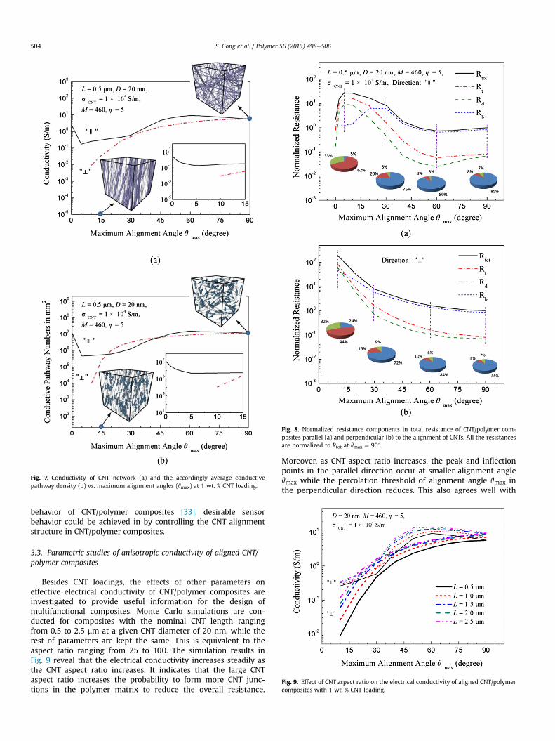
Fig. 7. Conductivity of CNT network (a) and the accordingly average conductivepathway density (b) vs. maximum alignment angles (qmax) at 1 wt. % CNT loading.
Fig. 8. Normalized resistance components in total resistance of CNT/polymer com-posites parallel (a) and perpendicular (b) to the alignment of CNTs. All the resistancesare normalized to Rtot at qmax ¼ 90� .
Fig. 9. Effect of CNT aspect ratio on the electrical conductivity of aligned CNT/polymercomposites with 1 wt. % CNT loading.
S. Gong et al. / Polymer 56 (2015) 498e506504
behavior of CNT/polymer composites [33], desirable sensorbehavior could be achieved in by controlling the CNT alignmentstructure in CNT/polymer composites.
3.3. Parametric studies of anisotropic conductivity of aligned CNT/polymer composites
Besides CNT loadings, the effects of other parameters oneffective electrical conductivity of CNT/polymer composites areinvestigated to provide useful information for the design ofmultifunctional composites. Monte Carlo simulations are con-ducted for composites with the nominal CNT length rangingfrom 0.5 to 2.5 mm at a given CNT diameter of 20 nm, while therest of parameters are kept the same. This is equivalent to theaspect ratio ranging from 25 to 100. The simulation results inFig. 9 reveal that the electrical conductivity increases steadily asthe CNT aspect ratio increases. It indicates that the large CNTaspect ratio increases the probability to form more CNT junc-tions in the polymer matrix to reduce the overall resistance.
Moreover, as CNT aspect ratio increases, the peak and inflectionpoints in the parallel direction occur at smaller alignment angleqmax while the percolation threshold of alignment angle qmax inthe perpendicular direction reduces. This also agrees well with

Fig. 10. Effect of CNT intrinsic conductivity on electrical conductivity of aligned CNT/polymer composites with 1 wt. % CNT loading.
S. Gong et al. / Polymer 56 (2015) 498e506 505
the variations of conductive pathway density in the respectivedirections.
Next, simulations are conducted for the CNT intrinsic conduc-tivity varying from 103 to 106 S/m, which is the typical range ofintrinsic conductivity reported experimentally for MWCNTs [36]. Itshows in Fig. 10 that the electrical conductivity in both directions isenhanced substantially as the CNT intrinsic conductivity increases.According to Eqs. (3) and (4), the intrinsic resistance resulting fromboth ballistic transport and CNT structural distortion decreases asthe intrinsic conductivity increases, leading to a lower total effec-tive resistance. All the characteristic points in both directionsappear at the same qmax, since the CNT network structure isunchanged.
Finally, the effect of polymer matrix property on the electricalconductivity is studied and shown in Fig. 11. The typical values ofwork functions of nylon 66, polystyrene, polycarbonate, and poly-imide are 3.95 eV, 4.22 eV, 4.26 eV, and 4.36 eV, respectively [39].Thus, four values (3.75, 4.00, 4.25, and 4.50 eV) of the work func-tions of polymers are selected for parametrical study. As shown inFig. 11, the effect of work functions of polymers is very limited inboth directions. This can be explained by Eqs. (5) and (6), whichindicate that the contact resistance is insensitive to the workfunctions of polymers.
Fig. 11. Effect of polymer work functions on the electrical conductivity of aligned CNT/polymer composites with 1 wt. % CNT loading.
4. Conclusions
The anisotropic electrical conductivity of aligned CNT/polymercomposites are studied by a newly developed percolation networkmodel. Compared with existing CNT percolation network models,there are two major improvements in the present model: (i) theCNTs are assumed distortable and the Van der Waals forces be-tween CNTs are considered to avoid CNT overlap, and (ii) theresistance induced by the CNT structural distortion is included inthe newmodel. With these improvements, simulation results are ingood agreement with experimental data. The analysis shows thatthe anisotropic electrical property of aligned CNT/polymer com-posites is mainly affected by the anisotropic average conductivepathway density, which varies with the CNT alignment state in thepolymer matrix. Moreover, some characteristic points are found inthe relationships between the anisotropic electrical conductivityand the maximum alignment angle. They are affected by the CNTloadings and aspect ratios. Finally, the decomposition of totalelectrical resistance CNT/polymer composites indicates that thealigned CNT structure can adjust the proportion of resistancecomponents in total resistance, which shows great potential indesigning smart sensing and multifunctional polymer composites.
References
[1] Yamamoto N, de Villoria RG, Wardle BL. Electrical and thermal propertyenhancement of fiber-reinforced polymer laminate composites throughcontrolled implementation of multi-walled carbon nanotubes. Compos SciTechnol 2012;72:2009e15.
[2] Vennerberg D, Hall R, Kessler MR. Supercritical carbon dioxide-assisted sila-nization of multi-walled carbon nanotubes and their effect on the thermo-mechanical properties of epoxy nanocomposites. Polymer 2014;55:4156e63.
[3] Moon D, Obrzut J, Douglas JF, Lam T, Koziol KK, Migler KB. Three dimensionalcluster distributions in processed multi-wall carbon nanotube polymer com-posites. Polymer 2014;55:3270e7.
[4] Puch F, Hopmann C. Morphology and tensile properties of unreinforced andshort carbon fibre reinforced Nylon 6/multiwalled carbon nanotube-com-posites. Polymer 2014;55:3015e25.
[5] Ajayan PM, Stephan O, Colliex C, Trauth D. Aligned carbon nanotube arraysformed by cutting a polymer resin-nanotube composite. Science 1994;265:1212e4.
[6] Sun W, Tomita H, Hasegawa S, Kitamura Y, Nakano M, Suehiro J. An array ofinterdigitated parallel wire electrodes for preparing a large scale nano-composite film with aligned carbon nanotubes. J Phys D Appl Phys 2011;44:445303e8.
[7] Bliznyuk VN, Singamaneni S, Sanford RL, Chiappetta D, Crooker B, Shibaev PV.Matrix mediated alignment of single wall carbon nanotubes in polymercomposite films. Polymer 2006;47:3915e21.
[8] White SI, Mutiso RM, Vora PM, Jahnke D, Hsu S, Kikkawa JM, et al. Electricalpercolation behavior in silver nanowireepolystyrene composites: simulationand experiment. Adv Funct Mater 2010;20:2709e16.
[9] Cebeci H, Villoria RG, Hart AJ, Wardle BL. Multifunctional properties of highvolume fraction aligned carbon nanotube polymer composites with controlledmorphology. Compos Sci Technol 2009;69:2649e56.
[10] Wardle BL, Saito DS, Garcı�a EJ, Hart AJ, Villoria RG, Verploegen EA. Fabricationand characterization of ultrahigh-volume-fraction aligned carbon nano-tubeepolymer composites. Adv Mater 2008;20:2707e14.
[11] Wang HY, Chang L, Yang XS, Yuan LX, Ye L, Zhu YJ, et al. Anisotropy intribological performances of long aligned carbon nanotubes/polymer com-posites. Carbon 2014;67:38e47.
[12] Oliva-Aviles AI, Aviles F, Sosa V. Electrical and piezoresistive properties ofmulti-walled carbon nanotube/polymer composite films aligned by an electricfield. Carbon 2011;49:2989e97.
[13] Martin CA, Sandler JKW, Windle AH, Schwarz MK, Bauhofer W, Schulte K,et al. Electric field-induced aligned multi-wall carbon nanotube networks inepoxy composites. Polymer 2005;46:877e86.
[14] Larijani MM, Khamse EJ, Asadollah Z, Asadi M. Effect of aligned carbonnanotubes on electrical conductivity behaviours in polycarbonate matrix. BullMater Sci 2012;35:305e11.
[15] Osazuwa O, Kontopoulou M, Xiang P, Ye ZB, Docoslis A. Electrically conductingpolyolefin composites containing electric field-aligned multiwall carbonnanotube structures: the effects of process parameters and filler loading.Carbon 2014;72:89e99.
[16] Kimura T, Ago H, Tobita M, Ohshima S, Kyotani M, Yumura M. Polymercomposites of carbon nanotubes aligned by a magnetic field. Adv Mater2002;14:1380e3.
S. Gong et al. / Polymer 56 (2015) 498e506506
[17] Kim IT, Lee JH, Shofner ML, Jacob K, Tannenbaum R. Crystallization kineticsand anisotropic properties of polyethylene oxide/magnetic carbon nanotubescomposite films. Polymer 2012;53:2402e11.
[18] Moaseri E, Karimi M, Baniadam M, Maghrebi M. Improvements in mechanicalproperties of multi-walled carbon nanotube-reinforced epoxy compositesthrough novel magnetic-assisted method for alignment of carbon nanotubes.Compos Part A 2014;64:228e33.
[19] Haslam MD, Raeymaekers B. Aligning carbon nanotubes using bulk acousticwaves to reinforce polymer composites. Compos Part B 2014;60:91e7.
[20] Chen W, Tao X. Production and characterization of polymer nanocompositewith aligned single wall carbon nanotubes. Appl Surf Sci 2006;252:3547e52.
[21] ChenW, Tao X. Self organizing alignment of carbon nanotube in thermoplasticpolyurethane. Macromol Rapid Commun 2005;26:1763e7.
[22] Akima N, Iwasa Y, Brown S, Barbour AM, Cao J, Musfeldt JL. Strong anisotropyin the far-infrared absorption spectra of stretch-aligned single-walled carbonnanotubes. Adv Mater 2006;18:1166e9.
[23] Shoji S, Suzuki H, Zaccaria RP, Sekkat Z, Kawata S. Optical polarizer made ofuniaxially aligned short single-wall carbon nanotubes embedded in a polymerfilm. Phys Rev B 2008;77:153407.
[24] Tsuda T, Ogasawara T, Moon SY, Nakamoto K, Takeda N, Shimamura Y, et al.Three dimensional orientation angle distribution counting and calculation forthe mechanical properties of aligned carbon nanotube/epoxy composites.Compos Part A 2014;65:1e9.
[25] Arras MML, Schillai C, Keller TF, Schulze R, Jandt KD. Alignment of multi-wallcarbon nanotubes by disentanglement in ultra-thin melt-drawn polymerfilms. Carbon 2013;60:366e78.
[26] Zamora-Ledezma C, Blanc C, Anglaret E. Controlled alignment of individualsingle-wall carbon nanotubes at high concentration in polymer matrices.J Phys Chem 2012;116:13760e6.
[27] Demir MM, Yilgor I, Yilgor E, Erman B. Electrospinning of polyurethane fibers.Polymer 2002;43:3303e9.
[28] Gupta P, Wilkes GL. Some investigations on the fiber formation by utilizing aside-by-side bicomponent electrospinning approach. Polymer 2003;44:6353e9.
[29] Cooper CA, Ravich D, Lips D, Mayer J, Wagner HD. Distribution and alignmentof carbon nanotubes and nanofibrils in a polymer matrix. Compos Sci Technol2002;67:1105e12.
[30] Berber S, Kwon YK, Tom�anek D. Unusually high thermal conductivity of car-bon nanotubes. Phys Rev Lett 2000;84:4613e6.
[31] Goh PS, Ismail AF, Ng BC. Directional alignment of carbon nanotubes inpolymer matrices: contemporary approaches and future advances. ComposPart A 2014;56:103e26.
[32] Du F, Fischer JE, Winey KI. Coagulation method for preparing single-walledcarbon nanotube/poly(methyl methacrylate) composites and their modulus,electrical conductivity, and thermal stability. J Polym Sci B: Polym Phys2003;41:3333e8.
[33] Hu N, Karube Y, Arai M, Watanabe T, Yan C, Li Y, et al. Investigation onsensitivity of a polymer/carbon nanotube composite strain sensor. Carbon2010;48:680e7.
[34] Theodosiou TC, Saravanos DA. Numerical investigation of mechanismsaffecting the piezoresistive properties of CNT-doped polymers using multi-scale models. Compos Sci Technol 2010;70:1312e20.
[35] Rahman R, Servati P. Effects of inter-tube distance and alignment ontunnelling resistance and strain sensitivity of nanotube/polymer compositefilms. Nanotechnology 2012;23:055703.
[36] Bao WS, Meguid SA, Zhu ZH, Pan Y, Weng GJ. A novel approach to predict theelectrical conductivity of multifunctional nanocomposites. Mech Mater2012;46:129e38.
[37] Gong S, Zhu ZH. On the mechanism of piezoresistivity of carbon nanotubepolymer composites. Polymer 2014;56:4136e49.
[38] Gong S, Zhu ZH, Meguid SA. Carbon nanotube agglomeration effect on pie-zoresistivity of polymer nanocomposites. Polymer 2014;55:5488e99.
[39] Gong S, Zhu ZH, Haddad EI. Modeling electrical conductivity of nano-composites by considering carbon nanotube deformation at nanotube junc-tions. J Appl Phys 2013;114:074303.
[40] Gu HB, Guo J, Yan XR, Wei HG, Zhang X, Liu JR, et al. Electrical transport andmagnetoresistance in advanced polyaniline nanostructures and nano-composites. Polymer 2014;55:4405e19.
[41] Gu HB, Zhang X, Wei HG, Huang YD, Wei SY, Guo ZH. An overview of themagnetoresistance phenomenon in molecular systems. Chem Soc Rev2013;42:5907e43.
[42] Ruoff RS, Tersoff J, Lorents DC, Subramoney S, Chan B. Radial deformation ofcarbon nanotubes by van der Waals forces. Nature 1993;364:514e6.
[43] Bower C, Rosen R, Jin L, Han J, Zhou O. Deformation of carbon nanotubes innanotubeepolymer composites. Appl Phys Lett 1999;74:3317e25.
[44] Yang X, He P, Gao H. Modeling frequency- and temperature-invariant dissi-pative behaviors of randomly entangled carbon nanotube networks undercyclic loading. Nano Res 2011;4:1191e8.
[45] Peng X, Tang F, Copple A. Engineering the work function of armchair graphenenanoribbons using strain and functional species: a first principles study. J PhysCondens Matter 2012;24:075501.
[46] Wang S, Liang Z, Wang B, Zhang C. Statistical characterization of single-wallcarbon nanotube length distribution. Nanotechnology 2006;17:634e9.
[47] Maiti A, Svizhenko A, Anantram MP. Electronic transport through carbonnanotubes: effects of structural deformation and tube chirality. Phys Rev Lett2002;88:126805.
[48] Datta S. Electronic transport in mesoscopic systems. Cambridge UniversityPress; 1997.
[49] Saito R, Dresselhaus G, Dresselhaus MS. Physical properties of carbon nano-tubes. London: Imperial College; 1998.
[50] Du F, Fischer JE, Winey KI. Effect of nanotube alignment on percolation con-ductivity in carbon nanotube/polymer composites. Phys Rev B 2005;72.121404e4.
[51] Wang Q, Dai J, Li W, Wei Z, Jiang J. The effects of CNT alignment on electricalconductivity and mechanical properties of SWNT/epoxy nanocomposites.Compos Sci Technol 2008;68:1644e8.