Lifetimes of Stratospheric Ozone-Depleting Substances, Their ...
Upload
khangminh22Category
view
1download
0
CONTRIBUTION NO. 1020 / December 2020
Study of Per- and Polyfluoroalkyl Substances in Bay Area POTWs: Phase 1 Sampling and Analysis PlanPrepared by:
Miguel Mendez, Diana Lin, and Rebecca Sutton San Francisco Estuary Institute
San Francisco Estuary Institute • 4911 Central Ave., Richmond, CA • www.sfei.org
Study of Per- and Polyfluoroalkyl Substances in Bay Area POTWs: Phase 1
Sampling and Analysis Plan
San Francisco Estuary Institute 4911 Central Avenue Richmond, CA 94804
Contribution #: 1020
Study of PFAS in Bay Area POTWs: Phase 1 SAP - 11/23/2020 - Final
1. Introduction 3
2. Key Personnel and Approvals 5
3. Sampling Schedule 7
4. Sampling Procedure 8
4.1 General Sampling Guidelines 8
4.2 Sample Equipment: Acceptable and Prohibited Materials 9
4.3 Sample Equipment Cleaning and Decontamination Procedures 11
4.4 Aqueous Sampling Guidelines 12
4.5 Biosolids Sampling Guidelines 17
5. Sampling Sites 20
6. Sample Labeling 20
7. Sample Handling and Custody 20
8. Laboratory Analytical Methods 21
9. Quality Control Requirements 24
10. Data Management 25
11. Reporting 25
12. Data Validation and Usability 26
13. References 26
27
31
36
40
Appendix A: Field Sampling Forms
Appendix B: Shipping Instructions
Appendix C: Supplementary Information Tables
Appendix D: POTW Process Diagrams
Appendix E: DOD QSM, Version 5.3 57

Study of PFAS in Bay Area POTWs: Phase 1 SAP - 11/23/2020 - Final
1. IntroductionThis Sampling and Analysis Plan (SAP) details the plan associated with the Per- and Polyfluoroalkyl Substances Monitoring for Bay Area Publicly-Owned Treatment Works, Phase 1: Study design, coordination of sample collection, data quality assurance and reporting. This study was developed to investigate per- and polyfluoroalkyl substances (PFAS) in matrices from Bay Area publicly-owned treatment works (POTWs) to inform the monitoring strategy and program decisions for the Regional Monitoring Program for Water Quality in San Francisco Bay (RMP) and address monitoring needs for the State Water Board. The study is a two-part study, and this plan details the tasks associated with Phase 1 of the study. Phase 1 will analyze samples from a representative set of Bay Area POTWs to measure concentrations of PFAS in wastewater influent, effluent, biosolids, and reverse osmosis concentrate (ROC). Phase 2 (currently planned for summer 2021) will be informed by results from Phase 1 and will also include sampling of tertiary recycled water.
The objective of Phase I is to analyze samples from a representative set of Bay Area POTWs to measure concentrations of PFAS in wastewater influent, effluent, biosolids, and ROC. Since some Bay Area POTWs are moving towards recycling water, sampling ROC will provide data on PFAS concentrations in ROC and inform management actions. The POTWs included in this SAP were carefully selected to be representative of various characteristics of Bay POTWs, providing a representative sample set to analyze the range of PFAS concentrations in wastewater matrices and various characteristics that may influence PFAS concentration that could be later investigated. Service populations represented in the sample set range from entirely residential to those with notable industrial discharges. This sampling set was selected based on consideration of the following factors:
● Discharge volume: Sampling at the largest facilities is prioritized in order to capture dominantflows to the Bay. A few medium and small size facilities are also represented.
● Service population and industries: Chosen facilities include those with minimal industrialsources as well as those with a greater percentage of flows coming from industrial sources,particularly sources related to fabricated metals, electronic manufacturing, airports, andmilitary bases.
● Participation in previous Bay RMP PFAS study in 2014: All facilities that participated inthe previous PFAS study are included to evaluate changes in specific PFAS concentrations.
● Treatment type: Different secondary treatment technologies, including advanced secondarytreatment processes, are included to understand potential impacts of the treatment processes onPFAS.
● Geographic location: Selected facilities are geographically diverse and represent allsubembayments.
The specific characteristics of each facility can be found in Appendix C. All facilities will collect grab samples of each matrix. A subgroup of facilities will concurrently collect composite samples to compare to grab samples and inform an understanding of the differences between the sampling methodologies. All samples will be analyzed for targeted PFAS compounds listed in Section 8 (Laboratory and Analytical Methods). Terminal PFAS in influent and biosolids samples after oxidation will also be analyzed to
Study of PFAS in Bay Area POTWs: Phase 1 SAP - 11/23/2020 - Final
understand the presence of important precursors and indicate the presence of other PFAS that may need to be identified and quantified. These efforts will help inform sampling design for Phase 2.
The specific objectives of the sampling effort are:
1. Collect influent, effluent, and biosolids samples for PFAS target and Total Oxidizable Precursors (TOP) analyses from the following POTWs:
○ Central Contra Costa Sanitary District (CCCSD)○ City of San Mateo Wastewater Treatment Plant (CSM)○ Dublin San Ramon Services District (DSRSD)○ East Bay Municipal Utility District Main Wastewater Treatment Plant (EBMUD)○ Fairfield-Suisun Sewer District (FSSD)○ Novato Sanitary District (NSD)○ Oceanside Water Pollution Control Plant (OSP), SFPUC○ Palo Alto Regional Water Quality Control Plant (PA)○ San Francisco International Airport Mel Leong Treatment Plant (SFO-S)○ San Francisco International Airport Mel Leong Treatment Industrial Plant (SFO-I)○ San Jose-Santa Clara Regional Wastewater Facility (SJ-SC)○ Southeast Water Pollution Control Plant (SEP), SFPUC○ Union Sanitary District (USD)○ Vallejo Flood & Wastewater District (VFWD)
2. Collect effluent samples at East Bay Dischargers Authority (EBDA) for PFAS target analyses. EBDA receives treated wastewater effluent from several POTWs, including Union Sanitary and Dublin San Ramon Services District, which are included in this study. EBDA also receives effluent from the City of San Leandro, Oro Loma Sanitary District, Castro Valley, City of Hayward, Livermore-Amador Valley Water Management Agency, serving the Cities of Pleasanton and Livermore and DSRSD. Sampling discharges at EBDA provides the opportunity to sample the combined flows from all these POTWs at one sampling location. Sampling at the individual facilities (USD and DSRSD) will provide information about PFAS changes through the treatment process and evaluation of the results with the service population.
3. Collect reverse osmosis concentrate (ROC) at Valley Water (VW) and DSRSD for PFAS target analyses. Valley Water produces purified water at its Advanced Water Purification Facility(AWPF) by treating secondary effluent from SJ-SC through microfiltration, reverse osmosis, and ultraviolet disinfection. Reverse osmosis concentrate (ROC) is the reject water from the AWPF, which is currently mixed with advanced secondary treated effluent from SJ-SC before discharge to the Bay. In this study, ROC from the AWPF is collected for PFAS analysis. DSRSD receives ROC from Zone 7, which is mixed with effluent from DSRSD effluent before it is transported to EBDA. In this study, ROC from Zone 7 which will be collected at DSRSD and analyzed for PFAS separately from DSRSD secondary treated effluent. Schematic diagrams of sampling locations relative to treatment processes and flows are shown in Appendix D.

Study of PFAS in Bay Area POTWs: Phase 1 SAP - 11/23/2020 - Final
The RMP’s Quality Assurance Program Plan (QAPP) (Yee et al., 2019) for field sampling design and analysis and Department of Defense (DoD) Table B-15 of Quality Systems Manual (QSM), version 5.3 for laboratory analysis of PFAS (DOD and Department of Energy (DOE), 2019), will be applied to this study unless otherwise stated. A short summary of relevant QAPP program requirements are included in this SAP for easy reference and review.
2. Key Personnel and ApprovalsThe personnel who will approve this SAP before it is finalized are shown in Table 1.
Table 1. Key Personnel Approvals for this SAP.
The personnel who should be contacted in case of any questions regarding this SAP are shown in Table 2.
Table 2. Key Personnel for PFAS sampling 2020 Contact
Name Affiliation Duties Initial and Date to Indicate Approval of Plan
Diana Lin SFEI Project Manager/Lead Scientist DL
Rebecca Sutton SFEI Lead Scientist RAS 2020-11-23
Don Yee SFEI RMP QA Officer DY 2020-11-16
Adam Wong SFEI RMP Data Manager AW-2020-11-23
Lorien Fono BACWA Executive Director
Wendy Linck State Water Board Senior Engineering Geologist
Richard Grace SGS AXYS Director - Sales, Marketing, and Service RG
Sean Campbell SGS AXYS Business and Technical Consultant SC
Name Affiliation Duties Contact Information (email/phone/cell)
Diana Lin SFEI Project Manager/Lead Scientist
[email protected] (510) 746-7385 / (714) 932-8085
Miguel Mendez SFEI Environmental Analyst [email protected]
(510) 746-7319 / (773) 698-5472
WL-2020-12-1
LF-2020-12-2

Study of PFAS in Bay Area POTWs: Phase 1 SAP - 11/23/2020 - Final
The personnel who should be contacted at each participating POTW in case of any questions regarding PFAS monitoring are shown in Table 3.
Table 3. POTW Contact Information
Adam Wong SFEI RMP Data Manager [email protected] (510) 746-7309
Name Affiliation Title/Duties Contact Information (email/phone)
Blake Brown CCCSD Senior Chemist [email protected] (925) 229-7237
Mary Lou Esparza CCCSD Laboratory Superintendent [email protected]
(925) 335-7751
Tim Potter CCCSD Environmental
Compliance Superintendent
[email protected] (925) 229-7380
Xiongbing Liang CSM Laboratory Supervisor [email protected]
(650) 522-7388
Connie Sanchez DSRSD Senior Chemist [email protected]
925-875-2325
Angie Berumen EBDA City of San Leandro
Lab Manager [email protected]
(510) 577-6042
Jackie Zipkin EBDA General Manager [email protected] (510) 206-3820
Alicia Chakrabarti EBMUD Manager of WW
Environmental Services [email protected]
(510) 287 2059
Nicole Van Aken FSSD Laboratory Manager [email protected]
(707) 428-9153
Liz Falejczyk NSD Environmental Services
Supervisor, Veolia Water at NSD
[email protected] (415) 892-1694 (ext 119)
Jennie Pang OSP & SEP Regulatory Specialist
(SFPUC WWE) [email protected]
(415) 934- 5762

Study of PFAS in Bay Area POTWs: Phase 1 SAP - 11/23/2020 - Final
The personnel who should be contacted at SGS AXYS in case of any questions on analysis of PFAS are shown in Table 4.
Table 4. Laboratory Contact Information
3. Sampling ScheduleTable 5. Anticipated Schedule for 2020 BACWA PFAS Study, Phase 1
Samantha Bialorucki PA Lab Manager [email protected]
(650) 329-2334
Samantha Engelage PA Senior Engineer [email protected]
(650) 329-2123
Suguna Pillay PA Senior Chemist [email protected]
Jennifer Acton SFO-S & SFO-I Acting Utility Manage
[email protected] (650) 821-8380
Eric Dunlavey SJ-SC Wastewater Compliance Manager
[email protected] (408) 635-4017
Tim Grillo USD Research and
Support Coach [email protected]
(510) 477-7561
Dan Jackson USD Lab Director [email protected]
(510) 517-1413
Anita Setty VFWD Environmental Services Superintendent
[email protected] (707) 652-7825
Medi Sinaki VW Senior Engineer [email protected]
(408) 630-2280
Lab / Company Name Phone Email Shipping Address
SGS AXYS Sean Campbell (250) 655-5834 [email protected] 2045 Mills Rd W V8L5X2 Sidney, British Columbia, CA
Date Activity
October 20, 2020 Draft Sampling and Analysis Plan
November 2020 Final Sampling and Analysis Plan

Study of PFAS in Bay Area POTWs: Phase 1 SAP - 11/23/2020 - Final
*Dates are subject to change based on adjustments to sampling plans
4. Sampling ProcedureThe following guidelines were adapted using guidance from California State Water Quality Control Board (California State Water Resources Control Board, 2020), Michigan Department of Environmental Quality (Michigan Department of Environmental Quality, 2018) and current literature on PFAS background contamination (Bartlett and Davis, 2018; Rodowa et al., 2020). Recent studies examining sources of PFAS contamination during sampling indicate background contamination may not be as common as previously suggested. To be consistent with published guidance, previous studies, and in an abundance of caution, several materials are best avoided if they do not compromise safety or practicality.
4.1 General Sampling Guidelines
At each POTW, samples should be collected in the following order. The purpose of this order is to avoid contamination of samples by collecting the cleanest sample first.
1. Effluent or ROC (if applicable)2. Influent3. Biosolids
Site Set-Up The sampling site should be evaluated prior to sampling to identify potential contamination risks and to select dedicated staging and sampling areas as defined below:
1. Eating Area: The eating area is separate from the sampling and staging areas, and the only placewhere food and drink should be stored and consumed. Food packaging must not be in thesampling and staging areas during sampling due to the potential for PFAS cross-contamination.
November 6 - December 18, 2020
Sample Collection. Avoid sampling on the week of November 23 to prevent shipping issues related to the Thanksgiving holiday.
*Sampling during precipitation events expected to cause inflow andinfiltration should be avoided to limit dilution of the wastewater signal.Sampling can resume when wastewater flows return to dry weatherconditions. The precipitation criteria will be different for each facility.
February 2021* Expected completion of analyses
Laboratory analytical results are expected within 6 weeks of receiving final samples from facilities.
February - April 2021* SFEI will upload analytical results to GeoTracker on behalf of facilities within 60 days of receiving final analytical results. SFEI will upload a monitoring report to GeoTracker within 90 days of receiving the final laboratory analytical report.
Summer 2021* SFEI will provide a technical memo describing results of Phase 1 of this study

Study of PFAS in Bay Area POTWs: Phase 1 SAP - 11/23/2020 - Final
2. Staging Area: The staging area is where equipment is set-up and personal protective equipment isput on and taken off. PFAS-free over-boots and PPE should be put on in the staging area prior tosampling activities.
3. Sampling Area: Sampling areas are the areas of the field where samples are collected. When staffneed to leave the site, they should move to the staging area before removing gloves, coveralls,and any other appropriate PPE, if worn.
Sample Collection Most samples for this study will be collected via grab sampling to minimize background contamination, increase method consistency, and best ensure each facility has the capabilities to meet sampling needs. Grab samples will be collected during each facility’s peak flow. Collection during peak flow is expected to be more representative of total flows entering the POTW compared to other non-peak flow times. To compare the representativeness of grab samples collected during peak flow with 24-hour composites, a few facilities (CCCSD, FSSD, and SFO-I) will also be collecting daily composite influent and effluent samples. This will aid in understanding how grab samples compare with 24-hour composites in representing influent and effluent PFAS concentrations, while informing future sampling design.
Field Sampling Form For all sampling events, please fill out the associated (aqueous or biosolids) field sampling form shown in Appendix A. The information requested specifically relates to each sampling event including sampling equipment used, procedures followed, and daily conditions at the POTW. Field sampling forms will be sent as excel files to each facility and include sampling IDs. The form may be completed after each sampling event and once all information requested is available. Please send completed forms to [email protected] and [email protected].
4.2 Sample Equipment: Acceptable and Prohibited Materials
The typical field sampling environment has many potential sources of PFAS including sampling equipment, field documentation, personal protective equipment, clothing, and personal care products. As this can lead to background contamination, common materials in the field sampling environment have been separated into three categories as defined below:
Acceptable Materials: These materials are known not to be sources of PFAS cross contamination and can be used during all sampling stages and in the immediate sampling environment.
Staging area-only materials: These materials may contain PFAS and should not come into direct contact with the sample. These materials can be used in the staging area, but should be used away from all sampling equipment. Thoroughly wash hands and use new gloves after handling any of these materials.
Prohibited materials : These materials are known to contain PFAS that may present a threat to sample integrity and should not be used during any stage of the sampling events.
Each facility has been provided with a PFAS field sampling kit including sample containers and shipping materials to collect and ship all requested samples. The contents of each kit shipped to participating POTWs is found in Appendix B.
Study of PFAS in Bay Area POTWs: Phase 1 SAP - 11/23/2020 - Final
All Sampling Equipment
Prohibited: Any and all sampling equipment that contain PFAS-based (fluoropolymer) parts that would be in direct contact with the sample or sampling environment. These fluoropolymers include, but are not limited to:
● Polytetrafluoroethylene (PTFE), including the trademark Teflon® and Hostaflon®, which can bein the ball lining of some hoses and tubing, and some objects that require the sliding action ofparts.
● Polyvinylidene fluoride (PVDF), including the trademark Kynar®, which can be in tubing andfilms/coatings on aluminum, galvanized or aluminized steel.
● Polychlorotrifluoroethylene (PCTFE), including the trademark Neoflon®, which can be in manyvalves, seals, and gaskets.
● Ethylene-tetrafluoro-ethylene (ETFE), including the trademark Tefzel®, which can be in manywire and cable insulation and covers, liners in pipes, and some cable tie wraps.
● Fluorinated ethylene propylene (FEP), including the trademarks Teflon® FEP and Hostaflon®FEP, and may also include Neoflon®, which can be in wire and cable insulation and covers, pipelinings, and some labware.
Staging area-only: Low density polyethylene (LDPE) should be avoided if it comes into direct contact with the sample. If absolutely necessary, LDPE parts may be used if an equipment blank has confirmed it is PFAS-free. LDPE resealable storage bags (i.e., Ziploc bags) may be used for storage and shipping.
Sample Containers Acceptable: High-density polyethylene (HDPE) containers of various sizes (500 mL, 250 mL, 125 mL, and/or 60 mL) provided by SGS AXYS.
Pumps, Tubing and Sampling Instruments Acceptable: Supplies must be made from acceptable materials known to be PFAS free, which include HDPE, polypropylene, silicone, stainless steel, nylon (e.g., cable ties), polyvinyl chloride (PVC), acetate, and cotton. Glass may be used as long as it is known to be PFAS-free (or decontaminated; see Section 4.3) and comes into contact with the sample for a short period of time (not appropriate for storage).
To collect composite samples, automatic samplers may be used though there may be an increased potential for cross-contamination because the tubing, valves, strainers, suction lines, distribution nozzles, and other parts may be made from PFAS (fluoropolymers). It is recommended that parts on the sampler be screened prior to sampling by reviewing the safety data sheets (if available) and collection of an equipment blank to verify that the parts are PFAS-free.
Field Documentation Acceptable: Ballpoint pens and Sharpie® markers (only fine or ultra-fine) for writing and labeling. Loose paper (non-waterproof, non-recycled) as well as aluminum, polypropylene, or Masonite field clipboards may be used.
Staging area-only: Rite in the Rain® notebooks, provided gloves are changed after note taking.
Prohibited: Regular and thick sized markers of any brand, sticky notes, plastic clipboards, or waterproof paper and notebooks.
Study of PFAS in Bay Area POTWs: Phase 1 SAP - 11/23/2020 - Final
Personal Protective Equipment and Other Clothing Acceptable: Synthetic or 100% cotton clothing that has been well-laundered without the use of fabric softeners. Any clothing (including shoes) made of or with polyurethane, PVC, wax coated fabrics, rubber and neoprene. Powderless nitrile gloves for all sampling events.
Staging area-only: Non PFAS-free boots and first aid adhesive wrappers.
Prohibited: Latex gloves, new or unwashed clothing, any clothes recently treated with fabric softeners, fabric protectors, insect resistance and water/stain/dirt-resistant chemicals. Anything made with water/stain/dirt-resistant fabrics such as Coated Tyvek®, Gore-Tex®, ScotchgardTM, and RUCO®.
Personal safety is paramount and should not be compromised to prevent cross-contamination. Therefore, if the use of PPE is necessary to ensure the health and safety of sampling personnel and no PFAS-free alternative is available, then note the use in the field sampling form. Please wash hands and change gloves after handling any PFAS containing products (including items designated only to the staging-area).
Personal Care Products Staging area-only: Sunscreens and insect repellents. preferably from products known to not contain PFAS (nonexhaustive list provided from the Michigan PFAS Sampling Quick Reference Field Guide).
Prohibited: Application of any PCPs in the sampling area.
If possible, please try to avoid use of personal care products (hair products, make-up, perfume/cologne, moisturizers, etc.) on the day of sampling. If any are used on the day of sampling, record in the field sampling form.
Food Packaging Materials Prohibited: PFAS are known to be prevalent in food packaging, including paper plates, aluminum foil, paper towels, food containers, bags, and wraps. Food and beverages should not be consumed at the sampling site. If they must be consumed during the sampling event, a dedicated eating area should be identified (see section 4.1).
4.3 Sample Equipment Cleaning and Decontamination Procedures
Sample equipment that comes into contact with the sampling media (i.e., buckets, carboys, extension rods, scoops, tubing, parts of automatic samplers) should be cleaned and decontaminated (or new) prior to use where possible. Automatic samplers should be decontaminated, or the strainer replaced between each sampling event. If new tubing is used, decontamination procedures are not necessary. Sampling equipment can be scrubbed using a polyethylene or PVC brush to remove particulates.
The following procedure is recommended for cleaning and decontamination: Wash with PFAS-free soap (i.e., Alconox®), scrub (if applicable). Follow up with a methanol rinse and rinse with PFAS free water. The laboratory will provide PFAS free reagent water for a final rinse collected for an equipment blank. Please note if this, or any other cleaning method, has been used in the field sampling form.

Study of PFAS in Bay Area POTWs: Phase 1 SAP - 11/23/2020 - Final
4.4 Aqueous Sampling Guidelines
Tables 6 and 7 detail the aqueous samples each POTW will be collecting for PFAS analysis. The contents of the table as they relate to sample guidelines are summarized below:
The following facilities will focus only on grab sampling for influent, effluent, and/or ROC: ● City of San Mateo Wastewater Treatment Plant (CSM)● Dublin San Ramon Services District (DSRSD)● East Bay Dischargers Authority (EBDA),● East Bay Municipal Utility District Main Wastewater Treatment Plant (EBMUD)● Novato Sanitary District (NSD)● Oceanside Water Pollution Control Plant (OSP)● Palo Alto Regional Water Quality Control Plant (PA)● Southeast Water Pollution Control Plant (SEP) ● San Francisco International Airport Mel Leong Treatment Plant (SFO-S)● Vallejo Flood & Wastewater District (VFWD)● Valley Water (VW)
Two facilities will conduct grab sampling of influent and effluent with additional collection of duplicate and/or equipment blank samples:
● San Jose-Santa Clara Regional Wastewater Facility (SJ-SC)● Union Sanitary District (USD)
The remaining facilities will run both grab and composite sampling for influent and effluent while also taking duplicates (grab and composite), field blanks, and equipment blanks:
● Central Contra Costa Sanitary District (CCCSD)● Fairfield-Suisun Sewer District (FSSD)● San Francisco International Airport Mel Leong Treatment Industrial Plant (SFO-I)
The following protocols should be followed when collecting any aqueous PFAS samples: ● Powderless nitrile gloves must be worn on hands before collecting samples, handling sample
containers, or handling sampling equipment.● The sample container must be kept sealed and only opened during sample collection. The
sampling container cap or lid should never be placed on the ground or on any other surface unlessit is PFAS-free. If it is necessary to set the cap down, it should be set on a clean surface (cottonsheeting, HDPE sheeting, triple rinsed cooler lid, etc.).
● Do not insert or let tubing or any materials inside the sample bottle. Dust and fibers must be keptout of sample bottles.
● Samples containers should be filled to 80-90% capacity (providing 10-20% volume headspace) toallow for expansion during freezing (all samples will be frozen upon receipt at the laboratory).Final volumes should correspond to roughly 400-450 mL (500 mL container), 100-110 mL (125mL), and 48-55 mL (60 mL).

Table 6. Influent Samples collected at each POTW.
Facility
Influent Grab
(125 mL)
Influent Grab
Duplicate(125 mL)
Influent Grab
Back-Up(125 mL)
Influent Grab + Backup
(60 mL)
Influent Composite (125 mL)
Influent Composite Duplicate(125 mL)
Influent Composite Back-Up(125 mL)
Influent Field Blank
(Pre-filled 500 mL)
Influent Equipment Blank
(500 mL)Total Influent
Samples Collected
PFAS Target Analysis PFAS TOP Analysis PFAS Target Analysis QA/QCCCCSD 2 1 3 2 2 1 3 1 1 16
CSM 1 - 1 2 - - - - - 4DSRSD 1 - 1 2 - - - - - 4
EBMUD 1 - 1 2 - - - - - 4FSSD 2 1 3 2 2 1 3 1 2** 17NSD 1 - 1 2 - - - - - 4OSP 1 - 1 2 - - - - - 4PA 1 - 1 2 - - - - - 4SEP 1 - 1 2 - - - - - 4
SFO-S 1 - 1 2 - - - - - 4SFO-I 2 1 3 2 2 1 3 1 1 16SJ-SC 1 4* 1 2 - - - - - 8USD 1 - 1 4^ - - - - 1 7
VFWD 1 - 1 2 - - - - - 4Sample container size noted in parenthesis. Sample containers should be filled with 10-20% headspace to allow for expansion upon freezing.Facilties highlighted in blue are collecting grab and composite samples to compare sampling methods* Sampling includes two Matrix Spike (MS) and two Matrix Spike Duplicate (MSD)**Sampling includes an equipment blank from the composite sampler and an equipment blank from the stainless steel bucket used to collect the grab sample.^Sampling includes a duplicate influent grab and back-up that will be used for TOP analysis.

Table 7. Effluent Samples collected at each POTW.
Facility
Effluent Grab
(500 mL)
Effluent Grab
Duplicate(500 mL)
Effluent Grab
Back-Up(500 mL)
Effluent Composite (500 mL)
EffluentComposite Duplicate(500 mL)
Effluent Composite
Back-up(500 mL)
Effluent Field Blank
(Pre-filled 500 mL)
Effluent Equipment Blank
(500 mL)Total Effluent
Samples Collected
PFAS Target Analysis QA/QCCCCSD 2 1 3 2 1 3 1 1 14
CSM 1 - 1 - - - - - 2DSRSD 2** - 2** - - - - - 4EBDA 1 - 1 - - - - - 2
EBMUD 1 - 1 - - - - - 2FSSD 2 1 3 2 1 3 1 1 14NSD 1 - 1 - - - - - 2OSP 1 - 1 - - - - - 2PA 1 - 1 - - - - - 2SEP 1 - 1 - - - - - 2
SFO-S 1 - 1 - - - - - 2SFO-I 2 1 3 2 1 3 1 1 14SJ-SC 1 4* 1 - - - - - 6USD 1 - 1 - - - - 1 3
VFWD 1 - 1 - - - - - 2VW 2 1 3 - - - - - 6
Sample container size noted in parenthesis. Sample containers should be filled with 10-20% headspace to allow for expansion upon freezing.Facilties highlighted in blue are collecting grab and composite samples to compare sampling methodsFacilties highlighted in gray are collecting reverse osmosis concentrate (ROC)* Sampling includes two Matrix Spike (MS) and two Matrix Spike Duplicate (MSD)** Sampling includes one effluent sample and one ROC sample

Study of PFAS in Bay Area POTWs: Phase 1 SAP - 11/23/2020 - Final
Grab Sampling Influent and effluent samples will be collected during peak flow at each facility to ensure capture of dominant flows. Wastewater influent and effluent will be directly collected in HDPE containers (500 mL, 125 mL or 60 mL) provided by SGS AXYS. If this is not possible, a beaker made of a known PFAS-free material (examples of allowable materials listed above) may be used to pour into the HDPE container. It is acceptable to collect chlorinated effluent samples and ship to the laboratory without any further treatment. Please note if samples are chlorinated in the field sampling form.
Various types of immersion sampling equipment may be used for sampling. Equipment used must be PFAS-free (see section 4.2), new or decontaminated (see section 4.3), and may include extension rods to immerse the laboratory sample bottle at the sample location, cable ties, beakers, and peristaltic pumps with tubing that extends into the wastewater. If the sampling bottle can not be used to directly sample, a sampling port or pump may be used instead. Sampling locations for all facilities are shown in process diagrams in Appendix D. Please document the use of any equipment or materials that come in direct contact with the sample and any change in sampling location in the field sampling form.
Weekend flow patterns at POTWs tend to be different from weekday flows patterns due to differences in activities from the serviced population. Samples should be collected at peak flow on a weekday to capture representative weekday flows. Sampling should be avoided on weekends and Mondays, because Mondays may be influenced by weekend flows. If samples are collected on Thursday or Friday, please freeze samples and ship to SGS AXYS on Monday.
Influent Influent samples should be collected at a location and in a manner that is representative of all influent received by the facility prior to treatment. Influent samples should be collected in a well mixed location prior to primary settling, which include but are not limited to the headworks of the inlet to the grit chamber or prior to any biological treatment. If possible, samples should be collected after bar screening and grit removal but before fine screening to obtain a representative influent sample. Please note any treatment processes before the influent sampling location in the field sampling form. The sampling location is also marked in the facility diagrams in Appendix D.
Each 125 mL influent field sample will have a back-up sample collected in a separate 125 mL HDPE container. In addition, two 60 mL samples will be collected to conduct TOP analysis. This means each influent grab sampling event will consist of two 125 mL samples and two 60 mL samples (both PFAS target and TOP analysis will be conducted on influent samples). Since collecting a 60 or 125 mL grab sample directly into a container may be difficult, it is suggested that the sample can be poured off from a larger beaker. A 500 mL HDPE container (extras provided) could be used to pour into a smaller container.
Effluent Effluent should be collected at a location and in a manner that is representative of final effluent discharged to receiving waters. Only 500 mL effluent samples will be collected (PFAS target analysis will be conducted on effluent samples). Each 500 mL effluent field sample will have a 500 mL back-up collected.
Study of PFAS in Bay Area POTWs: Phase 1 SAP - 11/23/2020 - Final
ROC ROC samples should be collected at a location and in a manner that is representative of the final ROC discharged to receiving waters. A grab sample and field duplicate will be collected on the same day and time (to capture variation from sampling the same day and time). The second field sample will be collected on any different day of the week. This is being done to capture the day-to-day variation. Only 500 mL ROC samples will be collected (PFAS target analysis will be conducted on ROC samples). Each 500 mL ROC field sample will have a 500 mL back-up collected.
Field Duplicate including Matrix Spike (MS) amd Matrix Spike Duplicate (MSD) For grab sampling, field duplicates are replicate samples collected in the field and submitted to the laboratory as two different samples. Field duplicates can be used to evaluate both field and laboratory precision. Influent and effluent field duplicates will be collected in HDPE containers (500 mL or 125 mL) provided by SGS AXYS using the same procedures noted above.
Two 60 mL field duplicates will be collected at USD at the same time as the other 60 mL samples being used for TOP analysis (4 samples total). The MS and MSD will be collected as 500 mL duplicate samples at SJ-SC at the same time as influent and effluent sampling events.
Full instructions for duplicates for facilities conducting both grab and composite sampling (CCCSD, FSSD, SFO-I) are noted in the composite sampling section (below).
Field Blank The field blank is collected to verify that the sampling environment does not introduce PFAS and cross-contaminate samples during the sampling event. The field blank is collected by opening a 500 mL container pre-filled with PFAS-free water (provided by SGS-AXYS) while collecting the grab sample. The field blank is treated the same throughout field and laboratory procedures as other collected field samples. A field blank will be collected at four facilities (CCCSD, FSSD, SFO-S, SFO-I) to be representative of typical POTW sampling environments.
Equipment Blank For grab sampling, only USD will be collecting an equipment blank due to its particular sampling set-up. Equipment blanks are collected from a final rinse by passing PFAS-free reagent water (provided by SGS-AXYS) over or through field sampling equipment prior to sample collection to assess the adequacy of the decontamination process and evaluate potential contamination from the equipment used. Each equipment blank should fill up to 500 mL (450 mL if frozen) in the provided HDPE containers.
Composite Sampling Influent and effluent samples at CCCSD and FSSD will be collected as 24-hour composites using autosamplers concurrently with grab sampling (same days). HDPE containers (500 mL) can be filled directly from the autosampler or poured from a PFAS-free container where a larger composite is collected. If possible, new tubing should be used for each sampling event. Automatic samplers should be decontaminated or strainer replaced between each sampling event. Record if tubing and strainers were decontaminated prior to use or new in the field sampling form.
Manual composites will be collected at SFO-I. This will require the collection of several grab samples (at least 4) spaced evenly through a 24-hour period and composited together. The sample should be

Study of PFAS in Bay Area POTWs: Phase 1 SAP - 11/23/2020 - Final
well-mixed to ensure solids are homogenized and the sample is representative of the solids content. It is acceptable to collect chlorinated effluent samples and ship to the laboratory without any further treatment. Further details for manual compositing should be included in the field sampling form.
Field Duplicate For composite sampling, field duplicates are replicate or split samples collected in the field and submitted to the laboratory as two or more different samples. Influent and effluent field duplicates will be collected in HDPE containers (125 or 500 mL) provided by SGS AXYS using the same procedures as in the sections above.
Facilities performing both grab and composite sampling (CCCSD, FSSD, SFO-I) will collect a total of three grabs and three composites. A field duplicate will be collected with the first field composite sample. Ideally, the field duplicate is a true replicate, where the sample is collected the same day but from different sips from the composite sampler. For example, if the normal sampling procedure is hourly sips into the composite bottle, the field replicate would be a second composite bottle; hourly sips would first go in Bottle A, then another in bottle B, repeated throughout the day. Another option is for replicates to be collected from a separate autosampler at the same location. If these options are not possible, then the field duplicate could be a split sample poured from a larger composite bottle on the same day, making sure the larger composite bottle is well-mixed and homogenized before pouring. The third sample will be collected as a separate field sample on a different day of the week to capture daily variations. The purpose of these samples are to determine how grab samples compare with 24-hour composites in representing influent and effluent PFAS concentrations. This evaluation will inform how representative wastewater samples should be collected in future PFAS POTW studies.
Equipment Blank For automatic samplers, equipment blanks are collected from a final rinse by passing PFAS-free reagent water (provided by SGS-AXYS) over or through field sampling equipment (i.e., tubing) before the collection of samples. Each equipment blank should fill up to 500 mL (or 450 mL if the sample will be frozen) in the provided HDPE containers. If a larger composite container is used to collect samples prior to pouring into the sample container, the composite container should also be rinsed.
Sample Storage It is recommended that aqueous samples to be analyzed for PFAS be frozen (below 0°C) as soon as possible. When frozen, the hold time for wastewater influent and effluent is 90 days from collection. If samples cannot be frozen on site after collection, samples should be shipped immediately to SGS AXYS (see section 7). Samples will be frozen there when they arrive.
4.5 Biosolids Sampling Guidelines
Table 8 details the biosolids samples each POTW will be collecting for PFAS analysis. The contents of the table as related to sample guidelines are summarized below:
All facilities listed will collect biosolid grab samples (CCCSD, CSM, DSRSD, EBMUD, FSSD, NSD, OSP, PA, SJ-SC, SEP, SFO-S, USD, VFWD). SFO-I does not produce biosolids; instead the solids separated from the wastewater treatment process will be sampled.

Table 8. Biosolids samples collected at each POTW.
FacilityBiosolids(250 mL)
Biosolids Duplicate(250 mL)
Biosolids Field Blank
(Pre-filled 500 mL)
Biosolids Equipment Blank
(500 mL)Total Biosolids
Samples CollectedTarget and TOP Analysis QA/QC Target Analysis
CCCSD 3* - 1 1 5CSM 1 - - - 1
DSRSD 1 - - - 1EBMUD 1 1 - - 2
FSSD 1 - 1 - 2NSD 1 - - - 1OSP 1 - - - 1PA 1 - - - 1
SEP 1 - - - 1SFO-S 1 1 1 1 4SFO-I 1** - - - 1SJ-SC 1 1 - - 2USD 1 1 - - 2
VFWD 1 - - - 1Sample container size noted in parenthesis. Sample containers should be filled half-way (125 mL). * Facility has various biosolids waste streams** Facility does not produce biosolids; instead the solids seperated from the treatment process will be sampled.

Study of PFAS in Bay Area POTWs: Phase 1 SAP - 11/23/2020 - Final
Some facilities will also collect a field duplicate to assess the precision of field and laboratory activities: EBMUD, SJ-SC, SFO-S, USD. Differences between the field sample and field duplicates calculated from these facilities will be used to assess the precision for all facilities. Three facilities will also collect equipment blanks and/or field blanks to assess the potential for contamination in field and laboratory activities: CCCSD, FSSD, SFO-S. The following protocols should be followed when collecting any biosolids PFAS samples:
● Powderless nitrile gloves must be worn on hands before collecting samples, handling sample containers, or handling sampling equipment.
● The sample container must be kept sealed and only opened during sample collection. The sampling container cap or lid should never be placed on the ground or on any other surface unless it is PFAS-free.
Biosolids Sampling A biosolids sample should be collected from the final step in the treatment process at each facility to represent the final product (highest solids content possible) that is produced and removed from each POTW. If liquids are present, a representative whole sample aliquot that includes both liquid and solid fractions should be collected. Samples should be collected in a way that is representative of biosolids produced by the facility. A single grab sample is appropriate if collected from a well-mixed treatment process. The 250 mL HDPE containers should be filled half-way (125 mL) by directly pouring or scooping from a well mixed location. If biosolids piles are heterogenous, several grab samples may be collected and composited to create a representative sample of biosolids. Please note the sampling method in the field sampling form. To fully assess the presence of PFAS in the biosolids treatment process, CCCSD will be collecting three biosolids samples. The first two samples (sludge cake and scum) will be collected before the biosolids are incinerated. A wet ash sample will also be collected after biosolids incineration. Field Duplicate For biosolids sampling, field duplicates are replicate samples collected in the field and submitted to the laboratory as two or more different samples. Biosolids field duplicates will be collected in HDPE containers (250 mL) provided by SGS AXYS on the same day as biosolids samples using identical procedures noted in the section above. Field Blank The field blank is collected by opening a 500 mL container pre-filled PFAS-free water (provided by the SGS-AXYS) while out in the field conducting grab sampling. The field blank is treated the same throughout field and laboratory procedures as collected grab samples. Equipment Blank For biosolids, equipment blanks are collected from a final rinse by passing PFAS-free reagent water (provided by SGS-AXYS) over or through field sampling equipment (i.e., scoops and/or containers used to grab biosolids) before the collection of samples. Each equipment blank should fill up to 500 mL (or 450 mL if the sample will be frozen) in the provided HDPE containers.

Study of PFAS in Bay Area POTWs: Phase 1 SAP - 11/23/2020 - Final
Sample Storage It is recommended that biosolids samples to be analyzed for PFAS be frozen (below 0°C) as soon as possible. When frozen, the hold time is extended to one year for biosolids. If samples cannot be frozen on site after collection, samples should be shipped immediately to SGS AXYS (see section 7).
5. Sampling Sites See Appendix D for individual POTW processing diagrams and location of sampling sites.
6. Sample Labeling The sample ID system used for the PFAS POTW analytical samples is as follows:
Facility Acronym - Matrix - Identifying Letter - Collection Method - Analysis - Number*
Where:
Facility Acronym = CCCSD, CSM, EBDA, EBMUD, FSSD, NSD, OSP, PA, SEP, SFOS, SFOI, SJSC, USD, VFWD, VW
Matrix = Influent (INF), Effluent (EFF), Reverse Osmosis Concentrate (ROC), Biosolids (BIO)
Identifying Letter = field sample (F), field sample from different day (F2), field replicate (R), field blank (B), and equipment rinse blank (E), back-up additional samples (A), matrix spike (MS), matrix spike duplicate (MSD)
Collection Method = Grab or Composite (Comp)
Analysis = Target or TOP (Total Oxidizable Precursor); Backups clearly denoted
Number* = wet ash (01), cake (02), scum (03); (Only for CCCSD biosolids)
Example: SJSC-INF-F-Grab-TOP Every container will be labeled with a unique sample ID following this system. SFEI will provide a full list of the sample labels including sample IDs and requested analytical methods from SGS AXYS that will be collected from each facility. The sample ID will be recorded on the field sampling form.
7. Sample Handling and Custody Chain of custody (COC) records will be maintained throughout the course of the sampling effort. SFEI will provide a pre-filled COC form for each facility listing the expected samples collected and indicate the requested laboratory analysis for each sample. Each participating facility will complete the COC form by filling out any missing information, include the original form with the sample shipment, and provide an electronic copy of the form to SFEI at the time of the shipment. Samples must be chilled during storage and shipment. It is preferred for samples to be frozen (below 0°C) as soon as possible at the facility until all samples are ready for shipment. Once frozen, hold time is one

Study of PFAS in Bay Area POTWs: Phase 1 SAP - 11/23/2020 - Final
year for the biosolids and 90 days for aqueous matrices (influent, effluent, ROC). Otherwise, the samples should be shipped immediately to the analytical laboratory, where they will be frozen when they arrive. The analytical laboratory will analyze and report analytical results within 6 weeks of receiving the last sample, as specified in the contract agreement. When preparing samples for shipment, it is recommended to double-bag samples (especially influent) using PFAS-free bags. HDPE bags are preferred, though LDPE bags may be used if they do not come into direct contact with the sample media. As much double-bagged wet ice as will fit in the cooler should be used for transporting and shipping liquid and frozen samples. Chemical or blue ice should not be used. Samples must be shipped by FEDEX priority overnight service on Monday, Tuesday, or Wednesday to avoid any issues with weekend shipping. As this is an international shipment, a commercial invoice (CI) is needed. The CI will be partially completed by SGS AXYS and sent together with the PFAS field sampling kit, which will also include specific facility packaging and shipping instructions (also found in Appendix B). Both SFEI ([email protected]; [email protected]) and SGS AXYS ([email protected]) should be included in any FedEx shipment notifications.
8. Laboratory Analytical Methods Aqueous samples and biosolids are analyzed using target PFAS analysis and Total Oxidizable Precursors analysis (TOP; influent and biosolids only). The method information including analytical list, reporting limits, and laboratory QA/QC measures can be directly obtained from SGS AXYS. TOP analysis is used to evaluate the presence of precursors that may not be included in the target analyte list. Biosolid samples will also be analyzed for Percent Solids. Table 9 notes the analytes with reporting limits (RLs) included for Target PFAS analysis (MLA-110, SGS AXYS). The RLs are below the reporting requirements specified by the Water Board (State Water Resources Control Board, 2020). TOP analysis includes the analytes with RLs in Table 10; SGS Axys has noted that additional PFAS analytes, including precursors, are currently being added to the analyte list. The concentrations of PFAS precursors are expected to be minimal after the oxidation procedures, and will be confirmed through the analysis of these compounds. TOP samples will be analyzed post-oxidation using base and heat activated persulfate. Laboratory analytical methods are specified in MLA-111 (SGS AXYS). Aqueous samples will be reported in units of ng/L; biosolid samples will be reported in units of ng/g dry weight, and percent solids content (%). Analytical SOPs will be requested from the laboratory and stored at SFEI, but will not be released to external parties without prior consent of the laboratory.

Table 9: Target PFAS analyte list (MLA-110, SGS AXYS) including reporting limits (RLs) for aqueous and biosolids samples.
Abbreviation GeotrackerPARLABEL PFAS Chemical Name (Acid/Conjugate Base) Aqueous RLs
(ng/L)Biosolids RLs
(ng/g dw)PFBA PFTBA Perfluorobutanoic acid (Perfluorobutanoate) 1.6 0.32PFPeA PFPA Perfluoropentanoic acid (Perfluoropentanoate) 0.8 0.16PFHxA PFHA Perfluorohexanoic acid (Perfluorohexanoate) 0.4 0.08PFHpA PFHPA Perfluoroheptanoic acid (Perfluoroheptanoate) 0.4 0.08PFOA PFOA Perfluorooctanoic acid (Perfluorooctanoate) 0.4 0.08PFNA PFNA Perfluorononanoic acid (Perfluorononanoate) 0.4 0.08PFDA PFNDCA Perfluorodecanoic acid (Perfluorodecanoate) 0.4 0.08PFUnA PFUNDCA Perfluoroundecanoic acid (Perfluoroundecanoate) 0.4 0.08PFDoA PFDOA Perfluorododecanoic acid (Perfluorododecanoate) 0.4 0.08PFTrDA PFTRIDA Perfluorotridecanoic acid (Perfluorotridecanoate) 0.4 0.08PFTeDA PFTEDA Perfluorotetradecanoic acid (Perfluorotetradecanoate) 0.4 0.08PFBS PFBSA Perfluorobutanesulfonic acid (Perfluorobutanesulfonate) 0.4 0.08PFPeS PFPES Perfluoropentanesulfonic acid (Perfluoropentanesulfonate) 0.4 0.08PFHxS PFHXSA Perfluorohexanesulfonic acid (Perfluorohexanesulfonate) 0.4 0.08PFHpS PFHPSA Perfluoroheptanesulfonic acid (Perfluoroheptanesulfonate) 0.4 0.08PFOS PFOS Perfluorooctanesulfonic acid (Perfluorooctanesulfonate) 0.4 0.08PFNS PFNS Perfluorononanesulfonic acid (Perfluorononanesulfonate) 0.4 0.08PFDS PFDSA Perfluorodecanesulfonic acid (Perfluorodecanesulfonate) 0.4 0.08PFDoS - Perfluorododecanesulfonic acid (Perfluorododecanesulfonate) 0.4 0.084:2 FTS 4:2FTS 1H, 1H, 2H, 2H-perfluorohexane sulfonic acid (1H, 1H, 2H, 2H-perfluorohexane sulfonate) 1.6 0.326:2 FTS 6:2FTS 1H, 1H, 2H, 2H-perfluorooctane sulfonic acid (1H, 1H, 2H, 2H-perfluorooctane sulfonate) 1.6 0.328:2 FTS 8:2FTS 1H, 1H, 2H, 2H-perfluorodecane sulfonic acid (1H, 1H, 2H, 2H-perfluorodecane sulfonate) 1.6 0.323:3 FTCA 3:3FTCA 2H, 2H, 3H, 3H-perfluorohexanoic acid (2H, 2H, 3H, 3H-perfluorohexanoate) 1.6 0.325:3 FTCA 5:3FTCA 2H, 2H, 3H, 3H-perfluorooctanoic acid (2H, 2H, 3H, 3H-perfluorooctanoate) 10 27:3 FTCA 7:3FTCA 2H, 2H, 3H, 3H-perfluorodecanoic acid (7:3 FTCA, 2H, 2H, 3H, 3H-perfluorodecanoate) 10 2PFOSA PFOSA Perfluorooctanesulfonamide 0.4 0.08N-MeFOSA MEFOSA N-Methylperfluorooctanesulfonamide 0.4 0.08N-EtFOSA ETFOSA N-Ethylperfluorooctanesulfonamide 0.4 0.08N-MeFOSAA NMEFOSAA N-Methylperfluoro-1-octanesulfonamidoacetic acid (N-Methylperfluoro-1-octanesulfonamidoacetate) 0.4 0.08N-EtFOSAA NETFOSAA N-Ethylperfluoro-1-octanesulfonamidoacetic acid (N-Ethylperfluoro-1-octanesulfonamidoacetate) 0.4 0.08N-MeFOSE MEFOSE N-Methylperfluoro-1-octanesulfonamidoethanol 4 0.8N-EtFOSE ETFOSE N-Ethylperfluoro-1-octanesulfonamidoethanol 4 0.8

HFPO-DA(GenX) HFPO-DA 2,3,3,3-Tetrafluoro-2-(1,1,2,2,3,3,3-heptafluoropropoxy)propionic acid
( 2,3,3,3-Tetrafluoro-2-(1,1,2,2,3,3,3-heptafluoropropoxy)propionoate) 1.6 0.32
ADONA ADONA Decafluoro-3H-4,8-dioxanonoic acid (Decafluoro-3H-4,8-dioxanonoate) 1.6 0.32NFDHA NFDHA Perfluoro-3,6-dioxaheptanoic acid (Perfluoro-3,6-dioxaheptanoate) 0.8 0.16PFMBA PFMBA Perfluoro-3-methoxypropanoic acid (Perfluoro-3-methoxypropanoate) 0.8 0.08PFMPA PFMPA Perfluoro-4-methoxybutanoic acid (Perfluoro-4-methoxybutanoate) 1.6 0.169Cl-PF3ONS 9-Cl-PF3ONS 9-chlorohexadecafluoro-3-oxanonane-1-sulfonic acid (9-chlorohexadecafluoro-3-oxanonane-1-sulfonate) 1.6 0.3211Cl-PF3OUdS 11-Cl-PF3OUdS 11-chloroeicosafluoro-3-oxaundecane-1-sulfonic acid (11-chloroeicosafluoro-3-oxaundecane-1-sulfonate) 1.6 0.32PFEESA PFEESA Perfluoro(2-ethoxyethane)sulfonic acid (Perfluoro(2-ethoxyethane)sulfonate) 0.4 0.08
Table 10: Total Oxidizable Precursors (TOP) PFAS analyte list (MLA-111, SGS-AXYS) including reporting limits (RLs) for aqueous samples. SGS AXYS is currently updating the protocol, and the updated protocol is expected to include additional PFAS precursors, which are expected to be minimal after the oxidation procedure.
Abbreviation PFAS Chemical Name (Acid/Conjugate Base) Aqueous RLs(ng/L)
PFBA Perfluorobutanoic acid (Perfluorobutanoate)
6-32
For PerfluorinatedCarboxylates C4-C14
PFPeA Perfluoropentanoic acid (Perfluoropentanoate)PFHxA Perfluorohexanoic acid (Perfluorohexanoate)PFHpA Perfluoroheptanoic acid (Perfluoroheptanoate)PFOA Perfluorooctanoic acid (Perfluorooctanoate)PFNA Perfluorononanoic acid (Perfluorononanoate)PFDA Perfluorodecanoic acid (Perfluorodecanoate)PFUnA Perfluoroundecanoic acid (Perfluoroundecanoate)PFDoA Perfluorododecanoic acid (Perfluorododecanoate)PFTrDA Perfluorotridecanoic acid (Perfluorotridecanoate)PFTeDA Perfluorotetradecanoic acid (Perfluorotetradecanoate)
PFBS Perfluorobutanesulfonic acid (Perfluorobutanesulfonate)
8
For perfluorinatedsulfonates C4-C10, C12
PFPeS Perfluoropentanesulfonic acid (Perfluoropentanesulfonate)PFHxS Perfluorohexanesulfonic acid (Perfluorohexanesulfonate)PFHpS Perfluoroheptanesulfonic acid (Perfluoroheptanesulfonate)PFOS Perfluorooctanesulfonic acid (Perfluorooctanesulfonate)PFNS Perfluorononanesulfonic acid (Perfluorononanesulfonate)PFDS Perfluorodecanesulfonic acid (Perfluorodecanesulfonate)PFDoS Perfluorododecanesulfonic acid (Perfluorododecanesulfonate)

Study of PFAS in Bay Area POTWs: Phase 1 SAP - 11/23/2020 - Final
9. Quality Control Requirements Field Quality Control Samples
Field blanks and equipment rinse blanks for each matrix are included in the sampling plan.
The field blank is collected to verify that the sampling environment does not introduce PFAS and cross-contaminate samples during the sampling event. The field blank is collected by opening a 500 mL container pre-filled PFAS-free spring water (provided by SGS-AXYS) while collecting the grab sample.
Additionally, the equipment blank is collected to evaluate potential contamination from equipment used during sampling, including automated samplers used to collect aqueous samples and scoops used to collect biosolids. The field blank and equipment rinse blank are treated the same throughout field and laboratory procedures as other field samples.
The field blank and equipment blank will be analyzed using target PFAS analysis (MLA-110), which has lower detection limits compared to the TOP analytical method (MLA-111).
The number of field blanks and field duplicates in this study exceed the minimum outlined in the RMP QAPP, which is a minimum frequency of one per 20 samples to evaluate variability including performance of the sampling system and methodology. Field blanks and field duplicates are collected from three different facilities that are meant to represent all participating facilities.
Laboratory Quality Control Procedures
Laboratory QC measures will comply with QA/QC criteria specified in DoD Table B-15 of Quality Systems Manual (QSM), version 5.3, which is included in Appendix C. Total Oxidizable Precursor results will be evaluated using the RMP QAPP Quality Assurance Program Plan (QAPP) (Yee et al., 2019). At a minimum the following QC data for TOP analysis will be evaluated:
1. Method/Procedural Blanks: samples of a clean (PFAS-free reagent water) taken through the entire analytical procedure, including preservatives, reagents, and equipment used in preparation and quantitation of analytes in samples; including the field sampling procedures for field blanks.
2. Ongoing Precision and Recovery (OPR) Quality Control Sample: an OPR is prepared by adding an aliquot of native standard containing model precursor compounds and terminal acids (containing C4-C14 carboxylates and C4-C11 and C12 sulfonates) to a clean sample matrix. During the oxidation procedure the model precursors in the OPR react to form terminal perfluorinated acids. Recovery values of the perfluorinated acids spiked plus the predicted reaction products are determined to quantify recovery and used as indication of overall method performance; see the tables below for acceptance ranges. A duplicate sample will be analyzed, with batches containing 7-20 samples. The batch is carried through the complete analytical process as a unit. For sample data to be reportable, the batch QC data must meet the established acceptance criteria tabulated in the laboratory’s operating procedures.
3. Surrogate (or internal) Standards: analytes (often isotopes or other substituted analogues of target compounds) introduced to samples to measure and correct for losses and errors introduced during analysis, with recoveries and corrections to reported values generally reported for each sample individually.

Study of PFAS in Bay Area POTWs: Phase 1 SAP - 11/23/2020 - Final
4. Matrix Duplicates: field samples to which known amounts of target analytes are added, indicating potential analytical interferences present in field samples and errors or losses in analyses not accounted for by surrogate or internal standard correction.
10. Data Management SFEI will request information about the field sampling parameters from each facility in the field sampling form. SFEI will use the information provided by the facility to fill out the appropriate CEDEN/electronic data format.
SGS AXYS will provide data to SFEI in the appropriate CEDEN/electronic data format templates (as provided by SFEI) within the timeframe stipulated in the contract (6 weeks). SGS AXYS should use the current on-line data checker to review data for vocabulary and business rule violations prior to submitting to SFEI using the SFEI Data Submittal Portal https://rdcdataupload.sfei.org/ (contact [email protected] for the current login and password). SFEI will work with the laboratory to address vocabulary and business rule issues identified from using the data checker.
SFEI will require data to be corrected and resubmitted if any of the following issues are encountered:
● Data submittal is missing target analytes listed in the contract ● Results not reported in the units and basis requested in the contract ● Field and QC samples not reported in equivalent units and basis for a given analyte.
The QA officer or designee will review the data for quality assurance and quality control and appropriate QA codes are applied to the dataset. The QAO or designee writes a report for each dataset outlining the quality of the data. This report highlights any issues that need to be addressed by the laboratory, project manager, or data management staff.
11. Reporting Each participating facility will be responsible for providing SFEI the facility’s GeoTracker Global ID and Field Point Names for each of the sampling sites associated with the study (influent, effluent, biosolids, and/or ROC). Each participating facility will be responsible for creating the Field Point Names in GeoTracker and for uploading a Geo_XY file with non-surveyed latitude and longitude into GeoTracker. Each facility will be responsible for generating the Geo_XY file. The Global IDs and Field Point Names should be included on the sampling form, or transmitted to SFEI after the sampling event. Within 60 days of receiving the final analytical laboratory report, SFEI will upload an Electronic Data Format (EDF) of the analytical results into the Water Board’s GeoTracker system on behalf of BACWA and participating POTWs. Field sampling analytical results corresponding to each facility will be uploaded. If appropriate, associated QA/QC samples, such as field blanks and field duplicates, which may have been collected from another facility, will be included. Only target PFAS analytical results for influent, effluent, and biosolids will be uploaded to GeoTracker. (TOP analytical results will not be uploaded to avoid misinterpretation of the results. ROC results will also not be uploaded to GeoTracker. A summary of TOP PFAS analytical results and ROC results will be included in the technical memo submitted to the state and regional Water Boards.)
Study of PFAS in Bay Area POTWs: Phase 1 SAP - 11/23/2020 - Final
One monitoring report will be developed from this SAP, and which will include target and TOP results from all participants of this study. Within 90 days of the receipt of the final analytical laboratory report, SFEI will upload a monitoring report via GeoTracker’s ESI portal on behalf of each facility. It is expected that each facility will provide SFEI with information about the sampling locations, flow measurements, and flow measurement devices used during sampling in a timely manner. SFEI will compile all reported data (analytical results, QA/QC analyses, any deviations from the SAP reported from each facility, and sampling locations and flow measurements reported by each facility) into one monitoring report.
12. Data Validation and Usability Data quality objectives for field and laboratory measurements evaluate the following:
● Field measurements – sensitivity, precision, accuracy, completeness ● Laboratory chemical analyses – sensitivity, precision, accuracy, completeness, contamination
SFEI staff will examine the data set for completeness (e.g., correct numbers of samples and analyses, appropriate QC sample data included) and accuracy (e.g., in sample IDs). The SFEI QAO or designee will examine submitted target PFAS QA data for conformance with MQOs, specified in DoD Table B-15 of Quality Systems Manual (QSM), version 5.3 (Appendix E). Data that are incomplete, inaccurate, or failing MQOs without appropriate explanation will be referred back to the laboratory for correction or clarification. The QAO will discuss data failing MQOs with laboratory staff to determine whether modifications to analytical methods can be made to improve results on reanalysis. If problems cannot be readily corrected (insufficient sample, irremovable interferences, or blank contamination based on past attempts with the lab), results outside the MQOs may be flagged to alert data users to uncertainties in quantitation. Results will not be censored.
13. References Bartlett, S.A., Davis, K.L., 2018. Evaluating PFAS cross contamination issues. Remediat. J. 28,
53–57. https://doi.org/10.1002/rem.21549 California State Water Resources Control Board, 2020. Per- and Polyfluoroalkyl Substances
(PFAS) Sampling Guidelines for Non-Drinking Water. Department of Defense (DOD), Department of Energy (DOE), 2019. DOD/DOE Consolidated
Quality Systems Manual (QSM) for Environmental Laboratories (DoD Quality Systems Manual Version 5.3).
Michigan Department of Environmental Quality, 2018. General PFAS Sampling Guidance. Rodowa, A.E., Christie, E., Sedlak, J., Peaslee, G.F., Bogdan, D., DiGuiseppi, B., Field, J.A.,
2020. Field Sampling Materials Unlikely Source of Contamination for Perfluoroalkyl and Polyfluoroalkyl Substances in Field Samples. Environ. Sci. Technol. Lett. 7, 156–163. https://doi.org/10.1021/acs.estlett.0c00036
State Water Resources Control Board, 2020. Water Code Sections 13267 and 13383 Order for the determination of the presence of per-and polyfluoroalkyl substances at publicly owned treatment works.
Yee, D., Franz, A., Wong, A., Ross, J., 2019. Quality Assurance Program Plan for the Regional Monitoring Program for Water Quality in San Francisco Bay (No. Contribution Number 966). San Francisco Estuary Institute, Richmond, CA.

Study of PFAS in Bay Area POTWs: Phase 1 SAP - 11/23/2020 - Final
Appendix A: Field Sampling Forms
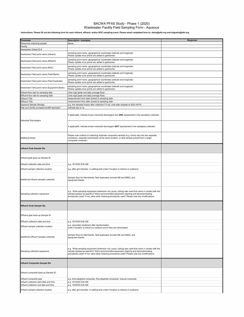
Parameter Description / examples Response
Personnel collecting sample Name
Facility
Geotracker Global ID #
Geotracker Field point name (Influent)sampling point name, geographical coordinates (latitude and longitude)Please update once points are added to geotracker.
Geotracker Field point name (Effluent)sampling point name, geographical coordinates (latitude and longitude)Please update once points are added to geotracker.
Geotracker Field point name (ROC)sampling point name, geographical coordinates (latitude and longitude)Please update once points are added to geotracker.
Geotracker Field point name (Field Blank)sampling point name, geographical coordinates (latitude and longitude)Please update once points are added to geotracker.
Geotracker Field point name (Field Duplicate)sampling point name, geographical coordinates (latitude and longitude)Please update once points are added to geotracker.
Geotracker Field point name (Equipment Blank)sampling point name, geographical coordinates (latitude and longitude)Please update once points are added to geotracker.
Influent flow rate for sampling date units mgd (peak and daily average flow)
Effluent flow rate for sampling date units mgd (peak and daily average flow)
Influent TSS measurement from date closest to sampling date
Effluent TSS measurement from date closest to sampling date
Aqueous Sample Storage e.g. Are samples frozen after collection? If not, note date shipped to SGS AXYS.
Has your facility accepted landfill leachate? Indicate yes or no
If applicable, indicate known industrial dischargers that ARE represented in the sample(s) collected.
If applicable, indicate known industrial dischargers NOT represented in the sample(s) collected.
Addtional NotesPlease note method of collecting duplicate composite samples (e.g. hourly sips into two separate containers, separate autosampler at the same location, or split sample poured from a larger composite container)
Influent Grab Sample IDs
Influent grab back-up Sample ID
Influent collection date and time e.g. 10/19/20 8:00 AM
Influent sample collection location e.g. after grit chamber, in settling tank (note if location is indoors or outdoors)
Additional influent samples collectedSample ID(s) for field blanks, field duplicates (include MS and MSD), and equipment blanks.
Sampling collection equipmente.g. What sampling equipment (extension rod, pump, tubing) was used that came in contact with the sample (please be specific)? Were recommended equipment cleaning and decontaminating procedures used? If not, were other cleaning procedures used? Please note any modifications.
Effluent Grab Sample IDs
Effluent grab back-up Sample ID
Effluent collection date and time e.g. 10/19/20 8:00 AM
Effluent sample collection locatione.g. secondary treatment after dechlorination(note if location is indoors or outdoors and if they are chlorinated)
Additional effluent samples collectedSample ID(s) for field blanks, field duplicates (include MS and MSD), and equipment blanks.
Sampling collection equipmente.g. What sampling equipment (extension rod, pump, tubing) was used that came in contact with the sample (please be specific)? Were recommended equipment cleaning and decontaminating procedures used? If not, were other cleaning procedures used? Please note any modifications.
Influent Composite Sample IDs
Influent composite back-up Sample ID
Influent composite type e.g. time-weighted composite, flow-weighted composite, manual composite
Influent collection start date and time e.g. 10/19/20 8:00 AM
Influent collection end date and time e.g. 10/20/20 8:00 AM
Influent sample collection location e.g. after grit chamber, in settling tank (note if location is indoors or outdoors)
BACWA PFAS Study - Phase 1 (2020)Wastewater Facility Field Sampling Form - Aqueous
Instructions: Please fill out the following form for each influent, effluent, and/or ROC sampling event. Please email completed form to: [email protected] and [email protected].
Industrial Dischargers

Influent collection method e.g. automated sampler into composite container, poured into sample container
Additional influent samples collected Sample ID(s) for field blanks, field duplicates, and equipment blanks.
Manual Composite Sampling collection equipment
e.g. What sampling equipment (extension rod, pump, tubing) was used that came in contact with the sample (please be specific)? Were recommended equipment cleaning and decontaminating procedures used? If not, were other cleaning procedures used? Please note any modifications.
Autosampler information
e.g. Type and brand of autosampler, type of tubing used (note if new). Were tubing and strainer replaced or decontiminated before sample collection? Were recommended equipment cleaning and decontaminating procedures used? If not, were other cleaning procedures used? Please note any modifications.
Effluent Composite Sample IDs
Effluent composite back-up Sample ID
Effluent composite type e.g. time-weighted composite, flow-weighted composite, manual composite
Effluent composite start date and time e.g. 10/19/20 8:00 AM
Effluent composte end date and time e.g. 10/20/20 8:00 AM
Effluent sample collection locatione.g. secondary treatment after dechlorination(note if location is indoors or outdoors and if they are chlorinated)
Effluent collection method e.g. automated sampler into composite container, poured into sample container
Additional effluent samples collected Sample ID(s) for field blanks, field duplicates, and equipment blanks.
Manual Composite Sampling collection equipment
e.g. What sampling equipment (extension rod, pump, tubing) was used that came in contact with the sample (please be specific)? Were recommended equipment cleaning and decontaminating procedures used? If not, were other cleaning procedures used? Please note any modifications.
Autosampler information
e.g. Type and brand of autosampler, type of tubing used (note if new). Were tubing and strainer replaced or decontiminated before sample collection? Were recommended equipment cleaning and decontaminating procedures used? If not, were other cleaning procedures used? Please note any modifications.
Hair products
Insect Repellants
Make-up
Perfume/Cologne
Moisturers
Sunblock
Brand new clothes
Chemically treated clothing (e.g. water/stain/dirt/insect resistance)
Recently laundered clothes
If applicable, please indiciate PFAS containing PPE or other clothing used during the sampling event.
Additional Notes Indicate if any other products containing PFAS were used while sampling.
Personal protective equipment and other clothing
Contact with PFAS containing productsPlease note if you have handled or come into contact with any of the following in the last 8 hours:
Personal care products

Parameter Description / examples Response
Personnel collecting sample Name
Facility
Geotracker Global ID #
Geotracker Field point name (Biosolids)sampling point name, geographical coordinates (latitude and longitude)Please update once points are added to geotracker.
Geotracker Field point name (Field Blank)sampling point name, geographical coordinates (latitude and longitude)Please update once points are added to geotracker.
Geotracker Field point name (Field Duplicate)sampling point name, geographical coordinates (latitude and longitude)Please update once points are added to geotracker.
Geotracker Field point name (Equipment Blank)sampling point name, geographical coordinates (latitude and longitude)Please update once points are added to geotracker.
Biosolids Sample Storage e.g. Are samples frozen? If not, note date shipped to SGS AXYS.
Has your facility accepted landfill leachate? Indicate yes or no
If applicable, indicate known industrial dischargers that ARE represented in the sample(s) collected.
If applicable, indicate known industrial dischargers NOT represented in the sample(s) collected.
Addtional Notes
Biosolids Sample ID(s)
Sampling MethodPlease note if the sample was collected as a single grab or a composite (indicate the number of samples combined).
Biosolids collection date and time e.g. 10/19/20 8:00 AM (indicate all times if a composite)
Biosolids sample collection location changesPlease clariy if a sampling location is indoors or outdoors. Also note if the location is different from what was indicated in the SAP.
Biosolids moisture content % weight of solid per volume of sample
Additional biosolids samples collectedSample ID(s) for field blanks, field duplicates (include MS and MSD), and equipment blanks.
Sampling collection equipment
e.g. What sampling equipment was used that came in contact with the sample? Were recommended equipment cleaning and decontaminating procedures used? If not, were other cleaning procedures used? Please note any modifications.
Hair Products
Insect Repellants
Make-up
Perfume/Cologne
Moisturers
Sunblock
Brand new clothes
Chemically treated clothing (e.g. water/stain/dirt/insect resistance)
Recently laundered clothes
If applicable, please indiciate PFAS containing PPE or other clothing used during the sampling event.
Additional Notes Indicate if any other products containing PFAS were used while sampling.
Personal protective equipment and other clothing
BACWA PFAS Study - Phase 1 (2020)Wastewater Facility Field Sampling Form - Biosolids
Instructions: Please fill out the following form for each biosolids event. Please email completed form to: [email protected] and [email protected].
Industrial Dischargers
Contact with PFAS containing productsPlease note if you have handled or come into contact with any of the following in the last 8 hours:
Personal care products

Study of PFAS in Bay Area POTWs: Phase 1 SAP - 11/23/2020 - Final
Appendix B: Shipping Instructions

PREPARING AND SHIPPING SAMPLES TO SGS AXYS
LABELING
- Follow procedures described in section 6 of Study of Per- and Polyfluoroalkyl Substances in Bay Area POTWs: Phase 1 Sampling and Analysis Plan.
CHAIN OF CUSTODY (COC)
- Follow procedures described in section 7 of Study of Per- and Polyfluoroalkyl Substances in Bay Area POTWs: Phase 1 Sampling and Analysis Plan.
- Original copy is placed inside a ziptop plastic bag and placed inside the cooler.
PACKAGING
1. Freeze all samples before packaging (if possible, also cool shipping container). 2. Place layer of bagged wet ice at bottom of cooler. 3. Place a layer of bubble wrap over the ice 4. Place each sample in a separate zip top bag lay over to of the bubble wrap layer. 5. Place a layer of bubble wrap over the sample containers. 6. Fill all remaining space with bagged wet ice. 7. Place Chain of Custody documents inside the cooler. 8. Close cooler and secure with tape.
SHIPPING DOCUMENTS
Complete and attach all required shipping documents to the outside of container.
- FedEx waybill – See waybill instructions and example waybill below. - 3 Copies of Commercial Invoice - Sign; date; add waybill number* - 2 copies included with waybill; 3rd copy
to courier
*FedEx waybill number is the tracking number (top right-hand corner).
Commercial Invoice
Fill the remaining sections of the commercial invoice
- Date of exportation - Shipper/exporter information - Waybill number (same as FedEx tracking number) - No. of PKGS = number of coolers - Qty. = number of samples - Total value = QTY x $5 - Total invoice value = total value if one cooler - Total invoice value = total value x no of PKGS if more than one cooler being shipped

International Air Waybill Instructions
Section 1: “From” Enter Shipper’s information as completely as possible Section 2: “To” Enter our address as follows: Sample Receiving SGS AXYS Analytical Services Ltd. 2045 Mills Road W Sidney B.C. V8L 5X2 Phone: 250-655-5800 Section 3: “Shipment Information” Enter total number of packages, total weight, and dimensions. Don’t enter any declared value. - Enter the approximate dimensions in the dimensions section. - Commodity description can be taken from the commercial invoice. See example for 4 effluent samples below. - Use Harmonized Sales Code provided on commercial invoice. - Country of Manufacture is the USA. - Enter the total customs value. Use a nominal value of $5.00 per bottle.
Note, Canada Export Declaration is not applicable. Leave this section blank. Example:
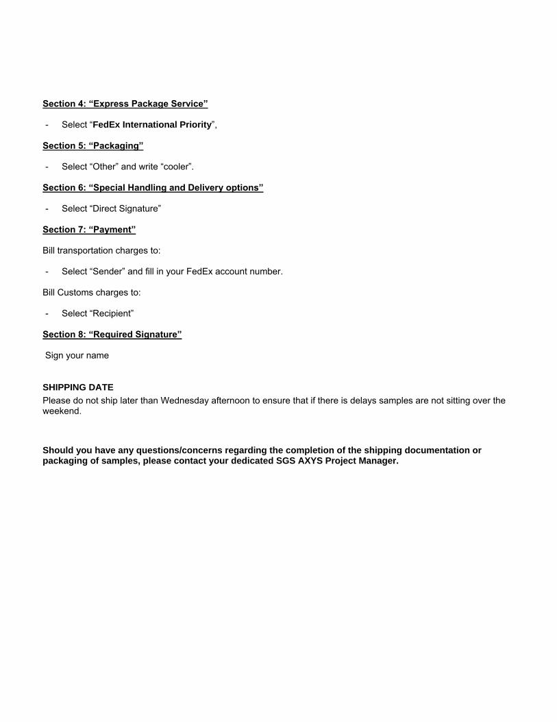
Section 4: “Express Package Service” - Select “FedEx International Priority”,
Section 5: “Packaging” - Select “Other” and write “cooler”.
Section 6: “Special Handling and Delivery options” - Select “Direct Signature”
Section 7: “Payment” Bill transportation charges to: - Select “Sender” and fill in your FedEx account number.
Bill Customs charges to: - Select “Recipient”
Section 8: “Required Signature” Sign your name
SHIPPING DATE
Please do not ship later than Wednesday afternoon to ensure that if there is delays samples are not sitting over the weekend.
Should you have any questions/concerns regarding the completion of the shipping documentation or packaging of samples, please contact your dedicated SGS AXYS Project Manager.
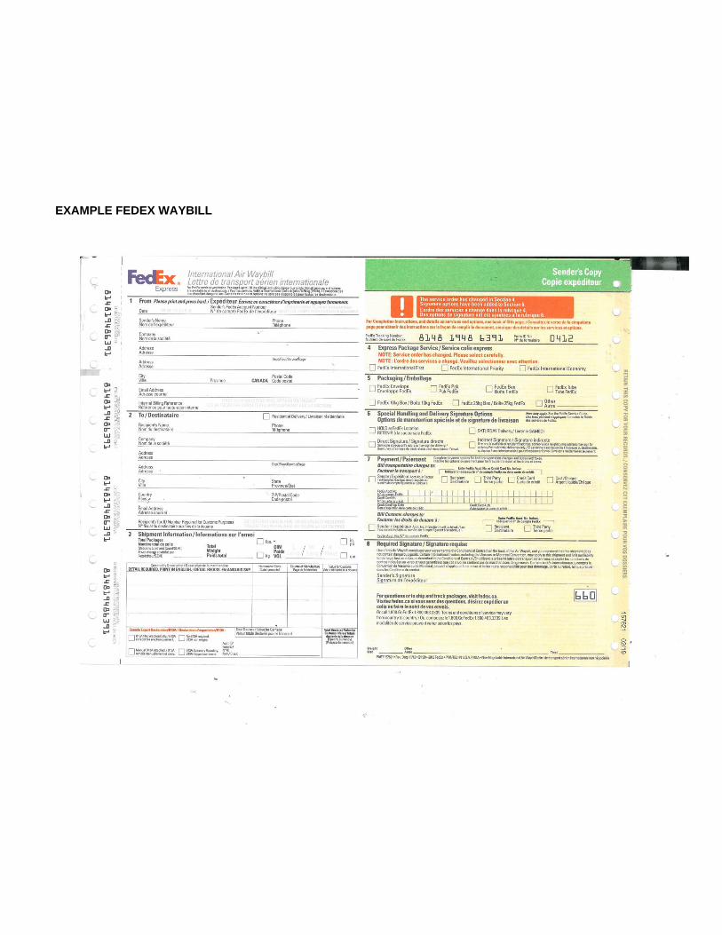
EXAMPLE FEDEX WAYBILL

Study of PFAS in Bay Area POTWs: Phase 1 SAP - 11/23/2020 - Final
Appendix C: Supplementary Information Tables

Appendix C Table 1. Characteristics of POTWs included in study.
POTW Subembayment EstimatedPopulation
PermittedADWF (MGD)
2018/2019 Flow to Bay
Secondary Treatment Type
Advanced Secondary/Filtration
(Yes/No)
Residential/Commercial % of
Total Received Flows*CCCSD Suisun 482,000 53.8 38.6 AS No 96
CSM South 150,000 15.7 11.6 AS No 100DSRSD South 146,900 20.2 2.3 (2016) AS No 94.3EBDA South - 107.8 65.0 - - -
EBMUD Central 650,000 120 58.0 High Purity Oxygen No 94FSSD Suisun 144,000 23.7 15.4 Oxidation Towers/AS Yes 75NSD San Pablo 60,000 7 4.8 AS No 95
OSP (SFPUC) Ocean 250,000 43 0 AS Yes 99PA Lower South 217,000 39 21.9 TF/AS Yes 90
SEP (SFPUC ) South 580,000 58 55.5 High Purity Oxygen No 98SFO-I South - 1.2 1.2 AS No 0SFO-S South - 1.2 1.2 AS No 100SJ-SC Lower South 1,500,000 167 93.8 AS/BNR Yes 94USD South 343,500 22 21.6 (2015) AS No 75
VFWD San Pablo 120,000 9 10.1 TF/Solids Contact No 97.4AS = Advanced Secondary, TF = Trickling Filter, BNR = Biological Nutrient Removal*Based on responses from each POTW regarding their service population

Appendix C Table 2. POTW shipping addresses and supplies provided in each PFAS sampling kit.
Facility Shipping AddressEffluent,
Equipment Blanks(500 mL HDPE)
ROC(500 mL HDPE)
Influent(125 mL HDPE)
Influent TOP
(60 mL HDPE)
Biosolids(250 mL HDPE)
Field BlankSpring Water
(500 mL HDPE)
PFAS-Free Reagent Water
(4 L)
CCCSD
ATTN: Mary Lou Esparza, Blake BrownCentral San District Offices & Treatment Plant5019 Imhoff Place Martinez, CA 94553
16 - 17 4 6 3 1
CSM
ATTN: Xiongbing LiangCity of San Mateo WWTP2050 Detroit DrSan Mateo, CA 94404
4 - 6 4 3 - -
DSRSD
DSRSD LaboratoryAttn: Connie Sanchez7399 Johnson DrivePleasanton, CA 94588
4 - 4 4 3 - -
EBDA
ATTN: Angie BerumenSan Leandro WWTP3000 Davis St. San Leandro, CA 94577
4 - - - - - -
EBMUD
ATTN: Nick Klumpp EBMUD WWTP, Lab MS 59 2020 Wake AveOakland, CA 94608
4 - 6 4 4 - -
FSSD
ATTN: Nicole Van AkenFairfield Suisun Sewer District WWTP1010 Chadbourne RdFairfield, CA 94534
16 - 17 4 3 3 1
NSD
ATTN: Liz FalejczykNovato Sanitary District WWTP500 Davidson Street Novato, CA 94945
4 - 6 4 3 - -
PA
ATTN: Lab, Samantha BialoruckiCity of Palo Alto RWQCP2501 Embarcadero WayPalo Alto, CA 94303
4 - 6 4 3 - -
OSP ATTN: Dolson Kwan, PFAS StudySoutheast Treatment Plant, Lab Sample Recieving750 Phelps St.San Francisco, CA, 94124
4 - 6 4 3 - -
SEP 4 - 6 4 3 - -
SFO-S ATTN: Brian KuhnSFO - Mel Leong Treatment Plant910 Clearwater DriveSan Francisco, Ca 94128
5 - 6 4 3 1 1
SFO-I 21 - 11 4 4 2 2
SJ-SC
ATTN: Payal SarkarSan Jose-Santa Clara RWF700 Los Esteros RoadSan Jose, CA 95134
10 - 10 10 - - -
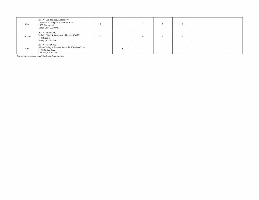
USD
ATTN: Dan Jackson, Laboratory Raymond A. Boege Alvarado WWTP5072 Benson Rd. Union City, CA 94587
6 - 7 6 4 - 1
VFWD
ATTN: Anita SettyVallejo Flood & Wastewater District WWTP450 Ryder St Vallejo, CA 94590
4 - 6 4 3 - -
VW
ATTN: Jason ChiarSilicon Valley Advanced Water Purification Center4190 Zanker RoadSan Jose, CA 95134
- 8 - - - - -
Extras have been provided of all sample containers.

Study of PFAS in Bay Area POTWs: Phase 1 SAP - 11/23/2020 - Final
Appendix D: POTW Process Diagrams

N.O.
N.C.
INFLUENT
FROM
MARTINEZ LINE
EMERGENCY OVERFLOW
TO CREEK
VARIABLE
MULTI-RAKES
SCREENINGS
INFLUENT FROM
OLD "A" LINE
Pumped Raw
Sewage Bypass
(optional)
ATMOSPHERE
ATMOSPHERE
WET
ASH
DRY
ASH
WASTE FILTER
BACKWASH
TO MARTINEZ
LINE
SODIUM
HYPOCHLORITE
No. 2 UTILITY
WATER
(OPTIONAL)
FINAL EFFLUENT
(TO SUISUN BAY)
WAS
(Emergency Only)
RAS
WAS
SE
CO
ND
AR
Y S
CU
M
SC
RU
BB
ER
W
AT
ER
RECIRC
PRIMARY SCUM
WASTE SCRUBBER WATER
CENTRATE
ALUM
OTHER PROCESS AND PLANT DRAINS
TH
IC
KE
NE
D S
CU
M
EMERGENCY SLUDGE
STORAGE STATION
DRAINBACK
GATE
SODIUM
HYPOCHLORITE
(OPTIONAL)
AIR
PR
IM
AR
Y S
LU
DG
E
INFLUENT PUMP 5
ATMOSPHERE
SELECTOR
CHANNEL
SEPTAGE
GRIT TO
DISPOSAL
STEAM
HYDROGEN
PEROXIDE
(AS NEEDED)
WASTEWATER TREATMENT PROCESS FLOW SCHEMATIC 2020
CENTRAL CONTRA COSTA SANITARY DISTRICT
(NOT ALL VALVES AND LINES SHOWN)
N.O.
N.C.
N.O.
N.C.
DAF UNDERFLOW
TWAS
INFLUENT
PUMPING
NO. 1 WATER
ATMOSPHERE
ATMOSPHERE
ELECTRICAL
POWER FOR
ON-SITE USE
PRE-AERATION
TANKS
HEADWORKS
ODOR CONTROL UNIT
ODOR CONTROL
UNIT
PRIMARY
SEDIMENTATION
TANKS
PRIMARY
EFFLUENT
PUMPING
ACTIVATED
SLUDGE
AERATION
TANKS
LANDFILL
OR REUSE
STANDBY POWER
GENERATORS
FUEL OIL
STORAGE
TANKS
LIME
SLUDGE
BLENDING
PUMPS
SLUDGE
BLENDING
TANK
FURNACE
CENTRIFUGE
CAKE PUMP
ODOR CONTROL
UNIT
DRY SCRUBBER
WASTE HEAT
BOILER
WET SCRUBBER
SCUM
DEWATERING
DAF
AERATION
BLOWER
STEAM
TURBINE
CONDENSATE
RETURN
COGEN
CALCIUM
THIOSULFATE
(OPTIONAL)
AUXILIARY
BOILERS
FILTER
PLANT
HOLDING
BASINS
ASH
CONVEYOR
SYSTEM
CAKE
HOPPER
HOLDING BASIN DRAINBACK FLOW
BOILER
FEEDWATER
1
2
7
6
3
4
5
8
RECYCLED
WATER
USERS
EMERGENCY
SLUDGE
STORAGE
TANK
HYDROGEN
PEROXIDE
(AS NEEDED)
ATMOSPHERE
N.C.
DA
F U
ND
ER
FLO
W
SODIUM
HYPOCHLORITE
N.C.
N.C.
N.C.
N.C.
N.C.
ASH
BINS
SODIUM
HYPOCHLORITE
NO. 3 WATER LP
NO. 3 WATER HP
SODIUM
HYPO-
CHLORITE
FINAL
EFFLUENT
PUMPING
(OPTIONAL)
U.V.
Disinfection
CLEARWELL
TREATMENT PLANT SAMPLING LOCATIONS
Sample Type of Sampler Used for Collection
1
2
3
4
5
6
7
8
Influent
Primary Effluent
RAS/WAS
Selector Channel
Aeration Tank Mixed Liquor
Final Effluent
Final Effluent Metals 1631
Cake
Sigma 900 Max
Manning
Manning
Hand grabbed when no foam present.
Use hand pump to collect sample when there is foam
Hand grabbed
Sigma 900 Max
Sigma 900 Max
Collected by Operations and stored in refrigerator in
Solids Conditioning Building
K:\Projects\_tp\Schematics_Diagrams\ProcessFlow\ProcessFlowSchematic_2015
Wastewater Flow
Solids
Alternate Solids
Chemicals
Steam
Electricity
Alternate Wastewater Flow
Legend
Sampling Points:
See the "Treatment Plant Sampling Locations"
Table below.
Gas
STRUCTURE
1
INFLUENT
FROM NEW
"A" LINE
DRY
WEATHER
CHANNEL
WET
WEATHER
CHANNEL
INFLUENT
STRUCTURE
STRUCTURE
2
SOUTH
SECONDARY
CLARIFIERS
NORTH
SECONDARY
CLARIFIERS
N.C.
N.C.
N.C.
N.C.
INFLUENT
DIVERSION
STRUCTURES
SCREENINGS
DISPOSAL
BIN
WASHER
COMPACTERS
TIPPING TROUGHS
SLU
IC
E
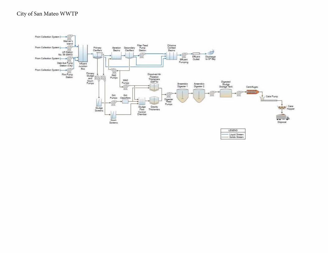
City of San Mateo WWTP
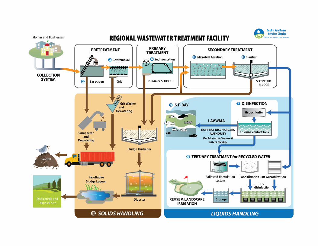
Dublin San Ram onServices District
Water, wastewater, recycled water

Influent Pumps (5)
Coarse Screens
(5)
Fine Screens (5)
Aerated Grit Chambers (8)
PrimarySedimentation Tanks (16)
Grit Dewatering (6)
Primary Sludge Pumps (16)
Digesters (11)
Secondary Clarifiers (12) Reactor Basins (8)
Oxygen Production Plant
Gravity Belt Thickeners (3)
Sludge Well
Centrifuge Feed
Pumps (5)
Dewatering Centrifuges (5)
Sludge Storage Hoppers (3)
Wet Weather Mid-Plant Pump Booster Station
5 pumps @ 85 MGD eachPWWF = 425 MGD
5 @ 106 MGD eachMix of 6mm and 3/4" Climber Bar Screens
8 tanks @ 0.24 MG eachPWWF = 425 MGD, 53 MGD each
6 grit classifiers18 grit hydrocyclones
Grit Pumps (16)
16 pumps @ 300, 500 gpm
PWWF = 320 MGD; 16 tanks @ 20 MGD eachADWF = 72 MGD; 9 tanks @ 8 MGD eachHLR = 500 - 1,300 gpd/ft2
3 pumps84 MGD eachPWWF = 168 MGD
Gravity Sludge Thickeners (2)
2 @ 0.47 MG eachHLR = 400 gpd/ft2
SLR = 16 lb/d-ft2
12 Tanks @ 1.61 MG each, Perimeter FeedPWWF = 168 MGD; 12 tanks @ 14 MGD eachADWF = 70 MGD; 10 tanks @ 7 MGD each
PWWF Peak Wet-Weather FlowRAS Return Activated SludgeSLR Solids Loading RateSRT Solids Residence TimeWAS Waste Activated Sludge
Cake Pumps
(5)
3 @ 150 gpm, 2 @ 300 gpm2.2 - 2.9% feed solids2 - 3 DT feed per hour overall
Total storage = 460 yd3
220 Klbs each
3 belts @ 1,100 gpm each3 meters long x 2 meters wide
66,750 gal
8 tanks @ 1.58 MG eachPWWF = 168 MGD; 8 tanks @ 21 MGD eachADWF = 70 MGD; 5 tanks @ 12 MGD each
RAS Pumps (4)WAS Pumps
(3)
Centrate to Primary Influent Channel
Filtrate to Secondary Influent Channel
Sodium Hypochlorite
-or-Ferric Chloride
Sodium Hypochlorite
Polymer
Ferric Chloride
Landfill (ADC) (50 - 70%)Land Application (30 - 50%)
8 Trucks/day avg.24-26 Wet Tons/load180 – 200 WT/day
Polymer
Figure 1 Summary of MWWTP Process and Capacity
4 pumps @ 20 MGD each 3 pumps @ 1000 gpm each
O2
Sodium Hypochlorite
NaOClInterceptors Intake
1st Stage:
2nd Stage:
Cake: 20 - 24%TS
Polymer
5 each6" Manual Bar
Screens
Vortex Grit Chambers (2)
Grit Pumps (2)3 pumps @ 275 gpm
Effluent Pumps (4)4 pumps @ 107 MGD each: PWWF = 320 MGD
Sodium Hypochlorite
Sodium Bisulfite
High Strength Receiving Stations
TWAS Pumps (3)3 pumps @ 250 gpm each
MicrofiltrationStorage1.5 MG
0.1 micron2000 gpm2.88 MGD
Recycled Water Distribution560 - 1740 gpm0.8 - 2.5 MGD
SF Bay
Plant Utility Water:Seal WaterPolymer DilutionGallery Hosing
4 stages: 1 deep-mix anoxic zone3 surface aeration zones
2 Plants @ 85 TPD each
Plant Utility Water:Tank HosingLine Flushing
External Customers:LandscapingDust Control
16 tanks @ 0.5 MG each
Landfill
Landfill
Septage Receiving
NaOCl
Storage Basin11 MG, 5 compartmentsPWWF = 95 MGDScum Concentrators (2)
Overflow Liquid to Headworks
Landfill
Flares (4)
3 each @ 2150 KWCompression ignition biogas/diesel engines
Power (net) to Plant or Grid143 MWh/day avg.168 MWh/day peak
Power Demand: 114 MWh/day avg. 126% of Demand met
BoilerHot Water Send
Hot Water Return
Heat Exchangers (11)
2.8 Mcf Biogas/day Combusted
Engine Cooling Water
C. Weir, 06/08/14C. Weir, 07/18/08V. De Lange, 11/01/02
To P
rimar
y In
fluen
t
Solids BlendingTanks (2)
FOG
Food Scrap and Solid Organics
Liquid Organics
8 Draft-tube mixed, fixed-cover, waffle-bottomed Digesters with constant pre-heated feed via feed loop. Excess feed returned to the Blend Tanks3 Unmixed, floating or Dystor covered, cone-bottomed Digesters with constant feed from 1st Stage Digesters via Bottom Draw or Overflow Standpipes.
11 Digesters Total @ 1.83 MG each
Wet Weather Blend Channel to Effluent Pumps
PWWF = 152 MGD
Sodium Hypochlorite
3 Liquid Bays - 26,700 gal2 Solid Bays - 20,000 gal2 pumps @ 350 gpm1 pump @ 150 gpm2 recirc pumps @ 250 gpm
2 Tanks @ 32,000 gal3 pumps @ 560 gpm, variable2 recirc pumps @ 800 gpmConcentric Tube HXR Preheat to 85F using residual heat after Digester Heating
2 Tanks@ 180,000 gal each2 recirc pumps@ 800 gpm eachSpiral HXR Preheat to 85F
Abbreviations:ADC Alternative Daily CoverADWF Average Dry-Weather FlowHLR Hydraulic Loading RateHXR Heat Exchanger
1 each @ 4600 KWRecuperating Turbine
Turbine Cooling Water
PolymerAnd/or
Ferric Chloride
Feed Loop
Standpipe
0.5 %TS in 5.0 %TS out
2 Chambers Rated at 35 MGD each
EBMUD

C
Inlet Pump Station
Headworks / Influent Screening
Primary Sedimentation
Basins
Oxidation Towers
Intermediate Clarifiers
Gravity Belt Thickeners
Ultraviolet Disinfection
Tertiary Filters
Secondary Clarifiers
Aeration Basins
Anaerobic Digesters
Combined Influent Flow 15 MGD
Tertiary Filter Flow 15 MGD
Total Flow to GBT
Waste Activated Sludge Flow
Intermediate Sludge Flow
Primary Sludge Flow
GBT Sludge Flow
Anaerobic DigesterSludge Flow
Screw Press Sludge to Lystek
Screw PressRecycle Flow
E-001 Flow
GBT Recycle Flow
Plant Drain Flow<1 MGD
Influent Flow from Cordelia, Central, and
Suisun PS13 MGD
Equalization Clarifier
Util ity/Outfall Pump Station
Recycled Water
LegendMetered
Flow
Redundant & Backup Power Sources
Emergency Generator
Energy Recovery
Portable
Sludge HoldingTanks
Inlet Pump Station Flow 2 MGD
Boynton Slough Flow 14 MGD
Util ity Pump Station Flow
1 MGD
In Plant Util ity Water Flow
Dew
ater
ing
Flow
Process Waste Flow
In Plant Pump Station
In P
lant
Flo
w
Adjusted Influent Flow 14 MGD
RA
SFl
ow
E-002 Flow E-003 Flow
E-005 Flow
Fairfield-Suisun Wastewater Treatment PlantWastewater Plant Flow Schematic
Balancing Ponds
(Optional)
EffluentHoldingPonds
(Optional)
Treatment Units
Screw Press
Filte
r Bac
kwas
h Fl
ow
Sludge Drying Beds
Hauled in Anaerobically
Digestible Material
Diverted Flow
Returned Flow
INF-001
E-001-D
Biosolids


Influent INF-001AWest Side Pump Station
Coarse Bar Screens Fine Bar Screens
Grit Removal
Aeration BasinsPrimary Clarifiers Secondary Clarifiers Ocean Outfall
Gravity Belt ThickenersTPAS TankThermophilicDigestersMesophilic DigesterScrew Press
Cyclone Classifier
LoadingBay
Rotary Drum Screen
Gas HoldingEnginesBoilersFlares
Biosolids
WaterReturnGrit
Screenings
ScumScum
RASPS
TPASBS
BiogasPolymer
Meso Hold
Scrubber
WAS
Screw Press Filtrate
ABBREVIATIONSPS
RAS
WAS
TPAS
BS
Hex
Primary Sludge
Return Activate Sludge
Waste Activated Sludge
Thickened Primary Activated Sludge
Blended Sludge
HeatExchanger
Biogas
Ferric Chloride
Grit
Polymer
Screenings
Scum
Solids
Water: Return, Drain
Water: Treatment Process
Monitoring Point
OCEANSIDE PROCESS SCHEMATIC
Agriculture Landfill Compost
FeCl3
Recirc
FeedDraw
PumpCombinedSewers
Heated Water
Hex
WaterTreatment
SludgeTreasureIsland
PS & SS
Plant Process Schematic
Oceanside Water Pollution Control Plant
Biosolids

5 6
rev March 2020
Palo Alto Regional Water Quality Control Plant Schematic
LiftStation
Influent
Septage
GritRemoval
ScumConcentrator
Odor Control Scrubber Drainage and Belt Press Filtrate
PrimarySludge
Belt Filter
Conveyors
Coke Storage Bins(Dewatered Sludge)
Odor Control System(Scrubber)
Exhaust
Drain
Presses
Dewatered Sludge
Foul Air
Foul Air
GravityThickeners
ThickenerOverflow WAS
Grit
Grease
To Landfill
Decant
PrimarySedimentation
InfluentJunction
Box
Fixed-FilmReactors Aeration
Basins
Headworks
BarScreens
Screenings
Sludge
SecondaryClarifiers
DualMediaFilters
Sludge
UltravioletDisinfection Effluent to
ReceivingWaters
RecycledWater to
Customers
Alt.
Filter Backwash
Backwash Waste to Headworks
Filters
BypassProcess Water
(No. 3 and No. 4)
ChlorineContact
Tank
BlendTank
Liquid Stream
Recycled Water
Solids Stream
Flow Meter
Sampling Location
Raw Sewage Influent
Primary Effluent
Tower Effluent
RAS with Tower Effluent
ML Channel to Secondary Clarifiers
Secondary Effluent (Influent Channel to DMF)
Final Effluent
Recycle Water
Sludge Cake Storage and Hopper
1
1
2
3
4
5
6
7
8
9
2
8
7
Legend
M
M
Scum
RAS
M
M
Odor and Exhaust Stream
MScum
M
M
M
M
M
M
M
M
M
M
Bypass
3 4
New& Old
PumpingPlants
M
*New Secondary Clarifier RASpumps only.
Tower Lift
Pumps
9
PROCESS SCHEMATICPALO ALTO REGIONAL WATER
QUALITY CONTROL PLANTCITY OF PALO ALTO

SANITARY PROCESS FLOW DIAGRAM
SFO Sanitary WWTP

Mel Leong Industrial Water Treatment Plant at San Francisco International Airport

City of San Jose, City of Santa Clara San Jose-Santa Clara Regional Wastewater Facility and Collection Systems
C

Raw Sewage
Bruce Flynn Pump Station
Raw ------1►•Sewage
Southeast Lift Station
Raw Sewage
Channel Pump Station
PR
Screenings
Ferric Chloride
Grit Removal Tanks
Dewatered PSM
Centrate Anaerobic Digesters
Biagas to Flares, Boilers, Engines
Sodium Hypochlorite
f Wet Weather Secondary Bypass
Sodium Bisulfite
+ r-----------------------------------------------,
Primary : Disinfection/ : Sedimentation Tanks I Aeration Basins Secondary Clarifiers Dechlorination 1
PS
CPAS
I ========i [!!!�---�!]---�► I
RAS
SSM
WAS
I
I
I
e------®
•
PPR Scum
Mixed Grease
Drum
Filtrate
TAS
Disinfected effluent for plant washdown use 001 Pier 80 Outfall
Gravity Belt Thickeners 002 Quint St Outfall Tank
LEGEND
Liquid Wet Weather Liquid Flow Solids Stream Scum Chemical Injection Heat Recycled Stream Biagas
@----------e Sample Points
ABBREVIATIONS
CPAS Combined Primary Activated Sludge PPR Pumped Plant Recycle PR Plant Recycle PS Primary Sludge PSM Primary Scum RAS Return Activated Sludge SSM Secondary Scum TAS Thickened Activated Sludge WAS Waste Activated Sludge

Anaerobic Digesters
Primary Clarifiers inside building
Raw Sewage
Screenings
Waste activated sludge (WAS) Prethickener
Gravity belt thickener
DegritterGravity
Thickener
Air
Return Activated Sludge
SecondaryClarifiers
Covered Aeration Basins
To Hayward Marsh &
EBDA
Secondary Digesters
To Land Application
1 2 3 4 5 6
To Landfill
To Landfill WasteActivated Sludge
M
Transfer Tank
Union Sanitary District Alvarado Wastewater Treatment Facility
Digester Sludge Feeding Detail
November 2005Centrifuge Dewatering
M
Disinfection with Sodium Hypochlorite
Headworks
Union Sanitary District

Existing Process
Sec Treatment Recycle PS
Secondary ClarifiersAeration Tanks
Biotowers
PS + WAS
Flow Split Structure 4
Chlorine Contact Tanks
(CCT B)
Mare Island Effluent PS
Bar ScreensFlow Split
Structure 1
Grit Chambers 2 &
3
Primary Clarifiers 9 - 12
Primary Clarifiers 1 - 8
Flow Split Structure 3
Junction Box 3
Carquinez Straight Effluent PS (Wet
Weather)
Chlorine Contact Tanks (CCT C)
Grit Chamber 1
Flow Split Structure 2Influent
PS
Vallejo Flood & Wastewater District

Figure 1 Biosolids Process Flowchart
Vallejo Flood & Wastewater District

Valley Water
ROC Sampling Point

Study of PFAS in Bay Area POTWs: Phase 1 SAP - 11/23/2020 - Final
Appendix E: DOD QSM, Version 5.3

Table B-15. Per- and Polyfluoroalkyl Substances (PFAS) Using Liquid Chromatography Tandem Mass Spectrometry (LC/MS/MS) With Isotope Dilution or Internal Standard Quantification in Matrices Other Than Drinking Water
QC Check Minimum Frequency Acceptance Criteria Corrective Action Flagging Criteria Comments
Aqueous Sample Preparation
Each sample andassociated batch QCsamples.
Solid Phase Extraction(SPE) must be usedunless samples areknown to contain highPFAS concentrations(e.g., Aqueous FilmForming Foam (AFFF)formulations). Inline SPEis acceptable.
Entire sample plus bottlerinsate must be extractedusing SPE.
Known high PFASconcentration samplesrequire serial dilution beperformed in duplicate.
Documented projectapproval is needed forsamples prepared byserial dilution as opposedto SPE.
NA. NA. Samples with > 1% solidsmay requirecentrifugation prior toSPE extraction.
Pre-screening of separatealiquots of aqueoussamples isrecommended.
Solid Sample Preparation
Each sample andassociated batch QCsamples.
Entire sample received bythe laboratory must behomogenized prior tosubsampling.
NA. NA. NA.
Biota Sample Preparation
Each sample andassociated batch QCsamples.
Sample prepared asdefined by the project(e.g., whole fish versusfilleted fish).
NA. NA. NA.

Table B-15. Per- and Polyfluoroalkyl Substances (PFAS) Using Liquid Chromatography Tandem Mass Spectrometry (LC/MS/MS) With Isotope Dilution or Internal Standard Quantification in Matrices Other Than Drinking Water
QC Check Minimum Frequency Acceptance Criteria Corrective Action Flagging Criteria Comments
AFFF and AFFF Mixture Samples Preparation
Each sample andassociated batch QCsamples.
Each field sample mustbe prepared in duplicate(equivalent to matrixduplicate).
Serial dilutions must beperformed to achieve thelowest LOQ possible foreach analyte.
NA. NA. Adsorption onto bottle isnegligible compared tosample concentration sosubsampling is allowed.
Multiple dilutions will mostlikely have to be reportedin order to achieve thelowest LOQ possible foreach analyte.
Sample Cleanup Procedure
Each sample andassociated batch QCsamples.
Not applicable to AFFFand AFFF MixtureSamples.
ENVI-CarbTM orequivalent must be usedon each sample andbatch QC sample.
NA. Flagging is notappropriate.
Cleanup should reducebias from matrixinterferences.
Mass Calibration Instrument must have avalid mass calibration priorto any sample analysis.
Mass calibration is verifiedafter each masscalibration, prior to initialcalibration (ICAL).
Calibrate the mass scaleof the MS with calibrationcompounds andprocedures described bythe manufacturer.
Mass calibration rangemust bracket the ionmasses of interest. Themost recent masscalibration must be usedfor every acquisition in ananalytical run.
Mass calibration must beverified to be ±0.5 amu ofthe true value, byacquiring a full scancontinuum massspectrum of a PFASstock standard.
If the mass calibrationfails, then recalibrate. If itfails again, consultmanufacturer instructionson corrective maintenance.
Flagging is notappropriate.
Problem must becorrected. No samplesmay be analyzed under afailing mass calibration.
The mass calibration isupdated on an as-neededbasis (e.g., QC failures,ion masses fall outside ofthe ±0.5 amu of the truevalue, major instrumentmaintenance isperformed, or theinstrument is moved).

Table B-15. Per- and Polyfluoroalkyl Substances (PFAS) Using Liquid Chromatography Tandem Mass Spectrometry (LC/MS/MS) With Isotope Dilution or Internal Standard Quantification in Matrices Other Than Drinking Water
QC Check Minimum Frequency Acceptance Criteria Corrective Action Flagging Criteria Comments
Mass Spectral Acquisition Rate
Each analyte, ExtractedInternal Standard (EIS)Analyte.
A minimum of 10 spectrascans are acquiredacross eachchromatographic peak.
NA. Flagging is notappropriate.
NA.
Calibration, Calibration Verification, and Spiking Standards
All analytes. Standards containingboth branched and linearisomers must be usedwhen commerciallyavailable.
PFAS method analytesmay consist of bothbranched and linearisomers, but quantitativestandards that contain thelinear and branchedisomers do not exist forall method analytes.
For PFAS that do nothave a quantitativebranched and linearstandard, identify thebranched isomers byanalyzing a qualitativestandard that includesboth linear and branchedisomers and determineretention times,transitions and transitionion ratios. Quantitatesamples by integratingthe total response (i.e.,accounting for peaks thatare identified as linearand branched isomers)and relying on the initialcalibration that uses thelinear isomer quantitativestandard.
NA. Flagging is notappropriate.
Standards containingboth branched and linearisomers are to be usedduring method validationand when reestablishingretention times, to ensurethe total response isquantitated for thatanalyte.
Technical gradestandards cannot be usedfor quantitative analysis.
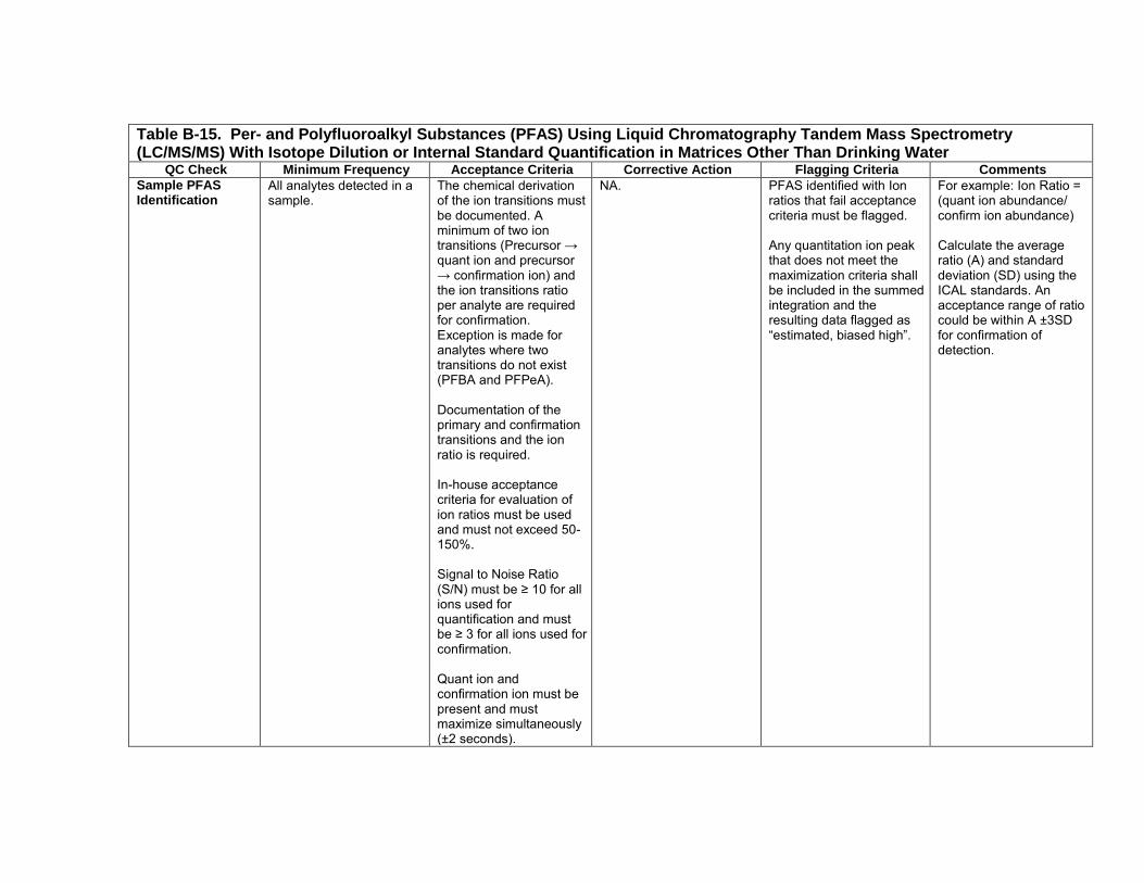
Table B-15. Per- and Polyfluoroalkyl Substances (PFAS) Using Liquid Chromatography Tandem Mass Spectrometry (LC/MS/MS) With Isotope Dilution or Internal Standard Quantification in Matrices Other Than Drinking Water
QC Check Minimum Frequency Acceptance Criteria Corrective Action Flagging Criteria Comments
Sample PFAS Identification
All analytes detected in asample.
The chemical derivationof the ion transitions mustbe documented. Aminimum of two iontransitions (Precursor →quant ion and precursor→ confirmation ion) andthe ion transitions ratioper analyte are requiredfor confirmation.Exception is made foranalytes where twotransitions do not exist(PFBA and PFPeA).
Documentation of theprimary and confirmationtransitions and the ionratio is required.
In-house acceptancecriteria for evaluation ofion ratios must be usedand must not exceed 50-150%.
Signal to Noise Ratio(S/N) must be ≥ 10 for allions used forquantification and mustbe ≥ 3 for all ions used forconfirmation.
Quant ion andconfirmation ion must bepresent and mustmaximize simultaneously(±2 seconds).
NA. PFAS identified with Ionratios that fail acceptancecriteria must be flagged.
Any quantitation ion peakthat does not meet themaximization criteria shallbe included in the summedintegration and theresulting data flagged as“estimated, biased high”.
For example: Ion Ratio =(quant ion abundance/confirm ion abundance)
Calculate the averageratio (A) and standarddeviation (SD) using theICAL standards. Anacceptance range of ratiocould be within A ±3SDfor confirmation ofdetection.

Table B-15. Per- and Polyfluoroalkyl Substances (PFAS) Using Liquid Chromatography Tandem Mass Spectrometry (LC/MS/MS) With Isotope Dilution or Internal Standard Quantification in Matrices Other Than Drinking Water
QC Check Minimum Frequency Acceptance Criteria Corrective Action Flagging Criteria Comments
Ion Transitions (Precursor-> Product)
Every field sample,standard, blank, and QCsample.
In order to avoid biasingresults high due to knowninterferences for sometransitions, the followingtransitions must be usedfor the quantification ofthe following analytes:
PFOA: 413 → 369PFOS: 499 → 80PFHxS: 399 → 80PFBS: 299 → 804:2 FTS: 327 → 3076:2 FTS: 427 → 4078:2 FTS: 527 → 507NEtFOSAA: 584 → 419NMeFOSAA: 570 → 419
If these transitions are notused, the reason must betechnically justified anddocumented (e.g.,alternate transition wasused due to observedinterferences).
NA. Flagging is not appropriate NA.

Table B-15. Per- and Polyfluoroalkyl Substances (PFAS) Using Liquid Chromatography Tandem Mass Spectrometry (LC/MS/MS) With Isotope Dilution or Internal Standard Quantification in Matrices Other Than Drinking Water
QC Check Minimum Frequency Acceptance Criteria Corrective Action Flagging Criteria Comments
Initial Calibration (ICAL)
At instrument set-up andafter ICV or CCV failure,prior to sample analysis.
The isotopically labeledanalog of an analyte(Extracted InternalStandard Analyte) mustbe used for quantitation ifcommercially available(Isotope DilutionQuantitation).
Commercial PFASstandards available assalts are acceptableproviding the measuredmass is corrected to theneutral acidconcentration. Resultsshall be reported as theneutral acid withappropriate CAS number.
If a labeled analog is notcommercially available,the Extracted InternalStandard Analyte with theclosest retention time orchemical similarity to theanalyte must be used forquantitation. (InternalStandard Quantitation)
Analytes must be within70-130% of their truevalue for each calibrationstandard.
(continued next page)
Correct problem, thenrepeat ICAL.
Flagging is notappropriate.
No samples shall beanalyzed until ICAL haspassed.
External Calibration is notallowed for any analyte.
Calibration can be linear(minimum of 5 standards)or quadratic (minimum of6 standards); weighting isallowed.

Table B-15. Per- and Polyfluoroalkyl Substances (PFAS) Using Liquid Chromatography Tandem Mass Spectrometry (LC/MS/MS) With Isotope Dilution or Internal Standard Quantification in Matrices Other Than Drinking Water
QC Check Minimum Frequency Acceptance Criteria Corrective Action Flagging Criteria Comments
Initial Calibration (ICAL)
(Continued)
ICAL must meet one ofthe two options below:
Option 1: The RSD of theRFs for all analytes mustbe ≤ 20%.
Option 2: Linear or non- linear calibrations musthave r2 ≥ 0.99 for eachanalyte.
Retention Time window position establishment
Once per ICAL and at thebeginning of the analyticalsequence.
Position shall be setusing the midpointstandard of the ICALcurve when ICAL isperformed.
On days when ICAL isnot performed, the initialCCV is used.
NA. NA. Calculated for eachanalyte and EIS.
Retention Time (RT) window width
Every field sample,standard, blank, and QCsample.
RT of each analyte andEIS analyte must fallwithin 0.4 minutes of thepredicted retention timesfrom the daily calibrationverification or, on dayswhen ICAL is performed,from the midpointstandard of the ICAL.
Analytes must elutewithin 0.1 minutes of theassociated EIS. Thiscriterion applies only toanalyte and labeledanalog pairs.
Correct problem andreanalyze samples.
NA. Calculated for eachanalyte and EIS.

Table B-15. Per- and Polyfluoroalkyl Substances (PFAS) Using Liquid Chromatography Tandem Mass Spectrometry (LC/MS/MS) With Isotope Dilution or Internal Standard Quantification in Matrices Other Than Drinking Water
QC Check Minimum Frequency Acceptance Criteria Corrective Action Flagging Criteria Comments
Instrument Sensitivity Check (ISC)
Prior to analysis and atleast once every 12 hours.
Analyte concentrationsmust be at LOQ;concentrations must bewithin ±30% of their truevalues.
Correct problem, rerunISC. If problem persists,repeat ICAL.
Flagging is notappropriate.
No samples shall beanalyzed until ISC hasmet acceptance criteria.
ISC can serve as theinitial daily CCV.
Initial Calibration Verification (ICV)
Once after each ICAL,analysis of a secondsource standard prior tosample analysis.
Analyte concentrationsmust be within ±30% oftheir true value.
Correct problem, rerunICV. If problem persists,repeat ICAL.
Flagging is notappropriate.
No samples shall beanalyzed until calibrationhas been verified.
Continuing Calibration Verification (CCV)
Prior to sample analysis,after every 10 fieldsamples, and at the end ofthe analytical sequence.
Concentration of analytesmust range from the LOQto the mid-levelcalibration concentration.
Analyte concentrationsmust be within ±30% oftheir true value.
Immediately analyze twoadditional consecutiveCCVs. If both pass,samples may be reportedwithout reanalysis. If eitherfails, or if two consecutiveCCVs cannot be run,perform correctiveaction(s) and repeat CCVand all associated samplessince last successful CCV.
Alternately, recalibrate ifnecessary; then reanalyzeall associated samplessince the last acceptableCCV.
If reanalysis cannot beperformed, data must bequalified and explained inthe Case Narrative.
Apply Q-flag to all resultsfor the specific analyte(s)in all samples since thelast acceptable calibrationverification.
Results may not bereported without validCCVs.
Instrument SensitivityCheck (ISC) can serve asa bracketing CCV.

Table B-15. Per- and Polyfluoroalkyl Substances (PFAS) Using Liquid Chromatography Tandem Mass Spectrometry (LC/MS/MS) With Isotope Dilution or Internal Standard Quantification in Matrices Other Than Drinking Water
QC Check Minimum Frequency Acceptance Criteria Corrective Action Flagging Criteria Comments
Instrument Blanks Immediately following thehighest standard analyzedand daily prior to sampleanalysis.
Concentration of eachanalyte must be ≤ ½ the LOQ.
Instrument Blank mustcontain EIS to enablequantitation ofcontamination.
If acceptance criteria arenot met after the highestcalibration standard,calibration must beperformed using a lowerconcentration for thehighest standard untilacceptance criteria is met.
If sample concentrationsexceed the highestallowed standard and thesample(s) followingexceed this acceptancecriteria (>1/2 LOQ), theymust be reanalyzed.
Flagging is onlyappropriate in cases whenthe sample cannot bereanalyzed and whenthere is no more sampleleft.
No samples shall beanalyzed until instrumentblank has metacceptance criteria.
Note: Successful analysisfollowing the higheststandard analyzeddetermines the highestconcentration thatcarryover does not occur.
When the higheststandard analyzed is notpart of the calibrationcurve, it cannot be usedto extend out thecalibration range, it isused only to document ahigher concentration atwhich carryover still doesnot occur.
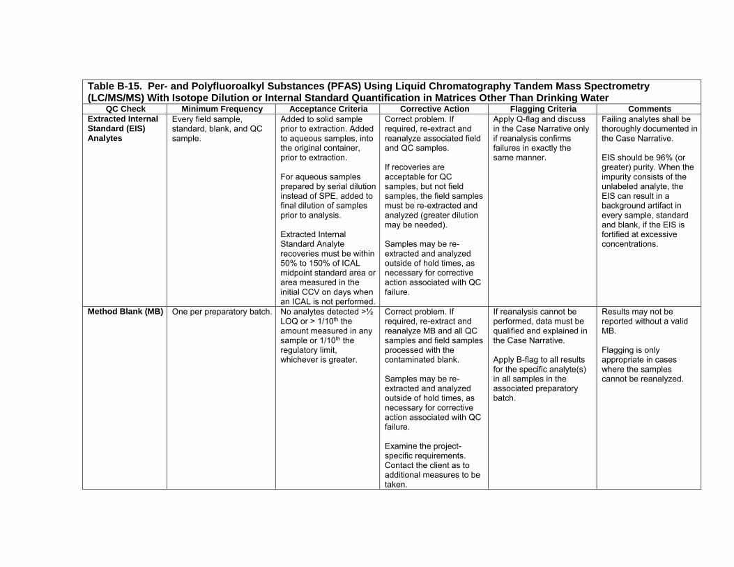
Table B-15. Per- and Polyfluoroalkyl Substances (PFAS) Using Liquid Chromatography Tandem Mass Spectrometry (LC/MS/MS) With Isotope Dilution or Internal Standard Quantification in Matrices Other Than Drinking Water
QC Check Minimum Frequency Acceptance Criteria Corrective Action Flagging Criteria Comments
Extracted Internal Standard (EIS) Analytes
Every field sample,standard, blank, and QCsample.
Added to solid sampleprior to extraction. Addedto aqueous samples, intothe original container,prior to extraction.
For aqueous samplesprepared by serial dilutioninstead of SPE, added tofinal dilution of samplesprior to analysis.
Extracted InternalStandard Analyterecoveries must be within50% to 150% of ICALmidpoint standard area orarea measured in theinitial CCV on days whenan ICAL is not performed.
Correct problem. Ifrequired, re-extract andreanalyze associated fieldand QC samples.
If recoveries areacceptable for QCsamples, but not fieldsamples, the field samplesmust be re-extracted andanalyzed (greater dilutionmay be needed).
Samples may be re-extracted and analyzedoutside of hold times, asnecessary for correctiveaction associated with QCfailure.
Apply Q-flag and discussin the Case Narrative onlyif reanalysis confirmsfailures in exactly thesame manner.
Failing analytes shall bethoroughly documented inthe Case Narrative.
EIS should be 96% (orgreater) purity. When theimpurity consists of theunlabeled analyte, theEIS can result in abackground artifact inevery sample, standardand blank, if the EIS isfortified at excessiveconcentrations.
Method Blank (MB) One per preparatory batch. No analytes detected >½LOQ or > 1/10th theamount measured in anysample or 1/10th theregulatory limit,whichever is greater.
Correct problem. Ifrequired, re-extract andreanalyze MB and all QCsamples and field samplesprocessed with thecontaminated blank.
Samples may be re-extracted and analyzedoutside of hold times, asnecessary for correctiveaction associated with QCfailure.
Examine the project-specific requirements.Contact the client as toadditional measures to betaken.
If reanalysis cannot beperformed, data must bequalified and explained inthe Case Narrative.
Apply B-flag to all resultsfor the specific analyte(s)in all samples in theassociated preparatorybatch.
Results may not bereported without a validMB.
Flagging is onlyappropriate in caseswhere the samplescannot be reanalyzed.
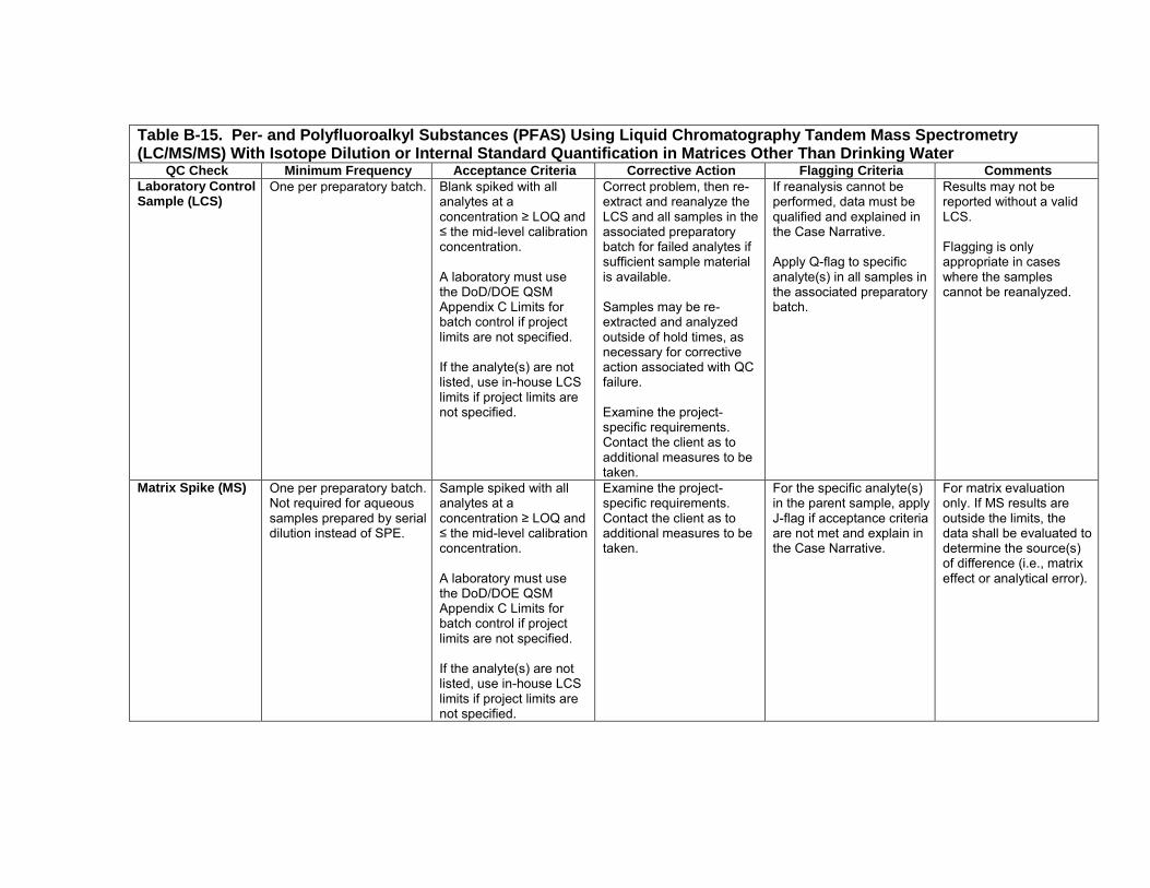
Table B-15. Per- and Polyfluoroalkyl Substances (PFAS) Using Liquid Chromatography Tandem Mass Spectrometry (LC/MS/MS) With Isotope Dilution or Internal Standard Quantification in Matrices Other Than Drinking Water
QC Check Minimum Frequency Acceptance Criteria Corrective Action Flagging Criteria Comments
Laboratory Control Sample (LCS)
One per preparatory batch. Blank spiked with allanalytes at aconcentration ≥ LOQ and≤ the mid-level calibrationconcentration.
A laboratory must usethe DoD/DOE QSMAppendix C Limits forbatch control if projectlimits are not specified.
If the analyte(s) are notlisted, use in-house LCSlimits if project limits arenot specified.
Correct problem, then re-extract and reanalyze theLCS and all samples in theassociated preparatorybatch for failed analytes ifsufficient sample materialis available.
Samples may be re-extracted and analyzedoutside of hold times, asnecessary for correctiveaction associated with QCfailure.
Examine the project-specific requirements.Contact the client as toadditional measures to betaken.
If reanalysis cannot beperformed, data must bequalified and explained inthe Case Narrative.
Apply Q-flag to specificanalyte(s) in all samples inthe associated preparatorybatch.
Results may not bereported without a validLCS.
Flagging is onlyappropriate in caseswhere the samplescannot be reanalyzed.
Matrix Spike (MS) One per preparatory batch.Not required for aqueoussamples prepared by serialdilution instead of SPE.
Sample spiked with allanalytes at aconcentration ≥ LOQ and ≤ the mid-level calibrationconcentration.
A laboratory must usethe DoD/DOE QSMAppendix C Limits forbatch control if projectlimits are not specified.
If the analyte(s) are notlisted, use in-house LCSlimits if project limits arenot specified.
Examine the project- specific requirements.Contact the client as toadditional measures to betaken.
For the specific analyte(s)in the parent sample, applyJ-flag if acceptance criteriaare not met and explain inthe Case Narrative.
For matrix evaluationonly. If MS results areoutside the limits, thedata shall be evaluated todetermine the source(s)of difference (i.e., matrixeffect or analytical error).

Table B-15. Per- and Polyfluoroalkyl Substances (PFAS) Using Liquid Chromatography Tandem Mass Spectrometry (LC/MS/MS) With Isotope Dilution or Internal Standard Quantification in Matrices Other Than Drinking Water
QC Check Minimum Frequency Acceptance Criteria Corrective Action Flagging Criteria Comments
Matrix Spike Duplicate (MSD) or Matrix Duplicate (MD)
For MSD: One perpreparatory batch.
For MD: Each aqueoussample prepared by serialdilution instead of SPE.
For MSD: Sample spikedwith all analytes at aconcentration ≥ LOQ and ≤ the mid-level calibrationconcentration.
A laboratory must usethe DoD/DOE QSMAppendix C Limits forbatch control if projectlimits are not specified.
If the analyte(s) are notlisted, use in-house LCSlimits if project limits arenot specified.
RPD ≤ 30% (between MS and MSD or sample andMD).
Examine the project- specific requirements.Contact the client as toadditional measures to betaken.
For the specific analyte(s)in the parent sample, applyJ-flag if acceptance criteriaare not met and explain inthe Case Narrative.
The data shall beevaluated to determinethe source of difference.
For Sample/MD: RPDcriteria only apply toanalytes whoseconcentration in thesample is ≥ LOQ.
The MD is a secondaliquot of the field samplethat has been preparedby serial dilution.
Post Spike Sample Only applies to aqueoussamples prepared by serialdilution instead of SPE thathave reported value of< LOQ for analyte(s).
Spike all analytesreported as < LOQ intothe dilution that the resultfor that analyte isreported from. The spikemust be at the LOQconcentration to bereported for this sampleas < LOQ.
When analyteconcentrations arecalculated as < LOQ, thepost spike for that analytemust recover within 70-130% of its true value.
When analyteconcentrations arecalculated as < LOQ, andthe spike recovery doesnot meet the acceptancecriteria, the sample,sample duplicate, and postspike sample must bereanalyzed atconsecutively higherdilutions until the criteria ismet.
Flagging is notappropriate.
When analyteconcentrations arecalculated as < LOQ,results may not bereported withoutacceptable post spikerecoveries.
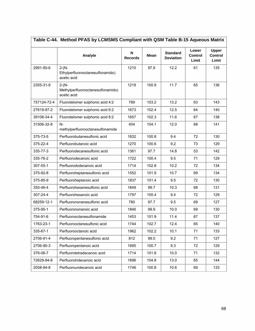
Table C-44. Method PFAS by LCMSMS Compliant with QSM Table B-15 Aqueous Matrix
CAS ID Analyte N
Records Mean
Standard
Deviation
Lower
Control
Limit
Upper
Control
Limit
2991-50-6 2-(N-Ethylperfluorooctanesulfonamido)acetic acid
1210 97.9 12.2 61 135
2355-31-9 2-(N-Methylperfluorooctanesulfonamido)acetic acid
1219 100.9 11.7 65 136
757124-72-4 Fluorotelomer sulphonic acid 4:2 789 103.2 13.2 63 143
27619-97-2 Fluorotelomer sulphonic acid 6:2 1673 102.4 12.5 64 140
39108-34-4 Fluorotelomer sulphonic acid 8:2 1657 102.3 11.6 67 138
31506-32-8 N-methylperfluorooctanesulfonamide
404 104.1 12.0 68 141
375-73-5 Perfluorobutanesulfonic acid 1832 100.8 9.4 72 130
375-22-4 Perfluorobutanoic acid 1270 100.6 9.2 73 129
335-77-3 Perfluorodecanesulfonic acid 1361 97.7 14.8 53 142
335-76-2 Perfluorodecanoic acid 1722 100.4 9.5 71 129
307-55-1 Perfluorododecanoic acid 1714 102.8 10.2 72 134
375-92-8 Perfluoroheptanesulfonic acid 1552 101.9 10.7 69 134
375-85-9 Perfluoroheptanoic acid 1837 101.4 9.5 72 130
355-46-4 Perfluorohexanesulfonic acid 1849 99.7 10.3 68 131
307-24-4 Perfluorohexanoic acid 1797 100.4 9.4 72 129
68259-12-1 Perfluorononanesulfonic acid 780 97.7 9.5 69 127
375-95-1 Perfluorononanoic acid 1846 99.9 10.0 69 130
754-91-6 Perfluorooctanesulfonamide 1453 101.9 11.4 67 137
1763-23-1 Perfluorooctanesulfonic acid 1744 102.7 12.4 65 140
335-67-1 Perfluorooctanoic acid 1962 102.2 10.1 71 133
2706-91-4 Perfluoropentanesulfonic acid 812 99.0 9.2 71 127
2706-90-3 Perfluoropentanoic acid 1695 100.7 9.3 72 129
376-06-7 Perfluorotetradecanoic acid 1714 101.8 10.0 71 132
72629-94-8 Perfluorotridecanoic acid 1696 104.8 13.0 65 144
2058-94-8 Perfluoroundecanoic acid 1746 100.8 10.6 69 133
68
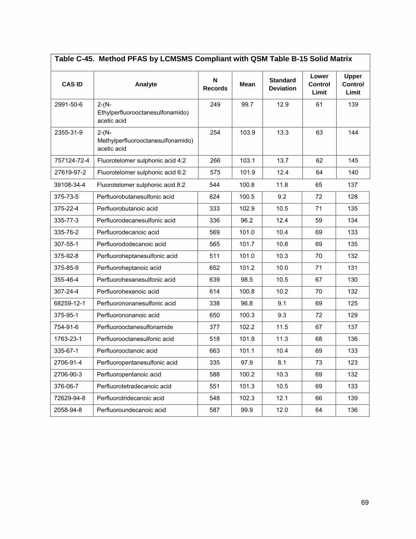
Table C-45. Method PFAS by LCMSMS Compliant with QSM Table B-15 Solid Matrix
CAS ID Analyte N
Records Mean
Standard
Deviation
Lower
Control
Limit
Upper
Control
Limit
2991-50-6 2-(N-Ethylperfluorooctanesulfonamido)acetic acid
249 99.7 12.9 61 139
2355-31-9 2-(N-Methylperfluorooctanesulfonamido)acetic acid
254 103.9 13.3 63 144
757124-72-4 Fluorotelomer sulphonic acid 4:2 266 103.1 13.7 62 145
27619-97-2 Fluorotelomer sulphonic acid 6:2 575 101.9 12.4 64 140
39108-34-4 Fluorotelomer sulphonic acid 8:2 544 100.8 11.8 65 137
375-73-5 Perfluorobutanesulfonic acid 624 100.5 9.2 72 128
375-22-4 Perfluorobutanoic acid 333 102.9 10.5 71 135
335-77-3 Perfluorodecanesulfonic acid 336 96.2 12.4 59 134
335-76-2 Perfluorodecanoic acid 569 101.0 10.4 69 133
307-55-1 Perfluorododecanoic acid 565 101.7 10.8 69 135
375-92-8 Perfluoroheptanesulfonic acid 511 101.0 10.3 70 132
375-85-9 Perfluoroheptanoic acid 652 101.2 10.0 71 131
355-46-4 Perfluorohexanesulfonic acid 639 98.5 10.5 67 130
307-24-4 Perfluorohexanoic acid 614 100.8 10.2 70 132
68259-12-1 Perfluorononanesulfonic acid 338 96.8 9.1 69 125
375-95-1 Perfluorononanoic acid 650 100.3 9.3 72 129
754-91-6 Perfluorooctanesulfonamide 377 102.2 11.5 67 137
1763-23-1 Perfluorooctanesulfonic acid 518 101.9 11.3 68 136
335-67-1 Perfluorooctanoic acid 663 101.1 10.4 69 133
2706-91-4 Perfluoropentanesulfonic acid 335 97.9 8.1 73 123
2706-90-3 Perfluoropentanoic acid 588 100.2 10.3 69 132
376-06-7 Perfluorotetradecanoic acid 551 101.3 10.5 69 133
72629-94-8 Perfluorotridecanoic acid 548 102.3 12.1 66 139
2058-94-8 Perfluoroundecanoic acid 587 99.9 12.0 64 136
69
Copyright © 2022 FDOKUMEN