Anatomy of common scatterpoint (CSP) gathers formed during equivalent offset prestack migration (EOM
10
Anatomy of CSP gathers CREWES Research Report — Volume 9 (1997) 28-1 Anatomy of common scatterpoint (CSP) gathers formed during equivalent offset prestack migration (EOM) John C. Bancroft and Hugh D. Geiger SUMMARY The equivalent offset method of prestack migration (EOM) is a two step process: the first being a gathering process that forms common scatterpoint (CSP) gathers, and the second a simplified Kirchhoff NMO to zero offset performed on the CSP gathers. CSP gathers contain a greater amount of information than conventional CMP gathers because they contain all input traces within the prestack migration aperture. These traces are sorted by an equivalent offset into bins in the CSP gather with no time shifting. The energy from these traces, which is typically associated with CMP gathers and poststack migration, is now combined into one CSP gather to produce a compounded distribution of energy. Understanding the distribution of energy on the CSP gather is essential to define parameters for a successful prestack migration. INTRODUCTION The formation of common scatterpoint gathers Common scatterpoint (CSP) gathers are formed at each output trace location similar to CMP gathers. The CSP gathers are composed of all input traces within the prestack migration aperture. The offset of each input trace is uniquely computed for each CSP location, and is based on the distance of the source and receiver relative to the CSP location. Figure 1b shows the ray paths for a given source and receiver travelling to and from a scatterpoint. The source and receiver are collocated at an imaginary surface position that maintains the same time T, thus defining the equivalent offset h e . Equating travel times gives ( 29 ( 29 2 1 2 2 2 0 2 1 2 2 2 0 2 1 2 2 2 0 2 + = - + + + + = V h T V h x T V h x T T e (1) where x is the distance from the CSP location to the CMP location, h the half source- receiver offset, T 0 the vertical one-way traveltime, and V the RMS velocity defined at the scatterpoint. Solving for h e gives 2 2 2 2 2 2 2 4 V T h x h x h e - + = . (2) The reflection point in Figure 1b is observed to lie on a hyperbolic moveout path at the equivalent offset h e , while still maintaining the original input time T as required by equation (1).
Transcript of Anatomy of common scatterpoint (CSP) gathers formed during equivalent offset prestack migration (EOM
Anatomy of CSP gathers
CREWES Research Report — Volume 9 (1997) 28-1
Anatomy of common scatterpoint (CSP) gathers formedduring equivalent offset prestack migration (EOM)
John C. Bancroft and Hugh D. Geiger
SUMMARY
The equivalent offset method of prestack migration (EOM) is a two step process:the first being a gathering process that forms common scatterpoint (CSP) gathers, andthe second a simplified Kirchhoff NMO to zero offset performed on the CSP gathers.
CSP gathers contain a greater amount of information than conventional CMPgathers because they contain all input traces within the prestack migration aperture.These traces are sorted by an equivalent offset into bins in the CSP gather with notime shifting. The energy from these traces, which is typically associated with CMPgathers and poststack migration, is now combined into one CSP gather to produce acompounded distribution of energy. Understanding the distribution of energy on theCSP gather is essential to define parameters for a successful prestack migration.
INTRODUCTION
The formation of common scatterpoint gathers
Common scatterpoint (CSP) gathers are formed at each output trace locationsimilar to CMP gathers. The CSP gathers are composed of all input traces within theprestack migration aperture. The offset of each input trace is uniquely computed foreach CSP location, and is based on the distance of the source and receiver relative tothe CSP location. Figure 1b shows the ray paths for a given source and receivertravelling to and from a scatterpoint. The source and receiver are collocated at animaginary surface position that maintains the same time T, thus defining theequivalent offset he. Equating travel times gives
( ) ( ) 21
2
22
0
21
2
22
0
21
2
22
0 2
+=
−++
++=V
hT
V
hxT
V
hxTT e (1)
where x is the distance from the CSP location to the CMP location, h the half source-receiver offset, T0 the vertical one-way traveltime, and V the RMS velocity defined atthe scatterpoint. Solving for he gives
22
22222 4
VT
hxhxhe −+= . (2)
The reflection point in Figure 1b is observed to lie on a hyperbolic moveout path atthe equivalent offset he, while still maintaining the original input time T as requiredby equation (1).

Bancroft and Geiger
28-2 CREWES Research Report — Volume 9 (1997)
xh h
T , z0 0
Ts
Tr
CSP R CMP S
Scatterpoint
T
he
T , z0 0
TsTr
CSP R CMP S
Scatterpoint
T
T
Figure 1. Ray diagram for a) a given source and receiver, and b) a colocated source andreceiver that defines the equivalent offset.
The equivalent offset is defined from source and receiver locations to scatterpointslocated below a surface position of the migrated output trace (Bancroft et al. 1996).Samples in each input trace, within the prestack migration aperture, are assigned anequivalent offset and then summed into offset bins of the CSP gather. The equivalentoffset in equation (2) includes a time and velocity dependence which may spread aninput trace across a number of offset bins. Equation (2) is only computed at thetransition times where the input trace moves from one input bin to another.
CSP gathers may be formed at any surface position: singularly for velocityanalysis, as a 2-D line extracted from a 3-D volume or for complete 2-D or 3-Dprocessing. The formation of CSP gathers is fast because no time shifting, scaling, orfiltering is required. Scattered energy lies on hyperbolic paths at the appropriateprestack migration velocity.
Velocity analysis
The movement of input energy to the CSP gathers is slightly dependent on velocity(Bancroft and Geiger 1996). Usually a stacking velocity from previous processing issufficient to form the CSP gathers. Velocity analysis of the hyperbolic moveout inthe CSP gathers (such as conventional semblance plots) can then be applied toestimate more accurate velocities. The improved velocities can be used to image thegather directly by applying Kirchhoff NMO, or as input velocities for creating moreaccurate CSP gathers.
Kirchhoff NMO and stack
Once the CSP gathers have been formed, the prestack migration is completed withKirchhoff NMO. Energy from seismic reflections is aligned along hyperbolic pathssimilar to a CMP gather. Conventional NMO correction (simply referred to as NMO)will flatten the hyperbolic reflection energy which is then stacked to produce the finalsection. The process however, must also include antialias filtering, phase filtering,
Anatomy of CSP gathers
CREWES Research Report — Volume 9 (1997) 28-3
and scaling that is part of the Kirchhoff migration process. We refer to this combinedprocess as Kirchhoff NMO. Note that a significant reduction in computational effortis achieved because the scaling and filtering is applied to the binned traces of the CSPgather after they have been formed.
DISTRIBUTION OF ENERGY ON THE CSP GATHER
Horizontal events
Energy from a 2-D horizontal constant amplitude reflector at time T0 forms ahyperbolic cylinder within the prestack volume (x, h, t) where x is the CMP location,h the half offset, and t the time axis, as illustrated in Figure 2a. A CMP gather is aplane (h, t) at a defined xcmp that intersects the cylinder, and contains energy along ahyperbolic curve as illustrated in Figure 2b. NMO and stacking moves the energy tothe apparent reflector position at T0 on the zero offset plane. Poststack time migrationproduces no additional change to the horizontal reflectors.
In creating a CSP gather at xcsp, all energy from the hyperbolic cylinder (that lieswithin the migration aperture) will be summed without time shifting into the CSPgather at an appropriate equivalent offset. This includes the CMP hyperbolic data, thezero offset data at time T0, and all points in between. Thus the CSP gather contains animage of the zero offset section, as illustrated by the horizontal event in Figure 2c.
The lower boundary of energy in Figure 2c is formed by the hyperbolic data closeto the xcsp plane. The gray area in Figure 2c represents the remaining energy from theprestack hyperbolic cylinder, which will lie between the horizontal event at T0 and thelower hyperbola. For band-limited seismic wavelets, this energy will destructivelyinterfere. Thus, for a horizontal reflector, all that appears in the CSP gather will bethe horizontal event at T0 and the hyperbolic event, as illustrated in Figure 2d. Thesetwo events converge at zero equivalent offset and time T0 to form a prow (bow ofyacht) shape. For horizontal constant amplitude events, the maximum equivalentoffset of specular energy is limited by the source-receiver offset. However, scatteredor diffuse energy from real data will lie well beyond this limiting offset. The largerequivalent offsets in CSP gathers include this energy and thus enhance the imaging.
The prow shape on a CSP gather, produced by horizontal reflectors, indicates thatthe formation of the gather combines specular and diffuse energy. As in poststackmigration of horizontal events, only the horizontal portion of the prow at zero offsetwill contribute energy to the output migrated trace. Consequently the zero offsetimprinting has no effect on the final migrated image.
A detailed analysis of the prow shape will also reveal different phase changes onthe horizontal and hyperbolic boundaries. These phase changes are a necessary partof the process and, after Kirchhoff NMO, will be combined to produce the correctphase of the horizontal reflector.

Bancroft and Geiger
28-4 CREWES Research Report — Volume 9 (1997)
a. b.
c. d.
Figure 2. Energy distribution for a horizontal reflector at time T0 displayed in a) as a surface ina prestack volume (x, h, t), b) a hyperbolic curve in a CMP gather before NMO, c) a CSPgather with a zone of destructive interference shown in gray, and d) with constructiveinterference showing horizontal and hyperbolic distributions of energy to form a “prow”.
The distribution of energy on the CSP gather is an essential part of the process.Kirchhoff NMO is a very powerful operation that reconstructs the appropriatereflection energy and attenuates all other energy.
Dipping events
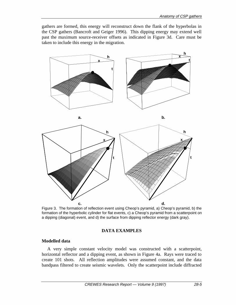
The horizontal reflector may be considered as a set of closely spaced scatterpointsalong a horizontal line. Energy from each scatterpoint lies on a surface defined byequation (1), often referred to as Cheop’s pyramid, as illustrated in Figure 3a. Withthe combination of many scatterpoints, this model constructively and destructivelyinterferes to produce a hyperbolic cylinder in the prestack volume, as illustrated inFigure 3b (and in Figure 2a).
Dipping events can also be considered a set of closely spaced scatterpoints lyingalong the event, as represented by the thick line in Figure 3c. The Cheop’s pyramidsfrom all scatterpoints (one is shown in Figure 3c) will reconstruct the appropriatedipping reflection surface shown in Figure 3d. When considering Cheop’s pyramidas a summation surface for prestack migration, the area of tangency (identified by thehighlighted band in Figure 3d), will be summed back to the scatterpoint. When CSP
Anatomy of CSP gathers
CREWES Research Report — Volume 9 (1997) 28-5
gathers are formed, this energy will reconstruct down the flank of the hyperbolas inthe CSP gathers (Bancroft and Geiger 1996). This dipping energy may extend wellpast the maximum source-receiver offsets as indicated in Figure 3d. Care must betaken to include this energy in the migration.
xh
t
xh
t
a. b.
x
h
t
x
h
t
c. d.Figure 3. The formation of reflection event using Cheop’s pyramid, a) Cheop’s pyramid, b) theformation of the hyperbolic cylinder for flat events, c) a Cheop’s pyramid from a scatterpoint ona dipping (diagonal) event, and d) the surface from dipping reflector energy (dark gray).
DATA EXAMPLES
Modelled data
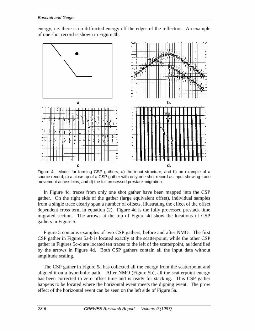
A very simple constant velocity model was constructed with a scatterpoint,horizontal reflector and a dipping event, as shown in Figure 4a. Rays were traced tocreate 101 shots. All reflection amplitudes were assumed constant, and the databandpass filtered to create seismic wavelets. Only the scatterpoint include diffracted
Bancroft and Geiger
28-6 CREWES Research Report — Volume 9 (1997)
energy, i.e. there is no diffracted energy off the edges of the reflectors. An exampleof one shot record is shown in Figure 4b.
a. b.
c. d.Figure 4. Model for forming CSP gathers, a) the input structure, and b) an example of asource record, c) a close up of a CSP gather with only one shot record as input showing tracemovement across bins, and d) the full processed prestack migration.
In Figure 4c, traces from only one shot gather have been mapped into the CSPgather. On the right side of the gather (large equivalent offset), individual samplesfrom a single trace clearly span a number of offsets, illustrating the effect of the offsetdependent cross term in equation (2). Figure 4d is the fully processed prestack timemigrated section. The arrows at the top of Figure 4d show the locations of CSPgathers in Figure 5.
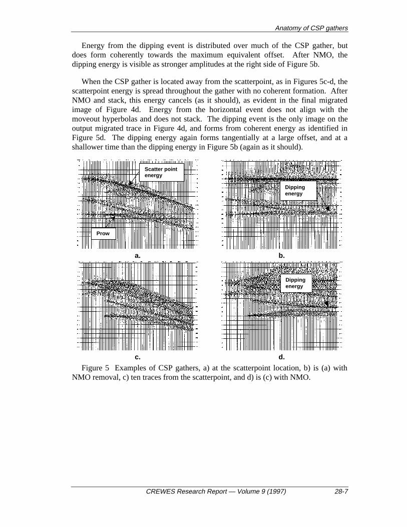
Figure 5 contains examples of two CSP gathers, before and after NMO. The firstCSP gather in Figures 5a-b is located exactly at the scatterpoint, while the other CSPgather in Figures 5c-d are located ten traces to the left of the scatterpoint, as identifiedby the arrows in Figure 4d. Both CSP gathers contain all the input data withoutamplitude scaling.
The CSP gather in Figure 5a has collected all the energy from the scatterpoint andaligned it on a hyperbolic path. After NMO (Figure 5b), all the scatterpoint energyhas been corrected to zero offset time and is ready for stacking. This CSP gatherhappens to be located where the horizontal event meets the dipping event. The proweffect of the horizontal event can be seen on the left side of Figure 5a.
Anatomy of CSP gathers
CREWES Research Report — Volume 9 (1997) 28-7
Energy from the dipping event is distributed over much of the CSP gather, butdoes form coherently towards the maximum equivalent offset. After NMO, thedipping energy is visible as stronger amplitudes at the right side of Figure 5b.
When the CSP gather is located away from the scatterpoint, as in Figures 5c-d, thescatterpoint energy is spread throughout the gather with no coherent formation. AfterNMO and stack, this energy cancels (as it should), as evident in the final migratedimage of Figure 4d. Energy from the horizontal event does not align with themoveout hyperbolas and does not stack. The dipping event is the only image on theoutput migrated trace in Figure 4d, and forms from coherent energy as identified inFigure 5d. The dipping energy again forms tangentially at a large offset, and at ashallower time than the dipping energy in Figure 5b (again as it should).
Prow
Scatter pointenergy
a. b.
c. d.
Figure 5 Examples of CSP gathers, a) at the scatterpoint location, b) is (a) withNMO removal, c) ten traces from the scatterpoint, and d) is (c) with NMO.
Dippingenergy
Dippingenergy

Bancroft and Geiger
28-8 CREWES Research Report — Volume 9 (1997)
REAL DATA EXAMPLES
Figure 6 contains an example of a CSP gather formed from an Alberta data set.The gather contains energy from horizontal reflectors that form the prow effectsidentified by the arrows.
Equivalent offset
time
0 max
Figure 6. An example of a CSP gather illustrating the prow effect.
Figure 7 contains a CMP gather, a CMP gather with the traces located at their trueoffset, and a CSP gather, all from the same data set shown in Figure 6. On the CSPgather, note the larger offsets, and full coverage of all offset traces. Thereconstruction of energy on the CSP gather comes from all input traces within themigration aperture, with energy positioned at an offset relative to the migrated tracelocation. Note the hyperbolic energy with zero offset time of 1.25s. This diffractionenergy comes from the edge of a channel at the same location as the CSP gather.Amplitudes in this CSP gather have been scaled for viewing purposes and showssome uneven patterns that may be due to gaps in acquisition geometry.
A conventional migration is compared with an equivalent offset prestack migration(EOM) in Figure 8. The data is also from the same Alberta data set and incorporatesthe CSP gather containing the channel edge. Note the superior signal to noise ratio inthe EOM example which illustrates that additional energy in CSP gathers does notdegrade the prestack migration.

Anatomy of CSP gathers
CREWES Research Report — Volume 9 (1997) 28-9
Figure 7. Comparison of a CMP gather, a CMP gather with traces at their true offset, and aCSP gather.
a. b.
Figure 8. Comparison of a) a traditional migration, and b) an EOM migration thatincorporates the CSP gather of Figure 7.
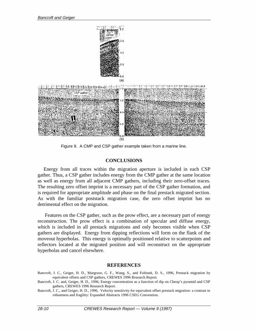
Figure 9 contains a comparison of a super-CMP gather and a two-sided CSPgather. This example is taken from a marine line where the water bottom is atapproximately 3.0s. The CSP gather was formed with a fixed equivalent offsetapplied to the entire trace. Consequently the entire input trace is summed into thegather. This approach captures a more complete zero offset image as is evident fromthe image of the sloping water bottom and its multiple at approximately 6 seconds.The CSP gather has a much greater offset than the CMP gather, and containshyperbolic energy that extends to these large offsets. Reflections from dipping eventsare evident as maximums on the flank of the hyperbolas. An arrow in Figure 9identifies one such example.
Bancroft and Geiger
28-10 CREWES Research Report — Volume 9 (1997)
Figure 9. A CMP and CSP gather example taken from a marine line.
CONCLUSIONS
Energy from all traces within the migration aperture is included in each CSPgather. Thus, a CSP gather includes energy from the CMP gather at the same locationas well as energy from all adjacent CMP gathers, including their zero-offset traces.The resulting zero offset imprint is a necessary part of the CSP gather formation, andis required for appropriate amplitude and phase on the final prestack migrated section.As with the familiar poststack migration case, the zero offset imprint has nodetrimental effect on the migration.
Features on the CSP gather, such as the prow effect, are a necessary part of energyreconstruction. The prow effect is a combination of specular and diffuse energy,which is included in all prestack migrations and only becomes visible when CSPgathers are displayed. Energy from dipping reflections will form on the flank of themoveout hyperbolas. This energy is optimally positioned relative to scatterpoints andreflectors located at the migrated position and will reconstruct on the appropriatehyperbolas and cancel elsewhere.
REFERENCES
Bancroft, J. C., Geiger, H. D., Margrave, G. F., Wang, S., and Foltinek, D. S., 1996, Prestack migration byequivalent offsets and CSP gathers, CREWES 1996 Research Report.
Bancroft, J. C. and, Geiger, H. D., 1996, Energy concentration as a function of dip on Cheop’s pyramid and CSPgathers, CREWES 1996 Research Report.
Bancroft, J. C., and Geiger, H. D., 1996, Velocity sensitivity for equivalent offset prestack migration: a contrast inrobustness and fragility: Expanded Abstracts 1996 CSEG Convention.