Analysis of turbine generator steady‐state reactances for load conditions
11
Analysis of Turbine Generator Steady-State Reactances for Load Conditions SHINICHI WAKUI, KAZUMASA IDE, MIYOSHI TAKAHASHI, GUSTAVO MONTOYA, FUTOSHI HIYAMA, and YASUOMI YAGI Hitachi Ltd., Japan SUMMARY This paper describes variations of turbine generator steady-state reactances for load conditions. When the tur- bine generator is of small size, magnetic saturation of the stator and rotor core is a problem. Therefore, it is important to understand the variations of the reactances for load conditions. The reactances of a 592-MVA turbine generator are calculated with d- and q-axis equations considering magnetic saturation and two-dimensional numerical mag- netic field analysis. The results are as follows. (1) The equivalent synchronous reactances consid- ering cross-magnetizing are smaller than the original syn- chronous reactances for load conditions. (2) Numerical values of the d- and q-axis mutual reactance and the field and q-axis mutual reactance are at their maximum when the d-axis linkage flux is nearly equal to the q-axis linkage flux under constant voltage. (3) The d-axis synchronous reactance drops with increasing reactive power under constant voltage and active power, but the q-axis synchronous reactance increases. (4) The variation of the equivalent d-axis synchro- nous reactance with increasing reactive power is similar to that of the d-axis synchronous reactance, but the variation of the equivalent q-axis synchronous reactance is different from that of the q-axis synchronous reactance. ' 1998 Scripta Technica. Electr Eng Jpn, 123(3): 7383, 1998 Key words: Turbine generator; d- and q-axis equa- tions; magnetic field analysis; magnetic saturation; reac- tance. 1. Introduction In the market for rotating machines in recent years, the demand for lower prices is increasing, in addition to demands regarding the performance of the machines, and low-cost implementation by reducing machine size be- comes necessary. One of the problems in such reduction is the pronounced magnetic saturation of the rotor and stator cores due to the high magnetic field implementation, and compensation of the accuracy drop in the characteristic calculations by nonlinear magnetic characteristics becomes necessary. In the general method, the characteristics of a syn- chronous machine under load conditions are calculated by first calculating the no-load and three-phase short-circuit characteristics and then using these and the numerical val- ues statistically processed by Potier reactances and so forth [1]. The generator performance must be determined origi- nally based on the characteristics under load conditions; however, it my not necessarily be the case that the electrical characteristics under load conditions can be accurately grasped as long as a method close to such an estimation is adopted. The characteristic values which show the electrical performance under load conditions are the reactances. These reactances are used in the analysis of stability and so forth for large-capacity synchronous machines to be oper- ated in power systems; however, in general, they are used by dividing them into two values, the saturated value and the unsaturated value. The saturated value is calculated for a state corresponding to the time when a no-load rated voltage occurs; however, under various load states, no account is taken of when the flux level and the direction of the main flux inside the generator change, and thus the reactance values change. Analytical techniques for performing power system analysis considering the effect of saturation in the generator reactances have been proposed [2, 3]. However, the power system voltage is fixed, and for the general operation pat- terns of generators whose power factor and output change, no examples have been confirmed in which the reactance values under various load states are calculated with allow- CCC0424-7760/98/030073-11 ' 1998 Scripta Technica Electrical Engineering in Japan, Vol. 123, No. 3, 1998 Translated from Denki Gakkai Ronbunshi, Vol. 117-D, No. 3, March 1997, pp. 364372 73
Transcript of Analysis of turbine generator steady‐state reactances for load conditions

Analysis of Turbine Generator Steady-State Reactances for Load Conditions
SHIN�ICHI WAKUI, KAZUMASA IDE, MIYOSHI TAKAHASHI, GUSTAVO MONTOYA,
FUTOSHI HIYAMA, and YASUOMI YAGIHitachi Ltd., Japan
SUMMARY
This paper describes variations of turbine generator
steady-state reactances for load conditions. When the tur-
bine generator is of small size, magnetic saturation of the
stator and rotor core is a problem. Therefore, it is important
to understand the variations of the reactances for load
conditions. The reactances of a 592-MVA turbine generator
are calculated with d- and q-axis equations considering
magnetic saturation and two-dimensional numerical mag-
netic field analysis. The results are as follows.
(1) The equivalent synchronous reactances consid-
ering cross-magnetizing are smaller than the original syn-
chronous reactances for load conditions.
(2) Numerical values of the d- and q-axis mutual
reactance and the field and q-axis mutual reactance are at
their maximum when the d-axis linkage flux is nearly equal
to the q-axis linkage flux under constant voltage.
(3) The d-axis synchronous reactance drops with
increasing reactive power under constant voltage and active
power, but the q-axis synchronous reactance increases.
(4) The variation of the equivalent d-axis synchro-
nous reactance with increasing reactive power is similar to
that of the d-axis synchronous reactance, but the variation
of the equivalent q-axis synchronous reactance is different
from that of the q-axis synchronous reactance. © 1998
Scripta Technica. Electr Eng Jpn, 123(3): 73�83, 1998
Key words: Turbine generator; d- and q-axis equa-
tions; magnetic field analysis; magnetic saturation; reac-
tance.
1. Introduction
In the market for rotating machines in recent years,
the demand for lower prices is increasing, in addition to
demands regarding the performance of the machines, and
low-cost implementation by reducing machine size be-
comes necessary. One of the problems in such reduction is
the pronounced magnetic saturation of the rotor and stator
cores due to the high magnetic field implementation, and
compensation of the accuracy drop in the characteristic
calculations by nonlinear magnetic characteristics becomes
necessary.
In the general method, the characteristics of a syn-
chronous machine under load conditions are calculated by
first calculating the no-load and three-phase short-circuit
characteristics and then using these and the numerical val-
ues statistically processed by Potier reactances and so forth
[1]. The generator performance must be determined origi-
nally based on the characteristics under load conditions;
however, it my not necessarily be the case that the electrical
characteristics under load conditions can be accurately
grasped as long as a method close to such an estimation is
adopted.
The characteristic values which show the electrical
performance under load conditions are the reactances.
These reactances are used in the analysis of stability and so
forth for large-capacity synchronous machines to be oper-
ated in power systems; however, in general, they are used
by dividing them into two values, the saturated value and
the unsaturated value. The saturated value is calculated for
a state corresponding to the time when a no-load rated
voltage occurs; however, under various load states, no
account is taken of when the flux level and the direction of
the main flux inside the generator change, and thus the
reactance values change.
Analytical techniques for performing power system
analysis considering the effect of saturation in the generator
reactances have been proposed [2, 3]. However, the power
system voltage is fixed, and for the general operation pat-
terns of generators whose power factor and output change,
no examples have been confirmed in which the reactance
values under various load states are calculated with allow-
CCC0424-7760/98/030073-11
© 1998 Scripta Technica
Electrical Engineering in Japan, Vol. 123, No. 3, 1998Translated from Denki Gakkai Ronbunshi, Vol. 117-D, No. 3, March 1997, pp. 364�372
73

ance for magnetic coupling of both the d axis and the field
with the q axis at saturation.
Therefore, it may be necessary to consider generator
performance under load conditions and to reconstruct the
design guidelines of the generator in order to enhance
magnetic loading and reduce machine size. When attention
is paid to these characteristics under load conditions, it is
necessary to determine quantitatively the variations of the
reactances of the generator under various load conditions.
As to the attempts to calculate the field current under
any load condition, Chari and others have proposed a
method using a two-dimensional magnetic field analysis
and the d�q axis equations [4, 5]. However, in that method,
since the aforementioned magnetic couplings between the
d and q axes and between the field and q axis which are
typical of saturation have not been considered, it is difficult
to allow for these effects. In order to solve this problem, the
authors and others have previously proposed a method for
calculating the field current and reactances under any load
condition while taking into account the magnetic couplings
which are typical of saturation; they reported that a good
analytical accuracy can be obtained even in a wide region
of saturation, compared to the case of not considering the
magnetic couplings which are typical of saturation [6].
In this paper, by applying the previously proposed
calculation method for reactances under any load condition,
the variations of the reactances under various load states are
quantitatively analyzed, investigated, and consolidated,
taking into account the magnetic couplings between the d
and q axes and between the field and q axis at saturation.
First, we will describe reactance calculations by the ex-
tended d�q axis equations with allowance for magnetic
saturation and the equivalent transformation of these reac-
tances into the reactances in the conventional d�q axis
equations without allowance for magnetic saturation. Then,
using a 592-MVA turbine generator, the variations of the
reactances are calculated for the case when the voltage and
power factor are constant and the output is varied, and for
the case when the voltage and output are constant and the
power factor is varied; and the results of transforming them
into the aforementioned equivalent reactances are shown.
As a result, the following become clear quantitatively: the
variations of the reactances expressing the magnetic cou-
plings which are typical of saturation when the load
changes, as well as the differences between the values of
the reactances defined by the d�q axis equations with
allowance for magnetic saturation and the values of the
equivalently transformed reactances defined by the conven-
tional d�q axis equations.
We will describe the above results in this paper.
2. Calculation Method for Field Current and
Reactances
In this section, we will describe the method for cal-
culating the field current and reactances under any load
condition by using the d�q axis equations with allowance
for magnetic saturation and a two-dimensional magnetic
field analysis, and will explain the method for equivalently
transforming the reactances thus obtained into the reac-
tances in the conventional d�q axis equations without al-
lowance for magnetic saturation.
2.1 Calculation method for field current and
reactances considering magnetic saturation
If the d-axis armature linkage flux fd, the q-axis
armature linkage flux fq, and the field linkage flux ffconsidering magnetic saturation are expressed in the per-
unit system, we obtain the following equations [6]:
where xd is the d-axis synchronous reactance, xq is the q-axis
synchronous reactance, xf is the field winding self-reac-
tance, xad is the d-axis armature reaction reactance, xdq is
the mutual reactance between the d and q axes, xfq is the
mutual reactance between the field and q axis, id is the
d-axis armature current, iq is the q-axis armature current,
and if is the field current. In Eqs. (1) to (3), the respective
reactances will be changed by the magnetic saturation.
Moreover, based on Eqs. (1) to (3), the d-axis arma-
ture voltage vd and q-axis armature voltage vq can be ex-
pressed by
where r is the armature winding resistance.
Figure 1 shows the vector diagram of the synchro-
nous generator. Figure 1(a) is the case without allowance
for magnetic saturation and Fig.1(b) is the case considering
magnetic saturation. They are drawn based on Eqs. (4) and
(5). In this figure, ef as well as ed and eq are, respectively,
the voltage induced by the field current and the voltage
drops produced by the d- and q-axis armature currents; efand ed are vectors in the q-axis direction and eq is a vector
in the d-axis direction in the case without allowance for
(1)
(2)
(3)
(4)
(5)
74
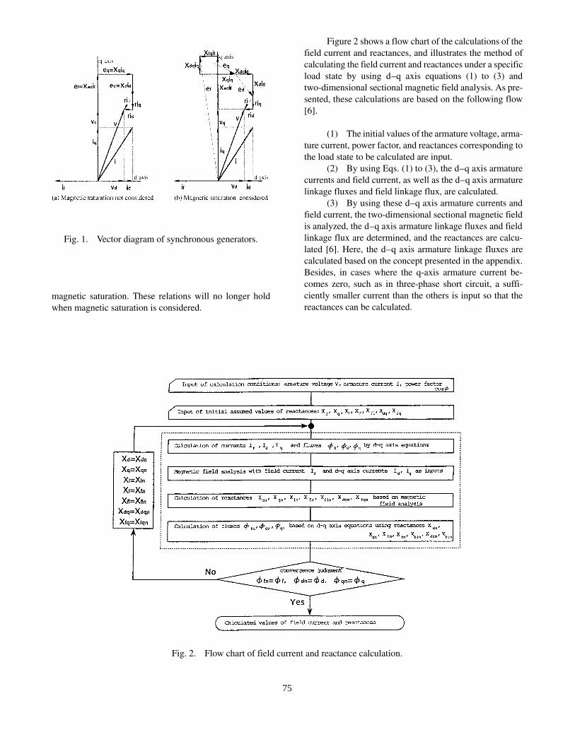
magnetic saturation. These relations will no longer hold
when magnetic saturation is considered.
Figure 2 shows a flow chart of the calculations of the
field current and reactances, and illustrates the method of
calculating the field current and reactances under a specific
load state by using d�q axis equations (1) to (3) and
two-dimensional sectional magnetic field analysis. As pre-
sented, these calculations are based on the following flow
[6].
(1) The initial values of the armature voltage, arma-
ture current, power factor, and reactances corresponding to
the load state to be calculated are input.
(2) By using Eqs. (1) to (3), the d�q axis armature
currents and field current, as well as the d�q axis armature
linkage fluxes and field linkage flux, are calculated.
(3) By using these d�q axis armature currents and
field current, the two-dimensional sectional magnetic field
is analyzed, the d�q axis armature linkage fluxes and field
linkage flux are determined, and the reactances are calcu-
lated [6]. Here, the d�q axis armature linkage fluxes are
calculated based on the concept presented in the appendix.
Besides, in cases where the q-axis armature current be-
comes zero, such as in three-phase short circuit, a suffi-
ciently smaller current than the others is input so that the
reactances can be calculated.
Fig. 1. Vector diagram of synchronous generators.
Fig. 2. Flow chart of field current and reactance calculation.
75

(4) The calculated reactances are corrected by con-
sidering the effect of the air ducts and end steps on the stator
side and the group slots on the rotor side as well as the
leakage reactances of the armature winding end portion [6].
(5) From the three-dimensional corrected reac-
tances, the d- and q-axis armature linkage fluxes and the
field linkage flux are calculated and updated.
(6) Whether or not the updated values of the linkage
fluxes agree with the values before update is judged. If they
agree, it is judged that the solutions of the currents, fluxes,
and reactances have converged; and if not, the updated
values of the reactances are replaced with the values before
update and the calculations of (2) to (5) are repeated.
2.2 Equivalent reactances
Equations (1) to (3) are the equations for the armature
linkage fluxes between the d and q axes and between the
field and q axis considering magnetic coupling; however,
they differ from the forms of the d- and q-axis equations of
the synchronous machines generally used. For this reason,
if the equations for the armature linkage fluxes are ex-
pressed by considering the effect of magnetic couplings
xdq between the d and q axes and coupling xfq between the
field and q axis in d- and q-axis synchronous reactances
xd and xq, we obtain
where xl is the armature leakage reactance and xaq is the
q-axis armature reaction reactance.
Here, xdeq and xqeq will be called the equivalent d-axis
synchronous reactance and equivalent q-axis synchronous
reactance, respectively; and xadeq and xaqeq will be called the
equivalent d-axis armature reaction reactance and equiva-
lent q-axis armature reaction reactance, respectively. These
reactances are defined in order to express the armature
linkage fluxes equal to the conventional equations without
the coupling of the d axis to the field and to the q axis.
However, as is also clear from the derivation of Eqs. (6) and
(7), these equivalent reactances can be compared with the
equations for the conventional linkage fluxes, but cannot be
used in the equation for the field linkage flux.
3. Variations of Reactances under Load Conditions
In this section, using a 592-MVA turbine generator,
we will first analyze the field current and reactances by the
analytical method shown in the preceding section, compare
them with the measured results, and confirm the calculation
accuracy of the proposed analytical technique under vari-
ous operating states. Then, we will calculate and investigate
the variations of the reactances for the case when the voltage
and power factor are constant and the output is varied, as
well as for the case when the voltage and output are constant
and the power factor is varied.
3.1 Generator under analysis
Table 1 shows the main specifications of the gener-
ator under consideration. The generator under considera-
tion is a 592-MVA turbine generator and is a
standardized-design machine of this class.
Figure 3 shows the three-phase short-circuit and no-
load saturation curves. The calculated values and measured
values of the three-phase short-circuit curve agree well. For
the no-load saturation curve, the calculated values of the
field current are slightly larger than the measured values;
however, a good calculation result is obtained even in the
region above the rated voltage where the magnetic satura-
tion is large. The reason why the calculated field currents
at no load are somewhat larger than the measured values
my be presumed to be that although the field flux linking
the end portion of the armature winding has occurred under
the state of no armature reaction, it is not considered in the
analysis.
Table 2 shows the analysis cases under load condi-
tions. Cases 1 to 4 are inductive loads near the rated power
factor 0.85, where the output is set at about 40, 60, 80, and
100% of the rated load, respectively. Cases 5 and 6 represent
a noninductive load with an output set at about 100% and
a capacitive load with an output set at about 100%, respec-
tively.
Figure 4 shows the calculated field currents under
load conditions. Figure 4(a) shows Cases 1 to 4 of Table 2,
namely, the field currents when the power factor is constant
at 0.85 p.u. and the load is increased. Figure 4(b) shows
Cases 5 and 6 of Table 2, namely, the field currents when
(6)
(7)
76

the output is constant at about 100% and the power factor
is varied. It is seen that the calculated field currents under
load conditions agree well with the measured values, with
little error, regardless of the magnitude of the load.
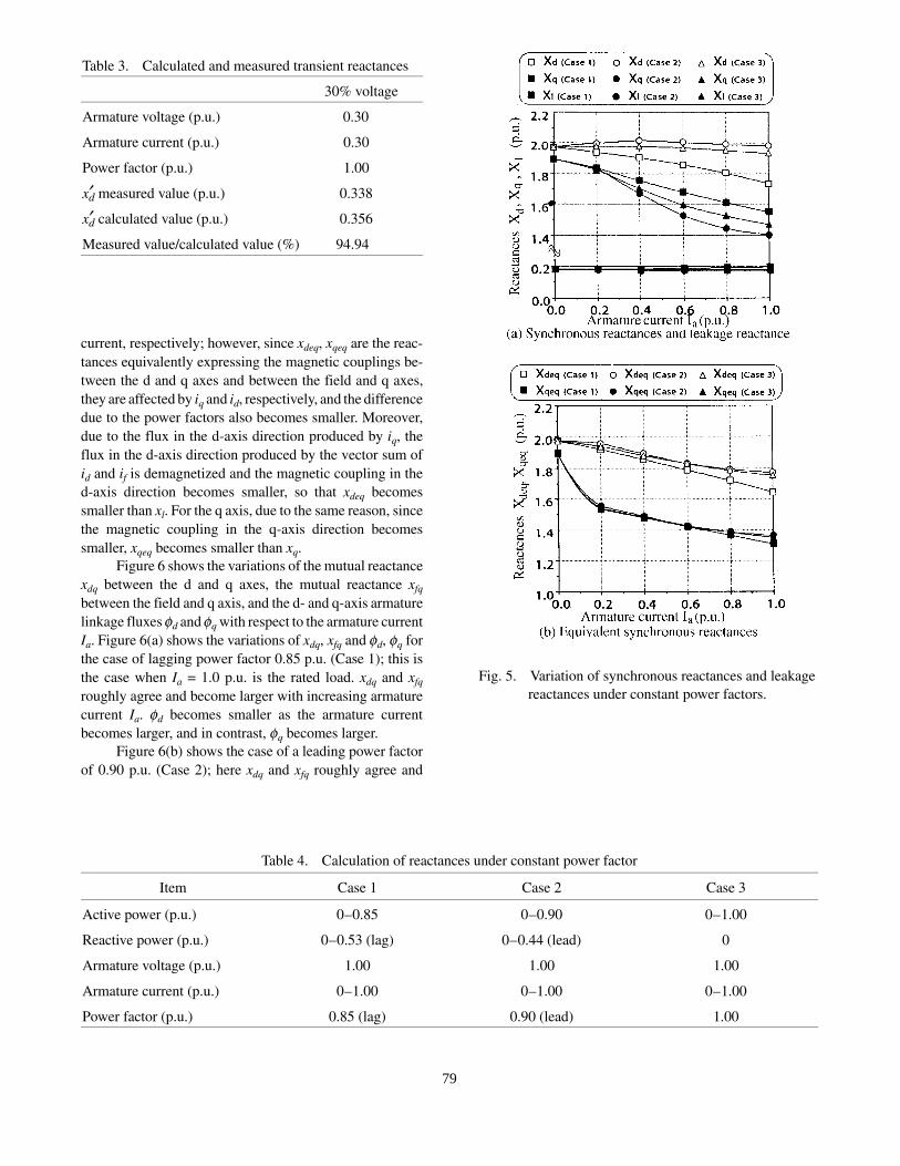
Table 3 shows the calculated transient reactances of
the 592-MVA turbine generator. The measured value is the
transient reactance xdg when a three-phase sudden short-cir-
cuit test is conducted from a no-load operating state at a
terminal voltage V = 0.3 p.u.; it corresponds to the unsatu-
rated value. The calculated value of xdg is calculated as the
sum of the armature leakage reactance xl and the field
leakage reactance xfl under the operating state Ia = 0.3 p.u.,
terminal voltage V = 0.3 p.u., and power factor 1.00 p.u.; it
corresponds to the unsaturated value. The calculated value
agrees with the measured value with an error of about 5%.
It is clear from the above results that the proposed
calculation method can calculate the field current and so
forth with good accuracy regardless of the operating states;
and it provides data with which the reactances under various
operating states can be calculated with good accuracy.
3.2 Variations of reactances at constant power
factor
Table 4 shows the reactance calculations at constant
power factor. Cases 1 to 3 are the calculation cases when
the armature current is varied while the specific power
factors, namely, a lag power factor of 0.85 p.u., a lead power
factor of 0.90 p.u., and 1.00 p.u. are set constant.
Figure 5 shows the variations of the synchronous
reactances and leakage reactances when the power factors
are set constant. Figure 5(a) plots the d-axis synchronous
reactance xd, the q-axis synchronous reactance xq, and the
leakage reactance xl; it is seen that xq becomes smaller as
the load becomes larger regardless of the power factor. On
the other hand, xd is about constant at a leading power factor
of 0.90 p.u. and at 1.00 p.u., where the flux level is low,
regardless of the load, and decreases as the load becomes
Fig. 3. Three-phase short-circuit and no-load saturation
curves.
Table 1. Specifications of 592-MVA turbine generator
Item Stator Rotor
Capacity (MVA) 592
Armature voltage (V) 20
Armature current (A) 17,090
Power factor (p.u.) 0.85 (lagging)
Number of poles 2
Frequency (Hz) 50
Number of rotations (rpm) 3000
Axial length of core (mm) 5800
Connection method 2Y �
Number of slots 48 32
Outer diameter of core (mm) 2466 1079.5
Cooling scheme water cooling direct hydrogen cooling
77

larger at a lagging power factor of 0.85. The decreased
reactances are caused by the fact that when the load be-
comes larger, since a voltage drop due to the leakage
reactance will occur, the fluxes of the rotor and stator cores
become large, and the cores will be further saturated. The
trend of xd becoming smaller is more pronounced when the
armature current lags farther behind the terminal voltage;
in contrast, the trend of xq becoming smaller is more pro-
nounced when the armature current is increasingly leading
the terminal voltage.
This can be understood from the fact that when the
power factor is increasingly leading, since the ratio of the
field magnetomotive force to the total magnetomotive force
becomes smaller due to the magnetizing action, and the
effect of the armature reaction affecting the fluxes inside
the generator becomes relatively larger, the fluxes inside the
generator incline toward the q-axis direction as the power
factor becomes increasingly leading. Namely, in a cylindri-
cal rotor such as a turbine generator, it is generally regarded
that xd @ xq, and this is shown numerically by the fact that
it holds when the power factor leads to an increasing extent.
Moreover, when the load becomes larger, since the synchro-
nous reactances xd and xq become smaller and the inherent
steady-state stability will be enhanced [7], synchronous
operation can be continued stably as the load becomes
larger. On the other hand, the armature leakage reactance
xl tends to increase slightly as the load becomes larger, in
opposition to the armature reaction reactances xd and xq, and
a difference due to the power factor is scarcely seen.
Figure 5(b) shows the equivalent d-axis synchronous
reactance xdeq and equivalent q-axis synchronous reactance
xqeq; xdeq and xqeq are calculated using Eqs. (6) and (7).
xdeq and xqeq decrease, regardless of the calculation cases,
due to magnetic saturation as the armature current becomes
larger. Moreover, for the same armature current value, xdeqand xqeq decrease in order of lagging power factor 0.85 p.u.
where the magnetic saturation is large, power factor 1.00
p.u., and leading power factor 0.90 p.u.; and when
xdeq, xqeq, and xd, xq are compared, xdeq and xqeq are smaller
than xd, xq, respectively, and the difference due to the dif-
ference of power factors also becomes smaller.
The reactances xd, xq based on the original definition
are directly dominated by the magnitudes of the d-axis
component id and q-axis component iq of the armature
Table 2. Calculation cases
Item Case 1 Case 2 Case 3 Case 4 Case 5 Case 6
Active power (p.u.) 0.356 0.507 0.677 0.845 0.840 0.797
Reactive power (p.u.) 0.193 (lag) 0.312 (lag) 0.427 (lag) 0.519 (lag) 0.030 (lag) 0.291 (lead)
Armature voltage (p.u.) 1.020 0.995 0.997 1.003 0.995 1.005
Armature current (p.u.) 0.404 0.605 0.802 0.989 0.848 0.854
Power factor (p.u.) 0.880 (lag) 0.851 (lag) 0.846 (lag) 0.852 (lag) 0.999 (lag) 0.940 (lead)
Fig. 4. Calculated field currents for load conditions.
78
current, respectively; however, since xdeq, xqeq are the reac-
tances equivalently expressing the magnetic couplings be-
tween the d and q axes and between the field and q axes,
they are affected by iq and id, respectively, and the difference
due to the power factors also becomes smaller. Moreover,
due to the flux in the d-axis direction produced by iq, the
flux in the d-axis direction produced by the vector sum of
id and if is demagnetized and the magnetic coupling in the
d-axis direction becomes smaller, so that xdeq becomes
smaller than xl. For the q axis, due to the same reason, since
the magnetic coupling in the q-axis direction becomes
smaller, xqeq becomes smaller than xq.
Figure 6 shows the variations of the mutual reactance
xdq between the d and q axes, the mutual reactance xfqbetween the field and q axis, and the d- and q-axis armature
linkage fluxes fd and fq with respect to the armature current
Ia. Figure 6(a) shows the variations of xdq, xfq and fd, fq for
the case of lagging power factor 0.85 p.u. (Case 1); this is
the case when Ia = 1.0 p.u. is the rated load. xdq and xfqroughly agree and become larger with increasing armature
current Ia. fd becomes smaller as the armature current
becomes larger, and in contrast, fq becomes larger.
Figure 6(b) shows the case of a leading power factor
of 0.90 p.u. (Case 2); here xdq and xfq roughly agree and
Table 3. Calculated and measured transient reactances
30% voltage
Armature voltage (p.u.) 0.30
Armature current (p.u.) 0.30
Power factor (p.u.) 1.00
xdg measured value (p.u.) 0.338
xdg calculated value (p.u.) 0.356
Measured value/calculated value (%) 94.94
Table 4. Calculation of reactances under constant power factor
Item Case 1 Case 2 Case 3
Active power (p.u.) 0�0.85 0�0.90 0�1.00
Reactive power (p.u.) 0�0.53 (lag) 0�0.44 (lead) 0
Armature voltage (p.u.) 1.00 1.00 1.00
Armature current (p.u.) 0�1.00 0�1.00 0�1.00
Power factor (p.u.) 0.85 (lag) 0.90 (lead) 1.00
Fig. 5. Variation of synchronous reactances and leakage
reactances under constant power factors.
79

become larger up to an armature current of Ia = 0. 4 p. u. as
Ia increases. However, they decrease when Ia exceeds 0.4
p.u. fd becomes smaller when the armature current be-
comes larger, but in contrast, fq becomes larger; however,
fd becomes smaller than fq when the armature current Iaexceeds 0.5 p.u.
Figure 6(c) shows the case of a power factor of 1.00
(Case 3). In the range where the armature current Ia is
smaller than 0.6 p.u., xdq and xfq become larger with increas-
ing Ia, but slowly become smaller when it exceeds this
value. Moreover, fd becomes smaller as Ia becomes larger,
and, in contrast, fq becomes larger. Besides, fd becomes
smaller than fq when the armature current reaches about 0.7
p.u.
In Fig. 6, it is seen that xdq and xfq have their maximum
values when fd and fq are about equal, and the maximum
value becomes about the same as the armature leakage
reactance xl. xdq and xfq express the magnetic coupling of
the d axis and the field with the q axis and will not occur
when the permeance is at a maximum on the d axis and a
minimum on the q axis or when the permeance is at a
minimum on the d axis and a maximum on the q axis. On
the other hand, in the case of no saliency, the flux level is
the same, and if there are positions intermediate between
the d and q axes where the permeance is maximum or
minimum, the magnetic coupling of the d axis or the field
with the q axis will reach a maximum. Here, it can be
understood that since the saliency of the turbine generator
is relatively small and the calculations of Fig. 6 are based
on the condition of constant terminal voltage, the flux level
inside the generator differs only by virtue of the amount of
voltage drop due to the armature leakage reactance, and the
vector sums of fd and fq in all calculation cases are about
the same; xdq and xfq will become maximum when fd and
fq are about equal.
But in Fig. 6, we see that xdq and xfq have their
maximum value in the regions where fd is a little larger than
fq. Even in a cylindrical rotor such as a turbine generator,
the iron ratio in the magnetic circuit is high on the d axis
because there is a magnetic pole portion, while the iron ratio
is low on the q axis. Namely, the more prominent effect of
the magnetic saturation in the rotor is on the d-axis side;
and even considering the magnetic circuit as a whole, the
d-axis side is more easily affected by magnetic saturation
than the q-axis side. Therefore, if the flux level is about the
same, xdq and xfq are likely to be larger in the region where
fd is somewhat larger than fq.
3.3 Variations of reactance at constant output
Table 5 calculates the reactances at constant output.
The calculation case shown is one in which the voltage is
constant at 1.00 p.u. and the power factor is changed from
a leading power factor of 0.90 p.u. to a lagging power factor
of 0.85 p.u. such that the output becomes 0.85 p.u.
Figure 7 shows the variations of the reactances and
linkage fluxes of the armature winding when the reactive
Fig. 6. Variations of mutual reactances and linkage
fluxes under constant power factors.
80

power is changed. This figure is the case shown in Table 5.
Figure 7(a) plots the synchronous reactances xd, xq, the
equivalent synchronous reactances xdeq, xqeq, and the leak-
age reactance xl. The trend of the variations of the reac-
tances due to the reactive power Wx is that xd becomes
smaller, but xq and xl become larger when the armature
current increasingly lags the terminal voltage. Moreover,
xdeq and xqeq do not change at a leading power factor when
the flux level is low; however, they become smaller with an
increase of the reactive power when a lagging power factor
occurs. When xd, xq and xdeq, xqeq are compared, both
xdeq, xqeq are smaller than xd, xq; in particular, for xq and
xqeq, the trends of variation accompanying the increase of
the reactive power are different.
Figure 7(b) shows the mutual reactances between the
d and q axes and and between the field and q axis, as well
as the armature linkage fluxes fd and fq. The d-axis arma-
ture linkage flux fd becomes larger as the power factor
becomes increasingly lagging, while in contrast, the q-axis
armature linkage flux fq becomes smaller. This is because
the demagnetizing action becomes larger as the power
factor lags to an increasing extent and the ratio of the field
magnetomotive force to the total magnetomotive force be-
comes larger, so that the effect of the armature reaction on
the fluxes inside the generator becomes smaller. Thus, in
the range of lagging power factors, magnetic saturation
occurs only on the d-axis component, and xd becomes
smaller but xq becomes larger when the reactive power
becomes larger. On the other hand, the mutual reactances
xdq and xfq between the d and q axes and between the field
and q axis agree roughly, and reach their maximum values
when the reactive power Wx is about 0.2 p.u. with a lagging
power factor. As shown in Fig. 6, this result also implies
that xdq and xfq are at about their maximum values when
fd @ fq in the case of constant armature voltage.
4. Conclusions
Using a 592-MVA turbine generator of standard de-
sign, we have analyzed the variations of the synchronous
reactance xd, xq, and so forth under load conditions, taking
into account the magnetic coupling typical of saturation;
and we have defined the equivalent reactances xdeq, xqeq,
taking into account the magnetic coupling typical of satu-
ration and have summarized the results of analyses of the
variations due to the loads. The results obtained are as
follows.
(1) The equivalent reactances xdeq, xqeq considering
magnetic coupling typical of saturation are smaller than the
reactances xd, xq based on the original definition in all
regions.
(2) In operation under constant voltage, the reac-
tances xdq, xfq expressing the coupling typical of saturation
become maximum when the d-axis flux and the q-axis flux
become about equal; these reactances are then also about
equal to the leakage reactance xl.
Table 5. Calculation of reactances at constant active
power
Active power (p.u.) 0.85
Reactive power (p.u.) 0.41 (leading)�0.53 (lagging)
Armature voltage (p.u.) 1.00
Power factor (p.u.) 0.90 (leading)�0.85 (lagging)
Fig. 7. Variation of reactances and linkage fluxes under
constant active power.
81

(3) xd becomes smaller but xq becomes larger when
the voltage and output are constant and the power factor is
changed from leading side to lagging side.
(4) Regarding (3), the trends of the variation of xdand xdeq are the same; however, the trends of xq and xqeq are
completely different in that xq becomes larger but xqeqbecomes smaller when the power factor is changed from
leading side to lagging side.
Saturation of reactances has been recognized quali-
tatively for a long time and attempts at modeling have also
been made; however, there are few examples which show
quantitatively the variations of the actual reactances in
large-capacity generators. The results presented in this pa-
per show quantitatively the variations of the reactances with
allowance for the magnetic coupling typical of saturation.
They may be useful numerical data for improvement of
characteristics under load conditions.
Acknowledgments
The authors thank Mr. Motoya Ito, Senior Researcher
at the Hitachi Research Laboratory of Hitachi Ltd., for his
guidance in this research.
REFERENCES
1. JEC 114. Synchronous Machines (1979).
2. Matsuki, Nagao, Okada, and Uenosono. Simulation
of steady-state characteristics and loss of synchro-
nism phenomena of a synchronous machine taking
into account magnetic saturation effect. Trans. I.E.E.
Japan, Vol. 104-B, No. 1 (1984).
3. Tamura and Takeda. A consideration on expression
of saturation in synchronous machine model for
power system simulation. Trans. I.E.E. Japan, Vol.
113-B, No. 2, pp. 1413�1421 (1993).
4. M.V.K. Chari et al. Load characteristics of synchro-
nous generators by finite-element method. IEEE
Trans. Power Appar. Syst., Vol. PAS-100, No. 1
(1981).
5. J.W. Dougherty and S.H. Minnich. Finite element
modeling of large turbine generators: Calculations
versus load test data. IEEE Trans. Power Appar. Syst.,
Vol. PAS-100, No. 8 (1981).
6. Ide et al. Synchronous machine field current calcula-
tions using dq-axes equations considering magnetic
saturation. Trans. I.E.E. Japan, Vol. 116-D, No. 3, pp.
328�336 (1996).
7. IEE Japan, Special Investigation Committee on
Specifications and Design of Synchronous Ma-
chines. Effects on specifications and design of syn-
chronous machines as well as apparatus parameters.
Tech. Rep. (Part II) I.E.E. Japan, No. 405 (1990).
APPENDIX
The equations for determining the d�q axis armature
linkage fluxes from the magnetic field analysis are given
below. The following fluxes are used with the transforma-
tion into per-unit system in this paper.
The respective magnetic vector potentials of the up-
per and lower coils of the armature obtained for every coil
section and the fundamental components of the distribu-
tions for the respective circumferential coordinates q are
taken as aSU(q) [Wb/m] and aSL(q) [Wb/m]. Then aSU(q)
and aSL(q) are given by
where q is the circumferential coordinate value with d axis
as reference (electrical angle).
Therefore, the d- and q-axis armature linkage fluxes
Fd [Wb] and Fd [Wb] are respectively
where Nspp is the number of slots per pole per phase of
stator, fwd is the distribution factor of armature winding,
fws is the short-pitch factor of armature winding, P is the
number of poles, nY is the number of parallel circuits of
armature winding, and Lc is the axial length of stator core
(m).
However, it is assumed that Eqs. (A3) and (A4) are
for double-layer windings and that there is one parallel
circuit in the winding section per layer.
(A1)
(A2)
(A3)
(A4)
82

AUTHORS (from left to right)
Shin�ichi Wakui (member) completed the master�s course in electrical engineering at the Mining Research Division of
the Graduate School of Akita University in 1992. He then joined Hitachi Ltd., and is now at the Hitachi Research Laboratory.
He is engaged in research on rotating electric machines. He received a Paper Award of the IEE Japan in 1996.
Kazumasa Ide (member) completed the first half of the doctoral course in electrical and communication engineering at
the Engineering Research Division of the Graduate School of Tohoku University in 1988. He then joined Hitachi Ltd., and is
now in the Electric Power and Machine Development Group. He is engaged in research on rotating electric machines. He has
a D.Eng. degree. He is a member of the Japan Society of Applied Magnetism and IEEE. He received a Paper Award of the IEE
Japan in 1993.
Miyoshi Takahashi (member) graduated from the Department of Electrical Engineering of the Faculty of Mining of Akita
University in 1972. He then joined Hitachi Ltd., and is now working in the Electric Power and Machine Development Group.
He is engaged in research on rotating electric machines. He is currently a Senior Researcher. He has a D.Eng. degree. He is a
member of the Japan Society of Applied Magnetism, Cryogenic Association of Japan, and IEEE. He received a Paper Award of
the IEE Japan in 1989 and 1996.
Gustavo Montoya (nonmember) completed the master�s course in electrical engineering in the Engineering Research
Division of the Graduate School of Muroran Institute of Technology in 1991. He then joined Hitachi Ltd., and is now at Hitachi
Works. He is engaged in the design and development of turbine generators.
Futoshi Hiyama (nonmember) joined Hitachi Ltd. in 1970 and is now at Hitachi Works. He is engaged in the design and
development of turbine generators. He is currently a Senior Engineer.
Yasuomi Yagi (member) completed the master�s course at the University of Tokyo in 1979. He then joined Hitachi Ltd.,
and is now at Hitachi Works. He is engaged in the design and development of superconducting magnets, nuclear fusion
equipment, turbine generators, and superconducting generators. In 1985, he completed the master�s course at the University of
Michigan. He is currently a Senior Engineer. He received a Paper Award of the IEE Japan in 1996.
83