Analysis of conventional and asymmetric aircraft configurations using CEASIOM
12
Comparison of Conventional and Asymmetric Aircraft Configurations using CEASIOM Cormac McFarlane & * Thomas S. Richardson, † Department of Aerospace Engineering, University of Bristol, Queens Building, University Walk, Bristol, BS8 1TR, UK Andrea Da Ronch & Ken Badcock School of Engineering, University of Liverpool, Liverpool, L69 3BX, UK This paper investigates whether drag reductions in cruise can be achieved for an aircraft by selecting a three-lifting-surface asymmetric design. A conventional T-tail design based on the existing EA500 Very Light Jet was selected as the baseline aircraft, and this was redesigned into a novel asymmetric configuration. CEASIOM, the Computerized Envi- ronment for Aircraft Synthesis and Integrated Optimization Methods, was then used to generate aerodynamic data sets for both aircraft, trim them at the cruise condition, and compare the thrust required to achieve trim. Acronyms CEASIOM Computerized Environment for Aircraft Synthesis and Integrated Optimization Methods CG Center of Gravity GUI Graphical User Interface MAC Mean Aerodynamic Chord SCAA Stability and Control Analyser and Assessor I. Introduction In this paper the Computerized Environment for Aircraft Synthesis and Integrated Optimization Methods (CEASIOM) is used to assess whether the suggested drag reduction of using an asymmetric three-lifting- surface aircraft design can be achieved in cruise. CEASIOM is currently being developed within the frame of the SimSAC Project (Simulating Aircraft Stability And Control Characteristics for Use in Conceptual Design) sponsored by the European Commission 6th Framework Programme. It uses adaptive-fidelity CFD to create aerodynamic datasets for aircraft, after which trim points can be calculated for the aircraft, and stability and control characteristics can be analysed using integrated software tools. Details of CEASIOM and its tools are given in Section II. A baseline configuration was selected against which the novel design could be compared with CEASIOM being used to analyse both aircraft. The novel configuration was designed to fulfill the same role as the baseline aircraft, with design decisions made to ensure that any drag reductions were a result of using three lifting surfaces rather than from relaxing requirements (such as the static margin). When generating the aerodynamic data sets for both aircraft the same methods were used, again to ensure the comparison was as accurate as possible. Details of the two aircraft configurations are given in Section III. The aerodynamic data sets generated for both aircraft were then used by CEASIOM to trim both aircraft in the cruise configuration. This enabled the thrust required to achieve trim in cruise to be compared for * Research Assistant, [email protected] † Lecturer in Flight Mechanics, Member AIAA, [email protected] 1 of 12 American Institute of Aeronautics and Astronautics AIAA Guidance, Navigation, and Control Conference 2 - 5 August 2010, Toronto, Ontario Canada AIAA 2010-8243 Copyright © 2010 by the American Institute of Aeronautics and Astronautics, Inc. All rights reserved.
-
Upload
independent -
Category
Documents
-
view
1 -
download
0
Transcript of Analysis of conventional and asymmetric aircraft configurations using CEASIOM
Comparison of Conventional and Asymmetric Aircraft
Configurations using CEASIOM
Cormac McFarlane &∗ Thomas S. Richardson, †
Department of Aerospace Engineering, University of Bristol,
Queens Building, University Walk, Bristol, BS8 1TR, UK
Andrea Da Ronch & Ken Badcock
School of Engineering, University of Liverpool,
Liverpool, L69 3BX, UK
This paper investigates whether drag reductions in cruise can be achieved for an aircraft
by selecting a three-lifting-surface asymmetric design. A conventional T-tail design based
on the existing EA500 Very Light Jet was selected as the baseline aircraft, and this was
redesigned into a novel asymmetric configuration. CEASIOM, the Computerized Envi-
ronment for Aircraft Synthesis and Integrated Optimization Methods, was then used to
generate aerodynamic data sets for both aircraft, trim them at the cruise condition, and
compare the thrust required to achieve trim.
Acronyms
CEASIOM Computerized Environment for Aircraft Synthesis and Integrated Optimization MethodsCG Center of GravityGUI Graphical User InterfaceMAC Mean Aerodynamic ChordSCAA Stability and Control Analyser and Assessor
I. Introduction
In this paper the Computerized Environment for Aircraft Synthesis and Integrated Optimization Methods(CEASIOM) is used to assess whether the suggested drag reduction of using an asymmetric three-lifting-surface aircraft design can be achieved in cruise.
CEASIOM is currently being developed within the frame of the SimSAC Project (Simulating AircraftStability And Control Characteristics for Use in Conceptual Design) sponsored by the European Commission6th Framework Programme. It uses adaptive-fidelity CFD to create aerodynamic datasets for aircraft, afterwhich trim points can be calculated for the aircraft, and stability and control characteristics can be analysedusing integrated software tools. Details of CEASIOM and its tools are given in Section II.
A baseline configuration was selected against which the novel design could be compared with CEASIOMbeing used to analyse both aircraft. The novel configuration was designed to fulfill the same role as thebaseline aircraft, with design decisions made to ensure that any drag reductions were a result of using threelifting surfaces rather than from relaxing requirements (such as the static margin). When generating theaerodynamic data sets for both aircraft the same methods were used, again to ensure the comparison was asaccurate as possible. Details of the two aircraft configurations are given in Section III.
The aerodynamic data sets generated for both aircraft were then used by CEASIOM to trim both aircraftin the cruise configuration. This enabled the thrust required to achieve trim in cruise to be compared for
∗Research Assistant, [email protected]†Lecturer in Flight Mechanics, Member AIAA, [email protected]
1 of 12
American Institute of Aeronautics and Astronautics
AIAA Guidance, Navigation, and Control Conference2 - 5 August 2010, Toronto, Ontario Canada
AIAA 2010-8243
Copyright © 2010 by the American Institute of Aeronautics and Astronautics, Inc. All rights reserved.
the two aicraft to determine whether the novel design was more efficient. A comparison of the two aircrafttrimmed for cruise is given in Section IV.
II. CEASIOM
The Computerized Environment for Aircraft Synthesis and Integrated Optimization Methods (CEA-SIOM) application is a conceptual aircraft design tool that enhances the process of conceptual design byincorporating stability and control assessment at an early stage. CEASIOM consists of several modules,with those which are used for the work in this paper described below. Further details on CEASIOM can befound in References.1,2
II.A. AcBuilder
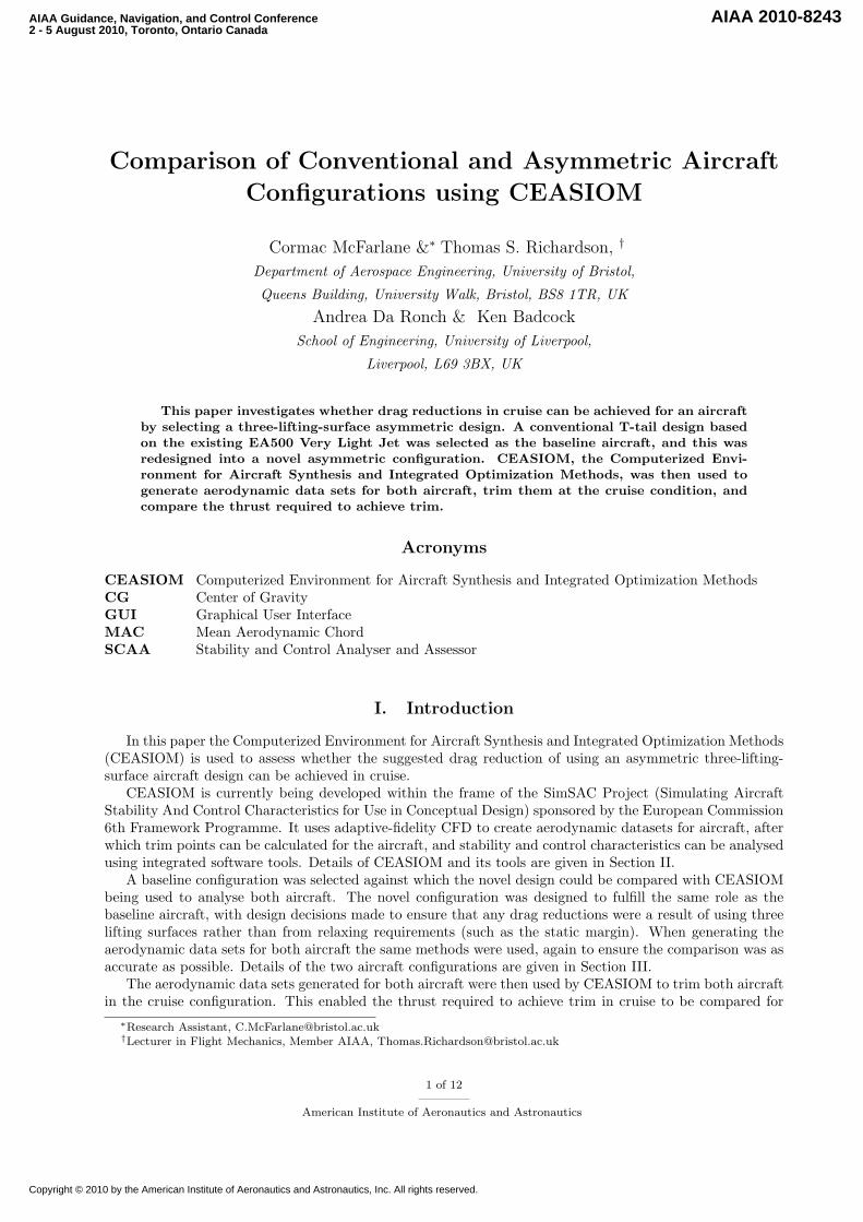
The AcBuilder module of CEASIOM is used to define a simplified aircraft geometry using around 100parameters. Examples of such parameters include the wing span, wing area, leading edge sweep etc. Avisual representation of the aircraft is generated by the software, as shown in Figure 1, allowing the user toverify the impact of changing any parameter on the aircraft model.
Figure 1. AcBuilder GUI
This module also estimates weights and balance parameters for the concept aircraft, which are necessaryfor assessing its stability and control characteristics.
II.B. AMB
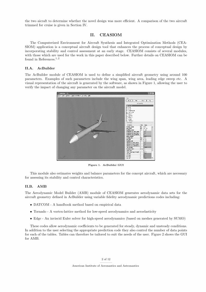
The Aerodynamic Model Builder (AMB) module of CEASIOM generates aerodynamic data sets for theaircraft geometry defined in AcBuilder using variable fidelity aerodynamic predictions codes including:
• DATCOM - A handbook method based on empirical data
• Tornado - A vortex-lattice method for low-speed aerodynamics and aeroelasticity
• Edge - An inviscid Euler solver for high-speed aerodynamics (based on meshes generated by SUMO)
These codes allow aerodynamic coefficients to be generated for steady, dynamic and unsteady conditions.In addition to the user selecting the appropriate prediction code they also control the number of data pointsfor each of the tables. Tables can therefore be tailored to suit the needs of the user. Figure 2 shows the GUIfor AMB.
2 of 12
American Institute of Aeronautics and Astronautics
Figure 2. AMB GUI
II.C. SCAA
The Stability and Control Analyser and Assessor (SCAA) module of CEASIOM is used to assess the stabilityand control characteristics of the concept aircraft using the weights and balance data generated in AcBuilderand the aerodynamic data sets generated in AMB. This module allows the user to trim the aircraft atspecified conditions, from which they can determine whether the resulting control surface deflections, angleof attack and drag are acceptable, or whether redesign of the aircraft is necessary. Figure 3 shows the GUIfor SCAA.
Figure 3. SCAA GUI
SCAA also linearises the aircraft model for each trim conditions, enabling an assessment of the char-acteristics of the dynamic modes to be made. Various specifications define requirements for the dynamicmodes, such as the short period and Dutch Roll, of an aircraft which can vary depending on its intendedrole. SCAA can be used to determine the flight envelope in which these requirements are met, and alsoprovides a tool for designing a feedback controller to move these modes if the requirements are not met. Thefeedback controller is tuned using an eigenstructure assignment algorithm.
3 of 12
American Institute of Aeronautics and Astronautics
III. Aircraft Configurations
The purpose of this paper is to determine whether there are any drag benefits to using an asymmetricthree-lifting-surface aircraft configuration, hereafter referred to as the Z-config. In order to carry out thisinvestigation two aircraft configurations are needed: a baseline conventional configuration to provide a basisfor comparison, and the Z-config itself. A description of these two models and their implementation inCEASIOM is given in the following sections.
III.A. EA500
The baseline aircraft selected for this investigation was the Eclipse Aerospace 500 Very Light Jet (EA500). Itis a small business jet with up to 6 seats, a T-tail, a low wing and two fuselage mounted engines. Accordingto its type certificate4 it has a maximum operating speed of Mach 0.65 and a maximum operating altitudeof 41,000 ft. In order to create a model of the EA500 in CEASIOM a number of parameters that definethe geometry of the aircraft needed to be determined. A detailed 3-view of the EA500 from the EclipseAerospace website3 was used to obtain these parameters. Values for some of the major dimensions are listedin Table 1.
Dimension Value Units
Fuselage Length 9.2 m
Wing Span 11 m
Wing Area 13.92 m2
Mean Aerodynamic Chord 1.385 m
Horizontal Tail Span 4.1 m
Horizontal Tail Area 3.24 m2
Vertical Tail Span 1̃.7 m
Vertical tail Area 2̃.8 m2
Table 1. EA500 dimensions
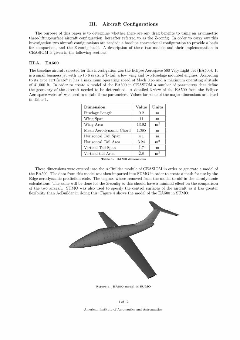
These dimensions were entered into the AcBuilder module of CEASIOM in order to generate a model ofthe EA500. The data from this model was then imported into SUMO in order to create a mesh for use by theEdge aerodynamic prediction code. The engines where removed from the model to aid in the aerodynamiccalculations. The same will be done for the Z-config so this should have a minimal effect on the comparisonof the two aircraft. SUMO was also used to specify the control surfaces of the aircraft as it has greaterflexibility than AcBuilder in doing this. Figure 4 shows the model of the EA500 in SUMO.
Figure 4. EA500 model in SUMO
4 of 12
American Institute of Aeronautics and Astronautics
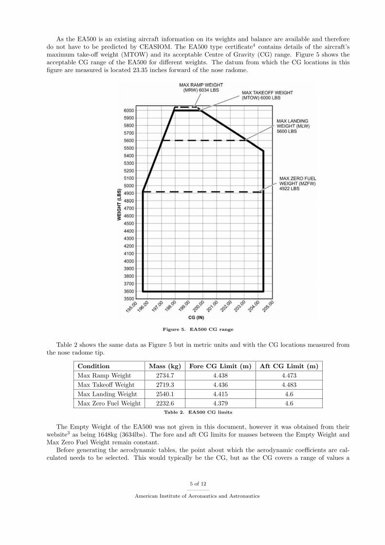
As the EA500 is an existing aircraft information on its weights and balance are available and thereforedo not have to be predicted by CEASIOM. The EA500 type certificate4 contains details of the aircraft’smaximum take-off weight (MTOW) and its acceptable Centre of Gravity (CG) range. Figure 5 shows theacceptable CG range of the EA500 for different weights. The datum from which the CG locations in thisfigure are measured is located 23.35 inches forward of the nose radome.
Figure 5. EA500 CG range
Table 2 shows the same data as Figure 5 but in metric units and with the CG locations measured fromthe nose radome tip.
Condition Mass (kg) Fore CG Limit (m) Aft CG Limit (m)
Max Ramp Weight 2734.7 4.438 4.473
Max Takeoff Weight 2719.3 4.436 4.483
Max Landing Weight 2540.1 4.415 4.6
Max Zero Fuel Weight 2232.6 4.379 4.6
Table 2. EA500 CG limits
The Empty Weight of the EA500 was not given in this document, however it was obtained from theirwebsite3 as being 1648kg (3634lbs). The fore and aft CG limits for masses between the Empty Weight andMax Zero Fuel Weight remain constant.
Before generating the aerodynamic tables, the point about which the aerodynamic coefficients are cal-culated needs to be selected. This would typically be the CG, but as the CG covers a range of values a
5 of 12
American Institute of Aeronautics and Astronautics
single point still had to be chosen. The foremost acceptable CG for the EA500 at its MTOW was used,corresponding to a point 4.44m aft of the aircraft nose.
The mesh generated using SUMO for the EA500 model was imported into the AMB module of CEASIOMwhere the Edge aerodynamic prediction code was used to generate aerodynamic data sets for the aircraft.These data sets consist of tables where the aerodynamic force and moment coefficients are calculated for arange of angles of attack, Mach numbers and one other variable. Four of these tables were generated withthe other variable in each case being sideslip, elevator deflection, rudder deflection or aileron deflection. Therange of values used for each of the variables in the tables is given in Table 3.
Variable Values Units
AoA [-4 -2 0 2 4 6 8 10] ◦
Mach [0.2 0.35 0.5 0.65] -
AoS [-6 -3 0 3 6] ◦
Elevator [-15 -7 0 7 15] ◦
Rudder [-20 -10 0 10 20] ◦
Aileron [-15 -7 0 7 15] ◦
Table 3. Variable values used for EA500 aerodynamic tables
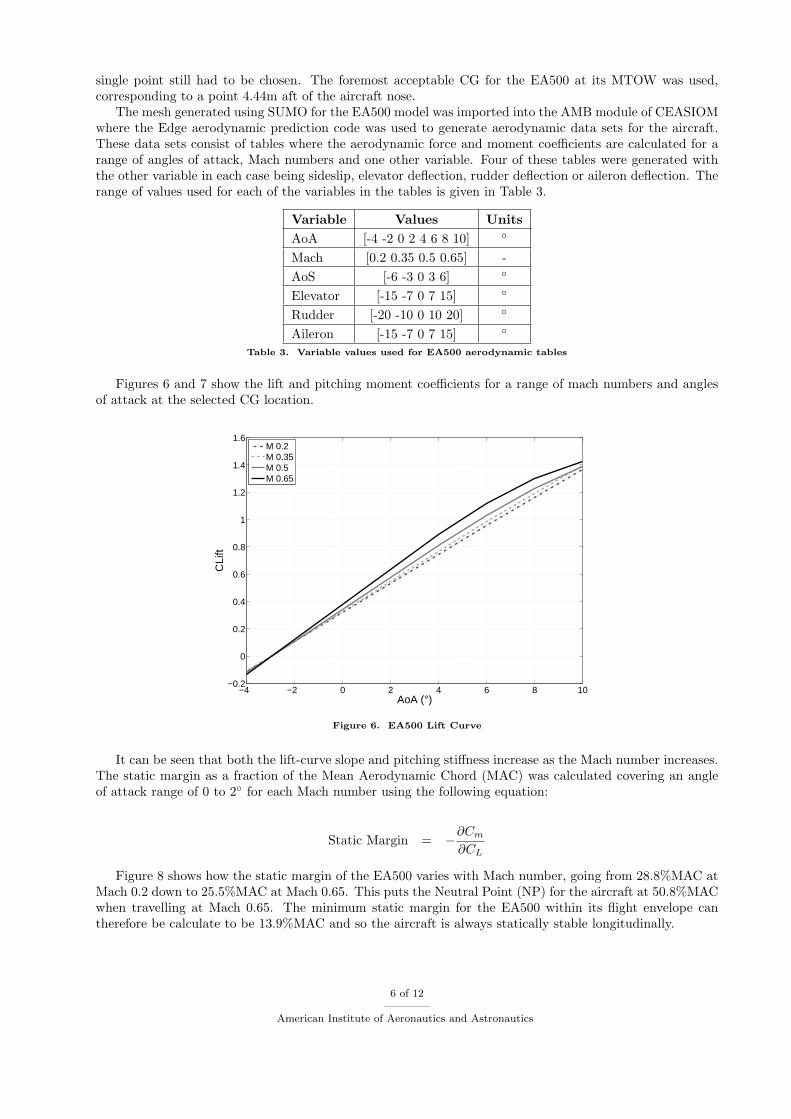
Figures 6 and 7 show the lift and pitching moment coefficients for a range of mach numbers and anglesof attack at the selected CG location.
−4 −2 0 2 4 6 8 10−0.2
0
0.2
0.4
0.6
0.8
1
1.2
1.4
1.6
AoA (°)
CLi
ft
M 0.2M 0.35M 0.5M 0.65
Figure 6. EA500 Lift Curve
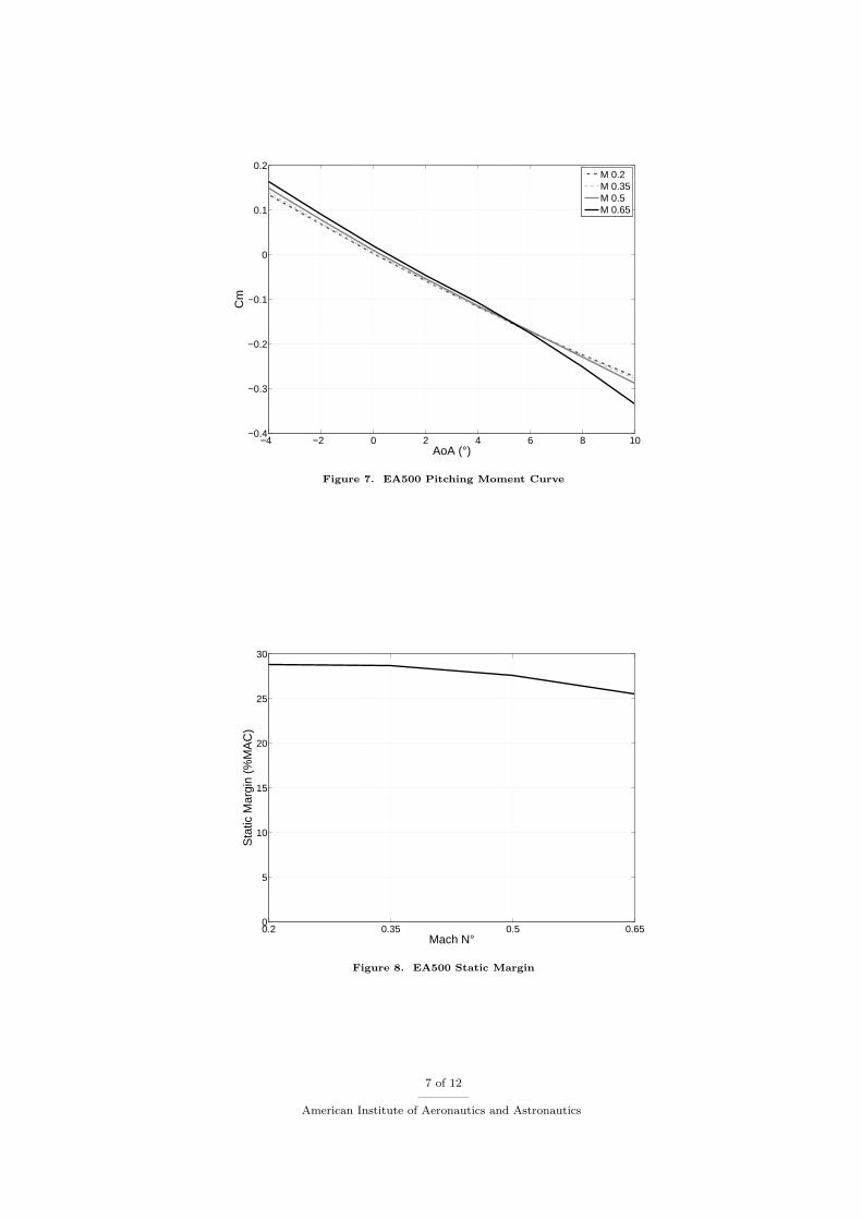
It can be seen that both the lift-curve slope and pitching stiffness increase as the Mach number increases.The static margin as a fraction of the Mean Aerodynamic Chord (MAC) was calculated covering an angleof attack range of 0 to 2◦ for each Mach number using the following equation:
Static Margin = −
∂Cm
∂CL
Figure 8 shows how the static margin of the EA500 varies with Mach number, going from 28.8%MAC atMach 0.2 down to 25.5%MAC at Mach 0.65. This puts the Neutral Point (NP) for the aircraft at 50.8%MACwhen travelling at Mach 0.65. The minimum static margin for the EA500 within its flight envelope cantherefore be calculate to be 13.9%MAC and so the aircraft is always statically stable longitudinally.
6 of 12
American Institute of Aeronautics and Astronautics
−4 −2 0 2 4 6 8 10−0.4
−0.3
−0.2
−0.1
0
0.1
0.2
AoA (°)
Cm
M 0.2M 0.35M 0.5M 0.65
Figure 7. EA500 Pitching Moment Curve
0.2 0.35 0.5 0.650
5
10
15
20
25
30
Mach N°
Sta
tic M
argi
n (%
MA
C)
Figure 8. EA500 Static Margin
7 of 12
American Institute of Aeronautics and Astronautics
III.B. Z-config
The Z-configuration is an asymmetric aircraft designed to fulfill the same role as the EA500. To ensurethe comparison between the two aircraft is as useful as possible the EA500 fuselage was also used for theZ-config.
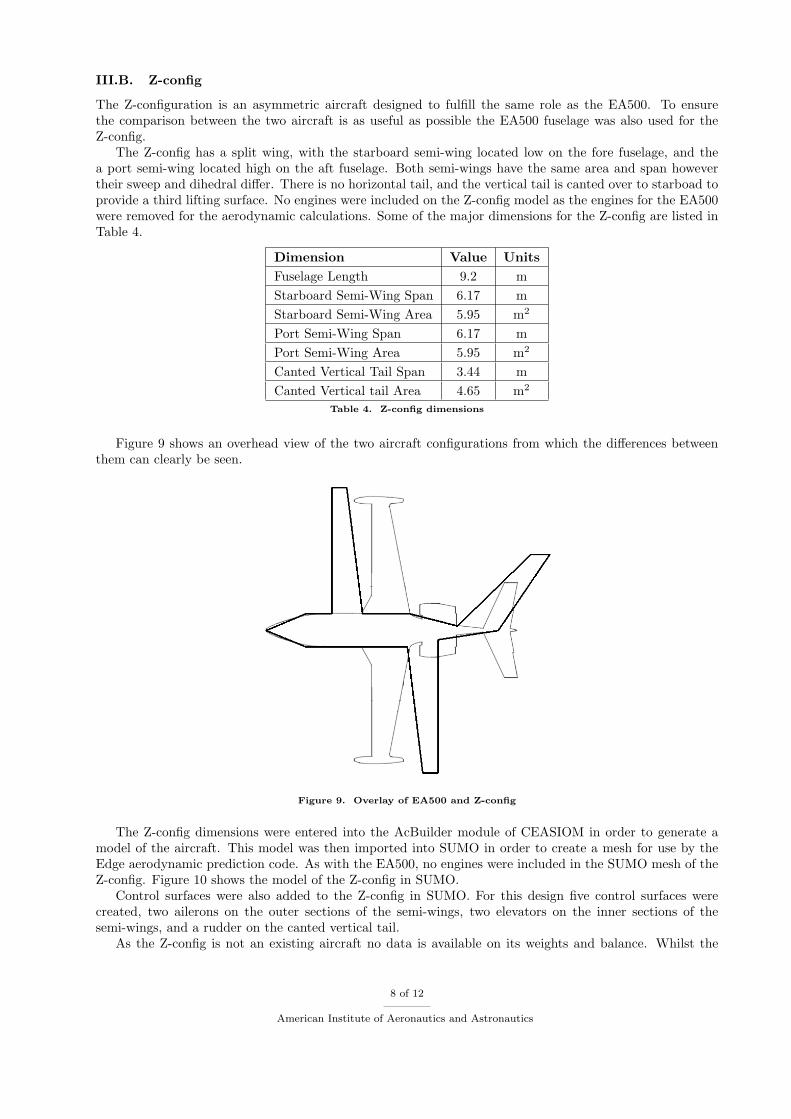
The Z-config has a split wing, with the starboard semi-wing located low on the fore fuselage, and thea port semi-wing located high on the aft fuselage. Both semi-wings have the same area and span howevertheir sweep and dihedral differ. There is no horizontal tail, and the vertical tail is canted over to starboad toprovide a third lifting surface. No engines were included on the Z-config model as the engines for the EA500were removed for the aerodynamic calculations. Some of the major dimensions for the Z-config are listed inTable 4.
Dimension Value Units
Fuselage Length 9.2 m
Starboard Semi-Wing Span 6.17 m
Starboard Semi-Wing Area 5.95 m2
Port Semi-Wing Span 6.17 m
Port Semi-Wing Area 5.95 m2
Canted Vertical Tail Span 3.44 m
Canted Vertical tail Area 4.65 m2
Table 4. Z-config dimensions
Figure 9 shows an overhead view of the two aircraft configurations from which the differences betweenthem can clearly be seen.
Figure 9. Overlay of EA500 and Z-config
The Z-config dimensions were entered into the AcBuilder module of CEASIOM in order to generate amodel of the aircraft. This model was then imported into SUMO in order to create a mesh for use by theEdge aerodynamic prediction code. As with the EA500, no engines were included in the SUMO mesh of theZ-config. Figure 10 shows the model of the Z-config in SUMO.
Control surfaces were also added to the Z-config in SUMO. For this design five control surfaces werecreated, two ailerons on the outer sections of the semi-wings, two elevators on the inner sections of thesemi-wings, and a rudder on the canted vertical tail.
As the Z-config is not an existing aircraft no data is available on its weights and balance. Whilst the
8 of 12
American Institute of Aeronautics and Astronautics
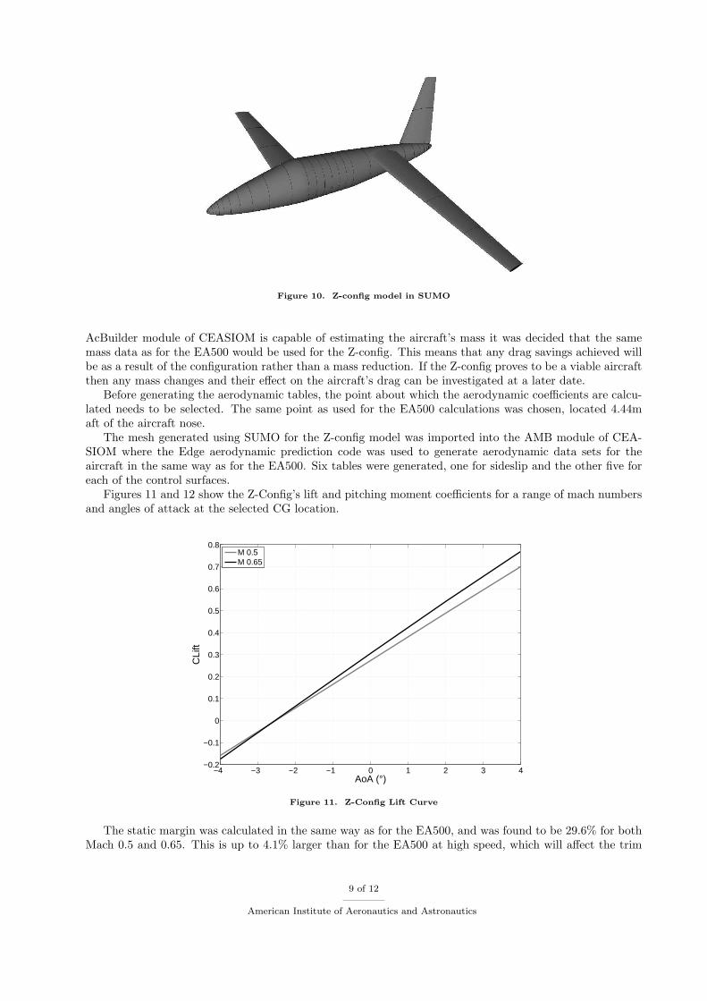
Figure 10. Z-config model in SUMO
AcBuilder module of CEASIOM is capable of estimating the aircraft’s mass it was decided that the samemass data as for the EA500 would be used for the Z-config. This means that any drag savings achieved willbe as a result of the configuration rather than a mass reduction. If the Z-config proves to be a viable aircraftthen any mass changes and their effect on the aircraft’s drag can be investigated at a later date.
Before generating the aerodynamic tables, the point about which the aerodynamic coefficients are calcu-lated needs to be selected. The same point as used for the EA500 calculations was chosen, located 4.44maft of the aircraft nose.
The mesh generated using SUMO for the Z-config model was imported into the AMB module of CEA-SIOM where the Edge aerodynamic prediction code was used to generate aerodynamic data sets for theaircraft in the same way as for the EA500. Six tables were generated, one for sideslip and the other five foreach of the control surfaces.
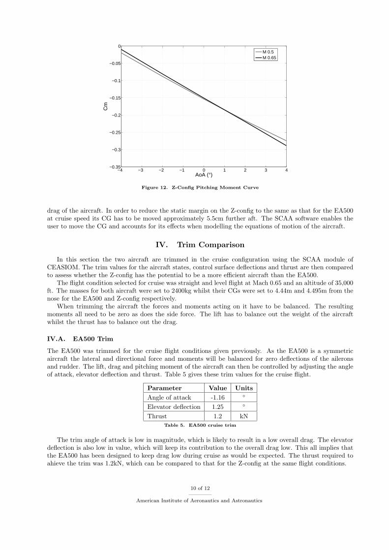
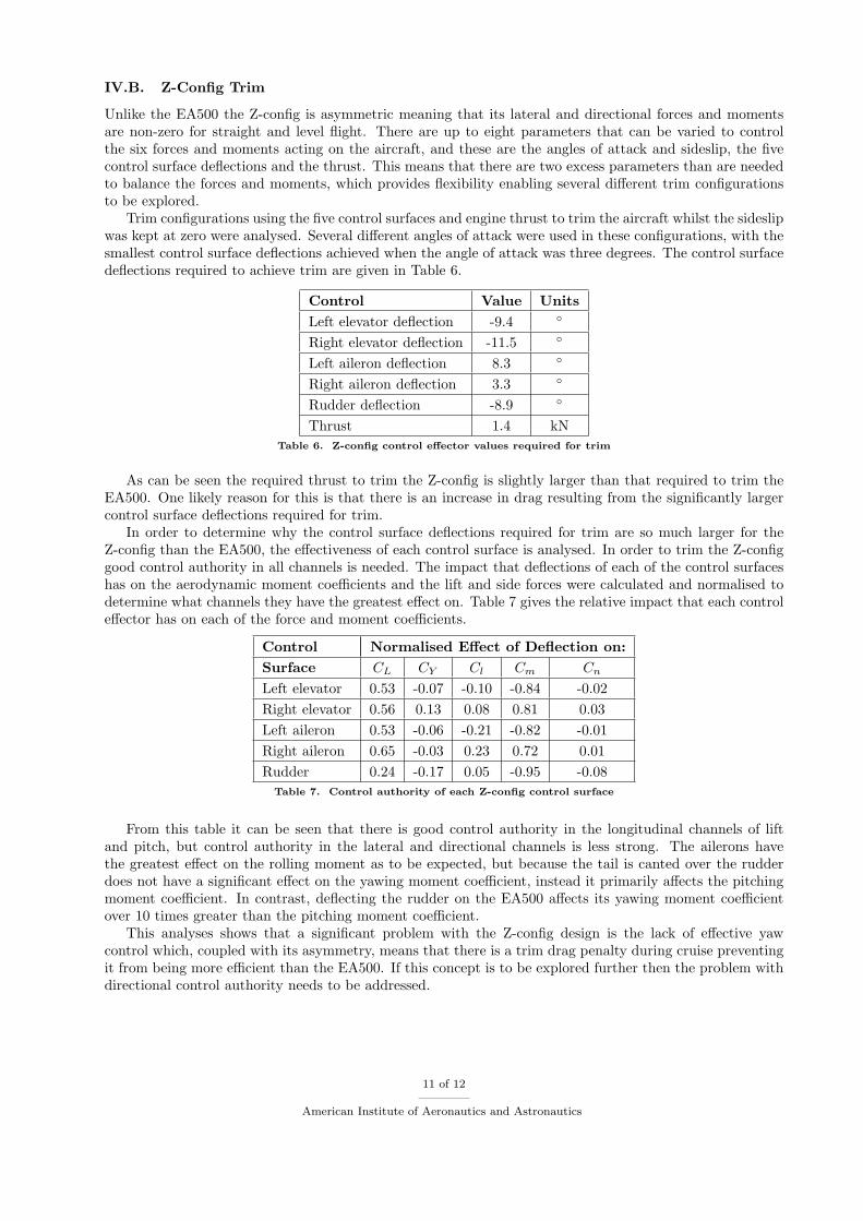
Figures 11 and 12 show the Z-Config’s lift and pitching moment coefficients for a range of mach numbersand angles of attack at the selected CG location.
−4 −3 −2 −1 0 1 2 3 4−0.2
−0.1
0
0.1
0.2
0.3
0.4
0.5
0.6
0.7
0.8
AoA (°)
CLi
ft
M 0.5M 0.65
Figure 11. Z-Config Lift Curve
The static margin was calculated in the same way as for the EA500, and was found to be 29.6% for bothMach 0.5 and 0.65. This is up to 4.1% larger than for the EA500 at high speed, which will affect the trim
9 of 12
American Institute of Aeronautics and Astronautics
−4 −3 −2 −1 0 1 2 3 4−0.35
−0.3
−0.25
−0.2
−0.15
−0.1
−0.05
0
AoA (°)
Cm
M 0.5M 0.65
Figure 12. Z-Config Pitching Moment Curve
drag of the aircraft. In order to reduce the static margin on the Z-config to the same as that for the EA500at cruise speed its CG has to be moved approximately 5.5cm further aft. The SCAA software enables theuser to move the CG and accounts for its effects when modelling the equations of motion of the aircraft.
IV. Trim Comparison
In this section the two aircraft are trimmed in the cruise configuration using the SCAA module ofCEASIOM. The trim values for the aircraft states, control surface deflections and thrust are then comparedto assess whether the Z-config has the potential to be a more efficient aircraft than the EA500.
The flight condition selected for cruise was straight and level flight at Mach 0.65 and an altitude of 35,000ft. The masses for both aircraft were set to 2400kg whilst their CGs were set to 4.44m and 4.495m from thenose for the EA500 and Z-config respectively.
When trimming the aircraft the forces and moments acting on it have to be balanced. The resultingmoments all need to be zero as does the side force. The lift has to balance out the weight of the aircraftwhilst the thrust has to balance out the drag.
IV.A. EA500 Trim
The EA500 was trimmed for the cruise flight conditions given previously. As the EA500 is a symmetricaircraft the lateral and directional force and moments will be balanced for zero deflections of the aileronsand rudder. The lift, drag and pitching moment of the aircraft can then be controlled by adjusting the angleof attack, elevator deflection and thrust. Table 5 gives these trim values for the cruise flight.
Parameter Value Units
Angle of attack -1.16 ◦
Elevator deflection 1.25 ◦
Thrust 1.2 kN
Table 5. EA500 cruise trim
The trim angle of attack is low in magnitude, which is likely to result in a low overall drag. The elevatordeflection is also low in value, which will keep its contribution to the overall drag low. This all implies thatthe EA500 has been designed to keep drag low during cruise as would be expected. The thrust required toahieve the trim was 1.2kN, which can be compared to that for the Z-config at the same flight conditions.
10 of 12
American Institute of Aeronautics and Astronautics
IV.B. Z-Config Trim
Unlike the EA500 the Z-config is asymmetric meaning that its lateral and directional forces and momentsare non-zero for straight and level flight. There are up to eight parameters that can be varied to controlthe six forces and moments acting on the aircraft, and these are the angles of attack and sideslip, the fivecontrol surface deflections and the thrust. This means that there are two excess parameters than are neededto balance the forces and moments, which provides flexibility enabling several different trim configurationsto be explored.
Trim configurations using the five control surfaces and engine thrust to trim the aircraft whilst the sideslipwas kept at zero were analysed. Several different angles of attack were used in these configurations, with thesmallest control surface deflections achieved when the angle of attack was three degrees. The control surfacedeflections required to achieve trim are given in Table 6.
Control Value Units
Left elevator deflection -9.4 ◦
Right elevator deflection -11.5 ◦
Left aileron deflection 8.3 ◦
Right aileron deflection 3.3 ◦
Rudder deflection -8.9 ◦
Thrust 1.4 kN
Table 6. Z-config control effector values required for trim
As can be seen the required thrust to trim the Z-config is slightly larger than that required to trim theEA500. One likely reason for this is that there is an increase in drag resulting from the significantly largercontrol surface deflections required for trim.
In order to determine why the control surface deflections required for trim are so much larger for theZ-config than the EA500, the effectiveness of each control surface is analysed. In order to trim the Z-configgood control authority in all channels is needed. The impact that deflections of each of the control surfaceshas on the aerodynamic moment coefficients and the lift and side forces were calculated and normalised todetermine what channels they have the greatest effect on. Table 7 gives the relative impact that each controleffector has on each of the force and moment coefficients.
Control Normalised Effect of Deflection on:
Surface CL CY Cl Cm Cn
Left elevator 0.53 -0.07 -0.10 -0.84 -0.02
Right elevator 0.56 0.13 0.08 0.81 0.03
Left aileron 0.53 -0.06 -0.21 -0.82 -0.01
Right aileron 0.65 -0.03 0.23 0.72 0.01
Rudder 0.24 -0.17 0.05 -0.95 -0.08
Table 7. Control authority of each Z-config control surface
From this table it can be seen that there is good control authority in the longitudinal channels of liftand pitch, but control authority in the lateral and directional channels is less strong. The ailerons havethe greatest effect on the rolling moment as to be expected, but because the tail is canted over the rudderdoes not have a significant effect on the yawing moment coefficient, instead it primarily affects the pitchingmoment coefficient. In contrast, deflecting the rudder on the EA500 affects its yawing moment coefficientover 10 times greater than the pitching moment coefficient.
This analyses shows that a significant problem with the Z-config design is the lack of effective yawcontrol which, coupled with its asymmetry, means that there is a trim drag penalty during cruise preventingit from being more efficient than the EA500. If this concept is to be explored further then the problem withdirectional control authority needs to be addressed.
11 of 12
American Institute of Aeronautics and Astronautics
V. Conclusions
A novel asymmetric aircraft configuration was suggested as offering possible efficiency benefits whencompared to a more conventional design. The CEASIOM environment was used to assess both the originalconventional aircraft and this novel design to determine whether the potential efficiency improvements can beachieved in cruise. Aerodynamic data sets for both aircraft were generated after which they were trimmed forcruise from which the thrust required for this trim was obtained. A higher thrust was required for the novelconfiguration than the conventional meaning that the potential efficiency improvements were not realised.The reason for this appears to be the large control surface desflections required for trim due to the poordirectional control authority. If this design is to be explored further then this problem needs to be addressed.
This study has demonstrated the usefulness of the CEASIOM software environment, which enables noveldesigns such as the Z-config to be analysed and their potential assessed. Whilst the Z-config design has notproved suitable it was possible not only to demonstrate this but to determine a factor that likely contributedto its failure to achieve the potential efficiency improvements. This provides the aircraft designer with usefulknowledge and feedback if the design is to be reworked at a later stage.
References
1von Kaenel, R., Rizzi, A., Oppelstrup, J., Goetzendorf-Grabowski, T., Ghoreyshi, M., Cavagna, L., Berard, A., “CEA-SIOM: Simulating Stability & Control With CFD/CSM in Aircraft Conceptual Design”, Paper 061, 26th ICAS, Alaska, Sept
2008.2www.ceasiom.com3www.eclipseaerospace.net, January 20104Eclipse Aerospace, EA500 “Type Certificate Data Sheet No. A00002AC”, Department of Transportation, Federal Aviation
Administration, Revision 4, September 2009.
12 of 12
American Institute of Aeronautics and Astronautics