Amphion/NAV: Deductive Synthesis of State Estimation Software
Upload
independentCategory
view
5download
0
An Update on STeP:
Deductive-Algorithmic Verification of
Reactive Systems ⋆
Zohar Manna,Nikolaj S. Bjørner, Anca Browne, Michael Colon, Bernd Finkbeiner,
Mark Pichora, Henny B. Sipma, and Tomas E. Uribe
Computer Science DepartmentStanford University
Stanford, CA. [email protected]
Abstract. The Stanford Temporal Prover, STeP, is a tool for the com-puter-aided formal verification of reactive systems, including real-timeand hybrid systems, based on their temporal specification. STeP in-tegrates methods for deductive and algorithmic verification, includingmodel checking, theorem proving, automatic invariant generation, ab-straction and modular reasoning. We describe the most recent version ofSTeP, Version 2.0.
In Rudolf Berghammer and Yassine Lakhnech, editors, Tool Support for System Specification, Development and Verification,
Advances in Computing Science, pages 174–188. Springer-Verlag, 1999.
1 Introduction
The Stanford Temporal Prover (STeP) is a tool for the computer-aided formalverification of reactive systems, including real-time and hybrid systems, basedon their temporal specification. STeP integrates model checking and deductivemethods to allow the verification of a broad class of systems, including param-eterized (N -component) circuit designs, parameterized (N -process) programs,and programs with infinite data domains.
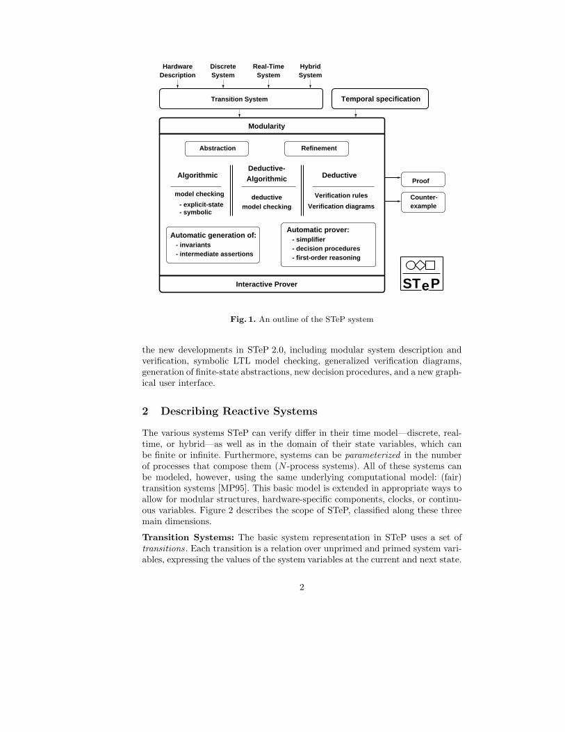
Figure 1 presents an outline of the STeP system. The main inputs are areactive system and a property to be proven for it, expressed as a temporal logicformula. The system can be a hardware or software description, and includereal-time and hybrid components (Section 2). Verification is performed by modelchecking or deductive means (Section 3), or a combination of the two (Section 4).
This paper presents an overview of the main features of STeP, including re-cent research and implementation leading up to the latest release, Version 2.0.Earlier descriptions of STeP are available as [BBC+96, BBC+95, MAB+94]. Re-cent test cases are reported in [BLM97, BMSU98, MS98]. This paper focuses on
⋆ This research was supported in part by the National Science Foundation under grantsCCR-95-27927 and CCR-98-04100, the Defense Advanced Research Projects Agencyunder NASA grant NAG2-892, ARO under grants DAAH04-95-1-0317, DAAH04-96-1-0122 and DAAG55-98-1-0471, ARO under MURI grant DAAH04-96-1-0341, andby Army contract DABT63-96-C-0096 (DARPA).
Abstraction
STeP
Proof
exampleCounter-
Refinement
Temporal specificationTransition System
DescriptionHardware
SystemDiscrete
SystemHybrid
SystemReal-Time
Interactive Prover
- simplifierAutomatic prover:
- decision procedures- first-order reasoning
Verification rules
Deductive
Verification diagrams
Algorithmic
model checking
- symbolic- explicit-state model checking
deductive
AlgorithmicDeductive-
- invariantsAutomatic generation of:
- intermediate assertions
Modularity
Fig. 1. An outline of the STeP system
the new developments in STeP 2.0, including modular system description andverification, symbolic LTL model checking, generalized verification diagrams,generation of finite-state abstractions, new decision procedures, and a new graph-ical user interface.
2 Describing Reactive Systems
The various systems STeP can verify differ in their time model—discrete, real-time, or hybrid—as well as in the domain of their state variables, which canbe finite or infinite. Furthermore, systems can be parameterized in the numberof processes that compose them (N -process systems). All of these systems canbe modeled, however, using the same underlying computational model: (fair)transition systems [MP95]. This basic model is extended in appropriate ways toallow for modular structures, hardware-specific components, clocks, or continu-ous variables. Figure 2 describes the scope of STeP, classified along these threemain dimensions.
Transition Systems: The basic system representation in STeP uses a set oftransitions. Each transition is a relation over unprimed and primed system vari-ables, expressing the values of the system variables at the current and next state.
2

STeP
Finite Automata Fair Trans.
Clocked Trans.Timed Automata
SCOPE
Hybrid
Real-Time
Time Model
Parameterization
1-component
N-components
Domain of Discrete Variables
(Hardware) (Software)Finite Infinite
Discrete
Hybrid Automata Phase Trans.
Fig. 2. Scope of STeP
Transitions can thus be represented as general first-order formulas, though morespecialized notations for guarded commands and assignments is also available.In the discrete case, transitions can be labeled as just or compassionate; suchfairness constraints are relevant to the proof of progress properties (see [MP95]).
SPL Programs: For convenience, discrete systems can be described in the Sim-ple Programming Language (SPL) of [MP95]. SPL programs are automaticallytranslated into the corresponding fair transition systems, which are then usedas the basis for verification.
Real-Time Systems: STeP can verify properties of real-time systems, using thecomputational model of clocked transition systems [MP96]. Clocked transitionsystems consist of standard instantaneous transitions that can reset auxiliaryclocks, and a progress condition that limits the time that the system can stay ina particular discrete state. Clocked transition systems are converted into discretetransition systems by including a tick transition that advances time, constrainedby the progress condition. The tick transition is parameterized by a positivereal-valued duration of the time step.
3
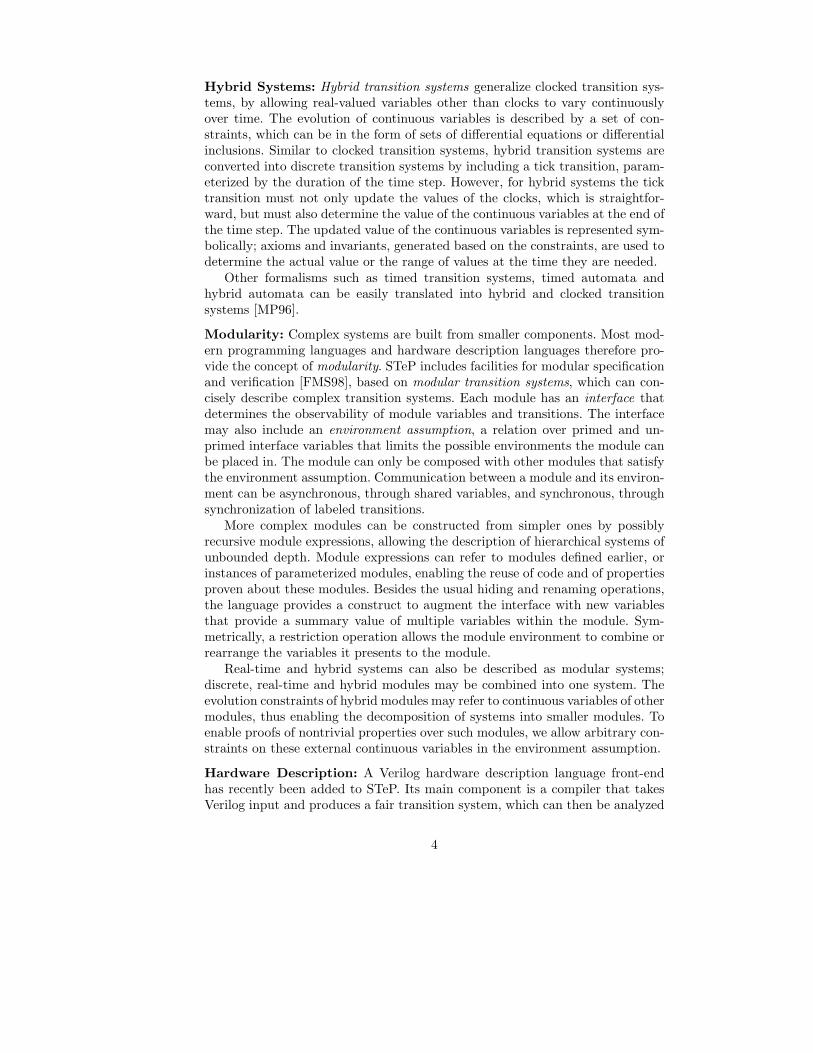
Hybrid Systems: Hybrid transition systems generalize clocked transition sys-tems, by allowing real-valued variables other than clocks to vary continuouslyover time. The evolution of continuous variables is described by a set of con-straints, which can be in the form of sets of differential equations or differentialinclusions. Similar to clocked transition systems, hybrid transition systems areconverted into discrete transition systems by including a tick transition, param-eterized by the duration of the time step. However, for hybrid systems the ticktransition must not only update the values of the clocks, which is straightfor-ward, but must also determine the value of the continuous variables at the end ofthe time step. The updated value of the continuous variables is represented sym-bolically; axioms and invariants, generated based on the constraints, are used todetermine the actual value or the range of values at the time they are needed.
Other formalisms such as timed transition systems, timed automata andhybrid automata can be easily translated into hybrid and clocked transitionsystems [MP96].
Modularity: Complex systems are built from smaller components. Most mod-ern programming languages and hardware description languages therefore pro-vide the concept of modularity. STeP includes facilities for modular specificationand verification [FMS98], based on modular transition systems, which can con-cisely describe complex transition systems. Each module has an interface thatdetermines the observability of module variables and transitions. The interfacemay also include an environment assumption, a relation over primed and un-primed interface variables that limits the possible environments the module canbe placed in. The module can only be composed with other modules that satisfythe environment assumption. Communication between a module and its environ-ment can be asynchronous, through shared variables, and synchronous, throughsynchronization of labeled transitions.
More complex modules can be constructed from simpler ones by possiblyrecursive module expressions, allowing the description of hierarchical systems ofunbounded depth. Module expressions can refer to modules defined earlier, orinstances of parameterized modules, enabling the reuse of code and of propertiesproven about these modules. Besides the usual hiding and renaming operations,the language provides a construct to augment the interface with new variablesthat provide a summary value of multiple variables within the module. Sym-metrically, a restriction operation allows the module environment to combine orrearrange the variables it presents to the module.
Real-time and hybrid systems can also be described as modular systems;discrete, real-time and hybrid modules may be combined into one system. Theevolution constraints of hybrid modules may refer to continuous variables of othermodules, thus enabling the decomposition of systems into smaller modules. Toenable proofs of nontrivial properties over such modules, we allow arbitrary con-straints on these external continuous variables in the environment assumption.
Hardware Description: A Verilog hardware description language front-endhas recently been added to STeP. Its main component is a compiler that takesVerilog input and produces a fair transition system, which can then be analyzed
4
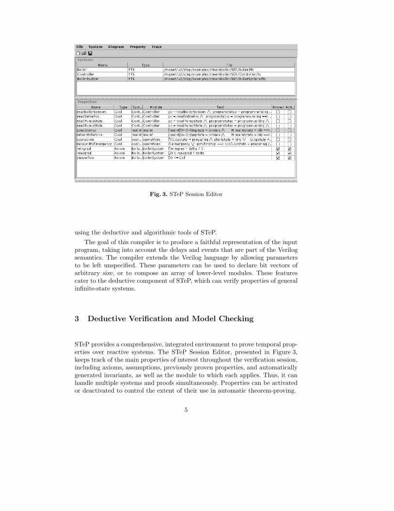
Fig. 3. STeP Session Editor
using the deductive and algorithmic tools of STeP.
The goal of this compiler is to produce a faithful representation of the inputprogram, taking into account the delays and events that are part of the Verilogsemantics. The compiler extends the Verilog language by allowing parametersto be left unspecified. These parameters can be used to declare bit vectors ofarbitrary size, or to compose an array of lower-level modules. These featurescater to the deductive component of STeP, which can verify properties of generalinfinite-state systems.
3 Deductive Verification and Model Checking
STeP provides a comprehensive, integrated environment to prove temporal prop-erties over reactive systems. The STeP Session Editor, presented in Figure 3,keeps track of the main properties of interest throughout the verification session,including axioms, assumptions, previously proven properties, and automaticallygenerated invariants, as well as the module to which each applies. Thus, it canhandle multiple systems and proofs simultaneously. Properties can be activatedor deactivated to control the extent of their use in automatic theorem-proving.
5

3.1 Property Specification: Linear-Time Temporal Logic
We use linear-time temporal logic (LTL) to represent properties of reactive sys-tems [MP95]. A model of LTL is an infinite sequence of states. We use the usualtemporal operators, such as 2p (p is always true), 3p (p is eventually true),p U q (p is true until q is true, which eventually happens), and p W q (p awaitsq—p is true at least until q is true, but q need not eventually happen).
We distinguish between safety and progress properties. Informally, safetyproperties say that certain “bad states” will never be reached, e.g. as in aninvariance 2p for an assertion p.
Progress properties, on the other hand, can say that “good” states will even-tually be reached (perhaps recurrently). Safety properties do not depend on thefairness constraints of the system, whereas progress properties require the justiceor compassion of particular transitions in order to be proved.
To specify properties of real-time and hybrid systems, temporal-logic proper-ties can refer to the global and auxiliary clocks, and to the continuous variables;the underlying temporal logic remains the same.
3.2 Deductive Verification
The deductive methods of STeP verify temporal properties of systems by meansof verification rules and verification diagrams. Verification rules reduce temporalproperties of systems to first-order verification conditions [MP95]. Verification
diagrams [MP94] provide a visual language for guiding, organizing, and display-ing proofs, and automatically generating the appropriate verification conditionsas well (see Section 4.1).
As clocked and hybrid transition systems are converted into fair transitionsystems, verification rules and diagrams are uniformly applicable to discrete,real-time and hybrid systems. However, due to the parameterization of the ticktransiton, the resulting verification conditions for real-time and hybrid systemsare usually more complex than those for (unparameterized) discrete systems.
Figure 4 shows the STeP Proof Editor, which is used to apply the basic deduc-tive temporal verification rules as well as the Gentzen-style interactive theoremproving rules. In a typical deductive verification effort, the top-level goal is atemporal formula to be proven valid for a given system. Verification rules or di-agrams are used to generate verification conditions, as subgoals, which togetherimply the system validity of the original temporal property. These subgoals arethen established automatically using decision procedures (Section 5.2) or inter-actively using the Gentzen-style rules. Model checking is also initiated by theProof Editor.
3.3 Model Checking
STeP features automatic explicit-state and symbolic model checking for linear-time temporal logic. The explicit-state model checker performs an incremental
6
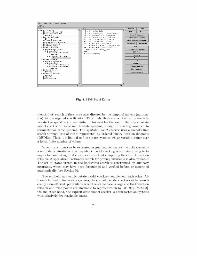
Fig. 4. STeP Proof Editor
(depth-first) search of the state-space, directed by the temporal tableau (automa-ton) for the negated specification. Thus, only those states that can potentiallyviolate the specification are visited. This enables the use of the explicit-statemodel checker on some infinite-state systems, though it is not guaranteed toterminate for these systems. The symbolic model checker uses a breadth-firstsearch through sets of states represented by ordered binary decision diagrams(OBDDs). Thus, it is limited to finite-state systems, whose variables range overa fixed, finite number of values.
When transitions can be expressed as guarded commands (i.e., the system isa set of deterministic actions), symbolic model checking is optimized using tech-niques for computing predecessor states without computing the entire transitionrelation. A specialized backwards search for proving invariants is also available.The set of states visited in the backwards search is constrained by auxiliaryinvariants, which may have been formulated and verified before, or generatedautomatically (see Section 5).
The symbolic and explicit-state model checkers complement each other. Al-though limited to finite-state systems, the symbolic model checker can be consid-erably more efficient, particularly when the state-space is large and the transitionrelation and fixed points are amenable to representation by OBDD’s [McM93].On the other hand, the explicit-state model checker is often faster on systemswith relatively few reachable states.
7

3.4 Modular Verification
Different components of a large system may require the application of differentverification methodologies, depending on their specific type (real-time or dis-crete, finite- or infinite-state). Using the notion of modular validity, modularproperties can be established by the same set of methods as global properties,accounting for environment transitions. Automatic property inheritance thenensures that such properties can be used as lemmas in proofs over compositemodules. In the case of recursively defined systems, properties can be estab-lished by structural induction.
Many properties are not directly guaranteed by a module, but hold onlyunder certain assumptions. STeP’s proof management allows assumptions to beused before their proof is available, checking the resulting dependency diagramto avoid unsound circular reasoning. Assumptions about the environment can bemade when proving a modular property, and subsequently discharged when themodule is composed with another. The search for appropriate assumptions canbe guided by constructing verification diagrams for each module and attemptingto prove the associated verification conditions [FMS98, MCF+98].
4 Combining Deductive and Algorithmic Methods
STeP includes formalisms that combine deductive and algorithmic verificationin a number of different ways, which differ in the degree and type of interventionthat is required from the user.
4.1 Generalized Verification Diagrams
Generalized verification diagrams [BMS95, MBSU98] are an extension of veri-fication diagrams that allow the verification of arbitrary temporal properties.Diagrams can be seen as intermediaries between the system and the property tobe proven. A set of verification conditions is proved, deductively, to show thatthe diagram faithfully represents computations of the system. An algorithmiccheck then establishes that the diagram corresponds to the formula being proved.Together, these two stages show that all computations of the system are modelsof the temporal property.
The STeP Diagram Editor, shown in Figure 5, allows the user to draw adiagram and then prove, using the Proof Editor, the associated verification con-ditions. In STeP 2.0, the Diagram Editor and the Proof Editor are more tightlycoupled, to facilitate the incremental development of diagrams. The user candraw an initial version and try to prove the associated verification conditions.If they fail, the user can make local corrections to the diagram (or discoversomething wrong with the system) and attempt the proof again.
The verification conditions are local to the diagram; failed verification con-ditions point to missing edges or nodes, weak assertions, or possible bugs inthe system. Since local changes to a diagram do not affect the verification condi-tions elsewhere, much of the work from the previous iteration can be saved. Using
8
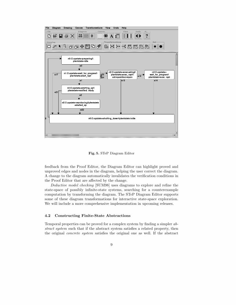
Fig. 5. STeP Diagram Editor
feedback from the Proof Editor, the Diagram Editor can highlight proved andunproved edges and nodes in the diagram, helping the user correct the diagram.A change to the diagram automatically invalidates the verification conditions inthe Proof Editor that are affected by the change.
Deductive model checking [SUM98] uses diagrams to explore and refine thestate-space of possibly infinite-state systems, searching for a counterexamplecomputation by transforming the diagram. The STeP Diagram Editor supportssome of these diagram transformations for interactive state-space exploration.We will include a more comprehensive implementation in upcoming releases.
4.2 Constructing Finite-State Abstractions
Temporal properties can be proved for a complex system by finding a simpler ab-
stract system such that if the abstract system satisfies a related property, thenthe original concrete system satisfies the original one as well. If the abstract
9
system is finite-state, its temporal properties can be established automaticallyusing a model checker. We have developed methods for automatically generatingfinite-state abstractions of possibly infinite-state systems, using the decision pro-cedures in STeP [CU98, Uri98]. We describe some of these decision proceduresin Section 5.2.
The abstraction algorithm compositionally abstracts the transitions of thesystem, expressed as first-order relations, relative to a given, fixed set of asser-tions which define the abstract state-space. The number of validity checks isproportional to the size of the system description, rather than the size of theabstract state-space.
Once the finite-state abstraction is generated, it can be model checked, explic-itly or symbolically (see Section 3.3). The generated abstractions are weakly pre-
serving for universal (∀CTL*) temporal properties, including LTL. This meansthat validity at the abstract level implies the validity of the original property overthe concrete system; however, if the abstract property fails, the original propertymight still hold. In this case, we say that the abstraction was not fine enough. Anabstract counterexample can be used, manually, to determine if a correspondingconcrete counterexample exists, or else to build a finer abstraction.
5 Deductive-Algorithmic Support
Besides model checking, described in Section 3.3, STeP provides two basic au-tomatic tools that support deductive and deductive-algorithmic verification: au-tomatic invariant generation and decision procedures. Both are used extensivelyin the combinations of deductive and algorithmic verification presented in Sec-tion 4.
5.1 Automatic Invariant Generation
Deductive verification is usually an incremental process: simple properties ofthe system being verified are proved first and then used to help establish morecomplex ones. STeP implements techniques for the automatic generation of in-
variants, as described in [BBM97]. Invariant generation is based on approximatepropagation, starting from the set of initial states, through the state-space ofthe system until a fixpoint is reached. Depending on the approximation methodused, different types of invariants can be generated:
– Local invariants result from analyzing the possible values of individual vari-ables, as well as the relation between control locations and data values.
– Linear invariants express linear relationships between system variables.– Polyhedral invariants generalize linear invariants, expressing polyhedral con-
straints over sets of system variables.
For real-time and hybrid systems STeP provides an alternative techniqueof invariant generation, also based on forward propagation of system behaviorthrough the state space, but now starting from the entire state space [BMSU98].
10

In this case every propagation step leads to an invariant; no fixpoint needs tobe computed. For hybrid systems these techniques have been further optimizedto take advantage of the structure of the constraints, resulting in stronger in-variants. In [MS98] we show an example where the invariants thus generated aresufficiently strong to prove the main property of interest.
5.2 Decision Procedures
The verification conditions generated in deductive verification refer to the do-main of computation of the system being verified. To establish verification con-ditions in the most automatic and efficient manner, STeP includes decision pro-
cedures for a number of theories frequently used in computation domains, andthus common in formal verification [Bjø98].
The basic integration of decision procedures is a variant of Shostak’s con-gruence closure-based algorithm [Sho84, CLS96, Bjø98]. At the top-level, analgorithm based on congruence closure propagates equality constraints throughfunction symbols. It invokes the other decision procedures as auxiliary simplifiersand solvers. The theories supported in this way include:
– Partial orders. Beyond basic equality, partial orders are a more expressiveconstraint language to specify relations between variables.
– Linear and non-linear arithmetic. STeP provides Fourier’s quantifier elimi-nation procedure to deal with formulas involving linear arithmetic; this pro-cedure also extracts implied equalities. Verification conditions involving non-linear arithmetic, which are common in the verification of hybrid systems,are dealt with by techniques that eliminate first- and second-degree variables,as described in [Wei97].
– Bit-vectors. Reasoning about bit-vectors is essential for hardware verifi-cation. STeP includes decision procedures for fixed-size bit-vectors withboolean bitwise operations and concatenation, and for non-fixed size bit-vectors with concatenation [BP98].
– Lists, queues, and word decision procedures. Lists and queues are commondata structures, especially in systems using abstract datatypes or asyn-chronous channels. Both lists and queues can be viewed as special cases ofwords, with concatenation being the basic operation. Although the knowndecision procedures for word equalities have prohibitive complexity, the spe-cial cases of lists and queues can be solved efficiently.
– Recursive data-types. STeP supports equality reasoning for general recursivedatatypes, which allow the specification of S-expressions and other tree-likestructures. Enumeration types and records are treated as special cases ofrecursive datatypes.Co-inductive data-types, such as lazy lists, are also supported. Both equalityconstraints and subterm relationships are supported in the integration ofdecision procedures.
– Set theory. STeP provides basic support for Multi-level Syllogistic Set-theory(MLSS) [CFO89, CZ98]. MLSS terms range over sets, and operations include
11
union, intersection, set-difference, and finite set-enumeration. Atomic rela-tions include set equality, inclusion and membership.
STeP uses decision procedures not only to check validity, but to simplify
formulas as well, rewriting them to smaller, logically equivalent ones. Efficientformula simplification can make verification conditions more readable and man-ageable, and improves the efficiency of subsequent validity checking.
The above decision procedures check validity of ground formulas, where nofirst-order quantification is present. STeP extends this combination of grounddecision procedures to include theory-specific unification algorithms, which findquantifier instantiations needed for first-order validity checking [BSU97].
As mentioned in Section 3.2, an interactive Gentzen-style theorem prover isavailable as part of the Proof Editor to establish verification conditions that arenot proved automatically.
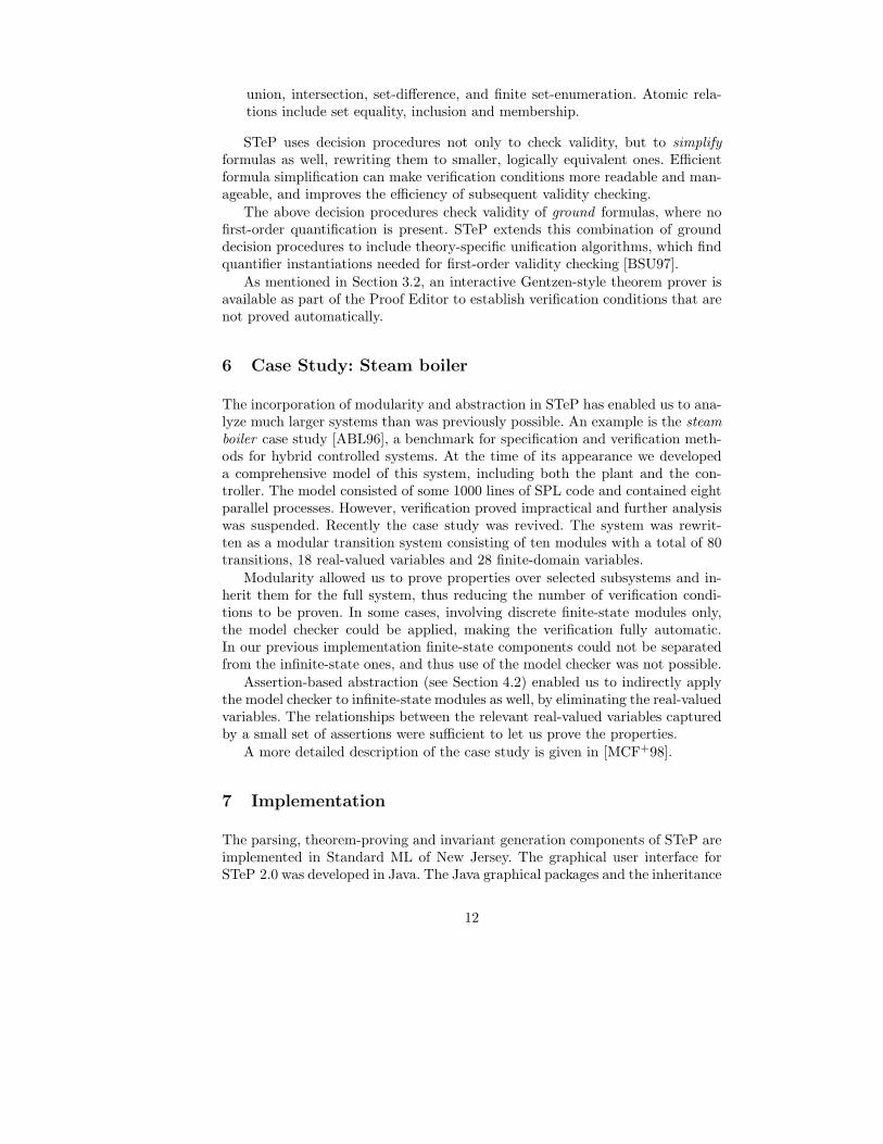
6 Case Study: Steam boiler
The incorporation of modularity and abstraction in STeP has enabled us to ana-lyze much larger systems than was previously possible. An example is the steam
boiler case study [ABL96], a benchmark for specification and verification meth-ods for hybrid controlled systems. At the time of its appearance we developeda comprehensive model of this system, including both the plant and the con-troller. The model consisted of some 1000 lines of SPL code and contained eightparallel processes. However, verification proved impractical and further analysiswas suspended. Recently the case study was revived. The system was rewrit-ten as a modular transition system consisting of ten modules with a total of 80transitions, 18 real-valued variables and 28 finite-domain variables.
Modularity allowed us to prove properties over selected subsystems and in-herit them for the full system, thus reducing the number of verification condi-tions to be proven. In some cases, involving discrete finite-state modules only,the model checker could be applied, making the verification fully automatic.In our previous implementation finite-state components could not be separatedfrom the infinite-state ones, and thus use of the model checker was not possible.
Assertion-based abstraction (see Section 4.2) enabled us to indirectly applythe model checker to infinite-state modules as well, by eliminating the real-valuedvariables. The relationships between the relevant real-valued variables capturedby a small set of assertions were sufficient to let us prove the properties.
A more detailed description of the case study is given in [MCF+98].
7 Implementation
The parsing, theorem-proving and invariant generation components of STeP areimplemented in Standard ML of New Jersey. The graphical user interface forSTeP 2.0 was developed in Java. The Java graphical packages and the inheritance
12
features of the language are well-suited for the implementation of a variety ofvisual formalisms with common features, as in the STeP Diagram Editor.
The explicit-state model checker is implemented in C, while the symbolicmodel checker uses ML linked together with external OBDD libraries, writtenin C. Similarly, the polyhedral invariant generation uses external polyhedra ma-nipulation routines, implemented in C [HP95].
Stand-alone components: Many of the components of STeP described abovecan be used in batch mode, as stand-alone components, including:
– the parser/translator from SPL into fair transition systems (Section 2)– the explicit-state and symbolic model checkers (Section 3.3)– the linear, local and polyhedral invariant generators (Section 5.1)– the validity checker and formula simplifier (Section 5.2)
These options are available as command-line options to a separate executablebinary file.
External systems: Verification conditions in STeP can be output to externaltheorem provers or decision procedures. In particular, the MONA package formonadic second order logic can be used; output to the OTTER and Gandalfresolution theorem provers is also provided. STeP interacts with these proversby invoking them in the background and digesting their output to check if theverification conditions have been discharged.
Obtaining STeP
To obtain STeP, send email to [email protected]. For more in-formation on the system, see the STeP web pages at
http://www-step.stanford.edu
Acknowledgements: Andrew Miller helped implement the STeP 2.0 interface.Mark Stickel provided AC-unification utilities and feedback. STeP 2.0 uses theOBDD package by Jørn Lind-Nielsen from DTU, Denmark, and the POLKA[HP95] polyhedral manipulation package from VERIMAG.
We thank Francesc Babot, Ralph Jeffords, Arjun Kapur, Uri Lerner, Ka FaiLo, Jonathan Ostroff, Calogero Zarba, and the students of CS256 at Stanfordfor their feedback on STeP.
References
[ABL96] J.R. Abrial, E. Boerger, and H. Langmaack, editors. Formal Methods forIndustrial Applications: Specifying and Programming the Steam Boiler Con-trol, vol. 1165 of LNCS. Springer-Verlag, 1996.
13
[BBC+95] N.S. Bjørner, A. Browne, E.S. Chang, M. Colon, A. Kapur, Z. Manna, H.B.Sipma, and T.E. Uribe. STeP: The Stanford Temporal Prover, User’s Man-ual. Technical Report STAN-CS-TR-95-1562, Computer Science Depart-ment, Stanford University, November 1995.
[BBC+96] N.S. Bjørner, A. Browne, E.S. Chang, M. Colon, A. Kapur, Z. Manna, H.B.Sipma, and T.E. Uribe. STeP: Deductive-algorithmic verification of reactiveand real-time systems. In R. Alur and T.A. Henzinger, editors, Proc. 8th
Intl. Conference on Computer Aided Verification, vol. 1102 of LNCS, pages415–418. Springer-Verlag, July 1996.
[BBM97] N.S. Bjørner, A. Browne, and Z. Manna. Automatic generation of invari-ants and intermediate assertions. Theoretical Computer Science, 173(1):49–87, February 1997. Preliminary version appeared in 1st Intl. Conf. on Prin-ciples and Practice of Constraint Programming, vol. 976 of LNCS, pp. 589–623, Springer-Verlag, 1995.
[Bjø98] N.S. Bjørner. Integrating Decision Procedures for Temporal Verification.PhD thesis, Computer Science Department, Stanford University, November1998.
[BLM97] N.S. Bjørner, U. Lerner, and Z. Manna. Deductive verification of param-eterized fault-tolerant systems: A case study. In Intl. Conf. on TemporalLogic. Kluwer, 1997. To appear.
[BMS95] A. Browne, Z. Manna, and H.B. Sipma. Generalized temporal verificationdiagrams. In 15th Conference on the Foundations of Software Technol-ogy and Theoretical Computer Science, vol. 1026 of LNCS, pages 484–498.Springer-Verlag, 1995.
[BMSU98] N.S. Bjørner, Z. Manna, H.B. Sipma, and T.E. Uribe. Deductive verifica-tion of real-time systems using STeP. Technical report, Computer ScienceDepartment, Stanford University, October 1998. Preliminary version ap-peared in 4th Intl. AMAST Workshop on Real-Time Systems, vol. 1231 ofLNCS, pages 22–43. Springer-Verlag, May 1997.
[BP98] N.S. Bjørner and M.C. Pichora. Deciding fixed and non-fixed size bit-vectors. In 4th Intl. Conf. on Tools and Algorithms for the Construction andAnalysis of Systems (TACAS), vol. 1384 of LNCS, pages 376–392. Springer-Verlag, 1998.
[BSU97] N.S. Bjørner, M.E. Stickel, and T.E. Uribe. A practical integration offirst-order reasoning and decision procedures. In Proc. of the 14th Intl.Conference on Automated Deduction, vol. 1249 of LNCS, pages 101–115.Springer-Verlag, July 1997.
[CFO89] D. Cantone, A. Ferro, and E. Omodeo. Computable Set Theory. OxfordSceince Publications, 1989.
[CLS96] D. Cyrluk, P. Lincoln, and N. Shankar. On Shostak’s decision procedure forcombinations of theories. In Proc. of the 13th Intl. Conference on AutomatedDeduction, vol. 1104 of LNCS, pages 463–477. Springer-Verlag, 1996.
[CU98] M.A. Colon and T.E. Uribe. Generating finite-state abstractions of reactivesystems using decision procedures. In A.J. Hu and M.Y. Vardi, editors,Proc. 10th Intl. Conference on Computer Aided Verification, vol. 1427 ofLNCS, pages 293–304. Springer-Verlag, July 1998.
[CZ98] D. Cantone and C.G. Zarba. A new fast tableau-based decision procedurefor an unquantified fragment of set theory. In Int. Workshop on First-OrderTheorem Proving (FTP’98), 1998.
14
[FMS98] B. Finkbeiner, Z. Manna, and H.B. Sipma. Deductive verification of mod-ular systems. In W.P. de Roever, H. Langmaack, and A. Pnueli, editors,Compositionality: The Significant Difference, COMPOS’97, vol. 1536 ofLNCS, pages 239–275. Springer-Verlag, 1998.
[HP95] N. Halbwachs and Y.E. Proy. POLyhedra desK cAlculator (POLKA).VERIMAG, Montbonnot, France, September 1995.
[MAB+94] Z. Manna, A. Anuchitanukul, N. Bjørner, A. Browne, E.S. Chang,M. Colon, L. de Alfaro, H. Devarajan, H.B. Sipma, and T.E. Uribe. STeP:The Stanford temporal prover. Technical Report STAN-CS-TR-94-1518,Computer Science Department, Stanford University, July 1994.
[MBSU98] Z. Manna, A. Browne, H.B. Sipma, and T.E. Uribe. Visual abstractionsfor temporal verification. In AMAST’98, LNCS. Springer-Verlag, 1998. Toappear.
[MCF+98] Z. Manna, M.A. Colon, B. Finkbeiner, H.B. Sipma, and T.E. Uribe. Ab-straction and modular verification of infinite-state reactive systems. InM. Broy, editor, Requirements Targeting Software and Systems Engineer-ing (RTSE), LNCS. Springer-Verlag, 1998. To appear.
[McM93] K.L. McMillan. Symbolic Model Checking. Kluwer Academic Pub., 1993.[MP94] Z. Manna and A. Pnueli. Temporal verification diagrams. In M. Hagiya
and J.C. Mitchell, editors, Proc. International Symposium on TheoreticalAspects of Computer Software, vol. 789 of LNCS, pages 726–765. Springer-Verlag, 1994.
[MP95] Z. Manna and A. Pnueli. Temporal Verification of Reactive Systems: Safety.Springer-Verlag, New York, 1995.
[MP96] Z. Manna and A. Pnueli. Clocked transition systems. Technical ReportSTAN-CS-TR-96-1566, Computer Science Department, Stanford University,April 1996.
[MS98] Z. Manna and H.B. Sipma. Deductive verification of hybrid systems usingSTeP. In T. Henzinger and S. Sastry, editors, Hybrid Systems: Computationand Control, vol. 1386 of LNCS, pages 305–318. Springer-Verlag, 1998.
[Sho84] R.E. Shostak. Deciding combinations of theories. J. ACM, 31(1):1–12,January 1984.
[SUM98] H.B. Sipma, T.E. Uribe, and Z. Manna. Deductive model checking. Toappear in Formal Methods in System Design, 1998. Preliminary versionappeared in Proc. 8th Intl. Conference on Computer Aided Verification,vol. 1102 of LNCS , Springer-Verlag, pp. 208–219, 1996.
[Uri98] T.E. Uribe. Abstraction-based Deductive-Algorithmic Verification of Reac-tive Systems. PhD thesis, Computer Science Department, Stanford Univer-sity, December 1998.
[Wei97] V. Weispfenning. Quantifier elimination for real algebra—the quadraticcase and beyond. In Applied Algebra and Error-Correcting Codes (AAECC)8, pages 85–101, 1997.
15
Copyright © 2022 FDOKUMEN