An Intelligent Hexapod Rescue Robot - Brac University
42
An Intelligent Hexapod Rescue Robot This thesis was submitted in partial fulfillment of the requirement for the Degree of Bachelor of Computer Science and Engineering By Shaker Mahmud Khandaker (14101193) Ratul Acharjee (14121061) Under the Supervision of Dr. Jia Uddin School of Engineering and Computer Science BRAC University, Dhaka, Bangladesh Submission date: 25-03-2018
-
Upload
khangminh22 -
Category
Documents
-
view
0 -
download
0
Transcript of An Intelligent Hexapod Rescue Robot - Brac University

An Intelligent Hexapod Rescue Robot
This thesis was submitted in partial fulfillment of the requirement for the
Degree of
Bachelor of Computer Science and Engineering
By
Shaker Mahmud Khandaker (14101193)
Ratul Acharjee (14121061)
Under the Supervision of
Dr. Jia Uddin
School of Engineering and Computer Science
BRAC University, Dhaka, Bangladesh
Submission date: 25-03-2018
Declaration
We hereby assure that all the work done for this thesis project is compiled with the results
attained from our own work. All of the algorithms, tools and materials that helped us developing this
project have been properly acknowledged and referenced. This thesis either in whole or in part, has
not been previously submitted for any degree anywhere.
Signature of Supervisor Signature of the Authors
Dr. Jia Uddin Shaker Mahmud Khandaker (14101193)
Ratul Acharjee (14121061)
ii | P a g e
Acknowledgement
Firstly, we thank our respected Supervisor Dr. Jia Uddin Sir for his supervision and
guidance throughout this project. His experience and kindness lead us to the completion of this
thesis.
We would also like to thank our parents for their patience and support on us. If it was not for
their sacrifices, we would not be able to come this far with our life and our project.
Finally, we are thankful to BRAC University for letting us complete this research and
allowing us all the opportunities.
iii| P a g e
Table of Contents
Acknowledgement ........................................................................................................................... iii
List of Figures ............................................................................................................. ...................... vi
Abstract ............................................................................................................................................. 1
Chapter 1 Introduction
1.1 Introduction…………………………………………………………………………….…… 2
1.2 Motivation………..………………………………………….……………………………… 3
1.3 Problem statement…………..……………………………………………………….……… 3
1.4 Solutions…………………………..………………………………………………………… 4
1.5 Methodology ………………………………………………………………………………... 4
1.6 Contribution summary …………………………..………………………..………………… 4
1.7 Thesis Outline ……………...………………………………………………..……………… 4
Chapter 2 Literature Review and Research
2.1 Literature review…………………………………………………………………………….. 5
Chapter 3 Proposed Model
3.1 Proposed working principle…………………………………………………..……………... 8
3.2 Components ……………...…………………………………………………..……………... 8
3.2.1 Arduino Mega ……………………………….………………….……………….… 9
3.2.2 Raspberry PI ……………………………….………………….…………………… 9
3.3 Current Working Principal ……………...…………………………………………..………. 12
3.3.1 Flow Chart of the model……………………………….………………….…….… 12
3.3.2 Unique Walking Algorithm ……………………………….….……………….….. 14
3.3.3 Hexapod Robot Gait ……………………………………………………………… 14
3.3.4 Terrain adaptation ………….…………………...………………………………… 15
iv| P a g e

3.3.5 Life Detection Algorithm………………………………………………………….. 18
3.3.5.1 Direction Algorithm……………………………………………………… 19
3.3.5.2 Distance Algorithm………………………………………………………. 20
3.4 Building prototype model ………………………………………………………………...... 20
3.4.1 Circuit details of the prototype model .…………….…………………...……….… 20
3.4.2 Hardware implementation ………………………. ….……………………………. 21
3.4.3 Dimension of Coxa Femur and Tibia ………………………………….…………. 22
3.5 Building final mode……………………………………………..……………………….…. 23
3.5.1 Servo Control Unit …………….……………….…………………………………. 23
3.5.2 Circuit diagram for version 2 ………………………………………….……….…. 24
3.5.3 Circuit diagram for Microphone Unit………………………….……………….…. 25
3.5.4 Mechanic design of hexapod ……….……………………………………………... 25
3.5.4.1 Body ..……….…………………………………………………………… 25
3.5.4.2 Structured legs ……………………………………..……………………. 26
3.5.4.3 Coordinate System………...……….……………………………………. 27
Chapter 4 Experimental Results
4.1 Experimental Setup …………………………………………………..……………………... 29
4.1.1 Experiments on Walking…………………………………………………………... 29
4.1.2 Experiments on Life Detection…………………………………………………... 30
4.2 Experimental Result and Analysis………………………..…………..……………………... 31
Chapter 5 Conclusion and Future Work
5.1 Conclusion …………………………………………………..……………………............... 33
5.2 Future Work…………………….………………………..…………..……………………... 33
References…………………..….………………………..…………..……………………... 34
v| P a g e
List of Figures
Figure 1. Block Diagram of the Robot ................................................................................................................ 8
Figure 2. (a) Arduino Mega, (b) Raspberry PI .................................................................................................. 9
Figure 3. Flowchart of Detective Mode………………………………………………………………………....10
Figure 4. (a) Micro-servo-sg90, (b) Microphone Module .............................................................................. 11
Figure 5. (a) Ultrasonic Sensor, (b) humidity and temperature Module.................................................... 12
Figure 6. Flowchart of the robot system ............................................................................................................. 13
Figure 7. Top view of the robot showing the movement direction ............................................................. 15
Figure 8. Scheme of proposed gait ....................................................................................................................... 16
Figure 9. The flowchart of terrain adaptation gait algorithm ........................................................................ 17
Figure 10. The microphone orientation in the hexapod .................................................................................. 18
Figure 11. Circuit Diagram of the prototype ..................................................................................................... 21
Figure 12. Model of the robot ................................................................................................................................ 22
Figure 13. (a) Tibia of the hexapod robot, (b) Femur of the hexapod robot ............................................ 22
Figure 14. Coxa of the hexapod robot ................................................................................................................. 23
Figure 15. Final version of the hexapod robot................................................................................................... 23
Figure 16. Circuit diagram of the servo control unit ....................................................................................... 24
Figure 17. Circuit diagram of the robot version 2 ............................................................................................ 24
Figure 18. Circuit diagram of the Microphone Unit ........................................................................................ 25
Figure 19. Main Body of hexapod ........................................................................................................................ 26
Figure 20. Hexapod leg measurement ................................................................................................................. 27
Figure 21. Coordinate System of structured leg of hexapod ......................................................................... 28
Figure 22. Results for sound source in North, distance 1m........................................................................... 17
Figure 23. Results for sound source in North-West, distance 0.7m ............................................................ 18
vi | P a g e
Abstract
This report proposes a survivor robot model inspired by the physique of a spider which can
be used in the cases of search and rescue operations. Multiple walking algorithms have been tested
on the robot and have been narrowed down to the most efficient walking algorithm among them.
The control of the robot has been done by an embedded android controller. The navigation of the
spider-bot has been implemented based on a six-leg system, which will be very convenient in rough
terrains. Functional algorithms have been implemented to move the robot under duress and onto
challenging fields. Moreover, these algorithms aids to the various speed parameters of the robot
based on the structure of the legs. Each of the legs has been designed using three servo motors
controlling the limbs from different joints. We have developed a unique algorithm to detect life and
send the distance and direction of the life from the robot to respond team. Additionally, a prototype
has been developed for experimental purpose and finally it has been upgraded to its final version.
1 | P a g e
CHAPTER 1
Introduction
1.1 Introduction
Important developments have been occurred in the history of science and technology.
Among them, the concept and applications of robots with each passing year are a larger place.
Speed and economic advantages in daily life and industrial applications have increased the use of
robots day by day. The robot is an electromechanical system which is capable of autonomous or
preprogrammed tasks [1]. Robots independently can also operate under the control of a computer
program such as can be directly operated by operator. Six-legged robots can be used as search and
rescue robots, space robots and discover robots. In these fields, hexapod robots present
opportunities as having small size and practical mobility. When viewed from this perspective, six-
legged walking robot can be easily scroll by produced algorithms in all types of terrain is an
advantage. The acceptable number of legs and the ability to move provide more controlled balance
to the robot when compared to the majority of multi-legged robots [2]. While wheeled robots are
faster on level ground than legged robots, hexapods are the fastest of the legged robots, as they have
the optimum number of legs for walking speed - studies have shown that a larger number of legs do
not increase walking speed [21].
Hexapods are also superior to wheeled robots because wheeled robots need a continuous,
even and most often a pre-constructed path. Hexapod robots however can traverse uneven ground,
step over obstacles and choose footholds to maximize stability and traction. Having maneuverable
legs allows hexapods to turn around on the spot [22]. In comparison to other multi-legged robots,
hexapods have a higher degree of stability as there are can be up to 5 legs in contact with the ground
during walking. Also, the robots center of mass stays consistently within the tripod created by the
leg movements, which also gives great stability.
Hexapods also show robustness, because leg faults or loss can be managed by changing the
walking mechanism. This redundancy of legs also makes it possible to use one or more legs as
hands to perform dexterous tasks. Because of all of these benefits, hexapod robots are becoming
more and more common, and it will be interesting to see what modifications robot cists come up
with to further improve and develop their form and function.
2 | P a g e
Unpredictable occurrences like natural disasters, terrorist attacks may cause damage to the
building structures and many lives may be trapped inside who may need assistance from outside. It
will take a long time to send human assistance. So sending robots to the affected area might be a
good solution [1]. But in order to do that, wheeled based rescue robots will face difficulties moving
in those irregular surface and obstacle-rich area [5]. So a flexible six-legged robot will be more
effective on these challenging situations [2].
1.2 Motivation
The knowledge we gathered from our university is the tool that we tried to use for the
welfare of our society. People suffer a tragic loss in any sort of disaster or terrorism act. We wanted
to minimize these sufferings by providing them a tool to fight back their loss. Moreover, we tried to
keep the production cost as minimum as possible so that our government can easily mass-produce
this robot without effecting the economy of our country much.
Robotics has created an impact all over the world in the field of modern technology. As a
developing country, Bangladesh shows a promise in this arena. We tried to implement the feature of
robotics for the betterment of not only our country, but also the whole world.
1.3 Problem Statement
It is really challenging to build a hexapod robot. We had to go through a lot of trouble to
build the robot. Firstly, making the body of the robot was challenging as it is really hard to get
access to a 3D printer and also it is expensive. Secondly, we wanted to build a system which is cost
efficient, however servo motors that are required to make this project are expensive. Moreover,
controlling 18 servo motors is really a tough task.
Weight management of the robot was another challenging task for us. As the robot demands
a flexible movement, it needed to be light-weighted. Finally, developing the walking algorithm cost
us a lot of time and efforts as it was required for the robot to be fast and efficient in action.
3 | P a g e
1.4 Solutions
We used PVC board to build the body of the robot with is highly cost efficient and light-
weight. As the robot is now more light-weighted, we required servo motors with less torque which
minimizes the overall cost. We used a 16-channel servo controller to ensure uninterrupted power to
all the servos. Finally, we cut of all the unnecessary parts from the body to make it flexible.
1.5 Methodology
In the literature review, previous works regarding hexapod robots are mentioned. We are
using the similar properties of hexapods and use them as rescue robot which is never done before.
Also, we are making it smaller and more cost efficient. We are integrating microphones to the
robots and use them to calculate approximate direction and distance of any survivor from the robot
in a disaster terrain. In order to do that, we have designed a unique algorithm. Our prototype robot
ran effectively and efficiently as we anticipated. So we are also creating outline for future working
scopes. Ours is a semi-autonomous robot and there is a scope for making it autonomous.
1.6 Contribution Summary
The proposed robot model that we have represented here in this thesis can contribute in
saving lives in any unpleasant occurrences like building collapses in natural disaster or terrorism
attacks. Generally, a wheeled robot is not capable of moving through rough and irregular surfaces.
So it will not be able to save lives in above mentioned scenarios. However, our proposed model
shows a great promise in this certain scenarios
Moreover, this robot can be used as a defense robot for a country which will be able to spy
and detect terrorist acts. Thus any unpleasant occurrences can be minimized.
1.7 Thesis Outline
Chapter 2 elaborates the background study behind the motivation of this project.
Chapter 3 covers the model of the hexapod rescue robot, walking algorithm, dimensions of
the archetype.
Chapter 4 shows the experimental results.
Chapter 5 brings an end to this paper mentioning its challenges and limitations along with
the future scope for this system.
. 4 | P a g e
CHAPTER 2
Literature Review and Research
2.1 Literature Review
In order to build such a robot that can walk smoothly and effortlessly through a rough terrain
many works have been done. The most significant work of them is the MorpHex Hexapod Robot in
2011 [13]. It has a very flexible movement of the limbs. The whole robot was designed using a 3D
printer. Another remarkable work was done in 2016 named Matrix and is a unique Hexapod Robot
that is based on Arduino and SSC32. It is controlled using an FRSKY Taranis / X8R Receiver [14].
Similar work was done which is known as Walknet where they observed the movement behavior of
the animals and formulated a structure for six-legged movement [16]. In order to observe and
monitor crisis situations of an impacted area a work has been done in 2011 where they used satellite
to identify condition of the affected area [17].
Lost lives in disasters and terrorism due to the lack of reinforcements is a matter of concern
and is one of the motivation of this paper [7].However, the lifesaving robot of Korea had the most
motivational impact on this proposed robot [8].
RHex developed by is a different robot compared to other hexapod robot because it is
actuated by brushed DC motor [27]. The motors that are used at this robot are Maxon type motor
with a 33:1 gearhead powered by a 24V NiMH battery. The design of the leg is one degree of
freedom and half-circle. According to the author, the method is easy to build and maintain the robot
and no sliding friction during spring displacement. This design is most suitable for stair climbing.
Another hexapod robot, Bill-Ant-P robot done by is made of aluminum and carbon fiber
sheets [28]. It uses MPI MX-450HP hobby motors for its reliability, high torque and affordability
movement. The motor have 8.37kg-cm of torque, can rotate about a 60 degree in 0.18sec, and has a
small internal dc motor consumes 1125mW of power at stall torque.
Another robot called as Gregor has been developed. The Gregor robot development model
has Autodesk Inverter 9.0 to define properties of parts such as mass. Rhinocerus 2.0 software is
used to coordinate of the constraints and model the robot that can be easily exported into the
dynamic simulation environment which is also used the same software [29].
5 | P a g e
MSR-H01 hexapod developed by Micromagic System is built from 26 precision laser-cut
5053 aluminum body and leg components. It is controlled by using a p.Brain-HexEngine and used
eighteen servomotors from three different types of servomotors. The link for the robot is Bluetooth.
Hexapod robot developed by used Devantech SD-21 board to control 18 servos by interfaced with
the preferred microcontroller, which is Arduino Decimilla board. The software that is used to
control the servo controller is Matlab. In other to control the robot leg, Jacobian inverse matrix
method is used to define the angles and leg position [23].
The walking robot Ragno is 33 cm long and 30 cm wide and 2.15 kg weights [24]. It has
four layers control architecture where the first is at off-board to compute the appropriate control
signal for all leg’s joint and send control commands to robots. The second layer is on-board control
layer that interprets commands from first layer and sends to leg controllers. There are six leg
controllers that work simultaneously and control the inputs send to them. The robot has a double
axis accelerometer and a gyroscope to measure the trunk orientation in a 3D space. The on-board
and off-board parts of the control system communicate by means of a Bluetooth connection.
Dash robot can move at 11 body-lengths per second or 1.5 meters per second [30]. The
weights of entire system is 16.2 grams (10x5 cm body dimension) with include weight of battery,
electronics, microcontroller, motor driver, and Bluetooth communication module. The alternating
tripod gait is used with 10 cm wide and 5 cm tall of legs. When it moves, the center of mass follows
a roughly sinusoidal trajectory, which is stable sinusoidal motion. Two statically stable gaits is
programmed for Ragno robot that are exploits a simple crawl and a tripod-like gait [24]. The crawl
is used for lower speed by transfer one leg per time while tripod gait is the fastest stable gait with
three legs placed on the ground at a time.
Method of movement for Gregor 1 hexapod robot is the locomotion control inspired from
the biological paradigm of the Central Pattern Generators (CPG). CPGs are neural networks that
produce rhythmic patterned outputs without sensory feedback. There are three types of robots
motion. Those are walking mode, lifting mode and shifting mode which can be selected by the user.
However, only the walking mode is selected in this subchapter to be explained further. The author
used tripod gait is used because it is stable compared to other gaits for hexapod robot. The first step
in gait control, the initial posture of all legs is decided, and the position of the leg tip is defined as
the “reference position”. Then, six cylinders of the legs movement are generated so as to be
6 | P a g e
included in the work space with the center of the robotics base is set as the reference position. Thus,
the center of rotation of the motion is obtained. Then, the diameter of each cylinder is reduced so
that it may be proportional to the distance between the centre of robot (COR) and each reference
position. The desired path of each leg is generated along the circumference of the cross section of
the cylinder which is perpendicular to the line from the COR to the reference position and passes
through the reference position. Finally, the angles of all joints are generated at every control period
so that each leg tip might track the desired path and the center of body might have the provided
velocity, and transmitted to the robot. The hexapod robot in the research, the hexapod robot also use
tripod gaits, the body of the robot and ground in parallel mechanism and supported by three legs.
This journal is focused on the kinetics movement of robot and the locomotion system. It is about the
Calculation on how the hexapod robot moves. The important aspects taken into
consideration are the inertial frame, locomotive referenced coordinate system of chassis and
coordinate system on the coxa.
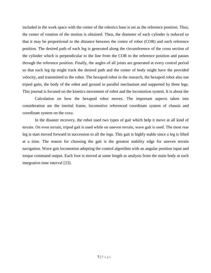
In the disaster recovery, the robot used two types of gait which help it move at all kind of
terrain. On even terrain, tripod gait is used while on uneven terrain, wave gait is used. The most rear
leg is start moved forward in succession to all the legs. This gait is highly stable since a leg is lifted
at a time. The reason for choosing the gait is the greatest stability edge for uneven terrain
navigation. Wave gait locomotion adopting the control algorithm with an angular position input and
torque command output. Each foot is moved at same length as analysis from the main body at each
integration time interval [23].
7 | P a g e
CHAPTER 3
Proposed Model
3.1 Proposed working principle
The hexapod robot acts as a rescue robot in a targeted arena. We will place the robot at a
place where human are not able to go further. We will have the full control of the robot. We will
control the robots movements and send it inside the disaster area. We will get a live camera feed
from the robot over WIFI. As we control the movements of the robot, the robot itself will also adapt
its movements by detecting obstacles in front of it by an ultrasonic sensor.
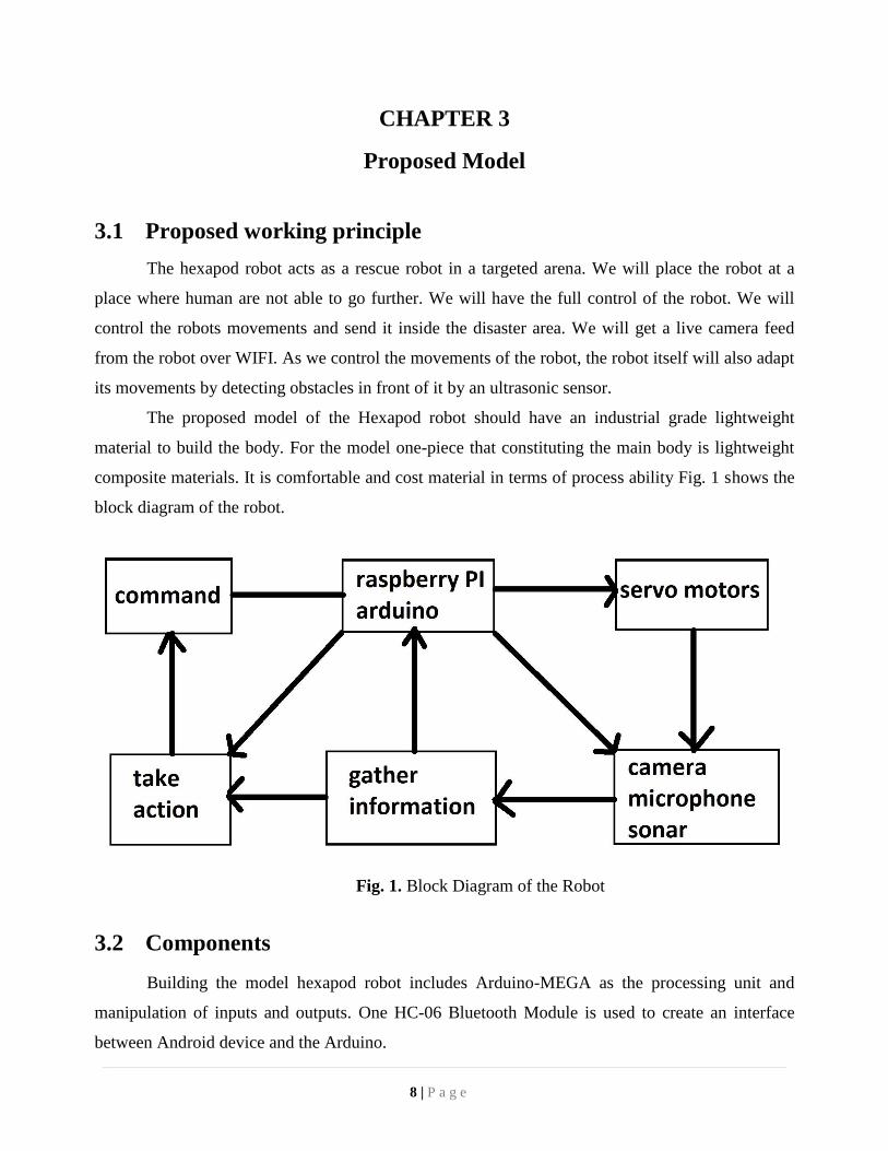
The proposed model of the Hexapod robot should have an industrial grade lightweight
material to build the body. For the model one-piece that constituting the main body is lightweight
composite materials. It is comfortable and cost material in terms of process ability Fig. 1 shows the
block diagram of the robot.
Fig. 1. Block Diagram of the Robot
3.2 Components
Building the model hexapod robot includes Arduino-MEGA as the processing unit and
manipulation of inputs and outputs. One HC-06 Bluetooth Module is used to create an interface
between Android device and the Arduino.
8 | P a g e
Moreover, one Ultrasonic Sensor is used to detect any obstacles in the surroundings. Then
eighteen SG90 Micro Servo Motors have been used which work as the movement joint of the robot.
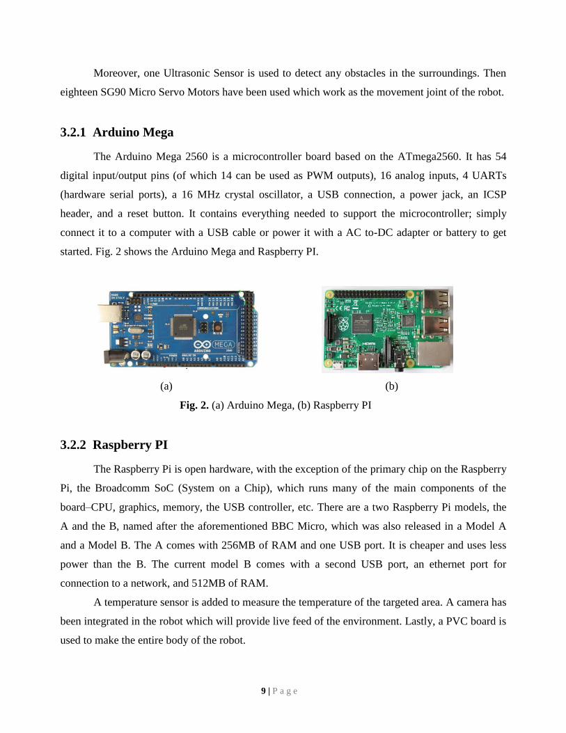
3.2.1 Arduino Mega
The Arduino Mega 2560 is a microcontroller board based on the ATmega2560. It has 54
digital input/output pins (of which 14 can be used as PWM outputs), 16 analog inputs, 4 UARTs
(hardware serial ports), a 16 MHz crystal oscillator, a USB connection, a power jack, an ICSP
header, and a reset button. It contains everything needed to support the microcontroller; simply
connect it to a computer with a USB cable or power it with a AC to-DC adapter or battery to get
started. Fig. 2 shows the Arduino Mega and Raspberry PI.
(a) (b)
Fig. 2. (a) Arduino Mega, (b) Raspberry PI
3.2.2 Raspberry PI
The Raspberry Pi is open hardware, with the exception of the primary chip on the Raspberry
Pi, the Broadcomm SoC (System on a Chip), which runs many of the main components of the
board–CPU, graphics, memory, the USB controller, etc. There are a two Raspberry Pi models, the
A and the B, named after the aforementioned BBC Micro, which was also released in a Model A
and a Model B. The A comes with 256MB of RAM and one USB port. It is cheaper and uses less
power than the B. The current model B comes with a second USB port, an ethernet port for
connection to a network, and 512MB of RAM.
A temperature sensor is added to measure the temperature of the targeted area. A camera has
been integrated in the robot which will provide live feed of the environment. Lastly, a PVC board is
used to make the entire body of the robot.
9 | P a g e
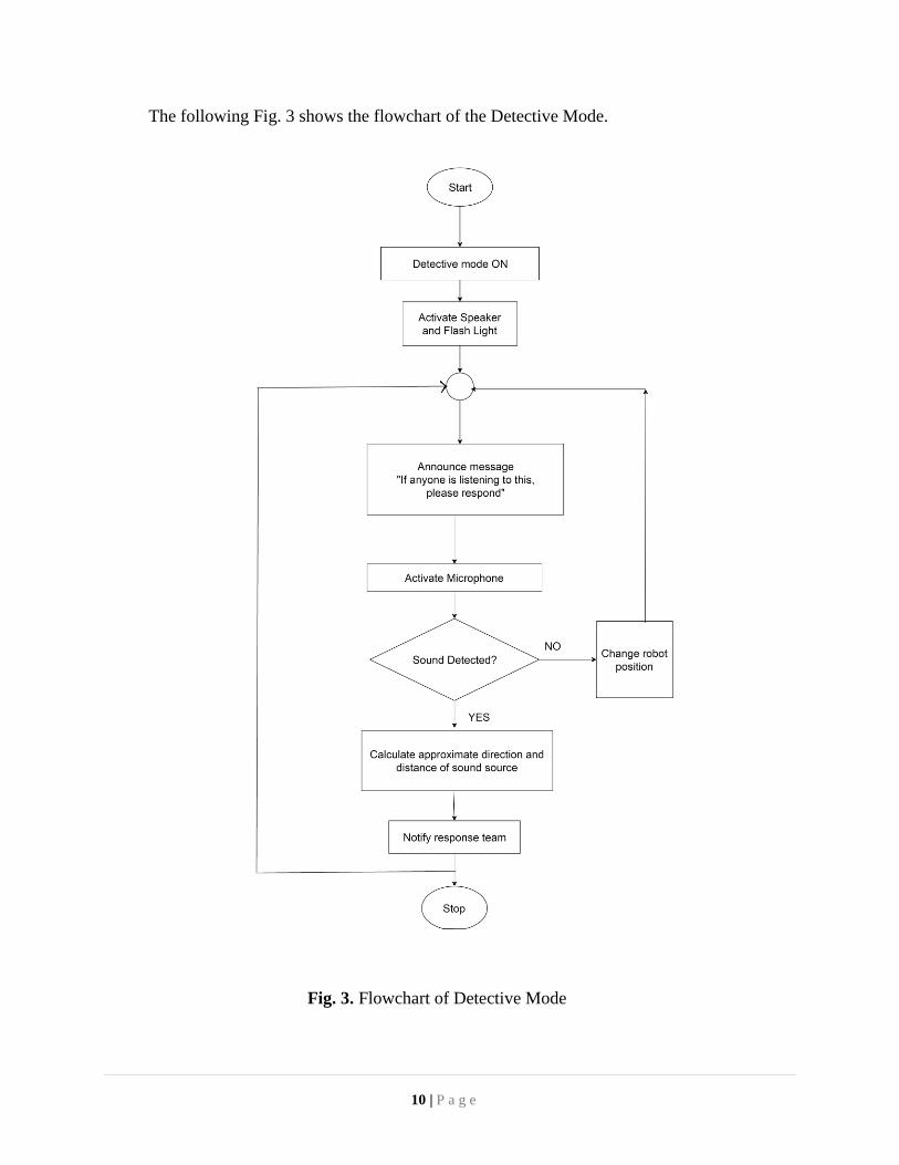
The following Fig. 3 shows the flowchart of the Detective Mode.
Fig. 3. Flowchart of Detective Mode
10 | P a g e
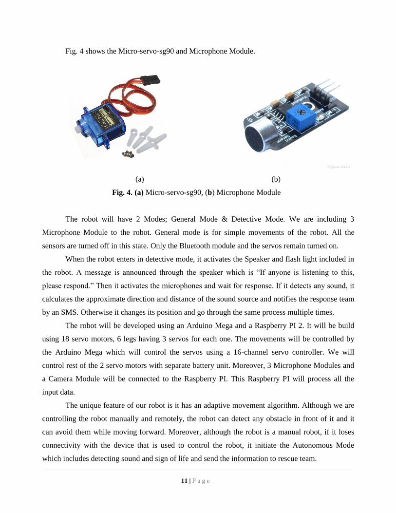
Fig. 4 shows the Micro-servo-sg90 and Microphone Module.
(a) (b)
Fig. 4. (a) Micro-servo-sg90, (b) Microphone Module
The robot will have 2 Modes; General Mode & Detective Mode. We are including 3
Microphone Module to the robot. General mode is for simple movements of the robot. All the
sensors are turned off in this state. Only the Bluetooth module and the servos remain turned on.
When the robot enters in detective mode, it activates the Speaker and flash light included in
the robot. A message is announced through the speaker which is “If anyone is listening to this,
please respond.” Then it activates the microphones and wait for response. If it detects any sound, it
calculates the approximate direction and distance of the sound source and notifies the response team
by an SMS. Otherwise it changes its position and go through the same process multiple times.
The robot will be developed using an Arduino Mega and a Raspberry PI 2. It will be build
using 18 servo motors, 6 legs having 3 servos for each one. The movements will be controlled by
the Arduino Mega which will control the servos using a 16-channel servo controller. We will
control rest of the 2 servo motors with separate battery unit. Moreover, 3 Microphone Modules and
a Camera Module will be connected to the Raspberry PI. This Raspberry PI will process all the
input data.
The unique feature of our robot is it has an adaptive movement algorithm. Although we are
controlling the robot manually and remotely, the robot can detect any obstacle in front of it and it
can avoid them while moving forward. Moreover, although the robot is a manual robot, if it loses
connectivity with the device that is used to control the robot, it initiate the Autonomous Mode
which includes detecting sound and sign of life and send the information to rescue team.
11 | P a g e
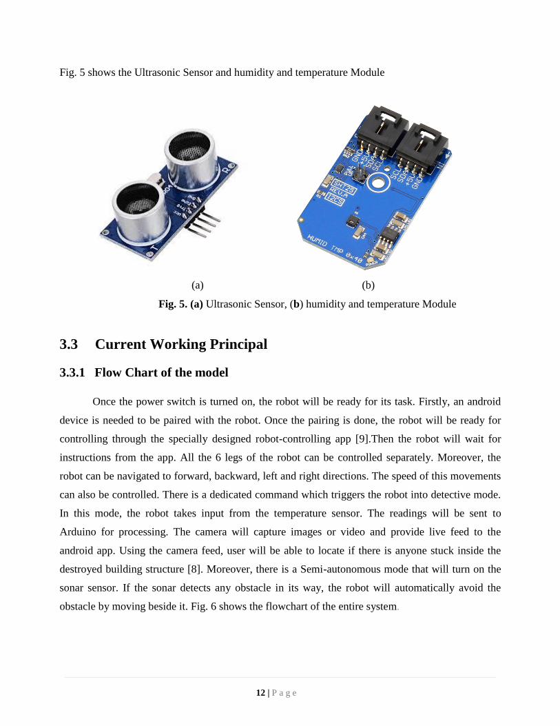
Fig. 5 shows the Ultrasonic Sensor and humidity and temperature Module
(a) (b)
Fig. 5. (a) Ultrasonic Sensor, (b) humidity and temperature Module
3.3 Current Working Principal
3.3.1 Flow Chart of the model
Once the power switch is turned on, the robot will be ready for its task. Firstly, an android
device is needed to be paired with the robot. Once the pairing is done, the robot will be ready for
controlling through the specially designed robot-controlling app [9].Then the robot will wait for
instructions from the app. All the 6 legs of the robot can be controlled separately. Moreover, the
robot can be navigated to forward, backward, left and right directions. The speed of this movements
can also be controlled. There is a dedicated command which triggers the robot into detective mode.
In this mode, the robot takes input from the temperature sensor. The readings will be sent to
Arduino for processing. The camera will capture images or video and provide live feed to the
android app. Using the camera feed, user will be able to locate if there is anyone stuck inside the
destroyed building structure [8]. Moreover, there is a Semi-autonomous mode that will turn on the
sonar sensor. If the sonar detects any obstacle in its way, the robot will automatically avoid the
obstacle by moving beside it. Fig. 6 shows the flowchart of the entire system.
12 | P a g e
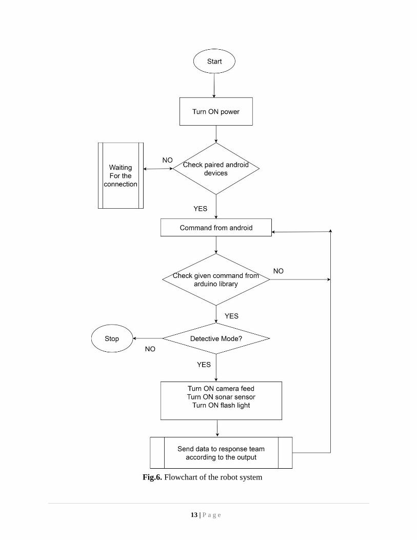
Fig.6. Flowchart of the robot system
13 | P a g e
3.3.2 Unique Walking Algorithm readMovement()
If move == forward,
moveForward();
Else If move == backward,
moveBackward();
Else If move == left,
moveLeft();
Else If move == right,
moveRight();
End
For moveForward()
Move three alternate legs 30 degree clockwise
Move other three alternate legs 30 degree anti-clockwise
For moveBackward()
Move three alternate legs 30 degree clockwise
Move other three alternate legs 30 degree anti-clockwise
For moveLeft()
Move all legs 30 degree anti-clockwise
For moveRight()
Move all legs 30 degree clockwise
End
3.3.3 Hexapod Robot Gait
This walking mechanism of the hexapod follows a six legged insect. This mechanism
involves the robot having three legs standing on the ground supporting the body while the other
three swing forward. In the below figure shown, the dotted line are for stance phase and the
straight line indicated as legs are for forward swing phase.
If the legs of the hexapod are labeled in an anticlockwise manner legs 1, 3 and 5 in Fig. 7.
14 | P a g e
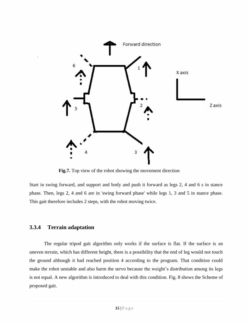
Fig.7. Top view of the robot showing the movement direction
Start in swing forward, and support and body and push it forward as legs 2, 4 and 6 s in stance
phase. Then, legs 2, 4 and 6 are in 'swing forward phase' while legs 1, 3 and 5 in stance phase.
This gait therefore includes 2 steps, with the robot moving twice.
3.3.4 Terrain adaptation
The regular tripod gait algorithm only works if the surface is flat. If the surface is an
uneven terrain, which has different height, there is a possibility that the end of leg would not touch
the ground although it had reached position 4 according to the program. That condition could
make the robot unstable and also harm the servo because the weight’s distribution among its legs
is not equal. A new algorithm is introduced to deal with this condition. Fig. 8 shows the Scheme of
proposed gait.
15 | P a g e
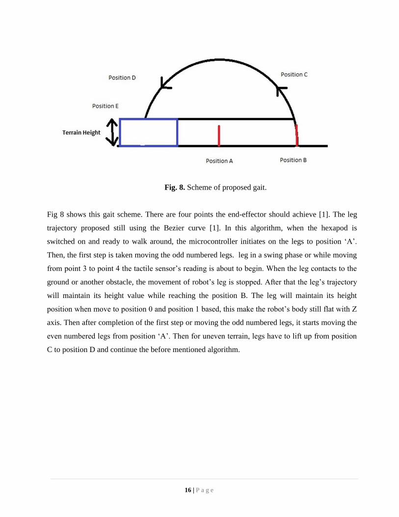
Fig. 8. Scheme of proposed gait.
Fig 8 shows this gait scheme. There are four points the end-effector should achieve [1]. The leg
trajectory proposed still using the Bezier curve [1]. In this algorithm, when the hexapod is
switched on and ready to walk around, the microcontroller initiates on the legs to position ‘A’.
Then, the first step is taken moving the odd numbered legs. leg in a swing phase or while moving
from point 3 to point 4 the tactile sensor’s reading is about to begin. When the leg contacts to the
ground or another obstacle, the movement of robot’s leg is stopped. After that the leg’s trajectory
will maintain its height value while reaching the position B. The leg will maintain its height
position when move to position 0 and position 1 based, this make the robot’s body still flat with Z
axis. Then after completion of the first step or moving the odd numbered legs, it starts moving the
even numbered legs from position ‘A’. Then for uneven terrain, legs have to lift up from position
C to position D and continue the before mentioned algorithm.
16 | P a g e
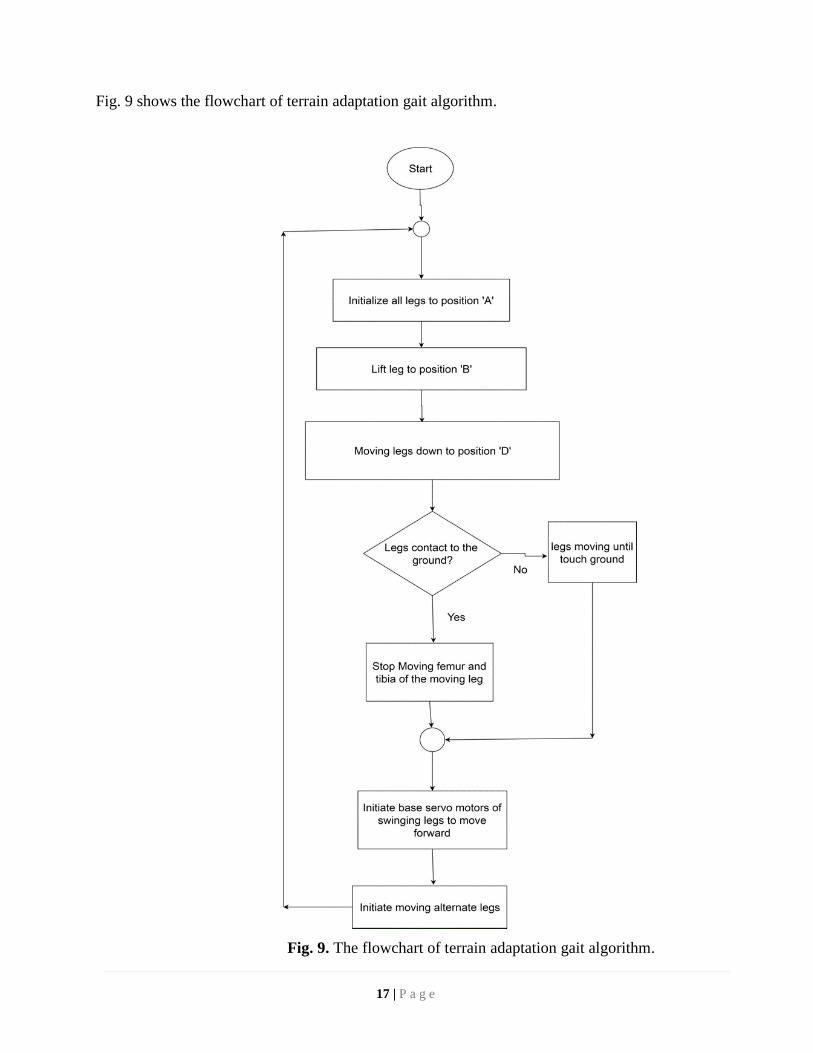
Fig. 9 shows the flowchart of terrain adaptation gait algorithm.
Fig. 9. The flowchart of terrain adaptation gait algorithm.
17 | P a g e
3.3.5 Life Detection Algorithm
We have developed an algorithm to detect the sign of life using the microphone where we
detect and process sound to predict the approximate direction and distance of sound source, in this
case, life.
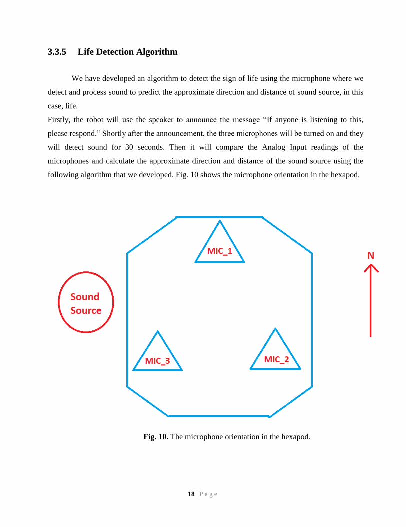
Firstly, the robot will use the speaker to announce the message “If anyone is listening to this,
please respond.” Shortly after the announcement, the three microphones will be turned on and they
will detect sound for 30 seconds. Then it will compare the Analog Input readings of the
microphones and calculate the approximate direction and distance of the sound source using the
following algorithm that we developed. Fig. 10 shows the microphone orientation in the hexapod.
Fig. 10. The microphone orientation in the hexapod.
18 | P a g e
3.3.5.1 Direction Algorithm
signalValue_1 = analogRead(MIC_1)*50;
signalValue_2 = analogRead(MIC_2)*50;
signalValue_3 = analogRead(MIC_3)*50;
if signalValue_1 > 0
MIC_1 detected sound
if signalValue_2 > 0
MIC_2 detected sound
if signalValue_3 > 0
MIC_3 detected sound
direction = maxValue(signalValue_1, signalValue_2, signalValue_3);
if direction == (signalValue_1 && signalValue_3)
sound source is in North-West
else if direction == (signalValue_1 && signalValue_2)
sound source is in North-East
else if direction == (signalValue_2 && signalValue_3)
sound source is in South
else if direction == signalValue_1
sound source is in North
else if direction == signalValue_2
sound source is in East
else if direction == signalValue_3
sound source is in West
Using this algorithm, the robot will be able to predict the direction of a life or the sound source.
19 | P a g e
3.3.5.2 Distance Algorithm
signalValue_1 = analogRead(MIC_1)*50;
signalValue_2 = analogRead(MIC_2)*50;
signalValue_3 = analogRead(MIC_3)*50;
pointer = maxValue(signalValue_1, signalValue_2, signalValue_3);
if pointer > 1200
sound source is within 3 meters
else if pointer > 900
sound source is within 2 meters
else if pointer > 600
sound source is within 1 meters
else if pointer > 300
sound source is within 0.5 meters
Using this algorithm, the robot will be able to predict the distance of a life or the sound source.
3.4 Building prototype model
Initially, we created a prototype of our proposed system. It was a simple hexapod robot
with only 18 servo motors and no other sensors. We build this prototype to test our hypothesis.
3.4.1 Circuit details of the prototype model
Firstly, all the electrical instruments were connected in a simulated circuit model
for testing purpose. Overall voltage and current requirements were calculated and the feasibility of
the circuits were tested. Fig. 11 shows the circuit diagram of the robot.
20 | P a g e
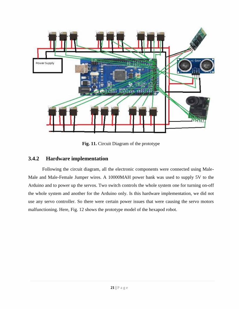
Fig. 11. Circuit Diagram of the prototype
3.4.2 Hardware implementation
Following the circuit diagram, all the electronic components were connected using Male-
Male and Male-Female Jumper wires. A 10000MAH power bank was used to supply 5V to the
Arduino and to power up the servos. Two switch controls the whole system one for turning on-off
the whole system and another for the Arduino only. Is this hardware implementation, we did not
use any servo controller. So there were certain power issues that were causing the servo motors
malfunctioning. Here, Fig. 12 shows the prototype model of the hexapod robot.
21 | P a g e
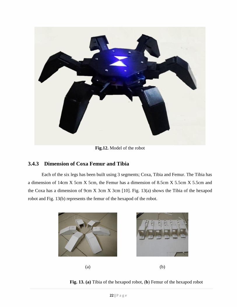
Fig.12. Model of the robot
3.4.3 Dimension of Coxa Femur and Tibia
Each of the six legs has been built using 3 segments; Coxa, Tibia and Femur. The Tibia has
a dimension of 14cm X 5cm X 5cm, the Femur has a dimension of 8.5cm X 5.5cm X 5.5cm and
the Coxa has a dimension of 9cm X 3cm X 3cm [10]. Fig. 13(a) shows the Tibia of the hexapod
robot and Fig. 13(b) represents the femur of the hexapod of the robot.
Fig. 13. (a) Tibia of the hexapod robot, (b) Femur of the hexapod robot
22 | P a g e
(a)
(b)
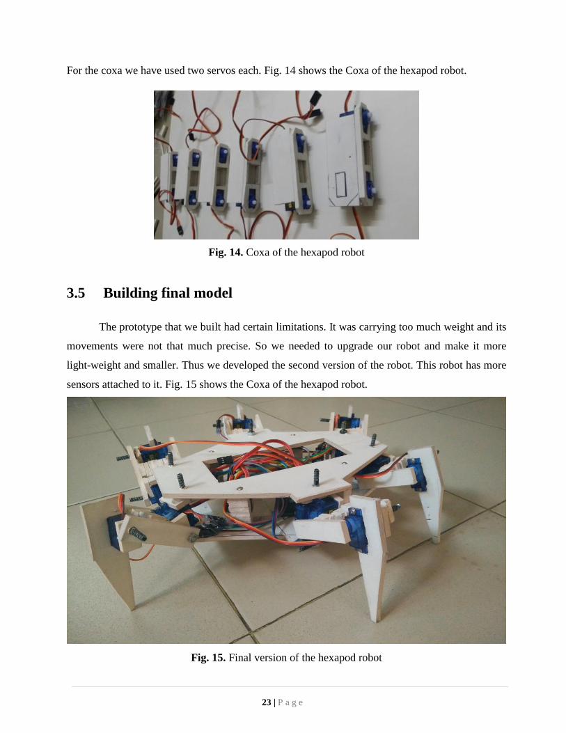
For the coxa we have used two servos each. Fig. 14 shows the Coxa of the hexapod robot.
Fig. 14. Coxa of the hexapod robot
3.5 Building final model
The prototype that we built had certain limitations. It was carrying too much weight and its
movements were not that much precise. So we needed to upgrade our robot and make it more
light-weight and smaller. Thus we developed the second version of the robot. This robot has more
sensors attached to it. Fig. 15 shows the Coxa of the hexapod robot.
Fig. 15. Final version of the hexapod robot
23 | P a g e
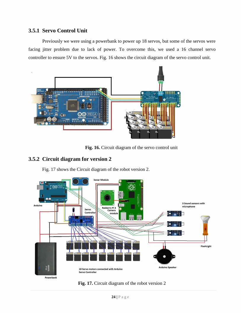
3.5.1 Servo Control Unit
Previously we were using a powerbank to power up 18 servos, but some of the servos were
facing jitter problem due to lack of power. To overcome this, we used a 16 channel servo
controller to ensure 5V to the servos. Fig. 16 shows the circuit diagram of the servo control unit.
Fig. 16. Circuit diagram of the servo control unit
3.5.2 Circuit diagram for version 2
Fig. 17 shows the Circuit diagram of the robot version 2.
Fig. 17. Circuit diagram of the robot version 2
24 | P a g e
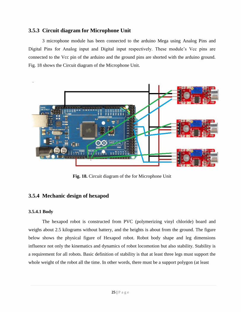
3.5.3 Circuit diagram for Microphone Unit
3 microphone module has been connected to the arduino Mega using Analog Pins and
Digital Pins for Analog input and Digital input respectively. These module’s Vcc pins are
connected to the Vcc pin of the arduino and the ground pins are shorted with the arduino ground.
Fig. 18 shows the Circuit diagram of the Microphone Unit.
Fig. 18. Circuit diagram of the for Microphone Unit
3.5.4 Mechanic design of hexapod
3.5.4.1 Body
The hexapod robot is constructed from PVC (polymerizing vinyl chloride) board and
weighs about 2.5 kilograms without battery, and the heights is about from the ground. The figure
below shows the physical figure of Hexapod robot. Robot body shape and leg dimensions
influence not only the kinematics and dynamics of robot locomotion but also stability. Stability is
a requirement for all robots. Basic definition of stability is that at least three legs must support the
whole weight of the robot all the time. In other words, there must be a support polygon (at least
25 | P a g e
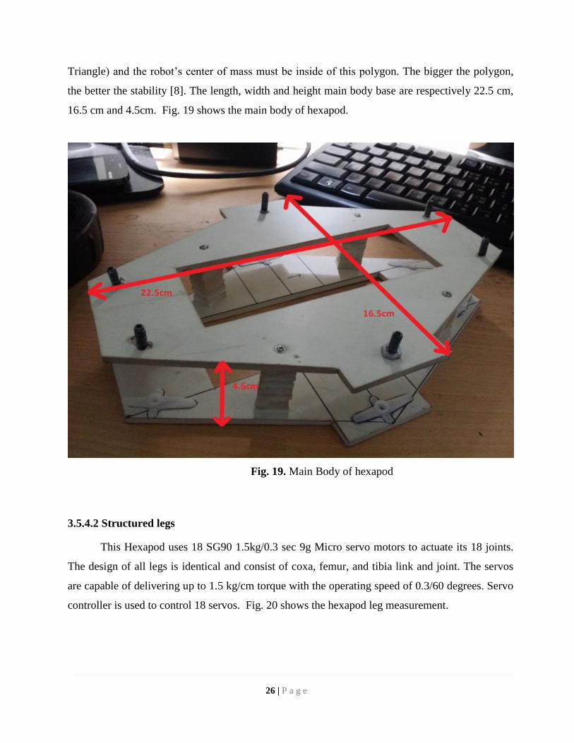
Triangle) and the robot’s center of mass must be inside of this polygon. The bigger the polygon,
the better the stability [8]. The length, width and height main body base are respectively 22.5 cm,
16.5 cm and 4.5cm. Fig. 19 shows the main body of hexapod.
Fig. 19. Main Body of hexapod
3.5.4.2 Structured legs
This Hexapod uses 18 SG90 1.5kg/0.3 sec 9g Micro servo motors to actuate its 18 joints.
The design of all legs is identical and consist of coxa, femur, and tibia link and joint. The servos
are capable of delivering up to 1.5 kg/cm torque with the operating speed of 0.3/60 degrees. Servo
controller is used to control 18 servos. Fig. 20 shows the hexapod leg measurement.
26 | P a g e
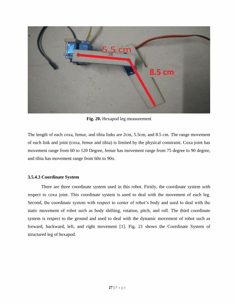
Fig. 20. Hexapod leg measurement
The length of each coxa, femur, and tibia links are 2cm, 5.5cm, and 8.5 cm. The range movement
of each link and joint (coxa, femur and tibia) is limited by the physical constraint. Coxa joint has
movement range from 60 to 120 Degree, femur has movement range from 75 degree to 90 degree,
and tibia has movement range from 60o to 90o.
3.5.4.3 Coordinate System
There are three coordinate system used in this robot. Firstly, the coordinate system with
respect to coxa joint. This coordinate system is used to deal with the movement of each leg.
Second, the coordinate system with respect to center of robot’s body and used to deal with the
static movement of robot such as body shifting, rotation, pitch, and roll. The third coordinate
system is respect to the ground and used to deal with the dynamic movement of robot such as
forward, backward, left, and right movement [1]. Fig. 21 shows the Coordinate System of
structured leg of hexapod.
27 | P a g e
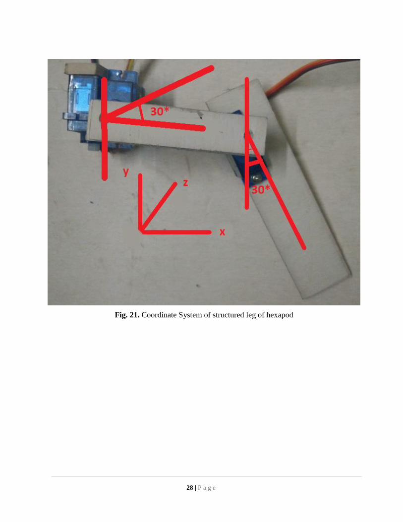
Fig. 21. Coordinate System of structured leg of hexapod
28 | P a g e
CHAPTER 4
Experimental Results
4.1 Experimental Setup
We have completed several experiments on our hexapod robot. These experiments can be
categorized into two major sectors. Firstly, we focused on the walking of the robot. Finally. We
experimented on the life detection algorithm using the microphones.
4.1.1 Experiments on Walking
After the completion of our prototype hexapod, while we tried to run the robot we faced
power failure as we did not powered up the servo motors properly. Moreover, the robot was
carrying a lot of weights. As a result, it was not able to stand in its feet. Besides, the ration of each
parts of legs were not balanced, so the leg movements were not smooth.
All these drawbacks led us to develop the second version of the hexapod. In this updated
version, we made all the parts smaller. We also used a servo-controller to make sure the power
issue has been taken care of. Moreover, we replaced the powerbank with cellphone-batteries to
reduce the overall weight of the robot.
After these modifications, the robot is currently able to stand in its feet and move forward,
backward, left and right. We have tested this movements both in plain surface and irregular
surface. The robot performs a perfect movement in the plain surface. However, it faces some
challenges moving in any surface with a slope. We increased the grip of each leg and it shows
slightly better performance. We tried to move the robot in stairs but it is still not capable of doing
so.
29 | P a g e
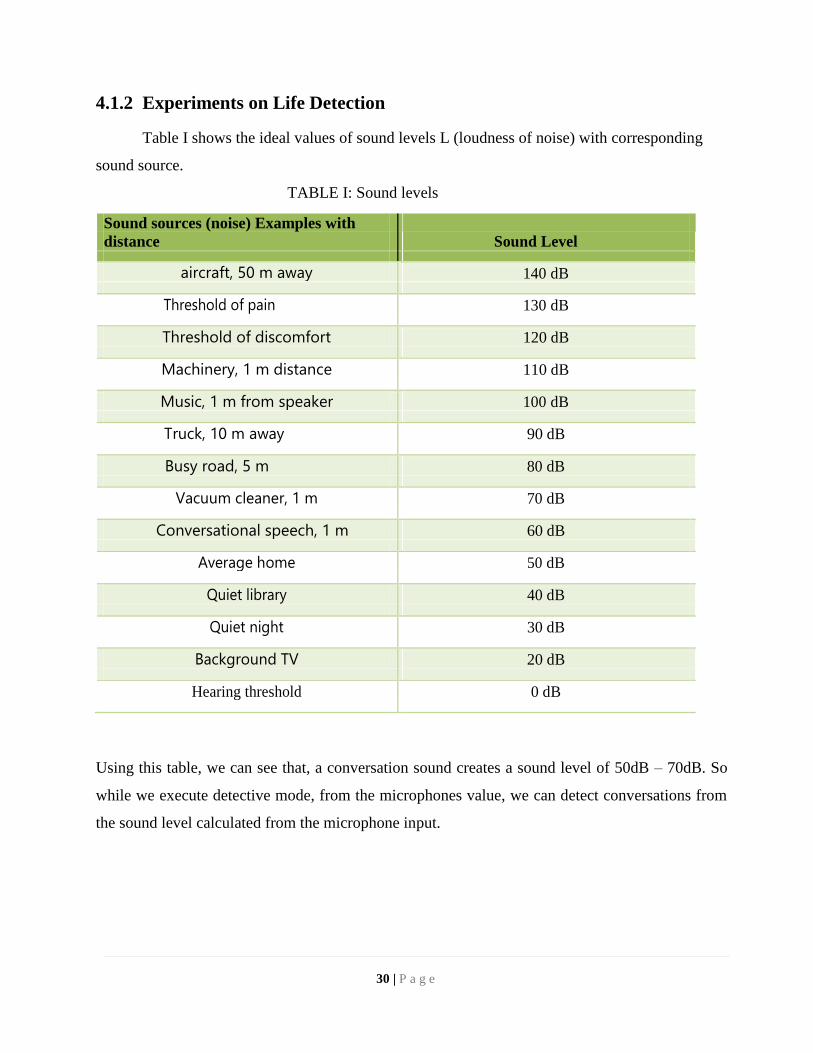
4.1.2 Experiments on Life Detection
Table I shows the ideal values of sound levels L (loudness of noise) with corresponding
sound source.
TABLE I: Sound levels
Sound sources (noise) Examples with
distance Sound Level
aircraft, 50 m away 140 dB
Threshold of pain 130 dB
Threshold of discomfort 120 dB
Machinery, 1 m distance 110 dB
Music, 1 m from speaker 100 dB
Truck, 10 m away 90 dB
Busy road, 5 m 80 dB
Vacuum cleaner, 1 m 70 dB
Conversational speech, 1 m 60 dB
Average home 50 dB
Quiet library 40 dB
Quiet night 30 dB
Background TV 20 dB
Hearing threshold 0 dB
Using this table, we can see that, a conversation sound creates a sound level of 50dB – 70dB. So
while we execute detective mode, from the microphones value, we can detect conversations from
the sound level calculated from the microphone input.
30 | P a g e
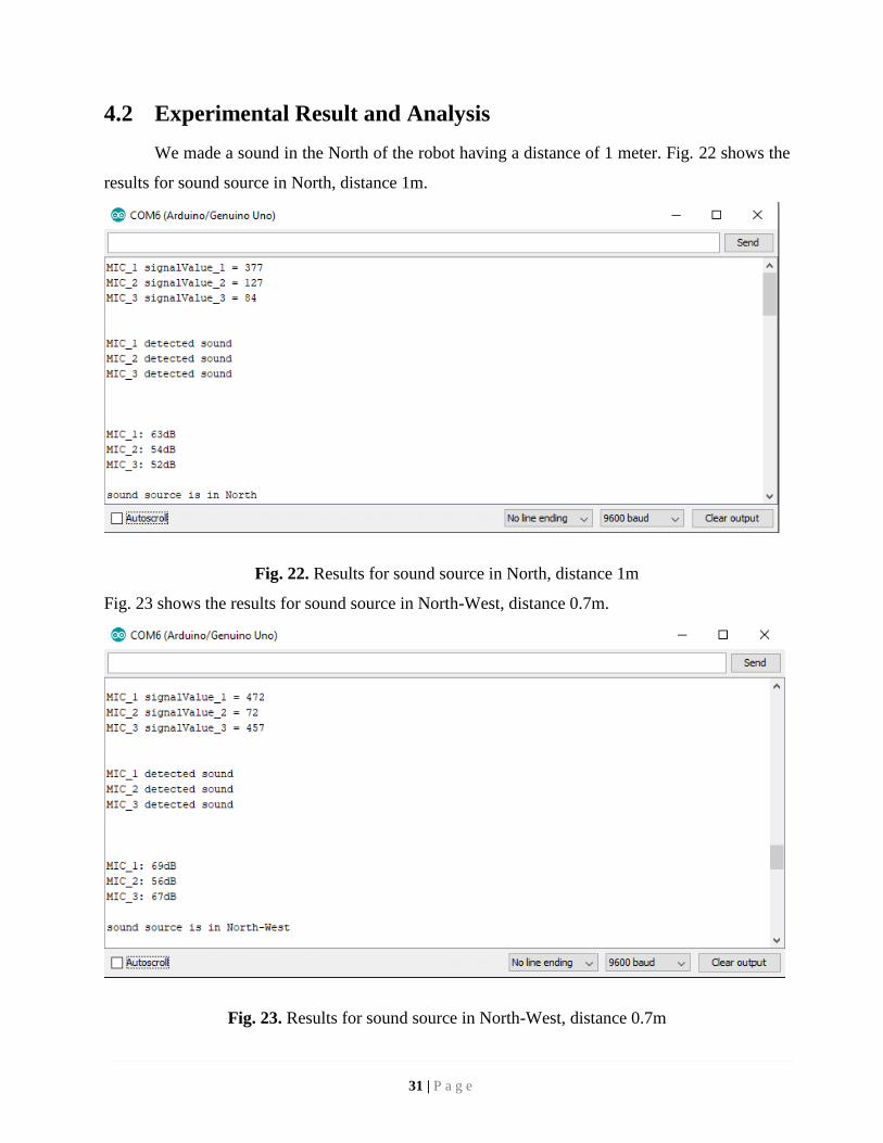
4.2 Experimental Result and Analysis
We made a sound in the North of the robot having a distance of 1 meter. Fig. 22 shows the
results for sound source in North, distance 1m.
Fig. 22. Results for sound source in North, distance 1m
Fig. 23 shows the results for sound source in North-West, distance 0.7m.
Fig. 23. Results for sound source in North-West, distance 0.7m
31 | P a g e
Here we can see that, all the 3 microphones detected sound a calculated approximate directions.
We made another sound in the North-West of the robot having a distance of 0.7 meter.
32 | P a g e
CHAPTER 5
Conclusion and Future Work
5.1 Conclusion
In the proposed system we have proposed a search and rescue robot that would be efficient
in crawling through narrow holes and spaces over rough and unfriendly terrains. The walking
algorithms used in the robot have been field tested properly and has an above average rate of
efficiency when compared to other such robots in related fields. To control the spider-bot we have
successfully made use of android UI and have implemented a navigation panel onto the user
interface. In many accidents that need inspection of the ground, and in cases where it is impossible
for a human being to properly look for any evidence that might help to save lives, the spider-bot
can come in handy, and the functional algorithms implemented would be quite efficient in helping
the robot move under extreme conditions. The robot has worked tremendously well in different
speed scenarios and responded well to each of the cases, which was entirely possible for the six
leg based design of the model, which has 3 servo motors each. It is hoped that small amount of
modification to our proposed system will transform it into a fully functional and ready-to-use
robot in real life scenario.
5.2 Future Work
Our robot is able to walk through rough and irregular surface which open up several
window of opportunities. In the future, robot can be functioned in such a way that it will have the
ability to climbing walls or gliding down to destination so that, it can be deployed to the disaster
area from air support as helicopters or planes. Moreover, if the size can be minimized, it can be
used as a spy robot which will help to stop terrorism acts.
33 | P a g e
References
[1] Isvara, Yudi., Rachmatullah, Syawaludin., Mutijarsa, Kusprasapta., E. Prabakti, Dinara. ,
Pragitatama, Wiharsa. Terrain Adaptation Gait Algorithm in a Hexapod Walking Robot.
2014 13th International Conference on Control, Automation, Robotics & Vision Marina
Bay Sands, Singapore, 10-12th December 2014 (ICARCV 2014).
[2] Liu,Yufei., Ding, Liang., Gao, Haibo., Liu, Guangjun., Deng, Zongquan. and Yu, Haitao.
Efficient Force Distribution Algorithm for Hexapod Robot Walking on Uneven Terrain.
IEEE International Conference on Robotics and Biomimetics, Qingdao, China, December
3-7, 2016.
[3] Zhong, Guoliang., Chen, Long. and Deng, Hua. A Performance Oriented Novel Design of
Hexapod Robots. IEEE/ASME TRANSACTIONS ON MECHATRONICS, VOL. 22, NO.
3, JUNE 2017.
[4] Copot, Cosmin., M. Ionescu, Clara., De Keyser, Robin. Body Leveling of a Hexapod
Robot using the Concept of Sensor Fusion. 2017 21st International Conference on System
Theory, Control and Computing (ICSTCC).
[5] Tikam, Mayur., Withey, Daniel. and J. Theron, Nicolaas. Standing Posture Control for a
Low-Cost Commercially Available Hexapod Robot. 2017 IEEE/RSJ International
Conference on Intelligent Robots and Systems (IROS) September 24–28, 2017,
Vancouver, BC, Canada.
[6] Hong, Jun., Tang, Kaiqiang., Chen, Chunlin. Obstacle Avoidance of Hexapod Robots
Using Fuzzy Q-Learning. 2017 IEEE Symposium Series on Computational Intelligence
(SSCI) 2017.
[7] Trivun, Darko., Dindo, Haris., Laþeviü, Bakir. Resilient Hexapod Robot. 2017 XXVI
International Conference on Information, Communication and Automation Technologies
(ICAT).
[8] D. Esteban, Dario., Luneckas, Mindaugas., Luneckas, Tomas., Kriauþinjnas, Jonas., Udris,
Dainius. Statically Stable Hexapod Robot Body Construction. 2016 IEEE 4th Workshop
on Advances in Information, Electronic and Electrical Engineering (AIEEE).
[9] Khudher, Dhayaa., Powell, Roger. Quadratic Programming for Inverse Kinematics Control
of a Hexapod Robot with Inequality Constraints. 2016 International Conference on
Robotics: Current Trends and Future Challenges (RCTFC).
34 | P a g e
[10] H. Hasnaa, El., Mohammed, Bennani. Planning tripod gait of an hexapod robot. 2017 14th
International Multi-Conference on Systems, Signals & Devices (SSD).
[11] Davids, A. Urban search and rescue robots: from tragedy to technology. IEEE Intelligent
systems 17, no. 2 (2002)
[12] Guerra-Hernandez, EI., Andres E., Batres-Mendoza P., Garcia-Capulin, C., Romero-
Troncoso R., Rostro-Gonzalez, H. A FPGA-based neuromorphic locomotion system for
multi-legged robots. IEEE Access (2017)
[13] MorpHex Hexapod Robot Available: http://zentasrobots.com/robot-projects/morphex-part-
1/ [Accessed: 19- Mar- 2018].
[14] “Matrix unique Hexapod Robot” (2016) Available:
https://www.youtube.com/watch?v=98wfZPm2mes
[15] Celaya, E., and Josep, M. Control of a six-legged robot walking on abrupt terrain. In
Robotics and Automation, 1996. Proceedings., 1996 IEEE International Conference on,
vol. 3, pp. 2731-2736. IEEE(1996)
[16] Cruse, H., Thomas K., Michael S., Jeffrey D., Josef S., Walknet. A biologically inspired
network to control six-legged walking. Neural networks 11, no. 7 (1998)
[17] Kumar, S., Geoffrey B., Abbasi, M., Liu, H. TweetTracker: An Analysis Tool for
Humanitarian and Disaster Relief. In ICWSM. (2011)
[18] Kim, S., S. Jung, S. U. Lee, K. Jeong, S. Park, Y. H. Kang, and D. Ok. Development of
disaster-mitigation and life-saving robot in Korea. In 39th Int. Symposium of Robotics,
Seoul, Korea, pp. 472-476. (2008)
[19] Pahuja, R., Narender K. Android Mobile Phone Controlled Bluetooth Robot Using 8051
Microcontroller. International Journal of Scientific Engineering and Research 2, no. 7
(2014)
[20] Wang, Z., Xilun D., Alberto, R., Alessandro, G. Mobility analysis of the typical gait of a
radial symmetrical six-legged robot.: Mechatronics 21, no. 7 (2011)
[21] Alexadre, P., Ghuys, D. and Pruemont, A. 1991. Gait analysis and implementation of a six
legged walking machine. Fifth International Conference on Advanced Robotics: Robots in
Unstructured Environments. 19 - 22 June 1991, vol. 2. pp 941 – 945
[22] Ding, X., Rovetta, A., Wang, Z. and Zhu, J. M. 2010. Locomotion analysis of hexapod
robot. In: Climbing and Walking Robots (ed: B Miripour) pp 291 - 310. InTech, Italy.
35 | P a g e
[23] Rashid,M. Z. A., Aras, M. S. M., Radzak, A. A., Kassim., A. M. and Jamali,A.
Development of Hexapod Robot with Manoeuvrable Wheel. International Journal of
Advanced Science and Technology, Vol. 49, December, 2012.
[24] Belter, D., Kasinski, A. and Skrzypczynski, P., 2008, September. Evolving feasible gaits
for a hexapod robot by reducing the space of possible solutions. In Intelligent Robots and
Systems, 2008. IROS 2008. IEEE/RSJ International Conference on (pp. 2673-2678). IEEE.
[25] “Servo Motor SG90,” Ee.ic.ac.uk. [online]. Available:
http://www.ee.ic.ac.uk/pcheung/teaching/DE1_EE/stores/sg90_datasheet .pdf. [Accessed:
16- Mar- 2018].
[26] I. Tzanellis, ArduinoRC. Arduino, 2017.
[27] Saranli, U., Buehler, M. and Koditschek, D.E., 2001. Rhex: A simple and highly mobile
hexapod robot. The International Journal of Robotics Research, 20(7), pp.616-631.
[28] Lewinger, W.A., Branicky, M.S. and Quinn, R.D., 2006. Insect-inspired, actively
compliant hexapod capable of object manipulation. In Climbing and Walking Robots (pp.
65-72). Springer, Berlin, Heidelberg.
[29] Schöner, G., Dose, M. and Engels, C., 1995. Dynamics of behavior: Theory and
applications for autonomous robot architectures. Robotics and autonomous systems, 16(2-
4), pp.213-245.
[30] Birkmeyer, P., Peterson, K. and Fearing, R.S., 2009, October. DASH: A dynamic 16g
hexapedal robot. In Intelligent Robots and Systems, 2009. IROS 2009. IEEE/RSJ
International Conference, pp. 2683-2689.
36 | P a g e