
An Innovative Receiver for Incoherent SAC-OCDMA Enabling SOA-Based Noise Cleaning: Experimental...
9
108 JOURNAL OF LIGHTWAVE TECHNOLOGY, VOL. 27, NO. 2, JANUARY 15, 2009 An Innovative Receiver for Incoherent SAC-OCDMA Enabling SOA-Based Noise Cleaning: Experimental Validation Julien Penon, Student Member, IEEE, Walid Mathlouthi, Sophie LaRochelle, Member, IEEE, and Leslie A. Rusch, Senior Member, IEEE Abstract—We propose a new low complexity receiver for spectral amplitude optical coded division multiple access (SAC OCDMA) that enables intensity noise reduction using semiconductor optical amplifiers (SOAs). Compared to the standard receiver requiring two optical filters at the receiver side, our receiver requires only one optical filter. While a 1.4-dB power penalty in incurred, net- work capacity is unchanged, i.e., BER floors due to intensity noise have the same level. The primary motivation for the low complexity receiver is not reduced component count, but rather modifying the receiver so that promising SOA noise mitigation techniques might be employed to increase system capacity. SOA noise cleaning suf- fers from a major limitation: filtering after the SOA can negate most of the signal enhancement, the so-called post SOA filtering issue. The only solution to date for the post-SOA filtering effect in SAC-OCDMA is prohibitively complex McCoy et al., J. Lightw. Technol., vol. 25, no. 1, pp. 394–401, Jan. 2007, i.e., requiring mul- tiple SOAs per client. We demonstrate that our proposed receiver drastically limits the client side filtering, thus maintaining noise suppression and overcoming the post-SOA filtering effect. We com- pare BER at up to 10 Gb/s with and without noise cleaning. When a noise cleaning module is used, BER improvement of several or- ders-of-magnitude is observed when only a few users are active in the network. Examination of the noise properties, however, leads us to conclude that highly populated networks will have diminished improvement. Index Terms—Balanced detection, fiber Bragg gratings, fre- quency encoded (FE) OCDMA, frequency encoding, incoherent source, intensity noise suppression, noise cleaning, optical code-di- vision multiple-access (OCDMA), semiconductor optical amplifier, SOA, spectral amplitude coded (SAC) OCDMA. I. INTRODUCTION A DOPTION of passive optical networks (PONs) requires a cost effective solution with a clear migration path to greater network capacity, both in terms of bit rate per house- hold and total households served. One technical solution is the use of inexpensive broadband sources, e.g., light emitting diodes (LEDs) in client equipment, or a high power centralized broad- band source distributed to clients via the PON for local modu- lation. The major impairment in systems using such incoherent sources is the intensity noise (IN) or phase induced intensity Manuscript received March 24, 2008; revised May 26, 2008. Current version published February 13, 2009. The authors are with the Department of Electrical and Computer Engi- neering, Université Laval, Québec, QC G1V 0A6, Canada (e-mail: julien.penon. [email protected]; [email protected]; [email protected]). Color versions of one or more of the figures in this paper are available online at http://ieeexplore.ieee.org. Digital Object Identifier 10.1109/JLT.2008.927795 noise (PIIN) [1] resulting from square law photodetection of in- coherent sources. IN is a signal dependent noise that increases with signal strength, leading to bit error rate (BER) floors. For systems using incoherent sources, this noise is inversely propor- tional to the effective optical bandwidth and proportional to the electrical bandwidth [2]. Several methods have been studied to reduce IN and increase performance when using incoherent sources. Clearly, can be increased, but at the cost of reduced spectral efficiency; at high bit rate this also leads to chromatic dispersion. Similarly, the bit rate, i.e., , could be reduced, but that would negate a migration path for PONs to increased capacity. More technological solu- tions to combat IN have been investigated. An electronic solu- tion proposed in [3] uses a feedback loop on the driving voltage of the modulator to compensate for intensity fluctuations in the incoherent source. This technique requires fast electronic circuits (photodiode, amplifier, RF combiner, etc.), making it costly. In [4], was increased without decreasing spectral efficiency by placing a nonlinear element just after demultiplexing of an inco- herent SS-WDM signal. Intra-channel four-wave mixing resulted in expanded , giving rise to a performance enhancement. Un- fortunately, this technique cannot be used in SAC-OCDMA sys- tems where channels are not spectrally orthogonal—extraction of only the desired user spectrum is impossible. The most promising solution to reduce IN in SAC-OCDMA systems with incoherent sources is noise cleaning techniques using semiconductor optical amplifiers (SOAs). A signal with large intensity swings enters a saturated SOA where large in- tensities see small gain, while small input intensities see large gain; this effect is referred to as gain compression. It was first proposed about a decade ago in [5] for incoherent spectrum- sliced wavelength division multiplexing (SS-WDM) transmis- sion. When using SOAs, best noise suppression is achieved by: 1) using deeply saturated [6] and fast recovery time gain SOAs [7]; 2) placing the SOA before data modulation; and 3) avoiding any optical filtering after the SOA that removes a significant part of the spectrum [8]. The first two conditions can be easily sat- isfied, but the third one is a major issue, often referred to as the post-SOA filtering issue. Unfortunately, in multiple access system, optical filtering is essential to demultiplex the signal. Two methods have been proposed to counter act the post-SOA filtering effect for incoherent SS-WDM. In the first [9], McCoy et al. varied the filter width at reception and measured Q factor im- provement as a function of reception filter width. Wider filtering at reception led to better noise cleaning, however the level of noise cleaning was severely curtailed compared to no filtering. 0733-8724/$25.00 © 2009 IEEE
Transcript of An Innovative Receiver for Incoherent SAC-OCDMA Enabling SOA-Based Noise Cleaning: Experimental...
108 JOURNAL OF LIGHTWAVE TECHNOLOGY, VOL. 27, NO. 2, JANUARY 15, 2009
An Innovative Receiver for Incoherent SAC-OCDMAEnabling SOA-Based Noise Cleaning:
Experimental ValidationJulien Penon, Student Member, IEEE, Walid Mathlouthi, Sophie LaRochelle, Member, IEEE, and
Leslie A. Rusch, Senior Member, IEEE
Abstract—We propose a new low complexity receiver for spectralamplitude optical coded division multiple access (SAC OCDMA)that enables intensity noise reduction using semiconductor opticalamplifiers (SOAs). Compared to the standard receiver requiringtwo optical filters at the receiver side, our receiver requires onlyone optical filter. While a 1.4-dB power penalty in incurred, net-work capacity is unchanged, i.e., BER floors due to intensity noisehave the same level. The primary motivation for the low complexityreceiver is not reduced component count, but rather modifying thereceiver so that promising SOA noise mitigation techniques mightbe employed to increase system capacity. SOA noise cleaning suf-fers from a major limitation: filtering after the SOA can negatemost of the signal enhancement, the so-called post SOA filteringissue. The only solution to date for the post-SOA filtering effectin SAC-OCDMA is prohibitively complex McCoy et al., J. Lightw.Technol., vol. 25, no. 1, pp. 394–401, Jan. 2007, i.e., requiring mul-tiple SOAs per client. We demonstrate that our proposed receiverdrastically limits the client side filtering, thus maintaining noisesuppression and overcoming the post-SOA filtering effect. We com-pare BER at up to 10 Gb/s with and without noise cleaning. Whena noise cleaning module is used, BER improvement of several or-ders-of-magnitude is observed when only a few users are active inthe network. Examination of the noise properties, however, leadsus to conclude that highly populated networks will have diminishedimprovement.
Index Terms—Balanced detection, fiber Bragg gratings, fre-quency encoded (FE) OCDMA, frequency encoding, incoherentsource, intensity noise suppression, noise cleaning, optical code-di-vision multiple-access (OCDMA), semiconductor optical amplifier,SOA, spectral amplitude coded (SAC) OCDMA.
I. INTRODUCTION
A DOPTION of passive optical networks (PONs) requiresa cost effective solution with a clear migration path to
greater network capacity, both in terms of bit rate per house-hold and total households served. One technical solution is theuse of inexpensive broadband sources, e.g., light emitting diodes(LEDs) in client equipment, or a high power centralized broad-band source distributed to clients via the PON for local modu-lation. The major impairment in systems using such incoherentsources is the intensity noise (IN) or phase induced intensity
Manuscript received March 24, 2008; revised May 26, 2008. Current versionpublished February 13, 2009.
The authors are with the Department of Electrical and Computer Engi-neering, Université Laval, Québec, QC G1V 0A6, Canada (e-mail: [email protected]; [email protected]; [email protected]).
Color versions of one or more of the figures in this paper are available onlineat http://ieeexplore.ieee.org.
Digital Object Identifier 10.1109/JLT.2008.927795
noise (PIIN) [1] resulting from square law photodetection of in-coherent sources. IN is a signal dependent noise that increaseswith signal strength, leading to bit error rate (BER) floors. Forsystems using incoherent sources, this noise is inversely propor-tional to the effective optical bandwidth and proportionalto the electrical bandwidth [2].
Several methods have been studied to reduce IN and increaseperformance when using incoherent sources. Clearly, can beincreased, but at the cost of reduced spectral efficiency; at highbit rate this also leads to chromatic dispersion. Similarly, the bitrate, i.e., , could be reduced, but that would negate a migrationpath for PONs to increased capacity. More technological solu-tions to combat IN have been investigated. An electronic solu-tion proposed in [3] uses a feedback loop on the driving voltageof the modulator to compensate for intensity fluctuations in theincoherent source. This technique requires fast electronic circuits(photodiode, amplifier, RF combiner, etc.), making it costly. In[4], was increased without decreasing spectral efficiency byplacing a nonlinear element just after demultiplexing of an inco-herentSS-WDMsignal. Intra-channel four-wavemixingresultedin expanded , giving rise to a performance enhancement. Un-fortunately, this technique cannot be used in SAC-OCDMA sys-tems where channels are not spectrally orthogonal—extractionof only the desired user spectrum is impossible.
The most promising solution to reduce IN in SAC-OCDMAsystems with incoherent sources is noise cleaning techniquesusing semiconductor optical amplifiers (SOAs). A signal withlarge intensity swings enters a saturated SOA where large in-tensities see small gain, while small input intensities see largegain; this effect is referred to as gain compression. It was firstproposed about a decade ago in [5] for incoherent spectrum-sliced wavelength division multiplexing (SS-WDM) transmis-sion. When using SOAs, best noise suppression is achieved by:1) using deeply saturated [6] and fast recovery time gain SOAs[7]; 2) placing the SOA before data modulation; and 3) avoidingany optical filtering after the SOA that removes a significant partof the spectrum [8]. The first two conditions can be easily sat-isfied, but the third one is a major issue, often referred to asthe post-SOA filtering issue. Unfortunately, in multiple accesssystem, optical filtering is essential to demultiplex the signal.
Two methods have been proposed to counter act the post-SOAfiltering effect for incoherent SS-WDM. In the first [9], McCoy etal. varied the filter width at reception and measured Q factor im-provement as a function of reception filter width. Wider filteringat reception led tobetternoisecleaning,however the levelofnoisecleaning was severely curtailed compared to no filtering.
0733-8724/$25.00 © 2009 IEEE
PENON et al.: INNOVATIVE RECEIVER FOR INCOHERENT SAC-OCDMA 109
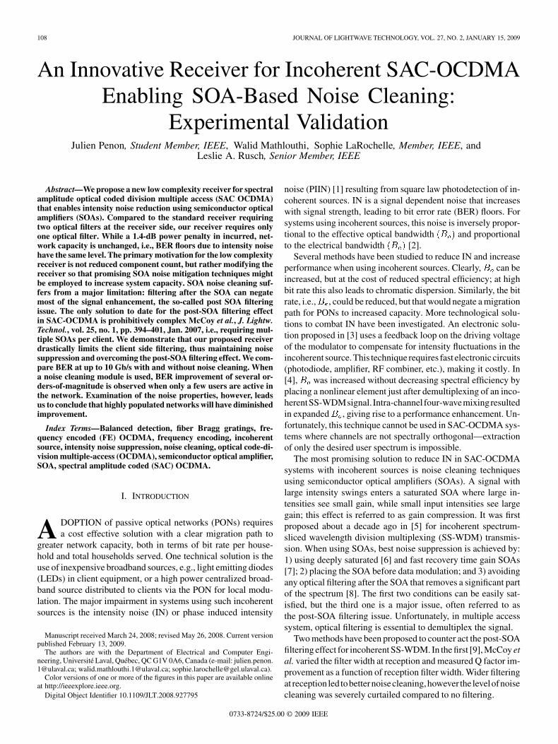
Fig. 1. SS-WDM receiver suitable with SOA-based noise cleaning.
A more effective solution to this problem for incoherentSS-WDM system uses the detection scheme proposed in [10]and presented in Fig. 1. In this solution, a notch filter matchedwith the signal to be demultiplexed is inserted in the lowerarm; all signals except the useful one are detected. Interferers’signals ( and in this example) are not affected bythe notch filter, so the noise cleaning effect is not reduced forbroadband signals from interferers. In the upper arm, no filteris present. The upper arm is also referred as the all-pass arm.In this arm, all signals are detected without experiencing anyoptical filtering process, thus the noise cleaning effect is strongfor all signals. Note that all interferers appear identically in botharms; these interfering signals (including their associated IN)are completely correlated and cancelled out during balancedphotodetection [11]. Finally, the noise cleaning effect for thedesired user’s signal is undiminished in the upper arm,while this signal and its associated IN are significantly rejectedon the lower arm; the net effect is a significant performanceimprovement.
Up to now no cost-effective solution based on SOA noisecleaning has been proposed for SAC-OCDMA systems usingincoherent sources. For instance, the suggestion of using oneSOA per frequency bin [12] was recognized by the proponentsas being prohibitively expensive. While [12] sought to quantifythe limits to SOA noise cleaning for SAC-OCDMA, their ex-perimental results are inconclusive. In those experiments onlyQ factor, RIN and eye diagram measurements were reported.Given the highly non-Gaussian nature of the noise-suppressedIN, only BER measurements truly capture the effectivenessof SOA based noise cleaning. Also, in that experiment -se-quences were used as SAC-OCDMA codes; these codes werefound in [13] to be ineffective due to their unnecessarily highcross-correlation. Unitary cross-correlation codes, in particularBIBD codes, were successfully tested in [14] and shown togreatly outperform -sequences; we use the same code familyfor experiments in this article. The -sequence code choicelimits the bit rate to 622 Mb/s, while use of BIBD codes permitsexperiments to be run up to 10 Gb/s, as we report here. In fair-ness, we also use twice the optical bandwidth as experimentsin [14], however it is the code that has the greatest impact.In this paper, we demonstrate up to five orders of magnitudeimprovement in BER using our new low complexity receiver;this receiver enables SAC-OCDMA systems to overcome thepost-SOA filtering effect under certain conditions.
Despite the drastic improvements we will report for a SAC-OCDMA system with few (three and less) users, our assessmentof the viability of this approach for large capacity networks isvery modest. We will see that the performance improvementdegrades as the number of users increases. We will argue thatthe post-SOA filtering effect returns in force as the number ofinterferers mounts.
In Section II, we present experimental validation of theperformance of our new low complexity receiver, characterizedby only one optical filter, compared to the standard receiverrequiring two optical filters at the receiver side. Having es-tablished the functionality of the proposed low complexityreceiver for incoherent SAC-OCDMA, we examine its ef-ficiency when associated with SOA-based noise cleaningmodules and anticipate limitations in Section III. Experimentaleye diagram measurements are used to illustrate concepts thatcannot be measured directly during simultaneous transmissionof OCDMA signals. In Section IV, the experimental setup ofthe incoherent SAC-OCDMA system and the SOA-based noisecleaning module is described. BER measurements are reportedand analyzed with and without noise cleaning. Finally, conclu-sions and suggestions for further optimizations are given.
II. LOW COMPLEXITY RECEIVER FOR INCOHERENT
SAC-OCDMA
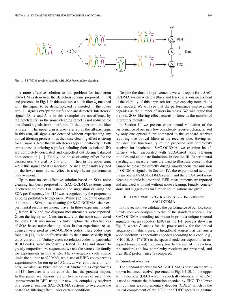
In this section, we validated the performance of our low com-plexity receiver compared to that of the standard receiver. TheSAC-OCDMA encoding technique imprints a unique spectralsignature via an encoder (ENC) in the 1-D process shown inFig. 2, where stands for the power and for the opticalfrequency. In this figure, a broadband source that delivers awide spectrum is spectrally encoded according to a code, e.g.,0010110. A “1” (“0”) in the spectral code correspond to an oc-cupied (unoccupied) frequency bin. In the rest of this section,the standard and low complexity receivers are presented, andtheir BER performance is compared.
A. Standard Receiver
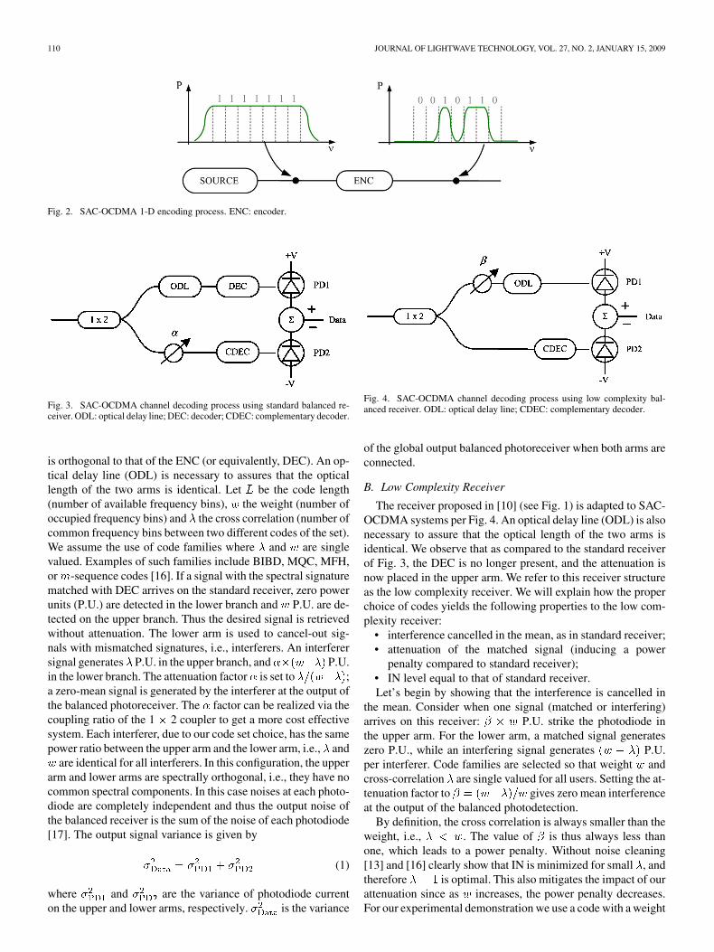
The standard receiver for SAC-OCDMA is based on the well-known balanced receiver presented in Fig. 3 [15]. In the upperarm, a decoder (DEC) which is spectrally identical to an ENCis used to extract the information encoded by ENC. The lowerarm contains a complementary decoder (CDEC) which is thelogical complement of the DEC; the CDEC spectral signature
110 JOURNAL OF LIGHTWAVE TECHNOLOGY, VOL. 27, NO. 2, JANUARY 15, 2009
Fig. 2. SAC-OCDMA 1-D encoding process. ENC: encoder.
Fig. 3. SAC-OCDMA channel decoding process using standard balanced re-ceiver. ODL: optical delay line; DEC: decoder; CDEC: complementary decoder.
is orthogonal to that of the ENC (or equivalently, DEC). An op-tical delay line (ODL) is necessary to assures that the opticallength of the two arms is identical. Let be the code length(number of available frequency bins), the weight (number ofoccupied frequency bins) and the cross correlation (number ofcommon frequency bins between two different codes of the set).We assume the use of code families where and are singlevalued. Examples of such families include BIBD, MQC, MFH,or -sequence codes [16]. If a signal with the spectral signaturematched with DEC arrives on the standard receiver, zero powerunits (P.U.) are detected in the lower branch and P.U. are de-tected on the upper branch. Thus the desired signal is retrievedwithout attenuation. The lower arm is used to cancel-out sig-nals with mismatched signatures, i.e., interferers. An interferersignal generates P.U. in the upper branch, and P.U.in the lower branch. The attenuation factor is set to ;a zero-mean signal is generated by the interferer at the output ofthe balanced photoreceiver. The factor can be realized via thecoupling ratio of the 1 2 coupler to get a more cost effectivesystem. Each interferer, due to our code set choice, has the samepower ratio between the upper arm and the lower arm, i.e., and
are identical for all interferers. In this configuration, the upperarm and lower arms are spectrally orthogonal, i.e., they have nocommon spectral components. In this case noises at each photo-diode are completely independent and thus the output noise ofthe balanced receiver is the sum of the noise of each photodiode[17]. The output signal variance is given by
(1)
where and are the variance of photodiode currenton the upper and lower arms, respectively. is the variance
Fig. 4. SAC-OCDMA channel decoding process using low complexity bal-anced receiver. ODL: optical delay line; CDEC: complementary decoder.
of the global output balanced photoreceiver when both arms areconnected.
B. Low Complexity Receiver
The receiver proposed in [10] (see Fig. 1) is adapted to SAC-OCDMA systems per Fig. 4. An optical delay line (ODL) is alsonecessary to assure that the optical length of the two arms isidentical. We observe that as compared to the standard receiverof Fig. 3, the DEC is no longer present, and the attenuation isnow placed in the upper arm. We refer to this receiver structureas the low complexity receiver. We will explain how the properchoice of codes yields the following properties to the low com-plexity receiver:
• interference cancelled in the mean, as in standard receiver;• attenuation of the matched signal (inducing a power
penalty compared to standard receiver);• IN level equal to that of standard receiver.Let’s begin by showing that the interference is cancelled in
the mean. Consider when one signal (matched or interfering)arrives on this receiver: P.U. strike the photodiode inthe upper arm. For the lower arm, a matched signal generateszero P.U., while an interfering signal generates P.U.per interferer. Code families are selected so that weight andcross-correlation are single valued for all users. Setting the at-tenuation factor to gives zero mean interferenceat the output of the balanced photodetection.
By definition, the cross correlation is always smaller than theweight, i.e., . The value of is thus always less thanone, which leads to a power penalty. Without noise cleaning[13] and [16] clearly show that IN is minimized for small , andtherefore is optimal. This also mitigates the impact of ourattenuation since as increases, the power penalty decreases.For our experimental demonstration we use a code with a weight
PENON et al.: INNOVATIVE RECEIVER FOR INCOHERENT SAC-OCDMA 111
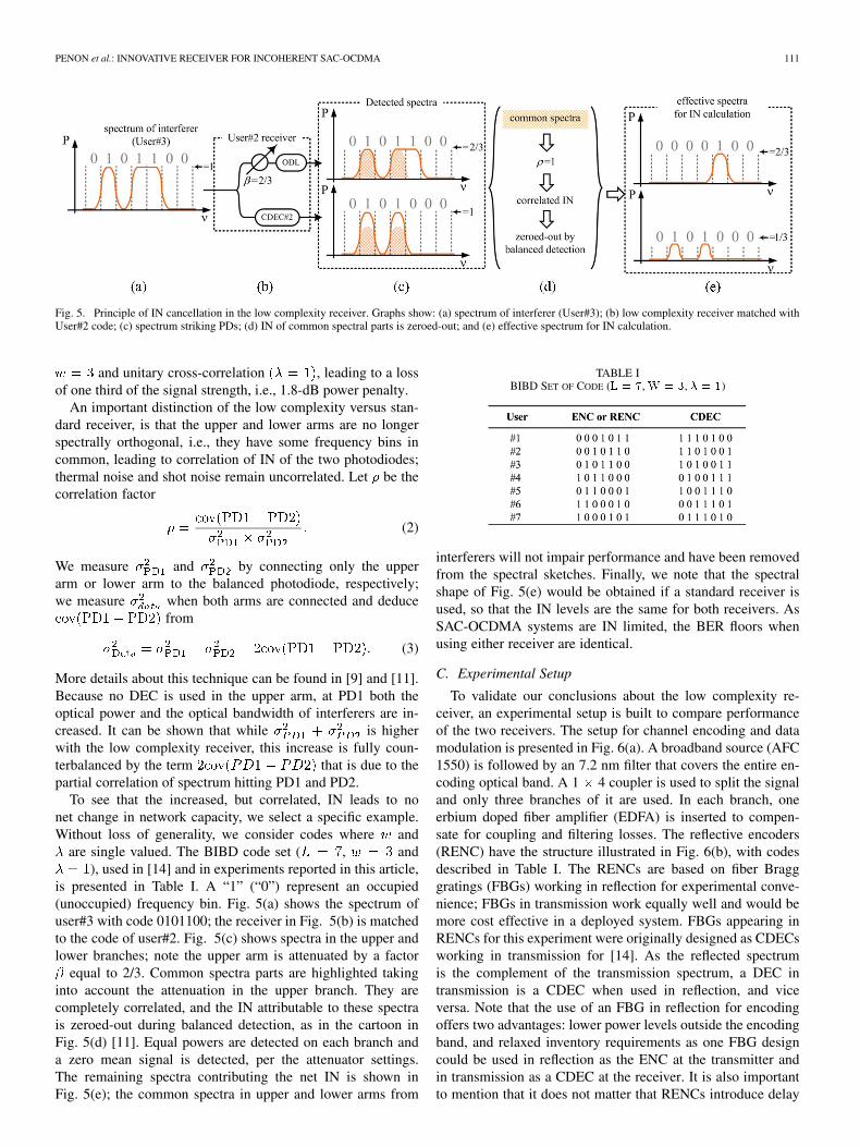
Fig. 5. Principle of IN cancellation in the low complexity receiver. Graphs show: (a) spectrum of interferer (User#3); (b) low complexity receiver matched withUser#2 code; (c) spectrum striking PDs; (d) IN of common spectral parts is zeroed-out; and (e) effective spectrum for IN calculation.
and unitary cross-correlation , leading to a lossof one third of the signal strength, i.e., 1.8-dB power penalty.
An important distinction of the low complexity versus stan-dard receiver, is that the upper and lower arms are no longerspectrally orthogonal, i.e., they have some frequency bins incommon, leading to correlation of IN of the two photodiodes;thermal noise and shot noise remain uncorrelated. Let be thecorrelation factor
(2)
We measure and by connecting only the upperarm or lower arm to the balanced photodiode, respectively;we measure when both arms are connected and deduce
from
(3)
More details about this technique can be found in [9] and [11].Because no DEC is used in the upper arm, at PD1 both theoptical power and the optical bandwidth of interferers are in-creased. It can be shown that while is higherwith the low complexity receiver, this increase is fully coun-terbalanced by the term that is due to thepartial correlation of spectrum hitting PD1 and PD2.
To see that the increased, but correlated, IN leads to nonet change in network capacity, we select a specific example.Without loss of generality, we consider codes where and
are single valued. The BIBD code set ( , and), used in [14] and in experiments reported in this article,
is presented in Table I. A “1” (“0”) represent an occupied(unoccupied) frequency bin. Fig. 5(a) shows the spectrum ofuser#3 with code 0101100; the receiver in Fig. 5(b) is matchedto the code of user#2. Fig. 5(c) shows spectra in the upper andlower branches; note the upper arm is attenuated by a factor
equal to 2/3. Common spectra parts are highlighted takinginto account the attenuation in the upper branch. They arecompletely correlated, and the IN attributable to these spectrais zeroed-out during balanced detection, as in the cartoon inFig. 5(d) [11]. Equal powers are detected on each branch anda zero mean signal is detected, per the attenuator settings.The remaining spectra contributing the net IN is shown inFig. 5(e); the common spectra in upper and lower arms from
TABLE IBIBD SET OF CODE (L = 7, W = 3, � = 1)
interferers will not impair performance and have been removedfrom the spectral sketches. Finally, we note that the spectralshape of Fig. 5(e) would be obtained if a standard receiver isused, so that the IN levels are the same for both receivers. AsSAC-OCDMA systems are IN limited, the BER floors whenusing either receiver are identical.
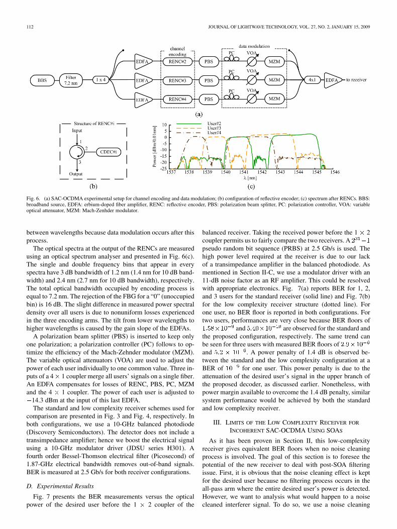
C. Experimental Setup
To validate our conclusions about the low complexity re-ceiver, an experimental setup is built to compare performanceof the two receivers. The setup for channel encoding and datamodulation is presented in Fig. 6(a). A broadband source (AFC1550) is followed by an 7.2 nm filter that covers the entire en-coding optical band. A 1 4 coupler is used to split the signaland only three branches of it are used. In each branch, oneerbium doped fiber amplifier (EDFA) is inserted to compen-sate for coupling and filtering losses. The reflective encoders(RENC) have the structure illustrated in Fig. 6(b), with codesdescribed in Table I. The RENCs are based on fiber Bragggratings (FBGs) working in reflection for experimental conve-nience; FBGs in transmission work equally well and would bemore cost effective in a deployed system. FBGs appearing inRENCs for this experiment were originally designed as CDECsworking in transmission for [14]. As the reflected spectrumis the complement of the transmission spectrum, a DEC intransmission is a CDEC when used in reflection, and viceversa. Note that the use of an FBG in reflection for encodingoffers two advantages: lower power levels outside the encodingband, and relaxed inventory requirements as one FBG designcould be used in reflection as the ENC at the transmitter andin transmission as a CDEC at the receiver. It is also importantto mention that it does not matter that RENCs introduce delay
112 JOURNAL OF LIGHTWAVE TECHNOLOGY, VOL. 27, NO. 2, JANUARY 15, 2009
Fig. 6. (a) SAC-OCDMA experimental setup for channel encoding and data modulation; (b) configuration of reflective encoder; (c) spectrum after RENCs. BBS:broadband source, EDFA: erbium-doped fiber amplifier, RENC: reflective encoder, PBS: polarization beam splitter, PC: polarization controller, VOA: variableoptical attenuator, MZM: Mach-Zenhder modulator.
between wavelengths because data modulation occurs after thisprocess.
The optical spectra at the output of the RENCs are measuredusing an optical spectrum analyser and presented in Fig. 6(c).The single and double frequency bins that appear in everyspectra have 3 dB bandwidth of 1.2 nm (1.4 nm for 10 dB band-width) and 2.4 nm (2.7 nm for 10 dB bandwidth), respectively.The total optical bandwidth occupied by encoding process isequal to 7.2 nm. The rejection of the FBG for a “0” (unoccupiedbin) is 16 dB. The slight difference in measured power spectraldensity over all users is due to nonuniform losses experiencedin the three encoding arms. The tilt from lower wavelengths tohigher wavelengths is caused by the gain slope of the EDFAs.
A polarization beam splitter (PBS) is inserted to keep onlyone polarization; a polarization controller (PC) follows to op-timize the efficiency of the Mach-Zehnder modulator (MZM).The variable optical attenuators (VOA) are used to adjust thepower of each user individually to one common value. Three in-puts of a 4 1 coupler merge all users’ signals on a single fiber.An EDFA compensates for losses of RENC, PBS, PC, MZMand the 4 1 coupler. The power of each user is adjusted to
14.3 dBm at the input of this last EDFA.The standard and low complexity receiver schemes used for
comparison are presented in Fig. 3 and Fig. 4, respectively. Inboth configurations, we use a 10-GHz balanced photodiode(Discovery Semiconductors). The detector does not include atransimpedance amplifier; hence we boost the electrical signalusing a 10-GHz modulator driver (JDSU series H301). Afourth order Bessel-Thomson electrical filter (Picosecond) of1.87-GHz electrical bandwidth removes out-of-band signals.BER is measured at 2.5 Gb/s for both receiver configurations.
D. Experimental Results
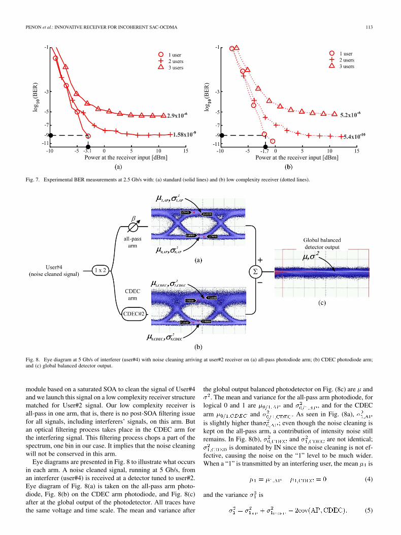
Fig. 7 presents the BER measurements versus the opticalpower of the desired user before the 1 2 coupler of the
balanced receiver. Taking the received power before the 1 2coupler permits us to fairly compare the two receivers. Apseudo random bit sequence (PRBS) at 2.5 Gb/s is used. Thehigh power level required at the receiver is due to our lackof a transimpedance amplifier in the balanced photodiode. Asmentioned in Section II-C, we use a modulator driver with an11-dB noise factor as an RF amplifier. This could be resolvedwith appropriate electronics. Fig. 7(a) reports BER for 1, 2,and 3 users for the standard receiver (solid line) and Fig. 7(b)for the low complexity receiver structure (dotted line). Forone user, no BER floor is reported in both configurations. Fortwo users, performances are very close because BER floors of
and are observed for the standard andthe proposed configuration, respectively. The same trend canbe seen for three users with measured BER floors ofand . A power penalty of 1.4 dB is observed be-tween the standard and the low complexity configuration at aBER of for one user. This power penalty is due to theattenuation of the desired user’s signal in the upper branch ofthe proposed decoder, as discussed earlier. Nonetheless, withpower margin available to overcome the 1.4 dB penalty, similarsystem performance would be achieved by both the standardand low complexity receiver.
III. LIMITS OF THE LOW COMPLEXITY RECEIVER FOR
INCOHERENT SAC-OCDMA USING SOAS
As it has been proven in Section II, this low-complexityreceiver gives equivalent BER floors when no noise cleaningprocess is involved. The goal of this section is to foresee thepotential of the new receiver to deal with post-SOA filteringissue. First, it is obvious that the noise cleaning effect is keptfor the desired user because no filtering process occurs in theall-pass arm where the entire desired user’s power is detected.However, we want to analysis what would happen to a noisecleaned interferer signal. To do so, we use a noise cleaning
PENON et al.: INNOVATIVE RECEIVER FOR INCOHERENT SAC-OCDMA 113
Fig. 7. Experimental BER measurements at 2.5 Gb/s with: (a) standard (solid lines) and (b) low complexity receiver (dotted lines).
Fig. 8. Eye diagram at 5 Gb/s of interferer (user#4) with noise cleaning arriving at user#2 receiver on (a) all-pass photodiode arm; (b) CDEC photodiode arm;and (c) global balanced detector output.
module based on a saturated SOA to clean the signal of User#4and we launch this signal on a low complexity receiver structurematched for User#2 signal. Our low complexity receiver isall-pass in one arm, that is, there is no post-SOA filtering issuefor all signals, including interferers’ signals, on this arm. Butan optical filtering process takes place in the CDEC arm forthe interfering signal. This filtering process chops a part of thespectrum, one bin in our case. It implies that the noise cleaningwill not be conserved in this arm.
Eye diagrams are presented in Fig. 8 to illustrate what occursin each arm. A noise cleaned signal, running at 5 Gb/s, froman interferer (user#4) is received at a detector tuned to user#2.Eye diagram of Fig. 8(a) is taken on the all-pass arm photo-diode, Fig. 8(b) on the CDEC arm photodiode, and Fig. 8(c)after at the global output of the photodetector. All traces havethe same voltage and time scale. The mean and variance after
the global output balanced photodetector on Fig. (8c) are and. The mean and variance for the all-pass arm photodiode, for
logical 0 and 1 are and , and for the CDECarm and . As seen in Fig. (8a),is slightly higher than ; even though the noise cleaning iskept on the all-pass arm, a contribution of intensity noise stillremains. In Fig. 8(b), and are not identical;
is dominated by IN since the noise cleaning is not ef-fective, causing the noise on the “1” level to be much wider.When a “1” is transmitted by an interfering user, the mean is
(4)
and the variance is
(5)
114 JOURNAL OF LIGHTWAVE TECHNOLOGY, VOL. 27, NO. 2, JANUARY 15, 2009
Fig. 9. Setup for SAC-OCDMA channel encoding, noise cleaning module and data modulation.
The same equations apply for logical 0. Multiple access inter-ference is cancelled in the mean by balanced photodetection,but IN leaks through in the variance. As we can see in Fig. 8(c),whether a logical 0 or 1 is transmitted by the interferer, the signalmean is zero and the variance is nonzero. These eye diagramsshow that the noise cleaning effect is maintained for any signalon the all-pass arm. Noise cleaning is, however, greatly reducedin the CDEC arm for interferers’ signals due to postfiltering ef-fect: one frequency bin per interferer is completely suppressed.
Two things can be conclude here. First, performance will begreatly improved when few users are active in the network, i.e.,the IN reduction of the desired user has a significant impacton the global noise in this condition. Second, as the numberof active user increases, performance enhancement with noisecleaning modules will be reduced. Almost all the residual noiseis due to interferers that are not fully noise cleaned in the CDECarm. In the next section, an experimental setup is described andBER is reported to verify affirmations made in this section.
IV. NOISE CLEANING EXPERIMENTAL SETUP AND RESULTS
In this section, the experimental setup with a noise cleaningmodule for each user is presented, and BER results from 2.5to 10 Gbit/s are reported. We use extremely high bit rates forthe optical bandwidth used to get highly intensity-noise-lim-ited system with pronounced error floors to probe the limits ofBER improvement. All results are obtained by using the pro-posed low complexity receiver of Fig. 4. Performance with andwithout SOA-based noise cleaning module are compared. Ourlow complexity receiver is shown to be an effective solutionfor exploiting the noise cleaning potential of SOA in incoherentSAC-OCDMA systems.
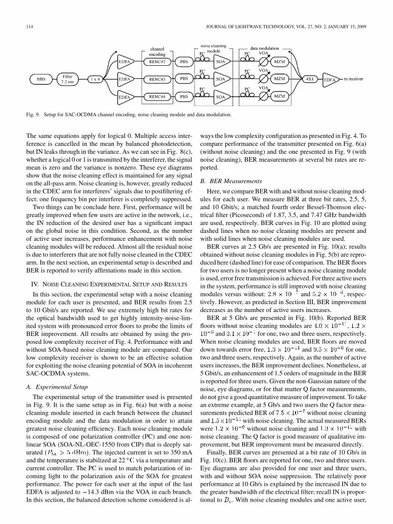
A. Experimental Setup
The experimental setup of the transmitter used is presentedin Fig. 9. It is the same setup as in Fig. 6(a) but with a noisecleaning module inserted in each branch between the channelencoding module and the data modulation in order to attaingreatest noise cleaning efficiency. Each noise cleaning moduleis composed of one polarization controller (PC) and one non-linear SOA (SOA-NL-OEC-1550 from CIP) that is deeply sat-urated . The injected current is set to 350 mAand the temperature is stabilized at 22 via a temperature andcurrent controller. The PC is used to match polarization of in-coming light to the polarization axis of the SOA for greatestperformance. The power for each user at the input of the lastEDFA is adjusted to 14.3 dBm via the VOA in each branch.In this section, the balanced detection scheme considered is al-
ways the low complexity configuration as presented in Fig. 4. Tocompare performance of the transmitter presented on Fig. 6(a)(without noise cleaning) and the one presented in Fig. 9 (withnoise cleaning), BER measurements at several bit rates are re-ported.
B. BER Measurements
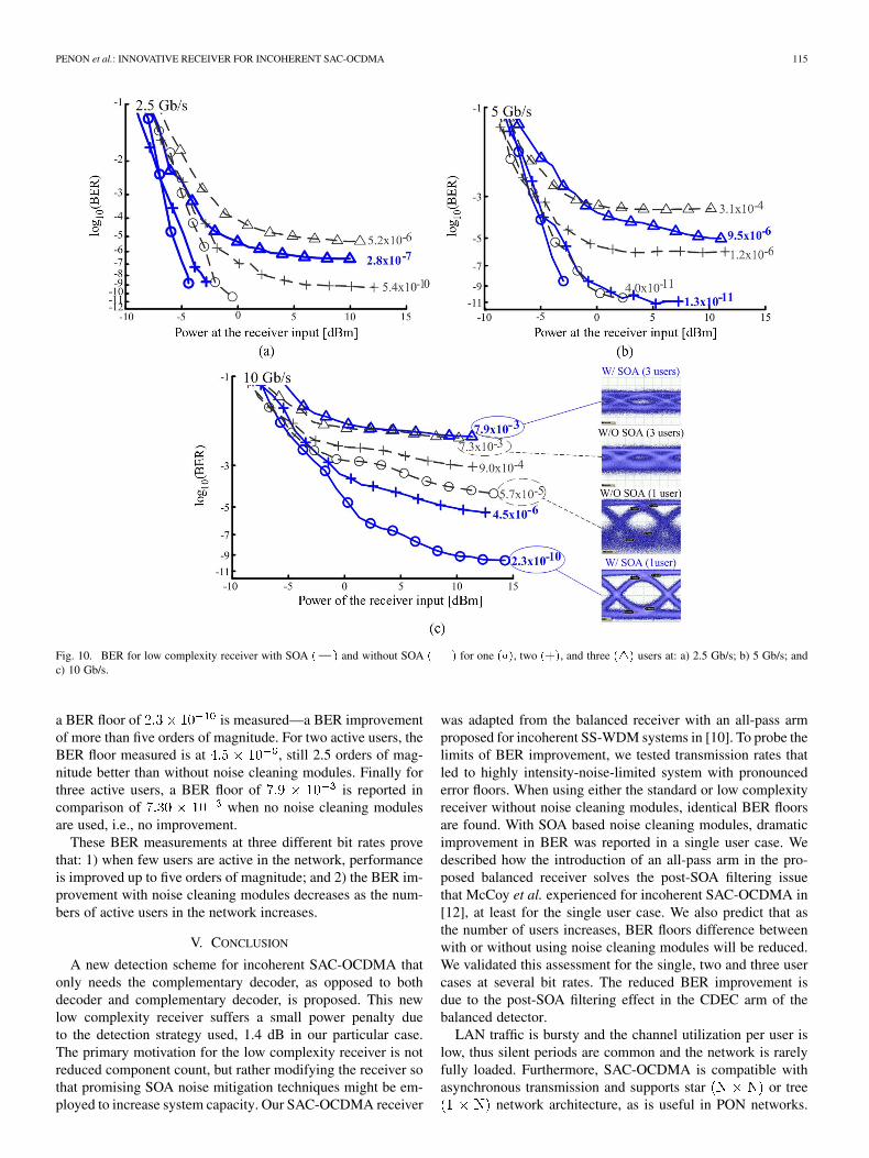
Here, we compare BER with and without noise cleaning mod-ules for each user. We measure BER at three bit rates, 2.5, 5,and 10 Gbit/s; a matched fourth order Bessel-Thomson elec-trical filter (Picosecond) of 1.87, 3.5, and 7.47 GHz bandwidthare used, respectively. BER curves in Fig. 10 are plotted usingdashed lines when no noise cleaning modules are present andwith solid lines when noise cleaning modules are used.
BER curves at 2.5 Gb/s are presented in Fig. 10(a); resultsobtained without noise cleaning modules in Fig. 5(b) are repro-duced here (dashed line) for ease of comparison. The BER floorsfor two users is no longer present when a noise cleaning moduleis used, error free transmission is achieved. For three active usersin the system, performance is still improved with noise cleaningmodules versus without: and , respec-tively. However, as predicted in Section III, BER improvementdecreases as the number of active users increases.
BER at 5 Gb/s are presented in Fig. 10(b). Reported BERfloors without noise cleaning modules are ,
and for one, two and three users, respectively.When noise cleaning modules are used, BER floors are moveddown towards error free, and for one,two and three users, respectively. Again, as the number of activeusers increases, the BER improvement declines. Nonetheless, at5 Gbit/s, an enhancement of 1.5 orders of magnitude in the BERis reported for three users. Given the non-Gaussian nature of thenoise, eye diagrams, or for that matter Q factor measurements,do not give a good quantitative measure of improvement. To takean extreme example, at 5 Gb/s and two users the Q factor mea-surements predicted BER of without noise cleaningand with noise cleaning. The actual measured BERswere without noise cleaning and withnoise cleaning. The Q factor is good measure of qualitative im-provement, but BER improvement must be measured directly.
Finally, BER curves are presented at a bit rate of 10 Gb/s inFig. 10(c). BER floors are reported for one, two and three users.Eye diagrams are also provided for one user and three users,with and without SOA noise suppression. The relatively poorperformance at 10 Gb/s is explained by the increased IN due tothe greater bandwidth of the electrical filter; recall IN is propor-tional to . With noise cleaning modules and one active user,
PENON et al.: INNOVATIVE RECEIVER FOR INCOHERENT SAC-OCDMA 115
Fig. 10. BER for low complexity receiver with SOA ( ) and without SOA (��) for one (�), two (+), and three (4) users at: a) 2.5 Gb/s; b) 5 Gb/s; andc) 10 Gb/s.
a BER floor of is measured—a BER improvementof more than five orders of magnitude. For two active users, theBER floor measured is at , still 2.5 orders of mag-nitude better than without noise cleaning modules. Finally forthree active users, a BER floor of is reported incomparison of when no noise cleaning modulesare used, i.e., no improvement.
These BER measurements at three different bit rates provethat: 1) when few users are active in the network, performanceis improved up to five orders of magnitude; and 2) the BER im-provement with noise cleaning modules decreases as the num-bers of active users in the network increases.
V. CONCLUSION
A new detection scheme for incoherent SAC-OCDMA thatonly needs the complementary decoder, as opposed to bothdecoder and complementary decoder, is proposed. This newlow complexity receiver suffers a small power penalty dueto the detection strategy used, 1.4 dB in our particular case.The primary motivation for the low complexity receiver is notreduced component count, but rather modifying the receiver sothat promising SOA noise mitigation techniques might be em-ployed to increase system capacity. Our SAC-OCDMA receiver
was adapted from the balanced receiver with an all-pass armproposed for incoherent SS-WDM systems in [10]. To probe thelimits of BER improvement, we tested transmission rates thatled to highly intensity-noise-limited system with pronouncederror floors. When using either the standard or low complexityreceiver without noise cleaning modules, identical BER floorsare found. With SOA based noise cleaning modules, dramaticimprovement in BER was reported in a single user case. Wedescribed how the introduction of an all-pass arm in the pro-posed balanced receiver solves the post-SOA filtering issuethat McCoy et al. experienced for incoherent SAC-OCDMA in[12], at least for the single user case. We also predict that asthe number of users increases, BER floors difference betweenwith or without using noise cleaning modules will be reduced.We validated this assessment for the single, two and three usercases at several bit rates. The reduced BER improvement isdue to the post-SOA filtering effect in the CDEC arm of thebalanced detector.
LAN traffic is bursty and the channel utilization per user islow, thus silent periods are common and the network is rarelyfully loaded. Furthermore, SAC-OCDMA is compatible withasynchronous transmission and supports star or tree
network architecture, as is useful in PON networks.
116 JOURNAL OF LIGHTWAVE TECHNOLOGY, VOL. 27, NO. 2, JANUARY 15, 2009
The proposed low complexity receiver with a SOA-based noisecleaning module has great potential in these networks. Actually,BER improvement of as little as one order of magnitude, e.g.,
compared to , can be crucial in systems using for-ward error correction. Future works will focus on merging threenoise mitigation solutions for a larger network size (16 usersand more): 1) the low complexity receiver; 2) SOA-based noisecleaning; and 3) an efficient FEC to boost performance.
ACKNOWLEDGMENT
The authors would like to thank Prof. L. Chen from McGillUniversity for providing an additional SOA for our experimentsand F. Vacondio, S. Ayotte, and A. Ghazisaeidi for helpful dis-cussions.
REFERENCES
[1] E. D. J. Smith, P. T. Gough, and D. P. Taylor, “Noise limits of opticalspectral-encoding CDMA systems,” Electron. Lett., vol. 31, no. 17, pp.1469–1470, Aug. 17, 1995.
[2] P. C. Becker, N. A. Olsson, and J. R. Simpson, Erbium-Doped FiberAmplifiers Fundamentals and Technology. San Diego, CA: Aca-demic, 1999.
[3] A. J. Keating, W. T. Holloway, and D. D. Sampson, “Feedforwardnoise reduction of incoherent light for spectrum-sliced transmission at2.5 Gb/s,” IEEE Photon. Technol. Lett., vol. 7, no. 12, pp. 1513–1515,Dec. 1995.
[4] J. Han, J. Ko, J. S. Lee, and S. Shin, “0.1-nm narrow bandwidth trans-mission of a 2.5-Gb/s spectrum-sliced incoherent light channel usingan all-optical bandwidth expansion technique at the receiver,” IEEEPhoton. Technol. Lett., vol. 10, no. 10, pp. 1501–1503, Oct. 1998.
[5] S. Kim, J. Han, J. Lee, and C. Park, “Suppression of intensity noise in10 Gbit/s spectrum-sliced incoherent light channel using gain-saturatedsemiconductor optical amplifiers,” Electron. Lett., vol. 35, no. 12, pp.1000–1001, Jun. 10, 1999.
[6] M. Zhao, G. Morthier, and R. Baets, “Analysis and optimization of in-tensity noise reduction in spectrum-sliced WDM systems using a sat-urated semiconductor optical amplifier,” IEEE Photon. Technol. Lett.,vol. 14, no. 3, pp. 390–392, Mar. 2002.
[7] A. D. McCoy, P. Horak, B. C. Thomsen, M. Ibsen, and D. J.Richardson, “Noise suppression of incoherent light using a gain-sat-urated SOA: Implications for spectrum-sliced WDM systems,” J.Lightw. Technol., vol. 23, no. 8, pp. 2399–2409, Aug. 2005.
[8] A. D. McCoy, B. C. Thomsen, M. Ibsen, and D. J. Richardson,“Filtering effects in a spectrum-sliced WDM system using SOA-basednoise reduction,” IEEE Photon. Technol. Lett., vol. 16, no. 2, pp.680–682, Feb. 2004.
[9] A. D. McCoy, P. Horak, B. C. Thomsen, M. Ibsen, and D. J.Richardson, “Intensity noise reduction of incoherent light usingsemiconductor optical amplifiers,” in Proc. Conf. Rec. 38th AsilomarSignals, Syst. Comput., Nov. 7–10, 2004, vol. 1, pp. 88–92.
[10] W. Mathlouthi, F. Vacondio, J. Penon, A. Ghazisaeidi, and L. A. Rusch,“DWDM achieved with thermal sources: A future-proof PON solu-tion,” in Proc. 33th Eur. Conf. Opt. Commun., Berlin, Germany, 2007.
[11] M. Abtahi, S. Ayotte, J. Penon, and L. A. Rusch, “Intensity noise inbalanced detection of correlated incoherent signals,” in Proc. IASTEDInt. Conf. Wireless Opt. Commun., Montreal, Canada, Jun. 2007.
[12] A. D. McCoy, M. Ibsen, P. Horak, B. C. Thomsen, and D. J.Richardson, “Feasibility study of SOA-based noise suppression forspectral amplitude coded OCDMA,” J. Lightw. Technol., vol. 25, no.1, pp. 394–401, Jan. 2007.
[13] S. Ayotte, M. Rochette, J. Magne, L. A. Rusch, and S. LaRochelle, “Ex-perimental verification and capacity prediction of FE-OCDMA usingsuperimposed FBG,” J. Lightw. Technol., vol. 23, no. 2, pp. 724–731,Feb. 2005.
[14] J. Penon, Z. A. El-Sahn, L. A. Rusch, and S. LaRochelle, “Spectral-am-plitude-coded OCDMA optimized for a realistic FBG frequency re-sponse,” J. Lightw. Technol., vol. 25, no. 5, pp. 1256–1263, May 2007.
[15] D. Zaccarin and M. Kavehrad, “An optical CDMA system based onspectral encoding of LED,” IEEE Photon. Technol. Lett., vol. 5, no. 4,pp. 479–482, Apr. 1993.
[16] Z. Wei and H. Ghafouri-Shiraz, “Codes for spectral-amplitude-codingoptical CDMA systems,” J. Lightw. Technol., vol. 20, no. 8, pp.1284–1291, Aug. 2002.
[17] A. Papoulis and S. U. Pilai, Probability, Random Variables and Sto-chastic Processes, 4th ed. New York: McGraw-Hill, Jan. 2002, pp.181–182.
Julien Penon (S’06) was born in Amiens, France,in 1979. He received the Diplôme d’Études Appro-fondies in optics and photonics from the UniversitéParis XI, Orsay, France, in 2003.
He is currently working toward the Ph.D. degreein optical telecommunications with a dissertationon spectral amplitude coded optical code-divisionmultiple-access (SAC-OCDMA) at the Centre d’Op-tique, Photonique et Lasers, Department of Electricaland Computer Engineering, Université Laval. Hisresearch interests include fiber-optic communication
systems, fiber Bragg gratings, and OCDMA.
Walid Mathlouthi received the B.S.E.E. degreefrom the École Nationale d’Ingénieurs de Tunis,Tunisia, and the M.S.E.E degree from UniversitéLaval, Québec, QC, Canada.
He is currently working toward the Ph.D. degree inelectrical engineering. His research interests includesemiconductor optical amplifiers, spectrum-slicedwavelength-division-multiplexing, fiber Bragg grat-ings, optical-code-division multiple access, wirelessoptical communications, and Silicon photonics.
Sophie LaRochelle (M’00) received the B.S. degreein engineering physics from the Université Laval,Québec, QC, Canada, in 1987 and the Ph.D. degreein optics from the University of Arizona, Tucson, in1992.
She was a Research Scientist from 1992 to 1996with the Defense Research Establishment Valcartier,Valcartier, QC, Canada, where she worked onelectrooptical systems. She is currently a Professorwith the Department of Electrical and ComputerEngineering, Université Laval, where she holds the
Canada Research Chair in Optical Fiber Communications and Components.Her current research activities are focused on active and passive fiber-opticcomponents for optical communication systems, including fiber Bragg grat-ings, optical amplifiers, and multiwavelength and pulsed fiber lasers. Her otherresearch interests include packet switching with all-optical label processing,optical code-division multiple-access systems, and nonlinear pulse propagation.
Leslie A. Rusch (S’91–M’94–SM’00) receivedthe B.S.E.E. (honors) degree from the CaliforniaInstitute of Technology, Pasadena, in 1980 and theM.A. and Ph.D. degrees in electrical engineeringfrom Princeton University, Princeton, NJ, in 1992and 1994, respectively.
She was previously the manager of a groupresearching new wireless technologies at Intel Corp.from 2001 to 2002. She is currently a Full Professorwith the Department of Electrical and ComputerEngineering, Université Laval, Québec, Canada,
performing research in wireless and optical communications. Her researchinterests include optical-code-division multiple access and spectrum-slicedWDM using incoherent sources for passive optical networks; semiconductorand erbium-doped optical amplifiers and their dynamics; radio over fiber; andin wireless communications, high performance, reduced complexity receiversfor ultrawide-band systems employing optical processing.