Improving Vision in Retinal Prostheses with Artificial Intelligence
Upload
independentCategory
view
1download
0
5. Baumgartner WA, Silverberg GD, Ream AK, Jamieson SW,Tarabek J, Reitz BA. Reappraisal of cardiopulmonary bypasswith deep hypothermia and circulatory arrest for complexneurosurgical operations. Surgery 1983;94:242–9.
6. Williams MD, Rainer WG, Fieger HG, Jr, Murray IP,Sanchez ML. Cardiopulmonary bypass, profound hypother-mia, and circulatory arrest for neurosurgery. Ann Thorac Surg1991;52:1069–75.
7. Aebert H, Brawanski A, Philipp A, Behr R, Ullrich OW, KeylC, Birnbaum DE. Deep hypothermia and circulatory arrestfor surgery of complex intracranial aneurysms. Eur J Cardio-thorac Surg 1998;13:223–9.
8. Lawton MT, Raudzens PA, Zabramski JM, Spetzler RF. Hy-pothermic circulatory arrest in neurovascular surgery: Evolv-ing indications and predictors of patient outcome. Neurosur-gery 1998;43:10–21.
9. Solomon RA. Principles of aneurysm surgery: Cerebral ische-mic protection, hypothermia, and circulatory arrest. Clin Neu-rosurg 1994;41:351–63.
10. Spetzler RF, Hadley MN, Rigamonti D, Carter LP, RaudzensPA, Shedd SA, Wilkinson E. Aneurysms of the basilar arterytreated with circulatory arrest, hypothermia, and barbituratecerebral protection. J Neurosurg 1988;68:868–79.
11. Bindslev L, Eklund J, Norlander O, Swedenborg J, Olsson P,Nilsson E, Larm O, Gouda I, Malmberg A, Scholander E.Treatment of acute respiratory failure by extracorporeal car-bon dioxide elimination performed with a surface heparinizedartificial lung. Anesthesiology 1987;67:117–20.
12. von Segesser LK, Garcia E, Turina M. Perfusion without sys-temic heparinization for rewarming in accidental hypother-mia. Ann Thorac Surg 1991;52:560–1.
13. von Segesser LK, Weiss BM, Garcia E, Turina MI. Clinicalapplication of heparin-coated perfusion equipment with spe-cial emphasis on patients refusing homologous transfusions.Perfusion 1991;6:227–33.
14. Salzman EW, Rosenberg RD, Smith MH, Lindon JN, Fa-vreau L. Effect of heparin and heparin fractions on plateletaggregation. J Clin Invest 1980;65:64–73.
15. Svennevig JL, Geiran OR, Karlsen H, Pedersen T, MollnesTE, Kongsgard U, Froysaker T. Complement activation dur-ing extracorporeal circulation. In vitro comparison of DurafloII heparin-coated and uncoated oxygenator circuits. J ThoracCardiovasc Surg 1993;106:466–72.
16. Videm V, Mollnes TE, Garred P, Svennevig JL. Biocompat-ibility of extracorporeal circulation: In vitro comparison ofheparin-coated and uncoated oxygenator circuits. J ThoracCardiovasc Surg 1991;101:654–60.
17. Buckberg GD, Hottenrott CE. Ventricular fibrillation: Its ef-fect on myocardial flow, distribution, and performance. AnnThorac Surg 1975;20:76–85.
18. Hottenrott CE, Towers B, Kurkji HJ, Maloney JV, BuckbergG. The hazard of ventricular fibrillation in hypertrophied ven-tricles during cardiopulmonary bypass. J Thorac CardiovascSurg 1973;66:742–53.
19. Race D, Stirling GR, Morris KN. Induced ventricular fibril-lation in open-heart surgery. J Thorac Cardiovasc Surg 1964;47:271–82.
20. Reis RL, Cohn LH, Morrow AG. Effects of induced ventricu-lar fibrillation on ventricular performance and cardiac me-tabolism. Circulation 1967;35(Suppl I):234–43.
21. Schraut W, Lamberti JJ, Kampman K, Anagnostopoulos C,Replogle R, Glagov S. Does local cardiac hypothermia duringcardiopulmonary bypass protect the myocardium from long-term morphological and functional injury? Ann Thorac Surg1977;24:315–22.
An In Vitro Methodology for Evaluatingthe Mechanical Properties of Aortic
Vascular Prostheses
*Virginio Quaglini, *Tomaso Villa,
*Francesco Migliavacca, †Michele Carmo,
†Piergiorgio Settembrini, *Roberto Contro, and
*Riccardo Pietrabissa, *Laboratory of Biological
Structure Mechanics, Bioengineering Department
and Department of Structural Engineering,
Politecnico di Milano; and †Department of
Vascular Surgery, S. Carlo Borromeo Hospital,
Università degli Study di Milano, Milan, Italy
Abstract: The main problem in the replacement of patho-logical segments of the aorta with vascular prostheses con-sists of matching the fluid admittance of the host arteryand the graft. This mismatch results from the differentcompliance between natural and prosthetic vessels andfrom the plastic dilatation of the prosthesis diameter thatoccurs after implantation. An experimental procedure wasset up for evaluating the mechanical properties of aorticvascular prostheses. An MTS 858 MiniBionix testing ma-chine was equipped with a purposely designed testing ap-paratus, which allows loading a ring-shaped prosthesisspecimen with forces that can be related easily to the trans-mural pressure acting on the prostheses in vivo. The ref-erence pressure waveforms are simulated from a lumpedparameter model of the cardiovascular system. Prelimi-nary tests on 3 different (woven, warp knitted, and carbon-coated warp knitted fabric) aortic prostheses point out agood reproducibility of the results. The fabric strongly af-fects the circumferential elasticity and the dimensional sta-bility of the graft. Simulation of hypertension promoteslarger diameter dilatation and reduction in compliance.Agreement between in vitro and clinical diameter mea-surements has been assessed for 8 prosthesis samples andfound to be adequate. This method is thus a potentiallyuseful means for preclinical evaluation of compliance ofvascular prostheses for the purpose of matching to nativevessels. Key Words: Vascular prostheses—Diameter di-latation—Compliance—Fluid admittance mismatch —Invitro tests.
Vascular prostheses are biomedical devices usedfor the repair of arterial segments that have lost theirfunctionality after stenosis, aneurysms, or mechani-cal traumas. Most of these reconstructions concernaortic segments. Indeed, the aorta is the artery thatusually endures the most severe stresses as it is sub-jected to the highest transmural pressure. In addi-tion, overpressures at the bifurcations, due to the
Received August 2001; revised November 2001.Address correspondence and reprint requests to Dr. Virginio
Quaglini, Laboratory of Biological Structure Mechanics, Depart-ment of Structural Engineering, Politecnico di Milano, PiazzaLeonardo da Vinci, 32, 20133, Milan, Italy. E-mail: [email protected]
THOUGHTS AND PROGRESS 555
Artif Organs, Vol. 26, No. 6, 2002
reflection of the pressure wave, concur to enforce ananeurismatic degenerative process of the aortic wall.
Several types of vascular prostheses are presentlyavailable, differing in material (biological or syn-thetic), structure (fiber construct or expanded poly-mer), surface coating, and so on. In the reconstruc-tion of the aorta and other large arteries, fabricprostheses (woven, weft knitted or warp knitted con-structs) are the most popular (1). They are flexibleand porous tubular structures made of fibers of PETor polytetrafluorethylene (PTFE); nowadays, PTFEhas fallen into disuse and almost exclusively Dacronfibers are used (2,3). Fabric prostheses are generallycrimped in order to avoid kinking and to be adapt-able to bending and stretching in situ.
The mechanical properties of vascular prosthesesdepend on both the fiber properties and the fabricgeometry and are one of the main factors affectingthe long-term reliability of the implant.
In situ vascular prostheses usually undergo diam-eter dilatation. A first phase or short-term dilatation,which is due to the flattening of the crimps, to theelastic deformation of the fibers, and to the struc-tural rearrangement of the stretched fabric, runs outin the first hours after the implantation (1). A long-term dilatation, which results in a plastic, i.e., irre-versible expansion of the fabric till its collapse, isassociated with creep and/or fatigue failure of thefibers that are promoted from the aggressive biologi-cal environment (3). Neglecting these long-term ef-fects, a stable graft geometry with a diameter largerthan in the free-load configuration usually is attainedwithin some hours under the transmural pressure(4).
A common measurement of the elasticity of a ves-sel is the compliance, which is defined as the frac-tional change in volume per unit change in transmu-ral pressure. The product of wall compliance andcross-sectional area, at a given pressure, is called thevessel fluid admittance.
The methods for evaluating the geometrical andmechanical properties of vascular grafts and naturalarteries can fall into 3 categories (5) to measure. Thefirst is dimensions. Noninvasive measurements of thelumen diameter are performed through ultrasonictracking (6,7) or A-mode echo-tracking (8–10). Thesecond is compliance. The in vivo compliance of avessel can be determined upon measured changes ofpressure and volume (8,11–14) or assessed on thebasis of Doppler ultrasound measurements of thepulse wave velocity (15–18). The third is elastic prop-erties of the wall materials. They are measured invitro by tensile tests on strips cut from the grafts(19).
Vascular prostheses feature mechanical propertiesthat are very different from those of natural arteries.When a segment of aorta is replaced by a stiffergraft, 2 main consequences arise. First, at the inter-faces, the different propagation rate of pressurewaves, which depends on the wall elasticity, causeswave reflections and eddy currents that in turn areknown to promote the formation of thrombi and in-timal hyperplasia (20,21). Second, due to the differ-ent radial dilatation of the prosthesis and the hostvessel, overstresses arise in the sutures at the anas-tomoses, leading to the formation of anastomotic an-eurysm, fatigue failure of sutures, and tearing of thehost artery. In order to achieve a perfect transmis-sion of the pressure pulse without reflection, the ad-mittance of the graft after implantation shouldmatch the host vessel one (21).
The preclinical assessment of the hydraulic func-tionality of vascular prostheses is performed bymeans of in vitro measurement of the graft admit-tance. In this article, a new methodology for the invitro mechanical characterization of aortic vascularprostheses in terms of compliance and diameter di-latation is presented, and the repeatability, accuracy,and consistency of the test results with in vivo Dopp-ler measurements are evaluated as well.
Materials and methods
Experimental set-up
Two specially designed fixtures (Fig. 1) weremounted on an MTS 858 MiniBionix servo-hydraulictesting machine (MTS Corp., Minneapolis, MN,U.S.A.). The lower fixture is connected to an MTS611.B-01, 25 N scale, load cell and the upper fixtureto the actuator of the testing machine. The 15 mmscale LVDT is used for measuring the actuator dis-placement. The MTS testing machine is driven froman MTS 790.01 Test Star closed-loop controller.
A straight segment, cut between 2 right cross sec-tions of the vascular prosthesis, is inserted onto the 2pairs of pins as illustrated in Fig. 1a. The minimumdiameter of the prosthesis that can be mounted onthe fixtures is 13 mm. When the upper fixture movesupward, the prosthesis is stretched, and its cross sec-tion takes on a rectangular shape. The axial forceF(t) applied from the testing machine at time t is thusrelated (Fig. 1b) to the wall stress sc(t) in the 2 ver-tical branches of the prosthesis wall, via the equilib-rium equation
F~t! = sc~t! ? 2s ? Ln (1)
where Ln is the nominal length and s the thickness ofthe specimen wall. In the absence of friction betweenthe prosthesis and the pins, the sc stress is uniform
THOUGHTS AND PROGRESS556
Artif Organs, Vol. 26, No. 6, 2002

along the whole cross section perimeter, includingthe 2 horizontal branches.
The circumferential stress sc, acting in vivo in theprosthesis wall far from the anastomoses, can beevaluated by modeling the graft as a thin-walled ves-sel subjected to the transmural pressure waveformp(t). Under the assumption of uniform pressure dis-tribution within the graft (both along the long axisand across the cross section of the vessel), at anytime t the value of sc is given by the equation(Fig. 1c)
sc~t! =p~t! ? D~t!
2s(2)
where D(t) denotes the current graft diameter attime t.
By combining Eqs. 1 and 2 we obtain
F~t! = D~t! ? Ln ? p~t! (3)
which gives the force waveform, F(t) that must beapplied to a prosthesis segment of nominal length Ln
and current diameter D(t) in order to produce in the
FIG. 1. The schematic drawing is of the experimental set-up for testing vascular pros-thesis specimens (A). The force F applied to the specimen is related to the wall stress scthrough the equilibrium (B). In a thin wall vessel the equilibrium relates sc to the trans-mural pressure p also (C).
THOUGHTS AND PROGRESS 557
Artif Organs, Vol. 26, No. 6, 2002

prosthesis wall the same circumferential stressescaused by the transmural pressure waveform p(t).
From the force and actuator displacement signals,measured by the transducers of the MTS testing ma-chine, 2 new signals are therefore defined. First is theequivalent diameter De(t) of the stretched prosthe-sis, which is calculated at each time instant as
De(t)42
p? @b + h~t! + p ? R# (4)
where b is the constant horizontal spread betweenthe pin axes, h(t) is their current vertical distance,and R is the radius of the pins (Fig. 2). Second is theequivalent transmural pressure pe (t), related to thecurrent circumferential stress in the specimen wallthrough Eq. 3:
Pe~t! =F~t!
De~t! ? Ln
(5)
The reference waveform of the aortic transmuralpressure to be used in the tests is obtained from aone-dimensional closed-loop model of the cardiovas-cular system. The model, which was implemented byusing an interactive program for simulating dynamicsystems (SIMNON, SSPA System, Lund, Sweden), isbased on the analogy between electrical and hydrau-lic networks and includes a model of the aorta and ofthe arterial and venous trees as illustrated in Fig. 3.This model is similar to others reported in the litera-ture (22).
The values (22) of the model parameters (resis-tances, conductances, and inductances) used to simu-late the normal pressure conditions are R1 4 3.75 ×10⁻³ mm Hg × s × cm−3, C1 4 0.22 mm Hg−1 × cm3,R2 4 6.75 × 10⁻² mm Hg × s × cm−3, L2 4 8.25 × 10⁻⁴
mm Hg × s2 × cm−3, C2 4 1.46 mm Hg−1 × cm3, R3
4 1.0 mm Hg × s × cm−3, and L3 4 3.4 × 10⁻⁴ mmHg × s2 × cm−3. The model is able to simulate alsopathological conditions by setting different values ofthe RCL parameters. Hypertension may be achievedby increasing R2 and/or R3. The input data of themodel is the ventricle ejection flow wave q(t), de-signed after Swanson and Clark (23). The mean aor-tic flow rate is 4.75 L/min, the heart beat 60 bpm, andthe right atrial pressure 4 mm Hg.
The output datum is the transmural pressurewaveform, p(t), calculated downstream from the as-cending arch of the aorta at a location correspondingto the vascular prosthesis placement. This pressurewaveform (Fig. 3, bottom) is used as the input for theMTS 790.14 Advanced Function Generator soft-ware, which drives the MTS testing machine. Thepressure waveform acts as the reference signal forthe closed loop control system of the MTS 790.01Test Star Controller while the feedback signal is theequivalent transmural pressure calculated via Eqs. 4and 5. So the load F that is applied to the prosthesissample is updated at each cycle according to Eq. 3,taking into account the diameter dilatation of thespecimen.
Preliminary tests
Three Dacron aortic prostheses (Sorin Biomedica,Saluggia, Italy), 16 mm nominal diameter, were usedin preliminary tests. In the following the prostheseswill be labeled as W16A, K16A, and CK16A. W16Ais a woven construct while K16A and CK16A arewarp knitted fabric. The wall of the CK16A prosthe-sis is carbon film coated. The test specimen consistedof a straight segment of ring shape, 25 mm length,cut between 2 right cross sections of the prosthesis.One specimen was obtained both from W16A andK16A while three specimens were cut from CK16A.The length, Ln, and the wall thickness, s, of the speci-mens, as reported in Table 1, were measured by agauge. Before testing, the specimens were kept in airat 37°C for 24 h.
Each specimen was mounted on the testing ma-chine as illustrated in Fig. 1a and subjected to a firstapplication of 36 × 103 cycles of the reference pres-sure waveform representing normal conditions(pressure ranging from 76 to 125 mm Hg at 1 Hzfrequency). The equivalent diameter (Eq. 4) and theequivalent transmural pressure (Eq. 5) were calcu-
FIG. 2. Shown is evaluation of the equivalent diameter of theprosthesis: h(t) is the vertical length between the pin axes (cur-rent displacement of the actuator plus pin spread at zero actuatordisplacement), b is the horizontal spread between the pins, and Ris the radius of the pins. For the fixtures employed in the text, b= 6 mm and R = 1.5 mm. The equivalent diameter is calculated bydividing the perimeter of the cross section by p.
THOUGHTS AND PROGRESS558
Artif Organs, Vol. 26, No. 6, 2002

lated and recorded for 10 cycles every 500 cycles atthe sample rate of 200 Hz. The specimens then weresubjected to a second application of 36 × 103 pres-sure cycles simulating hypertension (pressure rang-ing from 115 to 190 mm Hg at 1 Hz). Pressure anddiameter data were recorded as previously de-scribed.
The repetition of 36,000 pressure cycles was in-tended to precondition the specimen, simulating theshort-term diameter dilatation that the prosthesis islikely to undergo just after implantation, and themechanical response was evaluated once the stabilityof the response had been achieved.
By processing the data collected during the test,the following quantities were evaluated. First wasthe dilatation of the equivalent diameter, both at theequivalent systolic (De,syst) and diastolic (De,diast) lev-els, i.e., at the maximum and minimum levels, re-spectively, of equivalent pressure in each cycle. Sec-ond was the compliance in a cycle:
C = SVmax − Vmin
Vmin
?1
DpeD
cycle
(6)
where Dpe is the difference between systolic and di-astolic equivalent pressure and Vmax and Vmin are
TABLE 1. Preliminary tests: specimen dimensions
Specimen Material, fabric construction Nominal diameter (mm) Measured length (mm) Wall thickness (mm)
W16A1 Dacron, woven 16 24.1 0.44K16A1 Dacron, warp knitted 16 23.0 0.51CK16A1 Dacron, warp knitted 16 24.2 0.59CK16A2 Dacron, warp knitted 16 24.1 0.59CK16A3 Dacron, warp knitted 16 23.9 0.59
FIG. 3. The lumped parameter model of the cardiovascular system is shown. The model includes the arterial and venous trees. Thewaveform of the transmural pressure in the ascending arch of the aorta (point A) is the desired output. At the bottom, the aortic transmuralpressure waveforms output from the model of the cardiovascular system in condition of either normal pressure or hypertension is reportedas well.
THOUGHTS AND PROGRESS 559
Artif Organs, Vol. 26, No. 6, 2002

the volumes at systolic and diastolic peak, respec-tively.
Neglecting the specimen length variation, Eq. 6may be rewritten as
C = SDe,syst2 − De,diast
2
De,diast2
?1
DpeD
cycle
(7)
and Dpe as
Dpe =Fmax
De,syst ? Ln
−Fmin
De,diast ? Ln
(8)
where Fmax and Fmin are the applied forces that corre-spond through Eq. 3 to the systolic and diastolic peaksof the reference pressure waveform, respectively.
In vitro evaluation of the fluid admittance and
comparison to clinical data
Eight patients (age 69 ± 7.49 years) were submit-ted to vascular replacement following aneurismaticpathology. For all patients, 16 mm nominal diameterwarp knitted prostheses were used.
Systemic pressure immediately before implanta-tion, as reported in Table 2, was recorded for eachpatient. Unused pieces of the prostheses were col-lected at surgery time and tested on our experimen-tal set-up. The specimen consisted of a straight seg-ment of ring shape, 25 mm length, cut from thevascular prosthesis between 2 right cross sections.The actual length Ln and the wall thickness s weremeasured for each patient and are reported in Table 2.
Controls were performed on patients at 75.8 ± 48.6days after surgery by ultrasound scans with 2 ATLsystems (Ultramark 9 and HDI 3500, Bothell, WA,U.S.A.) equipped with multifrequency convex 2-4and 2-5 MHz probes, respectively. Longitudinal andtransverse scans were performed to determine theexact position of the prosthesis. The maximum in-
ternal anteroposterior diameter was measured in thelongitudinal scan at systolic peak for each patient.
Each prosthetic specimen was subjected in vitro tothe application of 36 × 103 loading cycles at 1 Hzfrequency with systolic and diastolic peaks of theequivalent pressure equal to those observed in thepatient immediately after implantation. The pressurewaveform was obtained by scaling and offsetting thereference pressure waveform from the lumped pa-rameter model of the cardiovascular system. Theequivalent transmural pressure and the equivalentdiameter were calculated and recorded for 10 cyclesevery 9,000 cycles at the sample rate of 200 Hz.
Results
Preliminary tests
The preliminary tests were performed on 5 graftspecimens that were tested cyclically in both normalpressure and hypertensive conditions in order to in-vestigate the sensitivity and the repeatability of thetest method.
Figure 4 compares the waveforms of the referencesignal and of the equivalent transmural pressure. Af-ter tuning of the closed-loop controller of the testingmachine, a good agreement between the 2 wave-
TABLE 2. In vitro tests on vascular prostheses:specimen dimensions and patient data
SpecimenWall thickness
(mm)Patient age
(years)Patient pressurerange (mm Hg)
I1 0.4 65 90–130I2 0.4 73 80–130I3 0.4 65 50–100I4 0.4 57 95–155I5 0.4 68 60–120I6 0.4 78 60–140C1 0.4 78 80–130C2 0.4 62 80–140
Nominal diameter of the prostheses 16 mm, specimen length 25mm.
I: Intervascular (Intervascular S.A., La Ciotat, France), C: Car-bograft (Sorin Bomedica, Saluggia, Italy).
FIG. 4. The graphs show equivalent transmural pressure wave-forms in condition of normal pressure (A) and hypertension (B).The thick line is the reference waveform from the lumped param-eter model, the thin line is the equivalent pressure feedback cal-culated according to Eq. 5 for specimen W16A1.
THOUGHTS AND PROGRESS560
Artif Organs, Vol. 26, No. 6, 2002
forms was attained. In particular, both the systolicand the diastolic peaks of equivalent pressure thatthe prosthesis was submitted to accurately repro-duced the reference ones.
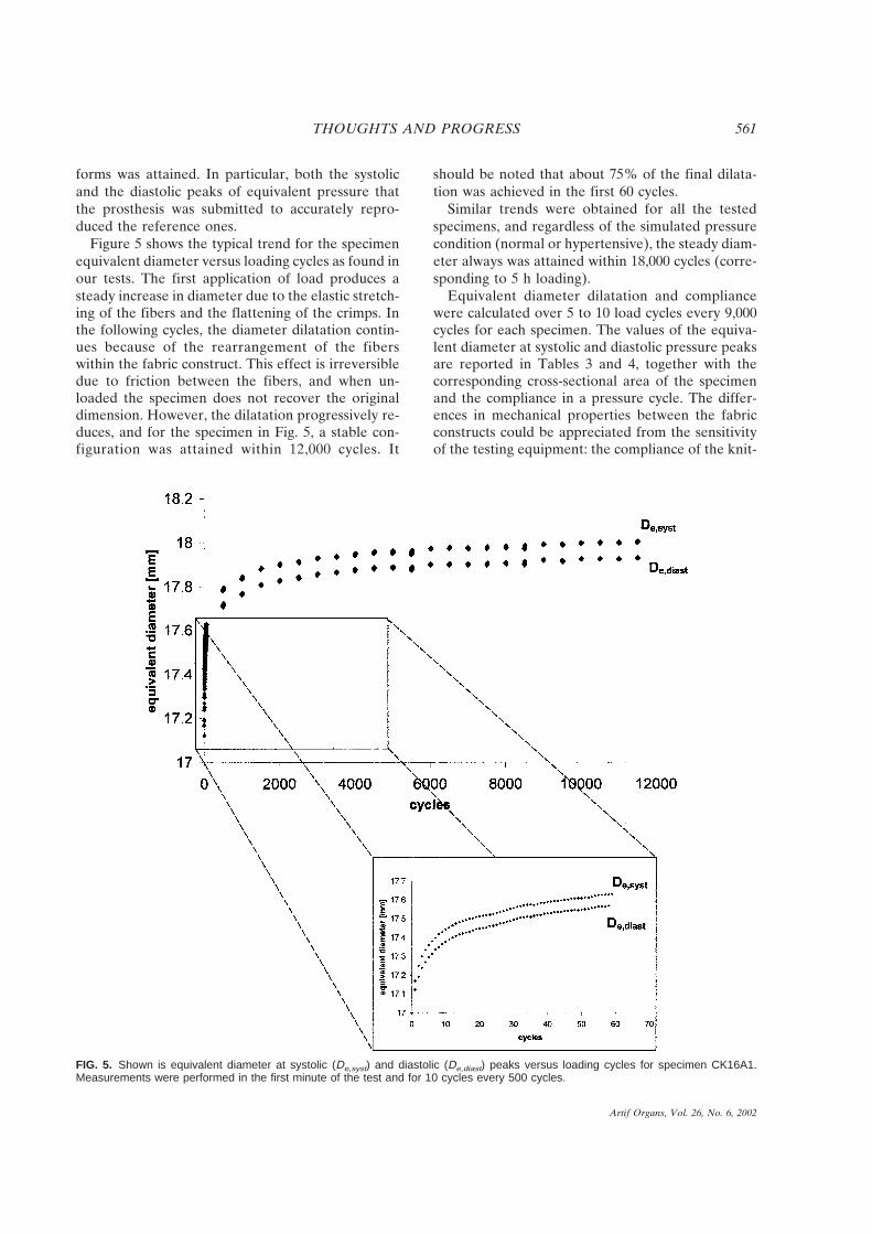
Figure 5 shows the typical trend for the specimenequivalent diameter versus loading cycles as found inour tests. The first application of load produces asteady increase in diameter due to the elastic stretch-ing of the fibers and the flattening of the crimps. Inthe following cycles, the diameter dilatation contin-ues because of the rearrangement of the fiberswithin the fabric construct. This effect is irreversibledue to friction between the fibers, and when un-loaded the specimen does not recover the originaldimension. However, the dilatation progressively re-duces, and for the specimen in Fig. 5, a stable con-figuration was attained within 12,000 cycles. It
should be noted that about 75% of the final dilata-tion was achieved in the first 60 cycles.
Similar trends were obtained for all the testedspecimens, and regardless of the simulated pressurecondition (normal or hypertensive), the steady diam-eter always was attained within 18,000 cycles (corre-sponding to 5 h loading).
Equivalent diameter dilatation and compliancewere calculated over 5 to 10 load cycles every 9,000cycles for each specimen. The values of the equiva-lent diameter at systolic and diastolic pressure peaksare reported in Tables 3 and 4, together with thecorresponding cross-sectional area of the specimenand the compliance in a pressure cycle. The differ-ences in mechanical properties between the fabricconstructs could be appreciated from the sensitivityof the testing equipment: the compliance of the knit-
FIG. 5. Shown is equivalent diameter at systolic (De,syst) and diastolic (De,diast) peaks versus loading cycles for specimen CK16A1.Measurements were performed in the first minute of the test and for 10 cycles every 500 cycles.
THOUGHTS AND PROGRESS 561
Artif Organs, Vol. 26, No. 6, 2002

ted prosthesis was 2 to 4 times the one measured forthe woven graft as found in the literature (19).
The effects of hypertension consisted in a strongincrease in diameter and a decrease in compliance asobserved in vivo (8,24,25) also.
Table 5 compares the results obtained for the 3specimens extracted from the same prosthesis seg-ment and subjected to the same testing procedure inorder to assess the repeatability of the method. Thestandard deviation was less than 2% for the equiva-lent diameter and less than 4% for the compliancemeasurements.
In vitro evaluation of the fluid admittance and
comparison to clinical data
The equivalent diameters evaluated in vitro at thestable configuration were compared to clinical mea-surements performed at controls. The agreement be-tween experimental and clinical measurements isshown by the regression analysis reported in Fig. 6.The mean value and standard deviation (Table 6) ofthe systolic diameter evaluated in vitro (Din vitro) was18.210 ± 1.133 mm while the statistics of in vivo mea-surements (Din vivo) was 18.446 ± 1.104 mm. The re-gression of Din vitro versus Din vivo was found to beR 4 0.769. In vitro measurements tended to over-estimate the in vivo dilatation, and the maximumerror was found to be of 9%. However, when Eq. 7
is used, the error in the diameter estimation shouldnot affect the estimation of the in vivo complianceperformed by using in vitro measures.
In in vitro tests, the compliance ranged between0.01558 and 0.04545 × 10⁻² mm Hg−1 (mean valueand standard deviation 0.02887 ± 0.01001 × 10⁻² mmHg−1) which is close to the value (0.01862 × 10⁻² mmHg−1) reported by Hastings (26). The aortic compli-ance in healthy subjects is known to be onefoldhigher (25,26).
Discussion
A new experimental method has been developedfor evaluating in vitro the mechanical properties ofaortic vascular grafts, i.e., compliance and irrevers-ible diameter dilatation. These properties are evalu-ated at the steady configuration attained by the graftsubjected to the cyclic transmural pressure.
With respect to in vivo conditions, some simplifi-cations have been introduced in the experimentalset-up. First, the specimens are exposed to air duringthe tests, and thus the chemical activity of the bio-
TABLE 5. Preliminary tests: repeatability of theexperimental procedure
De,syst
(mm)De,diast
(mm)Amax
(mm2)Amin
(mm2)
C(10−2
mm Hg−1)
Normal pressureMean 18.31 18.04 263.3 258.5 0.042SD 0.29 0.15 8.33 8.05 0.0016SD/mean ? 100 1.58 1.55 3.16 3.11 3.81
HypertensionMean 19.53 19.35 299.5 294.1 0.026SD 0.28 0.27 8.42 8.25 0.0009SD/mean ? 100 1.42 1.41 2.81 2.81 3.50
Mean values and standard deviations of the results for 3 nomi-nally identical specimens (CK16A1, CK16A2, and CK16A3).
FIG. 6. The graph shows a regression analysis comparing ex-perimental and in vivo diameter dilatation. Systolic diameter val-ues when steady dilatation is attained (in vivo after 18,000 loadcycles and in vitro at control) are reported.
TABLE 4. Preliminary test results: hypertensiveconditions (range 115–190 mm Hg)
SpecimenDe,syst
(mm)De,diast
(mm)Amax
(mm2)Amin
(mm2)C
(10−2 mm Hg−1)
W16A1 16.35 16.31 210.0 208.9 0.007K16A1 18.88 18.75 279.6 276.1 0.021CK16A1 19.73 19.56 305.8 300.5 0.025CK16A2 19.13 18.96 287.6 282.4 0.025CK16A3 19.71 19.53 305.1 299.4 0.027
1 mm Hg 4 133 Pa.De,diast and De,syst: equivalent diameter at systolic and diastolic
peak, Amax and Amin: cross-sectional area at systolic and diastolicpeak; C: compliance of the vessel in a pressure cycle.
TABLE 3. Preliminary test results: normal pressureconditions (range 76–125 mm Hg)
SpecimenDe,syst
(mm)De,diast
(mm)Amax
(mm2)Amin
(mm2)C
(10−2 mm Hg−1)
W16A1 16.09 16.05 203.2 202.2 0.009K16A1 18.50 18.40 268.8 265.9 0.023CK16A1 18.01 17.85 254.7 250.2 0.040CK16A2 18.22 18.05 260.7 255.9 0.042CK16A3 18.70 18.22 274.6 269.4 0.044
1 mm Hg 4 133 Pa.De,diast and De,syst: equivalent diameter at systolic and diastolic
peak, Amax and Amin: cross-sectional area at systolic and diastolicpeak; C: compliance of the vessel in a pressure cycle.
THOUGHTS AND PROGRESS562
Artif Organs, Vol. 26, No. 6, 2002

logical environment on the prosthesis wall is not ac-counted for. However, the environment usuallytakes some months to produce alterations on Dacronpolymers, and so its effect on the mechanical prop-erties of vascular prostheses just after the implanta-tion reasonably may be neglected. Furthermore, thespecimens used were dry and not wet, a conditionthat could be more realistic. Second, the mechanicalconstraints to the diameter dilatation due to the sur-rounding tissues are neglected. The change in me-chanical properties induced by the tissue ingrowththrough the pores of the graft wall is usually an un-controllable process (19), and therefore it has beenruled out in our in vitro procedure. Third, only thebehavior of the central segment of the vascular pros-thesis is modeled, and the boundary effects at itsextremities are neglected. The longitudinal tensiondue to the host artery at the anastomoses is ne-glected too. In vitro the prosthesis is therefore sub-jected to the circumferential stress only, differentlyfrom the biaxial loading conditions experienced invivo. As a consequence, the Poisson effect due to thelongitudinal stresses is not accounted for, and ahigher diameter dilatation than the implanted graft’sshould be expected in vitro.
In the preliminary tests, the repeatability of themethod was investigated. The loading history wasdefined by an equivalent pressure waveform, and theload to be applied to the specimen had to be updatedat each cycle in order to take into account the dila-tation of the specimen diameter. With a proper tun-ing, the closed-loop controller of the MTS testingmachine was assessed to produce a consistent andrepetitive loading history throughout the whole test.
Another assessment of repeatability was achievedby performing the same tests on 3 nominally identi-cal specimens: CK16A1, CK16A2, and CK16A3.The dispersion of the results (Table 5) was onefoldlower than the difference between the results forCK16A knitted and W16A woven specimens (Tables3 and 4).
The reliability of the test method was investigatedby comparing in vitro and clinical measurements ofthe dilated diameter. The clinical data were taken 2to 4 months after surgery when the long-term dila-tation still had not occurred. Despite the simplifica-tion introduced in the experimental set-up, an ad-equate agreement was found between the data (Fig.6). A tendency of the experimental method for over-estimating the actual dilatation of the graft was ob-served (Table 6). Part of this mismatch might becaused by the fact that the effect of the radial elas-ticity of the aortic wall to which the graft had beensutured in situ was not simulated in vitro, thus re-sulting in a larger dilatation of the specimen.
Conclusions
For the reliability of aortic reconstruction, vascu-lar prostheses are required to match the fluid admit-tance of the host artery. The preliminary evaluationof the above parameter is therefore fundamental toassess preclinically the suitability of a vascular pros-thesis from a fluid dynamic point of view.
This article presents a novel experimental methodfor in vitro evaluation of the mechanical propertiesof aortic vascular prostheses. The testing set-up con-sists of a closed-loop controlled hydraulic testing ma-chine and software that calculates the referencepressure waveforms. A purposely designed deviceconverts the axial load from the testing machine intothe circumferential stress in the wall of the prosthesisspecimen.
Two advantageous features of the method are thecapability of reproducing on the test specimen theactual waveform of the patient and the suitability ofthe software for simulating either states of normal orhypertensive pressure, thus allowing the study of theprosthesis behavior under different pressure condi-tions. The simplicity of the experimental apparatusand the effectiveness of the closed-loop control ofthe testing machine allow a good reproducibility ofthe testing conditions and the repeatability of theresults.
Some simplifications of the conditions in situ arerequired especially regarding the biological environ-ment, and so in vitro measurements cannot be re-lated exactly to in vivo properties (although an ad-equate agreement has been found in the experimentspresented in this article). Nevertheless, the resultsallow a straight comparison of performances amongvascular prostheses.
The proposed method is potentially useful formeasuring compliance of vascular prostheses for thepurpose of matching to native vessels as well as forforeseeing the amount of graft dilatation in situ in
TABLE 6. In vitro versus in vivo diameter dilatation
SpecimenDin vivo
(mm)Din vitro
(mm)(Din vitro − Din vivo)/
Din vitro ? 100
I1 19.0 19.19 0.99I2 16.3 16.63 3.79I3 18.1 18.89 4.18I4 18.4 17.16 −7.13I5 18.6 18.97 1.95I6 17.2 18.91 9.04C1 17.9 17.90 0.00C2 20.4 20.41 0.05
Din vivo, Din vitro: diameter at the systolic peak evaluated whensteady dilatation is attained.
THOUGHTS AND PROGRESS 563
Artif Organs, Vol. 26, No. 6, 2002
order to choose the proper size at surgery. Instead ofusing standard loading conditions, a chief advantageof the method is the chance of customizing the pres-sure waveform for each patient which increases theconsistency of the results.
The proposed methodology could be used as theground for preclinical assessment of the fluid dy-namic properties of vascular grafts and could givethe manufacturers information to be used to designnew and more efficient devices.
References
1. Hoffmann HL. Fabrication and testing of polyester arterialgrafts. In: Kambic HE, Kantrowitz A, Sung P, eds. VascularGraft Update: Safety and Performance. Philadelphia: Ameri-can Society for Testing Materials, 1986:71–81.
2. Christenson JT, Eklof B, Al-Huneidi W, Owunwanne A.Elastic and thrombogenic properties for different vasculargrafts and its influence on graft patency. Int Angiol 1987;6:81–7.
3. Riepe G, Loos J, Imig H, Schroder A, Schneider E, Peter-mann J, Rogge A, Ludwig M, Schenke A, Nassutt R, ChafkeN, Morlock M. Long term in vivo alterations of polyestervascular grafts in humans. Eur J Vasc Endovasc Surg 1997;13:540–8.
4. Lee JH, Wilson GJ. Anisotropic tensile viscoelastic propertiesof vascular graft materials tested at low strain rates. Bioma-terials 1986;7:423–31.
5. Lighthill J., ed. Mathematical Biofluiddynamics. Philadelphia:Society for Industrial and Applied Mathematics, 1975:227–52.
6. Gamble G, Zorn J, Sanders G, MacMahon S, Sharpe N. Es-timation of arterial stiffness, compliance and distensibilityfrom M-mode ultrasound measurements of the common ca-rotid artery. Stroke 1994;25:11–6.
7. Hasson JE, Megerman J, Abbott WM. Postsurgical changes inarterial compliance. Arch Surg 1984;119:788–91.
8. Weber R, Stergiopulos N, Brunner HR, Hayoz D. Contribu-tion of vascular tone and structure to elastic properties of amedium-sized artery. Hypertension 1996;27:816–22.
9. Tardy Y, Hayoz D, Mignot JP, Richard P, Brunner HR, Meis-ter JJ. Dynamic noninvasive measurements of arterial diam-eter and wall thickness. J Hypertens 1992;10(Suppl 6):S105–9.
10. Parati G, Casadei R, Groppelli A, Di Renzo M, Mancia G.Comparison of finger blood pressure and intra-arterial bloodpressure monitoring at rest and during laboratory testing. Hy-pertension 1989;13:647–55.
11. Lyman DJ, Fazzio FJ, Voorhees H, Robinson G, Albo D Jr.Compliance as a factor affecting the patency of a copoli-urethane vascular graft. J Biomed Mater Res 1978;12:337–45.
12. How TV, Clarke RM. The elastic properties of a poly-urethane arterial prosthesis. J Biomech 1984;17:597–609.
13. Blumenberg RM, Gelfand ML, Barton EA, Bowers CA,Gittleman DA. Clinical significance of aortic graft dilatation.J Vasc Surg 1991;14:175–80.
14. Tardy Y, Meister JJ, Perret F, Brunner HR, Arditi M. Non-invasive estimate of mechanical properties of peripheral ar-teries from ultrasonic and plethysmographic measurements.Clin Phys Physiol Meas 1991;12:39–54.
15. Lehmann ED, Hopkins KD, Gosling RG. Aortic compliancemeasurements using Doppler ultrasound: In vivo biochemicalcorrelates. Ultrasound Med Biol 1993;19:683–710.
16. Lehmann ED, Parker JR, Hopkins KD, Taylor MG, GoslingRG. Validation and reproducibility of pressure-corrected aor-tic distensibility measurements using pulse-wave-velocityDoppler ultrasound. J Biomed Eng 1993;15:221–8.
17. Lehmann ED, Gosling RG, Fatemi-Langroudi B, Taylor MG.Non-invasive Doppler ultrasound technique for the in vivo
assessment of aortic compliance. J Biomed Eng 1992;14:250–6.
18. Bramwell JC, Hill AV, McSwiney BA. The velocity of thepulse wave in man in relation to age as measured by thehot-wire sphygmograph. Heart 1923;10:233–55.
19. Hasegawa M, Azuma T. Mechanical properties of syntheticarterial grafts. J Biomech 1979;12:509–17.
20. Doo I, Iedruch W, Adams P, Rodkiewicz CM. Wall distensi-bility effect on arterial flow distribution. J Biomech 1984;17:643–9.
21. Ballyk PD, Walsh C, Butany J, Ojha M. Compliance mis-match may promote graft–artery intimal hyperplasia by alter-ing suture-line stresses. J Biomech 1997;31:229–37.
22. Avanzolini G, Barbini P, Cappello A, Cevenini G. CADCSsimulation of the closed-loop cardiovascular system. Int JBiomed Comput 1988;22:39–49.
23. Swanson WM, Clark RE. A simple cardiovascular systemsimulator: Design and performance. J Bioeng 1977;1:135–45.
24. Asmar R, Benetos A, Topouchian J, Laurent P, Pannier B,Brisac AM, Target R, Levy BI. Assessment of arterial disten-sibility by automatic pulse wave velocity measurement: Vali-dation and clinical application studies. Hypertension 1995;26:485–90.
25. Isnard R, Pannier B, Laurent S, London G, Diebold B, SafarME. Pulsatile diameter and elastic modulus of the aortic archin essential hypertension: a non invasive study. J Am CollCardiol 1989;13:399–405.
26. Hastings GW, ed. Cardiovascular Biomaterials. London:Springer-Verlag, 1992.
Is Roller Pump Induced Tubing Rupturea Clinical Possibility?
*Won Gon Kim, *Chan Il Chung, and
†Sang Rock Cho; *Department of Thoracic and
Cardiovascular Surgery and Heart Research
Institute, Seoul National University College of
Medicine; and †Clinical Research Center, Seoul
National University Hospital, Kangnam General
Hospital, Seoul, Korea
Abstract: We analyzed the effects of variations in the di-ameter of silicone rubber and polyvinyl chloride (PVC)tubings on the likelihood of tubing rupture during model-ing of accidental arterial line clamping in cardiopulmonarybypass (CPB) with a roller pump. A closed CPB circuitconstructed with a roller pump was tested with both PVCand silicone rubber tubings of 1⁄2, 3⁄8, and 1⁄4 inch internaldiameter. Arterial line pressure was monitored, and anocclusive clamp was placed across the tubing distal to thepressure monitor site to model an accidental arterial lineocclusion. A charge coupled device camera with 512 (hori-zontal) × 492 (vertical) pixels was installed above the rollerpump to measure tubing diameters at pump outlet wherethe maximum deformations (distension) of the tubings oc-curred. Quantitative measurement of the changes of tub-
Received July 2001; revised November 2001.Address correspondence and reprint requests to Dr. Won Gon
Kim, Department of Thoracic and Cardiovascular Surgery, HeartResearch Institute, Seoul National University College of Medi-cine, Clinical Research Center, Seoul National University Hospi-tal, Yongon-Dong 28, Chongro-Gu, Seoul 110-744, Korea.
THOUGHTS AND PROGRESS564
Artif Organs, Vol. 26, No. 6, 2002
Copyright © 2022 FDOKUMEN