An Improved Control Algorithm of Shunt Active Filter for Voltage Regulation, Harmonic Elimination,...
13
IEEE TRANSACTIONS ON POWER ELECTRONICS, VOL. 15, NO. 3, MAY 2000 495 An Improved Control Algorithm of Shunt Active Filter for Voltage Regulation, Harmonic Elimination, Power-Factor Correction, and Balancing of Nonlinear Loads Ambrish Chandra, Senior Member, IEEE, Bhim Singh, B. N. Singh, Member, IEEE, and Kamal Al-Haddad, Senior Member, IEEE Abstract—This paper deals with an implementation of a new control algorithm for a three-phase shunt active filter to regulate load terminal voltage, eliminate harmonics, correct supply power-factor, and balance the nonlinear unbalanced loads. A three-phase insulated gate bipolar transistor (IGBT) based current controlled voltage source inverter (CC-VSI) with a dc bus capacitor is used as an active filter (AF). The control algorithm of the AF uses two closed loop PI controllers. The dc bus voltage of the AF and three-phase supply voltages are used as feed back signals in the PI controllers. The control algorithm of the AF pro- vides three-phase reference supply currents. A carrier wave pulse width modulation (PWM) current controller is employed over the reference and sensed supply currents to generate gating pulses of IGBT’s of the AF. Test results are presented and discussed to demonstrate the voltage regulation, harmonic elimination, power-factor correction and load balancing capabilities of the AF system. Index Terms—Active filter, harmonic compensation, load bal- ancing, power-factor correction, voltage regulation. I. INTRODUCTION S OLID state control of ac power using thyristors and other semiconductor devices is in an extensive use in a number of applications such as adjustable speed drives (ASD’s), furnaces, computers power supplies, and asynchronous ac–dc–ac links. These power converters behave as nonlinear loads to ac supply system and cause harmonic injection, lower power-factor, poor voltage regulation, and utilization of ac network. Moreover, in a three-phase ac system some load unbalancing may be present due to the use of some typical loads such as traction and fur- naces. Single-phase loads on a three-phase supply system result in an unbalance in system voltage and supply current. The un- balance in the voltage affects the performance of other loads, Manuscript received November 11, 1998; revised January 18, 1999. This work was supported by the Natural Science and Engineering Research Council of Canada. Recommended by Associate Editor, F. D. Tan. A. Chandra, and K. Al-Haddad are with the Department of Electrical En- gineering. Ecole de Technologie Supérieure GREPCI, Montreal, Quebec H3C 1K3, Canada. B. Singh is with the Department of Electrical Engineering. Indian Institute of Technology Hauz Khas, New Delhi 110016 India. B. N. Singh is with the Department of Electrical Engineering and Computer Science, Tulane University, New Orleans, LA 70118 USA. Publisher Item Identifier S 0885-8993(00)03394-9. Fig. 1. Fundamental building block of the active filter. Fig. 2. Control scheme of the active filter. 0885-8993/00$10.00 © 2000 IEEE
Transcript of An Improved Control Algorithm of Shunt Active Filter for Voltage Regulation, Harmonic Elimination,...
IEEE TRANSACTIONS ON POWER ELECTRONICS, VOL. 15, NO. 3, MAY 2000 495
An Improved Control Algorithm of Shunt ActiveFilter for Voltage Regulation, Harmonic Elimination,Power-Factor Correction, and Balancing of Nonlinear
LoadsAmbrish Chandra, Senior Member, IEEE, Bhim Singh, B. N. Singh, Member, IEEE, and
Kamal Al-Haddad, Senior Member, IEEE
Abstract—This paper deals with an implementation of anew control algorithm for a three-phase shunt active filter toregulate load terminal voltage, eliminate harmonics, correctsupply power-factor, and balance the nonlinear unbalanced loads.A three-phase insulated gate bipolar transistor (IGBT) basedcurrent controlled voltage source inverter (CC-VSI) with a dc buscapacitor is used as an active filter (AF). The control algorithmof the AF uses two closed loop PI controllers. The dc bus voltageof the AF and three-phase supply voltages are used as feed backsignals in the PI controllers. The control algorithm of the AF pro-vides three-phase reference supply currents. A carrier wave pulsewidth modulation (PWM) current controller is employed over thereference and sensed supply currents to generate gating pulsesof IGBT’s of the AF. Test results are presented and discussedto demonstrate the voltage regulation, harmonic elimination,power-factor correction and load balancing capabilities of the AFsystem.
Index Terms—Active filter, harmonic compensation, load bal-ancing, power-factor correction, voltage regulation.
I. INTRODUCTION
SOLID state control of ac power using thyristors and othersemiconductor devices is in an extensive use in a number of
applications such as adjustable speed drives (ASD’s), furnaces,computers power supplies, and asynchronous ac–dc–ac links.These power converters behave as nonlinear loads to ac supplysystem and cause harmonic injection, lower power-factor, poorvoltage regulation, and utilization of ac network. Moreover, ina three-phase ac system some load unbalancing may be presentdue to the use of some typical loads such as traction and fur-naces. Single-phase loads on a three-phase supply system resultin an unbalance in system voltage and supply current. The un-balance in the voltage affects the performance of other loads,
Manuscript received November 11, 1998; revised January 18, 1999. Thiswork was supported by the Natural Science and Engineering Research Councilof Canada. Recommended by Associate Editor, F. D. Tan.
A. Chandra, and K. Al-Haddad are with the Department of Electrical En-gineering. Ecole de Technologie Supérieure GREPCI, Montreal, Quebec H3C1K3, Canada.
B. Singh is with the Department of Electrical Engineering. Indian Institute ofTechnology Hauz Khas, New Delhi 110016 India.
B. N. Singh is with the Department of Electrical Engineering and ComputerScience, Tulane University, New Orleans, LA 70118 USA.
Publisher Item Identifier S 0885-8993(00)03394-9.
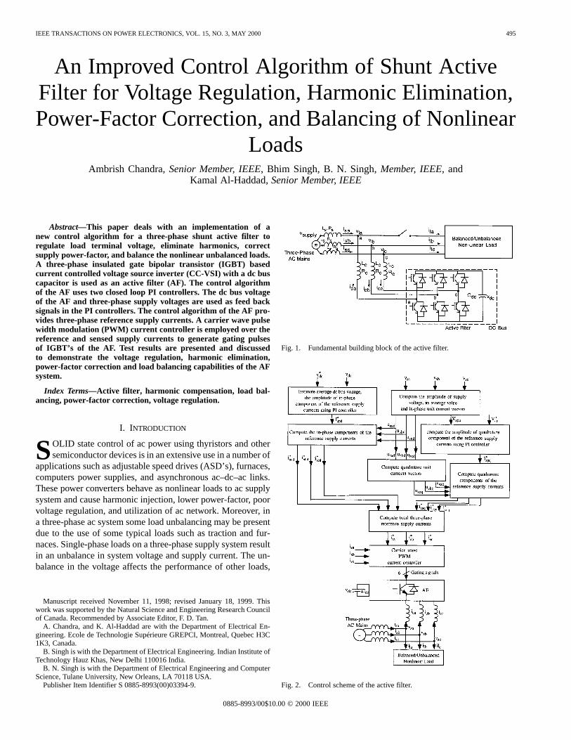
Fig. 1. Fundamental building block of the active filter.
Fig. 2. Control scheme of the active filter.
0885-8993/00$10.00 © 2000 IEEE
496 IEEE TRANSACTIONS ON POWER ELECTRONICS, VOL. 15, NO. 3, MAY 2000
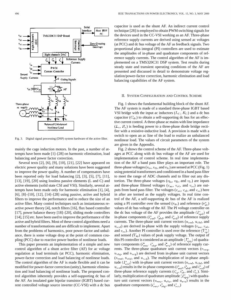
Fig. 3. Digital signal processing (DSP) system hardware of the active filter.
mainly the cage induction motors. In the past, a number of at-tempts have been made [1]–[28] on harmonic elimination, loadbalancing and power factor correction.
Several texts [2], [6], [9], [10], [21], [22] have appeared onelectric power quality and many solutions have been suggestedto improve the power quality. A number of compensators havebeen reported only for load balancing [2], [3], [5], [7], [11],[13], [19], [20] using lossless passive elements (L and C) andactive elements (solid state CSI and VSI). Similarly, several at-tempts have been made only for harmonic elimination [1], [4],[6], [8]–[10], [12], [14]–[28] using passive, active and hybridfilters to improve the performance and to reduce the size of anactive filter. Many control techniques such as instantaneous re-active power theory [4], notch filters [16], flux based controller[17], power balance theory [18]–[20], sliding mode controllers[14], [15] etc. have been used to improve the performance of theactive and hybrid filters. Most of these control algorithms need anumber of transformations and are difficult to implement. Apartfrom the problems of harmonics, poor power-factor and unbal-ance, there is some voltage drop at the point of common cou-pling (PCC) due to reactive power burden of nonlinear loads.
This paper presents an implementation of a simple and newcontrol algorithm of a shunt active filter (AF) for ac voltageregulation at load terminals (at PCC), harmonic elimination,power-factor correction and load balancing of nonlinear loads.The control algorithm of the AF is made flexible and it can bemodified for power-factor correction (unity), harmonic elimina-tion and load balancing of nonlinear loads. The proposed con-trol algorithm inherently provides a self-supporting dc bus ofthe AF. An insulated gate bipolar transistor (IGBT) based cur-rent controlled voltage source inverter (CC-VSI) with a dc bus
capacitor is used as the shunt AF. An indirect current controltechnique [28] is employed to obtain PWM switching signals forthe devices used in the CC-VSI working as an AF. Three-phasereference supply currents are derived using sensed ac voltages(at PCC) and dc bus voltage of the AF as feedback signals. Twoproportional plus integral (PI) controllers are used to estimatethe amplitudes of in-phase and quadrature components of ref-erence supply currents. The control algorithm of the AF is im-plemented on a TMS320C31 DSP system. Test results duringsteady state and transient operating conditions of the AF arepresented and discussed in detail to demonstrate voltage reg-ulation/power-factor correction, harmonic elimination and loadbalancing capabilities of the AF system.
II. SYSTEM CONFIGURATION AND CONTROL SCHEME
Fig. 1 shows the fundamental building block of the shunt AF.The AF system is made of a standard three-phase IGBT basedVSI bridge with the input ac inductors ( , ) and a dc buscapacitor ( ) to obtain a self-supporting dc bus for an effec-tive current control. A three-phase ac mains with line impedance( , ) is feeding power to a three-phase diode bridge recti-fier with a resistive-inductive load. A provision is made with aswitch to open an ac line of the load to realize an unbalancednonlinear load. The values of circuit parameters of the systemare given in the Appendix.
Fig. 2 shows the control scheme of the AF. Three-phase volt-ages at PCC along with dc bus voltage of the AF are used forimplementation of control scheme. In real time implementa-tion of the AF a band pass filter plays an important role. Thethree-phase voltages ( , , and ) are sensed at PCC (Fig. 1)using potential transformers and conditioned in a band pass filterto meet the range of ADC channels and to filter out any dis-tortion. The three-phase voltages (, , and ) are inputsand three-phase filtered voltages (, , and ) are out-puts from band pass filter. The voltages (, , and ) herein after are termed as the supply voltages. In real time con-trol of the AF, a self-supporting dc bus of the AF is realizedusing a PI controller over the sensed () and reference ( )values of dc bus voltage of the AF. The PI voltage controller onthe dc bus voltage of the AF provides the amplitude ofin-phase components ( , and ) of reference supplycurrents. The three-phase unit current vectors (, , and
) are derived in-phase with the supply voltages (, ,and ). Another PI controller is used over the referenceand sensed ( ) values of peak supply voltage. The output ofthis PI controller is considered as an amplitude of quadra-ture components ( , and ) of reference supply cur-rents. The three-phase quadrature unit current vectors (,
, and ) are derived from in-phase unit current vectors( , , and ). The multiplication of in-phase ampli-tude with in-phase unit current vectors ( , , and
) results in the in-phase components (, , and ) ofthree-phase reference supply currents (, , and ). Simi-larly, multiplication of quadrature amplitude with quadra-ture unit current vectors ( , , and ) results in thequadrature components ( , , and )
CHANDRA et al.: IMPROVED CONTROL ALGORITHM OF SHUNT ACTIVE FILTER 497
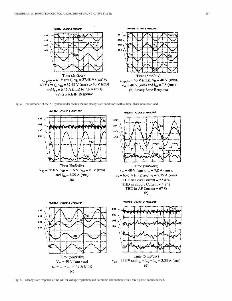
Fig. 4. Performance of the AF system under switch IN and steady state conditions with a three-phase nonlinear load.
Fig. 5. Steady state response of the AF for voltage regulation and harmonic elimination with a three-phase nonlinear load.
498 IEEE TRANSACTIONS ON POWER ELECTRONICS, VOL. 15, NO. 3, MAY 2000
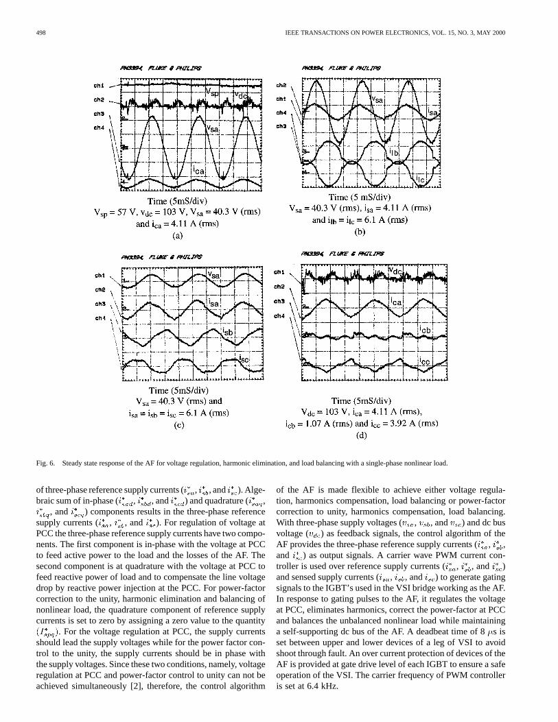
Fig. 6. Steady state response of the AF for voltage regulation, harmonic elimination, and load balancing with a single-phase nonlinear load.
of three-phase reference supply currents (, , and ). Alge-braic sum of in-phase ( , , and ) and quadrature ( ,
, and ) components results in the three-phase referencesupply currents ( , , and ). For regulation of voltage atPCC the three-phase reference supply currents have two compo-nents. The first component is in-phase with the voltage at PCCto feed active power to the load and the losses of the AF. Thesecond component is at quadrature with the voltage at PCC tofeed reactive power of load and to compensate the line voltagedrop by reactive power injection at the PCC. For power-factorcorrection to the unity, harmonic elimination and balancing ofnonlinear load, the quadrature component of reference supplycurrents is set to zero by assigning a zero value to the quantity
. For the voltage regulation at PCC, the supply currentsshould lead the supply voltages while for the power factor con-trol to the unity, the supply currents should be in phase withthe supply voltages. Since these two conditions, namely, voltageregulation at PCC and power-factor control to unity can not beachieved simultaneously [2], therefore, the control algorithm
of the AF is made flexible to achieve either voltage regula-tion, harmonics compensation, load balancing or power-factorcorrection to unity, harmonics compensation, load balancing.With three-phase supply voltages (, , and ) and dc busvoltage ( ) as feedback signals, the control algorithm of theAF provides the three-phase reference supply currents (, ,and ) as output signals. A carrier wave PWM current con-troller is used over reference supply currents (, , and )and sensed supply currents (, , and ) to generate gatingsignals to the IGBT’s used in the VSI bridge working as the AF.In response to gating pulses to the AF, it regulates the voltageat PCC, eliminates harmonics, correct the power-factor at PCCand balances the unbalanced nonlinear load while maintaininga self-supporting dc bus of the AF. A deadbeat time of 8s isset between upper and lower devices of a leg of VSI to avoidshoot through fault. An over current protection of devices of theAF is provided at gate drive level of each IGBT to ensure a safeoperation of the VSI. The carrier frequency of PWM controlleris set at 6.4 kHz.
CHANDRA et al.: IMPROVED CONTROL ALGORITHM OF SHUNT ACTIVE FILTER 499
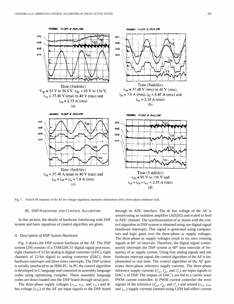
Fig. 7. Switch IN response of the AF for voltage regulation, harmonic elimination with a three-phase nonlinear load.
III. DSP HARDWARE AND CONTROL ALGORITHM
In this section, the details of hardware interfacing with DSPsystem and basic equations of control algorithm are given.
A. Description of DSP System Hardware
Fig. 3 shows the DSP system hardware of the AF. The DSPsystem [29] consists of a TSM320C31 digital signal processor,eight channels of 12 bit analog to digital converter (ADC), eightchannels of 12-bit digital to analog converter (DAC), threehardware interrupts and three timer interrupts. The DSP systemis serially interfaced to an IBM-PC. In PC the control algorithmis developed in C language and converted in assembly languagecodes using optimizing compiler. These assembly languagecodes are down loaded into the DSP board through serial port.
The three-phase supply voltages (, , and ) and dcbus voltage ( ) of the AF are input signals to the DSP board
through its ADC interface. The dc bus voltage of the AF issensed using an isolation amplifier (AD202) and scaled to feedto ADC channel. The synchronization of ac mains with the con-trol algorithm in DSP system is obtained using one digital signal(hardware interrupt). This signal is generated using compara-tors and logic gates over the three-phase ac supply voltages.The three-phase ac supply voltages result in six zero crossingsignals at 60 of intervals. Therefore, the digital signal contin-uously interrupts the DSP system at 60time intervals of fre-quency of ac supply system. Using four analog signals and onehardware interrupt signal, the control algorithm of the AF is im-plemented in real time. The control algorithm of the AF gen-erates three-phase reference supply currents. The three-phasereference supply currents (, , and ) are input signals toDAC’s of DSP. The outputs of DAC’s are fed to a carrier wavePWM current controller. In PWM current controller the errorsignals of the reference ( , , and ) and sensed ( , ,and ) supply currents (sensed using LEM hall-effect current
500 IEEE TRANSACTIONS ON POWER ELECTRONICS, VOL. 15, NO. 3, MAY 2000
Fig. 8. Switch IN response of the AF for voltage regulation, harmonic elimination and load balancing with a single-phase nonlinear load.
sensors) are compared with a carrier signals resulting in gatingpulses for the IGBT’s of the AF.
B. Basic Equations of Control Algorithm of the AF
The three-phase reference supply currents are computedusing three-phase supply voltages and dc bus voltage of the AF.These reference supply currents consist of two components, onein-phase and another in quadrature with the supply voltages.
1) Computation of In-Phase Components of ReferenceSupply Currents:The amplitude of in-phase componentof reference supply currents is computed using PI controllerover the average value of dc bus voltage () of the AF andits reference counterpart . Comparison of average andreference values of dc bus voltage of the AF results in a voltageerror, which is expressed as, , at th sampling instant
(1)
The error signal, , is processed in PI controller and outputat th sampling instant is expressed as
(2)
where and are proportional and integral gains ofthe dc bus voltage PI controller. The quantities, and
are the output of the voltage controller and voltageerror, respectively, at th sampling instant. The output
of PI controller is taken as amplitude of in-phasecomponent of the reference supply currents.
Three-phase in-phase components of the reference supplycurrents are computed using their amplitude and in-phaseunit current vectors derived in-phase with the supply voltages
and (3)
CHANDRA et al.: IMPROVED CONTROL ALGORITHM OF SHUNT ACTIVE FILTER 501
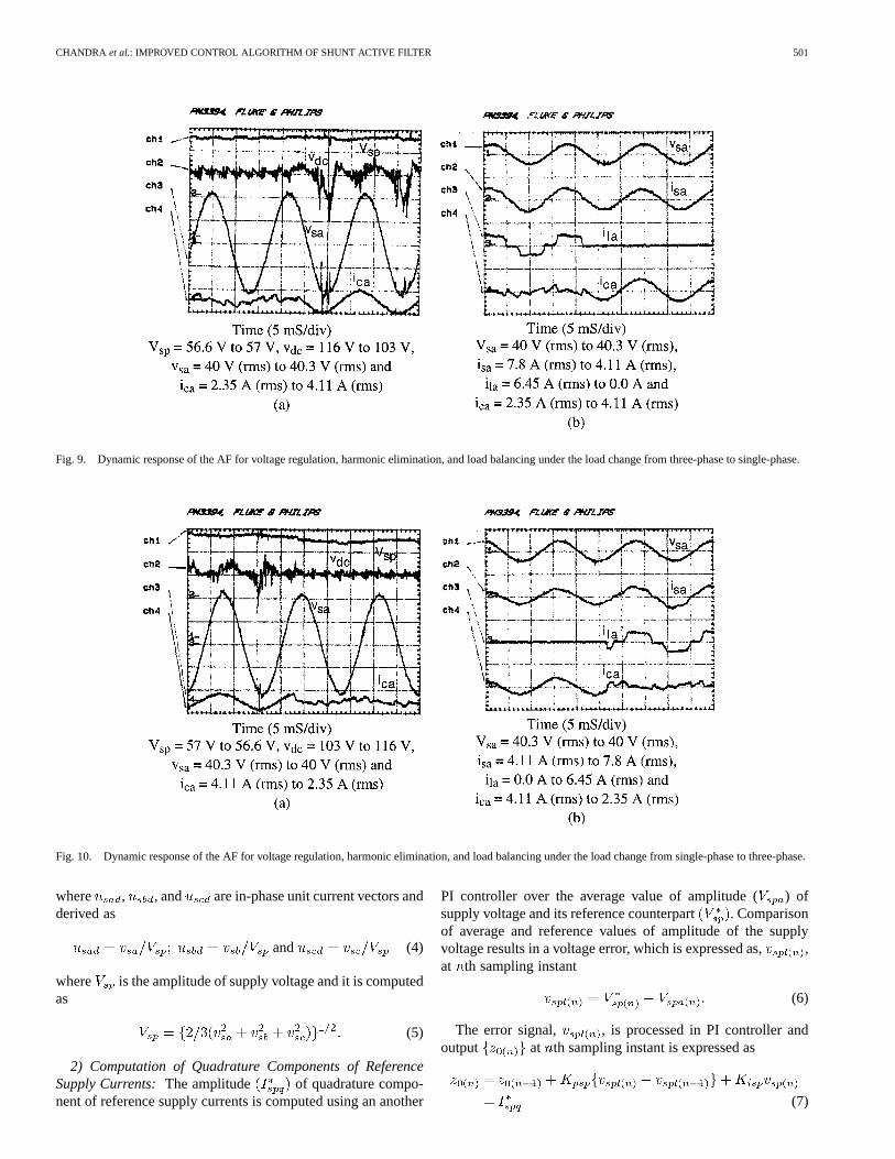
Fig. 9. Dynamic response of the AF for voltage regulation, harmonic elimination, and load balancing under the load change from three-phase to single-phase.
Fig. 10. Dynamic response of the AF for voltage regulation, harmonic elimination, and load balancing under the load change from single-phase to three-phase.
where , , and are in-phase unit current vectors andderived as
and (4)
where is the amplitude of supply voltage and it is computedas
(5)
2) Computation of Quadrature Components of ReferenceSupply Currents:The amplitude of quadrature compo-nent of reference supply currents is computed using an another
PI controller over the average value of amplitude ( ) ofsupply voltage and its reference counterpart . Comparisonof average and reference values of amplitude of the supplyvoltage results in a voltage error, which is expressed as, ,at th sampling instant
(6)
The error signal, , is processed in PI controller andoutput at th sampling instant is expressed as
(7)
502 IEEE TRANSACTIONS ON POWER ELECTRONICS, VOL. 15, NO. 3, MAY 2000
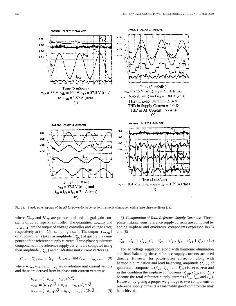
Fig. 11. Steady state response of the AF for power-factor correction, harmonic elimination with a three-phase nonlinear load.
where and are proportional and integral gain con-stants of ac voltage PI controller. The quantities, and
are the output of voltage controller and voltage error,respectively, at ( )th sampling instant. The outputof PI controller is taken as amplitude of quadrature com-ponent of the reference supply currents. Three-phase quadraturecomponents of the reference supply currents are computed usingtheir amplitude and quadrature unit current vectors as
and (8)
where , , and are quadrature unit current vectorsand these are derived from in-phase unit current vectors as
(9)
3) Computation of Total Reference Supply Currents:Three-phase instantaneous reference supply currents are computed byadding in-phase and quadrature components expressed in (3)and (8)
(10)
For ac voltage regulation along with harmonic eliminationand load balancing these reference supply currents are useddirectly. However, for power-factor correction along withharmonic elimination and load balancing, amplitude ofquadrature components ( , , and ) is set to zero andin this condition the in-phase components (, , and )become the total reference supply currents (, , and ).However, by giving a proper weight-age to two components ofreference supply currents a reasonably good compromise maybe achieved.
CHANDRA et al.: IMPROVED CONTROL ALGORITHM OF SHUNT ACTIVE FILTER 503
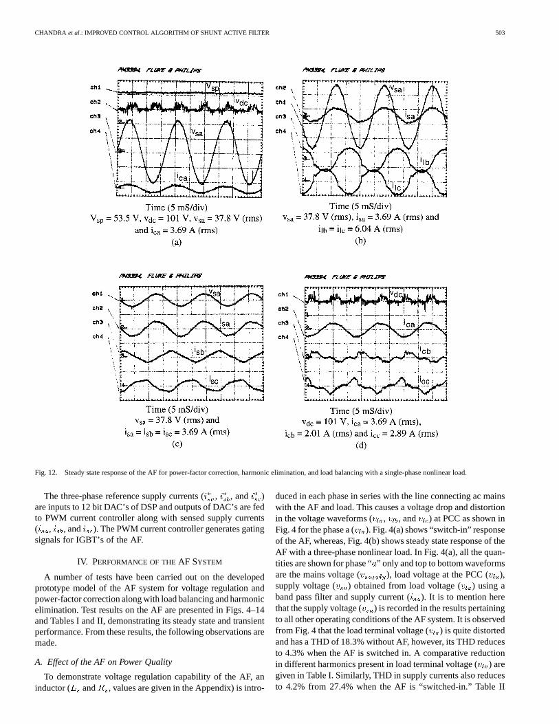
Fig. 12. Steady state response of the AF for power-factor correction, harmonic elimination, and load balancing with a single-phase nonlinear load.
The three-phase reference supply currents (, , and )are inputs to 12 bit DAC’s of DSP and outputs of DAC’s are fedto PWM current controller along with sensed supply currents( , , and ). The PWM current controller generates gatingsignals for IGBT’s of the AF.
IV. PERFORMANCE OF THEAF SYSTEM
A number of tests have been carried out on the developedprototype model of the AF system for voltage regulation andpower-factor correction along with load balancing and harmonicelimination. Test results on the AF are presented in Figs. 4–14and Tables I and II, demonstrating its steady state and transientperformance. From these results, the following observations aremade.
A. Effect of the AF on Power Quality
To demonstrate voltage regulation capability of the AF, aninductor ( and , values are given in the Appendix) is intro-
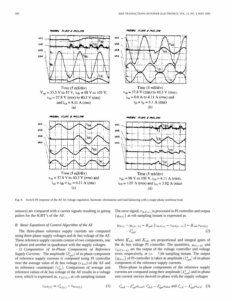
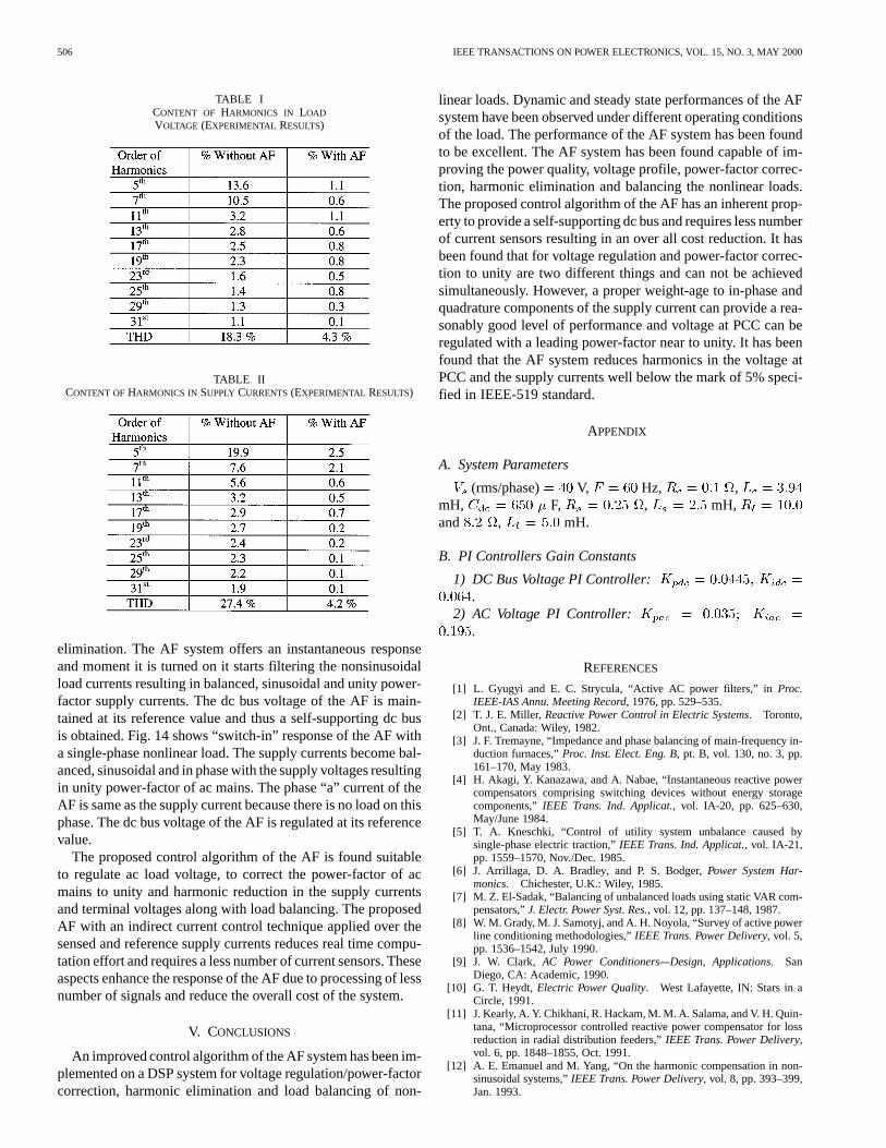
duced in each phase in series with the line connecting ac mainswith the AF and load. This causes a voltage drop and distortionin the voltage waveforms ( , , and ) at PCC as shown inFig. 4 for the phase a ( ). Fig. 4(a) shows “switch-in” responseof the AF, whereas, Fig. 4(b) shows steady state response of theAF with a three-phase nonlinear load. In Fig. 4(a), all the quan-tities are shown for phase “” only and top to bottom waveformsare the mains voltage ( ), load voltage at the PCC ( ),supply voltage ( ) obtained from load voltage ( ) using aband pass filter and supply current (). It is to mention herethat the supply voltage ( ) is recorded in the results pertainingto all other operating conditions of the AF system. It is observedfrom Fig. 4 that the load terminal voltage () is quite distortedand has a THD of 18.3% without AF, however, its THD reducesto 4.3% when the AF is switched in. A comparative reductionin different harmonics present in load terminal voltage () aregiven in Table I. Similarly, THD in supply currents also reducesto 4.2% from 27.4% when the AF is “switched-in.” Table II
504 IEEE TRANSACTIONS ON POWER ELECTRONICS, VOL. 15, NO. 3, MAY 2000
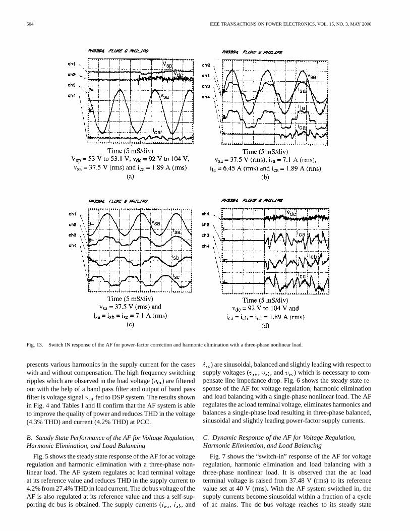
Fig. 13. Switch IN response of the AF for power-factor correction and harmonic elimination with a three-phase nonlinear load.
presents various harmonics in the supply current for the caseswith and without compensation. The high frequency switchingripples which are observed in the load voltage () are filteredout with the help of a band pass filter and output of band passfilter is voltage signal fed to DSP system. The results shownin Fig. 4 and Tables I and II confirm that the AF system is ableto improve the quality of power and reduces THD in the voltage(4.3% THD) and current (4.2% THD) at PCC.
B. Steady State Performance of the AF for Voltage Regulation,Harmonic Elimination, and Load Balancing
Fig. 5 shows the steady state response of the AF for ac voltageregulation and harmonic elimination with a three-phase non-linear load. The AF system regulates ac load terminal voltageat its reference value and reduces THD in the supply current to4.2% from 27.4% THD in load current. The dc bus voltage of theAF is also regulated at its reference value and thus a self-sup-porting dc bus is obtained. The supply currents (, , and
) are sinusoidal, balanced and slightly leading with respect tosupply voltages ( , , and ) which is necessary to com-pensate line impedance drop. Fig. 6 shows the steady state re-sponse of the AF for voltage regulation, harmonic eliminationand load balancing with a single-phase nonlinear load. The AFregulates the ac load terminal voltage, eliminates harmonics andbalances a single-phase load resulting in three-phase balanced,sinusoidal and slightly leading power-factor supply currents.
C. Dynamic Response of the AF for Voltage Regulation,Harmonic Elimination, and Load Balancing
Fig. 7 shows the “switch-in” response of the AF for voltageregulation, harmonic elimination and load balancing with athree-phase nonlinear load. It is observed that the ac loadterminal voltage is raised from 37.48 V (rms) to its referencevalue set at 40 V (rms). With the AF system switched in, thesupply currents become sinusoidal within a fraction of a cycleof ac mains. The dc bus voltage reaches to its steady state

CHANDRA et al.: IMPROVED CONTROL ALGORITHM OF SHUNT ACTIVE FILTER 505
Fig. 14. Switch IN response of the AF for power-factor correction, harmonic elimination, and load balancing with a single-phase nonlinear load.
value almost instantaneously due to fast dynamic response ofthe AF system. Fig. 8 shows the “switch-in” response of theAF with a single-phase nonlinear load. The supply currentsbecome sinusoidal and balanced almost instantaneously whichconfirms fast response of the AF. The ac load terminal voltageand dc bus voltage of the AF reach to their respective desiredvalues within a cycle of the ac mains.
Fig. 9 shows the dynamic response of the AF for a loadchange from three-phase to single-phase. The ac load terminalvoltage remains unaffected and the supply currents are reducedin amplitude but remain sinusoidal, balanced and slightlyleading with respect to supply voltages. Similarly, Fig. 10shows the dynamic response of the AF when a single-phasenonlinear load is changed to a three-phase. The three-phasesupply currents are observed with an increased amplitude butremain sinusoidal, balanced and slightly leading with respect tosupply voltage which is necessary to regulate ac load terminalvoltage.
D. Steady State Performance of the AF for Power-FactorCorrection, Harmonic Elimination, and Load Balancing
Fig. 11 shows the steady state response of the AF with athree-phase nonlinear load for power-factor correction and har-monic elimination. The AF is able to reduce harmonics in thesupply currents (THD 4.0% from 27.4%) and it improves thesupply power-factor to unity. The supply currents are balanced,sinusoidal and in-phase with the voltages. Fig. 12 shows thesteady state response of the AF with a single-phase nonlinearload. It is observed that the AF is able to balance a nonlinearsingle-phase load resulting in sinusoidal, balanced and unitypower-factor supply currents. The control algorithm also pro-vides a self-supporting dc bus of the AF.
E. Dynamic Performance of the AF for Power-FactorCorrection, Harmonic Elimination, and Load Balancing
Fig. 13 shows “switch-in” response of the AF with a three-phase nonlinear load for power-factor correction and harmonic
506 IEEE TRANSACTIONS ON POWER ELECTRONICS, VOL. 15, NO. 3, MAY 2000
TABLE ICONTENT OF HARMONICS IN LOAD
VOLTAGE (EXPERIMENTAL RESULTS)
TABLE IICONTENT OFHARMONICS IN SUPPLY CURRENTS(EXPERIMENTAL RESULTS)
elimination. The AF system offers an instantaneous responseand moment it is turned on it starts filtering the nonsinusoidalload currents resulting in balanced, sinusoidal and unity power-factor supply currents. The dc bus voltage of the AF is main-tained at its reference value and thus a self-supporting dc busis obtained. Fig. 14 shows “switch-in” response of the AF witha single-phase nonlinear load. The supply currents become bal-anced, sinusoidal and in phase with the supply voltages resultingin unity power-factor of ac mains. The phase “a” current of theAF is same as the supply current because there is no load on thisphase. The dc bus voltage of the AF is regulated at its referencevalue.
The proposed control algorithm of the AF is found suitableto regulate ac load voltage, to correct the power-factor of acmains to unity and harmonic reduction in the supply currentsand terminal voltages along with load balancing. The proposedAF with an indirect current control technique applied over thesensed and reference supply currents reduces real time compu-tation effort and requires a less number of current sensors. Theseaspects enhance the response of the AF due to processing of lessnumber of signals and reduce the overall cost of the system.
V. CONCLUSIONS
An improved control algorithm of the AF system has been im-plemented on a DSP system for voltage regulation/power-factorcorrection, harmonic elimination and load balancing of non-
linear loads. Dynamic and steady state performances of the AFsystem have been observed under different operating conditionsof the load. The performance of the AF system has been foundto be excellent. The AF system has been found capable of im-proving the power quality, voltage profile, power-factor correc-tion, harmonic elimination and balancing the nonlinear loads.The proposed control algorithm of the AF has an inherent prop-erty to provide a self-supporting dc bus and requires less numberof current sensors resulting in an over all cost reduction. It hasbeen found that for voltage regulation and power-factor correc-tion to unity are two different things and can not be achievedsimultaneously. However, a proper weight-age to in-phase andquadrature components of the supply current can provide a rea-sonably good level of performance and voltage at PCC can beregulated with a leading power-factor near to unity. It has beenfound that the AF system reduces harmonics in the voltage atPCC and the supply currents well below the mark of 5% speci-fied in IEEE-519 standard.
APPENDIX
A. System Parameters
(rms/phase) V, Hz, ,mH, F, , mH,and , mH.
B. PI Controllers Gain Constants
1) DC Bus Voltage PI Controller:.
2) AC Voltage PI Controller:.
REFERENCES
[1] L. Gyugyi and E. C. Strycula, “Active AC power filters,” inProc.IEEE-IAS Annu. Meeting Record, 1976, pp. 529–535.
[2] T. J. E. Miller, Reactive Power Control in Electric Systems. Toronto,Ont., Canada: Wiley, 1982.
[3] J. F. Tremayne, “Impedance and phase balancing of main-frequency in-duction furnaces,”Proc. Inst. Elect. Eng. B, pt. B, vol. 130, no. 3, pp.161–170, May 1983.
[4] H. Akagi, Y. Kanazawa, and A. Nabae, “Instantaneous reactive powercompensators comprising switching devices without energy storagecomponents,”IEEE Trans. Ind. Applicat., vol. IA-20, pp. 625–630,May/June 1984.
[5] T. A. Kneschki, “Control of utility system unbalance caused bysingle-phase electric traction,”IEEE Trans. Ind. Applicat., vol. IA-21,pp. 1559–1570, Nov./Dec. 1985.
[6] J. Arrillaga, D. A. Bradley, and P. S. Bodger,Power System Har-monics. Chichester, U.K.: Wiley, 1985.
[7] M. Z. El-Sadak, “Balancing of unbalanced loads using static VAR com-pensators,”J. Electr. Power Syst. Res., vol. 12, pp. 137–148, 1987.
[8] W. M. Grady, M. J. Samotyj, and A. H. Noyola, “Survey of active powerline conditioning methodologies,”IEEE Trans. Power Delivery, vol. 5,pp. 1536–1542, July 1990.
[9] J. W. Clark, AC Power Conditioners—Design, Applications. SanDiego, CA: Academic, 1990.
[10] G. T. Heydt,Electric Power Quality. West Lafayette, IN: Stars in aCircle, 1991.
[11] J. Kearly, A. Y. Chikhani, R. Hackam, M. M. A. Salama, and V. H. Quin-tana, “Microprocessor controlled reactive power compensator for lossreduction in radial distribution feeders,”IEEE Trans. Power Delivery,vol. 6, pp. 1848–1855, Oct. 1991.
[12] A. E. Emanuel and M. Yang, “On the harmonic compensation in non-sinusoidal systems,”IEEE Trans. Power Delivery, vol. 8, pp. 393–399,Jan. 1993.

CHANDRA et al.: IMPROVED CONTROL ALGORITHM OF SHUNT ACTIVE FILTER 507
[13] V. B. Bhavaraju and P. N. Enjeti, “Analysis and design of an active powerfilter for balancing unbalanced loads,”IEEE Trans. Power Electron., vol.8, pp. 640–647, Oct. 1993.
[14] S. Saetieo, R. Devaraj, and D. A. Torrey, “The design and implementa-tion of a three-phase active power filter based on sliding mode control,”IEEE Trans. Ind. Applicat., vol. 31, pp. 993–1000, Sept./Oct. 1995.
[15] B. Singh, K. Al-Haddad, and A. Chandra, “Active power filter withsliding mode control,” inProc. Inst. Elect. Eng., Generation, Transm.,Distrib., vol. 144, Nov. 1997, pp. 564–568.
[16] M. Rastogi, N. Mohan, and A. A. Edris, “Hybrid-active filtering of har-monic currents in power systems,”IEEE Trans. Power Delivery, vol. 10,pp. 1994–2000, Oct. 1995.
[17] S. Bhattacharya, A. Veltman, D. M. Divan, and R. D. Lorenz, “Fluxbased active filter controller,” inProc. IEEE-IAS Annu. Meeting Record,1995, pp. 2483–2491.
[18] H. L. Jou, “Performance comparison of the three-phase active powerfilter algorithms,” inProc. Inst. Elect. Eng., Generation, Transm, Dis-trib., vol. 142, Nov. 1995, pp. 646–652.
[19] J. W. Dixon, J. J. Garcia, and L. Moran, “Control system for three-phaseactive power filter which simultaneously compensates power-factor andunbalanced loads,”IEEE Trans. Ind. Electron., vol. 42, pp. 636–641,Dec. 1995.
[20] B. Singh, K. Al-Haddad, and A. Chandra, “A new control approach tothree-phase active filter for harmonics and reactive power compensa-tion,” IEEE Trans. Power Syst., vol. 13, pp. 133–138, Feb. 1998.
[21] D. A. Paice, Power Electronic Converter Harmonics—MultipulseMethods for Clean Power. New York: IEEE Press, 1996.
[22] R. C. Dugan, M. F. McGranaghan, and H. W. Beaty,Electrical PowerSystems Quality. New York: McGraw-Hill, 1996.
[23] J. Hafner, M. Aredes, and K. Neumann, “A shunt active power filterapplied to high voltage distribution lines,”IEEE Trans. Power Delivery,vol. 12, pp. 266–272, Jan. 1997.
[24] B. Singh, K. Al-Haddad, and A. Chandra, “Harmonic elimination,reactive power compensation and load balancing in three-phase, fourwire electric distribution systems supplying nonlinear loads,”J. ElectricPower Syst. Res., vol. 44, pp. 93–100, 1998.
[25] H. Akagi, “Control strategy and site selection of a shunt active filter fordamping of harmonic propagation in power distribution systems,”IEEETrans. Power Delivery, vol. 12, pp. 354–363, Jan. 1997.
[26] M. Aredes, K. Heumann, and E. H. Watanabe, “An universal activepower line conditioner,”IEEE Trans. Power Delivery, vol. 13, pp.545–551, Apr. 1998.
[27] P. T. Cheng, S. Bhattacharya, and D. M. Divan, “Control of square-waveinverters in high-power hybrid active filter systems,”IEEE Trans. Ind.Applicat., vol. 34, pp. 458–472, May/June 1998.
[28] B. N. Singh, A. Chandra, and K. Al-Haddad, “Performance comparisonof two current control techniques applied to an active filter,” inProc. 8thInt. Conf. Harmonics Quality Power ICHQP’98, vol. I, Athens, Greece,Oct. 14–16, 1998, pp. 133–138.
[29] MX31 Modular Embedded System Developer’s Guide, Sunnyvale, CA,1992.
Ambrish Chandra (SM’87) was born in Indiain 1955. He received the B.E. degree from theUniversity of Roorkee, India, in 1977, the M.Tech.degree from I.I.T., New Delhi, India, in 1980, andthe Ph.D. degree from the University of Calgary,Calgary, Alta., Canada, in 1987.
He worked as a Lecturer and later as a Readerat the University of Roorkee. He is a Professor inthe Electrical Engineering Department, Ecole deTechnologie Supérieure, Montreal, Que., Canada.His main research interests are power quality, active
filters, reactive power compensation, and FACTS.
Bhim Singh was born in Rahamapur, U.P., Indiain 1956. He received the B.E. degree from theUniversity of Roorkee, India, in 1977 and theM.Tech. and Ph.D. degrees from the Indian Instituteof Technology (IIT), New Delhi, in 1979 and 1983,respectively.
In 1983, he started working as a Lecturer and,in 1988 became a Reader in the Department ofElectrical Engineering, University of Roorkee.In December 1990, he started as an AssistantProfessor, became an Associate Professor in the
Department of Electrical Engineering, IIT, in 1994, and a Professor in 1997.His field of interest includes CAD, power electronics, active filters, static VARcompensation, analysis, and digital control of electrical machines.
Dr. Singh is a Fellow of IE(I) and IETE and a Life Member of ISTE, SSI, andNIQR.
B. N. Singh (M’98) was born in 1968. He receivedthe B.E. degree from M.M.M. Engineering College,Gorakhpur, India, in 1989, the M.E. degree from theUniversity of Roorkee, India, in 1991, and the Ph.D.degree from Indian Institute of Technology, NewDelhi, in 1996.
In September 1996, he joined the Departmentof Electrical Engineering, École de TechnologieSupérieure, Montréal, P.Q., Canada, as a Postdoc-toral Fellow, where he worked in the area of activefilters, UPFC, and FACTS. In February 1999, he
joined the Department of Electrical and Computer Engineering, ConcordiaUniversity, Montreal, as a Research Fellow, where he worked in the area ofpower supplies for telecommunication system. Recently, he joined the Depart-ment of Electrical Engineering and Computer Science, Tulane University, NewOrleans, LA, as an Assistant Professor. His main research interests are powersupplies, power electronics, power systems, electrical machines, and drives.
Kamal Al-Haddad (S’82–M’88–SM’92) was bornin Beirut, Lebanon, in 1954. He received the B.Sc.A.and the M.Sc.A. degrees from the Université duQuébec à Trois-Rivières, P.Q., Canada, in 1982 and1984, respectively, and the Ph.D. degree from theInstitut National Polytechnique, Toulouse, France,in 1988.
From June 1987 to June 1990, he was a Professorin the Engineering Department, Université duQuébec, Trois-Rivières. In June 1990, he joinedthe teaching staff as a Professor in the Electrical
Engineering Department, École de Technologie Supérieure, Université duQuébec, Montreal, P.Q. His fields of interest are static power converters,harmonics, and reactive power control, switch mode and resonant converters,including the modeling, control, and development of industrial prototypes forvarious applications.
Dr. Al-Haddad is a member of the Order of Engineering of Québec and theCanadian Institute of Engineers.