
An improved 3D shape context based non-rigid registration method and its application to small animal...
16
An improved 3D shape context based non-rigid registration method and its application to small animal skeletons registration Di Xiao 1 , David Zahra 2 , Pierrick Bourgeat 1 , Paula Berghofer 2 , Oscar Acosta Tamayo 1 , Catriona Wimberley 2 , Marie Claude Gregoire 2 , Olivier Salvado 1 1 Australian e-Health Research Center, ICTC, CSIRO, Australia 2 Radiopharmaceutical Research Institute, ANSTO, Australia Abstract. 3D shape context is a method to define matching points between similar shapes as a pre-processing step to non-rigid registration. The main limitation of the approach is point mismatching, which includes long geodesic distance mismatch causing wrong topological structure, and neighbors crossing mismatch between two adjacent points. In this paper, we propose a topological structure verification method to correct the long geodesic distance mismatch and a correspondence field smoothing method to correct the neighbors crossing mismatch. A robust 3D shape context model is generated and further combined with thin-plate spline model for non-rigid registration. The method was tested on phantoms and applied to rat hind limb and mouse hind limb skeletons registration from micro CT images. Errors between registered surfaces were reduced using the proposed method. The robustness of the method is demonstrated. Keywords: 3D Shape context, non-rigid registration, small animal skeleton registration, micro-CT images 1 Introduction Small animal imaging is increasingly used as a pre-clinical tool to identify new imaging agent, or assess effectiveness of therapy. This involves scanning a cohort of small rodents (typically mice and rats), and computing population statistics. Positron Emission Tomography (PET) scans are now often installed with a micro-CT scans to provide some anatomical information absent on the PET. One challenging step to study a large numbers of individual animals is performing spatial normalization. From the information present in the micro-CT, scans need to be warped to a template, before subsequent processing. Easily identifiable and robust anatomical features presented in CT images are the skeleton, the lungs and the skin surface. The problem, we are trying to solve in this study, is the automatic non-linear registration of different animal skeletons extracted from micro-CT, using a surface matching technique. Point matching based surface registration, using 3D shape context has recently emerged as an alternative to intensity bases non-linear registration [1]. Given a set of points on a surface, 3D shape context provide the corresponding point locations on a target surface. Once the matching is established, warping of one surface to the other can be performed with a smooth deformation model, such as thin-plate spline. Applying the deformation field to the whole volume allows deforming the whole animal to match a given template, assuming that soft tissues would be deform realistically once the skeletons are matched. Shape context was originally proposed by Belongie et al for 2D graph matching [2], as it provided an effective way to compute the similarity between two clouds of points. It was later extended [3] for measuring similarity between shapes and exploiting it for object recognition. Mori et al. [4, 5] demonstrated its ability for quick search for 2D similar shapes. Carneiro et al. [6] applied it to improve the distinctiveness of local image features. Yusuf et al. [7, 8] applied it for handwritten Urdu digit recognition and got zero percent error on their 28 test digits. Liu et al. [9] extended shape context to shape context pattern and applied it for feature point matching on Chinese character images by eigenvector analysis. Yang et al. [10] integrated shape context based recognition into image segmentation for 2D image segmentation. Nguyen et al. [11] used shape context descriptor computed on interest points for graphic symbol representation. A series of efforts were made for improving the performance of shape context for object recognition. Singh et al. [12] proposed an enhanced shape context by identifying corner points on object contours as landmarks, thereby reducing the number of points for shape context calculation and providing a fast object recognition method. Thayananthan et al. [13] added a figural continuity constraint. A combined shape and continuity cost was used for correspondence finding, thereby improving the robustness of shape context for object recognition in cluttered scenes. Urschler et al. [1] incorporated local grey value information from images, normalized cross correlation of neighborhood grey values between points, into shape context. The additional term added robustness against segmentation errors.
-
Upload
independent -
Category
Documents
-
view
5 -
download
0
Transcript of An improved 3D shape context based non-rigid registration method and its application to small animal...
An improved 3D shape context based non-rigid registration method and its application to small animal skeletons registration
Di Xiao1, David Zahra2, Pierrick Bourgeat1, Paula Berghofer2, Oscar Acosta Tamayo1, Catriona Wimberley2, Marie Claude Gregoire2, Olivier Salvado1
1Australian e-Health Research Center, ICTC, CSIRO, Australia 2Radiopharmaceutical Research Institute, ANSTO, Australia
Abstract. 3D shape context is a method to define matching points between similar shapes as a pre-processing step to non-rigid registration. The main limitation of the approach is point mismatching, which includes long geodesic distance mismatch causing wrong topological structure, and neighbors crossing mismatch between two adjacent points. In this paper, we propose a topological structure verification method to correct the long geodesic distance mismatch and a correspondence field smoothing method to correct the neighbors crossing mismatch. A robust 3D shape context model is generated and further combined with thin-plate spline model for non-rigid registration. The method was tested on phantoms and applied to rat hind limb and mouse hind limb skeletons registration from micro CT images. Errors between registered surfaces were reduced using the proposed method. The robustness of the method is demonstrated.
Keywords: 3D Shape context, non-rigid registration, small animal skeleton registration, micro-CT images
1 Introduction
Small animal imaging is increasingly used as a pre-clinical tool to identify new imaging agent, or assess effectiveness of therapy. This involves scanning a cohort of small rodents (typically mice and rats), and computing population statistics. Positron Emission Tomography (PET) scans are now often installed with a micro-CT scans to provide some anatomical information absent on the PET. One challenging step to study a large numbers of individual animals is performing spatial normalization. From the information present in the micro-CT, scans need to be warped to a template, before subsequent processing. Easily identifiable and robust anatomical features presented in CT images are the skeleton, the lungs and the skin surface. The problem, we are trying to solve in this study, is the automatic non-linear registration of different animal skeletons extracted from micro-CT, using a surface matching technique.
Point matching based surface registration, using 3D shape context has recently emerged as an alternative to intensity bases non-linear registration [1]. Given a set of points on a surface, 3D shape context provide the corresponding point locations on a target surface. Once the matching is established, warping of one surface to the other can be performed with a smooth deformation model, such as thin-plate spline. Applying the deformation field to the whole volume allows deforming the whole animal to match a given template, assuming that soft tissues would be deform realistically once the skeletons are matched.
Shape context was originally proposed by Belongie et al for 2D graph matching [2], as it provided an effective way to compute the similarity between two clouds of points. It was later extended [3] for measuring similarity between shapes and exploiting it for object recognition. Mori et al. [4, 5] demonstrated its ability for quick search for 2D similar shapes. Carneiro et al. [6] applied it to improve the distinctiveness of local image features. Yusuf et al. [7, 8] applied it for handwritten Urdu digit recognition and got zero percent error on their 28 test digits. Liu et al. [9] extended shape context to shape context pattern and applied it for feature point matching on Chinese character images by eigenvector analysis. Yang et al. [10] integrated shape context based recognition into image segmentation for 2D image segmentation. Nguyen et al. [11] used shape context descriptor computed on interest points for graphic symbol representation.
A series of efforts were made for improving the performance of shape context for object recognition. Singh et al. [12] proposed an enhanced shape context by identifying corner points on object contours as landmarks, thereby reducing the number of points for shape context calculation and providing a fast object recognition method. Thayananthan et al. [13] added a figural continuity constraint. A combined shape and continuity cost was used for correspondence finding, thereby improving the robustness of shape context for object recognition in cluttered scenes. Urschler et al. [1] incorporated local grey value information from images, normalized cross correlation of neighborhood grey values between points, into shape context. The additional term added robustness against segmentation errors.
A further application in 3D includes recovering 3D human body configuration [14, 15], human body pose [16, 17] and
human action recognition [18, 19]. However, these 3D applications used a temporal state which was added as an extra feature but the shape contexts were still calculated in 2D space.
A first 3D shape context was built by Kortgen et al [20] for measuring 3D shape similarity. Urschler et al. [1, 21, 22] extended 2D shape context to 3D and firstly applied it in image registration area for lung surfaces and thoracic registration from CT images. Di et al. [23] added surface curvature information from shapes to improve the performance of 3D shape context based surface registration.
One of limitations of shape context for point matching is that the significant amount of point mismatching may occur between two objects while their similarity is low both globally and locally, and the existence of outliers. The point mismatching issue was pointed out in [13, 24] for 2D object recognition and also existed in 3D shape context point matching [21]. In 3D shape context based registration, a straight forward solution for point mismatching is to remove percentage of the highest cost correspondences [1, 21, 23]. In this paper, we address the issue of point matching by correcting point correspondences prior to computing surface deformation. We classify point mismatch into two types: long geodesic distance mismatch and neighbors crossing mismatch. We propose to first correct long geodesic distance mismatch, before applying a smoothing filter to correct neighboring mismatches. The result is a quasi topologically preserving correspondence mapping between source and target surfaces. We further test the improved 3D shape context method on phantoms and applied it to rat and mouse hind limb skeletons registration. The paper is organized as the follows. In section 2, a 3D shape context based non-rigid registration is proposed and its limitations are pointed. Two point mismatching correction methods are proposed to improve the 3D shape context based registration method. In section 3, the improved method is tested on phantoms and rat hind limb skeletons. The performance of the algorithm is evaluated on synthetic hind limb skeletons and real rat and mouse hind limb data. A conclusion is given in section 4.
2 Method
2.1 3D shape context based non-rigid registration
Shape context
The shape context of a point is a measure of the distribution of relative positions of neighbouring points. The distribution is defined as a joint histogram where each histogram axis represents a parameter in polar coordinates. In implementation, bins around each point are defined. The number of the neighboring points in these bins is assimilated as a context to the point. In 2D shape context, a point histogram is built based on 2D polar coordinate system as shown in Fig. 1. In 3D shape context, a point histogram is built based on 3D spherical coordinate system as shown in Fig. 2. Along radial direction, bins are arranged uniformly in log-polar space which makes it more sensitive to positions of nearby points than to those of remaining points farther away. If there are i bins for the radius, j bins for azimuth and k bins
for elevation, there are Lkji =×× bins for the 3D shape context in total.
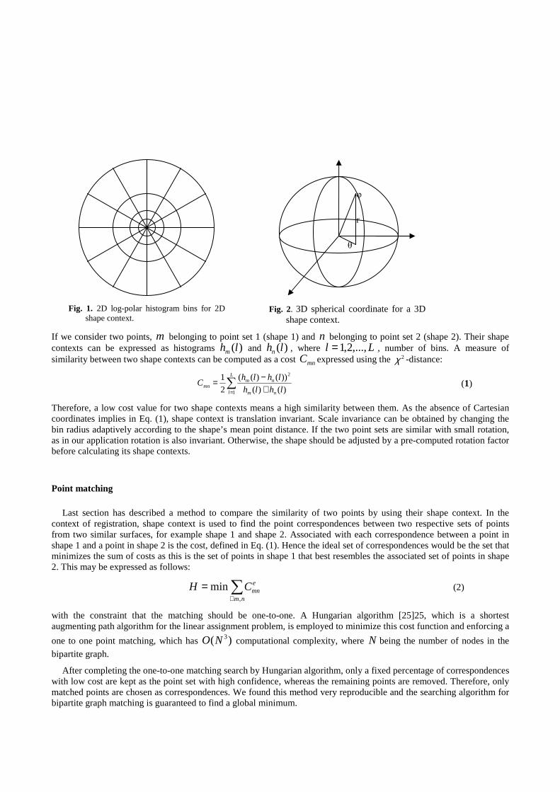
Fig. 1. 2D log-polar histogram bins for 2D shape context.
Fig. 2. 3D spherical coordinate for a 3D shape context.
If we consider two points, m belonging to point set 1 (shape 1) and n belonging to point set 2 (shape 2). Their shape contexts can be expressed as histograms )(lhm and )(lhn , where Ll ,...,2,1= , number of bins. A measure of similarity between two shape contexts can be computed as a cost mnC expressed using the 2χ -distance:
∑= +
−=L
l nm
nmmn lhlh
lhlhC
1
2
)()(
))()((
2
1 (1)
Therefore, a low cost value for two shape contexts means a high similarity between them. As the absence of Cartesian coordinates implies in Eq. (1), shape context is translation invariant. Scale invariance can be obtained by changing the bin radius adaptively according to the shape’s mean point distance. If the two point sets are similar with small rotation, as in our application rotation is also invariant. Otherwise, the shape should be adjusted by a pre-computed rotation factor before calculating its shape contexts.
Point matching
Last section has described a method to compare the similarity of two points by using their shape context. In the context of registration, shape context is used to find the point correspondences between two respective sets of points from two similar surfaces, for example shape 1 and shape 2. Associated with each correspondence between a point in shape 1 and a point in shape 2 is the cost, defined in Eq. (1). Hence the ideal set of correspondences would be the set that minimizes the sum of costs as this is the set of points in shape 1 that best resembles the associated set of points in shape 2. This may be expressed as follows:
∑∀
=nm
emnCH
,
min (2)
with the constraint that the matching should be one-to-one. A Hungarian algorithm [25]25, which is a shortest augmenting path algorithm for the linear assignment problem, is employed to minimize this cost function and enforcing a
one to one point matching, which has )( 3NO computational complexity, where N being the number of nodes in the
bipartite graph.
After completing the one-to-one matching search by Hungarian algorithm, only a fixed percentage of correspondences with low cost are kept as the point set with high confidence, whereas the remaining points are removed. Therefore, only matched points are chosen as correspondences. We found this method very reproducible and the searching algorithm for bipartite graph matching is guaranteed to find a global minimum.
φ
θ
r
Non-rigid registration
The points identified above are usually used in a further registration step as landmarks, which are chosen by mesh decimation from its original high-resolution mesh in this paper. They are a subset of the entire set of points on the two shapes, but representing the shape well because a uniform point distribution. After finding the point correspondences between the two sets of landmarks, the mapping of the entire set of points from one shape to another is modeled with a thin-plate spline (TPS) [26] to enforce a smooth deformation and is then applied to the whole volume containing the surfaces. The TPS model, describing the transformed point )',','( zyx independently as a function of original point
),,( zyx can be expressed as:
)),,(),,,(),,,(()',','( zyxfzyxfzyxfzyx zyx= (3)
and has the form:
∑=
−++++=n
iii zyxPUwzayaxaazyxf
14321 )),,((),,( (4)
where rrrU log)( 2= is the basis function, a= },,,{ 4321 aaaa the global affine parameters of the transformation and w= },...,{ 1 nww the additional non-linear deformation. iP are the landmarks interpolated by TPS. Therefore, by applying TPS, a non-linear registration is performed between two point sets. Landmarks correspondences are used to compute the coefficients of the TPS by minimizing its bending energy.
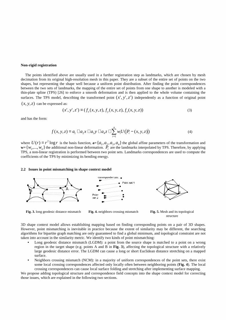
2.2 Issues in point mismatching in shape context model
Fig. 3. long geodesic distance mismatch Fig. 4. neighbors crossing mismatch Fig. 5. Mesh and its topological structure
3D shape context model allows establishing mapping based on finding corresponding points on a pair of 3D shapes. However, point mismatching is inevitable in practice because the extent of similarity may be different, the searching algorithms for bipartite graph matching are only guaranteed to find a global minimum, and topological constraint are not taken into account in the similarity metric. We identify two kinds of point mismatching:
• Long geodesic distance mismatch (LGDM): a point from the source shape is matched to a point on a wrong region in the target shape (e.g. points A and B in Fig. 3), affecting the topological structure with a relatively large geodesic distance error. The LGDM can cause a long or short Euclidean distance stretching on a mapped surface.
• Neighbors crossing mismatch (NCM): in a majority of uniform correspondences of the point sets, there exist some local crossing correspondences affected only locally often between neighboring points (Fig. 4). The local crossing correspondences can cause local surface folding and stretching after implementing surface mapping.
We propose adding topological structure and correspondence field concepts into the shape context model for correcting those issues, which are explained in the following two sections.

2.3 Topological structure correction (TSC) method
In a triangulated surface (mesh), a triangle is a fundamental cell of the surface as shown in Fig. 5. Any point in the surface has its specific topological location (spatial position and element of a cell), which has both spatial and topological relationship with its neighboring points. 3D shape context model only uses the spatial position information of points from a mesh regardless of the topological constraints of the points. We propose preserving the topological constraints in shape context and using geodesic distance to identify long geodesic distance mismatching points for solving the LGDM issue.
When the points from shape 1 are matched into the points in shape 2, the topology in shape 1 must be preserved. This preserved topological structure and the mapped points in shape 2 will generate a new mesh. For each corresponding point, both on its original mesh (shape 1) and new mesh, a geodesic distance pair between the point and its all topological neighboring points (Fig. 5) are represented as:
==
njjAd
njjAd
N
O
,...,1),,(
,...,1),,( (6)
where ),( jAdo is the geodesic distance between point A and its neighboring pointj (obtained according to the rule of neighboring point selection) on the original mesh and ),( jAdN the corresponding geodesic distance but on the new mesh . For each corresponding ),( jAdO and ),( jAdN that fulfill the following condition
njdjAdjAd OON ,...,1,|),(),(| =•>− α (7)
the current ),( jAdN is considered as long geodesic distance with its specific neighboring pointj , while compared to its original geodesic distance ),( jAdo . α is a scaling parameter determined from experiments.
The point A is classified as a LGDM point, if the percentage of the number of the long geodesic distances with the total number of neighboring points is larger than a threshold β . All classified LGDM correspondences will be removed from correspondence field. The method is effective for single point or sparse points mismatching in a homogeneous correspondence field, while its neighborhood points keep correct matching.
2.4 Correspondence field smoothing (CFS) method
Neighbors crossing mismatch may contains local topological mismatch. However, the proposed topological structure correction method may not solve the problem effectively because the mismatched points may still keep close relationship with its original neighboring points (both on its position and topological structure). On the other hand, from a vector field point of view, a field of crossing correspondences is a small patch of inhomogeneous vectors in a large homogeneous vector field. We propose a correspondence field smoothing approach for the NCM correction. A correspondence field (vector image) is generated from the sparse correspondences using thin-plate spline interpolation. A median smoothing here corrects the correspondence field. The kernel size was determined experimentally to remove crossing, without affecting the remaining homogenous field substantially. The approach includes the following steps:
1) An empty uniform vector image is generated from the bounding box of a source mesh. 2) The correspondences from the source points to the matched target points are calculated and assigned to the
corresponding positions (pixels) in the vector image as vectors. Thus, a vector image representing correspondence field is generated.
3) A TPS transformation is computed. All other pixels’ vectors are computed by the TPS transformation for performing vector field interpolation.
4) A median kernel smoothing filter is applied and a smooth correspondence vector image is obtained. 5) Revisit the positions of the sour points and pick up their corresponding vectors from the smooth vector image.
A smoothing correspondence field is finally obtained.
3 Experiments and discussions
We validated the proposed technique using several different phantoms. For small animal application, we chose rat and mouse hind limb skeletons, while can represent some general features of small animal skeletons, in our preliminary experiments. We tested our method on rat and mouse hind limb skeletons and evaluated its applicable value on small animal skeleton registration.
3.1 Test of traditional 3D shape context
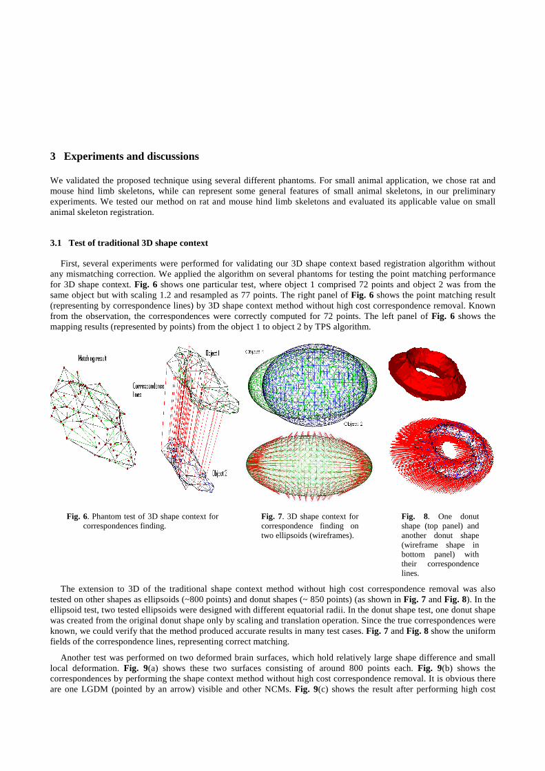
First, several experiments were performed for validating our 3D shape context based registration algorithm without any mismatching correction. We applied the algorithm on several phantoms for testing the point matching performance for 3D shape context. Fig. 6 shows one particular test, where object 1 comprised 72 points and object 2 was from the same object but with scaling 1.2 and resampled as 77 points. The right panel of Fig. 6 shows the point matching result (representing by correspondence lines) by 3D shape context method without high cost correspondence removal. Known from the observation, the correspondences were correctly computed for 72 points. The left panel of Fig. 6 shows the mapping results (represented by points) from the object 1 to object 2 by TPS algorithm.
Fig. 6. Phantom test of 3D shape context for correspondences finding.
Fig. 7. 3D shape context for correspondence finding on two ellipsoids (wireframes).
Fig. 8. One donut shape (top panel) and another donut shape (wireframe shape in bottom panel) with their correspondence lines.
The extension to 3D of the traditional shape context method without high cost correspondence removal was also tested on other shapes as ellipsoids (~800 points) and donut shapes (~ 850 points) (as shown in Fig. 7 and Fig. 8). In the ellipsoid test, two tested ellipsoids were designed with different equatorial radii. In the donut shape test, one donut shape was created from the original donut shape only by scaling and translation operation. Since the true correspondences were known, we could verify that the method produced accurate results in many test cases. Fig. 7 and Fig. 8 show the uniform fields of the correspondence lines, representing correct matching.
Another test was performed on two deformed brain surfaces, which hold relatively large shape difference and small local deformation. Fig. 9(a) shows these two surfaces consisting of around 800 points each. Fig. 9(b) shows the correspondences by performing the shape context method without high cost correspondence removal. It is obvious there are one LGDM (pointed by an arrow) visible and other NCMs. Fig. 9(c) shows the result after performing high cost
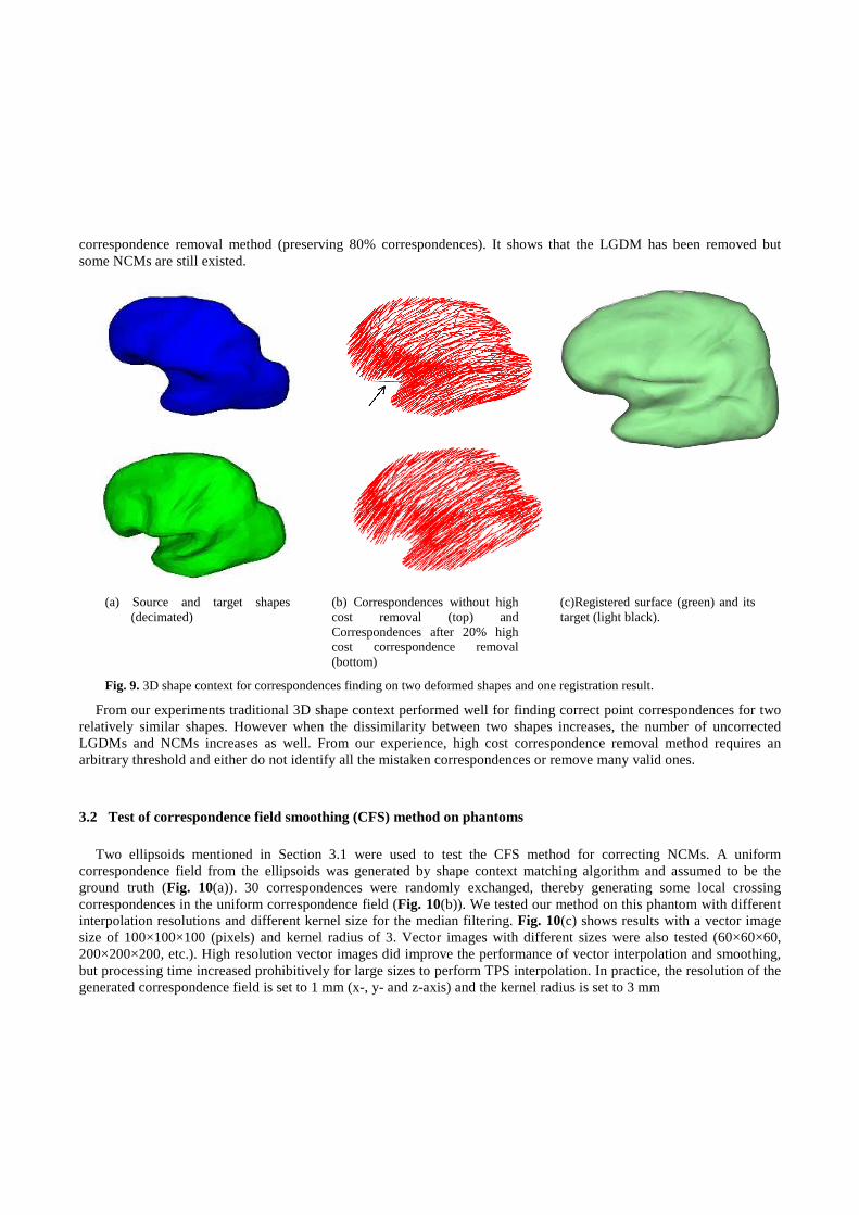
correspondence removal method (preserving 80% correspondences). It shows that the LGDM has been removed but some NCMs are still existed.
(a) Source and target shapes (decimated)
(b) Correspondences without high cost removal (top) and Correspondences after 20% high cost correspondence removal (bottom)
(c)Registered surface (green) and its target (light black).
Fig. 9. 3D shape context for correspondences finding on two deformed shapes and one registration result.
From our experiments traditional 3D shape context performed well for finding correct point correspondences for two relatively similar shapes. However when the dissimilarity between two shapes increases, the number of uncorrected LGDMs and NCMs increases as well. From our experience, high cost correspondence removal method requires an arbitrary threshold and either do not identify all the mistaken correspondences or remove many valid ones.
3.2 Test of correspondence field smoothing (CFS) method on phantoms
Two ellipsoids mentioned in Section 3.1 were used to test the CFS method for correcting NCMs. A uniform correspondence field from the ellipsoids was generated by shape context matching algorithm and assumed to be the ground truth (Fig. 10(a)). 30 correspondences were randomly exchanged, thereby generating some local crossing correspondences in the uniform correspondence field (Fig. 10(b)). We tested our method on this phantom with different interpolation resolutions and different kernel size for the median filtering. Fig. 10(c) shows results with a vector image size of 100×100×100 (pixels) and kernel radius of 3. Vector images with different sizes were also tested (60×60×60, 200×200×200, etc.). High resolution vector images did improve the performance of vector interpolation and smoothing, but processing time increased prohibitively for large sizes to perform TPS interpolation. In practice, the resolution of the generated correspondence field is set to 1 mm (x-, y- and z-axis) and the kernel radius is set to 3 mm
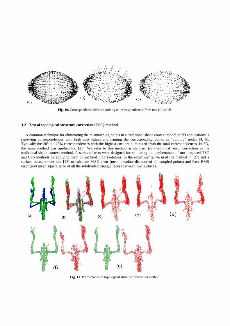
Fig. 10. Correspondence field smoothing on correspondences from two ellipsoids.
3.2 Test of topological structure correction (TSC) method
A common technique for eliminating the mismatching points in a traditional shape context model in 2D applications is removing correspondences with high cost values and naming the corresponding points as “dummy” nodes [4, 5]. Typically the 20% to 25% correspondences with the highest cost are eliminated from the total correspondences. In 3D, the same method was applied too [21]. We refer to this method as standard (or traditional) error correction in the traditional shape context method. A series of tests were designed for validating the performance of our proposed TSC and CFS methods by applying them on rat hind limb skeletons. In the experiments, we used the method in [27] and a surface measurement tool [28] to calculate MAD error (mean absolute distance of all sampled points) and Face RMS error (root mean square error of all the subdivided triangle faces) between two surfaces.
Fig. 11. Performance of topological structure correction method.
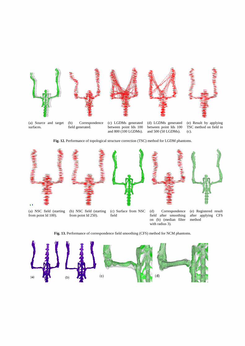
(a) Source and target surfaces.
(b) Correspondence field generated.
(c) LGDMs generated between point Ids 100 and 800 (100 LGDMs).
(d) LGDMs generated between point Ids 100 and 500 (50 LGDMs).
(e) Result by applying TSC method on field in (c).
Fig. 12. Performance of topological structure correction (TSC) method for LGDM phantoms.
(a) NSC field (starting from point Id 100).
(b) NSC field (starting from point Id 250).
(c) Surface from NSC field
(d) Correspondence field after smoothing on (b) (median filter with radius 3).
(e) Registered result after applying CFS method
Fig. 13. Performance of correspondence field smoothing (CFS) method for NCM phantoms.
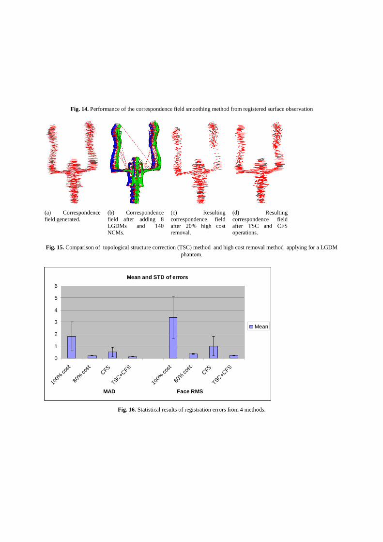
Fig. 14. Performance of the correspondence field smoothing method from registered surface observation
(a) Correspondence field generated.
(b) Correspondence field after adding 8 LGDMs and 140 NCMs.
(c) Resulting correspondence field after 20% high cost removal.
(d) Resulting correspondence field after TSC and CFS operations.
Fig. 15. Comparison of topological structure correction (TSC) method and high cost removal method applying for a LGDM phantom.
Mean and STD of errors
0
1
2
3
4
5
6
100%
cost
80%
cost
CFS
TSC+CFS
100%
cost
80%
cost
CFS
TSC+CFS
MAD Face RMS
Mean
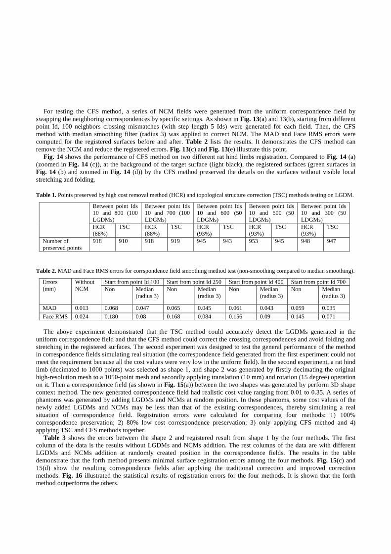
Fig. 16. Statistical results of registration errors from 4 methods.
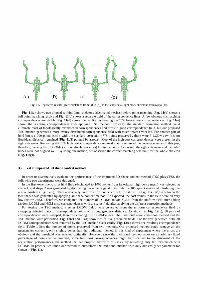
Fig. 17. Registered results (green skeletons from (a) to (d)) to the study data (light black skeletons from (a) to (d)).
Fig. 11(a) shows two aligned rat hind limb skeletons (decimated meshes) before point matching. Fig. 11(b) shows a full point matching result and Fig. 11(c) shows a separate field of the correspondence lines. A few obvious mismatching correspondences are visible. Fig. 11(d) shows the result after keeping the 76% lowest cost correspondences. Fig. 11(e) shows the resulting correspondences after applying TSC method. Typically, the standard correction method could eliminate most of topologically mismatched correspondences and create a good correspondence field, but our proposed TSC method generates a more evenly distributed correspondence field with much fewer errors left. For another pair of hind limbs (1000 points each), with the standard correction (778 points preserved), there were 3 LGDMs (with short Euclidean distance) remained (Fig. 11(f) pointed by arrows). Most of the high cost correspondences were present in the right calcaneus. Removing the 23% high cost correspondence removal mainly removed the correspondences in this part, therefore, causing the 3 LGDMs (with relatively low costs) left in the pubis. As a result, the right calcaneus and the pubic bones were not aligned well. By using our method, we observed the correct matching was built for the whole skeleton (Fig. 11(g)).
3.2 Test of improved 3D shape context method
In order to quantitatively evaluate the performance of the improved 3D shape context method (TSC plus CFS), the following two experiments were designed.
In the first experiment, a rat hind limb (decimated to 1000 points from its original high-dense mesh) was selected as shape 1, and shape 2 was generated by decimating the same original hind limb to a 1050-point mesh and translating it to a new position (Fig. 12(a)). Then a relatively uniform correspondence field (as shown in Fig. Fig. 12(b)) between the two shapes was generated by applying 3D shape context method. As expected, the cost values in the field were all very low (below 0.05). Therefore, we compared the number of LGDMs and/or NCMs from the uniform field after adding random LGDM and NCM miss-correspondences with the same field after applying the different correction methods.
For testing the TSC method, a series LGDM fields were generated from the uniform correspondence field by swapping selected pairs of corresponding points with long geodesic distance. As shown in Fig. 12(c), 50 pairs of correspondences were swapped, therefore creating 100 LGDM errors. The traditional error correction method and the TSC method were performed. Fig. 12(c) and 12(d) show two of five generated fields. For the five generated field, all LGDM correspondences were removed by the TSC method successfully. Fig. 12(e) shows one resulting correspondence field. Table 1 lists the number of points preserved from two methods. Our proposed method could remove all the mismatches correctly, only slightly better than the traditional method in this kind of experiment where the errors are obvious and the threshold was selected optimally. However, since the traditional method relies on an arbitrary fixed percentage of points to be removed, some high cost correspondences might be discarded to the detriment of the registration performances, the method that we propose addresses this issue by removing only the mist-match with LGDMs. In practice, we found our method to outperform the traditional method with only one easily set parameter (as shown in Fig. 11).
For testing the CFS method, a series of NCM fields were generated from the uniform correspondence field by
swapping the neighboring correspondences by specific settings. As shown in Fig. 13(a) and 13(b), starting from different point Id, 100 neighbors crossing mismatches (with step length 5 Ids) were generated for each field. Then, the CFS method with median smoothing filter (radius 3) was applied to correct NCM. The MAD and Face RMS errors were computed for the registered surfaces before and after. Table 2 lists the results. It demonstrates the CFS method can remove the NCM and reduce the registered errors. Fig. 13(c) and Fig. 13(e) illustrate this point.
Fig. 14 shows the performance of CFS method on two different rat hind limbs registration. Compared to Fig. 14 (a) (zoomed in Fig. 14 (c)), at the background of the target surface (light black), the registered surfaces (green surfaces in Fig. 14 (b) and zoomed in Fig. 14 (d)) by the CFS method preserved the details on the surfaces without visible local stretching and folding.
Table 1. Points preserved by high cost removal method (HCR) and topological structure correction (TSC) methods testing on LGDM.
Between point Ids 10 and 800 (100 LGDMs)
Between point Ids 10 and 700 (100 LDGMs)
Between point Ids 10 and 600 (50 LDGMs)
Between point Ids 10 and 500 (50 LDGMs)
Between point Ids 10 and 300 (50 LDGMs)
HCR (88%)
TSC HCR (88%)
TSC HCR (93%)
TSC HCR (93%)
TSC HCR (93%)
TSC
Number of preserved points
918 910 918 919 945 943 953 945 948 947
Table 2. MAD and Face RMS errors for corrspondence field smoothing method test (non-smoothing compared to median smoothing).
Start from point Id 100 Start from point Id 250 Start from point Id 400 Start from point Id 700 Errors (mm)
Without NCM Non Median
(radius 3) Non Median
(radius 3) Non Median
(radius 3) Non Median
(radius 3)
MAD 0.013 0.068 0.047 0.065 0.045 0.061 0.043 0.059 0.035
Face RMS 0.024 0.180 0.08 0.168 0.084 0.156 0.09 0.145 0.071 The above experiment demonstrated that the TSC method could accurately detect the LGDMs generated in the
uniform correspondence field and that the CFS method could correct the crossing correspondences and avoid folding and stretching in the registered surfaces. The second experiment was designed to test the general performance of the method in correspondence fields simulating real situation (the correspondence field generated from the first experiment could not meet the requirement because all the cost values were very low in the uniform field). In the second experiment, a rat hind limb (decimated to 1000 points) was selected as shape 1, and shape 2 was generated by firstly decimating the original high-resolution mesh to a 1050-point mesh and secondly applying translation (10 mm) and rotation (15 degree) operation on it. Then a correspondence field (as shown in Fig. 15(a)) between the two shapes was generated by perform 3D shape context method. The new generated correspondence field had realistic cost value ranging from 0.01 to 0.35. A series of phantoms was generated by adding LGDMs and NCMs at random position. In these phantoms, some cost values of the newly added LGDMs and NCMs may be less than that of the existing correspondences, thereby simulating a real situation of correspondence field. Registration errors were calculated for comparing four methods: 1) 100% correspondence preservation; 2) 80% low cost correspondence preservation; 3) only applying CFS method and 4) applying TSC and CFS methods together.
Table 3 shows the errors between the shape 2 and registered result from shape 1 by the four methods. The first column of the data is the results without LGDMs and NCMs addition. The rest columns of the data are with different LGDMs and NCMs addition at randomly created position in the correspondence fields. The results in the table demonstrate that the forth method presents minimal surface registration errors among the four methods. Fig. 15(c) and 15(d) show the resulting correspondence fields after applying the traditional correction and improved correction methods. Fig. 16 illustrated the statistical results of registration errors for the four methods. It is shown that the forth method outperforms the others.
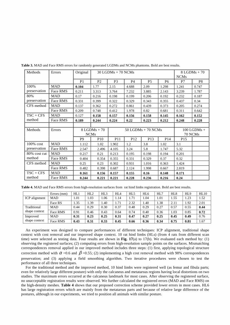
Table 3. MAD and Face RMS errors for randomly generated LGDMs and NCMs phantoms. Bold are best results.
Original 30 LGDMs + 70 NCMs 8 LGDMs + 70 NCMs
Methods Errors
P1 P2 P3 P4 P5 P6 P7 P8 MAD 0.104 1.77 2.15 4.688 2.09 1.298 1.241 0.747 100%
preservation Face RMS 0.211 3.313 3.764 7.232 3.885 2.143 3.239 1.787 MAD 0.17 0.216 0.198 0.199 0.206 0.192 0.232 0.187 80%
preservation Face RMS 0.331 0.399 0.322 0.329 0.343 0.355 0.437 0.34 MAD 0.137 0.362 0.272 0.861 0.439 0.373 0.205 0.274 CFS method Face RMS 0.209 0.748 0.412 1.978 0.82 0.681 0.311 0.642 MAD 0.127 0.158 0.157 0.156 0.158 0.145 0.162 0.152 TSC + CFS
method Face RMS 0.189 0.244 0.224 0.22 0.223 0.212 0.248 0.228
8 LGDMs + 70 NCMs
50 LGDMs + 70 NCMs 100 LGDMs + 70 NCMs
Methods Errors
P9 P10 P11 P12 P13 P14 P15 MAD 1.112 1.02 1.902 1.2 3.8 1.02 3.1 100% cost
preservation Face RMS 2.547 2.496 4.105 3.24 5.8 1.747 5.32 MAD 0.217 0.21 0.213 0.195 0.198 0.194 0.201 80% cost cut
method Face RMS 0.404 0.354 0.355 0.331 0.329 0.37 0.32 MAD 0.25 0.23 0.302 0.931 1.016 0.363 1.424 CFS method Face RMS 0.482 0.398 0.687 2.124 1.998 0.667 2.819 MAD 0.161 0.156 0.157 0.155 0.16 0.148 0.171 TSC + CFS
method Face RMS 0.244 0.221 0.221 0.228 0.236 0.216 0.24
Table 4. MAD and Face RMS errors from high-resolution surfaces from rat hind limbs registration. Bold are best results.
Errors (mm) HL1 HL2 HL3 HL4 HL5 HL6 HL7 HL8 HL9 HL10 MAD 1.01 1.03 1.06 1.14 1.71 1.04 1.01 1.55 1.23 1.52 ICP alignment
Face RS 1.35 1.39 1.40 1.71 2.32 1.40 1.38 2.11 1.92 2.01 MAD 0.44 0.29 0.30 0.37 0.48 0.29 0.27 0.57 0.55 0.44 Traditional
shape context Face RMS 0.91 0.46 0.43 0.64 0.74 0.40 0.36 1.03 0.85 0.72 MAD 0.31 0.23 0.25 0.31 0.47 0.27 0.25 0.45 0.49 0.76 Improved
shape context Face RMS 0.43 0.31 0.33 0.45 0.66 0.36 0.34 0.75 0.81 1.67 An experiment was designed to compare performances of different techniques: ICP alignment, traditional shape
context with cost removal and our improved shape context. 10 rat hind limbs (HLs) (from 4 rats from different scan time) were selected as testing data. Four results are shown in Fig. 17(a) to 17(b). We evaluated each method by: (1) observing the registered surfaces; (2) computing errors from high-resolution sample points on the surfaces. Mismatching correspondences removal applied in our improved method includes three steps: (1) first, applying topological structure correction method with α =0.6 and β =0.55; (2) implementing a high cost removal method with 98% correspondences
preservation; and (3) applying a field smoothing algorithm. Two iterative procedures were chosen to test the performance of all three techniques.
For the traditional method and the improved method, 10 hind limbs were registered well (as femur and fibula parts; even for relatively large different posture) with only the calcaneus and metatarsus regions having local distortions on two studies. The maximum errors occurred at the calcaneus landmark for most cases. After observing the registered surface, no unacceptable registration results were observed. We further calculated the registered errors (MAD and Face RMS) on the high-density meshes. Table 4 shows that our proposed correction scheme provided lower errors in most cases. HL6 has large registration errors which are mainly from the metatarsus parts and because of relative large difference of the postures, although in our experiments, we tried to position all animals with similar posture.
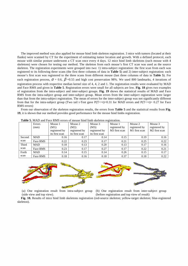
The improved method was also applied for mouse hind limb skeleton registration. 3 mice with tumors (located at their
flanks) were scanned by CT for the experiment of estimating tumor location and growth. With a defined protocol, each mouse with similar posture underwent a CT scan once every 4 days. 12 mice hind limb skeletons (each mouse with 4 skeletons) were chosen for testing our method. The skeleton from each mouse’s first CT scan was used as the source skeleton. The registration experiments were grouped into two: 1) intra-subject registration: the first scan from each was registered to its following three scans (the first three columns of data in Table 5) and 2) inter-subject registration: each mouse’s first scan was registered to the three scans from different mouse (last three columns of data in Table 5). For each registration process, α = 0.6, β =0.55 and high cost preservation 98%. We used 800 landmarks, 4 iterations of
registration process with respective median kernel size of 4, 4, 2 and 1. The registration results were evaluated by MAD and Face RMS and given in Table 5. Registration errors were small for all subjects are low. Fig. 18 gives two examples of registration from the intra-subject and inter-subject groups. Fig. 19 shows the statistical results of MAD and Face RMS from the intra-subject group and inter-subject group. Mean errors from the inter-subject registration were larger than that from the intra-subject registration. The mean of errors for the inter-subject group was not significantly different from that for the intra-subject group (Two tail t-Test gave P(T<=t)=0.31 for MAD errors and P(T<=t)= 0.27 for Face RMS errors)
From our observation of the skeleton registration results, the errors from Table 5 and the statistical results from Fig. 19, it is shown that our method provides good performance for the mouse hind limbs registration.
Table 5. MAD and Face RMS errors of mouse hind limb skeleton registration. Errors
(mm) Mouse 1 (M1): registered by its first scan
Mouse 2 (M2): registered by its first scan
Mouse 3 (M3): registered by its first scan
Mouse 1 registered by M3 first scan
Mouse 2 registered by M1 first scan
Mouse 3 registered by M2 first scan
MAD 0.16 0.17 0.14 0.15 0.19 0.16 Second scan Face RMS 0.22 0.23 0.17 0.21 0.25 0.22
MAD 0.18 0.13 0.20 0.13 0.17 0.16 Third scan Face RMS 0.23 0.17 0.27 0.17 0.22 0.21
MAD 0.14 0.15 0.14 0.26 0.15 0.17 Forth scan Face RMS 0.18 0.16 0.18 0.37 0.18 0.22
(a) One registration result from intra-subject group (side view and top view).
(b) One registration result from inter-subject group (before registration and top view of result)
Fig. 18. Results of mice hind limb skeletons registration (red-source skeleton; yellow-target skeleton; blue-registered skeleton).

Mean and STDEV
0
0.05
0.1
0.15
0.2
0.25
0.3
MAD Face RMS MAD Face RMS
Intra-subject Inter-subject
Mean
Fig. 19. Mean and standard deviation of registration errors from inter-subject and inter-subject groups
4 Conclusions
We proposed an improved 3D shape context model with point mismatching correction. The method was applied and tested on phantoms, rat hind limbs and mouse hind limbs registration. The experimental results demonstrated good performance and robustness to mismatching errors inherent with shape context technique. In our future work, we will optimize the iteration step and parameter settings. We will also test the tolerance of small animal skeleton posture that the registration method can apply.
Acknowledgments
This project is supported by Australian Commonwealth Scientific and Research Organization (CSIRO) and Australian Nuclear Science and Technology Organisation (ANSTO).
References
1. M. Urschler, H. Bischof, “Registering 3D lung surfaces using the shape context approach,” Proc. Medical Image Understanding and Analysis, 212-215 (2004).
2. S. Belongie, J. Malik and J. Puzicha, “Matching Shapes,” Proc. Eighth Int’l. Conf. Computer Vision, 454-461 (2001). 3. S. Belongie, J. Malik, J. Puzicha, “Shape matching and object recognition using shape contexts,” IEEE Trans. on Pattern Analysis
and Machine Intelligence, 24(24), 509-522 (2002). 4. G. Mori, S. Belongie, J. Malik, “Shape contexts enable efficient retrieval of similar shapes,” Proc. Of the 2001 IEEE Computer
Society Conference on Computer Visionand Pattern Recognition, 1, I-723 – I-730 (2001). 5. G. Mori, S. Belongie, J. Malik, “Efficient shape matching using shape contexts,” IEEE Trans. on Pattern Analysis and Machine
Intelligence, 27(11), 1832-1837 (2005). 6. G. Carneiro, and A.D. Jepson, “Pruning local feature correspondences using shape context,” Proc. Of the 17th Conference on
Pattern Recognition, 3, 16-19 (2004). 7. M. Yusuf, and T. Haider, “Recognition of handwritten Urdu digits using shape context,” International Conference on Intelligent
and Advanced Systems, 601-604 (2007).Proc. of 8th International Multitopic Conference, 569-572 (2004) 8. M. Yusuf, and T. Haider, “Accelerated recognition of handwritten Urdu digits using Shape Context based gradual pruning,”
International Conference on Intelligent and Advanced Systems, 601-604 (2007). 9. X, Liu, Y. Jia, and Y. Wang, “An Eigenvector Approach Based on Shape Context Patterns for Point Matching,” International
Symposium on Communications and Information Technologies, 455-458 (2006). 10. F. Yang, Y. Lu, and Y. Duan, “Combining hierarchical segmentation and shape context based recognition,” 8th International
Conf. on Computer and Information Technology, 839-844 (2008).

11. T-O Nguyen, S. Tabbone, O.R. Terrades, “Symbol descriptor based on shape context and vector model of information retrieval,” The Eighth IAPR International Workshop on Document Analysis Systems, 191-197 (2008).
12. L.B. Singh, and S.M. Hazarika, “Enhanced Shape Context for Object Recognition,” International Conference on Advanced Computing and Communications, 529-534 (2007).
13. A. Thayananthan, B. Stenger, P.H.S. Torr, and R. Cipolla, “Shape Context and Chamfer Matching in Cluttered Scenes,” Proc. IEEE Conf. Computer Vision and Pattern Recognition, 1, 127-133 (2003).
14. G. Mori and J. Malik, “Estimating Human Body Configurations using Shape Context Matching,” proc. European Conf. Computer Vision, 3, 666-680 (2002).
15. G. Mori, J. Malik, “Recovering 3D human body configurations using shape contexts,” IEEE Trans. on Pattern Analysis and Machine Intelligence, 28, 1052-1062 (2006).
16. X. Qui, Z. Wang, S. Xia, and J. Li, “Estimating articulated human pose from video using shape context,” Proc. of the Fifth IEEE International Symposium on Signal Processing and Information Technology, 583-588 (2005).
17. C. Hao, X. Qiu, Z. Wang, S. Chen, “Shape matching in pose reconstruction using shape context,” Proc. 12th International Multi-Media Modelling Conference, 169-176 (2006).
18. M. Grundmann, F. Meier, and I. Essa, “3D Shape Context and Distance Transform for Action Recognition,” 19th International Conference on pattern Recognition, 1-4 (2008).
19. P. Hsiao, C. Chen, and L. Chang, “Human Action Recognition using Temporal-State Shape Contexts,” 19th International Conference on pattern Recognition, 1-4 (2008).
20. M. Kortgen, G. Park, M. Novotni, R. Klein, “3D Shape Matching with 3D Shape Context,” Seventh Central European Seminar on Computer Graphics (2003).
21. M. Urschler, J. Bauer, H. Ditt, H. Bischof, “SIFT and Shape Context for Feature-Based Nonlinear Registration of Thoracic CT Images,” Proc. Computer Vision Approaches to Medical Image Analysis, 73-84, 2006.
22. M. Urschler, H. Bischof, “Assessing breathing motion by shape matching of lung and diaphragm surfaces,” Proceedings of the SPIE Medical Imaging, 5746, 440-452 (2005).
23. D. Xiao, P.T. Bourgeat, J.E. Fripp, O.A. Tamayo, M. Gregoire, O. Salvado, “Non-rigid registration of small animal skeletons from micro-CT using 3D shape context,” Proc. of SPIE Medical Image, (2009).
24. S. Giannarou, and T. Stathaki, “Object Identification in Complex Scenes using Shape Context Descriptor and Multi-stage Clustering,” 15th International Conference on Digital Signal Processing, 244-247 (2007).
25. R. Jonker, A. Volgenant, “A shortest augmenting path algorithm for dense and sparse linear assignment problems,” Computing, 38(4), 325-340 (1987).
26. F.L. Bookstein, “Principal warps: Thin-plate splines and the decomposition of deformation,” IEEE Trans. PAMI, 11(6), 567-585 (1989).
27. N. Aspert, D. Santa-Cruz, T. Ebrahimi, “MESH: Measuring Errors between Surfaces using the Hausdorff distance,” the proceedings of the IEEE Int. Conf. on Multimedia and Expo (ICME), I, 705-708 (2002).
28. http://www.cs.unc.edu/~xushun/research/MeshValmet.html