Artifacts and Their Functions - Oxford Handbooks - PhilArchive
lable at ScienceDirect
Journal of Archaeological Science 49 (2014) 70e82
Contents lists avai
Journal of Archaeological Science
journal homepage: http: / /www.elsevier .com/locate/ jas
An experimental assessment of the influences on edge damage tolithic artifacts: a consideration of edge angle, substrate grain size, rawmaterial properties, and exposed face
Shannon P. McPherron a,*, David R. Braun b, Tamara Dogand�zi�c a, Will Archer a,Dawit Desta a, Sam C. Lin c
aDepartment of Human Evolution, Max Planck Institute for Evolutionary Anthropology, Deutscher Platz 6, Leipzig, GermanybDepartment of Anthropology, George Washington University, Washington, D.C., USAcDepartment of Anthropology, University of Pennsylvania, Philadelphia, USA
a r t i c l e i n f o
Article history:Received 4 November 2013Received in revised form2 April 2014Accepted 4 April 2014Available online xxx
Keywords:TramplingExperimentEdge damageEdge anglesUsewearLithicsTaphonomy
* Corresponding author. Tel.: þ49 341 3550 363; faE-mail address: [email protected] (S.P. McPh
http://dx.doi.org/10.1016/j.jas.2014.04.0030305-4403/� 2014 Elsevier Ltd. All rights reserved.
a b s t r a c t
Functional analyses of stone tool assemblages face a number of methodological challenges. Aside fromdetermining specific uses, it can be difficult to know which artifacts in an assemblage were used at all.Typically retouch is taken as a proxy for indicating past use, but ignoring unretouched flakes meansexcluding the overwhelming majority of most assemblages. Assessing whether an unretouched flake hasbeen used is complicated. Edge damage on flakes can be caused by use or by taphonomic processes. Oneof the more important of these processes is trampling. Experiments have shown that trampling cancreate damage mimicking retouch, and unlike some other taphonomic processes trampling is otherwisedifficult to detect. One possible solution is to look for patterning in the placement (left vs. right, ventralvs. dorsal, proximal vs. distal) of edge damage, and recent studies using GIS based approaches haveshown the utility of this method at an assemblage level. Here we trampled a set of experimental flakesmade from two raw materials on two substrate types and analyzed the edge damage patterns using anewly developed image analysis program that is similar to previous GIS based approaches. We found thata previously unquantified variable, edge angle, is strongly correlated with the likelihood of damage. Thusin circumstances where edge angles are non-randomly distributed across flake types, trampling damagewill be patterned. These results have implications for previously published edge damage studies, andfurther indicate that basic flake mechanics need to be considered in studies where function is inferredfrom edge damage patterns. Approaches to the archaeological record that employs assemblage levelassessments of edge damage, must consider a range of factors when inferring behaviors from thesepatterns.
� 2014 Elsevier Ltd. All rights reserved.
1. Introduction
The vast majority of lithic assemblages consist of unretouchedflakes. While these flakes do typically factor into technologicalanalyses of assemblages, they are more difficult to analyze from afunctional perspective (Shott and Sillitoe, 2004, 2005). The diffi-culty with assessing function in these tools lies in knowing whichflakes, of potentially thousands in an assemblage, were actuallyused and which simply represent unused debris. Microscopic
x: þ49 341 3550 399.erron).
usewear or residue analysis can potentially shed some insights;however, these techniques can be difficult to apply to entire as-semblages. These techniques are applied typically only to unre-touched flakes which are suspected of being so-called desired end-products, normally based on analyses of the flake scar patterns oncores, e.g. bladelets, Kombewa flakes, and small Levallois flakes(Tixier and Turq, 1999; Dibble and McPherron, 2006; Eren andLycett, 2012). Additionally, both usewear and residue analysishave been the subject of considerable methodological debate thathas left their accuracy unclear (Shea, 1992; Odell, 2001; Bamforthet al., 1990; Young and Bamforth, 1990).
Recently, Bird et al. (2007) and then Schoville (2010; see alsoBrown et al., 2012; Wilkins et al., 2012) have presented a promising
S.P. McPherron et al. / Journal of Archaeological Science 49 (2014) 70e82 71
new approach using a GIS-based analysis of the location ofmacroscopic damage on lithic artifacts. Though Bird et al.’s initialpaper looked at only a small sample of points from the MiddleStone Age site of Pinnacle Point Cave 13B as an initial test of themethodology, the explicit goal was to create a method of assessingmacroscopic edge damage at the scale of an entire assemblage oflithics. This effort wasmotivated by the fact that theseMiddle StoneAge assemblages, unlike those of the Mousterian, have very fewretouched tools.
Schoville (2010), working with the same assemblages, thenimproved the methodology, included an experimental component,increased the size of the sample studied, and included additionalsites. For the improved methodology, Schoville digitizes each flakeand records its outline at true scale. Then for each flake he noted,using ArcGIS software, the locations of damage along the outline,both dorsal and ventral. With the results, it is possible to look forspatial patterns in damage including whether damage is symmet-rical left and right, ventral and dorsal, and proximal to distal. InSchoville (2010), Middle Stone Age points were analyzed and basedon the identified damage pattern, particularly left-right andventral-dorsal damage frequency asymmetries, it is concluded thatthe points were likely used as knives. This is supported by higherrelative damage frequencies on the medial portions of the tools. Afollowing study by Schoville and Brown (2010) documented dif-ferences in the distribution of damage along the edges of pointedartifacts from PP 13B and those identified on experimentalquartzite pointed forms that were used as spear tips. In a subse-quent study (Wilkins et al., 2012), unretouched points from KathuPan 1, a late Earlier Stone Age or early Middle Stone Age context,were analyzed with this method and compared to the previouslystudiedMiddle Stone Age points as well as to replicated points usedas projectile points. Here a pattern of preferential distal damage onthe ventral side and of symmetrical left-right damage was found inboth the experimental and archaeological points, thus leading to aninterpretation of spear point use. In Wilkins et al. (2012), damagethat occurred after patination was treated separately and consid-ered representative of post-depositional damage. At the assem-blage level, they found no preference for left versus right edgedamage. Interestingly dorsal damage frequencies on the Kathu Pan1 points did not differ from the post-patination damage fre-quencies. It is important to note, however, that post-patination isonly part of the post-depositional history of an artifact. Damage canoccur throughout the life-history of an artifact, and an artifact canbe damaged by other forces, including trampling, prior to burial andsubsequent to patination.
These new methods are vital because they provide a meansthrough which one of the most neglected components of thePaleolithic archaeological record (simple unretouched flakes) canbe used to infer behavior. Furthermore, because these methods arequantitative they should be less easily affected by the kinds of inter-analyst errors that have plagued other methods for describing andanalyzing edge damage. However, with all new methodologicaladvances, it is necessary to investigate the variety of possible in-fluences on the archaeological patterns to insure strong inferentiallinks between archaeological data and behavioral interpretations.Specifically, if the premise for a behavioral interpretation of unre-touched flakes is based on the non-random patterning of edgedamage (Bird et al., 2007; Schoville, 2010), it is critical to investigateif there are fundamental factors related to the physical properties ofthe flakes themselves that can cause such patterning in edge wear.
Several experimental studies have looked at the effects oftrampling on edge damage (Shea and Klenck,1993;McBrearty et al.,1998; Tringham et al., 1974; Flenniken and Haggarty, 1979; Gifford-Gonzalez et al., 1985; Nielsen, 1991; Pargeter, 2011). Some of theseare briefly reviewed here to provide a context for how our
particular trampling experiment differs from previously conductedexperiments. Trampling experiments conducted previously havefocused on specific questions and thus the design of these experi-ments reflects these differences. Early trampling experiments werefocused on the effect of trampling on individual artifacts and spe-cifically tuned to identifying signature criteria of trampled artifacts.
Tringham et al. (1974) trampled ten flint flakes on the ground.The conclusion of this early study was that damage was distributedrandomly around the perimeter of the flakes and only on the sur-face opposite the direction of force (by the trampler’s foot). Mostimportantly, Tringham noted that edge damage scars themselveswere randomly oriented, variable in size, and most were charac-terized by marked elongation. Flenniken and Haggarty (1979)investigated the effects of substrate on edge damage. They knap-ped obsidian nodules onto five different substrates with increasingquantities of larger, coarse grain clasts and subsequently trampledthem. They identified high rates of damage and found that thisdamage increased as substrate clast size increased. Subsequenttrampling experiments also investigated the effects of trampling onthe distribution of archaeological materials within a locality.
Gifford-Gonzalez et al. (1985) conducted a trampling experi-ment that focused on vertical displacements but also noted dam-age. They prepared two sets of 1000 obsidian pieces sorted intothree size fractions, painted the pieces so that damage could bemore easily identified, and trampled them on a sandy and a loamysubstrate. They found that smaller pieces (<2 cm) were equallydamaged in the two substrates, but that larger pieces were moredamaged in the sand substrate. They noted (but did not quantify)that the two samples of large flakes had different edge angle con-figurations. They posited that this may have led to higher fre-quencies of damage in the “sand” sample. However, theyconsidered this unlikely in this instance and instead offered theexplanation that the sand substrate allowed pieces to come intocontact with one another more frequently causing damage. Further,they looked at the character of damage on a subset of the pieces(N ¼ 14) to explicitly test the conclusions of Tringham et al. (1974).Gifford-Gonzalez and colleagues confirmed Tringham’s assertionthat damage is randomly distributed along the edge but could notconfirm that trampling produces randomly oriented flake scars.They also found that the shape of the flake scars varied betweensubstrates with more elongated flakes coming from the sandysubstrate. Again invoking inferences from fracture mechanics, Gif-ford and colleagues speculated that the shape of the removal mightbe related to whether the removal is a result of compression(pressure flakes) or “free impacts” (direct percussion). Similarly,Pryor (1988) also conducted an experiment to explicitly test someof the conclusions of Tringham et al. (1974). Pryor trampled 900painted obsidian flakes sorted by size classes on sand and loamsubstrates. While the quantitative results are in an unpublishedthesis, as summarized in Pryor (1988), flake size, substrate type,edge angle and the flake side (ventral or dorsal) together can ac-count for the frequency of damage. Interestingly, with regard toedge angle, Pryor argues that trampling creates snaps with abruptedge angles that inhibit further edge damage to the pieces and,therefore, disagrees with Tringham et al.’s conclusion that damageis randomly distributed around the perimeter of the flake. Pryor(1988) also found that damage occurs on both faces; however,Pryor’s experimental design allow for flakes to flip as a result oftrampling and allowed flakes to become layered one on top theother.
Nielsen (1991) trampled three sets of painted obsidian lithics in1m square units on firm, gravely substrates. One of these substrateswas trampled after extensive rain. He found that damage israndomly distributed regardless of edge angles, but that removalsare larger on flakes with steeper-edges (i.e. more obtuse edge
S.P. McPherron et al. / Journal of Archaeological Science 49 (2014) 70e8272
angles). McBrearty et al. (1998) looked at the effects of rawmaterialtype, substrate type, and artifact density on edge damage andconcluded that while all three played a role, impenetrable sub-strates are the greatest source of damage. They used both flint andobsidian in their experiments. They noted that the obsidian hadhigher rates of damage, and they attributed this to greater brittle-ness in the obsidian tools. For substrate, they used sands and loam.They found that damage rates were higher on the less penetrableloam. They also varied artifact densities. In a single square meterunit they varied the density of artifacts from 200 per square meterto 500 per square meter. McBrearty and colleagues found thatdamage rates were higher in the higher density squares. Eren et al.(2010) investigated the impact of trampling by animals on stonetools. Their results suggest that even soft substrates and short pe-riods of trampling can produce significant damage on the edges oftools. Pargeter (2011) trampled lithics of several rock types usingcattle and people. This study was designed to determine whetherspecific fractures, usually thought to be characteristic of projectileimpacts, could be mimicked by trampling. He found that thesefeatures (e.g. spin-off fractures) could be found in trampled as-semblages but only at low rates. Interestingly, Pargeter suggestedthat the frequency of tool damage was related to the brittleness ofthe edges.
Several of the trampling studies just summarized touch on animportant and somewhat neglected aspect of edge damage, namelyfracture mechanics. In essence, flaking of the edge that producesdamage is a process equivalent to knapping itself, but at a smallerscale, and thus can be referred to as ‘microflaking’ (Tringham et al.,1974). Several controlled experiments on fracture mechanics havedemonstrated that the main variables determining both thedetachment of a flake and its length are platform size and exteriorplatform angle (Speth, 1972; Dibble and Whittaker, 1981; Dibbleand Rezek, 2009). These experiments have demonstrated that forlower platform angles (i.e. more acute), a flake can be detached atlarger platform thicknesses. They have also shown that the energyrequired to remove a flake is directly determined by the size of theflake. As the exterior platform angle increases, the range of plat-form thickness that allows flake detachment drops significantly(Lin et al., 2013), the size of the flake increases and, as a result, theforce necessary to remove a flake increases. Consequently, exteriorplatform angles that are very acute can produce relatively smallflakes with very little force. If this model is applied to flake edgeangles (rather than core edges) then acute edges are more likely toproduce microflaking under conditions where minimal force isapplied to the edges of flakes. Furthermore, the greater platformthickness range that allow flake detachment in low exterior plat-form angle settings also means that edge contact caused by tram-pling has a higher probability for flake production when the edgeangle is acute. Flakes with more obtuse edge angles will requiregreater force to produce microflakes, and the removals are likely tobe larger.
One of the main concerns of most trampling experiments hasbeen whether trampling can produce damage on individual piecesthat mimics some feature that is usually assumed to be represen-tative of prehistoric behavior (use microwear, retouch etc.). Moststudies have concluded that the placement of damage is randomalong the edge and many concluded that trampling does not pro-duce many removals on a given piece (Shea and Klenck, 1993;Pargeter and Bradfield, 2012). Meanwhile some studies also notethat at times damage is frequent and clustered such that it re-sembles retouched tool forms (see especially McBrearty et al.,1998). One possible solution to these inconsistent results is toinvestigate damage patterns on assemblages rather than individualpieces. Thus inferences of behavior are based upon the probabilityof damage rather than the individual instances of damage. This
approach has been investigated by several studies, in particularthose associated with damage patterns on retouched tools in theMiddle Stone Age of South Africa (Bird et al., 2007; Schoville, 2010;Wilkins et al., 2012). It should be noted that in this approach theextent (invasiveness) of damage is not quantified. Similarly, severalstudies speculate on the role of edge angles in structuring edgedamage patterns (see also Akoshima,1987), but again none of themattempts to explicitly quantify this potential factor.
Here we use a controlled trampling experiment to identify thespecific effects of a variety of different factors that may influencethe frequency and distribution of damage on flake edges. It hasbeen assumed that random edge damage patterns are reflective ofpost-depositional processes based on the assumption that eachportion of the flake edge has a similar likelihood of being damagedby post-depositional processes. We simulated one post-depositional process, trampling, to determine its influence ondamage distribution and frequency.
The controlled trampling experiment reported here isolatedseveral variables that have a potential effect on edge damage.Specifically we isolated the influence of raw material durability(defined here as edge brittleness), edge angle, substrate and flakesurface in contact with substrate (ventral vs. dorsal). Our resultsshow that all four of these variables affect the frequency of edgedamage. Furthermore, these results indicate that post-depositionalprocesses can produce patterns that are significantly different fromrandom. We expect that these findings will help further refine theway in which we can apply these new techniques.
We sought to verify some previous conclusions about effects ofmaterial properties of stone and substrate grain size on edgedamage. Additionally, we tested damage in relation to which side ofthe flake was exposed to the substrate. We expect the assemblagepatterns will be patterned in specific ways based on inferencesfrom fracture mechanics and the results of previous experiments.These expectations are as follows: First, edge damage rates will bemore frequent on more brittle materials. Second, a larger portion ofthe edge will be damaged in coarser substrates. Third, edge damagewill be more frequent on the side that is facing up when the flake istrampled because damage is more often initiated by the hard un-derlying gravel substrate rather than the shoe, but which side isfacing up when trampled should not affect damage overall rates.Fourth, edge damage will occur more frequently where edge anglesare lower. Fifth, if it can be shown that edge angles are, on average,patterned across the length of flakes, it is expected that edgedamage locations will be patterned as well. Sixth, it is expected thatthe average edge angle on a flake will vary with flake shape suchthat broader flakes have lower edge angles, and as a result it isexpected that edge damage will vary with flake shape.
2. Methods
A set of flakes to be trampled was knapped from flint andhornfels. The flint was high quality material from Bergerac, France.The hornfels was collected from the Doring River and likely origi-nates from the numerous instances of contact metamorphism thatcan be found throughout the Karoo region of the interior of SouthAfrica (Waters and Lovegrove, 2002). As we were interested in theinfluence of material properties of stone on the frequency of edgedamage it was necessary to quantify mechanical properties thatmay affect edge damage. Although the overall hardness of a rock isreadily measured using a variety of different measures, rock hard-ness is heavily affected by differences in scale and rock type(Domanski and Webb, 1992; Domanski et al., 1994; Webb andDomanski, 2008; Tsobgou, 2009; Tsobgou and Dabard, 2010). It isimportant to use test measures specifically delineated for the scaleand material that is being investigated. The concept of brittleness
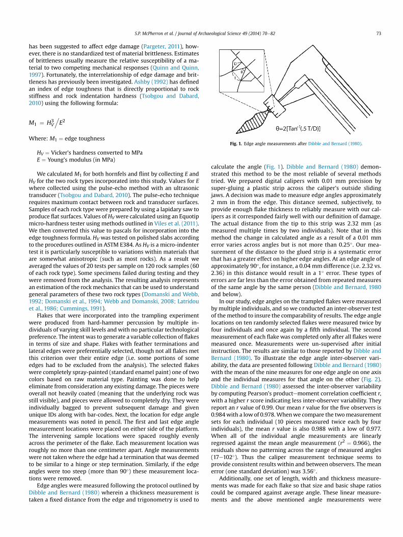
Fig. 1. Edge angle measurements after Dibble and Bernard (1980).
S.P. McPherron et al. / Journal of Archaeological Science 49 (2014) 70e82 73
has been suggested to affect edge damage (Pargeter, 2011), how-ever, there is no standardized test of material brittleness. Estimatesof brittleness usually measure the relative susceptibility of a ma-terial to two competing mechanical responses (Quinn and Quinn,1997). Fortunately, the interrelationship of edge damage and brit-tleness has previously been investigated. Ashby (1992) has definedan index of edge toughness that is directly proportional to rockstiffness and rock indentation hardness (Tsobgou and Dabard,2010) using the following formula:
M1 ¼ H3V
.E2
Where: M1 ¼ edge toughness
HV ¼ Vicker’s hardness converted to MPaE ¼ Young’s modulus (in MPa)
We calculated M1 for both hornfels and flint by collecting E andHV for the two rock types incorporated into this study. Values for Ewhere collected using the pulse-echo method with an ultrasonictransducer (Tsobgou and Dabard, 2010). The pulse-echo techniquerequires maximum contact between rock and transducer surfaces.Samples of each rock type were prepared by using a lapidary saw toproduce flat surfaces. Values ofHVwere calculated using an Equotipmicro-hardness tester using methods outlined in Viles et al. (2011).We then converted this value to pascals for incorporation into theedge toughness formula. HV was tested on polished slabs accordingto the procedures outlined in ASTM E384. As HV is a micro-indentertest it is particularly susceptible to variations within materials thatare somewhat anisotropic (such as most rocks). As a result weaveraged the values of 20 tests per sample on 120 rock samples (60of each rock type). Some specimens failed during testing and theywere removed from the analysis. The resulting analysis representsan estimation of the rockmechanics that can be used to understandgeneral parameters of these two rock types (Domanski and Webb,1992; Domanski et al., 1994; Webb and Domanski, 2008; Latridouet al., 1986; Cummings, 1991).
Flakes that were incorporated into the trampling experimentwere produced from hard-hammer percussion by multiple in-dividuals of varying skill levels and with no particular technologicalpreference. The intent was to generate a variable collection of flakesin terms of size and shape. Flakes with feather terminations andlateral edges were preferentially selected, though not all flakes metthis criterion over their entire edge (i.e. some portions of someedges had to be excluded from the analysis). The selected flakeswere completely spray-painted (standard enamel paint) one of twocolors based on raw material type. Painting was done to helpeliminate from consideration any existing damage. The pieces wereoverall not heavily coated (meaning that the underlying rock wasstill visible), and pieces were allowed to completely dry. They wereindividually bagged to prevent subsequent damage and givenunique IDs along with bar-codes. Next, the location for edge anglemeasurements was noted in pencil. The first and last edge anglemeasurement locations were placed on either side of the platform.The intervening sample locations were spaced roughly evenlyacross the perimeter of the flake. Each measurement location wasroughly no more than one centimeter apart. Angle measurementswere not takenwhere the edge had a termination that was deemedto be similar to a hinge or step termination. Similarly, if the edgeangles were too steep (more than 90�) these measurement loca-tions were removed.
Edge angles were measured following the protocol outlined byDibble and Bernard (1980) wherein a thickness measurement istaken a fixed distance from the edge and trigonometry is used to
calculate the angle (Fig. 1). Dibble and Bernard (1980) demon-strated this method to be the most reliable of several methodstried. We prepared digital calipers with 0.01 mm precision bysuper-gluing a plastic strip across the caliper’s outside slidingjaws. A decision was made to measure edge angles approximately2 mm in from the edge. This distance seemed, subjectively, toprovide enough flake thickness to reliably measure with our cal-ipers as it corresponded fairly well with our definition of damage.The actual distance from the tip to this strip was 2.32 mm (asmeasured multiple times by two individuals). Note that in thismethod the change in calculated angle as a result of a 0.01 mmerror varies across angles but is not more than 0.25�. Our mea-surement of the distance to the glued strip is a systematic errorthat has a greater effect on higher edge angles. At an edge angle ofapproximately 90�, for instance, a 0.04 mm difference (i.e. 2.32 vs.2.36) in this distance would result in a 1� error. These types oferrors are far less than the error obtained from repeated measuresof the same angle by the same person (Dibble and Bernard, 1980and below).
In our study, edge angles on the trampled flakes were measuredbymultiple individuals, and so we conducted an inter-observer testof the method to insure the comparability of results. The edge anglelocations on ten randomly selected flakes were measured twice byfour individuals and once again by a fifth individual. The secondmeasurement of each flake was completed only after all flakes weremeasured once. Measurements were un-supervised after initialinstruction. The results are similar to those reported by Dibble andBernard (1980). To illustrate the edge angle inter-observer vari-ability, the data are presented following Dibble and Bernard (1980)with the mean of the nine measures for one edge angle on one axisand the individual measures for that angle on the other (Fig. 2).Dibble and Bernard (1980) assessed the inter-observer variabilityby computing Pearson’s productemoment correlation coefficient r,with a higher r score indicating less inter-observer variability. Theyreport an r value of 0.99. Our mean r value for the five observers is0.984with a lowof 0.978.Whenwe compare the twomeasurementsets for each individual (10 pieces measured twice each by fourindividuals), the mean r value is also 0.988 with a low of 0.977.When all of the individual angle measurements are linearlyregressed against the mean angle measurement (r2 ¼ 0.966), theresiduals show no patterning across the range of measured angles(17e102�). Thus the caliper measurement technique seems toprovide consistent results within and between observers. Themeanerror (one standard deviation) was 3.56�.
Additionally, one set of length, width and thickness measure-ments was made for each flake so that size and basic shape ratioscould be compared against average angle. These linear measure-ments and the above mentioned angle measurements were
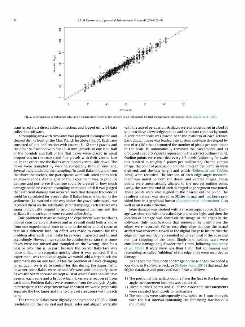
Fig. 2. A comparison of individual edge angle measurements versus the average of all individuals for that measurement (following Dibble and Bernard, 1980).
S.P. McPherron et al. / Journal of Archaeological Science 49 (2014) 70e8274
transferred via a direct cable connection, and logged using E4 datacollection software.
A trampling areawith two lanes was prepared in compacted andcleared dirt in front of the Max Planck Institute (Fig. 3). Each laneconsisted of one half section with coarse (8e12 mm) gravels andthe other half section with fine (5e8 mm) gravels. In one lane, halfof the hornfels and half of the flint flakes were placed in equalproportions on the coarse and fine gravels with their ventral faceup. In the other lane the flakes were placed ventral side down. Theflakes were trampled by walking completely through one lane.Several individuals did the trampling. To avoid flake initiation fromthe shoes themselves, the participants wore soft-soled shoes suchas shower shoes. As the goal of the experiment was to producedamage and not to see if damage could be created or how muchdamage could be created, trampling continued until it was judgedthat sufficient damage had occurred such that damage frequenciescould be calculated for every flake. If flakes became buried in thesediments (i.e. worked their way under the gravel substrates), wereplaced them on the substrates. After trampling, each artifact wasagain individually bagged to avoid subsequent damage and theartifacts from each zone were curated collectively.
One problem that arose during the experiment was that flakesmoved considerable distances and as a result could both a) movefrom one experimental zone or lane to the other and b) come torest on a different face. An effort was made to control for thisproblem after each pass. Flake faces were inspected and turnedaccordingly. However, we cannot be absolutely certain that someflakes were not missed and trampled on the “wrong” side for apass or two. This is, in part, because the correct flake face wasmore difficult to recognize quickly after it was painted. If thisexperiment was conducted again, we would add a large black dotsystematically on one face. As for the problem of flakes changinglanes, again we tried to control for this during the experiment;however, some flakes were missed. We were able to identify theseflakes afterward becausewe kept a list of which flakes should havebeen in each zone and a list of which flakes were recovered fromeach zone. Problem flakes were removed from the analysis. Again,in retrospect, if the experiment was repeated we would physicallyseparate the two lanes and the two gravel size zones within eachlane.
The trampled flakes were digitally photographed (3008 � 2000resolution) on their ventral and dorsal sides and aligned vertically
with the axis of percussion. Artifacts were photographed in a bed ofsalt to achieve a level edge outline and a constant color background.A centimeter scale was placed near the platform of each artifact.Each digital image was loaded into custom software developed byone of us (SM) that a) counted the number of pixels per centimeterin the scale, b) automatically removed the background, and c)produced a set of XY points representing the artifact outline (Fig. 4).Outline points were recorded every 6.7 pixels (adjusting for scalethis resulted in roughly 3 points per millimeter). On the ventralimage, the point of percussion and the limits of the platform weredigitized, and the box length and width (Debénath and Dibble,1994) were recorded. The location of each edge angle measure-ment was noted on both the dorsal and ventral images. Thesepoints were automatically aligned to the nearest outline point.Lastly, the start and end of each damaged edge segment was noted.These points were also aligned to the nearest outline point. Theresulting dataset was stored in SQLite format and has been pro-vided here in a graphical format (Supplemental Information 1) aswell as an R data structure.
Edge damage was studied with a macroscopic approach. Dam-age was observed with the naked eye and under light, and then thelocation of damage was noted on the image of the edges in thesoftware. Only modifications that removed the paint from theedges were recorded. When recording edge damage the actualartifact was reviewed as well as the digital image to insure that theedge damage recorded represented actual removal of the edge andnot just chipping of the paint. Single and isolated scars wereconsidered damage only if wider than 1 mm (following McBreartyet al., 1998). If scars were less than 1 mm but continuous andresembling so-called “nibbling” of the edge, they were recorded asdamage.
To analyze the frequency of damage on these edges, we coded aworkflow in R software package (R. Core Team, 2013) that read theSQLite database and processed each flake as follows:
1) The portion of the artifact outline from the first to the last edgeangle measurement location was extracted.
2) These outlines points and all of the associated measurementswere rescaled from pixels to millimeters.
3) The outlines were subsequently resampled to 1 mm intervalswith the last interval containing the remaining fraction of amillimeter.
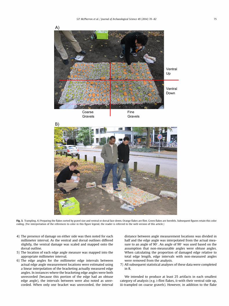
Fig. 3. Trampling. A) Preparing the flakes sorted by gravel size and ventral or dorsal face down. Orange flakes are flint. Green flakes are hornfels. Subsequent figures retain this colorcoding. (For interpretation of the references to color in this figure legend, the reader is referred to the web version of this article.)
S.P. McPherron et al. / Journal of Archaeological Science 49 (2014) 70e82 75
4) The presence of damage on either side was then noted for eachmillimeter interval. As the ventral and dorsal outlines differedslightly, the ventral damage was scaled and mapped onto thedorsal outline.
5) The location of each edge angle measure was mapped into theappropriate millimeter interval.
6) The edge angles for the millimeter edge intervals betweenactual edge angle measurement locations were estimated usinga linear interpolation of the bracketing actually measured edgeangles. In instances where the bracketing edge angles were bothunrecorded (because this portion of the edge had an obtuseedge angle), the intervals between were also noted as unre-corded. When only one bracket was unrecorded, the interval
distance between angle measurement locations was divided inhalf and the edge angle was interpolated from the actual mea-sure to an angle of 90�. An angle of 90� was used based on theassumption that non-measurable angles were obtuse angles.When calculating the proportion of damaged edge relative tototal edge length, edge intervals with non-measured angleswere removed from the analysis.
7) All subsequent statistical analyses of these data were completedin R.
We intended to produce at least 25 artifacts in each smallestcategory of analysis (e.g. i-flint flakes, ii-with their ventral side up,iii-trampled on coarse gravels). However, in addition to the flake
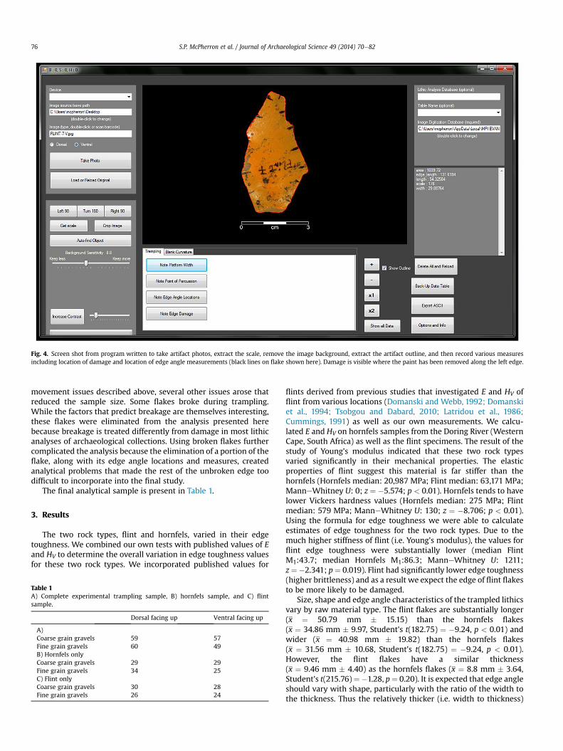
Fig. 4. Screen shot from program written to take artifact photos, extract the scale, remove the image background, extract the artifact outline, and then record various measuresincluding location of damage and location of edge angle measurements (black lines on flake shown here). Damage is visible where the paint has been removed along the left edge.
S.P. McPherron et al. / Journal of Archaeological Science 49 (2014) 70e8276
movement issues described above, several other issues arose thatreduced the sample size. Some flakes broke during trampling.While the factors that predict breakage are themselves interesting,these flakes were eliminated from the analysis presented herebecause breakage is treated differently from damage in most lithicanalyses of archaeological collections. Using broken flakes furthercomplicated the analysis because the elimination of a portion of theflake, along with its edge angle locations and measures, createdanalytical problems that made the rest of the unbroken edge toodifficult to incorporate into the final study.
The final analytical sample is present in Table 1.
3. Results
The two rock types, flint and hornfels, varied in their edgetoughness. We combined our own tests with published values of Eand HV to determine the overall variation in edge toughness valuesfor these two rock types. We incorporated published values for
Table 1A) Complete experimental trampling sample, B) hornfels sample, and C) flintsample.
Dorsal facing up Ventral facing up
A)Coarse grain gravels 59 57Fine grain gravels 60 49B) Hornfels onlyCoarse grain gravels 29 29Fine grain gravels 34 25C) Flint onlyCoarse grain gravels 30 28Fine grain gravels 26 24
flints derived from previous studies that investigated E and HV offlint from various locations (Domanski and Webb, 1992; Domanskiet al., 1994; Tsobgou and Dabard, 2010; Latridou et al., 1986;Cummings, 1991) as well as our own measurements. We calcu-lated E and HV on hornfels samples from the Doring River (WesternCape, South Africa) as well as the flint specimens. The result of thestudy of Young’s modulus indicated that these two rock typesvaried significantly in their mechanical properties. The elasticproperties of flint suggest this material is far stiffer than thehornfels (Hornfels median: 20,987 MPa; Flint median: 63,171 MPa;ManneWhitney U: 0; z ¼ �5.574; p < 0.01). Hornfels tends to havelower Vickers hardness values (Hornfels median: 275 MPa; Flintmedian: 579 MPa; ManneWhitney U: 130; z ¼ �8.706; p < 0.01).Using the formula for edge toughness we were able to calculateestimates of edge toughness for the two rock types. Due to themuch higher stiffness of flint (i.e. Young’s modulus), the values forflint edge toughness were substantially lower (median FlintM1:43.7; median Hornfels M1:86.3; ManneWhitney U: 1211;z¼�2.341; p¼ 0.019). Flint had significantly lower edge toughness(higher brittleness) and as a result we expect the edge of flint flakesto be more likely to be damaged.
Size, shape and edge angle characteristics of the trampled lithicsvary by raw material type. The flint flakes are substantially longer(x ¼ 50.79 mm � 15.15) than the hornfels flakes(x ¼ 34.86 mm � 9.97, Student’s t(182.75) ¼ �9.24, p < 0.01) andwider (x ¼ 40.98 mm � 19.82) than the hornfels flakes(x ¼ 31.56 mm � 10.68, Student’s t(182.75) ¼ �9.24, p < 0.01).However, the flint flakes have a similar thickness(x ¼ 9.46 mm � 4.40) as the hornfels flakes (x ¼ 8.8 mm � 3.64,Student’s t(215.76)¼�1.28, p¼ 0.20). It is expected that edge angleshould vary with shape, particularly with the ratio of the width tothe thickness. Thus the relatively thicker (i.e. width to thickness)
Flint Hornfels
Dam
aged
Pro
porti
on o
fMea
sure
able
Edg
e
0.0
0.1
0.2
0.3
0.4
0.5
0.6
N = 108 N = 117
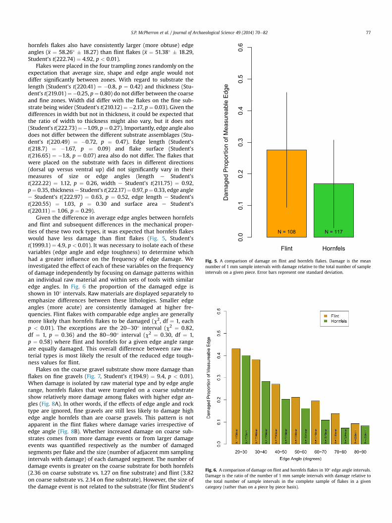
Fig. 5. A comparison of damage on flint and hornfels flakes. Damage is the meannumber of 1 mm sample intervals with damage relative to the total number of sampleintervals on a given piece. Error bars represent one standard deviation.
Fig. 6. A comparison of damage on flint and hornfels flakes in 10� edge angle intervals.Damage is the ratio of the number of 1 mm sample intervals with damage relative tothe total number of sample intervals in the complete sample of flakes in a givencategory (rather than on a piece by piece basis).
S.P. McPherron et al. / Journal of Archaeological Science 49 (2014) 70e82 77
hornfels flakes also have consistently larger (more obtuse) edgeangles (x ¼ 58.26� � 18.27) than flint flakes (x ¼ 51.38� � 18.29,Student’s t(222.74) ¼ 4.92, p < 0.01).
Flakes were placed in the four trampling zones randomly on theexpectation that average size, shape and edge angle would notdiffer significantly between zones. With regard to substrate thelength (Student’s t(220.41) ¼ �0.8, p ¼ 0.42) and thickness (Stu-dent’s t(219.01)¼�0.25, p¼ 0.80) do not differ between the coarseand fine zones. Width did differ with the flakes on the fine sub-strate being wider (Student’s t(210.12) ¼�2.17, p ¼ 0.03). Given thedifferences in width but not in thickness, it could be expected thatthe ratio of width to thickness might also vary, but it does not(Student’s t(222.73)¼�1.09, p¼ 0.27). Importantly, edge angle alsodoes not differ between the different substrate assemblages (Stu-dent’s t(220.49) ¼ �0.72, p ¼ 0.47). Edge length (Student’st(218.7) ¼ �1.67, p ¼ 0.09) and flake surface (Student’st(216.65) ¼ �1.8, p ¼ 0.07) area also do not differ. The flakes thatwere placed on the substrate with faces in different directions(dorsal up versus ventral up) did not significantly vary in theirmeasures of size or edge angles (length e Student’st(222.22) ¼ 1.12, p ¼ 0.26, width e Student’s t(211.75) ¼ 0.92,p¼ 0.35, thicknesse Student’s t(222.17)¼ 0.97, p¼ 0.33, edge anglee Student’s t(222.97) ¼ 0.63, p ¼ 0.52, edge length e Student’st(220.55) ¼ 1.03, p ¼ 0.30 and surface area e Student’st(220.11) ¼ 1.06, p ¼ 0.29).
Given the difference in average edge angles between hornfelsand flint and subsequent differences in the mechanical proper-ties of these two rock types, it was expected that hornfels flakeswould have less damage than flint flakes (Fig. 5, Student’st(1999.1) ¼ 4.9, p < 0.01). It was necessary to isolate each of thesevariables (edge angle and edge toughness) to determine whichhad a greater influence on the frequency of edge damage. Weinvestigated the effect of each of these variables on the frequencyof damage independently by focusing on damage patterns withinan individual raw material and within sets of tools with similaredge angles. In Fig. 6 the proportion of the damaged edge isshown in 10� intervals. Raw materials are displayed separately toemphasize differences between these lithologies. Smaller edgeangles (more acute) are consistently damaged at higher fre-quencies. Flint flakes with comparable edge angles are generallymore likely than hornfels flakes to be damaged (c2, df ¼ 1, eachp < 0.01). The exceptions are the 20e30� interval (c2 ¼ 0.82,df ¼ 1, p ¼ 0.36) and the 80e90� interval (c2 ¼ 0.30, df ¼ 1,p ¼ 0.58) where flint and hornfels for a given edge angle rangeare equally damaged. This overall difference between raw ma-terial types is most likely the result of the reduced edge tough-ness values for flint.
Flakes on the coarse gravel substrate show more damage thanflakes on fine gravels (Fig. 7, Student’s t(194.9) ¼ 9.4, p < 0.01).When damage is isolated by raw material type and by edge anglerange, hornfels flakes that were trampled on a coarse substrateshow relatively more damage among flakes with higher edge an-gles (Fig. 8A). In other words, if the effects of edge angle and rocktype are ignored, fine gravels are still less likely to damage highedge angle hornfels than are coarse gravels. This pattern is notapparent in the flint flakes where damage varies irrespective ofedge angle (Fig. 8B). Whether increased damage on coarse sub-strates comes from more damage events or from larger damageevents was quantified respectively as the number of damagedsegments per flake and the size (number of adjacent mm samplingintervals with damage) of each damaged segment. The number ofdamage events is greater on the coarse substrate for both hornfels(2.36 on coarse substrate vs. 1.27 on fine substrate) and flint (3.82on coarse substrate vs. 2.14 on fine substrate). However, the size ofthe damage event is not related to the substrate (for flint Student’s
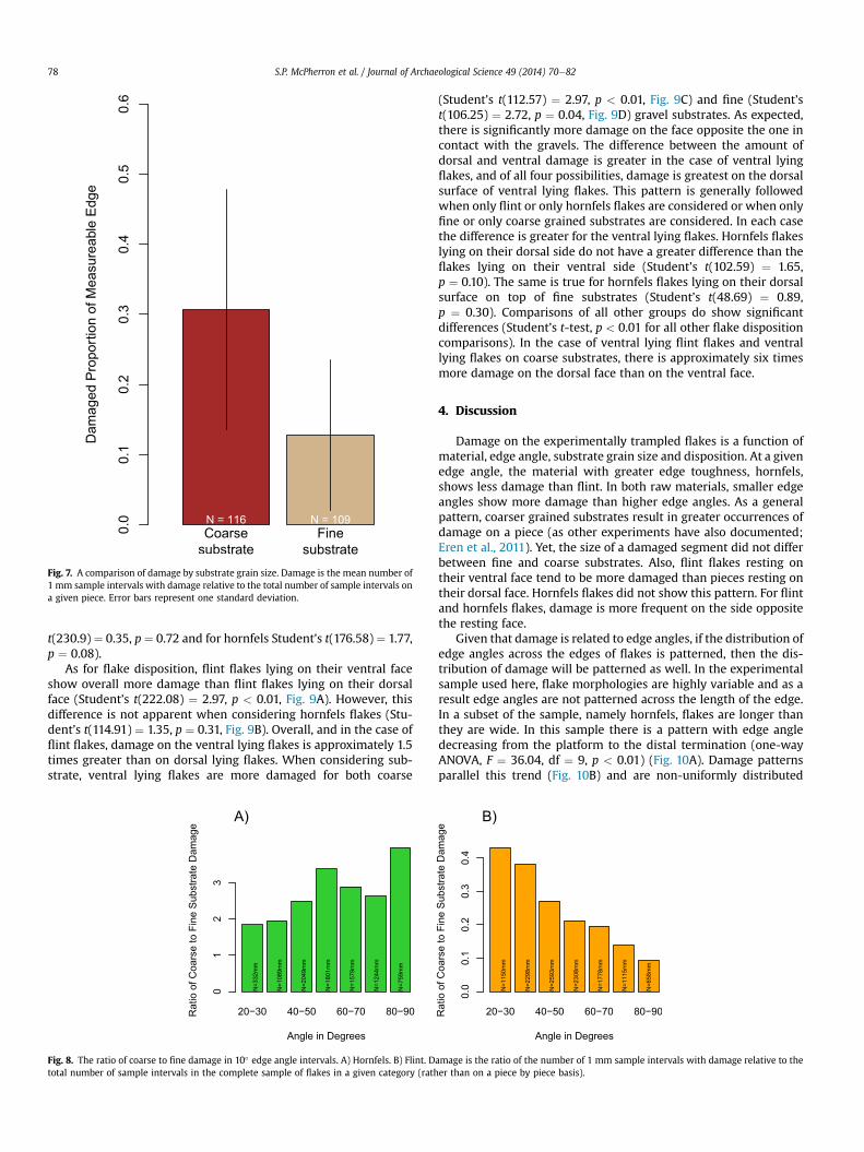
Fig. 7. A comparison of damage by substrate grain size. Damage is the mean number of1 mm sample intervals with damage relative to the total number of sample intervals ona given piece. Error bars represent one standard deviation.
S.P. McPherron et al. / Journal of Archaeological Science 49 (2014) 70e8278
t(230.9) ¼ 0.35, p¼ 0.72 and for hornfels Student’s t(176.58) ¼ 1.77,p ¼ 0.08).
As for flake disposition, flint flakes lying on their ventral faceshow overall more damage than flint flakes lying on their dorsalface (Student’s t(222.08) ¼ 2.97, p < 0.01, Fig. 9A). However, thisdifference is not apparent when considering hornfels flakes (Stu-dent’s t(114.91) ¼ 1.35, p ¼ 0.31, Fig. 9B). Overall, and in the case offlint flakes, damage on the ventral lying flakes is approximately 1.5times greater than on dorsal lying flakes. When considering sub-strate, ventral lying flakes are more damaged for both coarse
Fig. 8. The ratio of coarse to fine damage in 10� edge angle intervals. A) Hornfels. B) Flint. Dtotal number of sample intervals in the complete sample of flakes in a given category (rath
(Student’s t(112.57) ¼ 2.97, p < 0.01, Fig. 9C) and fine (Student’st(106.25) ¼ 2.72, p ¼ 0.04, Fig. 9D) gravel substrates. As expected,there is significantly more damage on the face opposite the one incontact with the gravels. The difference between the amount ofdorsal and ventral damage is greater in the case of ventral lyingflakes, and of all four possibilities, damage is greatest on the dorsalsurface of ventral lying flakes. This pattern is generally followedwhen only flint or only hornfels flakes are considered or when onlyfine or only coarse grained substrates are considered. In each casethe difference is greater for the ventral lying flakes. Hornfels flakeslying on their dorsal side do not have a greater difference than theflakes lying on their ventral side (Student’s t(102.59) ¼ 1.65,p ¼ 0.10). The same is true for hornfels flakes lying on their dorsalsurface on top of fine substrates (Student’s t(48.69) ¼ 0.89,p ¼ 0.30). Comparisons of all other groups do show significantdifferences (Student’s t-test, p < 0.01 for all other flake dispositioncomparisons). In the case of ventral lying flint flakes and ventrallying flakes on coarse substrates, there is approximately six timesmore damage on the dorsal face than on the ventral face.
4. Discussion
Damage on the experimentally trampled flakes is a function ofmaterial, edge angle, substrate grain size and disposition. At a givenedge angle, the material with greater edge toughness, hornfels,shows less damage than flint. In both raw materials, smaller edgeangles show more damage than higher edge angles. As a generalpattern, coarser grained substrates result in greater occurrences ofdamage on a piece (as other experiments have also documented;Eren et al., 2011). Yet, the size of a damaged segment did not differbetween fine and coarse substrates. Also, flint flakes resting ontheir ventral face tend to be more damaged than pieces resting ontheir dorsal face. Hornfels flakes did not show this pattern. For flintand hornfels flakes, damage is more frequent on the side oppositethe resting face.
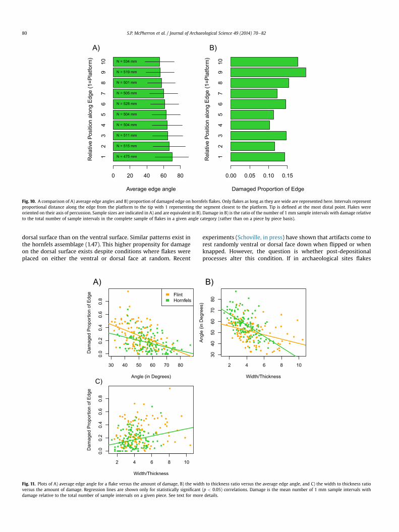
Given that damage is related to edge angles, if the distribution ofedge angles across the edges of flakes is patterned, then the dis-tribution of damage will be patterned as well. In the experimentalsample used here, flake morphologies are highly variable and as aresult edge angles are not patterned across the length of the edge.In a subset of the sample, namely hornfels, flakes are longer thanthey are wide. In this sample there is a pattern with edge angledecreasing from the platform to the distal termination (one-wayANOVA, F ¼ 36.04, df ¼ 9, p < 0.01) (Fig. 10A). Damage patternsparallel this trend (Fig. 10B) and are non-uniformly distributed
amage is the ratio of the number of 1 mm sample intervals with damage relative to theer than on a piece by piece basis).
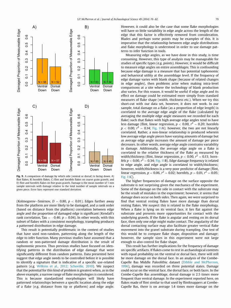
Fig. 9. A comparison of damage by which side (ventral or dorsal) is facing down. A)flint flakes, B) hornfels flakes, C) flint and hornfels flakes on coarse grain gravels, andD) flint and hornfels flakes on fine grain gravels. Damage is the mean number of 1 mmsample intervals with damage relative to the total number of sample intervals on agiven piece. Error bars represent one standard deviation.
S.P. McPherron et al. / Journal of Archaeological Science 49 (2014) 70e82 79
(KolmogoroveSmirnov, D ¼ 0.80, p < 0.01). Edges further awayfrom the platform are more likely to be damaged, and a rank order(based on distance from the platform) correlation between edgeangle and the proportion of damaged edge is significant (Kendall’srank correlation, Tau ¼ �0.46; p ¼ 0.04). In other words, with thissubset of flakes with a consistent morphology, trampling producesa patterned distribution in edge damage.
This result is potentially problematic in the context of studiesthat have used non-random, patterning along the length of theedge to infer function. Many previous studies have assumed that arandom or non-patterned damage distribution is the result oftaphonomic process. Thus previous studies have focused on iden-tifying patterns in the distribution of edge damage that weresignificantly different from random patterns. Data presented heresuggest that edge angle needs to be controlled before it is possibleto identify a signature that is indicative of a specific use-relatedpattern (e.g. Wilkins et al., 2012; Schoville, 2010). We suspectthat the potential for this kind of problem is greatest when, as in theabove example, a narrow range of flakemorphologies is considered.This is because standardized morphologies will likely havepatterned relationships between a specific location along the edgeof a flake (e.g. distance from tip or platform) and edge angle.
However, it could also be the case that some flake morphologieswill have so little variability in edge angle across the length of theedge that this factor is effectively removed from consideration.Blades and perhaps some points may be examples of this. It isimperative that the relationship between edge angle distributionsand flake morphology is understood in order to use damage pat-terns to infer function in tools.
Measuring edge angles, as we have done in this study, is timeconsuming. However, this type of analysis may be manageable forstudies of specific types (e.g. points). However, it would be difficultto measure edge angles on entire assemblages. This is confoundingbecause edge damage is a measure that has potential taphonomicand behavioral utility at the assemblage level. If the frequency ofedge damage varies with blank shape (because of related changesin edge angles), then problems arise when making intra-levelcomparisons at a site where the technology of blank productionalso varies. For this reason, it would be useful if edge angle and itseffect on damage could be estimated more simply from standardmeasures of flake shape (width, thickness etc.). When we try thisshort-cut with our data set, however, it does not work. In oursample, total damage on a flake (as a proportion of edge length) iscorrelated to the average edge angle of the flake (calculated byaveraging the multiple edge angle measures we recorded for eachflake) such that flakes with high average edge angles tend to haveless damage (flint, linear regression, p < 0.00, r2 ¼ 0.20; hornfelsp < 0.00, r2 ¼ 0.14; Fig. 11A); however, the two are not linearlycorrelated. Rather, a non-linear relationship is produced whereinlow average edge angle pieces have varying amounts of damage butas average edge angle increases the amount of damage per piecedecreases. In other words, average edge angle constrains variabilityin damage. Additionally, the average edge angle on a flake iscorrelated to the relative thickness of the flake as measured bywidth/thickness (flint, linear regression, p < 0.00, r2 ¼ 0.13; horn-fels p < 0.00, r2 ¼ 0.34; Fig. 11B). Edge damage frequency is relatedto edge angle, and edge angle is correlated to width/thickness;however, width/thickness is a very poor predictor of damage (flint,linear regression, p ¼ 0.06, r2 ¼ 0.02; hornfels, p ¼ 0.01, r2 ¼ 0.05;Fig. 11C).
The higher frequencies of damage on the surface opposite thesubstrate is not surprising given the mechanics of the experiment.Some of the damage on the side in contact with the substrate maybe the result of mistakes in the experiment; however, it seems thatdamage does occur on both sides. Then again, wewere surprised tofind that ventral resting flakes have more damage than dorsalresting flakes. We suspect this is related to the flake morphology.When a flake is lying on its ventral face, it lies flat against thesubstrate and presents more opportunities for contact with theunderlying gravels. If the flake is angular and resting on its dorsalface, then only one edge might make contact. The angularity of thedorsal contacting surface may also facilitate greater vertical flakemovement into the gravel substrate during trampling. One test ofthis would be to compare flake shape, disposition and damage;however, the sample sizes in this experiment were not largeenough to also control for flake shape.
This result has further implications for the frequency of damageon specific artifacts. If flakes come to rest in archaeological contextswith equal probability on the ventral or dorsal face, there will stillbe more damage on the dorsal face. In an analysis of the Combe-Capelle Bas Middle Paleolithic dataset (Dibble and McPherron,1996), damage was recorded on three potential states. Damagecould occur on the ventral face, the dorsal face, or both faces. In theCombe-Capelle Bas assemblage, dorsal damage is 2.5 times morefrequent than ventral damage. In the experiment reported here, onflakes made of flint similar to that used by flintknappers at Combe-Capelle Bas, there is on average 1.4 times more damage on the
12
34
56
78
910
Average edge angle
Rel
ativ
ePo
sitio
n al
ong
Edg
e (1
=Pla
tform
)
0 20 40 60 80
N = 475 mm
N = 515 mm
N = 511 mm
N = 504 mm
N = 504 mm
N = 528 mm
N = 505 mm
N = 501 mm
N = 519 mm
N = 534 mm
A)
12
34
56
78
910
Damaged Proportion of Edge
Rel
ativ
ePo
sitio
n al
ong
Edg
e (1
=Pla
tform
)
0.00 0.05 0.10 0.15
B)
Fig. 10. A comparison of A) average edge angles and B) proportion of damaged edge on hornfels flakes. Only flakes as long as they are wide are represented here. Intervals representproportional distance along the edge from the platform to the tip with 1 representing the segment closest to the platform. Tip is defined at the most distal point. Flakes wereoriented on their axis of percussion. Sample sizes are indicated in A) and are equivalent in B). Damage in B) is the ratio of the number of 1 mm sample intervals with damage relativeto the total number of sample intervals in the complete sample of flakes in a given angle category (rather than on a piece by piece basis).
S.P. McPherron et al. / Journal of Archaeological Science 49 (2014) 70e8280
dorsal surface than on the ventral surface. Similar patterns exist inthe hornfels assemblage (1.47). This higher propensity for damageon the dorsal surface exists despite conditions where flakes wereplaced on either the ventral or dorsal face at random. Recent
Fig. 11. Plots of A) average edge angle for a flake versus the amount of damage, B) the widtversus the amount of damage. Regression lines are shown only for statistically significantdamage relative to the total number of sample intervals on a given piece. See text for mor
experiments (Schoville, in press) have shown that artifacts come torest randomly ventral or dorsal face down when flipped or whenknapped. However, the question is whether post-depositionalprocesses alter this condition. If in archaeological sites flakes
h to thickness ratio versus the average edge angle, and C) the width to thickness ratio(p < 0.05) correlations. Damage is the mean number of 1 mm sample intervals withe details.
S.P. McPherron et al. / Journal of Archaeological Science 49 (2014) 70e82 81
come to rest preferentially on their ventral surface, the difference indamage on each face will be even greater. There are some data tosuggest that this is the case. Schick (1984, 1986) documented thepropensity of flakes to come to rest with their ventral face down influme experiments aimed at understanding post-depositionalprocesses in open-air Earlier Stone Age localities. At Tabun Cave,Jelinek recorded disposition and found a preference for ventral facedown flakes (Jelinek and Baumler personal communications). TheCombe-Capelle Bas pattern, therefore, may be the result of flakemechanics which favor dorsal removals plus processes that bringflakes to rest preferentially on their ventral surface. Thus, here too,trampling creates a non-random pattern in edge damage, becausehigher frequencies of damage on the dorsal surface is a product ofthe propensity for flakes to come to rest with their ventral facedown.
5. Conclusion
The experiment presented here was designed primarily to testthe effect of edge angle and raw material properties on the fre-quency and location of edge damage on trampled flakes. Indeed,damage is correlated with edge angle. Raw material variability alsoplays a rolewithmaterials that have lower edge toughness showinghigher damage rates on a wide range of edge angles. However, atlow edge angles (<30�), raw material variability did not make adifference. This indicates that these very low edge angles are likelyto show higher levels of damage regardless of their materialproperties. As a result, use-wear and taphonomic studies that relyon varying rates of edge damage and/or patterns in edge damagedistributions along the edges of flakes must first control for edgeangle and rawmaterial variability. So, for instance, if the technologyof blank production varies in a sequence, we can expect averageedge angles to vary as well. The present experiment suggests thiswill affect the frequency of damage on flakes. A level with thin,broad blanks is likely to exhibit patterns that appear to have higherfrequencies of edge damaged relative to a level where the majorityof blanks are thick and narrow blanks even if the incidence oftrampling between these two levels is identical. Similarly, if edgeangle varies systematically across the edge in particular artifactclasses (e.g. points, blades), then trampling damage will showpatterning in distributions along the edge as well. If, for instance,projectile points have lower edge angles at the distal end, thentrampling damage may appear more frequently at the tip. Thecurrent experiment only tested the effect of trampling. However,given that edge damage is the result of first principles related to thematerial properties of stone and fracture mechanics, it seems likelythat other post-depositional processes such a solifluction, cry-oturbation, and fluvial transport may result in similar patterns.
This finding is problematic for comparative studies of edgedamage rates at the assemblage level because measuring edgeangles as we have done here is time consuming. We attempted tofind a solution to the arduous process of measuring each individualedge angle by estimating average edge angle on a blank usingmajorflake shape variables (e.g. width to thickness ratio). However, while1) the amount of damage on a piece is related to the average edgeangle of that piece and 2) the average edge angle of a piece iscorrelated to its width to thickness ratio, the amount of damage ona piece is not correlated to the width to thickness ratio (relativethickness). One of the possibilities that remains to be investigatedwith our data set is whether a subsample of edge angle measure-ments on a piece would be sufficient to predict damage rates. Forinstance, it is possible that an estimate of the range in possible edgeangles for a given blank would be sufficient to understand edgedamage patterns. Similarly it might be possible to employ somecombination of an angle measure and an estimate of the proportion
of edge it represents. However, while this might work for assem-blage level characterizations of damage rates, this approach is likelynot sufficient for studies of the damage location patterns withinparticular artifact classes.
One of the unexpected results of this study is that when othervariables are held constant, dorsal damage rates are higher thanventral damage rates. This finding follows patterns previouslydocumented in archaeological collections (the Middle Paleolithicsite of Combe-Capelle Bas). Given the experimental design usedhere, this result is likely explained by the fact that flakes laying ontheir ventral surface present a more consistent contact with theunderlying substrate. In contrast flakes lying on their dorsal surfacemay have only a portion of their edge in contact with the substrate.Thus with regard to flake surface, trampling creates a patterned,non-random distribution. If it can be shown that flakes comepreferentially to rest on their ventral surface, this pattern will befurther amplified.
Acknowledgments
We thank Nicolas Zwyns for help making flakes and forparticipating in the edge angle measurement replication study. Wethank Harold L. Dibble for comments on the manuscript. We thankthe Max Planck Society for partially funding this project, and DavidBraun thanks the Alexander von Humboldt Foundation and theNational Research Foundation of South Africa (74206) for additionalsupport.
Appendix A. Supplementary data
Supplementary data related to this article can be found at http://dx.doi.org/10.1016/j.jas.2014.04.003.
References
Akoshima, Kaoru, 1987. Microflaking Quantification. In: de Sieveking, G.,Newcomer, M.H. (Eds.), The Human Uses of Flint and Chert. Cambridge Uni-versity Press, Cambridge, pp. 71e79.
Ashby, M.F., 1992. Materials Selection in Mechanical Design. Pergamon Press,Oxford.
Bamforth, D.B., Burns, G.R., Woodman, C., 1990. Ambiguous use traces and blind testresults: new data. J. Archaeol. Sci. 17, 413e430.
Bird, C., Minichillo, T., Marean, C.W., 2007. Edge damage distribution at theassemblage level on Middle Stone Age Lithics: an image-based GIS approach.J. Archaeol. Sci. 34, 771e780.
Brown, K.S., Marean, C.W., Jacobs, Z., Schoville, B.J., Oestmo, S., Fisher, E.C.,Bernatchez, J., Karkanas, P., Matthews, T., 2012. An early and enduring advancedtechnology originating 71,000 years ago in South Africa. Nature 491, 590e593.
Cummings, F.C., 1991. Machine Tunnelling Perfomance in Chalk with Flint withParticular Reference to the Mechanical Properties of Flint. Univerity of Brighton,Brighton.
Debénath, André, Dibble, Harold Lewis, 1994. Handbook of Paleolithic Typology:Lower and Middle Paleolithic of Europe, vol. 1. Univ. of Pennsylvania Museum,Philadelphia.
Dibble, H.L., Rezek, Z., 2009. Introducing a new experimental design for controlledstudies of flake formation: results for exterior platform angle, platform depth,angle of blow, velocity, and force. J. Archaeol. Sci. 36 (9), 1945e1954.
Dibble, H.L., Bernard, M.C., 1980. A comparative study of basic edge angle mea-surement techniques. Am. Antiq. 45 (4), 857e865.
Dibble, H.L., McPherron, S.P., 1996. A Multimedia Companion to the Middle Paleo-lithic Site of Combe-Capelle Bas (France). University of Pennsylvania MuseumPress, Philadelphia.
Dibble, H.L., Whittaker, J.C., 1981. New experimental evidence on the relation be-tween percussion flaking and flake variation. J. Archaeol. Sci. 8, 283e296.
Dibble, Harold L., McPherron, Shannon P., 2006. The missing Mousterian. Curr.Anthropol. 47 (5), 777e803.
Domanski, M., Webb, J., Boland, J., 1994. Mechanical properties of stone artefactmaterials and the effect of heat treatment. Archaeometry 36, 177e208.
Domanski, Marian, Webb, John A., 1992. Effect of heat treatment on siliceous rocksused in prehistoric lithic technology. J. Archaeol. Sci. 19 (6), 601e614 http://dx.doi.org/10.1016/0305-4403(92)90031-W.
Eren, Metin I., Boehem, Andrew R., Morgan, Brooke M., Anderson, Rick,Andrews, Brian, 2011. Flaked stone taphonomy: a controlled experimental
S.P. McPherron et al. / Journal of Archaeological Science 49 (2014) 70e8282
study of the effects of sediment consolidation on flake edge morphology.J. Taphon. 9 (3), 201e217.
Eren, M.I., Lycett, Stephen J., 2012. Why Levallois? A morphometric comparison ofexperimental ‘preferential’ Levallois flakes versus debitage flakes. PLoS One 7,e29273.
Eren, M.I., Durant, A., Neudorf, C., Haslam, M., Shipton, C., Bora, J., Korisettar, R.,Petraglia, M., 2010. Experimental examination of animal trampling effects onartifact movement in dry and water saturated substrates: a test case from SouthIndia. J. Archaeol. Sci. 37, 3010e3021.
Flenniken, J.J., Haggarty, J.C., 1979. Trampling as an agency in the formation of edgedamage: an experiment in lithic technology. Northwest Anthropol. Res. Notes13, 208e214.
Gifford-Gonzalez, D., Damrosch, D., Pryor, J., Thunen, R., 1985. The third dimensionin site structure: an experiment in trampling and vertical dispersal. Am. Antiq.50, 803e818.
Latridou, J.P., Letavernier, G., Linde, K., Etlicher, B., Ozouf, J.C., 1986. Porosity andfrost susceptibility of flints and chalk: laboratory experiments, comparison ofglacial and periglacial surface texture of flint materials and field investigations.In: Sieveking, D.G., Hart, M.B. (Eds.), The Scientific Study of Flint and Chert.Cambridge University Press, Cambridge.
Lin, Sam C., Rezek, Zeljko, Braun, David, Dibble, Harold L., 2013. On the utility andeconomization of unretouched flakes: the effects of exterior platform angle andplatform depth. Am. Antiq. 78 (4), 724e745.
McBrearty, Sally, Bishop, Laura, Plummer, Thomas, Dewar, Robert, Conard, Nicholas,1998. Tools underfoot: human trampling as an agent of lithic artifact edgemodification. Am. Antiq. 63 (1), 108e129.
Nielsen, A.E., 1991. Trampling the archaeological record: an experimental study. Am.Antiq. 56 (3), 483e503.
Odell, G.H., 2001. Stone tool research at the end of the millennium: classification,function, and behavior. J. Archaeol. Res. 9 (1), 45e100.
Pargeter, J., 2011. Assessing the macrofacture method for identifying Stone Agehunting weaponry. J. Archaeol. Sci. 38, 2882e2888.
Pargeter, Justin, Bradfield, Justin, 2012. The effects of class I and II sized bovids onmacrofracture formation and tool displacement: results of a trampling exper-iment in a southern African Stone Age context. J. Field Archaeol. 37 (3), 238e251.
Pryor, John, 1988. The effects of human trample damage on lithics: a considerationof crucial variables. Lithic Technol. 17 (1), 45e50.
Quinn, J.B., Quinn, G.D., 1997. Indentation brittleness of ceramics: a fresh approach.J. Mater. Sci. 32, 4331e4346.
R. Core Team, 2013. R: a language and environment for statistical computing. RFoundation for Statistical Computing, Vienna, Austria.
Schick, Kathy D., 1984. Processes of Paleolithic Site Formation: an ExperimentalStudy (PhD dissertation). University of California at Berkeley.
Schick, Kathy Diane, 1986. Stone Age Sites in the Making: Experiments in the For-mation and Transformation of Archaeological Occurrences. BAR.
Schoville, B.J., 2010. Frequency and distribution of edge damage on Middle StoneAge lithic points, Pinnacle Point 13B, South Africa. J. Hum. Evol. 59, e378ee391.
Schoville Benjamin, J., in press. Testing a taphonomic predictive model of edgedamage formation with Middle Stone Age points from Pinnacle Point cave 13Band Die Kelders Cave 1, South Africa. J. Archaeol. Sci. http://dx.doi.org/10.1016/j.jas.2013.10.002
Schoville, B., Brown, K.S., 2010. Comparing lithic assemblage edge damage distri-butions: examples from the late Pleistocene and preliminary experimental re-sults. vis-à-vis: Explorations in Anthrop. 10, 34e49.
Shea, J.J., Klenck, J.D., 1993. An experimental investigation of the effects of tramplingon the results of lithic microwear analysis. J. Archaeol. Sci. 20, 175e194.
Shea, J.J., 1992. Lithic microwear analysis in archeology. Evol. Anthropol. 1, 143e150.Shott, M.J., Sillitoe, P., 2004. Modeling use-life distributions in archaeology using
New Guinea Wola Ethnographic data. Am. Antiq. 69, 339e355.Shott, M.J., Sillitoe, P., 2005. Use life and curation in New Guinea experimental used
flakes. J. Archaeol. Sci. 32, 653e663.Speth, J.D., 1972. Mechanical basis of percussion flaking. Am. Antiq., 34e60.Tixier, J., Turq, A., 1999. Kombewa. Paléo 11, 135e143.Tringham, R., Cooper, G., Odell, G., Voytek, B., Whitman, A., 1974. Experimentation in
the formation of edge damage: a new approach to lithic analysis. J. FieldArchaeol. 1, 171e196.
Tsobgou, R.A., 2009. Mapping Mesolithic and Neolithic cultures behaviours andinteractions with nature and properties of rocks in Western France. J. Archaeol.Sci. 36, 1615e1625.
Tsobgou, R.A., Dabard, M.P., 2010. Petrographical, structural, and mechanical anal-ysis of armorican phtanites: a key raw material for the Mesolithic in WesternFrance. Geoarchaeology 25, 327e351.
Viles, Heather, Goudie, Andrew, Grab, Stefan, Lalley, Jennifer, 2011. The use of theSchmidt Hammer and Equotip for rock hardness assessment in geomorphologyand heritage science: a comparative analysis. Earth Surf. Process. Landf. 36 (3),320e333.
Waters, D., Lovegrove, D., 2002. Assessing the extent of disequilibrium and over-stepping of prograde metamorphic reactions in metapelites from the BushveldComplex aureole, South Africa. J. Metamorph. Geol. 20, 135e149.
Webb, J., Domanski, M., 2008. The relationship between lithology, flaking propertiesand artefact manufacture for Australian silcretes. Archaeometry 50, 555e575.
Wilkins, J., Schoville, B.J., Brown, K.S., Chazan, M., 2012. Evidence for early haftedhunting technology. Science 338, 942e946.
Young, D., Bamforth, D.B., 1990. On the macroscopic identification of used flakes.Am. Antiq., 403e409.
Copyright © 2022 FDOKUMEN