An evolved bike handlebar - POLITesi
72
Scuola del Design Corso di Laurea Magistrale Design & Engineering Relatore: Prof. Federico Elli Candidato: Sofia Marinelli 916212 Anno accademico: 2020/2021 An evolved bike handlebar
-
Upload
khangminh22 -
Category
Documents
-
view
1 -
download
0
Transcript of An evolved bike handlebar - POLITesi

Scuola del Design
Corso di Laurea Magistrale
Design & Engineering
Relatore:
Prof. Federico Elli
Candidato:
Sofia Marinelli
916212
Anno accademico:
2020/2021
An evolved bike handlebar


Scuola del Design
Corso di Laurea Magistrale
Design & Engineering
Relatore:
Prof. Federico Elli
Candidato:
Sofia Marinelli
916212
Anno accademico:
2020/2021

Questo progetto segna la fine di un percorso durato cinque anni in cui sono cresciuta professionalmente ma sopratutto psicologicamente. L’università mi ha permesso di acquisire nuove conoscenze tecniche, di conoscere culture diverse e di imparare a contare su me stessa. L’opportunità di vivere esperienze al di fuori della mia piccola realtà mi ha reso consapevole della bellezza della diversità e di quanto si può imparare da essa. Grazie a chi ha affrontato con me questo percorso, a chi mi ha permesso di viverlo e a chi mi ha aiutato a superare le difficoltà e ascoltata.
Alla mia famiglia e ai miei amici.
This project marks the end of a five-year journey in which I grew up professionally but above all psychologically. The university has allowed me to acquire new technical knowledge, to get to know different cultures and to learn to rely on myself. The opportunity to live experiences outside of my own little reality has made me aware of the beauty of diversity and how much you can learn from it. Thanks to those who have faced with me this path, to those who allowed me to live it and to those who helped me overcome the difficulties and listened.
To my family and my friends.

AbstractThis Master Thesis project starterd from one of the most important target of the Sustainable Development Goals, a global call to protect the environment and improve people’s lives: Sustainable cities and communities. Transport activities have emerged as one of the most pressing issues related to environmental problems worldwide; green vehicles are a strong answer to this issue. People’s growing awareness and Covid-19 situation generated a boom in bicycle usage and related market; the purest form of cycling is experiencing a renaissance, as a new, healthy and sustainable way of living the city. Technology is an important factor that helps and nudges peoples in keeping their green habits; it improves rider’s and bike’s safety with new and intelligent features. Bike handlebar is a perfect place in which integrate intelligent sensors and components designed to influence and improve rider’s behavior.

Index01 Design Research
The evolution of humanity in relation to the environment 10
The Sustainable Development Goals 12
Green mobility 13
Urban mobility 15
Italian mobility 17
Bicycle boom 20
Bike’s usage 22
A green future
Bike’s history 26
Bike’s categories 28
The bicycle
Bike’s accessories 32
Bike’s handlebar 34
02 Brief
Project’s opportunity 44
The idea in between 49
Market analysis 50
Let’s make it smart
Concept ideas 52
03 Project
Product description 54
How to install it 62
Too Smart - A smart bike handlebar
04 References
Data sheets 122
Images and graphs 132
Bibliography 138
How does it work 66
Product set - assemblies 72
Components’ list 80
Conclusion 120

Green future
01
Since Prehistoric times, humanity, by living activities, directly influenced world’s ecosystem, while, at the same time, climatic changes, as atmospheric conditions and seasons, played a role in the civilization of early human. This strict and necessary relationship between people and nature evolved through years, as brain size increased and more inhabitants adapted to different environments, bringing advances in human technology.
Technology is part of our lives since 3.3 millions years ago, when humanity started to modify stones to create knives for hunting purpose. Nowadays, it is present everywhere, in every object we use daily, changing our way of living and enhancing it. Unfortunately, besides improving people’s lives, there are important and “hidden” side effects affecting and threating nature balance. The planet has been harmed by continued industrialization and technological advances in developing countries, which have resulted in pollution and natural resource depletion. Environmental issues took on a global scale in the 20th century. In 1987, Gro Harlem Brundtland, President of the World Commission on Environment and Development (WCED), presented the study «Our Shared Future» (The Future of All of Us), formulating a sustainable development guideline that is still in effect today.
In the 21st century, there is a growing overall understanding of the danger posed by the human-induced enhanced greenhouse effect, which is primarily caused by forest clearing and fossil fuel combustion.
Design Research
The evolution of humanity in relation to the environment
Source: http://f u b i n i . s w a r t h m o r e .edu/~ENVS2/S2003/Heidi/FirstEssay.html
12
Figure 1.1: Green wave
13
Source: http://www.assiea.it/uploads/3/8/6/7/38673389/a r t i c o l o _ a s s i e a . p d f

14
In 2015, all the United Nation Members States adopted the Sustainable Development Goals (SDGs) as a global call to action to end hunger, protect the environment, and ensure stability and prosperity for all people by 2030. This project is structured by 17 global challenges: poverty, injustice, climate change, environmental destruction, stability and justice are among the issues discussed.
The 11th Sustainable Development Goal’s (SDG11) challenge, called “Sustainable cities and communities”, aims to make cities settlement more inclusive, safe, resilient and long-lasting with a particular focus on sustainable trasports. Transportation and mobility are critical components of long-term sustainability, as they boost economic growth and increase accessibility.
The world is becoming increasingly urbanized. More than half of the world’s population has lived in cities since 2007, and that percentage is expected to increase to 60% by 2030. Cities and metropolitan areas are global growth engines, contributing about 60% of global GDP (Gross Domestic Product); however, they are also responsible for about 70% of global carbon emissions and over 60% or resource consumption. The project’s aim is to provide access to secure, reliable, efficient and sustainable transportation systems for all by 2030.
Source: https://s d g s . u n . o r g / g o a l s
The Sustainable Development Goals
Figure 1.2: Sustainable Development Goals
15
Transport activities have emerged as one of the most pressing issues related to environmental problems. Greenhouse gas emissions (GHG), almost 23% of global energy and 18% of all man-made emissions in the global economy, and air pollution, causing health problems both to humanity and nature, are expected to rise up 40% by 2040. Each year, air pollution kills up to 3 million people, making it the most serious environmental health threat.
Green mobility
Source: https://o p e n k n o w l e d g e .w o r l d b a n k . o r g /handle/10986/30493
Source: https://www.e u r o . w h o . i n t / e n /data-and-evidence/e v i d e n c e - i n f o r m e d -p o l i c y - m a k i n g /p u b l i c a t i o n s / h e n -summaries-of-network-m e m b e r s - r e p o r t s /what-are -the -ef fects-on-health-of-transport-re la ted-ai r -pol lu t ion
Source: https://w w w . e l t i s . o r g /glossary/sustainable-t r a n s p o r t - s y s t e m
Source: https://www.mcgill.ca/sustainability/f i les/sus ta inabi l i t y/what-is-sustainability.pdf
The WHO study Health Effects of Transport-Related Air Pollution, published in 2005, is the first systematic review of road-related air pollution and the health threats it poses. Road transport is the main generator of emissions of gaseous air contaminants and suspended particulate matter (PM) of various sizes and compositions as nitrogen dioxide and benzene in cities.
Green mobility is a form of sustainable transportation that, according to the EU Transport Council:
“allows the basic access and development needs of society to be met safely and in a manner consistent with human and ecosystem health, and promotes equity within and between successive generations”;
“is affordable, operates fairly and efficiently, offers choice of transport mode, and supports a competitive economy, as well as balanced regional development”;
“limits emissions and waste within the planet’s ability to absorb them, uses renewable resources at or below their rates of generation and uses non-renewable resources at or below the rates of development of renewable substitutes while minimising the impact on the use of land and the generation of noise.”
The term sustainability means meeting our own needs without compromising the ability of future generations to meet their own needs.
GHD + AIR POLLUTION
+40% / each year
DEATH
+3 mil / each year
16
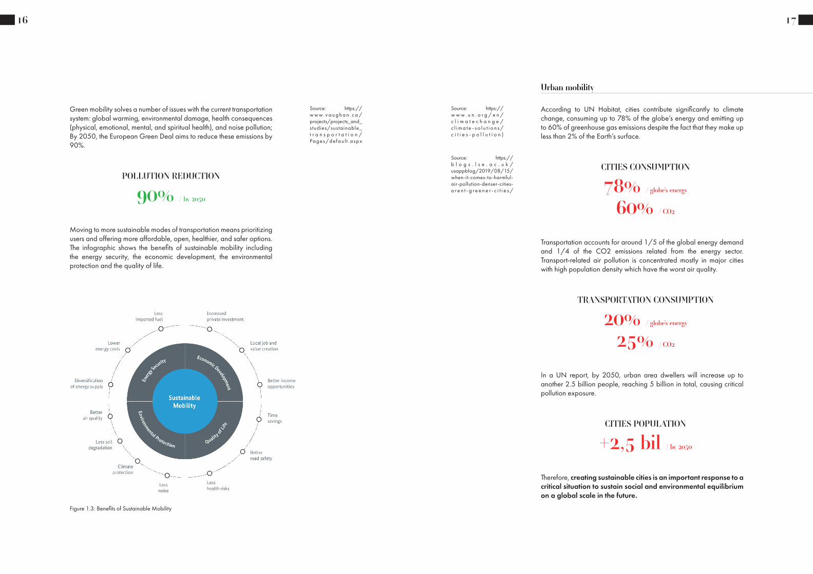
Green mobility solves a number of issues with the current transportation system: global warming, environmental damage, health consequences (physical, emotional, mental, and spiritual health), and noise pollution; By 2050, the European Green Deal aims to reduce these emissions by 90%.
Source: https://w w w. v a u g h a n . c a /projects/projects_and_studies/sustainable_t r a n s p o r t a t i o n /Pages/de fau l t .a spx
Moving to more sustainable modes of transportation means prioritizing users and offering more affordable, open, healthier, and safer options. The infographic shows the benefits of sustainable mobility including the energy security, the economic development, the environmental protection and the quality of life.
POLLUTION REDUCTION
90% / by 2050
Figure 1.3: Benefits of Sustainable Mobility
17
According to UN Habitat, cities contribute significantly to climate change, consuming up to 78% of the globe’s energy and emitting up to 60% of greenhouse gas emissions despite the fact that they make up less than 2% of the Earth’s surface.
Urban mobility
Source: https://w w w . u n . o r g / e n /c l i m a t e c h a n g e /c l i m a t e - s o l u t i o n s /c i t i e s - p o l l u t i o n )
CITIES CONSUMPTION
78% / globe’s energy
Source: https://b l o g s . l s e . a c . u k /usappblog/2019/08/15/when-it-comes-to-harmful-air-pollution-denser-cities-a r e n t - g r e e n e r - c i t i e s /
Transportation accounts for around 1/5 of the global energy demand and 1/4 of the CO2 emissions related from the energy sector.Transport-related air pollution is concentrated mostly in major cities with high population density which have the worst air quality.
In a UN report, by 2050, urban area dwellers will increase up to another 2.5 billion people, reaching 5 billion in total, causing critical pollution exposure.
60% / CO2
TRANSPORTATION CONSUMPTION
20% / globe’s energy
25% / CO2
CITIES POPULATION
+2,5 bil / by 2050
Therefore, creating sustainable cities is an important response to a critical situation to sustain social and environmental equilibrium on a global scale in the future.

18
In 2014, Denmark’s capital, Copenhagen, received the European Green Capital Award in recognition of its commitment to creating a more sustainable city making the metropolis a role model for European cities. By 2025, Copenhagen wants to reduce its carbon emission becoming the first CO2-neutral capital; car usage reduction, creation of green recreational areas and bicycle infrastructure are some of the operations of this great sustainable project aimed to improve people urban life.
Source: https://e c . e u r o p a . e u /e n v i r o n m e n t /europeangreencapital/w p - c o n t e n t /uploads/2012/07/Copenhagen-Shor t -L e a f l e t _ W e b . p d f
Unfortunately, Italy is not on the list of most sustainable cities in the world; it ranked only 27th this year in the Climate Change Performance Index.
CO2 free / by 2025
27th /Climate Change Performane Index
Source: https://ccpi.o r g / d o w n l o a d /the -cl imate -change -p e r f o r m a n c e -i n d e x - 2 0 2 1 /
As many other countries, there is a conflict between the youngest generation, interested in the climate change and fighting for it, and the politics’ difficulties in reaching ambitious sustainable actions.
Italy’s Sustainable Urban Mobility Plans (SUMP) is one of the most difficult projects trying to achieve sustainability levels as other countries in our neighborhood; its goals are to reduce vehicles pollution emissions, due to the high level of circulation in cities, to review traffic rules in order to create more restricted areas, in which vehicles cannot circulate, and to offer incentives for full electric vehicles, including electric scooters, bikes and public transport to gradually design a green future for the country.
Source: https://modo.v o l k s w a g e n g r o u p .i t/en/q- l i fe/sumps-dr iv ing-sus ta inable -mobility-in-italian-cities
19
Urban mobility and transportation’s evolution in Italy has been a source of heated discussions along last years. From the 17° Report on Italian mobility, made by ISFORT institute, it is clear that the demand for mobility is not increasing, but, on the contrary, it is recording a remarkable decrease in the last decade, even if there is a sign of recovery in 2018.
Italian urban mobility
Source: https://w w w. s t a t i s t a . c o m /s ta t i s t i c s/1122879/u r b a n - p u b l i c -t ra n s p o r t a t i o n - u s e -f re q u e n c y - i n - i t a l y /
Looking at ride distance and time data, short-range mobility, which accounts for almost all journeys on foot and by bicycle (just over a quarter of the total), has a dominant position in the Italian demand model: more than 3 out of 4 journeys are less than 10 km, compared to less than 3 out of 100 over 50 km.
Chart 1.1: Italian transportation (weekday avarage)
Total number of trips on the average weekday
Total number of passengers on the average weekday
Chart 1.2: Italian transportation (short-range)
% distributions of journeys and passengers*km by length classes
% distributions of urban journeys and suburban by time classes

20
On paper even though the short and medium distances have slightly decreased, almost all the journeys remain, and this is a good indicator to imagine that there is an interesting catchment area that can start to cover these distances using, for example, a bicycle or a scooter.
Italians move mostly by car: almost 6 out of 10 trips are made in the car and of these even 5 as a driver.
% distribution of journeys by type of means of transport used
Chart 1.3: Italian transportation (means of transport)
In May 2020, a survey showed that urban public transport is not the preferred travel option chosen by Italians. The graph shows that only the 21% of frequent users decide to take bus, train, etc., of which just 12% uses them daily and the rest at least 3 times a week. The majority, around 80%, occasionally or almost never uses public transport services.
Chart 1.4: Italian transportation (travel preferred option)
Il trasporto pubblico nel 2020: le ragioni del minor utilizzo
0,0
10,0
20,0
30,0
40,0
50,0
Ho paura del contagio prendendo ilmezzo pubblico
Salire sul mezzo pubblico èdiventato scomodo (distanze damantenere, mascherina, attesa…
Non vado più al lavoro perché sonoin smart working
In questo periodo non vado ascuola/non insegno
Ci sono meno corse, considerandole attese sono aumentati i tempi di
percorrenza del mezzo pubblico
Ho deciso di andare a piedi invecedi bus/tram/metro
Ho cambiato alcune destinazioni di viaggio e non c’è il mezzo pubblico
per le mie nuove destinazioni Non vado più al lavoro perché l’ho
perso
Prendo l’auto invece del mezzo pubblico perché adesso faccio
prima, c’è meno traffico
Ho deciso di prendere la biciclettainvece del mezzo pubblico
Prendo l’auto invece del mezzo pubblico perché adesso è più facile
parcheggiare
Prendo l’auto invece del mezzo pubblico perché adesso la benzina
costa meno
Altre motivazioni
In alcuni casi non ci sono piùpullman/treno/aereo per le mie
destinazioni
Mezzi pubbliciurbaniMezzi pubbliciextraurbani
Fonte: Osservatorio Audimob - Isfort
21
Because of the pandemic situation going on since the beginning of 2020, even more people prefer not to use the public transportation system mostly to avoid the risk of being infected
Chart 1.5: Italian transportation (weekday avarage)
Public transport in 2020: less use reasons

22
In the last year and a half, because of the critical situation created by the pandemic of Covid-19, Italy was one of the first countries facing several problems related to the virus’ diffusion in public spaces. Mobility was, and is, the most affected sector because of its great essentiality in big cities and its dangerous level of virus circulation. The International Association of Public Transport claimed that “although public transport is an essential service for the social and economic stability of our cities, at the same time, it has to be considered a high-risk environment”.
Covid-19 determined the rise of bicycle sales as many people were afraid of virus diffusion in public transport.
Source: https://impakter.com/future -public-transportation-w h y - h o w - i t a l y /
Bicycle boom
Figure 1.4: Men cycling
23
The use of the bike, one of the most basic form of mobility, increased as public anxiety was growing in big cities and as indoor physical exercise was limited, sometimes banned. The on-going bike industry’s boom, started even before the pandemic, had to accelerate the production to be able to keep up with a high number of requests, making suppliers struggling and cities being redesigned in order to receive so many new riders.
The pandemic rapidly changed people’s cycling habits and cities’ look.
Source: https://w w w . b b c . c o m /f u t u r e / b e s p o k e /m a d e - o n - e a r t h /t h e - g r e a t - b i c y c l e -b o o m - o f - 20 20 . h t m l
Figure 1.6: Bike store
Figure 1.5: Bike production

24
It is important to understand if the bike boom will be temporary, simply as a result of the pandemic’s effect on the market, or permanent, changing city’s design creating more bike lanes, keeping pushing incentives and boosting leisure cycling.
“Most of the growth we see is in recreation cycling, which is a gateway to transportation biking ,…” says Morgan Lommele, director of state policy at People for Bikes; “People for Bikes is researching the temporary changes cities made as a result of Covid-19, and whether those changes will become permanent.”.
To prevent temporal bike’s usage, it is important to create incentives, such as new bike lanes and financial aid, to maintain ridership among users. Indeed, Italy, as many other countries, encouraged cycling, since the first year of pandemic, through a cash-back program; Italian residents could ask for money-back, up to 500 euros, purchasing a vehicle without engine, bike’s accessories, subscriptions for public transport but also for sharing services.
As a new way of living the city, a healthy alternative to indoor sports and a safe and sustainable way to travel around the city, the purest form of cycling is experiencing a renaissance.
Source: https://w w w . b b c . c o m /f u t u r e / b e s p o k e /m a d e - o n - e a r t h /t h e - g r e a t - b i c y c l e -b o o m - o f - 20 20 . h t m l
Bike’s usage
Figure 1.7: Cycling illustration
25
“A bicycle-sharing system, public bicycle scheme, or public bike share (PBS) scheme, is a service in which bicycles are made available for shared use to individuals on a short-term basis for a price or free.”
Source: https://en.wikipedia.org/wiki/Bicycle-sharing_system
Figure 1.9: Bike mar
Figure 1.8: Bike sharing illustration
Since 2007, bicycle-sharing schemes (BSSs) are growing around the world, reaching up to 1600 schemes in operation in 2017.
Source: https://www.w r i . o r g / r e s e a r c h /evolution-bike-sharing

26
This kind of service, if we consider subscription fee and usage costs (€/min), are not convenient if we plan to use it for a long-term period. The average price of the subscription is around 50€/year and the usage price is 0.30€/half an hour (sometimes there is a fee to pay to unlock the bike).
Beside the price, bikes are most of the times damaged, blocked somewhere unreachable, far from the user’s location. Both dock and free float services encounter different problems that influence the user’s satisfaction; generally, only 3 users out of 10 are satisfied with the service. Bike path’s availability, maintenance, bike’s availability and cost are the main factors to create a positive experience and a successful service.
Source: https://www.altroconsumo.it/auto-e - m o t o / m o t o - b i c i /n e w s / b i k e - s h a r i n g
Figure 1.10: Bike sharing problem
In the long-term period, using a private bike it is more convenient and practical. The initial cost of buying a new bike is amortized over time and the product, if well maintained, can last forever. The user has a wide selection of different models to choose from in relation to size, usage, design, usability and comfort. A private bike gives the freedom to go anywhere without space and time restriction; it can be stored anywhere and modified as you want. Everyone has specific preferences as aesthetics, technical specifications and applications. Besides positive aspects, there are, of course, negative factors. Using a personal bike, means also to look after it in terms of security, maintenance and storage.Nowadays, thieves are one of the main cyclists’ concern; leave the bike parked outside is always a crucial matter.
Source: https://en.wikipedia.org/wiki/Bicycle-sharing_system
27
Figure 1.11: UX scheme
To push and keep ridership, besides urban design challenges, it is important to look at biker’s wants and needs in order to improve and create better user’s experience working directly on the product, the bike. The main key factors to keep in mind, while designing products, are related to user’s safety, bike’s features and bike’s safety. Both bike’s characteristics and accessories can help and improve user’s experience through technical characteristics, technologies and usability. Moreover, cost influences user’s judgment and willingness towards a green choice.
The global pandemic, besides all the negative consequences, is a golden opportunity to experiment a complete healthy, safe and basic way of travelling inside cities.

28
Bike’s invention dates back to the 19th century, when a German baron named Karl con Drais created a steerable, two wheeled vehicle called “velocipede” (called also “hobby-horse”, “draisine” and “running machine”). “Bicycle” term was first used in 1860, to replace the old one, and, by then, different French inventors created several models.Bike’s structure evolved through time, improving stability, modifying size and developing new technologies. In 1885, the modern version of the bike, that we use nowadays, began to take shape; John Kemp Starley designed a “safety bicycle” with equal wheels’ size and chain drive and, not long time after, brakes and tires design completed the project. At the end of 1960, bicycles’ sells doubled as a result of the high growing interest in physical activity by the Americans; racing bikes were the most purchased ones. Mountain bikes gained notoriety at the end on 80’s, when extreme sports began to be practiced by several people; the frame was much more solid than the racing one, suspension more complex and handlebar’s shape was different.
The bicycle was a disruptive technology in 19th and 20th centuries; it was the must-have, free, healthy, fashionable mode of transportation that could be used any time and everywhere.
Source: https://www.h i s t o r y. c o m / n e w s /bicycle-history-invention
Bike’s history
Figure 1.12: Bike’s history
Source: https://e n . w i k i p e d i a . o r g /wiki/History_of_the_bicycle#20th_century
The bicycle
Figure 1.13: Bike picture

This historic product, expressed in numerous models for different categories, is used all around the world, for different purposes, in different scenarios, and by different user’s types. Bikes are categorized by function, such as urban transport, sport “device” and leisure activity; riders’ numbers; rider’s position; frame’s structure; gear’s type; sport’s type and power system.
In general, the bike is “is a human-powered or motor-powered, pedal-driven, single-track vehicle, having two wheels attached to a frame, one behind the other.”
Looking at urban usage, there are two main categories: muscular bike and e-bike.
The muscular bike is the traditional one that we all used once in our life; it is a vehicle driven by the human muscular strength of the lower limbs.
Source: https://e n . w i k i p e d i a .o r g / w i k i / B i c y c l e
Bike’s categories
Figure 1.14: B&N bike picture
30
Figure 1.15: B&N bike
31
An E-Bike, diffused in the second half of 90’s, has an electric extra motor that reduces the effort needed to bike. There are two sub-categories of electric bike, depending on power assistance type: e-bike with pedal-power assistance (Pedelec) and e-bike with throttle (no need of pedaling from the rider). The electric motor can be placed either in one of the hubs or in the frame’s center; this determines bike’s capability and operationality.
Source: https://e n . w i k i p e d i a . o r g /wiki/Electric_bicycle
Figure 1.16: Cowboy bike
Using an e-bike can be an healthier choice than using a muscular bike for many reasons: it helps you to travel longer distances; it prevents great physical effort and sweating issue; it is faster; it is funnier; sometimes, electric bikes have integrated smart features that can improve cycling and give extra information. According to studies, those who ride an electric bicycle get much more exercise than those who ride a traditional bicycle.
Figure 1.17: VanMoof bike
Source: https://www.s c i e n c e d i re c t . c o m /science/ar t ic le/pii/S259019821930017X

32
Within these categories, bike commuters can choose either an “upright” model, a hybrid version or a folding one, according to their needs.
“Upright” bikes are designed in order to be comfortable and for short-time usage; the straight position of the user is essential to better look at traffic signals, vehicles and other road users.
The hybrid model brings together best aspects from road bike and “cruiser” bike: speed and comfort; it is a good solution both for long weekends and urban use.
When users decide to combine different means of transportations, space-saving is an important feature to consider; taking a bike on the train during rush hours can be a difficult task. Foldable bikes are engineered for maximum compactness in order to meet city commuters needs.
Source: https://n y m a g . c o m /strategist/article/best-commuter-bicycles.html
Figure 1.18: Upright bike
Figure 1.19: Hybrid bike
Figure 1.20: Fodable bike
33
In recent years, brands as VanMoof, founded in 2009, started to re-think about cities’ future implementing technologies in electric bikes.Smart bikes, either electric or muscular, are equipped with innovative features to help and improve user’s experience.
Technology becomes part of the daily commute, combining design, connectivity, safety and simplicity.
Source: https://www.toptal.com/designers/u s e r - e x p e r i e n c e /anticipatory-persuasive-emot ional-design-ux
Built-in sensors, integrated lights, navigation system are some of the smart features that provide security, connectivity and directions to the user. Smart city e-bikes are the most expanded ones in the market and, because of their cost, the less affordable ones. “We are changing the world with Technology” says Bill Gates. People and objects are linked by the technology we have. It links individuals to opportunities through access to education, better healthcare, information and public services, business opportunities and more to enhance their lives. It links people to objects and things with things that build possibilities that are more productive and sustainable.
Cycling is not more just a sport; it became a lifestyle.
People are more and more interested in bike’s characteristics and features. Users believe that items that are both functional and attractive “work better.” Products with a pleasing aesthetic and anticipatory nature will contribute to such high levels of consumer satisfaction that small flaws in those products can be overlooked. “People are seeking out products that are not just simple to use but a joy to use.” Said Bruce Claxton, Professor at Savannah College of Art and Design. Smart features, if well designed, can give the product a modern aesthetics, additional functionalities nudging the user to use it more often.
Figure 1.21: Technology illustration

The market is full of several accessories with different functions: lights, bells, lockers, GPSs, and so on. n Italy, some accessories are mandatory (brake levers, lights, bell, reflectors) and some optional (racks, gear shifter, GPS, directional lights, navigation system, ...). When buying a new bike, usually it is equipped with basic and mandatory accessories. The user is free to add more accessories and has a large selection of product to choose from, with different prices, functions and styles. Accessories are designed in order to be adaptable to almost all bikes; however, most of them, are easy to steal, need multiple charging and have different styles. On the other side, they are easy to steal, need multiple charging and have different styles.
Source: https://www.c-a n d - a . c o m / i t / i t /shop/sicurezza-in-bici
Bike’s accessories
34
Figure 1.22: Bike’s accessories
Figu
re 1
.23:
Bik
e ac
cess
orie
s whi
te b
ackg
roun
d

In smart bikes, mostly in e-smart-bike, integrated tech features are placed all over the product; of course, this is possible because of their layout and design. Traditional muscular and electric bike are not designed to have smart integrated features, this is why there are a product galaxy that can be attached to different bike’s parts. Handlebars are the main part on which accessories are designed to be fixed; lights, directional lights, bell, GPS, are just some of the accessories that can be easily mounted on it.
Bike handlebar is used as steering control, support part of user’s weight and it is also, because of its basic material, easy production and mounting, a perfect place in which integrate sensors, cables, lights, and so on.
Source: https://en.wikipedia.org/wiki/B i c y c l e _ h a n d l e b a r
Bike’s handlebar
36
Figure 1.24: Black bike handlebar
37
Modern handlebars are fixed to the bike through a stem, which is directly mounted on the steerer tube using an expander, spacers and screws; sometimes it is necessary to use a pipe to adapt the stem to the frame dimensions. They are usually equipped with brakes, hand grips, front light and, sometimes, gear shifter.
Figure 1.25: Bike handlebar stem scheme
Figure 1.26: Bike steerer tube scheme

Bike handlebars come in many different models designed with different sizes and shapes, for different purposes and with various styles; they can be made as unique piece together with other components (pipe, stem, etc.) or as a single part. City models, usually, are complete with all the other components because of no need of specific settings; parts are welded together, sometimes all of them, others one remains free.
Since 1935, even if it was considered unsafe, aluminum, in its different alloys, is the most used material in handlebars production; steel, carbon fiber or titanium are also used to improve aerodynamic, strength and create particular shapes.
There are so many different models in the market, each with different characteristics, advantages and disadvantages, that create various biking experience, influencing the overall handling.
38
Figure 1.29: Custom bike handlebar
Figure 1.28: Carbon fiber material
Figu
re 1
.27:
Can
yon
hand
leba
r
3939
Figu
re 1
.30:
H-b
ar b
ike
hand
leba
r
Figure 1.31: Black bike handlebar
Figure 1.32: Aluminum material
Figu
re 1
.33:
Col
ored
bik
e ha
ndle
bar

Because there is not only one brand that produce bike’s parts, but many of them, general rules, regarding dimensions, have been established in order to let parts, of a specific brand, fit others, made by another one.
40
Diameters in the stem clamp and grip areas are determined in all different options: mountain, road and cruiser. In the central area, mountain models and road bars have diameters of 25.4 and 26.0 mm, respectively, but they are all switching to 31.8 mm, used also on cruiser type. This change is made in order to improve stiffness and avoid companies produce different stem models. The lateral handlebar’s diameter, at its widest point away from the bulge, is set to 23.8 or 22.2 mm.
There are, of course, particular cases in which diameters are not standard, when something has to be customized or it is used for a specific activity. The overall handlebar’s shape depends also on other specifications: total width, total height, rise, up ad back sweep and control area. These dimensions, usually expressed in mm, can significantly differ on each single model, creating numerous possible shapes.
Figure 1.34: Bike handlebar standard dimensions
Source: https://w w w . b i k e m a n .com/bicycle -repair-t e ch - i n f o / b i ke m a n -t e c h - i n f o / 1 6 3 7 -handlebar-diameters
Figure 1.35: Bike handlebar views
4141
The stem is a fundamental part that connects the handlebar to the steerer tube of the bicycle fork; it affects bike’s overall handling and rider’s position. Because it has to fit round the handlebar central area, the stem has standard dimensions following the ones already mentioned. The steering column clamp area dimension depends on which type of stem and steerer fork tube is considered.
There are two different stem types: the quill and the threadless. In the first case, the stem, with an L shape, is inserted into the steerer tube, which is threaded and does not extend above the headset. The second one, the stem is clamped directly around the steerer tube, which is not threaded and extends above the headset. In both cases, it has a standard dimension that can be either 25.4 mm (1’’) or 28.6 (1 1/8’)’, depending on fork steerer tube diameter.
Source: https://b i k e . b i k e g r e m l i n .com/3729/bicycle -stem-size -standards/
Figure 1.36: Threadless stem
Figure 1.37: Quill stem

Stem length and angle vary affecting user’s position and bike’s usability. It can have extra features, like integrated suspension, or can be adjustable through a movable slide and hinge.
42
Figure 1.38: Adjustable stem
Figure 1.39: Sliding stem
Source: https://en.wikipedia.org/wiki/Stem_(bicyc le_par t )
4343
Bike grips are extremely important for hand position, overall user’s comfort and handlebar ends protection; they provide non-slip surfaces designed to decrease vibrations and minimize hand cramps.
The internal diameter can be 22.2 mm or 23.8 mm, according to standard handlebar dimensions, and its length up to 130 mm, usually 90 mm if there is a grip shifter.
Source: https://www.singletracks.com/mtb-gear/hands-sore-bike-gr ips-buyers-guide/
There are many different models in the market; they can differ by material, shape, outer diameter, surface pattern and color. Grips can be made in both synthetic materials, like rubber and foam, and natural ones, such as leather and even cork; they can be produced with a smooth or a patterned surface and its outer diameter can vary from 27 mm to 35 mm. Not all grips are round with a constant thickness; shapes, depending on bike’s usage, can have an ovalized profile, flat on one side and circular on the other or can be specially shaped.
Hand grips can be attached to the handlebar in two ways: by friction or using lock rings. In the first case, grips are simply slid around the bar and kept in place by friction; in the second one, lock rings are used in order to prevent twisting, securing it using one or more clamps tighten by bolts.
Figure 1.40: Bike handlebar grips dimensions
Figure 1.41: Colored bike handlebar grips

Brake levers, together with brakes pads on the wheels, are used to reduce bike’s speed or prevent it from moving. In traditional city bikes, these parts are connected to each other using a metal cable; moving the lever, the cable is tightened, and pads are pushed against the disk, blocking its rotation and, of course, the wheel. Brake levers shape can be different if they are used on a flat/upright bar or on a drop bar. Placed one on the left and one on the right, modern brake levers are mounted to the handlebar by a compression slot tightened around the bar; on old models they were even welded around it.
44
“Bicycle gearing is the aspect of a bicycle drivetrain that determines the relation between the cadence, the rate at which the rider pedals, and the rate at which the drive wheel turns.” Bikes can have one, called fixie bicycle, or, as the majority, multiple gears. The gear shifter is designed to control the shifting mechanism, selecting the specific gear ratio for comfort or efficiency.
Source: https://e n . w i k i p e d i a . o r g /wiki/Bicycle_gearing
Source: https://communitycyclingcenter.org/shop- t ip- t ypes-of-brakes-and-levers/
Source: https://www.park too l .com/b l o g / r e p a i r - h e l p /brake-lever-mounting-positioning-upright-bars
Figure 1.42: Classic bike lever Figure 1.43: Racing bike lever
Figure 1.44: Chain drive system
4545
Figure 1.48: Bike handlebar with levers
Bicycle gear shifters are usually divided into three categories: thumb shifter, usually mounted on mountain bikes and hybrids, twist grip shifter, the cheaper one normally equipped on city bikes, and drop bar integrated combo shifter, generally found on road bicycles with drop down handlebars. For each of them, there is a different interaction approach: in the first one, the user controls the shifter using two different fingers, without moving the hand; in the second one, user’s hand has to move to reach the grip area and turn it; in the latest, the shift lever is behind the brake lever, reducing hand’s movement and overall shifting time.
Source: https://www.choosemybicycle.com/e n / w o c / t y p e s - o f -gear-shifters-explained
Figure 1.45: Thumb shifter Figure 1.46: Twist grip shifter Figure 1.47: Integrated shifter

Let’s make it smart
02
Sterted from one of the most important and discussed topics of nowadays, Sustainability, the research was aimed at finding a possibility of concrete action in the market to develop as a design project opportunity. As it is clear in the SDGs, there are many fields and issues to be considered to improve and for which to find a solution. Since the population is expected to increase to 60% by 2030 and GHG emissions, 1/4 of global energy, to 40%/year, the 11th goal “Sustainable cities and communities”, an important ambition shared by all cities around the world, aims to make cities settlement more inclusive, safe, resilient and long-lasting with a particular focus on sustainable trasports. Green mobility is an option to reduce all the negative consequences of the current transportation system; by 2050 Europe aims to cut the emissions down by 90%. Some cities are working on reducing their carbon emission, for example reducing car usage and promoting and improving bicycle infrastructure. The pandemic situation, together with incentives, boosted the use of green vehicles, mainly bicycles, both private and sharing system. Cycling is experiencing a renaissance, a new way of living the city in a healthy, safe and sustainable way. Using a private bike gives the freedom, personalization, technical characteristics and aesthetics that city dwellers are searching for. Improve the user experience helps to push and maitain ridership; user’s and bike’s safety, bike’s features and cost are important factors to keep in mind while design a solution. Technology influences user’s involvement through smart features and accessories; bike handlebar is a perfect place in which integrate intelligent sensors and components designed to influence and improve rider’s actions.
Brief
Project’s opportunity
46
Figure 2.1: Colorful wave
47
Green mobility
Bicyclerenaissance
Maintainridership
Technologicsolution
RE
SEA
RC
H K
EY P
OIN
TS

48 49
Bike handlebars differ from shape, color and material, according to usage and personal preferences, but their dimensions are quite standard. This interchangable and adaptable product gives the possibility to create a unique piece that can fit different bikes, creating a huge design opportunity. Technologic
solution
Smart handlebar
There are important differences between muscular bike (urban) and smart bikes present in the actual market: the level of integration, aesthetics and product price.
Level of integration: In smart bikes, high quality material and complex manufacturing processes give the possibility to design a “unique piece” product; hidden cables, integrated accessories, components and possible electric motor create a technological and innovative product compared to the muscolar one.
Aesthetics: The high level of components integration in smart bikes generates modern shapes and a stylish aesthetics; muscolar bikes have a traditional aesthetics, different but always appreciated.
Product price: Traditional bikes are made with basic and cheaper manufacturing processes, keeping their cost lower than smart bikes’ price.
The idea is to design an handlebar that could integrate smart features, with a clean and modern aesthetics, adaptable both to traditional and electric bikes, keeping a medium/affordable price.
The idea in between
Muscolar bike (urban)
Low costNot connectedBasic aestheticsBasic/not integrated functionsNot electric/Electric
Smart bike
High costConnected
StylishIntegrated smart functions
Not electric/Electric
Urban bike withsmart features
Medium costConnected
Clean and simple aestheticsIntegrated smart functions
Not electric/Electric
Figure 2.2: Man on the bike illustration
Figure 2.3: Woman on the bike illustration
Figure 2.4: Traditional bike Figure 2.5: Smart bike

50 51
Market analysis
There are few examples of smart handlebars designed in the last decade. None of this models are still on the market, why?
Release period: Almost 10 years ago bike’s mobility numbers were not the same as today. Sustainability attention increased among people over the last years and, as result, society changed his behaviour and daily routine.
Features: Experience not worth money.
Design: Product’s success derives also from its aesthetics.
Cost: High product cost as result of high production cost.
ELIOS BAR
WINK BAR
INNOS LED
2013
Integrated front and back lightsDirectional lightsGPS
2017
Integrated lightsNavigation systemGPS
2012
Integrated front lights
Smart bikes and accessories market revenue is expected to reach $416.4 million by 2023. Sensors, anti-theft system, smart locks, navigation system, light indicators, smart helmets are some of the products or features that can be either integrated to the bike or used while riding.
Figure 2.10: SmrtGRiPS
Figure 2.6: Innos LED
Figure 2.7: Elios bar
Figure 2.8: Wink bar
Figure 2.9: SmartHalo
Figure 2.12: Lumos helmetFigure 2.11: Blinker grips
Figure 2.14: Hovding airbagFigure 2.13: BikeFinder

52 53
Concept ideas
During the concept phase, several ideas were explored with different approaches. Front light size and shape, batteries position, stem attach system and general components locations were key factors in creating disparate designs. The choosen idea was selected considering manu-facturing process complexity, user’s interaction, overall aesthetics and level of integration.
Figure 2.15: Concepts w

54 55
Too Smart A smart bike handlebar
03
Too Smart is a smart bike handlebar designed to trasform a basic city bike into an innovative and connected smart product with several fun-ctions: integrated front light; integrated back/directional lights; electronic bell; connectivity system, anti-theft system; navigation system with haptic and visual feedback.
Project
Project description
54
Figure 3.1: Product’s visualizations
55
Lighting (front and back)
Directional lights Electronic bell
Navigation system (lights and vibration)
Theft protection(GPS)
Connectivity(integrated SIM)
73,
5
100
183
,6
28,6
796,6
1/28
1:2scale
projection
A2Paper size
Page
Drawn by
SMVolume[cubic cm]
Manufacturing process
Date
Dimensions are in mmLinear tolerance 0.2
Project
Bike Smart Handlebar - Design & Engineering Thesis Project
Material
Finish
20-JUL-2021
General tollerances
unless otherwise specified
Bike Smart Handlebar Total AssemblyFile nameproject#_concept_part-name_revision
SOLIDWORKS Educational Product. For Instructional Use Only.
221,5
110
,6
100
796,6
scale
A2Date
Dimensions are in mmLinear tolerance 0.2
Bike Smart Handlebar Total Assembly
SOLIDWORKS Educational Product. For Instructional Use Only.
Figure 3.2: Product’s general dimensions

Front lightPowerful LED COB light to be identifiable and to light up the road in poor visibility situations
Battery caseLong lasting removable batteries to power all components, ensuring up to 7 days autonomy
Key locking systemStrong and secure key lock to block and un-block the battery case
Controller ringThree button switches to control direction lights and bike horn. It can be removed to install bike levers and other acces-sories
56 5756 57
Directional lightsLateral red indicators both to signal turning actions and bike’s posi-tion to other vehicles
SpeakerWaterproof speaker to be used as warning in dangerous cases or just to communicate rider’s presence
On/off button Single switch to turn on or off the complete sy-stem
Navigation lightsSmall LED lights to vi-sually indicate right or left turns
Hand gripSmart vibrant grips for a tactile navigation fe-edback
Figures 3.3, 3.4, 3.5, 3.6, 3.7: Product’s visualizations

58 59
The product is available in different colors, handlebar shapes, stem lengths and head tube inclinations to meet more aesthetic tastes and technical needs.
Colors: Black, blue, purple, red, green, orange, silver
Handlebar shapes: Flat, medium rise, high rise
Stem lenghts: 70 mm, 80 mm, 90 mm
Head tube inclinations: from 70° to 90°
90 mm 80 mm 70 mm
Figures 3.8, 3.9, 3.10: Handlebar models
Figures 3.11, 3.12, 3.13: Stem models Figures 3.14, 3.15, 3.16: Color variations
Green
Red
Orange
Blue
Purple
Silver
60
Materials:
Steerer clamp diameter:
Battery capacity:
Light output:
Speaker output:
Connectivity:
Al6061 / A380 / PC / SBR
28,6 mm (1 1/8’)
3,7 V / 9.800 mAh (up to 7 days autonomy)
150 lumen
87 decibel
Integrated SIM, GPS/GLONASS + GSM/GPRS
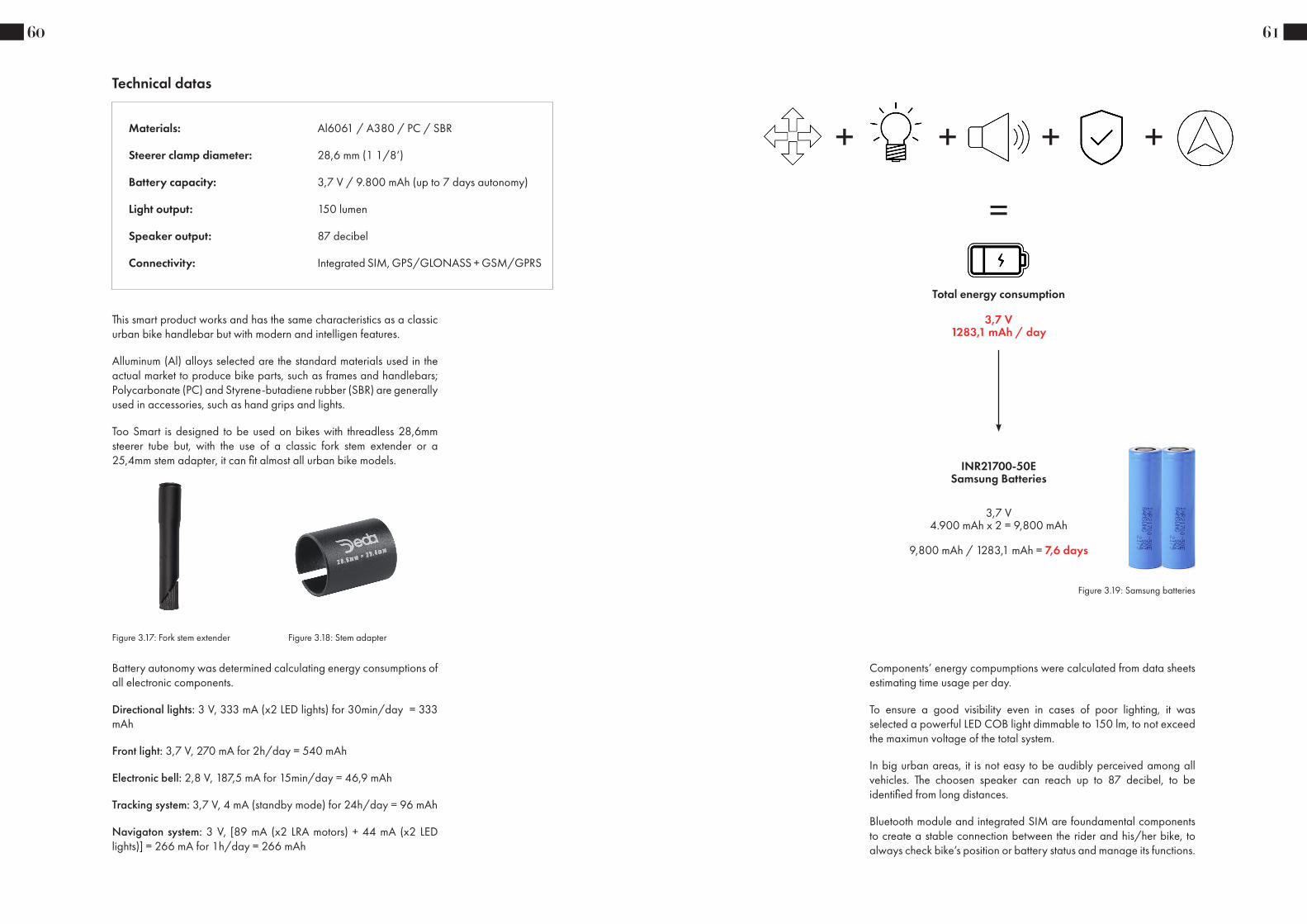
Technical datas
This smart product works and has the same characteristics as a classic urban bike handlebar but with modern and intelligen features.
Alluminum (Al) alloys selected are the standard materials used in the actual market to produce bike parts, such as frames and handlebars; Polycarbonate (PC) and Styrene-butadiene rubber (SBR) are generally used in accessories, such as hand grips and lights.
Too Smart is designed to be used on bikes with threadless 28,6mm steerer tube but, with the use of a classic fork stem extender or a 25,4mm stem adapter, it can fit almost all urban bike models.
Figure 3.17: Fork stem extender Figure 3.18: Stem adapter
Battery autonomy was determined calculating energy consumptions of all electronic components.
Directional lights: 3 V, 333 mA (x2 LED lights) for 30min/day = 333 mAh
Front light: 3,7 V, 270 mA for 2h/day = 540 mAh
Electronic bell: 2,8 V, 187,5 mA for 15min/day = 46,9 mAh
Tracking system: 3,7 V, 4 mA (standby mode) for 24h/day = 96 mAh
Navigaton system: 3 V, [89 mA (x2 LRA motors) + 44 mA (x2 LED lights)] = 266 mA for 1h/day = 266 mAh
61
Components’ energy compumptions were calculated from data sheets estimating time usage per day.
To ensure a good visibility even in cases of poor lighting, it was selected a powerful LED COB light dimmable to 150 lm, to not exceed the maximun voltage of the total system.
In big urban areas, it is not easy to be audibly perceived among all vehicles. The choosen speaker can reach up to 87 decibel, to be identified from long distances.
Bluetooth module and integrated SIM are foundamental components to create a stable connection between the rider and his/her bike, to always check bike’s position or battery status and manage its functions.
Total energy consumption
3,7 V1283,1 mAh / day
+ + + +
=
3,7 V4.900 mAh x 2 = 9,800 mAh
9,800 mAh / 1283,1 mAh = 7,6 days
INR21700-50E Samsung Batteries
Figure 3.19: Samsung batteries
62
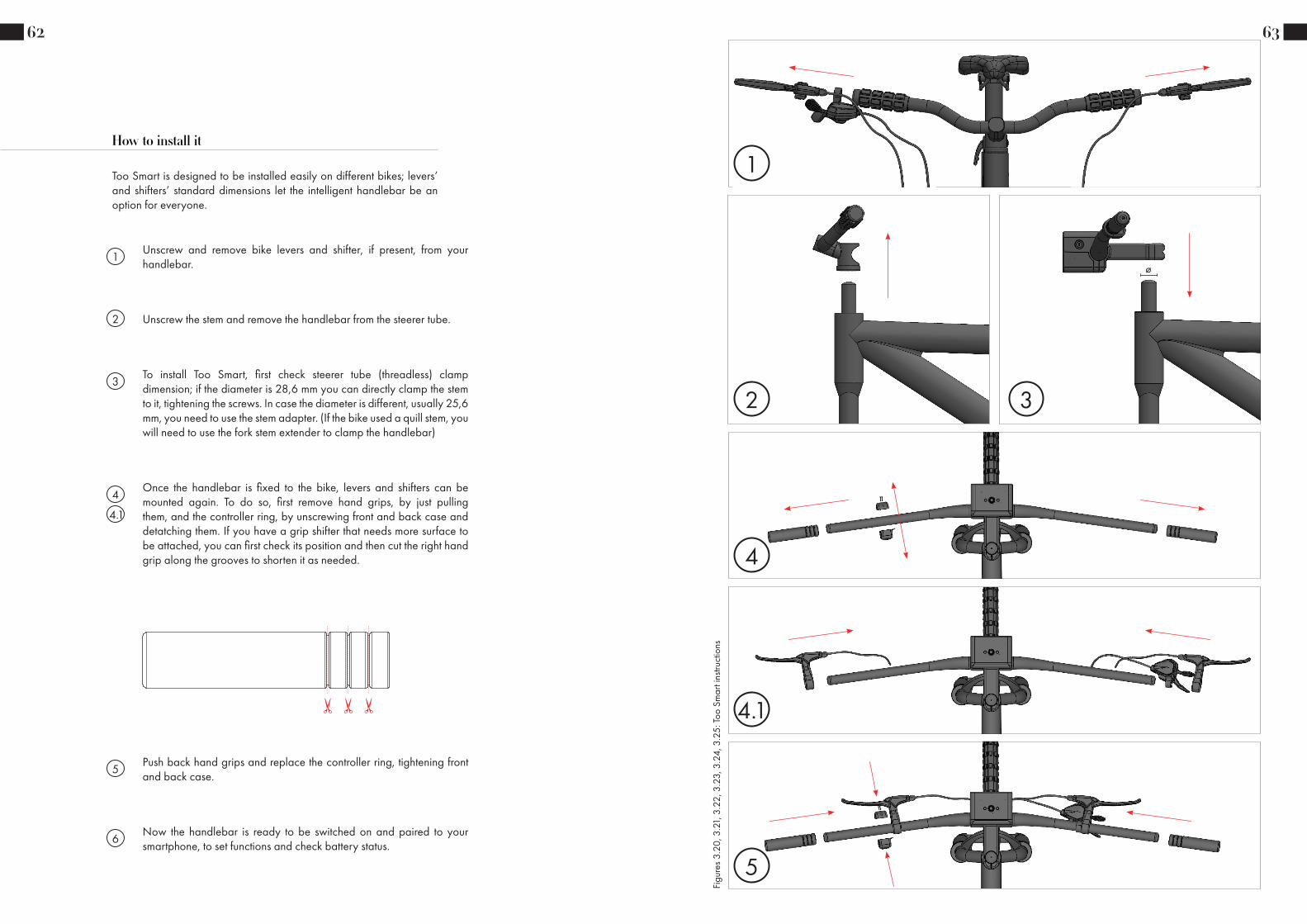
How to install it
Too Smart is designed to be installed easily on different bikes; levers’ and shifters’ standard dimensions let the intelligent handlebar be an option for everyone.
1Unscrew and remove bike levers and shifter, if present, from your handlebar.
2 Unscrew the stem and remove the handlebar from the steerer tube.
3To install Too Smart, first check steerer tube (threadless) clamp dimension; if the diameter is 28,6 mm you can directly clamp the stem to it, tightening the screws. In case the diameter is different, usually 25,6 mm, you need to use the stem adapter. (If the bike used a quill stem, you will need to use the fork stem extender to clamp the handlebar)
4Once the handlebar is fixed to the bike, levers and shifters can be mounted again. To do so, first remove hand grips, by just pulling them, and the controller ring, by unscrewing front and back case and detatching them. If you have a grip shifter that needs more surface to be attached, you can first check its position and then cut the right hand grip along the grooves to shorten it as needed.
6Now the handlebar is ready to be switched on and paired to your smartphone, to set functions and check battery status.
5Push back hand grips and replace the controller ring, tightening front and back case.
4.1
63
2 3
ø
4
4.1
5
1
Figu
res 3
.20,
3.2
1, 3
.22,
3.2
3, 3
.24,
3.2
5: To
o Sm
art i
nstru
ctio
ns

64 65
Figu
res 3
.26,
3.2
7, 3
.28,
3.2
9, 3
.30:
Too
Smar
t visu
aliz
atio
ns

66
How it works
Too Smart combines all smart features that a bike handlebar should have to ride safely and connected. It is easy and intuitive to use thanks to a “clean” and “clear” design: a single and central switch button to power it on, bluetooth connection to manage it through the smartphone and a controller ring to easily indicate rider’s intentions.
To turn on Too Smart handlebar press and hold the switch for 2 seconds. The button will blink for some time and when the light will be steady you are ready to ride your bike!
1
Figure 3.31: System power on
67
The front light will shine by itself; by using the app, you can manage power, light mode (steady or blinking) and the light can receive datas (location and time) to adjust itself.
2
Figure 3.32: Front light power on
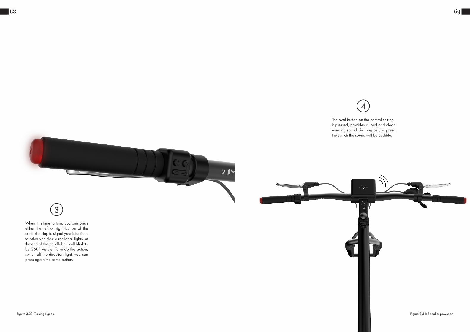
When it is time to turn, you can press either the left or right button of the controller ring to signal your intentions to other vehicles; directional lights, at the end of the handlebar, will blink to be 360° visible. To undo the action, switch off the direction light, you can press again the same button.
3
68
Figure 3.33: Turning signals
The oval button on the controller ring, if pressed, provides a loud and clear warning sound. As long as you press the switch the sound will be audible.
4
69
Figure 3.34: Speaker power on

When you do not know the way, you can connect the smartphone to the handlebar to have road indications without looking at the screen; LED lights, close to the On/Off button, will light up to signal the direction. To avoid light perception problems caused by the sunlight or distractions, LRA motors will vibrate to have a direct haptic feedback of maps directions.
5
70
Figure 3.35: Maps signals
After 7 days of usage, you may need to recharge batteries; with the provided key you can unlock and remove the battery case to charge it by using the cable charger. When it is fully charged, you can slide back the battery case and lock it with the key.
6
71
Figure 3.36: Battery case removal

72
Product set - assemblies
All different components are arranged in independent sub-assemblies that create a single total assembly.
- Front stem assembly
- Battery case assembly
- Controller ring assembly
- Expander assembly
- Back stem
- Hand grip
- Handlebar
- Handlebar o-ring gasket
- Controller ring back part
- Screws/Bolts
- Gaskets
- Connection cables
Sub-assemblies (I° level) Single components
All sub-assemblies are designed in order to simplify the total assembly process, to hide all visible connections between components and to ensure a stable and secure final product. This components’ organization allows a rapid and secure disassembly process, in case of product maintainace or components replacement.
- PCB stem assembly
Sub-assemblies (II° level)
221,5
110
,6
100
796,6
scale
A2Date
Dimensions are in mmLinear tolerance 0.2
Bike Smart Handlebar Total Assembly
SOLIDWORKS Educational Product. For Instructional Use Only.
Figure 3.37: Handlebar front view
4
8
14
13
10
117
9
1
3
5
2
6
12
Num. articolo Num. parte Descrizione Quantità
1 Handlebar 1
2 Connection Cable 13 Stem O-Ring Gasket 2
4 Stem Back Part 1
5 Stem Screw O-Ring Gasket 4
6 CB5_M5X12 27 Front Stem Assembly 1
8 CB5_M5X15 4
9 Battery Case Assembly 1
10 Controller Ring Assembly 1
11 Controller Back Case 112 CSPPN-ST-M2X10 Buy 2
13 Expander Assembly 2
14 Hand Grip 2
SOLIDWORKS Educational Product. For Instructional Use Only.
73
Total assembly
The total assembly is composed by 4 sub-assemblies (I° level), 1 sub-assembly (II° level) and single components.
1. Handlebar
2. Connection cable
3. Stem o-ring gasket
4. Back stem part
5. Stem screw o-ring gasket
6. CB5_M5X12
7. Front stem assembly
8. CB5_M5X15
9. Battery case assembly
10. Controller ring assembly
11. Controller back case
12. CSPPN-ST-M2X10
13. Expander assembly
14. Hand grip
Figure 3.38: Total assembly exploded view

Front stem assembly (I° level)
The first sub-assembly, of the I° level, is composed by 25 different components and 1 sub-assembly, of the II° level. Parts are fixed together by using screws, bolts and spacers or by interlocking them.
1. Stem front part
2. Stem square gasket
3. Stem round gasket
4. Pogo pin male
5. Pogo pin flat glasket
6. Pogo pin spacer
7. Acoustic membrane speaker
8. Lock cylindrical body
9. Lock nut
10. Lock o-ring gasket
11. Lock sheet metal
12. CSPPNW-ST-M3X6
13. PCB stem assembly
14. Button switch o-ring gasket
15. Button switch
16. Button switch nut
17. LED light lens
18. LED light o-ring
19. LED light flexible guide
20. Front LED light holder
21. CSPPN-ST-M2X10
22. Front LED light
23. Front LED light reflector
24. CSPPN-ST-M2X5
25. Front LED light round gasket
26. Front LED light diffuser
18
3 2
45
6
910
8
12 1113
24
22
23
21
25
26
20
7
1
1614
1519
17
Num. articolo Num. parte Descrizione Quantità
1 Stem Front Part Made 12 Stem Square Gasket Buy Custom 2
3 Stem Round Gasket Buy Custom 1
4 Pogo Pin Male Buy 1
5 Pogo Pin Flat Gasket Buy Custom 1
6 Pogo Pin Spacer Made 2
7 Acoustic Membrane Speaker Buy 1
8 Lock Cylindrical Body Buy 1
9 Lock Nut Buy 1
10 Lock O-Ring Gasket Buy 1
11 Lock Sheet Metal Buy Custom 1
12 CSPPNW-ST-M3X6 Buy 1
13 PCB Stem Assembly 1
14 Button Switch O-Ring Gasket Buy 1
15 Button Switch Buy 1
16 Button Switch Nut Buy 1
17 LED Light Lens Buy 2
18 LED Light O-Ring Buy Custom 2
19 LED Light Flexible Guide Buy Custom 2
20 Front LED Light Holder Made 1
21 CSPPN-ST-M2X10 Buy 2
22 Front LED Light Buy 1
23 Front LED Light Reflector Made 1
24 CSPPN-ST-M2X5 Buy 6
25 Front LED Light Round Gasket Buy Custom 1
26 Front LED Light Diffuser 1
SOLIDWORKS Educational Product. For Instructional Use Only.
74
Figure 3.39: Stem front part exploded view
1
6
3
2
5
7
4
Num. articolo Num. parte Descrizione Quantità
1 PCB Holder Made 12 PCB Stem Buy Custom 1
3 CSPPN-ST-M1,6X6 Buy 3
4 CSPPN-ST-M2X5 Buy 2
5 LED Light Flexible Guide Switch Buy 2
6 Speaker Buy 1
7 SPACER M2X1.5 Buy 2
6/11
2:1scale
projection
A2Paper size
Page
Drawn by
SMVolume[cubic cm]
Manufacturing process
Date
Dimensions are in mmLinear tolerance 0.2
Project
Bike Smart Handlebar - Design & Engineering Thesis Project
Material
Finish
20-JUL-2021
General tollerances
unless otherwise specified
PCB Stem AssemblyFile nameproject#_concept_part-name_revision
SOLIDWORKS Educational Product. For Instructional Use Only.
PCB stem assembly (II° level)
The principal PCB and speaker are both assembled on a bended sheet metal by using screws and spacers; components on the PCB are previously welded to the board to create direct connections between them. The sub-assembly is finally mounted inside the stem front part by screwing it.
1. PCB holder
2. PCB stem
3. CSPPN-ST-M1,6X6
4. CSPPN-ST-M2X5
5. LED light flexible guide switch
6. Speaker
7. Spacer M2X1.5
75
Figure 3.40: PCB stem exploded view

Battery case assembly (I° level)
Batteries are safely kept inside a removable waterproof case and its closure cap; battery’s PCB is placed above the module, where the male version of the pogo pin is placed in order to create a connection between the battery case and the front stem part. A thin layer of foam is placed under the batteries to prevent them from shaking and creating noise while riding the bike.
1. Battery case
2. Pogo pin female
3. Pogo pin flat gasket
4. PCB battery case
5. CSPPN-ST-M2X5
6. CBHS3-M3X15
7. Battery module
8. Battery module foam
9. Battery case gasket
10. Battery case cap
76
Figure 3.41: Battery case exploded view
Controller ring assembly (I° level)
Components are placed inside the controller ring front case one after the other and kept together by interlocking it to the closure part, the last one. Four gaskets prevent the water entering inside, keeping the PCB safe. The sub-assembly is mounted on the handlebar by screwing it to che controller ring back case.
1. Controller front case
2. Horn button gasket
3. Controller horn button
4. Direction button o-ring gasket
5. Controller direction button
6. PCB controller
7. Controller front case gasket
8. Controller front case closure
6
7
8
5
3
24
1
Num. articolo Nom. parte Material Finish Manufacturin
g Process Buy/Made Quantità
1 Controller Front Case AA380.0-F die Anodizing Die Casting Made 1
2 Horn Button Gasket
EPDM 60 Durometer Buy Custom 1
3 Controller Horn Button AA380.0-F die Anodizing Die Casting Made 1
4Direction Button O-Ring Gasket
EPDM 60 Durometer Buy Custom 2
5Controller Direction Button
AA380.0-F die Anodizing Die Casting Made 2
6 PCB Controller Material <not specified> Buy Custom 1
7Controller Front Case Gasket
EPDM 60 Durometer Buy Custom 1
8Controller Front Case Closure
AA380.0-F die Anodizing Die Casting Made 1
9/11
2:1scale
projection
A2Paper size
Page
Drawn by
SMVolume[cubic cm]
Manufacturing process
Date
Dimensions are in mmLinear tolerance 0.2
Project
Bike Smart Handlebar - Design & Engineering Thesis Project
Material
Finish
20-JUL-2021
General tollerances
unless otherwise specified
Controller Ring AssemblyFile nameproject#_concept_part-name_revision
SOLIDWORKS Educational Product. For Instructional Use Only.
77
Figure 3.42: Controller ring exploded view

Expander assembly (I° level)
This sub-assembly is placed at both handlebar’s ends and it has an expander body that keep it in place. Components are mounted in a row and kept together by a long bolt and two screws. Connection cables are arranged in such a way as to pass along the whole assembly to be brought to the center of the handlebar, where they can be connected to receive electricity.
1. ACB3_M3X40
2. Led light diffuser
3. Expander o-ring gasket
4. PCB LED light
5. Expander metal ring
6. Expander head
7. Expander central part
8. Expander cylindrical body
9. LRA motor
10. Expander cap
11. CSPPN-ST-M1,6X6
10
11
9
8
1
2
3
4
5
6
7
Num. articolo Num. parte Descrizione Quantità
1 ACB3_M3X40 Buy 1
2 LED Light Diffuser Made 1
3 Expander O-Ring Gasket Buy Custom 1
4 PCB LED Light Buy Custom 1
5 Expander Metal Ring Made 1
6 Expander Head Made 1
7 Expander Central Part Made 1
8 Expander Cylindrical Body Made 1
9 LRA Motor Buy 1
10 Expander Cap Made 1
11 CSPPN-ST-M1,6X6 Buy 2
11/11
2:1scale
projection
A2Paper size
Page
Drawn by
SMVolume[cubic cm]
Manufacturing process
Date
Dimensions are in mmLinear tolerance 0.2
Project
Bike Smart Handlebar - Design & Engineering Thesis Project
Material
Finish
20-JUL-2021
General tollerances
unless otherwise specified
Expander AssemblyFile nameproject#_concept_part-name_revision
SOLIDWORKS Educational Product. For Instructional Use Only.
78
Figure 3.43: Expander exploded view
79Level 0
Level 1Level 2
Single components
Total assembly
Front stem assembly
Controller ringassembly
Expanderassembly
PCB stem assembly
Battery case assembly
Back stem
Hand grips
Handlebar
Handlebaro-ring gasket
Controller ringback part
Screws/Bolts Gaskets Connectioncables

80
Components list
Too Smart handlebar is a combination of made and buy components, some designed to ensure a good resistance to outdoor conditions (rain, sunlight), some to resist applied stresses and others with specific electronic characteristics to be able to provide accurate datas.
Made components are designed in order to meet manufacturing processes’ specifications, bike market standard dimensions and materials requirements.
Buy components were selected looking at dimensions and performances, to ensure all different functions in the smallest possible space.
1. Handlebar
2. Stem back part
3. Stem front part
4. Front LED light holder
5. Front LED light reflector
6. Front LED light diffuser
7. PCB holder
8. Pogo pin spacer
9. Battery case
10. Battery case cap
11. Controller front case
12. Controller direction button
13. Controller horn button
14. Controller front case closure
15. Controller back case
16. LED light diffuser
17. Expander metal ring
18. Expander head
19. Expander central part
20. Expander cylindrical body
21. Expander cap
22. Hand grip
1. O-rings (different sizes)
2. Gaskets (different sizes)
3. Screws/Bolts/Spacers
4. Connection cables
5. Speaker
6. Acoustic membrane speaker
7. Key locking system
8. PCB stem
9. Button switch
10. LED light lens + flexible guide
11. Front LED light
12. Pogo pin set
13. PCB battery case
14. Battery module
15. Battery module foam
16. PCB controller
17. PCB LED light
18. LRA motor
81
Handlebar
The handlebar can be produced in different versions, modifying upsweep, backsweep and rise dimensions; diameters and central width are fixed measures that can not be changed. Al 6061 is the most used material in bike market and cheaper than other options. The part needs various manufaturing processes in order to achieve the final shape after which is anodized (different color options) and marked using a laser.
Quantity
Buy/Made
Material
Manufacturing process
Finish
1
Made
Al 6061
Extrusion - Drawing - Bending - Drilling
Anodizing - Laser Marking
Figures: 3.44, 3.45: Handlebar

82
Stem back part
This component is one of the two parts that keep the handlebar in place by screwing them around it. It can be produced in different versions, modifying stem length and steerer tube clamp inclination; clamp diameters are fixed measures that can not be changed. Al 6061 is the most used material in bike market and cheaper than other options. The part is made by CNC manufaturing process, in order to easily create different models, after which is anodized (different color options) and marked using a laser.
Quantity
Buy/Made
Material
Manufacturing process
Finish
1
Made
Al 6061
CNC
Anodizing - Laser Marking
Figures: 3.46, 3.47: Stem back part
83
Stem front part
Quantity
Buy/Made
Material
Manufacturing process
Finish
1
Made
Aluminum A380.0-F
Die Casting
Anodizing
This component, together with the previous one, keeps the handlebar in place and protects inside several parts from external conditions (water). A380.0-F is the most used aluminum alloy to die cast, mainly when there are large thickness variations. The part is made by die casting process with draft angles ≥ 1°, in order to achieve its complex and final shape after which is anodized (different color options).
Figures: 3.48, 3.49: Stem front part

84
Front LED light holder
This component, mounted inside the stem front part, serves to fix front LED light, reflector and diffuser; it also diffuses the heat generated by the front LED light. The part is simply made by sheet metal processes using Al 6061.
Quantity
Buy/Made
Material
Manufacturing process
Finish
1
Made
Al 6061
Laser cutting - Threading
-
Figures: 3.50, 3.51: Front LED light holder
85
Front LED light reflector
Quantity
Buy/Made
Material
Manufacturing process
Finish
1
Made
PC High Viscosity
Injection Molding
Electroplating
This component helps to reflect the light coming from the front LED light part. It is made by injection molding process with draft angles ≥ 1°, using polycarbonate material, and then electroplated to achieve the shine effect. PC was selected because the whole process is cheaper then using a metal material.
Figures: 3.52, 3.53: Front LED light reflector

86
Front LED light diffuser
This component, mounted on the stem front part by interlocking, serves to better diffuse front LED light and to protect internal parts from external conditions. The part is made by injection molding process, with draft angles ≥ 1°, using PC material.
Quantity
Buy/Made
Material
Manufacturing process
Finish
1
Made
PC High Viscosity
Injection Molding
-
Figures: 3.54, 3.55: Front LED light diffuser
87
PCB holder
Quantity
Buy/Made
Material
Manufacturing process
Finish
1
Made
Al 6061
Laser cutting - Threading - Bending
-
This component is fixed inside the stem front part and keeps together PCB stem and speaker. It is made by sheet metal processes, using Al 6061 material.
Figures: 3.56, 3.57: PCB holder

88
Pogo pin spacer
This component serves to create the needed distance to mount correctly the pogo pin male part. It is made by sheet metal process using Al 6061 material.
Quantity
Buy/Made
Material
Manufacturing process
Finish
2
Made
Al 6061
Laser cutting
-
Figures: 3.58, 3.59: Pogo pin spacer
89
Battery case
Quantity
Buy/Made
Material
Manufacturing process
Finish
1
Made
Aluminum A380.0-F
Die casting
Anodizing - Laser Marking
This component contains all components needed to create a rechargable battery pack: PCB battery; battery module; battery module foam and pogo pin female part. It is made by die casting process with draft angles ≥ 1°, using A.380.0-F material, in order to achieve its complex and final shape after which is anodized (different color options).
Figures: 3.60, 3.61, 3.62: Battery case

90
Battery case cap
Quantity
Buy/Made
Material
Manufacturing process
Finish
1
Made
Aluminum A380.0-F
Die casting
Anodizing
This component closes the battery case and protects internal components from external conditions. It is made by die casting process with draft angles ≥ 1°, using A380.0-F material, after which is anodized (different color options).
Figures: 3.63, 3.64: Battery case cap
91
Controller front case
This component contains all components of the controller ring assembly: buttons; gaskets; PCB controller and controller front case closure. It is made by die casting process with draft angles ≥ 1°, using A380.0-F material, after which is anodized (different color options).
Quantity
Buy/Made
Material
Manufacturing process
Finish
1
Made
Alumium A380.0-F
Die Casting
Anodizing
Figures: 3.65, 3.66: Controller front case

92
Controller direction button
This component is a button with which the rider can activate light signals. It is made by die casting process with draft angles ≥ 1°, using A380.0-F material, after which is anodized (different color options).
Quantity
Buy/Made
Material
Manufacturing process
Finish
2
Made
Alumium A380.0-F
Die Casting
Anodizing
Figures: 3.67, 3.68: Controller direction button
93
Controller horn button
Quantity
Buy/Made
Material
Manufacturing process
Finish
1
Made
Aluminum A380.0-F
Die casting
Anodizing
This component is a button with which the rider can activate the speaker. It is made by die casting process with draft angles ≥ 1°, using A380.0-F material, after which is anodized (different color options).
Figures: 3.69, 3.70: Controller horn button

94
Controller front case closure
Quantity
Buy/Made
Material
Manufacturing process
Finish
1
Made
Aluminum A380.0-F
Die casting
Anodizing
This component closes the controller case and protects internal components from external conditions. It is made by die casting process with draft angles ≥ 1°, using A380.0-F material, after which is anodized (different color options).
Figures: 3.71, 3.72: Controller front case closure
95
Controller back case
This component serves to mount and fix the controller ring assembly to the handlebar by screwing them together. It is made by die casting process with draft angles ≥ 1°, using A380.0-F material, after which is anodized (different color options).
Quantity
Buy/Made
Material
Manufacturing process
Finish
1
Made
Alumium A380.0-F
Die Casting
Anodizing
Figures: 3.73, 3.74: Controller back case

96
LED light diffuser
Quantity
Buy/Made
Material
Manufacturing process
Finish
2
Made
PC High Viscosity
Injection Molding
-
This component diffuses red directional lights to let the rider be 360° perceived fro other vehicles. It is made by injection molding process, with draft angles ≥ 1°, using PC material.
Figures: 3.75, 3.76: LED light diffuser
97
Expander metal ring
This component helps to diffuse the heat produced by PCB LED light. It is made by sheet metal process using Al 6061 material.
Quantity
Buy/Made
Material
Manufacturing process
Finish
2
Made
Al 6061
Laser cutting
Anodizing
Figures: 3.77, 3.78: Expander metal ring

98
Expander head
Quantity
Buy/Made
Material
Manufacturing process
Finish
2
Made
Aluminum A380.0-F
Die Casting
-
This component is one of the parts that creates the expander that keep in place the expander assembly; it pushes the expander central body against handlebar internal wall. It is made by die casting process with draft angles ≥ 1°, using A380.0-F material.
Figures: 3.79, 3.80: Expander head
This component is one of the parts that creates the expander that keep in place the expander assembly; it expands and pushes against the handlebar internal wall. It is made by die casting process with draft angles ≥ 1°, using A380.0-F material.
99
Expander central part
Quantity
Buy/Made
Material
Manufacturing process
Finish
2
Made
Al 6061
Extrusion - Knurling
-
Figures: 3.81, 3.82: Expander central part

This component is one of the parts that creates the expander that keep in place the expander assembly; it pushes the expander central body against handlebar internal wall. It is made by die casting process with draft angles ≥ 1°, using A380.0-F material.
100
Expander cylindrical body
Quantity
Buy/Made
Material
Manufacturing process
Finish
2
Made
Aluminum A380.0-F
Die Casting
-
Figures: 3.83, 3.84: Expander cylindrical body
101
Expander cap
This component is one of the parts that creates the expander that keep in place the expander assembly; it closes the expander cyindrical body securing inside the LRA motor. It is made by laser cutting process using Al 6061
Quantity
Buy/Made
Material
Manufacturing process
Finish
2
Made
Al 6061
Laser cutting
-
Figures: 3.85, 3.86: Expander cap

102
This component helps to create a comfortable hand grip. It can be cut along its grooves to mount different shifter models. It is made by injection molding process with draft angles ≥ 1°, using SBR material.
Hand grip
Quantity
Buy/Made
Material
Manufacturing process
Finish
2
Made
SBR
Injection Molding
-
Figures: 3.87, 3.88: Hand grip
103
O-Rings
These components are used to prevent water or dust going inside the product, preventing components to be damaged. They are buy custom parts due to different needed sizes.
Quantity
Buy/Made
Material
Manufacturing process
Finish
(Check technical drawings)
Buy Custom
Silicone Rubber
-
-
Figure: 3.89: O-rings

These components are used to prevent water or dust going inside the product, preventing components to be damaged. They are buy custom parts due to different needed sizes.
Gaskets
Quantity
Buy/Made
Material
Manufacturing process
Finish
-
Buy Custom
Silicone Rubber
-
-
104
Figure: 3.90: Gaskets
Screws/Bolts/Spacers
Different screws, bolts and spacers are used to create assemblies and sub-assemblies.
Quantity
Buy/Made
Material
Manufacturing process
Finish
(Check technical drawings)
Buy
Steel Alloy
-
-
105
Figure: 3.91: Screws, bolts and spacers

The SW250508-1 speaker from DB Unlimited has all the characteristics to be used in this project: it is waterproof, small and its sound pressure level reach up to 87 dB, enough to be perceived from other vehicles.
Speaker
Quantity
Buy/Made
Material
Manufacturing process
Finish
1
Buy
-
-
-
106
Figure: 3.92: Speaker
Acoustic membrane speaker
This think and light acoustic membrane is made of E-PTFE, a new type waterproof breathable material; it stops dust, water, salt and other corrosive liquid effectively, make the equipment sensitive parts exposed to outdoor safely (IP65~IP67).
Quantity
Buy/Made
Material
Manufacturing process
Finish
1
Buy Custom
-
-
-
107
Figure: 3.93: Acoustic membrane speaker

The MS202 CAM LOCK is a small locking system that blocks and unblocks the battery case using a key. It is customized in order to change its color and the locking piece dimensions.
Key locking system
Quantity
Buy/Made
Material
Manufacturing process
Finish
1
Buy Custom
Zinc Alloy
-
-
108
Figure: 3.94: Key locking system
PCB stem
This component is customized in order to have a board complete of all necessary components to create a smart multifunction product: an integrated SIM (SIM800C), an antenna (APARM1504-SG3), a microcontroller (PIC12C5XX), 2 LEDs (WL-SMCD SMD), 2 JST (S3B-PH-K-S) male connectors, a bluetooth module (RN4871) and an intelligent motion-sensing platform (MMA955xL).
Quantity
Buy/Made
Material
Manufacturing process
Finish
1
Buy Custom
-
-
-
109
Figure: 3.95: PCB stem
Antenna
Bluetooth
Movement sensor
Integrated SIM
JST connector
LED
Microcontroller

The momentary switch button with LED light is small and equipped with an o-ring seal and a nut to fix it in place. It is connected to the PCB stem with a cable and a JST female connector.
Button switch (ON/OFF)
Quantity
Buy/Made
Material
Manufacturing process
Finish
1
Buy
Stainless Steel
-
-
110
Figure: 3.96: Button switch
LED light lens + flexible guide
This buy custom component is made of 3 different parts: a LED lens, a flexible guide and a rigid board connector. The flexible guide is cut at the needed length.
Quantity
Buy/Made
Material
Manufacturing process
Finish
2
Buy Custom
-
-
-
111
56Art.-Nrn. in Fettdruck sind Lagerware, Art.-Nrn. in Magerdruck sind keine Lagerware. Erläuterung der Symbole Seite 69. Mindestmengen · Minimum quantitiesPart Nos. in bold font are available ex-stock with LowMOQs . Those in normal font are manufactured to order. Explanation of Symbols page 69. MOQ1 1000 MOQ2 1000
Flex-Lichtleitersystem, SMD-LEDs
Flex Light Guide System, SMD LEDs
Allgemeine Hinweise und Technische DatenAllgemeine Hinweise: siehe Seite 69Technische Daten LEDs: siehe Seite 67Gehäuse-Werkstoff: PC schwarz UL94LL-Werkstoff: PURLinsen-Werkstoff: PC glasklar UL94 / für 1216.1013 PMMA UL94Umgebungstemperatur: -40°C ... +85°CESD-Schutz: <12kV
General Remarks and Technical DataGeneral Remarks: see page 69Technical Data LEDs: see page 67Housing Material: PC black UL94LL-Material: PURLens-Material: PC clear UL94 / for 1216.1013 PMMA UL94Ambient Temperature: -40°C ... +85°CESD-Protection: <12kV
Die Gehäuse für die Lichtleiter werden über zwei Einpresszapfen in der Leiterkarte gehalten. Die Verwendung der Lichtleiter erfolgt in Verbindung mit SMD TOPLEDs. Gehäuse, Lichtleiter und Linsen werden unmontiert geliefert. Kundenspezifische Längen ab 55mm verfügbar.
The housings for the light guides are fixed on the PCB by two press-in lugs. These light guides have to be powered by SMD TOPLEDs. Housings, light guides and lenses will be delivered not assembled. Custom lengths are available from 55mm.
LED
LichtleiterLight guide
Frontplatte-Montagebohrung Ø 5,5Front panel Mounting Hole Ø 5,5
FrontplatteFront panel
LeiterkartePCB
LichtleiterweicheLight guide switchLinse
Lens
1
6
6Ø
3Ø
7.8
3.16
10R>
Einbaubeispiel 1216.1013 · Mounting Example 1216.1013
4.8
4.8
1.3Ø
4.5
2.6
1.5
Layoutvorschlag · Layout Suggestionmaximale LED-Höhe 2,1mm · max. LED height 2.1mm
Farbe · Color FaserFibre
LängeLength
Empfohlene LEDsRecommended LEDs Art.-Nr.
white Ø3mm 150 L1-L12 1216.1011red Ø3mm 150 L1-L12 1216.1012
transparent Ø3mm 150 L1-L12 1216.1013grey Ø3mm 150 L1-L12 1216.1014
yellow Ø3mm 150 L1-L12 1216.1017green Ø3mm 150 L1-L12 1216.1018
1216.1011 1216.1012 1216.1013 1216.1014 1216.1017 1216.1018
C+
Figure: 3.97: LED light lens and flexible guide
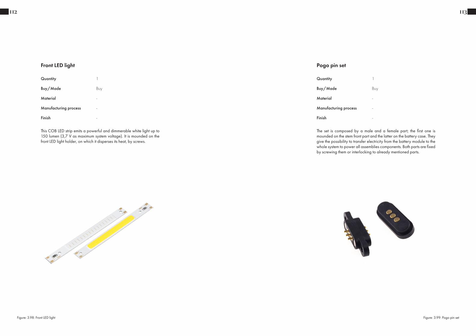
This COB LED strip emits a powerful and dimmerable white light up to 150 lumen (3,7 V as maximum system voltage). It is mounded on the front LED light holder, on which it disperses its heat, by screws.
Front LED light
Quantity
Buy/Made
Material
Manufacturing process
Finish
1
Buy
-
-
-
112
Figure: 3.98: Front LED light
Pogo pin set
The set is composed by a male and a female part; the first one is mounded on the stem front part and the latter on the battery case. They give the possibility to transfer electricity from the battery module to the whole system to power all assemblies components. Both parts are fixed by screwing them or interlocking to already mentioned parts.
Quantity
Buy/Made
Material
Manufacturing process
Finish
1
Buy
-
-
-
113
Figure: 3.99: Pogo pin set

This component is customized in order to have a board complete of all necessary components to create a powerbank: a rectifier (TC1014), a temperature sensor (LM61), a capacitor (Panasonic model), a voltage regulator (LD2980) and an inductor (SRR1260).
PCB battery case
Quantity
Buy/Made
Material
Manufacturing process
Finish
1
Buy Custom
-
-
-
114
Figure: 3.100: PCB battery case
Temperature sensor Voltage regulator
Inductor Capacitor
Rectifier
Battery module
The battery module is composed by 2 powerfull batteries (Samsung INR21700-50E, 4.900 mAh each) connected together and protected by a thin layer of PVC. It is placed on the battery case cap and mounted inside the battery case by interlocking it.
Quantity
Buy/Made
Material
Manufacturing process
Finish
1
Buy
-
-
-
115
Figure: 3.101, 3.102: Battery modules

The 3M self ddhesive EVA PE rubber foam is placed under the battery module in order to prevent vibrations while riding the bike.
Battery module foam
Quantity
Buy/Made
Material
Manufacturing process
Finish
1
Buy Custom
-
-
-
116
Figure: 3.103: Battery module foam
PCB controller
Quantity
Buy/Made
Material
Manufacturing process
Finish
1
Buy Custom
-
-
-
117
This component is customized in order to have a small board with 3 momentary switches and mounted inside the controller ring assembly. The momentary switches transmit the push button outputs from the controller directional buttons and horn button to the system.
Figure: 3.104: PCB controller
Momentary switch

PCB LED light
Quantity
Buy/Made
Material
Manufacturing process
Finish
2
Buy Custom
-
-
-
118
This component is customized in order to have a small board with 3 tiny red LED’s. It is mounted between the LED diffuser and the expander metal ring in the expander assembly.
Figure: 3.105: PCB LED light
LED
LRA motor
The waterproof LRA vibrant motor is placed inside the expande cylindrical body and connected to the system to receive maps inputs to transmit an haptic output directly under the rider’s hands. It can reach up to 25300 R/min with 3 V current.
Quantity
Buy/Made
Material
Manufacturing process
Finish
2
Buy
-
-
-
119
Figure: 3.106: LRA motor
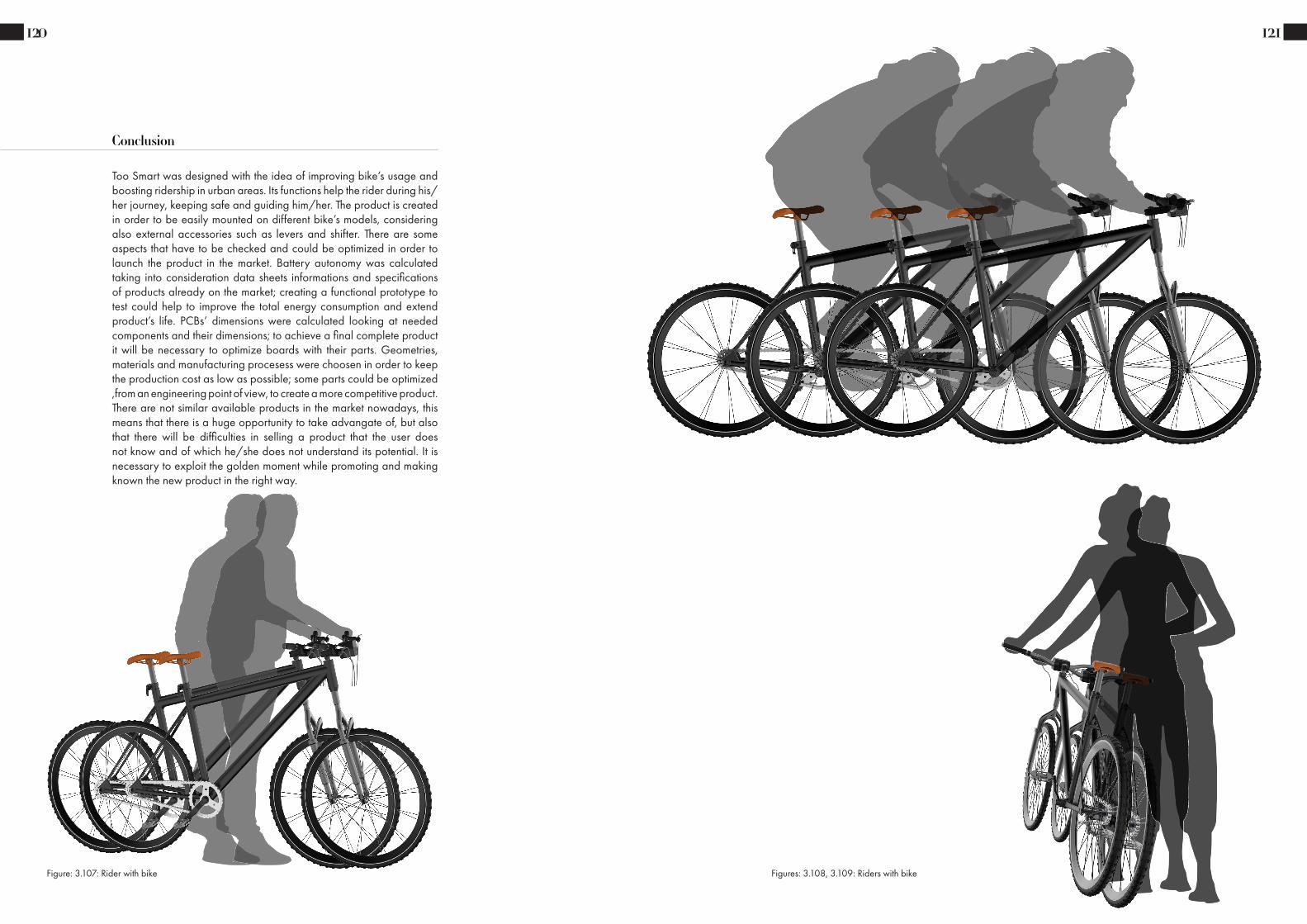
120
Conclusion
Too Smart was designed with the idea of improving bike’s usage and boosting ridership in urban areas. Its functions help the rider during his/her journey, keeping safe and guiding him/her. The product is created in order to be easily mounted on different bike’s models, considering also external accessories such as levers and shifter. There are some aspects that have to be checked and could be optimized in order to launch the product in the market. Battery autonomy was calculated taking into consideration data sheets informations and specifications of products already on the market; creating a functional prototype to test could help to improve the total energy consumption and extend product’s life. PCBs’ dimensions were calculated looking at needed components and their dimensions; to achieve a final complete product it will be necessary to optimize boards with their parts. Geometries, materials and manufacturing procesess were choosen in order to keep the production cost as low as possible; some parts could be optimized ,from an engineering point of view, to create a more competitive product. There are not similar available products in the market nowadays, this means that there is a huge opportunity to take advangate of, but also that there will be difficulties in selling a product that the user does not know and of which he/she does not understand its potential. It is necessary to exploit the golden moment while promoting and making known the new product in the right way.
121
Figure: 3.107: Rider with bike Figures: 3.108, 3.109: Riders with bike

Data sheets
122
1
1
2
2
3
3
4
4
A A
B B
C C
D D
DRAWN
CHECKED
APPROVED
CJ
Items Specifications ConditionsSound Pressure Level 87 dB (@ 10cm), Avg.Resonant Frequency 800 Hz
Frequency Range 800 ~ 10,000 HzNominal Power 1 W
Max. Power 1.5 WImpedance 8 Ω
Cone Material Mylar Mount Type Flange Mount IP Rating IP67
Storage Temperature -20 ~ +55 °COperating Temperature -20 ~ +55 °C
Weight 3.22 g
REVISION HISTORYREV DESCRIPTION DATE APPROVED
Released from Engineering 10/2/2017 C.E.1 Added polarity marking 10/25/2017 C.E.2 Updated height tolerance, resonant freqency and range 4/26/2018 C.E.3 Updated resonant frequency and range 4/30/2018 C.E.4 Updated solder terminal to rectangle 9/11/2019 C.E.
NOTES1) All dimensions are in mm unless otherwise noted
2) All tolerances are ± 0.2 mm unless otherwise noted3) All parts meet RoHS
4) Subject to change or redrawn without notice
Part Number:
Description:
This document contains data proprietary to DB Unlimited. Any use or reproduction, in any form, without prior written permission of DB Unlimited is prohibited. All terms and conditions can be found at www.dbunlimitedco.com
Waterproof Dynamic Speaker
P.D.
C.E.
4/14/2017
10/2/2017
10/2/2017
Side View Bottom ViewTop View
SW250508-1
XX X
"17 C"17=2017, C=Mar.
16
25 29.1
3 - Ø3.5
1.53 -
12
.8
6.7 ± 0.3
4.0 12.6
16.1
25.6
29.1
Date Code Marking
(+)
123
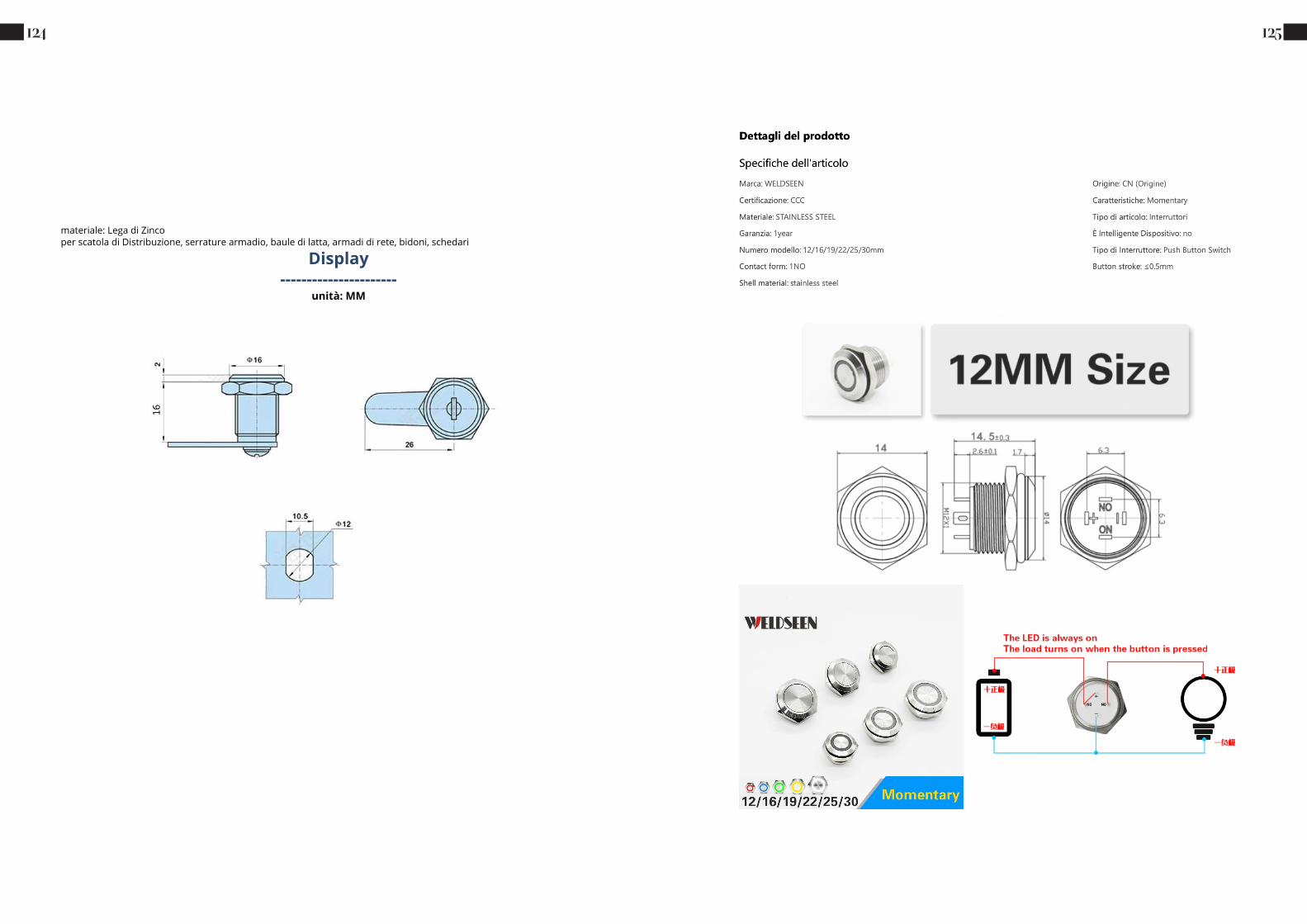
124 125

126
56Art.-Nrn. in Fettdruck sind Lagerware, Art.-Nrn. in Magerdruck sind keine Lagerware. Erläuterung der Symbole Seite 69. Mindestmengen · Minimum quantitiesPart Nos. in bold font are available ex-stock with LowMOQs . Those in normal font are manufactured to order. Explanation of Symbols page 69. MOQ1 1000 MOQ2 1000
Flex-Lichtleitersystem, SMD-LEDs
Flex Light Guide System, SMD LEDs
Allgemeine Hinweise und Technische DatenAllgemeine Hinweise: siehe Seite 69Technische Daten LEDs: siehe Seite 67Gehäuse-Werkstoff: PC schwarz UL94LL-Werkstoff: PURLinsen-Werkstoff: PC glasklar UL94 / für 1216.1013 PMMA UL94Umgebungstemperatur: -40°C ... +85°CESD-Schutz: <12kV
General Remarks and Technical DataGeneral Remarks: see page 69Technical Data LEDs: see page 67Housing Material: PC black UL94LL-Material: PURLens-Material: PC clear UL94 / for 1216.1013 PMMA UL94Ambient Temperature: -40°C ... +85°CESD-Protection: <12kV
Die Gehäuse für die Lichtleiter werden über zwei Einpresszapfen in der Leiterkarte gehalten. Die Verwendung der Lichtleiter erfolgt in Verbindung mit SMD TOPLEDs. Gehäuse, Lichtleiter und Linsen werden unmontiert geliefert. Kundenspezifische Längen ab 55mm verfügbar.
The housings for the light guides are fixed on the PCB by two press-in lugs. These light guides have to be powered by SMD TOPLEDs. Housings, light guides and lenses will be delivered not assembled. Custom lengths are available from 55mm.
LED
LichtleiterLight guide
Frontplatte-Montagebohrung Ø 5,5Front panel Mounting Hole Ø 5,5
FrontplatteFront panel
LeiterkartePCB
LichtleiterweicheLight guide switchLinse
Lens
1
6
6Ø
3Ø
7.8
3.16
10R>
Einbaubeispiel 1216.1013 · Mounting Example 1216.1013
4.8
4.8
1.3Ø
4.5
2.6
1.5
Layoutvorschlag · Layout Suggestionmaximale LED-Höhe 2,1mm · max. LED height 2.1mm
Farbe · Color FaserFibre
LängeLength
Empfohlene LEDsRecommended LEDs Art.-Nr.
white Ø3mm 150 L1-L12 1216.1011red Ø3mm 150 L1-L12 1216.1012
transparent Ø3mm 150 L1-L12 1216.1013grey Ø3mm 150 L1-L12 1216.1014
yellow Ø3mm 150 L1-L12 1216.1017green Ø3mm 150 L1-L12 1216.1018
1216.1011 1216.1012 1216.1013 1216.1014 1216.1017 1216.1018
C+
127

128 129
SAMSUNG SDI Confidential Proprietary
2
Spec. No. INR21700-50E Version No. 0.2
1. Scope This product specification has been prepared to specify the rechargeable lithium-ion cell ('cell') to be supplied to the customer by Samsung SDI Co., Ltd.
2. Description and Model
2.1 Description Cell (lithium-ion rechargeable cell) 2.2 Model INR21700-50E 2.3 Site Manufactured in Korea
3. Nominal Specifications (*1)
Item Specification
3.1 Standard discharge Capacity
Min 4,900mAh - Charge : 0.5C(2,450mA), 4.2V, 0.02C(98mA) cutoff @ RT - Discharge : 0.2C(980mA), 2.5V cutoff @ RT * 1C = 4,900mA
3.2 Rated discharge Capacity
Min 4,753mAh - Charge : 0.5C(2,450mA), 4.2V, 0.02C(98mA) cutoff @ RT - Discharge : 1C(4,900mA), 2.5V cutoff @ RT
3.3 Charging Voltage 4.2V
3.4 Nominal Voltage 3.6V
3.5 Charging Method CC-CV (constant voltage with limited current)
3.6 Charging Current Standard charge: 2,450mA
3.7 Charging Time Standard charge: 3hours
3.8 Max. Charge Current 4,900mA (not for cycle life)
3.9 Max. Discharge Current 9,800mA (for continuous discharge) 14,700mA (not for continuous discharge)
3.10 Discharge Cut-off Voltage 2.5V
3.11 Cycle life
Capacity ≥ 3,802mAh @ after 500cycles (80% of the Rated Discharge Capacity @ RT) - Charge : 0.5C(2,450mA), 4.2V, CCCV 0.05C(245mA) cut-off @ RT - Discharge: 1C(4,900mA), 2.5V cut-off @ RT
3.13 Recovery characteristics
Capacity recovery (after the storage) ≥ 4,278mAh (90% of the Rated Discharge Capacity @ RT) - Charge : 0.5C(2,450mA), 4.2V, 0.02C(98mA) cutoff @ RT - Storage : 30 days @ 60’C - Discharge : 1.0C(4,900mA) 2.50V cut-off @ RT
3.14 Cell Weight 69g max
3.15 Cell Dimension Cell height : Max.70.80mm Diameter : Φ Max.20.25mm

130 131

Images and charts
132 133
Figure 1.1: Green wave
Figure 1.2: Sustainable Development Goals
Figure 1.3: Benefits of Sustainable Mobility
Figure 1.4: Men cycling
Figure 1.5: Bike production
Figure 1.6: Bike store
Figure 1.7: Cycling illustration
Figure 1.8: Bike sharing illustration
Figure 1.9: Bike market info
Figure 1.10: Bike sharing problem
Figure 1.11: UX scheme
Figure 1.12: Bike’s history
Figure 1.13: Bike picture
Figure 1.14: B&N bike picture
Figure 1.15: B&N bike
Figure 1.16: Cowboy bike
Figure 1.17: VanMoof bike
Figure 1.18: Upright bike
Figure 1.19: Hybrid bike
Figure 1.20: Fodable bike
Figure 1.21: Technology illustration
Figure 1.22: Bike’s accessories
Figure 1.23: Bike accessories white background
Figure 1.24: Black bike handlebar
Figure 1.25: Bike handlebar stem scheme
Figure 1.26: Bike steerer tube scheme
Figure 1.27: Canyon handlebar
Figure 1.28: Carbon fiber material
Figure 1.29: Custom bike handlebar
Figure 1.30: H-bar bike handlebar
Figure 1.31: Black bike handlebar
Figure 1.32: Aluminum material
Figure 1.33: Colored bike handlebar
Figure 1.34: Bike handlebar standard dimensions
Figure 1.35: Bike handlebar views
Figure 1.36: Threadless stem
Figure 1.37: Quill stem
Figure 1.38: Adjustable stem
Figure 1.39: Sliding stem
Figure 1.40: Bike handlebar grips dimensions
Figure 1.41: Colored bike handlebar grips
Figure 1.42: Classic bike lever
Figure 1.43: Racing bike lever
Figure 1.44: Chain drive system
Figure 1.45: Thumb shifter
Figure 1.46: Twist grip shifter
Figure 1.47: Integrated shifter
Figure 1.48: Bike hadlebar with levers
Figure 2.1: Colorful wave
Figure 2.2: Man on the bike illustration
Figure 2.3: Woman on the bike illustration
Figure 2.4: Traditional bike
Images

134 135
Figure 2.5: Smart bike
Figure 2.6: Innos LED
Figure 2.7: Elios bar
Figure 2.8: Wink bar
Figure 2.9: SmartHalo
Figure 2.10: SmrtGRiPS
Figure 2.11: Blinker grips
Figure 2.12: Lumos helmet
Figure 2.13: BikeFinder
Figure 2.14: Hovding airbag
Figure 2.15: Concepts
Figure 2.16: 2D scketches
Figure 3.1: Product’s visualizations
Figure 3.2: Product’s general dimensions
Figures 3.3, 3.4, 3.5, 3.6, 3.7: Product’s visualizations
Figures 3.8, 3.9, 3.10: Handlebar models
Figures 3.11, 3.12, 3.13: Stem models
Figures 3.14, 3.15, 3.16: Color variations
Figure 3.17: Fork stem extender
Figure 3.18: Stem adapter
Figure 3.19: Samsung batteries
Figures 3.20, 3.21, 3.22, 3.23, 3.24, 3.25: Too Smart instructions
Figures 3.26, 3.27, 3.28, 3.29, 3.30: Too Smart visualizations
Figure 3.31: System power on
Figure 3.32: Front light power on
Figure 3.33: Turning signals
Figure 3.34: Speaker power on
Figure 3.35: Maps signals
Figure 3.36: Battery case removal
Figure 3.37: Handlebar front view
Figure 3.38: Total assembly exploded view
Figure 3.39: Stem front part exploded view
Figure 3.40: PCB stem exploded view
Figure 3.41: Battery case exploded view
Figure 3.42: Controller ring exploded view
Figure 3.43: Expander exploded view
Figures: 3.44, 3.45: Handlebar
Figures: 3.46, 3.47: Stem back part
Figures: 3.48, 3.49: Stem front part
Figures: 3.50, 3.51: Front LED light holder
Figures: 3.52, 3.53: Front LED light reflector
Figures: 3.54, 3.55: Front LED light diffuser
Figures: 3.56, 3.57: PCB holder
Figures: 3.58, 3.59: Pogo pin spacer
Figures: 3.60, 3.61, 3.62: Battery case
Figures: 3.63, 3.64: Battery case cap
Figures: 3.65, 3.66: Controller front case
Figures: 3.67, 3.68: Controller direction button
Figures: 3.69, 3.70: Controller horn button
Figures: 3.71, 3.72: Controller front case closure
Figures: 3.73, 3.74: Controller back case
Figures: 3.75, 3.76: LED light diffuser

136 137
Figures: 3.77, 3.78: Expander metal ring
Figures: 3.79, 3.80: Expander head
Figures: 3.81, 3.82: Expander central part
Figures: 3.83, 3.84: Expander cylindrical body
Figures: 3.85, 3.86: Expander cap
Figures: 3.87, 3.88: Hand grip
Figure: 3.89: O-rings
Figure: 3.90: Gaskets
Figure: 3.91: Screws, bolts and spacers
Figure: 3.92: Speaker
Figure: 3.93: Acoustic membrane speaker
Figure: 3.94: Key locking system
Figure: 3.95: PCB stem
Figure: 3.96: Button switch
Figure: 3.97: LED light lens and flexible guide
Figure: 3.98: Front LED light
Figure: 3.99: Pogo pin set
Figure: 3.100: PCB battery case
Figure: 3.101, 3.102: Battery modules
Figure: 3.103: Battery module foam
Figure: 3.104: PCB controller
Figure: 3.105: PCB LED light
Figure: 3.106: LRA motor
Figures: 3.107, 3.108, 3.109: Riders with bike
Chart 1.1: Italian transportation (weekday avarage)
Chart 1.2: Italian transportation (short-range)
Chart 1.3: Italian transportation (means of transport)
Chart 1.4: Italian transportation (travel preferred option)
Chart 1.5: Italian transportation (weekday avarage)
Charts
Bibliography
138
http://fubini.swarthmore.edu/~ENVS2/S2003/Heidi/FirstEssay.html
http://www.assiea.it/uploads/3/8/6/7/38673389/articolo_assiea.pdf
https://sdgs.un.org/goals
https://www.eltis.org/glossary/sustainable-transport-system
https://www.mcgill.ca/sustainability/files/sustainability/what-is-sustainability.pdf
https://www.vaughan.ca/projects/projects_and_studies/sustainable_transportation/Pages/default.aspx
https://www.un.org/en/climatechange/climate-solutions/cities-pollution
https://ec.europa.eu/environment/europeangreencapital/wp-content/uploads/2012/07/Copenhagen-Short-Leaflet_Web.pdf
https://modo.volkswagengroup.it/en/q-life/sumps-driving-sustainable-mobility-in-italian-cities
https://impakter.com/future-public-transportation-why-how-italy/
https://www.bbc.com/future/bespoke/made-on-earth/the-great-bicycle-boom-of-2020.html
https://en.wikipedia.org/wiki/Bicycle-sharing_system
https://www.wri.org/research/evolution-bike-sharing
https://www.altroconsumo.it/auto-e-moto/moto-bici/news/bike-sharing
https://en.wikipedia.org/wiki/Bicycle-sharing_system
https://www.history.com/news/bicycle-history-invention
https://en.wikipedia.org/wiki/History_of_the_bicycle#20th_century
https://en.wikipedia.org/wiki/Bicycle
https://en.wikipedia.org/wiki/Electric_bicycle
https://nymag.com/strategist/article/best-commuter-bicycles.html
\https://www.c-and-a.com/it/it/shop/sicurezza-in-bici
https://en.wikipedia.org/wiki/Bicycle_handlebar
https://www.bikeman.com/bicycle-repair-tech-info/bikeman-tech-info/1637-handlebar-diameters
https://bike.bikegremlin.com/3729/bicycle-stem-size-standards/
https://en.wikipedia.org/wiki/Stem_(bicycle_part)
139
https://www.singletracks.com/mtb-gear/hands-sore-bike-grips-buyers-guide/
https://communitycyclingcenter.org/shop-tip-types-of-brakes-and-levers/
https://www.parktool.com/blog/repair-help/brake-lever-mounting-positioning-upright-bars
https://en.wikipedia.org/wiki/Bicycle_gearing
https://www.choosemybicycle.com/en/woc/types-of-gear-shifters-explained
Sitography
Bals C, Burck J, Hagen U, Hohne N, Nascimento L. (2020). Climate Change Performance Index 2021.
Carozzi F, Sefi R. (2019). When it comes to harmful air pollution, denser cities aren’t greener cities.
Dalkmann H, Fisher A, Peet K. (2017). Green Mobility : Why Green Transport Interventions Matter for Sustainable Mobility.
European Commission (2019) Physical activity of electric bicycle users compared to conventional bicycle users and non-cyclists: Insights based on health and transport data from an online survey in seven European cities. Transportation Research Interdisciplinary Perspectives. Vol 1.
Krzyzanowski M, Kuna-Dibbert B, Schneider J, eds. (2005). Health effects of transport-related air pollution.
Malppan G J, Sunny T. (2015). A Review on Design Development in Bicycle. International Research Journal of Engineering and Technology (IRJET). Vol 2.
Varrella S. (2020). Urban public transportation use frequency in Italy 2020.
Articles
Books
Bralla J. (1998). Design for Manufacturability Handbook. McGraw-Hill Professional.
Livesey A. (2020). Bicycle Engineering and Technology. Routledge.
Ponting, Clive. (1991). A Green History of the World: The Environment and the Collapse of Great Civilizations. St. Martin’s Press, New York. (pp 18-65).