An Assessment of Gas Foil Bearing Scalability and the ...
14
Robert J. Bruckner Glenn Research Center, Cleveland, Ohio An Assessment of Gas Foil Bearing Scalability and the Potential Benefits to Civilian Turbofan Engines NASA/TM—2010-216732 August 2010 GT2010–22118
-
Upload
khangminh22 -
Category
Documents
-
view
0 -
download
0
Transcript of An Assessment of Gas Foil Bearing Scalability and the ...

Robert J. BrucknerGlenn Research Center, Cleveland, Ohio
An Assessment of Gas Foil Bearing Scalability andthe Potential Benefi ts to Civilian Turbofan Engines
NASA/TM—2010-216732
August 2010
GT2010–22118

NASA STI Program . . . in Profi le
Since its founding, NASA has been dedicated to the advancement of aeronautics and space science. The NASA Scientifi c and Technical Information (STI) program plays a key part in helping NASA maintain this important role.
The NASA STI Program operates under the auspices of the Agency Chief Information Offi cer. It collects, organizes, provides for archiving, and disseminates NASA’s STI. The NASA STI program provides access to the NASA Aeronautics and Space Database and its public interface, the NASA Technical Reports Server, thus providing one of the largest collections of aeronautical and space science STI in the world. Results are published in both non-NASA channels and by NASA in the NASA STI Report Series, which includes the following report types: • TECHNICAL PUBLICATION. Reports of
completed research or a major signifi cant phase of research that present the results of NASA programs and include extensive data or theoretical analysis. Includes compilations of signifi cant scientifi c and technical data and information deemed to be of continuing reference value. NASA counterpart of peer-reviewed formal professional papers but has less stringent limitations on manuscript length and extent of graphic presentations.
• TECHNICAL MEMORANDUM. Scientifi c
and technical fi ndings that are preliminary or of specialized interest, e.g., quick release reports, working papers, and bibliographies that contain minimal annotation. Does not contain extensive analysis.
• CONTRACTOR REPORT. Scientifi c and
technical fi ndings by NASA-sponsored contractors and grantees.
• CONFERENCE PUBLICATION. Collected papers from scientifi c and technical conferences, symposia, seminars, or other meetings sponsored or cosponsored by NASA.
• SPECIAL PUBLICATION. Scientifi c,
technical, or historical information from NASA programs, projects, and missions, often concerned with subjects having substantial public interest.
• TECHNICAL TRANSLATION. English-
language translations of foreign scientifi c and technical material pertinent to NASA’s mission.
Specialized services also include creating custom thesauri, building customized databases, organizing and publishing research results.
For more information about the NASA STI program, see the following:
• Access the NASA STI program home page at http://www.sti.nasa.gov
• E-mail your question via the Internet to help@
sti.nasa.gov • Fax your question to the NASA STI Help Desk
at 443–757–5803 • Telephone the NASA STI Help Desk at 443–757–5802 • Write to:
NASA Center for AeroSpace Information (CASI) 7115 Standard Drive Hanover, MD 21076–1320

Robert J. BrucknerGlenn Research Center, Cleveland, Ohio
An Assessment of Gas Foil Bearing Scalability andthe Potential Benefi ts to Civilian Turbofan Engines
NASA/TM—2010-216732
August 2010
GT2010–22118
National Aeronautics andSpace Administration
Glenn Research CenterCleveland, Ohio 44135
Prepared for theTurbo Expo 2010sponsored by the American Society of Mechanical EngineersGlasgow, Scotland, United Kingdom, June 14–18, 2010

Acknowledgments
The work presented in this paper was funded under the NASA Fundamental Aeronautics Program.
Available from
NASA Center for Aerospace Information7115 Standard DriveHanover, MD 21076–1320
National Technical Information Service5301 Shawnee Road
Alexandria, VA 22312
Available electronically at http://gltrs.grc.nasa.gov
This work was sponsored by the Fundamental Aeronautics Program at the NASA Glenn Research Center.
Level of Review: This material has been technically reviewed by technical management.
NASA/TM—2010-216732 1
An Assessment of Gas Foil Bearing Scalability and the Potential Benefits to Civilian Turbofan Engines
Robert J. Bruckner
National Aeronautics and Space Administration Glenn Research Center Cleveland, Ohio 44135
Abstract
Over the past several years the term oil-free turbomachinery has been used to describe a rotor support system for high speed turbomachinery that does not require oil for lubrication, damping, or cooling. The foundation technology for oil-free turbomachinery is the compliant foil bearing. This technology can replace the conventional rolling element bearings found in current engines. Two major benefits are realized with this technology. The primary benefit is the elimination of the oil lubrication system, accessory gearbox, tower shaft, and one turbine frame. These components account for 8 to 13 percent of the turbofan engine weight. The second benefit that compliant foil bearings offer to turbofan engines is the capability to operate at higher rotational speeds and shaft diameters. While traditional rolling element bearings have diminished life, reliability, and load capacity with increasing speeds, the foil bearing has a load capacity proportional to speed. The traditional applications for foil bearings have been in small, lightweight machines. However, recent advancements in the design and manufacturing of foil bearings have increased their potential size. An analysis, grounded in experimentally proven operation, is performed to assess the scalability of the modern foil bearing. This analysis was coupled to the requirements of civilian turbofan engines. The application of the foil bearing to larger, high bypass ratio engines nominally at the 120 kN (~25000 lb) thrust class has been examined. The application of this advanced technology to this system was found to reduce mission fuel burn by 3.05 percent.
Introduction A study has been performed to assess the scalability of
compliant surface gas foil bearings and to quantify the potential benefits to civilian turbofan engines. The present study is grounded within the NASA Fundamental Aeronautics Program—Subsonic Fixed Wing Project and its focus is limited to what is termed “N+1” propulsion systems. These systems are representative of the next generation of civilian aircraft. In terms of the propulsion system, this implies a two spool, direct-drive turbofan engines having bypass ratios in the range of 8 to 12. Future studies will consider advanced propulsion systems in which a new design space is enabled by gas foil bearings. By considering clean sheet propulsion
system designs that are not limited to current engineering design practices, enhanced benefits attributed to this bearing technology are expected in future system studies. Typically, gas foil bearings are used in much smaller turbomachines where the rotors are lighter, rotate faster, and where system auxiliary weights (such as the lubrication system) are a significant fraction of the overall system weight. However, advances in load capacity and scalability of the gas foil bearing warranted further study into larger systems. The gas foil bearing is the key technology in what has become known as “Oil-Free turbomachinery”.
Oil-Free turbomachinery, within the context of this study, is defined as high-speed rotating equipment operating without oil lubricated rotor supports, such as bearings, dampers, seals, and other components required in conventional turbo machines. Through the elimination of the lubricating oil, rolling element bearings and the requisite supporting subsystems it is envisioned that revolutionary improvements in performance, efficiency, and reliability of turbomachinery propulsion systems can be realized. The enabling technology of Oil-Free turbomachinery is the modern development of high speed, high temperature, and high load capacity foil bearings.
Nomenclature D Diameter of journal, mm [in.] D Load capacity coefficient, mN/(mm3krpm) [lbf/(in.3krpm)] N rotational speed, kilo-revolutions per minute (krpm) W Load supported by foil bearing, N [lbf]
Subscripts
pl preload t total dw deadweight
Compliant Foil Bearings A foil bearing is a self-acting hydrodynamic device capable
of separating rotating components of turbomachinery by a film of air or other gaseous “lubricant”. The benefits of such bearings to high speed turbomachinery can be quite significant. Among these benefits are reduced machine weight due to the elimination of the oil systems, removal of the traditional diameter—rotational speed limit (DN) imposed by
NASA/TM—2010-216732 2
rolling element bearings, and a synergistic use of working fluid as a lubricant enabling a contaminant free working fluid. However in order to realize these benefits, foil bearing must be able to support the required machine load and operate reliably and without burden to machine performance.
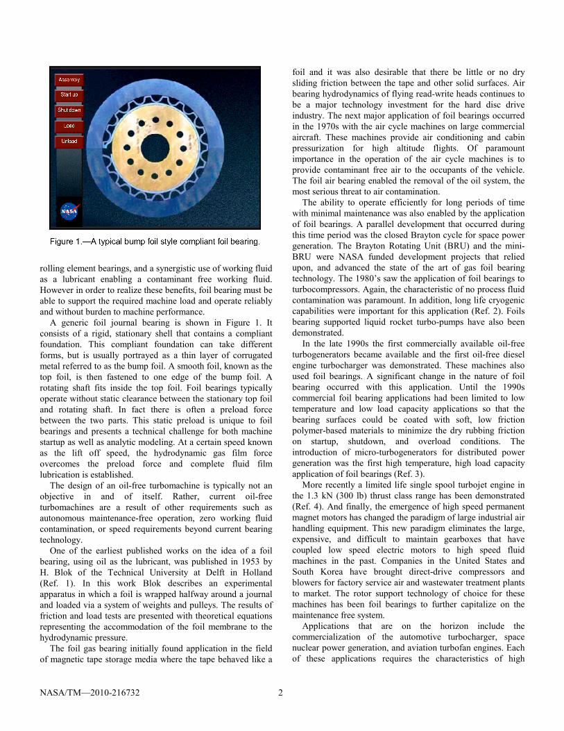
A generic foil journal bearing is shown in Figure 1. It consists of a rigid, stationary shell that contains a compliant foundation. This compliant foundation can take different forms, but is usually portrayed as a thin layer of corrugated metal referred to as the bump foil. A smooth foil, known as the top foil, is then fastened to one edge of the bump foil. A rotating shaft fits inside the top foil. Foil bearings typically operate without static clearance between the stationary top foil and rotating shaft. In fact there is often a preload force between the two parts. This static preload is unique to foil bearings and presents a technical challenge for both machine startup as well as analytic modeling. At a certain speed known as the lift off speed, the hydrodynamic gas film force overcomes the preload force and complete fluid film lubrication is established.
The design of an oil-free turbomachine is typically not an objective in and of itself. Rather, current oil-free turbomachines are a result of other requirements such as autonomous maintenance-free operation, zero working fluid contamination, or speed requirements beyond current bearing technology.
One of the earliest published works on the idea of a foil bearing, using oil as the lubricant, was published in 1953 by H. Blok of the Technical University at Delft in Holland (Ref. 1). In this work Blok describes an experimental apparatus in which a foil is wrapped halfway around a journal and loaded via a system of weights and pulleys. The results of friction and load tests are presented with theoretical equations representing the accommodation of the foil membrane to the hydrodynamic pressure.
The foil gas bearing initially found application in the field of magnetic tape storage media where the tape behaved like a
foil and it was also desirable that there be little or no dry sliding friction between the tape and other solid surfaces. Air bearing hydrodynamics of flying read-write heads continues to be a major technology investment for the hard disc drive industry. The next major application of foil bearings occurred in the 1970s with the air cycle machines on large commercial aircraft. These machines provide air conditioning and cabin pressurization for high altitude flights. Of paramount importance in the operation of the air cycle machines is to provide contaminant free air to the occupants of the vehicle. The foil air bearing enabled the removal of the oil system, the most serious threat to air contamination.
The ability to operate efficiently for long periods of time with minimal maintenance was also enabled by the application of foil bearings. A parallel development that occurred during this time period was the closed Brayton cycle for space power generation. The Brayton Rotating Unit (BRU) and the mini-BRU were NASA funded development projects that relied upon, and advanced the state of the art of gas foil bearing technology. The 1980’s saw the application of foil bearings to turbocompressors. Again, the characteristic of no process fluid contamination was paramount. In addition, long life cryogenic capabilities were important for this application (Ref. 2). Foils bearing supported liquid rocket turbo-pumps have also been demonstrated.
In the late 1990s the first commercially available oil-free turbogenerators became available and the first oil-free diesel engine turbocharger was demonstrated. These machines also used foil bearings. A significant change in the nature of foil bearing occurred with this application. Until the 1990s commercial foil bearing applications had been limited to low temperature and low load capacity applications so that the bearing surfaces could be coated with soft, low friction polymer-based materials to minimize the dry rubbing friction on startup, shutdown, and overload conditions. The introduction of micro-turbogenerators for distributed power generation was the first high temperature, high load capacity application of foil bearings (Ref. 3).
More recently a limited life single spool turbojet engine in the 1.3 kN (300 lb) thrust class range has been demonstrated (Ref. 4). And finally, the emergence of high speed permanent magnet motors has changed the paradigm of large industrial air handling equipment. This new paradigm eliminates the large, expensive, and difficult to maintain gearboxes that have coupled low speed electric motors to high speed fluid machines in the past. Companies in the United States and South Korea have brought direct-drive compressors and blowers for factory service air and wastewater treatment plants to market. The rotor support technology of choice for these machines has been foil bearings to further capitalize on the maintenance free system.
Applications that are on the horizon include the commercialization of the automotive turbocharger, space nuclear power generation, and aviation turbofan engines. Each of these applications requires the characteristics of high
NASA/TM—2010-216732 3
temperature, highly loaded foil bearings. Many significant challenges must be overcome to meet the demands of these future applications. The key challenges that must be understood include; the extent to which the foil bearing is scalable in terms of structure, gas dynamics, and rotordynamics, the identification of high speed limits that may exist for foil bearings, and the experimental verification of foil thrust bearing performance.
The application of foil bearings to small and mid-range aviation turbofan engines can enable substantial savings in the design and operation of a vehicle designed with such engines. A propulsion system study (Ref. 5) on a 50 passenger commercial regional jet and a notional 10 passenger supersonic business jet concludes that engine weight can be reduced by as much as 26 percent. This is a significant benefit to a machine as complex and mature as commercial turbofan engine. The application of foil bearings to these engines could achieve nearly a 3 percent reduction in mission fuel burn and NOx emissions for both of these applications. Additionally, an oil-free turbofan engine is a much simpler machine that is less likely to experience unanticipated problems, simpler to maintain, and more affordable to operate.
Technology State of the Art Heshmat (Ref. 6) presents an excellent summary of the
gas foil journal bearing commercial state-of-the-art. In this publication he lists the journal bearing diameter size used in various air cycle machines for both military and commercial aircraft. Bearings up to 50 mm in diameter have been commercially available for several decades. Recently improvements in foil bearing technology have occurred in terms of temperature capability as well as in size. The air cycle machines cited in Heshmat (Ref. 5) typically operate at temperatures below 500 °F, where soft polymer tribological coatings are used to overcome instances of dry sliding friction. However, for the gas turbine engine, a higher temperature capability is required. The NASA series of high temperature plasma sprayed materials has overcome this issue with demonstrated performance up to 1500 °F. Additionally the size class of commercially available foil journal bearings has increased to the 80 mm range. In the laboratory foil bearings have been demonstrated up to 150 mm in diameter and DN values of 4.03×106 mm-rpm (Ref. 7). Large radial foil seals, an offspring of foil bearing technology, have been demonstrated to DN value in excess of 4.03×10⁶ (Ref. 8). Although these large foil bearings are not yet at the same state-of-the-art as the 50 to 75 mm diameter bearings of air cycle machines, these demonstrations provide evidence that the physics of foil bearings is scalable to these high surface speeds. Additionally, these demonstration show that traditional machine design practices can accommodate the tolerances required by foil bearings. Although foil bearings and seals have been demonstrated in these applications, their performance in terms
of load capacity and rotordynamic stability has not yet been experimentally verified at these conditions.
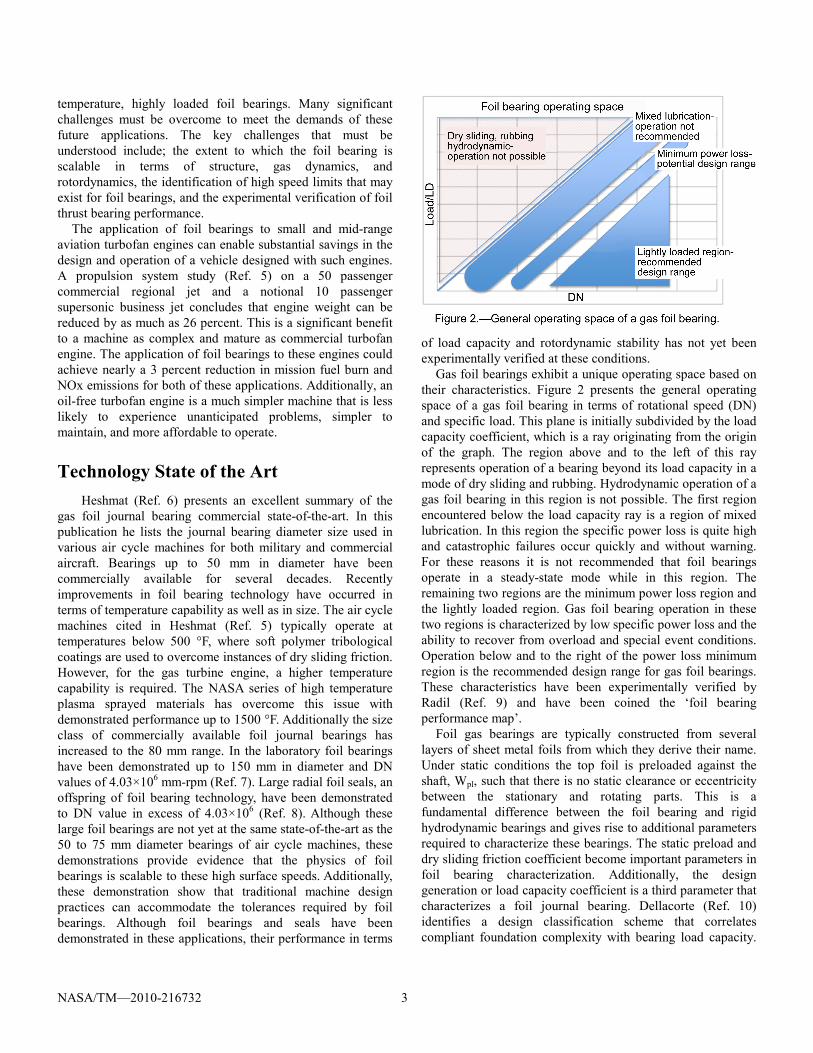
Gas foil bearings exhibit a unique operating space based on their characteristics. Figure 2 presents the general operating space of a gas foil bearing in terms of rotational speed (DN) and specific load. This plane is initially subdivided by the load capacity coefficient, which is a ray originating from the origin of the graph. The region above and to the left of this ray represents operation of a bearing beyond its load capacity in a mode of dry sliding and rubbing. Hydrodynamic operation of a gas foil bearing in this region is not possible. The first region encountered below the load capacity ray is a region of mixed lubrication. In this region the specific power loss is quite high and catastrophic failures occur quickly and without warning. For these reasons it is not recommended that foil bearings operate in a steady-state mode while in this region. The remaining two regions are the minimum power loss region and the lightly loaded region. Gas foil bearing operation in these two regions is characterized by low specific power loss and the ability to recover from overload and special event conditions. Operation below and to the right of the power loss minimum region is the recommended design range for gas foil bearings. These characteristics have been experimentally verified by Radil (Ref. 9) and have been coined the ‘foil bearing performance map’.
Foil gas bearings are typically constructed from several layers of sheet metal foils from which they derive their name. Under static conditions the top foil is preloaded against the shaft, Wpl, such that there is no static clearance or eccentricity between the stationary and rotating parts. This is a fundamental difference between the foil bearing and rigid hydrodynamic bearings and gives rise to additional parameters required to characterize these bearings. The static preload and dry sliding friction coefficient become important parameters in foil bearing characterization. Additionally, the design generation or load capacity coefficient is a third parameter that characterizes a foil journal bearing. Dellacorte (Ref. 10) identifies a design classification scheme that correlates compliant foundation complexity with bearing load capacity.

NASA/TM—2010-216732 4
A generation I design consists of a uniform stiffness foundation and is typical of early foil bearings. Generation II bearings vary the compliant foundation in one direction, for example in the axial or circumferential direction. Generation III bearings vary the compliant foundation in at least two directions. DellaCorte goes on to quantify the load capacity of foil journal bearings according to Equation (1). In the steady state performance testing of foil bearings great care is taken to minimize all applied loads other than the preload and deadweight load such that the total load is known very accurately. The performance coefficient is typically 0.08, 0.19, and 0.27 mN/(mm3krpm) [0.3, 0.7, and 1.0 lbf/(in.3krpm)] for generation I, II, and III bearings, respectively.
Wt = D (L x D) (D x N) (1) Where, Wt = Wpl + Wdw + Wdynamic + Wthermal +…..
Great care must be taken in using Equation (1) in both generating the data used to calculate the performance coefficient and in applying the equation for bearing design. At the authors laboratory experimental test rigs are balanced well beyond the ISO standards for high speed machinery in order to minimize the dynamic loads. Temperatures are also continuously monitored during the test to verify that steady state conditions are reached prior to data acquisition. The converse is also true for dynamic characterization of foil bearings. There currently is a dearth of experimental data in the open literature on dynamic stiffness and damping coefficients for foil bearings. Additionally, the data that does exist is somewhat inconsistent. The cause for this inconsistency is the lack of reporting on the non-controlled loads encountered during these dynamic tests.
Sizing Analysis The most challenging bearing location in a gas turbine
engine is the high pressure turbine bearing. This bearing can be located either between the high pressure and low pressure turbine, thus requiring an additional structural frame in the engine, or between compressor and turbine on the high spool (under the combustor). In the following analysis the latter location is assumed. This location within the gas turbine engine is particularly difficult to service with lubricating oils. However, since the gas foil bearing utilizes the secondary airflow that naturally exists in this location and requires no special services such as oil supplies and scavenge, it is advantageous to consider such cantilevered turbine designs for gas foil bearings. Figure 3 illustrates a typical and notional oil-free rotordynamic layout of a 2-spool turbofan engine. Preliminary sizing of a gas foil bearing is accomplished by the application of the rule of thumb load capacity equation by DellaCorte as presented above. However the sizing calculation is accomplished by recasting so that an applied load and lift- off speed is known and the bearing size is calculated. This
analysis has been conducted on the current fleet of commercial gas turbine engines to determine the size of foil bearing required to support the gas generator rotor in an overhung turbine design. Rotor mass, design rotational speed, and starter cut-off speed are used as inputs to this analysis. It has been assumed that bearing lift-off speed should occur at 20 percent of design speed for the high spool. By sizing the bearings for lift off at 20 percent of design speed a factor of safety of 5 is implied at design speed. This design margin is consistent with maneuver and special event loads that must be accounted for in aircraft engine design. Figure 4 illustrates the sizing point and operating point on a specific foil bearing map. The data presented in Figure 4 is typical of a third generation foil bearing operating with a 7 kPa preload pressure and 50 kPa deadweight load.
In the sizing analysis, bearing aspect ratios (L/D) of 1.0 and 1.5 are examined. The shorter bearings are more appropriate for supercritical shafting in which the bearings are subject to angular mis-alignment during startup, while the longer bearings typically exhibit better steady state performance. Results are plotted against low pressure turbine output power as the size class of the engine. In such a comparison both

NASA/TM—2010-216732 5
turbofan, turbojet, and turboshaft engines can be compared. Results of gas generator rotor weight, rotor speed and foil bearing size versus engine power output are summarized in Figure 5.
As mentioned in the previous section, the current state-of-the-art for gas foil bearing technology includes bearing in the size class from 50 to 75 mm in diameter are in widespread commercial use in air cycle machine, microturbines, and high speed electric motors. This size class of foil bearing has been commercialized at both low and high temperature bearing cavity conditions. According to the analysis performed above current foil bearing technology can be used for gas turbine engines up to 7.5 MW. In the range of 75 to 100 mm in
diameter, gas foil bearings have received a wealth of research and development activity over the past several years. Although there are no current commercial applications in this size class, the technology is well positioned for applications to gas turbine engines up to 15 MW. The largest gas foil bearing that has ever been designed and tested had a diameter of 150 mm. This size bearing would be able to support the gas generator rotor of a gas turbine engine that produces 25 MW of shaft power. Due to the asymptotic nature of the above analysis, gas foil bearing technology must only be grown from a 150 mm diameter bearing to a 250 mm diameter bearing in order to be applicable to even the largest of aeropropulsion engines available today.

NASA/TM—2010-216732 6
A similar bearing sizing analysis was performed for the low pressure turbine (LPT). The results are presented in Figure 6. The trend line for the LPT bearing shows a similar trend as that for the gas generator rotor with the distinction that larger diameter bearings are required at this location. This is largely due to the low shaft speed of the LPT. For the 25 MW engine size a 200 mm diameter bearing would provide adequate load carrying capability. Although this is beyond the scale of demonstrated foil bearing size, there are no indications that this is impossible to achieve with this technology. Furthermore if one examines the high speed LPT point in Figure 6 and fairs in a trend line to the origin, then a 150 mm diameter bearing would be able to support the LPT of a 25 MW engine. The high speed LPT point corresponds to an LPT that has been designed for a geared turbofan having a reduction gear ratio of 3:1 between the LPT and fan. This result indicates that advanced high pressure ratio geared turbofan engines are more suitable candidate engines for oil-free technology than the conventional direct drive architectures.
System Level Benefits The benefits of compliant gas foil bearing are applied to a
large commercial propulsion system. The notional 120 kN thrust high bypass ratio turbofan engine is shown in Figure 7. This size engine typically has a thrust to weight ratio of 5, placing its bare engine weight at approximately 2300 kg. Oil-free turbomachinery is primarily a high temperature and lightweight structure. The most obvious systems benefit lies in the weight reduction that is achievable by the elimination of the oil and lubrication system. Figure 8 shows these weight trends in terms of bare engine weight. The previous study of oil-free turbomachinery on aviation propulsion systems was focused on smaller engines. In this size class the weight of the oil and lubrication system is a larger fraction of the complete engine system. A similar trend is noted here as in the foil bearing sizing study. Just as in the bearing sizing study where the bearing size does not increase dramatically beyond the 15 MW power turbine size, the trend of lubrication subsystem weight does not change appreciably beyond the 2500 kg
engine. The implication of these trends is that if oil-free technology can buy its way onto a 2300 kg engine, then the benefits would also be favorable for the larger engines provided that bearing scaling issues do not limit the technology in this application. In addition to the elimination of the oil and lubrication system oil-free technology weight savings can also be realized through the elimination of the tower shaft and accessory gearboxes. The remaining accessories can be driven by dedicated, small electric motors. The relocation of the accessories also reduces the nacelle diameter and drag. The cantilevered turbine design enables the

NASA/TM—2010-216732 7
removal of a turbine frame, which comes with a substantial weight savings. Finally, performance benefits are achieved by reducing the tip clearances in the aero components. The tighter tip clearances are achieved in two ways. First by designing the shafting to have a first bend mode beyond the operating range. This is possible because the gas foil bearing can accommodate larger and more rigid shafting. The second method of tip clearance reduction is by eliminating the squeeze film dampers associated with current rotordynamic designs of ball bearing supported gas turbine engines. Sensitivity factors that relate these distinct benefits to mission fuel burn for a typical commercial mission are applied. The results are shown in Table 1. The application of oil-free turbomachinery technology to the commercial high bypass ratio turbofan engine in the 120 kN thrust class engine can reduce mission fuel burn by 3.05 percent. While not necessarily a large number, this benefit is restricted to applying an advanced technology to an existing system. When the advanced rotor support technology is applied to the engine centerline, a “clean sheet” design is usually warranted.
TABLE 1.—SUMMARY OF MISSION FUEL BURN REDUCTIONS Benefit Fuel burn savings,
percent Weight of oil 0.11 Weight of lube system 0.20 Weight of tower shaft 0.06 Weight of accessory GB 0.38 Combine turbine frames 0.47 Reduced nacelle area 0.04 HPC tip clearance 0.43 HPT tip clearance 0.56 LPT tip clearance 0.81
Total 3.05
Summary Compliant surface gas foil bearings have been assessed with
respect to large high bypass ratio turbofan engines in terms of their scalability and their potential systems benefits. The current state-of-the-art for commercial foil bearing is in the 50 to 75 mm diameter size class. Bearings up to 150 mm in diameter have been demonstrated to DN levels over 4 million. Based on current rules of thumb for foil bearing lift-off speed, this size bearing would be able to support the core of a large turbofan engine. There are no “show-stoppers” in terms of foil
bearing scalability, however, development work would need to be accomplished to elevate the technology readiness of this size foil bearings. Benefits of oil-free technology on the large turbofan engine include weight reductions, drag reductions, and aerodynamic performance benefits. Combining these benefits with sensitivity factors to relate all benefits to mission fuel burn shows a 3.05 percent fuel burn reduction compared to the current state-of-the-art. However, additional, less quantifiable benefits are also achieved with the adoption of foil bearing technology, namely oil-free turbomachines tend to be more reliable, safer, and require less maintenance than tradition oil lubricated machines.
References 1. Blok, H. and VanRussom, J., “The Foil Bearing—A New
Departure in Hydrodynamic Lubrication,” Lubrication Engineering, 1953.
2. Suriano, F.J., “Gas Foil Bearing Development Program,” U.S. Airforce Report #AFWAL-TR-81-2095.
3. Klaass, R.M., “The Quest for Oil-Free Gas Turbine Engines”, SAE International 3055th ser. 2006-01, 2006.
4. Heshmat, H., Tomaszewski, M., and Walton J. F., “Small Gas Turbine Engine Operating With High-Temperature Foil Bearings,” Paper GT2006-90791, presented at the International Gas Turbine Institute Turbo Expo Conference, Barcelona, Spain, June 2006.
5. Bruckner, R.J., “A Propulsion System Analysis of Oil Free Turbomachinery for Aviation Turbofan Engines,” AIAA–2004–4189, 2004.
6. Heshmat, H., “Operation of Foil Bearings Beyond the Bending Critical,” Transactions of the ASME, Vol. 122, January 2000.
7. Heshmat, H., Xu, D.S., “Experimental Investigation of 150 mm Diameter Large Hybrid Foil/Magnetic Bearing,” Proceedings of the International Gas Turbine Congress, Tokyo, Japan, ITC2003Toyko-TS—017, 2003.
8. Proctor, M., “Compliant Foil Seal Investigations,” NASA/CP—2004-212963, 2004.
9. Radil, K., DellaCorte, C, “A Three-Dimensional Foil Bearing Performance Map Applied to Oil-Free Turbomachinery,” Army Research Laboratory Technical Report, ARL–TR–4473, April 2009.
10. DellaCorte, C., Valco, M.J., “Load Capacity Estimation of Foil Air Journal Bearings for Oil-Free Turbomachinery Applications,” NASA-TM-209782.

REPORT DOCUMENTATION PAGE Form Approved
OMB No. 0704-0188 The public reporting burden for this collection of information is estimated to average 1 hour per response, including the time for reviewing instructions, searching existing data sources, gathering and maintaining the data needed, and completing and reviewing the collection of information. Send comments regarding this burden estimate or any other aspect of this collection of information, including suggestions for reducing this burden, to Department of Defense, Washington Headquarters Services, Directorate for Information Operations and Reports (0704-0188), 1215 Jefferson Davis Highway, Suite 1204, Arlington, VA 22202-4302. Respondents should be aware that notwithstanding any other provision of law, no person shall be subject to any penalty for failing to comply with a collection of information if it does not display a currently valid OMB control number. PLEASE DO NOT RETURN YOUR FORM TO THE ABOVE ADDRESS.
1. REPORT DATE (DD-MM-YYYY) 01-08-2010
2. REPORT TYPE Technical Memorandum
3. DATES COVERED (From - To)
4. TITLE AND SUBTITLE An Assessment of Gas Foil Bearing Scalability and the Potential Benefits to Civilian Turbofan Engines
5a. CONTRACT NUMBER
5b. GRANT NUMBER
5c. PROGRAM ELEMENT NUMBER
6. AUTHOR(S) Bruckner, Robert, J.
5d. PROJECT NUMBER
5e. TASK NUMBER
5f. WORK UNIT NUMBER WBS 561581.02.08.03.15.12
7. PERFORMING ORGANIZATION NAME(S) AND ADDRESS(ES) National Aeronautics and Space Administration John H. Glenn Research Center at Lewis Field Cleveland, Ohio 44135-3191
8. PERFORMING ORGANIZATION REPORT NUMBER E-17309
9. SPONSORING/MONITORING AGENCY NAME(S) AND ADDRESS(ES) National Aeronautics and Space Administration Washington, DC 20546-0001
10. SPONSORING/MONITOR'S ACRONYM(S) NASA
11. SPONSORING/MONITORING REPORT NUMBER NASA/TM-2010-216732
12. DISTRIBUTION/AVAILABILITY STATEMENT Unclassified-Unlimited Subject Category: 07 Available electronically at http://gltrs.grc.nasa.gov This publication is available from the NASA Center for AeroSpace Information, 443-757-5802
13. SUPPLEMENTARY NOTES
14. ABSTRACT Over the past several years the term oil-free turbomachinery has been used to describe a rotor support system for high speed turbomachinery that does not require oil for lubrication, damping, or cooling. The foundation technology for oil-free turbomachinery is the compliant foil bearing. This technology can replace the conventional rolling element bearings found in current engines. Two major benefits are realized with this technology. The primary benefit is the elimination of the oil lubrication system, accessory gearbox, tower shaft, and one turbine frame. These components account for 8 to 13 percent of the turbofan engine weight. The second benefit that compliant foil bearings offer to turbofan engines is the capability to operate at higher rotational speeds and shaft diameters. While traditional rolling element bearings have diminished life, reliability, and load capacity with increasing speeds, the foil bearing has a load capacity proportional to speed. The traditional applications for foil bearings have been in small, lightweight machines. However, recent advancements in the design and manufacturing of foil bearings have increased their potential size. An analysis, grounded in experimentally proven operation, is performed to assess the scalability of the modern foil bearing. This analysis was coupled to the requirements of civilian turbofan engines. The application of the foil bearing to larger, high bypass ratio engines nominally at the 120 kN (~25000 lb) thrust class has been examined. The application of this advanced technology to this system was found to reduce mission fuel burn by 3.05 percent.15. SUBJECT TERMS Foil bearings; Turbomachinery; Turbofan engines; Lubrication systems; Damping; Cooling
16. SECURITY CLASSIFICATION OF: 17. LIMITATION OF ABSTRACT UU
18. NUMBER OF PAGES
13
19a. NAME OF RESPONSIBLE PERSON STI Help Desk (email:[email protected])
a. REPORT U
b. ABSTRACT U
c. THIS PAGE U
19b. TELEPHONE NUMBER (include area code) 443-757-5802
Standard Form 298 (Rev. 8-98)Prescribed by ANSI Std. Z39-18