Reflective multi-foil insulations for buildings - KLIMAPEDIA
11
Energy and Buildings 56 (2013) 233–243 Contents lists available at SciVerse ScienceDirect Energy and Buildings j ourna l ho me p age: www.elsevier.com/locate/enbuild Review Reflective multi-foil insulations for buildings: A review Martin J. Tenpierik a,∗ , Evert Hasselaar b a Delft University of Technology, Faculty of Architecture, P.O. Box 5043, 2600 GA Delft, The Netherlands b Delft University of Technology, OTB Research Institute for the Built Environment, P.O. Box 5030, 2600 GA Delft, The Netherlands a r t i c l e i n f o Article history: Received 30 March 2012 Received in revised form 7 August 2012 Accepted 2 October 2012 Keywords: Reflective multi-foil insulations Thermal performance Review a b s t r a c t Slightly more than a decade ago, reflective multi-foil insulations were introduced onto the building mar- ket as a highly promising new type of thermal insulation material. These materials consist of several layers of thin metallic foil or metallised polymer film with a low emission coefficient combined with spacer materials in-between. Because of the low emission coefficient of the foils, radiation through the insulation material is significantly reduced as a result of which these materials are claimed to have very high thermal resistance, even up to 5 or 6 m 2 K/W. However, debate is still ongoing into whether these claims are correct. In contrast to some in situ measurements, hot box and hot plate measurements per- formed in laboratories result in much lower thermal resistance values. Based on a review of research reports and journal papers, this paper identifies the causes for the different results among different research institutes. From this analysis, conclusions are drawn about the thermal performance that can likely be expected from reflective multi-foil insulations. © 2012 Elsevier B.V. All rights reserved. Contents 1. Introduction . . . . . . . . . . . . . . . . . . . . . . . . . . . . . . . . . . . . . . . . . . . . . . . . . . . . . . . . . . . . . . . . . . . . . . . . . . . . . . . . . . . . . . . . . . . . . . . . . . . . . . . . . . . . . . . . . . . . . . . . . . . . . . . . . . . . . . . . . 233 2. Hot box measurements .... . . . . . . . . . . . . . . . . . . . . . . . . . . . . . . . . . . . . . . . . . . . . . . . . . . . . . . . . . . . . . . . . . . . . . . . . . . . . . . . . . . . . . . . . . . . . . . . . . . . . . . . . . . . . . . . . . . . . . . . . . 235 3. Hot plate measurements . . . . . . . . . . . . . . . . . . . . . . . . . . . . . . . . . . . . . . . . . . . . . . . . . . . . . . . . . . . . . . . . . . . . . . . . . . . . . . . . . . . . . . . . . . . . . . . . . . . . . . . . . . . . . . . . . . . . . . . . . . . . 235 4. In situ and lab measurements with a heat flow metre .... . . . . . . . . . . . . . . . . . . . . . . . . . . . . . . . . . . . . . . . . . . . . . . . . . . . . . . . . . . . . . . . . . . . . . . . . . . . . . . . . . . . . . . . . . 237 5. Comparative measurements with test houses . . . . . . . . . . . . . . . . . . . . . . . . . . . . . . . . . . . . . . . . . . . . . . . . . . . . . . . . . . . . . . . . . . . . . . . . . . . . . . . . . . . . . . . . . . . . . . . . . . . . . . 237 6. Discussion of differences between measurement results .... . . . . . . . . . . . . . . . . . . . . . . . . . . . . . . . . . . . . . . . . . . . . . . . . . . . . . . . . . . . . . . . . . . . . . . . . . . . . . . . . . . . . . . 240 6.1. Air tightness . . . . . . . . . . . . . . . . . . . . . . . . . . . . . . . . . . . . . . . . . . . . . . . . . . . . . . . . . . . . . . . . . . . . . . . . . . . . . . . . . . . . . . . . . . . . . . . . . . . . . . . . . . . . . . . . . . . . . . . . . . . . . . . . . 240 6.2. Ventilated or unventilated air cavities . . . . . . . . . . . . . . . . . . . . . . . . . . . . . . . . . . . . . . . . . . . . . . . . . . . . . . . . . . . . . . . . . . . . . . . . . . . . . . . . . . . . . . . . . . . . . . . . . . . . . . 240 6.3. Thermal bridges . . . . . . . . . . . . . . . . . . . . . . . . . . . . . . . . . . . . . . . . . . . . . . . . . . . . . . . . . . . . . . . . . . . . . . . . . . . . . . . . . . . . . . . . . . . . . . . . . . . . . . . . . . . . . . . . . . . . . . . . . . . . . 240 7. Calculation model for reflective multi-foil insulations . . . . . . . . . . . . . . . . . . . . . . . . . . . . . . . . . . . . . . . . . . . . . . . . . . . . . . . . . . . . . . . . . . . . . . . . . . . . . . . . . . . . . . . . . . . . . 240 8. Conclusions . . . . . . . . . . . . . . . . . . . . . . . . . . . . . . . . . . . . . . . . . . . . . . . . . . . . . . . . . . . . . . . . . . . . . . . . . . . . . . . . . . . . . . . . . . . . . . . . . . . . . . . . . . . . . . . . . . . . . . . . . . . . . . . . . . . . . . . . . . 242 References . . . . . . . . . . . . . . . . . . . . . . . . . . . . . . . . . . . . . . . . . . . . . . . . . . . . . . . . . . . . . . . . . . . . . . . . . . . . . . . . . . . . . . . . . . . . . . . . . . . . . . . . . . . . . . . . . . . . . . . . . . . . . . . . . . . . . . . . . . . 242 1. Introduction The attention for energy use reduction as an economic necessity and as a way of mitigating climate change has resulted in new build- ing products. Somewhat more than a decade ago, reflective multi- foil insulations were introduced onto the building market as a highly promising new type of thermal insulation material. Although these materials are relatively new for buildings, they already have a longer history in the field of cryogenic engineering where they have been applied at atmospheric pressure [1,2] and at very low ∗ Corresponding author. E-mail addresses: [email protected] (M.J. Tenpierik), [email protected] (E. Hasselaar). pressure [3–6]. Particularly these evacuated multi-foil insulations can achieve very low effective thermal conductivity even down to 1 × 10 −5 W/(m K) [3]. New developments for this type of evacuated reflective multi-foil insulations deal with the internal structure of these insulation materials so that an additional spacer material is no longer required [7]. Moreover, interest has arisen for high tem- perature applications [8,9]. This article will, however, deal with non-evacuated reflective multi-foil insulation for buildings (Fig. 1). These reflective multi-foil insulations consist of several layers of thin metallic foil or metallised polymer film with a low emission coefficient for long-wave radiation. The foils are separated from each other by a spacer material which creates a distance between the foils in the order of 2–8 mm. Typically these spacer materials are made of closed-cell polymer foam, polyester wool or bubble foil (Table 1). Thin layers of polyethylene film or polyester fleece are 0378-7788/$ – see front matter © 2012 Elsevier B.V. All rights reserved. http://dx.doi.org/10.1016/j.enbuild.2012.10.003
-
Upload
khangminh22 -
Category
Documents
-
view
0 -
download
0
Transcript of Reflective multi-foil insulations for buildings - KLIMAPEDIA

R
R
Ma
b
a
ARRA
KRTR
C
1
aifhtah
e
0h
Energy and Buildings 56 (2013) 233–243
Contents lists available at SciVerse ScienceDirect
Energy and Buildings
j ourna l ho me p age: www.elsev ier .com/ locate /enbui ld
eview
eflective multi-foil insulations for buildings: A review
artin J. Tenpierika,∗, Evert Hasselaarb
Delft University of Technology, Faculty of Architecture, P.O. Box 5043, 2600 GA Delft, The NetherlandsDelft University of Technology, OTB Research Institute for the Built Environment, P.O. Box 5030, 2600 GA Delft, The Netherlands
r t i c l e i n f o
rticle history:eceived 30 March 2012eceived in revised form 7 August 2012ccepted 2 October 2012
eywords:
a b s t r a c t
Slightly more than a decade ago, reflective multi-foil insulations were introduced onto the building mar-ket as a highly promising new type of thermal insulation material. These materials consist of severallayers of thin metallic foil or metallised polymer film with a low emission coefficient combined withspacer materials in-between. Because of the low emission coefficient of the foils, radiation through theinsulation material is significantly reduced as a result of which these materials are claimed to have very
2
eflective multi-foil insulationshermal performanceeview
high thermal resistance, even up to 5 or 6 m K/W. However, debate is still ongoing into whether theseclaims are correct. In contrast to some in situ measurements, hot box and hot plate measurements per-formed in laboratories result in much lower thermal resistance values. Based on a review of researchreports and journal papers, this paper identifies the causes for the different results among differentresearch institutes. From this analysis, conclusions are drawn about the thermal performance that canlikely be expected from reflective multi-foil insulations.
© 2012 Elsevier B.V. All rights reserved.
ontents
1. Introduction . . . . . . . . . . . . . . . . . . . . . . . . . . . . . . . . . . . . . . . . . . . . . . . . . . . . . . . . . . . . . . . . . . . . . . . . . . . . . . . . . . . . . . . . . . . . . . . . . . . . . . . . . . . . . . . . . . . . . . . . . . . . . . . . . . . . . . . . . 2332. Hot box measurements . . . . . . . . . . . . . . . . . . . . . . . . . . . . . . . . . . . . . . . . . . . . . . . . . . . . . . . . . . . . . . . . . . . . . . . . . . . . . . . . . . . . . . . . . . . . . . . . . . . . . . . . . . . . . . . . . . . . . . . . . . . . . 2353. Hot plate measurements . . . . . . . . . . . . . . . . . . . . . . . . . . . . . . . . . . . . . . . . . . . . . . . . . . . . . . . . . . . . . . . . . . . . . . . . . . . . . . . . . . . . . . . . . . . . . . . . . . . . . . . . . . . . . . . . . . . . . . . . . . . . 2354. In situ and lab measurements with a heat flow metre . . . . . . . . . . . . . . . . . . . . . . . . . . . . . . . . . . . . . . . . . . . . . . . . . . . . . . . . . . . . . . . . . . . . . . . . . . . . . . . . . . . . . . . . . . . . . 2375. Comparative measurements with test houses . . . . . . . . . . . . . . . . . . . . . . . . . . . . . . . . . . . . . . . . . . . . . . . . . . . . . . . . . . . . . . . . . . . . . . . . . . . . . . . . . . . . . . . . . . . . . . . . . . . . . . 2376. Discussion of differences between measurement results . . . . . . . . . . . . . . . . . . . . . . . . . . . . . . . . . . . . . . . . . . . . . . . . . . . . . . . . . . . . . . . . . . . . . . . . . . . . . . . . . . . . . . . . . . 240
6.1. Air tightness . . . . . . . . . . . . . . . . . . . . . . . . . . . . . . . . . . . . . . . . . . . . . . . . . . . . . . . . . . . . . . . . . . . . . . . . . . . . . . . . . . . . . . . . . . . . . . . . . . . . . . . . . . . . . . . . . . . . . . . . . . . . . . . . . 2406.2. Ventilated or unventilated air cavities . . . . . . . . . . . . . . . . . . . . . . . . . . . . . . . . . . . . . . . . . . . . . . . . . . . . . . . . . . . . . . . . . . . . . . . . . . . . . . . . . . . . . . . . . . . . . . . . . . . . . . 2406.3. Thermal bridges . . . . . . . . . . . . . . . . . . . . . . . . . . . . . . . . . . . . . . . . . . . . . . . . . . . . . . . . . . . . . . . . . . . . . . . . . . . . . . . . . . . . . . . . . . . . . . . . . . . . . . . . . . . . . . . . . . . . . . . . . . . . . 240
7. Calculation model for reflective multi-foil insulations . . . . . . . . . . . . . . . . . . . . . . . . . . . . . . . . . . . . . . . . . . . . . . . . . . . . . . . . . . . . . . . . . . . . . . . . . . . . . . . . . . . . . . . . . . . . . 2408. Conclusions . . . . . . . . . . . . . . . . . . . . . . . . . . . . . . . . . . . . . . . . . . . . . . . . . . . . . . . . . . . . . . . . . . . . . . . . . . . . . . . . . . . . . . . . . . . . . . . . . . . . . . . . . . . . . . . . . . . . . . . . . . . . . . . . . . . . . . . . . . 242
References . . . . . . . . . . . . . . . . . . . . . . . . . . . . . . . . . . . . . . . . . . . . . . . . . . . . . . . . . . . . . . . . . . . . . . . . . . . . . . . . . . . . . . . . . . . . . . . . . . . . . . . . . . . . . . . . . . . . . . . . . . . . . . . . . . . . . . . . . . . 242
. Introduction
The attention for energy use reduction as an economic necessitynd as a way of mitigating climate change has resulted in new build-ng products. Somewhat more than a decade ago, reflective multi-oil insulations were introduced onto the building market as aighly promising new type of thermal insulation material. Although
pressure [3–6]. Particularly these evacuated multi-foil insulationscan achieve very low effective thermal conductivity even down to1 × 10−5 W/(m K) [3]. New developments for this type of evacuatedreflective multi-foil insulations deal with the internal structure ofthese insulation materials so that an additional spacer material isno longer required [7]. Moreover, interest has arisen for high tem-perature applications [8,9]. This article will, however, deal with
hese materials are relatively new for buildings, they already have longer history in the field of cryogenic engineering where theyave been applied at atmospheric pressure [1,2] and at very low
∗ Corresponding author.E-mail addresses: [email protected] (M.J. Tenpierik),
[email protected] (E. Hasselaar).
378-7788/$ – see front matter © 2012 Elsevier B.V. All rights reserved.ttp://dx.doi.org/10.1016/j.enbuild.2012.10.003
non-evacuated reflective multi-foil insulation for buildings (Fig. 1).These reflective multi-foil insulations consist of several layers
of thin metallic foil or metallised polymer film with a low emissioncoefficient for long-wave radiation. The foils are separated from
each other by a spacer material which creates a distance betweenthe foils in the order of 2–8 mm. Typically these spacer materialsare made of closed-cell polymer foam, polyester wool or bubble foil(Table 1). Thin layers of polyethylene film or polyester fleece are
234 M.J. Tenpierik, E. Hasselaar / Energy and Buildings 56 (2013) 233–243
Table 1Overview of different types of reflective insulations.
Type Name Characteristics
1 Thermal insulation board withreflective exterior
Insulation material of polymer foam (like PIR or EPS), glass wool (MWG) or rock wool (MWR)with on one or two sides a low-emissivity foil or coating.
2A and 2B Reflective multi-foil insulation Multi-foil consisting of layers of metal foil or metallised polymer film, spacer material (forinstance PE film of polyester fleece) and closed-cell polymer foam or polyester wool. Inpractice the number of layers varies between 5 and 20. The first and last layers consist of a(reinforced) coated aluminium foil.
3 Thin reflective (bubble) foil This product has a thickness of less than 2 mm and consist typically of a bubble foil with onone or sometimes two sides a metal foil or metallised polymer film with low emissivity, as aresult increasing the thermal resistance of the adjoining air spaces; The product itself hardlyhas any thermal resistance.
4 Reflective foils and thermos cushions Reflective foils and thermos cushions consist of air cushions of metallised polymer film;thermos cushions are a foldable insulation material in which one or two air layers are trapped.
Adapted from [14].
sapemfmtwtto
F6s
Fig. 3. Example of a roof construction with reflective multi-foil insulation. R-value
Fig. 1. Example of a reflective multi-foil insulation material.
ometimes added between the reflective foils and spacer materialss well [10–14]. The total thickness of such a package of multi-le foils typically is in the range of 10–30 mm. Because of the lowmission coefficients of the foils, radiation through the insulationaterial is significantly reduced, because of which some manu-
acturers claim very high thermal performance for these reflectiveulti-foil insulation materials. Examples of how this type of insula-
ion material is used in buildings are shown in Figs. 2 and 3. Otherays of using reflective ‘insulation’ materials, is to equip one or
wo sides of a conventional insulation material with a highly reflec-ive coating [15,16] or to use single-layer radiant barriers as partf a roof construction mainly to reduce solar heat gains [16–19].
ig. 2. Example of a timber frame wall with both reflective multi-foil insulation and0 mm mineral fibre insulation. R-value of this total wall construction includingtandard boundary resistances is likely to be between 3.7 and 4.1 m2 K/W.
of this total roof construction including standard boundary resistances is likely tobe between 1.7 and 2.1 m2 K/W.
Medina [17], for instance, showed that for the subtropical climateof Austin, Texas, with hot summers and mild winters radiant barri-ers combined with fibreglass insulation with R = 1.94 m2 K/W in theattic could reduce the heat load from the roof with 44% over a wholeyear. Combined with fibreglass insulation with R = 3.35 m2 K/W thisreduction was 28%. This shows the potential of radiant barriers andsimilarly of other reflective insulation materials. Radiant barrierswill, however, not be discussed in this article.
Several research institutes have tested different types ofreflective multi-foil insulations using different test set-ups andequipment. On the one hand you have the measurements per-formed in a laboratory under strict testing conditions. FIWMünchen, NPL, WTCB, Fraunhofer IBP and Dublin Institute of Tech-nology for instance subjected multi-foil insulations to laboratorymeasurements using a guarded or calibrated hot box apparatus[20–25]. WTCB and Fraunhofer IBP also used a guarded hot plateapparatus to determine the equivalent thermal conductivity of thistype of insulation material [21,24]. NPL also performed lab mea-surements with a heat flow metre apparatus [22]. On the otherhand you have measurements performed in practice under reallife conditions. BRE and Alba Building Sciences Ltd and the Uni-versity of Reunion for example used a heat flow metre apparatusand thermocouples to determine the thermal resistance of builtwalls, roofs or floors insulated with reflective multi-foil insulations
[26–29]. From these thermal resistance values they were able todeduce the thermal resistance of the insulation material (includingair gaps). Sheffield Hallam University, Trada UK, WTCB, Fraunhofer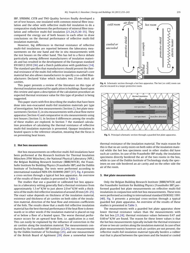
rgy and Buildings 56 (2013) 233–243 235
Islclcci
mstpaETmmuc
ttes
dosatotmho
2
bMthIiao
tanTetomwomTadbo
Fig. 4. Schematic section through a hot box apparatus. The hot (or cold) room canalso be encased in a larger protective room.
M.J. Tenpierik, E. Hasselaar / Ene
BP, SFRIMM, CSTB and TNO Quality Services finally developed aet of test houses, one insulated with common mineral fibre insu-ation and the other with reflective multi-foil insulation to do aomparative study between the performance of mineral fibre insu-ation and reflective multi-foil insulation [21,24,25,30–35]. Theyompared the energy use of both houses to each other to drawonclusions on the thermal performance of reflective multi-foilnsulation materials.
However, big differences in thermal resistance of reflectiveulti-foil insulations are reported between the laboratory mea-
urements on the one hand and the in situ measurements withhe test houses on the other hand. This has led to a fierce debatearticularly among different manufacturers of insulation materi-ls and has resulted in the development of the European standardN16012:2010 [36] and a Dutch publication with guidelines [14].he standard specifies that manufacturers should present the ther-al resistance of the multi-foil reflective insulation material’s coreaterial but also allows manufacturers to specify a so-called Man-
facturers Declared Value which includes two 25 mm thick airavities.
This paper presents a review of the literature on this type ofhermal insulation material for application in buildings. Based uponhis review and upon a description of the calculation procedure anxpected thermal resistance value for this type of product is beinguggested.
This paper starts with first describing the studies that have beenone into non-evacuated multi-foil insulation materials per typef investigation: hot box measurements (Section 2), hot plate mea-urements (Section 3), in situ measurements with a heat flow metrepparatus (Section 4) and comparative in situ measurements usingest houses (Section 5). In Section 6 differences among the resultsf these studies are explored. In Section 7 the standard calcula-ion procedure of calculating the thermal resistance of reflective
ulti-foil insulation materials is presented. Opaque insulation ineated spaces is the reference situation, meaning that the focus isn preventing heat losses.
. Hot box measurements
Hot box measurements on reflective multi-foil insulations haveeen performed at the Research Institute for Thermal Insulationünchen (FIW München), the National Physical Laboratory (NPL),
he Belgian Building Research Institute (BBRI/WTCB), the Fraun-ofer Institute for Building Physics (Fraunhofer IBP) and the Dublin
nstitute of Technology. The tests were performed according tonternational standard NEN-EN-ISO8990:2007 [37]. Fig. 4 presents
cross-section through a typical hot box apparatus. An overviewf the results of these studies is presented in Table 2.
The studies that use a guarded or calibrated hot box appara-us in a laboratory setting generally find a thermal resistance frompproximately 1.5 m2 K/W to just above 2.0 m2 K/W with a thick-ess of the multi-foil reflective insulation of around 20 mm [20–25].he exact value depends on thickness of the insulation material,xistence and thickness of air cavities on both sides of the insula-ion material, direction of the heat flow and emission coefficientsf the foils. The results show that a multi-foil reflective insulationaterial has the best thermal performance if the heat flow is down-ards or in other words if the insulation material is placed on top
f or below a floor of a heated space. The worse thermal perfor-ance occurs for an upward heat flow, i.e. application in a roof.
his can easily be explained by the influence of convection in the
ir cavities along the insulation material. The measurements con-ucted by the Fraunhofer IBP institute [23,24], two measurementsy the Dublin Institute of Technology [25], and one measurementf the British Board of Agrément [39] show a somewhat lowerFig. 5. Principal schematic section through a guarded hot plate apparatus.
thermal resistance of the insulation material. The main reason forthis is that no air cavity exists on both sides of the insulation mate-rial while the hot box specimens used in other studies did havesuch air cavities. In case of the Fraunhofer IBP study, the insulationspecimens directly bordered the air of the two rooms in the box,while in case of the Dublin Institute of Technology study the spec-imen on one side bordered an air cavity and on the other side theair of the room.
3. Hot plate measurements
Only the Belgian Building Research Institute (BBRI/WTCB) andthe Fraunhofer Institute for Building Physics (Fraunhofer IBP) per-formed guarded hot plate measurements on reflective multi-foilinsulations in conjunction with hot box measurements. These testswere performed according to international standard ISO8302:1991[40]. Fig. 5 presents a principal cross-section through a typicalguarded hot plate apparatus. An overview of the results of thesestudies is presented in Table 3.
The measurements with a guarded hot plate apparatus showlower thermal resistance values than the measurements withthe hot box [21,24]; thermal resistance values between 0.47 and0.60 m2 K/W are found. The reason for these lower values is thatthe hot box measurements typically include the thermal resistanceof one or two air cavities along the insulation material. In case of hot
plate measurements however such air cavities are not present; thereflective multi-foil insulation material typically borders a rubbermat that is placed between the specimen and the heated or cooled
236
M.J.
Tenpierik, E.
Hasselaar
/ Energy
and Buildings
56 (2013)
233–243
Table 2Overview of studies into the thermal performance of reflective multi-foil insulation materials using the hot box method.
(Guarded of calibrated) hot box method
Research institute Year Uncompressedthickness [mm]
Thickness ofcavities asidethe insulationmaterial [mm]
εfolie �T [K] Tav [◦C] Rtot [m2 K/W] Sources
Heat flow↑
Heat flow↓
Heat flow→
FIW München 2001 25 n.a.a n.a. n.a. n.a. 1.21 [20] ref. to [38]NPL 2004 7.49 2 × 20 0.06 ± 0.01 n.a. n.a. – 1.60 ± 0.06 – [20–22]
25b 1 × 90 Not measured n.a. n.a. ±1.40/±1.46c – 1.6025b 2 × 45 Not measured n.a. n.a. 1.71/±1.80c – 1.89
WTCB 2006 7.5 2 × 20 0.06 ± 0.01d 10 10 1.05 ± 0.06 1.53 ± 0.09 – [21]18.8 2 × 20 0.18 ± 0.02d 10 10 1.55 ± 0.09 1.61 ± 0.10 –19.2 2 × 20 0.19 ± 0.11/0.16 ± 0.13d 10 10 1.26 ± 0.08 1.63 ± 0.10 –
NPL 2007 23 (mean) ±43 and ±83 Not measured 19 10 1.89 ± 0.08 2.88 ± 0.12 2.04 ± 0.08 [22]Fraunhofer IBP 2007 n.a. Nonea Not measured 20.7 10.5 – – 0.72
n.a. n.a. 20.8 9.7 – – n.d. [23]n.a. n.a. 20.8e 9.7 – – n.d.n.a. n.a. 0.0f 25.0 – – n.d.
BBA 2006–2007 30 ±25 and ±70 0.16 n.a. n.a. 1.69g – – [39]30 Nonea 0.16 n.a. n.a. 0.91g – –
Fraunhofer IBP 2007–2008 n.a. Nonea 0.05 n.a. n.a. – – 1.00 [24]Dublin Institute of Technology 2009 25 50 and 32 Not measured 25.6 n.a. – – 1.68 ± 0.30i [25]
25 95 and bigh 26.7 n.a. – – 1.0095 and bigh 27.1 n.a. – – 0.70
n.d. means ‘data cannot be determined from the results.n.a. means ‘data not available’.
a During these measurements the foil insulation material was not built into a construction but was tested as a single material. The material thus bordered the adjacent air.b More values for three heat flow directions and different cavity widths can be found in the report. The measured values range from just below 1.1 m2 K/W to around 1.4 m2 K/W for two cavities of 30 mm and from just below
1.3 m2 K/W to around 2.0 m2 K/W for two cavities of 60–65 mm.c The test equipment had a slope of 45◦ .d Measured by TNO.e During this measurement there was an additional cold surface (−25 ◦C) on the cold side of the specimen simulating the effect of night-sky radiation on the roof component.f During this measurement there was an additional hot surface which emitted 600 W/m2 of heat towards the outer surface of the roof component simulating the effect solar radiation.g This value also includes thermal bridge effects caused by a wooden frame. The measured were performed under a slope of 45◦ .h One side of the insulation material directly bordered on the air of the room (the smaller surface film coefficient is considered in this value).i This value includes the gypsum board on one side of the construction.

M.J. Tenpierik, E. Hasselaar / Energy and Buildings 56 (2013) 233–243 237
Table 3Overview of studies into the thermal performance of reflective multi-foil insulation materials using the guarded hot plate method.
Guarded hot plate method
Research institute Year Uncompressedthickness [mm]
εfolie �T [K] Tav [◦C] Rtot [m2 K/W]Heat flow
Sources
WTCB 2006 7.5 0.06 ± 0.01 10 10 0.205 ± 0.004 [21]10 10 0.602 ± 0.012
.16 ± 0.13 10 10 0.469 ± 0.009n.a. n.a. 0.5 [24]
po
amof
4
bLsba[Apcc
ttsmdcrtidbedd
mcifatfrml
c
wrAr
Fig. 6. The influence of additional reflective layers on the thermal resistance of
18.8 0.18 ± 0.0219.2 0.19 ± 0.11/0
Fraunhofer IBP 2007–2008 n.a. 0.05
lates. As a consequence, the results of the hot plate measurementsnly include the thermal resistance of the insulation material itself.
The thermal resistances measured with the guarded hot platepparatus are also lower than the results of the hot box measure-ents by the Fraunhofer IBP [23,24] and the last two measurements
f the Dublin Institute of Technology [25]. The difference comesrom absence of surface resistances.
. In situ and lab measurements with a heat flow metre
In situ measurements with a heat flow metre were performedy the Building Research Establishment [26], Alba Building Sciencestd. [27,28] and the University of Reunion [29]. Moreover lab mea-urements with a heat flow metre apparatus have been performedy the National Physics Laboratory [22]. The results of these studiesre presented in Table 4. It is here important to mention that Saber41] showed that a heat flow metre in accordance with standardSTM C-518 underestimates the effective R-value of materials orroducts that include radiation shields in combination with wideavities (more than 25 mm). The main reason lies in non-uniformonvective flows in these cavities.
The in situ measurements with a heat flow metre conducted byhe Building Research Establishment (BRE), most measurements ofhe University of Reunion1 and the lab measurements from NPL alsohow thermal resistance values in the same order as the hot boxeasurements discussed previously: between 1.0 and 1.9 m2 K/W
epending on heat flow direction [22,26]. In all cases, the sameonstruction property is measured: the thermal resistance of theeflective multi-foil insulation itself plus the thermal resistance ofhe two adjacent non-ventilated air cavities (and in some casesncluding a small thermal resistance of some other materials). Theifference between the two measurement situations is that the hotox measurements are conducted in a laboratory in a controllednvironment while some measurements with heat flow metre areone in actual buildings. This difference is clearly visible in theifferences in specified uncertainties.
The thermal resistance values of reflective multi-foil insulationseasured by Alba Building Sciences Ltd however are signifi-
antly higher than the lab measurements [27,28]. Moreover, its striking that Alba Building Sciences twice measured the sameacade of a building on Victoria Road, Aberdeen, only one monthfter each other resulting in a factor 2 difference in measuredhermal resistance of the reflective multi-foil insulation in thisacade (1.86 m2 K/W versus 2.44 m2 K/W). After inspection, theesearchers concluded that the multi-foil insulation during the firsteasurement (1.86 m2 K/W) was inaccurately installed and that air
eaks disturbed the heat flows.One other interesting study, not presented in Table 4, was
onducted in 2010 at Eindhoven University of Technology ([14]
1 According to Miranville et al. [29], the higher thermal resistance value in winterith a naturally ventilated upper air cavity measured by the University of Reunion
esults from the high wind speeds in the cavity resulting from the trade winds.ccording to them these higher air speeds increase the thermal resistance of theoof construction.
reflective multi-foil insulation.
Adapted from [14].
referring to [42]). van der Meijden ([14] referring to [42]) wasinterested whether the reflective foils inside the insulation mate-rial have any effect on the total thermal resistance of the system.To be precise, he investigated whether 4 layers of 9 mm polyesterwool with reflective foils only on the outside have the same thermalresistance as 4 layers of 9 mm polyester wool with both reflectivefoils on the outside of the material and in-between each layer. Fig. 6presents some of the results. As can be seen, adding reflective foilsbetween the layers of polyester wool (+3+7 and +5; blue line) fur-ther increases the thermal resistance. He repeated the test with(translucent) 0.2 mm thick polyethylene film instead of reflectivefoil. This improved the performance as well, but less than the multi-reflection stop. Four reflective stops give a better result than tworeflective stops.
Finally, the study done by Pasztory et al. [43] should be men-tioned. With the objective of developing a new, cheap and robustreflective multi-plate insulation measurements were conducted onsamples with differing number of radiation shields and differingwidth of the cavities between these shields. These measurementswere conducted using a heat flow metre apparatus according toISO8301:1991 [44]. By increasing the number of radiation barriers,and as a result decreasing the width between the barriers, the effec-tive thermal conductivity of the system decreased. This decreasewas not linear however. The first inserted radiation barrier reducedthe effective thermal conductivity of the system more strongly thanadditional barriers.
5. Comparative measurements with test houses
Many research institutes conducted studies into the ther-mal performance of reflective multi-foil insulation materialsusing comparative measurements between two test houses

238
M.J.
Tenpierik, E.
Hasselaar
/ Energy
and Buildings
56 (2013)
233–243
Table 4Overview of studies into the thermal performance of reflective multi-foil insulation materials based on in situ or lab measurements with a heat flow metre.
In situ and lab measurements with a heat flow apparatus
Research institute Year Uncompressedthickness[mm]
Thickness ofcavities asidethe insulationmaterial [mm]
εfolie �T [K] Tav [◦C] Rtot [m2 K/W] Sources
Heat flow↑
Heat flow↓
Heat flow→
BRE (in situ) 2005 25 2 × 25 Not measured n.a. n.a. – – 1.72 ± 0.31 [26]
25 430 and 15 0.96 ± 0.19 – –
25 15 and crawlspace
– 1.85 ± 0.31 –
Alba Building SciencesLtd (in situ)
2006 25 100 and 25 Not measured 23.8 n.a. – – ±1.90a,b [27,28]
25 100 and 25 Not measured 19.6 n.a. – – ±3.48a,c
25 100 and 25 Not measured 25.2 n.a. – – ±3.61a
NPL (lab) 2007 23 (average) Total cavity85 mm
Not measured 20 10 1.73 2.47 – [22]
Total cavity85 mm
Not measured 20 25 1.70 2.19 –
University of Reunion 2012 25 n.a. Not measured n.a. – 1.44d – – [29]
25 n.a. Not measured n.a. – 1.47e – –
25 n.a. Not measured n.a. – 6.24f – –
25 n.a. Not measured n.a. – 1.66g – –
n.a. means ‘data not available’.a These values were derived from the measured U-values of the entire wall. The following were assumed for the calculation: thermal conductivity of granite and plasterboard is 2.2 resp. 0.17 W/(m K); only outdoor boundary
resistance of 0.04 m2 K/W was assumed due to the way of measuring.b This value is the result of a first measurement in the house Victoria Road 139b, Aberdeen from February 2006 [27].c This value is the result of a second measurement in the house Victoria Road 139b, Aberdeen from March 2006 [28].d Summer conditions and upper air cavity naturally ventilated; slope of the roof was 20◦ .e Summer conditions and no air cavity naturally ventilated; slope of the roof was 20◦ .f Winter conditions and upper air cavity naturally ventilated; slope of the roof was 20◦ .g Winter conditions and no air cavity naturally ventilated; slope of the roof was 20◦ .

M.J.
Tenpierik, E.
Hasselaar
/ Energy
and Buildings
56 (2013)
233–243
239
Table 5Overview of studies into the thermal performance of reflective multi-foil insulation materials based on comparative measurements with test houses.
Comparative measurements using test houses
Research institute year Uncompressedthickness [mm]
Thickness of cavitiesaside the insulationmaterial [mm]
εfolie Rtot [m2 K/W] Sources
Heat flow↗ (roof)
Heat flow→ (wall)
Sheffield hallamUniversity, CIM
2004–2005 25 n.a. Not measured 20 cmglasswool + 26%
– [25]
Sheffield hallam University, CIM 2005 30 30/40 and big Not measured 20 cm glass-wool + 39.8%a
– [25]
30 30/40 and big Not measured 20 cm glass-wool + 8.7%a
30 30/40 and big Not measured 20 cm glass-wool + 2.8%a
TRADA UK 2006 30 n.a. Not measured ±21 cmglasswool
– [25,30]
WTCB 2006 7.5 2 × 20 0.06 ± 0.01 – 1.73 [21]18.8 2 × 20 0.18 ± 0.02 – 1.7218.8 2 × 10 0.18 ± 0.02 – 1.4319.2 2 × 20 0.19 ± 0.11/0.16 ± 0.13 – 1.5519.2 1 × 10 0.19 ± 0.11/0.16 ± 0.13 – 1.15
Fraunhofer IBP 2007 25 120 + 160 and 60 Not measured ±20 cm glasswool (heatsupply)/±3.33(heat flowmetre)
– [31]
SFRIMM 2007 n.a. 140 and 40 Not measured 20 cm glasswool l + 28.4%
– [25]
CSTB 2005–2006 n.a. 80 and 100 Not measured 20 cm glass wool – 50.2% [32]Fraunhofer IBP 2007–2008 n.a. 120 + 195 and 45 0.05 2.0 – [24,33,34]
120–240TNO Q&S 2010 24b n.a. Not measured – 2.36 ± 0.02 [35]
40b n.a. Not measured – 3.42 ± 0.02
n.a. means ‘data not available’.a The first measurement was conducted with an indoor temperature of 21 ◦C and an outdoor temperature of −5 ◦C; the second measurement with 21 ◦C and 0 ◦C; the third measurement with 21 ◦C and 5 ◦C.b The outer layers were made of 2 × 8 mm bubble foil and not of reflective foil.

2 rgy an
[T
bsiamhdtbteltsIimm
savh[hblbCUmci
6
sltainna
6
iDmticaebsmit
A description of the computation scheme for calculating thethermal resistance of multi-foil thermal insulation materials can
40 M.J. Tenpierik, E. Hasselaar / Ene
21,24,25,30–32,35]. The results of these studies are presented inable 5.
This type of study is not standardized but in principle cane explained as follows. Two identical test houses or roof con-tructions are built; one is insulated with 200 mm mineral fibrensulation with “known” (better: presumed) thermal resistancend functions as a reference; the other is insulated with reflectiveulti-foil insulation and functions as the test case; next, both test
ouses are subjected to identical (real or simulated) weather con-itions and the energy demand for maintaining a constant indooremperature is monitored; this energy demand is then comparedetween the two houses; finally the thermal resistance of the reflec-ive multi-foil insulation is estimated from a this comparison onnergy demand and the “known” properties of mineral fibre insu-ation. So, if the energy demand in both test houses is identical,hen the multi-foil reflective insulation is supposed to have theame thermal resistance as the 200 mm mineral fibre insulation.f the energy use of the test house with the multi-foil reflectivensulation is x% higher/lower, then the thermal resistance of the
ulti-foil insulation is supposed to be x% lower/higher than of theineral fibre insulation.The results of the comparative measurements are not very con-
istent with each other. WTCB’s measured values using test housesre in agreement with their hot box results and their calculatedalues [21]. Also the comparative measurements by the Fraun-ofer IBP from 2007/2008 [24,33] and the measurements from CSTB32] resulted in thermal resistance values which are only slightlyigher than measured by other research institutes using the hotox technique. The thermal resistance of reflective multi-foil insu-
ation materials with a thickness of around 20 mm was found toe in the order of 1.5–2.5 m2 K/W by WTCB, Fraunhofer IBP andSTB. However, the studies by Sheffield Hallam University, TradaK, Fraunhofer IBP from 2005 to 2007, SFRIMM and TNO Q&S founduch higher thermal resistances, even up to 6.1 m2 K/W using the
omparative test method [25,30,31,35]. In the next section the mostmportant causes for these differences are identified.
. Discussion of differences between measurement results
A closer look at the results of the comparative measurementshows us that the thermal resistance of reflective multi-foil insu-ation derived from these measurements is based on the knownhermal resistance of 200 mm mineral fibre insulation, which isround 5.0 m2 K/W. However, such a comparison is only allowedf both test houses are exactly identical. This criterion however isot always met. Three factors play an important role here: air tight-ess of both test houses, the role of ventilated and non-ventilatedir cavities, and the influence of thermal bridges.
.1. Air tightness
The research report by Fraunhofer IBP [31] clearly shows themportance of differences in air tightness between both test houses.uring the experiment both the test house insulated with 200 mmineral fibre insulation and the test house insulated with a reflec-
ive multi-foil insulation of around 20 mm thick have an almostdentical heat loss. Purely based upon this result one could con-lude that the reflective multi-foil insulation (including adjacentir cavities) has an identical thermal resistance as 200 mm min-ral fibre insulation. However, the investigators also conducted alower door test in both test houses which showed that at a pres-
ure difference of 50 Pa the air tightness in the test house withineral fibre insulation was n50 = 1.3 h−1 while it was n50 = 0.9 h−1n the other test house. This means that the infiltration losses inhe test house with mineral fibre insulation were 45% higher. If
d Buildings 56 (2013) 233–243
these infiltration losses are not correctly considered, the higher airtightness of the test house with reflective multi-foil insulation isincorrectly attributed to the thermal resistance of this insulationmaterial. The investigators from Fraunhofer IBP also determinedthe thermal resistance of the reflective multi-foil insulation mate-rial in the roof with a heat flow metre apparatus as 3.33 m2 K/W.This is approximately two thirds of the value of 200 mm mineralfibre insulation.
In a follow-up study by Fraunhofer IBP in 2007–2008, theresearchers attempted to get the air tightness of both test housesas close together as possible and as small as possible [24]. In thatstudy a 20–22 mm thick reflective multi-foil insulation was foundto have a thermal resistance of 2.0 m2 K/W including air cavities.Also the study by CSTB [32] shows that, if the air tightness of bothtest houses is practically identical, the test house insulated with a20–25 mm thick reflective multi-foil insulation uses twice as muchenergy to maintain a constant and the same indoor temperatureas the test house insulated with 200 mm mineral fibre insulation.Higher air tightness should thus not be attributed to an intrinsicconstruction property as thermal resistance.
6.2. Ventilated or unventilated air cavities
Another factor that influences the result of the measurementswith test houses is whether the cavity alongside the reflectivemulti-foil insulation is ventilated or not (or weakly ventilated). NPLstudied the effect of opening the cavity on the cold side of a roofconstruction on the thermal resistance of the reflective multi-foilinsulation including cavity [22]. In case of a ventilated air cavity, thethermal transmittance of the entire construction, i.e. its U-value,was 9% higher compared to the construction with non-ventilatedair cavity. This implies that the thermal resistance of the total con-struction is a factor 1/1.09 smaller. This can be explained by the factthat in a well-ventilated air cavity the surrounding surfaces have atemperature close to the temperature of the air with which the cav-ity is ventilated.2 As a consequence, the insulating performance ofthe cavity is reduced; the resistance that remains is the convectiveboundary resistance between the surface of the reflective multi-foilinsulation and the air, the magnitude of which depending on thevelocity of the air flow.
6.3. Thermal bridges
A third factor that may lead to differences in the results of hotbox measurements and measurements using the test houses canalso be found in the report by Fraunhofer IBP [31] and in the paperby Belusko et al. [16]: thermal bridges. Because in the test housesthe mineral fibre insulation and the reflective multi-foil insulationmay be installed at a different position in the roof construction, i.e.between versus below the beams of the roof structure, the extentof the thermal bridges caused by for instance these roof beamsmay be different in both houses. Moreover, because of differencesin installation, differences in 3D heat flows may occur. Both fac-tors may result in an overestimation of the thermal resistance ofthe reflective multi-foil insulation compared to the mineral fibreinsulation.
7. Calculation model for reflective multi-foil insulations
be found in NEN-EN-ISO6946:2008 Annex B [45] but also in many
2 A surface film resistance causes a small temperature difference.

rgy and Buildings 56 (2013) 233–243 241
stadwirbs
mtegot
h
rt
obibttpbfiatcoF
h
ct
eaobrccb�i
h
T
nI
Fig. 7. Heat transfer coefficients for convection (ha;conv), conduction (ha;cond), radi-ation (hr) and total cavity (hg) and thermal resistance of the entire air cavity (Rg)as function of cavity thickness (d). Top: horizontal heat flow (in a facade); mid-dle: upward heat flow (typically in a roof in winter); bottom: downward heat flow(typically in a floor). Calculations according to NEN-EN-ISO6946:2008. The emission
M.J. Tenpierik, E. Hasselaar / Ene
tandard textbooks on building physics. In this model the heatransfer through a cavity with a certain thickness and with lengthnd width more than 10 times the thickness is divided into con-uction, convection and radiation. In very thin, non-ventilated oreakly ventilated cavities convection can be neglected3; the result-
ng heat transfer coefficient then is the sum of the conductive andadiative heat transfer coefficients. In wide cavities conduction cane neglected; the resulting heat transfer coefficient then equals theum of the convective and radiative heat transfer coefficients.
Conduction is a result of either electron or phonon (collisions ofolecules or atoms) transport in matter. Since heat transfer by elec-
rons is much quicker than by phonons, metals conduct heat moreasily than plastics. Conduction can occur in solids, liquids andases. The conductive heat transfer coefficient in a cavity dependsn the thickness of the cavity, d, and the thermal conductivity ofhe substance in the cavity, �. It is calculated as
a;cond = �
d(1)
When the molecules are not restricted in their movement atoom temperature at atmospheric pressure, the thermal conduc-ivity of air inside a cavity equals 0.025 W/(m K).
Convection is heat transfer resulting from the bulk movementf molecules typically caused by a pressure difference which maye caused by a temperature difference. Heat is then transferred as
nternal energy along with the molecules. Also along the interfaceetween a solid and a gas convective heat transfer occurs. Here,he boundary resistance needs to be considered. The thickness ofhe boundary layer is strongly affected by the speed of the air flowassing along the surface: the higher this speed is, the thinner theoundary layer is, and the higher the convective heat transfer coef-cient is. This implies that in not or weakly ventilated very thinir cavities convective heat transfer may be neglected unless largeemperature or pressure differences exist. The total heat transferoefficient for convection in an air cavity depends on the directionf the heat flow and on the temperature difference over the cavity.or a temperature difference smaller than 5 K, it equals
a;conv =
⎧⎨⎩
1.25 for horizontal heat flow
1.95 for upward heat flow
0.12d−0.44 for downward heat flow
(2)
In this equation, ha;conv [W/(m2 K)] is the total heat transferoefficient for convection in the cavity. For cavities with biggeremperature differences other values apply.
Radiative heat transfer between two surfaces is the net energyxchange by radiation. Every object with a temperature abovebsolute zero emits energy with an intensity to the fourth powerf its absolute temperature. Because irradiated surfaces reflectack part of the received radiation and emit radiation themselves,adiation energy exchange occurs. The radiation heat transferoefficient depends on the Rosseland mean temperature of theavity to the third power, T3
r [K3], the emission coefficients ofoth cavity surfaces, ε1, ε2, and the Stefan–Boltzmann constant,
[5.67 × 10⁻⁸ W/(m2 K4)]. The radiation heat transfer coefficients calculated as
3
r = 4εres�Tr (3)3r = (T2
1 + T22 )(T1 + T2)
4(4)
3 In a cavity thinner than approximately 20 mm for horizontal heat flow and thin-er than approximately 12 mm for upward heat flow convection can be neglected.
n cavities with downward heat flow convection can be neglected as well.
coefficient of both cavity walls equals 0.95 and the temperature difference acrossthe cavity equals 10 K.
1εres
= 1ε1
+ 1ε2
− 1 (5)
Particularly concerning the emission coefficients it is here alsoimportant to consider aging effects [46]. Important here for thisarticle is also to mention that the principle of reflective multi-foilinsulation is based on reducing the heat transfer coefficient for radi-ation by choosing materials with very low emission coefficients inthe order of 0.05–0.20.
The total heat transfer coefficient, hg [W/(m2 K)], and total ther-mal resistance of the cavity, Rg [m2 K/W], can now be computedfrom
hg = hr + max(ha;cond; ha;conv) (6)
and
Rg = h−1g (7)

242 M.J. Tenpierik, E. Hasselaar / Energy an
Fig. 8. Heat transfer coefficients for convection (ha;conv), conduction (ha;cond), radi-ation (hr) and total cavity (hg) and thermal resistance of the entire air cavity (Rg)as function of cavity thickness (d). Top: horizontal heat flow (in a facade); mid-dle: upward heat flow (typically in a roof in winter); bottom: downward heat flow(typically in a floor). Calculations according to NEN-EN-ISO6946:2008. The emissioncoefficient of both cavity walls equals 0.05 and the temperature difference acrossthe cavity equals 10 K.
adec
tamfmtrtw
merhaus, R.P. Reed (Eds.), Cryogenic Engineering, International CryogenicMonograph Series Part 3, Springer, New York, 2007, pp. 120–133.
[7] Ch. Jang, J. Kim, T.-H. Song, Combined heat transfer of radiation and conduction
Figs. 7 and 8 present the results of this calculation model for cavity with horizontal heat flow (top), upward heat flow (mid-le) and downward heat flow (bottom) for both a cavity with twomission coefficients of 0.95 (Fig. 8) and a cavity with two emissionoefficients of 0.05 (Fig. 7).
This calculation model was used by several researchers to checkhe results of their measurements against theory [21,22,35]. Theyll found a close correspondence of the thermal resistance valueseasured in a hot box to the theoretically predicted values for dif-
erent types of materials, with a few to many layers of insulationaterial and reflective foils. Flamant et al. [21] for instance found
he largest difference between measured and calculated thermalesistance to be 12% (product C; downward heat flow). The highhermal resistance values found by the comparative test set-ups
ere however not substantiated by the theory.d Buildings 56 (2013) 233–243
8. Conclusions
Conventional thermal insulation materials are typically testedin a laboratory with a (guarded) hot plate or with a (guarded orcalibrated) hot box. The first method allows for the determinationof the heat fluxes through the material alone, while the secondmethod also allows for the inclusion of additional heat fluxes fromand to its surfaces; the latter method thus allows for the thermalcharacterization of complete building components. Because theconditions of these two tests can be controlled, they give reliableresults. Other tests, however, like the comparative tests with testhouses, involve many uncontrolled variables and are very sensitiveto the quality of the test houses. These latter methods thereforelead to results with high uncertainty.
Very high thermal resistances as intrinsic property of20–30 mm thick reflective multi-foil insulation materials, of around5–6 m2 K/W, cannot be substantiated by this literature review. Athermal resistance of 1.5–2.5 m2 K/W (including cavity resistances)is more likely for this type of insulation material. The upper end ofthis range particularly applies to floor applications while the lowerend covers roof applications. It is important to stress that thesevalues also include the thermal resistance of accompanying air cav-ities and are based on foil emission coefficients of around 0.05–0.2at most. Given the same space available for insulation in the con-struction, solid insulation boards or blankets are thus likely to givesimilar or in case of wide cavities better thermal performance thanreflective multi-foil insulation materials. This is especially true forapplications in roofs and facades where the heat flow is upwardrespectively horizontal. The advantage of these reflective multi-foilinsulation materials over conventional thermal insulators, how-ever, might be that less material is needed.
From the results of this literature review, it can be concludedthat the insulating performance of thin reflective multi-foil insu-lations is determined to a large extent by the thermal resistanceof the air cavities alongside the material, to a large extent by thethickness of the insulating material and to some extent by thereflective layers. Moreover, ventilating one or both of the air cavi-ties reduces the total thermal resistance of the building component.Since these factors have a significant influence on the value of thethermal resistance of reflective multi-foil thermal insulation mate-rials (including air cavities), it is important that manufacturersspecify the conditions under which the presented thermal resis-tance values are applicable. These conditions among others includethe heat flow direction through the material and the thickness of aircavities alongside the material if included in the presented perfor-mance data. Only then a comparison to other insulation materialscan be made.
References
[1] R.H. Kropschot, Multiple layer insulation for cryogenic applications, Cryogenics1 (3) (1961) 171–177.
[2] T. Ohmori, Thermal performance of multilayer insulation around a horizontalcylinder, Cryogenics 45 (12) (2005) 725–732.
[3] R.G. Scurlock, B. Saull, Development of multilayer insulations with thermalconductivities below 0.1 �W/cm K, Cryogenics 16 (5) (1976) 303–311.
[4] K.G. Degen, S. Rossetto, R. Caps, J. Fricke, Evacuated multilayer foil insulations– minimization of heat transfer, in: T.W. Tong (Ed.), Thermal Conductivity 22 –Proceedings of the 22nd International Thermal Conductivity Conference, Ari-zona, November 1–7, 1993, Technomic Publishing Company Inc., Lancaster,1994, pp. 401–412.
[5] M.A. Green, Heat Transfer Through a Multilayer Insulation System as a Functionof Pressure in the Cryostat Vacuum Space, Advances in Cryogenic Engineering,vol. 43B, Plenum Press, New York, 1998, pp. 1313–1318.
[6] K.D. Timmerhaus, Insulation progress since the mid-1950s, in: K.D. Tim-
in stacked radiation shields for vacuum insulation panels, Energy and Buildings43 (12) (2011) 3343–3352.

rgy an
[
[
[
[
[
[
[
[
[
[
[
[
[
[
[
[
[
[
[
[
[
[
[
[
[
[
[
[
[[
[
[
[
[
[
[
M.J. Tenpierik, E. Hasselaar / Ene
[8] M. Spinnler, E.R.F. Winter, R. Viskanta, Th. Sattelmayer, Theoretical studiesof high-temperature multilayer thermal insulations using radiation scaling,Journal of Quantitative Spectroscopy and Radiative Transfer 84 (4) (2004)477–491.
[9] M. Spinnler, E.R.F. Winter, R. Viskanta, Studies on high-temperature multilayerthermal insulations, International Journal of Heat and Mass Transfer 47 (6–7)(2004) 1305–1312.
10] N. Hendriks, Enige bouwfysische aspecten van reflecterende isolatie – deel 3:soorten reflecterende isolatie, Dakenraad 102 (2011) 21–23.
11] N. Hendriks, Enige bouwfysische aspecten van reflecterende isolatie – deel 1:het werkingsprincipe, Dakenraad 100 (2011) 39–41.
12] N. Hendriks, Enige bouwfysische aspecten van reflecterende isolatie – deel 2:het belang van emissiviteit, Dakenraad 100 (2011) 39–41.
13] N. Hendriks, Enige bouwfysische aspecten van reflecterende isolatie –deel 4: combinaties met traditionele isolatie, Dakenraad 102 (2011)21–23.
14] N. Hendriks, Ontwerprichtlijn reflecterende isolatie. Aanwijzingen voor hetontwerpen en uitvoeren van reflecterende isolatie voor gevels, daken en vlo-eren, SBR Publication, Stichting Bouw Research, Rotterdam, 2012.
15] C. Craven, R. Garber-Slaght, Product Test: Reflective Insulation in Cold Climates,Technical Report Number TR 2011-01, Cold Climate Housing Research Center(CCHRC), Fairbanks, 2011.
16] M. Belusko, F. Bruno, W. Saman, Investigation of the thermal resistance of tim-ber attic spaces with reflective foil and bulk insulation, heat flow up, AppliedEnergy 88 (1) (2011) 127–137.
17] M.A. Medina, On the performance of radiant barriers in combinationwith different attic insulation levels, Energy and Buildings 33 (1) (2000)31–40.
18] C. Michels, R. Lamberts, S. Güths, Theoretical/experimental comparison of heatflux reduction in roofs achieved through the use of reflective thermal insulators,Energy and Buildings 40 (4) (2008) 438–444.
19] C. Michels, R. Lamberts, S. Güths, Evaluation of heat flux reduction provided bythe use of radiant barriers in clay tile roofs, Energy and Buildings 40 (4) (2008)445–451.
20] Celotex, Multi-foiled – Multi-Foil Performance Claims Disputed after Indepen-dent Tests by The NPL, Technical Bulletin 001/04 (2004), Celotex Ltd, Ipswich,http://just-insulation.com/pdfs/Celotex/Celotex Multi-foil Bulletin.pdf
21] G. Flamant, P. Wouters, D. Lheureux, J.-M. Seynhaeve, Ph. Ngendakumana, Ini-tiële thermische prestaties van dunne reflecterende producten, WTCB reportnr. 9-2006, WTCB, Brussels, 2006.
22] R. Williams, G. Ballard, Evaluation of the thermal performance of insulationsystems used in roof structures, NPL report MAT 8, NPL, Teddington, 2007.
23] N. König, Thermal insulation with IR-reflective multifoil products – anoverview, in: Presentation, Normapme Conference, 16 April 2007, Stuttgart,2007.
24] G. Hauser, M. Kersken, A. Schade, H. Sinnesbichler, Experimentelle und the-oretische Untersuchungen von Infrarot reflektierenden Dämmmaterialien,Bauphysik 33 (11) (2011) 33–42.
25] E. Frawley, Thermal testing of innovative building insulations, M.Sc. Thesis,Dublin Institute of Technology, Dublin, 2009, http://arrow.dit.ie/engmas/33
26] T.I. Ward, S.M. Doran, The Thermal Performance of Multi-foil Insulation,Report BRE, BRE Scotland, Glasgow, 2005, http://www.planningportal.gov.uk/uploads/br/multi-foil-insulation july2005.pdf
[
d Buildings 56 (2013) 233–243 243
27] G. Rooney, Thermal Insulation Performance Appraisal 139b & 141b Victo-ria Road Torry Aberdeen, Report Number 25035, Alba Building Sciences Ltd.,Norham, 2006, http://www.actis-isolation.com/pdf/albareport-firststudy.pdf
28] G. Rooney, Thermal Insulation Performance Appraisal 139b Victoria Road TorryAberdeen, Report Number 25038, Alba Building Sciences Ltd., Norham, 2006,http://www.actis-isolation.com/pdf/albareport-secondstudy.pdf
29] F. Miranville, A. Hamada Fakra, S. Guichard, H. Boyer, J.-Ph. Praene, D. Bigot,Evaluation of the thermal resistance of a roof-mounted multi-reflective radi-ant barrier for tropical and humid conditions: experimental study from fieldmeasurements, Energy and Buildings 48 (2012) 79–90.
30] BM TRADA, Q-mark Building Insulation Products, registration certificate, num-ber BIPS-0102, 2009.
31] E. Lindauer, H. Sinnesbichler, Field Tests Regarding the Thermal and EnergyPerformance of an ACTIS Roof Insulation System Compared to ConventionalMineral-fibre Insulation Materials, Brief Progress Report Part D, FraunhoferInstitut für Bauphysik, Holzkirchen, 2007.
32] CSTB, Comparative measurements of energy consumption of two cells put inexternal environment, report CSTB, CSTB, Marne-la-Vallee, 2007.
33] G. Hauser, A. Schade, H. Sinnesbichler, Potentiale und Grenzen von Infrarotreflektierenden Dämmmaterialien, IBP Mitteilung 36 (495) (2009) 1–2.
34] A. Schade, et al., Comparative Investigations of Different Roof Insulation Sys-tems Performed on Two Test Attics at the IBP Field Station at Holzkirchen.Report No. ES-02/2008, Fraunhofer Institut für Bauphysik, Holzkirchen, 2008.
35] J.J.A. Maat, Bepalen van de isolatiewaarde van Isobooster materiaal, Report8969R-10.E09.25177, TNO Quality Services BV, Eindhoven, 2010.
36] prNEN-EN16012:2010, Thermal insulation for buildings – Reflective insulationproducts – Determination of the declared thermal performance, NederlandsNormalisatie Instituut, Delft, 2010.
37] NEN-EN-ISO8990:2007, Thermal insulation – Determination of steady-statethermal transmission properties – Calibrated and guarded hot box, NederlandsNormalisatie Instituut, Delft, 2007.
38] FIW, Report A1-4/01, Forschungsinstitut für Wärmeschutz, München, 2001.39] BBA, Multifoil Insulation – Product Sheet 1 – Thinsulex Silver, agrément cer-
tificate No 06/4379, Britsch Board of Agrément, Garston, 2006/2007.40] ISO8302:1991, Thermal insulation – Determination of steady-state thermal
resistance and related properties – Guarded hot plate apparatus, InternationalOrganisation for Standardisation, Geneva, 1991.
41] H.H. Saber, Investigation of thermal performance of reflective insulations fordifferent applications, Building and Environment 52 (2012) (2012) 32–44.
42] C.M. van der Meijden, Meerlaagse reflecterende isolatie, M.Sc. Thesis, Eind-hoven University of Technology, Eindhoven, 2011.
43] Z. Pasztory, P.N. Peralta, I. Peszlen, Multi-layer heat insulation system for frameconstruction buildings, Energy and Buildings 43 (2–3) (2011) 713–717.
44] ISO8301:1991, Thermal Insulation – Determination of Steady-State ThermalResistance and Related Properties – Heat Flow Meter Apparatus, InternationalOrganisation for Standardisation, Geneva, 1991.
45] NEN-EN-ISO6946:2008, Building components and building elements – Ther-mal resistance and thermal transmittance –Calculation method, Nederlands
Normalisatie Instituut, Delft, 2008.46] M.H. Spitzner, N. Sack, J. Cammerer, H. Simon, Alterung Epsilon. Untersuchungdes Einflusses von Alterung und Verschmutzung auf das wärmetechnischeVerhalten von Baustoffen mit vermindertem Emissionsgrad, Report T 3247,Forschungsinstitut für Wärmeschutz, München, 2010.