Android on PC: On the Security of End-user Android Emulators
Upload
khangminh22Category
view
1download
0
YAŞAR UNIVERSITY GRADUATE SCHOOL OF NATURAL AND
APPLIED SCIENCES
An Application for Automobile Security on
Android Operating System
Halil Utku YILDIRIM
Thesis Advisor: Dr. Ahmet Koltuksuz
Department of Computer Engineering
Bornova-IZMIR
2012

i
ÖZET
OTOMOBİL GÜVENLİĞİ İÇİN ANDROID İŞLETİM
SİSTEMİ ÜZERİNDE BİR UYGULAMA
YILDIRIM, Halil Utku
Yüksek Lisans Tezi, Bilgisayar Mühendisliği Bölümü
Tez Danışmanı: Dr. Ahmet Koltuksuz
Haziran 2012, 64 sayfa
Güvenlik, günümüzde neredeyse her sektörde vazgeçilmez unsurlardan
biri haline gelmiştir. Otomotiv sektörü de bu anlamda önemli bir yere sahiptir.
1995‘ten günümüze kadar çeşitli yöntemler geliştirilmiştir. Bu yöntemler, başka
birileri tarafından etkisiz hale getirilmesi nedeniyle sürekli olarak değişim ve
gelişim göstermiştir. Bunlardan en önemlileri kart üzerinde diagnostik olarak
(OBD) gerçekleştirilmiştir. Bu teknoloji ile birlikte araç ile haberleşmek daha
kolay ve servislerin anlayacağı bir şekil almıştır. Daha sonra bu yeterli olmadığı
için, gelişmiş birkaç sürümü daha piyasadaki yürüyen bütün araçlarla
bütünleştirilmeye başlanmıştır. Araç haberleşmesinde de diğer sektörlerde olduğu
gibi uluslararası standartlar izlenmiştir. Böylece üretici firmalar ürünlerini belirli
bir format ile piyasaya sürmüşlerdir. Araç haberleşmesinin kolaylaşmasıyla
birlikte, daha güvenilir bir sistem ihtiyacı ortaya çıkmıştır. Hırsızlığa karşı
güvenlik sistemi 1998‘den günümüze kadar neredeyse bütün araçlarda
uygulanmıştır ancak bazen bu sistemler bile güvenliğin en büyük düşmanı ve
zaafı olan insan faktörüne karşı koymakta güçlük çekmiştir. Hırsızlığa karşı 100%
güvenli olduğu iddia edilerek satılan ve alınan araçlar aslında bu kadar güçlü bir
güvenlik altyapısına sahip değildir çünkü aracın kontrol üniteleri immobilizer adı
altında birbirleriyle haberleşmek zorundadır ve bu haberleşmeyi yorumlamak çok
da zor değildir. Sonuç olarak iki kablo arasındaki konuşan üniteler her zaman
izlenebilir bu yüzden bu haberleşmenin gene uluslararası yeni standartlarla
korunması gerekmektedir. Aksi takdirde otomobil hırsızlığı ile baş etmek
mümkün olmayacaktır. Bu çalışmamızda sizlere araçlardaki güvenlik sisteminin
nasıl çalıştığını ve ne derece zayıflıklarının olduğunu gözler önüne serdik.
Yöntemimiz ve uygulamamızla, aracınıza kendinizin bile yeni bir anahtar
programlayabileceğinizi ve bunu nasıl yapabileceğinizi göstereceğiz. Aynı
zamanda özel servis ve anahtarcı kitlelerin, yetkili servislere ihtiyaçları olmadan;
geliştirmiş olduğumuz uygulamayı kullanarak, bu işi nasıl yapabileceği somut
örneklerle kanıtlanacaktır.
Anahtar sözcükler: Araç güvenliği, hırsızla karşı güvenlik sistemi(immobilizer),
kart üzerinde diagnostik(OBD),otomobil hırsızlığı, araba anahtarcısı, özel servis.

ii
ABSTRACT
AN APPLICATION FOR AUTOMOBILE SECURITY
ON ANDROID OPERATING SYSYEM
YILDIRIM, Halil Utku
MSc in Computer Engineering
Supervisor: Dr. Ahmet Koltuksuz
June 2012, 64 pages
Nowadays, security is getting to be the most fundamental issue almost in
every industry. Automobile industry has also a serious place in this matter. Since
1995, there have been lots of methods that have been developed. These methods
had being changed and improved because of cracked by someone else. Because
they methods have been defused by some else, they have been changed and
improved continuously. One of the most important improvements was achieved as
on board diagnostics (OBD). With this technology, the vehicle communication
was getting easier and as the way to be understood by technicians. After this
because it is not adequate, improved versions have been released and started to be
integrated with the on road vehicles. Like the other areas, vehicle communication
has also followed some international standards. As a result, the manufacturer
companies have released their products with a standardized format. With the
vehicle communication became easier, the users need more secure systems.
Immobilizer system has been applied almost on all road cars which have been
produced since 1998 however sometimes even these systems might be deactivated
by the most dangerous enemy and weakness of the security which is human
beings. In reality, the car which is sold and bought by claiming 100% secure
against automotive thefts have not actually that much secure infrastructure
because the control units of the vehicle must communicate each other‘s under an
immobilizer system and these communication is not that much hard to interpret.
As a result, the talker control units between two cables can always be traced by
others that are why this communication needs to be protected under some
improved international standards. Otherwise it is not possible to handle with
automobile thefts. In this thesis, we have introduced you how these security
systems work and what weaknesses they have. With our method and application,
you can even program a new key with your own car. At the same time for
automobile locksmiths and special dealers will realize that they have no longer
need for the authorized dealers.
Keywords: Vehicle security, immobilizer, on-board diagnostics,
automobile theft, auto locksmith, special dealer.

iii
Acknowledgements
I am grateful to my supervisor Dr. Ahmet Koltuksuz for his suggestions
and criticisms about my study. I am also grateful to Türker Tunç who has allowed
me to use his previous studies and supplied essential material for my study. I
would like to thank Tekin Başöz for his valuable comments and suggestions.
I would like to address my thanks to Nasra LTD for their full support in
my whole study.
I would like to thank my family who encouraged and supported me during
my studies.

iv
TEXT OF OATH
I declare and honestly confirm that my study titled ―An Application for
Automobile Security on Android Operating System‖, and presented as Master‘s
Thesis has been written without applying to any assistance inconsistent with
scientific ethics and traditions and all sources I have benefited from are listed in
bibliography and I have benefited from these sources by means of making
references.
20 / 06 / 2012
Halil Utku YILDIRIM

v
CONTENTS
Page
ÖZET................................................................................................................... …i
ABSTRACT ...................................................................................................... … ii
ACKNOWLEDGEMENTS .................................................................................. iii
LIST OF FIGURES ............................................................................................ viii
LIST OF TABLES ................................................................................................ ix
LIST OF SYMBOLS AND ABBREVIATIONS .................................................. x
1 Introduction to vehicle communication………………………………….........1
1.1 Communication Protocols…………………………………………………… 1
1.2 On-Board Diagnostics (OBD)……………………………………………….. 7
1.2.1 First Generation (OBD1)………………………………………………….7
1.2.2 On-Board Diagnostics - Second Generation (OBD2)…………………….8
1.2.3 Objectives of OBD2……………………………………………………....8
1.3 OBD2 Signal Protocols ………………………………………………………9
1.4 ISO standards………………………………………………………………...10
1.5 Common devices……………………………………………………………..11
2 Immobilizer……………………………………………………………..........13
2.1 Immobilizer system…………………………………………………………..13
2.2 Cryptographic Background…………………………………………………..14
2.3 Standard security Architectures using RFID………………………………...15
2.4 Crypto Transponders………………………………………………………....16
2.4.1 System Overview………………………………………………………...16

vi
CONTENTS
Page
2.4.2 Design Objectives………………………………………………………..18
2.4.3 Encryption………………………………………………………………..18
2.4.4 Supervision Circuits……………………………………………………...19
3 Anti-theft and Alarm Systems……..................................................................22
3.1 Passive ANTI-THEFT Systems (PATS)…………………………………......22
3.1.1 The history of PATS evolution on Ford vehicles………………………...23
3.1.2 PATS Control Functions………………………………………………....24
3.1.3 Ford Keyless Entry Keypad Code Programming………………………...25
3.1.4 Ford Pats Key programming Using Two Programmed Keys………..…..26
3.1.5 Remote Keyless Entry (RKE) Transmitter Programming………….…....26
3.2 I-PATS……………………………………………………………………....27
3.3 D-PATS……………………………………………………………………...28
3.4 Key ID-Number Verification Process……………………………………….31
3.4.1 I-PATS…………………………………………………………………..31
3.4.2 D-PATS (Mazda2)……………………………………………………....32
3.4.3 D-PATS (Mazda3 and RX-8)…………………………………………...33
3.5 I-PATS Service Functions………………………………………………......34
3.6 D-PATS Service Functions (Mazda2)……………………………………....35
3.7 D-PATS Service Functions (Mazda3/RX-8)………………………………..36
3.8 Key Functions……………………………………………………………….36
3.8.1 Key Programming without WDS……………………………………….36
3.8.2 Key Deletion without WDS………………………………………….....37

vii
CONTENTS
Page
3.8.3 PATS Functions with WDS……………………………………………..38
4 APPLICATION DEVELOPMENT………………………………………....42
4.1 Overview of Android Operating System………………………………….....42
4.2 Application Analysis………………………………………………………...42
4.2.1 UML(Use case and Sequence Diagrams).……………………………….43
4.2.2 The Analysis of Web-based PHP Application………………………......44
4.2.3 The Analysis of the Android Based Application……………………......47
4.3 Display tests on different tablet computers……………………...………......49
5 Conclusions……………………………………………………………….....50
5.1 Thesis Summary…………………………………………………………......50
5.2 Contributions and Future Work…………………………………………......50
5.3 New system recommendations...…………………………………………….51
BIBLIOGRAPHY……………………………………………………………....52

viii
LIST OF FIGURES
Page
1.1 A VCM brand device………………………………………………………..11
2.1 System Block Diagram……………………………………………………....14
2.2 Crypto Transponder Systems………………………………………………...17
2.3 Plastic Wedge Transponder……………………………………………….....18
2.4 Crypto Transponder Block Diagram………………………………………....20
2.5 Timing of a Programming Process……………………………………….......21
3.1 I-PATS of Mazda6 (GG/GY)………………………………………………..27
3.2 I-PATS components……………………………………………………….....28
3.3 D-PATS of Mazda3 (BK)…………………………………………………....29
3.4 D-PATS components (Mazda2)………………………………………….......30
3.5 D-PATS components (Mazda3)………………………………………….......30
3.6 D-PATS components (RX-8)…………………………………………….......31
3.7 Key programming time line…………………………………………….…....37
3.8 Key erasing time line…………………………………………………….......38
4.1 Use-case diagrams………………………………………………………….. 43
4.2 Sequence diagram……………………………………………………………43
4.3 Login page-1……………………….…………………………………...........44
4.4 Login page-2…………………………………………………………………44
4.5 Registration page…………………………………………………………….45
4.6 Calculation page-1…………………………………………………………...46
4.7 Calculation page-2…………………………………………………………...46
4.8 AVD (Android Virtual Device)…………………………………………...…47
4.9 Webview……………………………………………………………………..48
4.10 Connection control…………………………………………………………48

ix
LIST OF TABLES
Page
1.1 High Level Automotive Protocols…………………………………………….1
3.1 I-PATS Service Functions…………………………………………………...34
3.2 Table (Mazda2)………………………………………………………………35
3.3 (Mazda3/RX-8)……………………………………………………………....36

x
LIST OF SYMBOLS AND ABBREVIATIONS
Symbols Explanation
R Response
f Functions
Cryptographic algorithm
RAND Challenge
Encryption key
Abbreviations
CAN Controller Area Network
DDS 1 Diesel Diebstahl Schutz
DLC Data Link Connector
DSM Diesel Smart Module
DTC Diagnostic Trouble Code
EPC Electronic Parts Catalogue
HEC Hybrid Electronic Cluster
IC Instrument Cluster
MIS Mazda Immobilizer System
OBD On-Board-Diagnostics
PATS Passive Anti-Theft System
I-PATS Integrated PATS
D-PATS Distributed PATS
PCM Powertrain Control Module
PID Parameter Identification
RF-ID Radio Frequency-Identification
RKE Remote Keyless Entry
SST Special Service Tool
VIN Vehicle Identification Number
WDS Worldwide Diagnostic System
W/M Workshop Manual

1
Chapter 1
Introduction to Vehicle Communication
1.1 Communication Protocols
The modern applications of automotive industry call for an ease of use and
security and are being applied by rapidly growing single or multiple
communication protocols which communicate over distributed electronic
architecture that includes electronic control units (ECUs). One of these protocols
is CAN and besides CAN, there are other similar competitive protocols within the
automotive industry.
Current high level automotive protocols are listed below. This list is not claimed
to be 100% complete and it is editable in any case.
Table 1.1 High Level Automotive Protocols. [1]
Let us briefly consider some of the most widely used protocols:
Can-Open [2]
CANopen has originally developed as a network standard with highly flexible
structuring capacity. In 1995, CANopen has been replaced as CAN for
international users and manufacturer companies. Originally, CANopen
communication profile used to rely on CAN application layer as an OSI
application layer. It operates on CAN data link which is usually being applied as
hardware.
CANopen is consisted of 7 layers while depending on CAN and originally
produced for factory automation applications and industry control systems. For
this 7 layers, it counts as both hardware and communication protocol.

2
CANopen profile indicates standard communication mechanism and device
functions. These properties include the structures for variety of differently
originated devices and some applications. Profile family is based on
communication profile (CiA-DS301), the structure for programmable devices
(CiA-DS302) and device profile set (CiA-DS-4xx). A client based profile is also
allowed. Main source code provides all required functions for CANopen so the
user would be allowed to develop everything they need by using these functions.
At the same time, CANopen is used at field vehicles, ship electronics, medical
hardware and railways. It also supports correlations between different devices,
synchronization, circular and event based data transfer and simultaneous
input/output adjustment.
Nowadays CANopen is current at automation under the international
producers and users group as CAN (CiA). CANopen is open source and
applicable at projects without any license.
CCP [3]
CAN calibration protocol also known as CCP is a protocol which developed
for providing the communication between target main processor and main frame
via CAN(controller area network) protocol.
Interface; defines the methods for handling module calibration, data collection
measurement and flash programming. Module developers have to decide whether
CCP is being completely supported by the device or partial involvement of ECU
support. There is no limiting at physical layer selection or bit rate preferred by the
system.
CCP was developed in early 90s by ASAP (a group of people who work on
application standardization system for German) and used by automotive industry.
They also improve it.
At first, CCP was used as a tracking program which uses standard protocols
instead of custom protocols specified by company.
For CCP message transfer, private talk or just 2 CAN identifier dialogue is
being used. Device always initiates talking with a single CAN message and also
controls the data transfer. As soon as message is being received by ECU, ECU is
obliged to respond the message with a CAN message.
CCP supports both point to point and multiple connections in a network.
Module calibration, data collection measurement and activities like flash
programming are capable of being performed for a single module or multiple
modules over CAN network.

3
DeviceNet [4]
DeviceNet is used for connecting the industrial devices such as photo
electronic sensors, limit switches, process sensors and other variety of
technologies via a single network. Therefore, DeviceNet can be described as the
communication links that are based on serial bus standard for automotive
networking. It is developed for the satisfaction of industrial environments over
safety and performance issues. DeviceNet has inherited its properties from
ControlNet, which has also developed by Allan-Bradley (now owned by Rockwell
Automation). It is layered on top of the CAN technology which is developed
Bosch. The involvement of CAN makes it low cost and robust in comparison with
the RS-485 based protocols.
As in strategy, Rockwell automation has decided to go for the open concept
and share it with third party vendors. Currently it is being handled by an
independent organization ‗ODVA‘ (Open Devicenet Vendors Association) in
North America. Later, they decided to call the technology as Common Industrial
Protocol (CIP), which consists from Ethernet/IP, ControlNet, DeviceNet and
Component, This technology is highly adaptable with all these protocols and also
offering ease of industrial control according to the others.
ISO 9141 (K-Line) [5]
The ISO 9141 standard specifies the requirements for setting up the
interchange of the digital information between an on board ECU and suitable
diagnostic tester to facilitate inspection, test, diagnosis and adjustment of vehicles,
systems and ECU‘s.
K or K and L are the two communication connections that ECU must have. A
bus system is the result of connecting K or L from one or multiple ECUs. A
diagnostic tester receives information in a serial digital from ECU via the Line K.
It may also carry commands as well as data from diagnostic tester to the ECU. It
is also used for initializing the serial communication. Line L only works one way
as diagnostic tester to the ECU. It is also able to initialize and/or to carry
commands and/or data. The standard K-line is ISO 9141 compatible for baud rates
up to 250 KBaud.
ISO 9141-2 describes a subset of ISO 9141:1989. It specifies the requirements
for setting up the interchange of digital information between on-board emissions
related electronic control units of road vehicles and the SAE OBDII scan tool as
specified in SAE J1978. It is limited to vehicles with nominal 12V supply voltage.
J1939 [6]
Related to concerns on design and use of devices that transmit electronic
signals and control information among vehicle components, the society of
automotive engineers (SAE) Truck and Bus Control and Communications

4
subcommittee has developed a family. SAE J1939 is a class C, very fast
communications network designed for supporting real-time closed loop control
functions between electronic control devices that are physically distributed
throughout the vehicle. It is used for off-highway machines in applications such as
construction, material handling, and forestry machines.
J1939 is structured into several parts based on the ISO Open Systems
Interconnect (OSI) Model. The OSI Model defines seven layers of
communication, each performing different functions.
Purpose of developing J1939 was using CAN protocol physical layers and
CAN data-link layer. Each message consists from 29 bit identifier that defines the
priority of the message; sender and what data is contained within ft. Collisions are
avoided due to the arbitration process that occurs while identifier is transmitted
using non-destructive arbitration. This allows transmitting messages with high
priority to get through with low latency due to equal access on the network for
any device.
Because J1939 document is allocated to each layer, not all of them are
explicitly defined by J1939...
Network members get almost every message that is broadcasted in J1939. This
removes the necessity additional request messages for devices to use data. A
specific destination address can be included in the message identifier when a
message needs to be directed.
First of all, a message must be created by first referencing the data content and
message table within appropriate J1939 documents in order to send a specific data
item. This will clarify the default property, data content value to use and the
transmission rate. It will also define the data field format because for reducing the
message overhead, related data items are packed together in a message. Messages
that consist from eight or more bytes can be sent a multi packet messages
KWP2000 [7]
KWP2000, also known as ―Keyword Protocol 2000‖ is a protocol on vehicle
that are manufactured and sold in Europe. It is a common name for ISO 14230.
ISO 14230 and ISO 9141 are quite similar protocols. They are similar as in
physical implementation but the data format makes the difference, an optional
‗fast‘ initialization sequence. Like ISO 9141, vehicle still needs to be initialized
for getting the diagnostic data from the ECU but there are two types of
initializations. One is ―Unchanged‖ which uses same 5-baud initialization
sequence and the ―fast‖ initialization. ―Fast‖ initialization is the result of sending
25 Millisecond pulse followed by a 10.7 Kbaud request sending rate.

5
Communication between an on-board tester and the on-board network is
described by KWP2000 operations. Establishing the communications link through
an initialization is the precondition of any communication between the tester unit
and the vehicle network. There are three different methods of initialization that are
being called by KWP2000 specification. Each one of them is described within the
ISO specification.
Supporting messages with field length of 255 bytes is an important aspect of
KWP mode operations.
NMEA 2000 [8]
NMEA 2000 is a standard that contains the requirements for the minimum
implementation of a serial-data communications network to interconnect marine
electronic equipment on board vessels. It has developed by Committee Working
Group in 90s. Sharing data, including commands and status, with other
compatible equipment over a single signaling channel is the signature of
equipment that designed with this standard.
Secondary decisions like navigation, power generation, engines and
machinery, fire alarm and control, etc. might be included to the operational
decisions such as operation of the ship and safety. The International Electro
technical Commission (IEC) standard IEC 61162-4 is addressing network
requirements. Based on Norwegian initiative called MiTS (Marine Information
Technology Standard), it is Ethernet-based system, designed for operation up to
100 megabits/second.
Data messages are transmitted as a series of data frames, each with error
checking and confirmed frame delivery. Data frames contain (in addition to
control and error-checking bits) an 8-byte data field and 29-bit identification field
that sets message priority and identifies data message, the source and the
destination. Typical data includes discrete parameters such as position latitude
and longitude, GPS status values, steering commands to autopilots, finite
parameter lists such as waypoints, and moderately sized blocks of data such as
electronic chart database updates.
The standard defines all of the pertinent layers of the International Standards
Organization Open Systems Interconnect (ISO/OSI) model, from the Application
Layer to Physical Layer, necessary to implement the required NMEA 2000
network functions.
The components of an NMEA 2000 networks are:
Physical Layer. Fully defined by the standard, including signaling
voltages, cables, and connectors.
Data Link Layer. Defined by ISO 11783-3 with and additional
requirements specified by the standard.

6
Network Layer. To be defined in the future versions of the standard.
Network Management. Defined by ISO 11783-5 with additional
requirements specified by the standard.
Application Layer. Fully defined by the standard and includes a provision
for manufacturer‘s proprietary messages.
XCP [9]
Interfaces for the description and integration of for micro-controller-based
open-loop and closed-loop control systems are defined by a European
organization called ASAM working group who members include several
automobile manufacturers and suppliers. Based on CAN calibration protocol
(CCP), XCP has been developed. XCP offers all services needed to record ECU-
internal run-time variables and calibrate the control algorithms by modifying
parameters.
Besides being a measurement and calibration protocol, XPC was a need for
media-independent global measurement and calibration protocol. The ―X‖
signifies a generic protocol independent of the medium used.
XCP is able to function on CAN, Ethernet (UDP and TCP/IP) and so SCI. It is
also planned to be use in Flexray, TTCAN, USB and Firewire.
Conversion that takes XPC protocol into a specific medium is described by the
XPC packet layer. It has a calibration data page initialization and switching,
online memory calibration (read/write access), synchronous data acquisition,
synchronous data simulation and flash programming for ECU development
process.
Communication models can be Standard, Block or Interspersed. Slave
responds to each packet request by sending the corresponding response packet or
an error packet with the standard communication model. Before sending the
packet, the master waits for a response. In order to increase the throughput of
memory uploads, downloads and flash programming, block transfer
communication model is used.
Communication with XCP requires two reserved XPC messages. Packets (data
objects) that contain 8-255 bytes of data, manages the dialog accomplishments.
XPC dialogs are mostly Master/Slave. Tool (Master) starts the dialog by sending a
request packet to the ECU. ECU (the slave) receives the packet and sends a
response packet. Minimum packet size required by the transfer medium is 8 bytes
(CAN).
There are two types of basic packets. One of them is for transferring generic
control commands (CTO) that carry out protocol commands and the other one is
7
for transferring the synchronous data (DTO). Applications for XCP contains
obtaining real-time ECU information via basic read and write functions, accessing
ECU parameters in real time, real-time adjustment of ECU process algorithms
(Calibration), in-system or in-vehicle evaluation of design concepts, evaluation of
engineering design modifications, in- system or in-vehicle flash programming and
emulation beyond the lab bench.
Data throughput (upload, download, flashing and measurement data) with
CAN 1MBit: 50K bytes/sec, with Ethernet 10MBit: 800K bytes/sec, USB 1.x: 1M
bytes/sec.
1.2 On-Board Diagnostics (OBD) [10]
OBD or On-board diagnostic is a general term for automotive industry
which refers a vehicle‘s self-diagnostic and reporting feature. By using OBD
systems, it gives permission to vehicle owner or garage technician to state of the
status of the vehicle sub-systems. After it is released in early 1980s it can give
variety information of on-board vehicle computers which made OBD system
possible. In the past, OBD only detect malfunction indicator light, or MIL, when a
problem is detected but it would just provide limited information belongs to the
problem. On the other hand, with the development of the new OBD system and
including communication port to provide more information and error codes called
diagnostic trouble codes, or DTCs, which allows the vehicle owner or authorized
dealer to identify the error fast by giving a real time data.
1.2.1 First Generation (OBD1) [11]
It is a first generation of On board diagnostics which includes from 1982
to 1995 and owned by most of the vehicles exception of some 1994 and 1995
ones.
California‘s Air Resources Board (CARB)and then the Environment
Protection Agency (EPA) has forced the vehicle manufacturers to include a self-
diagnostic program in their on-board computer beginning in 1998 and it became
to a name of OBD1 as the first generation of Onboard diagnostics.
OBD1 is a set of self-testing and diagnostic instructions programmed into
the vehicle‘s on-board computer. The programs are specifically designed to detect
failures in the sensors, actuators, switches and wiring of the various vehicle
emissions-related systems. If the computer detects a failure in any of these
components or systems, it lights an indicator on the dashboard to alert the driver.
The indicator lights only when an emissions-related problem is detected.
The computer also assigns a numeric code for each specific problem that it
detects, and stores these codes in its memory for later retrieval. These codes can
be retrieved from the computer‘s memory with the use of a ―Code Reader‖ or a
―Scan Tool.‖
8
1.2.2 On-Board Diagnostics - Second Generation (OBD2) [12]
The OBD2 System is actually an enhancement of the OBD1 System. Thus, In
addition to performing all the functions of the OBD1 System, the OBD2 System
has been enhanced with new Diagnostic Programs. These programs closely
monitor the functions of various emissions-related components and systems (as
well as other systems) and make this information readily available (with the
proper equipment) to the technician for evaluation.
The California Air Resources Board (CARB) conducted studies on OBD1
equipped vehicles. The information that was gathered from these studies showed
the following:
A large number of vehicles had deteriorating or degraded emissions-
related components. These components were causing an increase in
emissions.
Because OBD1 systems only detect failed components, the degraded
components were not setting codes.
Some emissions problems related to degraded components only occur
when the vehicle is being driven under a load. The emission checks being
conducted at the time were not performed under simulated driving
conditions. As a result, a significant number of vehicles with degraded
components were passing Emissions Tests.
Codes, code definitions, diagnostic connectors, communication protocols
and emissions terminology were different for each manufacturer. This
caused confusion for the technicians working on different make and model
vehicles.
To address the problems made evident by this study, CARB and the EPA
passed new laws and standardization requirements. These laws required that
vehicle manufacturers to equip their new vehicles with devices capable of meeting
all of the new emissions standards and regulations. It was also decided that an
enhanced on-board diagnostic system, capable of addressing all of these problems,
was needed. This new system is known as ―On-Board Diagnostics Generation
Two (OBD2).‖ The primary objective of the OBD2 system is to comply with the
latest regulations and emissions standards established by CARB and the EPA.
1.2.3 Objectives of OBD2 [13]
The Main Objectives of the OBD2 System are:
To use a standardized Diagnostic Link Connector (DLC) in all vehicles.
(Before OBD2, DLCs were of different shapes and sizes.)
To standardize communication procedures and protocols between the
diagnostic equipment (Scan Tools, Code Readers, etc.) and the vehicle‘s
on-board computer.
To standardize the code numbers, code definitions and language used to
describe faults. (Before OBD2, each vehicle manufacturer used their own
code numbers, code definitions and language to describe the same faults.)
To expand emissions-related system monitoring. This includes a set of
computer run diagnostics called Monitors. Monitors perform diagnostics

9
and testing to verify that all emissions-related components and/or systems
are operating correctly and within the manufacturer‘s specifications.
To detect degraded and/or failed emissions-related components or systems
that could cause tailpipe emissions to exceed by 1.5 times the Federal Test
Procedure (FTP) standard.
To expand the operation of the Malfunction Indicator Lamp (MIL) and
command the MIL ―on‖ when tailpipe emissions exceed the FTP standard
by 1.5 times.
1.3 OBD2 Signal Protocols [14]
There are five signaling protocols that are permitted with the OBD-II
interface. Most vehicles implement only one of the protocols. It is often possible
to deduce the protocol used based on which pins are present on the J1962
connector:
SAE J1850 PWM (pulse-width modulation - 41.6 kB/sec, standard of the Ford
Motor Company)
pin 2: Bus+
pin 10: Bus–
High voltage is +5 V
Message length is restricted to 12 bytes, including CRC
Employs a multi-master arbitration scheme called 'Carrier Sense Multiple
Access with Non-Destructive Arbitration' (CSMA/NDA)
SAE J1850 VPW (variable pulse width - 10.4/41.6 kB/sec, standard
of General Motors)
pin 2: Bus+
Bus idles low
High voltage is +7 V
Decision point is +3.5 V
Message length is restricted to 12 bytes, including CRC
Employs CSMA/NDA
ISO 9141-2. This protocol has an asynchronous serial data rate of 10.4 kBaud.
It is somewhat similar to RS-232, however the signal levels are different, and
communications happens on a single, bidirectional line without additional
handshake signals. ISO 9141-2 is primarily used in Chrysler, European, and
Asian vehicles.
pin 7: K-line
pin 15: L-line (optional)
UART signaling
K-line idles high, with a 510 ohm resistor to Vbatt
The active/dominant state is driven low with an open-collector driver.
Message length is restricted to 12 bytes, including CRC

10
ISO 14230 KWP2000 (Keyword Protocol 2000)
pin 7: K-line
pin 15: L-line (optional)
Physical layer identical to ISO 9141-2
Data rate 1.2 to 10.4 kBaud
Message may contain up to 255 bytes in the data field
ISO 15765 CAN (250 kBit/s or 500 kBit/s). The CAN protocol was developed
by Bosch for automotive and industrial control. Unlike other OBD protocols,
variants are widely use outside of the automotive industry. While it did not
meet the OBD-II requirements for U.S. vehicles prior to 2003, as of 2008 all
vehicles sold in the US are required to implement CAN as one of their
signaling protocols.
pin 6: CAN High
pin 14: CAN Low
All OBDII pin outs use the same connector but different pins are utilized with the
exception of pin 4 (battery ground) and pin 16 (battery positive).
1.4 ISO standards [15]
ISO 9141: Road vehicles — Diagnostic systems. International Organization
for Standardization, 1989.
Part 1: Requirements for interchange of digital information
Part 2: CARB requirements for interchange of digital information
Part 3: Verification of the communication between vehicle and OBD II
scan tool
ISO 11898: Road vehicles — Controller area network (CAN). International
Organization for Standardization, 2003.
Part 1: Data link layer and physical signaling
Part 2: High-speed medium access unit
Part 3: Low-speed, fault-tolerant, medium-dependent interface
Part 4: Time-triggered communication
ISO 14230: Road vehicles — Diagnostic systems — Keyword Protocol 2000,
International Organization for Standardization, 1999.
Part 1: Physical layer
Part 2: Data link layer
Part 3: Application layer
Part 4: Requirements for emission-related systems
ISO 15031: Communication between vehicle and external equipment for
emissions-related diagnostics, International Organization for Standardization,
2010.

11
Part 1: General information and use case definition
Part 2: Guidance on terms, definitions, abbreviations and acronyms
Part 3: Diagnostic connector and related electrical circuits, specification
and use
Part 4: External test equipment
Part 5: Emissions-related diagnostic services
Part 6: Diagnostic trouble code definitions
Part 7: Data link security
ISO 15765: Road vehicles — Diagnostics on Controller Area Networks
(CAN). International Organization for Standardization, 2004.
Part 1: General information
Part 2: Network layer services ISO 15765-2
Part 3: Implementation of unified diagnostic services (UDS on CAN)
Part 4: Requirements for emissions-related systems
1.5 Common devices
Figure 1.1 A VCM brand device.
There are many devices which scans the vehicle in order to identify the
diagnostic fault codes. For instance, IDS/VCM tool which is developed for Ford,
Mazda, Land Rover and Jaguar and used by authorized and special dealers. For
providing a communication with the vehicle user is required to make appropriate
connections with the vehicle and his computer. These devices mostly support
USB connections for computer. The user must plug the OBD cable into the

12
vehicle‘s OBD port and to the diagnostic tool to provide the communication
between the vehicle and diagnostic scan tool. There should be an USB cable in
order to deal with computer so it must be plugged in to the usb port on the
computer and the tool to communicate via diagnostic tool software. After the
connections have been configured properly, the user would open up the software
to connect to the vehicle to see DTCs and the other features which is provided by
the diagnostic tool.
By using this software the fault codes would be cleared from the vehicle‘s
electronic control unit (ECU). There are also some many features which use the
same communication port and protocols depending on the model and make.
These diagnostic tools could be varied based on the brand of the vehicle.
For instance, TECH2 and TECH3 for GM, Lexia-3 for Peugeot-Citroen, G-Scan
for Hyundai-Kia, Examiner for Fiat and so on…
The connection cables and methods could be varied depends on the
diagnostic device that is been used on the vehicle however the communication
approach is still the same.

13
Chapter 2
Immobilizer
With the need of improved security required for automotive industry,
many immobilizer systems started to use RFID (radio frequency identification)
technology in order to get benefit of its unique features. This article mentions the
system approaches for first and second generation of immobilizer systems. The
various security levels are discussed including the latest generation which is
called crypto-transponders.
In 1993 automotive theft increased rapidly and reaches to the amounts
which were not acceptable by insurance companies. After that German insurance
companies forced a fast introduction of immobilizer. Various forces such as
government agencies also started to worry about these thefts in other regions and
some security measures have been placed. In a short time the automotive industry
has developed some systems in order to protect the vehicles against thieves by not
allowing entering and/or starting the vehicle. These methods could be varied from
country to country depending on the consumer properties. For instance remote
keyless go has been chosen by USA and FRANCE unlikely transparent systems
has been chosen by German market. Because of RFID‘ unique features and due to
the fact that this technology started to be used in different areas, automotive
industry has decided to use of small battery less transponders that offer a high
level security with a low cost.
With the beginning of 1995, almost all European market has equipped with
OEM immobilizer. First results researched by German companies were very
impressive. The number of theft has decreased one of 10th compared to the
vehicles without immobilizer however some of criminal organizations have
figured out to pass the system by using advanced tools which indicates that the
security architecture must be improved to one step ahead. That is why the new
crypto-transponder generation has been developed and different security levels of
key-based immobilizer have been used. [16]
2.1 Immobilizer system
Key based immobilizer systems consists of four main components. The
transponder which is a battery less device and can be found in various markets
with different properties is the core of this system. Transponder needs to be
supplied by an external source in order to operate. The transceiver generates a
high frequency magnetic field which is radiated by an antenna coil. The
transponder is activated by energy and sends a data stream to a transceiver then
passed to the controller in order to data processing. There are some different

14
physical principles of RFID systems which are available on market. However
there are 2 systems based on its transmission of energy.
Full duplex systems. By using load modulation, the data signal generated
by transponder and the energy for the transponder are transmitted at the
same time.
Half duplex systems. The transmission of the energy for the transponder
and the data signal from the transponder are transmitted consecutively.
The energy is being stored by transponder in a capacitor and as soon as the
transponder switched off, the energy used for data transmission.
The different techniques can be used for system design but technically the
security system remains the same.
Figure 2.1 System Block Diagram.
2.2 Cryptographic Background
There are cryptographically 2 fundamental issues that include two
different tasks, the identification of the driver and proving his identity and the
authentication. Several methods for authentication could be applied for the driver.
[17]
Knowledge
Authentication means to prevent to be known the secret for instance a
password or PIN (Personal Identification Number) which has to be stated to proof
of identity. Using a keyboard is not acceptable by most of the users in automotive
application because its level of security is also not acceptable.
Biometrics
There are several methods which could be adapted to automotive industry in
order to provide a high level security. On the other hand, its cost is still a big issue
which has not figured out yet. That is the main reason why it is not acceptable.
Possession
Authentication is the means of possession and most common one that would
be widely used in the future. The possession of mechanical keys is the simplest

15
implementation. It provides higher security if the key contains an electronic tag
like transponder. The mechanical key and the code in the transponder must be
matching in order to start the vehicle.
All of these systems which have been mentioned above are just static
authentication procedures. It means the identity of the key can be verified by the
security system of the car but the identity of communication partner cannot be
checked. In order to solve this issue, the mutual authentication procedure can be
used to verify also the identity of communication partner.
If a much higher level of security wants to be achieved, the symmetrical
algorithm known as challenge/response protocol can be used. The identity can be
checked by sending a question (a challenge) and verifying the answer (response).
The correct answer can only be given if a secret is known that is shared by both
partners. This system has several advantages since the secret is not shared during
the general usage.
2.3 Standard security Architectures using RFID
There are several security systems using RFID transponders available on the
market. [18]
Fix Code Systems. These systems are the most commonly used. While
initialization process is occurred, different identification codes are being
learn by the controller which are stored in the transponders that belongs to
the vehicle. When the driver put the ignition key into the lock cylinder, the
fix code of the transponder is being read and compared to the codes that
are stored in the memory of the controller. The level of security depends
on what transponder is being used. There are write once transponders
which are delivered un-programmed and available on the market. With
these transponders, the programming is done by the user. There are some
readers/writers commercially available on the market which provides to
extract the code and use it in order to program un-programmed units.
However the copy of the fix code remains the same and cannot be
separated from the original. True Read Only systems on the market are
programmed in factory with a unique identification number which do not
allow copies. On the other hand, emulation of data signals on the radio
frequency is quiet possible but requires some effort and knowledge about
RF design.
Rolling Code Systems. It operates as the same way of fix code system
expect the secret code in the key is only valid for a specific time,
generally from one ignition cycle to the other. The system security
controller reprograms the transponder periodically. Even if the secret is
changes, cryptographically the procedure remains the same as static

16
authentication. In order to guarantee the reliability of the system,
transponder programming failures and mistakes while away from the
vehicle have to be taken care of and the resynchronization procedures
needs to be implemented by considering these. These are the most
important issues for these systems.
Password protected Transponders. These systems provide a simple mutual
authentication. The transponder will deny access to the secret data
information which is stored in its memory unless the password is true and
the identity is being proved. The length of the password depends on what
security level is required by the system. Usually, the password is
transmitted as plaintext and can be retrieved or guessed if the transponder
is available. Time to guess the password depends on the length of the
password and can vary from minutes to years.
Combined Rolling Code/Password Systems. It can be implemented by
using password protected read/write transponders and provides a higher
level of security.
2.4 Crypto Transponders
These are the second generation of transponders which is used by
immobilizers. The new generation of crypto transponders is developed by Texas
Instruments and based upon the TIRIS half-duplex RFID technology. They are
compatible to all standard RF interfaces which are on product range of TIRIS.
2.4.1 System Overview
The Digital Signature Transponder (DST) is a crypto device which offers
the challenge/ response functionality. While initialization is being processed, the
vehicle security system and the transponder exchange a secret encryption key. The
key cannot be read out; only the transponder response to a challenge sent by the
transceiver can be read.
Typically, the vehicle security system generates a 40 bit random number
(the challenge), and sends it to the transponder using Pulse Width Modulation
(PWM). In the transponder, the challenge is shifted into the challenge register. For
a short period of time, the transceiver provides the energy and the encryption logic
generates a 24 bit response (signature).

17
Figure 2.2 Crypto Transponder Systems.
The response R is a function of the encryption key , the challenge RAND
and the cryptographic algorithm ,
R = f ( , RAND, ) (2.1)
The response is returned to the transceiver using Frequency Shift Keying
(FSK).
By using the same algorithm and encryption key, the security system
calculates the expected response and compares the response which is received
from the transponder to the calculated one. The calculation of the expected
response can be done simultaneously to the communication between transponder
and the reader or after reception of transponder response. If these two values are
equal, then the information is sent to the engine management computer. The
challenge and response can be also generated after immobilization and stored for
the next cycle in time critical applications.
There are several advantages of this system,
The response is different all the time depending on the challenge and
authentication procedure is dynamic.
After initialization of the transponder, there are no portion of the
encryption key is ever transmitted.
The encryption key cannot be retrieved.
The transponder cannot be copied.
The encryption key can be locked irreversibly if desired.
The transponder is designed to operate at very low power and it is a complex
and mechanical micro system. [18] While energy is being transferred, less than

18
1µA is consumed by the transponder integrated circuit which allows a capacitor to
be charged over a considerable distance within a reasonable amount of time. It
takes less than 50ms. While the encryption process is being taken place, the
current expenditure is below 16µA. That is why, the typical maximum read range
and the standard Read only systems can be compared to each other.
Figure 2.3 Plastic Wedge Transponder.
2.4.2 Design Objectives
The Digital Signature Transponder was consist of many established circuit
blocks and assembly techniques in order to make sure compatibility to existing
transceiver hardware and for keeping qualified automated production lines
[19],[20],[21].
If the design challenges are apart from IC design:
Maintain low power consumption even though the large number of gates
for encryption.
Keep wiring of the encryption circuitry to a minimum.
Keep chip size to a minimum.
Spend considerable effort in order to ensure.
Provide a high level of cryptographic security.
Provide fast transaction times for the challenge/response cycle.
Spend low data processing effort for the encryption algorithm in the
vehicle security system.
Ensure reliability in the application in terms of highly advanced
supervision circuitry in the transponder.
2.4.3 Encryption
In a theory, all encryption algorithms are breakable. An algorithm is
computationally secure [22] if it cannot be broken within a reasonable amount of
time and by using reasonable resources. Reasonable is interpreted differently in
this context. Possible hypothesis for attacks against immobilizer systems are:
The attacker will not spend more than five minutes in the vehicle.

19
The key is no longer than ten days available for analysis.
The attacker is familiar with crypto analytical techniques.
Now, let us consider some of the attack types:
Brute force: the simplest approach to attack the system is scanning. A random
response to any challenge generated by the security system is simple transmitted
by an attacker; the average time to succeed is given by .
(2.2)
rb is the length of the response in bit and R is the repetition rate of the security
controller in seconds.
By supposing a repetition rate of 200 Milliseconds and a response length
of 24 bit, the average time to succeed is 19.4 days.
Dictionary attacks: can be used by considering the key is available to the
attacker for a certain period of time in order to build a dictionary of challenge
response pairs. In the vehicle, the attacker waits for a challenge which is already
in his dictionary to reply with the correct response and start the engine. According
to the statistical calculations even if the key is available for 10 days and the
dictionary is generated at a rate of four responses per second, the probability for a
successful attack within five minutes in the car is only 0.47%. As a result, it can
be understood that this method is not practical for the thief since this effort has to
be repeated for each vehicle.
Crypto analysis: gets benefit of the knowledge of the algorithm. Those attackers
try to find a mathematical solution to the problem in order to find the encryption
key with a limited amount of challenge response pairs. The algorithm of Digital
Signature Transponder has been developed to prevent these crypto analytical
methods.
2.4.4 Supervision Circuits [19]
Several supervision circuits are integrated in the Digital Signature
Transponder in order to make sure of reliability in the application. Several
supervision has to be passed before the transponder executes a programming or a
locking command. These tests are especially important for the locking process,
because if page was locked accidentally, it would make the transponder useless.
The controls are performed before the internal charge pump is activated in order
to generate the voltage which is required for programming the EEPROM cells.
A 16 bit Cyclic Redundancy Check (CRC) according to the CCITT
standard is used to test commands, data and addresses that have been received
during the write phase. The framing is verified by a control of the correct number
of bits.
In the course of the programming process, the programming voltage must
be high enough for a certain amount of time in order to make sure a reliable

20
programming depth. A Radio Frequency (RF) Limiter is integrated in the
transponder to protect the internal IC against overload in case of too high RF field
strength applied to the antenna. This limiter is also used for Programming
Supervision. The Saturation of the limiter shows that enough power is available to
ensure that the programming voltage is high enough. Before switching on the
charge pump, the status of the limiter circuit is checked for about 800ms. When
limitation occurs during this period of time, the charge pump is activated. After
that, the status of the RF limiter is checked continuously by an event counter that
evaluates the limiter signals. If the RF voltage drops due to external influence like
metal or movement in the field, a certain counter value is not reached during the
programming time. This indicates that programming might be not reliable. If any
of the checks fails, status information is sent to the reader unit for evaluation and
reaction. Also the response message to the reader, containing the status, addresses
and data is protected by the CRC to avoid false information.
Figure 2.4 Crypto Transponder Block Diagram.

21
Figure 2.5 Timing of a Programming Process.
A various security levels of RFID transponder and the latest generation
technology was mentioned above. Some designed features have been described in
detail. The security level of crypto transponder are growing rapidly when that is
compared to the standard systems however, it needs to be improved by the
improvement of current crypto algorithms in the future.
For instance passive entry which uses challenge response technique is
good enough for future generation vehicle entry systems. They require two way
communications. In order to solve the main issues of Passive Entry, such as faster
baud rate, longer ranges, anti-collision, the next milestone will be the introduction
of a higher, single (or dual) frequency technology which is well suited for the
special needs of the automotive market.

22
Chapter 3
Anti-theft and Alarm Systems
3.1 Passive ANTI-THEFT Systems [23]
The passive anti-theft system (PATS) uses radio frequency identification
technology in order to prevent the system against theft. Passive means that it does
not require any activity from the user so the driver does not need to do anything
extra in order to activate the system.
For this matter, a specially encoded ignition key is being used by PATS.
Each key contains a permanently installed electronic device which is called a
transponder. Each transponder contains a unique electronic identification code,
with over 72 million billion combinations. Before starting the vehicle by using
these encoded ignitions, each of them must be programmed into the powertrain
control module (PCM). If these keys also need to be configured, there are several
diagnostic procedures that need to be carried out.
The encoded key is larger than a traditional ignition key and it does not
require any batteries since it lasts till the vehicle life ends.
The transceiver module communicates with the encoded ignition key. It is
located behind the steering column shroud and contains an antenna connected to a
small electronic module. Over each vehicle start range, the transceiver module
reads the encoded ignition key identification code and sends the data to the PCM.
It includes the control functions. PCM module handles all of the PATS function
like receiving the identification code from the encoded ignition key and gives
permission to start the vehicle. When the vehicle ignition switch is turned to ON
or START, the PCM initiates the key inquiry set.
The PATS function uses PCM module in order to enable or disable the
engine. All elements of PATS function needs to be enabled to grant a permission
to start the vehicle. It will not start if one of these elements is not working
properly.
Pats uses a virtual theft indicator located on the top of the instrument
cluster. Under a normal operation such as switching the ignition ON or starting
the vehicle, the indicator will identify the key for three seconds. If there is a PATS
problem, this indicator will either flash rapidly or glow steadily (for more than
three seconds). PATS also "flashes" the theft indicator every two seconds at
ignition OFF to act as a visual theft deterrent. The PATS is not compatible with
aftermarket remote start systems, which allow the vehicle to be started from

23
outside the vehicle. These systems may reduce the vehicle security level, and also
may cause no-start issues. Remote start systems must be removed before
investigation of PATS-related no-start issues.
3.1.1 The history of PATS evolution on Ford vehicles [24]
Ford Motor Company vehicles equipped with the Passive Anti-Theft
System used the PATS II system for the all models of 1999 vehicles. The PATS II
system was introduced on half of the PATS equipped vehicles for the 1998 model
year. The other half of the PATS equipped vehicles for the 1998 model year were
equipped with the PATS I system. Many 2000 and later Ford vehicles use the E-
PATS system, which uses an encrypted transponder in the key that requires a
coded Access from the dealer for programming purposes.
Programming of a new key could be done with just one working key with
PATS I. All necessary information including programming procedure was
described on user manual.
On the other hand, two working keys were required for reprogramming the
vehicles which were equipped with PATS II. This is how the owner of vehicle
could program his own keys.
PATS I was used on the following vehicles.
1998 Contour V6 Duratech
1996-1997 Mustang
1996-1997 Taurus LX and SHO
1997-1998 Expedition
1997 Mark VIII
1998 Mystique LS
1997-1998 Navigator
1996-1997 Sable (Not all were included.)
PATS II was used on the following vehicles:
2003-2005 Aviator
2002-2003 Blackwood
2006 Mark LT
1998-2007 Mustang
1998-2006 Taurus LX, SE, and SHO
1998-2007 Explorer
1999-2006 Expedition
2000-2005 Excursion
2001-2006 Escape
2000-2007 Focus
1998-2002 Continental
1998-2006 Crown Victoria

24
1999-2004 Ranger V6 (In 2006, all Rangers were included.)
1999-2007 F150 and F250 LD
1999-2000 Contour V6
1999-2004 Windstar
1999-2006 Navigator
1998-2006 Town Car
2005-2006 Mariner
2003-2005 Marauder
1999-2002 Cougar
1998-2006 Grand Marquis
1999-2006 LS6 and LS8
2006 Milan
1997-1998 Mark VIII
1998-2007 Mountaineer
2005-2006 Montego
2004-2006 Monterey
1999-2000 Mystique LS
1998-2005 Sable
2002-2005 Thunderbird
2006-present Fusion
2005-present Freestyle
2004-present Freestar
2005-2006 GT
2005-2007 Five-Hundred
2006 Zephyr
2010 Ford Figo
3.1.2 PATS Control Functions [25]
There are 5 types of PATS Control functions which are A, B, C, D, and E. These
models are also separated according to the PATS Control functions as below:
System Type A
1998 Contour/Mystique built before 2/1/1998 (Kansas City) or 2/16/1998
(Cuautitlan)
1997-1998 Expedition
1998 Navigator
1996-1997 Mustang
1996-1997 Taurus/Sable
System Type B
1998-2001 Crown Victoria/Grand Marquis
1998-2001 Explorer (4-Door), Mountaineer (4-Door)
2000-2001 Excursion

25
1998 Mustang
1999-2000 Ranger
1998-1999 Taurus/Sable
2001 Explorer Sport (built before July 24, 2000), Explorer Sport Trac
(built before July 24, 2000)
System Type C
1998-2001 Continental
1999-2001 Expedition/Navigator
1999-2001 F-150
1999 F-250 LD
2000-2001 LS
1999-2001 Mustang
1998-2001 Town Car
1999-2000 Windstar
2002 Thunderbird
2002 Blackwood
System Type D
1997-1998 Mark VIII
System Type E
1998-2000 Contour/Mystique built on or after 2/1/1998 (Kansas City) or
2/16/1998 (Cuautitlan)
1999-2001 Cougar
2000-2001 Focus
2000-2001 Taurus/Sable
2001 Windstar
2001 Explorer Sport (built July 24, 2000 and later), Explorer Sport Track
(built July 24, 2000 and later)
2001 Ranger (3.0L and 4.0L Only)
2001 Escape
2002 Explorer (4-Door), Mountaineer (4-Door)
3.1.3 Ford Keyless Entry Keypad Code Programming [26]
1. Enter the permanent Ford factory keyless entry keypad code.
2. Press the 1/2 button within 5 seconds to activate the programming mode.
Holding the 1/2 button for more than 2 second after activation erases all
the stored customer codes. The existing codes do not need to be erased to
program a new code.
3. Within 5 seconds, enter the new 5-digit keyless entry keypad code.
4. Press the 1/2, 3/4, or 5/6 to indicate which of the 3 personal entry code
positions is to be programmed.

26
5. The door locks lock and unlock to confirm the new code is programmed.
6. To program an additional personal entry code, repeat Steps 2 through 4.
3.1.4 Ford Pats Key programming Using Two Programmed Keys [26]
1. Insert the first Ford programmed key into the ignition lock cylinder and
turn the key from the OFF position to the ON position (maintain the key in
the ON position for a minimum of 3 seconds and less than 10 seconds).
2. Turn the key to the OFF position and remove the first key from the
ignition lock cylinder.
3. Within 5 seconds of turning the key to the OFF position, insert the second
programmed key into the ignition lock cylinder and turn the key from the
OFF position to the ON position (maintain the key in the ON position for a
minimum of 3 seconds and less than 10 seconds).
4. Turn the key to the OFF position and remove the key from the ignition
lock cylinder.
5. Within 10 seconds of turning the key to the OFF position, insert the
unprogrammed key (the new key) into the ignition lock cylinder and turn
the key from the OFF position to the ON position (maintain the key in the
ON position for a minimum of 3 seconds and less than 10 seconds).
6. If it is desired to program additional key(s) (only up to 8 keys total can be
programmed into the IC), repeat Steps 1-5 for each additional key that
needs to be programmed.
7. Start the vehicle with the new key(s).
3.1.5 Remote Keyless Entry (RKE) Transmitter Programming [26]
1. The vehicle must be electronically unlocked before entering program
mode using the RKE transmitter, keyless entry keypad (if equipped) or
door lock control switch while the driver door is open.
2. Turn the key from OFF to RUN 8 times within 10 seconds, with the eighth
turn ending in RUN. If the module successfully enters the program mode,
it locks and then unlocks all doors.
3. Within 20 seconds, press any button on an RKE transmitter, and the doors
lock and then unlock to confirm that the RKE transmitter is programmed.
Repeat this step for each RKE transmitter.
4. If the door locks do not respond for any RKE transmitter, wait several
seconds and press the button again. If the door locks still fail to respond,
refer to Handles, Locks, Latches and Entry Systems in this section. Make
sure that no more than the maximum number of 6 RKE transmitters are
attempted to be programmed.
5. Exiting the programming mode is accomplished if one of the following
occurs:
27
The key transitions to the OFF position.
Twenty seconds have passed since entering programming mode or
since the last RKE transmitter was programmed.
The maximum number of 6 RKE transmitters have been programmed.
Ford family also uses PATS3, PATS4, PATS5 and PATS6 systems. These
were started to be used on vehicles after 2002. Most of these vehicles
communicate via CAN-BUS protocol.
By using Encrypted-PATS system also known as E-PATS, the coded
access would be required for the specific operations such as key erasing, ignition
key programming, and module initialization. These codes have been supplied by
only car dealers. As well as E-PATS system, there are Integrated-PATS and
Distributed-PATS which are used by Mazda vehicles.
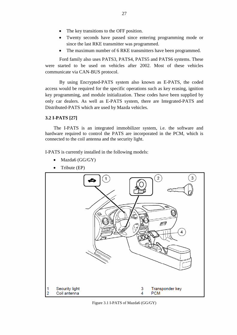
3.2 I-PATS [27]
The I-PATS is an integrated immobilizer system, i.e. the software and
hardware required to control the PATS are incorporated in the PCM, which is
connected to the coil antenna and the security light.
I-PATS is currently installed in the following models:
Mazda6 (GG/GY)
Tribute (EP)
Figure 3.1 I-PATS of Mazda6 (GG/GY)

28
Design and Operation
The system consists of transponder key, coil antenna, PCM and security
light. The key contains a crypto transponder with automatically changing
code.
The key ID-numbers are stored in a non-volatile memory of the PCM. At
each start the module compares the ID-number of the key used with those
it has stored.
The PCM activates starter, ignition and fuel injection if the verification of
the ID-number has been successful.
Figure 3.2 I-PATS components
3.3 D-PATS [27]
The D-PATS represents the latest PATS development stage. Compared to I-PATS
the control module requests a code from an additional module via the CAN
(Controller Area Network) bus in order to increase the passive anti-theft
protection.
Currently three different layouts of D-PATS are installed in the following models:
Mazda3 (BK)
RX-8 (SE)
Mazda2 (DY)

29
Figure 3.3 D-PATS of Mazda3 (BK)
Design and Operation
The PATS functionality is incorporated in the control module and has
been distributed to 2 components to increase anti-theft protection. As a
result, an additional component, which cannot be removed easily, is
required to enable engine start.
After completion of the usual PATS communication between transponder,
coil antenna and PCM, the control module also requests a code from the
additional module via the HS - CAN bus.
All of the code requests must be completed successfully before the control
module will send an enable signal for the engine start to the PCM.
The D-PATS consists of transponder key, coil antenna, IC or RKE, PCM
and security light. The key contains a crypto transponder with
automatically changing code.
Currently Mazda uses three variants of D-PATS:
The D-PATS of the Mazda2 (DY) uses the PCM to control the
immobilizer functions and the IC as additional component to verify the
validation code.

30
Figure 3.4 D-PATS components (Mazda2)
The D-PATS of the Mazda3 (BK) uses the IC to control the
immobilizer functions and the PCM as additional component to verify
the validation code.
Figure 3.5 D-PATS components (Mazda3)
The D-PATS of the RX-8 (SE) uses the RKE module to control the
immobilizer functions and the PCM as additional component to verify
the validation code.

31
Figure 3.6 D-PATS components (RX-8)
3.4 Key ID-Number Verification Process [27]
3.4.1 I-PATS
*: Data A and B are different random values each time.
UNSATISFACTORY RESULT
SATISFACTORY RESULT
(3) The PCM verifies calculation of data B and
consistency between the received key ID number and
the previously registered key ID numbers.
The ignition switch is turned from LOCK (ACC) to
ON (START) position. (Security light illuminates.)
Engine starting is permitted. (The security light goes
out after approx. 3 s.) Engine starting is
not permitted. (After
detecting an error,
the security light
illuminates or
flashes continuously
for approx. 1 min,
and then a DTC is
displayed repeatedly
10 times.)
(1) The PCM sends data A* to the key (transponder)
via the coil.
(2) The key (transponder) calculates data B* from
received data A and sends its specific key ID number
and data B to the PCM via the coil.

32
3.4.2 D-PATS (Mazda2)
*: Data A and C are different random values each time.
SATISFACTORY RESULT
SATISFACTORY RESULT
SATISFACTORY RESULT
(3) The PCM verifies consistency between the
received key ID number and the previously
registered key ID numbers.
The ignition switch is turned from LOCK (ACC) to
ON (START) position. (Security light illuminates.)
(4) The PCM makes a calculation using received
data B and compares it with sent data A.
Engine starting is not
permitted. (After
detecting the error
(such as non-
verification or
malfunction), the
security light
illuminates or flashes
continuously for
approx. 1 min, and
then a DTC is
displayed repeatedly
10 times.)
(1) The PCM sends data A* to the key (transponder)
via the coil.
(2) The key (transponder) calculates data B from
received data A and sends its specific key ID
number and data B to the PCM via the coil.
(5) The PCM requests data for verification from the
instrument cluster. Therefore it sends data C* to the
instrument cluster.
(6) The instrument cluster calculates data D from
received data C and sends it to the PCM.
(7) The PCM makes a calculation using received
data D and compares it with sent data C.
Engine starting is permitted.(The security light goes
out after approx. 3 s.)
UNSATISFACTORY RESULT
UNSATISFACTORY RESULT
UNSATISFACTORY RESULT

33
3.4.3 D-PATS (Mazda3 and RX-8)
*: Data A and C are different random values each time.
SATISFACTORY RESULT
SATISFACTORY RESULT
SATISFACTORY RESULT
(3) The IC / RKE verifies consistency between the
received key ID number and the previously
registered key ID numbers.
The ignition switch is turned from LOCK (ACC) to
ON (START) position. (Security light illuminates.)
(4) The IC / RKE makes a calculation using received
data B and compares it with sent data A.
Engine starting is not
permitted. (After
detecting the error (such
as non-verification or
malfunction), the security
light illuminates or
flashes continuously for
approx. 1 min, and then a
DTC is displayed
repeatedly 10 times.)
(1) The IC (Mazda3) / RKE (RX-8) sends data A* to
the key (transponder) via the coil.
(2) The key (transponder) calculates data B from
received data A and sends its specific key ID number
and data B to the IC / RKE via the coil.
(5) The IC / RKE requests data for verification from
the PCM.
(6) The PCM sends data C* to the IC / RKE.
(7) The IC / RKE calculates data D from received
data C and sends it to the PCM.
(8) The PCM makes a calculation using received data
D and compares it with sent data C.
Engine starting is permitted. (The security light goes
out after approx. 3 s.)
UNSATISFACTORY RESULT
UNSATISFACTORY RESULT
UNSATISFACTORY RESULT

34
3.5 I-PATS Service Functions [27]
Table 3.1 I-PATS Service Functions
Item Procedure
Key addition The key ID-number of the key to be added must be
registered in the PCM. Key ID number registration can be
performed according to the following methods:
Using two already registered keys ("Customer Spare
Key Programming" must be enabled).
Using WDS: Security access > "Additional Key
Programming".
Key
deletion/replacement
Registered key ID-numbers can be deleted from the PCM
using the following methods:
Using two already registered keys ("Customer Spare
Key Programming" must be enabled). All key ID-
numbers are cleared except those of the two keys
used.
Using WDS: Security Access > "Ignition Key Code
Erase". All key ID- numbers are cleared. Two keys
have to be registered to start the engine.
PCM replacement Key ID-numbers for all keys that were being used must be
registered in the new PCM.
New PCM - Two keys have to be registered to start
the engine.
Used PCM - Using WDS: Security Access > "Ignition
Key Code Erase". Two keys have to be registered to
start the engine.

35
3.6 D-PATS Service Functions [27]
Table 3.2 Table (Mazda2)
Item Procedure
Key addition The key ID-number of the key to be added must be
registered in the PCM. Key ID number registration can
be performed according to the following methods:
Using two already registered keys ("Customer Spare
Key Programming" must be enabled).
Using WDS: Security access > "Additional Key
Programming".
Key
deletion/replacement
Registered key ID-numbers can be deleted from the
PCM using the following methods:
Using two already registered keys ("Customer Spare
Key Programming" must be enabled). All key ID-
numbers are cleared except those of the two keys
used.
Using WDS: Security Access > "Ignition Key Code
Erase". All key ID- numbers are cleared. Two keys
have to be registered to start the engine.
PCM replacement Key ID-numbers for all keys that were being used must
be re-registered. Two or more keys have to be registered
to start the engine.
Using WDS: Security Access > "Parameter Reset"
and "Ignition Key Code Erase" must be performed.
All keys should be available.
Instrument cluster
replacement
Key ID numbers for all keys being used need not to be
re-registered. They are stored in the PCM and are
automatically transmitted to the new IC.
Security Access > "Parameter Reset" must be
performed with WDS.

36
3.7 D-PATS Service Functions [27]
Table 3.3 (Mazda3/RX-8)
Item Procedure
Key addition The key ID-number of the key to be added must be
registered in the IC or RKE. Key ID number registration
can be performed according to the following methods:
Using two already registered keys ("Customer Spare
Key Programming" must be enabled).
Using WDS: Security access > "Additional Key
Programming".
Key
deletion/replacement
Using WDS: Security Access > "Ignition Key Code
Erase". All key ID- numbers are cleared. Two keys
have to be registered to start the engine.
PCM replacement The key ID numbers of all keys being used need not to be
re-registered. They are stored in the IC or RKE and
automatically transmitted to the new PCM.
Using WDS: Security Access > "Parameter Reset"
must be performed.
IC or RKE
replacement
The key ID numbers of all keys being used must be re-
registered. Two keys must be registered at least to enable
engine start.
Using WDS: Security access > "Parameter Reset" and
"Ignition Key Code Erase" must be performed.
All keys should be available.
3.8 Key Functions [27]
3.8.1 Key Programming without WDS
• On all PATS additional keys can be programmed with two or more valid keys
according to the following procedure:
1. Insert the first valid key in the ignition switch and turn it to the ON position
for 3 s.
2. Insert the second valid key within 5 s in the ignition switch and turn it to
the ON position for 3 s.
3. Insert the new key in the ignition switch within 20 s and turn it to the ON
position for 3 s.
4. Program all further keys according to step 3. Then start the vehicle with all
keys to check for correct function.

37
5. After successful key programming, clear DTCs stored in the PCM.
Figure 3.7 Key programming time line
3.8.2 Key Deletion without WDS
• This procedure is available for I-PATS and for the D-PATS of the Mazda2
(DY). It is helpful when a key has been lost or the number of valid keys is
unknown, for example in the case of a used car. The procedure deletes all the
keys except for the two valid keys that are used:
1. Insert the first valid key in the ignition switch and turn it to the ON position
for 3 s.
2. Insert the second valid key within 5 s in the ignition switch and turn it to
the ON position for 3 s.
3. Turn the second valid key to the OFF position and turn it within 10 s back
to the ON position for 3 s.
4. Insert the first valid key within 10 s in the ignition switch and turn it to the
ON position for 10 s. The security light flashes for 5 s to confirm the
deleting procedure.
5. After successful key programming, clear DTCs stored in the PCM.
NOTE: The PATS function ―Customer spare key programming‖ must be enabled
for this procedure to operate.
NOTE: If the valid key is turned to the OFF position while the PATS LED is
flashing for 5 s, the deleting procedure is aborted.

38
Figure 3.8 Key erasing time line
3.8.3 PATS Functions with WDS
Security Access
• The security access is a special access mode via WDS for conducting certain
PATS service functions. The coded security access is designated to prevent
any misuse. The following PATS functions are protected:
– Programming additional keys
– Deleting all the keys and registering new keys
– Changing preset parameters for adding new keys using two registered keys
– Parameter reset
– Enabling / disabling the limitation in the number of programmable keys
• To get access to the protected PATS function menu select:
ToolboxBodySecurity PATS Functions. If you press the tick button,
the WDS will display the following information about PATS.
After you have pressed the tick button again, WDS asks you to retrieve a
security outcode from the PATS control module.
NOTE: The PATS function menu of the Mazda Tribute (EP) is accessible via a
timed security access instead of the coded security access. Prior to granting
security access the timed security access mode requires 10 minutes time delay
instead of a code to be entered.

39
If you press ―Yes‖, the WDS will display an outcode from the PATS control
module.
NOTE: When WDS displays the "outcode", do not turn the ignition switch from
the LOCK position to the ON position more than 5 times and do not
disconnect the battery cables. Otherwise a new outcode will be generated
for security reasons. The outcode contains 6 digits and the incode 4 digits.
NOTE: The Mazda dealer can obtain the incode from the Technical Hotline /
Technical Service Department with a prepared request form that must
contain the outcode, VIN and other data.
After you have pressed the tick button, the WDS displays a keyboard and
instructs you to enter the incode.
NOTE: The Ignition has to be switched to the ON position while the incode is
entered.
PATS Functions Menu
After the WDS has granted security access the following screen appears
displaying the PATS functions menu (here for the I-PATS of the Mazda6).
NOTE: When the security access is granted do not turn off WDS, do not
disconnect the data link connector (DLC), do not start the engine or turn the
ignition switch to the OFF position and leave for more than 10 seconds, as this
will exit the security access mode.
The PATS functions menu of the D-PATS looks slightly different. The items
―Unlimited Key Mode ON‖, ―Unlimited Key Mode OFF‖ and ―Program
Unlimited Key Code‖ have been removed (not for Mazda2) and the item
―Parameter Reset‖ has been added.
Items of the PATS Functions Menu
• Program additional ignition key
– Programs one or more additional ignition key(s) without erasing
registered keys. The procedure does not require the use of a registered
key.
• Ignition Key Code Erase
– Deletes all registered key ID-numbers. Requires to register 2 keys before
the engine will start.
• Customer Spare Key Programming Enable

40
– Permits the use of additional key programming without WDS using two
registered keys.
• Customer Spare Key Programming Disable
– Prohibits the use of additional key programming without WDS using two
registered keys. This is useful for hired vehicles.
• Parameter Reset
– Must be performed on vehicle with D-PATS when the PCM, IC or RKE
have been replaced. It requires second security access procedure.
• Unlimited key mode ON
– Disables the limitation to 8 programmable keys.
• Unlimited key mode OFF
– Enables the limitation to 8 programmable keys.
• Program unlimited key code
– Initializes access to the unlimited key mode functions.
NOTE: When you have selected the desired option follow the instructions
of the WDS.
NOTE: After selecting a function from the menu (except for ―Program
additional ignition key‖ and ―Customer Spare Key Programming Enable /
Disable‖) or after the menu is quitted the security access procedure must
be repeated again to choose additional options.
Parameter Reset
• After the D-PATS control module has been replaced the function ―Parameter
reset‖ must be performed. It synchronizes the control and the additional
module to enable the data transfer between them during the ID-number
verification process.
Parameter Reset Procedure
• Perform the Parameter reset according to the following procedure as shown in
the example for the IC of the Mazda3.
• After you have selected ―Parameter Reset‖ and pressed the tick button the
security access is requested again, i.e. a second incode is required.
Follow the instructions of the WDS.
The following screen displays all replaceable modules, which are involved in
the PATS of several vehicle types of Ford and Mazda. Select HEC module
and press the tick button. ―Ignition key code erase‖ is the next step.

41
NOTE: When the IC has been replaced on Mazda2 and Mazda3 the menu item
―HEC‖ must be selected. The items PATS, IC and VIC in this menu are
without function.
Press the tick button.
In this screen it is confirmed that all key ID-numbers have been deleted.
Afterwards two keys must be programmed. Press the tick button.
The final screen gives instructions for the required key programming. The
procedure is identical to the procedure ―Key programming without WDS‖ as
described above.

42
CHAPTER 4
Application Development
In this chapter, we will mention about the web application on automobile security.
For this purpose, Android operating system will be reviewed with its base
properties.
4.1 Overview of Android Operating System
Android is a mobile operating system, based on the Linux kernel. It has
developed by Google and later the Open Handset Alliance. The developers can
write managed code in the Java language, and control the device via Google-
developed Java libraries. Writing an application in C and other languages are also
possible by compiling to ARM native code; however, this development approach
is not officially supported by Google. The Android platform has been announced
on November 5th
2007 with the founding of the Open Handset Alliance and
consortium of 48 hardware, software, and telecom companies that gathered to
advancing open standards for mobile devices. Google released most of the
Android code under the Apache license as a free-software and open source
license.
Open Handset Alliance, is a consortium of several companies which
include Google, HTC, Intel, Motorola, Qualcomm, T-Mobile, Sprint Nextel and
NVIDIA. These companies whose aim is to develop technologies that will
significantly lower the cost of developing and distributing mobile devices and
services. The Android platform is the first step in this direction. A fully integrated
mobile "software stack" that consists of an operating system, middleware, user-
friendly interface and applications.
Currently Android operating system is under version 2 of the Apache
Software License (ASL). The Apache license allows manufacturers and mobile
operators to innovate using the platform without the requirement to contribute
those innovations back to the open source community.
4.2 Application Analysis
Linux operating system is based on UNIX which is arguably known as a
secure operating system for now. Android is UNIX based mobile operating
system as well and, it is just as much secure as an operating system, however it
might run slow because of the Java Virtual Machine. That is why, there is a need
of another web layer which is developed in PHP (Personal Home Page), while

43
developing the application, PHP is a web based programming language and also
supports object oriented programming. In order to improve the Android
application run time, a web application has been developed as a complete system.
As a result there is only a need of displaying a web page on the Android operating
system, and, that way security part is handled in the server. The calculations have
been made by web server and displayed by Android Tablet PCs or cellphones. We
will mention all of these in two parts.
4.2.1 UML (Use-case and sequence diagrams)
Figure 4.1 Use-case diagrams
Figure 4.2 Sequence diagram

44
4.2.2 The Analysis of Web-based PHP Application
Login Page
Login page simply checks whether the user id is on the server. If it is there, the
user should be able to sign in to the system. Otherwise the user will not able to
login to the system. If the ID has been confirmed by the server, the user will be
redirected to the next screen which has to ask the user to type his/her username
and password in order to login to the desired page. System check-ins and outs
should be saved in order to keep tracking of the usage. Screenshots can be found
below.
Figure 4.3 Login page-1
Figure 4.4 Login page-2

45
Registration Page
The user will be able to register to the system if he/she is trying to login to the
system for the first time. Firstly, the registration ID should be confirmed by the
server. If the ID exists, the user would see the registration page. Otherwise he will
not able to see this page or go any further. The user must fill the required
information which is based on his/her details. All these details should be stored in
the database for further investigations. Screenshots can be found below.
Figure 4.5 Registration page
Calculation Page
The user should see the calculation page if he/she has logged in to the system
successfully. The page includes image code prevention in order to prevent the
auto calculations by robots. The user must fill the out-code with the image code in
order to have the in-code for further actions such as key coding, key erasing,
module initialization etc. Every code pairs should be saved in order to keep

46
tracking of the usage for further investigation when required. Screenshots can be
found below.
Figure 4.6 Calculation Page-1
Figure 4.7 Calculation Page-2

47
4.2.3 The Analysis of the Android Based Application
Android Virtual Device- Emulator
The Android Development Tools (ADT) includes an emulator to run an
Android system. The emulator behaves like a real Android device (in most cases)
and, allows the developer to test the application without having a real device.
The version of the Android system, the size of the SD card, the screen
resolution and other relevant settings are configurable by the developer. Several of
them can be defined with different configurations.
These devices are called "Android Virtual Device-Emulator" (AVD) and it
allows to starting several processes in parallel. Starting a new emulator is very
slow, because the file system of the new AVD needs to get prepared.
The ADT allows deploying and running the Android program on the AVD.
During the development progress, the application has been tested on AVD by
using Oracle Java Eclipse platform. Screenshots can be found below.
Figure 4.8 AVD
Web views
Web view is one of Android class that displays web pages. Web view allows
developers to create your own window for viewing web pages (or even develop a

48
complete browser). The developed web view simply displays the web page of the
developed web-based application so the android user will be able to get rid of the
program loadings and lags. That will be the easiest way to make the application
smoother and faster. Screenshots can be found below.
Figure 4.9 Webview
Internet connection control
In order to prevent the message which says ―The web page cannot be
displayed, please check your internet connection.‖ The internet connection control
should be used. Hence, the user would realize that he is not connected to the
internet. This function is checking the device modules and quickly finds out
whether there is an internet connection or not. As a result, the user friendly
message will be displayed. Screenshots can be found below.
Figure 4.10 Connection control

49
It is designed to be used on every tablet computer and smart phones which have
been installed by Android Operating System.
4.3 Display tests on different tablet computers
The application has been tested on Motorola Xoom and Samsung Galaxy Tab.
They both have Android 3.0 Honeycomb platform with different hardware
properties so that provides us to see how the application works on different tablet
computers. The application can be modified to run on smart phones which have
different Android versions but this has not been tested on smart phones yet.

50
Chapter 5
Conclusions
As mentioned, the security in automotive industry is one of the most fundamental
issues that need to be handled carefully by manufacturers. Otherwise, it would
cause economically a big damage such as automotive thefts. In this thesis, we
study how modules of on road vehicles communicate each other‘s and what kind
of security system it being used and the weaknesses of these systems. We indicate
that every car brand is vulnerable as long as the communication approach remains
same. Experimental results show that some of these security systems have been
already defeated.
5.1 Thesis Summary
Using immobilizer, crypto transponders, PATS (passive anti-theft system) are
basically a good way to keep your vehicle secure however they are not in reality
when you consider the system as a whole. In this thesis we explained what kind of
communication protocols are being used in automotive industry and what
standards has been specified in order to apply them for all kind of makes. What is
more, we mentioned about the common diagnostic devices that are mainly used
by main dealers, special dealers and automobile locksmiths. We assessed some
sort of security protections against automotive thefts such as immobilizer.
Moreover, we also mentioned about Passive anti-theft system types and the brands
that are using these systems as a security measure.
In last chapter, as a proof of the system weaknesses, an application which
generates a challenge and response codes has been analyzed and designed for
android operating system in order to reach to a wide target group as it is the most
used mobile operating system in these days. According to our experiments, the
system has been generating codes 100% success rate which means our target
group which is in this stage auto locksmiths and car dealers will no longer need
for purchase the codes in order to complete their jobs.
5.2 Contributions and Future Work
After 2011, the auto manufacturers realize that their algorithms have been already
cracked so they have decided to develop a new algorithm. In order to examine the
new one, some samples are needed with chassis numbers and challenge and
response codes.
The automobiles which are developed after 2011 are currently on the roads
moreover their users need to get those vehicles into the car dealers for specific

51
issues. Otherwise the information is almost impossible to be received to examine
the security algorithms that are used. That is why gathering the samples for the
new system is still under progress.
As soon as the new samples have been received, the analyzing part of the new
algorithm will be started. In this thesis, the application is developed according to
the most common vehicles which are manufactured before 2012.
5.3 New system recommendations
Cryptographic smart cards can be applied in order to prevent the key‘s security.
The most common algorithms which have been used in smart card applications
are Triple DES and RSA that are secure enough as they cannot be broken with
brute force or other known attacks. However the safety of key is not guaranteed
because of the backdoors of diagnostic devices during the communication process
so they need to be built as a whole secure system. For this purpose, the
communication standards can be re-designed from the beginning because the
communication with the old protocols can be easily traceable as it has been
proved by this study.

52
Bibliography
[1] Vector, (2003), Introduction to Higher Level Protocols, p. 2.
[2] CAN-OPEN, “http://www.canopen-
solutions.com/canopen_fundamentals_en.html‖
[3] Vector, (2004-05-04), Introduction to CAN Calibration Protocol.
[4] DeviceNet, ―http://www.scribd.com/doc/29459521/Introduction-to-
DeviceNet‖
[5] Volkswagen Group of America Inc., K-Line Communication Description.
[6] J1939, ―http://www.sae.org/standardsdev/groundvehicle/j1939.htm‖
[7] KWP2000, ―http://en.wikipedia.org/wiki/Keyword_Protocol_2000‖
[8] NMEA 2000, “http://www.nmea.org/content/nmea_standards/downloads.asp‖
[9] XCP, ― http://www.asam.net‖
[10] On-Board Diagnostics (OBD), ―http://www.canobd2.com‖
[11] First Generation (OBD1), ―http://www.canobd2.com‖
[12] On-Board Diagnostics - Second Generation (OBD2),
―http://www.canobd2.com‖
[13] Objectives of OBD2, ―http://www.canobd2.com‖
[14] OBD Signal Protocols, ―http://en.wikipedia.org/wiki/On-board_diagnostics‖
[15] ISO standards, ―http://en.wikipedia.org/wiki/On-board_diagnostics‖
[16] Dr.-Ing. D. Anselm, Ismaning; Zwei Jahre elektronische Wegfahrsperre -
Ergebnisse im Jahre 1996; Elektronik im Kraftfahrzeug, Tagung Baden- Baden,
VDI-Berichte 1287, 1996
[17] Beutelspacher, A. Kersten, A.Pfau; Chipkarten als Sicherheitswerkzeug;
Springer-Verlag 1991
[18] Joe Schürmann, Herbert Meier; TIRIS TM - Leader in Radio Frequency
Identifi cation Technology, Texas Instruments Technical Journal Vol. 10, No. 6
[19] W. Steinhagen, U.Kaiser; A Low Power Read/Write Transponder IC for
High Performance Identifi cation Systems, Proceedings of ESSCIR ‗94, Ulm,
Germany, September 20-22, 1994, pp. 256-259

53
[20] U. Kaiser, W. Steinhagen, A Low Power Transponder IC for for High
Performance Identifi cation Systems, Proceedings of CICC ‗94, San Diego, CA,
USA, May 1-4, 1994, pp. 14.4.1-14.4.4
[21] U. Kaiser, W. Steinhagen, A Low Power Transponder IC for for High
Performance Identifi cation Systems, IEEE Journal of Solid-State Circuits, Vol.
JSSC 30, March 1995, pp. 306-310
[22] Schneier, Bruce; Applied Cryptography: Protocols, Algorithms and Source
Code in C; John Wiley & Sons, Inc. 1994
[23] Passive Anti-Theft System,
―http://media.ford.com/article_display.cfm?article_id=2620‖
[24] Securilock, ―http://en.wikipedia.org/wiki/SecuriLock‖
[25] Pats Control Functions, ―http://v8sho.com/SHO/TSB01062PATS.htm‖
[26] Fordpats programming,
―http://fullerisford.wordpress.com/2010/03/23/instructions-and-videos-on-
programming-ford-pats-keys/‖
[27] Mazda Motor Europe GmbH Training Services, 2005, Immobilizer System
Copyright © 2022 FDOKUMEN