Modeling and simulation of agent-based complex systems and application to natural disasters

AN AGENT BASED ENVIRONMENT FOR DISCOVERY AND COMPOSITION OF
SIMULATION COMPONENTS
By
IMRAN MAHMOOD
SCHOOL OF INFORMATION AND COMMUNICATION TECHNOLOGY (ICT) ROYAL INSTITUTE OF TECHNOLOGY (KTH)
Master of Science Thesis
Stockholm, Sweden. 2007
KTH/ICT/ECS-2007-141

i
A B S T R A C T
Modelling and Simulation (M&S) plays an important role in supporting development of concepts,
making business decisions, conducting safe and low-cost trainings, studies and analysis. Simulations
can help us understand the dynamics of the systems and give us a tool to study them before they are
even being developed. Moreover it provides a very suitable virtual environment for training, research
and experiments that are delicate in nature. Nonetheless the development of simulation models is a
multi-disciplinary and time/resource consuming process. Scientists have investigated different
approaches of reusing already existing components in order to reduce the cost. But this involves
various challenges one of which is called �Composability�.
Some previous work has already done at FOI, to investigate improved methods of composability of
BOM by introducing semantic attachments using OWL. This thesis is an effort to develop an agent
based environment that performs both syntactic and semantic composability matching on a given set
of components which are discovered from the repository according to the criteria given by a
simulation modeller in a simulation scenario. The outcome of this thesis will help in automating the
discovery and composition operations of model components.

ii
A C K N O W L E D G M E N T S
I wish to dedicate this manuscript to the soils of the great land of Sweden, which welcomed me to
come and allowed me to harvest the crop of knowledge. Now that it reaped, I will it take back to my
country, half for feeding and half for seeding.
I express sincere appreciation to Professor Rassul Ayani and Mr. Forshad Moradi for giving me a
chance to work on this topic and for their kind support in the preparation of this work.

i
Table of Contents Abstract .................................................................................................................................. i Acknowledgments .............................................................................................................. ii List of figures ...................................................................................................................... iii Glossary ............................................................................................................................... iv 1. Introduction ........................................................................................................... 1
1.1. Introduction: ................................................................................................... 1 1.1.1. Modeling and Simulation .............................................................................................. 1 1.1.2. Reusability: ....................................................................................................................... 3 1.1.3. Composability .................................................................................................................. 4
1.2. Motivation: ...................................................................................................... 4 1.3. Aim of the project ......................................................................................... 5 1.4. Statement of the problem: ........................................................................... 5 1.5. Purpose of the study: .................................................................................... 8
2. Background ............................................................................................................ 9 2.1. Description of Terms: ................................................................................... 9
2.1.1. BOM-Base Object Model: ............................................................................................ 9 2.1.2. SRML .............................................................................................................................. 12 2.1.3. SDR: ................................................................................................................................ 12 2.1.4. Onthologies: .................................................................................................................. 13 2.1.5. OWL: .............................................................................................................................. 13 2.1.6. Intelligent Agents: ......................................................................................................... 14 2.1.7. Multi-agent System (MAS): ......................................................................................... 14 2.1.8. Discovery and Composition process work flow: ................................................... 15
3. Agent based framework ..................................................................................... 17 3.1. Overview: ...................................................................................................... 17 3.2. Agent Oriented Software Engineering .................................................... 17 3.3. What is an Agent? ........................................................................................ 18 3.4. What is an Agent Framework? .................................................................. 18 3.5. JACK Agent Framework: ........................................................................... 19 3.6. Jack Agents: ................................................................................................... 19 3.7. Components of Jack Framework: ............................................................. 21
3.7.1. The JACK Agent Language ........................................................................................ 21 3.7.2. The JACK Agent Compiler ........................................................................................ 21 3.7.3. The JACK Agent Kernel ............................................................................................. 21 3.7.4. Jack Code Entities: ....................................................................................................... 22
3.8. JACK Development Environment (JDE) .............................................. 25 3.9. JACK Framework Workflow: ................................................................... 26
4. Implementation prototype ................................................................................ 29 4.1. Software development approach .............................................................. 29 4.2. System class diagram: .................................................................................. 31
4.2.1. Query Manager: ............................................................................................................. 31

ii
4.2.2. Combination Manager ................................................................................................. 31 4.2.3. Composition Manager ................................................................................................. 31 4.2.4. Comparison Manager ................................................................................................... 31 4.2.5. Presentation Manager .................................................................................................. 31
4.3. Sequence Diagram: ...................................................................................... 34 4.4. Jack Agent framework: ............................................................................... 38
4.4.1. Initialization: .................................................................................................................. 38 4.4.2. Parsing: ........................................................................................................................... 39 4.4.3. Discovery: ...................................................................................................................... 39 4.4.4. Virtual SDR: .................................................................................................................. 39 4.4.5. Combinations: ............................................................................................................... 42 4.4.6. Composition: ................................................................................................................. 42 4.4.7. Comparison: .................................................................................................................. 44
4.5. Future Improvements ................................................................................. 46 5. Test case study ..................................................................................................... 47
5.1. A Restaurant Scenario: ................................................................................ 47 5.2. Output of the test: ....................................................................................... 49
5.2.1. Step 1:.............................................................................................................................. 49 5.2.2. Step 2:.............................................................................................................................. 50 5.2.3. Step 3:.............................................................................................................................. 51 5.2.4. Step 4:.............................................................................................................................. 51 5.2.5. Step 5:.............................................................................................................................. 52
6. Conclusion & Future work ............................................................................... 53 6.1. Conclusion: ................................................................................................... 53 6.2. Future Work: ................................................................................................ 54
References .......................................................................................................................... 55 Index .................................................................................................................................... 57 Appendixes ......................................................................................................................... 58
1. Restaurant SRML ......................................................................................... 58

iii
L I S T O F F I G U R E S
Figure 1: System, Model and Simulation ............................................................................................................................. 2 Figure 2 BOM Conceptual Model, as described in (8) ................................................................................................... 12 Figure 3 Discovery and Composition process work flow [6] ...................................................................................... 17 Figure 4 JACK Process (a. Jack Language b. Jack Compiler c. Jack Runtime) ....................................................... 22 Figure 5 Jack Agent entities ................................................................................................................................................ 23 Figure 6 Jack Development Environment [12] ............................................................................................................... 26 Figure 7 Jack Agent Workflow ........................................................................................................................................... 27 Figure 8 System Architecture .............................................................................................................................................. 29 Figure 9 Class Diagram ........................................................................................................................................................ 32 Figure 10 Use case Model .................................................................................................................................................... 34 Figure 11 Sequence Diagram............................................................................................................................................... 35 Figure 12 Owl Description .................................................................................................................................................. 40 Figure 13 Discovery Rules [6] ............................................................................................................................................ 41 Figure 14 Composition Rules [6] ...................................................................................................................................... 42 Figure 15 Composition Logic ............................................................................................................................................. 43 Figure 16 Entire Process ...................................................................................................................................................... 45 Figure 17 Restaurant Sequence Diagram [6] ................................................................................................................... 48 Figure 18 Output Step 1: Parsing ....................................................................................................................................... 49 Figure 19 Output Step 2: Discovery .................................................................................................................................. 50 Figure 20 Output Step 3: Combinations ........................................................................................................................... 51 Figure 21 Output Step 4: Matching ................................................................................................................................... 51

iv
G L O S S A R Y
BOM Base Object Model
DoD - Department of Defense
FOI- Totalförsvarets Forskningsinstitut (Swedish Defence Research Agency)
HLA High Level Architecture
HTML - Hyper-Text Markup Language
HTTP - Hyper-Text Transfer Protocol
IDE - Integrated Development Environment
JDE Jack Development Environment
OWL - Web Ontology
PoC - Point of Contact
SISO - Simulation Interoperability Standards Organization
SRML Simulation Reference Markup Language
UML - Unified Modeling Language
XML - eXtensive Markup Language

C h a p t e r 1
1 . I N T R O D U C T I O N
1.1. Introduction:
1.1.1. Modeling and Simulation
A computer simulation is a program that attempts to simulate an abstract model of a
particular system. Computer simulations have become a useful tool in modeling of many natural
systems in physics (Computational Physics), chemistry and biology, human systems in
economics, psychology, and social science and in the process of engineering new technology, to
gain insight into the operation of those systems. Computer simulations vary from computer
programs that run a few minutes, to network-based groups of computers running for hours, to
simulations that run for days. The scale of systems being studied by computer simulations has
far exceeded anything possible (or perhaps even imaginable). Beside the fact that it involves a
high performance computational environment, the construction of such complex system is also
costly and time consuming. Even some times the cost of developing simulation is very high
however still computer simulation is worthy as in some cases running simulations is better than
the original system (e.g., nuclear tests, air combat, accident investigation or experimental
surgery), where lives are at risk so it becomes unavoidable to utilize the equivalent simulation
systems in order to better analyze the results of experiments and take precautionary measures
[1]. To summarize simulation plays an important role the scientific research and problem
solving. For more details please see [2].
Modeling and Simulation is a well know method of scientific problem solving used in scientific
community and other businesses to investigate solutions to a great range of problems. Simulations
are performed to study in depth the behavior of a system, formally represented mathematically or as
a computer program. They are performed on various scenarios to test the reaction of the system,
2
analyze various data-sets and their effect of the behaviors of the system. Simulations can be done on
existing systems or on conceptual systems, which saves a great deal of effort and money by making
it possible to find out how systems work before they are developed and built. A similar work can be
seen at [3].
A simulation is an implementation of a model of the existing system that is intended to be studied.
Each entity or object in the existing system represents a component in the simulation and each
component has a set of states. Moreover each interaction between the entities is represented by
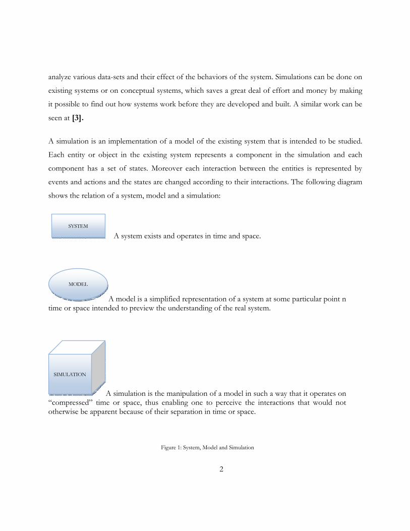
events and actions and the states are changed according to their interactions. The following diagram
shows the relation of a system, model and a simulation:
A system exists and operates in time and space.
A model is a simplified representation of a system at some particular point n time or space intended to preview the understanding of the real system.
A simulation is the manipulation of a model in such a way that it operates on �compressed� time or space, thus enabling one to perceive the interactions that would not otherwise be apparent because of their separation in time or space.
Figure 1: System, Model and Simulation
SIMULATION
MODEL
SYSTEM

3
We have so far established that simulation plays an important role in the business decision making
and scientific problem solving however when it comes to development/construction a simulation
system is not only a time consuming effort but also it implies greater cost. And due to this factor the
decision makers might find it discouraging to invest in the development of simulation models. A
simulation development process includes many steps including, requirement specification, conceptual
modelling, design, development, test, verification and validation. So in order to ensure the validity and
suitability of the simulation model a large amount of effort is required [3].
This has led the scientist and IT researchers to come to a conclusion that instead of constructing
new simulation components each time they are needed, they should go for the existing components
and reuse them. This approach to reuse pre-developed and already validated simulation components
has been inspired from different paradigms. One of which is component-based development, which
has already been successfully applied in manufacturing hardware and software industry, so it is easily
accepted and is favoured by the simulation researchers to adapt it.
1.1.2. Reusability:
The ability of a component or subprogram to be used again with or without modification as a building
block in a different program is called Reusability [4].
Component Reusability is about building a library of frequently used components, thus allowing new
programs to be assembled quickly from existing components. Component Reusability has been
known to be a very suitable approach in terms of time and cost saving. This concept has been
applied not only to the code, but also to the design, data, documentation, test materials,
specifications, and plan.
We have a repository named �Semantic Distributed Repository� to store the BOM components
that are identified as commonly used components. This repository not only contains model
components for simulations but also their semantic descriptions. So an important operation in the
reusability has been identified as �semantic discovery� of a suitable component.

4
1.1.3. Composability
According to Petty [5] composability:
1. �Is the capability to select and assemble simulation components in various combinations
into simulation systems to satisfy specific user requirements�
The assembled simulation components could be purpose-built or are reusable component.
There are two major aspects of composability, namely syntactic composability and semantic
composability. Syntactic composability is how to actually compose implementation of
components into a working simulation, while semantic composability is a more theoretic view
on composability that considers how models of simulations can be composed and remain valid,
via for example SCT � the Semantic Composability Theory. One view on composability that
relates highly to this thesis can be found in [4] where the author explains it as follows:
�Given a set of components, structured descriptions or specifications of the components,
sometimes called meta-data or meta-models, can be used to guide the process of selecting
components for a specific purpose and determining if a set of components can be effectively
composed�. [4: Page-13 ,Sec-2.2]
1.2. Motivation:
The initiative for this work has been inspired from some previous (Master thesis) research done
at FOI. Few of the important topics are as follows:
1. Composability and Reuse for Simulation Development using BOMs [4]
2. Syntactic and Semantic Model Composability based on BOMs [6]

5
In (6), an approach has been proposed to model composition using Semantic attachment of
BOMs and SRML. A three layered model was suggested for composing BOM based
components along with a set of discovery and matching rules.
Based on the work done so far, it was an intuitive effort to setup an intelligent automated
environment to support simulation modelers for performing composability operations: DMC
(Discovery, Matching and Composition) of the component available in the SDR: Semantic
Distributed Repository [8] thus making it a step ahead in the domain of
reusability/interoperability of simulation components. This will not only bring modernization in
the simulation research community but also be a threshold for the development of next
generation simulation systems. For details about the benefits of composition of simulation
models please refer to [4], [5], [6], [7]
1.3. Aim of the project
The aim of the thesis project is to define an agent-based environment for discovery of BOMs
based on predefined search criteria and presentation of different combination of components
that match the description. On each combination, the composition rules are applied (as proposed
by [6]) to calculate their syntactic and semantic composability degree so that they are validated by
a simulation modeler for later use. The work has been exemplified with a simple implementation
and using a real world Test Scenario: �The Restaurant Scenario�.
1.4. Statement of the problem:
The problem statement can be divided into three parts:
Part1:

6
Component-based Reusability: Utilization of pre-existing components when developing
complex software systems is increasingly applied within the software industry. Component-based
model development has been a long-term goal within the M&S community to increase reuse and
availability of simulation models. An initial work has already been done to investigate the
possibilities of component reusability, and it has been established that different components can
be composed together and by uniting them we can reuse them in different simulation scenarios.
Part2:
Composability: However, composing sub-models in order to build new models raise the non-
trivial issue of composability. There are two types of composability, syntactic and semantic.
Syntactic composability is concerned with the compatibility of implementation details, such as
parameter passing mechanisms, external data accesses, and timing mechanisms. It is the question
of whether a set of components can be combined. Semantic composability, on the other hand, is
concerned with whether the models that make up the composed simulation system can be
composed and remain valid. Some research has already been in progress to find out the
composability degree of two candidate BOMs and based on certain rules we can evaluate whether
they are composable or not.
Part3:
Agent-based environment: Now that we have a set of rules to find out a match between the
two or more BOMs so we can setup a multi agent-based environment in order to perform
automated discovery of related BOMs specified in a given simulation scenario (SRML), and an
intelligent way of performing the composition rules of different combinations of the candidate
BOMs (that have been discovered so far from the repository).
The process can even be improved by involving agents to be able to lookup the semantic aspects
of different BOMs in their attached ontology descriptions, and thus can perform semantic
matching on the fly. Furthermore a multi.-agent system can be designed to perform the
operations by introducing parallelism to increase the performance of the system.

7
To summarize the problem statement:
1. Can an agent-based system be used to traversing through the 7 step process which was
developed at FOI for discovery and composition of simulation components, [6] and
automatically determine if a set of BOMs are syntactically and semantically compatible according
to a given simulation model scenario?
2. How can agents be used to perform semantic matching given a set of OWL description of
BOMs?

8
1.5. Purpose of the study:
The purpose of this study is to contribute to the development of a run-time environment for
distributed multi-agent framework that is capable of the following:
1. Capable to co-ordination among various internal agents for co-operative distributed problem
solving.
2. Communication with various existing systems such as SDR [8]
3. Capable of integrating with various domain onthologies to perform semantic matching
4. Providing simulation modeler a graphical interface to input investigation data.
5. Capable of publishing the test results
This framework is desired to be used in ongoing research activities being held at FOI. So its
structure should be easily configurable and adaptable to changes.

9
C h a p t e r 2
2 . B A C K G R O U N D
2.1. Description of Terms:
Before we move on to the description of system design and implementation it is necessary to
define some technical terms that are commonly used/comprehended by the people of this
domain.
2.1.1. BOM-Base Object Model:
It is highly recommend to studying BOM specification [9] for anyone who is more interested in
this work. A brief overview of BOM concept is however given as below:
Concept of BOM is proposed by SISO [10] and it provides �a component framework for
facilitating interoperability, reuse, and composability�. BOM is an XML document containing the
�essential elements for specifying aspects of the conceptual model and documenting an interface
of a simulation component that can be used and reused in the design, development, and
extension of interoperable simulations�. The authors of BOM were intended to introduce the
BOM as a building block in the development and extension of a simulation and/or a federation
of simulations [9].
BOM is organized into four major parts:
1. Model Identification
2. Conceptual Model
3. Model Mapping
4. HLA Object.

10
They are briefly described in detail below. More details can be found at [6] and [9].
Model Identification
Metadata about the component is stored in this part. It includes Point of Contact (POC)
information, as well as general information about the component itself � what it simulates, how it
can and has been used as well as descriptions aimed towards helping developers find and reuse it.
Other information such as intended application domain, the purpose of component, Use History
and Use Limitation, which includes a list of all successful and unsuccessful inclusion of this BOM
in other simulations, would be part of the meta-data. It also provides the possibility to include
references to other documents (e.g. an OWL document) or BOMs used in the creation of this
component.
Conceptual Model
�Conceptual Model Definition provides a mechanism to identify up to the following four
different template components for representing the needs of a simulation:
Pattern Of Interplay
State Machine
Event Type
Entity Type
2.1.1.1 . Pattern of Interplay
�A pattern of interplay is represented by one or more pattern actions needed to accomplish a
specific purpose or capability� [9]. The Pattern Action is described by Pattern Description. The
pattern Description provides a table of all actions taken by the component, and describes what
conceptual entities and events take part in the action as well as lists a number of variations and
exceptions to the action that could happen. Each pattern action has one or more senders and

11
receivers providing a means for understanding the behavioral relationship among conceptual
entities, which are defined by entity types. The activity required for fulfilling each pattern action
can be associated with either an event type, or another BOM.
2.1.1.2 . State Machine
�The state machine template component provides a mechanism for identifying the behavior
states expected to be exhibited by one or more conceptual entities [9]. It lists all states in which
entities can be in, and state transitions (what conditions must be satisfied in order to exit the state
� via a specified action � into a next state). It provides a clear overview to the BOM composer of
how a federate that is implemented from a BOM will behave. Also state-machine can be used to
validate the BOM component by comparing it with reality.
2.1.1.3 . Entity Type
�A conceptual entity is an abstract representation of a real world entity, phenomenon, process, or
system. These conceptual entities are needed to understand the relationships within a pattern of
interplay, the roles with respect to state machines across one or more patterns of interplay, and
the responsibilities as sender and/or receiver in regards to the events that can occur to fulfill a
pattern of interplay�. Attributes of the conceptual entity types are presented in the BOM entity
type structure.
2.1.1.4 . Event Type
Each pattern action is supported by either an event or another BOM. Event Type contains a
listing of the Events present in the BOM. There are two different types of Events: BOM Trigger
and BOM Message. A BOM Trigger is an undirected event that is triggered by some entity
without a specific receiver. In other words, the entity sending out a Trigger does not care about
who receives a notification of the event. This might for example be a bomb exploding triggering
a blast wave. BOM Event, the next type, is an event sent from one conceptual entity directed to

12
another specified entity. Unlike BOM Trigger, this type of event is precisely directed to another
entity. The entire structure of a typical BOM can be seen in the following figure:
Figure 2 BOM Conceptual Model, as described in [9]
2.1.2. SRML
The Simulation Reference Mark-up Language (SRML) is based on XML that was developed by
the World Wide Web Consortium with support from the Boeing Company. It is an XML
application that can describe the behaviour of distributed simulation models, and its runtime
environment is software that is capable of executing those models [10]
SRML was developed with a number of goals, among them being a flexible reference standard
for representing simulations with enough expressive power to model almost anything for the
purpose of simulation.
2.1.3. SDR:
Semantic Distributed Repository was designed and developed for secure sharing of simulation models,
components and related resources such as computer resources. It consists of an overlay
architecture based on the technologies like Semantic Web, Peer-to-Peer and Grid techniques.
This project at the Swedish Defense Research Agency (FOI) has served the need for a repository
of simulation related resources. [8]
BOM Type
Pattern of Interplay
State Machine Entity Type
Event Type
Conceptual Model Definition
0..10..1
1..n1..n1..n1..n 1..n1..n
1..n1..n

13
2.1.4. Onthologies:
Ontology is a study of conceptions of reality and the nature of being. In philosophy, ontology
is the study of being or existence and forms the basic subject matter of metaphysics. It seeks to
describe or posit the basic categories and relationships of being or existence to define entities
and types of entities within its framework.
Ontology mainly deals with the precise utilization of words as descriptors of entities or realities
and ontology must give an account of which words refer to entities, which do not, why, and
what categories result. When one applies this process to nouns such as electrons, energy,
contract, happiness, time, truth, causality, and God, ontology becomes fundamental to many
branches of philosophy [11]
A commonly accepted definition of ontology as given by [12]:
�Specification of a representational vocabulary for a shared domain of discourse� definitions of
classes, relations, functions and other objects.�
Onthologies are used to share knowledge between people, business enterprises and information
systems. Onthologies are also a vehicle for establishing a consensus between diverse groups of
people, management or heterogeneous and distributed information systems.
2.1.5. OWL:
The Web Ontology Language (OWL) is a language for defining and instantiating Web
onthologies. OWL ontology may include descriptions of classes, along with their related
properties and instances. OWL is designed for use by applications that need to process the
content of information instead of just presenting information to humans. It facilitates greater
machine interpretability of Web content than that supported by XML, RDF, and RDF Schema

14
(RDF-S) by providing additional vocabulary along with a formal semantics. OWL is based on
earlier languages OIL and DAML+OIL, and is now a W3C recommendation.
OWL is seen as a major technology for the future implementation of a Semantic. It is playing
an important role in an increasing number and range of applications, and is the focus of
research into tools, reasoning techniques, formal foundations and language extensions. OWL
was designed to provide a common way to process the semantic content of web information. It
was developed to augment the facilities for expressing semantics (meaning) provided by XML,
RDF, and RDF-S. Consequently, it may be considered an evolution of these web languages in
terms of its ability to represent machine-interpretable semantic content on the web. Since
OWL is based on XML, OWL information can be easily exchanged between different types of
computers using different operating systems, and application languages. Because the language
is intended to be read by computer applications, it is sometimes not considered to be human-
readable, although readability can be enhanced by the use of certain viewers. OWL is being
used to create standards that provide a framework for asset management, enterprise
integration, and data sharing on the Web. [11]
2.1.6. Intelligent Agents:
According to Wooldridge [13]:
�An agent is a computer system that is situated in some environment and that is capable of
autonomous action in this environment in order to meet its design objectives�.
2.1.7. Multi-agent System (MAS):
A multi-agent system contains a number of agents which interact with one another through
communication. The agents are able to act in an environment; where each agent will act upon
or influence different parts of the environment. They interact with each other to solve large
problems, to allow interconnection and interoperation of multiple entities of a system, to

15
provide a solution to inherently distributed problems, to provide solutions which draw from
distributed information sources and to provide solutions where expertise is distributed [13].
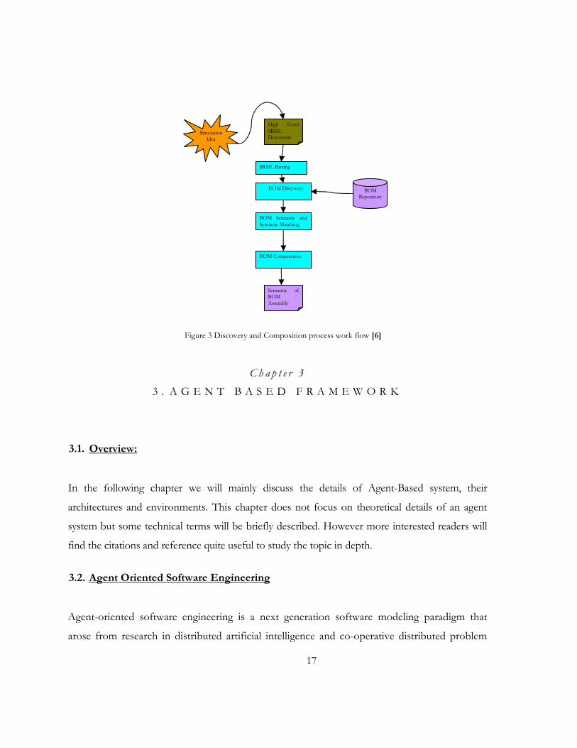
2.1.8. Discovery and Composition process work flow:
The basic steps in the process of the discovery and composition are proposed by the previous
researchers [4], [6]. The approach comprises of four phases:
SRML Parsing
BOM Discovery
BOM Matching and Composition
BOM Assembly Building
Each phase starts whenever the previous phase finishes. These four phases altogether make
seven steps:
1. The simulation scenario is parsed and then the candidate components identifications are
extracted from simulation scenario. The simulation scenario is written in SRML Light standard,
so its validity according to SRML scheme also might be checked. The �Item Class �tag is used as
a heuristic to identify and extract the type of candidate BOMs. The output of this step would be a
collection of syntaxes (identification/name of component + events sent/received by the
component) for possible BOM candidate .We call this collection SRML Object Model. (SRML
parsing phase)
2. A query is built based on the SRML Object Model and then it is applied to BOM repository. The
repository returns a collection of potential candidates according to the query. (Discovery phase)
3. The syntax (number of parameters and event name) and semantic (parameter data type and entity
type) of candidate components is filtered by comparison with those in SRML object model.
(Discovery phase)

16
4. Since there might be more than one candidate for each BOM, the composer makes a
permutation set of candidates. The composer adjusts the permutations based on received
feedbacks form syntactic and semantic BOM matching. The steps 5, 6 and 7 are done for each
permutation set. (Matching and Composition phase)
5. For each interaction, stated in simulation scenario, the syntax of message and action between
involving BOMs in the interaction is verified. If the BOMs have consensus on syntactic
composition, the semantic of BOMs is compared against each other based on the interaction.
(Matching and Composition phase).
6. If the syntax and semantic of all BOMs in the set are correct, the state machine composition
starts. The state machines of all candidates in that permutation set are run according to
simulation scenario interactions. In a successful run, all interactions mentioned in the scenario
appear in some order. It means that events passed between components will result in successful
state transition. So the order of action executions can be obtained.(Matching and Composition
phase)
7. By having in hand a right set of candidates, their interactions and the order of interactions, a
BOM assembly can be created from the current set of BOMs.
17
Figure 3 Discovery and Composition process work flow [6]
C h a p t e r 3
3 . A G E N T B A S E D F R A M E W O R K
3.1. Overview:
In the following chapter we will mainly discuss the details of Agent-Based system, their
architectures and environments. This chapter does not focus on theoretical details of an agent
system but some technical terms will be briefly described. However more interested readers will
find the citations and reference quite useful to study the topic in depth.
3.2. Agent Oriented Software Engineering
Agent-oriented software engineering is a next generation software modeling paradigm that
arose from research in distributed artificial intelligence and co-operative distributed problem
Simulation Idea
High Level SRML Document
SRML Parsing
BOM Discovery
BOM Semantic and Syntactic Matching
BOM Repository
Semantic of BOM Assembly
BOM Composition

18
solving. It addresses the need for software systems to exhibit rational, human-like behavior in
their domains of expertise. Traditional software development approaches are difficult to use for
building complex intelligent systems that posses multiple behaviors when operated in real-time
environments.
Agent oriented programming is highly suited to many application areas, including IT business
systems, military command and control, intelligent manufacturing, robotics, modeling and
simulation. Although still young and under development, this programming paradigm has
already demonstrated particular promise in a variety of distributed problem solving tasks such
as fleet organization, air traffic management and air combat simulation. Because of its ability to
handle complex programming challenges such as coordinated reactive processing, agent-
oriented programming is ideally suited to these environments [14].
3.3. What is an Agent?
Before we continue our discussion about the framework, I will take this opportunity to define
and agent and an agent framework in a more formal way.
The term agent is normally used to describe a range of software components that are used to
automate computational tasks such as information search, discovery or retrieval based on a
particular plan and finally capable of reasoning their moves in a well-defined way [14].
3.4. What is an Agent Framework?
An agent framework is a development & runtime environment inspired by specific agent
architecture that is used to develop a variety of simple and complex agents and also is used to

19
populate different instances of those agents. These agents live in that environment, they age
(get mature), act and react to their environment and die. The framework can conceptually be
taken as an API or programming library but it is more than just that. It is a runtime
environment for complex behavioral software entities that are artificially intelligent [14].
3.5. JACK Agent Framework:
During my research at FOI I have evaluated various agent frameworks (including Jade and
JadeX), but I considered JACK Agent Framework by Agent Oriented Software Pty. Ltd [14] to
be the best fit for the implementation of the problem under study. Out of many other reasons
that can be found in the technical manual following is the most important and worth
mentioning:
JACK framework was mainly design to serve in the area of Defense Modeling and
Simulation and its application in this domain include:
Plan based decision support
Modeling Complex Human Behavior in Defense simulations
Command and control information system resource coordination
3.6. Jack Agents:
The agents used in JACK are intelligent-agents; we will refer them as JACK agents. They model
reasoning behavior according to the theoretical Belief Desire Intention (BDI) architecture of
distributed artificial intelligence (DAI). They are autonomous software components that have
explicit goals to achieve or events to handle (desires). To describe how they should achieve
these desires, BDI agents are programmed with a set of plans. Each plan describes how to
achieve a goal under varying circumstances. When executed, the agent pursues its given goals
(desires), adopting the appropriate plans (intentions) according to its current set of data

20
(beliefs) about the state of the world. This combination of desires and beliefs initiating
context-sensitive intended behavior is part of what characterizes a BDI agent. [15].
A JACK agent is a software component that can exhibit reasoning behavior under both
proactive (goal directed) and reactive (event driven) stimuli. Each agent has:
1. A set of beliefs about the world
2. A set of events that it will respond to
3. A set of goals that it may desire to achieve (either at the request of an external agent, as a
consequence of an event, or when one or more of its beliefs change)
4. A set of plans that describe how it can handle the goals or events that may arise.
When an agent is instantiated in a system, it will wait until it is given a goal to achieve or
experiences an event that it must respond to. When such a goal or event arises, it determines
what course of action it will take. If the agent already believes that the goal or event has been
handled (as may happen when it is asked to do something that it believes has already been
achieved), it does nothing. Otherwise, it looks through its plans to find those that are relevant
to the request and applicable to the situation. If it has any problems executing this plan, it looks
for others that might apply and keeps cycling through its alternatives until it succeeds or all
alternatives are exhausted.

21
3.7. Components of Jack Framework:
3.7.1. The JACK Agent Language
The JACK Agent Language is the actual programming language used to describe an agent
oriented software system. The JACK Agent Language is a super-set of Java � encompassing
the Java syntax while extending it with constructs to represent agent-oriented features. [14]
3.7.2. The JACK Agent Compiler
The JACK Agent Compiler pre-processes JACK Agent Language source files and converts
them into pure Java. This Java source code can then be compiled into Java virtual machine
code to run on the target system. [14]
3.7.3. The JACK Agent Kernel
The JACK Agent Kernel is the runtime engine for programs written in the JACK Agent
Language. It provides a set of classes that give JACK Agent Language programs their agent
oriented functionality. Most of these classes run behind the scenes and implement the
underlying infrastructure and functionality that agents require, while others are used explicitly
in JACK Agent Language programs, inherited from and supplemented with callbacks as
required to provide agents with their own unique functionality [14].
The following figure illustrates the overall process of Jack agent development. Agent code is
written in the Jack Agent Language (JAL) which is compiled by Jack Complier and is
executed in a run time environment called Jack Run time.

22
Figure 4 JACK Process (a. Jack Language b. Jack Compiler c. Jack Runtime)
3.7.4. Jack Code Entities:
Following are the type of Jack code entities or classes that are required to form a Jack Agent.
To re-phrase, a typical Jack Agent needs the following resources (code snippets), to be able to
run in a Jack environment:
a. JACK event (.event)
b. JACK plan (.plan)
c. JACK agent (.agent)
d. JACK capability (.cap)
e. JACK view (view)
f. JACK belief set (.bel)
g. Other Java code (.java)
This can be seen in the following diagram:
Jack AgentLanguage (JAL)
Code
Jack
Compiler
JVM
Jack Kernel
Jack Agent container

We will only describe them briefly. Again details can be seen from the
[14].
3.7.4.1. Agent Class
The Agent class embodies all the functionality associated with a JACK intelligent agent.
agent should fully describe the functionality it implements via JACK Agent Language
definitions. In general, this definition needs to include the following conceptual statements:
� Belief Sets and Views which the agent can use and refer to.
� Events (both internal and external) that the agent is prepared to handle.
� Plans that the agent can execute.
� Events the agent can post internally
� Events the agent can send externally
23
Figure 5 Jack Agent entities
We will only describe them briefly. Again details can be seen from the Jack reference manual
The Agent class embodies all the functionality associated with a JACK intelligent agent.
agent should fully describe the functionality it implements via JACK Agent Language
In general, this definition needs to include the following conceptual statements:
which the agent can use and refer to.
(both internal and external) that the agent is prepared to handle.
that the agent can execute.
internally (to be handled by other plans).
externally to other agents.
reference manual
The Agent class embodies all the functionality associated with a JACK intelligent agent. An
agent should fully describe the functionality it implements via JACK Agent Language
In general, this definition needs to include the following conceptual statements:

24
3.7.4.2. Capability Class
Capabilities represent functional aspects of an agent that can be plugged in as required. This
capability as component approach allows an agent system architect to build up a library of
capabilities over time. These components can then be used to add selected functionality to an
agent.
3.7.4.3. Event Class
Events motivate an agent to take action. There are a number of event types in JACK, each with
different uses:
Internal stimuli � events that an agent sends to itself, usually as a result of executing reasoning
methods in plans that an agent has. These internal events are integral to the ongoing execution
of an agent and the reasoning that it undertakes.
External stimuli � such as messages from other agents, or percepts that an agent receives from
its environment
Motivations � which the agent may have, such as goals that the agent is committed to achieving.
Events are the origin of all activities within an agent-oriented system. In the absence of events
an agent sits idle. Whenever an event occurs, an agent initiates a task to handle it. This task can
be thought of as a thread of an activity within the agent. The task causes the agent to choose
between the plans it has available, executing a selected plan or plan set (depending on the event
processing model chosen) until it succeeds or fails.
3.7.4.4. Plan Class
The Plan class describes a sequence of actions that an agent can take when an event occurs.
Whenever an event is posted and an agent adopts a task to handle it, the first thing the agent
does is try to find a plan to handle the event. Plans can be thought of as pages from a
procedures manual. They describe, in explicit detail, exactly what an agent should do when a
given event occurs. Equipped with a set of plans, an agent has a set of skills and procedural

25
knowledge that it can draw upon as required. When the event that a plan addresses occurs, the
agent can execute this plan to handle it.
3.7.4.5. Belief set Relations
Belief sets are used in JACK to maintain an agent's beliefs about the world. An agent's belief
set can be stored as either an �Open World� or a �Closed World� class. �Open world� can be
defined as an environment where an agent can come across agents which he might or might
not know before and in closed world an agent can always encounter agents he always know or
can recognize.
The belief set represents these beliefs in a first order, tuple-based relational model.
3.8. JACK Development Environment (JDE)
The JACK Development Environment (JDE) is a cross-platform graphical editor suite written
entirely in Java for developing JACK agent and team based applications. The JDE allows the
definition of projects, aggregate agents and teams, and their component parts under these
projects [16].
A screen shot of JDE environment is shown in the following figure:

26
Figure 6 Jack Development Environment [16]
3.9. JACK Framework Workflow:
A typical JACK project workflow can be described in the following steps:
1. An agent is created, given an agent name and a Plan and an Event. The agent can either Posts
that event, or it handles it. Agent uses the Plan and that Event Handles the Plan. This
triangular relationship can be view as follows:

27
Figure 7 Jack Agent Workflow
2. Once this is ready, we can compile all the above as a capability component and add it in a
capability library e.g., in the above example and agent is posting as well as handling a parse
event and it has a parse plan to execute. So we can this parsing capability and it can be
compiled in a component �Parser�.
3. In a multi-agent system, we usually do not post and handle events by the same agent at a
time. So one agent will post an event and other (has a capability) to handle it. Once the event
is handled we can let the agent send/receive more events (message events) to the requestor
or to some other agent. This is how a process of co-operative co-ordination can be executed.
This message handling can be done within the same machine or across the network. JACK
kernel is completely capable of handling network communication. In a typical multi-agent
system we normally program a manager agent that is instantiated from a main java program
and it can delegate different tasks to different agents according to their expertise. This can be
stored in the Plain of Manager agent. The other agents can take tasks from the manager and
report the results to the same. We can allow them to negotiate among each other for the task
distribution (a famous Distributed Agent Programming problem) or have them in

28
communication/co-ordination to solve complex problems. Furthermore agents can increase
performance while solving a computation task by applying techniques of parallelism.

29
C h a p t e r 4
4 . I M P L E M E N T A T I O N P R O T O T Y P E
4.1. Software development approach
The software development approach that was mainly kept in focus for the implementation of the
agent-based framework was �Modular approach�. Since it is already a study of component
reusability, so it was favorable to design the system in the same fashion in order to inherit the
working environment of the facility
There are two perspectives of seeing the system architecture:
A. Horizontal Perspective (This will indicate the modules system contains)
B. Vertical Perspective ( This will indicate the layers system is comprised of)
The following diagram indicates the overall system architecture based on the above two
perspectives. Here the rows can be seen as system layers: Presentation layer, Business logic Layer
and data layer where as the columns depict the different modules that are programmed to make
the entire process functional. Following are the modules (which will be explained later):
Presentation Module Query Module Combination Module Composition Module Comparison Module Virtual SDR
Each element in the figure has its place i.e., if in middle row and left column, it means it�s a business object related to presentation module. There are different icons to represent the type of object.
Figure 8 System Architecture

30

31
4.2. System class diagram:
The following system class diagram in Figure 9 explains the basic modules of the core system.
(The core system refers to that part of the system which actually deals with the business logic)
4.2.1. Query Manager:
This module performs SRML parsing and constructs appropriate query, which is then sent to
the SDR for BOM discovery. In our case of implementation we have devised a virtual file
based SDR that emulates the functions of the real SDR present at the facility. This module is
also responsible to filter the discovered BOMs based on the discovery matching rules
4.2.2. Combination Manager
After the discovery the combination module forms all possible statistical combinations of the
selected BOMs. We will refer each combination as a compound from here onwards.
4.2.3. Composition Manager
In this module each compound will pass through a set of rules and will be given a
composability score based on its syntactic and semantic properties.
4.2.4. Comparison Manager
All the scores will be collected by the comparison manager and will be compared and sorted
to form a result sheet.
4.2.5. Presentation Manager
The result sheet formulated by the comparison module will be published by this module.

32
Figure 9 Class Diagram

33
Since each of the above modules is constructed in an agent based environment, following are the
different use cases (Figure 10) assigned to each agent. An important thing to note is, though
agents are programmed routines, but we are referring them as Actors because technically agents
are considered to be actors in the system. They have an autonomous decision making for
action/reaction based on some events. For details please refer to [13].

34
Figure 10 Use case Model
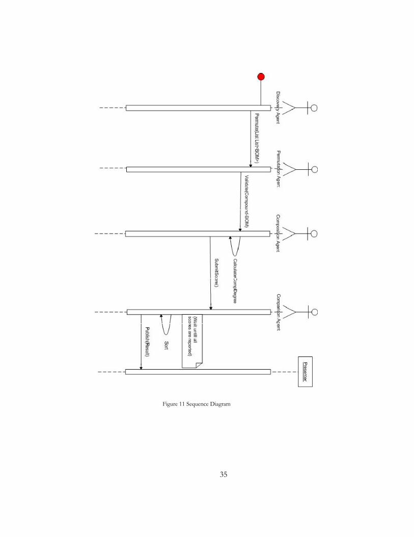
4.3. Sequence Diagram:
The sequence of actions can be viewed from the following diagram:
35
Figure 11 Sequence Diagram

36
In order to understand the sequence diagram, we need to know the different data types that were
defined to exchange data objects between different agents. They have been defined inform of
java beans. Following is the hierarchy that shows the Bean and sub-beans with in the bean:
SRMLInfo: o List [ItemInfo Items]
String ItemName List [ScriptInfo scripts]
o String name o String type o String[] parametes
List [SinkInfo sinks] String name String events

37
BOMInfo:
o String name o String version o String securityClassification o String description o String glyph o List [EntityInfo entities]
String Name List [String characteristics]
o List [EventInfo events] String Name String source String target List [String characteristics]
o List [PatternOfInterplayInfo poi]
String name List [ActionInfo actions]
String sequence String name String event String sender String receiver
o List [StateMachineInfo SM]
String name List [EventInfo events] List [StateInfo States]
String name String exitcondiction
They are used to carry all the data parsed from a BOM XML and later from OWL. From the
above sequence diagram (figure 11) it is clear that the server initiates a Parse request which is
severed by Parser Agent who instantiate an SRMLInfo bean and it forwards it to the discovery

38
agent which in turn reads the bean, and for each entity in the bean sends a query request to the
SDR, which returns a list of BOMInfo beans. These are further filtered by the discovery agent
and then are handed over to the Combination Agent. It creates all possible combinations that are
sent to the composition agent for matching. Each matching operation returns a score that is
collected by the comparison agent. Finally a list of scores is sorted and published to the presenter
4.4. Jack Agent framework:
The following section will describe the implementation of the Jack Agent Framework on top of
the core system. As it has already been explained in the previous chapter the Jack agent system is
a shell that is running on top of a Jack Kernel
The entire working of Jack agent framework is explained as follows:
4.4.1. Initialization:
The entry point of execution of this shell is a Main.java program that initiates the call to the
Manger agent. This agent is further responsible to govern all the tasks.
Please note that this �Manager Agent� term should not be confused with the system design of
Query Manager, Composition Manager etc. These are the modules and are formed based on the
convention used in Model Driven Component development where as the Manager Agent is the
Agent programmed to govern all the tasks.
The rationale to use a centralized approach in handling all the tasks is to accommodate
parallelism. This part contains all the initialization code. Normally in a typical multi-agent system
environment, it is important to populate agents in the agent container with their default metadata.
In our case we have agent names.

39
4.4.2. Parsing:
Once the agent manager is instantiated, it calls the presentation module to display input GUI for
locating an SRML file. When the user specify an appropriate SRML file, the Manager agent posts
a parse event to the Parser Agent, who has the capability to handle this event based on a parse
plan. When this event is posted the parser agent is actually running an XML file parser routine
specified by the basic parse plan and the entire SRML file is parsed and extracted in the memory
in form of SRML bean. This bean is designed to carry the entire SRML elements & attributes.
Thus it can be used to carry the SRML data which can be exchanged by various agents.
Once an SRML file is parsed the �posting method� , the method which is called when a post
event is handled, will return the SRML object to the Manager agent.
4.4.3. Discovery:
The manager agent can then send a request message to discovery agent to perform discovery on
all the entities identified so far from the parsing of the SRML file. This agent can further query
our virtual SDR and retrieve a list of BOM.
4.4.4. Virtual SDR:
In order to complete the implementation of the agent framework it was desired to emulate the
SDR locally in the system [instead of connecting directly to the real SDR due to confidentially
reason] thus we have devised a file-based SDR that contains XML and OWL files for each BOM.
When the Virtual SDR is initialized, it reads all the XML files stored in the disk and collects the
BOMS in a data structure, that is capable of performing search operations (similar to real SDR).
I have also contributed in the design of the OWL description schema for each BOM. The
following OWL classes were proposed that can be used as a schema for the OWL description:

40
Figure 12 Owl Description
This OWL description is a replica of BOM structure but in form of OWL class hierarchy. We
needed this to write the OWL description of BOMs. Based on the above class hierarchy we
developed instances (also known as individuals) for each BOM discussed in the Test case study.
This ontology attachment proved to be very successful in applying composition rules. In order to
connect to the ontology attachment document, Jena API was used. The following basic code
explains how to connect to a specific BOM OWL description:
public OntModel loadOWL(String pathToFile){ OntModel model = ModelFactory.createOntologyModel(OntModelSpec.OWL_MEM ); InputStream in = FileManager.get().open(file); if (in == null) { throw new IllegalArgumentException( "File: " + file + " not found"); } model.read(in, ""); return model; }

41
Since it is a file based ontology model, so we input an OWL file source and the above method
returns an Ontology Model which can further be used by Jena iterater to traverse and lookup or
compare for two different objects/entities or instances of the BOM.
So the query is constructed and handed over to the Discovery agent. This agent process the
discovery in two passes.
a. Simple discovery:
In the first pass, the BOMs are fetched only on the basis of criteria given by the manger
agent. It is quite possible to get a large number of BOMs in this step.
b. Filtration:
In the second pass, a filtration is performed based on the following discovery rule set:
Discovery Layer
Feature to be checked What is checked Rule
Syntactic
Action Event Name Rule-1
Message Number of parameters Rule-2
Semantic Entity Entity Type Rule-3
Message Data Type Rule-4
Figure 13 Discovery Rules [6]
After the filtration, the BOMs are collected in a list of Array and are sent back to the Manger
Agent. Manager agent is then responsible to put them into appropriate groups based on the
BOM classes (as identified from the Ontology of a given scenario and then SRML document).
When this re-grouping is done it will post a request to combination agent to perform the
combinations

42
4.4.5. Combinations:
The manager agent then employs a combination agent to perform all the possible statistical
combinations on the BOMs, which will run a routine and create all possible combinations. The
compounds are returned to the manager in form of an array list.
4.4.6. Composition:
Now finally the manager agent is ready to evaluate each compound for the composability degree,
so it sends request to the composition agent one by one for each compound and waits for the
score. The composition agent picks up the compound and start applying all the rules to evaluate
the composability degree. Following is the list of rules that are applied:
Composition Layer
Feature to be checked What is checked Rule Weight
Syntactic
Action
Event Name Rule-1
Mode In/Out
Binding Horizontal Message Number of parameters Rule-2 W2
Static Semantic
Action
Entity Type(Source & Target of Event
Rule-3 W3
Event Type N.A
Message Unit Rule-4 W4
Data Type Rule-5 W5
Business Role Rule-6 W6
Dynamic Semantic
State Machine of Composition ( State machines + Pre/Post
conditions on events)
Plug-in Pre matching is checked
Rule-7 W7
Figure 14 Composition Rules [6]
It is recommended for the readers to take a look at Syntactic and Semantics Model
Composability based on BOMs [6] for further information of the composition technique.
Jena OWL API is used inside the code body of Composition Agent in order to traverse in the
OWL description of BOMs and be able to perform semantic matching. These rules are applied

43
in the recursive order, i.e., when there is a match it continues to the second rule and then next
and then so on until it finally declares the two candidates to be composable. See the following
diagram for the process of composition.
Match A,B
Rule 1
Rule 2
pass
Rule 3
Rule 4
pass
Reason
fail
pass
Reason
Reason
fail
fail
Rule 5
passReason
fail
Score Calculation
Score
Figure 15 Composition Logic
Once the composition score is calculated it is returned to the manager agent. Since this
composition operation is done for each compound so both the agents are involved in a loop
until all compounds are scored.

44
4.4.7. Comparison:
The manager agent sends all the scores to the comparison agent who can sort the list according
to the logic defined by the simulation modeler and then publish the result accordingly
The following diagram illustrates the entire process in detail.
From the figure, it is clear that the Manager Agent first posts a parse request to the Parser Agent.
This is posted in form of a �Parse Event�, because either the Parser Agent might be idle at that
time or is busy in some existing task to finish. So when the Parse Event is posted Parser Agent
will be updated about the request and it will serve it by invoking its posting event , which in our
case is doParse(). This method will return a SRMLInfo bean back to the Manger Agent. Manager
Agent then updates its global variable for the SRMLInfo.
Then the Manager Agent posts a discovery request to the discovery agent which in turn performs
the discovery for each entity in the SRML bean and fetches the results from the SDR. It then
filters the irrelevant BOMS from its collection based on the events specified in the SRML and
returns an array of filleted BOMs back to the Manager Agent.
Then Manager Agent re-groups all the BOMs according to their classes� and calls the
Combination Agent to perform combinations on each class, who returns a list of all possible
combinations. For each combination in the list, Manager Agent then employs a composition
agent to perform the composition and return the score, which is collected in a list. Once all the
compounds have their composition result the comparison agent prints the score list.

45
Figure 16 Entire Process

46
4.5. Future Improvements
We can also improve the design of the system by dividing events into two categories: Post-
Request Event and Post-Response Event, this will help in achieving parallelism in the entire
pipeline of the project and after posting the request events, the manager agent does not have to
wait for the response and can continue some other jobs. When the response event is posted by
the task performer, the manager agent can easily handle it by spawning a new thread. This can be
referred as future improvement of the system.
47
C h a p t e r 5
5 . T E S T C A S E S T U D Y
5.1. A Restaurant Scenario:
In order to test the system, we have worked on the restaurant scenario previously proposed in
the previous thesis [6]. This case study is basically a simulation model of a restaurant, which has
the following simulation components:
1. Customer
2. Waiter
3. Table
4. Queue
5. Kitchen (Chef)
The overview of the simulation scenario is as follows:
A customer walks in a restaurant and wants to take a seat. For that he has to join a waiting
queue. When his turn comes he is allocated a table. When he occupies a table, a waiter goes to
attend him and gives him a menu. The customer orders food from the menu. The Waiter places
the order to the kitchen. When food is ready he serves the food. When customer finishes eating
he asks for the bill. Waiter gets the payment (either by cash or by credit card). Then customer
leaves the restaurant. Waiter cleans the table. The table is ready for another customer.
Starting with the test, we have a Restaurant SRML document that contains the actual simulation
scenario a modeler wants to test. [A copy of the Restaurant SRML is attached in the appendix C]
We also have a collection of BOMs related to restaurant scenario in our Virtual SDR along with
their OWL description. Based on the scenario mentioned in SRML we can draw the following

48
sequence diagram to preview the actions/events being sent and receive between the simulation
components:
Figure 17 Restaurant Sequence Diagram [6]
A : Customer
: Waiter : Queue : Table : Chef
Occupy(CustomerID)
RequestMenu(CustomerID)
GiveMenu(CustomerID, Menu)
Join(CustomerID)
TakeSit(TableID, CustomerID)
OrderFood (SelectedFood, CustomerID)
ServeFood(SelectedFood)
FoodReady(SelectedFood)GiveFood(SelectedFood)
AskBill(CustomerID)
GiveBill(Bill)
PayBillByCreditCard(CreditCard, Bill)
AskForSignature(Receipt)
Release(CustomerID)
CleanTable(TableID)
TableIsClean()
TableIsFree(TableID)
JoinAck(PlaceNo)
SignReceipt(Receipt)

49
5.2. Output of the test:
Now by running the Restaurant SRML scenario in the agent based system, we can see the
following outputs:
5.2.1. Step 1:
As a first step of the program execution, it asked for the SRML file. When importing the
appropriate file, it started parsing it and finally displayed the following tree graph of figure 18,
showing the entities, events, actions and parameters found in the SRML as follows:
Figure 18 Output Step 1: Parsing
(The folder means it has a child element. Page means it is a leaf)

50
5.2.2. Step 2:
In the next step, it sent a query for the following BOMs to the Virtual SDR:
Searching for: Customer
Searching for: Table
Searching for: Waiter
Searching for: Queue
Searching for: Kitchen
Following result was displayed after the discovery agent has finished searching Virtual SDR: 8 BOMs found for the entity: Customer
10 BOMs found for the entity: Table
9 BOMs found for the entity: Waiter
7 BOMs found for the entity: Queue
4 BOMs found for the entity: Kitchen
After applying the discovery rules, following BOMs were filtered: Apply discovery rules for filtration:
4 BOMS filtered for the entity: Customer
2 BOMS filtered for the entity: Table
3 BOMS filtered for the entity: Waiter
2 BOMS filtered for the entity: Queue
1 BOMS filtered for the entity: Kitchen
Figure 19 Output Step 2: Discovery

51
5.2.3. Step 3:
After the discovery the next step is creating combinations. Some of the combinations that were generated by the Combination Agent can be seen as below::
1. Customer1Table1Waiter1Queue1Kitchen1 2. Customer1Table1Waiter1Queue2Kitchen1 3. Customer1Table1Waiter2Queue1Kitchen1 4. Customer1Table1Waiter2Queue2Kitchen1 5. Customer1Table1Waiter3Queue1Kitchen1 6. Customer1Table1Waiter3Queue2Kitchen1 7. Customer1Table2Waiter1Queue1Kitchen1 8. Customer1Table2Waiter1Queue2Kitchen1 9. Customer1Table2Waiter2Queue1Kitchen1 10. Customer1Table2Waiter2Queue2Kitchen1 11. Customer1Table2Waiter3Queue1Kitchen1
Figure 20 Output Step 3: Combinations
5.2.4. Step 4:
After applying the composition rules, following output has been seen: TESTING BOM Customer1 WITH Table1
APPLYING RULE 1 : ********************************************************************************************** Release has a name match [EventNameA: Release <-> EventNameB :Release] Release has matched IN/OUT [Release_Action hasType Out <-> Release_Action hasType In] ********************************************************************************************** RULE 1 IS PASSED... ********************************************************************************************** APPLYING RULE 2 : ********************************************************************************************** EventA :Release has number of Parameters = 0 EventB :Release has number of Parameters = 0 ********************************************************************************************** RULE 2 IS PASSED... ********************************************************************************************** APPLYING RULE 3 : ********************************************************************************************** EntityType <-> EntityType EntityType <-> EntityType ********************************************************************************************** RULE 3 IS PASSED... ********************************************************************************************** APPLYING RULE 4 : ********************************************************************************************** Noparamater <-> Noparamater ********************************************************************************************** RULE 4 IS PASSED... **********************************************************************************************
Figure 21 Output Step 4: Matching

52
5.2.5. Step 5:
The final score for the BOM composability degree was calculated in the following steps:
1. All the events in each compound has an individual composability score which is calculated as
follows:
Syntactic Layer Score = If Rule 1 & 2 are true then 1 else 0
Semantic Layer score = [Rule-3 Score * w3 ]+ [Rule-4 Score * w4] + [Rule-5 Score *w5]
{w3, w4 , w5 = 1, 0.75, 0.25, 0} (6)
Total score for each event = Syntactic Layer Score + Semantic Layer score
2. Total score for each pair = Sum of All event score / N [Where N = no. of events]
3. Total semantic score of the whole compound = [total score of all the pairs / No. of pairs ]
4. Dynamic score of the whole compound = Score calculated by Jess Engine
5. Compsobility degree = Total semnatic score *0.5 + Dynamic Score*0.5

53
C h a p t e r 6
6 . C O N C L U S I O N & F U T U R E W O R K
6.1. Conclusion:
This research can be concluded with the following deductions:
6.1.1. With the help of Agent technology, we can not only match the components based on their
syntax, but also can evaluate their semantic context so that we can be assured of their
accurate functionality after they are composed.
6.1.2. As we have used a modular approach in designing and developing the agent environment,
we can always introduce new Agent Plans, beliefs and capabilities in order to deal with
more complex situations. Due to the modular approach used in the development of our
Agent system, it is an advantage that an agent (with multiple plans, beliefs and capabilities)
can decide, which plan he should proceed with to handle a particular situation. This can be
more useful when we are targeting complex simulation scenarios, with more rules and
constraints.
6.1.3. Ontology description associated with a particular simulation component, as proposed by
other researchers, proved to be a very useful tool to utilize by the agent system for being
able to perform semantic based discovery and matching.
6.1.4. Finally, the environment design is capable to be deployed on various platforms and on
various technologies. It can be executed in a single desktop machine or can be deployed
over a distributed network environment and can be executed across different machines. It
can also be hosted as a web service. But in that case an additional security layer (Agent-
Security) needs to be implemented.

54
6.2. Future Work:
This research initiative was just an effort to implement a basic agent-based framework that can
perform an automated discovery and composition of simulation components. There are a lot of
suggested improvements and future research. Some of them are stated as below:
6.2.1. The agent based system can be improved to keep the history of existing successful BOM
composition reports and reuse them to speed up the matching process. Already validated
combination can be retrieved from the history and could be considered for using with new
scenarios of similar nature.
6.2.2. Agent system can be redesigned to achieve parallelism in the matching pipeline. This
involves a great deal of negotiation, co-ordination and communication (which are already
known sophisticated features of Agent technology), to serve parallel tasks. This can help in
increasing performance up to a greater extent.
6.2.3. An automated SRML modeling GUI tool can be designed and incorporated with this
system in order to support the modelers. This can include a graphical library interface or
palette (actually connected to the SDR at the backend), that has components to choose
from and can be added in a graphical modeling canvas by drag & drop, and test their
interaction in various ways. Importing new onthologies and new BOM description in the
scenario can increase the number of possibilities for modeling complex simulation
scenarios.

55
R E F E R E N C E S
1. Fabian C Hadipriono Implementation of a virtual environment for traffic accident simulation. [thesis] 2003 .
2. Francis Neelamkavil Computer Simulation and Modelling . [Book : Wiley], 1990.
3. Farshad Moradi �Component-based Simulation Model using web services�, proceedings of the first Asia
International Conference on Modeling & Simulation, [Paper] 2007.
4. Peder Nordvaller �Composability and Reuse for Simulation Development using BOMs� [Thesis], IMIT-KTH, 2006
5. Mikel. D Petty, E. W. Weisel and R. R. Mielke �Overview of a Theory of Composability�, Virginia Modeling Analysis.. [Paper] 2004.
6. Shahab Mokherzadeh, Hossein Akbari �Syntatic and Semnatic Model Composibilty based on BOMs�.ICT-KTH, [thesis] 2007.
7. Farshad Moradi, Rassul Ayani, Peder Nordvaller, "Simulation Model Composition using
BOMs", in Proceedings of The 10-th International Symposium on Distributed Simulation and Real Time Applications, DS-RT '06, October 2006, Malaga, Spain.
8. Marianela Garcia Lozano, Rassul Ayani, Farshad Moradi, SDR - A Semantic
based Distributed Repository, in Proceedings of the first Asia Modelling symposium, AMS 2007, March 2007, Thailand.
9. BOM Guide version [Manual] 2006. http://www.boms.info/ 10. Group, SISO Product Development. Guide for Simulation Interoperability Standards Organization
(SISO). [Manual] http://www.sisostds.org/ 2006.
11. Edward N. Zalta Stanford Encyclopedia of Philosophy. [Book] 2003. 12. T. R. Gruber Toward principles for the design of ontologies used for knowledge sharing. [Report] 1993. 13. Michael Wooldridge. An Introduction to Multi-agent Systems. [Book], 2002. 14. AOS. Jack Agent Framework Manual. [Manual] http://www.agent-software.com 2006.

56
15. Nick Howden, Ralph Rönnquist, Andrew Hodgson, Andrew Lucas. JACK Intelligent Agents � Summary of an Agent Infrastructure. http://www.agent-software.com [Paper] 2001. 16. AOS. JACK� Intelligent Agents JDE Manual. http://www.agent-software.com 2006. 17. T.Berners-Lee, J.Handler and O.Lassila. The Semantic Web. Scientific American. 2001. 18. BOMworks. [Online] http://www.simventions.com/bomworks/.

57
I N D E X
A
agent based environment, i, iii, 32
API, 17, 38
B
BDI, 18 BOM, i, iii, i, iii, 5, 10, 11,
12, 13, 30, 36, 37, 46, 47, 48, 49, 52
C
Combination, i, 30, 45 Communication, i, 9 Comparison, ii, 30, 39 component, 2, 4, 5, 6, 7, 10,
11, 12, 18, 22, 24, 25, 28, 47, 48
Composability, i, iii, 5, 7, 38, 49
Composition Logic, i, 38 computer simulation, 1 co-operative, 9, 16, 26
D
Discovery, i, ii, i, 6, 27, 36, 44
distributed, 9, 13, 15, 16, 18, 47
E
Entity Type, 11, 12, 36, 37 Event Type, 11, 12, 37
F
FOI, iii, ii, iii, 6, 9, 18
H
HLA, iii, 10
I
Intelligent, i, 15, 49
J
Jack, i, ii, i, 18, 20, 21, 22, 24, 25, 35, 49
JACK Agent Compiler, i, 20 JACK Agent Kernel, i, 20 JACK Agent Language, i, 20,
22 JDE, i, 24, 49
M
Modelling, iii
O
Ontology, iii, 14, 37, 47 OWL), 14
P
Parsing, ii, i, 35, 43 Pattern Of Interplay, 11
R
Restaurant, ii, i, 6, 41, 42, 43, 52
Reusability, i, 4, 7 Rules, i, 36, 37
S
Semantic, 5, 6, 7, 14, 36, 37, 49
Simulation, i, iii, i, iii, 1, 3, 13, 18, 49, 52, 54
SRML, i, ii, iii, 8, 13, 30, 35, 36, 37, 41, 43, 48, 52
State Machine, 11, 12, 37
V
Virtual SDR, ii, 36, 41, 44

58
A P P E N D I X E S
1. Restaurant SRML
<?xml version="1.0" encoding="UTF-8" standalone="yes"?> <!-- This is a Restaurant Model --> <Simulations> <Simulation Name="Restaurant"> <Script Name="SimulationScript" type="text/javascript"/> <!-- Defining The BOM Objects --> <ItemClasses Name="AllItemClasses" > <ItemClass Name="Customer" Source="the place of CustomerBOM"/> <ItemClass Name="Table" Source="the place of TableBOM"/> <ItemClass Name="Waiter" Source="the place of WaiterBOM"/> <ItemClass Name="Queue" Source="the place of QueueBOM"/> <ItemClass Name="Kitchen" Source="the place of KitchenBOM"/> </ItemClasses> <Items Name="AllItems" > <Item ItemClass="Customer" ID="c00" Source="the place of CustomerBOM"> <Script Name="CustomerScript1" type="text/javascript">PostEvent(Queue,Join,CustomerID);</Script> <EventSink Name="CustomerNeedsAcknowledge" EventClasses="JoinAck"></EventSink> <EventSink Name="CustomerNeedsTable" EventClasses="TakeSit"></EventSink> <Script Name="CustomerScript2" type="text/javascript">PostEvent(Table,Occupy,CustomerID);</Script> <Script Name="CustomerScript3" type="text/javascript">PostEvent(Waiter,RequestMenu,CustomerID);</Script> <Script Name="CustomerScript4" type="text/javascript">PostEvent(Waiter,OrderFood,Food,CustomerID);</Script> <EventSink Name="CustomerNeedsFood" EventClasses="GiveFood"></EventSink> <EventSink Name="CustomerNeedsMenu"

59
EventClasses="GiveMenu"/> <Script Name="CustomerScript5" type="text/javascript">PostEvent(Waiter,AskBill,Order); <!-- PostEvent(Waiter, Waiter_PayBillByCash, Cash, Bill); --> </Script> <Script Name="CustomerScript6" type="text/javascript">PostEvent(Waiter,PayBillByCreditCard,CreditCard,Bill);</Script> <EventSink Name="CustomerNeedsReceipt" EventClasses="AskForSignature"></EventSink> <EventSink Name="CustomerNeedsBill" EventClasses="GiveBill"/> <Script Name="CustomerScript7" type="text/javascript">PostEvent(Table,Release,CustomerID);</Script> </Item> <Item ItemClass="Table" ID="t00" Source="the place of TableBOM"> <EventSink Name="TableNeedsCustomerToOccupy" EventClasses="Occupy"></EventSink> <EventSink Name="TableNeedsCustomerToRelease" EventClasses="Release"></EventSink> <Script Name="TableScript1" type="text/javascript">PostEvent(Waiter,CleanTable,TableID);</Script> <EventSink Name="TableNeedsWaiterToClean" EventClasses="TableIsClean"></EventSink> <Script Name="TableScript2" type="text/javascript">PostEvent(Queue,TableIsFree,TableID);</Script> </Item> <Item ItemClass="Waiter" ID="w00" Source="the place of WaiterBOM"> <EventSink Name="WaiterNeedsCustomerToAskForMenu" EventClasses="RequestMenu"></EventSink> <EventSink Name="WaiterNeedsCustomerToOrderFood" EventClasses="OrderFood"></EventSink> <Script Name="WaiterScript1" type="text/javascript">PostEvent(Customer,GiveFood,Food,Order);</Script> <EventSink Name="WaiterNeedsCustomerToAskForBill" EventClasses="AskBill"></EventSink> <EventSink Name="WaiterNeedsCustomerToPayByCreditCard"

60
EventClasses="PayBillByCreditCard"></EventSink> <Script Name="WaiterScript2" type="text/javascript">PostEvent(Customer,AskForSignature,Receipt);</Script> <EventSink Name="WaiterNeedsTableToAskForClean" EventClasses="CleanTable"></EventSink> <EventSink Name="WaiterNeedsFoodFromKitchen" EventClasses="FoodReady"/> <Script Name="WaiterScript3" type="text/javascript">PostEvent(Table,TableIsClean);</Script> <Script Name="WaiterScript6" type="text/javascript">PostEvent(Customer,GiveBill,Bill);</Script> <Script Name="WaiterScript4" type="text/javascript">PostEvent(Customer,GiveMenu,CustomerID,Menu);</Script> <Script Name="WaiterScript5" type="text/javascript">PostEvent(Kitchen,ServeFood,Food);</Script> </Item> <Item ItemClass="Queue" ID="q00" Source="the place of QueuBOM"> <EventSink Name="QueueNeedsCustomerToJoin" EventClasses="Join"></EventSink> <Script Name="QueueScript1" type="text/javascript">PostEvent(Customer,TakeSit,CustomerID,TableID);</Script> <Script Name="QueueScript2" type="text/javascript">PostEvent(Customer,JoinAck,CustomerID,QueueID);</Script> <EventSink Name="QueueNeedsTableToFree" EventClasses="TableIsFree"></EventSink> </Item> <Item ItemClass="Kitchen" ID="k00" Source="the place of KitchenBOM"> <Script Name="KitchenScript" type="text/javascript">PostEvent(Waiter,FoodReady,Food);</Script> <EventSink Name="KitchenNeedsWaiterToAskForPreparingFood" EventClasses="ServeFood"></EventSink> </Item> </Items> </Simulation> </Simulations>
Copyright © 2022 FDOKUMEN