
AMinima.pdf - TFMA Temple
33
Version 2.32 user’s guide
-
Upload
khangminh22 -
Category
Documents
-
view
2 -
download
0
Transcript of AMinima.pdf - TFMA Temple

V e r s i o n 2 . 3 2 u s e r ’ s g u i d e

1presentation

Technical Specifications :
Technical specifications and User's guide are subject to changewithout notice.
- Super16 only, 172,8° * spinning mirror reflex shutter,- Around 2 kg (4 Lbs) with on-board battery and film.- Overhaul dimensions: L: 245mm, H: 140mm, W: 110 mm(9.7" x 5.5" x 4.4")- Time recording by XTRprod compatible AatonCode-II matrix-es, accurate to a 1/4 of a frame. The camera can also be used asa master-clock - Sound level: 28 db (1-/+2).- Fiber-optic viewing screen, 1:1.78 (16/9) ratio viewing screenshows markings for wide-screen HDTV and 4:3 aspect ratios.- Frame Rate - 1 to 32 fps with internal Lithium and up to 50 fpswith an external 12V battery TBD and stop-frame with built-inintervalometer.- Nikon or Arri PL mount- Incident lightmeter -dome- showing T-stop and diff. T-stop,HMI frequency and monitor scan rates on the camera LCD dis-play.- DistantEye viewfinder “Aaton patent”; the only reflex camerawhich doesn't fog the film if your eye is not held against thecamera rubber eyecup.- Built-in Intervalometer- Back light display- 200' quick change magazines, 'B' wound rolls in Aaton's ~flexi-ble~ daylight spools (standard metallic 200 spools and 400' reelscannot be used with the A-Minima)
* Initial cameras (from # 006 to 025) have a 180° shutter. This shut-ter will be retrofitted in 172,8° when external housing is exchanged.
Chapter 1 - Presentation
5

1 - Viewing screen collimation port 9 - Shutter trigger2 - gate rear pressure plate 10 - Magazine release lever3 - Film pulldown claw4 - Take-up sprocket door5 - Feed sprocket door6 - Feed sprocket7 - Take-up sprocket8 - Magazine locking mechanism
1 2 3 4 5 6 7 9 10
8
1 - Magazine release lever2 - Lightmeter dome3 - Backlight LCD display4 - Batteries compartment5 - LED camera and timecode status indicator6 - Control panel7 - Camera run switch8 - Video assist port
1 2 3 4 5 6 7 8

1
2
3
4
5
6
78
1 - Camera rubber eyecup2 - magazine feed side3 - magazine take-up side4- Lightmeter dome5 - Lemo 5 timecode socket6 - Lemo 6 accessories socket7 - Magazine release lever8 - Magazine hinge.
6
3
4
5
7
1 - Diopter locking knob2 - PL lens port locking ring3 - A-minima fixed viewing screen4 - camera 172.8°mirror/shutter5 - Arri PL lens port6 - Video assist port7 - Access hole for locking the video assist lens.
2
1

1 - 3/8-16 mounting hole2 - Lemo 6 Aaton power base connection3 - power base locating hole4 - Magazine hinge5 - Magazine release lever6 - Hand strap holder
6
5 4
1
2
3
6
1 - Diopter locking knob2 - Magazine latch3 - 3/8-16 insert4 - camera run switch5 - Video port cover
1
2
3
4
5

2control panel

Chapter 2 - The A-Minima Control Panel
15
A-Minima control panel
The A-Minima control panel consist of an illuminated LCD display,six buttons to access and adjust all operator functions, and a camerastatus LED. Each buttons can have a different function, dependingon the mode you are in.
• Inches the camera by frame when you are in the cameradefault display.
• Allows you to select or change the camera parameters withina menu.
• Allows you to view, access and change the camera parameters.
• Allows you to enter a selected menu, to change or validate aparameter within a particular menu.
• Allows you to cancel a parameter or move a step backwardwhile setting a parameter.
• Wakes up the camera ( if left alone, the camera display willautomatically shut off after 5 minutes. Needless to say allsettings are saved in the camera internal memory)
• Shows battery voltage.• Powers down the camera electronics. • allows you to return to the camera default mode at any time• exit the "TV SYNC" and INTERVALLOMETER" mode.
Press on it to view the theoretical lens aperture.
This LED conveys camera status information.
• Yellow flashing: timecode has been initialized.• Slow red flashing: low battery.• Fast red blinking: camera not running at the selected speed• Solid red: end of film warning
YESNO

A-minima default display
When first powered or after pressing the blue button, the displayshows the camera selected speed / timecode status and remainingfootage.- If the Aatoncode has not been initialized, the upper line of the dis-play flashes between camera selected speed and “NO TIME”Press on the "YES" button to remove the NO TIME message.
- If the Aatoncode has been initialized in the camera, either from theA-Minima internal clock or from an external source, the upper lineof the display flashes between the selected speed and the timecodeinformation.
Camera running, the display shows the selected speed and theremaining footage.
Note: If no magazine is installed, the camera will display "NO MAG" in place of the footage.
If not in use for five minutes, the camera automatically powers itselfdown, unless timecode has first been initialized. Press on any keys,including the run switch, to wake up the camera.
Chapter 2 - The A-Minima Control Panel
17
Camera run :
The running function of the camera motor is accomplished electron-ically and can be accessed in two ways.
From the body :Starting with the camera software version 2.27, the red ON/OFFswitch located on the camera body, above the motor, must be trig-gered twice (within one second) in order to start the camera motor.
From the Aaton Power Base :Simply use the Aaton wooden handgrip and connect it to the Lemo2connector located between the two front rod inserts of the powerbase.
Camera inching :
From the body :Use the UP arrow to inch the camera frame by frame.
From the Power Base :Use the test position of the wooden handgrip.
Note: the test function of the wooden handgrip is not available forcameras with a serial number below A100.
Camera software version :
Press YES and BLUE key simultaneously to see your camera’sequipment number as well as EPROM version.
For camera software updates, please contact your Aaton representative.
Chapter 2 - The A-Minima Control Panel
16

DOWN key, NEW SPEED blinks, press YES then use YES and NOto select the digit you want to modify, UP or DOWN key to modifyit. After entering the last digit, you can add it to your preset speedlist, press YES to do so or NO if you do not wish to add this specif-ic speed in the preset speed list.
Note: when a specific speed is not added to the preset list, a starshows next to the displayed speed. Simply a warning. Not added orpart of the preset menu, this speed will be erased of the camerainternal memory as soon as you select another speed. (Nevertheless, when powered down, A-Minima keeps it into itsinternal memory)
To modify a specific speed, added to the preset speed list:A-minima allows you to modify or delete this speed. If you want tomodify it, access the speed menu, then choose "MODIFY" andselect a new speed from the PRESET or NEW SPEED menu.
Chapter 2 - The A-Minima Control Panel
19
Parameters setting :
In order to view or to change a camera parameter, use the DOWNkey to scroll through the different menus.Each menu can be accessed in the following order.
Speed setting
A-minima has a selection of preset speed that you can choose from.You can also make your selection of any 0,001 incremented crystalspeed between 1.000 and 50.000 fps.When setting the camera to a specific speed, not being part of thepreset ones, A-minima allows you to add or not this particular speedto the factory selected speed list. The added speed can be laterremoved from the preset speed selection.A factory selected speed cannot be deleted.The displayed messages can be different if you want to modify afactory preset speed, or if you want to modify a specific speed,added to the preset speed menu.
To modify and select a factory preset speed :From the camera default display, press the DOWN key once toaccess the speed menu, press YES, PRESET blinks, press YES, thenuse the UP or DOWN key to go through the speed selection, pressYES to validate your choice.
To modify a factory preset speed, and choose a specifc speed :From the camera default display, press the DOWN key once toaccess the speed menu, press YES, PRESET blinks, press the
Chapter 2 - The A-Minima Control Panel
18

Starting with the software version 2.32, the A-Minima allows you toset and recall the footage of four different magazines.Second on theControl panel menu, press the DOWN arrow twice to access themagazine A footage setting. Press again on the DOWN arrow if youwant to recall or set the mag B, C or D. The display showing thedesired mag ID and footage, pressing YES will allow you to vali-date (press YES) or change the mag footage (UP or DOWN arrowsthen YES)
Chapter 5 - Accessories
21
To delete a specific speed added to the preset listIf you want to deleted it from your preset list, choose DELETE,then press YES. The camera will default to 1.000 fps.
Magazine footage setting
Second on the list, press the DOWN key twice, press YES to accessthe magazine footage setting. With a fully loaded magazine installedon the camera press YES again -NEW MAG- to reset the control
panel to count down a full 200ft load.If a short end is being used, press the DOWN key -SET FOOT- thenYES. Use the UP or DOWN key to set the counter to the desiredfootage, press YES to validate.
Note: a magazine needs to be installed, locked in its running posi-tion, for you to have access to the magazine footage setting.
Chapter 2 - The A-Minima Control Panel
20
Press again on the DOWN arrow if you want to recall or set mag B,C or D
Note: a magazine needs to be installed, locked in its running posi-tion, for you to have access to the magazine footage setting. Thecamera does not take a physical reading of the film roll to determinethe footage reading or the magazine ID shown on the display. Bothmust be set by the user.

Timecode
As a standard feature, the A-minima is equipped with the capabilityof recording Aatoncode in camera time. Timecode information isexposed onto the film by means of seven micro diodes located intothe gate of the camera, near the camera pulldown claw. Thesediodes flash rapidly to form the code, as the film pass through thegate between exposures.Timecode can be quickly initialized from the camera internal clockor can be inputted from an external device.
Initializing the camera from its internal clock :Pressing the DOWN key four times will take you to the timecodemenu of the A-minima. Press YES to enter, CAM TIME blinks,press YES again. The display will show you the camera internaltime and date for few seconds, the yellow LED will start flashing.The camera is now initialized and will keep accurate time (withinhalf a frame) for eight hours.
Note: The Yellow blinking LED is the garanty that timecode hasbeen initialized and that the camera is running an accurate time. Thecamera internal clock is not accurate and timecode will not berecorded onto the film if it has not been first initialized. The camerainternal clock does not need the camera to be powered to keep thetime. The timecode generator does. Get into the habit of having afresh battery near by when replacing an exhausted one. An internalcamera capacitor allows a full minute for battery replacement beforetimecode is lost.
Chapter 2 - The A-Minima Control Panel
23
ASA setting
Third on the list, the ASA must be adjusted to the exposure index ofthe film stock being used. The ISO selector of the camera providessettings between 25 and 1000 ASA.
From the camera default display, press the DOWN key three timesto access the ASA setting menu, press YES, then use the UP orDOWN key to select the desired ASA. Press YES to validate.Note: for Aatoncode, proper ASAsetting will insure that the time-code matrixes recorded in between the film perforations will beexposed at an appropriate and useable level. When using the exter-nal camera incident lightmeter, it simply insures that the T stop indi-cation shown on the display is the correct one for a particular filmstock. When using the lightmeter, please check the speed setting.The T stop indication takes the camera speed into account.
Chapter 2 - The A-Minima Control Panel
22

Initializing the camera with an external device :The preferred method is by means of the OriginCplus wich inputstimecode in ASCII form. It is also possible for the camera to receiveinformation in SMPTE form, directly from a SMPTE device such asa TC audio recorder.
• Using the OriginCplus :(please refer to the OC+ manual in order to program it)Make surethe camera is powered. Connect the OriginCplus to the lemo5 sock-et located at the rear of the camera, above the lemo6 socket.Press *on the OriginCplos to send the timecode information. The cameradisplay will show the timecode and the small yellow LED located tothe right of the display will start to blink.• Using an external SMPTE device :Make sure the camera is powered. Connect the cable from theSMPTE output of the timecode device to the lemo5 receptacle ofthe camera. The display will show "LTC IN PROGRESS" thenshow the time, the small yellow LED located to the right of the dis-play will start to blink. Also, press on the UP arrow to re-initializethe camera with a new incoming LTC timecode.
Send ASCII ?
A-minima can be use to initialize another ASCII device.
From the camera default display, access this option by pressing theDOWN arrow five time (if the timecode has not been initialized,this option will not show on the camera display)Connect the camera to the timecode device, using the proper cable.Most likely, this would be a Lemo5 to Lemo5 cable. Please contactyour Aaton representative or rental house for further informationconcerning cables wiring.
Chapter 2 - The A-Minima Control Panel
25
Programming the internal clock with a new time :You can change the camera internal time within the timecode menu.Access the timecode menu, then press YES. Select NEW TIMEwith the DOWN key then press YES. First select the year with theUPor DOWN key, press YES to validate, A-minima will take youto each timecode field. After each fields are set as desired (the NObutton allows you to move backward one field at a time) and thatyou have reached the minutes, press YES, then press YES again tovalidate the time. A-minima displays this new time and date for fewseconds, the yellow LED will start flashing. The camera is now ini-tialized and will keep accurate time (within half a frame) for eighthours.
Note : If the camera has already been initialized and if you need tochange the time, simply access the timecode menu, press YES andA-Minima will take you to each field at a time.
Chapter 2 - The A-Minima Control Panel
24
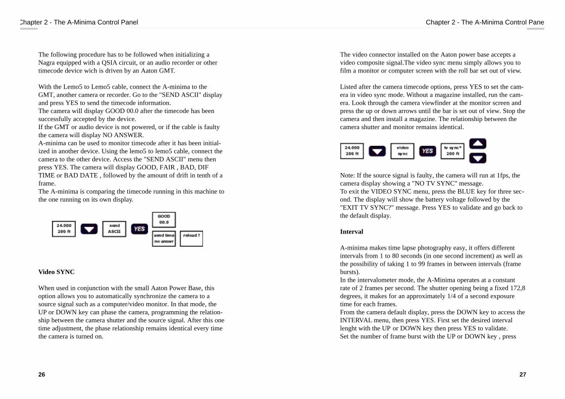
The video connector installed on the Aaton power base accepts avideo composite signal.The video sync menu simply allows you tofilm a monitor or computer screen with the roll bar set out of view.
Listed after the camera timecode options, press YES to set the cam-era in video sync mode. Without a magazine installed, run the cam-era. Look through the camera viewfinder at the monitor screen andpress the up or down arrows until the bar is set out of view. Stop thecamera and then install a magazine. The relationship between thecamera shutter and monitor remains identical.
Note: If the source signal is faulty, the camera will run at 1fps, thecamera display showing a "NO TV SYNC" message. To exit the VIDEO SYNC menu, press the BLUE key for three sec-ond. The display will show the battery voltage followed by the"EXIT TV SYNC?" message. Press YES to validate and go back tothe default display.
Interval
A-minima makes time lapse photography easy, it offers differentintervals from 1 to 80 seconds (in one second increment) as well asthe possibility of taking 1 to 99 frames in between intervals (framebursts).In the intervalometer mode, the A-Minima operates at a constantrate of 2 frames per second. The shutter opening being a fixed 172,8degrees, it makes for an approximately 1/4 of a second exposuretime for each frames.From the camera default display, press the DOWN key to access theINTERVAL menu, then press YES. First set the desired intervallenght with the UP or DOWN key then press YES to validate.Set the number of frame burst with the UP or DOWN key , press
Chapter 2 - The A-Minima Control Panel
27
The following procedure has to be followed when initializing aNagra equipped with a QSIA circuit, or an audio recorder or othertimecode device wich is driven by an Aaton GMT.
With the Lemo5 to Lemo5 cable, connect the A-minima to theGMT, another camera or recorder. Go to the "SEND ASCII" displayand press YES to send the timecode information.The camera will display GOOD 00.0 after the timecode has beensuccessfully accepted by the device. If the GMT or audio device is not powered, or if the cable is faultythe camera will display NO ANSWER. A-minima can be used to monitor timecode after it has been initial-ized in another device. Using the lemo5 to lemo5 cable, connect thecamera to the other device. Access the "SEND ASCII" menu thenpress YES. The camera will display GOOD, FAIR , BAD, DIFTIME or BAD DATE , followed by the amount of drift in tenth of aframe.The A-minima is comparing the timecode running in this machine tothe one running on its own display.
Video SYNC
When used in conjunction with the small Aaton Power Base, thisoption allows you to automatically synchronize the camera to asource signal such as a computer/video monitor. In that mode, theUP or DOWN key can phase the camera, programming the relation-ship between the camera shutter and the source signal. After this onetime adjustment, the phase relationship remains identical every timethe camera is turned on.
Chapter 2 - The A-Minima Control Panel
26

Chapter 5 - Accessories
29
YES to validate and enter the intervalometer control screen.The upper line of the display shows the interval set and the totalfootage available in your magazine.The lower line displays frame burst chosen and the number of framealready taken. You can reset the frame count to zero by pressing theDOWN key.You are now ready to start the camera with the camera on/offswitch.
To exit the INTERVAL menu, press the BLUE key for three second. The display will show the battery voltage followed by an" EXIT?"message. Press YES to validate and go back to the default display.
Note: With a 172,8° shutter, each exposure is 0,24s instead of 0,25sif you had a 180 degrees shutter.In 16mm, a full 200 feet roll contains 8000 frames. When viewed at24 frames per second, a roll last approx 5 minutes and 30 seconds.The following formula gives you the actual time T1 (in seconds) theevent will be filmed in according to the interval, frame burst chosenand the total number of frame taken.TI= (interval + (frame burst : 2) x (total Nb of frame : frame burst)
Chapter 2 - The A-Minima Control Panel
28
The upper line shows the interval set and the totalfootage available in your magazine
Press twice on the camera main on / off switch tostart the camera
Display during interval
To exit the INTERVAL menu, press the BLUE key for three seconds
Display during frame exposure
The new A-Minima software V2.32 brings variable exposure rateextending it from 1/4 sec to 255 sec, using pre-programmed set-tings.
Note: this new function is only available when setting the"frame burst" at 1 frame.

shutter :Go to the A-MINIMAOPTIONS menu, then press YES to enter.COUNTER flashes, press the DOWN key to select SHUTTER,press YES to access the SHUTTER MODE settings.Use the UP or DOWN key to scroll through the five different choices.
Depending on the mode you are in, the camera shutter pulse outlocated on pin 5 of the lemo 6 will be different.
Normal mode: the camera default mode.
Shutter long: When using the intervallometer function of the cam-era,this mode will synchronize a capping shutter to the cameraframe bursts.
Shutter flash: Used to synchronize a flash with the camera shutter.
Camera slave: to slave the camera shutter and speed to another A-Minima.
Note: an incoming signal must be present when using the camera inthe "camera slave" mode. If the source signal is faulty, the camera
Chapter 2 - The A-Minima Control Panel
31
Display light
In order to save battery power, the A-minima display backlight canbe turned off. From the camera default display, press the DOWNkey eight times to access the display light menu. Press YES to enter, select ON or OFF with the UP or DOWN key.
Press YES to validateNote:When pressing any keys of the control panel, the backlightwill be turned on for 30s, disregarding the display light setting. Also, to prevent excessive drain on the small on-board lithium bat-teries,the backlight will automaticaly turn itself off after five min-utes. If initialized with timecode, the camera display will flash forone second every ten seconds.
A-Minima Options:This is the last menu on the list. It allows you to set the camerafootage units and the camera shutter pulse output.
Counter :Go to the A-MINIMA OPTIONS menu, then press YES to enter.COUNTER flashes, press YES then use the UP or DOWN key toswitch the footage counter between feet and meters. Press YES tovalidate. The camera will then default to its default display, showingyou the desired footage unit.
Chapter 2 - The A-Minima Control Panel
30

will run at one frame per second, the red LED flashes and a "NOEXT SYNC" message is displayed.
Camera master: to control another A-Minima speed and shutter.
Please contact your Aaton representative or rental house for furtherinformation concerning cables wiring.
Chapter 2 - The A-Minima Control Panel
32
3magazine

The Film
The A-minima magazine is designed to accommodate the new"Aminima daylight spools" designed by Aaton. Manufactured anddelivered by Eastman Kodak, the spools can handle 200ft of film. The magazine coaxial design utilizes two identical spools, one oneach side. The A-minima spools are "daylight friendly". If you load and down-load your magazine in daylight, you will exposed approximately 5 ftof film during loading and 2 ft of film when taking the magazine offthe camera body.The spool is made of two flexible flanges attached on each side of aspecially designed core. Both flanges can be clipped on either side ofthe core.You should not need to separate the flanges from the core,but if you wish to do so, hold one flange firmly while turning theother one counter- c l o c k w i s e .
The film is being delivered by Kodak already rolled onto one of thespool. The film is spooled emulsion out. With its wind clockwise, theperforation should be towards you.
The maga z i n e
The magazine attach to the camera body by mean of two guidingpost located on the magazine take up side. A third post will triggerthe magazine shutter open when engaging the magazine onto thec a m e r a .You can manually move this post in order to open or close the shut-t e r. When pushed toward the nose of the magazine, the shutter isclosed. We recommend that you leave it closed to ensure the lighttightness of a loaded mag. Two locating pins, on either side of the mag throat, will maintain thecamera door closed when the magazine is installed on the camera inits running position.
Chapter 3 - Loading the A-Minima
35
1 - Magazine latch2 - Camera door locating pin3 - Magzine hinge
4 - Magazine guiding post5 - Shutter trigger6 - Magazine serial number
1
2
2 3
44
5 6

When engaging the mag onto the camera, the magazine shutteropens, allowing the two flexible spools to come in contact and bedriven by the camera take-up and feed sprockets. In this position,both spools are spread apart to ensure a clean and silent passage forthe film.
Loading the maga z i n e
Check that the magazine shutter is in its open position, if not, movethe trigger towards the rear of the magazine to open it. Open the magazine by pushing on the spring loaded lock and turningit clockwise. Place the magazine with the take up side to your right..Release both, feed and take-up spool locking mechanisms by pullingon the semi-circular lever. Remove the fully loaded spool from theblack bag and peel of the sticker, keeping it attached to the end of thefilm as you will need it to attach the film to the take-up spool. Gentlypull approximately one foot of film, being careful not to spread apartthe two flexible flanges. Install the loaded spool onto the mag feedspindle with its wind clockwise. Press evenly on each side of thecore and, while doing so, push the semi-circular lever down to lockthe spool in place. Using the sticker, attach the film to the take-up spool. Wind on a fewturn, clockwise and emulsion out. (you should not need to separatethe flanges from the core, but if you wish to do so, hold one flangefirmly while turning the other one counter-clockwise). Place the takeup spool on top of the feed side spool and flip it 180° (the flange pre-viously touching the feed spool should now be facing you). Guidingthe film into the throat of the magazine take-up side, install the spoolon the take-up spindle. Press evenly on each side of the core and,while doing so, push the semi-circular lever down to lock the spoolin place.Close the magazine, being careful not to pinch the film, close thelock and close the magazine shutter.
Chapter 3 - Loading the A-Minima
37
41 32
1 - Feed side2 - Feed spool3 - Take-up side4 - Magazine shutter

Installing the loaded magazine and threading theA-minima.
Before installing the magazine, adjust the loop length by pulling it tothe beginning of the magazine hinge.Also, on the camera body, open the feed and take-up sprocket doorby simply pushing them away from the sprockets (fig 1).Swing the gate pressure plate open by pulling it toward the rear ofthe camera.Before installing the magazine, you should power the camera body.When powered without a magazine, the camera motor automaticallymoves half a turn, in the test position, clearing the claw for the filmto be installed onto the gate. Install the magazine on the camera body with your right hand, mak-ing sure that the two locating pin are engaged into the camera lock-ing mechanisms. While "dropping" the magazine on the camera,spread apart the film loop at the magazine throat around the outsideof both take-up and feed sprockets.Engage the film around the upper take up sprocket and close thesprocket door, making sure that the film's perforations engage thesprocket teeth.Engage the film around the lower feed sprocket and close the sprock-et door.Install the film on the camera gate and close the rear pressure plate.Navigate the film into the gate channel with two fingers on each sideof the pressure plate until you ear this one pop into place. When cor-rectly set, the film should move freely, not being pinched by thepressure plate. If needed, open the feed sprocket door to adjust theloop length and center the figure eight loop top and bottom followingthe loop marking.Engage the magazine, pushing it firmly toward the front of the cam-era. Use the upper arrow located on the control panel to inch thecamera frame by frame. Run the camera a few feet to check yourthreading (after you become familiar threading the camera, youshould be able to load the camera without running a few feet of filmto save time and film stock)
Chapter 3 - Loading the A-Minima
39

Pull the magazine locking lever to release the magazine, close thecamera door and re-engage firmly the magazine into position. Presson the upper arrow to re-engage the claw and set your camera shutterin the reflex viewing position.
Re m oving the exposed film spool
After you exposed your full 200 ft roll, you can disengage the maga-zine from the camera and remove the daylight spool.Remenber to never pry the spool out of the magazine but to simplyrelease the spool locking mechanism and flip the magazine up sidedown to let the full spool fall into you hand.Wrap the complete spool in the black bag and into the can to send itto the lab.
Chapter 3 - Loading the A-Minima
40
4connectors

C o n n e c t o rs
The A-minima uses three connectors for power and accessory inputand output.Following is a detailed list, location and main function of each.
The Lemo 6 connector located at the rear of the camera is the mainaccessory connection of the A-minima. It provides remote on/offcontrol and power output as well a s a connection for accessorysuch as a capping shutter.
The lemo 6 connector located at the bottom of the camera body pro-vides remote on/off, power input and a connection for accessorysuch as the Aaton A-minima Power Base.
The Lemo 5 connector located at the rear of the camera, above theLemo 6, is the timecode interface. It provides timecode communica-tion in both ASCII (in and out) and SMPTE (in).
Chapter 4 - Connectors
43
1
2
3 4
5
6
1
34
5
6
2
1
2
3 4
5
LEMO 6
1 - Ground2 - Can Bus -3 - Can Bus +4 - + Batt (12 Volts)5 - Shutter pulse / Synch6 - Start
LEMO 6
1 - Ground2 - Can Bus -3 - Can Bus +4 - + Batt (12 Volts)5 - Shutter pulse / Synch6 - Start
LEMO 5
1 - Ground2 - LTC in3 - ASCII in / out4 - Not connected5 - Not connected
A-Minima Pin Attribution

5accessories

A-Minima Power Base
When used in conjunction with the A-minima camera body, theAaton small power base extends the camera functions.without com-promising its size, weight and ease of use.
The power base is multi functional: as a tripod intermediary plate, itaccepts a standard 15mm or 19mm sliding bridgeplate for buildingthe camera system for studio work. This configuration can acceptArri, Chrosziel or other manufacturer's mattebox, follow-focus andsupport equipment designed for bridgeplate use.
A lighter configuration is also possible using the two 15mm Aatonscrew-in front rods attached to the power base by means of two 3/8"threaded inserts located at the font of the base. This configuration can also accept Arri, Chrosziel or other manufac-turer's mattebox follow-focus and support equipment
The power base is also an electrical (fused) junction box between aremote 12 volts power source, the camera body and various acces-sories such as a zoom control or lens capping shutter.
Using its BNC connector, the power base allows you to automatical-ly synchronize the camera to a source signal such as one deliveredby a computer/video monitor.
Finally a remote ON/OFF capability is offered when connecting anAaton wooden handgrip to the power base Lemo 2 socket.
Chapter 5 - Accessories
47
1
43
21
5
1
54
32
2
1 - Lemo 6 accessories connector 4 - 3/8” camera screw2 - Front rods 3/8” threaded insert 5 - Lemo 2 handgrip socket3 - 3/8” threaded insert
1 - 5 Amps fuse holder 4 - BNC sync input2 - Lemo 6 camera connector 5 - XLR4 battery cable connector3 - Locating post

Use the 3/8" screw to attach the Aaton power base to the bottom ofthe camera body.A 5mm locating pin insures the correct lateralpositioning of the camera.
- The XLR4 connector located on the operator side is the main 12volts power input. It is designed to accept a standard XLR4 powercable. (Do not forget to move the switch, located in the disposablebattery compartment, to the "ext" position).
- The two Lemo 6 connectors located on the opposite side are thetwo main accessory connection. Designed to accept a power zoom,it also carries a sync signal and provides camera on/off- The Lemo 6 connector located at the top of the power base is theconnection between the A-minima camera body and the power base.It carries the 12 volt, camera on/off and external sync signals.Next to it is the main 5 Amp fuse.
- The Lemo 2 connector located between the two front rod insertsprovides camera remote on/off.
- The BNC input connector located next to the XLR4 connector isthe connection between the base and a video source signal. When avalid video signal is present, a small green led, located near theBNC connector will be lit.
Use a BNC cable connected on one end to the base and on the otherend to the video output of your monitor. On the camera controlpanel, press the "down" arrow to access the "video sync" menu.Press YES to set the camera in video sync mode. Without a maga-zine installed, run the camera. Look through the camera viewfinderat the monitor screen and press the up or down arrows until the baris set out of view. Stop the camera and then install a magazine. Therelationship between the camera shutter and monitor remains identi-cal.
Chapter 5 - Accessories
49
1
2 3
4
1
2
3 4
5
6
1
2
1
2
XLR4
1 - Ground2 - not connected3 - not connected4 - + batt (12 Volts)
LEMO6
1 - Ground2 - Can Bus -3 - Can Bus +4 - + Batt (12 Volts)5 - Shutter pulse / Synch6 - Start
LEMO2
1 - Ground2 - Start
BNC
1 - Video / sync in2 - Ground
Power Base Pin Attribution

Chapter 1 - Presentation
51
Chapter 1 - Presentation
50
The A-minima Clip-on Battery
Compact, lightweight and recellable, the A-minima Clip-On batteryprovides 1,7 Ah of power at 12 V, running approximately 30 x 200ftmagazines at 24 fps.The NiMH technology is superior to NiCad : about twice the capac-ity in smaller cells, abscence of memory effect eliminates the needto deplete the battery prior to recharging. The battery can be fastcharged whatever its state.The Clip-On battery can be charged using the Aaton CHA-3 charg-er through a cable adaptor connecting the battery Molex connectorto the CHA-3's XLR4 socket.
Technical specification :12 V - 1.7 Ah (1.6 to 1.8 Ah) Recellable A thermal sensor, installed inside the battery housing, shuts downthe CHA-3 charging cycle when the battery reaches 60° C duringchargeExternal dimensions: 86mm x 34mm x 61mm.Weight : 386 gr
1
2
3
1 - Molex charger connector 2 - Battery 12 volts output 3 - Locking lever (in the locked position)

The A-minima Top Handle
The A-minima top handle has been design to accommodate newways of carrying, operating or mounting the camera.
Safely attached to the camera 3/8" top insert, the orientable top han-dle also provides camera on/off capability, LCD monitor mountingor an extra 3/8"insert to receive accessories such as french flags orassistant lights.
As standard, a camera run function is available from the TopHandle. The On/Off cable delivered with the handle must be con-nected to the Lemo 6 socket located at the rear of the camera. Whilehand-holding the camera, press the switch two times (within 1 sec-ond) to start the camera. Press one time to stop the camera.
The handgrip can be adjusted for maximum handheld operatingcomfort. Use a 4mm Allen L wrench to loosen the attachment knob.Rotate the handgrip around the knob axe until your preferred posi-tion is found and lock the knob.Note that the handle is parallel tothe bottom of the camera.
The 3/8" insert, located on front of the Top Handle can easily andsafely hold accessories such as French flags, assistant lights, HFtransmitters...
An optional Aaton ball & socket head is also available in order touse the Top Handle as a small LCD monitor holder. Simply screwthe ball & socket head on the 3/8 insert located at the front of theTop Handle and attach your monitor. The ball & socket head pro-vides three dimensional monitor positions and a large knurdle knob,located at the base of the head, can be used to adjust the tension ofthe head or lock it in a desired position.When using the Transvideo A-Monitor, a small track, located at thebottom of the monitor offers intermediate mounting positions andcan be used to effectively balance the camera.
Chapter 1 - Presentation
53
Chapter 1 - Presentation
52
652 31
1 - Lemo 2 socket 6 - Transvideo mounting track2 - 3/8” attachment screw3 - Run switch4 - Head friction and locking knob5 - Aaton ball&socket head
4

The A-minima video assist
This on-board flicker less video assist has been designed to integratea reliable B & W CCD video camera without compromising the A-minima size, flexibility and ease of use.Powered internally from the A-minima camera body, it does notneed an outside power cable. Nevertheless, it is recommended topower it using the Aaton power base installed on the A-minimabody, not from the internal disposable batteries.The A-minima video assist has two separate video outputs. One is astandard BNC connector, the other one is a small Fisher4 connectorused for a small mini LCD monitor. This connector carries 12V,ground and composite video.The video assist also features a main on/off switch, a small runningLED and manual lens iris control.As standard from the factory The A-minima camera is equippedwith an internal 75/25 beamsplitter. This means that 25% of thelight from the viewfinder is sent to the CCD target.
Installing the video assist.
You should not usually have to do this operation. The video assist isdesigned to stay with the camera body. as it does not add excessiveweight.However, in some instances, you might need to do it. Please followthis procedure when installing the video assist on the camera.Unscrew the video port cover located above the camera motor, onthe control panel side, and pull out the wire bundle used to powerthe video assist.Through the hole located on the upper left corner of the camera lensport, carefully loosen the tightening screw used to later hold thevideo lens onto the camera internal tubular holder.Do not unscrew it completely as it could fall into the camera hous-ing. two or three turn will suffice.
Chapter 5 - Accessories
55
1 - Video lens iris lever 4 - On/Off switch2 - Fisher 4 socket 5 - BNC connector, video out3 - Run light
2
1
5
4
3
Video tap Pin Attribution
23
4 1
FISHER 4
1 - Ground2 - Video ground3 - Composite video out4 - + batt (12 Volts)
1
2
BNC
1 - Composite video out2 - Ground

The video housing is made of two "half shell".
The back one holds the video on/off switch, led and mini monitorconnector, the front one integrates the manual iris and threaded ringused to secure the video assist onto the camera.Unscrew the three allen screws holding both part together (see dia-gram)Carefully feed the camera wire and its Molex white connector inbetween the video lens and video front housing. Install the video head assembly into the tubular holder locatedinside the camera video port. Note the 45° orientation of the headassembly.When approaching the video to the camera housing, gently pull onthe camera wire to avoid pinching it.Push the CCD head all the way in and start turning the video thread-ed ring clockwise. Slightly rock the video front housing from left toright in order to engage its locating pin with the cutout machined onthe camera video port. Tighten the locking threaded ring.Connect the camera wire to the video three pin Molex connectorConnect a BNC cable to a monitor and to the BNC mounted on thevideo back housing. Be careful not to pull on the BNC cable as youcould damage the video electrical connections.Power the A-minima and turn on the video assist. You should see a picture of the viewing screen on the monitor. Openthe video lens iris by moving its lever towards the rear of the A-Minima.While looking at the image on the monitor gently move the CCDhead assembly until the viewing screen image is in focus and squareto the monitor. When this operation is achieved, hold the unit inposition and access the internal tubular holder screw. Tighten itmoderately.Replace the video back housing on the video front housing andsecure it in position with the three allen screws, being careful not topinch any wires.
Chapter 5 - Accessories
57

- Brazil Hagade [ Cameras, Keylink ]Rua Sergipe 475 CJ. 711Cep 01243-001 São Paulo BRAZILContact: Hugo KovenskiTel: 55 11 3661 7752Fax: 55 11 3661 7006E-mail: [email protected]: http://www.hagade.com.br
- Canada Trading Post and Video [ Keylink ]110 East Avenue North Hamilton,Ontario L8L 5H7, CANADAContact: Carter Lancastertel : 1 905 544 2774fax : 1 905 544-2601E-mail : [email protected]: http://www.tradingpostandvideo.comFor cameras, please contact [email protected]
- DenmarkZimmermann Film & Video Teknik [ Cameras ]H.C. Orstedsvej 11 B DK-1879 Frederiksberg C DENMARKContact: Peter and Poul ZimmermannTel: 45 3325 8525 Fax: 45 3325 8523 E-mail: [email protected]
59
Worldwide Support
Here is the list of the Aaton agents worldwide. If you cannot find anagent near you, please contact [email protected]. Australia, New-Zealand, Belgium, Brazil, Canada, Denmark,Eastern Countries, France, Germany, Greece, Holland, Italy, Japan,Korea, Malaysia, Mexico, Portugal, Spain, Sweden, South Africa,Switzerland, United Kingdom, USA
- Australia, New-Zealand Lemac Film [ Cameras, Keylink ] 277 Highett Street - Richmond 3121 Victoria AUSTRALIAContact:John BowringTel: 61 39 429 8588 Fax: 61 39 428 3336E-mail: [email protected]
- Belgium Color by Dejonghe [ Cameras ]Dikmuidekaai 4 B8500 Kortrije BELGIUMContact: Dirk DejongheTel: 32 5635 0710 Fax: 32 5635 0780E-mail: [email protected]
58
Worldwide supportWorldwide support

- Greece Chassapis [ Cameras ]Olymbou St. 55 152 34 Halandri GREECEContact: Stavros ChassapisTel: 30 1 682 1237 Fax: 30 1 684 6584 E-mail: [email protected]
- Holland Holland Equipment [ Cameras ]Van Marwijk Kooystraat 14 1096 BR Amsterdam NETHERLANDS Contact: Nico Van Den BoogaardTel: 31 20 694 35 75 Fax: 31 20 668 53 81 E-mail: [email protected]: http://www.hollandequipment.nl
- Italy Cartoni S.p.A [ Cameras ]Via Giuseppe Mirri, 13 - 00159 RomeITALYContact: Elisabetta CartoniTel: +39 06 4382002fax +39 06 43588293E-mail: [email protected]: http://www.cartoni.com
61
- Eastern CountriesInterLab [ Cameras, Keylink ]Contact: David SteinE-mail: [email protected]: http://www.interlab-net.com
- France Aaton s.a. [ Cameras, Keylink ]2 rue de la Paix BP 3002 38001 Grenoble Cedex FRANCEContact: Camera related: Frank FischerKeylink related: Alain BelletTel: 33 4 7642 9550 Fax: 33 4 7651 3491 E-mail: [email protected]@aaton.comWeb: http://www.aaton.com
- GermanyQ - for film & video GmbH [ Cameras, Keylink ]Zur Fischbachhoehe 1665307 Bad SchwalbachGERMANYContact: Thomas GoebelTel.: +49 6124 721820Fax: +49 6124 721821Mobile: +49 172 6103609e-mail: [email protected]: http://www.q4film.de
60
Worldwide supportWorldwide support

- Mexico AMTEC [ Cameras , Keylink ]AM Tecnologia. SA de C.V.Providencia No 853Col. del valle03100 Mexico, DFMEXICOContact: Andres MartinezTel: 525 523 1418Fax: 525 669 3183E-mail: [email protected]
- Portugal
Animatografo [ Cameras ]Rua da Rosa 252 1250 Lisboa PORTUGALContact: Antonio Da Cunha Telles Tel: 351 1347 4593 Fax: 351 1347 3252
- Spain EPC S.A. [ Cameras ]Equipos Profesionales Cinematograficos S.A.Nieremberg 29 28002 Madrid SPAINContact: Oscar Perez Tel: 34 1 519 4221 Fax: 34 1 519 2198 E-mail: [email protected]
63
- Japan Suzuki Ent. [ Cameras ]Dai Ichi Nichiya Bldg 2F 151 Tokyo JAPANContact: Sadaaki Suzuki Tel: 81 353 50 8235 Fax: 81 353 50 8237 E-mail: [email protected]
- Korea C.A.M. PROD [ Cameras ]Non Hyun Dong 67-10, To Ok Bldg. 1st Floor, Kang Nam GuSeoul 135-010KOREAcontact : Young Jin ParkTel : 82 2 3444 2229Fax : 82 2 3444 [email protected]
- MalaysiaTrans Asian & American films & Cinema [ Cameras ]7, Tingkat Taman Ipoh - 10 31400 Ipoh, Perak WEST MALAYSIAContact: Alexander Sange Tel: 605 545 7113Fax: 605 547 [email protected]
62
Worldwide supportWorldwide support

- USAAbelCine Tech / Los Angeles [ Cameras ]4110 West Magnolia Blvd CA91505 Burbank USAContact: Ian McCauslandTel: 1 818 972 9078 Fax: 1 818 972 2673 E-mail: [email protected]: http://www.abelcine.com
AbelCine Tech / New York [ Cameras ]66 Willow avenue NY 10305 Staten Island USAContact: Peter AbelTel: 1 718 273 8108 Fax: 1 718 273 8137 E-mail: [email protected]: http://www.abelcine.com
65
- Sweden RE Film Service AB [ Cameras ]Strindbergsgatan 58 115 53 Stockholm SWEDENContact: Hans Schott Tel: 46 8 662 25 35 Fax: 46 8 662 25 03 E-mail: [email protected]
- South Africa The Camera Platform [ Cameras ]39, Haven Road Broadacres RandburgContact: Tink Minster Tel: +27 11 705-2601 Fax: +27 11 705-2602 Cel: 083 375 2383 E-mail : [email protected]
- United Kingdom ICE Film Equipment [ Cameras, Keylink ]156 Caledonian Road, N1 9UU London GREAT BRITAINContact: Camera related: Peter BryantKeylink related: Peter PalmerTel: 44 171 278 0908 Fax: 44 171 278 4552 E-mail:[email protected] [Peter Bryant][email protected] [Peter Palmer][email protected] [Sales - Marketing]
64
Worldwide supportWorldwide support