
AM-16-44 Alternatives to Flare Gas Recovery for Sour Gas
17
American Fuel & Petrochemical Manufacturers 1667 K Street, NW Suite 700 Washington, DC 20006.3896 202.457.0480 voice 202.457.0486 fax www.afpm.org Annual Meeting March 13-15, 2016 Hilton San Francisco Union Square San Francisco, CA AM-16-44 Alternatives to Flare Gas Recovery for Sour Gas Presented By: Kenneth McIntush Trimeric Corporation Buda, TX Darryl Mamrosh Trimeric Corporation Buda, TX Rosalind Jones Trimeric Corporation Buda, TX Carrie Ann Beitler Trimeric Corporation Buda, TX
-
Upload
khangminh22 -
Category
Documents
-
view
3 -
download
0
Transcript of AM-16-44 Alternatives to Flare Gas Recovery for Sour Gas

American Fuel & Petrochemical Manufacturers 1667 K Street, NW
Suite 700
Washington, DC
20006.3896
202.457.0480 voice
202.457.0486 fax
www.afpm.org
Annual Meeting
March 13-15, 2016
Hilton San Francisco
Union Square
San Francisco, CA
AM-16-44 Alternatives to Flare Gas Recovery for Sour Gas
Presented By:
Kenneth McIntush
Trimeric Corporation
Buda, TX
Darryl Mamrosh
Trimeric Corporation
Buda, TX
Rosalind Jones
Trimeric Corporation
Buda, TX
Carrie Ann Beitler
Trimeric Corporation
Buda, TX

This paper has been reproduced for the author or authors as a courtesy by the American Fuel & Petrochemical Manufacturers. Publication of this paper does not signify that the contents necessarily reflect the opinions of the AFPM, its officers, directors, members, or staff. Requests for authorization to quote or use the contents should be addressed directly to the author(s).
AM-16-44
Page 1 of 15
ALTERNATIVES TO FLARE GAS RECOVERY FOR SOUR GAS
Kenneth E. McIntush, P.E. (Presenter), [email protected] Darryl L. Mamrosh, P.E., [email protected]
Rosalind A. Jones, [email protected] Carrie Ann M. Beitler, [email protected]
Trimeric Corporation Buda, TX
Main Phone: +1 512 295 8118
Abstract
For many sour gas streams present in a flare header, there may be less expensive options than
flare gas recovery. The compressors, liquids management, downstream treating, and other systems required for flare gas recovery can be very expensive to install and/or operate reliably. The presence of sulfur compounds, especially H2S, is often the primary reason why these streams are not sweet-fuel-gas quality and thus can’t continue to be flared. If the stream can be safely and economically treated to sweet-fuel-gas specifications without affecting flare system operation under upset / pressure-relief conditions, then treatment of the flare gas may be economically superior to flare gas recovery processes. This paper reviews the options for flare gas treatment (as an alternative to flare gas recovery) considered for an example oil refiner, including economics, applicable technologies, and techniques that allow gases to be treated under normal operating conditions while not impacting flare function during upset / pressure-relief conditions. Flare gas treatment options including caustic treating, fixed-bed solid H2S scavengers, direct-injection and lead-lag liquid H2S scavengers, and other techniques will be reviewed.
1.0 Introduction
Trimeric Corporation has many years of experience with H2S removal technologies to treat sour gas streams in various industries. Different technologies for H2S removal are often considered depending upon the amount of H2S that needs to be removed, so H2S removal applications are often categorized by the amount of H2S that is removed from the gas stream, usually characterized in terms of long tons of sulfur per day (LTPD). H2S removal technologies that can be used across the full range of possible industrial applications include but are not limited to: non-regenerable solid and liquid H2S scavengers, liquid redox, other regenerable liquid chemical processes, amine/Claus with or without a tail gas treating unit, and numerous others.
An example of a scenario in which an H2S-containing flare gas must be handled in an oil refining setting is provided in this paper. In this example, either H2S must be removed from a flare gas stream to below 60 ppmv to be safely below NSPS Subpart Ja requirements, or a flare gas recovery system must be installed. In this example, the source of H2S is the vent gas of a hydrotreater system that combines with a small natural gas purge stream. Other sweet-gas relief devices are tied into the flare gas system as well. The sulfur load for the flare gas stream is about 51 lb/day or 0.023 LTPD. The flare gas also contains some CO2 and O2 (1% and 0.3%, respectively) with the remaining bulk of the stream being hydrogen and various hydrocarbon species. Table 1 shows the conditions for the example flare gas stream.

AM-16-44
Page 2 of 15
Table 1. Example Refinery Flare Gas Conditions
Parameter Units Value
Flare gas flow rate scfd 100,000
H2S content ppmv 6000
CO2 content mole % 1
O2 content mole % 0.3
Hydrogen and other hydrocarbon content mole % 98.1
At this low sulfur load, it was anticipated that H2S removal would be less expensive than a flare
gas recovery system. The H2S removal system would need to treat the flare gas stream to sweet-fuel-gas specifications without impacting the flare system function during process upsets when pressure relief systems activate and the flare gas flow rate surges. The H2S removal system would not be required to remove H2S from gases resulting from major pressure relief events; instead, a bypass system would be used to route relief events directly to the flare under these conditions. The pressure drop through the H2S removal system would also need to be low (less than about 5 psi). This paper first presents an overview of typical flare gas recovery operations for reference. Then, the paper reviews the alternatives to flare gas recovery, namely treatment options for the low-tonnage H2S removal rates in this example flare gas application. Schematics are used to show the general concepts of how the technologies work. The major advantages and disadvantages for the most promising H2S removal processes and pertinent economic estimates are summarized. Finally, other techniques that could potentially be used to remove the H2S from the example flare gas stream, but are not as favorable, are also reviewed.
2.0 Flare Gas Recovery (FGR)
A typical flare gas recovery (FGR) system recovers process vent gases that would normally be flared so that they can be used as fuel gas elsewhere in the facility. FGR results in reduced use of purchased fuel gas (recovered gas from the flare displaces purchased fuel, e.g., natural gas), reduced emissions of combustion products at the flare, and reduced flare maintenance costs by extending the life of the associated flare tips due to fewer flaring episodes.
A typical FGR system is shown in Figure 1. The FGR inlet gas is taken downstream of the flare knockout drum and upstream of the liquid seal pot. The flare gas typically exits the main flare header via a branch connection and flows to a liquid-ring compressor (although other compressor types can be used) to increase the pressure of the gas to the desired level for use at the plant. Downstream of the liquid-ring compressor, the compressed gas then flows into a separator that removes condensed hydrocarbon liquids, seal water, and possibly condensed water from the gas. Since the recovered gas is sour in this example, the gas from the separator is sent to a downstream treating system. A water-cooled or air-cooled exchanger is used to remove the heat of compression generated in the system by cooling the water that is recirculated to the liquid-ring compressor. A small blowdown stream is usually generated from the liquid-ring system that typically flows to a sour water system. This blowdown stream is used to control the buildup of dissolved species in the recirculated water, and a small continuous makeup water stream is usually added to the system. Since the feed to the FGR unit comes from the flare header near the flare, very long piping runs (e.g., thousands of feet) may be necessary to

AM-16-44
Page 3 of 15
conduct low-pressure recovered sour gas to the FGR, higher-pressure recovered sour gas from the FGR, recovered hydrocarbon liquids, and/or sour water pipelines to their destinations.
The automated controls of the FGR adjust the flow of low-pressure recovered sour gas to the FGR unit in order to maintain a slight positive pressure on the flare header upstream of the liquid seal pot. This positive pressure ensures that air will not be drawn into the flare header or into the FGR unit. If the volume of flare gas that is relieved into the flare header is greater than the capacity of the FGR unit (for example, as would occur in a major pressure relief event), the pressure in the flare header will increase until it exceeds the backpressure exerted on the header by the liquid seal pot. In this scenario, the excess gas will pass through the seal pot and into the flare where it will be burned. The design of the liquid seal is also very important since it serves as the backpressure control device for the flare header and the low-pressure recovered sour gas to the FGR unit. On the other hand, if the volume of flare gas relieved into the flare gas header is less than the total capacity of the FGR unit, the control system adjusts the flow to the FGR unit. This is accomplished by turning off compressors and/or by recycling the compressor discharge gas back to the suction header via a recycle control valve. The speed of the compressors could also be controlled and adjusted (Baukal, 2013).
Figure 1. Typical Flare Gas Recovery Unit
FGR units are industry proven technology but can be expensive for sour gas streams given the need for compression, liquids management, downstream treating, potentially long recovered-product pipelines, and the control system necessary for consistent, safe operation and reliability. In addition to the high total capital cost and the FGR operating cost, the recovered sour gas, which generally goes into a fuel gas treating system (e.g., an amine unit), may also have negative consequences for the treating system. In this example, the recovered flare gas has 0.3% oxygen, and oxygen is known to cause amine degradation and amine system corrosion (Jones et.al, 2010). Because of these factors, alternative H2S treating technologies may be more economically advantageous for applications like this example.
AM-16-44
Page 4 of 15
3.0 Alternative H2S Treatment Options
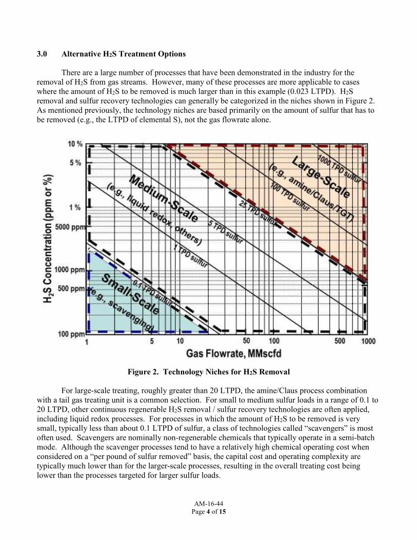
There are a large number of processes that have been demonstrated in the industry for the removal of H2S from gas streams. However, many of these processes are more applicable to cases where the amount of H2S to be removed is much larger than in this example (0.023 LTPD). H2S removal and sulfur recovery technologies can generally be categorized in the niches shown in Figure 2. As mentioned previously, the technology niches are based primarily on the amount of sulfur that has to be removed (e.g., the LTPD of elemental S), not the gas flowrate alone.
Figure 2. Technology Niches for H2S Removal
For large-scale treating, roughly greater than 20 LTPD, the amine/Claus process combination
with a tail gas treating unit is a common selection. For small to medium sulfur loads in a range of 0.1 to 20 LTPD, other continuous regenerable H2S removal / sulfur recovery technologies are often applied, including liquid redox processes. For processes in which the amount of H2S to be removed is very small, typically less than about 0.1 LTPD of sulfur, a class of technologies called “scavengers” is most often used. Scavengers are nominally non-regenerable chemicals that typically operate in a semi-batch mode. Although the scavenger processes tend to have a relatively high chemical operating cost when considered on a “per pound of sulfur removed” basis, the capital cost and operating complexity are typically much lower than for the larger-scale processes, resulting in the overall treating cost being lower than the processes targeted for larger sulfur loads.

AM-16-44
Page 5 of 15
The most promising technologies that were considered to remove the H2S from the example flare gas stream include: caustic treating, solid scavenging, and liquid scavenging. Each of these processes is discussed separately in greater detail. Other techniques that could be used, but which were not considered further due to unfavorable economic and/or operating conditions, are also presented. Finally, a table comparing the technologies is provided to summarize the options.
3.1 Caustic Treating
Sodium hydroxide (NaOH) solutions are often used to scrub H2S from gases for small-sulfur-load applications, although caustic treating is also sometimes applied to medium-scale applications, particularly when the product solution (NaSH) can be marketed. For cases where the caustic is not regenerated, caustic is a “scavenger.” The NaOH reacts with the H2S to form a liquid product with dissolved sodium bisulfide (NaSH) and/or sodium sulfide (Na2S) solutions. If CO2 is in the gas, it will also be scrubbed to form sodium bicarbonate (NaHCO3) and/or sodium carbonate (Na2CO3), which results in additional use of caustic and potential problems with carbonate salt precipitation. At moderate pH, NaSH and NaHCO3 are the predominant species while, at highly alkaline pH, Na2S and Na2CO3 will form.
Caustic scrubbing is done using a variety of equipment including: packed or trayed towers, sparged tanks, in-line contactors, Venturi contactors, or a combination of these devices. Caustic scrubbing can be implemented as a continuous process or in a semi-batch mode.
Caustic scrubbing applied as a continuous process can be designed to minimize the use of
caustic. In this mode of operation, the continuous caustic scrubbing tower is designed with two separate loops of recirculating caustic solution. Fresh caustic is fed to a top loop, which operates at a relatively high pH and serves as a polishing section to maximize H2S removal. Caustic overflows from the top section to the bottom section. The bulk of the H2S removal is done in the bottom recirculation loop which operates at lower pH. The continuous dual-loop system requires significant controls and relatively high capital cost. Although the dual-loop system offers low caustic consumption for H2S removal, it is not well suited for gas streams with a relatively large amount of CO2 relative to H2S (Mamrosh et. al., 2013; Mamrosh et. al., 2014).
Caustic scrubbing of H2S in a sparged tank or packed tower also results in the majority of the
CO2 in the feed gas being scrubbed. If the gas stream to be treated has large amounts of CO2 relative to the H2S, then the use of a “short-contact-time” contacting system can result in the absorption of the bulk of the H2S, while not absorbing most of the CO2. This concept takes advantage of the fact that H2S is absorbed more quickly than CO2 at high pH, and selective H2S removal can be achieved by limiting the contact between the gas and liquid in a static mixer, Venturi contactor, or other specialized contacting device. However, the complexity and relatively high capital cost of a continuous, short-contact-time system would not be warranted for this small sulfur load of only 0.023 LTPD (Mamrosh et. al., 2008; Mamrosh et. al. 2009).
Given the small sulfur load of this example flare gas application, it was assumed that the cost of using complex equipment to operate continuously would be greater than the savings realized by more efficiently utilizing the caustic. Therefore, the use of a simpler semi-batch scheme for caustic treating of the flare gas was chosen as the system that would likely have the lowest capital cost and operating complexity. A schematic of such a system, a sparged tank system, is shown in Figure 3. (Note: the
AM-16-44
Page 6 of 15
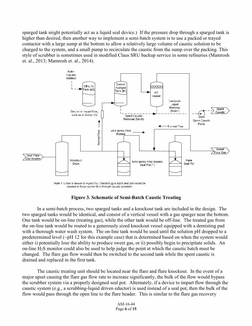
sparged tank might potentially act as a liquid seal device.) If the pressure drop through a sparged tank is higher than desired, then another way to implement a semi-batch system is to use a packed or trayed contactor with a large sump at the bottom to allow a relatively large volume of caustic solution to be charged to the system, and a small pump to recirculate the caustic from the sump over the packing. This style of scrubber is sometimes used in modified Claus SRU backup service in some refineries (Mamrosh et. al., 2013; Mamrosh et. al., 2014).
Figure 3. Schematic of Semi-Batch Caustic Treating
In a semi-batch process, two sparged tanks and a knockout tank are included in the design. The
two sparged tanks would be identical, and consist of a vertical vessel with a gas sparger near the bottom. One tank would be on-line (treating gas), while the other tank would be off-line. The treated gas from the on-line tank would be routed to a generously sized knockout vessel equipped with a demisting pad with a thorough water wash system. The on-line tank would be used until the solution pH dropped to a predetermined level (~pH 12 for this example case) that is determined based on when the system would either i) potentially lose the ability to produce sweet gas, or ii) possibly begin to precipitate solids. An on-line H2S monitor could also be used to help judge the point at which the caustic batch must be changed. The flare gas flow would then be switched to the second tank while the spent caustic is drained and replaced in the first tank.
The caustic treating unit should be located near the flare and flare knockout. In the event of a
major upset causing the flare gas flow rate to increase significantly, the bulk of the flow would bypass the scrubber system via a properly designed seal pot. Alternately, if a device to impart flow through the caustic system (e.g., a scrubbing-liquid driven eductor) is used instead of a seal pot, then the bulk of the flow would pass through the open line to the flare header. This is similar to the flare gas recovery
Norm
al F
low

AM-16-44
Page 7 of 15
compressor taking the normal flow, but allowing emergency flow from a major relief event to bypass to the flare. It may also be possible to use some other special device in place of the emergency-flow-bypass seal pot, for example a buckling-pin valve, rupture disk, or other highly reliable device.
The main advantage of caustic treating for this example flare gas application is that the chemical
costs are low, and, depending on the number of added features, the capital cost can be low. Even though a large portion of the caustic is wasted due to the co-absorption of CO2, the chemical cost is still reasonably low ($60,000/year) because caustic is an inexpensive chemical (cost: $500-1500/dry ton). A semi-batch-mode, sparged tank system is simple to operate with relatively modest capital expenses. Even though the caustic will need to be changed out approximately weekly, the change-out process is relatively easy. If the unit is operated properly and the caustic replaced when required, the spent solution should be a single-phase liquid that can be pumped to a waste collection system. Finally, fresh caustic (~20oBe would be used because it has the lowest freezing point of caustic solutions) can be easily added from a tank truck, a local tank, or from a refinery caustic supply line if available. The main disadvantage of using a semi-batch caustic treating for H2S removal is the waste of caustic due to nearly all of the CO2 scrubbing into solution. The caustic also cannot be fully utilized (e.g., it was not allowed to drop below ~pH 12 for this case) to avoid the precipitation of sodium bicarbonate salts, and avoid the breakthrough of H2S in the treated gas. The greater the ratio of CO2 to H2S in the feed gas, the greater the portion of caustic that will be wasted in scrubbing CO2 instead of H2S. Although the precipitation of salts should not occur under normal operating conditions, unusual conditions (such as very high CO2 to H2S ratios) or if the solution is not changed out when required, could result in salts formation. The formation of salts in the process can result in the plugging of the vessel and lines, which could lead to the need to shut down the system for a cleanout. Finally, the process produces a relatively large quantity (1.3 to 1.4 million pounds/ year) of poor-quality spent caustic solution (also referred to as NaSH solution, or sulfidic caustic) that needs to be disposed of either through reuse in an existing refinery caustic unit, sale to a third party, or as a waste stream. NaSH solution that has a low NaSH concentration and/or high Na2S and Na2CO3 concentrations is typically considered to be of low value. NaSH solutions containing a high concentration of NaSH (e.g., 25 – 40 wt%) and low levels of Na2S and Na2CO3 (e.g., less than a few percent each) can be valuable, marketable products, but the spent caustic that would be generated in this system would not meet the specifications usually required for outside sale.
If the disposal of this spent caustic as a waste material is required, it might be considered hazardous because of the high pH. Neutralization of the high pH by the addition of a strong acid may not be practical, because if this is done some of the H2S would be liberated from the spent caustic solution. More sophisticated caustic scrubber designs (e.g., the short-contact-time system mentioned previously) may be able to produce higher-quality product (high NaSH content with less Na2S and/or Na2CO3), and that high-quality product can often be sold.
3.2 Solid Scavenger Treating
A number of commercially available solid chemicals can be used as H2S scavenging agents (Fisher et. al. 1999). Several types of solid scavengers are based on the use of iron oxide (Fe2O3) to react with H2S in the presence of water to form iron-sulfur compounds and water. The iron oxide is a granular solid or a solid mixture on an inert substrate such as clay. Sufficient residence time of the gas with the scavenger solid is required to ensure that the H2S can be removed to ppm levels.

AM-16-44
Page 8 of 15
Other solid materials can also be used for H2S scavenging. These include solid scavengers containing potassium permanganate and copper or zinc oxides. Generally, solid scavengers that are not based on iron oxide are more expensive than the iron-oxide-based materials. Most iron oxide based scavengers require that some water be present in the feed gas stream in order to function at their full capacity. When dry gas streams are being treated (and water cannot be added), capacity can be greatly reduced, or more expensive mixed metal oxide scavenger products may be required. One of the older solid scavengers is iron sponge, which is made by depositing iron oxide on wood chips. It is an inexpensive product, but the spent material can be difficult to handle because it can be pyrophoric and must be kept wet after removal. Exposure of the spent material to oxygen results in exothermic side reactions that can cause the substrate to catch fire. Iron-oxide-based scavengers that are not pyrophoric generally use a non-flammable substrate material. These materials are not classified as pyrophoric but can still get hot when removed from service, so it is generally recommended to remove them wet to reduce thermal hazards.
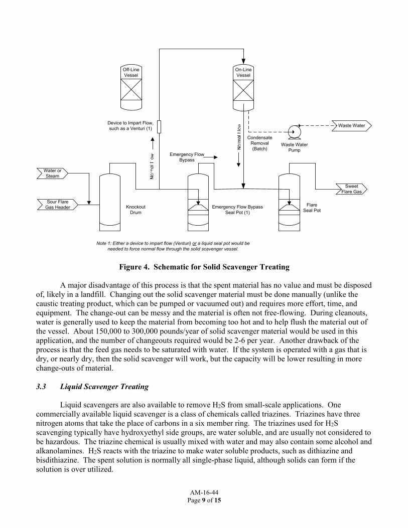
A system using non-pyrophoric iron oxides was considered for this example refinery flare gas application. A schematic diagram is shown in Figure 4. Two vessels are used in this process. One vessel would be on-line treating gas. The off-line vessel would be available for changing out the spent adsorbent, and then serve as a spare for the vessel in service. Water or steam is required to saturate the gas stream to increase the lifetime of the adsorbent. This can be done with a direct steam injection into the line or by adding a recirculating water spray. Because the flare gas flow rate could vary, control of the steam rate might be difficult and require significant instrumentation; a water spray could be simpler and less expensive. A pump could be used to transfer the water / condensate from these vessels. A seal pot, Venturi/ejector, or other special device (buckling pin, rupture disk, and/or relief valve) could be used to bypass the process during major flow events. It may also be necessary to monitor the treated gas H2S or another surrogate parameter to demonstrate removal.
The main advantages of using solid scavenger technology are that the process has been used in
industry for a number of years, is considered to be reliable, and the process is also simple since it requires just a single bed on line and one off line with minimal control requirements. As a result, the capital cost for the process is relatively low. The pressure drop through the system can be designed to be less than 1 psi. It is also possible to design the solid scavenging system to have a long time between changeouts (e.g., up to 8 months at one known refinery fuel gas application). Based on the sulfur load for this example flare gas stream and the assumed vessel sizes, the solid scavenger material would only need to be changed out every 70 to 180 days. This would result in a replacement cost ranging from $50,000 to $150,000/year depending on the specific product chosen. The spent product can usually be disposed of as a non-hazardous solid waste. Lastly, the effectiveness of solid scavengers is mostly independent of gas flow rate (below the design flow rate); therefore, there are typically few problems with turndown.
AM-16-44
Page 9 of 15
Figure 4. Schematic for Solid Scavenger Treating
A major disadvantage of this process is that the spent material has no value and must be disposed of, likely in a landfill. Changing out the solid scavenger material must be done manually (unlike the caustic treating product, which can be pumped or vacuumed out) and requires more effort, time, and equipment. The change-out can be messy and the material is often not free-flowing. During cleanouts, water is generally used to keep the material from becoming too hot and to help flush the material out of the vessel. About 150,000 to 300,000 pounds/year of solid scavenger material would be used in this application, and the number of changeouts required would be 2-6 per year. Another drawback of the process is that the feed gas needs to be saturated with water. If the system is operated with a gas that is dry, or nearly dry, then the solid scavenger will work, but the capacity will be lower resulting in more change-outs of material.
3.3 Liquid Scavenger Treating
Liquid scavengers are also available to remove H2S from small-scale applications. One commercially available liquid scavenger is a class of chemicals called triazines. Triazines have three nitrogen atoms that take the place of carbons in a six member ring. The triazines used for H2S scavenging typically have hydroxyethyl side groups, are water soluble, and are usually not considered to be hazardous. The triazine chemical is usually mixed with water and may also contain some alcohol and alkanolamines. H2S reacts with the triazine to make water soluble products, such as dithiazine and bisdithiazine. The spent solution is normally all single-phase liquid, although solids can form if the solution is over utilized.
On-Line
Vessel
Sour Flare
Gas Header
Sweet
Flare Gas
Off-Line
Vessel
Water or
Steam
Waste Water
Pump
Waste Water
Condensate
Removal
(Batch)
Knockout
Drum
Emergency Flow Bypass
Seal Pot (1)
Flare
Seal Pot
Device to Impart Flow,
such as a Venturi (1)
Emergency Flow
Bypass
Note 1: Either a device to impart flow (Venturi) or a liquid seal pot would be
needed to force normal flow through the solid scavenger vessel.

AM-16-44
Page 10 of 15
Triazine is frequently used in the natural gas production and treatment industries to remove small amounts of H2S to pipeline specification (< 4ppm). It is also practiced in the refinery setting, although it is not as common. Some refiners have been known to use direct injection scavenging (see Figure 5) on flare gas to temporarily remove H2S so as to lower the SOx emissions from a flare; the applications that the authors know of do not achieve deep H2S removal, although deep removal is possible in a properly designed system.
Figure 5. Schematic of Direct Injection H2S Scavenging
In direct injection, the process is fairly simple since the equipment consists of only a chemical injection pump, a means of introducing the scavenger into the sour gas pipeline, a length of pipe to allow for gas/liquid contact, and a downstream device for separating spent or excess scavenging agent from the treated gas. The amount of gas/liquid contact time is dependent on the type of contacting device, the gas velocity, and residence time. Because of this, the degree of mixing and efficiency is sensitive to changes in gas flow (Fisher et. al., 2003; Fisher et. al. 2005; Jamal et. al. 2009; Leppin et. al. 2009). Direct injection scavenging typically has a low capital cost; however, initial calculations showed that long pipe lengths would be required to reduce the H2S in this example refinery flare gas to the required 60 ppmv level.
If not enough pipe length is available, then a sparged tower could be used instead to meet the
treatment specification. With a reasonable liquid level above the sparger and an efficient sparger design, the pressure drop requirement of 5 psi could also be met. Because of this, a semi-batch process similar to that for semi-batch caustic treating could be implemented (see Figure 6). Storage for the fresh and spent triazine would be required. An H2S monitoring device or other surrogate method may be necessary to demonstrate removal.
Although the capital costs for using triazine scavenger in a semi-batch mode would be low, the
chemical costs for replacing the spent triazine would be significantly higher than the other H2S treating options considered in this study. Based on a typical cost of triazine, the annual chemical cost for

AM-16-44
Page 11 of 15
treating this example flare gas application would be $300,000 to $325,000/year, which is 3 to 5 times higher on average than the other options (caustic and iron oxide scavengers). About 750,000 to 800,000 pounds of spent triazine solution would need to be disposed of per year.
Figure 6. Schematic of Liquid Scavenger Treating (Batch Mode)
Other liquid scavenging materials that may be commercially available include sodium nitrite,
bleach, and peroxide. Sodium nitrite solution has significant historical use in H2S scavenging; its use results in the formation of solid elemental sulfur, so the spent solution is a slurry.
Bleach scavenging is usually done in a continuous mode of operation in a packed tower with the
addition of fresh makeup chemicals. Bleach consists of an aqueous solution of sodium hypochlorite; sometimes excess caustic is used to maintain the solution alkalinity and enhance the absorption of H2S. Bleach scrubbing oxidizes the H2S to sulfates (Na2SO4). It is not known if bleach scrubbing can be done in a simple sparged vessel, plus the high cost of bleach would result in treatment costs that are approximately 2-5 times that of caustic or iron oxide-based scavenging.
3.4 Other Techniques
Other technologies exist that could be used to remove H2S from flare gas streams. Contacting the flare gas stream with amine solution is one example. At the given sulfur load, installing a dedicated
On-Line
Vessel
Sour Flare
Gas Header
Sweet
Flare Gas
KO
Vessel
Batch
Triazine
Addition
Spent
Triazine
Removal
(Batch)
Carryover
Liquid
Removal
(Batch)
Off-Line
Vessel
Triazine Tank
Spent
Triazine Pump
Triazine
Feed Pump
Spent
Triazine
Storage
Knockout
Drum
Emergency Flow Bypass
Seal Pot (1)
Flare
Seal Pot
Device to Impart Flow,
such as a Venturi (1)
Emergency Flow
Bypass
Note 1: Either a device to impart flow (Venturi) or a liquid seal pot would needed
to force normal flow through the liquid scavenger vessel.

AM-16-44
Page 12 of 15
continuous operating amine unit would likely have a very high relative capital cost. However, if the refinery had an existing amine system it might be possible to tie into that system. A small portion of the amine could be drawn from the main lean-amine line and used in a conventional tray or packed column to remove the H2S from the flare gas. The rich amine would then be routed back to the main rich amine line in the amine plant. Some key items to consider with using this method are whether the lean amine is lean enough to remove the H2S at the flare gas stream operating temperature and pressure, with the low pressure being particularly significant. The amine contacting tower would need to be designed to handle fluctuations in the flare gas flow rate and/or have an effective bypass system, like some of the designs shown previously. Also, the composition of the flare gas stream would need to be considered as oxygen and other contaminants can significantly degrade the amine solution and cause amine-system corrosion (Jones et.al, 2010), and potentially also limit the amount of H2S that can be removed from the system. The removal of H2S from gases using redox chemistry is well known and widely practiced in industry. Typically, a water soluble metal or a water soluble metal-chelate is reacted with the H2S to form elemental sulfur. The elemental sulfur is filtered from the solution and the metal is regenerated to its reactive state using oxygen (air). These processes are typically used for sulfur loads above those associated with H2S scavenging, and below that associated with the use of amine/Claus (0.1 to 20 LTPD). Redox processes are typically designed as continuous processes, with H2S removed from the gas in one unit operation, and the solution regenerated in another. However, if the gas stream to be treated contains a substantial amount of oxygen, the H2S removal and solution regeneration can be done in one vessel; this may improve the economic viability of the redox processes into the lower sulfur load region. A batch liquid redox process was examined for this example case, since the flare gas stream has enough oxygen to meet the stoichiometric oxygen requirement of the reaction (1/2 mol O2 per mole H2S). However, there is not a significant amount of excess O2 in the gas. The low O2 to H2S ratio is lower than typical and may have kinetic or equilibrium limitations to the system that would constrain regeneration of the solution. For this reason, a batch redox process was not considered to be a candidate technology for H2S removal from the example refinery flare gas stream.
3.5 Overall Comparison of H2S Treating Technologies and Flare Gas Recovery
A comparison of the key alternative H2S treating technologies and the FGR option are presented
in Table 2 below. The comparison provides an indication of estimated capital and/or operating expenses as well as other intangibles, such as material handling and treatment limitations, which should be taken into consideration when evaluating and selecting an appropriate technology. All of the H2S treating technologies are operating in simple batch mode for this low sulfur tonnage application.
As shown in the table, the solid scavenger technology had the lowest capital cost estimate of the
H2S treating technologies and the flare gas recovery system. The chemical costs estimated for this process are on average 50% higher than the least expensive option (caustic treating). The solid scavengers produced the least amount of waste compared to the other H2S treatment processes. The main disadvantage to the solid scavengers is that the changeouts, although less frequent than the other

AM-16-44
Page 13 of 15
Table 2. Comparison of H2S Treating Technologies and Flare Gas Recovery for an Example 0.023 LTPD Flare Gas Stream
Process Advantages Disadvantages Pressure
Drop, psi
Changeout
Rate
(days)
Waste
Produced
(K lb/yr)
Chemical
Costs
($K/yr)
Relative
Capital ($)
Solid Scavenger
-- Established in industry for other low-pressure gases -- Selective to H2S adsorption -- Low pressure drop -- Least frequent changeouts -- Waste solid usually not hazardous
-- Changeouts considered by some operators to be time consuming and difficult -- Steam or water injection needed if flare gas is dry
1 70-180 150-300 50-150 1
Liquid Scavenger
-- Simple process -- Selective to H2S adsorption -- Spent liquid typically a single aqueous phase -- Cleanout / turnaround easy
-- High chemical costs -- Precipitation possible if over-spend scavenger -- Pressure drop limit pushed -- Odor with spent solution -- May not be possible to put waste to sewer
5 14 750-800 300-325 --
Caustic
-- Established in industry for other low-pressure gases -- Simple process -- Caustic is inexpensive -- Changeouts / turnaround easy -- Spent caustic may be reusable at other refinery caustic scrubbers
-- CO2 also scrubbed, wasting caustic -- Chance for salts to form if mis-operated -- Spent caustic waste can be considered hazardous -- High waste volume -- Solid elemental sulfur formation possible due to presence of O2
5 7 1300-1400 30-100 1.5
Flare Gas Recovery
-- Established in industry -- Lower flare emissions -- Lower fuel gas costs -- Lower flare maintenance -- Familiarity to refinery staff -- No chemical usage required -- No spent chemicals to dispose of
-- High capital cost -- Long lines may be necessary to send recovered gas and liquid to destination na na na na1 3
Notes: 1) The table does not include the operating costs (which can be high given the power for compression) and the value of the recovered fuel for the FGR option. 2) K = 1000

AM-16-44
Page 14 of 15
options, are considered by some operators to be rather messy and time intensive compared to the other treating options; saturation of the feed gas with water is also required, if low chemical costs are desired. The liquid scavenger process had significantly higher chemical costs (3-5 times greater on average) than the other two H2S treatment options. It also did not appear to provide any clear advantages in capital cost, complexity or reliability. It would probably be more competitive for cases where direct injection into an existing pipeline would be sufficient for reaching the desired H2S removal efficiency, which would result in a relatively low capital cost. Caustic treating had the lowest chemical costs of the technologies considered, but the capital costs for the process were about 50% higher than with solid scavenging. The higher capital costs may be a result of the need for a higher complexity of controls (e.g., pH probes, differential pressures, and level) and special material of construction due to potential corrosion issues with the caustic. Caustic treating produces a significant amount of spent caustic that must be disposed of, or potentially reused at the refinery if other caustic units are operated on site. Disposal costs are not included in the table. The alternative H2S treating options appear economically competitive to the flare gas recovery system for this low sulfur tonnage, example flare gas case. The capital expense for the FGR process is about 3 times greater than the lowest alternative H2S treating option (solid scavenging). The FGR process requires costly compression, controls, and long pipe lengths to communicate the recovered gas and liquid streams to their final destination. Additional treatment of the sour liquid and recovered gas streams is still also required. The potential benefits are reduced emissions and fuel gas costs; some flare maintenance cost savings may be achieved as well.
4.0 Summary
Alternative H2S treatment options are economically and technically viable compared to flare gas recovery for the example considered in this paper. It is important to evaluate the technologies on a case-by-case basis because the feed gas conditions (e.g., sulfur loading, hydrocarbon content, impurities, flow rate, temperature, and pressure), treatment specification, and other parameters (e.g., pressure drop, upset conditions) can impact the technology selection. For this example, refinery flare gas stream, the sulfur tonnage is low (0.023 LTPD), making the capital costs of the alternative H2S treating technologies less because simple batch operation H2S scavengers can be used. The chemical costs for the H2S scavengers are reasonable given the associated savings in capital cost. The compressor, controls, long liquid and recovered gas pipelines, and potential effects on fuel gas treating systems make the FGR unit less economically competitive for this gas stream because of capital cost.
5.0 References
1) Baukal, C., The John Zink Hamworthy Combustion Handbook, Second Edition, Volume 3 –
Applications (Industrial Combustion), August 23, 2013. 2) Fisher, K.S., J.E. Lundeen, D. Leppin, “Fundamentals of H2S Scavenging for Treatment of
Natural Gas,” Proceedings of the Ninth GRI Sulfur Recovery Conference, San Antonio, Texas, October 24-27, 1999.
3) Fisher, K.S., D. Leppin, R. Palla, A. Jamal, “Process Engineering for Natural Gas Treatment using Direct-Injection H2S Scavengers”, GasTIPS, Spring 2003, Vol 9, Number 2, pp. 12-17.

AM-16-44
Page 15 of 15
4) Fisher, Kevin S., Aqil Jamal, Dennis Leppin, “Design of Direct-Injection H2S Scavenging Systems”, Paper presented at the 55th Annual Laurance Reid Gas Conditioning Conference, Norman, Oklahoma, 2005.
5) Jamal, Aqil, Dennis Leppin, and Kevin Fisher, “Application of Direct-Injection Scavenging to Treatment of Sour Storage Field Withdrawal Gas”, (Abstract Only), Proceedings of Natural Gas Technologies 2005 Conference, Orlando, Florida, 2005.
6) Jones, R.A., McIntush, K.E., Wallace, C.B., "Oxygen Removal in Natural Gas Systems", Gas Processors Association Research Report RR-201, GPA Research No: 073, 26 February 2010
7) Leppin, D., K. Fisher, and D. Matonis, “Modeling Direct Injection of H2S Scavenger in Pipelines: Laboratory Investigations and Improved Computer Model”, Presented at the 88th Annual GPA Convention, San Antonio, TX, March 8 – 11, 2009.
8) Mamrosh, D., C. Beitler, K. Fisher, S. Stem, “Consider improved scrubbing designs for acid gases”, Hydrocarbon Processing, January 2008, pp. 69-74.
9) Mamrosh, D.L., C.M. Beitler, K.E. McIntush, K.S. Fisher, and S. Stem, "Use of Caustic in a Short Contact Time Approach to Selectively Scrub H2S from CO2-Contaminated Gas Streams”, Proceedings of the 59th Laurance Reid Gas Conditioning Conference, 22 February to 25 February 2009, Norman, Oklahoma, USA, pp. 445-459.
10) Mamrosh, D.L., K.E. McIntush, K. Fisher, C.M. Beitler, “Caustic Scrubber Design for Refinery Fuel Gas, Sour Water Stripper Gas, and Other Refinery Applications”, presented at Laurance Reid Gas Conditioning Conference 2013, Norman, OK, February 2013.
11) Mamrosh, D.L., K.E. McIntush, K. Fisher, “Caustic Scrubber Designs for H2S Removal from Refinery Gas Streams”, 2014 AFPM Annual Meeting, AM-14-48, March 2014.