Altima Security Lighting NEW MASTER - Nissan-TechInfo
23
DESCRIPTION: Security Light Kit APPLICATION: Altima Coupe and Sedan PART NUMBER: 999F4 AX008 - Universal Security Lighting Kit. KIT CONTENTS: 5. TOOLS REQUIRED ● Trim stick ● Ratchet and 6" extension ● 8mm and 10mm sockets ● 3/8", 3/16" and 1/2" drill bits, drill, drill stops. ● #2 Philips screwdriver ● Short #2 Philips screwdriver ● Protective cloth ● Scissors, tape measure and metric scale ● Protective gloves ● Electrical tape, masking tape. ● Needle nose pliers 6. PRE-INSTALLATION CAUTION/NOTES ● Dealer installation recommended. Instructions may refer to Service Manual ● Installation may require special tools ● This part is to be installed within a surface temperature range of 70-100 ºF ● Remove and prepare templates located at the end of Installation Instructions CAUTION ● This accessory must only be installed as specified in these instructions. ● Ensure at all times that parts are securely fitted and will not compromise the safe function of vehicle systems. C 1 Misc parts kit - part No 999F4 AX040 999F4 AX040 B 2 1. 2. A 1 999F4 AX080 999F4 AX002 Control module - part No 999F4 AX080 LED Assembly - part No 999F4 AX002 Service Part Number Description 4. 3. Item QTY GENUINE PARTS INSTALLATION INSTRUCTIONS Page 1 of 21 999F4 AX008II Rev 04/16/2012
-
Upload
khangminh22 -
Category
Documents
-
view
0 -
download
0
Transcript of Altima Security Lighting NEW MASTER - Nissan-TechInfo

DESCRIPTION: Security Light KitAPPLICATION: Altima Coupe and SedanPART NUMBER: 999F4 AX008 - Universal Security Lighting Kit.
KIT CONTENTS:
5. TOOLS REQUIRED
● Trim stick ● Ratchet and 6" extension● 8mm and 10mm sockets ● 3/8", 3/16" and 1/2" drill bits, drill, drill stops. ● #2 Philips screwdriver ● Short #2 Philips screwdriver● Protective cloth ● Scissors, tape measure and metric scale● Protective gloves ● Electrical tape, masking tape. ● Needle nose pliers
6. PRE-INSTALLATION CAUTION/NOTES
● Dealer installation recommended. Instructions may refer to Service Manual● Installation may require special tools● This part is to be installed within a surface temperature range of 70-100ºF● Remove and prepare templates located at the end of Installation Instructions
CAUTION
● This accessory must only be installed as specified in these instructions.
● Ensure at all times that parts are securely fitted and will not compromise the safe function of vehicle systems.
C 1 Misc parts kit - part No 999F4 AX040 999F4 AX040B 2
1.2.
A 1 999F4 AX080999F4 AX002
Control module - part No 999F4 AX080LED Assembly - part No 999F4 AX002
Service Part NumberDescription
4.
3.
Item QTY
GENUINE PARTS
INSTALLATION INSTRUCTIONS
Page 1 of 21 999F4 AX008II Rev 04/16/2012

INSTALLATION OVERVIEW
8. CRITICAL STEPS
INSTALLATION INSTRUCTIONS - Security lighting Kit
7.
The following steps are critical and must be performed EXACTLY as specified to ensureproper installation:
- Location of the lights must be followed exactly as described in this instruction. - Posi-Tap™ instructions must be specifically followed as described. - Be sure to apply masking tape as needed in order to protect any areas that may become scratched or damaged by tools. - Be sure to apply foam tape to any wiring components that can be damaged over time by sharp edges. - Test the functionality of the kit before final clean up and reinstallation of interior panels.
Page 2 of 21 999F4 AX008II Rev 04/16/2012

9. VEHICLE PREPARATION:
1) Apply parking brake2) Confirm the vehicle is no longer in the default shipping state (Extended Storage Switch Pulled Up and BCM
in Transit Mode). Failure to confirm the vehicle has been removed from this state will result in the loss of normal vehicle operation. The confirmation requires two checks:2a) Locate the Extended Storage Switch 2b) Turn the ignition switch from "OFF" to "ON" position. If
in the cabin fuse block. Once located, turn indicators illuminate for approx. 1 minute, thecheck that it is in the "Customer" vehicle is in shipping mode. To exit shipping mode, position. See below for reference. return the ignition switch to "OFF" position.
Simultaneously push the wiper and turn signal stalks downward and hold for 2 seconds.
10. ORDER OF INSTALLATION
1. Remove panels and trim. 4. Route Wiring 7. Final Check Items2. Prepare mud guards 5. Install controller3. Install LED Assemblies 6. Replace all panels
INSTALLATION INSTRUCTIONS - Security Lighting Kit
Move driver and passenger seats to full back position. Disconnect negative battery terminal before proceeding.
3) Record customer radio presets.
NOTE: USE CAUTION WHEN REMOVING / RE-INSTALLING TRIM COMPONENTS TO AVOIDDAMAGE, SCRATCHES, BREAKING OF CLIPS AND / OR INTERIOR TRIM PANELS.MOVE ALL TRIM COMPONENTS TO A PROTECTED AREA.
WARNING
INVENTORY - UP CUSTOMER - DOWN
NOTE: Typical vehicle condition shown here. Switch is easily identifiable by the permanent, push-pull fuse holder.Actual position on the fuse block may vary, vehicle to vehicle.
Page 3 of 21 999F4 AX008II Rev 04/16/2012

11. INTERIOR PREPARATION
INSTALLATION INSTRUCTIONS - Security Lighting Kit
Fig. 1 1. Carefully remove the LH Instrument side mask by the driver's door.
2. Pull the fuse cover from the steering finisher.
3. Remove the black #2 philips screw from the left side of the fuse cavity.
Fig. 2
Fig. 3
Page 4 of 21 999F4 AX008II Rev 04/16/2012

11. INTERIOR PREPARATION
INSTALLATION INSTRUCTIONS - Security Lighting Kit
5. Carefully pry out the center footwell panel from the driver side center stack.
Repeat for passenger side.
Fig. 5
4. Carefully pull the steering finisher away from the instrument panel. Pull the panel down as far as the wire harness will allow and move it aside.
Fig. 4
6. Carefully remove the footwell trim by the door on the driver side.
Repeat for passenger side.
Fig. 6
Page 5 of 21 999F4 AX008II Rev 04/16/2012

11. INTERIOR PREPARATION
Verify all panels have been removed. They are:
LH RH1. The Steering finisher - panel under steering column.2. Footwell panels for driver and passenger - panels at the center stack.3. Footwell trim for driver and passenger - panels near each door.4. Front sill plate cover - covers the door seal welt next to each seat.5. LH Instrument Side Mask - the panel by the door.6. Driver side A-Pillar trim.
Note: Make sure all panels have been removed.
INSTALLATION INSTRUCTIONS - Security Lighting Kit
7. Remove the footwell trim along the door seal welt. Repeat for passenger side.
Fig. 7
8. Carefully pull back the driver side door seal welt to access the A-Pillar trim panel.
9. Carefully remove the driver side A-Pillar trim panel.
NOTE: There is a retaining clip that holds the trim panel to the A Pillar along with a number of press clips. Use a pair ofneedle nose pliers torelease the retainingclip and free the A Pillar trim panel.
Fig. 9
Fig. 8
Page 6 of 21 999F4 AX008II Rev 04/16/2012

12. VEHICLE PREPARATION
INSTALLATION INSTRUCTIONS - Security Lighting Kit
10. Raise Vehicle
11. Starting at the REAR edge of the mud guard, measure and mark 368mm (14.5 inches) from the rear edge of the guard.
Measure and mark 13mm (1/2 inch) from the inner edge of the mud guard.
Note: The Altima is best drilled with the mud guards on the vehicle. The following steps are performed from below looking up at the bottom of the mudguard.
Fig. 11
Fig. 13
12. Apply the drill guide tape by peeling the adhesive backing off the tape and aligning the first drill mark with the starting hole position as marked on the mud guard. Carefully apply the tape along the length of the mud guard. Be sure to keep the drill marks on the tape at 100mm from the inside edge of the mud guard.
Fig. 12
14. Using a 1/2 inch drill bit, drill all the marked hole locations. A step drill bit can be used as well. Be sure to stop at the 1/2 inch step in the tool.
Clean each hole so there is no flashing or shoulder from the drill.
13. If drill guide tape is not available, use a tape measure to mark three locations at 16 inches apart. These three hole locations are 13mm from the inside edge of the mud guard. You can also use the LED assembly to determine the location of each hole.
Repeat process for both mud guards.
NOTE: IF ANY CLIPS ARE DAMAGED OR LOST, CONTACT DEALER FOR PART 76882 EG01A TO REPLACE.
NOTE: STEPS 11 THROUGH 14 FOR ALTIMA SEDAN ONLY
Page 7 of 21 999F4 AX008II Rev 04/16/2012

12. VEHICLE PREPARATION
INSTALLATION INSTRUCTIONS - Security Lighting Kit
NOTE: STEPS 15 THROUGH 19 FOR ALTIMA COUPE ONLY
15. Raise Vehicle
16. Starting at the REAR edge of the mud guard, measure and mark 368mm (14.5 inches) from the rear edge of the guard.
Measure and mark 13mm (1/2 inch) from the inner edge of the mud guard.
NOTE: The Altima is best drilled with the mud guards on the vehicle. The following steps are performed from below looking up at the bottom of the mudguard.
Fig. 16
Fig. 18
17. Apply the drill guide tape by peeling the adhesive backing off the tape and aligning the first drill mark with the starting hole position as marked on the mud guard. Carefully apply the tape along the length of the mud guard. Be sure to keep the drill marks on the tape at 100mm from the inside edge of the mud guard.
Fig. 17
19. Using a 1/2 inch drill bit, drill all the marked hole locations. A step drill bit can be used as well. Be sure to stop at the 1/2 inch step in the tool.
Clean each hole so there is no flashing or shoulder from the drill.
18. If drill guide tape is not available, use a tape measure to mark three locations at 16 inches apart. These three hole locations are 13mm from the inside edge of the mud guard. You can also use the LED assembly to determine the location of each hole.
Repeat process for both mud guards.
NOTE: IF ANY CLIPS ARE DAMAGED OR LOST, CONTACT DEALER FOR PART 76882 EG01A TO REPLACE.
Page 8 of 21 999F4 AX008II Rev 04/16/2012

12. VEHICLE PREPARATION
INSTALLATION INSTRUCTIONS - Security Lighting Kit
20. Clean the inside surface of the mud guard where the LED modules and the retaining tape will be mounted with soap and water. Dry the surfaces, then wipe with an alcohol prep pad(s) as shown. Wipe both mud guards.
Allow the alcohol to dry completely.
Note: Be sure installation temperature is within a range of 70-100ºF
Fig. 20
Fig. 21
Fig. 22
21. Starting at the NON-wire end (rear), remove the adhesive liner from the first LED module. Carefully place the lens of the LED into the hole, being sure to align the module straight and parallel with the edge of the mudguard. Press down firmly to adhere the module to the mud guard.
22. Repeat step 13 with the remaining three (3) LED modules. Be sure the wiring between the modules does not become twisted as you are installing them to the mud guard.
Once all the LED modules are in place, secure the wiring in between with one (1) piece of retaining tape as shown.
Note: Once the tape is down, it is very hard to pull back up.
Repeat process for both mud guards.
Page 9 of 21 999F4 AX008II Rev 04/16/2012

12. VEHICLE PREPARATION
INSTALLATION INSTRUCTIONS - Security Lighting Kit
23. Remove the plastic/rubber plug under the vehicle close to the front doors.
Note: This will be the pass through for the wires that control the LED assembly.
25. Carefully pry open three (3) plastic wire harness clips from inside driver side door sill. Carefully pull back carpet edge.
Fig. 23
Fig. 24
Fig. 25
24. From below the vehicle, feed one (1) rubber seal and the protective flex tubing provided in the kit over the wire extending from the front LED module. Note: Be sure the beveled side of the seal is facing away from the LED module.
Lower the vehicle.
13. INSTALLATION
Page 10 of 21 999F4 AX008II Rev 04/16/2012

13. INSTALLATION
INSTALLATION INSTRUCTIONS - Security Lighting Kit
26. Carefully peel back metallic tape to expose the access hole on the inside edge of the door sill.
Fig. 26
27. Next, feed the wires through the end of a long cable tie. Use the cable tie to route the wires through the hole in the bottom of the vehicle and up through the access hole inside the door sill.
Fig. 28 28. From below the vehicle, feed the flex tubing through both access holes. Slide another rubber seal provided in the kit over the wires and the flex tubing from inside the vehicle.
Note: The flex tubing is meant to pass through the rubber seals along with the wiring.
Raise the vehicle.
Fig. 27
Page 11 of 21 999F4 AX008II Rev 04/16/2012

13. INSTALLATION
INSTALLATION INSTRUCTIONS - Security Lighting Kit
29. Press the lower rubber seal into position. Apply a butyl sealant around the flex tubing where it passes through the rubber seal and at the other end around the wires. Locate the support leg from the mud guard to the vehicle close to the bottom seal.
Drill a 3/16 inch hole midway between the guard and the vehicle.
Use a 4 inch cable tie to secure the wires to the support leg.
Lower the vehicle.
Fig. 29
31. Feed the wires from the driver side LEDS through a section of flex tubing to protect the wires under the dash. Route the wires from the driver side to the fuse panel by running the wires up the harness and securing with cable ties.
Note: Recommended spacing for cable ties is 100mm to 120mm. Position cable ties as shown.
Fig. 30
Fig. 31a
30. Allow approx 3" of flex tubing over the wires on the inside of the vehicle. Press the inside rubber seal into position. Wrap electrical tape around the open end of the flex tubing.
Note: Make sure both seals, top and bottom, are properly installed.
Repeat procedure for passenger side of vehicle.
Fig. 31b
Page 12 of 21 999F4 AX008II Rev 04/16/2012

13. INSTALLATION
INSTALLATION INSTRUCTIONS - Security Lighting Kit
33. Route the wires from the passenger side to the fuse panel by running the wires up the harness to the carpet backer, across the backer to the center stack. Feed the wires through the center stack so they come out under the instrument cluster and across to the fuse panel. Secure with cable ties.
Fig. 32 32. Feed the wires from the passenger side LEDS through a section of flex tubing to protect the wires under the dash.
Fig. 33
Fig. 34 34. Carefully pull down the carpet backer, tuck the wiring behind and secure with foam tape. Press the carpet backer back into position.
Page 13 of 21 999F4 AX008II Rev 04/16/2012

13. INSTALLATION
INSTALLATION INSTRUCTIONS - Security Lighting Kit
Note: There should now be four (4) wires from the LED assemblies near the fuse block.
Pull the wires from the LED strips to the driver door handle. Use wire cutters to shorten the wires to a manageable length.
36. Reinstall the harness clips, both sides.
37. Reinstall the footwell trim, both sides.
38. Reinstall the footwell panels on both sides of the center stack.
35. Use cable ties and foam tape as shown to secure wiring under the instrument panel.
Fig. 35
Page 14 of 21 999F4 AX008II Rev 04/16/2012

14. POSI TAP INSTRUCTION
INSTALLATION INSTRUCTIONS - Security Lighting Kit
a)
b)
i. Straight and evenly spaced all the way aroundii. Tight and minimize gap (wire jacket should be crushed)
e) Insert wire to here
c)
d)
f) Tighten
a)
Fig. 3
i. Straight and evenly spaced all aroundii. Tight and no gap and test the signal
Fig. 4
Fig. 1
Fig. 2
1) Tap vehicle wire. a) Remove grey cap (slot side) from tap body. b) Slide cap around vehicle wire. c) Tighten the tap TIGHT with finger pressure.
4) Confirm the tapped accessory wire.
a) Inspect the tap to ensure correct installation. b) Test the signal to ensure that it is working properly.
Note: Do not re-use the tap for subsequent re-installation. Figures are not to scale.
2) Inspect the tap to ensure correct installation.
Note: Avoid putting pressure on the vehicle wire and tap for the remainder of the installation.
3) Tap accessory wire.
a) Remove red cap (non-pierce) side from tap. b) Remove the protective stub from the wire. c) Insert wire through the non-pierce side opening. d) Spread the individual strands into fan shape. e) Insert wire into the tap body and ensure that it is all the way in. f) Tighten the tap TIGHT with finger pressure.
Note: Identify and confirm (test if necessary) the correct vehicle wire to be tapped.
Grey Cap
Red C ap
Page 15 of 21 999F4 AX008II Rev 04/16/2012

14. POSI TAP INSTRUCTION
15. INSTALLATION
CAUTION
● Color(s) given in illustration(s) are for reference only. Use location(s) where color deviates.● If a vehicle wire is being used by another accessory and a posi-Tap is present, tap
the accessory wire NOT the vehicle wire.
INSTALLATION INSTRUCTIONS - Security Lighting Kit
5) Secure the tap.
a) Secure the tapped wire on the non-pierce side to the body of the tap with electrical tape (≥ 2 revolutions). b) Secure the body to harness where vehicle wire is being tapped with electrical tape (≥ 2 revolutions).
Fig. 5Vehicle Harness
Accessory harness..
.b) a)
39. There are two (2) connectors in the A Pillar. One will have 16 cavities.
Disconnect the upper or top part of the connector going up the pillar.
Locate the second and third cavity positions containing White wires LG01 and LG02.
40. Locate the Purple and White wires on the Security Lighting Controller. Push the ends of both wires through the end of a 15 inch cable tie and use the tie to direct the wires up through the dash to the A Pillar.
Fig. 39
Fig. 40
AS VIEWED FROM THE HARNESS SIDE
Page 16 of 21 999F4 AX008II Rev 04/16/2012

15. INSTALLATION
INSTALLATION INSTRUCTIONS - Security Lighting Kit
Using the diagram shown here, verify that the second wire over LG02 is tapped with the White Accessory wire and the thirdwire over LG01 is tapped with the PurpleAccessory wire.
42. Reinstall the door seal welt. Do not pinch the welt by the Instrument panel.
43. Reinstall the A Pillar trim panel. Make sure the retaining clip is pushed into the opening.
41. Use a Posi-tap and instructions to connect the White Accessory wire from the Controller to the White vehicle wire, LG02 and the Purple Accessory wire from the Controller to the White vehicle wire, LG01 at the A Pillar.
Fig. 41
44. Locate the fuse panel to the left of the steering column. Identify the connector with both a Violet/Yellow AND White/Blue wire in it. They will be located near each other.
Note: There are FIVE wires in the power harness for this kit. They are: White - Room Lamp input Purple - Battery Saver Green - Ignition input Black - Ground Orange - LEDs output
Fig. 44
AS VIEWED FROM THE HARNESS SIDE
Page 17 of 21 999F4 AX008II Rev 04/16/2012

15. INSTALLATION
INSTALLATION INSTRUCTIONS - Security Lighting Kit
Note: Test the LED strips before you continue by touching the Red wire to a 12V source on the vehicle. The LEDs should illuminate.
46. Route the four wires from the two LED strip to the area just above the fuse block. Add 150mm and cut the excess. Use a posi-tap to connect the Red wire from one LED strip to the other Red wire from the other LED strip.
45. Use a Posi-tap and instructions to connect the Green Accessory wire from the accent lighting power harness to the Violet/Yellow vehicle wire at the fuse panel connector. This is location MA03.
Fig. 45
47. Use a posi-tap to connect the Orange Accessory wire from the control module to the outer end of the Red wire from the LED strip. Leave a short length of wire extended past the posi-tap and bend down as shown. Use electrical tape to secure the red wire against the posi-tap with at least two revolutions.
Note: Make sure that the end of the Red wire is completely covered by the tape.
Fig. 47
AS VIEWED FROM THE HARNESS SIDE
Page 18 of 21 999F4 AX008II Rev 04/16/2012

15. INSTALLATION
INSTALLATION INSTRUCTIONS - Security Lighting Kit
50. Bundle the excess Controller module and Accessory wires. Secure wiring with two (2) cable ties. Wrap the Controller Module with foam tape to protect from sharp edges.
Note: Trim all cable ties.
Over all - this is how the controller needs to be connected: a. White (Room Lamp) from controller goes to LG02; a White (#2 slot) wire in the A-Pillar. b. Purple (Batt. Saver) from controller goes to LG01; a White (#3 slot) wire in the A-Pillar. c. Green from controller goes to MA03, a Violet/Yellow wire above the fuses. d. Black from controller goes to ground; a small bolt to the upper right of the fuse block. e. Orange from controller goes to the Red wire of the LEDs.
49. Use an 8mm nut driver or equivalent to remove the bolt on the upper right corner of the fuse panel. Secure the eyelet to the 8mm bolt. Reinstall bolt and tighten. See Fig. 50 for reference.
Note: If other accessories share the 8mm ground bolt, eyelets should be spaced 30 degrees apart.
Reconnect the negative battery terminal at this time.
48. Use a Posi-Tap to connect one Black Accessory ground wire to the second Black Accessory ground wire. Use a Posi-tap to connect the second Black Accessory ground wire to the Black wire of the controller module.
Fig. 50
Page 19 of 21 999F4 AX008II Rev 04/16/2012

15. INSTALLATION
INSTALLATION INSTRUCTIONS - Security Lighting Kit
51. Wrap more foam tape around the wire bundles and the Controller Module to secure them together and protect from sharp edges.
Use a cable tie to secure the wrapped Controller Module to the existing wire harness. Be sure not to block the fuse panel.
Fig. 51
Note: Trim all cable ties. Check all wiring. Make sure all trim is in place.
52. Wrap a piece of grey foam tape over the corner of the I-key box inside the steering finisher as shown.
53. Reinstall the steering finisher.
Reinstall the LH Instrument Side Mask.
Reinstall the kick plates.
Fig. 52
Page 20 of 21 999F4 AX008II Rev 04/16/2012

16. CHECK OUT
INSTALLATION INSTRUCTIONS - Security Lighting Kit
Inspect the vehicle for unfinished work.
(1) Close all doors.
(2) Using the keyless entry fob, press the door unlock.
(3) Verify the security lighting turns on and off with the dome lamp in the car.
(4) Enter the car and press the door unlock and then start the car.
(5) Verify the security lamps turn off when the car starts.
(6) With the car running, shifter in park, open the door and Verify the lights remain off.
(7) Turn off the car and open the door again and verify the lights come on when the door is opened.
(8) Unlock the doors, wait and then lock the doors. The Security lighting should turn off quickly with the doom lamp.
(9) Verify the functionality of all electrical vehicle components where harnesses were accessed.
(10) Check and clear trouble codes (DTC).
(11) Check power window auto-up control. If it is not functioning properly, hold switch in "up" position for 5 seconds.
Page 21 of 21 999F4 AX008II Rev 04/16/2012

17. BILL OF MATERIALS
Misc. parts kit
15 Installation Instructions (Web) N/A 999F4 AX008II
14 Butyl gum 1
13 Corrugated flex tube 4
12 Rubber grommet 4 28956 EA000
11 Grey foam rectangle 80mm x 30mm x 5mm - Adhesive one side 9
10 Cable tie 11" - Black 3
9 Replacement template 1 999V2 AW000
8 Alcohol preparation wipe 4
7 Drilling template strip 2
6 Cable tie 4" - Black 12
5 Posi-tap connector - Red / Grey 7 999M1 VT000
4 Wire retaining rectangle 40mm x 20mm - Adhesive one side 8
3 1 999F4 AX040
2 LED Strip (within polythene bag) 2 999F4 AX002
1 Control module (within polythene bag) 1 999F4 AX080
INSTALLATION INSTRUCTIONS - Security Lighting Kit
Nissan Security Lighting Kit - 999F4 AX008
Parts Contained in Bag Labelled 'Installation Kit'. Qty Part Number
BOM 999F4 AX008II Rev 04/16/2012
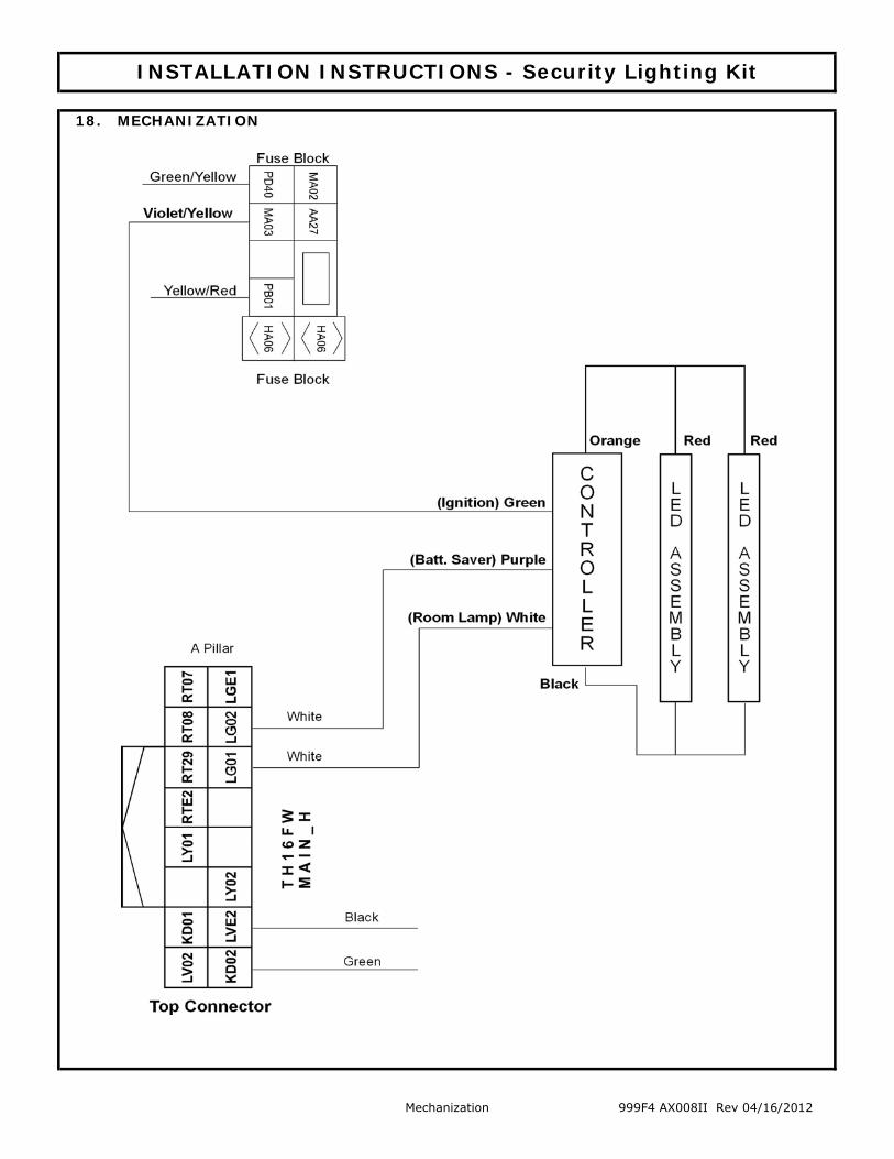
18. MECHANIZATION
INSTALLATION INSTRUCTIONS - Security Lighting Kit
Mechanization 999F4 AX008II Rev 04/16/2012