Algorithm manual - ECA Sites
122
Algorithm manual English
-
Upload
khangminh22 -
Category
Documents
-
view
0 -
download
0
Transcript of Algorithm manual - ECA Sites

Algorithm manualEnglish


3
Table Of Contents . . . . . . . . . . . . . . . . . . . . . . . . . . . . .3Introduction . . . . . . . . . . . . . . . . . . . . . . . . . . . . . . . . . .4Reverb Introduction . . . . . . . . . . . . . . . . . . . . . . . . . . . .5VSS™3 . . . . . . . . . . . . . . . . . . . . . . . . . . . . . . . . . . . . .7VSS™SR (Surround) . . . . . . . . . . . . . . . . . . . . . . . . .10Nonlin-2 . . . . . . . . . . . . . . . . . . . . . . . . . . . . . . . . . . . .19DVR-2 . . . . . . . . . . . . . . . . . . . . . . . . . . . . . . . . . . . . .21VSS™ 5.1 - Source . . . . . . . . . . . . . . . . . . . . . . . . . .23VSS™ 6.1 - Reverb . . . . . . . . . . . . . . . . . . . . . . . . . .27Reverb - 2 . . . . . . . . . . . . . . . . . . . . . . . . . . . . . . . . . .32Reverb - 3 . . . . . . . . . . . . . . . . . . . . . . . . . . . . . . . . . .34Rev Core - 2 . . . . . . . . . . . . . . . . . . . . . . . . . . . . . . . .36MD-3 . . . . . . . . . . . . . . . . . . . . . . . . . . . . . . . . . . . . .38MD-4 . . . . . . . . . . . . . . . . . . . . . . . . . . . . . . . . . . . . . .45MDX 5.1 . . . . . . . . . . . . . . . . . . . . . . . . . . . . . . . . . . .51MD 5.1 . . . . . . . . . . . . . . . . . . . . . . . . . . . . . . . . . . . .58Brickwall 2 . . . . . . . . . . . . . . . . . . . . . . . . . . . . . . . . . .64Toolbox - 5.1 . . . . . . . . . . . . . . . . . . . . . . . . . . . . . . . .68Spacepan 5.1 . . . . . . . . . . . . . . . . . . . . . . . . . . . . . . .72Engage . . . . . . . . . . . . . . . . . . . . . . . . . . . . . . . . . . . .73Unwrap HD . . . . . . . . . . . . . . . . . . . . . . . . . . . . . . . . .75De-Esser . . . . . . . . . . . . . . . . . . . . . . . . . . . . . . . . . . .81EQ - 5.1 . . . . . . . . . . . . . . . . . . . . . . . . . . . . . . . . . . .83Massenburg EQ . . . . . . . . . . . . . . . . . . . . . . . . . . . . .86VP-2 Stereo . . . . . . . . . . . . . . . . . . . . . . . . . . . . . . . .89VP-8 . . . . . . . . . . . . . . . . . . . . . . . . . . . . . . . . . . . . . .91Chorus - 1 . . . . . . . . . . . . . . . . . . . . . . . . . . . . . . . . . .93Phaser - 1 . . . . . . . . . . . . . . . . . . . . . . . . . . . . . . . . . .94Delay - 1 . . . . . . . . . . . . . . . . . . . . . . . . . . . . . . . . . . .95Delay - 2 . . . . . . . . . . . . . . . . . . . . . . . . . . . . . . . . . . .96Reflector 6 & Reflector LCR . . . . . . . . . . . . . . . . . . . .98Backdrop . . . . . . . . . . . . . . . . . . . . . . . . . . . . . . . . . .102Backdrop - Tutorial . . . . . . . . . . . . . . . . . . . . . . . . . .106LM5D . . . . . . . . . . . . . . . . . . . . . . . . . . . . . . . . . . . .109Matrix 88 . . . . . . . . . . . . . . . . . . . . . . . . . . . . . . . . . .118
TABLE OF CONTENTS
Prod No: 606147011 - Rev 1
Please note: We reserve the rights to change the contentsof this manual at any time. The latest manual revision canalways be downloaded from www.tcelectronic.com. If youneed additional information and support, be sure to visit theTC Support Portal: www.tcelectronic.com/support

4
INTRODUCTION
System 6000 contains a wealth of algorithms, and the listof algorithms will continuously be extended. Our mainfocus is to offer the best possible quality - both as stereo-and multi-channel versions.
Mainframe 6000 holds• One Scene Factory preset bank with up to 50 presets• One Routing Factory preset bank with up to 50 presets• Up to 14 Engine Factory preset banks with up to 99
presets each.
Bank Bank Name Algorithms used
F1 : Reverb A - Music St. VSS-3DVR-2
F2 : Reverb B - Music St. VSS-4HDNonLin2VSSM4
F3 : Reverb . Music Sur. Spacepan-5.1VSS 6.1 ReverbVSS-5.1 ReverbVSS-5.1 Source
F4 : Halls of Fame All Reverb types + Reflector
F5 : Reverb A - Film St. VSS-3
F6 : Reverb B - Film St. VSS-3VSS-M4VSS4 HD
F7 : Reverb C - Film Reflector 6Nonlin
F8 : Reverb (Film Sur.) SpacePan-5.1Reflector 6VSS-5.1 ReverbVSS-5.1 SourceVSS-6.1 ReverbVSS Surround
F9 : Mastering EQ 5.1MDW HiRes EQMDW HiRes 5.1De-Ess, Brickwall 2MD 3, MD4Matrix 88
F10 : Mastering EQ-5.1, MD-3, MD-5.1, Toolbox-5.1, Engage, BackDrop, UnWrap HD
F11 : Reserved
F12 : Pitch & Delay VP-2, VP-8, Delay-1, Delay-2
F13 : Reserved
F14 : M5000 Rev-2, Rev-3, CORE-2, Chorus-1, Delay-1, Delay-2, Phaser-1
Channel Distribution In Surround AlgorithmsTo best comply with the channel allocation used by most digital AES-format equipment the Input/Output channels on surround algorithms are allocated as follows:
1 Left2 Right3 Center4 LFE5 Left Surround6 Right Surround
These channel allocations comply with the following standards:
• ITU-Recommendation ITU-R BR.1384, Parameters for International Exchange of Multichannel Sound Recordings, 1998
• SMPTE 320M-1999, for Television - Channel Assignments and Levels on Multichannel Audio Media
• Surround Sound Forum Recommended Practice SSF- 02/1-E-2 (3-5-99), Multichannel Recording Format, Parameters for Programme Interchange andArchiving, Alignment of Reproduction Equipment
Grouping the Inputs/Outputs this way ensures optimal flexibility for further external processing and archiving,when working on setups following the above mentionedstandards.It is, however, worth noticing that total routing-flexibility ofphysical Inputs/Outputs to Engine Inputs/Outputs is available on System 6000 via the Routing page.
Metering In the Engine Edit PagesFor logical channel metering in the various surround algorithms, the meters on the Engine Edit pages are displayed in the following order.
Left - Center - Right - Surr. Left - Surr. Right - LFE
We believe that by displaying the meters on the EngineEdit pages in the same order as your speakers are physically placed, the most intuitive metering of channel-levels is achieved.

5
REVERB INTRODUCTION
The TC Reverb PaletteUntil 15-20 years ago, digital reverb was mostly used as ageneric effect applied to many sources of a mix.Nowadays, where more aux send and returns are atdisposal, new approaches have emerged. Elements of themix are being treated individually, adding room character,flavor and depth in more creative and complex ways.At TC, we call this a Source based approach, and we haveput more than 30 man-years of development time intodesign and refinement of Source based room simulation.When Generic digital reverbs were invented, they stretchedthe DSP power and memory bandwidth capabilities of theirtime; and Source specific processing was completely out ofthe question. Even though we may now consider Generictypes to be less than ideal, they still have applications forwhich they may be chosen instead of their Source basedcousins.The large reverb and room simulation palette of Reverb6000 allows the user to choose whatever principle suits apresent need.Below you will find a suggestion of when to use what.
Generic ReverbGeneric reverb is primarily a flattering sustain effect whichcan be added to many sources of a mix, or a completestereo or multichannel stem. It adds little character but alsodoes no harm, because the effect is blurred or washed out.If early reflections are offered, there are only few of themand they play a rudimentary role. Therefore, a stronglocalization is not imposed on the signal, which is what youwant when one reverb is used on many sources.For a graphical artist, the equivalent tool to Generic reverbwould be a paint brush.
Generic Reverb Pros• 1st choice for composite, mixed material and stems• 1st choice when used with multichannel joystick on
console or DAW• 1st choice for adding to classical main microphone pick-up• Works well on moving sources• Prettier than life• Quick and easy to use
Generic Reverb Cons• Blurring takes away character from individual sources• Pitch modulation may be a problem with some material• Mono compatibility often compromised to obtain extra
width• Imaging inferior to Source based reverb
Source ReverbWhen elements of a mix are picked up individually, achance exists to define exactly how each of them is to beheard. There is no reason to apply one Generic reverb toseveral single sources, unless they are supposed topresent an identical position to the final listener, or youhave run out of aux sends.When it is desirable to distinguish between single elementssharing more or less the same panning position, sourcebased reverb should be a first choice. Subtle discriminationbetween reflection patterns of individual sources can makeall the difference in the world when it comes to obtaining
depth, expression and natural imaging.Source Reverbs are able to generate multiple, complexearly reflection patterns. For best results, if somereflections are already picked up by a microphone, theyshould be excluded from the simulated pattern by using theappropriate reflection decrease control.Instruments or sources can alternatively share the samereverb input in groups, e.g. stage left, center and right, fora more complex and desirable result than a Generic, one-send reverb approach.For a graphical artist, the equivalent tool to Source reverbwould be a 3D rendering system or Virtual Studio.
Source Reverb Pros• 1st choice when input sources can be separated• 1st choice with spot microphones• More depth and distinction obtainable in a mix• Adds character and definition to a source• For any format, but especially 5.1 and 6.1, localization
and the size of the listening area may be improvedcompared to Generic Reverb types
Source Reverb Cons• Require more sends or direct feeds than Generic Reverb
types• No advantage on composite signals• Not ideal for moving sources
Sampling ReverbSampling reverbs present a variation of the Source theme:An impulse response is taken from an actual room basedon a specific source and pick-up position. This "cannedroom" with frozen source, pick-up and speaker positioning,can later be applied to any signal.
From experiments we have found it difficult to translate aroom feeling to speakers, due to compromises by naturebuilt into the emission and pick-up process when capturinga room response. This is especially true with multichannelformats such as 5.1 and 6.1, where DSP in simulators canbe used to optimize a virtual room for a specific speakerconfiguration.
Currently, no sampling reverbs are available on Reverb6000.
Sampling Reverb Pros• "Organic" or natural feeling• Some properties of a natural room may be captured• Different flavor to simulations
Sampling Reverb Cons• Little editing possible. Editing often doesn't sound right• Difficult to capture sense of space as well as it may be
simulated• Only one fixed source position per Engine• Long recall times• Lower dynamic range and bandwidth than VSS
algorithms

6
REVERB INTRODUCTION
Algorithm Name Input Format Output Format Reverb Type Rev 3 Stereo Stereo Generic
VSS 3 1 Source Stereo Source
VSS 3 SR 1 Source LtRt Source
NonLin 2 Mono Stereo Generic
DVR 2 Mono Quad Generic
VSS 4 2 Sources Stereo Source
VSS 5.1 Source 4 Sources 5.1 Source
VSS 6.1 Reverb 5.1 or 6.1 5.1 or 6.1 Generic
VSS-M4 4 x Mono 4x Mono Generic
Reverb 6000 algorithm overview

7
VSS™3
VSS™3The VSS™3 Reverb algorithm incorporates dedicatedEarly Reflection types for motion picture use, e.g. Car,Bathroom and Conference Rooms.
The VSS-3 algorithm occupies:@ Normal Sample Rate : 1/4 DSP Resource@ Double Sample Rate : 1/4 DSP Resource
Algorithm Inputs/Outputs are distributed as follows:
Main
Decay Range: 0.01 to 20sThe Decay time of the Reverb. Usually associated with thetime it takes the Reverb Tail to decay 60dB. This is theoverall Master Decay for the four band Decay parameters(found in the REVERB section below) which are multiplesof this base Reverb time.
Rev DelayRange: 0 - 200ms A delay to the diffuse field part of the Reverb. Adds additional time between the Early Reflections and theonset of the "diffuse field" of the Reverb.
Pre DelayRange: 0 to 100ms A delay placed at the Input of the algorithm. This sets howlong after the dry sound the Early Reflections and the diffuse field will begin.
Hi CutRange: 20 to 20kHzRolls off the top end as it enters the Reverb. Used in conjunction with Hi Soften and Hi Decay to"darken" a room.
Hi DecaySets the Decay time for the High-end frequencies of theReverb diffuse field.
LevelsRev LevelRange: -100dB to 0dB The Output level of the diffuse field part of the algorithmWhen Rev Level is set to off, the effect will consist entirelyof Early Reflections.
Early LevelRange: -100dB to 0dB The Output level of the Early Reflections. When Early Levis set to off the Reverb effect will consist entirely of Reverb“Tail”.
Dry LevelRange: Off to 0dBAttenuates the Dry signal level on the Output side thusleaving the Reverb and Early Level unaffected. Off equalsa “kill-dry” setting.
In LevelRange: Off to 0dBSets the In Level for the algorithm.
Out LevelRange: -100dB to 0dBThe overall Output level of the Reverb. This is mostly usedwhen the algorithms used in Serial with other Engines.
E1 - E4
S1S2
LR
INPUT OUTPUT••••••••
••••••••

8
VSSTM3
Early
Early TypeSeveral types are available - e.g. Bathroom, Car etc.Pick the type that best compliments your material or bestrepresents the effect you are going for.
Early ColorRange: -40/+40Adjusts the spectral balance in the high end frequencies.This is actually a simple way of adjusting a complex selection of frequencies.
Early PosHere you can select between a Close and a Distant setting. This enables you to change the distance between the listening position and the source in the same EarlyReflection pattern.
Please note that some of the Early Types onlyhave one position available.
Early SizeRange/Type: Small, Medium or LargeChanges the size of the Early Type parameter.
Some of the Early Types are one size.
Early Lo CutRange: Off to 400HzSets the Lo Cut frequency for the Early Reflections.
Early BalanceRange: -100dB R, Center, -100dB LThe left/right balance of the Early Reflections. Allows you tooffset the Early Reflections from the normal center position.
Reverb
ReverbRev TypeRange: Smooth, Natural, Alive, Fast, Fast Wd, Alive WdAdjust this parameter with the Early Level turned all theway off and the Rev Level all the way up. Change the typeto get a feel of what each one sounds like.
Rev. WidthRange: Wide, Stereo, Center or MonoWith this parameter you can change the width of the diffusefield. The Mono setting is where the left and right ReverbTails are completely identical, the Center setting opens abit up in the middle, Stereo is the normal stereo imagewidth and Wide covers the outside of the stereo image.
The RevTypes: Fast Wd and Alive Wd only haveone width (extremely wide).
Lo CutRange: 20Hz to 200HzAdjustable filter that allows you to remove low frequenciesfrom the Reverb. The Lo Cut frequency can be perceivedas a Threshold frequency. The cut will be performedaccording to the Lo Damp parameter.
Lo DampRange: -18dB to 0dBSets the amount of cut in dBs. (See Lo Cut descriptionabove).
Hi CutRange: 20Hz to 20kHz Rolls off the top end of the signal as it enters the Reverb.Used in conjunction with Hi Soften and Hi Decay to"darken" a room.
Hi SoftenRange: -50 to +50Hi Soften is a special filter used to "soften" the high frequencies of Reverb. This is not a simple Hi Cut filter buta complex set of filters working together to remove thosefrequencies that make a Reverb sound "brittle" or harsh. Hi Soften is scaled/linked to the Hi Cut and Hi Decay.

9
VSSTM3
Rev BalanceRange: -100dB R, center, -100dB LThe left/right balance of the Reverb. Allows you to offset thediffuse field from the normal center position.
DiffuseRange: -50 to +50 This parameter gives you more or less diffusion than thealgorithm designer intended for the given Decay time. Foroptimum performance the diffusion is automatically adjustedbehind the scenes whenever you change Decay times.This parameter gives you the added control to vary the diffusion around this automatic setting.
Decay/CrossoverLo DecayRange: 0.01 to 2.5Multiplier for the frequencies below the Lo Xover frequency.Example: If the Main Decay parameter is set to 2.0sec andthe Lo Decay parameter is set to 1.5, frequencies belowthe Lo Xover will decay for 3.0 sec. Conversely if this parameter is set to 0.5 the Decay timebelow the Lo Xover point will be only 1 sec.
Lo XoverRange: 20Hz to 500Hz Sets the frequency at which the transition from the low tothe low-mid frequencies takes place.
Lo Mid DecayRange: 0.01 to 2.5The Ratio control multiplier for the low-mid frequencies.
Mid XoverRange: 200Hz to 2kHzSets the frequency at which the transition from the low-midto the mid frequencies takes place.
Hi Mid DecayRange: 0.01 - 2.5The Ratio control multiplier for the mid frequencies. Thisparameter is normally set to 1.0 as it is the main parameteradjusted by the main Decay parameter. This mid-rangedecay control would normally be omitted, however, TCEngineers felt you could use this parameter as a fineadjustment tool to “tweak” a preset to sound just right without having to adjust the master Decay parameter.
Hi XoverRange: 500Hz to 20kHzSets the frequency at which the transition from the mid frequencies to the high frequencies takes place.
Hi DecayRange: 0.01 to 2.5Multiplier for the frequencies above the Hi Xover frequency.Example: If the main Decay parameter is set to 2.0sec andthe Hi Decay parameter is set to 1.5, frequencies abovethe Hi-Xover will decay for 3.0 sec. Conversely if this parameter is set to 0.5 the Decay time above the Hi Xoverpoint will be 1 sec.
Modulation
Reverb ModulationRevMod TypeOff, Smooth 1, Smooth 2, Perc, Wow, Vintage, WildSelects the type of modulation.
RevMod RateRange: -100, default, +100Allows you to offset the speed of the LFO from the factorydefault assigned to each Type.
RevMod WidthRange: 0% to 200%Sets the Width of the modulation.
Space ModulationSpcMod Type (Off, Normal, Fast, Slow, MidFreq, Sync)Selects the type of Space Modulation.
SpcMod Rate Range: -100, default, +100Allows you to offset the speed of the LFO from the factorydefault assigned to each type.
SpcMod WidthRange: 0 to 100%Sets the width of the modulation.
SpcMod DepthRange: -50, default, +50Allows you to offset the amount of space modulation fromthe factory default.

10
VSS™SR (SURROUND)
VSS™SR (Surround)The VSS™SR (Surround) algorithm is a unique room simulator with new facilities for 4:2:4surround production.The diffused field of the simulation is turned into aFront/Rear composition with separate Decay, Level andPredelay parameters for front and rear.The composite Output of the simulator is compatible withmono, stereo and surround reproduction.When used for surround production a surround encoder isnot needed, but monitoring should be done through aDolby SR compatible decoding system.
The VSS-SR algorithm occupies:@ Normal Sample Rate : 1/4 DSP Resource@ Double Sample Rate : 1/4 DSP Resource
Algorithm Inputs/Outputs are distributed as follows:
Main
Front Decay Range: 0.01 to 20sChanges the Decay time of the mono information in thesignal.
Front DelayRange: 0 to 200msChanges the Reverb Feed Delay time of the Front/Centerinformation in the signal.
Rear DecayRange: 0.01 to 20sChanges the Decay time of the stereo information in thesignal.
Rear DelayRange: 0 to 200msChanges the Reverb Feed Delay time of the Rear/Surroundinformation in the signal.
Pre DelayRange: 0 to 100msA delay placed at the Input of the algorithm. This parameterspecifies the time between the source material and thebeginning of the Early Reflections.
LevelsFront LevelRange: Off to 0dBChanges the level of the Front/Center information in the signal.
Rear LevelRange: Off - 0dBChanges the level of the Rear/Surround information in thesignal.
Early LevRange: Off - 0dBThe Output level of the Early Reflections. When Early Levis set to -100dB, the Reverb effect will consist entirely ofReverb Tail.
Dry LevelRange: Off to 0dBAttenuates the Dry signal level on the Output side thusleaving the Reverb and Early Level unaffected. Off equalsa “kill-dry” setting.
In LevelRange: Off to 0dBSets the Input level of the algorithm.
Out LevelRange: Off to 0dBThe overall Output level of the Reverb. This is mostly used when the algorithm is used in serialwith another Engine.
E1 - E4
S1S2
LtRt
INPUT OUTPUT••••••••
••••••••

11
VSS™SR (SURROUND)
Early Reflections
Early TypeRange: Several typesPick the type that best compliments your material or bestrepresents the effect you are going for.
Early SizeRange: Small, Medium, LargeChanges the size of the Early Type parameter.
Some of the Early Types are only one size.
Early ColorRange: -50 to +50Adjusts the spectral balance of the Early Type. The Hi Color parameter is actually an advanced Hi Cutparameter. The default setting of this parameter is customized to each of the Early Types.
Early Lo CutRange: Off to 400HzThis Early Lo Cut adjustable filter removes frequenciesfrom the low frequencies in the Early Frequencies.
Early PosSelect between a Close and a Distant setting. This enablesyou to change the distance between the listening positionand the source in the same Early Reflection pattern.
Note that some of the Early Types only have oneposition available.
Early BalanceRange: -100dB R, Center, -100dB LThe left/right balance of the Early Reflections. Allows you tooffset the Early Reflections from the normal center position.
Reverb
Rev TypeRange: Smooth, Natural, Metal, Fast, Fast WDAdjust this parameter with the Early Lev turned all the wayoff and the Rev Lev all the way up. Change the type to geta feel of what each one sounds like.
Rev WidthRange: Center, Stereo or WideThree modes of perceived width of the Diffused field.
Lo CutRange: 20Hz to 200HzSets the Lo Cut frequency of the Reverb Tail. The Lo Damp parameter controls the amount of Cut in dB.
Lo DampRange: -18dB to 0dBSets the amount of cut in dBs. Used with the Lo Cut parameter as described above.
Hi CutRange: 20 to 20kHzRolls off the top end as it enters the Reverb. Used in conjunction with Hi Soften and Hi Decay to"darken" a room.
Hi SoftenRange: -50 to +50Hi Soften is a special filter used to "soften" the high frequencies of the Reverb. This is not a simple Hi Cut filter but a complex set of filters working together to removethose frequencies that make a Reverb sound "brittle" orharsh. Hi Soften is scaled/linked to the Hi Cut and HiDecay parameters.
Rear LevelRange: -10dB - 0dBChanges the level of the Rear/Surround information in thesignal.

12
VSS™SR (SURROUND)
DiffuseRange: -50 to +50This parameter gives you more or less diffusion than thealgorithm designer intended for the given Decay time. Foroptimum performance the diffusion is automatically adjusted behind the scenes whenever you change Decaytimes. This parameter gives you the added control to varythe diffusion around this automatic setting.
Decay/CrossoverLo DecayRange: 0.01 to 2.5Multiplier for the frequencies below the Lo Xover frequency.Example: If the Main Decay parameter is set to 2.0sec andthe Lo Decay parameter is set to 1.5, frequencies belowthe Lo Xover will decay for 3.0 sec. Conversely if this parameter is set to 0.5 the Decay timebelow the Lo Xover point will be only 1 sec.
Lo XoverRange: 20Hz to 500HzSets the frequency at which the transition from the low tothe low-mid frequencies takes place.
Lo Mid DecayRange: 0.01 to 2.5The Ratio control multiplier for the low-mid frequencies.
Mid XoverRange: 200Hz to 2kHzSets the frequency at which the transition from the low-midto the mid frequencies takes place.
Hi Mid DecayRange: 0.01 to 2.5The Ratio control multiplier for the Hi-mid frequencies.
Hi XoverRange: 500Hz to 20kHzSets the frequency at which the transition from the mid frequencies to the high frequencies takes place.
Hi DecayRange: 0.01 to 2.5Multiplier for the frequencies above the Hi Xover frequency.Example: If the main Decay parameter is set to 2.0 sec andthe Hi Decay parameter is set to 1.5, frequencies abovethe Hi-Xover will decay for 3.0 sec. Conversely if thisparameter is set to 0.5 the Decay time above the Hi Xoverpoint will be 1 sec.
Rev DepthRange: Center, Stereo, DeepWith this parameter you can change the perceived Depthof the Reverb.
Mod
Reverb ModulationRevMod TypeRange: Off, Smooth 1, Smooth 2, Perc, Wow, Vintage, Wild.Selects the type of modulation.
RevMod RateRange: -100, default, +100Allows you to offset the speed of the LFO from the factorydefault assigned to each Type.
RevMod WidthRange: 0% to 200%Sets the Width of the modulation.
Space ModulationThis group of parameters sets the way the sound movesabout the room.
SpcMod Type Range: Off, Normal, Fast, Slow, MidFreq, Sync.Selects the Type of Modulation.
SpcMod Rate Range: -100, default, +100Allows you to offset the speed of the LFO from the factorydefault assigned to each type.
SpcMod WidthRange: 0% to 100%Sets the width of the modulation.
SpcMod DepthRange: -50, default, +50Allows you to offset the amount of space modulation fromthe factory default.

13
VSS™-4
VSS-4VSS-4 is a True Stereo Reverb - or two Source Input toStereo Output reverb - and radically departs from being anadditive sustain diffuse field added to a 2-channel signal.Based on source related Reflections from multiple angles,the precision of VSS-4 is comparable to real-world mono orstereo sources positioned in an authentic or virtual space.We dare say: "Stereo room simulation finally has come offage."The two Input sources can be used for either a final stereo-mix, or for positioning of two individual mono-sources in thesame virtual space.Because VSS-4 is a true stereo rendering of a real room,you'll experience that even with only one source Input, youget a stereo output including the early reflections andstereo diffused fields.Used for mastering purposes, VSS-4 maintains full bittransparency when bypassed and with the two Sourcesplaced in +/- 30 degrees position.
The VSS-4 algorithm occupies:@ Normal Sample Rate : 1/4 DSP Resource@ Double Sample Rate : 2/4 DSP Resource
Algorithm Inputs/Outputs are distributed as follows:
Main
Master ReverbFor the late part - or the diffused field - of the reverberation,following master parameters are available. For furthertweaking of the diffused field, additional parameters areavailable at the Color page.
E1 - E4
S1S2
LR
INPUT OUTPUT••••••••
••••••••
Master DecayRange: 0.1 to 20 secAdjusts the Master Reverb Decay time. Decay time can viathe Color page be further adjusted using the multipliers forthe following bands: Lo, LoMid, HiMid and Hi.
Pre DelayRange: 0 to 300msPre Delay on the complete wet signal including EarlyReflections.
Hi CutRange: 20Hz to 20kHzAttenuates the high-end frequencies of the Reverb (DiffuseField).
Reverb SizeRange: 0 to 15Adjusts the overall perceived size of the Diffuse Field partof the algorithm. Generally you would attempt to define theperceived room size by altering the Decay time. However,with the Size parameter you can achieve a similarperceived alteration of the room size while keeping theDecay time. The default value is meant as the size that thespecific Location Type is intended to have.
Reverb TypeRange: Normal or ColoredWhen a Location Type is selected a Reverb type isautomatically set. With the Reverb Type parameter it ispossible to select between the most natural soundingDiffuse field (Normal) and a more colored "vintage" Diffusefield setting.
Reverb DiffuseRange: -25 to 25This parameter gives you more or less diffusion than thealgorithm designer intended for the given Decay time. Foroptimum performance the diffusion is automatically adjustedbehind the scenes whenever you change Decay times.This parameter gives you the added control to vary the diffusion around this automatic setting.
Master EarlyFor control of the Early Reflection part of the reverberation,following parameters are available.
Decrease - Restriction in OrderRange: 0 to 100%Reflection patterns in System 6000 are rendered to a highorder. 1st order reflections have hit one surface beforearriving at the listener, 2nd order reflections two surfacesetc. High order reflections are often more diffuse than loworder ones. In System 6000 this effect is emulated byassigning individual diffusion characteristics to each reflection.During perceptual experiments, we have found that reducing particular orders of reflections can be useful foroptimizing the room response to a given microphone placement. On System 6000 this parameter is calledDecrease or ER Decrease. The 0% setting will enable thefull response while 100% is full reduction.

14
VSS™-4
Lo ColorRange: -50 to 50Lo Color adjustment of the Early Reflections
Hi ColorRange: -50 to 50Hi Color adjustment of the Early Reflections
Early StartRange: 0 to 100%Adjusting the Start time is an efficient way of getting rid ofthe first reflections that normally color the source the most.By adjusting the Start time, the first reflections are discard-ed but the timing of the later reflections remainsunchanged. Therefore this adjustment is typically moreacoustically precise and useful than a normal Predelaycontrol.
The parameter range limit will be less than 100% ifthe Early Stop parameter is set to anything otherthan 0%.
Early StopRange: 0 to 100%The Early Stop parameter can reduce the later reflectionsin the Early Reflections pattern. When using large locationtypes this can be a useful parameter to smooth the overallperception of the room.
The parameter range limit will be less than 100% ifthe Early Start parameter is set to anything otherthan 0%.
LevelsInstead of a mix-parameter controlling the wet/dry signalbalance, three individual levels are available. Overall Inputand Output levels are placed at the Setup page.
Reverb LevelRange: Off to 0dBAdjust the level of the Diffuse Field reflections.
Early LevelRange: Off to 0dBAdjust the level of the Early Reflections from the twosources.
Dry LevelRange: Off to 0dBAttenuates the Dry signal level on the Output side thusleaving the Reverb and Early Level unaffected. Off equalsa “kill-dry” setting.
Setup
Location TypeLocation TypeSelect between different Locations. Both the EarlyReflection- and Diffuse Field-types are changed whenswitching Location to give the optimal starting point forfurther adjustments.
PositionsSource 1 - Source 2Range: R 30º, R 15º, R 7º, C 0º, L 7º, L 15º, L 30ºSets the location of the two Input sources. Depending onthe Location Type the number of locations can vary.Typically a small room has less positions than a largelocation. Source 1 is Left Input and Source 2 is Right Input.
LevelsIn LevelRange: Off to 0dBControls the entire algorithm Input level.
Out LevelRange: Off to 0dBControls the entire algorithm Output level

15
VSS™-4
Color
ReverbLo CutRange: 20Hz to 200HzDetermines the Lo Cut frequency. Attenuation amount is controlled via the Lo Damp parameter.
Lo DampRange: 0 to -18dBAttenuation of the frequencies below the selected frequency via the Lo Cut parameter.
Hi CutRange: 20Hz to 20kHzDetermines the Hi Cut frequency for the Diffuse Field partof the Reverb.
Hi SoftenRange: -50 to +50Hi Soften is a special filter used to "soften" the high frequencies of Reverb diffuse field. This is not a simple HiCut filter but a complex set of filters working together toremove the frequencies that gives a "brittle" or “harsh”sounding Reverb. Hi Soften is scaled/linked to the Hi Cutand Hi Decay parameters.
Lo DecayRange: 0.01 to 2.5Decay multiplier in relation to the Master Decay, for thefrequencies below the Lo Xover setting. Example: When a Decay multiplier is set to 1.25 and theMaster Decay is 2.0 seconds the resulting decay time willbe 2.5 seconds.
LoMid DecayDecay multiplier in relation to the Master Decay, for thefrequencies above the Lo Xover and below the Mid Xoversettings. Example: When a Decay multiplier is set to 1.25and the Master Decay is 2.0 seconds the resulting decay
time will be 2.5 seconds.HiMid DecayDecay multiplier in relation to the Master Decay, for thefrequencies above the Mid Xover and below the Hi Xoversettings. Example: When a Decay multiplier is set to 1.25 and theMaster Decay is 2.0 seconds the resulting decay time willbe 2.5 seconds.
Hi DecayDecay multiplier in relation to the Master Decay, for thefrequencies above the Hi Xover setting. Example: When aDecay multiplier is set to 1.25 and the Master Decay is 2.0seconds the resulting decay time will be 2.5 seconds.
Lo XoverSets the Cross-over frequency between the Lo and LoMidDecay.
Mid XoverSets the Cross-over frequency between the LoMid andHiMid Decay.
Hi XoverSets the Cross-over frequency between the HiMid and HiDecay.
Gloss
Reverb ModulationThe algorithm designers have adjusted the diffuse field partof the reverb to be as smooth and natural sounding aspossible. However to integrate with the source material orto get a different sound, it's sometimes needed to add inmodulation to the late part of the reverb.
Modulation TypeSelect between different types of modulation on the fiveReverb diffuse fields.
Modulation RateRange: +/-50Adjusts the Rate of the selected modulation.
Modulation DepthRange: 0 - 200%Adjusts the Depth of the selected modulation.

16
VSS™-M4
The VSS-M4 algorithm occupies:@ Normal Sample Rate : 1/4 DSP Resource@ Double Sample Rate : 2/4 DSP Resource
Algorithm Inputs/Outputs are distributed as follows:
E1 - E4
Rev 1Rev 2Rev 3Rev 4
Rev 1 Rev 2Rev 3Rev 4
INPUT OUTPUT••••••••
••••••••
Main page
Parameters listed below may have shifted in finalimplementation.
Master Decay (Reverb 1 to 4)Range: 0.1 to 20sIndividual Decay parameters of the four reverbs.
This parameter is also available on the Reverb 1 to4 sub pages.
Pre Delay (Reverb 1 to 4)Range: 0 - 300msIndividual Pre Delay parameters of the four reverbs.
This parameter is also available on the Reverb 1 to4 sub pages.
Hi Decay (Reverb 1 to 4)Range: 20Hz to 20kHzIndividual Hi Cut parameters of the four reverbs.
This parameter is also available on the Reverb 1 to4 sub pages.
Link ModeOptions: Link 1+2 - Link 1+2, 3+4 - Link AllThe Link modes are used to link parameters between thefour Reverbs. E.g if “Link 1+2” is selected the MasterDecay of both Reverb 1 and Reverb 2 is controlled with asingle handle. The same applies for the Pre Delay and HIDecay parameters.
IntroductionMultiple mono reverbs may often be more useful than pre-configured structures for stereo, 5.1, 6.1 etc. The M4algorithm offers 4 discrete mono reverbs with 4 in and 4out in one Engine.
M4 reverbs can be used in multiple mono configurations,where the effect has to end up in predictable places, orcombined to cover arbitrary multichannel configurations like7, 10 or even 16 main channels with different settings, allwithin one Reverb/System 6000 frame.
VSS in MonoAll VSS reverbs feature de-correlated diffused fieldresponses. Such structures are costly from a DSP andmemory point of view, but the benefits become obvious ifthe mix-format is altered during reproduction, e.g. iflistening to stereo material in mono, 5.1 in matrixedsurround or stereo. The balance between wet and drysignal remains the same, so a deliberately wet stereo mixdoesn't suddenly turn into a dry version heard through akitchen radio.
The individual reverbs in the M4 handle correlation in afully flexible manner: Each of the 4 mono reverbs can beset to different modes, ensuring a de-correlated responseeven if all parameters are set identically.

17
VSS™-M4
Levels page
In Level (Reverb 1 to 4)Range: Off to 0dBIndividual input level of the four reverbs. If the input signalis close to full scale and/or long decay times are used, itmay be necessary to attenuate the input to avoid overload.
Reverb Level (Reverb 1 to 4)Range: Off to 0dBIndividual reverb (wet) level of the four reverbs.Note: This parameter is also available on the Rev.1 to 4sub pages.
Dry Level (Reverb 1 to 4)Range: Off to 0dBIndividual dry signal level of the four reverbs.In send/return configurations, the parameter should be setto Off.
Output Level (Reverb 1 to 4)Range: Off to 0dBIndividual output level of the four reverbs.
Reverb pages 1-4
ReverbMaster Decay (Reverb 1 to 4)Range: 0.1 to 20sIndividual Decay parameters of the four reverbs.
This parameter is also available on the Main page.
Reverb DiffuseRange: -50 to +50 This parameter offsets the diffusion away from what isconsidered optimum for a given Decay time.
BuildRange: Fast, SlowSelects the speed of the build-up (ie. attack) of the reverb.
Reverb Type (Reverb 1 to 4)Select between different reverb types for each of the fourreverbs. By selecting different types or different version (A,B, C, D), de-correlated responses are ensured.
This parameter is also available on the Main page.
Reverb Lo/HiCutLo CutRange: 20Hz to 200HzDetermines the Lo Cut frequency. Attenuation amount iscontrolled via the Lo Damp parameter.
Lo DampRange: 0 to -18dBAttenuation amount of frequencies below the Lo Cutsetting.
Hi CutRange: 20Hz to 20kHzDetermines the Hi Cut frequency.

18
VSS™-M4
Hi SoftenRange: -50 to +50Hi Soften is a complex filter used to shape the highfrequency spectrum of the Reverb diffused field. Hi Softenis scaled with Hi Cut and Hi Decay. A setting of "0" denotesa default setting.
DecayLo DecayRange: 0.01 to 2.5Decay multiplier related to Master Decay, for frequenciesbelow the Lo Xover setting.
Example: When a Decay multiplier is set at 1.25 and theMaster Decay is 2.0 sec the resulting decay time will be 2.5seconds.
LoMid DecayRange: 0.01 to 2.5Decay multiplier related to Master Decay, for frequenciesabove the Lo Xover setting.
Example: When a Decay multiplier is set at 1.25 and theMaster Decay is 2.0 sec the resulting decay time will be 2.5seconds.
HiMid DecayRange: 0.01 to 2.5Decay multiplier related to Master Decay, for frequenciesabove the Mid Xover setting.
Example: When a Decay multiplier is set at 1.25 and theMaster Decay is 2.0 sec the resulting decay time will be 2.5seconds.
Hi DecayRange: 0.01 to 2.5Decay multiplier related to Master Decay, for frequenciesabove the Hi Xover setting.
Example: When a Decay multiplier is set at 1.25 and theMaster Decay is 2.0 sec the resulting decay time will be 2.5seconds.
Lo XoverSets the Cross-over frequency between the Lo and LoMidDecay.
Mid XoverSets the Cross-over frequency between the LoMid andHiMid Decay.
Hi XoverSets the Cross-over frequency between the HiMid and HiDecay.

19
NONLIN-2
The NonLin-2 algorithm occupies:@ Normal Sample Rate : 1/4 DSP Resource@ Double Sample Rate : 1/4 DSP Resource
Algorithm Inputs/Outputs are distributed as follows:
E1 - E4
Mono LR
INPUT OUTPUT••••••••
••••••••
IntroductionNonLin is an Effect Reverb with controllable Envelope,Attack, Hold and Release. It is capable of generatingcompact Vocal Ambience, dramatic eighties drum andpercussion sounds, Reverse Reverb or completely newand twisted effects. Nonlin also does classic Gated Reverb,but because it doesn't need to be triggered, it can be usedon all sorts of program material.
The eighties with a TwistCompared to effect Reverbs from the past, Nonlin featureslonger and more diffused response with a higher resolution,but classic, low density processing is also available.However, there is more to updating a classic than freeEnvelope, selectable response and higher resolution.
NonLin also features a Twist parameter, which radicallyalters the sound, sometimes in weird ways. Adding Twistmay not always be pretty, but the parameter truly is a newspice included to spark imagination and storytelling, andwhich can be used to add character to any source of a mix.
Main Page
Pre DelayRange: 0 - 500msPre Delay offsets the Output and timing of the EnvelopeGenerator. It is typically used to obtain depth and definitionin a mix, or align the effect with a musical beat. Delays inthe 10-40 ms range can be considered for percussivesounds, while dense vocal slap effects could use 70-150ms of Pre Delay.
AttackRange: 0 - 500msSets the Attack time (= build up) of the Reverb Envelope.
Max. range for this parameter depends on the Holdand Release settings.
HoldRange: 0 - 500msSets the Hold time (= fully open time) of the ReverbEnvelope. For a typical eighties style response, Holdshould be set at 60-120 ms.
Max. range for this parameter depends on theAttack and Release settings.
ReleaseRange: 0 - 500msSets the Hold time (= Decay) of the Reverb Envelope.For a typical eighties style response, Release should beset at 0-100 ms. The most gated and unnatural effect isobtained at short Release settings.
Max. range for this parameter depends on theAttack and Hold settings.
Reverb StyleSelects the basic Reverb Style subjected to the Envelopeand Twist modifications. The Style parameter should beseen as an algorithm selection inside the algorithm. Different Styles have different features with regards todensity, diffusion type, spectral response, stereo image etc.Choose one that suits your program material.

20
NONLIN-2
Differences are more pronounced with low Diffusesettings and Twist Ratios.
DiffuseRange: 0 - 100%Sets the amount of diffusion applied to the Reverb Styleselected.
For high Diffuse ratios, the Attack and Decay timesof the reverb Envelope may be slightly affected.
Twist TypeSelects which type of funky effect treatment to be used onthe reverb. Twist Type should be regarded as a spicecapable of sparking imagination in the mix process. Try theeffect on all sorts of different sources to add character ormake them stand out. If spectral shaping using the Twistparameters get out of control, the Lo and Hi cuts can beused to stay within limits.
When the Twist Ratio is set at 0%, Twist Type hasno effect.
Twist RatioRange: 0 - 100%Applies the selected amount of "Twist" to the Reverb.
When the Twist Ratio is set at 0%, Twist Type hasno effect.
WidthRange: 0 - 100%Adjusts the Output Stereo Width. 0% denotes mono, while100% is max width.
The perceived width of the effect is also affected bythe Reverb Style and Diffuse parameters. Widthdifference between Styles is most obvious at lowDiffuse Ratios.
Levels page
In LevelRange: Off - 0dBAdjusts the input level.
If radical Style and Twist settings are used, or fullscale Input signals, it may be necessary to adjustthe Input level slightly down to avoid overloading
the Outputs. Overloads are shown as a red indicationabove the Engine number on top of the screen. Highresolution internal processing ensures that audio quality isnot affected, should headroom adjustments be necessary.
Out LevelRange: Off - 0dBAdjusts the Output level.
Dry LevelRange: Off - 0dBAdjusts the dry signal level passed through the Engine.For a typical send/return configuration, leave Dry level off.
Wet LevelRange: Off - 0dBAdjusts the wet Output level.
Lo CutRange: 20Hz to 20kHzLo Cut on the Reverb Input.
Hi CutRange: 20Hz to 20kHzHi cut on the Reverb Input.
Note:Lo and Hi Cut can help keeping heavily Twisted
processing better under control.

21
DVR-2
IntroductionDVR-2 offers Reverb and System 6000 users a pristineGeneric Reverb with true vintage flavor. Generic Reverb iscomplementary to Source Reverb, and both types are atdisposal in the 6000.
You can read more about Generic Reverb elsewhere in thismanual, but the term is used to describe a flattering sustaineffect, which can be added to many sources of a mix. Itproduces little character but also does no harm, becausethe effect is blurred or washed out. Instead, it adds a goodsense of spaciousness and more or less pronouncedmodulation.
Recreation of a ClassicThe development of DVR-2 has been a process extendingseveral years, with the goal of recreating the most shiningGeneric Reverb of all times, the EMT250. A particularly wellsounding machine was refurbished, and in the making ofDVR-2 many design disciplines were involved...
Hardware technical: What was the precision of convertersand how where they implemented in the eighties withemphasis, block scaling, linearity, filters etc? How muchprocessing and RAM was available, what was the samplerate etc?
Software technical: Which kind of processing was done indiscrete circuitry, what type of truncation and noisefloorartifacts would result, how could the low sample rate bemimicked precisely, and how could all of this be transferredto a modern DSP platform.
Perceptual: Making sure the qualities of the originalprocessor was preserved. Sweet modulation, spectralcharacteristics, spaciousness, distortion, saturation etc.Hundreds of hours spent listening and measuring.
User: The four basic parameters of the EMT250 werecarefully laid out, offering a remarkably simple userinterface with complex, yet optimized interactions under thehood. DVR-2 is a resemblance of that including range andcoarseness of parameters. Also the original I/O structure iskept with Mono in to Stereo and Quad out.
Better than the Classic?While DVR-2 in Normal mode is very close to the sound ofa perfectly aligned 250, having used much DSP power tomimic artifacts of old hardware, the algorithm can also beput in a High Resolution mode. Using this function, thenoisefloor is much lower, but use your own ears todetermine if this is actually a plus for a specific situation.
Please note: Many of the constraints and criteria listedabove produce non-linear audio behavior, making itimpossible to obtain more than a static and crude result iftrying to sample an original processor. A minute emulationdoes more justice to the original from an audio point ofview, and can also still be adjusted.
The DVR-2 Source algorithm occupies:@ Normal Sample Rate : 1/4 DSP Resource@ Double Sample Rate : Currently not available
Algorithm Inputs/Outputs are distributed as follows:
E1 - E4
Mono LR
SLSR
INPUT OUTPUT••••••••
••••••••
Main screen
ReverbDecayRange: 0.2 - 4.5sAdjusts the Master Decay time.
xLoRange: 0.5 to 2.0Decay multiplier for low frequencies. For a x1.0 setting, lowfrequency decay will equal the Decay setting.
xHiRange: 0.5 to Max.Decay multiplier for hi frequencies. For a x1.0 setting, highfrequency decay will equal the Decay setting.
Pre DelayRange: 0, 20, 40, 60msPre delay is the amount of time from an input is receiveduntil reverb starts building up at the output.

22
DVR-2
Reverb MixFr. Wet LevelRange: Off - 0dBAdjusts the reverb level of the two front output channels.
Fr. Dry LevelRange: Off - 0dBAdjusts the dry signal level of the two front outputchannels.
Sr. Wet LevelRange: Off - 0dBAdjusts the reverb level of the two surround outputchannels.
Sr. Wet LevelRange: Off - 0dBAdjusts the dry signal level of the two surround outputchannels.
LevelsIn LevelRange: Off - 0dBAdjusts the input level. It may be necessary to lower theinput level if signals close to full scale are fed to thealgorithm.
Out LevelRange: Off - 0dBAdjusts the Master output of all four channels.
High ResolutionIn Normal mode, processing is done to "vintage specs",see introduction paragraph. When the High Resolutiontoggle key is pressed, DVR-2 noise floor and resolution isbrought up date. Listen carefully to the overall miximpression when choosing operating mode. There is noright and wrong.
Level Screen
AdvancedEnablePress to enable/disable the Advanced ModeYou can always go back to Normal-Mode by pressingEnable again. Advanced mode settings are kept and youcan actually toggle between the two sets of settings forcomparing
Low ResSwitches the DVR-2 to a lower bit-resolution. This adds anolder and more grainy sound and also noise giving asimulation of various vintage reverbs.
Input TransEmulates the sound of Input transformers typically used invintage Reverbs. Use it to create a warm vintage likesound. Especially good for short Decay times.
Trim Lo FreqA subtle damping of selected frequencies in the lower end.
ModulationModulationSets the Depth of the modulation. Normal set to 100%.Increase if you like a more liquid, chorus like sound.
Hi CutFrequencyThis is DVR-2´s HiCut and can be used to limit or extendthe overall frequency spectrum.
Q-ScaleCorresponds the small potmeters inside older reverbs usedto equalize sound differences caused by electriccomponent-tolerances. Use the Q-scale in combinationwith the set with HiCut Frequency to shape the treble toyour personal flavour.

23
VSS™ 5.1 - SOURCE
Choosing VSS-5.1 Source or VSS-5.1 Reverb• If you wish to add reverb to a complete 5.1 mix or 5.1
stem, use the "VSS-5.1 Reverb" algorithm.• If you need free dynamic movement of sources utilizing
external joysticks or SpacePan 5.1, use the "VSS-5.1 Reverb" algorithm.
• If you wish to position single or composite sources withmax localization and sweet spot enhancement, use the"VSS-5.1 Source" algorithm.
VSS-5.1 Source IntroductionThe "VSS-5.1 Source" algorithm is an easy to use 5.1-surround Reverb. Four discrete Input sources can individually be positioned in the sound field. Input foursources or four composite sources (eg. 4 Auxes orGroups), choose a Location type and Output format.
High-quality Early Reflection patterns and five un-correlatedReverbs are integrated in this algorithm. The extensiveEarly Reflection patterns can be enabled to maximize localization and widen the sweet spot. Consistent localizationeven outside the speaker arrays can be obtained.When setting up VSS-5.1 Source it is important to choosewhether you want to have the dry signal passed throughthe algorithm or not. In some cases it may prove to be ahelp to pass both wet and dry signal through the algorithmto obtain precise localization.The VSS-5.1 can be turned into a true four Input to StereoOutput Reverb using the Output Format control.
The VSS-5.1 Source algorithm occupies:@ Normal Sample Rate : 2/4 DSP Resource@ Double Sample Rate : 3/4 DSP Resource
Algorithm Inputs/Outputs are distributed as follows:
E1 - E4
S1S2S3S4
LRC
SLSR
INPUT OUTPUT••••••••
••••••••
Main PageAt the Main - Master page overall parameters working onthe complete algorithm are available. Individual parametersfor each of the four Early Reflection generators and fiveReverb Diffuse fields are also available. They are placedon the following sub-pages.
Master ColorColor IntroductionAll Color parameters in VSS-5.1 Source are “easy to use”coloration parameters making it possible to adjust the perceived frequency response from the Reverb. The Colorparameters substitutes what is normally available as split-filters and frequency divided decay-times (multipliers).Behind the scenes (in the algorithm) these parameters arehighly complex and adjusts several underlying parameters(up to 134 for a single Color parameter).
Lo ColorRange: +/-50Adjusts the low frequency spectrum for the complete Output. This can be used for altering the overall color ofthe Reverb.
Hi ColorRange: +/-50Adjusts the high frequency spectrum for the complete Output. Relatively adjusts the four Hi Colors for the foursources.
Master ReverbMaster DecayRange: 0.1 to 20sAdjusts the Reverb Decay time for all five Reverb diffusedfields. If you want to adjust the Decay time individually perchannel, go to the Decay page and use the multipliers foreach channel.
Reverb SizeRange: -12 to 3. Default value is 0This is the parameter that adjusts the overall perceivedsize of the Diffused Field part of the algorithm.This is a really powerful parameter ! Try changing theReverb Size instead of the Decay time.

24
VSS™ 5.1 - SOURCE
Master LevelsER TrimRange: +/-12dBRelatively adjusts the four Early Reflections Input levelparameters.
Reverb TrimRange: +/-12dBRelatively adjusts the four Reverb input levels from the foursources.
Dry TrimRange: +/-12dBRelatively adjusts the four Dry Input levels for the foursources.
This parameter is only available when KillDry is setto Off.
Out levelRange: -100 to 0dBAdjusts the total Output level for the (up to five) Outputchannels.
Setup PageThe Setup page contains parameters for global settings ofthe algorithm.
Output SetupOutput ModeRange: 5.1 Music (ITU775), 5.1 Cinema, Stereo, Mono.The VSS-5.1 algorithm is optimized to 3 different speaker Output modes. This is due to the built-in positioningtools, and the fact that different speaker set-ups give different opportunities in the algorithm design. The OutputMode change is meant for quickly achieving approximatelythe same Reverb settings (Color and positions), for different Output formats.
Select Output mode between three speaker setups:• 5.1 Music (ITU775) with 5 identical speakers and
a +/-30/110 degree azimuth.
• 5.1 Cinema set-up with several surround speakers set-upin double L configuration.
• Stereo (Output on Left and Right front-speaker ).
Center ChannelRange: Off/On/Phantom OnThis parameter enables on/off setting of the Centerspeaker in the two multi-channel setups.The Phantom setting is a patent pending feature thatmakes the Center speaker integrate with the Left/Rightfront speakers more properly than a standard configuration.
Global Level OptionsKill-Dry Range: On/OffWhen set to “on” no dry signals are passed through the algorithm. This affects the Dry Level parameters for each ofthe four Source Inputs, only to be adjustable when set to off.
Distance SimulationRange: On/Off (On sets the Levels to 0dB).This parameter changes the perceived distance betweenthe listening position and the source. To achieve theDistance Simulation, the direction of the source is maintained while the Early Reflection pattern is carefullyadjusted according to the source level.
View PageAt this page the Location type is selected. Listening- andSource- positions can be placed in different places.Number and placement of positions will vary according tothe selected Output mode (Setup page) as well as Locationtype.
• Listening position is marked with a Triangle.• Available Source-positions are marked with dots.• Selected Source-positions are marked with a yellow dot
and numbers.
Location TypeRange: Different Locations.Changes the Location-type, meaning both the EarlyReflections and Reverb settings.

25
VSS™ 5.1 - SOURCE
PositionsListening PositionIn some large locations it's possible to change the listenersposition. In the smaller locations there is one listening position available.
Source 1 to 4 positioning In the selected location it is possible to position the fourInput sources individually. Different numbers of positionsare available, depending on the location type and Outputformat.
Sources pageThis page contains individual parameters for each of thefour sources.
Source 1-4Various parameters are available for each of the 4 sourcepositions. Press Source 1-4 to select which set of sourceparameters you wish to adjust.
Source 1-4 Early ReflectionsLo ColorRange: +/-50Adjusts the low frequency spectrum for the selected Source.
Hi ColorRange: +/-50Adjusts the high frequency spectrum for the selected Source.
Early StartRange: 0 to 100%Sets the starting point of the initial taps in the EarlyReflection pattern (The shortest taps).
The parameter range limit will be less than 100% ifthe Early Stop parameter is set to anything otherthan 0%.
Early StopRange: 100 to 0%Removes taps in the Early Reflection pattern from the endof the pattern.
The parameter range limit will be less than 100% ifthe Early Start parameter is set to anything otherthan 0%.
Reverb PositionEnables to emphasize or change the Source position originin the Reverb part of the algorithm.
Source 1-4 LevelsER LevelRange: -100 to 0dBAdjusts the level of the Early Reflection for the source.
Reverb Level Range: -100 to 0dBAdjusts the level of the source contribution to the fiveReverb Tails.
Dry LevelRange: -100 to 0dBAdjusts the level of Dry signal from the source.
In LevelRange: -100 to 0dBAdjusts the overall Input level from the source.
Reverb pageAt the Reverb page you access Color and Decay parameters for the five reverb diffuse fields.
Reverb ColorsLo ColorRange: +/-50Adjusts the spectral balance in the low end frequencies ofthe Reverb. All five diffuse fields respond to this parameter.
Mid ColorRange: +/-50Adjusts the spectral balance in the mid-range frequenciesof the Reverb. All five diffuse fields respond to thisparameter.

26
VSS™ 5.1 - SOURCE
Hi ColorRange: +/-50Adjusts the spectral balance in the high end frequencies ofthe Reverb. All five diffuse fields respond to this parameter.
Surround Channel Colors (Additive)Lo ColorRange: +/-50Additional Color adjustment of the Surround channels.Adjusts the spectral balance in the low-end frequencies ofthe Reverb.
Will not be available when Output Mode is set toStereo.
Mid ColorRange: +/-50Additional Color adjustment of the Surround channels.Adjusts the spectral balance in the mid-end frequencies ofthe Reverb.
Will not be available when Output Mode is set toStereo.
Hi ColorRange: +/-50Additional Color adjustment of the Surround channels.Adjusts the spectral balance in the hi-end frequencies ofthe Reverb.
Will not be available when Output Mode is set toStereo.
Reverb DecaysThe following 5 parameters are multipliers for each ofthe five channels according to the Master Decay parameter.
Decay and Multipliers - general explanationThe Decay time is generally defined as the time it takes forthe Reverb diffused field to decay 60dB. In this algorithm theoverall Decay time is set using the Master Decay parameter.To control the individual Decay time of the five channels weuse multipliers. By using different multiplier settings foreach of the 5 channels the Decay time for each channelcan be controlled.
Example:If the Master Decay parameter is set to 2.0sec and e.g. theLFr parameter is set to 1.5, the actual Decay time for theLFr channel will be 3.0 sec. (1.5 x 2.0) Conversely if thisparameter is set to 0.5 the Decay time for that channel willbe 1 sec. (0.5 x 2.0).
LFr DecayRange: 0.10 to 2.00Adjusts the left-front speaker Reverb Decay time.
Center DecayRange: 0.10 to 2.00Adjusts the Center speaker Reverb Decay time.
RFr DecayRange: 0.10 to 2.00Adjusts the right-front speaker Reverb Decay time.
LSr DecayRange: 0.10 to 2.00Adjusts the left-surround speaker Reverb Decay time.
Master Decay Range: 0.10 to 20.00The Master Decay parameter simultaneously adjusts theDecay time for all five diffused Fields relatively to the multiplier-settings for each channel.
RSr DecayRange: 0.10 to 2.00Adjusts the right-surround speaker Reverb Decay time.
Modulation PageModulation is available and operates on the Reverb part ofthe algorithm.
Reverb ModulationModulation TypeSelect between different types of modulation on the fiveReverb diffuse fields.
Modulation DepthRange: 0 - 200%Adjusts the Depth of the selected modulation.
Modulation RateRange: +/-50Adjusts the Rate of the selected modulation.

27
VSS™ 6.1 - REVERB
The VSS-6.1 Reverb algorithm occupies:@ Normal Sample Rate : 2/4 DSP Resource@ Double Sample Rate : 3/4 DSP Resource
Algorithm Inputs/Outputs are distributed as follows:
E1 - E4
LRCLFESLSRSC
LRC
LFESLSRSC
INPUT OUTPUT••••••••
••••••••
Main
Master ReverbMaster DecayRange: 0.1 to 20sAdjusts the Master Decay time for the entire Diffusedimage. If you need to adjust the Decay time individually perchannel, go to the Decay page and use the multipliers foreach channel.
Pre DelayRange: 0 to 300msPre Delay on the complete wet signal on all five main-channels.
Fr. Hi CutRange: 20Hz to 20kHzHi Cut parameter for the Reverb Diffuse fields in the Frontchannels.
Surr. Hi CutRange: 20Hz to 20kHzHi Cut parameter for the Reverb Diffuse fields in theSurround channels.Note that this parameter can be linked to Front Hi Cut onthe Decay page.
Master EarlyEach Location Type (see Setup page) has a predefinedcolorization. The Hi and Lo Color alter the default color ofthe selected Location.
Lo ColorRange: -50 to 50Master Lo Color adjustment of the Early Reflections.
Hi ColorRange: -50 to 50Master Hi Color adjustment of the Early Reflections.
ER. Decrease - Restrictions in OrderRange: 0 to 100%Reflection patterns in System 6000 are rendered to a highorder, but you may not always be interested in having a fullemulation, e.g. if the microphone already has picked up
Choose Your VerbMake sure to read the Reverb Intro in this manual aboutdistinguishing between Generic and Source Reverb types.VSS-6.1 is a Generic type. It takes in a completemultichannel mix or stem and adds complex EarlyReflections as well as uncorrelated diffused response tothe signal. VSS-6.1 is the first professional reverb toacknowledge the advantages of 6.1 room simulation tocover wide audiences like in a cinema, or make the mostout of SACD 6.0 reproduction.The improvements over 5.1 must be heard to be believed,so make sure to enable 6.1 mode when a separateSurround channel is available. The 6.1 mode is compatiblewith Dolby EX, DTS ES and SACD 6.0.
VSS-6.1 Reverb IntroductionReverb is added to the five or six main-channels (L,Center,R, SL, SR, SC). The LFE-channel is passed through timealigned but un-processed. The algorithm can be used atsample rates between 44.1 and 96kHz.
Input a 5.1 or 6.1 mix or stem, choose a Location type andOutput format. If you want to position single-sources intothe "VSS-6.1-Reverb" or dynamically move sources aroundin the surround-field, use either the SpacePan-5.1algorithm or a surround panner that may already existwithin your mixing console.
High-quality Early Reflection patterns and five un-correlated Reverbs are integrated in this algorithm. Theextensive Early Reflection patterns can be enabled toenhance localization and widen the sweet spot.
No Reverb is added to the LFE channel. The LFE channel is time aligned accordingto processing Delay.

28
VSS™ 6.1 - REVERB
some reflections.Based upon perceptual experiments, we have found thatreducing particular reflections is a method most useful foroptimizing the room response to a given microphoneplacement. The 0% setting enables the full response,which should be preferred for very closely mic'ed sources,while 100% ER Decrease is useful for sources picked up ata distance.
Note: 1st order reflections have hit one surface beforearriving at the listener, 2nd order reflections two surfacesetc. High order reflections are often more diffuse than loworder ones. In System 6000 this effect is emulated byassigning individual diffusion characteristics to eachreflection. More information about how to make the most ofthese vital possibilities is available in the paragraph "EarlyReflections working for You".
LevelsReverb LevelRange: Off to 0dBMaster output Level control of the Diffuse Field response.
Early LevelRange: Off to 0dBMaster output Level control of the Early Reflections.
Front LR LevelRange: Off to 0dBMaster wet level control (Early Reflections + Diffuse Field)of the Left and Right front channels.
Center LevelRange: Off to 0dBMaster wet level control (Early Reflections + Diffuse Field)of the Center channel.
Surround LevelRange: Off to 0dBMaster wet level control (Early Reflections + Diffuse Field)of the Left and Right surround channels.
Center Surround LevelRange: Off to 0dBMaster wet level control (Early Reflections + Diffuse Field)of the Center surround channel.
Setup
LocationLocationLocation TypeSelect between different Locations. Both the EarlyReflection and Diffuse Field characteristics are changedwhen switching Location to give the optimal starting pointfor further adjustments.
VariationFor some of the Locations it is also possible to selectbetween different variations of the same Location.Experiment and select the most appropriate Variation typefor your application.
Output FormatOutput FormatSelects Output (and Input) Format. 5.1 is normally chosenfor the domestic speaker arrangement, ITU 775, while 6.1is selected for Cinema formats like DTS ES and Dolby EX.6.1 mode may also be chosen for SACD 6.0 reproduction.
Note: The algorithm I/O assignments change when thisparameter is operated.
Center ChannelRange: Off/On/Pseudo On/ Reverb OnlyEnables on/off switching of the Center speaker in the twomulti-channel modes.The Phantom setting is a patentpending feature that sometimes makes the Center speakerintegrate in a more "music friendly" than a standard Onsetting.
LevelsIn LevelRange: Off to 0dBMaster Input Level Control for all channels, wet and drysignals.
Out LevelRange: Off to 0dBMaster Output Level Control for all channels, wet and drysignals.

29
VSS™ 6.1 - REVERB
Dry LevelRange: Off to 0dBSets the amount of Dry signal that is passed through thealgorithm. Off equals a kill-dry setting for a send/returnconfiguration, and is the default on Factory presets.
Color
There is a full set of the parameters described below forboth the Front and Surround channels. Select Front orSurround parameters using the two tabs “Front” and“Surround”, or link all five channels by activating the Linkbutton.
LinkWith Link enabled there is only one set of parameters onthe Color page covering all channels. When pressing Linka pop-up display prompts you whether you wish to copy allFront channel settings to the Surround channels. If youaccept, the settings for the Surround channels areoverwritten.
Reverb FrontLo CutRange: 20Hz to 200HzDetermines the Lo Cut frequency. Attenuation amount is controlled via the Lo Damp parameter.
Lo DampRange: 0 to -18dBAttenuation of the frequencies below the selected frequency via the Lo Cut parameter.
Hi CutRange: 20Hz to 20kHzDetermines the Hi Cut frequency.
Hi SoftenRange: -50 to +50Hi Soften is a special filter used to soften the Reverbresponse. This is not a Hi Cut, but a complex and dynamicset of filters for a particular purpose. Hi Soften isautomatically scaled with Hi Cut and Hi Decay
Decay CrossoverLo DecayRange: 0.01 to 2.5Decay multiplier in relation to the Master Decay, forfrequencies below the Lo Xover setting. Example: When a Decay multiplier is set to 1.25 and theMaster Decay is 2.0 seconds the resulting decay time willbe 2.5 seconds.
LoMid DecayDecay multiplier in relation to the Master Decay, forfrequencies above the LoXover and below the Mid Xoversettings.
HiMid DecayDecay multiplier in relation to the Master Decay, forfrequencies above the Mid Xover and below the Hi Xoversettings.
Hi DecayDecay multiplier in relation to the Master Decay, forfrequencies above the Hi Xover setting.
Lo XoverSets the Cross-over frequency between the Lo and LoMidDecay.
Mid XoverSets the Cross-over frequency between the LoMid andHiMid Decay.
Hi XoverSets the Cross-over frequency between the HiMid and HiDecay.
Decay
Master DecayMaster DecayRange: 0.1sec to 20sec. Sets the Master Decay time for all channels. Individualchannel Decay time is set using the Channels Decaymultipliers. Please note that some Location Types offer lessthan 20 sec. Decay time.

30
VSS™ 6.1 - REVERB
Reverb DiffuseRange: -50 to +50 Offsets the diffusion away from the default of a givenDecay time. For optimum performance, the diffusion isautomatically adjusted when Decay is changed.
Reverb SizeRange: 0 to 15Adjusts the overall perceived size of the Diffuse Field partof the response. It affects the spread and correlation of thediffused response, not the decay time. The default valuedepends on the Location Type chosen.
Reverb TypeRange: Normal/ ColoredWhen a Location Type is selected, a Reverb type isautomatically set. With the Reverb Type parameter it'spossible to select between the most natural soundingDiffuse field (Normal) and a more colored, glossy Diffusefield setting.
Channel DecayThe following parameters are Decay multipliers for thediffuse responses. The multipliers relate to the MasterDecay time. Example: If the Decay time is set at 2 secondsand a multiplier is set at 0.5, the actual Decay time of theselected channel is 1 second.
Left Range: 0.1 to 2.0Decay multiplier for the Left channel.
CenterRange: 0.1 to 2.0Decay multiplier for the Center channel.
RightRange: 0.1 to 2.0Decay multiplier for the Right channel.
Left SurroundRange: 0.1 to 2.0Decay multiplier for the Left Surround channel.
Right SurroundRange: 0.1 to 2.0Decay multiplier for the Right Surround channel.
Center SurroundThe diffuse part of the Center Surround channel is basedupon the Left and Right Surround multiplier settings.
Gloss
Reverb ModulationModulation TypeRange: Off, Default, Front/Rear, Front/Rear Subtle, FrontRear Diffuse, Left/Right, Clockwise, Center Clockwise,Chaos or Sync. Select between different types ofModulation on the diffused response.
Mod RateRange: -50 to + 50Offsets the speed of the modulation away from its default.
Mod DepthRange: 0 to 200Offsets the Depth of the modulation away from its default.
Early Reflections- working for YouIntroductionSystem 6000 internally renders complex Early Reflectionpatterns with much higher directional resolution than a 5.1or 6.1 speaker set-up can discretely provide. Even thoughall reflection patterns are minutely calculated and tuned, itcan be useful to scale down their complexity to integratethe room simulation as seamlessly as possible for a givensource material.VSS-6.1 Reverb therefore offers different means ofreducing the full patterns, making each pattern easy totailor for a wide range of applications.
Restrictions in Time - Early Start and Early StopThe Early Start and Early Stop parameters provideadjustments of when reflections will start and when theywill end.
Front & Surround Restriction - Restrictions in DirectionRange - Front Restriction: 22, 30, 45, 90 degreesRange - Surround Restrictions: 90, 115 degreesBy giving weight to certain directions of arrival, the usercan dramatically change the way a given reflection patternis perceived. In System 6000, the distinction betweenincoming reflections can be controlled in a frontal, lateral

31
VSS™ 6.1 - REVERB
and dorsal zone as shown on the illustration above. On theillustration the grey areas are the directions that arereproduced at full level.
Front & Surround LevelRange: Off to 0dBWhen the Front Restriction parameter is adjusted, theangle between the frontal and lateral zone is affected.When the Surround Restriction parameter is adjusted, theangle between the lateral and dorsal zone is affected. Thelevel of reflections arriving from the frontal and dorsalzones are controlled by the level controls Front Level andSurround Level. If Front Level and Surround Level are setat 0 dB, there is no reduction of Early Reflection level ineither zone.
Early StartRange: 0-100%Adjusting the Start time is an efficient way of getting rid ofthe first reflections that normally color the source the most.By adjusting the Start time, the first reflections arediscarded but the timing of the later reflections remainunchanged. Therefore this adjustment is typically moreacoustically precise and useful than a normal Predelaycontrol.
Early StopRange: 0-100%The Early Stop parameter can reduce the later reflectionsin the Early Reflections pattern. When using large locationtypes this can be a useful parameter to smooth the overallperception of the room.

32
REVERB - 2
The Reverb-2 algorithm occupies:@ Normal Sample Rate : 1/4 DSP Resource@ Double Sample Rate : 1/4 DSP Resource
Algorithm Inputs/Outputs are distributed as follows:
Main
MainDecayRange: 0.3 to 60.0sReverb diffuse field Decay time.
Pre DelayRange: 0 to 200Sets the time before the first reflection appears. Increasingthe Pre Delay will change the apparent position and, tosome degree, the size of the room.
Reverb DelayRange: 0 to 100msDelay time on the Reverb diffuse field only. Where the PreDelay parameter sets the Delay time on the entire algorithm,Early Reflections as well as diffuse field, the Reverb Delayparameter works on the diffuse field only.
Hi Cut FreqRange: 500Hz to flatHi Cut filter, shelving type. Provides an overall reverb highfrequency roll-off (6dB per octave), for creating a warmersound. Sets the Cut-off frequency of the overall Hi Cut filterin 1/3-octave steps.
Hi Cut AttRange: -40 to 0.0dBThe attenuation control sets the high frequency roll determined by Hi Cut Freq.
LevelsEarly LevelRange: -100dB to 0dBThe Output level of the Early Reflections. When Early Levelis set to off, the Reverb effect will consist entirely of Reverbdiffuse field.
Reverb LevelRange: off to 0.0dBSets the level of the reflection envelope relative to theEarly Reflections in 0.5dB steps. If Reverb Level is set tooff you will hear the initial reflections only.
In LevelRange: -100dB to 0dBSets the Input level of the algorithm.
Out LevelRange: -100dB to 0dBSets the Output level of the.
The Reverb 2 algorithm initially created for the TC M5000compliments most types of source material, howeverexperience has shown that the Reverb 2 algorithm isespecially good on percussive instruments, as it has a verywell-defined precise buildup. The Reverb 2 algorithm is aStereo In/Stereo Out Reverb.
E1 - E4
LR
LR
INPUT OUTPUT••••••••
••••••••

33
REVERB - 2
Reverb Page
Early ReflectionsShapeRoom/Hall simulation/approximation. With this control theEarly Reflections of the Reverb are chosen. Six distinctivelydifferent room shapes are available:
HALLThe HALL reflection pattern is based on the acoustic properties of the Boston Symphony Hall, USA.
FANThe FAN pattern is based on a fan-shaped hall similar tothe La Scala Concert Hall in Milan, Italy.
PRISMThe PRISM pattern is from acoustic designers “goldenratio” shoe box shaped Hall.
H.SHOEThe Horseshoe shaped pattern is based on theMusikvereinssaal in Austria.
CLUBThe CLUB pattern is based on the typical dimensions of aclub-sized location.
SMALLThe SMALL pattern is an artificially made, relatively smallroom. The room has been reworked to minimize some ofthe unfortunate coloring artifacts that would otherwise havedominated a room of this size.
SizeRange: 0.040 to 4.000sScales the dimensions of the simulated space dependingon the SHAPE chosen. The specific room being simulated is scaled 1:1 at SIZE =1.00. This can then bescaled up or down. Provided that the predelay setting isrelatively short, the corresponding volume of the simulatedspace is changed radically with this control. For example;with the HALL Early Reflections, the approximate room volume goes from 1.2 cubic meters to 1,280,000 cubicmeters.
XfeedRange: On/offWith this parameter switched off, the cross feeds in theEarly Reflections will be killed. The ER xFeed switched off,simultaneously with the parameter Rev Width set to 100%,will create a true stereo Reverb. The effect from the leftand the right channel will be generated totally independent.This is ideal for working with Dolby surround or forbroadcasting in general where mono compatibility is important. The feature is also especially applicable for thefilm industry and post production suites.
ER DiffuseRange: 0 to 100 %Simulation of reflections in the room "hitting" more or lessuneven surfaces. The ER Diffuse parameter affects the density of the Reverb Tail. To set the ER Diffuse properly,turn off the Rev Level parameter and adjust while listeningon percussive type of signals/instruments.
ReverbLo DecayRange: 0.01 to 2.50 timesRelative Decay time multiplier for low frequencies. This parameter responds according to the Lo Xover setting.
Hi DecayRange: 0.01 to 2.00 timesMultiplier for the high frequencies. If Hi Decay e.g. is set to0.5, the Hi Decay time is half that of the nominal Decaysetting. This parameter responds according to the Hi xOversetting.
Lo XoverRange: 20Hz to flatSets the crossover frequency for the Decay xLo time multiplier in 1/3-octave steps.
Hi XoverRange: 20Hz to flatSets the crossover frequency for the Decay x Hi multiplierin 1/3-octave steps.
WidthRange: 0 to 100 %Sets the apparent stereo width of the diffuse field of thealgorithm. At “0” the diffuse field will appear to be comingmainly from the center (mono compatible), whereas withRev Width set to '100' the L/R reverberators areindependent.
DiffuseRange: 1 to 25Imposes the characteristics of the Early Reflections on thelater reverberation. In order to set the Rev Diffuse properly,set the Early Lev parameter to off while adjusting the Rev Diffuse parameter. The Rev Diffuse parameter is bestjudged using continuous signals like vocal or guitars.

34
REVERB - 3
This is a description of the parameters specific to theReverb-3 algorithm. It is capable of making an exceptionallyclear Reverb sound using a very dense and naturalsounding Reverb Tail. Decay time can be controlled in fourindividually adjustable frequency bands. Using Diffuse andthe Distance controls, sounds can be made in whichpractically no Early Reflections are heard. Add a slightmodulation to this to minimize room interaction with yoursource material and you have - Reverb-3.
The Reverb-3 algorithm occupies:@ Normal Sample Rate : 1/4 DSP Resource@ Double Sample Rate : 1/4 DSP Resource
Algorithm Inputs/Outputs are distributed as follows:
Main Page
MainDecay Range: 0.3 to 30.0sReverberation Decay time.
Pre DelayRange: 1 to 150msSets the time that passes before the first reflectionappears.
DistanceRange: 0 to 15The relative distance control varies the mix relationshipbetween the early and the later reflections. When set to "0"more of the Early Reflections are heard, similar to beingclose to the sound source in a room. As you increase Distance toward "15" more of the later reflections are heard= further away from the sound source. Practically no EarlyReflections are heard at "15". Please note that at veryshort distances the Early Reflections interact with the directsignal creating 'chorus-like' colorations just as in real roomswith strong low-order reflections.
DiffuseRange: 1 to 9The Diffuse parameter simulates when the reflections in theroom "hit" more or less uneven surfaces. With smoothwalls low diffusion takes place. Walls that are uneven, withmany angles, pockets or with dedicated diffusers cause thereflections to break into a high number of less identifiablereflections producing much higher diffusion. The Diffuseparameter affects the quality of the diffuse field as well asthe spread of the Early Reflections.
Diffuse TypeRange: Smooth1, Smooth2, Wow 1, Short1 and Short2 The natural room mode peak frequencies and the smoothness of the diffuse field are affected by this parameter. Use Smooth1 and 2 for long decays, whereasthe others are made for shorter Decay times and to emulate the characteristics of well known plates.
Hi Cut FreqRange: 500Hz to flatHi Cut filter, shelving type. Provides an overall Reverb highfrequency roll-off (6dB per octave) that is suitable for making the space sound warmer.
Hi Cut AttRange: -40 to 0.0dBThe attenuation control sets the high frequency rolldetermined by Hi Cut Freq.
LevelsIn LevelRange: Off to 0.0dBSets the level of the Input to the Reverb in 0.5dB steps.
Out LevelRange: Off - 0.0dBSets the Output level of the Reverb in 0.5dB steps.
E1 - E4
LR
LR
INPUT OUTPUT••••••••
••••••••

35
REVERB - 3
Reverb Page
ReverbLo DecayRange: 0.01 to 2.5 timesRelative Decay time multiplier for low frequencies.
Example: If the x Lo parameter set to 1, the low frequency area, specified by the Lo Xover parameter, willremain unchanged. If set higher than 1, the Decay time forthat frequency area will be increased. If set lower than 1the Decay time will be decreased.
Lo XoverRange: 20Hz to 4.00kHzSets the crossover frequency for the x Lo Decay time multiplier in 1/3-octave steps. If Lo-Mid Xover is set higherthan Mid Xover the Mid Xover frequency will automaticallybe adjusted upward.
Mid DecayRange: 0.01 to 2.5 timesRelative Decay time multiplier for the low-mid frequencies.
Mid XoverRange: 200Hz to 6.30 KHzSets the crossover frequency for the Decay xLoMid Decaytime multiplier in 1/3 octave steps. If set lower than Lo Xover, then Lo Xover will change downward.
Hi DecayRange: 0.01 to 2.0 timesRelative Decay time multiplier for the high frequencies.
Hi XoverRange: 2.00kHz to flatSets the crossover frequency for the x Hi Decay time multiplier in 1/3-octave steps.
ModulationRate Range: 1 to 200The Modulation Rate varies the rate of modulation of the recirculating delay paths simulating the Reverb Tail. Thecontrol has no effect at a "0" setting.
Adding modulation to the Reverb has the effect ofsmoothing out the frequency response of the Reverb, byeffectively averaging out the room resonances.
DepthRange: 0 to 100%Controls the amount of delay path modulation or "wander"in the Reverb. The control interacts with the MODRATE, sowith either control set at a high setting you will start to hearpitch modulation. The amount of either parameter that youcan add depends on the type of material to which you areadding Reverb. Percussive types of sounds can be muchmore modulated than for example violin or an opera vocal.Please note that adding even the least amount ofmodulation will cause the very high frequencies to diminishslightly, somewhat similar to the high frequency dampingcaused by sound traveling naturally through air.

36
REV CORE - 2
The TC Electronic REV CORE algorithms are particularlygood for small room simulations. Due to the high density structure the relatively short Reverb diffuse fields occurringin small rooms can be convincingly reproduced. Thoughthe VSS algorithms are dedicated for Film and Postproduction the Rev Core algorithm, known from the TCM5000 are also highly usable for purposes as such. Youwill also find that it is a good choice on percussive material,as it is very smooth an non-coloring.
The Reverb Core-2 algorithm occupies:@ Normal Sample Rate : 1/4 DSP Resource@ Double Sample Rate : 1/4 DSP Resource
Algorithm Inputs/Outputs are distributed as follows:
Main
MainDecayRange: 0.3 to 60sReverberation Decay time.
Pre DelayRange: 0 to 200msSets the time that passes before the first reflection appear.(see table 1on the next page). Increasing the predelay willchange the apparent position and, to some degree, thesize of the room.
Reverb DelayRange: 0 to 100msDelay time on the Reverb Tail only. Where the Pre Delayparameter sets the Delay time on the entire algorithm,Early Reflections as well as Reverb Tail, the Reverb Delayparameter works on the Reverb Tail only.
Hi Cut FreqRange: 500Hz to flatHi Cut filter, shelving type. Provides an overall Reverb highfrequency roll-off (6dB per octave) that is suitable for making the space sound warmer.
Hi Cut AttRange: -40.0 to 0.0dBWith the Hi-Cut Att. parameter you can attenuate the frequency area specified by the Hi-Cut Freq parameter.
LevelsEarly LevelRange: Off to 0dBSets the level for the Early Reflections.
Reverb LevelRange: Off to 0.0dBSets the level of the reflection envelope relative to theEarly Reflections in 0.5dB steps. If Reverb Level is set tooff you will hear only the Early Reflections.
In LevelRange: Off to 0.0dBSets the level of the Input to the Reverb in 0.5dB steps.
Out LevelRange: Off to 0.0dBSets the Output level of the Reverb in 0.5dB steps.
E1 - E4
LR
LR
INPUT OUTPUT••••••••
••••••••

37
REV CORE - 2
Reverb
Early ReflectionsShapeRange: Hall, Fan Prism, H Shoe, Club and Small.Select one of the above to simulate a specific room shape.
SizeRange: 0.040 - 4.000sScales the dimensions of the simulated space dependingon the SHAPE chosen. The specific room that is being simulated is scaled 1:1 at SIZE =1.00. This can then bescaled up or down. Provided that the predelay setting isrelatively short, the corresponding volume of the simulatedspace is changed radically with this control.
XfeedRange: On/offWith this parameter switched off, the Cross-feeds in theEarly Reflections will be killed. With Xfeed set to off, and the Width parameter set to 100%, a true stereo Reverbis created. The effect from the left and the right channel willbe generated totally independently. The feature is especiallyapplicable for the film industry and post production suites.
ReverbLo DecayRange: 0.01 to 2.5 timesRelative Decay time multiplier for low frequencies.
Lo XoverRange: 20Hz to flatSets the frequency at which the transition from the low tothe low-mid frequencies takes place.
Hi DecayRange: 0.01 to 2.0 timesMultiplier for the high frequencies. If Hi Decay is set to 0.5,the Hi Decay time is half that of the nominal Decay setting.
Hi XoverRange: 20Hz to flatSets the frequency at which the transition from the mid frequencies to the high frequencies takes place.
WidthRange: 0 to 100 %Sets the apparent stereo width of the reverberating part ofthe algorithm. At “0” the diffuse field will appear to be coming mainly from the center (mono compatible), whereas with Width set to “100” the L/R reverberators areindependent.
Hi Cut FreqRange: 500Hz to flatRolls off the top end as it enters the Reverb Diffuse Field.Use this parameter to "darken" the room.
Hi Cut AttRange: -40.0 to 0.0dBThe attenuation control sets the high frequency roll determined by the Hi Cut Freq. parameter.
DiffuseRange: -50 to 50This parameter gives you more or less Diffusion than thealgorithm designer intended for the given Decay time. For optimum performance the diffusion is automaticallyadjusted behind the scenes whenever you change Decaytimes. This parameter gives you the added control to varythe Diffusion around this automatic setting.

38
MD-3
High resolution, multiband dynamics processing has beena trademark of TC Electronic for more than a decade.Splitting audio into frequency bands before expanding orcompressing, tremendously helps fight breathing andspectral intermodulation artifacts. Our algorithms aredesigned with the headroom to do so without introducingsplit- and recombination filter anomalies, and can be usedfor level optimization, mix assistance or discreet spectralbalancing as required.
MD3 is a refinement of the legendary MD2 dynamicsprocessor from M5000. It uses a multiband, 48 bitresolution structure, and offers a 3-band Compressor,Expander, 4-band parametric Equalizer and Limiter in onepowerful algorithm. MD3 can be configured for stereo ordual mono processing, and used on single sources as wellas composite stereo mixes.Alternatively, stereo material may be processed in the MSdomain, or MD3 may take in MS signals and convert themto stereo with processing taking place in either the LR orMS domain. The multiband section has the advantage ofadjustable look-ahead delay for gentle processing oftransients, while the Limiter uses its own overshoot proofmicro-delay to prevent output samples above the thresholdset.
MD-3 is offered as an option via license. Please read theappendix describing license options and how to obtaincodes. The MD-3 will run at Sample Rates (32, 44.1, 48,88.2 or 96kHz)
Signal flow through the algorithm:
Main page
Inlevel Left and Inlevel RightRange: Off to 0dB
<-40dB: in 3dB steps>-40dB in 0.5dB steps
Sets the Input level for the two Input channels
Input ModeRange: Stereo, Dual Mono, MS Linked, MS Unlink.Selects the Input mode.
StereoIn Stereo Mode the Expander/Compressor section of the algorithm uses one common SideChain for both Left andRight channels and the EQ section is linked.Please note that when coming from e.g. Dual Mono modeEQ settings from the Left channel will be copied to the rightchannel.
Dual MonoIn Dual Mono mode the Expander/Compressor section ofthe algorithm uses separate SideChains for the Left andRight Channel and they can be operated individually.
MS LinkedIn the MS Linked mode the MS Encoder is activated andthe Expander/Compressor section of the algorithm usesone common SideChain for both Left and Right channels.EQ is unlinked.
InLevel
MS Encoder
EQ
Normalizer
Exp/Comp
MS Decoder
Limiter
Softclipper Outlevel
Fader
Softclipper
E1 - E4
LR
LR
INPUT OUTPUT••••••••
••••••••
The MD-3 algorithm occupies:@ Normal Sample Rate : 1/4 DSP Resource@ Double Sample Rate : 1/4 DSP Resource
Algorithm Inputs/Outputs are distributed as follows:

39
MD-3
MS UnlinkedIn the MS Unlinked mode the MS Encoder is activated andthe Expander/Compressor section of the algorithm usesseparate SideChains for the Left and Right Channels.EQ is unlinked.
Output ModeRange: Left/Right, MSLeft/Right : Straight Output without MS Decode.MS : MS decode before the section.
DC blockRange: Off, OnThe DC block is a Lo Cut filter used to remove potentialDC-noise at 2Hz.
Expander/Compressor SetupLo XoverRange: Off, 25, 32, 40, 50, 63, 80Hz ......... 16kHzSets the Cross-over frequency between the Lo and MidExpander/Compressor bands for the two channels.
Hi XoverRange: Off, 25, 32, 40, 50, 63, 80Hz ......... 16kHzSets the Cross-over frequency between the Mid and the HiExpander and Compressor bands for the two channels.
CrestRange: Peak, 6, 10, 12, 14, 16, 20, 24, RMSSelect compression method between RMS and PEAK forall three bands. The dB steps between RMS and Peak arenumber of dBs needed for a peak-value to override RMSmeasurement and can be perceived as a Threshold setting.
Example:If the Crest parameter is set to 6dB, the Compressor willrespond to RMS values and to peaks 6dB higher than thecurrent RMS value.
Auto GainRange: Off/OnSwitches the Automatic Make-up gain on or off for theCompressor bands. When set to on the gain for each bandis adjusted according to Threshold and Ratio settings.When set to off, no automatic gain adjustments are performed
Nominal DelayRange: 0 to 15ms
<2ms in 0.1ms steps>2ms in 0.5 ms steps
Sets the nominal Delay of the signal compared to the Sidechain signal. This is also known as "Look aheaddelay", enabling the compressor section to become moreresponsive to the incoming signal thereby performing amore precise compression.
Reference LevelRange: -24dBFS to 0dBFS in 0.5dB stepsThis parameter sets the reference level in the algorithm.The reference level is the level at which the CompressorThreshold parameters will start operating when set to 0dB.

40
MD-3
the Expander/Compressor section of the algorithm usesone common SideChain for both Left and Right channels.EQ is unlinked.
MS UnlinkedIn the MS Unlinked mode the MS Encoder is activated andthe Expander/Compressor section of the algorithm usesseparate SideChains for the Left and Right Channels.EQ is unlinked.
Output ModeRange: Left/Right, MSLeft/Right : Straight Output without MS Decode.MS : MS decode before the limiter section.
DC blockRange: Off, OnThe DC block is a Lo Cut filter used to remove potentialDC-noise at 2Hz.
Expander/Compressor SetupLo XoverRange: Off, 25, 32, 40, 50, 63, 80Hz ......... 16kHzSets the Cross-over frequency between the Lo and MidExpander/Compressor bands for the two channels.
Hi XoverRange: Off, 25, 32, 40, 50, 63, 80Hz ......... 16kHzSets the Cross-over frequency between the Mid and the HiExpander and Compressor bands for the two channels.
CrestRange: Peak, 6, 10, 12, 14, 16, 20, 24, RMSSelect compression method between RMS and PEAK forall three bands. The dB steps between RMS and Peak arenumber of dBs needed for a peak-value to override RMSmeasurement and can be perceived as a Threshold setting.
Example:If the Crest parameter is set to 6dB, the Compressor willrespond to RMS values and to peaks 6dB higher than thecurrent RMS value.
Auto GainRange: Off/OnSwitches the Automatic Make-up gain on or off for theCompressor bands. When set to on the gain for each bandis adjusted according to Threshold and Ratio settings.When set to off, no automatic gain adjustments are performed
Nominal DelayRange: 0 to 15ms
<2ms in 0.1ms steps>2ms in 0.5 ms steps
Sets the nominal Delay of the signal compared to the Sidechain signal. This is also known as "Look aheaddelay", enabling the compressor section to become moreresponsive to the incoming signal thereby performing amore precise compression.
EQ page
IntroductionThis digital EQ features a four-band parametric EQ withhigh- and low-pass filters switchable between Notch, Parametric, Shelving and Cut filters. The needle sharpnotch filter has a range down to 0.01 octave and the shelving filters has a variable slope, ranging from gentle 3dB/oct over 6 and 9 to 12dB/oct. Cut filters are switchablebetween 12dB/oct maximum flat amplitude (Butterworth) orflat group delay (Bessel) types. The parametric equalizerfeatures a natural and well defined bandwidth behavior atall gain and width settings:
Basic operation• Press keys Lo, Mid1, Mid2 and Hi to activate/deactivate
the EQ bands.• Select Freq, Gain, Type or Lo/Hi to access all four
parameters on individual bands.• Press Bypass EQ to bypass all four bands.
Type Selector• Press Type and use faders 1-4 to select filter types.
For Lo and Hi filters select between filter types: Parametric, Notch, Shelve and Cut.
For Mid 1 and Mid 2 filters select between filter types:Parametric and Notch.
Reference LevelRange: -24dBFS to 0dBFS in 0.5dB stepsThis parameter sets the reference level in the algorithm.The reference level is the level at which the CompressorThreshold parameters will start operating when set to 0dB.

41
MD-3
Parametric Filter - Broad type
Shelving Filter
Notch Filter - Narrow Type
Cut Filter - Bessel type
Cut Filter - Butterworth type
FreqPress Freq and use Faders 1 to 4 to adjust frequence foreach of the four bands.
Range - Lo band : 20Hz to 20kHzRange - Mid1 band : 20Hz to 20kHzRange - Mid2 band : 20Hz to 20kHzRange - Hi band : 20Hz to 40kHz
GainPress Gain and use Faders 1 - 4 to adjust gain for each ofthe four EQ bands.
Range for the Parametric, Shelve and Cut type:Lo Gain : -12dB to +12dBMid1 Gain : -12dB to +12dBMid2 Gain : -12dB to +12dBHi Gain : -12dB to +12dB
Range for the Notch filter:Lo Gain : -100dB to 0dBMid1 Gain : -100dB to 0dBMid2 Gain : -100dB to 0dBHi Gain : -100dB to 0dB
TypePress and use Faders 1-4 to set BW value for each of the4 EQ bands.
Range for the Notch filter:Lo BW : 0.02oct to 1octMid1 BW : 0.02oct to 1octMid2 BW : 0.02oct to 1octHi BW : 0.02oct to 1oct
Range for the Parametric filter:Lo BW : 0.1oct to 4octMid1 BW : 0.1oct to 4octMid2 BW : 0.1oct to 4octHi BW : 0.1oct to 4oct

42
MD-3
Range for the Shelve filter:Lo BW : 3dB/oct to 12dB/octHi BW : 3dB/oct to 12dB/oct
Range for the Cut filter:Lo BW : Bessel or ButterworthHi BW : Bessel or Butterworth
Bandwidth/Q - Key-Values:
BW Q0.5 - 2.870.7 - 2.041.0 - 1.41
Expander
Expander PagePressing Threshold, Range, Ratio, Attack and Releasekeys will immediately assign Lo, Mid, Hi and Master valuesfor these parameters to Faders 1-4. Press the L/R key tosee all parameters at the same time. On the L/R page anyparameter can be assigned to Fader 6 by pressing theindividual parameter values.
Threshold parametersRange: -50dB to 0dB (in 0.5dB steps)When the signal drops below the the set Threshold valuethe Expander will be activated.
RangeRange: -40dB to 0dB in 0.5dB stepsThe Range parameter sets the Max attenuation relative tothe Ref level setting.Example: With a Ref Level setting of -6 dB and Range setto -10 the max attenuation can be -16dB.
Ratio parametersRange: Off to InfinityThe Ratio of the Gain Reduction.Example: If the signal drops 1 dB below the Threshold witha Ratio set to 1:3 the actual attenuation will be 3dB.
AttackRange: 0.3 to 100ms (Exponential)The Attack time is the time the Expander uses to generatethe gain reduction specified by the Ratio parameter.
ReleaseRange: 20ms to 7sec. (Exponential)The time it takes for the Expander to release its attenuation of the signal when the signal exceeds theThreshold.
Meter ZoomPress to zoom on the range of the Gain Reduction meters.
L/RPress to view all algorithm parameters at the same time.From the L/R page any parameter can be assigned toFader 6 simply by pressing the parameter value.
Normalizer
When using the EQ section (located just before theNormalizer) the gain might have been increased ordecreased. The Normalizer is used to optimize the gainbefore hitting the Expander/Compressor section.
Trim Left and Trim RightRange: -6 to +18dB in 0.1dB stepsLevel parameter between the EQ and Exp/Comp section.When Input Mode is set to Stereo the parameters will belinked.
SoftclipRange: Off to -6dBThe Softclipper is placed between the Normalizer andExp/Comp section. By enabling the Softclipper you areable to reduce potential overshoots.

43
MD-3
Compressor
Compressor PagePressing Threshold, Gain, Ratio, Attack and Releasekeys will immediately assign Lo, Mid, Hi and Master valuesfor these parameters to Faders 1-4. Press the L/R key tosee all parameters at the same time. On the L/R page anyparameter can be assigned to Fader 6 by pressing theindividual parameter values.
ThresholdRange: -25dB to 20dB (in 0.5dB steps)Relates to the Ref.Level setting.General explanation - when the Input signal exceeds theThreshold value the Compressor starts to reduce thedynamic content of the signal according to the set Ratio.
GainRange: Off, -18dB to 12dB in 0.5dB steps.Manual Makeup-gain for each compression band.
Where the Auto Gain control in the Main pagecompensates for the total gain reduction caused bythe Compressor, the Gain controls in theCompressor pages are used as additional gain controls on the individual bands.
RatioRange: Off to InfinitySpecifies the Ratio of the performed compression.Example: With a Ratio setting of 2:1 the compressor willreduce every 2dB above the Threshold point to only 1dB.
AttackRange: 0.3 to 100msThe Attack time is the time the Compressor uses to reachthe gain reduction specified by the Ratio parameter.Example: If the Input signal increases by 4dB above the setThreshold with a Ratio set to 2:1 and the Attack time set to20ms, the Compressor will use 20ms to reach a Gainreduction of 2dB.
ReleaseRange: 20ms to 7sThe fallback time. The time it takes for the Compressor torelease the attenuation of the signal.
Meter ZoomPress to zoom on the range of the Gain Reduction meters.
L/RPress to view all algorithm parameters at the same time.From the L/R page any parameter can be assigned toFader 6 simply by pressing the parameter value.

44
MD-3
Output page
Full Range LimiterSoftclipRange: -6dB to Off in 1dB steps.Softclipper after the Compressor. Threshold is relative to 0dBFS - not to the Ref Level.
ThresholdThreshold is relative to 0dBFS - not to the Ref Level.Range: -12 to +3 dB
-6 to + 3 in 0.1dB increments-12 to -6 in 0.5dB increments
ReleaseRange: 20ms to 7secRelease time for the Limiter.
CeilingRange: 0 to -0,10dB in 0.01dB steps.Fine-tuning parameter setting the Ceiling for the Limiter.
This parameter prevents the Output signal fromever exceeding the adjusted Threshold. It can beused to "hide" overloads to downstreamequipment, but it does not remove the distortionassociated with an over.
Trim LevelsTrim LRange: 0 to -12dB in 0.1dB stepsLeft channel Output level trim after the Compressor andOutput mode parameter (M/S) and before the Limitersection.
Trim RRange: 0 to -12dB in 0.1dB stepsRight channel Output level trim after the Compressor andOutput mode parameter (M/S) and before the Limitersection.
Output FaderOutput FaderRange: Off to 0dB (<-40dB: in 3dB steps, >-40 in 0.5dB steps)Output fader for both Outputs.
BalanceRange: -6dBL to -6dBRChanges the Output balance between the Left and Rightchannel.
COMPARE keyPress to activate compare function.
Compare LevelRange: -20 to 0dBDue to the difference in level, “in-circuit” and “out-of-circuit”comparisons are often difficult to make using the BYPASSkey. Use the Compare Level parameter to compensate.
Bypass Lim.Press to bypass the Limiter section.

45
MD-4
The MD-4 algorithm occupies:@ Normal Sample Rate : 1/4 DSP Resource@ Double Sample Rate : 1/2 DSP Resource
Algorithm Inputs/Outputs are distributed as follows:
I/O 1-2: Stereo or Dual mono processingI/O 3-4: Thru channels, no delay
Main Page
E1 - E4
1234
1234
INPUT OUTPUT••••••••
••••••••
InputIn Gain L - In Gain RRange: 0dB to OffInput Gain on Left and Right channels.
Delay Range: 0 to 2000msDelay setting for L and R channels
Delay UnitRange: Milliseconds (ms), Frames 24, Frames 25, orFrames 30.
Phase Inv. L - Phase Inv. RPhase Inverse switch for individual channels.
FilterLo CutRange: Off to 200Hz1st order low cut filter mainly for DC removal. If digitalInputs close to full scale are used, turn off the filter oradjust down the In Gain in order to avoid overloads.
NormalizeRange: -18 dB to +18 dBOverall Gain/Drive control. Once the Thresholds of theMultiband section and Limiters have been adjustedrelatively to each other, the Trim is a convenient place toadjust more or less dynamics processing and Loudness.
Trim offers the same "Drive" approach to level andThreshold used in classic analog Limiters. Unlike analogdesigns, MD4's 48 bit internal resolution preventsresolution and signal/noise ratio from being sacrificed,because the processing dynamic range is larger than even the highest resolution Input would be.
Setup Page
IntroductionMultiband processor featuring newly developed DXPprocessing that lifts up low level detail rather thansquashing the peaks. DXP processing is ideal for classicalmusic, acoustic music, voice, film to broadcast transfers –and other situations where low level subtleties tend to getlost. The algorithm also features normal and parallelcompression, and the basic mode can be combined withEQ, MS processing and upsampled, adaptive limiting. The five band structure uses phase linear reconstruction,and a 48 bit fixed point resolution signalpath.
MD4's hi-rate calculations provides the extra benefit of lowlatency dynamics processing with low transient distortion.For realtime sensitive applications the throughput delay is38 samples at 44.1 kHz (0.86 ms, or equivalent to asource-to-mic distance of 0.3 m = 1 foot). See thedescription of Look Ahead Delay for more information.

46
MD-4
SetupConfigurationRange: Stereo, Dual Mono, Stereo MS, Sum Mono, Left Mono or Right Mono.
When set to Stereo, the L and R channels use the sameDelay, Trim, EQ and Multiband settings. Additionally, the Land R sidechains of the Multiband section are linked.
When set to Dual Mono, the channels can have differentDelay, Trim, EQ, Multiband and Limit settings. The L and Rsidechains of the Multiband section are unlinked. Note Aand B labels on meters and channel selectors.
When set to Stereo MS, a stereo input is converted andprocessed as M and S. Note M and S labels on meters andchannel selectors. This allows individual Trim, EQ andMultiband processing to be applied to M and S elements ofthe signal, before it's converted back to stereo L/R at theoutput. In this mode the sidechains of the Multiband sectionare unlinked so M and S elements can be processedcompletely independently.
When set to Sum Mono, a 2 channel or stereo input issummed with the levels set on the Main page Trims, at arelative phase of 0 degrees (normal mono) and 48 bitresolution. The summed signal can have differentprocessing applied through the use of EQ, Multiband processing and Limiting. Note A and B labels on metersand channel selectors.
L Mono and R Mono provide modes where only one of theinput channels is passed to both outputs. The one signalcan have different processing applied through the use ofEQ, Multiband processing and Limiting. Note A and Blabels on meters and channel selectors.
The Configuration control affects the routing andsidechain linking of the 5-band section. Linking ofthe Limiter is unaffected by the Configuration, but isindependently set on the Limit page.
Reference LevelRange: -24 to 0dBFSThis control provides an absolute Reference Level for theThreshold settings in the Multiband section. Therefore, it isthe level at which the Compressor starts operating when itsthreshold is set to 0 dB, see level diagram. When the 5Band mode is set to DXP, Reference Level is the level atwhich the bands hit unity gain, regardless of their Steer and Threshold settings. See level diagram.
For use in broadcast and film production, normalReference Level settings would be -18 dBFS in somecountries, and - 20 dBFS in others. For mastering towardsa Full Scale delivery, a setting between -14 (wide dynamicrange output) and -6 dBFS (low dynamic range) would be more typical.
If you're working with analog inputs or outputs,remember to scale the converters to match thesurrounding equipment. Level in the Engines ofSystem 6000 are always expressed in absolutedigital level, dBFS. Go to the Frame-I/O-Slot pagesto check the analog settings. Examples: If Level Inand Level Out are set at 18 dBu, a Reference Level at -20 dBFS will be reached at an analoglevel of -2 dBu. If Level In and Level Out are set at24 dBu, the same Reference Level setting will bereached at +4 dBu.
When mastering with DXP mode, start with aReference Level around -8 dBFS. This will ensurethat loud parts are not subjected to excessive gainand therefore limiting. When all other parametershave been adjusted to complement the material, tryaltering the Reference Level up and down a coupleof dB to set the optimum average/peak ratio of thatparticular piece of material.
5 bandModeRange: This is a powerful control that changes betweenthree different ways of using MD4. Please familiarizeyourself with the virtues of each individual mode.
Normal modeThe Normal mode is a standard, five-band, downwardcompressor, where material over a certain Threshold willbe more and more affected by the compressor, finally to belimited when a second threshold is exceeded. Presetexamples can be found in Engine Factory Bank 10, decade4. MD4's 48 bit architecture can deliver subtle compressionindividually applied to different frequency bands and/ordifferent positions of a stereo image.
Used on single sources, Normal Mode can be used topunch up a kick or a snare drum by using a fairly longattack and fairly fast release time. The attack time and theamount of compression can have a big effect on how wellthe signal is handled by small speakers (ghettoblasters, car-fi, bookshelf enclosures etc).
Normal mode may be used with good results on otherpop/rock sources for compression and spectral control, forinstance with vocal, sax, guitar, bass etc.
The Threshold of the 5-band downward compressorin Normal Mode is set on the 5Band page, andrelative to Reference Level on the Setup page. IfReference Level is set at -8.0 dBFS, and theThreshold of a particular band is set at -6.0 dB, theabsolute Threshold of that band will be -14.0 dBFS.
Parallel modeThe Parallel Mode is a true, five-band upward compressor,where material above a certain Threshold is less and lessaffected by the Compressor. Preset examples can be foundin Engine Factory Bank 10, decade 4.

47
MD-4
On analog consoles, parallel channels are often employedto help control low level aspects of, for instance, vocal orbass. MD-4 allows using the same technique in the digitaldomain, where the "dry" part of the signal is always delaycompensated with the same amount as the look-aheaddelay influenced "wet" part of the signal. Inside thealgorithm, before the limiter, the "dry" and "wet" signals aresummed.
When Trim and Band gains are all 0.0 dB, gain throughMD-4 in parallel mode is unity, provided the signal is belowthe Threshold of compression.
Users have suggested an alternative calculation ofgain for Parallel Mode, namely to provide unity gainwith Trim at 0.0 dB, and all Band Gains at Off. If youtoo prefer parallel compression to be purelyadditive, walk this way: Set Trim at +6.0 dB, andturn all Band Gains Off. This will cause gain to beunity. Now, use the Band Gains to add gain. In thiscase, +6 dB will be reached when the Band Gainsare at 0.0 dB. If the current way of setting gain inParallel Mode is changed in a future softwareupdate, information will be provided to translatepresets based on the 3.50 gain structure.
DXP modeDXP Mode is a new five-band detail enhancer with anintegrated Brickwall 2 Limiter at its Output. DXP Mode wasdesigned as an alternative to traditional dynamicsprocessing - to lift up low level subtleties rather thanboosting and limiting elements that are already loud.
As seen on the level diagram, an inactive processing areais available above the Reference Level but below theThreshold of Limiting, so material neither too soft, nor tooloud can be left unaltered. Consequently, DXP mode offersa flexible tool for hi-res processing, which may be usedwith good results even on sensitive material such aclassical or other types of acoustic music. Used on spokenword or singing, DXP mode can improve speechintelligibility, and add extra character and expression.
Individual frequency bands may have different detailenhancement applied, and DXP can be combined with MSdiscrimination, for instance to lift up low level de-correlatedcomponents (wide=S) such as ambience, or to treat fullycorrelated components (center=M) in a certain way. Presetexamples can be found in Engine Factory Bank 10, decade 5.
DXP processing doesn't add anything to the signal that isn'tthere already. It merely magnifies the details or spectralcomponents which previously may have been masked. LikeNormal and Parallel mode, resolution of DXP mode is 48bit fixed point to maintain a processing margin over thesource material.
From a users point of view, this mode introduces a newparameter on each band, Steer, instead of Threshold. Steerdetermines the slope and boost of that particular band asshown in the level diagram. Bands hit unity gain (0 dBgain) at the Reference Level, so low level boosting onlytakes place below that level, and is at the max below each
band's Threshold. Note: Unity gain depends on the crestfactor of the input signal. Reference Level should be setapproximately 2 dB lower if a unity gain point is determinedwith a tone. Alternatively, Band Gains may be trimmeddown by the same amount.
If low level Steer gain brings up too much noise, a Defeatfunction is available to revert to unity gain a certain numberof dB below the DXP threshold.
Example:
With the following settings:- Limit Threshold set at -3 dBFS, - Reference Level at -12 dBFS, - DXP Threshold at -14 dB and - Defeat at -20 dB,
there will be unity gain between -12 dBFS and -3 dBFS,and full low level gain between -26 and -46 dBFS. Theslope with which MD4 reverts to unity gain below -46 dBFSis determined by the Defeat Ratio.
Look Ahead DelayRange: 0 to 15msLook Ahead Delay introduces an audio delay to allowprocessing to take place at precisely the right time. Itinfluences the 5 Band section regardless of its mode ofoperation (Normal, Parallel and DXP plus gain Defeat). TheBrickwall limiter at the output is independent of this setting,and uses a its own look ahead.
Each of the 5 bands has its own look ahead delay, whichcan never be longer than the Look Ahead Delay parameter.However, look ahead in the individual bands may beshorter than that to prevent attack to operate "ahead oftime". For example, if Look Ahead Delay is set at 10.0 ms, and Attack in the Hi Band at 3.0 ms, that particular bandwill only use a little more than 3 ms of the look ahead delayit has at its disposal. The actual audio delay is of coursealways the same in all 5 bands.

48
MD-4
Tip: If Attack times of double the Look Ahead Delay or lessare used in the 5 Band section, this setting may have a biginfluence on MD4's peak handling and therefore sound.However, if longer Attack times have been chosen, LookAhead Delay will not make much difference to theprocessing - besides from introducing a delay in the signalpath. The optimum balance between Look Ahead andAttack may be best found as an iterative process, becauseless tight peak control in the 5 Band section can put moreprocessing into the hands of the Limiter. If you use the gainDefeat function of the 5 Band section, low level transient handling will be improved by allowing 1 ms of Look AheadDelay.
When set to 0.0 ms, the delay through MD4 caused byadditional look ahead structures and up-sampling, amountsto 38 samples at 44.1 kHz (0.86 ms), 40 samples at 48 kHz (0.83 ms), 93 samples at 88.2 kHz (1.05ms) and 98samples at 96 kHz (1.02 ms).
CrestRange: RMS, 24dB, 20dB, 16dB, 14dB, 12dB, 10dB, 6dBor Peak.Select compression method between RMS and PEAK forall bands. The dB-steps between RMS and Peak arenumber of dBs needed for a peak-value to override RMSmeasurement and can be perceived as a Threshold setting.
Example:If the Crest parameter is set to 6dB, the Compressor willrespond to RMS values and to peaks 6dB higher than thecurrent RMS value.
EQ PageRegardless of sample rate, the Eq in MD4 uses 48 bit, fs/2analog modeling. You can for instance specify a boost of 3dB at 28 kHz, even though the machine may be operatingat a sample rate of 44.1 kHz. What this means is that thepart of the 3 dB boost falling inside the current pass-band(0 to 22.5 kHz) will be applied. Therefore, with the aboveexample, changing the bandwidth of the 28 kHz boost willresult in a noticeable difference.
Note that MS Configuration provides individual equalizationof the M and the S part of the signal, so you can moresurgically access elements of a complex mix. Becauseequalization is performed at 48 bit resolution, MD4 has theheadroom to boost even full scale signals, regardless ifprocessing is done in the L/R or M/S domain.
EQBypass EQEQ Bypass for comparing.
Select A/BSelect which channel to adjust when Mono or MSConfigurations have been chosen. In Stereo Configuration,the Select key disappears.
FreqPress and set which frequencies to adjust using the faders.
GainPress and set Gain for the selected frequencies.
TypeSelect EQ Type between the following types:- Notch from 0.02 to 1.00 oct- Parametric from 0.10 to 4 oct- Shelve 3/6/9/12 dB/oct- Bessel or Butterworth Lo and Hi Cut
Note: For traditional shelving response, choose Shelve 6dB/oct.
Lo & HiSelect switch assigning Lo or Hi end frequency parametersto faders for adjustments.

49
MD-4
5 Band Page
5 Band Compressor Fader GroupsThe following parameter groups and X-Over settings areeasily selected and assigned to the Faders pressing theindividual buttons.
• Threshold• Gain• Steer (DXP mode)• Attack• Release• X-overs
All parametersSelecting one of the “All” parameters enables you to adjustparameters for all bands simultaneously relative to theirindividual settings.
Defeat ThresholdIf too much noise is brought up by Gain in the 5 Bandsection, a Defeat function is available to revert to unity gaina certain number of dB below the threshold. Turn on or offthis function by setting the Defeat Ratio. Example: If theReference Level is set at -8 dBFS, 5 Band Threshold at -15dB and Defeat Threshold at -17 dB, gain above 0 dB in the 5 Band section will be defeated below -40 dBFS.
Defeat RatioIn the above example, the slope with which MD4 reverts tounity gain below -40 dBFS is determined by the DefeatRatio. For sensitive material with information in the vicinityof the Defeat Threshold, Defeat Ratios between 1:1.03 and1:2 will be best suited in combination with a Look AheadDelay of at least 1 ms.
Steer parameter (DXP mode)DXP processing enables boost of only low level materialwithout affecting material that is already loud enough. Thisgives less audibility and less transient distortion. The boostis applied to levels below the Reference level, and reachesits max at Threshold. The more Steer, the more audio issteered towards Ref Level.MD4 features different Steer in all 5 bands if so desired. For more information about this parameter, see theprevious description of DXP Mode.
Limiter Page
Brickwall LimiterTo exploit MD4's 48 bit signal path, the output includes aBrickwall 2 Limiter with upsampling and selectable,adaptive profiles. For more information about the Limiter,please consult the Brickwall 2 pages in this manual.
Soft Clip L - Soft Clip RRange: -3, 0, +3, +6dB, OffWhen active, Soft Clip applies a saturation effect on signalsclose to maximum Output level. This controlled distortion oftransients works well for adding loudness. While theBrickwall Limiter is extremely low distortion, Soft Clip is not.Use your own judgement if you want it or not.
Threshold L - Threshold RRange: -12 to 0 dBFSOutput Limiter Thresholds. Consider linking L and R whenused on stereo signals. Soft Clip threshold is relative to thissetting.
ProfileVarious profiles can be selected to best suit your materialto process: Voice, Loud, Universal, Soft and Dynamic.
Depending on your object for your particular session and,of course, your individual preferences you may find thatwith the different profiles you can shape you mix to be;
- "loud" by using the pop/rock setting, which pumps up therelease time fairly fast (though still adaptive)
- or “aggressive” by swamping more transients - or use the "universal" or "acoustic" settings that tend to
sound more natural and result in more natural transientsand ambience.

50
MD-4
Link LimiterPress to link parameters and sidechains of the twochannels.
Limiter linking is independent of the Configurationparameter on the Setup page. If heavy limitingaction is performed, the stereo image may begreatly affected if L and R channels are not linked.
FaderRange: Off to 0 dB.Output control(s) for L/R or A and B channels.

51
MDX 5.1
IntroductionMDX5.1 is a high resolution dynamics processor formultichannel signals. It presents a sophisticated new angleto dynamic range control, and is an alternative to traditionalcompression and limiting techniques.
MDX5.1 is capable of bringing up low level detail, ratherthan boosting everything, and then having to limit thetransients afterwards, see Fig 1. Low level lift can even beapplied to specific channels selectively in one, two or threefrequency bands.
Years of investigation into early listener fatigue in digitalaudio has led TC engineers to the conclusion that limitersand clippers are non-ideal matches for digital masteringand delivery. The blind limiting approach adds pronouncedtransient and alias distortion, plus the risk of generatingeven more distortion in reproduction equipment and datareduction systems. Unfortunately, this unfriendly type ofdistortion cannot be undone, and with the type of leveldetection employed today, it is not even visually detected.
The music industry, for the past ten years, has witnessedan ignorant quest for loudness rather than audio fidelity.Today, we stand on the verge of also damaging music andfilm heritage in multichannel formats. MDX5.1 hopefullyhelps make such a scenario less likely. Still, please becautious with bringing levels to the max. More processingmay always be added downstream.
Low level detail enhancement for mono and stereosignals can be obtained using the MD4 algorithm inDXP mode.
Fig 1. DXP processing vs. traditional Compression andLimiting.Note how already loud signals are unnecessarily affectedwhen relying on limiting and clipping.
ApplicationsMDX5.1 offers extensive inter-channel linking possibilities,and is well suited for both music and film material. Theingenious topology of System 6000 allows for low latencyprocessing (below 0.5 ms, equivalent to moving amicrophone approximately 16 cm or 6 inches), whichmakes MDX5.1 advantageous even for live or theatricalapplications.
On the Main page, MDX5.1 features Input Gain controls forthe Main Channels and for the LFE Channel. This enablesgain and normalization to be performed in the 48 bitdomain prior to low level processing and output limiting.These gain controls therefore operate in a safe location,well protected from generating output overloads.
Use the Input Gains as overload protected leveltrims in a critical realtime system, such asbroadcast, OB, live music or theatre.
On the Link pages, the 5 Main channels (L, C, R, SL andSR) can be linked in numerous ways. The concept is toassign channels to Sidechains. If all channels are assignedto the same Sidechain, processing is identical on all ofthem. If a channel is assigned to a different Sidechain,processing on that channel may be different fromprocessing on the other channels.
On the DXP pages, MDX5.1 has separate controls forSidechain 1-3 plus LFE. This enables, for instance,different settings for the Center or Surround channels,where speech intelligibility or low level ambience tend toget lost. Like when a feature film is re-purposed forbroadcast or DVD under domestic listening conditions.If it is required to process more audio channels than 5.1,Engines can be run in parallel to cater for 6.1, 7.1, 10.2,12.2 or even higher number formats. Parallel Enginesattain perfect phase conservation and resolution, and donot compromise audio in any way.
MDX5.1 features 48 bit fixed point processing throughout.Split and reconstruction filters are phase linear when thealgorithm is used in multiband modes.

52
MDX 5.1
Basic OperationThe Ref Level parameter on the Main page sets the unitygain point for all channels (unless gain offsets are applied),see Fig 2. The Thresholds on the DXP pages are relativeto Ref Level, so in this particular drawing, Ref Level is setat -12dBFS, while most DXP Thresholds are set at -16dB.If you invoke the Defeat Threshold, gain reverts to unity for"below radar" input levels. Defeat Threshold is relative toDXP Threshold. In the drawing, the Defeat Threshold is setat -20dB
Fig 2. MDX5.1 Level Diagram for different Steer andThreshold settings.
Defeat Threshold relates to DXP Threshold which relates toRef Level. Limit Threshold only relates to Digital Full Scaleoutput level.Note, that the lower the DXP Threshold, or the higher aSteer setting, the more low level boost is applied. The lowlevel boost can be different in different channels, and evenin different frequency bands.Also observe that the Limiter threshold setting is notrelative to Ref Level, but always referenced to output fullscale.
Reading the Gain MetersGain meters in MDX5.1 indicate absolute gain. The uppersegments of a meter gives an indication of the boost andfrequency response applied to low level signals, while thelower segments of a meter gives an indication of thecurrent (dynamic) gain and frequency response, see Fig 3.In this example, low level signals are subject to a 5dBboost in the Low and Hi band. The Low frequency band iscurrently attenuated by 2dB, while the Mid and Hi bandsare at 0dB gain.
Fig 3. Example of MDX5.1 GainMeter.The meter shows max lowlevel gain and spectral response,plus current gain and spectralresponse.In the example, the Lowband is currently attenuated by 2 dB,while Mid and Hi bands are at unitygain (0 dB).
User TipsAt the beginning of a session, it can save time to set anappropriate difference between the Ref Level parameterand the Limit Threshold.
Wide dynamic range material for a high resolution deliveryshould start with a substantial difference between the two,for instance 15dB or more.
If the delivery resolution is low, the difference should alsostart smaller. For heavily data reduced multichannelbroadcast using Dolby AC3, best results are typicallyobtained with a 6-10dB difference between Ref Level andthe Limit Threshold. With less data reduction, such as DTScodecs, or linear 16 bit formats, the best sound is normallyachieved with a difference of 8-15dB.
When significant data reduction is to be used, also becareful not to allow peaks going all the way to 0dBFS.Consider bringing down the Limit Threshold between 1 and4dB. Judge the quality of loud, spacious material passingthrough MDX5.1 plus data reduction plus decoding, whilelistening to the output of the data reduction decoder. Payspecial attention to transient distortion, and if the soundimage collapses at high levels.
In general, and especially for music mastering, start byprocessing all channels by the same amount. This can beachieved by assigning all channels to Sidechain 1, or byusing different sidechains with identical settings. Thenconclude if speech in the center channel, ambience in thesurrounds or activity in the LFE channel etc. needs specialattention and processing.

53
MDX 5.1
When it’s indicated to bring up dialog level and speechintelligibility, you may end up with something like the leveldiagram presented in Fig 4.
Fig 4. MDX5.1 Example. Preset named “Spectral Dialog Lift 1”.
In this example, low level boost and spectral shaping isadded to the Center channel.
The diagram shows more low level gain being added to theCenter channel than to the other channels. It also showsthe Center channel at low level being subjected to extraboost at high frequencies, thereby helping speechintelligibility further. The spectral boost is obtained bybringing the Hi band Steer up, and/or the Hi bandThreshold down in the sidechain which processes theCenter channel.
When Steer and Thresholds are set identically in all threefrequency bands, spectral shaping is not invoked. In Fig 4,the L/R Front and L/R Surround curves are examples ofchannels with no spectral shaping.
Tip: To produce multiple mastering versions from the samesource material, start doing the one for the highestresolution. Lower resolution versions can be achieved byadjusting the Limit Threshold to comply with the alternativedelivery format, then adjusting the Ref Level to optimizeresults under the new, restricted dynamic range conditions.In many cases, no further tweaking will be needed.
Please be advised that some reproduction systems distortwhen down-mixing hot multichannel signals to stereo.Therefore, don’t abuse multichannel formats by bringing allchannels close to 0dBFS at the same time, except for shortduration, loud incidents.
When making the final mastering adjustments, trychanging the Ref Level parameter up and down afew dB. This is an efficient way of trimminghundreds of parameters in MDX5.1 at the sametime. Listen to the result, while deciding what is theoptimum setting for that particular material.

54
MDX 5.1
The MD - 5.1 algorithm occupies:@ Normal Sample Rate : 1/4 DSP Resource@ Double Sample Rate : 2/4 DSP Resource
Algorithm Inputs/Outputs are distributed as follows:
Main
Input Gain NormalizerMain Channels + LFERange: -18dB to +18dBAs we process in a 48 bit domain both positive andnegative gain normalization can be performed prior to lowlevel processing and output limiting. These gain controlstherefore operate in a safe location, well protected fromgenerating output overloads.
SetupReference LevelRange: -24dBFS to 0dBFS in 0.5dB stepsThis parameter sets the reference level in the algorithm.The reference level is the level at which the Thresholdparameters will start operating when set to 0dB. E.g. if the Reference Level is set to -18dBFS (oftenreferred to as 0dBu), a Threshold setting at -4dB, willcause the Compressor to start operating at -22dBFS.
DXP Defeat LevelRange: Off to -3dBMDX5.1 may remove low level gain below the threshold setwith this parameter to avoid having irrelevant sources (e.g.background noise) become audible. Low level gain is notrevoked if the DXP Defeat Level parameter is set to Off.
The Defeat threshold is relative to DXP Band Thresholds,which are relative to Reference Level. Example: If Reference Level is set at -20 dBFS, BandThresholds at -15 dB, and DXP Defeat at -22 dB, low levelboost starts rolling off at -47 dBFS. See example at page 18.
CrestRange: Peak, 6dB, 10dB, 12dB, 14dB, 16dB, 20dB, 24dB, RMSSelect compression method between RMS and PEAK. The dB steps between RMS and Peak are the dBs neededfor a peak-value to override RMS measurement.
Nominal DelayRange: 0 to 15ms (<2ms in 0.1ms steps. >2ms in 0.5ms steps)Sets the nominal Delay of the signal compared to the Sidechain signal. This is also known as "Look aheadDelay", enabling the Compressor section to become more responsive to the incoming signal.
Lo XoverRange: Off to16kHzSets the Cross-over frequency between the Lo- and theMid- Expander and Compressor bands for the five mainchannels (LFr, RFr, Cnt, LSr, RSr).
The two Cross-over points are not allowed to crosseach other. Therefore the parameter range can beless than 16kHz if the Hi Xover parameter is setbelow 16kHz.
Hi XoverRange: Off to16kHzSets the Cross-over frequency between the Mid- and theHi- Expander and Compressor bands for the five mainchannels (LFr, RFr, Cnt, LSr, RSr).
E1 - E4
LRCLFESLSRXt
LRC
LFESLSR
INPUT OUTPUT••••••••
••••••••

55
MDX 5.1
Link - Feed
Side Chain FeedThe Setup/SC Feed page holds parameters specifyingwhich Input channels should feed the three Sidechains.
NormalRange: Off, OnWhen this parameter is set to “On” the Input channelsselected to be controlled by the respective sidechain willalso input to the sidechain.
SC1 Add1, SC 2 Add2, SC 3 Add3Range: Off, LFr Max, RFr Max, Cnt Max, LSr Max, RSrMax, Extern Max, LFr Sum, RFr Sum, Cnt Sum, LSr Sum,RSr Sum, Extern Sum.These parameters enable extra channels to be assigned tothe respective Sidechain Input. The extra Sidechain Inputchannels will not be processed by the sidechain.The Sum settings will add the Input to the sidechain,whereas the Max settings only will contribute to the sidechain if the level exceeds the other Input channel levels.
Link - Control
Side Chain Control(this description is identical to the MD5.1 explanation)The Sidechain assignment possibilities in the MDX5.1 arevery comprehensive. Carefully selecting which channelsshould be controlled by which Sidechains, is just as essential as dialing in the correct Threshold and Ratiovalues.
It is possible to freely select any or none of threeSidechains to control each of the main-channels. This alsogives you the option of grouping the channels. In additionto this, the LFE channel has its own Sidechain control. Thisenables e.g. setting up two MDX5.1 algorithms in serialsetup, while having six individual Sidechains available,enabling fully individual Sidechain controls of all channels.
At the Feed page it is possible to make additional Sidechainlink Inputs, for e.g. having the Center-channel contributingto the Sidechain Inputs of the two Front channels, to createa more coherent sound from the front-channels.
The illustration above reflects the processing parameter setto MDX5.1 in Normal mode.
Basic operationAt the Control page it is possible to decide whichSidechains should control which channels. Select any ofthree Sidechains to be assigned to any of the five Main-channels. You can also chose to pass the channelsunprocessed through the algorithm. The LFE channel canbe assigned to its own separate Sidechain, or leftunprocessed.
Setting a channel to unprocessed will preserve theprocessing delay through the algorithm, keeping thechannel time-aligned to the other (processed)channels.
Side Chain Control Range - for the five main channels: • Unprocessed• Side Chain 1• Side Chain 2• Side Chain 3
Range - for the LFE channel: • Unprocessed• LFE

56
MDX 5.1
DXP - SC1
Sidechain Fader Groups 1/2/3The DXP pages reveal separate controls for Sidechain 1-3plus LFE. This allows for different settings for the Center orSurround channels, where speech intelligibility or low levelambience tend to get lost, like when a feature film is re-purposed for broadcast or DVD under domestic listeningconditions.If it is required to process more audio channels than 5.1,Engines can be run in parallel to cater for 6.1, 7.1, 10.2,12.2 or even higher number formats. Parallel Enginesattain perfect phase conservation and resolution, and donot compromise audio in any way.
DXP - All
The “All” page gives and excellent overview of the threeSideChain parameters.
The All parameter grabs the Sidechain Mid value andchanges the Lo and Hi settings relative to this value. TheSidechain All Threshold, Gain and Steer all parameter isalso per default assigned to Fader 4 on the Sidechainpages.
Bypass DXPBypass function for the entire DXP processing section
Limit - Soft Clip
SoftClipFull Range SoftClipRange: 6dB to +3dB to OffSoftclipper Threshold setting after the Compressor for thefive multiband channels. Threshold is always relative to0dBFS (Not the Reference Level).
LFE SoftClipRange: 6dB to +3dB to OffSoftclipper Threshold setting for the LFE channel only.
Limit - Main Limit
Full Range LimiterThresholdRange: -12dB to Off-6 to OdB in 0.1dB increments-12 to -6 in 0.5dB incrementsBrickwall limiter for the five multiband channels. Thresholdis always relative to 0dBFS. LED on each Output meterindicates when Limiter is active.

57
MDX 5.1
ReleaseRange: 0.01 to 1.00 secondsRelease time for the Limiter.
Ceiling Range: -0.10dB to 0dBFine-tuning parameter setting the Ceiling for the Limiter.
Limit - LFE Limit
ThresholdRange: -12 to +3dB-6 to + 3 in 0.1dB increments-12 to -6 in 0.5dB incrementsBrickwall limiter for the LFE channel. Threshold is alwaysrelative to 0dBFS. LED on each Output meter indicateswhen limiter is active.
ReleaseRange: 0.01 to 1.00 secondsRelease time for the Limiter.
Ceiling Range: 0 to -0.10dB in 0.01dB steps.Fine-tuning parameter setting the Ceiling for the Limiter.
The Ceiling parameter prevents the Output signalfrom exceeding the adjusted Limiter Threshold. Itcan be used to "hide" overloads to downstreamequipment, but it does not remove the distortionassociated with an over.
BypassPress to bypass the algorithm
Output
Trim LevelsOutput trimsRange: 0dB to -12dB in 0.1dB stepsLevel trim of the Output channels. Only the fader is placedafter these trims. These parameters can be used to trim thelevels of the monitoring system, but please note that it alsoaffects the recorded material.
MuteAllows muting of each Output-channel.
Output FaderRange: Off to 0dB (<-40dB: in 3dB steps, >-40 in 0.5dB steps)Output fader for all 6 Outputs. Can be controlled with theoptional TC Master Fader connected to the GPI Input.
CompareEasy switchable On/Off compare function for the entireMDX 5.1 algorithm. This is not a bypass function as youare able to set a Compare Level (see below).
Compare LevelRange: -20 to 0dBThis function allows you to set a Compare level of theprocessed signal to match the unprocessed signal forbetter A/B listening.

58
MD 5.1
IntroductionThe MD-5.1 algorithm is a multi-channel multi-bandExpander/Compressor, with Limiters and extensive possibilities to assign channels tomultiple Sidechains.Based on the MD-2 and Finalizer heritage, four-banddynamics are here available for 5.1-productions. With theMD-5.1 it is possible to integrate dynamics processing in a5.1 environment offering features, which will not bepossible if using multiple stereo dynamic processors.Together with the EQ-5.1 and Toolbox-5.1 algorithms, MD-5.1 is an innovative package of mastering tools for multi-channel productions.
The MD-5.1 algorithm contains:• 5 channels of three band expansion and compression • Full-range brickwall limiter on all Outputs • 1 channel of full range expansion, compression andlimiting for the LFE channel• 3 Sidechains for the five main channels, that can beassigned in a flexible way • 1 extra Input channel that can be used for external SideChain input.
To utilize the algorithm correctly, make sure that the Inputsand Outputs are connected as follows:Engine channel 1: Left Front, LFrEngine channel 2: Right Front, RFrEngine channel 3: Center, CntEngine channel 4: Low Freq Effects, LFEEngine channel 5: Left Surround, LSrEngine channel 6: Right Surround, RSrEngine channel 7: External Sidechain input, Xt1 (no Outputavailable)
In the following the parameters in MD-5.1 will be explained.For further information regarding Mastering and multibanddynamics processing, please see the “In-DepthInformation” chapter in this manual.
The MD - 5.1 algorithm occupies:@ Normal Sample Rate : 1/4 DSP Resource@ Double Sample Rate : 2/4 DSP Resource
Algorithm Inputs/Outputs are distributed as follows:
Main
At the Main page you have access to the general set-upparameters for the Expander and Compressor sections.Meters are shown for all seven Inputs and six Outputs atthe right of the display.
Band Xover FrequenciesLo XoverRange: Off to16kHzSets the Cross-over frequency between the Lo- and theMid- Expander and Compressor bands for the five mainchannels (LFr, RFr, Cnt, LSr, RSr).
The two Cross-over points are not allowed to crosseach other. Therefore the parameter range can beless than 16kHz if the Hi Xover parameter is setbelow 16kHz.
Hi XoverRange: Off to16kHzSets the Cross-over frequency between the Mid- and theHi- Expander and Compressor bands for the five mainchannels (LFr, RFr, Cnt, LSr, RSr).
The two cross-over points are not allowed to crosseach other. Therefore the parameter range can beless than going down to Off, if the Lo Xover parameter is set above the Off position.
E1 - E4
LRCLFESLSRXt
LRC
LFESLSR
INPUT OUTPUT••••••••
••••••••

59
MD 5.1
Performance SettingsCrestRange: Peak, 6dB, 10dB, 12dB, 14dB, 16dB, 20dB, 24dB, RMSSelect compression method between RMS and PEAK. The dB steps between RMS and Peak are the dBs neededfor a peak-value to override RMS measurement.
Nominal DelayRange: 0 to 15ms (<2ms in 0.1ms steps. >2ms in 0.5ms steps)Sets the nominal Delay of the signal compared to the Sidechain signal. This is also known as "Look aheadDelay", enabling the Compressor section to become more responsive to the incoming signal.
Automatic Make Up GainRange: Off/OnSwitches the Automatic Make-up gain On or Off. As usingcompression is a reduction of dynamic range in the signala compensation for this loss of gain on the Output side ispossible. Use the Auto Make Up gain to achieve this.
Reference LevelRange: -24dBFS to 0dBFS in 0.5dB stepsThis parameter sets the reference level in the algorithm.The reference level is the level at which the Thresholdparameters will start operating when set to 0dB. E.g. if theReference Level is set to -18dBFS (often referred to as0dBu), a Threshold setting at -4dB, will cause theCompressor to start operating at -22dBFS.
Side Chain - Control page
The Sidechain assignment possibilities in the MD-5.1 arevery comprehensive. Carefully selecting which channelsshould be controlled by which Sidechains, is just as essential as dialing in the correct Threshold and Ratio values.
It is possible to freely select any or none of threeSidechains to control each of the main-channels. This alsogives you the option of grouping the channels. In additionto this, the LFE channel has its own Sidechain control. Thisenables e.g. setting up two MD-5.1 algorithms in serialsetup, while having six individual Sidechains available,enabling fully individual Sidechain controls of all channels.
At the Feed page it is possible to make additional Sidechainlink Inputs, for e.g. having the Center-channel contributingto the Sidechain Inputs of the two Front channels, to createa more coherent sound from the front-channels.
The illustration above reflects the Processing parameter setto MD-5.1 in Normal mode.
Basic operationAt the Setup/Control page it is possible to decide whichSidechains should control which channels. Select any ofthree Sidechains to be assigned to any of the five Main-channels. You can also chose to pass the channelsunprocessed through the algorithm. The LFE channel canbe assigned to its own separate Sidechain, or leftunprocessed.
Setting a channel to unprocessed will preserve theprocessing delay through the algorithm, keeping thechannel time-aligned to the other (processed)channels.
Side Chain Control Range - for the five main channels: • Unprocessed• Side Chain 1• Side Chain 2• Side Chain 3
Range - for the LFE channel: • Unprocessed• LFE
Side Chain - Feed page
The Setup/SC Feed page holds parameters specifyingwhich Input channels should feed the three Sidechains.
NormalRange: Off, OnWhen this parameter is set to “On” the Input channelsselected to be controlled by the respective sidechain willalso input to the sidechain.

60
MD 5.1
Add 1, Add 2 and Add 3Range: Off, LFr Max, RFr Max, Cnt Max, LSr Max, RSrMax, Xt Max, LFr Sum, RFr Sum, Cnt Sum, LSr Sum, RSrSum, Xt Sum.These parameters enable extra channels to be assigned tothe respective Sidechain Input. The extra Sidechain Inputchannels will not be processed by the sidechain.The Sum settings will add the Input to the sidechain,whereas the Max settings only will contribute to the sidechain if the level exceeds the other Input channel levels.
ExpanderExp. page
Pressing Threshold, Range, Ratio, Attack and Releasekeys will immediately assign Lo, Mid, Hi, All and LFEvalues for these parameters to Faders 1-4.Be aware that the range of the All parameter is relative tothe settings of the same parameters in the Compressorsection.
Threshold Range: -50dB to 0dB (in 0.5dB steps)When the signal drops below the set Threshold point theExpander starts to generate downward expansion.
Range Range: -40dB to 0dB in 0.5dB stepsSets the maximum range of the expansion.
Ratio Range: Off to InfinitySets the Expansion Ratio below the Threshold point.
Release Range: 20ms to 7sec. Sets the time it takes for the Expander to release its attenuation of the signal when the signal exceeds theThreshold again.
Attack Range: 0.3 to 100msSets the time it takes for the Expander to reach the attenuation specified by the Ratio parameter when thesignal drops below the Threshold point.
Meter ZoomPress Zoom to decrease meter range and have a moreaccurate metering.
Bypass Exp.Press to bypass the Expander section of the MD 5.1algorithm.
All LFE page
Pressing any parameter will assign this to Fader 6.
All - parametersThese parameters are equivalent to the “All” - Threshold,Range, Ratio, Attack and Release parameters.
LFE - parametersThese parameters are equivalent to the “LFE” - Threshold,Range, Ratio, Attack and Release parameters.
All L M H page
Pressing any parameter will assign this to Fader 6.
This page holds all Expander Threshold, Range, Ratio,Attack and Release parameters for the Lo, Mid and Hibands.

61
MD 5.1
CompressorComp. page
Pressing Threshold, Range, Ratio, Attack and Releasekeys will immediately assign Lo, Mid, Hi, All and LFEvalues for these parameters to Faders 1-4. Be aware thatthe range of the All parameter is relative to the settings ofthe same parameters in the Expander section.
Threshold Range: -25dB to 20dB (in 0.5dB steps)Sets the Threshold level at which the Compressor starts tooperate. The Threshold parameter relates to the ReferenceLevel setting.Example: If the Reference Level is set to -18dBFS, aThreshold setting of -4dB, will cause the compressor tostart operating at -22dBFS.
Gain Range: Off, -18dB to 12dB in 0.5dB steps.Adjusts the gain after the Compressor.
If the Auto Make-up gain parameter is set to On inthe Main page, these gains will already have beenadjusted according to the Threshold and Ratio parameters.
RatioRange: Off to InfinitySets the Compression Ratio that must be performed abovethe Threshold point.
Attack parametersRange: 0.3 to 100ms Sets the time the Compressor takes to reach the attenuation specified by the Ratio parameter when the levelexceeds the Threshold point.
Release parametersRange: 20ms to 7sec. Sets the time the Compressor takes to release the attenuation of the signal when the signal level drops belowthe Threshold point.
Meter ZoomPress Meter Zoom to decrease meter range and have amore accurate metering.
CompressorAll LFE
Pressing any parameter will assign this to Fader 6.
All - parametersThese parameters are equivalent to the “All” - Threshold,Range, Ratio, Attack and Release parameters.
LFE - parametersThese parameters are equivalent to the “LFE” - Threshold,Range, Ratio, Attack and Release parameters.
All L M H page
Pressing any parameter will assign this to Fader 6.
This page holds all Compressor Threshold, Range, Ratio,Attack and Release parameters for the Lo, Mid and Hibands.

62
MD 5.1
LimiterThe Limiter page is divided into three Sub-pages. Onecovering the Softclip section, one for the Full Range Limiterand one for the LFE Limiter.
Generic parameters in this algorithm:Meter ZoomPress Meter Zoom to decrease meter range and have amore accurate metering.
Bypass LimiterPress to Bypass the Limiter section of the 5.1 algorithm.
Soft Clip page
SoftclipFull Range SoftclipRange: -6dB to OffSoftclipper Threshold setting after the Compressor for thefive multiband channels. Threshold is always relative to0dBFS (Not the Reference Level).
LFE SoftclipRange: -6dB to OffSoftclipper Threshold setting for the LFE channel only.
Full Limit. page
ThresholdRange: -12dB to Off-6 to OdB in 0.1dB increments-12 to -6 in 0.5dB increments
Brickwall limiter for the five multiband channels. Thresholdis always relative to 0dBFS. LED on each Output meterindicates when Limiter is active.
ReleaseRange: 0.01 to 1.00 secondsRelease time for the Limiter.
Ceiling Range: -0.10dB to 0dBFine-tuning parameter setting the Ceiling for the Limiter.
The Ceiling parameter prevents the Output signalfrom exceeding the adjusted Limiter Threshold. Itcan be used to "hide" overloads to downstreamequipment, but it does not remove the distortionassociated with an over.
LFE Limiter page
LFE LimiterThresholdRange: -12 to +3dB-6 to + 3 in 0.1dB increments-12 to -6 in 0.5dB incrementsBrickwall limiter for the LFE channel. Threshold is alwaysrelative to 0dBFS. LED on each Output meter indicateswhen limiter is active.
ReleaseRange: 0.01 to 1.00 secondsRelease time for the Limiter.
Ceiling Range: 0 to -0.10dB in 0.01dB steps.Fine-tuning parameter setting the Ceiling for the Limiter.
The Ceiling parameter prevents the Output signalfrom exceeding the adjusted Limiter Threshold. Itcan be used to "hide" overloads to downstreamequipment, but it does not remove the distortionassociated with an over.

63
MD 5.1
Output
Trim LevelsOutput trimsRange: 0dB to -12dB in 0.1dB stepsLevel trim of the Output channels. Only the fader is placedafter these trims. These parameters can be used to trim thelevels of the monitoring system, but please note that it alsoaffects the recorded material.
MuteAllows muting of each Output-channel.
Output FaderRange: Off to 0dB (<-40dB: in 3dB steps, >-40 in 0.5dB steps)Output fader for all 6 Outputs. Can be controlled with theoptional TC Master Fader connected to the GPI Input.
CompareEasy switchable On/Off compare function for the entire MD5.1 algorithm. This is not a bypass function as you are ableto set a Compare Level (see below).
Compare LevelRange: -20 to 0dBThis function allows you to set a Compare level of theprocessed signal to match the unprocessed signal forbetter A/B listening.

64
BRICKWALL 2
IntroductionDo we need another Limiter?Several golden ears in pro audio believe that the bestsound in pop/rock music generally was produced between1982 and 1995. Despite higher resolution in converters andDSP, lower jitter and probably a better overallunderstanding of digital media, we seem to be on adeclining rather than inclining sound quality slope theseyears; even though people buying records and film may notbe aware of it.
Obviously, there could be many reasons for this we cannotdirectly influence: Trends, basic recording and microphoneplacement skills, more semi-pro equipment being used,shorter production times and therefore less attention todetail etc.
The last couple of years, however, TC through papersgiven at AES conventions has proven that at least onegood reason for trashy end listener and radio sound exists:The abuse of loudness maximizers in mastering. Whenlevels get squashed against full scale, 0 dBFS,reconstructed intersample peaks in DA and sample rateconverters may be considerable higher than the leveldownstream equipment was designed to handle. We callthis level "0dBFS+", and no current rules in masteringprevents such peaks from happening.
The BrickWall limiter is designed:1) to investigate if your signal is contaminated with
0dBFS+ peaks2) to remove them
If you are concerned about audio quality at the end listener,or have a desire to conserve talent, we believe you need alimiter with these virtues. The BrickWall limiter cannotprevent destruction of dynamic range from happening atearlier stages in the production process, but it can get rid ofthe signals we know are going to get distorted in consumerCD players, radio processors or data reduction codecs.
Precision in Level and TimeThe BrickWall limiter operates with extended precision inboth level (48 bit throughout) and time (5 timesoversampling). Double precision calculations are alwaysused, while hyper-precision in limiter timing can be turned
on or off using the Upsample key.
Level meters are always upsampled in order to identifyintersample and 0dBFS+ peaks on Inputs as well asOutputs. The meter scale is extended to +3dBFS becauseexcessive level normally falls between 0 and +3dBFS, andmost consumer equipment already exhibits severedistortion at +0.5 dBFS.
We recommend using the BrickWall limiter in Upsamplemode. However, if you wish to just limit the signal based onsample by sample values like a normal digital limiter, thefunction can be turned off. When turned off the limiter doesnot protect against 0dBFS+ peaks from occurring.
Limiter Time constantsLimiter Time constantsAnother important feature of Brickwall 2 is its adaptive timeconstants. Several internal timing parameters and detectionvariables are constantly updated to combat low frequencydistortion while maintaining quick adoption to occasionalpeaks. Control is applied modeling analog dynamicsbehavior in order to avoid introducing discontinuities andout of band dirt to the signal.
Years of research into static, dynamic and 0 dBFS+distortion in digital dynamics processing is built intoBrickwall 2 when Adaptive is activated. Therefore, the useof Adaptive Profiles is recommended. If you turn off theAdaptive setting, internal variables other than ReleaseTime will be fixed.
Absolute Bit TransparencyWhenever the BrickWall limiter is not attenuating the signal,it is passed completely unaffected, transparent to the 24thbit. Consequently, the BrickWall limiter may be used toremove 0dBFS+ peaks on already mastered and finallydithered material. When the Limiter is bit transparent, agreen indicator next to the Threshold control lights up.
Input and Output gain controls have 0.1dB increments, butsnap to bit shifts at 0, 6, 12, 18 and 24dB settings. When abit shift value is selected, a green indicator is lit on thescreen. Bit transparency from Input to Output is obtainedwhen Input Gain and Output Fader hit these values andsum to 0dB, e.g. Input/Output 0/0dB, -6/+6 dB, -12/+12dBetc.
Bit Pattern TransparencyWhen only bit shift gain settings are used on Input andOutput, bit patterns remain unchanged through thealgorithm, but can be shifted up (in the MSB direction) ordown (in the LSB direction) as desired. E.g. Input/Output+6/0 (one up), 0/-12 (two down).
LinkingThe two channels BrickWall limiters can be operatedindependently or linked. If pronounced limiting is performedon stereo material, linking should be considered to avoidL/R image shifts. If only mild and occasional limiting isbeing done, un-linked operation even on stereo materialmay sound the best.
The Brickwall Limiter occupies:@ Normal Sample Rate : 1/4 DSP Resource@ Double Sample Rate : 1/4 DSP Resource
Algorithm Inputs/Outputs are distributed as follows:
E1 - E4
LR
LR
INPUT OUTPUT
••••••••
••••••••

65
BRICKWALL 2
Soft ClipSoft Clip is a bandwidth limited distortion effect, not unlikeanalog tape saturation. Soft Clipping can add loudness to asignal at the price of distortion. The Soft Clip thresholdshould be adjusted so only the peak content of the signal isaffected, not the average part.
Because of the double precision calculations used in thealgorithm, pre-limiter signal level and the Soft ClipThreshold may exceed 0 dBFS. The Left and Right SoftClippers always operate un-linked.
Operational HintsNormal operating procedures involve first setting theLimiter Threshold at the desired maximum Output level. Ifyou want to protect downstream equipment from 0dBFS+signals, remember to invoke the Upsample option. If onlylimiting action is required, set Input Gain at 0dB. To addloudness without raising the peak content of the signal, usethe Input Gain as a drive control like on analog Limiters.
Use the Gain Reduction meters and your ears asguidelines to when it is time to stop adding more gain. Fornot previously limited or compressed signals, as a rule ofthumb, don't exceed 8dB of gain reduction if not for artisticreasons. If the signal is already heavily dynamic rangereduced, less drastic limiting treatment is indicated.
Experiment with different Auto Release and Soft Clipsettings to find the type that best compliments the material.When used in combination with the Dynamic Limiter, SoftClip can produce a louder and denser impression than thedynamic limiter by itself. If mis-used, excessive Soft Clipcan lead to an ear fatiguing sound.
With bit transparent settings, the BrickWall limiter canremove 0dBFS+ peaks on already mastered and finallydithered material. Under such conditions, it is notnecessary to apply dither to the signal again.
What goes in goes cloned to the output, as long as theinput stays below the threshold of limiting. This can beguaranteed because the architecture of System 6000 isdesigned that way, and Brickwall 2 doesn't rely on a workstation program or a computer OS to keep its fingers offthe audio.
Examples of Brickwall 2 presets for CD mastering,broadcast and post production can be found in EngineFactory Bank 10, decade 2.
Look-ahead Delay (Latency)To control peaks more precisely and minimize transientdistortion, Brickwall 2 inserts a short delay into thesignalpath. The delay amounts to approximately 0.8 ms atall sample rates: 37 samples at 44.1 kHz, 39 samples at 48kHz, 64 samples at 88.2 kHz and 69 samples at 96 kHz.(Delay times given reflect Engine in to Engine out, andtherefore excludes delay in I/O circuitry such as AD and DAconverters).
More informationAbout 0dBFS+ signals, required headroom in thesignalpath, behavior of consumer CD players andproduction equipment can be found at the TC website, fromwhich technical papers about related issues also can bedownloaded.
Main Page
Input Gain Left and RightRange: +/-24dBOverall Gain/Drive control at the input of the limiter. Oncethe threshold has been set, this is a convenient place toadjust more or less dynamics processing and loudness.
The Gain parameter offers the same "Drive" approach tolevel and threshold used in classic analog limiters. Unlikeanalog designs, however, Brickwall 2's 48 bit internalresolution prevents resolution and signal/noise ratio frombeing sacrificed, because the processing dynamic range islarger than even the highest resolution input would be.
If bit transparency and/or conservation of bitpatterns are of essence, note the green indicatorsabove the Gain controls. When they are lit, bit shiftsare used for gain control rather than roundedcalculations where bit patterns are re-shuffled. Forinstance, if a 1 bit shift up is used as Gain (+ 6.0dB), the antidote 1 shift down (-6.0 dB) can be usedat the output Fader to assure 24 bit transparency,when the signal is below the threshold of limiting. Ifthe Fader instead remains at 0.0 dB, the input bitpattern is still preserved, but the bits are shifted oneposition towards MSB.
Green Input Gain LED indicatorIndicates bit transparency (read introduction for details).
LinkPress to Link L and R Gain controls and the sidechains.Note that phase and delay controls work independently ofthis setting. If the limiting threshold is frequently hit withmusic, link the channels to stabilize the stereo image. Fordialog or un-correlated instruments, best results may beobtained by keeping the channels un-linked.
Green Limiter LED indicatorIndicates bit transparency (read introduction for details).

66
BRICKWALL 2
ThresholdRange: Off, 0dBFS to -25dBFSWhen the input level exceeds the Threshold, the signal willbe attenuated. Gain reduction meters at the bottom of thedisplay display the max amount of reduction applied toeither of the channels. When Link is active, the sameamount of reduction is used in both channels.
Note: The architecture of Brickwall 2 enables bittransparency to be obtained for any limiting Thresholdbetween Full Scale and -25 dBFS.
In CD mastering it is common practice to allow levelto digital Full Scale on a sample by sample basis.This has the consequence that downstreamequipment will behave unpredictably, and in manycases add distortion you don't hear. The distortion is
not harmonic, can be quite severe (more than 10%) andcause early listening fatigue. Consult the Tech Library atthe TC website for more details. To get rid of mostdistortion problems in most cases, make sure theUpsample key is pushed (green). Threshold can now beset safely at 0.0 dBFS, while Brickwall 2 still takes care ofpeaks that would otherwise cause distortion. Thealternative is to detect only single samples (Upsamplegrey), like most processors do, and lower the Threshold by2-3 dB to obtain the same degree of low distortiondownstream performance. Besides from post productionand broadcast work, at least one mastering situation existswhere you should consider a lower Threshold than 0 dBFSwith upsampling engaged: When dealing with material thatwill be subsequently low bit-rate data reduced. In suchcases try around -2 dBFS, and listen through the encoderand decoder
SoftclipRange: Off, +18dB, +12dB, +6dB, 0dB, -6dB, -12dBWhen the post Gain level exceeds the threshold set, SoftClip is activated. When Soft Clip is in operation, the redindications above the Gain Reduction meters light up.
Soft Clip deliberately adds harmonic distortion, andmay be balanced against the adaptive limiter formore apparent loudness, or as an effect. However,when processing sensitive material, and for liveapplications, it is recommended to turn off Soft Clipto avoid bad surprises.
UpsampleWhen activated (green) Brickwall 2 operates at 5 timesupsampling (regardless of System sample rate) to detectand remove intersample peaks above the Threshold. TheI/O meters are constantly upsampling to give an indicationof potential downstream distortion problems at the input aswell as the output. See the Threshold description for moreinformation.
AdaptiveMany different objectives exist when it comes to peaklimiting audio. From taking care of a few peaks in a gentleway to pushing up the average/peak ratio in order to raisethe apparent loudness, for voice cut-through or a dozenother reasons. Brickwall 2 extends the adaptive releasetime control of Brickwall 1 to include numerous new internal
variables, to make the algorithm respond intelligently for anumber of applications. Activate Adaptive (green) to takeadvantage of the different Profiles.
ProfileRange: Dynamic, Soft, Universal, Loud, Voice.The adaptive Profiles allow you to tell Brickwall 2 what yourintentions are. The selected Profile is only active whenAdaptive is pushed (green).
Several internal variables are dynamically updated basedon the Profile chosen, so distortion is perceived (andmeasured) to be as low as possible for a given loudness,and reduction in average/peak ratio. Maximum perceiveddistortion tolerated is different from Profile to Profile. Themulti-dimensional parameter-space is fully continuos toavoid situations where distortion could occur, or whereprocessing is suddenly altered without a detectible cause.Acquaintance yourself with the different Profiles to havethem at hand when called for by a specific application.
The Dynamic Profile offers gentle processing with minimumstatic and dynamic distortion. It's a first choice foraudiophile limiting, for instance with classical music, choiretc.
The Soft Profile also prioritizes low static and dynamicdistortion over loudness, and is typically suitable foracoustic music with natural transients and ambience, aswell as live applications.
The Universal Profile has a higher tolerance for perceiveddistortion than Dynamic and Soft. It is still magnitudesbetter than analog designs, but may be on the aggressiveside for sensitive music. It is a good choice for starters, andin production where you don't know what to expect.
The Loud Profile again has a higher tolerance for perceiveddistortion, and is therefore better suited for production andmastering rather than live applications.
The Voice Profile is targeted human voice, and adapts wellto asymmetrical signals. Used on composite material,perceivable distortion is to be expected with large ratios oflimiting.
ReleaseRange: 20 ms to 7 sec.Because dynamic release times are included with theadaptive profiles, Release becomes inactive when Adaptiveis selected.

67
BRICKWALL 2
Setup Page
TimingDelayFor alignment two Delay parameters is available for bothleft and right channels:
The total delay-time for each channel is the sum ofthese two Delay settings.
Delay Left and RightAdjust Delay time in course mode either displayed inmilliseconds or Frames.
Delay Fine Left and RightAdditional Delay to the course parameter setting, adjustedin Samples.
The Samples delay will vary in time depending on thesample-rate.
Delay UnitSwitches the displayed Delay value between milliseconds(ms) and Frames.
Phase Invert Left and RightPressing the Phase Inv. buttons performs a 180-degreesphase-shift on the respective Input channel.
OutputOutputRange: Off to 0dBOutput Level control.

68
TOOLBOX - 5.1
The Toolbox 5.1 is designed to support surround production. The algorithm offers different Level, Test and Bass management as well as Down Mix options. It is typically used in combination with the MD5.1 and VP-5.1 algorithms.Toolbox 5.1 is offered as an integrated part of the MD-5.1 and VP-8 algorithms License packages.
Level TrimSolo Mute
BassManage-ment
Calibrationnoise-tone
Level TrimRef. Levels Solo/Mute
FormatConversionLimiting
Input Output
The Toolbox algorithm occupies:@ Normal Sample Rate : 1/4 DSP Resource@ Double Sample Rate : 1/4 DSP Resource
Algorithm Inputs/Outputs are distributed as follows:
E1 - E4
LRCLFESLSRThruThru
LRC
LFESLSR
ThruThru
INPUT OUTPUT
••••••••
••••••••
Main Page
InputsMuteRange: Muted/UnmutedSets the Mute-status on the Input of of each of the 6
channels. The default setting is Unmuted.SoloWhen a Solo button is selected, the Inputs of all the fiveremaining channels will be set to Off, but they can beselected as additional solo channels.
OutputsMuteRange: Muted/UnmutedSets the Mute-status on the Output for each of the 6 channels.
SoloWhen a Solo button is selected, the Outputs of all the fiveremaining channels will be set to Off, but they can be
Format Page
The format conversion block enables you to down-mix 5.1signals to LCRS, Stereo or Mono mix's including Limiterfunction.
Output FormatThe Output Format section is basically used to convertMulti-channel signals to other formats. E.g. when goingfrom a 5.0 mix to a Stereo or mono signal.Note that the Bass management is placed before this format conversion in the signal chain. Use the distributepart of the Bass-Management to convert from 5.1 to 5.0mix.
Signal Flow
Thru - Thru channels are “hardwired” without anyadjustment options.

69
TOOLBOX - 5.1
Output FormatRange: 5.1 (=Off or Thru), LCRS, Stereo or MonoSelects the Output format in which your five main channelsInput material will be mixed down to.
90º Mono90 degrees mono Insert. This option is placed just beforethe two Limiters, meaning at LFr + RFr when Output formatis set to Mono, and LSr + RSr channels when LCRS isselected as Output format.
Mono OutputRange: Center, LFr+RFrSelects the Output channel when Mono is selected as Output format.
Mix LevelsFrom L/RRange: -100dB to 0dBSets the Input level from the Left and Right front channels.
This parameter is only available when Output is setto Mono or Stereo.
From CenterRange: -100dB to 0dBSets the Input level from the Center channel.
This parameter is only available when Output is setto Mono or Stereo.
From SL/SRRange: -100dB to 0dBSets the Input level from the Left and Right surround channels.
Output limiterTwo channels of broadband Output brickwall limiter, thatare placed differently according to the selected Output format.
Output format: 5.1 ThruThe Limiter is inactive.
Output format: LCRSThe Limiter operates on the LS and SR channels.
Output format: StereoThe Limiter operates as a Stereo Limiter on Left and Rightfront channels.
Output format: MonoThe Limiter operates on the Mono sum Output.
ThresholdRange: -12 to 0dB Limiter Threshold level for the two limiters available. TheLimiters will be placed at LFr + RFr Outputs when Stereoor Mono mode is selected as Output formats, and at LSr +RSr when LCRS is selected as Output format.
ReleaseRange: 10 to 1000 msSets the Release time for the selected Limiter.
Bass Page
Bass ManagementRange: Extract, Distribute, InactiveWhen the LFE Mode parameter is set to Distribute, theBass Management enables you to add LFE information tothe six Output channels in the system. This can normallybe compared to a 5.1 -> 5.0 process, but it can also be a5.1 -> 5.1 process, leaving the LFE channel unprocessed,while adding LFE information to the five Main-channels.The Bass Management is placed just before the OutputFormat conversion.
Main ChannelsLo CutRange: 10 - 200HzSets the frequency for the Lo Cut filter, on the five mainOutput channels (LFr, RFr, Cen, LSr, RSr)
OrderRange: Off, 2nd, 4th orderSets the slope of the Main channels Lo Cut filter.
LFE Channel Hi Cut Range: 10 - 200HzSets the frequency for the Hi Cut filter on the LFE channel.
OrderRange: Off, 2nd, 4th orderSets the slope of the LFE Hi Cut filter.

70
TOOLBOX - 5.1
To prevent this from happening at any time the “DisableBypass function is an excellent option.The Disable Bypass function is stored at preset level.
MuteOverall mute function of all Outputs.
Ref Level 1, 2 and 3Range -100dB to 0dBFor convenient switching between 3 different ReferenceLevels. To adjust level press the value field when Ref. Levelis activated and use Fader 6. To select Reference Level 1-3press the oval keys next to the value fields.
Trim Page
Input LevelsRange: -100dB to 0dBControls the Input level for each of the 6 channels.
Output LevelsRange: -100dB to 0dBControls the Output level for each of the 6 channels.
Main Channels To LFE/LFE To Main ChannelsDepending on the selected Bass Management Mode,Distribute or Extract, the Last section on the Bass page willappear as: “Main Channels to LFE” or “LFE to MainChannels”.
Via the parameters: L Front, Center, R Front, L Surround,LFE and R Surround, - it is possible to either:
• feed the main channels with signal from the LFE channel.• feed the LFE channel with signal from the Main Channels.
L Front, Center, R Front,L Surround, LFE, R SurroundRange: -100 - 0dBFS
-100 -> -40dB in 3dB steps, -40 -> 0dB in 0.5dB steps
Main Channels To LFE - Extract modeIn this mode the Level controls are used to extract signalfrom the Main Channels and feed them to the LFE channel. Use this mode when converting a 5.0 format to 5.1.
LFE To Main Channels - Distribute modeIn this mode the Level controls are used to distribute theLFE signal to the five Main Channels.Use this mode when converting a 5.1 format to 5.0.
Level Page
FaderRange: Off to 0dB (normal level range)Overall Level for all channels. Individual levels of thechannels can be adjusted on the Trim page. See nextsection.
Disable BypassOften the Toolbox is used as overall level control for 5.1monitoring. In these cases it can be dangerous to bypassthe Toolbox as the level then is raised to maximum.

71
TOOLBOX - 5.1
Calibration Page
Test signal generator (Oscillator)Toolbox-5.1 integrates a comprehensive test-signal generator meant for aligning the monitor system.
When a Test signal is selected, the Input source willnot be present on the Outputs.The Calibration tone is delivered on the very Input ofthe Toolbox.
GeneratorTypeRange: Sine, PinkNoise
WhiteNoiseLPF Pink Noise (Low Pass Filtered Pink noise), HPF Pink Noise (Hi Pass filtered pink noise)
This parameter selects the Signal generator type.Default: Sine
Sine FrequencyRange: 20Hz to 20kHzSelects the frequency when Osc. Type is set to Sine. Default: 1kHz
Output LevelOutput Level (RMS)Range: -60 - 0dBFS
-60 -> -6dB in 1dB steps-6 -> 0dB in 0.1dB steps
Sets the level of the selected generator to all six Outputchannels.Default: -20dBFS
LFE TrimRange: -12 - 0dB, in 0.1dB stepsAttenuates the LFE Output channel relative to the maintest-generator level.
Thru - Thru channels are “hardwired” without anyadjustment options.
Utilizing Thru Channels 7 and 8
Example 1In this example we have the VSS™3 algorithm loaded in Engine 1 and we want to monitor the Output on both digitaland analog Outputs. The Outputs of the VSS™3 is routedboth to the AES/EBU 1 L/R and via the Toolbox Thru channels to the ADA A cards Left and Right Output.
Example 2This is a very simple way of using the Thru channels of theToolbox for analog to digital conversion.

72
SPACEPAN 5.1
View Page
In the View page the positions of the 8 sources are indicated. Input level indication of each source is delicatelyillustrated via color strength. The parameters for each ofthe 8 sources can be adjusted as follows:
- with the Fader Link key disabled:Press S1 to S8 to locate the positions of each source. Theselected Source is indicated with a yellow dot. Positionsare selected by pressing the screen at the desired location.Scroll through the source parameters using the FaderGroup keys.
- with the Fader Link key enabled:Press the S1 to S8 key to access parameters for each ofthe 8 Input Sources and adjust position
Solo keyPress the Solo key to mute all Sources except the currently selected.
The SpacePan 5.1 algorithm occupies:@ Normal Sample Rate : 1/4 DSP Resource@ Double Sample Rate : 1/4 DSP Resource
Algorithm Inputs/Outputs are distributed as follows:
E1 - E4
S1S4S3S4S5S6S7S8
LRC
SLSR
INPUT OUTPUT••••••••
••••••••
Main Page
S1 to S8Select buttons for each of the 8 sources. Press to accessthe parameters for each of the 8 sources.
Source 1-8In levelRange: -100 to 0dBAdjusts the Input level of the selected source.
Focus and Bleed parametersAs these parameters highly affect each other you shouldunderstand the functionality of both. Please read the following few lines.
FocusRange: 0 to 100%Adjust the amount of focus on the selected channel. A 100% setting will result in muting of all other Outputchannels than the channel in which the source is positioned.A 0% setting will evenly distribute signal to all Output channels. This however is dependent on the setting of theBleed parameter.
BleedRange: Off to 0dBSets the minimum difference of level to channels enhancedvia the Focus parameter. If set to “100%” the Focusparameter will have no effect on the signal. If set to “Off “the Focus parameter will have full effect.
Delay L, C, R, SL, SRRange: 0-250msSets Delay time for each of the 5 Output channels. Thismeans for Each of the 8 Sources you actually have 5 individual Delay parameters. One for each source.

73
ENGAGE
IntroductionThe Engage algorithm deals with three-dimensional soundreproduction in headphones. Input 5.0 mixes purposed forcinema, DVD or audio only (e.g. DTS and DVD-audio), andachieve an engaging surround reproduction using ordinaryheadphones. The five Input channels are positioned as a"L, C, R, LS, RS" (5.0-mix) in the headphones, and deliversoptimum surround results for in-flight entertainment, web,games, or headphone optimized tracks for MiniDisc and CD.
After having finished a 5.1 music or film mix, you can nowdeliver optimum surround results for those of your listenersusing headphones. A Binaural version needing only theextra production and approval time it takes to do one real-time transfer. From flight entertainment, over web-content and games to headphone optimized tracks on ordinary MiniDiscs and CDs.
Combined with MD-5.1, Toolbox-5.1 and VSS-5.1, System6000 offers an integrated and truly flexible solution totailoring a 5.1-mix to different headphone listening conditions:
• When you need dynamic range conditioning of the 5.1 signal before format conversion through Engage.
• When you need peak limiting of the Engaged mix.• When you need pristine 5.1 Ambience or Room-
Simulation because of the confined headphone environment.
• When you wish to compare 5.1 down-mixed to normal stereo against 5.1 down-mixed using Engage.
• When you need special treatment of the LFE channel or the low frequency spectrum of your mix.
Main Page
HeadphonesHeadphonesSelect Type: Beyerdyn. DT770Beyerdyn. DT990 Sennheiser HD265AKG K141AKG K240AKG K66KossPhillips WalkmanGeneric 1Generic 2
Select the type of headphones you wish to optimize theprocessed signal to.
Input TrimLeftRange: Off to 0dBLevel control for the left channel.
CenterRange: Off to 0dBLevel control for the left channel.
RightRange: Off to 0dBLevel control for the left channel.
Surround LeftRange: Off to 0dBLevel control for the left channel.
Surround RightRange: Off to 0dBLevel control for the left channel.
The Engage algorithm occupies:@ Normal Sample Rate : 1/4 DSP Resource@ Double Sample Rate : Not Available
Algorithm Inputs/Outputs are distributed as follows:
E1 - E4
LRC
SLSR
LR
INPUT OUTPUT••••••••
••••••••

74
ENGAGE
Output Page
Out LevelLeftRange: Off to 0dBOutput level control of the Left channel.
RightRange: Off to 0dBOutput level control of the Right channel.
LimiterBrickwall type Limiter. LED on each Output meter indicateswhen limiter is active.
ThresholdRange: -12dB to 0dBSets the Threshold point of the Limiter. Threshold isrelative to 0dBFS.
ReleaseRange: 10ms to 1000msRelease time for the Limiter.

75
UNWRAP HD
UnWrap HD: Professional Stereo to 5.1 Up-conversionIn a perfect world, all audio recorded over the last fiftyyears would be available on multi-track tape formulated tolast for centuries. Unfortunately, the world is not perfect.Where source tapes are in a useable condition, the bestway to take full advantage of the original material istypically by performing a full remix., ideally producing onetype of master for every target format. However, reasonscan exist for preferring to up-convert instead:
• a classic mix is too sacred to touch • there is not enough time or budget to do a new mix • a multitrack source tape in a bad condition • sound effects have to be spread to 5.1 for cinema
presentation or HD broadcast • an up-converted original is requested as a benchmark
when remixing
IntroductionUnWrap HD puts the process of converting from stereo to5.1 in the hands of an audio professional – where itbelongs. It is the world's primary high-resolution up-conversion processor, and with its wealth of controls,UnWrap HD is the de facto standard in film, post and musicproduction. Thanks to rigorous phase and resolutionpreservation in the algorithm, up-converted material mayeven be subsequently down-mixed to stereo again with nosonic penalties. Processing is 48 bit, and sample rates upto 96kHz may be used.
Unwrap HD is not a one-size-fits-all solution, but provides ahost of parameters to aid the design of a result faithful tothe original with regards to width, timbre, spaciousness,foreground/background discrimination, and other importantfactors. Still, there may be situations where up-conversionwon't provide a satisfactory result, and where therecommendation would be perform a new mix or forget it.
UnWrap HD comes with up-conversion presets for the typestereo and LtRt program material typically dealt with inbroadcast, film production and music mastering. Presetsare located in Factory Bank F11, decade 3-6.
UnWrap™ and UnWrap™ HDThe original algorithm was called UnWrap, while the latestversion with more dialog and envelopment extractionfunctions is named UnWrap HD. Presets generated withthe original UnWrap application can be read using UnWrapHD, and still sound precisely like when they were created.Presets generated with UnWrap HD, however, cannot beloaded in UnWrap.
UnWrap HD in useUnWrap HD measures phase, delay and spectraldifferences between a pair of stereo channels to create a5.1 result. For different program material there will bedifferent parameter settings that best represent the originalmix. For different speaker setups, the same is true. Forinstance in film production, Surround arrays produce amore diffused sound than when using a point source ITUR-775 speaker setup, so the level and spectral balance ofthe presets should not be regarded as set in stone.Instead, Factory presets should be used as starting points.Please familiarize yourself with the controls and parameter-ranges on known material and a known 5.1 monitor systembefore attempting to unwrap new stuff.
Setting upThe best practice is to monitor the outputs of UnWrap HDthrough the Toolbox 5.1 (e.g. by loading preset "5.1 MonitorMatrix").
This way you can check all speakers one by one with pinknoise first, and also collapse the 5.1 signal to stereo ormono to make sure the result is still hearable. Try loadingsome of the UnWrap HD presets. You can A/B the processby pressing Bypass on the UnWrap HD Engine, or collapsethe signal to stereo again by selecting Stereo format on theToolbox Engine, if it is inserted downstream as suggested.
The UnWrap HD algorithm occupies:@ Normal Sample Rate : 1/4 DSP Resource@ Double Sample Rate : 2/4 DSP Resource
Algorithm Inputs/Outputs are distributed as follows:
E1 - E4
LR
LRC
LFESLSR
INPUT OUTPUT••••••••
••••••••

76
UNWRAP HD
Basic conversion optionsSome conversion options are of a profound nature, e.g. ifthe process is thought of as purely additive, if the ability tocollapse to mono or stereo again is important, or if an LFEchannel or Center channel should be derived at all.
Using the additive approach, UnWrap HD preserves theLeft and Right channels bit transparent all the way down tothe LSB of a 24 bit input. If the original stereo-mix is laterrequested, it can be obtained using only these twochannels. If subsequent down-mix capability using all thechannels is essential, this option is available too. In bothcases, the LFE channel can be fully exploited, omitted oranything in between, as can the Center.
Program related conversion optionsIt has been the goal to provide presets that can make mostkind of program material present itself better and moreengaging in 5.1 than in stereo. From old to recent pop androck music, sound effects, drama, unique classicalrecordings to highly ambient modern tracks, from ultra dryto wet source material, UnWrap HD comes with settings tocomplement most situations.Add to the default presets the capability to time-align allchannels at sample precision, widen or narrow the image,control the amount of Center and LFE channel to be used,change filters and envelopes, and you begin to get an ideaof the power behind this algorithm.
Time alignmentWhen all Delays are set at "0", all Outputs from UnWrapHD are aligned with sample precision. The basic Delaythrough the algorithm in this case is 3.6 ms at 44.1 and48kHz. Try offsetting the Delays in samples and ms, andnote the shift in image.
Delays may be used...- on the Surround channels to ensure that sounds appear
to originate from the front speakers.- on the Center channel to compensate for its position.- on the LFE channel to compensate for speaker position
or to advance/delay it for artistic reasons.
When the front channels are not assigned the same Delay,please note that a subsequent stereo down-mix may notwork so well.
Bit TransparencyWhen 0% L/R Processing is selected, Input Trims andOutput Levels are at 0dB, the inputs are bit transparentlycloned to the L Front and R Front Outputs.
Main PageInput trims are provided to carefully match the L/R balance.If working from analog tape, adjust balance with a 1kHzcalibration tone. If working from a digital master with stereolevels at full scale, it may be necessary to adjust downInput levels a little bit to avoid UnWrap HD overloads.The L/R Processing parameter determines how much the Land R front channels are processed. At 0% UnWrap HDonly adds sound to the 4 other channels preserving theoriginal L and R as they were. Somewhere between 60 and70% the width of the original mix is typically preservedeven though a Center channel is added. Tip: A/B the widthsoloing the three front channels and toggle by-pass.
UnWrap HD may derive an LFE signal from the Input. It isrecommended to low-pass it between 40 and 120Hz usinga 2nd or 4th order filter.
Center PageTo better separate and optimize the Center Output, EQ andcontour controls are provided.
First set the Ref. Level control at the approximatereference level of the Input signal. For a typical level, setRef. Level at -10 to -18dB. With a full scale digital Input,Ref. Level would be set high, typically 0 to -12dB. With aquiet or highly dynamic Input, set it between -15 and -25dB.
Then choose between the four Contour Styles, and finallyapply EQ to the center channel if desired.
UnWrap HD's 48 bit EQ can work wonders on most signalsand be used to selectively suppress spectral ranges wherethe L/R width could otherwise get compromised, or to boostselected frequencies to strengthen the center anchorfunction.
Surround PageTo control the surround channels, de-correlation, EQ andcontour controls are provided.
First set the Ref. Level control at the approximatereference level of the Input signal. For a typical level, setRef. Level at -10 to -18dB. With a full scale digital Input,Ref. Level would be set high, typically 0 to -12dB. With aquiet or highly dynamic Input, set it between -15 and -25dB. Choose between the four Contour Styles to zoom inon particular elements of the source, and finally select ade-correlation style also complementing the programmaterial.
The different de-correlation styles should always be tried.They are highly subjective and best evaluated with theFocus control set at "0". When a style is found, trychanging the Focus control to check if further optimizationis possible. It may prove convenient to solo the surroundchannels while doing so.

77
UNWRAP HD
Now adjust the de-correlation Tone and EQ parameters.Note that styles “Rotate” and “Dry” disable the Focusparameter. Also note that the Rotate style deliberately playsphase tricks with the surround signal, so it’s probably bestused for sound effects purposes. Tuning of the surroundparameters is an iterative process, and should include theDelay settings as well.
PresetsThe original UnWrap music upconversion presets can befound in Factory Bank F11-3.
New UnWrap HD presets for Music and Sound Effects arelocated in Factory Bank F11-4. These presets show newdegrees of foreground/background discrimination availablein the HD version. Note dedicated presets for classical, liveand venue music.
New UnWrap HD presets for Film and Post are located inFactory Bank F11-5. These presets typically have moreCenter channel focus than presets targeted music andeffects.
New UnWrap HD presets targeted Voice Over applicationsfor Post Production are located in Factory Bank F11-6.These presets feature up-conversion without the Centerspeaker, requested by post engineers who need to reservethe Center speaker for dialog. Note dedicated music andeffects presets.
For more information about particular presets, please referto the preset specification part of the manual.
Main
Input TrimLeft Input TrimRange: -12dB to 0dBInput level adjustment of the Left channel.
Right Input TrimRange: -12dB to 0dBInput level adjustment of the Right channel.
L/R ProcessingL/R ProcessingParameter range: 0 - 100%Process the Left and Right Front output signals.
LFE ProcessingLFE Hi Cut Frequency Range: 10 to 200HzSets the Hi Cut frequency for the output from the LFEchannel.
LFE Hi Cut SlopeRange: Off, 2nd, 4thSets how steep the LFE hi cut filter should operate.
Center

78
UNWRAP HD
Center Contour StyleSelect between different styles as processing for theCenter channel output. Parameter range: Off and a selection of styles.
Center Contour ThresholdSets the Threshold point for the Contour Style to beoperating.Parameter range: -25 to 0dB
EQThe EQ for the Center channel features four-bandparametric EQ with high- and low-pass filters switchablebetween Notch, Parametric, Shelving and Cut filters.
Basic operation• Select Freq, Gain or Type to access the same parameter
for the four EQ bands.• Select Lo or Hi to access the three parameters for the
individual EQ band.• Press Bypass EQ to bypass the entire EQ.
Bypass does not affect the selected Contour Style.
Type Selectoro Press Type and use faders 1-4 to select filter types.For Lo and Hi filters select between filter types: Parametric, Notch, Shelve and Cut.For Mid 1 and Mid 2 filters select between filter types:Parametric and Notch.
FreqPress Freq and use Faders 1 to 4 to adjust frequency foreach of the four bands.Range - Lo band : 20Hz to 5kHzRange - Mid1 band : 20Hz to 20kHzRange - Mid2 band : 20Hz to 20kHzRange - Hi band : 500Hz to 20kHz
GainPress Gain and use Faders 1 - 4 to adjust gain for each ofthe four EQ bands.
Range for the Parametric, Shelve and Cut type:Lo Gain : -12dB to +12dBMid1 Gain : -12dB to +12dBMid2 Gain : -12dB to +12dBHi Gain : -12dB to +12dB
Range for the Notch filter:Lo Gain : -100dB to 0dBMid1 Gain : -100dB to 0dBMid2 Gain : -100dB to 0dBHi Gain : -100dB to 0dB
TypePress and use Faders 1-4 to set BW value for each of the4 EQ bands.
Range for the Notch filter: Lo BW : 0.02oct to 1octMid1 BW : 0.02oct to 1octMid2 BW : 0.02oct to 1octHi BW : 0.02oct to 1oct
Range for the Parametric filter:Lo BW : 0.1oct to 4octMid1 BW : 0.1oct to 4octMid2 BW : 0.1oct to 4octHi BW : 0.1oct to 4oct
Range for the Shelve filter:Lo BW : 3dB/oct to 12dB/octHi BW : 3dB/oct to 12dB/oct
Range for the Cut filter:Lo BW : Bessel or ButterworthHi BW : Bessel or Butterworth
Surround
Contour StyleSelect between different styles as processing for thesurround channels output. Parameter range: Off and a selection of styles.
Contour ThresholdRange: -25 to 0dBSets the Threshold point for the Contour Style to beoperating.
Decorrelate StyleRange: A selection of stylesSelect between different styles of decorrelating the soundin the two surround output channels.
Decorrelate Amount Range: 0 - 100%Set how much you want to decorrelate the sound in thesurround outputs.

79
UNWRAP HD
Decorrelate ToneRange: +/- 40 steps.Adjust the tone (color) of the decorrelated part of the soundon the surround outputs.
EQThe EQ for the Center channel features four-bandparametric EQ with high- and low-pass filters switchablebetween Notch, Parametric, Shelving and Cut filters.
Basic operation• Select Freq, Gain or Type to access the same parameter
for the four EQ bands.• Select Lo or Hi to access the three parameters for the
individual EQ band.• Press Bypass EQ to bypass the entire EQ.
Bypass does not affect the selected Contour Style.
Type Selectoro Press Type and use faders 1-4 to select filter types.For Lo and Hi filters select between filter types: Parametric, Notch, Shelve and Cut.For Mid 1 and Mid 2 filters select between filter types:Parametric and Notch.
FreqPress Freq and use Faders 1 to 4 to adjust frequency foreach of the four bands.Range - Lo band : 20Hz to 5kHzRange - Mid1 band : 20Hz to 20kHzRange - Mid2 band : 20Hz to 20kHzRange - Hi band : 500Hz to 20kHz
GainPress Gain and use Faders 1 - 4 to adjust gain for each ofthe four EQ bands.
Range for the Parametric, Shelve and Cut type:Lo Gain : -12dB to +12dBMid1 Gain : -12dB to +12dBMid2 Gain : -12dB to +12dBHi Gain : -12dB to +12dB
Range for the Notch filter:Lo Gain : -100dB to 0dBMid1 Gain : -100dB to 0dBMid2 Gain : -100dB to 0dBHi Gain : -100dB to 0dBTypePress and use Faders 1-4 to set BW value for each of the4 EQ bands.
Range for the Notch filter: Lo BW : 0.02oct to 1octMid1 BW : 0.02oct to 1octMid2 BW : 0.02oct to 1octHi BW : 0.02oct to 1oct
Range for the Parametric filter:Lo BW : 0.1oct to 4octMid1 BW : 0.1oct to 4octMid2 BW : 0.1oct to 4octHi BW : 0.1oct to 4oct
Range for the Shelve filter:Lo BW : 3dB/oct to 12dB/octHi BW : 3dB/oct to 12dB/oct
Range for the Cut filter:Lo BW : Bessel or ButterworthHi BW : Bessel or Butterworth
Delay
Output DelayRange: 0 - 200msFor each of the six outputs it's possible to adjust the Delaytime in Milliseconds.
Fine Adjust Output DelayRange: 0 - 100 samplesIn addition to the Output Delay in milliseconds, it's possibleto adjust each of the six Output Delays in samplesresolution.
The total Delay on an Output channel is the normalms Delay setting, PLUS the Sample Delay setting.
The actual time a Delay set in Samples variesdepending on running Sample Rate. E.g. if you arerunning 48kHz, a 48 samples delay equals 1ms, andat 96kHz it equals 0.5ms.

80
UNWRAP HD
Output
OutputsMuteRange: Muted/UnmutedSets the Mute-status on the Output for each of the 6 channels.
SoloWhen a Solo button is selected, the Outputs of all the fiveremaining channels will be set to Off, but they can beselected as additional solo channels.
Output LevelsRange: -120 to +12dBIndividual Output levels for the six Output channels.
FaderRange: -120 to 0dBFades all six Outputs simultaneously. Preserves the individual Output levels until either the max.or min. value is reached.

81
DE-ESSER
IntroductionDeEssing is a well-known dynamics tool made forremoving unwanted sibilant sounds. This version in System6000 is improved significantly - e.g. with 48bit internalprocessing - enabling the process to be performed from100Hz to 20kHz giving the option to also use it as e.g. ade-popper.
A unique feature allowing the Threshold to operate eitherRelatively to average level of the signal or Absolute to0dBFS, makes the DeEsser work extremely musical e.g.on vocals that have a constant flaw regardless of the level.
The DeEsser is operating in Stereo, Dual-mono or M/Sprocessing modes.
ThresholdWhen the input level exceeds the Threshold, the DeEsserwill be in operation.
Threshold performance depends on the 'ThresholdMode' setting (Relative or Absolute) on the setuppage.
RatioThe Ratio of the gain reduction. When the Ratio is set to4:1 it means that for every 4dB the defined frequencyrange rises, the output level increases by only 1dB.
AttackThe Attack time is the response time that the DeEsser usesto reach the gain reduction specified by the Ratioparameter.
Release Release sets the fall-back time of the DeEsser, after thesignal drops below the Threshold.
FrequencySets the center frequency of the range the DeEsser willoperate in.
CurveSets the bandwidth or Lo/Hi shelf setting of the range theDeEsser will work in.
Side ChainPressing Sidechain enables to monitor the part of thesignal that is defined by the Frequency and Curveparameters. This is the part of the signal that the DeEsserwill "compress" when in operation. Adjusting the Frequencyand Curve parameters when monitoring the sidechain,makes it a lot easier to hear where the sibilant problemsoccur in the signal.
Inlevel Left and RightRange: Off to +12dBAdjusts the Input level for the two channels.
Outlevel Left and RightRange: Off to +12dBAdjusts the Output level for the two channels.
Phase Invert Left and RightApplies Phase inversion of the respective Input channel.
Threshold ModeDecides how the Threshold shall react. When set toRelative, the Threshold will be relative to the average levelof the signal. This means that also soft signals areprocessed. For signals where the average level isdetermined by signals outside the frequency range set, forexample, a vocal with sibilance, the Relative setting isuseful and very musical. When Mode is set to Absolute,the Threshold set refers to full scale, 0dBFS, and is
The De-Ess algorithm occupies:@ Normal Sample Rate : 1/4 DSP Resource@ Double Sample Rate : 1/4 DSP Resource
Algorithm Inputs/Outputs are distributed as follows:
E1 - E4
LRThruThruThruThruThruThru
LR
ThruThruThruThruThruThru
INPUT OUTPUT••••••••
••••••••

82
DE-ESSER
therefore well suited for limiting the maximum level in aspecified frequency range, e.g. the bass.
LinkThe Link parameter switches the DeEsser between Monoand Stereo operation. When activated one commonsidechain will be used internally (applying the sameDeEssing rate to both channels), and the parameters onthe Main page will be linked.
M/SWhen activated the DeEsser will operate internally in Midand Side mode. An M/S encoder is placed on the Input andan M/S decoder is placed on the output. This way it ispossible to input a L/R stereo signal, apply deessing to themono and side information separately, and output a newL/R stereo signal.

83
EQ - 5.1
The EQ 5.1 algorithm is a 6 channel 4-band equalizerwith various filter types available.
Main Page
Link Mode Two link modes can be used in the EQ 5.1 algorithm.Linked or Unlinked.
Unlinked mode:Enables separate handling of Lo, Mid1, Mid2 and Hi frequency areas for the 4 channel groups:
• L/R Front channels • L/R channels• Center channel • LFE channel
Linked mode:Press Link Main Channels to link the 5 main channels. A“pop-up” display will ask whether you wish to copy settingsfor the Center channel to the Front and Surround channels.When linked, the Lo, Mid1, Mid2, and Hi frequency areasare controlled with only one set of handles. The LFE channel however, is still treated separately.
Bypass/MuteBypass and Mute function for each of the 6 channels.
Levels Page
Input LevelsRange: -100 to 0dBInput level control for each of the 6 channels.
OutputRange: -100 to 0dBOutput level control for each of the 6 channels.
Front/Center/Surr./LFE pagesPress Front/Center/Surr. or LFE (side fane) to accessparameters for each of the channel groups.
Basic operation• Press keys Lo, Mid1, Mid2 and Hi to activate/deactivate
the EQ bands.• Select Freq, Gain, Type or Lo/Hi to access all four
parameters on individual bands.• Press Bypass EQ to bypass all four bands.
Type Selector• Press Type and use faders 1-4 to select filter types.
For Lo and Hi filters select between filter types: Parametric, Notch, Shelve and Cut.
For Mid 1 and Mid 2 filters select between filter types:Parametric and Notch.
The EQ 5.1 algorithm occupies:@ Normal Sample Rate : 1/4 DSP Resource@ Double Sample Rate : 1/4 DSP Resource
Algorithm Inputs/Outputs are distributed as follows:
E1 - E4
LRCLFESLSR
LRC
LFESLSR
INPUT OUTPUT••••••••
••••••••

84
EQ - 5.1
Parametric Filter - Broad type
Shelving Filter
Notch Filter - Narrow Type
Cut Filter - Bessel type
Cut Filter - Butterworth type
FreqPress Freq and use Faders 1 to 4 to adjust frequence foreach of the four bands.
Range - Lo band : 20Hz to 20kHzRange - Mid1 band : 20Hz to 20kHzRange - Mid2 band : 20Hz to 20kHzRange - Hi band : 20Hz to 40kHz
GainPress Gain and use Faders 1 - 4 to adjust gain for each ofthe four EQ bands.
Range for the Parametric, Shelve and Cut type:Lo Gain : -12dB to +12dBMid1 Gain : -12dB to +12dBMid2 Gain : -12dB to +12dBHi Gain : -12dB to +12dB
Range for the Notch filter:Lo Gain : -100dB to 0dBMid1 Gain : -100dB to 0dBMid2 Gain : -100dB to 0dBHi Gain : -100dB to 0dB

85
EQ - 5.1
TypePress and use Faders 1-4 to set BW value for each of the4 EQ bands.
Range for the Notch filter:Lo BW : 0.02oct to 1octMid1 BW : 0.02oct to 1octMid2 BW : 0.02oct to 1octHi BW : 0.02oct to 1oct
Range for the Parametric filter:Lo BW : 0.1oct to 4octMid1 BW : 0.1oct to 4octMid2 BW : 0.1oct to 4octHi BW : 0.1oct to 4oct
Range for the Shelve filter:Lo BW : 3dB/oct to 12dB/octHi BW : 3dB/oct to 12dB/oct
Range for the Cut filter:Lo BW : Bessel or ButterworthHi BW : Bessel or Butterworth
Bandwidth/Q - Key-Values:
BW Q0.5 - 2.870.7 - 2.041.0 - 1.41

86
MASSENBURG EQ
IntroductionMore than one flavor of EQIn recognition of George Massenburg's great sense ofaudio and strong influence on previous TC processors, thenew MDW HiRes EQ is offered as an licensed algorithmoption. The MDW design complements the TC alternativesand therefore offers the user a choice between severaldesirable EQ flavors, each with specific advantages. All ofthem have processing capabilities worthy of handling anycritical signalpath.
System 6000 and MDW HiRes EQThe combination System 6000/MDW HiRes EQ constitutesa 48 bit precision signal path from Input to Output. It comesin 2 and 6 channel configurations with flexible linking andabsolute/relative realtime adjustment properties. The 6channel version features 6 identical processing channelsmaking it equally suitable for controlling 5.1 and 6.0signals.
Quality equalization is not only a question of a fine filterdesign with high bit resolution. Precision in timing is just asimportant, as is conversion from Analog to Digital and viceversa. The high resolution routing, extremely low jitter andpristine conversion environment provided by System 6000bring out the best qualities in George's digital EQ design.
Sample RateIf the System rate is set at 44.1 or 48kHz, the signal is up-sampled to double rate, processed and down-sampled toSystem rate. This approach is one way of mimicking moreprecisely the behavior of analog EQs plus reducing aliasdistortion.
The EQ can also be operated at 88.2 or 96kHz. At highSystem rates, up/down sampling is bypassed, providing abit transparent signalpath at unity gain.
Bands and FiltersThe EQs feature 5 parametric bands per channel. Outerbands can be configured as shelving or 2nd order filters(Butterworth). Band 1 filters can be switched between 2ndand 4th order.
All five bands cover the complete frequency range. Eachparametric or shelving band is capable of cut/boost over a+/-25 dB range.
Channel Linking and operational HintsIn the 2 channel version, equalization of stereo materialshould initially be performed in Absolute link mode, i.e.changes applied to Left channel will also be applied toRight. If it is indicated to make different adjustments to Land R, the link is released until the desired differenceshave been established. Now a Relative link can beenabled, preserving the adjustment off-sets betweenchannels, but not having to adjust both of thempermanently.In the 6 channel version, up to three different Absolute linksmay be set. Before link channels can be changed, the LinkEnable key has to be active. When a link is established,the settings of the lowest channel number in the group willbe copied to the rest. The settings of all channels in a linkgroup will remain the same as long as the channels arelinked. When the desired number of links have beenestablished, it is advisable to turn off the Link Enablefunction to prevent against accidental editing and copying.Linking of all channels may serve as a quick way toachieve an identical initial setting of all channels.
LatencyAt 44.1 and 48kHz sampling, delay (latency) is 37 samples,which equals 0.84 ms at 44.1kHz and 0.77 ms at 48kHz.At 88.2 and 96kHz sampling, delay (latency) is 10 samples,which equals 0.11 ms at 88.2kHz and 0.10 ms at 96kHz.
NotesBecause of the upsampling approach, latency is higher atlow rates. As a reference to the real world, it's useful toremember that 1 ms of delay equals one foot of extradistance between source and microphone. 3 ms of delayequals one meter of extra distance between source andmicrophone.
The MDW Hi Res EQ 2 channel algorithm occupies:@ Normal Sample Rate : 1/4 DSP Resource@ Double Sample Rate : 1/4 DSP Resource
Algorithm Inputs/Outputs are distributed as follows:
E1 - E4
LR
LR
INPUT OUTPUT••••••••
••••••••
The MDW Hi Res EQ 6 channel algorithm occupies:@ Normal Sample Rate : 3/4 DSP Resource@ Double Sample Rate : 3/4 DSP Resource
Algorithm Inputs/Outputs are distributed as follows:
E1 - E4
123456
123456
INPUT OUTPUT••••••••
••••••••

87
MASSENBURG EQ
Operating the EQMost of the operation of the 2-ch. and 6-ch. versions areidentical. In the following it will be indicated whichparameters are specific for the 2-ch. or 6-ch. versionsrespectively. If nothing is mentioned, the description refersto both versions.
EQ pageOperating the EQ filters are similar in the 2-ch. and 6-ch.versions.
Detail BoxesIn the square detail boxes below the EQ-graphics,information about Freq., Q and Gain settings are displayedfor easy monitoring. Pressing the detail boxes turns therespective filter On/Off.
Band select buttonsWhen pressing one of the five round buttons below thedetail boxes, the respective Freq., Q and Gain parametersfor the band is assigned to fader 1-3. When activatinganother band - if it's a higher band - fader 4-6 will beassigned Freq., Q and Gain. If it's a lower band, it will beassigned to fader 1-3 and the first assigned band will bemoved to fader 4-6. It is possible continuously to select bands without having toremove bands from the faders, the Icon takes care of thisautomatically. It is possible to de-activate all bands by de-pressing the assigned filters.
Channel select buttons2-ch. versionIn the 2-ch. version a Select L/Select R button appearsright to the filter-select buttons. Pressing this buttonsswitches the monitored EQ-channel between left and right.When the two channels are linked Absolute (see mainpage), this function will not be available.
6-ch. versionIn the 6-ch. version a Channel select parameter is placedbelow the Output meters. This parameter is alwayspresent. Depending on assigned channels in the three Linkgroups (made on the Main page), the Channel selectparameter indicates one or more of the six channelnumbers when changing the parameter. E.g. if all sixchannels are assigned to Link group A, this parameter willnot have any further steps to select between.Note: It is only possible to select betweenchannels/channel-groups on the EQ-page.
ResetResets the Gain-values for all bands (Flat).Note: Because the cut-filters do not have a Gain-value,they are not reset with this function. Switch off the bandswith the detail boxes if needed.
A/BComparing two different EQ settings can be useful. When apreset initially is loaded the A/B button will be Greyindicating that the A and B settings are equal. When achange is made the A/B button turns green, indicating thata difference between the A and B settings is present.Toggle the A/B button to monitor the difference.Note: It is only the current view that will be saved with thepreset, NOT both the A and B settings.
Memory (Mem.)The Memory button is working in conjunction with the A/Bfunction. The Mem. function is locally storing current EQ-view (A) into the other setting (B). This way the A and Bsettings becomes equal and the A/B button becomes greyuntil a change is made in the settings.
ScaleSelects the range of the +/- gain range on the EQ-curvedisplay. This way it's possible to zoom the EQ display inthe vertical angle. The function is only for convenience anddoes not affect the EQ sound and performance.
ZoomPress the Zoom button to access a larger view of the EQdisplay. The band-select buttons remains available makingit possible to perform most EQ-adjustments in this mode.The function is only for convenience and does not affectthe EQ sound and performance.
Filter ranges for all channels:Filter #1:Curve: Lo/Hi Shelf, Q 0,18 to Q 32, Lo/Hi Pass 12/24dBFrequency: 15Hz to 29.500HzGain range: -25.4dB to +25.6dB
Filter #2, 3, 4 and 5Curve: Lo/Hi Shelf, Q 0,18 to Q 32, Lo/Hi Pass 12dBFrequency: 15Hz to 29.500HzGain range: -25.4dB to +25.6dB

88
MASSENBURG EQ
Channel Parameter LinkFor easier operation the EQ has different functions to Linkthe I/O channels settings.
2-ch. versionLocated at the Main page, following Link options areavailable:
Link RelativeThis option links the current settings of the left/rightchannels, and adjustments are then performed relativelyequal to both channels.
Link AbsoluteThis option enables you to Link the two channels withequal settings (True Stereo operation). When activating the'Link Absolute' button, you have to confirm that you want tolink the two channels, because the function is "destructive"in the sense that it overwrites the settings in Right channelwith the Left channel settings.
When Absolute Link is activated it's not possible toLink Relative or Copy channels.
Copy from Left to RightMomentary feature that copies settings from Left channel toRight channel.
Copy from Right to LeftMomentary feature that copies settings from Right channelto Left channel.
6-channel versionAt the Main page an Enable Linking button is present.When activated it is possible to assign any of the sixchannels to one of three Link Groups (Link A, B or C).When linking channels, the settings from the lowestchannel-number will be copied into the higher numberedchannels. The Link groups will then be selectable with theChannel select button located below the Output meters. If achannel is not assigned to one of the three groups, it canbe operated as an individual channel.
Copying of channel-settings are performed instantlywhen linking, therefore we recommend that carefulconsideration is done when changing Link groups.Also we recommend de-activating the EnableLinking when not in use.
Input/Output GainsFor all channels an Input gain and Output gain parameteris available.Parameter range: 0dB to -120dB (Off).
2-ch. versionThe Gain parameters are located at the Main page. When Link Absolute the Gain settings are included in thelinking.
6-ch. version 8The Gain parameters are located at the Level page.When Linking channels in groups, the Gain settings are notincluded.

89
VP-2 STEREO
Main
OperationPitch modeRange: Stereo Linked or DualStereo LinkedIn this mode the parameters for left and right channels arelinked and phase-locked and changes of any parameter viaFaders 1 and 2 will be performed on both channels.
DualIn Dual mode various parameters are available for both leftand right channel. As the processing is completelyindependent for the two channels, this processing can beconceived as a Dual Pitch Brain mode.
Input LevelsInLevel L/InLevel RRange: -100dB to 0dBSets the Input level for left and right channel.
Output LevelsWet Level L/ Wet Level RRange: -100dB to 0dBSets the” Wet” Output level for left and right channel.
Dry Level L/ Dry Level RRange: -100dB to 0dBSets the “Dry” Output level for left and right channel.
Pitch
PitchPitch L/ Pitch RRange: +/- 1200cent or +/- 100%Use this parameter to specify the transpose value.
Pitch UnitChose whether the transpose amount should be displayedin cent, % or semitones.
Factor/AdjustRange: 1, 10 or 100The Factor parameter is a multiplier factor for the Adjusthandles. Use the Adjust handles to fine-tune the transposevalue.
Pitch SplicingThe Splicing parameters are used to optimize how the pitchbrains compute the splice points. If very short Delay timesare used, audio quality trade-offs must be expected.
Max Delay - Left & Right Range: 0 to 100%Sets the maximum delay used for pitch change purposes. If low processing Delay is important, this parameter shouldbe set at minimum value when listening for splicing artifactspassing the lowest expected audio frequency.
The Delay found in the Effect section adds to theMax Delay.
Splice SizeRange: 0 to 100%Sets the maximum timing variation allowed when the pitchbrain looks for perfect splice points.If splicing intervals have to be kept constant, this controlshould be turned towards low values.
The VP-2 Stereo algorithm occupies :@ Normal Sample Rate : 1/4 DSP Resource@ Double Sample Rate : Not available
Algorithm Inputs/Outputs are distributed as follows:
E1 - E4
LR
LR
INPUT OUTPUT••••••••
••••••••

90
VP-2 STEREO
Feedback LevelsFeedback LRange: 0 to 100%Determines how much processed signal from the leftchannel that is fed back to the left Input channel of the algorithm.
Feedback RRange: 0 to 100%Determines how much processed signal from the rightchannel that is fed back to the right Input channel of the algorithm.
Cross L to RRange: 0 to 100%The percentage of processed signal from the algorithm’s leftOutput fed back to the right Input of the algorithm.
Cross R to LRange: 0 to 100%The percentage of processed signal from the algorithm’sright Output fed back to the left Input of the algorithm.
Pitch Splicing Illustration
EffectTo the processed signal a few effects can be added withinthe Pitch algorithm.
Effect ModeRange: On, OffEnables/disables the Effect mode.
DelayDelay LeftRange: 0 to 310msSets the Delay time for the processed signal in left channel.
Delay RightRange: 0 to 310msSets the Delay time for the processed signal in right channel.

91
VP-8
VP-8VP-8 is a pitch change algorithm for multichannel applications.
Up to 8 channels can be handled simultaneously. Usingintelligent splicing, VP8 has been designed specifically fortransposing multichannel, polyphonic material. However,Doppler shifts on entire stems may also be performedusing its smooth pitch update capability.With typical splice size settings, there will be a delayaround 1 frame through the algorithm (32-40ms). Additionaldelay may be added for precise alignment with frameboundaries or sync points.
Inputs and OutputsFor maximum flexibility, two groups of channels (1-4 and5-8) can be set independently or operated together. Audiophase coherency is maintained within both groups.When processing 5.1 or 7.1 material, this leaves you with several channel assignment options which is the reasonwhy channels are labeled 1-8 instead of specific channelnames.
For 5.1 transposing or Doppler shifting of non-music content, the recommended assignment is:1 L2 R3 Center4 n/a5 SL6 SR7 LFE8 n/a
For 5.1 transposing or Doppler shifting of music material,the recommended assignment is:1 L2 R3 Center4 LFE5 SL6 SR7 n/a8 n/a
The VP-8 Stereo algorithm occupies :@ Normal Sample Rate : 2/4 DSP Resource@ Double Sample Rate : Not available
Algorithm Inputs/Outputs are distributed as follows:
E1 - E4
12345678
12345678
INPUT OUTPUT••••••••
••••••••
For both 5.1 situations, this assignment may work better inspecial cases:1 L2 R3 SL4 SR5 Center6 LFE7 n/a8 n/a
For 7.1 transposing or Doppler shifting of non-music content, the recommended assignment is:1 IL2 IR3 Center4 LFE5 L6 R7 SL8 SR
For 7.1 transposing or Doppler shifting of music material,the recommended assignment is:1 L2 R3 Center4 LFE5 IL6 IR7 SL8 SR
For non-music applications you may prefer to keepthe LFE channel free of any transposing. (Low frequency material requires long splice timesand processing delay when transposed).
Main
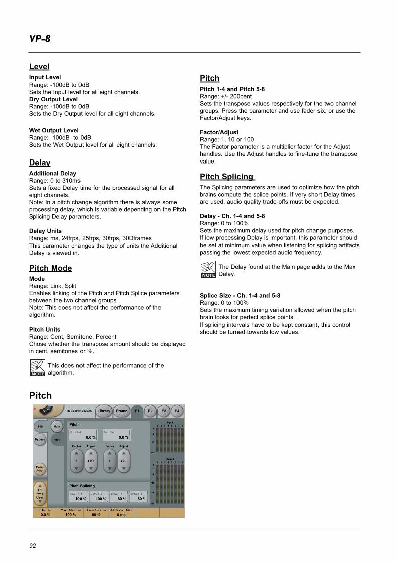
92
VP-8
LevelInput LevelRange: -100dB to 0dBSets the Input level for all eight channels.Dry Output Level Range: -100dB to 0dBSets the Dry Output level for all eight channels.
Wet Output Level Range: -100dB to 0dBSets the Wet Output level for all eight channels.
DelayAdditional Delay Range: 0 to 310msSets a fixed Delay time for the processed signal for alleight channels. Note: In a pitch change algorithm there is always someprocessing delay, which is variable depending on the PitchSplicing Delay parameters.
Delay UnitsRange: ms, 24frps, 25frps, 30frps, 30DframesThis parameter changes the type of units the AdditionalDelay is viewed in.
Pitch ModeModeRange: Link, SplitEnables linking of the Pitch and Pitch Splice parametersbetween the two channel groups.Note: This does not affect the performance of thealgorithm.
Pitch UnitsRange: Cent, Semitone, PercentChose whether the transpose amount should be displayedin cent, semitones or %.
This does not affect the performance of the algorithm.
Pitch
PitchPitch 1-4 and Pitch 5-8Range: +/- 200centSets the transpose values respectively for the two channelgroups. Press the parameter and use fader six, or use theFactor/Adjust keys.
Factor/AdjustRange: 1, 10 or 100The Factor parameter is a multiplier factor for the Adjusthandles. Use the Adjust handles to fine-tune the transposevalue.
Pitch Splicing The Splicing parameters are used to optimize how the pitchbrains compute the splice points. If very short Delay timesare used, audio quality trade-offs must be expected.
Delay - Ch. 1-4 and 5-8Range: 0 to 100%Sets the maximum delay used for pitch change purposes. If low processing Delay is important, this parameter shouldbe set at minimum value when listening for splicing artifactspassing the lowest expected audio frequency.
The Delay found at the Main page adds to the MaxDelay.
Splice Size - Ch. 1-4 and 5-8Range: 0 to 100%Sets the maximum timing variation allowed when the pitchbrain looks for perfect splice points.If splicing intervals have to be kept constant, this controlshould be turned towards low values.

93
CHORUS - 1
Main
ChorusSpeedRange: 0.1Hz to 10HzControls the Rate of sweep in a range from 1 sweep every10 seconds to 10 sweeps every second.
DepthRange: 0 to 100%Determines how wide a modulation (sweep) is produced.
LFO PhaseRange: 0º - 90º - 180ºDetermines the sine wave modulation phase shift betweenleft and right channels. At 0º the left and right modulationwill move in sync. At 180º the modulation will move thechannels against each other.
Golden RatioRange: Off - OnFor a smooth sounding Chorus effect set the Golden Ratioparameter in “on position”. This way an ideal settingbetween Speed and Depth is achieved. Basically thismeans that the higher Speed the less Depth is required toobtain the same feeling of Chorus amount.
Phase InvertRange: Off - OnInverts the phase of the Chorus in the right channel. Thisgives a considerably wider sounding Chorus effect.
FB DelayFeedback FeedbackRange: 0 to 99%Controls the amount of effect signal routed back to the Chorus Input (Flanging).
Feedback Lo CutRange: Off to 800HzFeedback Lo Cut enables you to remove low frequenciesfrom the feedback loop.
Feedback Hi CutRange: 1 kHz to offFeedback Hi Cut enables you to remove high frequenciesfrom the feedback loop.
DelayDelayRange: 1 to 670msA Chorus is basically a Delay being modulated by an LFO.The Delay parameter controls the length of this Delay. A typical Chorus uses Delays of approx 10ms.
Hi Cut FreqRange: 100Hz to flatHi Cut filter enables you to make the Chorus sound more"warm". This is a 6dB per octave filter.
Hi Cut AttRange: -40 to 0.0dBGain for Hi Cut filter. Adjustable in 0.5dB steps.
This algorithm that derives from the M5000 can producehigh resolution Stereo Chorus and Flanging effects, orModulated Stereo Delays of up to 650 ms per channel, andoffers a modulation oscillator with relative L/R phasecontrol. For micro-delay sensitive algorithms like flanging,note that predictable results are best obtained using adirect feed-through mixed inside the effect, rather thanmixing the signals outside the algorithm. The System 6000implementation of Chorus 1 can be used with sample ratesof up to 96kHz.
The Chorus algorithm occupies:@ Normal Sample Rate : 1/4 DSP Resource@ Double Sample Rate : 1/4 DSP Resource
Algorithm Inputs/Outputs are distributed as follows:
E1 - E4
LR
LR
INPUT OUTPUT••••••••
••••••••

94
PHASER - 1
A Phaser in general is a group of comb filters that areswept back and forth by an LFO within a certain frequencyrange. When the comb filter sound is mixed with the directsignal, the moving phasing sound is created due to theconstant moving phase cancelation of the combfilter frequencies in the direct signal.
Phaser SpeedRange: 0.1 to 10HzControls the Speed of the moving filters in the Phaser.
DepthRange: 0 to 100%Adjusts the Depth of the phasing filters.
FeedbackRange: -100 to 100%Controls the amount of processed signal fed back to theInput of the algorithm.
OrderRange: 4th, 8th, 12thSets the number of filters used to produce the Phaser.
FocusRange: Lo Freq, Hi FreqSets the overall frequency range in which the Phasershould operate.
Out LevelRange: -100 to 0dBControls the Output level of the Phaser algorithm.
In LevelRange: -100 to 0dBAdjusts the Input level of the algorithm.
MixRange: 0 to 100%Mixes between direct sound and phaser sound.
The Phaser algorithm occupies:@ Normal Sample Rate : 1/4 DSP Resource@ Double Sample Rate : 1/4 DSP Resource
Algorithm Inputs/Outputs are distributed as follows:
E1 - E4
LR
LR
INPUT OUTPUT••••••••
••••••••
This M5000 algorithm was originally designed as a digital version of the acclaimed TC XII stomp box phas-er. As its predecessor, it offers a selectable number ofswept filter sections (4, 8 or 12) to control the maxexcursion of the effect. For micro-delay sensitive algo-rithms like phasing, note that predictable results arebest obtained using a direct feed-through mixed insidethe effect, rather than mixing the signals outside thealgorithm. The System 6000 implementation of Phaser1 can be used with sample rates of up to 96kHz.

95
DELAY - 1
This algorithm deriving from the M5000 is straight, 24bit true Stereo Delay of up to 2.5 sec in each channelwith basic feedback control. The System 6000 imple-mentation of Delay 1 can be used with sample rates ofup to 96kHz.
Block Diagram
DelayLeft DelayRange: 0 to 2500msSets the Delay time for the left side.
Right DelayRange: 0 to 2500msSets the Delay time for the right side.
Hi CutRange: 500Hz to flatHi Cut filter, shelving type. Provides an overall high frequency roll-off (6dB per octave) that is well suited tomake the Delay effect sound warmer.
Hi Cut AttRange: -40 to 0.0dBThe attenuation control sets the high frequency roll determined by Hi Cut in 0.5dB steps.
FeedbackFeedbackRange: 0 to 99%Sets common feedback level for left and right Delay Outputin percent. It feeds the Delay Output for left and right separately to its own Input in order to make repeatablestereo echo effects. The control is common for left andright - but the signals are processed individually.
FB Lo CutRange: Off to 800HzCommon Lo Cut filter control for left and right feedback.
FB Hi CutRange: 1kHz to offCommon Hi Cut filter control for left and right feedback.
LevelsIn LevelRange: -100 to 0dBControls the Input level of the algorithm.
Out LevelRange: -100 to 0dBControls the Output level of the algorithm.
The Delay - 1 algorithm occupies:@ Normal Sample Rate : 1/4 DSP Resource@ Double Sample Rate : 1/4 DSP Resource
Algorithm Inputs/Outputs are distributed as follows:
E1 - E4
LR
LR
INPUT OUTPUT••••••••
••••••••

96
DELAY - 2
Main
Delay Line 1Delay 1Range: 1 to 2500msSets the Delay time for the left side.
Level 1Range: Off to 0.0dBThe Output level of channel 1.
Pan 1Range: 50L - center - 50RControls the position of channel 1 in the stereo image.
Delay Line 2Delay 2Range: 1 to 2500msSets the Delay time for the right side.
Level 2Range: Off to 0.0dBThe Output level of channel 2.
Pan 2Range: 50L - center - 50RControls the position of channel 2 in the stereo image.
Delay EQHi Cut FreqRange: 500Hz to flatHi Cut filter, shelving type. Provides an overall high frequency roll-off (6dB per octave) that is well suited tomake the Delay effect sound warmer.
Hi Cut Att Range: -40 to 0.0dBThe attenuation control sets the amount of high frequencyroll-off determined by the Hi Cut parameter in 0.5dB steps.
This M5000 algorithm is a 24 bit true stereo effect offering Delays of up to 2.5 sec in each channel with two filteredfeedback controls per channel (self feedback and x feedback). Delays may be modulated with control overrelative L/R phase for Chorus or Tape Delay emulation. The System 6000 implementation of Delay 2 can be usedwith sample rates of up to 96kHz.
The Delay - 2 algorithm occupies:@ Normal Sample Rate : 1/4 DSP Resource@ Double Sample Rate : 1/4 DSP Resource
Algorithm Inputs/Outputs are distributed as follows:
E1 - E4
LR
LR
INPUT OUTPUT••••••••
••••••••

97
DELAY - 2
LevelsMixRange: 0 to 100%Sets the mix between dry and wet signal.
In LevelRange: -100 to 0dBAdjusts the Input level of the algorithm.
Out LevelRange: -100 to 0dBAdjusts the Output level of the algorithm.
Pan InvertRange: Off - OnInverts the panning settings for the two Delay Lines.
FeedbackFeedback-1Range: -100 to 100%The percent of positive phase and negative phasefeedback for channel 1 feedback path includes Lo Cut andHi Cut filters.
Feedback- 2Range: -100 to 100%The percent of positive phase and negative phasefeedback for channel 2 feedback path includes Lo Cut andHi Cut filters.
XFB 1>2Range: -100 to 100%The percent of crossfeed from channel 1 Output to ch. 2Input.
XFB 2>1Range: -100 to 100%The percent of crossfeed from channel 2 Output to ch. 1Input.
Feedback EQLo FB AttRange: -40.0dB to 0.0dBGain for Lo Xover filter. Adjust in 0.5dB.
Hi FB AttRange: -40.0dB - 0.0dBGain for Hi Xover filter. Adjusts in 0.5dB.
Lo XoverRange: 20Hz to flatFrequency for 6dB pr. octave Lo Cut filter.
Hi XoverRange: 20Hz to flatFrequency for 6dB pr. octave Hi Cut filter.
ModulationSpeedRange: 0.1Hz to 10HzControls the rate of modulation sweeps in a range from 1sweep every 10 seconds to 10 sweeps per second.
DepthRange: 0 to 100%Determines how wide a modulation sweep is produced. If you do not want to modulate the effect signal, set thisparameter to 0%.
LFO PhaseRange: 0° - 90° - 180°Determines the sine wave modulation phase shift betweenleft and right channel. At 0° the left and right channel willmove in sync. At 180° the modulation will move againsteach other.

98
REFLECTOR 6 & REFLECTOR LCR
The Reflector-LCR algorithm occupies:@ Normal Sample Rate : 1/4 DSP Resource@ Double Sample Rate : 2/4 DSP Resource
Algorithm Inputs/Outputs are distributed as follows:
E1 - E4
Mono LRC
INPUT OUTPUT••••••••
••••••••
The Reflector-6 algorithm occupies:@ Normal Sample Rate : 1/4 DSP Resource@ Double Sample Rate : 2/4 DSP Resource
Algorithm Inputs/Outputs are distributed as follows:
E1 - E4
Mono LRC
LSRSCS
INPUT OUTPUT••••••••
••••••••
IntroductionReflector is a versatile Delay and Boundary effect formultichannel applications. Output configurations areoptimized for LCR, Stereo or Mono production.Advanced features such as individual EQ and multiplelayers of Diffusion, makes Reflector capable of crossing theborder between Ambience, Early Reflections, Reverb andDelay-effects.Reflector is able to generate plain delays, realistic ambientlocations, and with the long delay-times and diffusionavailable, it can also simulate the large outdoor locationssought after in film- and post production. Environmentssuch as Streets, Canyons, Forests etc.On top of this, Reflector enables the creation of wildsurround effects, making complex delay patterns for musicand film production etc.Effects can easily be edited, mirrored and auditioned onthe fly to allow the user to be part of an inspirational effectdesign process.
Please note that this manual section covers bothReflector 6 and Reflector LCR algorithms. Deviatingparameters are marked.Graphic illustration in this manual section are takenfrom Reflector LCR. Only meters and the Hyperpage are different in Reflector 6.
Main Page
The Main page contains Master parameters that offers aneasy way to alter a complex setup of all the reflectionsalong with the basic Output format and level adjustments.Normally, it is possible to alter the effect in the wanteddirection using only the parameters on the Main page. Ifmore detailed tweaking is required, go to the Taps andShade pages or use another preset as a starting point.
Delay MultiplierThis parameter multiplies the value of the 24 individualreflections ("taps"). When set to 'x 1.00' this means: "what you see is what youget" when monitoring the delay settings.
If the Delay multiplier is moved away from 'x 1.00', whenpressing 'Apply' the individual tap-delays are updated tothe actual delay-time, and the Delay Multiplier is reset to 'x1.00' indicating that the tap-values now are what you hear.
ApplyWhen pressing Apply, all the reflections ("taps") arerecalculated to the value they have according to the Delaymultiplier, and the Delay-multiplier is reset to 'x1.00'.
Shade MasterMaster parameter for Color adjustment. Adjusts all theindividual tap 'Shade' parameters relatively. The Shade response-curve is set at the Shade page.
Feedback MasterMaster Feedback parameter. Adjusts all the individual tap'Feedback' parameters relatively. However, taps set at 0%will always remain off even after adjusting the FeedbackMaster control.
Mirror PatternThe 'Mirror L/R' is a toggle key that mirrors the Delay-tappattern around the Y-axis (Left/Right). Note: The Mirror Pattern parameter is instant, and is notsaved with the preset, while of course the consequences ofhaving the key pressed are stored.

99
REFLECTOR 6 & REFLECTOR LCR
Output Format - Reflector LCRSelect Output format between: Center Mono, LR Mono, LRStereo, LCR
Output Format - Reflector 6Select Output format between: '5.0'; '5.0 minus Center';'6.0'; and '6.0 minus Center'.
For ITU775 reproduction (home theatre) music and postproduction, normally the 5.0 with or without center is meantto be used.
For cinema work taking advantage of utilizing an additionalcenter rear speaker (such as 6.1 DTS ES and Dolby EXformats) use one of the 6 channel settings.
SACD 6.0 production, or other formats requiring a rearheight channel, can also be based on a 6 channel settingwith or without the use of front center.
In LevelAdjusts the Input level.
Dry LevelAdjusts the output level of the Dry position.
Wet LevelMaster for the output level of all the reflections.
Dry - Reflector LCR
On this page the dry signal is positioned. If you work in asend/return loop without passing dry signal throughReflector (master Dry control turned down), the settings areirrelevant.The positioning consists of a power-panner withperceptually based improvements.
The panner response depends on selected outputformat.
X-PositionAdjusts the X-axis position for the dry-signal.
Dry - Reflector 6
On this page the dry signal is positioned. If you work in asend/return loop without passing dry signal throughReflector (master Dry control turned down), the settings areirrelevant.The positioning consists of a power-panner withperceptually based improvements.
The panner response depends on selected outputformat.
X-PositionAdjusts the X-axis position for the dry-signal.
Taps
Groups PageOn the Groups page it is possible to assign six reflections("taps") at a time to the faders by pressing the big buttonsin the bottom of the display (Tap1-6; 7-12; 13-18; 19-24).The grouping of taps is up to you and could be based ontime, direction, level, diffusion or other properties.
A dot above the taps indicate currently selected taps.
Above the Tap Group keys, six different parameters areavailable. When pressing e.g. the Delay button, the Delaysettings for the selected tap group will be assigned to thefaders.

100
REFLECTOR 6 & REFLECTOR LCR
The graphics area above the buttons indicates the tapsDelay, Level, Shade and Phase. Pan-position andFeedback is not displayed.
There are six parameters per tap (reflection):
DelayParameter range: 0 to 9000ms.The screen shows the relative distance betweenreflections. It scales automatically, keeping the longest tapat the far right all of the time.
LevelAdjusts the Output level for the tap (reflection). Height ofthe tap indicates level.
Pan - Reflector 6360-degree panner for positioning of the tap.
Pan - Reflector LCR+/-30 degree (from Left to Right) panner for positioning ofthe tap.
ShadeThe tap color is a combination of the Shade response andDiffusion type. When set to 0% no color change is applied,when set to 100% full response according to the Shadecurve settings are applied.On screen the Shade value is visualized from 0% = yellowto 100% = red.
Note 1: When a * symbol is next to the parameter value,this indicates that the Shade Master is different from 0,meaning the resulting Shade value is different from theindividual setting.
Note 2: When ( ) symbols are around the parameter, thisindicates that the parameter is out of range due to theMaster Shade setting (resulting in more than 100%). Whensettings are out of range, the relative differences betweentaps are no longer preserved.
FeedbackFeedback parameter from 0 to 100%.
Note 1: When a * symbol is next to the parameter value,this indicates that the Feedback Master is different from 0,meaning the resulting Feedback value is different from theindividual setting.
Note 2: When ( ) symbols are around the parameter, thisindicates that the parameter is out of range. The Feedbackis out of range (and limited) to a total of 100% for all taps.Put differently, when summing all 24 feedback values andthe Feedback Master, they cannot exceed 100% in total.When settings are out of range, the relative differencesbetween taps are no longer preserved.
PhaseSelects 0 or 180 degree audio phase for each tap.Taps set "out of phase" are visualized with a dot below thetap.
Taps - Single Page
Using Single tap view, it's possible to access the 24 taps(reflections) individually. When selecting a tap, the sixcorresponding parameters are assigned to the faders.
On screen, the dot above the tap indicates the currentlyselected tap.
For parameter details see the Group view page.
Taps - Hyper Page
Selecting Hyper view, accesses a 3D presentation of thereflection pattern. This is a different way of seeing thecomplete pattern, aware of arriving angle of reflections, butalso still showing Delay, Level, Shade and Phase.
To view the graphics from different angels, press and movethe Zero-Point with your finger.

101
REFLECTOR 6 & REFLECTOR LCR
AutoPress the Auto Fly button and make the picture rotateautomatically (It is still possible to move the graphics evenwhen Auto rotating). This function is not only meant to be asales tool, but is actually useful to provide an overview ofthe effect :-)
Tip: If you access the Hyper view page from the Singleview page, it is possible to adjust the last selected tapparameters.
Shade
Set the Shade response curve (equalization) on this page.Three bands (Lo-shelf, mid-parametric and Hi-shelf) areavailable to form the desired response curve for the 24individual Shade parameters.
Look at the Shade curve as a "max-range" for the coloradjustment to the taps (reflections). When a Shadeparameter is set to 100%, the resulting EQ curve is thesame as seen on the Shade EQ page.
EQPress the EQ button to access Frequency and Levelparameters for the three bands.The EQ levels are only attenuating.
TypeSelect the curve type for the three EQ bands. Band 1 and3 are shelving types, band 2 is parametric type.
Diffusion TypeSelects between different diffuse/boundary types or turnsdiffusion off.The diffuse amount is an integrated part of the Shadeparameters.

102
BACKDROP
The BackDrop algorithm occupies:@ Normal Sample Rate : 1/4 DSP Resource@ Double Sample Rate : Not available
Algorithm Inputs/Outputs are distributed as follows:
E1 - E4
LR
LR
INPUT OUTPUT••••••••
••••••••
Main
BackDrop's main screen allows you to set certain globalparameters.
Algorithm ModelAllows you to select between the Basic, MultiBand andMultiType algorithm models. These models are describedbelow in detail. You can instantly switch between models atany time and the settings for each model are recalled.
Processing ModeThe Processing Mode control allows you to alternatebetween BackDrop's two modes of operation - Stereo orM/S (mid/side). In Stereo mode, BackDrop assigns aseparate noise reduction process to the Left and Rightchannels while in M/S mode, BackDrop assigns a noisereduction process to the Mid signal and another to the Sidesignal. For certain stereo audio sequences, operating inM/S mode can give better results than when operating inStereo mode. It should be noted that when you change theProcessing Mode, BackDrop automatically recalculates thenoise print information for the current operating mode.
Left and Right Input TrimThe Left and Right Input Trim controls allow attenuation ofthe incoming signal level. The left and right signals can beindependently attenuated by as much as 12 dB. In order toget the maximum internal processing resolution fromBackDrop, the Input Trim controls should be set to 0 dB.
StatusOn the right side of the screen is a panel which is visibleon all of BackDrop's screens. At the top of this panel is aregion which displays the status of the noise print (No print,Calculating, Running or Error). In order for BackDrop tooperate properly, the word "Running" must appear in thestatus window, indicating that a valid noise print is available.If "No Print" appears in the status window, then you have notyet captured a valid noise print. If the word "Error" appearsthen the sampling rate has changed since you captured yournoise print.
IntroductionThe BackDrop noise reduction system was designed toprovide the maximum amount of noise reduction withoutaudibly altering the underlying signal. Since noise removalsystems can also remove part of the signal, BackDrop'sfundamental philosophy is to remove the noise with as littleprocessing as possible. That is, BackDrop monitors theincoming signal and continuously decides the perceptuallyoptimal processing to apply. This is accomplished usingadvanced mathematical algorithms resulting from morethan seven years of research. BackDrop's three patentedalgorithm models allow you to apply the processing withsurgical precision while leaving the music undisturbed.BackDrop lets you choose the algorithm model that bestsuits the noise you want to reduce.
BackDrop's Basic model provides a simple set of controlsthat are perfect for removing common broadband noisessuch as tape hiss. The MultiBand model expands yourcontrol by allowing you to divide the noise reductionprocess into three independent frequency bands. Thisgives you full control to shape the noise reduction acrossfrequency in such a way that you can maximize the noisereduction without damaging the signal. Finally, theMultiType model separates the noise into threecomponents (Buzz, Room, and Hiss) and lets you choosehow much of each noise component to reduce.
BackDrop was specifically designed to remove noisesfound in today's world (hums and buzzes, room rumble, airconditioning systems, tape hiss, etc.) and is not intended tobe used for removing clicks and pops.
As an integral part of each of its three algorithm models,BackDrop includes a complex model of the human auditorysystem. BackDrop continuously listens to the incomingsignal and removes only the parts of the noise that the earcan hear. BackDrop offers two unique controls (BasilarDispersion and Transient Recovery) to adjust certainparameters in the ear model. The ear model is another keycomponent in BackDrop's philosophy of applying as littleprocessing as possible to the incoming signal so that onlythe noise is removed, not the music.

103
BACKDROP
ListenThe Listen control allows you to select what is beingmonitored at BackDrop's output. By selecting the Removedbutton, you can listen to the noise that is being removed rather than the noise reduced material. The removedoption is particularly useful to determine if any of thedesired signal is being removed as a result of the noisereduction process. When in M/S mode a new controlappears in the Listen panel that allows you to monitor theoutput in either M/S or Stereo format. When M/S isselected in the Listen panel, the Mid signal is routed to theLeft output and the Side signal is routed to the RightOutput.
Model ScreenThe model screen provides all of BackDrop's controls forapplying noise reduction. The parameters available on themodel screen vary depending on which of the threeAlgorithm Models you are using (Basic, MultiBand orMultiType). However, the parameters are similar betweenmodels.
Basic Model
The Basic model offers the simplest set of controls forBackDrop. With the Basic model the noise reduction isapplied to all components of the noise and across theentire frequency range. The Basic model is a good choicewhen the level of the noise is relatively low and when it isnot very complex, such as tape hiss. The Basic model provides four controls (Aggression, Max Reduction, BasilarDispersion, and Transient Recovery).
AggressionThe Aggression parameter controls the overall amount ofprocessing that is applied to the input signal. Aggressioncan range from 0% to 100% with 0% meaning that noprocessing is being applied to the signal. The Aggressionparameter works in conjunction with Max Reduction.
Max ReductionMax Reduction is a sub-parameter of the Aggressionparameter. That is, Max Reduction will not have any effectunless Aggression has some value other than 0%.
The Max Reduction parameter tells BackDrop themaximum amount of noise reduction you are trying toachieve. Therefore, if Max Reduction is set to say 10dB,then BackDrop will not try to lower the noise by more than10dB. Depending on how the Aggression parameter is set,BackDrop may reduce the noise by less than 10 dB, butnot more. If Max Reduction is set to 0 dB, BackDrop will not removeany noise. Also, since Max Reduction works in conjunctionwith Aggression, the two parameters should be adjustedtogether in order to set the desired amount of noise reduction.
Basilar DispersionBasilar Dispersion is one of the two parameters whichadjusts the characteristics of BackDrop's model of thehuman auditory system. Specifically, Basilar Dispersioncontrols the amount of masking used in the BackDrop earmodel. Masking is the phenomenon by which a sound thatwould otherwise be audible is hidden (masked) by a loudersound. There are two types of masking that occur in thehuman auditory system (time-domain and frequency-domain) and both are controlled in BackDrop using theBasilar Dispersion parameter. Basilar Dispersion works inconjunction with Transient Recovery.
Basilar Dispersion ranges from 0% to 100% with 0%meaning that no masking is used in BackDrop's ear model.The effect of Basilar Dispersion is most readily heard ineliminating low level artifacts affectionately known as"musical noise", "Mars-men", or "space monkeys" that maybe found in other noise reduction products. As the amountof Basilar Dispersion is increased, the occurrence of theseartifacts is dramatically reduced.
Transient RecoveryTransient Recovery is a sub-parameter of BasilarDispersion. Therefore, Transient Recovery will only takeeffect when Basilar Dispersion is set to some value otherthan 0%.
The masking characteristics of the ear behave differently inthe presence of transient signals than with more steady-state signals. Therefore, Transient Recovery provides youwith a way to tell BackDrop's ear model how to behave inthe presence of transients.
As described above, Basilar Dispersion adjusts the amountof masking used in BackDrop's ear model and is used toeliminate certain low-level artifacts. One possible sideeffect of using high levels of Basilar Dispersion is that thetransient portions of the signal can become smeared. As itsname suggests, Transient Recovery offers the means to maintaining sharp attacks on the transients in the signal.
The effect of Transient Recovery is most easily heard whenBasilar Dispersion is set relatively high (greater than 75%)and there are obvious transients in the signal.

104
BACKDROP
MultiBand Model
The MultiBand model offers an enhanced set of controlscompared to the Basic model. The MultiBand modelprovides three independent noise reduction engines splitacross three frequency bands. Therefore you can apply asmuch or as little noise reduction as is needed in each ofthe three frequency bands. Of course, the cross-overfrequencies for the three bands are entirely adjustableproviding unprecedented flexibility in how the noisereduction is applied.
The MultiBand model is a good choice for higher levels ofnoise and when you need a high degree of precision inwhere you apply the noise reduction. The MultiBand modelprovides the same four primary controls (Aggression, MaxReduction, Basilar Dispersion, and Transient Recovery) ineach of the three frequency bands.
The Aggression, Max Reduction, Basilar Dispersion,Transient Recovery, and Link controls function exactlyas in the Basic Model, except they are split into three
bands.MultiType Model
The MultiType model offers a unique and exciting newapproach to noise reduction. The MultiType algorithm isbased on the realization that most noises are actually asum of several different individual noise components.Moreover, the noise components may not be equallyannoying and so it is sensible to apply more noisereduction to the components which are most annoying.
For example, consider a recording that has been corruptedby a combination of a hum due to a ground loop, roomrumble and tape hiss. In such a situation one often findsthat the tonal components of the hum are more annoyingthan the other two noise components. Therefore, it wouldbe very useful to apply the most noise reduction specificallyto the hum component. Conversely, the tape hisscomponent might be quite acceptable and so you mightwant to leave it untouched while reducing the room rumblecomponent. Other noise reduction algorithms operate onthe composite noise signal and treat each noisecomponent equally. With BackDrop's MultiType algorithm
LinkThe Link button links or gangs the controls so that theyoperate on both the left and right channels together. Whennot linked, separate controls are available for the Left andRight channels. When enabling Link mode, settings for theRight channel will be copied to the Left channel. A pop-updisplay will ask you to confirm this operation. It should benoted that the noise reduction processing remains inde-pendent for each channel even if the controls are linked.
BypassAs Bypass in BackDrop is used mainly as an A/B comparefunction the BackDrop bypass is made to work asdescribed here:• Bypass will always disable noise reduction but maintain
the gain and M/S settings so only the noise changes. • True 24-bit transparency is achieved during bypass as
long as the Input Level Trims are 0.0dB and Processing mode is Stereo.
Latency in the BackDrop algorithm is preserved inBypass mode for optimal compare function.Thelatency/processing delay for the BackDrop algorithmis approximately 56ms from digital In to digital Out.
Frequency (Hz)
dB
Composite Noise Spectrum
Frequency (Hz)
dB
Hiss
Room
Buzz
Decomposed Noise Spectrum

105
BACKDROP
you can selectively reduce each of these three componentswhile minimizing the processing applied to the signal you'recleaning up. The way in which BackDrop decomposes the noise intothree components is best described in the frequencydomain as illustrated in above figures. The first figureshows the spectrum of the composite noise (i.e. Buzz,Room noise and Hiss combined). The second figure showshow BackDrop decomposes the noise into the threecomponents. The Buzz component consists of the tonalparts of the noise. The Room component consists of thebroadband noise that does not have a flat spectrum. TheRoom component is often dominated by lower frequencynoise. Finally, the Hiss component consists of thebroadband noise having a relatively flat spectrum. In theexample shown in the figure the noise at higherfrequencies is predominantly due to hiss. BackDrop allowsyou to selectively reduce each of these noise components.
The MultiType model is a good choice when the noise ismade up of two or more components or when you havenoise (such as hum due to ground loops) with clear tonalcomponents. The MultiType model provides six primarycontrols (Buzz Aggression, Room Aggression, HissAggression, Max Reduction, Basilar Dispersion, andTransient Recovery).
Buzz AggressionBuzz Aggression controls the overall amount of processingapplied to the tonal components of the noise. BuzzAggression can range from 0% to 100% with 0% meaningthat no processing is being applied to the signal. The BuzzAggression parameter works in conjunction with MaxReduction.
Examples of noise sources with tonal components includehum (50 or 60Hz) due to power lines and ground loops aswell as the tonal components due to the cyclical nature ofsome noise sources such as air conditioners, cooling fans,hard disks or CRT fly-back transformers.
Room AggressionRoom Aggression controls the overall amount ofprocessing applied to any broadband noises that do nothave a flat spectrum. It is an aggression control for thecolored (non-flat) broadband portion of the noise. RoomAggression can range from 0% to 100% with 0% meaningthat no processing is being applied to the signal. TheRoom Aggression parameter works in conjunction with MaxReduction.Typical examples of noise sources that are targeted by theRoom Aggression parameter include room noises due toair conditioning units or cooling fans, as well as the lowfrequency rumble due to traffic noise or air movement in alarge hall.
Hiss AggressionHiss Aggression controls the overall amount of processingapplied to any broadband noises having a flat spectrum.Hiss Aggression can range from 0% to 100% with 0%meaning that no processing is being applied to the signal.
The Hiss Aggression parameter works in conjunction withMax Reduction. Typical examples of broadband noise
sources having a flat spectrum include tape hiss andquantization noise.
The Max Reduction, Basilar Dispersion, TransientRecovery, and Link Controls function exactly as in theBasic Model.
Print ScreenThe Print screen contains all of the controls needed tocapture the information required by BackDrop regarding thecharacteristics of the noise. BackDrop will not reduce thenoise properly unless you have provided it with a suitablenoise print. This screen provides five parameters (Capture,Calculate, Play, Trim Start, and Trim End).
CaptureThe Capture control causes BackDrop to automaticallycapture (record) 1.5 seconds of audio to use in the analysisof the noise characteristics.
When in playmode, capture is not available
CalculateWhen Capture is pressed, the Capture button is lit whileBackDrop records 1.5 seconds of audio. During this timethe status window will indicate that BackDrop is recordingthe audio. Once the audio has been captured, theCalculate button will automatically light up and the statuswindow will indicate that BackDrop is calculating the noiseprint information. BackDrop takes a few seconds tocalculate the noise print information since it is analyzing thenoise data and calculating the noise print information foreach of the three models (Basic, MultiBand and MultiType).
There are often times when it is necessary to recalculatethe noise print information without capturing new audio. Forexample, it is necessary to recalculate the noise printinformation after the Trim Start and Trim End points havebeen altered (see below). In this case, press the Calculatebutton to have BackDrop update the noise print informationbased on the audio contained between the Trim Start andTrim End points of the captured audio buffer.
It should be noted that when switching between Stereo andM/S processing mode, BackDrop automatically recalculatesthe noise print information for the current operating mode.BackDrop does this using the current Trim Start and TrimEnd settings.
PlayThe Play button starts and stops playback of the capturedaudio buffer. The audio buffer plays repeatedly until Play isturned off.
Trim Start and Trim EndThe Trim Start and Trim End controls allow you to zoom inon a specific range of the captured audio buffer. Thesecontrols are used to make sure that the audio containedbetween the start and end points contains only noise andno signal.

106
BACKDROP - TUTORIAL
When calculating the noise print information or when usingthe Play feature, only the audio contained between thestart and end points is used. Therefore, in order to updatethe noise print information, you should press Calculatewhenever the Trim Start or Trim End controls have beenaltered. It should be noted that whenever the Trim Start orTrim End controls are adjusted, BackDrop restarts playbackof the capture buffer from the Trim Start point.
Getting StartedThis section is intended to give you a simple guide to getstarted using BackDrop. BackDrop has a rather unique setof controls and you may require some time to get theoptimal performance from BackDrop.
If possible, in order to help you to become familiar withBackDrop's controls, use a piece of music that has a fairlyaudible (although not too high) level of hiss.
The first step when removing noise from a signal is tocapture a noise print so that BackDrop can learn thecharacteristics of the noise and dissect it into its variouscomponents. Start by going to the Print screen.
When you press the Capture button on the Print screen,BackDrop automatically records 1.5 seconds of audio. Itthen automatically calculates all of the noise printinformation that is required for the 3 algorithm models(Basic, MultiBand and MultiType).
In order to get the best possible performance fromBackDrop, it is important to capture a sample of just thenoise without any of the signal. Therefore, it is a good ideato use the Play feature to listen to the buffer of audio thathas been used to calculate the noise print information. Todo this, go to the Print screen and press Play. This will playthe captured buffer. If you hear any signal within the buffer,use the Trim Start and Trim End controls so that only noiseis heard. Once you are satisfied that there is only noisebetween the Trim Start and End points press the Calculatebutton to update the noise print information using the newbuffer start and end points. You are now ready go to theModel screen and apply the noise reduction.
When listening to the capture buffer using the Playfeature, BackDrop may already be performingnoise reduction depending on the present settingsof the controls. To hear the unprocessed capturebuffer, simply press Bypass.
Go to the Model screen and select the Basic algorithmusing the Algorithm Model control. In order to get an initialfeel for BackDrop's controls we will use some ratherextreme settings. Do not take these settings as anindication of typical settings for BackDrop's controls!
Start by linking BackDrop's controls using the Link button.Set Basilar Dispersion and Transient Recovery to 0%. Thiseffectively turns off BackDrop's model of the ear. Now setthe Aggression control to 100% and Max Reduction to 0dB. Because Max Reduction is set to 0 dB BackDrop willnot yet reduce the noise at all.
Slowly increase the level of Max Reduction. As you do thisyou should hear the level of the noise go down accordingly.Set Max Reduction to about 10 dB and listen as you turnthe processing on and off using the Bypass button. Thenoise reduction should be obvious. If not, something is notquite right and you should re-trace the above steps.Continue to increase the level of Max Reduction beyond 10dB. If the level of the noise in your input signal is relativelyhigh, you will likely begin to hear strange low-level randomchirping sounds. These low-level artifacts are usuallyreferred to as "musical noise" or sometimes as "Mars-men", or "space monkeys". These artifacts are commonlyfound in other noise reduction products and can seriouslylimit the usability of the noise reduction system.Fortunately, BackDrop provides you with a means ofeliminating these artifacts.
Slowly increase the level of the Basilar Dispersionparameter. You should hear the musical noise artifactsdisappear. This is exactly the purpose of the BasilarDispersion parameter. By taking advantage of the maskingproperties of the ear, Basilar Dispersion eliminates lowlevel artifacts that can occur as a result of the noisereduction process.
To further investigate BackDrop's controls, set Aggressionand Basilar Dispersion to 100% and set Max Reduction to100dB. You are now applying the maximum amount ofnoise reduction available from BackDrop. With this amountof noise reduction you will very likely hear distortions to thedesired signal.
For example, you may hear a smearing of the transientportions of the signal. BackDrop's Transient Recoveryparameter was specifically designed to maintain sharpattacks and to prevent transients from being smeared.Increase the Transient Recovery control and listen to howthe transients are restored to their original sound.
Hopefully, you now have a feel for the four primary controlsfor BackDrop's Basic algorithm. The controls for the othertwo algorithms (MultiBand and MultiType) are similar infunctionality. Remember that the settings for BackDrop'scontrols described in this tutorial are by no means therecommended settings. They were simply intended to helpyou become familiar with their effect.
It is instructive to play some more with the various controlsand to listen to the amount of noise reduction, theoccurrence of musical noise, and the smearing oftransients (signal distortion). These variables must bebalanced when using BackDrop to remove noise from youraudio. Fortunately, BackDrop provides you with acomprehensive set of tools to make the optimal possibletrade-off.
When using BackDrop's controls it is important toremember that Aggression and Max Reduction worktogether and so you should go back and forth betweenthese parameters in order to find the best settings. Thisalso applies to the Basilar Dispersion and TransientRecovery controls which work together.

107
BACKDROP - TUTORIAL
Advanced UseThe tutorial in the previous section was intended to giveyou a feel for some of BackDrop's controls. In this sectionwe endeavor to provide you with some guidelines forobtaining the best possible performance from BackDrop.The following steps have been found to be a suitableapproach for getting good performance under almost allcircumstances. As you become more familiar withBackDrop you will no doubt develop your own techniquesand strategies that work best for you.
As always, the first step in the noise reduction process is tocapture a sample of the audio for the noise printinformation. It is very important that the audio used tocalculate the noise print information contain only the noiseand none of the signal.
With the noise print information calculated, use theAlgorithm Model control to select the BackDrop algorithm(Basic, MultiBand or MultiType) that is best suited to thenoise you are trying to remove.
BackDrop's fundamental philosophy is to target the noisereduction to where it is needed most and to apply as littleprocessing as possible to the signal. The strategy outlinedin this section is in keeping with this philosophy. Generallyspeaking, to get the best results from BackDrop, do not be"over aggressive". Try to use as low an amount ofaggression, and Max Reduction as possible, and use amoderate amount of Basilar Dispersion (40% to 60%).
It is useful to begin by getting an idea of how much noisereduction is necessary for the audio sequence that you areworking on. In many cases reducing the noise by only afew decibels will make a dramatic improvement in thequality of the audio sequence. In most cases, you will notneed more than about 10 dB of noise reduction. Todetermine how much noise reduction is necessary, setBasilar Dispersion and Transient Recovery to 0%. SetAggression to 100% and Max Reduction to 0 dB. Slowlyincrease Max Reduction and listen as the level of noisegoes down. Use the Bypass button to turn the processingon and off. Adjust Max Reduction until you obtain theappropriate amount of noise reduction.
With Aggression set to 100%, you are probably applyingmore processing than necessary for the amount of noisereduction that you desire. Therefore, slowly lower theamount of Aggression until you here the level of the noisefloor begin to increase. This level of Aggressioncorresponds roughly to the amount of reduction that youdesire and the value of Max Reduction that you haveselected. Note that this relation between Aggression andMax Reduction depends on the signal being processed andso the relative settings will be different for different audiosequences.
It is now a good time to monitor BackDrop's output verycarefully and decide the following: Is this too much noise reduction? Often it is desirable toleave some background noise in the signal so that itdoesn't sound unnaturally clean. This is primarily true foran overall mixed signal rather than for individual tracks thatare yet to be mixed together.
Do you hear any artifacts? If you hear artifacts thenincrease the amount of Basilar Dispersion until the level ofthe artifacts becomes acceptable or the artifacts becomescompletely inaudible. In some cases, increasing theamount of Aggression slightly when applying BasilarDispersion can also reduce the artifacts. You can also takeadvantage of some of the residual hiss to mask artifactscreated by the process itself. By using a little less noisereduction and aggression, leaving a small amount ofresidual hiss, you will have a harder time hearing anyartifacts.
Are the transients (attacks) being smeared? If increasingthe amount of Basilar Dispersion has caused a smearing ofthe transients then you may want to increase the level ofTransient Recovery. It should be noted that higher levels ofTransient Recovery can cause some of the musical noiseto reappear. Therefore, Basilar Dispersion and TransientRecovery need to be adjusted together in order to minimizeboth the musical noise and the smearing of transients.
Are you losing the sound quality or clarity of the originalsource? It is easy to become very focussed on the task ofremoving noise and overlook the fact that the signal hasbecome somewhat distorted (altered). Remember to listento the signal as well as the noise.You will need to strike abalance between the amount of noise reduction possibleand the effect on the sound quality of the music. Keep inmind that BackDrop was specifically designed to enableyou to make the best possible trade-off for your application.
You should be aware that when removing noise it iscommon to uncover low-level sounds that you might thinkare artifacts resulting from BackDrop. Frequently thesesounds are actually part of the original signal but they werepartially hidden by the noise. Use the Bypass button tocompare the processed signal to the original signal to seeif the sound was actually part of the original.
While keeping the above points in mind, you should goback and forth between the various controls and adjustthem until the optimal noise reduction solution is reached.Of course, you should try all three of BackDrop's algorithmmodels to determine which one is best suited for the taskat hand. Remember that you can switch instantly betweenthe algorithm models and the settings for each model arepreserved as you switch, allowing you to compare yourbest settings for each.
It is also a good idea to periodically use the Removedbutton to hear what is being removed from the input signal.If you hear components of the signal, then this may be anindication that you are applying too much processing.Finally, if you are working on a stereo recording, it isworthwhile to try using BackDrop in both Stereo and M/Smodes. For certain audio sequences a dramaticimprovement in quality can be obtained by performing thenoise reduction processing in the M/S domain. You shouldnote that, in order to get the most from the M/S domainprocessing, the controls should be unlinked so thatdifferent amounts of processing can be applied to the Midand Side signals. Specifically, it is often more perceptuallybeneficial to apply more noise reduction to the Side signalthan to the Mid signal.

108
BACKDROP - TUTORIAL
Common Questions1) Is it better to get as long a noise print as possible?
The simple answer is yes, but the maximum length of thecapture buffer is 1.5 seconds. So there is no advantage tohaving a noise print that is longer than 1.5 seconds.BackDrop doesn't need more than 1.5 seconds in order tofully train itself on the noise in the signal.
2) Is it important to get a very good loop of the noise?
Again the answer is yes. If there is some signal in thecaptured buffer then BackDrop will not train itself properlyabout the nature of the noise that you are trying to remove.That is, it will try to remove part of the signal as well.
3) What if it is not possible to get a noise print?
This, of course, will limit BackDrop's ability to decide whatis noise and what is signal. There are two approaches youcan use in this case.
a) Find another piece of audio with similar noise and use itto capture the noise print information.
b) Find the quietest part of the audio signal and use it tocapture the noise print information. Then use the MultiTypealgorithm model to apply the noise reduction. Set the BuzzAggression and Room Aggression controls to 0%. Use theHiss Aggression to control the amount of noise reduction.This isn't perfect, but it should let you achieve somebroadband noise reduction.
4) Should I try to remove all the noise?
Often it is desirable to leave some background noise in thesignal so that it doesn't sound unnaturally clean. This isprimarily true for an overall mixed signal rather than forindividual tracks that are yet to be mixed together.
5) Do I always have to use Play, Trim Start/End andCalculate to get a good loop?
No. This is usually required when working with a tapetransport or when taking a print of a live room where it maybe hard to anticipate the material.If you are working with tracks on a hard disk recordingsystem, it is often handy play a noise-only portion of thetrack in loop-mode before pressing the Capture button.
6) Can I practice using Backdrop's controls by capturingnoise and using the capture buffer in Play mode?
You can use this technique for quick control checks but it isnot recommended for choosing final settings.
Since Backdrop's strength lies in allowing you to preciselycontrol the amount of reduction to apply without altering thesignal, it is always better to fine-tune the controls with apassage containing music. Focussing too much on just thenoise can lead you to over-processing, giving unfavorableresults when you listen to the entire signal.

109
LM5D
LM5 represents a quantum leap away from simply measuring audio level to measuring perceived loudness. The old levelmethod is responsible for unacceptable level jumps in television, for music CDs getting increasingly distorted, and fordifferent audio formats and program genres becoming incompatible: Pristine music tracks from the past don’t co-exist withnew recordings, TV commercials don’t fit drama, classical music or film and broadcast doesn’t match. The mostfundamental audio issue of all – control of loudness – every day makes millions of people adjust the volume control overand over again.LM5 is part of a universal and ITU standardized loudness control concept, whereby audio may easily and consistently bemeasured and controlled at various stages of production and distribution. LM5 works coherently together with other TCequipment, or with equipment of other brands adhering to the same global standard. Follow the guidelines given to allowaudio produced for different purposes to be mixed, without low dynamic range material such as commercials or pop CD’salways emerging the loudest.
• Realtime loudness meter adhering to ITU-R BS.1770.• Loudness History Radar display.• True-peak Bargraph display.• Universal Descriptors Center of Gravity and Consistency.• Supports mono, stereo and 5.1.• Presets for use in Broadcast, Music, Post and Film.

110
LM5D
IntroductionSince 1998, TC has performed listening tests and evaluation of loudness models; and therefore holds an extensive,Universal Database of loudness, based on ten thousands of assessments. The database covers all sorts of broadcastmaterial, music, commercials, feature film and experimental sounds, and is verified against other independent studies.
Fig 1. Left: DRT for consumers under different listening situationsRight: Peak level normalization means that material targeted low dynamic range platforms gets loud.
The Universal Database is authoritative from an academicas well as a practical point of view. It has beenindispensable when designing the LM5 meter, because itprovided the missing link between short-term and long-termloudness, and enabled the statistically founded UniversalDescriptors of LM5D.
The chart of Dynamic Range Tolerance in Fig 1 is a side-effect of the studies mentioned: Consumers were found tohave a distinct Dynamic Range Tolerance (DRT) specific totheir listening environment. The DRT is defined as aPreferred Average window with a certain peak levelHeadroom above it. The average sound pressure level,which obviously is different from one listening condition toanother, has to be kept within certain boundaries in orderto maintain speech intelligibility, and to avoid music oreffects from getting annoyingly loud or soft.
Audio engineers instinctively target a certain DRT profilewhen mixing, but because level normalization in broadcastand music production is based on peak level measures,low dynamic range signatures end up the loudest as shownby the red line in Fig 1, right. Audio production is thereforetrapped in a downward spiral, going for ever decreasingdynamic range. By now, the pop music industry is “right of”In Flight Entertainment in the illustration.
LM5 offers a standardized option: The visualization ofloudness history and DRT in combination with long-termdescriptors from production onwards, is a transparent andwell sounding alternative to our current peak levelobsession. Not only for music, but also in production forbroadcast or film. The engineer, who may not be an audioexpert, should be able to identify and consciously work withloudness developments within the limits of a targetdistribution platform, and with predictable results when theprogram is transcoded to another platform.
LM5 therefore color codes loudness so it’s easy to identifytarget level (green), below the noisefloor level (blue), orloud events (yellow), see Fig 2.

111
LM5D
Fig 2 Color coding and target loudness for selected broadcastplatforms based on a consumer’s Dynamic RangeTolerance, DRT. The aim is to center dynamic rangerestriction around average loudness, in this case the –20dB line, thereby automatically avoiding to wash outdifferences between foreground and background elementsof a mix.
Note how different the broadcast requirements are fromthose of Cinema.
When production engineers realize the boundaries theyshould generally stay within, less dynamics processing isautomatically needed during distribution, and therequirement for maintaining time-consuming metadata at abroadcast station is minimized.
In broadcast, the goal is to use the same loudnessmeasure for
- Production,- Ingest,- Linking- Master Control Processing- Logging
thereby ensuring better audio quality not only in DTV audio,but across all broadcast platforms. LM5 and TC processingcan co-exist with PPM meters, VU meters or Dolby’sLM100 meter. LM5 greatly increases the usability of LM100in production environments because it provides runningstatus, and gives a standardized and intuitive indication ofboth dialog and non-dialog program.

112
LM5D
Basic UseLM5 makes use of a unique way of visualizing short-term loudness, loudness history, and long-term statistical descriptors.It may be used with mono, stereo and 5.1 material for any type of program material.Press the “LM” key to bring up the Radar page. This page will be used most of the time. The basic functionality of theRadar page is shown in Fig 3.
Fig 3 - Radar page features of LM5D.Target Loudness is displayed at 12 o’clock of the outerring, and at the bold, concentric circle of the radar. TheUniversal Descriptors, Consistency and Center of Gravity,are the yellow numbers in the lower part of the display.Press the Reset key to reset Radar and Descriptors.
The “Transport Controls”, Pause and Reset, are used tomake the radar and descriptor measurements run, pauseand reset. Press the “Main” key to change preset nameand for adjusting more parameters. Press the “Setup” keyto change setup parameters. Presets can be storedspecifying target loudness, noise floor, overload conditionsetc using normal System 6000 preset handling procedures.
Radar PageCurrent Loudness: Outer RingThe outer ring of the Radar page displays currentloudness. The 0 LU point (i.e. Target Loudness) is at 12o’clock, and marked by the border between green andyellow, while the Low Level point is marked by the borderbetween green and blue. The “0 LU Equals” and “LowLevel Below” parameters are found on Prefs page. Forinstance, if 0 LU is set at -22 LFS, and Low Level is set at -20 LU, the color coding of Fig 3 applies.The user should be instructed to keep the outer ring in thegreen area, and around 12 o’clock on the average.Excursions into the blue or the yellow area should bebalanced, and not only go in one direction.The numbers associated with the outer ring may be
referenced at either maximum loudness, or have a zeropoint set somewhere mid-scale. Choose “LFS” or “LU” atthe Loudness Scale selection on the Main page dependingon your preference. Either way of looking at loudness isvalid. LFS reading is in line with how peak level is typicallymeasured in a digital system, and compatible with DolbyAC3 and E metadata, while the LU approach calls for acertain Target Loudness to have been predetermined, likee.g. a VU meter.

113
LM5D
Loudness History: RadarThe Loudness Radar shows a history of loudness over time. The loudness “landscape” may be used to judge if loudnessemphasis is put where you want it to be: If dialog segments are balanced against action parts, if the chorus of a song hasa lift against the verse, if the audience is too loud in a gameshow, or maybe as a target to aim for during a live transition etc.
The duration of one radar revolution may be set between 1minute and 24 hours. The Radar has 3, 4, 6, 8, 10 or 12dB between each concentric circle, while the 0 LU point isalways marked as the border between green and yellow atthe bold concentric circle, see Fig 3. For broadcast. the 0LU point is typically set between -18 and -24 LFS.
Universal DescriptorsAdditional to the short-term loudness (outer ring) andloudness history (radar), LM5D displays long-termstatistical descriptors that describe an entire program, filmor music track. Unlike concepts that measure only dialog,LM5D may measure any type of audio.
Center of Gravity (CoG) indicates the average loudness ofa program, and is directly operational. If, for instance, abroadcast station is operated at an average loudness levelof –22 LFS, and a commercial has its Center of Gravitymeasured at –19.5 LFS, the program should be attenuatedby 2.5 dB before transmission for a best fit.Consistency indicates the loudness variations inside aprogram. At one extreme, a steady tone displays aConsistency of 0.0 LU. Broadcast programming typicallycomes out with a Consistency between –2 and –5 LU,while classical music or a feature film can show morenegative readings, for instance a Consistency of –10 LU orlower. The number predicts how much loudness correctionin LU (cut and boost) is needed to have a program ormusic track played without frequent loudness variations.
Fig 4 - Different types of program shown on the RadarPleas note that these pictures derive from ProTools but measurements and radar display are identical to the ones found inDB4/Db8 and System 6000.
• Left: 5.1 move: Pirates of the Caribbean on a 12 minute per revolution Radar: Low Consistency.• Center: German news broadcast on a 4 minute per revolution Radar: Medium Consistency.• Right: Madonna’s Hung Up pop on a one minute per resolution Radar: High Consistency.
Center of Gravity ranges from –80 LFS to +12 LFS, whileConsistency ranges from –40 to 0 LU. Examples of typical Consistency / CoG values:Cinema movie: -6 to -15 LU / -22 to -30 LFSClassical music on CD: -5 to -12 LU / -15 to -30 LFS
Broadcast: -2 to -5 LU / -18 to -24 LFSCommercials: -0.5 to -2 LU / -15 to -22 LFSPre 1995 pop/rock CD: -1.5 to -5 LU / -14 to -20 LFSHyper-compressed pop/rock CD: -1 to -3 LU / -5 to -8 LFS
Note: If you’re involved with music mastering, pleaseobserve that you enter red light district for CoG valuescloser to zero than –12 LFS, and that you’re well insidethat zone if you pass the –10 LFS mark. Everything you doto make music even louder will end up getting counteractedin iTunes or at the broadcast station – but the distortion youadd to go higher will remain.The same warning may be given for TV commercialproduction. Don’t aim at max values, but allow Consistencyto go down a bit to let the program breathe. Look at theradar to put audio focus where you want it to be. Whenloudness gets normalized, that’s what will give yourmessage attention.Universal Descriptors are rooted in Leq(K) as referenced inITU-R BS.1770, and have been designed for robustnessagainst moderate gain offsets around normal broadcastoperating levels. If a program exhibits a Consistency of–3.5 LU, and the gain is offset by 10 dB, its Center ofGravity reading is shifted by 10 dB, while Consistencyremains unchanged. Please find more information aboutUniversal Descriptors in the Tech Library of the TC website.

114
LM5D
Long-term measurementsUniversal descriptors may be used to make program-duration measurements, or you may “spot-check” regulardialog or individual scenes as required. It is recommendednot to measure programs of a shorter duration thanapproximately 10 seconds, while the maximum durationmay be 24 hours or longer.
Reset Key
Before a new measurement, press the Reset key. Thisresets the descriptors, the radar and the true-peak meters.Run the audio, and watch the radar and descriptor fieldsupdate accordingly. It is normal that the descriptors waitfive seconds into the program before showing the firstreadings, while the radar updates instantly. The first fiveseconds of a program are included in the descriptorcalculations, even though they are not shown instantly.
LM5D incorporates an intelligent gate, which discriminatesbetween foreground and background material of aprogram. Consequently, a measure doesn’t start beforeaudio has been identified. It also pauses the measurementduring periods of only background noise, and in the fade-out of a music track.
Universal Descriptors and Dolby LM100Unlike methods that measure dialog only, LM5D may beused with any type of audio – which includes dialog, ofcourse. If you wish to measure dialog, it’s recommended todo a manual spot check of a program or a film. Find 10-30seconds of regular dialog and measure it with LM5D.Where dialog may be soft, regular or loud, and shift bymore than 15 dB inside a film, regular dialog tends to beless ambiguous and more consistent across a program.
For compatibility with a proprietary measure suchas Dolby LM100, only some of these meters areupdated to use ITU-R BS.1770 and Leq(K) whileothers are locked at Leq(A). The software version of
LM100 should be 1.3.1.5 or higher in order for it to complywith BS.1770, and to have its average loudness reading becompatible with Center of Gravity in LM5. Even used juston speech, Leq(A) is not a precise approximation toperceived loudness, so please update the unit to BS.1770to obtain similar readings and predictable results.
To measure dialog with LM5D the same way Dolby LM100is sometimes used, solo the Center channel during a spotcheck to momentarily disable the channel weightingspecified in BS.1770, if you’re working on a 5.1 stem.
Universal Descriptors and AC3 MetadataThe “Dialnorm” parameter in AC3 metadata should indicatethe average loudness of a program. Basic dynamic rangeand level control that rely on this parameter may take placein the consumer’s receiver. Therefore, its value should notbe far off target, or the consumer results become highlyunpredictable.Center of Gravity in LM5 is directly compatible withDialnorm in AC3. Most broadcast stations work against afixed dialnorm setting, for instance –23 LFS. This wouldthen be the CoG value to aim a program at. If the programisn’t only dialog, the best consumer listening results areachieved if you aim Center of Gravity a bit higher than themetadata goal. For a music program, for instance, the aimshould be 2-3 LU higher.
True-peak metersThe peak meters of LM5 display true-peak as specified inITU-R BS.1770. True-peak meters give a better indicationof headroom and risk of distortion in downstreamequipment such as sample rate converters, data reductionsystems and consumer electronics than digital samplemeters used e.g. in CD mastering. Note that the standardlevel meters in most digital workstations and mixers areonly sample peak (Final Cut, Avid, ProTools, Yamaha etc.),and should only be used as a rough guideline of theheadroom.Note that the meter scale is extended above 0 dBFS. Mostconsumer equipment distorts if you see readings above 0.With data reduced delivery, -3 dBFS should be regarded asmax level without too much distortion. To be on the safeside with regard to broadcast linking and transmission, -6dBFS should not be exceeded often. Please remember thatexcessive peak level may generate noticeable distortionand listener fatigue.
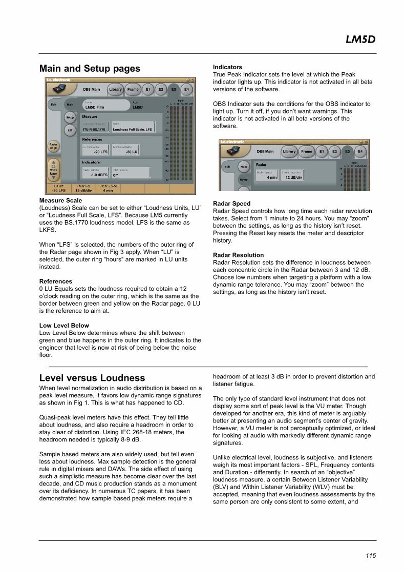
115
LM5D
Main and Setup pages
Measure Scale(Loudness) Scale can be set to either “Loudness Units, LU”or “Loudness Full Scale, LFS”. Because LM5 currentlyuses the BS.1770 loudness model, LFS is the same asLKFS.
When “LFS” is selected, the numbers of the outer ring ofthe Radar page shown in Fig 3 apply. When “LU” isselected, the outer ring “hours” are marked in LU unitsinstead.
References0 LU Equals sets the loudness required to obtain a 12o’clock reading on the outer ring, which is the same as theborder between green and yellow on the Radar page. 0 LUis the reference to aim at.
Low Level BelowLow Level Below determines where the shift betweengreen and blue happens in the outer ring. It indicates to theengineer that level is now at risk of being below the noisefloor.
IndicatorsTrue Peak Indicator sets the level at which the Peakindicator lights up. This indicator is not activated in all betaversions of the software.
OBS Indicator sets the conditions for the OBS indicator tolight up. Turn it off, if you don’t want warnings. Thisindicator is not activated in all beta versions of thesoftware.
Radar SpeedRadar Speed controls how long time each radar revolutiontakes. Select from 1 minute to 24 hours. You may “zoom”between the settings, as long as the history isn’t reset.Pressing the Reset key resets the meter and descriptorhistory.
Radar ResolutionRadar Resolution sets the difference in loudness betweeneach concentric circle in the Radar between 3 and 12 dB.Choose low numbers when targeting a platform with a lowdynamic range tolerance. You may “zoom” between thesettings, as long as the history isn’t reset.
Level versus LoudnessWhen level normalization in audio distribution is based on apeak level measure, it favors low dynamic range signaturesas shown in Fig 1. This is what has happened to CD.
Quasi-peak level meters have this effect. They tell littleabout loudness, and also require a headroom in order tostay clear of distortion. Using IEC 268-18 meters, theheadroom needed is typically 8-9 dB.
Sample based meters are also widely used, but tell evenless about loudness. Max sample detection is the generalrule in digital mixers and DAWs. The side effect of usingsuch a simplistic measure has become clear over the lastdecade, and CD music production stands as a monumentover its deficiency. In numerous TC papers, it has beendemonstrated how sample based peak meters require a
headroom of at least 3 dB in order to prevent distortion andlistener fatigue.
The only type of standard level instrument that does notdisplay some sort of peak level is the VU meter. Thoughdeveloped for another era, this kind of meter is arguablybetter at presenting an audio segment’s center of gravity.However, a VU meter is not perceptually optimized, or idealfor looking at audio with markedly different dynamic rangesignatures.
Unlike electrical level, loudness is subjective, and listenersweigh its most important factors - SPL, Frequency contentsand Duration - differently. In search of an “objective”loudness measure, a certain Between Listener Variability(BLV) and Within Listener Variability (WLV) must beaccepted, meaning that even loudness assessments by thesame person are only consistent to some extent, and

116
LM5D
depends on the time of day, her mood etc. BLV addsfurther to the blur, when sex, culture, age etc. areintroduced as variables.
Because of the variations, a generic loudness measure isonly meaningful when it is based on large subjectivereference tests and solid statistics. Together with McGillUniversity in Montreal, TC Electronic has undertakenextensive loudness model investigation and evaluation.
The results denounce a couple of Leq measures, namely Aand M weighted, as generic loudness measures. In fact, aquasi-peak meter showed better judgement of loudnessthan Leq(A) or Leq(M). Even used just for speech, Leq(A)is a poor pick, and it performs worse on music and effects.An appropriate choice for a low complexity, genericmeasurement algorithm, which works for listening levelsused domestically, has been known as Leq(RLB).Combined loudness and peak level meters exist already,for instance the ones from Dorroughs, but BS.1770 nowoffers a standardized way of measuring these parameters.In 2006, ITU-R Working Party 6J drafted a new loudnessand peak level measure, BS.1770, and the standard hassubsequently come into effect. It has been debated if theloudness part is robust enough, because it will obviouslyget exploited where possible. However, with a variety ofprogram material, Leq(RLB) has been verified inindependent studies to be a relatively accurate measure,and correlate well with human test panels. It thereforeseems justified to use Leq(RLB) as a baseline measure forloudness, especially because room for improvement is alsobuilt into the standard. The final BS.1770 standard includeda multichannel annex with a revised weighting filter, R2LB– now known as “K” weighting - and a channel weightingscheme. These two later additions have been less verifiedthan the basic Leq(RLB) frequency weighting.
The other aspect of BS.1770, the algorithm to measuretrue-peak, is built on solid ground. Inconsistent peak meterreadings, unexpected overloads, distortion in data reduceddelivery and conversion etc. has been extensivelydescribed, so in liaison with AES SC-02-01, an over-sampled true-peak level measure was included withBS.1770.
In conclusion, BS.1770 is an honorable attempt atspecifying loudness and peak level separately, instead ofthe simplistic (sample peak) and mixed up measures(quasi-peak) in use today. The loudness and peak levelmeasurement engine of LM5 follows the standard precisely. Possible updates to theITU standard may be released as LM5 updates, providedthat processing requirements doesn’t exhaust the system.
Technical papers from AES, SMPTE, NAB and DAFXconferences with more information about loudnessmeasurement, evaluation of loudness models, true-peakdetection, consequences of 0 dBFS+ signals etc., areavailable from the TC website. Visit the Tech Library atwww.tcelectronic.com/techlibrary.asp for details.
Meter CalibrationBecause of the frequency and channel weighting, and ofthe way channels sum, only specific tones and inputchannels should be used for calibration.
The most transparent results are obtained using a 1 kHzsine tone for calibration. Other frequencies or types ofsignal may be used (square wave, noise etc.), but don’texpect similar results. The beauty of the system lies in itsRMS foundation, so this is a feature, not an error. Thesame feature enables the loudness measure to identifyoverly hot CDs or commercials, and to take out of phasesignals into account just as much as signals that are inphase.
If we stick to standard methods for measuring peak audiolevel in a digital system, where a sine wave (asynchronousof the sample rate) with digital peaks at 0 dBFS, isregarded a 0 dBFS tone, BS.1770 and LM5 output theseresults:
One front channel fed with a –20 dBFS, 1 kHz sine tone =>Reading of –23,0 LFS.Two front channels fed with a –20 dBFS, 1 kHz sine tone=> Reading of –20,0 LFS.All 5.1 channels fed with a –20 dBFS, 1 kHz sine tone =>Reading of –15,4 LFS.
DisplayLM5 may use either the measurement unit of LU(Loudness Units) or LFS (Loudness Full Scale). LU andLFS are measurements in dB, reflecting the estimated gainoffset to arrive at a certain Reference Loudness (LU) orMaximum Loudness (LFS) as defined in BS.1770. Since acommon reference point for LU has not been agreed on atthe time of writing (February, 2008), LFS (or “LKFS”,pointing specifically to the Leq(R2LB) weighting ofBS.1770), might be favored initially to avoid ambiguous useof the term LU.
The effectiveness of any loudness meter depends on boththe graphical appearance and dynamic behavior of itsdisplay, as well as on its underlying measurementalgorithms. A short-term loudness meter also relies on themeasurement algorithm’s ability to output pertinentloudness information using different analysis windows, forinstance, 200-800 ms for running realtime updates. Itshould be noted how the optimum size of this windowvaries from study to study, possibly because the objectiveof a running display hasn’t been fully agreed upon.
Formal evaluation of a visualization system is challenging:First of all, one or more metrics must be defined by whichthe display should be evaluated. The correspondencebetween the sound heard and the picture seen is oneaspect to be evaluated. Another metric could characterizethe speed of reading the meter reliably.In LM5, short-term, mid-term and long-term of loudnessmeasurements are tied together coherently, and displayedin novel ways (angular reading and radar) that werepreferred in its development and test phases. However, weremain open to suggestions for further improvement of thevisualization of loudness.

117
LM5D
Post ScriptControl of loudness is the only audio issue that has made Itto the political agenda. Political regulation is currently beingput into effect in Europe to prevent hearing damage anddisturbances from PA systems, and to avoid annoying leveljumps during commercial breaks in television. In Australia,something similar may happen.
Many years of research into loudness of not only dialog,but also of loudness relating to any type of audioprogramming, has brought TC to the forefront of companiesin the world to perform realtime loudness measurementand control. Therefore, TC has taken active part inloudness standardization efforts in Japan, the UnitedStates, Europe and other areas.
In broadcast, digitization is driving the number of AVchannels and platforms up, while the total number ofviewers remains roughly the same. On the soundproduction side, it is therefore important that deliverycriteria can be easily specified and met, even by people notprimarily concerned with audio: Journalists, musicians,video editors, marketing professionals etc.
Using only dialog based audio measurements in digitalbroadcast, has led to ambiguous level management, morelevel jumps between programs, and extra time spent onaudio production and management in general. Non-dialogbased level jumps are currently creating havoc in digital TV,and LM5 helps correct that situation. The LM5 LoudnessMeter can be used to control level and improve sound, notonly in Dolby AC3 based transmissions, but also on otherbroadcast platforms, such as analog TV, mobile TV andIPTV.
To summarize: LM5 is part of a holistic and universalapproach to loudness control, starting at the production orlive engineer. When she realizes the dynamic range at herdisposal, less processing is needed at later stages of adistribution chain. The chain ends with the capability ofquality controlling everything upstream by applying thesame loudness measure for logging purposes: A closedloop.
Welcome to a new, standardized world of audio leveling.Across genres, across formats, across the globe.

118
MATRIX 88
Features • 8x8 48 bit mixer algorithm• Precision delay on all inputs and outputs• 2 stereo AUX sends with pre/post• 2 main mix outputs• Smooth crossfading between channels• Brickwall II Limiter• Part of the routing matrix
LimiterThresholdRange: -12dB to Off - in 0.1 dB incrementsBrickwall limiter for all channels. Threshold is alwaysrelative to 0dBFS. LED on each Output meter indicateswhen Limiter is active.
ProfileRange: Dynamic, Soft, Universal, Loud, VoiceSelect one of the 5 standard profiles that fist your sourcematerial best possible.
LinkBy activating Link, all limiter functions on left and rightchannels are linked.
Input page
Ch1 / Ch2 / Ch3InvPhase inverse for each input.
Delay 1-3Range: 0-333 ms / 0-14700 smp / 0-111 m / 0-373 feetDelay compensation for stereo channel pairs 1-3. Ideal for time alignment of input sources. See applicationexamples.
Balance 1-3Left/right balance for stereo channels 1-3The range is from hard left to hard right and is adjustable in0.1 dB steps.
Ch4 / Ch5Delay 4/5Range: 0-333 ms / 0-14700 smp / 0-111 m / 0-373 feetDelay compensation for channels 4+5.
Pan 4/5Left/right panning for mono channels 4 and 5The range is from hard left to hard right and is adjustable in0.1 dB steps.
Inv (Inverse) 4/5Phase inverse for each input.
Matrix 88 occupies:@ Normal Sample Rate : 1 DSP Resource@ Double Sample Rate : 1 DSP Resource(= 4 instances possible)
Algorithm Inputs/Outputs are distributed as follows:
E1 - E4
1L1R2L2R3L3R45
MAIN A LMAIN A RMAIN B LMAIN B R
AUX 1 LAUX 1 RAUX 2 LAUX 2 R
INPUT OUTPUT••••••••
••••••••
Main page
Dissolve TimingOn Duration & Mute DurationInput sources on can be muted/unmuted via the “ON”buttons on the Mix page. On Durations sets the fade-intime when a fader group is activated by pressing “ON”.Mute Duration sets the fade-out time when muting an inputsource.
UnitsDelay unitsThe delay time can be displayed in meters, feet orsamples.

119
MATRIX 88
Mix page
ON buttons & Solo OnThe ON buttons activate each of the 5 inputs. Three stereochannel pairs and 2 mono. When SOLO ON is inactive youcan listen to all five inputs simultaneously. When SOLO ONis activated only one input can be active at a time.
When using Solo mode the Dissolve timingparameters, found on the Setup page, sets theinput/output fade time on the Fader groups.
Faders 1-5 and Master FaderRange: Off to +12 dBLevel control for the input sources and Master Fader forthe entire algorithm.
Bit Transparency indicators
Indicates when level settings allow for 100% bittransparency. This is possible at 6 dB intervals. 0 dB, -6 dBetc. When both LEDs are lit you have bit transparency.
48 bit precision mixingPrecision mixing in the digital domain is a hot topic amongaudiophiles. Matrix 88 was designed to handle and mixhigh resolution audio without any loss of resolution or lowlevel detail. In combination with System 6000'ssynchronous design and immense jitter-rejection, this ishow good digital summing gets.
Signal handling and mix busses are 48 bit throughout inMatrix 88, and the Main busses have upsampled BrickWall 2limiters to take care of summing overs, should any occur.Note how input and output faders also operate in the 48 bitdomain, thereby enabling loss-free cut and even boost.
Matrix 88 is bit transparent from all inputs to all outputswith or without delay enabled. Bit pattern transparency isindicated by green dots next to the faders on the Mix page.Note how Pan and Balance controls are bit transparent andunity gain at center position. Only one channel is affectedwhen the control is moved away from center position. Thisapproach could be called "constant transparency" ratherthan, i.e. "constant power".
Because of bit-pattern transparency, you may pass andgain adjust even dithered master tracks without introducingdither again. If the limiter kicks in, dither will momentarilybe upset, but only at a point in time where it makes nodifference anyway, namely just after a peak has occurred.
In addition to perfect digital summing, Matrix 88 is also theultimate A/B/C stereo switch. Inputs may be alignedprecisely in level and time, and switching between themmay have well defined cross fades. One importantapplication for precision switching is the ability to judge atrack or program using different processing, while keepingloudness and other variables constant.
Gain Reduction metersIndicates the Limiter gain reduction.
Aux page
Aux 1 / Aux 2Channel faders 1-5Range: Off to +12 dBAux send for channel pairs 1/2, 3/4, 5/6 and monochannels 7 & 8.
Aux MasterAux 1 pre and Aux 2 pre buttonsPre/post switch for Aux 1 and Aux 2.
Master Aux 1 - Master Aux 2Range: Off to 0 dBMaster level control for master Aux 1 and 2.

120
MATRIX 88
Output page
Aux OutputAux 1/2 DelayRange: 0-333 ms / 0-14700 smp / 0-111 m / 0-373 feetDelay compensation for each Aux outputs.
Main OutputsDelay Main A/BRange: 0-333 ms / 0-14700 smp / 0-111 m / 0-373 feetDelay compensation for each Master outputs.
Master Fader Range: Off to 0 dB.Master level control for Main outputs A.
Main B Fader Range: Off to 0 dB.Master level control for Main outputs B.