
Air Accidents Investigation Branch - GOV.UK
62
AIRCRAFT ACCIDENT REPORT 3/2007 Air Accidents Investigation Branch Department for Transport Report on the accident to Piper PA-23-250 Aztec, N444DA 1 nm north of South Caicos Airport, Turks and Caicos Islands, Caribbean 26 December 2005 This investigation was carried out in accordance with Annex 13 (aircraft Accident and Incident Investigation) to the Convention on International Civil Aviation
-
Upload
khangminh22 -
Category
Documents
-
view
0 -
download
0
Transcript of Air Accidents Investigation Branch - GOV.UK

AIRCRAFT ACCIDENT REPORT 3/2007
Air Accidents Investigation Branch
Department for Transport
Report on the accident to Piper PA-23-250 Aztec, N444DA
1 nm north of South Caicos Airport, Turks and Caicos Islands, Caribbean
26 December 2005
This investigation was carried out in accordance with
Annex 13 (aircraft Accident and Incident Investigation) to the Convention on International Civil Aviation

ii
© Crown Copyright 2007
Published with the permission of the Department for Transport (Air Accidents Investigation Branch). This report contains facts which have been determined up to the time of publication. This information is published to inform the aviation industry and the public of the general circumstances of accidents and serious incidents. Extracts can be published without specific permission providing that the source is duly acknowledged. Published 31 May 2007 Printed in the United Kingdom for the Air Accidents Investigation Branch

iii
RECENT FORMAL AIRCRAFT ACCIDENT AND INCIDENT REPORTS ISSUED BY THE AIR ACCIDENTS INVESTIGATION BRANCH
THE FOLLOWING REPORTS ARE AVAILABLE ON THE INTERNET AT
http://www.aaib.gov.uk 5/2004 Bombardier CL600-2B16 Series 604, N90AG August 2004 at Birmingham International Airport on 4 January 2002. 1/2005 Sikorsky S-76A+, G-BJVX July 2002 near the Leman 49/26 Foxtrot Platform, in the North Sea on 16 July 2002. 2/2005 Pegasus Quik, G-STYX November 2005 at Eastchurch, Isle of Sheppey, Kent on 21 August 2004. 3/2005 Boeing 757-236, G-CPER December 2005 on 7 September 2003. 1/2006 Fairey Britten Norman BN2A Mk III-2 Trislander, G-BEVT January 2006 at Guernsey Airport, Channel Islands on 23 July 2004. 2/2006 Pilatus Britten-Norman BN2B-26 Islander, G-BOMG November 2006 West-north-west of Campbeltown Airport, Scotland on 15 March 2005. 3/2006 Boeing 737-86N, G-XLAG December 2006 at Manchester Airport on 16 July 2003. 1/2007 British Aerospace ATP, G-JEMC January 2007 10 nm southeast of Isle of Man (Ronaldsway) Airport on 23 May 2005. 2/2007 Boeing 777-236, G-YMME March 2007 on departure from London Heathrow Airport on 10 June 2004.

iv
Department for Transport Air Accidents Investigation Branch Farnborough House Berkshire Copse Road Aldershot Hampshire GU11 2HH May 2007 The Right Honourable Douglas Alexander Secretary of State for Transport Dear Secretary of State I have the honour to submit the report by Mr R J Tydeman, an Inspector of Air Accidents, on the circumstances of the accident to Piper PA-23-250 Aztec, which occurred approximately 1 nm north of South Caicos Airport, Turks and Caicos Islands on 26 December 2005. The Air Accidents Investigation Branch has an obligation to provide support in the investigation of air accidents occurring in the UK Overseas Territories, and our involvement in this investigation was in accordance with a Memorandum of Understanding between ourselves and the Civil Aviation Department of The Turks and Caicos Islands. Yours sincerely David King Chief Inspector of Air Accidents

v
Table of Contents Page
Synopsis .................................................................................................................................... 1
1. Factual information............................................................................................................ 3 1.1 History of the flight .................................................................................................. 3
1.1.1 Background to the Flight............................................................................ 3 1.1.2 Flight to South Caicos................................................................................ 3 1.1.3 Accident flight............................................................................................ 3
1.2 Injuries to persons .................................................................................................... 5 1.3 Damage to the aircraft .............................................................................................. 5 1.4 Other damage ........................................................................................................... 5 1.5 Personnel information .............................................................................................. 5
1.5.1 Pilot ............................................................................................................ 5 1.5.2 Flying experience ....................................................................................... 6
1.6 Aircraft Information ................................................................................................. 7 1.6.1 General information ................................................................................... 7 1.6.2 Aircraft Description ................................................................................... 7
1.6.2.1 General....................................................................................... 7 1.6.2.2 Structure..................................................................................... 8 1.6.2.3 Primary Flight Controls ............................................................. 8 1.6.2.4 Secondary Flight Controls ......................................................... 9 1.6.2.5 Landing Gear ............................................................................. 9 1.6.2.6 Seats and Harness ...................................................................... 9 1.6.2.7 Doors and Hatches................................................................... 10 1.6.2.8 Powerplant ............................................................................... 10 1.6.2.9 Fuel System ............................................................................. 12 1.6.2.10 Electrical System ..................................................................... 12 1.6.2.11 Hydraulic System .................................................................... 12 1.6.2.12 Vacuum System....................................................................... 12 1.6.2.13 Cockpit Instruments................................................................. 12
1.6.3 Aircraft History ........................................................................................ 13 1.6.3.1 Background.............................................................................. 13 1.6.3.2 Maintenance Check ................................................................. 13 1.6.3.3 Delivery Flight......................................................................... 14 1.6.3.4 Maintenance Work in TCI....................................................... 14 1.6.3.5 Operating Time........................................................................ 14
1.7 Meteorological information.................................................................................... 15 1.8 Aids to navigation .................................................................................................. 15 1.9 Communications..................................................................................................... 15 1.10 Aerodrome information.......................................................................................... 16
1.10.1 Airport ...................................................................................................... 16 1.10.2 Airport Operation ..................................................................................... 16 1.10.3 Environmental lighting............................................................................. 16

vi
1.11 Flight Recorders ..................................................................................................... 16 1.12 Aircraft and Accident Site Examination ................................................................ 17 1.12.1 On-Site Examination....................................................................................... 17
1.12.1.1 General..................................................................................... 17 1.12.1.2 Initial Examination .................................................................. 17 1.12.1.3 Wreckage Distribution............................................................. 18
1.12.2 Wreckage Recovery ................................................................................. 18 1.12.3 Detailed Wreckage Examination.............................................................. 19
1.12.3.1 Introduction ............................................................................. 19 1.12.3.2 Wreckage Layout..................................................................... 19 1.12.3.3 Structure Damage Characteristics ........................................... 20 1.12.3.4 Flight Controls......................................................................... 21 1.12.3.5 Powerplants - General ............................................................. 22 1.12.3.6 Left Engine .............................................................................. 23 1.12.3.7 Right Engine ............................................................................ 25 1.12.3.8 Left Propeller ........................................................................... 26 1.12.3.9 Right Propeller......................................................................... 27 1.12.3.10 Systems.................................................................................... 28 1.12.3.11 Seats and Harnesses................................................................. 28 1.12.3.12 Doors and Hatches................................................................... 28 1.12.3.13 Cockpit Indicators.................................................................... 29
1.13 Medical and pathological information ................................................................... 33 1.14 Fire ......................................................................................................................... 34 1.15 Survival aspects...................................................................................................... 34 1.16 Tests and research .................................................................................................. 34 1.17 Organisational and management information ........................................................ 34
1.17.1 Regulation of the flight ............................................................................ 34 1.17.2 Private flight............................................................................................. 35 1.17.3 Commercial air transport flight ................................................................ 35
1.18 Additional information........................................................................................... 36 1.18.1 Witness evidence...................................................................................... 36 1.18.2 Human factors .......................................................................................... 37
1.18.2.1 Spatial disorientation ............................................................... 37 1.18.2.2 Night vision ............................................................................. 38 1.18.2.3 Effects of alcohol..................................................................... 38 1.18.2.4 Other factors ............................................................................ 38
1.18.3 Incorrect Propeller Assembly................................................................... 38
2. Analysis ........................................................................................................................... 40 2.1 Operation of the aircraft ......................................................................................... 40
2.1.1 Pilot qualification, experience, training and operation of the flight ........ 40 2.1.2 Departure turn .......................................................................................... 41 2.1.3 Effects of alcohol ..................................................................................... 42
2.2 Spatial disorientation.............................................................................................. 42

vii
2.3 Commercial and private flights .............................................................................. 43 2.4 Reasons for attempting the flight ........................................................................... 43 2.5 Accident Site and Wreckage Evidence .................................................................. 44
2.5.1 General ..................................................................................................... 44 2.5.2 Accident Site ............................................................................................ 44 2.5.3 Impact Parameters .................................................................................... 44 2.5.4 Aircraft Configuration.............................................................................. 45 2.5.5 Flight Controls ......................................................................................... 45 2.5.6 Powerplant................................................................................................ 46
2.5.6.1 Powerplant Anomalies............................................................. 46 2.5.6.2 Power ....................................................................................... 48
2.5.7 Aircraft Structure ..................................................................................... 49 2.5.8 Systems .................................................................................................... 49 2.5.9 Summary .................................................................................................. 50
3 Conclusions...................................................................................................................... 51 (a) Findings .................................................................................................................. 51 (b) Causal factors ......................................................................................................... 52
4. Safety Recommendations ................................................................................................ 53
Glossary of Abbreviations ..................................................................................................... viii
Figures: Figure 1 - Turks and Caicos Islands Figure 2 - Accident Site Location Figure 3 - Piper Aztec General Arrangement Figure 4 - Propeller Mechanism Schematic Figure 5 - South Caicos Airport Figure 6 - Accident Site Figure 7 - Wreckage Layout Figure 8 - Severely Deformed Structure Figure 9 - Powerplants Figure 10 - Left Engine Left Magneto Drive Figure 11 - Right Engine Flow Divider Figure 12 - Right Engine No 3 Main Bearing Figure 13 - Right Propeller Mechanism Figure 14 - Instruments

viii
Glossary of Abbreviations AAIB - Air Accidents Investigation Branch AFISO - Airport Flight Information Service Officer AFM - Airplane Flight Manual agl - above ground level AI - Attitude Indicator amsl - above mean sea level ANO (OT) - Air Navigation Order (Overseas Territories) AOC - Air Operators Certificate ASI - Airspeed Indicator ATC - Air Traffic Control CAD - Civil Aviation Department CPL - Commercial Pilot's Licence DI - Directional Indicator EDP - Engine-Driven fuel Pump FAA - Federal Aviation Administration FCU - Fuel Control Unit ft - feet GPS - Global Positioning System GRP - Glass-fibre Reinforced Plastic hr(s) - hour(s) ICAO - International Civil Aviation Organisation IFR - Instrument Flight Rules IIC - Investigator in Charge lb - pound nm - nautical miles NTSB - National Transportation Safety Board OPBAT - Operations Bahamas, America and Turks and Caicos PCU - Propeller Control Unit POH - Pilot’s Operating Handbook psig - pounds per square inch (gauge) rpm - revolutions per minute shp - shaft horsepower TCI - Turks and Caicos Islands TSN - Time Since New UK - United Kingdom USA - United States of America USG - United States Gallon US Qt - United States Quart VFR - Visual Flight Rules VSI - Vertical Speed Indicator

1
Aircraft Accident Report No: 3/2007
Aircraft Type: Piper PA-23-250 Aztec
Serial number: 27-3935
Nationality: United States of America
Registration: N444DA
Location of Accident: 1 nm north of South Caicos Airport, Turks and Caicos Islands, Caribbean (N21º 31' 46" W071º32' 37")
Date and Time: 26 December 2005 at 2339 hrs UTC (1839 hrs local)
All times in this report are UTC (local times in brackets)
Synopsis The accident was reported to the Turks and Caicos Islands (TCI) Civil Aviation Department (CAD) on the evening of the 26 December 2005. The following day a request for assistance was made to the UK Air Accidents Investigation Branch (AAIB), under the terms of a pre-existing Memorandum of Understanding. The TCI CAD appointed an Investigator In Charge (IIC) to conduct an investigation in accordance with the provisions of Annex 13 to the International Civil Aviation Organisation (ICAO) Convention. The investigation was conducted by: Mr P Forbes (Investigator-in-Charge), Ms G M Dean (AAIB Operations), Mr P Thomas (Operations), Mr A N Cable (AAIB Engineering) and Mr K Malcolm (Engineering). The USA, as the country of aircraft manufacture and registration, appointed an Accredited Representative from the National Transportation Safety Board (NTSB). Further assistance to the investigation was provided by the manufacturers of the aircraft, the engines and the propellers.
The AAIB Inspectors arrived in the TCI on 28 December 2005. Investigation activities included interviewing witnesses to the accident, obtaining details of the aircraft’s and pilot’s backgrounds, assessing operational factors, inspecting the accident site and organising the recovery and examination of the aircraft wreckage.
The pilot involved in the accident had purchased the aircraft in the USA and flown it to the TCI on 24 December 2005. The accident occurred two days later on an internal flight at night, within the TCI, with the pilot and three passengers on board. The aircraft was seen to turn to the left shortly after takeoff and then, after only a brief time airborne, it entered a steep descent towards the sea from which it did not recover. All four occupants were fatally injured.

2
Inspection of the accident site and the wreckage showed that the aircraft had struck the sea at high speed while descending in a nose down and right wing low attitude. Detailed examination found evidence of a number of pre-impact powerplant anomalies but no signs of pre-impact failure or malfunction of the aircraft or its equipment relevant to the accident.
The pilot held a Federal Aviation Authority (FAA) Commercial Pilot’s Licence (CPL). His flying experience was limited and it is quite possible that he had not previously carried out a takeoff at night with limited local environmental lighting. At the time of the accident he did not meet the relevant recency requirements for flight at night with passengers. The evidence indicated that the accident resulted from a loss of control because of the spatial disorientation of the pilot.
The investigation identified the following causal factors:
1. A lack of appreciation by the pilot of the difficulty in executing a turn, very shortly after takeoff, in conditions of almost complete darkness.
2. A loss of control of the aircraft as a result of spatial disorientation.
Two safety recommendations have been made.

3
1. Factual information
1.1 History of the flight
1.1.1 Background to the Flight
On 24 December 2005 the pilot collected the aircraft from Fort Lauderdale Executive Airport, Florida, USA, and flew it, accompanied by another pilot to Providenciales Airport, TCI.
The aircraft was refuelled on 25 December 2005 with 92 USG and the refueller reported that on completion both tanks were full.
On 25 December the aircraft was flown by the pilot from Providenciales Airport to South Caicos, then on to Grand Turk and back to Providenciales (Figure 1). There is no record of the exact flight times but the total would have been approximately one hour.
1.1.2 Flight to South Caicos
Early in the afternoon of the 26 December, the pilot was telephoned by a friend to ask if he could fly the aircraft to South Caicos to collect himself and some friends to fly them to Providenciales. The pilot agreed to do so, a payment of US$300 was reportedly arranged for the flight.
The pilot collected the aircraft from the maintenance hangar where some rectification work had been carried out. He taxied the aircraft out and, at 2213 hrs (1613 hrs local), was seen to take off on Runway 28 at Providenciales before turning immediately left, in the direction of South Caicos.
As the aircraft arrived at South Caicos it was seen to pass low across the south west of the island, heading towards the airport. It was believed to have landed on Runway 29. The airport had closed for the evening so the exact time of arrival was not recorded but the landing was later entered into the Airfield Movement Log Book as having been at 2240 hrs (1740 hrs local).
1.1.3 Accident flight
After landing the aircraft was parked on the apron in front of the east side of the terminal (Figure 2). Five passengers boarded the aircraft for the intended flight to Providenciales. One of the passengers slipped on some oil on the wing while climbing onto the aircraft; he was reassured by the pilot that the oil was from an overflow and was not significant.
When all the passengers were aboard the pilot attempted to start one of the engines but, although it turned over, it did not start. He made several further attempts but after a while the aircraft battery was drained and the engine would

4
no longer turn over. The passengers got out of the aircraft and some of them left the airport. The pilot remained with the aircraft and telephoned a relative, who lived on the island, and asked them to bring a battery booster to the airport to enable him to jump-start the engine.
The pilot's relative brought the equipment to the airport and also telephoned an Airport Flight Information Service Officer (AFISO), who had recently gone off duty, and asked if she would go to the airport to assist the departure of the flight.
The AFISO received the call to go to the airport at around 2300 hrs (1800 hrs local) and arrived there shortly afterwards. She reported that she spoke to the pilot and asked what level he would like for his clearance to Providenciales; he requested 2,500 ft above mean sea level (amsl). She then went to the Control Tower, switched on the airport lighting and obtained a clearance from Providenciales Area Control; the clearance was issued for flight at 2,000 ft because of conflicting traffic at 2,500 ft.
At some stage, while the aircraft was parked, the pilot was seen by one of the intended passengers to put oil into one of the engines. When the relative arrived at the airport the pilot connected the booster to the aircraft battery, located in an equipment bay in the nose behind an access door. The passengers had now returned to the airport, with the exception of one who had decided not to travel, and they re-boarded the aircraft.
The pilot asked another pilot, who happened to be at the airport, to assist him with starting the engine. The pilot of N444DA stood by the front of the aircraft and the assisting pilot operated the starter from within the aircraft. The engine started and the pilot disconnected the booster and started to carry it across to the terminal, but as he did so the engine stopped. The assisting pilot subsequently reported that he had inadvertently switched off the magnetos. N444DA’s pilot returned to the aircraft, reconnected the booster and this time the engine started and continued to run.
The pilot disconnected and returned the booster before climbing into the aircraft to take over from the assisting pilot. At some time during this activity a second intended passenger decided not to go on the flight.
The pilot, with both engines now running and three passengers on board, contacted the South Caicos control tower. The AFISO passed weather information, a flight clearance to Providenciales and taxi instructions. The pilot acknowledged these transmissions and was then advised by the AFISO that the runway was clear for use at the pilot's discretion. He acknowledged this; no further radio transmissions were heard from the aircraft.
The aircraft was observed to taxi to Runway 11 and to take off. The takeoff run was described as short and the aircraft turned to the left very soon after it was off the ground. The aircraft was seen to climb in the turn at first, then,

5
according to varying reports, to either descend and climb or to descend, before entering its final steep descent from which the witnesses realised it would not recover.
Witness evidence indicated that the accident occurred at 2339 hrs (1839 hrs local). A number of witnesses raised the alarm and the AFISO contacted Providenciales Area Control to inform them of the accident. Local persons, including some in boats, searched for the aircraft. The Operations Bahamas, America and Turks and Caicos (OPBAT) helicopter was deployed from its base approximately 100 nm away. The crew of the helicopter located the aircraft wreckage at around 0200 hrs (2150 hrs local). There were no survivors.
1.2 Injuries to persons Crew Passengers Others
Fatal 1 3 - Serious - - - Minor - - - None - - -
1.3 Damage to the aircraft The aircraft was extensively broken-up.
1.4 Other damage Nil.
1.5 Personnel information
1.5.1 Pilot
Male, aged 33 years Licence: Commercial Pilot's Licence (FAA) Ratings: Single engine instrument Multi engine Medical certificate: Class 1 valid Flying experience: Total all types: Approx 300 hours Total on type 7 hours
Total last 90 days 7 hours Total last 28 days: 7 hours Total last 24 hours: 2 hours
The pilot retained in his logbook a First Class medical certificate issued on 15 December 2004. For the purposes of conducting a private flight this medical was valid until 31 December 2007.

6
The seven most recent hours of flight time was carried out during daylight hours.
The pilot of N444DA had discussed his new aircraft with another pilot, who was more experienced than he was on the type. This was with a view to arranging to fly together to enable the pilot of N444DA to gain some more experience on the aircraft. It was agreed between them that this could be done sometime in the next few days.
1.5.2 Flying experience
The pilot had carried out all of his formal flying training in Florida, USA. He commenced his training in November 2002 and qualified for his Private Pilot's Licence in February 2004. He then started training for a CPL, which he completed in May 2004 for single engine aircraft. His multi-engine commercial qualification was achieved in June 2004. At this time he had recorded 250 hrs of flight time of which 21 hrs were at night. The majority of his flight time was carried out in Florida. The training school in Florida reported that the pilot had initially been below average standard but had improved and eventually handled the aircraft quite well. He was, however, described as reluctant to apply himself to ground school subjects.
The pilot qualified for an Instrument Rating, valid for single engine aircraft only, in November 2004. At the time the rating was issued he had recorded around 45 hours of instrument experience, of which 13 hours were in a flight simulator and 32 hours took place in an aircraft under simulated instrument conditions. This is achieved by the use of blanking screens fitted to the aircraft windscreen, or specially designed spectacles for the pilot, both of which are designed to prevent the pilot using external visual references in flight.
On completion of his Instrument Rating the pilot was issued with a CPL with an endorsement which prohibited the carriage of passengers in multi-engine aircraft at night on cross country flights of more than 50 nm. The pilot supplied photocopies of this licence, which had been copied with the endorsement covered up, to the TCI CAD and to his eventual employer. This altered document gave the appearance that there were no restrictions on the licence.
The pilot was employed in TCI, by a local private company, as a pilot's assistant on a Britten-Norman Islander aircraft in December 2004. He was given the opportunity to fly the aircraft on positioning sectors when passengers were not on board. After two months and some 50 hrs of flight time the pilot left the company because he had shown a reluctance to accept training and did not meet their required standards. The pilot then appears to have focused his attention on acquiring his own aircraft.
The pilot’s logbook was reviewed in order to establish his previous flying experience. A substantial number of the entries in the logbook had either been

7
altered after entry, or appeared to be otherwise incorrect. Further checks on these logbook entries were made, where possible, with flying training schools, operators of the aircraft and owners of the aircraft, in an effort to verify whether the flights had taken place as recorded. An appreciable number of the entries were found to have been incorrect. It was estimated that, of the 950 hours of flight time recorded, only around 300 hours was actual flight time that could be credited to the pilot. It was not possible to identify and confirm any flight time for the pilot between March 2005 and December 2005, when he purchased the accident aircraft, nor was it possible to verify any previous experience on a Piper Aztec aircraft. There was no instrument flight time under actual instrument conditions recorded in his logbook.
1.6 Aircraft Information
1.6.1 General information
Manufacturer: Piper Aircraft Company
Type: PA-23-250 Aztec
Aircraft Serial No: 27-3935
Year of manufacture: 1966
Certificate of Registration: Issued by the FAA on 18 October 1996 to the previous owner (in Florida)
Certificate of Airworthiness: Issued by the FAA on 30 October 1996 in the Normal Category, valid while the aircraft was correctly maintained and registered in the USA
Engines: 2 x Lycoming IO-540-C4B5 piston engines
Nominal empty weight 2,933 lb
Maximum Takeoff Mass 5,200 lb
Actual Takeoff Mass (4,200 lb estimated)
Take-off centre of gravity: Estimated to be within limits
Departure Fuel 100 USG (estimated)
Nominal take-off ground run 820 ft
Total airframe hours: 5,026 hours (estimated)
1.6.2 Aircraft Description
1.6.2.1 General
The Piper PA-23-250 Aztec is a six-seat, low-winged monoplane powered by two wing-mounted piston engines driving constant-speed propellers (Figure 3).

8
It was developed from the PA-23 Apache, which entered production in 1954. A number of versions of the Aztec were manufactured in the USA by the Piper Aircraft Company between 1959-1975. The wingspan is 37.2 ft and the length 27.6 ft. The normal operating airspeed range is 63-172 kt (72-198 mph). Aircraft operating procedures for pilots are laid out in the Pilot's Operating Handbook (POH) and the Airplane Flight Manual (AFM), Piper Report No 1308.
1.6.2.2 Structure
The central fuselage is constructed of a welded tubular steel space-frame covered with aluminium alloy panels. The forward fuselage and aft fuselage sections attached to this core structure are of riveted aluminium alloy frame/stringer/skin construction. A small glass-fibre reinforced plastic (GRP) nose cone fairing housing a landing light is fitted to the front of the forward fuselage.
The wing is of riveted aluminium alloy construction. A torsion box, formed by a forward spar, main spar and rear spar with upper and lower wing skins attached, constitutes the main structural element. The main spar is a robust fabricated I-section member that passes through the lower part of the cabin. The forward and rear spars are attached to the fuselage structure at either side. The wing leading edge is formed by lightweight D-Section panels attached to the forward spar. The empennage (stabilator and fin) is of similar construction to the wing.
Each engine is mounted to the wing, forward of the main spar, by a welded tubular steel space-frame. The engine nacelles are of aluminium alloy, with a GRP nose section.
1.6.2.3 Primary Flight Controls
Primary flight control in pitch is by means of a pivoting tailplane, known as a stabilator, mounted in bearings at the aft end of the fuselage and fitted with an anti-balance weight and a servo trim tab. An aileron, hinged to the outboard part of each wing trailing edge, provides roll control. Yaw control is provided by a rudder, hinged to the fin trailing edge and fitted with a trim tab. Each of the three sets of control surfaces is operated manually from the cockpit controls, generally via a steel cable/pulley system; a rod/bellcrank linkage forms part of the aileron control circuit in each wing. N444DA was fitted with dual cockpit controls.
A trim facility, to allow adjustment of the neutral position and thus the elimination of sustained forces on the pilot’s controls, is provided in the pitch and yaw channels. This is effected in each case by a screwjack actuator that can vary the setting of the trim tab. Each screwjack is operated via a lightweight

9
steel cable/pulley system driven by a handle fitted in the cockpit roof. A mechanical trim position indicator, driven by the actuating mechanism, is located adjacent to each operating handle.
The aircraft is also fitted with an auto-pilot, which is capable of acting on the flight controls to acquire and maintain a selected aircraft heading and/or altitude. Auto-pilot modes and settings are selected electrically using a cockpit control unit.
1.6.2.4 Secondary Flight Controls
The secondary flight controls include a wing flap hinged to the inboard part of each wing trailing edge, adjacent to the aileron. When deployed, the flaps increase aerodynamic drag and reduce the airspeed at which the wing would suffer an aerodynamic stall. Flap position is selected by a cockpit lever that directly operates a hydraulic valve controlling a hydraulic piston/cylinder flap actuator mounted in the right side of the fuselage near the wing root. The actuator retracts to extend the flaps; maximum flap angle is 50°. The flap position is indicated on a cockpit gauge. Flap deployment for takeoff is optional; the 10° setting can be used to reduce the takeoff ground run. If flap is deployed for takeoff, it would normally be retracted when the aircraft is established in the climb with landing gear retracted, generally at around 300-500 ft above ground level (agl).
1.6.2.5 Landing Gear
The Aztec has a retractable tricycle landing gear, with each leg retracted and extended by a hydraulic piston/cylinder actuator. When the gear is in the extended position each leg is braced by a folding drag strut, maintained overcentred by spring loading, forming the downlock for the leg. The legs are held in the retracted position by the actuators.
The landing gear state is indicated by the illumination of a number of caption bulbs (small ‘pea’ bulbs, with a glass envelope diameter of 0.1-0.2 inch) in the cockpit. For each landing gear leg, the ‘Down & Locked’ condition (ie leg extended and in downlock) is indicated by the illumination of a bulb beneath a green lens in a panel adjacent to the landing gear selector lever. A single adjacent ‘All Up’ light, when illuminated, indicates that all three landing gear legs are fully retracted. An additional bulb, fitted in the landing gear selector lever under a red lens, illuminates to indicate that one or more gear legs is ‘In Transit’ (neither up nor in downlock).
1.6.2.6 Seats and Harness
The cabin is fitted with two forward seats, two centre seats and a double rear seat. The pilot normally occupies the forward left seat. The forward and centre

10
seats are mounted on two pairs of rails attached to the cabin floor. Forward seat longitudinal positions can be adjusted over a distance of 9 inches by sliding them on the rails; each seat is secured by two spring loaded plungers which, when released, locate in one of a series of holes in each rail.
A two-part webbing lap strap, fastened with a steel buckle, is fitted at each seat to brackets at the lower aft corner of the seat. No upper torso restraint straps were provided.
1.6.2.7 Doors and Hatches
The cabin main door fits in a frame in the forward right sidewall of the cabin, above the wing. The door is pivoted on two hinges at the front and retained closed by a main latch at the rear and by two auxiliary lock bolts. When the door is latched closed the bolts, one at the top and one at the base of the door, each locate in a latch plate fastened to the frame. The lower lock bolt operates a ‘Door Latched Closed’ indicator in the cockpit.
An emergency exit door is fitted in a frame in the fuselage left sidewall at the rear of the cabin. The door is located in the frame by four spigots and secured by two shoot bolts, one on the forward edge and one on the aft edge. Once installed, the door is secured by extending the bolts, each of which slides on a guide screw fixed to the door and mates with a lock pad attached to the door frame.
A baggage bay in the fuselage nose is fitted with an upward hinging door on the right side. The door is secured closed with a fore and an aft perimeter latch connected by rods to a lockable external handle.
A rear freight bay door is fitted in a frame in the right side of the fuselage behind the passenger cabin. The door is mounted on a piano hinge (ie full length pinned hinge) at the front and the door’s rear edge is secured closed by a latch assembly incorporating a rotating latch block that mates with a lock plate fitted in the frame.
The engine nacelles are formed primarily by a number of aluminium alloy panels, fastened along their edges by multiple quick-release screws. Each nacelle is fitted with a GRP nose section and a small quick-released hinged hatch in the top.
Hatches secured by quick-release fasteners are also installed in the side of the forward fuselage, one on either side, for access to the aircraft battery and other systems equipment.
1.6.2.8 Powerplant
Each powerplant consists of a 6-cylinder (horizontally-opposed), fuel injected, air-cooled, gasoline piston engine (Lycoming Type IO-540-C4B5), driving a

11
two-bladed, variable-pitch, constant-speed propeller directly from the crankshaft. The nominal maximum power output at sea-level is 250 shaft horsepower (shp) and the maximum propeller rotational speed is 2,575 revolutions per minute (rpm).
Accessories include an electric starter and a belt-driven alternator mounted on the front lower part of each engine. Additionally, an engine-driven accessory gearbox mounted on the rear of the crankcase powers other engine and aircraft accessories. The engine accessories consist of two magnetos and an engine-driven fuel pump (EDP). Aircraft accessories are an alternator, a vacuum pump and, in the case of the left engine, a hydraulic pump.
The propeller is a two-bladed constant-speed model (Hartzell Type HC-E2YR-2RBSF) with feathering capability. The hub and blades are of aluminium alloy construction. Rotation is clockwise, as viewed from the rear.
Propeller blade angles are driven in the low pitch direction (fine) by oil pressure acting on a piston within the propeller hub (Figure 4.1). They are driven in the high pitch direction (coarse, towards feather) by a combination of spring force and air pressure from an air charge in the hub acting on the piston. A propeller control unit (PCU) mounted on the engine regulates the oil pressure to maintain a set propeller rotational speed, adjustable by a propeller lever in the cockpit.
To facilitate engine starting, a start lock mechanism in the propeller hub maintains the blades at a low pitch setting on shutdown. With the propeller rotating at low speed, spring-loaded lock pins in the mechanism engage with the inner end of a high pitch stop sleeve bolted to the end of the pitch change rod. This prevents the blades from being driven to the feather position by the air charge and spring when oil pressure falls on engine shutdown. At higher rotational speeds, centrifugal loads on the lock pins cause them to withdraw, allowing blade angle to be varied.
The blade angle at feather is determined by a stop formed by contact between a register on the start lock housing and a feather stop washer fitted above the high pitch stop sleeve (Figure 4.2). A smaller diameter (5/16 inch outside diameter, 0.047 inch thick) steel washer is installed under the head of the stop screw. In order to adjust the blades angle at feather and at the high pitch stop, shimming washers can be fitted between the feather stop washer and the high pitch stop sleeve and between the high pitch stop sleeve and the pitch change rod.
Nominal blade pitch settings are:
Low pitch - 15.2° Start Lock - 20.7° Feather - 80.0°
Engine power is controlled by a cockpit throttle lever, and a mixture lever controls the fuel/air ratio. Power is set using manifold pressure gauges and a

12
dual tachometer to indicate rpm. Propeller speed is normally selected to maximum for take-off. When the aircraft is fully established in the climb the throttle and propeller speed settings are normally reduced to a climb setting.
1.6.2.9 Fuel System
Fuel is carried in two flexible bladder cells in each wing, interconnected to form a single tank in each wing. Total fuel capacity for the aircraft is 144 USG. An electric boost pump in each nacelle is normally selected on for takeoff to maintain fuel flow to the engine in the event of failure of the EDP. The EDP delivers fuel to a fuel control unit (FCU) mounted on the bottom of the engine sump.
1.6.2.10 Electrical System
The aircraft is fitted with a 14 volt direct-current electrical system powered by a 50 ampere alternator driven by each engine. An aircraft lead/acid battery (12 volt, 33 ampere-hour capacity) installed in the fuselage nose equipment bay provides electrical power storage and stabilisation.
1.6.2.11 Hydraulic System
The aircraft hydraulic system is pressurised by a pump driven by the left engine. Nominal system pressure is 1,150 psig. A fluid reservoir is located in the fuselage nose equipment bay. A hydraulic pack mounted beneath the pilot’s instrument panel provides a pressure regulating function and incorporates manually operated flap and landing gear selector valves.
1.6.2.12 Vacuum System
A vacuum system, powered by a carbon vane pump driven by each engine accessory gearbox, is used to power gyroscopes in some of the cockpit instruments.
1.6.2.13 Cockpit Instruments
Cockpit instruments are generally mechanical, either electrically or pneumatically driven. Primary indicators for instrument flying are an attitude indicator and a directional gyro indicator, both vacuum driven, and an electrically-driven turn coordinator. Each incorporates an integral gyroscope.
The main instrument panel is illuminated by a number of tower lights (ie a bulb in a small tower housing standing proud of the panel). The auto-pilot control unit has a number of integral illumination bulbs set in the front panel. A single rotary selector controls the brightness of all the instrument lighting.

13
1.6.3 Aircraft History
1.6.3.1 Background
N444DA was constructed in 1966. The aircraft’s technical records could not be located after the accident. It was reported that they may have been on board when N444DA crashed, but no traces were found in the wreckage. Numerous parts of a flight guide were recovered with the wreckage, indicating that there had not been an appreciable tendency for even lightweight items to drift away.
Registration documents showed that in October 1996 the aircraft had been removed from the Canadian Civil Aircraft Register and registered in the USA to a corporation based in Florida. The evidence suggested that the aircraft had remained in this ownership until sold at the end of 2005 to the pilot involved in the accident.
Reports indicated that after a period of operation in the TCI, N444DA had been moved to St Lucia, Windward Islands, probably in the latter part of 2002. A maintenance check had reportedly been carried out on 13 October 2003. At an unknown point the owner had moved the aircraft to the USA. Some witnesses suggested that, after leaving the TCI, the aircraft may have remained unused for one or more extended periods.
N444DA had reportedly landed at Tampa, Florida, in early 2005 with the nose landing gear retracted, resulting in forward fuselage damage and ground contact by the propeller blades. After temporary repairs the aircraft had been ferried with the landing gear down to an FAA approved maintenance organisation in Ft Lauderdale, Florida on 24 February 2005 for permanent repair.
A visit to the maintenance organisation by a member of the investigation team on 16 January 2006 established information on the range of work carried out. This indicated that the fuselage repair had consisted of replacement of the nose cone and a forward undersurface panel. The crankshaft gear retaining bolt and lockplate had been replaced on each engine, as required by FAA Airworthiness Directive 04-10-14 after a propeller strike, and crankshaft run-out checks had been conducted. Furthermore, the engine mounting bolts had been replaced and both propeller assemblies had been replaced with newly overhauled units.
1.6.3.2 Maintenance Check
Following the repair, the maintenance organisation had conducted a 100 Hour/Annual Check on N444DA. This had been followed by a post-maintenance flight test on 22 December 2005. A few anomalies were reportedly found and subsequently rectified.

14
1.6.3.3 Delivery Flight
The aircraft had been sold to the pilot involved in the accident and he and his companion, also a pilot, had been taken for a flight on 23 December 2005. All the aircraft maintenance documents had been loaded on the aircraft and the next day the two pilots had flown N444DA from Ft Lauderdale to Providenciales.
1.6.3.4 Maintenance Work in TCI
An approved maintenance organisation at Providenciales Airport had carried out work on N444DA on the day it arrived there. The personnel involved reported that on 24 December the owner pilot had asked for an excessive ‘Magneto Drop’ on the right engine to be investigated. This is a drop in engine rpm beyond specified limits when ground testing the magneto ignition systems by temporarily operating on only one of the two systems. Such a test is normally carried out before takeoff. The drop was reportedly in the order of 150 to 300 rpm, compared to a limit of 175 rpm with a maximum difference between magnetos of 50 rpm. A mechanic had found damage to the insulation of high tension ignition leads and had replaced the leads. The magneto drops were then found to be within limits.
On the day before the accident N444DA was flown by the owner pilot from Providenciales to South Caicos (45 nm) with a relative as passenger and then from South Caicos to Grand Turk (22 nm), before returning to Providenciales (65 nm) with another relative as passenger. A friend of the owner pilot, also a pilot, was on board for these three legs. He reported that a considerable amount of oil had been lost from the right engine during the trip, with the indicated quantity having reduced from 11 US Qt on departure from Providenciales to 3 US Qt on arrival back there.
The maintenance organisation at Providenciales Airport reported that the owner pilot had requested investigation of the oil loss problem on the afternoon of 26 December. The mechanic involved reportedly found that a connector in the oil pressure sensing line for the right engine had been leaking and resolved the problem by tightening it. After this work had been completed, the aircraft was seen by personnel at the maintenance organisation to depart Providenciales for South Caicos on its penultimate flight.
1.6.3.5 Operating Time
In the absence of the aircraft records the operating times could not be positively established. A Certificate of Maintenance Release issued on 8 March 2005 on completion of the rectification work required after the propeller strike listed the airframe, engine and propeller operating times noted in the aircraft records. From the available information it was estimated that the aircraft had then

15
operated for around a further 7 flying hours until the accident, giving the following estimated operating times:
Flight Time - hour At 8 March 05
(recorded) At Accident (estimated)
Airframe time since new (TSN) 5,009 5,016 Left Engine TSN 5,009 5,016 Right Engine TSN 4,445 4,452 Left & Right Engine time since major overhaul 1,156 1,163 Left & Right Propeller time since major overhaul
0 7
1.7 Meteorological information Meteorological data in the TCI region is not recorded. Reports from other pilots operating in the area and from local persons indicated that the weather around the time of the accident was fine and clear with light winds. A virtually cloud free sky was reported.
The time of sunset at South Caicos on 26 December was 2212 hrs (1712 hrs local). Flight at night in TCI airspace is defined as starting 30 minutes after sunset. The equivalent USA regulation was 60 minutes after sunset.
Sunset is followed by twilight, several definitions of which are in use, related to the angle of the sun below the horizon. Data from the US Naval Observatory showed that Civil Twilight, during which there may be sufficient ambient light to conduct outdoor activities, ended at South Caicos on 26 December at 2236 hrs (1736 hrs local). Astronomical Twilight, outside of which the sun does not contribute to illumination of the sky, ended at 2331 hrs (1831 hrs local). The accident occurred at 2339 hrs (1839 hr local).
The moon had not risen at the time of the accident. Observations at South Caicos Airport in the days following the accident confirmed that by the time of N444DA’s takeoff it would have been very dark.
1.8 Aids to navigation Not applicable
1.9 Communications The aircraft was in communication with the AFISO at the South Caicos Airport before departure. There were no recordings of the radio telephony transmissions available, nor was there required to be. The final communication from the aircraft reported by the AFISO was an acknowledgement of the

16
departure instructions, which took place while the aircraft was still on the ground.
1.10 Aerodrome information
1.10.1 Airport
The airport at South Caicos is owned and operated by the TCI CAD and is notified as being open during daylight hours (however the aerodrome is equipped for night operations).
The airport has a single runway 11/29 with an asphalt surface of 1,826 metres length and 30 metres width. The runway has high intensity edge lighting at 60 metre intervals, there is no centreline lighting. The apron was illuminated by floodlights, the taxiways were unlit. There were several windsocks at the airport, one of which was located to the left of Runway 11, approximately 1,000 ft along its length. The general layout of the airport is shown at Figure 2.
1.10.2 Airport Operation
The accident flight took place outside of the normal airport operating hours. The airport was reopened for the flight by an off duty Airport Flight Information Service Officer (AFISO), who had gone to the airport at the request of the pilot to facilitate the aircraft departure. The only service provided was an Air Traffic Service. The AFISO switched on the airport lighting and obtained a clearance for the flight from Providenciales Approach Control for N444DA to fly to Providenciales at 2,000 ft altitude.
The AFISO reported that it was customary to leave the runway lighting on until a departing aircraft had changed to the en-route frequency and that on this occasion the lights remained on until after the accident had occurred.
1.10.3 Environmental lighting
The town of South Caicos with its associated lights lies to the south of the airport. To the north-east, north and north-west of the airport, the area into which the aircraft turned after departure, there is an almost complete absence of environmental lighting. At most there may have been one or two isolated lights in the medium distance, with none in the near distance.
1.11 Flight Recorders The aircraft was not fitted with flight recorders. No recorder was required by the relevant regulations and they are not typically fitted to such aircraft.

17
1.12 Aircraft and Accident Site Examination
1.12.1 On-Site Examination
1.12.1.1 General
N444DA crashed into the sea in shallow water approximately 1 nm to the north-west of the landing threshold of Runway 11 at South Caicos Airport, around 0.5 nm offshore (Figures 2 and 5.1). The position of the Runway 11 landing threshold markings, determined using the Global Positioning System (GPS), is N21° 31' 01.1" / W071° 32' 14.0". Measurements taken at the airport indicated that the magnetic variation in the region was approximately 8°W.
The accident site area is part of the Caicos Bank, an extensive area of shallow water extending from South Caicos to Providenciales (Figure 1). The water depth at the time of the accident was approximately 3 ft (1 metre) over a sandy seabed. Initial assessment showed that the aircraft had suffered severe break-up and that the accident was not survivable (Figures 6.1 and 6.2).
1.12.1.2 Initial Examination
The accident site was accessed by small boat and the aircraft wreckage examined on site on 29 December 2005 (Figure 6.3). The examination continued during the subsequent recovery operations. The seabed in the area was of coral limestone sand, generally flat, but with numerous local depressions. The water was extremely clear, with a depth of around 1-2 ft at low tide and around 3-4 ft at high tide.
There appeared to be little prevailing or tidal current. Furthermore, winds in the area were light in the period between the accident and completion of the wreckage recovery and, given the extensive shallows, it appeared that there would have been no significant wave action. It was therefore judged likely that there had been little tendency following the accident for the wreckage to become buried due to scouring, or for it to drift, with the exception of any items that had floated. The distribution of the wreckage supported this assessment.
The wreckage was partially submerged and the on-site inspection was carried out by viewing the wreckage from both above and below water. The examination was completed in good weather.
No signs of pre-impact anomaly with the aircraft were evident. The information obtained showed that the aircraft had suffered extensive break-up, with major parts spread over a trail approximately 170 ft long oriented 020/200°M (magnetic). Smaller fragments were spread over a further approximately 100 ft at the northerly end of the trail of major parts, and for around 100 ft to either side of these parts, giving an overall wreckage trail approximately 270 ft long and around 200 ft wide at its northerly end.

18
1.12.1.3 Wreckage Distribution
The initial major items in the wreckage trail (from the southern end) were the right engine and propeller, connected by control cables to the inboard part of the right wing, which had the right main landing gear attached. These parts were followed by the left engine and propeller. Further on were a substantial outboard part of the left wing and major portions of the cabin, the inboard left wing, with the left main landing gear attached, and major parts of the rear fuselage, connected by control cables. The stabilator and the fin and rudder assembly were at the northern end of the trail. Fragments of cabin windscreen and window transparency were found throughout the trail, including in the region of the engines. Cockpit controls and instruments were generally distributed over the latter half of the trail.
Two areas where small items of wreckage had been buried in the sand were located near the start of the trail, approximately 17 ft apart. Each was around 4 ft across, with items buried up to around 2.5 ft into the seabed. The items recovered from beneath the seabed in these areas included the oil dipstick from the left engine together with other engine and nacelle components and indicated that the areas had been the impact points of the right and left engines respectively, in the 020°M trail direction.
The characteristics of the aircraft damage and the wreckage distribution indicated that initial impact had been at the southern end of the trail. The GPS position of the initial impact point was N21° 31' 45.9" / W071° 32' 36.9". The wreckage distribution indicated that the aircraft had been travelling on a track of approximately 020°M when it struck the water.
1.12.2 Wreckage Recovery
Following on-site examination the wreckage was recovered under AAIB control by a team of five local fishermen using two 18 ft open boats (Figure 6.4). Operations were restricted by potential grounding of the boats at low tide. The wreckage items were generally loaded manually, but heavier items were lifted using a manual chain hoist on a steel A-Frame set up on the seabed and manhandled into the boats. Attempts were made to retrieve smaller items from the seabed with rakes and to dig for buried items with garden forks, but it was not possible for these operations to cover the site exhaustively.
The wreckage was taken from the site to Cockburn Harbor on South Caicos Island in four boat loads and washed with fresh water on the quay, with the aim of reducing further corrosion, and then transported by road to a hangar at South Caicos Airport for further assessment. The recovery took two days and was completed on 31 December 2005.

19
1.12.3 Detailed Wreckage Examination
1.12.3.1 Introduction
The recovered wreckage was sorted and inspected in the hangar between 1-5 January 2006, with assistance from a local operator of an Aztec aircraft. It was then subject to detailed examination, between 6-10 January 2006, with the assistance of a Piper Aircraft Company representative on 6 and 7 January.
Facilities in the hangar were limited, particularly for disassembly, cutting or close inspection of components, but an adequate level of examination was achieved. A number of small parts were taken to the AAIB facility at Farnborough, UK, for further examination and photography using low-magnification optical microscopy.
The aircraft’s powerplants were strip-examined under AAIB control at relevant specialist facilities in the USA (Section 1.12.3.5).
1.12.3.2 Wreckage Layout
The wreckage was laid out in the hangar, with parts identified where possible using paint markings, construction features, damage characteristic matching and fracture matching (Figure 7). The identification process had the following objectives:
1. Determination of whether components had detached from the aircraft, either partially or completely, or been struck by foreign objects before the aircraft’s impact with the sea.
2. Assessment of the proportion of the aircraft recovered, to determine whether further recovery attempts were necessary.
3. Location of individual components for detailed inspection with the aim of determining information on the aircraft configuration (eg landing gear position) and flight parameters (eg airspeed) at the point of impact.
4. Determination of the main damage characteristics, to enable assessment of the aircraft’s attitude, groundspeed and flight path at the point of impact with the sea.
5. Location of individual components for detailed inspection for signs of pre-impact anomaly.
From the layout it was judged that 90-95% of the aircraft had been retrieved. It proved possible to positively identify most major systems components and an estimated 80% of the structure. It was notable that a number of small items with only marginal negative buoyancy were recovered. This included, for example,

20
most of the lightweight rubber boots provided to seal the rudder and brake pedals, separated from the controls, and parts of a paper flight guide, suggesting that there had been little drift of wreckage from the accident site.
A number of pieces of structural material, generally portions of aluminium alloy skin with stringers attached, had suffered very severe crumpling and tight convoluted folding damage (Figure 8) and because of this could not be positively identified within a reasonable time. Nearly all of these items also exhibited jagged and curled shattering type separation fractures. The features were indicative of particularly severe impact damage and fast fracturing, indicating that these items had been the first to make contact with the sea. Approximate locations for their originating position on the aircraft were suggested by assessment of the structural layout for regions where structure of a similar type and paint finish was absent and for locations where the identified structure exhibited particularly severe damage characteristics.
1.12.3.3 Structure Damage Characteristics
Features apparent from the wreckage layout indicated that the most severe impact damage had occurred to the outer part of the right wing and to the forward fuselage, particularly the lower right side. Overall deformation and fracture characteristics showed that the lower part of the centre fuselage and the right side of the rear fuselage had suffered major longitudinal compressive-type buckling.
The wing main spar had fractured at the wing root (at the fuselage sidewall) on both sides and both forward and rear spar fuselage attachments had fractured, structurally separating both wings from the fuselage. Damage features indicated that the right wing had been forcibly yawed to the right, relative to the fuselage, and both wings had been impacted on their inboard leading edges by the engines. The right wing outboard of the nacelle had disintegrated into skin and rib fragments around 2-3 ft square, and smaller. The outer part of the left wing had suffered severe downward distortion, approximately 5 ft from the tip, but the damage characteristics suggested that this had been a somewhat less violent event than for the outer part of the right wing. The left wing had also separated immediately outboard of the engine nacelle, and broken into a number of pieces.
The stabilator had survived virtually intact, with localised leading edge deformation on the right side. The fin and rudder had detached as a unit and remained virtually intact, albeit with a region of severe lateral crushing damage on the right side near the root, and gross deformation as a result.
The extremities of the aircraft were found to be present, ie parts of the nosecone and the tips of the wings, stabilator and fin, indicating that no major structural component had detached before impact. All primary and secondary flight

21
control surfaces were recovered. There were no signs of fire or explosive damage anywhere on the wreckage.
The effects on the aircraft structure were judged to be indicative of impact with an aircraft nose down pitch angle in the order of 10-20° and a right bank angle in the order of 20-40°. The substantial level of break-up suggested a horizontal groundspeed at impact of around 150-200 kt. No positive evidence of the vertical speed was available from the wreckage but it was judged from the wreckage distribution and wreckage characteristics that the flight path had been in the order of 15-25° below the horizontal.
1.12.3.4 Flight Controls
All of the primary and secondary flight control surfaces were recovered, together with most components of the control linkages. Portions of the control run cables, some of the cable pulleys and portions of the right aileron bellcrank were not identified. Both ailerons had fractured into two, but the other surfaces were largely intact.
The control surfaces, hinges, pivots and control mechanisms were examined in detail for signs of pre-impact anomaly such as a disconnection or fatigue fracture or a jam, and for evidence of the control setting at impact. All fractures had characteristics indicating failure due to ductile overload, with local deformation also generally evident, features that were consistent with having resulted from the impact with the sea. No signs of pre-impact failure were found. There were no signs of interference with the control runs by aircraft components or by foreign objects, although in the circumstances the possibility could not be positively dismissed. It was not possible to determine whether the auto-pilot had been serviceable.
Attempts were made to determine the control settings at the time of impact from witness marking between control surfaces and adjacent components, such as between the leading edge of the rudder surface and the trailing edge of the fin. The evidence for the empennage surfaces, together with a judgement as to its reliability, based on the detailed features of the evidence, was as follows:
CONTROL SURFACE
EVIDENCE
RELIAB-ILITY
Stabilator No reliable evidence -
Rudder Heavy witness mark near root and paint deposits on leading edge, both corresponding to rudder approximately centralised.
Medium
The evidence for the other control settings at the time of the accident was:

22
LEFT RIGHT CONTROL
EVIDENCE RELIAB-ILITY
EVIDENCE RELIAB-ILITY
Flap Witness marking and paint deposits on leading edge corresponding to flap UP.
Medium Heavy witness marking on flap leading edge, corresponding to flap UP.
High
Aileron Witness marking against left flap, indicating an approximately similar angle to the flap, ie approximately neutral.
Low Leading edge witness marking and crushing characteristics suggestive of aileron approximately neutral.
Medium
Actuator extensions of possible relevance were determined but, for the types of actuator concerned, the as-found setting was judged unlikely to be a reliable indication of the setting at impact. In the case of a piston/cylinder type actuator (eg the flap actuator) it is quite possible for the setting to be altered, after the hydraulic system has been breached, by forces applied during the accident break-up or during subsequent wreckage handling. Screwjack actuators are generally irreversible under the effects of impact loading but, where they are cable-operated (stabilator and rudder trim), the actuator setting could be changed by displacement of one cable relative to the other during the aircraft break-up or during wreckage handling. As-found positions were as follows, but on their own were not considered to provide a reliable indication of the position at impact:
Flap Actuator - Near fully extended, corresponding to flap UP.
Stabilator Trim Actuator - Position corresponding to slight aircraft nose down trim from the nominal neutral setting.
Rudder Trim Actuator - Position corresponding to approximately 50% aircraft nose right of the available range between neutral and full nose right.
1.12.3.5 Powerplants - General
Following initial examination, the aircraft engines, propellers and engine fuel control units (Figures 9.1 and 9.2) were crated in the South Caicos hangar and sent to the engine manufacturer for strip-examination at appropriate specialist facilities in the USA under AAIB direction and control. An appreciable time period was required for the transportation. On arrival, the units were quarantined and the crates first opened in the presence of the AAIB representative, who personally undertook subsequent transportation of the necessary units.
The engine examination took place at the engine manufacturer’s facility in Williamsport, Pennsylvania, on 1-3 March 2006, with a representative from the

23
Piper Aircraft Company present. The propellers were strip-examined at the propeller manufacturer’s facility in Piqua, Ohio, on 6 March 2006. Strip-examination of the engine FCUs was carried out at an overhaul agency familiar with the type of unit at Mattituck, Long Island, New York, on 8 March 2006.
The strip-examinations involved progressive disassembly, with tightening-torque checks of relevant bolts and nuts, detailed inspection of components for signs of excessive wear, pre-impact anomaly and setting at the time of impact. The units and their components were generally too damaged to allow functional testing but rig testing of engine spark plugs and electrical checks of magnetos were carried out where possible.
The engines, FCUs and propellers were found to exhibit appreciable internal corrosion in some areas, consistent with the effects of saltwater immersion.
Examination showed that both powerplants survived the accident generally intact, but with areas of moderate localised damage and detachment of some components. Damage was generally somewhat more severe for the right powerplant than the left. Both propeller assemblies remained attached to the engines. Left and right propeller blade damage was very similar in nature and extent.
The three pairs of engine control levers (throttle, propeller, mixture) and the Bowden cable type control runs to the powerplants were recovered. Attempts were made to find evidence of the control settings at the time of impact, particularly signs of witness marking between the cockpit control levers and their quadrants. However, it was likely that displacement of the cables during the aircraft break-up would have moved the control levers and no reliable indications of the settings at impact were found. It was noted that the control lever knobs were colour-coded as to their function but that all six were shaped the same. It is usual practice on more recently built aircraft to have a differently shaped knob for each function to assist the pilot in differentiating the levers.
1.12.3.6 Left Engine
Engine Model: Lycoming IO-540-C4B5, Serial No: L-4403-48.
The engine remained generally intact, but with areas of moderate localised damage. Some components and accessories had been forcibly detached, including the alternator and the FCU, and both lower engine mounts had fractured.
Strip-examination revealed evidence of several anomalies, as follows:
A. Left Magneto The cushion drive unit for the left magneto was found wrongly configured. The unit consists of two elastomeric blocks interposed between steel driving

24
elements and forms a torsional vibration isolator in the drive train for the magneto from the accessory gearbox (Figure 10). One of the elastomeric blocks was found on disassembly to be distorted, scratched and fractured, indicating that it had been severely twisted due to an incorrect installed position in the unit. This could only have resulted from displacement of the block during assembly; it appeared relatively easy for this to occur inadvertently. It did not appear that the anomaly would have had any significant effect on the operation of the magneto and no signs were found that it had done so.
B. Right Magneto A split pin (otherwise known as a cotter pin), intended to secure the nut screwed onto the right magneto shaft, was absent. There was no reason why the pin should have been affected by the accident and its absence had apparently resulted from an assembly omission. However, there had been no significant loosening of the nut and the operation of the magneto would not have been affected.
C. Oil Feed to Oil Pump No oil feed to the oil pump driveshaft was present. With the original type of shaft used in this engine model no such feed was provided. However, with the modified, hollow type of shaft that was found fitted, the relevant Lycoming Service Instruction (SI 1341) required a feed hole to be drilled in the accessory gearbox casing. No signs were found that the anomaly had resulted in excessive shaft wear or otherwise affected the operation of the engine.
D. Fuel Flow Divider Diaphragm An elastomeric diaphragm within the flow divider was found torn. The flow divider is a fuel system manifold, mounted on top of the engine crankcase, that receives high-pressure fuel flow piped from the FCU and directs it to the individual injectors. It incorporates a diaphragm-operated pressure holding valve to prevent residual fuel flow into the engine cylinders during and after shutdown. A breach in the diaphragm, if present when the engine was operating, would allow fuel to leak into the engine bay from a vent hole in the flow divider body cap. Later installations have the vent connected to an overboard drain pipe.
Specialist opinion on the effect of leakage via a torn diaphragm was sought from the fuel control system manufacturer and the overhauler. It appeared that the fuel/air mixture would be altered, but probably not to the extent of causing engine stoppage. However, the evidence was not definitive and the likely effect on engine operation could not be positively established. The engine manufacturer reported that in their experience rupturing of the diaphragm in normal service is highly unusual. However, the manufacturer had found that high aircraft decelerations in a crash situation can on occasion cause the

25
diaphragm to tear due to overpressure generated by inertial effects on the fuel in the supply line from the FCU.
The examination revealed no signs of failure of the main reciprocating and rotational components or bearings of the engine, of pre-impact failure of any engine component or accessory, or of excessive wear or metallic debris suggestive of running distress. All component damage was consistent with the effects of violent impact with the sea and subsequent corrosion, except as noted above. No evidence of engine rotation at impact was found, but the manufacturer’s experience indicated that such evidence would be unlikely with the type of impact suffered by N444DA, unless engine break-up resulted.
Strip-examination of the FCU (Model: Bendix RSA-5AD1, Serial No: 12765-11, Figure 9.3) revealed no signs of pre-impact failure or anomaly. Because of the nature of the FCU mechanisms there were few sources of possible evidence as to the settings at impact, and none was found.
1.12.3.7 Right Engine
Engine Model: Lycoming IO-540-C4B5, Serial No: L-5946-48.
Damage to the right engine was broadly similar to that for the left engine but generally somewhat more severe, with the right upper engine mount also having fractured and the starter motor, oil filter and EDP having forcibly detached, in addition to the alternator and the FCU.
Several engine anomalies were found, as follows:
A. Magnetos Both body clamping nuts for both magnetos were found to have low tightening torque (requirement 17 lb-ft). No signs were found to indicate that the nuts had been excessively loose in service, such as frettage of the nuts or washers. It was judged possible that crash forces had caused plastic deformation of the bolts onto which the nuts screwed and a consequent reduction in tightening torque. The engine manufacturer’s experience indicated that it would be unusual to find a loose magneto clamping nut in service, as engine vibration would tend to cause an untorqued nut to fairly rapidly unscrew and detach from the bolt. The manufacturer reported that rotation of a magneto from its set position over the full range of available adjustment would cause a reduction in maximum engine power but should not cause engine stoppage.
B. Oil Feed to Oil Pump No oil feed hole to the oil pump hollow driveshaft was present, as for the left engine, again with no signs that excessive wear or effects on engine operation had resulted.

26
C. Fuel Flow Divider Diaphragm The fuel flow divider diaphragm had torn, somewhat more extensively than for the left engine (Figure 11).
D. Crankcase No 3 Main Bearing An anomaly was found with the crankcase No 3 main bearing. A split crankcase is used, ie it is formed from two crankcase halves clamped together by a series of through-bolts. Saddle members integral with each crankcase half house four crankshaft main bearings, each comprising a pair of split plain bearing shells (Figure 12). One of the through-bolts passes through a bushed hole in the saddle members on either side of each bearing. Required bearing dimensions are obtained by a steel shim located on each bush and interposed between the crankcase halves. The arrangement positions the shim immediately adjacent to the split line of the bearing shells. It was found that the edge of one of the shims located at the No 3 main bearing had been severely crushed. This had clearly resulted from incorrect rotational positioning of the shim at installation, causing the shim to be erroneously clamped between the ends of the shells as the through-bolts were tightened. Close inspection indicated that there had been no adverse effect on the operation of the bearing.
As for the left engine, no signs of pre-impact failure or excessive wear were found and all component damage was consistent with the effects of violent impact with the sea and subsequent corrosion, except as noted above. Again, there was no clear evidence of engine rotation at impact.
Similarly, strip-examination of the FCU (Model: Bendix RSA-5AD1, Serial No: 18106-15) revealed no signs of pre-impact failure or anomaly, or of the settings at impact.
1.12.3.8 Left Propeller
Propeller Model: Hartzell Propeller Inc HC-E2YR-2RBSF, Serial No: BP10027B.
The propeller assembly remained intact, with deformation damage in some areas. The aluminium alloy spinner fairing had been severely deformed and wrapped tightly onto the pitch change cylinder. Both blades exhibited some rotational scoring on the camber side and had been mildly twisted towards low pitch. Both blades had also been bent rearwards over their inner portion, through around 40-60°. One blade had also been bent forward around 30° over the outer part of its span (Figure 9.4). The propeller manufacturer considered, based on experience, that the features indicated that the propeller had been rotating at impact, at a low to moderate power setting.

27
Strip-examination revealed that parts of the pitch change mechanism had fractured and other damage had occurred, all fully consistent with the effects of the accident impact. No signs of pre-impact failure or anomaly were found. A number of markings, possibly resulting from shock loading, were found on the mechanism. However, none of the markings was sufficiently positive to provide conclusive indication of the blade pitch angle at impact. The most definitive marks corresponded to a blade pitch angle of approximately 20°. Calculation by the propeller manufacturer indicated that a 20° blade angle would correspond to a nominal engine power of 13 shp, assuming an engine speed of 2,575 rpm and an aircraft indicated airspeed of 185 kt (see Section 1.12.3.13.5).
1.12.3.9 Right Propeller
Propeller Model: Hartzell Propeller Inc HC-E2YR-2RBSF, Serial No: BP6811.
The condition of the propeller assembly was generally similar to that for the left propeller. In particular, the blade deformation and rotational scoring features on the right propeller were very similar in nature and extent to those for the left propeller. Markings were again found on the pitch change mechanism corresponding to a 20° blade angle, although the evidence was not highly positive.
The findings of the strip-examination were also generally similar to those for the left propeller. However, in the case of the right propeller the feather stop/high pitch stop assembly was found incorrectly assembled (Figure 4.3). A 5/16 inch diameter steel washer, which should have been located on the start lock sleeve bolt, was found free (Figure 13) within the annular space between the sleeve and the start lock housing, a radial gap of 0.125 inch. In the position found the washer would prevent the propeller blades from achieving the full feather condition (Figure 4.4). Additionally, the absence of the washer from the stack would further reduce the blade angle in the feather condition. Calculation showed that the feather blade angle with the washer in the position found would be approximately 70° instead of the specified 80°.
The washer was found appreciably bent, indicative of diametral loading. This was consistent with the washer having been interposed in the stop mechanism when propeller feathering had been selected at some stage. Both the sleeve and housing had been lightly scored by contact with the washer, consistent with continued operation of the pitch change mechanism. No evidence was found to indicate that the operation of the propeller over the normal power-on range had been affected. The possible reasons for the incorrect assembly are considered in Section 1.18.3.

28
1.12.3.10 Systems
The carbon vane vacuum pump on each engine was intact; strip examination revealed no signs of pre-impact anomaly.
Detailed examination of other system components was either precluded by damage or was not considered relevant in the circumstances.
1.12.3.11 Seats and Harnesses
Four individual seats and the twin base of the rear seat were recovered. Different features made it possible to discriminate between the forward and centre seats but it was not possible to determine which had been fitted on the left and which on the right. The forward seats were identified as ‘A’ and ‘B’ and the centre seats as ‘C’ and ‘D’. The left seat rails and the mechanisms for Seats A and B that locked the seats to the rails longitudinally were identified.
Slight aftward bending was apparent on some of the locking plungers and slight forward elongation of the 7th lock hole from the front was apparent for both left seat rails. Witness markings from the seat rollers and retaining claws were also present on both rails. The evidence showed that the left forward seat had been secured with its locking plungers in the 7th lock hole from the front at the time of impact. This corresponded to positioning at 66% of the available adjustment range aft of the fully forward position.
All six seats had lap straps attached. All of the straps and buckles were intact, without evident signs of damage. Some of the buckles were found fastened and some unfastened but deformation to strap attachment brackets indicated that both forward seats and both centre seats had been occupied. No provision for upper torso restraint was found but it was clear that this would not have been relevant to survivability in this case.
1.12.3.12 Doors and Hatches
1.12.3.12.1 Cabin Main Door
Almost all parts of the cabin main door and its fixed frame in the fuselage were identified, broken into an appreciable number of pieces. Distortion characteristics indicated that the lower portion of both the door and the frame had been sheared rearwards relative to the top. The parts identified included both door hinges, the main latch and latch plate, and the two auxiliary lock bolts and their respective lock plates. Fracture features indicated that the hinges had failed in overload. Detailed examination revealed witness marks on the main latch plate and both auxiliary lock plates, indicating that the door had been

29
closed and the main latch and both bolts had been engaged with the respective plate at the point of impact.
1.12.3.12.2 Cabin Emergency Exit Door
The emergency exit door was recovered complete, except for its window, as was most of the doorframe. Deformation and marking of both shoot bolts by forcible contact with the guide screws showed that both bolts had been in the extended position at impact and thus that the door had been closed and latched.
1.12.3.12.3 Forward Baggage Compartment Door
Part of the forward baggage compartment door was identified, within a severely folded portion of the nose structure. The latches were not identified but it was judged likely that, had the door been open at the time of impact, it would have been torn free.
1.12.3.12.4 Rear Freight Bay Door
The rear freight bay door was recovered still attached to the doorframe forward member by its hinge and with the latch assembly in place. The latch plate remained installed in the doorframe aft member. Witness marking between the latch block and the latch plate indicated that the door had been in the secured closed position at impact.
1.12.3.12.5 Engine Nacelles
Most parts of both engine nacelle panels were identified, including fragments of the GRP nose sections. The parts included portions of the panel edges, with securing screws remaining fastened, and the evidence suggested that all the panels had been in place at the time of impact.
1.12.3.13 Cockpit Indicators
1.12.3.13.1 General
Evidence of cockpit instrument readings at the point of an accident impact can on occasion be obtained from witness markings on the instruments. These can either be markings on an instrument face left by the pointer as it distorts under high inertial loading at impact and strikes the face, or damage to the mechanism driving the pointer, such as deformation of teeth on disrupted meshing gearwheels. In some cases, distortion of the instrument can trap the mechanism at the impact setting. In the case of N444DA, some of the signs had been masked by corrosion, consistent with the effects of immersion in seawater. The recovered cockpit instruments are shown in Figure 14.1.
Evidence can also be found as to whether light bulbs were illuminated at the point of impact, by different effects on the coiled tungsten filament under

30
inertial loading that is sufficient to cause damage to the filament. If unlit, the filament is cold and thus brittle and will tend to fracture, sometimes into many pieces. Conversely, if the bulb is illuminated, the hot filament is considerably more ductile and the coil will tend to permanently stretch, sometimes to a considerable degree. The effects are evident under low power magnification, even on the small ‘pea’ bulbs commonly used.
A fractured filament can occasionally also signify a bulb that failed before the accident, or following initial impact. In the latter case it is possible that the loading at initial impact could be insufficient to damage the filament but that subsequent shocks during aircraft break up, after power has been lost from the bulb, could fracture the filament. The effects are dependent on the magnitude of the loading experienced by the bulb and on its direction. However, a stretched filament coil represents a positive indication that the bulb was illuminated at the point it received substantial shock loading.
1.12.3.13.2 Dual Tachometer
The dual tachometer (engine/propeller rpm indicator for both engines) was recovered almost intact, including the face and one pointer. However, detailed inspection found no evidence to suggest the indication at impact.
1.12.3.13.3 Engine Manifold Pressure Indicator
The major part of the engine manifold pressure indicator (indicator of induction manifold pressure for both engines) was recovered, but without parts that may have received witness marking. No evidence to suggest the indication at impact was found.
1.12.3.13.4 Engine Management Panel
The panel has dual instruments (left and right indications) indicating fuel quantity, engine oil pressure, engine oil temperature and engine cylinder head temperature (Figure 14.2). The instruments are identical in construction, with each having a pointer carried on a spring-loaded armature that is acted on by an electromagnetic field whose strength varies according to the value of the parameter being monitored. Evidence of impact indications with this type of instrument is most likely to be available from pointer marks on the face, or from jamming of the armature/pointer.
Remnants of all the indicators were recovered, in many cases with the pointer and all or part of the face absent. The available evidence and a judgement as to its reliability, based on the detailed features of the evidence, was as follows:

31
LEFT RIGHT INDICATOR [normal operating
range] EVIDENCE RELIAB-
ILITY EVIDENCE RELIAB-
ILITY
Fuel Quantity [0-100%]
Pointer witness marks on face at approximately 40%.
Medium No evidence. -
Engine Oil Pressure [60-90 psi]
Mechanism trapped at approximately 60-70 psi.
Medium Pointer witness marks on face, mechanism trapped, both at approximately 65 psi.
High
Engine Oil Temp [120-245°F]
Pointer witness marks on face at approximately 200°F.
Medium No evidence. -
Engine Cylinder Head Temp [200-500°F]
No evidence. - No evidence. -
1.12.3.13.5 Flight Instruments
The available evidence of the indication of the flight instruments at impact, and its judged reliability, was as follows:
INDICATOR [normal operating
range]
CONDITION EVIDENCE INDICATION RELIAB-ILITY
Vertical Speed Indicator (VSI)
Face recovered. No evidence. - -
Magnetic Compass
Recovered complete, mechanism found disrupted on stripping.
No evidence. - -
Directional Indicator (DI)
Recovered complete, stripped.
No evidence of indication or of whether gyroscope was rotating.
- -
Turn Coordinator
Recovered complete, mechanism found disrupted on stripping.
No evidence of indication, some signs that gyroscope was rotating.
Gyroscope rotating
Low
Attitude Indicator (AI)
Gyro, Bezel, fixed Sky/Ground background plate and part of gimbal with moving Sky/Ground plate recovered.
Multiple witness markings and paint transfer between the recovered components.
15-20° Nose Down Pitch, 25-30° Right Bank
High
Airspeed Indicator (ASI) [60 kt – redline at 250 kt]
Recovered largely intact, including the face and pointer.
Pointer witness marks on face.
185 kt High

32
1.12.3.13.6 Miscellaneous Instruments
The available evidence of the indication at impact of other relevant instruments and captions recovered, and its judged reliability, was as follows:
INDICATOR [normal operating
range]
CONDITION EVIDENCE INDICATION RELIAB-ILITY
Flap Position Indicator.
Almost intact. Pointer witness marks on face.
At or near UP High
ON/OFF bulb: filament fractured.
OFF High
HDG ENGAGED bulb: filament shattered.
OFF High
Largely intact, with ON/OFF, HDG ENGAGED and HEAD indicator bulbs each in situ, with glass envelope intact. HEAD bulb: multiple
filament fractures. OFF High
Auto-Pilot Control Unit
PITCH ENGAGED indicator bulb not recovered.
No evidence. - -
Ammeter [± 100 amp]
Recovered largely intact, with face and pointer, but severely distorted.
Pointer witness marks on face.
50-80 amp Medium
Vacuum Suction Indicator [3-6 inch of mercury (in Hg)]
Recovered intact, except glass.
Pointer witness marks on face.
4.8 in Hg High
1.12.3.13.7 Landing Gear Position Indicators
All of the landing gear indicator bulbs were recovered. Indications were as follows:

33
INDICATOR CONDITION EVIDENCE INDICATION RELIAB-ILITY
ALL UP bulbs: major stretch of filament coil.
Illuminated Very High
IN TRANSIT bulb: filament broken.
OFF High
Left Leg DOWN & LOCKED bulb: filament fractured.
OFF High
Nose Leg DOWN & LOCKED bulb: filament fractured.
OFF High
Landing Gear Indicator Light Bulbs.
ALL UP, leg(s) IN TRANSIT and three DOWN & LOCKED indicator bulbs each in situ, with glass envelope intact.
Right Leg DOWN & LOCKED bulb: no filament fracture or stretching.
No evidence -
1.12.3.13.8 Lighting
The evidence from lighting bulbs and controls was as follows: ILLUMINATION CONDITION EVIDENCE INDICATION RELIAB-
ILITY
Bulb A: filament fractured.
Off High Instrument Panel Tower Light Bulbs.
Two bulbs recovered in situ, with glass envelope intact. Bulb B: major stretch
of filament coil. Illuminated Very
High
Bulb C: major stretch of filament coil.
Illuminated Very High
Auto-Pilot Control Unit Bulb.
Two bulbs recovered in situ, with glass envelope intact. Bulb D: major stretch
of filament coil. Illuminated Very
High
Illumination Brightness Selector.
Part of control rheostat recovered severely damaged.
No evidence of position.
No evidence -
Wingtip Navigation Light Bulb.
Part recovered, but without filament.
No evidence of filament condition.
No evidence -
1.13 Medical and pathological information
Post mortem examinations were carried out on the pilot and the three passengers on 2 January 2006 at South Caicos. The results showed that all the deaths occurred as a result of multiple injuries. No signs of pre-existing illness of the pilot were found.
The toxicological report from the pilot indicated the presence of ethanol at 0.02% in the blood and 0.01% in the vitreous (ocular) fluid: ethanol is the substance that is measured to determine the level of alcohol present in the body.

34
The toxicological results were negative for other performance-impairing drugs. An analysis of the toxicological report was carried out by a medical practitioner. The report contained the following statement ‘there are several problems with measuring post mortem alcohol levels and the conclusions drawn need to be considered with the understanding that assessment of such levels is difficult and not necessarily precise.’ The analysis in the report therefore indicated that given the levels of ethanol present in the samples it was not possible to conclude whether or not alcohol had been consumed by the pilot before the flight.
1.14 Fire
The evidence indicated that there had been no pre-crash or post-crash fire.
1.15 Survival aspects
The accident was not survivable. Search and rescue was initiated locally by witnesses to the accident, and by Providenciales Air Traffic Control (ATC) when they were notified by the South Caicos AFISO. Initial attempts to locate the aircraft were made by people from the shore, and then later by local boats. However access to the site was hindered by shallow water, crossed by a deeper channel, and darkness. The wreckage was located by helicopter around 3 hrs after the accident.
1.16 Tests and research Not applicable.
1.17 Organisational and management information
1.17.1 Regulation of the flight
The aircraft was privately owned and operated. The aircraft was registered in the USA and accordingly the maintenance and airworthiness was under the jurisdiction of the FAA. The operation of the flight in TCI airspace fell under the authority of the TCI CAD. Regulation of flights within TCI airspace is in accordance with the United Kingdom Air Navigation (Overseas Territories) Order 2001 (UK ANO (OT)).
The privileges of the pilot’s FAA licence would allow a pilot to fly in accordance with the Visual Flight Rules (VFR) at night. For a pilot to be able to carry passengers at night Federal Aviation Regulation Section 61.57 applies as follows:
'No person may act as pilot in command of an aircraft carrying passengers during the period beginning 1 hour after sunset and ending 1 hour before sunrise, unless within the preceding 90 days that person has made at least

35
three takeoffs and three landings to a full stop during the period beginning 1 hour after sunset and ending 1 hour before sunrise.'
All flights operated at night in TCI airspace, ie between 30 minutes after sunset and 30 minutes before sunrise, are required to be flown in accordance with the Instrument Flight Rules (IFR) under the terms of the UK ANO (OT).
The UK ANO (OT) also contains the following paragraph regarding alcohol and drugs:
'A person shall not, when acting as a member of the crew of any aircraft or being carried in any aircraft for the purpose of so acting, be under the influence of drink or a drug to such an extent as to impair his capacity so to act.'
No specified blood alcohol concentration is provided in the regulation.
The FAA Regulation (FAR 91.17) prohibits any pilot from flying within 8 hours after the consumption of any alcoholic beverage or while having a blood alcohol concentration of 0.04% or greater.
1.17.2 Private flight
A pilot cannot accept remuneration for a private flight except under certain circumstances. Within the ANO (OT) there is provision for a pilot to share the 'direct costs' of a flight with his passengers and still to operate as a private flight. Direct costs are defined as 'the costs actually and necessarily incurred in connection with the flight without a view to profit'. These would typically be the cost of fuel and navigation fees, estimated at less than $100 for this flight. Flights involving cost sharing are restricted to no more than four persons (including the pilot) being on a flight, and to the costs being shared proportionately between the pilot and the passengers. For a pilot to accept remuneration for any other flight it must operate as a commercial flight in accordance with an Air Operators Certificate (AOC).
1.17.3 Commercial air transport flight
To operate an air charter service within the TCI there would be a number of conditions that would need to be met. These can be grouped broadly under two headings, these are the suitability and qualification of the operator, and the suitability and qualification of the aircraft.
The aircraft would have to be operated under the terms of an AOC and would require to either have been registered in TCI, or alternatively to have a special permission to operate in TCI. The purpose of an AOC is to make sure that the holder is competent to ensure that aircraft they operate, or are operated on their behalf, are operated safely and in accordance with the regulations. Aircraft would have to be suitably certificated, inspected and equipped, and then

36
maintained in accordance with an appropriate maintenance programme. A pilot flying on behalf of the operator would have to be correctly licensed and qualified on the aircraft type.
The pilot of N444DA did not hold an AOC and the aircraft was not operated under the terms of an AOC. The typical charter price for a flight between Providenciales and South Caicos was quoted locally as being around US $450.
1.18 Additional information
1.18.1 Witness evidence
Inbound flight There were several persons who said that they saw the aircraft flying unusually low over the town on its arrival at South Caicos. It was reported that it subsequently landed on Runway 29.
Airport Flight Information Service Officer From the position of the ATC tower it was not possible to see the area of the apron where the aircraft was parked because the view was obstructed by trees. The departure of the aircraft was observed from inside the tower by the AFISO and there was also one witness out on the roof of the tower building. The AFISO reported that the aircraft took off on Runway 11 and turned left very soon after takeoff. She then said 'the aircraft dropped in the turn, and then went up a bit'. Then as she saw it pass abeam the tower she could no longer see the aircraft's lights, with the exception of the red flashing beacon. She reported that the aircraft then dived and, although she was unable to see it, she knew it must have crashed.
Other witnesses Other witnesses observed the pre-flight activity and the departure of the aircraft from the area in front of the airport terminal and one witness watched the departure from the roof of the tower building. There were two persons who planned to go on the flight but eventually did not travel. There were also several witnesses to the flight in the local area.
One intended passenger, who in the end was not on board the aircraft when it took off, reportedly observed the pilot hitting the instrument panel, apparently in an attempt to make one or more of the instruments work.
The witnesses generally reported that the aircraft took off in an easterly direction, became airborne after a short distance and very soon afterwards entered a climbing turn to the left. The aircraft was observed by some to lose height in the turn, then to climb again before descending steeply towards the surface, whilst others believed it had entered its final descent from the climbing turn. Witnesses who were able to hear the aircraft reported that they could hear engine noise until the sound of the impact.
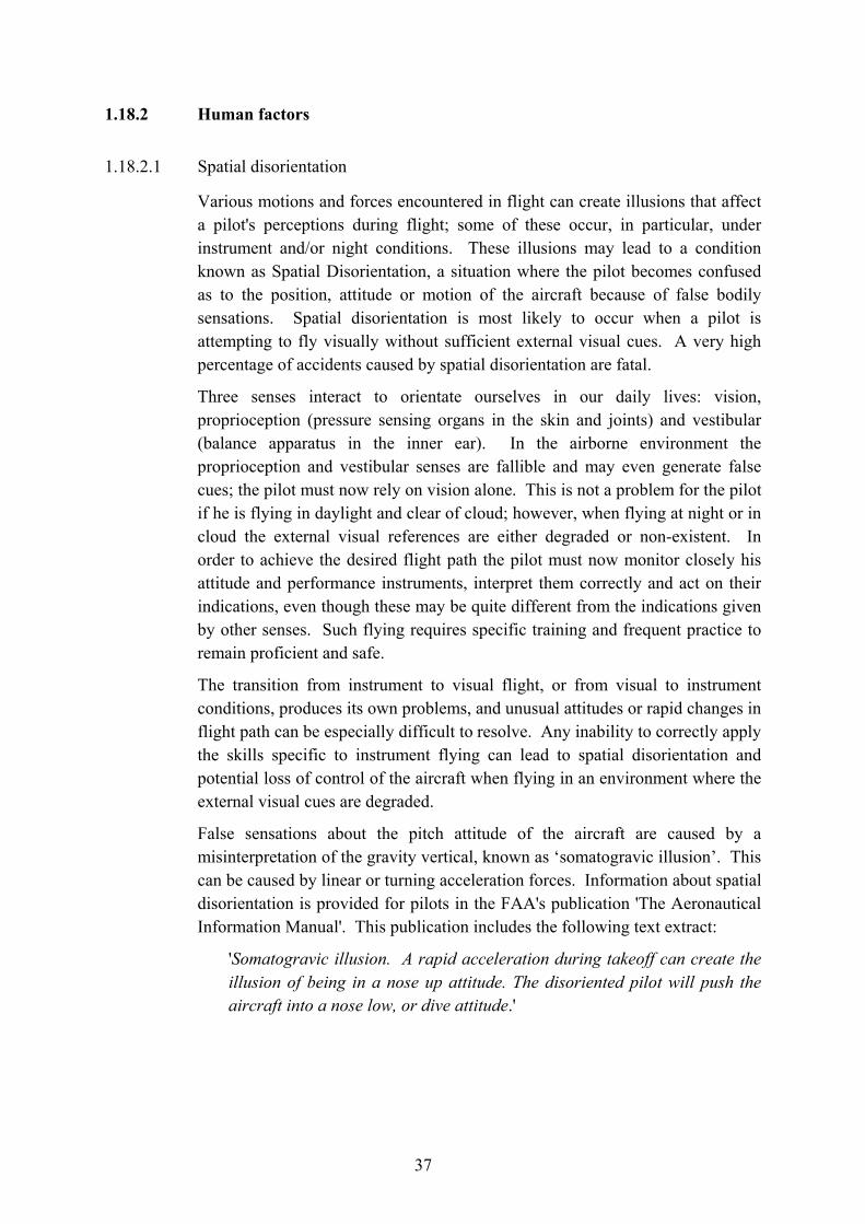
37
1.18.2 Human factors
1.18.2.1 Spatial disorientation
Various motions and forces encountered in flight can create illusions that affect a pilot's perceptions during flight; some of these occur, in particular, under instrument and/or night conditions. These illusions may lead to a condition known as Spatial Disorientation, a situation where the pilot becomes confused as to the position, attitude or motion of the aircraft because of false bodily sensations. Spatial disorientation is most likely to occur when a pilot is attempting to fly visually without sufficient external visual cues. A very high percentage of accidents caused by spatial disorientation are fatal.
Three senses interact to orientate ourselves in our daily lives: vision, proprioception (pressure sensing organs in the skin and joints) and vestibular (balance apparatus in the inner ear). In the airborne environment the proprioception and vestibular senses are fallible and may even generate false cues; the pilot must now rely on vision alone. This is not a problem for the pilot if he is flying in daylight and clear of cloud; however, when flying at night or in cloud the external visual references are either degraded or non-existent. In order to achieve the desired flight path the pilot must now monitor closely his attitude and performance instruments, interpret them correctly and act on their indications, even though these may be quite different from the indications given by other senses. Such flying requires specific training and frequent practice to remain proficient and safe.
The transition from instrument to visual flight, or from visual to instrument conditions, produces its own problems, and unusual attitudes or rapid changes in flight path can be especially difficult to resolve. Any inability to correctly apply the skills specific to instrument flying can lead to spatial disorientation and potential loss of control of the aircraft when flying in an environment where the external visual cues are degraded.
False sensations about the pitch attitude of the aircraft are caused by a misinterpretation of the gravity vertical, known as ‘somatogravic illusion’. This can be caused by linear or turning acceleration forces. Information about spatial disorientation is provided for pilots in the FAA's publication 'The Aeronautical Information Manual'. This publication includes the following text extract:
'Somatogravic illusion. A rapid acceleration during takeoff can create the illusion of being in a nose up attitude. The disoriented pilot will push the aircraft into a nose low, or dive attitude.'

38
1.18.2.2 Night vision
The human eye takes some minutes to adjust to darkness, but any degree of dark adaptation is lost within a few seconds of viewing a bright light. Subsequent adaptation to the dark takes many minutes.
1.18.2.3 Effects of alcohol
There is evidence that the presence of alcohol starts to affect the human body at almost any level. The opinion of the medical practitioner from his analysis of the toxicological report was as follows:
‘The main problems associated with levels in the 0.02% range are, decreased rate of decision making; changes in eye movements including nystagmus1 leading to difficulty in focusing on instruments especially in accelerated flight, i.e. a turn, and alteration of oculogyric responses increasing the risk of spatial disorientation.’
1.18.2.4 Other factors
The pilot had borrowed money to fund the purchase of the aircraft. It was reported to the investigation team that it had been his intention to establish a local charter service in order to earn money to repay the loan.
The passengers for the flight were all well known to the pilot and came from the same island community. It is possible that he was aware that there were likely to be a number of persons watching the departure of the aircraft from South Caicos.
The presence of an audience has been known to influence the behaviour of pilots, in particular this has been suggested as a contributing cause to some accidents which have occurred at airshows.
1.18.3 Incorrect Propeller Assembly
The right propeller was found to be incorrectly assembled, with a washer free in the pitch change mechanism (Section 1.12.3.9). The erroneous positioning of the washer could only have occurred on installation, most likely on the last occasion on which it had been installed.
The propeller manufacturer noted that the rig test normally carried out following initial re-assembly of a variable-pitch propeller in a USA overhaul shop includes measurement of the blade angle after shutdown with feather selected.
1 Nystagmus is the pattern of alternate slow sweeps and fast return movements of the eye.

39
If necessary, the feather angle is then adjusted to the specified value by substituting shimming washers of a different thickness on the stop screw, which retained the high pitch stop sleeve. The new shim thickness is determined by calculation based on the feather angle initially achieved.
This would normally be the last occasion on which the stop screw with its washers, shims and sleeve would be removed. It would then be usual for there to be no subsequent shop check of propeller operation, both because the re-shimming calculation was considered reliable and because of difficulties in achieving the necessary conditions. The propeller would normally be re-assembled with the mechanism engaged in the start lock, preventing the blades from being driven to feather with the propeller static. It would be possible to again spin the propeller on a test rig to disengage the start lock and then shutdown in feather to enable the feather angle to be checked. However, the manufacturer considered that there was likely to be a reluctance to leave the propeller in feather, because this could hinder engine starting after the propeller had been installed on an aircraft. This was considered to be the usual approach, even though the mechanism could be manually driven back into the start lock using blade paddles, with the propeller static.
If the re-assembly following the shimming adjustment of the feather angle were carried out with the propeller axis horizontal, it would be necessary for the washers, shims and sleeve to be carried on the screw during its installation. In this situation it would be possible for the washer to fall off and slip into the space where it was found without the error being apparent.

40
2. Analysis
2.1 Operation of the aircraft
2.1.1 Pilot qualification, experience, training and operation of the flight
The pilot held an FAA CPL with an appropriate type rating. He was thus licensed to fly the aircraft on a flight in the prevailing conditions, but because he had not fulfilled the takeoff and landing experience requirements in the 90 day period preceding the accident he was not qualified to carry passengers at night.
To operate the Piper Aztec aircraft at night in TCI the pilot would have been required to hold a licence with a valid Multi Engine Instrument Rating. The pilot did not have this qualification and therefore was not allowed to operate under IFR, which he was required to do in TCI airspace at night.
The take off from Providenciales was at sunset and the round-trip flight would have taken at least one hour. Night flight in TCI airspace starts 30 minutes after sunset and it would therefore not have been possible to complete the flight within this time. In the event, because of the delays, the takeoff from South Caicos was at around 1.5 hours after local sunset. At this time, almost complete darkness prevailed away from the area of the airport lights.
The pilot had limited experience on the Piper Aztec aircraft. His previous experience in flight at night was conducted almost exclusively within Florida, USA, and the majority of airports in that region are in locations with extensive cultural lighting. A pilot used to such an environment might not therefore be well prepared for a takeoff into an area without such illumination, for example South Caicos. He had quite possibly never experienced a takeoff at night without at least some environmental lighting.
While the pilot did hold a single engine instrument rating, most or all of his instrument flying hours had been obtained under controlled conditions, during his training course. One of the most difficult aspects of instrument flying is the unexpected transition into and out of flight without external visual references. Although this was a clear night it was dark and, without the benefit of environmental lighting, as soon as he turned the aircraft away from the runway the pilot would have been deprived of any external visual reference. Unless he understood and was prepared for this, maintaining control of the aircraft would be difficult.
Normal good practice in these conditions would be to climb straight ahead and concentrate on achieving stable instrument flight and a safe height before attempting any turning manoeuvre. The early turn he carried out points to a lack of appreciation that he would need to use his instruments for reference once airborne.

41
The pilot was exposed to bright flood lighting on the parking area before departure and subsequently to the bright runway lights on takeoff. If he had attempted to use his flight instruments as he turned away from the runway his eyes would have been poorly adapted for the relatively low light conditions, therefore he may have had difficulty in seeing the instruments.
2.1.2 Departure turn
The pilot was observed to carry out a turn very shortly after takeoff on departure from Providenciales and seems to have attempted a similar manoeuvre on his subsequent departure from South Caicos. A turn performed immediately after takeoff is an unnecessarily risky manoeuvre even in daylight but in darkness, where flight by sole reference to instruments will be required, it is even more so.
For this departure at night it would be expected that after takeoff a pilot would have focused his attention on the flight instruments and climbed straight ahead; there was no reason for a turn to have been initiated at such an early stage of the flight. Once stabilised in flight by reference to instruments and at a safe height, a turn to the left onto the planned course could then have been made safely.
Witness evidence showed that a turn to the left was carried out almost immediately after leaving the runway. If this manoeuvre was unintentional, then a significant problem would need to have occurred to cause the turn. The nature of such a problem could be a flight control restriction or disconnection, an unintentional engagement of the autopilot, a loss of control following an engine failure, an incapacitation of the pilot or some other unknown factor.
Some of these factors can be discounted in view of the circumstances. The aircraft had just been flown from Providenciales and there was no indication that there had been any control problem on that flight. If the turn shortly after takeoff had been the result of a control problem, it is unlikely that the aircraft would have stayed airborne as long as it did.
If the autopilot had been turned on accidentally it is possible that it would try to turn the aircraft as soon as it became airborne. However it is also probable that the pilot would have noticed that the controls were restricted by the autopilot on his pre-flight control check. Furthermore, evidence from the wreckage examination indicates that the autopilot was OFF.
The wreckage examination found no evidence of powerplant failure and indicated that both powerplants were delivering power at a similar level at the point of impact. Furthermore, witnesses did not report any obvious change in engine sound. If a loss of control had resulted from an engine failure after take off it is unlikely that the aircraft would have continued in flight as long as it did, or that the impact speed would have been as high as it was (Section 2.5).

42
Similarly, should incapacitation of the pilot have been responsible for the early turn, it would have been unlikely that the aircraft would have continued in flight for as long as it did.
The reason why the pilot would carry out an intentional early turn could not be determined but it is possible that the presence of friends on board the aircraft and spectators at the airport may have contributed to his decision to do so. With his relative lack of experience he may not have appreciated the risks associated with such a manoeuvre. He had made a similar turn on departure from Providenciales in good visual conditions and possibly did not realise the effect that darkness would have on the difficulty of such a manoeuvre. In conclusion, it is most likely that the turn after takeoff was made intentionally.
2.1.3 Effects of alcohol
Traces of alcohol were found in the toxicological samples from the pilot but, given the levels of ethanol present in the samples, it was not possible to conclude whether or not alcohol had been consumed by the pilot before the flight.
It should however be considered whether, if a relatively small amount of alcohol was present in the pilot's system before the flight, it could have affected his ability to safely conduct the flight. There are two possible effects of alcohol which may have had an influence in these circumstances. One is the effect upon behaviour, where even small levels of alcohol are known to increase confidence and, in these circumstances, this could have influenced the pilot’s decision to continue the flight in darkness following the delayed departure. The other effect is that the presence of alcohol could have increased the pilot’s susceptibility to spatial disorientation.
2.2 Spatial disorientation The impact attitude and speed at which the aircraft crashed (Section 2.5) indicated that a loss of control in flight had occurred. The most likely reason for this was that the pilot suffered from spatial disorientation; this is borne out by a number of different factors.
The pilot may have been unaware of, or may not have considered, the effect of the lack of environmental lighting to the north of the airfield and that he would need to fly with sole reference to his instruments. The evidence indicated that he had no recent experience of flight at night or of instrument flight. In any case his previous experience in both was relatively low and for instrument flight had taken place only on single engine aircraft. The greater complexity involved in flying a multi-engine aircraft would have added to the difficulty of instrument flight. Such flying requires specific training and frequent practice to remain proficient and safe.

43
The decision to turn at an early stage after takeoff, before he could have achieved stable instrument flight, would have prevented his then being able to adapt to flight by sole reference to instruments when it was required. The forces due the to acceleration during takeoff and the forces due to the left turn could both have contributed to create a somatogravic illusion of a nose up attitude. The pilot would then instinctively have pushed the nose of the aircraft down. If he attempted to refer to his instruments there would have been a conflict with his physical sensations, leading to disorientation, which he would have been unlikely to be able to resolve given his level of experience and lack of recent practice.
2.3 Commercial and private flights The additional requirements for the operation of a commercial air transport flight above those for a private flight are designed to ensure a level of oversight and regulation with a view to safeguarding public safety.
The distinction between private and commercial transport operations can be complicated, is often not well known by members of the public, and the passengers on this flight may well not have been aware of any distinction. They may reasonably have thought that the pilot was suitably qualified and sufficiently experienced to conduct the flight safely and could legitimately accept money for the flight. It could not be determined whether or not they knew that the typical charter price for such a flight was US $450, higher than the price they had apparently agreed to pay.
The evidence indicated that the pilot had agreed to carry out the flight on the basis that he would be paid. Were the flight to have been operated as a private flight on a cost sharing basis, direct costs only would have been shared. The direct costs for operating this flight, approximately $100, would have been considerably less than the $300 which was said to be the agreed amount, thus the flight did not meet the requirements for cost sharing. Furthermore the original intention was to carry five passengers, a number which would also have precluded cost sharing. In any case it is unlikely that the pilot was aware of the rules on cost sharing since the rules were specific to operation under the terms of the UK ANO (OT) and he had only been trained in FAA regulations. Thus the fee that was reportedly arranged for the flight could only have been on a commercial basis and the pilot was not entitled to carry out a commercial flight within TCI airspace.
2.4 Reasons for attempting the flight Whether or not the pilot knew that in accepting money for the flight he was in contravention of the TCI regulations is not certain. He should, however, have been aware that he was not allowed to carry passengers at night under the terms

44
of his FAA licence. It is necessary to consider some of the possible pressures on him in order to understand why he attempted to do so
The pilot had borrowed a substantial amount of money to purchase the aircraft, and it was his stated intention to earn money by flying it. He would not have been able to operate legitimately in TCI until he had obtained the appropriate licence and an AOC. However, the incentive of being paid to carry out the flight would have exerted a financial pressure and is possibly one reason why he accepted the flight originally.
The delay to the departure from South Caicos ensured that the takeoff would be made in darkness and the pilot should have cancelled the flight. However, a number of self-imposed pressures, other than financial, may have influenced him to continue. He may have been conscious that the people gathered at the airport were expecting to see him takeoff in his newly-acquired aircraft. In addition, his passengers were at the airport expecting to travel; it may have been difficult, and could have involved a loss of face, to explain to them that he could not fly them at night.
2.5 Accident Site and Wreckage Evidence
2.5.1 General
South Caicos is a relatively small island and the facilities available for inspection of the site and recovery and local inspection of the wreckage were understandably limited. However, it proved possible to carry out an effective recovery and a detailed and comprehensive investigation of the wreckage. This was assisted by good co-operation by the aircraft, engine and propeller manufacturers. Effective work by the recovery team meant that a large percentage of the aircraft, estimated at 90-95%, was recovered and a substantial amount of evidence was obtained from the accident site and the wreckage.
2.5.2 Accident Site
The evidence from the wreckage location showed that N444DA crashed into the sea in shallow water on the Caicos Bank approximately 1 nm to the north-west of the start of Runway 11 at South Caicos Airport. The accident site was around 0.5 nm from the local shore. Wreckage found embedded in the sand at just two positions indicated that both powerplants had struck the seabed but that most of the structural damage to the aircraft had resulted from impact with the water.
2.5.3 Impact Parameters
The pattern of wreckage distribution at the accident site indicated that the aircraft had been travelling in a north-north-easterly direction at the time of

45
impact (Figure 2). The distribution of the wreckage also showed that that the aircraft had been generally upright when it struck the sea. Multiple features of the damage revealed by the structural layout in the hangar, in particular the characteristics of the structural deformation in a number of areas, indicated that it had been pitched around 10-20° nose down and banked around 20-40° right at impact. Markings on the attitude indicator from the cockpit positively indicated that the aircraft attitude had been around 15-20° nose down pitch and 25-30° right bank.
The appreciable degree of structural break-up that occurred indicated that the aircraft had been travelling at relatively high speed at the time of impact, estimated at 150-200 kt. Positive evidence from instrument markings indicated that the airspeed had been close to 185 kt. The combined evidence from the characteristics of the wreckage distribution and structural damage and from the instrument markings suggested that the aircraft had been descending at around 20-25° to the horizontal.
It was clear from the evidence that the accident was not survivable.
2.5.4 Aircraft Configuration
Witness markings on the flap position indicator in the cockpit suggested that flaps had been in the retracted position at impact and this was reinforced by the markings on the flap surfaces, which also indicated that there had been no flap asymmetry.
Combined evidence from the light bulbs from the landing gear position indicator captions positively showed that the landing gear had been in the retracted position. The lack of evidence from one of the landing gear caption bulbs indicated that it had not received sufficient shock loading to provide an indication.
2.5.5 Flight Controls
Wreckage markings provided some indications suggesting that the rudder and ailerons were approximately neutral at impact.
While a few parts of the flight control systems could not be identified, most of the components were available for inspection. No signs of pre-impact failure were found. With the mechanical type of control systems used on the aircraft the possibility of a control jam could not be totally dismissed. However, the control channels were independent and in the event of the seizure of one primary control channel the function could generally be substituted by another primary control (eg rudder, if ailerons were jammed) or a trim system (eg pitch trim, if the stabilator were jammed). Thus, unless a seizure of one channel occurred while a substantial displacement of the control from neutral were present, the aircraft would probably remain controllable. No previous problems

46
with the flight control system had been reported and it was judged from the overall evidence to be improbable that malfunction of the flight controls had contributed to the accident.
Combined evidence from three indicator light bulbs associated with the auto-pilot selector showed that the auto-pilot had been off at impact. This was in accordance with the expectation that the auto-pilot would not have been selected on so soon after takeoff.
2.5.6 Powerplant
2.5.6.1 Powerplant Anomalies
A number of anomalies with the engines and propellers were found, some of which had been present before the accident, and were considered in detail during the investigation.
The rupture of the diaphragm in the fuel flow divider, as occurred on both engines, was reportedly an unusual occurrence in service. It was thus highly unlikely that both diaphragms had ruptured before the accident. Nonetheless, consideration was given to the possibility of diaphragm rupture before impact. While it appeared unlikely that this would have caused significant power loss from the associated engine, the available evidence did not allow the possibility to be totally eliminated. However, other evidence, indicating relatively high power levels on both powerplants for most of the flight and symmetrical power at impact (Section 2.5.6.2), indicated that pre-impact power loss as a result of diaphragm rupture had not occurred.
Additionally, rupturing of the diaphragm was known to result in some crash situations, due to excessive pressure generated by inertial forces on fuel in the pipelines. It was therefore judged likely that the ruptures had resulted at impact, and signified that appreciable quantities of fuel had been present in the high pressure fuel system of both engines at the time.
Furthermore, the evidence indicated that the low tightening torque present in both clamping nuts of both magnetos of the right engine had probably resulted from crash forces. Had the condition had been present before impact it was likely that a reduction in power, rather than stoppage of the engine, would have resulted if the nuts had been loose enough to allow one or both magnetos to displace from its set position. However, neither the frettage not detachment of the nuts due to vibration that would be expected if the condition had been present before impact had occurred. Additionally, other evidence indicated that there had not been a significant power loss during the flight (Section 2.5.6.2). It was therefore concluded that the low torque had resulted from crash forces.
The damage to the components of the drive unit for the left magneto of the left engine and the absence of a split pin intended to secure the right magneto shaft

47
nut of this engine resulted from assembly errors. However, neither anomaly would have affected the operation of the engine. Similarly, the lack of an oil feed hole in the accessory gearbox casing of both engines was not in accordance with the engine manufacturer’s instructions but had not affected engine operation.
The crushing of the crankcase shim on the right engine, clearly the result of an assembly error, was a potentially serious fault but in this case again had not affected engine operation.
The loose washer in the right propeller mechanism was a further instance of incorrect assembly, although the evidence indicated that it had not affected the operation of the propeller in the power-on range and had not contributed to the accident. However, this anomaly could have had serious consequences in the event of a shutdown of the right engine. In such a situation it would not have been possible to fully feather the propeller, as required in order to minimise aerodynamic drag from the blades. Thus the aircraft’s climb performance with the right engine shutdown would be reduced and the asymmetric yawing moment on the aircraft would be increased, increasing the minimum airspeed at which the aircraft would remain controllable.
This assembly error was clearly likely to have resulted on the last occasion on which the relevant part of the propeller mechanism had been assembled. This had possibly been during adjustment of the stop shims after rig testing following propeller overhaul. The fact that the mis-assembly had not been corrected indicated that no subsequent check measurement of the blade angles achieved with feather selected had been made, following running either on a rig or after installation of the propeller on the aircraft. While this was apparently normal practice, the lack of a check following final assembly did not appear acceptable, as demonstrated by this case. It has therefore been recommended that the FAA require that, before flight, variable-pitch propellers receive a full functional ground check following final assembly or re-assembly.
Thus, positive evidence was found that a substantial number of engine and propeller assembly errors were present before the accident, as follows:
Powerplant Component Anomaly
Left Left Magneto Drive unit mis-assembled
Left Right Magneto Shaft nut split pin absent
Left Accessory Gearbox Casing Oil feed hole for oil pump absent
Right Crankcase Shim mis-assembled
Right Propeller mechanism Washer mis-assembled
Right Accessory Gearbox Casing Oil feed hole for oil pump absent

48
While none of the anomalies appeared to have contributed to the accident, some of them could have had serious potential consequences. Their presence clearly indicated an inadequate standard of quality control during repair/overhaul. It has therefore been recommended that the FAA take measures aimed at ensuring an adequate standard of quality control during repair and overhaul operations on light aircraft engines and propellers.
2.5.6.2 Power
Positive signs of powerplant rotation at impact were not found on the engine components, but with this type of impact it could be expected that forces on the propeller blades on initial contact with the water could cause rapid engine stoppage. Experience showed that in similar circumstances, with engines rotating and delivering power, it was not unusual for such signs to be absent if the engine remained intact.
Signs suggesting that both engines were operating at impact were given by engine indicator features, with indications of normal oil temperature for the left engine and normal oil pressure for both engines.
Impact and corrosion damage precluded functional testing of most engine fuel and ignition system components and of the propeller pitch change mechanisms. However, the twisting and forward bending deformation of one of the blades on each propeller was characteristic of the effects of overload forces on the blade generated by initial blade contact with the water while at a positive relative angle of attack. The features therefore showed that both propellers had been rotating and delivering power at initial impact. It was judged likely that the rearward bending nearer the root of both blades on each propeller had occurred during the break-up, after the engines had rapidly slowed or stopped. The limited degree of forward blade bending could have been because the propellers were not delivering high power or because the relatively steep descent caused rapid engine stoppage at impact.
A particularly notable feature was the congruence between the deformation of the left and right pair of propeller blades, strongly indicating that the power level being delivered by the two engines and propellers at impact had been similar. Markings found on the pitch change mechanism of each propeller were indicative of a blade angle of around 20°, equivalent to a low power level, given the relatively high airspeed. While the markings were not considered highly positive, the power level they suggested was generally consistent with the extent of the propeller blade deformation.
No evidence was available to indicate the point in the flight at which the final power level had been set; it was possible that the pilot had reduced the power setting shortly before impact. The relatively high impact speed, achieved

49
comparatively shortly after takeoff, was notable and performance considerations indicated that the power delivered by both engines had been at a relatively high level for most of the flight.
Thus it was concluded that the two engines had been delivering approximately equal power, probably in the low-mid power range, at the point of impact, and that engine power had been at a relatively high level for most of the flight.
2.5.7 Aircraft Structure
The detailed examination revealed no signs that any parts had separated from the aircraft before impact, or that structural failure or foreign object impact had occurred. All doors and hatches were present and the evidence indicated that all were in the latched closed position at impact. Signs were found that the pilot’s seat had been latched securely at a mid position on its rails. It was clear that no fire had occurred on the aircraft.
2.5.8 Systems
The instrument witness markings suggesting that the charging rate of the aircraft’s electrical system was consistent with normal operation of the system. Additionally, the eyewitness reports of external aircraft lights visible suggested that there had not been a major electrical system failure. The positive evidence that at least some instrument panel and landing gear caption bulbs had been illuminated at impact reinforced this conclusion. Thus it was unlikely that a failure of the aircraft’s electrical system had contributed to the accident.
The absence of signs of pre-impact damage to both vacuum pumps, coupled with the evidence that both engines were operating at impact, and the evidence on the vacuum system indicator of a normal level of system pressure indicated that a vacuum system failure had not contributed to the accident. This was reinforced by the consistency of the indications given by the attitude indicator with the attitude initially determined from the overall examination of the aircraft wreckage. Thus it appeared highly unlikely that failure of either the aircraft’s vacuum system or the attitude indicator had contributed to the accident.
There was positive evidence that some of the instrument panel lighting bulbs had been illuminated at impact. The fracture of the filament of one of the recovered instrument panel illumination bulbs may have been the result of it having failed, or lost its power supply, before the accident. However, it would not be expected that this would cause a significant problem. It was also possible that the filament had been illuminated at initial impact but had received insufficient shock loading to stretch and had suffered the failure later in the aircraft break-up sequence.

50
The setting of the instrument panel lighting could not be established but an inadequate illumination level would inevitably have been immediately apparent, and likely to have been corrected, before takeoff.
2.5.9 Summary
In summary, the impact parameters were approximately as follows:
Track - North-north-easterly
Airspeed - 185 kt
Descent Angle - 20-25° to the horizontal
Pitch Angle - 15-20° nose down
Bank Angle - 25-30° right wing down
The configuration and probable condition of the aircraft was as follows:
Landing gear - Retracted
Flaps - Retracted
Powerplants - Left and right delivering similar power, at an approximately mid-low power level. Both powerplants had delivered relatively high power during most of the flight.
Doors and hatches - Closed
Electrical System - Functioning
Vacuum System - Functioning
Instrument Lighting - At least part of the system functioning, illumination level unknown
Attitude Indicator - Indicating correctly
As is usual with this type of investigation, it was not possible to totally dismiss the possibility of pre-impact failure or malfunction of the aircraft. However, a broad and detailed investigation revealed a substantial body of evidence. This provided no signs of a failure, malfunction or anomaly of the aircraft or its equipment likely to have been relevant to the cause of the accident. The evidence indicated that the accident had probably resulted from spatial disorientation of the pilot leading to a loss of control.

51
3 Conclusions
(a) Findings
1. Five passengers originally intended to travel on the flight; in the event three passengers were on board the accident flight.
2. The flight was delayed and the takeoff was carried out at night.
3. The weather was good but it was almost completely dark, with no moonlight and very little environmental ground lighting visible along the route flown.
4. The pilot was licensed to fly the aircraft at night but had not completed the required number of takeoffs and landings at night in the preceding 90 days and was therefore not allowed to carry passengers at night.
5. The pilot was not qualified to fly a multi-engine aircraft under Instrument Flight Rules, as was required at night within TCI.
6. There was a low level of ethanol present in the toxicological samples from the pilot; it was not possible to determine whether or not this was as a result of his having consumed alcohol at some time before the flight.
7. The pilot had limited night flying experience and possibly none that involved a takeoff into an area without some environmental lighting.
8. After takeoff the pilot would need to have flown the aircraft by sole reference to his flight instruments because of the darkness and absence of environmental lighting.
9. There was a left turn very soon after take off, which was probably carried out intentionally by the pilot; the subsequent flight path was erratic.
10. The aircraft descended into the sea at relatively high speed and suffered severe break-up.
11. Wreckage examination identified a substantial number of engine and propeller assembly errors; none was likely to have contributed to the accident.
12. Detailed investigation found no evidence of failure, malfunction or anomaly of the aircraft or its equipment likely to have been relevant to the cause of the accident.
52
13. The pilot probably suffered from spatial disorientation as a result of the accelerations during takeoff and the turn very shortly afterwards, leading to a loss of control.
(b) Causal factors
The investigation identified the following causal factors:
1. A lack of appreciation by the pilot of the difficulty in executing a turn very shortly after take-off in conditions of almost complete darkness.
2. A loss of control of the aircraft as a result of spatial disorientation.

53
4. Safety Recommendations The following safety recommendations have been made:
Recommendation 2007-001: It has been recommended that the FAA require that, before flight, variable-pitch propellers receive a full functional ground check following final assembly or re-assembly.
Recommendation 2007-002: It has been recommended that the FAA take measures aimed at ensuring an adequate standard of quality control during repair and overhaul operations on light aircraft engines and propellers.