Advanced SolidWorks Workshop 2018/19 - T4.ie
19
➢ Surfacing ➢ Advanced Mates ➢ Tips & Tricks including Visualize Advanced SolidWorks Workshop 2018/19
-
Upload
khangminh22 -
Category
Documents
-
view
4 -
download
0
Transcript of Advanced SolidWorks Workshop 2018/19 - T4.ie

➢ Surfacing
➢ Advanced Mates
➢ Tips & Tricks including Visualize
➢ 3 Visualize
Advanced SolidWorks
Workshop 2018/19
Advanced SolidWorks 2018-19 Page 3
Introduction
This workshop aims to upskill and develop teachers understanding of advanced modelling
techniques in SolidWorks 2018. The workshop will further interrogate ‘Surface Modelling’
techniques for teachers of Design and Communication Graphics while also examining
features such as Flex, Split Line, Rib, Combine, Lip & Groove, Vent, and advanced
Mechanical Mates.
Learning Intentions
At the end of this workshop you should be able to:
• Explore a modelling technique using planar or non-planar geometry with zero
thickness.
• Understand and apply some ‘Surfacing’ features in a SolidWorks design model.
• Understand and apply the use of non-planar 3D sketching.
• Explore the use of features including Flex, Split Line, Rib, Combine, Lip & Groove,
Vent, and advanced Mechanical Mates.
• Explore best practice when using SolidWorks including the use of SolidWorks Rx,
Pack & Go and toolbar settings
• Develop and understanding of SolidWorks Visualise, for the creation of enhanced
photorealistic images within the software.
Advanced SolidWorks 2018-19 Page 4
Key Messages for this workshop:
• Surface Modelling can be used to model complex designs within SolidWorks
• The transition from zero thickness surface geometry to solid objects is a necessary
and fluid transition in advanced cad modelling.
• The appropriate use of advanced commands such as those outlined above, will
significantly enhance realistic parametric modelling.
• 3D sketching (as opposed to sketching on a planar face) is a valuable technique in
appropriate applications.
Advanced SolidWorks 2018-19 Page 5
Desktop Fan
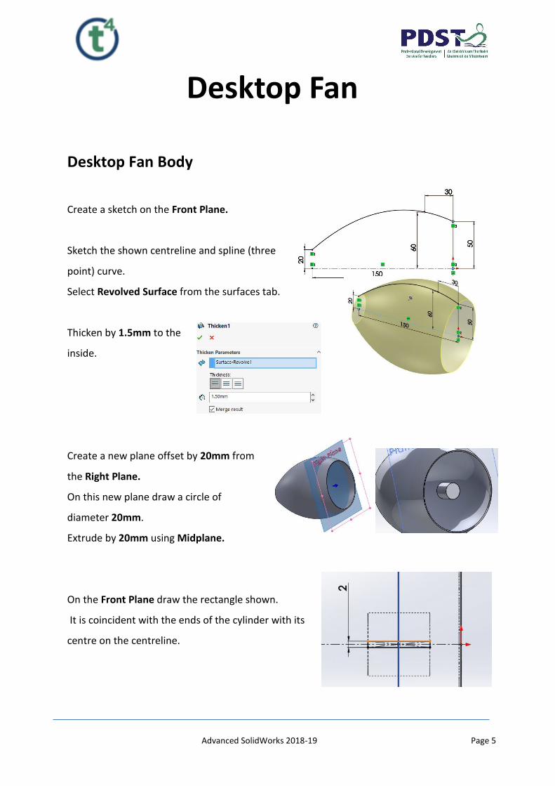
Desktop Fan Body
Create a sketch on the Front Plane.
Sketch the shown centreline and spline (three
point) curve.
Select Revolved Surface from the surfaces tab.
Thicken by 1.5mm to the
inside.
Create a new plane offset by 20mm from
the Right Plane.
On this new plane draw a circle of
diameter 20mm.
Extrude by 20mm using Midplane.
On the Front Plane draw the rectangle shown.
It is coincident with the ends of the cylinder with its
centre on the centreline.

Advanced SolidWorks 2018-19 Page 6
Select extrude in the
features tab and
extrude up to the inside
surface of the shell.
Select circular pattern to
create the other
supports.
Draw a 3mm diameter circle on the face of the
central hub and Extrude Cut through all.
Creating the Wings
Create two planes parallel to the front plane, 30mm
and 120mm respectively from the front plane as
shown.

Advanced SolidWorks 2018-19 Page 7
Select plane 3 and draw the 3-
point spline on the centreline as
shown. Add vertical relations to
the two end points of the spline.
The spline is 42mm from the
origin.
Accept the sketch and
draw the sketch shown
on Plane 2.
Select boundary surface from the surfaces tab.
In the features
tab select Mirror
and mirror about
the top plane.
Advanced SolidWorks 2018-19 Page 8
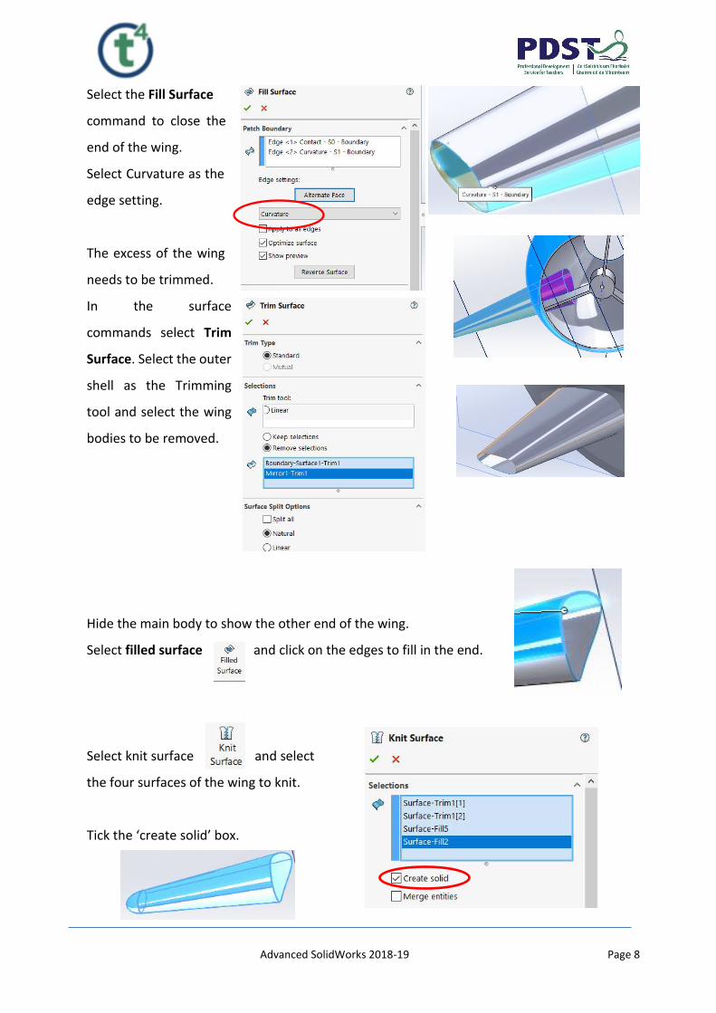
Select the Fill Surface
command to close the
end of the wing.
Select Curvature as the
edge setting.
The excess of the wing
needs to be trimmed.
In the surface
commands select Trim
Surface. Select the outer
shell as the Trimming
tool and select the wing
bodies to be removed.
Hide the main body to show the other end of the wing.
Select filled surface and click on the edges to fill in the end.
Select knit surface and select
the four surfaces of the wing to knit.
Tick the ‘create solid’ box.

Advanced SolidWorks 2018-19 Page 9
Select the Combine command and add the wing to the main part.
Add a 20mm fillet as shown.
Select the mirror
command to
complete the
wings
Creating a vent.
Create a plane at the back parallel to the right plane.
On this plane create the circle by using convert entities.
Advanced SolidWorks 2018-19 Page 10
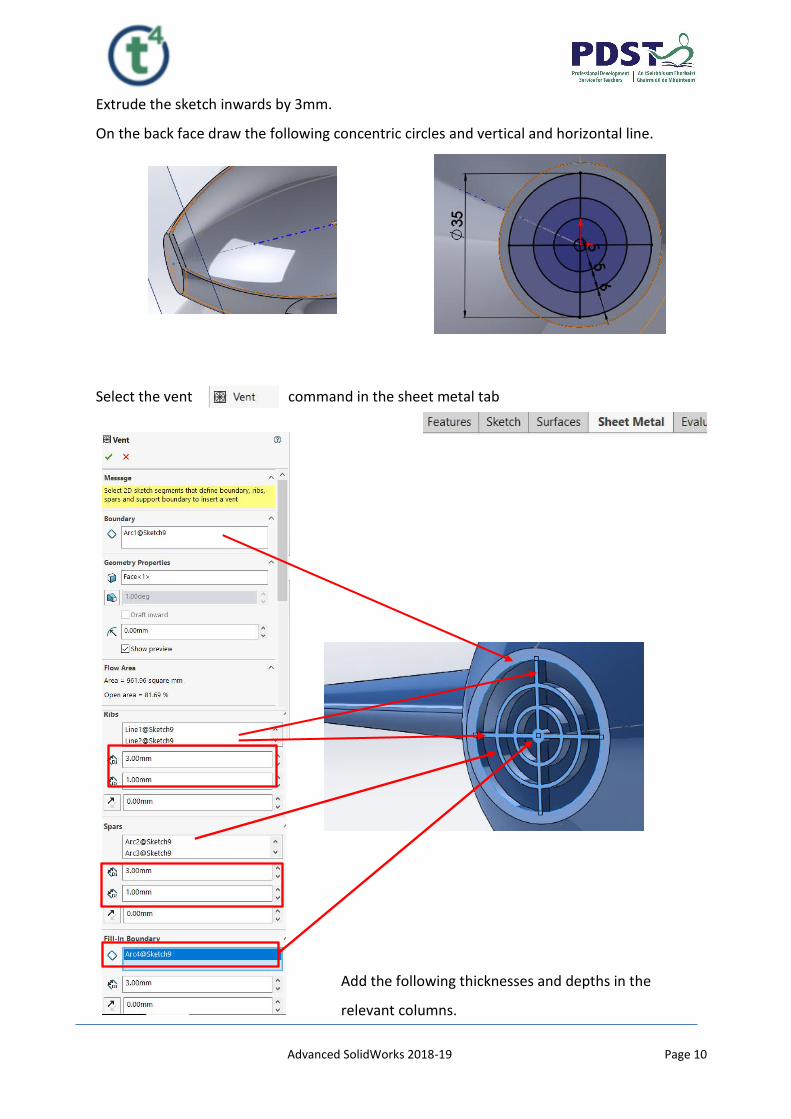
Extrude the sketch inwards by 3mm.
On the back face draw the following concentric circles and vertical and horizontal line.
Select the vent command in the sheet metal tab
Add the following thicknesses and depths in the
relevant columns.

Advanced SolidWorks 2018-19 Page 11
Accept to create the vent shown.
On the front plane draw a centreline at an angle of 70
degrees as shown. The line starts midway along the
centreline containing the origin.
Use convert entities to select the bottom arc.
Create a plane perpendicular to the line and containing
the end point of the line as shown.
On this plane draw a circle diameter 10mm.
Extrude by 10mm in
direction 1 and up
to body in direction
2
This cylinder will aid the assembly of the body to the base later.
Advanced SolidWorks 2018-19 Page 12
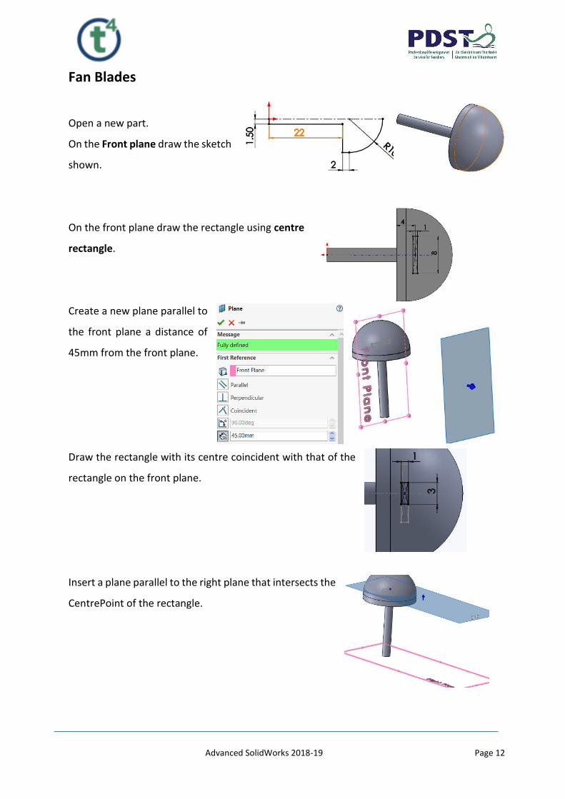
Fan Blades
Open a new part.
On the Front plane draw the sketch
shown.
On the front plane draw the rectangle using centre
rectangle.
Create a new plane parallel to
the front plane a distance of
45mm from the front plane.
Draw the rectangle with its centre coincident with that of the
rectangle on the front plane.
Insert a plane parallel to the right plane that intersects the
CentrePoint of the rectangle.

Advanced SolidWorks 2018-19 Page 13
Use two-point spline to draw the shape shown.
Make a pierce relation between the end of the spline and the short
side of the rectangles.
Mirror the spline about the centreline.
Use the loft command to create the blade.
Select the flex command as shown.
Advanced SolidWorks 2018-19 Page 14
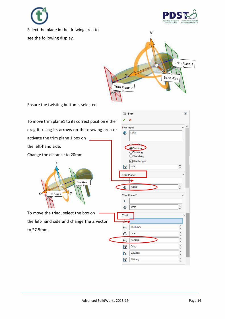
Select the blade in the drawing area to
see the following display.
Ensure the twisting button is selected.
To move trim plane1 to its correct position either
drag it, using its arrows on the drawing area or
activate the trim plane 1 box on
the left-hand side.
Change the distance to 20mm.
To move the triad, select the box on
the left-hand side and change the Z vector
to 27.5mm.
Advanced SolidWorks 2018-19 Page 15
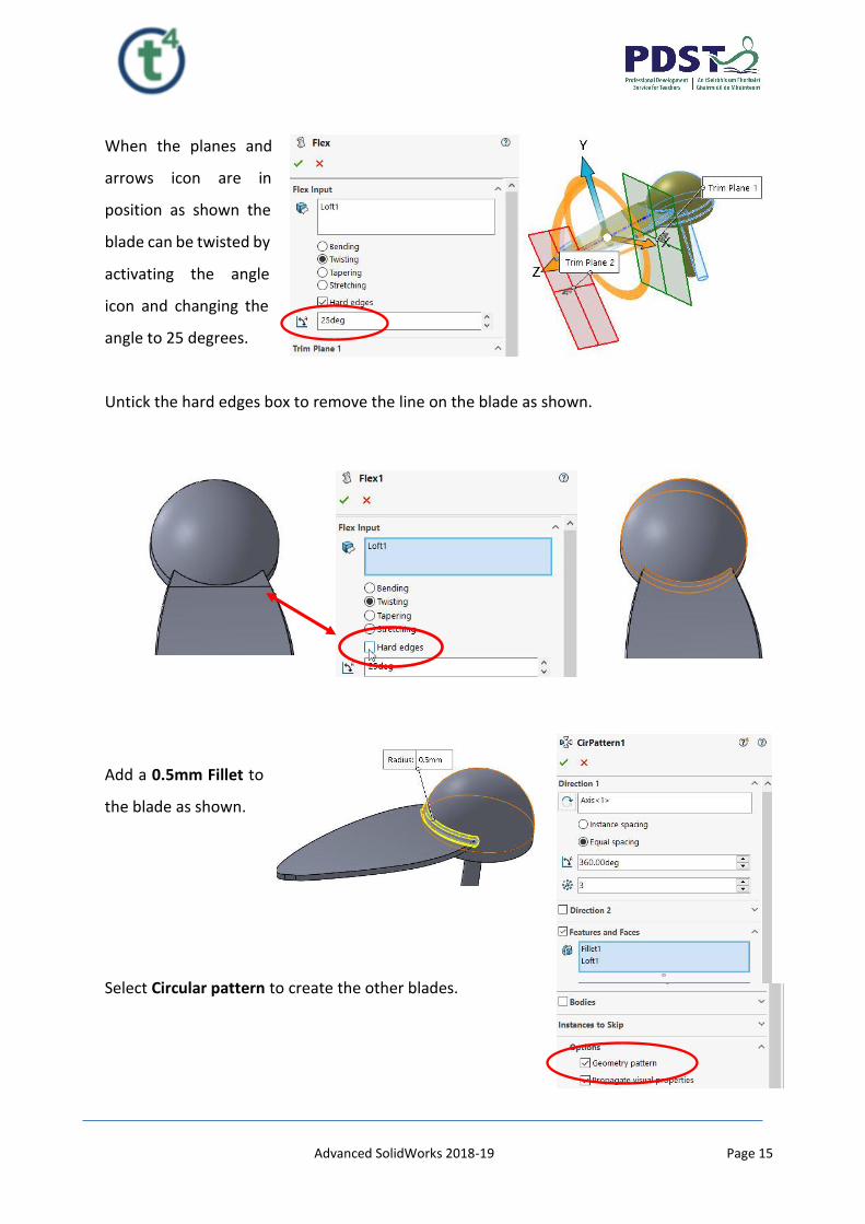
When the planes and
arrows icon are in
position as shown the
blade can be twisted by
activating the angle
icon and changing the
angle to 25 degrees.
Untick the hard edges box to remove the line on the blade as shown.
Add a 0.5mm Fillet to
the blade as shown.
Select Circular pattern to create the other blades.

Advanced SolidWorks 2018-19 Page 16
Make sure to tick
the geometry
pattern box.
Add a High Gloss Brown plastic finish to the part.
Desktop Fan Base
On the Top Plane draw the ellipse shown.
Insert a plane offset 30mm from the top plane.
Draw another ellipse to the given dimensions.
Select loft to complete the solid.
Draw a circle on plane 1 as shown and extrude cut by 20mm.
The top of the base needs to be curved to allow the body fit snugly into it. This is achieved
by using the Combine feature. The body is brought into the drawing and placed into its
final position and the excess of the base is removed.
Advanced SolidWorks 2018-19 Page 17
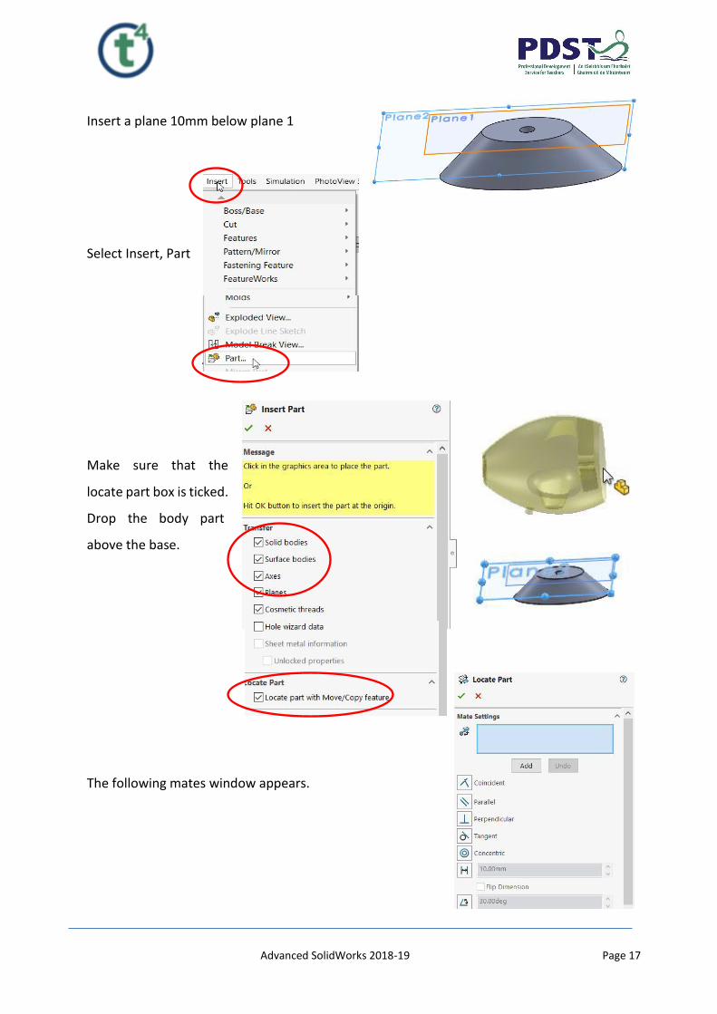
Insert a plane 10mm below plane 1
Select Insert, Part
Make sure that the
locate part box is ticked.
Drop the body part
above the base.
The following mates window appears.

Advanced SolidWorks 2018-19 Page 18
Mate the plane shown on the fan body with the
plane highlighted on the base and select add.
Mate the cylinder at the base of
the body with the hole in the base
and select add.
Finally mate the front plane of the fan body with the
front plane of the base. Select add then accept by
selecting the green tick.
The fan body is now in the correct position.

Advanced SolidWorks 2018-19 Page 19
Select the Combine command.
Select the subtract button.
Select the base part as the main body
and the fan body part as the body to
combine.
A window appears. Tick the base part as the body to keep
The base part is now created.
Add a High Gloss brown plastic to the part.
Advanced SolidWorks 2018-19 Page 20
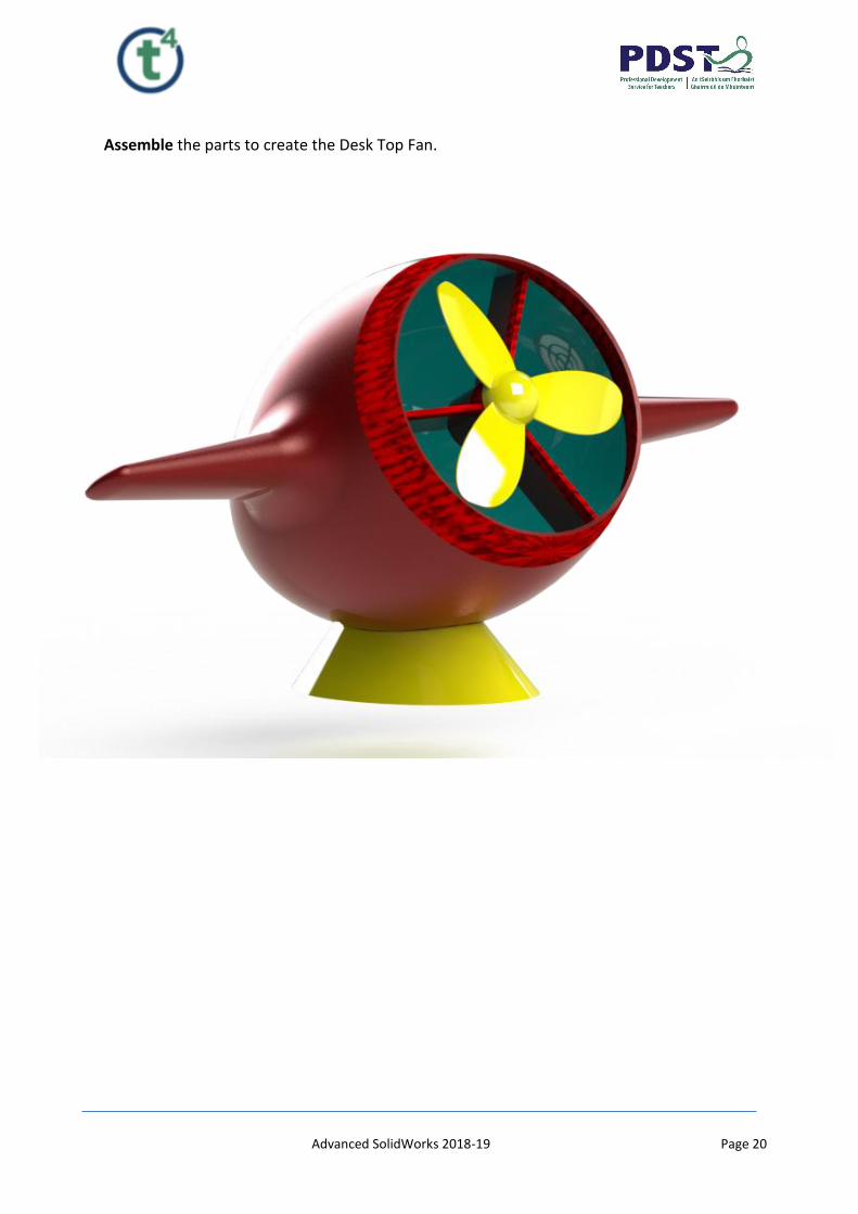
Assemble the parts to create the Desk Top Fan.