calculation of releases of radioactive materials in gaseous and ...
Upload
khangminh22Category
view
0download
0
Nokia — Proprietary.Use pursuant to applicable agreements.
7450 Ethernet Service Switch 7750 Service Router7950 Extensible Routing System
Advanced Configuration Guide - Part III Releases Up To 20.10.R2
3HE 14992 AAAE TQZZA 01
Issue: 01
January 2021
Advanced Configuration Guide - Part III Releases Up To 20.10.R2

Advanced Configuration Guide - Part IIIReleases Up To 20.10.R2
2 3HE 14992 AAAE TQZZA 01 Issue: 01
Nokia is committed to diversity and inclusion. We are continuously reviewing our customer documentation and consulting with standards bodies to ensure that terminology is inclusive and aligned with the industry. Our future customer documentation will be updated accordingly.
Nokia is a registered trademark of Nokia Corporation. Other products and company names mentioned herein may be trademarks or tradenames of their respective owners.
The information presented is subject to change without notice. No responsibility is assumed for inaccuracies contained herein.
© 2017-2021 Nokia.
Contains proprietary/trade secret information which is the property of Nokia and must not be made available to, or copied or used by anyone outside Nokia without its written authorization. Not to be used or disclosed except in accordance with applicable agreements.

Advanced Configuration Guide - Part III Releases Up To 20.10.R2
Issue: 01 3HE 14992 AAAE TQZZA 01 3
Table of ContentsPreface ........................................................................................................27About This Guide.................................................................................................................27
Multi-Service Integrated Service Adapter and Extended Services Appliance............................................................................. 29
Application Assurance — Application Identification and User-Defined Applications ..................................................................................31
Applicability ...................................................................................................................31Overview ...................................................................................................................31Configuration ...................................................................................................................33Conclusion ...................................................................................................................57
Application Assurance — App-Profile, ASO and Control Policies..................59Applicability ...................................................................................................................59Overview ...................................................................................................................59Configuration ...................................................................................................................60Conclusion ...................................................................................................................84
Application Assurance — Asymmetry Removal ...............................................85Applicability ...................................................................................................................85Overview ...................................................................................................................85Configuration ...................................................................................................................86Conclusion ...................................................................................................................99
Application Assurance — Best Practices for ISA and Host IOM Overload Protection ....................................................................................101
Applicability .................................................................................................................101Overview .................................................................................................................101Configuration .................................................................................................................107Conclusion .................................................................................................................122
Application Assurance — DNS IP Cache .........................................................123Applicability .................................................................................................................123Overview .................................................................................................................123Configuration .................................................................................................................126Conclusion .................................................................................................................133
Application Assurance — GTP Roaming Firewall ..........................................135Applicability .................................................................................................................135Overview .................................................................................................................135Configuration .................................................................................................................143Conclusion .................................................................................................................168

Advanced Configuration Guide - Part IIIReleases Up To 20.10.R2
4 3HE 14992 AAAE TQZZA 01 Issue: 01
Application Assurance — HTTP and HTTPS Redirect....................................169Applicability .................................................................................................................169Overview .................................................................................................................169Configuration .................................................................................................................170Conclusion .................................................................................................................195
Application Assurance — HTTP In Browser Notification ...............................197Applicability .................................................................................................................197Overview .................................................................................................................197Configuration .................................................................................................................198Conclusion .................................................................................................................207
Application Assurance — Local URL List Filtering ........................................209Applicability .................................................................................................................209Overview .................................................................................................................209Configuration .................................................................................................................211Conclusion .................................................................................................................222
Application Assurance — Security Gateway Stateful Firewall .....................223Applicability .................................................................................................................223Overview .................................................................................................................223Configuration .................................................................................................................226Conclusion .................................................................................................................250
Application Assurance — Stateful Firewall ....................................................251Applicability .................................................................................................................251Overview .................................................................................................................251Configuration .................................................................................................................255Conclusion .................................................................................................................270
Application Assurance — Usage Monitoring and Policy Control via Diameter Gx Protocol .................................................................................271
Applicability .................................................................................................................271Overview .................................................................................................................271Configuration .................................................................................................................283Conclusion .................................................................................................................298
Deterministic Large Scale NAT44 .....................................................................301Applicability .................................................................................................................301Overview .................................................................................................................301Configuration .................................................................................................................306Conclusion .................................................................................................................339
IP/GRE Termination............................................................................................341Applicability .................................................................................................................341Summary .................................................................................................................341Overview .................................................................................................................342Configuration .................................................................................................................344

Advanced Configuration Guide - Part III Releases Up To 20.10.R2
Issue: 01 3HE 14992 AAAE TQZZA 01 5
Conclusion .................................................................................................................368
L2-aware NAT (with dNAT and MNPs)..............................................................369Applicability .................................................................................................................369Overview .................................................................................................................369Configuration .................................................................................................................372Conclusion .................................................................................................................394Appendix A – Generic ESM Configuration ........................................................................395Appendix B – Logging .......................................................................................................400
L2TP Network Server .........................................................................................407Applicability .................................................................................................................407Overview .................................................................................................................407Configuration .................................................................................................................409Conclusion .................................................................................................................442
Multi-Chassis IPSec Redundancy.....................................................................443Applicability .................................................................................................................443Overview .................................................................................................................443Configuration .................................................................................................................445Conclusion .................................................................................................................474
NAT Stateless Dual-Homing..............................................................................475Applicability .................................................................................................................475Overview .................................................................................................................475Configuration .................................................................................................................477Conclusion .................................................................................................................503
Triple Play Service Delivery Architecture ............................................ 505
ARP Hosts ......................................................................................................507Applicability .................................................................................................................507Summary .................................................................................................................507Overview .................................................................................................................508Configuration .................................................................................................................510Conclusion .................................................................................................................530
Bridged CO ......................................................................................................531Applicability .................................................................................................................531Summary .................................................................................................................531Overview .................................................................................................................532Configuration .................................................................................................................538Conclusion .................................................................................................................565
DHCP Server Failover States ............................................................................567Applicability .................................................................................................................567Overview .................................................................................................................567Configuration .................................................................................................................578

Advanced Configuration Guide - Part IIIReleases Up To 20.10.R2
6 3HE 14992 AAAE TQZZA 01 Issue: 01
Conclusion .................................................................................................................594
DHCPv4 Server Basics ......................................................................................595Applicability .................................................................................................................595Overview .................................................................................................................595Configuration .................................................................................................................606Conclusion .................................................................................................................630
Diameter Application NASREQ .........................................................................631Applicability .................................................................................................................631Overview .................................................................................................................631Configuration .................................................................................................................633Conclusion .................................................................................................................645
Diameter Base Protocol: Establishing a Diameter Peer Connection ............647Applicability .................................................................................................................647Overview .................................................................................................................647Configuration .................................................................................................................649Conclusion .................................................................................................................661
ESM Basics ......................................................................................................663Applicability .................................................................................................................663Summary .................................................................................................................663Overview .................................................................................................................664Configuration .................................................................................................................667Conclusion .................................................................................................................698
ESM 128-bit Mode for DHCPv6 IA_NA WAN Hosts .........................................699Applicability .................................................................................................................699Overview .................................................................................................................699Configuration .................................................................................................................702Conclusion .................................................................................................................704
ESM IPv4: Multicast in a Wholesale/Retail Scenario ......................................705Applicability .................................................................................................................705Overview .................................................................................................................705Configuration .................................................................................................................707Conclusion .................................................................................................................719
ESM IPv4: Multicast with Redirection ..............................................................721Applicability .................................................................................................................721Overview .................................................................................................................721Configuration .................................................................................................................723Conclusion .................................................................................................................755
ESM IPv4: Multicast with SRRP ........................................................................757Applicability .................................................................................................................757Overview .................................................................................................................757

Advanced Configuration Guide - Part III Releases Up To 20.10.R2
Issue: 01 3HE 14992 AAAE TQZZA 01 7
Configuration .................................................................................................................759Conclusion .................................................................................................................788
ESM SLAAC Prefix Assignment via Local Address Server............................789Applicability .................................................................................................................789Overview .................................................................................................................789Configuration .................................................................................................................791Conclusion .................................................................................................................808
ESMv4: PPPoE Hosts.........................................................................................809Applicability .................................................................................................................809Summary .................................................................................................................809Overview .................................................................................................................810Configuration .................................................................................................................821Conclusion .................................................................................................................856
ESMv6: IPoE Dual Stack Hosts .........................................................................857Applicability .................................................................................................................857Summary .................................................................................................................857Overview .................................................................................................................858Configuration .................................................................................................................863Conclusion .................................................................................................................894
ESMv6: PPPoE Dual Stack Hosts .....................................................................895Applicability .................................................................................................................895Overview .................................................................................................................895Configuration .................................................................................................................898Conclusion .................................................................................................................925
Flexible Authentication Model in ESM .............................................................927Applicability .................................................................................................................927Overview .................................................................................................................927Configuration .................................................................................................................928Conclusion .................................................................................................................974
GTP Access ......................................................................................................975Applicability .................................................................................................................975Overview .................................................................................................................975Configuration .................................................................................................................981Conclusion ...............................................................................................................1001
High Scale QoS IOM in ESM Context: Expanded SLA Mode .......................1003Applicability ...............................................................................................................1003Overview ...............................................................................................................1003Configuration ...............................................................................................................1008Conclusion ...............................................................................................................1043

Advanced Configuration Guide - Part IIIReleases Up To 20.10.R2
8 3HE 14992 AAAE TQZZA 01 Issue: 01
High Scale QoS IOM in ESM Context: Single SLA Mode..............................1045Applicability ...............................................................................................................1045Overview ...............................................................................................................1045Configuration ...............................................................................................................1049Conclusion ...............................................................................................................1081Appendix A — Generic ESM Configuration.....................................................................1082
Ingress Multicast Path Management ..............................................................1085Applicability ...............................................................................................................1085Summary ...............................................................................................................1085Overview ...............................................................................................................1085Configuration ...............................................................................................................1090Conclusion ...............................................................................................................1125
IPoE Sessions...................................................................................................1127Applicability ...............................................................................................................1127Overview ...............................................................................................................1127Configuration ...............................................................................................................1139Conclusion ...............................................................................................................1155
IPv4 DHCP Hosts..............................................................................................1157Applicability ...............................................................................................................1157Overview ...............................................................................................................1158Configuration ...............................................................................................................1161Conclusion ...............................................................................................................1196
L2TP for Subscriber Access — LAC ..............................................................1197Applicability ...............................................................................................................1197Overview ...............................................................................................................1197Configuration ...............................................................................................................1208Conclusion ...............................................................................................................1251
Local User Database Basics ...........................................................................1253Applicability ...............................................................................................................1253Overview ...............................................................................................................1253Configuration ...............................................................................................................1255Conclusion ...............................................................................................................1283
Local User Database for DHCPv4 Server.......................................................1285Applicability ...............................................................................................................1285Overview ...............................................................................................................1285Configuration ...............................................................................................................1291Conclusion ...............................................................................................................1303
Local User Database for Enhanced Subscriber Management .....................1305Applicability ...............................................................................................................1305Summary ...............................................................................................................1305Overview ...............................................................................................................1306
Advanced Configuration Guide - Part III Releases Up To 20.10.R2
Issue: 01 3HE 14992 AAAE TQZZA 01 9
Configuration ...............................................................................................................1314Conclusion ...............................................................................................................1335
Managed SAPs with Routed CO .....................................................................1337Applicability ...............................................................................................................1337Overview ...............................................................................................................1337Configuration ...............................................................................................................1340Conclusion ...............................................................................................................1361
Multi-Chassis Ring Layer 2 with Enhanced Subscriber Management ........1363Applicability ...............................................................................................................1363Summary ...............................................................................................................1363Overview ...............................................................................................................1364Configuration ...............................................................................................................1369Conclusion ...............................................................................................................1391
Python Cache Support for ESM Applications ...............................................1393Applicability ...............................................................................................................1393Overview ...............................................................................................................1393Configuration ...............................................................................................................1394Conclusion ...............................................................................................................1410
RADIUS-Triggered Dynamic Data Service Provisioning ..............................1411Applicability ...............................................................................................................1411Overview ...............................................................................................................1411Configuration ...............................................................................................................1414Conclusion ...............................................................................................................1454
Raw Formatting of DHCPv4/v6 Options in ESM ............................................1455Applicability ...............................................................................................................1455Overview ...............................................................................................................1455Configuration ...............................................................................................................1463Conclusion ...............................................................................................................1484
Routed CO ....................................................................................................1485Applicability ...............................................................................................................1485Summary ...............................................................................................................1485Overview ...............................................................................................................1486Configuration ...............................................................................................................1489Conclusion ...............................................................................................................1526
Subscriber Redundancy for Routed CO ........................................................1527Applicability ...............................................................................................................1527Summary ...............................................................................................................1527Overview ...............................................................................................................1528Configuration ...............................................................................................................1530Conclusion ...............................................................................................................1561

Advanced Configuration Guide - Part IIIReleases Up To 20.10.R2
10 3HE 14992 AAAE TQZZA 01 Issue: 01
Virtual Residential Gateway Authentication Scenarios................................1563Applicability ...............................................................................................................1563Overview ...............................................................................................................1563Configuration ...............................................................................................................1568Conclusion ...............................................................................................................1589
Virtual Residential Gateway Home LAN Extension.......................................1591Applicability ...............................................................................................................1591Overview ...............................................................................................................1591Configuration ...............................................................................................................1593Conclusion ...............................................................................................................1613
Virtual Residential Gateway Home Pool Management .................................1615Applicability ...............................................................................................................1615Overview ...............................................................................................................1615Configuration ...............................................................................................................1618Conclusion ...............................................................................................................1632
WiFi Aggregation and Offload — Basic Open SSID......................................1633Applicability ...............................................................................................................1633Overview ...............................................................................................................1633Configuration ...............................................................................................................1636Conclusion ...............................................................................................................1653
WiFi Aggregation and Offload — Basic Secure SSID with Distributed RADIUS Proxy..........................................................................................1655
Applicability ...............................................................................................................1655Summary ...............................................................................................................1655Overview ...............................................................................................................1656Configuration ...............................................................................................................1657Conclusion ...............................................................................................................1677
WiFi Aggregation and Offload — IPv4/v6 Dual-Stack UEs ...........................1679Applicability ...............................................................................................................1679Summary ...............................................................................................................1679Overview ...............................................................................................................1679Configuration ...............................................................................................................1686Conclusion ...............................................................................................................1695
WiFi Aggregation and Offload — Migrant User Support ..............................1697Applicability ...............................................................................................................1697Overview ...............................................................................................................1697Configuration ...............................................................................................................1705Conclusion ...............................................................................................................1709
WiFi Aggregation and Offload — Open SSID with DSM and Lawful Intercept ...1711
Applicability ...............................................................................................................1711

Advanced Configuration Guide - Part III Releases Up To 20.10.R2
Issue: 01 3HE 14992 AAAE TQZZA 01 11
Summary ...............................................................................................................1711Overview ...............................................................................................................1712Configuration ...............................................................................................................1712Conclusion ...............................................................................................................1726

Advanced Configuration Guide - Part IIIReleases Up To 20.10.R2
12 3HE 14992 AAAE TQZZA 01 Issue: 01

Advanced Configuration Guide - Part III Releases Up To 20.10.R2
Issue: 01 3HE 14992 AAAE TQZZA 01 13
List of tablesApplication Assurance — Application Identification and User-Defined
Applications ..................................................................................31Table 1 Customer reserved App-filter ranges .......................................................37Table 2 Classification rules for the ISP ON-NET content services ........................40
Application Assurance — App-Profile, ASO and Control Policies..................59Table 3 Default QoS Policy, Application QoS Policy Table ..................................70
Application Assurance — Asymmetry Removal ...............................................85Table 4 Application Assurance Asymmetry Removal Topology ...........................87
Application Assurance — Best Practices for ISA and Host IOM Overload Protection ....................................................................................101
Table 5 Tracking ISA Load in the Reporting Interval ..........................................114
Application Assurance — GTP Roaming Firewall ..........................................135Table 6 Denied GTP message types for roaming interface ................................139Table 7 Allowed GTP message types (Cat-1) ....................................................140
Application Assurance — HTTP and HTTPS Redirect....................................169Table 8 AA redirect errors ..................................................................................183
Application Assurance — Security Gateway Stateful Firewall .....................223Table 9 SCTP PPIDs .........................................................................................236Table 10 GTP Messages ......................................................................................245
L2-aware NAT (with dNAT and MNPs)..............................................................369Table 11 Traffic Streams .......................................................................................382
ARP Hosts ......................................................................................................507Table 12 ARP Host Time-Related Parameters ......................................................519
Bridged CO ......................................................................................................531Table 13 Correlation of Hosts and BSA/BSR Services ........................................537Table 14 BSA/BSR Configuration for Host-1 Operation .......................................541Table 15 BSA/BSR Configuration for Host-2 Operation .......................................542Table 16 BSA/BSR Configuration for Host-3 Operation .......................................543
ESM 128-bit Mode for DHCPv6 IA_NA WAN Hosts .........................................699Table 17 64-bit WAN Mode Versus 128-bit WAN Mode .......................................701
ESMv4: PPPoE Hosts.........................................................................................809Table 18 Reserved PPPoE Tags ...........................................................................813

Advanced Configuration Guide - Part IIIReleases Up To 20.10.R2
14 3HE 14992 AAAE TQZZA 01 Issue: 01
Table 19 LCP and IPCP Code ..............................................................................816
ESMv6: IPoE Dual Stack Hosts .........................................................................857Table 20 Applicable Subscriber-Prefix Parameters ...............................................868Table 21 Timer Parameters ..................................................................................870Table 22 Router Advertisements Parameters ......................................................872Table 23 RADIUS AVPs ........................................................................................874Table 24 Local User Database Parameters .........................................................876Table 25 DHCP Lease State Information .............................................................877
ESMv6: PPPoE Dual Stack Hosts .....................................................................895Table 26 Subscriber Prefix Parameters ................................................................902Table 27 Subscriber Prefix Subnetting for SLAAC ................................................902Table 28 Subscriber-Prefix Parameters ...............................................................905Table 29 Prefix Subnetting for delegated-prefix-length /56 ..................................905Table 30 RADIUS AVPs ........................................................................................907Table 31 SLAAC-Related Parameters ..................................................................910Table 32 IPv6CP Nack Message Format ..............................................................925
High Scale QoS IOM in ESM Context: Expanded SLA Mode .......................1003Table 33 Input/Output Rates ...............................................................................1038
High Scale QoS IOM in ESM Context: Single SLA Mode..............................1045Table 34 Input and Output Rates throughout the Subscriber QoS
Hierarchy .............................................................................................1076
IPv4 DHCP Hosts..............................................................................................1157Table 35 Supported DHCP Option 82 Sub-Options ............................................1164Table 36 Information in DHCP Lease State .......................................................1170
L2TP for Subscriber Access — LAC ..............................................................1197Table 37 L2TPv2 Header Fields And Descriptions ..............................................1201Table 38 AVP Header Fields And Descriptions ...................................................1202Table 39 Generic L2TP RADIUS Attributes .........................................................1209Table 40 Nokia Specific L2TP RADIUS Attributes ..............................................1209
Local User Database Basics ...........................................................................1253Table 41 Masking Examples ...............................................................................1260
RADIUS-Triggered Dynamic Data Service Provisioning ..............................1411Table 42 Dynamic Service Attribute List for Setup, Modify and Teardown ........1421Table 43 Dynamic Service Actions on Control- and Data-Channel ....................1422Table 44 Function and Dictionary Relationship ..................................................1425
Raw Formatting of DHCPv4/v6 Options in ESM ............................................1455Table 45 RADIUS Inserted Raw Options ..........................................................1457Table 46 Python Modified DHCP Fields .............................................................1457Table 47 CLI Inserted DHCP Options ................................................................1458

Advanced Configuration Guide - Part III Releases Up To 20.10.R2
Issue: 01 3HE 14992 AAAE TQZZA 01 15
Table 48 DHCP options inserted via RADIUS .....................................................1471
Virtual Residential Gateway Home LAN Extension.......................................1591Table 49 ARP/MAT/BD-MAC-Prefix Possible Combinations .............................1606

Advanced Configuration Guide - Part IIIReleases Up To 20.10.R2
16 3HE 14992 AAAE TQZZA 01 Issue: 01

Advanced Configuration Guide - Part III Releases Up To 20.10.R2
Issue: 01 3HE 14992 AAAE TQZZA 01 17
List of figuresApplication Assurance — Application Identification and User-Defined
Applications ..................................................................................31Figure 1 App-Filters/Applications/AppGroup ...........................................................32Figure 2 HTTP persistent connection ......................................................................38Figure 3 Wireshark® www.wikipedia.org.................................................................40Figure 4 Wireshark® HTTPS www.whatsapp.com..................................................42Figure 5 HTTPS SNI................................................................................................43Figure 6 SIP Wireshark® capture............................................................................44Figure 7 H323 Wireshark® capture .........................................................................46Figure 8 Wireshark® GoGlobal ...............................................................................52
Application Assurance — App-Profile, ASO and Control Policies..................59Figure 9 Service Tier Example using ASO, App-Profile and AQP...........................65Figure 10 App-Profile, ASO, AQP Workflow Summary .............................................68Figure 11 Default Downstream Bandwidth Policing...................................................71
Application Assurance — Asymmetry Removal ...............................................85Figure 12 Application Assurance Asymmetry Removal Topology .............................87Figure 13 Network to Subscriber Traffic Flow............................................................97Figure 14 Subscriber to Network Traffic Flow............................................................98
Application Assurance — Best Practices for ISA and Host IOM Overload Protection ....................................................................................101
Figure 15 System Packet Datapath to AA ISA ........................................................102
Application Assurance — DNS IP Cache .........................................................123Figure 16 Basic Message Flow When Accessing Website .....................................124
Application Assurance — GTP Roaming Firewall ..........................................135Figure 17 AA GTP roaming FW deployment ...........................................................136Figure 18 CLI command ..........................................................................................139Figure 19 Configuration topology.............................................................................143
Application Assurance — HTTP and HTTPS Redirect....................................169Figure 20 HTTP redirect ..........................................................................................172Figure 21 Example setup.........................................................................................173Figure 22 Connected device without full Internet access ........................................182Figure 23 HTTP redirect using session filter captive redirect ..................................184Figure 24 HTTP redirection .....................................................................................187Figure 25 Access to whitelisted domain versus HTTPS redirect ............................188Figure 26 Subscriber receives warning ...................................................................189
Application Assurance — HTTP In Browser Notification ...............................197Figure 27 HTTP Notification –Setup ........................................................................198

Advanced Configuration Guide - Part IIIReleases Up To 20.10.R2
18 3HE 14992 AAAE TQZZA 01 Issue: 01
Figure 28 Notification Message Example – Quota 80% ..........................................199
Application Assurance — Local URL List Filtering ........................................209Figure 29 Local URL-list filtering setup....................................................................211
Application Assurance — Security Gateway Stateful Firewall .....................223Figure 30 LTE SeGW Firewall Deployment.............................................................224Figure 31 SeGW in Small Cells Architecture ...........................................................224Figure 32 Configuration Topology ...........................................................................227
Application Assurance — Stateful Firewall ....................................................251Figure 33 Block Unsolicited Traffic ..........................................................................252Figure 34 SFW — Allow Gaming.............................................................................253Figure 35 ALG Support Example — FTP ................................................................254Figure 36 Configuration Topology ...........................................................................257
Application Assurance — Usage Monitoring and Policy Control via Diameter Gx Protocol .................................................................................271
Figure 37 Gx reference point ...................................................................................272Figure 38 Convergence ...........................................................................................273Figure 39 Gx reference point ...................................................................................274Figure 40 Diameter protocol stack...........................................................................274Figure 41 ADC rules and related Nokia-defined AVPs defined for use by AA.........276Figure 42 PCC rules and related Nokia-defined AVPs defined for use by AA.........277Figure 43 ADC rule example of AVPs to install the application profile
“gold_level” ..............................................................................................277Figure 44 PCC rule example of AVPs to install the application profile
“gold_level” ..............................................................................................278Figure 45 Capture of the ADC rule assignment of the “gold_level” appProfile ........278Figure 46 Call flow diagram.....................................................................................281Figure 47 Example configuration setup ...................................................................284Figure 48 PCRF AVPs override call flow diagram...................................................292Figure 49 RAR containing ASOs and AppProfile override AVPs example ..............293Figure 50 RAR containing usage monitoring ADC rules example ...........................296
Deterministic Large Scale NAT44 .....................................................................301Figure 51 Deterministic NAT Mapping.....................................................................302Figure 52 Deterministic NAT Algorithm ...................................................................303Figure 53 Deterministic Mapping: Inside -> Outside Routing Instances .................304Figure 54 Deterministic Mapping: Outside IP Port-Blocks/Ranges .........................305Figure 55 Example Topology...................................................................................306Figure 56 Case 1 .....................................................................................................310Figure 57 Case 1 Results ........................................................................................316Figure 58 Case 1 Flows...........................................................................................316Figure 59 Case 2 .....................................................................................................321Figure 60 Case 2: Prefix 10.1.0.0/23 Results ..........................................................327Figure 61 Case 2: Prefix 10.2.0.0/22 Results ..........................................................327Figure 62 Case 3 ....................................................................................................328

Advanced Configuration Guide - Part III Releases Up To 20.10.R2
Issue: 01 3HE 14992 AAAE TQZZA 01 19
Figure 63 Case 3 Results ........................................................................................333Figure 64 Inverse Mapping Approach......................................................................334Figure 65 Sending Flows: Deterministic + non-Deterministic NAT..........................338
IP/GRE Termination............................................................................................341Figure 66 GRE Packet Format ................................................................................342Figure 67 7x50 Implementation ...............................................................................343Figure 68 IP/GRE over IPSec Tunnel......................................................................344Figure 69 GRE for Remote Access to a VPRN Service ..........................................351Figure 70 IP/GRE Tunneling via Static Route .........................................................352Figure 71 Example GRE over IPSec Tunnel ..........................................................356
L2-aware NAT (with dNAT and MNPs)..............................................................369Figure 72 NAT Binding ............................................................................................371Figure 73 Test Setup ...............................................................................................373Figure 74 Logical Mapping of Subscribers to L2-aware Pool ..................................378
L2TP Network Server .........................................................................................407Figure 75 Example Topology...................................................................................408Figure 76 Ingress/Egress QoS Processing..............................................................435
Multi-Chassis IPSec Redundancy.....................................................................443Figure 77 MC-IPSec Architecture ............................................................................444Figure 78 Test Topology..........................................................................................445
NAT Stateless Dual-Homing..............................................................................475Figure 79 Example Topology...................................................................................476Figure 80 Redundancy Status .................................................................................492Figure 81 Post-Failover Redundancy State.............................................................500
ARP Hosts ......................................................................................................507Figure 82 Bridged CO and Routed CO Example.....................................................509Figure 83 ARP Hosts in a Bridged CO Environment Example ................................510Figure 84 ARP Hosts in a Routed CO Environment Example .................................512Figure 85 ARP Host Session Timeout Example ......................................................521Figure 86 Trap Generation Example .......................................................................523Figure 87 Throttling Toward RADIUS Example .......................................................525Figure 88 ARP Host Mobility Example.....................................................................526
Bridged CO ......................................................................................................531Figure 89 Bridged CO Network Topology................................................................532Figure 90 Key Concepts of Bridged CO Model........................................................533Figure 91 Flow Chart for Subscriber-Profile Identification Algorithm .......................535Figure 92 Flowchart for SLA-Profile Identification Algorithm ...................................536Figure 93 Sample Topology.....................................................................................538Figure 94 Functionality of Each Node......................................................................538Figure 95 Host-1 Setup Process..............................................................................549Figure 96 Host-2 Setup Process..............................................................................552

Advanced Configuration Guide - Part IIIReleases Up To 20.10.R2
20 3HE 14992 AAAE TQZZA 01 Issue: 01
Figure 97 Host-3 Setup Process..............................................................................558
DHCP Server Failover States ............................................................................567Figure 98 General Redundancy Model....................................................................568Figure 99 DHCP Relay Agent and Server Redundancy Model ...............................569Figure 100 Access-Driven and Local-Remote Model ................................................570Figure 101 Local-Remote Model – Active-Standby ...................................................572Figure 102 Local-Remote Model – Subnet-Based Load Sharing ..............................573Figure 103 Local-Remote Model – Range-Based Load Sharing ...............................574Figure 104 Failover State Transition Diagram...........................................................575Figure 105 VPRN-1 Service Configuration ................................................................579
DHCPv4 Server Basics ......................................................................................595Figure 106 Accessing a DHCP server .......................................................................597Figure 107 Addresses, Subnets, and Pools in a DHCPv4 Server .............................601Figure 108 General Address Allocation for DHCP.....................................................604Figure 109 Baseline Service Configuration ...............................................................606
Diameter Application NASREQ .........................................................................631Figure 110 NASREQ trigger ......................................................................................632
Diameter Base Protocol: Establishing a Diameter Peer Connection ............647Figure 111 Diameter protocol stack...........................................................................648Figure 112 Diameter network topology......................................................................649
ESM Basics ......................................................................................................663Figure 113 Bridged RGW Scenario ...........................................................................666Figure 114 Routed RGW Scenario ............................................................................666Figure 115 SLA-Profile and Sub-Profile.....................................................................667Figure 116 Subscriber Host Identification and Instantiation Process ........................670Figure 117 Direct Address Assignment using LUDB/RADIUS ..................................676Figure 118 Indirect Address Assignment using a DHCP Server ...............................677Figure 119 Indirect Address Assignment using LAA .................................................679
ESM IPv4: Multicast in a Wholesale/Retail Scenario ......................................705Figure 120 Wholesale/Retail Model 1........................................................................706Figure 121 Wholesale/Retail Model 2........................................................................706Figure 122 Layer 3 Wholesale/Retail.........................................................................707Figure 123 L2TP Wholesale-Retail Multicast ............................................................714
ESM IPv4: Multicast with Redirection ..............................................................721Figure 124 Network Topology Overview....................................................................722Figure 125 Single BNG Setup with Multicast Redirection..........................................723Figure 126 Network Topology with MC-LAG .............................................................730Figure 127 IPoE Multicast Message Flow .................................................................740Figure 128 PPPoE Multicast Flow ............................................................................744

Advanced Configuration Guide - Part III Releases Up To 20.10.R2
Issue: 01 3HE 14992 AAAE TQZZA 01 21
ESM IPv4: Multicast with SRRP ........................................................................757Figure 129 Network Topology Overview....................................................................758Figure 130 Example Topology ..................................................................................759Figure 131 IPoE Subscriber Multicast Flow...............................................................770Figure 132 PPPoE Multicast Flow ............................................................................776
ESM SLAAC Prefix Assignment via Local Address Server............................789Figure 133 TPSDA Network Topology ......................................................................790
ESMv4: PPPoE Hosts.........................................................................................809Figure 134 Routed CO Network Topology.................................................................811Figure 135 Discovery Stage Messages .....................................................................814Figure 136 LCP Phase Messages.............................................................................817Figure 137 CHAP Handshaking Overview Process...................................................818Figure 138 PAP Overview Process ...........................................................................818Figure 139 IPCP Phase Messages............................................................................819Figure 140 Keepalive Messages ...............................................................................820Figure 141 Link Termination Phase...........................................................................820Figure 142 Authentication Flow Chart .......................................................................832Figure 143 Pado-Delay Scenario...............................................................................855
ESMv6: IPoE Dual Stack Hosts .........................................................................857Figure 144 Stateful IPoE Dual Stack Subscriber Hosts.............................................858Figure 145 Dual Stack IPoE Routed Gateway Service..............................................859Figure 146 DHCPv6 Lease Process (Part A) ............................................................860Figure 147 DHCPv6 Lease Process (Part B) ............................................................861Figure 148 Prefix Delegation .....................................................................................863Figure 149 IPv6 Address/Prefix Timers .....................................................................870
ESMv6: PPPoE Dual Stack Hosts .....................................................................895Figure 150 PPPoE Dual Stack Hosts ........................................................................896Figure 151 Dual Stack PPPoE Bridged Gateway Service Example ..........................897Figure 152 Dual Stack PPPoE Routed Gateway Service Example...........................897Figure 153 Message Flow for a Dual Stack PPPoE Host..........................................900Figure 154 Dual Stack PPPoE for Routed Gateway..................................................903Figure 155 DHCPv6 Renewals..................................................................................913
Flexible Authentication Model in ESM .............................................................927Figure 156 Topology..................................................................................................929
GTP Access ......................................................................................................975Figure 157 GTP Access to the BNG..........................................................................976Figure 158 EPS Bearer Across the Different Interfaces ............................................977Figure 159 GTP-C and GTP-U Encapsulation...........................................................977Figure 160 GTP-U in Up and Downstream................................................................978Figure 161 GTP-C Control - GTP Host Creation .......................................................980Figure 162 GTP-C Control - GTP Host Deletion........................................................981Figure 163 GTP Access Topology.............................................................................981

Advanced Configuration Guide - Part IIIReleases Up To 20.10.R2
22 3HE 14992 AAAE TQZZA 01 Issue: 01
Figure 164 GTP Tunnel and Subscriber Termination Configuration Logic ................984
High Scale QoS IOM in ESM Context: Expanded SLA Mode .......................1003Figure 165 Test Environment Example ...................................................................1006Figure 166 QoS Hierarchy in Expanded SLA Mode ................................................1008Figure 167 Managing Congestion on HSQ in Expanded SLA Mode.......................1035
High Scale QoS IOM in ESM Context: Single SLA Mode..............................1045Figure 168 Test Environment Example ...................................................................1048Figure 169 QoS Hierarchy in Single SLA Mode ......................................................1049Figure 170 Managing Congestion on HSQ in Single SLA Mode .............................1074Figure 171 ...............................................................................................................1077Figure 172 HS secondary shaper 2 .........................................................................1079Figure 173 Sub-2 aggregate level ...........................................................................1079Figure 174 Port Level ..............................................................................................1080
Ingress Multicast Path Management ..............................................................1085Figure 175 IOM/IMM Paths Connecting to Switch Fabric Planes............................1086Figure 176 Dynamic Bandwidth Rate Management ................................................1100Figure 177 Falling-Percent-Reset............................................................................1101Figure 178 Admin-Bw Rate Management................................................................1102
IPoE Sessions...................................................................................................1127Figure 179 IPoE Session .........................................................................................1127Figure 180 IPoE Session Key..................................................................................1129Figure 181 IPoE Session Creation Flow..................................................................1131Figure 182 IPoE Session Creation via AAA/RADIUS..............................................1132Figure 183 Configuring IPoE session authentication...............................................1138Figure 184 Baseline configuration ...........................................................................1140
IPv4 DHCP Hosts..............................................................................................1157Figure 185 Bridged CO Network Topology..............................................................1158Figure 186 Routed CO Network Topology...............................................................1158Figure 187 DHCP Lease Process............................................................................1160Figure 188 Subscriber Host Connectivity Verification..............................................1187Figure 189 DHCP Proxy Server: Lease Split Operation ..........................................1192Figure 190 DHCP Proxy Server: Lease Split Operation, DHCP Client
Disconnected.........................................................................................1193Figure 191 DHCP Host Mobility...............................................................................1194
L2TP for Subscriber Access — LAC ..............................................................1197Figure 192 PPP Access Architectures.....................................................................1198Figure 193 Supported LT2P Reachability Options ..................................................1199Figure 194 RADIUS Triggered Tunnel/Session Setup without LNS
Renegotiation ........................................................................................1204Figure 195 RADIUS Triggered Tunnel/Session Setup with LNS Renegotiation......1205Figure 196 Running Multiple PPP Sessions Over a Single L2TP Tunnel................1206Figure 197 PPP User Initiated Release/Terminate..................................................1207

Advanced Configuration Guide - Part III Releases Up To 20.10.R2
Issue: 01 3HE 14992 AAAE TQZZA 01 23
Figure 198 L2TP Tunnel and Session State Diagram .............................................1208Figure 199 Base Router Hosted LAC with Single Endpoint/Single Tunnel..............1211Figure 200 Base Router Hosted LAC with Multiple Endpoints ................................1212Figure 201 VRF Hosted LAC...................................................................................1214Figure 202 RADIUS Returns L2TP Tunnel Group...................................................1215Figure 203 LUDB Returns L2TP Tunnel Group.......................................................1217Figure 204 L2TP Keepalive Mechanism..................................................................1241Figure 205 Floating Peers Accept ...........................................................................1244Figure 206 Floating Peers Ignore ............................................................................1244Figure 207 Floating Peers Reject ............................................................................1245
Local User Database Basics ...........................................................................1253Figure 208 LUDB Applications.................................................................................1254Figure 209 Processing an LUDB Lookup Request ..................................................1255Figure 210 Creating LUDBs and LUDB Entries.......................................................1256Figure 211 Host Matching Examples.......................................................................1262Figure 212 Host Matching Examples (Continued) ...................................................1263
Local User Database for DHCPv4 Server.......................................................1285Figure 213 LUDB Access via a DHCPv4 Server .....................................................1286Figure 214 Example Configuration ..........................................................................1291Figure 215 Decoding the ESM User Option ............................................................1299
Local User Database for Enhanced Subscriber Management .....................1305Figure 216 LUDB Authentication .............................................................................1306Figure 217 Direct and Indirect LUDB Authentication ...............................................1307Figure 218 LUDB parameters for IPoE....................................................................1309Figure 219 LUDB parameters for PPPoE................................................................1310Figure 220 LUDB Authentication for Regular SAPs ................................................1311Figure 221 LUDB Authentication for Capture and Managed SAPs .........................1312Figure 222 Baseline setup.......................................................................................1314
Managed SAPs with Routed CO .....................................................................1337Figure 223 Network Topology..................................................................................1340
Multi-Chassis Ring Layer 2 with Enhanced Subscriber Management ........1363Figure 224 MC-Ring Layer 2 CO Dual Homing .......................................................1364Figure 225 Dual homing Under Steady-State Condition..........................................1366Figure 226 Broken Ring State .................................................................................1368Figure 227 Network Topology..................................................................................1369Figure 228 Unicast Services — Logical Topology ...................................................1377Figure 229 Multicast Service — Logical Setup ........................................................1386
Python Cache Support for ESM Applications ...............................................1393Figure 230 Test Topology........................................................................................1394
RADIUS-Triggered Dynamic Data Service Provisioning ..............................1411Figure 231 Principle Model of Dynamic Data Services............................................1413

Advanced Configuration Guide - Part IIIReleases Up To 20.10.R2
24 3HE 14992 AAAE TQZZA 01 Issue: 01
Figure 232 Test Topology........................................................................................1415Figure 233 Building Blocks of Dynamic Data Services............................................1415Figure 234 Hierarchy of Snippets ............................................................................1427
Raw Formatting of DHCPv4/v6 Options in ESM ............................................1455Figure 235 DHCPv4 Lease-Time Inserted by RADIUS and DHCPv4 Server..........1460Figure 236 Python Injected Hint for Lease-Time .....................................................1461Figure 237 Format of the IA-NA Option ...................................................................1462Figure 238 Format of the IA Address Option ...........................................................1462Figure 239 Topology................................................................................................1463
Routed CO ....................................................................................................1485Figure 240 Components of the Routed CO Model ..................................................1487Figure 241 Numbered Scenario For IES 1 ..............................................................1496Figure 242 Unnumbered Scenario for IES 1............................................................1507Figure 243 Hybrid Configuration..............................................................................1516
Subscriber Redundancy for Routed CO ........................................................1527Figure 244 Network Redundancy Components for ESM Routed CO......................1529
Virtual Residential Gateway Authentication Scenarios................................1563Figure 245 BRG and Home Device Management ...................................................1564Figure 246 Explicit BRG Authentication...................................................................1565Figure 247 Implicit BRG Authentication...................................................................1566Figure 248 Example Service Configuration for Explicit and Implicit BRG
Authentication........................................................................................1569
Virtual Residential Gateway Home LAN Extension.......................................1591Figure 249 vRGW-HLE............................................................................................1592Figure 250 BD Connections in the Data Plane ........................................................1593Figure 251 ARP Requests Flooded with AAR Disabled ..........................................1603Figure 252 No ARP Request Flooding with AAR Enabled ......................................1604Figure 253 MAT - Access to Network Direction.......................................................1605Figure 254 MAT - Network to Access Direction.......................................................1605
Virtual Residential Gateway Home Pool Management .................................1615Figure 255 Virtual Residential Gateway in the Network with Bridged
Residential Gateway at Home...............................................................1616Figure 256 Services Configuration Overview ..........................................................1618
WiFi Aggregation and Offload — Basic Open SSID......................................1633Figure 257 Call Flow for Open SSID .......................................................................1635Figure 258 WiFi Offload Scenario with Open SSID and Local DHCP Server..........1636
WiFi Aggregation and Offload — Basic Secure SSID with Distributed RADIUS Proxy..........................................................................................1655
Figure 259 WiFi Offload Scenario with Secure SSID and L2-Aware NAT...............1658Figure 260 Call Flow for Secure SSID with DSM ....................................................1670

Advanced Configuration Guide - Part III Releases Up To 20.10.R2
Issue: 01 3HE 14992 AAAE TQZZA 01 25
WiFi Aggregation and Offload — IPv4/v6 Dual-Stack UEs ...........................1679Figure 261 DHCPv4 + SLAAC/64 — Open SSID....................................................1681Figure 262 DHCPv4 + SLAAC/64 Model — Closed SSID.......................................1682Figure 263 DHCPv4 + SLAAC/64 with DHCPv4 Linking Model — Closed
SSID ......................................................................................................1683Figure 264 DHCPv4 + DHCPv6/128 IA_NA Model — Closed SSID .......................1684Figure 265 DHCPv4 + SLAAC/64 with DHCPv4 Linking Model — DTA .................1686
WiFi Aggregation and Offload — Migrant User Support ..............................1697Figure 266 Sequence of Events to Establish and Authenticate a Migrant User
(continued).............................................................................................1704Figure 267 Sequence of Events to Establish and Authenticate a Migrant Use .......1705
WiFi Aggregation and Offload — Open SSID with DSM and Lawful Intercept ...1711
Figure 268 WiFi Offload Scenario with Open SSID, DSM and LI ............................1713

Advanced Configuration Guide - Part IIIReleases Up To 20.10.R2
26 3HE 14992 AAAE TQZZA 01 Issue: 01

Advanced Configuration Guide - Part III Releases Up To 20.10.R2
Preface
Issue: 01 3HE 14992 AAAE TQZZA 01 27
Preface
About This Guide
The Classic CLI Advanced Configuration Guide is divided into three volumes, the Part I Guide, the Part II Guide, and the Part III Guide.
• Part I provides advanced configurations for basic systems, system management, interface configuration, router configuration, unicast routing protocols, MPLS, and OAM and diagnostics.
• Part II provides advanced configurations for services overview, Layer 2 and EVPN services, Layer 3 services, and Quality of Service.
• Part III provides advanced configurations for Multi-Service Integrated Adapter (MS-ISA) – Extended Services Appliance (ESA), and Triple Play Service Delivery Architecture (TPSDA).
The MD-CLI Advanced Configuration Guide is currently only one volume.
The guides are organized alphabetically within each category and provide feature and configuration explanations, CLI descriptions and overall solutions. The chapters in the Advanced Configuration Guide are written for and based on several releases, up to 20.10.R2. The Applicability section in each chapter specifies on which release the configuration is based.
The Advanced Configuration Guide supplements the user configuration guides listed in the 7450 ESS, 7750 SR, and 7950 XRS Documentation Suite Overview Card.
Audience
This manual is intended for network administrators who are responsible for configuring the routers. It is assumed that the network administrators have a detailed understanding of networking principles and configurations.

Preface
28
Advanced Configuration Guide - Part IIIReleases Up To 20.10.R2
3HE 14992 AAAE TQZZA 01 Issue: 01

Advanced Configuration Guide - Part III Releases Up To 20.10.R2
Multi-Service Integrated Service Adapter andExtended Services Appliance
Issue: 01 3HE 14992 AAAE TQZZA 01 29
Multi-Service Integrated Service Adapter and Extended Services Appliance
In This Section
This section provides MS-ISA and ESA configuration information for the following topics:
• Application Assurance — Application Identification and User-Defined Applications
• Application Assurance — App-Profile, ASO and Control Policies• Application Assurance — Asymmetry Removal• Application Assurance — Best Practices for ISA and Host IOM Overload
Protection• Application Assurance — DNS IP Cache• Application Assurance — GTP Roaming Firewall• Application Assurance — HTTP and HTTPS Redirect• Application Assurance — HTTP In Browser Notification• Application Assurance — Local URL List Filtering• Application Assurance — Security Gateway Stateful Firewall• Application Assurance — Stateful Firewall• Application Assurance — Usage Monitoring and Policy Control via Diameter Gx
Protocol• Deterministic Large Scale NAT44• IP/GRE Termination• L2-aware NAT (with dNAT and MNPs)• L2TP Network Server• Multi-Chassis IPSec Redundancy• NAT Stateless Dual-Homing

Multi-Service Integrated Service Adapter and Extended Services Appliance
30
Advanced Configuration Guide - Part IIIReleases Up To 20.10.R2
3HE 14992 AAAE TQZZA 01 Issue: 01

Advanced Configuration Guide - Part III Releases Up To 20.10.R2
Application Assurance — Application Identificationand User-Defined Applications
Issue: 01 3HE 14992 AAAE TQZZA 01 31
Application Assurance — Application Identification and User-Defined ApplicationsThis chapter describes Application Assurance (AA) Application Identification and User-Defined Applications configurations.
Topics in this chapter include:
• Applicability• Overview• Configuration examples• Conclusion
Applicability
The information and configuration in this chapter were initially based on SR OS Release 11.0.R3, but updates were made based on SR OS Release 19.10.R2.
There are no specific prerequisites for this example.
Overview
This chapter is intended for Application Assurance (AA) network architects and engineers. It provides best practice information to customize the AA policy and classify any type traffic to meet the service provider reporting, charging or control requirements.
In addition to the signatures built and supported by Nokia, service providers can create their own application signatures based on various criteria. This customization capability can be used to classify traffic hosted on the provider network (web portal, streaming service) or hosted on the Internet and not yet covered by the default AA signature set.

Application Assurance — Application Identification and User-Defined Applications
32
Advanced Configuration Guide - Part IIIReleases Up To 20.10.R2
3HE 14992 AAAE TQZZA 01 Issue: 01
Basics and Terminology
The following main components are used for AA classification:
• Application Filters — App-filters are used to define applications based on Layer 3 to Layer 7 criteria. They provide a mapping between one or more protocol signatures or customized traffic patterns into an application of interest.
• Application — Such as BitTorrent®, Netflix®. Traffic is classified into applications using app-filters.
• Application Group — Such as peer-to-peer, multimedia streaming. For the purpose of reporting and control, applications of similar type/function can be grouped together in Application Groups (App-Group).
• Charging Group — Such as zero rating, default. For the purpose of charging or control, applications and app-group can be grouped together in charging groups.
The following table is a high-level example to illustrate how app-filters are used to defined applications and show their logical grouping into app-group and charging group.
Figure 1 App-Filters/Applications/AppGroup
• BitTorrent® and Emule® applications are defined using their protocol signature and grouped in the P2P app-group.
• FTP application is defined using both ftp_data and ftp_control protocol signatures, the app is mapped in the file transfer app-group.
al_0680
Flexible classification/identification rules(apps-filters) to identify:- Standard applications- Custom defined applications
Expression - http:yahoo.com
App-Filter(ordered list of entries, ACL like)
ApplicationGroupCriteria
Maximum Flexibility to Identify Standard and Custom Applications of Interest
- Protocol- Expression: (HTTP, SIP, H323, TLS, RTSP)- L4 Server Port- IP Server Address- Flow Direction- Custom Protocol
Application
Google Maps
Social Networking
File Transfer
Peer to PeerCG#1 - Default
CG#2 - Zero Rating
CG#1 - Default
FTP
BitTorrent
Emule
Charging Group
Expression - http:maps.google.comExpression - http:facebook.comProtocol:ftp_control, ftp_dataProtocol:bittorrent, dht, utpProtocol:emule
Flexible applications/app-group creationand mapping for:- Reporting- Control (redirect, enrichment, policing...)
Independent charginggroup mapping fordifferentiated billing.
YahooWeb

Advanced Configuration Guide - Part III Releases Up To 20.10.R2
Application Assurance — Application Identificationand User-Defined Applications
Issue: 01 3HE 14992 AAAE TQZZA 01 33
• Google Maps® and Yahoo® web sites are defined using http expression and grouped together in the Web app-group.
Configuration
Classification criteria (App-filter)
The operator can take full advantage of the flexible AA policy configuration to classify traffic from any application of interest using various criteria ranging from Layer 3 to Layer 7 expressions.
Expression match criteria allows to further refine traffic classification by identifying traffic from HTTP, HTTPS (SSL/TLS), SIP, H323, RTSP, Citrix protocol signatures.
The different app-filter match criteria are listed below:
• L7 expression- HTTP: host, URI, user agent, referer - SSL/TLS: certificate org name, common name, SNI - H323: product ID- SIP: URI, user agent, media type - RTSP: host, URI, user agent - Citrix: application published name- RTMP: page-host, page-uri, swf-host, swf-uri
• IP protocol number • IP server address • TCP/UDP server port • Custom protocol • Protocol signature
The following operators are supported to define expression-based app-filters:
^ : Expression starts with$ : Expression ends with*: Wildcard - anything before or after\I: Forces case sensitivity\d: Any single decimal digit [0-9]

Application Assurance — Application Identification and User-Defined Applications
34
Advanced Configuration Guide - Part IIIReleases Up To 20.10.R2
3HE 14992 AAAE TQZZA 01 Issue: 01
Examples of expression match combinations:
Application definition example
The following example provides a basic configuration example with the application FTP made of two protocol signatures ftp_control and ftp_data; the application is mapped into the application group file transfer:
Create the application group.
configure application-assurance group 1:1 policyapp-group "File Transfer"exit
Create the application.
configure application-assurance group 1:1 policyapplication "FTP"
app-group "File Transfer"exit
Create the app-filters.
configure application-assurance group 1:1 policyapp-filter
entry <1..65535> createprotocol eq "ftp_data"
\.: Any single character\*: Asterisk character
^abcd*: match ‘abcd’ at beginning, can end with anything*abcd*: match ‘abcd’ anywhere*abcd$: match ‘abcd’ at the end^abcd$: exact expression match ‘abcd’^ab*cd$: string starts with 'ab', ends with 'cd' (anything else in between)^ab\dcd$: string starts with 'ab', followed by a decimal digit, ends with 'cd'
Note: It is possible to combine different criteria or expressions within the same filter in which case an implicit AND operation between the criteria within the same filter is done by the system.
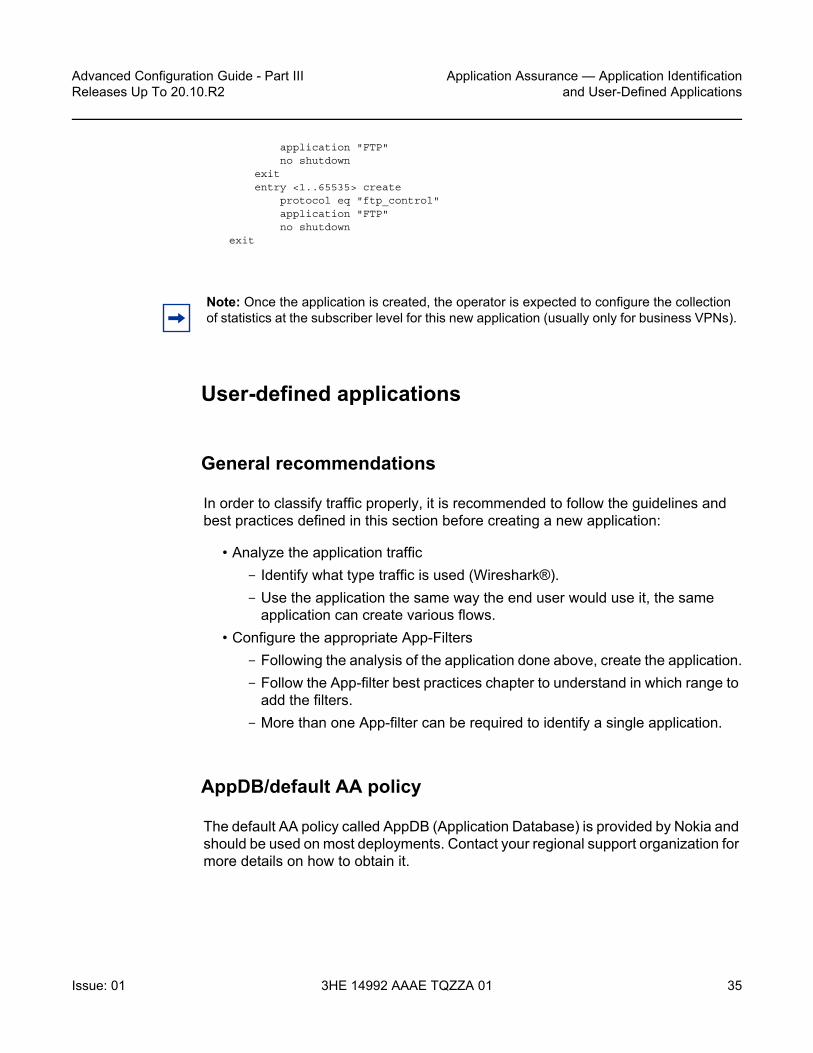
Advanced Configuration Guide - Part III Releases Up To 20.10.R2
Application Assurance — Application Identificationand User-Defined Applications
Issue: 01 3HE 14992 AAAE TQZZA 01 35
application "FTP"no shutdown
exitentry <1..65535> create
protocol eq "ftp_control"application "FTP"no shutdown
exit
User-defined applications
General recommendations
In order to classify traffic properly, it is recommended to follow the guidelines and best practices defined in this section before creating a new application:
• Analyze the application traffic- Identify what type traffic is used (Wireshark®).- Use the application the same way the end user would use it, the same
application can create various flows.• Configure the appropriate App-Filters
- Following the analysis of the application done above, create the application.- Follow the App-filter best practices chapter to understand in which range to
add the filters.- More than one App-filter can be required to identify a single application.
AppDB/default AA policy
The default AA policy called AppDB (Application Database) is provided by Nokia and should be used on most deployments. Contact your regional support organization for more details on how to obtain it.
Note: Once the application is created, the operator is expected to configure the collection of statistics at the subscriber level for this new application (usually only for business VPNs).

Application Assurance — Application Identification and User-Defined Applications
36
Advanced Configuration Guide - Part IIIReleases Up To 20.10.R2
3HE 14992 AAAE TQZZA 01 Issue: 01
This configuration includes applications and application-groups most providers can use by default and is designed to allow the addition of any custom entries required by service providers to identify additional services/applications.
The following customization options exist:
• Generating a configuration for a particular region (such as APAC)• Generating a new configuration (or updating a configuration) containing specific
applications
Before adding new entries to the template and customizing the configuration, it is recommended to follow the next guidelines on app-filters and ranges. These guidelines are key to allow an easy upgrade path from the policy configuration provided by Nokia.
App-filters
App-filters are an ordered list of entries. It is important to keep the order of this list consistent with the classification objective.
For instance, a common configuration mistake is to configure a filter rule for the HTTP protocol signature before HTTP expression filters. If that were the case, then app-filters using HTTP expressions would not be used as the system would find an acceptable match with the protocol signature before walking the list of expressions configured. This mistake is described in the following example:
entry 100 create description "Default HTTP Protocol" protocol eq "http"application "HTTP" no shutdownexitentry 110 create description "Google" expression 1 http-host eq "*.google.com$" application "Google" no shutdownexit
This is an incorrect App-filter order. App-filter entry #100 will always match before the http expression entry #110.
Note: It is not necessary to specify a protocol when defining an expression filter, the protocol is implicit based on the type of expression match criteria used (for instance, HTTP, SIP, H323).

Advanced Configuration Guide - Part III Releases Up To 20.10.R2
Application Assurance — Application Identificationand User-Defined Applications
Issue: 01 3HE 14992 AAAE TQZZA 01 37
App-filter ranges
The App-filter list is an ordered list, it is key to configure each app-filter in the right order and in the proper range.
The operator can customize the policy and create applications and app-filters by using the following ranges shown in Table 1 (other ranges are used by the default policy):
Ordering basics:
• Layer 7 expression-based filters are located before their parent protocol signature (for example, expression matches on http are located before the HTTP protocol app-filter; the same applies to TLS, SIP, H323, RTSP, Citrix).
• HTTP host and URI are located before the HTTP referer for accounting accuracy (for example, YouTube® from within Facebook® is classified as YouTube®)
• App-filters combining protocol signatures with Layer 4 port, IP protocol, IP address, or flow direction are always located before the protocol signature only filter range.
Table 1 Customer reserved App-filter ranges
Range Name Description Start End
Extended top range Top range, matches before any other filters 1 1499
High priority Top range for high priority matches 2000 4999
Expression range A HTTP Host, Host+URI; optionally with IP/Port match
19000 22999
Expression range B Other Expression Match; optionally with IP/Port match
33000 34999
Extended protocols Protocol-signature + Port|IP|Dir. match 40000 58999
Custom protocols Custom protocol signature match 61000 61999
Trusted/validate ports 1st packet validate, 1st packet trusted match 62000 63999

Application Assurance — Application Identification and User-Defined Applications
38
Advanced Configuration Guide - Part IIIReleases Up To 20.10.R2
3HE 14992 AAAE TQZZA 01 Issue: 01
HTTP
Protocol
HTTP is a client/server protocol using TCP/IP at the transport layer to deliver resources such as HTML files, images, videos and more.
HTTP 1.1 enables HTTP clients to use a persistent connection to a server allowing them to reuse the same TCP session for multiple HTTP transactions. Text, images, video, scripts and other objects can be downloaded individually in different transactions through the same TCP session.
Figure 2 describes a typical persistent HTTP connection between a web client and a server with multiple HTTP transactions within the same TCP session:
Figure 2 HTTP persistent connection
User-defined expression-based HTTP applications will use the first HTTP transaction to classify the flow (optionally this behavior can be modified).
HTTP request
The following example shows the content of a typical HTTP request to wikipedia.org which includes the following header fields: HTTP Host, HTTP URI, HTTP User Agent and HTTP referer fields:
al_0681
Single TCPConnection
HTTP Transaction #1
Open TCP ConnectionIndex.html...
<img src="http://www.example.com/images/1.gif>...
GET www.example.com/index.html
index.html
GET/images/1.gif
1.gif
Close TCP Connection
Client Server
HTTP Transaction #2

Advanced Configuration Guide - Part III Releases Up To 20.10.R2
Application Assurance — Application Identificationand User-Defined Applications
Issue: 01 3HE 14992 AAAE TQZZA 01 39
• HTTP Host — Represents the domain name (does not include “http://”).• HTTP URI — The URL trailer after the host domain name (begins with slash “/”).• HTTP Referer — The address of the previous web page from which a link to the
currently requested page was followed (in this example, the referer is www.google.com which means the user clicked on a link from a Google search pointing to wikipedia.org).
• HTTP User Agent — This identifies the web browser or application making the HTTP request.
Configuration examples
HTTP host (Wikipedia)
Classifying HTTP traffic from this web site can be done using a single expression tail anchored on the HTTP host:
configure application-assurance group 1:1 policy app-filterentry <1..65535> create
description "Wikipedia Web Access" expression 1 http-host eq "*.wikipedia.org$"
application "Wikipedia"no shutdown
exit
This can be confirmed using Wireshark®.
HTTP Request Header Host: en.wikipedia.org URI: /wiki/Main_PageUser Agent: Mozilla/5.0(Windows NT 6.1; WOW64)Referer: http://www.google.com/
Web Browser URL: http://en.wikipedia.org/wiki/Main_Page
Host
URI
25452
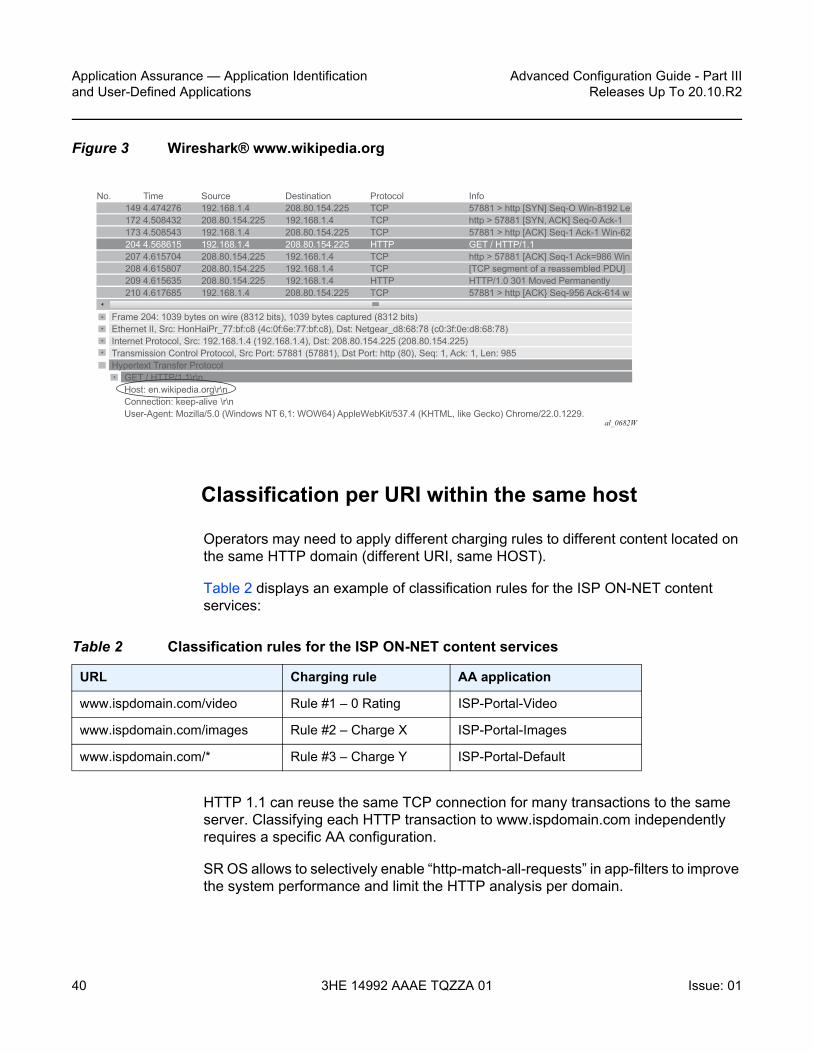
Application Assurance — Application Identification and User-Defined Applications
40
Advanced Configuration Guide - Part IIIReleases Up To 20.10.R2
3HE 14992 AAAE TQZZA 01 Issue: 01
Figure 3 Wireshark® www.wikipedia.org
Classification per URI within the same host
Operators may need to apply different charging rules to different content located on the same HTTP domain (different URI, same HOST).
Table 2 displays an example of classification rules for the ISP ON-NET content services:
HTTP 1.1 can reuse the same TCP connection for many transactions to the same server. Classifying each HTTP transaction to www.ispdomain.com independently requires a specific AA configuration.
SR OS allows to selectively enable “http-match-all-requests” in app-filters to improve the system performance and limit the HTTP analysis per domain.
al_0682W
No. Time Source Destination Protocol Info 149 4.474276 192.168.1.4 208.80.154.225 TCP 57881 > http [SYN] Seq-O Win-8192 Le 172 4.508432 208.80.154.225 192.168.1.4 TCP http > 57881 [SYN, ACK] Seq-0 Ack-1 173 4.508543 192.168.1.4 208.80.154.225 TCP 57881 > http [ACK] Seq-1 Ack-1 Win-62
204 4.568615 192.168.1.4 208.80.154.225 HTTP GET / HTTP/1.1 207 4.615704 208.80.154.225 192.168.1.4 TCP http > 57881 [ACK] Seq-1 Ack=986 Win 208 4.615807 208.80.154.225 192.168.1.4 TCP [TCP segment of a reassembled PDU] 209 4.615635 208.80.154.225 192.168.1.4 HTTP HTTP/1.0 301 Moved Permanently 210 4.617685 192.168.1.4 208.80.154.225 TCP 57881 > http [ACK} Seq-956 Ack-614 w
Frame 204: 1039 bytes on wire (8312 bits), 1039 bytes captured (8312 bits)Ethernet II, Src: HonHaiPr_77:bf:c8 (4c:0f:6e:77:bf:c8), Dst: Netgear_d8:68:78 (c0:3f:0e:d8:68:78)Internet Protocol, Src: 192.168.1.4 (192.168.1.4), Dst: 208.80.154.225 (208.80.154.225)Transmission Control Protocol, Src Port: 57881 (57881), Dst Port: http (80), Seq: 1, Ack: 1, Len: 985Hypertext Transfer Protocol GET / HTTP/1.1\r\n Host: en.wikipedia.org\r\n Connection: keep-alive \r\n User-Agent: Mozilla/5.0 (Windows NT 6,1: WOW64) AppleWebKit/537.4 (KHTML, like Gecko) Chrome/22.0.1229.
Table 2 Classification rules for the ISP ON-NET content services
URL Charging rule AA application
www.ispdomain.com/video Rule #1 – 0 Rating ISP-Portal-Video
www.ispdomain.com/images Rule #2 – Charge X ISP-Portal-Images
www.ispdomain.com/* Rule #3 – Charge Y ISP-Portal-Default

Advanced Configuration Guide - Part III Releases Up To 20.10.R2
Application Assurance — Application Identificationand User-Defined Applications
Issue: 01 3HE 14992 AAAE TQZZA 01 41
The following configuration example allows traffic classification of different URIs of the same domain (www.ispdomain.com) independently, therefore allowing differentiated charging and control:
• http-match-all-req is enabled on all host+uri app-filters to www.ispdomain.com• default app-filter required to match any traffic to www.ispdomain.com
configure application-assurance group 1:1 policyapp-filter
entry <1..65535> createdescription "Zero rated content"expression 1 http-host eq "^www.ispdomain.com$"expression 2 http-uri eq "^/video*"http-match-all-reqapplication "ISP Portal Video"no shutdown
exitentry <1..65535> create
description "Image charging"expression 1 http-host eq "^www.ispdomain.com$"expression 2 http-uri eq "^/images*"http-match-all-reqapplication "ISP Portal Images"no shutdown
exitentry <1..65535> create
description "Default charging"expression 1 http-host eq "^www.ispdomain.com$"http-match-all-reqapplication "ISP Portal Default"no shutdown
exit
SSL/TLS (HTTPs)
Protocol
HTTPS uses SSL/TLS to encrypt traffic between the client and the server. Because this communication is encrypted, it is not possible to identify the HTTP Host or URI. However, AA can still identify the service requested by the subscriber by looking at the TLS certificate information or Server Name Indication exchanged in the clear before the TLS session is established.
Note: SSL/TLS expression-based app-filters are not limited to HTTPS. HTTPS is not a protocol in itself, but it is HTTP traffic, tunneled encrypted into SSL/TLS on port 443.

Application Assurance — Application Identification and User-Defined Applications
42
Advanced Configuration Guide - Part IIIReleases Up To 20.10.R2
3HE 14992 AAAE TQZZA 01 Issue: 01
SSL/TLS certificates
The following snapshot (Figure 4) from Wireshark shows the SSL/TLS certificate exchanged using the mobile application whatsapp®.
Figure 4 Wireshark® HTTPS www.whatsapp.com
The certificate information can be found in the Server Hello message sent by the server, capturing SSL/TLS (HTTPS) traffic from this application can be done using a single app-filter entry tail anchored on the TLS Common Name Certificate:
configure application-assurance group 1:1 policyapp-filter
entry <1..65535> createdescription "Whats App tls and image/voice/video traffic"expression 1 tls-cert-subj-common-name eq
"*.whatsapp.net$"application "Whats App"no shutdown
exit
Server name indication
SSL/TLS traffic can optionally be identified using the Server Name Indication (SNI) which is an extension to the TLS protocol.
al_0683
No. Time Source Destination Protocol Info 42 44.854067 192.11.231.83 50.23.142.168 TCP 33084 > https [SYN] Seq-0 Win-64240 L 43 44.933347 50.23.142.168 192.11.231.83 TCP https > 33084 [SYN, ACK] Seq-0 Ack-1 44 45.213335 192.11.231.83 50.23.142.168 TCP 33084 > https [ACK] Seq-1 Ack-1 Win-12 45 45.342530 192.11.231.83 50.23.142.168 SSLv3 Client Hello
46 45.448230 50.23.142.168 192.11.231.83 TCP https > 33084 [ACK] Seq-1 Ack-75 Win-6 47 45.851643 50.23.142.168 192.11.231.83 SSLv3 Server Hello 48 45.853122 50.23.142.168 192.11.231.83 TCP [TCP segment of a reassembled PDU]
49 45.853231 50.23.142.168 192.11.231.83 TCP [TCP segment of a reassembled PDU]50 46.042243 192.11.231.83 50.23.142.168 TCP 33084 > https [ACK] Seq-75 Ack-2777 w
51 46.245518 192.11.231.83 50.23.142.168 TCP 33084 > https [ACK] Seq-75 Ack-4097 w52 46.334985 50.23.142.168 192.11.231.83 SSLv3 Certificate, Server Hello Done
[Reassembled TCP Segments (4686 bytes): #47(1309), #48(1388), #49(1320), #52(669)]Secure Socket Layer SSLv3 Record Layer: Handshake Protocol: Certificate Content Type: Handshake (22) Version: SSL 3.0 (0x0300) Length: 4672 Handshake Protocol: Certificate Handshake Type: Certificate (11) Length: 4668 Certificates Length: 4665 Certificates (4665 bytes) Certificate Length: 1377 Certificate (id-at-commonname-*.whatsapp.net.id-at-organizationalUnitName-Domain Control validated, id Certificate Length: 1250

Advanced Configuration Guide - Part III Releases Up To 20.10.R2
Application Assurance — Application Identificationand User-Defined Applications
Issue: 01 3HE 14992 AAAE TQZZA 01 43
The SNI is found in the TLS Client Hello, the http-host expression in the app-filter is reused to classify this traffic:
Figure 5 HTTPS SNI
configure application-assurance group 1:1 policyapp-filter
entry <1..65535> createdescription "Yahoo HTTP or TLS SNI"expression 1 http-host eq "*.yahoo.com$"application "Yahoo"no shutdown
exit
SIP
Protocol
SIP is a signaling protocol used for controlling multimedia communication sessions such as voice and video over RTP. AA automatically monitors SIP control flows and associates RTP/RTCP media flows accordingly in the sip_rtp protocol signature.
al_0684
No. Time Source Destination Protocol Info 4 0.088936 192.11.231.82 98.138.6.52 TCP iclpv-nlc > https [SYN] Seq-0 Win-1` 5 0.165069 98.138.6.52 192.11.231.82 TCP https > iclpv-nlc [SYN, ACK] Seq-0` 6 0.165136 192.11.231.82 98.138.6.52 TCP iclpv-nlc > https ACK] Seq-1 Ack-1` 8 0.383867 192.11.231.82 98.138.6.52 TLSv1 Client Hello
Cipher Suites (36 suites)Compression Methods Length: 1Compression Methods (1 method)Extensions Length: 56Extension: server_name Type: server_name (0x0000)
Data (30 bytes)Extension: elliptic_curvesExtension: ec_point_formatsExtension: SessionTicket TLS
0000 00 1e e5 7a 96 5f 00 0c 29 7e 53 cc 08 00 45 00 ...z._.. )~s...E.0010 00 da 80 dS 40 00 80 06 69 2c c0 0b e7 52 62 8a ....O... i....Rb.0020 06 34 05 72 01 bb 1f 6f 07 aS 3e de f1 43 50 18 .4.r...o ..>..CP.0030 fc 00 6e 15 00 00 16 03 01 00 ad 01 00 00 a9 03 ..n..... . . . . . . . .0040 01 4d 80 1d b4 c7 oc 86 06 8d 17 70 14 6c 85 ed .M....... ...p.1..0050 ff a3 30 5c 56 87 c3 09 98 d3 e0 b3 9e a1 45 04 ..O\v... . . . . . .E.0060 S1 00 00 48 00 ff c0 0a c0 14 00 88 00 87 00 38 Q..H.... . . . . . . . 80070 c0 0f c0 05 00 84 00 35 00 39 c0 07 c0 09 c0 11 .......5 .9 . . . . . .0080 c0 13 00 45 00 44 00 33 00 32 c0 0c c0 0e c0 02 ...E.D.3 .2 . . . . . .0090 c0 04 00 96 00 41 00 04 00 05 00 2f c0 08 c0 12 .....A.. . . . / . . . .00a0 00 16 00 13 c0 0d c0 03 fe ff 00 0a 01 00 00 38 ......... . . . . . . .800b0 00 00 00 1e 00 1c 00 00 19 75 73 2e 64 61 74 61 .. . . . . . . .us.data00c0 2e 74 6f 6f 6c 62 61 72 2e 79 61 68 6f 6f 2e 63 .toolbar .yahoo.c00d0 6f 6d 00 0a 00 08 00 06 00 17 00 18 00 19 00 0b om...... . . . . . . . .00e0 00 02 01 00 00 23 00 00 .....#..

Application Assurance — Application Identification and User-Defined Applications
44
Advanced Configuration Guide - Part IIIReleases Up To 20.10.R2
3HE 14992 AAAE TQZZA 01 Issue: 01
The operator can use a SIP expression match criteria in app-filter to further refine traffic classification and identify any additional application on top of the default AA policy. This can be particularly useful in business VPNs to identify voice and telepresence applications.
AA supports SIP expression match criteria on SIP URI, SIP user agent and SIP media type. The following snapshot from Wireshark® shows a SIP control exchange using the voice-video application Vonage® followed by the RTP media audio flow; the expression fields that can be matched using AA app-filters are highlighted:
Figure 6 SIP Wireshark® capture
Configuration example
The following configuration example provides the configuration to classify Vonage® SIP/RTP desktop traffic using SIP URI expression:
configure application-assurance group 1:1 policyapp-filter
entry <1..65535> createdescription "Vonage"expression 1 sip-uri eq "*voncp.com*"
al_0685
Session Initiation Protocol Request-Line: INVITE sip:[email protected];transport=UDP SIP/2.0 Method: INVITE Request-URI: sip:[email protected]; transport=UDP Request-URI User Part: 3102951568 Request-URI User Part: k.voncp.com [Resent Packet: False] Message Header From: “613-963-0148”<sip:[email protected]>;tag=1019fb60-7196c445-2710-4e9485ff-7b9cb12-4e9485ff To: <sip:[email protected]> Call-ID: [email protected] CSeq: 1 INVITE Via: SIP/2.0/UDP 69.196.150.113:10000;branch=z9hG4bK-4e9485ff-f42b6c64-49ad5933 P-Preferred-Identity: off Max-Forwards: 70 Supported: replaces.timer.100rel User-Agent: VTA001346FE8BF111.4.1-r060815-1.00.09-20070402170142 1248967645135/1007551373 308 Contact: <sip:[email protected]:10000;transport=UDP> Min-SE: 0 Content-Type: application/sdp Content-Length: 294 Message Body Session Description Protocol Session Description Protocol version (v): 0 Owner/Creator, Session Id (o): a0000 8644 6672 IN IP4 69.196.150.113 Session Name (s): SIP Cal Connection Information (c): IN IP4 69.196.150.113 Time Description, active time (t): 0 0 Media Description, name and address (m): audio 10050 RTP/AVP 0 101 8 2 18 Media Type: audio Media Port: 10050

Advanced Configuration Guide - Part III Releases Up To 20.10.R2
Application Assurance — Application Identificationand User-Defined Applications
Issue: 01 3HE 14992 AAAE TQZZA 01 45
application "Vonage"no shutdown
exit
H323
Protocol
Similar to SIP, H323 is a signaling protocol used for controlling multimedia communication sessions such as voice and video over RTP. AA automatically monitors H323 control flows and associates the RTP media flow accordingly in the h323_rtp protocol signature.
The operator can use an H323 expression match criteria app-filter to further refine traffic classification and identify any additional application on top of the default AA policy. This can be particularly useful in business VPNs to identify voice and telepresence applications.
AA supports H323 expression match criteria on the H323 product ID. The following snapshot from Wireshark shows an H323 control exchange using the Telepresence application LifeSize® followed by the RTP media audio flow; the expression field that can be matched using AA app-filters is highlighted:

Application Assurance — Application Identification and User-Defined Applications
46
Advanced Configuration Guide - Part IIIReleases Up To 20.10.R2
3HE 14992 AAAE TQZZA 01 Issue: 01
Figure 7 H323 Wireshark® capture
Configuration example
The following configuration example provides the configuration to classify LifeSize® H323/RTP traffic using the H323 product ID expression:
configure application-assurance group 1:1 policyapp-filter
entry <1..65535> createdescription "LifeSize H323 traffic"expression 1 h323-product-id eq "^LifeSize*"application "LifeSize"no shutdown
exit
al_0686
Transmission Control Protocol, Src Port: 61505 (61505), Det Port: h323hostcall (1720), Seq: 1, Ack: 1, Len: 212TPKT, Version: 3, Length: 212Q.931 Protocol discriminator: Q.931 Call reference value length: 2 Call reference flag: Message sent from originating side Call reference value: 461a Message type: SETUP (0x05) Bearer capability Display ‘Conference Room’ User-user H.225.0 CS H323-UserInformation h323-uu-pdu h323-message-body: setup (0) setup protocolIdentifier: 0.0.8.2250.0.5 (Version 5) sourceAddress: 3 items sourceInfo vendor vendor H.221 Manufacturer: Unknown (0xb500a11a) productId: LifeSize Express 220 versionId: 4.7.10.14 0. . . . . . . mc: False .0 . . . . . . undefinedNode: False

Advanced Configuration Guide - Part III Releases Up To 20.10.R2
Application Assurance — Application Identificationand User-Defined Applications
Issue: 01 3HE 14992 AAAE TQZZA 01 47
RTSP
Protocol
RTSP is a signaling protocol used for controlling media streaming content such as audio and video over RTP/RDT. AA automatically monitors the RTSP control flows and associates its RTP/RDT media flow with the rtp_rtsp protocol signature.
The operator can use an RTSP expression match criteria app-filter to further refine traffic classification and identify any additional application on top of the default AA policy. This can be particularly useful to identify specific streaming applications.
AA supports RTSP expression match criteria on the RTSP Host, URI, User Agent. The following snapshot from Wireshark® shows an RTSP setup request to YouTube® followed by the RTP media audio flow; the expression fields that can be matched in RTSP SETUP request using AA app- filters are highlighted:
Configuration example
The following configuration example provides the configuration to classify YouTube® RTSP/RTP traffic using RTSP Host expression:
configure application-assurance group 1:1 policyapp-filter
entry <1..65535> createdescription "YouTube RTSP/RTP Video"expression 1 rtsp-host eq "*.youtube.com$"application "YouTube"no shutdown
exit
25453
RTSP Header SETUP r tsp://v3.cache7.c.youtube.com/ZTww=/0/0/0/video.3gp/trackID=13 RTSP/1.0CSeq: 3User-Agent: Mozilla/5.0 (BlackBerry; U; BlackBerry 9800; en) AppleWebKit/54.8+ x-wap-profile: "http://www.blackberry.net/go/mobile/profiles/uaprof/9800_unknown/6.0.0.rdf"Transport: RTP/AVP;unicast;client_port=51132-51133;mode="PLAY"
Web Browser URL: //v3.cache7.c.youtube.com/ZTww=/0/0/0/video.3gp/trackID=13 RTSP/1.0
Host
URL
Application Assurance — Application Identification and User-Defined Applications
48
Advanced Configuration Guide - Part IIIReleases Up To 20.10.R2
3HE 14992 AAAE TQZZA 01 Issue: 01
Citrix
Protocol
Independent Computing Architecture (ICA) is a Citrix Systems® protocol used in Citrix’s WinFrame, Citrix XenApp (formerly called MetaFrame/Presentation Server), and Citrix XenDesktop products.
Citrix makes it possible to run applications remotely on large servers, thus making better use of server resources while at the same time allowing people using other platforms to use the applications, for example, run Microsoft® Word on a UNIX workstation.
Citrix_ica protocol signature will detect any remote application using Citrix (the protocol needs to be unencrypted and configured to non-seamless). The Citrix ICA session is started from a client and can be anything from Remote Desktop, SAP to Microsoft® Word.
The Citrix expression match app-filter is used to classify traffic based on the Citrix-published application. This published application is configured on the server and in the preceding example, it can be for instance RDP, SAP, Word, XLS or Microsoft® Word depending how the server is configured.
Configuration example
configure application-assurance group 1:1 policyapp-filter
entry <1..65535> createdescription "Citrix SAP Application"expression 1 citrix-app eq "SAP"application "Citrix SAP"no shutdown
exit
IP address and TCP/UDP port
Traffic from specific servers can be classified using IPv4/v6 server-address app-filter rules. It is used usually to identify traffic from an internal (on-net) server as opposed to an Internet (off-net) server.

Advanced Configuration Guide - Part III Releases Up To 20.10.R2
Application Assurance — Application Identificationand User-Defined Applications
Issue: 01 3HE 14992 AAAE TQZZA 01 49
The server-address app-filter automatically detects the client from the server by identifying which side opens the connection. It implicitly classifies traffic based on the server IP address or port number. For example, if A initiates a TCP connection to B, then flows from A to B and from B to A can be classified with a match on server-address B. Similarly, a flow initiated from B to A can be classified using a match on server-address A.
Server address
The following configuration example uses a server-address app-filter to classify traffic from server 10.1.1.1 in the application called Application-1:
configure application-assurance group 1:1 policyapp-filter
entry <1..65535> createdescription "Server #1 10.0.0.1"server-address eq 10.0.0.1/32application "Application-1"no shutdown
exit
Server address and server port
The following configuration example uses server-address and server-port app-filters to classify traffic from server 10.0.0.2 on port 1234 in the application called Application-2. It is particularly useful when the same server is used to provide different services that need to be classified separately:
configure application-assurance group 1:1 policyentry <1..65535> create
description "Server #2 10.0.0.2 port 1234 Only"server-address eq 10.0.0.2/32server-port eq 1234application "Application-2"no shutdown
exit
Server port and protocol signature
It is possible to combine a protocol signature with a port number in the same app-filter, this is typically done in business VPNs for specific internal applications not detected using existing AA protocol signatures.

Application Assurance — Application Identification and User-Defined Applications
50
Advanced Configuration Guide - Part IIIReleases Up To 20.10.R2
3HE 14992 AAAE TQZZA 01 Issue: 01
The following configuration example classifies a business VPN application running on TCP port 4000 and not detected by any other signatures. It combines the protocol signature unknown_tcp with the desired port number. This allows keeping the classification untouched for the rest of the protocols/applications and is the recommended approach:
configure application-assurance group 1:1 policyapp-filter
entry <1..65535> createdescription "Business VPN Application X Port 4000"server-port eq 4000protocol eq unknown_tcpapplication "Busines VPN Application X"no shutdown
exit
Flow setup direction
Traffic can be classified based on flow-setup-direction app-filter. The flow setup direction can be either subscriber-to-network or network-to-subscriber.
Network side and subscriber side is AA terminology related to where AA is enabled:
• In broadband and mobile networks, AA is enabled per subscriber. This means the subscriber side represents the ESM/mobile/transit subscriber while the network side represents Internet or other subscribers.
• In business VPNs, AA is enabled on a VPN SAP/spoke SDP and the subscriber side represents the local VPN site (SAP/spoke/transit).
The following example shows the configuration to classify http traffic hosted by AA subscribers (for example, broadband subscribers running a web server):
configure application-assurance group 1:1 policyapp-filter
entry <1..65535> createdescription "HTTP Server on the subscriber side"flow-setup-direction network-to-subscriberprotocol eq httpapplication "HTTP Server"no shutdown
exit
Note: It is important to follow the app-filter range recommendations for a proper classification of traffic using IP address or port number.

Advanced Configuration Guide - Part III Releases Up To 20.10.R2
Application Assurance — Application Identificationand User-Defined Applications
Issue: 01 3HE 14992 AAAE TQZZA 01 51
IP protocol
Traffic can be classified using an IP protocol number for non TCP/UDP traffic.
The following example provides the configuration to classify ICMP IPv4/v6 traffic:
configure application-assurance group 1:1 policyapp-filter
entry <1..65535> createdescription "ICMP v4"protocol eq "non_tcp_udp"ip-protocol-num eq icmpapplication "ICMP"no shutdown
exitentry <1..65535> create
description " ICMP v6"protocol eq "non_tcp_udp"ip-protocol-num eq ipv6-icmpapplication "ICMP"no shutdown
exit
Custom protocol
Custom protocols can be used to classify TCP/UDP applications using hexadecimal string matching (up to 16 hex octets) at a configurable payload offset in the data payload. The expression string length and offset must not exceed 128 bytes.
To illustrate this feature the Solaris® application GoGlobal is used. It provides remote access to a server (similar to VNC®). The following snapshot (Figure 6) from Wireshark® shows a TCP SYN/ACK session establishment followed by the first data exchange:
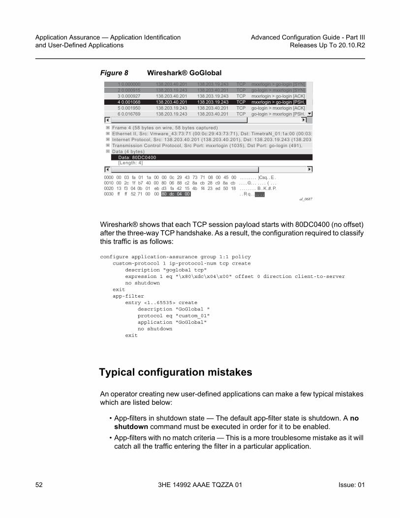
Application Assurance — Application Identification and User-Defined Applications
52
Advanced Configuration Guide - Part IIIReleases Up To 20.10.R2
3HE 14992 AAAE TQZZA 01 Issue: 01
Figure 8 Wireshark® GoGlobal
Wireshark® shows that each TCP session payload starts with 80DC0400 (no offset) after the three-way TCP handshake. As a result, the configuration required to classify this traffic is as follows:
configure application-assurance group 1:1 policycustom-protocol 1 ip-protocol-num tcp create
description "goglobal tcp"expression 1 eq "\x80\xdc\x04\x00" offset 0 direction client-to-serverno shutdown
exitapp-filter
entry <1..65535> createdescription "GoGlobal "protocol eq "custom_01"application "GoGlobal"no shutdown
exit
Typical configuration mistakes
An operator creating new user-defined applications can make a few typical mistakes which are listed below:
• App-filters in shutdown state — The default app-filter state is shutdown. A no shutdown command must be executed in order for it to be enabled.
• App-filters with no match criteria — This is a more troublesome mistake as it will catch all the traffic entering the filter in a particular application.
al_0687
1 0.000000 138.203.40.201 138.203.19.243 TCP mxxrlogin > go-login [SYN] 2 0.000915 138.203.19.243 138.203.40.201 TCP go-login > mxxrlogin [SYN] 3 0.000927 138.203.40.201 138.203.19.243 TCP mxxrlogin > go-login [ACK] 4 0.001068 138.203.40.201 138.203.19.243 TCP mxxrlogin > go-login [PSH, 5 0.001950 138.203.19.243 138.203.40.201 TCP go-login > mxxrlogin [ACK] 6 0.016769 138.203.19.243 138.203.40.201 TCP go-login > mxxrlogin [PSH.
Frame 4 (58 bytes on wire, 58 bytes captured)Ethernet II, Src: Vmware_43:73:71 (00:0c:29:43:73:71), Dst: TimetraN_01:1a:00 (00:03:Internet Protocol, Src: 138.203.40.201 (138.203.40.201), Dst: 138.203.19.243 (138.203Transmission Control Protocol, Src Port: mxxrlogin (1035), Dst Port: go-login (491),Data (4 bytes) Data: 80DC0400 [Length: 4]
0000 00 03 fa 01 1a 00 00 0c 29 43 73 71 08 00 45 00 . . . . . . . . )Csq. . E .0010 00 2c 1f b7 40 00 80 06 88 c2 8a cb 28 c9 8a cb . . . . ©. . . . . . . ( . . .0020 13 f3 04 0b 01 eb d3 fa 42 15 4b f4 23 ed 50 18 . . . . . . . . B . K .#. P.0030 ff ff 52 71 00 00 80 dc 04 00 . . R q . . . . . .

Advanced Configuration Guide - Part III Releases Up To 20.10.R2
Application Assurance — Application Identificationand User-Defined Applications
Issue: 01 3HE 14992 AAAE TQZZA 01 53
Troubleshooting application identification
Show commands
Router/partition statistics
Partition level statistics are not updated in real time. Instead, statistics for a particular flow are updated either at flow closure or every five minutes. The five-minute sliding window interval is a common interval for all flows in an ISA MDA. Different ISA MDAs will have a different five-minute windows as this interval is set at the MDA boot time.
The following command can be used to view the statistics for all applications configured in the ISA Group 1, Partition 1:
show application-assurance group 1:1 application count
Alternatively, it is possible to sort the display by octets, packets, flows:
show application-assurance group 1:1 application count top [octets|packets|flows] [max-count <max-count>]
The operator can also identify which app-filters are being hit by the AA policy per partition (this command is not available per subscriber), it is particularly useful to identify which filters are used and optionally prune unnecessary app-filters from user-defined applications:
show application-assurance group 1:1 policy app-filter
The following example was created for the application FTP:
A:PE# show application-assurance group 1:1 policy app-filter | match "application \"FTP\""
pre-lines 3 post-lines 2exitentry 44300 create (2 flows, 1205 B)
protocol eq "ftp_control"
Note: The app-filter policy is usually relatively large, in which case additional 7x50 SR CLI functionality can be used to filter out the output and only show the relevant information.

Application Assurance — Application Identification and User-Defined Applications
54
Advanced Configuration Guide - Part IIIReleases Up To 20.10.R2
3HE 14992 AAAE TQZZA 01 Issue: 01
application "FTP"no shutdown
exitentry 44301 create (2 flows, 1401 B)
protocol eq "ftp_data"application "FTP"no shutdown
exit
Because partition level statistics are not updated in real time, it is recommended for troubleshooting purposes to use subscriber statistics or sub-study statistics.
Subscriber statistics
Subscriber-level statistics can be updated in real time. AA is usually configured by the operator to collect subscriber-level statistics for all application groups in residential and Wifi, while business VPNs typically collect Application group and all applications for each site with AA enabled.
The following commands can be used to view per subscriber statistics for all app-groups or applications configured in ISA group 1, partition 1 for the ESM subscriber "Bob" or business VPN SAP 1/1/1:10:
show application-assurance group 1:1 aa-sub esm "bob" app-group countshow application-assurance group 1:1 aa-sub sap 1/1/1:10 application count
In case only app-group statistics are collected per subscriber, the aa-sub-study feature can be used to collect per application-level statistics for selected subscribers, as follows:
A:PE# configure application-assurance group 1:1 statistics aa-sub-study applicationA:PE>config>app-assure>group>statistics>aa-sub-study# aa-sub esm "bob"
Once done, the system will show all application level statistics for this subscriber:
show application-assurance group 1:1 aa-sub-study esm "bob" application count
Similar to partition-level statistics, aa-sub and aa-sub-study statistics can be sorted by octets, packets, flows:
show application-assurance group 1:1 aa-sub-study esm "bob" application count top [octets|packets|flows] [max-count <max-count>]

Advanced Configuration Guide - Part III Releases Up To 20.10.R2
Application Assurance — Application Identificationand User-Defined Applications
Issue: 01 3HE 14992 AAAE TQZZA 01 55
AppFilterMiss
The default policy configuration provides a failsafe application at the very end of the app-filter list to classify any remaining traffic in the AppFilterMiss application. There should never be any traffic in this application. This failsafe filter is used as a debug to make sure that there are no major issues in the configuration.
Tools
Flow-record-search
Traditional show commands may not provide enough information when troubleshooting flow identification and the operator can use the ISA flow-record-search tool to dump the ISA flow table for more information. This feature comes with a large number of filtering options documented in the user guide.
Each flow gives visibility into: Flow ID, Sub-Type, Sub-Name, Initiator, Direction, Source IP, Dest. IP, IP Protocol, Source Port, Dest. Port, FC, DSCP, Classified, Protocol, Application, App- Group, Charging Group, Packets tx, Bytes Tx, Packets-discarded, Bytes-discarded etc.
See below for the most commonly used commands.
The following command shows all the flows in an ISA card per ISA group:partition (can be a very long output, up to 3M entries):
tools dump application-assurance group 1:1 flow-record-search isa 1/2
Note: When the number of flows per ISA card reaches a threshold then per subscriber statistics are not available in real time anymore and only the snapshot command can be used to display the statistics recorded in the previous five-minute interval window:
show application-assurance group 1:1 aa-sub-study esm "bob" snapshot application count
Note: Traffic can typically be classified as AppFilterMiss when not all protocol signatures are mapped to a particular application. This could happen when upgrading to a new ISA software and enabling new protocol signature detection while not ensuring first that the correct application was provisioned. See the Release Note upgrade section for more details on AA signature upgrade.

Application Assurance — Application Identification and User-Defined Applications
56
Advanced Configuration Guide - Part IIIReleases Up To 20.10.R2
3HE 14992 AAAE TQZZA 01 Issue: 01
The following command shows all the flows per AA subscriber in a given group:partition:
tools dump application-assurance group 1:1 flow-record-search aa-sub esm "bob"
The following command shows all the active flows per AA subscriber in a given group:partition:
tools dump application-assurance group 1:1 flow-record-search aa-sub esm "bob" flow-status active
The flow-record-search command is also available with additional details by adding search-type detail at the end of the command line. Note that due to the length of the output it is recommended to paste the CLI output content in a notepad file.
HTTP host recorder
AA cflowd allows operators to export the HTTP domain extracted from HTTP flows to the NSP cflowd collector. This allows the operator to understand which HTTP hosts are visible in the network.
However, in case a cflowd collector is not deployed, AA provides the HTTP host recorder tool command to record HTTP hosts seen by AA. See the Multi-Service Integrated Services Adapter and Extended Services Appliance Guide for more details.
A:PE# show debugdebug
application-assurancegroup 1:1
http-host-recorderfilter
default-filter-action recordrecord http-host-app-filter-candidates
exitrate 100no shutdown
exitexit
exitexit
A:PE# tools dump application-assurance group 1:1 http-host-recorder top bytes

Advanced Configuration Guide - Part III Releases Up To 20.10.R2
Application Assurance — Application Identificationand User-Defined Applications
Issue: 01 3HE 14992 AAAE TQZZA 01 57
Port recorder
This function is particularly useful in business VPN (it can also be used in residential networks). The port-recorder AA tool function is similar to the http-recorder. It allows the operator to record which ports are used on selected applications.
It is most commonly used with the applications Unidentified TCP and Unidentified UDP but it can be configured to record any other applications:
A:PE# show debugdebug
application-assurancegroup 1:1
port-recorderapplication "Unidentified TCP"application "Unidentified UDP"rate 100shutdown
exitexit
exitexit
A:PE# tools dump application-assurance group 1:1 port-recorder top bytes
Conclusion
This example, which is intended for Application Assurance network architects and engineers, provides the information required to modify an existing AA policy following AA best practices and guidelines, and provides the necessary troubleshooting information to better understand application classification using Application Assurance.

Application Assurance — Application Identification and User-Defined Applications
58
Advanced Configuration Guide - Part IIIReleases Up To 20.10.R2
3HE 14992 AAAE TQZZA 01 Issue: 01

Advanced Configuration Guide - Part III Releases Up To 20.10.R2
Application Assurance — App-Profile, ASO andControl Policies
Issue: 01 3HE 14992 AAAE TQZZA 01 59
Application Assurance — App-Profile, ASO and Control PoliciesThis chapter provides information about Application Assurance (AA) app-profile, Application Service Options (ASOs) and control policy configurations.
Topics in this chapter include:
• Applicability• Overview• Configuration• Conclusion
Applicability
This example is applicable to all 7750, 7450 and 7750-SRc chassis supporting Application Assurance and was tested on SR OS release 12.0.R4.
It is recommended to use the AppDB prior to configuring traffic control policies. The AppDB is a default configuration file to define all of the applications of interest, including all of the relevant application-groups, applications and app-filters to classify traffic, and can be obtained through Nokia’s support organization.
Overview
In addition to providing valuable traffic analysis and statistics information using the 7750 Service Router (SR) or 7450 Ethernet Service Switch (ESS) and Application Assurance (AA), one of the key objectives of the AA solution is to provide the tools to manage subscriber traffic at the application level. Examples of traffic management actions include:
• Throttling low priority bandwidth hungry applications during peak hours.• Prioritizing and remarking selected applications.• Implementing a walled-garden environment providing open access to selected
free web services only, redirecting all other requests from unregistered subscribers to a registration portal with payment services.
Application Assurance — App-Profile, ASO and Control Policies
60
Advanced Configuration Guide - Part IIIReleases Up To 20.10.R2
3HE 14992 AAAE TQZZA 01 Issue: 01
• Enrich HTTP Header with subscriber identification parameters to offer subscribers transparent access to premium content.
• In browser notification which triggers the display of administrative, informational or promotional messages in selected browser-sessions.
• Stateful session filtering with Application Level Gateway (ALG) support to protect subscribers against unsolicited flows.
• Parental control services interworking with an external Internet Content Adaptation Protocol (ICAP) server for rating the requested web sites.
Application traffic control policies can be applied as global policies for all subscribers, or they can be activated for individual subscribers or groups of subscribers.
This example describes the basics of activating Application Assurance on a given subscriber through the use of App-Profile and demonstrates the use of static or dynamic traffic control policies using Application Service Options (ASOs) and Application QoS Policies (AQP). It also provides detailed information for configuring Bandwidth, Flow-Count and Flow-Rate Policing including Time of Day (ToD) policing. Other policy control actions can be found in the Advanced Configuration Guide or in the MS-ISA User Guide.
Configuration
Activation of AA Services
App-Profile
Application profiles (app-profile) enable application assurance services for a given Enhanced Subscriber Management (ESM), Distributed Subscriber Management (DSM), or transit subscriber, or for a SAP or spoke SDP which are commonly referred to as AA-subscribers (AA-sub). Each app-profile is unique in the system and defines the services that the AA subscriber will receive.
Assigning an app-profile to an ESM subscriber affects every host of that subscriber. Similarly, applying an app-profile to a SAP/spoke SDP will affect all traffic within that SAP/spoke SDP.
App-profiles are defined at the AA group partition level (in case of a partitioned ISA-AA group), see the configuration example below:

Advanced Configuration Guide - Part III Releases Up To 20.10.R2
Application Assurance — App-Profile, ASO andControl Policies
Issue: 01 3HE 14992 AAAE TQZZA 01 61
A:BNG# configureapplication-assurance group 1:1 policy
app-profile "1-1/15M" createdescription "App-Profile Description"divertcharacteristic "Parental Control" value "enabled"capacity-cost 15
exit
The app-profile parameters are:
• divert — Diverts all traffic from and to this subscriber to an ISA-AA. Configuring no divert effectively disables all AA services for subscribers using this app-profile.Default value: no divert.
• characteristic [<characteristic-name> value <value-name>] — one or more optional ASO service characteristics can be used to apply an AA control policy to the subscriber.
• capacity-cost <cost> — An application profile capacity cost is used to load balance AA subscribers across multiple ISA-AA cards. A common practice is to define a cost proportional to the expected peak BW for the subscribers using this profile (in Kbps or Mbps). The capacity cost is out of the scope of this example. The range is 1 to 65535, default 1.
This app-profile example uses the following naming convention:
<group-id>-<partition-id>/<BW>M where
• <group-id> — The ISA-AA group ID on which this profile is created.• <partition-id> — The AA partition ID on which this profile is created.• <BW-label> — Defines the maximum bandwidth used by the subscriber, which
is used for aa-subscriber cost load balancing and subscriber rate limiting. The M stands for Mbps.
In general the operator can choose to use either ASO characteristics override or multiple app-profiles to apply different AA QoS policies to ESM Subscribers or Business VPN sites. For flexibility and scale it is recommended to use ASO overrides whenever possible. This is described in more details below.
Note: Prior to using special characters in a policy object name the operator should verify the list of special characters supported by the 5620 SAM; for instance the 5620 SAM does not support the use of “:” in the app-profile name therefore it should be avoided.
Application Assurance — App-Profile, ASO and Control Policies
62
Advanced Configuration Guide - Part IIIReleases Up To 20.10.R2
3HE 14992 AAAE TQZZA 01 Issue: 01
Residential and Wi-Fi Services
The app-profile can be assigned or modified for ESM, DSM or Transit IP subscribers either at subscriber creation time or while the subscriber is in service:
• Subscriber creation — An app-profile can be assigned at subscriber creation time through RADIUS, DHCP Option 82, Local User Database, static configuration or through a default app-profile.
• In service app-profile modification — An app-profile can be dynamically modified in service through a RADIUS Change of Authorization (CoA). From software release 12.0.R1 an app-profile can also be dynamically modified in service through Gx.
In case no app-profile is returned at subscriber creation by RADIUS, LUDB or DHCP, or when no static configuration is present, the system can apply a default app-profile if configured within the subscriber group-interface (or MSAP policy) sub-sla-mgmt:
sub-sla-mgmtdef-app-profile "1-1/15M"
exit
Business VPN and other Service Interfaces
App-profiles are statically assigned to a given SAP, spoke SDP or transit prefix VPN site via the 5620 SAM or CLI.
The following configuration shows how to enable application assurance on a SAP or spoke SDP in a business VPRN service:
A:PE>config>service# vprn 100 customer 1 createdescription "L3 Service Customer 1"interface "to-site1" create
address 192.168.1.1/24sap 1/1/10:11 create
app-profile "1-1/15M"exit
interface "to-site2" createaddress 192.168.2.1/24spoke-sdp 12:100 create
app-profile "1-1/15M"exit
no shutdown

Advanced Configuration Guide - Part III Releases Up To 20.10.R2
Application Assurance — App-Profile, ASO andControl Policies
Issue: 01 3HE 14992 AAAE TQZZA 01 63
Defining Application Service Options
ASOs for Traffic Control - Introduction
To determine which application control policies need to be applied to a AA-subscriber, an app-profile with a number of service characteristics (ASOs) is associated with each subscriber. These service characteristics are then used as match criteria in AQP policy rules to determine which rules to apply.
Therefore ASOs are service characteristics assigned to a subscriber and are used to identify the traffic control policy rule (AQP) applicable to a subscriber or a group of subscribers.
Most policy rules will be applicable to multiple subscriber profiles; nevertheless it is possible that a specific subscriber requires a dedicated policy.
ASO Characteristics and Values
For each service option that can be used by one or more subscribers, an ASO characteristic should be defined with a number of values that represent all available choices for that service characteristic. The names and values of the ASO characteristics are configurable string values; best practice is to use strings that provide a meaningful description of the service characteristic they represent.
Each ASO characteristic requires a default value and each app-profile inherits the default value of all the ASO characteristics created in a given partition unless a characteristic is referenced directly in the app-profile or overwritten as described below.
ASOs are defined at the AA group partition level (in case of a partitioned ISA-AA group). In the configuration example below two different ASO characteristics are defined: “Parental Control” and “P2P-Sub-DL”:
BNG>config>app-assure# group 1:1 policyapp-service-options
characteristic "Parental Control" createvalue "disabled"value "enabled"default-value "disabled"
exitcharacteristic "P2P-Sub-DL" create
value "500k"value "1M"value "unlimited"

Application Assurance — App-Profile, ASO and Control Policies
64
Advanced Configuration Guide - Part IIIReleases Up To 20.10.R2
3HE 14992 AAAE TQZZA 01 Issue: 01
default-value "unlimited"exit
The ASO values and default value of a characteristic can be displayed using a show command:
A:BNG# show application-assurance group 1:1 policy app-service-option "P2P-Sub-DL"===============================================================================Application-Assurance Application Service Options===============================================================================Characteristic "P2P-Sub-DL"Value Default-------------------------------------------------------------------------------1M No500k Nounlimited Yes===============================================================================
When configuring service characteristics for optional service options, it is recommended to configure a default value which will not trigger any AQP policy action (the default value does not match any AQP match criteria) such that the behavior of existing subscribers and app-profiles will not change until the operator specifically configures or signals a non-default characteristic value for the subscriber or the app-profile. In the example above “Parental Control” “disabled” and “P2P-Sub-DL” “unlimited” would have no corresponding AQP by design; therefore if these particular service options were applied to a subscriber they would not match a QoS policy entry.
How to Specify Service Options for AA Subscribers
ASO Assignment in App-Profile
ASOs can be statically assigned in the app-profile; this type of ASO characteristic assignment is typically reserved to the default service options enabled on a large number of subscribers.
Figure 9 shows an example of AA service definition (ASO and app-profile) for a Gold and Bronze service tier definition with the following characteristics:
• Two app-profiles Gold and Bronze• Gold app-profile — No specific policy actions or ASO characteristics are
configured statically in the app-profile.

Advanced Configuration Guide - Part III Releases Up To 20.10.R2
Application Assurance — App-Profile, ASO andControl Policies
Issue: 01 3HE 14992 AAAE TQZZA 01 65
• Bronze app-profile — A specific ASO characteristic and value is assigned to the profile to limit Peer to Peer download traffic to 1Mbps (this example does not show the app-qos-policy nor policer configuration, this will be described later).
Figure 9 Service Tier Example using ASO, App-Profile and AQP
Each app-profile inherits the default values of all the ASO characteristics defined in a AA group-partition; in the example above this is reason why the app-profile Gold inherits “Parental Control” “disabled” and “P2P-Sub-DL” “unlimited”. The app-profile Bronze inherits “Parental Control” “disabled” while “P2P-Sub-DL” “1M” is assigned to this profile statically.
The operator can identify per app-profile which characteristics values are inherited from their default value and which are statically assigned using the following show command:
*A:BNG# show application-assurance group 1:1 policy app-profile "Gold"app-profile "Gold" create
divertcharacteristic "P2P-Sub-DL" inherits default-value "unlimited"characteristic "Parental Control" inherits default-value "disabled"
exit
A:BNG# show application-assurance group 1:1 policy app-profile "Bronze"app-profile "Bronze" create
divertcharacteristic "P2P-Sub-DL" value "1M"characteristic "Parental Control" inherits default-value "disabled"
exit
al_0569
BNG>config>app-assure# group 1:1 policyapp-service-options characteristic "Parental Control" create value "disabled" value "enabled" default-value "disabled" exit characteristic "P2P-Sub-DL" create value "500k" value "1M" value "unlimited" default-value "unlimited" exit
BNG>config>app-assure# group 1:1 policy app-profile "Gold" create divert exit app-profile "Bronze" create divert characteristic "P2P-Sub-DL" value "1M" exit
Gold App-Profile:Parental Control = disabled (inherited)P2P-DL= unlimited (inherited)
Bronze App-Profile:Parental Control = disabled (inherited)P2P-DL = 1M
Note: Using ASO overrides, described later, it is possible to implement the same choice of AA service options using a single app-profile.

Application Assurance — App-Profile, ASO and Control Policies
66
Advanced Configuration Guide - Part IIIReleases Up To 20.10.R2
3HE 14992 AAAE TQZZA 01 Issue: 01
ASO Overrides per Subscriber via RADIUS or Gx
Prior to SR OS 12.0.R1 the operator can assign (and modify: CoA) the app-profile per ESM or Transit-IP subscribers using the “Alc-App-Prof-Str” [26-6527-45] RADIUS attribute.
SR OS 12.0.R1 added support for ASO characteristic overrides for ESM and Transit-IP subscribers via RADIUS using the attribute “Alc-AA-App-Service-Options” [26-6527-193].This attribute can be returned during the subscriber creation process or while the subscriber is in service through RADIUS CoA. Refer to SR OS 12.0 RADIUS Attributes Reference Guide for more details related to the use of the AA RADIUS attributes.
An example of a RADIUS CoA message returned to the system to modify both the app-profile and one ASO characteristic is provided below:
NAS-Port-Id = "1/1/5:4088"Framed-IP-Address = 192.168.211.30Alc-App-Prof-Str = "1-1/15M"Alc-AA-App-Service-Options = "P2P-Sub-DL=1M"
The ASO characteristics and values assigned to a given subscriber (statically via app-profile or overridden) can be displayed using the following show command:
A:BNG# show application-assurance group 1:1 aa-sub esm "sub1" summary===============================================================================Application-Assurance Subscriber Summary (realtime)===============================================================================AA-Subscriber : sub1 (esm)ISA assigned : 1/2App-Profile : 1-1/15MApp-Profile divert : YesCapacity cost : 1Aarp Instance Id : N/AHTTP URL Parameters : (Not Specified)Last HTTP Notified Time : 2014/08/07 12:07:47-------------------------------------------------------------------------------Traffic Octets Packets Flows-------------------------------------------------------------------------------......-------------------------------------------------------------------------------Application Service Options (ASO)-------------------------------------------------------------------------------Characteristic Value Derived from-------------------------------------------------------------------------------P2P-Sub-DL 1M dyn-overrideParental Control disabled default===============================================================================

Advanced Configuration Guide - Part III Releases Up To 20.10.R2
Application Assurance — App-Profile, ASO andControl Policies
Issue: 01 3HE 14992 AAAE TQZZA 01 67
In the show command output above, the derived from field describes how the characteristics and values are assigned to the subscriber:
• app-profile — The characteristic’s value statically configured in the app-profile.• dyn-override — The characteristic’s value received from RADIUS or Gx.• default — The characteristic’s default value inherited (not statically configured in
the app-profile nor dynamically modified).
SR OS 12.0.R1 also introduced support for signaling the app-profile or ASO characteristics override via Gx, see Application Assurance — App-Profile, ASO and Control Policies for more details.
ASO Overrides for Business VPN and Other Services
Since SR OS 9.0.R1, ASO characteristic override values can be statically assigned to business VPN SAP, spoke SDP and transit prefix subscribers.
The operator can provision the AA policy override parameters, multiple characteristics overrides per AA-sub can be defined per override policy, see the configuration example below:
A:BNG>config>app-assure# group 1:1 policy-overridepolicy aa-sub sap 1/1/5:210 create
characteristic "P2P-Sub-DL" value "1M"characteristic "Parental Control" value "enabled"
exit
Application Control Policies
App-QoS-Policy (AQP)
App-Profile / ASO / AQP Workflow Summary
App-profiles enable application assurance services for a given AA-subscriber. Each app-profile is unique in the system and defines the service that the AA subscriber will receive.

Application Assurance — App-Profile, ASO and Control Policies
68
Advanced Configuration Guide - Part IIIReleases Up To 20.10.R2
3HE 14992 AAAE TQZZA 01 Issue: 01
To determine which control policies need to be applied to an AA-subscriber, a number of service characteristics (ASO) are associated with each AA-subscriber.
As described earlier, these service characteristics can either be configured directly within the app-profile or assigned using overrides and they are then used as match criteria in AQP policy rules to determine which application policy rules to apply.
The app-qos-policy (AQP) is an ordered list of entries defining policy actions for flows diverted to Application Assurance. Each AQP entry is composed of match criteria and action(s).
Flows are evaluated against all entries of the AA QoS policy defined in the AA group partition that the subscriber app-profile belongs to (in case of a partitioned AA group).
Figure 10 provides a configuration example summary with app-profile, ASO, AQP and policers:
Figure 10 App-Profile, ASO, AQP Workflow Summary
Match and Action Criteria
AQP Match Criteria
Multiple match criteria can be specified per AQP entry in which case the action will only apply to flows that match all criteria. The most common match criteria are: characteristic, application, app-group and charging-group.
The following AA match criteria can be used in an AQP:
• app-group {eq | neq} <app-group name>• application {eq | neq} <app name>• charging-group {eq | neq} <charging-group-name>• traffic-direction {subscriber-to-network|network-to-subscriber|both}
al_0570
BNG>config>app-assure# group 1:1 policyapp-service-options characteristic "Parental Control" create value "disabled" value "enabled" default-value "disabled" exit characteristic "P2P-Sub-DL" create value "500k" value "1M" value "unlimited" default-value "unlimited" exit
BNG>config>app-assure# group 1:1 policy app-profile "Gold" create divert exit app-profile "Bronze" create divert characteristic "P2P-Sub-DL" value "1M" exit
Gold App-Profile:Parental Control = disabled (inherited)P2P-DL= unlimited (inherited)
Bronze App-Profile:Parental Control = disabled (inherited)P2P-DL = 1M
BNG>config>app-assure# group 1:1 policy app-qos-policy entry 30 create match app-group eq "P2P" characteristic "P2P-Sub-DL" eq "1M" traffic-direction network-to-subscriber exit action bandwidth-policer "P2P-Sub-DL-1M" exit no shutdown

Advanced Configuration Guide - Part III Releases Up To 20.10.R2
Application Assurance — App-Profile, ASO andControl Policies
Issue: 01 3HE 14992 AAAE TQZZA 01 69
• characteristic <characteristic-name> <eq> <value-name>: up to 4 characteristics and values per AQP
• ip-protocol-num {eq | neq} <protocol-id>• src-ip {eq | neq} <ip-address> or ip-prefix-list <ip-prefix-list-name>• dst-ip {eq | neq} <ip-address> or ip-prefix-list <ip-prefix-list-name>• src-port {eq | neq} <port-num> or range <start-port-num><end-port-num>• dst-port {eq | neq} <port-num> or range <start-port-num><end-port-num>• dscp {eq | neq} <dscp-name>• aa-sub <aa-sub-name>
AQP Actions
The following AA traffic control policies can be specified in an AQP:
• drop• bandwidth-policer <policer-name>• flow-count-limit <policer-name>• flow-rate-limit <policer-name>• remark dscp in-profile <dscp-name> out-profile <dscp-name>• remark fc <fc-name>• remark priority <priority-level>• http-error-redirect <redirect-name>• http-redirect <redirect-name> flow-type <flow-type> — Redirect traffic to a
landing page• mirror-source [all-inclusive] <mirror-service-id>• session-filter <session-filter-name> — Session filter firewall• url-filter <url-filter-name>: category based URL Filtering using ICAP• http-notification <http-notification-name>• Additional drop actions:
- error-drop: configure a drop action for packets cut-through due to IP packet errors (bad IP checksums, tcp/udp port 0, etc.)
- overload-drop: configure a drop action for packets cut-through due to overload
- fragment-drop: configure a drop action for IP fragmented packets

Application Assurance — App-Profile, ASO and Control Policies
70
Advanced Configuration Guide - Part IIIReleases Up To 20.10.R2
3HE 14992 AAAE TQZZA 01 Issue: 01
Default Versus Application-Specific AQP Policies
Application QoS Policy
It usually requires the examination of a few packets to identify the protocol/application of a flow. When AQP entries are defined to match on IP header criteria (IP address, IP prefix list, TCP/UDP Port Number, IP Protocol, DSCP) or application criteria (application, App-Group or charging group), the AQP action will only be applied to matching application flows after a flow has been classified as a given application.
Default QoS Policy
If the AQP entry does not include match criteria against application (application, app-group and charging-group) or IP header information (IP address, IP prefix list, TCP/UDP port number, IP protocol, DSCP) then the AQP policy will be applied to all matching flows starting with the first packet of a flow before protocol and application identification is complete. Such AQPs are called default subscriber policies.
For an AQP to be qualified as a default subscriber policy, the match criteria must be limited to any combination of ASO characteristic values, traffic direction and optional AA subscriber name.
AQP match and actions for the default QoS policy and application QoS policy are summarized in Table 3:
Table 3 Default QoS Policy, Application QoS Policy Table
Policy AQP Match AQP Action
Default QoS ASO characteristic/values traffic direction aa-sub
Remark FC, DSCP, Priority Bandwidth, flow-count, flow-rate policing Session-filter Url-filter Mirror Error-drop, overload-drop, fragment-drop Drop

Advanced Configuration Guide - Part III Releases Up To 20.10.R2
Application Assurance — App-Profile, ASO andControl Policies
Issue: 01 3HE 14992 AAAE TQZZA 01 71
To ensure fair access to the ISA-AA bandwidth and flow resources, it is recommended to configure default AQP policy entries limiting bandwidth and flow resources per AA sub.
Figure 11 shows a default subscriber policy limiting the downstream bandwidth (network-to-subscriber direction) to 25Mbps per subscriber:
Figure 11 Default Downstream Bandwidth Policing
Implicit Default Subscriber Policy
Session-filter, url-filter, overload-drop, fragment-drop and error-drop can only be used as part of a default subscriber policy; therefore these actions are not compatible with application or IP header match criteria within the same AQP.
Application QoS ASO characteristic/values traffic direction aa-sub application app-group charging-group IP address, IP Prefix List TCP/UDP Port Number DSCP IP Protocol Number
Remark FC, DSCP, Priority Bandwidth, flow-count, flow-rate policing HTTP Notification HTTP Redirect HTTP Enrichment MirrorDrop
Table 3 Default QoS Policy, Application QoS Policy Table (Continued)
Policy AQP Match AQP Action
al_0571
7750>config>app-assure# group 1:1 policy app-service-options characteristic "access-rate" create value "100M" value "25M" default-value "100M" exit exit app-profile "1-1/25M" create description "25Mbps Site/Subscriber" divert characteristic "access-rate" value "25M" capacity-cost 25 exit
7750>config>app-assure# group 1:1 policy app-qos-policy entry 500 create match traffic-direction network-to-subscriber characteristic "access-rate" eq "25M" exit action bandwidth-policer "DefltPol-Sub-BW-DS-25Mbps" exit no shutdown
7750>config>app-assure# group 1 policer "DefltPol-Sub-BW-DS-25Mbps" type dual-bucket-bandwidth granularity subscriber create description "Default Policer for BW DL of Subscriber 25Mbps" rate 25000 mbs 470 exit

Application Assurance — App-Profile, ASO and Control Policies
72
Advanced Configuration Guide - Part IIIReleases Up To 20.10.R2
3HE 14992 AAAE TQZZA 01 Issue: 01
AQP Entries Evaluation
Multiple AQP Match Entries Per Flow
A single flow can match multiple AQP entries, in which case multiple actions can be selected based on the AQP entry’s order (the lowest number entry has the highest priority); the drop action takes precedence over any other AQP entry. The maximum numbers of actions that can be applied on a single flow are:
• 1 drop action• Any combination of (applied only if no drop action is selected)
- Up to 1 mirror action- Up to 1 FC, 1 priority and 1 DSCP remark action- Up to 4 BW policers (1 single rate AA-Sub, 1 dual rate AA-Sub, 2 single rate
system level)- Up to 12 flow policers (3 subscriber flow-count, 3 subscriber flow-rate, 3
system flow-count, 3 system flow-rate)- Up to 1 HTTP Redirect- Up to 1 HTTP Error Redirect- Up to 1 HTTP Enrichment- Up to 1 URL-Filter- Up to 1 HTTP-Notification- Up to 1 Session-Filter Firewall
• 1 error-drop• 1 overload-drop• 1 fragment-drop
An AQP entry match that would cause the above limits to be exceeded is ignored (no actions from that rule are selected) and the conflict counter for this AQP is incremented.
The operator can display hits and potential conflicts per AQP entry using the following show command:
A:BNG# show application-assurance group 1:1 policy app-qos-policy===============================================================================Application QOS Policy Table===============================================================================Entry Admin State Flow Hits Flow Conflicts-------------------------------------------------------------------------------30 in-service 0 0-------------------------------------------------------------------------------
Advanced Configuration Guide - Part III Releases Up To 20.10.R2
Application Assurance — App-Profile, ASO andControl Policies
Issue: 01 3HE 14992 AAAE TQZZA 01 73
No. of AQP entries: 1===============================================================================
AQP Evaluation
Flows are evaluated against all entries of the AA QoS Policy at different steps during the lifetime of the flow:
• Flow creation — The default subscriber policy AQP entries for matching flows are applied starting with the first packet of a flow so before application identification completes.
• Application identification completion— The application QoS policies are applied once flow identification has been completed.
• Policy change — When a configuration change is applied to the AA policy by executing the commit command on the AA group:partition policy, all diverted flows for subscribers using this policy partition will be evaluated again against all AQP entries. This re-evaluation happens as a paced background task; hence AQP control changes may not be applied immediately to all existing flows.
Policing
Policers
AA policer templates are configured as part of the AA Group configuration by specifying the policer name, type and granularity. Policers are unidirectional by definition so that separate policers must be defined per flow direction if the traffic needs to be policed in both directions (a separate AQP for each flow direction is therefore required as well).
The operator can configure the following types of policers:
• Bandwidth Policers- Single bucket system level- Single bucket AA subscriber level
Note: The default QoS policy entries are applied to the subscriber’s flows for packets received before and after application identification is completed.

Application Assurance — App-Profile, ASO and Control Policies
74
Advanced Configuration Guide - Part IIIReleases Up To 20.10.R2
3HE 14992 AAAE TQZZA 01 Issue: 01
- Dual bucket AA subscriber level• Flow Count Policer: system or AA subscriber level• Flow Setup-Rate Policer: system or AA subscriber level
Subscriber level policers are instantiated per AA sub, meaning:
• The system automatically uses a dedicated policer for every single subscriber, even when multiple subscribers match the same AQP entry.
• The same policer can be referenced in different AQP entries; in this case all subscribers’ flows matching any of these AQP entries are policed by the same subscriber policer. Example: if the same subscriber level policer ‘1Mbps’ is referenced in AQP entry 100 matching application BitTorrent and in AQP entry 110 matching application EDonkey, then the sum of both the BitTorrent and EDonkey traffic cannot exceed 1Mbps.
System level policers on the other hand are shared by all AA subscribers matching a given AQP entry. These policers are typically used in residential and Wi-Fi service deployments to limit the total bandwidth for an application or application group, for all subscribers or for a group of subscribers on the system or partition. An example would be a system level 500Mbps policer to limit the aggregated downstream bandwidth of “Peer to Peer” applications for all subscribers with a “Bronze” app-profile to 500Mbps.
Bandwidth Policing
Single Bucket Subscriber/System Bandwidth Policer
Single bucket policers police the matching traffic against a configured peak-information-rate (PIR). Traffic above the PIR can be marked as out of profile or dropped.
The configuration template for a single rate bandwidth policer is as follows:
BNG>config>app-assure# group 1policer <policer-name> type single-bucket-bandwidth
granularity {subscriber|system} createdescription <string>rate <pir-rate-in-Kbps>mbs <max-burst-size-in-Kbytes>
Note: In case multiple ISA-AA cards are used per system, the overall maximum throughput using a system level policer is equal to the policer rate limit times the number of ISA cards in the system.

Advanced Configuration Guide - Part III Releases Up To 20.10.R2
Application Assurance — App-Profile, ASO andControl Policies
Issue: 01 3HE 14992 AAAE TQZZA 01 75
adaptation-rule pir {max|min|closest}tod-override <tod-override-id>action permit-deny|priority-mark
where:
• action — Defines the action that must be taken by the policer for non-conforming traffic.
• permit-deny — Non-conforming packets will be dropped.• priority-mark — Non-conforming traffic will be marked as out of profile
(increasing the chances that non-conforming packets will be discarded in case of congestion on the egress queues).
• rate — Peak information rate in Kbps.• mbs — Maximum burst size in Kbytes.• adaptation-rule pir <max|min|closest> — The policers work at discrete
operational rates supported by the hardware. The adaptation rule specifies how the actual operational policer rate (supported by the hardware) must be selected as compared to the configured PIR. During operation, both the operational and configured rate can be displayed using the operational show application-assurance group <n> policer <policer-name> detail command.
• tod-override — Defines a time of day override policy applicable to a policer, this is described in more detail at the end of the policing section.
A single bucket subscriber level policer configuration example is shown below:
BNG>config>app-assure# group 1policer "P2P-Sub-DL-1M" type single-bucket-
bandwidth granularity subscriber createrate 1000mbs 19
exit
A single bucket system level policer configuration example is shown below:
BNG>config>app-assure# group 1policer "P2P-Sys-DL-100M" type single-bucket-bandwidth granularity system create
rate 100000mbs 1875
exit

Application Assurance — App-Profile, ASO and Control Policies
76
Advanced Configuration Guide - Part IIIReleases Up To 20.10.R2
3HE 14992 AAAE TQZZA 01 Issue: 01
Dual Bucket Subscriber Bandwidth Policer
Dual-bucket policers police the matching traffic against a configured peak information rate (PIR) and committed information rate (CIR). Traffic below CIR is marked in profile, traffic between CIR and PIR is marked as out of profile, and traffic above the PIR is dropped.
Dual-bucket policers can only be used as subscriber policers; system policers cannot be defined as dual-bucket policers.
The configuration is similar to the single-bucket policer, but adds the configuration of a CIR and a Committed Burst Size (CBS), and the action cannot be configured:
BNG>config>app-assure# group 1policer <policer-name> type dual-bucket-bandwidth
granularity {subscriber|system} createdescription <string>rate <pir-rate-in-Kbps> cir <cir-rate-in-Kbps>mbs <max-burst-size-in-Kbytes>cbs <committed-burst-size-in-Kbytes>adaptation-rule pir {max|min|closest} cir {max|min|closest}
A dual-bucket subscriber level policer configuration example is shown below:
BNG>config>app-assure# group 1policer "P2P-Sub-DL-2M-DB" type dual-bucket-
bandwidth granularity subscriber createrate 2000 cir 1000cbs 19mbs 38
exit
MBS/CBS Calculation for Bandwidth Policers
The default MBS/CBS value of a bandwidth policer is set to 0. This value can and should be modified by the operator to allow proper interworking with TCP based applications.
The formula to calculate the MBS or CBS buffer size, as documented in RFC 6349, Framework for TCP Throughput Testing, is:
Buffer (B) = Rate (bps) / 8 * RTT (s)
For Internet applications it is recommended to use a common Round Trip Time (RTT) of 150 msec.
An example using a single bucket subscriber level policer rate of 10000 Kbps:

Advanced Configuration Guide - Part III Releases Up To 20.10.R2
Application Assurance — App-Profile, ASO andControl Policies
Issue: 01 3HE 14992 AAAE TQZZA 01 77
MBS (B) = 1,000,000 / 8 * 0.150 = 18750 Bytes or 190 KB.
Note that these policer values may need to be further adjustment depending on the application.
Flow Rate Limit Policer
Flow rate limit policers police the maximum number of new flows that are accepted per second for matching traffic. The configuration is similar to the single-bucket bandwidth policer, with the rate and MBS now expressed in flows/sec and flows, respectively.
BNG>config>app-assure# group 1policer <policer-name> type flow-rate-
limit granularity {subscriber|system} createdescription <string>rate <flow-rate-in-flows/sec>mbs <max-burst-size-in-flows>adaptation-rule pir {max|min|closest}action permit-deny|priority-mark
This type of policer is primarily used for the default subscriber AQP policy in order to limit the maximum number of flow/seconds allocated per AA subscriber.
Note that in case the policer is used as part of the default AA subscriber policy then the priority-mark action has the effect to cut-through non conformant traffic in the ISA instead of drop using permit-deny.
Flow Count Limit Policer
Flow count limit policers police the maximum number of concurrent flows for matching traffic:
BNG>config>app-assure# group 1policer <policer-name> type flow-count-
limit granularity {subscriber|system} createdescription <string>action permit-deny|priority-markflow-count <max-number-of-flows>
This type of policer is primarily used for the default subscriber AQP policy in order to limit the maximum number of concurrent flows allocated per AA subscriber.

Application Assurance — App-Profile, ASO and Control Policies
78
Advanced Configuration Guide - Part IIIReleases Up To 20.10.R2
3HE 14992 AAAE TQZZA 01 Issue: 01
Note that the “priority-mark” has the effect to cut-through non conformant traffic in the ISA instead of drop using “permit-deny”.
Time of Day Policing
Software release 11.0.R1 introduced support for time-of-day (ToD) policer override. Up to 8 override rates with time of day specifications can be defined per policer, this time of day override using the system local time.
ToD overrides are supported for all policer types described in the previous section (bandwidth, flow-count, flow-rate) and can be configured using either daily or weekly patterns.
The configuration of ToD override on daily or weekly basis is shown in the following template:
BNG>config>app-assure# group 1policer "P2P-Sub-DL-1M-TOD" type single-bucket-bandwidth
granularity subscriber createaction permit-denyrate 1000mbs 19adaptation-rule pir closesttod-override <override-id>
description <string>time-range daily start <start-time> end <end-time>
[on <day> [<day>...(upto 7 max)]]time-range weekly start <day,start-time> end <day,end-time>rate 2000mbs 38
where:
• tod-override <override-id> — Up to 8 override-ids (with value 1-255) can be configured per policer.
• time-range — Can be configured to be triggered.- On a daily basis at the indicated start/end-time on the specified days.- On a weekly basis at the indicated start day+time and end-day+time.- Times can be indicated as <hh>:<mm> with a 15-minute granularity for the
minutes (mm = 0 | 15 | 30 | 45).
A configuration example for a single bucket system level bandwidth policer with the following ToD-override patterns follows:
• Default Rate Limit: 300Mbps• Rate Limit override to 100Mbps between 5PM and 10PM

Advanced Configuration Guide - Part III Releases Up To 20.10.R2
Application Assurance — App-Profile, ASO andControl Policies
Issue: 01 3HE 14992 AAAE TQZZA 01 79
• Rate Limit override to 200Mbps between 10PM and 12PM
BNG>config>app-assure# group 1policer "P2P-Sys-DL-300M-TOD" type single-bucket-bandwidth
granularity system createdescription "Peer to Peer Policer System level Policer"rate 300000mbs 5625tod-override 1 create
description "Override busy hour #1"time-range daily start 17:00 end 22:00rate 100000mbs 1875no shutdown
exittod-override 2 create
description "Override busy hour #1"time-range daily start 22:00 end 24:00rate 200000mbs 3750no shutdown
exit
The operator can display which policing rate is applied at any moment in time together with all configured override rates using the following command:
show application-assurance group <n> policer <policer-name> detail
Design and Configuration Examples
Default AA QoS Policy
To ensure fair access for all subscribers to the ISA-AA resources, and avoid that a disproportionate amount of ISA-AA resources are used by one or more subscribers which are misbehaving or receiving large traffic bursts from the Internet, it is recommended to configure the following three types of subscriber-level default AA QoS policies:
• A default bandwidth policer to limit the downstream bandwidth per subscriber (upstream bandwidth is already limited by ESM/SAP access ingress IOM QoS).
• A default flow count policer to limit the maximum number of active flows per traffic direction per subscriber. The operator can choose to drop or cut-through non conforming traffic.
• A default flow rate policer to limit the maximum flow setup rate per traffic direction per subscriber. The operator can choose to drop or cut-through non conforming traffic.

Application Assurance — App-Profile, ASO and Control Policies
80
Advanced Configuration Guide - Part IIIReleases Up To 20.10.R2
3HE 14992 AAAE TQZZA 01 Issue: 01
The minimum set of app-profiles used in a network is typically determined by the different access bandwidth rates; services characteristics are then used for each profile to apply a default QoS policy to limit bandwidth and flow resources accordingly.
In theory, it is possible to configure a set of default policers for every individual access bandwidth rate that is offered to a subscriber. This would however result in a large number of policers and corresponding ASO values plus app-profiles that need to be configured. Therefore, a best practice guideline is to define a small number of bandwidth ranges (not more than five to ten) that cover the full offered access bandwidth spectrum, and define for each bandwidth range a default bandwidth policer plus flow policers with appropriate limits.
As an example, assuming a residential deployment with 2 bandwidth ranges of up to 25Mbps and 100Mbps, the configuration below provides:
• Complete ASO and app-profile configuration.• Default QoS policy for subscribers in the 25Mbps range including bandwidth.• Flow count and flow rate policers are configured by default as permit-deny. Non
conforming traffic is dropped which is common for residential deployments; alternatively the operator can decide to configure these policers as priority-mark to cut-through traffic in the ISA-AA.
In this example the resources are limited per subscriber based on their access rate maximum speed from which flow count and flow rate are derived.
App-Profile and ASO
The configuration below provides the app-profile and ASO characteristics used for the default subscriber AQP policy for the 25Mbps and 100Mbps access bandwidth range:
BNG>config>app-assure# group 1:1 policyapp-service-options
characteristic "access-rate" createvalue "100M"value "25M"default-value "100M"
exitexitapp-profile "1-1/25M" create
description "25Mbps Site/Subscriber"divertcharacteristic "access-rate" value "25M"capacity-cost 25
exitapp-profile "1-1/100M" create
description "100Mbps Site/Subscriber"

Advanced Configuration Guide - Part III Releases Up To 20.10.R2
Application Assurance — App-Profile, ASO andControl Policies
Issue: 01 3HE 14992 AAAE TQZZA 01 81
divertcharacteristic "access-rate" value "100M"capacity-cost 100
exit
Default Bandwidth Policing – 25Mbps AA-SubBNG>config>app-assure# group 1
policer "DefltPol-Sub-BW-DS-25Mbps" type dual-bucket-bandwidthgranularity subscriber create
description "Deflt downstream BW policer for 25Mbps Subs"rate 25000
mbs
The AQP entry below will act as a default AQP policy since it does not include application or IP Header match criteria:
BNG>config>app-assure# group 1:1 policyapp-qos-policy
entry 500 createdescription "Deflt downstream BW policer for 25Mbps Subs"match
traffic-direction network-to-subscribercharacteristic "access-rate" eq "25M"
exitaction
bandwidth-policer "DefltPol-Sub-BW-DS-25Mbps"exitno shutdown
exit
Default Flow-Count-Limit Policing – 25Mbps AA-SubBNG>config>app-assure# group 1
policer "DefltPol-Sub-FlowCount-US-25Mbps" type flow-count-limitgranularity subscriber create
description "Deflt policer to limit active upstream flows for 25Mbps Subs”flow-count 10000action permit-deny
exitpolicer "DefltPol-Sub-FlowCount-DS-25Mbps" type flow-count-limit
granularity subscriber createdescription "Deflt policer to limit active downstream flows for 25Mbps Subs”flow-count 10000action permit-deny
Note: A similar configuration can be implemented for the 100Mbps access rate service option.

Application Assurance — App-Profile, ASO and Control Policies
82
Advanced Configuration Guide - Part IIIReleases Up To 20.10.R2
3HE 14992 AAAE TQZZA 01 Issue: 01
exit
The AQP entry below will act as a default AQP policy since it does not include application or IP Header match criteria:
BNG>config>app-assure# group 1:1 policy app-qos-policyentry 510 create
description " Deflt policer to limit active upstream flows for 25Mbps Subs"match
traffic-direction subscriber-to-networkcharacteristic "access-rate" eq "25M"
exitaction
flow-count-limit "DefltPol-Sub-FlowCount-US-25Mbps"exitno shutdown
exitentry 515 create
description " Deflt policer to limit active downstream flows for 25Mbps Subs"
matchtraffic-direction network-to-subscribercharacteristic "access-rate" eq "25M"
exitaction
flow-count-limit "DefltPol-Sub-FlowCount-DS-25Mbps"exitno shutdown
exit
Default Flow-Rate-Limit Policing – 25Mbps AA-SubBNG>config>app-assure# group 1
policer "DefltPol-Sub-FlowRate-US-25Mbps" type flow-rate-limitgranularity subscriber create
description "Deflt policer to limit upstream flow setup rate for 25Mbps Subs”
rate 200action permit-deny
exitpolicer "DefltPol-Sub-FlowRate-DS-25Mbps" type flow-rate-limit
granularity subscriber createdescription "Deflt policer to limit downstr flow setup rate for 25Mbps Subs"rate 200action permit-deny
exit
Note: A similar configuration can be implemented for the 100Mbps access rate service option.

Advanced Configuration Guide - Part III Releases Up To 20.10.R2
Application Assurance — App-Profile, ASO andControl Policies
Issue: 01 3HE 14992 AAAE TQZZA 01 83
The AQP entry below will act as a default AQP policy since it does not include application or IP Header match criteria:
BNG>config>app-assure# group 1:1 policy app-qos-policyentry 520 create
description "Deflt policer to limit upstream flow setup rate for 25Mbps Subs"
matchtraffic-direction subscriber-to-networkcharacteristic "access-rate" eq "25M"
exitaction
flow-rate-limit "DefltPol-Sub-FlowRate-US-25Mbps"exitno shutdown
exitentry 525 create
description "Deflt policer to limit downstr flow setup rate for 25Mbps Subs"match
traffic-direction network-to-subscribercharacteristic "access-rate" eq "25M"
exitaction
flow-rate-limit "DefltPol-Sub-FlowRate-DS-25Mbps"exitno shutdown
exit
Application BW Policing (Per Subscriber)
The configuration example below provides a per AA subscriber peer-to-peer rate limit of 1Mbps. It does not include the app-profile configuration since the ASO characteristic and values can be either statically configured within the app-profile or dynamically signaled through RADIUS or Gx using ASO overrides.
AA subscribers with service characteristic "P2P-Sub-DL" value of "1M" will have a bandwidth policer of 1Mbps applied to peer to peer traffic in the network to subscriber direction:
BNG>config>app-assure# group 1policer "P2P-Sub-DL-1M" type single-bucket-
bandwidth granularity subscriber createdescription "Per-
subscr BW policer to limit P2P downstream traffic to 1Mbps"rate 1000mbs 19
Note: A similar configuration can be implemented for the 100Mbps access rate service option.

Application Assurance — App-Profile, ASO and Control Policies
84
Advanced Configuration Guide - Part IIIReleases Up To 20.10.R2
3HE 14992 AAAE TQZZA 01 Issue: 01
action permit-denyexit
BNG>config>app-assure# group 1:1 policyapp-service-options
characteristic "P2P-Sub-DL" createvalue "10M"value "1M"value "unlimited"default-value "unlimited"
exit
BNG>config>app-assure# group 1:1 policy app-qos-policyentry 30 create
description "Per-subscr BW policer to limit P2P downstream traffic to 1Mbps"match
app-group eq "Peer to Peer"traffic-direction network-to-subscribercharacteristic "P2P-Sub-DL" eq "1M"
exitaction
bandwidth-policer "P2P-Sub-DL-1M"exitno shutdown
exit
Conclusion
This example provides detailed information to properly configure and use app-profiles, ASOs and AQPs to successfully configure application policy control rules using Application Assurance.

Advanced Configuration Guide - Part III Releases Up To 20.10.R2
Application Assurance — Asymmetry Removal
Issue: 01 3HE 14992 AAAE TQZZA 01 85
Application Assurance — Asymmetry RemovalThis chapter describes Application Assurance asymmetry removal configurations.
Topics in this chapter include:
• Applicability• Overview• Configuration• Conclusion
Applicability
This chapter was originally written for and configured on release 11.0.R1. The CLI in the current edition corresponds to release 14.0.R4.
The prerequisites for this chapter are a base understanding of AA configuration and operation for single homed deployments. This chapter applies to dual-homed SAPs and spoke SDPs configurations, in a business or residential AA context. AARP is not used for ESM AA subscribers.
Overview
This chapter is intended for Application Assurance (AA) network architects and engineers. It provides best practices recommendations to configure AA Asymmetry Removal.
Asymmetry means that the two directions of a traffic flow (to-sub and from-sub) take different paths through the network. Asymmetry removal is a means of eliminating traffic asymmetry between a set of dual-homed SAP or spoke SDP endpoints. This can be across endpoints within a single node or across a pair of inter-chassis link connected routers, which is the topology explained in this chapter. Asymmetry removal ensures all packets of a dual-homed AA subscriber are diverted to an AA ISA in order to achieve accurate per subscriber traffic identification and policy enforcement.

Application Assurance — Asymmetry Removal
86
Advanced Configuration Guide - Part IIIReleases Up To 20.10.R2
3HE 14992 AAAE TQZZA 01 Issue: 01
Traffic asymmetry is created when there are dual-homed links for a service, and the links are simultaneously carrying traffic. Asymmetry removal for transit subscribers must be implemented in the first routed hop on the network side of the subscriber management point, so there will be a deterministic and fixed SAP/spoke SDP representing the downstream subscriber management node. This ensures there are no more than two paths that the flows can take, both covered by the asymmetry removal solution.
Configuration
Application Assurance Redundancy Protocol (AARP) provides the data plane connectivity for dynamically keeping a dual-homed AA subscriber’s traffic on the same ISA-AA for AA processing. An AARP instance is configured between the dual-homed routers to establish connectivity with the same AARP instance number on each node.
When asymmetry exists between dual-chassis redundant systems, Ipipe spoke SDPs are used to interconnect these services between peer nodes over an Inter-Chassis Link (ICL). The following sections explain the configuration and operation of the services for use with the Application Assurance Redundancy Protocol.
AARP Service Configuration
The following services must be configured to establish communications between the AARP instances in each of the paired nodes.
• Network topology is a VPRN (or IES) service configured in each node, with a dual-homed SAP from each node to a downstream access element.
• Assumes starting point with AA ISAs installed with identical AA policy and divert enabled in each node.
• Also, the system needs basic routing and LDP configuration for the SDP and the spoke SDPs to be established.

Advanced Configuration Guide - Part III Releases Up To 20.10.R2
Application Assurance — Asymmetry Removal
Issue: 01 3HE 14992 AAAE TQZZA 01 87
Figure 12 Application Assurance Asymmetry Removal Topology
Configuration Commands for AARP
To enable AARP, AARP instances and AARP interfaces on both nodes must be configured. AARP operation has the following dependencies between the nodes:
• Shunt links configured and operationally up, both subscriber side shunt and network side shunt.
VPRN200
VPRN200
PE-1Master AARP
PE-2Backup AARP
IPIPE210
MPLS CORE
AARP Interfaces-Network Side Shunt
(SpokeSDP)
AARP Interfaces-Subcriber Side Shunt
(Spoke SDP)
7450/BRAS
IPIPE210
192.0.2.2/32 192.0.2.1/32
21:213
21:201
21:200
12:213
12:212
12:201
21:212SAP 1/1/4:200App Profile appProf1AARP Instance 200
SAP 1/1/4:200App Profile appProf1AARP Instance 200
12:200
al_0242
Table 4 Application Assurance Asymmetry Removal Topology
On PE-2 On PE-1
system ip: 192.0.2.2 system ip: 192.0.2.1
dual-homed service: 200 dual-homed service: 200
dual-homed sap: 1/1/4:200 dual-homed sap: 1/1/4:200
app-profile diverting: yes app-profile diverting: yes

Application Assurance — Asymmetry Removal
88
Advanced Configuration Guide - Part IIIReleases Up To 20.10.R2
3HE 14992 AAAE TQZZA 01 Issue: 01
• Peer communications established between nodes, AARP instance operational status will be up when peers are communicating.
• Dual-homed sap/spoke SDP configured with a unique AARP instance (matched by dual-homed interface).
• App-profile configured against sap/spoke SDP with divert enabled (making the sub an aa-sub). The app-profile is the trigger to divert the traffic in the node with the active AARP instance to one of the ISAs in that node, per normal AA divert behavior.
Begin with PE-2:
configureapplication-assurance
aarp 200 createdescription "aarp protecting a dual-homed sap"priority 100peer 192.0.2.1no shutdown
exitexit
exit
Ipipe shunt configuration
configureservice
sdp 21 mpls createfar-end 192.0.2.1ldpkeep-alive
shutdownexitno shutdown
exitipipe 210 customer 1 vc-switching create
service-mtu 1556spoke-sdp 21:200 create
aarp 200 type subscriber-side-shuntno shutdown
exitspoke-sdp 21:201 create
aarp 200 type network-side-shuntno shutdown
exitno shutdown
exitexit
exit
Dual-homed and Interface Shunt Configuration
configure

Advanced Configuration Guide - Part III Releases Up To 20.10.R2
Application Assurance — Asymmetry Removal
Issue: 01 3HE 14992 AAAE TQZZA 01 89
servicevprn 200 customer 1 create
description "VPRN 200 Dual Homed Routed Service"aarp-interface "subside_1" create
spoke-sdp 21:212 createaarp 200 type subscriber-side-shuntno shutdown
exitexitaarp-interface "netside_1" create
spoke-sdp 21:213 createaarp 200 type network-side-shuntno shutdown
exitexitinterface "int-BRAS-1" create
sap 1/1/4:200 createaarp 200 type dual-homedapp-profile "app-prof-1"
exitexitno shutdown
exitexit
exit
Then similarly configure the associated AARP configuration on PE-1:
configureapplication-assurance
aarp 200 createdescription "aarp protecting a dual-homed sap"priority 200peer 192.0.2.2no shutdown
exitexit
exit
Ipipe Shunt Configuration
configureservice
sdp 12 mpls createfar-end 192.0.2.2ldpkeep-alive
shutdownexitno shutdown
exitipipe 210 customer 1 vc-switching create
service-mtu 1556spoke-sdp 12:212 create
aarp 200 type subscriber-side-shuntno shutdown
exit

Application Assurance — Asymmetry Removal
90
Advanced Configuration Guide - Part IIIReleases Up To 20.10.R2
3HE 14992 AAAE TQZZA 01 Issue: 01
spoke-sdp 12:213 createaarp 200 type network-side-shuntno shutdown
exitno shutdown
exitexit
exit
Dual-homed and Interface Shunt Configuration
configureservice
vprn 200 customer 1 createaarp-interface "subside_1" create
spoke-sdp 12:200 createaarp 200 type subscriber-side-shuntno shutdown
exitexitaarp-interface "netside_1" create
spoke-sdp 12:201 createaarp 200 type network-side-shuntno shutdown
exitexitinterface "int-BRAS-1" create
sap 1/1/4:200 createdescription "AA enabled SAP"aarp 200 type dual-homedapp-profile "app-prof-1"
exitexitno shutdown
exitexit
exit
Show Commands for AARP
Verify correct configuration on each node. The following output displays the example configuration for PE-1.
Starting with the AARP instance in each node, verify that the AARP instance operational state is up (if everything is properly configured as intended):
*A:PE-1# show application-assurance aarp 200===============================================================================AARP Instance 200===============================================================================Description : aarp protecting a dual-homed sapAdmin State : Up Oper State : Up

Advanced Configuration Guide - Part III Releases Up To 20.10.R2
Application Assurance — Asymmetry Removal
Issue: 01 3HE 14992 AAAE TQZZA 01 91
Local IP : 192.0.2.1 Peer IP : 192.0.2.2Local State : master Peer State : backupLocal Priority : 200 Peer Priority : 100
Local Flags : nonePeer Flags : nonePeer End-Point : none
Master Selection Mode : minimizeSwitchovers
-------------------------------------------------------------------------------Service References-------------------------------------------------------------------------------Service Reference Reference Type-------------------------------------------------------------------------------VPRN 200 1/1/4:200 Dual-HomedIpipe 210 12:212 Subscriber-Side Pipe ShuntIpipe 210 12:213 Network-Side Pipe ShuntVPRN 200 12:200 Subscriber-Side AARP-Interface ShuntVPRN 200 12:201 Network-Side AARP-Interface Shunt-------------------------------------------------------------------------------No. of service references: 5-------------------------------------------------------------------------------===============================================================================*A:PE-1#
Verifying that the AARP instance is up is an indication that the dual-node communications for AARP is working (instance, shunts, etc.). In addition, in the preceding output, verify on both PE nodes that the intended SAPs are dual-homed for that instance.
Now a detailed review of the configured AARP shunt infrastructure services can be shown to make sure they are all properly configured with intended AARP parameters (such as AARP ID and Type on the network and subscriber side shunts) as displayed in the following output:
*A:PE-1# show service id 210 all
===============================================================================Service Detailed Information===============================================================================Service Id : 210 Vpn Id : 0Service Type : IpipeName : (Not Specified)Description : (Not Specified)Customer Id : 1 Creation Origin : manualLast Status Change: 10/03/2016 11:45:51Last Mgmt Change : 10/03/2016 11:45:51Admin State : Up Oper State : UpMTU : 1556Vc Switching : TrueSAP Count : 0 SDP Bind Count : 2CE IPv4 Discovery : n/a Keep address : NoCE IPv6 Discovery : n/a Stack Cap Sig : n/a
Eth Legacy Fault Notification
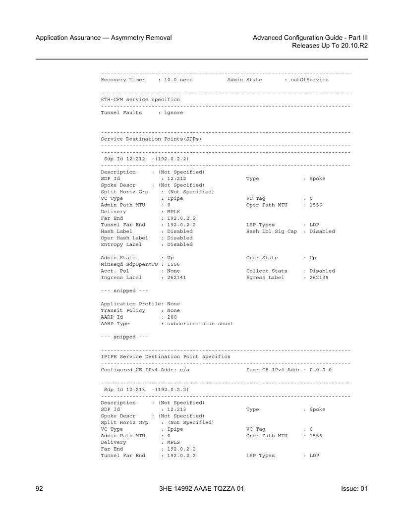
Application Assurance — Asymmetry Removal
92
Advanced Configuration Guide - Part IIIReleases Up To 20.10.R2
3HE 14992 AAAE TQZZA 01 Issue: 01
-------------------------------------------------------------------------------Recovery Timer : 10.0 secs Admin State : outOfService
-------------------------------------------------------------------------------ETH-CFM service specifics-------------------------------------------------------------------------------Tunnel Faults : ignore
-------------------------------------------------------------------------------Service Destination Points(SDPs)--------------------------------------------------------------------------------------------------------------------------------------------------------------Sdp Id 12:212 -(192.0.2.2)
-------------------------------------------------------------------------------Description : (Not Specified)SDP Id : 12:212 Type : SpokeSpoke Descr : (Not Specified)Split Horiz Grp : (Not Specified)VC Type : Ipipe VC Tag : 0Admin Path MTU : 0 Oper Path MTU : 1556Delivery : MPLSFar End : 192.0.2.2Tunnel Far End : 192.0.2.2 LSP Types : LDPHash Label : Disabled Hash Lbl Sig Cap : DisabledOper Hash Label : DisabledEntropy Label : Disabled
Admin State : Up Oper State : UpMinReqd SdpOperMTU : 1556Acct. Pol : None Collect Stats : DisabledIngress Label : 262141 Egress Label : 262139
--- snipped ---
Application Profile: NoneTransit Policy : NoneAARP Id : 200AARP Type : subscriber-side-shunt
--- snipped ---
-------------------------------------------------------------------------------IPIPE Service Destination Point specifics-------------------------------------------------------------------------------Configured CE IPv4 Addr: n/a Peer CE IPv4 Addr : 0.0.0.0
-------------------------------------------------------------------------------Sdp Id 12:213 -(192.0.2.2)
-------------------------------------------------------------------------------Description : (Not Specified)SDP Id : 12:213 Type : SpokeSpoke Descr : (Not Specified)Split Horiz Grp : (Not Specified)VC Type : Ipipe VC Tag : 0Admin Path MTU : 0 Oper Path MTU : 1556Delivery : MPLSFar End : 192.0.2.2Tunnel Far End : 192.0.2.2 LSP Types : LDP

Advanced Configuration Guide - Part III Releases Up To 20.10.R2
Application Assurance — Asymmetry Removal
Issue: 01 3HE 14992 AAAE TQZZA 01 93
Hash Label : Disabled Hash Lbl Sig Cap : DisabledOper Hash Label : DisabledEntropy Label : Disabled
Admin State : Up Oper State : UpMinReqd SdpOperMTU : 1556Acct. Pol : None Collect Stats : DisabledIngress Label : 262140 Egress Label : 262138
--- snipped ---
Application Profile: NoneTransit Policy : NoneAARP Id : 200AARP Type : network-side-shunt
--- snipped ---
===============================================================================*A:PE-1#
Next, the configuration of the VPRN service of the dual-homed SAP can be reviewed to ensure it reflects the attached endpoints for the shunt Ipipe spoke SDPs:
*A:PE-1# show service id 200 all===============================================================================Service Detailed Information===============================================================================Service Id : 200 Vpn Id : 0Service Type : VPRNName : (Not Specified)Description : (Not Specified)Customer Id : 1 Creation Origin : manualLast Status Change: 10/03/2016 11:45:51Last Mgmt Change : 10/03/2016 11:45:51Admin State : Up Oper State : Up
Route Dist. : 64496:200 VPRN Type : regularOper Route Dist : 64496:200Oper RD Type : configuredAS Number : None Router Id : 192.0.2.1ECMP : Enabled ECMP Max Routes : 1Max IPv4 Routes : No LimitAuto Bind TunnelResolution : disabledMax IPv6 Routes : No LimitIgnore NH Metric : DisabledHash Label : DisabledEntropy Label : DisabledVrf Target : target:64496:200Vrf Import : NoneVrf Export : NoneMVPN Vrf Target : NoneMVPN Vrf Import : NoneMVPN Vrf Export : NoneCar. Sup C-VPN : DisabledLabel mode : vrfBGP VPN Backup : Disabled

Application Assurance — Asymmetry Removal
94
Advanced Configuration Guide - Part IIIReleases Up To 20.10.R2
3HE 14992 AAAE TQZZA 01 Issue: 01
BGP Export Inactv : Disabled
SAP Count : 1 SDP Bind Count : 2VSD Domain : <none>
--- snipped ---
-------------------------------------------------------------------------------Service Destination Points(SDPs)--------------------------------------------------------------------------------------------------------------------------------------------------------------Sdp Id 12:200 -(192.0.2.2)
-------------------------------------------------------------------------------Description : (Not Specified)SDP Id : 12:200 Type : SpokeSpoke Descr : (Not Specified)VC Type : n/a VC Tag : n/aAdmin Path MTU : 0 Oper Path MTU : 1556Delivery : MPLSFar End : 192.0.2.2Tunnel Far End : 192.0.2.2 LSP Types : LDPHash Label : Disabled Hash Lbl Sig Cap : DisabledOper Hash Label : DisabledEntropy Label : Disabled
Admin State : Up Oper State : Up
--- snipped ---
Application Profile: NoneTransit Policy : NoneAARP Id : 200AARP Type : subscriber-side-shunt
--- snipped ---
-------------------------------------------------------------------------------IPIPE Service Destination Point specifics-------------------------------------------------------------------------------Configured CE IPv4 Addr: n/a Peer CE IPv4 Addr : 0.0.0.0
-------------------------------------------------------------------------------Sdp Id 12:201 -(192.0.2.2)
-------------------------------------------------------------------------------Description : (Not Specified)SDP Id : 12:201 Type : SpokeSpoke Descr : (Not Specified)VC Type : n/a VC Tag : n/aAdmin Path MTU : 0 Oper Path MTU : 1556Delivery : MPLSFar End : 192.0.2.2Tunnel Far End : 192.0.2.2 LSP Types : LDPHash Label : Disabled Hash Lbl Sig Cap : DisabledOper Hash Label : DisabledEntropy Label : Disabled
Admin State : Up Oper State : Up
--- snipped ---

Advanced Configuration Guide - Part III Releases Up To 20.10.R2
Application Assurance — Asymmetry Removal
Issue: 01 3HE 14992 AAAE TQZZA 01 95
Application Profile: NoneTransit Policy : NoneAARP Id : 200AARP Type : network-side-shunt
--- snipped ---
*A:PE-1#
Continuing deeper into the same VPRN service show output, or using the following show command, it can be verified that the dual-homed SAP itself is properly configured and associated with that service and AARP instance:
*A:PE-1# show service id 200 sap 1/1/4:200 detail
===============================================================================Service Access Points(SAP)===============================================================================Service Id : 200SAP : 1/1/4:200 Encap : q-tagDescription : AA enabled SAPAdmin State : Up Oper State : UpFlags : NoneMulti Svc Site : NoneLast Status Change : 10/03/2016 11:45:51Last Mgmt Change : 10/03/2016 11:45:51Sub Type : regularDot1Q Ethertype : 0x8100 QinQ Ethertype : 0x8100Split Horizon Group: (Not Specified)
Admin MTU : 1518 Oper MTU : 1518Ingr IP Fltr-Id : n/a Egr IP Fltr-Id : n/aIngr Mac Fltr-Id : n/a Egr Mac Fltr-Id : n/aIngr IPv6 Fltr-Id : n/a Egr IPv6 Fltr-Id : n/aqinq-pbit-marking : both
Egr Agg Rate Limit: maxQ Frame-Based Acct : Disabled Limit Unused BW : Disabled
Acct. Pol : None Collect Stats : Disabled
Anti Spoofing : None Dynamic Hosts : EnabledAvl Static Hosts : 0 Tot Static Hosts : 0Calling-Station-Id : n/a
Application Profile: app-prof-1Transit Policy : NoneAARP Id : 200AARP Type : dual-homed
Oper Group : (none) Monitor Oper Grp : (none)Host Lockout Plcy : n/aLag Link Map Prof : (none)Bandwidth : Not-Applicable
--- snipped ---
===============================================================================

Application Assurance — Asymmetry Removal
96
Advanced Configuration Guide - Part IIIReleases Up To 20.10.R2
3HE 14992 AAAE TQZZA 01 Issue: 01
*A:PE-1#
Network to Subscriber Traffic Flow
When the AARP is operationally up, AARP tracks which ISA is the master ISA for each dual-homed AARP instance and uses the inter-chassis services (spoke SDP AARP shunts) to move all traffic for each instance traffic to the node with the Master ISA.
Looking at traffic in the network to subscriber direction (Figure 13):
• Traffic arriving on PE-1 is diverted to the local master ISA, processed, then proceeds to the egress SAP.
• Traffic arriving on PE-2 with the backup AARP interface is sent to the master node for AA processing. The ingress FP forwards packets to network-side-shunt AARP interface for remote AA divert.
• Arriving on PE-1, the packets on the AARP Ipipe are diverted to the master ISA where the packets are processed as if this traffic was traveling in the to-sub direction towards the dual-homed endpoint on PE-1, then returned to PE-2.
• Entering PE-2, the traffic from the subscriber side shunt interface is not diverted to ISAs in that node and egresses on the AARP instance SAP.
With this behavior, traffic always returns to the original ingress node before egressing toward the subscriber (network path for the flows are not modified).

Advanced Configuration Guide - Part III Releases Up To 20.10.R2
Application Assurance — Asymmetry Removal
Issue: 01 3HE 14992 AAAE TQZZA 01 97
Figure 13 Network to Subscriber Traffic Flow
Subscriber to Network Traffic Flow
Looking at traffic in the subscriber to network direction (Figure 14):
• Traffic arriving on PE-1 is diverted to the local master ISA, processed, then proceeds to the egress SAP.
• Traffic arriving on PE-2 with the backup AARP ISA is sent to the master node for AA processing (not diverted to an ISA in PE-2). The ingress FP forwards packets to subscriber-side-shunt AARP interface for remote AA divert.
• Arriving on PE-1, the packets on the AARP Ipipe are diverted to the master ISA where the packets are processed as if the traffic was flowing in the from-sub direction on the dual-homed endpoint, then returned to PE-2 over the Ipipe’s AARP subscriber-side-shunt.
• Entering PE-2, the traffic from the network side shunt interface is forwarded by the IES/VPRN service to its destination.
Traffic to/from backup AARP is sent tothe master Node for AA Divert
VPRN/IES
VPRN/IES
PE-1Master AARPAA Sub ContextAA Flow Records
IPIPE
MPLS CORE
Traffic not diverted to the MS-ISA and forwarded toits destination.
”AA divert” to AA-ISA for flowprocessing (divert to ISA paths not shown).
7450/BRAS
IPIPE
21:213
21:201
21:200
12:213
12:212
12:201
21:212
AA-Subscriber Interface AA-Subscriber Interface
12:2.0.0
al_0243
Ingress FP routing/destinationlookup from AARP backup interface.Forwards packets network-side-shunt AARP interface for remoteAA divert.
PE-2Master AARPAA Sub ContextNo AA Flow Records

Application Assurance — Asymmetry Removal
98
Advanced Configuration Guide - Part IIIReleases Up To 20.10.R2
3HE 14992 AAAE TQZZA 01 Issue: 01
Figure 14 Subscriber to Network Traffic Flow
Typical Configuration Mistakes
Operators configuring AARP can make some typical mistakes listed below that will keep the AARP instance in Operational State down:
• The spoke SDP AARP shunt instances’ IDs must be aligned with the respective spoke SDP on the peer node: if not, it will result in a flag indicating shunt mismatch in the show output.
• Ipipe service MTU alignment — The Ipipe service MTU values must be the same in both nodes, otherwise it will result in the services be in operational status UP, but the AARP instance will remain down.
Traffic to/from backup AARP is sent tothe master Node for AA Divert
VPRN/IES
VPRN/IES
PE-1Master AARPAA Sub ContextAA Flow Records
IPIPE
MPLS CORE
Traffic not diverted to the MS-ISA and forwarded toits destination.
”AA divert” to AA-ISA for flowprocessing (divert to ISA paths not shown).
7450/BRAS
IPIPE
21:213
21:201
21:200
12:213
12:212
12:201
21:212
AA-Subscriber Interface AA-Subscriber Interface
12:2.0.0
al_0243
Ingress FP routing/destinationlookup from AARP backup interface.Forwards packets network-side-shunt AARP interface for remoteAA divert.
PE-2Master AARPAA Sub ContextNo AA Flow Records

Advanced Configuration Guide - Part III Releases Up To 20.10.R2
Application Assurance — Asymmetry Removal
Issue: 01 3HE 14992 AAAE TQZZA 01 99
Conclusion
This chapter is intended for Application Assurance (AA) network architects and engineers to provide the information required to understand and configure dual-node asymmetry removal following the intended service configuration as used by the AARP implementation.

Application Assurance — Asymmetry Removal
100
Advanced Configuration Guide - Part IIIReleases Up To 20.10.R2
3HE 14992 AAAE TQZZA 01 Issue: 01

Advanced Configuration Guide - Part III Releases Up To 20.10.R2
Application Assurance — Best Practices for ISA andHost IOM Overload Protection
Issue: 01 3HE 14992 AAAE TQZZA 01 101
Application Assurance — Best Practices for ISA and Host IOM Overload ProtectionThis chapter provides information about Application Assurance best practices for ISA and host IOM overload protection.
Topics in this chapter include:
• Applicability• Overview• Configuration• Conclusion
Applicability
This configuration note is applicable to all 7750 SR/SR-c and 7450 ESS chassis supporting Application Assurance (AA).
The configuration was tested on release 12.0.R4.
Overview
The Multi-Service Integrated Services Adapter (MS-ISA) is a processing resource module installed in a7x50 SR/ESS system on an ISA host IOM. This example describes the best practices for configuration and monitoring of the system to ensure proper engineering of the system resources involved in AA ISA capacity planning.
As shown in Figure 15, traffic is diverted to an AA ISA by provisioning of an application profile (app-profile) for a subscriber or SAP service context. SR OS then automatically handles traffic diversion for both directions of traffic for that AA subscriber context, through one of the AA ISAs in the AA group where that app-profile is defined.

Application Assurance — Best Practices for ISA and Host IOM Overload Protection
102
Advanced Configuration Guide - Part IIIReleases Up To 20.10.R2
3HE 14992 AAAE TQZZA 01 Issue: 01
Figure 15 System Packet Datapath to AA ISA
The following elements in the 7x50 SR/ESS system must be properly engineered for any given AA deployment. Each element is described in this section:
1. ISA capacity cost and load balancing across ISAs.2. ISA host IOM network egress QoS. Host IOM egress network ports weighted-
average shared buffer pool thresholds (within the egress QoS configuration for each group) are used for overload cut-through processing.
3. ISA resources and statistics collection.- Flows- Traffic volume (bandwidth)- Subscribers- Flow setup rate- ISA overload cut-through- ISA default subscriber policies
ISA Capacity Planning Approach
This example illustrates an approach to the configuration of the 7x50 SR/ESS AA system to address these considerations:
• IOM/ISA-AA network egress QoS configuration should be designed to treat the ISA as a network port with normal network port maximum delay (by MBS).
al_0535
Subscribers or Service-interface with Application Profile IOM FlexPath:
L2/L3 Forwarding +Ingress Divert Decision
IOM FlexPath:L2/L3 Forwarding +Ingress Divert Decision
PORT 1/1 VLAN 5
PORT
Diverted TrafficNot-diverted Traffic
Access orNetwork Port
Access orNetwork Port
‘from-sub’ VirtualIngress Network Port
Apply QoSPolicies
StatisticsCollection
ApplicationIdentification
‘to-sub’ VirtualIngress Network Port
‘to-sub’ VirtualEgress Network Port
‘from-sub’ VirtualEgress Network Port
MDAMDA IOMIOM Fabric
IOM ISA
ISA Host IOM with FPVirtual Network Ports(with Network-QOS)
High-touchAA Processing

Advanced Configuration Guide - Part III Releases Up To 20.10.R2
Application Assurance — Best Practices for ISA andHost IOM Overload Protection
Issue: 01 3HE 14992 AAAE TQZZA 01 103
• Within the ISA, fair access to the ISA-AA bandwidth and flow resources must be ensured: it is recommended that default Application QoS Policy (AQP) policy entries be configured limiting bandwidth and flow resources per AA subscriber.
• Thresholds for SNMP alerts that indicate a high load on ISA processing should be configured: capacity cost, flow, bandwidth.
• Capacity tracking in live deployments should be performed for parameters that can affect overload: flow setup rate, bandwidth, and subscriber-count per ISA.
• Use of other scale related consumable AA resources against system maximum limits. This includes parameters such as statistics records, transit-ip table entries, and transit-prefix TCAM entries, which should be planned and periodically tracked. These limits will not affect overload of the ISA but may affect intended service operation.
• For recommendations of the specific parameters to watch in a given deployment as well as the values of the system limits for a given release, contact your regional support organization.
AA Overload and Resource Monitoring
Overload is a condition where the total packet processing requirements for traffic arriving on a given ISA exceeds the available resources, resulting in the host IOM egress buffers reaching a configured “overload” threshold. Above this threshold, the ISA can be configured to forward excess traffic (called overload cut-through). If cut-through is not enabled and the overload condition continues, the egress queue MBS threshold will eventually be reached, after which packets will be discarded. Even if overload cut-through is enabled, any egress traffic that exceeds the maximum bus capacity of the ISA queue discard threshold will be discarded.
ISA capacity overload events are supported within the system resource monitoring and logging capabilities if the traffic and resource load crosses any of the following high and low load thresholds on a per-ISA basis. Exceeding one of these thresholds does not in itself indicate an overload state.
a. Host IOM egress network ports weighted-average shared buffer pool thresholds (within the egress QoS configuration for each AA group) are used for triggering and removing overload cut-through processing. Care should be taken in the configuration of these buffers, as the IOM flexpath has significant buffer capacity that can result in latency larger than the network SLA acceptable guidelines. A properly engineered configuration will have large enough buffering to not trigger ISA overload unnecessarily (due to normal bursts with a reasonable traffic load) but will not incur excessive latency prior to triggering the overload state.

Application Assurance — Best Practices for ISA and Host IOM Overload Protection
104
Advanced Configuration Guide - Part IIIReleases Up To 20.10.R2
3HE 14992 AAAE TQZZA 01 Issue: 01
b. ISA capacity cost: if the capacity cost of all subscribers on the ISA exceeds a threshold, an event is raised but the overload condition is not set (unless other resources are exhausted). ISA overload or traffic cut-through does not occur simply if capacity cost is exceeded. It is used to capacity plan an intended load for the ISA, proportional to resource use per subscriber, in order to generate events prior to overload to allow appropriate action to mitigate the resource consumption (such as provisioning more ISAs).
c. Flow table consumption (number of allocated flow resources in use): the flow table high-watermark threshold warnings are for proactive notification of a high load. The ISA will cut-through new flows when the “flow resources in use” is at the maximum flow limit. Reaching the flow limit does not generate backpressure to the IOM, nor is the ISA considered in an overload state. Flow usage thresholds are different from bit-rate/packet-rate/flow-setup-rate thresholds in that when the flow table high-watermark threshold is exceeded, the ISA will no longer be operating as application-aware for the flows with no context. The default subscriber policy is applied to traffic that required a flow record but was unable to allocate one, which is a similar behavior to overload cut-through.The following terms are used to describe flow resources:- Maximum flows: the maximum AA flow table size for a given release.- Flows: on the show screens, the “flows” field is an indication of the number
of unique 5-tuple entries in the flow table. This includes active and inactive flows; inactive will age out of the table after a period of inactivity that is dependent on the protocol used.
- Active flows: the number of flows with traffic in the current reporting interval.- Flow resources in use: the number of allocated flows in the flow table. This
number is greater than the number of active flows, reflecting inactive flows and flows pre-allocated for some dynamic protocols (control + data channels) and for some UDP traffic.
d. Traffic volume: traffic rate in bytes/sec and packets/sec is the dominant cause of ISA overload in most network scenarios, when the ISA is presented with more traffic than it can process. This results in the ISA internal ingress buffers reaching a threshold that causes backpressure to the IOM egress queues (toward the ISA), allowing the ISA to process the packets it already has. This internal backpressure mechanism is normal behavior, allowing burst tolerance at the IOM-to-ISA interface; thus backpressure is not in itself an indication of overload. Overload occurs when the bursts or the load of traffic is sustained long enough to reach the ISA host IOM network port egress weighted-average shared buffer threshold. The actual amount of traffic that can be passed through an ISA is dependent on the application traffic mix, flow density, and AA policy configurations and will vary by network type and by region. The bit-rate and packet-rate watermarks can be used to provide event notification when the traffic rates exceed planning expectations.

Advanced Configuration Guide - Part III Releases Up To 20.10.R2
Application Assurance — Best Practices for ISA andHost IOM Overload Protection
Issue: 01 3HE 14992 AAAE TQZZA 01 105
e. Flow setup rate: this is generally proportional to total traffic volume, and as such can be a factor in ISA overload. The flow setup rate is the rate at which new flows are presented to the ISA, each resulting in additional tasks that are specific to flow state creation; thus the ISA has a sensitivity to flow setup rates as fewer cycles are available for other datapath tasks when the flow setup rate is high. In residential networks, flow setup rates of 3 k to 5 k flows/sec per Gbps of traffic are common. The flow setup watermarks can be used to provide event notification when the rate exceeds planning expectations.
ISA Overload Models
For an ISA overload strategy, there are two design options for configuring the overload behavior of the system:
• Host IOM egress discards: in this model, the philosophy is to treat AA packet processing resources in the same way as a network interface (of somewhat variable capacity depending on the traffic characteristics). When too much traffic is presented to the ISA, it backpressures the host IOM egress, which will buffer packets. If the egress buffer thresholds are exceeded, the ISA will discard according to the egress QoS slope policy. This is configured by not enabling isa-overload-cut-through and use of appropriate egress QoS policies. Firewall or session filter deployments may use this model.
• Overload cut-through: the ISA group can be enabled to cut-through some traffic if an overload event occurs, triggered when the IOM network port weighted-average queues depth exceeds the weighted-average shared high-watermark threshold. In this ISA state, some packets are cut-through from application analysis but retain subscriber context with the default subscriber policy applied. This mode of deployment is intended for situations where it is preferable to forward packets even if not identified by AA than to drop/discard the packet. For example, if AA is providing value-added services (VAS) such as In-Browser Notification (IBN), analytics, or traffic rate limiting, this would usually be the preferred model as the underlying service should be preserved even if capacity to provide the VAS is not available.
Note that even with overload cut-through enabled, there is a hardware-based maximum ISA throughput of approximately 11 Gbps for MS-ISA and 40 Gbps for MS-ISA2. If this is exceeded on a sustained basis, IOM egress discards may still occur.

Application Assurance — Best Practices for ISA and Host IOM Overload Protection
106
Advanced Configuration Guide - Part IIIReleases Up To 20.10.R2
3HE 14992 AAAE TQZZA 01 Issue: 01
Understanding Packet and Protocol Cut-Through
Traffic can be cut-through the ISA-AA card on a packet-by-packet basis, in which case packets do not go through AA identification and subscriber application policy. The conditions that trigger cut-through include:
• Overload (IOM egress network port weighted-average shared buffer threshold): excess traffic bypasses all AA processing except for the default subscriber policy
• Non-conformant IP packet: traffic bypasses all AA processing except IP protocol checks and the default subscriber policy. Optionally, these packets can be discarded in AA.
• Flow table full: for new 5-tuples sent to the ISA, if the flow table is full, the packets are cut-through the ISA and only the default subscriber policy is applied.
For cut-through traffic, no flow records exist but it is counted under per-subscriber protocol statistics as one of the following counters, depending on the case:
• cut_through — Statistics for any packet that could not map to a flow, but that has a valid subscriber ID. This can be an error packet, fragmented out-of-order, no flow resource, invalid TCP flags, etc. This is the most important count for indicating overload cut-through, as it counts all traffic in overload cut-through mode (when the weighted-average threshold has been crossed).
• denied_by_default_policy — Packets that are dropped due to a default policy with a flow-based policer (flow rate or flow count) with action discard.
• cut_through_by_default_policy — Packets that failed to pass flow-based policers with an action of priority-mark.
An example of overload cut-through statistics in the CLI is shown below:
A:BNG# show application-assurance group 1 protocol count===============================================================================Application-Assurance Protocol Statistics===============================================================================Protocol Disc Octets Packets Flows-------------------------------------------------------------------------------advanced_direct_connect 0% 0 0 0aim 0% 0 0 0
Note: The default subscriber policy is a set of AQP rules that apply AQP match criteria limited to Application Service Options (ASO), aa-sub, and traffic-direction starting with the first packet of a flow, with no match conditions based on AA identification (application, app-group, charging-group, IP header). Packets will be either denied_by_default_policy or cut_through_by_default_policy, depending on the policer action configuration in the AQP rules.

Advanced Configuration Guide - Part III Releases Up To 20.10.R2
Application Assurance — Best Practices for ISA andHost IOM Overload Protection
Issue: 01 3HE 14992 AAAE TQZZA 01 107
amazon_video 0% 0 0 0ares 0% 0 0 0bbm 0% 0 0 0betamax_voip 0% 0 0 0bgp 0% 0 0 0bittorrent 0% 678428534 5322929 1036129cccam 0% 0 0 0citrix_ica 0% 0 0 0citrix_ima 0% 0 0 0cnnlive 0% 0 0 0cups 0% 0 0 0cut_through 0% 5299435739 10603771 0cut_through_by_default_policy 0% 0 0 0cvs 0% 0 0 0daap 0% 0 0 0dcerpc 0% 0 0 0denied_by_default_policy 0% 0 0 0
Configuration
This example illustrates a typical, configuration of a 7x50 system for AA each of the configuration topics.
AA Traffic Load Test Environment
Application assurance identifies every byte and every packet of hundreds of real-world applications using per-flow stateful analysis techniques. It is a challenge to find test equipment that can accurately emulate full scale (10 Gbps to 40 Gbps) with traffic mixes and flow behaviors representing hundreds of thousands of end users with application clients across a range of devices. Some specialized stateful test equipment can emulate large traffic rates, but even the best will have equipment-specific patterns and behaviors not representative of live traffic. Therefore, the best scenario to engineer the AA overload configuration is by iteration in live deployments: setting an initial target and modifying the configuration based on ISA performance under load.
For a lab test of ISA throughput and loading, Nokia uses stateful test equipment which supports emulation of various service provider traffic mix profiles suitable for generating overload conditions; however, it is outside the scope of this document to configure AA throughput tests.

Application Assurance — Best Practices for ISA and Host IOM Overload Protection
108
Advanced Configuration Guide - Part IIIReleases Up To 20.10.R2
3HE 14992 AAAE TQZZA 01 Issue: 01
The operator should be aware that use of unrealistic, non-stateful traffic generators can result in a high level of unknown traffic, with the ISA performance impacted by continually trying to identify large numbers of packets of no real application type. This, combined with cut-through for invalid IP packets, can result in ISA overload and traffic cut-through (due to overload or invalid IP packets) at traffic levels not representative of actual ISA performance on real traffic.
ISA Capacity Cost and Load Balancing Across ISAs
These AA group-level commands define the load balancing parameters within an ISA group.
*A:BNG# configure isaapplication-assurance-group 1 aa-sub-scale residential create
no descriptionno fail-to-openisa-capacity-cost-high-threshold 304000isa-capacity-cost-low-threshold 272000partitionsdivert-fc beno shutdown
exit
The following should be noted related to this configuration:
• Up to 7 primary and 1 backup ISAs are allowed. If the AA services are considered “value added” and not part of a paid service, backups are usually not used since the “fail to fabric” capability keeps the underlying service running.
• The default behavior in case of ISA failure is “no fail-to-open”, which means “fail-to-wire”; if an ISA fails, traffic is forwarded as if no divert was configured
• Threshold for sending capacity-cost SNMP traps: the unit used for capacity cost is a variable defined in the network design; in this example, it is expressed in Mbps of the subscriber total BW UP+DOWN with a high watermark set to 7600 Mbps × 40 = 304000 (where 40 is an oversubscription ratio). The low watermark is equal to 6800 Mbps × 40 = 272000.
• Partitions should always be enabled to configure additional policies in the future (for example, wifi/business)
• divert-fc configuration applies to the AA group: in this example, FC BE Internet is the only diverted FC; this is typical for AA residential and WLan-GW deployments. For VPN services, typically all datapath FCs are diverted to AA.

Advanced Configuration Guide - Part III Releases Up To 20.10.R2
Application Assurance — Best Practices for ISA andHost IOM Overload Protection
Issue: 01 3HE 14992 AAAE TQZZA 01 109
ISA-AA Host IOM - Network Egress Shared Memory and QoS
The amount of shared memory allocated per port, along with the network port egress QoS policy, determine the maximum delay for traffic diverted to Application Assurance.
This maximum network port delay is typically determined by the operator and must be used to define the proper QoS configuration to apply to the ISA-AA ports; this QoS configuration may be the same (typically) as what is applied to regular network ports on the 7x50 SR/ESS.
On the line cards there is shared network egress memory per ISA-AA port, with the ISA-AA is represented by two network ports on the host IOM:
• “from-sub”: for traffic sent from the subscriber to the network • “to-sub”: for traffic sent from the network to the subscriber
configure isa application-assurance-group 1qos
egressfrom-subscriber
poolslope-policy "default"resv-cbs default
exitqueue-policy "network-facing-egress"port-scheduler-policy "network-facing"
exitto-subscriber
poolslope-policy "default"resv-cbs default
exitqueue-policy "network-facing-egress"port-scheduler-policy "network-facing"
exitexitno shutdown
The amount of shared memory reserved for each egress network port is determined by the speed of the port (10 Gbps for MS-ISA and 40 Gbps for MS-ISA2) and the egr-percentage-of-rate ratio configuration.
MS-ISA uses by default 1000% and 500% of the rate respectively for to-sub and from-sub ports, while MS-ISA2 uses by default 100% for both to-sub and from-sub ports.

Application Assurance — Best Practices for ISA and Host IOM Overload Protection
110
Advanced Configuration Guide - Part IIIReleases Up To 20.10.R2
3HE 14992 AAAE TQZZA 01 Issue: 01
It is typically recommended that these values be adjusted when MS-ISA and a high-speed Ethernet MDA are mixed on the same IOM, since in this context the amount of shared memory allocated to the Ethernet MDA should be increased by reducing the MS-ISA network ports memory allocation ratio. If two MS-ISAs are installed on the same IOM, the system will by default allocate 50% of the network egress shared memory to each ISA. In addition, an operator may adjust these values in case the actual network-to-subscriber versus subscriber-to-network ratio is significantly different in the production network, in order to achieve the expected maximum tolerated network delay.
The operator can modify the egr-percentage-of-rate per port using the command below:
A:BNG# configure port 1/2/fm-subA:BNG>config>port# info detail----------------------------------------------
modify-buffer-allocation-rateegr-percentage-of-rate 500
exit----------------------------------------------A:BNG# configure port 1/2/to-subA:BNG>config>port# info detail----------------------------------------------
modify-buffer-allocation-rateegr-percentage-of-rate 1000
exit
Network egress scheduling/queuing priority is for all ISAs within a group defined at the AA ISA group level
An example below with ISA-AA and 2 x 10G Eth MDA:
7750# configure port <slot>/<isa-aa-mda>/fm-submodify-buffer-allocation-rate
egr-percentage-of-rate 65
7750# configure port <slot>/<isa-aa-mda>/to-submodify-buffer-allocation-rate
egr-percentage-of-rate 130
In this example, the configuration defines:
• from-sub — Approximately 190 msec worth of buffer at 2500 Mbps.• to-sub— Approximately 190 msec worth of buffer at 5000 Mbps.• The buffer can be further refined from the network QoS policy.
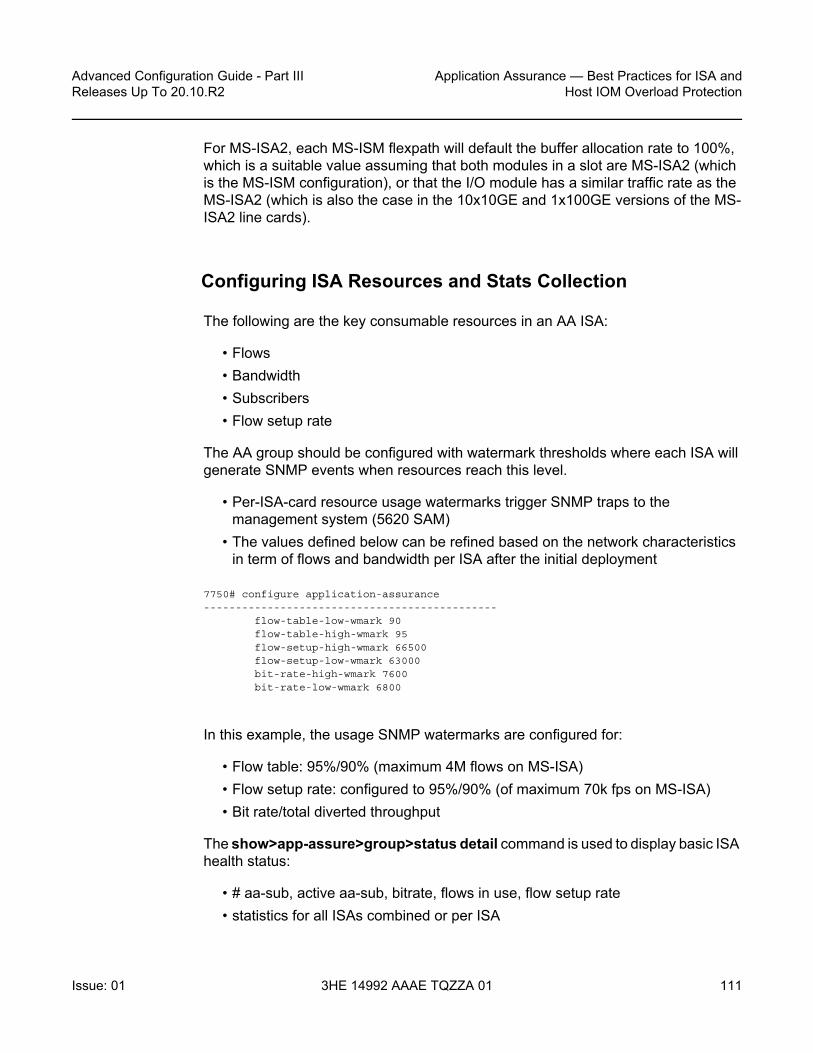
Advanced Configuration Guide - Part III Releases Up To 20.10.R2
Application Assurance — Best Practices for ISA andHost IOM Overload Protection
Issue: 01 3HE 14992 AAAE TQZZA 01 111
For MS-ISA2, each MS-ISM flexpath will default the buffer allocation rate to 100%, which is a suitable value assuming that both modules in a slot are MS-ISA2 (which is the MS-ISM configuration), or that the I/O module has a similar traffic rate as the MS-ISA2 (which is also the case in the 10x10GE and 1x100GE versions of the MS-ISA2 line cards).
Configuring ISA Resources and Stats Collection
The following are the key consumable resources in an AA ISA:
• Flows• Bandwidth• Subscribers• Flow setup rate
The AA group should be configured with watermark thresholds where each ISA will generate SNMP events when resources reach this level.
• Per-ISA-card resource usage watermarks trigger SNMP traps to the management system (5620 SAM)
• The values defined below can be refined based on the network characteristics in term of flows and bandwidth per ISA after the initial deployment
7750# configure application-assurance----------------------------------------------
flow-table-low-wmark 90flow-table-high-wmark 95flow-setup-high-wmark 66500flow-setup-low-wmark 63000bit-rate-high-wmark 7600bit-rate-low-wmark 6800
In this example, the usage SNMP watermarks are configured for:
• Flow table: 95%/90% (maximum 4M flows on MS-ISA)• Flow setup rate: configured to 95%/90% (of maximum 70k fps on MS-ISA)• Bit rate/total diverted throughput
The show>app-assure>group>status detail command is used to display basic ISA health status:
• # aa-sub, active aa-sub, bitrate, flows in use, flow setup rate • statistics for all ISAs combined or per ISA

Application Assurance — Best Practices for ISA and Host IOM Overload Protection
112
Advanced Configuration Guide - Part IIIReleases Up To 20.10.R2
3HE 14992 AAAE TQZZA 01 Issue: 01
A:BNG# show application-assurance group 1 status detail===============================================================================Application-Assurance Status===============================================================================Last time change affecting status : 05/30/2014 17:18:34Number of Active ISAs : 4Flows : 214007945881Flow Resources In Use : 2955164AA Subs Created : 70567AA Subs Deleted : 10544AA Subs Modified : 0Seen IP Requests Sent : 0Seen IP Requests Dropped : 0-------------------------------------------------------------------------------
Current Average Peak-------------------------------------------------------------------------------Active Flows : 2911508 2769454 4582522Flow Setup Rate (per second) : 33923 29400 67865Traffic Rate (Mbps) : 7620 7238 22628Packet Rate (per second) : 1254138 1182571 3044376AA-Subs Downloaded : 69887 66129 70567Active Subs : 23131 19737 38114-------------------------------------------------------------------------------
Packets Octets-------------------------------------------------------------------------------Diverted traffic : 7437950197613 5530634242355947Diverted discards : 0 0
Congestion : 0 0Errors : 0 N/A
Entered ISA-AAs : 7437950180191 5530634229794634Buffered in ISA-AAs : 22 29849Discarded in ISA-AAs : 97790 47801217
Policy : 0 0Congestion : 0 0Errors : 97790 47801217
Modified in ISA-AAsPacket size increased : 0 0Packet size decreased : 0 0
Errors (policy bypass) : 28283549 21160338635Exited ISA-AAs : 7437950082379 5530634181963568Returned discards : 0 0
Congestion : 0 0Errors : 0 N/A
Returned traffic : 7437950054070 5530634162337570===============================================================================
This can also be run on a per-ISA basis:
show application-assurance group 1 status isa <slot/port> detail

Advanced Configuration Guide - Part III Releases Up To 20.10.R2
Application Assurance — Best Practices for ISA andHost IOM Overload Protection
Issue: 01 3HE 14992 AAAE TQZZA 01 113
Note that for MS-ISA2, there is a maximum AA packet rate of 7 M pps; under most known traffic mix scenarios, the ISA should be safely below this packet rate when at maximum bandwidth throughput. However, it is worth periodically checking this value, because if the maximum packet rate is exceeded, and overload cut-through will result. (For MS-ISA, the maximum packet rate supported is high enough to not be feasible with realistic application-based traffic mixes).
The ISA aa-performance record should always be enabled in a network for capacity planning purposes in order to properly plan when to add new ISA cards if required and to monitor the network health:
*A:BNG>config>isa# info----------------------------------------------
application-assurance-group 1 aa-sub-scale residential createno descriptionprimary <slot/port>backup <slot/port>no fail-to-openisa-capacity-cost-high-threshold 304000isa-capacity-cost-low-threshold 272000partitionsstatistics
performanceaccounting-policy 7collect-stats
exitexitdivert-fc beno shutdown
exit
The commands highlighted in bold above will export information on the total traffic load and resource utilization of the ISA card:
• Flows — active flows, setup rates, resource allocation• Traffic rates — bandwidth, packets• Subscribers — active, configured, statistics resource allocation in use
The AA statistics collection configuration refers to accounting policies that are also defined in the 7x50 SR/ESS system:
*A:BNG>config# logfile-id 7
description "ISA Performance Stats"location cf2:rollover 15 retention 12
exitaccounting-policy 7
description "ISA Performance Stats“collection-interval 15record aa-performance

Application Assurance — Best Practices for ISA and Host IOM Overload Protection
114
Advanced Configuration Guide - Part IIIReleases Up To 20.10.R2
3HE 14992 AAAE TQZZA 01 Issue: 01
to file 7no shutdown
exit
From the AA performance record the following fields in Table 5 can be used as to tracking ISA load in the reporting interval (typically a 15 to 60 minute period):
Table 5 Tracking ISA Load in the Reporting Interval
Record Name
Type Description Load planning use
dco cumulative octets discarded due to congestion in MDA
Should be 0; ISA internal congestion
dcp cumulative packets discarded due to congestion in MDA
Should be 0; ISA internal congestion
dpo cumulative octets discarded due to policy in MDA Not related to load planning
dpp cumulative packets discarded due to policy in MDA
Not related to load planning
pbo cumulative octets policy bypass Not used. Traffic was for an invalid subscriber and the group was "no fail-to-open"
pbp cumulative packets policy bypass Not used. Traffic was for an invalid subscriber and the group was "no fail-to-open"
nfl cumulative number of flows informative
caf intervalized current active flows informative
aaf intervalized average active flows informative
paf intervalized peak active flows Check vs max
cfr intervalized current flow setup rate informative
afr intervalized average flow setup rate Check meets expected norms; increasing over time increases load
pfr intervalized peak flow setup rate informative
ctr intervalized current traffic rate informative
atr intervalized average traffic rate Check meets expected norms; increasing over time increases load
ptr intervalized peak traffic rate Check vs max

Advanced Configuration Guide - Part III Releases Up To 20.10.R2
Application Assurance — Best Practices for ISA andHost IOM Overload Protection
Issue: 01 3HE 14992 AAAE TQZZA 01 115
The intended deployment model is for this statistic record to be collected by 5620 SAM along with all other AA records and be stored in the 5670 RAM database for subsequent analytics purposes, such as trending charts or setting thresholds of key values. It is recommended that a CRON script be used to export the AA performance record to a storage server for post processing if the 5670 RAM is not deployed:
• If the 5670 RAM is not yet deployed in the network, it is possible to automatically collect the XML accounting files and provide high-level reporting through an XML-to-CSV conversion.
• The simplest approach is to configure a CRON script on the 7x50 SR/ESS to automatically retrieve the CF accounting file (alternatively, any other scripting mechanism with an interval < retention can be used)
• It is recommended that the rollover interval of the file-id policy be modified to 6H or above in order to collect fewer files while keeping the same collection interval.
*A:BNG# file type cf2:/scriptfile copy cf2:/act/*.gz ftp://login:password@IP-ADDRESS/acct/router1/
*A:BNG>config>cron# info----------------------------------------------
script "test-ftp-act"location "cf2:/script"no shutdown
exitaction "cron1"
results "ftp://login:password@IP-ADDRESS/results/router1-result.log"script "test-ftp-act"no shutdown
cpr intervalized current packet rate informative
apr intervalized average packet rate informative
ppr intervalized peak packet rate informative
cds intervalized current diverted subscribers informative
ads intervalized average diverted subscribers informative
pds intervalized peak diverted subscribers Check vs max and expected norms; increasing over time increases load
rfi intervalized flows in use Check vs max and expected norms; increasing over time increases load
rcc cumulative ISA capacity cost Check meets expected norms; increasing over time increases load
Table 5 Tracking ISA Load in the Reporting Interval (Continued)
Record Name
Type Description Load planning use

Application Assurance — Best Practices for ISA and Host IOM Overload Protection
116
Advanced Configuration Guide - Part IIIReleases Up To 20.10.R2
3HE 14992 AAAE TQZZA 01 Issue: 01
exitschedule "schedule1"
interval 36000action "cron1"no shutdown
exit
Note that the interval 36000 is in seconds (10 hours).
With this XML to CSV export mechanism, a spreadsheet can be used by the network engineer to periodically track the ISA resource utilization.
ISA Overload Cut-through
The system can be configured to react to overload based on the weighted-average (WA) queue depth of the shared network port buffer pool from-sub and to-sub. Overload cut-through is typically recommended for use of AA for value-added services where, in the event of overload, the preference is for the ISA to continue to pass packets without AA processing. However, firewall use cases will prefer to drop excess traffic in the event of overload, in which case overload cut-through may not be desired.
In addition to triggering an alarm, further packets sent to the ISA after the WA high-watermark threshold is reached are cut-through immediately by the ISA card without application identification or subscriber policy processing, if the isa-overload-cut-through command is enabled.
The WA queue depth is typically configured based on the maximum tolerated delay for the service diverted and the amount of shared buffer space allocated from the IOM.
AA deployment recommended settings:
• high watermark — 33% of the maximum MBS for all diverted network queues• low watermark — 5% of the maximum MBS for all diverted network queues

Advanced Configuration Guide - Part III Releases Up To 20.10.R2
Application Assurance — Best Practices for ISA andHost IOM Overload Protection
Issue: 01 3HE 14992 AAAE TQZZA 01 117
The recommended high and low watermarks assume that the sum of the network port egress queues MBS size is 100% of the shared buffer. If this network queue maximum size is further reduced in the network QoS policy, the watermark values must be adapted proportionally; for example, if the total MBS size cannot exceed 50% of the shared buffer, then the watermark values would be divided by 2 => High Wmark = 16%, Low Wmark = 2%. Adjusting the MBS and the wa-shared-high-wmark and wa-shared-low-wmark values proportionately ensures that the MBS point (after which discards occur) is above the WA shared high-watermark threshold; otherwise, the ISA will not ever overload if MBS discards are occurring first.
A:BNG# configure isa application-assurance-group 1isa-overload-cut-throughqos
egressfrom-subscriber
wa-shared-high-wmark 16wa-shared-low-wmark 2
exitto-subscriber
wa-shared-high-wmark 16wa-shared-low-wmark 2
exitexit
exit
The show>isa>group commands can be used to verify that overload cut-though is enabled.
*A:BNG>show isa application-assurance-group 1=============================================================ISA Application-assurance-groups=============================================================ISA-AA Group Index : 1Description : (Not Specified)Subscriber Scale : residentialWLAN GW Group Index : N/APrimary ISA-AA : 1/2 up/activeBackup ISA-AA : 2/1 downLast Active change : 07/02/2014 12:17:45Admin State : UpOper State : UpDiverted FCs : beFail to mode : fail-to-wirePartitions : enabledQoS
Egress from subscriberPool : default
Reserved Cbs : defaultSlope Policy : default
Queue Policy : defaultScheduler Policy :
Egress to subscriberPool : default
Reserved Cbs : defaultSlope Policy : default

Application Assurance — Best Practices for ISA and Host IOM Overload Protection
118
Advanced Configuration Guide - Part IIIReleases Up To 20.10.R2
3HE 14992 AAAE TQZZA 01 Issue: 01
Queue Policy : defaultScheduler Policy :
Capacity CostHigh Threshold : 4294967295Low Threshold : 0
Overload Cut Through : enabledTransit Prefix
Max IPv4 entries : 0Max IPv6 entries : 0Max IPv6 remote entries : 0
HTTP EnrichmentMax Packet Size : 1500 octets
========================================================================
To monitor the load status of an ISA, enter the following CLI command.
*A:BNG>show application-assurance group 1 status isa 5/1 cpu==========================================Application-Assurance ISA CPU Utilization(Test time 993791 uSec)==========================================Management CPU Usage------------------------------------------Name CPU Time CPU Usage
(uSec)------------------------------------------System 14277 1.43%Management 61101 6.15%Statistics 69850 7.02%Idle 848563 85.39%==========================================Datapath CPU Usage------------------------------------------Name CPU Time CPU Usage
(uSec)------------------------------------------System 14277 1.43%Packet Processing 61101 6.15%Application ID 69850 7.02%Idle 848563 85.39%
Additionally, the system log files can be used to examine the AA overload history to determine when the overload state was entered and exited. It can be helpful to send AA events to a separate log using the following configuration:
logfilter 45
default-action dropentry 10
action forwardmatch
application eq "application_assurance"exit
exitexit

Advanced Configuration Guide - Part III Releases Up To 20.10.R2
Application Assurance — Best Practices for ISA andHost IOM Overload Protection
Issue: 01 3HE 14992 AAAE TQZZA 01 119
log-id 45description "application-assurance log"filter 45from mainto memory 500
exit
The log files can then be examined to see if overload has occurred, and how frequently. If overload occurs with any regularity, it is a situation that should be addressed. Below is an example of a log file showing AA overload:
A:BNG# show log log-id 45===============================================================================Event Log 45===============================================================================Description : application-assurance logwarning: 13 events dropped from logMemory Log contents [size=500 next event=16 (not wrapped)]
15 2014/08/14 17:00:32.66 EST WARNING: APPLICATION_ASSURANCE #4433 Base"ISA AA Group 1 MDA 5/1 exiting overload cut through processing."
14 2014/08/14 17:00:32.55 EST WARNING: APPLICATION_ASSURANCE #4431 Base"ISA-AA group 1 MDA 5/1 wa-shared buffer use is less than or equal to 1% in the to-subscriber direction or corresponding tmnxBsxIsaAaGrpToSbWaSBufOvld notification hasbeen disabled."
13 2014/08/14 17:00:32.06 EST WARNING: APPLICATION_ASSURANCE #4432 Base"ISA AA Group 1 MDA 5/1 entering overload cut through processing."
12 2014/08/14 17:00:32.05 EST WARNING: APPLICATION_ASSURANCE #4430 Base"ISA-AA group 1 MDA 5/1 wa-shared buffer use is greater than or equal to 35% in the to-subscriber direction."
The primary indicator to look at in CLI statistics for ISA load indication is datapath CPU Usage. Regardless of the configuration and traffic profiles in use, datapath CPU usage gives a consistent indication of whether the ISA is under heavy load (the cause of overload is the inability of the ISA to perform more tasks). The idle datapath time is not proportionate to bandwidth throughput, but if idle datapath CPU usage is under 5%, this indicates an approaching maximum processing load.
At an average datapath use of 95-100% (less than 5% idle) the ISA is creating latency and backpressuring the host IOM egress. It is the best way to know how close to overload the ISA has been. Attempting to examine data throughput statistics such as bit rate, flow setup rate and packet rate to predict overload is not recommended, as these are quite variable under normal circumstances and are not directly correlated to overload. Once in overload, the data statistics (volume, setup rate, etc.) are useful for determining what threshold traps to put in place for the future, but the needed thresholds will always be specific to the live deployment traffic mix and policy configuration.

Application Assurance — Best Practices for ISA and Host IOM Overload Protection
120
Advanced Configuration Guide - Part IIIReleases Up To 20.10.R2
3HE 14992 AAAE TQZZA 01 Issue: 01
Below is an example of the status for an ISA that is fully loaded but not yet in overload:
*A:BNG>show application-assurance group 1 status isa 5/1 cpu==========================================Application-Assurance ISA CPU Utilization==========================================
----------------------------------------------Management CPU Usage (Test time 999636 uSec)----------------------------------------------Name CPU Time CPU Usage
(uSec)----------------------------------------------System 1540 0.15%Management 14 ~0.00%Statistics 643955 64.42%ICAP Client 603 0.06%Idle 353524 35.37%----------------------------------------------
----------------------------------------------Datapath CPU Usage (Test time 999735 uSec)----------------------------------------------Name CPU Time CPU Usage
(uSec)----------------------------------------------System 188374 18.84%Packet Processing 534203 53.43%Application ID 277158 27.72%Idle 0 0.00%----------------------------------------------
In this example, 0% idle datapath CPU means the ISA is fully used. When the Datapath CPU Usage Idle average is in the 5-10% range consistently, the ISA should be considered “full”; to add new subscribers, more ISAs are required.
If the excessive traffic condition persists, backpressure from the ISA to the IOM will buffer packets in the egress buffers, and when the egress MBS is exceeded, the ISA host IOM will indicate Diverted discards due to congestion if cut-through is not enabled:
*A:BNG>show application-assurance group 1 status detail===============================================================================Application-Assurance Status===============================================================================Last time change affecting status : 08/12/2014 13:16:15Number of Active ISAs : 1Flows : 235754165Flow Resources In Use : 12000000AA Subs Created : 14224AA Subs Deleted : 0AA Subs Modified : 1Seen IP Requests Sent : 0Seen IP Requests Dropped : 0

Advanced Configuration Guide - Part III Releases Up To 20.10.R2
Application Assurance — Best Practices for ISA andHost IOM Overload Protection
Issue: 01 3HE 14992 AAAE TQZZA 01 121
-------------------------------------------------------------------------------Current Average Peak
-------------------------------------------------------------------------------Active Flows : 8452434 3786948 10632607Flow Setup Rate (per second) : 246578 65104 298677Traffic Rate (Mbps) : 33702 13229 35813Packet Rate (per second) : 6847697 2466118 6945936AA-Subs Downloaded : 14224 13710 14224Active Subs : 14224 9934 14224-------------------------------------------------------------------------------
Packets Octets-------------------------------------------------------------------------------Diverted traffic : 8924242848 5983284952320Diverted discards : 752486 729147667
Congestion : 752486 729147667Errors : 0 N/A
Entered ISA-AAs : 8923417360 5982508976617Buffered in ISA-AAs : 57 19277Discarded in ISA-AAs : 0 0
Policy : 0 0Congestion : 0 0Errors : 0 0
Modified in ISA-AAsPacket size increased : 0 0Packet size decreased : 0 0
Errors (policy bypass) : 0 0Exited ISA-AAs : 8923417303 5982508957340Returned discards : 0 0
Congestion : 0 0Errors : 0 N/A
Returned traffic : 8923285123 5982432640249===============================================================================
ISA Default Subscriber Policy
Default Subscriber Policy — AQP with match criteria not using App-ID or 5-tuple. Match only includes traffic direction and/or ASO characteristic and/or subscriber-name.
It is recommended that each ISA be configured with some default subscriber policies that get applied to all subscribers at all times, independent of application flow ID, and even when an ISA is in overload cut-through. These policies protect the ISA resources and provide fairness of resource allocation between subscribers by limiting the ISA resources that can be consumed by a single subscriber. A starting point for the recommended policers is (in all cases, network-specific tuning is recommended):

Application Assurance — Best Practices for ISA and Host IOM Overload Protection
122
Advanced Configuration Guide - Part IIIReleases Up To 20.10.R2
3HE 14992 AAAE TQZZA 01 Issue: 01
• Per-subscriber flow rate policer: value more than expected maximum peak per-subscriber rate for active subscribers. The policer protects one subscriber from attacking the network with an excessive flow rate and affecting ISA flow rate resources used by other customers. A typical rate for residential networks could be 100 fps per subscriber.
• Per-subscriber flow count policer: value more than expected maximum per-subscriber flow count for active subscribers. The policer protects one subscriber from consuming excessive flow counts and affecting ISA flow resources used by other customers.
• Downstream bandwidth per subscriber: to a value more than the maximum rate supported by the service, or to less than the maximum per-subscriber capability of the ISA, whichever is lower. For fixed networks, several default policer rates are recommended using a per-sub ASO value for low, medium and large rate ranges set at a rate related to the subscriber access speed. For example, for an FTTH service the per-sub policers could be set at 3 value ranges: below 25Mbps, with another at 100Mbps sub policer for services between 25Mbps and 100Mbps, and another sub-policer for rates between 100Mbps and 1Gbps. The settings for a mobile 3G network rate may be 1Mbps and in an LTE network the rate may be vhcc10Mbs.
For a CLI example of a default subscriber policy, see Application Assurance — App-Profile, ASO and Control Policies.
Conclusion
Any deployment of Application Assurance should include careful capacity planning of the ISA resources, with an appropriate ISA overload strategy, whether for overload cut-through to keep excess traffic flowing, or with a discard policy engineered in the host IOM egress QoS policies.
ISA resource use should be monitored via appropriately configured resource thresholds, events, log files, XML records and show screens to ensure that sufficient ISA resources are available as required.

Advanced Configuration Guide - Part III Releases Up To 20.10.R2
Application Assurance — DNS IP Cache
Issue: 01 3HE 14992 AAAE TQZZA 01 123
Application Assurance — DNS IP CacheThis chapter describes the Application Assurance - DNS IP Cache.
Topics in this chapter include:
• Applicability• Overview• Configuration• Conclusion
Applicability
The information and configuration in this chapter are based on SR OS Release 15.0 R5.
Overview
This chapter is intended for network architects and engineers working with Application Assurance (AA). It provides an example to configure the DNS IP Cache, which can be used by operators to ensure that traffic will be correctly classified to prevent charging fraud.
This chapter assumes that the reader has a basic understanding of AA policy (application-filters, applications, application-qos-policies). Additionally, the reader is expected to know the basics of HTTP and DNS.
Nokia recommends using the AA policy configuration templates provided by the Nokia Application Database (AppDB). The AppDB contains an optimized configuration to classify all supported applications and includes all relevant application groups, applications, and app-filters. It can be obtained through Technical Support.
AA uses various methods to classify traffic. Criteria include L3/4 information (IP addresses and ports), or L7 information (HTTP hostnames or other HTTP headers). Classification of Internet services using L3/4 information alone is not very common because IP addresses may change (service providers may add or remove IP addresses), or IP addresses may be region-specific. A more reliable method is to use L7 information, usually the HTTP hostname.

Application Assurance — DNS IP Cache
124
Advanced Configuration Guide - Part IIIReleases Up To 20.10.R2
3HE 14992 AAAE TQZZA 01 Issue: 01
To access a website, after receiving the URL, a browser will perform two basic tasks:
1. Generate a DNS request to resolve the hostname to an IP address2. Send an HTTP request to the web server, using the IP address from the
preceding step, and display the web server response to the user browser
Figure 16 shows the basic message flow.
Figure 16 Basic Message Flow When Accessing Website
HTTP is not a strict protocol. Several web server implementations have not implemented the standard completely and may allow requests that appear invalid. The most common case is an HTTP request in which the destination IP address of the packet does not correspond to the hostname.
For example, consider that:
• The IP address of www.domain1.com is a.b.c.d (IP1).• The IP address of www.domain2.com is e.f.g.h (IP2).
If the web server running at IP1 receives an HTTP request containing the hostname www.domain2.com, it will reply and provide the content of www.domain1.com. This may happen because several web server implementations (for example, HTTP1.0) ignore the hostname requested.
This may lead to misclassification and incorrect handling of the flow. More specifically, some users may take advantage of this, as follows:
7750 SRUser wants to
access the website
The content ofwww.domain.com is
displayed in the browser
The browser generates anHTTP request and sends itto the IP address learned
DNS_Request (www.domain.com)
DNS_Response (www.domain.com, IPs)
HTTP_Request (www.domain.com)
DNS server
HTTP_Response
Websitewww.domain.com
The browser sends arequest to find out the
IP address of the website
27196

Advanced Configuration Guide - Part III Releases Up To 20.10.R2
Application Assurance — DNS IP Cache
Issue: 01 3HE 14992 AAAE TQZZA 01 125
• Assume that www.domain2.com is a free-of-charge (zero rated) site and www.domain1.com is a chargeable site. Any classification and charging function (including AA) that uses only the hostname will classify the traffic as traffic toward www.domain2.com.
• As a result, the user will receive the content of www.domain1.com for free.
There are Internet applications that use this technique to bypass the operator charging policies. For malicious purposes, some applications manipulate (forge) the HTTP headers. Subscribers appear to be browsing a zero-rated site, while traffic is directed to a chargeable site. The applications tunnel traffic to a proxy server. The HTTP host header is a zero-rated site and the host that the subscriber wants to visit is inserted in another header (usually the x-online-host header).
To protect against such host header attacks, AA has implemented the DNS IP Cache feature.
AA will populate a cache with the DNS responses generated when the user requests to access a website, by inspecting DNS traffic. During traffic classification, apart from checking the hostname included in the HTTP request, AA will ensure that the destination IP of the packet matches an entry contained in the cache table.
For example, consider that the cache currently contains the following:
The operator can configure an app-filter with match criteria, as follows:
• Hostname equal to www.domain1.com• Server address contained in the cache
The system will then verify that the packet contains the hostname configured and the packet destination is an IP address contained in the cache. Only if both criteria are true, the app-filter will match.
Regardless of how access to www.domain1.com is charged, the operator will be certain that this traffic will be correctly classified and charged and no other traffic will be charged at this rate (which may be zero-rated).
For additional protection, the operator can also configure a list of trusted DNS servers. The cache will be populated only with the responses from those DNS servers. This ensures that the cache will not be corrupted with responses from malicious DNS servers.
Domain IP addresswww.domain1.com 172.20.1.135
172.20.1.136

Application Assurance — DNS IP Cache
126
Advanced Configuration Guide - Part IIIReleases Up To 20.10.R2
3HE 14992 AAAE TQZZA 01 Issue: 01
Operators are advised to use the DNS IP Cache feature for any web traffic that the operator charges at a lower rate or for web traffic that is free. This includes operator websites or partner sites.
Some users will attempt to exploit the operator configuration, trying to obtain content at reduced rates or free of charge. Enabling the feature in the configuration will validate the hostname included in the HTTP request, preventing charging fraud.
Configuration
The example configuration comprises a 7750 SR configured with ISA-AA. The configuration requires a web client and Internet access through SR. The same general DNS IP cache configuration also applies to AA deployed in VSR, MG, and CMG systems.
To pass traffic between two endpoints and verify the configuration, an Epipe service can be created.
The following example assumes:
• The user has the IP address 192.168.2.11.• The zero-rated website is "www.nokia.com".• The IP address of the trusted DNS server is 192.0.2.1.
The following sections show how to configure a DNS IP cache to contain the IP addresses of the website www.nokia.com. Only the IP addresses provided by the trusted DNS server will be added in the cache. Finally, an app-filter will be configured whose match criteria will be both the domain and the IP addresses contained in the cache.
To verify the configuration, the operator needs to generate DNS traffic and HTTP traffic to www.nokia.com (as shown in Figure 16).
Creating a DNS IP Cache
Create a dns-ip-cache entry and populate it with DNS responses for "*.nokia.com$", only from the DNS server 192.0.2.1:
*A:Dut-C>config>app-assure>group# info----------------------------------------------dns-ip-cache "nokia-cache" create
description "dns cache for nokia"

Advanced Configuration Guide - Part III Releases Up To 20.10.R2
Application Assurance — DNS IP Cache
Issue: 01 3HE 14992 AAAE TQZZA 01 127
dns-matchdomain "domain1" expression "*.nokia.com$"server-address 192.0.2.1
exitno shutdown----------------------------------------------
Create an app-filter
Nokia recommends using the AA AppDB for a complete library of application and app-filter definitions. The AppDB contains verified configurations for all common applications. Operators are advised to consult the AppDB, then edit one of the predefined app-filters for the application to be verified.
It is common for operators to define app-filters for domains that are not included in the AppDB, such as on-net websites:
app-filterentry 100 create
expression 1 http-host eq "*.sponsor1-operator.com$"server-address eq dns-ip-cache "dns-ip-cache1"application "Sponsor Content #1"no shutdown
Create the Application for the Nokia Website
The configuration is as follows:
*A:Dut-C>config>app-assure>group# info----------------------------------------------policy
beginapplication "Nokia NET" create
description "Nokia website"app-group "Web"
exitcommit
exit----------------------------------------------
Create an App-filter for Nokia Traffic, Which Uses the DNS IP Cache
In the example, it is assumed that Nokia content is fetched from the host www.nokia.com.

Application Assurance — DNS IP Cache
128
Advanced Configuration Guide - Part IIIReleases Up To 20.10.R2
3HE 14992 AAAE TQZZA 01 Issue: 01
*A:Dut-C>config>app-assure>group# info---------------------------------------------policy
beginapp-filter
entry 61000 createdescription "Nokia Web Access"expression 1 http-host eq "*.nokia.com$"server-address eq dns-ip-cache "nokia-cache"application "Nokia NET"no shutdown
exitexitcommit
exit----------------------------------------------
The preceding app-filter will match traffic if the hostname matches *.nokia.com$ and if the destination IP address of the packet matches an entry in the cache.
Create application-qos-policy entries
Create a default subscriber policy to inspect DNS responses. This application QoS policy (AQP) is used to populate the cache. No match criteria are needed. AA will only analyze DNS traffic to populate the cache.
*A:Dut-C>config>app-assure>group# info---------------------------------------------policy
beginapp-qos-policy
entry 50 createaction
dns-ip-cache "nokia-cache"exitno shutdown
exitexitcommit
exit----------------------------------------------
Operational Considerations
a. When configuring the DNS IP cache (chapter 3.1), configuration of the following parameters was omitted:- size (10)

Advanced Configuration Guide - Part III Releases Up To 20.10.R2
Application Assurance — DNS IP Cache
Issue: 01 3HE 14992 AAAE TQZZA 01 129
- high-wmark (90)- low-wmark (90)
The default values—shown in parentheses—were used. - size refers to the maximum number of entries in the cache (it can be
between 10 and 32000). The cache size is set to values above 1000 in live deployments, depending on the operator use cases. If the cache becomes full, new IP addresses will be ignored.
- high-wmark defines the high watermark value for the DNS IP cache (percentage). When the number of IP addresses stored in the cache exceeds the threshold defined, the system will generate a trap.
- low-wmark defines the low watermark value for the DNS IP cache (percentage). Assuming the high watermark value was reached and a trap was generated, the system will clear the trap if the number of IP addresses stored in the cache drops below the low watermark value.
b. Apart from the number of IP addresses that can be stored in the cache (10 in our example), there are also a maximum number of domains that can be stored. These maximum values are indicated in the show command outputs described later.
c. The AQP configured to populate the cache uses a default subscriber policy. A default subscriber policy does not contain any match criteria against application (application, app-group, charging-group) or L3/4 information (IP address or prefix, TCP/UDP port, IP protocol, DSCP). The AQP will be applied to all matching flows starting with the first packet of a flow. Match criteria can only be by application service options, traffic direction, and optional AA subscriber name.
d. The app-filter was created by consulting app-filters defined in the AppDB. The entry ranges have been defined in the AppDB. The ranges defined ensure that after Nokia upgrades the AppDB, the custom protocols (defined by the operator) will not be affected. Therefore, the operator should use an entry in the correct range, so that the configuration is not removed after a policy upgrade done with the policy sync tool. User-defined application groups must prefix their description with the text "Custom", thus facilitating future policy upgrades.
e. If the cache becomes full, new DNS responses will still increase the "Cache full count" and will still get a hit on "DNS Total responses", "Domain name matched", and "Domain & server matched", assuming that they match (see the next section for the show command output). An IP address will expire and be removed from the cache if it is not included in any DNS response for a specified period of time.

Application Assurance — DNS IP Cache
130
Advanced Configuration Guide - Part IIIReleases Up To 20.10.R2
3HE 14992 AAAE TQZZA 01 Issue: 01
Troubleshooting and Debugging
Using the tools and show commands, the operator can verify whether DNS responses are present in the cache and that the configuration is valid.
Show Commands
The following show commands can be used to evaluate the configuration created and verify whether traffic has matched.
The following command shows the DNS IP cache:
*A:Dut-C# show application-assurance group 1 dns-ip-cache "nokia-cache"
===============================================================================Application Assurance Group 1 dns-ip-cache "nokia-cache"===============================================================================Admin Status : UpAQP Ref : YesDomain expressions : 1 (out of 32)Server addresses : 1 (out of 64)High watermark : 90%Low watermark : 80%Cache size : 10
-------------------------------------------------------------------------------ISA Usage (%) Alarm Hit Count
State-------------------------------------------------------------------------------1/2 0 0.00 clear 83/1 0 0.00 clear 8===============================================================================
The preceding output provides the following information:
• The administrative status of the DNS IP cache "nokia-cache" is "Up". An administrative status of "Down" indicates that the DNS IP cache is not in use.
• The DNS IP cache "nokia-cache" is referenced by an AQP.• The number of configured domain expressions (in our example, "*.nokia.com$")
equals 1 and the maximum value (shown in brackets) is 32.• The number of server addresses is 1 and the maximum value (shown in
brackets) is 64.• The number of times a cache lookup was successful (hit count) is 8. A hit count
of 0 indicates a possible configuration error.
The following command displays the content of each ISA card:

Advanced Configuration Guide - Part III Releases Up To 20.10.R2
Application Assurance — DNS IP Cache
Issue: 01 3HE 14992 AAAE TQZZA 01 131
*A:Dut-C# show application-assurance group 1 dns-ip-cache "nokia-cache" isa 1/2
===============================================================================Application Assurance Group 1 dns-ip-cache "nokia-cache" ISA 1/2===============================================================================Admin Status : UpAQP Ref : YesDomain expressions : 1 (out of 32)Server addresses : 1 (out of 64)High watermark : 90%Low watermark : 80%Cache size : 10
-------------------------------------------------------------------------------ISA 1/2 DNS Stats-------------------------------------------------------------------------------DNS
Total responses : 5Domain name matched : 5Domain & server matched : 5
CacheTotal entries added : 2Total entries removed : 1
Usage : 1 (10.00%) threshold alarm clearFull count : 0Hit count : 8Miss count : 0
===============================================================================
The preceding output provides additional information about the:
• total number of DNS responses that were analyzed (Total responses)• number of times the domain name defined in the DNS match criteria matched a
DNS response (Domain name matched)• number of times both the domain name and server address defined in the DNS
match criteria matched a DNS response (Domain & server matched)• total number of entries added in the cache (2 in the preceding example)• total number of entries removed from the cache (1 in the preceding example).
An entry will be removed from the cache if an internal timer expires. This ensures that the cache does not maintain very old IP addresses, which may no longer be valid. If the IP address is re-learned, the timer will be reset.
• successful/unsuccessful IP address lookups in the cache (Hit/Miss count)
If one or more of the preceding values indicates an error, the configuration should be checked. The domain/server configured may not match the hostname requested (for example, the operator configured the domain "*.nokia.com" while the user requested the hostname "*.nokia.co.uk").
The following command shows the created app-filter:
*A:Dut-C# show application-assurance group 1 policy app-filter 61000

Application Assurance — DNS IP Cache
132
Advanced Configuration Guide - Part IIIReleases Up To 20.10.R2
3HE 14992 AAAE TQZZA 01 Issue: 01
app-filterentry 61000 create (0 flows, 0 B)
description "Nokia Web Access "expression 1 http-host eq "*.nokia.com$"server-address eq dns-ip-cache "nokia-cache"application "Nokia NET"no shutdown
exitexit
The following command shows the AQP used to populate the cache and verifies that traffic is matched.
*A:Dut-C# show application-assurance group 1 policy app-qos-policy 50
===============================================================================Application QOS Policy Entry 50 (Default Subscriber Policy)===============================================================================Description : (Not Specified)Admin State : in-serviceHits : 2 flowsConflicts : 0 flows
Match :
Action :DNS IP Cache : nokia-cache
===============================================================================
The Admin State "in-service" indicates that the AQP is in use. If no traffic has matched and the number of hits remains zero, the configuration should be checked.
Tools Commands
The following tools command dumps the initial status of the DNS IP cache (assuming that the server with IP address 192.168.1.100 can be accessed via FTP):
*A:Dut-C# tools dump application-assurance group 1 dns-ip-cache "nokia-cache"url ftp://username:[email protected]/tmp/mylog.log
This command dumps the contents of the cache in a file. Adding a URL is optional; however, for cache tables that contain a large number of entries, it is a better option. The command will generate a text file that contains the following:
=====================================================Application-Assurance dns-ip-cache "nokia-cache"Current Time: "11/08/2017 12:45:32" (UTC)
group: 1isa: 3/2admin state: no shutdownmax-entries: 10

Advanced Configuration Guide - Part III Releases Up To 20.10.R2
Application Assurance — DNS IP Cache
Issue: 01 3HE 14992 AAAE TQZZA 01 133
=====================================================ip-address creationTime(UTC) lastUpdated(sec) numDNSResponseslastMatchTime(UTC) numTimesMatched
Total entries in-use: 0
=====================================================
DNS traffic is generated to populate the cache and HTTP messages are sent to verify that the filter matched correctly. Afterward, the following command is launched to dump the cache.
*A:Dut-C# tools dump application-assurance group 1 dns-ip-cache "nokia-cache"url ftp://username:[email protected]/tmp/mylog.log
=====================================================Application-Assurance dns-ip-cache "nokia-cache"Current Time: "11/13/2017 09:02:25" (UTC)
group: 1isa: 3/1admin state: no shutdownmax-entries: 10
=====================================================ip-address creationTime(UTC) lastUpdated(sec) numDNSResponses lastMatchTime(UTC)numTimesMatched8.1.17.21 "11/13/2017 08:31:35" 136 4 "11/13/2017 09:00:09"
7
Total entries in-use: 1=====================================================
The preceding log shows that the cache entry matched four times (numDNSResponses). Traffic was sent to this address seven times (numTimesMatched).
Conclusion
This chapter describes how an operator can ensure that traffic will match the correct filter and ensure that fraudulent traffic will not be misclassified. By using the DNS IP Cache feature, operators can ensure that traffic will be correctly charged.

Application Assurance — DNS IP Cache
134
Advanced Configuration Guide - Part IIIReleases Up To 20.10.R2
3HE 14992 AAAE TQZZA 01 Issue: 01

Advanced Configuration Guide - Part III Releases Up To 20.10.R2
Application Assurance — GTP Roaming Firewall
Issue: 01 3HE 14992 AAAE TQZZA 01 135
Application Assurance — GTP Roaming Firewall This chapter describes Application Assurance GTP roaming firewall.
Topics in this chapter include:
• Applicability• Overview• Configuration• Conclusion
Applicability
The configuration and information in this chapter are based on SR OS Release 20.2.R2.
Overview
Wireless network operators rely on GPRS Tunneling Protocol (GTP) for the delivery of mobile data services across the access network. However, GTP is not designed to be secure, exposing the mobile access network to attacks from both its own subscribers and its partner networks.
The Application Assurance (AA) SR OS 20.2.R2 firewall feature extends AA-Integrated Service Adapter (AA-ISA) application-level analysis to provide an in-line stateful service that integrates into a 7750 Service Router. The feature provides protection for mobile operator infrastructure against attacks from compromised mobile gateways: Serving Gateways (SGWs) or Packet data network Gateways (PGWs).
AA stateful packet filtering, combined with AA L7 classification and control, provides operators with advanced, next-generation firewall (FW) functionality. This AA stateful FW feature runs on AA-ISA and, using stateful inspection, not only inspects packets at Layers 3 to 7, but also monitors and keeps track of the connection state. Figure 17 shows an example AA GTP roaming FW deployment.

Application Assurance — GTP Roaming Firewall
136
Advanced Configuration Guide - Part IIIReleases Up To 20.10.R2
3HE 14992 AAAE TQZZA 01 Issue: 01
Figure 17 AA GTP roaming FW deployment
S8/Gp AA FW deployment
AA FW is deployed as a GTP FW on S8/Gp (or S5/Gn) interfaces, either as part of a 7750 SR router in the form of an AA-ISA hardware module or as a separate Virtual SR (VSR) appliance. AA FW provides operators with network security, such as:
• GTP protocol validation, which checks for anomaly attacks that involve malformed, corrupt, or spoofed traffic: - header length checks- Information Element (IE) length validation- invalid reserved field validation- reserved IE validation- missing mandatory IE validation- sequence number validation
3G RAN
LTE RAN
MME
SGSN GGSN
Internet
S-GWSeGW
IuPS
S1-MME
S1-U S5 SGi
Gn Gi
Gn
Gp/S8
Gn
OtherOperator
(Roaming Partner)
P-GW
HPLMN
36100

Advanced Configuration Guide - Part III Releases Up To 20.10.R2
Application Assurance — GTP Roaming Firewall
Issue: 01 3HE 14992 AAAE TQZZA 01 137
- Tunnel Identification (TEID) validation - blocks GTP tunnel creations that have not been signaled correctly
• PGW and SGW redirection protection• GTP-in-GTP check• Handover control to prevent session hijacking • Source address (User Equipment (UE)) anti-spoofing protection• Protection against unauthorized Public Land Mobile Network (PLMN) and/or
Access Point Name (APN) access: - filter message-based APN, International Mobile Subscriber Identity (IMSI)
prefix • Protection against unsupported GTP message types:
- filter messages, based on message types and/or message length• Protection against flooding attack:
- GTP traffic bandwidth policing, which limits the GTP bandwidth from a roaming partner SGW/PGW
- GTP tunnel limiting, which limits the number of concurrent GTP tunnels and/or the setup rate of these tunnels from a roaming partner SGW/PGW
• Protection against IP fragmentation-based attacks:- drop rules for IP fragmentation of GTP messages
AA FW supports both GTPv1 and GTPv2. It is typically deployed as an L3/VPRN service. SAPs/spokes are diverted to AA for a GTP FW. L2/VPLS connectivity is supported by AA. AA transit subscribers (identified by SGW IPs) are auto-created under the parent-diverted SAPs/spokes.
UE IP address anti-spoofing
Source address spoofing is initiated by a malicious UE that hijacks (spoofs) an IP address of another UE and invokes a download from a malicious server on the Internet. After the download begins, the malicious UE exits the session. The UE under attack (receiving the download traffic) gets charged for traffic it did not solicit.
AA FW associates the GTP-c messages of the UE IP address IE with the GTP-u packets to ensure that the packets carried in the upstream have the correct source IP address (inner IP within the GTP-u tunnel). Because the UE address is negotiated within the PDP context creation handshake, any packets originating from the UE that contain a different source address are detected by AA FW and dropped.
To enable UE IP address anti-spoofing protection, the operator needs to enable "validate-source-ip-addr", as follows:

Application Assurance — GTP Roaming Firewall
138
Advanced Configuration Guide - Part IIIReleases Up To 20.10.R2
3HE 14992 AAAE TQZZA 01 Issue: 01
*A:Dut-C>config>app-assure>group>+---gtp-filter <gtp-filter-name> [create]| +---gtp-tunnel-database| +---validate-source-ip-addr
GTP TEID validation
Compromised mobile gateways (GSNs) can send storms of GTP traffic with invalid GTP TEIDs to cause a denial of service (DoS) attack. By inspecting GTP-c messages, AA FW supports stateful correlation of upstream and downstream GTP flows (DstIP + TEID) of the same PDN session. AA drops packets with TEIDs that have not been negotiated correctly.
The operator can enable AA to drop GTP traffic with an invalid TEID using:
*A:Dut-C>config>app-assure>group>+---gtp-filter <gtp-filter-name> [create]| +---gtp-tunnel-database| +---validate-gtp-tunnels
GTP anomaly prevention/sequence number checks
Protocol anomaly attacks involve malformed or corrupt packets that typically fall outside of the protocol specifications. Packets are denied by AA FW if they fail the sanity check. The following are some examples of GTP sanity checks:
• invalid GTP header length, • invalid IE length, • invalid reserved fields, • invalid sequence number,• missing mandatory IEs.
Also, AA FW performs sequence number validation whereby it ensures no out-of-sequence GTP packets. By default, sequence number validation is disabled. To enable it, the following CLI command can be used:

Advanced Configuration Guide - Part III Releases Up To 20.10.R2
Application Assurance — GTP Roaming Firewall
Issue: 01 3HE 14992 AAAE TQZZA 01 139
Figure 18 CLI command
GTP packets with wrong sequence numbers are dropped when validate-sequence-number is enabled.
GTP message-type filtering
AA FW performs GTP message validation, in which packets with invalid message types (that are not applicable to the roaming interfaces) are denied by the AA GTP-c inspection command:
36101
*A:Dut-C>config>app-assure>group>
+---gtpc-inspection
+---gtp-filter “gtp-roaming-FW” [create]
| +---gtp-tunnel-database
| | +---validate-sequence-number
Enables GTP-C inspection - ensures proper IE states/order - Discards any message type that is invalid for S5/S8 (Gn/p) interfaces
Plausibility/Anomaly drops
Drops packets with incorrectsequence number
Table 6 Denied GTP message types for roaming interface
GTP-u port GTP-c port
Denied GTPv1 message types
None GTPU_PDUGTPV1_END_MARKERGTPV1_MSG_ERR_INDGTPV1-ALL-MBMS message-typesGTPV1-ALL-Location management message-types
Denied GTPv2 message types
N/A GTP_PKT_ERROR_INDICATIONGTP_PKT_DNLK_DATA_FAIL_INDICATIONGTP_PKT_STOP_PAGING_INDICATIONGTP_PKT_CRE_INDR_TNL_REQGTP_PKT_CRE_INDR_TNL_RSPGTP_PKT_DEL_INDR_TNL_REQGTP_PKT_DEL_INDR_TNL_RSPGTP_PKT_RELEASE_BEARERS_REQGTP_PKT_RELEASE_BEARERS_RSPGTP_PKT_DNLK_DATAGTP_PKT_DNLK_DATA_ACKGTP_PKT_MOD_ACCESS_BEARERS_REQGTP_PKT_MOD_ACCESS_BEARERS_RSP
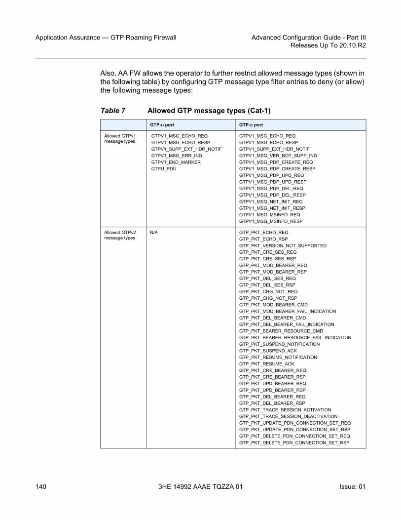
Application Assurance — GTP Roaming Firewall
140
Advanced Configuration Guide - Part IIIReleases Up To 20.10.R2
3HE 14992 AAAE TQZZA 01 Issue: 01
Also, AA FW allows the operator to further restrict allowed message types (shown in the following table) by configuring GTP message type filter entries to deny (or allow) the following message types:
Table 7 Allowed GTP message types (Cat-1)
GTP-u port GTP-c port
Allowed GTPv1 message types
GTPV1_MSG_ECHO_REQGTPV1_MSG_ECHO_RESPGTPV1_SUPP_EXT_HDR_NOTIFGTPV1_MSG_ERR_INDGTPV1_END_MARKERGTPU_PDU
GTPV1_MSG_ECHO_REQGTPV1_MSG_ECHO_RESPGTPV1_SUPP_EXT_HDR_NOTIFGTPV1_MSG_VER_NOT_SUPP_INDGTPV1_MSG_PDP_CREATE_REQGTPV1_MSG_PDP_CREATE_RESPGTPV1_MSG_PDP_UPD_REQGTPV1_MSG_PDP_UPD_RESPGTPV1_MSG_PDP_DEL_REQGTPV1_MSG_PDP_DEL_RESPGTPV1_MSG_NET_INIT_REQGTPV1_MSG_NET_INIT_RESPGTPV1_MSG_MSINFO_REQGTPV1_MSG_MSINFO_RESP
Allowed GTPv2 message types
N/A GTP_PKT_ECHO_REQGTP_PKT_ECHO_RSPGTP_PKT_VERSION_NOT_SUPPORTEDGTP_PKT_CRE_SES_REQGTP_PKT_CRE_SES_RSPGTP_PKT_MOD_BEARER_REQGTP_PKT_MOD_BEARER_RSPGTP_PKT_DEL_SES_REQGTP_PKT_DEL_SES_RSPGTP_PKT_CHG_NOT_REQGTP_PKT_CHG_NOT_RSPGTP_PKT_MOD_BEARER_CMDGTP_PKT_MOD_BEARER_FAIL_INDICATIONGTP_PKT_DEL_BEARER_CMDGTP_PKT_DEL_BEARER_FAIL_INDICATIONGTP_PKT_BEARER_RESOURCE_CMDGTP_PKT_BEARER_RESOURCE_FAIL_INDICATIONGTP_PKT_SUSPEND_NOTIFICATIONGTP_PKT_SUSPEND_ACKGTP_PKT_RESUME_NOTIFICATIONGTP_PKT_RESUME_ACKGTP_PKT_CRE_BEARER_REQGTP_PKT_CRE_BEARER_RSPGTP_PKT_UPD_BEARER_REQGTP_PKT_UPD_BEARER_RSPGTP_PKT_DEL_BEARER_REQGTP_PKT_DEL_BEARER_RSPGTP_PKT_TRACE_SESSION_ACTIVATION GTP_PKT_TRACE_SESSION_DEACTIVATION GTP_PKT_UPDATE_PDN_CONNECTION_SET_REQ GTP_PKT_UPDATE_PDN_CONNECTION_SET_RSP GTP_PKT_DELETE_PDN_CONNECTION_SET_REQ GTP_PKT_DELETE_PDN_CONNECTION_SET_RSP

Advanced Configuration Guide - Part III Releases Up To 20.10.R2
Application Assurance — GTP Roaming Firewall
Issue: 01 3HE 14992 AAAE TQZZA 01 141
By default, the GTP message filter allows all GTP messages.
To configure GTPv2 message filtering, the following command is used:
*A:Dut-C>config>app-assure>group>+---gtp-filter <gtp-filter-name> [create]
+---gtpc-inspection| +---message-type-v2| | || | +---default-action {permit|deny}| | || | +---entry <entry-id> value <gtpv2-message-value> action {permit|deny}| | | no entry <entry-id>
To configure GTPv1 message filtering, the following command is used:
*A:Dut-C>config>app-assure>group>| +---message-type| | || | +---default-action {permit|deny}| | || | +---entry <entry-id:1..255> value <gtpv1-message-value> action {permit|deny}| | | no entry <entry-id>
Unauthorized APN attack – APN filtering
APN filtering checks GTP-c messages to determine if a roaming subscriber is allowed to access a specified external network (/aka APN). The "create-session-request" and "create pdp request" GTP message types contain an APN IE in the header of a GTP packet. An APN IE consists of an external network ID (for example, nokia.com) and, optionally, a unique ID that identifies the operator PLMN.
APN filtering prevents malicious UEs from initiating a "create PDP/session request" flood attack toward the PGW/GGSN for invalid or disallowed APNs. The operator can configure an AA GTP filter to perform APN filtering to restrict roaming subscribers access to specific external networks.
An APN filter, an IMSI prefix, and an SGSN address pool can be used together to filter GTP packets, as follows:
Note: If the operator configures a message type that is invalid for the roaming interface to be denied, it will be dropped and counted under that filter entry (and not tagged as dropped due to "wrong-interface" in the event log). However, configuring the message-type filter to "permit" a message type that is invalid for the roaming interface will not take effect, because the packet with the specified message type will be dropped by the GTP-c protocol inspection process.

Application Assurance — GTP Roaming Firewall
142
Advanced Configuration Guide - Part IIIReleases Up To 20.10.R2
3HE 14992 AAAE TQZZA 01 Issue: 01
*A:Dut-C>config>app-assure>group>+---gtp-filter <gtp-filter-name> [create]| +---imsi-apn-filter //NEW and all its children attributes| | +---default-action {permit|deny} //default permit| | +---entry <entry-id: 1031..2030> create| | | + apn <string 0|1..32 characters>| | | |---no apn| | | + src-gsn ip-prefix-list <ip-prefix-list>| | | + src-gsn <ip address prefix>| | | |---no src-gsn| | | + action {permit|deny} //default permit| | +---no entry <entry-id>
By default, AA FW permits all APNs.
Unauthorized PLMN access – IMSI prefix filtering
The PLMN of a subscriber home network is identified by combining the Mobile Country Code (MCC) and Mobile Network Code (MNC). MCC-MNC is also known as the International Mobile Station Identity (IMSI) prefix. The IMSI prefix acts as a PLMN identifier.
GTP IMSI prefix filters can be configured to deny GTP incoming traffic from invalid roaming partners. Conversely, GTP IMSI prefix filters can allow only incoming traffic from those network operators that have signed roaming agreements. Any GTP packets with IMSI prefixes not matching the configured prefixes are dropped.
As shown in the Unauthorized APN attack – APN filtering section, IMSI filter entry can also be optionally combined with an SGSN/SGW IP address (or IP address prefix list) to further restrict allowed IMSI prefix traffic to specific SGSN/SGW nodes.
Unauthorized network access
An attacker, using an unauthorized GSN, can cause a DoS attack using spoofed PDP context delete messages (DoS attack) or spoofed update PDP context requests to hijack existing sessions. Such attacks can also spoof a create PDP context request to gain unlawful Internet access. Session hijacking can come from either the SGW/SGSN or the PGW/GGSN. An unauthorized GSN can hijack GTP tunnels or cause a DoS attack by intercepting another GSN and redirecting traffic to it.
Operators can use AA FW to configure pools of trusted GSN IP addresses (using AA IP-prefix-list) to stop spoofed requests from untrusted GSNs. AA IP prefix lists can be configured to model GSN groups, as follows:

Advanced Configuration Guide - Part III Releases Up To 20.10.R2
Application Assurance — GTP Roaming Firewall
Issue: 01 3HE 14992 AAAE TQZZA 01 143
*A:Dut-C>config>app-assure>group#ip-prefix-list ip-prefix-list-name [create]
prefix ip-prefix/ip-prefix-length [name prefix-name]
These lists are then referenced in session filters, such that only sessions that match the lists can be "permitted", as follows:
*A:Dut-C>config>app-assure>group# session-filterdefault-action denyentry # Configure an entry in the session filter
matchsrc-ip # Configure IPs that correspond to authorized SGW/SSGN
actionpermit
Configuration
AA GTP filtering functionality is enhanced in SR OS Release 20.2.R2 to include support for the AA FW feature related to the GTP roaming interface. The GTP filters are optional Application QoS Policy actions (AQP actions). AQPs have partition-level scope, which allows different FW policies to be implemented by using AA partition concepts within the same AA-ISA.
The configuration topology in Figure 19 shows how the VSR equipped with AA FW functionality provides protection for the S8 interfaces.
Figure 19 Configuration topology
36101
Roaming partner ASGWs
172.16.111.2/30
Roaming partners
Roaming partner BSGWs
172.16.111.1/30
MS-ISA–AA/FW
VSR
PGW172.16.120.0/30
VPRN 2 -Private side
VPRN 1 -Private side
AA-divert S8
S8
S8
S8
S8

Application Assurance — GTP Roaming Firewall
144
Advanced Configuration Guide - Part IIIReleases Up To 20.10.R2
3HE 14992 AAAE TQZZA 01 Issue: 01
Pre-setup requirements
Configuration of a VSR router is required if a 7750 SR is not already used in the access network on the S8 interfaces. If a 7750 SR is already deployed, AA-ISA must be configured.
See the Application Assurance — Stateful Firewall chapter for basic knowledge about AA-FW functionality.
Platform-dependent configuration
VSR
For GTP FW deployment in VSR, the following configuration supports load balancing of traffic across multiple CPU cores:
*A:7750-1>config> config>isa>aa-grp# vm-traffic-distribution-by-teid
7750 hardware
GTP FW deployment in 7750 hardware is only supported by ISA2:
*A:7750-1>config> config>isa>aa-grp# minimum-isa-generation 2
Allocation of memory for stateful GTP processing
To support stateful GTP processing (for example, TEID, sequence number, and UE IP validation FW operations), the operator must configure the system to allocate sufficient memory resources, as follows:
*A:7750-1>config>isa>aa-grp# shared-resourcesgtp-tunnel-database 100

Advanced Configuration Guide - Part III Releases Up To 20.10.R2
Application Assurance — GTP Roaming Firewall
Issue: 01 3HE 14992 AAAE TQZZA 01 145
Configuration to divert SAPs/VPRN traffic into AA-ISA
In this configuration example, one VPRN is used per wireless roaming partner network. In the example, two roaming partner networks are used for illustration. In real networks, this number is much bigger.
However, before configuring SAPs for diversion, the operator can optionally define some Application Service Option (ASO) characteristics to provide different FW policies for different roaming partners, as follows:
*A:7750-1>config>app-assure>group 1:1 policybeginapp-service-options
characteristic "FW-Protection" persist-id 1 createvalue "OFF" persist-id 1value "ON" persist-id 2default-value "OFF"
exitcharacteristic "strict-FW-Protection" persist-id 2 create
value "OFF" persist-id 1value "ON" persist-id 2default-value "OFF"
exitexitcommit
For more information about ASO configuration, see the Application Assurance — App-Profile, ASO and Control Policies chapter.
After configuring any ASO characteristics, define an application profile and transit IP policy; for example:
*A:7750-1>config>app-assure>group$ info----------------------------------------------
policybeginapp-profile "default" create
description "App profile that applies to the whole SAP"divertcharacteristic "FW-Protection" value "ON"
exitapp-profile "strict-FW" create
description "App profile that applies strict FW rules to the SAP"
divertcharacteristic "FW-Protection" value "ON"characteristic "strict-FW-Protection" value "ON"
exitcommit
exittransit-ip-policy 1 create
def-app-profile "strict-FW"detect-seen-iptransit-auto-create
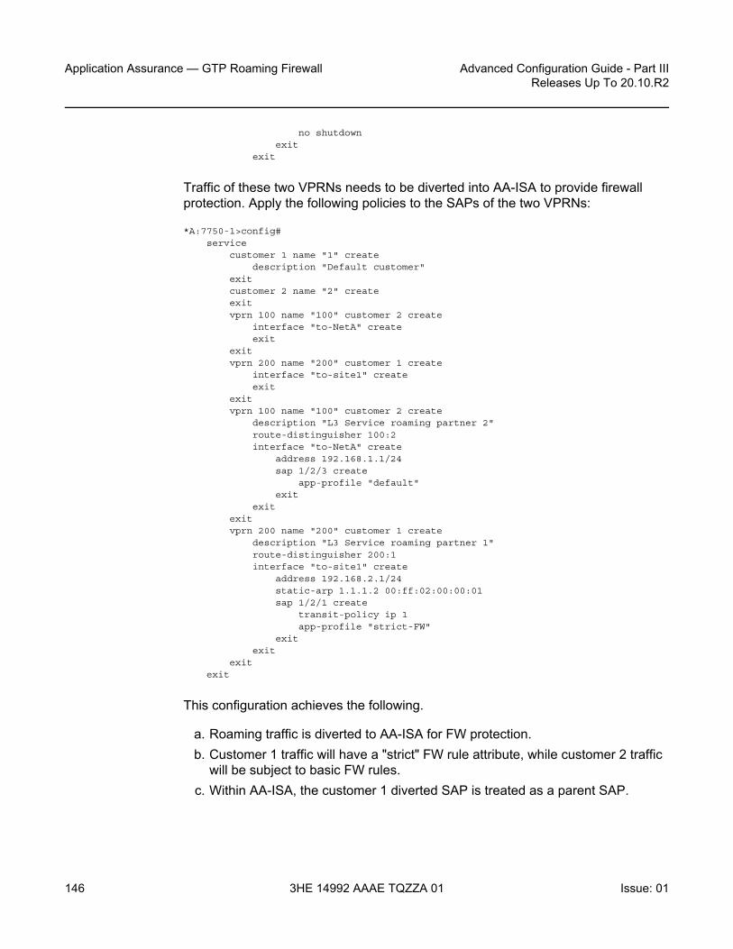
Application Assurance — GTP Roaming Firewall
146
Advanced Configuration Guide - Part IIIReleases Up To 20.10.R2
3HE 14992 AAAE TQZZA 01 Issue: 01
no shutdownexit
exit
Traffic of these two VPRNs needs to be diverted into AA-ISA to provide firewall protection. Apply the following policies to the SAPs of the two VPRNs:
*A:7750-1>config#service
customer 1 name "1" createdescription "Default customer"
exitcustomer 2 name "2" createexitvprn 100 name "100" customer 2 create
interface "to-NetA" createexit
exitvprn 200 name "200" customer 1 create
interface "to-site1" createexit
exitvprn 100 name "100" customer 2 create
description "L3 Service roaming partner 2"route-distinguisher 100:2interface "to-NetA" create
address 192.168.1.1/24sap 1/2/3 create
app-profile "default"exit
exitexitvprn 200 name "200" customer 1 create
description "L3 Service roaming partner 1"route-distinguisher 200:1interface "to-site1" create
address 192.168.2.1/24static-arp 1.1.1.2 00:ff:02:00:00:01sap 1/2/1 create
transit-policy ip 1app-profile "strict-FW"
exitexit
exitexit
This configuration achieves the following.
a. Roaming traffic is diverted to AA-ISA for FW protection. b. Customer 1 traffic will have a "strict" FW rule attribute, while customer 2 traffic
will be subject to basic FW rules.c. Within AA-ISA, the customer 1 diverted SAP is treated as a parent SAP.

Advanced Configuration Guide - Part III Releases Up To 20.10.R2
Application Assurance — GTP Roaming Firewall
Issue: 01 3HE 14992 AAAE TQZZA 01 147
- Instead of treating the whole SAP as a single subscriber, subscribers are auto-created within this SAP, based on the IP address of the SGWs/SSGNs.
Configuration FW events log
To configure a log that captures events related to various AA firewall actions:
*A:7750-1# configure application-assurance group 1:1*A:7750-1>config>app-assure>group# event-log "FW_events_log" create*A:7750-1>config>app-assure>group>evt-log$ buffer-type circular*A:7750-1>config>app-assure>group>evt-log$ max-entries 100000*A:7750-1>config>app-assure>group>evt-log$ no shutdown*A:7750-1>config>app-assure>group>evt-log$ exit*A:7750-1>config>app-assure>group# info----------------------------------------------
---snip---event-log "FW_events_log" create
buffer-type circularmax-entries 100000no shutdown
exit
The event log can be referenced in various FW actions that are configured later in this chapter.
*A:7750-1# tools dump application-assurance group 1:1 event-log "FW_event_log" isa 1/1
=====================================================Application-Assurance event-log "FW_events_log"Current Time: "05/19/2020 19:03:58" (UTC)
group[:partition]: 1:1isa: 1/1admin state: no shutdownbuffer-type: circularmax-entries: 100000
=====================================================
Note: If the operator does not require per SGW/SSGN control (such as limiting the total bandwidth of a SGW to prevent DoS attack), the "transit IP policy" from the SAP configuration can be removed. This will cause AA to treat the whole SAP as a single subscriber, as in the case of the customer 2 SAP.
Note: Alternatively, due to the limited size of the log and the large amount of traffic AA can handle, it is recommended that the operator use the syslog mechanism instead of local logging, as follows:
config>app-assure>group>event-log>syslog

Application Assurance — GTP Roaming Firewall
148
Advanced Configuration Guide - Part IIIReleases Up To 20.10.R2
3HE 14992 AAAE TQZZA 01 Issue: 01
Event-sourceAction SubType SubName Direction Src-ipDst-ip Ip-protocol Src-port Dst-port Timestamp"gtp filter gtp-filter-partner1 reason: filtered-gtp-message-type, teid: 0x0001d100,MT: 36, version: 2"
deny transit "1_10.10.68.1/32" from-sub 10.10.68.110.10.68.3 udp 2123 2123 "05/19/2020 18:54:50""gtp filter gtp-filter-partner1 reason: filtered-gtp-message-type, teid: 0x00019100,MT: 37, version: 2"
deny transit "1_10.10.68.1/32" to-sub 10.10.68.310.10.68.1 udp 2123 2123 "05/19/2020 18:54:55"
Total Records: 2=====================================================
The following command clears all the entries within the specified log:
*A:7750-1# clear application-assurance group 1:1 event-log "FW_events_log"
Configuration to limit total traffic from SGWs
Nokia recommends that a total limit be placed on how much bandwidth and how many flows an SGW/SGSN can generate toward the network. The exact limit values are a function of the number of end devices that are served by the roaming partner SGW/SGSN and capacity limits of the HPLMN PGW/GGSN, plus some additional margin.
In the following example, it is assumed that traffic from each roaming SGW will not exceed 1200 concurrent flows/second (serving about 200 roaming UEs) and 50 Mb/s. These need to be replaced in actual deployments with appropriate values that reflect the specific network deployment.
*A:7750-1>config>app-assure>group# info----------------------------------------------
policer "limit_roamingSGW_Flows" type flow-count-limitgranularity subscriber create
flow-count 1200gtp-traffic
exitpolicer "limit_roamingSGW_bw" type single-bucket-bandwidth
granularity subscriber createrate 50000mbs 500
exit----------------------------------------------
Apply the configured policers as actions from within the default subs-policy AQP entry:
*A:7750-1>config>app-assure>group>policy>aqp#

Advanced Configuration Guide - Part III Releases Up To 20.10.R2
Application Assurance — GTP Roaming Firewall
Issue: 01 3HE 14992 AAAE TQZZA 01 149
entry 500 createdescription "limit per SGW flow and b/w- partner 1"match
traffic-direction subscriber-to-networkcharacteristic "strict-FW-Protection" eq "ON"
exitaction
bandwidth-policer "limit_roamingSGW_bw"flow-count-limit "limit_roamingSGW_Flows"
exitno shutdown
exit
For GTP traffic flow count policing, it is important that "aqp-initial-lockup" is enabled:
*A:7750-1# configure application-assurance group 1:1 aqp-initial-lookup
Apply the configured policers as actions from within the default subs-policy AQP entry, as follows:
*A:7750-1>config>app-assure>group>policy>aqp#entry 501 create
no shutdowndescription "limit total SGW flow and b/w- partner 2 "match
traffic-direction subscriber-to-networkcharacteristic "strict-FW-Protection" eq "OFF"
exit
Note: All the preceding actions apply to the traffic direction "subscriber-to-network". These actions do not apply to traffic in the other direction (downlink), because the purpose of the AA FW is to protect the network resources from upstream traffic from compromised roaming partner SGWs.
Note: No policers are placed for the traffic of customer 2, because its profile does not have "strict policing" enabled. A policer can be configured to limit the total bandwidth and flows from all SGWs served to the customer 1 SAP, as follows:
*A:7750-1>config>app-assure>group# info----------------------------------------------
policer "limit_roamingSGWs_total_Flows" type flow-count-limit granularity subscriber create
flow-count 12000gtp-traffic
exitpolicer "limit_roamingSGWs_total_bw" type single-bucket-bandwidth
granularity subscriber createrate 500000mbs 5000
exit----------------------------------------------

Application Assurance — GTP Roaming Firewall
150
Advanced Configuration Guide - Part IIIReleases Up To 20.10.R2
3HE 14992 AAAE TQZZA 01 Issue: 01
actionbandwidth-policer "limit_roamingSGWs_total_bw"flow-count-limit "limit_roamingSGWs_total_Flows"
exitexit
GTP filtering – disallow traffic from unauthorized SGWs
To use GTP filtering to disallow traffic from unauthorized SGWs, perform the following steps:
1. Create AA IP lists2. Use AA IP lists in session filters and AQPs3. Reference session filters within AQPs
Step 1. Create AA IP lists, by creating an AA IP prefix list that contains SGW IP addresses or range of addresses for each customer, as follows:Roaming partner 1
*A:7750-1>config>app-assure# group 1:1ip-prefix-list "Roaming1_ALL_SGWs" create
description "SGWs subnet-partner 1"prefix 172.16.100.0/24
exitip-prefix-list "Roaming2_ALL_SGWs" create
description "SGWs subnet for roaming partner2"prefix 172.16.110.100/30
exit
Roaming partner 2*A:7750-1>config>app-assure>group#
ip-prefix-list "Roaming2_ALL_SGWs" createdescription "SGWs subnet for roaming partner2"prefix 172.16.110.100/30
exit
Step 2. The AA IP prefix lists can be referenced and used in AA FW rules using session filters and AQPs, as follows:
*A:7750-1>config>app-assure>group#session-filter "restricted_access_partner1" create
description "SGWs_allowed_partner1"default-action denyentry 10 create
description "allow GTP-u from authorized subnets"match
ip-protocol-num udpsrc-ip ip-prefix-list "Roaming1_ALL_SGWs"dst-port eq 2152

Advanced Configuration Guide - Part III Releases Up To 20.10.R2
Application Assurance — GTP Roaming Firewall
Issue: 01 3HE 14992 AAAE TQZZA 01 151
exitaction permit
exitentry 11 create
description "allow GTP-c from authorized subnets"match
ip-protocol-num udpsrc-ip ip-prefix-list "Roaming1_ALL_SGWs"dst-port eq 2123
exitaction permit
exitentry 20 create
description "allow DNS"match
ip-protocol-num *src-ip ip-prefix-list "Roaming1_ALL_SGWs"dst-port eq 53
exitaction permit
exitexitsession-filter "restricted_access_partner2" create
description "SGWs_allowed_partner2"default-action deny event-log "FW_events_log"entry 10 create
description "allow GTP-u from authorized subnets"match
ip-protocol-num udpsrc-ip ip-prefix-list "Roaming2_ALL_SGWs"dst-port eq 2152
exitaction permit
exitentry 11 create
description "allow GTP-c from authorized subnets"match
ip-protocol-num udpsrc-ip ip-prefix-list "Roaming2_ALL_SGWs"dst-port eq 2123
exitaction permit
exitentry 20 create
description "allow DNS"match
ip-protocol-num *src-ip ip-prefix-list "Roaming2_ALL_SGWs"dst-port eq 53
exitaction permit
exitexit

Application Assurance — GTP Roaming Firewall
152
Advanced Configuration Guide - Part IIIReleases Up To 20.10.R2
3HE 14992 AAAE TQZZA 01 Issue: 01
Step 3. The configured session filters need to be referenced within AQPs, as follows:
*A:7750-1>config>app-assure>group>policy>aqp#entry 510 create
description "apply FW rules for roaming partner 1"match
traffic-direction subscriber-to-networkcharacteristic "strict-FW-Protection" eq "ON"
exitaction
session-filter "restricted_access_partner1"exitno shutdown
exitentry 511 create
description "apply FW rules for roaming partner 2"match
traffic-direction subscriber-to-networkcharacteristic "strict-FW-Protection" eq "OFF"
exitaction
session-filter "restricted_access_partner2"exitno shutdown
exit
Restrict downstream traffic (optional)
Operators can optionally restrict downstream traffic to specific destinations and protocols, as follows:
*A:7750-1>config>app-assure>group#session-filter "restricted_downstream_traffic_1" create
description "allow only traffic to only signed up partners"default-action denyentry 10 create
description "allow GTP-u from authorized subnets"match
ip-protocol-num udpdst-ip ip-prefix-list "Roaming1_ALL_SGWs"dst-port eq 2152
exit
Note: Optionally, you can combine the session filter entries for the two roaming partners into a single session filter (for scale reasons). AA supports a total of 300 session filters. If there are less than 300 roaming partners, you can use a session filter per partner for customization purposes (related to, for example, IP subnets). If the number of partners is greater than the maximum number of session filters, you need to aggregate entries into a fewer number of session filters. Be aware of overlapping IP addresses from different roaming partner networks/VPRNs.

Advanced Configuration Guide - Part III Releases Up To 20.10.R2
Application Assurance — GTP Roaming Firewall
Issue: 01 3HE 14992 AAAE TQZZA 01 153
action permitexitentry 11 create
description "allow GTP-c to authorized subnets"match
ip-protocol-num udpdst-ip ip-prefix-list "Roaming1_ALL_SGWs"dst-port eq 2123
exitaction permit
exitentry 20 create
description "allow DNS"match
ip-protocol-num *dst-ip ip-prefix-list "Roaming1_ALL_SGWs"
exitaction permit
exitexitsession-filter "restricted_downstream_partner2" create
description "SGWs_allowed_partner2"default-action deny event-log "FW_events_log"entry 10 create
description "allow GTP-u to authorized subnets"match
ip-protocol-num udpdst-ip ip-prefix-list "Roaming2_ALL_SGWs"dst-port eq 2152
exitaction permit
exitentry 11 create
description "allow GTP-c to authorized subnets"match
ip-protocol-num udpdst_ip ip-prefix-list "Roaming2_ALL_SGWs"dst-port eq 2123
exitaction permit
exitexit
The session filters need to be referenced from AQP, as follows:
*A:7750-1>config>app-assure>group>policy>aqp#entry 514 create
description "apply FW rules for roaming partner 1"match
traffic-direction network-to-subscriber
Note: The preceding configuration provides the most flexibility and allows IP addresses to overlap between different partner networks. However, it comes at the cost of creating separate session filters for each partner. If IP addresses do not overlap, a single session filter is sufficient.

Application Assurance — GTP Roaming Firewall
154
Advanced Configuration Guide - Part IIIReleases Up To 20.10.R2
3HE 14992 AAAE TQZZA 01 Issue: 01
characteristic "strict-FW-Protection" eq "ON"exitaction
session-filter "restricted_downstream_partner1"exitno shutdown
exitentry 513 create
description "apply FW rules for roaming partner 2"match
traffic-direction network-to-subscribercharacteristic "strict-FW-Protection" eq "OFF"
exitaction
session-filter "restricted_downstream_partner2"exitno shutdown
exit
Configuration to protect against malformed packets
It is always recommended in FW deployments that overload-drop, error-drop, and fragment-drop are enabled within the default sub-policy, as follows:
*A:7750-1>config>app-assure>group>policy>aqp#entry 50 create
description "drop error and fragmented packets"action
overload-drop event-log "FW_events_log"error-drop event-log "FW_events_log"fragment-drop all event-log "FW_events_log"
exitno shutdown
exit
Note:
• The overload-drop action ensures that AA-ISA, if it gets overloaded, drops the excess traffic instead of cutting it through without applying FW rules.
• The error-drop action ensures that AA-ISA drops malformed IP packets.• The fragment-drop all action allows the operator to drop all fragmented traffic, drop out-
of-order fragments only, or allow fragments through. Because many network DoS attacks use IP fragmentation to initiate attacks, allowing fragments through is not recommended for firewall deployments. As a minimum, if fragmentation is used, the operator is recommended to configure AA to drop out-of-order fragmented packets.
• The preceding actions are applied to all traffic. Therefore, there are no AQP match conditions configured.

Advanced Configuration Guide - Part III Releases Up To 20.10.R2
Application Assurance — GTP Roaming Firewall
Issue: 01 3HE 14992 AAAE TQZZA 01 155
Plausibility of GTP messages and GTP message validation
To protect the network from malformed GTP packets and associated attacks as described in the overview section, a GTP filter needs to be created and referenced from an AQP entry.
Step 1. Configure the GTP filter object to:a. Enable GTP-c inspection so that the FW:
a. Ensures the correct IE states and orderb. Discards any GTP packet that contains an invalid message type for
S5/S8 (Gn/Gp) interfaceb. Enable sequence number checking for GTP-c traffic (for partner 1
traffic)c. Enable the GTP filter to check and drop errored GTP packets
(anomalies)d. Enable GTP message length checking (to minimize exposure to code
injection attacks). The maximum is set here (for example, 1250 bytes). The value is operator dependent, and should be replaced with the figure used by the operator.
e. Drop GTP-in-GTP encapsulated packets *A:7750-1>config>app-assure>group>gtp#
event-log "FW_events_log"gtpc-inspectiongtp-filter "gtp-filter-partner1" create
description "gtp-filter for partner 1"max-payload-length 1250event-log "FW_events_log" action denygtp-in-gtp denygtp-tunnel-database
validate-sequence-numberexit
exitgtp-filter "gtp-filter-partner2" create
description "gtp-filter for partner 2"max-payload-length 1250event-log "FW_events_log" action denygtp-in-gtp deny
no shutdown
Step 2. The configured GTP filters need to be referenced from AQP entries, as follows:
*A:7750-1>config>app-assure>group>policy>aqp#entry 512 create
description "apply SGW GTP filter rules"match
characteristic "strict-FW-Protection" eq "ON"

Application Assurance — GTP Roaming Firewall
156
Advanced Configuration Guide - Part IIIReleases Up To 20.10.R2
3HE 14992 AAAE TQZZA 01 Issue: 01
exitaction
gtp-filter "gtp-filter-partner1"exitno shutdown
exitentry 513 create
description "apply SGW GTP filter rules"match
characteristic "strict-FW-Protection" eq "OFF"exitaction
gtp-filter "gtp-filter-partner2"exitno shutdown
exit
Filtering of GTP message types
In this configuration, traffic from partner 2 is considered "safe/trusted". Therefore, unlike traffic from partner 1, no additional GTP message-type filtering is applied to it, beyond the GTP Cat-1 (see Table 7) message filtering applied as a result of enabling GTP-c inspection.
For roaming partner 1 traffic, the GTP filter is configured to block some Cat-1 optional message types (GTPv1 and GTPv2):
• GTPv2: Trance session activation/deactivation (this is optional for S8)• GTPv1: Allows only the message types used by GTP-u and blocks GTPv1
message types used by GTP-c
The GTP filter is configured as follows:
*A:7750-1>config>app-assure>group>gtp#event-log "FW_events_log" action denygtpc-inspectiongtp-filter "gtp-filter-partner1" create
description "gtp-filter for partner 1"max-payload-length 1250event-log "FW_events_log" action denymessage-type
default-action denyentry 1 value "echo-request" action permitentry 2 value "echo-response" action permitentry 3 value "error-indication" action permit
Note: By configuring GTP-c inspection, only Cat-1 message types (see Table 7) are allowed and all others are denied. Therefore, there is little to no need for additional GTP message filtering configuration.

Advanced Configuration Guide - Part III Releases Up To 20.10.R2
Application Assurance — GTP Roaming Firewall
Issue: 01 3HE 14992 AAAE TQZZA 01 157
entry 4 value "supported-extension-headers-notification"action permit
entry 5 value "end-marker" action permitentry 6 value "g-pdu" action permit
exitmessage-type-gtpv2
default-action permitentry 524 value "trace-session-activation" action denyentry 525 value "trace-session-deactivation" action deny
exitgtp-in-gtp denyimsi-apn-filter
default-action denyentry 1031 create
apn ANY_APNmcc-mnc-prefix 161379action permit
exitexitgtp-tunnel-database
validate-sequence-numberexit
exit
TEID validation
For roaming partner 1, to protect the network resources from spoofed TEIDs, the FW is recommended to verify that the TEIDs used in the GTP-u traffic are valid (that is, correctly negotiated via GTP-c), as follows:
*A:7750-1>config>app-assure>group>gtp#gtp-filter "gtp-filter-partner1"
gtp-tunnel-databasevalidate-gtp-tunnels
exitexit
Since roaming partner 2 network is trusted, no TEID validation is needed.
UE IP address anti-spoofing
It is a good practice to protect the network against UEs spoofing a different IP address, as follows:
*A:7750-1>config>app-assure>group>gtp#gtp-filter "gtp-filter-partner1"
gtp-tunnel-databasevalidate-source-ip-addr
exit

Application Assurance — GTP Roaming Firewall
158
Advanced Configuration Guide - Part IIIReleases Up To 20.10.R2
3HE 14992 AAAE TQZZA 01 Issue: 01
exit
This example applied to partner 1 traffic. Validation of source IP requires the use of a GTP tunnel database.
APN and IMSI filtering
In this example, only Home-Routed (HR) traffic from partner 1 is allowed, regardless of the APN. The rest is denied. This is achieved by configuring an IMSI prefix (="1613797") that corresponds to the Home network.
For roaming partner 2, MVNO traffic is allowed as well as HR traffic. This MVNO traffic (specific IMSI prefix = "1613400" in this example) is only allowed to attach to the mvnoguest.com APN, as follows:
*A:7750-1>config>app-assure>group>gtp#gtp-filter "gtp-filter-partner1"
imsi-apn-filterdefault-action denyentry 1031 create
apn ANY_APNmcc-mnc-prefix 161379action permit
exitexit
exitgtp-filter "gtp-filter-partner2"
imsi-apn-filterdefault-action denyentry 1040 create
apn mvnnoguest.com$mcc-mnc-prefix 161340action permit
exitentry 1041 create
apn ANY_APNmcc-mnc-prefix 161379action permit
exitexit
exit
Limiting concurrent session creations
To further lower the risk of DoS attacks using massive amounts of session/PDN create messages, it is recommended that the operator configure the maximum concurrent number of endpoints (TIEDs) that an SGW can create.
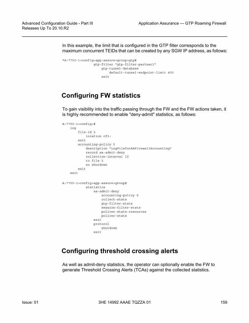
Advanced Configuration Guide - Part III Releases Up To 20.10.R2
Application Assurance — GTP Roaming Firewall
Issue: 01 3HE 14992 AAAE TQZZA 01 159
In this example, the limit that is configured in the GTP filter corresponds to the maximum concurrent TEIDs that can be created by any SGW IP address, as follows:
*A:7750-1>config>app-assure>group>gtp#gtp-filter "gtp-filter-partner1"
gtp-tunnel-databasedefault-tunnel-endpoint-limit 400
exit
Configuring FW statistics
To gain visibility into the traffic passing through the FW and the FW actions taken, it is highly recommended to enable "deny-admit" statistics, as follows:
A:7750-1>config>#log
file-id 5location cf3:
exitaccounting-policy 5
description "LogFileforAAFirewallAccounting"record aa-admit-denycollection-interval 10to file 5no shutdown
exitexit
A:7750-1>config>app-assure>group#statistics
aa-admit-denyaccounting-policy 5collect-statsgtp-filter-statssession-filter-statspolicer-stats-resourcespolicer-stats
exitprotocol
shutdownexit
Configuring threshold crossing alerts
As well as admit-deny statistics, the operator can optionally enable the FW to generate Threshold Crossing Alerts (TCAs) against the collected statistics.

Application Assurance — GTP Roaming Firewall
160
Advanced Configuration Guide - Part IIIReleases Up To 20.10.R2
3HE 14992 AAAE TQZZA 01 Issue: 01
The operator needs to set the low- and high-water marks according to the conditions of their networks. The following values are for illustration purposes only.
A:7750-1> config>app-assure>group>stats#threshold-crossing-alert
gtp-sanity-drop direction from-sub createhigh-wmark 100 low-wmark 60
exitthreshold-crossing-alert
gtp-sanity-drop direction from-sub createhigh-wmark 100 low-wmark 60
exitgtp-filter "gtp-filter-partner1"
validate-gtp-tunnels direction from-sub createhigh-wmark 100 low-wmark 60
exitvalidate-sequence-number direction from-sub create
high-wmark 100 low-wmark 60exitvalidate-src-ip-addr direction from-sub create
high-wmark 100 low-wmark 60exitmissing-mandatory-ie direction from-sub create
high-wmark 100 low-wmark 60exittunnel-resource-limit direction from-sub create
high-wmark 100 low-wmark 60exittunnel-endpoint-limit direction from-sub create
high-wmark 100 low-wmark 60exitmessage-type
default-action direction from-sub createhigh-wmark 100 low-wmark 60
exitheader-sanity direction from-sub create
high-wmark 100 low-wmark 60exit
exitmessage-type-gtpv2
entry 524 direction from-sub createhigh-wmark 100 low-wmark 60
exitentry 525 direction from-sub create
high-wmark 100 low-wmark 60exit
exitimsi-apn-filter
default-action direction from-sub createhigh-wmark 100 low-wmark 60
Note: NSP also supports TCAs. The operator has a choice to enable TCAs on both the FW and/or NSP. The advantage of TCAs generated directly from the FW is that they tend to be more real-time relative to NSP TCAs. However, NSP supports a larger TCA scale than the FW.

Advanced Configuration Guide - Part III Releases Up To 20.10.R2
Application Assurance — GTP Roaming Firewall
Issue: 01 3HE 14992 AAAE TQZZA 01 161
exitexit
exitgtp-filter "gtp-filter-partner2"
missing-mandatory-ie direction from-sub createhigh-wmark 100 low-wmark 60
exittunnel-resource-limit direction from-sub create
high-wmark 100 low-wmark 60exittunnel-endpoint-limit direction from-sub create
high-wmark 100 low-wmark 60exitimsi-apn-filter
default-action direction from-sub createhigh-wmark 100 low-wmark 60
exitexit
exitexit
Configuring GTP and GTP-c applications
By configuring AA app-filters to define GTP-u and GTP-c applications, the operator can gain further visibility into the volume of traffic of these applications, as follows:
A:7750-1>config> config>app-assure>group>policy
beginapplication "GTP_c" createexitapplication "GTP_other" createexitapplication "GTP_u" createexitapp-filter
entry 40000 createprotocol eq "gtp"server-port eq 2152application "GTP_u"no shutdown
exitentry 40010 create
protocol eq "gtp"server-port eq 2123application "GTP_c"no shutdown
exitentry 40020 create
protocol eq "gtp"application "GTP_other"no shutdown
exitexitcommit

Application Assurance — GTP Roaming Firewall
162
Advanced Configuration Guide - Part IIIReleases Up To 20.10.R2
3HE 14992 AAAE TQZZA 01 Issue: 01
The export and display of statistics related to these applications use standard AA per application per partition or per application per subscriber XML records and "show" routines.
Relevant debug routines
CLI show routines
*A:7750-1>config>app-assure>group>gtp>gtp-fltr# show application-assurancegroup 1:1 session-filter "restricted_access_partner1"===============================================================================AA Session Filter Instance "restricted_access_partner1"===============================================================================Description : SGWs_allowed_partner1Default Action : deny
Event Log : (Not Specified)AQP Entries :
510-------------------------------------------------------------------------------Filter Match Criteria-------------------------------------------------------------------------------Entry : 10Description : allow GTP-u from authorized subnetsIP Protocol : udpSource IP List : Roaming1_ALL_SGWsDest Port : eq 2152Action : permit
Event Log : (Not Specified)Hits : 1 flows-------------------------------------------------------------------------------Entry : 11Description : allow GTP-c from authorized subnetsIP Protocol : udpSource IP List : Roaming1_ALL_SGWsDest Port : eq 2123Action : permit
Event Log : (Not Specified)Hits : 2 flows-------------------------------------------------------------------------------Entry : 20Description : allow DNSIP Protocol : *Source IP List : Roaming1_ALL_SGWsDest Port : eq 53Action : permit
Event Log : (Not Specified)Hits : 0 flows-------------------------------------------------------------------------------No. of entries : 3===============================================================================

Advanced Configuration Guide - Part III Releases Up To 20.10.R2
Application Assurance — GTP Roaming Firewall
Issue: 01 3HE 14992 AAAE TQZZA 01 163
*A:7750-1>show application-assurance group 1:1 gtp gtp-filter "gtp-filter-partner1"===============================================================================Application Assurance Group 1:1 GTP Filter "gtp-filter-partner1"===============================================================================Description : gtp-filter for partner 1Maximum payload length : 1250Event log : FW_events_logEvent log action : denyDefault action : denyDefault GTPv2 action : permitDefault IMSI-APN action : denyGTP in GTP action : denyValidate GTP tunnels : enabledValidate sequence number : enabledValidate source IP address : enabledGTP tunnel endpoint limit : 400Configured messages : 6Configured GTPv2 messages : 2Configured IMSI-APN filters : 1Packets arrived : 18Packets denied
Payload length : 0Message type : 0GTPv2 message type : 2IMSI-APN filter : 0Mandatory header : 0Extension header : 0Information element : 0Invalid TEID : 0Invalid sequence number : 0Invalid source IP address : 0Missing mandatory IE : 0GTP in GTP : 0No tunnel resource : 0Tunnel endpoint limit : 0
Packets permitted : 16===============================================================================
*A:7750-1>show application-assurance group 1:1 gtp===============================================================================Application Assurance Group 1:1 GTP===============================================================================Admin status : UpEvent log : FW_events_logEvent log action : denyMode : filteringGTP-C inspection : Enabled
-------------------------------------------------------------------------------GTP Statistics sub-to-net net-to-sub-------------------------------------------------------------------------------Incoming packets 9 9Packets denied
UDP packet length 0 0GTP message length 0 0GTP version 0 0
-------------------------------------------------------------------------------Packets permitted 9 9-------------------------------------------------------------------------------

Application Assurance — GTP Roaming Firewall
164
Advanced Configuration Guide - Part IIIReleases Up To 20.10.R2
3HE 14992 AAAE TQZZA 01 Issue: 01
-------------------------------------------------------------------------------GTP Policing Statistics sub-to-net net-to-sub-------------------------------------------------------------------------------Packets arrived 9 9Packets denied
gtp-traffic flow-count policer 0 0Other 0 0
-------------------------------------------------------------------------------Packets permitted 9 9-------------------------------------------------------------------------------
-------------------------------------------------------------------------------GTP Filter Statistics sub-to-net net-to-sub-------------------------------------------------------------------------------Packets arrived 9 9Packets denied 1 1Packets permitted
gtp-filter 8 8no gtp-filter 0 0
-------------------------------------------------------------------------------Total GTP packets permitted 8 8===============================================================================
*A:7750-1>show application-assurance group 1 aa-sub-list==============================================================================Application-Assurance Subscriber List for Group 1==============================================================================type aa-sub ISA App-Profile divert
assigned------------------------------------------------------------------------------group 1:1------------------------------------------------------------------------------sap 1/2/1 1/1 strict-FW Yessap 1/2/3 1/1 default Yestransit 1_10.10.68.1/32 1/1 strict-FW Yes------------------------------------------------------------------------------Number of aa-subs found in group 1:1 : 3Total number of aa-subs found : 3==============================================================================
CLI tools dump routines
*A:7750-1>tools dump application-assurance group 1:1 flow-record-search isa 1/1
=====================================================Application-Assurance flow record searchSearch Start Time: "05/19/2020 19:04:37" (UTC)Search Criteria:group[:partition]: 1:1isa: 1/1protocol name: none specifiedapplication name: none specifiedapp-group name: none specifiedflow-status: none specified

Advanced Configuration Guide - Part III Releases Up To 20.10.R2
Application Assurance — GTP Roaming Firewall
Issue: 01 3HE 14992 AAAE TQZZA 01 165
start-flowId: none specifiedclassified: none specifiedserver-ip: none specifiedserver-port: none specifiedclient-ip: none specifiedbytes-tx: none specifiedflow-duration: none specifiedmax-count: none specifiedflow-modified: none specifiedsearch-type: default
=====================================================FlowId Init Src-ip Dst-ip Ip-prot Src-prt Dst-prtProtocol Application
Pkts-tx Bytes-tx Pkts-disc Bytes-discTime-ofp(UTC) Time-olp(UTC)
2 no 10.10.68.3 10.10.68.1 udp 2123 2123"gtp" "GTP_c"
1 46 0 0"05/19/2020 18:54:50" "05/19/2020 18:54:50"
3 yes 10.10.68.1 10.10.68.3 udp 2123 2123"gtp" "GTP_c"
2 359 0 0"05/19/2020 18:54:50" "05/19/2020 18:54:50"
4 yes 10.10.68.3 10.10.68.1 udp 2123 2123"gtp" "GTP_c"
2 326 1 51"05/19/2020 18:54:50" "05/19/2020 18:54:55"
7 yes 10.10.68.1 10.10.68.3 udp 63760 2152"gtp" "GTP_u"
5 500 0 0"05/19/2020 18:54:50" "05/19/2020 18:54:50"
8 yes 10.10.68.3 10.10.68.1 udp 64784 2152"gtp" "GTP_u"
5 500 0 0"05/19/2020 18:54:50" "05/19/2020 18:54:50"
11 yes 10.10.68.1 10.10.68.3 udp 2123 2123"gtp" "GTP_c"
1 136 1 91"05/19/2020 18:54:50" "05/19/2020 18:54:50"
SEARCH COMPLETED.Search End Time: "05/19/2020 19:04:37" (UTC)Total Records: 6=====================================================
*A:7750-1>tools dump application-assurance group 1:1 admit-deny-stats============================================================================================================================================Application-Assurance Group 1:1 Admit-Deny Statistics============================================================================================================================================--------------------------------------------------------------------------------------------------------------------------------------------
Admitted Sub-To-Net Denied Sub-To-Net Admitted Net-To-Sub Denied Net-To-SubPacket Validation Statistics(Packets) (Packets) (Packets) (Packets)--------------------------------------------------------------------------------------------------------------------------------------------Error

Application Assurance — GTP Roaming Firewall
166
Advanced Configuration Guide - Part IIIReleases Up To 20.10.R2
3HE 14992 AAAE TQZZA 01 Issue: 01
0 0 0 0Fragments: Out-Of-Order0 0 0 0Fragments: All0 0 0 0OverloadN/A 0 N/A 0GTP Sanity9 0 9 0--------------------------------------------------------------------------------------------------------------------------------------------
Admitted Sub-To-Net Denied Sub-To-Net Admitted Net-To-Sub Denied Net-To-SubGTP Filter Statistics(Packets) (Packets) (Packets) (Packets)--------------------------------------------------------------------------------------------------------------------------------------------GTP Filter: gtp-filter-partner1Entry: 1 echo-request
0 0 0 0Entry: 2 echo-response
0 0 0 0Entry: 3 error-indication
0 0 0 0Entry: 4 supported-extension-headers-notification
0 0 0 0Entry: 5 end-marker
0 0 0 0Entry: 6 g-pdu
5 0 5 0Message Type Default Action
0 0 0 0GTPv2 Entry: 524 trace-session-activation
0 1 0 0GTPv2 Entry: 525 trace-session-deactivation
0 0 0 1GTPv2 Message Type Default Action
3 0 3 0IMSI-APN Entry: 1031
N/A 0 N/A 0IMSI-APN Filter Default Action
N/A 0 N/A 0Max Payload Length
N/A 0 N/A 0Message Type Header Sanity
N/A 0 N/A 0Invalid TEID
N/A 0 N/A 0Invalid Sequence Number
N/A 0 N/A 0Invalid Source IP Address
N/A 0 N/A 0Missing Mandatory IEs
N/A 0 N/A 0GTP in GTP Action
N/A 0 N/A 0GTP Tunnel DB Resource
N/A 0 N/A 0Tunnel Endpoint Limit

Advanced Configuration Guide - Part III Releases Up To 20.10.R2
Application Assurance — GTP Roaming Firewall
Issue: 01 3HE 14992 AAAE TQZZA 01 167
N/A 0 N/A 0GTP Filter: gtp-filter-partner2Message Type Default Action
0 0 0 0GTPv2 Message Type Default Action
0 0 0 0IMSI-APN Entry: 1040
N/A 0 N/A 0IMSI-APN Entry: 1041
N/A 0 N/A 0IMSI-APN Filter Default Action
N/A 0 N/A 0Max Payload Length
N/A 0 N/A 0Message Type Header Sanity
N/A 0 N/A 0Invalid TEID
N/A 0 N/A 0Invalid Sequence Number
N/A 0 N/A 0Invalid Source IP Address
N/A 0 N/A 0Missing Mandatory IEs
N/A 0 N/A 0GTP in GTP Action
N/A 0 N/A 0GTP Tunnel DB Resource
N/A 0 N/A 0Tunnel Endpoint Limit
N/A 0 N/A 0--------------------------------------------------------------------------------------------------------------------------------------------
Admitted Sub-To-Net Denied Sub-To-Net Admitted Net-To-Sub Denied Net-To-SubSession Filter Statistics(Sessions) (Packets) (Sessions) (Packets)--------------------------------------------------------------------------------------------------------------------------------------------Session Filter: restricted_access_partner1Entry: 10
1 0 0 0Entry: 11
2 0 0 0Entry: 20
0 0 0 0Default Action
0 0 0 0Session Filter: restricted_access_partner2Entry: 10
0 0 0 0Entry: 11
0 0 0 0Entry: 20
0 0 0 0Default Action
0 0 0 0Session Filter: restricted_downstream_partner1Entry: 10
0 0 1 0

Application Assurance — GTP Roaming Firewall
168
Advanced Configuration Guide - Part IIIReleases Up To 20.10.R2
3HE 14992 AAAE TQZZA 01 Issue: 01
Entry: 110 0 1 0Entry: 20
0 0 0 0Default Action
0 0 0 0Session Filter: restricted_downstream_partner2Entry: 10
0 0 0 0Entry: 11
0 0 0 0Default Action
0 0 0 0--------------------------------------------------------------------------------------------------------------------------------------------
Admitted Sub-To-Net Denied Sub-To-Net Admitted Net-To-Sub Denied Net-To-SubFlow Policer Statistics(Flows) (Flows) (Flows) (Flows)--------------------------------------------------------------------------------------------------------------------------------------------Subscriber Flow Count Policers
limit_roamingSGW_Flows0 0 0 0
limit_roamingSGWs_total_Flows0 0 0 0--------------------------------------------------------------------------------------------------------------------------------------------
Conclusion
A 3GPP roaming interface using GTP presents a security risk to mobile access networks. The AA GTP stateful firewall protects the network infrastructure from untrusted roaming partner networks.

Advanced Configuration Guide - Part III Releases Up To 20.10.R2
Application Assurance — HTTP and HTTPS Redirect
Issue: 01 3HE 14992 AAAE TQZZA 01 169
Application Assurance — HTTP and HTTPS RedirectThis chapter provides information about Application Assurance - HTTP and HTTPS Redirect.
Topics in this chapter include:
• Applicability• Overview• Configuration• Conclusion
Applicability
The information and configuration in this chapter are based on SR OS release 15.0.R5.
Overview
This chapter is intended for network architects and engineers working with Application Assurance AA). The user should have a basic understanding of AA policies (application service options, application filters, applications, application QoS policies), HTTP, and DNS.
Nokia recommends using the AppDB when configuring Application QoS Policies (AQPs) for traffic control policies. The AppDB is a default configuration file that can be obtained through Nokia's support organization, and contains information to classify all supported applications, including all relevant application ("app-") groups, applications, and app-filters.
Operators have scenarios where they need to allow some restricted web access to subscribers (while generally blocking all other Internet access). The allowed sites may be authentication sites, such as payment sites. Alternatively, the sites may be portals owned by the operators, which may offer app-store services or user account management.

Application Assurance — HTTP and HTTPS Redirect
170
Advanced Configuration Guide - Part IIIReleases Up To 20.10.R2
3HE 14992 AAAE TQZZA 01 Issue: 01
There are several ways that HTTP redirection can be implemented in an AA policy:
• HTTP policy redirect with (or without) URL whitelisting: redirects HTTP traffic to a web portal based on a policy decision
• HTTPS captive redirect with (or without) DNS IP cache whitelisting: redirects all HTTP/HTTPS traffic to a web portal, except for traffic toward domains configured in a DNS IP cache
• URL filter triggered HTTP redirect or HTTPS captive redirect (SR OS Release 16.0): redirects all HTTP/HTTPS traffic, based on a URL filter policy decision, where on block decision, the request can be redirected to a message portal
AA is a preferred choice for the operator to configure HTTP redirect. As opposed to CPM-based redirect (offered as part of subscriber management), AA can provide high performance with no system (or ISA) limits on the number of HTTP sessions per second that can be redirected. ISA2 can support more than 5000 redirects per second. CPM-based redirect is quite limited and, in many customer deployments, not able to support the required redirect rates (CPM-based redirect can support a maximum of 250 simultaneous connections). Even if only a simple subscriber redirect is needed (without whitelisting or captive redirect), AA-based redirect should be preferred over CPM-based redirect.
The following sections describe the different methods of implementing HTTP and HTTPS redirection with whitelisting, why and when to use each one, provide the configuration, and describe how to troubleshoot and correct common errors.
HTTP redirection based on URL filtering is not included in this chapter. For URL filtering, see chapter Application Assurance — Local URL List Filtering.
Configuration
The following two use cases are described in this section:
• AA HTTP redirect with URL whitelisting• HTTPS redirect using session filter captive redirect

Advanced Configuration Guide - Part III Releases Up To 20.10.R2
Application Assurance — HTTP and HTTPS Redirect
Issue: 01 3HE 14992 AAAE TQZZA 01 171
AA HTTP redirect with URL whitelisting
Operators have several use cases where they need to redirect a subscriber to a specific web page. Redirection may be the result of a policy (for example, the subscription does not allow certain content to be viewed) or for informative reasons (for example, the subscriber is not authenticated).
Operators may still need to allow the subscriber to access certain sites (for example, portals provided by the operator). The URLs that a subscriber may still access are called whitelisted URLs.
AA has the capability to perform HTTP redirection by using the "HTTP 302 Found" response code. This works as follows:
The subscriber generates an HTTP request to view a specific page. When AA receives the HTTP response, it classifies the flow and performs the redirect action by modifying that response. The web server replies with a "200 OK" response containing the page content, and AA modifies the HTTP response to a "302 Redirect" and sends it to the subscriber. The response contains the new URL that the subscriber should be redirected to. The subscriber's browser, upon receiving the response, automatically generates a new HTTP request for the URL received, as shown in Figure 20.

Application Assurance — HTTP and HTTPS Redirect
172
Advanced Configuration Guide - Part IIIReleases Up To 20.10.R2
3HE 14992 AAAE TQZZA 01 Issue: 01
Figure 20 HTTP redirect
The redirect is shown in more detail in the following HTTP traces:
1. The browser sends an HTTP request for www.example.org. The HTTP packet contains the following information:
Hypertext Transfer ProtocolGET / HTTP/1.1\r\n… …Host: www.example.org\r\n… …
- "GET" is followed by the path requested. In this example, the subscriber requested the root path (therefore "/").
- "Host" contains the hostname (domain) requested.2. The web server replies with a "200 OK" message.3. The SR OS node receives the server response and classifies the flow. The
router determines that it will redirect the request. It replies with a message indicating the new URL along with the original URL. The HTTP packet contains the following information:
Hypertext Transfer ProtocolHTTP/1.1 302 Found\r\n
7750 SR192.168.1.67
HTTP_Request(www.example.org)
HTTP_Response(200-OK)
HTTP_Response(302_Found,http://192.0.2.1/redirect_main.html?OriginalURL=www.example.org
HTTP_Request(192.0.2.1/redirect_main.html?OriginalURL=www.example.org)
HTTP_Response(200-OK)
www.example.com
27928
Redirect server192.0.2.1
Request willbe redirected
The browser generatesa new HTTP request
The content ofwww.portal.com is
displayed in the browser
User wants to accesswww.weather.com

Advanced Configuration Guide - Part III Releases Up To 20.10.R2
Application Assurance — HTTP and HTTPS Redirect
Issue: 01 3HE 14992 AAAE TQZZA 01 173
Location: http://192.0.2.1/redirect_main.html?OriginalURL=www.example.org/\r\n… … …
- The HTTP response status code "302" indicates that the web browser should generate a new HTTP request.
- "Location" contains the URL that the subscriber should be redirected to.4. The subscriber's browser receives the redirect request and automatically
generates a new HTTP request for the new URL. The HTTP packet sent by the browser is as follows:
Hypertext Transfer ProtocolGET /redirect_main.html?OriginalURL=www.example.org/ HTTP/1.1Host: 192.0.2.1\r\n…
- As in step 1, the GET request contains the path.- Similarly, "Host" contains the hostname (domain) requested. "Host" can
contain either a domain or an IP address.
Figure 21 shows the example setup containing a 7750 SR with ISA-AA. The setup requires a web client, a web server (which will be the redirect server), and Internet access through the router. A default configuration has been loaded from the AppDB.
Figure 21 Example setup
The following sections describe the configuration of the following objects:
• The redirect policy to configure the redirect URL, the information to be appended to the URL, plus how to handle non-HTTP traffic
• An application and app-filter for the redirect portal• A charging group for the whitelisted URLs• An app-filter to define the whitelisted URL• An ASO that will be used as a policy decision to perform redirection• An AQP to perform redirection
7750 SRTest user192.168.1.67
Internet
Redirectserver
HTTP, DNS HTTP
HTTP, DNS
27929

Application Assurance — HTTP and HTTPS Redirect
174
Advanced Configuration Guide - Part IIIReleases Up To 20.10.R2
3HE 14992 AAAE TQZZA 01 Issue: 01
Creating the redirect policy
The redirect policy is configured as follows:
*A:Dut-C>config>app-assure>group# info----------------------------------------------
http-redirect "policy-redirect" createdescription "redirects certain http traffic to a portal"template 5tcp-client-resetredirect-url "http://192.0.2.1/redirect_main.html?OriginalURL=$URL"no shutdown
exit----------------------------------------------
The preceding configuration defines:
• The template to be used ("template 5" means that macro substitution will be used). This allows the operator to append additional information to the redirect information, which can be used by the redirect portal to offer more details about why the subscriber was redirected or to offer more personalized services.
• Traffic that cannot be redirected will be TCP reset. This provides immediate feedback to the subscriber that the service requested is not available. The client application will not have to wait for the TCP session to expire.
• The redirect URL. The original URL will be appended.
Creating the application and app-filter for the redirect portal
The application "Captive Portal" is created and used in the app-filter that contains the redirect server address, as follows:
*A:Dut-C>config>app-assure>group# info----------------------------------------------
policybeginapplication "Captive Portal" create
description "HTTP Redirect portal"app-group "Web"
exit
app-filterentry 200 create
server-address eq 192.0.2.1/32application "Captive Portal"no shutdown
exitexitcommit
exit
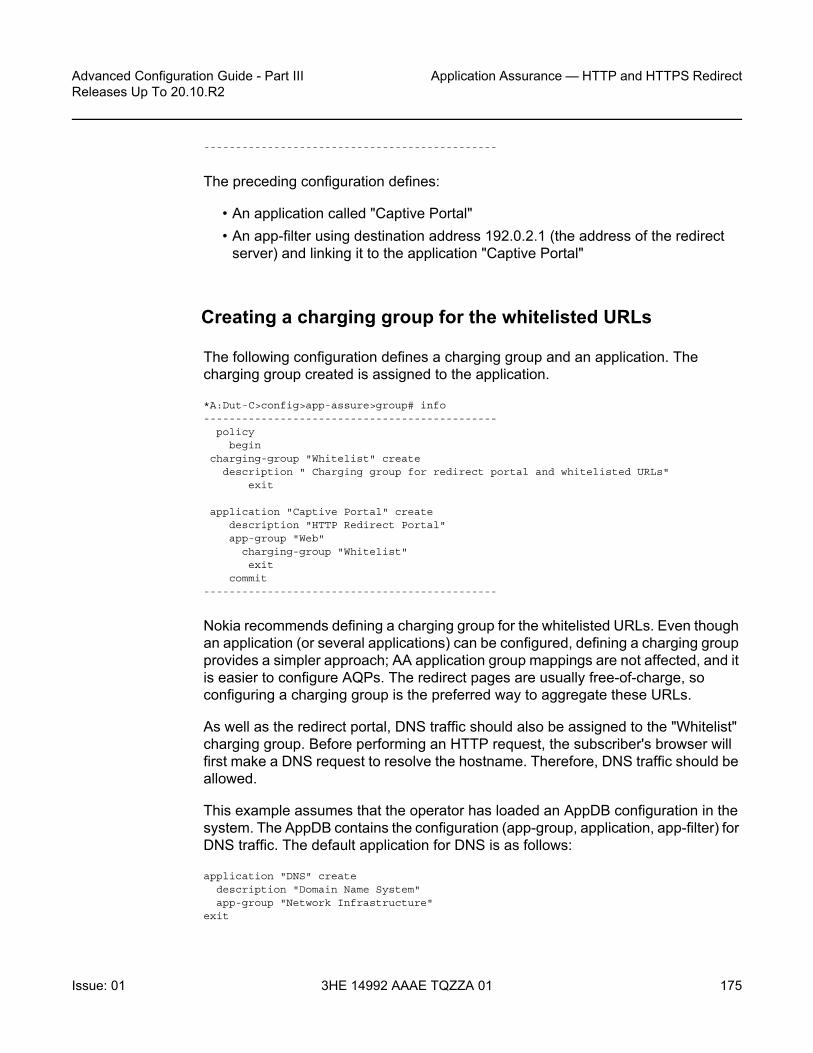
Advanced Configuration Guide - Part III Releases Up To 20.10.R2
Application Assurance — HTTP and HTTPS Redirect
Issue: 01 3HE 14992 AAAE TQZZA 01 175
----------------------------------------------
The preceding configuration defines:
• An application called "Captive Portal"• An app-filter using destination address 192.0.2.1 (the address of the redirect
server) and linking it to the application "Captive Portal"
Creating a charging group for the whitelisted URLs
The following configuration defines a charging group and an application. The charging group created is assigned to the application.
*A:Dut-C>config>app-assure>group# info----------------------------------------------
policybegin
charging-group "Whitelist" createdescription " Charging group for redirect portal and whitelisted URLs"
exit
application "Captive Portal" createdescription "HTTP Redirect Portal"app-group "Web"
charging-group "Whitelist"exit
commit----------------------------------------------
Nokia recommends defining a charging group for the whitelisted URLs. Even though an application (or several applications) can be configured, defining a charging group provides a simpler approach; AA application group mappings are not affected, and it is easier to configure AQPs. The redirect pages are usually free-of-charge, so configuring a charging group is the preferred way to aggregate these URLs.
As well as the redirect portal, DNS traffic should also be assigned to the "Whitelist" charging group. Before performing an HTTP request, the subscriber's browser will first make a DNS request to resolve the hostname. Therefore, DNS traffic should be allowed.
This example assumes that the operator has loaded an AppDB configuration in the system. The AppDB contains the configuration (app-group, application, app-filter) for DNS traffic. The default application for DNS is as follows:
application "DNS" createdescription "Domain Name System"app-group "Network Infrastructure"
exit

Application Assurance — HTTP and HTTPS Redirect
176
Advanced Configuration Guide - Part IIIReleases Up To 20.10.R2
3HE 14992 AAAE TQZZA 01 Issue: 01
This preceding configuration should be modified as follows:
*A:Dut-C>config>app-assure>group# info----------------------------------------------policy
beginapplication "DNS" create
description "Domain Name System"app-group "Network Infrastructure"charging-group "Whitelist"
exitcommit
----------------------------------------------
Creating an application for the whitelisted URLs
The following configuration creates a new application that contains all the whitelisted URLs. The application is assigned to the "Whitelist" charging group.
*A:Dut-C>config>app-assure>group# info----------------------------------------------
policybegin
application "URL-Whitelist" createdescription "URLs to be whitelisted"app-group "Web"charging-group "Whitelist"
exitcommit
----------------------------------------------
Creating app-filters for the whitelisted URLs
The following configuration creates an app-filter for the whitelisted URLs. The configuration contains the URL and assigns it to an application.
*A:Dut-C>config>app-assure>group# info----------------------------------------------
policybeginapp-filterentry 61001 create
description "dummy whitelisted domain"expression 1 http-host eq "*.domain.com$"application "URL-Whitelist"no shutdown
exitcommit
----------------------------------------------

Advanced Configuration Guide - Part III Releases Up To 20.10.R2
Application Assurance — HTTP and HTTPS Redirect
Issue: 01 3HE 14992 AAAE TQZZA 01 177
The operator can extend the preceding configuration and add more whitelisted URLs.
Configuring the ASO and AQP
The following configuration defines:
• An ASO that will be used as a policy criterion to decide whether redirection will occur. The ASO is called "redirect" and has two values: "no" and "yes". The default value will be "no" (do not redirect).
• An AQP to perform redirection. The match criteria will be the preceding ASO and the value of the charging group. If the match criteria are met, the action will be to drop and redirect the flow using the "policy-redirect" defined.
*A:Dut-C>config>app-assure>group# info----------------------------------------------
policybeginapp-service-options
characteristic "redirect" createvalue "no"value "yes"default-value "no"
exitexit
app-qos-policyentry 400 create
matchcharging-group neq "Whitelist"characteristic "redirect" eq "yes"
exitaction
drophttp-redirect "policy-redirect" flow-type dropped-flows
exitno shutdown
exitexitcommit
----------------------------------------------
Having the charging group as match criteria is a future-proof solution: the configuration can easily be adapted in the future (if, for example, additional URLs should be whitelisted).

Application Assurance — HTTP and HTTPS Redirect
178
Advanced Configuration Guide - Part IIIReleases Up To 20.10.R2
3HE 14992 AAAE TQZZA 01 Issue: 01
Troubleshooting and debugging
The following show commands can be used to verify the configuration and correct possible errors.
The following command shows the redirect policy:
*A:Dut-C# show application-assurance group 1 http-redirect "policy-redirect" detail
===============================================================================Application Assurance Group 1 HTTP Redirect policy-redirect===============================================================================Description : redirects certain http traffic to a portalTemplate : 5
: Redirect supporting macro substitution using HTTP 302Redirect URL : http://10.99.99.40/redirect_main.html?OriginalURL=$URLCaptive Redirect : No
Redirect HTTPS : NoVLAN ID : N/A
Admin Status : UpAQP Ref : Yes
-------------------------------------------------------------------------------Group 1-------------------------------------------------------------------------------Redirects Sent : 0Client Resets Sent : 0Redirects Not Sent :
Out of Resources : 0Config Errors : 0Other Errors : 0
-------------------------------------------------------------------------------Total-------------------------------------------------------------------------------Redirects Sent : 0Client Resets Sent : 0Redirects Not Sent :
Out of Resources : 0Config Errors : 0Other Errors : 0
===============================================================================
Note: The use of ASOs is optional and shown here for completeness. It is used only in some policy-dependent redirect cases, where the operator may need to provide the redirect policy only to some subscribers. In most cases, all subscribers get the same redirect policy and the ASOs are not used. App-profiles may also be used to implement a match condition for a policy-based redirect.

Advanced Configuration Guide - Part III Releases Up To 20.10.R2
Application Assurance — HTTP and HTTPS Redirect
Issue: 01 3HE 14992 AAAE TQZZA 01 179
The preceding command provides the following information:
• The template used, along with a definition of that template• The URL that the subscriber will be redirected to• Whether this is a captive redirect and whether HTTPS will be redirected• The admin status of the policy. An admin status of "Down" indicates that the
policy is not in use.• Whether this policy is referenced by an AQP. If it is not referenced, it is not used.• "Redirects Sent" indicates the number of times that AA has sent a redirect
message.• "Client Resets Sent" indicates the number of times that TCP reset was sent.• "Out of Resources" indicates the number of times that a redirect was not sent.
The reasons relate to exhaustion of ISA resources (for example, memory).• "Config Errors": for example, a command is in shutdown state• "Other Errors": errors that are not in any of the preceding two categories
The following command shows the "Captive Portal" application:
*A:Dut-C# show application-assurance group 1 policy application "Captive Portal"
===============================================================================Application Instance "Captive Portal"===============================================================================Description : HTTP Redirect portalApp Group : WebExport Id : noneCharging Group : Whitelist
References-------------------------------------------------------------------------------AA Sub Stat : noneCflowd : noneAQP Entries :App Filters :
200
Reference Counts-----------------------------------No. of cflowd references : 0No. of AQP entry references : 0No. of app filter references : 1===============================================================================
The preceding command provides the following information:
• The charging group assigned• The app-filters linked (200)
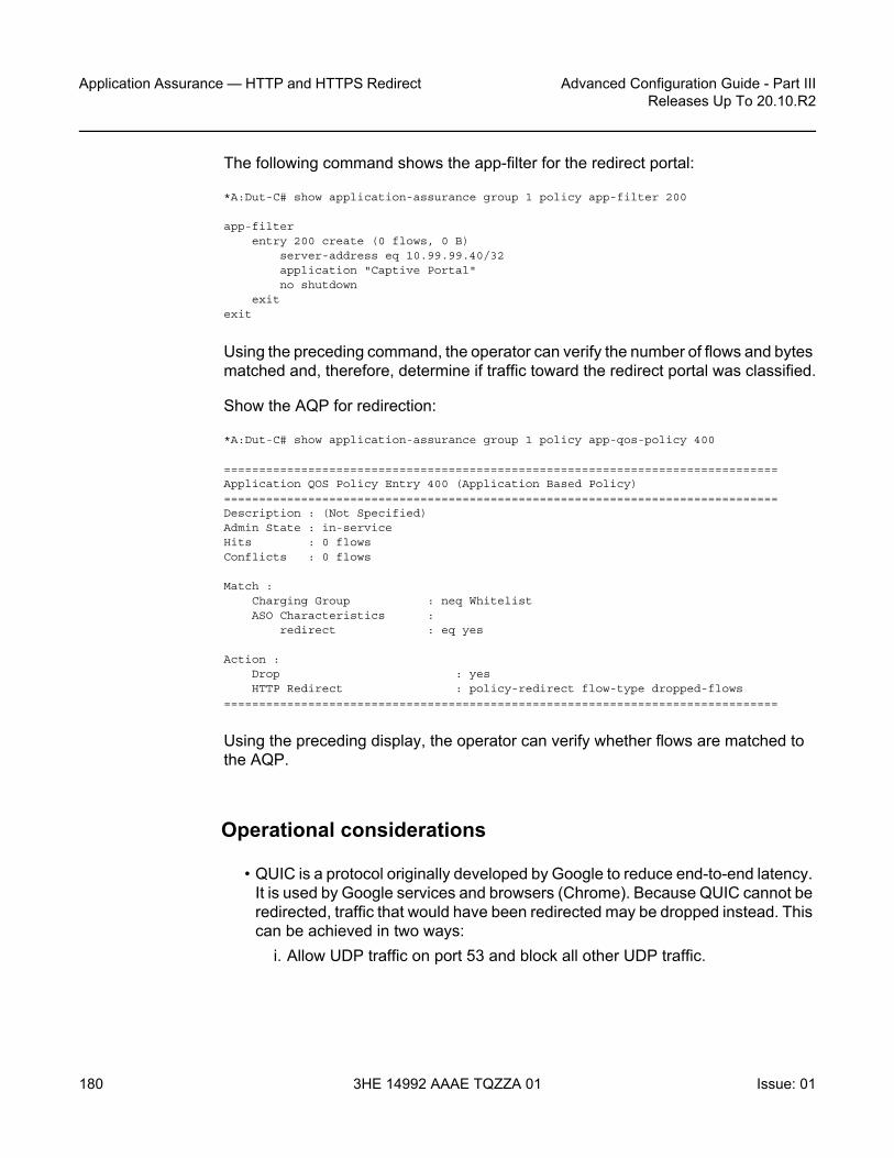
Application Assurance — HTTP and HTTPS Redirect
180
Advanced Configuration Guide - Part IIIReleases Up To 20.10.R2
3HE 14992 AAAE TQZZA 01 Issue: 01
The following command shows the app-filter for the redirect portal:
*A:Dut-C# show application-assurance group 1 policy app-filter 200
app-filterentry 200 create (0 flows, 0 B)
server-address eq 10.99.99.40/32application "Captive Portal"no shutdown
exitexit
Using the preceding command, the operator can verify the number of flows and bytes matched and, therefore, determine if traffic toward the redirect portal was classified.
Show the AQP for redirection:
*A:Dut-C# show application-assurance group 1 policy app-qos-policy 400
===============================================================================Application QOS Policy Entry 400 (Application Based Policy)===============================================================================Description : (Not Specified)Admin State : in-serviceHits : 0 flowsConflicts : 0 flows
Match :Charging Group : neq WhitelistASO Characteristics :
redirect : eq yes
Action :Drop : yesHTTP Redirect : policy-redirect flow-type dropped-flows
===============================================================================
Using the preceding display, the operator can verify whether flows are matched to the AQP.
Operational considerations
• QUIC is a protocol originally developed by Google to reduce end-to-end latency. It is used by Google services and browsers (Chrome). Because QUIC cannot be redirected, traffic that would have been redirected may be dropped instead. This can be achieved in two ways:
i. Allow UDP traffic on port 53 and block all other UDP traffic.

Advanced Configuration Guide - Part III Releases Up To 20.10.R2
Application Assurance — HTTP and HTTPS Redirect
Issue: 01 3HE 14992 AAAE TQZZA 01 181
QUIC is over UDP. Therefore, by allowing UDP on port 53 and blocking all other traffic, the operator can perform DNS requests, but all other UDP traffic (including QUIC) will be blocked.
ii. Create an application to block UDP traffic on port 443 at the first packet.QUIC is running on port 443. Therefore, the following app-filter will block QUIC traffic (UDP traffic on port 443). The "first-packet-validate" option is used for applications using a well-known TCP/UDP port and ensures that the policy will be applied from the first packet, while allowing AA to detect an unexpected application to the well-known port.
policybeginapplication "UDP 443 Validate" create
description "First Packet Verify application for any UDP on port 443such as QUIC"
app-group "Web"exitapp-filter
entry 700 createip-protocol-num eq udpserver-port eq 443 first-packet-validateapplication "UDP 443 Validate"no shutdown
exitexitcommit
• Some mobile OSs (for example, Android) generate an HTTP request to a predefined "test URL" to verify that Internet access exists. The HTTP request is sent immediately after the device connects to a WiFi network. Even though the HTTP requests are generated in the background, redirecting these URLs will result in the redirect response to be presented in the web browser.Depending on the operator's use case, these URLs may be redirected. Redirecting these URLs may affect the DNS cache of the mobile device. The device thinks that it does not have full Internet access. On Android devices, the subscriber will see a message similar to the following:

Application Assurance — HTTP and HTTPS Redirect
182
Advanced Configuration Guide - Part IIIReleases Up To 20.10.R2
3HE 14992 AAAE TQZZA 01 Issue: 01
Figure 22 Connected device without full Internet access
The app-filter for the redirect server was configured using the server IP address (server-address eq 192.0.2.1/32). The app-filter for the redirect server can also be configured using a host (or any other HTTP-related) expression. An example configuration follows:
app-filterentry 200 create
expression 1 http-host eq "*.redirect_domain.com$"application "Captive Portal"no shutdown
exitexit
The preceding configuration will classify HTTP traffic when the hostname is "*.redirect_domain.com$". If this configuration approach is chosen, the operator must be certain that the app-filter will classify all the traffic toward the redirect portal. There may be cases where some content may be fetched from additional locations too (for example, "*.content_domain.com$"); therefore, additional app-filters should be configured.To ensure that the configuration is correct and complete, a trace can be analyzed.
Table 8 describes what each AA redirect error means.

Advanced Configuration Guide - Part III Releases Up To 20.10.R2
Application Assurance — HTTP and HTTPS Redirect
Issue: 01 3HE 14992 AAAE TQZZA 01 183
HTTPS redirect using session filter captive redirect
A second use case is HTTP redirect using session filter captive redirect. Captive redirect is used to redirect HTTP or HTTPS flows, without sending any traffic to the Internet. In the case of HTTP traffic, it is achieved by terminating the TCP sessions in AA. HTTP flows will then be redirected to a predefined URL, while non-HTTP flows will be TCP reset.
However, the majority of web traffic is HTTPS. Simply blocking (and TCP resetting) HTTPS traffic is not friendly to the end user: they are not given any explanation as to why access was not allowed, might think there was some different error, and will probably try again. AA can also redirect HTTPS traffic to a different page and provide information to the subscriber about why access to the site is not allowed.
Operators may still need to allow some HTTP whitelisted traffic. Captive redirect can be combined with a DNS IP cache to allow (not redirect) certain HTTP traffic. The operator may configure a DNS IP cache for the whitelisted domains (domains that the subscriber may access). This section will provide an example configuration to achieve this.
A DNS IP cache is used to ensure that traffic will be correctly classified and charged. After the feature has been enabled, AA will sniff subscribers' DNS responses and populate a cache containing the HTTP domain and the IP addresses that the DNS server provided. Traffic will only be classified into applications or app-groups if the hostname configured matches the one found, and the IP address of the packet matches an entry in the DNS cache.
Additional information about DNS IP cache (including configuration instructions) is available in the Application Assurance — DNS IP Cache chapter.
Table 8 AA redirect errors
Redirect not sent Description
Out of resources No buffer resources
Config errors Disabled redirect configuration, VLAN ID missing, session is not TCP
Other errors Fragmented response packet

Application Assurance — HTTP and HTTPS Redirect
184
Advanced Configuration Guide - Part IIIReleases Up To 20.10.R2
3HE 14992 AAAE TQZZA 01 Issue: 01
Captive redirect is mostly used when the operator wants to redirect HTTPS traffic. Even though this chapter also provides the configuration for HTTP captive redirect, it is only shown for completeness. Captive redirect of HTTP traffic is hardly ever used, adds more complexity, and provides no additional benefit over the HTTP redirect described in the previous section.
Figure 23 shows the high-level message flow of HTTP redirect using session filter captive redirect.
Figure 23 HTTP redirect using session filter captive redirect
Consider an operator that needs to allow traffic to www.domain1.com and redirect all other HTTP traffic, see Figure 23. Therefore, the operator will configure the DNS IP cache to sniff DNS traffic and populate the cache with the IP addresses of that whitelisted domain.
7750 SR
DNS_Request(www.domain1.com)
DNS_Response(www.domain1.com, IP1)
www.domain1.com www.domain2.com
27930
DNS server
Request willbe redirected
www.domain1.comcontent displayed
User attemptsto access
www.domain2.com
HTTP_Response(www.domain1.com)
HTTP_Request(www.domain1.com)
DNS_Response(www.domain2.com, IP2)
DNS_Request(www.domain2.com)
HTTP_Response 302 - Redirect
HTTP_Request(www.domain2.com)
!
! = portal whitelisted
User attemptsto access
www.domain1.com

Advanced Configuration Guide - Part III Releases Up To 20.10.R2
Application Assurance — HTTP and HTTPS Redirect
Issue: 01 3HE 14992 AAAE TQZZA 01 185
• If the subscriber needs to access www.domain1.com, the DNS traffic will be analyzed by SR and the DNS IP cache will be updated. When the subscriber sends the HTTP request toward www.domain1.com, the traffic will be allowed because the destination IP address of the traffic will match the IP address contained in the cache.
• If the subscriber attempts to access www.domain2.com, the request will not be allowed because the destination IP address will not be present in the cache. This request will be redirected. The DNS IP cache will not be populated with the IP address of www.domain2.com.
Creating a DNS IP cache for the whitelisted domain
The following configuration will create and populate a DNS IP cache:
• DNS responses for the host "*.domain1.com$". Traffic to www.domain.com will be allowed (whitelisted).
• responses only from the DNS server with IP address 8.1.17.21 (which is considered a trusted DNS server)
*A:Dut-C>config>app-assure>group# info----------------------------------------------
dns-ip-cache "domain1-cache" createdescription "dns cache for domain1"dns-match
domain "domain1" expression "*.domain1.com$"server-address 8.1.17.21
exitno shutdown
exit----------------------------------------------
Creating a default subscriber policy
The following configuration will create a default subscriber policy to snoop DNS responses. This AQP is used to populate the cache.
No match criteria are needed. AA will only analyze the DNS traffic to populate the cache.
*A:Dut-C>config>app-assure>group# info----------------------------------------------policy
beginapp-qos-policy
entry 50 createaction

Application Assurance — HTTP and HTTPS Redirect
186
Advanced Configuration Guide - Part IIIReleases Up To 20.10.R2
3HE 14992 AAAE TQZZA 01 Issue: 01
dns-ip-cache "domain1-cache"exitno shutdown
exitexitcommit
exit----------------------------------------------
Configuring captive redirect
The following will configure a captive redirect policy for the redirect portal. The configuration defines the redirect URL. Using macro substitution, the original URL that the subscriber requested will be appended in the redirect URL. Non-HTTP traffic will be TCP reset. The template specifies that the redirect template be used: "template 5" defines macro substitution using HTTP 302.
HTTPS traffic will also be redirected.
*A:Dut-C>config>app-assure>group# info----------------------------------------------http-redirect "capt-redirect" create
template 5tcp-client-resetredirect-url "http:// 192.0.2.1/redirect_main.html?OriginalURL=$URL"captive-redirect
redirect-httpsexitno shutdown
exit----------------------------------------------
The preceding configuration did not define the VLAN ID. The VLAN ID refers to an AA IP aa-interface that the operators need to create within the subscriber service (IES or VPRN) for ESM subscribers, and is used by the ISA to respond to the subscriber. Operators need to create one interface per AA ISA card.
The VLAN ID does not need to be defined if the ISA group aa-sub-scale mode is configured for DSM.
Figure 24 shows the high-level message flow of HTTP redirection.

Advanced Configuration Guide - Part III Releases Up To 20.10.R2
Application Assurance — HTTP and HTTPS Redirect
Issue: 01 3HE 14992 AAAE TQZZA 01 187
Figure 24 HTTP redirection
As shown in Figure 24:
• The subscriber attempts to access a site.• The SR OS node determines that traffic will be redirected. No traffic will be
allowed to pass.• The SR OS node returns an HTTP response message indicating the redirect.• The browser automatically generates a new request toward the redirect portal.• The content of the redirect page is shown to the subscriber.
Figure 25 shows how HTTP access to a whitelisted domain is allowed, while access to an HTTPS site is redirected.
7750 SR192.168.1.67
HTTP_Request(www.weather.com)
HTTP_Response(302_Found, http://192.0.2.1/redirect_main.html?OriginalURL=www.weather.com)
27931
Redirect server192.0.2.1
Request willbe redirected
The browsergenerates a new
HTTP request
The content of theredirect page is displayed
on the browser
HTTP_Response(200-OK)
HTTP_Request(192.0.2.1/redirect_main.html?OriginalURL=www.weather.com)
User attemptsto access
www.weather.com

Application Assurance — HTTP and HTTPS Redirect
188
Advanced Configuration Guide - Part IIIReleases Up To 20.10.R2
3HE 14992 AAAE TQZZA 01 Issue: 01
Figure 25 Access to whitelisted domain versus HTTPS redirect
As shown in Figure 25:
• The subscriber first attempts to access www.domain1.com. This site has been configured as a whitelisted site in SR OS, so access to the portal is allowed.
• The subscriber next attempts to access the HTTPS site www.portal.com. This portal is not a whitelisted one. Therefore, the system will perform HTTPS redirection.
7750 SR192.168.1.67
HTTP_Request(www.domain1.com)
HTTP sitewww.portal.com www.domain1.com
27932
Redirect server192.0.2.1
Request willbe redirected
User attemptsto access
www.portal.com
User attemptsto access
www.domain1.com
User acceptscertificate signed
by 7750 SR
The content of theredirect page isdisplayed on the
browser
SSL:Server_Hello(certificate=Nokia)
TCP Handshake
HTTP_Request(192.0.2.1/redirect_main.html?OriginalURL=www.portal.com)
SSL:Client_Hello=www.portal.com)
HTTP_Response(200-OK)
!
! = portal is whitelisted. Access allowed.
HTTP_Response(200-OK)
New SSL tunnel established

Advanced Configuration Guide - Part III Releases Up To 20.10.R2
Application Assurance — HTTP and HTTPS Redirect
Issue: 01 3HE 14992 AAAE TQZZA 01 189
The system will return a self-signed Nokia certificate, similar to the following.
Figure 26 Subscriber receives warning
• If the subscriber accepts the new certificate, a new SSL tunnel will be established and a new request toward the redirect server will be generated.
• Finally, the subscriber will see the contents of the redirect page.
Configuring a session filter
The following session filter is configured to:
• Allow DNS traffic (UDP traffic on port 53) • Allow domains included in the DNS IP cache (traffic to www.domain1.com)• Allow traffic to the redirect portal (portal IP address: 192.0.2.1)• Redirect all other TCP traffic to the redirect portal
*A:Dut-C>config>app-assure>group# info----------------------------------------------session-filter "capt_redirect" create
description "Session filter for captive redirect policy"

Application Assurance — HTTP and HTTPS Redirect
190
Advanced Configuration Guide - Part IIIReleases Up To 20.10.R2
3HE 14992 AAAE TQZZA 01 Issue: 01
default-action denyentry 5 create
matchip-protocol-num udpdst-port eq 53
exitaction permit
exitentry 10 create
matchdst-ip dns-ip-cache "domain1-cache"
exitaction permit
exitentry 15 create
description "Allow traffic to the redirect landing page server"match
ip-protocol-num tcpdst-ip 192.0.2.1/32dst-port eq 80
exitaction permit
exitentry 20 create
matchip-protocol-num tcp
exitaction http-redirect "capt-redirect"
exitexit----------------------------------------------
Troubleshooting and debugging: show commands
Operators can verify their configuration as follows.
The following command shows the session filter together with the number of flows matched:
*A:Dut-C# show application-assurance group 1 session-filter "capt_redirect"
===============================================================================AA Session Filter Instance "capt_redirect"===============================================================================Description : Session filter for captive redirect policyDefault Action : deny
Event Log : (Not Specified)AQP Entries :-------------------------------------------------------------------------------Filter Match Criteria-------------------------------------------------------------------------------Entry : 5Description : (Not Specified)IP Protocol : udpDest Port : eq 53

Advanced Configuration Guide - Part III Releases Up To 20.10.R2
Application Assurance — HTTP and HTTPS Redirect
Issue: 01 3HE 14992 AAAE TQZZA 01 191
Action : permitEvent Log : (Not Specified)
Hits : 0 flows-------------------------------------------------------------------------------Entry : 10Description : (Not Specified)IP Protocol : noneDest IP Cache : domain1-cacheAction : permit
Event Log : (Not Specified)Hits : 0 flows-------------------------------------------------------------------------------Entry : 15Description : Allow traffic to the redirect landing page serverIP Protocol : tcpDest IP : 192.0.2.1/32Dest Port : eq 80Action : permit
Event Log : (Not Specified)Hits : 0 flows-------------------------------------------------------------------------------Entry : 20Description : (Not Specified)IP Protocol : tcpAction : http-redirect capt-redirect
Event Log : (Not Specified)Hits : 0 flows-------------------------------------------------------------------------------No. of entries : 4===============================================================================
The preceding show output provides the following information:
• The "Default Action" specifies the action to take if a packet does not match any of the filters defined in the session filter (deny).
• The filters defined are:- Allowing DNS traffic (UDP traffic on port 53, entry 5)- Allowing traffic matching the DNS IP cache (entry 10)- Allowing traffic to the redirect portal (entry 15)- Redirecting all other traffic (entry 20)
• The "Hits" counter on each filter provides information about how many flows matched the corresponding filter.
The following command shows the DNS IP cache:
*A:Dut-C# show application-assurance group 1 dns-ip-cache "domain1-cache"
===============================================================================Application Assurance Group 1 dns-ip-cache "domain1-cache"===============================================================================Admin Status : UpAQP Ref : YesDomain expressions : 1 (out of 32)

Application Assurance — HTTP and HTTPS Redirect
192
Advanced Configuration Guide - Part IIIReleases Up To 20.10.R2
3HE 14992 AAAE TQZZA 01 Issue: 01
Server addresses : 1 (out of 64)High watermark : 90%Low watermark : 80%Cache size : 10-------------------------------------------------------------------------------ISA Usage (%) Alarm Hit Count
State-------------------------------------------------------------------------------1/2 0 0.00 clear 03/1 0 0.00 clear 0===============================================================================
The preceding command shows:
• The administrative status of the DNS IP cache ("Up"). An administrative status of "Down" indicates that the DNS IP cache is not in use.
• Whether the DNS IP cache created is referenced by an AQP• The number of configured domain expressions (in the example:
"*.domain1.com$") and the maximum value (shown in brackets)• The number of server addresses and the maximum value (shown in brackets)• The number of times a cache lookup was successful ("Hit Count"). A hit count of
0 indicates a possible configuration error.
The following command shows information about the HTTP redirect:
*A:Dut-C# show application-assurance group 1 http-redirect "capt-redirect" detail
===============================================================================Application Assurance Group 1 HTTP Redirect capt-redirect===============================================================================Description : (Not Specified)Template : 5
: Redirect supporting macro substitution using HTTP 302Redirect URL : http://192.0.2.1/redirect_main.html?OriginalURL=$URLCaptive Redirect : Yes
Redirect HTTPS : YesVLAN ID : N/A
Admin Status : UpAQP Ref : No
-------------------------------------------------------------------------------Group 1-------------------------------------------------------------------------------Redirects Sent : 0Client Resets Sent : 0Redirects Not Sent :
Out of Resources : 0Config Errors : 0Other Errors : 0
-------------------------------------------------------------------------------Total-------------------------------------------------------------------------------Redirects Sent : 0

Advanced Configuration Guide - Part III Releases Up To 20.10.R2
Application Assurance — HTTP and HTTPS Redirect
Issue: 01 3HE 14992 AAAE TQZZA 01 193
Client Resets Sent : 0Redirects Not Sent :
Out of Resources : 0Config Errors : 0Other Errors : 0
===============================================================================
The preceding output provides the following information:
• The template used and description about the template• The redirect URL• Whether this is a captive redirect and whether HTTPS will be redirected also• The VLAN ID. Captive redirect uses the provisioned VLAN ID to send the HTTP
response to the subscribers; therefore, this VLAN ID must be properly assigned in the same VPN as the subscriber (not needed for DSM).
• The admin status of the redirect. An admin status of "Down" indicates that the policy is not in use.
• "Redirects Sent" indicates the number of times that AA has sent a redirect message.
• "Client Resets Sent" indicates the number of times that TCP reset was sent.• "Out of Resources" indicates the number of times that a redirect was not sent.
The reasons relate to exhaustion of resources in ISA (such as memory).• "Config Errors": for example, a command is in shutdown state• "Other Errors": errors that are not in any of the preceding two categories
Troubleshooting and debugging: tools commands
Based on an FTP server with IP address 192.168.1.100, the operator can dump the contents of the DNS IP cache, as follows:
*A:Dut-C# tools dump application-assurance group 1 dns-ip-cache "domain1-cache" url ftp://username:[email protected]/path/to/mylog.log
The preceding command will generate a text file, containing the following:
=====================================================Application-Assurance dns-ip-cache "domain1-cache"Current Time: "11/08/2017 12:45:32" (UTC)
group: 1isa: 3/2admin state: no shutdownmax-entries: 10
=====================================================ip-address creationTime(UTC) lastUpdated(sec) numDNSResponses lastMatchTime(UTC)

Application Assurance — HTTP and HTTPS Redirect
194
Advanced Configuration Guide - Part IIIReleases Up To 20.10.R2
3HE 14992 AAAE TQZZA 01 Issue: 01
numTimesMatched
Total entries in-use: 0
=====================================================
The log file shows the number of times that a cache entry was matched (numDNSResponses) and the number of times that traffic to this address was sent (numTimesMarches).
Operational considerations
HTTPS redirect is not available in releases earlier than SR OS 14.0 (the session will simply be TCP reset).
Some browsers store certificates of popular sites. If the subscriber tries to access one of those sites, the browser will not accept the AA-signed certificate and the redirect page will never be displayed. The subscriber does not have an option to accept the certificate.
If the operator wants to configure an HTTPS redirect (either on VSR since Rel. 14.0 or in CMG since Rel.10.0), the FW ASL License is mandatory. It is needed to enable the use of the session filter by the captive redirect.
When using the standard HTTP redirect, there is no need for an aa-interface. However, when using the captive redirect, the operator needs one aa-interface per VPN service, not one interface per subscriber VLAN. To associate the redirect policy with the subscriber in the correct VPN for captive redirect, the operator needs to use ASO/ASO override, which will point to a redirect policy per VPN-this redirect policy will point to an aa-interface in the correct VPN service.
Captive redirect is special in the sense that no traffic is allowed from the Internet (apart from the traffic to the redirect portal).
HTTPS captive redirect cannot be used with ESM subscribers on L2-aware NAT. The forwarding model used for L2-aware NAT does not allow the use of HTTPS captive redirect. If configured, the session filter will be hit, but no TCP message will be sent to the subscriber. The AA statistics will show discarded packets.

Advanced Configuration Guide - Part III Releases Up To 20.10.R2
Application Assurance — HTTP and HTTPS Redirect
Issue: 01 3HE 14992 AAAE TQZZA 01 195
Conclusion
This chapter shows how an operator can configure HTTP redirection. The chapter describes the different use cases, how HTTP redirection can be combined with DNS IP cache, and how HTTPS traffic can be redirected.

Application Assurance — HTTP and HTTPS Redirect
196
Advanced Configuration Guide - Part IIIReleases Up To 20.10.R2
3HE 14992 AAAE TQZZA 01 Issue: 01

Advanced Configuration Guide - Part III Releases Up To 20.10.R2
Application Assurance — HTTP In BrowserNotification
Issue: 01 3HE 14992 AAAE TQZZA 01 197
Application Assurance — HTTP In Browser NotificationThis chapter provides information about Application Assurance HTTP in browser notification.
Topics in this chapter include:
• Applicability• Overview• Configuration• Conclusion
Applicability
This chapter is applicable to all 7x50 systems supporting Application Assurance and was tested on SR OS release 13.0.R2.
There are no specific prerequisites for this example.
Overview
Using the 7x50s and Application Assurance, subscribers connected to an operator network can be sent fully customizable on-screen notification messages displayed in a non-disruptive and cost-effective manner through their web browser.
This chapter describes the different options for the operator to customize the notification messages returned to the subscriber using either different HTTP-Notification policies or using the flexible HTTP-URL-PARAM VSA mechanism.
This chapter also describes the additional configuration required with the introduction in SR OS 13.0.R1 of the Notification status monitoring capability allowing the system to notify the subscriber at the next candidate flow instead of waiting for the next notification interval in case the previous notification did not result in a success.

Application Assurance — HTTP In Browser Notification
198
Advanced Configuration Guide - Part IIIReleases Up To 20.10.R2
3HE 14992 AAAE TQZZA 01 Issue: 01
Configuration
The setup comprises of the following elements, see HTTP Notification –Setup:
• 7750 SR + ISA-AA.• Apache Web Server (delivering notification Javascript and content).• Subscriber (Desktop/Tablet/Smartphone).• Authentication, Authorization and Accounting (AAA) for subscriber
authentication and Policy Modification.• Internet Access.
Figure 27 HTTP Notification –Setup
This example describes how to configure HTTP notification to display different notification messages. It demonstrates a simple example in the context of a residential deployment where a message is displayed when the subscriber reaches 80% or 100% of their maximum allowed volume (usage cap).
al_0539
1/1/5:4088
AA Access Req.CoA
Sub1192.168.211.30
Web Server/Message Server
192.168.150.251
PCRF/RADIUS
Internet

Advanced Configuration Guide - Part III Releases Up To 20.10.R2
Application Assurance — HTTP In BrowserNotification
Issue: 01 3HE 14992 AAAE TQZZA 01 199
Figure 28 Notification Message Example – Quota 80%
In this context the operator has two options:
• Use a dedicated http-notification policy per message type.• Use a common http-notification policy for any message type together with the
newly introduced Http-Url-Param RADIUS VSA.
This example provides configuration examples for both options.
HTTP Notification Policy per Message Type
In this option a dedicated http-notification policy for each notification message is required.
HTTP Notification Policy
Two dedicated HTTP notification policies are used to return a different message to the subscribers when reaching 80% and 100% of their usage cap, the interval in between notifications is set to 15 minutes.
configureapplication-assurance group 1
http-notification "notification-quota-100" createdescription "100% Usage Cap Notification"script-url "http://192.168.150.251/In-Browser-Notification/script/quota-
100.js"template 1interval 15no shutdown
exit
configureapplication-assurance group 1
al_0540

Application Assurance — HTTP In Browser Notification
200
Advanced Configuration Guide - Part IIIReleases Up To 20.10.R2
3HE 14992 AAAE TQZZA 01 Issue: 01
http-notification "notification-quota-80" createdescription "80% Usage Cap Notification"script-url "http://192.168.150.251/In-Browser-Notification/script/quota-
80.js"template 1interval 15no shutdown
exit
Notification Status Monitoring
The operator then needs to enable the http-match-all-req feature for any HTTP request sent to the messaging server in order to monitor HTTP notification success and failures. This is done by creating a new application and enabling http-match-all-req within the app-filter.
Success and failure notifications include a specific HTTP encoded URI automatically interpreted as a success or a failure by Application Assurance on a per subscriber basis. If a failure is detected, the system will automatically attempt to notify a new candidate flow instead of waiting for the next notification interval.
configureapplication-assurance group 1:1 policy
application "IBN Messaging Server" createapp-group "Web"
exitapp-filter
entry 100 createexpression 1 http-host eq "^192.168.150.251$"http-match-all-reqapplication "IBN Messaging Server"no shutdown
exitexit
App-Profiles and App-Service-Options
Event based HTTP notifications is enabled by a policy modification triggered via RADIUS or Gx by modifying the subscriber app-profile or using the Application Service Option (ASO) override.
In this implementation of the HTTP notification policy per message type, the following ASO configuration is used:
configureapplication-assurance group 1:1 policy
app-service-option

Advanced Configuration Guide - Part III Releases Up To 20.10.R2
Application Assurance — HTTP In BrowserNotification
Issue: 01 3HE 14992 AAAE TQZZA 01 201
characteristic "quota-message-notification" createvalue "100"value "80"value "disabled"default-value "disabled"
exitexitapp-profile "1-1/Default" create
divertexit
The ASO characteristic quota-message values of 100 and 80 enable the App-Qos-Policy (AQP) notification-quota-100 and notification-quota-80 as defined below:
configureapplication-assurance group 1:1 policy app-qos-policy
entry 1000 creatematch
characteristic "quota-message-notification" eq "100"application neq "Advertising Statistics"
exitaction
http-notification "notification-quota-100"exitno shutdown
exitentry 1100 create
matchcharacteristic "quota-message-notification" eq "80"application neq "Advertising Statistics"
exitaction
http-notification "notification-quota-80"exitno shutdown
exit
RADIUS Policy
The following RADIUS CoA message is used to override the ASO characteristic of a residential subscriber so that a notification message can be returned to the subscriber when they reach 80% of their usage cap:
NAS-Port-Id = "1/1/5:4088"Framed-IP-Address = 192.168.211.30Alc-AA-App-Service-Options = "quota-message-notification=80"Alc-App-Prof-Str = "1-1/Default"

Application Assurance — HTTP In Browser Notification
202
Advanced Configuration Guide - Part IIIReleases Up To 20.10.R2
3HE 14992 AAAE TQZZA 01 Issue: 01
Show Commands
Before the subscriber usage cap limit is reached, and before the RADIUS CoA message is received, the subscriber ASO parameter flag quota-message-notification is set to its default value disabled and therefore no App QoS Policy is triggered.
A:PE# show application-assurance group 1:1 aa-sub esm "sub1" summary===============================================================================Application-Assurance Subscriber Summary (realtime)===============================================================================AA-Subscriber : sub1 (esm)ISA assigned : 1/2App-Profile : 1-1/DefaultApp-Profile divert : YesCapacity cost : 1Aarp Instance Id : N/AHTTP URL Parameters : (Not Specified)Last HTTP Notified Time : N/A-------------------------------------------------------------------------------Traffic Octets Packets Flows-------------------------------------------------------------------------------... ...-------------------------------------------------------------------------------Application Service Options (ASO)-------------------------------------------------------------------------------Characteristic Value Derived from-------------------------------------------------------------------------------quota-message-notification disabled default===============================================================================
After the RADIUS CoA message is sent, the subscriber ASO characteristic quota-message-notification value is set to 80, the subscriber-related App QoS Policy entry 1100 now matches for this subscriber:
A:PE# show application-assurance group 1:1 aa-sub esm "sub1" summary===============================================================================Application-Assurance Subscriber Summary (realtime)===============================================================================AA-Subscriber : sub1 (esm)ISA assigned : 1/2App-Profile : 1-1/DefaultApp-Profile divert : YesCapacity cost : 1Aarp Instance Id : N/AHTTP URL Parameters : (Not Specified)Last HTTP Notified Time : N/A-------------------------------------------------------------------------------Traffic Octets Packets Flows-------------------------------------------------------------------------------... ...-------------------------------------------------------------------------------Application Service Options (ASO)-------------------------------------------------------------------------------Characteristic Value Derived from-------------------------------------------------------------------------------

Advanced Configuration Guide - Part III Releases Up To 20.10.R2
Application Assurance — HTTP In BrowserNotification
Issue: 01 3HE 14992 AAAE TQZZA 01 203
quota-message-notification 80 dyn-override===============================================================================
The same command can be used to identify when the last successful subscriber notification occurred, see the Last HTTP Notified Time field:
A:PE# show application-assurance group 1:1 aa-sub esm "sub1" summary===============================================================================Application-Assurance Subscriber Summary (realtime)===============================================================================AA-Subscriber : sub1 (esm)ISA assigned : 1/2App-Profile : 1-1/DefaultApp-Profile divert : YesCapacity cost : 1Aarp Instance Id : N/AHTTP URL Parameters : (Not Specified)Last HTTP Notified Time : 2014/06/24 15:35:49-------------------------------------------------------------------------------
The operator can also identify how many notifications have been sent per http-notification policy per partition:
A:PE# show application-assurance group 1 http-notification "notification-quota-80"===============================================================================Application Assurance Group 1 HTTP Notification "notification-quota-80"===============================================================================Description : 80% Usage Cap NotificationTemplate : 1 - Javascript-url with subId and optional Http-Url-ParamScript URL : http://192.168.150.251/In-Browser-Notification/script/quota-80.
jsAdmin Status : UpAQP Ref : YesInterval : 15 minutes-------------------------------------------------------------------------------Group 1:1 Statistics-------------------------------------------------------------------------------Notified : 2 Succeeded : 2Criteria Not Matched : 5 Failed : 0===============================================================================
The counter Criteria Not Matched is the number of HTTP flows which did not meet the AA ISA flow selection criteria for In Browser Notification. HTTP flow selection is constrained so that only HTTP web pages flows originating from a web browser are targeted, HTTP requests for content such as video or images are not candidate for notification.
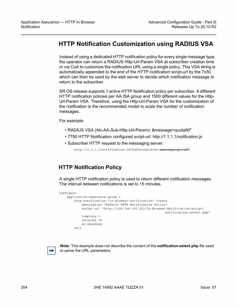
Application Assurance — HTTP In Browser Notification
204
Advanced Configuration Guide - Part IIIReleases Up To 20.10.R2
3HE 14992 AAAE TQZZA 01 Issue: 01
HTTP Notification Customization using RADIUS VSA
Instead of using a dedicated HTTP notification policy for every single message type, the operator can return a RADIUS Http-Url-Param VSA at subscriber creation time or via CoA to customize the notification URL using a single policy. This VSA string is automatically appended to the end of the HTTP notification script-url by the 7x50 which can then be used by the web server to decide which notification message to return to the subscriber.
SR OS release supports 1 active HTTP Notification policy per subscriber, 8 different HTTP notification policies per AA ISA group and 1500 different values for the Http-Url-Param VSA. Therefore, using the Http-Url-Param VSA for the customization of the notification is the recommended model to scale the number of notification messages.
For example:
• RADIUS VSA (Alc-AA-Sub-Http-Url-Param): &message=quota80"• 7750 HTTP Notification configured script-url: http://1.1.1.1/notification.js• Subscriber HTTP request to the messaging server:
http://1.1.1.1/notification.js?SubId=sub1&var=&message=quota80
HTTP Notification Policy
A single HTTP notification policy is used to return different notification messages. The interval between notifications is set to 15 minutes.
configureapplication-assurance group 1
http-notification "in-browser-notification" createdescription "Default HTTP Notification Policy"script-url "http://192.168.150.251/In-Browser-Notification/script/
notification-select.php"template 1interval 15no shutdown
exit
Note: This example does not describe the content of the notification-select.php file used to parse the URL parameters.

Advanced Configuration Guide - Part III Releases Up To 20.10.R2
Application Assurance — HTTP In BrowserNotification
Issue: 01 3HE 14992 AAAE TQZZA 01 205
Notification Status Monitoring
The operator then needs to enable the http-match-all-req feature for any HTTP request sent to the messaging server in order to monitor HTTP notification success and failures. This is done by creating a new application and enabling http-match-all-req within the app-filter.
Success and failure notifications include a specific HTTP encoded URI automatically interpreted as a success or a failure by Application Assurance on a per subscriber basis. If a failure is detected, the system will automatically attempt to notify a new candidate flow, instead of waiting for the next notification interval.
configureapplication-assurance group 1:1 policy
application "IBN Messaging Server" createapp-group "Web"
exitapp-filter
entry 100 createexpression 1 http-host eq "^192.168.150.251$"http-match-all-reqapplication "IBN Messaging Server"no shutdown
exitexit
App-Profile and App-Service-Options
Similar to the previous example, HTTP notifications are enabled per subscriber using RADIUS or Gx by modifying the subscriber app-profile or using ASO override.
The following ASO configuration is used:
configureapplication-assurance group 1:1 policy
app-service-optioncharacteristic "in-browser-notification"
value "enabled"value "disabled"default-value "disabled"
exit
The ASO characteristic in-browser-notification value enabled is used to enable the app-qos-policy matching the http-notification policy in-browser-notification as shown below:
configure

Application Assurance — HTTP In Browser Notification
206
Advanced Configuration Guide - Part IIIReleases Up To 20.10.R2
3HE 14992 AAAE TQZZA 01 Issue: 01
application-assurance group 1:1 policy app-qos-policyentry 1300 create
matchcharacteristic "in-browser-notification" eq "enabled"application neq "Advertising Statistics"
exitaction
http-notification "in-browser-notification"exitno shutdown
RADIUS Policy
The following RADIUS CoA message is used to modify the ASO characteristic of a residential subscriber and assign a specific Http-Url-Param VSA. The in-browser-notification ASO characteristic with value enabled is dynamically assigned to the subscriber along with the Http-Url-Param &message=quota80:
NAS-Port-Id = "1/1/5:4088"Framed-IP-Address = 192.168.211.30Alc-AA-App-Service-Options = "in-browser-notification=enabled"Alc-AA-Sub-Http-Url-Param = "&message=quota80"Alc-App-Prof-Str = "1-1/Default"
The subscriber HTTP request to the messaging server has the following format and includes the Http-Url-Param value as an argument of the URL:
http://192.168.150.251/In-Browser-Notification/script/notification-select.php?SubId=sub1&var=&message=quota80
The web server can now use the parameter value to make a decision to return a suitable notification message related to the subscriber usage cap.
Show Commands
Both the in-browser-notification ASO characteristic with value enabled and the HTTP-Url-Param VSA can be shown as follows:
A:PE# show application-assurance group 1:1 aa-sub esm "sub1" summary===============================================================================Application-Assurance Subscriber Summary (realtime)===============================================================================AA-Subscriber : sub1 (esm)ISA assigned : 1/2App-Profile : 1-1/DefaultApp-Profile divert : Yes

Advanced Configuration Guide - Part III Releases Up To 20.10.R2
Application Assurance — HTTP In BrowserNotification
Issue: 01 3HE 14992 AAAE TQZZA 01 207
Capacity cost : 1Aarp Instance Id : N/AHTTP URL Parameters : &message=quota80Last HTTP Notified Time : N/A-------------------------------------------------------------------------------Traffic Octets Packets Flows-------------------------------------------------------------------------------... ...-------------------------------------------------------------------------------Application Service Options (ASO)-------------------------------------------------------------------------------Characteristic Value Derived from-------------------------------------------------------------------------------in-browser-notification enabled dyn-overridequota-message-notification disabled default===============================================================================
The operator can also display the HTTP URL parameters VSA currently in use, per AA ISA group:
A:PE## tools dump application-assurance group 1 http-url-param-list-------------------------------------------------------------------------------Application-Assurance Subscriber HTTP URL parameters for Group 1:-------------------------------------------------------------------------------==============================================Http Url Parameter Sub Usage----------------------------------------------"&message=quota80" 1==============================================Total entries displayed 1
Conclusion
This chapter, intended for Application Assurance (AA) network architects and engineers, provides two implementation options for configuring and deploying HTTP In Browser Notification. It also explains how to take advantage of the Http-Url-Param RADIUS VSA to flexibly define various messaging campaigns using a common AA notification policy.

Application Assurance — HTTP In Browser Notification
208
Advanced Configuration Guide - Part IIIReleases Up To 20.10.R2
3HE 14992 AAAE TQZZA 01 Issue: 01

Advanced Configuration Guide - Part III Releases Up To 20.10.R2
Application Assurance — Local URL List Filtering
Issue: 01 3HE 14992 AAAE TQZZA 01 209
Application Assurance — Local URL List FilteringThis chapter provides information about the Application Assurance local URL list filtering.
Topics in this chapter include:
• Applicability• Overview• Configuration• Conclusion
Applicability
This chapter is applicable to all 7x50 systems supporting Application Assurance and was initially based on SR OS Release 13.0.R2. The chapter has been updated with CLI and functionality changes introduced in SR OS Release 19.10.R1, but the CLI in the sections URL-list update and Cron job is based on SR OS Release 16.0.
There are no specific prerequisites for this feature.
Overview
The local URL-list filtering capability provided by Application Assurance offers the following:
• configuration of a list of URLs which are globally allowed (allow-list)• configuration of a list of restricted URLs subscribers should be prevented from
accessing (deny-list)
The lists are stored locally in the 7x50 system compact flash (CF).
This chapter provides a guide for configuring deny-lists.
Deny-lists assist service providers to comply with regulatory requirements for network-wide URL filtering policies, such as:

Application Assurance — Local URL List Filtering
210
Advanced Configuration Guide - Part IIIReleases Up To 20.10.R2
3HE 14992 AAAE TQZZA 01 Issue: 01
• Court-ordered URL takedown• Child protection• Government-mandated URL takedown list
The 7x50 uses the Application Assurance capabilities to extract the URL from a subscriber HTTP/HTTPS request and compare it to the list of URLs contained in the local file. If a match occurs, the subscriber request is redirected to a preconfigured web server landing page, typically describing why the access to this resource was denied.
The system supports both unencrypted and OpenSSL Triple Data Encryption Standard (3DES) encrypted file formats to protect the content of the list.
HTTP/HTTPS filtering
Each HTTP request within a TCP flow is analyzed and filtered. For HTTPS traffic, the system extracts the domain name information contained in the Transport Layer Security (TLS) Server Name Indication (SNI).
Setup details
The setup consists of the following elements, as shown in Figure 29:
• 7x50 + ISA-AA• Web server (redirect landing page)• FTP server (source for the URL-list file)• Subscriber (desktop/laptop/tablet/smart phone)• Internet access• Optional: AAA for subscriber authentication and policy modification

Advanced Configuration Guide - Part III Releases Up To 20.10.R2
Application Assurance — Local URL List Filtering
Issue: 01 3HE 14992 AAAE TQZZA 01 211
Figure 29 Local URL-list filtering setup
This chapter is written in the context of a residential or WiFi deployment. However, local URL-list filtering is also applicable to business VPN services.
Configuration
To configure the system for local URL-list filtering, the operator needs to:
• Create a URL-list policy referencing a valid URL-list file located on the system compact flash
• Create a URL-filter policy for local filtering by referencing the URL-list policy previously created
• Create an App-QoS-Policy (AQP) to apply this url-filter policy• Optionally configure a cron job to automatically fetch a new list file and upgrade
the URL list.
URL-list policy and URL-filter policy
In the following example, two dedicated URL-list and URL-filter policies show URL filtering based on a plain text file and an encrypted file:
al_0803
FTP server(URL-list source)
PCRF/RADIUS
Internet
subscriber
Web server(redirect landing page)
RADIUS
Diameter

Application Assurance — Local URL List Filtering
212
Advanced Configuration Guide - Part IIIReleases Up To 20.10.R2
3HE 14992 AAAE TQZZA 01 Issue: 01
configureapplication-assurance group 1
url-list "denylist1-encrypted" createdescription "Demo URL Filtering List - Encrypted File"decrypt-key "ON3HU2GFPHmpOHwWbSGw/zdM4iuxzySpqS7pw/u3qIcuG4mABmrhc."
hash2file "cf3:\aa-url-list\url-list1.encrypted"no shutdown
exiturl-filter "local-filter-list1-encrypted" create
local-filteringdeny-list "denylist1-encrypted"
default-action allowhttp-redirect "redirect-denylist"
exitno shutdown
exit
configureapplication-assurance group 1
url-list "denylist1-plaintext" createdescription "Demo URL Filtering List - Plaintext File"file "cf3:\aa-url-list\url-list1-plaintext.txt"no shutdown
exiturl-filter "local-filter-list1-txt" create
local-filteringdeny-list "denylist1-plaintext"
default-action allowhttp-redirect "redirect-denylist"
exitno shutdown
exit
In the preceding example, both URL-filter policies are defined using default-action allow. The default action is used in case the file could not be loaded by the system, either at boot time or the first time the URL-list file was configured in the system. Possible causes are, for example:
• File corrupted, compact flash corrupted• Incorrect file encryption format or password• Wrong URL format in the file• Too many URLs in the file
Operators should always use default-action allow when configuring the URL-filter policy associated with a URL-list file because the file or the CF may be corrupted, in which case the system logs an error and a trap is raised.
Note that if a valid URL-list file was previously in use, and an invalid file is uploaded and the URL-list policy upgraded using this file, then the system will continue using the previous list.

Advanced Configuration Guide - Part III Releases Up To 20.10.R2
Application Assurance — Local URL List Filtering
Issue: 01 3HE 14992 AAAE TQZZA 01 213
HTTP-redirect policy
Both URL-filter policies defined in the preceding example refer to the following http-redirect policy; subscribers accessing a URL from the URL-list file are redirected to the following landing page:
configureapplication-assurance group 1
http-redirect "redirect-denylist" createdescription "Redirect for Local List URL Filtering"template 5tcp-client-resetredirect-url "http://172.16.70.100/Redirect/redirect-denylist.html?
Request edURL=$URL"no shutdown
exit
URL-list file
File format
A URL-list file may contain either hostnames or URLs.
To create a URL-list containing hostnames, set expression-match in the url-list configuration:
config>app-assure>group# url-list url-list-name [create]description <description-string>no descriptiondecrypt-key key | hash-key | hash2-key [hash | hash2]no decrypt-keyfile file-urlno filesize url-list-sizeexpression-match[no] shutdown
A URL-list with hostnames only (using expression-match) may contain the following wildcards:
• Head anchors character set [^ *]• Tail anchors character set [$ *]• Mid expression character set [\d \l \. \**]• Hex escaped characters [\x00 - \xFF]

Application Assurance — Local URL List Filtering
214
Advanced Configuration Guide - Part IIIReleases Up To 20.10.R2
3HE 14992 AAAE TQZZA 01 Issue: 01
Note that when expression-match is enabled, the list should contain hostnames only (with optional wildcards).
When configuring a URL-list with expression-match disabled (default), the system supports the following format for the URLs contained in the URL-list file:
• URLs without the HTTP keyword. For example:www.domain.com/path
• URLs with the HTTP keyword. For example:http://www.domain.com/path
In all cases, the following is supported:
• Comment lines starting with the number sign character (#). For example:# This is a comment line
• Printable ASCII characters. URLs using non-printable ASCII characters are percent-encoded by the web browser automatically and, therefore, need to be percent-encoded in the URL-list file.
File encryption
OpenSSL triple DES -nosalt is the supported encryption format. Files can be encrypted offline on a server using the following command:
openssl des3 -nosalt -in <input.txt> -out <output.enc>
List upgrade
The URL-list file can be upgraded using the admin command:
A:BNG# admin application-assurance group 1 url-list "denylist1-plaintext" upgrade
The upgrade result is logged in the system log-id 99:
A:BNG# show log log-id 99===============================================================================Event Log 99===============================================================================Description : Default System LogMemory Log contents [size=500 next event=72 (not wrapped)]71 2015/07/07 13:09:25.01 EST MINOR: APPLICATION_ASSURANCE #4446 Base url-list success

Advanced Configuration Guide - Part III Releases Up To 20.10.R2
Application Assurance — Local URL List Filtering
Issue: 01 3HE 14992 AAAE TQZZA 01 215
"URL list "denylist1-plaintext" in ISA-AA group 1 has been updated. There are 3 entries in the URL list."
App-profiles and app-service-options
Application Assurance policies can be selectively applied to specific AA subscribers by modifying the app-profile assigned to the subscriber or using Application Service Option (ASO) override. See SR OS User Guide for more information about modifying the app-profile or ASO assigned to AA subscribers (RADIUS, Gx, Override).
In this example, the following ASO configuration is used:
configureapplication-assurance group 1:1 policy
app-service-optionscharacteristic "local-list-filtering" create
value "no"value "yes-encrypted"value "yes-plaintext"default-value "no"
exitexitapp-profile "1-1/Default" create
divertexit
The ASO characteristic local-list-filtering value of yes-encrypted and yes-plaintext enable the AQP entry 210 and 220 in the example:
configureapplication-assurance group 1:1 policy app-qos-policy
entry 210 creatematch
characteristic "local-list-filtering" eq "yes-encrypted"exitaction
url-filter "local-filter-list1-encrypted"exitno shutdown
exitentry 220 create
matchcharacteristic "local-list-filtering" eq "yes-plaintext"
exitaction
url-filter "local-filter-list1-txt"exitno shutdown
exit
If the url-filter policy needs to be applied to 100% of the subscribers in the network, it is also possible to remove the ASO match criteria.

Application Assurance — Local URL List Filtering
216
Advanced Configuration Guide - Part IIIReleases Up To 20.10.R2
3HE 14992 AAAE TQZZA 01 Issue: 01
URL-list update
The system supports a flexible mechanism to upgrade the URL list automatically, using either cron or the NSP, to comply with the regulatory requirements for list upgrade frequency.
To configure a crontab job to periodically upgrade the URL list, the operator needs to:
• Generate the file to be periodically executed and store it to compact flash. As an example, create a file with filename "fetch.txt" with the following content:
filecopy ftp://user:[email protected]/home/cmg/test/list.txt . forceexitadmin application-assurance group 1 url-list "test" upgrade
The preceding commands will fetch a file from an ftp server and store it in compact flash. Assuming the operator has configured a local url-list "test" containing the file "list.txt", the url list will be upgraded.
• Configure the script policy:>config>system>script-control# info----------------------------------------------
script "bring"location "cf3:/fetch.txt"no shutdown
exitscript-policy "test"
results "cf3:/results.txt"script "bring"no shutdown
exit
• Configure the crontab job:>config>system>cron# info----------------------------------------------
schedule "bring_list"interval 60script-policy "test"no shutdown
exit----------------------------------------------
The preceding configuration will execute the commands stored in the file "fetch.txt" every 60 seconds. A value of 60 seconds was chosen for the test. In a real deployment, a list would be typically updated every 12 – 24 hours. A log file (results "results.txt") will also be created.
The end result will be that the system will automatically fetch from an ftp server a new list file, store it to compact flash and upgrade the URL list.

Advanced Configuration Guide - Part III Releases Up To 20.10.R2
Application Assurance — Local URL List Filtering
Issue: 01 3HE 14992 AAAE TQZZA 01 217
Show commands
url-list
The status of the URL list can be shown in the CLI. The url-list show command provides basic admin and operational status, as well as the number of URLs in the list. The command also provides reasons for any possible issue related to loading the list, as well as the last successfully deployed file and the last upgrade attempt. Therefore, the operator can determine whether the latest version of the file is currently in use or if an error occurred when trying to upgrade the list.
Show command output:
Label DescriptionAdmin Status [Up | Down] - Administrative status of the url-listOper Status [Up | Down] - Operational status of the url-listOper Flags [admin-down | file-does-not-exist |invalid-file-format |
too-many-urls| switch-over-error]File Deployed to ISA [Yes | No] - This flag describes if the file located in
the compact flash is the one deployed in the ISA, in theevent the file is overwritten and before the admin upgradecommand is used this flag will display “No”.
Upgrade StatisticsLast Success Last time the list was successfully upgradedFile Name File name for the last successful upgradeURL Entries Number of URLs loaded at the last successBlank/Comment Lines Number of blank or commented out linesLast Attempt Last time the operator tried to upgrade the listResult Success | Failure. Result of the last upgradeFile Name File name for the last upgrade attempt
*A:Dut-C# show application-assurance group 1 url-list "Deny List1"======================================================================Application Assurance Group 1 url-list "Deny List1"======================================================================Description : (Not Specified)Size : standardHost Expressions : disabledAdmin Status : UpOper Status : UpOper Flags : <none>File deployed to ISAs : Yes-------------------------------------------------------------------------------Upgrade Statistics-------------------------------------------------------------------------------Last Success : 11/02/2020 15:07:40DeployedFile Name : cf1:/host.txtURL Entries : 1 ( 0.01% full)URL Characters : 6 (~0.00% full)

Application Assurance — Local URL List Filtering
218
Advanced Configuration Guide - Part IIIReleases Up To 20.10.R2
3HE 14992 AAAE TQZZA 01 Issue: 01
URL Host Expr Entries: 1 ( 0.01% full)Blank/Comment Lines : 1Last Attempt : 11/02/2020 15:07:40Result : SuccessFile Name : cf1:/host.txt======================================================================
url-filter
The url-filter show command provides its operational and admin status, as well as actions taken, such as the number of redirects. With URL list filtering, using a default-action set to allow, the only counters increasing are allow, redirect, and default.
*A:Dut-C>config>app-assure>group>url-filter# show application-assurance group 1 url-filter "Url Filter1"===============================================================================Application Assurance Group 1 URL Filter "Url Filter1"===============================================================================Description : (Not Specified)Admin Status : UpOper Status : UpOper Flags : <none>HTTP Request Filtering : allAQP Referenced : No-------------------------------------------------------------------------------URL Stats Summary-------------------------------------------------------------------------------Total Requests : 0 Default Action : 0Requests Allowed: 0 Reqs Block/Redir: 0-------------------------------------------------------------------------------Local Filter-------------------------------------------------------------------------------deny-list : Deny List1 Admin Status : Up Oper Status : Up Oper Flags : <none> Number of URLs : 1 Default Action : block-all HTTP Redirect : (Not Specified) URL-List Lookups : 0 Match : 0 Miss : 0 Default Action : 0===============================================================================

Advanced Configuration Guide - Part III Releases Up To 20.10.R2
Application Assurance — Local URL List Filtering
Issue: 01 3HE 14992 AAAE TQZZA 01 219
http-redirect
The http-redirect show command provides more information about how the traffic was blocked; for example, it differentiates TCP client reset used for HTTPS from regular redirect used for HTTP traffic.
A:BNG# show application-assurance group 1 http-redirect "redirect-denylist"===============================================================================Application Assurance Group 1 HTTP Redirect redirect-denylist===============================================================================Description : Redirect for Local List URL FilteringTemplate : 5
: Redirect supporting macro substitution using HTTP 302Redirect URL : http://172.16.70.100/Redirect/redirect-denylist.
html?RequestedURL=$URLAdmin Status : UpAQP Ref : No-------------------------------------------------------------------------------Summary Statistics-------------------------------------------------------------------------------Grp:Part Redirects Client Resets Redirects
Sent Sent Not Sent-------------------------------------------------------------------------------1:1 2 1 0-------------------------------------------------------------------------------Total 2 1 0-------------------------------------------------------------------------------===============================================================================
Cron job
This chapter provides details on how to verify that the cron job executes successfully. The operator can see the location and execution interval of the file which is executed periodically, the time it was last executed and any possible errors which may have occurred during execution using the following command:
# show system cron schedule "bring_list"===============================================================================CRON Schedule Information===============================================================================Schedule : bring_listSchedule owner : TiMOS CLIDescription : noneAdministrative status : enabledOperational status : enabledScript Policy : testScript Policy Owner : TiMOS CLIScript : bringScript Owner : TiMOS CLIScript source location : cf3:/fetch.txtScript results location : cf3:/results.txtSchedule type : periodic

Application Assurance — Local URL List Filtering
220
Advanced Configuration Guide - Part IIIReleases Up To 20.10.R2
3HE 14992 AAAE TQZZA 01 Issue: 01
Interval : 0d 00:01:00 (60 seconds)Repeat count : infiniteNext scheduled run : 0d 00:00:51End time : noneWeekday : noneMonth : noneDay of month : noneHour : noneMinute : noneNumber of schedule runs : 12Last schedule run : 2019/09/13 11:28:25 EESTNumber of schedule failures : 0Last schedule failure : no errorLast failure time : never
===============================================================================
The following command provides more information on the execution cycle:
*A:4LS_CloudMG# show system script-control script-policy "test"
===============================================================================Script-policy Information===============================================================================Script-policy : testScript-policy Owner : TiMOS CLIAdministrative status : enabledOperational status : enabledScript : bringScript owner : TiMOS CLIScript source location : cf3:/fetch.txtScript results location : cf3:/results.txtMax running allowed : 1Max completed run histories : 1Max lifetime allowed : 0d 01:00:00 (3600 seconds)Completed run histories : 1Executing run histories : 0Initializing run histories : 0Max time run history saved : 0d 01:00:00 (3600 seconds)Script start error : N/ALast change : 2019/09/13 10:31:20 EESTMax row expire time : neverLast application : cronLast auth. user account : not-specified
===============================================================================Script Run History Status Information-------------------------------------------------------------------------------Script Run #25-------------------------------------------------------------------------------Start time : 2019/09/13 11:29:25 EESTEnd time : 2019/09/13 11:29:26 EESTElapsed time : 0d 00:00:01 Lifetime : 0d 00:00:00State : terminated Run exit code : noErrorResult time : 2019/09/13 11:29:26 EESTKeep history : 0d 00:59:41Error time : neverResults file : cf3:/results.txt_20190913-082924-UTC.646420.out

Advanced Configuration Guide - Part III Releases Up To 20.10.R2
Application Assurance — Local URL List Filtering
Issue: 01 3HE 14992 AAAE TQZZA 01 221
Run exit : SuccessError : N/AApplication : cron Auth. user ac*: not-specified* indicates that the corresponding row element may have been truncated.===============================================================================
Every time a crontab job is executed, a log file is generated. The filename will be "results.txt_<timestamp>.out", where:
• results.txt: configured in the script-policy• <timestamp>:file timestamp. As an example: 20190913-082324-UTC.646436.
An example log file will be: results.txt_20190913-082324-UTC.646436.out and the log file contents is as follows:
Pre-processing configuration file (V0v0)...Completed processing 4 lines in 0.0 seconds*A:4LS_CloudMG# file*A:4LS_CloudMG# copy ftp://user:[email protected]/home/cmg/test/list.txt . forceCopying file ftp://user:[email protected]/home/cmg/test/list.txt ... OK1 file copied.*A:4LS_CloudMG# exit*A:4LS_CloudMG# admin application-assurance group 1 url-list "test" upgradeExecuted 4 lines in 0.7 seconds from file cf3:\fetch.txt
Finally, using the following command, the operator may check when the list was last upgraded and verify that the cron job runs as intended:
# show application-assurance group 1 url-list "test"
===============================================================================Application Assurance Group 1 url-list "test"===============================================================================Description : (Not Specified)Size : standardAdmin Status : UpOper Status : UpOper Flags : <none>File deployed to ISAs : Yes
-------------------------------------------------------------------------------Upgrade Statistics-------------------------------------------------------------------------------Last Success : 09/13/2019 11:49:57
DeployedFile Name : cf3:\list.txtURL Entries : 8 ( 0.05% full)URL Characters : 103 (~0.00% full)Blank/Comment Lines : 0
Last Attempt : 09/13/2019 11:49:57Result : Success
File Name : cf3:\list.txt===============================================================================

Application Assurance — Local URL List Filtering
222
Advanced Configuration Guide - Part IIIReleases Up To 20.10.R2
3HE 14992 AAAE TQZZA 01 Issue: 01
Conclusion
This chapter, intended for Application Assurance (AA) network architects and engineers, provides two examples for deploying URL-list filtering, upgrading the list and displaying its statistics, as well as configuring a cron job so that the system will periodically fetch a new URL list file and upgrade the list automatically.

Advanced Configuration Guide - Part III Releases Up To 20.10.R2
Application Assurance — Security Gateway StatefulFirewall
Issue: 01 3HE 14992 AAAE TQZZA 01 223
Application Assurance — Security Gateway Stateful Firewall This chapter provides information about Application Assurance Security gateway stateful firewall.
Topics in this chapter include:
• Applicability• Overview• Configuration• Conclusion
Applicability
This chapter is applicable to all 7750 SR/SR-c and 7450 ESS chassis supporting Application Assurance (AA).
The configuration was tested on release 13.0.R2.
Overview
The SR OS 13.0.R1 AA stateful firewall feature runs on AA-ISA and extends application-level analysis to provide an in-line stateful service, integrated within the Security Gateway (SeGW). The feature provides protection for mobile infrastructure; Mobility Management Entities (MMEs), Serving Gateways (SGWs), and Network Management Systems (NMSs), against attacks from compromised base stations, evolved NodeBs (eNBs), or Femto Access Points (FAPs). AA stateful packet filtering, combined with AA L7 classification and control, provides advanced, next-generation firewall functionality. Using stateful packet filtering, the AA FW not only inspects packets at layers 3 to 7, but also monitors the connection state.
AA FW deployed within a SeGW in ultra-broadband access networks (3G/4G/Femto) provides back-end core network security protection, as per Figure 1. AA FW offers protection for the following 3rd Generation Partnership Project (3GPP) defined interfaces:
1. S1-MME

Application Assurance — Security Gateway Stateful Firewall
224
Advanced Configuration Guide - Part IIIReleases Up To 20.10.R2
3HE 14992 AAAE TQZZA 01 Issue: 01
2. S1-U 3. Operations, Administration and Maintenance (OAM)
Figure 30 LTE SeGW Firewall Deployment
Similarly, the SeGW architecture for Femto deployment is based on two 7750 SR systems terminating the mobile backhaul side (front-end and connecting to, for example, a 9365 Base Station Router Gateway (BSR-GW) and other network elements of the packet core (back-end), as per Figure 31:
Figure 31 SeGW in Small Cells Architecture
al_0823
OAM
MCSync
MS-ISA AA—FirewallMS-ISA IPSEC
AA-ISA provides back-end core network security protection
Firewall protection for:
S1-MME (SCTP) TrafficS1-U (GTP-U) TrafficOAM Traffic
SEGW FW
IPSEC
C-Plane
U-Plane
OAM
S1 OVER IPSEC9762 LTEEnterprise
Cells
S1-MME
S1-U
HSSePC
PCRF
Internet
MBHEthernet/IP/
MPLS
PGWSGW
MME
AAA7750-SR
SeGW
SeGW
1588 PTP GMOAM
NMSNTP
al_0824
FW
FW
IPSECIu’
Iu-CS
Iu-PS
MCSync1U’ OVER
IPSEC936x Small Cell Access Points
(Home/Enterprise/Metro) Gn
Internet
MBHEthernet/IP/
MPLS
9471 WMM
MSc
Motive HDM
5620 SAMCA
PS Core
Voice Core
OAM
7750-SR
9360 Small Cell Gateway Cluster
NTP
7750-SR
9365BSR-GW
SeGW
SeGW
SGSN
HLR
AAA
7750-SR MG
GGSN
BVG
BSG
BPG PW
PSTN

Advanced Configuration Guide - Part III Releases Up To 20.10.R2
Application Assurance — Security Gateway StatefulFirewall
Issue: 01 3HE 14992 AAAE TQZZA 01 225
The two SeGWs run in stateful redundant mode: upon partial or total failure of the active SeGW for a set of IPSec tunnels, the other SeGW takes over without terminating the IPSec tunnels, providing hitless failover.
In addition to MS-ISA hardware dedicated to the IPSec function, each SeGW supports one or more additional MS-ISAs running AA to provide firewall capabilities. The firewall rules protect the BSR as well as the BSR-GW and packet core network elements (NEs) from malicious attacks or unauthorized traffic.
The objective of this chapter is to describe the required configuration within AA-ISA in order to enable AA FW and protection for S1-MME, S1-U, and OAM traffic. Basic knowledge of AA-ISA diversion configuration is assumed.
S1-MME Traffic Protection
The purpose of AA FW in this deployment is to protect the MME infrastructure against an attack from a compromised eNB or FAP. Network flooding attacks, malformed packets, and port scans are examples of denial of service (DoS) attacks that can be carried out using a compromised eNB or FAP.
AA FW provides inspection of the Stream Control Transmission Protocol (SCTP) used to communicate to the MME. Such inspection includes checking for SCTP payload protocol IDs (PPIDs), source /destination ports, SCTP chunk validation, and malformed SCTP packets (such as checksum validation). In addition, the operator can configure DoS flooding rules, such as policers to limit the bandwidth and/or flow counts of SCTP traffic.
S1-U Traffic Protection
The purpose of AA FW in this deployment is to protect the SGW infrastructure against an attack from a compromised eNB or FAP. AA FW supports protection against:
• malformed GPRS Tunneling Protocol User plane (GTP-U) packet attacks Checking packet sanity, which include GTP-U mandatory, optional, and extension header checks, as well as checks for invalid reserved information elements (IE) and missing IEs.
• unsupported GTP messages Filtering messages based on message type and/or message length.
• flooding attacks

Application Assurance — Security Gateway Stateful Firewall
226
Advanced Configuration Guide - Part IIIReleases Up To 20.10.R2
3HE 14992 AAAE TQZZA 01 Issue: 01
Shaping GTP traffic bandwidth, which limits the GTP-U bandwidth that a FAP can send to the core (SGW). Limiting GTP tunnels, which limits the number of concurrent GTP tunnels and/or setup rate of these tunnels from a FAP to the core network.To prevent the shared resources of bandwidth and the SGW processor from being consumed by an attacker, Nokia recommends the GTP flow rate limiting configuration.
• IP fragmentation-based attacks Applying various drop rules for IP fragmentation of GTP messages.
OAM Traffic Protection
The purpose of AA FW protection in this deployment is to protect against any abuse of OAM network resources, such as NMS.
Network flooding attacks, malformed packets, and port scans are examples of such attacks that can be carried out using a compromised eNB or FAP.
See the configuration described in the Application Assurance — Stateful Firewall chapter for this context of OAM protection in SeGW.
Configuration
AA-ISA Application QoS Policies (AQPs) are enhanced in Release 13.0.R1 with several new AQP actions that provide SCTP and GTP filtering functionality. As with all AQPs, these actions have partition-level scope, which allows different FW policies to be implemented by using AA partition concepts within the same AA-ISA.
The configuration topology in Figure 32 shows the SeGW FW functionality of S1-U and S1-MME interfaces. Geo-redundancy, which is a very common deployment option, is not described in this here because it is described in the Multi-Chassis IPSec Redundancy chapter.

Advanced Configuration Guide - Part III Releases Up To 20.10.R2
Application Assurance — Security Gateway StatefulFirewall
Issue: 01 3HE 14992 AAAE TQZZA 01 227
Figure 32 Configuration Topology
Pre-Setup Requirements
Configure tunnel ISAs with optional multi-chassis redundancy. See the Multi-Chassis IPSec Redundancy chapter for more information.
Step 1. Divert AA traffic and apply basic firewall rules.Step 1.1. Divert private VPRN traffic into AA-ISA with AA multi-chassis redundancy.This step is required for any of the configurations in Steps 2, 3 or 4. There is no dependency between Steps 2, 3 or 4.
al_0825
MMEs172.16.110.100/30 NMS
172.16.120.0/30
SGWs172.16.111.1/30
MS-ISA-AA/FW
S1-mmeS1-u
OAM
AA-divert
MS-ISA(s) - TG-1
IPsec Tunnel
VPRN 2-Private Side
7750 SeGW 1
Mobile Access NetworkMobile Access Network(Backhaul)(Backhaul)
VPRN 1-Public Side

Application Assurance — Security Gateway Stateful Firewall
228
Advanced Configuration Guide - Part IIIReleases Up To 20.10.R2
3HE 14992 AAAE TQZZA 01 Issue: 01
In this example, one private VPRN is used for all traffic to/from eNBs. In some small cell deployments, eNB traffic is split into three different VPRNs: one for control (S1-MME), one for management (OAM), and one for bearer traffic (S1-U GTP-U). In that case, each of these VPRNs needs to be diverted into AA-ISA in order to provide firewall protection. First, define an application profile and transit IP policy, such as:
*A:7750-1>config>app-assure>group$ info----------------------------------------------
policybeginapp-profile "default" create
description " App profile that applies to the whole SAP"divert
exitcommit
exittransit-ip-policy 1 create
description "Per eNB-IP Sub policy"detect-seen-iptransit-auto-create
no shutdownexit
Then, apply these policies to the SAP on the private side of the IPSec tunnel ISA:
*A:7750-1>config>service>vprn>if# info----------------------------------------------
sap tunnel-1.private:1 createtransit-policy ip 1app-profile "default"
exit
This configuration achieves:- Traffic to/from the IPSec tunnel ISA private SAP is diverted to AA-ISA
for the purpose of FW protection,- Within AA-ISA, the diverted SAP is treated as a parent SAP. That is,
instead of treating the whole SAP as a single subscriber, subscribers are auto-created within this SAP based on the IP address of the eNBs.
Step 1.2. Protect against malformed packets.In firewall deployments, it is recommended that overload-drop, error-drop, and fragment-drop (all) are enabled within the default sub-policy, as shown in the example below:- overload-drop ensures that AA-ISA, when overloaded, drops the
excess traffic instead of allowing it through, without applying firewall rules.
- error-drop ensures that AA-ISA drops malformed IP packets.

Advanced Configuration Guide - Part III Releases Up To 20.10.R2
Application Assurance — Security Gateway StatefulFirewall
Issue: 01 3HE 14992 AAAE TQZZA 01 229
- fragment-drop (all) because many network DoS attacks use IP fragmentation to initiate attacks, the operator has the option to drop all fragmented traffic, drop out-of-order fragments only, or allow fragments through. Allowing fragments through is not recommended for firewall deployments.
*A:7750-1>config>app-assure>group>policy# app-qos-policy*A:7750-1>config>app-assure>group>policy>aqp# info----------------------------------------------
entry 500 createdescription "apply SeGW session filter rules"match
traffic-direction subscriber-to-networkexitaction
overload-droperror-dropfragment-drop all
exitno shutdown
exitexit
----------------------------------------------*A:7750-1>config>app-assure>group>policy#
Step 1.3. Limit total traffic from any eNB.It is recommended that a total limit be placed on how much bandwidth and how many flows an eNB or FAP can generate toward the network, regardless of the type of traffic.The limit values are a function of the number of end devices that are served by the eNB or FAP, plus some additional margin:
*A:7750-1>config>app-assure>group# info----------------------------------------------
policer "limit_eNBs_total_Flows" type flow-count-limit granularity subscriber
createflow-count 1000
exitpolicer "limit_eNBs_total_bw" type single-bucket-
bandwidth granularity subscriber createrate 500mbs 500
exit----------------------------------------------*A:7750-1>config>app-assure>group#
Note: If the traffic from eNB or FAP is separated into different private SAPs, based on traffic type (S1-AP, S1-U, or OAM), as with some deployment topologies, then the policing limit value is dependent on the SAP traffic type as well as the number of end devices. See policing limit settings in Steps 2 and 3.

Application Assurance — Security Gateway Stateful Firewall
230
Advanced Configuration Guide - Part IIIReleases Up To 20.10.R2
3HE 14992 AAAE TQZZA 01 Issue: 01
Apply the configured policers as actions from within the default sub-policy AQP entry:
*A:7750-1>config>app-assure>group>policy# app-qos-policy entry 500*A:7750-1>config>app-assure>group>policy>aqp>entry>action# flow-count-limit "limit_eNBs_total_Flows"*A:7750-1>config>app-assure>group>policy>aqp>entry>action# bandwidth-policer "limit_eNBs_total_bw"*A:7750-1>config>app-assure>group>policy>aqp>entry# info----------------------------------------------
description "apply SeGW session filter rules"match
traffic-direction subscriber-to-networkexitaction
bandwidth-policer "limit_eNBs_total_bw"flow-count-limit "limit_eNBs_total_Flows"session-filter "SeGW_FW"overload-droperror-dropfragment-drop all
exitno shutdown
----------------------------------------------*A:7750-1>config>app-assure>group>policy>aqp>entry#
Step 2. Configure AA-ISA to provide firewall protection to protect MMEs (S1-AP traffic).Step 2.1. Create IP AA lists.First, create an AA IP prefix list that contains eNB IP addresses or range of addresses:
*A:7750-1>config>app-assure# group 1:1*A:7750-1>config>app-assure>group# ip-prefix-list "ALL_eNBs" create*A:7750-1>config>app-assure>group>pfx>$ description "eNodeB subnet"*A:7750-1>config>app-assure>group>pfx>$ prefix 172.16.100.0/24*A:7750-1>config>app-assure>group>pfx>$ exit
Next, optionally create an AA IP list that contains MME IP addresses (in case there are more than one):
*A:7750-1>config>app-assure>group# ip-prefix-list "MMEs" create*A:7750-1>config>app-assure>group>pfx>$ description "MME(s) subnet"*A:7750-1>config>app-assure>group>pfx>$ prefix 172.16.110.100/30*A:7750-1>config>app-assure>group>pfx>$ exit
Note: All of the above listed actions use the traffic direction of subscriber-to-network. That is, they are not applied to traffic in the other direction (downstream) because the purpose of the firewall is to protect the network resources from upstream traffic coming from compromised eNBs or FAPs.

Advanced Configuration Guide - Part III Releases Up To 20.10.R2
Application Assurance — Security Gateway StatefulFirewall
Issue: 01 3HE 14992 AAAE TQZZA 01 231
After the above lists are created, they can be referenced and used in AA FW rules using session filters and AQPs.Step 2.2. Allow only SCTP traffic towards MMEs — No port scanning.A basic setup creates session-filter rules that will only allow SCTP traffic between eNBs and MMEs.
*A:7750-1>config>app-assure>group# session-filter "SeGW_FW" create*A:7750-1>config>app-assure>group>sess-fltr$ default-action deny*A:7750-1>config>app-assure>group>sess-fltr$ entry 1 create*A:7750-1>config>app-assure>group>sess-fltr>entry$ description "allow SCTP to MM Es"*A:7750-1>config>app-assure>group>sess-fltr>entry$ match*A:7750-1>config>app-assure>group>sess-fltr>entry>match$ ip-protocol-num "sctp"*A:7750-1>config>app-assure>group>sess-fltr>entry>match$ src-ip ip-prefix-list "ALL_eNBs"*A:7750-1>config>app-assure>group>sess-fltr>entry>match$ dst-ip ip-prefix-list "MMEs"*A:7750-1>config>app-assure>group>sess-fltr>entry>match$ dst-port eq 6005*A:7750-1>config>app-assure>group>sess-fltr>entry>match$ exit*A:7750-1>config>app-assure>group>sess-fltr>entry$ action permit*A:7750-1>config>app-assure>group>sess-fltr>entry$ exit
Next, the newly created session filter needs to be referenced from a default sub-policy AQP action, as follows:
*A:7750-1>config>app-assure>group>policy>aqp# info----------------------------------------------
entry 500 createdescription "apply SeGW session filter rules"match
traffic-direction subscriber-to-networkexitaction
session-filter "SeGW_FW"overload-droperror-dropfragment-drop all
exitno shutdown
exitexit
----------------------------------------------*A:7750-1>config>app-assure>group>policy#
Using traffic direction subscriber-to-network in the above AQP entry achieves two objectives:1. Protects MMEs by allowing only SCTP traffic to be initiated from eNB
subnets toward MMEs. Port scanning toward MME is blocked.
Note: In the above configuration, SCTP traffic on MMEs is assumed to be running on port 6005.

Application Assurance — Security Gateway Stateful Firewall
232
Advanced Configuration Guide - Part IIIReleases Up To 20.10.R2
3HE 14992 AAAE TQZZA 01 Issue: 01
2. Allows MMEs to have full access to eNBs.
Step 2.3. DoS protection: Limit the number of SCTP flows from eNBs.In this step, the operator configures a flow count policer to limit the number of SCTP flows that an eNB can generate toward the MMEs. This protects the MMEs against a compromised eNB trying to set up many SCTP flows.
*A:7750-1# configure application-assurance group 1*A:7750-1>config>app-assure>group# policer "sctp_flow_count" type flow-count-limit granularity subscriber create*A:7750-1>config>app-assure>group>policer$ flow-count 2*A:7750-1>config>app-assure>group>policer$ exit
In the above configuration, an eNB or FAP can have up to two flows at a time. In practice, there should only be one SCTP session, one flow in each direction, per eNB-MME pair. The above example uses two flows to leave a margin in case a second, backup, MME needs to communicate with the eNB, while still providing enough protection.Add the defined policer as a flow-count-limit as an AQP action, as follows:
A:7750-1>config>app-assure>group>policy>aqp# entry 100A:7750-1>config>app-assure>group>policy>aqp>entry$ info----------------------------------------------
description "limit SCTP traffic"match
traffic-direction subscriber-to-networkip-protocol-num eq sctp
exitaction
flow-count-limit "sctp_flow_count"exitno shutdown
----------------------------------------------A:7750-1>config>app-assure>group>policy>aqp>entry$
Step 2.3.1. Configure an AA FW events log.It is sometimes advisable to configure a log that captures events related to various AA FW actions. Due to the limited size of the log and the large amount of traffic AA can handle, consider the usefulness of the information in the log when: - debugging a configuration- testing a configuration in a staged environment- capturing infrequent actions
Note: It is important that an AQP, containing a session-filter action, does not contain any matching condition other than ASOs, traffic direction, or subscriber ID. Subscriber ID is not applicable in this deployment use-case.

Advanced Configuration Guide - Part III Releases Up To 20.10.R2
Application Assurance — Security Gateway StatefulFirewall
Issue: 01 3HE 14992 AAAE TQZZA 01 233
To configure a log:*A:7750-1# configure application-assurance group 1:1*A:7750-1>config>app-assure>group# event-log "FW_drops_log" create*A:7750-1>config>app-assure>group>evt-log$ buffer-type circular*A:7750-1>config>app-assure>group>evt-log$ max-entries 100000*A:7750-1>config>app-assure>group>evt-log$ no shutdown*A:7750-1>config>app-assure>group>evt-log$ exit*A:7750-1>config>app-assure>group# info----------------------------------------------
---snipped---event-log "FW_drops_log" create
buffer-type circularmax-entries 100000no shutdown
exit
To reference the configured log from within the deny action of the session filter:
*A:7750-1>config>app-assure>group>sess-fltr# info----------------------------------------------
default-action deny event-log "FW_drops_log"entry 1 create
description "allow SCTP to MMEs"match
ip-protocol-num sctpsrc-ip ip-prefix-list "ALL_eNBs"dst-ip ip-prefix-list "MMEs"
exitaction permit
exit----------------------------------------------*A:7750-1>config>app-assure>group>sess-fltr#
To view the log:*A:7750-1# tools dump application-assurance group 1:1 event-log "FW_drops_log" isa 1/2=====================================================Application-Assurance event-log "FW_drops_log"Current Time: "06/10/2015 22:45:30" (UTC)
group[:partition]: 1:1isa: 1/2admin state: no shutdownbuffer-type: circularmax-entries: 100000
=====================================================Event-source
Action SubType SubName Direction Src-ip Dst-ip Ip-protocol Src-port Dst-port Timestamp
Total Records: 0=====================================================*A:7750-1#

Application Assurance — Security Gateway Stateful Firewall
234
Advanced Configuration Guide - Part IIIReleases Up To 20.10.R2
3HE 14992 AAAE TQZZA 01 Issue: 01
To clear all the entries within the specified log: *A:7750-1# clear application-assurance group 1:1 event-log "FW_drops_log"
Step 2.4. DoS protection: Limit the SCTP bandwidth from eNBSimilar to the previous step, the operator configures a flow bandwidth policer to limit the amount of SCTP traffic that an eNB can generate toward the MMEs. This protects the MMEs against a compromised eNB trying to flood the MMEs.
*A:7750-1# configure application-assurance group 1*A:7750-1>config>app-assure>group# info-------------------------------------------------snipped---
policer "sctp_bw_limit" type single-bucket-bandwidth granularity subscriber create
rate 30mbs 10
exit---snipped---
exit----------------------------------------------*A:7750-1>config>app-assure>group#
In the above example, a single leaky-bucket policer is configured with a rate set to 30 kb/s and maximum burst size of 10 kbytes. This provides enough bandwidth to ensure normal operations, while still providing a ceiling limit of how much traffic any eNB can send toward the MMEs.The value for this policer is a function of the amount of user equipment (UEs) served by the eNB/FAP. For example, in a small cell deployment, with 32 active users per 9962 FAP, the S1-MME bandwidth is estimated to be: Uplink — toward MME : 2.7 kb/s Downlink — from MME toward FAP : 28 kb/sAdd the defined policer as a subscriber policy, as follows:
A:7750-1>config>app-assure>group>policy>aqp# entry 100A:7750-1>config>app-assure>group>policy>aqp>entry$ info----------------------------------------------
description "limit SCTP traffic"match
traffic-direction subscriber-to-networkip-protocol-num eq sctp
exitaction
bandwidth-policer "sctp_bw_limit"flow-count-limit "sctp_flow_count"
exitno shutdown
----------------------------------------------A:7750-1>config>app-assure>group>policy>aqp>entry$

Advanced Configuration Guide - Part III Releases Up To 20.10.R2
Application Assurance — Security Gateway StatefulFirewall
Issue: 01 3HE 14992 AAAE TQZZA 01 235
Step 2.4.1 Configure additional limits for all traffic to MMEs.To further protect the MMEs from a distributed attack, whereby a number of eNBs or FAPs are compromised, an AA FW can be configured to limit total traffic, not just from a single eNB as outlined in previous sections, but from all eNBs toward the MMEs.It is recommended to configure the following three protection limits:1. total bandwidth of SCTP toward MMEs2. total number of flows toward MMEs3. flow setup rate toward the MMEs
The configuration is shown below:*A:7750-1>config>app-assure>group# info----------------------------------------------
policer "limit_total_sctp_bw" type single-bucket-bandwidth granularity system create
rate 1200mbs 100
exitpolicer "limit_total_sctp_flows" type flow-count-
limit granularity system createflow-count 400
exitpolicer "limit_total_sctp_flows_rate" type flow-rate-
limit granularity system createrate 100mbs 100
exit----------------------------------------------*A:7750-1>config>app-assure>group#
The policers are then referenced from within the appropriate AQP entry that matches the MMEs traffic and SCTP:
*A:7750-1>config>app-assure>group>policy>aqp# info-------------------------------------------------snipped---
entry 110 createdescription " limit system traffic towards MMEs"match
traffic-direction subscriber-to-networksrc-ip eq ip-prefix-list "ALL_eNBs"
Note:
• The policers are of type system and not subscriber in order to be applied to all eNBs or FAPs, as is the case when auto-transit subscribers are created (see Step 1).
• The actual limits of these policers are a function of the total number of eNBs served by the SeGW. In the above configuration, it is assumed that there are 400 eNBs. Therefore, the total limit is 400 flows of SCTP traffic.
• A flow setup rate limit of 100 is set to protect MMEs from a storm of new SCTP flows.

Application Assurance — Security Gateway Stateful Firewall
236
Advanced Configuration Guide - Part IIIReleases Up To 20.10.R2
3HE 14992 AAAE TQZZA 01 Issue: 01
dst-ip eq ip-prefix-list "MMEs"exitaction
bandwidth-policer "limit_total_sctp_bw"flow-rate-limit "limit_total_sctp_flows_rate"flow-count-limit "limit_total_sctp_flows"
exitno shutdown
exit*A:7750-1>config>app-assure>group>policy>aqp#
Step 2.5. Allow only specified SCTP PPIDs toward the MMEs.In this step, the operator blocks all except the specified SCTP messages that contain configured PPIDs, using an AA SCTP filter configuration:
*A:7750-1>config>app-assure>group# sctp-filter- no sctp-filter <sctp-filter-name>- sctp-filter <sctp-filter-name> [create]
<sctp-filter-name> : [32 chars max]<create> : keyword
[no] description - Configure a description of the SCTP filter[no] event-log - Configure an event log for packets dropped by the SCTP
filterppid + Configure actions for specific or default PPIDs
(Payload Protocol Identifiers)[no] ppid-range - Configure the range of allowable PPIDs for the SCTP
filter
The filter specifies either a range of PPIDs or individual PPIDs:*A:7750-1>config>app-assure>group>sctp-fltr>ppid$ entry 1
- entry <entry-id> value <ppid-value> action {permit|deny}- no entry <entry-id>
<entry-id> : [1..255]<ppid-value> : [0..4294967295]D | [256 chars max]<permit|deny> : permit|deny
The PPIDs can be specified either by their values or by names. Names are specified in RFC4960. See Table 9.
Note: It is possible, but redundant, to add the ip-protocol eq sctp command as a match condition, because the configured session filter already ensures that only SCTP traffic can flow between eNBs and MMEs.
Table 9 SCTP PPIDs
Value SCTP PPID Value SCTP PPID
0 Reserved by SCTP 31 Service Area Broadcast Protocol (SABP)

Advanced Configuration Guide - Part III Releases Up To 20.10.R2
Application Assurance — Security Gateway StatefulFirewall
Issue: 01 3HE 14992 AAAE TQZZA 01 237
1 IUA 32 Fractal Generator Protocol (FGP)
2 M2UA 33 Ping Pong Protocol (PPP)
3 M3UA 34 CalcApp Protocol (CALCAPP)
4 SUA 35 Scripting Service Protocol (SSP)
5 M2PA 36 NetPerfMeter Protocol Control Channel (NPMP-CONTROL)
6 V5UA 37 NetPerfMeter Protocol Data Channel (NPMP-DATA)
7 H.248 38 Echo (ECHO)
8 BICC/Q.2150.3 39 Discard (DISCARD)
9 TALI 40 Daytime (DAYTIME)
10 DUA 41 Character Generator (CHARGEN)
11 ASAP 42 3GPP RNA
12 ENRP 43 3GPP M2AP
13 H.323 44 3GPP M3AP
14 Q.IPC/Q.2150.3 45 SSH over SCTP
15 SIMCO <draft-kiesel-midcom-simco-sctp-00.txt>
46 Diameter in a SCTP DATA chunk
16 DDP Segment Chunk 47 Diameter in a DTLS/SCTP DATA chunk
17 DDP Stream Session Control 48 R14P. BER Encoded ASN.1 over SCTP
18 S1 Application Protocol (S1AP) 49 Unassigned
19 RUA 50 WebRTC DCEP
20 HNBAP 51 WebRTC String
21 ForCES-HP 52 WebRTC Binary Partial (deprecated)
22 ForCES-MP 53 WebRTC Binary
23 ForCES-LP 54 WebRTC String Partial (deprecated)
24 SBc-AP 55 3GPP PUA
25 NBAP 56 WebRTC String Empty
26 Unassigned 57 WebRTC Binary Empty
Table 9 SCTP PPIDs (Continued)
Value SCTP PPID Value SCTP PPID

Application Assurance — Security Gateway Stateful Firewall
238
Advanced Configuration Guide - Part IIIReleases Up To 20.10.R2
3HE 14992 AAAE TQZZA 01 Issue: 01
It is recommended to limit the SCTP traffic to only those packets with S1 AP PPID. The SCTP filter can be configured to deny all by default and only allow PPID S1 AP (by value = 18 or by name: s1-application-protocol) as follows:
*A:7750-1# configure application-assurance group 1:1sctp-filter "SCTP-PPID-Filter" create
description "Allow only S1AP PPID"event-log "FW_drops_log"ppid
default-action denyentry 1 value "s1-application-protocol" action permit
exit
This configured SCTP filter is then referenced as an action from within an AQP entry:
*A:7750-1>config>app-assure>group>policy>aqp# info----------------------------------------------
entry 100 createdescription "limit SCTP traffic"match
traffic-direction subscriber-to-networkip-protocol-num eq sctp
exitaction
bandwidth-policer "sctp_bw_limit"flow-count-limit "sctp_flow_count"sctp-filter "SCTP-PPID-Filter"
exitno shutdown
exit----------------------------------------------A:7750-1>config>app-assure>group>policy>aqp#
To view the packets allowed or denied by the configured SCTP filter:*A:7750-1# show application-assurance group 1:1 sctp-filter "SCTP-PPID-Filter"===============================================================================Application Assurance Group 1:1 SCTP Filter "SCTP-PPID-Filter"===============================================================================Description : Allow only S1AP PPIDMaximum PPID : 4294967295
27 X2AP 58-4294967295 Unassigned
28 IRCP - Inter Router Capability Protocol
29 LCS-AP
30 MPICH2
Table 9 SCTP PPIDs (Continued)
Value SCTP PPID Value SCTP PPID

Advanced Configuration Guide - Part III Releases Up To 20.10.R2
Application Assurance — Security Gateway StatefulFirewall
Issue: 01 3HE 14992 AAAE TQZZA 01 239
Minimum PPID : 0Default action : denyConfigured PPIDs : 1
Packets arrived : 0Packets denied
Malformed packet : 0PPID out of range : 0PPID denied : 0
Packets permitted : 0===============================================================================*A:7750-1#
Currently, the SCTP filter statistics cannot be reset on the fly without shutting down the SCTP filter. Another way to view the effect of the configured SCTP filter is to check the firewall log, if configured:
*A:7750-1# tools dump application-assurance group 1:1 event-log "FW_drops_log" isa 1/2
Step 3. ConfigureAA-ISA to protect SGW (GTP-U traffic).The steps to configure the AA-ISA in an SeGW to protect against attacks toward the SGW are similar to the steps for SCTP traffic. While GTP filtering is very different from SCTP filtering, configuration to limit the flow counts, bandwidth, and session filter are similar. Step 3.1. Create an AA IP list for SGWs.In addition to the lists configured in step 2.1, the operator can optionally configure a list that contains the SGW IP addresses that are served by the SeGW, in case there is more than one.
*A:7750-1# configure application-assurance group 1:1 ip-prefix-list "SGWs" create*A:7750-1>config>app-assure>group>pfx>$ description "Serving Gateways IPs"*A:7750-1>config>app-assure>group>pfx>$ prefix 172.16.111.1/32*A:7750-1>config>app-assure>group>pfx>$ prefix 172.16.111.2/32*A:7750-1>config>app-assure>group>pfx>$ exit
Step 3.2. Allow only GTP-U traffic toward SGWs — No port scanning.
Note: The SCTP malformed packet counter shown above increments when an AA SCTP filter encounters an SCTP packet that is malformed, such as:
• IP packet is too small to contain a common SCTP header• SCTP chunk LEN < 4 bytes: each SCTP chunk header is 4 bytes, so the SCTP chunk
cannot be smaller than this• remaining space in the IP packet is too small to contain a chunk header (for example,
your packet has 2 chunks and the 2nd chunk length goes beyond the IP length advertised)
• IP packet is too small to contain the chunk

Application Assurance — Security Gateway Stateful Firewall
240
Advanced Configuration Guide - Part IIIReleases Up To 20.10.R2
3HE 14992 AAAE TQZZA 01 Issue: 01
Similar to Step 2.2, create an GTP filter to allow only GTP traffic to/from eNBs to SGWs:
*A:7750-1>config>app-assure>group>sess-fltr# info----------------------------------------------
default-action deny event-log "FW_drops_log"---snipped---entry 2 create
description "allow GTP-u to SGWs"match
ip-protocol-num udpsrc-ip ip-prefix-list "ALL_eNBs"dst-ip ip-prefix-list "SGWs"dst-port eq 2152
exitaction permit
exit----------------------------------------------*A:7750-1>config>app-assure>group>sess-fltr#
The following session filter needs to be added to the default sub-policy AQP, similar to Step 2.2:
*A:7750-1>config>app-assure>group>policy>aqp# info----------------------------------------------
entry 500 createdescription "apply SeGW session filter rules"match
traffic-direction subscriber-to-networkexitaction
session-filter "SeGW_FW"overload-droperror-dropfragment-drop all
exitno shutdown
exitexit
----------------------------------------------
For AA to recognize GTP traffic and perform sanity packet checking, configure a GTP filter at the group:partition level:
*A:7750-1# configure application-assurance group 1:1 gtp no shutdown
Step 3.3. DoS protection — Limit the number of GTP-U flows from eNBs.AA can be configured to limit the number of GTP flows from an eNB. A GTP-U flow is defined by GTP-U packet destination IP + tunnel ID (TEID). AA allows the operator to configure two limits: one that applies to the each eNB and one that applies for all GTP-U traffic from all eNBs:
*A:7750-1>config>app-assure>group# info----------------------------------------------
policer "GTPu-Flow-count-limit" type flow-count-limit granularity subscriber create

Advanced Configuration Guide - Part III Releases Up To 20.10.R2
Application Assurance — Security Gateway StatefulFirewall
Issue: 01 3HE 14992 AAAE TQZZA 01 241
flow-count 800gtp-traffic
exit
The actual value of the flow count limit is a function of the number of UEs or devices served by an eNB or FAP. In the above case, it is assumed that there are 100 devices with a maximum of 8 GTP-U flows per device. For FAP, the number is typically around 32 devices per FAP. Note: By 3GPP standards, the maximum number of GTP-U tunnels per device is 16. Assuming that there are 1000 eNBs or FAPs that are served by the SeGW, then to limit the total number of GTP-U flows, the operator can apply the following system policer:
*A:7750-1>config>app-assure>group# info----------------------------------------------
policer "limit_total_GTPU_Flow_count" type flow-count-limit granularity system create
flow-count 800000gtp-traffic
exit
Configure AQPs to execute the policers:*A:7750-1>config>app-assure>group>policy>aqp# info-------------------------------------------------snipped---
entry 120 createdescription "limit GTP-U traffic"match
traffic-direction subscriber-to-networkexitaction
flow-count-limit "GTPu-Flow-count-limit"exitno shutdown
exitentry 130 create
description "limit TOTAL GTPU towards SGWs"match
traffic-direction subscriber-to-networkexitaction
flow-count-limit "limit_total_GTPU_Flow_count"exitno shutdown
exit
For GTP-U flow count policing, it is important that aqp-initial-lockup is enabled:
*A:7750-1# configure application-assurance group 1:1 aqp-initial-lookup
The above configured limits are applied only to upstream traffic, to protect the network. No limit is placed on the downstream traffic toward the eNBs.

Application Assurance — Security Gateway Stateful Firewall
242
Advanced Configuration Guide - Part IIIReleases Up To 20.10.R2
3HE 14992 AAAE TQZZA 01 Issue: 01
The operator can view the effect of the configured policers on GTP traffic by running the following show routine:
*A:7750-1>show>app-assure>group# gtp===============================================================================Application Assurance Group 1:1 GTP===============================================================================Admin status : UpEvent log : (Not Specified)-------------------------------------------------------------------------------GTP Statistics sub-to-net net-to-sub-------------------------------------------------------------------------------Incoming packets 0 0Packets denied
UDP packet length 0 0GTP message length 0 0GTP version 0 0
-------------------------------------------------------------------------------Packets permitted 0 0--------------------------------------------------------------------------------------------------------------------------------------------------------------GTP Policing Statistics sub-to-net net-to-sub-------------------------------------------------------------------------------Packets arrived 0 0Packets denied
gtp-traffic flow-count policer 0 0Other 0 0
-------------------------------------------------------------------------------Packets permitted 0 0--------------------------------------------------------------------------------------------------------------------------------------------------------------GTP Filter Statistics sub-to-net net-to-sub-------------------------------------------------------------------------------Packets arrived 0 0Packets denied (gtp-filter) 0 0Packets permitted
gtp-filter 0 0no gtp-filter 0 0
-------------------------------------------------------------------------------Total GTP packets permitted 0 0===============================================================================*A:7750-1>show>app-assure>group#
Note: For small cell deployments, the number of GTP-U tunnels per FAP is a function of:
1. deployment mode: a. residential = 32 (9962 MSEC-MS-MCI Enterprise) UEs, b. enterprise = 8 (9961 MSHC) UEs.
2. number of guaranteed bit rate (GBR) tunnels (max 8) and non-GBR tunnels (max 8) per UE.
Therefore, the GTP-U tunnel limit per FAP should be set to 32 x 8 = 256 for residential deployments or 8 x 8 = 64 for enterprise deployments.

Advanced Configuration Guide - Part III Releases Up To 20.10.R2
Application Assurance — Security Gateway StatefulFirewall
Issue: 01 3HE 14992 AAAE TQZZA 01 243
In the last section shown above, GTP filter statistics are related to GTP filters that are discussed and configured later in Step 3.5 of this chapter.Step 3.4. DoS protection: Limit the GTP-U bandwidth from eNBs.This step is similar to Step 3.3, but instead of configuring a flow count policer, the operator configures bandwidth policers:
*A:7750-1>config>app-assure>group# info----------------------------------------------
policer "GTPU_bw_limit" type single-bucket-bandwidth granularity subscriber create
rate 5000mbs 100
exit
policer "limit_total_GTPU_bw" type single-bucket-bandwidth granularity system create
rate 2000000mbs 2000
exit
*A:7750-1>config>app-assure>group>policy>aqp# info-------------------------------------------------snipped---
entry 120 createdescription "limit GTP-U traffic"match
traffic-direction subscriber-to-networkexitaction
bandwidth-policer "GTPU_bw_limit"flow-count-limit "GTPu-Flow-count-limit"
exitno shutdown
exitentry 130 create
description "limit TOTAL GTPU towards SGWs"match
traffic-direction subscriber-to-networkexitaction
bandwidth-policer "limit_total_GTPU_bw"flow-count-limit "limit_total_GTPU_Flow_count"
exitno shutdown
exit
The above configured limits are applied only to upstream traffic, to protect the network. No limit is placed on downstream traffic toward the eNB. As a debugging tool, the operator can use the AA flow-record-search command to check the status of GTP flows through the ISA:
*A:7750-1# tools dump application-assurance group 1:1 flow-record-search isa 1/2 flow-status active protocol "gtp"=====================================================Application-Assurance flow record search, Version 1.0Search Start Time: "06/16/2015 20:38:09" (UTC)

Application Assurance — Security Gateway Stateful Firewall
244
Advanced Configuration Guide - Part IIIReleases Up To 20.10.R2
3HE 14992 AAAE TQZZA 01 Issue: 01
Search Criteria:group[:partition]: 1:1isa: 1/2protocol name: "gtp"application name: none specifiedapp-group name: none specifiedflow-status: activestart-flowId: none specifiedclassified: none specifiedserver-ip: none specifiedserver-port: none specifiedclient-ip: none specifiedbytes-tx: none specifiedflow-duration: none specifiedmax-count: none specifiedsearch-type: default
=====================================================FlowId Init Src-ip Dst-ip Ip-prot Src-prt Dst-prt Protocol Application Pkts-tx Bytes-tx Pkts-disc Bytes-disc Time-ofp(UTC) Time-olp(UTC)SEARCH COMPLETED.Search End Time: "06/16/2015 20:38:09" (UTC)Total Records: 0=====================================================*A:7750-1#
GTP flows that are to be denied by the previous AA configurations should not appear in the search results.Step 3.5. Further GTP filtering and validation.AA allows the operator to configure a GTP filter to enforce which GTP message types are allowed/denied, as well as the maximum allowed GTP message length:
*A:7750-1>config>app-assure>group>gtp>gtp-fltr#[no] description - Configure a description of the GTP filter[no] event-log - Configure an event log for packets dropped by the GTP filter[no] max-payload-le* - Configure the maximum payload length of the GTP filter
message-type + Configure actions for specific or default messages
*A:7750-1>config>app-assure>group>gtp>gtp-fltr#
The list of GTP message types are defined by 3GPP standard 3GPP TS 29.281 as per Table 10.
Note: An AA GTP filter allows the operator to configure a maximum payload size for the GTP traffic. However, in this configuration example, no maximum payload size is configured.

Advanced Configuration Guide - Part III Releases Up To 20.10.R2
Application Assurance — Security Gateway StatefulFirewall
Issue: 01 3HE 14992 AAAE TQZZA 01 245
Table 10 GTP Messages
Message Type Value (Decimal)
Message Message Type Value (Decimal)
Message
1 “echo-request” 55 “”forward-relocation-complete
2 “echo-response” 56 “relocation-cancel-request”
3 “versi”n-not-supported: 57 “relocation-cancel-response”
4 “node-alive-request” 58 “forward-sms-context”
5 “ node-alive-response” 59 “forward-relocation-complete-acknowledge”
6 “redirection-request” 60 “forward-sms-context-acknowledge”
7 “redirection-response” 70 “ran-information-relay”
16 “create-pdp-context-request” 96 “mbms-notification-request”
17 “create-pdp-context-response” 97 “mbms-notification-response”
18 “update-pdp-context-request” 98 “mbms-notification-reject-request”
19 “update-pdp-context-response” 99 “mbms-notification-reject-response”
20 “delete-pdp-context-request” 100 “create-mbms-context-request”
21 “delete-pdp-context-response” 101 “create-mbms-context-response”
22 “initiate-pdp-context-activation-request”
102 “update-mbms-context-request”
23 “initiate-pdp-context-activation-response”
103 “update-mbms-context-response”
26 “error-indication” 104 “delete-mbms-context-request”
27 “pdu-notification-request” 105 “delete-mbms-context-response”
28 “pdu-notification-response” 112 “mbms-registration-request”
29 “pdu-notification-reject-request” 113 “mbms-registration-response”
30 “pdu-notification-reject-response” 114 “mbms-de-registration-request”
31 “supported-extension-headers-notification”
115 “mbms-de-registration-response”
32 “send-routing-information-for-gprs-request”
116 “mbms-session-start-request”

Application Assurance — Security Gateway Stateful Firewall
246
Advanced Configuration Guide - Part IIIReleases Up To 20.10.R2
3HE 14992 AAAE TQZZA 01 Issue: 01
Of the 67 GTP message types shown above, only 6 are allowed, by the standards, for GTP-U:
echo-request echo-response error-indicationg-pdu end-marker supported-extension-headers-notification
If these message types are permitted by the configured GTP filter, AA performs extensive GTP-U header checking on these six types.
33 “send-routing-information-for-gprs-response”
117 “mbms-session-start-response”
34 “Failure-report-request” 118 “mbms-session-stop-request”
35 “failure-report-request” 119 “mbms-session-stop-response”
36 “note-ms-gprs-present-request” 120 “mbms-session-update-request”
37 “note-ms-gprs-present-response” 121 “mbms-session-update-response”
48 “identification-request” 128 “ms-info-change-notification-request”
49 “identification-response” 129 “ms-info-change-notification-response”
50 “sgsn-context-response” 240 “data-record-transfer-request”
51 “sgsn-context-request” 241 “data-record-transfer-response”
52 “sgsn-context-acknowledge” 254 “end-marker”
53 “forward-relocation-request” 255 “g-pdu”
54 “forward-relocation-response”
Table 10 GTP Messages (Continued)
Message Type Value (Decimal)
Message Message Type Value (Decimal)
Message
Note: If no GTP filter is configured, no extensive GTP-U header checks are performed. For example, if the operator wants to allow all GTP-U packets and perform all GTP header sanity checks, then a GTP filter that permits all message types needs to be configured, with the default action of permit and with no values, such as:
gtp-filter “allow-all” create message-type default-action permit

Advanced Configuration Guide - Part III Releases Up To 20.10.R2
Application Assurance — Security Gateway StatefulFirewall
Issue: 01 3HE 14992 AAAE TQZZA 01 247
Because AA FW in an SeGW is protecting an S1-U interface running GTP-U, the GTP filter only needs to allow the six GTP messages that are permitted for GTP-U:
*A:7750-1>config>app-assure>group>gtp# info----------------------------------------------
gtp-filter "filter-gtp-msgs" createdescription "allow only certain msg types"message-type
default-action denyentry 1 value "echo-request" action permitentry 2 value "echo-response" action permitentry 3 value "error-indication" action permitentry 4 value "supported-extension-headers-
notification" action permitentry 5 value "end-marker" action permitentry 6 value "g-pdu" action permit
exitexitno shutdown
----------------------------------------------*A:7750-1>config>app-assure>group>gtp#
This GTP filter is then referenced from within an AQP entry action, as follows, in order for it to take effect:
*A:7750-1>config>app-assure>group>policy>aqp# info----------------------------------------------
entry 120 createdescription "limit GTP-U traffic"match
traffic-direction subscriber-to-networkdst-ip eq ip-prefix-list "SGWs"
exitaction
bandwidth-policer "GTPU_bw_limit"flow-count-limit "GTPu-Flow-count-limit"gtp-filter "filter-gtp-msgs"
exitno shutdown
exit
The operator can view the effect of the configured GTP filter on S1-U traffic using the following show routine:
*A:7750-1>show>app-assure>group# gtp gtp-filter "filter-gtp-msgs"===============================================================================Application Assurance Group 1:1 GTP Filter "filter-gtp-msgs"===============================================================================Description : allow only certain msg typesMaximum payload length : (Not Specified)Default action : denyConfigured messages : 6
Packets arrived : 0Packets denied
Payload length : 0Message type : 0

Application Assurance — Security Gateway Stateful Firewall
248
Advanced Configuration Guide - Part IIIReleases Up To 20.10.R2
3HE 14992 AAAE TQZZA 01 Issue: 01
Mandatory header : 0Extension header : 0Information element : 0
Packets permitted : 0===============================================================================*A:7750-1>show>app-assure>group#
The above output is in addition to the information provided by the overall GTP show command:
*A:7750-1>show>app-assure>group# gtp
Step 4. Configure AA-ISA to protect NMS (OAM Traffic).Step 4.1. Create an IP AA list that contains the NMS server IPs.
*A:7750-1# configure application-assurance group 1:1*A:7750-1>config>app-assure>group# info----------------------------------------------
ip-prefix-list "NMSs" createdescription "Network Management-OAM subnet"prefix 172.16.120.0/30
exit
Step 4.2. Allow eNBs to initiate FTP- and ICMP-only traffic toward NMS, block port scanning.
*A:7750-1>config>app-assure>group>sess-fltr# info----------------------------------------------
default-action deny event-log "FW_drops_log"
entry 3 createdescription "allow FTP to NMS"match
ip-protocol-num tcpsrc-ip ip-prefix-list "ALL_eNBs"dst-ip ip-prefix-list "NMSs"dst-port eq 22
exitaction permit
exitentry 4 create
description "allow ICMP to NMS"match
ip-protocol-num icmpsrc-ip ip-prefix-list "ALL_eNBs"dst-ip ip-prefix-list "NMSs"
exitaction permit
exit----------------------------------------------*A:7750-1>config>app-assure>group>sess-fltr#
Note: In the case of small cell deployments, different NMS servers need to be configured.

Advanced Configuration Guide - Part III Releases Up To 20.10.R2
Application Assurance — Security Gateway StatefulFirewall
Issue: 01 3HE 14992 AAAE TQZZA 01 249
The operator can view the effect of the session filter on traffic, in terms of how many times it is applied, using the following show routine:
*A:7750-1>show>app-assure>group# session-filter===============================================================================AA Session Filter Table===============================================================================Name Default Action Referenced Entries-------------------------------------------------------------------------------SeGW_FW deny aqp 4-------------------------------------------------------------------------------No. of session filters: 1===============================================================================*A:7750-1>show>app-assure>group#*A:7750-1>show>app-assure>group# session-filter "SeGW_FW"===============================================================================AA Session Filter Instance "SeGW_FW"===============================================================================Description : (Not Specified)Default Action : deny
Event Log : FW_drops_logAQP Entries :
500-------------------------------------------------------------------------------Filter Match Criteria-------------------------------------------------------------------------------Entry : 1Description : allow SCTP to MMEsIP Protocol : sctpSource IP List : ALL_eNBsDest IP List : MMEsAction : permit
Event Log : (Not Specified)Hits : 0 flows-------------------------------------------------------------------------------Entry : 2Description : allow GTP-u to SGWsIP Protocol : udpSource IP List : ALL_eNBsDest IP List : SGWsDest Port : eq 2152Action : permit
Event Log : (Not Specified)Hits : 0 flows-------------------------------------------------------------------------------Entry : 3Description : allow FTP to NMSIP Protocol : tcpSource IP List : ALL_eNBsDest IP List : NMSsDest Port : eq 22Action : permit
Event Log : (Not Specified)Hits : 0 flows-------------------------------------------------------------------------------Entry : 4Description : allow ICMP to NMSIP Protocol : icmpSource IP List : ALL_eNBs

Application Assurance — Security Gateway Stateful Firewall
250
Advanced Configuration Guide - Part IIIReleases Up To 20.10.R2
3HE 14992 AAAE TQZZA 01 Issue: 01
Dest IP List : NMSsAction : permit
Event Log : (Not Specified)Hits : 0 flows-------------------------------------------------------------------------------No. of entries : 4===============================================================================*A:7750-1>show>app-assure>group#
Conclusion
The SR OS AA stateful firewall feature runs on AA-ISA and extends application-level analysis to provide an in-line stateful service, integrated within the Security Gateway (SeGW).
AA stateful packet filtering, combined with AA Layer 7 classification and control, provides advanced, next-generation firewall functionality, protecting mobile network core infrastructure, such as MMEs, SGWs, and NMSs.
Note: The above configuration is generic and may need to be modified to suit the deployment requirements. For example, in the case of small cell SeGW deployment, traffic on other ports needs to be allowed to/from different NMS type servers, such as allowing TCP port 7003 and port 7013 to HDM servers. This can be accomplished by configuring additional entries in the above session filter.
Note: By allowing port 22 for FTP, the AA FW automatically opens and closes the associated data channel ports. For more information about AA FW capabilities, with regard to OAM FW protection, see Application Assurance Stateful Firewall.
Advanced Configuration Guide - Part III Releases Up To 20.10.R2
Application Assurance — Stateful Firewall
Issue: 01 3HE 14992 AAAE TQZZA 01 251
Application Assurance — Stateful Firewall This chapter describes Application Assurance stateful firewall (FW) configurations for protecting residential and WiFi subscribers.
Topics in this chapter include:
• Applicability• Overview• Configuration• Conclusion
Applicability
Initially, this chapter was written for SR OS release 11.0.R1. The TCP validation section was added for SR OS release 14.0.R4.
Overview
The AA SR OS 11.0.R1 stateful FW feature extends AA-ISA application level analysis to provide an in-line integrated stateful service that protects subscribers from malicious attacks. AA stateful packet filtering combined with AA L7 classification and control, empowers operators with advanced, next generation firewall functionality that is integrated within the Service Router. The AA stateful firewall (FW) and application firewall runs on AA-ISA. Using stateful inspection, the AA firewall not only inspects packets at layers 3-7, but also monitors and keeps track of the connection's state. If the operator configures a deny action within a session filter, then the matching packets (matching both the AA Application QoS policy (AQP) and associated session filter match conditions) are dropped and no flow session state/context is created.
AA FW can be used in all deployments of AA-ISA; mobile (MG OS) and fixed (SR OS), however the configurations examples here, while still very applicable (and almost 100% identical in mobile deployments) are focused on AA-ISA deployments in fixed networks.
The AA-ISA FW enabled solution provides:

Application Assurance — Stateful Firewall
252
Advanced Configuration Guide - Part IIIReleases Up To 20.10.R2
3HE 14992 AAAE TQZZA 01 Issue: 01
• Stateful (and stateless) packet filtering and inspection with application-level gateway (ALG) support
• DoS attack protection
In SR OS release 14.0, additional firewall functionalities were added, such as TCP-validation, threshold crossing alerts, syslog and statistics related to firewall actions.
The objective of this chapter is to describe the required configuration within AA-ISA (divert to AA-ISA basic knowledge is assumed) in order to enable AA FW and protect AA subscribers from attacks (Unsolicited attacks and DoS attacks), while still allowing pin-holing through the firewall, so that applications like peer to peer gaming and various ALGs (such as FTP) are not affected.
Stateful Filtering
By performing stateful inspection, AA-ISA takes into account which side initiated a session and acts accordingly. Stateful flow processing and inspection utilizes IP layers 3/ 4 header information to build a state of the flow within AA-ISA. Layer 7 inspection is used in order to provide ALG support. Stateful flow/session processing takes note of the originator of the session and hence can allow traffic to be initiated from the subscriber, while denying (when configured) traffic originating from the network. Packets received from the network are inspected against the session filter and only those that are part of a subscriber initiated session are allowed.
Figure 33 Block Unsolicited Traffic
al_0254
Internet
nokia.com
Stateful PacketInspection Firewall
This was requested bya computer on the homenetwork, deliver it.
This was not requested bya computer on the homenetwork, drop it.
Here’s the web pageyou asked for.
HackerHere’s the web file transfer you asked for.
Request aweb page.
SubscriberDevice
1
1
3
2
2

Advanced Configuration Guide - Part III Releases Up To 20.10.R2
Application Assurance — Stateful Firewall
Issue: 01 3HE 14992 AAAE TQZZA 01 253
To support the example shown in Figure 33, AA is configured with an action to block unsolicited traffic; traffic that is not originated/initiated from the subscriber. The direction field in match criteria of AQPs is utilized to enable this functionality.
Figure 34 SFW — Allow Gaming
Figure 34 shows a similar concept. It is used to allow UDP traffic for peer to peer applications (such as gaming). Once the traffic from one peer is seen by AA-ISA, a pin-hole is opened in the reverse direction to allow for the corresponding UDP traffic from the peer.
Stateless packet filtering on the other hand does not take note of the session initiator. It discards or allows packets independently of any previous packets. In addition to AA-ISA’s support for stateless (and stateful) filtering, stateless packet filtering can be performed in the system using line card ACLs (and/or MGISM PCC rules in mobile gateway deployments).
al_0255
Hacker
HackerSubscriber1
Subscriber2
InternetGaming Server
Web-access
Unsolicited Trafficfrom Internet
or On-netP2P Gaming(With Server
basedRegistration)
Discarded

Application Assurance — Stateful Firewall
254
Advanced Configuration Guide - Part IIIReleases Up To 20.10.R2
3HE 14992 AAAE TQZZA 01 Issue: 01
Application Layer Gateway Filtering
Figure 35 ALG Support Example — FTP
AA FW inspection of packets at Layer 7 offers Application Layer Gateway functionality for a large list of applications (for example, FTP, SIP, RTSP, PPTP, IRC, etc.). These applications make use of control channels or flows that spawn other flows. AA FW inspects the payload of these control flows so it can open a pinhole in advance for unspawned data flows. Figure 35 depicts an example of AA ALG support for FTP traffic.
Denial Of Service (DOS) Protection
DoS attacks work by consuming network and system resources, making them unavailable for legitimate network applications. Network flooding attacks, malformed packets and port scans are examples of such DoS attacks.
The aim of AA FW DOS protection is to protect subscribers and prevent any abuse of network resources.
Using AA FW stateful session filters, operators can protect their subscribers from any port scan scheme. This can be done by configuring the session filters to disallow any traffic that is initiated from the network.
Command Port21
al_0256
Client
AA-FW
2. AA FW inspectsthe flow and opena pinhole for thedataport (38069)
1. AA FW allows the flow since it isinitiated by the user
Data Port38069
Command Port37843
Server
Data Port20
Client uses random port toconnect to server’s port 21 to
establish connection
Server then opens data connection from server’sport 20 to client’s computer on a random port
Active Mode FTP Connection

Advanced Configuration Guide - Part III Releases Up To 20.10.R2
Application Assurance — Stateful Firewall
Issue: 01 3HE 14992 AAAE TQZZA 01 255
Furthermore, AA ISA provides configurable flow policers. These policers, once configured, prevent a wide range of flooding attacks (such as ICMP PING flooding, UDP flooding, SYN Flood Attack...etc.). These policers provide protection at multiple levels; per system per application/application groups and per subscriber per applications/applications groups.
There are two types of AA ISA flow policers; flow setup rate policers and flow count policers. Flow setup rate policers limit the number of new flows, while flow count policers limit the total number of active flows.
In order to protect hosts and network resources, AA FW validates/checks different fields in the packet’s header (checksum, TCP Flag, etc.) and if any fails it declares the packet to be invalid. This complements the 7x50 subscriber management enhanced security features, such as IP (or MAC) anti-spoofing protection (such as protecting against LAND attacks) and network protocol DoS protections. The cut-through-drop AQP action must be configured in order to drop these types of invalid packets.
Virtual FW/Zone-Based FW
AA FW can provide up to 128 virtual FWs, each with its own FW policies. This is achieved through the use of AA-partitions.
In addition, AA subscribers within the same AA partition can have different application profiles with different Application Service Options (ASO) values. This provides a further control mechanism to enable/disable firewall rules.
For example, the operator may want to have some subscribers possess full firewall protection, while other subscribers not subscribed to this service to have a partial firewall protection that focuses on protecting network resources, rather than network and subscribers resources.
Configuration
AA-ISA AQPs were enhanced in R11.0.R1 with several AQP actions that provide session filtering functionality. As is the case of all AQPs, these have partition level scope, which allows different FW policies to be implemented by utilizing AA partitions concepts within the same AA-ISA group. Hence, multiple virtual AA FW instances can be realized, without the need for multiple physical instances of FWs to implement different FW policies.

Application Assurance — Stateful Firewall
256
Advanced Configuration Guide - Part IIIReleases Up To 20.10.R2
3HE 14992 AAAE TQZZA 01 Issue: 01
The AA FW stateful session filter consists of multiple entries (similar to ACLs) with a match an action per entry. Actions are deny or permit. A deny action results in packets being discarded without creating a session/flow context. Match conditions include IP protocol types, source and destination IP addresses and ports. An overall default action is also configurable in case of no match to any session filter entry.
AQPs with session filter actions need to have — as a matching condition — traffic direction, ASOs, and/or a subscriber name. These AQP match rules cannot have any references to applications and/or application groups.
An AQP action to drop malformed/errored packets is also available.
Statistics are incremented when packets are dropped by a session filter. These are accounted against:
• protocol = denied by default policy, • application= unknown, • application group = unknown.
The configuration topology is shown in Figure 36.

Advanced Configuration Guide - Part III Releases Up To 20.10.R2
Application Assurance — Stateful Firewall
Issue: 01 3HE 14992 AAAE TQZZA 01 257
Figure 36 Configuration Topology
Step 1. Application Profile configuration:There is nothing new introduced in application profiles in order to support FW. This section explains how to configure the application profile to allow differentiated FW services for different subscribers. In a nut shell, the AA common building construct/attribute for differentiated policy is ASO. To configure an ASO for FW protection:
configure application-assurance group 1:1 policybeginapp-service-options
characteristic "FW-Protection" createvalue "None"value "ON"default-value "None"
exitcharacteristic "ISP-Protection" create
value "None"value "ON"default-value "None"
exitcharacteristic "DOS-Protection" create
al_0257
Hacker
HackerSubscriber1
app-profileProtectedSub
Subscriber3
(Unprotected)app-profile
not_ProtectedSub
Subscriber2
app-profileProtectedSub
Internet
ISP-ManagementSub-Net
LAN1: 10.10.8.0/24LAN2: 192.168.0.0/24
Gaming Server
Web-access
Unsolicited Traffic(Not Dropped)
Unsolicited Traffic(Dropped)
Except fromISPs Management
Subnets
P2P Gaming(With Server-
basedRegistration)

Application Assurance — Stateful Firewall
258
Advanced Configuration Guide - Part IIIReleases Up To 20.10.R2
3HE 14992 AAAE TQZZA 01 Issue: 01
value "None"value "ON"default-value "None"
exitexit
In the preceding example:- ASO FW protection allows the operator to select if the subscriber is FW
protected or not.- ASO DOS protection refers to if the subscriber is protected from DOS
attacks. - ASO ISP protection is different from the preceding two as it protects the
ISP resources by (in the example that follows) not allowing unsolicited traffic. This should be ON for all subscribers (it is then arguable if someone needs it to be defined in the ASO list, instead of merely configuring an AQP to protect ISP resources all the time).
These ASOs are referenced in appProfiles (and later in AQPs) as follows:configure application-assurance group 1:1 policy
beginapp-profile "Protected" create
divertcharacteristic "FW-Protection" value "ON"characteristic "ISP-Protection" value "ON"characteristic "DOS-Protection" value "ON"
exit
The preceding application profile Protected is assigned to subscribers who opted/subscribed to the firewall protection service; for example sub 1 and sub 2 in the example shown in Configuration Topology. Subscribers who are not protected (for example sub 3 in Figure 36) are assigned a different profile:
configure application-assurance group 1:1 policybegin
app-profile "unProtected" createdivertcharacteristic "FW-Protection" value "None"characteristic "ISP-Protection" value "ON"characteristic "DOS-Protection" value "None"
exit

Advanced Configuration Guide - Part III Releases Up To 20.10.R2
Application Assurance — Stateful Firewall
Issue: 01 3HE 14992 AAAE TQZZA 01 259
An alternative method to using application profiles/ASOs to provide differentiated services is to configure multiple partitions with different AQPs/ session filters. One partition for example will be for subscribers who are provided with firewall protection, while another is used for subscribers who are not protected. This configuration is simpler and provides statistics per partition. This example however covers the more complex case using ASOs/appProfiles.
Step 2. Flow count policer configuration:
configure application-assurance group 1 policer Dos_police_Flow_count type flow-count-limit granularity subscriber create
flow-count 500exit
The preceding configuration limits the number of flows a subscriber can have at any time to 500. This is done to protect against DoS attacks. The value 500 is arbitrary and requires tuning for each deployment.
configure application-assurance group 1 policer Dos_Police_ICMPFlows type flow-count-limit granularity system create
flow-count 5000exit
This configuration limits the total number of flows that matches the configured AQP matching condition. It is used for ICMP applications to prevent mass port scanning.
Step 3. TCP Protocol Validation configurationconfigure application-assurance group 1:1 tcp-validate TCP_protect create
This simple configuration allows the operator to call TCP_protect policy from within an AQP action entry.The operator can also configure the policy to be “strict”, in which case the AA checks for valid sequence and acknowledgements numbers. In this example, the “strict” option is not used.
Step 4. Application configurationThe following configuration is standard with AppDB. It is shown here for reference.
configure application-assurance group 1:1 policy beginapplication ICMP createexitapp-filterentry 1540 createprotocol eq "non_tcp_udp"ip-protocol-num eq icmpapplication "ICMP"no shutdown

Application Assurance — Stateful Firewall
260
Advanced Configuration Guide - Part IIIReleases Up To 20.10.R2
3HE 14992 AAAE TQZZA 01 Issue: 01
exitentry 35500 createprotocol eq "non_tcp_udp"ip-protocol-num eq ipv6-icmpapplication "ICMP"no shutdown
exit
Step 5. Session-FilterThe following displays session-filter configuration commands to be used in Step 6 later.
configure application-assurance group 1:1 session-filter <name> createdescription <description>
default-action permit|deny # default=denyentry n create
description <entry-description>match
ip-protocol-num <ip-protocol-number>no src-ip <ip4_or_v6-address/mask>no dst-ip <ip4_or_v6-address/mask>no src-port {eq|gt|lt} <port-num> #or
range <start-port-num> <end-port-num>no dst-port {eq|gt|lt} <port-num> #or
range <start-port-num> <end-port-num>exitaction permit|deny
exitentry m create---snip---
Parameters- entry n — A session filter can have multiple match-action rules, each
of these match-action rules represent an entry within the session-filter. The entries are executed in order. If a match is found, within one entry, the subsequent entries within the session-filter are skipped (not evaluated).
- default-action [permit | deny] — This action is performed if no match is found for any of the configured entries within the session-filter. Default is deny.
• A deny action will drop the packet and will not allow a flow record to be allocated for that flow. A drop action within AA AQP will drop the packet but it will still create flow record.
• A permit action will allow the packet to flow through the system. A flow record is also allocated. The packet may get dropped by other configured AQP actions (due to header check failures).
- description description-stringThis configures a text string, up to 80 characters, which can be used to describe the use of the session-filter.

Advanced Configuration Guide - Part III Releases Up To 20.10.R2
Application Assurance — Stateful Firewall
Issue: 01 3HE 14992 AAAE TQZZA 01 261
- match — Keywords to perform the action specified under the action keyword only if the conditions in the match section are met.
• ip-protocol ip-protocol-numberip-protocol-number — 1..255- Decimal, hexadecimal or binary representation - Supported IANA IP protocol names: - crtp, crudp, egp, eigrp, encap, ether-ip, gre, icmp, idrp, igmp, igp, ip, ipv6, ipv6-frag, ipv6-icmp, ipv6-no-nxt, ipv6-opts, ipv6-route, isis, iso-ip, l2tp, ospf-igp, pim, pnni, ptp, rdp, rsvp, sctp, stp, tcp, udp, vrrp
• src-ip/dst-ip ipv4-address/masksrc-ip/dst-ip iv6-address/mask- Source/destination IP address within the packet header.- IPv4 or IPv6 formats are allowed, with prefixes masks.
• src-port src-port-numberssrc-port {eq | gt | lt} port-numeq — equal, exact matchgt — match port numbers that are greater than the one specified.lt — match port numbers that are smaller than the one specified.port-num — 0..65535 (Applicable to TCP, UDP and SCTP protocols only.)
• src-port range start-port-num end-port-numrange — Keyword- that match port numbers within the specified range:start-port-num — 0..65535end-port-num — 0..65535
• dst-port dst-port-number- Same as source port number explained above, but applied against destination port number.
- action deny | permit• deny or permit action is only executed if a match is found.• deny action will drop the packet and will not create a flow record.• permit action will allow the packet to go through (unless another
different action is found that causes it to be dropped).- no entry entry-id
• Causes the entry to be deleted.- no session-filter session-filter-name
• Causes the session filter to be deleted.config application-assurance group 1:1

Application Assurance — Stateful Firewall
262
Advanced Configuration Guide - Part IIIReleases Up To 20.10.R2
3HE 14992 AAAE TQZZA 01 Issue: 01
session-filter " denyUnsolictedwMgntCntrl" createdescription “S-FW opted-in sub – allow ISP access"default-action denyentry 10 create
description "allow ICMP access from ISP LAN1"match
ip-protocol-num icmpsrc-ip 10.10.8.0/24
exitaction permit
exitentry 20 create
description "allow ICMP access from ISP LAN2"match
ip-protocol-num icmpsrc-ip 192.168.0.0/24
exitaction permit
exitentry 30 create
description "allow all TCP (e.g. FTP/telnet)access from ISP LAN2"match
ip-protocol-num tcpsrc-ip 192.168.0.0/24
exitaction permit
entry 40 createdescription "allow TCP on port 80 /HTTP access from ISP LAN1"match
ip-protocol-num tcpsrc-ip 10.10.8.0/24dst-port eq 80
exitaction permit
exit
This session filter is used to protect systems located in LAN2. It drops all unsolicited traffic except for FTP coming from LAN1.
configure application-assurance group 1:1session-filter "protectISPLan2" create
description "S-FW to deny all unsolicited requests to LAN2"default-action denyentry 10 create
description "allow ftp access from ISP LAN1"match
ip-protocol-num tcpsrc-ip 10.10.8.0/24dst-port eq 21
exitaction permit
exitexit
Step 6. AQP configuration:

Advanced Configuration Guide - Part III Releases Up To 20.10.R2
Application Assurance — Stateful Firewall
Issue: 01 3HE 14992 AAAE TQZZA 01 263
configure application-assurance group 1:1 policybeginapp-qos-policy
entry 100 createdescription "Protecting ISP1 from DoS attacks from subs"match
traffic-direction subscriber-to-networkcharacteristic "ISP-Protection" eq "ON"dst-ip eq 10.10.8.0/24
exitaction
flow-count-limit Dos_police_Flow_countexitno shutdown
exit
entry 105 createdescription "Protecting ISP2 from DoS attacks from subs"match
traffic-direction subscriber-to-networkcharacteristic "ISP-Protection" eq "ON"dst-ip eq 192.168.0.0/24
exitaction
flow-count-limit Dos_police_Flow_countexitno shutdown
exit
These AQPs protect the ISP network by limiting the number of concurrent flows. Dropping malformed packets is done by entry 130 (later).To guard against ICMP flooding attacks, a flow count policer (defined earlier) is used as follows:
configure application-assurance group 1:1 policybeginapp-qos-policy entry 107 create
matchapplication eq "ICMP"traffic-direction subscriber-to-network
exitaction
flow-count-limit Dos_Police_ICMPFlowsexitno shutdown
exit
To guard against attacks exploiting TCP handshake mechanisms, TCP validate policy (defined earlier) is used as follows:
configure application-assurance group 1:1 policybeginapp-qos-policy
entry 108 creatematch
characteristic "ISP-Protection" eq "ON"

Application Assurance — Stateful Firewall
264
Advanced Configuration Guide - Part IIIReleases Up To 20.10.R2
3HE 14992 AAAE TQZZA 01 Issue: 01
exitaction
tcp-validate "TCP_protect"exitno shutdown
exitentry 109 create
matchcharacteristic "FW-Protection" eq "ON"
exitaction
tcp-validate "TCP_protect"exit
no shutdownexit
TCP validation works on both direction and needs to be called in from within a sub-default AQP entry. Therefore, this AQP action cannot be restricted to one ISP versus another because no destination IP can be specified. The configuration shown runs TCP validation policy when ISP-Protection or FW-protection ASOs are enabled.The preceding configuration will ensure, for example, that no TCP session starts without the proper handshake message exchanges.In order to protect ISP LAN2 from all incoming traffic (unsolicited), the operator configures entry 120.
entry 120 creatematch
traffic-direction subscriber-to-networkcharacteristic "ISP-Protection" eq "ON"
exitaction
session-filter "protectISPLan2"exitno shutdown
exit
ProtectISPLan2 session filter drops all unsolicited traffic to LAN2 (highly secure) except for access to FTP services coming from ISP LAN1. Details of these configurations are shown in Session-Filter (step 5).To enable stateful protection for opted-in subscribers:
configure application-assurance group 1:1 policybeginapp-qos-policy
entry 110 createdescription "FW for managed opted-in subs"match
traffic-direction network-to-subscribercharacteristic "FW-Protection" eq "ON"
exitaction
session-filter "denyUnsolictedwMgntCntrl"exit

Advanced Configuration Guide - Part III Releases Up To 20.10.R2
Application Assurance — Stateful Firewall
Issue: 01 3HE 14992 AAAE TQZZA 01 265
no shutdownexit
The preceding AQP protects opt-in subscribers from unsolicited traffic but still allows unsolicited traffic from ISP subnets to manage the subscriber’s network.Dropping malformed/illegal packets and protecting against DOS attacks is done via the following entry 130 and 131.
entry 130 creatematch
traffic-direction subscriber-to-network
characteristic "DOS-Protection" eq "ON"exitaction
flow-count-limit Dos_police_Flow_countexitno shutdown
exitentry 131 create
matchcharacteristic "DOS-Protection" eq "ON"
exitaction
error-dropoverload-dropfragment-drop all
exitno shutdown
exit
Step 7. Configuration of Threshold Crossing Alerts (TCA).Operators can configure AA to generate TCAs for various firewall related parameters, such as error-drop, session-filter hits, TCP-validate, fragment-drop-all etc. as well as flow count policers. An example of a TCA used for TCP_validation policy is as follows:
configure application-assurance group 1:1 statistics threshold-crossing-alerttcp-validate "TCP_protect" direction from-sub createhigh-wmark 50 low-wmark 40
exit
Unlike the other TCAs, in order to configure TCAs for flow count policers, operators need first to configure AA admit-deny to allocate ISA resources to record, such as:
configure application-assurance group 1:1 statistics aa-admit-deny policer-stats-resources
Then, a TCA can be configured for any flow based policer in the system, such as:
configure application-assurance group 1:1 statistics threshold-crossing-alert

Application Assurance — Stateful Firewall
266
Advanced Configuration Guide - Part IIIReleases Up To 20.10.R2
3HE 14992 AAAE TQZZA 01 Issue: 01
policer "Dos_police_Flow_count" direction from-sub createhigh-wmark 300 low-wmark 199
exit
The system allows the various AA-admit-deny statistics to be exported via XML according to the configured accounting policy on the system. SAM-A can then use these statistics to generate the right reports / alerts. As a prerequisite, an accounting policy is configured for aa-admit-deny statistics:
configure log accounting-policy 5 record aa-admit-deny
Then, the operator can configure AA to export the statistics related to various firewall functions configured in the system, such as:.
configure application-assurance group 1:1 statistics aa-admit-denyaccounting-policy 5collect-statssession-filter-statspolicer-stats-resourcestcp-validate-stats
exit
GTP and STCP admit deny stats are related to firewall deployment within a SeGW, which is not covered within the scope of this chapter.
Show Routine — AQP:
*A:PE-1# show application-assurance group 1:1 policy app-qos-policy 110
===============================================================================Application QOS Policy Entry 110 (Default Subscriber Policy)===============================================================================Description : FW for managed opted-in subsAdmin State : in-serviceHits: : 0 flowsConflicts : 0 flows
Match :Traffic Direction : network-to-subscriberASO Characteristics :
FW-Protection : eq ONAction :
Session Filter : denyUnsolictedwMgntCntrl================================================================
Show Routines — Session Filter:
*A:PE-1# show application-assurance group 1:1 session-filter "denyUnsolictedwMgntCntrl"===============================================================================AA Session Filter Instance "denyUnsolictedwMgntCntrl"===============================================================================Description : (Not Specified)

Advanced Configuration Guide - Part III Releases Up To 20.10.R2
Application Assurance — Stateful Firewall
Issue: 01 3HE 14992 AAAE TQZZA 01 267
Default Action : denyEvent Log : (Not Specified)
AQP Entries: :110
-----------------------------------------------------------
-------------------------------------------------------------------------------Filter Match Criteria----------------------------------------------------------- -------------------------------------------------------------------------------Entry : 10Description : allow ICMP access from ISP LAN1IP Protocol : icmpSource IP : 10.10.8.0/24Action : permit
Event Log : (Not Specified)Hits: : 0 flows----------------------------------------------------------- -------------------------------------------------------------------------------Entry : 20Description : allow ICMP access from ISP LAN2IP Protocol : icmpSource IP : 192.168.0.0/24Action : permit
Event Log : (Not Specified)Hits: : 0 flows----------------------------------------------------------- -------------------------------------------------------------------------------Entry : 30Description : allow all TCP (e.g. FTP/telnet)access from ISP LAN2IP Protocol : tcpSource IP : 192.168.0.113/320/24Action : permit
Event Log : (Not Specified)Hits: : 0 flows------------------------------------------------------------------------------------------------------------------------------------------Entry : 40Description : allow TCP on port 80 /HTTP access from ISP LAN1IP Protocol : tcpSource IP : 10.10.8.0/24SourceDest Port : eq 80Action : permit
Event Log : (Not Specified)Hits: : 0 flows----------------------------------------------------------- -------------------------------------------------------------------------------No. of entries : 4==========================================================
Show Routines — TCP Validation:
*A:PE-1# show application-ass group 1:1 tcp-validate "TCP_protect"===============================================================================Application Assurance Group 1:1 tcp-validate "TCP_protect"===============================================================================Description : (Not Specified)Event log : (Not Specified)

Application Assurance — Stateful Firewall
268
Advanced Configuration Guide - Part IIIReleases Up To 20.10.R2
3HE 14992 AAAE TQZZA 01 Issue: 01
Strict Validation: NoAQP referenced : Yes
-------------------------------------------------------------------------------Decision Statistics sub-to-net net-to-sub-------------------------------------------------------------------------------Total-------------------------------------------------------------------------------Allowed
Octets 0 0Packets 0 0
DroppedOctets 0 0Packets 0 0
Dropped Reason-------------------------------------------------------------------------------Bad Flags
Octets 0 0Packets 0 0
Bad OptionsOctets 0 0Packets 0 0
Bad Sequence NumberOctets 0 0Packets 0 0
Bad Acknowledgment NumberOctets 0 0Packets 0 0
No EstablishmentOctets 0 0
Packets 0 0SYN After Conn Establishment
Octets 0 0Packets 0 0
Asymmetric TrafficOctets 0 0Packets 0 0
Traffic After Reset (RST)Octets 0 0Packets 0 0
FragmentedOctets 0 0Packets 0 0
*A:PE-1# show application-assurance threshold-crossing-alert detail===============================================================================Application Assurance Threshold Crossing Alerts===============================================================================-------------------------------------------------------------------------------policer "Dos_police_Flow_count" from-sub-------------------------------------------------------------------------------Group:Part : 1:1 Trigger on : denied-trafficHigh watermark : 300 Low watermark : 199Last raised : N/A Last cleared : N/AState : cleared-------------------------------------------------------------------------------tcp-validate "TCP_protect" from-sub

Advanced Configuration Guide - Part III Releases Up To 20.10.R2
Application Assurance — Stateful Firewall
Issue: 01 3HE 14992 AAAE TQZZA 01 269
-------------------------------------------------------------------------------Group:Part : 1:1 Trigger on : denied-trafficHigh watermark : 50 Low watermark : 40Last raised : N/A Last cleared : N/AState : clearedNo. of TCAs : 2===============================================================================*A:PE-1#
*A:PE-1>tools>dump>app-assure>group# admit-deny-stats===============================================================================Application-Assurance Group 1:1 Admit-Deny Statistics===============================================================================----------------------------------------------------------------------------------Admitted Sub-To-Net Denied Sub-To-Net Admitted Net-To-Sub Denied Net-To-SubPacket Validation Statistics
(Packets) (Packets) (Packets) (Packets)----------------------------------------------------------------------------------Error
0 0 0 0Fragments: Out-Of-Order
0 0 0 0Fragments: All
0 0 0 0Overload
N/A 0 N/A 0----------------------------------------------------------------------------------
Admitted Sub-To-Net Denied Sub-To-Net Admitted Net-To-Sub Denied Net-To-SubSession Filter Statistics
(Sessions) (Packets) (Sessions) (Packets)----------------------------------------------------------------------------------Session Filter: testEntry: 1 0
0 0 0Default Action 0
0 0 0----------------------------------------------------------------------------------
Admitted Sub-To-Net Denied Sub-To-Net Admitted Net-To-Sub Denied Net-To-SubTCP Validation Statistics
(Packets) (Packets) (Packets) (Packets)----------------------------------------------------------------------------------test 0
0 0 0TCP_protect 0
0 0 0TCP_protect_ISP1 0
0 0 0----------------------------------------------------------------------------------*A:PE-1>tools>dump>app-assure>group#

Application Assurance — Stateful Firewall
270
Advanced Configuration Guide - Part IIIReleases Up To 20.10.R2
3HE 14992 AAAE TQZZA 01 Issue: 01
Conclusion
The AA stateful packet filtering feature combined with AA Layer 7 classification and control empowers operators with an advanced, next generation firewall functionality that is integrated within SR OS. This chapter focused on traditional stateful and stateless session firewall functionality.

Advanced Configuration Guide - Part III Releases Up To 20.10.R2
Application Assurance — Usage Monitoring andPolicy Control via Diameter Gx Protocol
Issue: 01 3HE 14992 AAAE TQZZA 01 271
Application Assurance — Usage Monitoring and Policy Control via Diameter Gx ProtocolThis chapter provides information about the diameter (Gx) control feature.
Topics in this chapter include:
• Applicability• Overview• Configuration• Conclusion
Applicability
This chapter was initially based on SR OS Release 13.0.R1, but the Diameter Base configuration in the current edition is based on SR OS Release 19.10.R1.
Overview
The Gx reference point is defined in the Policy and Charging Control (PCC) architecture within the 3rd Generation Partnership Project (3GPP) standardization body. The Gx reference point is used for policy and charging control. The PCC architecture is defined in the 23.203 3GPP technical specification, while the Gx functionality is defined in the 29.212 3GPP technical specification. The SR OS implementation of Gx supports both Release 11 and Release 12 of the specification. Gx is an application of the Diameter Base Protocol (RFC 6733).
As shown in Figure 37, Gx is placed between a policy server Policy and Charging Rule Function (PCRF) and a traffic forwarding node Policy and Charging Enforcement Function (PCEF) that enforces rules set by the policy server.

Application Assurance — Usage Monitoring and Policy Control via Diameter Gx Protocol
272
Advanced Configuration Guide - Part IIIReleases Up To 20.10.R2
3HE 14992 AAAE TQZZA 01 Issue: 01
Figure 37 Gx reference point
Although the Gx reference point is defined within the 3GPP standardization body, its applicability has also spread to wire-line operations to achieve mobile–fixed convergence gains by streamlining policy management functions into a single Gx based infrastructure, see Figure 38.
al_0651
Sp
Rx
SdGxx Gx
Sy
Service Data FlowBased
Credit Control
ApplicationFunction
(AF)
Traffic DetectionFunction
(TDF)Offline
ChargingSystem(OFCS)
BearerBinding and
EventReportingFunction(BBERF)
AN-Gateway
Policy andCharging
EnforcementFunction(PCEF)
Gateway
Policy and Charging Rules Function(PCRF)
Subscription ProfileRepository
(SPR)
Gy
Gz
Online Charging System (OCS)

Advanced Configuration Guide - Part III Releases Up To 20.10.R2
Application Assurance — Usage Monitoring andPolicy Control via Diameter Gx Protocol
Issue: 01 3HE 14992 AAAE TQZZA 01 273
Figure 38 Convergence
Gx support on SR OS is applicable to Enhanced Subscriber Management (ESM) functions, including the Application Assurance (AA) functions. The focus of this chapter is on the AA aspects of Gx.
The SR OS based Gx interface offers the following functionalities:
• ESM subscriber-based policy decision providing- QoS attributes- charging attributes- subscriber identification
• Usage management- usage reporting from PCEF to PCRF
al_0652
Gx
Policy decision seperatedPCRF/Gx and AAA/RADIUS
PCRF
PGW
RADIUS
AAA
BNG
Gx Gx
One common place (PCRF) and onecommon method (Gx) for policy decision
PCRF
PGW BNG

Application Assurance — Usage Monitoring and Policy Control via Diameter Gx Protocol
274
Advanced Configuration Guide - Part IIIReleases Up To 20.10.R2
3HE 14992 AAAE TQZZA 01 Issue: 01
Figure 39 Gx reference point
Note that Gx does not provide subscriber authentication or subscriber IP address assignment.
Figure 40 Diameter protocol stack
Policy assignment use case
The SR OS accepts the following policy information from PCRF using Gx:
• Subscriber profile strings and SLA profile strings.
al_0653
Rule Engine SPR
Decision
Enforcement
PCRF(Policy and Charging Rules Function)
SubscriberProfileRepository
5780 DSC
7750 SR (BNG/WLANGW)7750 SR-MG (PGW/GGSN)
Per SubscriberPolicy Information:
QoS RulesCharging Rules
—(Pushed or Pulled)
PCEF(Policy and Charging Enforcement Function)
Gx
al_0654
DiameterApplications
Gy(SR-OS 10)
Gx(SR-OS 12) Other Applications...
TCP SCTP
Diameter Base Protocol: IETF RFC 3588DiameterBase Protocol
Transport
on-line charging authorization

Advanced Configuration Guide - Part III Releases Up To 20.10.R2
Application Assurance — Usage Monitoring andPolicy Control via Diameter Gx Protocol
Issue: 01 3HE 14992 AAAE TQZZA 01 275
• Subscriber-QoS-overrides.• Application profile strings.• Application subscriber options (ASOs) related to AA.
Gx operates at subscriber host level and creates an “IP-CAN Session” (IP Connectivity Access Network) for every subscriber host. However, as AA operates at the subscriber level, AA related policies apply to all the hosts belonging to that subscriber.
This chapter covers AA related functionalities, namely: application profile and ASO assignments and override. These functionalities are defined in either:
a. Application Detection and Control (ADC) rules—per 3GPP release 11— orb. Policy and Charging Control (PCC) rules—per 3GPP release 12—.
- Application Profile Alc-AA-Profile-Name Attribute-Value-Pair (AVP)• RADIUS equivalent is Alc-App-Prof-Str Vendor-Specific-Attribute
(VSA)- ASO overrides Alc-AA-Service-Options AVP
• RADIUS equivalent is Alc-AA-App-Service-Options VSA
Details of the ADC rules and related Nokia defined AVPs defined for use by AA are shown in Figure 41.

Application Assurance — Usage Monitoring and Policy Control via Diameter Gx Protocol
276
Advanced Configuration Guide - Part IIIReleases Up To 20.10.R2
3HE 14992 AAAE TQZZA 01 Issue: 01
Figure 41 ADC rules and related Nokia-defined AVPs defined for use by AA
The ADC-Rule-Install is at the root level of the GX message.
As for 3GPP release 12, the details of the PCC rules and related Nokia-defined AVPs defined for use by AA are shown in Figure 41.
al_0655
ADC-Rule-Install ::= < AVP Header: 1092 >*[ ADC-Rule-Definition ]*[ ADC-Rule-Name ]*[ ADC-Rule-Base-Name ][ Rule-Activation-Time ][ Rule-Deactivation-Time ]*[ AVP ]
Grayed-out italic AVPs arenot supported
Octetstring, just a name forreference for the rule to install
for usage monitoring (see later)
for usage monitoring (see later)
Application profile to be used
0 or more ASO overrides
Alc-AA-Functions ::= < AVP Header: 1001 > [ Alc-AA-Profile-Name ]*[ Alc-AA-Service-Options ]
Alc-AA-Service-Options ::= < AVP Header: 1003 >{ Alc-AA-Serv-Option-Name }{ Alc-AA-Serv-Option-Value }
ADC-Rule-Definition ::= < AVP Header: 1094 >{ ADC-Rule-Name }[ TDF-Application-Identifier ][ Service-Identifier ][ Rating-Group ][ Reporting-Level ][ Online ][ Offline ][ Metering-Method ][ Precedence ][ Flow-Status ][ QoS-Information ][ Monitoring-Key ][ Redirect-Information ][ Mute-Notification ]*[ AVP ]

Advanced Configuration Guide - Part III Releases Up To 20.10.R2
Application Assurance — Usage Monitoring andPolicy Control via Diameter Gx Protocol
Issue: 01 3HE 14992 AAAE TQZZA 01 277
Figure 42 PCC rules and related Nokia-defined AVPs defined for use by AA
The PCC-Rule-Install, as in the case of ADC-Rule-Install, is at the root level of the GX message.
An example of the AVPs to install the application profile “gold_level” using 3GPP release 11 (/ADC rules) is shown in Figure 42.
Figure 43 ADC rule example of AVPs to install the application profile “gold_level”
An example of the AVPs to install the “gold_level” application profile using 3GPP release 12 (/PCC rules) is shown in Figure 45.
al_0859
Charging-Rule-Install ::= < AVP Header: 1001 >
Alc-AA-Functions ::= < AVP Header: 1001 > [ Alc-AA-Profile-Name ] [ Alc-AA-Service-Options ]
Alc-AA-Service-Options ::= < AVP Header: 1003 > { Alc-AA-Serv-Option-Name } { Alc-AA-Serv-Option-Value }
*[ Charging-Rule-Definition ] *[ Charging-Rule-Name ]
Charging-Rule-Definition ::= < AVP Header: 1003 > {Charging-Rule-Name }
[TDF-Application-Identifier ][Monitoring-Key ] *[AVP ]
Octetstring, a name for referencefor the rule to install:- For ASO and App profile setting, the name has to start with “aa-functions:”- For AA usage-monitoring, the name has to start with “AA-UM:”
for AA usage monitoring
Application profile to be used
0 or more ASO overrides
al_0656
ADC-Rule-Install ADC-Rule-Definition ADC-Rule-Name = “aa-functions:appprof” Alc-AA-Functions Alc-AA-Profile-Name = “gold_level”
format is “aa-functions:<name>”,where name can be anything
“gold_level” matches with the application profile configured in the BNG

Application Assurance — Usage Monitoring and Policy Control via Diameter Gx Protocol
278
Advanced Configuration Guide - Part IIIReleases Up To 20.10.R2
3HE 14992 AAAE TQZZA 01 Issue: 01
Figure 44 PCC rule example of AVPs to install the application profile “gold_level”
The assignment of the gold_level appProfile is shown in another format in Figure 45.
Figure 45 Capture of the ADC rule assignment of the “gold_level” appProfile
al_PCCRule
PCC-Rule-Install PCC-Rule-Definition PCC-Rule-Name = “aa-functions:appprof” Alc-AA-Functions Alc-AA-Profile-Name = “gold_level”
format is “aa-functions:<name>”,where name can be anything
“gold_level” matches with the application profile configured in the BNG
Note: ADC-Rule-Names and PCC-Rule-Names have to start with aa-functions when they contain an Alc-AA-Functions AVP.
al_0657
adc-rule-install (1092) V------- [184] vendor-id TGPP data [172] (Grouped) adc-rule-definition (1094) V------ [172] vendor-id TGPP data [160] (Grouped) adc-rule-name (1096) V------ [32] vendore-id TGPP data [20] (UTF8String) : aa-functions:appprof AA-Functions (1001) V------ [128] vendor-id ALU data [116] (Grouped) AA-Profile-Name (1002) V------ [17] vendor-id ALU data [5] (UTF8String) : gold level AA-App-Service-Options (1003) V------ [48] vendor-id ALU data [36] (Grouped) AA-App-Service-Options-Name (1004) V------ [17] vendor-id ALU data [5] (UTF8String) : level AA-App-Serv-Options-Value (1005) V------ [16] vendor-id ALU data [4] (UTF8String) : high AA-App-Service-Options (1003) V------ [48] vendor-id ALU data [36] (Grouped) AA-App-Serv-Options-Name (1004) V------ [18] vendor-id ALU data [6] (UTF8String) : p2p AA-App-Serv-Options-Value (1005) V------ [14] vendor-id ALU data [2] (UTF8String) : unlimited
Advanced Configuration Guide - Part III Releases Up To 20.10.R2
Application Assurance — Usage Monitoring andPolicy Control via Diameter Gx Protocol
Issue: 01 3HE 14992 AAAE TQZZA 01 279
Application profiles and ASO overrides can be changed on-the-fly with a Re-Authentication-Request (RAR) message according to these rules:
• If an Application profile is present in the Gx message it is applied first. Then ASO AVPs are applied when present (in the Gx message). In other words:- If a RAR message only contains the same application profile and no ASO
overrides, then all previous ASO overrides are removed.- When a RAR message contains the same application profile and new ASO
overrides, then the new ASO overrides are applied, and the previous ASO overrides are removed.
- When a RAR message contains a new application profile, all previous ASO overrides are removed and replaced with the ASOs in the RAR if present.
- When a RAR message does not contain an application profile but only ASO overrides, then the new ASO overrides are added to the existing ASO overrides.
Note that a single Gx ADC (or PCC) rule cannot contain both AA subscriber policies (appProfile/ASO) and AA Usage monitoring (as outlined later). These have to be in separate ADC (or PCC) rules.
Usage management/monitoring use-case
The AA-ISA can monitor application usage at the subscriber level and report back to the PCRF whenever the usage exceeds the threshold(s) set by the PCRF when receiving requests from the PCRF over the Gx interface.
Usage monitoring can be used by operators to report to PCRF when:
• The AA-ISA detects the start of a subscriber application by setting the usage threshold to a very low value.
• A pre-set usage volume per subscriber application is exceeded.
AA can monitor subscriber’s traffic for any defined:
• Application,• Application group, and/or• Charging group.
The AA-ISA reports the accumulated usage when:
• A usage threshold is reached.• The PCRF explicitly disables the usage monitoring.

Application Assurance — Usage Monitoring and Policy Control via Diameter Gx Protocol
280
Advanced Configuration Guide - Part IIIReleases Up To 20.10.R2
3HE 14992 AAAE TQZZA 01 Issue: 01
• The PCRF requests a report.• The ADC (or PCC) rule associated with the monitoring instance is removed or
deactivated.• A session is terminated.
An AA defined application, application group and/or charging group is automatically allowed to be referenced by an ADC (or PCC) rule for the purpose of usage monitoring only if:
{It is already selected for either XML or RADIUS per subscriber accounting
OR
It is explicitly enabled by the operator for per subscriber statistics collection}
AND
Usage monitoring is enabled for the given AA group:partition
Figure 46 illustrates the different messaging/call flows involved in application level usage monitoring. Details of the different supported AVPs used in these messages are illustrated later.

Advanced Configuration Guide - Part III Releases Up To 20.10.R2
Application Assurance — Usage Monitoring andPolicy Control via Diameter Gx Protocol
Issue: 01 3HE 14992 AAAE TQZZA 01 281
Figure 46 Call flow diagram
The AA-ISA/PCEF supports Usage-Thresholds AVPs that refer to the thresholds (in bytes) at which point an event needs to be sent back to the PCRF, (see Figure 44).
Time based thresholds are not supported.
AA supports the “grant-service-unit” AVP using the following possible values (AVP):
• CC-Input-Octets AVP (code 412): from subscriber total byte count threshold. • CC-Output-Octet AVP (code 414): to subscriber total byte count threshold. • CC-Total-octets AVP (code 421): threshold of aggregate traffic (input and output
byte counters).
al_0658
1) AA Sets the threshold for the specified user (Thresh= Grant_service_Unit)2) Starts byte counter(s) (B_cnt) for the specified aa CG, app-grp, or app(s) (referred to by the TDF-app-ID)
When, one of the thresholds is crossed (B_cnt = Thresh):• Send Event_Trigger AVP = “USAGE_Report”• Sends Usage_Monitoring_InformationAVP(s) [ includes: • Monitoring_Key=x,Used_Service_Unit (=B_cnt),Usage- monitoring-level (=ADC) ]• AA resets B_cnt = 0 and starts counting again.• AA sets Thresh = N/A.
If A new threshold is received, in Usage_monitor_info AVP / Grant- Service-Unit, then AA sets Thresh = Grant_ServiceUnit (the new threshold).Else, AA does stop monitoring.
Attachment Release (PPPoE / IPoE)
Attachment Request (PPPoE / IPoE)1
CCR(I)
CCA(I)
7750 SR7450 ESSAA-ISA PCRF
CCR(U)
CCA(U)
RAR
CCR(U)
CCR(T)
2 3
5 4
6
7 8
10 9
12 11
15 14
17
16
18
Response
ESM Subscriber
AA reports usage counters for all specified /enabled usage monitoring Keys. The Usage-Monitoring-Information AVP includes the monitoring key in the Monitoring-Key AVP and the
accumulated volume usage in the Used-Service-Unit AVP (= B_cnt).
1. For all requested monitoring keys, AA responds with Sends Usage_Monitoring_InformationAVP(s) [ includes: Monitoring_Key=x,Used_Service_Unit (=B_cnt),Usage- monitoring-level (=ADC) ]2. If no monitoring key is specified, then usage-mon-info is reported for all enabled monitoring instances of the sub.3. AA resets B_cnt = 0 and starts counting again.4. No change to threshold values
PCRF responds with: a) Usage_Monitoring_Information AVP(s) [ includes: Monitoring_Key=x,Grant_Service_Unit,Usage- monitoring-level (=ADC), USAGE_MONITORING_ REPORT_REQUIRED]b) Sets Event-Trigger AVP = USAGE_REPORT (26) c) Define/install/activate ADC rule(s) with TDF- Application-Identifier = aa CG/app-grp/or app, monitoring key= x
PCRF can –optionally- respond with a new threshold in CCA message using Usage_Monitoring_InformationAVP(s) [ includes: Monitoring_Key=x,Grant_Service_Unit,Usage-monitoring-level (=ADC), USAGE_MONITORING_REPORT_REQUIRED]Else, reporting stops.
PCRF can initiate volume usage request [push model] , by sending:Usage_Monitoring_Information AVP(s) [ Monitoring_Key=x,Usage-monitoring-level (=ADC), Usage-Monitoring-Report =USAGE_MONITORING_REPORT_REQUIRE (0) ]If no monitoring key is specified, then all monitoring instances are requested.

Application Assurance — Usage Monitoring and Policy Control via Diameter Gx Protocol
282
Advanced Configuration Guide - Part IIIReleases Up To 20.10.R2
3HE 14992 AAAE TQZZA 01 Issue: 01
As shown in Figure 46, (T=7), AA sends a Credit Control Request (CCR_ message) with a "USAGE_REPORT" Event-Trigger AVP to the PCRF when the usage counter reaches the configured usage monitoring threshold for a given subscriber (and given application group). AA counters are reset (to zero) when the monitoring threshold is reached (and an event is sent back to the PCRF). The counter(s) however does not stop counting newly arriving traffic. AA counters only include “admitted” packets. Any packets that were discarded by AA due to, for example, policing actions are not counted for usage-monitoring purposes.
The TDF-Application-Identifier AVP (within the ADC or PCC rule) refers to an AA Charging group, an AA application group or to an AA application. TDF-Application-Identifiers (for example, charging-groups) have to be manually entered at the PCRF to match the AA charging groups defined in the AA. If the TDF-Application-Identifier refers to a name that is used for both a charging group and an application (or an application group), AA monitors the charging group. In other words, the AA charging group has a higher precedence than the AA application group.
Gx usage monitoring AVP summary
For 3GPP release 11 (using ADC rules), the following AVPs are used for AA-Usage monitoring:
ADC-Rule-Install ::= < AVP Header: 1092 >*[ ADC-Rule-Definition ]*[ ADC-Rule-Name ]
ADC-Rule-Definition ::= < AVP Header: 1094 >{ ADC-Rule-Name }[ TDF-Application-Identifier ]; AA app/app-grp/chrg-grp[ Monitoring-Key ];
Usage-Monitoring-Information::= < AVP Header: 1067 >[ Monitoring-Key ]
0,2[ Granted-Service-Unit ]Granted-Service-Unit ::= < AVP Header: 431 >
[ CC-Total-Octets ][ CC-Input-Octets ][ CC-Output-Octets ]
0,2[ Used-Service-Unit ]Used-Service-Unit ::= < AVP Header: 446 >
[ CC-Total-Octets ] ;[ CC-Input-Octets ][ CC-Output-Octets ]
[ Usage-Monitoring-Level ]; ADC_RULE_LEVEL (2)

Advanced Configuration Guide - Part III Releases Up To 20.10.R2
Application Assurance — Usage Monitoring andPolicy Control via Diameter Gx Protocol
Issue: 01 3HE 14992 AAAE TQZZA 01 283
[ Usage-Monitoring-Report ]; immidiate report -- USAGE_MONITORING_REPORT_REQUIRED (0)
[ Usage-Monitoring-Support ]; to disable : USAGE_MONITORING_DISABLED (0)
For 3GPP release 12 (using PCC rules), the following AVPs are used for AA-Usage monitoring:
Charging-Rule-Install ::= < AVP Header: 1001 >*[ Charging-Rule-Definition ]*[ Charging-Rule-Name ]
Charging-Rule-Definition ::= < AVP Header: 1003 >{ Charging-Rule-Name } ;/ starts with “UM-AA:”
[ TDF-Application-Identifier ]; AA app/app-grp/chrg-grp[ Monitoring-Key ];
Usage-Monitoring-Information::= < AVP Header: 1067 >[ Monitoring-Key ]
0,2[ Granted-Service-Unit ]Granted-Service-Unit ::= < AVP Header: 431 >[ CC-Total-Octets ][ CC-Input-Octets ][ CC-Output-Octets ]
0,2[ Used-Service-Unit ]Used-Service-Unit ::= < AVP Header: 446 >
[ CC-Total-Octets ] ;[ CC-Input-Octets ][ CC-Output-Octets ]
[ Usage-Monitoring-Level ]; PCC_RULE_LEVEL (1)
[ Usage-Monitoring-Report ]; immidiate report -- USAGE_MONITORING_REPORT_REQUIRED (0)
[ Usage-Monitoring-Support ]; to disable : USAGE_MONITORING_DISABLED (0)
Configuration
This configuration example highlights the commands illustrating how Gx can be used to:
• Override AppProfile and ASO characteristics.

Application Assurance — Usage Monitoring and Policy Control via Diameter Gx Protocol
284
Advanced Configuration Guide - Part IIIReleases Up To 20.10.R2
3HE 14992 AAAE TQZZA 01 Issue: 01
• Set and retrieve AA level usage monitoring metrics.
While the configuration associated with setting up the Gx interface toward the PCRF is shown for the sake of completeness, that aspect of the configuration is not explored in detail, and only a 3GPP release 11 model is shown Similarly, the Gx policies and usage monitoring associated with ESM host policies (non-AA aspects) are out of the scope of this chapter.
The configuration on the 7750 node is the same, independent of whether the PCRF supports 3GPP release 11 (ADC) or release 12(PCC) to provide AA policy control function.
Figure 47 Example configuration setup
The BNG is set up with at least one IOM and one MS-ISA MDA configured as ISA-AA.
configurecard 1
card-type iom3-xpmda 1
mda-type m20-1gb-xp-sfpno shutdown
exitmda 2
mda-type isa-aano shutdown
exitno shutdown
exitcard 3
card-type iom3-xp
al_0659
PCRF
BNG
Gx
ESMSub
DHCP/Auth

Advanced Configuration Guide - Part III Releases Up To 20.10.R2
Application Assurance — Usage Monitoring andPolicy Control via Diameter Gx Protocol
Issue: 01 3HE 14992 AAAE TQZZA 01 285
mda 1mda-type isa-aano shutdown
exitmda 2
mda-type isa-aano shutdown
exitno shutdown
exit
The configurations in this example are broken down into four main steps:
Step 1. Configuring the Gx interface (high-level)Step 2. Configuring AA application profiles and ASOs (high-level)Step 3. Configuring AA applications filters (high-level)Step 4. Configuring AA usage-monitoring
The focus of this configuration example is on Step 4, and the updated show routines related to AA ESM subscriber state are shown at the end of Step 2.
Step 1. Configuring the Gx interface (high-level).These commands bring up the Gx diameter control channel between the Gx Controller(/Server), also known as PCRF, and the PCEF(/BNG).
configureaaa
diameter node "bng-gx.realm-1.com" create description "Authentication and Policy Management" source-address 192.0.2.2 peer index 1 "dra-1.realm-1.com" create address 10.1.0.10 no shutdown exit exit exit exit
exit
The diameter node “bng-gx.realm-1.com” is then referenced under subscriber management.
configuresubscriber-mgmt
diameter-application-policy "diamAppPlcy" create application gx diameter-node "bng-gx.realm-1.com" destination-realm "realm-1.com"
exitexit

Application Assurance — Usage Monitoring and Policy Control via Diameter Gx Protocol
286
Advanced Configuration Guide - Part IIIReleases Up To 20.10.R2
3HE 14992 AAAE TQZZA 01 Issue: 01
Then the created subscriber management policy “diamAppPlcy” is applied to the subscriber interface.
configureservice
customer 1 createdescription "Default customer"
exities 1 customer 1 vpn 1 create
description "Default Ies description for service id 1"subscriber-interface "ies-1-172.16.0.0" create
address 172.16.0.0/12group-interface "grp-1-35782656-1" create
dhcpserver 172.16.200.200trustedlease-populate 2000gi-address 172.16.0.0no shutdown
exitdiameter-application-policy "diamAppPlcy"sap 1/1/4:1 create
description "sap-grp-1"sub-sla-mgmt
def-sub-profile "sub_prof"def-sla-profile "sla_prof"def-app-profile "app_prof_1"sub-ident-policy "sub_ident_A_1"multi-sub-sap 2no shutdown
exitexit
exitexitservice-name "ACG Ies 1"no shutdown
exit
Now verify the configuration and connectivity towards the PCRF by running the following command:
# show aaa diameter-node "bng-gx.realm-1.com" peers
===============================================================================Peers===============================================================================Host identity Status Default Preference Active-------------------------------------------------------------------------------dra-1.realm-1.com I-Open No 50 Yes-------------------------------------------------------------------------------No. of peers: 1===============================================================================

Advanced Configuration Guide - Part III Releases Up To 20.10.R2
Application Assurance — Usage Monitoring andPolicy Control via Diameter Gx Protocol
Issue: 01 3HE 14992 AAAE TQZZA 01 287
The Peer-State-Machine State (PSM), as per RFC 6733, has the value I-OPEN indicating that the peer is operational. The “I-” stands for Initiator state, in this case the BNG is the initiator.A detailed look into the traffic statistics between the PCEF and the PCRF (Gx controller) can be viewed using a show statistics command (see below). These statistics provide a breakdown of the messages exchanged:
# show aaa diameter-node "bng-gx.realm-1.com" peer "dra-1.realm-1.com" statistics
===============================================================================Peer "dra-1.realm-1.com"===============================================================================Message Sent Received-------------------------------------------------------------------------------Capabilities-Exchange-Request 7 0Capabilities-Exchange-Answer 0 7Disconnect-Peer-Request 0 0Disconnect-Peer-Answer 0 0Device-Watchdog-Request 1217 778Device-Watchdog-Answer 778 1217Application message request 0 0Application message answer 0 0
Last cleared time: N/A===============================================================================
# show subscriber-mgmt diameter-application-policy "diamAppPlcy" statistics
===============================================================================Diameter node statistics for policy "diamAppPlcy"===============================================================================Message Requests Answers-------------------------------------------------------------------------------Initial Credit-Control 2 2Update Credit-Control 14 14Termination Credit-Control 1 1Re-Auth 2 2Abort-Session 0 0-------------------------------------------------------------------------------
Request message transmission failur* 0Request message retransmissions 0
Result code Sent Received-------------------------------------------------------------------------------(1xxx) Informational 0 0(2xxx) Success 0 14(3xxx) Protocol Errors 0 0(4xxx) Transient Failures 0 0(5xxx) Permanent Failures 0 0===============================================================================* indicates that the corresponding row element may have been truncated.
Step 2. Configuring AA application profiles and ASOs (high-level)To illustrate the use of application profiles and ASO overrides using Gx RAR messages, four ASOs and 2 appProfiles are defined, as follows.

Application Assurance — Usage Monitoring and Policy Control via Diameter Gx Protocol
288
Advanced Configuration Guide - Part IIIReleases Up To 20.10.R2
3HE 14992 AAAE TQZZA 01 Issue: 01
“app_prof_1” is the default app-profile used when a subscriber is created on AA.
configureapplication-assurance
group 129:34883 createpolicy
beginapp-service-options
characteristic "permitDNS" persist-id 1 createvalue "no"value "yes"default-value "yes"
exitcharacteristic "permitRDP" persist-id 2 create
value "no"value "yes"default-value "yes"
exitcharacteristic "permitHTTP" persist-id 3 create
value "no"value "yes"default-value "yes"
exitexitapp-profile "app_prof_1" create
description "Application Profile Id app_prof_1"divert
exitapp-profile "app_prof_2" create
description "Application Profile Id app_prof_2"divert
exit
Step 3. Configuring AA applications filters (high-level)First create the application group, as follows.
configureisa
application-assurance-group 129 createprimary 3/2backup 1/2partitionsdivert-fc beno shutdown
exit
Then create the partition and associated charging groups, application groups, applications, etc.
configureapplication-assurance
group 129:34883 createpolicy
begincharging-group "0_rated" create
export-id 1exit

Advanced Configuration Guide - Part III Releases Up To 20.10.R2
Application Assurance — Usage Monitoring andPolicy Control via Diameter Gx Protocol
Issue: 01 3HE 14992 AAAE TQZZA 01 289
charging-group "default_charge_group" createexport-id 255
exitdefault-charging-group "default_charge_group"app-group "Other" create
export-id 8exitapp-group "Peer to Peer" create
export-id 3exitapp-group "Remote Connectivity" create
export-id 4exitapp-group "Unknown"
charging-group "0_rated"export-id 1
exitapp-group "Web" create
export-id 10exitapplication "DNS" create
description "default-description for application DNS"app-group "Other"export-id 12
exitapplication "BitTorrent" create
app-group "Peer to Peer"export-id 3
exitapplication "HTTP" create
description "default-description for application HTTP"app-group "Web"export-id 26
exitapplication "RDP" create
description "default-description for application RDP"app-group "Remote Connectivity"export-id 61
exitapplication "Unknown"
charging-group "0_rated"export-id 1
exitexitcommit
exitexit
exit
Example app-filter definitions defining HTTP, DNS, Bittorrent and RDP applications are as follows.
configureapplication-assurance
group 129:34883policy
beginapp-filter
entry 6 create

Application Assurance — Usage Monitoring and Policy Control via Diameter Gx Protocol
290
Advanced Configuration Guide - Part IIIReleases Up To 20.10.R2
3HE 14992 AAAE TQZZA 01 Issue: 01
description "default-description for AppFilter entry 6"protocol eq "rdp"ip-protocol-num eq tcpapplication "RDP"no shutdown
exitentry 9 create
description "default-description for AppFilter entry 9"protocol eq "dns"ip-protocol-num eq udpserver-port eq range 53 55application "DNS"no shutdown
exitentry 20 create
description "default-description for AppFilter entry 20"protocol eq "bittorrent"ip-protocol-num eq tcpapplication "BitTorrent"no shutdown
exitentry 38 create
description "default-description for AppFilter entry 38"protocol eq "http"ip-protocol-num eq tcpserver-port gt 8738application "HTTP"no shutdown
exitexitcommit
exitexit
exit
Example AQP configurations for blocking DNS, RDP and HTTP traffic are as follows.
configureapplication-assurance
group 129:34883policy
beginapp-qos-policy
entry 2 creatematch
application eq "DNS"characteristic "permitDNS" eq "no"
exit
Note: The focus of this example is on the definition of app-filters and/or AQPs. These are listed above (and below) for illustration purposes. The “sample” AQP configurations and app-filters shown here should not be used in a real-life configuration. Their configuration should follow the information in Application Assurance — Application Identification and User-Defined Applications.

Advanced Configuration Guide - Part III Releases Up To 20.10.R2
Application Assurance — Usage Monitoring andPolicy Control via Diameter Gx Protocol
Issue: 01 3HE 14992 AAAE TQZZA 01 291
actiondrop
exitno shutdown
exitentry 3 create
matchapplication eq "HTTP"characteristic "permitHTTP" eq "no"ip-protocol-num neq 0
exitaction
dropexitno shutdown
exitentry 4 create
matchapplication eq "RDP"app-group eq "Remote Connectivity"characteristic "permitRDP" eq "no"ip-protocol-num neq udp
exitaction
dropexitno shutdown
exitexitcommit
exitexit
exit
When an ESM subscriber is created, it is associated with the default AA app-profile, as seen using the show command below.
*A:BNG-1>show>app-assure>group# aa-sub esm "sub_172.16.0.2" summary===============================================================================Application-Assurance Subscriber Summary (realtime)===============================================================================AA-Subscriber : sub_172.16.0.2 (esm)ISA assigned : 3/2App-Profile : app_prof_1App-Profile divert : YesCapacity cost : 1Aarp Instance Id : N/AHTTP URL Parameters : (Not Specified)Last HTTP Notified Time : N/A-------------------------------------------------------------------------------Traffic Octets Packets Flows-------------------------------------------------------------------------------From subscriber:
Admitted 0 0 0Denied 0 0 0Active flows 0
To subscriber:Admitted 0 0 0

Application Assurance — Usage Monitoring and Policy Control via Diameter Gx Protocol
292
Advanced Configuration Guide - Part IIIReleases Up To 20.10.R2
3HE 14992 AAAE TQZZA 01 Issue: 01
Denied 0 0 0Active flows 0
Flow counts:Terminated 0Short duration 0Med duration 0Long duration 0
Total flow duration : 0 seconds-------------------------------------------------------------------------------Top App-Groups Octets Packets Flows-------------------------------------------------------------------------------None-------------------------------------------------------------------------------Application Service Options (ASO)-------------------------------------------------------------------------------Characteristic Value Derived from-------------------------------------------------------------------------------permitDNS yes defaultpermitRDP yes defaultpermitHTTP yes default===============================================================================*A:BNG-1>show>app-assure>group#
After the PCRF sends out AppProfile and ASO override AVPs, using either PCC or ADC rules, in RAR messages (as shown below) it can be seen that the new parameters (new profile and new values for permitDNS and permitHTTP ASOs) are updated for that ESM subscriber.
Figure 48 PCRF AVPs override call flow diagram
al_0660
BNGSubscriber DHCP AAA PCRF
RAR
RAA
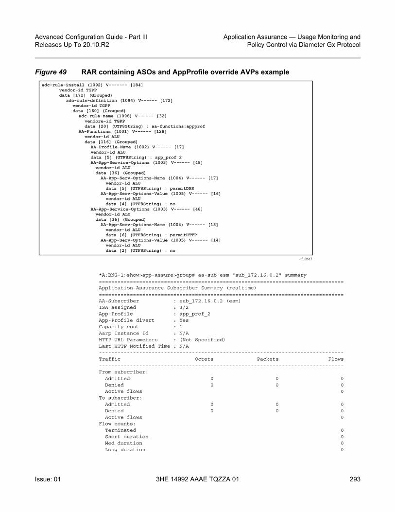
Advanced Configuration Guide - Part III Releases Up To 20.10.R2
Application Assurance — Usage Monitoring andPolicy Control via Diameter Gx Protocol
Issue: 01 3HE 14992 AAAE TQZZA 01 293
Figure 49 RAR containing ASOs and AppProfile override AVPs example
*A:BNG-1>show>app-assure>group# aa-sub esm "sub_172.16.0.2" summary===============================================================================Application-Assurance Subscriber Summary (realtime)===============================================================================AA-Subscriber : sub_172.16.0.2 (esm)ISA assigned : 3/2App-Profile : app_prof_2App-Profile divert : YesCapacity cost : 1Aarp Instance Id : N/AHTTP URL Parameters : (Not Specified)Last HTTP Notified Time : N/A-------------------------------------------------------------------------------Traffic Octets Packets Flows-------------------------------------------------------------------------------From subscriber:
Admitted 0 0 0Denied 0 0 0Active flows 0
To subscriber:Admitted 0 0 0Denied 0 0 0Active flows 0
Flow counts:Terminated 0Short duration 0Med duration 0Long duration 0
al_0661
adc-rule-install (1092) V------- [184] vendor-id TGPP data [172] (Grouped) adc-rule-definition (1094) V------ [172] vendor-id TGPP data [160] (Grouped) adc-rule-name (1096) V------ [32] vendore-id TGPP data [20] (UTF8String) : aa-functions:appprof AA-Functions (1001) V------ [128] vendor-id ALU data [116] (Grouped) AA-Profile-Name (1002) V------ [17] vendor-id ALU data [5] (UTF8String) : app_prof 2 AA-App-Service-Options (1003) V------ [48] vendor-id ALU data [36] (Grouped) AA-App-Serv-Options-Name (1004) V------ [17] vendor-id ALU data [5] (UTF8String) : permitDNS AA-App-Serv-Options-Value (1005) V------ [16] vendor-id ALU data [4] (UTF8String) : no AA-App-Service-Options (1003) V------ [48] vendor-id ALU data [36] (Grouped) AA-App-Serv-Options-Name (1004) V------ [18] vendor-id ALU data [6] (UTF8String) : permitHTTP AA-App-Serv-Options-Value (1005) V------ [14] vendor-id ALU data [2] (UTF8String) : no

Application Assurance — Usage Monitoring and Policy Control via Diameter Gx Protocol
294
Advanced Configuration Guide - Part IIIReleases Up To 20.10.R2
3HE 14992 AAAE TQZZA 01 Issue: 01
Total flow duration : 0 seconds
-------------------------------------------------------------------------------Top App-Groups Octets Packets Flows-------------------------------------------------------------------------------None
-------------------------------------------------------------------------------Application Service Options (ASO)-------------------------------------------------------------------------------Characteristic Value Derived from-------------------------------------------------------------------------------permitDNS no dyn-overridepermitRDP yes defaultpermitHTTP no dyn-override===============================================================================
Step 4. Configuring AA usage monitoring
Once the applications, application groups and/or charging groups are defined and configured (see previous steps), the operator needs:
• to enable the collection of per-subscriber statistics so they can be used for Gx based usage-monitoring. This step is not needed for any app/appgrp or charging group that is already enabled for per-subscriber statistics. In other words, if XML or RADIUS accounting is enabled for a given app/appgrp or charging group, then Gx usage-monitoring is also automatically enabled.
• to enable usage-monitoring for the given AA group:partition.configure
application-assurancegroup 129:34883
statisticsaa-sub
usage-monitoringapp-group "Unknown" export-using accounting-policy
radius-accounting-policycharging-group "0_rated" export-using accounting-policy
radius-accounting-policycharging-group "default_charge_group" export-using
accounting-policyradius-accounting-policyapplication "BitTorrent" no-export
exit
In the preceding example:
• The usage-monitoring command is used to enable Gx usage monitoring for the specified AA partition.
• The aa-group and charging-group commands specify which charging groups and AA groups are selected for export. In this case 0-rated, Unknown, and default-charging-group are selected for RADIUS accounting and they automatically qualify for Gx-usage monitoring.

Advanced Configuration Guide - Part III Releases Up To 20.10.R2
Application Assurance — Usage Monitoring andPolicy Control via Diameter Gx Protocol
Issue: 01 3HE 14992 AAAE TQZZA 01 295
• The BitTorrent application however needs to be explicitly configured as “no-export” as it needs to be enabled for Gx-usage monitoring.
The operator can display the number of usage monitoring rules for a given subscriber. This is shown below after the ESM subscriber is created, but before any ADC rules are installed for usage-monitoring by PCRF, so AA reports that no rules apply (“0”).
*A:BNG-1>show>app-assure>group# aa-sub esm "alcatel_A_1" usage-monitor status===============================================================================Application-Assurance Subscriber "alcatel_A_1" (esm)Usage Monitor Status===============================================================================Type Name Oper Status--------------------------------------------------------------------------------------------------------------------------------------------------------------No. of rules: 0===============================================================================*A:BNG-1>show>app-assure>group#
The PCRF then sends a RAR message with a usage monitoring ADC or PCC rule for the BitTorrent application to set the usage thresholds for BitTorrent for the ESM subscriber “alcatel_A_1” to (in bytes):
Input (from sub) 1378168
Output (to sub) 1381148
Total traffic (up and down) 18446744073709551614

Application Assurance — Usage Monitoring and Policy Control via Diameter Gx Protocol
296
Advanced Configuration Guide - Part IIIReleases Up To 20.10.R2
3HE 14992 AAAE TQZZA 01 Issue: 01
Figure 50 RAR containing usage monitoring ADC rules example
This is then reflected on the AA-ISA:
*A:BNG-1>show>app-assure>group# aa-sub esm "alcatel_A_1" usage-monitor status===============================================================================Application-Assurance Subscriber "alcatel_A_1" (esm)Usage Monitor Status===============================================================================Type Name Oper Status-------------------------------------------------------------------------------application BitTorrent active-------------------------------------------------------------------------------No. of rules: 1===============================================================================*A:BNG-1>show>app-assure>group#
Note the “active” oper status is set since there is at least one usage monitoring threshold associated with this application.
Given that there is no traffic flowing yet to or from the subscriber the counters currently are “0”:
al_0662
usage-monitoring-information (1067) V------- [80] vendor-id TGPP data [68] (Grouped) monitoring-key (1066) V------ [25] vendor-id TGPP data [13] (UTF8String) : torrentmonkey granted-service-units (431) ------- [24] data [16] (Grouped) cc-input-octets (412) ------ [16] data [8] (Unsigned64) : 1378168 cc-output-octets (414) ------ [16] data [8] (Unsigned64) : 1378168 cc-total-octets (421) ------ [16] data [8] (Unsigned64) : 18446744073709551614 monitoring-key (1068) V------ [16] vendor-id TGPP data [4] (Enumerated) : 2 : ADC RULE LEVEL
adc-rule-install (1092) V------- [96] vendor-id TGPP data [84] (Grouped) adc-rule-definition (1094) V------ [84] vendor-id TGPP data [72] (Grouped) adc-rule-name (1096) V------ [20] vendore-id TGPP data [8] (UTF8String) whatever tdf-application-id (1088) V------[22] vendor-id ALU data [10] (UTF8String) : BitTorrent monitoring-key (1066) V------ [25] vendor-id TGPP data [13] (UTF8String) : torrentmonkey

Advanced Configuration Guide - Part III Releases Up To 20.10.R2
Application Assurance — Usage Monitoring andPolicy Control via Diameter Gx Protocol
Issue: 01 3HE 14992 AAAE TQZZA 01 297
*A:BNG-1>show>app-assure>group# aa-sub esm "alcatel_A_1" usage-monitor count===============================================================================Application-Assurance Subscriber "alcatel_A_1" (esm)Usage Monitor Credit Statistics===============================================================================Application: "BitTorrent"Direction Status Granted Used % Used-------------------------------------------------------------------------------to sub valid 1378168 0 0%from sub valid 1381148 0 0%both valid 18446744073709551614 0 0%===============================================================================*A:BNG-1>show>app-assure>group#
The status is set to “valid” since a threshold (or Grant) is received.
When, at a later stage, traffic starts flowing again usage-monitor subscriber statistics are updated as shown below.
*A:BNG-1>show>app-assure>group# aa-sub esm "alcatel_A_1" usage-monitor count===============================================================================Application-Assurance Subscriber "alcatel_A_1" (esm)Usage Monitor Credit Statistics===============================================================================Application: "BitTorrent"Direction Status Granted Used % Used-------------------------------------------------------------------------------to sub valid 1378168 137816 10%from sub valid 1381148 13781 1%both valid 18446744073709551614 151597 5%===============================================================================*A:BNG-1>show>app-assure>group#
The PCRF can also at the same time set ADC or PCC rules for other applications (such as the 0_rated and the default_charging_group charging groups).
In the following case, the PCRF installs an ADC usage monitoring rule for:
• Charging group: “0-rated”, but without usage thresholds• Charging group: “default_charge_group”, and sets only a threshold for “to sub”
traffic.
This results in having a usage policy for the “0-rated” charging group installed but this is not active since there are no grants associated with it:
*A:BNG-1>show>app-assure>group# aa-sub esm "alcatel_A_1" usage-monitor status===============================================================================Application-Assurance Subscriber "alcatel_A_1" (esm)Usage Monitor Status===============================================================================Type Name Oper Status-------------------------------------------------------------------------------

Application Assurance — Usage Monitoring and Policy Control via Diameter Gx Protocol
298
Advanced Configuration Guide - Part IIIReleases Up To 20.10.R2
3HE 14992 AAAE TQZZA 01 Issue: 01
application BitTorrent activecharging-group 0_rated inactivecharging-group default_charge_group active-------------------------------------------------------------------------------No. of rules: 3===============================================================================*A:BNG-1>show>app-assure>group#
Note that the “inactive” status for the “0-rated” charging group is due to no grants being received.
Moreover, detailed counters show:
*A:BNG-1>show>app-assure>group# aa-sub esm "alcatel_A_1" usage-monitor count===============================================================================Application-Assurance Subscriber "alcatel_A_1" (esm)Usage Monitor Credit Statistics===============================================================================Application: "BitTorrent"Direction Status Granted Used % Used-------------------------------------------------------------------------------to sub valid 1378168 137816 10%from sub valid 1381148 13781 1%both valid 18446744073709551614 151597 5%-------------------------------------------------------------------------------Charging-Group: "0_rated"Direction Status Granted Used % Used-------------------------------------------------------------------------------to sub invalid n/a 0 n/afrom sub invalid n/a 0 n/aboth invalid n/a 0 n/a-------------------------------------------------------------------------------Charging-Group: "default_charge_group"Direction Status Granted Used % Used-------------------------------------------------------------------------------to sub valid 1000000 1378084 100%from sub invalid n/a 1574 n/aboth invalid n/a 1379658 n/a===============================================================================*A:BNG-1>show>app-assure>group#
Again, the “invalid” status above reflects the fact that no grants have been received.
Conclusion
The introduction of the diameter (/Gx) control feature on the 7x50 BNG enables operators to consolidate policy management systems used in wire-line and wireless environments into a single system. This provides an increase in operational efficiency as mobile and fixed networks convergence gains more traction.

Advanced Configuration Guide - Part III Releases Up To 20.10.R2
Application Assurance — Usage Monitoring andPolicy Control via Diameter Gx Protocol
Issue: 01 3HE 14992 AAAE TQZZA 01 299
This example illustrates how policy control and usage monitoring of the 7x50 BNG Application Assurance services can be achieved over standard 3GPP Diameter Gx protocol.

Application Assurance — Usage Monitoring and Policy Control via Diameter Gx Protocol
300
Advanced Configuration Guide - Part IIIReleases Up To 20.10.R2
3HE 14992 AAAE TQZZA 01 Issue: 01

Advanced Configuration Guide - Part III Releases Up To 20.10.R2
Deterministic Large Scale NAT44
Issue: 01 3HE 14992 AAAE TQZZA 01 301
Deterministic Large Scale NAT44This chapter provides information about deterministic large scale NAT44 configurations.
Topics in this chapter include:
• Applicability• Overview• Configuration• Conclusion
Applicability
The information and configuration in this chapter was based on release 11.0.R3, and is updated to release 14.0.R4.
Overview
Deterministic Network Address Translation (NAT) is a mode of operation where mappings between the NAT subscriber and the outside IP address and port range are allocated at the time of configuration.
In deterministic NAT for Large Scale NAT IPv4-to-IPv4 (LSN44) subscribers, each LSN44 subscriber is permanently mapped to an outside IP address and a dedicated (deterministic) port-block based on a specific algorithm.
Logging is not needed in this case because the reverse mapping can be obtained using the reverse of the preceding algorithm.
A deterministic LSN44 subscriber can have only one deterministic port-block that can (optionally) be extended by one or multiple dynamic port-blocks in case all ports in deterministic port-block are exhausted.
In case an LSN44 subscriber has been assigned both deterministic and dynamic port blocks, logging for the dynamic port-block allocation/de-allocation is required.
A scalable logging solution for dynamic port-blocks is achievable using RADIUS or IPFIX.

Deterministic Large Scale NAT44
302
Advanced Configuration Guide - Part IIIReleases Up To 20.10.R2
3HE 14992 AAAE TQZZA 01 Issue: 01
Logging for dynamic port-blocks is out of the scope of this chapter.
Figure 51 Deterministic NAT Mapping
Algorithm
The deterministic NAT algorithm makes a predictable mapping between the (inside IP, routing instance) and the (outside IP, routing instance, deterministic port block).
The algorithm is revertive, meaning that a given (outside IP, routing instance, deterministic port block) will derive a given (inside IP, routing Instance).
The algorithm is loosely based on draft-donley-behave-deterministic-cgn-00.txt, which allows for the dynamic expansion of the port-blocks once the ports in the original deterministic port-block are exhausted.
IP1_x WKrange
PFrange
IP2_x WKrange
PFrange
IP3_x WKrange
PFrange
outside range x
OutsideIPs
DeterministicBlocks
(optional)Dynamic Blocks
0 1023 * 65,535
outside range y
Well knownPort range
Static portForwarding
range
IP1_y WKrange
PFrange
IP2_y WKrange
PFrange
Inside Prefix AIP1_AIP2_AIP3_A…
Inside Prefix BIP1_BIP2_BIP3_B…
26145

Advanced Configuration Guide - Part III Releases Up To 20.10.R2
Deterministic Large Scale NAT44
Issue: 01 3HE 14992 AAAE TQZZA 01 303
Figure 52 Deterministic NAT Algorithm
Deterministic Mapping
Any inside prefix in any routing instance can be mapped to any pool in any routing instance.
In deterministic NAT, prefixes from multiple routing instances can be mapped to the same outside pool, also prefixes from a single inside routing instance can be selectively mapped to different outside pools.
26146
(Outside IP, Routing Instance, Deterministic Port Block) Fwd mappingInverse mapping
(Inside IP, Routing Instance) Deterministic NAT Algorithm
1 2
3

Deterministic Large Scale NAT44
304
Advanced Configuration Guide - Part IIIReleases Up To 20.10.R2
3HE 14992 AAAE TQZZA 01 Issue: 01
Figure 53 Deterministic Mapping: Inside -> Outside Routing Instances
Mapping Rules
A deterministic LSN44 subscriber is mapped to only one deterministic block which can further be extended to multiple dynamic blocks if ports within the deterministic block are exhausted.
The subscriber-limit is the number of subscribers that can be deterministically mapped to one outside IP address (i.e. compression ratio) and must be a power of 2.
The total number of deterministic ports (DetP) per outside IP address is determined by this subscriber-limit and the number of deterministic ports per subscriber.
The remaining ports (DynP) beyond the deterministic port range up to 65535 will be dedicated for dynamic use when a deterministic block is exhausted.
Base Router*
VPRN-O*
26147
VPRN-I*
Base Router*
Pool-a
Pool-b
Pool-c
Pool-d
Prefix-a
Prefix-b
Prefix-f
Prefix-g
Prefix-c
Prefix-d
Prefix-e
Deterministic NATInside Outside
*Routing-Based NAT cannot be used if inside/outside routing instances are the same

Advanced Configuration Guide - Part III Releases Up To 20.10.R2
Deterministic Large Scale NAT44
Issue: 01 3HE 14992 AAAE TQZZA 01 305
Every host using an inside prefix is guaranteed one dedicate block in the deterministic port ranges.
If the inside prefix length is m < 32-n, where 2^n=subscriber-limit, then the prefix must be broken into pieces so that all hosts (subscriber-limit) in each piece maps exactly to one outside IP address.
For example, if there is an inside prefix 192.168.0.0/23, with m=23 and a maximum number of 256 hosts; and the subscriber-limit set to 256, then n=8. This results in 23 < 24 (32-8) and so this inside prefix has to be broken into 2 pieces, in other words, this inside prefix will fit into 2 outside IP addresses, each of 256 port-blocks.
In case that the prefix length is m ≥ 32-n, where 2^n=subscriber-limit, then all hosts from the configured prefix are mapped to the same outside IP.
For example, if there is an inside prefix 192.168.1.0/25, with m=25 and a maximum number of 128 hosts, and the subscriber-limit set to 256, then n=8. This results in 25 > 24 (32-8), so definitely 128 hosts can fit in one outside IP because there are 256 available port-blocks, in other words, this inside prefix will fit into one outside IP where 128 blocks have been used out of the 256 port-blocks available, and the rest (256-128) are wasted.
Overbooking of the outside address pool is not supported in deterministic NAT.
Figure 54 Deterministic Mapping: Outside IP Port-Blocks/Ranges
WK portrange
PF portrangeOutside IP
DetP DynP
Deterministic Port Ranges
Dynamic Port Ranges
0 1023 * 65,535
26148
Legend:
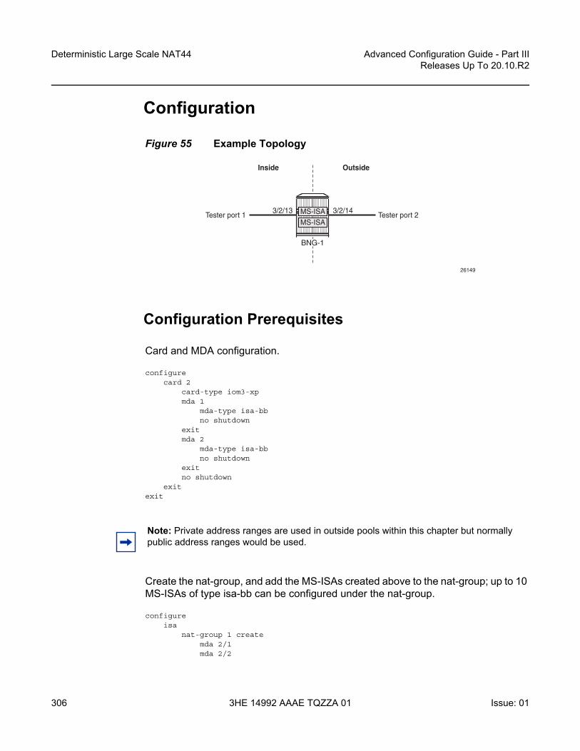
Deterministic Large Scale NAT44
306
Advanced Configuration Guide - Part IIIReleases Up To 20.10.R2
3HE 14992 AAAE TQZZA 01 Issue: 01
Configuration
Figure 55 Example Topology
Configuration Prerequisites
Card and MDA configuration.
configurecard 2
card-type iom3-xpmda 1
mda-type isa-bbno shutdown
exitmda 2
mda-type isa-bbno shutdown
exitno shutdown
exitexit
Create the nat-group, and add the MS-ISAs created above to the nat-group; up to 10 MS-ISAs of type isa-bb can be configured under the nat-group.
configureisa
nat-group 1 createmda 2/1mda 2/2
26149
Tester port 1 Tester port 2
Inside Outside
3/2/13 3/2/14
BNG-1
MS-ISAMS-ISA
Note: Private address ranges are used in outside pools within this chapter but normally public address ranges would be used.

Advanced Configuration Guide - Part III Releases Up To 20.10.R2
Deterministic Large Scale NAT44
Issue: 01 3HE 14992 AAAE TQZZA 01 307
active-mda-limit 1no shutdown
exitexit
exit
Configuration Commands
A NAT outside pool is configured using the following command:
configure {router | service vprn <service-id>}nat
outsidepool <nat-pool-name> [nat-group <nat-group-id> type <pool-type> create]
port-reservation {blocks <num-blocks> | ports <num-ports>}port-forwarding-range <range-end>subscriber-limit <subscriber-limit>deterministicport-reservation <det-num-ports>
exitaddress-range <start-ip-address> <end-ip-address> create
exitexit
exitexit
where:
nat-pool-name — Specifies the name of the NAT pool up to 32 characters max.
nat-group-id — Specifies the NAT group ID. The values are 1 — 4.
pool-type — Species the pool type (large-scale).
num-blocks — Specifies the number of dynamic port-blocks per outside IP address. The values are 1 — 64512
num-ports — Specifies the number of ports per dynamic block. The values are 1 — 32256
range-end — Specifies the upper limit of the port range available for static port forwarding. The values are 1023 — 65535
subscriber-limit — Specifies the maximum number of subscribers per outside IP address. A power of 2 (2^n) number for deterministic NAT[1,2,4,8,16,32,64,128,256,512,1024,2048, 4096, 8192,16348, 32768]1..65535 for non-deterministic NATdefault: 65535 for non-deterministic

Deterministic Large Scale NAT44
308
Advanced Configuration Guide - Part IIIReleases Up To 20.10.R2
3HE 14992 AAAE TQZZA 01 Issue: 01
det-num-ports — Specifies the number of ports in a deterministic port block that is allocated and dedicated to a single subscriber during the configuration phase. The values are 1..65535
start-ip-address — Specifies the first outside IP address in the a.b.c.d format.
end-ip-address — Specifies the last outside IP address in the a.b.c.d format.
A NAT policy is configured using the following command:
configure service natnat-policy <nat-policy-name> [create]
block-limit <[1..40]>pool <nat-pool-name> {router <router-instance> | service-name <service-name>}
exit
where:
nat-policy-name — Specifies the NAT policy name up to 32 characters max.
block-limit —The maximum number of deterministic plus dynamic port blocks that can be assigned to a single inside IP address. In other words, the maximum number of dynamic port blocks that can be assigned to an inside IP address when the deterministic port block is exhausted equals (block-limit - 1).
nat-pool-name — Specifies the NAT pool name up to 32 characters max.
service-name — Specifies the name of the service up to 64 characters max.
A NAT inside prefix is configured using the following command:
configure [router| service vprn <service-id>]nat
insideclassic-lsn-max-subscriber-limit <max>deterministic
Note:
• When the subscriber-limit equals 1, each subscriber is mapped to a single outside IP address, though the NAPT (port translation) function is still performed.
• 1:1 NAT mode in combination with deterministic NAT is not supported.
router-instance — Specifies the router instance the pool belongs to, either by router name or service ID.
<router-name>|<service-id>The router name values are Base or service-id [1..2147483647]

Advanced Configuration Guide - Part III Releases Up To 20.10.R2
Deterministic Large Scale NAT44
Issue: 01 3HE 14992 AAAE TQZZA 01 309
prefix <ip-prefix/length> subscriber-type <nat-sub-type>nat-policy <nat-policy-name> create
map start <lsn-sub-address> end <lsn-sub-address> to <outside-ip-address>no shutdownexit
exitexit
exit
where:
max — The power of 2 (2^n) number that must match the largest subscriber limit number in a deterministic pool referenced from this inside routing instance. The range for this command is the same as the subscriber-limit command under the pool hierarchy. The values are 1,2,4,8 — 32768
ip-prefix/length — A prefix on the inside encompassing subscribers that will be deterministically mapped to an outside IP address and port block in the corresponding pool.
Following rules apply to the classic-lsn-max-subscriber-limit:
• Should be greater than or equal to the largest subscriber-limit of all pools referenced by the NAT policies within the corresponding inside routing instance.
• Must be configured before any inside prefix configuration.• Must be 2^n and affects the ingress hashing of deterministic subscribers and
also non-deterministic subscribers in case both are configured under the same inside router instance.
Three cases are now configured to demonstrate the use of deterministic and dynamic port-block usage:
<ip-prefix/ip-pref*> <ipv4-prefix>/<ipv4-prefix-length> |<ipv6-prefix>/<ipv6-prefix-length>
<ipv4-prefix> a.b.c.d (host bits must be 0)<ipv4-prefix-length> [0..32]<ipv6-prefix> x:x:x:x:x:x:x:x (eight 16-bit pieces)
x:x:x:x:x:x:d.d.d.dx - [0..FFFF]Hd - [0..255]D
<ipv6-prefix-length> [0..128]<nat-sub-type>: classic-lsn-sub<nat-policy-name> Specifies a NAT policy name up to 32 characters in length.

Deterministic Large Scale NAT44
310
Advanced Configuration Guide - Part IIIReleases Up To 20.10.R2
3HE 14992 AAAE TQZZA 01 Issue: 01
• Case 1: Mapping multiple prefixes from the same VRF (VPRN 15001) into the same outside pool, routing instance “Base”.
• Case 2: Mapping multiple prefixes from the same VRF (VPRN 15001) into different outside pools, routing instance VPRN 15002
• Case 3: Mapping overlapping prefixes from different VRFs (VPRN 15001 and VPRN 15002) into the same outside pool, routing instance “Base”.
In each case all of the traffic is NATed.
Case 1
Configured with:
• Mapping multiple prefixes of the same VRF into the same outside pool.• NAT all traffic.
Figure 56 Case 1
The NAT outside pool is configured as follows:
configurerouter
natoutside
pool "nat-pool-1" nat-group 1 type large-scale createport-reservation ports 180port-forwarding-range 4023subscriber-limit 128deterministic
port-reservation 300exitaddress-range 192.168.0.1 192.168.0.100 createexitno shutdown
Base Router
26150
VPRN-15001
nat-pool-110.0.0.0/24
10.10.4.0/22
Deterministic NATInside Outside

Advanced Configuration Guide - Part III Releases Up To 20.10.R2
Deterministic Large Scale NAT44
Issue: 01 3HE 14992 AAAE TQZZA 01 311
exitexit
exitexit
exit
The NAT policy is configured as follows:
configureservice
natnat-policy "nat-policy-1" create
block-limit 4pool "nat-pool-1" router Base
exitexit
exitexit
The NAT inside prefix is configured as follows:
configureservice
vprn 15001 customer 1 createnat
insidedestination-prefix 0.0.0.0/0classic-lsn-max-subscriber-limit 256deterministic
prefix 10.0.0.0/24 subscriber-type classic-lsn-subnat-policy "nat-policy-1" create
map start 10.0.0.0 end 10.0.0.255 to 192.168.0.1no shutdown
exit
prefix 10.10.4.0/22 subscriber-type classic-lsn-subnat-policy "nat-policy-1" create
map start 10.10.4.0 end 10.10.7.255 to 192.168.0.3no shutdown
exitexit
exitexitno shutdown
exitexit
exit
map statements are automatically created when the prefix is created and it is no shutdown.

Deterministic Large Scale NAT44
312
Advanced Configuration Guide - Part IIIReleases Up To 20.10.R2
3HE 14992 AAAE TQZZA 01 Issue: 01
Show Commands
The subscriber-limit is set to 128 for the 10.0.0.0/24 prefix, so it is broken into two smaller /25 prefixes each. Each of these smaller prefixes are mapped into a specific outside IP address.
To show the first Large Scale NAT (LSN) subscriber of the first /25 prefix for inside routing instance 15001, the following command can be used:
*A:PE1# show service nat lsn-subscribers inside-router 15001 inside-ip 10.0.0.0
===============================================================================NAT LSN subscribers===============================================================================Subscriber : [[email protected]]NAT policy : nat-policy-1Subscriber ID : 276824064-------------------------------------------------------------------------------Type : classic-lsn-subInside router : 15001Inside IP address prefix : 10.0.0.0/32ISA NAT group : 1ISA NAT group member : 1Outside router : "Base"Outside IP address : 192.168.0.1
-------------------------------------------------------------------------------No. of LSN subscriber instances: 1===============================================================================*A:PE1#
The last subscriber mapping to the same 192.168.0.1 outside IP address has inside address 10.0.0.127.

Advanced Configuration Guide - Part III Releases Up To 20.10.R2
Deterministic Large Scale NAT44
Issue: 01 3HE 14992 AAAE TQZZA 01 313
To show the first LSN subscriber of the second /25 prefix for inside routing instance 15001, the following command can be used:
*A:PE1# show service nat lsn-subscribers inside-router 15001 inside-ip 10.0.0.128
===============================================================================NAT LSN subscribers===============================================================================Subscriber : [[email protected]]NAT policy : nat-policy-1Subscriber ID : 276824192-------------------------------------------------------------------------------Type : classic-lsn-subInside router : 15001Inside IP address prefix : 10.0.0.128/32ISA NAT group : 1ISA NAT group member : 1Outside router : "Base"Outside IP address : 192.168.0.2
-------------------------------------------------------------------------------No. of LSN subscriber instances: 1===============================================================================*A:PE1#
The last subscriber mapping to the same 192.168.0.2 outside IP address has inside address 10.0.0.255.
To show the base router LSN blocks corresponding to the first inside IP address within the 10.0.0.0/24 prefix, the following command can be used:
*A:PE1# show router nat lsn-blocks inside-ip 10.0.0.0
===============================================================================Large-Scale NAT blocks for Base===============================================================================192.168.0.1 [4024..4323]Pool : nat-pool-1Policy : nat-policy-1Started : 2016/10/27 11:18:59Inside router : vprn15001Inside IP address : 10.0.0.0
-------------------------------------------------------------------------------Number of blocks: 1===============================================================================*A:PE1#
To show the base router LSN blocks corresponding to the last inside IP address within the 10.0.0.0/24 prefix, the following command can be used:
*A:PE1# show router nat lsn-blocks inside-ip 10.0.0.255
===============================================================================Large-Scale NAT blocks for Base

Deterministic Large Scale NAT44
314
Advanced Configuration Guide - Part IIIReleases Up To 20.10.R2
3HE 14992 AAAE TQZZA 01 Issue: 01
===============================================================================192.168.0.2 [42124..42423]Pool : nat-pool-1Policy : nat-policy-1Started : 2016/10/27 11:18:59Inside router : vprn15001Inside IP address : 10.0.0.255
-------------------------------------------------------------------------------Number of blocks: 1===============================================================================*A:PE1#
The subscriber-limit is 128 for the 10.10.4.0/22 prefix, so it is broken into eight /25 prefixes. Each of these smaller prefixes are mapped into a specific outside IP address.
To show the first LSN subscriber of the first /25 prefix for inside routing instance 15001, the following command can be used:
*A:PE1# show service nat lsn-subscribers inside-ip 10.10.4.0
===============================================================================NAT LSN subscribers===============================================================================Subscriber : [[email protected]]NAT policy : nat-policy-1Subscriber ID : 276824320-------------------------------------------------------------------------------Type : classic-lsn-subInside router : 15001Inside IP address prefix : 10.10.4.0/32ISA NAT group : 1ISA NAT group member : 1Outside router : "Base"Outside IP address : 192.168.0.3
-------------------------------------------------------------------------------No. of LSN subscriber instances: 1===============================================================================*A:PE1#
The last subscriber mapping to the same 192.168.0.3 outside IP address has inside address 10.10.4.127.
To show the first LSN subscriber of the last /25 prefix for inside routing instance 15001, the following command can be used:
*A:PE1# show service nat lsn-subscribers inside-ip 10.10.7.128
===============================================================================NAT LSN subscribers===============================================================================Subscriber : [[email protected]]NAT policy : nat-policy-1

Advanced Configuration Guide - Part III Releases Up To 20.10.R2
Deterministic Large Scale NAT44
Issue: 01 3HE 14992 AAAE TQZZA 01 315
Subscriber ID : 276825216-------------------------------------------------------------------------------Type : classic-lsn-subInside router : 15001Inside IP address prefix : 10.10.7.128/32ISA NAT group : 1ISA NAT group member : 1Outside router : "Base"Outside IP address : 192.168.0.10
-------------------------------------------------------------------------------No. of LSN subscriber instances: 1===============================================================================*A:PE1#
To show the base router LSN blocks corresponding to the first inside IP within 10.10.4.0/24 prefix, the following command can be used:
*A:PE1# show router nat lsn-blocks inside-ip 10.10.4.0
===============================================================================Large-Scale NAT blocks for Base===============================================================================192.168.0.3 [4024..4323]Pool : nat-pool-1Policy : nat-policy-1Started : 2016/10/27 11:18:59Inside router : vprn15001Inside IP address : 10.10.4.0
-------------------------------------------------------------------------------Number of blocks: 1===============================================================================*A:PE1#
To show the base router LSN blocks corresponding to the last inside IP within 10.10.4.0/24 prefix, the following command can be used:
*A:PE1# show router nat lsn-blocks inside-ip 10.10.7.255
===============================================================================Large-Scale NAT blocks for Base===============================================================================192.168.0.10 [42124..42423]Pool : nat-pool-1Policy : nat-policy-1Started : 2016/10/27 11:18:59Inside router : vprn15001Inside IP address : 10.10.7.255
-------------------------------------------------------------------------------Number of blocks: 1===============================================================================*A:PE1#

Deterministic Large Scale NAT44
316
Advanced Configuration Guide - Part IIIReleases Up To 20.10.R2
3HE 14992 AAAE TQZZA 01 Issue: 01
Mapping Results
According to this configuration, each inside IP address has one deterministic block of 300 ports and can have up to three dynamic blocks (block-limit = 4) each of 180 ports, allowing a maximum of 300+3*180 = 840 flows.
Figure 57 Case 1 Results
Sending Flows
For the inside IP 10.0.0.1, several UDP flows will be sent and both the deterministic and dynamic blocks mappings will be verified.
Figure 58 Case 1 Flows
Deterministic Port ranges Dynamic Port ranges
0
192.168.0.1
192.168.0.2
192.168.0.3
192.168.0.4
192.168.0.10
192.168.0.100
1023 4023 42,423 65,535
26148
WKWKrangerange
PFPFrangerange
WKrange
PFrange
WKrange
PFrange
WKrange
PFrange
WKrange
PFrange
WKrange
PFrange
WKrange
PFrange 300 300 300 300 180 180 180 180 180 180
Inside Range10.0.0.0/24:
10.0.0.0/2510.0.0.128/25
10.10.7.128/25
Inside Range10.10.4.0/22:
10.10.4.0/2510.10.4.128/25
128 Det portBlocks Per Outside IP
26151
26152
UDP flowsSRC-IP: 10.0.0.1
SRC-Port: 32000-32xxx
BNG-1
VPRN15001

Advanced Configuration Guide - Part III Releases Up To 20.10.R2
Deterministic Large Scale NAT44
Issue: 01 3HE 14992 AAAE TQZZA 01 317
When sending 300 UDP flows or less, all flows are mapped to a single deterministic block because the number of ports in a deterministic block is 300. There is no logging; because no dynamic blocks are used, only the deterministic block is used.
To show LSN blocks on the outside routing instance Base and the outside ports allocated for the inside IP 10.0.0.1, the following command can be used:
*A:PE1# show router nat lsn-blocks inside-ip 10.0.0.1
===============================================================================Large-Scale NAT blocks for Base===============================================================================192.168.0.1 [4324..4623]Pool : nat-pool-1Policy : nat-policy-1Started : 2016/10/27 11:18:59Inside router : vprn15001Inside IP address : 10.0.0.1
-------------------------------------------------------------------------------Number of blocks: 1===============================================================================*A:PE1#
When increasing the number of flows such that: 301 ≤ number of flows ≤ 480
• In addition to the deterministic block (300 ports), there will be an extension by 1 dynamic block of 180 ports (port-reservation=180).
• Logging occurs for the dynamic port-block.
To show the base router LSN blocks and the outside ports allocated to the inside IP address 10.0.0.1, the following command can be used:
*A:PE1# show router nat lsn-blocks inside-ip 10.0.0.1
===============================================================================Large-Scale NAT blocks for Base===============================================================================192.168.0.1 [4324..4623]Pool : nat-pool-1Policy : nat-policy-1Started : 2016/10/27 11:18:59Inside router : vprn15001Inside IP address : 10.0.0.1
192.168.0.1 [44044..44223]Pool : nat-pool-1Policy : nat-policy-1Started : 2016/10/28 12:40:41Inside router : vprn15001Inside IP address : 10.0.0.1
-------------------------------------------------------------------------------Number of blocks: 2

Deterministic Large Scale NAT44
318
Advanced Configuration Guide - Part IIIReleases Up To 20.10.R2
3HE 14992 AAAE TQZZA 01 Issue: 01
===============================================================================*A:PE1#
Logging is verified using Log 99 (in case event-control nat events are generated) which shows the mapping details to the new dynamic block as follows:
2 2016/10/28 12:40:41.51 UTC MINOR: NAT #2012 Base NAT"{12} Map 192.168.0.1 [44044-44223] MDA 2/1 -- 276824065 classic-lsn-sub %1 vprn15001 10.0.0.1 at 2016/10/28 12:40:41"
When increasing the number of flows such that: 481 ≤ number of flows ≤ 660
• In addition to the deterministic block (300 ports), there will be an extension by 2 dynamic blocks of 180 ports each.
• Logging occurs for the dynamic port-blocks.
To show LSN blocks on the outside routing instance Base and the outside ports allocated for the inside IP 10.0.0.1, the following command is used:
*A:PE1# show router nat lsn-blocks inside-ip 10.0.0.1
===============================================================================Large-Scale NAT blocks for Base===============================================================================192.168.0.1 [4324..4623]Pool : nat-pool-1Policy : nat-policy-1Started : 2016/10/27 11:18:59Inside router : vprn15001Inside IP address : 10.0.0.1
192.168.0.1 [44044..44223]Pool : nat-pool-1Policy : nat-policy-1Started : 2016/10/28 12:40:41Inside router : vprn15001Inside IP address : 10.0.0.1
192.168.0.1 [44224..44403]Pool : nat-pool-1Policy : nat-policy-1Started : 2016/10/28 12:41:52Inside router : vprn15001Inside IP address : 10.0.0.1
-------------------------------------------------------------------------------Number of blocks: 3===============================================================================*A:PE1#
Logging is verified using Log 99 (in case event-control nat events are generated) which shows the mapping details to the new dynamic block as follows:
3 2016/10/28 12:41:52.66 UTC MINOR: NAT #2012 Base NAT

Advanced Configuration Guide - Part III Releases Up To 20.10.R2
Deterministic Large Scale NAT44
Issue: 01 3HE 14992 AAAE TQZZA 01 319
"{13} Map 192.168.0.1 [44224-44403] MDA 2/1 -- 276824065 classic-lsn-sub %1 vprn15001 10.0.0.1 at 2016/10/28 12:41:52"
When increasing the number of flows such that :661 ≤ number of flows ≤ 840
• In addition to the deterministic block (300 ports), there will be an extension by 3 dynamic blocks of 180 ports each.
• Logging occurs for the dynamic port-blocks.
To show LSN blocks on the outside routing instance “Base” and the outside ports allocated for the inside IP 10.0.0.1, the following command can be used:
*A:PE1# show router nat lsn-blocks inside-ip 10.0.0.1
===============================================================================Large-Scale NAT blocks for Base===============================================================================192.168.0.1 [4324..4623]Pool : nat-pool-1Policy : nat-policy-1Started : 2016/10/27 11:18:59Inside router : vprn15001Inside IP address : 10.0.0.1
192.168.0.1 [44044..44223]Pool : nat-pool-1Policy : nat-policy-1Started : 2016/10/28 12:40:41Inside router : vprn15001Inside IP address : 10.0.0.1
192.168.0.1 [44224..44403]Pool : nat-pool-1Policy : nat-policy-1Started : 2016/10/28 12:41:52Inside router : vprn15001Inside IP address : 10.0.0.1
192.168.0.1 [44404..44583]Pool : nat-pool-1Policy : nat-policy-1Started : 2016/10/28 12:43:46Inside router : vprn15001Inside IP address : 10.0.0.1
-------------------------------------------------------------------------------Number of blocks: 4===============================================================================*A:PE1#
Logging is verified using Log 99 (in case event-control nat events are generated) which shows the mapping details to the new dynamic block as follows:
4 2016/10/28 12:43:46.71 UTC MINOR: NAT #2012 Base NAT"{14} Map 192.168.0.1 [44404-44583] MDA 2/1 -- 276824065 classic-lsn-

Deterministic Large Scale NAT44
320
Advanced Configuration Guide - Part IIIReleases Up To 20.10.R2
3HE 14992 AAAE TQZZA 01 Issue: 01
sub %1 vprn15001 10.0.0.1 at 2016/10/28 12:43:46"
When increasing number of flows such that the number of flows > 840
• No more extension by dynamic blocks (block-limit = 4) allowed.• Any flows more than 840 will be dropped and the relevant NAT statistics
incremented.
To verify NAT statistics, first check the NAT group/member and MS-ISA associated with the outside IP 192.168.0.1/32:
*A:PE1# show router route-table 192.168.0.1/32
===============================================================================Route Table (Router: Base)===============================================================================Dest Prefix[Flags] Type Proto Age Pref
Next Hop[Interface Name] Metric-------------------------------------------------------------------------------192.168.0.1/32 Remote NAT 01d01h26m 0
NAT outside to mda 2/1 0-------------------------------------------------------------------------------No. of Routes: 1Flags: n = Number of times nexthop is repeated
B = BGP backup route availableL = LFA nexthop availableS = Sticky ECMP requested
===============================================================================*A:PE1#
To check which group/member does this MS-ISA belong to, the following command can be used:
*A:PE1# show isa nat-group 1 members
===============================================================================ISA Group 1 members===============================================================================Group Member State Mda Addresses Blocks Se-% Hi Se-Prio-------------------------------------------------------------------------------1 1 active 2/1 175 23648 < 1 N 0-------------------------------------------------------------------------------No. of members: 1===============================================================================*A:PE1#
To verify relevant statistics for this NAT group/member, the following command can be used:
*A:PE1# show isa nat-group 1 member 1 statistics | match flowno matching flow : 56818max flow exceeded : 0TCP no flow for RST : 0TCP no flow for FIN : 0

Advanced Configuration Guide - Part III Releases Up To 20.10.R2
Deterministic Large Scale NAT44
Issue: 01 3HE 14992 AAAE TQZZA 01 321
TCP no flow : 128094flow log failed : 0new flow : 1470768found flow : 39661850flow create logged : 0flow delete logged : 0flow log pkt tx : 0flow create failed, key ambiguous : 0flow create failed, conflicting policies : 0*A:PE1#
Case 2
Configured with:
• Mapping multiple prefixes from the same VRF into different outside pools.• NAT all traffic.
Figure 59 Case 2
The NAT outside pools are configured as follows:
configureservice
vprn 15002 customer 1 createnat
outsidepool "nat-pool-2" nat-group 1 type large-scale create
port-reservation ports 80subscriber-limit 256deterministic
port-reservation 180exitaddress-range 192.168.2.1 192.168.2.200 createexitno shutdown
exit
VPRN-15002
26153
VPRN-15001
nat-pool-2
nat-pool-3
10.1.0.0/23
10.2.0.0/22
Deterministic NATInside Outside

Deterministic Large Scale NAT44
322
Advanced Configuration Guide - Part IIIReleases Up To 20.10.R2
3HE 14992 AAAE TQZZA 01 Issue: 01
pool "nat-pool-3" nat-group 1 type large-scale createport-reservation ports 120port-forwarding-range 4023subscriber-limit 64deterministic
port-reservation 840exitaddress-range 192.168.3.1 192.168.3.200 createexitno shutdown
exitexit
exitexit
exitexit
The NAT policies are configured as follows:
configureservice
natnat-policy "nat-policy-2" create
block-limit 4pool "nat-pool-2" router 15002
exitnat-policy "nat-policy-3" create
block-limit 2pool "nat-pool-3" router 15002
exitexit
exitexit
The NAT inside prefix is configured as follows:
configureservice
vprn 15001 customer 1 createnat
insidedestination-prefix 0.0.0.0/0classic-lsn-max-subscriber-limit 256deterministic
prefix 10.1.0.0/23 subscriber-type classic-lsn-subnat-policy "nat-policy-2" create
map start 10.1.0.0 end 10.1.1.255 to 192.168.2.1no shutdown
exitprefix 10.2.0.0/22 subscriber-type classic-lsn-sub
nat-policy "nat-policy-3" createmap start 10.2.0.0 end 10.2.3.255 to 192.168.3.1no shutdown
exitexit
exitexit
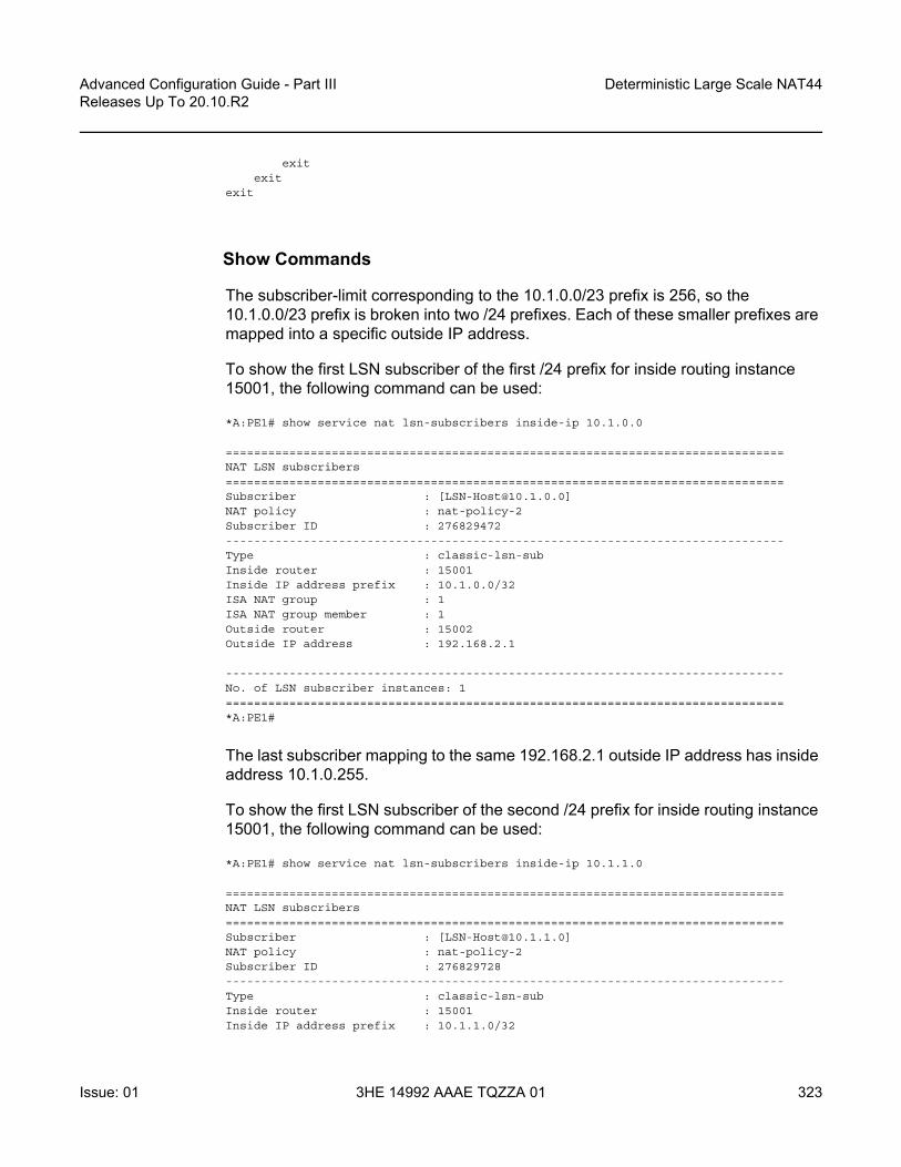
Advanced Configuration Guide - Part III Releases Up To 20.10.R2
Deterministic Large Scale NAT44
Issue: 01 3HE 14992 AAAE TQZZA 01 323
exitexit
exit
Show Commands
The subscriber-limit corresponding to the 10.1.0.0/23 prefix is 256, so the 10.1.0.0/23 prefix is broken into two /24 prefixes. Each of these smaller prefixes are mapped into a specific outside IP address.
To show the first LSN subscriber of the first /24 prefix for inside routing instance 15001, the following command can be used:
*A:PE1# show service nat lsn-subscribers inside-ip 10.1.0.0
===============================================================================NAT LSN subscribers===============================================================================Subscriber : [[email protected]]NAT policy : nat-policy-2Subscriber ID : 276829472-------------------------------------------------------------------------------Type : classic-lsn-subInside router : 15001Inside IP address prefix : 10.1.0.0/32ISA NAT group : 1ISA NAT group member : 1Outside router : 15002Outside IP address : 192.168.2.1
-------------------------------------------------------------------------------No. of LSN subscriber instances: 1===============================================================================*A:PE1#
The last subscriber mapping to the same 192.168.2.1 outside IP address has inside address 10.1.0.255.
To show the first LSN subscriber of the second /24 prefix for inside routing instance 15001, the following command can be used:
*A:PE1# show service nat lsn-subscribers inside-ip 10.1.1.0
===============================================================================NAT LSN subscribers===============================================================================Subscriber : [[email protected]]NAT policy : nat-policy-2Subscriber ID : 276829728-------------------------------------------------------------------------------Type : classic-lsn-subInside router : 15001Inside IP address prefix : 10.1.1.0/32

Deterministic Large Scale NAT44
324
Advanced Configuration Guide - Part IIIReleases Up To 20.10.R2
3HE 14992 AAAE TQZZA 01 Issue: 01
ISA NAT group : 1ISA NAT group member : 1Outside router : 15002Outside IP address : 192.168.2.2
-------------------------------------------------------------------------------No. of LSN subscriber instances: 1===============================================================================*A:PE1#
The last subscriber mapping to the same 192.168.2.2 outside IP address has inside address 10.1.1.255.
To show the VPRN-15002 LSN blocks corresponding to the first inside IP address within 10.1.0.0/23 prefix, the following command can be used:
*A:PE1# show router 15002 nat lsn-blocks inside-ip 10.1.0.0
===============================================================================Large-Scale NAT blocks for vprn15002===============================================================================192.168.2.1 [1024..1203]Pool : nat-pool-2Policy : nat-policy-2Started : 2016/10/28 12:53:23Inside router : vprn15001Inside IP address : 10.1.0.0
-------------------------------------------------------------------------------Number of blocks: 1===============================================================================*A:PE1#
To show the VPRN-15002 LSN blocks corresponding to the last inside IP address within 10.1.0.0/23 prefix, the following command can be used:
*A:PE1# show router 15002 nat lsn-blocks inside-ip 10.1.1.255
===============================================================================Large-Scale NAT blocks for vprn15002===============================================================================192.168.2.2 [46924..47103]Pool : nat-pool-2Policy : nat-policy-2Started : 2016/10/28 12:53:23Inside router : vprn15001Inside IP address : 10.1.1.255
-------------------------------------------------------------------------------Number of blocks: 1===============================================================================*A:PE1#

Advanced Configuration Guide - Part III Releases Up To 20.10.R2
Deterministic Large Scale NAT44
Issue: 01 3HE 14992 AAAE TQZZA 01 325
The subscriber-limit corresponding to the 10.2.0.0/22 prefix is 64,so the 10.2.0.0/22 prefix is broken into sixteen /26 prefixes. Each of these /26 prefixes is mapped to a specific outside IP address.
To show the first LSN subscriber for the inside routing instance 15001 for the first /26 prefix, the following command can be used:
*A:PE1# show service nat lsn-subscribers inside-ip 10.2.0.0
===============================================================================NAT LSN subscribers===============================================================================Subscriber : [[email protected]]NAT policy : nat-policy-3Subscriber ID : 276829984-------------------------------------------------------------------------------Type : classic-lsn-subInside router : 15001Inside IP address prefix : 10.2.0.0/32ISA NAT group : 1ISA NAT group member : 1Outside router : 15002Outside IP address : 192.168.3.1
-------------------------------------------------------------------------------No. of LSN subscriber instances: 1===============================================================================*A:PE1#
The last inside address mapping to the 192.168.3.1 outside address is 10.2.0.63.
To show the first LSN subscriber for the inside routing instance 15001 for the last /26 prefix, the following command can be used:
*A:PE1# show service nat lsn-subscribers inside-ip 10.2.3.192
===============================================================================NAT LSN subscribers===============================================================================Subscriber : [[email protected]]NAT policy : nat-policy-3Subscriber ID : 276830944-------------------------------------------------------------------------------Type : classic-lsn-subInside router : 15001Inside IP address prefix : 10.2.3.192/32ISA NAT group : 1ISA NAT group member : 1Outside router : 15002Outside IP address : 192.168.3.16
-------------------------------------------------------------------------------No. of LSN subscriber instances: 1===============================================================================*A:PE1#

Deterministic Large Scale NAT44
326
Advanced Configuration Guide - Part IIIReleases Up To 20.10.R2
3HE 14992 AAAE TQZZA 01 Issue: 01
The last inside address mapping to the 192.168.3.16 outside address is 10.2.3.255.
To show the VPRN-15002 LSN blocks corresponding to the first inside IP address within the 10.2.0.0/22 prefix, the following command can be used:
*A:PE1# show router 15002 nat lsn-blocks inside-ip 10.2.0.0
===============================================================================Large-Scale NAT blocks for vprn15002===============================================================================192.168.3.1 [4024..4863]Pool : nat-pool-3Policy : nat-policy-3Started : 2016/10/28 12:53:23Inside router : vprn15001Inside IP address : 10.2.0.0
-------------------------------------------------------------------------------Number of blocks: 1===============================================================================*A:PE1#
To show the VPRN-15002 LSN blocks corresponding to the last inside IP within 10.2.0.0/22 prefix, the following command can be used:
*A:PE1# show router 15002 nat lsn-blocks inside-ip 10.2.3.255
===============================================================================Large-Scale NAT blocks for vprn15002===============================================================================192.168.3.16 [56944..57783]Pool : nat-pool-3Policy : nat-policy-3Started : 2016/10/28 12:53:23Inside router : vprn15001Inside IP address : 10.2.3.255
-------------------------------------------------------------------------------Number of blocks: 1===============================================================================*A:PE1#
Mapping results
According to this configuration, for the 10.1.0.0/23 prefix, each inside IP address has one deterministic block of 180 ports and can have up to three dynamic blocks (block-limit =4) each of 80 ports, allowing for a maximum of 180+3*80 = 420 flows.

Advanced Configuration Guide - Part III Releases Up To 20.10.R2
Deterministic Large Scale NAT44
Issue: 01 3HE 14992 AAAE TQZZA 01 327
Figure 60 Case 2: Prefix 10.1.0.0/23 Results
According to this configuration, for the 10.2.0.0/22 prefix, each inside IP address has one deterministic block of 840 ports, and can have up to one dynamic block (block-limit =2) of 120 ports, allowing for a maximum of 840+120 = 960 flows.
Figure 61 Case 2: Prefix 10.2.0.0/22 Results
Deterministic Port ranges Dynamic Port ranges
0
192.168.2.1
192.168.2.2
192.168.2.3
192.168.2.4
192.168.2.200
1023 47,103 65,535
WKWKrangerangeWK
range
WKrange
WKrange
WKrange
WKrange 180 180 180 180 80 80 80 80 80 80
Inside Range10.1.0.0/23:
10.1.0.0/2410.1.1.0/24
256 Det portBlocks Per Outside IP
26154
Deterministic Port ranges Dynamic Port ranges
0
192.168.3.1
192.168.3.2
192.168.3.3
192.168.3.16
192.168.3.100
1023 4023 57,783 65,535
26148
WKWKrangerange
PFPFrangerange
WKrange
PFrange
WKrange
PFrange
WKrange
PFrange
WKrange
PFrange
WKrange
PFrange 840 840 840 840 120 120 120 120 120 120
Inside Range10.2.0.0/22:
10.2.0.0/2610.2.0.64/26
10.2.0.128/26
10.2.0.192/26
64 Det portBlocks Per Outside IP
26155

Deterministic Large Scale NAT44
328
Advanced Configuration Guide - Part IIIReleases Up To 20.10.R2
3HE 14992 AAAE TQZZA 01 Issue: 01
Case 3
Configured with:
• Mapping overlapping prefixes from different VRFs into the same outside pool.• NAT all traffic.
Figure 62 Case 3
The NAT outside pool is configured as follows:
configurerouter "Base"
natoutside
pool "nat-pool-4" nat-group 1 type large-scale createport-reservation ports 461port-forwarding-range 4023subscriber-limit 64deterministic
port-reservation 500exitaddress-range 192.168.4.1 192.168.4.100 createexitno shutdown
exitexit
exitexit
exit
The NAT policy is configured as follows:
configureservice
natnat-policy "nat-policy-4" create
Base Router
26156
VPRN-15001
nat-pool-4
10.5.0.0/20
VPRN-15001
Inside Outside
10.5.0.0.0/27
Deterministic NAT

Advanced Configuration Guide - Part III Releases Up To 20.10.R2
Deterministic Large Scale NAT44
Issue: 01 3HE 14992 AAAE TQZZA 01 329
block-limit 4pool "nat-pool-4" router Base
exitexit
exitexit
The NAT inside prefix is configured as follows:
configureservice
vprn 15001 customer 1 createnat
insidedestination-prefix 0.0.0.0/0classic-lsn-max-subscriber-limit 256deterministic
prefix 10.5.0.0/20 subscriber-type classic-lsn-subnat-policy "nat-policy-4" create
map start 10.5.0.0 end 10.5.15.255 to 192.168.4.1no shutdown
exitexit
exitexit
exitexit
exit
configureservice
vprn 15002 customer 1 createnat
insidedestination-prefix 0.0.0.0/0classic-lsn-max-subscriber-limit 128deterministic
prefix 10.5.0.0/27 subscriber-type classic-lsn-subnat-policy "nat-policy-4" create
map start 10.5.0.0 end 10.5.0.31 to 192.168.4.65no shutdown
exitexit
exitexit
exitexit
exit
Show Commands
For the 10.5.0.0/20 prefix on VPRN 15001, the subscriber-limit is 64.The 10.5.0.0/20 prefix will be broken into 64 smaller /26 prefixes, each will be mapped into a specific outside IP address.

Deterministic Large Scale NAT44
330
Advanced Configuration Guide - Part IIIReleases Up To 20.10.R2
3HE 14992 AAAE TQZZA 01 Issue: 01
To show the first LSN subscriber for the inside routing instance 15001 of the first /26 prefix, the following command can be used:
*A:PE1# show service nat lsn-subscribers inside-ip 10.5.0.0 inside-router 15001
===============================================================================NAT LSN subscribers===============================================================================Subscriber : [[email protected]]NAT policy : nat-policy-4Subscriber ID : 276825344-------------------------------------------------------------------------------Type : classic-lsn-subInside router : 15001Inside IP address prefix : 10.5.0.0/32ISA NAT group : 1ISA NAT group member : 1Outside router : "Base"Outside IP address : 192.168.4.1
-------------------------------------------------------------------------------No. of LSN subscriber instances: 1===============================================================================*A:PE1#
The last inside address mapping to the 192.168.4.1 outside address is 10.5.0.63.
To show the first Large Scale NAT (LSN) subscriber for the inside routing instance 15001 of the last /26 prefix, the following command can be used:
*A:PE1# show service nat lsn-subscribers inside-ip 10.5.15.192 inside-router 15001
===============================================================================NAT LSN subscribers===============================================================================Subscriber : [[email protected]]NAT policy : nat-policy-4Subscriber ID : 276829376-------------------------------------------------------------------------------Type : classic-lsn-subInside router : 15001Inside IP address prefix : 10.5.15.192/32ISA NAT group : 1ISA NAT group member : 1Outside router : "Base"Outside IP address : 192.168.4.64
-------------------------------------------------------------------------------No. of LSN subscriber instances: 1===============================================================================*A:PE1#
The last inside address mapping to the 192.168.4.64 outside address is 10.5.15.255.

Advanced Configuration Guide - Part III Releases Up To 20.10.R2
Deterministic Large Scale NAT44
Issue: 01 3HE 14992 AAAE TQZZA 01 331
To show the base router LSN blocks corresponding to the first inside IP address within the 10.5.0.0/20 prefix, the following command can be used:
*A:PE1# show router nat lsn-blocks inside-ip 10.5.0.0 inside-router 15001
===============================================================================Large-Scale NAT blocks for Base===============================================================================192.168.4.1 [4024..4523]Pool : nat-pool-4Policy : nat-policy-4Started : 2016/10/27 13:11:38Inside router : vprn15001Inside IP address : 10.5.0.0
-------------------------------------------------------------------------------Number of blocks: 1===============================================================================*A:PE1#
To show the base router LSN blocks corresponding to the last inside IP address within the 10.5.0.0/20 prefix, the following command can be used:
*A:PE1# show router nat lsn-blocks inside-ip 10.5.15.255 inside-router 15001
===============================================================================Large-Scale NAT blocks for Base===============================================================================192.168.4.64 [35524..36023]Pool : nat-pool-4Policy : nat-policy-4Started : 2016/10/27 13:11:38Inside router : vprn15001Inside IP address : 10.5.15.255
-------------------------------------------------------------------------------Number of blocks: 1===============================================================================*A:PE1#
For the 10.5.0.0/27 prefix in VPRN 15002, the subscriber-limit is 64.The 10.5.0.0/27 prefix will be mapped into one outside IP address.
To show the first LSN subscriber for the inside routing instance 15002 of the 10.5.0.0/27 prefix, the following command can be used:
*A:PE1# show service nat lsn-subscribers inside-ip 10.5.0.0 inside-router 15002
===============================================================================NAT LSN subscribers===============================================================================Subscriber : [[email protected]]NAT policy : nat-policy-4Subscriber ID : 276829440-------------------------------------------------------------------------------
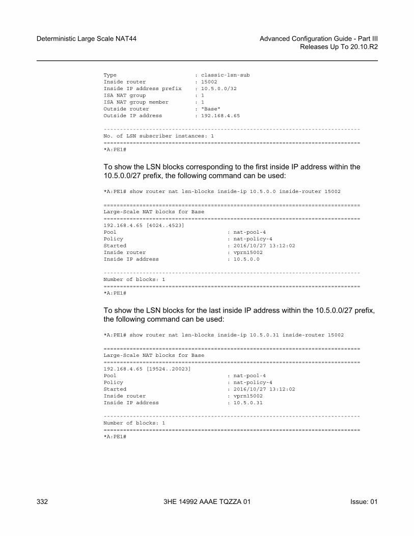
Deterministic Large Scale NAT44
332
Advanced Configuration Guide - Part IIIReleases Up To 20.10.R2
3HE 14992 AAAE TQZZA 01 Issue: 01
Type : classic-lsn-subInside router : 15002Inside IP address prefix : 10.5.0.0/32ISA NAT group : 1ISA NAT group member : 1Outside router : "Base"Outside IP address : 192.168.4.65
-------------------------------------------------------------------------------No. of LSN subscriber instances: 1===============================================================================*A:PE1#
To show the LSN blocks corresponding to the first inside IP address within the 10.5.0.0/27 prefix, the following command can be used:
*A:PE1# show router nat lsn-blocks inside-ip 10.5.0.0 inside-router 15002
===============================================================================Large-Scale NAT blocks for Base===============================================================================192.168.4.65 [4024..4523]Pool : nat-pool-4Policy : nat-policy-4Started : 2016/10/27 13:12:02Inside router : vprn15002Inside IP address : 10.5.0.0
-------------------------------------------------------------------------------Number of blocks: 1===============================================================================*A:PE1#
To show the LSN blocks for the last inside IP address within the 10.5.0.0/27 prefix, the following command can be used:
*A:PE1# show router nat lsn-blocks inside-ip 10.5.0.31 inside-router 15002
===============================================================================Large-Scale NAT blocks for Base===============================================================================192.168.4.65 [19524..20023]Pool : nat-pool-4Policy : nat-policy-4Started : 2016/10/27 13:12:02Inside router : vprn15002Inside IP address : 10.5.0.31
-------------------------------------------------------------------------------Number of blocks: 1===============================================================================*A:PE1#

Advanced Configuration Guide - Part III Releases Up To 20.10.R2
Deterministic Large Scale NAT44
Issue: 01 3HE 14992 AAAE TQZZA 01 333
Mapping Results
According to this configuration, each inside IP address within VPRN 15001 has one deterministic block of 500 ports and can have up to three dynamic blocks (block-limit =4) of 461 ports each, allowing a maximum of 500+3*461 = 1883 flows.
According to this configuration each inside IP address within VPRN 15002 has one deterministic block of 500 ports and can have up to three dynamic blocks (block-limit =4) of 461 ports each, allowing a maximum of 500+3*461 = 1883 flows.
For VPRN 15002, since the number of LSN subscribers (32) is less than the number of deterministic blocks (64), then 32 deterministic blocks will be wasted, specifically 32*500 = 16,000 ports will be wasted which is not good in terms of capacity planning.
Figure 63 Case 3 Results
Inverse Mapping
In deterministic LSN44, the inside IP addresses are mapped to outside IP addresses and corresponding port blocks based on a deterministic algorithm. The inverse mapping that reveals the subscriber identity behind the NAT is based on the reversal of this algorithm.
Deterministic Port ranges Dynamic Port ranges
0
192.168.4.1
192.168.4.2
192.168.4.3
192.168.4.65
192.168.4.64
192.168.4.100
1023 4023 30,023
26148
WKWKrangerange
PFPFrangerange
WKrange
PFrange
WKrange
PFrange
WKrange
PFrange
WKrange
PFrange
WKrange
PFrange
WKrange
PFrange 500 500 500 461 461 461 461 461 461500
VPRN 15001Inside Range10.5.0.0/20:10.5.0.0/26
10.5.0.64/2610.5.0.128/26
10.5.15.192/26
VPRN 15002Inside Range10.5.0.0/27:
10.5.0.0/27
64 Det portBlocks Per Outside IP
26157
X X
32 Wasted Det Port Blocks

Deterministic Large Scale NAT44
334
Advanced Configuration Guide - Part IIIReleases Up To 20.10.R2
3HE 14992 AAAE TQZZA 01 Issue: 01
Inverse mappings can be done either online or offline:
• Online — Locally on the 7x50 node, via CLI (MIB)• Offline — Externally, via a Python script. The purpose of such an offline
approach is to provide fast queries without accessing the 7x50.
Figure 64 Inverse Mapping Approach
Online Approach
A tools command is available which shows the reverse mapping (outside to inside) for deterministic NAT instead of using logging.
tools dump nat deterministic-mapping outside-ip <ipv4-address> router <router-instance> outside-port <[1..65535]>
<ipv4-address> : a.b.c.d<router-instance> : <router-name>|<service-id>
router-name - "Base"service-id - [1..2147483647]
CLI (MIB)External Server
(with Python installed)
ftp/tftp
7x50
PythonScript
Offline approachOnline approach
26158

Advanced Configuration Guide - Part III Releases Up To 20.10.R2
Deterministic Large Scale NAT44
Issue: 01 3HE 14992 AAAE TQZZA 01 335
Using Case 3 as an example, to obtain (inside IP, inside routing instance), the inverse mapping for a specific (outside IP, outside routing instance, outside port) is done as follows:
*A:PE1# tools dump nat deterministic-mapping outside-ip 192.168.4.1 router "Base" outside-port 4024classic-lsn-sub inside router 15001 ip 10.5.0.0 --outside router Base ip 192.168.4.1 port 4024 at Fri Oct 28 13:04:22 UTC 2016
*A:PE1#
*A:PE1# tools dump nat deterministic-mapping outside-ip 192.168.4.65 router "Base" outside-port 4024classic-lsn-sub inside router 15002 ip 10.5.0.0 --outside router Base ip 192.168.4.65 port 4024 at Fri Oct 28 13:04:45 UTC 2016
*A:PE1#
Offline Approach
The purpose of such an offline approach is to provide fast queries without the need to directly query the 7x50.
This is achieved by generating and exporting a Python script for reverse querying, which is a manual operation that needs to be repeated every time there is configuration change in deterministic NAT.
The script is exported (manually) to the external system.
To configure remotely the location for the Python script, the following command is used:
configure service nat deterministic-script location <remote-url>
Once the script location is specified, the script can be exported to that location using the following command:
admin nat save-deterministic-script
remote-url — A remote location where the script is stored: [{ftp://|tftp://}<login>:<pswd>@ <remote-locn>/][<file-path>]Maximum length is 180 characters.

Deterministic Large Scale NAT44
336
Advanced Configuration Guide - Part IIIReleases Up To 20.10.R2
3HE 14992 AAAE TQZZA 01 Issue: 01
Using the following command the status of the script can be checked, and whether it is necessary to re-save (export) the script or not:
*A:PE1# show service nat deterministic-script
===============================================================================Deterministic NAT script data===============================================================================Location : ftp://*:*@123.123.123.123/pub/python/detnat.pySave needed : noLast save result : successLast save time : 2016/10/28 13:05:41===============================================================================*A:PE1#
The external system must have the Python scripting language installed with the following modules: getopt, math, os, socket, and sys.
The Python script can then be run on the external server; the parameters are as follows:
[[email protected] ~]$ ./detnat.pyError: need exactly one of --forward or --backward arguments
Usage: detnat.py DIRECTION PARAMETERSPerform forward or backard NAPT according to the configured deterministic rules.
DIRECTION:-f, --forward Translate from inside to outside address/port-b, --backward Translate from outside to inside address/port
PARAMETERS:-a, --address=IP-ADDRESS The address to translate. IPv6 addresses can be
specified in shorthand or full notation.-p, --port=PORT The outside port in case of backward translation.-s, --service=SERVICE-ID The service where the IP-ADDRESS originates from.
This is the inside service in case of forwardtranslation and the outside service in case ofbackward translation.To specify the base router, this option must beomitted.
-h, --help Show this help message[[email protected] ~]$
where deterministic-nat.py is the name of the python script previously exported.
As an example of a forward query:
[[email protected] ~]$ ./detnat.py -f -s 15001 -a 10.0.0.1classic-lsn-sub has public ip address 192.168.0.1 from base router and is using ports [4324 -4623]
[[email protected] ~]$
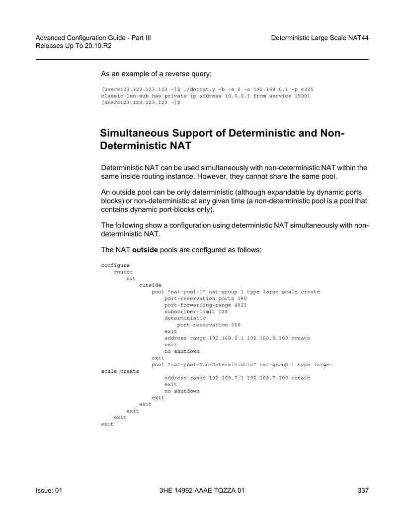
Advanced Configuration Guide - Part III Releases Up To 20.10.R2
Deterministic Large Scale NAT44
Issue: 01 3HE 14992 AAAE TQZZA 01 337
As an example of a reverse query:
[[email protected] ~]$ ./detnat.y -b -s 0 -a 192.168.0.1 -p 4325classic-lsn-sub has private ip address 10.0.0.1 from service 15001[[email protected] ~]$
Simultaneous Support of Deterministic and Non-Deterministic NAT
Deterministic NAT can be used simultaneously with non-deterministic NAT within the same inside routing instance. However, they cannot share the same pool.
An outside pool can be only deterministic (although expandable by dynamic ports blocks) or non-deterministic at any given time (a non-deterministic pool is a pool that contains dynamic port-blocks only).
The following show a configuration using deterministic NAT simultaneously with non-deterministic NAT.
The NAT outside pools are configured as follows:
configurerouter
natoutside
pool "nat-pool-1" nat-group 1 type large-scale createport-reservation ports 180port-forwarding-range 4023subscriber-limit 128deterministic
port-reservation 300exitaddress-range 192.168.0.1 192.168.0.100 createexitno shutdown
exitpool "nat-pool-Non-Deterministic" nat-group 1 type large-
scale createaddress-range 192.168.7.1 192.168.7.100 createexitno shutdown
exitexit
exitexit
exit

Deterministic Large Scale NAT44
338
Advanced Configuration Guide - Part IIIReleases Up To 20.10.R2
3HE 14992 AAAE TQZZA 01 Issue: 01
The NAT policies are configured as follows:
configureservice
natnat-policy "nat-policy-1" create
block-limit 4pool "nat-pool-1" router Base
exitnat-policy "nat-policy-Non-Deterministic" create
pool "nat-pool-Non-Deterministic" router Baseexit
exitexit
exit
The NAT inside prefixes are configured as follows:
configureservice
vprn 15001 customer 1 createnat
insidedestination-prefix 0.0.0.0/0classic-lsn-max-subscriber-limit 256deterministic
prefix 10.0.0.0/24 subscriber-type classic-lsn-subnat-policy "nat-policy-1" create
map start 10.0.0.0 end 10.0.0.255 to 192.168.0.1no shutdown
exitexitnat-policy "nat-policy-Non-Deterministic"
exitexitno shutdown
exitexit
exit
In this example, the inside IP prefixes that do not match any of the deterministic prefixes will be NATed using a non-deterministic pool.
Figure 65 Sending Flows: Deterministic + non-Deterministic NAT
500 UDP flows
SRC-IP: 10.7.0.1SRC-Port: 1024-1523
3/2/13
26159
BNG-1192.0.2.1

Advanced Configuration Guide - Part III Releases Up To 20.10.R2
Deterministic Large Scale NAT44
Issue: 01 3HE 14992 AAAE TQZZA 01 339
To check which NAT pool/NAT policy is used for NATing the inside IP 10.7.0.1, the following command can be used:
*A:PE1# show router nat lsn-blocks inside-ip 10.7.0.1
===============================================================================Large-Scale NAT blocks for Base===============================================================================192.168.7.100 [1024..1527]Pool : nat-pool-Non-DeterministicPolicy : nat-policy-Non-DeterministicStarted : 2016/10/28 13:24:56Inside router : vprn15001Inside IP address : 10.7.0.1
-------------------------------------------------------------------------------Number of blocks: 1===============================================================================*A:PE1#
Conclusion
This example provides the commands required for configuring deterministic LSN44 NAT. Both deterministic as well as non-deterministic NAT are supported, with simultaneous operation being possible.
Inverse query can be done online or offline to retrieve the NAT mappings. Logging is not needed as long as there are no dynamic blocks assigned to LSN44 subscribers.

Deterministic Large Scale NAT44
340
Advanced Configuration Guide - Part IIIReleases Up To 20.10.R2
3HE 14992 AAAE TQZZA 01 Issue: 01

Advanced Configuration Guide - Part III Releases Up To 20.10.R2
IP/GRE Termination
Issue: 01 3HE 14992 AAAE TQZZA 01 341
IP/GRE TerminationThis chapter describes advanced IP/GRE termination configurations.
Topics in this chapter include:
• Applicability• Summary• Overview• Configuration• Conclusion
Applicability
The chapter was initially written for SR OS release 9.0.R8. The CLI in the current edition corresponds to 15.0.R2.
The IP GRE tunnel termination configuration described in this chapter requires an MS-ISA. IP GRE tunnels without ISA are beyond the scope of this chapter.
Summary
Initially, the 7750 SR only supported GRE SDP tunnels which use pseudowire encapsulation. From SR OS 8.0.R5 onward, the 7750 SR supports tunneling IPv4 packets in an IPv4 GRE tunnel. A common use case is remote access to a VPRN over a public IP network because IP/GRE tunneling allows encapsulated packets to follow a path based on the outer IP header which is useful when the inner IP packet cannot or should not be forwarded natively over this path.
This chapter provides configuration and troubleshooting commands for IP/GRE termination.

IP/GRE Termination
342
Advanced Configuration Guide - Part IIIReleases Up To 20.10.R2
3HE 14992 AAAE TQZZA 01 Issue: 01
Overview
Generic Routing Encapsulation (GRE) allows packets of one protocol, the payload protocol, to be encapsulated by packets of another protocol, called the delivery protocol. A GRE packet has an Outer Delivery Header, GRE Header and Payload Packet (Figure 66).
Figure 66 GRE Packet Format
The outer delivery and GRE header for outgoing traffic is as follows.
• Outer Delivery header- The source address in the IPv4 delivery header is the configured source
address.- The destination address in the IPv4 delivery header is the configured
remote-ip (or backup-remote-ip) address.- The IP protocol value in the IPv4 delivery header is 0x2F or 47 (GRE).- The DSCP in the IPv4 Outer Delivery header is:
• Set to the value configured for the tunnel. • Otherwise, the DSCP value from the Payload Packet is copied into the
Outer Delivery header.- The TTL in the IPv4 Outer Delivery header is set to 255.
• GRE Header- The Checksum (C) bit in the GRE header is set to 0 (no checksum present).- The version in the GRE header is 0.- The protocol type in the GRE header is 0x0800 for IPv4.
The outer delivery and GRE header for incoming traffic is as follows:
• Outer Delivery header- If the packet is a fragment (More Fragments=1, non-zero fragment offset),
it is dropped.
IPv4 Header (20 bytes)
IPv4 or IPv6 Payload Packet
Outer DeliveryHeader 20 bytes
GRE Header 4 bytes
Payload Packet
0 1 2 3 4 5 6 7 8 9 10 1 12 13 14 15 16 17 18 19 20 21 22 23 24 25 26 27 28 29 30 31
TTL 255
C-bit(0) Ver(0)Reserved (0) Protocol Type 0x0800 (IP)Reserved 1 (Optional)Checksum (Optional)
Protocol 0x2F
al_0132

Advanced Configuration Guide - Part III Releases Up To 20.10.R2
IP/GRE Termination
Issue: 01 3HE 14992 AAAE TQZZA 01 343
- If the Checksum (C) bit in the GRE header is set, then the included checksum is validated; if the checksum is incorrect, the packet is discarded.
- If the version in the GRE header is not 0, the packet is discarded.- If the source/destination address pair in the IPv4 delivery header is any
other combination, the packet is dropped.• GRE Header
- If the Checksum (C) bit in the GRE header is set, then the included checksum is validated; if the checksum is incorrect, the packet is discarded.
- If the version in the GRE header is not 0, the packet is discarded.
7750 SR Implementation
Encapsulation, de-encapsulation and other datapath operations related to IP/GRE are handled by the isa-tunnel MDA.
For GRE tunnels configured as SDPs (which are not covered by this section), no ISA-tunnel MDA is required.
Figure 67 7x50 Implementation
The 7750 SR initially supported the IP/GRE tunnels with static routes and BGP. IP/GRE tunnels have been enhanced by adding support for OSPF and BFD on private tunnel interfaces (used with static routes, OSPF, or BGP) and GRE protection by tunneling into an IPSec tunnel.
al_0133
VPRN/IES VPRN/IESVPRN/IES
ISA-Tunnel
ISA-Tunnel
ISA-Tunnel
VPRN/IESInternet

IP/GRE Termination
344
Advanced Configuration Guide - Part IIIReleases Up To 20.10.R2
3HE 14992 AAAE TQZZA 01 Issue: 01
Figure 68 IP/GRE over IPSec Tunnel
Configuration
Tunnel ISA MDA
The ISA-tunnel MDA supports IP/GRE and IPSec tunnels and is configured as follows:
*A:PE-1#configure card 1 mda 2 mda-type "isa-tunnel"
The following command checks the MDA configuration:
*A:PE-1# show mda
===============================================================================MDA Summary===============================================================================Slot Mda Provisioned Type Admin Operational
Equipped Type (if different) State State-------------------------------------------------------------------------------1 1 m4-10gb-xp-xfp up up
2 isa-tunnel up upisa-ms
Tunnel Groups and Tunnel Group Restrictions
The first step of the GRE tunnel configuration is to configure a tunnel group.
al_0134
VPRN/IES VPRN/IESVPRN/IES
ISA-Tunnel
IPsec-TunnelGRE-Tunnel GRE-Tunnel
ISA-Tunnel
VPRN/IESInternet

Advanced Configuration Guide - Part III Releases Up To 20.10.R2
IP/GRE Termination
Issue: 01 3HE 14992 AAAE TQZZA 01 345
A tunnel group can have one tunnel ISA designated primary and optionally one tunnel-ISA designated backup. When a GRE tunnel is created, it is assigned to the primary tunnel-ISA in its tunnel group. If the primary tunnel-ISA fails, the backup tunnel-ISA (if not already claimed by another tunnel group) takes over for the failed card.
*A:PE-1# configure isa tunnel-group- tunnel-group <tunnel-group-id> [create]- tunnel-group <tunnel-group-id> isa-scale-mode <isa-scale-mode> [create]- no tunnel-group <tunnel-group-id>
<tunnel-group-id> : [1..16]<isa-scale-mode> : tunnel-limit-2k
k = 1024<create> : keyword - mandatory while creating an entry.
[no] active-mda-num* - Configure number of active MDAs[no] backup - Configure ISA-Tunnel-Group backup ISA[no] description - Configure the ISA group description[no] ipsec-responde* - Enable/Disable responder-only for IPsec Ikev2 tunnels only[no] mda - Configure MDA to associate with[no] multi-active - Configure multi-active status of tunnel-group[no] primary - Configure ISA-Tunnel-Group primary ISA[no] reassembly - Configure reassembly wait time[no] shutdown - Administratively enable/disable an ISA-Tunnel-Group
*A:PE-1# configureisa
tunnel-group 1 createprimary 1/2backup 2/1no shutdown
exit
The failed tunnels are re-established using a cold-standby on the backup tunnel-ISA (cold standby means the backup tunnel-ISA has no state or configuration information about the tunnels prior to the failure).
A tunnel-ISA cannot be primary for more than one tunnel group.
*A:PE-1>config>isa# tunnel-group 2 create*A:PE-1>config>isa>tunnel-grp# primary 1/2MINOR: IPSECGRPMGR #1003 The specified MDA is primary in another Tunnel Group
A tunnel-ISA cannot be primary in one tunnel group and backup in another tunnel group.
*A:PE-1>config>isa# tunnel-group 2 create*A:PE-1>config>isa>tunnel-grp# backup 1/2MINOR: IPSECGRPMGR #1003 The specified MDA is primary in another Tunnel Group
The following commands shows the ISA tunnel-group (after tunnel group 2 has been removed):

IP/GRE Termination
346
Advanced Configuration Guide - Part IIIReleases Up To 20.10.R2
3HE 14992 AAAE TQZZA 01 Issue: 01
*A:PE-1# show isa tunnel-group
===============================================================================ISA Tunnel Groups===============================================================================Tunnel PrimaryIsa BackupIsa ActiveIsa Admin OperGroupId State State-------------------------------------------------------------------------------1 1/2 2/1 1/2 Up Up-------------------------------------------------------------------------------No. of ISA Tunnel Groups: 1===============================================================================*A:PE-1#
The following command shows the number of the IP (GRE) tunnels (after configuring IES and VPRN services with tunnel interfaces):
*A:PE-1# show ip tunnel count--------------------------------------------------------------------------------IP Tunnels: 2--------------------------------------------------------------------------------*A:PE-1#
The following command shows all IP tunnels:
*A:PE-1# show ip tunnel
===============================================================================IP Tunnels===============================================================================TunnelName SapId SvcId AdmnLocal Address DlvrySvcId OperOperRemoteAddress
-------------------------------------------------------------------------------gre-tunnel-1 tunnel-1.private:1 1 Up192.168.1.1 2 Up192.168.3.1
protected-gre-tunnel tunnel-1.private:5 3 Up192.168.11.1 3 Up192.168.33.1
-------------------------------------------------------------------------------IP Tunnels: 2===============================================================================*A:PE-1#
The detailed tunnel information is as follows:
*A:PE-1# show ip tunnel "gre-tunnel-1"
===============================================================================IP Tunnel Configuration Detail===============================================================================Service Id : 1 Sap Id : tunnel-1.private:1Tunnel Name : gre-tunnel-1Description : NoneGRE Header : Yes Delivery Service : 2

Advanced Configuration Guide - Part III Releases Up To 20.10.R2
IP/GRE Termination
Issue: 01 3HE 14992 AAAE TQZZA 01 347
GRE Keys Set : FalseGRE Send Key : N/A GRE Receive Key : N/AAdmin State : Up Oper State : UpSource Address : 192.168.1.1Remote Address : 192.168.3.1Backup Address : (Not Specified)Oper Remote Addr : 192.168.3.1DSCP : NoneReassembly : inheritClear DF Bit : false IP MTU : maxEncap IP MTU : maxPkt Too Big : truePkt Too Big Num : 100 Pkt Too Big Intvl: 10 secsOper Flags : NoneLast Oper Changed: 05/16/2017 08:43:56Host MDA : 1/2TCP MSS Adjust
Public : DisabledPrivate : Disabled
-------------------------------------------------------------------------------Target Address Table-------------------------------------------------------------------------------Destination IP IP Resolved Status-------------------------------------------------------------------------------10.0.0.2 Yes-------------------------------------------------------------------------------
===============================================================================IP Tunnel Statistics: gre-tunnel-1===============================================================================Errors Rx : 0 Errors Tx : 0Pkts Rx : 145 Pkts Tx : 145Bytes Rx : 9394 Bytes Tx : 9599Key Ignored Rx : 0 Too Big Tx : 0Seq Ignored Rx : 0Vers Unsup. Rx : 0Invalid Chksum Rx: 0Key Mismatch Rx : 0===============================================================================
===============================================================================Fragmentation Statistics===============================================================================Encapsulation Overhead : 24Pre-Encapsulation
Fragmentation Count : 0Last Fragmented Packet Size : 0
Post-EncapsulationFragmentation Count : 0Last Fragmented Packet Size : 0
==============================================================================================================================================================*A:PE-1#

IP/GRE Termination
348
Advanced Configuration Guide - Part IIIReleases Up To 20.10.R2
3HE 14992 AAAE TQZZA 01 Issue: 01
Interfaces
The interface toward the Internet (or WAN):
• Can be a network interface or VPRN/IES interface.• Provides IP reachability.
The tunnel public interface:
• Can be an IES or VPRN interface. • Represents the public side of the tunnel-ISA.
The delivery VPRN/IES service (the service connected to the Internet) must have at least one IP interface associated with a public tunnel SAP in order to receive and process GRE encapsulated packets.
The public tunnel SAP type has the format tunnel-id.private | public:tag (where the id corresponds to the tunnel group). Figure 69 shows the example topology, where CE-3 in customer site A is connected to PE-1. The IES service with public tunnel SAP is configured on PE-1 as follows:
*A:PE-1>config>service>ies>if# sap ?- no sap <sap-id>- sap <sap-id> [create]
<sap-id>---snip---
tunnel-id - tunnel-<id>.<private|public>:<tag>tunnel - keywordid - [1..16]tag - [0..4094]
---snip---
*A:PE-1# configureservice
ies 2 customer 1 createinterface "int-tunnel-public" create
address 192.168.1.2/30tos-marking-state untrustedsap tunnel-1.public:1 createexit
exitinterface "int-PE-1-CE-3" create
address 192.168.13.1/24sap 1/1/2:2 createexit
exitno shutdown
exit

Advanced Configuration Guide - Part III Releases Up To 20.10.R2
IP/GRE Termination
Issue: 01 3HE 14992 AAAE TQZZA 01 349
PE-1 has address 192.168.1.2/30 assigned to the interface “int-tunnel-public in IES 2. In a similar way, CE-3 has address 192.168.3.2/30 assigned to the interface “int-tunnel-public” in IES 2.
In order to reach 192.168.3.0/30 on CE-3, a static route is configured on PE-1, as follows:
*A:PE-1# configure router static-route-entry 192.168.3.0/30 next-hop 192.168.13.2 no shutdown
In a similar way, a static route is configured on CE-3 to reach 192.168.1.0/30 on PE-1.
Mask /32 is not supported on the public tunnel. When address 192.168.1.2/32 is configured on the interface “int-tunnel-public”, the public tunnel cannot be created, as follows:
*A:PE-1>config>service>ies>if# address 192.168.1.2/32*A:PE-1>config>service>ies# interface "tunnel-public" sap tunnel-1.public:1 createINFO: PIP #1288 Cannot bind when there are /32 or /128 addresses configured
Therefore, the address configured on the interface will have mask /30 instead of /32, as shown earlier.
The tunnel private interface:
• Can be an IES or VPRN interface.• Represents the private side of the tunnel-ISA.
The private tunnel SAP has the format tunnel-id.private | public:tag (where the id corresponds to the tunnel-group) as shown in the following example where an unprotected GRE tunnel is configured in the SAP context.
*A:PE-1>config>service>vprn>if# sap ?- no sap <sap-id>- sap <sap-id> [create]
<sap-id>---snip---
tunnel-id - tunnel-<id>.<private|public>:<tag>tunnel - keywordid - [1..16]tag - [0..4094]
---snip---
*A:PE-1# configureservice
vprn 1 customer 1 createroute-distinguisher 64496:1vrf-target target:64496:1interface "int-gre-tunnel" tunnel create
address 10.0.0.1/30

IP/GRE Termination
350
Advanced Configuration Guide - Part IIIReleases Up To 20.10.R2
3HE 14992 AAAE TQZZA 01 Issue: 01
sap tunnel-1.private:1 createip-tunnel "gre-tunnel-1" create
dest-ip 10.0.0.2gre-header
---snip---
It is not mandatory to have the same tag (internal dot1q) in private and public GRE tunnels.
sap tunnel-1.private:1 <=> sap tunnel-1.public:2
Unprotected GRE Tunnel Configuration
To associate an unprotected GRE tunnel with a private tunnel SAP, the ip-tunnel command is configured in the SAP context.
*A:PE-1# configureservice
vprn 1 customer 1 create---snip---
interface "int-gre-tunnel" tunnel createaddress 10.0.0.1/30sap tunnel-1.private:1 create
ip-tunnel "gre-tunnel-1" createdest-ip 10.0.0.2gre-header---snip---
The dest-ip keyword followed by the private IP address of the remote tunnel endpoint is mandatory.
If this remote IP address is not within the subnet of the local private endpoint, then the tunnel will not come up.
The following parameters are configured in the ip-tunnel context:
• The source address of the GRE tunnel. This is the source IPv4 address of GRE encapsulated packets sent by the delivery service. It must be an address in the subnet of the associated public tunnel SAP interface.
• The remote IP address. If this address is reachable in the delivery service (there is a route), then this is the destination IPv4 address of GRE encapsulated packets sent by the delivery service.
• The backup remote IP address. If the remote IP address of the tunnel is not reachable, then this is the destination IPv4 address of GRE encapsulated packets sent by the delivery service.

Advanced Configuration Guide - Part III Releases Up To 20.10.R2
IP/GRE Termination
Issue: 01 3HE 14992 AAAE TQZZA 01 351
• The delivery service. This is the identifier or name of the IES or VPRN service where GRE encapsulated packets are injected and terminated. The delivery service can be the same service where the private tunnel SAP interface resides.
• The DSCP marking in the outer IP header of GRE encapsulated packets. If this is not configured, then the default copies the DSCP from the inner IP header to the outer IP header.
*A:PE-1# configureservice
vprn 1 customer 1 createroute-distinguisher 64496:1vrf-target target:64496:1interface "int-gre-tunnel" tunnel create
address 10.0.0.1/30sap tunnel-1.private:1 create
ip-tunnel "gre-tunnel-1" createdest-ip 10.0.0.2gre-headersource 192.168.1.1remote-ip 192.168.3.1delivery-service 2dscp af22no shutdown
exit---snip---
• A private tunnel SAP can have only one IP/GRE tunnel (per SAP).*A:PE-1# configure service vprn 1 interface "int-gre-tunnel" sap tunnel-1.private:1 ip-tunnel "gre-tunnel-2" createMINOR: SVCMGR #5120 Only one IP tunnel allowed per SAP
IP/GRE Tunneling via Static Route
A static route can reference the GRE tunnel directly (by next-hop IP address) or the GRE tunnel can be the resolved next-hop for an indirect static route (Figure 69).
Figure 69 GRE for Remote Access to a VPRN Service
Public IPNetwork IP VPN
Service Provider
al_0135
VPRN
PE-1
GRE Tunnel
Site A Site BPE-2
VPRN

IP/GRE Termination
352
Advanced Configuration Guide - Part IIIReleases Up To 20.10.R2
3HE 14992 AAAE TQZZA 01 Issue: 01
The details of both ends on the GRE tunnel, at site A and PE-1, are shown in Figure 70. The node at left hand side is CE-3 at site A.
Figure 70 IP/GRE Tunneling via Static Route
The following shows the configuration of VPRN 1 on PE-1.
*A:PE-1# configureservice
vprn 1 customer 1 createroute-distinguisher 64496:1vrf-target target:64496:1interface "int-gre-tunnel" tunnel create
address 10.0.0.1/30sap tunnel-1.private:1 create
ip-tunnel "gre-tunnel-1" createdest-ip 10.0.0.2gre-headersource 192.168.1.1remote-ip 192.168.3.1delivery-service 2no shutdown
exitexit
exitstatic-route-entry 172.16.3.1/32
next-hop 10.0.0.2no shutdown
exitexitno shutdown
exit
The configuration of the VPRN on CE-3 is similar.
To check the static route status:
*A:PE-1# show router 1 static-route
===============================================================================Static Route Table (Service: 1) Family: IPv4
Internet
al_0136
VPRN 1
ISA-Tunnel
Tunnel src IP:192.168.3.1/30
IES 2
sap tunnel-1.private:110.0.0.2/30
sap tunnel-1.public:1192.168.3.2/30
VPRN 1
ISA-Tunnel
Tunnel src IP:192.168.1.1/30
IES 2
sap tunnel-1.private:110.0.0.1/30
sap tunnel-1.public:1192.168.1.2/30

Advanced Configuration Guide - Part III Releases Up To 20.10.R2
IP/GRE Termination
Issue: 01 3HE 14992 AAAE TQZZA 01 353
===============================================================================Prefix Tag Met Pref Type Act
Next Hop Interface-------------------------------------------------------------------------------172.16.3.1/32 0 1 5 NH Y
10.0.0.2 int-gre-tunnel-------------------------------------------------------------------------------No. of Static Routes: 1===============================================================================*A:PE-1#
IP/GRE Tunneling via BGP Peering
In this section, the configuration has BGP running inside the GRE tunnel.
*A:PE-1# configureservice
vprn 1 customer 1 createautonomous-system 64496route-distinguisher 64496:1vrf-target target:64496:1interface "int-gre-tunnel" tunnel create
address 10.0.0.1/30sap tunnel-1.private:1 create
ip-tunnel "gre-tunnel-1" createdest-ip 10.0.0.2gre-headersource 192.168.1.1remote-ip 192.168.3.1delivery-service 2no shutdown
exitexit
exitinterface "loopback1" create
address 172.31.1.1/32loopback
exitstatic-route-entry 172.16.3.1/32
next-hop 10.0.0.2no shutdown
exitexitbgp
group "group-1"type internallocal-address 172.31.1.1neighbor 172.16.3.1exit
exitno shutdown
exitno shutdown
exit

IP/GRE Termination
354
Advanced Configuration Guide - Part IIIReleases Up To 20.10.R2
3HE 14992 AAAE TQZZA 01 Issue: 01
It is mandatory to configure the autonomous-system in the VPRN context, otherwise the BGP session will not be established.
The configuration of the VPRN on CE-3 is similar.
The following command on PE-1 shows the summary of the BGP sessions. The BGP session between peers 172.16.1.1 in VPRN 1 on PE-1 and 172.16.3.1 in VPRN 1 on CE-3 is established for address family IPv4.
*A:PE-1# show router 1 bgp summary all
===============================================================================BGP Summary===============================================================================Legend : D - Dynamic Neighbor===============================================================================NeighborDescriptionServiceId AS PktRcvd InQ Up/Down State|Rcv/Act/Sent (Addr Family)
PktSent OutQ-------------------------------------------------------------------------------172.16.3.1Svc: 1 64496 3 0 00h00m12s 0/0/0 (IPv4)
4 0-------------------------------------------------------------------------------*A:PE-1#
IP/GRE Tunneling via OSPFv2 Peering
OSPF can be run on IES and VPRN IP interfaces associated with private IP/GRE tunnel SAPs.
All OSPF features are supported, including area 0 and non-area 0 support, virtual links, authentication, BFD, configurable protocol timers.
*A:PE-1# configureservice
vprn 1 customer 1 createroute-distinguisher 64496:1vrf-target target:64496:1interface "int-gre-tunnel" tunnel create
address 10.0.0.1/30sap tunnel-1.private:1 create
ip-tunnel "gre-tunnel-1" createdest-ip 10.0.0.2gre-headersource 192.168.1.1remote-ip 192.168.3.1delivery-service 2no shutdown
exitexit

Advanced Configuration Guide - Part III Releases Up To 20.10.R2
IP/GRE Termination
Issue: 01 3HE 14992 AAAE TQZZA 01 355
exitinterface "loopback1" create
address 172.31.1.1/32loopback
exitospf
area 0.0.0.0interface "int-gre-tunnel"exitinterface "loopback1"exit
exitno shutdown
exitno shutdown
exit
The following command shows the OSPF neighbors for VPRN 1:
*A:PE-1# show router 1 ospf neighbor
===============================================================================Rtr vprn1 OSPFv2 Instance 0 Neighbors===============================================================================Interface-Name Rtr Id State Pri RetxQ TTL
Area-Id-------------------------------------------------------------------------------int-gre-tunnel 192.0.2.3 Full 1 0 33
0.0.0.0-------------------------------------------------------------------------------No. of Neighbors: 1===============================================================================*A:PE-1#
The OSPF routes in the routing table of VPRN 1 are as follows:
*A:PE-1# show router 1 route-table protocol ospf
===============================================================================Route Table (Service: 1)===============================================================================Dest Prefix[Flags] Type Proto Age Pref
Next Hop[Interface Name] Metric-------------------------------------------------------------------------------172.16.3.1/32 Remote OSPF 00h05m46s 10
10.0.0.2 10-------------------------------------------------------------------------------No. of Routes: 1Flags: n = Number of times nexthop is repeated
B = BGP backup route availableL = LFA nexthop availableS = Sticky ECMP requested
===============================================================================*A:PE-1#

IP/GRE Termination
356
Advanced Configuration Guide - Part IIIReleases Up To 20.10.R2
3HE 14992 AAAE TQZZA 01 Issue: 01
IP/GRE Tunneling Protection using IPSec Tunnel Mode
To provide protection against potential threats such as spoofing, the GRE packets can be encrypted and authenticated using IPSec.
GRE packets receive IPSec protection by forwarding them, after encapsulation by a tunnel-ISA, into an IPSec tunnel supported by another (or the same) tunnel-ISA.
Note that when configuring GRE protection by an IPSec tunnel:
• A GRE tunnel and its protecting IPSec tunnel may belong to the same or different tunnel-groups (the same tunnel-group is assumed in the following example).
• A GRE tunnel and its protecting IPSec tunnel may be assigned to the same tunnel-ISA (if they belong to the same tunnel-group) or different tunnel-ISAs.
• A single IPSec tunnel can protect one or more GRE tunnels in addition to other IP traffic that meets the IPSec security policy.
• The private IPSec tunnel SAP interface and public GRE tunnel SAP interface are always part of the same VPRN. The private GRE tunnel SAP interface can be part of this same VPRN or a different VPRN.
In the following example, the GRE tunnel and its protecting IPSec tunnel belong to the same tunnel group.
Figure 71 Example GRE over IPSec Tunnel
al_0137
IES 4VRPN 3
TunnelGroup 1
Tunnel Group 1
Router CE-3 Router PE-1
Tunnel Group 1GRE Tunnel
IPsec Tunnel (Private Side)IPsec Tunnel (Public Side)
Public SAP
10.0.0.5
10.1.1.2192.168.33.2
Private SAP1/2
IES 4 VRPN 3
TunnelGroup 1
10.0.0.6
10.2.2.2192.168.11.2
1/2

Advanced Configuration Guide - Part III Releases Up To 20.10.R2
IP/GRE Termination
Issue: 01 3HE 14992 AAAE TQZZA 01 357
IPSec Configuration
An ike-policy and ipsec-transform must be configured on PE-1 and CE-3, as follows:
configureipsec
ike-transform 1 createdh-group 5
exitike-policy 1 create
ike-transform 1exitipsec-transform 1 create
esp-encryption-algorithm aes256exit
The public/private side of the GRE tunnel and the private side of the IPSec tunnel are in the same VPRN, as shown in the following configuration example.
*A:PE-1# configureservice
vprn 3 customer 1 createipsec
security-policy 1 createentry 1 create
local-ip 192.168.11.0/24remote-ip 192.168.33.0/24
exitexit
exitroute-distinguisher 64496:3vrf-target target:64496:3interface "int-private-ipsec-1" tunnel create
sap tunnel-1.private:3 createipsec-tunnel "ipsec-tunnel-for-gre-tunnel" create
security-policy 1local-gateway-address 10.2.2.1 peer 10.1.1.1
delivery-service 4dynamic-keying
ike-policy 1pre-shared-key "pass"transform 1
exitno shutdown
exitexit
exitinterface "int-public-gre-1" create
address 192.168.11.2/24sap tunnel-1.public:4 createexit
exitinterface "int-private-gre-1" tunnel create
address 10.0.0.6/30sap tunnel-1.private:5 create

IP/GRE Termination
358
Advanced Configuration Guide - Part IIIReleases Up To 20.10.R2
3HE 14992 AAAE TQZZA 01 Issue: 01
ip-tunnel "protected-gre-tunnel" createdest-ip 10.0.0.5gre-headersource 192.168.11.1remote-ip 192.168.33.1delivery-service 3no shutdown
exitexit
exitstatic-route-entry 192.168.33.0/24
ipsec-tunnel "ipsec-tunnel-for-gre-tunnel"no shutdown
exitexitno shutdown
exit
The following displays a configuration example of the public side of the IPSec tunnel:
*A:PE-1# configureservice
ies 4 customer 1 createinterface "public-ipsec-1" create
address 10.2.2.2/24tos-marking-state untrustedsap tunnel-1.public:3 createexit
exitinterface "int2-PE-1-CE-3" create
address 192.168.113.1/30sap 1/1/2:4 createexit
exitno shutdown
exit
The following static route is configured in the base router on PE-1:
*A:PE-1# configure router static-route-entry 10.1.1.0/24 next-hop 192.168.113.2 no shutdown
The configuration is similar on CE-3.
The following command shows that the tunnel “protected-gre-tunnel” with SAP tunnel-1.private:5 is up:
*A:PE-1# show ip tunnel
===============================================================================IP Tunnels===============================================================================TunnelName SapId SvcId AdmnLocal Address DlvrySvcId OperOperRemoteAddress

Advanced Configuration Guide - Part III Releases Up To 20.10.R2
IP/GRE Termination
Issue: 01 3HE 14992 AAAE TQZZA 01 359
-------------------------------------------------------------------------------gre-tunnel-1 tunnel-1.private:1 1 Up192.168.1.1 2 Up192.168.3.1
protected-gre-tunnel tunnel-1.private:5 3 Up192.168.11.1 3 Up192.168.33.1
-------------------------------------------------------------------------------IP Tunnels: 2===============================================================================*A:PE-1#
The following command shows the IP/GRE tunnel information for this IPSec tunnel:
*A:PE-1# show ip tunnel "protected-gre-tunnel"
===============================================================================IP Tunnel Configuration Detail===============================================================================Service Id : 3 Sap Id : tunnel-1.private:5Tunnel Name : protected-gre-tunnelDescription : NoneGRE Header : Yes Delivery Service : 3GRE Keys Set : FalseGRE Send Key : N/A GRE Receive Key : N/AAdmin State : Up Oper State : UpSource Address : 192.168.11.1Remote Address : 192.168.33.1Backup Address : (Not Specified)Oper Remote Addr : 192.168.33.1DSCP : NoneReassembly : inheritClear DF Bit : false IP MTU : maxEncap IP MTU : maxPkt Too Big : truePkt Too Big Numb*: 100 Pkt Too Big Intvl: 10 secsOper Flags : NoneLast Oper Changed: 05/16/2017 10:20:08Host MDA : 1/2TCP MSS Adjust
Public : DisabledPrivate : Disabled
-------------------------------------------------------------------------------Target Address Table-------------------------------------------------------------------------------Destination IP IP Resolved Status-------------------------------------------------------------------------------10.0.0.5 Yes-------------------------------------------------------------------------------
===============================================================================IP Tunnel Statistics: protected-gre-tunnel===============================================================================Errors Rx : 0 Errors Tx : 0Pkts Rx : 4 Pkts Tx : 5Bytes Rx : 336 Bytes Tx : 420

IP/GRE Termination
360
Advanced Configuration Guide - Part IIIReleases Up To 20.10.R2
3HE 14992 AAAE TQZZA 01 Issue: 01
Key Ignored Rx : 0 Too Big Tx : 0Seq Ignored Rx : 0Vers Unsup. Rx : 0Invalid Chksum Rx: 0Key Mismatch Rx : 0===============================================================================
===============================================================================Fragmentation Statistics===============================================================================Encapsulation Overhead : 24Pre-Encapsulation
Fragmentation Count : 0Last Fragmented Packet Size : 0
Post-EncapsulationFragmentation Count : 0Last Fragmented Packet Size : 0
==============================================================================================================================================================* indicates that the corresponding row element may have been truncated.*A:PE-1#
By default, the IPSec tunnel is down if it is not used by any traffic, as follows:
*A:PE-1# show ipsec tunnel
===============================================================================IPsec Tunnels===============================================================================TunnelName LocalAddress SvcId Admn Keying
SapId RemoteAddress DlvrySvcId Oper SecPlcy
-------------------------------------------------------------------------------ipsec-tunnel-for-gre-tunnel 10.2.2.1 3 Up Dynamic
tunnel-1.private:3 10.1.1.1 4 Down 1-------------------------------------------------------------------------------IPsec Tunnels: 1===============================================================================*A:PE-1#
After it is used by traffic, the status will be changed to be up.
*A:PE-1# ping router 3 10.0.0.5PING 10.0.0.5 56 data bytes64 bytes from 10.0.0.5: icmp_seq=1 ttl=64 time=1.42ms.64 bytes from 10.0.0.5: icmp_seq=2 ttl=64 time=1.35ms.64 bytes from 10.0.0.5: icmp_seq=3 ttl=64 time=1.26ms.64 bytes from 10.0.0.5: icmp_seq=4 ttl=64 time=1.34ms.64 bytes from 10.0.0.5: icmp_seq=5 ttl=64 time=1.28ms.
---- 10.0.0.5 PING Statistics ----5 packets transmitted, 5 packets received, 0.00% packet lossround-trip min = 1.26ms, avg = 1.33ms, max = 1.42ms, stddev = 0.058ms*A:PE-1#
The IPSec tunnel is now up, as follows:

Advanced Configuration Guide - Part III Releases Up To 20.10.R2
IP/GRE Termination
Issue: 01 3HE 14992 AAAE TQZZA 01 361
*A:PE-1# show ipsec tunnel
===============================================================================IPsec Tunnels===============================================================================TunnelName LocalAddress SvcId Admn Keying
SapId RemoteAddress DlvrySvcId Oper SecPlcy
-------------------------------------------------------------------------------ipsec-tunnel-for-gre-tunnel 10.2.2.1 3 Up Dynamic
tunnel-1.private:3 10.1.1.1 4 Up 1-------------------------------------------------------------------------------IPsec Tunnels: 1===============================================================================
BFD Support on Private Tunnel Interfaces
BFD is supported on IP interfaces associated with private IP/GRE tunnel SAPs. The BFD state of the interface can be used by static routes, OSPFv2 and/or BGP configured on the interface. It is not used to trigger a switchover to the backup remote IP address of the GRE tunnel.
The following displays a static route example:
*A:PE-1# configureservice
vprn 1 customer 1 createroute-distinguisher 64496:1vrf-target target:64496:1interface "int-gre-tunnel" tunnel create
address 10.0.0.1/30bfd 100 receive 100 multiplier 3sap tunnel-1.private:1 create
ip-tunnel "gre-tunnel-1" createdest-ip 10.0.0.2gre-headersource 192.168.1.1remote-ip 192.168.3.1delivery-service 2no shutdown
exitexit
exitstatic-route-entry 172.16.3.1/32
next-hop 10.0.0.2bfd-enableno shutdown
exitexitno shutdown
exit

IP/GRE Termination
362
Advanced Configuration Guide - Part IIIReleases Up To 20.10.R2
3HE 14992 AAAE TQZZA 01 Issue: 01
The following command shows that the BFD session on interface “int-gre-tunnel” is up for protocol static:
*A:PE-1# show router 1 bfd session
===============================================================================Legend:
Session Id = Interface Name | LSP Name | Prefix | RSVP Sess Name | Service Idwp = Working path pp = Protecting path
===============================================================================BFD Session===============================================================================Session Id State Tx Pkts Rx Pkts
Rem Addr/Info/SdpId:VcId Multipl Tx Intvl Rx IntvlProtocols Type LAG Port LAG ID
-------------------------------------------------------------------------------int-gre-tunnel Up 75 62
10.0.0.2 3 100 100static central N/A N/A
-------------------------------------------------------------------------------No. of BFD sessions: 1===============================================================================*A:PE-1#
When no static routes are configured and OSPF is configured instead, the configuration of VPRN 1 on PE-1 is as follows:
*A:PE-1# configureservice
vprn 1 customer 1 createroute-distinguisher 64496:1vrf-target target:64496:1interface "int-gre-tunnel" tunnel create
address 10.0.0.1/30bfd 100 receive 100 multiplier 3sap tunnel-1.private:1 create
ip-tunnel "gre-tunnel-1" createdest-ip 10.0.0.2gre-headersource 192.168.1.1remote-ip 192.168.3.1delivery-service 2no shutdown
exitexit
exitinterface "loopback1" create
address 172.31.1.1/32bfd 100 receive 100 multiplier 3loopback
exitospf
area 0.0.0.0interface "int-gre-tunnel"
bfd-enableno shutdown
exit

Advanced Configuration Guide - Part III Releases Up To 20.10.R2
IP/GRE Termination
Issue: 01 3HE 14992 AAAE TQZZA 01 363
interface "loopback1"no shutdown
exitexitno shutdown
exitno shutdown
The following shows that the BFD session is up for protocol OSPF on interface “int-gre-tunnel”:
*A:PE-1# show router 1 bfd session
===============================================================================Legend:
Session Id = Interface Name | LSP Name | Prefix | RSVP Sess Name | Service Idwp = Working path pp = Protecting path
===============================================================================BFD Session===============================================================================Session Id State Tx Pkts Rx Pkts
Rem Addr/Info/SdpId:VcId Multipl Tx Intvl Rx IntvlProtocols Type LAG Port LAG ID
-------------------------------------------------------------------------------int-gre-tunnel Up 287 287
10.0.0.2 3 100 100ospf2 central N/A N/A
-------------------------------------------------------------------------------No. of BFD sessions: 1===============================================================================*A:PE-1#
When BGP is configured instead of OSPF, the configuration of VPRN 1 on PE-1 is as follows:
*A:PE-1# configureservice
vprn 1 customer 1 createautonomous-system 64496route-distinguisher 64496:1vrf-target target:64496:1interface "int-gre-tunnel" tunnel create
address 10.0.0.1/30bfd 100 receive 100 multiplier 3sap tunnel-1.private:1 create
ip-tunnel "gre-tunnel-1" createdest-ip 10.0.0.2gre-headersource 192.168.1.1remote-ip 192.168.3.1delivery-service 2no shutdown
exitexit
exitinterface "loopback1" create
address 172.31.1.1/32

IP/GRE Termination
364
Advanced Configuration Guide - Part IIIReleases Up To 20.10.R2
3HE 14992 AAAE TQZZA 01 Issue: 01
bfd 100 receive 100 multiplier 3loopback
exitstatic-route-entry 172.16.3.1/32
next-hop 10.0.0.2no shutdown
exitexitbgp
group "group-1"type internallocal-address 172.31.1.1neighbor 172.16.3.1
bfd-enableexit
exitno shutdown
exitno shutdown
exit
The following command shows that the BFD session is up for protocol BGP on interface “loopback1”:
*A:PE-1# show router 1 bfd session
===============================================================================Legend:
Session Id = Interface Name | LSP Name | Prefix | RSVP Sess Name | Service Idwp = Working path pp = Protecting path
===============================================================================BFD Session===============================================================================Session Id State Tx Pkts Rx Pkts
Rem Addr/Info/SdpId:VcId Multipl Tx Intvl Rx IntvlProtocols Type LAG Port LAG ID
-------------------------------------------------------------------------------loopback1 Up 642 642
172.16.3.1 3 100 100bgp central N/A N/A
-------------------------------------------------------------------------------No. of BFD sessions: 1===============================================================================*A:PE-1#

Advanced Configuration Guide - Part III Releases Up To 20.10.R2
IP/GRE Termination
Issue: 01 3HE 14992 AAAE TQZZA 01 365
IP/GRE Termination – Advanced Topics
DSCP Value of Outer Delivery Header
• Default behavior — The DSCP value from the payload header is copied into the outer GRE header. This is a one to one copy and no QoS classifications are required. It is performed when no DSCP value is configured under the private gre-tunnel.
• Non default behavior — DSCP is configured under the private SAP (following example using DSCP af41).
*A:PE-1# configureservice
vprn 1 customer 1 createautonomous-system 64496route-distinguisher 64496:1vrf-target target:64496:1interface "int-gre-tunnel" tunnel create
address 10.0.0.1/30bfd 100 receive 100 multiplier 3sap tunnel-1.private:1 create
ip-tunnel "gre-tunnel-1" createdest-ip 10.0.0.2gre-headersource 192.168.1.1remote-ip 192.168.3.1delivery-service 2dscp af41no shutdown
exit---snip---
The log filter output showsTOS=88 (DSCP=af41) in the public network.
*A:PE-1# show filter log 102
===============================================================================Filter Log===============================================================================Admin state : EnabledDescription : (Not Specified)Destination : MemoryWrap : Enabled-------------------------------------------------------------------------------Maximum entries configured : 1000Number of entries logged : 10-------------------------------------------------------------------------------2017/05/16 09:45:21 Ip Filter: 2:10 Desc:SAP: tunnel-1.private:1 Direction: Egress Action: ForwardSrc MAC: 16-09-ff-00-02-c9 Dst MAC: 00-00-00-03-ff-9c EtherType: 0800Src IP: 10.0.0.1 Dst IP: 10.0.0.2 Flags: 0 TOS: 88 TTL: 64 Len: 84
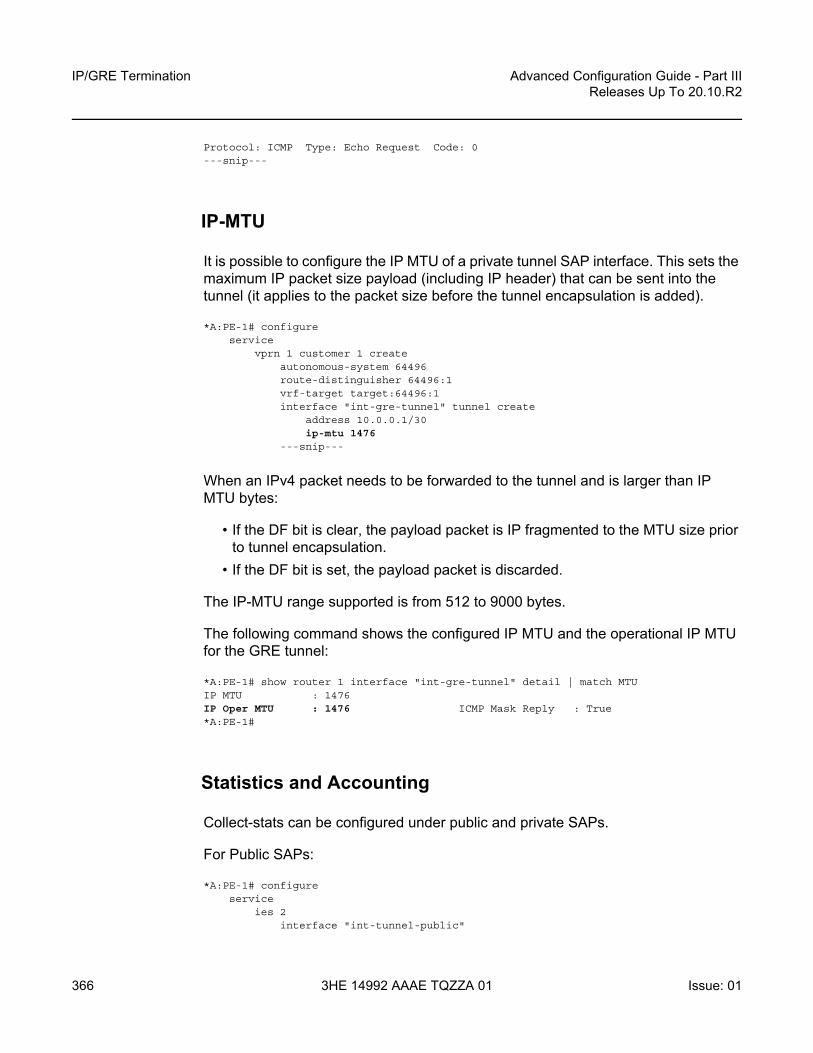
IP/GRE Termination
366
Advanced Configuration Guide - Part IIIReleases Up To 20.10.R2
3HE 14992 AAAE TQZZA 01 Issue: 01
Protocol: ICMP Type: Echo Request Code: 0---snip---
IP-MTU
It is possible to configure the IP MTU of a private tunnel SAP interface. This sets the maximum IP packet size payload (including IP header) that can be sent into the tunnel (it applies to the packet size before the tunnel encapsulation is added).
*A:PE-1# configureservice
vprn 1 customer 1 createautonomous-system 64496route-distinguisher 64496:1vrf-target target:64496:1interface "int-gre-tunnel" tunnel create
address 10.0.0.1/30ip-mtu 1476
---snip---
When an IPv4 packet needs to be forwarded to the tunnel and is larger than IP MTU bytes:
• If the DF bit is clear, the payload packet is IP fragmented to the MTU size prior to tunnel encapsulation.
• If the DF bit is set, the payload packet is discarded.
The IP-MTU range supported is from 512 to 9000 bytes.
The following command shows the configured IP MTU and the operational IP MTU for the GRE tunnel:
*A:PE-1# show router 1 interface "int-gre-tunnel" detail | match MTUIP MTU : 1476IP Oper MTU : 1476 ICMP Mask Reply : True*A:PE-1#
Statistics and Accounting
Collect-stats can be configured under public and private SAPs.
For Public SAPs:
*A:PE-1# configureservice
ies 2interface "int-tunnel-public"

Advanced Configuration Guide - Part III Releases Up To 20.10.R2
IP/GRE Termination
Issue: 01 3HE 14992 AAAE TQZZA 01 367
sap tunnel-1.public:1collect-stats
exitexjt
For Private SAPs:
*A:PE-1# configureservice
vprn 1interface "int-gre-tunnel"
sap tunnel-1.private:1collect-stats
exitexit
Filtering, Policing, and QoS
An IP-filter and QoS policy can be applied to the ingress and egress traffic of the private and public SAPs.
Public SAPs:
*A:PE-1# configureservice
ies 2 customer 1 createinterface "int-tunnel-public" create
address 192.168.1.2/30tos-marking-state untrustedsap tunnel-1.public:1 create
ingressqos 10filter ip 1
exitegress
qos 20filter ip 2
exit
Private SAPs:
*A:PE-1# configureservice
vprn 1 customer 1 createroute-distinguisher 64496:1vrf-target target:64496:1interface "int-gre-tunnel" tunnel create
address 10.0.0.1/30sap tunnel-1.private:1 create
ingressqos 10filter ip 1

IP/GRE Termination
368
Advanced Configuration Guide - Part IIIReleases Up To 20.10.R2
3HE 14992 AAAE TQZZA 01 Issue: 01
exitegress
qos 20filter ip 2
exit---snip---
Mirroring
The public and private SAPs can be mirrored.
*A:PE-1# show debugdebug
mirror-source 99sap tunnel-1.private:3 egress ingresssap tunnel-1.public:1 egress ingressno shutdown
exitexit
Conclusion
This chapter provides configuration and show commands for IP/GRE termination.

Advanced Configuration Guide - Part III Releases Up To 20.10.R2
L2-aware NAT (with dNAT and MNPs)
Issue: 01 3HE 14992 AAAE TQZZA 01 369
L2-aware NAT (with dNAT and MNPs)This chapter provides information about Network Address Translation (NAT) in combination with Enhanced Subscriber Management (ESM).
Topics in this chapter include:
• Applicability• Overview• Configuration• Conclusion• Appendix A – Generic ESM Configuration• Appendix B – Logging
Applicability
The information and configuration in this chapter are applicable to all SR OS nodes that support Broadband (BB) MS-ISAs, including the virtual version of MS-ISA in VSR, and was tested on SR OS 15.0.R4.
Overview
L2-aware network address translation (NAT) is an enhanced NAT functionality that offers better IPv4 address conservation ratios than traditional NAT44. L2-aware NAT relies on tight integration between enhanced subscriber management (ESM) and NAT, and in the context of ESM, it maps (or binds) an ESM subscriber to an outside IP address and a single port block (PB). In this fashion, the private (inside) IPv4 address in L2-aware NAT is abstracted from the binding.
Note: Binding is distinct from the flow/session concept. Flow or session state is maintained for each specific conversation between the two end nodes (this includes IP addresses, ports, and protocol), whereas binding is mapping between an inside entity (the subscriber ID in L2-aware NAT or the IPv4 source IP address in large scale NAT44 (LSN44)) and the outside IP address and the PB. Flows/session can then consume ports within the PB.

L2-aware NAT (with dNAT and MNPs)
370
Advanced Configuration Guide - Part IIIReleases Up To 20.10.R2
3HE 14992 AAAE TQZZA 01 Issue: 01
On the public side (outside), L2-aware NAT allows multiple hosts (inside IPv4 addresses) under the same subscriber to share the same outside IPv4 address and a PB. This contrasts with traditional NAT44 where each inside IPv4 address (host) is mapped to a unique IPv4 address and PB combination.
On the private side (inside), the abstraction of the host IPv4 address from the binding allows assignment of the same inside IPv4 address to multiple hosts that belong to different subscribers. This sharing of an inside IPv4 address between hosts that belong to different subscribers means that each host still has its own instance of the shared IPv4 address. For example, host 1 of subscriber 1 and host 2 of subscriber 2 can be both assigned the same inside IP address (for instance 10.10.1.1).
A binding in L2-aware NAT is defined as the following:
<subId, nat-policy> → <outside routing context, outside srcIP address, outside PB>
Where:
A simplified example of an L2-aware NAT binding is shown in Figure 72. Subscriber 1 is mapped to the outside IP address 172.16.1.1 and PB 1. This means that the source IP addresses (10.10.1.1 and 10.10.1.2) for all hosts under Subscriber 1 will be translated to 172.16.1.1 and the source port will be translated to one of the ports from PB 1. Similar logic can be applied to Subscriber 2 mappings, where Subscriber 2 hosts will use PB 2 from the same outside IP address.
InsideSub-id Subscriber ID in the ESM context.Nat-policy NAT policy associated with the ESM subscriber. This
association is performed within the sub-profile. A subscriber can have multiple NAT policies (MNPs), in which case each subscriber will have one binding per NAT policy.
OutsideOutside routing context
Outside routing context that contains an L2-aware pool. NAT traffic is sent out of the node via this routing context.
Outside SrcIP address A subscriber in conjunction with the NAT policy is assigned this outside IP address. The source IP address of the subscriber traffic will be replaced by this IP address.
Outside PB A subscriber in conjunction with the NAT policy is assigned this outside PB. A source (TCP/UDP) port of the subscriber traffic will be replaced by one of the source ports from this PB. In the ICMP case, the query ID is selected from this PB.

Advanced Configuration Guide - Part III Releases Up To 20.10.R2
L2-aware NAT (with dNAT and MNPs)
Issue: 01 3HE 14992 AAAE TQZZA 01 371
Figure 72 NAT Binding
NAT binding in MS-ISA will be used to translate traffic arriving from the subscriber. When the first packet of the flow from the subscriber is received, the translation is performed and a flow state is created. This flow state is maintained for the duration of the flow. All consecutive packets of the flow will rely on the flow state lookup for translation.
The flow mapping in L2-aware NAT is characterized as:
<subId, inside srcIP address, inside srcPort, foreign ip address, foreign port, protocol> → <outside routing context, outside IP address, outside port, destination ipaddress, foreign port, protocol>
Flow mapping is more specific than a binding (which is a partial mapping), and the fields in flow mapping are self-explanatory. The flow mapping contains the original source IP address, which is needed to determine where to send the return (downstream) traffic.
The subId field needs to be unique in the mappings at the subscriber level, allowing all the other fields (including the source IP address) to overlap between the subscribers. This is the basis for sharing of the source IP addresses between the subscribers.
In flow mapping, there is a naming distinction between the foreign IP address and the destination IP address. A foreign IP address is the original destination IP address in the packet sourced by the host. This foreign IP address can be translated by destination-based NAT (dNAT), just like source IP is translated by NAT. In this case, the translated foreign IP address on the outside in the SR OS CLI syntax becomes a destination IP address. This naming distinction helps to differentiate two IP addresses of the same field in the IP header, one before dNAT is performed and the other after dNAT is performed.
26868
subsciber 1 host1 (dhcp) srcpIP 10.10.1.1 host2 (pppoe) srcpIP 10.10.1.2
subsciber 2 host1 (dhcp) srcpIP 10.10.1.1 host2 (pppoe) srcpIP 10.10.1.2
WK
0-1023 65535
PB1 PB2 PBn
Public Ports
L2-AwareNAT
Public IP Address172.16.1.1

L2-aware NAT (with dNAT and MNPs)
372
Advanced Configuration Guide - Part IIIReleases Up To 20.10.R2
3HE 14992 AAAE TQZZA 01 Issue: 01
The reason why there is only a foreign port (and no destination port) is that in SR OS the original destination port is not translated by dNAT, while the original destination IP is.
L2-aware NAT requires that ESM and NAT are collocated in the same SR OS node. Because of the tight integration between ESM and NAT, logging of L2-aware NAT resources can be integrated into ESM accounting via AAA.
This chapter does not discuss L2-aware NAT intra-chassis redundancy. Intra-chassis redundancy for L2-aware NAT offers protection against MS-ISA failure. The supported modes are:
• Active/Standby MS-ISA• Active/Active MS-ISA• L2-aware Bypass
Each L2-aware NAT intra-chassis redundancy mode is described in the 7450 ESS, 7750 SR, and VSR Multiservice Integrated Service Adapter and Extended Services Appliance Guide.
Configuration
The test setup in this configuration example will accommodate:
• Two L2-aware subscribers.• Two hosts per L2-aware subscriber – one DHCPv4 host and one PPPoEv4 host
per L2-aware subscriber.• IP addresses overlap between the subscribers. • Traffic split from a single host to three different NAT pools and outside routing
contexts. This is achieved by selecting a NAT policy based on the destination IP address of the traffic.
• Destination-based NAT (dNAT) – some of the traffic is subjected to dNAT, where the destination IP address in the outgoing packet is translated (in addition to the source IP address and source port).
The test setup is shown in Figure 73.

Advanced Configuration Guide - Part III Releases Up To 20.10.R2
L2-aware NAT (with dNAT and MNPs)
Issue: 01 3HE 14992 AAAE TQZZA 01 373
Figure 73 Test Setup
The N2X traffic simulator on the left is used to simulate two homes (subscribers) with DHCPv4 and PPPoE hosts. Those hosts are terminated on an IES interface in a Base router in the BNG and they are further associated with the L2-aware NAT pools in VPRN1, VPRN2, and the Base router. ESM host authentication and IP address assignment is performed via local user database (LUDB). Accounting for the subscribers is sent to an AAA server and the accounting records contain NAT logging information.
Once the subscriber hosts are instantiated, traffic is sent through L2-aware NAT. This traffic is then used to further examine operation of L2-aware NAT in SR OS BNG.
The L2-aware NAT configuration in SR OS is split into two major parts:
• NAT-specific configuration – this is the subject of this document.
Base Router
N2X TrafficSimulator 401/2
L2-Aware NATNAT pool: 172.16.1.1I2-aware-vprn-1
VPRN 1
L2-Aware NATNAT pool: 172.16.2.2I2-aware-vprn-2dNAT: 192.168.8.5
VPRN 2
ESM
LUDB
N2X TrafficSimulator 402/1
L2-Aware NATNAT pool: 172.16.3.3I2-aware-base
AAA(Accounting
Server)
DHCPv4
PPPoEv4
Traffic Streams
SR OSBNG
26866

L2-aware NAT (with dNAT and MNPs)
374
Advanced Configuration Guide - Part IIIReleases Up To 20.10.R2
3HE 14992 AAAE TQZZA 01 Issue: 01
• ESM-specific configuration focuses on ESM subscribers and is described in other chapters in this volume. There are some key parts of ESM configuration that are essential for understanding L2-aware NAT operation and those parts will be described in this section. For the sake of completeness, the remaining, more generic part of ESM configuration is described in Appendix A – Generic ESM Configuration.
NAT-specific Configuration
L2-aware NAT requires the system IP address to be configured in the node. Without the system IP address, L2-aware NAT will not be operational. Lack of the system IP address within the L2-aware node is a common problem in most troubleshooting scenarios. The system IP is used within the system to pass traffic between the carrier IOM (where MS-ISA is attached) and the MS-ISA itself. The following is the command to configure the system IP address:
configurerouter
interface "system"address 192.0.2.2/32no shutdown
exit
The inside NAT context in the following code identifies the private (inside) side of NAT, which in this example is configured in the Base routing context.
The address in the l2-aware context (in this example, address 10.10.1.254/24) represents the default gateway and an L2-aware subnet. All ESM hosts with IP addresses within the configured L2-aware subnet (in this example, 10.10.2.0/24) are subjected to L2-aware NAT.
ESM hosts with IP addresses out of the L2-aware subnet can be instantiated as regular (not L2-aware) hosts, effectively bypassing L2-aware NAT within the L2-aware enabled subscriber.
The outside NAT context contains the NAT pool configuration that is used for address translation. In this example, traffic is mapped to three outside contexts: Base, VPRN 1, and VPRN 2. IP address 172.16.3.3 is used for translation in the Base outside routing context, IP address 172.16.1.1 in the VPRN 1 outside routing context, and IP address 172.16.2.2 in the VPRN 2 outside routing context.
VPRN 1 and VPRN 2 also contain NAT pools with their own IP addresses.
configurerouter
nat

Advanced Configuration Guide - Part III Releases Up To 20.10.R2
L2-aware NAT (with dNAT and MNPs)
Issue: 01 3HE 14992 AAAE TQZZA 01 375
insidel2-aware
address 10.10.1.254/24exit
exitoutside
pool "l2-aware-base" nat-group 1 type l2-aware createport-reservation ports 2000address-range 172.16.3.3 172.16.3.3 createexitno shutdown
exitexit
exit
configureservice
vprn 1 name "1" customer 1 createnat
outsidepool "l2-aware-vprn-1" nat-group 1 type l2-aware create
port-reservation ports 2000address-range 172.16.1.1 172.16.1.1 createexitno shutdown
exitexit
exitexitvprn 2 name "2" customer 1 create
natoutside
port-reservation ports 2000pool "l2-aware-vprn-2" nat-group 1 type l2-aware create
address-range 172.16.2.2 172.16.2.2 createexitno shutdown
exitexit
exitexit
NAT pool selection (and with this, the outside routing context) is performed based on the foreign IP address (traffic destination) in the packet. This is configured in the nat-prefix-list, which is then applied to the L2-aware subscriber via sub-profile.
Packets arriving from the inside and destined to networks 192.168.7.0/24 and 192.168.8.0/24 will be respectively routed to the VPRN 1 and VPRN 2 routing context, which are implied through NAT policies “l2-aware-vrf1” and “l2-aware-vrf2” referenced in the nat-prefix-list.
All other traffic will use the default NAT policy “l2-aware-base”, which is directly referenced in the sub-profile. This NAT policy is pointing to the Base outside routing context. Also, traffic identified by NAT classifier “vrf2” will be subject to dNAT.

L2-aware NAT (with dNAT and MNPs)
376
Advanced Configuration Guide - Part IIIReleases Up To 20.10.R2
3HE 14992 AAAE TQZZA 01 Issue: 01
In the example, NAT classifier “vrf2” identifies UDP traffic destined to port 5001. This implies that destination IP address for traffic that is mapped to VPRN 2 with UDP destination port 5001 will be translated. The new destination IP address (192.168.8.5) is configured in the NAT classifier “vrf2”, which is then applied via NAT policy “l2-aware-vrf2”.
All other traffic (destined to a destination UDP port other than 5001) will pass transparently through the classifier without the destination IP address being modified. Traffic that is subject to dNAT can be identified (or classified) based on destination-port only.
The block-limit command in L2-aware pool is automatically set to “1”. That is, each L2-aware subscriber is assigned exactly one PB. Additional PB allocation is not supported. That is why it is important that this single PB allocated to each L2-aware subscriber is initially configured with a large enough number of ports – this is performed via pool configuration (in this example, port-block size is set to 2000 ports). Once all the ports in this PB are exhausted, no new ports can be allocated.
configuresubscriber-mgmt
sub-profile "sub-prof-1" createnat-policy "l2-aware-base"nat-prefix-list "l2aware-mnp"
exit
configureservice
natnat-classifier "vrf2" create
entry 1 createaction dnat ip-address 192.168.8.5match protocol udp
dst-port-range start 5001 end 5001exit
exitexitnat-policy "l2-aware-base" create
block-limit 1pool "l2-aware-base" router Base
exitnat-policy "l2-aware-vrf1" create
block-limit 1pool "l2-aware-vprn-1" router 1
exitnat-policy "l2-aware-vrf2" create
dnatnat-classifier "vrf2"
exitexitnat-prefix-list "l2aware-mnp" application l2-aware-dest-to-policy create
prefix 192.168.7.0/24 nat-policy "l2-aware-vrf1"prefix 192.168.8.0/24 nat-policy "l2-aware-vrf2"
exitexit

Advanced Configuration Guide - Part III Releases Up To 20.10.R2
L2-aware NAT (with dNAT and MNPs)
Issue: 01 3HE 14992 AAAE TQZZA 01 377
On the ESM side, anti-spoof configuration is of particular importance in L2-aware NAT.
• L2-aware deployments with bridged homes (multiple ESM hosts within a subscriber) must have the anti-spoofing option set to ip-mac. This will allow each host within the home to be distinctly identified in ESM and consequently receive proper ESM treatment (filters, QoS, accounting, and so on).
• L2-aware deployments with routed CPEs must have the anti-spoofing option set to nh-mac. In this case, only one host per ESM subscriber is allowed and this single host is the routed CPE. There can be multiple hosts behind this routed CPE and they will be all seen and properly treated (using NAT) by the MS-ISA. However, ESM will not be aware of them and all downstream traffic will be sent to the routed CPE (ESM host), which will then further route traffic to the proper destination.From an ESM perspective, this approach is different from that for non-L2-aware ESM deployments. Non-L2-aware ESM deployments allow multiple ESM hosts per subscriber with the nh-mac anti-spoofing option enabled, where the ESM hosts have different MACs.
configuresubscriber-mgmt
msap-policy "msaps" createsub-sla-mgmt
sub-ident-policy "sub_ident_pol"multi-sub-sap limit 10
exities-vprn-only-sap-parameters
anti-spoof ip-macexit
exit
This preceding described configuration is shown in Figure 74.

L2-aware NAT (with dNAT and MNPs)
378
Advanced Configuration Guide - Part IIIReleases Up To 20.10.R2
3HE 14992 AAAE TQZZA 01 Issue: 01
Figure 74 Logical Mapping of Subscribers to L2-aware Pool
Logging
In this example, NAT logging is integrated with ESM accounting. This is configuration dependent and L2-aware NAT also supports syslog to convey information, about a subscriber that is hidden behind NAT, to the operator.
With RADIUS logging, NAT-specific information is carried in the Alc-Nat-Port-Range VSA, which must be explicitly enabled in accounting-policy. The ESM accounting model used in this example is per host-accounting with interim updates. For brevity, only the accounting records for host 1 of the subscriber 1 are shown following:
• Acct Start is generated when the ESM host is created. The first host for the subscriber will allocate NAT resources in the MS-ISA.
• Acct Interim-Update message is generated periodically (configuration dependent) and additionally carries information about consumed bytes flowing through queues/policers associated with the subscriber host.
N2X TrafficSimulator 401/2
N2X TrafficSimulator 402/1
26867
sub1 host1 (dhcp) srcpIP 10.10.1.1 host2 (pppoe) srcpIP 10.10.1.2
sub2 host1 (dhcp) srcpIP 10.10.1.1 host2 (pppoe) srcpIP 10.10.1.2
N2X Traffic Simulator 401/2
L2-Aware NATNAT pool: 172.16.1.1I2-aware-vprn-1
VPRN 1
Base Router
L2-Aware NATNAT pool: 172.16.2.2I2-aware-vprn-2dNAT: 192.168.8.5
VPRN 2
L2-Aware NATNAT pool: 172.16.3.3I2-aware-base
192.168.5.2
N2X Traffic Simulator 402/1
192.168.7.2
192.168.8.5

Advanced Configuration Guide - Part III Releases Up To 20.10.R2
L2-aware NAT (with dNAT and MNPs)
Issue: 01 3HE 14992 AAAE TQZZA 01 379
• Acct Stop is generated when the ESM host is terminated. NAT resources are then released. The significance of this is that freeing the NAT resources coincides with the termination of the subscriber, without having to wait for NAT flows in the MS-ISA to time out, long after the user has ceased.
Appendix B – Logging lists a more comprehensive stream of logs for all four hosts that are established in this exercise.
root@linux:/var/log/freeradius/radacct/192.168.114.2# more detail-20170814Mon Aug 14 09:14:45 2017
Acct-Status-Type = StartNAS-IP-Address = 192.0.2.2Framed-IP-Address = 10.10.1.1NAS-Identifier = "BNG1"Acct-Session-Id = "D896FF0000002E59916D5E"Acct-Multi-Session-Id = "D896FF0000002F59916D5E"Event-Timestamp = "Aug 14 2017 02:29:02 PDT"NAS-Port-Type = EthernetNAS-Port-Id = "1/1/5:1.1"ADSL-Agent-Circuit-Id = "sub-1"ADSL-Agent-Remote-Id = "host-1"Alc-Subsc-ID-Str = "sub-1"Alc-Subsc-Prof-Str = "sub-prof-1"Alc-SLA-Prof-Str = "sla-1"Alc-Nat-Port-Range = "172.16.3.3 1024-3023 router base l2-aware-base"Alc-Nat-Port-Range = "172.16.1.1 1024-3023 router 1 l2-aware-vrf1"Alc-Nat-Port-Range = "172.16.2.2 1024-3023 router 2 l2-aware-vrf2"Alc-Client-Hardware-Addr = "00:00:65:01:01:01"Acct-Unique-Session-Id = "fe5e55d7102d3f81"Timestamp = 1502727285Request-Authenticator = Verified
Mon Aug 14 09:20:11 2017Acct-Status-Type = Interim-UpdateNAS-IP-Address = 192.0.2.2Framed-IP-Address = 10.10.1.1NAS-Identifier = "BNG1"Acct-Session-Id = "D896FF0000002E59916D5E"Acct-Session-Time = 326Acct-Multi-Session-Id = "D896FF0000002F59916D5E"Event-Timestamp = "Aug 14 2017 02:34:28 PDT"NAS-Port-Type = EthernetNAS-Port-Id = "1/1/5:1.1"ADSL-Agent-Circuit-Id = "sub-1"ADSL-Agent-Remote-Id = "host-1"Alc-Subsc-ID-Str = "sub-1"Alc-Subsc-Prof-Str = "sub-prof-1"Alc-SLA-Prof-Str = "sla-1"Alc-Nat-Port-Range = "172.16.3.3 1024-3023 router base l2-aware-base"Alc-Nat-Port-Range = "172.16.1.1 1024-3023 router 1 l2-aware-vrf1"Alc-Nat-Port-Range = "172.16.2.2 1024-3023 router 2 l2-aware-vrf2"Alc-Client-Hardware-Addr = "00:00:65:01:01:01"Alc-Acct-Triggered-Reason = regularAlc-Acct-I-Inprof-Octets-64 = 0x00010000000000000000Alc-Acct-I-Outprof-Octets-64 = 0x0001000000000000b220Alc-Acct-I-Inprof-Pkts-64 = 0x00010000000000000000Alc-Acct-I-Outprof-Pkts-64 = 0x000100000000000001c8

L2-aware NAT (with dNAT and MNPs)
380
Advanced Configuration Guide - Part IIIReleases Up To 20.10.R2
3HE 14992 AAAE TQZZA 01 Issue: 01
Alc-Acct-O-Inprof-Octets-64 = 0x00010000000000000000Alc-Acct-O-Outprof-Octets-64 = 0x00010000000000000000Alc-Acct-O-Inprof-Pkts-64 = 0x00010000000000000000Alc-Acct-O-Outprof-Pkts-64 = 0x00010000000000000000Acct-Unique-Session-Id = "fe5e55d7102d3f81"Timestamp = 1502727611Request-Authenticator = Verified
Mon Aug 14 09:30:34 2017Acct-Status-Type = StopNAS-IP-Address = 192.0.2.2Framed-IP-Address = 10.10.1.1NAS-Identifier = "BNG1"Acct-Session-Id = "D896FF0000002E59916D5E"Acct-Session-Time = 949Acct-Terminate-Cause = User-RequestAcct-Multi-Session-Id = "D896FF0000002F59916D5E"Event-Timestamp = "Aug 14 2017 02:44:51 PDT"NAS-Port-Type = EthernetNAS-Port-Id = "1/1/5:1.1"ADSL-Agent-Circuit-Id = "sub-1"ADSL-Agent-Remote-Id = "host-1"Alc-Subsc-ID-Str = "sub-1"Alc-Subsc-Prof-Str = "sub-prof-1"Alc-SLA-Prof-Str = "sla-1"Alc-Nat-Port-Range = "172.16.3.3 1024-3023 router base l2-aware-base"Alc-Nat-Port-Range = "172.16.1.1 1024-3023 router 1 l2-aware-vrf1"Alc-Nat-Port-Range = "172.16.2.2 1024-3023 router 2 l2-aware-vrf2"Alc-Client-Hardware-Addr = "00:00:65:01:01:01"Alc-Acct-I-Inprof-Octets-64 = 0x00010000000000000000Alc-Acct-I-Outprof-Octets-64 = 0x00010000000000037974Alc-Acct-I-Inprof-Pkts-64 = 0x00010000000000000000Alc-Acct-I-Outprof-Pkts-64 = 0x000100000000000008e5Alc-Acct-O-Inprof-Octets-64 = 0x00010000000000000000Alc-Acct-O-Outprof-Octets-64 = 0x00010000000000000000Alc-Acct-O-Inprof-Pkts-64 = 0x00010000000000000000Alc-Acct-O-Outprof-Pkts-64 = 0x00010000000000000000Acct-Unique-Session-Id = "fe5e55d7102d3f81"Timestamp = 1502728234Request-Authenticator = Verified
root@linux:/var/log/freeradius/radacct/192.168.114.2#
Operational Commands
In this example, three streams of traffic are run from host 1 of each subscriber (six streams in total). Traffic flows in the upstream direction (from the inside routing context to the outside routing context) and it will cause L2-aware NAT to allocate resources and create mappings that can be observed with the show and debug commands.

Advanced Configuration Guide - Part III Releases Up To 20.10.R2
L2-aware NAT (with dNAT and MNPs)
Issue: 01 3HE 14992 AAAE TQZZA 01 381
Host 1 of each subscriber is initiating three streams to three different destinations. Accordingly, traffic from the same host will be (based on the destination) routed to three different L2-aware NAT pools and outside routing contexts. One of the streams (stream 3) will, in addition to its source IP address/port, have its destination IP address translated as well.
The six traffic stream definitions are shown in Table 11:
• All six streams have the same source IP address, 10.10.1.1. The significance of this is that both subscribers have hosts that are assigned the same inside (private) IP address.
• All streams carry UDP protocol.• The source UDP port is 5000 for all streams.• The UDP foreign port is 5000 except for the stream 3, which is assigned UDP
foreign port 5001. Traffic with the foreign port 5001 is identified through the NAT classifier and is selected for dNAT (foreign IP address will be translated).
• Each host sends traffic to three different destinations and this is signified by three different foreign IP addresses:- The stream with the foreign IP address 192.168.5.2 is sent to the Base
routing context (pool l2-aware-base).- The stream with the foreign IP address 192.168.7.2 is sent to the VPRN 1
routing context (pool l2-aware-vprn-1).- The stream with the foreign IP address 192.168.8.2 is sent to the VPRN 2
routing context (pool l2-aware-vprn-2).• The column labelled Out IP (Outside IP address) represents a newly translated
source (private) IP address by L2-aware NAT. Each of the three pools (one per routing context in Base, VPRN 1, and VPRN 2) has its own single outside IP address configured. In this example, each pool has a single outside IP address configured but, usually, multiple address ranges per NAT pool are supported.
• Each subscriber is allocated a single PB per pool with 2000 ports (configuration dependent) in each pool – this is reflected in the PB column. Subscriber 1 is allocated the same PB range in all three pools (one per routing context). A similar setup is shown for subscriber 2. In this example, the PBs allocated per subscriber in three pools coincidentally match due to a low number of subscribers in the system (only two subscribers in our example). Usually, with an increased number of subscribers in the system, the probability for matching PB allocations per subscriber across pools would decrease. That is, each pool allocates PB independently of any other pool.
• The Out Port column indicates a new (translated) source UDP source port, after L2-aware NAT is performed.

L2-aware NAT (with dNAT and MNPs)
382
Advanced Configuration Guide - Part IIIReleases Up To 20.10.R2
3HE 14992 AAAE TQZZA 01 Issue: 01
• The Dest IP column indicates that the foreign IP address is modified only for stream 3, which is subject to dNAT (identified by UDP foreign port 5001 via a NAT classifier). The remaining streams do not have foreign IP addresses translated.
• The Destination ports on the outside in all three streams remain unchanged. This applies even for stream 3, which is subject to dNAT (only the foreign IP address is translated by dNAT functionality).
Dynamically allocated parameters by L2-aware NAT are in the following traffic streams table (fields in bold typeface - Out IP, PB, Out Port, Dest IP) populated based on the observation in the system once the traffic is run. The values are collected based on the output provided by debug commands and a tools dump nat sessions command (both of them are shown further in the text).
Show Commands
A good starting point for troubleshooting is a generic NAT command, show service nat overview, with the output that would normally point to misconfiguration:
*A:BNG1# show service nat overview
===============================================================================NAT overview===============================================================================Inside/ Policy/ TypeOutside Pool-------------------------------------------------------------------------------* l2-aware-base l2aware
Table 11 Traffic Streams
Host Strm Packet Fields Before NAT (inside routing context – Base) Packet Fields After NAT (outside routing context)
Src IP Prot Src Port
Forgn Port
Forgn IP Outside Rtr
OutIP
PB Out Port
DestIP
Dest Port
Sub1 Host1
1 10.10.1.1 UDP 5000 5000 192.168.5.2 Base 172.16.3.3 1024-3023
2186 192.168.5.2 5000
2 192.168.7.2 VRF1 172.16.1.1 1024-3023
1124 192.168.7.2
3 5001 192.168.8.2 VRF2 172.16.2.2 1024-3023
3690 192.168.8.5 5001
Sub2Host1
4 10.10.1.1 UDP 5000 5000 192.168.5.2 Base 172.16.3.3 3024-5023
4470 192.168.5.2 5000
5 192.168.7.2 VRF1 172.16.1.1 3024-5023
4666 192.168.7.2
6 192.168.8.2 VRF2 172.16.2.2 3024-5023
4698 192.168.8.2

Advanced Configuration Guide - Part III Releases Up To 20.10.R2
L2-aware NAT (with dNAT and MNPs)
Issue: 01 3HE 14992 AAAE TQZZA 01 383
Base l2-aware-base
* l2-aware-vrf1 l2awarevprn1 l2-aware-vprn-1
* l2-aware-vrf2 l2awarevprn2 l2-aware-vprn-2===============================================================================
No firewall policies found.*A:BNG1#
The output of the show port statistics command provides information relevant to packet flow between the carrier IOM (to which the MS-ISA is attached) and the MS-ISA itself.
In the following output, “1/2/nat-in-l2” is the port on the carrier IOM that represents the private (inside) side of NAT and “1/2/nat-out-ip” is the port on the carrier IOM that represents the public (outside) side of NAT. In this example, traffic is sent only in one direction, from private side to public side, and therefore:
• Traffic is egressing port “1/2/nat-in-l2” on the IOM and entering MS-ISA on the private side (11789 packets).
• Traffic is leaving MS-ISA on the public side and ingressing port “1/2/nat-out-ip” on the IOM (11789 packets).
*A:BNG1# show port statistics
===============================================================================Port Statistics on Slot 1===============================================================================Port Ingress Ingress Egress EgressId Packets Octets Packets Octets-------------------------------------------------------------------------------1/1/2 223162 25147835 0 01/1/3 815114 78685140 614895 606303231/1/4 15484 1531339 230226 257282651/1/5 84116 8375228 1054 698541/1/10 5115 835288 345 1104421/2/nat-out-ip 11789 1131744 0 01/2/nat-in-l2 0 0 11789 1532570
===============================================================================Port Statistics on Slot A===============================================================================Port Ingress Ingress Egress EgressId Packets Octets Packets Octets-------------------------------------------------------------------------------A/1 81952168 0 28663 2721059===============================================================================

L2-aware NAT (with dNAT and MNPs)
384
Advanced Configuration Guide - Part IIIReleases Up To 20.10.R2
3HE 14992 AAAE TQZZA 01 Issue: 01
NAT resources are allocated during the subscriber instantiation phase (when the first host for an L2-aware subscriber is created), before any data traffic from the subscriber side is even initiated.
The following command is run to verify that the two subscribers, each with two hosts (one DHCP and one PPPoE) are online. In addition, this command lists limited input related to L2-aware NAT:
• NAT policies associated with the subscriber• Outside IP address allocated to the subscriber• Port range in a PB
As shown in the output of this command, both L2-aware subscribers have hosts with overlapping IP addresses, which is a unique characteristic in L2-aware NAT functionality.
*A:BNG1# show service active-subscribers
===============================================================================Active Subscribers===============================================================================-------------------------------------------------------------------------------Subscriber sub-1 (sub-prof-1)-------------------------------------------------------------------------------NAT Policy: l2-aware-baseOutside IP: 172.16.3.3Ports : 1024-3023
NAT Policy: l2-aware-vrf1Outside IP: 172.16.1.1 (vprn1)Ports : 1024-3023
NAT Policy: l2-aware-vrf2Outside IP: 172.16.2.2 (vprn2)Ports : 1024-3023
--------------------------------------------------------------------------------------------------------------------------------------------------------------(1) SLA Profile Instance sap:[1/1/5:1.1] - sla:sla-1-------------------------------------------------------------------------------IP Address
MAC Address Session Origin Svc Fwd-------------------------------------------------------------------------------10.10.1.2
00:00:65:01:01:02 PPP 1 IPCP 3 Y10.10.1.1
00:00:65:01:01:01 N/A DHCP 3 Y-------------------------------------------------------------------------------
-------------------------------------------------------------------------------Subscriber sub-2 (sub-prof-1)-------------------------------------------------------------------------------NAT Policy: l2-aware-baseOutside IP: 172.16.3.3

Advanced Configuration Guide - Part III Releases Up To 20.10.R2
L2-aware NAT (with dNAT and MNPs)
Issue: 01 3HE 14992 AAAE TQZZA 01 385
Ports : 3024-5023
NAT Policy: l2-aware-vrf1Outside IP: 172.16.1.1 (vprn1)Ports : 3024-5023
NAT Policy: l2-aware-vrf2Outside IP: 172.16.2.2 (vprn2)Ports : 3024-5023
--------------------------------------------------------------------------------------------------------------------------------------------------------------(1) SLA Profile Instance sap:[1/1/5:1.2] - sla:sla-1-------------------------------------------------------------------------------IP Address
MAC Address Session Origin Svc Fwd-------------------------------------------------------------------------------10.10.1.2
00:00:65:01:02:02 PPP 1 IPCP 3 Y10.10.1.1
00:00:65:01:02:01 N/A DHCP 3 Y-------------------------------------------------------------------------------
-------------------------------------------------------------------------------Number of active subscribers : 2===============================================================================*A:BNG1#
NAT-specific show commands can provide more information about the L2-aware subscribers. One such command is show service nat l2-aware-subscribers. In this example, this command is run in a simplest form, but it can be expanded with additional filtering capabilities:
show service nat l2-aware-subscribers [nat-policy <policy-name>] [nat-group <nat-group-id>] [member <[1..255]>] [outside-router <router-instance>] [outside-ip <outside-ip-address>] [firewall-policy <policy-name>]
*A:BNG1# show service nat l2-aware-subscribers
===============================================================================Layer-2-Aware NAT subscribers===============================================================================
Subscriber : sub-1-------------------------------------------------------------------------------ISA NAT group : 1ISA NAT group member : 1UPnP policy : (None)Default NAT policy : l2-aware-basePer-host port block size : N/AFirewall policy : (None)
Policy : l2-aware-basePurpose : natOutside router : BaseOutside IP : 172.16.3.3DNAT default IP address override : (Not Specified)

L2-aware NAT (with dNAT and MNPs)
386
Advanced Configuration Guide - Part IIIReleases Up To 20.10.R2
3HE 14992 AAAE TQZZA 01 Issue: 01
DNAT disabled by override : falsePorts : 1024-3023
Policy : l2-aware-vrf1Purpose : natOutside router : vprn1Outside IP : 172.16.1.1DNAT default IP address override : (Not Specified)DNAT disabled by override : falsePorts : 1024-3023
Policy : l2-aware-vrf2Purpose : natOutside router : vprn2Outside IP : 172.16.2.2DNAT default IP address override : (Not Specified)DNAT disabled by override : falsePorts : 1024-3023
Subscriber : sub-2-------------------------------------------------------------------------------ISA NAT group : 1ISA NAT group member : 1UPnP policy : (None)Default NAT policy : l2-aware-basePer-host port block size : N/AFirewall policy : (None)
Policy : l2-aware-basePurpose : natOutside router : BaseOutside IP : 172.16.3.3DNAT default IP address override : (Not Specified)DNAT disabled by override : falsePorts : 3024-5023
Policy : l2-aware-vrf1Purpose : natOutside router : vprn1Outside IP : 172.16.1.1DNAT default IP address override : (Not Specified)DNAT disabled by override : falsePorts : 3024-5023
Policy : l2-aware-vrf2Purpose : natOutside router : vprn2Outside IP : 172.16.2.2DNAT default IP address override : (Not Specified)DNAT disabled by override : falsePorts : 3024-5023
-------------------------------------------------------------------------------No. of subscribers: 2
===============================================================================

Advanced Configuration Guide - Part III Releases Up To 20.10.R2
L2-aware NAT (with dNAT and MNPs)
Issue: 01 3HE 14992 AAAE TQZZA 01 387
Host-level L2-aware NAT information can be obtained via the show service nat l2-aware-hosts command. This command also provides additional filters for more targeted results:
show service nat l2-aware-hosts [outside-router <router-instance>] [outside-ip <outside-ip-address>] [inside-ip-prefix <ip-prefix/mask>]
In this case, the most generic version of this command is run where all four hosts and their L2-aware NAT specific information is shown:
*A:BNG1# show service nat l2-aware-hosts
===============================================================================Layer-2-Aware NAT hosts===============================================================================Subscriber : sub-1Inside IP address : 10.10.1.1-------------------------------------------------------------------------------Policy : l2-aware-baseBypassing : falseOutside router : "Base"Outside IP address : 172.16.3.3Port block : N/A
Policy : l2-aware-vrf1Bypassing : falseOutside router : 1Outside IP address : 172.16.1.1Port block : N/A
Policy : l2-aware-vrf2Bypassing : falseOutside router : 2Outside IP address : 172.16.2.2Port block : N/A
Subscriber : sub-1Inside IP address : 10.10.1.2-------------------------------------------------------------------------------Policy : l2-aware-baseBypassing : falseOutside router : "Base"Outside IP address : 172.16.3.3Port block : N/A
Policy : l2-aware-vrf1Bypassing : falseOutside router : 1Outside IP address : 172.16.1.1Port block : N/A
Policy : l2-aware-vrf2Bypassing : falseOutside router : 2Outside IP address : 172.16.2.2Port block : N/A

L2-aware NAT (with dNAT and MNPs)
388
Advanced Configuration Guide - Part IIIReleases Up To 20.10.R2
3HE 14992 AAAE TQZZA 01 Issue: 01
Subscriber : sub-2Inside IP address : 10.10.1.1-------------------------------------------------------------------------------Policy : l2-aware-baseBypassing : falseOutside router : "Base"Outside IP address : 172.16.3.3Port block : N/A
Policy : l2-aware-vrf1Bypassing : falseOutside router : 1Outside IP address : 172.16.1.1Port block : N/A
Policy : l2-aware-vrf2Bypassing : falseOutside router : 2Outside IP address : 172.16.2.2Port block : N/A
Subscriber : sub-2Inside IP address : 10.10.1.2-------------------------------------------------------------------------------Policy : l2-aware-baseBypassing : falseOutside router : "Base"Outside IP address : 172.16.3.3Port block : N/A
Policy : l2-aware-vrf1Bypassing : falseOutside router : 1Outside IP address : 172.16.1.1Port block : N/A
Policy : l2-aware-vrf2Bypassing : falseOutside router : 2Outside IP address : 172.16.2.2Port block : N/A
-------------------------------------------------------------------------------No. of hosts: 4===============================================================================
The following two commands are more generic and their output displays packet and event statistics related to NAT operation in two contexts:
• Per MS-ISA• Per member within the ISA
A member within an MS-ISA is a concept related to intra-chassis redundancy. CPM maintains a copy of the member configuration so that it can download it to a rescuing MS-ISA during the switchover (when an MS-ISA fails). An MS-ISA can contain one or more (in A/A redundancy model) members.

Advanced Configuration Guide - Part III Releases Up To 20.10.R2
L2-aware NAT (with dNAT and MNPs)
Issue: 01 3HE 14992 AAAE TQZZA 01 389
show isa nat-group 1 mda 1/2 statisticsshow isa nat-group 1 member 1 statistics
The output is the following:
*A:BNG1# show isa nat-group 1 mda 1/2 statistics===============================================================================ISA NAT Group 1 MDA 1/1===============================================================================no resource : 0pkt rx on wrong port : 0unsupported protocol : 0no host or host group : 0no ip or port : 0no matching flow : 0max flow exceeded : 0TCP no flow for RST : 0TCP no flow for FIN : 0TCP no flow : 0addr. dep. filtering : 0ICMP type unsupported : 0ICMP local unsupported : 0ICMP/ICMPv6 checksum error : 0ICMP embedded checksum error : 0ICMP/ICMPv6 unsupported embedded L4 : 0ICMP/ICMPv6 too short : 0ICMP/ICMPv6 length error : 0Pkt not IPv4 or IPv6 : 0Pkt rcv error : 0Pkt error : 0IPv4 header checksum violation : 0IP header malformed : 0IP malformed packet : 0IP ttl zero : 0IPv4 opt /IPv6 ext headers : 0IP undefined error : 0IPv6 fragments unsupported : 0TCP/UDP malformed : 0TCP/UDP checksum failure : 0Pkt send error : 0no buf to copy pkt : 0no policy : 0policy not in use by subscriber : 0locked by mgmt core : 0port range log failed : 0MTU exceeded : 0DS Lite unrecognized next hdr : 0DS Lite unknown AFTR : 0too many fragments for IP packet : 0too many fragmented packets : 0too many fragment holes : 0too many frags buffered : 0fragment list expired : 0fragment rate too high : 0flow log failed : 0no multiple host or subscr. IPs allowed : 0NAT64 disabled : 0NAT64 invalid src addr : 0

L2-aware NAT (with dNAT and MNPs)
390
Advanced Configuration Guide - Part IIIReleases Up To 20.10.R2
3HE 14992 AAAE TQZZA 01 Issue: 01
NAT64 frag has zero checksum : 0NAT64 v4 has zero checksum : 0NAT64 ICMP frag unsupported : 0Reassembly Failures : 0subscriber-id unknown : 0packet hashed to wrong MDA : 0Nptv6 map failed : 0Nptv6 IID all 1's : 0UPnP rate too high : 0Dest. IP is unroutable : 0no TCP/UDP checksum : 0to local : 0to local ignored : 0new flow : 0TCP closed : 0TCP expired : 0UDP expired : 0ICMP/ICMPv6 expired : 0GRE expired : 0ICMP local : 0found flow : 0ARPs ignored : 10Fragments RX L2A : 0Fragments RX LSN : 0Fragments RX DSL : 0Fragments RX DORMANT : 0Fragments RX OUT : 0Fragments TX L2A : 0Fragments TX LSN : 0Fragments TX DSL : 0Fragments TX DORMANT : 0Fragments TX NAT64 : 0Fragments TX OUT : 0flow create logged : 0flow delete logged : 0flow log pkt tx : 0Reassembled Pkts : 0subscriber-id cached : 0subscriber-id delayed : 0subscriber-id timeout : 0forwarded DS-Lite V6 pkts : 0V6 pkts fragmented : 0dropped multicast : 0SSDP rx : 0SSDP tx : 0SSDP dropped : 0UPnP rx : 0UPnP tx : 0UPnP dropped : 0no radius resources : 0no radius connection resources : 0Dest. NAT dest. IP mismatch : 0Dest. NAT foreign IP mismatch : 0temp. no policy : 0no SNat enabled : 0no default policy : 0flow create failed, key ambiguous : 0flow create failed, conflicting policies : 0NAT64 unrecognized next hdr : 0

Advanced Configuration Guide - Part III Releases Up To 20.10.R2
L2-aware NAT (with dNAT and MNPs)
Issue: 01 3HE 14992 AAAE TQZZA 01 391
ICMP/ICMPv6 unsupported embedded L3 : 0TCP reset waiting : 0IPv6 downstream prohibited : 0IPv6 ext. hdr parse error : 0any V6 L4 expired : 0ICMP embedded IPv6 ext. hdr parse error : 0ICMPv6 type unsupported : 0ICMP/ICMPv6 fragmented error : 0Service-chaining rx : 0Service-chaining tx : 0Service-chaining encapsulation error : 0Service-chaining decapsulation error : 0Service-chaining filter drop : 0PPPoE uplink down : 0ICMP6 PTB dropped (mtu < 1280) : 0firewall addr. dep. filtering : 0unresolved L2-aware V6 host : 0===============================================================================*A:BNG1#
Resources monitoring is performed via the following commands:
tools dump nat isa resources nat-group <id> member <id>tools dump nat isa resources mda <card-id/mds-id>show isa nat-system-resources nat-group <id> member <id>
The NAT scale depends on the hardware (vSIMs, MS-ISA1, MS-ISA2, VSR-NAT).
Tools Commands
To display the complete session state, the following command can be used:
tools dump nat sessions [nat-group <nat-group-id>] [mda <mda-id>] [protocol {gre|icmp|icmp6|tcp|udp|unknown}] [inside-ip <ip-prefix[/ip-prefix- length]>] [inside-router <router-instance>] [inside-port <port-number>] [outside-ip <ipv4-address>] [outside-port <port-number>] [foreign-ip
<ip-address>] [foreign-port <port-number>] [dslite-address<ipv6-address>] [wlan-gw-ue <ieee-
address>] [next index <index>] [upnp] [member <member-id>] [nat-policy <policy-name>] [dest-ip <ip-address>] [firewall-policy <policy-name>] [address-type <addr-type>] [vas-filter
<filter-name>] [vas-filter-entry <vas-filter-entry-id>][l2-aware-subscriber <sub-ident>]
The output of this command is used to populate dynamically allocated fields (in bold) in Table 11. The command, in its basic form, is run as:
*A:BNG1# tools dump nat sessions
===============================================================================Matched 6 sessions on Slot #1 MDA #2===============================================================================

L2-aware NAT (with dNAT and MNPs)
392
Advanced Configuration Guide - Part IIIReleases Up To 20.10.R2
3HE 14992 AAAE TQZZA 01 Issue: 01
Owner : L2-aware Subscr sub-1Policy : l2-aware-vrf1FlowType : UDP Timeout (sec) : 299Inside IP Addr : 10.10.1.1Inside Port : 5000Outside IP Addr : 172.16.1.1Outside Port : 1124Foreign IP Addr : 192.168.7.2Foreign Port : 5000Dest IP Addr : 192.168.7.2Nat Group : 1Nat Group Member : 1-------------------------------------------------------------------------------Owner : L2-aware Subscr sub-2Policy : l2-aware-vrf1FlowType : UDP Timeout (sec) : 300Inside IP Addr : 10.10.1.1Inside Port : 5000Outside IP Addr : 172.16.1.1Outside Port : 4666Foreign IP Addr : 192.168.7.2Foreign Port : 5000Dest IP Addr : 192.168.7.2Nat Group : 1Nat Group Member : 1-------------------------------------------------------------------------------Owner : L2-aware Subscr sub-2Policy : l2-aware-baseFlowType : UDP Timeout (sec) : 300Inside IP Addr : 10.10.1.1Inside Port : 5000Outside IP Addr : 172.16.3.3Outside Port : 4470Foreign IP Addr : 192.168.5.2Foreign Port : 5000Dest IP Addr : 192.168.5.2Nat Group : 1Nat Group Member : 1-------------------------------------------------------------------------------Owner : L2-aware Subscr sub-1Policy : l2-aware-vrf2FlowType : UDP Timeout (sec) : 300Inside IP Addr : 10.10.1.1Inside Port : 5000Outside IP Addr : 172.16.2.2Outside Port : 2068Foreign IP Addr : 192.168.8.2Foreign Port : 5001Dest IP Addr : 192.168.8.5Nat Group : 1Nat Group Member : 1-------------------------------------------------------------------------------Owner : L2-aware Subscr sub-1Policy : l2-aware-baseFlowType : UDP Timeout (sec) : 299Inside IP Addr : 10.10.1.1Inside Port : 5000Outside IP Addr : 172.16.3.3Outside Port : 2186

Advanced Configuration Guide - Part III Releases Up To 20.10.R2
L2-aware NAT (with dNAT and MNPs)
Issue: 01 3HE 14992 AAAE TQZZA 01 393
Foreign IP Addr : 192.168.5.2Foreign Port : 5000Dest IP Addr : 192.168.5.2Nat Group : 1Nat Group Member : 1-------------------------------------------------------------------------------Owner : L2-aware Subscr sub-2Policy : l2-aware-vrf2FlowType : UDP Timeout (sec) : 299Inside IP Addr : 10.10.1.1Inside Port : 5000Outside IP Addr : 172.16.2.2Outside Port : 3690Foreign IP Addr : 192.168.8.2Foreign Port : 5000Dest IP Addr : 192.168.8.2Nat Group : 1Nat Group Member : 1-------------------------------------------------------------------------------
Clear Commands
The following command clears L2-aware subscribers:
clear nat isa nat-group 1 member 1 l2-aware-
Debug Commands
Troubleshooting ESM subscribers is described in other configuration guides focusing on ESM. This chapter focuses only on the NAT aspect of ESM in L2-aware NAT.
L2-aware NAT debug output shows session (or flow) initiation information. As traffic is run, translations of the source IP address/port are performed and this information is displayed for debugging purposes. Traffic from both subscribers in this example is debugged with these two commands:
*A:BNG1# show debugdebug
natl2-aware-sub id 1 subscriber "sub-1"l2-aware-sub id 2 subscriber "sub-2"
Note: ESM subscribers are also deleted with this command. Therefore, this command should be used with caution because DHCP hosts in ESM do not send termination messages back to the client. This leaves the DHCP client in a state where it is not aware that its DHCP state in the L2-aware node has been deleted.

L2-aware NAT (with dNAT and MNPs)
394
Advanced Configuration Guide - Part IIIReleases Up To 20.10.R2
3HE 14992 AAAE TQZZA 01 Issue: 01
exitexit
The following configuration sends debug output to the Telnet/SSH sessions screen:
A:BNG1>config>log# info----------------------------------------------
log-id 50from debug-traceto sessionno shutdown
exit
Debug output shows translations that are being performed on the incoming traffic, which consists of six streams in this example:
1 2017/08/31 08:37:39.223 WEST MINOR: DEBUG #2001 Base NAT "NAT: L2-Aware@sub-1Initiated flow from 172.16.3.3(port 2186) to 192.168.5.2(port 5000) protocol UDP"
2 2017/08/31 08:37:39.223 WEST MINOR: DEBUG #2001 Base NAT "NAT: L2-Aware@sub-1Initiated flow from 172.16.1.1(port 1124) to 192.168.7.2(port 5000) protocol UDP"
3 2017/08/31 08:37:39.483 WEST MINOR: DEBUG #2001 Base NAT "NAT: L2-Aware@sub-1Initiated flow from 172.16.2.2(port 3690) to 192.168.8.2(port 5001) protocol UDP"
4 2017/08/31 08:37:39.743 WEST MINOR: DEBUG #2001 Base NAT "NAT: L2-Aware@sub-2Initiated flow from 172.16.3.3(port 4470) to 192.168.5.2(port 5000) protocol UDP"
5 2017/08/31 08:37:39.743 WEST MINOR: DEBUG #2001 Base NAT "NAT: L2-Aware@sub-2Initiated flow from 172.16.1.1(port 4666) to 192.168.7.2(port 5000) protocol UDP"
6 2017/08/31 08:37:40.003 WEST MINOR: DEBUG #2001 Base NAT "NAT: L2-Aware@sub-2Initiated flow from 172.16.2.2(port 4698) to 192.168.8.2(port 5000) protocol UDP”
Note that dNAT information is not displayed in the debug output.
Conclusion
L2-aware NAT integrates NAT functionality into ESM. NAT resources (outside IP address and a PB) are allocated per ESM subscriber and, consequently, all the hosts within the subscriber share those NAT resources. Each subscriber is initially assigned a single PB that will be used during the lifetime of the subscriber. The number of ports in this PB must be large enough to accommodate the needs of the subscriber during its lifetime.
The integration between ESM and NAT in L2-aware NAT introduces the following:

Advanced Configuration Guide - Part III Releases Up To 20.10.R2
L2-aware NAT (with dNAT and MNPs)
Issue: 01 3HE 14992 AAAE TQZZA 01 395
• Using the subscriber-id field (instead of source IPv4 address) to identify the NAT binding allows the source IPv4 address to be abstracted from the binding. This allows hosts of different subscribers to have overlapping IP addresses . IPv4 addresses cannot overlap between the hosts of the same subscriber, but they can overlap between the hosts of different subscribers.
• NAT logging can be integrated into ESM RADIUS accounting, simplifying operations and removing the need for a separate network resource dedicated to the collection of NAT logs.
• NAT resources are released when the ESM subscriber is disconnected. This prevents lingering of NAT resources in the system waiting for the timer of the last session to expire long after the entity that initially requested those resources ceased to exist. This improves resource utilization in a system with a high number of subscribers.
L2-aware NAT should be considered for deployment because it allows coupling between ESM and NAT.
Appendix A – Generic ESM Configuration
Appendix A describes the generic part of the ESM configuration.
ESM configuration starts with a subscriber-interface configured in an inside routing context. In this example, subscriber hosts are instantiated in the IES 3 service, under the group-interface “group-int-1”, which is created under the subscriber-interface “sub-int-1”. Authentication and address assignment of the subscriber hosts is performed via local user database (LUDB) user-db “user-db-1”. The IP addresses that are assigned to the hosts are statically configured in LUDB (no DHCP server is used in this setup).
configureservice
ies 3 customer 1 createsubscriber-interface "sub-int-1" create
address 10.10.1.254/24group-interface "group-int-1" create
dhcpproxy-server
emulated-server 10.10.1.254no shutdown
exitoption
action keepcircuit-idremote-id
exittrusted

L2-aware NAT (with dNAT and MNPs)
396
Advanced Configuration Guide - Part IIIReleases Up To 20.10.R2
3HE 14992 AAAE TQZZA 01 Issue: 01
lease-populate 100gi-address 10.10.1.254user-db "user-db-1"no shutdown
exitpppoe
anti-spoof mac-sid-ippolicy "pppoe_pol"session-limit 100sap-session-limit 100user-db "user-db-1"
no shutdownexitno shutdown
exitexit
exitservice-name "ies-3"no shutdown
exitexit
Subscriber SAPs are automatically created based on the VLAN tags carried in the initial control packets of the subscriber hosts. This VLAN auto-detection and SAP auto-creation is configured under the capture SAP hierarchy. The capture SAP is configured to support LUDB authentication for dynamic DHCPv4/PPPoEv4 host instantiation, as follows:
configureservice
vpls 10 name "10" customer 1 createsap 1/1/5:1.* capture-sap create
trigger-packet dhcp pppoedhcp-user-db "user-db-1"pppoe-policy "pppoe_pol"pppoe-user-db "user-db-1"
exitexit
The first interaction between ESM and L2-aware NAT is performed through a sub-profile. Specifically, a nat-policy within the sub-profile is used to associate the ESM subscriber with NAT.
A nat-prefix-list within the sub-profile provides the place to configure multiple nat-policies per subscriber. Selection of nat-policy (and with this, the NAT pool and outside routing context) is based on the destination IP address in the packet sent by the subscriber.
RADIUS accounting records passed to the accounting server will contain subscriber-host specific information, including NAT logs. This is configured via a RADIUS accounting policy, which is referenced in the sub-profile.
configure

Advanced Configuration Guide - Part III Releases Up To 20.10.R2
L2-aware NAT (with dNAT and MNPs)
Issue: 01 3HE 14992 AAAE TQZZA 01 397
subscriber-mgmtsub-profile "sub-prof-1" create
nat-policy "l2-aware-base"nat-prefix-list "l2aware-mnp"radius-accounting
policy "acct"exit
exit
Although an sla-profile is a mandatory configuration for a subscriber, the sla-profile content is not relevant for understanding L2-aware NAT concepts. A basic sla-profile is chosen with default settings: a default qos-policy 1 and no ip-filters.
The Sub-profile and sla-profile are associated with the subscriber(-host) during the authentication phase and, in this case, this is achieved through LUDB.
configuresubscriber-mgmt
sla-profile "sla-1" createexit
The MSAP policy is a mandatory configuration for dynamically created SAPs (Managed SAP or MSAPs). It is used to determine SAP parameters during the MSAP creation process based on control traffic (DHCP or PPPoE) of the first host (MSAP trigger traffic). Parameters defined in msap-policy that are of relevance to our example are:
• Sub-ident-policy → this is a mandatory parameter in ESM that governs mapping of subscriber-related profiles (sub-profile, SLA-profile) to the subscriber host during the authentication phase.
• Anti-spoof filter → this is of particular importance in L2-aware NAT and is already described in more detail in the Configuration section.
configuresubscriber-mgmt
msap-policy "msaps" createsub-sla-mgmt
sub-ident-policy "sub_ident_pol"multi-sub-sap limit 10
exities-vprn-only-sap-parameters
anti-spoof ip-macexit
exit
Sub-ident-policy is a mandatory configuration in ESM. It determines the mapping method between the sub/SLA profiles and the corresponding strings obtained during the authentication phase for the subscriber. Subscriber strings obtained during the authentication phase point, in some form (determined by sub-ident-policy), to the configured sub/SLA profiles (in the SR OS node) that will be associated with the subscriber.

L2-aware NAT (with dNAT and MNPs)
398
Advanced Configuration Guide - Part IIIReleases Up To 20.10.R2
3HE 14992 AAAE TQZZA 01 Issue: 01
configuresubscriber-mgmt
sub-ident-policy "sub_ident_pol" createsub-profile-map
use-direct-map-as-defaultexitsla-profile-map
use-direct-map-as-defaultexit
exit
In this example, authentication of the subscriber hosts and IP address assignment is performed through LUDB. The hosts are identified based on circuit-id and remote-id fields in DHCP and PPPoE control packets. Sla-sub-profile strings in the LUDB are directly mapped to the configured sub/sla-profiles in SR OS node. This direct mapping is implied by the preceding use-direct-map-as-default command within sub-ident-policy. The LUDB carries only ESM specific configuration. There is no NAT relevant configuration present in the LUDB.
configuresubscriber-mgmt
local-user-db "user-db-1" createipoe
match-list circuit-id remote-idhost "sub-1-host-1" create
host-identificationcircuit-id string "sub-1"remote-id string "host-1"
exitaddress 10.10.1.1identification-strings 254 create
subscriber-id "sub-1"sla-profile-string "sla-1"sub-profile-string "sub-prof-1"
exitmsap-defaults
group-interface "group-int-1"policy "msaps"service 3
exitoptions
subnet-mask 255.255.255.0exitno shutdown
exithost "sub-2-host-1" create
host-identificationcircuit-id string "sub-2"remote-id string "host-1"
exitaddress 10.10.1.1identification-strings 254 create
subscriber-id "sub-2"sla-profile-string "sla-1"sub-profile-string "sub-prof-1"
exit

Advanced Configuration Guide - Part III Releases Up To 20.10.R2
L2-aware NAT (with dNAT and MNPs)
Issue: 01 3HE 14992 AAAE TQZZA 01 399
msap-defaultsgroup-interface "group-int-1"policy "msaps"service 3
exitoptions
subnet-mask 255.255.255.0exitno shutdown
exitexitppp
match-list circuit-id remote-idhost "sub-1-host-2" create
host-identificationcircuit-id string "sub-1"remote-id string "host-2"
exitaddress 10.10.1.2/24identification-strings 254 create
subscriber-id "sub-1"sla-profile-string "sla-1"sub-profile-string "sub-prof-1"
exitmsap-defaults
group-interface "group-int-1"policy "msaps"service 3
exitno shutdown
exithost "sub-2-host-2" create
host-identificationcircuit-id string "sub-2"remote-id string "host-2"
exitaddress 10.10.1.2/24identification-strings 254 create
subscriber-id "sub-2"sla-profile-string "sla-1"sub-profile-string "sub-prof-1"
exitmsap-defaults
group-interface "group-int-1"policy "msaps"service 3
exitno shutdown
exitexitno shutdown
exit
The accounting policy identifies the type of accounting and the attributes that will be carried in an accounting message. Among the ESM-specific attributes, nat-port-range is the only NAT-related attribute that will carry NAT logging information for the subscriber.

L2-aware NAT (with dNAT and MNPs)
400
Advanced Configuration Guide - Part IIIReleases Up To 20.10.R2
3HE 14992 AAAE TQZZA 01 Issue: 01
configuresubscriber-mgmt
radius-accounting-policy "acct" createno queue-instance-accountinghost-accounting interim-updateupdate-interval 5include-radius-attribute
circuit-idframed-ip-addrmac-addressnas-identifiernas-port-idnat-port-rangeremote-idsla-profilesub-profilesubscriber-iduser-namealc-acct-triggered-reason
exitsession-id-format numberradius-server-policy "aaa"
exit
Appendix B – Logging
Appendix B shows the RADIUS logging stream for all four hosts used in this chapter:
root@ linux:/var/log/freeradius/radacct/192.168.114.2# more detail-20170814Mon Aug 14 09:14:45 2017
Acct-Status-Type = StartNAS-IP-Address = 192.0.2.2Framed-IP-Address = 10.10.1.1NAS-Identifier = "BNG1"Acct-Session-Id = "D896FF0000002E59916D5E"Acct-Multi-Session-Id = "D896FF0000002F59916D5E"Event-Timestamp = "Aug 14 2017 02:29:02 PDT"NAS-Port-Type = EthernetNAS-Port-Id = "1/1/5:1.1"ADSL-Agent-Circuit-Id = "sub-1"ADSL-Agent-Remote-Id = "host-1"Alc-Subsc-ID-Str = "sub-1"Alc-Subsc-Prof-Str = "sub-prof-1"Alc-SLA-Prof-Str = "sla-1"Alc-Nat-Port-Range = "172.16.3.3 1024-3023 router base l2-aware-base"Alc-Nat-Port-Range = "172.16.1.1 1024-3023 router 1 l2-aware-vrf1"Alc-Nat-Port-Range = "172.16.2.2 1024-3023 router 2 l2-aware-vrf2"Alc-Client-Hardware-Addr = "00:00:65:01:01:01"Acct-Unique-Session-Id = "fe5e55d7102d3f81"Timestamp = 1502727285Request-Authenticator = Verified
Mon Aug 14 09:14:53 2017Acct-Status-Type = Start

Advanced Configuration Guide - Part III Releases Up To 20.10.R2
L2-aware NAT (with dNAT and MNPs)
Issue: 01 3HE 14992 AAAE TQZZA 01 401
NAS-IP-Address = 192.0.2.2Service-Type = Framed-UserFramed-Protocol = PPPFramed-IP-Address = 10.10.1.2NAS-Identifier = "BNG1"Acct-Session-Id = "D896FF0000003159916D66"Acct-Multi-Session-Id = "D896FF0000002F59916D5E"Event-Timestamp = "Aug 14 2017 02:29:10 PDT"NAS-Port-Type = PPPoEoQinQNAS-Port-Id = "1/1/5:1.1"ADSL-Agent-Circuit-Id = "sub-1"ADSL-Agent-Remote-Id = "host-2"Alc-Subsc-ID-Str = "sub-1"Alc-Subsc-Prof-Str = "sub-prof-1"Alc-SLA-Prof-Str = "sla-1"Alc-Nat-Port-Range = "172.16.3.3 1024-3023 router base l2-aware-base"Alc-Nat-Port-Range = "172.16.1.1 1024-3023 router 1 l2-aware-vrf1"Alc-Nat-Port-Range = "172.16.2.2 1024-3023 router 2 l2-aware-vrf2"Alc-Client-Hardware-Addr = "00:00:65:01:01:02"Acct-Unique-Session-Id = "cc1701cf565fcdf5"Timestamp = 1502727293Request-Authenticator = Verified
Mon Aug 14 09:15:02 2017Acct-Status-Type = StartNAS-IP-Address = 192.0.2.2Framed-IP-Address = 10.10.1.1NAS-Identifier = "BNG1"Acct-Session-Id = "D896FF0000003259916D70"Acct-Multi-Session-Id = "D896FF0000003359916D70"Event-Timestamp = "Aug 14 2017 02:29:20 PDT"NAS-Port-Type = EthernetNAS-Port-Id = "1/1/5:1.2"ADSL-Agent-Circuit-Id = "sub-2"ADSL-Agent-Remote-Id = "host-1"Alc-Subsc-ID-Str = "sub-2"Alc-Subsc-Prof-Str = "sub-prof-1"Alc-SLA-Prof-Str = "sla-1"Alc-Nat-Port-Range = "172.16.3.3 3024-5023 router base l2-aware-base"Alc-Nat-Port-Range = "172.16.1.1 3024-5023 router 1 l2-aware-vrf1"Alc-Nat-Port-Range = "172.16.2.2 3024-5023 router 2 l2-aware-vrf2"Alc-Client-Hardware-Addr = "00:00:65:01:02:01"Acct-Unique-Session-Id = "57659d99038f7c0d"Timestamp = 1502727302Request-Authenticator = Verified
Mon Aug 14 09:15:09 2017Acct-Status-Type = StartNAS-IP-Address = 192.0.2.2Service-Type = Framed-UserFramed-Protocol = PPPFramed-IP-Address = 10.10.1.2NAS-Identifier = "BNG1"Acct-Session-Id = "D896FF0000003559916D76"Acct-Multi-Session-Id = "D896FF0000003359916D70"Event-Timestamp = "Aug 14 2017 02:29:26 PDT"NAS-Port-Type = PPPoEoQinQNAS-Port-Id = "1/1/5:1.2"ADSL-Agent-Circuit-Id = "sub-2"

L2-aware NAT (with dNAT and MNPs)
402
Advanced Configuration Guide - Part IIIReleases Up To 20.10.R2
3HE 14992 AAAE TQZZA 01 Issue: 01
ADSL-Agent-Remote-Id = "host-2"Alc-Subsc-ID-Str = "sub-2"Alc-Subsc-Prof-Str = "sub-prof-1"Alc-SLA-Prof-Str = "sla-1"Alc-Nat-Port-Range = "172.16.3.3 3024-5023 router base l2-aware-base"Alc-Nat-Port-Range = "172.16.1.1 3024-5023 router 1 l2-aware-vrf1"Alc-Nat-Port-Range = "172.16.2.2 3024-5023 router 2 l2-aware-vrf2"Alc-Client-Hardware-Addr = "00:00:65:01:02:02"Acct-Unique-Session-Id = "433924b3304e2d9e"Timestamp = 1502727309Request-Authenticator = Verified
Mon Aug 14 09:19:42 2017Acct-Status-Type = Interim-UpdateNAS-IP-Address = 192.0.2.2Service-Type = Framed-UserFramed-Protocol = PPPFramed-IP-Address = 10.10.1.2NAS-Identifier = "BNG1"Acct-Session-Id = "D896FF0000003159916D66"Acct-Session-Time = 289Acct-Multi-Session-Id = "D896FF0000002F59916D5E"Event-Timestamp = "Aug 14 2017 02:33:59 PDT"NAS-Port-Type = PPPoEoQinQNAS-Port-Id = "1/1/5:1.1"ADSL-Agent-Circuit-Id = "sub-1"ADSL-Agent-Remote-Id = "host-2"Alc-Subsc-ID-Str = "sub-1"Alc-Subsc-Prof-Str = "sub-prof-1"Alc-SLA-Prof-Str = "sla-1"Alc-Nat-Port-Range = "172.16.3.3 1024-3023 router base l2-aware-base"Alc-Nat-Port-Range = "172.16.1.1 1024-3023 router 1 l2-aware-vrf1"Alc-Nat-Port-Range = "172.16.2.2 1024-3023 router 2 l2-aware-vrf2"Alc-Client-Hardware-Addr = "00:00:65:01:01:02"Alc-Acct-Triggered-Reason = regularAlc-Acct-I-Inprof-Octets-64 = 0x00010000000000000000Alc-Acct-I-Outprof-Octets-64 = 0x00010000000000009024Alc-Acct-I-Inprof-Pkts-64 = 0x00010000000000000000Alc-Acct-I-Outprof-Pkts-64 = 0x00010000000000000171Alc-Acct-O-Inprof-Octets-64 = 0x00010000000000000000Alc-Acct-O-Outprof-Octets-64 = 0x00010000000000000000Alc-Acct-O-Inprof-Pkts-64 = 0x00010000000000000000Alc-Acct-O-Outprof-Pkts-64 = 0x00010000000000000000Acct-Unique-Session-Id = "cc1701cf565fcdf5"Timestamp = 1502727582Request-Authenticator = Verified
Mon Aug 14 09:20:01 2017Acct-Status-Type = Interim-UpdateNAS-IP-Address = 192.0.2.2Service-Type = Framed-UserFramed-Protocol = PPPFramed-IP-Address = 10.10.1.2NAS-Identifier = "BNG1"Acct-Session-Id = "D896FF0000003559916D76"Acct-Session-Time = 292Acct-Multi-Session-Id = "D896FF0000003359916D70"Event-Timestamp = "Aug 14 2017 02:34:18 PDT"NAS-Port-Type = PPPoEoQinQ

Advanced Configuration Guide - Part III Releases Up To 20.10.R2
L2-aware NAT (with dNAT and MNPs)
Issue: 01 3HE 14992 AAAE TQZZA 01 403
NAS-Port-Id = "1/1/5:1.2"ADSL-Agent-Circuit-Id = "sub-2"ADSL-Agent-Remote-Id = "host-2"Alc-Subsc-ID-Str = "sub-2"Alc-Subsc-Prof-Str = "sub-prof-1"Alc-SLA-Prof-Str = "sla-1"Alc-Nat-Port-Range = "172.16.3.3 3024-5023 router base l2-aware-base"Alc-Nat-Port-Range = "172.16.1.1 3024-5023 router 1 l2-aware-vrf1"Alc-Nat-Port-Range = "172.16.2.2 3024-5023 router 2 l2-aware-vrf2"Alc-Client-Hardware-Addr = "00:00:65:01:02:02"Alc-Acct-Triggered-Reason = regularAlc-Acct-I-Inprof-Octets-64 = 0x00010000000000000000Alc-Acct-I-Outprof-Octets-64 = 0x0001000000000000a5a0Alc-Acct-I-Inprof-Pkts-64 = 0x00010000000000000000Alc-Acct-I-Outprof-Pkts-64 = 0x000100000000000001a8Alc-Acct-O-Inprof-Octets-64 = 0x00010000000000000000Alc-Acct-O-Outprof-Octets-64 = 0x00010000000000000000Alc-Acct-O-Inprof-Pkts-64 = 0x00010000000000000000Alc-Acct-O-Outprof-Pkts-64 = 0x00010000000000000000Acct-Unique-Session-Id = "433924b3304e2d9e"Timestamp = 1502727601Request-Authenticator = Verified
Mon Aug 14 09:20:11 2017Acct-Status-Type = Interim-UpdateNAS-IP-Address = 192.0.2.2Framed-IP-Address = 10.10.1.1NAS-Identifier = "BNG1"Acct-Session-Id = "D896FF0000002E59916D5E"Acct-Session-Time = 326Acct-Multi-Session-Id = "D896FF0000002F59916D5E"Event-Timestamp = "Aug 14 2017 02:34:28 PDT"NAS-Port-Type = EthernetNAS-Port-Id = "1/1/5:1.1"ADSL-Agent-Circuit-Id = "sub-1"ADSL-Agent-Remote-Id = "host-1"Alc-Subsc-ID-Str = "sub-1"Alc-Subsc-Prof-Str = "sub-prof-1"Alc-SLA-Prof-Str = "sla-1"Alc-Nat-Port-Range = "172.16.3.3 1024-3023 router base l2-aware-base"Alc-Nat-Port-Range = "172.16.1.1 1024-3023 router 1 l2-aware-vrf1"Alc-Nat-Port-Range = "172.16.2.2 1024-3023 router 2 l2-aware-vrf2"Alc-Client-Hardware-Addr = "00:00:65:01:01:01"Alc-Acct-Triggered-Reason = regularAlc-Acct-I-Inprof-Octets-64 = 0x00010000000000000000Alc-Acct-I-Outprof-Octets-64 = 0x0001000000000000b220Alc-Acct-I-Inprof-Pkts-64 = 0x00010000000000000000Alc-Acct-I-Outprof-Pkts-64 = 0x000100000000000001c8Alc-Acct-O-Inprof-Octets-64 = 0x00010000000000000000Alc-Acct-O-Outprof-Octets-64 = 0x00010000000000000000Alc-Acct-O-Inprof-Pkts-64 = 0x00010000000000000000Alc-Acct-O-Outprof-Pkts-64 = 0x00010000000000000000Acct-Unique-Session-Id = "fe5e55d7102d3f81"Timestamp = 1502727611Request-Authenticator = Verified
Mon Aug 14 09:20:16 2017Acct-Status-Type = Interim-UpdateNAS-IP-Address = 192.0.2.2

L2-aware NAT (with dNAT and MNPs)
404
Advanced Configuration Guide - Part IIIReleases Up To 20.10.R2
3HE 14992 AAAE TQZZA 01 Issue: 01
Framed-IP-Address = 10.10.1.1NAS-Identifier = "BNG1"Acct-Session-Id = "D896FF0000003259916D70"Acct-Session-Time = 313Acct-Multi-Session-Id = "D896FF0000003359916D70"Event-Timestamp = "Aug 14 2017 02:34:33 PDT"NAS-Port-Type = EthernetNAS-Port-Id = "1/1/5:1.2"ADSL-Agent-Circuit-Id = "sub-2"ADSL-Agent-Remote-Id = "host-1"Alc-Subsc-ID-Str = "sub-2"Alc-Subsc-Prof-Str = "sub-prof-1"Alc-SLA-Prof-Str = "sla-1"Alc-Nat-Port-Range = "172.16.3.3 3024-5023 router base l2-aware-base"Alc-Nat-Port-Range = "172.16.1.1 3024-5023 router 1 l2-aware-vrf1"Alc-Nat-Port-Range = "172.16.2.2 3024-5023 router 2 l2-aware-vrf2"Alc-Client-Hardware-Addr = "00:00:65:01:02:01"Alc-Acct-Triggered-Reason = regularAlc-Acct-I-Inprof-Octets-64 = 0x00010000000000000000Alc-Acct-I-Outprof-Octets-64 = 0x0001000000000000b734Alc-Acct-I-Inprof-Pkts-64 = 0x00010000000000000000Alc-Acct-I-Outprof-Pkts-64 = 0x000100000000000001d5Alc-Acct-O-Inprof-Octets-64 = 0x00010000000000000000Alc-Acct-O-Outprof-Octets-64 = 0x00010000000000000000Alc-Acct-O-Inprof-Pkts-64 = 0x00010000000000000000Alc-Acct-O-Outprof-Pkts-64 = 0x00010000000000000000Acct-Unique-Session-Id = "57659d99038f7c0d"Timestamp = 1502727616Request-Authenticator = Verified
Mon Aug 14 09:30:34 2017Acct-Status-Type = StopNAS-IP-Address = 192.0.2.2Framed-IP-Address = 10.10.1.1NAS-Identifier = "BNG1"Acct-Session-Id = "D896FF0000002E59916D5E"Acct-Session-Time = 949Acct-Terminate-Cause = User-RequestAcct-Multi-Session-Id = "D896FF0000002F59916D5E"Event-Timestamp = "Aug 14 2017 02:44:51 PDT"NAS-Port-Type = EthernetNAS-Port-Id = "1/1/5:1.1"ADSL-Agent-Circuit-Id = "sub-1"ADSL-Agent-Remote-Id = "host-1"Alc-Subsc-ID-Str = "sub-1"Alc-Subsc-Prof-Str = "sub-prof-1"Alc-SLA-Prof-Str = "sla-1"Alc-Nat-Port-Range = "172.16.3.3 1024-3023 router base l2-aware-base"Alc-Nat-Port-Range = "172.16.1.1 1024-3023 router 1 l2-aware-vrf1"Alc-Nat-Port-Range = "172.16.2.2 1024-3023 router 2 l2-aware-vrf2"Alc-Client-Hardware-Addr = "00:00:65:01:01:01"Alc-Acct-I-Inprof-Octets-64 = 0x00010000000000000000Alc-Acct-I-Outprof-Octets-64 = 0x00010000000000037974Alc-Acct-I-Inprof-Pkts-64 = 0x00010000000000000000Alc-Acct-I-Outprof-Pkts-64 = 0x000100000000000008e5Alc-Acct-O-Inprof-Octets-64 = 0x00010000000000000000Alc-Acct-O-Outprof-Octets-64 = 0x00010000000000000000Alc-Acct-O-Inprof-Pkts-64 = 0x00010000000000000000

Advanced Configuration Guide - Part III Releases Up To 20.10.R2
L2-aware NAT (with dNAT and MNPs)
Issue: 01 3HE 14992 AAAE TQZZA 01 405
Alc-Acct-O-Outprof-Pkts-64 = 0x00010000000000000000Acct-Unique-Session-Id = "fe5e55d7102d3f81"Timestamp = 1502728234Request-Authenticator = Verified
Mon Aug 14 09:30:34 2017Acct-Status-Type = StopNAS-IP-Address = 192.0.2.2Framed-IP-Address = 10.10.1.1NAS-Identifier = "BNG1"Acct-Session-Id = "D896FF0000003259916D70"Acct-Session-Time = 931Acct-Terminate-Cause = User-RequestAcct-Multi-Session-Id = "D896FF0000003359916D70"Event-Timestamp = "Aug 14 2017 02:44:51 PDT"NAS-Port-Type = EthernetNAS-Port-Id = "1/1/5:1.2"ADSL-Agent-Circuit-Id = "sub-2"ADSL-Agent-Remote-Id = "host-1"Alc-Subsc-ID-Str = "sub-2"Alc-Subsc-Prof-Str = "sub-prof-1"Alc-SLA-Prof-Str = "sla-1"Alc-Nat-Port-Range = "172.16.3.3 3024-5023 router base l2-aware-base"Alc-Nat-Port-Range = "172.16.1.1 3024-5023 router 1 l2-aware-vrf1"Alc-Nat-Port-Range = "172.16.2.2 3024-5023 router 2 l2-aware-vrf2"Alc-Client-Hardware-Addr = "00:00:65:01:02:01"Alc-Acct-I-Inprof-Octets-64 = 0x00010000000000000000Alc-Acct-I-Outprof-Octets-64 = 0x000100000000000378acAlc-Acct-I-Inprof-Pkts-64 = 0x00010000000000000000Alc-Acct-I-Outprof-Pkts-64 = 0x000100000000000008e3Alc-Acct-O-Inprof-Octets-64 = 0x00010000000000000000Alc-Acct-O-Outprof-Octets-64 = 0x00010000000000000000Alc-Acct-O-Inprof-Pkts-64 = 0x00010000000000000000Alc-Acct-O-Outprof-Pkts-64 = 0x00010000000000000000Acct-Unique-Session-Id = "57659d99038f7c0d"Timestamp = 1502728234Request-Authenticator = Verified
Mon Aug 14 09:30:47 2017Acct-Status-Type = StopNAS-IP-Address = 192.0.2.2Service-Type = Framed-UserFramed-Protocol = PPPFramed-IP-Address = 10.10.1.2NAS-Identifier = "BNG1"Acct-Session-Id = "D896FF0000003159916D66"Acct-Session-Time = 954Acct-Terminate-Cause = User-RequestAcct-Multi-Session-Id = "D896FF0000002F59916D5E"Event-Timestamp = "Aug 14 2017 02:45:04 PDT"NAS-Port-Type = PPPoEoQinQNAS-Port-Id = "1/1/5:1.1"ADSL-Agent-Circuit-Id = "sub-1"ADSL-Agent-Remote-Id = "host-2"Alc-Subsc-ID-Str = "sub-1"Alc-Subsc-Prof-Str = "sub-prof-1"Alc-SLA-Prof-Str = "sla-1"Alc-Nat-Port-Range = "172.16.3.3 1024-3023 router base l2-aware-base"Alc-Nat-Port-Range = "172.16.1.1 1024-3023 router 1 l2-aware-vrf1"

L2-aware NAT (with dNAT and MNPs)
406
Advanced Configuration Guide - Part IIIReleases Up To 20.10.R2
3HE 14992 AAAE TQZZA 01 Issue: 01
Alc-Nat-Port-Range = "172.16.2.2 1024-3023 router 2 l2-aware-vrf2"Alc-Client-Hardware-Addr = "00:00:65:01:01:02"Alc-Acct-I-Inprof-Octets-64 = 0x00010000000000000000Alc-Acct-I-Outprof-Octets-64 = 0x00010000000000037974Alc-Acct-I-Inprof-Pkts-64 = 0x00010000000000000000Alc-Acct-I-Outprof-Pkts-64 = 0x000100000000000008e5Alc-Acct-O-Inprof-Octets-64 = 0x00010000000000000000Alc-Acct-O-Outprof-Octets-64 = 0x00010000000000000000Alc-Acct-O-Inprof-Pkts-64 = 0x00010000000000000000Alc-Acct-O-Outprof-Pkts-64 = 0x00010000000000000000Acct-Unique-Session-Id = "cc1701cf565fcdf5"Timestamp = 1502728247Request-Authenticator = Verified
Mon Aug 14 09:30:47 2017Acct-Status-Type = StopNAS-IP-Address = 192.0.2.2Service-Type = Framed-UserFramed-Protocol = PPPFramed-IP-Address = 10.10.1.2NAS-Identifier = "BNG1"Acct-Session-Id = "D896FF0000003559916D76"Acct-Session-Time = 938Acct-Terminate-Cause = User-RequestAcct-Multi-Session-Id = "D896FF0000003359916D70"Event-Timestamp = "Aug 14 2017 02:45:04 PDT"NAS-Port-Type = PPPoEoQinQNAS-Port-Id = "1/1/5:1.2"ADSL-Agent-Circuit-Id = "sub-2"ADSL-Agent-Remote-Id = "host-2"Alc-Subsc-ID-Str = "sub-2"Alc-Subsc-Prof-Str = "sub-prof-1"Alc-SLA-Prof-Str = "sla-1"Alc-Nat-Port-Range = "172.16.3.3 3024-5023 router base l2-aware-base"Alc-Nat-Port-Range = "172.16.1.1 3024-5023 router 1 l2-aware-vrf1"Alc-Nat-Port-Range = "172.16.2.2 3024-5023 router 2 l2-aware-vrf2"Alc-Client-Hardware-Addr = "00:00:65:01:02:02"Alc-Acct-I-Inprof-Octets-64 = 0x00010000000000000000Alc-Acct-I-Outprof-Octets-64 = 0x000100000000000378acAlc-Acct-I-Inprof-Pkts-64 = 0x00010000000000000000Alc-Acct-I-Outprof-Pkts-64 = 0x000100000000000008e3Alc-Acct-O-Inprof-Octets-64 = 0x00010000000000000000Alc-Acct-O-Outprof-Octets-64 = 0x00010000000000000000Alc-Acct-O-Inprof-Pkts-64 = 0x00010000000000000000Alc-Acct-O-Outprof-Pkts-64 = 0x00010000000000000000Acct-Unique-Session-Id = "433924b3304e2d9e"Timestamp = 1502728247Request-Authenticator = Verified
root@linux:/var/log/freeradius/radacct/192.168.114.2#

Advanced Configuration Guide - Part III Releases Up To 20.10.R2
L2TP Network Server
Issue: 01 3HE 14992 AAAE TQZZA 01 407
L2TP Network ServerThis chapter provides information about L2TP network servers (LNS).
Topics in this chapter include:
• Applicability• Overview• Configuration• Conclusion
Applicability
Initially, this chapter was written for SR OS release 11.0.R7, but the CLI in this edition is based on release 16.0.R7.
Overview
The Layer 2 Tunneling Protocol (L2TP) is a tunneling protocol commonly used to transport PPP sessions from an initiator known as an L2TP Access Concentrator (LAC) to an L2TP Network Server (LNS). L2TP is typically used for wholesaling residential broadband services. In this scenario, the LAC resides in the wholesaler’s network and has a Layer-2 connection to an access concentrator such as a DSLAM. The LAC responds during the discovery phase (if PPPoE is used) and during PPP Link Control Protocol (LCP) negotiation. The LAC also performs an initial authentication of the subscriber. A successful authentication, typically from RADIUS, indicates to the LAC that PPP frames from this subscriber should be tunneled to an LNS at the indicated IP address. The LAC then tunnels the PPP frames from this subscriber over an L2TP tunnel to the LNS, where the PPP session is actually terminated. In other words, PPP sessions require L2TP tunnels for the sessions to get carried over.

L2TP Network Server
408
Advanced Configuration Guide - Part IIIReleases Up To 20.10.R2
3HE 14992 AAAE TQZZA 01 Issue: 01
L2TP uses two types of messages; control messages and data messages. Control messages are used in the establishment, maintenance, and tearing down of tunnels and sessions. In order to provide extensibility and maximize interoperability, the payloads of control messages are encoded using Attribute Value Pairs (AVPs), some of which are applicable to all control messages, and some of which are specific to particular control messages. The L2TP header contains sequence number fields that must be present in control messages to allow for a reliable L2TP control channel that guarantees delivery. Data messages are used to encapsulate PPP frames being carried over the tunnel. Data messages are not retransmitted if packet loss occurs.
L2TP has a common fixed header format for both control and data messages, and a Type (T) bit in the header is used to indicate whether the packet is a control (1) or data (0) message. The L2TP packet is then carried in a transport protocol, and although the specifications allow L2TP to be directly encapsulated over Frame Relay, ATM, and UDP/IP, the latter is used almost exclusively.
The objective of this chapter is to provide a generic overview of how to configure the 7750 SR to support the LNS and LTS (L2TP Tunnel Switching) functions.
Example Topology
The example topology used through this chapter is shown in Figure 75. Both the LAC and the LNS participate in IS-IS and LDP, together with PE-1. All three devices form part of AS 64496 and peer using iBGP for the VPN-IPv4 address family. None of these protocols is mandatory for supporting LNS functionality; L2TP packets can ingress the system over any network interface as native IP or encapsulated as IP in MPLS, or through an IES/VPRN IP interface (SAP) as native IP. The MPLS data-plane within the example topology is chosen purely because of its simplicity and flexibility. Tester T1 simulates a DSLAM and one or more PPP clients, and is connected directly to the LAC. Although the LAC in this topology is a 7750 SR router, the configuration requirements of that device are beyond the scope of this example. Tester T2 provides a traffic source/sink capability and is connected directly to PE-1.
Figure 75 Example Topology
al_0508
Tester T1PPP Client
Tester T2Traffic Sink
LAC192.0.2.1
LNS192.0.2.2
IS-IS, LDPMP-BGP (AS 64496)
PE-1192.0.2.3

Advanced Configuration Guide - Part III Releases Up To 20.10.R2
L2TP Network Server
Issue: 01 3HE 14992 AAAE TQZZA 01 409
Hardware Configuration
To support LNS (and LTS) functionality, at least one MS-ISA card is required, which must be configured as MDA type isa-bb, and must be housed in the carrier IOM. The MS-ISA performs L2TP data-plane encapsulation and de-capsulation, whereas the subscriber processing (Enhanced Subscriber Management or ESM) for PPP sessions is implemented within the carrier IOM.
configurecard 1
card-type iom3-xpmda 1
mda-type m4-10gb-xp-xfpno shutdown
exitmda 2
mda-type isa-bbno shutdown
exitno shutdown
exitexit
The MS-ISA is then configured to become a member of an lns-group. Up to six MS-ISAs can be configured to belong to one or more lns-groups. When two or more MS-ISAs belong to the same lns-group, by default PPP sessions are load-balanced over those MS-ISAs on a per-session basis.
configureisa
lns-group 1 createmda 1/2no shutdown
exitexit
exit
Configuration
ESM Base Configuration
For completeness, the following outputs contain the base ESM configuration that is applied to subscribers instantiated at the LNS throughout this chapter. Deviations from these base parameters are mentioned explicitly.

L2TP Network Server
410
Advanced Configuration Guide - Part IIIReleases Up To 20.10.R2
3HE 14992 AAAE TQZZA 01 Issue: 01
The SLA-Profile and Sub-Profile configurations have a minimal set of parameters. The SLA-Profile uses the default ingress/egress QoS policy of 1, while the no qos-marking-from-sap command ensures that any subsequent marking is inherited from the egress QoS policy referenced in the SLA-profile, and not taken from the egress SAP. In order to do on-line accounting through RADIUS, the Sub-Profile also calls the relevant RADIUS accounting policy. Finally, the sub-ident-policy is configured with use-direct-map-as-default for the sub-profile-map and sla-profile-map, which means that the strings passed from RADIUS in the Alc-Subs-Prof-Str and Alc-SLA-Prof-Str Vendor Specific Attributes (VSAs) are interpreted verbatim so they are not used as string input to a mapping function.
configuresubscriber-mgmt
sla-profile "sla-profile-1" createegress
no qos-marking-from-sapexit
exitsub-profile "sub-profile-1" create
radius-accountingpolicy "sm-acct-1"
exitexitsub-ident-policy "all-subscribers" create
sub-profile-mapuse-direct-map-as-default
exitsla-profile-map
use-direct-map-as-defaultexit
exitexit
exit
Whilst it is entirely possible to authenticate subscribers locally using a local user database (LUDB), the more widely deployed approach is to use RADIUS, and this approach is therefore used throughout this chapter. The next output shows the authentication policy sm-auth-1 and the RADIUS accounting policy sm-acct-1. Both policies reference the radius-server-policy aaa-radius-1, which provides the context to configure the source-address to use for RADIUS messages and an associated routing context. The RADIUS server policy then references a RADIUS server radius-172.16.1.11, which in turn allows for configuration of the server IP address, the secret key to be used for message exchanges, and any other optional port configuration. In this example also Change of Authorization (COA) is configured at RADIUS server level, through the accept-coa command.
The intention is not to provide a complete description of all of the RADIUS parameters as this would distract from the objective of this chapter.

Advanced Configuration Guide - Part III Releases Up To 20.10.R2
L2TP Network Server
Issue: 01 3HE 14992 AAAE TQZZA 01 411
configurerouter
radius-serverserver "radius-172.16.1.11" address 172.16.1.11 secret vsecret1 create
accept-coapending-requests-limit 1024
exitexit
exitaaa
radius-server-policy "aaa-radius-1" createservers
router "Base"source-address 192.0.2.2server 1 name "radius-172.16.1.11"
exitexit
exitsubscriber-mgmt
authentication-policy "sm-auth-1" createpppoe-access-method pap-chapinclude-radius-attribute
nas-port-idnas-identifieraccess-loop-optionscalling-station-id remote-id
exitradius-server-policy "aaa-radius-1"
exitradius-accounting-policy "sm-acct-1" create
no queue-instance-accountingsession-accounting interim-update host-updateupdate-interval 120include-radius-attribute
circuit-idframed-ip-addrnas-identifiernas-port-idnas-port-typesla-profilesub-profilesubscriber-idstd-acct-attributes
exitsession-id-format numberradius-server-policy "aaa-radius-1"
exitexit
exit

L2TP Network Server
412
Advanced Configuration Guide - Part IIIReleases Up To 20.10.R2
3HE 14992 AAAE TQZZA 01 Issue: 01
Basic LNS Configuration
To illustrate the building blocks that are required to implement LNS functionality, a VPRN is used on the LAC and the LNS supporting an L2TP tunnel and terminating PPP sessions at the LNS side of the L2TP tunnel. The required configuration for this VPRN at the LNS is shown in the following output. The unicast VPRN parameters such as route-distinguisher and vrf-import/vrf-export are not discussed here, only the parameters that are relevant to subscriber termination, which are equally applicable to VPRN and/or IES services.
The interface called system is a logical loopback interface and is used as the LNS endpoint address for L2TP signaling. The name of this interface is not important; this interface only must be a loopback interface. The LAC has a corresponding interface with IP address 192.168.0.1. The address of the interface system is also used in the subscriber-interface context as argument to the unnumbered command, meaning this IP address is used for the purpose of IPCP negotiation with incoming PPP sessions. Within the subscriber-interface context, the group-interface has a different definition than a conventional ESM group interface. A conventional group interface contains one or more SAPs belonging to the same port or LAG. However, in the context of LNS, there are no SAPs. The group interface also might terminate sessions within the same L2TP tunnel which are anchored on different MS-ISAs in a common lns-group. To accommodate this, the group-interface has the creation-time attribute lns. This attribute essentially means that the group interface can terminate subscribers from more than one port/LAG; where port/LAG is interpreted as different MS-ISAs.
The group-interface then provides a sap-parameters context that allows for configuration of sub-sla-mgmt parameters that would typically be found under a SAP. These parameters apply to all subscribers terminated on this group interface. In the example shown, only the sub-ident-policy is configured; meaning that other ESM parameters such as sla-profile, sub-profile, and subscriber-id must be obtained from a different source. In this chapter, they are obtained through RADIUS.
The static route black-holes prefix 10.48.127.0/24 ensures this prefix is added to the route-table. Subscribers are allocated /32 addresses from this range, which must be advertised upstream to PE-1 to ensure end-to-end IP connectivity. This is implemented through the vrf-export policy (not shown for conciseness).
Within the l2tp context, an hierarchy of groups and tunnels is defined. Groups reside directly under the l2tp context, and tunnels reside within the group context. Groups are intended to administratively organize tunnels that may share a common use or contain common parameters. The L2TP tunnel characteristics can be inherited from the group context, or overridden within the tunnel context. In the group context shown in the following output, the lns-group 1 command refers to the lns-group previously configured at the ISA level. This is followed by the local-address

Advanced Configuration Guide - Part III Releases Up To 20.10.R2
L2TP Network Server
Issue: 01 3HE 14992 AAAE TQZZA 01 413
command that defines the IP address to be used as a source address for L2TP signaling. The ppp context then defines the characteristics to be used when PPP sessions are established. In this case, the authentication mechanism is CHAP, and the previously configured RADIUS authentication-policy is used to authenticate the user. During the PPP session setup, the LAC negotiates LCP and authentication parameters with the subscriber. Two AVPs, the Proxy LCP AVP and the Proxy Authentication AVP allow this information to be forwarded by the LAC to the LNS. This information can be accepted by the LNS, allowing PPP to continue with negotiation of IPCP, or it can be rejected, in which case the LNS initiates a new round of NCP and PPP authentication. The proxy-authentication and proxy-lcp commands allow the information contained in these AVPs to be accepted.
Finally, the tunnel context provides the context for defining L2TP tunnel specific parameters. The peer command defines the far-end (LAC) IP address to which L2TP messages are addressed. The password is used to authenticate the far-end tunnel initiator, and is used in conjunction with the challenge parameter to implement a CHAP-like authentication mechanism. The default behavior is to never challenge the initiator (LAC); the challenge always command is the reverse of this behavior. The remote-name is used to provide an additional level of security. When the Start Control Connection Request (SCCRQ) is received from the LAC initiating the tunnel setup, it carries a mandatory Host Name AVP. The value of this AVP is compared with the name configured in the remote-name, and only tunnels with matching names are accepted. In a similar way, the local-name parameter is used to populate the Host Name AVP sent by the LNS in the SCCRP, and can be used as a similar security feature at the LAC.
When two or more MS-ISAs belong to the same lns-group, PPP sessions are load-balanced over those MS-ISAs on a per-session basis by default. Although it is not shown in the following configuration example, it is worth mentioning that within each L2TP group context, an option exists to load-balance the sessions on a per-L2TP tunnel basis using the load-balance-method per-tunnel command. This can be useful, for example, when multiple sessions are received from a single subscriber (for example, MLPPP member links) which must be handled within the same MS-ISA.
configureservice
vprn 1 customer 1 createvrf-import "vrf1-import"vrf-export "vrf1-export"route-distinguisher 64496:1auto-bind-tunnel
resolution-filterldp
exitresolution filter
exit

L2TP Network Server
414
Advanced Configuration Guide - Part IIIReleases Up To 20.10.R2
3HE 14992 AAAE TQZZA 01 Issue: 01
interface "system" createaddress 192.168.0.2/32loopback
exitsubscriber-interface "LNS-SUB-INT" create
unnumbered 192.168.0.2group-interface "LNS-GROUP-INT" lns create
sap-parameterssub-sla-mgmt
sub-ident-policy "all-subscribers"exit
exitexit
exitstatic-route-entry 10.48.127.0/24
black-holeno shutdown
exitexitl2tp
group "L2TP-GROUP-1" createhello-interval 60idle-timeout 600lns-group 1local-address 192.168.0.2ppp
authentication chapauthentication-policy "sm-auth-1"default-group-interface "LNS-GROUP-INT" service-id 1keepalive 10 hold-up-multiplier 3proxy-authenticationproxy-lcp
exittunnel "L2TP-TUNNEL-1" create
challenge alwayslocal-name "LNS"peer 192.168.0.1remote-name "LAC"password tunnelpwdno shutdown
exitno shutdown
exitno shutdown
exitno shutdown
exitexit
exit

Advanced Configuration Guide - Part III Releases Up To 20.10.R2
L2TP Network Server
Issue: 01 3HE 14992 AAAE TQZZA 01 415
As previously described, RADIUS is used to authenticate the subscriber, which upon successful authentication returns the ESM parameters, Subscriber-ID (Alc-Subsc-ID-Str), SLA-Profile (Alc-SLA-Prof-Str), and Sub-Profile (Alc-Subsc-Prof-Str) as needed for instantiating the subscriber in SR OS. These parameters could be obtained locally on the LNS using the def-sub-id, def-sla-profile and def-sub-profile commands under the group-interface sap-parameters. This enables a mechanism to provide default parameters in the absence of another source. However, passing them from RADIUS has some benefits, such as:
• It is comparatively easy to provide different SLA- and Sub-Profiles to different users, which can be used to differentiate service levels.
• If RADIUS infrastructure is available and used to provide ESM parameters, it is relatively easy to extend that infrastructure to provide for mid-session changes of those parameters (such as sla-profile and sub-profile) using a Change of Authorization (CoA).
The following provides an example of a RADIUS users file entry for the test subscriber. In addition to the previously defined ESM parameters, the Alc-Serv-ID VSA is used to define the service number in which this subscriber must be terminated (in this case, VPRN 1 as previously configured), while the Alc-Interface VSA is used to define the relevant group interface within that service. If it is intended that all PPP sessions ingressing on a particular L2TP group are all to be terminated within a common service and group interface, it is not necessary for the RADIUS server to send the Alc-Serv-ID and Alc-Interface VSAs defining the service and group interface.Instead, a default service and group interface can be defined within the ppp context of the l2tp group using the parameter default-group-interface <name> service-id <number>. The remainder of the attributes in the output are well-known standard attributes.
[email protected] Cleartext-Password := "letmein"Alc-Subsc-ID-Str = "[email protected]",Alc-Subsc-Prof-Str = "sub-profile-1",Alc-SLA-Prof-Str = "sla-profile-1",Alc-Serv-Id = "1",Alc-Interface = "LNS-GROUP-INT",Service-Type = Framed-User,Framed-Protocol = PPP,Framed-IP-Address = 10.48.127.27,

L2TP Network Server
416
Advanced Configuration Guide - Part IIIReleases Up To 20.10.R2
3HE 14992 AAAE TQZZA 01 Issue: 01
L2TP Tunnel Setup
Before the PPP session can be terminated at the LNS, an L2TP tunnel must be established between the LAC and LNS. This is achieved using a three-way control message exchange of Start Control Connection Request (SCCRQ), Start Control Connection Reply (SCCRP), and Start Control Connection Connected (SCCN). All of these messages are explicitly acknowledged by the peer using the sequence numbers (number sent, number received) in the L2TP header, thereby creating a reliable control channel. The acknowledgment can be piggybacked in a corresponding control message, or it can be an explicit acknowledgment using a control packet with only an L2TP header, known as a Zero Length Body (ZLB) message.
The SCCRQ is used to initiate the tunnel between LAC and LNS, and although it can be sent by either the LAC or LNS, it is typically sent by the LAC toward the LNS (as in this example). The SCCRQ contains a number of mandatory AVPs, denoted by the M-bit in the AVP header (set to 1), including Message Type, Protocol Version, Host Name, Framing Capabilities, and Assigned Tunnel ID. It can also contain a number of optional AVPs, such as Vendor Name, and Firmware Revision, which can be ignored by the recipient if they are unrecognized.
1 2019/05/23 16:27:13.662 CEST MINOR: DEBUG #2001 vprn1 L2TP(v2, ctrl, ingress)"L2TP(v2, ctrl, ingress): UDP 192.168.0.1:1701 -> 192.168.0.2:1701tunnel 0 session 0, ns 0 nr 0, flags:, reserved=0
AVP MessageType(0,0), flags: mandatory, reserved=0StartControlConnectionRequest(1)
AVP ProtocolVersion(0,2), flags: mandatory, reserved=0version=1, revision=0
AVP HostName(0,7), flags: mandatory, reserved=0"LAC"
AVP WindowSize(0,10), flags: mandatory, reserved=064
AVP FramingCapabilities(0,3), flags: mandatory, reserved=0sync=no, async=no
AVP BearerCapabilities(0,4), flags: mandatory, reserved=0digital=yes, analogue=no
AVP FirmwareRevision(0,6), flags:, reserved=04096
AVP VendorName(0,8), flags:, reserved=0"Nokia"
AVP AssignedTunnelId(0,9), flags: mandatory, reserved=010007"
The SCCRP is sent in response to the SCCRQ and is used to indicate that the parameters in the SCCRQ were acceptable and that the establishment of the L2TP tunnel can continue. The SCCRP contains the same mandatory AVPs and can contain the same optional AVPs as the SCCRQ, but an additional optional AVP is the Challenge AVP which is included as a result of the challenge always and password parameters configured within the tunnel context.

Advanced Configuration Guide - Part III Releases Up To 20.10.R2
L2TP Network Server
Issue: 01 3HE 14992 AAAE TQZZA 01 417
2 2019/05/23 16:27:13.662 CEST MINOR: DEBUG #2001 vprn1 L2TP(v2, ctrl, egress)"L2TP(v2, ctrl, egress): UDP 192.168.0.2:1701 -> 192.168.0.1:1701tunnel 10007 session 0, ns 0 nr 1, flags:, reserved=0
AVP MessageType(0,0), flags: mandatory, reserved=0StartControlConnectionReply(2)
AVP ProtocolVersion(0,2), flags: mandatory, reserved=0version=1, revision=0
AVP HostName(0,7), flags: mandatory, reserved=0"LNS"
AVP WindowSize(0,10), flags: mandatory, reserved=064
AVP FramingCapabilities(0,3), flags: mandatory, reserved=0sync=no, async=no
AVP BearerCapabilities(0,4), flags: mandatory, reserved=0digital=yes, analogue=no
AVP FirmwareRevision(0,6), flags:, reserved=04096
AVP VendorName(0,8), flags:, reserved=0"Nokia"
AVP AssignedTunnelId(0,9), flags: mandatory, reserved=09265
AVP Challenge(0,11), flags: mandatory, reserved=00d 12 69 86 37 7b 35 7f d7 00 22 bd ca 25 ad ab59 d7 33 d5 a1 01 92 4f 22 a9 9a d8 b3 68 55 6098 96 8c f9 e4 0a 9c ce e3 b9 ed 48 d8 "
The response to the SCCRP, and the completion of the three-way message exchange is the SCCN. The only mandatory AVP for the SCCN is the Message Type, and since the SCCRP contained a Challenge AVP, the SCCN also contains an AVP Challenge Response. If this response is not satisfactory to the LNS, it generates a Stop Control Connection Notification (StopCCN) with a result code indicating that the requester is not authorized, and subsequently removes any associated tunnel state.
3 2019/05/23 16:27:13.664 CEST MINOR: DEBUG #2001 vprn1 L2TP(v2, ctrl, ingress)"L2TP(v2, ctrl, ingress): UDP 192.168.0.1:1701 -> 192.168.0.2:1701tunnel 9265 session 0, ns 1 nr 1, flags:, reserved=0
AVP MessageType(0,0), flags: mandatory, reserved=0StartControlConnectionConnected(3)
AVP ChallengeResponse(0,13), flags: mandatory, reserved=0e6 10 7b 11 36 7d ba fc e6 14 4d 30 3d f0 9a ba "
With a successful three-way exchange completed, the L2TP tunnel is established. A snapshot view of all L2TP tunnels within the relevant routing context can be displayed using the command in the following output. The Loc-Tu-ID and Rem-Tu-ID are the local and remote tunnel IDs passed in the Assigned Tunnel Id AVP in the SCCRP and SCCRQ respectively. The Conn ID, or connection Id, is a locally significant parameter used for identifying a particular tunnel, and is a 32-bit representation of the local tunnel Id (1442 * 65536 = 946470912). The connection ID is for example used in event log entries for this tunnel. If the state is shown as established, then one or more PPP sessions are running over the tunnel. The state can also be establishedIdle meaning that although the tunnel is up and established, there are no PPP sessions active within the tunnel.

L2TP Network Server
418
Advanced Configuration Guide - Part IIIReleases Up To 20.10.R2
3HE 14992 AAAE TQZZA 01 Issue: 01
*A:LNS# show router 1 l2tp tunnel===============================================================================Conn ID Loc-Tu-ID Rem-Tu-ID State Blacklist-state Ses Active
Group Ses TotalAssignment
-------------------------------------------------------------------------------607191040 9265 10007 establishedIdle not-blacklisted 0
L2TP-GROUP-1 0L2TP-TUNNEL-1
-------------------------------------------------------------------------------No. of tunnels: 1===============================================================================*A:LNS#
Once a tunnel is established, maintenance and health-checking of that tunnel is achieved using a keepalive mechanism that employs Hello control messages. The Hello message contains only one AVP, the Message Type AVP, which indicates it is a Hello message. The Hello messages operate asynchronously between the peers. There is no echo request and echo response function, but simply a Hello followed by an acknowledgment. The Hello is acknowledged in the same way as other control messages, using either piggybacking or ZLB acknowledgments. This asynchronous behavior allows for either end of the tunnel to be configured for different Hello intervals (they are not negotiated), or even for one end not send Hellos at all.
5 2019/05/23 16:28:11.374 CEST MINOR: DEBUG #2001 vprn1 L2TP(v2, ctrl, ingress)"L2TP(v2, ctrl, ingress): UDP 192.168.0.1:1701 -> 192.168.0.2:1701tunnel 9265 session 0, ns 2 nr 1, flags:, reserved=0
AVP MessageType(0,0), flags: mandatory, reserved=0Hello(6)"
6 2019/05/23 16:28:11.374 CEST MINOR: DEBUG #2001 vprn1 L2TP(v2, ctrl, egress)"L2TP(v2, ctrl, egress): UDP 192.168.0.2:1701 -> 192.168.0.1:1701tunnel 10007 session 0, ns 1 nr 3, flags:, reserved=0"
The Hello interval at the LNS is configurable under the l2tp, group, or tunnel contexts using the hello-interval parameter. The range is 60 to 3600 seconds, with the default being 60 seconds. The hello-interval infinite option suppresses sending of Hellos. If the system sends a Hello message and does not get an acknowledgment, it will retransmit the Hello message as many times as the value of the max-retries-estab parameter, each time with an exponential back-off. The max-retries-estab parameter can be configured in the l2tp, group, or tunnel contexts. The default value is 5, and if no acknowledgment is received before this value is exceeded, the tunnel is declared down and a StopCCN is sent toward the peer.
The retry interval starts with 1 second and doubles on each retry with a maximum-interval of 8 seconds. For example, using a max-retries-estab value of 7 results in a retry of [1, 2, 4, 8, 8, 8 seconds]

Advanced Configuration Guide - Part III Releases Up To 20.10.R2
L2TP Network Server
Issue: 01 3HE 14992 AAAE TQZZA 01 419
The StopCCN is a message that can be generated by either LAC or LNS and is used to inform its peer that the tunnel is being closed. This implicitly means that all PPP sessions carried within that tunnel are also being closed without any associated control messages for those sessions. The StopCCN must contain the Message Type and Tunnel ID AVPs, and additionally carries a Result Code AVP with result code and error code fields to indicate to the peer the reason for the tunnel closure.
9 2017/06/07 15:19:00.56 CEST MINOR: DEBUG #2001 vprn1 L2TP(v2, ctrl, ingress)"L2TP(v2, ctrl, ingress): UDP 192.168.0.1:1701 -> 192.168.0.2:1701tunnel 14442 session 0, ns 2 nr 3, flags:, reserved=0
AVP MessageType(0,0), flags: mandatory, reserved=0StopControlConnectionNotification(4)
AVP ResultCode(0,1), flags: mandatory, reserved=0result-code: "generalRequestToClearControlConnection"(1),error-code: "noGeneralError"(0)error-msg: "operator request"
AVP AssignedTunnelId(0,9), flags: mandatory, reserved=011458"
10 2017/06/07 15:19:00.56 CEST MINOR: DEBUG #2001 vprn1 L2TP(v2, ctrl, egress)"L2TP(v2, ctrl, egress): UDP 192.168.0.2:1701 -> 192.168.0.1:1701tunnel 11458 session 0, ns 3 nr 3, flags:, reserved=0"
The tunnel Connection Id can be used as an additional argument to display the details of a particular tunnel when multiple tunnels are present. The following output is an example of this taken just after the L2TP tunnel has been closed by the LAC peer, and is intentionally taken at this time to illustrate the purpose of some of the fields shown in the output. The State is moved to closedByPeer, and the Stop CCN Result field and Error Message field respectively contain the result code and error code of the Result Code AVP received from the LAC in the StopCCN. Because the tunnel is now in a closedByPeer state, all state and information related to this tunnel is removed from the system after a period defined by the Destruct Timeout (shown in the output as Destruct TO). The intention of the Destruct Timeout is to retain information about the tunnel closure which might aid operational communities. The default value as shown is 60 seconds, but it can be configured using the destruct-timeout parameter in the l2tp, group, or tunnel contexts. The remainder of the fields in the output are the operational parameters of the tunnel and are self-explanatory.
*A:LNS# show router 1 l2tp tunnel detail
===============================================================================L2TP Tunnel 607191040===============================================================================
Connection ID: 607191040Protocol : v2State : closedByPeerIP : 192.168.0.2UDP : 1701Peer IP : 192.168.0.1Peer UDP : 1701Tx dst-IP : 192.168.0.1

L2TP Network Server
420
Advanced Configuration Guide - Part IIIReleases Up To 20.10.R2
3HE 14992 AAAE TQZZA 01 Issue: 01
Tx dst-UDP : 1701Rx src-IP : 192.168.0.1Rx src-UDP : 1701Name : LNSRemote Name : LACAssignment ID: L2TP-TUNNEL-1Group Name : L2TP-GROUP-1Acct. Policy : N/AError Message: operator request
Remote Conn ID : 655818752Tunnel ID : 9265 Remote Tunnel ID : 10007Preference : 50 Receive Window : 64Hello Interval (s): 300 AVP Hiding : neverIdle TO (s) : 600 Destruct TO (s) : 60Max Retr Estab : 5 Max Retr Not Estab: 5Cfg'd Sess Limit : unlimited Oper Session Limit: 32767
'Transport Type : udpIp Challenge : alwaysTime Started : 05/23/2019 16:27:14 Time Idle : N/ATime Established : 05/23/2019 16:27:14 Time Closed : 05/23/2019 16:30:15Stop CCN Result : generalReq General Error : noErrorBlacklist-state : not-blacklistedSet Dont Fragment : true
FailoverState : not-recoverableRecovery Conn ID : N/ARecovery state : not-applicableRecovered Conn ID : N/ARecovery method : mcsTrack SRRP : (Not specified)Ctrl msg behavior : handleRecovery time (ms)Requested : N/APeer : N/A--------------------------------------------------------------------------------------------------------------------------------------------------------------No. of tunnels: 1===============================================================================*A:LNS#
PPP Session Setup
Once the L2TP tunnel is created, the process of establishing a PPP session can start. Once again, a three-way control message exchange is used for establishing a session within an L2TP tunnel, consisting of the Incoming Call Request (ICRQ), Incoming Call Reply (ICRP), and Incoming Call Connected (ICCN). Given that they are control messages, they are all explicitly acknowledged using piggybacking or ZLB acknowledgments.

Advanced Configuration Guide - Part III Releases Up To 20.10.R2
L2TP Network Server
Issue: 01 3HE 14992 AAAE TQZZA 01 421
The ICRQ is sent from the LAC to the LNS to indicate that it has received an incoming call (PPP session) and that a session needs to be established between the two peers for this call. The ICRQ provides enough information about the call for the LNS to make a decision about whether it should answer the call or not. The ICRQ contains the Message Type and Assigned Session ID AVPs as well as a Call Serial Number AVP, which can be used on both the LAC and LNS as an easy reference to the call for troubleshooting purposes. The ICRQ can also carry optional AVPs including Calling Number and Access Line Information AVPs (RFC 5515) such as Circuit ID, Remote ID, Actual Data Rate Upstream, and Actual Data Rate Downstream.
5 2019/05/23 16:38:49.730 CEST MINOR: DEBUG #2001 vprn1 L2TP(v2, ctrl, ingress)"L2TP(v2, ctrl, ingress): UDP 192.168.0.1:1701 -> 192.168.0.2:1701tunnel 12229 session 0, ns 2 nr 1, flags:, reserved=0
AVP MessageType(0,0), flags: mandatory, reserved=0IncomingCallRequest(10)
AVP AssignedSessionId(0,14), flags: mandatory, reserved=015859
AVP CallSerialNumber(0,15), flags: mandatory, reserved=015550
AVP CallingNumber(0,22), flags: mandatory, reserved=0"LAC 1/1/3:2"
AVP AgentCircuitId(3561,1), flags:, reserved=0"circuit0"
AVP AgentRemoteId(3561,2), flags:, reserved=0"remote0"
AVP ActDataRateUp(3561,129), flags:, reserved=02000000
AVP ActDataRateDown(3561,130), flags:, reserved=04000000"
The ICRP is sent by the LNS toward the LAC in response to the ICRQ to indicate that the parameters in the ICRQ were acceptable, and that the LAC should go ahead and proceed with the call. The ICRP contains only two AVPs; the Message Type and the Assigned Session ID. The Assigned Session ID values are local to each peer as opposed to a negotiated or agreed-upon value.
7 2019/05/23 16:38:49.731 CEST MINOR: DEBUG #2001 vprn1 L2TP(v2, ctrl, egress)"L2TP(v2, ctrl, egress): UDP 192.168.0.2:1701 -> 192.168.0.1:1701tunnel 8826 session 15859, ns 1 nr 3, flags:, reserved=0
AVP MessageType(0,0), flags: mandatory, reserved=0IncomingCallReply(11)
AVP AssignedSessionId(0,14), flags: mandatory, reserved=014338"
The final message in the three-way exchange used for establishing sessions within the tunnel is the ICCN. It is sent by the LAC to the LNS to indicate that the call has been answered, so the L2TP session is moved to the established state. It also provides additional information on parameters that were used to answer the call which may not have been available when the ICRQ was sent (although it is likely that in most cases they were available). At a minimum, the ICCN must contain the Message Type, Framing Type, and TX Connect Speed AVPs. The TX Connect

L2TP Network Server
422
Advanced Configuration Guide - Part IIIReleases Up To 20.10.R2
3HE 14992 AAAE TQZZA 01 Issue: 01
Speed defines the speed in bits per second from the perspective of traffic flowing from the LAC toward the subscriber (i.e. the LAC downstream rate) and, for best accuracy, can be derived by the LAC from the PPP Broadband Forum Access Line Characteristic tags inserted by the access node (Appendix C TR-101). The TX Connect Speed can be useful for indirect setting of a Hierarchical QoS (H-QoS) aggregate rate. It is indirect because the LNS cannot infer and set an aggregate rate based directly on the TX Connect Speed AVP, but rather the TX Connect Speed is passed to the RADIUS server (using the include-radius-attribute access-loop-option parameter in the authentication policy), which in turn may pass the aggregate rate to the LNS in a QoS override VSA. This is described further in the QoS section.
A number of optional AVPs can also be present providing information from the LCP negotiation between the LAC and client. These include Initial Receive, Last Transmit and Last Receive LCP Config Requests, together with Proxy Authentication Type, Name, Challenge, and Response. These parameters allow the LNS to either force a renegotiation of LCP, or to continue with the PPP session and move to the IPCP phase. The final AVP present in the ICCN shown is the RX Connect Speed AVP, which is the opposite of the TX Connect Speed and defines the speed in bits per second from the perspective of traffic flowing from the subscriber toward the LAC.
9 2019/05/23 16:38:49.732 CEST MINOR: DEBUG #2001 vprn1 L2TP(v2, ctrl, ingress)"L2TP(v2, ctrl, ingress): UDP 192.168.0.1:1701 -> 192.168.0.2:1701tunnel 12229 session 14338, ns 3 nr 2, flags:, reserved=0
AVP MessageType(0,0), flags: mandatory, reserved=0IncomingCallConnected(12)
AVP FramingType(0,19), flags: mandatory, reserved=0sync=no, async=no
AVP TxConnectSpeed(0,24), flags: mandatory, reserved=04294967295
AVP InitialRxLcpConfReq(0,26), flags:, reserved=001 04 05 d4[1] MRU: 1492
AVP LastTxLcpConfReq(0,27), flags:, reserved=001 04 05 d4 03 05 c2 23 05 05 06 3c 32 9f a6[1] MRU: 1492[3] Authentication-Protocol: 0xc223 (CHAP), Algorithm = 5 (MD5)[5] Magic-Number: 0x3c329fa6
AVP LastRxLcpConfReq(0,28), flags:, reserved=001 04 05 d4[1] MRU: 1492
AVP ProxyAuthenType(0,29), flags:, reserved=0chap(2)
AVP ProxyAuthenName(0,30), flags:, reserved=0"[email protected]"
AVP ProxyAuthenChallenge(0,31), flags:, reserved=0d2 cb 6f 10 90 61 f5 bf 59 72 e0 d2 4b 8c c5 0502 5c c5 9e d3 c5 65 d9 f0 08 38 71 d0 a2 75 236e 64 b3 7f 45 a9 3f 9e 9b a0 f0 e6 ac
AVP ProxyAuthenId(0,32), flags:, reserved=0id=1, reserved=0
AVP ProxyAuthenResponse(0,33), flags:, reserved=0d5 3e 86 2f 2b 50 0d 0b 01 15 5b 0f 6d ec aa fb
AVP RxConnectSpeed(0,38), flags:, reserved=04294967295"

Advanced Configuration Guide - Part III Releases Up To 20.10.R2
L2TP Network Server
Issue: 01 3HE 14992 AAAE TQZZA 01 423
On completion of the three-way control message exchange required for session setup, the LNS authenticates the user in the incoming call. In this example, RADIUS is used, which returns the standard and vendor-specific attributes previously defined in the users file. A successful authentication allows the LNS to move to the IPCP phase with the subscriber. In this example, RADIUS returns the IP address in the standard attribute Framed-IP-Address, but equally local pooling with a DHCP server could be used. For conciseness, the IPCP phase is not detailed within this example because the process is reasonably well-known and understood. However, on completion of the IPCP phase, the subscriber is instantiated and the L2TP session becomes active. The Tunnel-ID and Session-ID parameters are locally generated numbers that are passed in L2TP control messages. As previously described, the Connection Id is a locally significant parameter that is a 32-bit representation of the local tunnel Id (6482 * 65536 = 424804352). The ID field is again a locally significant parameter used to identify the L2TP session, and is again represented as a 32-bit number. It is derived from a sum of the Control Connection ID plus the Session ID (424804352 + 26255 = 424830607).
*A:LNS# show router 1 l2tp session
===============================================================================L2TP Session Summary===============================================================================ID Control Conn ID Tunnel-ID Session-ID State-------------------------------------------------------------------------------801454082 801439744 12229 14338 established
[email protected]: LNS-GROUP-INTservice-id: 110.48.127.27
-------------------------------------------------------------------------------No. of sessions: 1===============================================================================*A:LNS#
The PPP session is also recorded in the subscriber-host table of VPRN 1 and a forwarding state of Fwding indicates that all attributes and resources associated with this subscriber are correctly installed and activated within the system. The subscriber username is shown, as is its MAC address and IP address. The IP address has an origin of IPCP. The fact that a MAC address is displayed here is somewhat misleading because this is a PPP over L2TP session, which does not have a MAC address present in any of its headers. When the MS-ISA removes the L2TP header, it converts the PPP packet to PPPoE for ease of subsequent processing. As a result of this, the MS-ISA generates a dummy MAC address, and this is the MAC address shown. The displayed SAP 1/2/lns-esm:1.259 is automatically generated by the system. Each operational MS-ISA that is part of the lns-group creates two internal objects, known as lns-net and lns-esm. These objects are the network-side (lns-net) and the subscriber-side (lns-esm) of each MS-ISA.

L2TP Network Server
424
Advanced Configuration Guide - Part IIIReleases Up To 20.10.R2
3HE 14992 AAAE TQZZA 01 Issue: 01
When the first L2TP session within this service is established, the system creates one lns-esm SAP where the first two digits indicate the MDA slot (1/2) where the MS-ISA is installed, and the last two numbers are the internal Q-in-Q tags used through the MS-ISA (1.259). This internal Q-in-Q tag value is of little relevance, but for informational purposes is derived from the group interface If index. If there is more than one MS-ISA active in the lns-group, a second session would be load-balanced onto this MS-ISA, and a second lns-esm SAP would be created, until a maximum of six SAPs is reached, which corresponds to the maximum number of supported active MS-ISA boards.
*A:LNS# show service id 1 subscriber-hosts=============================================================Subscriber Host table=============================================================Sap Subscriber
IP AddressMAC Address PPPoE-SID Origin Fwding State
-------------------------------------------------------------[1/2/lns-esm:1.259] [email protected]
10.48.127.2700:00:2f:c5:38:02 1 IPCP Fwding
-------------------------------------------------------------Number of subscriber hosts : 1=============================================================*A:LNS#
It is also possible to view the internal lns-net object, shown in the next output as interface name _tmnx_lns-in-1/2 with port number 1/2/lns-net:1*. To further clarify (and reiterate), the lns-esm and lns-net are simply internal objects used to route L2TP traffic through the MS-ISA board. Upstream traffic (subscriber to LNS) ingresses through lns-net into the MS-ISA where the L2TP header is decapsulated before PPP packets are presented to the service group interface through lns-esm. Downstream traffic (LNS to subscriber) passes through lns-esm into the MS-ISA where the PPP packets are encapsulated in L2TP before egressing through lns-net and being routed toward the destination.
*A:LNS# show service id 1 interface==============================================================================Interface Table==============================================================================Interface-Name Adm Opr(v4/v6) Type Port/SapId
IP-Address PfxState------------------------------------------------------------------------------system Up Up/Down VPRN loopback
192.168.0.2/32 n/aLNS-SUB-INT Up Up/Down VPRN S* subscriber
Unnumbered If[192.168.0.2] n/aLNS-GROUP-INT Up Up/Down VPRN G* bbg-5.lns-esm_tmnx_lns-in-1/2 Up Up/Down VPRN 1/2/lns-net:1*
- -------------------------------------------------------------------------------Interfaces : 4==============================================================================

Advanced Configuration Guide - Part III Releases Up To 20.10.R2
L2TP Network Server
Issue: 01 3HE 14992 AAAE TQZZA 01 425
Wholesale/Retail
In the example configuration used so far, the L2TP tunnel/session is terminated in VPRN 1, and the subscriber is also terminated in the same VPRN 1. However, a common requirement is to build per-customer VRFs (VPRNs), particularly for business users. To meet this requirement, the so-called ‘Wholesale/Retail’ model is used, which provides a mechanism to terminate the subscriber in a different service context from the service which actually terminated the L2TP tunnel/session.
To achieve this, a second service is created which becomes the ‘Retail VRF’, or customer-specific VRF, and the previously defined VPRN 1 becomes the Wholesale VRF (which actually requires no further configuration). The necessary configuration for the Retail VRF is as follows and its parameters have been previously explained. Although they may seem obvious, there are a couple of points that are worth revisiting. The vrf-import and vrf-export parameters are used to reference policies to import/export VPN-IPv4/v6 prefixes with the customer-specific Route-Target Extended Communities. Given that a different routing context and unique Route-Targets are used for this Retail VRF, it is perfectly feasible to re-use the same IP address in VPRN 2 as was used in VPRN 1 for the unnumbered subscriber interface. The group interface has a different name from the group interface in VPRN 1, but this is simply for illustration purposes and both group interfaces can have the same name if a standard naming convention is required. More importantly, the group interface must have the creation-time attribute lns to allow subscriber termination without SAPs. The static route black-holes prefix 10.10.148.0/24, ensuring this prefix is added to the route-table. This IP address range is used to allocate addresses to subscribers, and is therefore advertised in VPN-IPv4.
configureservice
vprn 2 customer 1 createvrf-import "vrf2-import"vrf-export "vrf2-export"route-distinguisher 64496:2auto-bind-tunnel
resolution-filterldp
exitresolution filter
exitinterface "loopback" create
address 192.168.0.2/32loopback
exitsubscriber-interface "VPRN2-SUB-INT" create
unnumbered 192.168.0.2group-interface "VPRN2-GROUP-INT" lns create
sap-parameterssub-sla-mgmt
sub-ident-policy "all-subscribers"exit
exit

L2TP Network Server
426
Advanced Configuration Guide - Part IIIReleases Up To 20.10.R2
3HE 14992 AAAE TQZZA 01 Issue: 01
exitexitstatic-route-entry 10.10.48.0/24
black-holeno shutdown
exitexitno shutdown
exitexit
exit
In addition to the Retail VRF configuration, the RADIUS entry for the subscriber returns Alc-Serv-Id VSA with a value of 2 to indicate the Retail VRF Service Id, while the Alc-Interface VSA refers to the group interface name within that Retail VRF.
[email protected] Cleartext-Password := "letmein"Alc-Subsc-ID-Str = "[email protected]",Alc-Subsc-Prof-Str = "sub-profile-1",Alc-SLA-Prof-Str = "sla-profile-1",Alc-Serv-Id = "2",Alc-Interface = "VPRN2-GROUP-INT",Service-Type = Framed-User,Framed-Protocol = PPP,Framed-IP-Address = 10.10.148.22
In this Wholesale/Retail scenario, the high-level functions are as follows:
• The L2TP tunnel and session are terminated in the Wholesale VRF (in this example, VPRN 1).
• When the LNS receives the ICCN for the session, it authenticates the user (in this example via RADIUS).
RADIUS returns the Retail VRF service Id and group interface. If RADIUS returns IP address information this address is used for the purpose of IPCP negotiation with the subscriber within the Retail VRF (in this example, VPRN 2). If RADIUS does not return IP address information, it can be derived from either of the following:
• A DHCP client function within the group interface, which is used to obtain an IP address from a local or remote DHCP server.
• The local-address-assignment feature, which directly accesses a local DHCP server through an internal procedure call (the server pool name must be obtained through RADIUS, LUDB, or default-pool-name).
Once the subscriber is activated, the PPP session and subscriber-host can be seen in VPRN 2. The description field of the show service id 2 ppp session command is however somewhat misleading. It is automatically concatenated from the VPRN that terminated the L2TP tunnel, the tunnel Connection Id, the local tunnel Id, and the L2TP session Id. It should not be misinterpreted as meaning that the subscriber has been terminated in VPRN 1.

Advanced Configuration Guide - Part III Releases Up To 20.10.R2
L2TP Network Server
Issue: 01 3HE 14992 AAAE TQZZA 01 427
*A:LNS# show service id 2 ppp session
===============================================================================PPP sessions for service 2===============================================================================User-Name
Descr.Up Time Type Termination IP/L2TP-Id/Interface-Id MC-Stdby
-------------------------------------------------------------------------------subscriber2@isp.net
vprn:1 connid:449518148 tid:6859 sid:67240d 00:00:10 oL2tp local 10.10.148.22
-------------------------------------------------------------------------------No. of PPP sessions: 1===============================================================================*A:LNS#
QoS
In the preceding examples, the subscriber PPP sessions terminated by the LNS have been instantiated using the default SAP-ingress/egress QoS policies (policy 1), with a single queue and no use of H-QoS. This section demonstrates the use of slightly more complex QoS policies that employ H-QoS, with the intention of providing an overview of those capabilities.
For subscriber termination in broadband networks, it is fairly commonplace to use one or more policers on ingress, and not apply an aggregate rate limit on ingress (upstream) traffic. Whilst this is possible in SR OS for general ESM subscriber termination, policers are not supported when the system is functioning as an LNS. It is therefore necessary to use one or more queues on ingress with the usual considerations with regard to the use of service-queuing or shared-queuing. Conversely, on egress (downstream) it is common to see more than one queue in use for different services, particularly for business services, with an aggregate rate applied to the subscriber through the use of H-QoS. For example, assume that there are three classes in use; Best-Effort (BE), Assured-Forwarding (AF), and Expedited Forwarding (EF). This section will look at two ways to achieve this. Firstly using a conventional H-QoS scheduler, and secondly using an egress Port-Scheduler.
The SAP-ingress QoS policy classifies traffic into three Forwarding Classes (FCs) and maps those FCs to a single queue. Ingress traffic is not rate-limited (default PIR in queue 1 is max), and queue 1 is not mapped to a parent H-QoS scheduler.
configureqos
sap-ingress 10 createqueue 1 createexitqueue 11 multipoint createexit

L2TP Network Server
428
Advanced Configuration Guide - Part IIIReleases Up To 20.10.R2
3HE 14992 AAAE TQZZA 01 Issue: 01
fc "af" createqueue 1
exitfc "be" create
queue 1exitfc "ef" create
queue 1exitdscp be fc "be"dscp ef fc "ef"dscp af31 fc "af"
exitexit
exit
A scheduler policy is created having a single a tier 1 scheduler with a rate-limit of 8Mb/s.
configureqos
scheduler-policy "Subscriber-Aggregate-Policy" createtier 1
scheduler "Aggregrate-Rate" createrate 8000
exitexit
exitexit
exit
The SAP-egress QoS policy performs egress classification and maps classified traffic to the relevant FC, which in turn is mapped to its own queue. All queues are mapped to the previously configured tier 1 scheduler Aggregate-Rate such that queue 3 (EF) is allocated bandwidth first, and queue 1 (BE) and 2 (AF) are allocated bandwidth next in a 1:4 ratio.
configureqos
sap-egress 10 createqueue 1 create
parent "Aggregrate-Rate" level 2 weight 20exitqueue 2 best-effort create
parent "Aggregrate-Rate" level 2 weight 80exitqueue 3 expedite create
parent "Aggregrate-Rate" cir-level 3rate 1024 cir 1024
exitfc af create
queue 2exitfc be create
queue 1exit

Advanced Configuration Guide - Part III Releases Up To 20.10.R2
L2TP Network Server
Issue: 01 3HE 14992 AAAE TQZZA 01 429
fc ef createqueue 3
exitdscp be fc "be"dscp ef fc "ef"dscp af31 fc "af"
exitexit
exit
To this point, the QoS configuration is no different from a typical SAP-level QoS application. To make it applicable to ESM, the previously configured SAP-ingress and SAP-egress QoS policies must be referenced in the ingress/egress contexts of the sla-profile, respectively. Equally, the H-QoS scheduler-policy must be referenced in the ingress/egress contexts of the sub-profile. In this example, H-QoS is only used on egress, and as a result the scheduler-policy is referenced only in the egress context.
configuresubscriber-mgmt
sla-profile "ESM-SLA-PROF" createingress
qos 10exit
exitegress
qos 10exitno qos-marking-from-sap
exitexitsub-profile "ESM-SUB-PROF" create
collect-statsradius-accounting
policy "AAA-ACCT-POLICY"exitegress
scheduler-policy "Subscriber-Aggregate-Policy"exit
exitexit
exitexit
The queues assigned to the subscriber through the preceding SAP-ingress/egress QoS policies, together with accumulative statistics can be viewed using the show service active-subscribers subscriber <name> detail command (real time rates can be seen using the monitor command). The H-QoS scheduler hierarchy, with the SAP-egress queues mapped as child queues to a parent scheduler can be validated

L2TP Network Server
430
Advanced Configuration Guide - Part IIIReleases Up To 20.10.R2
3HE 14992 AAAE TQZZA 01 Issue: 01
using the command show qos scheduler-hierarchy subscriber <name> egress. The detail argument as an extension of this command provides a significant amount of detail on real-time bandwidth allocated to each queue by the scheduler in the within-CIR and above-CIR passes. It also provides a useful snapshot on offered traffic loads in Kb/s on a per-queue basis.
*A:LNS# show qos scheduler-hierarchy subscriber "[email protected]" egress
===============================================================================Scheduler Hierarchy - Subscriber [email protected]===============================================================================Egress Scheduler Policy : Subscriber-Aggregate-Policy-------------------------------------------------------------------------------Root (Egr)| slot(1)|--(S) : Aggregrate-Rate (Port 1/2/lns-esm Orphan)| || |--(Q) : [email protected]:sla-profile-1 2->1/2/lns-esm:1.263->3| || |--(Q) : [email protected]:sla-profile-1 2->1/2/lns-esm:1.263->2| || |--(Q) : [email protected]:sla-profile-1 2->1/2/lns-esm:1.263->1| ||
===============================================================================*A:LNS#
The advantage of using conventional H-QoS schedulers is that they can be applied universally on ingress and egress to provide a subscriber aggregate rate capability. The disadvantage of this approach is that the aggregate rate defined in the scheduler-policy (or overridden in the sub-profile) cannot be dynamically overridden from RADIUS using the QoS-override VSA (Alc-Subscriber-QoS-Override). If ingress H-QoS is not a requirement, but the ability to override the subscriber egress aggregate-rate is, then H-QoS should be implemented using an egress port-scheduler.
The egress port-scheduler is functionally the same as a conventional H-QoS scheduler in the manner with which it arbitrates bandwidth across its child queues. However, it has some notable differences:
• It is applied at the egress port level. Any queue that uses that egress port to which it is applied that is not explicitly mapped to a port-scheduler is considered an orphan queue. Orphan queues are not serviced by the port-scheduler until all of its child queues have been serviced.
• Unlike conventional H-QoS schedulers that include only Ethernet overhead, the port-scheduler includes Preamble and Inter-Frame Gap for each packet.
• It is supported only on Ethernet ports, and only on egress.

Advanced Configuration Guide - Part III Releases Up To 20.10.R2
L2TP Network Server
Issue: 01 3HE 14992 AAAE TQZZA 01 431
• The egress aggregate rate applied to the subscriber can be overridden from RADIUS.
The first bullet point above is significant from an LNS perspective. In general, after ESM handling, downstream traffic for subscribers egresses the system over a physical port. This is not the case for L2TP subscribers, for which the traffic is passed through to the MS-ISA for L2TP encapsulation before egressing the LNS (and in fact could egress the system on any number of physical ports). It is therefore not possible to apply the port-scheduler policy to the egress port in the conventional manner, and what is needed is a mechanism to apply the port-scheduler policy to the logical internal ports that interface to the MS-ISA. To achieve this, an intermediate object known as a port-policy is used, which, when configured, references the port-scheduler policy, and which subsequently is applied to the relevant lns-group.
Create the port-scheduler-policy.
configureqos
port-scheduler-policy "egress-port-scheduler" createexit
exitexit
Create the port-policy and reference the previously configured port-scheduler policy.
configureport-policy "isa-port-policy" create
egress-scheduler-policy "egress-port-scheduler"exit
exit
Attach the port-policy to the lns-group containing the MS-ISA.
configureisa
lns-group 1 createshutdownport-policy "isa-port-policy"no shutdown
exitexit
exit
Once the port-scheduler policy and port-policy are in place, the subscriber QoS can reference it. The QoS configuration previously used for conventional H-QoS schedulers differs in both the sap-egress policy and sub-profile when an egress port-scheduler is used. The queues within the sap-egress policy are each configured to be parented to the egress port-scheduler using the port-parent keyword (as opposed the parent keyword used for conventional H-QoS schedulers).

L2TP Network Server
432
Advanced Configuration Guide - Part IIIReleases Up To 20.10.R2
3HE 14992 AAAE TQZZA 01 Issue: 01
configureqos
sap-egress 10 createqueue 1 create
port-parent level 2 weight 20exitqueue 2 best-effort create
port-parent level 2 weight 80exitqueue 3 expedite create
port-parent cir-level 3rate 1024 cir 1024
exitfc af create
queue 2exitfc be create
queue 1exitfc ef create
queue 3exitdscp be fc "be"dscp ef fc "ef"dscp af31 fc "af"
exitexit
exit
The sub-profile contains no reference to scheduler policies, but instead contains a per-subscriber egress aggregate rate in Kb/s, defined through the agg-rate-limit parameter.
configuresubscriber-mgmt
sub-profile "sub-profile-1"egress
no scheduler-policyagg-rate-limit 8000
exitexit
exitexit
Once again, the queues assigned to the subscriber through the preceding SAP-ingress/egress QoS policies, together with accumulative statistics, can be viewed using the show service active-subscribers subscriber <name> detail command (real time rates can be seen using the monitor command). The scheduler SAP-egress queues mapped as child queues to a port-scheduler can be validated using the show qos scheduler-hierarchy subscriber <name> egress command. The detail argument provides a significant amount of detail on bandwidth allocated to

Advanced Configuration Guide - Part III Releases Up To 20.10.R2
L2TP Network Server
Issue: 01 3HE 14992 AAAE TQZZA 01 433
each queue by the scheduler in the within-CIR and above-CIR passes. It also provides a useful snapshot on offered traffic loads in Kb/s on a per-queue basis. Alternatively, all of the child queues and orphans mapped to the port-scheduler can be displayed using the show qos scheduler-hierarchy port <slot/mda/lns-esm> command, again with the optional detail argument.
*A:LNS# show qos scheduler-hierarchy subscriber "[email protected]" egress
===============================================================================Scheduler Hierarchy - Subscriber [email protected]===============================================================================Egress Scheduler Policy :-------------------------------------------------------------------------------Root (Egr)| slot(1)|--(Q) : [email protected]:sla-profile-1 2->1/2/lns-esm:1.263->3 (Port1/2/lns-esm)
||--(Q) : [email protected]:sla-profile-1 2->1/2/lns-esm:1.263->2 (Port1/2/lns-esm)
||--(Q) : [email protected]:sla-profile-1 2->1/2/lns-esm:1.263->1 (Port1/2/lns-esm)
|
===============================================================================*A:LNS#
With the previously configured QoS policies and schedulers available, the aggregate rate limit in use for the subscriber can be viewed using the show service active-subscribers subscriber <name> detail command. There are three fields in this output that are of interest here. The E. Agg Rate Limit field shows the configured rate-limit in the sub-profile and is therefore relatively static. The RADIUS Rate-Limit field shows the aggregate rate received by RADIUS using the Alc-Subscriber-QoS-Override VSA, which overrides any rate limit statically configured in the sub-profile. Finally, the Oper-Rate-Limit shows the static or RADIUS-received rate-limit, minus any other H-QoS adjustments, such as Multicast H-QoS adjustment (snooping on IGMP joins) or ANCP line-rate adjustments.
*A:LNS# show service active-subscribers subscriber "[email protected]" detail| match expression " E. Agg Rate Limit|RADIUS Rate-Limit|Oper-Rate-
Limit"E. Sched. Policy : N/A E. Agg Rate Limit: 8000RADIUS Rate-Limit: N/AOper-Rate-Limit : 8000Hs-Oper-Rate-Limit : Maximum*A:LNS#
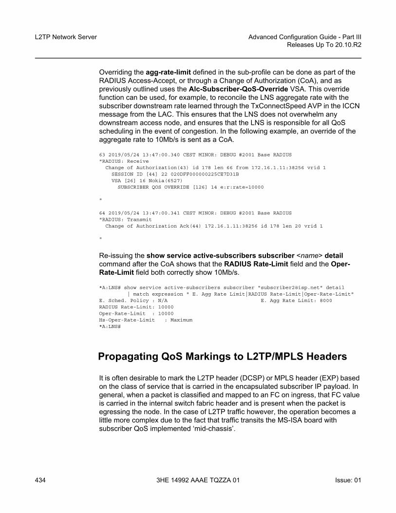
L2TP Network Server
434
Advanced Configuration Guide - Part IIIReleases Up To 20.10.R2
3HE 14992 AAAE TQZZA 01 Issue: 01
Overriding the agg-rate-limit defined in the sub-profile can be done as part of the RADIUS Access-Accept, or through a Change of Authorization (CoA), and as previously outlined uses the Alc-Subscriber-QoS-Override VSA. This override function can be used, for example, to reconcile the LNS aggregate rate with the subscriber downstream rate learned through the TxConnectSpeed AVP in the ICCN message from the LAC. This ensures that the LNS does not overwhelm any downstream access node, and ensures that the LNS is responsible for all QoS scheduling in the event of congestion. In the following example, an override of the aggregate rate to 10Mb/s is sent as a CoA.
63 2019/05/24 13:47:00.340 CEST MINOR: DEBUG #2001 Base RADIUS"RADIUS: Receive
Change of Authorization(43) id 178 len 66 from 172.16.1.11:38256 vrid 1SESSION ID [44] 22 020DFF000000225CE7D31BVSA [26] 16 Nokia(6527)
SUBSCRIBER QOS OVERRIDE [126] 14 e:r:rate=10000
"
64 2019/05/24 13:47:00.341 CEST MINOR: DEBUG #2001 Base RADIUS"RADIUS: Transmit
Change of Authorization Ack(44) 172.16.1.11:38256 id 178 len 20 vrid 1
"
Re-issuing the show service active-subscribers subscriber <name> detail command after the CoA shows that the RADIUS Rate-Limit field and the Oper-Rate-Limit field both correctly show 10Mb/s.
*A:LNS# show service active-subscribers subscriber "[email protected]" detail| match expression " E. Agg Rate Limit|RADIUS Rate-Limit|Oper-Rate-Limit"
E. Sched. Policy : N/A E. Agg Rate Limit: 8000RADIUS Rate-Limit: 10000Oper-Rate-Limit : 10000Hs-Oper-Rate-Limit : Maximum*A:LNS#
Propagating QoS Markings to L2TP/MPLS Headers
It is often desirable to mark the L2TP header (DCSP) or MPLS header (EXP) based on the class of service that is carried in the encapsulated subscriber IP payload. In general, when a packet is classified and mapped to an FC on ingress, that FC value is carried in the internal switch fabric header and is present when the packet is egressing the node. In the case of L2TP traffic however, the operation becomes a little more complex due to the fact that traffic transits the MS-ISA board with subscriber QoS implemented ‘mid-chassis’.

Advanced Configuration Guide - Part III Releases Up To 20.10.R2
L2TP Network Server
Issue: 01 3HE 14992 AAAE TQZZA 01 435
In the upstream direction (from subscriber to LNS), traffic arrives encapsulated in L2TP at the ingress IOM, and is passed through the MS-ISA via the internal object lns-net. When traffic exits the MS-ISA through lns-esm as native IP, it is subject to subscriber ingress QoS implemented on the (MS-ISA) carrier IOM. Traffic is classified and mapped to an FC at this point, and that FC mapping is maintained in the switch fabric header. As a result, marking of traffic is effected by the network egress QoS policy.
Figure 76 Ingress/Egress QoS Processing
In the downstream direction (from LNS to subscriber), traffic arrives at the ingress IOM as native IP and is diverted to the MS-ISA via the lns-esm internal object. At the lns-esm, the traffic is subject to subscriber egress QoS. When the traffic is passed through lns-esm to the MS-ISA for L2TP encapsulation, internal Q-in-Q VLAN tags are attached as previously described. As the lns-esm is effectively a SAP-egress, the internal switch fabric header containing the FC marking is removed at this point, and, as a result FC information is lost.
Therefore, in order to allow for FC-continuity through the MS-ISA, the system implements a queue-group at the ingress of lns-net that has a dot1p to FC mapping as shown in Figure 76. Assuming a SAP-egress QoS policy that employs FCs BE, AF and EF, the QoS policy would include the additional configuration to implement the appropriate dot1p marking as shown in the following output. When traffic arrives at lns-net, it is classified and mapped into the appropriate FCs, and the associated FC mapping included in the switch fabric header. At network egress, the L2TP packet is then subject to marking as defined in the network egress QoS policy.
al_0509
UpstreamTraffic(L2TP)
SubscriberQoS
DownstreamTraffic (IP)
FC Dot1p
BE 0
L2 1
AF 2
L1 3
H2 4
EF 5
H1 6
NC 7
IOMIOMIOM
Ins-net
Ins-esm

L2TP Network Server
436
Advanced Configuration Guide - Part IIIReleases Up To 20.10.R2
3HE 14992 AAAE TQZZA 01 Issue: 01
configureqos
sap-egress 10 createqueue 1 createexitqueue 2 best-effort createexitqueue 3 expedite createexitfc af create
queue 2dot1p 2
exitfc be create
queue 1dot1p 0
exitfc ef create
queue 3dot1p 5
exitdscp be fc "be"dscp ef fc "ef"dscp af31 fc "af"
exitexit
exit
Framed-Route
The majority of residential services in broadband networks have a single registered 32-bit IPv4 address on the WAN side of the RG and a private (RFC 1918) network on the LAN side. Traffic from the LAN toward the BNG (and Internet) is thereafter subject to Network Address and Port Translation (NAPT). However, a common requirement for delivery of business services is the ability for the BNG to recognize one or more IP subnets on the LAN side of the RG that is not subject to NAT, and the subscriber prefix is a route to a network. This is achieved using the standard RADIUS Framed-Route attribute, or dynamic BGP peering. Both serve the function of allowing one or more subnets to be learned at the LNS with a next-hop IP address of the RG WAN.
To provide an example of the use of Framed-Route, the Retail VRF VPRN 2 is again used, and in fact requires no modification in order to support subscribers with Framed-Routes. In general ESM, where Framed-Route is used, there is a requirement to configure anti-spoof type nh-mac, but for LNS SAPs this is the default. The RADIUS users file is updated to also return a Framed-Route attribute for prefix 10.128.46.0/24 with a next-hop determined by the subscriber IP prefix. The prefix has a metric of 10, and has a tag of value 200, which may be used for example, for routing policy.

Advanced Configuration Guide - Part III Releases Up To 20.10.R2
L2TP Network Server
Issue: 01 3HE 14992 AAAE TQZZA 01 437
[email protected] Cleartext-Password := "letmein"Alc-Subsc-ID-Str = "[email protected]",Alc-Subsc-Prof-Str = "sub-profile-1",Alc-SLA-Prof-Str = "sla-profile-1",Alc-Serv-Id = "2",Alc-Interface = "VPRN2-GROUP-INT",Service-Type = Framed-User,Framed-Protocol = PPP,Framed-IP-Address = 10.10.148.22,Framed-Route = "10.128.46.0/24 0.0.0.0 10 tag 200",
In SR OS, a prefix learned through the Framed-Route attribute is known internally as a Managed Route. Once the subscriber is instantiated, the presence of the Managed Route can be verified as installed.
*A:LNS# show service id 2 ppp session detail | match "Managed Routes"post-lines 5
Managed Routes-------------------------------------------------------------------------------IP Address Status Metric Tag Pref-------------------------------------------------------------------------------10.128.46.0/24 installed 10 200 0-------------------------------------------------------------------------------*A:LNS#
The Managed Route can also be seen present in the VPRN routing-table, learned through protocol Managed.
*A:LNS# show router 2 route-table protocol managed
===============================================================================Route Table (Service: 2)===============================================================================Dest Prefix[Flags] Type Proto Age Pref
Next Hop[Interface Name] Metric-------------------------------------------------------------------------------10.128.46.0/24 Remote Managed 00h01m33s 0
10.10.148.22 10-------------------------------------------------------------------------------No. of Routes: 1Flags: n = Number of times nexthop is repeated
B = BGP backup route availableL = LFA nexthop availableS = Sticky ECMP requested
===============================================================================*A:LNS#

L2TP Network Server
438
Advanced Configuration Guide - Part IIIReleases Up To 20.10.R2
3HE 14992 AAAE TQZZA 01 Issue: 01
L2TP Tunnel Switching (LTS)
In general, L2TP tunnels are established directly between LAC and LNS. However, if there are a large number of LAC devices (and therefore a large number of L2TP tunnels), it may be desirable to perform some aggregation of these tunnels before presenting them to the LNS. This is implemented by one or more LNS devices performing the function of an L2TP Tunnel Switch (LTS). The LTS terminates multiple L2TP tunnels from the LAC(s), and sources a single L2TP tunnel toward the target LNS, switching L2TP sessions from one tunnel to another tunnel accordingly.
SR OS supports LTS functionality, and from a configuration perspective, it requires no more than L2TP being enabled (no shutdown) in the required routing context if the relevant attributes are returned from RADIUS. As with LNS functions, at least one MS-ISA is required to support LTS functions. In this example, VPRN 1 is used with the previously defined configuration. To recap, this VPRN has a single L2TP group “L2TP-GROUP-1”, and within that group, a single tunnel defined “L2TP-TUNNEL-1” that terminates the tunnel from the LAC. To demonstrate LTS functionality, the LAC continues to function as a LAC, the LNS functions as an LTS, and PE-1 becomes the LNS.
The RADIUS users file for [email protected] is modified to include a number of additional attributes and VSAs. The Alc-Serv-Id and Alc-Interface define the service ID and group interface where the subscriber is terminated, and this can be any IES or VPRN service. The Alc-Tunnel-Serv-Id VSA identifies the service where the L2TP tunnel is initiated. It can be different from the service where the subscriber is terminated, but id does not need to. If it is a different service, then the minimum requirement is that L2TP is placed in a no shutdown state. In this example VPRN 1 terminates the subscriber, and also initiates the L2TP tunnel. The other attributes are standard attributes defined in RFC 2868 for L2TP tunnel setup. The Tunnel-Assignment-Id attribute is used to maintain the concept of groups and tunnels, where Tunnel-Assignment-Id:0 is used to indicate the group name and Tunnel-Assignment-Id:1 is used to indicate the tunnel name. This provides sufficient information for the LTS to initiate an L2TP tunnel without any additional nodal configuration.
[email protected] Cleartext-Password := "letmein"Alc-Subsc-ID-Str = "[email protected]",Alc-Subsc-Prof-Str = "sla-profile-1",Alc-SLA-Prof-Str = "sub-profile-1",Alc-Serv-Id = "1",Alc-Interface = "LNS-GROUP-INT",Alc-Tunnel-Serv-Id = 1,Tunnel-Assignment-Id:0 = "RADIUS-returned-Tunnel-Group",Tunnel-Type:1 += L2TP,Tunnel-Medium-Type:1 += IP,Tunnel-Server-Endpoint:1 += 192.168.0.3,Tunnel-Password:1 += "letmein",Tunnel-Assignment-Id:1 += "RADIUS-returned-Tunnel-Name",Tunnel-Client-Auth-Id = "LTS",

Advanced Configuration Guide - Part III Releases Up To 20.10.R2
L2TP Network Server
Issue: 01 3HE 14992 AAAE TQZZA 01 439
The LAC forwards the PPP session into the LAC to LTS tunnel, and after the LTS receives the ICCN from the LAC, it proceeds in authenticating the subscriber. RADIUS returns the preceding attributes with sufficient information for the LTS to instantiate the subscriber and initiates an L2TP tunnel/session with PE-1, the target LNS. The LNS then authenticates the user once more, this time providing it with IP address information through IPCP negotiation. This interaction between PPP client and LNS is transparent to the LTS, which is responsible for switching PPP packets between L2TP sessions. However, the user is instantiated in the system as a full-fledged subscriber.
*A:LNS# show service id 1 ppp session
===============================================================================PPP sessions for service 1===============================================================================User-Name
Descr.Up Time Type Termination IP/L2TP-Id/Interface-Id MC-Stdby
-------------------------------------------------------------------------------subscriber1@isp.net
vprn:1 connid:345328060 tid:5269 sid:188760d 00:01:42 oL2tp lac 905456423
-------------------------------------------------------------------------------No. of PPP sessions: 1===============================================================================*A:LNS#
Within VPRN 1, two L2TP tunnels are active. The entry with Connection Id 937033728 belongs to group RADIUS-returned-Tunnel-Group (obtained from the Tunnel-Assignment-Id:0 RADIUS attribute) and has tunnel name RADIUS-returned-Tunnel-Name (obtained from the Tunnel-Assignment-Id:1 RADIUS attribute). This is the tunnel from LTS to LNS, and it is in the Established state and has one session active. The entry with Connection Id 560005120 is the statically defined tunnel from the LAC, belonging to the CLI-configured group L2TP-GROUP-1 with tunnel name L2TP-TUNNEL-1. This tunnel is also in the Established state, with one session active.
*A:LNS# show router 1 l2tp tunnel===============================================================================Conn ID Loc-Tu-ID Rem-Tu-ID State Blacklist-state Ses Active
Group Ses TotalAssignment
-------------------------------------------------------------------------------345309184 5269 12695 established not-blacklisted 1
L2TP-GROUP-1 1L2TP-TUNNEL-1
905445376 13816 12071 established not-blacklisted 1RADIUS-returned-Tunnel-Group 1
RADIUS-returned-Tunnel-Name-------------------------------------------------------------------------------No. of tunnels: 2===============================================================================*A:LNS#

L2TP Network Server
440
Advanced Configuration Guide - Part IIIReleases Up To 20.10.R2
3HE 14992 AAAE TQZZA 01 Issue: 01
Equally, within VPRN 1, two L2TP sessions are active for subscriber [email protected]. Session 937037337 is carried in Tunnel-ID 14298, which, as shown in the previous output, is the tunnel toward the LNS, while session 560030762 is carried in Tunnel-ID 8545, which is the tunnel toward the LAC.
*A:LNS# show router 1 l2tp session
===============================================================================L2TP Session Summary===============================================================================ID Control Conn ID Tunnel-ID Session-ID State-------------------------------------------------------------------------------345328060 345309184 5269 18876 established
[email protected]: LNS-GROUP-INTservice-id: 1905456423
905456423 905445376 13816 11047 established-------------------------------------------------------------------------------No. of sessions: 2===============================================================================*A:LNS#
IPv6
The deployment of IPv6 into residential broadband networks dictates some design choices, or perhaps even some enforced IPv6 address allocation mechanisms:
• Bridged or Routed Residential Gateways (RGs). • Numbered or unnumbered WAN. • Stateful (DHCPv6) or stateless (Stateless Address Auto-Configuration, or
SLAAC) address assignment.
The purpose of this example is not to show every possibility, but simply to demonstrate that enabling IPv6 is possible at the LNS, just as if this were a conventional BNG doing PPP Termination and Aggregation (PTA). This example uses a widely adopted approach of dual-stack Routed RG with DHCPv6 Prefix Delegation.
The configuration of VPRN 2 is modified to include some IPv6 parameters. In the subscriber-interface context, the delegated-prefix-len command is set to variable indicating that prefixes delegated to subscribers may be of varying length (the default delegated prefix length is /64). The allow-unmatching-prefixes command tells the subscriber interface to operate in an IPv6 unnumbered mode, allowing IPv6

Advanced Configuration Guide - Part III Releases Up To 20.10.R2
L2TP Network Server
Issue: 01 3HE 14992 AAAE TQZZA 01 441
addresses to be allocated to subscribers that do not fall within the range of any IPv6 subnet defined under the subscriber interface. Within the group-interface context, the ipv6 context places router-advertisements into a no shutdown state and has the managed-configuration flag set indicating that stateful (DHCPv6) address configuration is to be used.
Also a dhcp6 proxy-server is enabled, providing an interworking function between the RADIUS server (where the Delegated Prefix is obtained from) and the DHCPv6 client. The proxy will take the RADIUS-provided prefix and responds to the clients Solicit message with an DHCPv6 Advertise message containing the delegated prefix (IA_PD). Because the DHCPv6 messages from the client need to be received over the subscriber PPP session, the proxy-server is configured to allow this using the client-applications ppp command. Finally, there is a static-route for black-holing the /48 IPv6 prefix. The client is allocated a /64 prefix from this range and this static-route is used to provide an aggregated upstream prefix advertisement.
configureservice
vprn 2subscriber-interface "VPRN2-SUB-INT" create
ipv6default-dns 2001:db8:2c41::56delegated-prefix-len variableallow-unmatching-prefixes
exitgroup-interface "VPRN2-GROUP-INT" lns create
ipv6router-advertisements
managed-configurationno shutdown
exitdhcp6
proxy-serverclient-applications pppno shutdown
exitexit
exitexit
exitstatic-route-entry 2a00:8010:1b00::/48
black-holeno shutdown
exitexitno shutdown
exitexit
exit
The RADIUS users file entry for [email protected] is also modified to return the IPv6 Delegated Prefix using the standard attribute Delegated-IPv6-Prefix.

L2TP Network Server
442
Advanced Configuration Guide - Part IIIReleases Up To 20.10.R2
3HE 14992 AAAE TQZZA 01 Issue: 01
[email protected] Cleartext-Password := "letmein"Alc-Subsc-ID-Str = "[email protected]",Alc-Subsc-Prof-Str = "sub-profile-1",Alc-SLA-Prof-Str = "sla-profile-1",Alc-Serv-Id = "2",Alc-Interface = "VPRN2-GROUP-INT",Service-Type = Framed-User,Framed-Protocol = PPP,Framed-IP-Address = 10.10.148.22,Delegated-IPv6-Prefix = 2001:db8:1b00:100::/64
After the PPP LCP phase and RADIUS authentication, the LNS is aware that the subscriber also has IPv6 enabled (in this case because it received the Delegated-IPv6-Prefix attribute). As a result, the LNS begins to negotiate both IPCP and IPv6CP with the client. For IPv6CP, only an Interface-ID is negotiated, for which the LNS uses an EUI-64 extended version of the chassis MAC address. Once IPv6CP negotiation is completed, the client can initiate a DHCPv6 Solicit for a delegated prefix (IA_PD option). After a successful Advertise/Request/Reply exchange the subscriber is instantiated as dual-stack IPv4/IPv6.
*A:LNS# show service active-subscribers subscriber "[email protected]"
===============================================================================Active Subscribers===============================================================================-------------------------------------------------------------------------------Subscriber [email protected] (sub-profile-1)--------------------------------------------------------------------------------------------------------------------------------------------------------------(1) SLA Profile Instance sap:[1/2/lns-esm:1.263] - sla:sla-profile-1-------------------------------------------------------------------------------IP Address
MAC Address Session Origin Svc Fwd-------------------------------------------------------------------------------10.10.148.22
00:00:14:95:29:18 PPP 1 IPCP 2 Y2001:db8:1b00:100::/64
00:00:14:95:29:18 PPP 1 DHCP6-PD 2 Y-------------------------------------------------------------------------------
===============================================================================*A:LNS#
Conclusion
SR OS offers a comprehensive feature set for LNS implementations. The MS-ISA provides the hardware-assist for L2TP encapsulation/de-capsulation while the carrier IOM implements conventional subscriber management functions.

Advanced Configuration Guide - Part III Releases Up To 20.10.R2
Multi-Chassis IPSec Redundancy
Issue: 01 3HE 14992 AAAE TQZZA 01 443
Multi-Chassis IPSec RedundancyThis chapter provides information about multi-chassis IPSec redundancy configurations.
Topics in this chapter include:
• Applicability• Overview• Configuration• Conclusion
Applicability
This chapter was originally written for release 10.0.R8. The CLI in this version corresponds to 16.0.R7.
Overview
Multi-Chassis IPSec redundancy (MC-IPSec) is a stateful inter-chassis IPSec failover mechanism. IPSec tunnel states are synchronized between the master and standby chassis. A tunnel-group failure on the master or a master chassis failure could trigger MC-IPSec failover to the standby chassis.
The following are some highlights of this feature:
• Internet Key Exchange version 2 (IKEv2) only• Multi-active tunnel-group only• The granularity of failover is tunnel-group, which means a specific tunnel-group
could failover to the standby chassis independent of other tunnel-groups on the master chassis
• Supports both static and dynamic LAN-to-LAN tunnel
This feature has the following building blocks:
• Master election- MIMP (MC-IPSec Mastership Protocol) runs between the chassis to elect a
master, MIMP run for each tunnel-group independently

Multi-Chassis IPSec Redundancy
444
Advanced Configuration Guide - Part IIIReleases Up To 20.10.R2
3HE 14992 AAAE TQZZA 01 Issue: 01
• Synchronization- MCS (Multi-Chassis Synchronization) synchronizes IPSec states between
chassis• Routing
- MC-IPSec-aware routing attracts traffic to the master chassis- Shunting support- MC-IPSec aware Virtual Router Redundancy Protocol (VRRP)
Figure 77 MC-IPSec Architecture
The fundamentals of MC-IPSec are:
• Only the master processes Encapsulating Security Payload (ESP) and IKE traffic. If the standby receives traffic, it could shunt it to the master if possible. The traffic will be discarded if the standby fails to shunt the traffic.
• The same local gateway address should be provisioned on both chassis.• MC-IPSec does not synchronize configurations.• MC-IPSec aware routing attracts traffic to the master for both public and private
services. This is achieved by exporting the corresponding IPSec routes to the routing protocol via a route policy and setting a different routing metric according to the MC-IPSec state.
al_0297Standby
Master
Private NetworkPublic Network
Routing Adv/VRRP
MCS MIMPShunt
Routing Adv
Routing Adv/VRRP Routing Adv

Advanced Configuration Guide - Part III Releases Up To 20.10.R2
Multi-Chassis IPSec Redundancy
Issue: 01 3HE 14992 AAAE TQZZA 01 445
• In case of a Layer 2 public network, MC-IPSec aware VRRP could be used to trigger VRRP switchover upon MC-IPSec switchover.
• MCS synchronizes IPSec states between chassis so that existing IPSec tunnels do not need to be re-established upon switchover.
• MIMP elects mastership between two chassis, and it could also detect chassis failure and tunnel-group failure; a central BFD session can be associated with MIMP to achieve fast chassis failure detection.
Configuration
The test topology is shown in Figure 78.
Figure 78 Test Topology
Test setup:
• An IPSec tunnel is initiated by CE-5 and terminated on the master of the SeGW-1/SeGW-2 pair.
• IES 1 and VPRN 2 are the public and private services, respectively, on SeGW-1/SeGW-2/CE-5.
• VPRN 2 is also configured on P-3.
al_0296SeGW-2
SeGW-1
P-3S-4
CE-5
Sys: 192.0.2.3
Sys: 192.0.2.1
172.16.1.100/241/1/1
172.16.1.252/241/1/2
192.168.13.1/301/1/1
192.168.13.2/301/1/2
VRRP 10 Backup Addr:172.16.1.254IPsec GW addr:10.10.20.1
192.168.23.1/301/1/2
172.16.1.253/241/1/1
192.168.23.2/301/1/1
IPsec tunnel addr:10.10.10.1
int-loopback-1:192.168.1.5/32
• CE-5: IPsec Client• S-4: VPLS Switch• SeGW-1/SeGW-2: Master and
Standby Security Gateway• P-3: Core Router
int-loopback-1:192.168.1.3/32
1/1/3
1/1/2
1/1/3192.168.12.1/30
192.168.12.2/301/1/3
1/1/1

Multi-Chassis IPSec Redundancy
446
Advanced Configuration Guide - Part IIIReleases Up To 20.10.R2
3HE 14992 AAAE TQZZA 01 Issue: 01
• Static LAN-to-LAN tunnel with pre-shared key.• Local VPLS service 3 on S-4 to simulate a Layer 2 switch.• VRRP 10 between SeGW-1 and SeGW-2 to provide a backup address
192.168.1.254, which is also the default next-hop for CE-5.• VRRP policy 1 is bound to VRRP 10 to change the in-use priority upon MC-
IPSec switchover.• OSPF is the IGP running in the base routing instance between SeGW-1, SeGW-
2 and P-3.• MP-BGP is running between SeGW-1, SeGW-2 and P-3 for exchanging VPRN
2 routes. • A ping between loopback interface address 192.168.1.5 on CE-5 and
192.168.1.3 on P-3 in VPRN 2 is used to verify the connectivity over the IPSec tunnel.
The MC-IPSec configuration commands are shown below.
config>redundancy>multi-chassis>peer <ip-address> [create]
syncipsectunnel-group <tunnel-group-id> sync-tag <tag-name> [create]
mc-ipsecbfd-enablediscovery-interval <interval-1> [boot <interval-2>]hold-on-neighbor-failure <multiplier>keep-alive-interval <interval>tunnel-group <tunnel-group-id> [create]
peer-group <tunnel-group-id>priority <priority>shutdown
config>router>policy-options>policy-statement>entry>from>state ipsec-master-with-peer|ipsec-non-master|ipsec-master-without-peerprotocol ipsec
config>service>ies>if>config>service>vprn>if>
static-tunnel-redundant-next-hop <ip-address>dynamic-tunnel-redundant-next-hop <ip-address>
config>isa>tunnel-grp>ipsec-responder-only
config>vrrp>policy>priority-event>mc-ipsec-non-forwarding <tunnel-grp-id>
hold-clear <seconds>hold-set <seconds>priority <priority-level> explicit
Parameters:

Advanced Configuration Guide - Part III Releases Up To 20.10.R2
Multi-Chassis IPSec Redundancy
Issue: 01 3HE 14992 AAAE TQZZA 01 447
• peer <ip-address> [create] — This command creates or enters a multi-chassis peer. The peer address is by default the system address. This can be changed on the peer using the config>redundancy>multi-chassis>peer>source-address command.
• sync>ipsec — This command enables MCS to synchronize IPSec states.• tunnel-group <tunnel-group-id> sync-tag <tag-name> [create] — This
command enables MCS to synchronize the IPSec states of the specified tunnel-group.The sync-tag parameter is used to match the tunnel-group of the peer. The tunnel-group states with the same sync-tag on both chassis will be synchronized.
• mc-ipsec — This command enters the multi-chassis IPSec configuration context.
• bfd-enable — This command enables tracking a central BFD session, if the BFD session goes down, then the system considers the peer is down and changes the mc-ipsec status of the configured tunnel-group accordingly. The BFD session uses the source address of MCS as its source address and the MCS peer address as the destination address. Other BFD parameters are configured with the bfd command on the interface that the MCS source address resides on.Configuration of this command is optional.
• discovery-interval <interval-1> [boot <interval-2>] — This command specifies the time interval that the tunnel-group stays in “Discovery” state. Interval-1 is used as discovery-interval when a new tunnel-group is added to multi-chassis redundancy (mp-ipsec); interval-2 is used as discovery-interval after system boot-up, it is optional, and when it is not specified, the value for interval-1will be used. Both intervals have a default value of 300 seconds.
• hold-on-neighbor-failure <multiplier> — This command specifies the number of keep-alive failures before considering the peer to be down. Default is 3.
• keep-alive-interval <interval> — This command specifies the time interval of the mastership election protocol keep-alive packets. Default value is 1 second, range: 0.5 ~ 50 seconds.
• tunnel-group <tunnel-group-id> [create] — This command enables multi-chassis redundancy for the specified tunnel-group, or enters an already configured tunnel-group context. The configured tunnel-groups could failover independently.
• peer-group <tunnel-group-id> — This command specifies the corresponding tunnel-group id on the peer node. The peer tunnel-group id is not necessarily equal to local tunnel-group id.

Multi-Chassis IPSec Redundancy
448
Advanced Configuration Guide - Part IIIReleases Up To 20.10.R2
3HE 14992 AAAE TQZZA 01 Issue: 01
• priority <priority> — This command specifies the local priority of the tunnel-group, this is used to elect a master, where the higher number wins. If the priorities are the same, then the peer which has more active ISAs wins; if the priority and the number of active ISAs are same, then the peer with higher IP address wins. Default value is 100, range: 0..255
• shutdown — This command disables the multi-chassis redundancy for the specified tunnel-group
• state ipsec-master-with-peer|ipsec-non-master|ipsec-master-without-peer — These commands specify the mc-ipsec state in a “from” statement of a route policy entry. ipsec-master-with-peer: The corresponding tunnel-group is Master with peer reachable.ipsec-master-without-peer: The corresponding tunnel-group is Master with peer unreachable.ipsec-non-master: The corresponding tunnel-group is not Master.
• protocol ipsec — This command specifies the IPSec as protocol in a “from” statement of a route policy entry. protocol ipsec means the /32 local gateway routes (of both static and dynamic tunnels) and reverse route of dynamic tunnel.
• static-tunnel-redundant-next-hop <ip-address> dynamic-tunnel-redundant-next-hop <ip-address> — These commands specify the redundant next-hop address on a public or private IPSec interface (with public or private tunnel-sap) for a static and dynamic IPSec tunnel respectively. The specified next-hop address will be used by the standby node to shunt traffic to the master in case it receives any traffic. The next-hop address will be resolved in the routing table of the corresponding service.Notes:- Shunting is supported over:
• Directly connected SAP• Spoke SDP terminated IP interface
- Shunting over auto-bind tunnel is not supported.- Shunting will not work if the tunnel-group is down.
• ipsec-responder-only — With this command configured, the system will only act as IKE responder except for the automatic CHILD_SA rekey upon MC-IPSec switchover.This command is required for MC-IPSec support of static LAN-to-LAN tunnel
• mc-ipsec-non-forwarding <tunnel-grp-id> — This command creates a new VRRP policy priority event: mc-ipsec-non-forwarding. It will be triggered whenever the specified tunnel-group enters non-forwarding state.
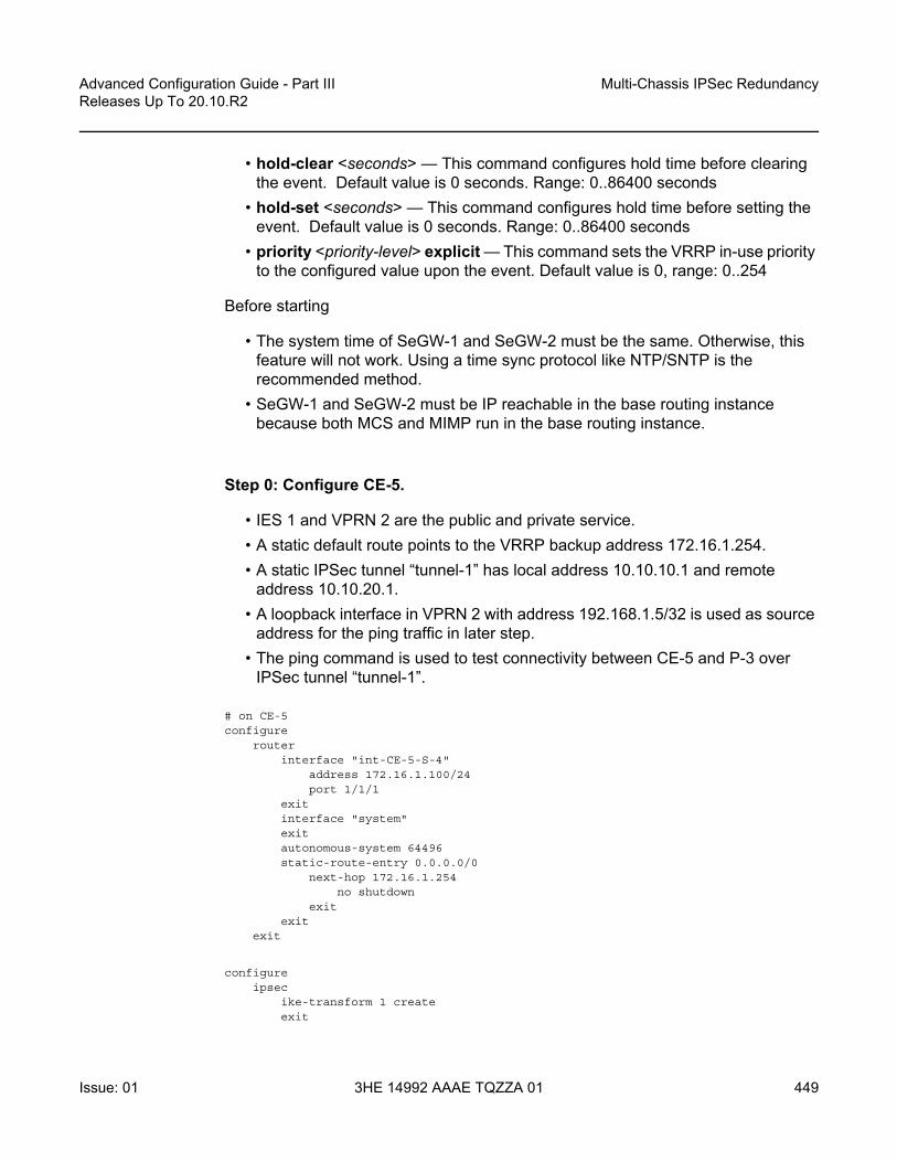
Advanced Configuration Guide - Part III Releases Up To 20.10.R2
Multi-Chassis IPSec Redundancy
Issue: 01 3HE 14992 AAAE TQZZA 01 449
• hold-clear <seconds> — This command configures hold time before clearing the event. Default value is 0 seconds. Range: 0..86400 seconds
• hold-set <seconds> — This command configures hold time before setting the event. Default value is 0 seconds. Range: 0..86400 seconds
• priority <priority-level> explicit — This command sets the VRRP in-use priority to the configured value upon the event. Default value is 0, range: 0..254
Before starting
• The system time of SeGW-1 and SeGW-2 must be the same. Otherwise, this feature will not work. Using a time sync protocol like NTP/SNTP is the recommended method.
• SeGW-1 and SeGW-2 must be IP reachable in the base routing instance because both MCS and MIMP run in the base routing instance.
Step 0: Configure CE-5.
• IES 1 and VPRN 2 are the public and private service.• A static default route points to the VRRP backup address 172.16.1.254.• A static IPSec tunnel “tunnel-1” has local address 10.10.10.1 and remote
address 10.10.20.1.• A loopback interface in VPRN 2 with address 192.168.1.5/32 is used as source
address for the ping traffic in later step. • The ping command is used to test connectivity between CE-5 and P-3 over
IPSec tunnel “tunnel-1”.
# on CE-5configure
routerinterface "int-CE-5-S-4"
address 172.16.1.100/24port 1/1/1
exitinterface "system"exitautonomous-system 64496static-route-entry 0.0.0.0/0
next-hop 172.16.1.254no shutdown
exitexit
exit
configureipsec
ike-transform 1 createexit

Multi-Chassis IPSec Redundancy
450
Advanced Configuration Guide - Part IIIReleases Up To 20.10.R2
3HE 14992 AAAE TQZZA 01 Issue: 01
ike-policy 1 createike-version 2dpdike-transform 1
exitipsec-transform 1 createexit
exit
configureisa
tunnel-group 1 createprimary 1/2no shutdown
exitexit
configureservice
ies 1 customer 1 createinterface "int-IPsec-Public-1" create
address 10.10.10.254/24tos-marking-state untrustedsap tunnel-1.public:1 createexit
exitno shutdown
exit
configureservice
vprn 2 customer 1 createipsec
security-policy 1 createentry 10 create
local-ip 192.168.1.5/32remote-ip 192.168.1.3/32
exitexit
exitroute-distinguisher 64496:2interface "int-loopback-1" create
address 192.168.1.5/32loopback
exitinterface "int-IPsec-private-1" tunnel create
sap tunnel-1.private:1 createipsec-tunnel "tunnel-1" create
security-policy 1local-gateway-address 10.10.10.1 peer 10.10.20.1
delivery-service 1dynamic-keying
ike-policy 1pre-shared-key "pass"transform 1
exitno shutdown
exit

Advanced Configuration Guide - Part III Releases Up To 20.10.R2
Multi-Chassis IPSec Redundancy
Issue: 01 3HE 14992 AAAE TQZZA 01 451
exitexitstatic-route-entry 192.168.1.3/32
ipsec-tunnel "tunnel-1"no shutdown
exitexitno shutdown
exit
Step 1. Configure S-4.
• A local VPLS service 3 simulates a Layer 2 switch between CE-5, SeGW-1 and SeGW-2.
# on S-4configure
servicevpls 3 customer 1 create
sap 1/1/1 createexitsap 1/1/2 createexitsap 1/1/3 createexitno shutdown
exit
Step 2. Configure P-3
• P-3 simulates the core network router, connecting to SeGW-1 and SeGW-2.• A loopback interface with address 192.168.1.3/32 in VPRN 2 is the destination
address of the ping traffic from CE-5.• MP-BGP session between P-3 and SeGW-1/SeGW-2 to receive 192.168.1.5/32
route in VPRN 2.• GRE spoke SDPs to connect to SeGW-1 and SeGW-2.
# on P-3configure
routerinterface "int-P-3-SeGW-1"
address 192.168.13.2/30port 1/1/2
exitinterface "int-P-3-SeGW-2"
address 192.168.23.2/30port 1/1/1
exitinterface "system"
address 192.0.2.3/32exitautonomous-system 64496exit

Multi-Chassis IPSec Redundancy
452
Advanced Configuration Guide - Part IIIReleases Up To 20.10.R2
3HE 14992 AAAE TQZZA 01 Issue: 01
configurerouter
ospfarea 0.0.0.0
interface systemexitinterface "int-P-3-SeGW-1"exitinterface "int-P-3-SeGW-2"exit
exitno shutdown
exit
configureservice
sdp 31 createsignaling offfar-end 192.0.2.1no shutdown
exitsdp 32 create
signaling offfar-end 192.0.2.2no shutdown
exitexit
configureservice
vprn 2 customer 1 createroute-distinguisher 64496:2vrf-target target:64496:2interface "int-loopback-1" create
address 192.168.1.3/32loopback
exitspoke-sdp 31 create
description "SDP to SeGW-1"exitspoke-sdp 32 create
description "SDP to SeGW-2"exitno shutdown
exit
configurerouter
bgpgroup "MPBGP"
family vpn-ipv4type internalneighbor 192.0.2.1exitneighbor 192.0.2.2exit
exitno shutdown

Advanced Configuration Guide - Part III Releases Up To 20.10.R2
Multi-Chassis IPSec Redundancy
Issue: 01 3HE 14992 AAAE TQZZA 01 453
Step 3. Configure IPSec tunnel on SeGW-1.
• The tunnel-group must be in multi-active mode before MC-IPSec can be enabled.
• Interface "int-Redundant-1" is a spoke-sdp terminated interface is used for shunting.
• GRE SDPs 12 and 13 toward SeGW-2 and P-3.• IPSec tunnel “tunnel-1” is the tunnel to CE-5; both SeGW-1 and SeGW-2 use
the same local gateway address: 10.10.20.1.# on SeGW-1configure
isatunnel-group 1 create
ipsec-responder-onlymulti-activemda 1/2no shutdown
exit
configurerouter
interface "int-SeGW-1-P-3"address 192.168.13.1/30port 1/1/1
exitinterface "int-SeGW-1-SeGW-2"
address 192.168.12.1/30port 1/1/3
exitinterface "system"
address 192.0.2.1/32bfd 100 receive 100 multiplier 3
exitautonomous-system 64496static-route-entry 10.10.10.0/24
next-hop 172.16.1.100no shutdown
exitexit
exit
configurerouter
ospfarea 0.0.0.0
interface "system"exitinterface "int-SeGW-1-SeGW-2"exitinterface "int-SeGW-1-P-3"exit
exitno shutdown
exit

Multi-Chassis IPSec Redundancy
454
Advanced Configuration Guide - Part IIIReleases Up To 20.10.R2
3HE 14992 AAAE TQZZA 01 Issue: 01
configureipsec
ike-transform 1 createexitike-policy 1 create
ike-version 2ipsec-lifetime 7200ike-transform 1
exitipsec-transform 1 createexit
exit
configureservice
sdp 12 createsignaling offfar-end 192.0.2.2no shutdown
exitsdp 13 create
signaling offfar-end 192.0.2.3no shutdown
exit
configureservice
ies 1 customer 1 createinterface "int-SeGW-1-S-4" create
address 172.16.1.252/24sap 1/1/2 createexit
exitinterface "int-IPsec-Public-1" create
address 10.10.20.254/24tos-marking-state untrustedsap tunnel-1.public:1 createexitstatic-tunnel-redundant-next-hop 192.168.12.2
exitno shutdown
exit
configureservice
vprn 2 customer 1 createipsec
security-policy 1 createentry 10 create
local-ip 192.168.1.3/32remote-ip 192.168.1.5/32
exitexit
exitroute-distinguisher 64496:2vrf-target target:64496:2interface "int-IPsec-Private-1" tunnel create
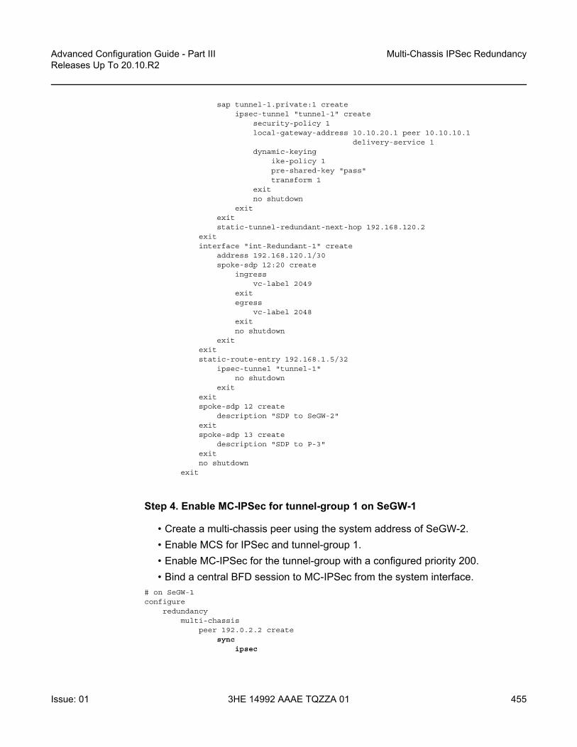
Advanced Configuration Guide - Part III Releases Up To 20.10.R2
Multi-Chassis IPSec Redundancy
Issue: 01 3HE 14992 AAAE TQZZA 01 455
sap tunnel-1.private:1 createipsec-tunnel "tunnel-1" create
security-policy 1local-gateway-address 10.10.20.1 peer 10.10.10.1
delivery-service 1dynamic-keying
ike-policy 1pre-shared-key "pass"transform 1
exitno shutdown
exitexitstatic-tunnel-redundant-next-hop 192.168.120.2
exitinterface "int-Redundant-1" create
address 192.168.120.1/30spoke-sdp 12:20 create
ingressvc-label 2049
exitegress
vc-label 2048exitno shutdown
exitexitstatic-route-entry 192.168.1.5/32
ipsec-tunnel "tunnel-1"no shutdown
exitexitspoke-sdp 12 create
description "SDP to SeGW-2"exitspoke-sdp 13 create
description "SDP to P-3"exitno shutdown
exit
Step 4. Enable MC-IPSec for tunnel-group 1 on SeGW-1
• Create a multi-chassis peer using the system address of SeGW-2.• Enable MCS for IPSec and tunnel-group 1.• Enable MC-IPSec for the tunnel-group with a configured priority 200.• Bind a central BFD session to MC-IPSec from the system interface.
# on SeGW-1configure
redundancymulti-chassis
peer 192.0.2.2 createsync
ipsec

Multi-Chassis IPSec Redundancy
456
Advanced Configuration Guide - Part IIIReleases Up To 20.10.R2
3HE 14992 AAAE TQZZA 01 Issue: 01
tunnel-group 1 sync-tag "tunnel-group-1" createno shutdown
exitmc-ipsec
bfd-enabletunnel-group 1 create
peer-group 1priority 200no shutdown
exitexitno shutdown
exitexit
configurerouter
interface "system"address 192.0.2.1/32bfd 100 receive 100 multiplier 3no shutdown
exit
Step 5. Configure MC-IPSec aware routing on SeGW-1.
• Export static route 192.168.1.5/32 in VPRN 2 to P-3 by using route-policy "IPsec-to-MPBGP".
• Set the local preference of the 192.168.1.5/32 according to the MC-IPSec state:- ipsec-master-with-peer: 200- ipsec-non-master:100- ipsec-master-without-peer: 200
State “ipsec-master-without-peer” could be used to attract traffic to the designated master in case of “Dual Master” (meaning two chassis lose the MIMP connection in the base routing instance). In this example, SeGW-1 has local preference 200 and SeGW-2 has local preference 100 for ipsec-master-without-peer.
• Apply the policy “IPsec-to-MPBGP” to VPRN 2.# on SeGW-1configure
routerpolicy-options
beginprefix-list "CE-5-Internal"
prefix 192.168.1.5/32 exactexitcommunity "vprn2" members "target:64496:2"policy-statement "IPsec-to-MPBGP"
entry 10from
prefix-list "CE-5-Internal"state ipsec-master-with-peer

Advanced Configuration Guide - Part III Releases Up To 20.10.R2
Multi-Chassis IPSec Redundancy
Issue: 01 3HE 14992 AAAE TQZZA 01 457
exitaction accept
community add "vprn2"local-preference 200
exitexitentry 20
fromprefix-list "CE-5-Internal"state ipsec-non-master
exitaction accept
community add "vprn2"local-preference 100
exitexitentry 30
fromprefix-list "CE-5-Internal"state ipsec-master-without-peer
exitaction accept
community add "vprn2"local-preference 200
exitexitdefault-action accept
community add "vprn2"exit
exitcommit
exitexit
configurerouter
bgpgroup "MPBGP"
family vpn-ipv4type internalneighbor 192.0.2.2exitneighbor 192.0.2.3exit
exitno shutdown
exit
configureservice
vprn 2 customer 1 createvrf-export "IPsec-to-MPBGP"
exit
Step 6. Configure MC-IPSec-aware VRRP on SeGW-1.
• The VRRP instance needs to be in preempt mode.

Multi-Chassis IPSec Redundancy
458
Advanced Configuration Guide - Part IIIReleases Up To 20.10.R2
3HE 14992 AAAE TQZZA 01 Issue: 01
• Use “mc-ipsec-non-forwarding” priority event to lower the in-use VRRP priority upon MC-IPSec switchover, which ensures VRRP and MC-IPSec have the same master.
• Apply the vrrp-policy to interface "int-SeGW1-S1" of IES 1.- This only needs to be configured on the designated VRRP master, in this
case, SeGW-1.# on SeGW-1configure
vrrppolicy 1
priority-eventmc-ipsec-non-forwarding 1
priority 50 explicitexit
exitexit
configureservice
ies 1 customer 1 createinterface "int-SeGW-1-S-4" create
vrrp 10backup 172.16.1.254priority 200policy 1ping-reply
exitsap 1/1/2 createexit
exit
Step 7. Repeat Step 3 to Step 5 on SeGW-2.
# on SeGW-2configure
isatunnel-group 1 create
ipsec-responder-onlymulti-activemda 1/2no shutdown
exit
configureredundancy
multi-chassispeer 192.0.2.1 create
syncipsectunnel-group 1 sync-tag "tunnel-group-1" createno shutdown
exitmc-ipsec
bfd-enable

Advanced Configuration Guide - Part III Releases Up To 20.10.R2
Multi-Chassis IPSec Redundancy
Issue: 01 3HE 14992 AAAE TQZZA 01 459
tunnel-group 1 createpeer-group 1priority 150no shutdown
exitexitno shutdown
exitexit
configurerouter
interface "int-SeGW-2-P-3"address 192.168.23.1/30port 1/1/2
exitinterface "int-SeGW-2-SeGW-1"
address 192.168.12.2/30port 1/1/3
exitinterface "system"
address 192.0.2.2/32bfd 100 receive 100 multiplier 3
exitautonomous-system 64496static-route-entry 10.10.10.0/24
next-hop 172.16.1.100no shutdown
exitexit
exit
configurerouter
ospfarea 0.0.0.0
interface "system"exitinterface "int-SeGW-2-SeGW-1"exitinterface "int-SeGW-2-P-3"exit
exitno shutdown
exit
configureipsec
ike-transform 1 createexitike-policy 1 create
ike-version 2ike-transform 1
exitipsec-transform 1 createexit
exit

Multi-Chassis IPSec Redundancy
460
Advanced Configuration Guide - Part IIIReleases Up To 20.10.R2
3HE 14992 AAAE TQZZA 01 Issue: 01
configurerouter
policy-optionsbeginprefix-list "CE-5-Internal"
prefix 192.168.1.5/32 exactexitcommunity "vprn2" members "target:64496:2"policy-statement "IPsec-to-MPBGP"
entry 10from
prefix-list "CE-5-Internal"state ipsec-master-with-peer
exitaction accept
community add "vprn2"local-preference 200
exitexitentry 20
fromprefix-list "CE-5-Internal"state ipsec-non-master
exitaction accept
community add "vprn2"local-preference 100
exitexitentry 30
fromprefix-list "CE-5-Internal"state ipsec-master-without-peer
exitaction accept
community add "vprn2"local-preference 100
exitexitdefault-action accept
community add "vprn2"exit
exitcommit
exit
configurerouter
bgpgroup "MPBGP"
family vpn-ipv4type internalneighbor 192.0.2.1exitneighbor 192.0.2.3exit
exitno shutdown
exit

Advanced Configuration Guide - Part III Releases Up To 20.10.R2
Multi-Chassis IPSec Redundancy
Issue: 01 3HE 14992 AAAE TQZZA 01 461
configureservice
sdp 21 createsignaling offfar-end 192.0.2.1no shutdown
exitsdp 23 create
signaling offfar-end 192.0.2.3no shutdown
exit
configureservice
ies 1 customer 1 createinterface "int-SeGW-2-S-4" create
address 172.16.1.253/24vrrp 10
backup 172.16.1.254ping-reply
exitsap 1/1/1 createexit
exitinterface "int-IPsec-Public-1" create
address 10.10.20.254/24tos-marking-state untrustedsap tunnel-1.public:1 createexitstatic-tunnel-redundant-next-hop 192.168.12.1
exitno shutdown
exit
configureservice
vprn 2 customer 1 createipsec
security-policy 1 createentry 10 create
local-ip 192.168.1.3/32remote-ip 192.168.1.5/32
exitexit
exitvrf-export "IPsec-to-MPBGP"route-distinguisher 64496:2vrf-target target:64496:2interface "int-IPsec-Private-1" tunnel create
sap tunnel-1.private:1 createipsec-tunnel "tunnel-1" create
security-policy 1local-gateway-address 10.10.20.1 peer 10.10.10.1
delivery-service 1dynamic-keying
ike-policy 1pre-shared-key "pass"

Multi-Chassis IPSec Redundancy
462
Advanced Configuration Guide - Part IIIReleases Up To 20.10.R2
3HE 14992 AAAE TQZZA 01 Issue: 01
transform 1exitno shutdown
exitexitstatic-tunnel-redundant-next-hop 192.168.120.1
exitinterface "int-Redundant-1" create
address 192.168.120.2/30spoke-sdp 21:20 create
ingressvc-label 2048
exitegress
vc-label 2049exitno shutdown
exitexitstatic-route-entry 192.168.1.5/32
ipsec-tunnel "tunnel-1"no shutdown
exitexitspoke-sdp 21 create
description "SDP to SeGW-1"exitspoke-sdp 23 create
description "SDP to P-3"exitno shutdown
exit
Step 8. Verify the MC-IPSec status on SeGW-1 and SeGW-2.
• Verify that SeGW-1 is the master and SeGW-2 is the standby for tunnel-group 1 because SeGW-1 has higher priority 200.
• Verify that SeGW-1 is the VRRP 10 master and SeGW-2 is the backup.
*A:SeGW-1# show redundancy multi-chassis mc-ipsec peer 192.0.2.2
===============================================================================Multi-Chassis MC-IPsec===============================================================================Peer Name : (Not Specified)Peer Addr : 192.0.2.2Keep Alive Intvl: 1.0 secs Hold on Nbr Fail : 3Discovery Intvl : 300 secs Discovery Boot Intvl : 300 secsBFD : EnableLast update : 04/11/2019 15:14:04
======================================================================Multi-Chassis IPsec Multi Active Tunnel-Group Table======================================================================ID Peer Group Priority Admin State Mastership----------------------------------------------------------------------1 1 200 Up master

Advanced Configuration Guide - Part III Releases Up To 20.10.R2
Multi-Chassis IPSec Redundancy
Issue: 01 3HE 14992 AAAE TQZZA 01 463
----------------------------------------------------------------------Multi Active Tunnel Group Entries found: 1=====================================================================================================================================================*A:SeGW-1#
*A:SeGW-2# show redundancy multi-chassis mc-ipsec peer 192.0.2.1
===============================================================================Multi-Chassis MC-IPsec===============================================================================Peer Name : (Not Specified)Peer Addr : 192.0.2.1Keep Alive Intvl: 1.0 secs Hold on Nbr Fail : 3Discovery Intvl : 300 secs Discovery Boot Intvl : 300 secsBFD : EnableLast update : 04/11/2019 14:36:21
======================================================================Multi-Chassis IPsec Multi Active Tunnel-Group Table======================================================================ID Peer Group Priority Admin State Mastership----------------------------------------------------------------------1 1 150 Up standby----------------------------------------------------------------------Multi Active Tunnel Group Entries found: 1===============================================================================*A:SeGW-2#
*A:SeGW-1# show router vrrp instance===============================================================================VRRP Instances===============================================================================Interface Name VR Id Own Adm State Base Pri Msg Int
IP Opr Pol Id InUse Pri Inh Int-------------------------------------------------------------------------------int-SeGW-1-S-4 10 No Up Master 200 1
IPv4 Up 1 200 NoBackup Addr: 172.16.1.254
-------------------------------------------------------------------------------Instances : 1===============================================================================*A:SeGW-1#
*A:SeGW-2# show router vrrp instance===============================================================================VRRP Instances===============================================================================Interface Name VR Id Own Adm State Base Pri Msg Int
IP Opr Pol Id InUse Pri Inh Int-------------------------------------------------------------------------------int-SeGW-2-S-4 10 No Up Backup 100 1
IPv4 Up n/a 100 NoBackup Addr: 172.16.1.254
-------------------------------------------------------------------------------Instances : 1===============================================================================*A:SeGW-2#

Multi-Chassis IPSec Redundancy
464
Advanced Configuration Guide - Part IIIReleases Up To 20.10.R2
3HE 14992 AAAE TQZZA 01 Issue: 01
Step 9. Trigger the tunnel-1 setup on CE-5 by sending pings.
*A:CE-5# ping router 2 192.168.1.3PING 192.168.1.3 56 data bytes64 bytes from 192.168.1.3: icmp_seq=1 ttl=63 time=4.48ms.64 bytes from 192.168.1.3: icmp_seq=2 ttl=63 time=4.74ms.64 bytes from 192.168.1.3: icmp_seq=3 ttl=63 time=4.41ms.64 bytes from 192.168.1.3: icmp_seq=4 ttl=63 time=4.56ms.64 bytes from 192.168.1.3: icmp_seq=5 ttl=63 time=3.80ms.
---- 192.168.1.3 PING Statistics ----5 packets transmitted, 5 packets received, 0.00% packet lossround-trip min = 3.80ms, avg = 4.40ms, max = 4.74ms, stddev = 0.319ms*A:CE-5#
*A:CE-5# show ipsec tunnel
===============================================================================IPsec Tunnels===============================================================================TunnelName LocalAddress SvcId Admn Keying
SapId RemoteAddress DlvrySvcId Oper SecPlcy
-------------------------------------------------------------------------------tunnel-1 10.10.10.1 2 Up Dynamic
tunnel-1.private:1 10.10.20.1 1 Up 1-------------------------------------------------------------------------------IPsec Tunnels: 1===============================================================================*A:CE-5#
Step 10. Verify that the tunnel status on SeGW-1/SeGW-2 is “up”.
• Verify that MCS database is in-sync, so the tunnel status is “up” on both chassis.• Verify P-3 receives two 192.168.15/32 VPN IPv4 routes, the route from SeGW-
1 has local preference 200, and the one from SeGW-2 has 100.*A:SeGW-1# show ipsec tunnel
===============================================================================IPsec Tunnels===============================================================================TunnelName LocalAddress SvcId Admn Keying
SapId RemoteAddress DlvrySvcId Oper SecPlcy
-------------------------------------------------------------------------------tunnel-1 10.10.20.1 2 Up Dynamic
tunnel-1.private:1 10.10.10.1 1 Up 1-------------------------------------------------------------------------------IPsec Tunnels: 1===============================================================================*A:SeGW-1#
*A:SeGW-2# show ipsec tunnel
===============================================================================

Advanced Configuration Guide - Part III Releases Up To 20.10.R2
Multi-Chassis IPSec Redundancy
Issue: 01 3HE 14992 AAAE TQZZA 01 465
IPsec Tunnels===============================================================================TunnelName LocalAddress SvcId Admn Keying
SapId RemoteAddress DlvrySvcId Oper SecPlcy
-------------------------------------------------------------------------------tunnel-1 10.10.20.1 2 Up Dynamic
tunnel-1.private:1 10.10.10.1 1 Up 1-------------------------------------------------------------------------------IPsec Tunnels: 1===============================================================================*A:SeGW-2#
*A:SeGW-1# show redundancy multi-chassis sync
===============================================================================Multi-chassis Peer Table===============================================================================Peer-------------------------------------------------------------------------------Peer IP Address : 192.0.2.2Description : (Not Specified)Authentication : DisabledSource IP Address : 192.0.2.1Admin State : EnabledWarm standby : NoRemote warm standby : No-------------------------------------------------------------------------------Sync-status-------------------------------------------------------------------------------Client Applications : IPsecSync Admin State : UpSync Oper State : UpSync Oper Flags :DB Sync State : inSyncNum Entries : 2Lcl Deleted Entries : 0Alarm Entries : 0OMCR Standby Entries : 0OMCR Alarm Entries : 0Rem Num Entries : 2Rem Lcl Deleted Entries : 0Rem Alarm Entries : 0Rem OMCR Standby Entries: 0Rem OMCR Alarm Entries : 0==============================================================================================================================================================*A:SeGW-1#
*A:SeGW-2# show redundancy multi-chassis sync===============================================================================Multi-chassis Peer Table===============================================================================Peer-------------------------------------------------------------------------------Peer IP Address : 192.0.2.1Description : (Not Specified)Authentication : Disabled

Multi-Chassis IPSec Redundancy
466
Advanced Configuration Guide - Part IIIReleases Up To 20.10.R2
3HE 14992 AAAE TQZZA 01 Issue: 01
Source IP Address : 192.0.2.2Admin State : EnabledWarm standby : NoRemote warm standby : No-------------------------------------------------------------------------------Sync-status-------------------------------------------------------------------------------Client Applications : IPsecSync Admin State : UpSync Oper State : UpSync Oper Flags :DB Sync State : inSyncNum Entries : 2Lcl Deleted Entries : 0Alarm Entries : 0OMCR Standby Entries : 0OMCR Alarm Entries : 0Rem Num Entries : 2Rem Lcl Deleted Entries : 0Rem Alarm Entries : 0Rem OMCR Standby Entries: 0Rem OMCR Alarm Entries : 0==============================================================================================================================================================*A:SeGW-2#
*A:P-3# show router bgp routes vpn-ipv4===============================================================================BGP Router ID:192.0.2.3 AS:64496 Local AS:64496
===============================================================================Legend -Status codes : u - used, s - suppressed, h - history, d - decayed, * - valid
l - leaked, x - stale, > - best, b - backup, p - purgeOrigin codes : i - IGP, e - EGP, ? - incomplete
===============================================================================BGP VPN-IPv4 Routes===============================================================================Flag Network LocalPref MED
Nexthop (Router) Path-Id LabelAs-Path
-------------------------------------------------------------------------------u*>i 64496:2:192.168.1.5/32 200 None
192.0.2.1 None 524287No As-Path
*i 64496:2:192.168.1.5/32 100 None192.0.2.2 None 524287No As-Path
u*>i 64496:2:192.168.120.0/30 100 None192.0.2.1 None 524287No As-Path
*>i 64496:2:192.168.120.0/30 100 None192.0.2.2 None 524287No As-Path
u*>i 64496:2:192.168.120.1/32 100 0192.0.2.1 None 524287No As-Path
u*>i 64496:2:192.168.120.2/32 100 0192.0.2.2 None 524287

Advanced Configuration Guide - Part III Releases Up To 20.10.R2
Multi-Chassis IPSec Redundancy
Issue: 01 3HE 14992 AAAE TQZZA 01 467
No As-Path-------------------------------------------------------------------------------Routes : 6===============================================================================*A:P-3#
Step 11. Trigger MC-IPSec switchover by shutting down the MS-ISA.
• Verify the VRRP/MC-IPSec state on SeGW-1 is “master”, SeGW-2 is “backup”/”standby”.
• Shutdown the MS-ISA on SeGW-1, which is currently Master.• Verify that the MC-IPSec state of tunnel-group 1 on SeGW-1 becomes
“notEligible”, SeGW-2 becomes “master”.Note: notEligible means the tunnel-group is down, check the SR OS MS-ISA Guide for details description of MIMP states.
• Verify that the VRRP state on SeGW-1 becomes “backup” and SeGW-2 becomes “master”. This is triggered by MC-IPSec switchover, configured via mc-ipsec-non-forwarding event in vrrp-policy 1.
*A:SeGW-1# show redundancy multi-chassis mc-ipsec peer 192.0.2.2
===============================================================================Multi-Chassis MC-IPsec===============================================================================Peer Name : (Not Specified)Peer Addr : 192.0.2.2Keep Alive Intvl: 1.0 secs Hold on Nbr Fail : 3Discovery Intvl : 300 secs Discovery Boot Intvl : 300 secsBFD : EnableLast update : 04/11/2019 15:14:04
======================================================================Multi-Chassis IPsec Multi Active Tunnel-Group Table======================================================================ID Peer Group Priority Admin State Mastership----------------------------------------------------------------------1 1 200 Up master----------------------------------------------------------------------Multi Active Tunnel Group Entries found: 1=====================================================================================================================================================*A:SeGW-1#
*A:SeGW-1# show router vrrp instance
===============================================================================VRRP Instances===============================================================================Interface Name VR Id Own Adm State Base Pri Msg Int
IP Opr Pol Id InUse Pri Inh Int-------------------------------------------------------------------------------int-SeGW-1-S-4 10 No Up Master 200 1
IPv4 Up 1 200 NoBackup Addr: 172.16.1.254

Multi-Chassis IPSec Redundancy
468
Advanced Configuration Guide - Part IIIReleases Up To 20.10.R2
3HE 14992 AAAE TQZZA 01 Issue: 01
-------------------------------------------------------------------------------Instances : 1===============================================================================*A:SeGW-1#
*A:SeGW-2# show redundancy multi-chassis mc-ipsec peer 192.0.2.1
===============================================================================Multi-Chassis MC-IPsec===============================================================================Peer Name : (Not Specified)Peer Addr : 192.0.2.1Keep Alive Intvl: 1.0 secs Hold on Nbr Fail : 3Discovery Intvl : 300 secs Discovery Boot Intvl : 300 secsBFD : EnableLast update : 04/11/2019 14:36:21======================================================================Multi-Chassis IPsec Multi Active Tunnel-Group Table======================================================================ID Peer Group Priority Admin State Mastership----------------------------------------------------------------------1 1 150 Up standby----------------------------------------------------------------------Multi Active Tunnel Group Entries found: 1=====================================================================================================================================================*A:SeGW-2#
*A:SeGW-2# show router vrrp instance
===============================================================================VRRP Instances===============================================================================Interface Name VR Id Own Adm State Base Pri Msg Int
IP Opr Pol Id InUse Pri Inh Int-------------------------------------------------------------------------------int-SeGW-2-S-4 10 No Up Backup 100 1
IPv4 Up n/a 100 NoBackup Addr: 172.16.1.254
-------------------------------------------------------------------------------Instances : 1===============================================================================*A:SeGW-2#
*A:SeGW-1# configure card 1 mda 2 shutdown
*A:SeGW-1# show redundancy multi-chassis mc-ipsec peer 192.0.2.2
===============================================================================Multi-Chassis MC-IPsec===============================================================================Peer Name : (Not Specified)Peer Addr : 192.0.2.2Keep Alive Intvl: 1.0 secs Hold on Nbr Fail : 3Discovery Intvl : 300 secs Discovery Boot Intvl : 300 secsBFD : EnableLast update : 04/11/2019 15:14:04

Advanced Configuration Guide - Part III Releases Up To 20.10.R2
Multi-Chassis IPSec Redundancy
Issue: 01 3HE 14992 AAAE TQZZA 01 469
======================================================================Multi-Chassis IPsec Multi Active Tunnel-Group Table======================================================================ID Peer Group Priority Admin State Mastership----------------------------------------------------------------------1 1 200 Up notEligible----------------------------------------------------------------------Multi Active Tunnel Group Entries found: 1=====================================================================================================================================================*A:SeGW-1#
*A:SeGW-1# show router vrrp instance
===============================================================================VRRP Instances===============================================================================Interface Name VR Id Own Adm State Base Pri Msg Int
IP Opr Pol Id InUse Pri Inh Int-------------------------------------------------------------------------------int-SeGW-1-S-4 10 No Up Backup 200 1
IPv4 Up 1 50 NoBackup Addr: 172.16.1.254
-------------------------------------------------------------------------------Instances : 1===============================================================================*A:SeGW-1#
*A:SeGW-2# show redundancy multi-chassis mc-ipsec peer 192.0.2.1
===============================================================================Multi-Chassis MC-IPsec===============================================================================Peer Name : (Not Specified)Peer Addr : 192.0.2.1Keep Alive Intvl: 1.0 secs Hold on Nbr Fail : 3Discovery Intvl : 300 secs Discovery Boot Intvl : 300 secsBFD : EnableLast update : 04/11/2019 14:36:21
======================================================================Multi-Chassis IPsec Multi Active Tunnel-Group Table======================================================================ID Peer Group Priority Admin State Mastership----------------------------------------------------------------------1 1 150 Up master----------------------------------------------------------------------Multi Active Tunnel Group Entries found: 1=====================================================================================================================================================*A:SeGW-2#
*A:SeGW-2# show router vrrp instance
===============================================================================VRRP Instances===============================================================================

Multi-Chassis IPSec Redundancy
470
Advanced Configuration Guide - Part IIIReleases Up To 20.10.R2
3HE 14992 AAAE TQZZA 01 Issue: 01
Interface Name VR Id Own Adm State Base Pri Msg IntIP Opr Pol Id InUse Pri Inh Int
-------------------------------------------------------------------------------int-SeGW-2-S-4 10 No Up Master 100 1
IPv4 Up n/a 100 NoBackup Addr: 172.16.1.254
-------------------------------------------------------------------------------Instances : 1===============================================================================*A:SeGW-2#
Step 12. Trigger the MC-IPSec switchover by rebooting SeGW-1.
• Restore state as in Step 10 (before the MC-IPSec switchover).- Note: The MC-IPSec switchover could be triggered manually with the tools
perform redundancy multi-chassis mc-ipsec force-switchover tunnel-group 1 command.
• Verify the VRRP/MC-IPSec state on SeGW-1 is “master”, SeGW-2 is “backup”/”standby”.
• Reboot SeGW-1 which is the current Master.• Verify the MC-IPSec state of tunnel-group 1 on SeGW-2 becomes “eligible”
while SeGW-1 is rebooting.• Verify the VRRP state on SeGW-2 becomes “master” during SeGW-1 reboot.• After SeGW-1 comes up, verify MC-IPSec state of tunnel-group 1 is “discovery”
initially, and then becomes “standby”;- Note: The “discovery” state means system has not established the MIMP
session with peer yet. • Verify the MC-IPSec state of tunnel-group 1 on SeGW-2 becomes “master”
when SeGW-1 becomes “standby”.• After SeGW-1 comes up, verify the VRRP state is “backup”.
A:SeGW-1# tools perform redundancy multi-chassis mc-ipsec force-switchover tunnel-group 1Forcing a mastership switchover may impact traffic. Are you sure (y/n)? yA:SeGW-1#
A:SeGW-1# show redundancy multi-chassis mc-ipsec peer 192.0.2.2
===============================================================================Multi-Chassis MC-IPsec===============================================================================Peer Name : (Not Specified)Peer Addr : 192.0.2.2Keep Alive Intvl: 1.0 secs Hold on Nbr Fail : 3Discovery Intvl : 300 secs Discovery Boot Intvl : 300 secsBFD : EnableLast update : 04/11/2019 14:25:02======================================================================Multi-Chassis IPsec Multi Active Tunnel-Group Table

Advanced Configuration Guide - Part III Releases Up To 20.10.R2
Multi-Chassis IPSec Redundancy
Issue: 01 3HE 14992 AAAE TQZZA 01 471
======================================================================ID Peer Group Priority Admin State Mastership----------------------------------------------------------------------1 1 200 Up master----------------------------------------------------------------------Multi Active Tunnel Group Entries found: 1=====================================================================================================================================================A:SeGW-1#
A:SeGW-1# show router vrrp instance===============================================================================VRRP Instances===============================================================================Interface Name VR Id Own Adm State Base Pri Msg Int
IP Opr Pol Id InUse Pri Inh Int-------------------------------------------------------------------------------int-SeGW-1-S-4 10 No Up Master 200 1
IPv4 Up 1 200 NoBackup Addr: 172.16.1.254
-------------------------------------------------------------------------------Instances : 1===============================================================================A:SeGW-1#
*A:SeGW-2# show redundancy multi-chassis mc-ipsec peer 192.0.2.1
===============================================================================Multi-Chassis MC-IPsec===============================================================================Peer Name : (Not Specified)Peer Addr : 192.0.2.1Keep Alive Intvl: 1.0 secs Hold on Nbr Fail : 3Discovery Intvl : 300 secs Discovery Boot Intvl : 300 secsBFD : EnableLast update : 04/11/2019 14:36:21
======================================================================Multi-Chassis IPsec Multi Active Tunnel-Group Table======================================================================ID Peer Group Priority Admin State Mastership----------------------------------------------------------------------1 1 150 Up standby----------------------------------------------------------------------Multi Active Tunnel Group Entries found: 1=====================================================================================================================================================*A:SeGW-2#
*A:SeGW-2# show router vrrp instance
===============================================================================VRRP Instances===============================================================================Interface Name VR Id Own Adm State Base Pri Msg Int
IP Opr Pol Id InUse Pri Inh Int-------------------------------------------------------------------------------int-SeGW-2-S-4 10 No Up Backup 100 1

Multi-Chassis IPSec Redundancy
472
Advanced Configuration Guide - Part IIIReleases Up To 20.10.R2
3HE 14992 AAAE TQZZA 01 Issue: 01
IPv4 Up n/a 100 NoBackup Addr: 172.16.1.254
-------------------------------------------------------------------------------Instances : 1===============================================================================*A:SeGW-2#
Then SeGW-1 comes up.
A:SeGW-1# show redundancy multi-chassis mc-ipsec peer 192.0.2.2
===============================================================================Multi-Chassis MC-IPsec===============================================================================Peer Name : (Not Specified)Peer Addr : 192.0.2.2Keep Alive Intvl: 1.0 secs Hold on Nbr Fail : 3Discovery Intvl : 300 secs Discovery Boot Intvl : 300 secsBFD : EnableLast update : 04/15/2019 09:32:18
======================================================================Multi-Chassis IPsec Multi Active Tunnel-Group Table======================================================================ID Peer Group Priority Admin State Mastership----------------------------------------------------------------------1 1 200 Up discovery----------------------------------------------------------------------Multi Active Tunnel Group Entries found: 1=====================================================================================================================================================A:SeGW-1#
A:SeGW-1# show redundancy multi-chassis mc-ipsec peer 192.0.2.2
===============================================================================Multi-Chassis MC-IPsec===============================================================================Peer Name : (Not Specified)Peer Addr : 192.0.2.2Keep Alive Intvl: 1.0 secs Hold on Nbr Fail : 3Discovery Intvl : 300 secs Discovery Boot Intvl : 300 secsBFD : EnableLast update : 04/15/2019 09:32:18
======================================================================Multi-Chassis IPsec Multi Active Tunnel-Group Table======================================================================ID Peer Group Priority Admin State Mastership----------------------------------------------------------------------1 1 200 Up standby----------------------------------------------------------------------Multi Active Tunnel Group Entries found: 1=====================================================================================================================================================A:SeGW-1#

Advanced Configuration Guide - Part III Releases Up To 20.10.R2
Multi-Chassis IPSec Redundancy
Issue: 01 3HE 14992 AAAE TQZZA 01 473
A:SeGW-1# show router vrrp instance
===============================================================================VRRP Instances===============================================================================Interface Name VR Id Own Adm State Base Pri Msg Int
IP Opr Pol Id InUse Pri Inh Int-------------------------------------------------------------------------------int-SeGW-1-S-4 10 No Up Backup 200 1
IPv4 Up 1 50 NoBackup Addr: 172.16.1.254
-------------------------------------------------------------------------------Instances : 1===============================================================================A:SeGW-1#
*A:SeGW-2# show redundancy multi-chassis mc-ipsec peer 192.0.2.1===============================================================================Multi-Chassis MC-IPsec===============================================================================Peer Name : (Not Specified)Peer Addr : 192.0.2.1Keep Alive Intvl: 1.0 secs Hold on Nbr Fail : 3Discovery Intvl : 300 secs Discovery Boot Intvl : 300 secsBFD : EnableLast update : 04/11/2019 14:36:21======================================================================Multi-Chassis IPsec Multi Active Tunnel-Group Table======================================================================ID Peer Group Priority Admin State Mastership----------------------------------------------------------------------1 1 150 Up master----------------------------------------------------------------------Multi Active Tunnel Group Entries found: 1=====================================================================================================================================================*A:SeGW-2#
*A:SeGW-2# show router vrrp instance===============================================================================VRRP Instances===============================================================================Interface Name VR Id Own Adm State Base Pri Msg Int
IP Opr Pol Id InUse Pri Inh Int-------------------------------------------------------------------------------int-SeGW-2-S-4 10 No Up Master 100 1
IPv4 Up n/a 100 NoBackup Addr: 172.16.1.254
-------------------------------------------------------------------------------Instances : 1===============================================================================*A:SeGW-2#

Multi-Chassis IPSec Redundancy
474
Advanced Configuration Guide - Part IIIReleases Up To 20.10.R2
3HE 14992 AAAE TQZZA 01 Issue: 01
Configuration Guidelines
The following is a list of configuration and operational guidelines that the user should follow for MC-IPSec:
• To avoid high CPU load and issues in some complex cases, the following are suggestions for configuring IKEv2 lifetime:
1. Both IKE_SA and CHILD_SA lifetime on MC-IPSec chassis (SeGW-1 and SeGW-2) should be around 3 times larger than on the IPSec peer (CE-5).
2. With the first rule, the lifetime of the side with smaller lifetime should NOT be too small (these being the default values):
• IKE_SA: >= 86400 seconds• CHILD_SA: >= 3600 seconds
3. With the first rule, on the side with smaller lifetime, the IKE_SA lifetime should be at least 3 times larger than CHILD_SA lifetime.
• IKE protocol is the control plane of IPSec, so IKE packet should be treated as high QoS priority in end-to-end path of public service.- On public interface, a sap-ingress qos policy should be configured to ensure
IKE packet gets high QoS priority. • Configure responder-only under tunnel-group for static LAN-to-LAN tunnel.• Enable DPD (Dead Peer Detection) on peer side, configure “no dpd” on MC-
IPSec chassis side.• Direct and redundant physical link between MC-IPSec chassis should be
configured with enough bandwidth for MCS and shunting traffic, and proper QoS configuration to make sure the MIMP/MCS packet treated as high priority traffic.
• System time must be same on both MC-IPSec chassis.• Check and make sure the protection status is "nominal" on both chassis before
you do a controlled switchover. Protection status could be displayed via command “show redundancy multi-chassis mc-ipsec peer <addr>”.
• Wait at least 5 minutes between two consecutive switchovers if possible, to prevent a second switchover happening before the standby is ready to take over mastership.
Conclusion
MC-IPSec provides a stateful multi-chassis IPSec redundancy solution. This is very important in a carrier grade network, especially in applications like mobile backhaul where high value 3G/4G mobile services run over IPSec tunnels.

Advanced Configuration Guide - Part III Releases Up To 20.10.R2
NAT Stateless Dual-Homing
Issue: 01 3HE 14992 AAAE TQZZA 01 475
NAT Stateless Dual-HomingThis chapter describes NAT stateless dual-homing.
Topics in this chapter include:
• Applicability• Overview• Configuration• Conclusion
Applicability
The information and configuration in this chapter are based on SR OS release 14.0.R4.
Overview
With the IPv4 address space almost consumed, many operators are deploying Network Address Translation (NAT) at centralized or semi-centralized points in their IP/MPLS networks. The NAT function is implemented using Carrier Grade NAT (CGN) nodes, which typically support tens of thousands of clients/subscribers. Therefore, a failure of one of these nodes would be considered a significant event.
Many operators consider a stateful failover mechanism between CGN nodes to be too demanding with regard to control plane requirements and state synchronization of NAT bindings. A reasonable compromise appears to be a stateless failover mechanism, capable of providing failover between geo-redundant CGN devices, but with manageable control plane implications.
This chapter describes the NAT stateless dual-homing feature supported in SR OS. NAT stateless dual-homing is supported for Large-Scale NAT and NAT64, and this chapter describes how both can be supported, either independently or together.

NAT Stateless Dual-Homing
476
Advanced Configuration Guide - Part IIIReleases Up To 20.10.R2
3HE 14992 AAAE TQZZA 01 Issue: 01
Example Topology
The topology shown in Figure 79 is an example of the use of NAT stateless dual-homing. PE-2, PE-4, RR-10, CGN-1, and CGN-2 form part of Autonomous System 64496 and run IS-IS level 2 and LDP. PE-2, PE-4, CGN-1, and CGN-2 are clients of Route Reflector RR-10 and peer with the VPN-IPv4 and VPN-IPv6 address families.
IAR-1 acts as an Internet Service Provider (ISP) edge router belonging to AS 65535, and provides Internet access to AS 65596. CGN-1 and CGN-2 are configured with a VPRN (1000) that serves as a NAT outside routing VPN Routing and Forwarding (VRF) instance. In this VRF, both CGN-1 and CGN-2 peer with IAR-1 in EBGP for the IPv4 address family. CGN-1 and CGN-2 advertise the relevant NAT outside pools to IAR-1, and IAR-1 advertises a default route to both CGN-1 and CGN-2. IAR-1 has IP connectivity to a web server at 10.1.128.43/24.
CE-2 is connected to PE-2 and is part of VPRN 200. CE-2 has an IPv4 host (172.31.102.3) that serves to test NAT44 connectivity to the web server, and an IPv6 host (2001:DB8:4001:200::3) that serves to test NAT64 connectivity to the web server.
Figure 79 Example Topology
26075
.2
.1.1
.2
RR-10192.0.2.10
www
Host172.31.102.3/24
2001:DB8:4001:200::3
CE-2
Web Server10.1.128.43/24
172.31.19.0/30
EBGP
172.31.18.0/30
CGN-2192.0.2.9
CGN-1192.0.2.8
EBGP
IAR-1
VPRN1000
VPRN1000
VPRN200
VPRN200
PE-2192.0.2.2
PE-4192.0.2.4
VPRN200

Advanced Configuration Guide - Part III Releases Up To 20.10.R2
NAT Stateless Dual-Homing
Issue: 01 3HE 14992 AAAE TQZZA 01 477
Configuration
To support NAT functionality, some form of Integrated Services Adapter (ISA) or Integrated Services Module (ISM) is required, as listed in the Applicability section. In this example, CGN-1 and CGN-2 both have a single MS-ISA card, which is configured as MDA type isa-bb and is housed in a carrier IOM of type IOM3-XP-B, as follows:
configurecard 1
card-type iom3-xp-bmda 2
mda-type isa-bbno shutdown
exitno shutdown
exit
The MS-ISA is then configured to become a member of one or more nat-groups. Up to fourteen MS-ISAs can be configured to belong to up to four NAT groups. When more than one MS-ISA is configured in a NAT group, the MS-ISAs can work in active-standby mode or active-active mode.
In active-standby mode, one or more MS-ISAs act as standby, and in normal operation, are idle. If an active MS-ISA fails, one standby MS-ISA accepts the traffic from the failed card. In the active-standby scenario, the mapping between failed card and standby card can always be considered to be 1:1. In active-active mode, all of the MS-ISAs in the NAT group are active, and if one MS-ISA in the group fails, the load is distributed across the remaining active MS-ISAs in the group.
The default setting is active-standby. In both active-standby and active-active modes, the dynamically created NAT bindings are not synchronized between cards. Therefore, a failover will cause an interruption in traffic until the NAT bindings are re-initiated by the clients/subscribers behind the NAT.
The NAT group also requires that an active-mda-limit is configured, as follows, which allows the operator to specify how many MDAs (MS-ISAs) will be active in the group. Any operational MDAs above this configured limit will be considered spare MDAs. Finally, the nat-group must be placed in a no shutdown state.
configureisa
nat-group 1 createactive-mda-limit 1mda 1/2no shutdown
exitexit

NAT Stateless Dual-Homing
478
Advanced Configuration Guide - Part IIIReleases Up To 20.10.R2
3HE 14992 AAAE TQZZA 01 Issue: 01
NAT Outside Context
The NAT outside function is responsible for creation of the NAT bindings, using outside IP addresses defined in outside pools (together with their associated ports), and for advertising the address ranges in those pools to upstream routers. The NAT stateless dual-homing redundancy mechanism is based on ownership of an outside pool, where each member of a redundant pair can assume either an active (master) or standby role for an outside pool. This active/standby role is determined by the presence of a monitor prefix. Both CGN nodes of a redundant pair implement the following:
1. Advertise a unique route into the routing instance that the NAT outside function resides in. This is known as the export route and may be advertised into the Global Routing Table (GRT) or a VPRN instance. For example, CGN-1 advertises (exports) prefix P1 while CGN-2 advertises prefix P2.
2. Check for the presence of a configured route in the routing instance that the NAT outside function resides in. This is known as the monitor route. Continuing the preceding example, CGN-1 monitors prefix P2 while CGN-2 monitors prefix P1.
Therefore, the export route of CGN-1 becomes the monitor route of CGN-2, and the export route of CGN-2 becomes the monitor route of CGN-1. The redundancy mechanism thereafter checks the (virtual) routing table of the NAT outside function for the presence of the monitor route. If it is not present, the redundancy state for the pool is set to active and the following occurs (subject to routing policy):
1. The redundancy export route is populated in the NAT outside routing instance and advertised externally in the relevant routing instance.
2. The outside pool address is populated in the NAT outside routing instance and advertised externally in the relevant routing instance.
3. Routes that need to become active in any associated NAT inside routing instances, to attract traffic to the active CGN node, are populated in the relevant routing tables. For example, NAT64 translator routes and/or NAT44 steering routes, both of which are described later in this chapter, are populated.
If the monitor route is present, the redundancy state for the pool is set to standby and the following occurs:
1. The redundancy export route is not populated in the NAT outside routing instance and is, therefore, not eligible to be advertised externally.
2. The outside pool address is not populated in the NAT outside routing instance and is, therefore, not eligible to be advertised externally.
3. Routes that need to become active in any associated NAT inside routing instances, to attract traffic to the active CGN node, are not populated in the relevant routing tables.

Advanced Configuration Guide - Part III Releases Up To 20.10.R2
NAT Stateless Dual-Homing
Issue: 01 3HE 14992 AAAE TQZZA 01 479
There are no configurable options for selection of active/standby CGN nodes. The status of a node is based on the presence of the monitor route. In the event of a collision during redundancy startup, hardcoded debounce timers ensure that only a single CGN node is selected as active.
The first of two following examples shows the configuration of VPRN 1000 (the NAT outside VRF) at CGN-2, with the second configuration showing the vrf-export and vrf-import policy statements. For advertising and importing routes from/to the VRF, there are two requirements: to advertise the export redundancy route and to import the monitor route. This is the purpose of the “vrf1000-export” and “vrf1000-import” policy statements. Other VPRN parameters are generic and, therefore, not discussed here.
The VPRN contains an interface, “to-IAR-1”, which has an associated EBGP peering session to IAR-1. The export policy under the BGP neighbor context will be described later in this chapter. That policy contains sufficient logic to advertise the NAT outside pools.
The NAT pools are configured in the nat outside context. The first configuration provides an example of a single pool, “4-to-4”, which will be used for NAT44. As well as a name, the pool requires association with a NAT group, and definition of the type of NAT that will be configured; in this case, large-scale. The mode of the pool is set to napt to indicate N:1 NAT, and the address-range that will be used for outside addressing is 10.1.4.1 to 10.1.4.254.
The relevant and required parameters for stateless dual-homing are configured in the redundancy context. In this example, CGN-2 exports prefix 192.168.0.249/32 and monitors prefix 192.168.0.248/32. Conversely, CGN-1 exports prefix 192.168.0.248/32 and monitors prefix 192.168.0.249/32. The redundancy node and the pool must be placed into a no shutdown state.
*A:CGN-2#configure
servicevprn 1000 customer 1 create
vrf-import "vrf1000-import"vrf-export "vrf1000-export"autonomous-system 64496route-distinguisher 64496:1000auto-bind-tunnel
resolution anyexitinterface "to-IAR-1" create
address 172.31.19.2/30sap 1/1/2:200 createexit
exitaggregate 10.1.4.0/24 summary-onlybgp
group "EBGP"family ipv4

NAT Stateless Dual-Homing
480
Advanced Configuration Guide - Part IIIReleases Up To 20.10.R2
3HE 14992 AAAE TQZZA 01 Issue: 01
peer-as 65535split-horizonneighbor 172.31.19.1
authentication-key <password>export "vrf1000-ebgp-export"
exitexitno shutdown
exitnat
outsidepool "4-to-4" nat-group 1 type large-scale create
redundancyexport 192.168.0.249/32monitor 192.168.0.248/32no shutdown
exitmode naptaddress-range 10.1.4.1 10.1.4.254 createexitno shutdown
exitexit
exitservice-name "NAT-Outside"no shutdown
exitexit
*A:CGN-2#configure
routerpolicy-options
beginprefix-list "vrf1000-nat-export"
prefix 192.168.0.249/32 exactexitcommunity "vrf1000-export" members "target:64496:1000"community "vrf1000-import" members "target:64496:1000"policy-statement "vrf1000-export"
entry 10from
protocol natprefix-list "vrf1000-nat-export"
exitto
protocol bgp-vpnexitaction accept
community add "vrf1000-export"exit
exitexitpolicy-statement "vrf1000-import"
entry 10from
community "vrf1000-import"exitaction accept

Advanced Configuration Guide - Part III Releases Up To 20.10.R2
NAT Stateless Dual-Homing
Issue: 01 3HE 14992 AAAE TQZZA 01 481
exitexitdefault-action dropexit
exit
After the redundancy node and pool are placed into a no shutdown state, the master and standby can be elected, based on the previously described criteria. In this example, CGN-2 becomes the active CGN node for the pool “4-to-4”. This is shown using the following command, where the Active field shows true. Conversely, the same output at CGN-1 shows the Active field as false.
*A:CGN-2# show router 1000 nat pool "4-to-4"
===============================================================================NAT Pool 4-to-4===============================================================================Description : (Not Specified)ISA NAT Group : 1Pool type : largeScaleApplications : (None)Admin state : inServiceMode : naptPort forwarding dyn blocks reserved : 0Port forwarding range : 1 - 1023Port reservation : 128 blocksBlock usage High Watermark (%) : 90Block usage Low Watermark (%) : 20Subscriber limit per IP address : 65535Active : trueDeterministic port reservation : (Not Specified)Last Mgmt Change : 10/06/2016 11:29:41===============================================================================
===============================================================================NAT address ranges of pool 4-to-4===============================================================================Range Drain Num-blk-------------------------------------------------------------------------------10.1.4.1 - 10.1.4.254 0-------------------------------------------------------------------------------No. of ranges: 1===============================================================================
===============================================================================NAT members of pool 4-to-4 ISA NAT group 1===============================================================================Member Block-Usage-% Hi-------------------------------------------------------------------------------1 < 1 N-------------------------------------------------------------------------------No. of members: 1===============================================================================
===============================================================================Dual-Homing===============================================================================

NAT Stateless Dual-Homing
482
Advanced Configuration Guide - Part IIIReleases Up To 20.10.R2
3HE 14992 AAAE TQZZA 01 Issue: 01
Type : LeaderExport route : 192.168.0.249/32Monitor route : 192.168.0.248/32Admin state : inServiceDual-Homing State : Active===============================================================================
===============================================================================Dual-Homing fate-share-group===============================================================================Router Pool Type-------------------------------------------------------------------------------vprn1000 4-to-4 Leader-------------------------------------------------------------------------------No. of pools: 1===============================================================================
Although the entire 10.1.4.0/24 block is allocated for NAT outside addressing, the address range shown in the preceding output does not include the network address (10.1.4.0/24) or broadcast address (10.1.4.255/24). Therefore, the address range does not include the entire /24 prefix and has to be fragmented into a number of longer prefixes, known through protocol NAT, to cover the 10.1.4.1-10.1.4.255 range. This is shown in the route table of VPRN 1000, following, and is due to the whole subnet not being defined in the address-range configuration. (If the address range was 10.1.4.0-10.1.4.255, there would be a single entry of 10.1.4.0/24 in the route table of VPRN 1000.)
*A:CGN-2# show router 1000 route-table 10.1.4.0/24 longer
===============================================================================Route Table (Service: 1000)===============================================================================Dest Prefix[Flags] Type Proto Age Pref
Next Hop[Interface Name] Metric-------------------------------------------------------------------------------10.1.4.0/24 Blackh* Aggr 00h01m34s 130
Black Hole 010.1.4.1/32 Remote NAT 00h01m34s 0
NAT outside to mda 1/2 010.1.4.2/31 Remote NAT 00h01m34s 0
NAT outside to mda 1/2 010.1.4.4/30 Remote NAT 00h01m34s 0
NAT outside to mda 1/2 010.1.4.8/29 Remote NAT 00h01m34s 0
NAT outside to mda 1/2 010.1.4.16/28 Remote NAT 00h01m34s 0
NAT outside to mda 1/2 010.1.4.32/27 Remote NAT 00h01m34s 0
NAT outside to mda 1/2 010.1.4.64/26 Remote NAT 00h01m34s 0
NAT outside to mda 1/2 010.1.4.128/26 Remote NAT 00h01m34s 0
NAT outside to mda 1/2 010.1.4.192/27 Remote NAT 00h01m34s 0
NAT outside to mda 1/2 010.1.4.224/28 Remote NAT 00h01m34s 0
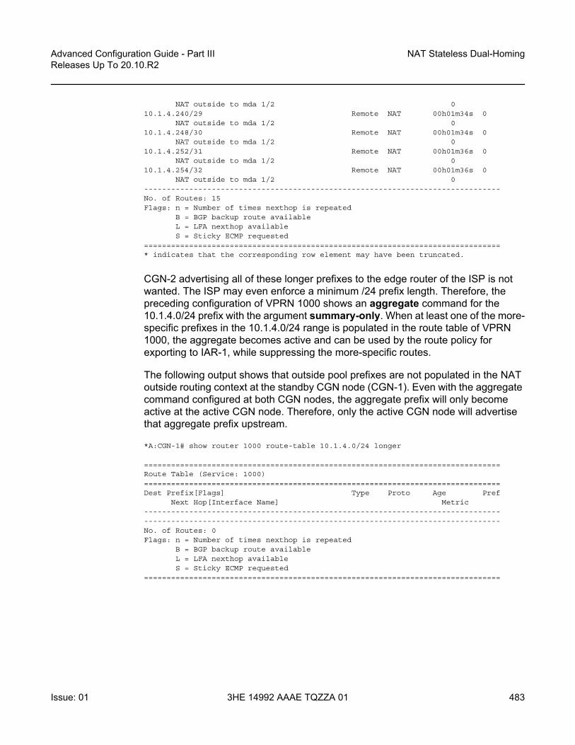
Advanced Configuration Guide - Part III Releases Up To 20.10.R2
NAT Stateless Dual-Homing
Issue: 01 3HE 14992 AAAE TQZZA 01 483
NAT outside to mda 1/2 010.1.4.240/29 Remote NAT 00h01m34s 0
NAT outside to mda 1/2 010.1.4.248/30 Remote NAT 00h01m34s 0
NAT outside to mda 1/2 010.1.4.252/31 Remote NAT 00h01m36s 0
NAT outside to mda 1/2 010.1.4.254/32 Remote NAT 00h01m36s 0
NAT outside to mda 1/2 0-------------------------------------------------------------------------------No. of Routes: 15Flags: n = Number of times nexthop is repeated
B = BGP backup route availableL = LFA nexthop availableS = Sticky ECMP requested
===============================================================================* indicates that the corresponding row element may have been truncated.
CGN-2 advertising all of these longer prefixes to the edge router of the ISP is not wanted. The ISP may even enforce a minimum /24 prefix length. Therefore, the preceding configuration of VPRN 1000 shows an aggregate command for the 10.1.4.0/24 prefix with the argument summary-only. When at least one of the more-specific prefixes in the 10.1.4.0/24 range is populated in the route table of VPRN 1000, the aggregate becomes active and can be used by the route policy for exporting to IAR-1, while suppressing the more-specific routes.
The following output shows that outside pool prefixes are not populated in the NAT outside routing context at the standby CGN node (CGN-1). Even with the aggregate command configured at both CGN nodes, the aggregate prefix will only become active at the active CGN node. Therefore, only the active CGN node will advertise that aggregate prefix upstream.
*A:CGN-1# show router 1000 route-table 10.1.4.0/24 longer
===============================================================================Route Table (Service: 1000)===============================================================================Dest Prefix[Flags] Type Proto Age Pref
Next Hop[Interface Name] Metric--------------------------------------------------------------------------------------------------------------------------------------------------------------No. of Routes: 0Flags: n = Number of times nexthop is repeated
B = BGP backup route availableL = LFA nexthop availableS = Sticky ECMP requested
===============================================================================

NAT Stateless Dual-Homing
484
Advanced Configuration Guide - Part IIIReleases Up To 20.10.R2
3HE 14992 AAAE TQZZA 01 Issue: 01
So far, only one pool has been defined that could be used for stateless dual-homing for both NAT44 and NAT64. However, to allow for independent address management of each of these functions, a separate outside pool is created for each. The following configuration shows two pools in the nat outside context of VPRN 1000: the pool “4-to-4”, which is for NAT44 purposes, and the pool “6-to-4”, which is for NAT64 purposes.
The address range defined in the “6-to-4” pool is 10.1.6.1 to 10.1.6.254. As with the range 10.1.4.1 to 10.1.4.254 in the “4-to-4” pool, an aggregate command is configured to advertise the 10.1.6.0/24 prefix, while suppressing the more-specific prefixes.
With the redundancy node in the “6-to-4” pool, there are instances where traffic from a NAT inside routing context may be mapped to multiple outside pools, which in a stateless dual-homed environment may cause the NAT function to fail. For example, assume a NAT outside context has two pools, P1 and P2, where pool P1 is active and pool P2 is standby. An active pool can trigger the advertisement of inside and outside prefixes, and traffic will be attracted to this CGN node. When traffic arrives, it may be mapped to pool P1 on the active CGN node, due to the NAT mapping criteria. However, traffic may also be mapped to pool P2, due to the mapping criteria; this traffic will fail because the pool P2 is active on the redundant CGN node.
To ensure that this traffic failure does not happen, a group of pools accessed by the same inside routing context must all be active on the same CGN node simultaneously. To achieve this, SR OS uses a Pool Fate Sharing Group (PFSG). The PFSG ensures that all co-located pools accessed by the same inside routing context are either active or standby; not a combination of both. This is achieved by having a leader pool and follower pools.
If the leader pool is active, all follower pools are active. If the leader pool is standby, all follower pools are standby. This is enabled in the redundancy context of the “6-to-4” pool using the follow command. The follow command configures the pool as a follower and allows the user to access the routing context and outside pool of the leader pool. In the following example, pool “4-to-4” is a leader pool and pool “6-to-4” is a follower pool, which always assumes the same state as that of the leader.
*A:CGN-2#configure
servicevprn 1000 customer 1 create
aggregate 10.1.4.0/24 summary-onlyaggregate 10.1.6.0/24 summary-onlynat
outsidepool "4-to-4" nat-group 1 type large-scale create
redundancyexport 192.168.0.249/32monitor 192.168.0.248/32no shutdown

Advanced Configuration Guide - Part III Releases Up To 20.10.R2
NAT Stateless Dual-Homing
Issue: 01 3HE 14992 AAAE TQZZA 01 485
exitmode naptaddress-range 10.1.4.1 10.1.4.254 createexitno shutdown
exitpool "6-to-4" nat-group 1 type large-scale create
redundancyfollow router 1000 pool "4-to-4"
exitmode naptaddress-range 10.1.6.1 10.1.6.254 createexitno shutdown
exitexit
exit
The following output shows a PFSG with leaders and followers in the operational state of pool “6-to-4” at CGN-2. The pool state is active, but the Dual-Homing Type field indicates that this pool is a follower. Therefore, the state is derived from the state of the leader pool, which is pool “4-to-4” in router 1000. The output also contains a list of all the pools that are part of the same PFSG.
*A:CGN-2# show router 1000 nat pool "6-to-4"
===============================================================================NAT Pool 6-to-4===============================================================================Description : (Not Specified)ISA NAT Group : 1Pool type : largeScaleApplications : (None)Admin state : inServiceMode : naptPort forwarding dyn blocks reserved : 0Port forwarding range : 1 - 1023Port reservation : 128 blocksBlock usage High Watermark (%) : 90Block usage Low Watermark (%) : 20Subscriber limit per IP address : 65535Active : trueDeterministic port reservation : (Not Specified)Last Mgmt Change : 10/06/2016 13:09:07===============================================================================
===============================================================================NAT address ranges of pool 6-to-4===============================================================================Range Drain Num-blk-------------------------------------------------------------------------------10.1.6.1 - 10.1.6.254 0-------------------------------------------------------------------------------No. of ranges: 1===============================================================================
===============================================================================

NAT Stateless Dual-Homing
486
Advanced Configuration Guide - Part IIIReleases Up To 20.10.R2
3HE 14992 AAAE TQZZA 01 Issue: 01
NAT members of pool 6-to-4 ISA NAT group 1===============================================================================Member Block-Usage-% Hi-------------------------------------------------------------------------------1 < 1 N-------------------------------------------------------------------------------No. of members: 1===============================================================================
===============================================================================Dual-Homing===============================================================================Type : FollowerFollow-pool : "4-to-4" router 1000Dual-Homing State : Active===============================================================================
===============================================================================Dual-Homing fate-share-group===============================================================================Router Pool Type-------------------------------------------------------------------------------vprn1000 4-to-4 Leadervprn1000 6-to-4 Follower-------------------------------------------------------------------------------No. of pools: 2===============================================================================
NAT Policies
NAT policies allow for definition of NAT attributes such as:
• filtering behavior (endpoint-independent or address-and-port-dependent)• NAT mapping timeouts• per-user session/flow limits• configuration of Application Level Gateway (ALG) protocols• high/low resource watermarks.
These attributes are generic NAT configuration parameters that are beyond the scope of this chapter.
A NAT policy also references the routing context and name of the outside pool used for the creation of NAT bindings associated with the policy. Therefore, if multiple outside pools are needed, multiple NAT policies must also be used. The following shows the configuration of the required NAT policies at CGN-2.

Advanced Configuration Guide - Part III Releases Up To 20.10.R2
NAT Stateless Dual-Homing
Issue: 01 3HE 14992 AAAE TQZZA 01 487
Because two outside pools exist in VPRN 1000 (the pool “4-to-4” for NAT44 and the pool “6-to-4” for NAT64), two policies are created using the nat-policy parameter. The nat-policy “NAT44” uses the pool keyword to access the “4-to-4” pool in router 1000, while the nat-policy “NAT64” uses the same pool keyword to access the “6-to-4” pool in router 1000. In this example, the same outside routing context is used for both NAT policies, but the outside routing contexts can also be different for each policy.
configureservice
natnat-policy "NAT44" create
pool "4-to-4" router 1000exitnat-policy "NAT64" create
pool "6-to-4" router 1000exit
exit
NAT Inside Context
The NAT inside routing context is the interface toward the customer or end user. There can be multiple NAT inside routing contexts mapped to a single NAT outside context (the relationship can be 1:1 or N:1). This is possible even if overlapping addresses are used in two or more NAT inside routing contexts because the NAT flow mapping tuple consists of the parameters {routing-instance, inside-IP, inside-port} mapped to {routing-instance, outside-IP, outside-port}.
The NAT inside routing context is responsible for two main functions:
1. Diverting some or all traffic toward the NAT function (ISA board).2. Attracting traffic that should be subject to NAT toward it. This should be
conditional because only the master CGNAT node should attract traffic toward itself.
For diverting traffic toward the NAT function, there are two approaches:
1. The first approach is to use IP filters with action nat to divert matched traffic into the ISA. Traffic subject to NAT can have a different inside and outside routing context, or the same routing context can be used for both inside and outside.
2. The second approach is a routing-based approach using a destination-prefix in the nat inside context. Any traffic with a destination address matching the defined destination-prefix is forwarded to the ISA for NAT. When the destination-prefix approach is used, different routing contexts must be used for inside and outside.

NAT Stateless Dual-Homing
488
Advanced Configuration Guide - Part IIIReleases Up To 20.10.R2
3HE 14992 AAAE TQZZA 01 Issue: 01
For NAT44, both the IP filter and destination-prefix approaches are permitted. For NAT64, the diversion to NAT is only supported using IPv6 filters. The example setup in this chapter consists of both NAT44 and NAT64. Therefore, for the purpose of standardization across the NAT44 and NAT64 functions, the IP filter-based approach is used for both.
In Figure 79, CE-2 is connected to PE-2 and is part of VPRN 200. To provide Internet access with stateless NAT dual-homing to VPRN 200, it is extended to both CGN-1 and CGN-2 as a NAT inside VRF. The following shows the configuration of VPRN 200 at CGN-2 with a similar configuration also applied at CGN-1.
Because one of the main functions of the NAT inside routing context is to attract traffic toward the (active) CGN node, this is configured in the nat inside context. The redundancy parameter provides a context for the configuration of NAT44 redundancy when the diversion to NAT is implemented with IP filters. In this redundancy context, the peer command is used to configure the address of the redundant peer (in this case CGN-1). If upstream traffic that is subject to NAT inadvertently arrives at the CGN node that is standby for the outside pool used for the NAT mapping, this parameter provides a forwarding address for that traffic. However, if destination-prefix based redirect to NAT is used instead of IP filters, only a nat-policy and destination-prefix need to be configured in the NAT inside routing context.
The steering-route command is optional. It allows for configuration of a (non-default) prefix/length that is only active in the routing table of the NAT inside routing context of the active CGN node. When this steering route is active in the routing table, it can either be advertised directly using the route-policy framework, or it can be used as an indirect next-hop to advertise some other prefix. This latter approach is used in the following configuration example, where the steering-route of 192.168.203.1/32 is used as an indirect next-hop for the static-route-entry of 0.0.0.0/0. This creates the following dependencies:
• If the CGN node is active, the steering route of 192.168.203.1/32 becomes active in the routing table of VPRN 200.
• When 192.168.203.1/32 is active, it becomes a valid indirect next-hop for 0.0.0.0/0, so this route also becomes active in the routing table.
• When the default route is active, it can be exported to the rest of the VPN using the route-policy framework.
In the first of three following configurations, the vrf-export command accesses a policy with the name vrf200-export. The second configuration shows the contents of that policy, where entry 10 accesses a prefix-list (vrf200-lsn44-default) containing the default route and advertises it into BGP-VPN, with the relevant Route-Target (target:64496:200) and Origin (origin:64496:200) Extended Communities attached.

Advanced Configuration Guide - Part III Releases Up To 20.10.R2
NAT Stateless Dual-Homing
Issue: 01 3HE 14992 AAAE TQZZA 01 489
The Origin Extended Community is used by the redundant CGN peer to drop the default route, as shown in entry 10 of the corresponding vrf200-import policy in the same configuration. The reason for dropping the default route at the standby CGN node is that the vrf200-export policy only requires that a default route is present in the routing table in order to source/advertise a default route itself. If the standby CGN node imports the default route from the active CGN node into the routing table, the standby will also attempt to advertise a default route, which is not wanted.
The nat64 command provides the context to configure the NAT64 redundancy parameters. In the case of NAT64, the CGN node becomes a translator between the IPv6 and IPv4 address families and needs to advertise the NAT64 translator address that will be used by IPv6 clients to embed IPv4 addresses. In the first configuration, the address 2001:DB8:122:344::/96 is used as the NAT64 translator address. As with NAT44, the advertisement of this address is conditional and must only be advertised by the active CGN node. This is ensured because the prefix is only present in the routing table of the active CGN, not the standby CGN.
Entry 20 of the vrf200-export policy shown in the second configuration provides the relevant policy rules to ensure that this IPv6 prefix is advertised into BGP-VPN with the relevant Route-Target value when the prefix is present in the routing table.
The last parameter in the nat inside context is the nat-policy, which is known as the default NAT policy and must exist in the nat inside context. When multiple NAT policies are used in a single NAT inside routing context, the default NAT policy is used for any traffic that is not matched (using the destination-prefix for NAT44 or IPv4/IPv6 filters for NAT44/NAT64) and associated with an explicit NAT policy. The default NAT policy can reference a separate NAT policy, or it can reference a NAT policy that is already in use.
As previously described, the intention is to use IP filters to implement the diversion to NAT. The relevant IPv4 and IPv6 filter IDs (ID number 200 in both cases) are shown in the third configuration. The IPv4 filter has no match criteria in this example; it has action nat using nat-policy “NAT44”, which accesses the outside pool “4-to-4” in VPRN 1000. The IPv6 filter also has no match criteria and has action nat, but distinguishes between DSLite (DSLite is not supported for NAT stateless dual-homing) and NAT64, using the nat-type argument. The nat-policy that should be used is the policy “NAT64”, which accesses the outside pool “6-to-4” in VPRN 1000. These IP filters need to match traffic that ingresses the redundant CGN nodes from the MPLS side of VPRN 200 and are, therefore, applied in the network ingress context in the first configuration.
The remainder of the VPRN parameters are generic and are not explained here.
*A:CGN-2#configure
servicevprn 200 customer 1 create

NAT Stateless Dual-Homing
490
Advanced Configuration Guide - Part IIIReleases Up To 20.10.R2
3HE 14992 AAAE TQZZA 01 Issue: 01
vrf-import "vrf200-import"vrf-export "vrf200-export"route-distinguisher 64496:200auto-bind-tunnel
resolution anyexit
exitstatic-route-entry 0.0.0.0/0
indirect 192.168.203.1no shutdown
exitexitnat
insidenat-policy "NAT44"nat64
prefix 2001:db8:122:344::/96no shutdown
exitredundancy
peer 192.0.2.8steering-route 192.168.203.1/32
exitexit
exitnetwork
ingressfilter ip 200filter ipv6 200
exitexitno shutdown
exit
*A:CGN-2#configure
routerpolicy-options
beginprefix-list "vrf200-lsn44-default"
prefix 0.0.0.0/0 exactexitprefix-list "vrf200-nat64-translator"
prefix 2001:db8:122:344::/96 exactexitcommunity "vrf200-soo" members "origin:64496:200"community "vrf200-export" members "target:64496:200"community "vrf200-import" members "target:64496:200"policy-statement "vrf200-export"
entry 10from
prefix-list "vrf200-lsn44-default"exitto
protocol bgp-vpnexitaction accept
community add "vrf200-soo" "vrf200-export"exit

Advanced Configuration Guide - Part III Releases Up To 20.10.R2
NAT Stateless Dual-Homing
Issue: 01 3HE 14992 AAAE TQZZA 01 491
exitentry 20
fromprefix-list "vrf200-nat64-translator"
exitto
protocol bgp-vpnexitaction accept
community add "vrf200-export"exit
exitexitpolicy-statement "vrf200-import"
entry 10from
community "vrf200-soo"exitaction reject
exitentry 20
fromcommunity "vrf200-import"
exitaction acceptexit
exitexit
*A:CGN-2#configure
filterip-filter 200 create
entry 10 createaction
nat nat-policy "NAT44"exit
exitexitipv6-filter 200 create
entry 10 createaction
nat nat-type nat64 nat-policy "NAT64"exit
exitexit
exit
Verification of the Active CGN Node
After the configuration of the inside and NAT outside routing contexts, with the associated NAT policies, the state of the stateless redundant CGN nodes can be verified; see Figure 80.

NAT Stateless Dual-Homing
492
Advanced Configuration Guide - Part IIIReleases Up To 20.10.R2
3HE 14992 AAAE TQZZA 01 Issue: 01
Figure 80 Redundancy Status
The following two outputs show that the pool “4-to-4” is a leader at both CGN-1 and CGN-2 (for which pool “6-to-4” is a follower), and that CGN-2 is the active CGN node.
*A:CGN-2# show router 1000 nat pool "4-to-4" | match "Dual-Homing State" pre-lines 6Dual-Homing===============================================================================Type : LeaderExport route : 192.168.0.249/32Monitor route : 192.168.0.248/32Admin state : inServiceDual-Homing State : Active
*A:CGN-1# show router 1000 nat pool "4-to-4" | match "Dual-Homing State" pre-lines 6Dual-Homing===============================================================================Type : LeaderExport route : 192.168.0.248/32Monitor route : 192.168.0.249/32Admin state : inServiceDual-Homing State : Standby
26100
AS 65535
AS 64496
CGN-1Standby CGN
IAR-1
VPRN1000
VPRN200
PE-2192.0.2.2
VPRN200
NAT insideVRF
NAT outsideVRF
NAT insideVRF
NAT outsideVRF
0.0.0.0/02001:DB8:122:344::/96
10.1.4.0/24 (pool 4-to-4)10.1.6.0/24 (pool 6-to-4)
Redundancy Monitor192.168.0.249
Redundancy Export192.168.0.249
CGN-2Active CGN
VPRN1000
VPRN200

Advanced Configuration Guide - Part III Releases Up To 20.10.R2
NAT Stateless Dual-Homing
Issue: 01 3HE 14992 AAAE TQZZA 01 493
Although the redundancy export route is populated in the NAT outside routing table and advertised externally by the active CGN node (if permitted by route-policy), it is not populated in the NAT outside routing table of the standby CGN, which is not advertised externally. The following two outputs show that CGN-2 advertises its export route (192.168.0.249/32) into IPv4 BGP-VPN, but CGN-1 does not advertise its own export route because the monitor route (192.168.0.249/32) is present.
*A:CGN-2# show router bgp routes vpn-ipv4 rd 64496:1000 hunt---snip----------------------------------------------------------------------------------RIB Out Entries-------------------------------------------------------------------------------Network : 192.168.0.249/32Nexthop : 192.0.2.9Route Dist. : 64496:1000 VPN Label : 262128Path Id : NoneTo : 192.0.2.10Res. Nexthop : n/aLocal Pref. : 100 Interface Name : NotAvailableAggregator AS : None Aggregator : NoneAtomic Aggr. : Not Atomic MED : 0AIGP Metric : NoneConnector : NoneCommunity : target:64496:1000Cluster : No Cluster MembersOriginator Id : None Peer Router Id : 192.0.2.10Origin : IGPAS-Path : No As-PathRoute Tag : 0Neighbor-AS : N/AOrig Validation: N/ASource Class : 0 Dest Class : 0
-------------------------------------------------------------------------------
*A:CGN-1# show router 1000 route-table 192.168.0.249/32
===============================================================================Route Table (Service: 1000)===============================================================================Dest Prefix[Flags] Type Proto Age Pref
Next Hop[Interface Name] Metric-------------------------------------------------------------------------------192.168.0.249/32 Remote BGP VPN 06d03h21m 170
192.0.2.9 (tunneled) 0-------------------------------------------------------------------------------No. of Routes: 1Flags: n = Number of times nexthop is repeated
B = BGP backup route availableL = LFA nexthop availableS = Sticky ECMP requested
*A:CGN-1# show router bgp routes vpn-ipv4 rd 64496:1000 hunt---snip----------------------------------------------------------------------------------

NAT Stateless Dual-Homing
494
Advanced Configuration Guide - Part IIIReleases Up To 20.10.R2
3HE 14992 AAAE TQZZA 01 Issue: 01
RIB Out Entries--------------------------------------------------------------------------------------------------------------------------------------------------------------
As well as the export/monitor routes, the outside pools are populated in the NAT outside routing context and advertised by the active CGN node. The outside pools are summarized as 10.1.4.0/24 (pool “4-to-4”) and 10.1.6.0/24 (pool “6-to-4“) using the aggregate command in VPRN 1000. Because the (more-explicit) NAT outside pool addresses are only populated in the route table of the active CGN node, the aggregate will also only be populated in the routing table of the active CGN node. Therefore, the following policy is applied to the EBGP peering session with IAR-1 at both CGN-1 and CGN-2. The output following the policy example shows that CGN-2 advertises both of the NAT outside pools to IAR-1, while CGN-1 advertises no outside pool prefixes to IAR-1.
configurerouter
policy-optionsbeginpolicy-statement "vrf1000-ebgp-export"
entry 10from
protocol aggregateexitto
protocol bgpexitaction accept
origin igpexit
exitdefault-action dropexit
exitcommit
*A:CGN-2# show router 1000 bgp neighbor 172.31.19.1 advertised-routes===============================================================================BGP Router ID:192.0.2.9 AS:64496 Local AS:64496
===============================================================================Legend -Status codes : u - used, s - suppressed, h - history, d - decayed, * - valid
l - leaked, x - stale, > - best, b - backup, p - purgeOrigin codes : i - IGP, e - EGP, ? - incomplete
===============================================================================BGP IPv4 Routes===============================================================================Flag Network LocalPref MED
Nexthop (Router) Path-Id LabelAs-Path
-------------------------------------------------------------------------------i 10.1.4.0/24 n/a None
172.31.19.2 None -64496

Advanced Configuration Guide - Part III Releases Up To 20.10.R2
NAT Stateless Dual-Homing
Issue: 01 3HE 14992 AAAE TQZZA 01 495
i 10.1.6.0/24 n/a None172.31.19.2 None -64496
-------------------------------------------------------------------------------Routes : 2===============================================================================
*A:CGN-1# show router 1000 bgp neighbor 172.31.18.1 advertised-routes===============================================================================BGP Router ID:192.0.2.8 AS:64496 Local AS:64496
===============================================================================Legend -Status codes : u - used, s - suppressed, h - history, d - decayed, * - valid
l - leaked, x - stale, > - best, b - backup, p - purgeOrigin codes : i - IGP, e - EGP, ? - incomplete
===============================================================================BGP IPv4 Routes===============================================================================Flag Network LocalPref MED
Nexthop (Router) Path-Id LabelAs-Path
-------------------------------------------------------------------------------No Matching Entries Found===============================================================================
In the NAT inside routing instance, any routes that are used to attract traffic are populated in the relevant route tables of the active CGN node and must be advertised externally. For the NAT44 function, the steering route 192.168.203.1/32 populates the route table of the active CGN node, and this route is used as an indirect next-hop for a static-route-entry to a default route. For the NAT64 function, the NAT64 translator address 2001:DB8:122:344::/96 is used to attract IPv6 traffic with IPv4-embedded addresses.
The first of the two following outputs shows that CGN-2 is advertising the NAT44 default route as a VPN-IPv4 prefix and the NAT64 translator address as a VPN-IPv6 prefix. Both routes are advertised with the relevant Route-Target for VPRN 200 (target:64496:200) and, therefore, will be imported by PE-2 and subsequently advertised to CE-2. The second output shows the same commands entered at CGN-1 and verifies that because CGN-1 is the standby CGN node, it is not advertising either VPN-IPv4/VPN-IPv6 prefix.
*A:CGN-2# show router bgp routes vpn-ipv4 rd 64496:200 hunt===============================================================================BGP Router ID:192.0.2.9 AS:64496 Local AS:64496
===============================================================================Legend -Status codes : u - used, s - suppressed, h - history, d - decayed, * - valid
l - leaked, x - stale, > - best, b - backup, p - purgeOrigin codes : i - IGP, e - EGP, ? - incomplete
===============================================================================BGP VPN-IPv4 Routes===============================================================================

NAT Stateless Dual-Homing
496
Advanced Configuration Guide - Part IIIReleases Up To 20.10.R2
3HE 14992 AAAE TQZZA 01 Issue: 01
---snip----------------------------------------------------------------------------------RIB Out Entries-------------------------------------------------------------------------------Network : 0.0.0.0/0Nexthop : 192.0.2.9Route Dist. : 64496:200 VPN Label : 262141Path Id : NoneTo : 192.0.2.10Res. Nexthop : n/aLocal Pref. : 100 Interface Name : NotAvailableAggregator AS : None Aggregator : NoneAtomic Aggr. : Not Atomic MED : NoneAIGP Metric : NoneConnector : NoneCommunity : target:64496:200Cluster : No Cluster MembersOriginator Id : None Peer Router Id : 192.0.2.10Origin : IGPAS-Path : No As-PathRoute Tag : 0Neighbor-AS : N/AOrig Validation: N/ASource Class : 0 Dest Class : 0
-------------------------------------------------------------------------------
*A:CGN-2# show router bgp routes vpn-ipv6 rd 64496:200 hunt===============================================================================BGP Router ID:192.0.2.9 AS:64496 Local AS:64496
===============================================================================Legend -Status codes : u - used, s - suppressed, h - history, d - decayed, * - valid
l - leaked, x - stale, > - best, b - backup, p - purgeOrigin codes : i - IGP, e - EGP, ? - incomplete
===============================================================================BGP VPN-IPv6 Routes===============================================================================---snip----------------------------------------------------------------------------------RIB Out Entries-------------------------------------------------------------------------------Network : 2001:db8:122:344::/96Nexthop : ::ffff:192.0.2.9Route Dist. : 64496:200 VPN Label : 262141Path Id : NoneTo : 192.0.2.10Res. Nexthop : n/aLocal Pref. : 100 Interface Name : NotAvailableAggregator AS : None Aggregator : NoneAtomic Aggr. : Not Atomic MED : 0AIGP Metric : NoneConnector : NoneCommunity : target:64496:200Cluster : No Cluster MembersOriginator Id : None Peer Router Id : 192.0.2.10Origin : IGP

Advanced Configuration Guide - Part III Releases Up To 20.10.R2
NAT Stateless Dual-Homing
Issue: 01 3HE 14992 AAAE TQZZA 01 497
AS-Path : No As-PathRoute Tag : 0Neighbor-AS : N/AOrig Validation: N/ASource Class : 0 Dest Class : 0
-------------------------------------------------------------------------------
*A:CGN-1# show router bgp routes vpn-ipv4 rd 64496:200 hunt===============================================================================BGP Router ID:192.0.2.8 AS:64496 Local AS:64496
===============================================================================Legend -Status codes : u - used, s - suppressed, h - history, d - decayed, * - valid
l - leaked, x - stale, > - best, b - backup, p - purgeOrigin codes : i - IGP, e - EGP, ? - incomplete
===============================================================================BGP VPN-IPv4 Routes===============================================================================---snip----------------------------------------------------------------------------------RIB Out Entries--------------------------------------------------------------------------------------------------------------------------------------------------------------
*A:CGN-1# show router bgp routes vpn-ipv6 rd 64496:200 hunt===============================================================================BGP Router ID:192.0.2.8 AS:64496 Local AS:64496
===============================================================================Legend -Status codes : u - used, s - suppressed, h - history, d - decayed, * - valid
l - leaked, x - stale, > - best, b - backup, p - purgeOrigin codes : i - IGP, e - EGP, ? - incomplete
===============================================================================BGP VPN-IPv6 Routes===============================================================================---snip----------------------------------------------------------------------------------RIB Out Entries--------------------------------------------------------------------------------------------------------------------------------------------------------------
Verification of Data Path
The host connected to CE-2 and the web server accessible from IAR-1 are used to verify the end-to-end data path for both NAT44 and NAT64.

NAT Stateless Dual-Homing
498
Advanced Configuration Guide - Part IIIReleases Up To 20.10.R2
3HE 14992 AAAE TQZZA 01 Issue: 01
NAT44
The host connected to CE-2 initiates an IPv4 UDP session toward the web server with a source address of 172.31.102.3 and a destination address of 10.1.128.43. The source port used is 1357, and the destination port is 80.
A two-way data transfer is verified as successful. The following output shows the details of the NAT44 binding at CGN-2, the active CGN node. The inside IP address and port are as described, while the allocated outside IP address is 10.1.4.254 using outside port 1047.
*A:CGN-2# tools dump nat sessions inside-ip 172.31.102.3
===============================================================================Matched 1 session on Slot #1 MDA #2===============================================================================Owner : [email protected] : 200Policy : NAT44FlowType : UDP Timeout (sec) : 300Inside IP Addr : 172.31.102.3Inside Port : 1357Outside IP Addr : 10.1.4.254Outside Port : 1047Foreign IP Addr : 10.1.128.43Foreign Port : 80Dest IP Addr : 10.1.128.43Nat Group : 1Nat Group Member : 1-------------------------------------------------------------------------------===============================================================================
NAT64
The host connected to CE-2 also initiates an IPv6 UDP session toward the web server with a source address of 2001:DB8:4001:200::3 and a destination address of 2001:DB8:122:344::A01:802B. The destination address represents the NAT64 translator address (2001:DB8:122:344::/96) and the embedded IPv4 address (10.1.128.43) translated into colon-hexidecimal format (A01:802B). The source port is 2468 and the destination port is 80.
A two-way data transfer is verified as successful. The following output shows the details of the NAT64 binding at CGN-2. Again, the inside IPv6 address and port are as described, while the allocated outside IP address is 10.1.6.254 using outside port 1032.
*A:CGN-2# tools dump nat sessions inside-ip 2001:db8:4001:200::3

Advanced Configuration Guide - Part III Releases Up To 20.10.R2
NAT Stateless Dual-Homing
Issue: 01 3HE 14992 AAAE TQZZA 01 499
===============================================================================Matched 1 session on Slot #1 MDA #2===============================================================================Owner : NAT64-Sub@2001:db8:4001:200::3Router : 200Policy : NAT64FlowType : UDP Timeout (sec) : 300Inside IP Addr : 2001:db8:4001:200::3
Inside Port : 2468Outside IP Addr : 10.1.6.254Outside Port : 1032Foreign IP Addr : 10.1.128.43Foreign Port : 80Dest IP Addr : 10.1.128.43Nat Group : 1Nat Group Member : 1-------------------------------------------------------------------------------===============================================================================
Failover
Before simulating a failover test, an IPv4 UDP session is established between the host connected to CE-2 and the web server, to ensure data-path continuity during the failure.
CGN-2 is the active CGN node; to simulate a failure of the MS-ISA board, it is placed into a shutdown state.
*A:CGN-2# configure card 1 mda 2 shutdown
1 2016/10/13 15:10:21.39 UTC WARNING: SNMP #2004 Base 1/2/nat-in-ip"Interface 1/2/nat-in-ip is not operational"
2 2016/10/13 15:10:21.39 UTC MINOR: NAT #2024 Base NAT"The state of NAT group 1 changed to out-of-service."
Figure 81 shows the example topology in the post-failover redundancy state.

NAT Stateless Dual-Homing
500
Advanced Configuration Guide - Part IIIReleases Up To 20.10.R2
3HE 14992 AAAE TQZZA 01 Issue: 01
Figure 81 Post-Failover Redundancy State
Because the MS-ISA in slot 1/2 is the only MDA in nat-group 1, it is sufficient to force the NAT group down. After nat-group 1 is declared down at CGN-2, the following actions take place:
1. CGN-2 transitions the active state to false for the leader outside pool and any follower pools because its admin state changed to down, as follows:
22 2016/10/13 15:10:21.40 UTC WARNING: NAT #2017 vprn1000 NAT redundancy"The Large Scale NAT activity changed to false for pool "4-to-4" - state changedto "Down"."
23 2016/10/13 15:10:21.40 UTC WARNING: NAT #2017 vprn1000 NAT redundancy"The Large Scale NAT activity changed to false for pool "6-to-4" - state changedto "Down"."
26101
AS 65535
AS 64496
IAR-1
PE-2192.0.2.2
VPRN200
NAT insideVRF
NAT outsideVRF
NAT insideVRF
NAT outsideVRF
0.0.0.0/02001:DB8:122:344::/96
10.1.4.0/24 (pool 4-to-4)10.1.6.0/24 (pool 6-to-4)
Redundancy Monitor192.168.0.248
Redundancy Export192.168.0.248
CGN-2Standby CGN
VPRN1000
VPRN200
CGN-1Active CGN
VPRN200
VPRN1000

Advanced Configuration Guide - Part III Releases Up To 20.10.R2
NAT Stateless Dual-Homing
Issue: 01 3HE 14992 AAAE TQZZA 01 501
2. CGN-2 withdraws the redundancy export route (192.168.0.249/32) from the NAT outside routing context (VPRN 1000). This means that the monitor route is no longer present in the routing table of CGN-1. Therefore, CGN-1 transitions to an active state and advertises its own export route. In this example, where BGP is used to advertise monitor routes, the Minimum Route Advertisement Interval is configured for 1 second, to reduce re-convergence times. However, when the monitor route is withdrawn at the standby CGN node, the system will wait for 10 seconds to ensure that this is not a route flap before declaring itself active. This is a non-configurable timer.
6 2016/10/13 15:10:31.53 UTC WARNING: NAT #2017 vprn1000 NAT redundancy"The Large Scale NAT activity changed to true for pool "4-to-4" - state changedto "Active"."
8 2016/10/13 15:10:31.53 UTC WARNING: NAT #2017 vprn1000 NAT redundancy"The Large Scale NAT activity changed to true for pool "6-to-4" - state changedto "Active"
3. Because CGN-2 is now standby, the outside pool addresses are no longer present in the routing table of the outside routing context (VPRN 1000). Therefore, they are withdrawn by CGN-2 in the EBGP peering session to IAR-1. Conversely, because CGN-1 is now active, it advertises the outside pools to IAR-1.
4. The NAT44 redundancy steering route (192.168.203.1/32) is no longer active in the NAT inside (VPRN 200) routing table at CGN-2. Therefore, the default route no longer has a valid next-hop, so the route is withdrawn. Conversely, the steering route is now present in the routing table of VPRN 200 at CGN-1. Therefore, the default route becomes active, and is advertised into VPRN 200 as a VPN-IPv4 prefix.
5. The NAT64 translator address is no longer active in the NAT inside (VPRN 200) IPv6 routing table at CGN-2, so the address is withdrawn. Conversely, the NAT64 translator address is now present in the IPv6 routing table of VPRN 200 at CGN-1 and is advertised into VPRN 200 as a VPN-IPv6 prefix.
The operational state of the outside pools can be verified at CGN-1, as follows:
*A:CGN-1# show router 1000 nat pool "4-to-4" | match "Dual-Homing" post-lines 12Dual-Homing===============================================================================Type : LeaderExport route : 192.168.0.248/32Monitor route : 192.168.0.249/32Admin state : inServiceDual-Homing State : Active===============================================================================
===============================================================================Dual-Homing fate-share-group===============================================================================Router Pool Type-------------------------------------------------------------------------------

NAT Stateless Dual-Homing
502
Advanced Configuration Guide - Part IIIReleases Up To 20.10.R2
3HE 14992 AAAE TQZZA 01 Issue: 01
vprn1000 4-to-4 Leadervprn1000 6-to-4 Follower-------------------------------------------------------------------------------No. of pools: 2===============================================================================
Finally, the integrity of the IPv4 UDP session between the host connected to CE-2 and the web server is verified, and the associated NAT binding is shown at CGN-1, as follows:
*A:CGN-1# tools dump nat sessions inside-ip 172.31.102.3
===============================================================================Matched 1 session on Slot #1 MDA #2===============================================================================Owner : [email protected] : 200Policy : NAT44FlowType : UDP Timeout (sec) : 300Inside IP Addr : 172.31.102.3Inside Port : 1357Outside IP Addr : 10.1.4.254Outside Port : 1049Foreign IP Addr : 10.1.128.43Foreign Port : 80Dest IP Addr : 10.1.128.43Nat Group : 1Nat Group Member : 1-------------------------------------------------------------------------------===============================================================================
When the failure is resolved at CGN-2 and the MS-ISA comes back online, the failover mechanism is non-revertive. This is because CGN-2 already has the CGN-1 export route present in the routing table of the NAT outside routing context (VPRN 1000) as its monitor route. The following output at CGN-2 shows the MS-ISA and NAT group 1 transitioning to in-service, followed by the active state of the outside pools changing from down to standby.
*A:CGN-2# configure card 1 mda 2 no shutdown
9 2016/10/13 15:55:10.39 UTC MINOR: NAT #2024 Base NAT"The state of NAT group 1 changed to in-service."
10 2016/10/13 15:55:10.39 UTC MINOR: NAT #2025 Base NAT"The NAT group 1 is not degraded."
17 2016/10/13 15:55:10.40 UTC WARNING: NAT #2017 vprn1000 NAT redundancy"The Large Scale NAT activity changed to false for pool "4-to-4" - state changedto "Standby"."
18 2016/10/13 15:55:10.39 UTC WARNING: NAT #2017 vprn1000 NAT redundancy"The Large Scale NAT activity changed to false for pool "6-to-4" - state changedto "Standby"."

Advanced Configuration Guide - Part III Releases Up To 20.10.R2
NAT Stateless Dual-Homing
Issue: 01 3HE 14992 AAAE TQZZA 01 503
19 2016/10/13 15:55:10.39 UTC MINOR: NAT #2020 Base NAT"The NAT MDA 1/2 is now active in group 1."
Conclusion
NAT stateless dual-homing provides a compromise between a lack of redundancy and the protocol and state synchronization requirements for stateful NAT redundancy. This is particularly true when CGN nodes provide a gateway to the Internet where Service Level Agreements (SLAs) are often difficult to guarantee.
This chapter provides an example of how NAT stateless dual-homing is configured and describes how SR OS provides the redundancy mechanism for NAT44 and NAT64. The example in this chapter does not represent the only way that NAT stateless dual-homing can be delivered. It uses VPRNs in both the inside and outside routing contexts, but the GRT is also an option for either. It uses IP filtering for NAT diversion for both NAT44 and NAT64, but a routing-based approach using destination-prefix is also option for NAT44. It uses BGP in the NAT outside routing context and BGP-VPN in the NAT inside routing context to advertise redundancy routes externally, but any routing protocol that can be accessed through the route-policy framework is applicable.

NAT Stateless Dual-Homing
504
Advanced Configuration Guide - Part IIIReleases Up To 20.10.R2
3HE 14992 AAAE TQZZA 01 Issue: 01

Advanced Configuration Guide - Part III Releases Up To 20.10.R2
Triple Play Service Delivery Architecture
Issue: 01 3HE 14992 AAAE TQZZA 01 505
Triple Play Service Delivery Architecture
In This Section
This section provides TPSDA configuration information for the following topics:
• ARP Hosts• Bridged CO• DHCP Server Failover States• DHCPv4 Server Basics• Diameter Application NASREQ• Diameter Base Protocol: Establishing a Diameter Peer Connection• ESM Basics• ESM 128-bit Mode for DHCPv6 IA_NA WAN Hosts• ESM IPv4: Multicast in a Wholesale/Retail Scenario• ESM IPv4: Multicast with Redirection• ESM IPv4: Multicast with SRRP• ESM SLAAC Prefix Assignment via Local Address Server• ESMv4: PPPoE Hosts• ESMv6: IPoE Dual Stack Hosts• ESMv6: PPPoE Dual Stack Hosts• Flexible Authentication Model in ESM• GTP Access• High Scale QoS IOM in ESM Context: Expanded SLA Mode• High Scale QoS IOM in ESM Context: Single SLA Mode• Ingress Multicast Path Management• IPoE Sessions• IPv4 DHCP Hosts• L2TP for Subscriber Access — LAC• Local User Database Basics

Triple Play Service Delivery Architecture
506
Advanced Configuration Guide - Part IIIReleases Up To 20.10.R2
3HE 14992 AAAE TQZZA 01 Issue: 01
• Local User Database for DHCPv4 Server• Local User Database for Enhanced Subscriber Management• Managed SAPs with Routed CO• Multi-Chassis Ring Layer 2 with Enhanced Subscriber Management• Python Cache Support for ESM Applications• RADIUS-Triggered Dynamic Data Service Provisioning• Raw Formatting of DHCPv4/v6 Options in ESM• Routed CO• Subscriber Redundancy for Routed CO• Virtual Residential Gateway Authentication Scenarios• Virtual Residential Gateway Home LAN Extension• Virtual Residential Gateway Home Pool Management• WiFi Aggregation and Offload — Basic Open SSID• WiFi Aggregation and Offload — Basic Secure SSID with Distributed RADIUS
Proxy• WiFi Aggregation and Offload — IPv4/v6 Dual-Stack UEs• WiFi Aggregation and Offload — Migrant User Support• WiFi Aggregation and Offload — Open SSID with DSM and Lawful Intercept

Advanced Configuration Guide - Part III Releases Up To 20.10.R2
ARP Hosts
Issue: 01 3HE 14992 AAAE TQZZA 01 507
ARP HostsThis chapter describes advanced ARP host configurations.
Topics in this chapter include:
• Applicability• Summary• Overview• Configuration• Conclusion
Applicability
This section describes ARP hosts and is applicable to the 7450 ESS and 7750 SR series and was tested on SR-OS 13.0 R3.
Summary
In business access areas, CPEs typically get their IP address information through DHCP and PPPoE. However, CPE network facing interfaces can be configured statically. In such cases, the first packet the network receives from the user is an ARP to the Broadband Service Aggregator (BSA) or Broadband Service Router (BSR) interface. In order to accommodate such configurations, Enhanced Subscriber Management (ESM) feature set supports RP hosts.
In practice, this means that authentication, self-provisioning and Service Level Agreement (SLA) enforcement can be triggered by reception of ARP packets.
The BRAS node will learn the IP-MAC association based on the received arp-request packet and will instanciate subscriber-hosts based on results from RADIUS authentication, the same way as this would happen through DHCP or PPPoE.

ARP Hosts
508
Advanced Configuration Guide - Part IIIReleases Up To 20.10.R2
3HE 14992 AAAE TQZZA 01 Issue: 01
This section provides configuration and troubleshooting commands for ARP hosts. Features common with other host types and not unique to arp-hosts are not described in this chapter. (Not exhaustive list: RADIUS managed routes, routed subscriber with dynamic BGP peering, Wholesale/Retail, Managed SAPs configurations, ESM related host limitation mechanisms, host High-Availability, multi-chassis peer synchronization).
Knowledge of the Triple Play Service Delivery Architecture (TPSDA) concepts is assumed throughout this document.
Overview
ARP host is supported in the bridged CO (VPLS) and the routed CO (Subscriber Interface) model. It is triggered by the first ARP packet received from the host. ARP host is also supported in a wholesale/retail context and on managed SAPs (MSAP).
The IP and MAC addresses are extracted from the ARP request. They are copied in the access-request message sent to the RADIUS server:
• RADIUS attribute [1] Username = IP address• VSA [26][27] Client Hardware Address = MAC address
On successful authentication RADIUS will reply with an access-accept message, and ESM will create the ARP host. ESM string assignment options are out of the scope for this scenario.
Warning: Enhanced Subscriber Management and RADIUS authentication are mandatory for the use of ARP hosts.

Advanced Configuration Guide - Part III Releases Up To 20.10.R2
ARP Hosts
Issue: 01 3HE 14992 AAAE TQZZA 01 509
Figure 82 Bridged CO and Routed CO Example
RADIUSServer
BSR-1BSA-1 PE-1
CPE-1
CPE-3
BSAN-1
sapsapsap
sap sdp
BSAN-2
CPE-4
VPRNVPLS
CPE-2
OSSG373
Routed-COESM
Bridged-COESM

ARP Hosts
510
Advanced Configuration Guide - Part IIIReleases Up To 20.10.R2
3HE 14992 AAAE TQZZA 01 Issue: 01
Configuration
ARP Hosts in a Bridged CO Environment
Figure 83 ARP Hosts in a Bridged CO Environment Example
Enabling ARP-host for the Bridged CO model requires a composite service; a VPLS on the BSA node and a VPRN/IES on the BSR node. RADIUS authentication and subscriber management, which mandates IP-MAC or NH-MAC type anti-spoofing, are mandatory for ARP hosts.
# on BSA-1configure
servicevpls 2 customer 1 create
description "ARP host - Bridged CO"stp
RADIUSServer
BSR-1
Access-Request
USER NAME [1] IPxVSA [26] 19 Alcatel (6527)CHADDR [27] MACx
ESM-StringsOptional-Strings
ARP-Request toGW BSR-1
Snoop ARP and Extract IP/MACFrom ARP-Request
WasBufferedat BSA-1
BSA-1 PE-1
CPE-1 sapGW
BSAN-2
VPRNVPLS
OSSG374
IPx/MACx
ARP Request to GWARP Reply
Access-Accept
ESM
Create Host and AssignSession-Timeout
Install ARP-Reply and Assign ARP-Timout

Advanced Configuration Guide - Part III Releases Up To 20.10.R2
ARP Hosts
Issue: 01 3HE 14992 AAAE TQZZA 01 511
shutdownexitsap 1/1/1:1 create
authentication-policy "authentication-1"anti-spoof ip-macsub-sla-mgmt
sub-ident-policy "sub-id-default"multi-sub-sap 10no shutdown
exitarp-host
no shutdownexit
exitspoke-sdp 12:2 createexitno shutdown
exitexit
exit
The RADIUS authentication policy does not require any specific parameter settings. The RADIUS username attribute will always contain the host IP address, meaning that the authentication policy parameter user-name-format is irrelevant for ARP hosts.
configuresubscriber-mgmt
authentication-policy "authentication-1" createpassword ALUradius-authentication-server
server 1 address 172.16.1.1 secret ALUexit# re-authentication is optionalre-authentication# only required when RADIUS Disconnect is needed (optional)accept-authorization-change
exitexit
The CPE ARPs are snooped and the first CPE ARP triggers a RADIUS accept-request. Any subsequent ARPs will trigger RADIUS re-authentication only if the ARP host configurable min-auth-interval is expired and if the previously defined re-authentication parameter is set. The initial ARP is only forwarded to the BSR-1 upon successful RADIUS authentication by means of a RADIUS access-accept message. The same RADIUS access-accept message and passing the several session limit checks, triggers the instanciation of the host.
The BSR-1 node requires a VPRN/IES as part of the composite service. No ARP-host-specific parameters are required on the BSR-1 for the bridged CO model.
# on BSR-1configure service
vprn 1 customer 1 create

ARP Hosts
512
Advanced Configuration Guide - Part IIIReleases Up To 20.10.R2
3HE 14992 AAAE TQZZA 01 Issue: 01
route-distinguisher 64496:1auto-bind-tunnel
resolution-filterldp
exitresolution filter
exitvrf-target target:64496interface "int-BSA1-p2mp-1" create
description "ARP host - Bridged CO" address 10.2.0.6/29ip-mtu 1500spoke-sdp 21:2 createexit
exitexit
exit
ARP Hosts in a Routed CO Environment
Figure 84 ARP Hosts in a Routed CO Environment ExampleRADIUSServer
BSR-1
Access-Request
USER NAME [1] IPxVSA [26] 19 Alcatel (6527)CHADDR [27] MACx
ESM-StringsOptional-Strings
ARP-Request Snoop ARP and Extract IP/MACFrom ARP-Request
PE-1
CPE-3GW
VPRN
OSSG375
IPx/MACx
ARP Reply
Access-Accept
ESM
ESM
Create Host and AssignSession-Timeout and UpdateIP ARP Table
Install ARP-Reply and Assign ARP-Timout

Advanced Configuration Guide - Part III Releases Up To 20.10.R2
ARP Hosts
Issue: 01 3HE 14992 AAAE TQZZA 01 513
Enabling ARP-host for the routed CO model is identical for VPRN and IES services. RADIUS authentication and subscriber management, which mandates IP-MAC or NH-MAC type anti-spoofing, are mandatory for ARP hosts.
The initial ARP will, only upon successful RADIUS authentication and passing the several sessions limit checks, create the ARP host. The ARP reply or update of the IP ARP table is not performed on any unsuccessful RADIUS authentication.
# on BSR-1configure service
vprn 1 customer 1 createroute-distinguisher 64496:1auto-bind-tunnel
resolution-filterldp
exitresolution filter
exit
vrf-target target:64496:1subscriber-interface "sub-int-1" create
description "ARP host - Routed CO" address 10.1.0.6/29group-interface "group-int-1" create
authentication-policy "authentication-1"sap 1/1/1:1 create
anti-spoof ip-macsub-sla-mgmt
sub-ident-policy "sub-id-default"no shutdown
exitexitarp-host
no shutdownexit
exitexit
exitexit
RADIUS User Configuration Bridged/Routed CO
The username in the RADIUS access request is always the statically configured IP address from the CPE and configured as key in the RADIUS users file. The RADIUS Framed-Route attribute is not required and is silently ignored (if returned to BSA/BSR node).
"10.1.0.1" Auth-Type := Local, User-Password == ALUAlc-Subsc-ID-Str = "arp-host-routed-%{User-name}",Alc-Subsc-Prof-Str = "sub-profile-1",Alc-SLA-Prof-Str = "sla-profile-1"

ARP Hosts
514
Advanced Configuration Guide - Part IIIReleases Up To 20.10.R2
3HE 14992 AAAE TQZZA 01 Issue: 01
"10.2.0.1" Auth-Type := Local, User-Password == ALUAlc-Subsc-ID-Str = "arp-host-bridged-%{User-name}",Alc-Subsc-Prof-Str = "sub-profile-1",Alc-SLA-Prof-Str = "sla-profile-1"
Setup and Debugging of ARP Host
Identical methodologies are used to debug/setup and troubleshoot ARP hosts for the bridged or the Routed CO model. The Routed CO model is used as an example through the rest of this section on ARP hosts.
There are two modes of ARP host debugging: all and dropped-only. The dropped-only mode shows all cases where the creation of the ARP host will be unsuccessful.
By default, all enabled ARP hosts on a service will be monitored. More specific filtering on a particular IP, MAC or SAP is optional.
All main traps are by default cyclically logged in log-id 99 and can be viewed anytime.
debug service id 1 arp-host mode all
ARP host mandate RADIUS authentication and a separate debug option is available for RADIUS interaction.
debug radius detail
CPE-3 with statically configured IP1 10.1.0.1 sends an ARP to the BSR-1 gateway.
1 2015/06/22 15:48:00.72 CEST MINOR: DEBUG #2001 Base RADIUS"RADIUS: Transmit
Access-Request(1) 172.16.1.1:1812 id 2 len 79 vrid 1 pol authentication-1USER NAME [1] 8 10.1.0.1PASSWORD [2] 16 gy3yhtT5dF9YYilHtiiNNkNAS IP ADDRESS [4] 4 192.0.2.2VSA [26] 19 Alcatel(6527)
CHADDR [27] 17 00:00:0a:01:00:01"
2 2015/06/22 15:48:00.74 CEST MINOR: DEBUG #2001 Base RADIUS"RADIUS: Receive
Access-Accept(2) id 2 len 94 from 172.16.1.1:1812 vrid 1 pol authentication-1VSA [26] 26 Alcatel(6527)
SUBSC ID STR [11] 24 arp-host-routed-10.1.0.1VSA [26] 15 Alcatel(6527)
SUBSC PROF STR [12] 13 sub-profile-1VSA [26] 15 Alcatel(6527)
SLA PROF STR [13] 13 sla-profile-1"
3 2015/06/22 15:48:00.75 CEST MINOR: DEBUG #2001 vprn1 ARP Host

Advanced Configuration Guide - Part III Releases Up To 20.10.R2
ARP Hosts
Issue: 01 3HE 14992 AAAE TQZZA 01 515
"ARP Host: Created ARP hostVPRN 1, SAP 1/1/1:1
IP: 10.1.0.1MAC: 00:00:0a:01:00:01
"
A:BSR-1# show log log-id 99--- snipped ---58 2015/06/22 15:48:00.73 CEST WARNING: SVCMGR #2500 Base Subscriber created"Subscriber arp-host-routed-10.1.0.1 has been created in the system"
The user name in the RADIUS access-request contains the CPE’s IP address independent from the user-name-format defined in the authentication policy. The MAC address of the ARP host is included in the RADIUS access-request as VSA (Alc-Client-Hardware-Addr) independent on the include-radius-attribute mac-address parameter from the authentication policy.
The show service id 1 arp-host command displays all active ARP hosts on this service.
A:BSR-1# show service id 1 arp-host===============================================================================ARP host table, service 1===============================================================================IP Address Mac Address Sap Id Remaining MC
Time Stdby-------------------------------------------------------------------------------10.1.0.1 00:00:0a:01:00:01 1/1/1:1 03h59m23s-------------------------------------------------------------------------------Number of ARP hosts : 1===============================================================================A:BSR-1#
More specific filters such as sap, ip-address, mac and others can be used to show dedicated ARP hosts created on the BSR.
A:BSR-1# show service id 1 arp-host ip-address 10.1.0.1 detail===============================================================================ARP hosts for service 1===============================================================================Service ID : 1IP Address : 10.1.0.1MAC Address : 00:00:0a:01:00:01Subscriber-interface : sub-int-1Group-interface : group-int-1SAP : 1/1/1:1Remaining Time : 03h59m15s
Sub-Ident : "arp-host-routed-10.1.0.1"Sub-Profile-String : "sub-profile-1"SLA-Profile-String : "sla-profile-1"App-Profile-String : ""

ARP Hosts
516
Advanced Configuration Guide - Part IIIReleases Up To 20.10.R2
3HE 14992 AAAE TQZZA 01 Issue: 01
ARP host ANCP-String : ""ARP host Int Dest Id : ""Category-Map-Name : ""
RADIUS-User-Name : "10.1.0.1"
Session Timeout (s) : 14400Start Time : 06/22/2015 15:48:00Last Auth : 06/22/2015 15:48:00Last Refresh : 06/22/2015 15:48:00Persistence Key : N/A-------------------------------------------------------------------------------Number of ARP hosts : 1===============================================================================A:BSR-1#
Dynamically created ARP hosts are added as /32 addresses to the routing table and marked with protocol type Sub Mgmt. Routes of the Sub Mgmt protocol type are not exported into vpn-ipv4 by the default vrf-target policy. A separate, dedicated vrf-export policy is required to achieve this.
A:BSR-1# show router 1 route-table 10.1.0.0/24 longer===============================================================================Route Table (Service: 1)===============================================================================Dest Prefix[Flags] Type Proto Age Pref
Next Hop[Interface Name] Metric-------------------------------------------------------------------------------10.1.0.0/29 Local Local 00h04m21s 0
sub-int-1 010.1.0.1/32 Remote Sub Mgmt 00h00m56s 0
[group-int-1] 0-------------------------------------------------------------------------------No. of Routes: 2Flags: n = Number of times nexthop is repeated
B = BGP backup route availableL = LFA nexthop availableS = Sticky ECMP requested
===============================================================================A:BSR-1#
Specific ARP host counters can be shown or cleared using the CLI command show/clear service id 1 ARP host statistics.
A:BSR-1# show service id 1 arp-host statistics===============================================================================ARP host statistics===============================================================================Num Active Hosts : 1Received Triggers : 5Ignored Triggers : 3Ignored Triggers (overload) : 0SHCV Checks Forced : 0Hosts Created : 1Hosts Updated : 1Hosts Deleted : 0

Advanced Configuration Guide - Part III Releases Up To 20.10.R2
ARP Hosts
Issue: 01 3HE 14992 AAAE TQZZA 01 517
Authentication Requests Sent : 4===============================================================================A:BSR-1#
The ARP hosts mandate Enhanced Subscriber managed (ESM) and therefore an anti-spoofing configuration (IP-MAC or NH-MAC). The anti-spoofing table with active hosts can be viewed with the command show service id 1 subscriber-hosts.
A:BSR-1# show service id 1 subscriber-hosts=============================================================Subscriber Host table=============================================================Sap Subscriber
IP AddressMAC Address PPPoE-SID Origin Fwding State
-------------------------------------------------------------1/1/1:1 arp-host-routed-10.1.0.1
10.1.0.100:00:0a:01:00:01 N/A ARP-Host Fwding
-------------------------------------------------------------Number of subscriber hosts : 1=============================================================A:BSR-1#
An ARP host can be manually deleted from the system using one of the two following methods:
• clear service id 1 arp-host• RADIUS disconnect message
Using the first method, clear service id 1 arp-host and omitting any more specific parameter results in the removal of all ARP hosts in this service. Extra filters such as ip-address, mac or sap-id are required to remove a specific ARP host.
*A:BSR-1# clear service id 1 arp-host- arp-host {all | mac <ieee-address> | sap <sap-id> | ip-address <ip-
address[/mask]> }- arp-host {port <port-id> | {inter-dest-id <intermediate-destination-id> | no-
inter-dest-id} [port <port-id>] }- arp-host statistics [sap <sap-id> | interface <interface-name>]
A:BSR-1# clear service id 1 arp-host ip-address 10.1.0.1
Using the second method, RADIUS disconnect always result in the removal of a unique host because nas-port-id and framed-ip-address are mandatory parameters in the RADIUS disconnect message. This RADIUS disconnect message is used also for other host-types.
nas-port-id = 1/1/1:1framed-ip-address=10.1.0.1

ARP Hosts
518
Advanced Configuration Guide - Part IIIReleases Up To 20.10.R2
3HE 14992 AAAE TQZZA 01 Issue: 01
RADIUS disconnect messages are, for security reasons, rejected by default. The RADIUS disconnect messages can be accepted by enabling the accept-authorization-change parameter in the authentication policy. The debug radius detail command and show subscriber-mgmt authentication coa-statistics can be used during troubleshooting.
10 2015/06/22 15:51:08.43 CEST MINOR: DEBUG #2001 Base RADIUS"RADIUS: Receive
Disconnect Request(40) id 247 len 44 from 172.16.1.1:46749 vrid 1SESSION ID [44] 22 02DAFF0000000255881288
"
11 2015/06/22 15:51:08.42 CEST MINOR: DEBUG #2001 Base RADIUS"RADIUS: Transmit
Disconnect Ack(41) 172.16.1.1:46749 id 247 len 26 vrid 1 pol authentication-1TERMINATE CAUSE [49] 4 Admin Reset(6)
"
12 2015/06/22 15:51:08.43 CEST MINOR: DEBUG #2001 vprn1 ARP Host"ARP Host: Removed ARP host
VPRN 1, SAP 1/1/1:1
IP: 10.1.0.1MAC: 00:00:0a:01:00:01
"
In both cases the ARP host with an IP address is removed from the system together with all related state information (such as an anti-spoof filter and an IP ARP entry).
ARP Host Session Timeout
The remaining time is initialized at the ARP host session timeout value (300s to 14400s) and starts counting down when an ARP host is instanciated. Ultimately the host is removed from the system when the remaining time becomes zero. Any subsequent arp-request or arp-reply for this host results in the remaining value to be reset to the host session timeout value defined.
The default assigned session timeout at ARP host creation time is 14400 seconds, a value which can be overruled by the optional RADIUS attribute session-Timeout but not by the node group-interface arp-timeout parameter.
RADIUS values lower than 300 seconds will be silently adjusted to 300 seconds and values above 14400 seconds are topped silently to 14400 seconds.
"10.1.0.1" Auth-Type := Local, User-Password == ALUAlc-Subsc-ID-Str = "arp-host-routed-%{User-name}",Alc-Subsc-Prof-Str = "sub-profile-1",Alc-SLA-Prof-Str = "sla-profile-1",Session-Timeout = 300 # value in seconds

Advanced Configuration Guide - Part III Releases Up To 20.10.R2
ARP Hosts
Issue: 01 3HE 14992 AAAE TQZZA 01 519
A:BSR-1# show service id 1 arp-host===============================================================================ARP host table, service 1===============================================================================IP Address Mac Address Sap Id Remaining MC
Time Stdby-------------------------------------------------------------------------------10.1.0.1 00:00:0a:01:00:01 1/1/1:1 00h04m56s-------------------------------------------------------------------------------Number of ARP hosts : 1===============================================================================A:BSR-1#
A:BSR-1# show service id 1 arp-host ip-address 10.1.0.1 detail===============================================================================ARP hosts for service 1===============================================================================Service ID : 1IP Address : 10.1.0.1MAC Address : 00:00:0a:01:00:01Subscriber-interface : sub-int-1Group-interface : group-int-1SAP : 1/1/1:1Remaining Time : 00h04m39s
Sub-Ident : "arp-host-routed-10.1.0.1"Sub-Profile-String : "sub-profile-1"SLA-Profile-String : "sla-profile-1"App-Profile-String : ""ARP host ANCP-String : ""ARP host Int Dest Id : ""Category-Map-Name : ""
RADIUS-User-Name : "10.1.0.1"
Session Timeout (s) : 300Start Time : 06/22/2015 15:53:11Last Auth : 06/22/2015 15:53:11Last Refresh : 06/22/2015 15:53:11Persistence Key : N/A-------------------------------------------------------------------------------Number of ARP hosts : 1===============================================================================A:BSR-1#
Typical time related parameters of the ARP host are:
Table 12 ARP Host Time-Related Parameters
Parameter Comment
Session Timeout Time value in seconds and retrieved by default or by the RADIUS Accept message and pasted into the remaining time at the moment of ARP host creation or RADIUS re-authentication.

ARP Hosts
520
Advanced Configuration Guide - Part IIIReleases Up To 20.10.R2
3HE 14992 AAAE TQZZA 01 Issue: 01
ARP hosts do not have an expiry timer in the ARP table and have type managed.
A:BSR-1# show service id 1 arp 10.1.0.1===============================================================================ARP Table===============================================================================IP Address MAC Address Type Expiry Interface SAP-------------------------------------------------------------------------------10.1.0.1 00:00:0a:01:00:01 Managed 00h00m00s group-int-1 1/1/1:1===============================================================================A:BSR-1#
An automatic mechanism is implemented to handle the possible asynchronicity between the ARP session timeout values installed on the BSR and the ARP timeouts installed on the CPE. This mechanism is mostly effective in case the timeout on the CPE exceeds the timeout on the BSR. In this case, the BSR session would expire, resulting in a host removal with a deletion of the corresponding anti-spoof entry because the CPE ARP request arrives too late. This CPE ARP request will however recreate the session but requires the complete setup of the host RADIUS authentication included. This mechanism causes unwanted service interruption for this ARP host.
A better approach, which is implemented in an automatic way, and illustrated in Figure 85 is an ARP request triggered by the BSR towards the CPE prior to the session timeout. The ARP reply sent by the CPE then will reset the remaining lifetime for the ARP host to the session timeout. If the ARP reply is received outside the min-auth-interval window and the parameter re-authentication in the authentication policy is set, then RADIUS re-authentication is executed. This re-authentication mechanism is described later in the Throttling Toward RADIUS section.
Remaining Time The remaining time before the ARP host is deleted from the system (updated each time an ARP request/reply is seen for this host).
Start Time Time and date when this host was created (first ARP received).
Last Auth Time and date when this host was last RADIUS authenticated.
Last Refresh Time and date when last ARP was received for this host.
Table 12 ARP Host Time-Related Parameters (Continued)
Parameter Comment

Advanced Configuration Guide - Part III Releases Up To 20.10.R2
ARP Hosts
Issue: 01 3HE 14992 AAAE TQZZA 01 521
Figure 85 ARP Host Session Timeout Example
This mechanism, also known as automatic Subscriber Host Connectivity Verification (SHCV), will prevent that the host will be deleted and re-created, resulting in undesired service interruptions, in case asynchronous CPE-BSR ARP session values would be used.
The debug service id 1 host-connectivity-verify command shows the sequence of events and can be used for troubleshooting. Debugging and ARP host counters show the automatic SHCV mechanism with an active CPE.
4 2015/06/25 16:32:45.21 CEST MINOR: DEBUG #2001 vprn1 SHCV"SHCV: Forced Check Scheduled
1/1/1:1ARP host 10.1.0.1 00:00:0a:01:00:01"
5 2015/06/25 16:32:46.11 CEST MINOR: DEBUG #2001 vprn1 SHCV"SHCV: Forced Check
1/1/1:1
RADIUSServer
BSR-1
t0
t1
Access-Request
ESM-stringsSession-Timeout 300
ARP-Request
PE-1
CPE-3GW
VPRN
OSSG376
IPx/MACx
ARP-Reply
Access-Request
ARP Reply
ARP Request
Access-Accept
ESM
ESM
Create host and assignSession-Timeout=2h
Keep Alive is done at 2/3 of thelifetime, with a variation of -10% to +10% in order tocreate some jitter
Radius Access-Request issent if t1-t0 > min-auth-interval and auth-plcyre-authentication set
ARP-timeout 4 hvalue decided by CPE
“Reset remaining lifetimeARP-Host to Session-Timeout”

ARP Hosts
522
Advanced Configuration Guide - Part IIIReleases Up To 20.10.R2
3HE 14992 AAAE TQZZA 01 Issue: 01
ARP host 10.1.0.1 00:00:0a:01:00:01"
6 2015/06/25 16:32:46.12 CEST MINOR: DEBUG #2001 vprn1 SHCV"SHCV: Received Reply
1/1/1:1ARP host 10.1.0.1 00:00:0a:01:00:01"
7 2015/06/25 16:32:46.12 CEST MINOR: DEBUG #2001 vprn1 ARP Host"ARP Host: Updated ARP host
VPRN 1, SAP 1/1/1:1
IP: 10.1.0.1MAC: 00:00:0a:01:00:01
"
8 2015/06/25 16:34:29.34 CEST MINOR: DEBUG #2001 vprn1 SHCV"SHCV: Received Reply
1/1/1:1ARP host 10.1.0.1 00:00:0a:01:00:01"
9 2015/06/25 16:34:29.34 CEST MINOR: DEBUG #2001 vprn1 ARP Host"ARP Host: Updated ARP host
VPRN 1, SAP 1/1/1:1
IP: 10.1.0.1MAC: 00:00:0a:01:00:01
"
A:BSR-1# show service id 1 arp-host statistics===============================================================================ARP host statistics===============================================================================Num Active Hosts : 1Received Triggers : 3Ignored Triggers : 0Ignored Triggers (overload) : 0SHCV Checks Forced : 1Hosts Created : 1Hosts Updated : 2Hosts Deleted : 0Authentication Requests Sent : 1===============================================================================A:BSR-1#
CPEs that are not active and which therefore do not respond to ARP requests as part of the automatic SHCV check will be rechecked three times with 10 second intervals.
The number of retries and the interval cannot be changed. A trap is generated, but the ARP host is not removed and will remain until the session-timeout expires or until the host revives. This mechanism is displayed in Figure 86.

Advanced Configuration Guide - Part III Releases Up To 20.10.R2
ARP Hosts
Issue: 01 3HE 14992 AAAE TQZZA 01 523
Figure 86 Trap Generation Example
16 2015/06/25 16:42:38.21 CEST MINOR: DEBUG #2001 vprn1 SHCV"SHCV: Forced Check Scheduled
1/1/1:1ARP host 10.1.0.1 00:00:0a:01:00:01"
17 2015/06/25 16:42:39.11 CEST MINOR: DEBUG #2001 vprn1 SHCV"SHCV: Forced Check
1/1/1:1ARP host 10.1.0.1 00:00:0a:01:00:01"
18 2015/06/25 16:42:49.11 CEST MINOR: DEBUG #2001 vprn1 SHCV"SHCV: Forced Check
1/1/1:1ARP host 10.1.0.1 00:00:0a:01:00:01"
19 2015/06/25 16:42:59.11 CEST MINOR: DEBUG #2001 vprn1 SHCV"SHCV: Forced Check
1/1/1:1ARP host 10.1.0.1 00:00:0a:01:00:01"
20 2015/06/25 16:43:09.11 CEST MINOR: DEBUG #2001 vprn1 SHCV
RADIUSServer
BSR-1
Access-Request
ESM-stringsSession-Timeout 18000
ARP-Request
PE-1
CPE-3GW
VPRN
OSSG377
IPx/MACx
Send Trap
ARP Reply
ARP Request
Access-Accept
ESM
ESM
Create host and assignSession-Timeout=2h
Don’t delete hostSession Timeout
10 secs
10 secs
Delete Host
Keep Alive is done at 2/3 of thelifetime, with a variation of -10% to +10% in order tocreate some jitter
ARP-Timeout 4hvalue decided by CPE
ARP Request
ARP Request

ARP Hosts
524
Advanced Configuration Guide - Part IIIReleases Up To 20.10.R2
3HE 14992 AAAE TQZZA 01 Issue: 01
"SHCV: Connectivity Lost1/1/1:1ARP host 10.1.0.1 00:00:0a:01:00:01"
21 2015/06/25 16:43:10.21 CEST MINOR: DEBUG #2001 vprn1 ARP Host"ARP Host: Removed ARP host
VPRN 1, SAP 1/1/1:1
IP: 10.1.0.1MAC: 00:00:0a:01:00:01
"
Throttling Toward RADIUS
A new ARP request from the ARP host will trigger RADIUS re-authentication only when the min-auth-interval has expired. The minimum RADIUS authentication interval between two consecutive authentication attempts for the same ARP host is by default 15 minutes but can range between 1 and 6000 minutes.
configureservice
vprn 1 customer 1 create--snip--
arp-hostmin-auth-interval 60 # value in minutesno shutdown
exitexit
exit

Advanced Configuration Guide - Part III Releases Up To 20.10.R2
ARP Hosts
Issue: 01 3HE 14992 AAAE TQZZA 01 525
Figure 87 Throttling Toward RADIUS Example
A:BSR-1# show service id 1 arp-host detail===============================================================================ARP hosts for service 1===============================================================================Service ID : 1IP Address : 10.1.0.1MAC Address : 00:00:0a:01:00:01Subscriber-interface : sub-int-1Group-interface : group-int-1SAP : 1/1/1:1Remaining Time : 00h04m31s
Sub-Ident : "arp-host-routed-10.1.0.1"Sub-Profile-String : "sub-profile-1"SLA-Profile-String : "sla-profile-1"App-Profile-String : ""ARP host ANCP-String : ""ARP host Int Dest Id : ""Category-Map-Name : ""
RADIUSServer
BSR-1
Access-Request
ESM-Strings
ARP-Request
PE-1
CPE-3GW
VPRN
OSSG378
IPx/MACx
ARP Reply
ARP Request
Access-Accept
ESM
ESM
Update Host
Update Host
Update Host
Update Host
ARP Request
ARP Request
ARP Request
t0
t1
Access-Request
Radius Access-Request issent if t1- t0 > min-auth-interval and auth-plcyre-authentication Set
Only if Re-Authentication inAuthentication-Policy Enabled
t1’
t1’’
t1’’’

ARP Hosts
526
Advanced Configuration Guide - Part IIIReleases Up To 20.10.R2
3HE 14992 AAAE TQZZA 01 Issue: 01
RADIUS-User-Name : "10.1.0.1"
Session Timeout (s) : 300Start Time : 06/22/2015 15:59:32Last Auth : 06/22/2015 15:59:32Last Refresh : 06/22/2015 16:00:33Persistence Key : N/A-------------------------------------------------------------------------------Number of ARP hosts : 1===============================================================================A:BSR-1#
ARP Host Mobility
In order for ARP host mobility to function, host-connectivity-verification must not be enabled. This is different when compared with DHCP host mobility.
The implementation for routed CO is displayed in Figure 88 and works the same for bridged CO. The mac-pinning command in routed CO context has no influence on this behavior.
Figure 88 ARP Host Mobility ExampleRADIUSServer
BSR-1
Arp-Host Active
PE-1
CPE-3 VPRN
OSSG379
IPx/MACx
IPx/MACx
ARP Request
ARP RequestNew ARP dropped
Mobility Check Activated
Host-Connectivity-VerifyParam not required
+
ARP Request
SAP-1
SAP-2
CPE-4
ARP Request
Arp-Host-1 deleted
Procedure for new ARP-Host
ARP Request
10 secs
10 secs
1
2

Advanced Configuration Guide - Part III Releases Up To 20.10.R2
ARP Hosts
Issue: 01 3HE 14992 AAAE TQZZA 01 527
ARP Host Persistency
ARP hosts can be made persistent across reboots and do not differ with other host types such as DHCP hosts.
configuresystem
persistencesubscriber-mgmt
location cf3:exit
exit
The persistence key and the index into the persistency file are linked to the ARP host at host creation time.
A:BSR-1# show service id 1 arp-host detail===============================================================================ARP hosts for service 1===============================================================================Service ID : 1IP Address : 10.1.0.1MAC Address : 00:00:0a:01:00:01Subscriber-interface : sub-int-1Group-interface : group-int-1SAP : 1/1/1:1Remaining Time : 00h04m32s
Sub-Ident : "arp-host-routed-10.1.0.1"Sub-Profile-String : "sub-profile-1"SLA-Profile-String : "sla-profile-1"App-Profile-String : ""ARP host ANCP-String : ""ARP host Int Dest Id : ""Category-Map-Name : ""
RADIUS-User-Name : "10.1.0.1"
Session Timeout (s) : 300Start Time : 06/22/2015 15:59:32Last Auth : 06/22/2015 15:59:32Last Refresh : 06/22/2015 16:03:33Persistence Key : 0x00000000-------------------------------------------------------------------------------Number of ARP hosts : 1===============================================================================*A:BSR-1#
The content of the stored record is viewed with the tools dump persistency command using the persistency key as a record number.
*A:BSR-1# tools dump persistence submgt record 0x00000000----------------------------------------Persistence Record

ARP Hosts
528
Advanced Configuration Guide - Part IIIReleases Up To 20.10.R2
3HE 14992 AAAE TQZZA 01 Issue: 01
----------------------------------------Client : submgtPersist-Key : 0x00000000Filename : cf3:\submgmt.011Entries : Index FedHandle Last Update Action Valid
000040 0x00000000 2015/06/22 14:01:31 (UTC) ADD YesData : 243 bytes
Host Type : ARP hostService ID : 1SAP ID : 1/1/1:1NH MAC : 00:00:0a:01:00:01Created : 2015/06/22 13:59:32 (UTC)IP : 10.1.0.1Session Timeout: 300 (seconds)RADIUS Fallback: NOAcct-Sess-Id : 02DAFF00000008558814C4Multi-Sess-Id : 02DAFF00000009558814C4Class Attr : 0 bytesUser-Name : "10.1.0.1"host is authenticated by radius: trueSubscriber-Id : "arp-host-routed-10.1.0.1"Sub-Profile-Str: "sub-profile-1"SLA-Profile-Str: "sla-profile-1"
*A:BSR-1#
Session Limitation Options
The maximum number of allowed arp-hosts in a bridged CO model can be configured with the per SAP parameter host-limit in the range of 1 to 32767.
configureservice
vpls 2--snipsap 1/1/3:1
arp-host# default value for host-limit is 1host-limit 1no shutdown
exitexit
exit
The maximum number of allowed arp-hosts in a routed CO model can be configured with the per group interface parameter host-limit in the range of 1 to 32767 and/or by the sap-host-limit parameter.
configureservice
vprn 1--snip--
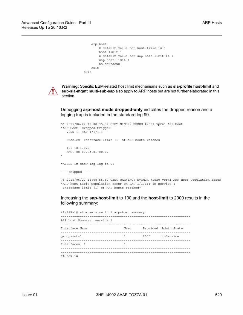
Advanced Configuration Guide - Part III Releases Up To 20.10.R2
ARP Hosts
Issue: 01 3HE 14992 AAAE TQZZA 01 529
arp-host# default value for host-limie is 1host-limit 1# default value for sap-host-limit is 1sap-host-limit 1no shutdown
exitexit
Debugging arp-host mode dropped-only indicates the dropped reason and a logging trap is included in the standard log 99.
56 2015/06/22 16:08:35.37 CEST MINOR: DEBUG #2001 vprn1 ARP Host"ARP Host: Dropped trigger
VPRN 1, SAP 1/1/1:1
Problem: Interface limit (1) of ARP hosts reached
IP: 10.1.0.2MAC: 00:00:0a:01:00:02
"
*A:BSR-1# show log log-id 99
--- snipped ---
78 2015/06/22 16:08:55.52 CEST WARNING: SVCMGR #2520 vprn1 ARP Host Population Error"ARP host table population error on SAP 1/1/1:1 in service 1 -Interface limit (1) of ARP hosts reached"
Increasing the sap-host-limit to 100 and the host-limit to 2000 results in the following summary:
*A:BSR-1# show service id 1 arp-host summary====================================================================ARP host Summary, service 1====================================================================Interface Name Used Provided Admin State--------------------------------------------------------------------group-int-1 1 2000 inService--------------------------------------------------------------------Interfaces: 1 1--------------------------------------------------------------------====================================================================*A:BSR-1#
Warning: Specific ESM-related host limit mechanisms such as sla-profile host-limit and sub-sla-mgmt multi-sub-sap also apply to ARP hosts but are not further elaborated in this section.

ARP Hosts
530
Advanced Configuration Guide - Part IIIReleases Up To 20.10.R2
3HE 14992 AAAE TQZZA 01 Issue: 01
Conclusion
This chapter provides configuration and troubleshooting commands for dynamic ARP hosts. ARP hosts can be instantiated in a Layer 2 bridged CO (VPLS) environment as well as in a Layer 3 Routed CO (IES/VPRN subscriber interface) context.

Advanced Configuration Guide - Part III Releases Up To 20.10.R2
Bridged CO
Issue: 01 3HE 14992 AAAE TQZZA 01 531
Bridged COThis chapter provides information about Bridged CO model of Triple Play Service Delivery Architecture (TPSDA).
Topics in this chapter include:
• Applicability• Summary• Overview• Configuration• Conclusion
Applicability
The information and configuration in this chapter are based on SR OS release 7.0.R4. This chapter is related only to the use of IPv4 DHCP hosts.
Summary
This chapter provides information about basic technology, network topology and configuration examples which are used in Bridged CO model of Triple Play Service Delivery Architecture (TPSDA). Regardless of aggregation technologies which are used by customers Nokia offers flexible and easy to use methodology to manage DHCP subscribers in Layer 2 domain and distribute subscriber management intelligence across multiple nodes.
Knowledge of the Triple Play Service Delivery Architecture (TPSDA) concepts is assumed throughout this chapter.

Bridged CO
532
Advanced Configuration Guide - Part IIIReleases Up To 20.10.R2
3HE 14992 AAAE TQZZA 01 Issue: 01
Overview
Bridged CO is a basic TPSDA model and implies that access nodes are united in one Layer 2 aggregation network and VPLS is used as a primary technology for these purposes. This fact allows the use of subscriber management functionality on BSA nodes. Bridged CO network topology is shown in Figure 89.
Figure 89 Bridged CO Network Topology
Following types of nodes are defined in Bridged CO model:
• Broadband Service Access Node (BSAN) — Access node connected to Layer 2 domain to aggregate all traffic from subscribers (IP DSLAM, ethernet switch).
• Broadband Services Aggregator (BSA) — Layer 2 node, which is capable for subscriber management in VPLS service (7450 ESS).
• Broadband Service Router (BSR) — Layer 3 node, which is capable for routing and service allocation (7750 SR).
As any model, Bridged CO introduces several key concepts that must be determined in advance. Major ones are presented in Figure 90 and include:
• Subscriber— A set of hosts belonging to a single connection line (switch port, DSL line)
• Subscriber host — Unique customer device (could be PC, IP phone, STB, routed CPE).
• Subscriber-profile — Configured entity which defines the aggregate QoS for all hosts within a subscriber context.
• SLA-profile — Configured entity which defines QoS policies and filters for a subset of hosts within a subscriber context.
• Subscriber identification policy — Configured entity which defines the python script for dynamic subscriber host identification
• Authentication policy — Configured entity which defines the RADIUS servers to use for dynamic subscriber host identification
DHCP
InternetVoIP
Video ServerRADIUSBSR
DSL,GPON
AggregationNetwork
ServicesNetwork
BSAN BSA
OSSG441
IES/VPRN
VPLS

Advanced Configuration Guide - Part III Releases Up To 20.10.R2
Bridged CO
Issue: 01 3HE 14992 AAAE TQZZA 01 533
• Subscriber identification string — 32 characters identification string which uniquely identifies a subscriber on a node.
Figure 90 Key Concepts of Bridged CO Model
For normal operation each subscriber has to get several parameters / attributes:
• Subscriber-ID — Attribute, which uniquely identifies subscriber on the node and used as index key in subscriber database
• IP parameters — Attributes, which allows host to get access to services • Subscriber profile and SLA — Profile for subscriber host ?a set of filters and QoS
policies.• Lease time — Period when subscriber parameters are kept in subscriber
database on the node.
There are several methods how to get each of these parameters:
• Static• Python scripts • RADIUS• DHCP
Each of the subscriber parameters could be defined in several ways simultaneously. In this case use the following algorithm for selecting:
Step 1. For subscriber profile1. A lookup in the subscriber-explicit-map is performed with the sub-
ident string returned by the Python script, RADIUS or statically configured. If a matching entry is found, the sub-profile-name (if defined) is taken. If no entry was found go to 2.
OSSG447
SAP-1(HSI) Scheduler
Scheduler
Sub-1Sub-2
SAP-2(VoIP)
Sub-1Sub-2
SAP-3(Video)
Sub-1Sub-2
Interface
Subscriber Host Subscriber SAP SLA Profile Subscriber Profile
SubscriberBSA

Bridged CO
534
Advanced Configuration Guide - Part IIIReleases Up To 20.10.R2
3HE 14992 AAAE TQZZA 01 Issue: 01
A:BSA>config>subscr-mgmt# infoexplicit-subscriber-map
entry key "Sub-1" sub-profile "sub-profile-1" sla-profile "sla-profile-1"
2. If a sub-ident-policy is defined on the SAP, a lookup is done on its sub-profile-map with the sub-profile string from the script. The sub-profile-name is taken from the entry. If no entry was found go to 3.
A:BSA>config>service>vpls>sap# infosub-sla-mgmt
sub-ident-policy "sub-ident-policy-1"
A:BSA>config>subscr-mgmt# infosub-ident-policy "sub-ident-policy-1" create
sub-profile-mapentry key "sub-1" sub-profile "sub-profile-1"
3. If provisioned, the sub-profile-name is taken from the def-sub-profile attribute on the SAP. If no entry was found go to 4.
A:BSA>config>service>vpls>sap# infosub-sla-mgmt
def-sub-profile "sub-profile-1"
4. If a sub-profile with the name default is provisioned. If no entry was found DHCP Ack is dropped.
A:BSA>config>subscr-mgmt# infosub-profile "default" create

Advanced Configuration Guide - Part III Releases Up To 20.10.R2
Bridged CO
Issue: 01 3HE 14992 AAAE TQZZA 01 535
Figure 91 Flow Chart for Subscriber-Profile Identification Algorithm
Step 2. For SLA profile1. The sla-profile-name is taken from the sub-ident string (returned by the
Python script, RADIUS or statically configured) in the subscriber-explicit-map. If no entry was found go to 2.
A:BSA>config>subscr-mgmt# infoexplicit-subscriber-map
entry key "Sub-1" sub-profile "sub-profile-1" sla-profile "sla-profile-1"
2. A lookup with the sla-profile string from the script is done in the sla-profile-map of the sub-profile found earlier. The corresponding sla-profile-name is used. If no entry was found go to 3:
A:BSA>config>subscr-mgmt# infosub-profile "sub-profile-1" create
sla-profile-mapentry key "sla-1" sla-profile "sla-profile-1"
3. The sla-profile-name is taken from sla-profile-map of the sub-ident-policy configured on the SAP. The corresponding sla-profile-name is used. If no entry was found go to 4.
A:BSA>config>service>vpls>sap# infosub-sla-mgmt
sub-ident-policy "sub-ident-policy-1"
A:BSA>config>subscr-mgmt# infosub-ident-policy "sub-ident-policy-1" create
sla-profile-mapentry key "sla-1" sla-profile "sla-profile-1"
Sub-ident string is returned by Python script, RADIUS or statically configured
FoundCorrespondence in
subscriber-explicit-map
FoundSub-profilewith name“default”
FoundCorrespondence insub-profile-map
on SAP
FoundCorrespondence in
def-sub-profileon SAP
Accept and use
YES
NO
YES YES YES
NO NO
NO
RejectDHCPAck
OSSG451

Bridged CO
536
Advanced Configuration Guide - Part IIIReleases Up To 20.10.R2
3HE 14992 AAAE TQZZA 01 Issue: 01
4. The sla-profile-name is taken from the def-sla-profile attribute on the SAP. If no entry was found DHCP Ack is dropped.
A:BSA>config>service>vpls>sap# infosub-sla-mgmt
def-sla-profile "sla-profile-1"
Figure 92 Flowchart for SLA-Profile Identification Algorithm
Bridged CO supports typical access node connection models, such as:
• One VLAN per service (ESM for subscriber differentiation and SAP for service)• One VLAN per subscriber (SAP for subscriber differentiation and QoS flag for
service)• One VLAN per access node (ESM for subscriber differentiation and QoS flag for
service)
Each of these modes has its pros and cons, but this is out of scope of this document.
Sla-profile string is returned by Python script, RADIUS or statically configured
FoundCorrespondence insub-indent string in
subscriber-explicit-map
FoundCorrespondence in
def-sla-profileon SAP
FoundCorrespondence insub-profile-map
of sub-profilefound earlier
FoundCorrespondence in
sla-profile-mapof sub-ident-policy
on SAP
Accept and use
YES
NO
YES YES YES
NO NO
NO
RejectDHCPAck
OSSG452
Note: Static configuration has priority over RADIUS configuration and RADIUS has priority over DHCP/Python scripts.
Note: Each host can have different SLA-profile, while sub-profile applies to whole subscriber. The last definition of sub-profile will force all previously defined hosts to change their sub-profile.

Advanced Configuration Guide - Part III Releases Up To 20.10.R2
Bridged CO
Issue: 01 3HE 14992 AAAE TQZZA 01 537
This configuration guide focuses on configuration of one subscriber with three different hosts. VLAN per service is used as mode of subscriber aggregation and mixed RADIUS and DHCP as subscriber identification method. IP termination is done in IES service of BSR.
Correlation of BSA/BSR services and subscriber hosts is presented in Table 13.
Different methods of authentication and address allocation were chosen for demonstration purposes. The customer is not limited to one method and can use a combination of methods as presented in this guide.
The following entities should be configured in advanced. Refer to the appropriate platform user guide for specific information. See Preface for a list of documents.
• Basic router configuration (interfaces, routing protocols, MPLS)
Table 13 Correlation of Hosts and BSA/BSR Services
BSA (Service/Features) BSR (Service/Features)
Host-1 ca:00:0c:54:00:08
VPLS-100 • DHCP proxy server • SAP/SDP DHCP snoop • Sub-Ident origin via RADIUS • Sla/Sub-profiles via RADIUS • IP options via RADIUS
IES-100
Host-2 ca:01:08:10:00:08
VPLS-200 • SAP/SDP DHCP snoop • Sub-Ident origin through
RADIUS • Sla/Sub-profiles through
RADIUS• IP options through DHCP
IES-200 • DHCP relay
Host-3 ca:02:02:d0:00:08
VPLS-300• SAP/SDP DHCP snoop • Sub-Ident origin through
DHCP • Sla/Sub-profiles through
DHCP • IP options through DHCP
IES-300 • DHCP relay

Bridged CO
538
Advanced Configuration Guide - Part IIIReleases Up To 20.10.R2
3HE 14992 AAAE TQZZA 01 Issue: 01
• External RADIUS server• External/Local DHCP server
Configuration
A sample topology is presented in Figure 93.
Figure 93 Sample Topology
Bridged CO model requires certain techniques and features to be used on different nodes. Major methods are presented in Figure 94.
Figure 94 Functionality of Each Node
The following configuration steps are required:
Internet
VoIP
Video ServerRADIUS
BSRBSA
SAP 1/1/1
OSSG446
IES/VPRN
VPLS
VPLS-100
IES-100
VPLS-200
IES-200
VPLS-300
IES-300
spoke-sdpVLAN 100
spoke-sdpVLAN 200
spoke-sdpVLAN 300
BSRBSA
SDP Interface
Interface DHCPLoopback
SAPRADIUSDHCP
Host IESVPLS
OSSG442
DHCP SnoopDHCP Proxy
L2 DHCP Relay
DHCP Client DHCP Snoop DHCP Relay RADIUSLocal DHCPServer

Advanced Configuration Guide - Part III Releases Up To 20.10.R2
Bridged CO
Issue: 01 3HE 14992 AAAE TQZZA 01 539
Step 1. On BSA1. Configure subscriber management profiles
1. Configure sla profiles2. Configure subscriber profiles 3. Configure subscriber identification policies4. Configure authentication and accounting policies if required
2. Configure VPLS service 1. Configure split horizon group2. Configure SAP
2.1 Configure anti-spoofing filters 2.2 Configure DHCP snooping2.3 Configure optional parameters (lease split, L2 DHCP relay agent, etc.)2.4 In case of RADIUS authentication apply authentication policy2.5 Configure ESM
3. Configure SDP3.1 Configure DHCP snooping
Step 2. On BSR1. Configure IES service
1. Configure IP interface1.1 Configure DHCP relay agent if required
Basic ESM Configuration on BSA
Subscriber management is enabled on BSA in Bridged CO model. A relevant configuration is presented below. SLA and subscriber profiles show the default configurations. The authentication policy appeals to RADIUS server 192.0.2.5. The subscriber identification policy is configured to use DHCP Option 254 to transfer custom attributes (subscriber-id, sla-profile, sub-profile, etc.)
A:BSA>config>subscr-mgmt# infoauthentication-policy "auth-policy-1" create
password password-1radius-authentication-server
router "management"server 1 address 192.0.2.5 secret ALU
exitinclude-radius-attribute
circuit-id

Bridged CO
540
Advanced Configuration Guide - Part IIIReleases Up To 20.10.R2
3HE 14992 AAAE TQZZA 01 Issue: 01
remote-idnas-port-idnas-identifier
exitexitsla-profile "sla-profile-1" createexitsla-profile "sla-profile-2" createexitsla-profile "sla-profile-3" createexitsla-profile "sla-profile-default" createexitsub-profile "sub-profile-1" createexitsub-profile "sub-profile-default" createexitsub-ident-policy "sub-ident-policy-1" create
sub-profile-mapuse-direct-map-as-default
exitsla-profile-map
use-direct-map-as-defaultexitstrings-from-option 254
exit
The string-from-option 254 command is shared in-built dhcp-server of BSR. Using this option, the DHCP server could transmit subscriber identification options such the subscriber-id, sla-profile-string, and sub-profile-string.
BSA/BSR Configuration for Host-1 Operation
The test subscriber has three hosts. Host-1 gets all necessary information from RADIUS server.

Advanced Configuration Guide - Part III Releases Up To 20.10.R2
Bridged CO
Issue: 01 3HE 14992 AAAE TQZZA 01 541
In this case BSA takes role of DHCP proxy with DHCP server emulation. DHCP snooping on the SAP must be enabled. Anti-spoofing filters on the SAP must be enabled. An authentication policy must be applied on the SAP.
vpls 100 customer 1 createsplit-horizon-group "RSHG-1" residential-group createexit
--snip--sap 1/1/4:100 split-horizon-group "RSHG-1" create
dhcpsnooplease-populate 400proxy-server
emulated-server 10.0.1.253no shutdown
exitno shutdown
exitauthentication-policy "auth-policy-1"anti-spoof ip-macsub-sla-mgmt
def-sub-id string "default-subscriber"def-sub-profile "sub-profile-default"def-sla-profile "sla-profile-default"sub-ident-policy "sub-ident-policy-1"no shutdown
exitexitspoke-sdp 12:100 createexitno shutdown
exit
Table 14 BSA/BSR Configuration for Host-1 Operation
BSA (Service/Features)
BSR (Service/Features)
Host-1 ca:00:0c:54:00:08
VPLS-100 • DHCP proxy server • SAP/SDP DHCP snoop • Sub-Ident origin through
RADIUS • Sla/Sub-profiles through
RADIUS • IP options through RADIUS
IES-100

Bridged CO
542
Advanced Configuration Guide - Part IIIReleases Up To 20.10.R2
3HE 14992 AAAE TQZZA 01 Issue: 01
On BSR IES-100, the service is configured with a pure IP interface, which plays role of DG for host-1.
ies 100 customer 1 createinterface "int-host-1" create
address 10.0.1.254/24spoke-sdp 21:100 createexit
exitno shutdown
exit
BSA/BSR Configuration for Host-2 Operation
The test subscriber has three hosts. Host-2 gets subscriber-id and sla/sub-profiles information from RADIUS server and IP options from DHCP server.
DHCP snooping on the SAP and SDP must be enabled. Anti-spoofing filters on the SAP must be enabled.
vpls 200 customer 1 createsplit-horizon-group "RSHG-1" residential-group createexit
--snip--sap 1/1/4:200 split-horizon-group "RSHG-1" create
dhcpsnooplease-populate 400no shutdown
exitauthentication-policy "auth-policy-1"anti-spoof ip-macsub-sla-mgmt
Table 15 BSA/BSR Configuration for Host-2 Operation
BSA (Service/Features)
BSR (Service/Features)
Host-2 ca:01:08:10:00:08
VPLS-200 • SAP/SDP DHCP snoop • Sub-Ident origin through
RADIUS • Sla/Sub-profiles through
RADIUS • IP options through DHCP
IES-200 • DHCP relay

Advanced Configuration Guide - Part III Releases Up To 20.10.R2
Bridged CO
Issue: 01 3HE 14992 AAAE TQZZA 01 543
def-sub-id string "default-subscriber"def-sub-profile "sub-profile-default"def-sla-profile "sla-profile-default"sub-ident-policy "sub-ident-policy-1"no shutdown
exitexitspoke-sdp 12:200 create
dhcpsnoop
exitexitno shutdown
exit
On BSR IES-200, the service is configured with an IP interface which as the DG for Host-2. DHCP relay must be configured to transform broadcast DHCP discover message into unicast and send it to DHCP server for processing.
ies 200 customer 1 createinterface "int-host-2" create
address 10.0.2.254/24dhcp
server 192.0.2.4trustedno shutdown
exitspoke-sdp 21:200 createexit
exitno shutdown
exit
BSA/BSR Configuration for Host-3 Operation
The test subscriber has three hosts. Host-3 receives all necessary information from the DHCP server.
Table 16 BSA/BSR Configuration for Host-3 Operation
BSA (Service/Features)
BSR (Service/Features)
Host-3 ca:02:02:d0:00:08
VPLS-300 * SAP/SDP DHCP snoop * Sub-Ident origin through DHCP * Sla/Sub-profiles through DHCP * IP options through DHCP
IES-300 * DHCP relay

Bridged CO
544
Advanced Configuration Guide - Part IIIReleases Up To 20.10.R2
3HE 14992 AAAE TQZZA 01 Issue: 01
DHCP snooping on the SAP and SDP must be enabled. Anti-spoofing filters on the SAP must be enabled.
vpls 300 customer 1 createsplit-horizon-group "RSHG-1" residential-group createexit
---- snip ---sap 1/1/4:300 split-horizon-group "RSHG-1" create
dhcpsnooplease-populate 400no shutdown
exitanti-spoof ip-macsub-sla-mgmt
def-sub-id string "default-subscriber"def-sub-profile "sub-profile-default"def-sla-profile "sla-profile-default"sub-ident-policy "sub-ident-policy-1"no shutdown
exitexitspoke-sdp 12:300 create
dhcpsnoop
exitexitno shutdown
exit
On BSR IES-300, the service is configured with IP interface, which plays role of DG for host-3. DHCP relay must be configured to transform broadcast DHCP discover message into unicast and send it to DHCP server for processing.
ies 300 customer 1 createinterface "int-host-3" create
address 10.0.3.254/24dhcp
server 192.0.2.4trustedno shutdown
exitspoke-sdp 21:300 createexit
exitno shutdown
exit

Advanced Configuration Guide - Part III Releases Up To 20.10.R2
Bridged CO
Issue: 01 3HE 14992 AAAE TQZZA 01 545
RADIUS Configuration Bridged CO
The username in the RADIUS access request is configurable and could be one of the following formats:
• mac — MAC Source Address of the DHCP DISCOVER message • circuit-id — Taken from option 82 in the received DHCP message. If no circuit-
id can be found, the DHCP-msg is rejected.• tuple — Concatenation of MAC source address and circuit-ID • ascii-converted-circuit-id — Identical to circuit-id, but the user name will be sent
to the RADIUS server as a string of hex digits• ascii-converted-tuple — Identical to tuple, but the circuit-id part of the user name
will be sent to the RADIUS server as a string of hex digits
A:BSA>config>subscr-mgmt>auth-plcy# user-name-format- user-name-format <format> [append domain-name]- no user-name-format
<format> : mac|circuit-id|tuple|ascii-converted-circuit-id|ascii-converted-tuple
For simplicity, MAC format is used in this guide.
There are two hosts configured in the users file on RADIUS server:
• a:00:0c:54:00:08 — The mac address of host-1 host [VPLS/IES 100]. For host-1 all necessary parameters are returned: subscriber-id, sla/sub-profiles, IP parameters and lease time.
• a:01:08:10:00:08 — The mac address of host-2 host [VPLS/IES 200]. For host-2 only subscriber-id, sla/sub-profiles are returned, while ip parameters and lease time are returned from DHCP server.
ca:00:0c:54:00:08 Auth-Type := Local, User-Password == "password-1"Alc-Subsc-ID-Str = "sub-id-1",Alc-Subsc-Prof-Str == "sub-profile-1",Alc-SLA-Prof-Str == "sla-profile-1",Framed-IP-Address = 10.0.1.1,Framed-IP-Netmask = 255.255.255.0,Alc-Default-Router = 10.0.1.254,Session-Timeout = 6000
ca:01:08:10:00:08 Auth-Type := Local, User-Password == "password-1"Alc-Subsc-ID-Str = "sub-id-1",
Note: Refer to IPv4 DHCP Hosts for detailed information about how to use different options.

Bridged CO
546
Advanced Configuration Guide - Part IIIReleases Up To 20.10.R2
3HE 14992 AAAE TQZZA 01 Issue: 01
Alc-Subsc-Prof-Str == "sub-profile-1",Alc-SLA-Prof-Str == "sla-profile-2"
Local DHCP Server Configuration Bridged CO
In the setup local DHCP server is used with reference to local user database.
A:BSR>config>router>dhcp# infolocal-dhcp-server "dhcp-server-1" create
user-db "user-db-1"pool "pool-1" create
subnet 10.0.2.0/24 createexitsubnet 10.0.3.0/24 createexit
exitno shutdown
exit
The local user database is configured on BSR. Identification is done via MAC address of a host, which is taken from DHCP-Discover message. There are several possibilities to identify DHCP host. match-list command is used for this purpose.
*A:BSR>config>subscr-mgmt>loc-user-db>dhcp# match-list- no match-list- match-list <dhcp-match-type-1> [<dhcpmatch-type-2>...(up to 4 max)]
<dhcp-match-type> : circuit-id|mac|option60|remote-id|sap-id|service-id|string|system-id
There are two hosts configured:
• a:01:08:10:00:08 — mac address of host-2 [VPLS/IES 200]. DHCP returns ip address, subnet mask and default route.
• a:02:02:d0:00:08 — mac address of host-3 [VPLS/IES 300]. DHCP returns all necessary parameters: subscriber-id, sla/sub-profiles and all ip options.
A:BSR>config>subscr-mgmt# infolocal-user-db "user-db-1" create
dhcpmatch-list mac
Note: Subnets must be configured, even if all IP parameters are returned from local user DB. Without this option, DHCP server do not return IP parameters.

Advanced Configuration Guide - Part III Releases Up To 20.10.R2
Bridged CO
Issue: 01 3HE 14992 AAAE TQZZA 01 547
host "host-2" createhost-identification
mac ca:01:08:10:00:08exitaddress 10.0.2.1options
subnet-mask 255.255.255.0default-router 10.0.2.254
exitno shutdown
exithost "host-3" create
host-identificationmac ca:02:02:d0:00:08
exitaddress 10.0.3.1identification-strings 254 create
subscriber-id "sub-id-1"sla-profile-string "sla-profile-3"sub-profile-string "sub-profile-1"
exitoptions
subnet-mask 255.255.255.0default-router 10.0.3.254
exitno shutdown
exitexitno shutdown
exit
Setup Procedures and Debugging
Subscriber/Host Verification
The initialization of all active subscribers and hosts can be shown using the how service active-subscribers command. Different options can be used to filter the output of the command.
A:BSA# show service active-subscribers===============================================================================Active Subscribers===============================================================================-------------------------------------------------------------------------------Subscriber sub-id-1 (sub-profile-1)--------------------------------------------------------------------------------------------------------------------------------------------------------------(1) SLA Profile Instance sap:1/1/4:100 - sla:sla-profile-1-------------------------------------------------------------------------------IP Address MAC Address PPPoE-SID Origin-------------------------------------------------------10.0.1.1 ca:00:0c:54:00:08 N/A DHCP

Bridged CO
548
Advanced Configuration Guide - Part IIIReleases Up To 20.10.R2
3HE 14992 AAAE TQZZA 01 Issue: 01
-------------------------------------------------------------------------------(2) SLA Profile Instance sap:1/1/4:200 - sla:sla-profile-2-------------------------------------------------------------------------------IP Address MAC Address PPPoE-SID Origin-------------------------------------------------------10.0.2.1 ca:01:08:10:00:08 N/A DHCP-------------------------------------------------------------------------------(3) SLA Profile Instance sap:1/1/4:300 - sla:sla-profile-3-------------------------------------------------------------------------------IP Address MAC Address PPPoE-SID Origin-------------------------------------------------------10.0.3.1 ca:02:02:d0:00:08 N/A DHCP-------------------------------------------------------------------------------Number of active subscribers : 1===============================================================================A:BSA#
Hierarchy of subscriber hosts is represented in a convenient form using following command.
A:BSA# show service active-subscribers hierarchy===============================================================================Active Subscriber hierarchy===============================================================================-- sub-id-1 (sub-profile-1)
||-- sap:1/1/4:100 - sla:sla-profile-1| || |-- 10.0.1.1 - ca:00:0c:54:00:08 - N/A (DHCP)| |||-- sap:1/1/4:200 - sla:sla-profile-2| || |-- 10.0.2.1 - ca:01:08:10:00:08 - N/A (DHCP)| |||-- sap:1/1/4:300 - sla:sla-profile-3| || |-- 10.0.3.1 - ca:02:02:d0:00:08 - N/A (DHCP)| |
Host-1 Setup Debug
The Host-1 setup process is shown in Figure 95.

Advanced Configuration Guide - Part III Releases Up To 20.10.R2
Bridged CO
Issue: 01 3HE 14992 AAAE TQZZA 01 549
Figure 95 Host-1 Setup Process
Host-1 sends DHCP discover message in VLAN 100 to BSA. BSA plays role of DHCP proxy server and transforms DHCP discover into RADIUS access-request message. After receiving RADIUS access-accept BSA transforms it to DHCP Ack message. Session setup process could be represented using debug commands:
A:BSA# debug service id 100 dhcp mode egr-ingr-and-droppedA:BSA# debug service id 100 dhcp detail-level mediumA:BSA# debug radius detail18 2009/12/15 06:31:56.63 UTC MINOR: DEBUG #2001 Base SVCMGR"SVCMGR: RX DHCP Packet
VPLS 100, SAP 1/1/4:100
BootRequest to UDP port 67ciaddr: 0.0.0.0 yiaddr: 0.0.0.0siaddr: 0.0.0.0 giaddr: 0.0.0.0chaddr: ca:00:0c:54:00:08 xid: 0xd42
DHCP options:[53] Message type: Discover
--snip--"19 2009/12/15 06:31:56.63 UTC MINOR: DEBUG #2001 management RADIUS"RADIUS: Access-Request
user ca:00:0c:54:00:08 policy auth-policy-1"20 2009/12/15 06:31:56.63 UTC MINOR: DEBUG #2001 management RADIUS"RADIUS: Transmit
Access-Request(1) 192.0.2.5:1812 id 69 len 85USER NAME [1] 17 ca:00:0c:54:00:08PASSWORD [2] 16 lkhSVrFePQ0A0Xc4ZyMwMkNAS IP ADDRESS [4] 4 192.0.2.1NAS PORT TYPE [61] 4 Ethernet(15)NAS PORT ID [87] 9 1/1/4:100
BSR
DHCP
BSA
SDP Interface
Interface DHCPLoopback
SAPRADIUSHost 1 IESVPLS
OSSG443
DHCP SnoopDHCP Proxy
L2 DHCP Relay
DHCP-DISCOVER
DHCP-OFFER
DHCP Client RADIUS
DHCP-REQUEST
DHCP-ACK
RADIUS-ACCESS-REQUEST
RADIUS-ACCESS-ACCEPT

Bridged CO
550
Advanced Configuration Guide - Part IIIReleases Up To 20.10.R2
3HE 14992 AAAE TQZZA 01 Issue: 01
NAS IDENTIFIER [32] 3 BSA"21 2009/12/15 06:31:56.73 UTC MINOR: DEBUG #2001 management RADIUS"RADIUS: Receive
Access-Accept(2) id 69 len 108 from 138.203.18.79:1812VSA [26] 10 Alcatel(6527)
SUBSC ID STR [11] 8 sub-id-1VSA [26] 15 Alcatel(6527)
SUBSC PROF STR [12] 13 sub-profile-1VSA [26] 15 Alcatel(6527)
SLA PROF STR [13] 13 sla-profile-1FRAMED IP ADDRESS [8] 4 10.0.1.1FRAMED IP NETMASK [9] 4 255.255.255.0VSA [26] 6 Alcatel(6527)
DEFAULT ROUTER [18] 4 10.0.1.254SESSION TIMEOUT [27] 4 6000
"22 2009/12/15 06:31:56.73 UTC MINOR: DEBUG #2001 Base SVCMGR"SVCMGR: TX DHCP Packet
VPLS 100, SAP 1/1/4:100
BootReply to UDP port 68ciaddr: 0.0.0.0 yiaddr: 10.0.1.1siaddr: 10.0.1.253 giaddr: 0.0.0.0chaddr: ca:00:0c:54:00:08 xid: 0xd42
DHCP options:[53] Message type: Offer
--snip--"23 2009/12/15 06:31:57.57 UTC MINOR: DEBUG #2001 Base SVCMGR"SVCMGR: RX DHCP Packet
VPLS 100, SAP 1/1/4:100
BootRequest to UDP port 67ciaddr: 0.0.0.0 yiaddr: 0.0.0.0siaddr: 0.0.0.0 giaddr: 0.0.0.0chaddr: ca:00:0c:54:00:08 xid: 0xd42
DHCP options:[53] Message type: Request
--snip--"24 2009/12/15 06:31:57.57 UTC MINOR: DEBUG #2001 Base SVCMGR"SVCMGR: TX DHCP Packet
VPLS 100, SAP 1/1/4:100
BootReply to UDP port 68ciaddr: 0.0.0.0 yiaddr: 10.0.1.1siaddr: 10.0.1.253 giaddr: 0.0.0.0chaddr: ca:00:0c:54:00:08 xid: 0xd42
DHCP options:[53] Message type: Ack
--snip

Advanced Configuration Guide - Part III Releases Up To 20.10.R2
Bridged CO
Issue: 01 3HE 14992 AAAE TQZZA 01 551
The number of snooped/forwarded/dropped/proxied DHCP packets can be checked using the show service id 100 dhcp statistics command.
A:BSA# show service id 100 dhcp statistics=====================================================DHCP Statistics, service 100=====================================================Client Packets Snooped : 2Client Packets Forwarded : 0Client Packets Dropped : 0Client Packets Proxied (RADIUS) : 2Client Packets Proxied (Lease-Split) : 0Server Packets Snooped : 0Server Packets Forwarded : 0Server Packets Dropped : 0DHCP RELEASEs Spoofed : 0DHCP FORCERENEWs Spoofed : 0=====================================================A:BSA#
Connectivity of Host-1could be checked with the show service id 100 subscriber-hosts command. Different options can be used to filter output of the command.
A:BSA# show service id 100 subscriber-hosts detail===============================================================================Subscriber Host table===============================================================================Sap IP Address MAC Address PPPoE-SID Origin
Subscriber-------------------------------------------------------------------------------1/1/4:100 10.0.1.1 ca:00:0c:54:00:08 N/A DHCP
sub-id-1-------------------------------------------------------------------------------Sub Profile : sub-profile-1SLA Profile : sla-profile-1App Profile : N/A-------------------------------------------------------------------------------Number of subscriber hosts : 1
The DHCP lease state can be checked with the show service id 100 dhcp lease-state command. Different options can be used to filter output of a command.
A:BSA# show service id 100 dhcp lease-state detail===============================================================================DHCP lease states for service 100===============================================================================Service ID : 100IP Address : 10.0.1.1Client HW Address : ca:00:0c:54:00:08SAP : 1/1/4:100Remaining Lifetime : 01h33m41sPersistence Key : N/ASub-Ident : "sub-id-1"Sub-Profile-String : "sub-profile-1"

Bridged CO
552
Advanced Configuration Guide - Part IIIReleases Up To 20.10.R2
3HE 14992 AAAE TQZZA 01 Issue: 01
SLA-Profile-String : "sla-profile-1"--snip--Sub-Ident origin : RadiusStrings origin : RadiusLease Info origin : Radius--snip--Radius User-Name : "ca:00:0c:54:00:08"-------------------------------------------------------------------------------Number of lease states : 1===============================================================================A:BSA#
Host-2 Setup Debug
Host-1 setup process is displayed in Figure 96.
Figure 96 Host-2 Setup Process
Host-2 sends DHCP discover message in VLAN 200 to BSA. Host-2 is authenticated through RADIUS and gets subscriber-id, sla/sub-profiles. DHCP Discover message is flooded in VPLS service and reaches IP interface on BSA, where DHCP relay is configured. Session setup process could be represented using debug commands:
A:BSA# debug service id 200 dhcp mode egr-ingr-and-droppedA:BSA# debug service id 200 dhcp detail-level mediumA:BSA#*A:BSA#18 2009/12/15 13:00:36.28 UTC MINOR: DEBUG #2001 Base SVCMGR
BSR
DHCP
BSA
SDP Interface
Interface DHCPLoopback
SAPRADIUSHost 2 IESVPLS
OSSG444
DHCP SnoopDHCP Proxy
L2 DHCP Relay
DHCP-DISCOVERDHCPSnoop
DHCPSnoop
DHCP-OFFER
DHCP Client RADIUSDHCP Snoop DHCP Relay Local DHCPServer
DHCP-DISCOVER DHCP-DISCOVER
DHCP-REQUEST DHCP-REQUEST
DHCP-OFFER
DHCP-REQUEST
DHCP-OFFER
DHCP-ACK DHCP-ACKDHCP-ACK
RADIUS-ACCESS-REQUEST
RADIUS-ACCESS-ACCEPT

Advanced Configuration Guide - Part III Releases Up To 20.10.R2
Bridged CO
Issue: 01 3HE 14992 AAAE TQZZA 01 553
"SVCMGR: RX DHCP PacketVPLS 200, SAP 1/1/4:200
BootRequest to UDP port 67ciaddr: 0.0.0.0 yiaddr: 0.0.0.0siaddr: 0.0.0.0 giaddr: 0.0.0.0chaddr: ca:01:08:10:00:08 xid: 0xfc8
DHCP options:[53] Message type: Discover
--snip--
19 2009/12/15 13:00:36.28 UTC MINOR: DEBUG #2001 management RADIUS"RADIUS: Access-Request
user ca:01:08:10:00:08 policy auth-policy-1"
20 2009/12/15 13:00:36.28 UTC MINOR: DEBUG #2001 management RADIUS"RADIUS: Transmit
Access-Request(1) 192.0.2.5:1812 id 80 len 85USER NAME [1] 17 ca:01:08:10:00:08PASSWORD [2] 16 .czdppt/0qAsqKqStbvnV.NAS IP ADDRESS [4] 4 192.0.2.1NAS PORT TYPE [61] 4 Ethernet(15)NAS PORT ID [87] 9 1/1/4:200NAS IDENTIFIER [32] 3 BSA
"
21 2009/12/15 13:00:36.34 UTC MINOR: DEBUG #2001 management RADIUS"RADIUS: Receive
Access-Accept(2) id 80 len 78 from 138.203.18.79:1812VSA [26] 10 Alcatel(6527)
SUBSC ID STR [11] 8 sub-id-1VSA [26] 15 Alcatel(6527)
SUBSC PROF STR [12] 13 sub-profile-1VSA [26] 15 Alcatel(6527)
SLA PROF STR [13] 13 sla-profile-2"22 2009/12/15 13:00:36.34 UTC MINOR: DEBUG #2001 Base SVCMGR"SVCMGR: TX DHCP Packet
flooding in VPLS 200
BootRequest to UDP port 67ciaddr: 0.0.0.0 yiaddr: 0.0.0.0siaddr: 0.0.0.0 giaddr: 0.0.0.0chaddr: ca:01:08:10:00:08 xid: 0xfc8
DHCP options:[53] Message type: Discover
--snip--"
23 2009/12/15 13:00:36.35 UTC MINOR: DEBUG #2001 Base SVCMGR"SVCMGR: RX DHCP Packet
VPLS 200, spoke-sdp 12:200
BootReply to UDP port 68ciaddr: 0.0.0.0 yiaddr: 10.0.2.1siaddr: 192.0.2.4 giaddr: 0.0.0.0chaddr: ca:01:08:10:00:08 xid: 0xfc8

Bridged CO
554
Advanced Configuration Guide - Part IIIReleases Up To 20.10.R2
3HE 14992 AAAE TQZZA 01 Issue: 01
DHCP options:[53] Message type: Offer
--snip--"
24 2009/12/15 13:00:36.34 UTC MINOR: DEBUG #2001 Base SVCMGR"SVCMGR: TX DHCP Packet
VPLS 200, SAP 1/1/4:200
BootReply to UDP port 68ciaddr: 0.0.0.0 yiaddr: 10.0.2.1siaddr: 192.0.2.4 giaddr: 0.0.0.0chaddr: ca:01:08:10:00:08 xid: 0xfc8
DHCP options:[53] Message type: Offer
--snip--"
25 2009/12/15 13:00:36.46 UTC MINOR: DEBUG #2001 Base SVCMGR"SVCMGR: RX DHCP Packet
VPLS 200, SAP 1/1/4:200
BootRequest to UDP port 67ciaddr: 0.0.0.0 yiaddr: 0.0.0.0siaddr: 0.0.0.0 giaddr: 0.0.0.0chaddr: ca:01:08:10:00:08 xid: 0xfc8
DHCP options:[53] Message type: Request
--snip--"
26 2009/12/15 13:00:36.46 UTC MINOR: DEBUG #2001 Base SVCMGR"SVCMGR: TX DHCP Packet
flooding in VPLS 200
BootRequest to UDP port 67ciaddr: 0.0.0.0 yiaddr: 0.0.0.0siaddr: 0.0.0.0 giaddr: 0.0.0.0chaddr: ca:01:08:10:00:08 xid: 0xfc8
DHCP options:[53] Message type: Request
--snip--"
27 2009/12/15 13:00:36.47 UTC MINOR: DEBUG #2001 Base SVCMGR"SVCMGR: RX DHCP Packet
VPLS 200, spoke-sdp 12:200
BootReply to UDP port 68ciaddr: 0.0.0.0 yiaddr: 10.0.2.1siaddr: 192.0.2.4 giaddr: 0.0.0.0chaddr: ca:01:08:10:00:08 xid: 0xfc8
DHCP options:[53] Message type: Ack
--snip--"
28 2009/12/15 13:00:36.46 UTC MINOR: DEBUG #2001 Base SVCMGR"SVCMGR: TX DHCP Packet
VPLS 200, SAP 1/1/4:200

Advanced Configuration Guide - Part III Releases Up To 20.10.R2
Bridged CO
Issue: 01 3HE 14992 AAAE TQZZA 01 555
BootReply to UDP port 68ciaddr: 0.0.0.0 yiaddr: 10.0.2.1siaddr: 192.0.2.4 giaddr: 0.0.0.0chaddr: ca:01:08:10:00:08 xid: 0xfc8
DHCP options:[53] Message type: Ack
--snip--"
DHCP relay is enabled in service IES-200 on BSR.
A:BSR# debug router ip dhcp mode egr-ingr-and-droppedA:BSR#*A:BSR#17 2009/12/15 13:00:36.34 UTC MINOR: DEBUG #2001 Base PIP"PIP: DHCPinstance 1 (Base), interface index 6 (int-host-2),
received DHCP Boot Request on Interface int-host-2 (1/1/2) Port 67
H/W Type: Ethernet(10Mb) H/W Address Length: 6ciaddr: 0.0.0.0 yiaddr: 0.0.0.0siaddr: 0.0.0.0 giaddr: 0.0.0.0chaddr: ca:01:08:10:00:08 xid: 0xfc8
DHCP options:[53] Message type: Discover
--snip--"
18 2009/12/15 13:00:36.34 UTC MINOR: DEBUG #2001 Base PIP"PIP: DHCPinstance 1 (Base),
transmitted DHCP Boot Request to 192.0.2.4 Port 67
H/W Type: Ethernet(10Mb) H/W Address Length: 6ciaddr: 0.0.0.0 yiaddr: 0.0.0.0siaddr: 0.0.0.0 giaddr: 10.0.2.254chaddr: ca:01:08:10:00:08 xid: 0xfc8
DHCP options:[53] Message type: Discover
--snip--"
19 2009/12/15 13:00:36.35 UTC MINOR: DEBUG #2001 Base PIP"PIP: DHCPinstance 1 (Base),
received DHCP Boot Reply on 192.0.2.4 Port 67
H/W Type: Ethernet(10Mb) H/W Address Length: 6ciaddr: 0.0.0.0 yiaddr: 10.0.2.1siaddr: 192.0.2.4 giaddr: 10.0.2.254chaddr: ca:01:08:10:00:08 xid: 0xfc8
DHCP options:[53] Message type: Offer
--snip--"
20 2009/12/15 13:00:36.35 UTC MINOR: DEBUG #2001 Base PIP"PIP: DHCP

Bridged CO
556
Advanced Configuration Guide - Part IIIReleases Up To 20.10.R2
3HE 14992 AAAE TQZZA 01 Issue: 01
instance 1 (Base), interface index 6 (int-host-2),transmitted DHCP Boot Reply to Interface int-host-2 (spoke-21:200) Port 68
H/W Type: Ethernet(10Mb) H/W Address Length: 6ciaddr: 0.0.0.0 yiaddr: 10.0.2.1siaddr: 192.0.2.4 giaddr: 0.0.0.0chaddr: ca:01:08:10:00:08 xid: 0xfc8
DHCP options:[53] Message type: Offer
--snip--"
21 2009/12/15 13:00:36.47 UTC MINOR: DEBUG #2001 Base PIP"PIP: DHCPinstance 1 (Base), interface index 6 (int-host-2),
received DHCP Boot Request on Interface int-host-2 (1/1/2) Port 67
H/W Type: Ethernet(10Mb) H/W Address Length: 6ciaddr: 0.0.0.0 yiaddr: 0.0.0.0siaddr: 0.0.0.0 giaddr: 0.0.0.0chaddr: ca:01:08:10:00:08 xid: 0xfc8
DHCP options:[53] Message type: Request
--snip--"
22 2009/12/15 13:00:36.47 UTC MINOR: DEBUG #2001 Base PIP"PIP: DHCPinstance 1 (Base),
transmitted DHCP Boot Request to 192.0.2.4 Port 67
H/W Type: Ethernet(10Mb) H/W Address Length: 6ciaddr: 0.0.0.0 yiaddr: 0.0.0.0siaddr: 0.0.0.0 giaddr: 10.0.2.254chaddr: ca:01:08:10:00:08 xid: 0xfc8
DHCP options:[53] Message type: Request
--snip--"
23 2009/12/15 13:00:36.47 UTC MINOR: DEBUG #2001 Base PIP"PIP: DHCPinstance 1 (Base),
received DHCP Boot Reply on 192.0.2.4 Port 67
H/W Type: Ethernet(10Mb) H/W Address Length: 6ciaddr: 0.0.0.0 yiaddr: 10.0.2.1siaddr: 192.0.2.4 giaddr: 10.0.2.254chaddr: ca:01:08:10:00:08 xid: 0xfc8
DHCP options:[53] Message type: Ack
--snip--"
24 2009/12/15 13:00:36.47 UTC MINOR: DEBUG #2001 Base PIP"PIP: DHCPinstance 1 (Base), interface index 6 (int-host-2),
transmitted DHCP Boot Reply to Interface int-host-2 (spoke-21:200) Port 68

Advanced Configuration Guide - Part III Releases Up To 20.10.R2
Bridged CO
Issue: 01 3HE 14992 AAAE TQZZA 01 557
H/W Type: Ethernet(10Mb) H/W Address Length: 6ciaddr: 0.0.0.0 yiaddr: 10.0.2.1siaddr: 192.0.2.4 giaddr: 0.0.0.0chaddr: ca:01:08:10:00:08 xid: 0xfc8
DHCP options:[53] Message type: Ack
--snip--
The number of snooped/forwarded/dropped/proxied DHCP packets could be checked using the show service id 200 dhcp statistics command.
A:BSA# show service id 200 dhcp statistics=====================================================DHCP Statistics, service 200=====================================================Client Packets Snooped : 2Client Packets Forwarded : 2Client Packets Dropped : 0Client Packets Proxied (RADIUS) : 0Client Packets Proxied (Lease-Split) : 0Server Packets Snooped : 2Server Packets Forwarded : 2Server Packets Dropped : 0DHCP RELEASEs Spoofed : 0DHCP FORCERENEWs Spoofed : 0=====================================================A:BSA#
The connectivity of Host-2 can be verified with the show service id 200 subscriber-hosts command. Different options can be used to filter output of the command.
A:BSA# show service id 200 subscriber-hosts detail===============================================================================Subscriber Host table===============================================================================Sap IP Address MAC Address PPPoE-SID Origin
Subscriber-------------------------------------------------------------------------------1/1/4:200 10.0.2.1 ca:01:08:10:00:08 N/A DHCP
sub-id-1-------------------------------------------------------------------------------Sub Profile : sub-profile-1SLA Profile : sla-profile-2App Profile : N/A-------------------------------------------------------------------------------Number of subscriber hosts : 1===============================================================================A:BSA#
DHCP lease state can be verified with the show service id 200 dhcp lease-state command. Different options can be used to filter output of the command.

Bridged CO
558
Advanced Configuration Guide - Part IIIReleases Up To 20.10.R2
3HE 14992 AAAE TQZZA 01 Issue: 01
A:BSA# show service id 200 dhcp lease-state detail===============================================================================DHCP lease states for service 200===============================================================================Service ID : 200IP Address : 10.0.2.1Client HW Address : ca:01:08:10:00:08SAP : 1/1/4:200Remaining Lifetime : 09d23h44mPersistence Key : N/ASub-Ident : "sub-id-1"Sub-Profile-String : "sub-profile-1"SLA-Profile-String : "sla-profile-2"--snip--Sub-Ident origin : RadiusStrings origin : RadiusLease Info origin : DHCP--snip--Radius User-Name : "ca:01:08:10:00:08"-------------------------------------------------------------------------------Number of lease states : 1===============================================================================A:BSA#
Host-3 Setup Debug
The Host-3 setup process is presented in Figure 97.
Figure 97 Host-3 Setup Process
BSR
DHCP
BSA
SDP Interface
Interface DHCPLoopback
SAPRADIUSHost 3 IESVPLS
OSSG445
DHCP SnoopDHCP Proxy
L2 DHCP Relay
DHCP-DISCOVER
DHCPSnoop
DHCPSnoop
DHCP-OFFER
DHCP Client RADIUSDHCP Snoop DHCP Relay Local DHCPServer
DHCP-DISCOVER DHCP-DISCOVER
DHCP-REQUEST DHCP-REQUEST
DHCP-OFFER
DHCP-REQUEST
DHCP-OFFER
DHCP-ACK DHCP-ACKDHCP-ACK

Advanced Configuration Guide - Part III Releases Up To 20.10.R2
Bridged CO
Issue: 01 3HE 14992 AAAE TQZZA 01 559
Host-3 sends DHCP a discover message in VLAN 300 to BSA. Host-3 receives all parameters from the DHCP server using pre-configured Option 254. A DHCP discover message is flooded in VPLS service and reaches IP interface on BSA where DHCP relay is configured. The session setup process can be represented using debug commands.
A:BSA# debug service id 300 dhcp mode egr-ingr-and-droppedA:BSA# debug service id 300 dhcp detail-level medium*A:BSA#33 2009/12/15 13:02:34.39 UTC MINOR: DEBUG #2001 Base SVCMGR"SVCMGR: RX DHCP Packet
VPLS 300, SAP 1/1/4:300
BootRequest to UDP port 67ciaddr: 0.0.0.0 yiaddr: 0.0.0.0siaddr: 0.0.0.0 giaddr: 0.0.0.0chaddr: ca:02:02:d0:00:08 xid: 0x2a6
DHCP options:[53] Message type: Discover
--snip--"34 2009/12/15 13:02:34.38 UTC MINOR: DEBUG #2001 Base SVCMGR"SVCMGR: TX DHCP Packet
flooding in VPLS 300
BootRequest to UDP port 67ciaddr: 0.0.0.0 yiaddr: 0.0.0.0siaddr: 0.0.0.0 giaddr: 0.0.0.0chaddr: ca:02:02:d0:00:08 xid: 0x2a6
DHCP options:[53] Message type: Discover
--snip--"35 2009/12/15 13:02:34.40 UTC MINOR: DEBUG #2001 Base SVCMGR"SVCMGR: RX DHCP Packet
VPLS 300, spoke-sdp 12:300
BootReply to UDP port 68ciaddr: 0.0.0.0 yiaddr: 10.0.3.1siaddr: 192.0.2.4 giaddr: 0.0.0.0chaddr: ca:02:02:d0:00:08 xid: 0x2a6
DHCP options:[53] Message type: Offer
--snip--"36 2009/12/15 13:02:34.40 UTC MINOR: DEBUG #2001 Base SVCMGR"SVCMGR: TX DHCP Packet
VPLS 300, SAP 1/1/4:300
BootReply to UDP port 68ciaddr: 0.0.0.0 yiaddr: 10.0.3.1siaddr: 192.0.2.4 giaddr: 0.0.0.0chaddr: ca:02:02:d0:00:08 xid: 0x2a6
DHCP options:

Bridged CO
560
Advanced Configuration Guide - Part IIIReleases Up To 20.10.R2
3HE 14992 AAAE TQZZA 01 Issue: 01
[53] Message type: Offer--snip--"37 2009/12/15 13:02:34.52 UTC MINOR: DEBUG #2001 Base SVCMGR"SVCMGR: RX DHCP Packet
VPLS 300, SAP 1/1/4:300
BootRequest to UDP port 67ciaddr: 0.0.0.0 yiaddr: 0.0.0.0siaddr: 0.0.0.0 giaddr: 0.0.0.0chaddr: ca:02:02:d0:00:08 xid: 0x2a6
DHCP options:[53] Message type: Request
--snip--"38 2009/12/15 13:02:34.52 UTC MINOR: DEBUG #2001 Base SVCMGR"SVCMGR: TX DHCP Packet
flooding in VPLS 300
BootRequest to UDP port 67ciaddr: 0.0.0.0 yiaddr: 0.0.0.0siaddr: 0.0.0.0 giaddr: 0.0.0.0chaddr: ca:02:02:d0:00:08 xid: 0x2a6
DHCP options:[53] Message type: Request
--snip--"39 2009/12/15 13:02:34.53 UTC MINOR: DEBUG #2001 Base SVCMGR"SVCMGR: RX DHCP Packet
VPLS 300, spoke-sdp 12:300
BootReply to UDP port 68ciaddr: 0.0.0.0 yiaddr: 10.0.3.1siaddr: 192.0.2.4 giaddr: 0.0.0.0chaddr: ca:02:02:d0:00:08 xid: 0x2a6
DHCP options:[53] Message type: Ack
--snip--"40 2009/12/15 13:02:34.53 UTC MINOR: DEBUG #2001 Base SVCMGR"SVCMGR: TX DHCP Packet
VPLS 300, SAP 1/1/4:300
BootReply to UDP port 68ciaddr: 0.0.0.0 yiaddr: 10.0.3.1siaddr: 192.0.2.4 giaddr: 0.0.0.0chaddr: ca:02:02:d0:00:08 xid: 0x2a6
DHCP options:[53] Message type: Ack
--snip--
DHCP relay is enabled in service IES-300 on the BSR.

Advanced Configuration Guide - Part III Releases Up To 20.10.R2
Bridged CO
Issue: 01 3HE 14992 AAAE TQZZA 01 561
A:BSR# debug router ip dhcp mode egr-ingr-and-dropped*A:BSR#29 2009/12/15 13:02:34.39 UTC MINOR: DEBUG #2001 Base PIP"PIP: DHCPinstance 1 (Base), interface index 7 (int-VoD),
received DHCP Boot Request on Interface int-VoD (1/1/2) Port 67
H/W Type: Ethernet(10Mb) H/W Address Length: 6ciaddr: 0.0.0.0 yiaddr: 0.0.0.0siaddr: 0.0.0.0 giaddr: 0.0.0.0chaddr: ca:02:02:d0:00:08 xid: 0x2a6
DHCP options:[53] Message type: Discover
--snip--30 2009/12/15 13:02:34.39 UTC MINOR: DEBUG #2001 Base PIP"PIP: DHCPinstance 1 (Base),
transmitted DHCP Boot Request to 192.0.2.4 Port 67
H/W Type: Ethernet(10Mb) H/W Address Length: 6ciaddr: 0.0.0.0 yiaddr: 0.0.0.0siaddr: 0.0.0.0 giaddr: 10.0.3.254chaddr: ca:02:02:d0:00:08 xid: 0x2a6
DHCP options:[53] Message type: Discover
--snip--"31 2009/12/15 13:02:34.39 UTC MINOR: DEBUG #2001 Base PIP"PIP: DHCPinstance 1 (Base),
received DHCP Boot Reply on 192.0.2.4 Port 67
H/W Type: Ethernet(10Mb) H/W Address Length: 6ciaddr: 0.0.0.0 yiaddr: 10.0.3.1siaddr: 192.0.2.4 giaddr: 10.0.3.254chaddr: ca:02:02:d0:00:08 xid: 0x2a6
DHCP options:[53] Message type: Offer
--snip--"32 2009/12/15 13:02:34.39 UTC MINOR: DEBUG #2001 Base PIP"PIP: DHCPinstance 1 (Base), interface index 7 (int-VoD),
transmitted DHCP Boot Reply to Interface int-VoD (spoke-21:300) Port 68
H/W Type: Ethernet(10Mb) H/W Address Length: 6ciaddr: 0.0.0.0 yiaddr: 10.0.3.1siaddr: 192.0.2.4 giaddr: 0.0.0.0chaddr: ca:02:02:d0:00:08 xid: 0x2a6
DHCP options:[53] Message type: Offer
--snip--"33 2009/12/15 13:02:34.53 UTC MINOR: DEBUG #2001 Base PIP"PIP: DHCP

Bridged CO
562
Advanced Configuration Guide - Part IIIReleases Up To 20.10.R2
3HE 14992 AAAE TQZZA 01 Issue: 01
instance 1 (Base), interface index 7 (int-VoD),received DHCP Boot Request on Interface int-VoD (1/1/2) Port 67
H/W Type: Ethernet(10Mb) H/W Address Length: 6ciaddr: 0.0.0.0 yiaddr: 0.0.0.0siaddr: 0.0.0.0 giaddr: 0.0.0.0chaddr: ca:02:02:d0:00:08 xid: 0x2a6
DHCP options:[53] Message type: Request
--snip--"34 2009/12/15 13:02:34.53 UTC MINOR: DEBUG #2001 Base PIP"PIP: DHCPinstance 1 (Base),
transmitted DHCP Boot Request to 192.0.2.4 Port 67
H/W Type: Ethernet(10Mb) H/W Address Length: 6ciaddr: 0.0.0.0 yiaddr: 0.0.0.0siaddr: 0.0.0.0 giaddr: 10.0.3.254chaddr: ca:02:02:d0:00:08 xid: 0x2a6
DHCP options:[53] Message type: Request
--snip--"35 2009/12/15 13:02:34.53 UTC MINOR: DEBUG #2001 Base PIP"PIP: DHCPinstance 1 (Base),
received DHCP Boot Reply on 192.0.2.4 Port 67
H/W Type: Ethernet(10Mb) H/W Address Length: 6ciaddr: 0.0.0.0 yiaddr: 10.0.3.1siaddr: 192.0.2.4 giaddr: 10.0.3.254chaddr: ca:02:02:d0:00:08 xid: 0x2a6
DHCP options:[53] Message type: Ack
--snip--36 2009/12/15 13:02:34.53 UTC MINOR: DEBUG #2001 Base PIP"PIP: DHCPinstance 1 (Base), interface index 7 (int-VoD),
transmitted DHCP Boot Reply to Interface int-VoD (spoke-21:300) Port 68
H/W Type: Ethernet(10Mb) H/W Address Length: 6ciaddr: 0.0.0.0 yiaddr: 10.0.3.1siaddr: 192.0.2.4 giaddr: 0.0.0.0chaddr: ca:02:02:d0:00:08 xid: 0x2a6
DHCP options:[53] Message type: Ack
--snip--"
The number of snooped/forwarded/dropped/proxied DHCP packets can be verified with the using show service id 300 dhcp statistics command.
A:BSA# show service id 300 dhcp statistics=====================================================

Advanced Configuration Guide - Part III Releases Up To 20.10.R2
Bridged CO
Issue: 01 3HE 14992 AAAE TQZZA 01 563
DHCP Statistics, service 300=====================================================Client Packets Snooped : 2Client Packets Forwarded : 2Client Packets Dropped : 0Client Packets Proxied (RADIUS) : 0Client Packets Proxied (Lease-Split) : 0Server Packets Snooped : 2Server Packets Forwarded : 2Server Packets Dropped : 0DHCP RELEASEs Spoofed : 0DHCP FORCERENEWs Spoofed : 0=====================================================A:BSA#
The connectivity of Host-3 can be verified with the show service id 300 subscriber-hosts command. Different options can be used to filter output of a command.
A:BSA# show service id 300 subscriber-hosts detail===============================================================================Subscriber Host table===============================================================================Sap IP Address MAC Address PPPoE-SID Origin
Subscriber-------------------------------------------------------------------------------1/1/4:300 10.0.3.1 ca:02:02:d0:00:08 N/A DHCP
sub-id-1-------------------------------------------------------------------------------Sub Profile : sub-profile-1SLA Profile : sla-profile-3App Profile : N/A-------------------------------------------------------------------------------Number of subscriber hosts : 1===============================================================================A:BSA#
The DHCP lease state could be checked with the show service id 300 dhcp lease-state command. Different options can be used to filter output of a command.
A:BSA# show service id 300 dhcp lease-state detail===============================================================================DHCP lease states for service 300===============================================================================Service ID : 300IP Address : 10.0.3.1Client HW Address : ca:02:02:d0:00:08SAP : 1/1/4:300Remaining Lifetime : 09d23h52mPersistence Key : N/ASub-Ident : "sub-id-1"Sub-Profile-String : "sub-profile-1"SLA-Profile-String : "sla-profile-3"--snip--Sub-Ident origin : DHCPStrings origin : DHCPLease Info origin : DHCP--snip--

Bridged CO
564
Advanced Configuration Guide - Part IIIReleases Up To 20.10.R2
3HE 14992 AAAE TQZZA 01 Issue: 01
Radius User-Name : ""-------------------------------------------------------------------------------Number of lease states : 1===============================================================================A:BSA#
Advanced Topics
Limiting Number of Subscribers
This topic is discussed in DHCP hosts. Refer to IPv4 DHCP Hosts for detailed information.
vpls 100 customer 1 create--snip--sap 1/1/4:100 split-horizon-group "RSHG-1" create
--snip--sub-sla-mgmt
--snip--multi-sub-sap 2
Limiting Number of Lease States
This topic is discussed in DHCP hosts. Refer to IPv4 DHCP Hosts for detailed information.
vpls 100 customer 1 create--snip--sap 1/1/4:100 split-horizon-group "RSHG-1" create
dhcplease-populate 400
Limiting Number of Host Per SLA-Profile
This topic is discussed in DHCP hosts. Refer to IPv4 DHCP Hosts for detailed information.
subscriber-mgmtsla-profile "sla-profile-1" create
host-limit 1 [remove-oldest]

Advanced Configuration Guide - Part III Releases Up To 20.10.R2
Bridged CO
Issue: 01 3HE 14992 AAAE TQZZA 01 565
Subscriber Host Connectivity Verification
This topic is discussed in DHCP hosts. Refer to IPv4 DHCP Hosts for detailed information.
vpls 100 customer 1 createsap 1/1/4:100 split-horizon-group "RSHG-1" create
host-connectivity-verify source-ip 10.1.0.253 source-mac 1e:54:ff:00:00:00 interval 1 action remove
A:BSA# show service id 100 host-connectivity-verify statistics===============================================================================Host connectivity check statistics===============================================================================Svc SapId/ DestIp Timestamp Time since OperId SdpId Address last-reply/conn-lost Reply/Lost State-------------------------------------------------------------------------------100 1/1/4:100 10.0.1.1 12/15/2009 09:04:06 0d 00:00:11 Up-------------------------------------------------------------------------------1 host-connectivity states : 1 Up / 0 Down / 0 Retry pending===============================================================================A:BSA#
Lease Split
This topic is discussed in DHCP hosts. Refer to IPv4 DHCP Hosts for detailed information.
vpls 100 customer 1 create--snip--sap 1/1/4:100 split-horizon-group "RSHG-1" create
dhcpproxy-server
lease-time hrs 1
DHCP Option 82
This topic is discussed in DHCP hosts. Refer to IPv4 DHCP Hosts for detailed information.
Conclusion
This note provides configuration and troubleshooting commands for Bridged CO model.

Bridged CO
566
Advanced Configuration Guide - Part IIIReleases Up To 20.10.R2
3HE 14992 AAAE TQZZA 01 Issue: 01

Advanced Configuration Guide - Part III Releases Up To 20.10.R2
DHCP Server Failover States
Issue: 01 3HE 14992 AAAE TQZZA 01 567
DHCP Server Failover StatesThis chapter describes DHCP server failover states.
Topics in this chapter include:
• Applicability• Overview• Configuration• Conclusion
Applicability
This chapter is applicable to SR OS routers and is based on SR OS release 14.0.R7.
Overview
A common way to maintain DHCP service during a partial power loss or partial network outage is to provide DHCP server redundancy, where two DHCP servers in the network serve a common set of subnets. Failover is a mechanism where the second server takes the role of the first server in case of a failure or a planned network outage, thereby providing a backup.
Failover requires a pair of redundant servers, and IP address assignment continuity is ensured in case of a failure of one of the servers, while at same time preventing address duplication. This contributes to a higher availability of service in the network.
Failover can be performed by an operator taking manual actions, but in most networks failover is usually performed automatically, relying on failure detection mechanisms that can trigger the activation of the second server.
For the peers of a redundant pair to take over the role of each other, they must have the same view of the network and subnets they need to serve, in terms of:
• the definition of the common subnets• the leases already assigned in these subnets

DHCP Server Failover States
568
Advanced Configuration Guide - Part IIIReleases Up To 20.10.R2
3HE 14992 AAAE TQZZA 01 Issue: 01
The definitions of the subnets to be shared are synchronized through configuration, whereas the leases assigned by both DHCP peers are synchronized with each other through Multi Chassis Synchronization (MCS). MCS is also used to detect communication failures between the DHCP servers, but MCS cannot detect whether the cause is a link failure or a server failure.
Figure 98 shows the general redundancy model, where clients connected to the Layer 2 access nodes AN1, AN2, and AN3 get their addresses from the DHCP servers located in BNG1 and BNG2, via relay agents that are also located in BNG1 and BNG2. Access network redundancy can be supported through the Subscriber Routed Redundancy protocol (SRRP) or through Multi Chassis Link Aggregation (MC-LAG) in combination with SRRP.
Figure 98 General Redundancy Model
2 2
1
MCS
SRRPin Access
Backbone
BNG1 BNG2
Accessaggregation
AN2
AN3AN1
26352

Advanced Configuration Guide - Part III Releases Up To 20.10.R2
DHCP Server Failover States
Issue: 01 3HE 14992 AAAE TQZZA 01 569
Figure 99 shows the DHCP relay agent and server redundancy model, where the DHCP relay agents R1 and R2 and the DHCP servers S1 and S2 are situated in different nodes in the network. DHCP requests received from the access network are relayed onto S1 and S2 via R1 and R2. MCS is used for synchronizing the lease database between servers S1 and S2. MCS can also be used for synchronizing the subscriber management information between R1 and R2, but that is out of the scope of this chapter.
MCS typically runs over a direct link connecting the two peers of a pair (scenario 1 in Figure 98), but can also run over backbone links if no direct link is present (scenario 2 in Figure 98). Regardless of the scenario, this link is referred to as the intercommunication link (ICL), and it should be well protected with multiple underlying physical paths.
DHCP server failover relies on the detection of a failure of the ICL. This link should be disjoint from the access links toward the DHCP clients.
Figure 99 DHCP Relay Agent and Server Redundancy Model
DHCP server failover requires the nodes of a failover pair to have their date and time synchronized. This is commonly implemented using the network time protocol (NTP).
In the configuration section of this chapter, the local-remote deployment model is used, using a single relay agent and two DHCPv4 servers.
For basic DHCPv4 server configuration, see the DHCPv4 Server Basics chapter.
26353
S1 DHCPServer
S2 DHCPServer
MCS DHCP
MCS SUB-MGMT
SRRP MC-LAG
R1 DHCPRelay
R2 DHCPRelay

DHCP Server Failover States
570
Advanced Configuration Guide - Part IIIReleases Up To 20.10.R2
3HE 14992 AAAE TQZZA 01 Issue: 01
DHCP Server Failover and Address Management
For DHCP servers to support failover, the redundant servers need to share a set of subnets and address ranges so that one can take the role of the other in case of a failure, at the same time avoiding double allocations.
Following models are supported to achieve these requirements; see Figure 100:
• access-driven model• local-remote model
Figure 100 Access-Driven and Local-Remote Model
Note: An unsupported local-local model is similar to the access-driven model. They behave the same in terms of their failover, but different in terms of error handling; the local-local model can emit erroneous traps, whereas the access-driven model does not.
10.10.10.0/24 ACCESS-DRIVEN
1.1.1.1DHCPsRELAYSRRP-Master
SRRP MCS
SRRP-Standby
ESM
10.10.10.0/24 ACCESS-DRIVEN
1.1.1.1DHCPsRELAY
FAILOVER
10.10.10.0/25 LOCAL10.10.10.128/25 REMOTE1.1.1.1
DHCPs 11.11.11.0/25 REMOTE11.11.11.128/25 LOCAL
SRRP-Master
10.10.10.0/25 REMOTE10.10.10.128/25 LOCAL1.1.1.1
DHCPs 11.11.11.0/25 LOCAL11.11.11.128/25 REMOTE
SRRP MCS
SRRP-Standby ESM
ESM
FAILOVER
ESM
RELAY
RELAY
26354

Advanced Configuration Guide - Part III Releases Up To 20.10.R2
DHCP Server Failover States
Issue: 01 3HE 14992 AAAE TQZZA 01 571
In the access-driven model, the address ranges on both DHCP servers are defined as access-driven. As for the topology, the relay agents are configured to relay the messages to and from one server only, and Nokia recommends that both DHCP servers use the same interface address. This can be achieved by hosting the ESM, relay, and DHCP server functionalities in the same router.
In the local-remote model, address ranges declared as local on one peer must be declared as remote on the other peer, and vice versa. As for the topology, the relay agents are configured to relay the messages to and from both servers, and do not need to be hosted by the same routers as the DHCP servers.
Avoiding Double Allocations
To avoid double allocations in the access-driven model, only one path should be active out of the access network toward the relay agent and the accompanying DHCP server. This is achieved through SRRP or MC-LAG in combination with SRRP in the access network. The relay agent must relay the messages to and from one server only, so this model is effectively an active-standby model.
To avoid double allocations in the local-remote model, where two paths from the access network to the DCHP servers exist and where two DHCP servers work in parallel, the following rules apply:
• Addresses from the local (and access-driven) ranges can always be allocated, even when there is a communication failure between the peer servers, or when the peer server is down.
• Addresses from remote ranges should only be allocated when the peer server is down.
When the ICL between the peers fails, so that the DHCP servers become isolated from each other, new clients connecting are allocated addresses from local (or access-driven) address ranges only. Because the ranges are declared as local on one peer, and remote on the other, without any overlap, there is no risk of double allocations. Because of the ICL failure, lease synchronization between the peers is not possible.
However, if the ICL failure lasts for an extended time, while both servers are up and running, then both peers consider their partner to be down. Both servers can start allocating addresses from their remote ranges, and there is a risk of assigning the same address to different clients. This situation must be avoided by ensuring that, when both peers are up, the ICL is also up.
Double allocations in a network is an indication of either two DHCP servers being isolated for too long or a misconfiguration in the network, and must never happen.

DHCP Server Failover States
572
Advanced Configuration Guide - Part IIIReleases Up To 20.10.R2
3HE 14992 AAAE TQZZA 01 Issue: 01
The DHCP Server Failover States and State Transitions section in this chapter provides a more extensive explanation.
Local-Remote Model – Active-Standby Configuration
The first example of the local-remote model is an active-standby configuration; see Figure 101. All the ranges in all pools are declared local on DHCP server A (the active server), and remote on DHCP server B (the standby server).
Usually, leases are allocated by the active DHCP server. The standby DHCP server synchronizes with the active server through MCS, so it can take over all ranges of all subnets in case of a failure.
Even though server B also receives DHCP requests from clients, it will not allocate addresses from its subnets (because they are all declared remote) unless server A is down. Only when server A goes down does server B become active, and connects, rebinds, and renews clients.
Caution must be taken when deploying this model, because fast switchover requires ignoring the maximum client lead time (MCLT) on takeover and a low value for the partner down delay, as described later in this chapter.
Figure 101 Local-Remote Model – Active-Standby
Server A
Subnet-1
Range-1 - Local
Range-2 - Local
Subnet-2
Active
Range-3 - Local
Range-4 - Local
Server B
Subnet-1
Range-1 - Remote
Range-2 - Remote
Subnet-2
Standby
Range-3 - Remote
Range-4 - Remote
MCS
26355

Advanced Configuration Guide - Part III Releases Up To 20.10.R2
DHCP Server Failover States
Issue: 01 3HE 14992 AAAE TQZZA 01 573
Local-Remote Model – Load Sharing Configuration
The second example of the local-remote model is a load sharing configuration; see Figure 102. All subnet-1 ranges are declared local on server A, and remote on server B. For subnet-2, this is the opposite.
Usually, leases are allocated by both server A and server B. Server A is responsible for subnet-1, and thus manages addresses from subnet-1 (allocation, rebind, renew). At the same time, server B is responsible for subnet-2.
The standby DHCP server synchronizes with the active server through MCS, so it can take over all ranges of all subnets in case of a failure. Addresses from the remote ranges are managed only in case the server is in the partner down state.
Figure 102 Local-Remote Model – Subnet-Based Load Sharing
A variant of this model is shown in Figure 103, where a subnet is split into two ranges with the first range declared as local and the second range declared as a remote. The local/remote ratio can be chosen arbitrarily. For example, the ratio for subnet-1 can be defined as 80/20, meaning that for a range of 100 addresses, 80 addresses are available in the local range and 20 in the remote range. At the same time, a 50/50 ratio can be defined for subnet-2.
Server A
Subnet-1
Range-1 - Local
Range-2 - Local
Subnet-2
Range-3 - Remote
Range-4 - Remote
Server B
Subnet-1
Range-1 - Remote
Range-2 - Remote
Subnet-2
Range-3 - Local
Range-4 - Local
MCS
26356

DHCP Server Failover States
574
Advanced Configuration Guide - Part IIIReleases Up To 20.10.R2
3HE 14992 AAAE TQZZA 01 Issue: 01
Figure 103 Local-Remote Model – Range-Based Load Sharing
DHCP Server Failover States and State Transitions
When a DHCP server is configured and enabled for failover, SR OS maintains a failover state, see Figure 104. The failover state can have one of the following values:
• INIT – the DHCP server is initializing and possibly recovering its leases from the persistency database (if persistency is enabled). In this state, the DHCP server does not respond to any unicast or broadcast messages.
• STARTUP – the DHCP server recovers leases through MCS, and does not respond to any unicast or broadcast messages.
• PRE-NORMAL – the DHCP server responds to unicast and broadcast messages for addresses in the local range, and to unicast messages for addresses in the remote range.
• NORMAL – the DHCP server responds to local addresses only.• COMMUNICATIONS-INTERRUPTED – the DHCP server responds to local
(and access-driven) addresses only, and operator intervention is required. In the remainder of this chapter, this state is abbreviated as COMM-INT.
• PARTNER-DOWN – the DHCP server responds to local and remote ranges.
Server A
Subnet-1
Range-1 - Local
Range-2 - Remote
Subnet-2
Range-3 - Local
Range-4 - Remote
Server B
Subnet-1
Range-1 - Remote
Range-2 - Local
Subnet-2
Range-3 - Remote
Range-4 - Local
MCS
26357
Note: All these deployment models are supported for both IPv4 and IPv6, except for the model shown in Figure 103, because IPv6 prefixes cannot be organized in ranges.

Advanced Configuration Guide - Part III Releases Up To 20.10.R2
DHCP Server Failover States
Issue: 01 3HE 14992 AAAE TQZZA 01 575
Figure 104 Failover State Transition Diagram
Enabling failover (no shutdown) triggers the change to the INIT failover state.
The INIT state is used while the DHCP server is recovering its lease database from persistency files when persistency applies. When recovery is completed, the failover state transitions to STARTUP. When persistency does not apply, the failover state transitions immediately to STARTUP.
When entering the STARTUP state, the startup-wait-timer is started to supervise the TCP connection setup to the MCS peer. If this timer expires and the connection is still not established, MCS communication has failed, and the failover state changes to COMM-INT. MCS recovery starts automatically if the TCP connection is established. When MCS recovery finishes, the failover state is changed to PRE-NORMAL. However, if an MCS state-record indicates that the failover state was PARTNER-DOWN before a reboot, the failover state is set to PARTNER-DOWN immediately.
The DHCP server will not respond to any DHCP messages while in the INIT or STARTUP state.
When the PRE-NORMAL state is reached at power on or reboot (so the previous failover state was STARTUP), the system immediately changes the failover state to NORMAL.
In the NORMAL state, the DHCP server manages the addresses from the local (and access-driven) address ranges. In parallel, MCS keeps the DHCP lease states between the peers synchronized. If an MCS no-sync event is received, the failover state changes to COMM-INT.
26358
failover no shutdown
Init
Normal
Pre-Normal
Startup
Comm-Int
Partner Down

DHCP Server Failover States
576
Advanced Configuration Guide - Part IIIReleases Up To 20.10.R2
3HE 14992 AAAE TQZZA 01 Issue: 01
Because MCS cannot determine whether a server is down or a server is not reachable because of an ICL failure, an operator must intervene when the COMM-INT state is reached. If no operator intervenes for an extended period of time (defined by the partner-down-delay, default 23h 59m 59s), the failover state changes to PARTNER-DOWN.
This is not a problem if the DHCP peer is down; for example, because of a power failure. The active DHCP server starts managing the addresses from the local and the remote address ranges. When the failing DHCP peer is up and running again, it gets to the NORMAL state through the process previously described.
The situation where two DHCP peers are isolated and running independent of each other, so that both are in the PARTNER-DOWN state, must be avoided. It would lead to double allocations, where both servers assign the same addresses to different clients, which is service disrupting to the users involved. Potential duplicates are resolved when the MCLT timer expires, and both peers are synchronized again.
Getting into the COMM-INT status is not service affecting, but should be avoided because DHCP lease synchronization fails. Operators must prevent both DHCP servers getting into the PARTNER-DOWN state, and the time to take corrective actions is bound by the partner-down-delay. If the partner-down-delay is not sufficiently large, ensure that one of the peer DHCP servers is not reachable by any of the clients anymore; for example, by shutting down or removing power from that server.
When in either the COMM-INT or PARTNER-DOWN state, and an MCS sync-event is received because the ICL becomes active again, the DHCP server moves to the PRE-NORMAL state, and starts the pre-normal-timer, which is initialized to the MCLT value, described in the next section.
In the PRE-NORMAL state, the DHCP server recovers the remote leases through MCS. While in this state, the DHCP server will respond to unicast and broadcast DHCP messages from the local ranges, and to unicast DHCP messages from the remote range. Recovery will be finished before the pre-normal timer expires, after which the failover state returns to NORMAL.
Maximum Client Lead Time
When failover does not apply, the DHCP server provides lease durations as defined in the pool or subnet definitions. When a client explicitly requests a lease duration, the server checks and validates the requested lease duration, potentially changing the requested lease duration to match the boundaries.

Advanced Configuration Guide - Part III Releases Up To 20.10.R2
DHCP Server Failover States
Issue: 01 3HE 14992 AAAE TQZZA 01 577
Regardless of the failover deployment model, it is important that DHCP servers can only allocate or extend a lease for a limited amount of time beyond the lease time known by its peer. The maximum client lead time (MCLT) defines the maximum time that one server can extend the lease for a client’s binding, beyond the time known by the partner server, and is a safeguard against potential double allocations.
Nokia recommends using the same value for the MCLT on both partners of a failover pair. If they are different, the larger value is used. The default MCLT value is 10 min.
In the NORMAL state, clients initially get a lease time equal to the MCLT time. Over time, when renewing and rebinding, the allocated lease times are gradually increased to:
• the requested lease times if they are within the configured bounds• the configured lease timer value
See the Lease Time Synchronization chapter in the 7450 ESS, 7750 SR, and VSR Triple Play Service Delivery Architecture Guide for examples.
In the COMM-INT state, lease durations for existing leases are gradually decreased on renewal and rebinding, down to a minimum value defined by the MCLT. New clients are provided lease times equal to the MCLT.
When the DHCP server returns to the NORMAL state, lease durations start increasing again if clients renew and rebind.
Commands Controlling Failover and Failover State
Commands controlling failover are available at the DHCP server level, or at the pool level, in the base router and in a VPRN context.
These commands are grouped in the failover context:
• peer <ip-address> tag <sync-tag>• ignore-mclt-on-takeover• maximum-client-lead-time• partner-down-delay• startup-wait-time
The peer address is the IPv4 or IPv6 address of the DHCP failover peer, and is accompanied by a string of up to 32 characters, which serves as the sync-tag. This sync-tag must be the same on both peers.

DHCP Server Failover States
578
Advanced Configuration Guide - Part IIIReleases Up To 20.10.R2
3HE 14992 AAAE TQZZA 01 Issue: 01
The use of the other parameters is explained in the DHCP Server Failover States and State Transitions and Maximum Client Lead Time sections of this chapter.
A tools command is available, forcing the failover state to PARTNER-DOWN, and should be used with caution:
*A:P-2# tree flat | match tools | match force-partnertools perform router dhcp local-dhcp-server failover force-partner-downtools perform router dhcp local-dhcp-server pool failover force-partner-downtools perform router dhcp6 local-dhcp-server failover force-partner-downtools perform router dhcp6 local-dhcp-server pool failover force-partner-down*A:P-2#
Configuration
Starting a DHCP server in an SR OS environment requires following steps:
1. Configure the DHCP server.2. Configure the interfaces for the DHCP server to listen on.3. Configure one or more relay agents.
The baseline configuration used in this chapter is shown in Figure 105, and relies on the relay agent to relay DHCP messages to and from both DHCP servers.
The example scenario uses DHCP clients only.

Advanced Configuration Guide - Part III Releases Up To 20.10.R2
DHCP Server Failover States
Issue: 01 3HE 14992 AAAE TQZZA 01 579
Figure 105 VPRN-1 Service Configuration
Configure Multi-Chassis Synchronization
MCS must be configured before configuring failover, because the DHCP lease state database is to be synchronized between the failover peers. Therefore, P-2 points to P-3, and vice-versa, as follows:
# P-2configure
redundancymulti-chassis
peer 192.0.2.3 createsync
local-dhcp-serverno shutdown
exitno shutdown
exitexit
exitexit
# P-3configure
redundancy
P-2192.0.2.2
MCS
pool-1 subnet 10.10.0.0/25 range 10.10.0.11 10.10.0.110 failover local range 10.10.0.111 10.10.0.210 failover remote
P-3192.0.2.3
pool-1 subnet 10.10.0.0/25 range 10.10.0.11 10.10.0.110 failover remote range 10.10.0.111 10.10.0.210 failover local
PE-1192.0.2.1
To clients
DHCP server-1
10.11.11.1/24
DHCP server-2
10.11.12.1/24
DHCP relay-agent
10.10.0.1/24
26359

DHCP Server Failover States
580
Advanced Configuration Guide - Part IIIReleases Up To 20.10.R2
3HE 14992 AAAE TQZZA 01 Issue: 01
multi-chassispeer 192.0.2.2 create
synclocal-dhcp-serverno shutdown
exitno shutdown
exitexit
exitexit
For MCS and failover to work, the clocks of the servers must be aligned, which is achieved through NTP. Configuration of NTP is beyond the scope of this chapter.
Configure common DHCP subnets
The 10.10.0.0/24 subnet is shared by P-2 and P-3. The [11-110] range is declared local to P-2 and remote to P-3. The [111-210] range is declared remote to P-2 and local to P-3, as follows:
# P-2configure
servicevprn 1 customer 1 create
dhcplocal-dhcp-server "dhcp-1" create
use-gi-address scope poolpool "pool-1" create
optionsdns-server 1.1.1.1 1.1.2.2lease-time min 20
exitsubnet 10.10.0.0/24 create
optionssubnet-mask 255.255.255.0default-router 10.10.0.1
exitaddress-range 10.10.0.11 10.10.0.110 failover localaddress-range 10.10.0.111 10.10.0.210 failover remote
exitexit
The subnet and pool definitions on P-3 are as follows:
# P-3configure
servicevprn 1 customer 1 create
dhcplocal-dhcp-server "dhcp-2" create
use-gi-address scope pool

Advanced Configuration Guide - Part III Releases Up To 20.10.R2
DHCP Server Failover States
Issue: 01 3HE 14992 AAAE TQZZA 01 581
pool "pool-1" createoptions
dns-server 1.1.1.1 1.1.2.2lease-time min 20
exitsubnet 10.10.0.0/24 create
optionssubnet-mask 255.255.255.0default-router 10.10.0.1
exitaddress-range 10.10.0.11 10.10.0.110 failover remoteaddress-range 10.10.0.111 10.10.0.210 failover local
exitexit
Configure Failover
P-2’s failover configuration for this example is as follows:
# P-2configure
servicevprn 1 customer 1 create
dhcplocal-dhcp-server "dhcp-1" create
failoverpeer 192.0.2.3 tag "mytag"maximum-client-lead-time min 12no shutdown
exitno shutdown
exitexit
P-3’s failover configuration for this example is as follows:
# P-3configure
servicevprn 1 customer 1 create
dhcplocal-dhcp-server "dhcp-2" create
failoverpeer 192.0.2.2 tag "mytag"maximum-client-lead-time min 12no shutdown
exitno shutdown
exitexit

DHCP Server Failover States
582
Advanced Configuration Guide - Part IIIReleases Up To 20.10.R2
3HE 14992 AAAE TQZZA 01 Issue: 01
Configure the Relay Agent
The DHCP relay agent for service VPRN 1 on PE-1 relays the DHCP messages to and from servers 10.11.11.1 and 10.11.12.1, as follows:
# PE-1configure
servicevprn 1 customer 1 create
route-distinguisher 64496:1auto-bind-tunnel
resolution-filterldp
exitresolution filter
exitvrf-target target:64496:1subscriber-interface "int-SUB1" create
address 10.10.0.1/24group-interface "int-GRP1" create
arp-populatedhcp
optionaction replacecircuit-idno remote-id
exitserver 10.11.11.1 10.11.12.1lease-populate 100client-applications dhcp pppgi-address 10.10.0.1no shutdown
exitsap 1/1/1:1 create
sub-sla-mgmt--- snipped ---
exitexit
exitexit
Debug and Troubleshooting
The following configuration enables debugging for DHCP server dhcp-1 on VPRN 1 on both P-2 and P-3:
debugrouter "1"
local-dhcp-server "dhcp-1"detail-level mediummode egr-ingr-and-dropped
exit

Advanced Configuration Guide - Part III Releases Up To 20.10.R2
DHCP Server Failover States
Issue: 01 3HE 14992 AAAE TQZZA 01 583
exitexit
To ensure that the debug output is sent to a session, the following additional configuration is needed:
configurelog
log-id 1from debug-traceto sessionno shutdown
exitexit
exit
Operation and Verification
The following command shows all DHCP servers for VPRN 1. The DHCP server names are listed together with their administrative state.
*A:P-2# show router 1 dhcp servers all==================================================================Overview of DHCP Servers==================================================================Active Leases: 2Maximum Leases: 159744Router Server Admin State------------------------------------------------------------------Service: 1 dhcp-1 inService==================================================================*A:P-2#
The following command shows the DHCP server summary for server dhcp-1. The parameters related to failover are shown in bold. The first block applies to the entire DHCP server of dhcp-1, the second block is specific to pool-1.
*A:P-2# show router 1 dhcp local-dhcp-server "dhcp-1" summary===============================================================================DHCP server dhcp-1 router 1===============================================================================Admin State : inServiceOperational State : inServicePersistency State : shutdownUser Data Base : N/AUse gateway IP address : enabled (scope pool)Use pool from client : disabledSend force-renewals : disabledCreation Origin : manualLease Hold Time : 0h0m0sLease Hold Time For : N/AUser-ident : mac-circuit-id

DHCP Server Failover States
584
Advanced Configuration Guide - Part IIIReleases Up To 20.10.R2
3HE 14992 AAAE TQZZA 01 Issue: 01
Failover Admin State : inServiceFailover Oper State : normalFailover Persist Key : N/AAdministrative MCLT : 0h12m0sOperational MCLT : 0h12m0sStartup wait time : 0h2m0sPartner down delay : 23h59m59s
Ignore MCLT : disabled
-------------------------------------------------------------------------------Pool name : pool-1-------------------------------------------------------------------------------Failover Admin State : outOfServiceFailover Oper State : shutdownFailover Persist Key : N/AAdministrative MCLT : 0h10m0sOperational MCLT : 0h10m0sStartup wait time : 0h2m0sPartner down delay : 23h59m59s
Ignore MCLT : disabled-------------------------------------------------------------------------------Subnet Free % Stable Declined Offered Rem-pend Drain-------------------------------------------------------------------------------10.10.0.0/24 (L) 100 100% 0 0 0 0 N
(R) N/A 0 N/A N/A N/A NTotals for pool 100 100% 0 0 0 0-------------------------------------------------------------------------------
Totals for server 100 100% 0 0 0 0
-------------------------------------------------------------------------------Interface associationsInterface Admin-------------------------------------------------------------------------------
-------------------------------------------------------------------------------Local Address Assignment associationsGroup interface Admin--------------------------------------------------------------------------------------------------------------------------------------------------------------No associations found===============================================================================*A:P-2#
With the DHCP server dhcp-1 on P-2 in the NORMAL failover state, a user connecting gets an address allocated from a local pool, with the initial lease time set to the MCLT, as follows:
1 2017/02/02 15:18:23.20 CET MINOR: DEBUG #2001 vprn1 DHCP server"DHCP server: dhcp-1Rx DHCP Discover
ciaddr: 0.0.0.0 yiaddr: 0.0.0.0siaddr: 0.0.0.0 giaddr: 10.10.0.1chaddr: 00:00:00:01:01:01 xid: 0x21
DHCP options:

Advanced Configuration Guide - Part III Releases Up To 20.10.R2
DHCP Server Failover States
Issue: 01 3HE 14992 AAAE TQZZA 01 585
[82] Relay agent information: len = 25[1] Circuit-id: PE-1|1|int-GRP1|1/1/1:1
[53] Message type: Discover[255] End
"
2 2017/02/02 15:18:23.20 CET MINOR: DEBUG #2001 vprn1 DHCP server"DHCP server: dhcp-1lease added for 10.10.0.12 state=offer"
3 2017/02/02 15:18:23.20 CET MINOR: DEBUG #2001 vprn1 DHCP server"DHCP server: dhcp-1Tx DHCP Offer to relay agent at 10.10.0.1 vrId=2
ciaddr: 0.0.0.0 yiaddr: 10.10.0.12siaddr: 10.11.11.1 giaddr: 10.10.0.1chaddr: 00:00:00:01:01:01 xid: 0x21
DHCP options:[82] Relay agent information: len = 25
[1] Circuit-id: PE-1|1|int-GRP1|1/1/1:1[53] Message type: Offer[54] DHCP server addr: 10.11.11.1[51] Lease time: 720[1] Subnet mask: 255.255.255.0[3] Router: 10.10.0.1[6] Domain name server: length = 8
1.1.1.11.1.2.2
[255] End"
4 2017/02/02 15:18:23.22 CET MINOR: DEBUG #2001 vprn1 DHCP server"DHCP server: dhcp-1Rx DHCP Request
ciaddr: 0.0.0.0 yiaddr: 0.0.0.0siaddr: 0.0.0.0 giaddr: 10.10.0.1chaddr: 00:00:00:01:01:01 xid: 0x21
DHCP options:[82] Relay agent information: len = 25
[1] Circuit-id: PE-1|1|int-GRP1|1/1/1:1[53] Message type: Request[50] Requested IP addr: 10.10.0.12[54] DHCP server addr: 10.11.11.1[255] End
"
5 2017/02/02 15:18:23.22 CET MINOR: DEBUG #2001 vprn1 DHCP server"DHCP server: dhcp-1lease update for 10.10.0.12 state=stable"
6 2017/02/02 15:18:23.22 CET MINOR: DEBUG #2001 vprn1 DHCP server"DHCP server: dhcp-1Tx DHCP Ack to relay agent at 10.10.0.1 vrId=2
ciaddr: 0.0.0.0 yiaddr: 10.10.0.12

DHCP Server Failover States
586
Advanced Configuration Guide - Part IIIReleases Up To 20.10.R2
3HE 14992 AAAE TQZZA 01 Issue: 01
siaddr: 10.11.11.1 giaddr: 10.10.0.1chaddr: 00:00:00:01:01:01 xid: 0x21
DHCP options:[82] Relay agent information: len = 25
[1] Circuit-id: PE-1|1|int-GRP1|1/1/1:1[53] Message type: Ack[54] DHCP server addr: 10.11.11.1[51] Lease time: 720[1] Subnet mask: 255.255.255.0[3] Router: 10.10.0.1[6] Domain name server: length = 8
1.1.1.11.1.2.2
[255] End"
Server dhcp-1 on P-3 also offers a lease, but the client does not accept that offer so that lease is deleted. Because the client acknowledges the lease allocated by P-2, that lease is synchronized through MCS, as follows:
2 2017/02/02 15:18:23.68 CET MINOR: DEBUG #2001 vprn1 DHCP server"DHCP server: dhcp-1Rx DHCP Discover
ciaddr: 0.0.0.0 yiaddr: 0.0.0.0siaddr: 0.0.0.0 giaddr: 10.10.0.1chaddr: 00:00:00:01:01:01 xid: 0x21
DHCP options:[82] Relay agent information: len = 25
[1] Circuit-id: PE-1|1|int-GRP1|1/1/1:1[53] Message type: Discover[255] End
"
3 2017/02/02 15:18:23.68 CET MINOR: DEBUG #2001 vprn1 DHCP server"DHCP server: dhcp-1lease added for 10.10.0.112 state=offer"
4 2017/02/02 15:18:23.68 CET MINOR: DEBUG #2001 vprn1 DHCP server"DHCP server: dhcp-1Tx DHCP Offer to relay agent at 10.10.0.1 vrId=2
ciaddr: 0.0.0.0 yiaddr: 10.10.0.112siaddr: 10.11.12.1 giaddr: 10.10.0.1chaddr: 00:00:00:01:01:01 xid: 0x21
DHCP options:[82] Relay agent information: len = 25
[1] Circuit-id: PE-1|1|int-GRP1|1/1/1:1[53] Message type: Offer[54] DHCP server addr: 10.11.12.1[51] Lease time: 720[1] Subnet mask: 255.255.255.0[3] Router: 10.10.0.1[6] Domain name server: length = 8

Advanced Configuration Guide - Part III Releases Up To 20.10.R2
DHCP Server Failover States
Issue: 01 3HE 14992 AAAE TQZZA 01 587
1.1.1.11.1.2.2
[255] End"
5 2017/02/02 15:18:23.70 CET MINOR: DEBUG #2001 vprn1 DHCP server"DHCP server: dhcp-1Rx DHCP Request
ciaddr: 0.0.0.0 yiaddr: 0.0.0.0siaddr: 0.0.0.0 giaddr: 10.10.0.1chaddr: 00:00:00:01:01:01 xid: 0x21
DHCP options:[82] Relay agent information: len = 25
[1] Circuit-id: PE-1|1|int-GRP1|1/1/1:1[53] Message type: Request[50] Requested IP addr: 10.10.0.12[54] DHCP server addr: 10.11.11.1[255] End
"
6 2017/02/02 15:18:23.70 CET MINOR: DEBUG #2001 vprn1 DHCP server"DHCP server: dhcp-1dropped: Client didn't accept our offer, deleting lease 10.10.0.112"
7 2017/02/02 15:18:23.70 CET MINOR: DEBUG #2001 vprn1 DHCP server"DHCP server: dhcp-1lease added for 10.10.0.12 state=stable"
With one user connected, check the leases on P-2 and P-3, as follows:
*A:P-2# show router 1 dhcp local-dhcp-server "dhcp-1" leases
===============================================================================Leases for DHCP server dhcp-1 router 1===============================================================================IP Address Lease State Mac Address Remaining Clnt Fail
PPP user name/Opt82 Circuit Id LifeTime Type CtrlUser-db/Sticky-lease Hostname
-------------------------------------------------------------------------------10.10.0.12 stable 00:00:00:01:01:01 0h33m31s dhcp local
PE-1|1|int-GRP1|1/1/1:1-------------------------------------------------------------------------------1 leases found===============================================================================*A:P-2#
*A:P-3# show router 1 dhcp local-dhcp-server "dhcp-1" leases
===============================================================================Leases for DHCP server dhcp-1 router 1===============================================================================IP Address Lease State Mac Address Remaining Clnt Fail
PPP user name/Opt82 Circuit Id LifeTime Type CtrlUser-db/Sticky-lease Hostname

DHCP Server Failover States
588
Advanced Configuration Guide - Part IIIReleases Up To 20.10.R2
3HE 14992 AAAE TQZZA 01 Issue: 01
-------------------------------------------------------------------------------10.10.0.12 stable 00:00:00:01:01:01 0h33m5s dhcp remote
PE-1|1|int-GRP1|1/1/1:1-------------------------------------------------------------------------------1 leases found===============================================================================*A:P-3#
For lease 10.10.0.12, failover control is local on P-2 and remote on P-3, and this matches the pool definitions from the beginning of the configuration section.
The details for the 10.10.0.12 lease can be shown with the following command. The remaining potential expiration time is ahead of the remaining lifetime, as follows:
*A:P-2# show router 1 dhcp local-dhcp-server "dhcp-1" leases 10.10.0.12 detail
===============================================================================Lease for DHCP server dhcp-1 router 1===============================================================================IP-address : 10.10.0.12Lease-state : stableLease started : 2017/02/02 15:18:23Last renew : N/ARemaining LifeTime : 0h8m24sRemaining Potential Exp. Time: 0h32m24sSticky-lease Host Name : N/AMAC address : 00:00:00:01:01:01Xid : 0x21Failover Control : localClient Type : dhcpUser-db Host Name : N/AUser-db Address Type : N/APersistence Key : N/AOpt82 Hex Dump : (length=27)
: 52 19 01 17 50 45 2d 31 7c 31 7c 69 6e 74 2d 47: 52 50 31 7c 31 2f 31 2f 31 3a 31
Opt82 Circuit Id : PE-1|1|int-GRP1|1/1/1:1Opt82 Remote Id :Opt82 Subscr Id :Opt82 VS System :Opt82 VS Clnt MAC :Opt82 VS Service :Opt82 VS SAP :Opt82 VS String :Lease Remaining Hold Time : 0h0m0s===============================================================================*A:P-2#
On renewal of this lease, the offered lease time is increased to the configured lease time, as follows:
7 2017/02/02 15:24:24.10 CET MINOR: DEBUG #2001 vprn1 DHCP server"DHCP server: dhcp-1Rx DHCP Request
ciaddr: 10.10.0.12 yiaddr: 0.0.0.0

Advanced Configuration Guide - Part III Releases Up To 20.10.R2
DHCP Server Failover States
Issue: 01 3HE 14992 AAAE TQZZA 01 589
siaddr: 0.0.0.0 giaddr: 0.0.0.0chaddr: 00:00:00:01:01:01 xid: 0x21
DHCP options:[82] Relay agent information: len = 25
[1] Circuit-id: PE-1|1|int-GRP1|1/1/1:1[53] Message type: Request[255] End
"
8 2017/02/02 15:24:24.10 CET MINOR: DEBUG #2001 vprn1 DHCP server"DHCP server: dhcp-1lease update for 10.10.0.12 state=stable"
9 2017/02/02 15:24:24.10 CET MINOR: DEBUG #2001 vprn1 DHCP server"DHCP server: dhcp-1Tx DHCP Ack to client at 10.10.0.12 vrId=2
ciaddr: 10.10.0.12 yiaddr: 10.10.0.12siaddr: 10.11.11.1 giaddr: 0.0.0.0chaddr: 00:00:00:01:01:01 xid: 0x21
DHCP options:[82] Relay agent information: len = 25
[1] Circuit-id: PE-1|1|int-GRP1|1/1/1:1[53] Message type: Ack[54] DHCP server addr: 10.11.11.1[51] Lease time: 1800[1] Subnet mask: 255.255.255.0[3] Router: 10.10.0.1[6] Domain name server: length = 8
1.1.1.11.1.2.2
[255] End"
The remaining lifetime and the potential remaining expiration time are adjusted, as follows:
*A:P-2# show router 1 dhcp local-dhcp-server "dhcp-1" leases 10.10.0.12 detail
===============================================================================Lease for DHCP server dhcp-1 router 1===============================================================================IP-address : 10.10.0.12Lease-state : stableLease started : 2017/02/02 15:18:23Last renew : 2017/02/02 15:24:24Remaining LifeTime : 0h25m1sRemaining Potential Exp. Time: 0h40m1sSticky-lease Host Name : N/AMAC address : 00:00:00:01:01:01Xid : 0x21Failover Control : localClient Type : dhcpUser-db Host Name : N/AUser-db Address Type : N/A
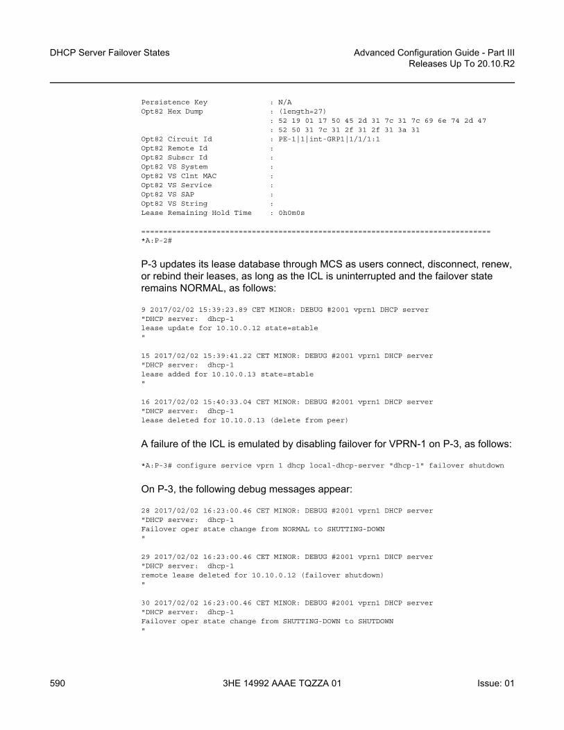
DHCP Server Failover States
590
Advanced Configuration Guide - Part IIIReleases Up To 20.10.R2
3HE 14992 AAAE TQZZA 01 Issue: 01
Persistence Key : N/AOpt82 Hex Dump : (length=27)
: 52 19 01 17 50 45 2d 31 7c 31 7c 69 6e 74 2d 47: 52 50 31 7c 31 2f 31 2f 31 3a 31
Opt82 Circuit Id : PE-1|1|int-GRP1|1/1/1:1Opt82 Remote Id :Opt82 Subscr Id :Opt82 VS System :Opt82 VS Clnt MAC :Opt82 VS Service :Opt82 VS SAP :Opt82 VS String :Lease Remaining Hold Time : 0h0m0s
===============================================================================*A:P-2#
P-3 updates its lease database through MCS as users connect, disconnect, renew, or rebind their leases, as long as the ICL is uninterrupted and the failover state remains NORMAL, as follows:
9 2017/02/02 15:39:23.89 CET MINOR: DEBUG #2001 vprn1 DHCP server"DHCP server: dhcp-1lease update for 10.10.0.12 state=stable"
15 2017/02/02 15:39:41.22 CET MINOR: DEBUG #2001 vprn1 DHCP server"DHCP server: dhcp-1lease added for 10.10.0.13 state=stable"
16 2017/02/02 15:40:33.04 CET MINOR: DEBUG #2001 vprn1 DHCP server"DHCP server: dhcp-1lease deleted for 10.10.0.13 (delete from peer)
A failure of the ICL is emulated by disabling failover for VPRN-1 on P-3, as follows:
*A:P-3# configure service vprn 1 dhcp local-dhcp-server "dhcp-1" failover shutdown
On P-3, the following debug messages appear:
28 2017/02/02 16:23:00.46 CET MINOR: DEBUG #2001 vprn1 DHCP server"DHCP server: dhcp-1Failover oper state change from NORMAL to SHUTTING-DOWN"
29 2017/02/02 16:23:00.46 CET MINOR: DEBUG #2001 vprn1 DHCP server"DHCP server: dhcp-1remote lease deleted for 10.10.0.12 (failover shutdown)"
30 2017/02/02 16:23:00.46 CET MINOR: DEBUG #2001 vprn1 DHCP server"DHCP server: dhcp-1Failover oper state change from SHUTTING-DOWN to SHUTDOWN"

Advanced Configuration Guide - Part III Releases Up To 20.10.R2
DHCP Server Failover States
Issue: 01 3HE 14992 AAAE TQZZA 01 591
31 2017/02/02 16:23:00.46 CET MINOR: DEBUG #2001 vprn1 DHCP server"DHCP server: dhcp-1RX failover peer state COMMUNICATION-INTERRUPTED"
On P-2, the following debug messages appear:
32 2017/02/02 16:23:00.45 CET MINOR: DEBUG #2001 vprn1 DHCP server"DHCP server: dhcp-1RX failover peer state SHUTDOWN"
33 2017/02/02 16:23:00.45 CET MINOR: DEBUG #2001 vprn1 DHCP server"DHCP server: dhcp-1Failover oper state change from NORMAL to COMMUNICATION-INTERRUPTED"
Displaying the DHCP server summary for VPRN-1 on P-2 again shows the failover operational state as noCommunication. “Time Left” indicates how much time is left before the failover state changes to the PARTNER-DOWN operational state if no action is taken for resolving the communication issue.
*A:P-2# show router 1 dhcp local-dhcp-server "dhcp-1" summary===============================================================================DHCP server dhcp-1 router 1===============================================================================Admin State : inServiceOperational State : inServicePersistency State : shutdownUser Data Base : N/AUse gateway IP address : enabled (scope pool)Use pool from client : disabledSend force-renewals : disabledCreation Origin : manualLease Hold Time : 0h0m0sLease Hold Time For : N/AUser-ident : mac-circuit-id
Failover Admin State : inServiceFailover Oper State : noCommunicationFailover Persist Key : N/ATime Left : 23h56m15s before state transitionAdministrative MCLT : 0h12m0sOperational MCLT : 0h12m0sStartup wait time : 0h2m0sPartner down delay : 23h59m59s
Ignore MCLT : disabled
--- snipped ---
===============================================================================*A:P-2##
Check the status for lease 10.10.0.12 again, as follows.
*A:P-2# show router 1 dhcp local-dhcp-server "dhcp-1" leases 10.10.0.12 detail

DHCP Server Failover States
592
Advanced Configuration Guide - Part IIIReleases Up To 20.10.R2
3HE 14992 AAAE TQZZA 01 Issue: 01
===============================================================================Lease for DHCP server dhcp-1 router 1===============================================================================IP-address : 10.10.0.12Lease-state : stableLease started : 2017/02/02 15:18:23Last renew : 2017/02/02 16:24:24Remaining LifeTime : 0h23m35sRemaining Potential Exp. Time: 0h23m35sSticky-lease Host Name : N/AMAC address : 00:00:00:01:01:01Xid : 0x21Failover Control : localClient Type : dhcpUser-db Host Name : N/AUser-db Address Type : N/APersistence Key : N/AOpt82 Hex Dump : (length=27)
: 52 19 01 17 50 45 2d 31 7c 31 7c 69 6e 74 2d 47: 52 50 31 7c 31 2f 31 2f 31 3a 31
Opt82 Circuit Id : PE-1|1|int-GRP1|1/1/1:1Opt82 Remote Id :Opt82 Subscr Id :Opt82 VS System :Opt82 VS Clnt MAC :Opt82 VS Service :Opt82 VS SAP :Opt82 VS String :Lease Remaining Hold Time : 0h0m0s
===============================================================================*A:P-2#
New clients connecting are allocated addresses from the local address ranges on either P-2 or P-3, even when the server is in the COMM-INT failover state. In this example, both clients are allocated and acknowledged addresses by P-2, as follows:
*A:P-2# show router 1 dhcp local-dhcp-server "dhcp-1" leases
===============================================================================Leases for DHCP server dhcp-1 router 1===============================================================================IP Address Lease State Mac Address Remaining Clnt Fail
PPP user name/Opt82 Circuit Id LifeTime Type CtrlUser-db/Sticky-lease Hostname
-------------------------------------------------------------------------------10.10.0.12 stable 00:00:00:01:01:01 0h19m2s dhcp local
PE-1|1|int-GRP1|1/1/1:110.10.0.14 stable 00:00:00:01:01:02 0h10m51s dhcp local
PE-1|1|int-GRP1|1/1/1:1-------------------------------------------------------------------------------2 leases found===============================================================================*A:P-2#

Advanced Configuration Guide - Part III Releases Up To 20.10.R2
DHCP Server Failover States
Issue: 01 3HE 14992 AAAE TQZZA 01 593
Solving the communications issue is emulated by enabling failover for VPRN-1 on P-3 again:
*A:P-3# configure service vprn 1 dhcp local-dhcp-server "dhcp-1" failover no shutdown
The debug log on P-2 shows as follows:
49 2017/02/02 16:41:17.60 CET MINOR: DEBUG #2001 vprn1 DHCP server"DHCP server: dhcp-1RX failover peer state NORMAL"
50 2017/02/02 16:41:17.60 CET MINOR: DEBUG #2001 vprn1 DHCP server"DHCP server: dhcp-1Failover oper state change from COMMUNICATION-INTERRUPTED to PRE-NORMAL"
The debug log on P-3 shows as follows:
37 2017/02/02 16:41:17.60 CET MINOR: DEBUG #2001 vprn1 DHCP server"DHCP server: dhcp-1Failover oper state change from SHUTDOWN to STARTUP"
38 2017/02/02 16:41:17.60 CET MINOR: DEBUG #2001 vprn1 DHCP server"DHCP server: dhcp-1Failover oper state change from STARTUP to PRE-NORMAL"
39 2017/02/02 16:41:17.60 CET MINOR: DEBUG #2001 vprn1 DHCP server"DHCP server: dhcp-1Failover oper state change from PRE-NORMAL to NORMAL"
40 2017/02/02 16:41:17.60 CET MINOR: DEBUG #2001 vprn1 DHCP server"DHCP server: dhcp-1lease added for 10.10.0.12 state=stable"
41 2017/02/02 16:41:17.60 CET MINOR: DEBUG #2001 vprn1 DHCP server"DHCP server: dhcp-1lease added for 10.10.0.14 state=stable"
42 2017/02/02 16:41:17.60 CET MINOR: DEBUG #2001 vprn1 DHCP server"DHCP server: dhcp-1RX failover peer state NORMAL"
The leases allocated by P-2 are synchronized with peer P-3, so they are marked as remote leases, as follows:
*A:P-3# show router 1 dhcp local-dhcp-server "dhcp-1" leases

DHCP Server Failover States
594
Advanced Configuration Guide - Part IIIReleases Up To 20.10.R2
3HE 14992 AAAE TQZZA 01 Issue: 01
===============================================================================Leases for DHCP server dhcp-1 router 1===============================================================================IP Address Lease State Mac Address Remaining Clnt Fail
PPP user name/Opt82 Circuit Id LifeTime Type CtrlUser-db/Sticky-lease Hostname
-------------------------------------------------------------------------------10.10.0.12 stable 00:00:00:01:01:01 0h38m37s dhcp remote
PE-1|1|int-GRP1|1/1/1:110.10.0.14 stable 00:00:00:01:01:02 0h31m57s dhcp remote
PE-1|1|int-GRP1|1/1/1:1-------------------------------------------------------------------------------2 leases found===============================================================================*A:P-3#
Eventually, P-2’s failover state changes to NORMAL again, as follows:
57 2017/02/02 16:53:17.85 CET MINOR: DEBUG #2001 vprn1 DHCP server"DHCP server: dhcp-1Failover oper state change from PRE-NORMAL to NORMAL"
Conclusion
SR OS supports DHCP server redundancy with failover, providing ISPs the capabilities to offer DHCP service during a partial power loss or partial network outage.

Advanced Configuration Guide - Part III Releases Up To 20.10.R2
DHCPv4 Server Basics
Issue: 01 3HE 14992 AAAE TQZZA 01 595
DHCPv4 Server BasicsThis chapter describes DHCPv4 server basics.
Topics in this chapter include:
• Applicability• Overview• Configuration• Conclusion
Applicability
This chapter is applicable to SR OS routers and is based on SR OS release 14.0.R4.
Overview
The Dynamic Host Configuration Protocol for IPv4 (DHCPv4) provides a method for assigning addresses to hosts, and conveys additional configuration data to these hosts.
DHCPv4 allows for a flexible mapping of addresses to devices; for example, identified through their MAC address. While the DHCPv4 server owns and manages addresses organized in one or more pools, a DHCPv4 client obtains an address from the DHCPv4 server, which creates a lease for that client. This provides the client the right to use the address, and the server ensures that the address will not be assigned to other clients.
The DHCPv4 server implemented in SR OS has the following features:
• Address management. The DHCPv4 server keeps track of the used and unused addresses. For the used addresses, lease durations are maintained.
• Configuration parameter management. The DHCPv4 server stores parameters that are to be used by clients when they connect.
• Persistency. When enabled, the DHCPv4 server stores the leases on non-volatile storage so that the leases remain across potential node reboots.
• Failover capability. In dual-homed DHCPv4 server scenarios, a primary DHCPv4 server can take over the responsibility of a failing peer.

DHCPv4 Server Basics
596
Advanced Configuration Guide - Part IIIReleases Up To 20.10.R2
3HE 14992 AAAE TQZZA 01 Issue: 01
The DHCPv4 server failover capability is beyond the scope of this chapter.
In this chapter, when DHCP is mentioned, it implies DHCPv4.
Characteristics
IPv4 addresses and parameters are provided by the DHCP server through the Discover – Offer – Request – Acknowledge (DORA) message sequence as explained in the IPv4 DHCP Hosts chapter.
IPoE clients use DORA messages to communicate with the DHCP server via a relay agent. PPP clients use Link Control Protocol (LCP) and Internet Protocol Control Protocol (IPCP) to communicate with the router, and a local (DHCP) client manages the communication with the DHCP server. IPoE clients and PPP clients are also referred to as native clients and simulated clients, respectively.
When the DHCP server and the relay agent are physically located in the same SR OS node, the server is referred to as a local DHCP server; when they are in different nodes, the server is considered remote. Clients can obtain an address from a local, remote, or (external) third-party DHCP server.
A DHCP server can be used for IPoE users and PPP users simultaneously. A DHCP server must be hosted by a VPRN service or the base router. It can be accessed in either of the following ways; see Figure 106:
• When a DHCP user connects, the DORA message sequence running between the DHCP client and the DHCP server also passes through a relay agent, adding and removing user-defined options along the way. The relay agent and the DHCP server can be located in the same or in a different (remote) node.
• When a PPP user connects through LCP and IPCP on a service with an internal DHCP client (local client) configured, the local client manages the DORA communication toward the DHCP server, if the relay agent also has relaying enabled for PPP applications. The local client and the DHCP server can be located in the same or in a different (remote) node.
• When a PPP user connects through LCP and IPCP on a service with local address assignment configured, the DHCP server is accessed through an API-call. See the ESM SLAAC Prefix Assignment via Local Address Server chapter for an explanation of the local address assignment concept, which also applies to PPP.

Advanced Configuration Guide - Part III Releases Up To 20.10.R2
DHCPv4 Server Basics
Issue: 01 3HE 14992 AAAE TQZZA 01 597
Figure 106 Accessing a DHCP server
A DHCP server is supported for the routed CO model as well as for the bridged CO model.
A DHCP server can be hosted by the base router or a VPRN service, for public or private use. Because multiple VPRN services can coexist in a single node, each having its own DHCP server, overlapping address ranges are supported.
DHCP Lease
The DHCP server maintains the following data for every allocation request in a lease:
1. client-type (PPP or DHCP)2. IP address3. MAC address4. lease state5. option 82, if relevant6. option 60 (vendor class identifier), if relevant7. lease timer related data8. persistence key, if applicable
DHCPv4
DORA
DORA API-call
IPCP
PPP
Relay Agent / Local Client
IPCP
PPP
Local AddressAssignment
DHCPv4 server
26095

DHCPv4 Server Basics
598
Advanced Configuration Guide - Part IIIReleases Up To 20.10.R2
3HE 14992 AAAE TQZZA 01 Issue: 01
A lease for a single client is in one of the following states:
1. offered: The IP address was offered to the client. The client still has to acknowledge the offer by sending a DHCP request.
2. stable: The IP address is now in use by the client.3. force-renew-pending: The IP address is in use by the client, but the server sends
a DHCP force-renew message to the client, because an option has changed at pool, subnet, or client (via LUDB) level.
4. remove-pending: The IP address is in use by the client, but the corresponding subnet range is deleted. The server sends a force-renew message to the client to force the client to reinitialize in order to get a new IP address.
5. held: The IP address has been used by the client but the lease has expired. The lease is now in the hold list so that the client can get the same IP address upon the next request for a lease.
6. internal: The IP address has been leased via local address assignment and is in use.
7. internal-orphan: The IP address has been leased via local address assignment and is in use. However, there is no configured subnet to which this lease belongs, because it has been removed or because this lease was installed through dual-homing.
8. internal-offered: The IP address has been offered via local address assignment, but the client has not acknowledged the offer yet.
9. internal-held: The IP address has been offered via local address assignment, but the lease is currently not active. The address is now in the hold list so that the same IP address can be offered to the same client upon request of a lease.
10. sticky: The IP address is reserved for the client and will remain reserved until the reservation for it is cleared. The client will get the same IP address upon the next request for a lease.
User Identification
The key to the leases managed by the DHCP server is configured at server level, and can be set to one of the following values (the default value being mac-circuit-id):
configure (router | service vprn <service-id>) dhcp local-dhcp-server <server-name>user-ident {client-id|circuit-id|mac|mac-circuit-id|remote-id}
The client ID is DHCP option 61; the circuit ID and the remote ID are sub-options 1 and 2 of DHCP option 82, respectively.

Advanced Configuration Guide - Part III Releases Up To 20.10.R2
DHCPv4 Server Basics
Issue: 01 3HE 14992 AAAE TQZZA 01 599
Setting user-ident to, for example, circuit-id can provide a CPE the same IP address regardless of its MAC address; thereby facilitating CPE replacement scenarios.
Lease Hold Time
The usual way for a DHCP client to indicate to the DHCP server it does not need its lease anymore is by sending a release message to the server; this is referred to as a solicited release.
However, when a client gets disconnected, or loses power, no release message is received by the server and the lease ultimately expires; this is referred to as an unsolicited release.
Without a lease hold timer, a lease is immediately deleted when the client sends the release message, or when the lease expires. The corresponding address is returned back to the pool of free addresses, and can be assigned to different clients. There is no guarantee that a client gets the same address again.
With a lease hold timer defined, a lease (entry) is not immediately deleted when the lease timer expires. Instead, the lease is put in the held or internal-held state. The lease is deleted when the hold timer expires, and the address is returned back to the pool. When the client connects, renews, or rebinds its lease before the hold timer expires, the client gets its previous lease again. There is no guarantee that the client gets the same address.
A lease hold timer can optionally be defined at the DHCP server level using the following command:
configure (router | service vprn <service-id>) dhcp local-dhcp-server <server-name>lease-hold-time [days <days>] [hrs <hours>] [min <minutes>] [sec <seconds>]
<days> : [0..7305]<hours> : [0..23]<minutes> : [0..59]<seconds> : [0..59]
If delayed deletion is also required on reception of a release message (solicited release), use the following command:
configure (router | service vprn <service-id>) dhcp local-dhcp-server <server-name>lease-hold-time-for solicited-release
The same behavior can be applied to IPSec, but that is beyond the scope of this chapter.

DHCPv4 Server Basics
600
Advanced Configuration Guide - Part IIIReleases Up To 20.10.R2
3HE 14992 AAAE TQZZA 01 Issue: 01
Fixed address allocation using DHCP server
Devices using DHCPv4 but still require the same IPv4 (fixed) can be populated in a LUDB associated with a DHCPv4 server. Sometimes these devices are called static devices because they get a fixed IP addressed assigned each time they request a DHCP lease. See the Local User Database for DHCPv4 Server chapter.
The DHCPv4 server also supports lease reservation based on client identifiers provisioned at the time of reservation. After a lease is reserved, it is referred to as a sticky lease in the server.
This sticky lease will subsequently only be assigned to a DHCP client using the same identifiers, though it is not required for such a client to ever exist. Sticky leases are not removed via timeout or DHCP releases but can only be removed via the management interface (SNMP/CLI). Sticky leases are typically not used for devices using DHCPv4 but for applications like vRGW through SNMP.
A sticky lease requires a host name. Identification of the host can be through a MAC address, a circuit ID, a remote ID, or a combination of these. The IP address must be in the range of the parenting pool.
tools perform router <router-id> dhcp local-dhcp-server <server-name> pool <pool-name> create-sticky-lease <hostname>
[mac <ieee-address>][circuit-id <circuit-id>]
[client-id <client-id>][requested-ip-address <ip-address>][circuit-id-hex <circuit-id-hex-string>][client-id-hex <client-id-hex-string>]
<hostname> : [32 chars max]<ieee-address> : xx:xx:xx:xx:xx:xx or xx-xx-xx-xx-xx-xx<circuit-id> : [253 chars max]<client-id> : [255 chars max]<ip-address> : a.b.c.d<circuit-id-hex-st*> : [0x0..0xFFFFFFFF...(max 506 hex nibbles)]<client-id-hex-str*> : [0x0..0xFFFFFFFF...(max 510 hex nibbles)]
Pool and Subnet Management
The DHCPv4 servers manage IPv4 addresses, subnets, and pools. These are hierarchically related to one another; see Figure 107.

Advanced Configuration Guide - Part III Releases Up To 20.10.R2
DHCPv4 Server Basics
Issue: 01 3HE 14992 AAAE TQZZA 01 601
Figure 107 Addresses, Subnets, and Pools in a DHCPv4 Server
A subnet is identified by an IP address and a netmask, and defines:
• One or more address ranges – The ranges in the subnet that the server can allocate addresses from. Multiple address ranges cannot overlap.
• One or more exclude address ranges (optional) – A sub-range of the preceding range that the server will not allocate addresses from.
• Minimum-free – A notification is generated when the amount of free leases reaches this value (trap and log 99).
• Maximum-declined – Security counter measure, to prevent rogue clients from depleting the subnet. When this maximum value is reached, the oldest declined address will be returned to the pool.
• DHCP options:- default-router – up to four addresses can be defined - subnet-mask – subnet mask to be used by the clients - custom-options – additional options, when required
A pool is identified by name (maximum 32 characters), and defines:
• One or more subnets• Min-lease-time – requests for a shorter lease time are set to this value; default
is 10 min• Max-lease-time – requests for a longer lease time are set to this value; default
is 10 days• Offer-time – a timer indicating how long an offer remains valid before the
address offered is returned to the pool when no Request message is received (default 1 min)
26096
pool-1 options subnet-1 options address-range [exclude-range] … subnet-p options ddress-range [exclude-range]
pool-n options subnet-1 options address-range [exclude-range] … subnet-q options ddress-range [exclude-range]
DHCPv4 server

DHCPv4 Server Basics
602
Advanced Configuration Guide - Part IIIReleases Up To 20.10.R2
3HE 14992 AAAE TQZZA 01 Issue: 01
• Minimum-free – a notification is generated when the amount of free leases reaches this value (trap and log 99), with an optional trap when all leases are used
• DHCP options:- dns-server – up to four DNS servers can be specified- domain-name – the domain to use for DNS resolution when clients provide
unqualified host names.- lease-renew-time – defines when the client transitions to the renew state
(T1)- lease-rebind-time – defines when the client transitions to the rebinding state
(T2)- lease-time – the duration of time that the DHCP server grants to the DHCP
client- netbios-name-server – defines up to four NetBIOS name servers- netbios-node-type – defines the NetBIOS node type (B, P, M, or H)- custom-option – additional options, when required
The options added by the DHCP server in response to an allocation request is a combination of the options provided by an LUDB (if applicable), subnet options, and pool options, in this sequence.
Lease Time
A DHCP client can request a specific lease time. The DHCP server checks for this value to be within the bounds as defined at pool level. If the requested lease time is out of bounds, it is set to either the minimum or the maximum value.
If a DHCP client does not request a specific lease time, the DHCP server takes the value from a matching LUDB entry, if available, or from the lease-time parameter defined at pool level, in this sequence. If the pool level lease time is not defined, the maximum lease time is used.
The best practice is to apply the following rule when defining values for the various timers:
lease-time > lease-rebind-time > lease-renew-time
However, the server does not check consistency of these timers, because the final values offered to the DHCP clients can come from various sources, which are out of the control of the DHCP server.

Advanced Configuration Guide - Part III Releases Up To 20.10.R2
DHCPv4 Server Basics
Issue: 01 3HE 14992 AAAE TQZZA 01 603
The local DHCP client always requests a lease time of 1 h to the server for PPP users connecting via the local client.
Address Allocation
When a request arrives at the DHCPv4 server, the server accesses the lease state database using the user ID as a key, checking for an existing lease. If a lease is already available, that lease is used.
Assuming that no lease is present in the lease state database yet, and that the server has a local user database attached, a matching entry is searched for in that local user database; see the Local User Database for DHCPv4 Server chapter.
In terms of address assignment, an LUDB attached to a DHCP server can return:
• an IP address – This (fixed) address is offered to the requester, where this address must not overlap with the address ranges configured in the local DHCP server.
• a Gi address – This address overrules any Gi address received from the requester.
• a pool name – A free address in one of the subnets in that pool is offered. Optionally, a secondary pool can be defined, which is used in case the primary pool is exhausted.
• use-gi-address [scope <subnet|pool>] – When the scope is set to subnet, the server offers an address from the subnet that includes the Gi address. When the scope is set to pool, the server offers an address from the subnet that includes the Gi address, or from the other subnets belonging to the same pool.
• use-pool-from-client [delimiter <delimiter>] – The pool name specified in the DHCP client message options and added by the relay agent is used. A free address in one of the subnets in that pool is offered. If two pools are available, the configured delimiting character identifies the splitting-point to find the names of both pools.
If a unique address is found in the LUDB, that address is offered by the server to the requester.
For the general address allocation flow, see Figure 108. The Local User Database for DHCPv4 Server chapter applies when an LUDB is attached to the DHCP server.

DHCPv4 Server Basics
604
Advanced Configuration Guide - Part IIIReleases Up To 20.10.R2
3HE 14992 AAAE TQZZA 01 Issue: 01
Figure 108 General Address Allocation for DHCP
Two additional parameters are available at the server level, controlling which pool and subnet an address is taken from, as follows:
[no] use-pool-from-client [delimiter <delimiter>]<delimiter> : [1 chars max]
[no] use-gi-address [scope <scope>]<scope> : subnet|pool
With a requester-provided pool name and use-pool-from-client active, the server checks for that pool to exist before selecting a free address from one of the subnets in that pool.
With a requester-provided Gi address and use-gi-address scope subnet active, a free address is taken from the subnet that includes the Gi address. With use-gi-address scope pool, another subnet in the pool is used if the original subnet is exhausted.
The following rules apply to the DHCP server address allocation flow:
• Assume a DHCP server with an LUDB applied, and use-gi-address active:
26097
use-gi-address
does poolexist
use-pool-from-client
pool-nameavailable
allocateaddress
droprequest
droprequest
Y
Y
Y
Y
Y
Y
N
NN
N
N
match
LUDB

Advanced Configuration Guide - Part III Releases Up To 20.10.R2
DHCPv4 Server Basics
Issue: 01 3HE 14992 AAAE TQZZA 01 605
- A host lookup failure will not result in the request being dropped. The server sends an offer using an address selected based on the Gi address.
- A successful host lookup, but returning a non-existent pool name, results in the server dropping the request, so no offer is sent.
• Assume a DHCP server without an LUDB applied, but with use-pool-from-client and use-gi-address active:- A requester not providing a pool name results in the server sending an offer
using an address selected based on the Gi address.- A requester providing a non-existent pool name results in the server
dropping the request, so no offer is sent.
Therefore, use-pool-from-client takes precedence over use-gi-address. The DHCP server selects an address from a pool if that pool exists. If no pool name is provided to the DHCP server, address selection is based on the Gi address, when allowed through the use-gi-address directive.
The pool name provided by a relay agent can be a concatenation of two pool names, where the delimiter character is used to split the string apart in the original pool names.
Subnet Draining
When a subnet is put in the drained state through the drain command, no new leases can be assigned from that subnet. Existing leases are cleaned up upon renewal or rebinding of the client. This is useful in renumbering scenarios; see the Configuration section for an example.
Force Renew
Parameter force-renews enables DHCP servers to issue DHCP force-renew messages to stable clients, informing them about a configuration change.
With force-renews enabled, the server does not need to wait for a client to pass through its renew or rebind sequence to provide the reconfigured options, speeding up the configuration change.
Changes can be applied at the LUDB-level, subnet level, or pool-level.

DHCPv4 Server Basics
606
Advanced Configuration Guide - Part IIIReleases Up To 20.10.R2
3HE 14992 AAAE TQZZA 01 Issue: 01
DHCP Server Persistency
The DHCP protocol does not have a keep-alive mechanism to detect unavailability. Without precaution, a node reboot causes the loss of the DHCP lease state. Because DHCP clients only attempt a reinitialization sequence after expiration of the lease timer, service outages could become unacceptably long.
The DHCP server lease state can be made persistent across reboots. The lease state is then restored from a persistency file stored on the compact flash. Therefore, DHCP clients will only lose connectivity for the duration of the reboot, and no renew or rebind is needed.
Configuration
Starting a DHCP server up in an SR OS environment requires following steps:
• Configure the DHCP server.• Configure the interfaces for the DHCP server to listen on.• Configure one or more relay agents.
The baseline configuration used in this chapter is shown in Figure 109.
Figure 109 Baseline Service Configuration
26098
1/1/1:1
1/1/1
1/1/1:2int-GRP
int-DHCP
int-SUB
10.10.0.1/2510.11.0.1/24
address 10.11.11.1/32local-dhcp-server dhcp4-VPRN1
pool-1 options … subnet 10.10.0.0/25 range 10.10.0.11 10.10.0.30 … subnet 10.11.0.0/24 range 10.11.0.11 10.11.0.20 …
…
DHCPv4 server – dhcp4-VPRN1VPRN1
dhcp server 10.11.11.1/32 gi-address 10.10.0.1

Advanced Configuration Guide - Part III Releases Up To 20.10.R2
DHCPv4 Server Basics
Issue: 01 3HE 14992 AAAE TQZZA 01 607
Configure the DHCP Server
One or more DHCP servers can be configured in the base router or in any routed service. VPRN 1 from Figure 109 has a single DHCP server named dhcp4-VPRN1, with two pools: pool-1 and pool-2. The first pool contains two subnets; the second pool contains a single subnet.
Address selection is primarily based on a pool name (use-pool-from-client), and secondarily on the Gi address with the scope set to pool (use-gi-address scope pool). This means that address selection will be Gi address-based, if no pool name is provided to the server. Having the scope set to pool enables the server to allocate addresses from other subnets within the same pool.
Different options and custom options are defined at different levels. All subnets include an address range. Subnet 10.10.0.0/25 also has an exclusion range, as follows:
configureservice
vprn 1 customer 1 createdhcp
local-dhcp-server dhcp4-VPRN1 createuse-gi-address scope pooluse-pool-from-clientpool "pool-1" create
optionsdns-server 1.1.1.1 1.1.2.2lease-time hrs 2custom-option 150 address 1.1.1.1
exitsubnet 10.10.0.0/25 create
optionssubnet-mask 255.255.255.128default-router 10.10.0.1 10.10.0.2custom-option 130 string "MyOption1"
exitexclude-addresses 10.10.0.61 10.10.0.70address-range 10.10.0.11 10.10.0.126
exitsubnet 10.11.0.0/24 create
optionssubnet-mask 255.255.255.0default-router 10.11.0.1custom-option 130 string "MyOption2"
exitaddress-range 10.11.0.11 10.11.0.20
exitexitpool "pool-2" create
subnet 10.20.0.0/16 createoptions
subnet-mask 255.255.0.0default-router 10.20.0.1
exit

DHCPv4 Server Basics
608
Advanced Configuration Guide - Part IIIReleases Up To 20.10.R2
3HE 14992 AAAE TQZZA 01 Issue: 01
address-range 10.20.0.21 10.20.0.120exit
exitno shutdown
exitexit
exitexit
exit
Configure the DHCP Interface
The DHCP server needs to be listening on one or more interfaces. In the example from Figure 108, the DHCP server is associated with interface int-DHCP, with loopback address 10.11.11.1, as follows. The DHCP server cannot be applied to a group interface.
configureservice
vprn 1 createinterface "int-DHCP" create
address 10.11.11.1/24local-dhcp-server "dhcp4-VPRN1"loopback
exitexit
exitexit
Configure Relay Agents
The configuration of the DHCP server must align with the configuration of the relay agents for the server to assign addresses correctly. For example, defining the server to allocate addresses based on a pool name, but not providing a pool name toward the server, might not provide the expected result, because this will not necessarily lead to addresses being assigned and offered to clients.
The DHCP relay agent is configured in the dhcp context, as follows:
• gi-address – the gateway IPv4 address used by the relay agent• server – up to 8 DHCP servers can be defined by their IPv4 address; only
10.11.11.11 is used in this example• client-applications dhcp ppp – the DHCP server will allocate addresses for
DHCP and PPP clients

Advanced Configuration Guide - Part III Releases Up To 20.10.R2
DHCPv4 Server Basics
Issue: 01 3HE 14992 AAAE TQZZA 01 609
• option – the options added/removed to/from messages toward the server. In the example, the circuit-id, the remote-id, and the pool-name are added.
• trusted – this parameter ensures that DHCP messages with option 82 included and the gi-address set to zero are being processed instead of being dropped
configureservice
vprn 1 customer 1 createsubscriber-interface "int-SUB" create
group-interface "int-GRP" createdhcp
optionaction replacecircuit-idremote-idvendor-specific-option
pool-nameexit
exitserver 10.11.11.1lease-populate 100client-applications dhcp pppgi-address 10.10.0.1no shutdown
exitexit
exitexit
exitexit
Configure DHCP Server Persistency
The following configuration stores the DHCP server lease-state persistency file on cf1:
configuresystem
persistencedhcp-server
location cf1:exit
exitexit
exit
The persistency file is pre-allocated, providing space for the maximum number of allowed leases, which avoids file system space issues during normal operation, as follows:
*A:PE1>file cf1:\ # dir

DHCPv4 Server Basics
610
Advanced Configuration Guide - Part IIIReleases Up To 20.10.R2
3HE 14992 AAAE TQZZA 01 Issue: 01
Volume in drive cf1 on slot A has no label.
Volume in drive cf1 on slot A is formatted as FAT32
Directory of cf1:\
09/19/2016 04:29p <DIR> .ssh/09/21/2016 01:58p 248513024 dhcp_serv.00609/21/2016 01:58p 5825024 dhcp_serv.i06
2 File(s) 254338048 bytes.1 Dir(s) 7759888384 bytes free.
*A:PE1>file cf1:\ #
A message is issued to log-id 99 to indicate that the persistence file is ready for use, as follows:
*A:PE1# show log log-id 99
===============================================================================Event Log 99===============================================================================Description : Default System LogMemory Log contents [size=500 next event=10722 (wrapped)]10721 2016/09/21 12:44:58.24 CEST WARNING: SYSTEM #2037 Base dhcp-server Persistence Report"Persistency event: dhcp-server persistence file ready for use"
The tools dump persistence summary command provides persistency information. The following example shows that the file cf1:\dhcp_serv.006 is used for storing persistency records for the DHCP server:
*A:PE1# tools dump persistence summary================================================================================Persistence Summary on Slot A (active)================================================================================Client Location #Registrations File State
Avg Nr Fragments #Entries Subsystem StateFile Fill Level #Entries Queued
--------------------------------------------------------------------------------dhcp-server cf1:\dhcp_serv.006 5 ACTIVE
1.0 5 OK0% 0
--------------------------------------------------------------------------------Total for cf1: 3% in use--------------------------------------------------------------------------------
*A:PE1#
Persistency records are identified using the persistence key. This key is part of the lease state. The following command shows the persistence key for lease 10.11.0.14:
*A:PE1# show router 1 dhcp local-dhcp-server "dhcp4-VPRN1" leases 10.11.0.14 detail
===============================================================================

Advanced Configuration Guide - Part III Releases Up To 20.10.R2
DHCPv4 Server Basics
Issue: 01 3HE 14992 AAAE TQZZA 01 611
Lease for DHCP server dhcp4-VPRN1 router 1===============================================================================IP-address : 10.11.0.14Lease-state : stableLease started : 2016/10/17 15:28:36
--- snipped ---
User-db Address Type : N/APersistence Key : 0x00000004Lease Remaining Hold Time : 0h0m0s
===============================================================================*A:PE1#
The DHCP server lease state records can be shown using the following command. This example shows the record for key 0x00000004:
*A:PE1# tools dump persistence dhcp-server record 0x00000004----------------------------------------Persistence Record----------------------------------------Client : dhcp-serverPersist-Key : 0x00000004Filename : cf1:\dhcp_serv.006Entries : Index FedHandle Last Update Action Valid
004289 0x00000079 2016/10/17 14:48:46 (UTC) UPDATE YesData : 151 bytes
type : V4 leaseservice Id : 1server : dhcp4-VPRN1IP : 10.11.0.14MAC : 00:00:00:01:01:03XID : 0x00000020state : stablelease mode : ETstart time : 2016/10/17 13:28:36 (UTC)last renew : 2016/10/17 14:48:46 (UTC)expires : 2016/10/17 14:58:46 (UTC)failctrl : localopt60 len : 0opt61 len : 0opt82 len : 0sticky name:
*A:PE1#
DHCP server lease state persistency is typically used together with subscriber management persistency if the DHCP server and subscriber management functions are managed by the same network node; see the IPv4 DHCP Hosts chapter.

DHCPv4 Server Basics
612
Advanced Configuration Guide - Part IIIReleases Up To 20.10.R2
3HE 14992 AAAE TQZZA 01 Issue: 01
Configure a Sticky Lease
The following command creates a sticky lease with name me-010101, using MAC address 00:00:00:01:02:02 and IP address 10.11.0.20:
*A:PE1# tools perform router 1 dhcp local-dhcp-server "dhcp4-VPRN1" pool "pool-1" create-sticky-lease me-010202 mac 00:00:00:01:02:02 requested-ip-address 10.11.0.20
===============================================================================Sticky lease creation result===============================================================================Result : SuccessIP-address : 10.11.0.20Lease-state : stickyLease started : 2016/10/17 17:07:00Remaining LifeTime : N/ASticky-lease Host Name : me-010202MAC address : 00:00:00:01:02:02Persistence Key : N/A===============================================================================*A:PE1#
No user database may be assigned to the DHCP server to create sticky leases.
A clear command can be used to delete a sticky lease, as follows:
clear router 1 dhcp local-dhcp-server "dhcp4-VPRN1" sticky-leases hostname "me-010202"
Operation and Verification
The following command shows all DHCP servers defined in the system. The maximum and active number of leases are shown. The router and services where the DHCP servers are hosted are listed, together with the server name and an indication whether this server is in- or out-of-service.
*A:PE1# show router dhcp servers all
==================================================================Overview of DHCP Servers==================================================================Active Leases: 5Maximum Leases: 159744
Router Server Admin State------------------------------------------------------------------Service: 1 dhcp4-VPRN1 inService==================================================================*A:PE1#

Advanced Configuration Guide - Part III Releases Up To 20.10.R2
DHCPv4 Server Basics
Issue: 01 3HE 14992 AAAE TQZZA 01 613
The following command shows all leases currently allocated by DHCP server dhcp4-VPRN1 in VPRN-1. In this example, the leases for the DHCP and PPP clients are all “stable”. Sticky leases are always shown, even when they are not online.
*A:PE1# show router 1 dhcp local-dhcp-server "dhcp4-VPRN1" leases
===============================================================================Leases for DHCP server dhcp4-VPRN1 router 1===============================================================================IP Address Lease State Mac Address Remaining Clnt Fail
PPP user name/Opt82 Circuit Id LifeTime Type CtrlUser-db/Sticky-lease Hostname
-------------------------------------------------------------------------------10.10.0.11 stable 00:00:00:01:01:01 0h9m16s dhcp local
10.10.0.12 stable 00:00:00:01:01:02 0h7m36s dhcp local
10.11.0.14 stable 00:00:00:01:01:03 0h9m9s dhcp local
10.11.0.17 stable 00:00:00:00:00:33 0h59m55s ppp localPE1|1|int-GRP|1/1/1:1
10.11.0.20 sticky 00:00:00:01:02:02 N/A dhcp N/A
me-010202-------------------------------------------------------------------------------5 leases found===============================================================================*A:PE1#
The following command shows the leases on the same server allocated from the 10.11.0.0/24 subnet:
*A:PE1# show router 1 dhcp local-dhcp-server "dhcp4-VPRN1" leases 10.11.0.0/24
===============================================================================Leases for DHCP server dhcp4-VPRN1 router 1===============================================================================IP Address Lease State Mac Address Remaining Clnt Fail
PPP user name/Opt82 Circuit Id LifeTime Type CtrlUser-db/Sticky-lease Hostname
-------------------------------------------------------------------------------10.11.0.14 stable 00:00:00:01:01:03 0h7m31s dhcp local
10.11.0.18 stable 00:00:00:00:00:33 0h59m40s ppp localPE1|1|int-GRP|1/1/1:1
10.11.0.20 sticky 00:00:00:01:02:02 N/A dhcp N/A
me-010202-------------------------------------------------------------------------------3 leases found===============================================================================*A:PE1#
The following command shows the details of a single lease:
*A:PE1# show router 1 dhcp local-dhcp-server "dhcp4-

DHCPv4 Server Basics
614
Advanced Configuration Guide - Part IIIReleases Up To 20.10.R2
3HE 14992 AAAE TQZZA 01 Issue: 01
VPRN1" leases 10.11.0.18/32 detail
===============================================================================Lease for DHCP server dhcp4-VPRN1 router 1===============================================================================IP-address : 10.11.0.18Lease-state : stableLease started : 2016/10/17 17:15:57Last renew : N/ARemaining LifeTime : 0h57m55sRemaining Potential Exp. Time: 0h0m0sSticky-lease Host Name : N/AMAC address : 00:00:00:00:00:33Xid : 0x8bf01670Failover Control : localClient Type : pppUser-db Host Name : N/AUser-db Address Type : N/APersistence Key : 0x00000005Opt82 Hex Dump : (length=71)
: 52 45 01 15 50 45 31 7c 31 7c 69 6e 74 2d 47 52: 50 7c 31 2f 31 2f 31 3a 31 02 06 00 00 00 00 00: 33 09 24 00 00 19 7f 1f 02 06 00 00 00 00 00 33: 06 01 01 01 03 50 45 31 03 04 00 00 00 01 04 07: 31 2f 31 2f 31 3a 31
Opt82 Circuit Id : PE1|1|int-GRP|1/1/1:1Opt82 Remote Id : (hex) 00 00 00 00 00 33Opt82 VS System : PE1Opt82 VS Clnt MAC : 00:00:00:00:00:33Opt82 VS Service : (hex) 00 00 00 01Opt82 VS SAP : 1/1/1:1Opt82 VS String :Opt82 VS PPPoE Session ID :Opt60 Hex Dump : (length=10)
: 41 4c 55 37 58 58 58 53 42 4dLease Remaining Hold Time : 0h0m0s
===============================================================================*A:PE1#
Troubleshooting
The following command shows summary data for the DHCP server:
*A:PE1# show router 1 dhcp local-dhcp-server "dhcp4-VPRN1" summary===============================================================================DHCP server dhcp4-VPRN1 router 1===============================================================================Admin State : inServiceOperational State : inServicePersistency State : okUser Data Base : N/AUse gateway IP address : enabled (scope pool)Use pool from client : enabledSend force-renewals : disabled

Advanced Configuration Guide - Part III Releases Up To 20.10.R2
DHCPv4 Server Basics
Issue: 01 3HE 14992 AAAE TQZZA 01 615
Creation Origin : manualLease Hold Time : 0h10m0sLease Hold Time For : (Not specified)User-ident : mac-circuit-id
Failover Admin State : outOfServiceFailover Oper State : shutdownFailover Persist Key : 0x00000003Administrative MCLT : 0h10m0sOperational MCLT : 0h10m0sStartup wait time : 0h2m0sPartner down delay : 23h59m59s
Ignore MCLT : disabled
-------------------------------------------------------------------------------Pool name : pool-1-------------------------------------------------------------------------------Failover Admin State : outOfServiceFailover Oper State : shutdownFailover Persist Key : 0x00000001Administrative MCLT : 0h10m0sOperational MCLT : 0h10m0sStartup wait time : 0h2m0sPartner down delay : 23h59m59s
Ignore MCLT : disabled-------------------------------------------------------------------------------Subnet Free % Stable Declined Offered Rem-pend Drain-------------------------------------------------------------------------------10.10.0.0/25 0 0% 2 0 0 0 N10.11.0.0/24 241 98% 3 0 0 0 NTotals for pool 241 97% 5 0 0 0-------------------------------------------------------------------------------
-------------------------------------------------------------------------------Pool name : pool-2-------------------------------------------------------------------------------Failover Admin State : outOfServiceFailover Oper State : shutdownFailover Persist Key : 0x00000007Administrative MCLT : 0h10m0sOperational MCLT : 0h10m0sStartup wait time : 0h2m0sPartner down delay : 23h59m59s
Ignore MCLT : disabled-------------------------------------------------------------------------------Subnet Free % Stable Declined Offered Rem-pend Drain-------------------------------------------------------------------------------10.20.0.0/16 100 100% 0 0 0 0 NTotals for pool 100 100% 0 0 0 0-------------------------------------------------------------------------------
Totals for server 341 98% 5 0 0 0
-------------------------------------------------------------------------------Interface associationsInterface Admin-------------------------------------------------------------------------------int-VPRN1-DHCPv4 Up

DHCPv4 Server Basics
616
Advanced Configuration Guide - Part IIIReleases Up To 20.10.R2
3HE 14992 AAAE TQZZA 01 Issue: 01
-------------------------------------------------------------------------------Local Address Assignment associationsGroup interface Admin-------------------------------------------------------------------------------===============================================================================*A:PE1#
The following command shows DHCP server statistics:
*A:PE1# show router 1 dhcp local-dhcp-server "dhcp4-VPRN1" server-stats
===============================================================================Statistics for DHCP Server dhcp4-VPRN1 router 1===============================================================================Rx Discover Packets : 2449Rx Request Packets : 12752Rx Release Packets : 53Rx Decline Packets : 0Rx Inform Packets : 0
Tx Offer Packets : 177Tx Ack Packets : 1184Tx Nak Packets : 63Tx Forcerenew Packets : 58
Client Ignored Offers : 0Leases Timed Out : 2
Dropped Bad Packet : 11205Dropped Invalid Type : 0Dropped No User Database : 0Dropped Unknown Host : 0Dropped User Not Allowed : 0Dropped Lease Not Ready : 0Dropped Lease Not Found : 5Dropped Not Serving Pool : 2297Dropped Invalid User : 0Dropped Overload : 0Dropped Persistence Overload : 0Dropped Generic Error : 0Dropped Destined To Other : 0Dropped Address Unavailable : 300Dropped Max Leases Reached : 0Dropped Server Shutdown : 0Dropped No Subnet For Fixed IP: 0Dropped Duplicate From Diff GI: 0Dropped busy primary audit : 0Dropped transmission failed : 0
Rx Internal Requests : 0Rx Internal Releases : 0Dropped Internal w/LUDB : 0Dropped Internal w/Failover : 0Dropped Internal w/Conflicts : 0
Failover statistics-------------------------------------------------------------------------------Dropped Invalid Packets : 0

Advanced Configuration Guide - Part III Releases Up To 20.10.R2
DHCPv4 Server Basics
Issue: 01 3HE 14992 AAAE TQZZA 01 617
Failover Shutdown : 0Lease Already Expired : 0Maximum Lease Count Reached : 0Subnet Not Found : 0Range Not Found : 0Host Conflict : 0Address Conflict : 0Peer conflict : 0Persistence congestion : 0No Lease Hold Time Configured : 0Invalid Prefix Length : 0Lease Not Found : 0===============================================================================*A:PE1#
The following command shows extended server statistics:
*A:PE1# show router 1 dhcp local-dhcp-server "dhcp4-VPRN1" pool-ext-stats
===============================================================================Extended pool statistics for server "dhcp4-VPRN1"===============================================================================
Current Peak Peak Timestamp-------------------------------------------------------------------------------Pool pool-1Local:
Offered Leases 0 1 10/17/2016 17:15:57Stable Leases 5 5 10/17/2016 17:15:57Provisioned Addresses 246Used Addresses 5 5 10/17/2016 17:21:24Free Addresses 241 241 10/17/2016 17:21:24Used Pct 3 3 10/17/2016 17:21:24Free Pct 97 97 10/17/2016 17:21:24
Last Reset Time 10/17/2016 15:26:31-------------------------------------------------------------------------------Pool pool-2Local:
Offered Leases 0 0 10/17/2016 17:22:15Stable Leases 0 0 10/17/2016 17:22:15Provisioned Addresses 100Used Addresses 0 0 10/17/2016 17:22:15Free Addresses 100 100 10/17/2016 17:22:15Used Pct 0 0 10/17/2016 17:22:15Free Pct 100 100 10/17/2016 17:22:15
Last Reset Time 10/17/2016 17:22:15-------------------------------------------------------------------------------Number of entries 2===============================================================================*A:PE1#
The following command shows the addresses that are still free in a particular subnet:
*A:PE1# show router 1 dhcp local-dhcp-server "dhcp4-VPRN1" free-addresses 10.11.0.0/24
===============================================================================Free addresses

DHCPv4 Server Basics
618
Advanced Configuration Guide - Part IIIReleases Up To 20.10.R2
3HE 14992 AAAE TQZZA 01 Issue: 01
===============================================================================IP Address Fail Ctrl-------------------------------------------------------------------------------10.11.0.11 local10.11.0.12 local10.11.0.13 local10.11.0.15 local10.11.0.16 local--- snipped ---10.11.0.253 local10.11.0.254 local-------------------------------------------------------------------------------No. of free addresses: 241===============================================================================*A:PE1#
The following command shows the DHCP server associations; this is the list of interfaces that the DHCP server is listening on:
*A:PE1# show router 1 dhcp local-dhcp-server "dhcp4-VPRN1" associations===============================================================================DHCP server dhcp4-VPRN1 router 1===============================================================================Interface associationsInterface Admin-------------------------------------------------------------------------------int-VPRN1-DHCPv4 Up
-------------------------------------------------------------------------------Local Address Assignment associationsGroup interface Admin-------------------------------------------------------------------------------===============================================================================*A:PE1#
The following configuration enables debugging for DHCP server dhcp4-VPRN1 on VPRN 1:
debugrouter "1"
local-dhcp-server "dhcp4-VPRN1"detail-level highmode egr-ingr-and-dropped
exitexit
exit
To ensure that the debug output is sent to a session, the following additional configuration is needed:
configurelog
log-id 1description "Send debug log to the current telnet/ssh session"from debug-traceto session

Advanced Configuration Guide - Part III Releases Up To 20.10.R2
DHCPv4 Server Basics
Issue: 01 3HE 14992 AAAE TQZZA 01 619
no shutdownexit
exitexit
With this configuration, the following output is shown when the IPoE host with MAC address 00:00:00:01:01:01 connects:
13 2016/10/17 18:51:12.30 CEST MINOR: DEBUG #2001 vprn1 DHCP server"DHCP server: dhcp4-VPRN1Rx DHCP Discover
ciaddr: 0.0.0.0 yiaddr: 0.0.0.0siaddr: 0.0.0.0 giaddr: 10.10.0.1chaddr: 00:00:00:01:01:01 xid: 0x21
DHCP options:[82] Relay agent information: len = 23
[1] Circuit-id: PE1|1|int-GRP|1/1/1:1[53] Message type: Discover[255] End
Hex Packet Dump:01 01 06 00 00 00 00 21 00 00 00 00 00 00 00 00 00 00 00 00 00 00 00 00 0a--- snipped ---00 00 00 00 00 00 00 00 00 00 00 00 00 00 00 00 00 00 00 00 00 00 00 00 00
"
14 2016/10/17 18:51:12.30 CEST MINOR: DEBUG #2001 vprn1 DHCP server"DHCP server: dhcp4-VPRN1lease added for 10.10.0.12 state=offer"
15 2016/10/17 18:51:12.30 CEST MINOR: DEBUG #2001 vprn1 DHCP server"DHCP server: dhcp4-VPRN1Tx DHCP Offer to local relay agent 10.10.0.1 vrId=2
ciaddr: 0.0.0.0 yiaddr: 10.10.0.12siaddr: 10.11.11.1 giaddr: 10.10.0.1chaddr: 00:00:00:01:01:01 xid: 0x21
DHCP options:[82] Relay agent information: len = 23
[1] Circuit-id: PE1|1|int-GRP|1/1/1:1[53] Message type: Offer[54] DHCP server addr: 10.11.11.1[51] Lease time: 600[1] Subnet mask: 255.255.255.0[3] Router: 10.10.0.1[130] Unknown option: len = 9, value = 4d 79 4f 70 74 69 6f 6e 31[6] Domain name server: length = 8
1.1.1.11.1.2.2
[150] Unknown option: len = 4, value = 01 01 01 01[255] End
Hex Packet Dump:02 01 06 00 00 00 00 21 00 00 00 00 00 00 00 00 0a 0a 00 0c 0a 0b 0b 01 0a

DHCPv4 Server Basics
620
Advanced Configuration Guide - Part IIIReleases Up To 20.10.R2
3HE 14992 AAAE TQZZA 01 Issue: 01
--- snipped ---31 7c 31 7c 69 6e 74 2d 47 52 50 7c 31 2f 31 2f 31 3a 31 ff
"
16 2016/10/17 18:51:12.32 CEST MINOR: DEBUG #2001 vprn1 DHCP server"DHCP server: dhcp4-VPRN1Rx DHCP Request
ciaddr: 0.0.0.0 yiaddr: 0.0.0.0siaddr: 0.0.0.0 giaddr: 10.10.0.1chaddr: 00:00:00:01:01:01 xid: 0x21
DHCP options:[82] Relay agent information: len = 23
[1] Circuit-id: PE1|1|int-GRP|1/1/1:1[53] Message type: Request[50] Requested IP addr: 10.10.0.12[54] DHCP server addr: 10.11.11.1[255] End
Hex Packet Dump:01 01 06 00 00 00 00 21 00 00 00 00 00 00 00 00 00 00 00 00 00 00 00 00 0a--- snipped ---31 2f 31 3a 31 ff 00 00 00 00 00 00 00 00 00 00 00 00 00 00 00 00 00 00 00
"
17 2016/10/17 18:51:12.32 CEST MINOR: DEBUG #2001 vprn1 DHCP server"DHCP server: dhcp4-VPRN1lease update for 10.10.0.12 state=stable"
18 2016/10/17 18:51:12.52 CEST MINOR: DEBUG #2001 vprn1 DHCP server"DHCP server: dhcp4-VPRN1Tx DHCP Ack to local relay agent 10.10.0.1 vrId=2
ciaddr: 0.0.0.0 yiaddr: 10.10.0.12siaddr: 10.11.11.1 giaddr: 10.10.0.1chaddr: 00:00:00:01:01:01 xid: 0x21
DHCP options:[82] Relay agent information: len = 23
[1] Circuit-id: PE1|1|int-GRP|1/1/1:1[53] Message type: Ack[54] DHCP server addr: 10.11.11.1[51] Lease time: 600[1] Subnet mask: 255.255.255.0[3] Router: 10.10.0.1[130] Unknown option: len = 9, value = 4d 79 4f 70 74 69 6f 6e 31[6] Domain name server: length = 8
1.1.1.11.1.2.2
[150] Unknown option: len = 4, value = 01 01 01 01[255] End
Hex Packet Dump:02 01 06 00 00 00 00 21 00 00 00 00 00 00 00 00 0a 0a 00 0c 0a 0b 0b 01 0a

Advanced Configuration Guide - Part III Releases Up To 20.10.R2
DHCPv4 Server Basics
Issue: 01 3HE 14992 AAAE TQZZA 01 621
--- snipped ---31 7c 31 7c 69 6e 74 2d 47 52 50 7c 31 2f 31 2f 31 3a 31 ff
"
When a client terminates its connection, the following output is shown:
19 2016/10/17 18:52:05.97 CEST MINOR: DEBUG #2001 vprn1 DHCP server"DHCP server: dhcp4-VPRN1Rx DHCP Release
ciaddr: 10.10.0.12 yiaddr: 0.0.0.0siaddr: 0.0.0.0 giaddr: 0.0.0.0chaddr: 00:00:00:01:01:01 xid: 0x21
DHCP options:[82] Relay agent information: len = 23
[1] Circuit-id: PE1|1|int-GRP|1/1/1:1[53] Message type: Release[54] DHCP server addr: 10.11.11.1[255] End
Hex Packet Dump:01 01 06 00 00 00 00 21 00 00 00 00 0a 0a 00 0c 00 00 00 00 00 00 00 00 00--- snipped ---00 00 00 00 00 00 00 00 00 00 00 00 00 00 00 00 00 00 00 00 00 00 00 00 00
"
20 2016/10/17 18:52:05.96 CEST MINOR: DEBUG #2001 vprn1 DHCP server"DHCP server: dhcp4-VPRN1lease deleted for 10.10.0.12 (rxd release)"
A PPP user connecting via local address assignment shows the following messages:
21 2016/10/17 18:52:15.97 CEST MINOR: DEBUG #2001 vprn1 DHCP server"DHCP server: dhcp4-VPRN1Rx internal Request
primary pool : pool-2ciaddr : 0.0.0.0
"
22 2016/10/17 18:52:15.97 CEST MINOR: DEBUG #2001 vprn1 DHCP server"DHCP server: dhcp4-VPRN1lease added for 10.20.0.22 state=internal"
When this user terminates the PPP session, the following messages are shown:
23 2016/10/17 18:52:26.41 CEST MINOR: DEBUG #2001 vprn1 DHCP server"DHCP server: dhcp4-VPRN1Rx internal Release
ciaddr : 10.20.0.22"
24 2016/10/17 18:52:26.41 CEST MINOR: DEBUG #2001 vprn1 DHCP server

DHCPv4 Server Basics
622
Advanced Configuration Guide - Part IIIReleases Up To 20.10.R2
3HE 14992 AAAE TQZZA 01 Issue: 01
"DHCP server: dhcp4-VPRN1lease deleted for 10.20.0.22 (rxd internal release)"
Renumbering – Subnet Mask Change
The baseline configuration has the subnet 10.10.0.0/25 defined, providing address space for up to 126 addresses. The range that the server can take free addresses from starts at 10.10.0.11, and ends at 10.10.0.126, excluding the 10.10.0.61 to 10.10.70 sub-range.
Assume that subnet 10.10.0.128/25 was removed from a different BNG, and now can be used in this BNG. This subnet can be aggregated with the 10.10.0.0/25 network to become subnet 10.10.0.0/24. At the same time, the requirement is to not disrupt services for already connected users.
The following steps are required at the DHCP server:
• ensure that no force-renews is active• delete the original subnet • create the new subnet
Preventing the DHCP server from sending force-renew messages is important so that already connected users do not lose their connection, as follows:
*A:PE1# configure service vprn 1 dhcp local-dhcp-server dhcp4-VPRN1 no force-renews
The following command deletes the original subnet:
*A:PE1# configure service vprn 1 dhcp local-dhcp-server "dhcp4-VPRN1"pool "pool-1" no subnet 10.10.0.0/25
Leases are not deleted when the subnet is deleted; their status changes from stable to removePending, as follows:
*A:PE1# show router 1 dhcp local-dhcp-server "dhcp4-VPRN1" leases
===============================================================================Leases for DHCP server dhcp4-VPRN1 router 1===============================================================================IP Address Lease State Mac Address Remaining Clnt Fail
PPP user name/Opt82 Circuit Id LifeTime Type CtrlUser-db/Sticky-lease Hostname
-------------------------------------------------------------------------------10.10.0.11 removePending 00:00:00:01:01:01 1h57m25s dhcp local
10.10.0.12 removePending 00:00:00:03:01:01 0h57m30s ppp localPE1|1|int-GRP|1/1/1:1

Advanced Configuration Guide - Part III Releases Up To 20.10.R2
DHCPv4 Server Basics
Issue: 01 3HE 14992 AAAE TQZZA 01 623
-------------------------------------------------------------------------------2 leases found===============================================================================*A:PE1#
This status change is also shown in the debug log, as follows:
132 2016/10/14 14:10:57.66 CEST MINOR: DEBUG #2001 vprn1 DHCP server"DHCP server: dhcp4-VPRN1lease 10.10.0.11 scheduled for removal"
133 2016/10/14 14:10:57.66 CEST MINOR: DEBUG #2001 vprn1 DHCP server"DHCP server: dhcp4-VPRN1lease 10.10.0.12 scheduled for removal"
134 2016/10/14 14:10:57.66 CEST MINOR: DEBUG #2001 vprn1 DHCP server"DHCP server: dhcp4-VPRN1lease 10.10.0.11 scheduled for removal"
135 2016/10/14 14:10:57.66 CEST MINOR: DEBUG #2001 vprn1 DHCP server"DHCP server: dhcp4-VPRN1lease 10.10.0.12 scheduled for removal"
Users trying to renew or connect will not get an address as long as no new subnet is defined.
Create the new 10.10.0.0/24 subnet, with the new address range starting at 10.10.0.11 and ending at 10.10.0.254, as follows. The original exclusion range still applies, but a new exclusion address 10.10.0.129 is added, to be described later:
configureservice
vprn 1 customer 1 createdhcp
local-dhcp-server dhcp4-VPRN1 createuse-gi-address scope poolno force-renewspool "pool-1" create
optionsdns-server 1.1.1.1 1.1.2.2lease-time hrs 2custom-option 150 address 1.1.1.1
exitsubnet 10.10.0.0/24 create
optionssubnet-mask 255.255.255.0default-router 10.10.0.1
exitexclude-addresses 10.10.0.61 10.10.0.70exclude-addresses 10.10.0.129 10.10.0.129address-range 10.10.0.11 10.10.0.254
exit

DHCPv4 Server Basics
624
Advanced Configuration Guide - Part IIIReleases Up To 20.10.R2
3HE 14992 AAAE TQZZA 01 Issue: 01
exitexit
exitexit
exitexit
Leases that were in use before return to the stable state, if they are not in the exclusion range, as follows:
*A:PE1# show router 1 dhcp local-dhcp-server "dhcp4-VPRN1" leases
===============================================================================Leases for DHCP server dhcp4-VPRN1 router 1===============================================================================IP Address Lease State Mac Address Remaining Clnt Fail
PPP user name/Opt82 Circuit Id LifeTime Type CtrlUser-db/Sticky-lease Hostname
-------------------------------------------------------------------------------10.10.0.11 stable 00:00:00:01:01:01 1h49m43s dhcp local
10.10.0.12 stable 00:00:00:03:01:01 0h49m48s ppp localPE1|1|int-GRP|1/1/1:1
-------------------------------------------------------------------------------2 leases found===============================================================================*A:PE1#
The following command adds the 10.10.0.129/25 address to the int-SUB subscriber interface, so that offers in the 10.10.0.128/25 range will not get dropped by the relay agent. Any address in the 10.10.0.128/25 subnet could be used; the lowest one is used in this example. Because this address is in use by the subscriber interface, it must be added to the exclusion list in the DHCP server, as follows:
*A:PE1# configure service vprn 1 subscriber-interface int-SUB address 10.10.0.129/25
This configuration ensures service continuity for already connected subscribers. They will get their new /24 subnet when they renew or rebind their lease. No change is needed at the relay agent.
Merging the two subnets at the subscriber interface is only possible with a service interruption, because the subscriber interface addresses cannot be deleted when leases are in use. Also the Gi address configured in the dhcp context must be deleted.
*A:PE1>config>service>vprn>sub-if# no address 10.10.0.1/25INFO: PIP #1398 Cannot delete/change address when managed ARPs or leases defined forthis subnet exist - 1 managed-arps or leases exist
*A:PE1>config>service>vprn>sub-if#

Advanced Configuration Guide - Part III Releases Up To 20.10.R2
DHCPv4 Server Basics
Issue: 01 3HE 14992 AAAE TQZZA 01 625
To also merge the subnets at the subscriber interface, all the leases in these subnets must be deleted. When the address defined at the subscriber interface is also used as the Gi address by the relay agent, the Gi address must be removed first. Then, the subscriber interface address can be deleted and recreated with the correct netmask. Also, the Gi address can be redefined after that. The changes at the DHCP server are similar to the ones defined previously.
Renumbering – Subnet Migration
The following changes to the baseline configuration have to be made to support the migration of DHCP clients from the 10.10.0.0/25 and 10.11.0.0/24 subnets to the 10.12.0.0/20 subnet. For that purpose, the 10.10.0.0/25 and the 10.11.0.0/24 subnets have the keyword drain added, so that leases in the corresponding address ranges will not be extended.
This new 10.12.0.0/20 subnet has a new subnet mask, a new default router, and three address ranges. New clients connecting will automatically get addresses from this new subnet. To ensure existing clients will not lose their connection, the use-gi-address scope is set to pool, so that they get a new lease from the new subnet when renewing or rebinding.
In scenarios where lease times are long (an order of magnitude of months or even years), it can take a considerable time before all clients have a lease in the new subnet. Having DHCP clients supporting force-renew can help speed up the migration process. The following configuration has force-renews enabled.
Address 10.12.0.1 is used as the default router for this subnet, so this address is added to the int-SUB subscriber-interface. This address will later be used as the Gi address.
configureservice
vprn 1dhcp
local-dhcp-server "dhcp4-VPRN1" createuse-gi-address scope poolforce-renewspool "pool-1" create
optionsdns-server 1.1.1.1 1.1.2.2lease-time hrs 2
exitsubnet 10.10.0.0/25 create
drainoptions
subnet-mask 255.255.255.0default-router 10.10.0.1
exit

DHCPv4 Server Basics
626
Advanced Configuration Guide - Part IIIReleases Up To 20.10.R2
3HE 14992 AAAE TQZZA 01 Issue: 01
address-range 10.10.0.11 10.10.0.12exitsubnet 10.11.0.0/24 create
drainoptions
subnet-mask 255.255.255.0default-router 10.10.0.1
exitaddress-range 10.11.0.11 10.11.0.254
exitsubnet 10.12.0.0/20 create
optionssubnet-mask 255.255.240.0default-router 10.12.0.1
exitaddress-range 10.12.0.10 10.12.12.255address-range 10.12.13.1 10.12.14.255address-range 10.12.15.10 10.12.15.254
exitexitno shutdown
exitexitsubscriber-interface "int-SUB"
address 10.12.0.1/20exit
exitexit
exit
The following command shows that the original subnets are in the drained state:
*A:PE1# show router 1 dhcp local-dhcp-server "dhcp4-VPRN1" summary===============================================================================DHCP server dhcp4-VPRN1 router 1===============================================================================Admin State : inServiceOperational State : inServicePersistency State : ok
--- snipped ---
-------------------------------------------------------------------------------Pool name : pool-1-------------------------------------------------------------------------------Failover Admin State : outOfServiceFailover Oper State : shutdownFailover Persist Key : 0x00000001Administrative MCLT : 0h10m0sOperational MCLT : 0h10m0sStartup wait time : 0h2m0sPartner down delay : 23h59m59s
Ignore MCLT : disabled-------------------------------------------------------------------------------Subnet Free % Stable Declined Offered Rem-pend Drain-------------------------------------------------------------------------------10.10.0.0/25 2 100% 0 0 0 0 Y10.11.0.0/24 244 100% 0 0 0 0 Y

Advanced Configuration Guide - Part III Releases Up To 20.10.R2
DHCPv4 Server Basics
Issue: 01 3HE 14992 AAAE TQZZA 01 627
10.12.0.0/20 4072 99% 3 0 0 0 NTotals for pool 4318 99% 3 0 0 0-------------------------------------------------------------------------------
Totals for server 4318 99% 3 0 0 0
--- snipped ---
===============================================================================*A:PE1#
Because the DHCP server is configured with force-renew, connected clients are sent a force-renew message. In response, the client tries to extend its lease by sending a request message using the current address. The DHCP server sends a negative-acknowledgement (NAK) to the requesting client, because the subnet is in the draining state. This forces the client to go through the DHCP initialization process; a new DORA message sequence is initiated. Therefore, the client gets a free address in the new subnet, with a new netmask, and a new default router, as follows. The same DNS servers are offered, because these pool options were not changed.
1 2016/10/15 19:19:36.04 CEST MINOR: DEBUG #2001 vprn1 DHCP server"DHCP server: dhcp4-VPRN1Tx DHCP ForceRenew to client at 10.10.0.12 vrId=2
ciaddr: 0.0.0.0 yiaddr: 0.0.0.0siaddr: 10.11.11.1 giaddr: 0.0.0.0chaddr: 00:00:00:01:01:01 xid: 0x1f
DHCP options:[53] Message type: ForceRenew[54] DHCP server addr: 10.11.11.1[255] End
"
2 2016/10/15 19:19:36.05 CEST MINOR: DEBUG #2001 vprn1 DHCP server"DHCP server: dhcp4-VPRN1Rx DHCP Request
ciaddr: 10.10.0.12 yiaddr: 0.0.0.0siaddr: 0.0.0.0 giaddr: 0.0.0.0chaddr: 00:00:00:01:01:01 xid: 0x1f
DHCP options:[53] Message type: Request[255] End
"
3 2016/10/15 19:19:36.05 CEST MINOR: DEBUG #2001 vprn1 DHCP server"DHCP server: dhcp4-VPRN1subnet is drainingTx DHCP Nak to client 10.10.0.12 vrId=2 (via snooping function)
ciaddr: 0.0.0.0 yiaddr: 0.0.0.0siaddr: 0.0.0.0 giaddr: 0.0.0.0chaddr: 00:00:00:01:01:01 xid: 0x1f

DHCPv4 Server Basics
628
Advanced Configuration Guide - Part IIIReleases Up To 20.10.R2
3HE 14992 AAAE TQZZA 01 Issue: 01
DHCP options:[53] Message type: Nak[54] DHCP server addr: 10.11.11.1[255] End
"
4 2016/10/15 19:19:36.06 CEST MINOR: DEBUG #2001 vprn1 DHCP server"DHCP server: dhcp4-VPRN1Rx DHCP Discover
ciaddr: 0.0.0.0 yiaddr: 0.0.0.0siaddr: 0.0.0.0 giaddr: 10.10.0.1chaddr: 00:00:00:01:01:01 xid: 0x1f
DHCP options:[53] Message type: Discover[255] End
"
5 2016/10/15 19:19:36.06 CEST MINOR: DEBUG #2001 vprn1 DHCP server"DHCP server: dhcp4-VPRN1lease added for 10.12.0.17 state=offer"
6 2016/10/15 19:19:36.06 CEST MINOR: DEBUG #2001 vprn1 DHCP server"DHCP server: dhcp4-VPRN1Tx DHCP Offer to local relay agent 10.10.0.1 vrId=2
ciaddr: 0.0.0.0 yiaddr: 10.12.0.17siaddr: 10.11.11.1 giaddr: 10.10.0.1chaddr: 00:00:00:01:01:01 xid: 0x1f
DHCP options:[53] Message type: Offer[54] DHCP server addr: 10.11.11.1[51] Lease time: 7200[1] Subnet mask: 255.255.240.0[3] Router: 10.12.0.1[6] Domain name server: length = 8
1.1.1.11.1.2.2
[150] Unknown option: len = 4, value = 01 01 01 01[255] End
"
7 2016/10/15 19:19:36.07 CEST MINOR: DEBUG #2001 vprn1 DHCP server"DHCP server: dhcp4-VPRN1Rx DHCP Request
ciaddr: 0.0.0.0 yiaddr: 0.0.0.0siaddr: 0.0.0.0 giaddr: 10.10.0.1chaddr: 00:00:00:01:01:01 xid: 0x1f
DHCP options:[53] Message type: Request[50] Requested IP addr: 10.12.0.17[54] DHCP server addr: 10.11.11.1[255] End
"

Advanced Configuration Guide - Part III Releases Up To 20.10.R2
DHCPv4 Server Basics
Issue: 01 3HE 14992 AAAE TQZZA 01 629
8 2016/10/15 19:19:36.07 CEST MINOR: DEBUG #2001 vprn1 DHCP server"DHCP server: dhcp4-VPRN1lease update for 10.12.0.17 state=stable"
9 2016/10/15 19:19:36.24 CEST MINOR: DEBUG #2001 vprn1 DHCP server"DHCP server: dhcp4-VPRN1Tx DHCP Ack to local relay agent 10.10.0.1 vrId=2
ciaddr: 0.0.0.0 yiaddr: 10.12.0.17siaddr: 10.11.11.1 giaddr: 10.10.0.1chaddr: 00:00:00:01:01:01 xid: 0x1f
DHCP options:[53] Message type: Ack[54] DHCP server addr: 10.11.11.1[51] Lease time: 7200[1] Subnet mask: 255.255.240.0[3] Router: 10.12.0.1[6] Domain name server: length = 8
1.1.1.11.1.2.2
[150] Unknown option: len = 4, value = 01 01 01 01[255] End
"
When the original DHCP server subnets are fully drained, they can be safely deleted. However, deleting a subnet from a pool before it is fully drained results in the remaining leases being scheduled for removal, as follows:
140 2016/10/10 15:12:42.87 CEST MINOR: DEBUG #2001 vprn1 DHCP server"DHCP server: dhcp4-VPRN1lease 10.11.0.11 scheduled for removal"
The number of leases pending for removal can be shown using following command:
*A:PE1# show router 1 dhcp local-dhcp-server "dhcp4-VPRN1" summary===============================================================================DHCP server dhcp4-VPRN1 router 1===============================================================================Admin State : inServiceOperational State : inService
--- snipped ---
-------------------------------------------------------------------------------Pool name : pool-1-------------------------------------------------------------------------------Failover Admin State : outOfServiceFailover Oper State : shutdownFailover Persist Key : 0x00000001Administrative MCLT : 0h10m0sOperational MCLT : 0h10m0sStartup wait time : 0h2m0sPartner down delay : 23h59m59s
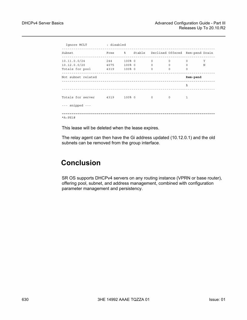
DHCPv4 Server Basics
630
Advanced Configuration Guide - Part IIIReleases Up To 20.10.R2
3HE 14992 AAAE TQZZA 01 Issue: 01
Ignore MCLT : disabled-------------------------------------------------------------------------------Subnet Free % Stable Declined Offered Rem-pend Drain-------------------------------------------------------------------------------10.11.0.0/24 244 100% 0 0 0 0 Y10.12.0.0/20 4075 100% 0 0 0 0 NTotals for pool 4319 100% 0 0 0 0-------------------------------------------------------------------------------Not subnet related Rem-pend-------------------------------------------------------------------------------
1-------------------------------------------------------------------------------
Totals for server 4319 100% 0 0 0 1
--- snipped ---
===============================================================================*A:PE1#
This lease will be deleted when the lease expires.
The relay agent can then have the Gi address updated (10.12.0.1) and the old subnets can be removed from the group interface.
Conclusion
SR OS supports DHCPv4 servers on any routing instance (VPRN or base router), offering pool, subnet, and address management, combined with configuration parameter management and persistency.

Advanced Configuration Guide - Part III Releases Up To 20.10.R2
Diameter Application NASREQ
Issue: 01 3HE 14992 AAAE TQZZA 01 631
Diameter Application NASREQThis chapter provides information about Diameter Application NASREQ.
Topics in this chapter include:
• Applicability• Overview• Configuration• Conclusion
Applicability
The information and configuration in this chapter are based on SR OS Release 19.10.R1.
Overview
NASREQ is defined in RFC 7155, Diameter Network Access Server Application and uses the Diameter base protocol defined in RFC 6733, Diameter Base Protocol. The purpose of NASREQ in SR OS is to provide subscriber authentication and authorization. NASREQ provides functionality that is also available via RADIUS but uses the Diameter protocol instead.
NASREQ complements the other Diameter applications supported in SR OS:
• Gx provides advanced authorization capabilities for subscribers and usage monitoring, and interfaces with a Policy and Charging Rules Function (PCRF).
Note: This chapter covers the Diameter NASREQ application in combination with the Diameter base protocol implementation that is available from SR OS Release 16.0.R4 onward (configured in the aaa CLI context as diameter node). The legacy Diameter base implementation (configured in the aaa CLI context as diameter-peer-policy) is supported in maintenance mode only, without any further feature enhancement planned. Nokia recommends using or transitioning to the new Diameter base protocol implementation. See also the Diameter Base Protocol: Establishing a Diameter Peer Connection chapter of this Advanced Configuration Guide

Diameter Application NASREQ
632
Advanced Configuration Guide - Part IIIReleases Up To 20.10.R2
3HE 14992 AAAE TQZZA 01 Issue: 01
• Gy or Diameter Credit Control Application (DCCA) provides on-line charging functionality, and interfaces with an On-line Charging Server (OCS).
• NASREQ provides subscriber authentication and authorization, and interfaces with a AAA server.
These three Diameter applications use the Diameter base protocol, which is described in the Diameter Base Protocol: Establishing a Diameter Peer Connection chapter of this Advanced Configuration Guide. That chapter also describes the configuration of the Diameter base protocol, which is very similar for all supported Diameter applications, and is not repeated in this chapter.
When a subscriber connects to the BNG, NASREQ is triggered, as would have been the case with RADIUS authentication. Figure 110 shows a sample call flow for NASREQ and Gx applications when an IPoE IPv4 subscriber session connects. The supported NASREQ messages are Authentication and Authorization Request (AAR) and Authentication and Authorization Answer (AAA), and the BNG assumes that the AAA server does not maintain session state. Therefore, there is no need for the BNG to send a message to the AAA server to indicate when the subscriber has ended the session. The BNG negotiates with the AAA server that it expects a stateless behavior by sending the Auth-Session-State AVP with value NO_STATE_MAINTAINED (1) as defined in RFC 6733, and the AAA server must confirm that by sending back the AVP with the same value.
Figure 110 NASREQ trigger
As shown in Figure 110, NASREQ is triggered when the DHCP discover is received, while Gx, using the Credit Control Request (CCR-I) and Credit Control Answer (CCA-I) messages, is triggered at the end, after the IP address allocation.
al_0804
Subscriber BNG DHCP
AARAAA
CCR-I
DHCP Discover
DHCP Discover
DHCP Offer
DHCP Request
DHCP Ack
DHCP Offer
DHCP RequestDHCP Ack
CCA-I
AAA PCRF

Advanced Configuration Guide - Part III Releases Up To 20.10.R2
Diameter Application NASREQ
Issue: 01 3HE 14992 AAAE TQZZA 01 633
Supported NASREQ AVPs in AAA are listed in the Triple Play Service Delivery Architecture Guide, and include AVPs for subscriber identification, profiles, service selection, address allocation, and so on.
All the NASREQ AVPs are also supported by RADIUS, and their meaning is described in the RADIUS Attributes Reference Guide.
Some AVPs, such as SLA profile and subscriber profile strings can be obtained from both NASREQ in the authentication phase and from Gx in the authorization phase. In this case, the last received value from Gx is used for the subscriber session creation.
The AAA server authenticates a subscriber based on a password. For IPoE subscribers, the password is configured in the BNG because DHCP cannot provide a subscriber password, and for PPP, the authentication is performed through PAP or CHAP. PPPoE PADI authentication via NASREQ is not supported in SR OS.
Configuration
The configuration of NASREQ authentication is performed in four steps:
Step 1. Configure a Diameter nodeStep 2. Configure a Diameter application policy.Step 3. Assign the Diameter application policy.Step 4. Apply a Python policy (optional).
In the first step, the Diameter node configures the Diameter base protocol and is described in the Diameter Base Protocol: Establishing a Diameter Peer Connection chapter. As explained in this chapter, a Diameter peer can support multiple applications, such as NASREQ and Gx:
# show aaa diameter-node "bng-gx.realm-1.com" routing-table
===============================================================================Routes===============================================================================Realm-Name
Application Pref. Id Server-Identifier-------------------------------------------------------------------------------realm-2.com
nasreq gx 10 1 dra-1.realm-2.comrealm-2.com
nasreq gx 20 2 dra-2.realm-2.com-------------------------------------------------------------------------------No. of routes: 2===============================================================================

Diameter Application NASREQ
634
Advanced Configuration Guide - Part IIIReleases Up To 20.10.R2
3HE 14992 AAAE TQZZA 01 Issue: 01
For the example in this chapter, a direct connection exists between the Diameter NASREQ client (BNG) and two NASREQ servers (aaa-1 and aaa-2):
configureaaa
diameternode "bng-nasreq.nokia.com" create
peer index 1 "aaa-1.nokia.com" createaddress 2001:db8:2:6::1preference 10no shutdown
exitpeer index 2 "aaa-2.nokia.com" create
address 172.16.7.2preference 20no shutdown
exitexit
exitexit
# show aaa diameter-node "bng-nasreq.nokia.com" peers
===============================================================================Peers===============================================================================Host identity Status Default Preference Active-------------------------------------------------------------------------------aaa-1.nokia.com I-Open No 10 Yesaaa-2.nokia.com I-Open No 20 Yes-------------------------------------------------------------------------------No. of peers: 2===============================================================================
# show aaa diameter-node "bng-nasreq.nokia.com" routing-table
===============================================================================Routes===============================================================================Realm-Name
Application Pref. Id Server-Identifier-------------------------------------------------------------------------------nokia.com
nasreq 10 1 aaa-1.nokia.comnokia.com
nasreq 20 2 aaa-2.nokia.com-------------------------------------------------------------------------------No. of routes: 2===============================================================================
When the transport connection for one of the peers is down, the remaining peer is used for authentication. When multiple peers are available, the peer selection is based on the lowest preference value or in case of equal preference, based on the lowest index number. In the example peer aaa-1.nokia.com is used when both peers are up.

Advanced Configuration Guide - Part III Releases Up To 20.10.R2
Diameter Application NASREQ
Issue: 01 3HE 14992 AAAE TQZZA 01 635
In the second step, the Diameter application policy configures the NASREQ application. For example (info detail):
configuresubscriber-mgmt
diameter-application-policy "diam-nasreq-1"description "Diameter application policy - NASREQ"application nasreqdiameter-node "bng-nasreq.nokia.com" destination-realm "nokia.com"on-failure failover enabled handling retry-and-terminatetx-timer 10nasreq
mac-format "aa:"password "YqXTV45qof/gOY1WFhJbKjjkhg==" hash2user-name-format macno user-name-operationinclude-avp
no called-station-idno calling-station-idcircuit-idno imeino nas-portnas-port-id prefix-type none suffix-type noneno nas-port-typeno rat-typeremote-idno user-location-info
exitexit
exitexit
A Diameter application policy handles exact one application: NASREQ, Gx, or Gy. In this example, we use application nasreq and configure application specific parameters in the nasreq context.
A Diameter node is configured in the application policy to select the diameter routing context in which the NASREQ messages should be forwarded to the AAA server: diameter-node "bng-nasreq.nokia.com" destination-realm "nokia.com". The node is identified with its origin host "bng-nasreq.nokia.com" and must be configured in the aaa context. The destination realm specifies the realm of the NASREQ server and is used in the Destination-Realm AVP of the application messages. In the example, client and server are in the same realm.
The on-failure session failure handling specifies the Diameter application behavior when no answer is received on a request or an answer is received with a protocol error in the result code (except for DIAMETER_UNABLE_TO_DELIVER (3002) and DIAMETER_TOO_BUSY (3004) that are handled in the Diameter node). Possible configuration options are:
• The subscriber sessions must be authenticated (that is, accepted) in case of failure. NASREQ should not retransmit the AA-Request message.

Diameter Application NASREQ
636
Advanced Configuration Guide - Part IIIReleases Up To 20.10.R2
3HE 14992 AAAE TQZZA 01 Issue: 01
on-failure failover disabled handling continue
• The subscriber sessions must be rejected in case of failure. NASREQ should not retransmit the AA-Request message.
on-failure failover disabled handling terminate
• NASREQ should retransmit the AA-Request and reject the subscriber session when the second attempt also fails (this is the configuration used in the example):
on-failure failover enabled handling retry-and-terminate
The tx-timer is the time that the Diameter application waits to get an answer from the AAA server before applying the configured failure handling. In the example, no tx-timer is configured, so the default of 10 seconds applies.
The application specific parameters are configured in the nasreq context:
• The format of the MAC address to be used in all NASREQ AVPs with a MAC is configured with the mac-format command. The default format is ab:cd:ef:01:02:03
• password configures the authentication password to be used for IPoE subscriber sessions. For PPP subscribers sessions, the credentials are provided in the PAP or CHAP authentication.
• the AAA server checks the identity of the subscriber based on the User-Name AVP. For PPPoE subscriber sessions, the PAP/CHAP username is copied in the User-Name AVP. For IPoE subscriber sessions, the username can be configured with the command user-name-format. Options for the username format are, for example: - MAC address (with or without giaddr), - circuit-id from the relay agent information (for example, DHCP Option 82 for
IPv4), - information from DHCP option 60 and 61 (which contain the Client-id and
Vendor-Class information), - and NAS port Id.
• For both IPoE and PPPoE subscriber sessions, the username format can optionally be manipulated with the user-name-operation command to add, remove, or replace a domain name.
• Several optional AVPs can be included in the NASREQ AA-Request message and are configured in the include-avp context. In the example, circuit-id, remote-id, and nas-port-id are added.
In the third and last mandatory step, the Diameter application policy must be applied using the diameter-auth-policy name command to any of the following:

Advanced Configuration Guide - Part III Releases Up To 20.10.R2
Diameter Application NASREQ
Issue: 01 3HE 14992 AAAE TQZZA 01 637
• a VPRN or IES group interface• a local user database (LUDB) IPoE or PPP host• a VPLS capture SAP• a gtp apn policy
A diameter authentication policy is mutually exclusive with a radius authentication policy:
>config>subscr-mgmt>loc-user-db>ipoe>host# auth-policy "auth-policy-1"MINOR: SVCMGR #1558 cannot configure a nasreq and a radius policy together
The fourth optional configuration step enables the manipulation of AA-Request and AA-Answer NASREQ messages with a Python script. A sample script that copies the User-Name AVP into the Subscription-Id AVP (which is not defined for NASREQ) in AA-Request messages is as follows:
# show python python-script "nasreq-1" source-in-use
===============================================================================Python script "nasreq-1"===============================================================================Admin state : inServiceOper state : inServicePrimary URL : ftp://*:*@10.1.1.1/./python/diameter/nasreq-1.pySecondary URL : (Not Specified)Tertiary URL : (Not Specified)Active URL : primary
-------------------------------------------------------------------------------Source (dumped from memory)-------------------------------------------------------------------------------
1 from binascii import *2 from alc import diameter34 def getint_b2a_hex(val):5 return int(b2a_hex(val),16)67 def byte_to_binary(n):8 return ''.join(str((n & (1 << i)) and 1) for i in reversed(range(8)))9
10 def hex_to_binary(h):11 return ''.join(byte_to_binary(ord(b)) for b in unhexlify(h))1213 def checkbitset(byte,index):14 return ((byte&(1<<index))!=0)1516 def checkRequestOrReply():17 if checkbitset(int(hex_to_binary(b2a_hex(diameter.flags))),7) is True:18 return 'R'19 else :20 return 'A'2122 if getint_b2a_hex(diameter.code) == 265 and checkRequestOrReply() == 'R':23 try:

Diameter Application NASREQ
638
Advanced Configuration Guide - Part IIIReleases Up To 20.10.R2
3HE 14992 AAAE TQZZA 01 Issue: 01
24 username = diameter.get_avps(1,0)[0][1]25 if username != "":26 diameter.set_grouped_avps(443,0,[('@', {(450,0): [('@','\x00\x00\
x00\x04')], (444,0): [('@',str(username))]})])27 except Exception, err: print "Python FAILED to fetch username"
===============================================================================
Configuration to activate the Python script for the example:
configurepython
python-script "nasreq-1" createdescription "Diameter NASREQ - AAR: copy User-Name in Subscription-Id"primary-url "ftp://*:*@10.1.1.1/./python/diameter/nasreq-1.py"no shutdown
exitpython-policy "py-nasreq-1" create
description "Diameter NASREQ - Python"diameter aar direction egress script "nasreq-1"
exitexitaaa
diamaternode "bng-nasreq.nokia.com" create
python-policy "py-nasreq-1"---snip---
exitexit
exit
The Python policy must be configured in the Diameter node and can act on all Diameter base and application messages forwarded or received on any of the peers in the node. The Python policy defines on which messages a script should be activated. In the example, the script "nasreq-1" operates on the AAR messages in the egress direction. In a similar way, Python scripts can also be applied to AAA messages in the ingress direction.
Troubleshooting
The operational state of the Diameter application policy can be shown with the following show command:
# show subscriber-mgmt diameter-application-policy "diam-nasreq-1"
===============================================================================DIAMETER application policy "diam-nasreq-1"===============================================================================Description : Diameter application policy - NASREQSession failover : enabledFailover handling : retry-and-terminatePeer policy : (Not Specified)

Advanced Configuration Guide - Part III Releases Up To 20.10.R2
Diameter Application NASREQ
Issue: 01 3HE 14992 AAAE TQZZA 01 639
Diameter node : bng-nasreq.nokia.comDestination-realm : nokia.comApplication : nasreqTx timer (s) : 10Last management change : 11/25/2019 13:33:46-------------------------------------------------------------------------------NASREQ-------------------------------------------------------------------------------Include AVP : circuit-id
remote-idnas-port-id
NAS-Port-Id prefix type : noneNAS-Port-Id suffix type : noneUser name format : macUser name operation : no-operationMAC address format : aa:Last management change : 11/25/2019 13:13:04===============================================================================
===============================================================================Associations===============================================================================
No interfaces found using diameter-auth-policy "diam-nasreq-1".
-------------------------------------------------------------------------------Local User Database IPOE Hosts using diameter-auth-policy "diam-nasreq-1"-------------------------------------------------------------------------------Local User Database IPOE Host-------------------------------------------------------------------------------ludb-1 sub-02-01_diam-------------------------------------------------------------------------------No. of Local User Database IPOE Hosts: 1-------------------------------------------------------------------------------
No Local User Database PPP Hosts found using diameter-auth-policy "diam-nasreq-1".
No associated SAP's found.
===============================================================================
The following show command provides Diameter application message statistics for the NASREQ application policy, that includes transmit and receive counters per message type, transmit failures, retransmissions, and statistics per error category:
# show subscriber-mgmt diameter-application-policy "diam-nasreq-1" statistics
===============================================================================Diameter node statistics for policy "diam-nasreq-1"===============================================================================Message Requests Answers-------------------------------------------------------------------------------Authorization-Authentication 85 56-------------------------------------------------------------------------------
Request message transmission failur* 29Request message retransmissions 0

Diameter Application NASREQ
640
Advanced Configuration Guide - Part IIIReleases Up To 20.10.R2
3HE 14992 AAAE TQZZA 01 Issue: 01
Result code Sent Received-------------------------------------------------------------------------------(1xxx) Informational 0 0(2xxx) Success 0 53(3xxx) Protocol Errors 0 0(4xxx) Transient Failures 0 3(5xxx) Permanent Failures 0 0===============================================================================* indicates that the corresponding row element may have been truncated.
Diameter debugging is split between node and application level:
debugdiameter
applicationpolicy "diam-nasreq-1"
session-messagesexit
exitnode "bng-nasreq.nokia.com"
peer "aaa-1.nokia.com"exitpeer "aaa-2.nokia.com"exit
exitexit
In this chapter, the Diameter application level debugging for application messages is explained as well as application message routing errors that are reported in the node level debug. When a Python script is active for the node, the debug messages are logged after Python processing.
The session-messages option configured in the diameter application policy debug enables debug output for all Diameter application messages for the specified application policy. For a NASREQ application policy, this includes AA-Request and AA-Answer messages. By default, application error conditions are also logged in the debug output. Debug for application error conditions can be disabled with the debug option no on-error at the application or at the policy debug context.
To enable debug for the Python script that manipulates the NASREQ messages, use this debug configuration:
debugpython
python-script "nasreq-1"script-all-info
exitexit
exit

Advanced Configuration Guide - Part III Releases Up To 20.10.R2
Diameter Application NASREQ
Issue: 01 3HE 14992 AAAE TQZZA 01 641
Following is a debug output example of a new IPoE subscriber setup: a DHCP Discover is received on a capture SAP, followed by the Diameter NASREQ AAR and AAA authentication messages. The Python script debug output shows that AVP 443 (Subscription ID) is added which is also visible in the AAR message debug (logged after the Python script is executed):
234756 2019/11/25 16:55:07.994 UTC minor: DEBUG #2001 Base SVCMGRSVCMGR: RX DHCP Packet
VPLS 10, SAP 1/1/2:*.*
BootRequest to UDP port 67ciaddr: 0.0.0.0 yiaddr: 0.0.0.0siaddr: 0.0.0.0 giaddr: 0.0.0.0chaddr: 00:02:01:00:00:01 xid: 0xf66ff11b
DHCP options:[82] Relay agent information: len = 21
[1] Circuit-id: CircuitID[2] Remote-id: RemoteID
[53] Message type: Discover[255] End
234757 2019/11/25 16:55:07.994 UTC minor: DEBUG #2001 Base Python OutputPython Output: nasreq-1
234758 2019/11/25 16:55:07.994 UTC minor: DEBUG #2001 Base Python ResultPython Result: nasreq-1Diameter AVP code 443, SET
"('@', '\\x00\\x00\\x01\\xc2@\\x00\\x00\\x0c\\x00\\x00\\x00\\x04\\x00\\x00\\x01\\xbc@\\x00\\x00\\x1900:02:01:00:00:01\\x00\\x00\\x00')"
234759 2019/11/25 16:55:07.995 UTC minor: DEBUG #2001 Base DIAMETERDIAMETER: Message TransmissionTransmit: "AAR"Application policy: "diam-nasreq-1"Node: "bng-nasreq.nokia.com"Received peer: N/ATransmit peer: "aaa-1.nokia.com"Python policy: "py-nasreq-1"
Headerver 1 len 336 flags RP------ code 265app-id 1 hbh-id 12691 e2e-id 1731030625
AVPssession-Id (263) -M------ [42]
data [34] (UTF8String) : bng-nasreq.nokia.com;1572949245;91auth-appl-id (258) -M------ [12]
data [4] (Unsigned32) : 1 : Nasreqorigin-host (264) -M------ [28]
data [20] (DiameterIdentity) : bng-nasreq.nokia.comorigin-realm (296) -M------ [17]
data [9] (DiameterIdentity) : nokia.comdestination-realm (283) -M------ [17]
data [9] (DiameterIdentity) : nokia.comauth-request-type (274) -M------ [12]
data [4] (Enumerated) : 3 : AUTHORIZE_AUTHENTICATE

Diameter Application NASREQ
642
Advanced Configuration Guide - Part IIIReleases Up To 20.10.R2
3HE 14992 AAAE TQZZA 01 Issue: 01
nas-port-id (87) -M------ [21]data [13] (UTF8String) : 1/1/2:2513.20
origin-state-id (278) -M------ [12]data [4] (Unsigned32) : 1572949245
user-name (1) -M------ [25]data [17] (UTF8String) : 00:02:01:00:00:01
user-password (2) -M------ [11]data [3] (OctetString) : 0x50 57 44
auth-session-state (277) -M------ [12]data [4] (Enumerated) : 1 : NO_STATE_MAINTAINED
agent-circuit-id (1) VM------ [21]vendor-id DSL_FORUMdata [9] (OctetString) : 0x43 69 72 63 75 69 74 49 44
agent-remote-id (2) VM------ [20]vendor-id DSL_FORUMdata [8] (OctetString) : 0x52 65 6d 6f 74 65 49 44
subscription-id (443) -M------ [48]data [40] (Grouped)
subscription-id-type (450) -M------ [12]data [4] (Enumerated) : 4 : private
subscription-id-data (444) -M------ [25]data [17] (UTF8String) : 00:02:01:00:00:01
234760 2019/11/25 16:55:08.008 UTC minor: DEBUG #2001 Base DIAMETERDIAMETER: Message ReceptionReceive: "AAA"Application policy: "diam-nasreq-1"Node: "bng-nasreq.nokia.com"Received peer: "aaa-1.nokia.com"Transmit peer: N/APython policy: "py-nasreq-1"
Headerver 1 len 372 flags -P------ code 265app-id 1 hbh-id 12691 e2e-id 1731030625
AVPssession-Id (263) -M------ [42]
data [34] (UTF8String) : bng-nasreq.nokia.com;1572949245;91auth-appl-id (258) -M------ [12]
data [4] (Unsigned32) : 1 : Nasreqorigin-host (264) -M------ [23]
data [15] (DiameterIdentity) : aaa-1.nokia.comorigin-realm (296) -M------ [17]
data [9] (DiameterIdentity) : nokia.comresult-code (268) -M------ [12]
data [4] (Unsigned32) : 2001 : DIAM_RESCODE_SUCCESSauth-session-state (277) -M------ [12]
data [4] (Enumerated) : 1 : NO_STATE_MAINTAINEDalc-subscriber-id-str (11) V------- [21]
vendor-id NOKIAdata [9] (UTF8String) : sub-02-01
alc-subscriber-profile-str (12) V------- [25]vendor-id NOKIAdata [13] (UTF8String) : sub-profile-1
alc-sla-profile-str (13) V------- [25]vendor-id NOKIAdata [13] (UTF8String) : sla-profile-1
alc-msap-service-id (31) V------- [16]vendor-id NOKIA

Advanced Configuration Guide - Part III Releases Up To 20.10.R2
Diameter Application NASREQ
Issue: 01 3HE 14992 AAAE TQZZA 01 643
data [4] (Unsigned32) : 1000alc-msap-interface (33) V------- [25]
vendor-id NOKIAdata [13] (UTF8String) : group-int-2-1
alc-msap-policy (32) V------- [25]vendor-id NOKIAdata [13] (UTF8String) : msap-policy-1
framed-pool (88) -------- [23]data [15] (UTF8String) : pool-pe2-1000-2
framed-ipv6-pool (100) -------- [23]data [15] (OctetString) : pool-pe2-1000-2
alc-delegated-ipv6-pool (131) V------- [27]vendor-id NOKIAdata [15] (OctetString) : pool-pe2-1000-2
Let's consider a failure scenario, for example a configuration error in the diameter application policy where the destination realm for the NASREQ server is incorrect: the realm realm-1.com cannot be routed in the node bng-nasreq.nokia.com:
configuresubscriber-mgmt
diameter-application-policy "diam-nasreq-1"description "Diameter application policy - NASREQ"application nasreqdiameter-node "bng-nasreq.nokia.com" destination-realm "realm-1.com"---snip---
# show aaa diameter-node "bng-nasreq.nokia.com" routing-table
===============================================================================Routes===============================================================================Realm-Name
Application Pref. Id Server-Identifier-------------------------------------------------------------------------------nokia.com
nasreq 10 1 aaa-1.nokia.comnokia.com
nasreq 20 2 aaa-2.nokia.com-------------------------------------------------------------------------------No. of routes: 2===============================================================================
In this case, the diameter node level debug displays the routing failure:
244903 2019/11/27 14:26:48.705 UTC minor: DEBUG #2001 Base SVCMGRSVCMGR: RX DHCP Packet
VPLS 10, SAP 1/1/2:*.*
BootRequest to UDP port 67ciaddr: 0.0.0.0 yiaddr: 0.0.0.0siaddr: 0.0.0.0 giaddr: 0.0.0.0chaddr: 00:02:01:00:00:01 xid: 0xf66ff11b
DHCP options:[82] Relay agent information: len = 21
[1] Circuit-id: CircuitID

Diameter Application NASREQ
644
Advanced Configuration Guide - Part IIIReleases Up To 20.10.R2
3HE 14992 AAAE TQZZA 01 Issue: 01
[2] Remote-id: RemoteID[53] Message type: Discover[255] End
244904 2019/11/27 14:26:48.705 UTC minor: DEBUG #2001 Base DIAMETERDIAMETER: FailureTransmit: "AAR"Application policy: "diam-nasreq-1"Node: "bng-nasreq.nokia.com"Received peer: N/ATransmit peer: N/APython policy: "py-nasreq-1"Result code: N/AError message: "no route to destination"Failed AVP: N/A
Message:Header
ver 1 len 288 flags RP------ code 265app-id 1 hbh-id 2384494 e2e-id 1731030625
AVPssession-Id (263) -M------ [43]
data [35] (UTF8String) : bng-nasreq.nokia.com;1572949245;121auth-appl-id (258) -M------ [12]
data [4] (Unsigned32) : 1 : Nasreqorigin-host (264) -M------ [28]
data [20] (DiameterIdentity) : bng-nasreq.nokia.comorigin-realm (296) -M------ [17]
data [9] (DiameterIdentity) : nokia.comdestination-realm (283) -M------ [19]
data [11] (DiameterIdentity) : realm-1.comauth-request-type (274) -M------ [12]
data [4] (Enumerated) : 3 : AUTHORIZE_AUTHENTICATEnas-port-id (87) -M------ [21]
data [13] (UTF8String) : 1/1/2:2513.20origin-state-id (278) -M------ [12]
data [4] (Unsigned32) : 1572949245user-name (1) -M------ [25]
data [17] (UTF8String) : 00:02:01:00:00:01user-password (2) -M------ [11]
data [3] (OctetString) : 0x50 57 44auth-session-state (277) -M------ [12]
data [4] (Enumerated) : 1 : NO_STATE_MAINTAINEDagent-circuit-id (1) VM------ [21]
vendor-id DSL_FORUMdata [9] (OctetString) : 0x43 69 72 63 75 69 74 49 44
agent-remote-id (2) VM------ [20]vendor-id DSL_FORUMdata [8] (OctetString) : 0x52 65 6d 6f 74 65 49 44

Advanced Configuration Guide - Part III Releases Up To 20.10.R2
Diameter Application NASREQ
Issue: 01 3HE 14992 AAAE TQZZA 01 645
Conclusion
In this chapter the configuration and troubleshooting of the Diameter NASREQ application is described. The NASREQ application provides subscriber authentication and authorization.

Diameter Application NASREQ
646
Advanced Configuration Guide - Part IIIReleases Up To 20.10.R2
3HE 14992 AAAE TQZZA 01 Issue: 01

Advanced Configuration Guide - Part III Releases Up To 20.10.R2
Diameter Base Protocol: Establishing a DiameterPeer Connection
Issue: 01 3HE 14992 AAAE TQZZA 01 647
Diameter Base Protocol: Establishing a Diameter Peer ConnectionThis chapter provides information about configuring and troubleshooting the Diameter Base protocol to establish a Diameter peer connection.
Topics in this chapter include:
• Applicability• Overview• Configuration• Conclusion
Applicability
This information and configuration in this chapter are based on SR OS Release 19.10.R1.
Overview
Diameter is an Authentication, Authorization and Accounting (AAA) protocol defined by the IETF in RFC 6733, Diameter Base Protocol. While historically wireline access networks were largely based on RADIUS for subscriber authentication, authorization, and accounting, it was decided by 3rd Generation Partnership Project (3GPP) that wireless access networks will be largely based on Diameter. Over time, operators are looking to converge both types of networks, and one of the aspects of this is to replace RADIUS in wireline access networks by Diameter.
Diameter is based on three layers: the transport layer, the Diameter base protocol layer and the Diameter applications as shown in Figure 111.
Note: This chapter covers the Diameter base protocol implementation that is available from SR OS Release 16.0.R4 onward (configured in the aaa CLI context as diameter node). The legacy Diameter base implementation (configured in the aaa CLI context as diameter-peer-policy) is supported in maintenance mode only, without any further feature enhancement planned. Nokia recommends using or transitioning to the new Diameter base protocol implementation.

Diameter Base Protocol: Establishing a Diameter Peer Connection
648
Advanced Configuration Guide - Part IIIReleases Up To 20.10.R2
3HE 14992 AAAE TQZZA 01 Issue: 01
Figure 111 Diameter protocol stack
The bottom layer is the transport layer and can be either TCP or SCTP. SR OS supports TCP. The Diameter base protocol implementation in SR OS is based on RFC 6733. The top layer contains the Diameter applications. SR OS supports NASREQ for authentication, Gx for authorization, policy management and usage monitoring and Gy or Diameter Credit Control Application (DCCA) for online charging.
Figure 112 shows a Diameter network topology that will be used in the configuration examples in this chapter.
A Diameter Client (BNG) is connected via peer-1a and peer-1b to two Diameter Agents (DRA-1 and DRA-2) that provide connectivity to the Diameter Application Servers (PCRF). Via these peers, the BNG can authenticate and perform policy control of subscriber sessions using the NASREQ and Gx applications. The same Diameter Client (BNG) is also directly connected to another Diameter Application Server (OCS) via peer-2. Via this peer, on-line charging can be done for the subscriber sessions using the Gy application.
DiameterApplications
TCP SCTP
DiameterBase Protocol
Transport
Applicationsession
Diameterpeer
35618
NASREQauthentication
Gxauthorization
Gyon-line charging
OtherApplications...
Diameter Base Protocol: IETF RFC 6733

Advanced Configuration Guide - Part III Releases Up To 20.10.R2
Diameter Base Protocol: Establishing a DiameterPeer Connection
Issue: 01 3HE 14992 AAAE TQZZA 01 649
Figure 112 Diameter network topology
Configuration
The Diameter base protocol and the Diameter applications are configured separately, where the Diameter base protocol must be configured first, and the Diameter applications next. The transport layer configuration is part of the Diameter base protocol layer. This example describes the Diameter base protocol configuration.
The Diameter base protocol and the corresponding transport layer configuration is based on Diameter Nodes. Each Diameter Node represents a Diameter routing instance and contains a list of peers in the routing domain that provide direct or indirect connectivity to application servers.
An example Diameter node configuration that corresponds with the topology in Figure 112 is shown below.
configureaaa
diameternode "bng-gx.realm-1.com" create
description "Authentication and Policy Management"
PCRFDiameterServer
PCRFDiameterServer
OCS DiameterServer
BNGDiameterClient
DRA-1Diameter
Agent
DRA-2Diameter
Agent
bng-gx.realm-1.comDiameter node
NASREQ Gx
bng-gx.realm-1.comDiameter node
realm-2.comrealm-1.com
Gy
Diameter application policies
Diameter application policy
peer-1a
peer-1b
peer-2
Diameter Gx application sessions
Diameter Gy application sessions35619

Diameter Base Protocol: Establishing a Diameter Peer Connection
650
Advanced Configuration Guide - Part IIIReleases Up To 20.10.R2
3HE 14992 AAAE TQZZA 01 Issue: 01
ipv6-source-address 2001:db8::2source-address 192.0.2.2peer index 1 "dra-1.realm-2.com" create
address 2001:db8:2:6::1preference 10no shutdown
exitpeer index 2 "dra-2.realm-2.com" create
address 172.16.7.2preference 20no shutdown
exitexitnode "bng-gy.realm-1.com" origin-realm "realm-1.com" create
description "Credit Control"router "management"peer index 1 "ocs.realm-1.com" create
address 192.99.3.0no shutdown
exitexit
exitexit
A Diameter node configuration requires a unique origin host as key. The origin host is used in Diameter application policies to associate the application with the node. All Diameter base and application messages forwarded via the peers of that node use the configured origin host in the Origin-Host AVP. The value for the Origin-Realm AVP is by default derived from the configured origin host: the realm is the part of the origin host after the first dot (".") as delimiter or equal to the origin host when it does not contain a delimiter. For example, for node "bng-gx.realm-1.com": Origin-Host = "bng-gx.realm-1.com", Origin-Realm = "realm-1.com". It is also possible to explicitly configure an origin realm as shown in the example for the node "bng-gy.realm-1.com".
A node configuration can include a routing context, and an IPv4 and/or IPv6 source address. These parameters are used to establish the TCP transport connection for all peers in the node. The specified source address must be a reachable local interface address in the specified or in the default routing instance. For node "bng-gx.realm-1.com" in the example, no routing instance is specified. By default, the TCP connections are established in the Base router using the specified source addresses. For node "bng-gy.realm-1.com" in the example, the out of band routing instance router "management" is used to establish the TCP connection of its peer. As no source address is specified, the system will automatically select an interface address, in this case an out of band IP address configured in the Boot Options File (BOF).

Advanced Configuration Guide - Part III Releases Up To 20.10.R2
Diameter Base Protocol: Establishing a DiameterPeer Connection
Issue: 01 3HE 14992 AAAE TQZZA 01 651
Within a Diameter node, up to 5 peers can be configured with an index value between 1 and 5 as key, an IPv4 or IPv6 destination address for the TCP connection, and a mandatory destination host that is used as Destination-Host AVP value for all Diameter base messages on the peer. In a Diameter node, one peer is selected to forward application messages for a specific application session. The other peers provide redundancy when supported by the Diameter application, such as Gy session failover. A Diameter peer for application messages is selected based on following criteria:
1. Forwarding:If the application message contains a Destination-Host AVP, select the peer in the peer table with a matching configured destination host. This is the forwarding phase.
2. Routing:When the lookup in the peer table fails, perform a lookup in the realm routing table and select the peer with realm name equal to the Destination-Realm AVP in the application message, and with matching application ID. When multiple peers are matched, select in order of priority until a single peer is found:
a. the peer with the lowest configured preference (default preference is 50)b. the peer with the lowest index
3. Default peer:When both forwarding lookup in the peer table and routing lookup in the realm routing table were unsuccessful, use the peer configured as default-peer. Only a single peer in a node can be configured as a default-peer:
>config>aaa>diam>node>peer# default-peerMINOR: DIAM #2001 Multiple default peer is not allowed
For node "bng-gx.realm-1.com" in the example, peer-1a with index 1 has a configured preference of 10 and peer-2 with index 2 has a configured preference of 20. Diameter Gx application messages will fail the peer table lookup as the destination host of the PCRF will not be present (no direct connection between Diameter client and Diameter application server):
# show aaa diameter-node "bng-gx.realm-1.com" peers
===============================================================================Peers===============================================================================Host identity Status Default Preference Active-------------------------------------------------------------------------------dra-1.realm-2.com I-Open No 10 Yesdra-2.realm-2.com I-Open No 20 Yes-------------------------------------------------------------------------------No. of peers: 2===============================================================================

Diameter Base Protocol: Establishing a Diameter Peer Connection
652
Advanced Configuration Guide - Part IIIReleases Up To 20.10.R2
3HE 14992 AAAE TQZZA 01 Issue: 01
Instead a realm routing table lookup is performed to find the peer for forwarding the application messages. In this case peer-1a (dra-1.realm-2.com) is selected based on the matching destination realm (realm-2.com), application ID (Gx) and the lower preference value:
# show aaa diameter-node "bng-gx.realm-1.com" routing-table
===============================================================================Routes===============================================================================Realm-Name
Application Pref. Id Server-Identifier-------------------------------------------------------------------------------realm-2.com
nasreq gx 10 1 dra-1.realm-2.comrealm-2.com
nasreq gx 20 2 dra-2.realm-2.com-------------------------------------------------------------------------------No. of routes: 2===============================================================================
The realm routing table is populated based on the Origin-Realm AVP and Application-Id AVP received in the Capability Exchange Answer message together with the configured index and preference values.
Note that Diameter answer messages do not rely on peer or realm routing table lookups. Answers are forwarded over the same route in the reverse direction of the matching requests. This is achieved with a transactional cache in each traversed Diameter node, using the Hop-by-Hop AVP to match requests with answers.
When enabling the peer (no shutdown), the system tries to establish the transport TCP connection. Once the TCP session is up, the system starts a Diameter Capability Exchange using the configured Diameter identity (Origin-Host and Origin-Realm AVPs) and advertising support for all SR OS Diameter applications in Application-Id AVP's (NASREQ, Gx, and Gy). When the Origin-Host AVP in the received CEA message corresponds with the destination host configured for the peer (case insensitive) and at least one application in the CEA is common with the SR OS advertised applications, then the peer moves to the I-Open state (I from Initiator). An example of a Capability Exchange is illustrated in detail in the troubleshooting section.
Optionally, a connection and a watchdog timer can be configured in the Diameter node:
configureaaa
diameternode "bng-gx.realm-1.com" create
connection-timer 30--- snip ---peer index 1 "dra-1.realm-2.com" create

Advanced Configuration Guide - Part III Releases Up To 20.10.R2
Diameter Base Protocol: Establishing a DiameterPeer Connection
Issue: 01 3HE 14992 AAAE TQZZA 01 653
connection-timer 30watchdog-timer 30--- snip ---
• connection-timerThe connection timer or Tc timer controls the frequency at which a transport connection is attempted to be established. The default value is 30 seconds. This timer can be configured per node to be used by all peers or overridden per peer.
• watchdog-timerThe watchdog timer controls the frequency at which Device-Watchdog-Request messages are transmitted to the peer, and is called the Tw timer in RFC 3539, Authentication, Authorization and Accounting (AAA) Transport Profile. A small timer results in a faster detection of a peer failure at the expense of generating more messages. The timer is configured per peer and its default value is 30 seconds.
A Python policy can be configured in the Diameter node to manipulate Diameter messages transmitted to and/or received on its peers.
configureaaa
diameternode "bng-gy.realm-1.com" origin-realm "realm-1.com" create
python-policy "py-diameter-1"---snip---
exitexit
exit
Manipulating Diameter messages, such as changing the content or format of AVPs using Python is out of the scope of this chapter.
By default, Diameter messages are sent with a DSCP set to AF41. The DSCP value can be changed with the sgt-qos configuration:
# configure router sgt-qos application diameter dscp "nc1"
SR OS uses TCP as transport and the TCP destination port number is fixed to the standard Diameter base protocol port 3868. The source port is randomly chosen from the ephemeral port range.
Troubleshooting
The status and statistics of the Diameter peers can be verified with following show commands:

Diameter Base Protocol: Establishing a Diameter Peer Connection
654
Advanced Configuration Guide - Part IIIReleases Up To 20.10.R2
3HE 14992 AAAE TQZZA 01 Issue: 01
# show aaa diameter-node "bng-gx.realm-1.com" peers
===============================================================================Peers===============================================================================Host identity Status Default Preference Active-------------------------------------------------------------------------------dra-1.realm-2.com I-Open No 10 Yesdra-2.realm-2.com I-Open No 20 Yes-------------------------------------------------------------------------------No. of peers: 2===============================================================================
# show aaa diameter-node "bng-gx.realm-1.com" peer "dra-1.realm-2.com"
===============================================================================Peer "dra-1.realm-2.com"===============================================================================Index : 1Status : I-OpenAdministrative state : enabledActive : YesActive applications : nasreq gxLast disconnect cause : rebootingPreference : 10Default peer : NoConnection timer (s) : N/AWatchdog timer (s) : 13Pending messages : 0Remote realm : realm-2.comRemote IP address : 2001:db8:2:6::1Remote TCP port : 3868Remote Origin-State-Id : 1574235027Local host identity : bng-gx.realm-1.comLocal realm : realm-1.comLocal IP address : 2001:db8::2Local TCP port : 53734Last management change : 11/19/2019 15:05:48===============================================================================
# show aaa diameter-node "bng-gx.realm-1.com" peer "dra-1.realm-2.com" statistics
===============================================================================Peer "dra-1.realm-2.com"===============================================================================Message Sent Received-------------------------------------------------------------------------------Capabilities-Exchange-Request 7 0Capabilities-Exchange-Answer 0 7Disconnect-Peer-Request 1 4Disconnect-Peer-Answer 4 1Device-Watchdog-Request 1217 778Device-Watchdog-Answer 778 1217Application message request 0 0Application message answer 0 0
Last cleared time: N/A===============================================================================

Advanced Configuration Guide - Part III Releases Up To 20.10.R2
Diameter Base Protocol: Establishing a DiameterPeer Connection
Issue: 01 3HE 14992 AAAE TQZZA 01 655
To clear the peer statistics, use following command:
# clear aaa diameter-node "bng-gx.realm-1.com" peer "dra-1.realm-2.com" statistics
Diameter debugging is split between node and application level:
debugdiameter
applicationpolicy "diam-nasreq-1"
session-messagesexit
exitnode "bng-gx.realm-1.com"
peer "dra-1.realm-2.com"peer-to-peer
exitexit
exitexit
In this chapter, the Diameter base protocol debugging for peer messages is explained, configured at the node level debug. When a Python script is active for the node, the debug messages are logged after Python processing.
To debug the Diameter base protocol messages for peer "dra-1.realm-2.com", use the following debug commands:
debugdiameter
node "bng-gx.realm-1.com"peer "dra-1.realm-2.com"
peer-to-peerexit
exitexit
exit
The peer-to-peer option enables debug output for all Diameter base messages of the specified peer: Capabilities Exchange, Device Watchdog and Disconnect Peer messages. By default, error conditions are also logged in the debug output. Debug for error conditions can be disabled per Diameter node or per peer with the debug option no on-error. Errors reported at the node level include Diameter base errors that are unrelated to a peer, such as a routing problem for a Diameter application message. Errors reported at the peer level include all errors that occur after peer selection and peer connection errors.
Let's start with the peer connection in Closed state (remote end rebooting):
*A:pe2# show aaa diameter-node "bng-gx.realm-1.com" peer "dra-1.realm-2.com"
===============================================================================

Diameter Base Protocol: Establishing a Diameter Peer Connection
656
Advanced Configuration Guide - Part IIIReleases Up To 20.10.R2
3HE 14992 AAAE TQZZA 01 Issue: 01
Peer "dra-1.realm-2.com"===============================================================================Index : 1Status : ClosedAdministrative state : enabledActive : NoActive applications :Last disconnect cause : rebootingPreference : 10Default peer : NoConnection timer (s) : 18Watchdog timer (s) : N/APending messages : 0Remote realm : (Not Specified)Remote IP address : (Not Specified)Remote TCP port : (Not Specified)Remote Origin-State-Id : (Not Specified)Local host identity : bng-gx.realm-1.comLocal realm : realm-1.comLocal IP address : (Not Specified)Local TCP port : (Not Specified)Last management change : 11/19/2019 15:05:48===============================================================================
The Connection timer(s) field in above peer details output show that in 18 seconds, a new connection attempt will be made, followed by a Capabilities Exchange when successful. The transmitted Capabilities-Exchange-Request (CER) and received Capabilities-Exchange-Answer (CEA) are shown in the debug output:
233997 2019/11/20 19:17:16.271 UTC minor: DEBUG #2001 Base DIAMETERDIAMETER: Message TransmissionTransmit: "CER"Application policy: N/ANode: "bng-gx.realm-1.com"Received peer: N/ATransmit peer: "dra-1.realm-2.com"Python policy: N/A
Headerver 1 len 284 flags R------- code 257app-id 0 hbh-id 19864 e2e-id 3486524428
AVPsorigin-host (264) -M------ [26]
data [18] (DiameterIdentity) : bng-gx.realm-1.comorigin-realm (296) -M------ [19]
data [11] (DiameterIdentity) : realm-1.comhost-ip-addr (257) -M------ [26]
data [18] (Address) : ipv6 2001:db8::2vendor-id (266) -M------ [12]
data [4] (Unsigned32) : 6527product-name (269) -------- [13]
data [5] (UTF8String) : SR-OSauth-appl-id (258) -M------ [12]
data [4] (Unsigned32) : 1 : Nasreqauth-appl-id (258) -M------ [12]
data [4] (Unsigned32) : 4 : Gyauth-appl-id (258) -M------ [12]
data [4] (Unsigned32) : 16777238 : Gx

Advanced Configuration Guide - Part III Releases Up To 20.10.R2
Diameter Base Protocol: Establishing a DiameterPeer Connection
Issue: 01 3HE 14992 AAAE TQZZA 01 657
vend-specific-appl-id (260) -M------ [32]data [24] (Grouped)
vendor-id (266) -M------ [12]data [4] (Unsigned32) : 10415
auth-appl-id (258) -M------ [12]data [4] (Unsigned32) : 4 : Gy
vend-specific-appl-id (260) -M------ [32]data [24] (Grouped)
vendor-id (266) -M------ [12]data [4] (Unsigned32) : 10415
auth-appl-id (258) -M------ [12]data [4] (Unsigned32) : 16777238 : Gx
supported-vendor-id (265) -M------ [12]data [4] (Unsigned32) : 3561
supported-vendor-id (265) -M------ [12]data [4] (Unsigned32) : 6527
supported-vendor-id (265) -M------ [12]data [4] (Unsigned32) : 10415
supported-vendor-id (265) -M------ [12]data [4] (Unsigned32) : 13019
firmware-revision (267) -------- [12]data [4] (Unsigned32) : 191001
233998 2019/11/20 19:17:16.275 UTC minor: DEBUG #2001 Base DIAMETERDIAMETER: Message ReceptionReceive: "CEA"Application policy: N/ANode: "bng-gx.realm-1.com"Received peer: "dra-1.realm-2.com"Transmit peer: N/APython policy: N/A
Headerver 1 len 240 flags -------- code 257app-id 0 hbh-id 19864 e2e-id 3486524428
AVPsresult-code (268) -M------ [12]
data [4] (Unsigned32) : 2001 : DIAM_RESCODE_SUCCESSorigin-host (264) -M------ [25]
data [17] (DiameterIdentity) : dra-1.realm-2.comorigin-realm (296) -M------ [19]
data [11] (DiameterIdentity) : realm-2.comhost-ip-addr (257) -M------ [26]
data [18] (Address) : ipv6 2001:db8:2:6::1vendor-id (266) -M------ [12]
data [4] (Unsigned32) : 6527product-name (269) -------- [28]
data [20] (UTF8String) : PythonDiameterAgent1origin-state-id (278) -M------ [12]
data [4] (Unsigned32) : 1574277432supported-vendor-id (265) -M------ [12]
data [4] (Unsigned32) : 10415auth-appl-id (258) -M------ [12]
data [4] (Unsigned32) : 1 : Nasreqauth-appl-id (258) -M------ [12]
data [4] (Unsigned32) : 16777238 : Gxvend-specific-appl-id (260) -M------ [32]
data [24] (Grouped)vendor-id (266) -M------ [12]

Diameter Base Protocol: Establishing a Diameter Peer Connection
658
Advanced Configuration Guide - Part IIIReleases Up To 20.10.R2
3HE 14992 AAAE TQZZA 01 Issue: 01
data [4] (Unsigned32) : 10415auth-appl-id (258) -M------ [12]data [4] (Unsigned32) : 16777238 : Gx
firmware-revision (267) -------- [12]data [4] (Unsigned32) : 1
The result of the successful Capabilities Exchange is that the peer moved to the I-Open state, ready to forward NASREQ and Gx application messages:
# show aaa diameter-node "bng-gx.realm-1.com" peer "dra-1.realm-2.com"
===============================================================================Peer "dra-1.realm-2.com"===============================================================================Index : 1Status : I-OpenAdministrative state : enabledActive : YesActive applications : nasreq gxLast disconnect cause : rebootingPreference : 10Default peer : NoConnection timer (s) : N/AWatchdog timer (s) : 9Pending messages : 0Remote realm : realm-2.comRemote IP address : 2001:db8:2:6::1Remote TCP port : 3868Remote Origin-State-Id : 1574277432Local host identity : bng-gx.realm-1.comLocal realm : realm-1.comLocal IP address : 2001:db8::2Local TCP port : 55199Last management change : 11/19/2019 15:05:48===============================================================================
The Watchdog timer(s) field in preceding peer details output shows that in 9 seconds, a Device Watchdog exchange will be initiated. The transmitted Device-Watchdog-Request (DWR) and received Device-Watchdog-Answer (DWA) are shown in the debug output:
233999 2019/11/20 19:17:44.268 UTC minor: DEBUG #2001 Base DIAMETERDIAMETER: Message TransmissionTransmit: "DWR"Application policy: N/ANode: "bng-gx.realm-1.com"Received peer: N/ATransmit peer: "dra-1.realm-2.com"Python policy: N/A
Headerver 1 len 68 flags R------- code 280app-id 0 hbh-id 19865 e2e-id 3486524431
AVPsorigin-host (264) -M------ [26]
data [18] (DiameterIdentity) : bng-gx.realm-1.comorigin-realm (296) -M------ [19]

Advanced Configuration Guide - Part III Releases Up To 20.10.R2
Diameter Base Protocol: Establishing a DiameterPeer Connection
Issue: 01 3HE 14992 AAAE TQZZA 01 659
data [11] (DiameterIdentity) : realm-1.com
234000 2019/11/20 19:17:44.271 UTC minor: DEBUG #2001 Base DIAMETERDIAMETER: Message ReceptionReceive: "DWA"Application policy: N/ANode: "bng-gx.realm-1.com"Received peer: "dra-1.realm-2.com"Transmit peer: N/APython policy: N/A
Headerver 1 len 92 flags -------- code 280app-id 0 hbh-id 19865 e2e-id 3486524431
AVPsresult-code (268) -M------ [12]
data [4] (Unsigned32) : 2001 : DIAM_RESCODE_SUCCESSorigin-host (264) -M------ [25]
data [17] (DiameterIdentity) : dra-1.realm-2.comorigin-realm (296) -M------ [19]
data [11] (DiameterIdentity) : realm-2.comorigin-state-id (278) -M------ [12]
data [4] (Unsigned32) : 1574277432
Now let's try to bring up the peer in the node bng-gy.realm-1.com:
# show aaa diameter-node "bng-gy.realm-1.com" peers
===============================================================================Peers===============================================================================Host identity Status Default Preference Active-------------------------------------------------------------------------------ocs.realm-1.com Closed No 50 No-------------------------------------------------------------------------------No. of peers: 1===============================================================================
Debug is enabled at the peer level for error conditions without the peer-to-peer option. Failures are reported, but not all transmitted and received peer messages.
debugdiameter
node "bng-gy.realm-1.com"peer "ocs.realm-1.com"exit
exitexit
exit
The Diameter server is provisioned with an origin host different from the configured destination host for the peer, resulting in a failure and peer reset:
234330 2019/11/22 14:57:32.272 UTC minor: DEBUG #2001 management DIAMETERDIAMETER: FailureReceive: "CEA"

Diameter Base Protocol: Establishing a Diameter Peer Connection
660
Advanced Configuration Guide - Part IIIReleases Up To 20.10.R2
3HE 14992 AAAE TQZZA 01 Issue: 01
Application policy: N/ANode: "bng-gy.realm-1.com"Received peer: "ocs.realm-1.com"Transmit peer: N/APython policy: N/AResult code: "DIAM_RESCODE_INVALID_AVP_VALUE"Error message: "mismatch with locally stored information"Failed AVP:
origin-host (264) -M------ [27]data [19] (DiameterIdentity) : ocs.wrong-realm.com
Message:Header
ver 1 len 176 flags -------- code 257app-id 0 hbh-id 6050 e2e-id 3486524894
AVPsresult-code (268) -M------ [12]
data [4] (Unsigned32) : 2001 : DIAM_RESCODE_SUCCESSorigin-host (264) -M------ [27]
data [19] (DiameterIdentity) : ocs.wrong-realm.comorigin-realm (296) -M------ [23]
data [15] (DiameterIdentity) : wrong-realm.comhost-ip-addr (257) -M------ [14]
data [6] (Address) : ipv4 192.99.3.0vendor-id (266) -M------ [12]
data [4] (Unsigned32) : 6527product-name (269) -------- [28]
data [20] (UTF8String) : PythonDiameterServerorigin-state-id (278) -M------ [12]
data [4] (Unsigned32) : 1574434643auth-appl-id (258) -M------ [12]
data [4] (Unsigned32) : 4 : Gyfirmware-revision (267) -------- [12]
data [4] (Unsigned32) : 1
234331 2019/11/22 14:57:32.272 UTC minor: DEBUG #2001 management DIAMETERDIAMETER: Peer ResetNode: "bng-gy.realm-1.com"Peer: "ocs.realm-1.com"Reason: "failed to parse received CEA"
Events
Following events are defined for the Diameter base protocol:
=======================================================================ApplicationID# Event Name P g/s Logged Dropped
-----------------------------------------------------------------------2007 tmnxDiamMessageDropped MI thr 0 02008 tmnxDiamNdPeerStatActiveChanged MI thr 46 0
=======================================================================
Advanced Configuration Guide - Part III Releases Up To 20.10.R2
Diameter Base Protocol: Establishing a DiameterPeer Connection
Issue: 01 3HE 14992 AAAE TQZZA 01 661
The tmnxDiamNdPeerStatActiveChanged event is generated when the state of a Diameter peer toggles between active / not active:
38080 2019/11/22 14:52:02.269 UTC MINOR: DIAMETER #2008 management peer state change"DIAMETER node bng-gy.realm-1.com, peer ocs.realm-1.com is active"
The tmnxDiamMessageDropped event is generated when Diameter base drops a malformed message.
Conclusion
As a result of fixed mobile network convergence, Diameter is used in fixed access networks as an alternative for Radius based AAA. Diameter peering provides reliable and secure transport with peer redundancy. Its functionality is defined in a base Diameter protocol specified in RFC 6733. Various applications can be layered on top of base Diameter and they can utilize the robust transport capabilities that Diameter provides.

Diameter Base Protocol: Establishing a Diameter Peer Connection
662
Advanced Configuration Guide - Part IIIReleases Up To 20.10.R2
3HE 14992 AAAE TQZZA 01 Issue: 01

Advanced Configuration Guide - Part III Releases Up To 20.10.R2
ESM Basics
Issue: 01 3HE 14992 AAAE TQZZA 01 663
ESM BasicsThis chapter provides information about Enhanced Subscriber Management.
Topics in this chapter include:
• Applicability• Summary• Overview• Configuration• Conclusion
Applicability
The information and configuration in this chapter are based on SR OS release 11.0.R4.
Summary
Subscriber management in general includes the following functions:
• subscriber host authentication, identification, addressing, authorization and accounting:- authentication – Check whether the subscriber host is allowed access via a
Local User Data Base (LUDB) or via a RADIUS server.- identification – Fetch the data to use for the subscriber host, including the
definition of the subscriber-ID.- addressing – Fetch the address information to use, IPv4 and/or IPv6.- authorization – Check what the subscriber host is allowed to do.- accounting – Both off-line charging (RADIUS and XML) and on-line
charging (RADIUS credit control and Diameter credit control application) are supported.
• subscriber host instantiation, based on:- A protocol (DHCP, PPPoE/oA/oEoA or ARP) for dynamic hosts, and started
through a trigger packet.- A static configuration for static hosts.

ESM Basics
664
Advanced Configuration Guide - Part IIIReleases Up To 20.10.R2
3HE 14992 AAAE TQZZA 01 Issue: 01
• subscriber QoS - Ensure per service and per application SLAs, based on:- the overall subscriber rate- subscriber profiles- service level agreement profiles
• subscriber security:- Avoid malicious access through anti-spoofing and based on access control
lists (ACLs) / IP-filters.- DDOS mitigation.
• subscriber persistency – The subscriber state is written to flash-disk (a.k.a. persistent data) and automatically restored on node reboot.
• subscriber resiliency – The subscriber state is retained in case of a node failure in redundant environments, through Multi Chassis Synchronization (MCS).
• subscriber troubleshooting, using: - OAM test.- mirroring.- debugging and event logging.
Enhanced Subscriber Management (ESM) implies subscriber management functions are applied at subscriber level. Subscriber hosts are created, and all of the features listed above apply.
Basic Subscriber Management (BSM) implies subscriber management functions are applied at SAP level. Only a subset of the functions listed above apply.
This example gives an overview of the ESM data required to perform subscriber management functions, and how the ESM data is organized.
Overview
The following terminology is used extensively in Triple Play Service Delivery Architecture (TPSDA) and is key to understanding ESM:
• device• subscriber host• subscriber

Advanced Configuration Guide - Part III Releases Up To 20.10.R2
ESM Basics
Issue: 01 3HE 14992 AAAE TQZZA 01 665
A device is equipment located at the customer premises. Example devices are computers, smart-phones, set-top boxes, etc including the Residential Gateway (RGW) providing the connection towards the Internet. The RGW is connected to the access network using an XDSL-connection, a PON-connection, etc.
A subscriber is a collection of subscriber hosts connected to a single RGW. The subscriber is identified by its subscriber-ID, a character string of 32 characters maximum which is used for administrative purposes.
Unlike devices, which are physical entities, subscribers and subscriber hosts are logical entities. These are created dynamically and resources are allocated when a device connects to the network and becomes active.
The following host types are recognized by the Broadband Network Gateway (BNG):
• DHCP hosts• PPPoE hosts• ARP hosts
The BNG uses the combination of following parameters to uniquely identify a single subscriber host:
• SAP-id• IP-address• MAC-address• session-ID (PPPoE only)
Multiple subscriber hosts can be associated with a single device.
Figure 113 shows a bridged RGW scenario. Subscriber-1has two devices, device-1 and device-2. Device-1 is a dual stack PPPoE device and is assigned an IPv4 address for host-1 and an IPv6 SLAAC prefix for host-2, both running over a single PPPoE session. Device-2 is a single stack IPoE device and is assigned an IPv4 address for host-3.

ESM Basics
666
Advanced Configuration Guide - Part IIIReleases Up To 20.10.R2
3HE 14992 AAAE TQZZA 01 Issue: 01
Figure 113 Bridged RGW Scenario
Figure 114 shows a routed dual stack RGW scenario. Subscriber-2 has two devices but they are hidden behind the RGW. The IP-addresses used by these devices are not known by the BNG. The RGW contains three hosts:
• Host-1 is assigned an outside IPv4 address, which the RGW uses for Network Address Translation (NAT).
• Host-2 is assigned an IPv6 wan host address or SLAAC prefix, which the RGW uses towards the outside network.
• Host-3 is assigned an IPv6 prefix for prefix delegation, which the RGW uses for allocating IPv6 addresses to IPv6 capable devices in the home network.
Figure 114 Routed RGW Scenario
al_0450
BNGAccess Network
PPPoEv4v6
IPoEv4
BridgedRGW
Device-2
Device-1
Dual-Stackhost-1: IPv4@host-2: IPv6
Single-Stackhost-3: IPv4@
Subscriber-1
al_0451
BNGAccess Network
IPoEv4v6
IPv4’@
IPv6’@
IPv4”@
IPv6”@host-3: IPv6 PD-prefix
host-2: IPv6 wan-host
host-1: IPv4@
Subscriber-2
Dual StackRouted RGW
NAT

Advanced Configuration Guide - Part III Releases Up To 20.10.R2
ESM Basics
Issue: 01 3HE 14992 AAAE TQZZA 01 667
Detailed information on both scenarios can be found in ESMv6: IPoE Dual Stack Hosts and the ESMv6: PPPoE Dual Stack Hosts respectively.
Configuration
Figure 115 shows two objects closely related to subscribers and subscriber hosts:
• SLA profile• Subscriber profile
Figure 115 SLA-Profile and Sub-Profile
SLA Profile
A Service Level Agreement profile (SLA profile) is a template identified by name (maximum 32 chars) which defines:
• per service QoS settings as part of the QoS policy (ingress and egress):- queue/policer- scheduling/priority levels- bandwidth limits (CIR/PIR) and queue/policer depths (MBS/CBS)- classification- (re-)marking
• IP-filters for IPv4 and/or IPv6 (ingress and egress):- Access Control Lists (ACL)/Filters
• host-limit
al_0452
Sub-1
Sub-2GE
subscriber SAP sub-profilesla-profile
sub-1(aggr sched)
sub-2(aggr sched)
sub-1
sub-n
sub-1
sub-n
SAP1Data
SAP2Voice
Access Network

ESM Basics
668
Advanced Configuration Guide - Part IIIReleases Up To 20.10.R2
3HE 14992 AAAE TQZZA 01 Issue: 01
• credit-control
An example SLA profile is shown below.
configuresubscriber-mgmt
sla-profile "sla-prof-1" createingress
qos 100exit
exitegress
qos 100exit
exitexit
An instance of the sla-profile is created at host instantiation time.
The SLA profile enforces traffic control on a per service per subscriber basis. When multiple hosts for the same subscriber use the same SLA profile they share the same set of queues/policers as long as they are on the same SAP. The combined traffic for these hosts is controlled by the settings defined in the SLA profile.
Subscriber Profile
The subscriber profile (sub-profile) is a template identified by name (maximum 32 chars) which defines:
• per subscriber QoS settings:- aggregate rate (egress only)- scheduler policy (ingress and egress)- policer control policy (ingress and egress)
• the accounting profile (RADIUS or XML)• multicast parameters (igmp-policy, etc.)• Network Address Translation (NAT) parameters• the ANCP (Access Node Control Protocol) parameters• the default sla-profile mappings• etc.
An example subscriber profile is shown below.
configuresubscriber-mgmt
sub-profile "sub-prof-1" create

Advanced Configuration Guide - Part III Releases Up To 20.10.R2
ESM Basics
Issue: 01 3HE 14992 AAAE TQZZA 01 669
ingresspolicer-control-policy "pol-ctrl-1"exit
exitegress
scheduler-policy "down-1"exit
exitexit
An instance of the sub-profile is created at host instantiation time.
The sub-profile enforces traffic control on a per subscriber basis. he aggregate traffic of all hosts of a particular subscriber is controlled by the settings defined in the sub-profile, as long as the subscriber hosts are terminated on the same card.
QoS details are out of the scope of this example.
Subscriber SAP
A subscriber SAP is a SAP in a VPLS (Bridged CO model, which is not covered), VPRN or IES service (both in the Routed CO model) on which the queues/policers and other resources are allocated and de-allocated on a per subscriber basis.
A static SAP is a subscriber SAP when sub-sla-mgmt is enabled and becomes operational when in the no shutdown state. Multiple subscribers can connect through this SAP simultaneously when multi-sub-sap is enabled.
configureservice
ies 1subscriber-interface "sub-int-1"
group-interface "grp-int-1-1"sap 1/1/1:101 create
description "data SAP for DLSAM-1"sub-sla-mgmt
multi-sub-sap 400--- snip ---no shutdown
exitexit
Single SAP parameters (profiled-traffic-only and non-sub-traffic) are taken into account only when multi-sub-sap is left at its default of 1.

ESM Basics
670
Advanced Configuration Guide - Part IIIReleases Up To 20.10.R2
3HE 14992 AAAE TQZZA 01 Issue: 01
Subscriber Host Identification and Instantiation
The general subscriber host identification (authentication) process is depicted in Figure 116 and encompasses fetching the ESM data for a connecting device.
Figure 116 Subscriber Host Identification and Instantiation Process
ESM data is organized as a set of profiles which control the behavior of individual subscribers and subscriber hosts.
Static hosts are instantiated using the manually provisioned ESM data.
For dynamic hosts, the host identification and instantiation process is started by a trigger message (1 in Figure 116) which can be one of the following:
• DHCPv4 DISCOVER• DHPCv6 SOLICIT• PPPoE PADI• PPPoA LCP Configuration Request• ARP REQUEST
The following types of ESM data are distinguished as mandatory or optional ESM data.
al_0453
ESMDate
Source
1. LUDB
2. RADIUS
3. DHCPv4 ACK Python
4. default
trigger
DHCPv6 SOLICITDHCPv4 DISCOVERARP REQUESTPPPoE PADIPPPoA LCP CONF REQ
string
SAP-id
address-info
subscriber-id
sub-profile
sla-profile
app-profile
sub-ident-policy
string
sub-profile stringsla-profile string
•••app-profile string
sub-profile namesla-profile name
•••app-profile name
def-sub-profile namedef-sla-profile name
•••def-app-profile name
use-direct-map-as-default
name
string-x name-y
name
instantiation1
2
5
7
68
3
4

Advanced Configuration Guide - Part III Releases Up To 20.10.R2
ESM Basics
Issue: 01 3HE 14992 AAAE TQZZA 01 671
Mandatory ESM data is:
• address information (IPv4 and/or IPv6)• subscriber ID• sub-profile data• sla-profile data
Optional ESM data includes:
• app-profile data• inter-dest-id• Access Node Control Protocol (ANCP) data
A host is instantiated only when all mandatory ESM data is available for that host.
The ESM data sources (2) are consulted in following predefined sequence:
1. LUDB2. RADIUS3. DHCPv4 ACK python4. Default
The ESM data sources provide:
• the subscriber-id (3)• the profile strings (5)
Address information (IPv4 and/or IPv6) (4) can be provided by:
• the LUDB or RADIUS ESM data sources• a DHCP server
The LUDB, RADIUS or DHCPv4 ACK python ESM data sources provide profile strings (5) which have a maximum length of 16 characters. They must be translated into profile names (6) which have a maximum length of 32 characters. The profile name is the key to access the actual profile data. The ESM data source default directly returns profile names (7), which do not need any translation.
The ESM string to profile name translation is defined in configurable mapping tables which are part of the subscriber identification policy (sub-ident-policy). Mapping tables can be defined for:
• the sub-profile• the sla-profile

ESM Basics
672
Advanced Configuration Guide - Part IIIReleases Up To 20.10.R2
3HE 14992 AAAE TQZZA 01 Issue: 01
• the app-profile
In case no mapping is needed because the strings and names are set to the same set of values, then a subscriber identification policy is needed with the attribute use-direct-map-as-default. (See section Subscriber Identification Policy.)
Note the subscriber-id does not need to be translated.
The instantiation process (8) ensures the subscriber host is created:
• The subscriber host is added to the active subscriber list.• Resources (queues, policers, filters, etc) are allocated for SLA enforcement.• Status information is updated.
As a result the system starts forwarding user data to and from that subscriber host.
A subscriber is instantiated as soon as the first subscriber host for this subscriber is instantiated, and deleted when the last subscriber host for this subscriber is deleted.
Subscriber Identification Policy
The subscriber identification policy is identified by name and defines:
• a description (optional)• the sub-profile map• the sla-profile map• the app-profile map (optional)• the location of a DHCPv4 ACK python script (optional):
- primary, secondary and tertiary locations are possible• the DHCP option used to get the identification strings from (optional)
A subscriber identification policy is needed for dynamic hosts only. In that case one of the ESM data sources from Figure 116 is used.
Using a python script for subscriber host identification and instantiation is restricted to IPv4 hosts when triggered by the DHCPv4 ACK message.
The first example has no explicit mappings.
configuresubscriber-mgmt
sub-ident-policy "sub-id-pol-1" createdescription "direct mapping policy"

Advanced Configuration Guide - Part III Releases Up To 20.10.R2
ESM Basics
Issue: 01 3HE 14992 AAAE TQZZA 01 673
sub-profile-mapuse-direct-map-as-default
exitsla-profile-map
use-direct-map-as-defaultexitapp-profile-map
use-direct-map-as-defaultexit
exit
The second example contains explicit mappings.
configuresubscriber-mgmt
sub-ident-policy "sub-id-pol-2" createdescription "explicit mapping policy"sub-profile-map
entry key "sub-string-1" sub-profile "sub-prof-1"entry key "sub-string-2" sub-profile "sub-prof-2"entry key "sub-string-3" sub-profile "sub-prof-3"
exitsla-profile-map
entry key "sla-string-1" sla-profile "sla-prof-1"entry key "sla-string-2" sla-profile "sla-prof-2"entry key "sla-string-21" sla-profile "sla-prof-20"entry key "sla-string-22" sla-profile "sla-prof-20"
exitexit
Note that multiple strings can be mapped to the same profile, as the example above shows.
The subscriber identification policy is applied at SAP level in the sub-sla-mgmt context, as shown below.
configureservice
ies 1subscriber-interface "sub-int-1" create
--- snip ---group-interface "grp-int-1-1" create
--- snip ---sap 1/1/1:111 create
sub-sla-mgmtdef-sub-profile "sub-prof-1"def-sla-profile "sla-prof-1"sub-ident-policy "sub-id-pol-1"multi-sub-sap 400no shutdown
exitexit
exitexit

ESM Basics
674
Advanced Configuration Guide - Part IIIReleases Up To 20.10.R2
3HE 14992 AAAE TQZZA 01 Issue: 01
Combining Multiple ESM Data Sources
Multiple ESM data sources from Figure 116 can be consulted for instantiating a subscriber host. When multiple ESM data sources are used, they are accessed in following sequence:
1. LUDB2. RADIUS3. DHCPv4 ACK python4. Default
The outputs from the different data sources are merged. Data is appended as explained in the Flexible Authentication Model in ESM section of this guide.
Default ESM Data Profiles
Default ESM data profiles are used when the other ESM data sources (LUDB, RADIUS, DHCPv4 ACK python) only provide partial data, or no data at all. The default data complements the data provided by the data sources in order to get the full set of ESM data needed for host instantiation.
Default ESM data profiles are defined per SAP in the sub-sla-mgmt context, as shown in the following example.
configureservice
ies 1subscriber-interface "sub-int-1-1"
group-interface "grp-int-1-1"sap 1/1/1:111 create
sub-sla-mgmtdef-sub-profile "sub-prof-1"def-sla-profile "sla-prof-1"sub-ident-policy "sub-id-pol-1"multi-sub-sap 400no shutdown
exit
Address Information
Address information for both IPv4 as well as IPv6 is provided to subscriber hosts using a DHCPv4/v6 server, an LUDB or a RADIUS server.

Advanced Configuration Guide - Part III Releases Up To 20.10.R2
ESM Basics
Issue: 01 3HE 14992 AAAE TQZZA 01 675
The IPv4 and IPv6 address information encompasses:
• IPv4 and/or IPv6 address/mask and prefix• default gateway (in IPv6 announced through RA messages)• DNS server(s)• etc
The following cases can be distinguished to obtain an IPv4 or IPv6 address/prefix upon LUDB/RADIUS authentication:
• LUDB/RADIUS returns a unique IPv4/IPv6 address/prefix, directly.• LUDB/RADIUS returns a pool name, which then is resolved to a unique IP
address/prefix through:- a DHCP server,- or Local Address Assignment (LAA).
• LUDB/RADIUS does not return a unique IPv4/IPv6 address/prefix, nor a pool-name. In that case a DHCP server is contacted using a gi-address or link-address to obtain an address/prefix.
Configuring a DHCP server is out of the scope of this example.
Direct Address Assignment using LUDB/RADIUS
In the example shown in Figure 117, a unique IP address is retrieved from LUDB/RADIUS. No interaction with a DHCP server is needed at all.
This scenario applies to IPoE (DHCPv4, DHCPv6 and SLAAC) as well as to PPPoE (IPCP, DHCPv6, and SLAAC).

ESM Basics
676
Advanced Configuration Guide - Part IIIReleases Up To 20.10.R2
3HE 14992 AAAE TQZZA 01 Issue: 01
Figure 117 Direct Address Assignment using LUDB/RADIUS
DHCP clients require a DHCP server address in the DHCP messages, and as such a server-id (IPv6) and/or an emulated-server (IPv4) must be configured, see the example below. IPCP and SLAAC do not require a DHCP server so these commands can be omitted.
configureservice
ies 1subscriber-interface "sub-int-1" create
--- snip ---group-interface "grp-int-1-1" create
ipv6dhcp6
--- snip ---proxy-server
server-id duid-llclient-applications dhcp pppno shutdown
exitexit
exitarp-populatedhcp
proxy-serveremulated-server 10.1.1.254no shutdown
exit
--- snip ---exit
The emulated-server address must be a unique address in one of the subnets allowed on this subscriber interface.
al_0454
LUDB
Proxy
IPoE/PPP
address-info
DHCPv4 DORA
DHCPv6 SARR
PPP IPCP
RA
RADIUS
LAN WAN

Advanced Configuration Guide - Part III Releases Up To 20.10.R2
ESM Basics
Issue: 01 3HE 14992 AAAE TQZZA 01 677
Indirect Address Assignment using a DHCP server
In the example shown in Figure 118, the IPv4/IPv6 address/prefix is obtained from a DHCP server, using a pool-name as returned by LUDB/RADIUS.
The DHCP server (DHCPv4/DHCPv6) can be co-located with the BNG node (internal DHCP server) or can be external to the BNG node.
This scenario applies to both DHCPv4/DHCPv6 as well as to PPP. PPP relies on an internal DHCP client and communicates with the PPP client through IPCP.
Figure 118 Indirect Address Assignment using a DHCP Server
Relaying is configured for IPv4 and for IPv6 separately, at group-interface level.
The DHCPv4 relay agent is configured in the dhcp context:
• gi-address – The gateway IPv4-address used by the relay-agent.• server - The DHCP server IPv4-address, 10.11.11.11 in the example.• client-applications dhcp ppp
- The DHCP server accepts requests for DHCP and for PPP.• option – The options added/removed to/from messages towards the server. In
the example the circuit-id, the remote-id and the pool-name are added.• trusted – This parameter ensures that DHCP messages with option 82 included
and the gi-address set to zero are being processed instead of being dropped.
al_0455
LUDB
Relay
LocalDHCPv4Server
LocalDHCPv6Server
IPoE/PPP
DHCPv4 DORA• Discover• Offer• Request• Acknowledge
DHCPv6 SARR• Solicit• Advertise• Request• Reply
DHCPv6Server
DHCPv4Server
pool-name
DHCPv4 DORA
DHCPv6 SARR
PPP IPCP
DHCPv6 Relay Fwd/Reply
DHCPv4 DORA
RA
DORA
RADIUS
LAN WAN

ESM Basics
678
Advanced Configuration Guide - Part IIIReleases Up To 20.10.R2
3HE 14992 AAAE TQZZA 01 Issue: 01
The DHCPv6 relay agent is configured in the ipv6 dhcp6 relay context:
• server - The DHCP server IPv6 address, 2001:DB8::11 in the example.• client-applications dhcp ppp
The DHCP server accepts requests for DHCP and for PPP.
configureservice
ies 1subscriber-interface "sub-int-1"
--- snip ---group-interface "grp-int-1-1"
ipv6--- snip ---dhcp6
relayserver 2001:DB8::11client-applications dhcp pppno shutdown
exitexit
exitdhcp
optionaction replacecircuit-idremote-idvendor-specific-option
pool-nameexit
exitserver 10.11.11.1trustedlease-populate 100client-applications dhcp pppgi-address 10.1.1.254no shutdown
exit
Indirect Address Assignment using LAA
In the example shown in Figure 119 LUDB/RADIUS returns a pool-name which is resolved into an IP address using Local Address Assignment (LAA). LAA is implemented using a procedure call to an internal DHCP server, and not through the typical DHCPv4 DORA or DHCPv6 SARR sequence.

Advanced Configuration Guide - Part III Releases Up To 20.10.R2
ESM Basics
Issue: 01 3HE 14992 AAAE TQZZA 01 679
Figure 119 Indirect Address Assignment using LAA
This scenario applies to PPPv4 hosts as well as to IPv6 SLAAC hosts. LAA can also be used to provide the IA-NA address in DHCPv6 proxy scenarios where an LUDB or a RADIUS server provides an IPv6 Delegated Prefix (Delegated-IPv6-Prefix) and an IPv6 WAN Address Pool (Framed-IPv6-Pool).
LAA is configured at group-interface level and overrules the relay scenario for the IPCP DHCP client (PPP) when both are configured.
The IPv4 parameters are configured in the local-address-assignment context:
• server – The internal DHCPv4 server to contact, identified by name.• default-pool – Defines the pool name to use in case neither the LUDB nor the
RADIUS server provides a pool-name.• client-application – ppp-v4.
The IPv6 parameters are configured in the local-address-assignment ipv6 context:
• server – the DHCPv6 server to contact, identified by name.• client-application – ppp-slaac and/or ipoe-wan.
An example is show below.
configureservice
ies 1
al_0456
LUDB
LAA
(Default Pool)
LocalDHCPv4Server
LocalDHCPv6Server
IPoE/PPP
DHCPv4 DORA• Discover• Offer• Request• Acknowledge
DHCPv6 SARR• Solicit• Advertise• Request• Reply
pool-name
IPv6 SLAAC
PPP IPCP
RA
API API
RADIUS
LAN WAN

ESM Basics
680
Advanced Configuration Guide - Part IIIReleases Up To 20.10.R2
3HE 14992 AAAE TQZZA 01 Issue: 01
subscriber-interface "sub-int-1" create--- snip ---group-interface "grp-int-1-1" create
local-address-assignmentserver "int-dhcp-v4"client-application ppp-v4default-pool "pool4-2"ipv6
server "int-dhcp-v6"client-application ppp-slaac ipoe-wan
exitno shutdown
exit
LAA details are out of the scope of this example.
ESM Data Retrieval Examples
The following ESM data source scenarios are examined below:
• static host ESM data retrieval• dynamic host ESM data retrieval:
- RADIUS- LUDB + RADIUS access
DHCPv4 ACK python details are out of the scope of this example.
ESM Data Retrieval for Static Hosts
The example below shows the creation of a static host. The IP address is mandatory, a MAC address is optional.
configureservice
ies 1subscriber-interface "sub-int-1"
group-interface "grp-int-1-1"sap 1/1/1:111
description "sap for customer 1"static-host ip 10.1.1.101 create
sla-profile "sla-prof-2"sub-profile "sub-prof-2"subscriber 03-7654321no shutdown
exitexit

Advanced Configuration Guide - Part III Releases Up To 20.10.R2
ESM Basics
Issue: 01 3HE 14992 AAAE TQZZA 01 681
Identification is not needed for static hosts: the subscriber-id, sub-profile and sla-profile used, are configured explicitly. Instantiation takes place at host creation time (no shutdown).
The following command shows the details for a single static host. The forwarding state is Not Fwding, meaning that no traffic can be forwarded to and from that host in this state.
*A:BNG# show service id 1 static-host ip-address 10.1.1.101 detail===============================================================================Static Hosts for service 1===============================================================================Sap IP Address Configured MAC Dynamic MAC
Subscriber Admin State Fwding State-------------------------------------------------------------------------------1/1/1:111 10.1.1.101 N/A N/A
03-7654321 Up Not Fwding-------------------------------------------------------------------------------Subscriber-interface : sub-int-1Group-interface : grp-int-1-1Sub Profile : sub-prof-2SLA Profile : sla-prof-2App Profile : N/A-------------------------------------------------------------------------------Number of static hosts : 1===============================================================================*A:BNG# #
Once the MAC address of the host is learned through the ARP protocol, the forwarding state is set to Fwding and traffic now can be forwarded to and from that host.
*A:BNG# show service id 1 static-host===============================================================================Static Hosts for service 1===============================================================================Sap IP Address Configured MAC Dynamic MAC
Subscriber Admin State Fwding State-------------------------------------------------------------------------------1/1/1:111 10.1.1.101 N/A 00:00:00:99:99:99
03-7654321 Up Fwding-------------------------------------------------------------------------------Number of static hosts : 1===============================================================================*A:BNG# #
ESM Data Retrieval through RADIUS
A RADIUS server can provide ESM data, including:

ESM Basics
682
Advanced Configuration Guide - Part IIIReleases Up To 20.10.R2
3HE 14992 AAAE TQZZA 01 Issue: 01
• subscriber-id• address information• sub-profile-string• sla-profile-string• etc.
The BNG sends a RADIUS Access-Request including the User-Name attribute identifying the host for authentication purposes. The User-Name format is configurable on the BNG:
• MAC-address• circuit-ID, remote-ID• user@domain• etc.
An excerpt from the Free-RADIUS user file used for this example is shown below. The first line of a block contains the User-Name with the credentials.
00:00:00:22:22:22 Auth-Type := Local, Cleartext-Password := ""Alc-Subsc-ID-Str = "sub-22",Alc-Subsc-Prof-Str = "sub-string-1",Alc-SLA-Prof-Str = "sla-string-1"
BSAN64|40|1/1/2:300 Auth-Type := Local, User-Password == "LetMeIn"Alc-Subsc-ID-Str = "subscriber-300",Alc-Subsc-Prof-Str = "subpro1-string",Alc-SLA-Prof-Str = "slapro1-string",Session-Timeout = 600
sub202@provider Cleartext-Password := "sub202"Alc-Subsc-ID-Str = "sub-44",Alc-Subsc-Prof-Str = "sub-string-3",Alc-SLA-Prof-Str = "sla-string-22",Framed-IP-Address = 10.2.1.202,Framed-IP-Netmask = 255.255.255.0
The lines following the User-Name with the credentials lists the attributes the RADIUS server returns after successfully authenticating the user, and include:
• Alc-Subsc-ID-Str• Alc-Subsc-Prof-Str• Alc-SLA-Prof-Str• Framed-IP-Address• Framed-IP-Netmask• etc.

Advanced Configuration Guide - Part III Releases Up To 20.10.R2
ESM Basics
Issue: 01 3HE 14992 AAAE TQZZA 01 683
Authentication Policy
An authentication policy is needed for retrieval of the data from a RADIUS server, indirectly indicating the RADIUS server(s) to contact.
The following steps are needed to create an authentication policy:
1. Define one or more RADIUS servers.2. Define a RADIUS server policy.3. Define an authentication policy.
Step 1. The example defines a single RADIUS server, indicating the name, the address and the secret to use.
configurerouter
radius-serverserver "server-1" address 192.168.202.84 secret secret-1 create
exit
Step 2. The radius-server-policy refers to the server defined above. In this example the Base router is used to reach the RADIUS server.
configureaaa
radius-server-policy "rad-serv-pol-1" createdescription "Radius AAA server policy"servers
router "Base"server 1 name "server-1"
exitexit
Step 3. The authentication policy specifies to include the circuit-id and the remote-id attributes towards the RADIUS server as well as the radius-server-policy to use. Multiple authentication policies can be defined.
configuresubscriber-mgmt
authentication-policy "auth-pol-1" createpppoe-access-method pap-chapinclude-radius-attribute
circuit-idremote-id
exitradius-server-policy "rad-serv-pol-1"
The authentication policy is applied at a group-interface. The example below shows both group interfaces using the same authentication policy.

ESM Basics
684
Advanced Configuration Guide - Part IIIReleases Up To 20.10.R2
3HE 14992 AAAE TQZZA 01 Issue: 01
configureservice
ies 1subscriber-interface "sub-int-1"
group-interface "grp-int-1-1"-- snip --authentication-policy "auth-pol-1"-- snip –
exitgroup-interface "grp-int-1-2"
-- snip --authentication-policy "auth-pol-1"-- snip –
exit
DHCP Host
The following command shows the strings returned by the RADIUS server for the DHCPv4 host with MAC-address 00:00:00:22:22:22.
A:BNG# show service id 1 dhcp lease-state mac 00:00:00:22:22:22 detail===============================================================================DHCP lease states for service 1===============================================================================Service ID : 1IP Address : 10.1.1.9Client HW Address : 00:00:00:22:22:22Subscriber-interface : sub-int-1Group-interface : grp-int-1-1SAP : 1/1/1:112Up Time : 0d 00:03:30Remaining Lease Time : 9d 23:56:30Remaining SessionTime: N/APersistence Key : N/A
Sub-Ident : "sub-22"Sub-Profile-String : "sub-string-2" # profile string before translationSLA-Profile-String : "sla-string-2" # profile string before translationApp-Profile-String : ""Lease ANCP-String : ""Lease Int Dest Id : ""Category-Map-Name : ""
--- snip ---
Lease-Time : 10d 00:00:00DHCP Server Addr : 10.11.11.1Radius User-Name : "00:00:00:22:22:22"-------------------------------------------------------------------------------Number of lease states : 1===============================================================================A:BNG#

Advanced Configuration Guide - Part III Releases Up To 20.10.R2
ESM Basics
Issue: 01 3HE 14992 AAAE TQZZA 01 685
The strings returned by the RADIUS server are translated according the subscriber identification profile for retrieval of the actual profile data.
The actual profiles being used can be found using following command.
*A:BNG# show service id 1 subscriber-hosts mac 00:00:00:22:22:22 detail=============================================================Subscriber Host table=============================================================Sap Subscriber
IP AddressMAC Address PPPoE-SID Origin Fwding State
-------------------------------------------------------------1/1/1:112 sub-22
10.1.1.600:00:00:22:22:22 N/A DHCP Fwding
-------------------------------------------------------------Subscriber-interface : sub-int-1Group-interface : grp-int-1-1Sub Profile : sub-prof-2 # profile name after translationSLA Profile : sla-prof-2 # profile name after translationApp Profile : N/AEgress Q-Group : N/A
--- snip ---
-------------------------------------------------------------Number of subscriber hosts : 1=============================================================*A:BNG#
PPP Host
The following command shows the strings returned by the RADIUS server for the PPP host with user-name sub202@provider.
*A:BNG# show service id 1 ppp session user-name sub202@provider detail===============================================================================PPP sessions for service 1==============================================================================
User-Name : sub202@provider
Description : svc:1 sap:1/1/1:212 mac:00:00:00:44:44:44 sid:1Up Time : 0d 00:17:13Type : oETermination : localIP/L2TP-Id/If-Id : 10.2.1.202MC-Standby : NoSession Time Left : N/A
--- snip ---
Subscriber : "sub-44"

ESM Basics
686
Advanced Configuration Guide - Part IIIReleases Up To 20.10.R2
3HE 14992 AAAE TQZZA 01 Issue: 01
Sub-Profile-String : "sub-string-3" # profile string before translationSLA-Profile-String : "sla-string-22" # profile string before translationANCP-String : ""Int-Dest-Id : ""App-Profile-String : ""Category-Map-Name : ""
--- snip ---
Radius Class :Radius User-Name : sub202@provider--- snip ----------------------------------------------------------------------------------No. of sessions: 1===============================================================================*A:BNG# #
The actual profiles being used can be found using following command.
*A:BNG# show service id 1 subscriber-hosts mac 00:00:00:44:44:44 detail=============================================================Subscriber Host table=============================================================Sap Subscriber
IP AddressMAC Address PPPoE-SID Origin Fwding State
-------------------------------------------------------------1/1/1:212 sub-44
10.2.1.20200:00:00:44:44:44 1 IPCP Fwding
-------------------------------------------------------------Subscriber-interface : sub-int-2Group-interface : grp-int-2-1Sub Profile : sub-prof-3 # profile name after translationSLA Profile : sla-prof-20 # profile name after translationApp Profile : N/A
--- snip ---
-------------------------------------------------------------Number of subscriber hosts : 1=============================================================*A:BNG#
For both the DHCPv4 host as well as the PPPv4 host, the output aligns with the data provided by the RADIUS server and the defined profile maps.
ESM Data Retrieval through a Local User Database
A Local User Database (LUDB) can provide ESM data for DHCP and PPP hosts, including:

Advanced Configuration Guide - Part III Releases Up To 20.10.R2
ESM Basics
Issue: 01 3HE 14992 AAAE TQZZA 01 687
• subscriber-id• address information• sub-profile string• sla-profile string• MSAP service-id• retail service-id• etc.
Retrieval of data in an LUDB requires matching criteria, which can be one of the following items, or a combination of the following items, including:
• MAC-address• circuit-id/remote-id• username• SAP-id• etc.
The example below defines an LUDB named ludb-1 which matches DHCP hosts by means of MAC address, and PPP hosts by means of username.
configuresubscriber-mgmt
local-user-db "ludb-1" createdhcp
match-list machost "host-121" create
host-identificationmac 00:00:00:aa:aa:aa
exitaddress 10.1.1.121identification-strings 254 create
subscriber-id "sub-121"sla-profile-string "sla-string-3"sub-profile-string "sub-string-2"
exitoptions
subnet-mask 255.255.255.0default-router 10.1.1.254
exitipv6-wan-address-pool "pool6-2"ipv6-delegated-prefix-pool "pool6-2"no shutdown
exithost "host-122" create
host-identificationmac 00:00:00:bb:bb:bb
exitauth-policy "auth-pol-1"no shutdown
exit

ESM Basics
688
Advanced Configuration Guide - Part IIIReleases Up To 20.10.R2
3HE 14992 AAAE TQZZA 01 Issue: 01
exitppp
match-list usernamehost "host-123" create
host-identificationusername "user@domain"
exitaddress 10.1.1.123/32password pap useridentification-strings 254 create
subscriber-id "sub-123"sla-profile-string "sla-string-3"sub-profile-string "sub-string-1"
exitno shutdown
exitexitno shutdown
exit
An LUDB can be applied at group interface level in different contexts:
• dhcp• ipv6 dhcp6• ppp• pppoe
For the LUDB to provide ESM data, no authentication policy may be applied at group interface level, and the LUDB itself must be in the no shutdown state.
The following example shows the LUDB named ludb-1 applied to group-interface grp-int-1-2 in the dhcp and the pppoe context.
configureservice
ies 1subscriber-interface "sub-int-1"
address 10.1.1.254/24address 10.1.2.254/24group-interface "grp-int-1-2"
dhcp--- snip ---gi-address 10.1.1.254user-db "ludb-1"no shutdown
Note:
• The entire LUDB can be disabled.• Individual host entries can be disabled.

Advanced Configuration Guide - Part III Releases Up To 20.10.R2
ESM Basics
Issue: 01 3HE 14992 AAAE TQZZA 01 689
exitno authentication-policysap 1/1/1:121 create
sub-sla-mgmtdef-sub-profile "sub-prof-1"def-sla-profile "sla-prof-1"sub-ident-policy "sub-id-pol-1"multi-sub-sapno shutdown
exitexitsap 1/1/1:122 create
sub-sla-mgmtdef-sub-profile "sub-prof-1"def-sla-profile "sla-prof-1"sub-ident-policy "sub-id-pol-1"multi-sub-sapno shutdown
exitexitpppoe
session-limit 100user-db "ludb-1"no shutdown
exitexit
For host-121, with MAC-address 00:00:00:aa:aa:aa, all ESM data is provided by the LUDB. The detailed DHCP lease state shows the actual profile strings, the subscriber-ID and the IP address used. The Lease Info origin is set to UserDb.
A:BNG# show service id 1 dhcp lease-state mac 00:00:00:aa:aa:aa detail===============================================================================DHCP lease states for service 1===============================================================================Service ID : 1IP Address : 10.1.1.121Client HW Address : 00:00:00:aa:aa:aaSubscriber-interface : sub-int-1Group-interface : grp-int-1-2SAP : 1/1/1:121--- snip ---Sub-Ident : "sub-121"Sub-Profile-String : "sub-string-2"SLA-Profile-String : "sla-string-3"--- snip ---Lease Info origin : UserDb--- snip ---Ip-Netmask : 255.255.255.0Broadcast-Ip-Addr : 10.1.1.255Default-Router : 10.1.1.254Primary-Dns : N/ASecondary-Dns : N/A--- snip ---Relay Agent Information
Circuit Id : BNG|1|grp-int-1-2|1/1/1:121Radius User-Name : ""

ESM Basics
690
Advanced Configuration Guide - Part IIIReleases Up To 20.10.R2
3HE 14992 AAAE TQZZA 01 Issue: 01
-------------------------------------------------------------------------------Number of lease states : 1===============================================================================*A:BNG#
The detailed DHCPv6 lease state for the same host is shown below. The Lease State info now is DHCP for both IA-NA as well as for IA-PD where the IA-NA and the IA-PD are allocated by the DHCP server based on the ipv6-wan-address-pool and the ipv6-delegated-prefix-pool respectively, as indicated by the LUDB.
*A:BNG# show service id 1 dhcp6 lease-state mac 00:00:00:aa:aa:aa detail===============================================================================DHCP lease states for service 1===============================================================================Service ID : 1IP Address : 2001:DB8:201::1/128Client HW Address : 00:00:00:aa:aa:aaSubscriber-interface : sub-int-1Group-interface : grp-int-1-2SAP : 1/1/1:121--- snip ---Sub-Ident : "sub-121"Sub-Profile-String : "sub-string-2"SLA-Profile-String : "sla-string-3"--- snip ---Pool Name : "pool6-2"Dhcp6 Server Addr : 2001:DB8::11--- snip ---Lease Info origin : DHCP--- snip ---Radius User-Name : ""-------------------------------------------------------------------------------Service ID : 1IP Address : 2001:DB8:202::/56Client HW Address : 00:00:00:aa:aa:aaSubscriber-interface : sub-int-1Group-interface : grp-int-1-2SAP : 1/1/1:121--- snip ---Sub-Ident : "sub-121"Sub-Profile-String : "sub-string-2"SLA-Profile-String : "sla-string-3"--- snip ---Pool Name : "pool6-2"Dhcp6 Server Addr : 2001:DB8::11--- snip ---Lease Info origin : DHCP--- snip ---Radius User-Name : ""-------------------------------------------------------------------------------Number of lease states : 2===============================================================================*A:BNG#

Advanced Configuration Guide - Part III Releases Up To 20.10.R2
ESM Basics
Issue: 01 3HE 14992 AAAE TQZZA 01 691
Because only an authentication policy is defined for host-122, with MAC address 00:00:00:bb:bb:bb, the profile strings and the subscriber-ID are provided by the RADIUS server. The IP address is provided by the DHCP server. The Lease Info origin is set to DHCP.
A:BNG# show service id 1 dhcp lease-state mac 00:00:00:bb:bb:bb detail===============================================================================DHCP lease states for service 1===============================================================================Service ID : 1IP Address : 10.1.1.5Client HW Address : 00:00:00:bb:bb:bbSubscriber-interface : sub-int-1Group-interface : grp-int-1-2SAP : 1/1/1:122--- snip ---Sub-Ident : "sub-122"Sub-Profile-String : "sub-string-3"SLA-Profile-String : "sla-string-1"--- snip ---Lease Info origin : DHCP
Ip-Netmask : 255.255.255.0Broadcast-Ip-Addr : N/ADefault-Router : 10.1.1.254--- snip ---Lease-Time : 10d 00:00:00DHCP Server Addr : 10.11.11.1
Relay Agent InformationCircuit Id : BNG|1|grp-int-1-2|1/1/1:122
Radius User-Name : "00:00:00:bb:bb:bb"-------------------------------------------------------------------------------Number of lease states : 1===============================================================================A:BNG#
For host-123, the subscriber-ID, the profile strings and the IP-address are provided by the LUDB. Similar to host-121, no interaction with a RADIUS server is needed at all. The IP origin is set to local-user-db.
A:BNG# show service id 1 ppp session user-name "user@domain" detail===============================================================================PPP sessions for service 1===============================================================================
User-Name : user@domain
Description : svc:1 sap:1/1/1:122 mac:00:00:00:cc:cc:cc sid:1Up Time : 0d 00:46:10Type : oE-- snip --PPP MTU : 1492PPP Auth-Protocol : PAPPPP User-Name : user@domain

ESM Basics
692
Advanced Configuration Guide - Part IIIReleases Up To 20.10.R2
3HE 14992 AAAE TQZZA 01 Issue: 01
Subscriber-interface : sub-int-1Group-interface : grp-int-1-2
IP Origin : local-user-dbDNS Origin : noneNBNS Origin : none
Subscriber : "sub-123"Sub-Profile-String : "sub-string-1"SLA-Profile-String : "sla-string-3"-- snip --IP Address : 10.1.1.123/32-- snip --Circuit-Id :Remote-Id :
Radius Session-TO : N/ARadius Class :Radius User-Name :Logical-Line-Id :-------------------------------------------------------------------------------No. of sessions: 1===============================================================================A:BNG#
LUDB details are out of the scope of this example.
Optional ESM Data
Limits
The maximum number of hosts, subscribers, sessions and leases are checked during the host instantiation process, and can be defined at following levels:
• sla-profile level: host-limit• sap-level: multi-sub-sap• group-interface level: lease-populate, session-limit, sap-session-limit
The sla-profile optionally defines a maximum number of hosts allowed by this profile. An example is shown below.
configuresubscriber-mgmt
sla-profile "sla-prof-3" createhost-limit 4ingress
qos 100

Advanced Configuration Guide - Part III Releases Up To 20.10.R2
ESM Basics
Issue: 01 3HE 14992 AAAE TQZZA 01 693
exitexitegress
qos 100exit
exitexit
By default only hosts from a single subscriber can connect through a SAP. This condition can be lifted as follows.
configureservice
ies 1subscriber-interface "sub-int-1"
group-interface "grp-int-1-1"sub-sla-mgmtsap 1/1/1:112 create
sub-sla-mgmtdef-sub-profile "sub-prof-1"def-sla-profile "sla-prof-1"sub-ident-policy "sub-id-pol-2"multi-sub-sapno shutdown
exitexit
The maximum number of leases assigned to subscriber hosts by the DHCP server can be defined at group interface level as follows.
configureservice
ies 1subscriber-interface "sub-int-1"
address 10.1.1.254/24group-interface "grp-int-1-1"
dhcpproxy-server
emulated-server 10.1.1.254no shutdown
exitserver 10.11.11.1trustedlease-populate 100client-applications dhcp pppgi-address 10.1.1.254no shutdown
exit
The maximum number of sessions for PPP as well as for PPPoE, including the sap-session-limit, is also defined at group interface level, as the example below shows.
configureservice
ies 1subscriber-interface "sub-int-1"
group-interface "grp-int-1-1"

ESM Basics
694
Advanced Configuration Guide - Part IIIReleases Up To 20.10.R2
3HE 14992 AAAE TQZZA 01 Issue: 01
pppsession-limit 50
exitpppoe
session-limit 40sap-session-limit 30no shutdown
exit
Filtering
Filter policies allow for selectively dropping, forwarding or redirecting ingress/egress traffic. They are also known as access control lists (ACLs) and can optionally be included in the SLA-profile.
An example sla-profile with IP-filters is show below.
configuresubscriber-mgmt
sla-profile "sla-prof-3" createhost-limit 4ingress
qos 100exitip-filter 1ipv6-filter 1
exitegress
qos 100exitip-filter 2ipv6-filter 2
exit
Filter policies must be defined before they can be used in an SLA profile.
Accounting
Accounting policies define how to count the traffic for billing purposes on a per service basis. Two types of accounting are available:
• RADIUS accounting• XML accounting
For RADIUS accounting, the accounting data is stored on the RADIUS accounting server. For XML accounting, the accounting data is stored locally on a flash-disk on the node.

Advanced Configuration Guide - Part III Releases Up To 20.10.R2
ESM Basics
Issue: 01 3HE 14992 AAAE TQZZA 01 695
The example below shows the definition of a radius-accounting-policy and reuses the radius-server-policy defined before.
configuresubscriber-mgmt
radius-accounting-policy "rad-acct-pol-1" createhost-accounting interim-updateupdate-interval 5include-radius-attribute
framed-ip-addrsla-profilesub-profile
exitradius-accounting-server
router "Base"server 1 address 192.168.202.84 secret secret-1
exitradius-server-policy "rad-serv-pol-1"
exit
The radius-accounting policy is referred to from the SUB profile as shown in the example below.
configuresubscriber-mgmt
sub-profile "sub-prof-1" createradius-accounting-policy "rad-acct-pol-1"ingress
policer-control-policy "pol-ctrl-1"exit
exitegress
scheduler-policy "down-1"exit
exitexit
For XML accounting, an accounting policy is referred to from the SUB profile.
configuresubscriber-mgmt
sub-profile "sub-prof-2" createaccounting-policy 10collect-statsingress
scheduler-policy "sched-up-1"exit
egressscheduler-policy "sched-down-1"exit
exitexit
The collect-stats command activates the generation of accounting files.

ESM Basics
696
Advanced Configuration Guide - Part IIIReleases Up To 20.10.R2
3HE 14992 AAAE TQZZA 01 Issue: 01
Accounting policies must be defined before they can be used in a SUB profile.
RADIUS accounting and XML accounting details are out of the scope of this example.
Application Profile
An application profile is needed for supporting Application Assurance.
Traffic is diverted to an MS-ISA MDA which processes the traffic according the application profile, which for that purpose is assigned to:
• an ESM subscriber, or an group of ESM subscribers• a SAP• a spoke SDP
ESM subscribers are assigned an application profile either statically or dynamically.
The example below shows the assignment of an application profile to a static host.
configureservice
ies 1subscriber-interface "sub-int-1"
group-interface "grp-int-1-1"sap 1/1/1:111
description "sap for customer 1"static-host ip 10.1.1.101 create
app-profile "app-prof-3"sla-profile "sla-prof-2"sub-profile "sub-prof-1"subscriber 03-7654321no shutdown
exitexit
For dynamic hosts, the same rules apply as for the sub-profile scriber and the sla-profile, meaning that the app-profile can be found through:
1. LUDB2. RADIUS3. DHCPv4 ACK python4. Default
The example below shows the assignment of a default application profile at the SAP level.

Advanced Configuration Guide - Part III Releases Up To 20.10.R2
ESM Basics
Issue: 01 3HE 14992 AAAE TQZZA 01 697
configureservice
ies 1subscriber-interface "sub-int-1"
group-interface "grp-int-1-1"sub-sla-mgmtsap 1/1/1:112 create
sub-sla-mgmtdef-sub-profile "sub-prof-1"def-sla-profile "sla-prof-1"def-app-profile "app-prof-1"sub-ident-policy "sub-id-pol-2"multi-sub-sapno shutdown
exitexit
Application profiles must be defined before they can be referenced.
Application Assurance and Application Assurance subscribers details are out of the scope of this example.
Intermediate Destinations
An intermediate destination is an aggregation point in the network and identified through the intermediate destination identity (inter-dest-id).
Most typically Access Nodes (ANs) are considered intermediate destinations.
The inter-dest-id is an optional per subscriber attribute.
The intermediate destination is used in the BNG for supporting QoS, as an example:
• By shaping the aggregate rate of all egress traffic of subscribers connected to an AN to prevent congestion of the link towards that AN.
• To ensure fairness amongst the subscriber hosts connected to that AN. For that purpose the inter-dest-id is linked to an hierarchical scheduler via a virtual port (Vport).
The example below shows the assignment of the inter-dest-id to a static host.
configureservice
ies 1subscriber-interface "sub-int-1"
group-interface "grp-int-1-1"sap 1/1/1:111
description "sap for customer 1"static-host ip 10.1.1.101 create
inter-dest-id "bsan-1"sla-profile "sla-prof-2"

ESM Basics
698
Advanced Configuration Guide - Part IIIReleases Up To 20.10.R2
3HE 14992 AAAE TQZZA 01 Issue: 01
sub-profile "sub-prof-1"subscriber 03-7654321no shutdown
exitexit
The inter-dest-id does not to be translated.
Intermediate destination details are is out of the scope of this example.
Conclusion
This chapter explains basic ESM concepts including the definition of subscribers and subscriber hosts. The host identification and instantiation process was explained, indicating the mandatory and optional ESM data fetched during the process (address information, sub-profile, sla-profile, app-profile, inter-dest-id, etc.). The address information retrieval process was explained. The different sources from where the ESM data can originate were mentioned, including some examples. Also the sub-ident-policy and the authentication-policy, needed during the identification and instantiation process, are explained in detail.
Advanced Configuration Guide - Part III Releases Up To 20.10.R2
ESM 128-bit Mode for DHCPv6 IA_NA WAN Hosts
Issue: 01 3HE 14992 AAAE TQZZA 01 699
ESM 128-bit Mode for DHCPv6 IA_NA WAN HostsThis chapter describes ESM 128-bit Mode for DHCPv6 IA_NA WAN Hosts.
Topics in this chapter include:
• Applicability• Overview• Configuration• Conclusion
Applicability
The information and configuration in this chapter are based on SR OS release 16.0.R4 and cover both IPoE and PPPoE subscribers.
Basic knowledge of ESM is a prerequisite.
Overview
Nokia Triple Play Service Delivery Architecture (TPSDA) supports both 64-bit and 128-bit WAN mode. This chapter describes 64-bit and 128-bit WAN mode for DHCPv6 IA_NA WAN hosts and provides an example 128-bit WAN mode subscriber interface configuration for IPoE IPv6 hosts.
The 64-bit and 128-bit WAN mode is a creation time configurable parameter on the subscriber interface. The parameter specifies the host addressing schema for a DHCPv6 WAN host (DHCPv6 IA_NA). By default, all subscriber interfaces use the 64-bit WAN mode. This means that each WAN host created on the system would consume an entire /64 prefix. More specifically, the WAN host would construct only one 128-bit address out of the entire /64 prefix. By comparison, the 128-bit WAN mode allows a single 128-bit address for each DHCPv6 WAN host. Therefore, when using DHCPv6 IA_NA, the 128-bit WAN mode reduces IPv6 address consumption. All ESM features are supported regardless of the configured WAN mode.

ESM 128-bit Mode for DHCPv6 IA_NA WAN Hosts
700
Advanced Configuration Guide - Part IIIReleases Up To 20.10.R2
3HE 14992 AAAE TQZZA 01 Issue: 01
In 64-bit mode, the subscriber interface expects all WAN hosts to have /64 unique prefixes. The system will only distinguish individual IPv6 subscribers by the first 64 bits of an IPv6 address. When IPv6 WAN addresses are /64 unique, a WAN host consumes an entire /64 prefix (with the exception of IPoE-bridged mode, described later). For example, if the first IPv6 WAN host is assigned an DHCPv6 IA_NA address of 2001::1, the next address must be a 64-bit increment. Therefore, the second IPv6 WAN host must be assigned a DHCPv6 IA_NA address of 2001:0:0:1::1. In this mode, all WAN hosts are assigned a /64 prefix regardless of whether the host is using SLAAC or DHCPv6. This provides the flexibility for allowing the subscriber to choose between using SLAAC or DHCPv6 when assigned a /64 prefix.
The 128-bit mode allows the system to distinguish individual IPv6 WAN hosts using the full 128-bit address. For example, if the first IPv6 WAN host is assigned an address of 2001::1, the next host address can be a 128-bit increment, which is 2001::2. Compared to 64-bit mode, a single WAN host no longer consumes an entire /64 prefix. When the system is operating in 128-bit mode, a /96 prefix is automatically created in the FIB to assist in subscriber host lookup. Therefore, in 128-bit mode, subnets using a prefix length of 96 or longer are recommended. Within a /96 subnet, about 4 billion IPv6 addresses (WAN hosts) can be supported.
Extra considerations are required for subscriber interfaces operating in 128-bit mode.
• All subscribers within a subscriber interface should use a single /96 prefix (or longer; for example, /97).
• In the case where multiple prefixes are required (for example, service differentiation), Nokia recommends keeping the number of /96 prefixes to a minimum.
• The 128-bit WAN mode can support SLAAC hosts. The system will not derive a /96 prefix from the SLAAC host. However, the system does not allow a SLAAC host and a DHCPv6 IA_NA host to share the same subscriber interface prefix. SLAAC hosts must use a different prefix than a DHCPv6 IA_NA host.
• The routing instance (VPRN or IES) supports a mixture of 64-bit and 128-bit WAN mode subscriber interfaces.
The local DHCPv6 server supports assigning both incremental DHCP IA_NA /64 and /128 addresses. The local DHCP server will determine which subscriber interface the DHCP IA_NA request is from. With this information, the server will automatically determine whether the next incremental /64 or /128 address should be assigned. There is no configuration required on the local DHCP server; this is performed automatically by the server.

Advanced Configuration Guide - Part III Releases Up To 20.10.R2
ESM 128-bit Mode for DHCPv6 IA_NA WAN Hosts
Issue: 01 3HE 14992 AAAE TQZZA 01 701
In addition, it is possible to use the local DHCP server for DHCPv6 IA_NA address assignment while using AAA for DHCPv6 IA_PD prefix assignment. For this, the local address assignment feature is required (configured under group-interface). The client application is IPoE WAN and the DHCPv6 IA_NA address is assigned via a pool name retrieved from AAA or LUDB. The local address assignment also supports incremental /64 and /128 address assignment. This is also determined automatically by the local DHCP server without requiring any additional configuration.
For IPoE-bridged mode, Nokia recommends using only the 64-bit WAN mode. IPoE-bridged mode allows a single subscriber up to 128 bridge hosts sharing the same /64 prefix. Nokia does not recommend using 128-bit WAN mode when IPoE bridging is required. This is due to the 128-bit WAN mode generating at least one /96 prefix per subscriber. There is a limit of prefixes supported per subscriber interface. In 64-bit WAN mode, the subscriber is assigned an entire /64 prefix, but the mode allows each host to have an incremental 128-bit address.
Table 1 compares the 64-bit WAN mode with the 128-bit WAN mode.
Note: In 64-bit mode, all bridge hosts must use the same SLA profile, while in 128-bit mode, each DHCPv6 IA_NA host can have a unique SLA profile.
Table 17 64-bit WAN Mode Versus 128-bit WAN Mode
64-bit WAN mode 128-bit WAN mode Comments
IPv6 WAN hosts IPv6 WAN hosts must be assigned 64-bit incremental addresses.
IPv6 WAN hosts can be assigned 128-bit incremental addresses.
DHCPv6 local-dhcp-server
Automatically assigns incremental /64 addresses to DHCP IA_NA requests.
Automatically assigns incremental /128 addresses to DHCP IA_NA requests.
Requires no configuration.
Local-address-assignment for DHCPv6 IA_NA
Automatically assigns incremental /64 addresses to DHCP IA_NA requests.
Automatically assigns incremental /128 addresses to DHCP IA_NA requests.
Local address assignment is used when the local DHCP server is used to assign the DHCPv6 IA_NA addresses while AAA assigns the DHCPv6 IA_PD addresses.

ESM 128-bit Mode for DHCPv6 IA_NA WAN Hosts
702
Advanced Configuration Guide - Part IIIReleases Up To 20.10.R2
3HE 14992 AAAE TQZZA 01 Issue: 01
Configuration
Create a 128-bit WAN mode subscriber interface for IPoE IPv6 hosts.
As already indicated, the WAN mode is a creation-time parameter. It is not possible to toggle between 64-bit and 128-bit mode once the subscriber interface is created.
Step 1. Create a subscriber interface as a 128-bit WAN mode interface, as follows:
*A:BNG-1>config>service>ies# info----------------------------------------------
description "BNG-1"subscriber-interface "sub-int-1" wan-mode mode128 create
Step 2. Following is the rest of a subscriber management configuration on the BNG. For 128-bit WAN mode, the prefix length for the WAN host is 96. Nokia recommends using prefix length 96 or longer when using 128-bit WAN mode.
*A:BNG-1>config>service>ies# info----------------------------------------------
IPoE-bridged-mode Supported. Recommended mode.Up to 128 bridge hosts can share the same /64 prefix. All bridge hosts must share the same SLA profile.
Supported. Not recommended mode.Up to 128 bridge hosts can share the same /64 prefix. DHCPv6 IA_NA hosts can have unique SLA profilesSLAAC hosts must share the same SLA profile.
FIB No FIB impact. A host creation will automatically install a /96 FIB entry. Hosts that share the same /96 will not create new FIB entries. If all hosts within the same /96 entry are removed from the system, the /96 FIB entry will automatically be removed.
128-bit WAN mode can impact FIB scaling if used incorrectly.128-bit WAN mode is intended for deployments where all WAN hosts under a single subscriber interface share a /96 prefix (or smaller). A /96 prefix can serve up to 4 billion WAN subscribers.
Table 17 64-bit WAN Mode Versus 128-bit WAN Mode (Continued)
64-bit WAN mode 128-bit WAN mode Comments

Advanced Configuration Guide - Part III Releases Up To 20.10.R2
ESM 128-bit Mode for DHCPv6 IA_NA WAN Hosts
Issue: 01 3HE 14992 AAAE TQZZA 01 703
description "BNG-1"subscriber-interface "sub-int-1" wan-mode mode128 create
address 10.255.255.253/8ipv6
subscriber-prefixesprefix 2001:db8::/96 wan-host
exitexitgroup-interface "group-int-1" create
dhcpserver 192.168.0.1lease-populate 10client-applications dhcpgi-address 10.255.255.253no shutdown
exitipv6
dhcp6proxy-server
no shutdownexitrelay
link-address 2001:db8::server 2001:db9::1client-applications dhcpno shutdown
exitexit
exitsap 1/1/5:4 create
sub-sla-mgmtdef-sub-id use-sap-iddef-sub-profile "sub-profile-1"def-sla-profile "sla-profile-1"sub-ident-policy "sub-ident-policy-1"multi-sub-sap 10no shutdown
exitexit
exitexit
With the preceding configuration, the subscriber interface is ready to support 128-bit incremental IPv6 address assignment, as follows:
*A:BNG-1> show service active-subscribers hierarchy
===============================================================================Active Subscribers Hierarchy===============================================================================-- sub_1 (sub-profile-1)
|+-- sap:1/1/5:4 - sla:sla-profile-1
|+-- IPOE-session - mac:00:00:10:10:13:13 - svc:1
|+-- 2001:db8::1/128 - DHCP6

ESM 128-bit Mode for DHCPv6 IA_NA WAN Hosts
704
Advanced Configuration Guide - Part IIIReleases Up To 20.10.R2
3HE 14992 AAAE TQZZA 01 Issue: 01
-- sub_2 (sub-profile-1)|+-- sap:1/1/5:4 - sla:sla-profile-1
|+-- IPOE-session - mac:00:00:10:10:13:14 - svc:1
|+-- 2001:db8::2/128 - DHCP6
-------------------------------------------------------------------------------Number of active subscribers : 2Flags: (N) = the host or the managed route is in non-forwarding state===============================================================================
If the subscriber interface is in 64-bit WAN mode, the system will reject a subsequent subscriber host that requests addresses that overlap with the /64 prefix of existing hosts, as follows:
*A:eng-BNG-2>config>service>vprn>sub-if>grp-if>ipv6# show log log-id 99
===============================================================================Event Log 99===============================================================================Description : Default System LogMemory Log contents [size=500 next event=367512 (wrapped)]
367507 2018/09/19 20:18:37.656 UTC WARNING: DHCP #2005 IES1 Lease State Population Error"Lease state table population error on SAP 1/1/5:4 in service 1 -Host with IP 2001:db8::2/
128 and MAC 00:00:10:10:13:14 conflicts with existing host in service 1"===============================================================================
Conclusion
Different operators have unique IPv6 WAN addressing requirements. The 64-bit WAN mode is most suitable for assigning a /64 prefix to a subscriber (WAN host). This mode gives the subscriber flexibility to either use the /64 prefix for SLAAC or one address out of the /64 prefix for a DHCPv6 IA_NA address. The 128-bit WAN mode is for operators who prefer to use DHCPv6 IA_NA addressing. With 128-bit mode, each subscriber is assigned a single 128-bit address, minimizing IPv6 WAN address consumption. By using different WAN modes, addressing scaling and efficiency can be improved.

Advanced Configuration Guide - Part III Releases Up To 20.10.R2
ESM IPv4: Multicast in a Wholesale/Retail Scenario
Issue: 01 3HE 14992 AAAE TQZZA 01 705
ESM IPv4: Multicast in a Wholesale/Retail ScenarioThis chapter describes ESM IPv4 multicast configurations in a wholesale/retail scenario.
Topics in this chapter include:
• Applicability• Overview• Configuration• Conclusion
Applicability
This chapter applies to SR OS routers, covers multicast in a wholesale and retail scenario for both IPoE and PPPoE subscribers, and was originally written for SR OS release 11.0.R1. The CLI is updated to release 15.0.R3.
Overview
Triple Play Service Delivery Architecture (TPSDA) allows operators to integrate High Speed Internet (HSI), voice and video services within a single network. The goal of this configuration example is to provide a walkthrough of a wholesale/retail multicast setup.
There are two wholesale/retail models in TPSDA. In the first model, a retail service instance is co-located with the wholesale service on the wholesale router whereas in the second model, for PPP services only, the retail service is on a separate BNG. Figure 120 shows the first model, and consists of two 7750s. The first is a wholesaler Broadband Network Gateway (BNG) with a co-located retail service and the second is a retailer router. Figure 121 shows the second model where the retail service is hosted by a separate router and the connection between the wholesale and retail utilizes Layer 2 Tunneling Protocol (L2TP).

ESM IPv4: Multicast in a Wholesale/Retail Scenario
706
Advanced Configuration Guide - Part IIIReleases Up To 20.10.R2
3HE 14992 AAAE TQZZA 01 Issue: 01
Figure 120 Wholesale/Retail Model 1
Figure 121 Wholesale/Retail Model 2
In both models, the 7450 is used as an aggregation switch to aggregate the traffic of the PPPoE and IPoE subscribers. The wholesale router and the retail router are 7750s. The wholesale router is connected to the aggregation switch and to the retail router. The retail router is connected directly to the multicast source. The 7450 can only be an L2TP Access Concentrator (LAC), whereas the 7750 can be a LAC or an L2TP Network Server (LNS).
There are two basic requirements for a subscriber to receive multicast streams. First, the group interface for the subscribers must have IGMP enabled. Second, the Enhanced Subscriber Management (ESM) subscriber must be allowed to receive multicast streams by having IGMP enabled. When both requirements are met, the BNG will process the subscribers’ IGMP messages, otherwise, IGMP messages are dropped. All customer premise equipment (CPE) originated IGMP messages are aggregated via the 7450 and passed onto the wholesale BNG. It is always the retail VPRN that processes the IGMP messages. The wholesale VPRN SAPs forward the actual multicast streams.
al_0549
Subscribers
AggregationSwitch
IGMPIPoE/PPPoE Session
WholesaleRouter
RetailRouter
MulticastSource
74507750 SR
7750 SR
WholesaleVPRN
RetailVPRN Retail
VPRN
al_0550
Subscribers
AggregationSwitch
IGMPPPPoE Session
WholesaleRouterLAC
RetailRouterLNS
L2TP
MulticastSource
74507750 SR 7750 SR
WholesaleVPRN Retail
VPRN
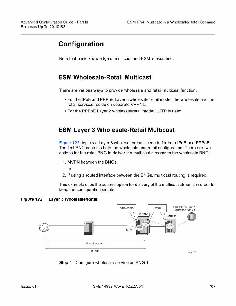
Advanced Configuration Guide - Part III Releases Up To 20.10.R2
ESM IPv4: Multicast in a Wholesale/Retail Scenario
Issue: 01 3HE 14992 AAAE TQZZA 01 707
Configuration
Note that basic knowledge of multicast and ESM is assumed.
ESM Wholesale-Retail Multicast
There are various ways to provide wholesale and retail multicast function.
• For the IPoE and PPPoE Layer 3 wholesale/retail model, the wholesale and the retail services reside on separate VPRNs.
• For the PPPoE Layer 2 wholesale/retail model, L2TP is used.
ESM Layer 3 Wholesale-Retail Multicast
Figure 122 depicts a Layer 3 wholesale/retail scenario for both IPoE and PPPoE. The first BNG contains both the wholesale and retail configuration. There are two options for the retail BNG to deliver the multicast streams to the wholesale BNG:
1. MVPN between the BNGsor
2. If using a routed interface between the BNGs, multicast routing is required.
This example uses the second option for delivery of the multicast streams in order to keep the configuration simple.
Figure 122 Layer 3 Wholesale/Retail
Step 1 - Configure wholesale service on BNG-1
al_0551IGMP
1/1/2:1
Wholesale Retail GROUP 239.255.1.1SRC 192.168.4.2
Host Session
BNG-1 BNG-2
VPRN1
VPRN2 VPRN
2

ESM IPv4: Multicast in a Wholesale/Retail Scenario
708
Advanced Configuration Guide - Part IIIReleases Up To 20.10.R2
3HE 14992 AAAE TQZZA 01 Issue: 01
The configuration for the wholesale service on BNG-1 with the group interface added to IGMP is as follows. This configuration applies to both IPoE and PPPoE.
# on BNG-1configure
servicevprn 1 customer 1 create
description "wholesale"route-distinguisher 65536:1interface "system" create
address 192.0.2.20/32loopback
exitsubscriber-interface "sub-vprn-1-ws" create
unnumbered "system"group-interface "grp-vprn-1-ws" create
arp-populatedhcp
client-applications dhcp pppno shutdown
exitauthentication-policy "auth-radius-1"sap 1/1/2:1 create
sub-sla-mgmtdef-sub-id use-sap-iddef-sub-profile "sub-profile-1"def-sla-profile "sla-profile-1"sub-ident-policy "sub-ident-1"multi-sub-sap 10no shutdown
exitexitpppoe
session-limit 10sap-session-limit 10no shutdown
exitexit
exitigmp
group-interface "grp-vprn-1-ws"no shutdown
exitno shutdown
exitno shutdown
exitexit
exit
Step 2 - Configure retail service on BNG-1

Advanced Configuration Guide - Part III Releases Up To 20.10.R2
ESM IPv4: Multicast in a Wholesale/Retail Scenario
Issue: 01 3HE 14992 AAAE TQZZA 01 709
Also on BNG-1, a separate VPRN is configured for the retail provider. The retail configuration is a little different from the wholesale configuration. The configuration for the retail VPRN with IGMP and PIM enabled is as follows. This configuration is applicable to both IPoE and PPPoE. The multicast streams received in the retail VPRN are forwarded to the wholesale VPRN. Other retail VPRNs can offer multicast streams as well, and the same multicast addresses can be re-used as long as the address is assigned to a different retail VPRN.
# on BNG-1configure
servicevprn 2 customer 2 create
description "retail"route-distinguisher 65536:2interface "system" create
address 172.16.1.1/32loopback
exitinterface "int-BNG-1-BNG-2" create
address 192.168.12.1/30sap 1/1/1 createexit
exitsubscriber-interface "sub-vprn-2-rt" \
fwd-service 1 fwd-subscriber-interface "sub-vprn-1-ws" create
address 10.255.255.254/8dhcp
server 172.16.1.2lease-populate 200client-applications dhcp pppgi-address 10.255.255.254no shutdown
exitexitigmp
group-interface fwd-service 1 "grp-vprn-1-ws"no shutdown
exitno shutdown
exitpim
interface "int-BNG-1-BNG-2"exitno shutdown
exitospf
area 0.0.0.0interface "sub-vprn-2-rt"
interface-type point-to-pointno shutdown
exitinterface "system"
no shutdownexit

ESM IPv4: Multicast in a Wholesale/Retail Scenario
710
Advanced Configuration Guide - Part IIIReleases Up To 20.10.R2
3HE 14992 AAAE TQZZA 01 Issue: 01
interface "int-BNG-1-BNG-2"interface-type point-to-pointno shutdown
exitexitno shutdown
exitno shutdown
exitexit
exit
Step 3 - Configure an IGMP policy
Per host replication is mandatory in a wholesale/retail scenario. A single SAP in a wholesale service might be shared among different retailers. A wholesale host that has requested a multicast group will always have the multicast delivered directly. Other hosts on the SAPs might belong to a different retailer and therefore 1) retailers might not have the same multicast group and sources and 2) their bandwidth should not be impacted by other hosts’ multicast. Per-host replication is configured in the igmp-policy igmp-policy-1. This is mandatory for both IPoE and PPPoE subscribers.
# on BNG-1configure
subscriber-mgmtigmp-policy "igmp-policy-1" create
per-host-replicationexitsla-profile "sla-profile-1" createexitsub-profile "sub-profile-1" create
igmp-policy "igmp-policy-1"exit
exitexit
Step 4 - Configure retail service on BNG-2
The interfaces are added to OSPF and to PIM on the retail BNG that is connected to the multicast source.
# on BNG-2configure
servicevprn 2 customer 2 create
dhcplocal-dhcp-server "dhcp-RETAIL" create
use-gi-addresspool "pool-RETAIL-1" create
subnet 10.0.0.0/8 createoptions
default-router 10.255.255.254exitaddress-range 10.0.0.1 10.0.0.100

Advanced Configuration Guide - Part III Releases Up To 20.10.R2
ESM IPv4: Multicast in a Wholesale/Retail Scenario
Issue: 01 3HE 14992 AAAE TQZZA 01 711
exitexitno shutdown
exitexitroute-distinguisher 65536:2interface "system" create
address 172.16.1.2/32local-dhcp-server "dhcp-RETAIL"loopback
exitinterface "int-BNG-2-BNG-1" create
address 192.168.12.2/30sap 2/1/1 createexit
exitinterface "int-BNG-2-MCAST" create
address 192.168.4.1/30sap 1/1/6 createexit
exitpim
interface "int-BNG-2-BNG-1"exitinterface "int-BNG-2-MCAST"exitno shutdown
exitospf
area 0.0.0.0interface "system"
no shutdownexitinterface "int-BNG-2-BNG-1"
interface-type point-to-pointno shutdown
exitinterface "int-BNG-2-MCAST"
passiveno shutdown
exitexitno shutdown
exitno shutdown
exitexit
exit
With the configuration from all previous steps, the wholesale/retail setup is ready to process IGMP messages. Now an IGMPv3 request is sent to the wholesale SAP. The (S,G) is (192.168.4.2, 239.255.1.1) and the subscriber IP address is 10.0.0.1. The following output shows that the (S,G) is not registered in the wholesale VPRN, but in the retail VPRN.
*A:BNG-1# show router 1 igmp group===============================================================================

ESM IPv4: Multicast in a Wholesale/Retail Scenario
712
Advanced Configuration Guide - Part IIIReleases Up To 20.10.R2
3HE 14992 AAAE TQZZA 01 Issue: 01
IGMP Interface Groups===============================================================================No Matching Entries===============================================================================IGMP Host Groups===============================================================================No Matching Entries===============================================================================IGMP SAP Groups===============================================================================No Matching Entries===============================================================================*A:BNG-1#
*A:BNG-1# show router 2 igmp group===============================================================================IGMP Interface Groups===============================================================================No Matching Entries===============================================================================IGMP Host Groups===============================================================================(192.168.4.2,239.255.1.1)
Fwd List : 10.0.0.1 UpTime: 0d 00:01:41-------------------------------------------------------------------------------Entries : 1===============================================================================IGMP SAP Groups===============================================================================No Matching Entries===============================================================================*A:BNG-1#
The following command shows all subscribers’ (S,G) pairs.
*A:BNG-1# show service active-subscribers igmp detail
===============================================================================Active Subscribers Detail===============================================================================Subscriber IGMP-Policy
HostAddr GrpItf NumGroupsGrpAddr Type Up-Time Mode
SrcAddr Type Blk/Fwd-------------------------------------------------------------------------------sub-video-1 igmp-policy-1
10.0.0.1 grp-vprn-1-ws 1239.255.1.1 Dynamic 0d 00:02:16 Include
192.168.4.2 Dynamic Fwd-------------------------------------------------------------------------------Number of Subscribers : 1===============================================================================*A:BNG-1#

Advanced Configuration Guide - Part III Releases Up To 20.10.R2
ESM IPv4: Multicast in a Wholesale/Retail Scenario
Issue: 01 3HE 14992 AAAE TQZZA 01 713
Only the retail VPRN is responsible for processing the IGMP messages. Therefore to troubleshoot a wholesale/retail setup, debug is only relevant on the retail router instance.
debugrouter "2"
igmpgroup-interface fwd-service "1" "grp-vprn-1-ws"host "10.0.0.1"packet mode egr-ingr-and-dropped
exitexit
exit
1 2017/07/06 13:58:14.57 CEST MINOR: DEBUG #2001 vprn2 IGMP[3]"IGMP[3]: RX-PKT[000 01:09:17.920] IGMP host 10.0.0.1 V3 PDU: 10.0.0.1 -> 224.0.0.22 pduLen 20
Type: V3 REPORT maxrespCode 0x0 checkSum 0x2352Num Group Records: 1
Group Record 0Type: ALW_NEW_SRCS, AuxDataLen 0, Num Sources 1Mcast Addr: 239.255.1.1Source Address List
192.168.4.2"
2 2017/07/06 13:58:14.57 CEST MINOR: DEBUG #2001 vprn2 IGMP[vprn2 inst 3]"IGMP[vprn2 inst 3]: igmpIfGroupAddAdding 239.255.1.1 to IGMP host 10.0.0.1 database"
3 2017/07/06 13:58:14.57 CEST MINOR: DEBUG #2001 vprn2 IGMP[vprn2 inst 3]"IGMP[vprn2 inst 3]: igmpProcessGroupRecProcess group rec ALW_NEW_SRCS received on host 10.0.0.1 for group 239.255.1.1 in mode INCLUDE. Num srcs 1"
4 2017/07/06 13:58:14.57 CEST MINOR: DEBUG #2001 vprn2 IGMP[vprn2 inst 3]"IGMP[vprn2 inst 3]: igmpIfSrcAddAdding i/f source entry for host 10.0.0.1 (192.168.4.2,239.255.1.1) to IGMP fwdList Database, redir if N/A"
The same debug configuration can be used for troubleshooting IGMP leave messages, as follows.
16 2017/07/06 14:01:34.78 CEST MINOR: DEBUG #2001 vprn2 IGMP[3]"IGMP[3]: RX-PKT[000 01:12:38.120] IGMP host 10.0.0.1 V3 PDU: 10.0.0.1 -> 224.0.0.22 pduLen 20
Type: V3 REPORT maxrespCode 0x0 checkSum 0x2252Num Group Records: 1
Group Record 0Type: BLK_OLD_SRCS, AuxDataLen 0, Num Sources 1Mcast Addr: 239.255.1.1Source Address List
192.168.4.2"
17 2017/07/06 14:01:34.78 CEST MINOR: DEBUG #2001 vprn2 IGMP[vprn2 inst 3]
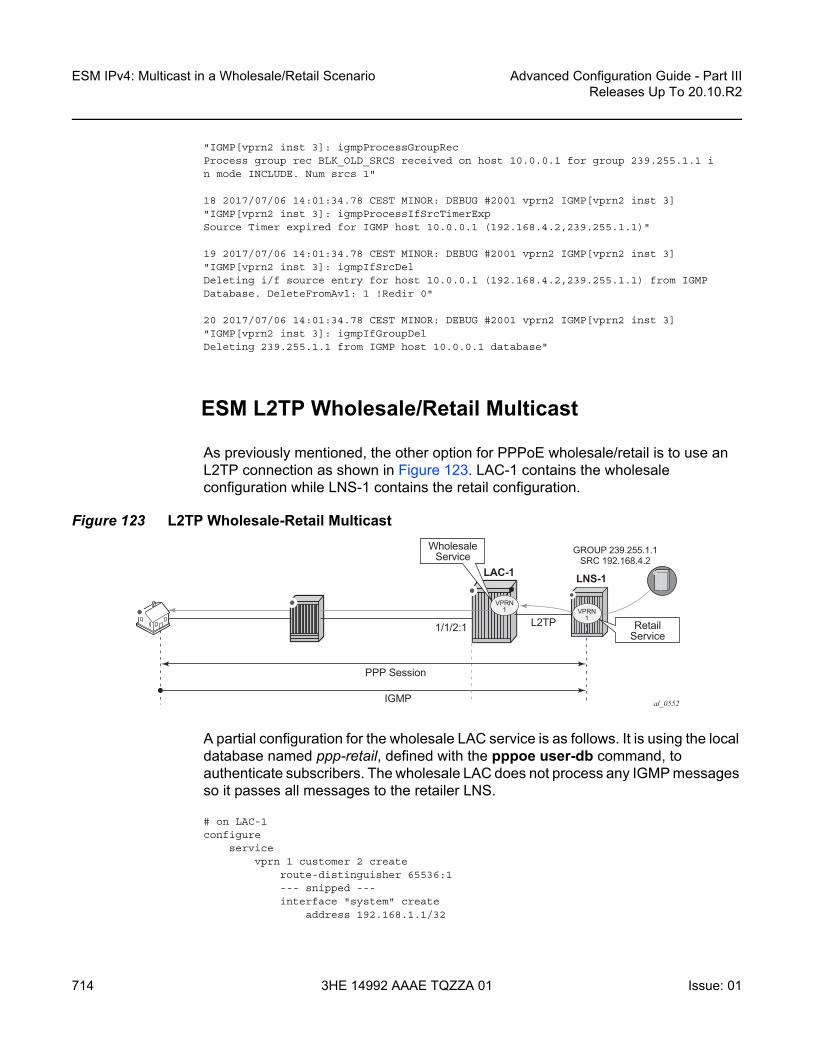
ESM IPv4: Multicast in a Wholesale/Retail Scenario
714
Advanced Configuration Guide - Part IIIReleases Up To 20.10.R2
3HE 14992 AAAE TQZZA 01 Issue: 01
"IGMP[vprn2 inst 3]: igmpProcessGroupRecProcess group rec BLK_OLD_SRCS received on host 10.0.0.1 for group 239.255.1.1 in mode INCLUDE. Num srcs 1"
18 2017/07/06 14:01:34.78 CEST MINOR: DEBUG #2001 vprn2 IGMP[vprn2 inst 3]"IGMP[vprn2 inst 3]: igmpProcessIfSrcTimerExpSource Timer expired for IGMP host 10.0.0.1 (192.168.4.2,239.255.1.1)"
19 2017/07/06 14:01:34.78 CEST MINOR: DEBUG #2001 vprn2 IGMP[vprn2 inst 3]"IGMP[vprn2 inst 3]: igmpIfSrcDelDeleting i/f source entry for host 10.0.0.1 (192.168.4.2,239.255.1.1) from IGMPDatabase. DeleteFromAvl: 1 !Redir 0"
20 2017/07/06 14:01:34.78 CEST MINOR: DEBUG #2001 vprn2 IGMP[vprn2 inst 3]"IGMP[vprn2 inst 3]: igmpIfGroupDelDeleting 239.255.1.1 from IGMP host 10.0.0.1 database"
ESM L2TP Wholesale/Retail Multicast
As previously mentioned, the other option for PPPoE wholesale/retail is to use an L2TP connection as shown in Figure 123. LAC-1 contains the wholesale configuration while LNS-1 contains the retail configuration.
Figure 123 L2TP Wholesale-Retail Multicast
A partial configuration for the wholesale LAC service is as follows. It is using the local database named ppp-retail, defined with the pppoe user-db command, to authenticate subscribers. The wholesale LAC does not process any IGMP messages so it passes all messages to the retailer LNS.
# on LAC-1configure
servicevprn 1 customer 2 create
route-distinguisher 65536:1--- snipped ---interface "system" create
address 192.168.1.1/32
al_0552IGMP
1/1/2:1 L2TP
WholesaleService
RetailService
GROUP 239.255.1.1SRC 192.168.4.2
PPP Session
LAC-1 LNS-1
VPRN1 VPRN
1

Advanced Configuration Guide - Part III Releases Up To 20.10.R2
ESM IPv4: Multicast in a Wholesale/Retail Scenario
Issue: 01 3HE 14992 AAAE TQZZA 01 715
loopbackexitsubscriber-interface "int-SUB-LAC-1" create
unnumbered "system"group-interface "int-GRP-LAC-1" create
sap 1/1/2:1 createsub-sla-mgmt
def-sub-id use-sap-iddef-sub-profile "sub-profile-1"def-sla-profile "sla-profile-1"sub-ident-policy "sub-ident-1"multi-sub-sap 1000no shutdown
exitexitpppoe
session-limit 10sap-session-limit 10user-db "ppp-retail"no shutdown
exitexit
exit--- snipped ---l2tp
group "grp-retail-1" createtunnel "tnl-retail-1" create
local-address 192.168.1.1local-name "lac-1"peer 192.168.1.2no shutdown
exitno shutdown
exitno shutdown
exitno shutdown
exitexit
exit
The local user database ppp-retail is defined as follows:
# on LAC-1configure
subscriber-mgmtlocal-user-db "ppp-retail" create
pppmatch-list usernamehost "retail1.com" create
host-identificationusername "retail1.com" domain-only
exitidentification-strings 254 create
sla-profile-string "sla-profile-1"sub-profile-string "sub-profile-1"
exitl2tp

ESM IPv4: Multicast in a Wholesale/Retail Scenario
716
Advanced Configuration Guide - Part IIIReleases Up To 20.10.R2
3HE 14992 AAAE TQZZA 01 Issue: 01
group "grp-LAC-RETAIL-1" service-id 1exitno shutdown
exitexitno shutdown
exitexit
exit
The retailer BNG hosts the L2TP Network Server (LNS). The following is a configuration extract for the LNS. To support multicast, IGMP is enabled on the ESM group-interface in the retail service, and PIM is enabled on the interface to the multicast source.
# on LNS-1configure
servicevprn 1 customer 2 create
route-distinguisher 65536:1--- snipped ---interface "system" create
address 192.168.1.2/32loopback
exitinterface "int-VPRN-1-MCAST" create
address 192.168.4.1/30sap 1/1/6 createexit
exitsubscriber-interface "int-SUB-LNS-1" create
address 10.1.1.254/24group-interface "int-GRP-LNS-1" lns create
sap-parameterssub-sla-mgmt
def-sla-profile "sla-profile-1"def-sub-profile "sub-profile-1"sub-ident-policy "sub-ident-1"
exitexit
exitexitigmp
group-interface "int-GRP-LNS-1"no shutdown
exitno shutdown
exitl2tp
group "lns" protocol v2 createlns-group 1ppp
default-group-interface "int-GRP-LNS-1" service-id 1keepalive 90 hold-up-multiplier 5proxy-authenticationproxy-lcpuser-db "ppp-retail"

Advanced Configuration Guide - Part III Releases Up To 20.10.R2
ESM IPv4: Multicast in a Wholesale/Retail Scenario
Issue: 01 3HE 14992 AAAE TQZZA 01 717
exittunnel "tunnel" create
remote-name "lac-1"no shutdown
exitno shutdown
exitno shutdown
exitpim
interface "int-VPRN-1-MCAST"exitno shutdown
exitno shutdown
exitexit
exit
With the previous configuration applied, the wholesale/retail multicast setup can be verified. Firstly, send an IGMP message from the subscriber; the following example uses IGMPv3. The (S,G) sent is (192.168.4.2, 239.255.1.1) from the subscriber with IP address 10.1.1.1.
*A:LNS-1# show service active-subscribers igmp detail
===============================================================================Active Subscribers Detail===============================================================================Subscriber IGMP-Policy
HostAddr GrpItf NumGroupsGrpAddr Type Up-Time Mode
SrcAddr Type Blk/Fwd-------------------------------------------------------------------------------user1@retail1.com igmp-policy-1
10.1.1.1 int-GRP-1 1239.255.1.1 Dynamic 0d 00:01:34 Include
192.168.4.2 Dynamic Fwd-------------------------------------------------------------------------------Number of Subscribers : 1===============================================================================*A:LNS-1#
The IGMP group is not seen in the wholesale router instance (as shown by the following output on LAC-1), however, it is seen in the retail router instance (as shown by the second output below on LNS-1).
*A:LAC-1# show router 1 igmp group===============================================================================IGMP Interface Groups===============================================================================No Matching Entries===============================================================================IGMP Host Groups===============================================================================No Matching Entries

ESM IPv4: Multicast in a Wholesale/Retail Scenario
718
Advanced Configuration Guide - Part IIIReleases Up To 20.10.R2
3HE 14992 AAAE TQZZA 01 Issue: 01
===============================================================================IGMP SAP Groups===============================================================================No Matching Entries===============================================================================*A:LAC-1#
*A:LNS-1# show router 1 igmp group===============================================================================IGMP Interface Groups===============================================================================No Matching Entries===============================================================================IGMP Host Groups===============================================================================(192.168.4.2,239.255.1.1)
Fwd List : 10.1.1.1 UpTime: 0d 00:02:58-------------------------------------------------------------------------------Entries : 1===============================================================================IGMP SAP Groups===============================================================================No Matching Entries===============================================================================*A:LNS-1#
Only the retail BNG (LNS-1) is responsible for processing the IGMP messages. Therefore, to troubleshoot ESM multicast for an L2TP service, the following debug commands are used on the LNS.
debugrouter "1"
igmpgroup-interface "int-GRP-1"host "10.1.1.1"packet mode egr-ingr-and-dropped
exitexit
exit
56 2017/07/05 15:21:09.51 CEST MINOR: DEBUG #2001 vprn1 IGMP[2]"IGMP[2]: RX-PKT[000 00:26:16.790] IGMP host 10.1.1.1 V3 PDU: 10.1.1.1 -> 224.0.0.22 pduLen 20
Type: V3 REPORT maxrespCode 0x0 checkSum 0x2352Num Group Records: 1
Group Record 0Type: ALW_NEW_SRCS, AuxDataLen 0, Num Sources 1Mcast Addr: 239.255.1.1Source Address List
192.168.4.2"
57 2017/07/05 15:21:09.51 CEST MINOR: DEBUG #2001 vprn1 IGMP[vprn1 inst 2]"IGMP[vprn1 inst 2]: igmpIfGroupAddAdding 239.255.1.1 to IGMP host 10.1.1.1 database"
58 2017/07/05 15:21:09.51 CEST MINOR: DEBUG #2001 vprn1 IGMP[vprn1 inst 2]

Advanced Configuration Guide - Part III Releases Up To 20.10.R2
ESM IPv4: Multicast in a Wholesale/Retail Scenario
Issue: 01 3HE 14992 AAAE TQZZA 01 719
"IGMP[vprn1 inst 2]: igmpProcessGroupRecProcess group rec ALW_NEW_SRCS received on host 10.1.1.1 for group 239.255.1.1 in mode INCLUDE. Num srcs 1"
59 2017/07/05 15:21:09.51 CEST MINOR: DEBUG #2001 vprn1 IGMP[vprn1 inst 2]"IGMP[vprn1 inst 2]: igmpIfSrcAddAdding i/f source entry for host 10.1.1.1 (192.168.4.2,239.255.1.1) to IGMP fwdList Database, redir if N/A"
The IGMP leave messages can also be seen in the debug, as follows.
1 2017/07/05 16:41:03.05 CEST MINOR: DEBUG #2001 vprn1 IGMP[2]"IGMP[2]: RX-PKT[000 00:24:30.330] IGMP host 10.1.1.1 V3 PDU: 10.1.1.1 -> 224.0.0.22 pduLen 20
Type: V3 REPORT maxrespCode 0x0 checkSum 0x2252Num Group Records: 1
Group Record 0Type: BLK_OLD_SRCS, AuxDataLen 0, Num Sources 1Mcast Addr: 239.255.1.1Source Address List
192.168.4.2"
2 2017/07/05 16:41:03.06 CEST MINOR: DEBUG #2001 vprn1 IGMP[vprn1 inst 2]"IGMP[vprn1 inst 2]: igmpProcessGroupRecProcess group rec BLK_OLD_SRCS received on host 10.1.1.1 for group 239.255.1.1 in mode INCLUDE. Num srcs 1"
3 2017/07/05 16:41:03.06 CEST MINOR: DEBUG #2001 vprn1 IGMP[vprn1 inst 2]"IGMP[vprn1 inst 2]: igmpProcessIfSrcTimerExpSource Timer expired for IGMP host 10.1.1.1 (192.168.4.2,239.255.1.1)"
4 2017/07/05 16:41:03.06 CEST MINOR: DEBUG #2001 vprn1 IGMP[vprn1 inst 2]"IGMP[vprn1 inst 2]: igmpIfSrcDelDeleting i/f source entry for host 10.1.1.1 (192.168.4.2,239.255.1.1) from IGMPDatabase. DeleteFromAvl: 1 !Redir 0"
Conclusion
Multicast is an essential part of Triple Play Services. The SR/ESS TPSDA solution is much more than a baseline multicast delivery. It includes individual subscriber awareness and provides each retailer a separate routing context for managing their own multicast content. Subscriber awareness allows for the fine-tuning of each subscriber multicast experience and also for troubleshooting on a per subscriber basis. This example provides a complete configuration walkthrough for multicast delivery for both IPoE and PPPoE in a wholesale/retail model.

ESM IPv4: Multicast in a Wholesale/Retail Scenario
720
Advanced Configuration Guide - Part IIIReleases Up To 20.10.R2
3HE 14992 AAAE TQZZA 01 Issue: 01
Advanced Configuration Guide - Part III Releases Up To 20.10.R2
ESM IPv4: Multicast with Redirection
Issue: 01 3HE 14992 AAAE TQZZA 01 721
ESM IPv4: Multicast with RedirectionThis chapter describes ESM IPv4 multicast with redirection configurations.
Topics in this chapter include:
• Applicability• Overview• Configuration• Conclusion
Applicability
The configuration in this chapter was initially based on SR OS release 11.0.R1 and covers both IPoE and PPPoE subscribers. The CLI is updated to release 15.0.R3.
Overview
Triple Play Service Delivery Architecture (TPSDA) allows operators to integrate High Speed Internet (HSI), voice, and video services within a single network. The goal of this chapter is to walk through a TPSDA multicast architecture with redirection. The topics are divided into the following sections:
• Single BNG with redirection• SRRP BNG configuration with Multi Chassis Link Aggregation (MC-LAG) and
redirection• IPoE ESM multicast walkthrough• PPPoE ESM multicast walkthrough• Subscriber Routed Redundancy Protocol (SRRP)
- Multi-Chassis Synchronization (MCS) walkthrough• IGMP Debugging

ESM IPv4: Multicast with Redirection
722
Advanced Configuration Guide - Part IIIReleases Up To 20.10.R2
3HE 14992 AAAE TQZZA 01 Issue: 01
In ESM IPv4: Multicast with SRRP, multicast is directly distributed to a subscriber through a subscriber SAP. This chapter walks through another popular model which redirects all multicast streams to a common routed interface for all subscribers. When multicast is put on the common routed interface, one single copy of a multicast stream is delivered to multiple subscribers. In this model, per-subscriber replication of multicast streams is done on an access node or on the aggregation network in order to minimize the bandwidth consumed by the multicast traffic in access/aggregation.
Figure 124 shows two BNGs configured with SRRP to provide redundancy. The P router is connected to the multicast source and is connected to both BNGs. The connections between the BNGs and the P router, and the multicast source and the P router, are running PIM to provide multicast delivery. On the access side, the two BNGs are connected to an aggregation switch via MC-LAG aggregating the traffic for both PPPoE and IPoE subscribers. The BNGs facing the subscriber side are IGMP aware and will respond to any subscribers’ IGMP requests.
Figure 124 Network Topology Overview
There are two requirements for a subscriber to receive multicast streams. First, the ESM group-interface must have IGMP enabled. Second, each subscriber’s subscriber profile must be customized to allow them to receive multicast streams. When both requirements are met, the BNG will process the subscribers’ IGMP messages, otherwise, IGMP messages are dropped. All customer premise equipment (CPE) IGMP messages are aggregated via the 7450 and passed onto the
AGG-1 P-1 Multicast Source
BNG-1
BNG-2
7750 SR 7750 SR
al_0270
7750 SR
7450MC-LAG
with SRRP
IPoE/PPPoE Session
Subscribers
IES
IES

Advanced Configuration Guide - Part III Releases Up To 20.10.R2
ESM IPv4: Multicast with Redirection
Issue: 01 3HE 14992 AAAE TQZZA 01 723
BNGs. Because the BNGs are running SRRP, the SRRP master is the only BNG processing and answering the IGMP messages. Protocol Independent Multicast (PIM) is used between the BNG and the P router to request the multicast streams. If PIM is successful in retrieving the multicast group, the multicast stream is forwarded toward the individual subscribers. This is the typical multicast delivery for TPSDA.
Configuration
This example builds on the ESM multicast foundation described in chapter ESM IPv4: Multicast with SRRP. It starts with a single BNG setup with redirection.
ESM Multicast Interface Redirection
Figure 125 shows a popular ESM multicast model that redirects all multicast streams to a dedicated router interface. When configuring a redirected interface be aware that:
1. Redirection between Global Routing Table (GRT) interfaces and VPRN interfaces is not supported
2. GRT interfaces are interfaces that reside in the base router or in an IES.3. Redirection can be performed between interfaces in the GRT or between the
interfaces in any VPRN (even different VPRNs).
The following scenario start with a simple ESM multicast configuration for BNG, without redirection.
Figure 125 Single BNG Setup with Multicast Redirection
al_0271
Host Session
1/1/4:1
Group 239.255.1.1
192.168.4.2
IGMP
1/1/2:1
IES1
RedirectInterface
SRC

ESM IPv4: Multicast with Redirection
724
Advanced Configuration Guide - Part IIIReleases Up To 20.10.R2
3HE 14992 AAAE TQZZA 01 Issue: 01
The BNG-1 baseline configuration excluding multicast redirection is as follows. The local DHCP server is hosted on BNG-1, and is bound to interface int-DHCP-lb1.
configurerouter Base
dhcplocal-dhcp-server "dhcp-local-server" create
use-gi-address scope poolpool "pool-1" create
subnet 10.0.0.0/8 createoptions
subnet-mask 255.0.0.0default-router 10.255.255.254
exitaddress-range 10.0.0.10 10.0.0.254
exitexitno shutdown
exitexitinterface "int-DHCP-lb1"
address 192.168.0.1/32loopbacklocal-dhcp-server "dhcp-local-server"no shutdown
exitinterface "system"
address 192.0.2.1/32no shutdown
exitexit
exit
Subscribers are located in the 10.0.0.0/8 subnet. The multicast stream (S,G) is (192.168.4.2, 239.255.1.1).
configureservice
ies 1 customer 1 createdescription "BNG-1"interface "int-BNG-1-MCAST-S1" create
address 192.168.4.1/30sap 1/1/5 createexit
exitsubscriber-interface "sub-int-1" create
address 10.255.255.254/8group-interface "grp-int-1" create
srrp-enabled-routingdhcp
server 192.168.0.1trustedlease-populate 10client-applications dhcp pppgi-address 10.255.255.254no shutdown
exit

Advanced Configuration Guide - Part III Releases Up To 20.10.R2
ESM IPv4: Multicast with Redirection
Issue: 01 3HE 14992 AAAE TQZZA 01 725
authentication-policy "auth-1"sap 1/1/4:1 create
sub-sla-mgmtdef-sub-profile "sub-profile-1"def-sla-profile "sla-profile-1"sub-ident-policy "sub-ident-1"multi-sub-sap 10no shutdown
exitexitpppoe
no shutdownexit
exitexitno shutdown
exitexit
exit
To support multicast, group-interface grp-int-1 is IGMP enabled, and interface int-BNG-1-MCAST-S1 is PIM enabled.
configurerouter Base
igmpgroup-interface "grp-int-1"
no shutdownexitno shutdown
exitpim
interface "int-BNG-1-MCAST-S1"exitno shutdown
exitexit
exit
The subscriber management profiles enabling multicast for ESM subsribers are defined as follows:
configuresubscriber-mgmt
igmp-policy "igmp-policy-1" createexitsub-profile "sub-profile-1" create
igmp-policy "igmp-policy-1"exit
exitexit
A router interface is defined to redirect all multicast streams to, and added to the igmp context, as follows.
configure

ESM IPv4: Multicast with Redirection
726
Advanced Configuration Guide - Part IIIReleases Up To 20.10.R2
3HE 14992 AAAE TQZZA 01 Issue: 01
serviceies 1
interface "int-REDIRECT" createaddress 192.168.10.1/30sap 1/1/2:1 createexit
exitexit
exitexit
configurerouter
igmpinterface "int-REDIRECT"
no shutdownexitno shutdown
exitexit
exit
A router redirection policy is defined, redirecting every (S,G) toward the redirected interface, as follows:
configurerouter
policy-optionsbeginpolicy-statement "mcast-REDIR-IF"
default-action acceptmulticast-redirection fwd-service 1 "int-REDIRECT"
exitexitcommit
exitexit
exit
The redirection policy then is applied to the igmp policy, which in turn is applied to the subscriber profile, as follows:
configuresubscriber-mgmt
igmp-policy "igmp-policy-1"redirection-policy "mcast-REDIR-IF"
exitsub-profile "sub-profile-1" create
igmp-policy "igmp-policy-1"exit
exitexit
From this point on all multicast streams will be redirected to the int-REDIRECT interface.

Advanced Configuration Guide - Part III Releases Up To 20.10.R2
ESM IPv4: Multicast with Redirection
Issue: 01 3HE 14992 AAAE TQZZA 01 727
Now send an IGMPv3 join message and then use the show router igmp group command to verify that all multicast streams are redirected. In this example, IGMPv3 is used with an (S,G) of (192.168.4.2, 239.255.1.1).
For PPPoE subscribers, the multicast (S,G) shows up on both the redirected interface and the host, as follows:
*A:BNG-1# show router igmp group===============================================================================IGMP Interface Groups===============================================================================
(192.168.4.2,239.255.1.1) UpTime: 0d 00:00:30Fwd List : int-REDIRECT
-------------------------------------------------------------------------------Entries : 1===============================================================================IGMP Host Groups===============================================================================(192.168.4.2,239.255.1.1)
Fwd List : 10.0.0.10 UpTime: 0d 00:00:30-------------------------------------------------------------------------------Entries : 1===============================================================================IGMP SAP Groups===============================================================================No Matching Entries===============================================================================*A:BNG-1#
For IPoE subscribers, the multicast (S,G) shows up on both the redirected interface and the SAP.
*A:BNG-1# show router igmp group===============================================================================IGMP Interface Groups===============================================================================
(192.168.4.2,239.255.1.1) UpTime: 0d 00:01:40Fwd List : int-REDIRECT
-------------------------------------------------------------------------------Entries : 1===============================================================================IGMP Host Groups===============================================================================(192.168.4.2,239.255.1.1)
Fwd List : 10.0.0.12 UpTime: 0d 00:01:40-------------------------------------------------------------------------------Entries : 1===============================================================================IGMP SAP Groups===============================================================================No Matching Entries===============================================================================*A:BNG-1#

ESM IPv4: Multicast with Redirection
728
Advanced Configuration Guide - Part IIIReleases Up To 20.10.R2
3HE 14992 AAAE TQZZA 01 Issue: 01
Now the int-REDIRECT interface is the only interface sending out multicast streams. The first command shows that the group interface does not register any multicast group (Num-Groups=0). The second command shows that all multicast groups are registered against the redirected interface (Num-Groups=1).
*A:BNG-1# show router igmp group-interface
===============================================================================IGMP Group-Interfaces===============================================================================FwdSvc Group-Interface Adm/Opr-State Import-Policy
SAP Adm/Opr-Version Num-Groups-------------------------------------------------------------------------------1 grp-int-1 Up/Up none
1/1/4:1 3/3 0-------------------------------------------------------------------------------Group-Interfaces = 1, SAPs = 1===============================================================================*A:BNG-1#
*A:BNG-1# show router igmp interface
===============================================================================IGMP Interfaces===============================================================================Interface Adm Oper Querier Cfg/Opr Num Policy
Version Groups-------------------------------------------------------------------------------int-REDIRECT Up Up 192.168.10.1 3/3 1 none-------------------------------------------------------------------------------Interfaces : 1===============================================================================*A:BNG-1#
Debug facilities can be used to troubleshoot multicast redirection issues. The following output shows the multicast stream is redirected to a regular routed interface after an IGMP join.
74 2017/06/29 09:52:21.07 CEST MINOR: DEBUG #2001 Base IGMP[1]"IGMP[1]: RX-PKT[000 19:43:29.700] IGMP host 10.0.0.12 V3 PDU: 10.0.0.12 -> 224.0.0.22 pduLen 20
Type: V3 REPORT maxrespCode 0x0 checkSum 0x2352Num Group Records: 1
Group Record 0Type: ALW_NEW_SRCS, AuxDataLen 0, Num Sources 1Mcast Addr: 239.255.1.1Source Address List
192.168.4.2"
75 2017/06/29 09:52:21.07 CEST MINOR: DEBUG #2001 Base IGMP[Base inst 1]"IGMP[Base inst 1]: igmpIfGroupAddAdding 239.255.1.1 to IGMP host 10.0.0.12 database"
76 2017/06/29 09:52:21.07 CEST MINOR: DEBUG #2001 Base IGMP[Base inst 1]"IGMP[Base inst 1]: igmpProcessGroupRec

Advanced Configuration Guide - Part III Releases Up To 20.10.R2
ESM IPv4: Multicast with Redirection
Issue: 01 3HE 14992 AAAE TQZZA 01 729
Process group rec ALW_NEW_SRCS received on host 10.0.0.12 for group 239.255.1.1in mode INCLUDE. Num srcs 1"
77 2017/06/29 09:52:21.07 CEST MINOR: DEBUG #2001 Base IGMP[Base inst 1]"IGMP[Base inst 1]: igmpIfSrcAddAdding i/f source entry for host 10.0.0.12 (192.168.4.2,239.255.1.1) to IGMP fwdList Database, redir if interface int-REDIRECT [ifIndex 6]"
The following output shows what happens when an IGMP leave message is sent so that the multicast stream is no longer being forwarded.
170 2017/06/29 10:05:22.07 CEST MINOR: DEBUG #2001 Base IGMP[1]"IGMP[1]: RX-PKT[000 19:56:30.700] IGMP host 10.0.0.12 V3 PDU: 10.0.0.12 -> 224.0.0.22 pduLen 20
Type: V3 REPORT maxrespCode 0x0 checkSum 0x2252Num Group Records: 1
Group Record 0Type: BLK_OLD_SRCS, AuxDataLen 0, Num Sources 1Mcast Addr: 239.255.1.1Source Address List
192.168.4.2"
171 2017/06/29 10:05:22.07 CEST MINOR: DEBUG #2001 Base IGMP[Base inst 1]"IGMP[Base inst 1]: igmpProcessGroupRecProcess group rec BLK_OLD_SRCS received on host 10.0.0.12 for group 239.255.1.1in mode INCLUDE. Num srcs 1"
172 2017/06/29 10:05:22.07 CEST MINOR: DEBUG #2001 Base IGMP[Base inst 1]"IGMP[Base inst 1]: igmpProcessIfSrcTimerExpSource Timer expired for IGMP host 10.0.0.12 (192.168.4.2,239.255.1.1)"
173 2017/06/29 10:05:22.07 CEST MINOR: DEBUG #2001 Base IGMP[Base inst 1]"IGMP[Base inst 1]: igmpIfSrcDelDeleting i/f source entry for host 10.0.0.12 (192.168.4.2,239.255.1.1) from IGMPDatabase. DeleteFromAvl: 1 Redir 0"
174 2017/06/29 10:05:22.07 CEST MINOR: DEBUG #2001 Base IGMP[Base inst 1]"IGMP[Base inst 1]: igmpIfGroupDelDeleting 239.255.1.1 from IGMP host 10.0.0.12 database"

ESM IPv4: Multicast with Redirection
730
Advanced Configuration Guide - Part IIIReleases Up To 20.10.R2
3HE 14992 AAAE TQZZA 01 Issue: 01
ESM Multicast Redirection with SRRP and MC-LAG
Figure 126 shows a numbered SRRP setup with MC-LAG SAPs serving both IPoE and PPPoE subscribers. ESM IPv4: Multicast with SRRP covers the configuration of regular SRRP SAPs, consequently this example provides configuration guidelines to use a different type of SAP: SRRP MC-LAG SAPs. Note that redirection on SRRP SAPs without MC-LAG is also supported. The configuration of the RADIUS server is out of the scope of this example.
Figure 126 Network Topology with MC-LAG
The baseline configuration for BNG-1 excluding the IGMP configuration is as follows. The configuration begins with the MC-LAG configuration. ESM is configured in an IES service, but it is also possible to configure ESM in a VPRN. The redirection interface must be in the same routing instance as the group-interface, this applies to both regular SRRP SAPs and MC-LAG SAPs. In the following example, the MC-LAG is lag-1, customer data traffic is using VLAN 4, MC-LAG control traffic is using VLAN 5, and the redirected multicast streams are using VLAN 4094.
# Baseline for BNG-1configure
lag 1mode accessencap-type dot1qport 1/1/4 priority 1lacp active administrative-key 32768
AGG-1 P-1
RADIUS
BNG-1
BNG-2
MC-LAG
LAG2/1/2
1/1/2
1/1/21/1/1
1/1/4
1/1/1
SRRP10.255.255.254 10.255.255.252
192.168.3.1/30
192.168.23.1
192.168.23.2
10.255.255.253
2/1/2
1/1/21/1/6 IES
dhcp-local-server10.1.1.1
IES
On BNG 1 and 2, port 1/1/5 and 1/1/1• VLAN 4 is for data path• VLAN 4094 is the redirected interface• Redirect interface uses 192.168.10.0/24

Advanced Configuration Guide - Part III Releases Up To 20.10.R2
ESM IPv4: Multicast with Redirection
Issue: 01 3HE 14992 AAAE TQZZA 01 731
no shutdownexit
exit
configureredundancy
multi-chassispeer 192.0.2.3 create
mc-laglag 1 lacp-key 1 system-id 00:00:00:00:00:01 system-
priority 100no shutdown
exitsync
igmpsrrpsub-mgmt ipoe pppoeport lag-1 create
range 4-4 sync-tag "mclagdata"range 5-5 sync-tag "mclagcontrol"
exitno shutdown
exitno shutdown
exitexit
exitexit
configureservice
ies 1 customer 1 createdescription "BNG-1"redundant-interface "mclink-BNG-1-BNG-2" create
address 192.168.11.0/31ip-mtu 1500spoke-sdp 23:1 create
no shutdownexit
exitinterface "int-LAG-REDIRECTED" create
address 192.168.10.252/24vrrp 1
backup 192.168.10.254exitsap lag-1:4094 createexit
exitsubscriber-interface "sub-int-1" create
address 10.255.255.252/8 gw-ip-address 10.255.255.254 track-srrp 1group-interface "grp-int-1" create
srrp-enabled-routingdhcp
server 192.168.0.1lease-populate 10client-applications dhcp pppgi-address 10.255.255.252no shutdown

ESM IPv4: Multicast with Redirection
732
Advanced Configuration Guide - Part IIIReleases Up To 20.10.R2
3HE 14992 AAAE TQZZA 01 Issue: 01
exitauthentication-policy "auth-1"redundant-interface "mclink-BNG-1-BNG-2"sap lag-1:4 create
sub-sla-mgmtdef-sub-id use-sap-iddef-sub-profile "sub-profile-1"def-sla-profile "sla-profile-1"sub-ident-policy "sub-ident-1"multi-sub-sap 10no shutdown
exitexitsap lag-1:5 createexitsrrp 1 create
message-path lag-1:5priority 200no preemptno shutdown
exitpppoe
no shutdownexit
exitexitno shutdown
exitexit
exit
configurerouter Base
interface "int-BNG-1-BNG-2"address 192.168.23.1/30port 1/1/3:4040no shutdown
exitinterface "int-BNG-1-P-1"
address 192.168.24.1/30port 1/1/2:4040no shutdown
exitinterface "system"
address 192.0.2.2/32bfd 100 receive 100 multiplier 3no shutdown
exitospf 0
traffic-engineeringarea 0.0.0.0
interface "system"no shutdown
exitinterface "int-BNG-1-BNG-2"
interface-type point-to-pointmetric 10000no shutdown
exit

Advanced Configuration Guide - Part III Releases Up To 20.10.R2
ESM IPv4: Multicast with Redirection
Issue: 01 3HE 14992 AAAE TQZZA 01 733
interface "int-BNG-1-P-1"interface-type point-to-pointno shutdown
exitinterface "sub-int-1"
no shutdownexitinterface "int-LAG-REDIRECTED"
no shutdownexit
exitno shutdown
exitpim
interface "int-BNG-1-P-1"exit
exitexit
exit
The baseline configuration for BNG-2 excluding the IGMP configuration is as follows. The default SRRP priority for BNG-2 is lower than the SRRP priority for BNG-1 and therefore BNG-2 will be in standby mode.
# Baseline for BNG-2configure
lag 1mode accessencap-type dot1qport 1/1/1 priority 1lacp active administrative-key 32768no shutdown
exitexit
configureredundancy
multi-chassispeer 192.0.2.2 create
mc-laglag 1 lacp-key 1 system-id 00:00:00:00:00:01 system-
priority 100no shutdown
exitsync
igmpsrrpsub-mgmt ipoe pppoeport lag-1 create
range 4-4 sync-tag "mclagdata"range 5-5 sync-tag "mclagcontrol"
exitno shutdown
exitno shutdown
exitexit

ESM IPv4: Multicast with Redirection
734
Advanced Configuration Guide - Part IIIReleases Up To 20.10.R2
3HE 14992 AAAE TQZZA 01 Issue: 01
exitexit
configureservice
ies 1 customer 1 createdescription "BNG-2, SRRP1"redundant-interface "mclink-BNG-2-BNG-1" create
address 192.168.11.1/31ip-mtu 1500spoke-sdp 32:1 create
no shutdownexit
exitinterface "int-LAG-REDIRECTED" create
address 192.168.10.253/24vrrp 2
backup 192.168.10.254exitsap lag-1:4094 createexit
exitsubscriber-interface "sub-int-1" create
address 10.255.255.253/8 gw-ip-address 10.255.255.254 track-srrp 1group-interface "grp-int-1" create
srrp-enabled-routingdhcp
server 192.168.0.1lease-populate 10client-applications dhcp pppgi-address 10.255.255.253no shutdown
exitauthentication-policy "auth-1"redundant-interface "mclink-BNG-2-BNG-1"sap lag-1:4 create
sub-sla-mgmtdef-sub-id use-sap-iddef-sub-profile "sub-profile-1"def-sla-profile "sla-profile-1"sub-ident-policy "sub-ident-1"multi-sub-sap 10no shutdown
exitexitsap lag-1:5 createexitsrrp 1 create
message-path lag-1:5priority 150no shutdown
exitpppoe
no shutdownexit
exitexitno shutdown
exit

Advanced Configuration Guide - Part III Releases Up To 20.10.R2
ESM IPv4: Multicast with Redirection
Issue: 01 3HE 14992 AAAE TQZZA 01 735
exitexit
configurerouter Base
interface "int-BNG-2-BNG-1"address 192.168.23.2/30port 1/1/3:4040no shutdown
exitinterface "int-BNG-2-P-1"
address 192.168.34.1/30port 1/1/2:4040no shutdown
exitinterface "system"
address 192.0.2.3/32bfd 100 receive 100 multiplier 3no shutdown
exitospf 0
traffic-engineeringarea 0.0.0.0
interface "system"no shutdown
exitinterface "int-BNG-2-BNG-1"
interface-type point-to-pointmetric 10000no shutdown
exitinterface "int-BNG-2-P-1"
interface-type point-to-pointno shutdown
exitinterface "sub-int-1"
no shutdownexitinterface "int-LAG-REDIRECTED"
no shutdownexit
exitno shutdown
exitigmp
no shutdownexitpim
interface "int-BNG-2-P-1"exitno shutdown
exitexit
exit

ESM IPv4: Multicast with Redirection
736
Advanced Configuration Guide - Part IIIReleases Up To 20.10.R2
3HE 14992 AAAE TQZZA 01 Issue: 01
The baseline configuration for the 7450 aggregation switch is as follows. It has a LAG interface configured. There are two VPLSs. The first is VPLS 1 which is used to receive all redirected multicast traffic on VLAN 4094. The second is VPLS 2 which is responsible for passing all subscriber traffic on VLAN 4.
# Baseline for AGG-1configure
lag 1mode accessencap-type dot1qport 2/1/1port 2/1/2lacp active administrative-key 32768no shutdown
exitexit
configureservice
vpls 4 customer 1 createdescription "for user traffic"stp
shutdownexitsap 1/1/6:4 create
description "to spirent"no shutdown
exitsap lag-1:4 create
no shutdownexitno shutdown
exitexit
exit
configureservice
vpls 4094 customer 1 createdescription "for the multicast streams"stp
shutdownexitsap lag-1:4094 create
no shutdownexitsap 1/1/5:4094 create
no shutdownexitno shutdown
exitexit
exit

Advanced Configuration Guide - Part III Releases Up To 20.10.R2
ESM IPv4: Multicast with Redirection
Issue: 01 3HE 14992 AAAE TQZZA 01 737
The baseline configuration for the P router is as follows. It is now responsible for DHCP address assignment (moved from BNG-1 in the previous configuration to allow for redundant operations in case of failure of either BNG-1 or BNG-2) and is also attached to the multicast source.
# Baseline for P-1configure
routerdhcp
local-dhcp-server "dhcp-local-server" createuse-gi-address scope poolpool "pool-1" create
subnet 10.0.0.0/8 createoptions
subnet-mask 255.0.0.0default-router 10.255.255.254
exitaddress-range 10.0.0.10 10.0.0.254
exitexitno shutdown
exitexitinterface "int-DHCP-lb1"
address 192.168.0.1/32loopbacklocal-dhcp-server "dhcp-local-server"no shutdown
exitinterface "int-P-1-BNG-1"
address 192.168.24.2/30port 1/1/1:4040no shutdown
exitinterface "int-P-1-BNG-2"
address 192.168.34.2/30port 1/1/2:4040no shutdown
exitinterface "int-P-1-mcast-source"
address 192.168.4.1/30port 1/1/5:4092no shutdown
exitinterface "system"
address 192.0.2.4/32no shutdown
exitospf 0
traffic-engineeringarea 0.0.0.0
interface "system"no shutdown
exitinterface "int-DHCP-lb1"
no shutdownexitinterface "int-P-1-BNG-1"

ESM IPv4: Multicast with Redirection
738
Advanced Configuration Guide - Part IIIReleases Up To 20.10.R2
3HE 14992 AAAE TQZZA 01 Issue: 01
interface-type point-to-pointno shutdown
exitinterface "int-P-1-BNG-2"
interface-type point-to-pointno shutdown
exitinterface "int-P-1-mcast-source"
passiveno shutdown
exitexitno shutdown
exitpim
interface "int-P-1-BNG-1"exitinterface "int-P-1-BNG-2"exitinterface "int-P-1-mcast-source"exit--- snipped ---no shutdown
exitexit
exit
Enable IGMP on Group Interface and Redirect Interface
The following configuration shows how to add the group-interface and redirect interface to IGMP. If ESM is configured in a VPRN, each VPRN will have its own IGMP instance. Remember to apply the following configuration to both BNG-1 and BNG-2.
# on BNG-1 and BNG-2configure
routerigmp
group-interface "grp-int-1"no shutdown
exitinterface "int-LAG-REDIRECTED"
no shutdownexitno shutdown
exitexit
exit
Next, the IGMP policy is configured to redirect all multicast streams to a dedicated interface. The following configuration outlines the steps necessary to enable multicast redirection.

Advanced Configuration Guide - Part III Releases Up To 20.10.R2
ESM IPv4: Multicast with Redirection
Issue: 01 3HE 14992 AAAE TQZZA 01 739
Define a router redirection policy. This will redirect every (S,G) toward the redirected interface.
configurerouter
policy-optionsbeginpolicy-statement "mcast-REDIR-IF"
default-action acceptmulticast-redirection fwd-service 1 "int-LAG-REDIRECTED"
exitexitcommit
exitexit
exit
Apply the redirection policy to the IGMP policy, as follows:
configuresubscriber-mgmt
igmp-policy "igmp-policy-1" createredirection-policy "mcast-REDIR-IF""
exitexit
exit
Add multi-chassis synchronization for the redirected interface on BNG-1. This will synchronize the IGMP state on this MC-LAG interface. A similar configuration is required on BNG-2.
# on BNG-1configure
redundancymulti-chassis
peer 192.0.2.3 createsync
igmpsrrpsub-mgmt ipoe pppoeport lag-1 create
range 4-4 sync-tag "mclagdata"range 5-5 sync-tag "mclagcontrol"range 4094-4094 sync-tag "mclagmulticast"
exitno shutdown
exitno shutdown
exitexit
exitexit

ESM IPv4: Multicast with Redirection
740
Advanced Configuration Guide - Part IIIReleases Up To 20.10.R2
3HE 14992 AAAE TQZZA 01 Issue: 01
ESM IGMP IPoE walkthrough
With the baseline configuration applied, the BNG is ready to process IGMP messages and deliver multicast streams to the subscribers through the redirected interface. Figure 4 shows the message flow for IPoE subscribers requesting and receiving multicast traffic.
• The group-interface and redirect interface must have IGMP enabled. • The subscriber must be associated with an IGMP-policy via a sub-profile.
Figure 127 IPoE Multicast Message Flow
To verify the (ESM enabled) group-interface and the redirect interface are ready for multicast, use the following show commands. Remember the IES service ID is 1, the group-interface name is grp-int-1 and the interface name is int-LAG-REDIRECTED.
Verify if the group interface and redirected interface have IGMP enabled.
*A:BNG-1# show router igmp group-interface
===============================================================================IGMP Group-Interfaces===============================================================================FwdSvc Group-Interface Adm/Opr-State Import-Policy
SAP Adm/Opr-Version Num-Groups-------------------------------------------------------------------------------1 grp-int-1 Up/Up none
lag-1:4 3/3 0
IPoE Subscriber Created
Redirected to interfacespecified in IGMP policy
Must have1) IGMP Configured Group Interface and Redirect Interface2) Subscriber must have IGMP-Policy
IGMPv3 Reportgrp: 239.255.1.1src-lp: 192.168.4.2
BNG-1 P-1 MCAST ServerAGG-1Subscriber
IES
Multicast Packet:Eth 01:00:5e:ff:01:01IP 239.255.1.1
Multicast Packet:Eth 01:00:5e:ff:01:01IP 239.255.1.1
Multicast Packet:Eth 01:00:5e:ff:01:01IP 239.255.1.1
Multicast Packet:Eth 01:00:5e:ff:01:01IP 239.255.1.1
SRRP State:Master
PIM Join(192.168.4.2.239.255.1.1) PIM Join
(192.168.4.2.239.255.1.1)
al_0274

Advanced Configuration Guide - Part III Releases Up To 20.10.R2
ESM IPv4: Multicast with Redirection
Issue: 01 3HE 14992 AAAE TQZZA 01 741
lag-1:5 3/3 0-------------------------------------------------------------------------------Group-Interfaces = 1, SAPs = 2===============================================================================*A:BNG-1#
*A:BNG-1# show router igmp interface
===============================================================================IGMP Interfaces===============================================================================Interface Adm Oper Querier Cfg/Opr Num Policy
Version Groups-------------------------------------------------------------------------------int-LAG-REDIRECTED Up Up 192.168.10.253 3/3 0 none-------------------------------------------------------------------------------Interfaces : 1===============================================================================*A:BNG-1#
Ensure the subscriber is associated with an IGMP-policy. Because the IGMP-policy is associated with a subscriber-profile, verification of an IGMP-policy is performed via the sub-profile.
*A:BNG-1# show subscriber-mgmt sub-profile "sub-profile-1"
===============================================================================Subscriber Profile sub-profile-1===============================================================================Description : (Not Specified)I. Sched. Policy : N/AE. Sched. Policy : N/A E. Agg Rate Limit: MaxI. Policer Ctrl. : N/AE. Policer Ctrl. : N/AI. vport-hashing : DisabledI. sec-sh-hashing: DisabledQ Frame-Based Ac*: DisabledAcct. Policy : N/A Collect Stats : DisabledANCP Pol. : N/AAccu-stats-pol : (Not Specified)HostTrk Pol. : N/AIGMP Policy : igmp-policy-1MLD Policy : N/APIM Policy : N/ASub. MCAC Policy : N/ANAT Policy : N/AFirewall Policy : N/AUPnP Policy : N/ANAT Prefix List : N/ADef. Encap Offset: none Encap Offset Mode: noneAvg Frame Size : N/AVol stats type : fullPreference : 5LAG hash class : 1LAG hash weight : 1-------------------------------------------------------------------------------Radius Accounting

ESM IPv4: Multicast with Redirection
742
Advanced Configuration Guide - Part IIIReleases Up To 20.10.R2
3HE 14992 AAAE TQZZA 01 Issue: 01
-------------------------------------------------------------------------------Policy : N/ASession Opti.Stop: False-------------------------------------------------------------------------------HSMDA-2-------------------------------------------------------------------------------I. Qos Policy : 1 E. Qos Policy : 1
E. Agg Rate Limit: MaxE. WRR Policy : N/A Pkt Byte Offset : add 0*-------------------------------------------------------------------------------Last Mgmt Change : 06/27/2017 12:01:27===============================================================================* indicates that the corresponding row element may have been truncated.--- snipped ---*A:BNG-1#
After the verification, the BNGs are ready to deliver multicast streams. Next, initiate an IGMP report from a subscriber requesting a multicast channel. In this example, IGMPv3 with SSM is used. If the IPoE subscriber is receiving multicast through the subscriber SAP then the IGMP group will be associated with the SAP. Because redirection is used, the IGMP group is associated with the redirected interface instead. The following output shows that when an IGMP message is received and processed, an (S,G) binding is associated with the redirected interface. The example uses an IGMPv3 SSM message requesting (192.168.4.2, 239.255.1.1). The subscriber IP address is 10.0.0.11.
*A:BNG-1# show router igmp group===============================================================================IGMP Interface Groups===============================================================================
(192.168.4.2,239.255.1.1) UpTime: 0d 00:01:16Fwd List : int-LAG-REDIRECTED
-------------------------------------------------------------------------------Entries : 1===============================================================================IGMP Host Groups===============================================================================(192.168.4.2,239.255.1.1)
Fwd List : 10.0.0.11 UpTime: 0d 00:01:16-------------------------------------------------------------------------------Entries : 1===============================================================================IGMP SAP Groups===============================================================================No Matching Entries===============================================================================*A:BNG-1#
Next, verify the individual subscribers and their IGMP information. First verify the IGMP policy related to the subscriber.
*A:BNG-1# show service active-subscribers igmp detail===============================================================================Active Subscribers Detail

Advanced Configuration Guide - Part III Releases Up To 20.10.R2
ESM IPv4: Multicast with Redirection
Issue: 01 3HE 14992 AAAE TQZZA 01 743
===============================================================================Subscriber IGMP-Policy
HostAddr GrpItf NumGroupsGrpAddr Type Up-Time Mode
SrcAddr Type Blk/Fwd-------------------------------------------------------------------------------ipoe-sub-1 igmp-policy-1
10.0.0.11 grp-int-1 1239.255.1.1 Dynamic 0d 00:03:30 Include
192.168.4.2 Dynamic Fwd-------------------------------------------------------------------------------Number of Subscribers : 1===============================================================================*A:BNG-1#
Because the IGMP-policy controls bandwidth, interoperability, and restricts multicast groups, it is useful to view what is defined in the IGMP-policy if the subscriber fails to receive multicast streams.
*A:BNG-1# show subscriber-mgmt igmp-policy "igmp-policy-1"
===============================================================================IGMP Policy igmp-policy-1===============================================================================Import Policy :Admin Version : 3Num Subscribers : 1Host Max Group : No LimitHost Max Sources : No LimitHost Max Group Sources : No LimitQuery Interval : NoneQuery Last Member Interval : NoneQuery Response Interval : NoneRouter Alert Check : EnabledFast Leave : yesRedirection Policy : mcast-REDIR-IFPer Host Replication : noEgress Rate Modify : noMcast Reporting Destination Name :Mcast Reporting Admin State : Disabled===============================================================================*A:BNG-1#
The following command lists the (S,G)s that all subscribers are requesting. The operational status for the host is Up. The multicast stream is not delivered directly over the subscriber SAP, but over the int-LAG-REDIRECTED interface instead.
*A:BNG-1# show router igmp hosts detail===============================================================================IGMP Host 10.0.0.11===============================================================================Oper Status : Up MacAddress : 00:10:94:00:00:02Oper version : 3 Subscriber : ipoe-sub-1Num Groups : 1 GrpItf : grp-int-1Max Grps Till Now: 1 IGMP-Policy : igmp-policy-1PPPoE SessionId : N/A Next query time: 0d 00:00:32

ESM IPv4: Multicast with Redirection
744
Advanced Configuration Guide - Part IIIReleases Up To 20.10.R2
3HE 14992 AAAE TQZZA 01 Issue: 01
FwdSvcId : 1 Max Srcs Allow*: No LimitMax Grps Allowed : No Limit Max Grp Srcs A*: No LimitQry Interval : 125 Qry Last Mbr I*: 1Qry Resp Interval: 10 Router Alert C*: Enabled
-------------------------------------------------------------------------------IGMP Group-------------------------------------------------------------------------------Group Address : 239.255.1.1 Up Time : 0d 00:06:33Expires : Not running Mode : IncludeV1 Host Timer : Not running Type : DynamicV2 Host Timer : Not running Compat Mode: IGMP Version 3Redir.SvcId : N/A Redir.Intf : int-LAG-REDIRECTED-----------------------------------------------------------Source Address Expires Type Fwd/Blk-----------------------------------------------------------192.168.4.2 0d 00:02:55 Dynamic Fwd-------------------------------------------------------------------------------Hosts : 1===============================================================================* indicates that the corresponding row element may have been truncated.*A:BNG-1#
ESM IGMP PPPoE Walkthrough
The same baseline configuration is used for PPPoE subscriber. Figure 128 shows the message flow for delivery of multicast streams to PPPoE subscribers.
Figure 128 PPPoE Multicast Flow
PPPoE Subscriber createdSrc MAC: 00:00:00:00:00:01
Redirected to interfacespecified in IGMP policy
Must have1) IGMP configured Group Interface and Redirect Interface2) Subscriber must have IGMP-Policy
IGMPv3 Reportgrp: 239.255.1.1src-lp: 192.168.4.2
BNG-1 P-1 MCAST ServerAGG-1Subscriber
IES
Multicast Packet:Eth 01:00:5e:ff:01:01IP 239.255.1.1
Multicast Packet:Eth 01:00:5e:ff:01:01IP 239.255.1.1
Multicast Packet:Eth 01:00:5e:ff:01:01IP 239.255.1.1
Multicast Packet:Eth 01:00:5e:ff:01:01IP 239.255.1.1
SRRP State:Master
PIM Join(192.168.4.2.239.255.1.1) PIM Join
(192.168.4.2.239.255.1.1)
al_0275

Advanced Configuration Guide - Part III Releases Up To 20.10.R2
ESM IPv4: Multicast with Redirection
Issue: 01 3HE 14992 AAAE TQZZA 01 745
By default, PPPoE subscribers receive multicast streams via Ethernet unicast over subscriber SAPs. PPPoE does not have a multicast mechanism and requires all data traffic to be unicasted. However, because multicast streams are redirected, the streams are sent as multicast at both Layers 2 and 3 (the Layer 2 header will have a multicast destination MAC address and the Layer 3 header will have a multicast destination IP address).
Verify the IGMP on the group-interface. It shows very little difference from the IPoE group interface. No multicast streams are delivered directly over the subscriber SAP group interface.
*A:BNG-1# show router igmp group-interface detail
===============================================================================IGMP Group-Interfaces===============================================================================FwdSvc/Grp-Intf : 1/grp-int-1Admin-Status : Up Oper-Status : UpImport-Policy : none Subnet-Check : EnabledRouter-Alert-Check : Enabled Sub-Hosts-Only : EnabledMCAC Policy Name : MCAC Const Adm St : EnableMCAC Max Unconst BW: no limit MCAC Max Mand BW : no limitMCAC In use Mand BW: 0 MCAC Avail Mand BW : unlimitedMCAC In use Opnl BW: 0 MCAC Avail Opnl BW : unlimitedQry Interval : None Qry Last Mbr Inter*: NoneQry Resp Interval : NoneMCAC If-Policy Name:-------------------------------------------------------------------------------SAP : lag-1:4Admin/Oper version: 3/3 Num Groups : 0Max Groups Allowed: No Limit Max Groups Till Now: 1Max Sources Allow*: No LimitMax Grp Srcs Allo*: No LimitQry Interval : 125 Qry Last Memb Inte*: 1Qry Resp Interval : 10
-------------------------------------------------------------------------------SAP : lag-1:5Admin/Oper version: 3/3 Num Groups : 0Max Groups Allowed: No Limit Max Groups Till Now: 0Max Sources Allow*: No LimitMax Grp Srcs Allo*: No LimitQry Interval : 125 Qry Last Memb Inte*: 1Qry Resp Interval : 10
-------------------------------------------------------------------------------Group-Interfaces = 1, SAPs = 2===============================================================================* indicates that the corresponding row element may have been truncated.*A:BNG-1#
All multicast streams should be delivered over the redirected interface. The following output shows the IGMP group for a PPPoE subscriber and also that the multicast stream is associated with the int-LAG-REDIRECTED interface. The (S,G) is (192.168.4.2, 239.255.1.1) and the subscriber IP address is 10.0.0.12.

ESM IPv4: Multicast with Redirection
746
Advanced Configuration Guide - Part IIIReleases Up To 20.10.R2
3HE 14992 AAAE TQZZA 01 Issue: 01
*A:BNG-1# show router igmp group===============================================================================IGMP Interface Groups===============================================================================
(192.168.4.2,239.255.1.1) UpTime: 0d 00:02:03Fwd List : int-LAG-REDIRECTED
-------------------------------------------------------------------------------Entries : 1===============================================================================IGMP Host Groups===============================================================================(192.168.4.2,239.255.1.1)
Fwd List : 10.0.0.12 UpTime: 0d 00:02:03-------------------------------------------------------------------------------Entries : 1===============================================================================IGMP SAP Groups===============================================================================No Matching Entries===============================================================================*A:BNG-1#
The following output shows all the subscribers and the (S,G)s they have joined. Note that there is only one PPPoE subscriber and the multicast stream is redirected.
*A:BNG-1# show router igmp hosts detail
===============================================================================IGMP Host 10.0.0.12===============================================================================Oper Status : Up MacAddress : 00:10:94:00:00:03Oper version : 3 Subscriber : pppoe-sub-1Num Groups : 1 GrpItf : grp-int-1Max Grps Till Now: 1 IGMP-Policy : igmp-policy-1PPPoE SessionId : 1 Next query time: 0d 00:00:23FwdSvcId : 1 Max Srcs Allow*: No LimitMax Grps Allowed : No Limit Max Grp Srcs A*: No LimitQry Interval : 125 Qry Last Mbr I*: 1Qry Resp Interval: 10 Router Alert C*: Enabled
-------------------------------------------------------------------------------IGMP Group-------------------------------------------------------------------------------Group Address : 239.255.1.1 Up Time : 0d 00:02:50Expires : Not running Mode : IncludeV1 Host Timer : Not running Type : DynamicV2 Host Timer : Not running Compat Mode: IGMP Version 3Redir.SvcId : N/A Redir.Intf : int-LAG-REDIRECTED-----------------------------------------------------------Source Address Expires Type Fwd/Blk-----------------------------------------------------------192.168.4.2 0d 00:02:44 Dynamic Fwd-------------------------------------------------------------------------------Hosts : 1===============================================================================* indicates that the corresponding row element may have been truncated.*A:BNG-1#

Advanced Configuration Guide - Part III Releases Up To 20.10.R2
ESM IPv4: Multicast with Redirection
Issue: 01 3HE 14992 AAAE TQZZA 01 747
To view the (S,G)s of a single subscriber, use the following command.
*A:BNG-1# show service active-subscribers igmp subscriber "pppoe-sub-1" detail
===============================================================================Active Subscribers Detail===============================================================================Subscriber IGMP-Policy
HostAddr GrpItf NumGroupsGrpAddr Type Up-Time Mode
SrcAddr Type Blk/Fwd-------------------------------------------------------------------------------pppoe-sub-1 igmp-policy-1
10.0.0.12 grp-int-1 1239.255.1.1 Dynamic 0d 00:04:42 Include
192.168.4.2 Dynamic Fwd-------------------------------------------------------------------------------Number of Subscribers : 1===============================================================================*A:BNG-1#
ESM IGMP MCS
The BNGs are configured with SRRP for both IPoE and PPPoE subscribers. This provides stateful redundancy when the master BNG fails. The SRRP master BNG will be the only BNG processing and answering IGMP messages, while the standby BNG synchronizes the state information of all subscribers via MCS in real time. In the event of a failure, the standby takes over and starts processing all IGMP messages. As the standby BNG has the full state information of all subscribers, including the (S,G)s they have joined, PIM starts sending joins for those (S,G)s immediately after failover. Restoration of all multicast streams happens quickly and relies on the PIM configuration and the underlying routing infrastructure. Note that the PIM command non-dr-attract-traffic can be used to reduce the failover outage by attracting multicast to the non designated PIM router.
The following output shows the items that are synchronized between the BNGs. To reduce the ESM multicast restoration time, it is important that all subscriber related data (IPoE, PPPoE, SRRP and IGMP) are kept in sync. BNG-1 has system IP address 192.0.2.2 and BNG-2 has system IP address 192.0.2.3.
*A:BNG-1# show redundancy multi-chassis sync peer 192.0.2.3 detail
===============================================================================Multi-chassis Peer Table===============================================================================Peer-------------------------------------------------------------------------------Peer IP Address : 192.0.2.3Description : (Not Specified)Authentication : DisabledSource IP Address : 192.0.2.2

ESM IPv4: Multicast with Redirection
748
Advanced Configuration Guide - Part IIIReleases Up To 20.10.R2
3HE 14992 AAAE TQZZA 01 Issue: 01
Admin State : EnabledWarm standby : NoRemote warm standby : No-------------------------------------------------------------------------------Sync-status-------------------------------------------------------------------------------Client Applications : IGMP SUBMGMT-IPOE SUBMGMT-PPPOE SRRPSync Admin State : UpSync Oper State : UpSync Oper Flags :DB Sync State : inSyncNum Entries : 31Lcl Deleted Entries : 0Alarm Entries : 0OMCR Standby Entries : 0OMCR Alarm Entries : 0Rem Num Entries : 31Rem Lcl Deleted Entries : 2Rem Alarm Entries : 0Rem OMCR Standby Entries: 0Rem OMCR Alarm Entries : 0
===============================================================================MCS Application Stats===============================================================================Application : igmpNum Entries : 3Lcl Deleted Entries : 0Alarm Entries : 0OMCR Standby Entries : 0OMCR Alarm Entries : 0-------------------------------------------------------------------------------Rem Num Entries : 3Rem Lcl Deleted Entries : 2Rem Alarm Entries : 0Rem OMCR Standby Entries: 0Rem OMCR Alarm Entries : 0-------------------------------------------------------------------------------
--- snipped ---
-------------------------------------------------------------------------------Application : subMgmtIpoeNum Entries : 1Lcl Deleted Entries : 0Alarm Entries : 0OMCR Standby Entries : 0OMCR Alarm Entries : 0-------------------------------------------------------------------------------Rem Num Entries : 1Rem Lcl Deleted Entries : 0Rem Alarm Entries : 0Rem OMCR Standby Entries: 0Rem OMCR Alarm Entries : 0-------------------------------------------------------------------------------Application : srrpNum Entries : 26Lcl Deleted Entries : 0Alarm Entries : 0

Advanced Configuration Guide - Part III Releases Up To 20.10.R2
ESM IPv4: Multicast with Redirection
Issue: 01 3HE 14992 AAAE TQZZA 01 749
OMCR Standby Entries : 0OMCR Alarm Entries : 0-------------------------------------------------------------------------------Rem Num Entries : 26Rem Lcl Deleted Entries : 0Rem Alarm Entries : 0Rem OMCR Standby Entries: 0Rem OMCR Alarm Entries : 0-------------------------------------------------------------------------------
--- snipped ---
-------------------------------------------------------------------------------Application : subMgmtPppoeNum Entries : 1Lcl Deleted Entries : 0Alarm Entries : 0OMCR Standby Entries : 0OMCR Alarm Entries : 0-------------------------------------------------------------------------------Rem Num Entries : 1Rem Lcl Deleted Entries : 0Rem Alarm Entries : 0Rem OMCR Standby Entries: 0Rem OMCR Alarm Entries : 0-------------------------------------------------------------------------------
--- snipped ---
===============================================================================Ports synced on peer 192.0.2.3===============================================================================Port/Encap Tag-------------------------------------------------------------------------------lag-1
4-4 mclagdata5-5 mclagcontrol4094-4094 mclagmulticast
===============================================================================
--- snipped ---
*A:BNG-1#
To check the details of the sync data across the BNGs, a tools command giving a detailed description of the IGMP information synced across MCS can be used.
*A:BNG-1# tools dump redundancy multi-chassis sync-database application igmp detail
If no entries are present for an application, no detail will be displayed.
FLAGS LEGEND: ld - local delete; da - delete alarm; pd - pending global delete;oal - omcr alarmed; ost - omcr standby
Peer Ip 192.0.2.3
Application IGMP
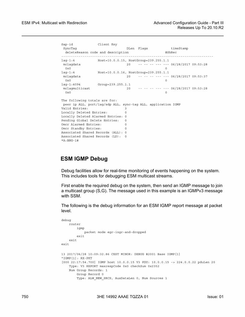
ESM IPv4: Multicast with Redirection
750
Advanced Configuration Guide - Part IIIReleases Up To 20.10.R2
3HE 14992 AAAE TQZZA 01 Issue: 01
Sap-id Client KeySyncTag DLen Flags timeStampdeleteReason code and description #ShRec
-------------------------------------------------------------------------------lag-1:4 Host=10.0.0.15, HostGroup=239.255.1.1mclagdata 20 -- -- -- --- --- 06/28/2017 09:53:280x0 0
lag-1:4 Host=10.0.0.16, HostGroup=239.255.1.1mclagdata 20 -- -- -- --- --- 06/28/2017 09:53:370x0 0
lag-1:4094 Group=239.255.1.1mclagmulticast 20 -- -- -- --- --- 06/28/2017 09:53:280x0 0
The following totals are for:peer ip ALL, port/lag/sdp ALL, sync-tag ALL, application IGMP
Valid Entries: 3Locally Deleted Entries: 0Locally Deleted Alarmed Entries: 0Pending Global Delete Entries: 0Omcr Alarmed Entries: 0Omcr Standby Entries: 0Associated Shared Records (ALL): 0Associated Shared Records (LD): 0*A:BNG-1#
ESM IGMP Debug
Debug facilities allow for real-time monitoring of events happening on the system. This includes tools for debugging ESM multicast streams.
First enable the required debug on the system, then send an IGMP message to join a multicast group (S,G). The message used in this example is an IGMPv3 message with SSM.
The following is the debug information for an ESM IGMP report message at packet level.
debugrouter
igmppacket mode egr-ingr-and-dropped
exitexit
exit
13 2017/06/28 10:09:32.86 CEST MINOR: DEBUG #2001 Base IGMP[1]"IGMP[1]: RX-PKT[000 22:17:54.700] IGMP host 10.0.0.15 V3 PDU: 10.0.0.15 -> 224.0.0.22 pduLen 20
Type: V3 REPORT maxrespCode 0x0 checkSum 0x2352Num Group Records: 1
Group Record 0Type: ALW_NEW_SRCS, AuxDataLen 0, Num Sources 1

Advanced Configuration Guide - Part III Releases Up To 20.10.R2
ESM IPv4: Multicast with Redirection
Issue: 01 3HE 14992 AAAE TQZZA 01 751
Mcast Addr: 239.255.1.1Source Address List
192.168.4.2"
The following is the debug information for an ESM IGMP host. The multicast stream is redirected to the LAG interface and that an MCS entry is installed for the new IGMP group.
debugrouter
igmphost "10.0.0.15"
exitexit
exit
22 2017/06/28 10:11:53.84 CEST MINOR: DEBUG #2001 Base IGMP[Base inst 1]"IGMP[Base inst 1]: igmpIfGroupAddAdding 239.255.1.1 to IGMP host 10.0.0.15 database"
23 2017/06/28 10:11:53.84 CEST MINOR: DEBUG #2001 Base IGMP[Base inst 1]"IGMP[Base inst 1]: igmpProcessGroupRecProcess group rec ALW_NEW_SRCS received on host 10.0.0.15 for group 239.255.1.1in mode INCLUDE. Num srcs 1"
24 2017/06/28 10:11:53.84 CEST MINOR: DEBUG #2001 Base IGMP[Base inst 1]"IGMP[Base inst 1]: igmpIfSrcAddAdding i/f source entry for host 10.0.0.15 (192.168.4.2,239.255.1.1) to IGMP fwdList Database, redir if interface int-LAG-REDIRECTED [ifIndex 7]"
25 2017/06/28 10:11:53.84 CEST MINOR: DEBUG #2001 Base IGMP[Base inst 1]"IGMP[Base inst 1]: igmpMcsAddIfGroupBuilding MCS entry for host 10.0.0.15, group 239.255.1.1"
26 2017/06/28 10:11:56.31 CEST MINOR: DEBUG #2001 Base IGMP[Base inst 1]"IGMP[Base inst 1]: igmpProcessGroupRecProcess group rec ALW_NEW_SRCS received on host 10.0.0.15 for group 239.255.1.1in mode INCLUDE. Num srcs 1"
27 2017/06/28 10:11:56.30 CEST MINOR: DEBUG #2001 Base IGMP[Base inst 1]"IGMP[Base inst 1]: igmpMcsAddIfGroupBuilding MCS entry for host 10.0.0.15, group 239.255.1.1"
The following debug information is received for ESM IGMP when MCS sync is enabled. The MCS sends a sync message for the redirect interface.
debugrouter
igmpmcs "int-LAG-REDIRECTED"
exitexit
exit

ESM IPv4: Multicast with Redirection
752
Advanced Configuration Guide - Part IIIReleases Up To 20.10.R2
3HE 14992 AAAE TQZZA 01 Issue: 01
46 2017/06/28 10:19:06.23 CEST MINOR: DEBUG #2001 Base IGMP MCS[1]"IGMP MCS[1]: TX-MCS Datainterface int-LAG-REDIRECTED [ifIndex 7]Key Type: Group, Len: 9, Grp Addr: 239.255.1.1Data Type: Group, Len: 20, Ver: 0, RecType: 1, Compat Mode: 3,Num Fwd Srcs: 1, Num Blk Srcs: 0Fwd Sources:
192.168.4.2"
47 2017/06/28 10:19:11.05 CEST MINOR: DEBUG #2001 Base IGMP MCS[1]"IGMP MCS[1]: TX-MCS Datainterface int-LAG-REDIRECTED [ifIndex 7]Key Type: Group, Len: 9, Grp Addr: 239.255.1.1Data Type: Group, Len: 20, Ver: 0, RecType: 1, Compat Mode: 3,Num Fwd Srcs: 1, Num Blk Srcs: 0Fwd Sources:
192.168.4.2"
The corresponding debug information for ESM IGMP MCS sync on BNG-2 looks as follows:
1 2017/06/28 10:19:06.24 CEST MINOR: DEBUG #2001 Base IGMP MCS[1]"IGMP MCS[1]: RX-MCS Datainterface int-LAG-REDIRECTED [ifIndex 8]Key Type: Group, Len: 9, Grp Addr: 239.255.1.1Data Type: Group, Len: 20, Ver: 0, RecType: 1, Compat Mode: 3,Num Fwd Srcs: 1, Num Blk Srcs: 0Fwd Sources:
192.168.4.2"
The same debug commands can be used for viewing IGMP leave messages. The following debug information is received for an ESM IGMP leave at the packet level. The leave report message received over the subscriber SAP results in the multicast stream being stopped on the redirected interface, after ensuring no other CPE devices still require the multicast streams (by means of a query).
debugrouter
igmppacket mode egr-ingr-and-dropped
exitexit
exit
64 2017/06/28 10:26:25.31 CEST MINOR: DEBUG #2001 Base IGMP[1]"IGMP[1]: RX-PKT[000 22:34:47.160] IGMP host 10.0.0.15 V3 PDU: 10.0.0.15 -> 224.0.0.22 pduLen 20
Type: V3 REPORT maxrespCode 0x0 checkSum 0x2252Num Group Records: 1
Group Record 0Type: BLK_OLD_SRCS, AuxDataLen 0, Num Sources 1Mcast Addr: 239.255.1.1

Advanced Configuration Guide - Part III Releases Up To 20.10.R2
ESM IPv4: Multicast with Redirection
Issue: 01 3HE 14992 AAAE TQZZA 01 753
Source Address List192.168.4.2
"
65 2017/06/28 10:26:25.31 CEST MINOR: DEBUG #2001 Base IGMP[1]"IGMP[1]: TX-PKT[000 22:34:47.160] IGMP interface int-LAG-REDIRECTED [ifIndex 7] V3 PDU: 192.168.10.253 -> 239.255.1.1 pduLen 16
Type: QUERY maxrespCode 0xa checkSum 0x36ccGroupAddr: 239.255.1.1
S bit 0, QRV 2, Encoded-QQIC 125, NumSources 1Source Address List:
192.168.4.2"
66 2017/06/28 10:26:26.86 CEST MINOR: DEBUG #2001 Base IGMP[1]"IGMP[1]: TX-PKT[000 22:34:48.710] IGMP interface int-LAG-REDIRECTED [ifIndex 7] V3 PDU: 192.168.10.253 -> 239.255.1.1 pduLen 16
Type: QUERY maxrespCode 0xa checkSum 0x36ccGroupAddr: 239.255.1.1
S bit 0, QRV 2, Encoded-QQIC 125, NumSources 1Source Address List:
192.168.4.2"
The following debug information is received for an ESM IGMP host showing various IGMP events. The MCS also signals the removal of the IGMP entry in the database.
debugrouter
igmphost "10.0.0.15"
exitexit
exit
73 2017/06/28 10:30:29.95 CEST MINOR: DEBUG #2001 Base IGMP[Base inst 1]"IGMP[Base inst 1]: igmpProcessGroupRecProcess group rec BLK_OLD_SRCS received on host 10.0.0.15 for group 239.255.1.1in mode INCLUDE. Num srcs 1"
74 2017/06/28 10:30:29.95 CEST MINOR: DEBUG #2001 Base IGMP[Base inst 1]"IGMP[Base inst 1]: igmpProcessIfSrcTimerExpSource Timer expired for IGMP host 10.0.0.15 (192.168.4.2,239.255.1.1)"
75 2017/06/28 10:30:29.95 CEST MINOR: DEBUG #2001 Base IGMP[Base inst 1]"IGMP[Base inst 1]: igmpIfSrcDelDeleting i/f source entry for host 10.0.0.15 (192.168.4.2,239.255.1.1) from IGMPDatabase. DeleteFromAvl: 1 Redir 0"
76 2017/06/28 10:30:29.95 CEST MINOR: DEBUG #2001 Base IGMP[Base inst 1]"IGMP[Base inst 1]: igmpIfGroupDelDeleting 239.255.1.1 from IGMP host 10.0.0.15 database"
77 2017/06/28 10:30:29.95 CEST MINOR: DEBUG #2001 Base IGMP[Base inst 1]"IGMP[Base inst 1]: igmpMcsDelIfGroup

ESM IPv4: Multicast with Redirection
754
Advanced Configuration Guide - Part IIIReleases Up To 20.10.R2
3HE 14992 AAAE TQZZA 01 Issue: 01
Building MCS entry for host 10.0.0.15, group 239.255.1.1"
78 2017/06/28 10:30:29.95 CEST MINOR: DEBUG #2001 Base IGMP[Base inst 1]"IGMP[Base inst 1]: igmpMcsDelIfGroupDeleting MCS entry for host 10.0.0.15, group 239.255.1.1, Glb"
The following debug information is received when MCS removes the entry on BNG-1. MCS also triggers the backup BNG to remove the multicast stream.
debugrouter
igmpmcs "int-LAG-REDIRECTED"
exitexit
exit
84 2017/06/28 10:34:35.06 CEST MINOR: DEBUG #2001 Base IGMP MCS[1]"IGMP MCS[1]: TX-MCS Datainterface int-LAG-REDIRECTED [ifIndex 7]Key Type: Group, Len: 9, Grp Addr: 239.255.1.1Data Type: Group, Len: 20, Ver: 0, RecType: 1, Compat Mode: 3,Num Fwd Srcs: 1, Num Blk Srcs: 0Fwd Sources:
192.168.4.2"
85 2017/06/28 10:34:36.86 CEST MINOR: DEBUG #2001 Base IGMP MCS[1]"IGMP MCS[1]: TX-MCS Data (GlblDel)interface int-LAG-REDIRECTED [ifIndex 7]Key Type: Group, Len: 9, Grp Addr: 239.255.1.1Data Type: Group, Len: 16, Ver: 0, RecType: 1, Compat Mode: 3,Num Fwd Srcs: 0, Num Blk Srcs: 0"
The debug information on BNG-2 shows the sync message received over MCS for the removal of the multicast (S,G).
9 2017/06/28 10:34:22.88 CEST MINOR: DEBUG #2001 Base IGMP MCS[1]"IGMP MCS[1]: RX-MCS Datainterface int-LAG-REDIRECTED [ifIndex 8]Key Type: Group, Len: 9, Grp Addr: 239.255.1.1Data Type: Group, Len: 20, Ver: 0, RecType: 1, Compat Mode: 3,Num Fwd Srcs: 1, Num Blk Srcs: 0Fwd Sources:
192.168.4.2"

Advanced Configuration Guide - Part III Releases Up To 20.10.R2
ESM IPv4: Multicast with Redirection
Issue: 01 3HE 14992 AAAE TQZZA 01 755
Conclusion
Multicast is an essential part of Triple Play Services. The SR OS TPSDA solution is much more than a baseline multicast delivery, it includes individual subscriber awareness and offers a full state redundancy option. Subscriber awareness allows for fine tuning of subscriber multicast settings and for troubleshooting on a per subscriber basis. Full state redundancy reduces failover time and ensures high availability of multicast services. This example provided a complete configuration walkthrough of both the IPoE and PPPoE SRRP model with redirection. All multicast streams can be redirected to a dedicated interface for all subscribers to receive.

ESM IPv4: Multicast with Redirection
756
Advanced Configuration Guide - Part IIIReleases Up To 20.10.R2
3HE 14992 AAAE TQZZA 01 Issue: 01

Advanced Configuration Guide - Part III Releases Up To 20.10.R2
ESM IPv4: Multicast with SRRP
Issue: 01 3HE 14992 AAAE TQZZA 01 757
ESM IPv4: Multicast with SRRPThis chapter describes ESM IPv4 multicast with SRRP configurations.
Topics in this chapter include:
• Applicability• Overview• Configuration• Conclusion
Applicability
This chapter applies to SR OS routers, and was originally written for release 11.0.R1. The CLI is updated to release 15.0.R3. It covers multicast with Subscriber Routed Redundancy Protocol (SRRP) for IPoE and PPPoE subscribers.
Overview
Triple Play Service Delivery Architecture (TPSDA) has allowed operators to integrate High Speed Internet (HSI), voice, and video services within a single network. The goal of this chapter is to walk through the configuration of a redundant TPSDA multicast architecture and the configuration of multicast filters. The topics are divided into the following sections:
• Enhanced Subscriber Management (ESM) multicast baseline configuration- IGMP configuration on ESM group interface- ESM IGMP-policy configuration
• IPoE ESM multicast walkthrough• PPPoE ESM multicast walkthrough• IGMP Subscriber Router Redundancy Protocol (SRRP)
- Multi-Chassis Synchronization (MCS) walkthrough• IGMP Debugging• IGMP Control Plane Filters• IGMP Data Plane Filters

ESM IPv4: Multicast with SRRP
758
Advanced Configuration Guide - Part IIIReleases Up To 20.10.R2
3HE 14992 AAAE TQZZA 01 Issue: 01
The network topology displayed in Figure 129 shows a typical TPSDA setup. It consists of three 7750s and a single 7450. Two 7750s are configured as Broadband Network Gateways (BNGs) and the third 7750 is configured as a P router. The 7450 is used as an aggregation switch to aggregate all subscribers.
Figure 129 Network Topology Overview
Both BNGs are configured with SRRP to provide redundancy. SRRP is only used for redundancy purposes. SRRP is not required for supporting multicast. The P router is connected to the multicast source and to the network side of both BNGs. The connections between the BNGs and the P router are also running PIM to provide multicast delivery. On the access side, the two BNGs are connected to an aggregation switch which aggregates the traffic originating from both PPPoE and IPoE subscribers. The BNGs are IGMP capable and will respond to subscribers’ IGMP requests.
There are two requirements to enable multicast delivery using ESM. First, the ESM group interface must have IGMP enabled. Second, the ESM subscribers must be configured with an IGMP-policy to receive multicast. When both requirements are met, the BNG will process the subscribers’ IGMP messages, otherwise, IGMP messages are simply ignored and dropped. All customer premise equipment (CPE) IGMP messages are aggregated via the 7450 and passed to the BNGs. Because the BNGs are running SRRP, the SRRP master is the only BNG processing and answering the IGMP messages. Protocol Independent Multicasting (PIM) is then used between the BNG and the P router to request the multicast stream. If PIM is successful in retrieving the multicast group, the multicast stream is forwarded toward the subscribers. This is the typical multicast delivery model for TPSDA.
AGG-17450 ESS
P17750 SR
Multicast SourceBNG-1
BNG-2
7750 SR
SRRP
al_0261
7750 SR
IPoE/PPPoE Session
Subscribers
IES
IES

Advanced Configuration Guide - Part III Releases Up To 20.10.R2
ESM IPv4: Multicast with SRRP
Issue: 01 3HE 14992 AAAE TQZZA 01 759
Configuration
This section expects a basic knowledge of ESM.
ESM SRRP Baseline Configuration
Figure 130 shows the addressing scheme used in the setup. The example uses numbered SRRP subscriber interfaces with static SAPs serving both IPoE and PPPoE subscribers. The configuration of the RADIUS server is out of the scope of this example.
Figure 130 Example Topology
The baseline configuration for BNG-1 follows, excluding the IGMP configuration. In this example, the subscriber-interface is configured in an IES, although it is possible to configure the subscriber-interface in a VPRN. OSPF and PIM are provisioned to provide routing and multicast capabilities. The SRRP configuration with priority 200 ensures BNG-1 is the master when both BNGs are active because the SRRP priority for BNG-2 is lower.
# BNG-1
DHCP Local Server10.1.1.1
192.168.34.0/30
192.168.24.0/30
192.168.1.0/30
10.255.255.252
2/1/2 1/1/11/1/2
1/1/2
1/1/4
1/1/1
2/1/1 1/1/2
1/1/610.255.255.253
SSRP10.255.255.254
AGG-1 P-1
RADIUSServer
BNG-1
BNG-2
SDP
al_0262SDP
Subscriber
IES
IES
On BNG-1 port 1/1/4 and BNG-2 port 1/1/1:• VLAN 4 - Data Path• VLAN 5 - SRRP Control Path
1/1/3
1/1/3

ESM IPv4: Multicast with SRRP
760
Advanced Configuration Guide - Part IIIReleases Up To 20.10.R2
3HE 14992 AAAE TQZZA 01 Issue: 01
configureservice
ies 1 customer 1 createredundant-interface "mclink-BNG-1-BNG-2" create
address 192.168.11.0/31ip-mtu 1500spoke-sdp 23:1 create
no shutdownexit
exitsubscriber-interface "sub-int-1" create
address 10.255.255.252/8 gw-ip-address 10.255.255.254 track-srrp 1group-interface "grp-int-1" create
srrp-enabled-routingdhcp
optionaction replacecircuit-idno remote-id
exitserver 192.168.0.1lease-populate 10client-applications dhcp pppgi-address 10.255.255.252no shutdown
exitauthentication-policy "auth-1"redundant-interface "mclink-BNG-1-BNG-2"sap 1/1/4:4 create
sub-sla-mgmtdef-sub-id use-sap-iddef-sub-profile "sub-profile-1"def-sla-profile "sla-profile-1"sub-ident-policy "sub-ident-1"multi-sub-sap 10no shutdown
exitexitsap 1/1/4:5 createexitsrrp 1 create
message-path 1/1/4:5priority 200no preemptno shutdown
exitpppoe
no shutdownexit
exitexitno shutdown
exitexit
exit
configurerouter
ospf

Advanced Configuration Guide - Part III Releases Up To 20.10.R2
ESM IPv4: Multicast with SRRP
Issue: 01 3HE 14992 AAAE TQZZA 01 761
area 0.0.0.0interface "system"
no shutdownexitinterface "int-BNG-1-BNG-2"
interface-type point-to-pointmetric 10000no shutdown
exitinterface "int-BNG-1-P-1"
interface-type point-to-pointno shutdown
exitinterface "sub-int-1"
no shutdownexit
exitno shutdown
exitpim
interface "int-BNG-1-P-1"exitno shutdown
exitexit
exit
The baseline configuration for BNG-2 follows, excluding the IGMP configuration. The SRRP priority for BNG-2 is lower than the SRRP priority for BNG-1, thus BNG-2 will be in standby mode.
# BNG-2configure
serviceies 1 customer 1 create
no shutdownredundant-interface "mclink-BNG-2-BNG-1" create
address 192.168.11.1/31ip-mtu 1500spoke-sdp 32:1 create
no shutdownexit
exitsubscriber-interface "sub-int-1" create
address 10.255.255.253/8 gw-ip-address 10.255.255.254 track-srrp 1group-interface "grp-int-1" create
srrp-enabled-routingdhcp
optionaction replacecircuit-idno remote-id
exitserver 192.168.0.1lease-populate 10client-applications dhcp pppgi-address 10.255.255.253no shutdown

ESM IPv4: Multicast with SRRP
762
Advanced Configuration Guide - Part IIIReleases Up To 20.10.R2
3HE 14992 AAAE TQZZA 01 Issue: 01
exitauthentication-policy "auth-1"redundant-interface "mclink-BNG-2-BNG-1"sap 1/1/1:4 create
sub-sla-mgmtdef-sub-id use-sap-iddef-sub-profile "sub-profile-1"def-sla-profile "sla-profile-1"sub-ident-policy "sub-ident-1"multi-sub-sap 10no shutdown
exitexitsap 1/1/1:5 createexitsrrp 1 create
message-path 1/1/1:5priority 150no preemptno shutdown
exitpppoe
no shutdownexit
exitexitno shutdown
exitexit
exit
configurerouter
ospfarea 0.0.0.0
interface "system"no shutdown
exitinterface "int-BNG-2-BNG-1"
interface-type point-to-pointmetric 10000no shutdown
exitinterface "int-BNG-2-P-1"
interface-type point-to-pointno shutdown
exitinterface "sub-int-1"
no shutdownexit
exitno shutdown
exitpim
interface "int-BNG-2-P-1"exitno shutdown
exitexit

Advanced Configuration Guide - Part III Releases Up To 20.10.R2
ESM IPv4: Multicast with SRRP
Issue: 01 3HE 14992 AAAE TQZZA 01 763
exit
The baseline configuration for the aggregation switch AGG-1 follows. Two VPLS services are configured. VPLS 5 is responsible for passing SRRP control traffic over VLAN 5. VPLS 4 is responsible for passing all subscriber data traffic over VLAN 4.
# AGG-1configure
servicevpls 4 customer 1 create
description "for user traffic"stp
shutdownexitsap 1/1/6:4 create
no shutdownexitsap 2/1/1:4 create
no shutdownexitsap 2/1/2:4 create
no shutdownexitno shutdown
exitvpls 5 customer 1 create
description "for SRRP/redundancy"stp
shutdownexitsap 2/1/1:5 create
no shutdownexitsap 2/1/2:5 create
no shutdownexitno shutdown
exitexit
exit
The baseline configuration on the P router is as follows. The P router has a local DHCP server configured and performs the DHCP address assignment. The P router also is attached to the multicast source and uses PIM to deliver multicast streams.
# P-1configure
router Basedhcp
local-dhcp-server "dhcp-local-server" createuse-gi-address scope poolpool "pool-1" create
subnet 10.0.0.0/8 createoptions
subnet-mask 255.0.0.0default-router 10.255.255.254

ESM IPv4: Multicast with SRRP
764
Advanced Configuration Guide - Part IIIReleases Up To 20.10.R2
3HE 14992 AAAE TQZZA 01 Issue: 01
exitaddress-range 10.0.0.10 10.0.0.254
exitexitno shutdown
exitexitinterface "int-DHCP-lb1"
address 192.168.0.1/32loopbacklocal-dhcp-server "dhcp-local-server"no shutdown
exitinterface "int-P-1-BNG-1"
address 192.168.24.2/30port 1/1/1:4094no shutdown
exitinterface "int-P-1-BNG-2"
address 192.168.34.2/30port 1/1/2:4094no shutdown
exitinterface "int-P-1-mcast-source"
address 192.168.4.1/30port 1/1/5:4092no shutdown
exitinterface "system"
address 192.0.2.4/32no shutdown
exitospf 0
traffic-engineeringarea 0.0.0.0
interface "system"no shutdown
exitinterface "int-DHCP-lb1"
no shutdownexitinterface "int-P-1-BNG-1"
interface-type point-to-pointno shutdown
exitinterface "int-P-1-BNG-2"
interface-type point-to-pointno shutdown
exitinterface "int-P-1-mcast-source"
passiveno shutdown
exitexitno shutdown
exitpim
interface "int-P-1-BNG-1"exit

Advanced Configuration Guide - Part III Releases Up To 20.10.R2
ESM IPv4: Multicast with SRRP
Issue: 01 3HE 14992 AAAE TQZZA 01 765
interface "int-P-1-BNG-2"exitinterface "int-P-1-mcast-source"exit--- snipped ---no shutdown
exitexit
exit
Enable IGMP on Group Interfaces
The configuration below adds the group interface to IGMP. If the subscriber-interface is configured in a VPRN, each VPRN will have its individual IGMP instance. Add the group-interface to the IGMP instance.
# on BNG-1 and BNG-2configure
routerigmp
group-interface "grp-int-1"no shutdown
exitno shutdown
exitexit
exit
Placing the group-interface into IGMP is the first step required to deliver multicast streams. The options available in this IGMP context can be classified into two categories:
1. Bandwidth and multicast group management2. Interoperability[no] disable-router* - Enable/disable the IGMP router alert check option[no] import - Import a policy to filter IGMP packets[no] max-groups - Configure the maximum number of groups for this group-
interface[no] max-grp-sources - Configure the maximum number of group sources for this
group-interface[no] max-sources - Configure the maximum number of sources for this group-
interfacemcac + Configure multicast CAC policy and constraints for this inte
rface[no] query-interval - Configure the frequency at which Host-Query packets are
transmitted[no] query-last-mem* - Configure the frequency at which Group-Specific-
Query packetsare transmitted
[no] query-response* - Configure the time to wait to receive a response to theHost-Query message from the host
[no] query-src-ip -

ESM IPv4: Multicast with SRRP
766
Advanced Configuration Guide - Part IIIReleases Up To 20.10.R2
3HE 14992 AAAE TQZZA 01 Issue: 01
Configure the IP source address used in IGMP queries for thisgroup interface
[no] shutdown - Administratively enable/disable the interface[no] sub-hosts-only - Enable/disable the IGMP traffic from known hosts only[no] subnet-check - Enable/disable local subnet checking for IGMP[no] version - Configure the version of IGMP
The bandwidth and multicast group management options are:
• Import — Used for white-listing or black-listing multicast groups in the IGMP control plane. More configuration detail is offered in a later section.
• Max-groups — Controls the maximum number of groups (channels) allowed on the group interface.
• Max-sources — Controls the maximum number of sources of the multicast streams on a group interface.
• Max-grp-sources — Specifies the maximum number of multicast group and source pairs for a group-interface.
• MCAC — Multicast Connection Admission Control (MCAC) is a bandwidth management feature to control the amount of multicast streams a group interface is allowed to receive. It can also be applied at subscriber level to offer a hierarchical control. Multicast bandwidth can be controlled on a per subscriber basis.
• query-interval — defines the frequency at which general host-query messages are sent out by the querier.
• query-last-member-interval — defines the frequency at which the querier sends group-specific queries including messages sent in response to leave-group messages.
• query-response-interval — defines how long the querier waits to receive a response to a host-query message from a host.
• query-src-ip — defines the query source IP address for the group interface.
The interoperability options available are:
• Router alert — enable or disable router alert processing.• Sub-hosts-only — Only subscriber originated IGMP messages are accepted and
anything else is ignored. Sometimes, IGMP message might not arrive directly from the subscriber. For example, an aggregation switch or DSLAM residing between the CPE and the BNG might perform IGMP proxy. The switch/DSLAM will insert its own source IP-address in place of the subscriber.It should be noted that, when an IGMP proxy is used, the identity of the subscriber is lost (because the original source IP of the IGMP message is replaced).

Advanced Configuration Guide - Part III Releases Up To 20.10.R2
ESM IPv4: Multicast with SRRP
Issue: 01 3HE 14992 AAAE TQZZA 01 767
• Subnet-check — IGMP messages will be checked against the group interface subnet. All IGMP messages with a source address that is not in the local subnet are dropped.
• Version — The RFCs define three versions of IGMP, all of them are supported by SR OS.It must be noted that when subscribers are sending IGMPv1 or v2 in a bridged LAN, suppression of IGMP messages can occur. If an IGMP host detects the presence of another host reporting for the same multicast group, it will suppress its own IGMP report message and silently receive the multicast stream. When IGMP messages are suppressed, the BNG might not be able to account for the real multicast bandwidth consumption of each subscriber. IGMPv3, on the other hand, forces all hosts to send IGMP reports. This guarantees that the BNG identifies each subscriber’s IGMP request.
ESM IGMP Policy
In addition to enabling IGMP on the group interface, the subscriber must be allowed to receive multicast streams through an IGMP policy. For this purpose, the IGMP-policy is associated with the subscriber’s subscriber-profile. Therefore during authentication, either RADIUS, the local user database (LUDB), or the default-sub-profile should return a sub-profile with an IGMP policy. The provisioning requires two steps:
First create the IGMP policy, as follows:
configuresubscriber-mgmt
igmp-policy "igmp-policy-1" createexit
exitexit
Then add the IGMP policy to a subscriber-profile, as follows:
configuresubscriber-mgmt
sub-profile "sub-profile-1" createigmp-policy "igmp-policy-1"
exitexit
exit
The above configuration is the minimum requirement for a subscriber to receive multicast streams. The different options inside an IGMP policy are:
[no] description - Description for the policy[no] disable-router* - Enable/disable the router alert check option

ESM IPv4: Multicast with SRRP
768
Advanced Configuration Guide - Part IIIReleases Up To 20.10.R2
3HE 14992 AAAE TQZZA 01 Issue: 01
[no] egress-rate-mo* - Configure the egress rate modification[no] fast-leave - Enable/disable fast-leave processing[no] import - Specify the import policy to filter packets[no] max-num-groups - Configure the max number of multicast groups[no] max-num-grp-so* - Configure the max number of multicast group sources[no] max-num-sources - Configure the max number of multicast sources[no] mcast-reporting + Configure the mcast reporting[no] per-host-repli* - Enable/disable per-host-replication processing[no] query-interval - Configure the frequency at which Host-Query packets are
transmitted[no] query-last-mem* - Configure the frequency at which Group-Specific-
Query packetsare transmitted
[no] query-response* - Configure the time to wait to receive a response to theHost-Query message from the host
[no] redirection-po* - Specify the redirection policystatic + Add/remove static group membership
[no] version - Configure the version
Again, two groups of options are available: the bandwidth and multicast group management options, and the interoperability options.
Bandwidth and multicast group management options:
• Import — Used for white-listing and black-listing multicast groups. This allows the import policy to be defined per subscriber.
• Max-num-group — Limits the maximum multicast groups for the group interface. This limits the groups per subscriber.
• Max-num-sources — Limits the maximum multicast sources for the group interface. This limits the sources per subscriber.
• Max-num-grp-sources — Limits the maximum multicast group and source pairs for the group interface.
• Egress-rate-modify — This feature adjusts the subscriber queue bandwidth according to multicast consumption. It is used in conjunction with MCAC. An MCAC policy defines the bandwidth consumption per multicast group. As a subscriber joins a multicast group, the bandwidth of the multicast channel is subtracted from the subscriber queue bandwidth. The remaining bandwidth is what the subscriber can use for all other services.
• query-interval — defines the frequency at which general host-query messages are sent out by the querier.
• query-last-member-interval — defines the frequency at which the querier sends group-specific queries including messages sent in response to leave-group messages.
• query-response-interval — defines how long the querier waits to receive a response to a host-query message from a host.
Interoperability options:

Advanced Configuration Guide - Part III Releases Up To 20.10.R2
ESM IPv4: Multicast with SRRP
Issue: 01 3HE 14992 AAAE TQZZA 01 769
• Fast-leave — Enables the router to withdraw the multicast group quickly when receiving an IGMP leave message without any last query. This should be used in a subscriber per SAP (dot1q or qinq) model.
• Static — This allows the provisioning of static multicast groups that the subscriber will receive regardless of any IGMP report. The static multicast group can be Source Specific Multicast (SSM) based.
• Per-host-replication — SR OS has the capability to replicate a multicast source per subscriber. For example, if 10 subscribers are requesting the same multicast group, then 10 multicast streams are replicated and delivered individually to each subscriber. PPPoE requires service delivery to be point to point. To achieve this, the Ethernet header destination address for the multicast stream is the subscriber’s source MAC. The IP layer destination is the same as the multicast group that the subscriber requested. For IPoE, without per-host replication, the standard multicast MAC representing the multicast group is used as the destination MAC address when delivering the multicast streams to the subscribers. When per-host replication is used for IPoE subscribers, the destination MAC address will be the host’s own MAC address and the IP destination will be the same as the multicast group that the subscriber is interested in. The multicast stream is then delivered to the subscriber via MAC learning as a unicast stream.When per-host-replication is enabled, all multicast streams will be using the subscriber queues. It is no longer necessary to use egress-rate-modify as mentioned before.
• Redirection-policy — Another popular model for multicast deployment is to redirect all multicast streams to another interface instead of sending the content directly to the subscriber. All subscribers use a common VLAN to receive the multicast streams.
ESM IGMP IPoE Walkthrough
With the baseline configuration applied, the BNG is ready to process IGMP messages and deliver multicast. Figure 131 shows a flow for IPoE subscribers requesting and receiving multicast traffic. The key items are highlighted in dotted box:
1. The ESM group-interface must have IGMP enabled2. The subscriber must be associated with an IGMP-policy via sub-profile.
The subscriber sends an IGMPv3 report using (192.168.4.2, 239.255.1.1).

ESM IPv4: Multicast with SRRP
770
Advanced Configuration Guide - Part IIIReleases Up To 20.10.R2
3HE 14992 AAAE TQZZA 01 Issue: 01
Figure 131 IPoE Subscriber Multicast Flow
To verify that the group interface is ready for multicast, use the following show command. Remember that the IES service id is 1 and the group-interface name is grp-int-1.
*A:BNG-1# show router igmp group-interface
===============================================================================IGMP Group-Interfaces===============================================================================FwdSvc Group-Interface Adm/Opr-State Import-Policy
SAP Adm/Opr-Version Num-Groups-------------------------------------------------------------------------------1 grp-int-1 Up/Up none
1/1/4:4 3/3 01/1/4:5 3/3 0
-------------------------------------------------------------------------------Group-Interfaces = 1, SAPs = 2===============================================================================*A:BNG-1#
Ensure the subscriber is associated with an IGMP-policy. Since the IGMP-policy is associated with a subscriber-profile, verifying the IGMP-policy is done through the subscriber profile, as follows:
IPoE Subscriber
Must have1) IGMP Configured Group Interface2) Subscriber Must Have IGMP-Policy
IGMPv3 Reportgrp: 239.255.1.1src-lp: 192.168.4.2
BNG-1 P-1 Multicast ServerAgg-1Subscriber
IES
Multicast Packet:Eth 01:00:5e:ff:01:01IP 239.255.1.1
Multicast Packet:Eth 01:00:5e:ff:01:01IP 239.255.1.1
Multicast Packet:Eth 01:00:5e:ff:01:01IP 239.255.1.1
Multicast Packet:Eth 01:00:5e:ff:01:01IP 239.255.1.1
SRRP State:Master
PIM Join(192.168.4.2.239.255.1.1)
PIM Join(192.168.4.2.239.255.1.1)
al_0263

Advanced Configuration Guide - Part III Releases Up To 20.10.R2
ESM IPv4: Multicast with SRRP
Issue: 01 3HE 14992 AAAE TQZZA 01 771
*A:BNG-1# show subscriber-mgmt sub-profile "sub-profile-1"
===============================================================================Subscriber Profile sub-profile-1===============================================================================Description : (Not Specified)I. Sched. Policy : N/AE. Sched. Policy : N/A E. Agg Rate Limit: MaxI. Policer Ctrl. : N/AE. Policer Ctrl. : N/AI. vport-hashing : DisabledI. sec-sh-hashing: DisabledQ Frame-Based Ac*: DisabledAcct. Policy : N/A Collect Stats : DisabledANCP Pol. : N/AAccu-stats-pol : (Not Specified)HostTrk Pol. : N/AIGMP Policy : igmp-policy-1MLD Policy : N/APIM Policy : N/ASub. MCAC Policy : N/ANAT Policy : N/AFirewall Policy : N/AUPnP Policy : N/ANAT Prefix List : N/ADef. Encap Offset: none Encap Offset Mode: noneAvg Frame Size : N/AVol stats type : fullPreference : 5LAG hash class : 1LAG hash weight : 1-------------------------------------------------------------------------------Radius Accounting-------------------------------------------------------------------------------Policy : N/ASession Opti.Stop: False-------------------------------------------------------------------------------HSMDA-2-------------------------------------------------------------------------------I. Qos Policy : 1 E. Qos Policy : 1
E. Agg Rate Limit: MaxE. WRR Policy : N/A Pkt Byte Offset : add 0*-------------------------------------------------------------------------------Last Mgmt Change : 06/21/2017 11:58:50===============================================================================* indicates that the corresponding row element may have been truncated.
--- snipped ---
*A:BNG-1#
After the verification, the BNGs are ready to deliver multicast streams.
First, initiate an IGMP report from a subscriber requesting a multicast channel. In this example, IGMPv3 SSM is used. IPoE by default replicates per-SAP. If the IGMP message was successfully received and processed, an (S,G) binding will be associated with the subscriber SAP.

ESM IPv4: Multicast with SRRP
772
Advanced Configuration Guide - Part IIIReleases Up To 20.10.R2
3HE 14992 AAAE TQZZA 01 Issue: 01
In this case, the IGMPv3 SSM message requests (192.168.4.2, 239.255.1.1). The subscriber host is assigned an IP address of 10.0.0.11. To verify the IGMP message was successfully processed, check that the (S,G) is learned on the IGMP instance. The following example shows a successful IGMP message processed by the BNG, the (S,G) is registered against the subscriber SAP and the host.
*A:BNG-1# show router igmp group===============================================================================IGMP Interface Groups===============================================================================No Matching Entries===============================================================================IGMP Host Groups===============================================================================(192.168.4.2,239.255.1.1)
Fwd List : 10.0.0.11 UpTime: 0d 00:05:27-------------------------------------------------------------------------------Entries : 1===============================================================================IGMP SAP Groups===============================================================================(192.168.4.2,239.255.1.1)
Fwd List : 1/1/4:4 UpTime: 0d 00:05:27-------------------------------------------------------------------------------Entries : 1===============================================================================*A:BNG-1#
For more IGMP details on the group interface, including maximum multicast groups and bandwidth management, use the following command:
*A:BNG-1# show router igmp group-interface detail
===============================================================================IGMP Group-Interfaces===============================================================================FwdSvc/Grp-Intf : 1/grp-int-1Admin-Status : Up Oper-Status : UpImport-Policy : none Subnet-Check : EnabledRouter-Alert-Check : Enabled Sub-Hosts-Only : EnabledMCAC Policy Name : MCAC Const Adm St : EnableMCAC Max Unconst BW: no limit MCAC Max Mand BW : no limitMCAC In use Mand BW: 0 MCAC Avail Mand BW : unlimitedMCAC In use Opnl BW: 0 MCAC Avail Opnl BW : unlimitedQry Interval : None Qry Last Mbr Inter*: NoneQry Resp Interval : NoneMCAC If-Policy Name:-------------------------------------------------------------------------------SAP : 1/1/4:4Admin/Oper version: 3/3 Num Groups : 1Max Groups Allowed: No Limit Max Groups Till Now: 1Max Sources Allow*: No LimitMax Grp Srcs Allo*: No LimitQry Interval : 125 Qry Last Memb Inte*: 1Qry Resp Interval : 10
-------------------------------------------------------------------------------

Advanced Configuration Guide - Part III Releases Up To 20.10.R2
ESM IPv4: Multicast with SRRP
Issue: 01 3HE 14992 AAAE TQZZA 01 773
Group-Address : 239.255.1.1 Up Time : 0d 00:05:54Expires : N/A Mode : includeV1 Host Timer : Not running Type : dynamicV2 Host Timer : Not running Compat Mode : IGMP Version 3------------------------------------------------------------------GrpSrc-Address Expires Type Fwd/Blk------------------------------------------------------------------192.168.4.2 0d 00:04:18 dynamic Fwd
-------------------------------------------------------------------------------SAP : 1/1/4:5Admin/Oper version: 3/3 Num Groups : 0Max Groups Allowed: No Limit Max Groups Till Now: 0Max Sources Allow*: No LimitMax Grp Srcs Allo*: No LimitQry Interval : 125 Qry Last Memb Inte*: 1Qry Resp Interval : 10
-------------------------------------------------------------------------------Group-Interfaces = 1, SAPs = 2===============================================================================* indicates that the corresponding row element may have been truncated.*A:BNG-1#
If the subscriber fails to receive multicast traffic, check if the subscriber has an associated IGMP policy with the following command. If the subscriber entry is missing, make sure the subscriber has a sub-profile that is tied to an IGMP-policy.
*A:BNG-1# show service active-subscribers igmp detail
===============================================================================Active Subscribers Detail===============================================================================Subscriber IGMP-Policy
HostAddr GrpItf NumGroupsGrpAddr Type Up-Time Mode
SrcAddr Type Blk/Fwd-------------------------------------------------------------------------------subscr-1 igmp-policy-1
10.0.0.11 grp-int-1 1239.255.1.1 Dynamic 0d 00:08:50 Include
192.168.4.2 Dynamic Fwd-------------------------------------------------------------------------------Number of Subscribers : 1===============================================================================*A:BNG-1#
Another possibility for failing to receive multicast traffic could be due to the control mechanisms inside the IGMP-policy such as: bandwidth control, multicast groups restrictions, and interoperability options. Use the following command to view the IGMP policy configured control parameters.
*A:BNG-1# show subscriber-mgmt igmp-policy "igmp-policy-1"
===============================================================================IGMP Policy igmp-policy-1===============================================================================Import Policy :

ESM IPv4: Multicast with SRRP
774
Advanced Configuration Guide - Part IIIReleases Up To 20.10.R2
3HE 14992 AAAE TQZZA 01 Issue: 01
Admin Version : 3Num Subscribers : 1Host Max Group : No LimitHost Max Sources : No LimitHost Max Group Sources : No LimitQuery Interval : NoneQuery Last Member Interval : NoneQuery Response Interval : NoneRouter Alert Check : EnabledFast Leave : yesRedirection Policy :Per Host Replication : noEgress Rate Modify : noMcast Reporting Destination Name :Mcast Reporting Admin State : Disabled===============================================================================*A:BNG-1#
The command to view the (S,G)s that all subscribers are requesting is as follows. Since the system has only one subscriber, this example only shows one host.
*A:BNG-1# show router igmp hosts detail
===============================================================================IGMP Host 10.0.0.11===============================================================================Oper Status : Up MacAddress : 00:10:94:00:00:13Oper version : 3 Subscriber : subscr-1Num Groups : 1 GrpItf : grp-int-1Max Grps Till Now: 1 IGMP-Policy : igmp-policy-1PPPoE SessionId : N/A Next query time: 0d 00:01:29FwdSvcId : 1 Max Srcs Allow*: No LimitMax Grps Allowed : No Limit Max Grp Srcs A*: No LimitQry Interval : 125 Qry Last Mbr I*: 1Qry Resp Interval: 10 Router Alert C*: Enabled
-------------------------------------------------------------------------------IGMP Group-------------------------------------------------------------------------------Group Address : 239.255.1.1 Up Time : 0d 00:10:30Expires : Not running Mode : IncludeV1 Host Timer : Not running Type : DynamicV2 Host Timer : Not running Compat Mode: IGMP Version 3Redir.SvcId : N/A Redir.Intf : N/A-----------------------------------------------------------Source Address Expires Type Fwd/Blk-----------------------------------------------------------192.168.4.2 0d 00:03:46 Dynamic Fwd-------------------------------------------------------------------------------Hosts : 1===============================================================================* indicates that the corresponding row element may have been truncated.*A:BNG-1#
To check for an individual subscriber and its requested (S,G)s, the following command can be used.

Advanced Configuration Guide - Part III Releases Up To 20.10.R2
ESM IPv4: Multicast with SRRP
Issue: 01 3HE 14992 AAAE TQZZA 01 775
*A:BNG-1# show service active-subscribers igmp subscriber "subscr-1" detail
===============================================================================Active Subscribers Detail===============================================================================Subscriber IGMP-Policy
HostAddr GrpItf NumGroupsGrpAddr Type Up-Time Mode
SrcAddr Type Blk/Fwd-------------------------------------------------------------------------------subscr-1 igmp-policy-1
10.0.0.11 grp-int-1 1239.255.1.1 Dynamic 0d 00:13:31 Include
192.168.4.2 Dynamic Fwd-------------------------------------------------------------------------------Number of Subscribers : 1===============================================================================*A:BNG-1#
ESM IGMP PPPoE Walkthrough
IGMP message processing and delivery of multicast streams to PPPoE subscribers is considered next. Figure 132 shows the message flow for multicast stream delivery to PPPoE subscribers.

ESM IPv4: Multicast with SRRP
776
Advanced Configuration Guide - Part IIIReleases Up To 20.10.R2
3HE 14992 AAAE TQZZA 01 Issue: 01
Figure 132 PPPoE Multicast Flow
As stated earlier, the important configuration aspects are highlighted in the dotted box. The main difference between IPoE subscribers and PPPoE subscribers is the encapsulation on the last stretch of the multicast data path. PPPoE subscribers receive multicast streams via Ethernet unicast while IPoE subscribers receive multicast streams via Ethernet multicast. PPPoE natively does not have a multicast mechanism and requires all data traffic to be unicasted. Even if the subscribers are on the same SAP, multicast streams are replicated per subscriber. To achieve this, the IP header indicates a multicast address while the Ethernet header destination MAC address is changed to the subscriber’s MAC address.
Verify the group interface. It is very similar to the output for the IPoE group interface.
*A:BNG-1# show router igmp group-interface detail
===============================================================================IGMP Group-Interfaces===============================================================================FwdSvc/Grp-Intf : 1/grp-int-1Admin-Status : Up Oper-Status : UpImport-Policy : none Subnet-Check : EnabledRouter-Alert-Check : Enabled Sub-Hosts-Only : EnabledMCAC Policy Name : MCAC Const Adm St : EnableMCAC Max Unconst BW: no limit MCAC Max Mand BW : no limit
PPPoE Subscriber CreatedSrc MAC: 00:00:00:00:00:01
Must have1) IGMP Configured Group Interface2) Subscriber Must Have IGMP-Policy
IGMPv3 Reportgrp: 239.255.1.1src-lp: 192.168.4.2
BNG-1 P-1 Multicast ServerAgg-1Subscriber
IES
Unicast Packet:Eth 00:00:00:00:00:01IP 239.255.1.1
Unicast Packet:Eth 00:00:00:00:00:01IP 239.255.1.1
Multicast Packet:Eth 01:00:5e:ff:01:01IP 239.255.1.1
Multicast Packet:Eth 01:00:5e:ff:01:01IP 239.255.1.1
SRRP State:Master
PIM Join(192.168.4.2.239.255.1.1)
PIM Join(192.168.4.2.239.255.1.1)
al_0264

Advanced Configuration Guide - Part III Releases Up To 20.10.R2
ESM IPv4: Multicast with SRRP
Issue: 01 3HE 14992 AAAE TQZZA 01 777
MCAC In use Mand BW: 0 MCAC Avail Mand BW : unlimitedMCAC In use Opnl BW: 0 MCAC Avail Opnl BW : unlimitedQry Interval : None Qry Last Mbr Inter*: NoneQry Resp Interval : NoneMCAC If-Policy Name:Bonding connection : N/A-------------------------------------------------------------------------------SAP : 1/1/4:4Admin/Oper version: 3/3 Num Groups : 0Max Groups Allowed: No Limit Max Groups Till Now: 1Max Sources Allow*: No LimitMax Grp Srcs Allo*: No LimitQry Interval : 125 Qry Last Memb Inte*: 1Qry Resp Interval : 10
-------------------------------------------------------------------------------SAP : 1/1/4:5Admin/Oper version: 3/3 Num Groups : 0Max Groups Allowed: No Limit Max Groups Till Now: 0Max Sources Allow*: No LimitMax Grp Srcs Allo*: No LimitQry Interval : 125 Qry Last Memb Inte*: 1Qry Resp Interval : 10
-------------------------------------------------------------------------------Group-Interfaces = 1, SAPs = 2===============================================================================* indicates that the corresponding row element may have been truncated.*A:BNG-1#
Next an IGMPv3 message is sent toward the BNG. The (S,G) is (192.168.4.2, 239.255.1.1). The PPPoE subscriber is assigned an IP address of 10.0.0.15.
The following output shows the key difference between a PPPoE subscriber and an IPoE subscriber. A PPPoE multicast stream is replicated per host and not per SAP. This output shows this clearly because the multicast group is associated with the host and not with the SAP.
*A:BNG-1# show router igmp group===============================================================================IGMP Interface Groups===============================================================================No Matching Entries===============================================================================IGMP Host Groups===============================================================================(192.168.4.2,239.255.1.1)
Fwd List : 10.0.0.15 UpTime: 0d 00:03:39-------------------------------------------------------------------------------Entries : 1===============================================================================IGMP SAP Groups===============================================================================No Matching Entries===============================================================================*A:BNG-1#

ESM IPv4: Multicast with SRRP
778
Advanced Configuration Guide - Part IIIReleases Up To 20.10.R2
3HE 14992 AAAE TQZZA 01 Issue: 01
The next command shows all of the subscribers and all the (S,G)s joined. In this case there is only one PPPoE subscriber.
*A:BNG-1# show router igmp hosts detail
===============================================================================IGMP Host 10.0.0.15===============================================================================Oper Status : Up MacAddress : 00:10:94:00:00:14Oper version : 3 Subscriber : pppoe-sub-1Num Groups : 1 GrpItf : grp-int-1Max Grps Till Now: 1 IGMP-Policy : igmp-policy-1PPPoE SessionId : 1 Next query time: 0d 00:01:02FwdSvcId : 1 Max Srcs Allow*: No LimitMax Grps Allowed : No Limit Max Grp Srcs A*: No LimitQry Interval : 125 Qry Last Mbr I*: 1Qry Resp Interval: 10 Router Alert C*: Enabled
-------------------------------------------------------------------------------IGMP Group-------------------------------------------------------------------------------Group Address : 239.255.1.1 Up Time : 0d 00:05:03Expires : Not running Mode : IncludeV1 Host Timer : Not running Type : DynamicV2 Host Timer : Not running Compat Mode: IGMP Version 3Redir.SvcId : N/A Redir.Intf : N/A-----------------------------------------------------------Source Address Expires Type Fwd/Blk-----------------------------------------------------------192.168.4.2 0d 00:03:22 Dynamic Fwd-------------------------------------------------------------------------------Hosts : 1===============================================================================* indicates that the corresponding row element may have been truncated.*A:BNG-1#
To view each individual subscriber and their respective (S,G)s, use the following command.
*A:BNG-1# show service active-subscribers igmp subscriber "pppoe-sub-1" detail
===============================================================================Active Subscribers Detail===============================================================================Subscriber IGMP-Policy
HostAddr GrpItf NumGroupsGrpAddr Type Up-Time Mode
SrcAddr Type Blk/Fwd-------------------------------------------------------------------------------pppoe-sub-1 igmp-policy-1
10.0.0.15 grp-int-1 1239.255.1.1 Dynamic 0d 00:07:31 Include
192.168.4.2 Dynamic Fwd-------------------------------------------------------------------------------Number of Subscribers : 1===============================================================================*A:BNG-1#

Advanced Configuration Guide - Part III Releases Up To 20.10.R2
ESM IPv4: Multicast with SRRP
Issue: 01 3HE 14992 AAAE TQZZA 01 779
ESM IGMP MCS
The BNGs are configured with SRRP for both IPoE and PPPoE subscribers. This provides stateful redundancy when the master BNG fails. The master BNG will be the only one processing and answering IGMP messages. The standby BNG does not perform any IGMP processing and receives updates through MCS for all subscribers in real time. In the event of a failure, the standby will become active and starts processing all IGMP messages. The standby will also immediately trigger PIM joins for all of the subscribers’s (S,G)s. This is all possible because the standby is always synchronized with the master BNG prior to the failover. Restoration of all multicast channels should happen quickly after the failover and depends on both the PIM configuration and the underlying routing infrastructure.
The key parameters for MCS for ESM multicast are: syncing of subscribers (ipoe, pppoe), SRRP and IGMP. The redundancy configuration for BNG-1 is as follows. The configuration for BNG-2 is similar.
configureredundancy
multi-chassispeer 192.0.2.3 create
syncigmpsrrpsub-mgmt ipoe pppoeport 1/1/4 create
range 4-4 sync-tag "sub"range 5-5 sync-tag "srrp"
exitno shutdown
exitno shutdown
exitexit
exitexit
The following command displays the number of entries being synced across the BNGs.
*A:BNG-1# show redundancy multi-chassis sync peer 192.0.2.3 detail
===============================================================================Multi-chassis Peer Table===============================================================================Peer-------------------------------------------------------------------------------Peer IP Address : 192.0.2.3Description : (Not Specified)Authentication : DisabledSource IP Address : 192.0.2.2Admin State : Enabled

ESM IPv4: Multicast with SRRP
780
Advanced Configuration Guide - Part IIIReleases Up To 20.10.R2
3HE 14992 AAAE TQZZA 01 Issue: 01
Warm standby : NoRemote warm standby : No-------------------------------------------------------------------------------Sync-status-------------------------------------------------------------------------------Client Applications : IGMP SUBMGMT-IPOE SUBMGMT-PPPOE SRRPSync Admin State : UpSync Oper State : UpSync Oper Flags :DB Sync State : inSyncNum Entries : 29Lcl Deleted Entries : 0Alarm Entries : 0OMCR Standby Entries : 0OMCR Alarm Entries : 0Rem Num Entries : 29Rem Lcl Deleted Entries : 0Rem Alarm Entries : 0Rem OMCR Standby Entries: 0Rem OMCR Alarm Entries : 0
===============================================================================MCS Application Stats===============================================================================Application : igmpNum Entries : 2Lcl Deleted Entries : 0Alarm Entries : 0OMCR Standby Entries : 0OMCR Alarm Entries : 0-------------------------------------------------------------------------------Rem Num Entries : 2Rem Lcl Deleted Entries : 0Rem Alarm Entries : 0Rem OMCR Standby Entries: 0Rem OMCR Alarm Entries : 0-------------------------------------------------------------------------------Application : igmpSnoopingNum Entries : 0Lcl Deleted Entries : 0Alarm Entries : 0OMCR Standby Entries : 0OMCR Alarm Entries : 0-------------------------------------------------------------------------------Rem Num Entries : 0Rem Lcl Deleted Entries : 0Rem Alarm Entries : 0Rem OMCR Standby Entries: 0Rem OMCR Alarm Entries : 0-------------------------------------------------------------------------------Application : subMgmtIpoeNum Entries : 1Lcl Deleted Entries : 0Alarm Entries : 0OMCR Standby Entries : 0OMCR Alarm Entries : 0-------------------------------------------------------------------------------Rem Num Entries : 1Rem Lcl Deleted Entries : 0

Advanced Configuration Guide - Part III Releases Up To 20.10.R2
ESM IPv4: Multicast with SRRP
Issue: 01 3HE 14992 AAAE TQZZA 01 781
Rem Alarm Entries : 0Rem OMCR Standby Entries: 0Rem OMCR Alarm Entries : 0-------------------------------------------------------------------------------Application : srrpNum Entries : 26Lcl Deleted Entries : 0Alarm Entries : 0OMCR Standby Entries : 0OMCR Alarm Entries : 0-------------------------------------------------------------------------------Rem Num Entries : 26Rem Lcl Deleted Entries : 0Rem Alarm Entries : 0Rem OMCR Standby Entries: 0Rem OMCR Alarm Entries : 0-------------------------------------------------------------------------------
--- snipped ---
*A:BNG-1#
To check the details of the synchronized data across the BNGs, use the following command. It provides a detailed description of the IGMP information synced across MCS.
*A:BNG-1# tools dump redundancy multi-chassis sync-database application igmp detail
If no entries are present for an application, no detail will be displayed.
FLAGS LEGEND: ld - local delete; da - delete alarm; pd - pending global delete;oal - omcr alarmed; ost - omcr standby
Peer Ip 192.0.2.3
Application IGMPSap-id Client KeySyncTag DLen Flags timeStampdeleteReason code and description #ShRec
-------------------------------------------------------------------------------1/1/4:4 SapGroup=239.255.1.1, 0.0.0.0sub 20 -- -- -- --- --- 06/22/2017 12:42:510x0 0
1/1/4:4 Host=10.0.0.16, HostGroup=239.255.1.1sub 20 -- -- -- --- --- 06/22/2017 12:42:510x0 0
The following totals are for:peer ip ALL, port/lag/sdp ALL, sync-tag ALL, application IGMP
Valid Entries: 2Locally Deleted Entries: 0Locally Deleted Alarmed Entries: 0Pending Global Delete Entries: 0Omcr Alarmed Entries: 0Omcr Standby Entries: 0Associated Shared Records (ALL): 0Associated Shared Records (LD): 0

ESM IPv4: Multicast with SRRP
782
Advanced Configuration Guide - Part IIIReleases Up To 20.10.R2
3HE 14992 AAAE TQZZA 01 Issue: 01
*A:BNG-1#
ESM IGMP Debug
There are many debug features for ESM multicast. Debug allows real-time monitoring of all events happening on the system and can assist operators with troubleshooting. First enable debug on the system, then send an IGMP message to join a multicast group (S,G). Again the IGMP message used in this case is IGMPv3 with SSM. The following is the debug information for ESM IGMP at packet level.
debugrouter
igmppacket mode egr-ingr-and-dropped
exitexit
exit
1050 2017/06/22 15:58:25.90 CEST MINOR: DEBUG #2001 Base IGMP[1]"IGMP[1]: RX-PKT[001 02:05:49.110] IGMP host 10.0.0.17 V3 PDU: 10.0.0.17 -> 224.0.0.22 pduLen 20
Type: V3 REPORT maxrespCode 0x0 checkSum 0x2352Num Group Records: 1
Group Record 0Type: ALW_NEW_SRCS, AuxDataLen 0, Num Sources 1Mcast Addr: 239.255.1.1Source Address List
192.168.4.2"
Below is the debug information for ESM IGMP at host level and the associated IGMP events.
debugrouter
igmphost "10.0.0.17"
exitexit
exit
1055 2017/06/22 16:00:37.72 CEST MINOR: DEBUG #2001 Base IGMP[Base inst 1]"IGMP[Base inst 1]: igmpIfGroupAddAdding 239.255.1.1 to IGMP host 10.0.0.17 database"
1056 2017/06/22 16:00:37.72 CEST MINOR: DEBUG #2001 Base IGMP[Base inst 1]"IGMP[Base inst 1]: igmpProcessGroupRecProcess group rec ALW_NEW_SRCS received on host 10.0.0.17 for group 239.255.1.1in mode INCLUDE. Num srcs 1"
1057 2017/06/22 16:00:37.72 CEST MINOR: DEBUG #2001 Base IGMP[Base inst 1]

Advanced Configuration Guide - Part III Releases Up To 20.10.R2
ESM IPv4: Multicast with SRRP
Issue: 01 3HE 14992 AAAE TQZZA 01 783
"IGMP[Base inst 1]: igmpIfSrcAddAdding i/f source entry for host 10.0.0.17 (192.168.4.2,239.255.1.1) to IGMP fwdList Database, redir if sap 1/1/4:4"
Below is the debug information for ESM IGMP if MCS synchronization is enabled.
debugrouter
igmpmcs "grp-int-1"
exitexit
exit
1109 2017/06/22 16:17:24.49 CEST MINOR: DEBUG #2001 Base IGMP[Base inst 1]"IGMP[Base inst 1]: igmpMcsAddIfGroupBuilding MCS entry for host 10.0.0.17, group 239.255.1.1"lear screen
The same debug commands can be used for viewing subscribers IGMP leave messages. The following is the debug information for ESM IGMP at packet level.
debugrouter
igmppacket mode egr-ingr-and-dropped
exitexit
exit
1091 2017/06/22 16:11:49.53 CEST MINOR: DEBUG #2001 Base IGMP[1]"IGMP[1]: RX-PKT[001 02:19:12.740] IGMP host 10.0.0.18 V3 PDU: 10.0.0.18 -> 224.0.0.22 pduLen 20
Type: V3 REPORT maxrespCode 0x0 checkSum 0x2251Num Group Records: 1
Group Record 0Type: BLK_OLD_SRCS, AuxDataLen 0, Num Sources 1Mcast Addr: 239.255.1.2Source Address List
192.168.4.2"
The following is the debug information for ESM IGMP at host level and the associated IGMP events.
debugrouter
igmphost "10.0.0.17"
exitexit
exit
1113 2017/06/22 16:21:04.08 CEST MINOR: DEBUG #2001 Base IGMP[Base inst 1]

ESM IPv4: Multicast with SRRP
784
Advanced Configuration Guide - Part IIIReleases Up To 20.10.R2
3HE 14992 AAAE TQZZA 01 Issue: 01
"IGMP[Base inst 1]: igmpProcessGroupRecProcess group rec BLK_OLD_SRCS received on host 10.0.0.17 for group 239.255.1.1in mode INCLUDE. Num srcs 1"
1114 2017/06/22 16:21:04.08 CEST MINOR: DEBUG #2001 Base IGMP[Base inst 1]"IGMP[Base inst 1]: igmpProcessIfSrcTimerExpSource Timer expired for IGMP host 10.0.0.17 (192.168.4.2,239.255.1.1)"
1115 2017/06/22 16:21:04.08 CEST MINOR: DEBUG #2001 Base IGMP[Base inst 1]"IGMP[Base inst 1]: igmpIfSrcDelDeleting i/f source entry for host 10.0.0.17 (192.168.4.2,239.255.1.1) from IGMPDatabase. DeleteFromAvl: 1 Redir 0"
1116 2017/06/22 16:21:04.08 CEST MINOR: DEBUG #2001 Base IGMP[Base inst 1]"IGMP[Base inst 1]: igmpIfGroupDelDeleting 239.255.1.1 from IGMP host 10.0.0.17 database"
The following debug information is seen when MCS removes the entry on the standby BNG.
debugrouter
igmpmcs "grp-int-1"
exitexit
exit
1117 2017/06/22 16:21:04.08 CEST MINOR: DEBUG #2001 Base IGMP[Base inst 1]"IGMP[Base inst 1]: igmpMcsDelIfGroupBuilding MCS entry for host 10.0.0.17, group 239.255.1.1"
1118 2017/06/22 16:21:04.08 CEST MINOR: DEBUG #2001 Base IGMP[Base inst 1]"IGMP[Base inst 1]: igmpMcsDelIfGroupDeleting MCS entry for host 10.0.0.17, group 239.255.1.1, Glb"
IGMP Control Plane Filters
IGMP control plane filtering can be applied at the router level and/or subscriber level (IGMP-policy). The filter list contains multicast groups (S,G) and is provisioned at the router level in the policy-options context. The filter can be applied either as a black-list or a white-list.
Provision a prefix list for the multicast group (G). The following configuration is an example showing the various options possible for the prefix list. The only one used in this configuration is the prefix 239.255.1.1/32.
configurerouter
policy-optionsbegin

Advanced Configuration Guide - Part III Releases Up To 20.10.R2
ESM IPv4: Multicast with SRRP
Issue: 01 3HE 14992 AAAE TQZZA 01 785
prefix-list "igmp-prefix-list-1"prefix 239.255.1.1/32 exactprefix 239.255.2.0/24 longerprefix 239.255.3.0/24 prefix-length-range 24-25prefix 239.255.4.0/24 through 25
exitcommit
exitexit
exit
A white-list router policy is configured as follows, allowing only the prefix list specified and rejecting everything else. Source-address configuration is also possible for IGMP v3 (S,G). The white-list is used for the demonstration later in this chapter.
configurerouter
policy-optionsbeginpolicy-statement "igmp-white-list-1"
entry 10from
group-address "igmp-prefix-list-1"source-address 192.168.4.2
exitaction acceptexit
exitdefault-action reject
exitcommit
exitexit
exit
An example black-list router policy is configured as follows, denying the prefix list and accepting everything else. Again, source-address configuration is possible for IGMP v3 (S,G). The use of this black-list is not demonstrated.
configurerouter
policy-optionsbeginpolicy-statement "igmp-black-list-1"
entry 10from
group-address "igmp-prefix-list-1"source-address 192.168.4.2
exitaction reject
exitdefault-action acceptexit
exitcommit
exit

ESM IPv4: Multicast with SRRP
786
Advanced Configuration Guide - Part IIIReleases Up To 20.10.R2
3HE 14992 AAAE TQZZA 01 Issue: 01
exitexit
Hierarchical filter
The filter can be applied in two places. First, at router/group-interface level, this will apply to all subscribers connected to the group interface.
configurerouter
igmpgroup-interface "grp-int-1"
import "igmp-white-list-1"no shutdown
exitno shutdown
exitexit
exit
The group-interface filter takes precedence over the subscriber level filter. After the group-interface applies its filter against the incoming IGMP messages, the individual subscriber defined IGMP filters will be applied to the remaining IGMP messages.
configuresubscriber-mgmt
igmp-policy "igmp-policy-1" createimport "igmp-white-list-1"
exitexit
exit
Use the debug command to verify that the policy is working correctly for the host. Group 239.255.1.2 is not in the white-list and so is dropped.
debugrouter "Base"
igmpgroup-interface "grp-int-1"host "10.0.0.16"packet mode egr-ingr-and-dropped
exitexit
exit
390 2017/06/22 13:15:27.83 CEST MINOR: DEBUG #2001 Base IGMP[1]"IGMP[1]: RX-PKT[000 23:22:51.040] IGMP host 10.0.0.16 V3 PDU: 10.0.0.16 -> 224.0.0.22 pduLen 20
Type: V3 REPORT maxrespCode 0x0 checkSum 0x2751Num Group Records: 1
Group Record 0Type: MODE_IS_INCL, AuxDataLen 0, Num Sources 1Mcast Addr: 239.255.1.2Source Address List

Advanced Configuration Guide - Part III Releases Up To 20.10.R2
ESM IPv4: Multicast with SRRP
Issue: 01 3HE 14992 AAAE TQZZA 01 787
192.168.4.2"
391 2017/06/22 13:15:27.83 CEST MINOR: DEBUG #2001 Base IGMP[Base inst 1]"IGMP[Base inst 1]: igmpParseV3ReportIGMP V3 policy DROP on host 10.0.0.16, from host 10.0.0.16, grpAddr 239.255.1.2,srcAddr 192.168.4.2"
"
IGMP Data Plane Filters
IGMP data plane filter utilize the ip-filter defined in the sla-profile. Again the filter can be used as a black-list or a white-list.
Configure an ip-filter. The following is an example of a black-list filter.
configurefilter
ip-filter 1 createdefault-action forwardentry 1 create
matchdst-ip 239.255.1.1/32
exitaction
dropexit
exitexit
exitexit
Apply the configured ip filter into an sla-profile. Because multicast content is sent toward the subscriber, it is applied to the sla-profile egress.
configuresubscriber-mgmt
sla-profile "sla-profile-1" createegress
ip-filter 1exit
exitexit
exit
To view the statistics of the filter applied to the subscribers, use the following command.
*A:BNG-1# show filter ip 1 counters
===============================================================================IP Filter
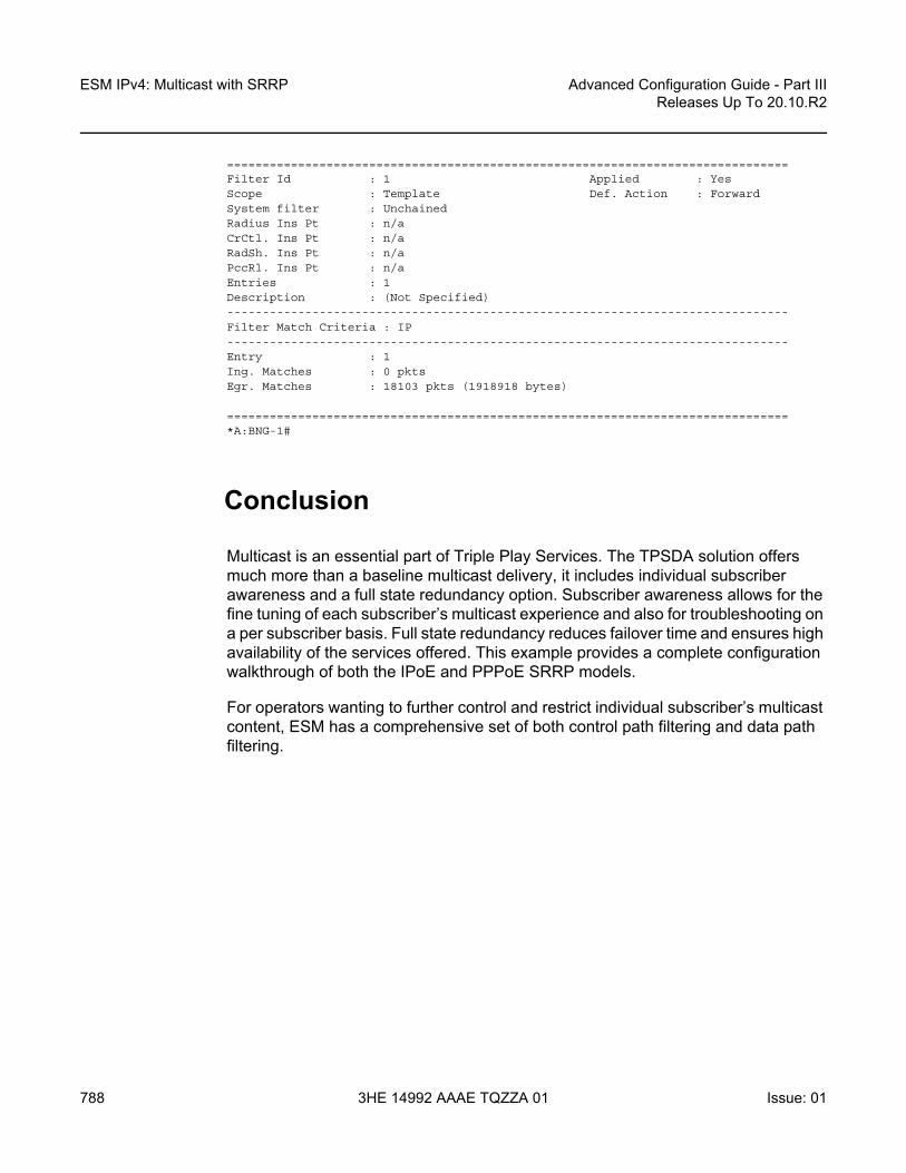
ESM IPv4: Multicast with SRRP
788
Advanced Configuration Guide - Part IIIReleases Up To 20.10.R2
3HE 14992 AAAE TQZZA 01 Issue: 01
===============================================================================Filter Id : 1 Applied : YesScope : Template Def. Action : ForwardSystem filter : UnchainedRadius Ins Pt : n/aCrCtl. Ins Pt : n/aRadSh. Ins Pt : n/aPccRl. Ins Pt : n/aEntries : 1Description : (Not Specified)-------------------------------------------------------------------------------Filter Match Criteria : IP-------------------------------------------------------------------------------Entry : 1Ing. Matches : 0 pktsEgr. Matches : 18103 pkts (1918918 bytes)
===============================================================================*A:BNG-1#
Conclusion
Multicast is an essential part of Triple Play Services. The TPSDA solution offers much more than a baseline multicast delivery, it includes individual subscriber awareness and a full state redundancy option. Subscriber awareness allows for the fine tuning of each subscriber’s multicast experience and also for troubleshooting on a per subscriber basis. Full state redundancy reduces failover time and ensures high availability of the services offered. This example provides a complete configuration walkthrough of both the IPoE and PPPoE SRRP models.
For operators wanting to further control and restrict individual subscriber’s multicast content, ESM has a comprehensive set of both control path filtering and data path filtering.

Advanced Configuration Guide - Part III Releases Up To 20.10.R2
ESM SLAAC Prefix Assignment via Local AddressServer
Issue: 01 3HE 14992 AAAE TQZZA 01 789
ESM SLAAC Prefix Assignment via Local Address ServerThis chapter provides information about ESM SLAAC prefix assignment via local address server.
Topics in this chapter include:
• Applicability• Overview• Configuration• Conclusion
Applicability
The information and configuration in this chapter was based on SR OS release 13.0.R1. The CLI in the current edition is SR OS release 16.0.R7 based. Both Internet Protocol over Ethernet (IPoE) and Point-to-Point Protocol over Ethernet (PPPoE) are supported.
Overview
Triple Play Service Delivery Architecture (TPSDA) supports IPv6 address/prefix assignment through Dynamic Host Configuration Protocol (DHCP), Point-to-Point Protocol (PPP), and Stateless Address Auto-Configuration (SLAAC). This chapter provides configuration examples of SLAAC prefix assignment via the local address server.
The network topology shown in Figure 133 shows a TPSDA setup. The setup consists of a 7750 SR serving as a Broadband Network Gateway (BNG). The 7450 is used as a Layer 2 switch aggregating all subscriber traffic.

ESM SLAAC Prefix Assignment via Local Address Server
790
Advanced Configuration Guide - Part IIIReleases Up To 20.10.R2
3HE 14992 AAAE TQZZA 01 Issue: 01
Figure 133 TPSDA Network Topology
There are two methods available for subscriber SLAAC prefix assignment. The first method, not covered in this chapter, is to pre-define a static SLAAC prefix for each subscriber on the BNG, in a Local User Database (LUDB) or via a RADIUS AAA server. With such a configuration, the database would contain hundreds of thousands of /64 SLAAC prefixes, each with their associated host. Every time a subscriber moved to a new location (a new subnet), the allocation of a new prefix within the new subnet would be required, along with a manual update of the database.
The second method, covered in this chapter, is to simplify SLAAC prefix assignment. A local address server is configured to dynamically assign SLAAC prefixes to hosts. Only a SLAAC pool name is obtained from RADIUS or LUDB after a successful subscriber authentication. This pool name is then used to assign a SLAAC prefix to the subscriber, out of the named address pool.
Using a local pool for SLAAC prefix assignment provides the following advantages:
• Reduces the configuration required on the RADIUS server, the local user database (LUDB), and the BNG to a few lines;
• Removes the complexity of managing actual prefixes in a database; • Reduces configuration errors; for example, accidentally assigning the same
prefix to two different subscribers.
The local address server already has tools, logs, and monitoring features for prefix management, such as prefix depletion and subnet migration. Service providers can rely on the local address server to assist in SLAAC prefix assignment.
al_0805
7750 SR
BNG-1
IES
7450
Subscribers
IPoE/PPPoE session
Aggregation Switch (Agg-1)

Advanced Configuration Guide - Part III Releases Up To 20.10.R2
ESM SLAAC Prefix Assignment via Local AddressServer
Issue: 01 3HE 14992 AAAE TQZZA 01 791
Configuration
This guide assumes a basic knowledge of ESM.
Different Types of SLAAC Hosts
SLAAC is supported for both PPP and IP over Ethernet hosts. The local address server can be enabled for either or both host types on a group interface level.
PPP SLAAC Hosts
PPP IPv4 hosts rely on IPCP to retrieve an IPv4 address. However, IPv6CP does not assign IPv6 addresses or prefixes to the host. PPP hosts rely on router solicitations (RSs) or DHCPv6 to obtain IPv6 addresses/prefixes.
PPP SLAAC hosts creation requires three configuration steps.
Step 1. Following is a baseline PPP subscriber management configuration on the BNG.
# on BNG-1configure
serviceies 1 customer 1 create
subscriber-interface "sub-int-1" createipv6
subscriber-prefixesprefix 2001:db8::/32 wan-host
exitexitgroup-interface "group-int-1" create
ipv6router-advertisements
prefix-optionsautonomous
exitno shutdown
exitexitsap 1/1/1:1 create
sub-sla-mgmtdef-sub-id use-sap-iddef-sub-profile "sub-profile-1"def-sla-profile "sla-profile-1"sub-ident-policy "sub-ident-policy-1"multi-sub-sap 10

ESM SLAAC Prefix Assignment via Local Address Server
792
Advanced Configuration Guide - Part IIIReleases Up To 20.10.R2
3HE 14992 AAAE TQZZA 01 Issue: 01
no shutdownexit
exitpppoe
no shutdownexit
exitexit
exit
Step 2. A DHCPv6 server is used as the local address server to assign SLAAC prefixes. It is possible to reuse the same pool for both DHCPv6 and SLAAC address/prefix assignment. For SLAAC hosts, the keyword wan-host is required.
# on BNG-1configure
routerdhcp6
local-dhcp-server "dhcp6-server-1" createuse-pool-from-clientpool "pool-v6-1" create
prefix 2001:db8::/32 wan-host createexit
exitno shutdown
exitexit
Step 3. On the PPP group interface, configure the local address server. Specify that the local address server is to be used for client application ppp-slaac. The server name must match the name configured for the DHCPv6 server (step 2). The DHCPv6 server is reused as the local address server.
# on a/BNG1configure
serviceies 1
subscriber-interface "sub-int-1" creategroup-interface "group-int-1" create
local-address-assignmentipv6
client-application ppp-slaac ipoe-slaacserver "dhcp6-server-1"
exitno shutdown
exitexit
exitexit
There are two options for supplying a SLAAC pool name for a PPP host: RADIUS and LUDB.

Advanced Configuration Guide - Part III Releases Up To 20.10.R2
ESM SLAAC Prefix Assignment via Local AddressServer
Issue: 01 3HE 14992 AAAE TQZZA 01 793
Option 1: During PPP authentication, RADIUS can return the SLAAC pool name attribute along with other subscriber attributes. Note: Remove the user-db configuration from pppoe when using RADIUS authentication. Add an authentication policy to the group interface to enable RADIUS authentication.
# on a/BNG1configure
serviceies 1
subscriber-interface "sub-int-1" creategroup-interface "group-int-1" create
authentication-policy "auth-policy-1"exit
exitexit
Then, add the attribute Alc-SLAAC-IPv6-Pool to the RADIUS user database. The following is an example from a freeradius clients file.
user_ppp_01 Auth-Type := CHAP, Cleartext-Password := passwordAlc-SLA-Prof-Str = "sla-profile-1",Alc-Subsc-ID-Str = "home-ppp-1",Alc-Subsc-Prof-Str = "sub-profile-1",Alc-SLAAC-IPv6-Pool = pool-v6-1,Alc-PPP-Force-IPv6CP = 1
Option 2: During PPP authentication, an LUDB can return the SLAAC pool name attribute along with other subscriber attributes. Note: Remove the authentication policy from the group interface when using LUDB.
First, create an LUDB and add a user to the LUDB. This LUDB is configured with a default host for all PPPoE hosts and returns a default SLAAC pool name.
# on a/BNG1configure
subscriber-mgmtlocal-user-db "pppoe-ludb-lookup" create
pppmatch-list usernamehost "default" create
ipv6-slaac-prefix-pool "pool-v6-1"no shutdown
exitexitno shutdown
exitexit
exit
Then, refer to this LUDB from the group interface.

ESM SLAAC Prefix Assignment via Local Address Server
794
Advanced Configuration Guide - Part IIIReleases Up To 20.10.R2
3HE 14992 AAAE TQZZA 01 Issue: 01
# on a/BNG1configure
serviceies 1
subscriber-interface "sub-int-1" creategroup-interface "group-int-1" create
pppoeuser-db "pppoe-ludb-lookup"no shutdown
exitexit
exitexit
With the preceding configuration, this group interface supports SLAAC prefix assignment through the local address pool. The following is the result of a PPP host being assigned a SLAAC prefix by the local address server.
*A:BNG-1# show service active-subscribers hierarchy
===============================================================================Active Subscribers Hierarchy===============================================================================-- 1/1/1:1 (sub-profile-1)
|+-- sap:1/1/1:1 - sla:sla-profile-1
|+-- PPP-session - mac:00:00:00:11:11:11 - sid:1 - svc:1
| circuit-id:circuit1|+-- 2001:db8::/64 - SLAAC
-------------------------------------------------------------------------------Number of active subscribers : 1Flags: (N) = the host or the managed route is in non-forwarding state===============================================================================*A:BNG-1#
In the show pppoe session, the IPv6 prefix is from the local address pool and the pool name is from authentication (RADIUS or LUDB).
*A:BNG-1# show service id 1 pppoe session detail
===============================================================================PPPoE sessions for svc-id 1===============================================================================Sap Id Mac Address Sid Up Time Type
IP/L2TP-Id/Interface-Id MC-Stdby-------------------------------------------------------------------------------1/1/1:1 00:00:00:11:11:11 1 0d 00:02:29 local
02:00:00:FF:FE:11:11:11
LCP State : OpenedIPCP State : ClosedIPv6CP State : Opened

Advanced Configuration Guide - Part III Releases Up To 20.10.R2
ESM SLAAC Prefix Assignment via Local AddressServer
Issue: 01 3HE 14992 AAAE TQZZA 01 795
PPP MTU : 1492PPP Auth-Protocol : CHAPPPP User-Name : sub@domain
Subscriber-interface : sub-int-1Group-interface : group-int-1
IP Origin : noneDNS Origin : noneNBNS Origin : none
Subscriber : "1/1/1:1"Sub-Profile-String : ""SLA-Profile-String : ""SPI group ID : (Not Specified)ANCP-String : ""Int-Dest-Id : ""App-Profile-String : ""Category-Map-Name : ""Acct-Session-Id : "0217FF0000000C5CB82FA7"Sap-Session-Index : 1
IP Address : N/APrimary DNS : N/ASecondary DNS : N/APrimary NBNS : N/ASecondary NBNS : N/AAddress-Pool : N/A
IPv6 Prefix : 2001:db8::/64IPv6 Prefix Origin : local-poolIPv6 Prefix Pool : "pool-v6-1"IPv6 Del.Pfx. : N/AIPv6 Del.Pfx. Origin : noneIPv6 Del.Pfx. Pool : ""IPv6 Address : N/AIPv6 Address Origin : noneIPv6 Address Pool : ""Primary IPv6 DNS : N/ASecondary IPv6 DNS : N/ARouter adv. policy : N/A
Ignoring DF bit : falseRadius sub-if prefix : N/A
Circuit-Id : circuit1Remote-Id :
Radius Session-TO : N/ARadius Class :Radius User-Name : sub@domainLogical-Line-Id :Service-Name :-------------------------------------------------------------------------------Number of sessions : 1===============================================================================*A:BNG-1#

ESM SLAAC Prefix Assignment via Local Address Server
796
Advanced Configuration Guide - Part IIIReleases Up To 20.10.R2
3HE 14992 AAAE TQZZA 01 Issue: 01
ICMP6 debugging can be used to show the SLAAC address assignment process.
debugrouter
ipicmp6
exitexit
43 2019/04/18 10:04:55.642 CEST MINOR: DEBUG #2001 Base TIP"TIP: ICMP6_PKTICMP6 egressing on group-int-1 (Base):
fe80::17:ffff:fe00:0 -> ff02::1Type: Router Advertisement (134)Code: No Code (0)
Hop Limit : 64Flags :Retrans Time : 0Def Life Time : 4500Reachable Time: 0Option : Prefix : 2001:db8::/64
Flags : On Link AutoconfigValid Life Time: 86400Pref Life Time: 3600
"
IPoE SLAAC Hosts
IPoE offers two methods to create an SLAAC host:
1. Triggered by a successful IPv4 host creation2. Triggered by an RS request
SLAAC Host Creation via IPv4 Host
A successful IPv4 host creation can subsequently trigger the creation of a SLAAC host; this is known as IPoE-linking. The SLAAC prefix for the host must be provided through either RADIUS or LUDB during the IPv4 host authentication.
IPoE SLAAC host creation through IPoE linking requires four steps.
Step 1. Following is a baseline IPoE subscriber management configuration on the BNG.
# on BNG-1configure
service

Advanced Configuration Guide - Part III Releases Up To 20.10.R2
ESM SLAAC Prefix Assignment via Local AddressServer
Issue: 01 3HE 14992 AAAE TQZZA 01 797
ies 1 customer 1 createdescription "BNG-1"subscriber-interface "sub-int-1" create
address 10.255.255.253/8ipv6
subscriber-prefixesprefix 2001:db8::/32 wan-host
exitexitgroup-interface "group-int-1" create
dhcpserver 192.168.0.1lease-populate 10client-applications dhcpgi-address 10.255.255.253no shutdown
exitipv6
router-advertisementsprefix-options
autonomousexitno shutdown
exitexitsap 1/1/1:1 create
sub-sla-mgmtdef-sub-id use-sap-id--- snipped ---multi-sub-sap 10no shutdown
exitexit
exitexit
Step 2. Enable IPoE-linking to allow SLAAC host creation after a successful IPv4 host creation. Several options should be enabled for the SLAAC host to function. Gratuitous router advertisement will send unsolicited router advertisements with a SLAAC prefix for the host to use. The BNG uses the gratuitous router advertisement to let the subscriber know the assigned prefix to auto-configure. In this case, where prefixes are dynamically assigned, the subscriber will not know the prefix ahead of time, so the gratuitous router advertisement must be enabled. Shared-circuit-id will allow the SLAAC host to use the same circuit ID as the IPv4 host.
# on BNG-1configure
serviceies 1
subscriber-interface "sub-int-1"group-interface "group-int-1"
ipoe-linkingshared-circuit-idgratuitous-rtr-advno shutdown
exit

ESM SLAAC Prefix Assignment via Local Address Server
798
Advanced Configuration Guide - Part IIIReleases Up To 20.10.R2
3HE 14992 AAAE TQZZA 01 Issue: 01
Step 3. As with PPP hosts, the DHCPv6 server is reused as the local address server for SLAAC prefix assignment. It is possible to reuse the same pool for both DHCPv6 and SLAAC subscribers. For SLAAC hosts, the keyword wan-host is required. In this case, an IPv4 host must be created first to trigger the creation of the IPv6 SLAAC host. The following example uses the local DHCPv4 server for IPv4 address assignment, but it is possible to use other methods for IPv4 address assignment, such as through LUDB and RADIUS proxy.
configurerouter
dhcplocal-dhcp-server "dhcp-server-1" create
use-gi-address scope poolpool "pool-v4-1" create
subnet 10.0.0.0/8 createoptions
subnet-mask 255.0.0.0default-router 10.255.255.253
exitaddress-range 10.0.0.10 10.0.0.254
exitexitno shutdown
exitexitdhcp6
local-dhcp-server "dhcp6-server-1" createuse-pool-from-clientpool "pool-v6-1" create
prefix 2001:db8::/32 wan-host createexit
exitno shutdown
exitexit
exitexit
Step 4. On the group interface, configure the local address server. Specify that the local address-server is to be used for client application ipoe-slaac. The server name must match the name configured for the DHCPv6 server (Step 3). The local address server reuses the local DHCPv6 server.
configureservice
ies 1subscriber-interface "sub-int-1" create
group-interface "group-int-1" createlocal-address-assignment
ipv6client-application ipoe-slaacserver "dhcp6-server-1"
exitno shutdown
exit

Advanced Configuration Guide - Part III Releases Up To 20.10.R2
ESM SLAAC Prefix Assignment via Local AddressServer
Issue: 01 3HE 14992 AAAE TQZZA 01 799
There are two options for supplying a SLAAC pool name for the DHCPv4 host: RADIUS and LUDB.
Option 1: During authentication, RADIUS can return the SLAAC pool name attribute along with other subscriber attributes. Note: Remove the user-db configuration from the DHCP and IPOE-session context when using RADIUS authentication. First, add an authentication policy to the group interface to allow RADIUS authentication.
# on a/BNG1configure
serviceies 1
subscriber-interface "sub-int-1" creategroup-interface "group-int-1" create
authentication-policy "auth-policy-1"exit
exitexit
Then, add the attribute Alc-SLAAC-IPv6-Pool to the subscriber host RADIUS user database. The following is an example using the client file on freeradius.
00:00:10:10:12:13 Cleartext-Password := passwordAlc-SLA-Prof-Str = "sla-profile-1",Alc-Subsc-ID-Str = "home-ipoe-1",Alc-Subsc-Prof-Str = "sub-profile-1",Alc-SLAAC-IPv6-Pool = pool-v6-1
Option 2: During authentication, LUDB can return the SLAAC pool name attribute along with other subscriber attributes. Note: Remove the authentication policy from the group interface when using LUDB.
First, create an LUDB and add a user in the LUDB. This LUDB is configured with a default host for all DHCPv4 hosts and returns a default SLAAC pool name.
# on a/BNG1configure
subscriber-mgmtlocal-user-db "ipoe-ludb-lookup" create
ipoematch-list sap-idhost "default" create
ipv6-slaac-prefix-pool "pool-v6-1"no shutdown
exitexitno shutdown
exitexit
exit
Then, refer to this LUDB from the group interface. The LUDB can be referred to in two places.

ESM SLAAC Prefix Assignment via Local Address Server
800
Advanced Configuration Guide - Part IIIReleases Up To 20.10.R2
3HE 14992 AAAE TQZZA 01 Issue: 01
Nokia recommends that IPoE subscribers use an IPoE session. In this case, the LUDB is referenced from the group interface ipoe-session context.
# on a/BNG1configure
serviceies 1
subscriber-interface "sub-int-1" creategroup-interface "group-int-1" create
ipoe-sessionuser-db "ipoe-ludb-lookup"no shutdown
exitexit
exitexit
For operators that do not use IPoE sessions (not recommended), the LUDB is referenced from the group interface dhcp context.
# on a/BNG1configure
serviceies 1
subscriber-interface "sub-int-1" creategroup-interface "group-int-1" create
dhcpuser-db "ipoe-ludb-lookup"no shutdown
exitexit
exitexit
With the preceding configuration, the local address server on the group interface is ready to assign SLAAC prefixes. Start a DHCPv4 session to the group interface SAP.
*A:BNG-1# show service active-subscribers hierarchy===============================================================================Active Subscribers Hierarchy===============================================================================-- 1/1/1:1 (sub-profile-1)
|+-- sap:1/1/1:1 - sla:sla-profile-1
|+-- IPOE-session - mac:00:00:00:22:22:22 - svc:1
||-- 10.0.0.10 - DHCP|+-- 2001:db8::/64 - SLAAC
-------------------------------------------------------------------------------Number of active subscribers : 1Flags: (N) = the host or the managed route is in non-forwarding state===============================================================================*A:BNG-1#

Advanced Configuration Guide - Part III Releases Up To 20.10.R2
ESM SLAAC Prefix Assignment via Local AddressServer
Issue: 01 3HE 14992 AAAE TQZZA 01 801
In the show ipoe session, the IPv6 prefix origin is from the local address pool and the pool name is from authentication (RADIUS or LUDB).
*A:BNG-1# show service id 1 ipoe session detail
===============================================================================IPoE sessions for service 1===============================================================================
SAP : 1/1/1:1Mac Address : 00:00:00:22:22:22Circuit-Id : 11Remote-Id : AASession Key : sap-mac
MC-Standby : No
Subscriber-interface : sub-int-1Group-interface : group-int-1
Termination Type : localUp Time : 0d 00:07:55Session Time Left : N/ALast Auth Time : 04/18/2019 10:45:43Min Auth Intvl (left) : infinite (N/A)Persistence Key : N/A
Subscriber : "1/1/1:1"Sub-Profile-String : ""SLA-Profile-String : ""SPI group ID : (Not Specified)ANCP-String : ""Int-Dest-Id : ""App-Profile-String : ""Category-Map-Name : ""Acct-Session-Id : "0217FF000000215CB83937"Sap-Session-Index : 1
IP Address : 10.0.0.10/8IP Origin : DHCPPrimary DNS : N/ASecondary DNS : N/APrimary NBNS : N/ASecondary NBNS : N/AAddress-Pool : N/A
IPv6 Prefix : 2001:db8::/64IPv6 Prefix Origin : LclPoolIPv6 Prefix Pool : "pool-v6-1"IPv6 Del.Pfx. : N/AIPv6 Del.Pfx. Origin : NoneIPv6 Del.Pfx. Pool : ""IPv6 Address : N/AIPv6 Address Origin : NoneIPv6 Address Pool : ""Primary IPv6 DNS : N/ASecondary IPv6 DNS : N/ARouter adv. policy : N/A

ESM SLAAC Prefix Assignment via Local Address Server
802
Advanced Configuration Guide - Part IIIReleases Up To 20.10.R2
3HE 14992 AAAE TQZZA 01 Issue: 01
Radius sub-if prefix : N/A
Radius Session-TO : N/ARadius Class :Radius User-Name :
GTP IMSI :GTP APN : (Not Specified)-------------------------------------------------------------------------------Number of sessions : 1===============================================================================*A:BNG-1#
ICMP6 debugging can be used to show the SLAAC address assignment process.
debugrouter
ipicmp6
exitexit
exit
63 2019/04/18 10:45:44.212 CEST MINOR: DEBUG #2001 Base TIP"TIP: ICMP6_PKTICMP6 egressing on group-int-1 (Base):
fe80::17:ffff:fe00:0 -> ff02::1Type: Router Advertisement (134)Code: No Code (0)
Hop Limit : 64Flags :Retrans Time : 0Def Life Time : 4500Reachable Time: 0Option : Src Link Layer Addr 02:17:01:01:00:01Option : Prefix : 2001:db8::/64
Flags : On Link AutoconfigValid Life Time: 86400Pref Life Time: 3600
"
SLAAC Host Creation via RS Trigger
An IPv6 SLAAC host can be created through a host router originated solicit message, which removes the dependency of a SLAAC host on successful DHCPv4 host creation.
SLAAC hosts creation via RS trigger requires four configuration steps.
Step 1. The following is a baseline IPoE subscriber management configuration on the BNG.

Advanced Configuration Guide - Part III Releases Up To 20.10.R2
ESM SLAAC Prefix Assignment via Local AddressServer
Issue: 01 3HE 14992 AAAE TQZZA 01 803
# on BNG-1configure
serviceies 1
description "BNG-1"subscriber-interface "sub-int-1" create
ipv6subscriber-prefixes
prefix 2001:db8::/32 pd wan-hostexit
exitgroup-interface "group-int-1" create
ipv6router-advertisements
prefix-optionsautonomous
exitno shutdown
exitexitsap 1/1/1:1 create
sub-sla-mgmtdef-sub-id use-sap-iddef-sub-profile "sub-profile-1"def-sla-profile "sla-profile-1"sub-ident-policy "sub-ident-policy-1"multi-sub-sap 10no shutdown
exitexit
exitexit
exit
Step 2. Enable the group interface to process router solicit messages. There are a few options available for router solicit triggered hosts. The inactivity timer will remove the host if the global unique address of the host is not learned through Neighbor Solicitation (NS), Router Solicitation (RS), or Duplicate Address Detection (DAD) messages within the time specified. The min-auth-interval is the interval that a subscriber must wait before the next router-solicit messages is used for re-authentication. Re-authentication can occur if the first RS was lost, or the BNG/RADIUS system was queued up with requests.
# on a/BNG1configure
serviceies 1
subscriber-interface "sub-int-1" creategroup-interface "group-int-1" create
ipv6router-solicit
inactivity-timer min 5min-auth-interval min 5user-db "ipoe-ludb-lookup"no shutdown
exit

ESM SLAAC Prefix Assignment via Local Address Server
804
Advanced Configuration Guide - Part IIIReleases Up To 20.10.R2
3HE 14992 AAAE TQZZA 01 Issue: 01
Step 3. A DHCPv6 server is used as the local address server for SLAAC prefix assignment. It is possible to reuse the same pool for both DHCPv6 and SLAAC subscribers. For SLAAC hosts, the keyword wan-host is required.
# on BNG-1configure
routerdhcp6
local-dhcp-server "dhcp6-server-1" createuse-pool-from-clientpool "pool-v6-1" create
prefix 2001:db8::/32 wan-host createexit
exitno shutdown
exitexit
Step 4. On the group interface, configure the local address server. Specify that the local address server is to be used for client application ipoe-slaac. The server name must match the name configured for the DHCPv6 server. The local address server reuses the local DHCPv6 server.
# on BNG-1configure
serviceies 1 customer 1 create
subscriber-interface "sub-int-1" creategroup-interface "group-int-1" create
local-address-assignmentipv6
client-application ppp-slaac ipoe-slaacserver "dhcp6-server-1"
exitno shutdown
exitexit
There are two options for supplying the SLAAC pool name for the DHCPv4 host: RADIUS and LUDB.
Option 1: During authentication, RADIUS can return the SLAAC pool name attribute along with other subscriber attributes. Note: Remove the user-db configuration from the router-solicit and ipoe-session when using RADIUS authentication. First, add an authentication policy to the group interface to allow RADIUS authentication.
# on a/BNG1configure
serviceies 1
subscriber-interface "sub-int-1" creategroup-interface "group-int-1" create
authentication-policy "auth-policy-1"exit

Advanced Configuration Guide - Part III Releases Up To 20.10.R2
ESM SLAAC Prefix Assignment via Local AddressServer
Issue: 01 3HE 14992 AAAE TQZZA 01 805
Then, add the attribute Alc-SLAAC-IPv6-Pool to the subscriber host RADIUS user database.
00:00:10:10:12:13 Cleartext-Password := passwordAlc-SLA-Prof-Str = "sla-profile-1",Alc-Subsc-ID-Str = "home-ipoe-1",Alc-Subsc-Prof-Str = "sub-profile-1",Alc-SLAAC-IPv6-Pool = pool-v6-1,
Option 2: During authentication, LUDB can return the SLAAC pool name attribute along with other subscriber attributes. Note: Remove the authentication policy from the group interface when using LUDB.
First, create an LUDB and add a user in the LUDB. The LUDB configures a default host for all SLAAC hosts and returns a default SLAAC pool name.
# on BNG-1configure
subscriber-mgmtlocal-user-db "ipoe-ludb-lookup" create
ipoematch-list sap-idhost "default" create
ipv6-slaac-prefix-pool "pool-v6-1"no shutdown
exitexitno shutdown
exitexit
exit
Then, refer to this LUDB from the group interface. The LUDB can be referred to in two places.
Nokia recommends that IPoE subscribers use an IPoE session. In this case, the LUDB is referenced from the group interface ipoe-session context.
# on BNG-1configure
serviceies 1
subscriber-interface "sub-int-1" creategroup-interface "group-int-1" create
ipoe-sessionuser-db "ipoe-ludb-lookup"no shutdown
exitexit
exitexit

ESM SLAAC Prefix Assignment via Local Address Server
806
Advanced Configuration Guide - Part IIIReleases Up To 20.10.R2
3HE 14992 AAAE TQZZA 01 Issue: 01
For operators that do not enable IPoE sessions on the BNG (not recommended), the LUDB can be referred to from the group interface in the router-solicit context.
# on a/BNG1configure
serviceies 1
subscriber-interface "sub-int-1" creategroup-interface "group-int-1" create
ipv6router-solicit
user-db "ipoe-ludb-lookup"no shutdown
exitexit
exitexit
exit
With the preceding configuration, the group interface is ready to assign SLAAC prefixes from the local address pool. Let the host trigger a router solicit packet.
*A:BNG-1# show service active-subscribers hierarchy
===============================================================================Active Subscribers Hierarchy===============================================================================-- 1/1/1:1 (sub-profile-1)
|+-- sap:1/1/1:1 - sla:sla-profile-1
|+-- IPOE-session - mac:00:00:00:33:33:33 - svc:1
|+-- 2001:db8::/64 - SLAAC
-------------------------------------------------------------------------------Number of active subscribers : 1Flags: (N) = the host or the managed route is in non-forwarding state===============================================================================*A:BNG-1#
In the show ipoe session, the IPv6 prefix is from the local address pool and the pool name is from authentication (RADIUS or LUDB).
*A:BNG-1# show service id 1 ipoe session detail
===============================================================================IPoE sessions for service 1===============================================================================
SAP : 1/1/1:1Mac Address : 00:00:00:33:33:33Circuit-Id :Remote-Id :Session Key : sap-mac

Advanced Configuration Guide - Part III Releases Up To 20.10.R2
ESM SLAAC Prefix Assignment via Local AddressServer
Issue: 01 3HE 14992 AAAE TQZZA 01 807
MC-Standby : No
Subscriber-interface : sub-int-1Group-interface : group-int-1
Termination Type : localUp Time : 0d 00:02:21Session Time Left : N/ALast Auth Time : 04/18/2019 11:07:52Min Auth Intvl (left) : infinite (N/A)Persistence Key : N/A
Subscriber : "1/1/1:1"Sub-Profile-String : ""SLA-Profile-String : ""SPI group ID : (Not Specified)ANCP-String : ""Int-Dest-Id : ""App-Profile-String : ""Category-Map-Name : ""Acct-Session-Id : "0217FF000000255CB83E67"Sap-Session-Index : 1
IP Address : N/AIP Origin : NonePrimary DNS : N/ASecondary DNS : N/APrimary NBNS : N/ASecondary NBNS : N/AAddress-Pool : N/A
IPv6 Prefix : 2001:db8::/64IPv6 Prefix Origin : LclPoolIPv6 Prefix Pool : "pool-v6-1"IPv6 Del.Pfx. : N/AIPv6 Del.Pfx. Origin : NoneIPv6 Del.Pfx. Pool : ""IPv6 Address : N/AIPv6 Address Origin : NoneIPv6 Address Pool : ""Primary IPv6 DNS : N/ASecondary IPv6 DNS : N/ARouter adv. policy : N/ARadius sub-if prefix : N/A
Radius Session-TO : N/ARadius Class :Radius User-Name :
GTP IMSI :GTP APN : (Not Specified)-------------------------------------------------------------------------------Number of sessions : 1===============================================================================*A:BNG-1#
ICMP6 debugging can be used to show the SLAAC address assignment process.

ESM SLAAC Prefix Assignment via Local Address Server
808
Advanced Configuration Guide - Part IIIReleases Up To 20.10.R2
3HE 14992 AAAE TQZZA 01 Issue: 01
debugrouter
ipicmp6
exitexit
exit
71 2019/04/18 11:07:52.372 CEST MINOR: DEBUG #2001 Base TIP"TIP: ICMP6_PKTICMP6 egressing on group-int-1 (Base):
fe80::17:ffff:fe00:0 -> ff02::1Type: Router Advertisement (134)Code: No Code (0)
Hop Limit : 64Flags :Retrans Time : 0Def Life Time : 4500Reachable Time: 0Option : Src Link Layer Addr 02:17:01:01:00:01Option : Prefix : 2001:db8::/64
Flags : On Link AutoconfigValid Life Time: 86400Pref Life Time: 3600
"
Conclusion
7750 SR TPSDA offers a variety of address assignment options such as PPP, DHCPv4, DHCPv6, and SLAAC. These options allow service providers to pick the address assignment scheme that best fits their networks. SLAAC address assignment is an essential IPv6 address assignment protocol. Having to assign a static prefix per subscriber host in advance could be a challenge for operators. This chapter provides a complete configuration example of using the local address server to assign prefixes dynamically to IPoE and PPPoE subscriber hosts. This efficient way to assign SLAAC prefixes to subscribers enables operators to achieve a faster time to market for new IPv6 services.

Advanced Configuration Guide - Part III Releases Up To 20.10.R2
ESMv4: PPPoE Hosts
Issue: 01 3HE 14992 AAAE TQZZA 01 809
ESMv4: PPPoE HostsThis chapter describes advanced IPv4 Enhanced Subscriber Management (ESM) PPPoE host configurations.
Topics in this chapter include:
• Applicability• Summary• Overview• Configuration• Conclusion
Applicability
This chapter applies to SR OS routers and was written for release 8.0.R4. The CLI is updated to release 15.0.R2.
This chapter describes support of PPP termination and aggregation (PTA) hosts. L2TP-hosts are out of the scope of this chapter. Only IPv4 PPPoE hosts are handled in this chapter.
PPPoE hosts are only supported in a Routed CO model (IES or VPRN) using Ethernet SAPs with null, dot1q, or QinQ encapsulation.
Summary
The delivery of services to residential customers encompassing voice, video, and data is covered by Triple Play Service Delivery Architecture (TPSDA).
In the TPSDA, a subscriber is defined as a collection of hosts pertaining to a single access connection (for example, DSL line) and identified by a subscriber identifier. A subscriber host is an end user terminal within the subscriber home (PC, set-top box, home gateway) that is identified in the network with a unique (IP address/MAC address) tuple for IPoE or (PPPoE session ID; MAC address) tuple for PPPoE.

ESMv4: PPPoE Hosts
810
Advanced Configuration Guide - Part IIIReleases Up To 20.10.R2
3HE 14992 AAAE TQZZA 01 Issue: 01
The following host types are distinguished:
Static hosts
• ip-mac• ip-only
Dynamic hosts
• ARP-host• DHCP-host• PPPoE-host
This chapter provides configuration and troubleshooting commands for PPPoE-hosts and will use a local user database (LUDB) for host authentication and ESM (Enhanced Subscriber Management) string assignments.
The IP information in this chapter is retrieved from a Local DHCP server.
The authentication, IP information, and ESM strings can come all from an LUDB, a RADIUS server, a (local) DHCP server, or any combination of them. These combinations are out of the scope of this chapter.
Knowledge of the TPSDA concept is assumed throughout this document.
Overview
PPPoE Hosts in a Routed CO Environment
The network topology for a Routed CO environment is displayed in Figure 134.

Advanced Configuration Guide - Part III Releases Up To 20.10.R2
ESMv4: PPPoE Hosts
Issue: 01 3HE 14992 AAAE TQZZA 01 811
Figure 134 Routed CO Network Topology
The following configuration tasks should already be configured and are not detailed or explained in this chapter. See the appropriate user guide.
• Basic service router configuration (system interface, IGP, MPLS, BGP)• Routed CO service topology: VPRN or IES service with subscriber- and group-
interface on BSR-1• ESM • Local User Data Base (LUDB) • Local Dynamic Host Configuration Protocol (DHCP) server
In the Routed CO model, PPPoE hosts can be instantiated in routed services, such as the base router, IES, and VPRN. The configuration section of this chapter focuses on PPPoE hosts instantiated in a VPRN servicelocated in BSR-1 (Routed CO).
Review of the PPPoE Protocol
PPPoE, Point-to-Point Protocol over Ethernet, is a network protocol for encapsulating PPP frames inside Ethernet frames. The protocol is described in RFC 2516, A Method for Transmitting PPP Over Ethernet (PPPoE), and is based on RFC 1661, The Point-to-Point Protocol (PPP), which provides a standard method for transporting multi-protocol datagrams over point-to-point links.
PPP has three main components:
• A method for encapsulating multi-protocol datagrams.• A link control protocol (LCP) for establishing, configuring, and testing the data-
link connection.• A family of network control protocols (NCP) for establishing and configuring
different network-layer protocols.
BSAN BSR-1
Simulated
Local DHCP server/local DB
OSSG448
ESM

ESMv4: PPPoE Hosts
812
Advanced Configuration Guide - Part IIIReleases Up To 20.10.R2
3HE 14992 AAAE TQZZA 01 Issue: 01
Ethernet networks are packet-based and have no concept of a connection or circuit. By using PPPoE, users can virtually dial from one machine to another over an Ethernet network; establish a point to point connection between them and then transport data packets over the connection.
In a typical wire-line solution with broadband access, PPPoE is used between a client (PC or modem) and a Network Access Server (NAS) (also called Broadband Network Gateway (BNG) or Broadband Service Router (BSR)) through an access node, like a Broadband Service Access Node (BSAN).
PPPoE consists of two phases, the Discovery Stage and the Session Stage.
Discovery Stage
The discovery phase offers a stateless client-server model. When the Discovery Stage completes, both peers know the PPPoE SESSION_ID and the peer's Ethernet address, which together uniquely define the PPPoE session. There are four steps in the Discovery Stage:
Step 1. PPPoE Active Discovery Initiation (PADI)Initiation (Host broadcast) — This broadcast packet is used by the client to search for an active server (BNG/BSR/NAS) providing access to a service.Additional attributes on the PADI message could be added if a BSAN is situated between the client and the BRAS.
Step 2. PPPoE Active Discovery Offer (PADO)Access concentrator unicast — If the access server can provide the service it will respond with a unicast PADO to signal the client it may request connectivity. Multiple servers may respond and the client may choose a server to connect.
Step 3. PPPoE Active Discovery Request (PADR):Host unicast — After the client receives a PADO it will send a PADR unicast packet to connect to a server.
Step 4. PPPoE Active Discovery Session-Confirmation (PADS)Access concentrator unicast — A server will respond to the client with this unicast packet to establish the session and provide the session-id. Once the PADS was provided, the Session Stage begins.Discovery PPPoE Ethernet frames have the ETHER_TYPE field set to the value 0x8863.

Advanced Configuration Guide - Part III Releases Up To 20.10.R2
ESMv4: PPPoE Hosts
Issue: 01 3HE 14992 AAAE TQZZA 01 813
PPPoE Tags
IANA has set up a registry of PPPoE tag values (16-bit values). PPPoE tag values already in use are specified as reserved values as shown in Table 18. All other tag values between 0 and 65535 are to be assigned by IANA.
Explanations for some PPPoE tags (RFC 2516) are shown in the PPPoE discovery debug messages:
0x0101 Service-Names — This tag indicates that a service name follows. The tag_value is an UTF-8 string that is not null terminated. When the tag_length is zero, this tag is used to indicate that any service is acceptable. Examples of the use of the service-name tag are to indicate an ISP name or a class or quality of service.
Table 18 Reserved PPPoE Tags
Tag Value Tag Name
0 0x0000 End-Of-List
257 0x0101 Service-Name
258 0x0102 AC-Name
259 0x0103 Host-Uniq
260 0x0104 AC-Cookie
261 0x0105 Vendor-Specific
262 0x0106 Credits
263 0x0107 Metrics
264 0x0108 Sequence Number
272 0x0110 Relay-Session-Id
273 0x0111 HURL
274 0x0112 MOTM
288 0x0120 PPP-Max-Payload
289 0x0121 IP_Route_Add
513 0x0201 Service-Name-Error
514 0x0202 AC-System-Error
515 0x0203 Generic-Error

ESMv4: PPPoE Hosts
814
Advanced Configuration Guide - Part IIIReleases Up To 20.10.R2
3HE 14992 AAAE TQZZA 01 Issue: 01
(0x0102) AC-Names — This tag indicates that a string follows which uniquely identifies this particular Access Concentrator unit from all others. It may be a combination of trademark, model, and serial id information, or simply an UTF-8 rendition of the MAC address of the box. It is not null terminated.
(0x0103) Host-Uniq — This tag is used by a host to uniquely associate an access concentrator response (PADO or PADS) to a particular host request (PADI or PADR). The tag_value is binary data of any value and length that the host chooses. It is not interpreted by the Access Concentrator. The host may include a host-uniq tag in a PADI or PADR. If the access concentrator receives this tag, it must include the tag unmodified in the associated PADO or PADS response.
(0x0104) AC-Cookie — This tag is used by the access concentrator to aid in protecting against denial of service attacks. The access concentrator may include this tag in a PADO packet. If a host receives this tag, it must return the tag unmodified in the following PADR. The tag_value is binary data of any value and length and is not interpreted by the host.
Figure 135 Discovery Stage Messages
BSAN BSR-1
Simulated
Local DHCP Server/Local DB
OSSG449-2a
ESM
PADI, Session ID: 0x0000PPPoE tag: option: 0x101, 0x103 PPPoE enabled under froup
interface with ludb-1
Discovery Stage
PADO, Session ID: 0x0000PPPoE tag: option: 0x101, 0x102, 0x103, 0x104
PADR, Session ID: 0x0000PPPoE tag: option; 0x101, 0x102, 0x103, 0x104
PADS, Session ID: 0x0001PPPoE tag: option: 0x101, 0x102, 0x103

Advanced Configuration Guide - Part III Releases Up To 20.10.R2
ESMv4: PPPoE Hosts
Issue: 01 3HE 14992 AAAE TQZZA 01 815
Session Stage
This next stage after Discovery is called the Session Stage. Once the MAC address of the peer is known and a session-id is exchanged, the two end points have all the information needed to start building a point-to-point connection over Ethernet and exchange packets over the connection.
This stage can be divided into to the following sections:
• Setup• Maintenance• Termination
Setup
PPP Link Control Protocol (LCP)
Both the NAS and the user open the PPP session based on LCP packets. All post-discovery PPPoE Ethernet frames have the ETHER_TYPE field set to the value 0x8864.
The authentication method and the MRU are negotiated during this phase.
RFC 2516 mandates a maximum negotiated Maximum Receive Unit (MRU) of 1492.
RFC 4638, Accommodating a Maximum Transit Unit/Maximum Receive Unit (MTU/MRU) Greater Than 1492 in the Point-to-Point Protocol over Ethernet (PPPoE), relaxes this restriction and allows a maximum negotiated MRU greater than 1492 to minimize fragmentation in next-generation broadband networks.
The SR OS implementation follows RFC 4638 when the client implements these extensions.
LCP uses config_request and config_ack/nack to negotiate parameters:
• LCP goes to final state opened when configure-ack is sent & received.• The own options are proposed in configure request.
There are three cases for the LCP negations parameters:
• Peer supports the option and its content. - Peer will agree and send config-ack.

ESMv4: PPPoE Hosts
816
Advanced Configuration Guide - Part IIIReleases Up To 20.10.R2
3HE 14992 AAAE TQZZA 01 Issue: 01
• Peer does not support an option - Peer will send configure-reject with the option that is not supported.- Resend of configure-request without that option.- Peer agrees and sends config-ack.
• Peer does support the option, but not the content.- Peer will send config-nack with the option and its new content.- Resend of configure-request with same options but new content.- Peer agrees and sends config-ack.
Table 19 LCP and IPCP Code
Code Packet Type
1 Configure-Request
2 Configure-Ack
3 Configure-Nak
4 Configure-Reject
5 Terminate-Request
6 Terminate-Ack
7 Code-Reject
8 Protocol-Reject
9 Echo-Request
10 Echo-Reply
11 Discard-Request
12 Identification
13 Time-Remaining
14 Reset-request CCP
15 Reset-Ack CCP

Advanced Configuration Guide - Part III Releases Up To 20.10.R2
ESMv4: PPPoE Hosts
Issue: 01 3HE 14992 AAAE TQZZA 01 817
Figure 136 LCP Phase Messages
Authentication Phase
The client authenticates itself through PAP (PPP Password Authentication Protocol) or CHAP (Challenge Handshake Authentication Protocol) to check for access permission. For the CHAP authentication, the BSR initiates the authentication as shown in Figure 137. The password is hashed on the link and plain text in the RADIUS Access-Request message.
BSAN BSR-1
Simulated
Local DHCP server/local DB
OSSG449
ESM
PADI, Session ID: 0x0000PPPoE tag: option: 0x101, 0x103 pppoe Enabled Under Group
Interface With ludb-1
Discovery Stage
PADO, Session ID: 0x0000PPPoE tag: option: 0x101, 0x102, 0x103, 0x104
PADR, Session ID: 0x0000PPPoE tag: option; 0x101, 0x102, 0x103, 0x104
PADS, Session ID: 0x0001PPPoE tag: option: 0x101, 0x102, 0x103

ESMv4: PPPoE Hosts
818
Advanced Configuration Guide - Part IIIReleases Up To 20.10.R2
3HE 14992 AAAE TQZZA 01 Issue: 01
Figure 137 CHAP Handshaking Overview Process
For PAP, the client initiates the authentication as shown in Figure 138. The password is sent as plain text on the link and hashed in a RADIUS Access-Request message.
Figure 138 PAP Overview Process
BSAN BSR-1
Simulated Local DHCP server/local DB
OSSG454
ESM
(1) Challenge
HashUser-name
Sid x HashUser-name
Sid x
Random-yuser-pswsid x
MDS
Name BSRSession id xRandom-y
Name BSRsid xRandom-y
LookupUser-name
Random-yuser-psw
sid x
MDS
Hash = ? Hash
(2) Response
(4) Failure
(3) Success
BSAN BSR-1
Simulated Local DHCP server/local DB
OSSG455
ESM
(1) Auth-requestpeer-id: name userpassword: user-psw
name useruser-psw
Check in the databasename user = name useruser psw = user psw
(3) Auth-nack “login incorrect”
(2) Auth-ack “login ok”

Advanced Configuration Guide - Part III Releases Up To 20.10.R2
ESMv4: PPPoE Hosts
Issue: 01 3HE 14992 AAAE TQZZA 01 819
Network-Layer Protocol Phase (PPP IPCP Opening Phase)
At this stage, the user requests an IP address to be used for data transmission. During this negotiation, the client will also receive a Domain Name Server (DNS), NBNS (Netbios Name Server) address, etc. if they are requested.
Figure 139 IPCP Phase Messages
Maintenance
PPP uses keepalives in order to maintain the integrity of the connection. This keepalive mechanism uses an echo-request that is sent to remote PPP peer, following which the remote PPP peer should respond with an echo-reply. The connection is considered down if a number of echo replies are missed. Both sides can initiate keepalives which run independently.
BSAN BSR-1
Simulated Local DHCP server/local DB
OSSG456
ESM
IPCP Configure-request, Session ID: 0x0001, ID=198 [3]IP address: 10.2.0.254
SessionStage:
IPCP
IPCP Configure-request, Session ID: 0x0001, ID=1 [3]IP address: 0.0.0.0
IPCP Configure-ack, Session ID: 0x0001, ID=106 [3]IP address: 10.2.0.254
IPCP Configure-request, Session ID: 0x0001, ID=2 [3]IP address: 10.2.0.82
IPCP Configure-ack, Session ID: 0x0001, ID=2 [3]IP address: 10.2.0.82
IPCP Configure-nack, Session ID: 0x0001, ID=1 [3]IP address: 10.2.0.82

ESMv4: PPPoE Hosts
820
Advanced Configuration Guide - Part IIIReleases Up To 20.10.R2
3HE 14992 AAAE TQZZA 01 Issue: 01
Figure 140 Keepalive Messages
Termination
Link Termination Phase
A PPPoE session can be terminated by either the client or the BRAS and consists of a Terminate-request followed by a PADT.
Figure 141 Link Termination Phase
BSAN BSR-1
Simulated Local DHCP server/local DB
OSSG457
ESM
Link Control Protocol, Echo-request,Session ID:0x001 Value
SessionKeepalive
Link Control Protocol, Echo-request,Session ID:0x001 Value
Link Control Protocol, Echo-reply,Session ID:0x001 Value
Link Control Protocol, Echo-reply,Session ID:0x001 Value
BSAN BSR-1
Simulated Local DHCP server/local DB
OSSG458
ESM
Terminate-request, Session ID: 0x001 Value
TerminationLink Termination
Phase
Terminate-ack, Session ID: 0x001 Value
PADT, Session ID: 0x001 Value
PADT, Session ID: 0x001 Value
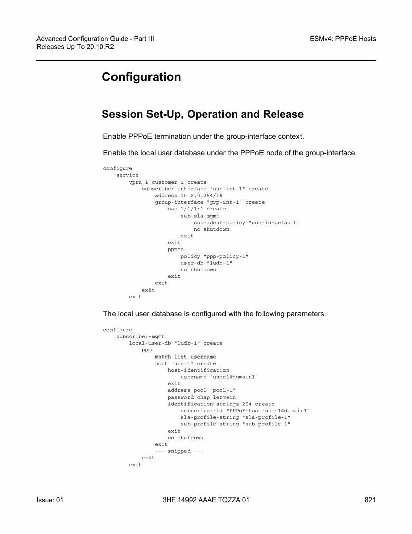
Advanced Configuration Guide - Part III Releases Up To 20.10.R2
ESMv4: PPPoE Hosts
Issue: 01 3HE 14992 AAAE TQZZA 01 821
Configuration
Session Set-Up, Operation and Release
Enable PPPoE termination under the group-interface context.
Enable the local user database under the PPPoE node of the group-interface.
configureservice
vprn 1 customer 1 createsubscriber-interface "sub-int-1" create
address 10.2.0.254/16group-interface "grp-int-1" create
sap 1/1/1:1 createsub-sla-mgmt
sub-ident-policy "sub-id-default"no shutdown
exitexitpppoe
policy "ppp-policy-1"user-db "ludb-1"no shutdown
exitexit
exitexit
The local user database is configured with the following parameters.
configuresubscriber-mgmt
local-user-db "ludb-1" createppp
match-list usernamehost "user1" create
host-identificationusername "user1@domain1"
exitaddress pool "pool-1"password chap letmeinidentification-strings 254 create
subscriber-id "PPPoE-host-user1@domain1"sla-profile-string "sla-profile-1"sub-profile-string "sub-profile-1"
exitno shutdown
exit--- snipped ---
exitexit

ESMv4: PPPoE Hosts
822
Advanced Configuration Guide - Part IIIReleases Up To 20.10.R2
3HE 14992 AAAE TQZZA 01 Issue: 01
The PPPoE policy ppp-policy-1 is defined as follows:
*A:BSR-1# configure subscriber-mgmt ppp-policy "ppp-policy-1"*A:BSR-1>config>subscr-mgmt>ppp-policy# info detail----------------------------------------------
no descriptionno default-pap-passwordno default-user-namedisable-cookiesno force-ppp-mtu-gt-1492no ipcp-subnet-negotiationkeepalive 30 hold-up-multiplier 3no pado-ac-namepado-delay 30no ppp-initial-delayno ppp-mtuno lcp-ignore-magic-numbersmax-sessions-per-mac 63mlppp
no accept-mrruno endpointno short-sequence-numbers
exitreply-on-padtppp-authentication pref-chapppp-chap-challenge-length min 32 max 64no unique-sid-per-sapno re-establish-sessionno reject-disabled-ncpno session-timeoutppp-optionsexit
----------------------------------------------*A:BSR-1>config>subscr-mgmt>ppp-policy#
The PPPoE policy defines the parameters which are used when establishing the PPPoE session, and includes:
• Disable-cookies — This parameter disables the use of cookies.• Keepalive — This command defines the keepalive interval and the number of
keepalives that can be missed before the session is declared down for this PPPoE policy.- [10 — 300] seconds: Specifies the keepalive interval in seconds.- hold-up-multiplier [1 — 5]: Specifies the number of keepalives that can be
missed.• PADO-delay — This parameter configures the delay timeout before sending a
PPPoE Active Discovery Offer (PADO) packet.- [1 — 30] deciseconds
• PPP-mtu — This parameter configures the maximum PPP MTU size.- [512 — 9212]: possible values for MTU size.

Advanced Configuration Guide - Part III Releases Up To 20.10.R2
ESMv4: PPPoE Hosts
Issue: 01 3HE 14992 AAAE TQZZA 01 823
• Max-sessions-per-mac — This parameter sets the maximum PPPoE sessions that can be opened for the MAC address. - [1 — 63]: possible PPPoE sessions per MAC address.
• Reply-on-PADT — Some of the PPPoE clients expect reply on PPPoE Active Discovery Terminate (PADT) message before the context of the session is cleared up. To support such client, a command enabling reply to PADT is provided.- [Default] no reply-on-padt
• PPP-options — This parameter enables the context to configure PPP options which is not supported by default
These parameters will be explained later in details according to their existence in the respective PPPoE phase.
Multiple PPPoE policies may be configured, but the default policy cannot be modified or deleted.
The PPPoE policy is applied within the PPPoE context under the group interface.
Troubleshooting the PPPoE discovery messages (PADI, PADO, PADR, PADS, and PADT) is done through PPPoE debugging:
*A:BSR-1# debug service id 1 ppp packet discovery- discovery [padi] [pado] [padr] [pads] [padt]- no discovery
<padi> : keyword - debug PADI packets<pado> : keyword - debug PADO packets<padr> : keyword - debug PADR packets<pads> : keyword - debug PADS packets<padt> : keyword - debug PADT packets
*A:BSR-1#
*A:BSR-1# show debugdebug
serviceid 1
ppppacket
mode egr-ingr-and-droppeddiscoverypppdhcp-client
exitexit
exitexit
exit*A:BSR-1#

ESMv4: PPPoE Hosts
824
Advanced Configuration Guide - Part IIIReleases Up To 20.10.R2
3HE 14992 AAAE TQZZA 01 Issue: 01
To display the debugging information, a dedicated log should be created:
configurelog
log-id 1from debug-traceto sessionno shutdown
exitexit
exit
Discovery Stage
The following is an example of PPPoE (PADI discovery packet) debug log output:
1 2017/05/16 12:07:16.94 CEST MINOR: DEBUG #2001 vprn1 PPPoE"PPPoE: RX Packet
VPRN 1, SAP 1/1/1:1
DMAC: ff:ff:ff:ff:ff:ffSMAC: 00:00:67:14:01:02Ether Type: 0x8863 (Discovery)
PPPoE Header:Version: 1 Type : 1Code : 0x09 (PADI) Session-Id: 0x0000 (0)Length : 65
PPPoE Tags:[0x0101] Service-Name: "AGILENT"[0x0103] Host-Uniq: len = 1, value = 31[0x0105] Vendor-Specific: vendor-id = 0x0de9 (ADSL Forum)
[0x01] Agent-Circuit-Id: "circuit10"[0x02] Agent-Remote-Id: "remote10"[0x81] Actual-Upstream: 1024[0x82] Actual-Downstream: 16384[0x90] Access-Loop-Encap: 01 01 00
"
PPPoE Policy Parameters
Service name — The client can ask a particular service. Empty means that any service is acceptable. The service name can indicate an ISP name, class, QoS.
1 2017/05/16 12:07:16.94 CEST MINOR: DEBUG #2001 vprn1 PPPoE"PPPoE: RX Packet
VPRN 1, SAP 1/1/1:1
DMAC: ff:ff:ff:ff:ff:ffSMAC: 00:00:67:14:01:02

Advanced Configuration Guide - Part III Releases Up To 20.10.R2
ESMv4: PPPoE Hosts
Issue: 01 3HE 14992 AAAE TQZZA 01 825
Ether Type: 0x8863 (Discovery)
PPPoE Header:Version: 1 Type : 1Code : 0x09 (PADI) Session-Id: 0x0000 (0)Length : 65
PPPoE Tags:[0x0101] Service-Name: "AGILENT"--- snipped ---
"
The BSR echoes the service name present in the PADI message. Empty means that any service is acceptable.
2 2017/05/16 12:07:19.97 CEST MINOR: DEBUG #2001 vprn1 PPPoE"PPPoE: TX Packet
VPRN 1, SAP 1/1/1:1
DMAC: 00:00:67:14:01:02SMAC: 14:f2:01:01:00:01Ether Type: 0x8863 (Discovery)
PPPoE Header:Version: 1 Type : 1Code : 0x07 (PADO) Session-Id: 0x0000 (0)Length : 48
PPPoE Tags:[0x0101] Service-Name: "AGILENT"--- snipped ---
"
Host-Uniq — The host can include a unique tag of any length inserted In PADI or PADR.The AC should echo back this tag in the PADO or PADS.
1 2017/05/16 12:07:16.94 CEST MINOR: DEBUG #2001 vprn1 PPPoE"PPPoE: RX Packet
VPRN 1, SAP 1/1/1:1
DMAC: ff:ff:ff:ff:ff:ffSMAC: 00:00:67:14:01:02Ether Type: 0x8863 (Discovery)
PPPoE Header:Version: 1 Type : 1Code : 0x09 (PADI) Session-Id: 0x0000 (0)Length : 65
PPPoE Tags:--- snipped ---[0x0103] Host-Uniq: len = 1, value = 31--- snipped ---
"

ESMv4: PPPoE Hosts
826
Advanced Configuration Guide - Part IIIReleases Up To 20.10.R2
3HE 14992 AAAE TQZZA 01 Issue: 01
Vendor-specific information —The following parameters can optionally be added to the PADI by the PPPoE intermediate agent (BSAN):
• Agent-Circuit-Id• Agent-Remote-Id• Access-loop-Encapsulation• Access loop characteristics (actual-upstream, actual-downstream)
The debug output:
1 2017/05/16 12:07:16.94 CEST MINOR: DEBUG #2001 vprn1 PPPoE"PPPoE: RX Packet
VPRN 1, SAP 1/1/1:1
DMAC: ff:ff:ff:ff:ff:ffSMAC: 00:00:67:14:01:02Ether Type: 0x8863 (Discovery)
PPPoE Header:Version: 1 Type : 1Code : 0x09 (PADI) Session-Id: 0x0000 (0)Length : 65
PPPoE Tags:--- snipped ---[0x0105] Vendor-Specific: vendor-id = 0x0de9 (ADSL Forum)
[0x01] Agent-Circuit-Id: "circuit10"[0x02] Agent-Remote-Id: "remote10"[0x81] Actual-Upstream: 1024[0x82] Actual-Downstream: 16384[0x90] Access-Loop-Encap: 01 01 00
"
Cookies — The cookies can be seen in the PADO message. This tag of any value and length may be included by the AC and is echoed back by the client to the AC in the next PADR.
2 2017/05/16 12:07:19.97 CEST MINOR: DEBUG #2001 vprn1 PPPoE"PPPoE: TX Packet
VPRN 1, SAP 1/1/1:1
DMAC: 00:00:67:14:01:02SMAC: 14:f2:01:01:00:01Ether Type: 0x8863 (Discovery)
PPPoE Header:Version: 1 Type : 1Code : 0x07 (PADO) Session-Id: 0x0000 (0)Length : 18
PPPoE Tags:--- snipped ---[0x0104] ACCookie: len = 16, value = d7 91 --- snipped --- ba 74
"

Advanced Configuration Guide - Part III Releases Up To 20.10.R2
ESMv4: PPPoE Hosts
Issue: 01 3HE 14992 AAAE TQZZA 01 827
When disable-cookies is configured, the use of cookies will be disabled, when omitted the no-disable-cookies will be used.
*A:BSR-1# configure subscriber-mgmt ppp-policy "ppp-policy-1" disable-cookies
The cookies are encoded back by the client in the next PADR message.
AC-name — The string that uniquely identifies the access concentrator (AC).
2 2017/05/16 12:07:19.97 CEST MINOR: DEBUG #2001 vprn1 PPPoE"PPPoE: TX Packet
VPRN 1, SAP 1/1/1:1
DMAC: 00:00:67:14:01:02SMAC: 14:f2:01:01:00:01Ether Type: 0x8863 (Discovery)
PPPoE Header:Version: 1 Type : 1Code : 0x07 (PADO) Session-Id: 0x0000 (0)Length : 48
PPPoE Tags:--- snipped ---[0x0102] AC-Name: "BSR-1"--- snipped ---
"
PADO-delay — SROS has the possibility to delay the sending of the PADO message to the client. This feature could be used if the client is dual homed to two BSRs and is explained later in the chapter.
When PADO-delay is configured, the configured value equals the delay timeout before sending PADO, when omitted the PADO-delay value of 0 msec will be used.
*A:BSR-1# configure subscriber-mgmt ppp-policy "ppp-policy-1" pado-delay ?- no pado-delay- pado-delay <deci-seconds>
<deci-seconds> : [1..30]
*A:BSR-1#
Authentication — PPPoE hosts are authenticated based on username-password information (PAP/CHAP authentication) or on information embedded in the PADI message in case of PADI authentication.
For CHAP authentication, the min and max values for the ppp-chap-challenge are defined when enabling ppp-chap-challenge length. When omitted, a min of 32 and max of 64 are used.

ESMv4: PPPoE Hosts
828
Advanced Configuration Guide - Part IIIReleases Up To 20.10.R2
3HE 14992 AAAE TQZZA 01 Issue: 01
*A:BSR-1# configure subscriber-mgmt ppp-policy "ppp-policy-1" ppp-chap-challenge-length
- ppp-chap-challenge-length min <minimum-length> max <maximum-length>- no ppp-chap-challenge-length
<minimum-length> : [8..64]<maximum-length> : [8..64]
*A:BSR-1#
To complete the discovery phase, the server must provide a session-id to the client and SR OS allocates session-id 1 when the MACs are different.
*A:BSR-1# show service id 1 pppoe session===============================================================================PPPoE sessions for svc-id 1===============================================================================Sap Id Mac Address Sid Up Time Type
IP/L2TP-Id/Interface-Id MC-Stdby-------------------------------------------------------------------------------1/1/1:1 00:00:67:14:01:02 1 0d 00:01:32 local
10.2.0.1-------------------------------------------------------------------------------Number of sessions : 1===============================================================================*A:BSR-1#
Session Stage
LCP
During the link establishment phase, client and server negotiate options and need to come to an agreement on these options. Options that are unknown by the peer are rejected whereas known options with unknown content are nack’d. In the latter case, the peer needs to resend the same option, but with another content. In case of a reject, the peer should remove that option. An Ack will be sent if there is a full agreement.
One of the more important options that is exchanged is the maximum receive unit (MRU) and the authentication protocol that will be used later in the authentication phase. The first option, the MRU value (minus overhead) is sent from the BSR toward the client and is the lowest value between the port MTU and the optional configured ppp-mtu in the ppp-policy.
Note: In the VLAN per service model (N: 1 VLAN), the MACs are the same and the PPPoE interworking is done at the BSAN.

Advanced Configuration Guide - Part III Releases Up To 20.10.R2
ESMv4: PPPoE Hosts
Issue: 01 3HE 14992 AAAE TQZZA 01 829
RFC 2516 mandates a maximum negotiated Maximum Receive Unit (MRU) of 1492, but RFC 4638 relaxes this restriction and allows a maximum negotiated MRU greater than 1492 to minimize fragmentation in next-generation broadband networks. The SR OS implementation follows RFC 4638 when the client implements these extensions.
If a PPPoE client wants to use MRU>1492 in the LCP-config request, it should include the ppp-max-payload tag with the higher MTU value in the initial PADI message.
*A:BSR-1# configure subscriber-mgmt ppp-policy "ppp-policy-1" ppp-mtu ?- no ppp-mtu- ppp-mtu <mtu-bytes>
<mtu-bytes> : [512..9212]
*A:BSR-1#
For LCP, the PPPoE debug output is as follows:
5 2017/05/16 12:07:20.12 CEST MINOR: DEBUG #2001 vprn1 PPPoE"PPPoE: TX Packet
VPRN 1, SAP 1/1/1:1
DMAC: 00:00:67:14:01:02SMAC: 14:f2:01:01:00:01Ether Type: 0x8864 (Session)
PPPoE Header:Version: 1 Type : 1Code : 0x00 Session-Id: 0x0001 (1)Length : 21
PPP:Protocol : 0xc021 (LCP)Code : 1 (Configure-Request)Identifier: 239 Length : 19
Options:[1] MRU: 1492--- snipped ---
"
The second important option, the authentication method used in the authentication phase is exchanged between client and server and can be PAP or CHAP authentication. The authentication method is not exchanged when PADI authentication is done. PADI authentication means that the BSR will authenticate the user based on parameters in the PADI message. Authentication based on PADI and PAP/CHAP is possible.
The debug output for CHAP authentication protocol is as follows:

ESMv4: PPPoE Hosts
830
Advanced Configuration Guide - Part IIIReleases Up To 20.10.R2
3HE 14992 AAAE TQZZA 01 Issue: 01
8 2017/05/16 12:07:20.89 CEST MINOR: DEBUG #2001 vprn1 PPPoE"PPPoE: RX Packet
VPRN 1, SAP 1/1/1:1
DMAC: 14:f2:01:01:00:01SMAC: 00:00:67:14:01:02Ether Type: 0x8864 (Session)
PPPoE Header:Version: 1 Type : 1Code : 0x00 Session-Id: 0x0001 (1)Length : 21
PPP:Protocol : 0xc021 (LCP)Code : 2 (Configure-Ack)Identifier: 239 Length : 19
Options:[1] MRU: 1492[3] Authentication-Protocol: 0xc223 (CHAP), Algorithm = 5 (MD5)[5] Magic-Number: 0x772a29d2
"
The debug output for PAP authentication is as follows:
72 2017/05/16 14:46:50.68 CEST MINOR: DEBUG #2001 vprn1 PPPoE"PPPoE: RX Packet
VPRN 1, SAP 1/1/1:1
DMAC: 14:f2:01:01:00:01SMAC: 00:00:67:13:01:02Ether Type: 0x8864 (Session)PPPoE Header:Version: 1 Type : 1Code : 0x00 Session-Id: 0x0001 (1)Length : 20
PPP:Protocol : 0xc021 (LCP)Code : 2 (Configure-Ack)Identifier: 134 Length : 18
Options:[1] MRU: 1492[3] Authentication-Protocol: 0xc023 (PAP)[5] Magic-Number: 0x0538a9d5
"
CHAP to PAP fallback case
For user authentication, with pap-chap-access, always try CHAP first; if that doesn't succeed, try PAP.

Advanced Configuration Guide - Part III Releases Up To 20.10.R2
ESMv4: PPPoE Hosts
Issue: 01 3HE 14992 AAAE TQZZA 01 831
The option to be used first (CHAP/PAP) is defined when enabling the ppp-authentication. When omitted, CHAP is always preferred.
*A:BSR-1# configure subscriber-mgmt ppp-policy "ppp-policy-1" ppp-authentication ?- no ppp-authentication- ppp-authentication {pap|chap|pref-chap|pref-pap}
*A:BSR-1#
PPPoE clients that implement undocumented options also require an agreement on those unknown options. By default, the 7750 SR will reject unknown options, but the ppp-option feature in the pppoe-policy allows for support of undocumented client LCP or IPCP/IPv6CP options. If the received LCP or IPCP/IPv6CP option matches the configured options in the pppoe-policy, an ack will be sent instead of a reject.
*A:BSR-1# configure subscriber-mgmt ppp-policy "ppp-policy-1"ppp-options custom-option ?
- custom-option <protocol> <option-number> address <ip-address>- custom-option <protocol> <option-number> hex <hex-string>- custom-option <protocol> <option-number> string <ascii-string>- no custom-option <protocol> <option-number>
<protocol> : lcp|ipcp|ipv6cp<option-number> : [0..255]<ip-address> : a.b.c.d<ascii-string> : [127 chars max]<hex-string> : [0x0..0xFFFFFF...(max 254 hex nibbles)]
*A:BSR-1#
Troubleshooting the PPPoE LCP session messages is done with PPPoE debugging:
A:BSR-1# debug service id 1 ppp packet ppp ?- no ppp- ppp [lcp] [pap] [chap] [ipcp] [ipv6cp]
<lcp> : keyword - debug LCP packets<pap> : keyword - debug PAP packets<chap> : keyword - debug CHAP packets<ipcp> : keyword - debug IPCP packets<ipv6cp> : keyword - debug IPv6CP packets
A:BSR-1#
At the end of the LCP phase, authentication is started.
SROS supports three main methods for PPPoE authentication.
• PADI or PAP/CHAP authentication through RADIUS• PADI or PAP/CHAP authentication through a LUDB• PADI authentication via LUDB then PAP/CHAP pre-authentication through
RADIUS

ESMv4: PPPoE Hosts
832
Advanced Configuration Guide - Part IIIReleases Up To 20.10.R2
3HE 14992 AAAE TQZZA 01 Issue: 01
DHCP server authentication will not be explained in this section because this is more authorization than authentication.
The flow chart of the PPPoE host authentication process is shown in Figure 142 and starts with the request to the middle left.
Figure 142 Authentication Flow Chart
PPPoE users get authenticated via the LUDB if this LUDB is configured under the group-interface, as follows:
configureservice
vprn 1subscriber-interface "sub-int-1" create
group-interface "grp-int-1" createpppoe
Perform LUDBPAP/CHAP
authenticationand append data
Perform RADIUSPAP/CHAP
authenticationand append data
Perform RADIUSPADI
authenticationand append data
Perform LUDBPADI authentication
and append data
PAP/CHAPauth-methodin auth plcy?
LDB entryreturns
auth-polcy?
auth-method= none
PPPoEauth-methodPAP/CHAP?
PPPoEacess-method
PADI?
auth-policyon groupinterface?
LUDB ongroup
interface?
Matchlistcontains
username?
IP addressavailable?
Sufficientdata
available?
Sufficientdata
available?
Drop
Drop
Instantiate
REQUEST
Retail
Append defaultESM strings
Perform DHCP(DHCP-client or LAA)
requestand append data
OSSG460
Y
N
Y
N
N
N
N
N
N
N
Y
Y
YY
Y
N
Y
N
Y
Y

Advanced Configuration Guide - Part III Releases Up To 20.10.R2
ESMv4: PPPoE Hosts
Issue: 01 3HE 14992 AAAE TQZZA 01 833
user-db "ludb-1"
Users get authenticated via RADIUS if an authentication-policy is configured under the same group-interface. RADIUS has precedence if both are configured, as follows:
configureservice
vprn 1subscriber-interface "sub-int-1" create
group-interface "grp-int-1" createauthentication-policy "auth-1"pppoe
user-db "ludb-1"no shutdown
exitexit
Users that get authenticated via the LUDB can still go to RADIUS if the authentication-policy is moved from the group-interface to the LUDB.
configuresubscriber-mgmt
local-user-db "ludb-1" createppp
match-list username--- snipped ---host "user2" create
host-identificationusername "user2@domain1"
exitauth-policy "auth-1"address pool "pool-1"password pap letmeinidentification-strings 254 create
subscriber-id "PPPoE-host-user2@domain1"sla-profile-string "sla-profile-1"sub-profile-string "sub-profile-1"
exitno shutdown
exit--- snipped ---
exitexit
exitexit
This last mechanism could be used to pick up parameters like pado-delay or to check some variables such as circuit-id, remote-id from the LUDB during discovery phase and subsequently to use RADIUS for PAP/CHAP authentication.
*A:BSR-1# configure subscriber-mgmt local-user-db "ludb-1" ppp host "user2"host-identification ?
- host-identification

ESMv4: PPPoE Hosts
834
Advanced Configuration Guide - Part IIIReleases Up To 20.10.R2
3HE 14992 AAAE TQZZA 01 Issue: 01
[no] circuit-id - Configure the circuit id of this host[no] derived-id - Configure the host ID to be derived by a python script from
DHCP packets during a DHCP transaction[no] encap-tag-range - Configure the SAP encap range tags for this host[no] mac - Configure the MAC address of this host[no] remote-id - Configure the remote id of this host[no] sap-id - Configure the SAP identifier of this host[no] service-name - Configure the service name of this host[no] username - Configure the user name of this host
*A:BSR-1#
Both RADIUS and LUDB support PADI or PAP/CHAP authentication.
PPPoE users that are authenticated through the LUDB and have in the LUDB a match-list other than username will get authenticated based on PADI parameters like mac, circuit-id, remote-id.
*A:BSR-1# configure subscriber-mgmt local-user-db "ludb-1" ppp match-list ?- no match-list- match-list <ppp-match-type-1> [<ppp-match-type-2>...(up to 3 max)]
<ppp-match-type> : circuit-id|derived-id|mac|remote-id|sap-id|encap-tag-range|service-name|username
*A:BSR-1#
PPPoE users that have in the LUDB a match-list equal to username will use the PAP/CHAP authentication method.
configuresubscriber-mgmt
local-user-db "ludb-1" createppp
match-list usernamehost "user1" create
host-identificationusername "user1@domain1"
exitaddress pool "pool-1"password chap letmeinidentification-strings 254 create
subscriber-id "PPPoE-host-user1@domain1"sla-profile-string "sla-profile-1"sub-profile-string "sub-profile-1"
exitno shutdown
exit--- snipped ---
exitexit
exitexit

Advanced Configuration Guide - Part III Releases Up To 20.10.R2
ESMv4: PPPoE Hosts
Issue: 01 3HE 14992 AAAE TQZZA 01 835
PPPoE users that are authenticated through RADIUS and have in the authentication policy, a pppoe-access-method equal to PADI will use the mac or circuit-id information from the PADI in their request to RADIUS.
*A:BSR-1# configure subscriber-mgmt authentication-policy "auth-1"pppoe-access-method ?
- no pppoe-access-method- pppoe-access-method {none|padi|pap-chap}
*A:BSR-1#
The selection for mac or circuit-id can be altered via the parameter user-name-format.
*A:BSR-1# configure subscriber-mgmt authentication-policy "auth-1"user-name-format ?
- no user-name-format- user-name-format <format> [mac-format <mac-format>]- user-name-format <format> append [<domain-name>]
[mac-format <mac-format>]- user-name-format <format> append domain-name- user-name-format <format> default-domain <domain-name>
[mac-format <mac-format>]- user-name-format <format> replace <domain-name>
[mac-format <mac-format>]- user-name-format <format> strip [mac-format <mac-format>]
<format> : ascii-converted-circuit-id|ascii-converted-tuple|circuit-id|dhcp-client-vendor-opts|mac|mac-giaddr|ppp-user-name|tuple
<domain-name> : max 128 chars, no @ needed<mac-format> : (only when format is dhcp-client-vendor-opts)
like ab: for 00:0c:f1:99:85:b8or XY- for 00-0C-F1-99-85-B8or mmmm. for 0002.03aa.abffor xx for 000cf19985b8
*A:BSR-1#
PPPoE users that are authenticated through RADIUS and having a pppoe-access-method equal to pap-chap in the authentication policy use the username from the authentication phase in their request to RADIUS. The parameter user-name-format is irrelevant in this last case.
RADIUS Authentication
When authentication is provided through RADIUS, two methods can be used to authenticate the PPPoE session.
• PADI authentication• PAP/CHAP authentication

ESMv4: PPPoE Hosts
836
Advanced Configuration Guide - Part IIIReleases Up To 20.10.R2
3HE 14992 AAAE TQZZA 01 Issue: 01
The RADIUS policy specifies which parameters are provided in the RADIUS access-request message.
The following parameters can be configured:
• Circuit-id: Provided through the PADI/PADR PPPoE relay vendor specific tag as specified in TR-101 of the DSL Forum.
• Remote-id: Provided through the PADI/PADR PPPoE relay vendor specific tag as specified in TR-101 of the DSL Forum.
• NAS-port-id: SAP ID on which the PPPoE session terminates (e.g. 1/1/3:1).• NAS-identifier: System name of the NAS or BNG.• PPPoE-service-name: Provided through the PPPoE PADI packet.• access-loop-options: Provided through the PAD/PADR PPPoE extensions as
specified in TR-101 of the DSL Forum.
The option to use PADI authentication or PAP/CHAP authentication is selected with the following configuration in the RADIUS policy:
*A:BSR-1# configure subscriber-mgmt authentication-policy "auth-1" pppoe-access-method ?
- no pppoe-access-method- pppoe-access-method {none|padi|pap-chap}
*A:BSR-1#
When PADI authentication is used the MAC address or the PPPoE relay tag (Circuit-ID) or a combination of MAC address and circuit ID can be used to identify the subscriber in the RADIUS server.
The attributes included in the RADIUS Access-Request message is configured in the RADIUS policy using the following command:
*A:BSR-1# configure subscriber-mgmt authentication-policy "auth-" include-radius-attribute ?
- include-radius-attribute- no include-radius-attribute
[no] access-loop-op* - Enable/disable generation of the DSL Forum access loopcharacteristics RADIUS attributes[no] acct-session-id - Enable/disable generation of the Acct-Session-Id RADIUSattribute[no] called-station* - Enable/disable generation of the called-station-id RADIUSattribute[no] calling-statio* - Enable/disable generation of the calling-station-id RADIUSattribute[no] circuit-id - Enable/disable generation of the agent-circuit-id RADIUSattribute[no] dhcp-options - Enable/disable generation of the dhcp-
options RADIUS attribute[no] dhcp-vendor-cl* - Enable/disable generation of the dhcp-vendor-class-id RADIUS

Advanced Configuration Guide - Part III Releases Up To 20.10.R2
ESMv4: PPPoE Hosts
Issue: 01 3HE 14992 AAAE TQZZA 01 837
attribute[no] dhcp6-options - Enable/disable generation of the dhcp6-
options RADIUS attribute[no] mac-address - Enable/disable generation of the client MAC address RADIUSattribute[no] nas-identifier - Enable/disable generation of the NAS-Identifier RADIUSattribute[no] nas-port - Enable/disable include of the NAS-Port attribute[no] nas-port-id - Enable/disable generation of the NAS-Port-
Id RADIUS attribute[no] nas-port-type - Enable/disable generation of the NAS-Port-
Type RADIUS attribute[no] pppoe-service-* - Enable/disable generation of the pppoe-service-name RADIUSattribute[no] remote-id - Enable/disable generation of the agent-remote-id RADIUSattribute[no] sap-session-in* - Enable/disable generation of the per-
SAP unique session index[no] tunnel-server-* - Enable/disable generation of the tunnel-server-attrs RADIUSattribute[no] wifi-num-attac* - Enable/disable including the Alc-Num-Attached-UEs RADIUSattribute[no] wifi-ssid-vlan - Enable/disable including the per-SSID VLAN ID in Alc-Wlan
-SSID-VLAN
*A:BSR-1#
Local User Database Authentication
A second authentication option for PPPoE termination is to use the local user database of the BSR 7750 for PAP/CHAP authentication (this option will be used in this example). With this authentication method, the client’s PPPoE session is authenticated locally on the BSR without any constraint of an external radius server.
The local user database is configured with the following parameters:
configuresubscriber-mgmt
local-user-db "ludb-1" createppp
match-list usernamehost "user1" create
host-identificationusername "user1@domain1"
exitaddress pool "pool-1"password chap letmeinidentification-strings 254 create
subscriber-id "PPPoE-host-user1@domain1"sla-profile-string "sla-profile-1"sub-profile-string "sub-profile-1"
exitno shutdown
exit--- snipped ---

ESMv4: PPPoE Hosts
838
Advanced Configuration Guide - Part IIIReleases Up To 20.10.R2
3HE 14992 AAAE TQZZA 01 Issue: 01
With the LUDB authentication method, authentication can be provided by the username/password combination.
To enable the local authentication method, the local user database is configured under the PPPoE node of the group-interface as follows.
configureservice
vprn 1subscriber-interface "sub-int-1" create
group-interface "grp-int-1" createpppoe
policy "ppp-policy-1"user-db "ludb-1"no shutdown
exitexit
exit
The properties of LUDB user user-1 are as follows:
*A:BSR-1# show subscriber-mgmt local-user-db "ludb-1" ppp-host "user1"
===============================================================================PPP Host "user1"===============================================================================Admin State : UpLast Mgmt Change : 05/16/2017 11:57:57
Host IdentificationMac Address : N/ACircuit Id : N/ARemote Id : N/ASap Id : N/AService Name : N/AUser Name : user1@domain1Encap Tag Range : N/ADerived Id : N/A
Matched Objects : userName
Address : pool "pool-1"Password Type : CHAPPADO Delay : 0msecPre Auth Policy : N/AAuth Policy : N/APadi Auth Policy : N/A--- snipped ---
DHCPv6 lease timesRenew timer : > 9999 daysRebind timer : > 9999 daysPreferred lifetime : 0d 00:00:00Valid lifetime : 0d 00:00:00
Identification Strings (option 254)Subscriber Id : PPPoE-host-user1@domain1

Advanced Configuration Guide - Part III Releases Up To 20.10.R2
ESMv4: PPPoE Hosts
Issue: 01 3HE 14992 AAAE TQZZA 01 839
SLA Profile String : sla-profile-1Sub Profile String : sub-profile-1App Profile String : N/AANCP String : N/AInter Destination Id: N/ACategory Map Name : N/A
--- snipped ---
Access loop infoCircuit ID format : noneCircuit ID : N/ARemote ID format : noneRemote ID : N/A
===============================================================================*A:BSR-1#
To debug the LUDB, use the command as follows:
*A:BSR-1# debug subscriber-mgmt local-user-db "ludb-1" detail ?- detail {all|failed}- no detail
*A:BSR-1#
See the LUBD Basics chapter for further information.
DHCP Client Authentication
A third authentication method for PPPoE termination is to perform PPPoE to DHCP transformation (where the router acts as a DHCP client on behalf of the PPP session) and to use a DHCP server for session authentication. This method is useful when a similar authentication is used for DHCP based clients.
The PPPoE to DHCP authentication method can provide authentication on the basis of MAC address, circuit ID or remote ID.
IPCP
IP and DNS information can be obtained from different sources like LUDB and RADIUS for fixed IP addressing or (local) DHCP for dynamic IP pool management.
If IP information is returned from a DHCP server, then the PPPoE options such as the DNS name are retrieved from the DHCP ACK and provided to the PPPoE client.

ESMv4: PPPoE Hosts
840
Advanced Configuration Guide - Part IIIReleases Up To 20.10.R2
3HE 14992 AAAE TQZZA 01 Issue: 01
Local DHCP Server
This chapter uses a local DHCP server as a source for the IP address information of the PPPoE host.
configureservice
vprn 1 customer 1 createdhcp
local-dhcp-server "server-1" createuse-pool-from-clientpool "pool-1" create
subnet 10.2.0.0/16 createexclude-addresses 10.2.0.254 10.2.0.255address-range 10.2.0.1 10.2.0.253
exitexitno shutdown
exitexit
exitexit
exit
To check the DHCP server summary:
*A:BSR-1# show router 1 dhcp local-dhcp-server "server-1" summary===============================================================================DHCP server server-1 router 1===============================================================================Admin State : inServiceOperational State : inServicePersistency State : shutdownUser Data Base : N/AUse gateway IP address : disabledUse pool from client : enabled
--- snipped ---
-------------------------------------------------------------------------------Pool name : pool-1-------------------------------------------------------------------------------Failover Admin State : outOfServiceFailover Oper State : shutdownFailover Persist Key : N/AAdministrative MCLT : 0h10m0sOperational MCLT : 0h10m0sStartup wait time : 0h2m0sPartner down delay : 23h59m59s
Ignore MCLT : disabled-------------------------------------------------------------------------------Subnet Free % Stable Declined Offered Rem-pend Drain-------------------------------------------------------------------------------10.2.0.0/16 252 99% 1 0 0 0 NTotals for pool 252 99% 1 0 0 0-------------------------------------------------------------------------------Totals for server 252 99% 1 0 0 0

Advanced Configuration Guide - Part III Releases Up To 20.10.R2
ESMv4: PPPoE Hosts
Issue: 01 3HE 14992 AAAE TQZZA 01 841
-------------------------------------------------------------------------------Interface associationsInterface Admin-------------------------------------------------------------------------------local-dhcp-server-1 Up
-------------------------------------------------------------------------------Local Address Assignment associationsGroup interface Admin-------------------------------------------------------------------------------===============================================================================*A:BSR-1#
To debug the DHCP server:
debugrouter "1"
local-dhcp-server "server-1"detail-level highmode egr-ingr-and-dropped
exitexit
exit
Keepalive
The keepalive timer (defined in seconds) and the hold-up-multiplier are defined when enabling keepalives. When omitted, a 30 second keepalive timer and three hold-up-multipliers are used.
*A:BSR-1# configure subscriber-mgmt ppp-policy "ppp-policy-1" keepalive ?- keepalive <seconds> [hold-up-multiplier <multiplier>]- no keepalive
<seconds> : [4..300]<multiplier> : [1..5]
*A:BSR-1#
The keepalive defines the interval between LCP Echo Requests in seconds. The hold-up-multiplier defines the number of missed replies before the PPPoE session is considered dead.
To check the keepalive statistics:
*A:BSR-1# show service id 1 pppoe session session-id 1 mac 00:00:67:14:01:02statistics
===============================================================================PPPoE sessions for svc-id 1===============================================================================Sap Id Mac Address Sid Up Time Type

ESMv4: PPPoE Hosts
842
Advanced Configuration Guide - Part IIIReleases Up To 20.10.R2
3HE 14992 AAAE TQZZA 01 Issue: 01
IP/L2TP-Id/Interface-Id MC-Stdby-------------------------------------------------------------------------------1/1/1:1 00:00:67:14:01:02 1 0d 00:05:45 local
10.2.0.4
Packet Type Received Transmitted-------------------------------------------------------------------------------LCP Configure-Request 1 1LCP Configure-Ack 1 1LCP Configure-Nak 0 0LCP Configure-Reject 0 0LCP Terminate-Request 0 0LCP Terminate-Ack 0 0LCP Code-Reject 0 0LCP Echo-Request 35 0LCP Echo-Reply 0 35LCP Protocol-Reject 0 0LCP Discard-Request 0 0-------------------------------------------------------------------------------PAP Authenticate-Request 0 -
--- snipped ----------------------------------------------------------------------------------CHAP Challenge - 1CHAP Response 1 -
--- snipped ----------------------------------------------------------------------------------IPCP Configure-Request 2 1IPCP Configure-Ack 1 1
--- snipped ----------------------------------------------------------------------------------IPV6CP Configure-Request 0 0IPV6CP Configure-Ack 0 0
--- snipped ----------------------------------------------------------------------------------Unknown Protocol 0 --------------------------------------------------------------------------------Number of sessions : 1===============================================================================*A:BSR-1#
The BSR supports an optimized implementation of keepalive mechanism; this is a mechanism where client and/or server can check the aliveness of the peer. This LCP echo-request is sent on expiration of a timer, derived from the configured pppoe-policy keepalive value.
An LCP echo reply is returned to the client after a LCP echo request is received and the preceding timer on the BSR is reset to the initial keepalive value.
The preceding mechanism results in an optimized mechanism if the keepalive timers from the client are smaller than the configured values on the BSR.
The client or BSR will terminate the session with a PADT if no LCP echo-reply is received within the time specified by the hold-up-multiplier.

Advanced Configuration Guide - Part III Releases Up To 20.10.R2
ESMv4: PPPoE Hosts
Issue: 01 3HE 14992 AAAE TQZZA 01 843
An example for Echo Request from BSR and Echo Reply from the PPPoE host is as follows:
15:36:27.907363 00:00:67:14:01:02 > 14:f2:01:01:00:01, ethertype 802.1Q (0x8100),length 64: vlan 1, p 7, ethertype PPPoE S, PPPoE [ses 0x1] LCP (0xc021),length 10: LCP, Echo-Request (0x09), id 249, length 10
encoded length 8 (=Option(s) length 4)0x0000: c021 09f9 0008Magic-Num 0x00000000
15:36:27.907844 14:f2:01:01:00:01 > 00:00:67:14:01:02, ethertype 802.1Q (0x8100),length 60: vlan 1, p 5, ethertype PPPoE S, PPPoE [ses 0x1] LCP (0xc021),length 10: LCP, Echo-Reply (0x0a), id 249, length 10
encoded length 8 (=Option(s) length 4)0x0000: c021 0af9 0008Magic-Num 0x3298fadc
To check the PPPoE session for a particular service, use the show service id <service-id> pppoe session command. Detailed output as well as additional output filtering is available:
*A:BSR-1# show service id 1 pppoe session ?- session [interface <ip-int-name|ip-address> | sap <sap-id>]
[type <pppoe-session-type>] [session-id <session-id>] [mac <ieee-address>][ip-address <ip-prefix[/prefix-length]>] [port <port-id>][no-inter-dest-id | inter-dest-id <intermediate-destination-id>][steering-profile <steering-profile>] [router-advertisement-policy<router-adv-policy>] [detail|statistics]
- session l2tp-connection-id <connection-id> [detail|statistics]
The details of the PPPoE session for MAC address 00:00:67:14:01:02 are as follows:
*A:BSR-1# show service id 1 pppoe session mac 00:00:67:14:01:02 detail
===============================================================================PPPoE sessions for svc-id 1===============================================================================Sap Id Mac Address Sid Up Time Type
IP/L2TP-Id/Interface-Id MC-Stdby-------------------------------------------------------------------------------1/1/1:1 00:00:67:14:01:02 1 0d 00:14:05 local
10.2.0.4
LCP State : OpenedIPCP State : OpenedIPv6CP State : ClosedPPP MTU : 1492PPP Auth-Protocol : CHAPPPP User-Name : user1@domain1
Subscriber-interface : sub-int-1Group-interface : grp-int-1
IP Origin : dhcpDNS Origin : noneNBNS Origin : none

ESMv4: PPPoE Hosts
844
Advanced Configuration Guide - Part IIIReleases Up To 20.10.R2
3HE 14992 AAAE TQZZA 01 Issue: 01
Subscriber : "PPPoE-host-user1@domain1"Sub-Profile-String : "sub-profile-1"SLA-Profile-String : "sla-profile-1"ANCP-String : ""Int-Dest-Id : ""App-Profile-String : ""Category-Map-Name : ""Acct-Session-Id : "14F2FF00000009591AFDFA"Sap-Session-Index : 1
IP Address : 10.2.0.4/32Primary DNS : N/ASecondary DNS : N/APrimary NBNS : N/ASecondary NBNS : N/AAddress-Pool : pool-1
IPv6 Prefix : N/AIPv6 Prefix Origin : noneIPv6 Prefix Pool : ""IPv6 Del.Pfx. : N/AIPv6 Del.Pfx. Origin : noneIPv6 Del.Pfx. Pool : ""IPv6 Address : N/AIPv6 Address Origin : noneIPv6 Address Pool : ""Primary IPv6 DNS : N/ASecondary IPv6 DNS : N/ARouter adv. policy : N/A
Ignoring DF bit : falseRadius sub-if prefix : N/A
Circuit-Id : circuit10Remote-Id : remote10
Radius Session-TO : N/ARadius Class :Radius User-Name : user1@domain1Logical-Line-Id :Service-Name :Data link : ethernetEncaps 1 : untagged-ethernetEncaps 2 : not-availableOrigin : tagsLink Rate Down : 16384Rate Origin : tags-------------------------------------------------------------------------------Number of sessions : 1===============================================================================*A:BSR-1#
An event will be generated when a PPPoE host has been created in the system.
*A:BSR-1# show log log-id 99
===============================================================================Event Log 99

Advanced Configuration Guide - Part III Releases Up To 20.10.R2
ESMv4: PPPoE Hosts
Issue: 01 3HE 14992 AAAE TQZZA 01 845
===============================================================================Description : Default System LogMemory Log contents [size=500 next event=75 (not wrapped)]
73 2017/05/16 15:26:18.19 CEST WARNING: SVCMGR #2500 Base Subscriber created"Subscriber PPPoE-host-user1@domain1 has been created in the system"
--- snipped ---
*A:BSR-1#
The PPPoE host will appear in the subscriber-host table for the service with origin set to IPCP.
*A:BSR-1# show service id 1 subscriber-hosts
=============================================================Subscriber Host table=============================================================Sap Subscriber
IP AddressMAC Address PPPoE-SID Origin Fwding State
-------------------------------------------------------------1/1/1:1 PPPoE-host-user1@domain1
10.2.0.400:00:67:14:01:02 1 IPCP Fwding
-------------------------------------------------------------Number of subscriber hosts : 1=============================================================*A:BSR-1#
A host route (/32) for its IP address is inserted in the routing table toward the appropriate group-interface.
*A:BSR-1# show router 1 route-table
===============================================================================Route Table (Service: 1)===============================================================================Dest Prefix[Flags] Type Proto Age Pref
Next Hop[Interface Name] Metric-------------------------------------------------------------------------------10.2.0.0/16 Local Local 03h47m06s 0
sub-int-1 010.2.0.4/32 Remote Sub Mgmt 00h18m50s 0
[grp-int-1] 0172.16.0.1/32 Local Local 03h47m12s 0
local-dhcp-server-1 0-------------------------------------------------------------------------------No. of Routes: 3Flags: n = Number of times nexthop is repeated
B = BGP backup route availableL = LFA nexthop availableS = Sticky ECMP requested
===============================================================================*A:BSR-1#

ESMv4: PPPoE Hosts
846
Advanced Configuration Guide - Part IIIReleases Up To 20.10.R2
3HE 14992 AAAE TQZZA 01 Issue: 01
To advertise the PPPoE host subnets to other protocol/network, a policy statement should be defined with using from protocol direct.
configurerouter
policy-optionsbegin
policy-statement "policy-1"entry 10
fromprotocol direct
exit--- snipped ---
exitexit
commitexit
exitexit
Terminate
Some PPPoE clients expect a reply on PADT message before the context of the session is cleared up. To support such clients, a command enabling reply to PADT is configured.
When reply-on-padt is configured, the BSR will reply with PADT message, when omitted, no PADT will be sent from the BSR as a reply on the client’s PADT.
*A:BSR-1# configure subscriber-mgmt ppp-policy "ppp-policy-1" reply-on-padt
The PPPoE debug output:
116 2017/05/16 15:47:16.67 CEST MINOR: DEBUG #2001 vprn1 PPPoE"PPPoE: RX Packet
VPRN 1, SAP 1/1/1:1
DMAC: 14:f2:01:01:00:01SMAC: 00:00:67:14:01:02Ether Type: 0x8863 (Discovery)
PPPoE Header:Version: 1 Type : 1Code : 0xa7 (PADT) Session-Id: 0x0001 (1)Length : 0
"
117 2017/05/16 15:47:16.68 CEST MINOR: DEBUG #2001 vprn1 PPPoE"PPPoE: TX Packet
VPRN 1, SAP 1/1/1:1

Advanced Configuration Guide - Part III Releases Up To 20.10.R2
ESMv4: PPPoE Hosts
Issue: 01 3HE 14992 AAAE TQZZA 01 847
DMAC: 00:00:67:14:01:02SMAC: 14:f2:01:01:00:01Ether Type: 0x8863 (Discovery)
PPPoE Header:Version: 1 Type : 1Code : 0xa7 (PADT) Session-Id: 0x0001 (1)Length : 0
"
A PPPoE host can be manually deleted from the system using following clear command:
*A:BSR-1# clear service id 1 ppp session ?- session [sap-id <sap-id>] [interface <ip-int-name|ip-address>]
[mac <ieee-address>] [session-id <session-id>][type <pppoe-session-type>] [ip-address <ip-prefix[/prefix-length]>][port <port-id>] [inter-dest-id <intermediate-destination-id>][no-inter-dest-id] [user-name <user-name>][sub-ppp-type {oa|oe|oeoa|ol2tp}] [no-padt]
- session all [no-padt]
--- snipped ---
*A:BSR-1#
The logs indicate a cause for terminating the PPP session:
• Admin Reset — Use the clear command or a RADIUS Disconnect Request.TERMINATE CAUSE [49] 4 Admin Reset(6)
• User Request — User disconnects the session.TERMINATE CAUSE [49] 4 User Request(1)
• Accounting OFF- When accounting policy has been removed from sap/interface/sub-profile.- The VPRN service which is transporting accounting information has been
shutdown.- The last RADIUS accounting server has been removed from an already
applied accounting policy.TERMINATE CAUSE [49] 4 NAS Request(10)
• PPPoE keepalive timeoutTERMINATE CAUSE [49] 4 Lost Carrier(2)
• RADIUS session timeout

ESMv4: PPPoE Hosts
848
Advanced Configuration Guide - Part IIIReleases Up To 20.10.R2
3HE 14992 AAAE TQZZA 01 Issue: 01
PPPoE Hosts Advanced Topics
QoS Aspects
VLAN encapsulated downstream PPPoE control traffic is generated by default with dot1p value 7. This value can be overruled with the following commands:
In case of the PPPoE hosts instantiated in the Base routing instance using an IES service.
*A:BSR-1# configure router sgt-qos application pppoe dot1p 5
In case of the PPPoE hosts instantiated in a VPRN service subscriber-interface.
*A:BSR-1# configure service vprn 1 sgt-qos application pppoe dot1p 5
The show router sgt-qos command displays the configured and default DSCP and default dot1p values per application. Because PPPoE is a Layer 2 protocol we will see only the dot1p settings. The default dot1p value none corresponds with value 7.
*A:BSR-1# show router 1 sgt-qos application pppoe
===============================================================================Dot1p Application Values===============================================================================Application Configured Dot1p Value Default Dot1p Value-------------------------------------------------------------------------------pppoe 5 7===============================================================================*A:BSR-1#
Limiting the Number of PPPoE Hosts
The maximum number of PPPoE sessions can be controlled by the parameters session-limit, sap-session-limit, host-limit, multi-sub-sap limit and max-sessions-per mac.
session-limit — The maximum number of PPPoE sessions for an IES/VPRN group-interface is defined when enabling session-limit. When omitted, a single PPPoE session is allowed.
configureservice
vprn 1 customer 1 createsubscriber-interface "sub-int-1" create

Advanced Configuration Guide - Part III Releases Up To 20.10.R2
ESMv4: PPPoE Hosts
Issue: 01 3HE 14992 AAAE TQZZA 01 849
group-interface "grp-int-1" createpppoe
policy "ppp-policy-1"session-limit 1user-db "ludb-1"no shutdown
exitexit
The debug log shows a message when the session-limit is reached, as follows:
199 2017/05/16 16:03:22.14 CEST MINOR: DEBUG #2001 vprn1 PPPoE"PPPoE: Dropped Packet
VPRN 1, SAP 1/1/1:1
Problem: Reached the interface session limit (1) for "grp-int-1"
DMAC: ff:ff:ff:ff:ff:ffSMAC: 00:00:67:13:01:02Ether Type: 0x8863 (Discovery)
PPPoE Header:Version: 1 Type : 1Code : 0x09 (PADI) Session-Id: 0x0000 (0)Length : 37
PPPoE Tags:[0x0101] Service-Name: ""[0x0103] Host-Uniq: len = 1, value = 32[0x0105] Vendor-Specific: vendor-id = 0x0de9 (ADSL Forum)
[0x01] Agent-Circuit-Id: "cicuit11"[0x02] Agent-Remote-Id: "remote11"
"
Also a trap is generated, as follows:
*A:BSR-1# show log log-id 99
===============================================================================Event Log 99===============================================================================Description : Default System LogMemory Log contents [size=500 next event=88 (not wrapped)]
87 2017/05/16 16:03:22.15 CEST WARNING: PPPOE #2001 vprn1 PPPoE session failure"PPPoE session failure on SAP 1/1/1:1 in service 1 - Reached the interface sessionlimit (1) for "grp-int-1""
--- snipped ---
*A:BSR-1#
Note: The discovery phase is completed before the session-limit check is executed.

ESMv4: PPPoE Hosts
850
Advanced Configuration Guide - Part IIIReleases Up To 20.10.R2
3HE 14992 AAAE TQZZA 01 Issue: 01
Sap-session-limit
The maximum number of PPPoE sessions per SAP for an IES/VPRN group-interface is defined when enabling sap-session-limit. When omitted, a single PPPoE session per SAP is allowed:
configureservice
vprn 1 customer 1 createsubscriber-interface "sub-int-1" create
group-interface "grp-int-1" createpppoe
policy "ppp-policy-1"session-limit 10sap-session-limit 1user-db "ludb-1"no shutdown
exitexit
exitexit
exitexit
The debug log shows a message when the session-limit is reached, as follows:
201 2017/05/16 16:10:34.00 CEST MINOR: DEBUG #2001 vprn1 PPPoE"PPPoE: Dropped Packet
VPRN 1, SAP 1/1/1:1
Problem: Reached the per-SAP session limit (1) for "grp-int-1"
DMAC: ff:ff:ff:ff:ff:ffSMAC: 00:00:67:13:01:02Ether Type: 0x8863 (Discovery)
PPPoE Header:Version: 1 Type : 1Code : 0x09 (PADI) Session-Id: 0x0000 (0)Length : 37
PPPoE Tags:[0x0101] Service-Name: ""[0x0103] Host-Uniq: len = 1, value = 32[0x0105] Vendor-Specific: vendor-id = 0x0de9 (ADSL Forum)
[0x01] Agent-Circuit-Id: "cicuit11"[0x02] Agent-Remote-Id: "remote11"
"
A trap is generated when trying to instantiate a new PPPoE session while the configured number of the sessions per sap is reached.
*A:BSR-1# show log log-id 99
===============================================================================Event Log 99

Advanced Configuration Guide - Part III Releases Up To 20.10.R2
ESMv4: PPPoE Hosts
Issue: 01 3HE 14992 AAAE TQZZA 01 851
===============================================================================Description : Default System LogMemory Log contents [size=500 next event=89 (not wrapped)]
88 2017/05/16 16:10:34.00 CEST WARNING: PPPOE #2001 vprn1 PPPoE session failure"PPPoE session failure on SAP 1/1/1:1 in service 1 - Reached the per-SAP session limit(1) for "grp-int-1""
--- snipped ---
*A:BSR-1#
Max-sessions-per-mac
The BSR 7750 implementation defines a unique PPPoE session based on the PPPoE SESSION_ID and the client’s MAC address.
The maximum number of PPPoE sessions per mac is defined when enabling max-sessions-per-mac. When omitted, a single PPPoE session per mac is allowed.
configuresubscriber-mgmt
ppp-policy "ppp-policy-1"disable-cookiesmax-sessions-per-mac 256reply-on-padt
exitexit
exit
Although the command is max-session-per-mac, actually it means the maximum number of supported sessions-per-MAC-per-SAP especially in N: 1 VLAN model.
The debug log shows a message when the max-sessions-per-mac limit is reached, as follows:
226 2017/05/16 16:30:38.82 CEST MINOR: DEBUG #2001 vprn1 PPPoE"PPPoE: Dropped Packet
VPRN 1, SAP 1/1/1:1
Problem: Reached the maximum number (1) of PPPoE sessions for MAC00:00:67:13:01:02
DMAC: ff:ff:ff:ff:ff:ffSMAC: 00:00:67:13:01:02Ether Type: 0x8863 (Discovery)
PPPoE Header:Version: 1 Type : 1Code : 0x09 (PADI) Session-Id: 0x0000 (0)Length : 37--- snipped ---

ESMv4: PPPoE Hosts
852
Advanced Configuration Guide - Part IIIReleases Up To 20.10.R2
3HE 14992 AAAE TQZZA 01 Issue: 01
"
A trap is generated when trying to instantiate a new PPPoE session using the same MAC while the configured number of max-sessions-per-mac is reached.
*A:BSR-1# show log log-id 99
===============================================================================Event Log 99===============================================================================Description : Default System LogMemory Log contents [size=500 next event=92 (not wrapped)]
91 2017/05/16 16:30:38.82 CEST WARNING: PPPOE #2001 vprn1 PPPoE session failure"PPPoE session failure on SAP 1/1/1:1 in service 1 - Reached the maximum number (1)of PPPoE sessions for MAC 00:00:67:13:01:02"
--- snipped ---
*A:BSR-1#
Host-limit
The maximum number of PPPoE hosts is defined when enabling host-limit. When omitted, a single host is allowed.
configuresubscriber-mgmt
sla-profile "sla-profile-1"host-limits
overall 10exit
exitexit
exit
If the configured host-limit is reached for a subscriber, access is denied for a new host, and an event is generated.
*A:BSR-1# show log log-id 99
===============================================================================Event Log 99===============================================================================Description : Default System LogMemory Log contents [size=500 next event=110 (not wrapped)]
108 2017/05/16 16:38:30.68 CEST WARNING: PPPOE #2001 vprn1 PPPoE session failure"PPPoE session failure on SAP 1/1/1:1 in service 1 -[00:00:67:13:01:02,6,user3@domain1] sla-profile sla-profile-1 : host-limit overall(1) exceeded for subscriber PPPoE-host-user3@domain1 on SAP 1/1/1:1 "
--- snipped ---

Advanced Configuration Guide - Part III Releases Up To 20.10.R2
ESMv4: PPPoE Hosts
Issue: 01 3HE 14992 AAAE TQZZA 01 853
*A:BSR-1#
An optional command remove-oldest can be specified. In this case, the new host is accepted and the old one will be removed.
configuresubscriber-mgmt
sla-profile "sla-profile-1"host-limits
overall 10remove-oldest
exitexit
exitexit
Multi-sub-sap
This parameter defines the maximum number of subscribers (dynamic and static) that can be simultaneously active on this SAP.
When omitted, a single PPPoE session per sap is allowed (no multi-sub-sap).
configureservice
vprn 1subscriber-interface "sub-int-1"
group-interface "grp-int-1"sap 1/1/1:1
sub-sla-mgmtmulti-sub-sap 100--- snipped ---
exitexit
exit
A trap is generated when trying to instantiate a new PPPoE session while the configured number of the multi-sub-sap is reached.
*A:BSR-1# show log log-id 99
===============================================================================Event Log 99===============================================================================Description : Default System LogMemory Log contents [size=500 next event=127 (not wrapped)]
125 2017/05/16 16:43:57.28 CEST WARNING: PPPOE #2001 vprn1 PPPoE session failure"PPPoE session failure on SAP 1/1/1:1 in service 1 -[00:00:67:13:01:02,1,user3@domain1] Number of subscribers exceeds the configuredmulti-sub-sap limit (1)"

ESMv4: PPPoE Hosts
854
Advanced Configuration Guide - Part IIIReleases Up To 20.10.R2
3HE 14992 AAAE TQZZA 01 Issue: 01
--- snipped ---
*A:BSR-1#
Redundancy
Redundancy for PPPoE sessions can be used for load balancing sessions between the two BSRs. PADO-delays (which can come from RADIUS, LUDB, and policy) are used to achieve that.
The redundant BSRs need different IP subnets, and upon failure the PPP sessions will need to be re-established.
Because PADI messages are broadcast on a multi-access network, all BSRs on that network will reply with a PADO to the initiator.
The PADR and PADS are sent in unicast to the MAC address from the first received PADO message.
In order to allow control over the NAS/BSR selection for a PPPoE session, SR OS offers the ability to delay the PADO message. Due to the fact that PPPoE clients select the NAS/BSR for further communication based on the first PADO message that arrives, this functionality provides control over the NAS/BSR that gets selected for a PPPoE session.
On top if for some reason a NAS/BSR, without PADO delay configured in the PPPoE policy, does not reply on PADI messages to the client, another NAS/BSR with a PADO delay configured will reply based on the time configured and ultimately the PPPoE session will be established with the PADO delayed NAS/BSR.

Advanced Configuration Guide - Part III Releases Up To 20.10.R2
ESMv4: PPPoE Hosts
Issue: 01 3HE 14992 AAAE TQZZA 01 855
Figure 143 Pado-Delay Scenario
Check the PADO delay value, as follows:
*A:BSR-1# show subscriber-mgmt ppp-policy "ppp-policy-1"
===============================================================================PPP Policy "ppp-policy-1"===============================================================================Description : (Not Specified)Last Mgmt Change : 05/16/2017 16:37:04PPP-mtu : N/A Force PPP-mtu >1492 : NoKeepalive Interval : 30s Keepalive Multiplier : 3Disable AC-Cookies : Yes PADO Delay : 3000msecMax Sessions-Per-Mac : 2 Reply-On-PADT : YesAllow Same CID : No Re-establish Session : DisabledPPP-Authentication : pref-CHAP PPP-CHAP Challenge : 32 - 64PPP-Init-Delay (ms) : 0 IPCP negotiate subnet: NoUnique SIDs-Per-SAP : disabled Reject-Disabled-Ncp : NoIgnore-Magic-Num : No Session Timeout : unlimitedPADO AC-Name : (Not Specified)Default username : (Not Specified)Default password : (Not Specified)
-------------------------------------------------------------------------------PPP Custom Options-------------------------------------------------------------------------------Protocol Number Value-------------------------------------------------------------------------------No options configured.
-------------------------------------------------------------------------------MLPPP-------------------------------------------------------------------------------Accept MRRU : falseRequest short sequence nr. : falseEndpoint class : nullEndpoint address : (Not Specified)
BSAN
BSR-1
pado-delay = 0
pado-delay = 30
Simulated
Active
Standby
OSSG459
BSR-2
PADI
PADI

ESMv4: PPPoE Hosts
856
Advanced Configuration Guide - Part IIIReleases Up To 20.10.R2
3HE 14992 AAAE TQZZA 01 Issue: 01
-------------------------------------------------------------------------------*A:BSR-1#
Another option to achieve redundancy is through Multi Chassis Synchronization (MCS), but that is beyond the scope of this chapter.
High Availability
The PPPoE session state is HA: the session state is synchronized to the standby CPM. When the active CPM fails, all PPPoE hosts stay active without service interruption.
Conclusion
This chapter provides configuration and troubleshooting commands for PPPoE hosts in a Layer 3 Routed CO (IES/VPRN subscriber interface) context.

Advanced Configuration Guide - Part III Releases Up To 20.10.R2
ESMv6: IPoE Dual Stack Hosts
Issue: 01 3HE 14992 AAAE TQZZA 01 857
ESMv6: IPoE Dual Stack HostsThis chapter describes IPoE dual stack hosts for ESMv6 configurations.
Topics in this chapter include:
• Applicability• Summary• Overview• Configuration• Conclusion
Applicability
This chapter describes ESMv6: IPoE dual stack hosts and is based on SR OS 8.0.R4.The CLI is updated to release 15.0.R1.
This chapter focuses on IPoE IPv6. IPv4 configuration is shown for completeness and is described in more detail in IPv4 DHCP Hosts.
Prerequisites
Configuring IPoE dual stack hosts for ESMv6 are dependent on the following.
• Routed CO (IES/VPRN service) with Enhanced Subscriber Management (ESM)• Routed Gateway (RG) in the home
Summary
In this chapter, the configuration, operation, and troubleshooting of IPoE dual stack hosts in a routed home gateway environment is described. Focus is on the Enhanced Subscriber Management for IPv6 (ESMv6) part where DHCPv6 is used for IPv6 address assignment. In the Broadband Network Gateway (BNG), authentication, authorization, and IPv6 prefix configuration for an IPoE IPv6 host can be done by a local user database (LUDB) or RADIUS.

ESMv6: IPoE Dual Stack Hosts
858
Advanced Configuration Guide - Part IIIReleases Up To 20.10.R2
3HE 14992 AAAE TQZZA 01 Issue: 01
Overview
IPoE Dual Stack Hosts
An IPoE dual stack subscriber may support both IPv4 and IPv6 simultaneously. The dual stack hosts share a common subscriber identification policy and have a common SLA- and Subscriber-profile.
IPoE IPv4 and IPv6 hosts operate independently because they are set up through different protocols, DHCPv4 and DHCPv6 respectively.
For a stateful IPoE dual stack subscriber, up to three different types of subscriber hosts can be instantiated.
Figure 144 Stateful IPoE Dual Stack Subscriber Hosts
Dual Stack IPoE Routed Gateway
In services supporting dual stack IPoE Routed Gateways, the RG in the home network obtains an IPv4 address through the DHCPv4 protocol and an IPv6 Prefix Delegation (PD) prefix and/or wan-host IPv6 address through the DHCPv6 protocol. The Broadband Network Gateway (BNG) authenticates and authorizes both sessions independently.
In the home network, the dual stack RG performs Network Address Translation (NAT) for IPv4, using the assigned IPv4 address as outside address. A globally unique IPv6 prefix per subscriber is assigned and delegated by the BNG to the RG for use in the home network. The RG can use Stateless Address Auto Configuration (SLAAC) or DHCPv6 to allocate IPv6 addresses from this so called Prefix Delegation (PD) prefix to the devices in the home network. The wan-host IPv6 address is used by the RG on the WAN side (network facing). In case of an unnumbered RG, no wan-host address is obtained.
OSSG507
DHCPv4 IPv4 host
DHCPv6 IPv6 wan hostIPv6 pd host
dual stacksubscriber• subscriber-id• sla-profile• sub-profile
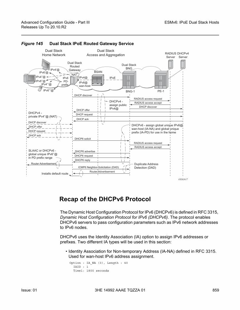
Advanced Configuration Guide - Part III Releases Up To 20.10.R2
ESMv6: IPoE Dual Stack Hosts
Issue: 01 3HE 14992 AAAE TQZZA 01 859
Figure 145 Dual Stack IPoE Routed Gateway Service
Recap of the DHCPv6 Protocol
The Dynamic Host Configuration Protocol for IPv6 (DHCPv6) is defined in RFC 3315, Dynamic Host Configuration Protocol for IPv6 (DHCPv6). The protocol enables DHCPv6 servers to pass configuration parameters such as IPv6 network addresses to IPv6 nodes.
DHCPv6 uses the Identity Association (IA) option to assign IPv6 addresses or prefixes. Two different IA types will be used in this section:
• Identity Association for Non-temporary Address (IA-NA) defined in RFC 3315.Used for wan-host IPv6 address assignment. Option : IA_NA (3), Length : 40
IAID : 1Time1: 1800 seconds
RADIUSServer
DHCPv4Server
BSAN
DHCPv4 -private IPv4’’@ (NAT)
DHCPv4 -assign publicIPv4@
IPoEIPv4@
IPv4’@
IPv4’’@IPv6’’@
IPv4’’’@
IPv6PD-
prefix
IPv6’’’@
IPv6’@NAT
IPv6@wan-host
BNG-1
Dual StackBNG
Dual StackRouted
Gateway
Dual StackHome Network
Dual StackAccess and Aggregation
PE-1
OSSG617
DHCP discoverRADIUS access request
DHCP discover
DHCP discover
DHCP request
RADIUS access accept
RADIUS access requestRADIUS access accept
DHCP offer
DHCP request
DHCP ackDHCP6 solicit
DHCP6 advertise
DHCP6 request
DHCP6 reply
ICMP6 Neighbor Solicitation (DAD)
Router Advertisement
DHCP offer
DHCP ack
SLAAC or DHCPv6 -global unique IPv6’’@in PD prefix range
Installs default route
DHCPv6 - assign global unique IPv6@wan-host (IA-NA) and global uniqueprefix (IA-PD) for use in the home
Duplicate AddressDetection (DAD)
Router Advertisement

ESMv6: IPoE Dual Stack Hosts
860
Advanced Configuration Guide - Part IIIReleases Up To 20.10.R2
3HE 14992 AAAE TQZZA 01 Issue: 01
Time2: 2880 secondsOption : IAADDR (5), Length : 24
Address : 2001:db8:b001:101::1Preferred Lifetime : 3600 secondsValid Lifetime : 86400 seconds
• Identity Association for Prefix Delegation (IA-PD), defined in RFC3633. Used for prefix delegation assignment (for an explanation on prefix delegation, see Prefix Delegation)Option : IA_PD (25), Length : 41
IAID : 1Time1: 1800 secondsTime2: 2880 secondsOption : IAPREFIX (26), Length : 25
Prefix : 2001:db8:a001:103::/56Preferred Lifetime : 3600 secondsValid Lifetime : 86400 seconds
The DHCPv6 lease process is outlined in Figure 146 and Figure 147.
Figure 146 DHCPv6 Lease Process (Part A)
A DHCPv6 client, sends a Solicit message to locate servers to the All DHCPv6 Relay Agents and Servers link-scoped multicast address (FF02::1:2), using its link-local address as source address. The DHCPv6 client includes in the Solicit message its ClientID, Identity Associations (IA) to request IPv6 address or prefix allocation and optionally an Option Request option.
OSSG509
DHCPv6 Server
Advertise
InitialBinding
Client
Reply
SolicitSA=FE80::...(client), DA=FF02::1:2
Options: ClientId, IA-NA, Option Request (DNS-Servers)
SA=FE80::...(server), DA=FE80::... (client)
Options: ServerId, ClientID, DNS-Servers, IA-NA (IAID, IAADDR)
SA=FE80::...(client), DA=FF02::1:2
SA=FE80::...(server), DA=FE80::... (client)
Options: ServerId, ClientID, IA-NA, Option Request (DNS-Servers)
Options: ServerId, ClientID, DNS-Servers, IA-NA (IAID, IAADDR)
Request

Advanced Configuration Guide - Part III Releases Up To 20.10.R2
ESMv6: IPoE Dual Stack Hosts
Issue: 01 3HE 14992 AAAE TQZZA 01 861
Any on-link DHCPv6 server responds with a unicasted Advertise message using the link local addresses. The server includes in the Advertise message the ClientID, its ServerID, IPv6 addresses and/or prefixes in Identity Associations (IA) and options containing the requested configuration parameters.
The DHCPv6 client selects an Advertise message and sends a Request message to the All DHCPv6 Relay Agents and Servers link-scoped multicast address. It includes its ClientID, the ServerID of the corresponding DHCPv6 server, Identity Associations (IA) to request IPv6 address or prefix allocation and optionally an Option Request option.
Upon receipt of a valid Request message, the DHCPv6 server with corresponding ServerID, sends a unicast Reply message using the link local addresses. The Reply contains the ClientID and ServerID, IPv6 addresses and/or prefixes in Identity Associations (IA) and options containing the requested configuration options.
The DHCPv6 client should perform Duplicate Address Detection (DAD) on the addresses in any IA it received in the REPLY before using that address for traffic.
Figure 147 DHCPv6 Lease Process (Part B)
OSSG510
DHCPv6 Server
Replyrenew
rebind
release
Client
Reply
RenewT1Expired
T2Expired
Time
SA=FE80::...(client), DA=FF02::1:2
Options: ClientId, ServerId, IA-NA (IAID, IAADDR)
SA=FE80::...(server), DA=FE80::... (client)
Options: ServerId, ClientID, IA-NA (IAID, IAADDR)
SA=FE80::...(client), DA=FF02::1:2
SA=FE80::...(server), DA=FE80::... (client)
Options: ClientID, IA-NA (IAID, IAADDR)
Options: ServerId, ClientID, IA-NA (IAID, IAADDR)
Rebind
Reply
SA=FE80::...(client), DA=FF02::1:2
SA=FE80::...(server), DA=FE80::... (client)
Options: ClientID, ServerId, IA-NA, (IAID, IAADDR)
Options: ServerId, ClientID, IA-NA (IAID, IAADDR), Status Code
Release

ESMv6: IPoE Dual Stack Hosts
862
Advanced Configuration Guide - Part IIIReleases Up To 20.10.R2
3HE 14992 AAAE TQZZA 01 Issue: 01
Upon expiration of the renew timer T1 associated with the Identity Association option, the DHCPv6 client sends a Renew to the All DHCPv6 Relay Agents and Servers link-scoped multicast address to request an extension of the lifetime of an address. It includes its ClientID, the ServerID of the DHCPv6 server that originally provided the address, and Identity Associations (IA) containing the IPv6 address or prefix for which an extension of the lifetime is requested.
Upon expiration of the rebind timer T2 associated with the Identity Association option (no response received to the Renew), the DHCPv6 client sends a Rebind to the All DHCPv6 Relay Agents and Servers link-scoped multicast address to request an extension of the lifetime of an address. It includes its ClientID and Identity Associations (IA) containing the IPv6 address or prefix for which an extension of the lifetime is requested.
If a DHCPv6 client no longer uses one or more of the assigned addresses or prefixes, it sends a Release message to the server that assigned the address or prefix. The server acknowledges with a Reply message and includes a status code (for example, success).
If the DHCPv6 server sends a Server Unicast Option, then the DHCPv6 client should unicast the Request, Renew Release, and Decline messages to the server using the IPv6 address specified in the option. The 7750 SR DHCPv6 proxy server does not include the Server Unicast Option.
The DHCPv6 client should perform Duplicate Address Detection (DAD) on each of the addresses assigned through DHCPv6, before using that address for traffic. The DHCPv6 client uses Neighbor Solicitation for this purpose as described in RFC 4862, IPv6 Stateless Address AutoConfiguration.
Unlike DHCPv4, DHCPv6 does not provide a default route. In IPv6, default routes are learned via Router Advertisements (see Enable Router Advertisements).
Prefix Delegation
Prefix Delegation (PD) is a mechanism for automated delegation of IPv6 prefixes using DHCPv6. A delegating router delegates a long-lived IPv6 prefix to a requesting router. The delegating router does not require knowledge about the topology of the links in the network to which the prefixes will be assigned.

Advanced Configuration Guide - Part III Releases Up To 20.10.R2
ESMv6: IPoE Dual Stack Hosts
Issue: 01 3HE 14992 AAAE TQZZA 01 863
Figure 148 Prefix Delegation
In the context of ESM IPv6, the BNG is the delegating router (DHCPv6 server) and the Routed Gateway in the home is the requesting router (DHCPv6 client). The DHCPv6 option Identity Association for Prefix Delegation (IA-PD) (Figure 148) is used to assign the IPv6 prefix.
Note that the mechanism through which a requesting router (routed gateway) assigns IPv6 addresses on its interfaces (home network) is arbitrary and can be based upon SLAAC (as shown in Figure 148) or DHCPv6.
Configuration
ESMv6 for IPoE is applicable in a Routed CO environment. The two following scenarios show a minimal configuration to enable dual stack subscribers in a VPRN service context where the ESM IPv6 specific parts are highlighted. No subscriber QoS policies are defined because this is out of the scope for this chapter.
Scenario 1 - RADIUS
RADIUS is used for authentication and authorization (later referenced as RADIUS), and is configured as follows:
configurerouter
radius-serverserver "radius-172.16.1.2" address 172.16.1.2 secret vsecret1 create
accept-coaexit
exitexit
OSSG511
2001:DB8:A001::/48
DelegatingRouter
RequestingRouter
2001:db8:a001:100::/56
2001:db8:a001:200::/56
PD
RA
RA
PD

ESMv6: IPoE Dual Stack Hosts
864
Advanced Configuration Guide - Part IIIReleases Up To 20.10.R2
3HE 14992 AAAE TQZZA 01 Issue: 01
exit
configureaaa
radius-server-policy "rsp-1" createservers
router "Base"source-address 192.0.2.1server 1 name "radius-172.16.1.2"
exitexit
exitexit
configuresubscriber-mgmt
authentication-policy "auth-1" createdescription "RADIUS authentication policy"pppoe-access-method pap-chapradius-server-policy "rsp-1"password letmein
exitexit
exit
The subscriber management profiles used in this chapter are defined as follows:
configuresubscriber-mgmt
sla-profile "sla-profile-1" createexitsub-profile "sub-profile-1" createexitsub-ident-policy "sub-ident-1" create
sub-profile-mapuse-direct-map-as-default
exitsla-profile-map
use-direct-map-as-defaultexitstrings-from-option 254
exitexit
exit
Service VPRN-1 is defined as follows:
configureservice
vprn 1 customer 1 createdhcp
local-dhcp-server "dhcp-s1" createuse-gi-addresspool "pool-1" create
subnet 10.1.0.0/16 createoptions
subnet-mask 255.255.0.0

Advanced Configuration Guide - Part III Releases Up To 20.10.R2
ESMv6: IPoE Dual Stack Hosts
Issue: 01 3HE 14992 AAAE TQZZA 01 865
default-router 10.1.255.254exitaddress-range 10.1.0.1 10.1.0.255
exitexitno shutdown
exitexit--- snipped ---interface "system" create
address 192.0.2.1/32local-dhcp-server "dhcp-s1"loopback
exitsubscriber-interface "sub-int-1" create
address 10.1.255.254/16dhcp
gi-address 10.1.255.254exitipv6
delegated-prefix-len 56subscriber-prefixes
prefix 2001:db8:a001::/48 pdprefix 2001:db8:b001:100::/56 wan-host
exitexitgroup-interface "grp-int-1" create
description "radius authentication and authorization"ipv6
router-advertisementsmanaged-configurationno shutdown
exitdhcp6
proxy-serverno shutdown
exitexit
exitdhcp
proxy-serveremulated-server 10.1.255.254no shutdown
exitserver 192.0.2.1trustedlease-populate 10no shutdown
exitauthentication-policy "auth-1"sap 1/1/1:1 create
sub-sla-mgmtsub-ident-policy "sub-ident-1"multi-sub-sap 10no shutdown
exitexit
exit--- snipped ---

ESMv6: IPoE Dual Stack Hosts
866
Advanced Configuration Guide - Part IIIReleases Up To 20.10.R2
3HE 14992 AAAE TQZZA 01 Issue: 01
exitservice-name "dual-stack-service"no shutdown
exitexit
exit
Scenario 2 - LUDB
The Local User Database used for authentication and authorization (later referenced as LUDB) is defined as follows:
configuresubscriber-mgmt
local-user-db ludb-1 createipoe
match-list machost "host-3" create
host-identificationmac 00:0c:29:00:00:23
exitaddress gi-addressidentification-strings 254 create
subscriber-id "sub-3"sla-profile-string "sla-profile-1"sub-profile-string "sub-profile-1"
exitoptions
subnet-mask 255.255.0.0default-router 10.1.255.254
exitipv6-address 2001:db8:b001:103::3ipv6-delegated-prefix 2001:db8:a001:300::/56ipv6-delegated-prefix-len 56options6
dns-server 2001:db8:dddd:1::1 2001:db8:dddd:2::1exitno shutdown
exit--- snipped ---
exitno shutdown
exitexit
exit
Service VPRN-1 is extended as follows:
configureservice
vprn 1 customer 1 create--- snipped ---subscriber-interface "sub-int-1" create
address 10.1.255.254/16

Advanced Configuration Guide - Part III Releases Up To 20.10.R2
ESMv6: IPoE Dual Stack Hosts
Issue: 01 3HE 14992 AAAE TQZZA 01 867
dhcpgi-address 10.1.255.254
exitipv6
delegated-prefix-len 56subscriber-prefixes
prefix 2001:db8:a001::/48 pdprefix 2001:db8:b001:100::/56 wan-host
exitexitgroup-interface "grp-int-2" create
description "ludb authentication and authorization"ipv6
router-advertisementsprefix-options
autonomousexitno shutdown
exitdhcp6
user-db "ludb-1"proxy-server
client-applications ipoeno shutdown
exitexit
exitdhcp
proxy-serveremulated-server 10.1.255.254no shutdown
exitserver 192.0.2.1trustedlease-populate 10user-db "ludb-1"no shutdown
exitsap 1/1/1:2 create
sub-sla-mgmtdef-sub-profile "sub-profile-1"def-sla-profile "sla-profile-1"sub-ident-policy "sub-ident-1"multi-sub-sap 10no shutdown
exitexit
exitexitservice-name "dual-stack-service"no shutdown
exitexit
exit

ESMv6: IPoE Dual Stack Hosts
868
Advanced Configuration Guide - Part IIIReleases Up To 20.10.R2
3HE 14992 AAAE TQZZA 01 Issue: 01
Configuring IPv6 Subscriber Prefixes
Applies to both scenarios RADIUS and LUDB.
IPv6 subscriber prefixes must be defined at the subscriber-interface <sub-int-name> ipv6 subscriber-prefixes context. Three types of prefixes can be configured:
• wan-host — Prefix from which the IPv6 addresses are assigned that are to be used on the Routed Gateway WAN interface (network facing).
• pd — Prefix from which the IPv6 Prefix Delegation prefixes are assigned that are to be used by the Routed Gateway for allocation in the home network (LAN interfaces).
• pd wan-host (both) — Prefix from which both IPv6 addresses (wan-host) and IPv6 Prefix Delegation prefixes (pd) can be assigned. This requires that the delegated prefix length is set to 64 bits.
A subscriber prefix length must be between /32 and /63.
Subscriber prefixes are subnetted in fixed length subnets that are assigned to subscriber hosts:
• /64 for wan-host subscriber prefixesA /128 IPv6 address is assigned to the subscriber host. Broadband Forum standards require a /64 prefix per subscriber even when used for WAN interfaces and thus the full /64 subnet gets associated with the subscriber host [ref. WT-177 - IPv6 in the context of TR-101]. Two subscriber hosts cannot get an IPv6 address from the same /64 subnet.
• /delegated-prefix-len (/48..64) for pd subscriber prefixesThe delegated prefix length is configured in the subscriber-interface <sub-int-name> ipv6 context. The recommended value by Broadband Forum standards is /56 (default = /64) [ref. WT-177 - IPv6 in the context of TR-101]. The configured length applies to all pd subscriber prefixes on a subscriber-interface.
Table 20 provides an overview of the subscriber-prefix parameters that apply:
Table 20 Applicable Subscriber-Prefix Parameters
Subscriber prefix type
Subscriber prefix length
DHCPv6 option Must be subnetted as
wan-host /32..63 IA-NA /64 (assigned as /128)
pd /32..63 (*) IA-PD /delegated-prefix-len
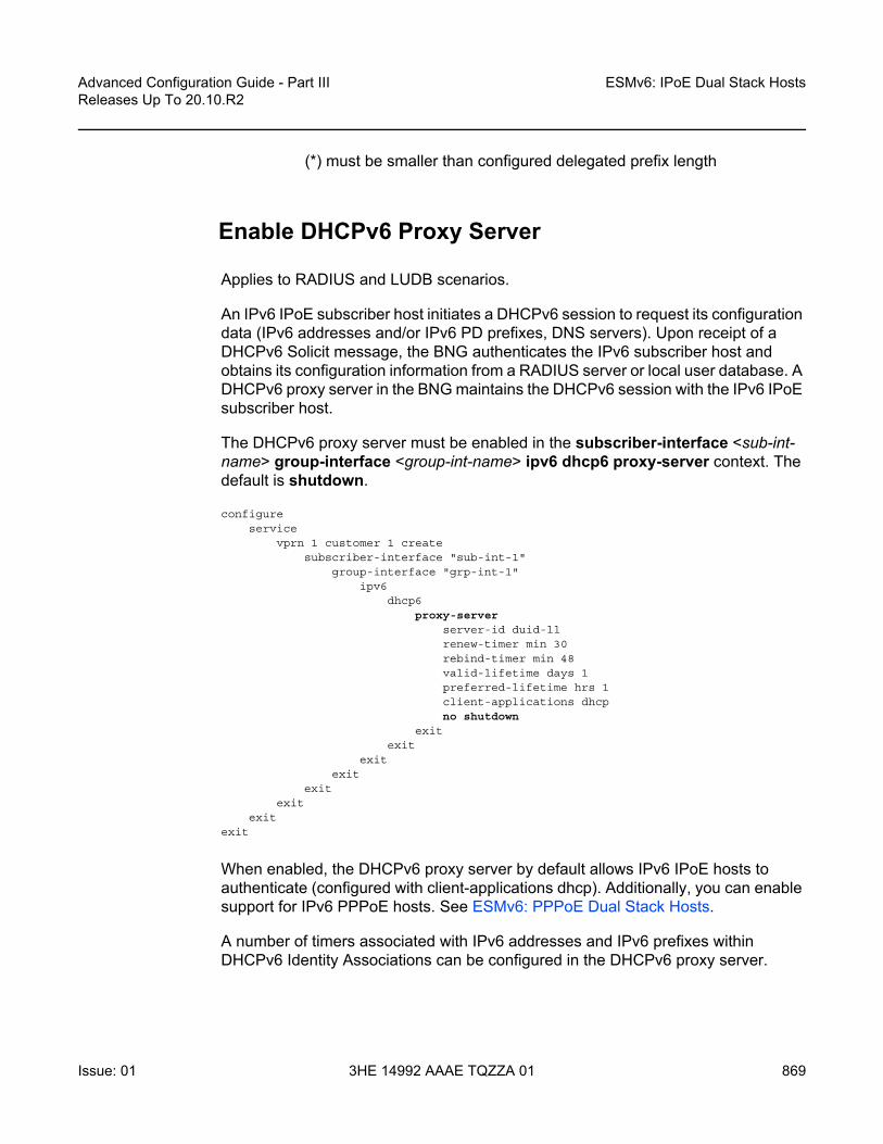
Advanced Configuration Guide - Part III Releases Up To 20.10.R2
ESMv6: IPoE Dual Stack Hosts
Issue: 01 3HE 14992 AAAE TQZZA 01 869
(*) must be smaller than configured delegated prefix length
Enable DHCPv6 Proxy Server
Applies to RADIUS and LUDB scenarios.
An IPv6 IPoE subscriber host initiates a DHCPv6 session to request its configuration data (IPv6 addresses and/or IPv6 PD prefixes, DNS servers). Upon receipt of a DHCPv6 Solicit message, the BNG authenticates the IPv6 subscriber host and obtains its configuration information from a RADIUS server or local user database. A DHCPv6 proxy server in the BNG maintains the DHCPv6 session with the IPv6 IPoE subscriber host.
The DHCPv6 proxy server must be enabled in the subscriber-interface <sub-int-name> group-interface <group-int-name> ipv6 dhcp6 proxy-server context. The default is shutdown.
configureservice
vprn 1 customer 1 createsubscriber-interface "sub-int-1"
group-interface "grp-int-1"ipv6
dhcp6proxy-server
server-id duid-llrenew-timer min 30rebind-timer min 48valid-lifetime days 1preferred-lifetime hrs 1client-applications dhcpno shutdown
exitexit
exitexit
exitexit
exitexit
When enabled, the DHCPv6 proxy server by default allows IPv6 IPoE hosts to authenticate (configured with client-applications dhcp). Additionally, you can enable support for IPv6 PPPoE hosts. See ESMv6: PPPoE Dual Stack Hosts.
A number of timers associated with IPv6 addresses and IPv6 prefixes within DHCPv6 Identity Associations can be configured in the DHCPv6 proxy server.

ESMv6: IPoE Dual Stack Hosts
870
Advanced Configuration Guide - Part IIIReleases Up To 20.10.R2
3HE 14992 AAAE TQZZA 01 Issue: 01
RFC 4862 defines two timers associated with graceful degradation of address bindings:
• Preferred lifetime — The length of time that a valid address is preferred (the time until deprecation). When the preferred lifetime expires, the address becomes deprecated and its use should be discouraged for new sessions.
• Valid lifetime — The length of time an address remains in the valid state (the time until invalidation). The valid lifetime must be greater than or equal to the preferred lifetime. When the valid lifetime expires, the address becomes invalid.
RFC 3315 (DHCPv6) defines two timers associated with an Identity Association (IA) option that give the servers explicit control over when a client recontacts the server about a specific IA:
• T1 (renew) — The time at which the client contacts the server from which the addresses/prefix in the IA were obtained to extend the lifetimes of the addresses/prefix assigned to the IA
• T2 (rebind) — The time at which the client contacts any available server to extend the lifetimes of the addresses/prefixes assigned to the IA;
These timers are common for all DHCPv6 sessions in a group-interface and cannot be configured from RADIUS or local user database.
Figure 149 IPv6 Address/Prefix Timers
When violating the following rule, the default timers will be used:
OSSG618
Tentative(DAD in
Progress)Preferred
(Unrestricted Use)
T1 (renew)AddressAssigned to
Interface
ValidLifetime
i.e., dhcp6proxy-serverlease time
T2 (rebind)
ValidDeprecated
(Use Discouraged)Invalid
(Use Forbidden)
Time
PreferredLifetime
Table 21 Timer Parameters
Timer Use Default Range
T1 Renew timer 1800s (30 min) 0..604800s (7 days)
T2 Rebind timer 2880s (48 min) 0..1209600s (14 days)
preferred-lifetime 3600s (1hr) 300..4294967295s
valid-lifetime DHCPv6 lease time 86400s (24 hrs) 300..4294967295s

Advanced Configuration Guide - Part III Releases Up To 20.10.R2
ESMv6: IPoE Dual Stack Hosts
Issue: 01 3HE 14992 AAAE TQZZA 01 871
If the DHCPv6 lease is not renewed by the client before the DHCPv6 lease timer expires, then the subscriber host is deleted from the system. In other words, beyond the valid lifetime, subscriber traffic from/to the associated IPv6 addresses is dropped.
Enable Router Advertisements
Applies to both scenarios RADIUS and LUDB.
In IPv6, default routes are automatically installed via the router discovery mechanism. Unsolicited Router Advertisements (RA) must explicitly be enabled on a group interface. The default is shutdown.
configureservice
vprn 1 customer 1 createsubscriber-interface "sub-int-1"
group-interface "grp-int-1"ipv6
router-advertisementsmanaged-configurationno shutdown
exitexit
exitexit
exitexit
exit
The managed-configuration flag is set for consistency only. It tells the hosts that addresses can be requested using DHCPv6. However, as described in the Security section later (see Security), the host cannot rely on this flag because DHCPv6 must be initiated by the host before the BNG sends RAs.
Additional parameters that can be configured with respect to the router advertisements (defaults are shown):
configureservice
vprn 1 customer 1 createsubscriber-interface "sub-int-1"
group-interface "grp-int-1"ipv6
router-advertisementsshutdowncurrent-hop-limit 64dns-options
no include-dnsrdnss-lifetime 3600
exit

ESMv6: IPoE Dual Stack Hosts
872
Advanced Configuration Guide - Part IIIReleases Up To 20.10.R2
3HE 14992 AAAE TQZZA 01 Issue: 01
no force-mcastno managed-configurationmax-advertisement 1800min-advertisement 900no mtuno other-stateful-configurationprefix-options
no autonomouson-linkpreferred-lifetime 3600valid-lifetime 86400
exitreachable-time 0retransmit-time 0router-lifetime 4500
exitexit
exitexit
exitexit
exit
Table 22 Router Advertisements Parameters
Parameter Description (RFC 4861, Neighbor Discovery for IP version 6 (IPv6))
Value Range (default)
current-hop-limit The default value that should be placed in the Hop Count field of the IP header for outgoing IP packets. A value of zero means unspecified (by this router); the RG picks its own value.
0..255 (64)
dns-options:include-dns
Indication to include the Recursive DNS Server (RDNSS) option as defined in RFC 6106 in IPv6 RAs for DNS name resolution of IPv6 SLAAC hosts
(no)
dns-options:rdnss-lifetime
Indicates the maximum time that the RDNSS address may be used for name resolution
3600 (s)
force-mcast Configures multicast router advertisements on this interface, either IP or MAC
(no)
managed-configuration
Managed address configuration flag. When set, it indicates that addresses are available through DHCPv6
(no)
max-advertisement Unsolicited Router Advertisements are not strictly periodic: the interval between subsequent transmissions is randomized to reduce the probability of synchronization with the advertisements from other routers on the same link. Whenever a multicast advertisement is sent from an interface, the timer is reset to a uniformly distributed random value between the interface's configured MinRtrAdvInterval and MaxRtrAdvInterval.
900..1800 s (1800)
min-advertisement 900..1350 s (900)

Advanced Configuration Guide - Part III Releases Up To 20.10.R2
ESMv6: IPoE Dual Stack Hosts
Issue: 01 3HE 14992 AAAE TQZZA 01 873
RADIUS Authentication and Authorization
Applies to the RADIUS scenario only.
The RADIUS authentication and authorization configuration for IPoE IPv6 subscriber host is no different from an IPv4 subscriber host:
configurerouter
radius-server
mtu Routers can advertise an MTU for hosts to use on the link. 1280..9212 bytes (no)
other-stateful-configuration (not applicable for IPoE)
Other configuration flag. When set, it indicates that other configuration information is available through DHCPv6. (DNS). Can be ignored if managed address configuration flag is enabled
(no)
prefix-options: autonomous (not applicable for IPoE)
Autonomous address-configuration flag. When set indicates that this prefix can be used for stateless address autoconfiguration (SLAAC)
(no)
prefix-options:on-link
Indicates whether the prefix will be assigned to an interface on the specified link
(no)
prefix-options: preferred-lifetime (not applicable for IPoE)
The length of time in seconds that addresses generated from the prefix via stateless address autoconfiguration (SLAAC) remain preferred
0..4294967295 (3600)
prefix-options: valid-lifetime (not applicable for IPoE)
The length of time in seconds that the prefix is valid for the purpose of on-link determination. (also used by SLAAC)
0..4294967295 (86400)
reachable-time The time that a node assumes a neighbor is reachable after having received a reachability confirmation. Used by the Neighbor Unreachability Detection algorithm. A value of zero means unspecified (by this router); the RG picks its own value.
0..3600000 ms (0)
retransmit-time The time between retransmitted Neighbor Solicitation messages. Used by address resolution and the Neighbor Unreachability Detection algorithm. A value of zero means unspecified (by this router); the RG picks its own value.
0..1800000 ms (0)
router-lifetime The lifetime associated with the default router in units of seconds.
2700..9000 s (4500)
Table 22 Router Advertisements Parameters (Continued)
Parameter Description (RFC 4861, Neighbor Discovery for IP version 6 (IPv6))
Value Range (default)

ESMv6: IPoE Dual Stack Hosts
874
Advanced Configuration Guide - Part IIIReleases Up To 20.10.R2
3HE 14992 AAAE TQZZA 01 Issue: 01
server "radius-172.16.1.2" address 172.16.1.2 secret vsecret1 createaccept-coa
exitexit
exitexit
configureaaa
radius-server-policy "rsp-1" createservers
router "Base"source-address 192.0.2.1server 1 name "radius-172.16.1.2"
exitexit
exitexit
configuresubscriber-mgmt
authentication-policy "auth-1" createdescription "RADIUS authentication policy"pppoe-access-method pap-chapradius-server-policy "rsp-1"password letmein
exitexit
exit
Additional RADIUS AVPs that are applicable to IPoE IPv6 subscriber hosts are listed in Table 23.
Table 23 RADIUS AVPs
RADIUS AVP Type Purpose
Alc-IPv6-Address [26-6527-99]
ipv6addr maps to IA_NA of DHCPv6 (RG WAN interface address)
Alc-Ipv6-Primary-Dns [26-6527-105]
ipv6addr maps to DNS Recursive Name Server option (RFC 3646, DNS Configuration options for Dynamic Host Configuration Protocol for IPv6 (DHCPv6)) in DHCPv6
Alc-Ipv6-Secondary-Dns[26-6527-106]
ipv6addr maps to DNS Recursive Name Server option (RFC 3646) in DHCPv6
Delegated-IPv6-Prefix [123]
ipv6prefix maps to IA_PD for prefix delegation (RFC 3633, IPv6 Prefix Options for Dynamic Host Configuration Protocol (DHCP) version 6) in DHCPv6

Advanced Configuration Guide - Part III Releases Up To 20.10.R2
ESMv6: IPoE Dual Stack Hosts
Issue: 01 3HE 14992 AAAE TQZZA 01 875
A sample FreeRADIUS users record to authenticate a dual stack IPoE subscriber:
00:0c:20:00:00:21 Cleartext-Password := "letmein"Alc-Subsc-ID-Str = "sub-1",Alc-Subsc-Prof-Str = "sub-profile-1",Alc-SLA-Prof-Str = "sla-profile-1",Framed-IP-Address = 10.1.0.1,Framed-IP-Netmask = 255.255.0.0,Framed-Route = "172.16.11.0/24 0.0.0.0",Alc-Ipv6-Address = 2001:db8:b001:101::1,Delegated-IPv6-Prefix = 2001:db8:a001:100::/56,Alc-Ipv6-Primary-Dns = 2001:db8:dddd:1::1,Alc-Ipv6-Secondary-Dns = 2001:db8:dddd:2::1,
The FreeRADIUS Server 2.0.0 and greater has full support for both IPv6 attributes and IPv6 network packets.
The IPv6 address/prefix related timers can be configured in the dhcp6 proxy-server context (see Enable DHCPv6 Proxy Server).
Local User Database Authentication and Authorization
Applies to the LUDB scenario only.
The configuration example below focuses on the IPv6 host configuration. The details for local user database host matching and IPv4 host specific parameters are out of scope for this section.
configuresubscriber-mgmt
local-user-db "ludb-1" createdhcp
match-list machost "host-1" create
host-identificationmac 00:0c:29:00:00:23
exitaddress gi-address # IPv4 hostidentification-strings 254 create
subscriber-id "sub-3"sla-profile-string "sla-profile-1"sub-profile-string "sub-profile-1"
exitoptions
subnet-mask 255.255.0.0 # IPv4 hostdefault-router 10.1.255.254 # IPv4 host
exitipv6-address 2001:db8:b001:103::3 # IPv6 hostipv6-delegated-prefix 2001:db8:a001:300::/56 # IPv6 hostoptions6

ESMv6: IPoE Dual Stack Hosts
876
Advanced Configuration Guide - Part IIIReleases Up To 20.10.R2
3HE 14992 AAAE TQZZA 01 Issue: 01
dns-server 2001:db8:dddd:1::1 2001:db8:dddd:2::1exitno shutdown
exitexitno shutdown
exitexit
exit
configureservice
vprn 1 customer 1 createsubscriber-interface "sub-int-1" create
group-interface "grp-int-2" createdescription "ludb authentication and authorization"ipv6
--- snipped ---dhcp6
user-db "ludb-1"proxy-server
client-applications dhcpno shutdown
exitexit
exitdhcp
--- snipped ---server 192.0.2.1trustedlease-populate 10user-db "ludb-1"no shutdown
exitexit
exitexit
exitexit
Besides the identification strings that are common to theIPv4 and IPv6 hosts, specific IPv6 host related parameters can be configured:
Table 24 Local User Database Parameters
local-user-db CLI parameter Purpose
ipv6-address Maps to IA_NA of DHCPv6 (RG WAN interface address)
ipv6-prefix Maps to IA_PD for prefix delegation (RFC 3633) in DHCPv6
options6:dns-server
Defines the IPv6 DNS server address to be used for name resolution

Advanced Configuration Guide - Part III Releases Up To 20.10.R2
ESMv6: IPoE Dual Stack Hosts
Issue: 01 3HE 14992 AAAE TQZZA 01 877
The IPv6 address/prefix related timers can be configured in the dhcp6 proxy-server context (see Enable DHCPv6 Proxy Server).
DHCP and DHCP6 Lease State
Applies to both scenarios RADIUS and LUDB.
The DHCP lease state is an internal database structure that keeps track of the DHCP host states. The DHCP lease state enables subscriber management functions (for example, per subscriber QoS and accounting) and security functions (for example, dynamic anti-spoof filtering) on the DHCP host.
The DHCP lease information for a specific host is extracted from the DHCPv4 ack message in case of DHCPv4 and from the DHCPv6 reply message in case of DHCPv6
Typical information stored in the DHCP lease state includes (partial table; additional data can be stored for managed SAPs, wholesale-retail).
Table 25 DHCP Lease State Information
Parameter Comment
Service ID Service where the DHCP host is connected.
IP Address IPv4 or IPv6 address of the DHCP host.
Client HW Address Ethernet MAC address of the DHCP host.
Subscriber-interface (Routed CO only)
Subscriber interface name where the DHCP host is instantiated.
Group-interface (Routed CO only)
Group interface name where the DHCP host is instantiated.
SAP SAP where the DHCP hosts is connected.
Remaining Lifetime The remaining time before the DHCP host is deleted from the system (updated each time a DHCP renew/rebind occurs).
Persistence Key Lookup key for this host in the persistency file.
Sub-Ident ESM: Subscriber ID of the DHCP host.
Sub-Profile-String ESM: Subscriber profile string of the DHCP host.
SLA-Profile-String ESM: SLA profile string of the DHCP host.
App-Profile-String ESM: Application profile string of the DHCP host.

ESMv6: IPoE Dual Stack Hosts
878
Advanced Configuration Guide - Part IIIReleases Up To 20.10.R2
3HE 14992 AAAE TQZZA 01 Issue: 01
Lease ANCP-String ESM: ANCP string for this DHCP host.
Lease Int Dest Id ESM: Internal destination ID for this DHCP host.
Category-Map-Name ESM: Volume and Time based accounting.
Dhcp6 ClientId (DUID) DHCPv6 client unique identifier.
Dhcp6 IAID Identity Association ID chosen by the client.
Dhcp6 IAID Type Identity Association type: prefix (PD) or non-temporary (wan-host).
Dhcp6 Client Ip Link local IPv6 address of the host.
Sub-Ident origin ESM: Origin for the Subscriber ID for this host (None, DHCP, RADIUS).
Strings origin ESM: Origin for the ESM strings for this host (None, DHCP, RADIUS).
Lease Info origin ESM: Origin for the IP configuration for this host (None, DHCP, RADIUS).
Ip-Netmask The IP netmask for this DHCP host.
Broadcast-Ip-Addr The broadcast IP address for this host.
Default-Router The default gateway for this host.
Primary-Dns The primary DNS server for this host.
Secondary-Dns The secondary DNS server for this host.
Primary-Nbns The primary NetBIOS name server for this host.
Secondary-Nbns The secondary NetBIOS name server for this host.
ServerLeaseStart Time and date that the lease for this host started (first DHCP ack received).
ServerLastRenew Time and date that the lease for this host was last renewed.
ServerLeaseEnd Time and date that the lease for this host will expire.
Session-Timeout Lease time specified by the DHCP server.
DHCP Server Addr IP address of the DHCP server that allocated the lease for this host.
Circuit Id DHCP Relay Agent information option 82 Circuit ID content.
Remote Id DHCP Relay Agent information option 82 Remote ID content.
Table 25 DHCP Lease State Information (Continued)
Parameter Comment

Advanced Configuration Guide - Part III Releases Up To 20.10.R2
ESMv6: IPoE Dual Stack Hosts
Issue: 01 3HE 14992 AAAE TQZZA 01 879
DHCPv4 lease state population is enabled by default on a group-interface with DHCP configured as no shutdown. The number of DHCPv4 leases allowed on each SAP of the group-interface must be configured with the lease-populate option (by default a single DHCPv4 host is allowed on each SAP of the group-interface).
DCHPv6 lease state population is enabled by default on a group-interface with DHCP6 proxy-server configured as no shutdown. The number of DHCPv6 leases (hosts) cannot be limited per group-interface.
configureservice
vprn 1 customer 1 createsubscriber-interface "sub-int-1" create
group-interface "grp-int-1" createdescription "radius authentication and authorization"ipv6
dhcp6proxy-server
no shutdownexit
exitexitdhcp
proxy-serveremulated-server 10.1.255.254no shutdown
exitserver 192.0.2.1trustedlease-populate 10no shutdown
exitexit
exitexit
exitexit
To check the DHCPv4 or DHCPv6 lease state for a particular service, use the following commands (detailed output as well as additional output filtering is available):
*A:BNG# show service id 1 dhcp | dhcp6 lease-state ?
- lease-state [wholesaler <service-id>] [sap <sap-id>|sdp <sdp-id:vc-id>|interface <interface-name>|ip-address <ip-address[/mask]>|chaddr
RADIUS User-Name ESM: Username used in the RADIUS authentication access request.
Table 25 DHCP Lease State Information (Continued)
Parameter Comment

ESMv6: IPoE Dual Stack Hosts
880
Advanced Configuration Guide - Part IIIReleases Up To 20.10.R2
3HE 14992 AAAE TQZZA 01 Issue: 01
<ieee-address>|mac <ieee-address>|{[port <port-id>][no-inter-dest-id |inter-dest-id <inter-dest-id>]}] [session {none|ipoe}] [detail]
*A:BNG# show service id 1 dhcp lease-state detail
===============================================================================DHCP lease states for service 1===============================================================================Service ID : 1IP Address : 10.1.0.1Client HW Address : 00:0c:29:00:00:21Subscriber-interface : sub-int-1Group-interface : grp-int-1SAP : 1/1/1:1Termination Type : localUp Time : 0d 00:58:34Remaining Lease Time : 6d 23:01:26Remaining SessionTime: N/APersistence Key : 0x00000000
Sub-Ident : "sub-1"Sub-Profile-String : "sub-profile-1"SLA-Profile-String : "sla-profile-1"App-Profile-String : ""Lease ANCP-String : ""Lease Int Dest Id : ""Category-Map-Name : ""
Lease Info origin : Radius
Ip-Netmask : 255.255.0.0Broadcast-Ip-Addr : 10.1.255.255Default-Router : N/APrimary-Dns : N/ASecondary-Dns : N/APrimary-Nbns : N/ASecondary-Nbns : N/A
ServerLeaseStart : 04/20/2017 13:01:09ServerLastRenew : 04/20/2017 13:01:09ServerLeaseEnd : 04/27/2017 13:01:09Session-Timeout : N/AIPoE|PPP session : NoLease-Time : 7d 00:00:00DHCP Server Addr : N/ARadius User-Name : "00:0c:29:00:00:21"-------------------------------------------------------------------------------Number of lease states : 1===============================================================================*A:BNG#
*A:BNG# show service id 1 dhcp6 lease-state detail
===============================================================================DHCP lease states for service 1===============================================================================Service ID : 1IP Address : 2001:db8:a001:100::/56

Advanced Configuration Guide - Part III Releases Up To 20.10.R2
ESMv6: IPoE Dual Stack Hosts
Issue: 01 3HE 14992 AAAE TQZZA 01 881
Client HW Address : 00:0c:29:00:00:21Subscriber-interface : sub-int-1Group-interface : grp-int-1SAP : 1/1/1:1Termination Type : localUp Time : 0d 00:55:11Remaining Lease Time : 0d 23:34:49Remaining SessionTime: N/APersistence Key : 0x0000000b
Sub-Ident : "sub-1"Sub-Profile-String : "sub-profile-1"SLA-Profile-String : "sla-profile-1"App-Profile-String : ""Lease ANCP-String : ""Lease Int Dest Id : ""Category-Map-Name : ""Dhcp6 ClientId (DUID): 00010001208a25ac000c29000021Dhcp6 IAID : 1Dhcp6 IAID Type : prefixDhcp6 Client Ip : fe80::20c:29ff:fe00:21Primary-Dns : 2001:db8:dddd:1::1Secondary-Dns : 2001:db8:dddd:2::1Pool Name : ""Dhcp6 Server Addr : N/ADhcp6 ServerId (DUID): N/ADhcp6 InterfaceId : N/ADhcp6 RemoteId : N/ARadius sub-if prefix : N/ARouter adv. policy : N/A
Lease Info origin : Radius
ServerLeaseStart : 04/20/2017 13:06:36ServerLastRenew : 04/20/2017 13:36:36ServerLeaseEnd : 04/21/2017 13:36:36Session-Timeout : N/AIPoE|PPP session : NoRadius User-Name : "00:0c:29:00:00:21"-------------------------------------------------------------------------------Service ID : 1IP Address : 2001:db8:b001:101::1/128Client HW Address : 00:0c:29:00:00:21Subscriber-interface : sub-int-1Group-interface : grp-int-1SAP : 1/1/1:1Termination Type : localUp Time : 0d 00:55:11Remaining Lease Time : 0d 23:34:49Remaining SessionTime: N/APersistence Key : 0x0000000a
Sub-Ident : "sub-1"Sub-Profile-String : "sub-profile-1"SLA-Profile-String : "sla-profile-1"App-Profile-String : ""Lease ANCP-String : ""Lease Int Dest Id : ""Category-Map-Name : ""

ESMv6: IPoE Dual Stack Hosts
882
Advanced Configuration Guide - Part IIIReleases Up To 20.10.R2
3HE 14992 AAAE TQZZA 01 Issue: 01
Dhcp6 ClientId (DUID): 00010001208a25ac000c29000021Dhcp6 IAID : 2Dhcp6 IAID Type : non-temporaryDhcp6 Client Ip : fe80::20c:29ff:fe00:21Primary-Dns : 2001:db8:dddd:1::1Secondary-Dns : 2001:db8:dddd:2::1Pool Name : ""Dhcp6 Server Addr : N/ADhcp6 ServerId (DUID): N/ADhcp6 InterfaceId : N/ADhcp6 RemoteId : N/ARadius sub-if prefix : N/ARouter adv. policy : N/A
Lease Info origin : Radius
ServerLeaseStart : 04/20/2017 13:06:36ServerLastRenew : 04/20/2017 13:36:36ServerLeaseEnd : 04/21/2017 13:36:36Session-Timeout : N/AIPoE|PPP session : NoRadius User-Name : "00:0c:29:00:00:21"-------------------------------------------------------------------------------Number of lease states : 2===============================================================================*A:BNG#
Operation
An IPoE dual stack subscriber in a numbered Routed Gateway scenario consumes three subscriber host entries:
• IPv4 host — DHCPv4 session based• IPv6 wan-host — DHCPv6 session based• IPv6 Prefix Delegation host — DHCPv6 session based
*A:BNG# show service active-subscribers
===============================================================================Active Subscribers===============================================================================-------------------------------------------------------------------------------Subscriber sub-1 (sub-profile-1)--------------------------------------------------------------------------------------------------------------------------------------------------------------(1) SLA Profile Instance sap:1/1/1:1 - sla:sla-profile-1-------------------------------------------------------------------------------IP Address
MAC Address Session Origin Svc Fwd-------------------------------------------------------------------------------10.1.0.1
00:0c:29:00:00:21 N/A DHCP 1 Y2001:db8:a001:100::/56

Advanced Configuration Guide - Part III Releases Up To 20.10.R2
ESMv6: IPoE Dual Stack Hosts
Issue: 01 3HE 14992 AAAE TQZZA 01 883
00:0c:29:00:00:21 N/A DHCP6 1 Y2001:db8:b001:101::1/128
00:0c:29:00:00:21 N/A DHCP6 1 Y-------------------------------------------------------------------------------
-------------------------------------------------------------------------------Subscriber sub-3 (sub-profile-1)--------------------------------------------------------------------------------------------------------------------------------------------------------------(1) SLA Profile Instance sap:1/1/1:2 - sla:sla-profile-1-------------------------------------------------------------------------------IP Address
MAC Address Session Origin Svc Fwd-------------------------------------------------------------------------------10.1.0.8
00:0c:29:00:00:23 N/A DHCP 1 Y2001:db8:a001:300::/56
00:0c:29:00:00:23 N/A DHCP6 1 Y2001:db8:b001:103::3/128
00:0c:29:00:00:23 N/A DHCP6 1 Y-------------------------------------------------------------------------------
-------------------------------------------------------------------------------Number of active subscribers : 2===============================================================================*A:BNG#
The optional hierarchy parameter for the active-subscribers display provides a top-down level overview for this subscriber:
*A:BNG# show service active-subscribers hierarchy
===============================================================================Active Subscribers Hierarchy===============================================================================-- sub-1 (sub-profile-1)
|+-- sap:1/1/1:1 - sla:sla-profile-1
||-- 10.1.0.1 - mac:00:0c:29:00:00:21 - DHCP - svc:1||-- 2001:db8:a001:100::/56 - mac:00:0c:29:00:00:21 - DHCP6 - svc:1|+-- 2001:db8:b001:101::1/128 - mac:00:0c:29:00:00:21 - DHCP6 - svc:1
-- sub-3 (sub-profile-1)|+-- sap:1/1/1:2 - sla:sla-profile-1
||-- 10.1.0.8 - mac:00:0c:29:00:00:23 - DHCP - svc:1||-- 2001:db8:a001:300::/56 - mac:00:0c:29:00:00:23 - DHCP6 - svc:1|+-- 2001:db8:b001:103::3/128 - mac:00:0c:29:00:00:23 - DHCP6 - svc:1
-------------------------------------------------------------------------------Number of active subscribers : 2Flags: (N) = the host or the managed route is in non-forwarding state

ESMv6: IPoE Dual Stack Hosts
884
Advanced Configuration Guide - Part IIIReleases Up To 20.10.R2
3HE 14992 AAAE TQZZA 01 Issue: 01
===============================================================================*A:BNG#
The total number (sum) of IPv4 and IPv6 hosts per subscriber can be limited in the corresponding sla-profile with the host-limit parameter:
configuresubscr-mgmt
sla-profile "sla-profile-1" createhost-limits
overall 3exit
exitexit
exit
To display the IPv4/IPv6 routing table for dual stack hosts:
*A:BNG# show router 1 route-table ipv4 protocol sub-mgmt
===============================================================================Route Table (Service: 1)===============================================================================Dest Prefix[Flags] Type Proto Age Pref
Next Hop[Interface Name] Metric-------------------------------------------------------------------------------10.1.0.1/32 Remote Sub Mgmt 01h05m03s 0
[grp-int-1] 010.1.0.8/32 Remote Sub Mgmt 00h00m49s 0
[grp-int-2] 0-------------------------------------------------------------------------------No. of Routes: 2Flags: n = Number of times nexthop is repeated
B = BGP backup route availableL = LFA nexthop availableS = Sticky ECMP requested
===============================================================================*A:BNG#
*A:BNG# show router 1 route-table ipv6 protocol sub-mgmt
===============================================================================IPv6 Route Table (Service: 1)===============================================================================Dest Prefix[Flags] Type Proto Age Pref
Next Hop[Interface Name] Metric-------------------------------------------------------------------------------2001:db8:a001:100::/56 Remote Sub Mgmt 01h00m03s 0
[grp-int-1] 02001:db8:a001:300::/56 Remote Sub Mgmt 00h03m00s 0
[grp-int-2] 02001:db8:b001:101::1/128 Remote Sub Mgmt 01h00m03s 0
[grp-int-1] 02001:db8:b001:103::3/128 Remote Sub Mgmt 00h03m00s 0
[grp-int-2] 0-------------------------------------------------------------------------------No. of Routes: 4

Advanced Configuration Guide - Part III Releases Up To 20.10.R2
ESMv6: IPoE Dual Stack Hosts
Issue: 01 3HE 14992 AAAE TQZZA 01 885
Flags: n = Number of times nexthop is repeatedB = BGP backup route availableL = LFA nexthop availableS = Sticky ECMP requested
===============================================================================*A:BNG#
Troubleshooting
Apart from the show commands in this chapter, the following additional commands can be used for troubleshooting:
• Default system log• Debug• Statistics
The default system log can be shown as follows:
A:BNG-1# show log log-id 99
Use appropriate filtering to reduce the output if needed.
Debugging can be done with the definitions as follows:
debugrouter "Base"
radiuspacket-type authentication accounting coadetail-level high
exitexitrouter "1"
ipdhcp
detail-level highmode egr-ingr-and-dropped
exitdhcp6
mode egr-ingr-and-droppeddetail-level high
exiticmp6
exitlocal-dhcp-server "dhcp-s1"
detail-level mediummode egr-ingr-and-dropped
exitexitsubscriber-mgmt
local-user-db "ludb-1"detail all

ESMv6: IPoE Dual Stack Hosts
886
Advanced Configuration Guide - Part IIIReleases Up To 20.10.R2
3HE 14992 AAAE TQZZA 01 Issue: 01
exitexit
exit
Additional filtering (such as only DHCPv6 debug for a particular interface) may be needed to prevent a flood of debug messages.
DHCPv4 statistics can be shown as follows:
*A:BNG# show router 1 dhcp statistics
====================================================================DHCP Global Statistics (Service: 1)====================================================================Rx Packets : 86Tx Packets : 36Rx Malformed Packets : 0Rx Untrusted Packets : 0Client Packets Discarded : 12Client Packets Relayed : 46Client Packets Snooped : 4Client Packets Proxied (RADIUS) : 24Client Packets Proxied (Diameter) : 0Client Packets Proxied (User-Db) : 0Client Packets Proxied (Lease-Split) : 0Server Packets Discarded : 0Server Packets Relayed : 25Server Packets Snooped : 0DHCP RELEASEs Spoofed : 0DHCP FORCERENEWs Spoofed : 0Client packets streamed : 0====================================================================*A:BNG#
DHCPv6 statistics can be shown as follows:
*A:BNG# show router 1 dhcp6 statistics
===========================================================================DHCP6 statistics (Router: 1)===========================================================================Msg-type Rx Tx Dropped---------------------------------------------------------------------------1 SOLICIT 6 0 02 ADVERTISE 0 6 03 REQUEST 6 0 04 CONFIRM 0 0 05 RENEW 1 0 06 REBIND 0 0 07 REPLY 0 11 08 RELEASE 4 0 09 DECLINE 0 0 010 RECONFIGURE 0 0 011 INFO_REQUEST 0 0 012 RELAY_FORW 0 0 013 RELAY_REPLY 0 0 014 LEASEQUERY 0 0 0

Advanced Configuration Guide - Part III Releases Up To 20.10.R2
ESMv6: IPoE Dual Stack Hosts
Issue: 01 3HE 14992 AAAE TQZZA 01 887
15 LEASEQUERY_REPLY 0 0 0
---------------------------------------------------------------------------Dhcp6 Drop Reason Counters :---------------------------------------------------------------------------1 Dhcp6 oper state is not Up on src itf 02 Dhcp6 oper state is not Up on dst itf 03 Relay Reply Msg on Client Itf 04 Hop Count Limit reached 05 Missing Relay Msg option, or illegal msg type 06 Unable to determine destination client Itf 07 Out of Memory 08 No global Pfx on Client Itf 09 Unable to determine src Ip Addr 0
10 No route to server 011 Subscr. Mgmt. Update failed 012 Received Relay Forw Message 013 Packet too small to contain valid dhcp6 msg 014 Server cannot respond to this message 015 No Server Id option in msg from server 016 Missing or illegal Client Id option in client msg 017 Server Id option in client msg 018 Server DUID in client msg does not match our own 019 Client sent message to unicast while not allowed 020 Client sent message with illegal src Ip address 021 Client message type not supported in pfx delegation 022 Nbr of addrs or pfxs exceeds allowed max (128) in msg 023 Unable to resolve client's mac address 024 The Client was assigned an illegal address 025 Illegal msg encoding 026 Client message not supported 027 IA options in info request 028 No IA option in client msg 029 No addresses in confirm msg 030 No relay servers configured 031 Blocked by host lockout 032 No link address available 033 Dropped by Python 034 Invalid server 035 Packet dropped on SRRP backup interface 036 DHCP transaction not found 037 Could not determine retail interface 038 Packet dropped by DHCP filter 039 Packet dropped because authentication failed 0===========================================================================*A:BNG#
RADIUS statistics can be shown as follow:
*A:BNG# show subscriber-mgmt authentication "auth-1" statistics
===============================================================================Authentication Policy Statistics===============================================================================-------------------------------------------------------------------------------Policy name : auth-1subscriber packets authenticated : 0subscriber packets rejected : 0

ESMv6: IPoE Dual Stack Hosts
888
Advanced Configuration Guide - Part IIIReleases Up To 20.10.R2
3HE 14992 AAAE TQZZA 01 Issue: 01
subscriber packets rejected send failed : 0-------------------------------------------------------------------------------===============================================================================*A:BNG#
*A:BNG# show aaa radius-server-policy "rsp-1" statistics
===============================================================================RADIUS server policy "rsp-1" statistics===============================================================================Tx transaction requests : 24Rx transaction responses : 24Transaction requests timed out : 0Transaction requests send failed : 0Packet retries : 0Transaction requests send rejected : 0Authentication requests failed : 4Accounting requests failed : 0Ratio of access-reject over auth responses : 16%Transaction success ratio : 100%Transaction failure ratio : 0%Statistics last reset at : n/a
Server 1 "radius-172.16.1.2" address 172.16.1.2 auth-port 1812 acct-port 1813-------------------------------------------------------------------------------Tx request packets : 24Rx response packets : 24Request packets timed out : 0Request packets send failed : 0Request packets send failed (overload) : 0Request packets waiting for reply : 0Response packets with invalid authenticator : 0Response packets with invalid msg authenticator : 0Authentication packets failed : 4Accounting packets failed : 0Avg auth response delay (10 100 1K 10K) in ms : 1.25 168 168 168Avg acct response delay (10 100 1K 10K) in ms : n/aStatistics last reset at : n/a
===============================================================================*A:BNG#

Advanced Configuration Guide - Part III Releases Up To 20.10.R2
ESMv6: IPoE Dual Stack Hosts
Issue: 01 3HE 14992 AAAE TQZZA 01 889
Advanced Topics
Security
Downstream Router Advertisements
When a SAP is bound to a subscriber/group-interface which has IPv6 enabled, there will be no initial downstream Router Advertisement (RA) message sent. If a SAP is shared by multiple subscribers, it would be possible for an unauthenticated host to receive the RA.
Instead the RAs are sent in unicast to allow per-host IPv6 link configuration. This requires the host information (MAC address and link-local IPv6 address) to be known. Therefore, for IPoE, until a DHCPv6 session is bound, no unsolicited or solicited RAs are sent.
Processing Neighbor Discovery Messages
Processing Neighbor Discovery messages: Neighbor Advertisements (NA), Neighbor Solicitations (NS) and Router Solicitations (RS).
Neighbor discovery messages are not processed prior to IPoE IPv6 host authentication to avoid DoS attacks consuming CPU resources. This implies that an IPoE host should initiate the DHCPv6 session without link information and knowledge of routers on the link as required by the Broadband Forum standards (ref. TR-124 issue 2 — Functional Requirements for Broadband Residential Gateway Devices). This is not a problem as the DHCPv6 solicit/request messages are sent to a well-known multicast address with direct link-layer mapping.
After DHCP host authentication, Neighbor Discovery messages will not result in a neighbor cache entry. Instead a managed neighbor cache entry is created based on the DHCPv6 lease state. This managed neighbor cache entry cannot be displayed. The above mechanism prevents DoS attacks from poisoning the neighbor cache with bogus entries.
Router advertisements in response to a router solicitation are internally throttled so that they are not sent more often than once every three seconds.

ESMv6: IPoE Dual Stack Hosts
890
Advanced Configuration Guide - Part IIIReleases Up To 20.10.R2
3HE 14992 AAAE TQZZA 01 Issue: 01
Anti-spoof Filters
For each authenticated IPoE IPv6 host, an anti-spoof filter entry is created that allows upstream traffic with exact match on the tuple {masked source IP, source MAC} to pass. Traffic from unauthenticated hosts is silently dropped.
Managed SAPs
To allow the creation of managed SAPs in a dual stack environment, both DHCPv4 discover and DHCPv6 solicit messages received on a capture SAP should trigger RADIUS authentication:
configureservice
vpls 2 customer 1 createsap 1/1/2:* capture-sap create
trigger-packet dhcp dhcp6authentication-policy "radius-1"
exitno shutdown
exitexit
exit
A full description of the managed SAP functionality is out of the scope of this chapter.
RADIUS Change of Authorization (CoA)
The only CoA action that is allowed for IPoE IPv6 hosts is a change of ESM strings (SLA-profile, subscriber-profile, application-profile, etc). Creation of a new IPv6 host or forcing a DHCPv6 renew is not supported.
Only a single address attribute (Framed-IP-Address, Delegated-IPv6-Prefix or Alc-IPv6-Address) may be given in a single request. When host-accounting is enabled, only the host specific accounting session IDs (Acct-Session-Id) can be used. This means that to change for example the sla-profile for all three hosts of a dual stack subscriber, three CoA messages should be sent.
A full description of the RADIUS CoA functionality is out of the scope of this section.

Advanced Configuration Guide - Part III Releases Up To 20.10.R2
ESMv6: IPoE Dual Stack Hosts
Issue: 01 3HE 14992 AAAE TQZZA 01 891
Accounting
There are no separate accounting statistics available for IPv4 and IPv6 traffic unless they are mapped in a different Forwarding Class/queue.
In RADIUS accounting, host-accounting could be enabled to see the IPv4 and IPv6 host instantiations separately: an accounting start/stop is generated for each individual subscriber host. The actual accounting data is included in the interim updates and accounting stop message for the sla-profile instance.
A full description of the accounting functionality is out of the scope of this section.
Lease State Persistency
A DHCPv4/DHCPv6 (hereafter referred to as DHCP) session does not have a keep-alive mechanism to detect unavailability. A new DHCP session set-up is only attempted after expiration of the DHCP lease time. A node reboot causing the loss of DHCP lease state and the corresponding anti-spoof filters could therefore result in unacceptable long service outages.
The DHCP lease state can be made persistent across node reboots: DHCP lease state is restored from a persistency file stored on the compact flash file system. As a result, DHCP sessions will only lose connectivity during the time of reboot without being completely disconnected.
To activate the DHCP lease state persistency:
configuresystem
persistencesubscriber-mgmt
description "DHCP lease state persistency"location cf1:
exitexit
exitexit
A dedicated persistency file will be created on the specified compact flash file system. The file is initialized to store the maximum number of allowed hosts; its size is fixed to avoid file system space problems during operations.
*A:BNG# file dir cf1:
Volume in drive cf1 on slot A has no label.
Volume in drive cf1 on slot A is formatted as FAT32

ESMv6: IPoE Dual Stack Hosts
892
Advanced Configuration Guide - Part IIIReleases Up To 20.10.R2
3HE 14992 AAAE TQZZA 01 Issue: 01
Directory of cf1:\
09/19/2016 04:29p <DIR> .ssh/04/20/2017 03:02p 536871424 submgmt.01204/20/2017 02:59p 12583424 submgmt.i12
2 File(s) 549454848 bytes.1 Dir(s) 7464747008 bytes free.
*A:BNG#
Each time the DHCP lease is renewed, the persistency file is updated together with the lease state. If the file update fails, an event is generated to indicate that persistency cannot be guaranteed.
The format of the persistency file may vary between different SR OS software releases. When upgrading, the persistency file is automatically upgraded to the new format. To downgrade the persistency file to a lower SR OS release version, use the following command:
*A:BNG# tools perform persistence downgrade target-version ?- downgrade target-version <target> [reboot]
<target> : the version you want to downgrade tosubmgt
14.0 (current) - cf1:\submgmt.01213.0 - cf1:\submgmt.01112.0 - cf1:\submgmt.01011.0 - cf1:\submgmt.00910.0 - cf1:\submgmt.0089.0 - cf1:\submgmt.0078.0 - cf1:\submgmt.0067.0 - cf1:\submgmt.0056.0 - cf1:\submgmt.0045.0 - cf1:\submgmt.0034.0 - cf1:\submgmt.pst
<reboot> : reboot system after successful conversion
*A:BNG#
The content of the persistency file can be looked at using the following commands:
*A:BNG# show service id 1 dhcp6 lease-state detail
===============================================================================DHCP lease states for service 1===============================================================================Service ID : 1IP Address : 2001:db8:a001:100::/56Client HW Address : 00:0c:29:00:00:21Subscriber-interface : sub-int-1Group-interface : grp-int-1SAP : 1/1/1:1Termination Type : localUp Time : 0d 00:01:49

Advanced Configuration Guide - Part III Releases Up To 20.10.R2
ESMv6: IPoE Dual Stack Hosts
Issue: 01 3HE 14992 AAAE TQZZA 01 893
Remaining Lease Time : 0d 23:58:11Remaining SessionTime: N/APersistence Key : 0x00000002
Sub-Ident : "sub-1"Sub-Profile-String : "sub-profile-1"SLA-Profile-String : "sla-profile-1"App-Profile-String : ""Lease ANCP-String : ""Lease Int Dest Id : ""Category-Map-Name : ""Dhcp6 ClientId (DUID): 00010001208a25ac000c29000021Dhcp6 IAID : 1Dhcp6 IAID Type : prefixDhcp6 Client Ip : fe80::20c:29ff:fe00:21Primary-Dns : 2001:db8:dddd:1::1Secondary-Dns : 2001:db8:dddd:2::1Pool Name : ""Dhcp6 Server Addr : N/ADhcp6 ServerId (DUID): N/ADhcp6 InterfaceId : N/ADhcp6 RemoteId : N/ARadius sub-if prefix : N/ARouter adv. policy : N/A
Lease Info origin : Radius
ServerLeaseStart : 04/20/2017 14:44:01ServerLastRenew : 04/20/2017 14:44:01ServerLeaseEnd : 04/21/2017 14:44:01Session-Timeout : N/AIPoE|PPP session : NoRadius User-Name : "00:0c:29:00:00:21"-------------------------------------------------------------------------------Service ID : 1IP Address : 2001:db8:a001:300::/56Client HW Address : 00:0c:29:00:00:23Subscriber-interface : sub-int-1Group-interface : grp-int-2SAP : 1/1/1:2Termination Type : localUp Time : 0d 00:01:36Remaining Lease Time : 0d 23:58:24Remaining SessionTime: N/APersistence Key : 0x00000005
Sub-Ident : "sub-3"Sub-Profile-String : "sub-profile-1"SLA-Profile-String : "sla-profile-1"
--- snipped ---
-------------------------------------------------------------------------------Number of lease states : 4===============================================================================*A:BNG#
*A:BNG# tools dump persistence submgt record 0x2----------------------------------------

ESMv6: IPoE Dual Stack Hosts
894
Advanced Configuration Guide - Part IIIReleases Up To 20.10.R2
3HE 14992 AAAE TQZZA 01 Issue: 01
Persistence Record----------------------------------------Client : submgtPersist-Key : 0x00000002Filename : cf1:\submgmt.012Entries : Index FedHandle Last Update Action Valid
000002 0x00000002 2017/04/20 12:45:24 (UTC) ADD YesData : 366 bytes
Host Type : IpV6 node addressService ID : 1SAP ID : 1/1/1:1NH MAC : 00:0c:29:00:00:21Created : 2017/04/20 12:44:01 (UTC)IP : 2001:db8:a001:100::/56Srvr Last Renew: 2017/04/20 12:44:01 (UTC)Srvr Lse End : 2017/04/21 12:44:01 (UTC)Dhcp6 Pfx len : 56Dhcp6 Iaid : 1Dhcp6 Iaid Typ : 25Dhcp6 Client Mg: fe80::20c:29ff:fe00:21Dhcp6 Client Id: 00010001208a25ac000c29000021RADIUS Fallback: NOAcct-Sess-Id : 14F2FF0000003658F8AD11Multi-Sess-Id : 14F2FF0000003458F8AD0AClass Attr : 0 bytesUser-Name : "00:0c:29:00:00:21"host is authenticated by radius: trueSubscriber-Id : "sub-1"Sub-Profile-Str: "sub-profile-1"SLA-Profile-Str: "sla-profile-1"Ipv6 Primary Dns: 2001:db8:dddd:1::1Ipv6 Secondary Dns: 2001:db8:dddd:2::1Ipv6 Delegated Prefix Origin: RadiusPD Server validLifeTime: 86400PD Server preferredLifeTime: 3600
*A:BNG#
Conclusion
This chapter provides configuration, operation, and troubleshooting commands for dual stack IPoE subscribers on Routed Gateways. Focus is on the ESMv6 part where DHCPv6 is used for IPv6 address assignment on the RG network interface (wan host) and for allocation of an IPv6 prefix delegation prefix for use in the home network (pd host). In the BNG, authentication, authorization and IPv6 prefix configuration for an IPoE IPv6 host is done by a local user database or RADIUS.

Advanced Configuration Guide - Part III Releases Up To 20.10.R2
ESMv6: PPPoE Dual Stack Hosts
Issue: 01 3HE 14992 AAAE TQZZA 01 895
ESMv6: PPPoE Dual Stack HostsThis chapter describes ESMv6 PPPoE dual stack host configurations.
Topics in this chapter include:
• Applicability• Overview• Configuration• Conclusion
Applicability
This chapter is applicable to SROS routers and was initially based on release 8.0.R.4. The CLI is updated to release15.0.R1.
Prerequisites:
• Routed CO (IES/VPRN service) with Enhanced Subscriber Management (ESM)• Bridged or routed home gateway
Overview
PPPoE Dual Stack
A PPPoE dual stack subscriber may support both IPv4 and IPv6 simultaneously. The dual stack hosts share a common subscriber identification policy and have a common sla-profile and subscriber-profile and are linked together through one PPPoE session.
Note: The focus of this chapter is on PPPoE IPv6. IPv4 configuration is shown for completeness.

ESMv6: PPPoE Dual Stack Hosts
896
Advanced Configuration Guide - Part IIIReleases Up To 20.10.R2
3HE 14992 AAAE TQZZA 01 Issue: 01
For PPPoE dual stack hosts, one subscriber host is created for IPv4 and another one for the IPv6 address family.
Figure 150 PPPoE Dual Stack Hosts
ESM for IPv6 is supported through RADIUS and local user database (LUDB) for authentication, address assignment and authorization.
PPPoE dual stack subscriber-hosts are supported for bridged and routed home gateways.
Dual Stack PPPoE Bridged Gateway Service
In the dual stack PPPoE host service, the PPPoE session is initiated directly from a dual stack device in the home network. PPPoE is used to carry IPv6 and (optionally) IPv4 traffic from the device to the broadband remote access server (BRAS), also called broadband network gateway (BNG).
Unlike the routed gateway application examples (see later), no IPv6 prefix delegation occurs in the bridged gateway service. Instead, a global unicast address prefix (/64) is advertised using Router Advertisements (RAs) directly to the PPPoE interface on the host.
The device addresses are self-assigned through stateless auto configuration (SLAAC). where SLAAC makes use of ICMPv6 router-advertisements to announce these IPv6 prefixes. The SLAAC prefixes have a mandatory length of /64.
This application is targeted at operators who currently use a bridging modem in the customer premises and who want to incrementally add IPv6 capability without a change of the modem on the customer site.
1 IPv4 host
1 IPv6 host
1 PPPoE session
Subscriber • Sla-profile-1 • Sub-profile-1
OSSG580

Advanced Configuration Guide - Part III Releases Up To 20.10.R2
ESMv6: PPPoE Dual Stack Hosts
Issue: 01 3HE 14992 AAAE TQZZA 01 897
Figure 151 Dual Stack PPPoE Bridged Gateway Service Example
Dual Stack PPPoE Routed Gateway Service
The dual stack PPPoE routed gateway service runs over a dual stack PPPoE session between a dual stack router and BNG. It allows operators using PPPoE in their networks (with either PPPoE to the RG or PPPoA with translation to PPPoE in the DSLAM) to deploy IPv6 services in conjunction with existing IPv4 services.
Because a routed RG is used, a unique subscriber IPv6 prefix is delegated to the dual stack router for use within the home network. DHCPv6 is used to provide prefix delegation (PD). No WAN IPv6 address assignment is supported in this model. The dual stack router does not perform any NAT for IPv6 traffic.
Figure 152 Dual Stack PPPoE Routed Gateway Service Example
IPCP
RA (ICMPv6)
BNG
IPv4@IPv6/64 prefix
IPv4@IPv6@
BridgedGatewayDual-stack
Host
OSSG581
PPPoE Session
IESVRF
IPCP
DHCPv6
BNG
IPv4@
IPv4@
RADHCPv6
IPv6 PD-prefix
IPv4’@IPv6”@
IPv4’@IPv6’@
RoutedGateway
(RG)
RequestingRouter
DelegatingRouter
Dual-stackHost
OSSG582
PPPoE Session
IESVRF
NATv4

ESMv6: PPPoE Dual Stack Hosts
898
Advanced Configuration Guide - Part IIIReleases Up To 20.10.R2
3HE 14992 AAAE TQZZA 01 Issue: 01
SLAAC
The IPv6 stateless auto configuration (SLAAC) mechanism requires no manual configuration of hosts, minimal configuration of routers, and no additional servers (such as DHCP). The stateless mechanism allows a host to generate its own address using a combination of locally available information and information advertised by routers. Routers advertise /64 prefixes, by an ICMPv6 router advertisement, that identify the subnet(s) associated with a link, while hosts generate a 64-bit “interface identifier” that uniquely identifies an interface on a subnet. An address is formed by combining the two.
DHCPv6
The Dynamic Host Configuration Protocol for IPv6 (DHCPv6) is defined in RFC 3315. The protocol enables DHCPv6 servers to pass configuration parameters such as IPv6 network addresses or DNSv6 addresses to IPv6 nodes.
For further information on DHCPv6, see ESMv6: IPoE Dual Stack Hosts.
Prefix Delegation
Prefix Delegation (PD) is a mechanism for automated delegation of IPv6 prefixes using DHCPv6. A delegating router delegates a long-lived IPv6 prefix to a requesting router. The delegating router does not require knowledge about the topology of the links in the network to which the prefixes will be assigned.
For further information on Prefix Delegation, see ESMv6: IPoE Dual Stack Hosts.
Configuration
ESMv6 for PPPoE is applicable in a routed CO environment. Details of non-specific dual stack configurations like authentication-policies, sla-profile, subscriber-profile, accounting-policies and QoS policies are out of scope for this chapter.
The minimal RADIUS authentication configuration and ESM string configuration is added for completeness.
configure

Advanced Configuration Guide - Part III Releases Up To 20.10.R2
ESMv6: PPPoE Dual Stack Hosts
Issue: 01 3HE 14992 AAAE TQZZA 01 899
routerradius-server
server "radius-172.16.1.2" address 172.16.1.2 secret vsecret1 createaccept-coa
exitexit
exit
configureaaa
radius-server-policy "rsp-1" createservers
router "Base"source-address 192.0.2.1server 1 name "radius-172.16.1.2"
exitexit
exit
configuresubscriber-mgmt
authentication-policy "auth-1" createdescription "RADIUS authentication policy"pppoe-access-method pap-chapradius-server-policy "rsp-1"
exitexit
configuresubscriber-mgmt
sla-profile "sla-profile-1" createexitsub-profile "sub-profile-1" createexitsub-ident-policy "sub-ident-1" create
sub-profile-mapuse-direct-map-as-default
exitsla-profile-map
use-direct-map-as-defaultexit
exitexit
Service
Dual Stack PPPoE for Bridged Gateway
Figure 153 shows the message flow for a dual stack PPPoE host behind a bridged gateway corresponding with the configured service.

ESMv6: PPPoE Dual Stack Hosts
900
Advanced Configuration Guide - Part IIIReleases Up To 20.10.R2
3HE 14992 AAAE TQZZA 01 Issue: 01
Figure 153 Message Flow for a Dual Stack PPPoE Host
For dual stack PPPoE, the BNG initiates the IPv6 control protocol (IPv6CP) protocol to the client during the session setup phase if the appropriate attributes have been returned by the RADIUS server on authentication. The RADIUS attribute that triggers the setup of a dual stack PPPoE host in bridged mode is framed-ipv6-prefix which should contain a /64 prefix for the client. When a PPPoE host has successfully completed the IPv6CP negotiation, the BNG will transmit an RA to the PPPoE host containing the prefix and any other option that is configured. The host can request optional IPv6 DNS server information from the BNG by sending a DHCPv6 information-request.
The following example shows a minimal configuration to enable dual stack subscribers in an IES service context with the ESM IPv6-specific parts in bold.
configureservice
ies 1 customer 1 createsubscriber-interface "sub-int-1" create
RADIUS
BSAN
NCP
SLAAC
IPv4@ES 1
IPv6@
10.1.0.2542001:DB8:C001:100::/56 wan-host
Dual StackBNG-1
BridgedGateway
Dual StackPPPoE Host
PE-1
OSSG583
PADI/PADO/PADR/PADS
LCP Configuration Req/Ack
CHAP Challenge/Response
CHAP Authentication Successful
IPCP Configuration Req/Ack10.1.0.254
Interface-id
10.1.0.1
Interface-idIPv6CP Configuration Req/Ack
ICMPv6 Router Solicitation
RADIUS Access Request
RADIUS Access Accept
FRAMED IP ADDRESS 10.1.0.1
FRAMED IPV6 PREFIX 2001:DB8:C001:101::/64
Alc-IPv6-Primary-DNS 2001:db8:dddd:1::1Alc-IPv6-Secondary-DNS 2001:db8:dddd:2::1
ICMPv6 Router AdvertisementDefault GWPREFIX 2001:DB8:C001:101::/64
DHCPv6DHCP6 Information RequestOption 23 : DNS Recursive Name Server
DHCP6 ReplyDNS 2001:db8:dddd:1::1DNS 2001:db8:dddd:2::1

Advanced Configuration Guide - Part III Releases Up To 20.10.R2
ESMv6: PPPoE Dual Stack Hosts
Issue: 01 3HE 14992 AAAE TQZZA 01 901
address 10.1.0.254/16ipv6
subscriber-prefixesprefix 2001:db8:c001:100::/56 wan-host
exitexitgroup-interface "group-int-1" create
ipv6router-advertisements
prefix-optionsautonomous
exitno shutdown
exitdhcp6
proxy-serverclient-applications pppno shutdown
exitexit
exitauthentication-policy "auth-1"sap 1/1/1:1 create
sub-sla-mgmtsub-ident-policy "sub-ident-1"multi-sub-sap 10no shutdown
exitexitpppoe
session-limit 10sap-session-limit 10no shutdown
exitexit
exitno shutdown
exitexit
IPv6 subscriber prefixes must be defined in the subscriber-interface <sub-int-name> ipv6 subscriber-prefixes context.
Three types of prefixes can be configured where wan-host is required for the bridged gateway scenario and pd is used for the dual stack PPPoE routed gateway scenario.
• wan-host — Prefix from which the IPv6 addresses are assigned (by DHCPv6 IA_NA) for the IPoEv6 routed gateway WAN interface (network facing) or a prefix from which /64 prefixes are assigned for the PPPoE (by RA SLAAC) hosts in the bridged gateway model.
• pd — Prefix from which the IPv6 prefix delegation prefixes are assigned that are to be used by the IPoEv6 or PPPoEv6 routed gateway for allocation in the home network (LAN interfaces).

ESMv6: PPPoE Dual Stack Hosts
902
Advanced Configuration Guide - Part IIIReleases Up To 20.10.R2
3HE 14992 AAAE TQZZA 01 Issue: 01
• pd wan-host (both) — Prefix from which both IPv6 addresses (wan-host) and IPv6 prefix delegation prefixes (pd) can be assigned. This requires that the delegated prefix length is set to 64 bits.
Table 26 and Table 27 provide an overview of the subscriber-prefix parameters that apply and an example of subscriber prefix subnetting for SLAAC.
Dual Stack PPPoE for Routed Gateway
Figure 154 shows the message flow for a dual stack PPPoE host located behind a routed gateway corresponding with the configured service.
Table 26 Subscriber Prefix Parameters
Subscriber Prefix Type
Prefix Length DHCPv6 Option
SLAAC RADIUS AVP Must be subnetted as
wan-host /32..63 N/A yes [97]Framed-IPv6-Prefix
/64
Table 27 Subscriber Prefix Subnetting for SLAAC
Subscriber prefix Framed-IPv6-Prefix Hosts
2001:db8:c001:100::/56 2001:db8:c001:101::/64 pppoev6-host-1
2001:db8:c001:102::/64 pppoev6-host-2
2001:db8:c001:103::/64 pppoev6-host-3
<snip> <snip>
2001:db8:c001:1FF::/64 pppoev6-host-256
2001:db8:c001:200::/56 2001:db8:c001:201::/64 PPPoEv6-host-257
2001:db8:c001:202::/64 PPPoEv6-host-258
2001:db8:c001:203::/64 PPPoEv6-host-259
<snip> <snip>
2001:db8:c001:2FF::/64 PPPoEv6-host-512

Advanced Configuration Guide - Part III Releases Up To 20.10.R2
ESMv6: PPPoE Dual Stack Hosts
Issue: 01 3HE 14992 AAAE TQZZA 01 903
Figure 154 Dual Stack PPPoE for Routed Gateway
Initially, a PPPoE routed gateway follows the same steps as a dual stack PPPoE host. The BNG receives a prefix from RADIUS (in this case through a delegated-ipv6-prefix attribute), which is used as a trigger to initiate the IPv6CP protocol to the client. The prefix that is offered to the client should have the same prefix length as the one configured under the subscriber interface ipv6 context (delegated-prefix length).This length should be between 48 and 64 bits, inclusive.
After the IPv6CP protocol has completed, the client must run the DHCPv6 protocol over its PPPoE tunnel to receive a delegated prefix (IA_PD) and optionally IPv6 DNS server information.
This delegated prefix can then be subdivided by the client and distributed over its own downstream interfaces. During the DHCPv6 message exchange, no extra RADIUS request will be made; the information is stored during the initial PPPoE authentication until the client starts DHCPv6. Only after DHCPv6 has completed, the IPv6 subscriber host will be instantiated, and the BNG will start sending RAs if
Radius
BSAN
DHCPv4 -private IPv4’’@ (NAT)
Delegated-IPv6-Prefix2001:DB8:D001:100::/56
Reply on Router- Solicitationis done only after successfulDHCPv6 host setup
IPv4@IPv4’@
IPv6@
NAT
IES 1
10.1.0.2542001:DB8:D001::/48
Dual StackBNG-1
Dual StackPPPoE Routed
Gateway
Dual StackHome
Network
PE-1
OSSG677
DHCP discover
PADI/PADO/PADR/PADS
LCP Configuration Req/Ack
CHAP Challenge/Response
CHAP Authentication Successful
IPCP Configuration Req/Ack
IPv6CP Configuration Req/Ack
ICMPv6 RA
Radius Access Accept
DHCP6 advertise
DHCP6 reply
ICMPv6 Router AdvertisementDefault GW
IA-PD 2001:DB8:D001:100::/56DNS 2001:db8:dddd:1::1DNS 2001:db8:dddd:2::1
Radius Access Request
ICMPv6 Router Solicitation
DHCP6 solicit
10.1.0.2
Interface-id
10.1.0.254
Interface-id
DHCP6 request
Option 25 : IA-PDOption 23 : DNS recursive name server
DHCP offer
DHCP request
DHCP ack
SLAAC or DHCPv6
DHCPv6
FRAMED IP ADDRESS 10.1.0.2
Alc-IPv6-Primary-DNS 2001:db8:dddd:1::1Alc-IPv6-Secondary-DNS2001:db8:dddd:2::1
!

ESMv6: PPPoE Dual Stack Hosts
904
Advanced Configuration Guide - Part IIIReleases Up To 20.10.R2
3HE 14992 AAAE TQZZA 01 Issue: 01
configured. (It is a mandatory requirement for the BNG to send RAs which makes enabling router-advertisements under the group-level mandatory). The router advertisements do not contain any prefix information, which has already been provided by DHCPv6, but it is used as an indication to the client that its default gateway should be the BNG.
configureservice
ies 1 customer 1 createsubscriber-interface "sub-int-1" create
address 10.1.0.254/16ipv6
delegated-prefix-len 56subscriber-prefixes
prefix 2001:db8:d001::/48 pdexit
exitgroup-interface "group-int-1" create
ipv6router-advertisements
prefix-optionsautonomous
exitno shutdown
exitdhcp6
proxy-serverclient-applications pppno shutdown
exitexit
exitauthentication-policy "auth-1"sap 1/1/1:1 create
sub-sla-mgmtsub-ident-policy "sub-ident-1"multi-sub-sap 10no shutdown
exitexitpppoe
session-limit 10sap-session-limit 10no shutdown
exitexit
exitno shutdown
exitexit
exit
IPv6 subscriber prefixes must be defined at the subscriber-interface <sub-int-name> ipv6 subscriber-prefixes context, see Dual Stack PPPoE Bridged Gateway Service.

Advanced Configuration Guide - Part III Releases Up To 20.10.R2
ESMv6: PPPoE Dual Stack Hosts
Issue: 01 3HE 14992 AAAE TQZZA 01 905
Subscriber prefixes are subnetted in fixed length subnets that are assigned to subscriber hosts:
• /delegated-prefix-len (/48..64) for p subscriber prefixes
The delegated prefix length is configured in the subscriber-interface <sub-int-name> ipv6 context. The recommended value is /56 (default = /64). The configured length applies to all pd subscriber prefixes on a subscriber-interface.
Table 28 and Table 29 provide an overview of the subscriber-prefix parameters that apply and an example of prefix subnetting for delegated-prefix-length /56.
*Must be smaller than configured delegated prefix length.
Table 28 Subscriber-Prefix Parameters
Subscriber Prefix Type
Prefix Length DHCPv6 Option SLAAC RADIUS AVP Must be sub netted as
pd /48..64 * IA-PD N/A [123] Delegated-IPv6-Prefix
/delegated-prefix-len
Table 29 Prefix Subnetting for delegated-prefix-length /56
Subscriber Prefix and /56 delegated-prefix-len
Framed-IPv6-Prefix Hosts
2001:db8:d001::/48 2001:db8:d001:100::/56 Responsibility Home Gateway (HGW)
Responsibility HGW
Responsibility HGW
2001:db8:d001:200::/56 Responsibility HGW
Responsibility HGW
Responsibility HGW
<snip> --
2001:db8:d001:FF00::/56 Responsibility HGW
Responsibility HGW
Responsibility HGW
<snip> -- --

ESMv6: PPPoE Dual Stack Hosts
906
Advanced Configuration Guide - Part IIIReleases Up To 20.10.R2
3HE 14992 AAAE TQZZA 01 Issue: 01
RADIUS
The RADIUS authentication policy shown at the beginning of the Configuration section must be applied to the group-interface, and is used for both IPv4 and IPv6.
configureservice
ies 1 customer 1 createsubscriber-interface "sub-int-1" create
group-interface "group-int-1" createauthentication-policy "auth-1"
exitexit
exitexit
exit
IPv4 and IPv6 configuration information can come from LUDB or AAA/RADIUS.
Commonly used RADIUS Attribute Value pairs (AVPs) that are applicable for PPPoE IPv6 subscriber hosts are listed in Table 30.
2001:db8:d002::/48 2001:db8:d002:100::/56 Responsibility HGW
Responsibility HGW
Responsibility HGW
2001:db8:d002:200::/56 Responsibility HGW
Responsibility HGW
Responsibility HGW
<snip> --
2001:db8:d002:FF00::/56 Responsibility HGW
Responsibility HGW
Responsibility HGW
Table 29 Prefix Subnetting for delegated-prefix-length /56 (Continued)
Subscriber Prefix and /56 delegated-prefix-len
Framed-IPv6-Prefix Hosts

Advanced Configuration Guide - Part III Releases Up To 20.10.R2
ESMv6: PPPoE Dual Stack Hosts
Issue: 01 3HE 14992 AAAE TQZZA 01 907
Dual Stack PPPoE for Bridged Gateway
The following shows a sample of a FreeRADIUS user record to authenticate a dual stack PPPoE subscriber for a bridged gateway:
bridged@domain1 Cleartext-Password := "letmein"Framed-IP-Address = 10.1.0.1,Framed-IP-Netmask = 255.255.255.0,Alc-Subsc-ID-Str = "%{User-name}",Alc-Subsc-Prof-Str = "sub-profile-1",Alc-SLA-Prof-Str = "sla-profile-1",Framed-IPv6-Prefix = "2001:db8:c001:0101::/64",Alc-IPv6-Primary-DNS = "2001:db8:dddd:1::1",Alc-IPv6-Secondary-DNS = "2001:db8:dddd:2::1",
Dual Stack PPPoE for Routed Gateway
The following shows a sample of a FreeRADIUS user record to authenticate a dual stack PPPoE subscriber for a routed gateway:
routed@domain1 Cleartext-Password := "letmein"Framed-IP-Address = 10.1.0.2,Framed-IP-Netmask = 255.255.255.0,Alc-Subsc-ID-Str = "%{User-name}",Alc-Subsc-Prof-Str = "sub-profile-1",Alc-SLA-Prof-Str = "sla-profile-1",Delegated-IPv6-Prefix = "2001:db8:d001:0100::/56",Alc-IPv6-Primary-DNS = "2001:db8:dddd:1::1",Alc-IPv6-Secondary-DNS = "2001:db8:dddd:2::1",
Table 30 RADIUS AVPs
RADIUS AVP Type Purpose
Framed-IPv6-Prefix [97] ipv6prefix Maps to SLAAC (RFC 4862) /64 Prefix-information in ICMPv6 RA.
Delegated-IPv6-Prefix [123] ipv6prefix Maps to IA_PD for prefix delegation (RFC 3633) in DHCPv6
Alc-Ipv6-Primary-Dns [26-6527-105]
ipv6addr Maps to DNS recursive name server option (RFC 3646) in DHCPv6
Alc-Ipv6-Secondary-Dns [26-6527-106]
ipv6addr Maps to DNS recursive name server option (RFC 3646) in DHCPv6

ESMv6: PPPoE Dual Stack Hosts
908
Advanced Configuration Guide - Part IIIReleases Up To 20.10.R2
3HE 14992 AAAE TQZZA 01 Issue: 01
A RADIUS user’s configuration with multiple delegated-ipv6-prefixes for the same dual stack PPPoE host will result in a single DHCPv6 advertise message sent by the BNG with a single IA_PD option and single IA-Prefix. The other RADIUS configured delegated-IPv6-prefixes are silently dropped by the BNG.
Router Advertisements
ICMPv6 router advertisements have two major functions.
• Default router function for hosts• Address auto-configuration for hosts aka SLAAC
Unsolicited RA must explicitly be enabled on a group interface (default shutdown) and are refreshed with a pseudo random timer. The boundaries of this random timer are configurable with the min-advertisement parameter (minimum with default set to 900s) and max-advertisement (maximum with default set to 1800s).
configureservice
ies 1 customer 1 createsubscriber-interface "sub-int-1" create
group-interface "group-int-1" createipv6
router-advertisementsmax-advertisement 1800 # default 30 minmin-advertisement 900 # default 15 minno shutdown
exitexit
exitexit
exitexit
The router-advertisements router-lifetime parameter (default 4500 sec) specifies how long the host is allowed to use the originator of the RA as default gateway. This timer is configurable between 2700 and 9000 seconds.
Configuring a router-advertisements router-life timer smaller than the router-advertisements min-advertisement timer results in a dual stack PPPoE host without a default gateway.
configureservice
ies 1 customer 1 createsubscriber-interface "sub-int-1" create
group-interface "group-int-1" createipv6
router-advertisements

Advanced Configuration Guide - Part III Releases Up To 20.10.R2
ESMv6: PPPoE Dual Stack Hosts
Issue: 01 3HE 14992 AAAE TQZZA 01 909
router-lifetime 4500no shutdown
exitexit
exitexit
exitexit
The following prefix-options autonomous parameter specifies whether or not offered RADIUS IPv6 prefix can be used for stateless address configuration (SLAAC). The prefix-options lifetime parameter defines how long the host is allowed to use this prefix. Configuring a prefix-option valid-lifetime smaller than the router-advertisements min-advertisement timer results in host traffic being sourced with the link-local address instead of global unique IPv6 address.
configureservice
ies 1 customer 1 createsubscriber-interface "sub-int-1" create
group-interface "group-int-1" createipv6
router-advertisementsprefix-options
autonomous # required for SLAACon-linkpreferred-lifetime 3600 # default 1 hourvalid-lifetime 86400 # default 24 hours
exitno shutdown
exitexit
exitexit
exitexit
exit
The following is a snapshot from an ICMPv6 RA message with default timer settings with a focus on the SLAAC function.
Internet Control Message Protocol v6Type: 134 (Router advertisement)
--- snip ---
ICMPv6 Option (Prefix information)Type: Prefix information (3)Length: 32Prefix length: 64Flags: 0x40
1... .... = on link.1.. .... = Auto # Auto-Configuration flag..0. .... = Not router address...0 .... = Not site prefix
Valid lifetime: 86400 # Default value 24 hour

ESMv6: PPPoE Dual Stack Hosts
910
Advanced Configuration Guide - Part IIIReleases Up To 20.10.R2
3HE 14992 AAAE TQZZA 01 Issue: 01
Preferred lifetime: 3600 # Default value 1 hourPrefix: 2001:DB8:C001:101:: # SLAAC prefix
SLAAC-related parameters are listed in Table 31.
Router advertisements parameters common to PPPoEv6 and IPoEv6 are listed and explained in ESMv6: IPoE Dual Stack Hosts.
For dual stack PPPoE hosts, the default values, as shown in the following output, can be used. Timer values equal to zero (reachable-time and retransmit-time) causes the host to use its own timers for that function. The reachable-time is used by the host for Neighbor_Unreachable_Detection (NUD) whereas the retransmit-time is used by the host for Duplicate_Address_Detection (DAD). DAD is normally only performed by dual stack IPoE hosts and not by dual stack PPPoE hosts.
configureservice
ies 1 customer 1 createsubscriber-interface "sub-int-1" create
group-interface "group-int-1" createipv6
router-advertisementscurrent-hop-limit 64dns-options
no include-dnsrdnss-lifetime 3600
exitno force-mcastno managed-configurationno mtuno other-stateful-configurationreachable-time 0retransmit-time 0no shutdown
exit
Table 31 SLAAC-Related Parameters
Parameter Description (RFC-4861) Value Range (Default)
prefix-options: autonomous
Autonomous address-configuration flag. When set indicates that this prefix can be used for stateless address auto configuration (SLAAC)
(no)
prefix-options: preferred-lifetime
The length of time in seconds that the addresses generated from the prefix through stateless address auto configuration (SLAAC) remains preferred.
0..4294967295 s (3600s) 1hour
prefix-options: valid-lifetime
The length of time in seconds that the prefix is valid for the purpose of on-link determination.
0..4294967295 s (86400s) 24hours

Advanced Configuration Guide - Part III Releases Up To 20.10.R2
ESMv6: PPPoE Dual Stack Hosts
Issue: 01 3HE 14992 AAAE TQZZA 01 911
exitexit
exitexit
DHCPv6 Proxy Server
Dual Stack PPPoE for Bridged Gateway
Dual stack PPPoE hosts using SLAAC for address assignment do not require DHCPv6. SR OS supports DNSv6 information through the RA DNS Option (RFC 5006, IPv6 Router Advertisement Option for DNS Configuration), and can also be configured to use DHCPv6 information requests and replies to retrieve the DNSv6 information. This requires the DHCPv6 proxy server to be enabled (the default is shutdown) and PPPoE defined as client-application (default=dhcp only). No lease state is kept for this DNSv6 information and therefore it is known as stateless DHCPv6.
configureservice
ies 1 customer 1 createsubscriber-interface "sub-int-1" create
group-interface "group-int-1" createipv6
dhcp6proxy-server
client-applications pppno shutdown
exitexit
exitexit
exitexit
exitexit
Dual Stack PPPoE for Routed Gateway
An IPv6 PPPoE routed gateway initiates, after successful IPv6CP negotiation, a DHCPv6 session to request its configuration data (IPv6 PD prefixes, DNS servers). A DHCPv6 proxy server in the BNG maintains the DHCPv6 session with the IPv6 PPPoE subscriber host. The DHCPv6 proxy server must be enabled (the default is shutdown) and PPPoE defined as client-application (default=dhcp only).

ESMv6: PPPoE Dual Stack Hosts
912
Advanced Configuration Guide - Part IIIReleases Up To 20.10.R2
3HE 14992 AAAE TQZZA 01 Issue: 01
configureservice
ies 1 customer 1 createsubscriber-interface "sub-int-1" create
group-interface "group-int-1" createipv6
dhcp6proxy-server
server-id duid-llrenew-timer min 30 # defaultrebind-timer min 48 # defaultvalid-lifetime days 1 # defaultpreferred-lifetime hrs 1 # defaultclient-applications pppno shutdown
exitexit
A number of timers associated with IPv6 addresses and IPv6 prefixes within DHCPv6 identity associations can be configured in the DHCPv6 proxy server context. These timers are valid for IPoEv6 and PPPoEv6 sessions and are listed and further explained in ESMv6: IPoE Dual Stack Hosts.
There is never RADIUS re-authentication for dual stack PPPoE routed gateways on DHCPv6 renewals as indicated in Figure 155.

Advanced Configuration Guide - Part III Releases Up To 20.10.R2
ESMv6: PPPoE Dual Stack Hosts
Issue: 01 3HE 14992 AAAE TQZZA 01 913
Figure 155 DHCPv6 Renewals
DHCPv6 Lease State
The DHCPv6 lease state table keeps track of the DHCPv6 host states. The DHCP lease information for a specific host is extracted from the DHCPv6 reply message in case of DHCPv6. Stateful (with lease state) DHCPv6 is applicable for dual stack PPPoE on routed gateway where Stateless (without lease state) DHCPv6 is optional and applicable for dual stack PPPoE on bridged gateways.
For more information on DHCPV6 lease states, see ESMv6: IPoE Dual Stack Hosts.
RADIUSBSAN
IPv4’@ IPv4@IES 1
IPv6@
10.1.0.2542001:DB8:D001::/48
Dual StackBNG-1
Dual Stack PPPoERouted Gateway
Dual StackHome
Network
PE-1
OSSG584
CHAP Challenge/Response
CHAP Authentication Successful
IPCP / IPv6CP
DHCP6 Solicit
DHCP6 Request
RADIUS Access Request
RADIUS Access Accept
DHCP6 Advertise
DHCP6 Reply
DHCP6 Renew
DHCP6 Reply
Renew-timerThere is neverre-authenticationfor PPPoEv6 hosts.

ESMv6: PPPoE Dual Stack Hosts
914
Advanced Configuration Guide - Part IIIReleases Up To 20.10.R2
3HE 14992 AAAE TQZZA 01 Issue: 01
Operation
Dual Stack PPPoE for Bridged Gateway
A PPPoEv6 dual stack subscriber scenario for a bridged home gateway consumes two subscriber host entries shared by a common subscriber.
• IPv4 host-addressing by IPCP • IPv6 wan-host addressing by SLAAC
*A:BNG# show service active-subscribers subscriber bridged@domain1"bridged@domain1"
===============================================================================Active Subscribers===============================================================================-------------------------------------------------------------------------------Subscriber bridged@domain1 (sub-profile-1)--------------------------------------------------------------------------------------------------------------------------------------------------------------(1) SLA Profile Instance sap:1/1/1:1 - sla:sla-profile-1-------------------------------------------------------------------------------IP Address
MAC Address Session Origin Svc Fwd-------------------------------------------------------------------------------10.1.0.1
00:0c:29:00:00:11 PPP 1 IPCP 1 Y2001:db8:c001:101::/64
00:0c:29:00:00:11 PPP 1 SLAAC 1 Y-------------------------------------------------------------------------------
===============================================================================*A:BNG#
The hierarchy parameter for active-subscribers gives a top level down overview for this subscriber.
*A:BNG# show service active-subscribers hierarchy subscriber "bridged@domain1"
===============================================================================Active Subscribers Hierarchy===============================================================================-- bridged@domain1 (sub-profile-1)
|+-- sap:1/1/1:1 - sla:sla-profile-1
|+-- PPP-session - mac:00:0c:29:00:00:11 - sid:1 - svc:1
||-- 10.1.0.1 - IPCP|+-- 2001:db8:c001:101::/64 - SLAAC

Advanced Configuration Guide - Part III Releases Up To 20.10.R2
ESMv6: PPPoE Dual Stack Hosts
Issue: 01 3HE 14992 AAAE TQZZA 01 915
===============================================================================*A:BNG#
IPCP and IPv6CP are in an opened state for the dual stack PPPoE session and their origin is RADIUS, as shown below.
*A:BNG# show service id 1 pppoe session ip-address 10.1.0.1 detail
===============================================================================PPPoE sessions for svc-id 1===============================================================================Sap Id Mac Address Sid Up Time Type
IP/L2TP-Id/Interface-Id MC-Stdby-------------------------------------------------------------------------------1/1/1:1 00:0c:29:00:00:11 1 0d 00:01:27 local
10.1.0.102:0C:29:FF:FE:00:00:11
LCP State : OpenedIPCP State : OpenedIPv6CP State : OpenedPPP MTU : 1492PPP Auth-Protocol : CHAPPPP User-Name : bridged@domain1
Subscriber-interface : sub-int-1Group-interface : group-int-1
IP Origin : radiusDNS Origin : noneNBNS Origin : none
Subscriber : "bridged@domain1"Sub-Profile-String : "sub-profile-1"SLA-Profile-String : "sla-profile-1"
--- snipped ---
IPv6 Prefix : 2001:db8:c001:101::/64IPv6 Prefix Origin : radiusIPv6 Prefix Pool : ""IPv6 Del.Pfx. : N/AIPv6 Del.Pfx. Origin : noneIPv6 Del.Pfx. Pool : ""IPv6 Address : N/AIPv6 Address Origin : noneIPv6 Address Pool : ""Primary IPv6 DNS : 2001:db8:dddd:1::1Secondary IPv6 DNS : 2001:db8:dddd:2::1
--- snipped ---
-------------------------------------------------------------------------------Number of sessions : 1===============================================================================*A:BNG#

ESMv6: PPPoE Dual Stack Hosts
916
Advanced Configuration Guide - Part IIIReleases Up To 20.10.R2
3HE 14992 AAAE TQZZA 01 Issue: 01
The IPv6 routing table for dual stack hosts is displayed using the protocol keyword sub-mgmt.
*A:BNG# show router route-table ipv6 protocol sub-mgmt
===============================================================================IPv6 Route Table (Router: Base)===============================================================================Dest Prefix[Flags] Type Proto Age Pref
Next Hop[Interface Name] Metric-------------------------------------------------------------------------------2001:db8:c001:101::/64 Remote Sub Mgmt 00h01m37s 0
[group-int-1] 0-------------------------------------------------------------------------------No. of Routes: 1Flags: n = Number of times nexthop is repeated
B = BGP backup route availableL = LFA nexthop availableS = Sticky ECMP requested
===============================================================================*A:BNG#
DNSv6
DNSv6 information, in a dual stack PPPoE bridged gateway model, is optionally retrieved through stateless DHCPv6 information requests. Debugging is done through debug commands or/and observation by statistics counters.
100 2017/04/19 14:16:40.01 CEST MINOR: DEBUG #2001 Base TIP"TIP: DHCP6_PKT
Incoming DHCP6 Msg : INFO_REQUEST (11)on itf group-int-1
Trans Id : 0xcef3f0Option : CLIENTID (1), Length : 14
LLT : HwTyp=0001,T=322878930,LL=000c29c851ca00010001133ebdd2000c29c851ca
Option : ELAPSED_TIME (8), Length : 2Time : 100 seconds
Option : ORO (6), Length : 4Requested Option : DNS_NAME_SRVR (23)
101 2017/04/19 14:16:40.02 CEST MINOR: DEBUG #2001 Base TIP"TIP: DHCP6_PKT
Outgoing DHCP6 Msg : REPLY (7)to itf group-int-1
Trans Id : 0xcef3f0Option : SERVERID (2), Length : 10
LL : HwTyp=0001,LL=24b1ff0000000003000124b1ff000000
Option : CLIENTID (1), Length : 14LLT : HwTyp=0001,T=322878930,LL=000c29c851ca00010001133ebdd2000c29c851ca
Option : DNS_NAME_SRVR (23), Length : 32Server : 2001:db8:dddd:1::1Server : 2001:db8:dddd:2::1

Advanced Configuration Guide - Part III Releases Up To 20.10.R2
ESMv6: PPPoE Dual Stack Hosts
Issue: 01 3HE 14992 AAAE TQZZA 01 917
DHCPv6 statistics can be shown as follows:
*A:BNG# show router dhcp6 statistics
===========================================================================DHCP6 statistics (Router: Base)===========================================================================Msg-type Rx Tx Dropped---------------------------------------------------------------------------1 SOLICIT 0 0 02 ADVERTISE 0 0 03 REQUEST 0 0 04 CONFIRM 0 0 05 RENEW 0 0 06 REBIND 0 0 07 REPLY 0 0 08 RELEASE 0 0 09 DECLINE 0 0 010 RECONFIGURE 0 0 011 INFO_REQUEST 0 0 012 RELAY_FORW 0 0 013 RELAY_REPLY 0 0 014 LEASEQUERY 0 0 015 LEASEQUERY_REPLY 0 0 0
---------------------------------------------------------------------------Dhcp6 Drop Reason Counters :---------------------------------------------------------------------------1 Dhcp6 oper state is not Up on src itf 02 Dhcp6 oper state is not Up on dst itf 03 Relay Reply Msg on Client Itf 0
--- snipped ---
38 Packet dropped by DHCP filter 039 Packet dropped because authentication failed 0===========================================================================*A:BNG#
To clear the statistics use following command:
*A:BNG# clear router dhcp6 statistics
Entries, for dual stack PPPoE subscribers, in the IPv4 ARP and/or IPv6 neighbor cache table are counted as internal entries and are shown from the summary parameter.
*A:BNG# show router arp summary
============================================================ARP Table Summary (Router: Base)============================================================Local ARP Entries : 3Static ARP Entries : 0Dynamic ARP Entries : 1Managed ARP Entries : 0

ESMv6: PPPoE Dual Stack Hosts
918
Advanced Configuration Guide - Part IIIReleases Up To 20.10.R2
3HE 14992 AAAE TQZZA 01 Issue: 01
Internal ARP Entries : 1BGP-EVPN ARP Entries : 0------------------------------------------------------------No. of ARP Entries : 5============================================================*A:BNG#
*A:BNG# show router neighbor summary
=================================================================Neighbor Table Summary (Router: Base)=================================================================Static Nbr Entries : 0Dynamic Nbr Entries : 0Managed Nbr Entries : 0Internal Nbr Entries : 1Evpn Nbr Entries : 0-----------------------------------------------------------------No. of Neighbor Entries : 1=================================================================*A:BNG#
Dual Stack PPPoE for Routed Gateway
A PPPoEv6 dual stack subscriber scenario for a routed CPE consumes two subscriber host entries sharing a common subscriber.
• IPv4 host addressing through IPCP • IPv6 pd addressing through DHCPv6
*A:BNG# show service active-subscribers subscriber routed@domain1"routed@domain1"
===============================================================================Active Subscribers===============================================================================-------------------------------------------------------------------------------Subscriber routed@domain1 (sub-profile-1)--------------------------------------------------------------------------------------------------------------------------------------------------------------(1) SLA Profile Instance sap:1/1/1:1 - sla:sla-profile-1-------------------------------------------------------------------------------IP Address
MAC Address Session Origin Svc Fwd-------------------------------------------------------------------------------10.1.0.2
00:0c:29:00:00:12 PPP 1 IPCP 1 Y2001:db8:d001:100::/56
00:0c:29:00:00:12 PPP 1 DHCP6-PD 1 Y-------------------------------------------------------------------------------
===============================================================================*A:BNG#

Advanced Configuration Guide - Part III Releases Up To 20.10.R2
ESMv6: PPPoE Dual Stack Hosts
Issue: 01 3HE 14992 AAAE TQZZA 01 919
The hierarchy parameter for active-subscribers gives a top level down overview for this subscriber.
*A:BNG# show service active-subscribers hierarchy subscriber "routed@domain1"
===============================================================================Active Subscribers Hierarchy===============================================================================-- routed@domain1 (sub-profile-1)
|+-- sap:1/1/1:1 - sla:sla-profile-1
|+-- PPP-session - mac:00:0c:29:00:00:12 - sid:1 - svc:1
||-- 10.1.0.2 - IPCP|+-- 2001:db8:d001:100::/56 - DHCP6-PD
===============================================================================*A:BNG#
IPCP and IPv6CP are in an opened state for the dual stack PPPoE session and their origin is RADIUS, as shown below.
*A:BNG# show service id 1 pppoe session ip-address 10.1.0.2 detail
===============================================================================PPPoE sessions for svc-id 1===============================================================================Sap Id Mac Address Sid Up Time Type
IP/L2TP-Id/Interface-Id MC-Stdby-------------------------------------------------------------------------------1/1/1:1 00:0c:29:00:00:12 1 0d 00:00:55 local
10.1.0.202:0C:29:FF:FE:00:00:12
LCP State : OpenedIPCP State : OpenedIPv6CP State : OpenedPPP MTU : 1492PPP Auth-Protocol : CHAPPPP User-Name : routed@domain1
Subscriber-interface : sub-int-1Group-interface : group-int-1
IP Origin : radiusDNS Origin : noneNBNS Origin : none
Subscriber : "routed@domain1"Sub-Profile-String : "sub-profile-1"SLA-Profile-String : "sla-profile-1"
--- snipped ---

ESMv6: PPPoE Dual Stack Hosts
920
Advanced Configuration Guide - Part IIIReleases Up To 20.10.R2
3HE 14992 AAAE TQZZA 01 Issue: 01
IPv6 Prefix : N/AIPv6 Prefix Origin : noneIPv6 Prefix Pool : ""IPv6 Del.Pfx. : 2001:db8:d001:100::/56IPv6 Del.Pfx. Origin : radiusIPv6 Del.Pfx. Pool : ""IPv6 Address : N/AIPv6 Address Origin : noneIPv6 Address Pool : ""Primary IPv6 DNS : 2001:db8:dddd:1::1Secondary IPv6 DNS : 2001:db8:dddd:2::1
--- snipped ---
-------------------------------------------------------------------------------Number of sessions : 1===============================================================================*A:BNG#
The IPv6 routing table for dual stack hosts is displayed using the protocol keyword sub-mgmt.
*A:BNG# show router route-table ipv6 protocol sub-mgmt
===============================================================================IPv6 Route Table (Router: Base)===============================================================================Dest Prefix[Flags] Type Proto Age Pref
Next Hop[Interface Name] Metric-------------------------------------------------------------------------------2001:db8:d001:100::/56 Remote Sub Mgmt 00h01m01s 0
[group-int-1] 0-------------------------------------------------------------------------------No. of Routes: 1Flags: n = Number of times nexthop is repeated
B = BGP backup route availableL = LFA nexthop availableS = Sticky ECMP requested
===============================================================================*A:BNG#
DNSv6
DNSv6 information, in a dual stack PPPoE routed gateway model, is optionally retrieved by stateful DHCPv6 information requests. Troubleshooting is done through debug commands or/and observation by statistics counters.
16 2017/04/19 09:38:54.26 CEST MINOR: DEBUG #2001 Base TIP"TIP: DHCP6_PKT
Incoming DHCP6 Msg : SOLICIT (1)on itf group-int-1
Trans Id : 0xe3f882Option : CLIENTID (1), Length : 14
LLT : HwTyp=0001,T=545839492,LL=000c29000012

Advanced Configuration Guide - Part III Releases Up To 20.10.R2
ESMv6: PPPoE Dual Stack Hosts
Issue: 01 3HE 14992 AAAE TQZZA 01 921
000100012088d984000c29000012Option : IA_PD (25), Length : 12
IAID : 1Time1: 0 secondsTime2: 0 seconds
Option : ORO (6), Length : 2Requested Option : DNS_NAME_SRVR (23)
"
17 2017/04/19 09:38:54.26 CEST MINOR: DEBUG #2001 Base TIP"TIP: DHCP6_PKT
Outgoing DHCP6 Msg : ADVERTISE (2)to itf group-int-1
Trans Id : 0xe3f882Option : SERVERID (2), Length : 10
LL : HwTyp=0001,LL=14f2ff0000000003000114f2ff000000
Option : CLIENTID (1), Length : 14LLT : HwTyp=0001,T=545839492,LL=000c29000012000100012088d984000c29000012
Option : DNS_NAME_SRVR (23), Length : 32Server : 2001:db8:dddd:1::1Server : 2001:db8:dddd:2::1
Option : IA_PD (25), Length : 41IAID : 1Time1: 1800 secondsTime2: 2880 secondsOption : IAPREFIX (26), Length : 25
Prefix : 2001:db8:d001:100::/56Preferred Lifetime : 3600 secondsValid Lifetime : 86400 seconds
"
18 2017/04/19 09:38:54.27 CEST MINOR: DEBUG #2001 Base TIP"TIP: DHCP6_PKT
Incoming DHCP6 Msg : REQUEST (3)on itf group-int-1
Trans Id : 0x1971dcOption : CLIENTID (1), Length : 14
LLT : HwTyp=0001,T=545839492,LL=000c29000012000100012088d984000c29000012
Option : SERVERID (2), Length : 10LL : HwTyp=0001,LL=14f2ff0000000003000114f2ff000000
Option : IA_PD (25), Length : 12IAID : 1Time1: 0 secondsTime2: 0 seconds
Option : ORO (6), Length : 2Requested Option : DNS_NAME_SRVR (23)
"
19 2017/04/19 09:38:54.27 CEST MINOR: DEBUG #2001 Base TIP"TIP: DHCP6_PKT
Outgoing DHCP6 Msg : REPLY (7)to itf group-int-1
Trans Id : 0x1971dcOption : SERVERID (2), Length : 10
LL : HwTyp=0001,LL=14f2ff000000

ESMv6: PPPoE Dual Stack Hosts
922
Advanced Configuration Guide - Part IIIReleases Up To 20.10.R2
3HE 14992 AAAE TQZZA 01 Issue: 01
0003000114f2ff000000Option : CLIENTID (1), Length : 14
LLT : HwTyp=0001,T=545839492,LL=000c29000012000100012088d984000c29000012
Option : DNS_NAME_SRVR (23), Length : 32Server : 2001:db8:dddd:1::1Server : 2001:db8:dddd:2::1
Option : IA_PD (25), Length : 41IAID : 1Time1: 1800 secondsTime2: 2880 secondsOption : IAPREFIX (26), Length : 25
Prefix : 2001:db8:d001:100::/56Preferred Lifetime : 3600 secondsValid Lifetime : 86400 seconds
"
Use the following command to display the DHCPv6 statistics.
*A:BNG# show router dhcp6 statistics
===========================================================================DHCP6 statistics (Router: Base)===========================================================================Msg-type Rx Tx Dropped---------------------------------------------------------------------------1 SOLICIT 1 0 02 ADVERTISE 0 1 03 REQUEST 1 0 04 CONFIRM 0 0 05 RENEW 0 0 06 REBIND 0 0 07 REPLY 0 1 08 RELEASE 0 0 09 DECLINE 0 0 010 RECONFIGURE 0 0 011 INFO_REQUEST 0 0 012 RELAY_FORW 0 0 013 RELAY_REPLY 0 0 014 LEASEQUERY 0 0 015 LEASEQUERY_REPLY 0 0 0
---------------------------------------------------------------------------Dhcp6 Drop Reason Counters :---------------------------------------------------------------------------1 Dhcp6 oper state is not Up on src itf 02 Dhcp6 oper state is not Up on dst itf 0
--- snipped ---38 Packet dropped by DHCP filter 039 Packet dropped because authentication failed 0===========================================================================*A:BNG#
Use the following command to clear the DHCPv6 statistics.
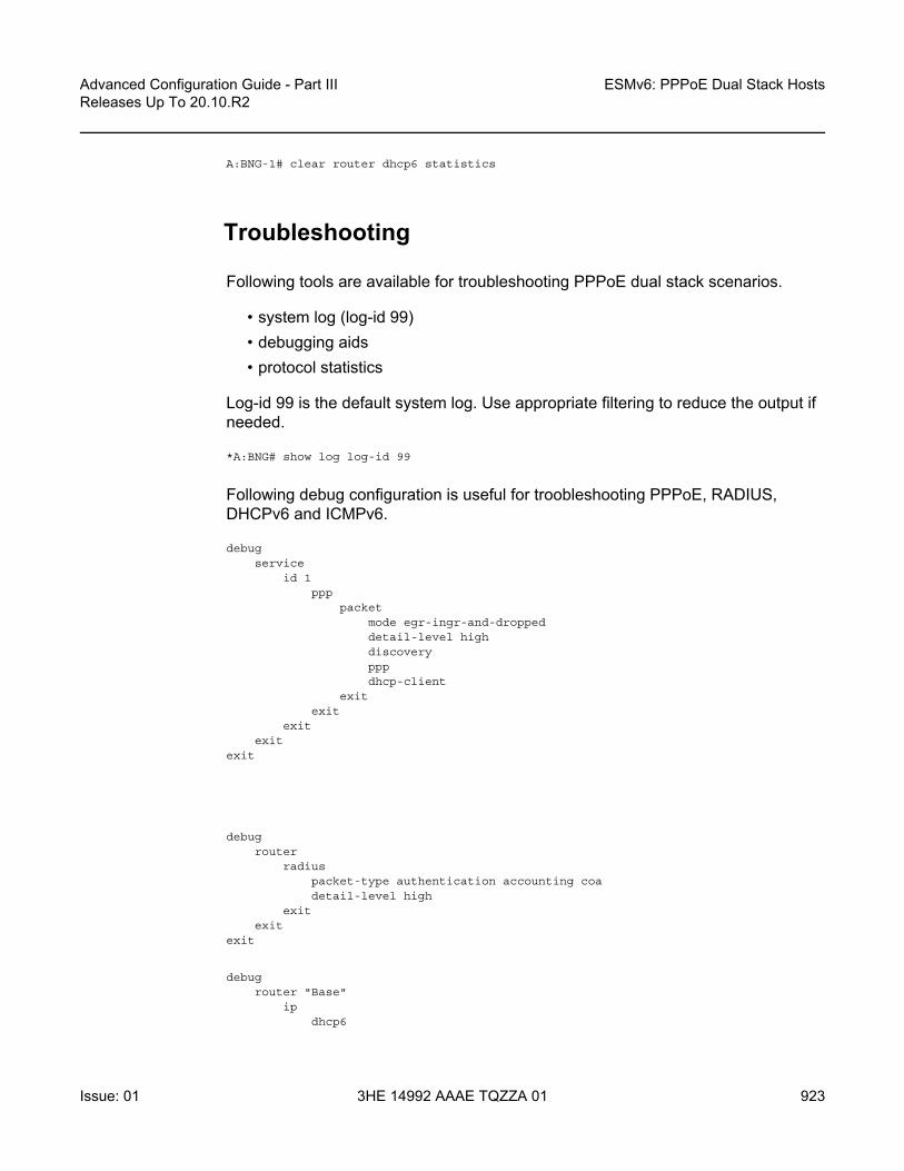
Advanced Configuration Guide - Part III Releases Up To 20.10.R2
ESMv6: PPPoE Dual Stack Hosts
Issue: 01 3HE 14992 AAAE TQZZA 01 923
A:BNG-1# clear router dhcp6 statistics
Troubleshooting
Following tools are available for troubleshooting PPPoE dual stack scenarios.
• system log (log-id 99)• debugging aids• protocol statistics
Log-id 99 is the default system log. Use appropriate filtering to reduce the output if needed.
*A:BNG# show log log-id 99
Following debug configuration is useful for troobleshooting PPPoE, RADIUS, DHCPv6 and ICMPv6.
debugservice
id 1ppp
packetmode egr-ingr-and-droppeddetail-level highdiscoverypppdhcp-client
exitexit
exitexit
exit
debugrouter
radiuspacket-type authentication accounting coadetail-level high
exitexit
exit
debugrouter "Base"
ipdhcp6

ESMv6: PPPoE Dual Stack Hosts
924
Advanced Configuration Guide - Part IIIReleases Up To 20.10.R2
3HE 14992 AAAE TQZZA 01 Issue: 01
mode egr-ingr-and-droppeddetail-level high
exiticmp6
exitexit
exit
Use the following commands for showing protocol related statistics.
show router dhcp6 statisticsshow service id 1 pppoe session statistics
Advanced Topics
RADIUS COA
For dual stack PPPoE subscriber hosts, RADIUS-triggered mid-session change or/and session terminations identify the subscriber host to be changed by the same prefix that was originally returned from RADIUS or by the host-session-id (If RADIUS accounting host-accounting is enabled and the accounting session-id format equals number). Changing either the IPv4 or IPv6 information will result in both the v4 and v6 subscriber hosts being modified. Further elaboration on accounting is out of scope in this document.
IPv6CP Interface ID
IPv6CP negotiates, unlike ipv4-addresses in IPv4CP, only interface-ids (interface-id: the last 64 bits of an IPv6 address is the interface identifier that is unique to the 64-bit prefix of the IPv6 address and is usually derived from the link-layer or MAC address).
Dual stack PPPoE subscribers and the BNG exchange their interface-ids during the NCP phase. For ESM subscriber-interfaces on the BNG the interface-id is derived from the chassis-mac address.
• The BNG will nack the PPPoE host’s IPv6CP configuration request if the dual stack PPPoE host negotiates an interface-id equal zero or an interface-id equal to the BNG interface ID. In that scenario, the BNG offers in the IPv6CP nack message a suitable interface ID, see Table 32.

Advanced Configuration Guide - Part III Releases Up To 20.10.R2
ESMv6: PPPoE Dual Stack Hosts
Issue: 01 3HE 14992 AAAE TQZZA 01 925
• The BNG terminates the session if the dual stack PPPoE hosts nacks its IPv6CP configuration request and offers something else to the BNG.
Conclusion
This chapter provides configuration and troubleshooting commands for dual stack PPPoE subscribers on bridged or routed gateways. SLAAC is used as IPv6 address assignment for bridged gateway scenarios and stateful DHCPv6 prefix-delegation is used for address assignment for routed gateway scenarios. No RG WAN IPv6 address assignment is supported in this latter model.
DNSv6 addressing on a bridged gateway is retrieved by stateless DHCPv6 (information request and reply).
Table 32 IPv6CP Nack Message Format
1 2 3 4 5 6 7 8
SAP ID Last 2 bytes MAC host Session ID

ESMv6: PPPoE Dual Stack Hosts
926
Advanced Configuration Guide - Part IIIReleases Up To 20.10.R2
3HE 14992 AAAE TQZZA 01 Issue: 01

Advanced Configuration Guide - Part III Releases Up To 20.10.R2
Flexible Authentication Model in ESM
Issue: 01 3HE 14992 AAAE TQZZA 01 927
Flexible Authentication Model in ESMThis chapter provides information about Flexible Authentication Models in ESM.
Topics in this chapter include:
• Applicability• Overview• Configuration• Conclusion
Applicability
This chapter is applicable to SROS routers in the Routed Central Office (RCO) model and was initially written for SR OS release 11.0.R2, but the CLI in the current edition is based on SR OS release 15.0.R2.
Overview
The flexible authentication model for IPoE and PPPoE subscribers allows for mixing of configuration parameters obtained during the authentication phase from different sources: Local User Database (LUDB), RADIUS, or DHCP options that can be populated via a custom Python script. In case the same parameter is available from multiple sources, a priority mechanism is enforced whereby the parameter received from a higher priority source overrides the parameters received from the lower priority source in the following priority: LUDB to RADIUS to Python.
In this chapter we will configure a dual-stack IPoE and a dual stack PPPoE host using four different methods to obtain their configuration parameters. The setup will utilize a single BNG node with a locally configured DHCP server and LUDB as well as an external RADIUS server. Subscriber hosts are instantiated on managed (dynamic) SAPs.
The subscriber configuration parameters are in general divided into two categories:
• IP addressing parameters of the host — IPv4/v6 address/prefix, DNS servers, IPv4 default-gateway, IPv4 subnet-mask, IPv4/v6 address pool name, DHCPv4/v6 lease times, etc.

Flexible Authentication Model in ESM
928
Advanced Configuration Guide - Part IIIReleases Up To 20.10.R2
3HE 14992 AAAE TQZZA 01 Issue: 01
• Non IP addressing parameters of the host — Subscriber hosts strings are used to associate the subscriber-host with the desired level of service (sub/sla-profiles, inter-dest-id string, etc); managed routes are used for routing purposes to/from the host; etc.
The following four scenarios will be examined:
1. DHCP relay case (IP address is assigned via local DHCP server) with NO authentication. See DHCP Relay Case with No Authentication.
2. DHCP relay case (IP address is assigned via local DHCP server) with LUDB + RADIUS authentication. See DHCP Relay Case with LUDB + RADIUS Authentication.RADIUS provides: sub/sla-profile strings and a framed IPv4 route. LUDB provides: IP address pool, inter-dest-id string for Vport assignment, msap-defaults (routing context parameters and msap-policy).
3. IP proxy case (IP address is assigned via RADIUS) with LUDB + RADIUS authentication. IP Proxy Case with LUDB + RADIUS AuthenticationRADIUS provides: IP addresses and related parameters (DNS server, IPv4 default-gateway, etc), inter-dest-id string for Vport assignment and a framed route. IPv6 lease-times are provided under the group-interface.LUDB provides: sub/sla-profile strings and msap-defaults (routing context parameters and msap-policy).
4. IP proxy case (IP address is assigned via LUDB) with LUDB + RADIUS authentication. IP Proxy Case with LUDB + RADIUS AuthenticationRADIUS provides: sub/sla-profile strings and a framed IPv4 route.LUDB provides IP addresses and related parameters (DNS server, IPv4 default-gateway, etc), inter-dest-id string for Vport assignment and msap-defaults (routing context parameters and msap-policy).
In cases 2-4, the domain-name domain1 is appended to the IPoE and PPPoE username in LUDB, before RADIUS authentication takes place.
Configuration
The topology is shown in Figure 156.

Advanced Configuration Guide - Part III Releases Up To 20.10.R2
Flexible Authentication Model in ESM
Issue: 01 3HE 14992 AAAE TQZZA 01 929
Figure 156 Topology
There is a common part of the configuration that applies uniformly across all four examined scenarios. This common part is outlined below and will not be repeated again when we describe more specific cases. It is assumed that the more specific cases also contain this common part of the configuration.
Common Configuration Part
Access Ethernet Port with QinQ Encapsulation
The following output displays a configuration example.
configureport 1/1/1
ethernetmode accessencap-type dot1q
exitexit
exit
al_0260
7750 BNG
RADIUSServer
DHCPv4/6 (LDRA),PPPoEv4/6
Client SimulatorDHCPv4/6 Server
LUDB
1/1/1
1/1/2
V4: 10.10.1.1V6: 2001:db8::1/128

Flexible Authentication Model in ESM
930
Advanced Configuration Guide - Part IIIReleases Up To 20.10.R2
3HE 14992 AAAE TQZZA 01 Issue: 01
Capture SAP
A capture SAP is used to dynamically detect the VLAN id(s) in incoming DHCP/PPPoE packets (triggering packets) and conditionally instantiate the managed (dynamic) SAP. LUDB must be configured under the capture SAP to authorize the user accessing the capture SAP. The LUDB may contain additional parameters needed to set up the subscriber, it can point the subscriber to the RADIUS server for additional parameters or it may contain a default subscriber-host entry without any configuration parameters.
In this case, the msap-defaults under the capture SAP is used to select the routing context where the msap is created. msap-defaults can be also configured in the LUDB or be supplied via RADIUS.
PPPoE policy and msap policy are used to define PPPoE and SAP level parameters. Because the (dynamic) SAP does not exist at the time when the initial DHCP/PPPoE packets are received, the PPPoE/SAP level parameters are taken from the PPPoE/msap policy under the capture SAP. For example, those parameters are used in the PPP PADx/LCP/Authentication setup phase, they define default subscriber host strings, maximum number of subscriber hosts per SAP, the anti-spoofing mode, etc.
The X in the LUDB name (ludb-X) has to be replaced by a number depending on the scenario.
configureservice
vpls 2 customer 1 createstp
shutdownexitsap 1/1/1:* capture-sap create
description "open DHCP model testing"trigger-packet dhcp dhcp6 pppoedhcp-user-db "ludb-X"dhcp6-user-db "ludb-X"pppoe-policy "pppoe-pol-1"pppoe-user-db "ludb-X"msap-defaults
group-interface "grp-int-1"policy "msap-pol-1"service 1
exitexitno shutdown
exitexit
exit

Advanced Configuration Guide - Part III Releases Up To 20.10.R2
Flexible Authentication Model in ESM
Issue: 01 3HE 14992 AAAE TQZZA 01 931
auto-sub-id
The auto-sub-id-key command can be used in situations where the more specific subscriber-id string is not returned from LUDB or RADIUS. In this case, the auto subscriber-id for IPoE hosts is set to the circuit-id while for PPPoE hosts the auto subscriber-id is set to the circuit-id plus session-id separated by the “|” delimiter which is inserted by default.
configuresubscriber-mgmt
auto-sub-id-keyipoe-sub-id-key circuit-idppp-sub-id-key circuit-id session-id
exitexit
exit
PPPoE Policy
There is a maximum of PPPoE sessions per MAC on a managed SAP. The default is 1 but is increased here to 10.
configuresubscriber-mgmt
ppp-policy "pppoe-pol-1" createppp-mtu 1400max-sessions-per-mac 10
exitexit
exit
MSAP Policy
The MSAP policy defines the anti-spoofing mode which is in this particular example set to next-hop MAC (nh-mac). It also defines the default subscriber management parameters in case they are not supplied via LUDB or RADIUS.
configuresubscriber-mgmt
msap-policy "msap-pol-1" createsub-sla-mgmt
def-sub-id use-auto-iddef-sub-profile "sub-profile-1"def-sla-profile "sla-profile-1"sub-ident-policy "sub-ident-1"multi-sub-sap limit 500
exities-vprn-only-sap-parameters

Flexible Authentication Model in ESM
932
Advanced Configuration Guide - Part IIIReleases Up To 20.10.R2
3HE 14992 AAAE TQZZA 01 Issue: 01
anti-spoof nh-macexit
exitexit
exit
subscriber-interface Configuration
The following output displays a subscriber interface configuration.
configureservice
vprn 1 customer 1 createsubscriber-interface "sub-int-1" create
# support for un-numbered IPv4 clientsallow-unmatching-subnets# default gateway for IPv4 numbered clientsaddress 10.12.0.1/24ipv6
# fixed delegated prefix length for IA-PDdelegated-prefix-len 56# support for un-numbered IPv6 clientsallow-unmatching-prefixes
exitgroup-interface "grp-int-1" create
ipv6router-advertisements
# hint to the client to use DHCPv6managed-configuration# enabling router-advertisementsno shutdown
exitdhcp6
# must be the same as under the capture-SAPuser-db "ludb-1"
exitexit# ARP table is populated based on the lease state tablearp-populatedhcp
server 10.10.1.1# accept DHCP packets on this group interfacetrusted# max number of DHCPv4 clients on each# SAP of this group-interfacelease-populate 100# must be the same as under the capture-SAPuser-db "ludb-1"no shutdown
exitpppoe
policy "pppoe-pol-1"session-limit 1000sap-session-limit 1000# must be the same as under the capture-SAP

Advanced Configuration Guide - Part III Releases Up To 20.10.R2
Flexible Authentication Model in ESM
Issue: 01 3HE 14992 AAAE TQZZA 01 933
user-db "ludb-1"no shutdown
exitexit
exitno shutdown
exitexit
exit
For numbered/unnumbered subscriber-hosts also take a look at the DHCP/PPPoE clients whose assigned IP address is outside of any IP subnet/prefix configured under the subscriber-interface.
Specific Configuration Parts
DHCP Relay Case with No Authentication
The IP address is assigned via local DHCP server. The LUDB is accessed even in the scenario without authentication. There must be a default host LUDB entry present that will match on any value specified in the match-list criteria. The LUDB is accessed from the capture SAP (part of the common configuration).
configuresubscriber-mgmt
local-user-db "ludb-1" createdescription "for CASE-1"ipoe
# host matching is based on circuit-ID in DHCP packetsmatch-list circuit-idhost "default" create
no shutdownexit
exitppp
# host matching is base on PPPoE usernamematch-list usernamehost "default" create
# explicitly enable IPCPv6force-ipv6cpno shutdown
exitexitno shutdown
exitexit
exit

Flexible Authentication Model in ESM
934
Advanced Configuration Guide - Part IIIReleases Up To 20.10.R2
3HE 14992 AAAE TQZZA 01 Issue: 01
Once the routing context (service id and group-interface) is determined as defined under the capture SAP defaults (part of the common configuration), the DHCP/PPPoE requests are served according to the group-interface configuration. The IP address request is relayed to the DHCPv4/v6 server. Since the LUDB does not provide a pool name, the gi-address and the link-address is used by the DHCP relay/server to select the pool from which the IP address will be assigned.
configureservice
vprn 1 customer 1 createsubscriber-interface "sub-int-1" create
group-interface "grp-int-1" createipv6
dhcp6# DHCPv6 relay configurationrelay
link-address 2001:DB8:30::# DHCPv6 server IPv6 addressserver 2001:DB8::1client-applications dhcp pppno shutdown
exitexit
exitarp-populatedhcp
# DHCPv4 server IP addressserver 10.10.1.1client-applications dhcp pppgi-address 10.12.0.1no shutdown
exitexit
exitno shutdown
exitexit
exit
DHCPv4/v6 servers are locally configured in the node and attached to a loopback interface.
configureservice
vprn 1 customer 1 createinterface "int-DHCP" create
# IPv4 address which the DHCPv4 is listening onaddress 10.10.1.1/24ipv6
# IPv6 address which the DHCPv6 server is listening onaddress 2001:DB8::1/128local-dhcp-server "svc-1-dhcp6"
exit# attaching the DHCPv4 server to the loopback interfacelocal-dhcp-server "svc-1-dhcp4"loopback

Advanced Configuration Guide - Part III Releases Up To 20.10.R2
Flexible Authentication Model in ESM
Issue: 01 3HE 14992 AAAE TQZZA 01 935
exitexit
exitexit
In the local DHCP servers two pools are defined:
• LUDB — To be used for IP address assignment when LUDB returns the pool name.
• Gi-addr — To be used when gi-address/link-address are used to select the pool for IP address assignment.
Lease times for IPv4 and IPv6 are configured in the local DHCP server which is used only in the relay case (when the IP address is supplied via DHCP server and not through RADIUS or the LUDB).
configureservice
vprn 1 customer 1 createdhcp
local-dhcp-server "svc-1-dhcp4" create# the gi-address can be used to select the pooluse-gi-address# the pool name can be explicitly provideduse-pool-from-client# the pool used when the LUDB provides the pool namepool "ludb" create
optionsdns-server 172.16.16.16 172.16.16.17# DHCPv4 lease timelease-time hrs 1
exitsubnet 10.10.0.0/24 create
optionssubnet-mask 255.255.255.0default-router 10.10.0.1
exitaddress-range 10.10.0.100 10.10.0.200
exitexit# pool selected based on the gi-addresspool "gi-addr" create
optionsdns-server 172.16.16.16 172.16.16.17# DHCPv4 lease timelease-time hrs 1
exitsubnet 10.12.0.0/24 create
optionssubnet-mask 255.255.255.0default-router 10.12.0.1
exitaddress-range 10.12.0.100 10.12.0.200
exitexitno shutdown

Flexible Authentication Model in ESM
936
Advanced Configuration Guide - Part IIIReleases Up To 20.10.R2
3HE 14992 AAAE TQZZA 01 Issue: 01
exitexitdhcp6
local-dhcp-server "svc-1-dhcp6" createuse-link-addressuse-pool-from-clientpool "ludb" create
prefix 2001:DB8:10::/48 pd wan-host createpreferred-lifetime min 30rebind-timer min 20renew-timer min 15# DHCPv6 lease timevalid-lifetime hrs 1options
dns-server 2001:DB8::1000 2001:DB8::1001exit
exitexitpool "gi-addr" create
prefix 2001:DB8:30::/48 pd wan-host createpreferred-lifetime min 30rebind-timer min 20renew-timer min 15# DHCPv6 lease timevalid-lifetime hrs 1options
dns-server 2001:DB8::1000 2001:DB8::1001exit
exitexitno shutdown
exitexit
exitexit
exit
Default sub/sla-profiles, from the msap-policy, are used (part of the common configuration).
configuresubscriber-mgmt
sla-profile "sla-profile-1" createdescription "default SLA profile"host-limits
overall 3exit
exitsub-profile "sub-profile-1" create
description "default SUB profile"egress
agg-rate-limit 1000exit
exitexit
exit

Advanced Configuration Guide - Part III Releases Up To 20.10.R2
Flexible Authentication Model in ESM
Issue: 01 3HE 14992 AAAE TQZZA 01 937
Show Commands
The following command shows that the default sub/sla-profiles are in use, that the IP addresses are selected from the gi-addr pool in local DHCP server and that the subscriber-id is set to circuit-id for the IPoE subscriber-host and to username|session-id combination for the PPPoE subscriber-host.
*A:BNG-1# show service active-subscribers
===============================================================================Active Subscribers===============================================================================-------------------------------------------------------------------------------Subscriber open-dhcp-1 (sub-profile-1)--------------------------------------------------------------------------------------------------------------------------------------------------------------(1) SLA Profile Instance sap:[1/1/1:11] - sla:sla-profile-1-------------------------------------------------------------------------------IP Address
MAC Address Session Origin Svc Fwd-------------------------------------------------------------------------------10.12.0.107
00:0c:29:00:00:11 N/A DHCP 1 Y2001:db8:30:103::1/128
00:0c:29:00:00:11 N/A DHCP6 1 Y2001:db8:30:400::/56
00:0c:29:00:00:11 N/A DHCP6 1 Y-------------------------------------------------------------------------------
-------------------------------------------------------------------------------Subscriber open-pppoe-1|1 (sub-profile-1)--------------------------------------------------------------------------------------------------------------------------------------------------------------(1) SLA Profile Instance sap:[1/1/1:21] - sla:sla-profile-1-------------------------------------------------------------------------------IP Address
MAC Address Session Origin Svc Fwd-------------------------------------------------------------------------------10.12.0.108
00:0c:29:00:00:21 PPP 1 IPCP 1 Y2001:db8:30:104::1/128
00:0c:29:00:00:21 PPP 1 DHCP6 1 Y2001:db8:30:500::/56
00:0c:29:00:00:21 PPP 1 DHCP6-PD 1 Y-------------------------------------------------------------------------------
-------------------------------------------------------------------------------Number of active subscribers : 2===============================================================================*A:BNG-1#
The following command shows more details about the subscriber-host, such as the group-interface, address origin, acct-session-id, etc. Even though there are only two dual-stack hosts (one IPoE and one PPPoE), each of them has three IP addresses that show up as different hosts.

Flexible Authentication Model in ESM
938
Advanced Configuration Guide - Part IIIReleases Up To 20.10.R2
3HE 14992 AAAE TQZZA 01 Issue: 01
For the purpose of brevity, the output for only two IP hosts are shown, one with an IPv4 address and one with an IPv6 address. The remaining IP addresses/prefixes are not shown because the output follows the same logic.
*A:BNG-1# show service id 1 subscriber-hosts detail
=============================================================Subscriber Host table=============================================================Sap Subscriber
IP AddressMAC Address PPPoE-SID Origin Fwding State
-------------------------------------------------------------[1/1/1:11] open-dhcp-1
10.12.0.10700:0c:29:00:00:11 N/A DHCP Fwding
-------------------------------------------------------------Subscriber-interface : sub-int-1Group-interface : grp-int-1Sub Profile : sub-profile-1SLA Profile : sla-profile-1App Profile : N/AEgress Q-Group : N/AEgress Vport : N/AAcct-Session-Id : 14F2FF00000026591168E2Acct-Q-Inst-Session-Id: 14F2FF00000027591168E2Address Origin : DynamicOT HTTP Rdr IP-FltrId : N/AOT HTTP Rdr Status : N/AOT HTTP Rdr Fltr Src : N/AHTTP Rdr URL Override : N/AGTP local break-out : NoDIAMETER session ID Gx: N/A-------------------------------------------------------------[1/1/1:11] open-dhcp-1
2001:db8:30:103::1/12800:0c:29:00:00:11 N/A IPoE-DHCP6 Fwding
-------------------------------------------------------------
--- snipped ---
-------------------------------------------------------------[1/1/1:11] open-dhcp-1
2001:db8:30:400::/5600:0c:29:00:00:11 N/A IPoE-DHCP6 Fwding
-------------------------------------------------------------
--- snipped ---
-------------------------------------------------------------[1/1/1:21] open-pppoe-1|1
10.12.0.10800:0c:29:00:00:21 1 IPCP Fwding
-------------------------------------------------------------
--- snipped ---
-------------------------------------------------------------

Advanced Configuration Guide - Part III Releases Up To 20.10.R2
Flexible Authentication Model in ESM
Issue: 01 3HE 14992 AAAE TQZZA 01 939
[1/1/1:21] open-pppoe-1|12001:db8:30:104::1/128
00:0c:29:00:00:21 1 PPP-DHCP6 Fwding-------------------------------------------------------------
--- snipped ---
-------------------------------------------------------------[1/1/1:21] open-pppoe-1|1
2001:db8:30:500::/5600:0c:29:00:00:21 1 PPP-DHCP6 Fwding
-------------------------------------------------------------Subscriber-interface : sub-int-1Group-interface : grp-int-1Sub Profile : sub-profile-1SLA Profile : sla-profile-1App Profile : N/AEgress Q-Group : N/AEgress Vport : N/AAcct-Session-Id : 14F2FF0000002E5911690EAcct-Q-Inst-Session-Id: 14F2FF0000002C5911690EAddress Origin : DynamicOT HTTP Rdr IP-FltrId : N/AOT HTTP Rdr Status : N/AOT HTTP Rdr Fltr Src : N/AHTTP Rdr URL Override : N/AGTP local break-out : NoDIAMETER session ID Gx: N/A-------------------------------------------------------------Number of subscriber hosts : 6=============================================================*A:BNG-1#
The following command shows that there are no sub/sla-profile strings assigned to the subscriber. Instead the default sub/sla-profiles from the msap-policy are used.
The IP address is assigned by the DHCP server which also supplied the def-gw information, DNS servers, the net-mask and the lease time.
The circuit-id and the subscriber-id are set to the same value.
*A:BNG-1# show service id 1 dhcp lease-state detail
===============================================================================DHCP lease states for service 1===============================================================================Service ID : 1IP Address : 10.12.0.107Client HW Address : 00:0c:29:00:00:11Subscriber-interface : sub-int-1Group-interface : grp-int-1SAP : [1/1/1:11]Termination Type : localUp Time : 0d 00:02:11Remaining Lease Time : 0d 00:57:49Remaining SessionTime: N/APersistence Key : N/A

Flexible Authentication Model in ESM
940
Advanced Configuration Guide - Part IIIReleases Up To 20.10.R2
3HE 14992 AAAE TQZZA 01 Issue: 01
Sub-Ident : "open-dhcp-1"Sub-Profile-String : ""SLA-Profile-String : ""App-Profile-String : ""Lease ANCP-String : ""Lease Int Dest Id : ""Category-Map-Name : ""
Lease Info origin : DHCP
Ip-Netmask : 255.255.255.0Broadcast-Ip-Addr : N/ADefault-Router : 10.12.0.1Primary-Dns : 172.16.16.16Secondary-Dns : 172.16.16.17Primary-Nbns : N/ASecondary-Nbns : N/A
ServerLeaseStart : 05/09/2017 08:59:46ServerLastRenew : 05/09/2017 08:59:46ServerLeaseEnd : 05/09/2017 09:59:46Session-Timeout : N/AIPoE|PPP session : NoLease-Time : 0d 01:00:00DHCP Server Addr : 10.10.1.1
Relay Agent InformationCircuit Id : open-dhcp-1
Radius User-Name : ""-------------------------------------------------------------------------------Number of lease states : 1===============================================================================*A:BNG-1#
Then there is a similar command used for DHCPv6 lease-state details.
For the purpose of brevity, the output for only two IPv6 leases is shown. The remaining two IPv6 leases are not shown because the output follows the same logic.
*A:BNG-1# show service id 1 dhcp6 lease-state detail
===============================================================================DHCP lease states for service 1===============================================================================Service ID : 1IP Address : 2001:db8:30:103::1/128Client HW Address : 00:0c:29:00:00:11Subscriber-interface : sub-int-1Group-interface : grp-int-1SAP : [1/1/1:11]Termination Type : localUp Time : 0d 00:02:34Remaining Lease Time : 0d 00:57:26Remaining SessionTime: N/APersistence Key : N/A
Sub-Ident : "open-dhcp-1"

Advanced Configuration Guide - Part III Releases Up To 20.10.R2
Flexible Authentication Model in ESM
Issue: 01 3HE 14992 AAAE TQZZA 01 941
Sub-Profile-String : ""SLA-Profile-String : ""App-Profile-String : ""Lease ANCP-String : ""Lease Int Dest Id : ""Category-Map-Name : ""Dhcp6 ClientId (DUID): 0001000120a31b12000c29000011Dhcp6 IAID : 2Dhcp6 IAID Type : non-temporaryDhcp6 Client Ip : fe80::20c:29ff:fe00:11Primary-Dns : N/ASecondary-Dns : N/APool Name : ""Dhcp6 Server Addr : 2001:db8::1Dhcp6 ServerId (DUID): 0003000114f2ff000000Dhcp6 InterfaceId : open-dhcp-1Dhcp6 RemoteId : N/ARadius sub-if prefix : N/ARouter adv. policy : N/A
Lease Info origin : DHCP
ServerLeaseStart : 05/09/2017 09:00:00ServerLastRenew : 05/09/2017 09:00:00ServerLeaseEnd : 05/09/2017 10:00:00Session-Timeout : N/AIPoE|PPP session : NoRadius User-Name : ""-------------------------------------------------------------------------------Service ID : 1IP Address : 2001:db8:30:104::1/128Client HW Address : 00:0c:29:00:00:21
--- snipped ---
-------------------------------------------------------------------------------Service ID : 1IP Address : 2001:db8:30:400::/56Client HW Address : 00:0c:29:00:00:11
--- snipped ---
-------------------------------------------------------------------------------Service ID : 1IP Address : 2001:db8:30:500::/56Client HW Address : 00:0c:29:00:00:21Subscriber-interface : sub-int-1Group-interface : grp-int-1SAP : [1/1/1:21]Termination Type : localUp Time : 0d 00:02:06Remaining Lease Time : 0d 00:57:54Remaining SessionTime: N/APersistence Key : N/A
Sub-Ident : "open-pppoe-1|1"Sub-Profile-String : ""SLA-Profile-String : ""App-Profile-String : ""

Flexible Authentication Model in ESM
942
Advanced Configuration Guide - Part IIIReleases Up To 20.10.R2
3HE 14992 AAAE TQZZA 01 Issue: 01
Lease ANCP-String : ""Lease Int Dest Id : ""Category-Map-Name : ""Dhcp6 ClientId (DUID): 0001000120a33d28000c29000021Dhcp6 IAID : 1Dhcp6 IAID Type : prefixDhcp6 Client Ip : fe80::20c:29ff:fe00:21Primary-Dns : N/ASecondary-Dns : N/APool Name : ""Dhcp6 Server Addr : 2001:db8::1Dhcp6 ServerId (DUID): 0003000114f2ff000000Dhcp6 InterfaceId : open-pppoe-1Dhcp6 RemoteId : N/ARadius sub-if prefix : N/ARouter adv. policy : N/A
Lease Info origin : DHCP
ServerLeaseStart : 05/09/2017 09:00:30ServerLastRenew : 05/09/2017 09:00:30ServerLeaseEnd : 05/09/2017 10:00:30Session-Timeout : N/AIPoE|PPP session : PPPRadius User-Name : "open-pppoe-1"-------------------------------------------------------------------------------Number of lease states : 4===============================================================================*A:BNG-1#
DHCP Relay Case with LUDB + RADIUS Authentication
IP address is assigned via local DHCP server.
• RADIUS provides sub/sla-profile strings and a framed IPv4 route. • LUDB provides IP address pool, inter-dest-id string for Vport assignment, msap-
defaults (routing context parameters and msap-policy).
Vport aggregate rate limit and the port scheduler are now added to the physical port. The Vport is associated with the subscriber through the inter-dest-id string obtained via LUDB.
configureport 1/1/1
ethernetmode accessencap-type dot1qegress-scheduler-policy "port"access
egressvport "open-dhcp" create
agg-raterate 500

Advanced Configuration Guide - Part III Releases Up To 20.10.R2
Flexible Authentication Model in ESM
Issue: 01 3HE 14992 AAAE TQZZA 01 943
exithost-match dest "open-auth-vport" create
exitexit
exitexitno shutdown
exitexit
The LUDB is used to assign the IP pool name (pool-name = ludb) and the inter-dest-id string (inter-dest-id = open-auth-vport) to the subscriber. The pool name is carried to the DHCP server via custom DHCP options [(82,9,13) in DHCPv4 and (17,1->wan_pool and 2->pfx_pool) in DHCPv6].
The domain name domain1 is appended to the username (circuit-id = open-dhcp-2 or username = open-pppoe-2) before an Access-Request message is sent to the RADIUS server which is configured in the authentication policy auth-pol-1.
The inter-dest-id string taken from the LUDB is passed to the subscriber management module in the node via DHCP option 254 in DHCP ACK/Reply.
configuresubscriber-mgmt
local-user-db "ludb-2" createdescription "for CASE-2"ipoe
match-list circuit-idhost "open-dhcp-2" create
host-identificationcircuit-id string "open-dhcp-2"
exitaddress pool "ludb"auth-policy "auth-pol-1"auth-domain-name "domain1"identification-strings 254 create
inter-dest-id "open-auth-vport"exitmsap-defaults
group-interface "grp-int-1"policy "msap-pol-1"service 1
exitipv6-wan-address-pool "ludb"ipv6-delegated-prefix-pool "ludb"no shutdown
exitexitppp
match-list circuit-id mac usernamehost "open-ppp-2" create
host-identificationusername "open-pppoe-2"
exitauth-policy "auth-pol-1"address pool "ludb"

Flexible Authentication Model in ESM
944
Advanced Configuration Guide - Part IIIReleases Up To 20.10.R2
3HE 14992 AAAE TQZZA 01 Issue: 01
password chap "letmein"identification-strings 254 create
inter-dest-id "open-auth-vport"exitmsap-defaults
group-interface "grp-int-1"policy "msap-pol-1"service 1
exitipv6-delegated-prefix-pool "ludb"ipv6-wan-address-pool "ludb"no shutdown
exitexitno shutdown
exitexit
exit
The inter-dest-id string taken from the LUDB is passed to the subscriber management module in the node via DHCPv4/v6 option 254 that is specified in the subscriber identification policy.
configuresubscriber-mgmt
sub-ident-policy "sub-ident-1" createstrings-from-option 254
exitexit
exit
The RADIUS server is defined via the authentication policy. The domain name can be appended to the PPPoE subscriber host directly via the authentication-policy while for IPoE subscribers, the domain name is appended via the authentication-policy in conjunction with the LUDB. This can be verified in the output (shown later) of the show service id 1 dhcp lease-state detail and show service id 1 dhcp6 lease-state detail commands (on the “radius user-name” line).
configuresubscriber-mgmt
authentication-policy "auth-pol-1" createdescription "RADIUS authentication policy"password "letmein"ppp-user-name append "domain1"user-name-format circuit-id appendaccept-authorization-changepppoe-access-method pap-chapradius-server-policy "rad-serv-pol-1"
exitexit
exit
The RADIUS user configuration file uses the domain-name extension, as inserted by the BNG, to authenticate the user:

Advanced Configuration Guide - Part III Releases Up To 20.10.R2
Flexible Authentication Model in ESM
Issue: 01 3HE 14992 AAAE TQZZA 01 945
open-dhcp-2@domain1 Cleartext-Password := "letmein"Alc-Subsc-Prof-Str = rad-sub,Alc-SLA-Prof-Str = rad-sla,Framed-Route = "192.168.1.0/24 0.0.0.0",
open-pppoe-2@domain1 Cleartext-Password := "letmein"Alc-Subsc-Prof-Str = rad-sub,Alc-SLA-Prof-Str = rad-sla,Framed-Route = "192.168.2.0/24 0.0.0.0",
DHCPv4/v6 servers are locally configured in the 7x50 and attached to a loopback interface:
configureservice
vprn 1 customer 1 createinterface "int-DHCP" create
# IPv4 address which the DHCPv4 server is listening onaddress 10.10.1.1/24ipv6
# IPv6 address which the DHCPv6 server is listening onaddress 2001:DB8::1/128# attach the DHCPv6 server to this loopback interfacelocal-dhcp-server "svc-1-dhcp6"
exit# attach the DHCPv4 server to this loopback interfacelocal-dhcp-server "svc-1-dhcp4"loopback
exitexit
exitexit
Group-interface configuration. Note that common parts of the configuration as defined earlier, still apply:
configureservice
vprn 1 customer 1 createsubscriber-interface "sub-int-1" create
group-interface "grp-int-1" createipv6
dhcp6user-db "ludb-2"# DHCPv6 relay configurationrelay
link-address 2001:DB8:30::server 2001:DB8::1client-applications dhcp pppno shutdown
exitexit
exitarp-populate# DHCPv6 relay configurationdhcp
proxy-server

Flexible Authentication Model in ESM
946
Advanced Configuration Guide - Part IIIReleases Up To 20.10.R2
3HE 14992 AAAE TQZZA 01 Issue: 01
emulated-server 10.12.0.1no shutdown
exitoption
# SR OS will not insert its own circuit-IDno circuit-id# SR OS will not insert its own remote-IDno remote-idvendor-specific-option
pool-nameexit
exitserver 10.10.1.1client-applications dhcp pppuser-db "ludb-2"no shutdown
exitpppoe
policy "pppoe-pol-1"session-limit 1000sap-session-limit 1000user-db "ludb-2"no shutdown
exitexit
exitno shutdown
exitexit
exit
Lease times for IPv4 and IPv6 are configured in the local DHCP server. Lease times under the local DHCP server are used only in the relay case (when IP address is supplied via DHCP server and not RADIUS or LUDB). In the proxy case, the lease times can be obtained via LUDB, RADIUS, or group-interface.
configureservice
vprn 1 customer 1 createdhcp
local-dhcp-server "svc-1-dhcp4" create# gi-address can be used to select the pooluse-gi-address# pool name can be explicitly provideduse-pool-from-client# pool used when LUDB provides the pool namepool "ludb" create
optionsdns-server 172.16.16.16 172.16.16.17lease-time hrs 1
exitsubnet 10.10.0.0/24 create
optionssubnet-mask 255.255.255.0default-router 10.10.0.1
exitaddress-range 10.10.0.100 10.10.0.200

Advanced Configuration Guide - Part III Releases Up To 20.10.R2
Flexible Authentication Model in ESM
Issue: 01 3HE 14992 AAAE TQZZA 01 947
exitexit# pool selected based on the gi-addresspool "gi-addr" create
optionsdns-server 172.16.16.16 172.16.16.17lease-time hrs 1
exitsubnet 10.12.0.0/24 create
optionssubnet-mask 255.255.255.0default-router 10.12.0.1
exitaddress-range 10.12.0.100 10.12.0.200
exitexitno shutdown
exitexitdhcp6
local-dhcp-server "svc-1-dhcp6" createuse-link-addressuse-pool-from-clientpool "ludb" create
prefix 2001:DB8:10::/48 pd wan-host createpreferred-lifetime min 30rebind-timer min 20renew-timer min 15valid-lifetime hrs 1options
dns-server 2001:DB8::1000 2001:DB8::1001exit
exitexitpool "gi-addr" create
prefix 2001:DB8:30::/48 pd wan-host createpreferred-lifetime min 30rebind-timer min 20renew-timer min 15valid-lifetime hrs 1options
dns-server 2001:DB8::1000 2001:DB8::1001exit
exitexitno shutdown
exitexit
exitexit
exit
RADIUS sub/sla-profiles supplied via RADIUS are used:
configuresubscriber-mgmt
sla-profile "rad-sla" createdescription "sla-profile obtained from RADIUS"

Flexible Authentication Model in ESM
948
Advanced Configuration Guide - Part IIIReleases Up To 20.10.R2
3HE 14992 AAAE TQZZA 01 Issue: 01
host-limitsoverall 100
exitegress
qos 1 vport-schedulerexitip-filter 1
exitexitsub-profile "rad-sub" create
description "sub-profile obtained from RADIUS"egress
agg-rate-limit 15000exit
exitexit
exit
Show Commands
The following command shows that the rad-sub/sla-profiles, as supplied via RADIUS, are in use.
The IP addresses are selected from the pool-name LUDB in the local DHCP server. The subscriber-id is circuit-id for IPoE subscriber-host and the username|session-id combination for PPPoE subscriber host.
*A:BNG-1# show service active-subscribers
===============================================================================Active Subscribers===============================================================================-------------------------------------------------------------------------------Subscriber open-dhcp-2 (rad-sub)--------------------------------------------------------------------------------------------------------------------------------------------------------------(1) SLA Profile Instance sap:[1/1/1:12] - sla:rad-sla-------------------------------------------------------------------------------IP Address
MAC Address Session Origin Svc Fwd-------------------------------------------------------------------------------10.10.0.102
00:0c:29:00:00:12 N/A DHCP 1 Y2001:db8:10:101::1/128
00:0c:29:00:00:12 N/A DHCP6 1 Y2001:db8:10:200::/56
00:0c:29:00:00:12 N/A DHCP6 1 Y-------------------------------------------------------------------------------
-------------------------------------------------------------------------------Subscriber open-pppoe-2|1 (rad-sub)--------------------------------------------------------------------------------------------------------------------------------------------------------------(1) SLA Profile Instance sap:[1/1/1:22] - sla:rad-sla-------------------------------------------------------------------------------

Advanced Configuration Guide - Part III Releases Up To 20.10.R2
Flexible Authentication Model in ESM
Issue: 01 3HE 14992 AAAE TQZZA 01 949
IP AddressMAC Address Session Origin Svc Fwd
-------------------------------------------------------------------------------10.10.0.103
00:0c:29:00:00:22 PPP 1 IPCP 1 Y2001:db8:10:102::1/128
00:0c:29:00:00:22 PPP 1 DHCP6 1 Y2001:db8:10:300::/56
00:0c:29:00:00:22 PPP 1 DHCP6-PD 1 Y-------------------------------------------------------------------------------
-------------------------------------------------------------------------------Number of active subscribers : 2===============================================================================*A:BNG-1#
The following command shows more details about the subscriber-host, such as the group-interface, vport, address origin, acct-session-id, etc. Vport is selected based on the inter-dest-id string supplied via the LUDB.
For the purpose of brevity, the output for only two IP addresses hosts is shown, one with an IPv4 address and one with an IPv6 address. The remaining IP addresses/prefixes are not shown because the output follows the same logic.
*A:BNG-1# show service id 1 subscriber-hosts detail=============================================================Subscriber Host table=============================================================Sap Subscriber
IP AddressMAC Address PPPoE-SID Origin Fwding State
-------------------------------------------------------------[1/1/1:12] open-dhcp-2
10.10.0.10200:0c:29:00:00:12 N/A DHCP Fwding
-------------------------------------------------------------Subscriber-interface : sub-int-1Group-interface : grp-int-1Sub Profile : rad-subSLA Profile : rad-slaApp Profile : N/AEgress Q-Group : N/AEgress Vport : open-dhcpAcct-Session-Id : 14F2FF0000002F59116C4AAcct-Q-Inst-Session-Id: 14F2FF0000003059116C4AAddress Origin : DynamicOT HTTP Rdr IP-FltrId : N/AOT HTTP Rdr Status : N/AOT HTTP Rdr Fltr Src : N/AHTTP Rdr URL Override : N/AGTP local break-out : NoDIAMETER session ID Gx: N/A-------------------------------------------------------------[1/1/1:12] open-dhcp-2
2001:db8:10:101::1/12800:0c:29:00:00:12 N/A IPoE-DHCP6 Fwding
-------------------------------------------------------------

Flexible Authentication Model in ESM
950
Advanced Configuration Guide - Part IIIReleases Up To 20.10.R2
3HE 14992 AAAE TQZZA 01 Issue: 01
--- snipped ---
-------------------------------------------------------------[1/1/1:12] open-dhcp-2
2001:db8:10:200::/5600:0c:29:00:00:12 N/A IPoE-DHCP6 Fwding
-------------------------------------------------------------
--- snipped ---
-------------------------------------------------------------[1/1/1:22] open-pppoe-2|1
10.10.0.10300:0c:29:00:00:22 1 IPCP Fwding
-------------------------------------------------------------
--- snipped ---
-------------------------------------------------------------[1/1/1:22] open-pppoe-2|1
2001:db8:10:102::1/12800:0c:29:00:00:22 1 PPP-DHCP6 Fwding
-------------------------------------------------------------
--- snipped ---
-------------------------------------------------------------[1/1/1:22] open-pppoe-2|1
2001:db8:10:300::/5600:0c:29:00:00:22 1 PPP-DHCP6 Fwding
-------------------------------------------------------------Subscriber-interface : sub-int-1Group-interface : grp-int-1Sub Profile : rad-subSLA Profile : rad-slaApp Profile : N/AEgress Q-Group : N/AEgress Vport : open-dhcpAcct-Session-Id : 14F2FF0000003759116C68Acct-Q-Inst-Session-Id: 14F2FF0000003559116C68Address Origin : DynamicOT HTTP Rdr IP-FltrId : N/AOT HTTP Rdr Status : N/AOT HTTP Rdr Fltr Src : N/AHTTP Rdr URL Override : N/AGTP local break-out : NoDIAMETER session ID Gx: N/A-------------------------------------------------------------Number of subscriber hosts : 6=============================================================*A:BNG-1#

Advanced Configuration Guide - Part III Releases Up To 20.10.R2
Flexible Authentication Model in ESM
Issue: 01 3HE 14992 AAAE TQZZA 01 951
The following command shows that the subscriber identity is set to circuit-id (plus session-id) as instructed by auto-sub-id-key command (subscriber-id string is not returned via the LUDB or RADIUS). The lease times are set to 1h as defined in the DHCP server. The username passed to RADIUS is a circuit-id or a username appended with the domain1 domain name.
*A:BNG-1# show service id 1 dhcp lease-state detail
===============================================================================DHCP lease states for service 1===============================================================================Service ID : 1IP Address : 10.10.0.102Client HW Address : 00:0c:29:00:00:12Subscriber-interface : sub-int-1Group-interface : grp-int-1SAP : [1/1/1:12]Termination Type : localUp Time : 0d 00:01:36Remaining Lease Time : 0d 00:58:25Remaining SessionTime: N/APersistence Key : N/A
Sub-Ident : "open-dhcp-2"Sub-Profile-String : "rad-sub"SLA-Profile-String : "rad-sla"App-Profile-String : ""Lease ANCP-String : ""Lease Int Dest Id : "open-auth-vport"Category-Map-Name : ""
Lease Info origin : DHCP
Ip-Netmask : 255.255.255.0Broadcast-Ip-Addr : N/ADefault-Router : 10.10.0.1Primary-Dns : 172.16.16.16Secondary-Dns : 172.16.16.17Primary-Nbns : N/ASecondary-Nbns : N/A
ServerLeaseStart : 05/09/2017 09:14:18ServerLastRenew : 05/09/2017 09:14:18ServerLeaseEnd : 05/09/2017 10:14:18Session-Timeout : N/AIPoE|PPP session : NoLease-Time : 0d 01:00:00DHCP Server Addr : 10.10.1.1
Relay Agent InformationCircuit Id : open-dhcp-2
Radius User-Name : "open-dhcp-2@domain1"
-------------------------------------------------------------------------------Managed Routes-------------------------------------------------------------------------------IP Address Status Metric Tag Pref-------------------------------------------------------------------------------

Flexible Authentication Model in ESM
952
Advanced Configuration Guide - Part IIIReleases Up To 20.10.R2
3HE 14992 AAAE TQZZA 01 Issue: 01
192.168.1.0/24 installed 0 none 0--------------------------------------------------------------------------------------------------------------------------------------------------------------Number of lease states : 1===============================================================================*A:BNG-1#
For the purpose of brevity the output for only two IPv6 leases is shown. The remaining two IPv6 leases are not shown because the output follows the same logic.
*A:BNG-1# show service id 1 dhcp6 lease-state detail
===============================================================================DHCP lease states for service 1===============================================================================Service ID : 1IP Address : 2001:db8:10:101::1/128Client HW Address : 00:0c:29:00:00:12Subscriber-interface : sub-int-1Group-interface : grp-int-1SAP : [1/1/1:12]Termination Type : localUp Time : 0d 00:01:59Remaining Lease Time : 0d 00:58:02Remaining SessionTime: N/APersistence Key : N/A
Sub-Ident : "open-dhcp-2"Sub-Profile-String : "rad-sub"SLA-Profile-String : "rad-sla"App-Profile-String : ""Lease ANCP-String : ""Lease Int Dest Id : "open-auth-vport"Category-Map-Name : ""Dhcp6 ClientId (DUID): 0001000120a33b22000c29000012Dhcp6 IAID : 2Dhcp6 IAID Type : non-temporaryDhcp6 Client Ip : fe80::20c:29ff:fe00:12Primary-Dns : N/ASecondary-Dns : N/APool Name : "ludb"Dhcp6 Server Addr : 2001:db8::1Dhcp6 ServerId (DUID): 0003000114f2ff000000Dhcp6 InterfaceId : open-dhcp-2Dhcp6 RemoteId : N/ARadius sub-if prefix : N/ARouter adv. policy : N/A
Lease Info origin : DHCP
ServerLeaseStart : 05/09/2017 09:14:27ServerLastRenew : 05/09/2017 09:14:27ServerLeaseEnd : 05/09/2017 10:14:27Session-Timeout : N/AIPoE|PPP session : NoRadius User-Name : "open-dhcp-2@domain1"-------------------------------------------------------------------------------Service ID : 1

Advanced Configuration Guide - Part III Releases Up To 20.10.R2
Flexible Authentication Model in ESM
Issue: 01 3HE 14992 AAAE TQZZA 01 953
IP Address : 2001:db8:10:102::1/128Client HW Address : 00:0c:29:00:00:22
--- snipped ---
-------------------------------------------------------------------------------Service ID : 1IP Address : 2001:db8:10:200::/56Client HW Address : 00:0c:29:00:00:12
--- snipped ---
-------------------------------------------------------------------------------Service ID : 1IP Address : 2001:db8:10:300::/56Client HW Address : 00:0c:29:00:00:22Subscriber-interface : sub-int-1Group-interface : grp-int-1SAP : [1/1/1:22]Termination Type : localUp Time : 0d 00:01:39Remaining Lease Time : 0d 00:58:21Remaining SessionTime: N/APersistence Key : N/ASub-Ident : "open-pppoe-2|1"Sub-Profile-String : "rad-sub"SLA-Profile-String : "rad-sla"App-Profile-String : ""Lease ANCP-String : ""Lease Int Dest Id : "open-auth-vport"Category-Map-Name : ""Dhcp6 ClientId (DUID): 0001000120a3175e000c29000022Dhcp6 IAID : 1Dhcp6 IAID Type : prefixDhcp6 Client Ip : fe80::20c:29ff:fe00:22Primary-Dns : N/ASecondary-Dns : N/APool Name : "ludb"Dhcp6 Server Addr : 2001:db8::1Dhcp6 ServerId (DUID): 0003000114f2ff000000Dhcp6 InterfaceId : open-pppoe-2Dhcp6 RemoteId : N/ARadius sub-if prefix : N/ARouter adv. policy : N/A
Lease Info origin : DHCP
ServerLeaseStart : 05/09/2017 09:14:48ServerLastRenew : 05/09/2017 09:14:48ServerLeaseEnd : 05/09/2017 10:14:48Session-Timeout : N/AIPoE|PPP session : PPPRadius User-Name : "open-pppoe-2@domain1"-------------------------------------------------------------------------------Number of lease states : 4===============================================================================*A:BNG-1#

Flexible Authentication Model in ESM
954
Advanced Configuration Guide - Part IIIReleases Up To 20.10.R2
3HE 14992 AAAE TQZZA 01 Issue: 01
IP Proxy Case with LUDB + RADIUS Authentication
IP address is assigned via RADIUS.
• RADIUS provides IP addresses (IPv6 lease-times are provided under the group-interface) and related parameters (DNS server, IPv4 default-gateway, etc), inter-dest-id string for Vport assignment and a framed route.
• LUDB provides sub/sla-profile strings and msap-defaults (routing context parameters and msap-policy).
Vport aggregate rate limit and the port scheduler are now added to the physical port. The Vport is associated with the subscriber through the inter-dest-id string obtained via the LUDB.
configureport 1/1/1
ethernetmode accessencap-type dot1qegress-scheduler-policy "port"access
egressvport "open-dhcp" create
agg-raterate 500
exithost-match dest "open-auth-vport" create
exitexit
exitexitno shutdown
exitexit
The LUDB is used to assign the sub/sla-profile strings.
The domain name domain1 is appended to the username (circuit-id = open-dhcp-3 or username = open-pppoe-3) before an Access-Request is sent to the RADIUS server that is configured in the authentication policy auth-pol-1.
configuresubscriber-mgmt
local-user-db "ludb-3" createdescription "for CASE-3"ipoe
match-list circuit-idhost "open-dhcp-3" create
host-identificationcircuit-id string "open-dhcp-3"
exitauth-policy "auth-pol-1"auth-domain-name "domain1"

Advanced Configuration Guide - Part III Releases Up To 20.10.R2
Flexible Authentication Model in ESM
Issue: 01 3HE 14992 AAAE TQZZA 01 955
identification-strings 254 createsla-profile-string "ludb-sla"sub-profile-string "ludb-sub"
exitmsap-defaults
group-interface "grp-int-1"policy "msap-pol-1"service 1
exitno shutdown
exitexitppp
match-list circuit-id mac usernamehost "open-ppp-3" create
host-identificationusername "open-pppoe-3"
exitauth-policy "auth-pol-1"password chap "letmein"identification-strings 254 create
sla-profile-string "ludb-sla"sub-profile-string "ludb-sub"
exitmsap-defaults
group-interface "grp-int-1"policy "msap-pol-1"service 1
exitno shutdown
exitexitno shutdown
exitexit
exit
RADIUS is defined via the authentication-policy. The domain name can be appended to the PPPoE subscriber host directly via authentication-policy, while for IPoE subscribers the domain name is appended via authentication-policy in conjunction with LUDB.
configuresubscriber-mgmt
authentication-policy "auth-pol-1" createdescription "RADIUS authentication policy"password "letmein"ppp-user-name append "domain1"user-name-format circuit-id appendaccept-authorization-changepppoe-access-method pap-chapradius-server-policy "rad-serv-pol-1"
exitexit
exit

Flexible Authentication Model in ESM
956
Advanced Configuration Guide - Part IIIReleases Up To 20.10.R2
3HE 14992 AAAE TQZZA 01 Issue: 01
The RADIUS user configuration file uses the domain extension as inserted by the BNG node to authenticate the user. The inter-dest-id string and the host IP address are provided by the RADIUS server (proxy case) along with other IP addressing parameters.
The IPv4 lease time (30 minutes) for IPv4 addresses are provided by the RADIUS server, while the lease time (30 minutes) for IPv6 addresses/prefixes are configured under the group-interface.
open-dhcp-3@domain1 Cleartext-Password := "letmein"Alc-Int-Dest-Id-Str = open-auth-vport,Framed-IP-Address = 10.10.0.230,Framed-IP-Netmask = 255.255.255.0,Alc-Default-Router = 10.10.0.1,Alc-Lease-Time = 1800,Client-DNS-Pri = 172.16.20.20,Client-DNS-Sec = 172.16.20.21,Alc-IPv6-Address = 2001:db8::100,Delegated-IPv6-Prefix = 2001:DB8:40:100::/56,Alc-IPv6-Primary-Dns = 2001:DB8::2000,Alc-Ipv6-Secondary-Dns = 2001:DB8::2001,Framed-Route = "192.168.1.0/24 0.0.0.0",
open-pppoe-3@domain1 Cleartext-Password := "letmein"Alc-Int-Dest-Id-Str = open-auth-vport,Framed-IP-Address = 10.10.0.231,Framed-IP-Netmask = 255.255.255.255,Client-DNS-Pri = 172.16.20.20,Client-DNS-Sec = 172.16.20.21,Alc-IPv6-Address = 2001:db8:0:1::100,Delegated-IPv6-Prefix = 2001:DB8:40:200::/56,Alc-IPv6-Primary-Dns = 2001:DB8::2000,Alc-Ipv6-Secondary-Dns = 2001:DB8::2001,Framed-Route = "192.168.2.0/24 0.0.0.0",
The group-interface configuration is as follows. Note that common parts of the configuration as defined earlier still apply.
configureservice
vprn 1 customer 1 createsubscriber-interface "sub-int-1" create
group-interface "grp-int-1" createipv6
dhcp6proxy-server
renew-timer min 7rebind-timer min 10valid-lifetime min 30preferred-lifetime min 15client-applications dhcp pppno shutdown
exitexit
exitdhcp

Advanced Configuration Guide - Part III Releases Up To 20.10.R2
Flexible Authentication Model in ESM
Issue: 01 3HE 14992 AAAE TQZZA 01 957
proxy-serveremulated-server 10.12.0.1no shutdown
exitexit
exitexit
exitexit
exit
RADIUS sub/sla-profiles supplied via the LUDB are used:
configuresubscriber-mgmt
sla-profile "ludb-sla" createdescription "sla-profile obtained via LUDB"host-limits
overall 100exitegress
qos 1 vport-schedulerexitip-filter 1
exitexitsub-profile "ludb-sub" create
description "sub-profile obtained via LUDB"egress
agg-rate-limit 15000exit
exitexit
exit
Show Commands
The following command shows that the LUDB-sub/sla-profiles, as supplied via LUDB, are in use. The IP addresses are supplied via the RADIUS server. The subscriber-id is auto-generated (not returned via LUDB or RADIUS) and it is set to circuit-id for the IPoE subscriber-host, and to the username|session-id combination for PPPoE subscriber host.
*A:BNG-1# show service active-subscribers
===============================================================================Active Subscribers===============================================================================-------------------------------------------------------------------------------Subscriber open-dhcp-3 (ludb-sub)--------------------------------------------------------------------------------------------------------------------------------------------------------------(1) SLA Profile Instance sap:[1/1/1:13] - sla:ludb-sla-------------------------------------------------------------------------------

Flexible Authentication Model in ESM
958
Advanced Configuration Guide - Part IIIReleases Up To 20.10.R2
3HE 14992 AAAE TQZZA 01 Issue: 01
IP AddressMAC Address Session Origin Svc Fwd
-------------------------------------------------------------------------------10.10.0.230
00:0c:29:00:00:13 N/A DHCP 1 Y2001:db8::100/128
00:0c:29:00:00:13 N/A DHCP6 1 Y2001:db8:40:100::/56
00:0c:29:00:00:13 N/A DHCP6 1 Y-------------------------------------------------------------------------------
-------------------------------------------------------------------------------Subscriber open-pppoe-3|1 (ludb-sub)--------------------------------------------------------------------------------------------------------------------------------------------------------------(1) SLA Profile Instance sap:[1/1/1:23] - sla:ludb-sla-------------------------------------------------------------------------------IP Address
MAC Address Session Origin Svc Fwd-------------------------------------------------------------------------------10.10.0.231
00:0c:29:00:00:23 PPP 1 IPCP 1 Y2001:db8:0:1::100/128
00:0c:29:00:00:23 PPP 1 DHCP6 1 Y2001:db8:40:200::/56
00:0c:29:00:00:23 PPP 1 DHCP6-PD 1 Y-------------------------------------------------------------------------------
-------------------------------------------------------------------------------Number of active subscribers : 2===============================================================================*A:BNG-1#
The following command shows more details about the subscriber-host, such as the group-interface, vport, address origin, acct-session-id, etc. Vport is selected based on the inter-dest-id string supplied via RADIUS.
For the purpose of brevity, the output for only two hosts is shown, one with IPv4 address and one with IPv6 prefix. The remaining IP addresses/prefixes are not shown because the output follows the same logic.
*A:BNG-1# show service id 1 subscriber-hosts detail
=============================================================Subscriber Host table=============================================================Sap Subscriber
IP AddressMAC Address PPPoE-SID Origin Fwding State
-------------------------------------------------------------[1/1/1:13] open-dhcp-3
10.10.0.23000:0c:29:00:00:13 N/A DHCP Fwding
-------------------------------------------------------------Subscriber-interface : sub-int-1Group-interface : grp-int-1Sub Profile : ludb-sub

Advanced Configuration Guide - Part III Releases Up To 20.10.R2
Flexible Authentication Model in ESM
Issue: 01 3HE 14992 AAAE TQZZA 01 959
SLA Profile : ludb-slaApp Profile : N/AEgress Q-Group : N/AEgress Vport : N/AAcct-Session-Id : 14F2FF0000003A59119C39Acct-Q-Inst-Session-Id: 14F2FF0000003B59119C39Address Origin : AAAOT HTTP Rdr IP-FltrId : N/AOT HTTP Rdr Status : N/AOT HTTP Rdr Fltr Src : N/AHTTP Rdr URL Override : N/AGTP local break-out : NoDIAMETER session ID Gx: N/A-------------------------------------------------------------[1/1/1:13] open-dhcp-3
2001:db8::100/12800:0c:29:00:00:12 N/A IPoE-DHCP6 Fwding
-------------------------------------------------------------
--- snipped ---
-------------------------------------------------------------[1/1/1:13] open-dhcp-3
2001:db8:40:100::/5600:0c:29:00:00:12 N/A IPoE-DHCP6 Fwding
-------------------------------------------------------------
--- snipped ---
-------------------------------------------------------------[1/1/1:23] open-pppoe-3|1
10.10.0.23100:0c:29:00:00:23 1 IPCP Fwding
-------------------------------------------------------------
--- snipped ---
-------------------------------------------------------------[1/1/1:23] open-pppoe-3|1
2001:db8:0:1::100/12800:0c:29:00:00:23 1 PPP-DHCP6 Fwding
-------------------------------------------------------------
--- snipped ---
-------------------------------------------------------------[1/1/1:23] open-pppoe-3|1
2001:db8:40:200::/5600:0c:29:00:00:23 1 PPP-DHCP6 Fwding
-------------------------------------------------------------Subscriber-interface : sub-int-1Group-interface : grp-int-1Sub Profile : ludb-subSLA Profile : ludb-slaApp Profile : N/AEgress Q-Group : N/AEgress Vport : N/AAcct-Session-Id : 14F2FF0000004259119D4EAcct-Q-Inst-Session-Id: 14F2FF0000004059119D4E

Flexible Authentication Model in ESM
960
Advanced Configuration Guide - Part IIIReleases Up To 20.10.R2
3HE 14992 AAAE TQZZA 01 Issue: 01
Address Origin : AAAOT HTTP Rdr IP-FltrId : N/AOT HTTP Rdr Status : N/AOT HTTP Rdr Fltr Src : N/AHTTP Rdr URL Override : N/AGTP local break-out : NoDIAMETER session ID Gx: N/A-------------------------------------------------------------Number of subscriber hosts : 6=============================================================*A:BNG-1#
The following command shows that the subscriber identity is set to circuit-id (plus session-id) as instructed by the auto-sub-id-key command (the subscriber-id string is not returned via LUDB or RADIUS). The lease times are set to 30 minutes as defined by RADIUS for IPv4 addresses and by the group-interface for IPv6 addresses/prefixes (proxy-case). The username passed to RADIUS is the circuit-id or username appended to the domain1 domain name. The origin of the lease is RADIUS.
*A:BNG-1# show service id 1 dhcp lease-state detail
===============================================================================DHCP lease states for service 1===============================================================================Service ID : 1IP Address : 10.10.0.230Client HW Address : 00:0c:29:00:00:13Subscriber-interface : sub-int-1Group-interface : grp-int-1SAP : [1/1/1:13]Termination Type : localUp Time : 0d 00:06:17Remaining Lease Time : 0d 00:23:43Remaining SessionTime: N/APersistence Key : N/A
Sub-Ident : "open-dhcp-3"Sub-Profile-String : "ludb-sub"SLA-Profile-String : "ludb-sla"App-Profile-String : ""Lease ANCP-String : ""Lease Int Dest Id : "open-auth-vport"Category-Map-Name : ""
Lease Info origin : Radius
Ip-Netmask : 255.255.255.0Broadcast-Ip-Addr : 10.10.0.255Default-Router : 10.10.0.1Primary-Dns : 172.16.20.20Secondary-Dns : 172.16.20.21Primary-Nbns : N/ASecondary-Nbns : N/A
ServerLeaseStart : 05/09/2017 12:38:49

Advanced Configuration Guide - Part III Releases Up To 20.10.R2
Flexible Authentication Model in ESM
Issue: 01 3HE 14992 AAAE TQZZA 01 961
ServerLastRenew : 05/09/2017 12:38:49ServerLeaseEnd : 05/09/2017 13:08:49Session-Timeout : N/AIPoE|PPP session : NoLease-Time : 0d 00:30:00DHCP Server Addr : N/A
Relay Agent InformationCircuit Id : open-dhcp-3
Radius User-Name : "open-dhcp-3@domain1"
-------------------------------------------------------------------------------Managed Routes-------------------------------------------------------------------------------IP Address Status Metric Tag Pref-------------------------------------------------------------------------------192.168.1.0/24 installed 0 none 0--------------------------------------------------------------------------------------------------------------------------------------------------------------Number of lease states : 1===============================================================================*A:BNG-1#
For the purpose of brevity, the details for only two IPv6 prefixes are shown. The remaining two IPv6 leases are not shown because the output follows the same logic.
*A:BNG-1# show service id 1 dhcp6 lease-state detail
===============================================================================DHCP lease states for service 1===============================================================================Service ID : 1IP Address : 2001:db8::100/128Client HW Address : 00:0c:29:00:00:12Subscriber-interface : sub-int-1Group-interface : grp-int-1SAP : [1/1/1:13]Termination Type : localUp Time : 0d 00:06:24Remaining Lease Time : 0d 00:23:37Remaining SessionTime: N/APersistence Key : N/A
Sub-Ident : "open-dhcp-3"Sub-Profile-String : "ludb-sub"SLA-Profile-String : "ludb-sla"App-Profile-String : ""Lease ANCP-String : ""Lease Int Dest Id : "open-auth-vport"Category-Map-Name : ""Dhcp6 ClientId (DUID): 0001000120a33b41000c29000012Dhcp6 IAID : 2Dhcp6 IAID Type : non-temporaryDhcp6 Client Ip : fe80::20c:29ff:fe00:12Primary-Dns : 2001:db8::2000Secondary-Dns : 2001:db8::2001Pool Name : ""Dhcp6 Server Addr : N/A

Flexible Authentication Model in ESM
962
Advanced Configuration Guide - Part IIIReleases Up To 20.10.R2
3HE 14992 AAAE TQZZA 01 Issue: 01
Dhcp6 ServerId (DUID): N/ADhcp6 InterfaceId : open-dhcp-3Dhcp6 RemoteId : N/ARadius sub-if prefix : N/ARouter adv. policy : N/A
Lease Info origin : Radius
ServerLeaseStart : 05/09/2017 12:38:59ServerLastRenew : 05/09/2017 12:38:59ServerLeaseEnd : 05/09/2017 13:08:59Session-Timeout : N/AIPoE|PPP session : NoRadius User-Name : "open-dhcp-3@domain1"-------------------------------------------------------------------------------Service ID : 1IP Address : 2001:db8:0:1::100/128Client HW Address : 00:0c:29:00:00:23Subscriber-interface : sub-int-1Group-interface : grp-int-1SAP : [1/1/1:23]
--- snipped ---
-------------------------------------------------------------------------------Service ID : 1IP Address : 2001:db8:40:100::/56Client HW Address : 00:0c:29:00:00:12Subscriber-interface : sub-int-1Group-interface : grp-int-1SAP : [1/1/1:13]
--- snipped ---
-------------------------------------------------------------------------------Service ID : 1IP Address : 2001:db8:40:200::/56Client HW Address : 00:0c:29:00:00:23Subscriber-interface : sub-int-1Group-interface : grp-int-1SAP : [1/1/1:23]Termination Type : localUp Time : 0d 00:01:58Remaining Lease Time : 0d 00:28:02Remaining SessionTime: N/APersistence Key : N/A
Sub-Ident : "open-pppoe-3|1"Sub-Profile-String : "ludb-sub"SLA-Profile-String : "ludb-sla"App-Profile-String : ""Lease ANCP-String : ""Lease Int Dest Id : "open-auth-vport"Category-Map-Name : ""Dhcp6 ClientId (DUID): 0001000120a45903000c29000023Dhcp6 IAID : 1Dhcp6 IAID Type : prefixDhcp6 Client Ip : fe80::20c:29ff:fe00:23Primary-Dns : 2001:db8::2000

Advanced Configuration Guide - Part III Releases Up To 20.10.R2
Flexible Authentication Model in ESM
Issue: 01 3HE 14992 AAAE TQZZA 01 963
Secondary-Dns : 2001:db8::2001Pool Name : ""Dhcp6 Server Addr : N/ADhcp6 ServerId (DUID): N/ADhcp6 InterfaceId : open-pppoe-3Dhcp6 RemoteId : N/ARadius sub-if prefix : N/ARouter adv. policy : N/A
Lease Info origin : Radius
ServerLeaseStart : 05/09/2017 12:43:26ServerLastRenew : 05/09/2017 12:43:26ServerLeaseEnd : 05/09/2017 13:13:26Session-Timeout : N/AIPoE|PPP session : PPPRadius User-Name : "open-pppoe-3@domain1"-------------------------------------------------------------------------------Number of lease states : 4===============================================================================*A:BNG-1#
IP Proxy Case with LUDB + RADIUS Authentication
The IP address is assigned via LUDB.
• RADIUS provides sub/sla-profile strings and a framed IPv4 route.• LUDB provides IP addresses (IPv6 lease-times are provided under the group-
interface) and related parameters (DNS server, IPv4 default-gateway, etc), inter-dest-id string for Vport assignment and msap-defaults (routing context parameters and msap-policy).
Vport aggregate rate limit and the port scheduler are now added to the physical port. The Vport is associated with the subscriber through the inter-dest-id string obtained via the LUDB.
configureport 1/1/1
ethernetmode accessencap-type dot1qegress-scheduler-policy "port"access
egressvport "open-dhcp" create
agg-raterate 500
exithost-match dest "open-auth-vport" create
exitexit
exitexit

Flexible Authentication Model in ESM
964
Advanced Configuration Guide - Part IIIReleases Up To 20.10.R2
3HE 14992 AAAE TQZZA 01 Issue: 01
no shutdownexit
exit
The LUDB is used to assign the inter-dest-id string, host IP addresses and IP addressing parameters. The DHCP lease time for IPv4 addresses is set to 15 minutes in the LUDB while lease times for IPv6 addresses/prefixes is set under the group-interface (set to 30 minutes).
Domain name alu-domain is appended to the username (circuit-id = open-dhcp or username = open-pppoe) before an Access-Request is sent to the RADIUS server that is configured in the authentication-policy auth-pol-1.
configuresubscriber-mgmt
local-user-db "ludb-4" createdescription "for CASE-4"ipoe
match-list circuit-idhost "open-dhcp-4" create
host-identificationcircuit-id string "open-dhcp-4"
exitaddress 10.10.0.230auth-policy "auth-pol-1"auth-domain-name "domain1"identification-strings 254 create
inter-dest-id "open-auth-vport"exitmsap-defaults
group-interface "grp-int-1"policy "msap-pol-1"service 1
exitoptions
subnet-mask 255.255.255.0default-router 10.10.0.254dns-server 172.16.20.20 172.16.20.21lease-time min 15
exitoptions6
dns-server 2001:DB8::2000 2001:DB8::2001exitipv6-address 2001:DB8::100ipv6-delegated-prefix 2001:DB8:40:100::/56no shutdown
exitexitppp
match-list circuit-id mac usernamehost "open-ppp-4" create
host-identificationusername "open-pppoe-4"
exitauth-policy "auth-pol-1"address 10.10.0.231/32

Advanced Configuration Guide - Part III Releases Up To 20.10.R2
Flexible Authentication Model in ESM
Issue: 01 3HE 14992 AAAE TQZZA 01 965
password chap "letmein"identification-strings 254 create
inter-dest-id "open-auth-vport"exitmsap-defaults
group-interface "grp-int-1"policy "msap-pol-1"service 1
exitoptions
dns-server 172.16.20.20 172.16.20.21exitoptions6
dns-server 2001:DB8::2000 2001:DB8::2001exitipv6-address 2001:DB8::1:0:0:0:100ipv6-delegated-prefix 2001:DB8:40:200::/56no shutdown
exitexitno shutdown
exitexit
exit
RADIUS is defined via the authentication-policy. The domain name can be appended to the PPPoE subscriber host directly via authentication-policy while for IPoE subscribers, the domain name is appended via authentication policy in conjunction with LUDB.
configuresubscriber-mgmt
authentication-policy "auth-pol-1" createdescription "RADIUS authentication policy"password "letmein"ppp-user-name append "domain1"user-name-format circuit-id appendaccept-authorization-changepppoe-access-method pap-chapradius-server-policy "rad-serv-pol-1"
exitexit
exit
The RADIUS user configuration file uses the domain extension as inserted by the 7x50 to authenticate the user.
open-dhcp-4@domain1 Cleartext-Password := "letmein"Alc-Subsc-Prof-Str = rad-sub,Alc-SLA-Prof-Str = rad-sla,Framed-Route = "192.168.1.0/24 0.0.0.0",
open-pppoe-4@domain1 Cleartext-Password := "letmein"Alc-Subsc-Prof-Str = rad-sub,Alc-SLA-Prof-Str = rad-sla,Framed-Route = "192.168.2.0/24 0.0.0.0",

Flexible Authentication Model in ESM
966
Advanced Configuration Guide - Part IIIReleases Up To 20.10.R2
3HE 14992 AAAE TQZZA 01 Issue: 01
The group interface configuration is as follows. Common parts of the configuration as defined earlier still apply.
configureservice
vprn 1 customer 1 createsubscriber-interface "sub-int-1" create
group-interface "grp-int-1" createipv6
user-db "ludb-4"dhcp6
proxy-serverrenew-timer min 7rebind-timer min 10valid-lifetime min 30preferred-lifetime min 15client-applications dhcp pppno shutdown
exitexit
exitdhcp
proxy-serveremulated-server 10.12.0.1no shutdown
exituser-db "ludb-4
exitexit
exitexit
exitexit
RADIUS sub/sla-profiles supplied by RADIUS are defined as:
configuresubscriber-mgmt
sla-profile "ludb-sla" createdescription "sla-profile obtained via LUDB"host-limits
overall 3exitegress
qos 1 vport-schedulerexitip-filter 1
exitexitsub-profile "ludb-sub" create
description "sub-profile obtained via LUDB"egress
agg-rate-limit 15000exit
exitexit
exit

Advanced Configuration Guide - Part III Releases Up To 20.10.R2
Flexible Authentication Model in ESM
Issue: 01 3HE 14992 AAAE TQZZA 01 967
Show Commands
The following command shows that the rad-sub/sla-profiles, as provided by RADIUS, are in use. The IP addresses are provided by LUDB. The subscriber-id is auto-generated (not returned via the LUDB or RADIUS) and it is set to circuit-id for IPoE subscriber-host(s) and to username|session-id combination for PPPoE subscriber host(s).
*A:BNG-1# show service active-subscribers
===============================================================================Active Subscribers===============================================================================-------------------------------------------------------------------------------Subscriber open-dhcp-4 (rad-sub)--------------------------------------------------------------------------------------------------------------------------------------------------------------(1) SLA Profile Instance sap:[1/1/1:14] - sla:rad-sla-------------------------------------------------------------------------------IP Address
MAC Address Session Origin Svc Fwd-------------------------------------------------------------------------------10.10.0.230
00:0c:29:00:00:14 N/A DHCP 1 Y2001:db8::100/128
00:0c:29:00:00:14 N/A DHCP6 1 Y2001:db8:40:100::/56
00:0c:29:00:00:14 N/A DHCP6 1 Y-------------------------------------------------------------------------------
-------------------------------------------------------------------------------Subscriber open-pppoe-4|1 (rad-sub)--------------------------------------------------------------------------------------------------------------------------------------------------------------(1) SLA Profile Instance sap:[1/1/1:24] - sla:rad-sla-------------------------------------------------------------------------------IP Address
MAC Address Session Origin Svc Fwd-------------------------------------------------------------------------------10.10.0.231
00:0c:29:00:00:24 PPP 1 IPCP 1 Y2001:db8:0:1::100/128
00:0c:29:00:00:24 PPP 1 DHCP6 1 Y2001:db8:40:200::/56
00:0c:29:00:00:24 PPP 1 DHCP6-PD 1 Y-------------------------------------------------------------------------------
-------------------------------------------------------------------------------Number of active subscribers : 2===============================================================================*A:BNG-1#
The following command shows more details about the subscriber-host, such as the group-interface, vport, address origin, acct-session-id, etc. Vport is selected based on the inter-dest-id string as supplied via RADIUS.
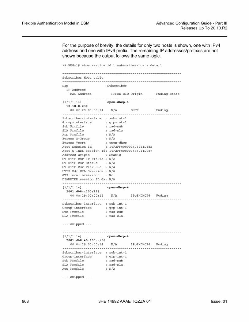
Flexible Authentication Model in ESM
968
Advanced Configuration Guide - Part IIIReleases Up To 20.10.R2
3HE 14992 AAAE TQZZA 01 Issue: 01
For the purpose of brevity, the details for only two hosts is shown, one with IPv4 address and one with IPv6 prefix. The remaining IP addresses/prefixes are not shown because the output follows the same logic.
*A:BNG-1# show service id 1 subscriber-hosts detail
=============================================================Subscriber Host table=============================================================Sap Subscriber
IP AddressMAC Address PPPoE-SID Origin Fwding State
-------------------------------------------------------------[1/1/1:14] open-dhcp-4
10.10.0.23000:0c:29:00:00:14 N/A DHCP Fwding
-------------------------------------------------------------Subscriber-interface : sub-int-1Group-interface : grp-int-1Sub Profile : rad-subSLA Profile : rad-slaApp Profile : N/AEgress Q-Group : N/AEgress Vport : open-dhcpAcct-Session-Id : 14F2FF000000475911D18BAcct-Q-Inst-Session-Id: 14F2FF000000445911D087Address Origin : StaticOT HTTP Rdr IP-FltrId : N/AOT HTTP Rdr Status : N/AOT HTTP Rdr Fltr Src : N/AHTTP Rdr URL Override : N/AGTP local break-out : NoDIAMETER session ID Gx: N/A-------------------------------------------------------------[1/1/1:14] open-dhcp-4
2001:db8::100/12800:0c:29:00:00:14 N/A IPoE-DHCP6 Fwding
-------------------------------------------------------------Subscriber-interface : sub-int-1Group-interface : grp-int-1Sub Profile : rad-subSLA Profile : rad-sla
--- snipped ---
-------------------------------------------------------------[1/1/1:14] open-dhcp-4
2001:db8:40:100::/5600:0c:29:00:00:14 N/A IPoE-DHCP6 Fwding
-------------------------------------------------------------Subscriber-interface : sub-int-1Group-interface : grp-int-1Sub Profile : rad-subSLA Profile : rad-slaApp Profile : N/A
--- snipped ---

Advanced Configuration Guide - Part III Releases Up To 20.10.R2
Flexible Authentication Model in ESM
Issue: 01 3HE 14992 AAAE TQZZA 01 969
-------------------------------------------------------------[1/1/1:24] open-pppoe-4|1
10.10.0.23100:0c:29:00:00:24 1 IPCP Fwding
-------------------------------------------------------------Subscriber-interface : sub-int-1Group-interface : grp-int-1Sub Profile : rad-subSLA Profile : rad-sla
--- snipped ---
-------------------------------------------------------------[1/1/1:24] open-pppoe-4|1
2001:db8:0:1::100/12800:0c:29:00:00:24 1 PPP-DHCP6 Fwding
-------------------------------------------------------------Subscriber-interface : sub-int-1Group-interface : grp-int-1Sub Profile : rad-subSLA Profile : rad-sla
--- snipped ---
-------------------------------------------------------------[1/1/1:24] open-pppoe-4|1
2001:db8:40:200::/5600:0c:29:00:00:24 1 PPP-DHCP6 Fwding
-------------------------------------------------------------Subscriber-interface : sub-int-1Group-interface : grp-int-1Sub Profile : rad-subSLA Profile : rad-slaApp Profile : N/AEgress Q-Group : N/AEgress Vport : open-dhcpAcct-Session-Id : 14F2FF0000004C5911D288Acct-Q-Inst-Session-Id: 14F2FF0000004A5911D288Address Origin : StaticOT HTTP Rdr IP-FltrId : N/AOT HTTP Rdr Status : N/AOT HTTP Rdr Fltr Src : N/AHTTP Rdr URL Override : N/AGTP local break-out : NoDIAMETER session ID Gx: N/A-------------------------------------------------------------Number of subscriber hosts : 6=============================================================*A:BNG-1#
The following command shows that the subscriber identity is set to circuit-id (plus session-id) as instructed by the auto-sub-id-key command (the subscriber-id string is not returned via the LUDB or RADIUS). The DHCPv4 lease time is set to set to 15 minutes as defined by the LUDB. The DHCPv6 lease times are set to 30 minutes as configured under the group-interface. The username passed to RADIUS is the circuit-id or username appended by the domain1 domain name. The origin of the lease is RADIUS.

Flexible Authentication Model in ESM
970
Advanced Configuration Guide - Part IIIReleases Up To 20.10.R2
3HE 14992 AAAE TQZZA 01 Issue: 01
*A:BNG-1# show service id 1 dhcp lease-state detail
===============================================================================DHCP lease states for service 1===============================================================================Service ID : 1IP Address : 10.10.0.230Client HW Address : 00:0c:29:00:00:14Subscriber-interface : sub-int-1Group-interface : grp-int-1SAP : [1/1/1:14]Termination Type : localUp Time : 0d 00:09:25Remaining Lease Time : 0d 00:13:07Remaining SessionTime: N/APersistence Key : N/A
Sub-Ident : "open-dhcp-4"Sub-Profile-String : "rad-sub"SLA-Profile-String : "rad-sla"App-Profile-String : ""Lease ANCP-String : ""Lease Int Dest Id : "open-auth-vport"Category-Map-Name : ""
Lease Info origin : UserDb
Ip-Netmask : 255.255.255.0Broadcast-Ip-Addr : 10.10.0.255Default-Router : 10.10.0.254Primary-Dns : 172.16.20.20Secondary-Dns : 172.16.20.21Primary-Nbns : N/ASecondary-Nbns : N/A
ServerLeaseStart : 05/09/2017 16:26:19ServerLastRenew : 05/09/2017 16:33:50ServerLeaseEnd : 05/09/2017 16:48:50Session-Timeout : N/AIPoE|PPP session : NoLease-Time : 0d 00:15:00DHCP Server Addr : N/A
Relay Agent InformationCircuit Id : open-dhcp-4
Radius User-Name : "open-dhcp-4@domain1"
-------------------------------------------------------------------------------Managed Routes-------------------------------------------------------------------------------IP Address Status Metric Tag Pref-------------------------------------------------------------------------------192.168.1.0/24 installed 0 none 0--------------------------------------------------------------------------------------------------------------------------------------------------------------Number of lease states : 1===============================================================================*A:BNG-1#

Advanced Configuration Guide - Part III Releases Up To 20.10.R2
Flexible Authentication Model in ESM
Issue: 01 3HE 14992 AAAE TQZZA 01 971
For the purpose of brevity, the details for only two IPv6 leases is shown. The remaining two IPv6 leases are not shown because the output follows the same logic.
*A:BNG-1# show service id 1 dhcp6 lease-state detail
===============================================================================DHCP lease states for service 1===============================================================================Service ID : 1IP Address : 2001:db8::100/128Client HW Address : 00:0c:29:00:00:14Subscriber-interface : sub-int-1Group-interface : grp-int-1SAP : [1/1/1:14]Termination Type : localUp Time : 0d 00:13:48Remaining Lease Time : 0d 00:23:11Remaining SessionTime: N/APersistence Key : N/A
Sub-Ident : "open-dhcp-4"Sub-Profile-String : "rad-sub"SLA-Profile-String : "rad-sla"App-Profile-String : ""Lease ANCP-String : ""Lease Int Dest Id : "open-auth-vport"Category-Map-Name : ""Dhcp6 ClientId (DUID): 0001000120a487cf000c29000014Dhcp6 IAID : 2Dhcp6 IAID Type : non-temporaryDhcp6 Client Ip : fe80::20c:29ff:fe00:14Primary-Dns : 2001:db8::2000Secondary-Dns : 2001:db8::2001Pool Name : ""Dhcp6 Server Addr : N/ADhcp6 ServerId (DUID): N/ADhcp6 InterfaceId : open-dhcp-4Dhcp6 RemoteId : N/ARadius sub-if prefix : N/ARouter adv. policy : N/A
Lease Info origin : UserDb
ServerLeaseStart : 05/09/2017 16:22:26ServerLastRenew : 05/09/2017 16:29:25ServerLeaseEnd : 05/09/2017 16:59:25Session-Timeout : N/AIPoE|PPP session : NoRadius User-Name : "open-dhcp-4@domain1"-------------------------------------------------------------------------------Service ID : 1IP Address : 2001:db8:0:1::100/128Client HW Address : 00:0c:29:00:00:24Subscriber-interface : sub-int-1Group-interface : grp-int-1SAP : [1/1/1:24]
--- snipped ---
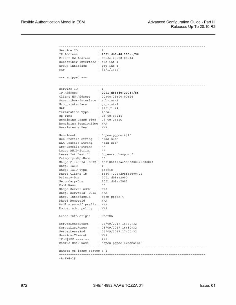
Flexible Authentication Model in ESM
972
Advanced Configuration Guide - Part IIIReleases Up To 20.10.R2
3HE 14992 AAAE TQZZA 01 Issue: 01
-------------------------------------------------------------------------------Service ID : 1IP Address : 2001:db8:40:100::/56Client HW Address : 00:0c:29:00:00:14Subscriber-interface : sub-int-1Group-interface : grp-int-1SAP : [1/1/1:14]
--- snipped ---
-------------------------------------------------------------------------------Service ID : 1IP Address : 2001:db8:40:200::/56Client HW Address : 00:0c:29:00:00:24Subscriber-interface : sub-int-1Group-interface : grp-int-1SAP : [1/1/1:24]Termination Type : localUp Time : 0d 00:05:44Remaining Lease Time : 0d 00:24:16Remaining SessionTime: N/APersistence Key : N/A
Sub-Ident : "open-pppoe-4|1"Sub-Profile-String : "rad-sub"SLA-Profile-String : "rad-sla"App-Profile-String : ""Lease ANCP-String : ""Lease Int Dest Id : "open-auth-vport"Category-Map-Name : ""Dhcp6 ClientId (DUID): 0001000120a45933000c29000024Dhcp6 IAID : 1Dhcp6 IAID Type : prefixDhcp6 Client Ip : fe80::20c:29ff:fe00:24Primary-Dns : 2001:db8::2000Secondary-Dns : 2001:db8::2001Pool Name : ""Dhcp6 Server Addr : N/ADhcp6 ServerId (DUID): N/ADhcp6 InterfaceId : open-pppoe-4Dhcp6 RemoteId : N/ARadius sub-if prefix : N/ARouter adv. policy : N/A
Lease Info origin : UserDb
ServerLeaseStart : 05/09/2017 16:30:32ServerLastRenew : 05/09/2017 16:30:32ServerLeaseEnd : 05/09/2017 17:00:32Session-Timeout : N/AIPoE|PPP session : PPPRadius User-Name : "open-pppoe-4@domain1"-------------------------------------------------------------------------------Number of lease states : 4===============================================================================*A:BNG-1#

Advanced Configuration Guide - Part III Releases Up To 20.10.R2
Flexible Authentication Model in ESM
Issue: 01 3HE 14992 AAAE TQZZA 01 973
Troubleshooting Commands
The following output shows the debugging commands which can be used to troubleshoot problems with the different authentication models.
debugrouter "Base"
radiuspacket-type authentication accounting coadetail-level medium
exitexitrouter "1"
ipdhcp
detail-level highmode egr-ingr-and-dropped
exitdhcp6
mode egr-ingr-and-droppeddetail-level high
exitexitlocal-dhcp-server "svc-1-dhcp4"
detail-level highmode egr-ingr-and-dropped
exitlocal-dhcp-server "svc-1-dhcp6"
detail-level highmode egr-ingr-and-dropped
exitexitservice
id 1ppp
packetmode egr-ingr-and-droppeddetail-level highdiscoverypppdhcp-client
exitexit
exitid 2
dhcpmode egr-ingr-and-droppeddetail-level high
exitdhcp6
mode alldetail-level high
exitppp
packetmode dropped-onlydetail-level high

Flexible Authentication Model in ESM
974
Advanced Configuration Guide - Part IIIReleases Up To 20.10.R2
3HE 14992 AAAE TQZZA 01 Issue: 01
discoverypppdhcp-client
exitexit
exitexitsubscriber-mgmt
local-user-db "ludb-1"detail all
exitlocal-user-db "ludb-2"
detail allexitlocal-user-db "ludb-3"
detail allexitlocal-user-db "ludb-4"
detail allexit
exitexit
configurelog
log-id 1from debug-traceto sessionno shutdown
exitexit
exit
Conclusion
The flexible authentication model allows access to various sources (LUDB, RADIUS, and Python) of subscriber parameters during the subscriber establishment phase. This model can be utilized for IPoE, PPPoE or L2TP subscribers in IES or VPRN services (including a wholesale/retail VRF model). A typical use case would be in a wholesale/retail environment where the wholesaler enforces its own rules via the LUDB before it passes the authentication request to the retailer’s RADIUS server.
Advanced Configuration Guide - Part III Releases Up To 20.10.R2
GTP Access
Issue: 01 3HE 14992 AAAE TQZZA 01 975
GTP Access This chapter provides information about GTP access.
Topics in this chapter include:
• Applicability• Overview• Configuration• Conclusion
Applicability
The information and configuration in this chapter are based on SR OS Release 16.0.R3.
Overview
The GPRS Tunneling Protocol (GTP) is defined by 3GPP for carrying data through mobile backhaul networks. GTP-U (User plane) is used to forward User Equipment (UE) traffic between the Radio Access Network (RAN) and the core network. GTPv2-C (Control plane) is used within the 4G Evolved Packet Core (EPC) to establish and maintain these GTP-U tunnels. Basic Evolved Packet System (EPS) knowledge is assumed throughout this chapter.
Nokia provides Enhanced Subscriber Management (ESM) features to stationary wireless subscribers over GTP. This offers service providers the means to provide broadband services to areas that cannot be easily or sufficiently covered using traditional fixed access technologies. GTP is another type of access to the BNG, and the set of concepts applying to this context are generally referred to as fixed wireless access. In the Nokia GTP solution, the Serving Gateway (S-GW) and the Packet Data Network (PDN) Gateway (P-GW) functions are integrated with the BNG, as shown in Figure 157.

GTP Access
976
Advanced Configuration Guide - Part IIIReleases Up To 20.10.R2
3HE 14992 AAAE TQZZA 01 Issue: 01
Figure 157 GTP Access to the BNG
In 3GPP architectures, specific communication channels between two entities are called interfaces. These 3GPP-defined interfaces are logical interfaces and unrelated to physical router interfaces. For example, the S11 interface covers the communication between the Mobility Management Entity (MME) and the S-GW, the S1-U interface the data path communication between the eNodeB and the S-GW, and the S5 interface the communication between the S-GW and the P-GW. The S1-MME interface covers the communication between the eNB and the MME. S11 and S1-U use GTP as their encapsulation protocol.
When a UE is activated, the UE attachment process is started, where the initial signaling passes via the eNB, the MME, and the S-GW to the P-GW to establish an EPS bearer. The EPS bearer runs from the UE via the eNB and the S-GW to the P-GW; the MME is not on the data path. Some subsequent signaling can run on the straight path from the UE to the P-GW.
The EPS bearer is a transmission path running end-to-end between a UE and a P-GW, which carries the user data; see Figure 158. The EPS bearer is the concatenation of a radio bearer on the air interface, a GTP tunnel on the S1-U interface between the eNB and the S-GW, and a GTP tunnel on the S5 interface between the S-GW and the P-GW.
eNBUE LTEBNG
))) )))
S1-MME S11
S5S1-U
27982
S-GW
MME
P-GW

Advanced Configuration Guide - Part III Releases Up To 20.10.R2
GTP Access
Issue: 01 3HE 14992 AAAE TQZZA 01 977
Figure 158 EPS Bearer Across the Different Interfaces
GTP-C signaling procedures are used to establish an S1 and an S5 bearer, during which Tunneling End ID (TEID) values are assigned and exchanged. These TEIDs are locally significant, and the upstream and downstream channels can have different TEIDs. With an S1 and S5 bearer established, user data can pass through using GTP-U encapsulation; see Figure 159. UDP ports 2123 and 2152 are used for GTP-C and GTP-U, respectively.
Figure 159 GTP-C and GTP-U Encapsulation
As part of the UE attachment procedure, the UE is assigned an IPv4/IPv6 address by the P-GW and a default bearer is established. The default bearer remains established throughout the lifetime of the PDN connection to provide the UE with always-on IP connectivity to that PDN. The default bearer QoS parameters can be provided by either the MME, Policy Control and Charging Rules Function (PCRF), RADIUS server, or locally.
Application/service layer
UL servicedata flows
RB-ID S1-TEID
UE eNodeB
Radio bearer
S-GW
UL-TFT RB-ID
DL servicedata flows
P-GW
S1-TEID S5/S8-TEID
DL-TFT S5/S8-TEIDUL-TFT DL-TFT
S1 bearer S5/S8 bearer27983
TEID_a
GTP-Uheader
UDPIP
IP-pgw ->IP_sgw
UDP_dst=2152
GTP-C messageTEID_k
GTP-Cheader
UDPIP
IP-pgw ->IP_sgw
UDP_dst=2123
IP-a ->IP_m
27984

GTP Access
978
Advanced Configuration Guide - Part IIIReleases Up To 20.10.R2
3HE 14992 AAAE TQZZA 01 Issue: 01
The GTP-U tunnel encapsulation used in the network is shown in Figure 160. The IPv4/IPv6 address assigned to the UE during the attachment process is used end-to-end. For the outer header of the S1 GTP tunnel, the eNB and the S-GW IPv4 addresses are used. Similarly, for the S5 GTP tunnel, the S-GW and P-GW IPv4 addresses are used.
Figure 160 GTP-U in Up and Downstream
Because the S-GW and P-GW functionalities are integrated with the BNG, the S5 logical interface is internal to the system. SR OS supports TPSDA over GTP access tunnels initiated over the S11 (GTPv2-C) interface, where the UE data traffic is on the S1-U (GTP-U) interface. This is sometimes referred to as ESM over GTP (ESMoGTP).
(b) from the Internet to the UE
(a) from the UE to the Internet
Dst IP: S-GWSrc IP: P-GWTEID: UL S5-TEID
Src IP: InternetDst IP: UE
4
Src IP: InternetDst IP: UE
3
Dst IP: eNBSrc IP: S-GWTEID: DL S1-TEID
21
Src IP: InternetDst IP: UE
Src IP: InternetDst IP: UE
eNBUE
S5 GTP tunnelS1 GTP tunnel
S-GW P-GW
Dst IP: P-GWSrc IP: S-GWTEID: UL S5-TEID
Src IP: UEDst IP: Internet
4
Src IP: UEDst IP: Internet
3
Dst IP: S-GWSrc IP: eNBTEID: UL S1-TEID
21
Src IP: UEDst IP: Internet
Src IP: UEDst IP: Internet
eNBUE
S5 GTP tunnelS1 GTP tunnel
S-GW P-GW
GTP-U tunnelIP packet
Legend:
27985

Advanced Configuration Guide - Part III Releases Up To 20.10.R2
GTP Access
Issue: 01 3HE 14992 AAAE TQZZA 01 979
Both IPv4 and IPv6 connectivity over GTP is supported. GTP session authentication can be performed using LUDB, RADIUS, or NASREQ.
ESMoGTP requires PXC FPE in order to support L3 re-routing in the access network and in-line encapsulation/decapsulation of the GTP protocol.
GTP-C Control - GTP Host Creation and Host Deletion
Figure 161 shows the steps used for creating a GTP host.
1. A GTP S11 interface must be created and enabled for the BNG to accept and process the Create Session Request message emitted by the MME. This message includes IMSI, IMEI, MS-ISDN, APN, QCI, and so on.
2. The APN received is mapped via the APN policy to an authentication method (RADIUS, LUDB, or NASREQ), and to an optional default service and group interface. Also, a peer profile can be applied to that interface, defining keepalive timer (KA), default GTP Information Elements (IEs), Python-derived policies, and so on.
3. By default, the IMSI is used for authentication toward AAA.4. The Access Accept message sent by AAA returns the standard set of ESM
parameters, such as the IP address, QoS overrides, service ID, and group interface where the GTP host must be created.
5. The Create Session response includes the locally assigned TEID, IPv4/IPv6 information, AMBR, QCI, and the S1-U TEID and the S1-U endpoint. The GTP host is created.
6. The MME sends a Modify Bearer Request Message to update the default bearer information with the eNB final information (IP, TEID, and so on).
7. The BNG starts a keep-alive timer per S11 peer, using the timer values defined by the peer profile. Also, the MME can start a keep-alive timer, independent from the BNG.
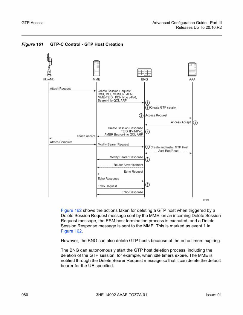
GTP Access
980
Advanced Configuration Guide - Part IIIReleases Up To 20.10.R2
3HE 14992 AAAE TQZZA 01 Issue: 01
Figure 161 GTP-C Control - GTP Host Creation
Figure 162 shows the actions taken for deleting a GTP host when triggered by a Delete Session Request message sent by the MME: on an incoming Delete Session Request message, the ESM host termination process is executed, and a Delete Session Response message is sent to the MME. This is marked as event 1 in Figure 162.
However, the BNG can also delete GTP hosts because of the echo timers expiring.
The BNG can autonomously start the GTP host deletion process, including the deletion of the GTP session; for example, when idle timers expire. The MME is notified through the Delete Bearer Request message so that it can delete the default bearer for the UE specified.
Create and install GTP Host
7
6
6
5
Create GTP session2
4
Acct Req/Resp
3
1
Access Accept
Access Request
Attach Accept
Create Session ResponseTEID, IPv4/IPv6,
AMBR Bearer-info QCI, ARP
Router Advertisement
Echo Response
Echo Request
Modify Bearer Response
Echo Request
Echo Response
Modify Bearer Request
Create Session RequestIMSI, MEI, MSISDN, APN,MME-TEID, PDN type v4/v6,Bearer-info QCI, ARP
Attach Complete
Attach Request
AAABNGMMEUE/eNB
27986

Advanced Configuration Guide - Part III Releases Up To 20.10.R2
GTP Access
Issue: 01 3HE 14992 AAAE TQZZA 01 981
Figure 162 GTP-C Control - GTP Host Deletion
Configuration
Figure 163 shows the topology used for demonstrating GTP Access.
Figure 163 GTP Access Topology
Delete all1
Acct Req/Resp
Detach AcceptDelete Session Resp
Delete Session ReqDetach Request
AAABNGMMEUE/eNB
27987
192.168.100.1
192.168.101.1
BNG/S-GW/P-GW
192.168.0.200:00:5e:00:53:00
L3AGGREGATION
MME
1/2/4PXC/FPE port
1/2/1:1192.168.0.100:00:5e:00:53:01eNB
27988

GTP Access
982
Advanced Configuration Guide - Part IIIReleases Up To 20.10.R2
3HE 14992 AAAE TQZZA 01 Issue: 01
On the BNG, the traffic entering on port 1/2/1 is internally routed to port 1/2/4, which is configured as a PXC port; see 7450 ESS, 7750 SR, and 7950 XRS Advanced Configuration Guide - Part I for Releases Up To 20.10.2, the Port Cross-Connect (PXC) chapter for more information. The PXC port 1/2/4 additionally requires subscriber management extensions to be enabled in the forwarding plane (FPE), see 7450 ESS, 7750 SR, and 7950 XRS Advanced Configuration Guide - Part II for Releases Up To 20.10.2, the VXLAN Forwarding Path Extension chapter, and the encap-type is set to qinq:
# on BNG-1configure
port 1/2/1ethernet
mode accessencap-type dot1q
exitno shutdown
exitport 1/2/4
ethernetmode hybridencap-type dot1q
exitno shutdown
exitport-xc
pxc 1 createport 1/2/4no shutdown
exitexitport-xc
pxc 1 createport 1/2/4no shutdown
exitexitport pxc-1.a
ethernetencap-type qinq
exitno shutdown
exitport pxc-1.b
ethernetencap-type qinq
exitno shutdown
exitexit
configurefwd-path-ext
fpe 1 createpath pxc 1sub-mgmt-extensions

Advanced Configuration Guide - Part III Releases Up To 20.10.R2
GTP Access
Issue: 01 3HE 14992 AAAE TQZZA 01 983
exitexit
exit
The status of the PXC port can be verified as follows:
*A:BNG-1# show port-xc
===============================================================================Port Cross-Connect Information===============================================================================PXC Admin Oper Port DescriptionId State State Id-------------------------------------------------------------------------------1 Up Up 1/2/4 (Not Specified)-------------------------------------------------------------------------------No. of PXCs: 1===============================================================================*A:BNG-1#
With subscriber management extensions enabled, SR OS can dynamically create SAPs on which GTP subscribers can be terminated at a later stage. The status for FPE 1 shows that the subscriber management extensions are enabled, as follows. The operational state indicated as N/A at the end of the same line is not relevant.
*A:BNG-1# show fwd-path-ext fpe 1
===============================================================================FPE Id: 1===============================================================================Description : (Not Specified)Path : pxc 1Pw Port : Disabled Oper : downSub Mgmt Extension : Enabled Oper : N/AVxlan Termination : Disabled Oper : down===============================================================================*A:BNG-1#
The APN policy pol-APN-ACG is defined in the subscriber management gtp context, as follows. The other profiles are required for ESM host and subscriber setup.
configuresubscriber-mgmt
gtpapn-policy "pol-APN-ACG" create
apn acg.mnc001.mcc001.gprs createuser-db "ludb-GTP"
exitexit
exitsla-profile "sla-prof-1" createexitsub-profile "sub-prof-1" createexitsub-ident-policy "sub-id-pol-direct" create

GTP Access
984
Advanced Configuration Guide - Part IIIReleases Up To 20.10.R2
3HE 14992 AAAE TQZZA 01 Issue: 01
sub-profile-mapuse-direct-map-as-default
exitsla-profile-map
use-direct-map-as-defaultexit
exitexit
exit
Two services are used to provide GTP access to the BNG, as shown in Figure 164. The first routed service provides the GTP tunnel termination, and the second provides the infrastructure to terminate the GTP subscribers.
Figure 164 GTP Tunnel and Subscriber Termination Configuration Logic
GTP Tunnel Terminating VPRN
In Figure 164, VPRN 10 implements the GTP tunnel termination. The GTP traffic enters VPRN 10 on interface int-BNG-L3AGG with MAC address 00:00:5e:00:53:01 on SAP 1/2/1:1. The interface int-GTP-endpoint is defined as a loopback interface, potentially providing redundancy to the L3 aggregation network. Static routes and a static ARP entry are defined in VPRN 10 for reaching the MME and the eNB through the L3 aggregation network, providing control over the L3 aggregation test environment. The APN policy provides the link between the tunnel termination VPRN (10) and the subscriber terminating VPRN (11). The peer-profile map defines which peer profile is used for which MME. In this example, the APN policy is pol-APN-ACG, and the peer profile is gtp-s11-pp-1. VPRN 10 is configured as follows:
configure
no explicit SAPsgtp parameters
Subscriber TerminationTunnel Termination
VPRN 11
fpe 1
pxc 1 create port 1/2/4 no shutdownexit
fpe 1 create path pxc 1 sub-mgmt-extensionsexit
apn-policy “pol-APN-ACG” create apn acg.mnc001.mcc001.gprs create user-db “ludb-GTP” exitexit
peer-profile “gtp-s11-pp-1” create interface-type s11 keep-alive interval 90 mne qos ambr down-link 21000 up-link 11000 exit exitexit
1/2/1:1
peer-profileapn-policy
VPRN 10
L3 AGG
27989

Advanced Configuration Guide - Part III Releases Up To 20.10.R2
GTP Access
Issue: 01 3HE 14992 AAAE TQZZA 01 985
servicevprn 10 name "GTP-tunnel-termination" customer 1 create
description "GTP Tunnel termination"route-distinguisher 64496:10interface "int-GTP-endpoint" create
description "Tunnel endpoint IP"address 192.0.2.10/32loopback
exitinterface "int-BNG-L3AGG" create
address 192.168.0.1/24mac 00:00:5e:00:53:01static-arp 192.168.0.2 00:00:5e:00:53:00sap 1/2/1:1 createexit
exitstatic-route-entry 192.168.100.0/24
next-hop 192.168.0.2no shutdown
exitexitstatic-route-entry 192.168.101.0/24
next-hop 192.168.0.2no shutdown
exitexitgtp
s11interface "int-GTP-endpoint" create
apn-policy "pol-APN-ACG"exitpeer-profile-map
address 192.168.100.1/32 peer-profile "gtp-s11-pp-1"exit
exitexitno shutdown
exitexit
exit
Peer Profile
A peer-profile policy controls the keep-alive interval, and the QoS configuration to be used for MMEs (AMBR, ARP, QCI, …). The peer profile gtp-s11-pp-1 used for the example shown in Figure 8 is defined as follows. AMBR downlink and uplink are set to 21000 kb/s and 11000 kb/s, respectively, and QCI is set to 8.
configuresubscriber-mgmt
gtppeer-profile "gtp-s11-pp-1" create
interface-type s11keep-alive interval 90

GTP Access
986
Advanced Configuration Guide - Part IIIReleases Up To 20.10.R2
3HE 14992 AAAE TQZZA 01 Issue: 01
mmeqos
ambr down-link 21000 up-link 11000arp 1down-link gbr 0 mbr 0qci 8up-link gbr 0 mbr 0
exitexit
exitexit
exitexit
APN Policy
An APN policy controls the authentication method per APN (LUDB, RADIUS, or Diameter). The APN policy pol-APN-ACG used for the example shown in Figure 164 is defined as follows. Only one APN is defined (acg.mnc001.mcc001.gprs), and the UEs using this APN are authenticated through the ludb-GTP LUDB.
configuresubscriber-mgmt
gtpapn-policy "pol-APN-ACG" create
apn acg.mnc001.mcc001.gprs createuser-db "ludb-GTP"
exitexit
exitexit
exit
For authenticating GTP users using an LUDB, the LUDB must define hosts in the IPoE section of the LUDB. In this example, host matching is based on the IMSI, which is automatically populated in the IPoE string match criterion. Therefore, the match-list string command is used, but matching can also be based on a Derived ID provided by a Python script. Individual hosts can be matched using the string command for host-identification. To avoid the definition of many hosts, a default host can be used. In both cases, the output provides the service and the interface where the GTP subscriber must be implemented, as well as the IPv4/IPv6 address information required for the Local Address Assignment (LAA), as follows:
configuresubscriber-mgmt
local-user-db "ludb-GTP" createipoe
match-list stringhost "host-1" create
host-identificationstring "001020000000111"

Advanced Configuration Guide - Part III Releases Up To 20.10.R2
GTP Access
Issue: 01 3HE 14992 AAAE TQZZA 01 987
exitaddress pool "pool4-1"identification-strings 254 create
subscriber-id "GTP-subscriber-111"sla-profile-string "sla-prof-1"sub-profile-string "sub-prof-1"
exitinterface "int-GRP" service-id 11ipv6-slaac-prefix-pool "pool6-1"no shutdown
exithost "default" create
address pool "pool4-1"interface "int-GRP" service-id 11ipv6-slaac-prefix-pool "pool6-1"no shutdown
exitexitno shutdown
exitexit
exit
GTP Subscriber Terminating VPRN
In Figure 163, VPRN 11 implements the GTP subscriber termination. Because GTP subscribers are ESM subscribers, the regular ESM concepts apply, meaning that subscriber management profiles are required; however, no explicit SAP definitions are required. LAA is used, where server lcl-DHCPs-ip4 is used for IPv4, and lcl-DHCPs-ip6 is used for IPv6. To support SLAAC, the IPv6 route-advertisement context has prefix-options autonomous enabled. The gtp-parameters context in the group interface defines the FPE to be used and must be enabled (no shutdown), as follows:
configureservice
vprn 11 name "GTP-subsc-termination" customer 1 createdescription "GTP subscriber termination"
--- snipped ---
route-distinguisher 64496:11subscriber-interface "int-SUSBC" create
address 192.168.50.1/24ipv6
delegated-prefix-len 56subscriber-prefixes
prefix 2001:db8:101::/48 wan-hostexit
exitgroup-interface "int-GRP" gtp create
gtp-parametersfpe 1

GTP Access
988
Advanced Configuration Guide - Part IIIReleases Up To 20.10.R2
3HE 14992 AAAE TQZZA 01 Issue: 01
no shutdownexitipv6
router-advertisementsprefix-options
autonomousexitno shutdown
exitexitlocal-address-assignment
server "lcl-DHCPs-ip4"client-application ipoe-v4ipv6
client-application ipoe-slaacserver "lcl-DHCPs-ip6"
exitno shutdown
exitsap-parameters
sub-sla-mgmtdef-sla-profile "sla-prof-1"def-sub-profile "sub-prof-1"sub-ident-policy "sub-id-pol-direct"
exitexit
exitexitno shutdown
exitexit
exit
Enabling the gtp-parameters context (no shutdown) results in SR OS creating SAP pxc-1.b:1.8, as follows. The square brackets indicate that the SAP is created automatically, without any explicit configuration.
*A:BNG-1# show service id 11 sap
===============================================================================SAP(Summary), Service 11===============================================================================PortId SvcId Ing. Ing. Egr. Egr. Adm Opr
QoS Fltr QoS Fltr-------------------------------------------------------------------------------[pxc-1.b:1.8] 11 1 none 1 none Up Up-------------------------------------------------------------------------------Number of SAPs : 1-------------------------------------------------------------------------------===============================================================================*A:BNG-1#

Advanced Configuration Guide - Part III Releases Up To 20.10.R2
GTP Access
Issue: 01 3HE 14992 AAAE TQZZA 01 989
When the UE with IMSI 001020000000111 connects, an S11 session is created, as follows. The 00:03:ff:f0:01:20 MAC address and pxc-1.b:1.8 SAP are internally generated to link the GTP session with an ESM IPoE session. The remote S1-U address is 192.168.101.1 for Bearer 6. The locally and remotely assigned TEID values are also shown.
*A:BNG-1# show subscriber-mgmt gtp s11 session imsi 001020000000111
===============================================================================GTP S11 sessions===============================================================================IMSI : 001020000000111APN : acg.mnc001.mcc001.gprs-------------------------------------------------------------------------------Peer router : 10Peer address : 192.168.100.1Remote control TEID : 22Local control TEID : 4293919008PDN TEID : 4293919008Charging characteristics : (None)Uplink AMBR (kbps) : 10000Downlink AMBR (kbps) : 20000Ipoe-session SAP : [pxc-1.b:1.8]Ipoe-session Mac Address : 00:03:ff:f0:01:20Bearer 6
Rem S1-U address : 192.168.101.1rem TEID : 22loc TEID : 4293919014uplink GBR (kbps) : 0uplink MBR (kbps) : 0downlink GBR (kbps) : 0downlink MBR (kbps) : 0QoS Class ID : 8alloc/ret priority : 1
-------------------------------------------------------------------------------No. of GTP S11 sessions: 1===============================================================================*A:BNG-1#
Additionally, an ESM subscriber and an IPoE session is created on SAP pxc-1.b:1.8, as follows. The subscriber identifier is taken from the LUDB (GTP-subscriber-111). The IPoE session is created on service 11 and uses the internally generated MAC address. The IPv4 and the IPv6 addresses are combined in the same IPoE session, with MAC address 00:03:ff:e0:01:20.
*A:BNG-1# show service active-subscribers hierarchy
===============================================================================Active Subscribers Hierarchy===============================================================================-- 001020000000111 (sub-prof-1)
|+-- sap:[pxc-1.b:1.8] - sla:sla-prof-1
|

GTP Access
990
Advanced Configuration Guide - Part IIIReleases Up To 20.10.R2
3HE 14992 AAAE TQZZA 01 Issue: 01
+-- IPOE-session - mac:00:03:ff:e0:01:20 - svc:11||-- 192.168.50.12 - GTP|+-- 2001:db8:101:1::/64 - GTP
-------------------------------------------------------------------------------Number of active subscribers : 1Flags: (N) = the host or the managed route is in non-forwarding state===============================================================================*A:BNG-1#
Because an IPv4 address and an IPv6 address is used, two subscriber hosts are created on VPRN 11, as follows:
*A:BNG-1# show service id 11 subscriber-hosts
=============================================================Subscriber Host table=============================================================Sap Subscriber
IP AddressMAC Address PPPoE-SID Origin Fwding State
-------------------------------------------------------------[pxc-1.b:1.8] 001020000000111
192.168.50.1200:03:ff:e0:01:20 N/A GTP Fwding
[pxc-1.b:1.8] 0010200000001112001:db8:101:1::/64
00:03:ff:e0:01:20 N/A GTP Fwding-------------------------------------------------------------Number of subscriber hosts : 2=============================================================*A:BNG-1#
With two UEs connected to the BNG, the IPv4 and IPv6 addresses present in the routing tables are as follows. The addresses assigned to the UE that attached first are shown in bold.
*A:BNG-1# show router 11 route-table ipv4
===============================================================================Route Table (Service: 11)===============================================================================Dest Prefix[Flags] Type Proto Age Pref
Next Hop[Interface Name] Metric-------------------------------------------------------------------------------192.168.50.0/24 Local Local 21h22m33s 0
int-SUSBC 0192.168.50.12/32 Remote Sub Mgmt 00h28m52s 0
[int-GRP] 0192.168.50.13/32 Remote Sub Mgmt 00h01m13s 0
[int-GRP] 0-------------------------------------------------------------------------------No. of Routes: 3Flags: n = Number of times nexthop is repeated

Advanced Configuration Guide - Part III Releases Up To 20.10.R2
GTP Access
Issue: 01 3HE 14992 AAAE TQZZA 01 991
B = BGP backup route availableL = LFA nexthop availableS = Sticky ECMP requested
===============================================================================*A:BNG-1#
*A:BNG-1# show router 11 route-table ipv6
===============================================================================IPv6 Route Table (Service: 11)===============================================================================Dest Prefix[Flags] Type Proto Age Pref
Next Hop[Interface Name] Metric-------------------------------------------------------------------------------2001:db8:101::/48 Local Local 21h23m02s 0
int-SUSBC 02001:db8:101:1::/64 Remote Sub Mgmt 00h29m21s 0
[int-GRP] 02001:db8:101:2::/64 Remote Sub Mgmt 00h01m42s 0
[int-GRP] 0-------------------------------------------------------------------------------No. of Routes: 3Flags: n = Number of times nexthop is repeated
B = BGP backup route availableL = LFA nexthop availableS = Sticky ECMP requested
===============================================================================*A:BNG-1#
Debug
Debugging is useful when troubleshooting GTP scenarios. The debug configuration used is as follows:
debugrouter service-name "GTP-subsc-termination"
ipdhcp
detail-level highmode egr-ingr-and-dropped
exitexitlocal-dhcp-server "lcl-DHCPs-ip4"
detail-level highmode egr-ingr-and-dropped
exitexitsubscriber-mgmt
local-user-db "ludb-GTP"detail all
exitexitgtp
event

GTP Access
992
Advanced Configuration Guide - Part IIIReleases Up To 20.10.R2
3HE 14992 AAAE TQZZA 01 Issue: 01
packetdetail-level highmode all
exitexit
exit
The trace for the UE with IMSI 001020000000111 initiating a connection to APN acg.mnc001.mcc001.gprs is as follows; also see Figure 161. Step 1 is the Create Session request, with the parameters supplied by the test-tool (IMSI, APN, RAT TYPE, PDN TYPE, and so on). Step 9 indicates that a GTP downlink is created. Step 12 indicates that the LUDB is accessed successfully. Steps 13, 14, and 15 indicate that LAA is used for address assignment. Step 28 indicates that an S1-U session is successfully established.
*A:BNG-1# show log log-id 1 ascending
===============================================================================Event Log 1===============================================================================Description : (Not Specified)Memory Log contents [size=100 next event=31 (not wrapped)]
1 2018/09/18 10:39:53.567 CEST MINOR: DEBUG #2001 vprn10 GTP"GTP: GTPv2_INGRESSIP Hdr: Src: 192.168.100.1, Dst: 192.0.2.10, Len: 205UDP Hdr: Src: 2123, Dst: 2123, Len: 185GTPv2 Hdr: Len: 173, Seq: 105, TEID: 0x0GTPv2_INGRESS| S11-C: 192.168.100.1 | Rx: Create Session Req
[IMSI] : 001020000000111[APN] : acg.mnc001.mcc001.gprs[RAT TYPE] : EUTRAN[CSID] : inst: 0 Len: 7 Val: 01010203040102[PDN TYPE] : IPv4v6[INDICATION] : GTP DAF[S11 MME-C F-TEID] : 0x00000028 IPv4: 192.168.100.1[BEARER CXT] : Add :0x6
Bearer Qos: PVI: 0x00 PL: 0x0f PCI: 0x00 QCI: 0x09MBR: UL: 1000 kbps, DL: 1000 kbps GMBR: UL: 0 kbps, DL: 0 kbps
[RECOVERY] : 1[PROTO CFG OPTS] : 0x80 (PPP_USE_IPPDP)
IPCP_PROTO_ID: REQPRIDNS : 0.0.0.0PRINBNS: 0.0.0.0SECDNS : 0.0.0.0SECNBNS: 0.0.0.0
DNSv6_CONT_ID:REQPCSCF_CONT_ID:REQIPV4_LINK_MTU:REQ "
2 2018/09/18 10:39:53.567 CEST MINOR: DEBUG #2001 Base GTP"GTP: GTP_USER_CREATED
imsi = 001020000000111 imei = 0000000000000000msIsdn = 0000000000000000bssid = 0:0:0:0:0:0

Advanced Configuration Guide - Part III Releases Up To 20.10.R2
GTP Access
Issue: 01 3HE 14992 AAAE TQZZA 01 993
ssid =uli = 0 0 0 0 0 0 0 0 0 0 0 0 0
"
3 2018/09/18 10:39:53.567 CEST MINOR: DEBUG #2001 Base GTP"GTP: GTP_ADD_DOWNLINK_TO_USER
imsi = 001020000000111 imei = 0000000000000000msIsdn = 0000000000000000bssid = 0:0:0:0:0:0ssid =uli = 0 0 0 0 0 0 0 0 0 0 0 0 0
"
4 2018/09/18 10:39:53.567 CEST MINOR: DEBUG #2001 Base GTP"GTP: GTP_PEER_CREATED
peer = {2, 192.168.100.1, 2123} ver 2 laddr 192.0.2.10"
5 2018/09/18 10:39:53.567 CEST MINOR: DEBUG #2001 Base GTP"GTP: GTP_ADD_DOWNLINK_TO_PEER
peer = {2, 192.168.100.1, 2123} ver 2 laddr 192.0.2.10"
6 2018/09/18 10:39:53.567 CEST MINOR: DEBUG #2001 vprn10 GTP"GTP: PEER ADDED
peer = 192.168.100.1 peer port = 2123 src = 192.0.2.10Gtpv2 restartcnt = 1 path mgmt state = disabledka retry cnt= 0
"
7 2018/09/18 10:39:53.567 CEST MINOR: DEBUG #2001 Base GTP"GTP: RETRANSMIT_CTXT_ALLOCATED
type Create Session Resp peer {2, 192.168.100.1, 2123} seqnr 105"
8 2018/09/18 10:39:53.567 CEST MINOR: DEBUG #2001 vprn10 GTP"GTP: PEER PATH MGMT ENABLED
peer = 192.168.100.1 peer port = 2123 src = 192.0.2.10Gtpv2 restartcnt = 1 path mgmt state = upka retry cnt= 0
"
9 2018/09/18 10:39:53.567 CEST MINOR: DEBUG #2001 vprn10 GTP"GTP: GTP_DOWNLINK_CREATED
gtp proto=GTPgtp iftype=S11loc s11 teid=0rem s11 teid=28s5 teid=0pdn type=0pdn v4 address=::pdn v6 address=::vrf=2ingIfIndex=3gtp-c src ip=192.0.2.10

GTP Access
994
Advanced Configuration Guide - Part IIIReleases Up To 20.10.R2
3HE 14992 AAAE TQZZA 01 Issue: 01
gtp-c dst ip=192.168.100.1gtp-u src ip=192.0.2.10gtp-u dst ip=::chargChar=0dnLkAMBR=0upLkAMBR=0debug flag=1imei nonemsIsdn nonedef bearerId=0
"
10 2018/09/18 10:39:53.567 CEST MINOR: DEBUG #2001 Base GTP"GTP: BEARER_CTXT_ALLOCATED
imsi = 001020000000111 apn = acg.mnc001.mcc001.gprsid = 6
"
11 2018/09/18 10:39:53.567 CEST MINOR: DEBUG #2001 Base GTP"GTP: GTP_ADD_BEARER_TO_RX_CTXT
type Create Session Resp peer {2, 192.168.100.1, 2123} seqnr 105"
12 2018/09/18 10:39:53.567 CEST MINOR: DEBUG #2001 Base LUDB"LUDB: User lookup success - host found
string:original: 001020000000111masked: 001020000000111
Host host-1 found in user data base ludb-GTP"
13 2018/09/18 10:39:53.568 CEST MINOR: DEBUG #2001 vprn11 DHCP server"DHCP server: lcl-DHCPs-ip4Rx internal <NULL>
ciaddr : 0.0.0.0"
14 2018/09/18 10:39:53.568 CEST MINOR: DEBUG #2001 vprn11 DHCP server"DHCP server: lcl-DHCPs-ip4lease added for 192.168.50.15 state=internalOffered"
15 2018/09/18 10:39:53.568 CEST MINOR: DEBUG #2001 vprn11 DHCP server"DHCP server: lcl-DHCPs-ip4lease update for 192.168.50.15 state=internal"
16 2018/09/18 10:39:53.570 CEST MINOR: DEBUG #2001 Base GTP"GTP: GTP_REMOVE_BEARER_FROM_RX_CTXT
type Create Session Resp peer {2, 192.168.100.1, 2123} seqnr 105"
17 2018/09/18 10:39:53.570 CEST MINOR: DEBUG #2001 Base GTP"GTP: RETRANSMIT_CTXT_UPDATED
type Create Session Resp peer {2, 192.168.100.1, 2123} seqnr 105"

Advanced Configuration Guide - Part III Releases Up To 20.10.R2
GTP Access
Issue: 01 3HE 14992 AAAE TQZZA 01 995
18 2018/09/18 10:39:53.570 CEST MINOR: DEBUG #2001 vprn10 GTP"GTP: GTPv2_EGRESSIP Hdr: Src: 192.0.2.10, Dst: 192.168.100.1, Len: 228UDP Hdr: Src: 2123, Dst: 2123, Len: 208GTPv2 Hdr: Len: 196, Seq: 105, TEID: 0x28I:*** | A:*** | S11-C: 192.0.2.10 | Tx: Create Session Resp
[CAUSE] : SUCCESS[RECOVERY] : 6[PROTO CFG OPTS] : 0x80 (PPP_USE_IPPDP)
IPCP_PROTO_ID: REJPRIDNS : 0.0.0.0PRINBNS: 0.0.0.0SECDNS : 0.0.0.0SECNBNS: 0.0.0.0
IPV4_LINK_MTU: 1400[S11/S4-C SGW F-TEID] : 0xffb00120 IPv4: 192.0.2.10[S5/S8-C PGW F-TEID] : 0xffb00120 IPv4: 192.0.2.10[APN RESTRICTION] : No Context/Restriction[PDN ADDR ALLOC] : IPv4v6 192.168.50.15 2001:db8:101:2:17:ffff:fe00:1/64[AMBR] : UL: 11000 kbps, DL: 21000 kbps[BEARER CXT] : Add :0x6 Cause: SUCCESS
Bearer Qos: PVI: 0x00 PL: 0x01 PCI: 0x00 QCI: 0x08MBR: UL: 0 kbps, DL: 0 kbps GMBR: UL: 0 kbps, DL: 0 kbps[S1-U SGW F-TEID] : 0xffb00126 IPv4: 192.0.2.10[S5/S8-U PGW F-TEID] : 0xffb00126 IPv4: 192.0.2.10"
19 2018/09/18 10:39:53.570 CEST MINOR: DEBUG #2001 vprn10 GTP"GTP: GTP_ACCESS_ACCEPT
gtp proto=GTPgtp iftype=S11loc s11 teid=ffb00120rem s11 teid=28s5 teid=ffb00120pdn type=3pdn v4 address=192.168.50.15pdn v6 address=2001:db8:101:2:17:ffff:fe00:1vrf=2ingIfIndex=3gtp-c src ip=192.0.2.10gtp-c dst ip=192.168.100.1gtp-u src ip=192.0.2.10gtp-u dst ip=0.0.0.0chargChar=0dnLkAMBR=21000upLkAMBR=11000debug flag=1imei nonemsIsdn nonedef bearerId=6
"
20 2018/09/18 10:39:53.592 CEST MINOR: DEBUG #2001 vprn10 GTP"GTP: GTPv2_INGRESSIP Hdr: Src: 192.168.100.1, Dst: 192.0.2.10, Len: 62UDP Hdr: Src: 2123, Dst: 2123, Len: 42GTPv2 Hdr: Len: 30, Seq: 106, TEID: 0xffb00120GTPv2_INGRESS| S11-C: 192.168.100.1 | Rx: Modify Bearer Req

GTP Access
996
Advanced Configuration Guide - Part IIIReleases Up To 20.10.R2
3HE 14992 AAAE TQZZA 01 Issue: 01
[BEARER CXT] : Add :0x6[S1-U eNB F-TEID] : 0x00000028 IPv4: 192.168.101.1"
21 2018/09/18 10:39:53.592 CEST MINOR: DEBUG #2001 vprn10 GTP"GTP: GTP_DOWNLINK_IN_SESSION_MSG_REVD
gtp proto=GTPgtp iftype=S11loc s11 teid=ffb00120rem s11 teid=28s5 teid=ffb00120pdn type=3pdn v4 address=192.168.50.15pdn v6 address=2001:db8:101:2:17:ffff:fe00:1vrf=2ingIfIndex=3gtp-c src ip=192.0.2.10gtp-c dst ip=192.168.100.1gtp-u src ip=192.0.2.10gtp-u dst ip=0.0.0.0chargChar=0dnLkAMBR=21000upLkAMBR=11000debug flag=1imei nonemsIsdn nonedef bearerId=6
Gtpv2 Modify Bearer Req"
22 2018/09/18 10:39:53.592 CEST MINOR: DEBUG #2001 Base GTP"GTP: RETRANSMIT_CTXT_ALLOCATED
type Modify Bearer Resp peer {2, 192.168.100.1, 2123} seqnr 106"
23 2018/09/18 10:39:53.592 CEST MINOR: DEBUG #2001 Base GTP"GTP: GTP_ADD_BEARER_TO_RX_CTXT
type Modify Bearer Resp peer {2, 192.168.100.1, 2123} seqnr 106"
24 2018/09/18 10:39:53.593 CEST MINOR: DEBUG #2001 vprn10 GTP"GTP: GTP_REMOVE_BEARER_FROM_DOWNLINK
gtp proto=GTPgtp iftype=S11loc s11 teid=ffb00120rem s11 teid=28s5 teid=ffb00120pdn type=3pdn v4 address=192.168.50.15pdn v6 address=2001:db8:101:2:17:ffff:fe00:1vrf=2ingIfIndex=3gtp-c src ip=192.0.2.10gtp-c dst ip=192.168.100.1gtp-u src ip=192.0.2.10gtp-u dst ip=0.0.0.0chargChar=0dnLkAMBR=21000upLkAMBR=11000debug flag=1

Advanced Configuration Guide - Part III Releases Up To 20.10.R2
GTP Access
Issue: 01 3HE 14992 AAAE TQZZA 01 997
imei nonemsIsdn nonedef bearerId=6
"
25 2018/09/18 10:39:53.593 CEST MINOR: DEBUG #2001 Base GTP"GTP: BEARER_CTXT_FREED
imsi = 001020000000111 apn = acg.mnc001.mcc001.gprsid = 6
"
26 2018/09/18 10:39:53.593 CEST MINOR: DEBUG #2001 Base GTP"GTP: GTP_REMOVE_BEARER_FROM_RX_CTXT
type Modify Bearer Resp peer {2, 192.168.100.1, 2123} seqnr 106"
27 2018/09/18 10:39:53.593 CEST MINOR: DEBUG #2001 vprn10 GTP"GTP: GTPv2_EGRESSIP Hdr: Src: 192.0.2.10, Dst: 192.168.100.1, Len: 92UDP Hdr: Src: 2123, Dst: 2123, Len: 72GTPv2 Hdr: Len: 60, Seq: 106, TEID: 0x28I:*** | A:*** | S11-C: 192.0.2.10 | Tx: Modify Bearer Resp
[CAUSE] : SUCCESS[RECOVERY] : 6[S11/S4-C SGW F-TEID] : 0xffb00120 IPv4: 192.0.2.10[BEARER CXT] : Add :0x6 Cause: SUCCESS
[S1-U SGW F-TEID] : 0xffb00126 IPv4: 192.0.2.10"
28 2018/09/18 10:39:53.593 CEST MINOR: DEBUG #2001 vprn10 GTP"GTP: GTP_S1U_ESTABLISHED
gtp proto=GTPgtp iftype=S11loc s11 teid=ffb00120rem s11 teid=28s5 teid=ffb00120pdn type=3pdn v4 address=192.168.50.15pdn v6 address=2001:db8:101:2:17:ffff:fe00:1vrf=2ingIfIndex=3gtp-c src ip=192.0.2.10gtp-c dst ip=192.168.100.1gtp-u src ip=192.0.2.10gtp-u dst ip=192.168.101.1chargChar=0dnLkAMBR=21000upLkAMBR=11000debug flag=1imei nonemsIsdn nonedef bearerId=6
"
29 2018/09/18 10:40:23.347 CEST MINOR: DEBUG #2001 Base GTP"GTP: RETRANSMIT_CTXT_FREED
type Modify Bearer Resp peer {2, 192.168.100.1, 2123} seqnr 106"

GTP Access
998
Advanced Configuration Guide - Part IIIReleases Up To 20.10.R2
3HE 14992 AAAE TQZZA 01 Issue: 01
30 2018/09/18 10:40:23.347 CEST MINOR: DEBUG #2001 Base GTP"GTP: RETRANSMIT_CTXT_FREED
type Create Session Resp peer {2, 192.168.100.1, 2123} seqnr 105"*A:BNG-1#
The trace for the UE with IMSI 001020000000111 disconnecting from APN acg.mnc001.mcc001.gprs is as follows; also see Figure 162. Step 1 is the Delete Session Request, initiated by the eNB. Step 4 indicates that the IP address is released. The GTP downlink is deleted and the bearer is removed from the GTP downlink. Step 13 indicates that the GTP user is deleted, step 15 indicates that the GTP peer is deleted.
*A:BNG-1# show log log-id 1 ascending
===============================================================================Event Log 1===============================================================================Description : (Not Specified)Memory Log contents [size=100 next event=16 (not wrapped)]
1 2018/09/18 10:00:37.063 CEST MINOR: DEBUG #2001 vprn10 GTP"GTP: GTPv2_INGRESSIP Hdr: Src: 192.168.100.1, Dst: 192.0.2.10, Len: 45UDP Hdr: Src: 2123, Dst: 2123, Len: 25GTPv2 Hdr: Len: 13, Seq: 104, TEID: 0xffc00120GTPv2_INGRESS| S11-C: 192.168.100.1 | Rx: Delete Session Req
[EBI] : 0x6 "
2 2018/09/18 10:00:37.063 CEST MINOR: DEBUG #2001 vprn10 GTP"GTP: GTP_DOWNLINK_IN_SESSION_MSG_REVD
gtp proto=GTPgtp iftype=S11loc s11 teid=ffc00120rem s11 teid=27s5 teid=ffc00120pdn type=3pdn v4 address=192.168.50.14pdn v6 address=2001:db8:101:2:17:ffff:fe00:1vrf=2ingIfIndex=3gtp-c src ip=192.0.2.10gtp-c dst ip=192.168.100.1gtp-u src ip=192.0.2.10gtp-u dst ip=192.168.101.1chargChar=0dnLkAMBR=21000upLkAMBR=11000debug flag=1imei nonemsIsdn nonedef bearerId=6
Gtpv2 Delete Session Req"
3 2018/09/18 10:00:37.063 CEST MINOR: DEBUG #2001 Base GTP

Advanced Configuration Guide - Part III Releases Up To 20.10.R2
GTP Access
Issue: 01 3HE 14992 AAAE TQZZA 01 999
"GTP: RETRANSMIT_CTXT_ALLOCATEDtype Delete Session Resp peer {2, 192.168.100.1, 2123} seqnr 104
"
4 2018/09/18 10:00:37.064 CEST MINOR: DEBUG #2001 vprn11 DHCP server"DHCP server: lcl-DHCPs-ip4lease deleted for 192.168.50.14 (rxd internal release)"
5 2018/09/18 10:00:37.064 CEST MINOR: DEBUG #2001 vprn10 GTP"GTP: GTPv2_EGRESSIP Hdr: Src: 192.0.2.10, Dst: 192.168.100.1, Len: 51UDP Hdr: Src: 2123, Dst: 2123, Len: 31GTPv2 Hdr: Len: 19, Seq: 104, TEID: 0x27I:*** | A:*** | S11-C: 192.0.2.10 | Tx: Delete Session Resp
[CAUSE] : SUCCESS[RECOVERY] : 6"
6 2018/09/18 10:00:37.064 CEST MINOR: DEBUG #2001 vprn10 GTP"GTP: GTP_DOWNLINK_DELETED
gtp proto=GTPgtp iftype=S11loc s11 teid=ffc00120rem s11 teid=27s5 teid=ffc00120pdn type=3pdn v4 address=192.168.50.14pdn v6 address=2001:db8:101:2:17:ffff:fe00:1vrf=2ingIfIndex=3gtp-c src ip=192.0.2.10gtp-c dst ip=192.168.100.1gtp-u src ip=192.0.2.10gtp-u dst ip=192.168.101.1chargChar=0dnLkAMBR=21000upLkAMBR=11000debug flag=1imei nonemsIsdn nonedef bearerId=6
"
7 2018/09/18 10:00:37.064 CEST MINOR: DEBUG #2001 vprn10 GTP"GTP: GTP_REMOVE_BEARER_FROM_DOWNLINK
gtp proto=GTPgtp iftype=S11loc s11 teid=ffc00120rem s11 teid=27s5 teid=ffc00120pdn type=3pdn v4 address=192.168.50.14pdn v6 address=2001:db8:101:2:17:ffff:fe00:1vrf=2ingIfIndex=3gtp-c src ip=192.0.2.10gtp-c dst ip=192.168.100.1gtp-u src ip=192.0.2.10

GTP Access
1000
Advanced Configuration Guide - Part IIIReleases Up To 20.10.R2
3HE 14992 AAAE TQZZA 01 Issue: 01
gtp-u dst ip=192.168.101.1chargChar=0dnLkAMBR=21000upLkAMBR=11000debug flag=1imei nonemsIsdn nonedef bearerId=6
"
8 2018/09/18 10:00:37.064 CEST MINOR: DEBUG #2001 Base GTP"GTP: BEARER_CTXT_FREED
imsi = 001020000000111 apn = acg.mnc001.mcc001.gprsid = 6
"
9 2018/09/18 10:00:37.064 CEST MINOR: DEBUG #2001 Base GTP"GTP: RETRANSMIT_CTXT_FREED
type Delete Session Resp peer {2, 192.168.100.1, 2123} seqnr 104"
10 2018/09/18 10:00:37.064 CEST MINOR: DEBUG #2001 Base GTP"GTP: GTP_REMOVE_DOWNLINK_FROM_PEER
peer = {2, 192.168.100.1, 2123} ver 2 laddr 192.0.2.10"
11 2018/09/18 10:00:37.064 CEST MINOR: DEBUG #2001 Base GTP"GTP: GTP_PEER_DELETED
peer = {2, 192.168.100.1, 2123} ver 2 laddr 192.0.2.10"
12 2018/09/18 10:00:37.064 CEST MINOR: DEBUG #2001 Base GTP"GTP: GTP_REMOVE_DOWNLINK_FROM_USER
imsi = 001020000000111 imei = 0000000000000000msIsdn = 0000000000000000bssid = 0:0:0:0:0:0ssid =uli = 0 0 0 0 0 0 0 0 0 0 0 0 0
"
13 2018/09/18 10:00:37.064 CEST MINOR: DEBUG #2001 Base GTP"GTP: GTP_USER_DELETED
imsi = 001020000000111 imei = 0000000000000000msIsdn = 0000000000000000bssid = 0:0:0:0:0:0ssid =uli = 0 0 0 0 0 0 0 0 0 0 0 0 0
"
14 2018/09/18 10:00:37.064 CEST MINOR: DEBUG #2001 vprn10 GTP"GTP: PEERDB Peer not used
peer = 192.168.100.1 peer port = 2123 src = 192.0.2.10Gtpv2 state = Active
"

Advanced Configuration Guide - Part III Releases Up To 20.10.R2
GTP Access
Issue: 01 3HE 14992 AAAE TQZZA 01 1001
15 2018/09/18 10:00:37.064 CEST MINOR: DEBUG #2001 vprn10 GTP"GTP: PEER DELETED
peer = 192.168.100.1 peer port = 2123 src = 192.0.2.10Gtpv2 restartcnt = 1 path mgmt state = upka retry cnt= 0
"
Conclusion
Using GTP access technology, service providers can offer broadband services to areas that cannot be easily and sufficiently covered using traditional fixed access technologies. By offering LTE users GTP access to the BNG, the service providers can leverage the potential of wireless access with traditional BNG service offerings, including HQoS and multicast.

GTP Access
1002
Advanced Configuration Guide - Part IIIReleases Up To 20.10.R2
3HE 14992 AAAE TQZZA 01 Issue: 01

Advanced Configuration Guide - Part III Releases Up To 20.10.R2
High Scale QoS IOM in ESM Context: Expanded SLAMode
Issue: 01 3HE 14992 AAAE TQZZA 01 1003
High Scale QoS IOM in ESM Context: Expanded SLA ModeThis chapter describes the High Scale QoS (HSQ) IOM in the Enhanced Subscriber Management (ESM) context
Topics in this chapter include:
• Applicability• Overview• Configuration• Conclusion
Applicability
This chapter is applicable to the 7750 SR-7/12/12e platforms and describes the High Scale QoS (HSQ) IOM in the Enhanced Subscriber Management (ESM) context. The information and configuration in this chapter are based on SR OS Release 15.0.R4.
Overview
This chapter describes the QoS operation and configuration of the High Scale QoS IOM (HSQ), with a focus on the expanded SLA mode in the Enhanced Subscriber Management (ESM) context.
This chapter can be considered as an extension of the High Scale QoS IOM in ESM Context: Single SLA Mode chapter and it is recommended that the High Scale QoS IOM in ESM Context: Single SLA Mode chapter be read first. Generic concepts and configuration that is common to both chapters will not be repeated in this chapter. For example, high-level HSQ description or generic ESM configuration (as in Appendix A in the High Scale QoS IOM in ESM Context: Single SLA Mode chapter) will not be repeated here. However, since QoS is a centerpiece of this chapter, the QoS-specific configuration will be provided, even for the parts that may overlap between the two chapters (for example, HS attachment policy configuration is the same in both chapters and it will be repeated here).

High Scale QoS IOM in ESM Context: Expanded SLA Mode
1004
Advanced Configuration Guide - Part IIIReleases Up To 20.10.R2
3HE 14992 AAAE TQZZA 01 Issue: 01
Expanded SLA mode on HSQ is the default mode of operation in the ESM context and in contrast to single SLA mode, it allows multiple SLA profile instances (SPIs) per subscriber. That is, expanded SLA mode allows multiple HSQ queue groups per subscriber. Multiple subscriber hosts\sessions are supported per each SPI and HSQ queue group.
While expanded SLA mode provides better QoS flexibility at the subscriber level than single SLA mode, its scale becomes restricted by the number of HS primary shapers on the HSQ IOM. In Expanded SLA Mode, one HS primary shaper is allocated per subscriber to limit the subscriber aggregate rate (which can now consist of multiple HSQ queue groups). Since the HSQ IOM supports 16k HS primary shapers, the scale of the subscribers on HSQ IOM becomes limited by the same number. These two factors (greater QoS flexibility at the subscriber level and reduced subscriber scale) are the two main differences between the two SLA modes of operation.
The SLA mode of operation is enabled per subscriber and it cannot be changed online (while the subscriber is established). The reason why expanded SLA mode is the default mode, even though it reduces the subscriber scale, is that this mode adheres to the existing ESM principles in SR OS where the number of SPIs per subscriber is not restricted.
Like the Single SLA Mode chapter, this chapter is also conceptually divided into two parts:
• The focus of the first part is on the (egress) QoS configuration for two subscribers, named “sub-1” and “sub-2”. Each subscriber has two hosts and consequently two SPIs and HSQ queue groups. Subscriber hosts will be referred to as:- Host 1-1: first host of sub-1- Host 1-2: second host of sub-1- Host 2-1: first host of sub-2- Host 2-2: second host of sub-2
• The second part focuses on examining HSQ traffic management capabilities in the ESM context by observing output traffic patterns in a congested system.
Note: Some small number of HS primary shapers are used internally by the system, so are not available to subscribers.
Note: Subscriber sessions are also supported. This example is, however, based on subscriber hosts while the subscriber session concept is left disabled.

Advanced Configuration Guide - Part III Releases Up To 20.10.R2
High Scale QoS IOM in ESM Context: Expanded SLAMode
Issue: 01 3HE 14992 AAAE TQZZA 01 1005
Topics related to the generic operation of HSQ IOM and ESM that are not directly described in this chapter are included in the following:
• Configuring single SLA mode in ESM is in the chapter High Scale QoS IOM in ESM Context: Single SLA Mode.
• Configuring HSQ in the service context is in the chapter High Scale QoS IOM: QoS, Service, and Network Configuration.
• Generic ESM concepts are described in the 7450 ESS, 7750 SR, and VSR Triple Play Service Delivery Architecture Guide and in numerous chapters in ACG part III – TPSDA.
Test Environment
Figure 165 shows the test environment example with two subscribers in expanded SLA mode, each with two DHCPv4 hosts set up in the BNG. DHCPv4 control traffic (simulated subscriber hosts) is initiated from port 103/1 on a traffic generator. Subscribers are authenticated via local user database (LUDB) and instantiated on managed service access points (MSAPs) in the IES 3 service. Subscriber IP addresses are assigned statically via LUDB.
To explore traffic management capabilities under congestion, a number of traffic streams are generated in the downstream direction, from port 203/1 on the traffic generator toward the subscriber hosts on port 103/1.

High Scale QoS IOM in ESM Context: Expanded SLA Mode
1006
Advanced Configuration Guide - Part IIIReleases Up To 20.10.R2
3HE 14992 AAAE TQZZA 01 Issue: 01
Figure 165 Test Environment Example
The QoS hierarchy associated with the subscribers is shown in Figure 166. At a high level, this hierarchy can be described as follows:
• Each of the two subscribers (sub-1 and “sub-2”) has two hosts, each of which is associated with an SPI and HSQ queue group. HSQ queue group is always comprised of eight queues. However, not all the queues are required to be used by the subscriber. In this example, only six queues are used by each subscriber while the two remaining queues, although allocated to the subscriber, remain unused.
• All four hosts use the same HS attachment policy template. This means that the mapping between the queues, scheduling classes (SC), and WRR groups is the same for all four hosts.
TrafficGenerator
203/1192.168.20.2/30
TrafficGenerator
103/1BNG
3/1/2192.168.20.1/30
3/1/1
SUB 1 (DHCPv4)
Host 1 IP = 10.10.1.1Host 2 IP = 10.10.1.2
SUB 2 (DHCPv4)
Host 1 IP = 10.10.1.3Host 2 IP = 10.10.1.4
BNG
IES 3
LUDB
ESM
26876
Traffic Flow
Note: Subscriber sessions are also supported. This example is, however, based on subscriber hosts while the subscriber session concept is left disabled.

Advanced Configuration Guide - Part III Releases Up To 20.10.R2
High Scale QoS IOM in ESM Context: Expanded SLAMode
Issue: 01 3HE 14992 AAAE TQZZA 01 1007
• Queues 1 and 2 are attached to WRR group 1 at the local HSQ queue group level and served in 4:1 ratio. WRR group 1 is attached to the lowest scheduling class 1, whereas queues 3, 4, 5, and 6 are directly attached to scheduling classes 3, 4, 5, and 6, respectively.
• Each HSQ queue group is rate limited at the aggregate level. In this example, there is only one host associated with each HSQ queue group. However, multiple hosts per SPI and HSQ queue group can be configured.
• Each subscriber is rate limited at the aggregate level.• Subscribers are mapped to the same HS secondary shapers. • Mapping between the subscribers and their HS secondary shapers is achieved
via outer VLANs. Sub-1 and sub-2 on SAPs with the outer VLAN 1 are mapped to the HS secondary shaper 1.
• The HS secondary shaper is associated with the HS port scheduler that has its own aggregate rate limit set. Because there is only one HS secondary shaper configured per port in this example, the smaller configured aggregate rate limit of the two (HS secondary shaper and the port shaper) will affect traffic going out this port.
• At the port level, the scheduling class 6 is rate limited while scheduling classes 4 and 5 are collapsed into a WRR group, which is rate limited.

High Scale QoS IOM in ESM Context: Expanded SLA Mode
1008
Advanced Configuration Guide - Part IIIReleases Up To 20.10.R2
3HE 14992 AAAE TQZZA 01 Issue: 01
Figure 166 QoS Hierarchy in Expanded SLA Mode
Configuration
The configuration section is split into two parts:
• ESM-specific configuration as it relates to HSQ• QoS-specific configuration as it relates to HSQ

Advanced Configuration Guide - Part III Releases Up To 20.10.R2
High Scale QoS IOM in ESM Context: Expanded SLAMode
Issue: 01 3HE 14992 AAAE TQZZA 01 1009
ESM-specific Configuration
For repeating parts of common ESM configuration, see the High Scale QoS IOM in ESM Context: Single SLA Mode chapter.
Each of the two subscribers (sub-1 and sub-2) have their own sub-profiles, which will determine the HS SLA mode in which the subscriber operates, as well as the aggregate rate limit in kb/s for each subscriber. The aggregate rate of the subscriber is configured via its HS primary shaper. The hs-agg-rate-limit command in sub-profile is the only command that is applicable to HS primary shaper. Since the Expanded SLA Mode is the default mode, its configuration is not shown in the CLI unless requested by the detail keyword:
configuresubscriber-mgmt
sub-profile "sub-prof-1" createegress
hs-agg-rate-limit 100000exit
exitsub-profile "sub-prof-2" create
egresshs-agg-rate-limit 150000
exitexit
With info detail or admin display-config detail commands, the Expanded SLA Mode configuration is shown (irrelevant parts are removed from the output):
subscriber-mgmtsub-profile "sub-prof-1" create
hs-sla-mode expandedegress
hs-agg-rate-limit 100000exit
Each subscriber host has its own SPI that references the QoS SAP policy on egress (in this case, QoS SAP egress policies 10, 20, 30, and 40). Each SLA profile defines the aggregate rate in kb/s that will be applied to the corresponding HSQ queue group, and in this case to each subscriber host.
The egress QoS SAP policy defines the QoS characteristics at the subscriber host level (or HSQ queue group level), such as:
• traffic classification• queue/WRR rates and weights• mapping between the queues, WRR groups, and scheduling classes by
referencing the HS attachment policy. configure

High Scale QoS IOM in ESM Context: Expanded SLA Mode
1010
Advanced Configuration Guide - Part IIIReleases Up To 20.10.R2
3HE 14992 AAAE TQZZA 01 Issue: 01
subscriber-mgmtsla-profile "sla-1-1" create
egressqos 10exiths-agg-rate-limit 50000
exitexitsla-profile "sla-1-2" create
egressqos 20exiths-agg-rate-limit 70000
exitexitsla-profile "sla-2-1" create
egressqos 30exiths-agg-rate-limit 80000exit
exitsla-profile "sla-2-2" create
egressqos 40exiths-agg-rate-limit 100000
exitexit
exit
For detailed descriptions of the configuration options in MSAP policy, see the High Scale QoS IOM in ESM Context: Single SLA Mode chapter, because this configuration is shared:
configuresubscriber-mgmt
msap-policy "msaps" createsub-sla-mgmt
def-inter-dest-id use-top-qsub-ident-policy "sub_ident_pol"no multi-sub-sapsingle-sub-parameters
profiled-traffic-onlyexit
exities-vprn-only-sap-parameters
ingressqos 1 service-queuing
exitexit
exit

Advanced Configuration Guide - Part III Releases Up To 20.10.R2
High Scale QoS IOM in ESM Context: Expanded SLAMode
Issue: 01 3HE 14992 AAAE TQZZA 01 1011
QoS-specific configuration
At the subscriber level (or HSQ queue group level), the HS attachment policy defines mapping between the queues, WRR groups, and scheduling classes. In this example, queues 1 and 2 are mapped to a WRR group 1, which is mapped into scheduling class 1. Queues 3 to 6 are mapped to respective scheduling classes (SC 3 to 6). Queues 7 and 8, although allocated, are unattached, so will drop any traffic that they receive. A maximum of two WRR groups are supported at the HSQ queue group level and in this example, only WRR 1 is used.
The low burst max class parameter is set to 3, which ensures that the three lower scheduling classes (1 to 3) are stopped being served first if HSQ queue group aggregate congestion occurs. The HSQ queue group aggregate shaper has two burst tolerance thresholds: when the first threshold is reached, scheduling classes 1 to 3 will be removed from the service list, followed by the higher-level scheduling classes (4 to 6) being removed when the second burst tolerance threshold is reached. This designation of scheduling classes in two tiers ensures lower latency for traffic associated with higher scheduling classes during short-lived congestion periods.
The following defined HS attachment policy is applied to the subscriber hosts through the SAP egress policy referenced in the SLA profile. In this example, all four subscriber hosts use the same HS attachment policy:
configureqos
hs-attachment-policy "hs-attach-1-1" createlow-burst-max-class 3queue 1 wrr-group 1queue 2 wrr-group 1queue 3 sched-class 3queue 4 sched-class 4queue 5 sched-class 5queue 6 sched-class 6queue 7 unattachedqueue 8 unattachedwrr-group 1 sched-class 1wrr-group 2 unattached
exitexit
Besides referencing the HS attachment policy, the SAP egress policy defines traffic classification, as well as characteristics of queues and WRR groups at the subscriber level. In this example, the SAP egress policy 10 is associated with the host 1 of subscriber sub-1. The queues 1 and 4 are in the context of WRR group 1 serviced in the ratio 1:4.

High Scale QoS IOM in ESM Context: Expanded SLA Mode
1012
Advanced Configuration Guide - Part IIIReleases Up To 20.10.R2
3HE 14992 AAAE TQZZA 01 Issue: 01
The aggregate rate of WRR 1 is set to 20Mb/s. Mapping of forwarding classes to queues is self-explanatory. Separate SAP egress policies (20, 30, and 40) are applied to the remaining hosts (host 1-2, host 2-1, and host 2-2). The only difference between the QoS SAP egress policies for the subscriber hosts is the rate of the WRR group 1, which is 40Mb/s for host 1-2, 60Mb/s for host 2-1, and 80Mb/s for host 2-2.
The SAP egress policy is applied in the SLA profile for the subscriber. The WRR group rate (along with other QoS parameters) can be dynamically overridden via RADIUS/Diameter during authentication or while the host/session is online. This functionality would allow having one SAP egress policy configured where parameters can be dynamically overridden, when the policy is applied to the subscriber host or session.
configureqos
sap-egress 10 createhs-attachment-policy "hs-attach-1-1"queue 1 create
hs-wrr-weight 1exitqueue 2 create
hs-wrr-weight 4exitqueue 3 createexitqueue 4 createexitqueue 5 createexitqueue 6 createexiths-wrr-group 1
rate 20000exitfc af create
queue 3exitfc be create
queue 1exitfc h1 create
queue 5exitfc h2 create
queue 6exitfc l1 create
queue 4exit
Note: Although the SAP egress policy syntax implies that such policy is applied per SAP, in the ESM context, this policy is instantiated via the SLA profile; therefore. the queue/policer instantiations are performed per SPI and not per SAP.

Advanced Configuration Guide - Part III Releases Up To 20.10.R2
High Scale QoS IOM in ESM Context: Expanded SLAMode
Issue: 01 3HE 14992 AAAE TQZZA 01 1013
fc l2 createqueue 2
exitdscp af12 fc "af"dscp be fc "be"dscp af22 fc "h1"dscp ef fc "h2"dscp af21 fc "l1"dscp af11 fc "l2"
exit
It was already shown in the ESM-specific Configuration section that the HSQ queue group aggregate rate limit is configured in the SLA profile while the aggregate rate of the subscriber is managed by the HS primary shaper and is configured in the sub-profile.
The next hierarchy level in the chain (up from the subscriber level) is performed by the HS secondary shapers that are directly configured in the egress context of the port. In this example, there is only one configured HS secondary shaper that corresponds to the outer VLAN on the subscriber SAPs. The network representation of the HS secondary shaper is an access node downstream from the BNG.
The HS secondary shaper “1” is configured with the aggregate rate of 250Mb/s. The rates are configured in kb/s. Similarly, as at the subscriber level, the low-burst-max-class 3 command maps all scheduling classes at or below level 3 to the low burst tolerance threshold, while all scheduling classes above level 3 are mapped to the high burst tolerance threshold at the HS secondary shaper level. Therefore, in case of short congestion periods, objects associated with scheduling classes 3 and below will be removed from the service list before the objects associated with scheduling classes 4 and above.
configureport 3/1/1
ethernetmode accessencap-type qinqegress
hs-scheduler-policy "hs1"hs-secondary-shaper "1" create
aggregaterate 250000low-burst-max-class 3
exitexit
exitexitno shutdown
exit
The last configuration block in the scheduling hierarchy is an HS port scheduler, which is associated with the port via the command hs-scheduler-policy “hs1” in the preceding CLI code.

High Scale QoS IOM in ESM Context: Expanded SLA Mode
1014
Advanced Configuration Guide - Part IIIReleases Up To 20.10.R2
3HE 14992 AAAE TQZZA 01 Issue: 01
The HS port scheduler characteristics in this example are defined as follows:
• The maximum rate is set to 300Mb/s. However, in this example, this rate limit has no effect on traffic because it is higher than the 250Mb/s rate configured on HS secondary shaper 1. Because HS secondary shaper 1 is the only one configured under the port, the lower rate of this HS secondary shaper will limit traffic before it reaches the 300Mb/s limit configured on the port. More realistic deployment scenarios would contain multiple secondary shapers per port.
• Scheduling classes 4 and 5 are collapsed into a single scheduling priority (5) and they are served in a 1:2 ratio. This is performed via WRR group 1.This collapsing of scheduling classes 4 and 5 occurs at the port level, whereas scheduling classes 1 and 2 are collapsed at the subscriber level (HSQ queue group level).
• The WRR 1 at the port level is rate limited to 60Mb/s.• The highest priority (6) scheduling class is rate limited to 20Mb/s at the port level.
configureqos
hs-scheduler-policy "hs1" createmax-rate 200
group 1 rate 60scheduling-class 4 group 1 weight 10scheduling-class 5 group 1 weight 20scheduling-class 6 rate 20
exitexit
The delta between the low and high burst tolerance thresholds at the subscriber and HS secondary shaper levels can be adjusted with the hs-fixed-high-thresh-delta command that is configured at the card level. In this example, the difference between the thresholds is set to 12kbytes.
configurecard 3
card-type iom4-e-hsmda 1
mda-type me10-10gb-sfp+no shutdown
exitfp 1egress
hs-fixed-high-thresh-delta 12000exit
exitno shutdown
Note: All the rates under the HS port scheduler are configured in Mb/s.
Advanced Configuration Guide - Part III Releases Up To 20.10.R2
High Scale QoS IOM in ESM Context: Expanded SLAMode
Issue: 01 3HE 14992 AAAE TQZZA 01 1015
Operational Commands
Operational commands are used to troubleshoot the system and monitor its operational state. The focus of this section will be on show, clear, and tools dump commands. The debug commands are omitted because there are no debug commands related to QoS on HSQ IOM and the debug commands related to ESM are described in other chapters. Also, there are no log events related to QoS on HSQ IOM.
Show Commands
Show commands in this section are divided into two groups:
• Show commands that display association between ESM and QoS objects where all displayed information is static and it does not change autonomously over time.
• Show commands that display QoS hierarchy with the running rates (where the state is changing autonomously).
Show commands have filters (or CLI parameters) that can be used to control the amount of the output information. This section will provide a few show commands; it is left to the user to explore all the options available for a particular show command.
Subscriber Management Related Show Commands
Examining subscriber associations with QoS objects should begin with the show service active-subscribers command. The output of this command provides information about the subscriber context and the output can vary in detail depending on the options with which this command is run. Besides the subscriber name, underlying subscriber SAPs, and SLA/sub-profile names, the following information is provided:
• SLA mode in which the subscriber operates on HSQ (single versus expanded SLA mode)
• Aggregate rate of the subscriber • Ingress and egress QoS policies• Subscriber association with an HS secondary shaper and the inter dest id string
that is used to make this association • Ingress queue/policer statistics • Egress queues statistics

High Scale QoS IOM in ESM Context: Expanded SLA Mode
1016
Advanced Configuration Guide - Part IIIReleases Up To 20.10.R2
3HE 14992 AAAE TQZZA 01 Issue: 01
For brevity, only the information for subscriber sub-1 (both hosts) is shown in the following output.
*A:PE-1# show service active-subscribers subscriber "sub-1" detail
===============================================================================Active Subscribers===============================================================================-------------------------------------------------------------------------------Subscriber sub-1 (sub-prof-1)-------------------------------------------------------------------------------I. Policer Ctrl. : N/AE. Policer Ctrl. : N/AI. vport-hashing : DisabledI. sec-sh-hashing: DisabledQ Frame-Based Ac*: DisabledAcct. Policy : N/A Collect Stats : DisabledANCP Pol. : N/AAccu-stats-pol : (Not Specified)HostTrk Pol. : N/AIGMP Policy : N/AMLD Policy : N/APIM Policy : N/ASub. MCAC Policy : N/ANAT Policy : N/AFirewall Policy : N/AUPnP Policy : N/ANAT Prefix List : N/ADef. Encap Offset: none Encap Offset Mode: noneAvg Frame Size : N/AVol stats type : fullPreference : 5LAG hash class : 1LAG hash weight : 1Sub. ANCP-String : "sub-1"Sub. Int Dest Id : "1"Igmp Rate Adj : N/ARADIUS Rate-Limit: N/AOper-Rate-Limit : 100000-------------------------------------------------------------------------------Radius Accounting-------------------------------------------------------------------------------Policy : N/ASession Opti.Stop: False-------------------------------------------------------------------------------HS-------------------------------------------------------------------------------SLA-mode : expanded E Agg Rate Limit : 100000Hs Second Shaper : "1"* indicates that the corresponding row element may have been truncated.-------------------------------------------------------------------------------(1) SLA Profile Instance
- sap:[3/1/1:1.1] (IES 3 - group-int-1)- sla:sla-1-1
-------------------------------------------------------------------------------Description : (Not Specified)Host Limits : No LimitEgr Sched-Policy : N/A

Advanced Configuration Guide - Part III Releases Up To 20.10.R2
High Scale QoS IOM in ESM Context: Expanded SLAMode
Issue: 01 3HE 14992 AAAE TQZZA 01 1017
Ingress Qos-Policy : 1 Egress Qos-Policy : 10Ingress Queuing Type : Service-queuing (Not Applicable to Policer)Ingr IP Fltr-Id : N/A Egr IP Fltr-Id : N/AIngr IPv6 Fltr-Id : N/A Egr IPv6 Fltr-Id : N/AIngress Report-Rate : MaximumEgress Report-Rate : MaximumEgress Remarking : from Sap QosCredit Control Pol. : N/ACategory Map : (Not Specified)Use ing L2TP DSCP : falseHs-Agg-Rate-Limit : 50000Egress HS Q stat mode: no-overrideHs-Oper-Rate-Limit : 50000Egr hqos mgmt status : disabled--------------------------------------------------------------------------------------------------------------------------------------------------------------IP Address
MAC Address Session Origin Svc Fwd-------------------------------------------------------------------------------10.10.1.1
00:00:64:01:01:01 N/A DHCP 3 Y--------------------------------------------------------------------------------------------------------------------------------------------------------------SLA Profile Instance statistics-------------------------------------------------------------------------------
Packets Octets
Off. HiPrio : 0 0Off. LowPrio : 0 0Off. Uncolor : 0 0Off. Managed : 0 0
Queueing Stats (Ingress QoS Policy 1)Dro. HiPrio : 0 0Dro. LowPrio : 0 0For. InProf : 0 0For. OutProf : 0 0
Queueing Stats (Egress QoS Policy 10)Dro. In/InplusProf : 0 0Dro. Out/ExcProf : 89016218 89016218000For. In/InplusProf : 0 0For. Out/ExcProf : 74180626 74180626000
-------------------------------------------------------------------------------SLA Profile Instance per Queue statistics-------------------------------------------------------------------------------
Packets Octets
Ingress Queue 1 (Unicast) (Priority)Off. HiPrio : 0 0Off. LowPrio : 0 0Dro. HiPrio : 0 0Dro. LowPrio : 0 0For. InProf : 0 0For. OutProf : 0 0
Egress Queue 1Dro. In/InplusProf : 0 0

High Scale QoS IOM in ESM Context: Expanded SLA Mode
1018
Advanced Configuration Guide - Part IIIReleases Up To 20.10.R2
3HE 14992 AAAE TQZZA 01 Issue: 01
Dro. Out/ExcProf : 34006842 34006842000For. In/InplusProf : 0 0For. Out/ExcProf : 3083545 3083545000
Egress Queue 2Dro. In/InplusProf : 0 0Dro. Out/ExcProf : 24756213 24756213000For. In/InplusProf : 0 0For. Out/ExcProf : 12334174 12334174000
Egress Queue 3Dro. In/InplusProf : 0 0Dro. Out/ExcProf : 0 0For. In/InplusProf : 0 0For. Out/ExcProf : 29672356 29672356000
Egress Queue 4Dro. In/InplusProf : 0 0Dro. Out/ExcProf : 14981296 14981296000For. In/InplusProf : 0 0For. Out/ExcProf : 7272638 7272638000
Egress Queue 5Dro. In/InplusProf : 0 0Dro. Out/ExcProf : 7708660 7708660000For. In/InplusProf : 0 0For. Out/ExcProf : 14545275 14545275000
Egress Queue 6Dro. In/InplusProf : 0 0Dro. Out/ExcProf : 7563207 7563207000For. In/InplusProf : 0 0For. Out/ExcProf : 7272638 7272638000
-------------------------------------------------------------------------------(2) SLA Profile Instance
- sap:[3/1/1:1.1] (IES 3 - group-int-1)- sla:sla-1-2
-------------------------------------------------------------------------------Description : (Not Specified)Host Limits : No LimitEgr Sched-Policy : N/AIngress Qos-Policy : 1 Egress Qos-Policy : 20Ingress Queuing Type : Service-queuing (Not Applicable to Policer)Ingr IP Fltr-Id : N/A Egr IP Fltr-Id : N/AIngr IPv6 Fltr-Id : N/A Egr IPv6 Fltr-Id : N/AIngress Report-Rate : MaximumEgress Report-Rate : MaximumEgress Remarking : from Sap QosCredit Control Pol. : N/ACategory Map : (Not Specified)Use ing L2TP DSCP : falseHs-Agg-Rate-Limit : 70000Egress HS Q stat mode: no-overrideHs-Oper-Rate-Limit : 70000Egr hqos mgmt status : disabled--------------------------------------------------------------------------------------------------------------------------------------------------------------

Advanced Configuration Guide - Part III Releases Up To 20.10.R2
High Scale QoS IOM in ESM Context: Expanded SLAMode
Issue: 01 3HE 14992 AAAE TQZZA 01 1019
IP AddressMAC Address Session Origin Svc Fwd
-------------------------------------------------------------------------------10.10.1.2
00:00:64:01:01:02 N/A DHCP 3 Y--------------------------------------------------------------------------------------------------------------------------------------------------------------SLA Profile Instance statistics-------------------------------------------------------------------------------
Packets Octets
Off. HiPrio : 0 0Off. LowPrio : 0 0Off. Uncolor : 0 0Off. Managed : 0 0
Queueing Stats (Ingress QoS Policy 1)Dro. HiPrio : 0 0Dro. LowPrio : 0 0For. InProf : 0 0For. OutProf : 0 0
Queueing Stats (Egress QoS Policy 20)Dro. In/InplusProf : 0 0Dro. Out/ExcProf : 118692005 118692005000For. In/InplusProf : 0 0For. Out/ExcProf : 74182782 74182782000
-------------------------------------------------------------------------------SLA Profile Instance per Queue statistics-------------------------------------------------------------------------------
Packets Octets
Ingress Queue 1 (Unicast) (Priority)Off. HiPrio : 0 0Off. LowPrio : 0 0Dro. HiPrio : 0 0Dro. LowPrio : 0 0For. InProf : 0 0For. OutProf : 0 0
Egress Queue 1Dro. In/InplusProf : 0 0Dro. Out/ExcProf : 48844432 48844432000For. In/InplusProf : 0 0For. Out/ExcProf : 3083637 3083637000
Egress Queue 2Dro. In/InplusProf : 0 0Dro. Out/ExcProf : 39593533 39593533000For. In/InplusProf : 0 0For. Out/ExcProf : 12334536 12334536000
Egress Queue 3Dro. In/InplusProf : 0 0Dro. Out/ExcProf : 0 0For. In/InplusProf : 0 0For. Out/ExcProf : 29673215 29673215000

High Scale QoS IOM in ESM Context: Expanded SLA Mode
1020
Advanced Configuration Guide - Part IIIReleases Up To 20.10.R2
3HE 14992 AAAE TQZZA 01 Issue: 01
Egress Queue 4Dro. In/InplusProf : 0 0Dro. Out/ExcProf : 14981730 14981730000For. In/InplusProf : 0 0For. Out/ExcProf : 7272849 7272849000
Egress Queue 5Dro. In/InplusProf : 0 0Dro. Out/ExcProf : 7708883 7708883000For. In/InplusProf : 0 0For. Out/ExcProf : 14545696 14545696000
Egress Queue 6Dro. In/InplusProf : 0 0Dro. Out/ExcProf : 7563427 7563427000For. In/InplusProf : 0 0For. Out/ExcProf : 7272849 7272849000
To reveal the subscriber hierarchy in a terse form with respect to the sub/SLA-profiles and the SAP, the following command can be run:
*A:PE-1# show service active-subscribers hierarchy
===============================================================================Active Subscribers Hierarchy===============================================================================-- sub-1 (sub-prof-1)
||-- sap:[3/1/1:1.1] - sla:sla-1-1| || +-- 10.10.1.1 - mac:00:00:64:01:01:01 - DHCP - svc:3|+-- sap:[3/1/1:1.1] - sla:sla-1-2
|+-- 10.10.1.2 - mac:00:00:64:01:01:02 - DHCP - svc:3
-- sub-2 (sub-prof-2)||-- sap:[3/1/1:1.2] - sla:sla-2-1| || +-- 10.10.1.3 - mac:00:00:64:01:01:03 - DHCP - svc:3|+-- sap:[3/1/1:1.2] - sla:sla-2-2
|+-- 10.10.1.4 - mac:00:00:64:01:01:04 - DHCP - svc:3
-------------------------------------------------------------------------------Number of active subscribers : 2Flags: (N) = the host or the managed route is in non-forwarding state===============================================================================
The following SAP related show command confirms that the SAP queues are removed from the underlying subscriber SAP (under the stats section at the end of the output). This was ensured by configuring the profiled-traffic-only command in the MSAP policy, with the purpose of reducing the queue consumption on ingress and egress.

Advanced Configuration Guide - Part III Releases Up To 20.10.R2
High Scale QoS IOM in ESM Context: Expanded SLAMode
Issue: 01 3HE 14992 AAAE TQZZA 01 1021
*A:PE-1# show service id 3 sap 3/1/1:1.1 detail
===============================================================================Service Access Points(SAP)===============================================================================Service Id : 3SAP : 3/1/1:1.1 Encap : qinqQinQ Dot1p : DefaultDescription : Managed SAP - Capture Svc 10 3/1/1:*.*Admin State : Up Oper State : UpFlags : NoneMulti Svc Site : NoneLast Status Change : 09/22/2017 17:17:22Last Mgmt Change : 09/22/2017 17:21:50Sub Type : managedCapture Service Id : 10 Capture SAP : 3/1/1:*.*MSAP Policy : msapsIdle : no Sticky : noDot1Q Ethertype : 0x8100 QinQ Ethertype : 0x8100Split Horizon Group: (Not Specified)
Admin MTU : 1522 Oper MTU : 1522Ingr IP Fltr-Id : n/a Egr IP Fltr-Id : n/aIngr Mac Fltr-Id : n/a Egr Mac Fltr-Id : n/aIngr IPv6 Fltr-Id : n/a Egr IPv6 Fltr-Id : n/aqinq-pbit-marking : both
Egr Agg Rate Limit: maxQ Frame-Based Acct : Disabled Limit Unused BW : Disabled
Acct. Pol : None Collect Stats : Disabled
Anti Spoofing : Ip-Mac Dynamic Hosts : EnabledAvl Static Hosts : 0 Tot Static Hosts : 0Calling-Station-Id : n/a
Application Profile: NoneTransit Policy : NoneAARP Id : None
Oper Group : (none) Monitor Oper Grp : (none)Host Lockout Plcy : n/aLag Link Map Prof : (none)Bandwidth : Not-ApplicableOper DCpu Prot Pol*: _default-access-policy
-------------------------------------------------------------------------------ETH-CFM SAP specifics-------------------------------------------------------------------------------Tunnel Faults : accept AIS : DisabledMC Prop-Hold-Timer : n/aSquelch Levels : NoneCollect Lmm Stats : DisabledLMM FC Stats : NoneLMM FC In Prof : None
-------------------------------------------------------------------------------QOS-------------------------------------------------------------------------------Ingress qos-policy : 1 Egress qos-policy : 1

High Scale QoS IOM in ESM Context: Expanded SLA Mode
1022
Advanced Configuration Guide - Part IIIReleases Up To 20.10.R2
3HE 14992 AAAE TQZZA 01 Issue: 01
Ingress FP QGrp : (none) Egress Port QGrp : (none)Ing FP QGrp Inst : (none) Egr Port QGrp Inst: (none)Shared Q plcy : n/a Multipoint shared : DisabledI. Sched Pol : (Not Specified)E. Sched Pol : (Not Specified)I. Policer Ctl Pol : (Not Specified)E. Policer Ctl Pol : (Not Specified)E. HS Sec. Shaper : (Not Specified)I. QGrp Redir. List: (Not Specified)E. QGrp Redir. List: (Not Specified)-------------------------------------------------------------------------------Subscriber Management-------------------------------------------------------------------------------Admin State : Up MAC DA Hashing : FalseDef Sub-Id : Use auto-sub-idDef Sub-Profile : NoneDef SLA-Profile : NoneDef Inter-Dest-Id : (Use top-q-tag)Def App-Profile : NoneSub-Ident-Policy : sub_ident_pol
Subscriber Limit : 1Single-Sub-ParametersProf Traffic Only : TrueNon-Sub-Traffic : N/A
Static host managementMAC learn options : N/A
-------------------------------------------------------------------------------Sap Statistics-------------------------------------------------------------------------------Last Cleared Time : N/A
Packets OctetsCPM Ingress : 5 1077
Forwarding Engine StatsDropped : 0 0Received Valid : 0 0Off. HiPrio : 0 0Off. LowPrio : 0 0Off. Uncolor : 0 0Off. Managed : 0 0
Queueing Stats(Ingress QoS Policy 1)Dro. HiPrio : 0 0Dro. LowPrio : 0 0For. InProf : 0 0For. OutProf : 0 0
Queueing Stats(Egress QoS Policy 1)Dro. In/InplusProf : 0 0Dro. Out/ExcProf : 0 0For. In/InplusProf : 0 0For. Out/ExcProf : 0 0-------------------------------------------------------------------------------Sap per Queue stats-------------------------------------------------------------------------------

Advanced Configuration Guide - Part III Releases Up To 20.10.R2
High Scale QoS IOM in ESM Context: Expanded SLAMode
Issue: 01 3HE 14992 AAAE TQZZA 01 1023
Packets OctetsNo entries found===============================================================================* indicates that the corresponding row element may have been truncated.
QoS-related Show Commands in ESM Context
Examination of the subscriber QoS hierarchy on HSQ can start at the subscriber (HS queue group and SAP) level and gradually move through the HS secondary shaper, and finally the port level. The output of the show commands should confirm that the subscriber is associated with the QoS object as intended by the configuration.
For example, the following output shows that HS attachment policy “hs-attach-1-1” is associated with the QoS SAP egress policy 10. It was determined previously that QoS SAP egress policy 10 is associated with host 1 of the subscriber 1 (“sub-1-1”). In this case, a two-step process was necessary to track the association between the subscriber and the HS attachment policy.
*A:PE-1# show qos sap-egress 10 association
===============================================================================QoS Sap Egress===============================================================================
-------------------------------------------------------------------------------Sap Egress Policy (10)-------------------------------------------------------------------------------Policy-id : 10 Scope : TemplateEthernet-ctag : False Parent-loc : defaultName : (Not Specified)Description : (Not Specified)Policy Active : True Plcrs HQoS Managed : FalsePost Plcr Mapping Policy: (Not Specified)HS Attachment Policy : hs-attach-1-1
-------------------------------------------------------------------------------Dynamic Configuration Information-------------------------------------------------------------------------------PccRule Insert Point : n/a DynPlcr Insert Point : n/aCBS : Def MBS : DefParent : (Not Specified)Level : 1 Weight : 1Packet Byte Offset : 0Stat Mode : minimal-------------------------------------------------------------------------------
-------------------------------------------------------------------------------Associations-------------------------------------------------------------------------------SLA Profiles :- sla-1-1

High Scale QoS IOM in ESM Context: Expanded SLA Mode
1024
Advanced Configuration Guide - Part IIIReleases Up To 20.10.R2
3HE 14992 AAAE TQZZA 01 Issue: 01
-------------------------------------------------------------------------------HSMDA Associations-------------------------------------------------------------------------------No Associations Found.
===============================================================================
The output from the HS attachment policy reflects the QoS configuration state at the subscriber level that is shown in Figure 2:
• Queues 1 and 2 are attached to WRR 1.• Queues 3 to 6 are directly attached to the corresponding scheduling classes (3
to 6). • Queues 7 and 8 are unattached.• WRR 2 is unattached. • HS attachment policy “hs-attach-1” is associated with QoS SAP egress policies
10, 20, 30, and 40 that correspond to subscriber hosts “sub-1-1”, “sub-1-2”, “sub-2-1”, and “sub-2-2”.
*A:PE-1# show qos hs-attachment-policy "hs-attach-1-1" detail
===============================================================================HS Attachment Policy Information===============================================================================Policy Name : hs-attach-1-1Description : (Not Specified)Low Burst Max Class : 3
-------------------------------------------------------------------------------Queue Scheduling Class WRR Group-------------------------------------------------------------------------------1 (Not-Applicable) 12 (Not-Applicable) 13 3 (Not-Applicable)4 4 (Not-Applicable)5 5 (Not-Applicable)6 6 (Not-Applicable)7 unattached unattached8 unattached unattached
-------------------------------------------------------------------------------WRR Group Scheduling Class-------------------------------------------------------------------------------1 12 unattached
-------------------------------------------------------------------------------Associations-------------------------------------------------------------------------------Network-Queue Policy-------------------------------------------------------------------------------No Matching Entries
Sap-Egress Policy-------------------------------------------------------------------------------

Advanced Configuration Guide - Part III Releases Up To 20.10.R2
High Scale QoS IOM in ESM Context: Expanded SLAMode
Issue: 01 3HE 14992 AAAE TQZZA 01 1025
10203040
Egress Queue-Group Templates-------------------------------------------------------------------------------No Matching Entries
Association between the HS secondary shaper and the subscribers can be verified with the following command. HS secondary shaper is allocated per port (or LAG). The two subscribers sub-1 and sub-2 are instantiated on SAPs with the outer VLAN tag “1” and consequently they are both associated with the HS secondary shaper 1. The HS secondary shaper 1 is rate limited to 120Mb/s while its scheduling classes are left open (max rate).
*A:PE-1# show port 3/1/1 hs-secondary-shaper "1" associations
===============================================================================Ethernet Port 3/1/1 Egress HS Secondary Shaper Information===============================================================================Policy Name : 1Description : (Not Specified)Rate : 250000 KbpsLow Burst Max Class: 3
-------------------------------------------------------------------------------Class Rate-------------------------------------------------------------------------------1 max2 max3 max4 max5 max6 max-------------------------------------------------------------------------------
-------------------------------------------------------------------------------Service Associations-------------------------------------------------------------------------------Service ID Service Type SAP-------------------------------------------------------------------------------No Service Associations Found.-------------------------------------------------------------------------------
-------------------------------------------------------------------------------Subscriber Associations-------------------------------------------------------------------------------Subscriber ID-------------------------------------------------------------------------------sub-1sub-2-------------------------------------------------------------------------------Number of subscriber associations : 2

High Scale QoS IOM in ESM Context: Expanded SLA Mode
1026
Advanced Configuration Guide - Part IIIReleases Up To 20.10.R2
3HE 14992 AAAE TQZZA 01 Issue: 01
The port scheduler information can be obtained with the following command. This command is run in the QoS context (as opposed to being run in the port context, which was the case for HS secondary schedulers). The reason for this is that the HS secondary scheduler is configured directly under the port, while the HS port scheduler is configured in an HS scheduler policy (in QoS context), which is then applied to a port.
*A:PE-1# show qos hs-scheduler-policy "hs1" detail
===============================================================================HS Scheduler Policy Information===============================================================================Policy Name : hs1Description : (Not Specified)Max Rate : 300 Mbps
-------------------------------------------------------------------------------Scheduling Class Rate Group Weight in Group-------------------------------------------------------------------------------1 max 0 12 max 0 13 max 0 14 max 1 105 max 1 206 20 Mbps 0 1
-------------------------------------------------------------------------------Group Rate-------------------------------------------------------------------------------1 60 Mbps
-------------------------------------------------------------------------------Port Ethernet Egress Associations-------------------------------------------------------------------------------3/1/1
Show Commands with Dynamically Changing Information
The following commands show the QoS hierarchy with the running rates of the objects (queues, WRR groups, scheduling classes, secondary shapers, and port shapers) and the queue buffer depths in the QoS hierarchy. The command output in this section is based on the scenario described in the Traffic Management on HSQ section.
Note: Running rates are the dynamically calculated rates while traffic is running.

Advanced Configuration Guide - Part III Releases Up To 20.10.R2
High Scale QoS IOM in ESM Context: Expanded SLAMode
Issue: 01 3HE 14992 AAAE TQZZA 01 1027
The following subscriber hierarchy (for sub-1) shows the rates per subscriber host, per scheduling priority (and consequently, scheduling class), starting at the queue level and moving up toward the port level. For example, scheduling priority 1 starts with the rates of two subscriber host queues (1 and 2) that are mapped to the WRR group and then it moves up to the rate at the HS secondary shaper level (the summed rate of all the entities at scheduling priority 1 at the HS secondary shaper level), ending with the rate of the scheduling class 1 at the port level. The aggregate rate of the HS secondary shaper and the port in the subscriber hierarchy are also provided.
In this case, the rates between the two HSQ queue groups (or subscriber hosts) are evenly spread. This distribution will be explained in the Traffic Management on HSQ section. The subscriber hosts can be differentiated by the two different SLA profiles with which they are associated.
*A:PE-1# show qos hs-scheduler-hierarchy subscriber "sub-1" egress
===============================================================================Hs Scheduler Hierarchy Information===============================================================================PortId : 3/1/1SAP : [3/1/1:1.1]SLA Profile : sla-1-1Hs Sched Policy Name : hs1
Port Max-Rate : 250 MbpsHs-Sec-Shaper:1 Agg-Rate : 250479 Kbps
Scheduler Priority 6Scheduler Class 6 Rate : 20 Mbps
Hs-Sec-Shaper:1 Class 6 Rate : 20040 KbpsQueue : 6 Rate : 4912 Kbps
Scheduler Priority 5 Group 1Scheduler Class 5 Rate : 40 Mbps Weight : 20
Hs-Sec-Shaper:1 Class 5 Rate : 40098 KbpsQueue : 5 Rate : 9824 Kbps
Scheduler Class 4 Rate : 20 Mbps Weight : 10Hs-Sec-Shaper:1 Class 4 Rate : 20024 Kbps
Queue : 4 Rate : 4912 Kbps
Scheduler Priority 3Scheduler Class 3 Rate : 81 Mbps
Hs-Sec-Shaper:1 Class 3 Rate : 81746 KbpsQueue : 3 Rate : 20032 Kbps
Scheduler Priority 2Scheduler Class 2 Rate : 0 Mbps
Hs-Sec-Shaper:1 Class 2 Rate : 0 Kbps
Scheduler Priority 1Scheduler Class 1 Rate : 88 Mbps
Hs-Sec-Shaper:1 Class 1 Rate : 88568 KbpsQueue : 1 Group : 1 Rate : 2080 KbpsQueue : 2 Group : 1 Rate : 8336 Kbps

High Scale QoS IOM in ESM Context: Expanded SLA Mode
1028
Advanced Configuration Guide - Part IIIReleases Up To 20.10.R2
3HE 14992 AAAE TQZZA 01 Issue: 01
===============================================================================PortId : 3/1/1SAP : [3/1/1:1.1]SLA Profile : sla-1-2Hs Sched Policy Name : hs1
Port Max-Rate : 250 MbpsHs-Sec-Shaper:1 Agg-Rate : 250414 Kbps
Scheduler Priority 6Scheduler Class 6 Rate : 20 Mbps
Hs-Sec-Shaper:1 Class 6 Rate : 20040 KbpsQueue : 6 Rate : 4912 Kbps
Scheduler Priority 5 Group 1Scheduler Class 5 Rate : 40 Mbps Weight : 20
Hs-Sec-Shaper:1 Class 5 Rate : 40065 KbpsQueue : 5 Rate : 9808 Kbps
Scheduler Class 4 Rate : 20 Mbps Weight : 10Hs-Sec-Shaper:1 Class 4 Rate : 20040 Kbps
Queue : 4 Rate : 4912 Kbps
Scheduler Priority 3Scheduler Class 3 Rate : 81 Mbps
Hs-Sec-Shaper:1 Class 3 Rate : 81714 KbpsQueue : 3 Rate : 20040 Kbps
Scheduler Priority 2Scheduler Class 2 Rate : 0 Mbps
Hs-Sec-Shaper:1 Class 2 Rate : 0 Kbps
Scheduler Priority 1Scheduler Class 1 Rate : 88 Mbps
Hs-Sec-Shaper:1 Class 1 Rate : 88552 KbpsQueue : 1 Group : 1 Rate : 2080 KbpsQueue : 2 Group : 1 Rate : 8336 Kbps
===============================================================================
The following command provides the running rates at the HS secondary shaper and port levels:
*A:PE-1# show qos hs-scheduler-hierarchy port 3/1/1 hs-secondary-shapers
===============================================================================Hs Scheduler Hierarchy Information===============================================================================Hs Sched Policy Name : hs1
Port Max-Rate : 250 Mbps
Scheduler Priority 6Scheduler Class 6 Rate : 20 Mbps
Scheduler Priority 5 Group 1Scheduler Class 5 Rate : 40 Mbps Weight : 20Scheduler Class 4 Rate : 20 Mbps Weight : 10
Scheduler Priority 3

Advanced Configuration Guide - Part III Releases Up To 20.10.R2
High Scale QoS IOM in ESM Context: Expanded SLAMode
Issue: 01 3HE 14992 AAAE TQZZA 01 1029
Scheduler Class 3 Rate : 81 Mbps
Scheduler Priority 2Scheduler Class 2 Rate : 0 Mbps
Scheduler Priority 1Scheduler Class 1 Rate : 88 Mbps
-------------------------------------------------------------------------------HS Secondary Shaper Rates-------------------------------------------------------------------------------Hs-Sec-Shaper:1 Agg-Rate : 249043 Kbps
Class 6 Rate : 19926 KbpsClass 5 Rate : 39853 KbpsClass 4 Rate : 19926 KbpsClass 3 Rate : 81273 KbpsClass 2 Rate : 0 KbpsClass 1 Rate : 88062 Kbps
Hs-Sec-Shaper:default Agg-Rate : 0 KbpsClass 6 Rate : 0 KbpsClass 5 Rate : 0 KbpsClass 4 Rate : 0 KbpsClass 3 Rate : 0 KbpsClass 2 Rate : 0 KbpsClass 1 Rate : 0 Kbps
-------------------------------------------------------------------------------
Another important parameter to monitor is the depth of the queues. This provides information about the congestion at the queue level. The buffer space per queue is allocated automatically by the system and, in the following case, the buffers are rather large. Deep buffering causes longer delays. To avoid this, the queue buffers can be adjusted by the mbs command under the queue definition in the QoS SAP egress policy. For example, 15kbytes would accommodate roughly fifteen 1000byte packets in a buffer queue.
*A:PE-1>config>qos>sap-egress# info----------------------------------------------
queue 1 creatembs 15 kilobytes
The following output shows that, except for queues 3, all queues have their buffers fully used. Because there is no congestion on queues 3, their buffer depth is low.
*A:PE-1# show hs-pools port 3/1/1 egress subscriber "sub-1"| match "Queue Information" pre-lines 1 post-lines 200-------------------------------------------------------------------------------Queue Information-------------------------------------------------------------------------------Queue Name : Sub=sub-1:sla-1-1 3->3/1/1:1.1->1FC Map : be ef ncAdmin PIR : 20000 Oper PIR : 0Admin MBS : 64 KB Oper MBS : 64 KBHS Wrr Group : 1

High Scale QoS IOM in ESM Context: Expanded SLA Mode
1030
Advanced Configuration Guide - Part IIIReleases Up To 20.10.R2
3HE 14992 AAAE TQZZA 01 Issue: 01
HS Wrr Class Weight: 1 HS Wrr Weight : 1Depth : 58 KBHS Class : 1 HS Alt Port Class Pool : NoHS Slope Policy : _tmnx_hs_default
Queue Name : Sub=sub-1:sla-1-1 3->3/1/1:1.1->2FC Map : l2Admin PIR : 20000 Oper PIR : 0Admin MBS : 64 KB Oper MBS : 64 KBHS Wrr Group : 1HS Wrr Class Weight: 1 HS Wrr Weight : 4Depth : 58 KBHS Class : 1 HS Alt Port Class Pool : NoHS Slope Policy : _tmnx_hs_default
Queue Name : Sub=sub-1:sla-1-1 3->3/1/1:1.1->3FC Map : afAdmin PIR : Max Oper PIR : MaxAdmin MBS : 375000 B Oper MBS : 375296 BHS Wrr Group : (not-applicable)HS Wrr Class Weight: 1 HS Wrr Weight : 0Depth : 1 KBHS Class : 3 HS Alt Port Class Pool : NoHS Slope Policy : _tmnx_hs_default
Queue Name : Sub=sub-1:sla-1-1 3->3/1/1:1.1->4FC Map : l1Admin PIR : Max Oper PIR : MaxAdmin MBS : 375000 B Oper MBS : 375296 BHS Wrr Group : (not-applicable)HS Wrr Class Weight: 1 HS Wrr Weight : 0Depth : 333 KBHS Class : 4 HS Alt Port Class Pool : NoHS Slope Policy : _tmnx_hs_default
Queue Name : Sub=sub-1:sla-1-1 3->3/1/1:1.1->5FC Map : h1Admin PIR : Max Oper PIR : MaxAdmin MBS : 375000 B Oper MBS : 375296 BHS Wrr Group : (not-applicable)HS Wrr Class Weight: 1 HS Wrr Weight : 0Depth : 333 KBHS Class : 5 HS Alt Port Class Pool : NoHS Slope Policy : _tmnx_hs_default
Queue Name : Sub=sub-1:sla-1-1 3->3/1/1:1.1->6FC Map : h2Admin PIR : Max Oper PIR : MaxAdmin MBS : 375000 B Oper MBS : 375296 BHS Wrr Group : (not-applicable)HS Wrr Class Weight: 1 HS Wrr Weight : 0Depth : 332 KBHS Class : 6 HS Alt Port Class Pool : NoHS Slope Policy : _tmnx_hs_default
Queue Name : Sub=sub-1:sla-1-2 3->3/1/1:1.1->1FC Map : be ef ncAdmin PIR : 40000 Oper PIR : 0Admin MBS : 64 KB Oper MBS : 64 KB

Advanced Configuration Guide - Part III Releases Up To 20.10.R2
High Scale QoS IOM in ESM Context: Expanded SLAMode
Issue: 01 3HE 14992 AAAE TQZZA 01 1031
HS Wrr Group : 1HS Wrr Class Weight: 1 HS Wrr Weight : 1Depth : 56 KBHS Class : 1 HS Alt Port Class Pool : NoHS Slope Policy : _tmnx_hs_default
Queue Name : Sub=sub-1:sla-1-2 3->3/1/1:1.1->2FC Map : l2Admin PIR : 40000 Oper PIR : 0Admin MBS : 64 KB Oper MBS : 64 KBHS Wrr Group : 1HS Wrr Class Weight: 1 HS Wrr Weight : 4Depth : 58 KBHS Class : 1 HS Alt Port Class Pool : NoHS Slope Policy : _tmnx_hs_default
Queue Name : Sub=sub-1:sla-1-2 3->3/1/1:1.1->3FC Map : afAdmin PIR : Max Oper PIR : MaxAdmin MBS : 375000 B Oper MBS : 375296 BHS Wrr Group : (not-applicable)HS Wrr Class Weight: 1 HS Wrr Weight : 0Depth : 1 KBHS Class : 3 HS Alt Port Class Pool : NoHS Slope Policy : _tmnx_hs_default
Queue Name : Sub=sub-1:sla-1-2 3->3/1/1:1.1->4FC Map : l1Admin PIR : Max Oper PIR : MaxAdmin MBS : 375000 B Oper MBS : 375296 BHS Wrr Group : (not-applicable)HS Wrr Class Weight: 1 HS Wrr Weight : 0Depth : 333 KBHS Class : 4 HS Alt Port Class Pool : NoHS Slope Policy : _tmnx_hs_default
Queue Name : Sub=sub-1:sla-1-2 3->3/1/1:1.1->5FC Map : h1Admin PIR : Max Oper PIR : MaxAdmin MBS : 375000 B Oper MBS : 375296 BHS Wrr Group : (not-applicable)HS Wrr Class Weight: 1 HS Wrr Weight : 0Depth : 332 KBHS Class : 5 HS Alt Port Class Pool : NoHS Slope Policy : _tmnx_hs_default
Queue Name : Sub=sub-1:sla-1-2 3->3/1/1:1.1->6FC Map : h2Admin PIR : Max Oper PIR : MaxAdmin MBS : 375000 B Oper MBS : 375296 BHS Wrr Group : (not-applicable)HS Wrr Class Weight: 1 HS Wrr Weight : 0Depth : 333 KBHS Class : 6 HS Alt Port Class Pool : NoHS Slope Policy : _tmnx_hs_default
-------------------------------------------------------------------------------

High Scale QoS IOM in ESM Context: Expanded SLA Mode
1032
Advanced Configuration Guide - Part IIIReleases Up To 20.10.R2
3HE 14992 AAAE TQZZA 01 Issue: 01
Clear Commands
Clear commands in the HSQ context are used to clear statistics associated with the HS secondary shaper:
clear port <port-id> hs-secondary-shaper <name> statistics
Resources Monitoring
The tools dump system-resources command is used to monitor resource on an HSQ IOM.
Some of the resources (HSQ queue groups, HS primary shapers, HS secondary shapers, HS turbo queue groups, and so on) are allocated for internal use, thereby reducing the number of resources in the Free column. Such internally consumed resources are not available to be part of the user configuration.
The number of internally consumed resources depends on the configuration and MDA types. In the following example, the number of allocated HS queue groups is 40. Each of the four subscriber hosts consume one HS queue group, which means that 36 HS queue groups are internally allocated.
Out of 23 allocated HS primary shapers, two are allocated for the two subscribers and one is allocated to fulfill the HSQ hierarchy chain in conjunction with the default HS secondary shaper. This leaves 20 HS primary shapers consumed internally by the HSQ IOM.
Similarly, out of 22 allocated HS secondary shapers in total, only two are user related (and visible via show commands): a default HS secondary shaper and the HS secondary shaper 1. This means that 20 HS secondary shapers are internally consumed. The same logic can be followed for turbo HS queue groups, which are out of the scope in this chapter.
*A:PE-1# tools dump system-resources 3
Note: 100G ports support port-based (access or network) HS queue groups on egress that can be configured to support higher throughput rates. Such port-based high-rate HS queue groups on egress are referred to as egress HS turbo queue groups.
Note: On HSQ IOM, a complete scheduling hierarchy must be maintained between each attached queue at the SPI level and its port priority. That is, the HSQ has no provision for bypassing the primary and secondary shaping/scheduling levels.

Advanced Configuration Guide - Part III Releases Up To 20.10.R2
High Scale QoS IOM in ESM Context: Expanded SLAMode
Issue: 01 3HE 14992 AAAE TQZZA 01 1033
Resource Manager info at 004 h 09/22/17 22:09:11.322:
Hardware Resource Usage for Slot #3, CardType iom4-e-hs, Cmplx #0:| Total | Allocated | Free
-------------------------------|-----------|-----------|------------SAP Ingress QoS Policies | 1791| 1| 1790
Dynamic Egress Classification + 2047| 5| 2042SAP Egress QoS Policies - | 5|
Network Egress Classification - | 0|Ingress Queues | 131072| 502| 130570Egress Queues | 786432| 143| 786289
Egress HS Turbo Queue Groups | 64| 10| 54Egress HS Queue Groups | 98240| 40| 98200
Primary Shapers + 16384| 23| 16361Explicit Primary Shapers - | 2|Managed Primary Shapers - | 21|
Secondary Shapers | 4096| 22| 4074Ingress Policers | 511999| 1| 511998Egress Policers | 262143| 1| 262142
Ingress Policer Stats | 511967| 0| 511967Egress Policer Stats | 262111| 0| 262111
Qos Ingress Root Arbiters | 65535| 1| 65534Qos Egress Root Arbiters | 65535| 1| 65534
Qos Intermediate Arbiters | 262143| 0| 262143Egress QoS Bypass | 131071| 0| 131071
Ingress ACL Entries | 65536| 2| 65534Ingress QoS Entries | 16384| 2| 16382
Ingress IPv6 ACL Entries | 28672| 2| 28670Ingress IPv6 QoS Entries | 4096| 2| 4094
Egress ACL Entries | 32768| 2| 32766Egress QoS Entries | 14336| 2| 14334
Egress IPv6 ACL Entries | 16384| 2| 16382Egress IPv6 QoS Entries | 2048| 2| 2046
Ingress ACL Filters | 2047| 0| 2047Ingress IPv6 ACL Filters | 2047| 0| 2047
Egress ACL Filters | 2047| 0| 2047Egress IPv6 ACL Filters | 2047| 0| 2047
QoS User Schedulers | 98303| 0| 98303QoS User Scheduler Overrides | 196607| 0| 196607Sap IngQGrp RedirLst Entries | 31999| 0| 31999
Dynamic Service Entries + 131071| 4| 131067Subscriber Hosts - 131071| 4| 131067
Encap Group Members - 65535| 0| 65535Egr Network Queue Group Mappings - 131071| 0| 131071SapInst EgrQGrp RedirLst Entries - 31999| 0| 31999
Dynamic Nexthop Entries + 511999| 4| 511995Subscriber Nexthops - 511999| 4| 511995
Ipsec tunnels - 511999| 0| 511999Subscriber SPI QoS Overrides | 131072| 0| 131072
Mac Fdb Entries | 511999| 0| 511999Egress TLS Mcast Entries | 368639| 1| 368638

High Scale QoS IOM in ESM Context: Expanded SLA Mode
1034
Advanced Configuration Guide - Part IIIReleases Up To 20.10.R2
3HE 14992 AAAE TQZZA 01 Issue: 01
Traffic Management on HSQ
This section examines traffic output on HSQ IOM during congestion. Figure 167 is a graphic representation of the configuration described previously, but with traffic streams running through the HSQ IOM.
Six traffic streams are sent in the downstream direction toward each of the four subscriber hosts (host 1-1, host 1-2, host 2-1, and host 2-2): in total, there are 24 traffic streams. The traffic streams are shown on the left side of Figure 167, with their names, offered rates (IN column) and measured output rates (OUT column). The traffic streams are sent and analyzed by the traffic generator.
The four shaded squares in the center of Figure 167 represent the four subscriber hosts and their scheduling classes. The QoS hierarchy is shown on the right side. Red shaded areas (shapers) represent points of congestion on HSQ IOM caused by the 24 traffic streams.
Each of the six traffic streams per subscriber host is fed into the six queues of each subscriber host (or HSQ queue groups). The first digit in the traffic stream name represents the subscriber, the second digit represents the subscriber host, and the third digit represents the queue to which this stream is sent. For example, STRM 1-2-3 represents a traffic stream sent to queue 3 of the second host for subscriber 1.
To summarize the scenario shown in Figure 167:
• Traffic streams 1 and 2 of each subscriber host are mapped to subscriber queues 1 and 2, which are in turn associated with WRR group 1 at the subscriber host (HSQ queue group) level.
• WRR group 1 is, depending on the subscriber host, rate limited to 20Mb/s, 40Mb/s, 60Mb/s, and 80 Mb/s. Weight ratio between queues 2 and 1 is 4:1. WRR group 1 is then attached to scheduling class 1.
• Traffic stream 3 is via queue 3 directly mapped to scheduling class 3. • Scheduling class 2 is unused in this example.• Traffic streams 4 and 5 are via queues 4 and 5 mapped to scheduling classes 4
and 5, which are at the port level collapsed into WRR group 1 with an aggregate rate limit of 60Mb/s.
• Traffic stream 6 is the highest priority stream that is via queue 6 mapped to scheduling class 6. At the port level, scheduling class 6 is rate limited to 20Mb/s.
• Subscriber host (HSQ queue group) aggregate rates are set to 50Mb/s, 70Mpbs, 80 Mb/s, and 100Mb/s, respectively.
• Subscribers (sub-1 and sub-2) aggregate rates (HS primary shapers) are set to 100Mb/s and 150 Mb/s, respectively.

Advanced Configuration Guide - Part III Releases Up To 20.10.R2
High Scale QoS IOM in ESM Context: Expanded SLAMode
Issue: 01 3HE 14992 AAAE TQZZA 01 1035
• Subscribers sub-1 and sub-2 are mapped to HS secondary shaper “1” (via outer VLAN on their SAPs) with the aggregate rate of 250 Mb/s.
• HS port scheduler is rate limited to 300Mb/s.
The configured rate limits at the subscriber level are L2 rates, while configured rate limits at the HS secondary shaper level and the HS port level include L1 overhead and are, therefore, on-the-wire rates. On-the-wire rates account for 20 additional bytes in each Ethernet frame (8 bytes preamble and 12 bytes IFG).
All traffic streams are sent with constant rates (no added burstiness) and fixed packet size (1000 bytes). Therefore, the difference between the L2 rates and the on-the-wire rates for the 1000byte packets is 1000/1020 = 0.98 or 2%. That is, on-the-wire rates are 2% higher than the L2 rates. The name for this 2% delta factor in this chapter will be the Rate Conversion Factor (RCF).
Figure 167 Managing Congestion on HSQ in Expanded SLA Mode

High Scale QoS IOM in ESM Context: Expanded SLA Mode
1036
Advanced Configuration Guide - Part IIIReleases Up To 20.10.R2
3HE 14992 AAAE TQZZA 01 Issue: 01
Table 33 lists the input/output rates throughout the subscriber QoS hierarchy. Red shaded table cells represent congested objects. The numbers in blue represent the L2 output rates measured on the traffic generator. The numbers in red (in parentheses) are configured aggregate rates for the object in the hierarchy. The numbers above them are either the operational rates measured by SR OS and observed via the show qos hs-scheduler-hierarchy command, or the manually summed rates under the hierarchy.
Some of the output columns in this table require additional explanation:
• Per stream output rates (first column under the Output Rate section) are L2 rates as measured by the traffic generator. The analysis of the results will be based on these rates.However, those rates can also be displayed within the system via the show qos hs-scheduler-hierarchy subscriber <sub-name> egress command. RCF must be used to correctly interpret the results in respective rate domains (L1 versus L2).
• WRR rates at the subscriber level (second column under the Output Rate section) are populated by manually adding rates measured by the traffic generator for traffic streams 1 and 2. The 4:1 notation in parentheses represents the weight ratio between the two streams. There are no means to observe the WRR group rates at the subscriber level directly within the system (via show commands).
• Aggregate rates per host (third column under the Output Rate section) are populated by manually adding the rates measured by the traffic generator from all six traffic streams for each subscriber. There are no means to observe the aggregate subscriber rate directly within the system (via show commands). Those rates also represent the HSQ queue group aggregate rate because each host in this example is associated with an HSQ queue group.
• Aggregate rates per subscriber (fourth column under the Output Rate section) are populated by manually adding the rates measured by the traffic generator from all six traffic streams for each subscriber. There are no means to observe the aggregate subscriber rate directly within the system (via show commands).
• Aggregate rates per HS secondary shaper (fifth column under the Output Rate section) are on-the-wire rates displayed via the show qos hs-scheduler-hierarchy port 3/1/1 hs-secondary-shapers command. The displayed rates are rounded to the nearest Mb/s.
Note: Running aggregate rates per HSQ queue group or subscriber (HS primary shaper) are now available via show commands.

Advanced Configuration Guide - Part III Releases Up To 20.10.R2
High Scale QoS IOM in ESM Context: Expanded SLAMode
Issue: 01 3HE 14992 AAAE TQZZA 01 1037
• Per scheduling class rates at the port level (sixth column under the Output Rate section) are displayed via the show qos hs-scheduler-hierarchy port 3/1/1 command. The displayed rates are rounded by the system to the nearest Mb/s. The discrepancy between the actual rates for scheduling class 3 (80Mb/s) and the displayed rate (81Mb/s) is due to the measuring and rounding inaccuracy at display time. The actual rate at scheduling class 3 at the port level can be calculated by summing the rates measured (by the traffic generator) of each traffic stream 3 for each subscriber and adjusting the sum for the on-the-wire rate (RCF). The same logic applies to scheduling class 1 (actual rate 86.8Mb/s vs 88Mb/s measured rate).
• The WRR-1 rate at the port level (seventh column under the Output Rate section) is manually calculated by adding the rates measured by the traffic generator of all streams mapped to scheduling classes 5 and 4 (8 traffic streams in total, two per each subscriber host), then converting this rate into the on-the-wire rate. At the port level, traffic on scheduling classes 5 and 4 is weighted in a 2:1 ratio (this is noted in parentheses).
• The port rate (last column under the Output Rate section) is collected from two places:- The top number in obtained via the show qos hs-scheduler-hierarchy
command and represents the on-the-wire rate. - The bottom number in blue is the number measured by the traffic generator,
which only measures L2 rates. On-the-wire rates can be converted to L2 rates by multiplying the on-the-wire rates by the RCF.

High Scale QoS IOM in ESM Context: Expanded SLA Mode
1038
Advanced Configuration Guide - Part IIIReleases Up To 20.10.R2
3HE 14992 AAAE TQZZA 01 Issue: 01
Table 33 Input/Output Rates
Strm Input rate in [mbps]
Output rate in [mbps]
Per strm
Agg per host
Per strm (L2)
WRR on subscr level
Agg per host (L2)
Agg per subscr (L2)
Agg per secondary shaper (wire)
Per sch class on port level (wire)
WRR-1 on port level (wire)
Port
1-1-6 10 110 4.9 - 50 (50)
100 (100)
250(250)
SC 6 20 (20)
- 250 (300) 245.1(L2)
1-1-5 15 9.8 - -
1-1-4 15 4.9 - -
1-1-3 20 20 - -
1-1-2 25 8.3 10.4 (4:1)
SC 540
60 (60) (2:1)1-1-1 25 2.1
1-2-6 10 130 4.9 - 50 (70)
1-2-5 15 9.8 -
1-2-4 15 4.9 - SC 4 20
1-2-3 20 20 -
1-2-2 35 8.3 10.4 (4:1)
1-2-1 35 2.1
2-1-6 10 160 4.9 - 72.6 (80)
145.2 (150)
SC 3 81
-
2-1-5 15 9.8 - -
2-1-4 15 4.9 - -
2-1-3 20 20 - -
2-1-2 50 26.4 33 (4:1)
SC 2 -
-
2-1-1 50 6.6 -
2-2-6 10 160 4.9 - 72.6 (100)
-
2-2-5 15 9.8 - -
2-2-4 15 4.9 - SC 1 88
-
2-2-3 20 20 - -
2-2-2 50 26.4 33 (4:1)
-
2-2-1 50 6.6 -

Advanced Configuration Guide - Part III Releases Up To 20.10.R2
High Scale QoS IOM in ESM Context: Expanded SLAMode
Issue: 01 3HE 14992 AAAE TQZZA 01 1039
Analysis of Results
The analysis of results begins with the rates per stream measured by the traffic generator. The expected behavior is that those rates agree with the theoretical rate calculations based on our understanding of QoS on HSQ IOM.
Considering the six strict priority classes in the HSQ scheduling mechanism, the expectation is that the traffic is serviced in the order of priority, from the highest scheduling class 6 to the lowest scheduling class 1. Consequently, the traffic analysis starts with the streams that are mapped to the highest priority scheduling class 6 (streams 1-1-6, 1-2-6, 2-1-6, 2-2-6, that is, stream 6 of each subscriber host).
Scheduling class 6 (streams 1-1-6, 1-2-6, 2-1-6, and 2-2-6) – the highest priority scheduling class
Due to the aggregate rate limit of 20Mb/s for scheduling class 6 at the port level, it is expected that each subscriber host receives an equal amount of traffic on scheduling class 6:
(20 Mb/s (aggregate rate of SC 6))÷(4 streams (one per subscriber host)) =5 Mb/s
The measured results on the traffic generator for traffic streams 6 in Table 1 show that each subscriber host receives 4.9Mb/s out of an offered 10Mb/s. The slight difference between the expected (5Mb/s) and the measured (4.9Mb/s) rate is caused by the discrepancy between the L2 rates at the subscriber level (as measured by the traffic generator), and on-the-wire rates enforcement (20Mb/s) at the scheduling class 6 at the port level. Multiplying 5Mb/s by the RCF (1000/1020) will align the results.
This slight discrepancy between the L2 and on-the-wire rates is common throughout the remaining analysis. Because this is well understood and expected, it will not be mentioned again.
Scheduling classes 5 and 4 (streams 1-1-5, 1-1-4, 1-2-5, 1-2-4, 2-1-5, 2-1-4, 2-2-5, and 2-2-4)
Scheduling classes 5 and 4 are collapsed at the port level into WRR group 1, which is at the next scheduling priority to be served. These two scheduling classes are served by WRR group 1 in a 2:1 ratio. The aggregate rate limit for WRR 1 at the port level is set to 60Mb/s.

High Scale QoS IOM in ESM Context: Expanded SLA Mode
1040
Advanced Configuration Guide - Part IIIReleases Up To 20.10.R2
3HE 14992 AAAE TQZZA 01 Issue: 01
Expected rates for combined scheduling classes 5 and 4 of each host are
60Mb/s÷4=15Mb/s
When 15Mb/s is distributed between the two scheduling classes in the 2:1 ratio, each host should receive 10Mb/s on scheduling class 5 and 5Mb/s on scheduling class 4, for the total of 15Mb/s (out of an offered 30Mb/s).
The measured results in Table 33 are 9.8Mb/s on scheduling class 5 and 4.9Mb/s on scheduling class 4 for traffic streams 4 and 5 of each individual host. This is in line with the expected results (the slight difference is due to L2 rates measured by the traffic generator and enforced on-the-wire rates at the port level).
Scheduling class 3 (streams 1-1-3, 1-2-3, 2-1-3, and 2-2-3)
Traffic streams mapped to scheduling class 3 do not have any rate restriction at the scheduling class level. Those streams can be only limited by the congestion at the HSQ queue group aggregate level, the subscriber aggregate level, the HS secondary shaper aggregate level, or the port aggregate level. Because the total amount of traffic so far is below congestion level at each point in the hierarchy, it is expected that traffic stream 3 flows unimpeded. Consequently, each subscriber host should receive the full input rate of 20Mb/s on scheduling class 3. The actual results in Table 33 are aligned with the expected results.
To confirm that there is no congestion at the aggregate level so far for the subscriber hosts, the subscribers, the HS secondary shapers, and the port, a calculation shows that each subscriber host has received an equal amount of bandwidth so far: 39.6Mb/s. This is below the configured aggregate rate limits at the host, the subscriber, the HS secondary scheduler and the port levels:
• 39.6Mb/s is below the configured limit of 50Mb/s for host 1-1.• 39.6Mb/s is below the configured limit of 70Mb/s for host 1-2.• 39.6Mb/s is below the configured limit of 80Mb/s for host 2-1.• 39.6Mb/s is below the configured limit of 100Mb/s for host 2-2.• 79.2Mb/s (39.6Mb/s x 2) is below the configured limit of 100Mb/s for sub-1.• 79.2Mb/s (39.6Mb/s x 2) is below the configured limit of 150Mb/s for sub-2.• Sub-1 and sub-2 compete for the bandwidth at HS secondary shaper “1”, and
their combined rate of 158.4 Mb/s (39.6Mb/s x 4) is below the configured aggregate rate of the HS secondary shaper “1” (250Mb/s) or the port shaper (300Mb/s).

Advanced Configuration Guide - Part III Releases Up To 20.10.R2
High Scale QoS IOM in ESM Context: Expanded SLAMode
Issue: 01 3HE 14992 AAAE TQZZA 01 1041
Scheduling classes 2 and 1 (streams 1-1-2, 1-1-1, 1-2-2, 1-2-1, 2-1-2, 2-1-1, 2-2-2, 2-2-1) – the lowest priority scheduling classes
The total amount of offered (input) traffic for lowest priority scheduling classes 1 and 2 across all four subscriber hosts is 560Mb/s (110Mb/s for host 1-1, 130Mb/s for host 1-2, 160Mb/s for host 2-1, and 160Mb/s for host 2-2). This additional amount of traffic will cause congestion on the aggregate level for host 1-1, subscriber sub-1, and HS secondary shaper 1.
Up to this point, the spare capacity on the HS secondary shaper 1 is:
250 Mb/s (HS secondary shaper 1 aggregate on-the-wire rate limit)
- 40.3 1 Mb/s (on-the-wire traffic from host 1-1 up to this point)
- 40.3 Mb/s (on-the-wire traffic from host 1-2 up to this point)
- 40.3 Mb/s (on-the-wire traffic from host 2-1 up to this point)
- 40.3 Mb/s (on-the-wire traffic from host 2-2 up to this point)
_______________________________________________________
= 88.8 Mb/s 2 (capacity left on the HS secondary shaper 1 up to this point)
Considering that each host has so far received 40.3Mb/s (on-the-wire rate), the 88.8Mb/s left on the HS secondary shaper will be distributed between scheduling classes 2 and 1 for each of the hosts (1-1, 1-2, 2-1, and 2-2) in the following manner:
• Host 1-1, limited by its configured aggregate rate limit of 50Mb/s (L2 rate) will receive (50Mb/s – 39.6Mb/s =) 10.4Mb/s.
Note:
1. 40.3Mb/s corresponds to 39.6Mb/s converted to L2 rate.2. Spare capacity for HS secondary shaper “1” is calculated based on on-the-wire rates
while the subscriber aggregate capacity is calculated in L2 rates because the aggregate rate limit in HS secondary shaper in SR OS is configured in on-the-wire rates while the subscriber aggregate rates are configured in L2 rates.

High Scale QoS IOM in ESM Context: Expanded SLA Mode
1042
Advanced Configuration Guide - Part IIIReleases Up To 20.10.R2
3HE 14992 AAAE TQZZA 01 Issue: 01
• The amount of bandwidth that host 1-2 receives is limited by the sub-1 configured aggregate rate limit (100Mb/s). Because host 1-1 and host 1-2 belong to the same subscriber (sub-1) and host 1-1 is limited by its own configured limit of 50Mb/s, this will leave 50Mb/s of aggregate bandwidth for host 2-1. That is, host 1-2 is not limited by its own configured aggregate rate (70Mb/s) but by that of the sub-1, which is now congested. Therefore, host 1-2 will receive (50Mb/s – 39.6Mb/s =) 10.4Mb/s of bandwidth on scheduling classes 2 and 1.
• The remaining 66.2Mb/s (L2 rate) is delegated to sub-2, and this will not be enough to congest any aggregate rate at the sub-2 level. Therefore, this bandwidth will be equally divided over host 2-1 and 2-2, each receiving 33.1Mb/s (L2 rate) on scheduling classes 2 and 1.
Considering the preceding bandwidth distribution for scheduling classes 2 and 1 for all four hosts and the 4:1 weight ratio between scheduling classes 2 and 1, the following conclusion can be reached:
• Host 1-1 → 10.4Mb/s in 4:1 ratio:- scheduling class 2 will receive 8.32Mb/s - scheduling class 1 will receive 2.08Mb/s
• Host 1-2 → 10.4Mb/s in 4:1 ratio:- scheduling class 2 will receive 8.32Mb/s - scheduling class 1 will receive 2.08Mb/s
• Host 2-1 → 33.1Mb/s in 4:1 ratio:- scheduling class 2 will receive 26.5Mb/s - scheduling class 1 will receive 6.62Mb/s
• Host 2-2 → 33.1Mb/s in 4:1 ratio:- scheduling class 2 will receive 26.5Mb/s - scheduling class 1 will receive 6.62Mb/s
These numbers match the rates measured by the traffic generator for streams <1-1-2>, <1-1-1>, <1-2-2>, <1-2-1>, <2-1-2>, <2-1-1>, <2-2-2>, <2-2-1> in Table 33.

Advanced Configuration Guide - Part III Releases Up To 20.10.R2
High Scale QoS IOM in ESM Context: Expanded SLAMode
Issue: 01 3HE 14992 AAAE TQZZA 01 1043
Conclusion
This chapter described traffic management capabilities and configuration of HSQ IOM with ESM in expanded SLA mode. This chapter is an extension of the chapter High Scale QoS IOM in ESM Context: Single SLA Mode. Both single and expanded SLA modes rely on the unique properties of HSQ IOM, while each mode has a unique set of characteristics:
• Single SLA mode provides higher subscriber scale per HSQ IOM, but allows only one SLA profile instance (SPI) per subscriber. This means that only a single SAP per subscriber (or residence) is supported (service per SAP model is not supported).
• In contrast, expanded SLA mode supports multiple SPIs per subscriber (and SAPs), but with the reduced subscriber scale. The reduction in subscriber scale is caused by the tie-in between the subscribers and HS primary shapers. That is, the aggregate subscriber rate is enforced through HS primary shapers, which means that the mapping between a subscriber and an HS primary shaper is 1:1 Therefore, 16k HS primary shapers on HSQ will determine the subscriber scale in expanded SLA mode.
Expanded SLA Mode can be used in service per SAP deployments where each subscriber is assigned to multiple SAPs, or it can be used on a single SAP where various services require that each of them is assigned its own HSQ queue group (or SPI).
HSQ IOM is a module of choice in an environment that demands high performance (200Gb/s per IOM) in combination with QoS functionality and a high number of egress queues.
Note: On HSQ, a subscriber cannot be dissociated from an HS primary shaper, or from the QoS hierarchy.

High Scale QoS IOM in ESM Context: Expanded SLA Mode
1044
Advanced Configuration Guide - Part IIIReleases Up To 20.10.R2
3HE 14992 AAAE TQZZA 01 Issue: 01

Advanced Configuration Guide - Part III Releases Up To 20.10.R2
High Scale QoS IOM in ESM Context: Single SLAMode
Issue: 01 3HE 14992 AAAE TQZZA 01 1045
High Scale QoS IOM in ESM Context: Single SLA ModeThis chapter describes the High Scale QoS (HSQ) IOM in the Enhanced Subscriber Management (ESM) context.
Topics in this chapter include:
• Applicability• Overview• Configuration• Conclusion• Appendix A — Generic ESM Configuration
Applicability
This chapter is applicable to the 7750 SR-7/12/12e platforms and describes the High Scale QoS (HSQ) IOM in the Enhanced Subscriber Management (ESM) context. The information and configuration in this chapter are based on SR OS Release 15.0.R4.
Overview
This chapter describes the QoS operation and configuration of the High Scale QoS (HSQ) IOM, with a focus on single SLA mode in the Enhanced Subscriber Management ESM context.
Single SLA mode on HSQ is characterized by a single SLA profile instance (SPI) per subscriber. The subscriber can have multiple hosts or sessions 1, which are all sharing this single SPI. Single SLA mode can be enabled per subscriber and, while enabled, any attempt to establish more than one SPI per subscriber will be rejected by the system.
The default SLA mode on HSQ IOM is expanded SLA mode, which supports multiple SPIs per subscriber. This topic is covered in chapter High Scale QoS IOM in ESM Context: Expanded SLA Mode.
HSQ IOM in the context of ESM provides the following benefits:

High Scale QoS IOM in ESM Context: Single SLA Mode
1046
Advanced Configuration Guide - Part IIIReleases Up To 20.10.R2
3HE 14992 AAAE TQZZA 01 Issue: 01
• Traffic management functionality on egress with seven tiers of shaping hierarchy, six strict priority scheduling levels, and weighted round-robin (WRR) groups at the subscriber and port level.
• Increased scale with 786k 2 egress queues.• Aggregate throughput in the range of 200 Gb/s full-duplex per HSQ IOM. • ~96k subscribers per HSQ IOM in 1:1 (sub/SAP) scenario, each with 8 egress
queues in single SLA mode 3.
With HSQ IOM, the ESM continues to support existing SAP deployment models in the following way:
• Subscriber per SAP (1:1) – single SLA mode and expanded SLA mode • Multiple subscribers per SAP (N:1) – single SLA mode and expanded SLA mode
• Multiple SAPs per subscriber (service per SAP) – only 4 expanded SLA mode
HSQ IOM supports an enhanced egress QoS architecture to provide scalable network, service, and subscriber QoS. At ingress, the HSQ supports regular FP3 QoS with a high ingress policer scaling.
The emphasis in this chapter is on egress shaping and scheduling in the ESM context. Buffer pool management on HSQ is not described in this chapter. Generic ESM concepts are described in other chapters, but for the sake of completeness, a basic ESM configuration as it applies to the example in this chapter is outlined in Appendix A — Generic ESM Configuration.
This chapter is conceptually divided into two parts:
• The focus of the first part is on the (egress) QoS configuration for three subscribers, named “sub-1”, “sub-2”, and “sub-3”.
Note:
1. The example in this chapter is based on subscriber hosts and the subscriber session concept is disabled.
2. A few tens of egress queues are allocated for internal use, so are unavailable for subscribers.
3. The number of subscribers per HSQ IOM in expanded SLA mode depends on the number of available HS primary shapers (16k in total). Because some of the HS primary shapers may be used internally, it is recommended that the exact number of free resources on an HSQ card is periodically checked with the tools dump system-resources command.
4. Because each SAP under the same subscriber requires its own SPI, this model is not supported in single SLA mode.

Advanced Configuration Guide - Part III Releases Up To 20.10.R2
High Scale QoS IOM in ESM Context: Single SLAMode
Issue: 01 3HE 14992 AAAE TQZZA 01 1047
• The second part focuses on examining HSQ traffic management capabilities in the ESM context by observing output traffic patterns in a congested system.
Topics related to the generic operation of HSQ IOM and ESM that are not directly described in this chapter are included in the following:
• Configuring expanded SLA mode in ESM is in the chapter High Scale QoS IOM in ESM Context: Expanded SLA Mode.
• Configuring HSQ in the service context is in the chapter High Scale QoS IOM: QoS, Service and Network Configuration.
• Generic ESM concepts are described in the 7450 ESS, 7750 SR, and VSR Triple Play Service Delivery Architecture Guide and in numerous TPSDA chapters in the ACG.
Test Environment
Figure 168 shows the test environment example with three subscribers in single SLA mode, each with a single DHCPv4 host setup in the BNG.
DHCPv4 traffic (simulated subscriber hosts) is initiated from port 103/1 on a traffic generator. Subscribers are authenticated via local user database (LUDB) and instantiated on managed SAPs (MSAPs) in the IES 3 service. Subscriber IP addresses are assigned statically via LUDB.
To explore traffic management capabilities under congestion, a number of traffic streams are generated in the downstream direction, from port 203/1 on the same traffic generator toward the subscribers on port 103/1.

High Scale QoS IOM in ESM Context: Single SLA Mode
1048
Advanced Configuration Guide - Part IIIReleases Up To 20.10.R2
3HE 14992 AAAE TQZZA 01 Issue: 01
Figure 168 Test Environment Example
The QoS hierarchy associated with the subscribers is shown in Figure 169. At a high level, this hierarchy can be described as follows:
• Each of the three subscribers (sub-1, sub-2, and sub-3) is associated with an HSQ queue group. The HSQ queue group always comprises eight queues. However, not all the queues are required to be used by the subscriber. In this example, only six queues are used by each subscriber, while the two remaining queues, although allocated to the subscriber, remain unused.
• All three subscribers share the same HS attachment policy. This means that the mapping between the queues, scheduling classes (SC), and WRR groups is the same for all three subscribers.
• Queues 1 and 2 are attached to WRR group 1 at the local HSQ queue group level and served in 4:1 ratio. WRR group 1 is attached to the lowest scheduling class 1, whereas queues 3, 4, 5, and 6 are directly attached to scheduling classes 3, 4, 5, and 6, respectively.
• Each subscriber is rate limited at the aggregate level.• Subscribers are mapped to two HS secondary shapers. Limiting the aggregate
rates of these shapers will ensure that the bandwidth capacity of the corresponding access nodes in the network is not overrun.
N2X TrafficSimulator 203/1192.168.20.2/30
N2X TrafficSimulator 103/1BNG
3/1/2192.168.20.1/30
3/1/1
SUB 1 (DHCPv4)
10.10.1.1
SUB 2 (DHCPv4)
10.10.1.2
SUB 3 (DHCPv4)
10.10.1.3
BNG
IES 3
LUDB
ESM
26891
Traffic Flow

Advanced Configuration Guide - Part III Releases Up To 20.10.R2
High Scale QoS IOM in ESM Context: Single SLAMode
Issue: 01 3HE 14992 AAAE TQZZA 01 1049
• Mapping between the subscribers and their HS secondary shapers is achieved via outer VLANs. Sub-1 and sub-2 on SAPs with the outer VLAN 1 are mapped to HS secondary shaper 1 while sub-3 on outer VLAN 3 is mapped to HS secondary shaper 2.
• The two HS secondary shapers are associated with the HS port scheduler that has its own aggregate rate limit set.
• At the port level, scheduling class 6 is rate limited while scheduling classes 4 and 5 are collapsed into a WRR group, which is rate limited.
Figure 169 QoS Hierarchy in Single SLA Mode
Configuration
The configuration section is split into two parts:
• HSQ-specific ESM configuration

High Scale QoS IOM in ESM Context: Single SLA Mode
1050
Advanced Configuration Guide - Part IIIReleases Up To 20.10.R2
3HE 14992 AAAE TQZZA 01 Issue: 01
• HSQ-specific QoS configuration
HSQ-specific ESM Configuration
The generic ESM configuration used in this example is provided in Appendix A — Generic ESM Configuration, for the sake of completeness. This section focuses only on HSQ-specific ESM configuration.
Each of the three subscribers have their own sub-profiles, which will determine the HS SLA mode in which the subscriber operates, as well as the aggregate rate limit (in kb/s) for each subscriber:
configuresubscriber-mgmt
sub-profile "sub-prof-1" createhs-sla-mode singleegress
hs-agg-rate-limit 50000exit
exitsub-profile "sub-prof-2" create
hs-sla-mode singleegress
hs-agg-rate-limit 75000exit
exitsub-profile "sub-prof-3" createhs-sla-mode single
egresshs-agg-rate-limit 100000
exitexit
Each subscriber has its own SPI 1 that references the QoS SAP policy on egress (in this case, QoS SAP egress policies 10, 20, and 30). The egress QoS SAP policy defines the QoS characteristics at the local subscriber level (or HSQ queue group level), such as:
• traffic classification• queue/WRR rates and weights• mapping between the queues, WRR groups, and scheduling classes by
referencing the HS attachment policy
Note:
1. The subscriber, and all the hosts within the subscriber, will share this SPI.

Advanced Configuration Guide - Part III Releases Up To 20.10.R2
High Scale QoS IOM in ESM Context: Single SLAMode
Issue: 01 3HE 14992 AAAE TQZZA 01 1051
configuresubscriber-mgmt
sla-profile "sla-1" createegress
qos 10exit
exitexitsla-profile "sla-2" create
egressqos 20exit
exitexitsla-profile "sla-3" create
egressqos 30exit
exitexit
exit
MSAP policy is a mandatory configuration for dynamically created SAPs (Managed SAP or MSAPs) where, in the context of HSQ, a few key parameters are provisioned:
• The def-inter-dest-id use-top-q command associates subscribers with the HS secondary shaper by matching the outer VLAN ID of the subscriber SAP to the HS secondary shaper name. For example, a subscriber on SAP 3/1/1:1.2 will be mapped to HS secondary shaper 1: configure
port 3/1/1ethernet
mode accessencap-type qinqegress
hs-scheduler-policy "hs1"hs-secondary-shaper "1" create
aggregaterate 150000
exitexit
exitexit
exit
• The qos 1 service-queuing command disables shared queueing on ingress because ingress shared queuing is not supported on HSQ. With shared queuing disabled and service queuing enabled, every configured subscriber or SAP queue on ingress is potentially allocated multiple times, which leads to inefficient use of resources. Every configured queue on ingress is multiplied by the number of possible destination forwarding complexes. For this reason, Nokia recommends that policers are used on ingress.

High Scale QoS IOM in ESM Context: Single SLA Mode
1052
Advanced Configuration Guide - Part IIIReleases Up To 20.10.R2
3HE 14992 AAAE TQZZA 01 Issue: 01
• The profiled-traffic-only command provides a resource optimization that removes queues from the subscriber SAP. By default, one ingress and one egress queue is instantiated per subscriber SAP due to a default QoS SAP policy "1" 1 that is applied to a SAP. In most cases 2, these SAP queues remain unused because each subscriber uses its own sets of separate subscriber queues that are allocated per SPI. Therefore, the SAP queues can be safely removed.
For example, if there are 50k subscribers on an HSQ IOM, with each subscriber on its own SAP, then removing the default SAP queues:- preserves 50k queues on ingress. These ingress queues are allocated from
the 128k ingress queue pool and are now available for ingress subscriber queuing. Removing the SAP queues on ingress becomes even more relevant on HSQ, which does not support shared queuing on ingress. Non-shared queuing on ingress means that the number of ingress queues allocated per each SAP would increase proportionally with the number of destination forwarding complexes in the system.
- preserves 50k queues on egress from the 768k egress queue pool. Because each subscriber requires 8 queues on egress, these 50k egress queues can be used for an additional ~6k subscribers.
SAP queue removal works only for subscribers in 1:1 model (subscriber per SAP) and where the number of subscribers per SAP is limited to 1. This requires one additional command: no multi-sub-sap (or alternatively multi-sub-sap limit 1). The following command can be used to verify that the SAP queues have been removed: show service id <srvc-id> sap <sap-id> stats
The resulting msap policy configuration is as follows:
configuresubscriber-mgmt
Note:
1. The default SAP egress policy can be replaced with another, non-default SAP egress policy. However, the SAP egress policy cannot be removed from a SAP.
2. A SAP queue in the ESM context on HSQ is used when multicast per SAP replication mode for the subscriber is enabled. In multicast per SAP replication mode, a single copy of each multicast stream is sent for all hosts of the subscriber via a SAP queue. If the SAP queue is removed, multicast traffic will flow via failover queues or via a queue group that must be explicitly configured.

Advanced Configuration Guide - Part III Releases Up To 20.10.R2
High Scale QoS IOM in ESM Context: Single SLAMode
Issue: 01 3HE 14992 AAAE TQZZA 01 1053
msap-policy "msaps" createsub-sla-mgmt
def-inter-dest-id use-top-qsub-ident-policy "sub_ident_pol"no multi-sub-sapsingle-sub-parameters
profiled-traffic-onlyexit
exities-vprn-only-sap-parameters
ingressqos 1 service-queuing
exitexit
exit
HSQ-specific QoS Configuration
At the subscriber level (or HSQ queue group level), the HS attachment policy defines mapping between the queues, WRR groups, and scheduling classes. In this example, queues 1 and 2 are mapped to a WRR group 1, which is mapped into scheduling class 1. Queues 3 to 6 are mapped to respective scheduling classes (SC 3 to 6). Queues 7 and 8, although allocated, are unattached, so will drop any traffic that they receive. A maximum of two WRR groups are supported at the HSQ queue group level and in this example, only WRR 1 is used.
The low burst max class parameter is set to 3, which ensures that the 3 lower scheduling classes (1 to 3) are stopped being served first if HSQ queue group aggregate congestion occurs. The HSQ queue group aggregate shaper has two burst tolerance thresholds: when the first threshold is reached, scheduling classes 1 to 3 will be removed from the service list, followed by the higher level scheduling classes (4 to 6) being removed when the second threshold is reached. This designation of scheduling classes in two tiers ensures lower latency for traffic associated with higher scheduling classes during short-lived congestion periods.
The following defined HS attachment policy is applied to the subscriber through the SAP egress policy referenced in the SLA profile. In this example, all three subscribers use the same HS attachment policy:
configureqos
hs-attachment-policy "hs-attach-1-1" createlow-burst-max-class 3queue 1 wrr-group 1queue 2 wrr-group 1queue 3 sched-class 3queue 4 sched-class 4queue 5 sched-class 5queue 6 sched-class 6queue 7 unattached

High Scale QoS IOM in ESM Context: Single SLA Mode
1054
Advanced Configuration Guide - Part IIIReleases Up To 20.10.R2
3HE 14992 AAAE TQZZA 01 Issue: 01
queue 8 unattachedwrr-group 1 sched-class 1wrr-group 2 unattached
exitexit
Besides referencing the HS attachment policy, the SAP egress 1 policy defines traffic classification, as well as characteristics of queues and WRR groups at the subscriber level. In this example, the SAP egress policy 10 is associated with sub-1. The queues 1 and 4 are in the context of WRR group 1 serviced in the ratio 1:4.
The aggregate rate of WRR 1 is set to 20 Mb/s. Mapping of forwarding classes to queues is self-explanatory. Similarly, SAP egress policies are applied to sub-2 (policy 20) and sub-3 (policy 30). The only difference between the QoS SAP egress policies for the subscribers is the rate of the WRR group 1, which is 40 Mb/s for sub-2 and 60 Mb/s for sub-3.
The SAP egress policy is applied in the SLA profile for the subscriber. The WRR group rate (along with other QoS parameters) can be dynamically overridden via RADIUS/Diameter during authentication or while the host/session is online. This functionality would allow having only one SAP egress policy configured where parameters can be dynamically overridden, when the policy is applied to the subscriber host or session.
configureqos
sap-egress 10 createhs-attachment-policy "hs-attach-1-1"queue 1 create
hs-wrr-weight 1exitqueue 2 create
hs-wrr-weight 4exitqueue 3 createexitqueue 4 createexitqueue 5 createexitqueue 6 createexiths-wrr-group 1
rate 20000exit
Note:
1. Although the SAP egress policy syntax implies that such policy is applied per SAP, in the ESM context this policy is instantiated via the SLA profile; therefore, the queue/policer instantiations are performed per SPI and not per SAP.

Advanced Configuration Guide - Part III Releases Up To 20.10.R2
High Scale QoS IOM in ESM Context: Single SLAMode
Issue: 01 3HE 14992 AAAE TQZZA 01 1055
fc af createqueue 3
exitfc be create
queue 1exitfc h1 create
queue 5exitfc h2 create
queue 6exitfc l1 create
queue 4exitfc l2 create
queue 2exitdscp af12 fc "af"dscp be fc "be"dscp af22 fc "h1"dscp ef fc "h2"dscp af21 fc "l1"dscp af11 fc "l2"
exit
The next hierarchy level in the chain (up from the subscriber level) is performed by the two HS secondary shapers that are directly configured in the egress context of the port. The names of the two HS secondary shapers correspond to the outer VLANs on the subscriber SAPs. The network represents the HS secondary shapers as the access nodes downstream from BNG.
The HS secondary shapers "1" and "2" are configured with the aggregate rates of 120 Mb/s and 150 Mb/s, respectively. The rates are configured in kb/s. Similarly, as at the subscriber level, the low-burst-max-class 3 command maps all scheduling classes at or below level 3 to the low burst tolerance threshold, while all scheduling classes above level 3 are mapped to the high burst tolerance threshold at the HS secondary shaper level. Therefore, in case of congestion, objects associated with scheduling classes 3 and below will be removed from the service list before the objects associated with scheduling classes 4 and above.
configureport 3/1/1
ethernetmode accessencap-type qinqegress
hs-scheduler-policy "hs1"hs-secondary-shaper "1" create
aggregaterate 120000low-burst-max-class 3
exitexiths-secondary-shaper "2" create

High Scale QoS IOM in ESM Context: Single SLA Mode
1056
Advanced Configuration Guide - Part IIIReleases Up To 20.10.R2
3HE 14992 AAAE TQZZA 01 Issue: 01
aggregaterate 150000low-burst-max-class 3
exitexit
exitexitno shutdown
exit
The last configuration block in the scheduling hierarchy is an HS port scheduler, which is associated with the port via the command hs-scheduler-policy "hs1" in the preceding CLI code.
The HS port scheduler characteristics in this example are defined as follows:
• The maximum rate is set to 200 Mb/s. • Scheduling classes 4 and 5 are collapsed into a single scheduling priority (5) and
they are served in a 1:2 ratio. This is performed via WRR group 1.This collapsing of scheduling classes 4 and 5 occurs at the port level, whereas scheduling classes 1 and 2 are collapsed at the subscriber level (HSQ queue group level).
• The WRR 1 at the port level is rate limited to 60 Mb/s.• The highest priority (6) scheduling class is rate limited to 20 Mb/s at the port
level.
configureqos
hs-scheduler-policy "hs1" createmax-rate 200
group 1 rate 60scheduling-class 4 group 1 weight 10scheduling-class 5 group 1 weight 20scheduling-class 6 rate 20
exitexit
The delta between the low and high burst tolerance thresholds at the subscriber and HS secondary shaper levels can be adjusted with the hs-fixed-high-thresh-delta command that is configured at the card level. In this example, the difference between the thresholds is set to 12 kbytes. The default value is 4000 bytes.
Note: All the rates under the HS port scheduler are in Mb/s.

Advanced Configuration Guide - Part III Releases Up To 20.10.R2
High Scale QoS IOM in ESM Context: Single SLAMode
Issue: 01 3HE 14992 AAAE TQZZA 01 1057
The lower threshold for the buckets is calculated automatically by the system, based on many internal inputs (clock frequency of rate timer, shaper type, heuristics, MDA type, and so on).
configurecard 3
card-type iom4-e-hsmda 1
mda-type me10-10gb-sfp+no shutdown
exitfp 1
egresshs-fixed-high-thresh-delta 12000
exitexit
no shutdown
Operational Commands
Operational commands are used to troubleshoot the system and monitor its operational state. The focus of this section will be on show, clear, and tools dump commands. The debug commands are omitted because there are no debug commands related to QoS on HSQ IOM and the debug commands related to ESM are described in other chapters. Also, there are no log events related to QoS on HSQ IOM.
Show Commands
Show commands in this section are divided into two groups:
• Show commands that display association between ESM and QoS objects where all displayed information is static and does not change autonomously over time.
• Show commands that display QoS hierarchy with the running rates (where the state is changing autonomously).
Show commands have filters (or CLI parameters) that can be used to control the amount of the output information. This section will provide a few show command examples; it is left to the user to explore all the options available for a particular show command.

High Scale QoS IOM in ESM Context: Single SLA Mode
1058
Advanced Configuration Guide - Part IIIReleases Up To 20.10.R2
3HE 14992 AAAE TQZZA 01 Issue: 01
Subscriber Management Related Show Commands
Examining subscriber associations with QoS objects should begin with the show service active-subscribers command. The output of this command provides information about the subscriber context and the output can vary in detail depending on the options with which this command is run. Besides the subscriber name, underlying subscriber SAPs, and SLA/sub-profile names, the following information is provided:
• SLA mode in which the subscriber operates on HSQ (single versus expanded SLA mode)
• Aggregate rate of the subscriber • Ingress and egress QoS policies• Subscriber association with an HS secondary shaper and the inter dest id string
that is used to make this association • Ingress queue/policer statistics • Egress queues statistics
For brevity, only the information for subscriber sub-1 is shown in the following output:
A:PE-1# show service active-subscribers subscriber "sub-1" detail
===============================================================================Active Subscribers===============================================================================-------------------------------------------------------------------------------Subscriber sub-1 (sub-prof-1)-------------------------------------------------------------------------------I. Policer Ctrl. : N/AE. Policer Ctrl. : N/AI. vport-hashing : DisabledI. sec-sh-hashing: DisabledQ Frame-Based Ac*: DisabledAcct. Policy : N/ACollect Stats : DisabledANCP Pol. : N/AAccu-stats-pol : (Not Specified)HostTrk Pol. : N/AIGMP Policy : N/AMLD Policy : N/APIM Policy : N/ASub. MCAC Policy : N/ANAT Policy : N/AFirewall Policy : N/AUPnP Policy : N/ANAT Prefix List : N/ADef. Encap Offset: noneEncap Offset Mode: noneAvg Frame Size : N/AVol stats type : fullPreference : 5LAG hash class : 1

Advanced Configuration Guide - Part III Releases Up To 20.10.R2
High Scale QoS IOM in ESM Context: Single SLAMode
Issue: 01 3HE 14992 AAAE TQZZA 01 1059
LAG hash weight : 1Sub. ANCP-String : "sub-1"Sub. Int Dest Id : "1"Igmp Rate Adj : N/ARADIUS Rate-Limit: N/AOper-Rate-Limit : 50000-------------------------------------------------------------------------------Radius Accounting-------------------------------------------------------------------------------Policy : N/ASession Opti.Stop: False-------------------------------------------------------------------------------HS-------------------------------------------------------------------------------SLA-mode : single E Agg Rate Limit : 50000Hs Second Shaper : "1"* indicates that the corresponding row element may have been truncated.-------------------------------------------------------------------------------(1) SLA Profile Instance
- sap:[3/1/1:1.1] (IES 3 - group-int-1)- sla:sla-1
-------------------------------------------------------------------------------Description : (Not Specified)Host Limits : No LimitEgr Sched-Policy : N/AIngress Qos-Policy : 1 Egress Qos-Policy : 10Ingress Queuing Type : Service-queuing (Not Applicable to Policer)Ingr IP Fltr-Id : N/A Egr IP Fltr-Id : N/AIngr IPv6 Fltr-Id : N/A Egr IPv6 Fltr-Id : N/AIngress Report-Rate : MaximumEgress Report-Rate : MaximumEgress Remarking : from Sap QosCredit Control Pol. : N/ACategory Map : (Not Specified)Use ing L2TP DSCP : falseHs-Agg-Rate-Limit : MaximumEgress HS Q stat mode: no-overrideHs-Oper-Rate-Limit : MaximumEgr hqos mgmt status : disabled--------------------------------------------------------------------------------------------------------------------------------------------------------------IP Address
MAC Address Session Origin Svc Fwd-------------------------------------------------------------------------------10.10.1.1
00:00:64:01:01:01 N/A DHCP 3 Y--------------------------------------------------------------------------------------------------------------------------------------------------------------SLA Profile Instance statistics-------------------------------------------------------------------------------
Packets Octets
Off. HiPrio : 0 0Off. LowPrio : 0 0Off. Uncolor : 0 0Off. Managed : 0 0
Queueing Stats (Ingress QoS Policy 1)Dro. HiPrio : 0 0

High Scale QoS IOM in ESM Context: Single SLA Mode
1060
Advanced Configuration Guide - Part IIIReleases Up To 20.10.R2
3HE 14992 AAAE TQZZA 01 Issue: 01
Dro. LowPrio : 0 0For. InProf : 0 0For. OutProf : 0 0
Queueing Stats (Egress QoS Policy 10)Dro. In/InplusProf : 88117477 88822416816Dro. Out/ExcProf : 68563861 69112371888For. In/InplusProf : 41604295 41937129360For. Out/ExcProf : 87102263 87799081104
-------------------------------------------------------------------------------SLA Profile Instance per Queue statistics-------------------------------------------------------------------------------
Packets Octets
Ingress Queue 1 (Unicast) (Priority)Off. HiPrio : 0 0Off. LowPrio : 0 0Dro. HiPrio : 0 0Dro. LowPrio : 0 0For. InProf : 0 0For. OutProf : 0 0
Egress Queue 1Dro. In/InplusProf : 0 0Dro. Out/ExcProf : 62846249 63349018992For. In/InplusProf : 0 0For. Out/ExcProf : 2014638 2030755104
Egress Queue 2Dro. In/InplusProf : 56805196 57259637568Dro. Out/ExcProf : 0 0For. In/InplusProf : 8055689 8120134512For. Out/ExcProf : 0 0
Egress Queue 3Dro. In/InplusProf : 0 0Dro. Out/ExcProf : 256284 258334272For. In/InplusProf : 0 0For. Out/ExcProf : 51632424 52045483392
Egress Queue 4Dro. In/InplusProf : 22176682 22354095456Dro. Out/ExcProf : 0 0For. In/InplusProf : 16739851 16873769808For. Out/ExcProf : 0 0
Egress Queue 5Dro. In/InplusProf : 0 0Dro. Out/ExcProf : 5461328 5505018624For. In/InplusProf : 0 0For. Out/ExcProf : 33455201 33722842608
Egress Queue 6Dro. In/InplusProf : 9135599 9208683792Dro. Out/ExcProf : 0 0For. In/InplusProf : 16808755 16943225040For. Out/ExcProf : 0 0
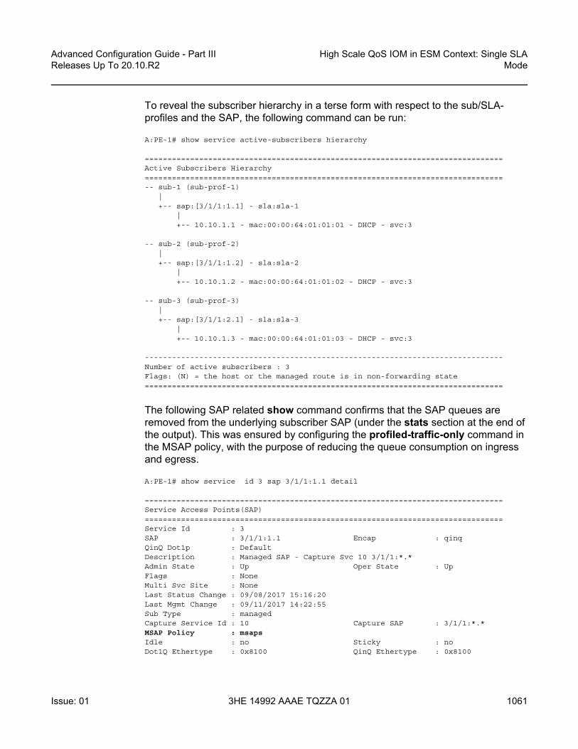
Advanced Configuration Guide - Part III Releases Up To 20.10.R2
High Scale QoS IOM in ESM Context: Single SLAMode
Issue: 01 3HE 14992 AAAE TQZZA 01 1061
To reveal the subscriber hierarchy in a terse form with respect to the sub/SLA-profiles and the SAP, the following command can be run:
A:PE-1# show service active-subscribers hierarchy
===============================================================================Active Subscribers Hierarchy===============================================================================-- sub-1 (sub-prof-1)
|+-- sap:[3/1/1:1.1] - sla:sla-1
|+-- 10.10.1.1 - mac:00:00:64:01:01:01 - DHCP - svc:3
-- sub-2 (sub-prof-2)|+-- sap:[3/1/1:1.2] - sla:sla-2
|+-- 10.10.1.2 - mac:00:00:64:01:01:02 - DHCP - svc:3
-- sub-3 (sub-prof-3)|+-- sap:[3/1/1:2.1] - sla:sla-3
|+-- 10.10.1.3 - mac:00:00:64:01:01:03 - DHCP - svc:3
-------------------------------------------------------------------------------Number of active subscribers : 3Flags: (N) = the host or the managed route is in non-forwarding state===============================================================================
The following SAP related show command confirms that the SAP queues are removed from the underlying subscriber SAP (under the stats section at the end of the output). This was ensured by configuring the profiled-traffic-only command in the MSAP policy, with the purpose of reducing the queue consumption on ingress and egress.
A:PE-1# show service id 3 sap 3/1/1:1.1 detail
===============================================================================Service Access Points(SAP)===============================================================================Service Id : 3SAP : 3/1/1:1.1 Encap : qinqQinQ Dot1p : DefaultDescription : Managed SAP - Capture Svc 10 3/1/1:*.*Admin State : Up Oper State : UpFlags : NoneMulti Svc Site : NoneLast Status Change : 09/08/2017 15:16:20Last Mgmt Change : 09/11/2017 14:22:55Sub Type : managedCapture Service Id : 10 Capture SAP : 3/1/1:*.*MSAP Policy : msapsIdle : no Sticky : noDot1Q Ethertype : 0x8100 QinQ Ethertype : 0x8100

High Scale QoS IOM in ESM Context: Single SLA Mode
1062
Advanced Configuration Guide - Part IIIReleases Up To 20.10.R2
3HE 14992 AAAE TQZZA 01 Issue: 01
Split Horizon Group: (Not Specified)
Admin MTU : 1522 Oper MTU : 1522Ingr IP Fltr-Id : n/a Egr IP Fltr-Id : n/aIngr Mac Fltr-Id : n/a Egr Mac Fltr-Id : n/aIngr IPv6 Fltr-Id : n/a Egr IPv6 Fltr-Id : n/aqinq-pbit-marking : both
Egr Agg Rate Limit: maxQ Frame-Based Acct : Disabled Limit Unused BW : Disabled
Acct. Pol : None Collect Stats : Disabled
Anti Spoofing : Ip-Mac Dynamic Hosts : EnabledAvl Static Hosts : 0 Tot Static Hosts : 0Calling-Station-Id : n/a
Application Profile: NoneTransit Policy : NoneAARP Id : None
Oper Group : (none) Monitor Oper Grp : (none)Host Lockout Plcy : n/aLag Link Map Prof : (none)Bandwidth : Not-ApplicableOper DCpu Prot Pol*: _default-access-policy
-------------------------------------------------------------------------------ETH-CFM SAP specifics-------------------------------------------------------------------------------Tunnel Faults : accept AIS : DisabledMC Prop-Hold-Timer : n/aSquelch Levels : NoneCollect Lmm Stats : DisabledLMM FC Stats : NoneLMM FC In Prof : None
-------------------------------------------------------------------------------QOS-------------------------------------------------------------------------------Ingress qos-policy : 1 Egress qos-policy : 1Ingress FP QGrp : (none) Egress Port QGrp : (none)Ing FP QGrp Inst : (none) Egr Port QGrp Inst: (none)Shared Q plcy : n/a Multipoint shared : DisabledI. Sched Pol : (Not Specified)E. Sched Pol : (Not Specified)I. Policer Ctl Pol : (Not Specified)E. Policer Ctl Pol : (Not Specified)E. HS Sec. Shaper : (Not Specified)I. QGrp Redir. List: (Not Specified)E. QGrp Redir. List: (Not Specified)-------------------------------------------------------------------------------Subscriber Management-------------------------------------------------------------------------------Admin State : Up MAC DA Hashing : FalseDef Sub-Id : Use auto-sub-idDef Sub-Profile : NoneDef SLA-Profile : NoneDef Inter-Dest-Id : (Use top-q-tag)Def App-Profile : None

Advanced Configuration Guide - Part III Releases Up To 20.10.R2
High Scale QoS IOM in ESM Context: Single SLAMode
Issue: 01 3HE 14992 AAAE TQZZA 01 1063
Sub-Ident-Policy : sub_ident_polSubscriber Limit : 1Single-Sub-ParametersProf Traffic Only : TrueNon-Sub-Traffic : N/A
Static host managementMAC learn options : N/A
-------------------------------------------------------------------------------Sap Statistics-------------------------------------------------------------------------------Last Cleared Time : N/A
Packets OctetsCPM Ingress : 3 443
Forwarding Engine StatsDropped : 0 0Received Valid : 0 0Off. HiPrio : 0 0Off. LowPrio : 0 0Off. Uncolor : 0 0Off. Managed : 0 0
Queueing Stats(Ingress QoS Policy 1)Dro. HiPrio : 0 0Dro. LowPrio : 0 0For. InProf : 0 0For. OutProf : 0 0
Queueing Stats(Egress QoS Policy 1)Dro. In/InplusProf : 0 0Dro. Out/ExcProf : 0 0For. In/InplusProf : 0 0For. Out/ExcProf : 0 0-------------------------------------------------------------------------------Sap per Queue stats-------------------------------------------------------------------------------
Packets OctetsNo entries found===============================================================================* indicates that the corresponding row element may have been truncated.A:PE-1#
QoS Related Show Commands in ESM Context
Examination of the subscriber QoS hierarchy on HSQ can start at the subscriber (HSQ queue group and SAP) level and gradually move through the HS secondary shaper, and finally the port level. The output of the show commands should confirm that the subscriber is associated with the QoS object as intended by the configuration.

High Scale QoS IOM in ESM Context: Single SLA Mode
1064
Advanced Configuration Guide - Part IIIReleases Up To 20.10.R2
3HE 14992 AAAE TQZZA 01 Issue: 01
For example, the following output shows that HS attachment policy "hs-attach-1-1" is associated with QoS SAP egress policy 10. It was determined previously that QoS SAP egress policy 10 is associated with subscribersub-1. In this case, a two-step process was necessary to track the association between the subscriber and the HS attachment policy.
A:PE-1# show qos sap-egress 10 association
===============================================================================QoS Sap Egress===============================================================================
-------------------------------------------------------------------------------Sap Egress Policy (10)-------------------------------------------------------------------------------Policy-id : 10 Scope : TemplateEthernet-ctag : False Parent-loc : defaultName : (Not Specified)Description : (Not Specified)Policy Active : True Plcrs HQoS Managed : FalsePost Plcr Mapping Policy: (Not Specified)HS Attachment Policy : hs-attach-1-1
-------------------------------------------------------------------------------Dynamic Configuration Information-------------------------------------------------------------------------------PccRule Insert Point : n/a DynPlcr Insert Point : n/aCBS : Def MBS : DefParent : (Not Specified)Level : 1 Weight : 1Packet Byte Offset : 0Stat Mode : minimal-------------------------------------------------------------------------------
-------------------------------------------------------------------------------Associations-------------------------------------------------------------------------------SLA Profiles :- sla-1
-------------------------------------------------------------------------------HSMDA Associations-------------------------------------------------------------------------------No Associations Found.
===============================================================================
The output from the HS attachment policy reflects the QoS configuration state at the subscriber level that is shown in Figure 169:
• Queues 1 and 2 are attached to WRR 1.• Queues 3 to 6 are directly attached to the corresponding scheduling classes (3
to 6).

Advanced Configuration Guide - Part III Releases Up To 20.10.R2
High Scale QoS IOM in ESM Context: Single SLAMode
Issue: 01 3HE 14992 AAAE TQZZA 01 1065
• Queues 7 and 8 are unattached.• WRR 2 is unattached. • HS attachment policy "hs-attach-1" is associated with QoS SAP egress policies
10, 20, and 30 that correspond to sub-1, sub-2, and sub-3. A:PE-1# show qos hs-attachment-policy "hs-attach-1-1" detail
===============================================================================HS Attachment Policy Information===============================================================================Policy Name : hs-attach-1-1Description : (Not Specified)Low Burst Max Class : 3
-------------------------------------------------------------------------------Queue Scheduling Class WRR Group-------------------------------------------------------------------------------1 (Not-Applicable) 12 (Not-Applicable) 13 3 (Not-Applicable)4 4 (Not-Applicable)5 5 (Not-Applicable)6 6 (Not-Applicable)7 unattached unattached8 unattached unattached-------------------------------------------------------------------------------WRR Group Scheduling Class-------------------------------------------------------------------------------1 12 unattached
-------------------------------------------------------------------------------Associations-------------------------------------------------------------------------------Network-Queue Policy-------------------------------------------------------------------------------No Matching Entries
Sap-Egress Policy-------------------------------------------------------------------------------102030
Egress Queue-Group Templates-------------------------------------------------------------------------------No Matching Entries
-------------------------------------------------------------------------------

High Scale QoS IOM in ESM Context: Single SLA Mode
1066
Advanced Configuration Guide - Part IIIReleases Up To 20.10.R2
3HE 14992 AAAE TQZZA 01 Issue: 01
Association between the HS secondary shaper and the subscribers can be verified with the following command. The HS secondary shaper is allocated per port (or LAG). The two subscribers (sub-1 and sub-2) are instantiated on SAPs with the outer VLAN tag 1; consequently, they are both associated with HS secondary shaper 1. The HS secondary shaper 1 is rate limited to 120 Mb/s while its scheduling classes are left open (max rate).
A:PE-1# show port 3/1/1 hs-secondary-shaper "1" associations
===============================================================================Ethernet Port 3/1/1 Egress HS Secondary Shaper Information===============================================================================Policy Name : 1Description : (Not Specified)Rate : 120000 KbpsLow Burst Max Class: 3
-------------------------------------------------------------------------------Class Rate-------------------------------------------------------------------------------1 max2 max3 max4 max5 max6 max-------------------------------------------------------------------------------
-------------------------------------------------------------------------------Service Associations-------------------------------------------------------------------------------Service ID Service Type SAP-------------------------------------------------------------------------------No Service Associations Found.-------------------------------------------------------------------------------
-------------------------------------------------------------------------------Subscriber Associations-------------------------------------------------------------------------------Subscriber ID-------------------------------------------------------------------------------sub-1sub-2-------------------------------------------------------------------------------Number of subscriber associations : 2-------------------------------------------------------------------------------
The port scheduler information can be obtained with the following command. This command is run in the QoS context (as opposed to being run in the port context, which was the case for HS secondary schedulers). The reason for this is that the HS secondary scheduler is configured directly under the port, while the HS port scheduler is configured in an HS scheduler policy (in QoS context), which is then applied to a port.
A:PE-1# show qos hs-scheduler-policy "hs1" detail

Advanced Configuration Guide - Part III Releases Up To 20.10.R2
High Scale QoS IOM in ESM Context: Single SLAMode
Issue: 01 3HE 14992 AAAE TQZZA 01 1067
===============================================================================HS Scheduler Policy Information===============================================================================Policy Name : hs1Description : (Not Specified)Max Rate : 200 Mbps
-------------------------------------------------------------------------------Scheduling Class Rate Group Weight in Group-------------------------------------------------------------------------------1 max 0 12 max 0 13 max 0 14 max 1 105 max 1 206 20 Mbps 0 1
-------------------------------------------------------------------------------Group Rate-------------------------------------------------------------------------------1 60 Mbps
-------------------------------------------------------------------------------Port Ethernet Egress Associations-------------------------------------------------------------------------------3/1/1-------------------------------------------------------------------------------===============================================================================
Show Commands with Dynamically Changing Information
The following commands show the QoS hierarchy with the measured rates 1 of the objects (queues, WRR groups, scheduling classes, secondary shapers, and port shapers) and the queue buffer depths in the QoS hierarchy. The command output in this section is based on the scenario described in the Traffic Management on HSQ section.
The following subscriber hierarchy shows the rates per scheduling priority (and consequently, scheduling class), starting at the queue level and moving up toward the port level. For example, scheduling priority 1 starts with the rates of two subscriber queues (1 and 2) that are mapped to the WRR group. Scheduling priority 1 then moves to the rate at the HS secondary shaper level (the summed rate of all the entities at scheduling priority 1 at the HS secondary shaper level), ending with the rate of the scheduling class 1 at the port level. The aggregate rate of the HS secondary shaper and the port in the subscriber hierarchy are also provided.
Note:
1. Running rates are the dynamically calculated rates while traffic is running.

High Scale QoS IOM in ESM Context: Single SLA Mode
1068
Advanced Configuration Guide - Part IIIReleases Up To 20.10.R2
3HE 14992 AAAE TQZZA 01 Issue: 01
A:PE-1# show qos hs-scheduler-hierarchy subscriber "sub-1" egress
===============================================================================Hs Scheduler Hierarchy Information===============================================================================PortId : 3/1/1SAP : [3/1/1:1.1]SLA Profile : sla-1Hs Sched Policy Name : hs1
Port Max-Rate : 200 MbpsHs-Sec-Shaper:1 Agg-Rate : 120017 Kbps
Scheduler Priority 6Scheduler Class 6 Rate : 19 Mbps
Hs-Sec-Shaper:1 Class 6 Rate : 13349 KbpsQueue : 6 Rate : 6528 Kbps
Scheduler Priority 5 Group 1Scheduler Class 5 Rate : 40 Mbps Weight : 20
Hs-Sec-Shaper:1 Class 5 Rate : 26699 KbpsQueue : 5 Rate : 13072 Kbps
Scheduler Class 4 Rate : 19 Mbps Weight : 10Hs-Sec-Shaper:1 Class 4 Rate : 13300 Kbps
Queue : 4 Rate : 6528 Kbps
Scheduler Priority 3Scheduler Class 3 Rate : 61 Mbps
Hs-Sec-Shaper:1 Class 3 Rate : 40800 KbpsQueue : 3 Rate : 20008 Kbps
Scheduler Priority 2Scheduler Class 2 Rate : 0 Mbps
Hs-Sec-Shaper:1 Class 2 Rate : 0 Kbps
Scheduler Priority 1Scheduler Class 1 Rate : 58 Mbps
Hs-Sec-Shaper:1 Class 1 Rate : 25867 KbpsQueue : 1 Group : 1 Rate : 752 KbpsQueue : 2 Group : 1 Rate : 3104 Kbps
===============================================================================
The following command provides the measured rates at the HS secondary shaper and port levels:
A:PE-1# show qos hs-scheduler-hierarchy port 3/1/1 hs-secondary-shapers
===============================================================================Hs Scheduler Hierarchy Information===============================================================================Hs Sched Policy Name : hs1
Port Max-Rate : 200 Mbps
Scheduler Priority 6Scheduler Class 6 Rate : 20 Mbps
Scheduler Priority 5 Group 1

Advanced Configuration Guide - Part III Releases Up To 20.10.R2
High Scale QoS IOM in ESM Context: Single SLAMode
Issue: 01 3HE 14992 AAAE TQZZA 01 1069
Scheduler Class 5 Rate : 40 Mbps Weight : 20Scheduler Class 4 Rate : 19 Mbps Weight : 10
Scheduler Priority 3Scheduler Class 3 Rate : 61 Mbps
Scheduler Priority 2Scheduler Class 2 Rate : 0 Mbps
Scheduler Priority 1Scheduler Class 1 Rate : 58 Mbps
-------------------------------------------------------------------------------HS Secondary Shaper Rates-------------------------------------------------------------------------------Hs-Sec-Shaper:1 Agg-Rate : 119519 Kbps
Class 6 Rate : 13268 KbpsClass 5 Rate : 26544 KbpsClass 4 Rate : 13284 KbpsClass 3 Rate : 40661 KbpsClass 2 Rate : 0 KbpsClass 1 Rate : 25761 Kbps
Hs-Sec-Shaper:2 Agg-Rate : 79764 KbpsClass 6 Rate : 6642 KbpsClass 5 Rate : 13300 KbpsClass 4 Rate : 6625 KbpsClass 3 Rate : 20342 KbpsClass 2 Rate : 0 KbpsClass 1 Rate : 32852 Kbps
Hs-Sec-Shaper:default Agg-Rate : 0 KbpsClass 6 Rate : 0 KbpsClass 5 Rate : 0 KbpsClass 4 Rate : 0 KbpsClass 3 Rate : 0 KbpsClass 2 Rate : 0 KbpsClass 1 Rate : 0 Kbps
-------------------------------------------------------------------------------
Another important parameter to monitor is the depth of the queues. This provides information about the degree of congestion at the queue level. The buffer space per queue is allocated automatically by the system and, in the following case, the buffers are rather large. Deep buffering causes longer delays. To avoid this, the queue buffers can be adjusted by the mbs command under the queue definition in the QoS SAP egress policy. For example, 15 kbytes would accommodate roughly fifteen 1000 byte packets in a buffer queue.
*A:PE-1>config>qos>sap-egress# info----------------------------------------------
queue 1 creatembs 15 kilobytes

High Scale QoS IOM in ESM Context: Single SLA Mode
1070
Advanced Configuration Guide - Part IIIReleases Up To 20.10.R2
3HE 14992 AAAE TQZZA 01 Issue: 01
The following output shows that, except for queue 3, all queues have their buffers fully used. Because there is no congestion on queue 3, its buffer is unused.
A:PE-1# show hs-pools port 3/1/1 egress subscriber "sub-1" | match "Queue Information" pre-lines 1 post-lines 100-------------------------------------------------------------------------------Queue Information-------------------------------------------------------------------------------Queue Name : Sub=sub-1:sla-1 3->3/1/1:1.1->1FC Map : be ef ncAdmin PIR : 20000 Oper PIR : 0Admin MBS : 64 KB Oper MBS : 64 KBHS Wrr Group : 1HS Wrr Class Weight: 1 HS Wrr Weight : 1Depth : 58 KBHS Class : 1 HS Alt Port Class Pool : NoHS Slope Policy : _tmnx_hs_default
Queue Name : Sub=sub-1:sla-1 3->3/1/1:1.1->2FC Map : l2Admin PIR : 20000 Oper PIR : 0Admin MBS : 64 KB Oper MBS : 64 KBHS Wrr Group : 1HS Wrr Class Weight: 1 HS Wrr Weight : 4Depth : 58 KBHS Class : 1 HS Alt Port Class Pool : NoHS Slope Policy : _tmnx_hs_default
Queue Name : Sub=sub-1:sla-1 3->3/1/1:1.1->3FC Map : afAdmin PIR : Max Oper PIR : MaxAdmin MBS : 262500 B Oper MBS : 262656 BHS Wrr Group : (not-applicable)HS Wrr Class Weight: 1 HS Wrr Weight : 0Depth : 2 KBHS Class : 3 HS Alt Port Class Pool : NoHS Slope Policy : _tmnx_hs_default
Queue Name : Sub=sub-1:sla-1 3->3/1/1:1.1->4FC Map : l1Admin PIR : Max Oper PIR : MaxAdmin MBS : 262500 B Oper MBS : 262656 BHS Wrr Group : (not-applicable)HS Wrr Class Weight: 1 HS Wrr Weight : 0Depth : 233 KBHS Class : 4 HS Alt Port Class Pool : NoHS Slope Policy : _tmnx_hs_default
Queue Name : Sub=sub-1:sla-1 3->3/1/1:1.1->5FC Map : h1Admin PIR : Max Oper PIR : MaxAdmin MBS : 262500 B Oper MBS : 262656 BHS Wrr Group : (not-applicable)HS Wrr Class Weight: 1 HS Wrr Weight : 0Depth : 233 KBHS Class : 5 HS Alt Port Class Pool : NoHS Slope Policy : _tmnx_hs_default

Advanced Configuration Guide - Part III Releases Up To 20.10.R2
High Scale QoS IOM in ESM Context: Single SLAMode
Issue: 01 3HE 14992 AAAE TQZZA 01 1071
Queue Name : Sub=sub-1:sla-1 3->3/1/1:1.1->6FC Map : h2Admin PIR : Max Oper PIR : MaxAdmin MBS : 262500 B Oper MBS : 262656 BHS Wrr Group : (not-applicable)HS Wrr Class Weight: 1 HS Wrr Weight : 0Depth : 233 KBHS Class : 6 HS Alt Port Class Pool : NoHS Slope Policy : _tmnx_hs_default
-------------------------------------------------------------------------------===============================================================================A:PE-1#
Clear Commands
Clear commands in the HSQ context are used to clear statistics associated with the HS secondary shaper:
clear port <port-id> hs-secondary-shaper <name> statistics
Resources Monitoring
The following command is used to monitor resource on an HSQ IOM. Some of the resources (HSQ queue groups, HS primary shapers, HS secondary shapers, HS turbo queue groups 1, and so on) are allocated for internal use, thereby reducing the number of resources in the Free column. Such internally consumed resources are not available to be part of the user configuration.
The number of internally consumed resources depends on the configuration and MDA types.
In the following example, the number of allocated HS queue groups is 39. Each of the three subscribers consumes one HS queue group, which means that 36 HS queue groups are internally allocated. Similarly, out of 23 allocated HS secondary shapers, only 3 are user related (and visible via show commands): a "default" HS secondary shaper, HS secondary shaper 1, and HS secondary shaper 2. This means that 20 HS secondary shapers are internally consumed.
The same logic can be used for turbo HS queue groups and HS primary shapers. In addition, one managed HS primary shaper is always allocated per each HS secondary shaper. Both turbo HS queue groups and HS primary shapers are out of the scope of this chapter.

High Scale QoS IOM in ESM Context: Single SLA Mode
1072
Advanced Configuration Guide - Part IIIReleases Up To 20.10.R2
3HE 14992 AAAE TQZZA 01 Issue: 01
Hardware Resource Usage for Slot #3, CardType iom4-e-hs, Cmplx #0:| Total | Allocated | Free
-------------------------------|-----------|-----------|------------SAP Ingress QoS Policies | 1791| 1| 1790
Dynamic Egress Classification + 2047| 4| 2043SAP Egress QoS Policies - | 4|
Network Egress Classification - | 0|Ingress Queues | 131072| 501| 130571Egress Queues | 786432| 137| 786295
Egress HS Turbo Queue Groups | 64| 10| 54Egress HS Queue Groups | 98240| 39| 98201
Primary Shapers + 16384| 23| 16361Explicit Primary Shapers - | 0|Managed Primary Shapers - | 23|
Secondary Shapers | 4096| 23| 4073Ingress Policers | 511999| 1| 511998Egress Policers | 262143| 1| 262142
Ingress Policer Stats | 511967| 0| 511967Egress Policer Stats | 262111| 0| 262111
Qos Ingress Root Arbiters | 65535| 1| 65534Qos Egress Root Arbiters | 65535| 1| 65534
Qos Intermediate Arbiters | 262143| 0| 262143Egress QoS Bypass | 131071| 0| 131071
Ingress ACL Entries | 65536| 2| 65534Ingress QoS Entries | 16384| 2| 16382
Ingress IPv6 ACL Entries | 28672| 2| 28670Ingress IPv6 QoS Entries | 4096| 2| 4094
Egress ACL Entries | 32768| 2| 32766Egress QoS Entries | 14336| 2| 14334
Egress IPv6 ACL Entries | 16384| 2| 16382Egress IPv6 QoS Entries | 2048| 2| 2046
Ingress ACL Filters | 2047| 0| 2047Ingress IPv6 ACL Filters | 2047| 0| 2047
Egress ACL Filters | 2047| 0| 2047Egress IPv6 ACL Filters | 2047| 0| 2047
QoS User Schedulers | 98303| 0| 98303QoS User Scheduler Overrides | 196607| 0| 196607Sap IngQGrp RedirLst Entries | 31999| 0| 31999
Dynamic Service Entries + 131071| 3| 131068Subscriber Hosts - 131071| 3| 131068
Encap Group Members - 65535| 0| 65535Egr Network Queue Group Mappings - 131071| 0| 131071SapInst EgrQGrp RedirLst Entries - 31999| 0| 31999
Dynamic Nexthop Entries + 511999| 3| 511996Subscriber Nexthops - 511999| 3| 511996
Ipsec tunnels - 511999| 0| 511999Subscriber SPI QoS Overrides | 131072| 0| 131072
Mac Fdb Entries | 511999| 0| 511999Egress TLS Mcast Entries | 368639| 1| 368638
Note:
1. 100G ports support port-based (access or network) HSQ queue groups on egress that can be configured to support higher throughput rates. Such port-based high rate HSQ queue groups on egress are referred to as egress HS turbo queue groups.

Advanced Configuration Guide - Part III Releases Up To 20.10.R2
High Scale QoS IOM in ESM Context: Single SLAMode
Issue: 01 3HE 14992 AAAE TQZZA 01 1073
Traffic Management on HSQ
This section examines traffic output on HSQ IOM during congestion. Figure 170 is a graphic representation of the configuration described previously, but with traffic streams running through the IOM.
Six traffic streams are sent in the downstream direction toward each of the three subscribers-in total there are 18 traffic streams. The traffic streams are shown on the left side of the figure, with their names, offered rates (IN column) and measured output rates (OUT column). The traffic streams are sent and analyzed by the traffic generator.
The three gray shaded squares in the center of the figure represent the three subscribers and their scheduling classes. The QoS hierarchy is shown on the right side. Red shaded areas (shapers) represent points of congestion on HSQ IOM caused by the 18 traffic streams.
Each of the six traffic streams per subscriber is fed into different subscriber queues. The first digit in the traffic stream name represents the subscriber, whereas the second digit represents the queue to which this stream is sent. For example, STRM 2-3 represents a traffic stream sent to sub-2, queue 3.
To summarize the scenario shown in Figure 170:
• Traffic streams 1 and 2 of each subscriber are mapped to subscriber queues 1 and 2, which are in turn associated with WRR group 1 at the subscriber level.
• WRR group 1 is, depending on the subscriber, rate limited to 20 Mb/s, 40 Mb/s, or 60 Mb/s. Weight ratio between queues 2 and 1 is 4:1. WRR group 1 is then attached to scheduling class 1.
• Traffic stream 3 is via queue 3 directly mapped to scheduling class 3. Scheduling class 2 is unused in this example.
• Traffic streams 4 and 5 are via queues 4 and 5 mapped to scheduling classes 4 and 5, which are at the port level collapsed into WRR group 1 with an aggregate rate limit of 60 Mb/s.
• Traffic stream 6 is the highest priority stream that is via queue 6 mapped to scheduling class 6. At the port level, scheduling class 6 is rate limited to 20 Mb/s.
• Subscriber (sub-1, sub-2, and sub-3) aggregate rates are set to 50 Mb/s, 75 Mb/s, and 100 Mb/s, respectively.
• Subscribers sub-1 and sub-2 are mapped to HS secondary shaper 1 (via the outer VLANs on their SAPs) while sub-3 is mapped to HS secondary shaper 2.
• HS port scheduler is rate limited to 200 Mb/s.

High Scale QoS IOM in ESM Context: Single SLA Mode
1074
Advanced Configuration Guide - Part IIIReleases Up To 20.10.R2
3HE 14992 AAAE TQZZA 01 Issue: 01
The configured rate limits at the subscriber level are L2 rates, whereas the configured rate limits at the HS secondary shaper level and the HS port level include L1 overhead and are, therefore, on-the-wire rates. On-the-wire rates account for 20 additional bytes in each Ethernet frame (8 bytes preamble and 12 bytes IFG).
All traffic streams are sent with constant rates (no added burstiness) and fixed packet size (1000 bytes). Therefore, the difference between the L2 rates and the on-the-wire rates for the 1000 byte packets is 1000/1020 = 0.98 or 2%. That is, on-the-wire rates are 2% higher than the L2 rates. The name for this 2% delta factor in this chapter will be the Rate Conversion Factor (RCF).
Figure 170 Managing Congestion on HSQ in Single SLA Mode
Table 34 lists the input/output rates throughout the subscriber QoS hierarchy. Red shaded table cells represent congested objects. The numbers on the blue background represent the output rates measured on the traffic generator. The numbers in red (in parentheses) are configured aggregate rates for the object in the hierarchy. The numbers above them are operational rates measured by SR OS and observed via the show qos hs-scheduler-hierarchy command.
Some of the output columns in this table require additional explanation:

Advanced Configuration Guide - Part III Releases Up To 20.10.R2
High Scale QoS IOM in ESM Context: Single SLAMode
Issue: 01 3HE 14992 AAAE TQZZA 01 1075
• Per stream output rates are L2 rates as measured by the traffic generator. The resulting analysis will be based on these rates.
• However, those rates can also be displayed via the show qos hs-scheduler-hierarchy subscriber <sub-name> egress command. RCF must be used to correctly interpret the results in respective rate domains (L1 versus L2).
• WRR rates at the subscriber level (second column under the Output Rate section) are populated by manually adding rates measured by the traffic generator for traffic streams 1 and 2. The 4:1 indication in parentheses represents the weight ratio between the two streams. There are no means to observe the WRR group rates at the subscriber level directly within the system (via show commands).
• Aggregate rates per subscriber (third column under the Output Rate section) are populated by manually adding the rates measured by the traffic generator from all six traffic streams for each subscriber. There are no means to observe the aggregate subscriber rate directly within the system (via show commands).
• Aggregate rates per HS secondary shaper (fourth column under the Output Rate section) are on-the-wire rates displayed via the show qos hs-scheduler-hierarchy port 3/1/1 hs-secondary-shapers command. The displayed rates are rounded to the nearest Mb/s.
• Per scheduling class rates at the port level (fifth column under the Output Rate section) are displayed via the show qos hs-scheduler-hierarchy port 3/1/1 command. The displayed rates are rounded by the system to the nearest Mb/s. The discrepancy between the actual rates for scheduling class 3 (60 Mb/s) and the displayed rate (61 Mb/s) is due to the measuring and rounding inaccuracy at display time. The actual rate at scheduling class 3 at the port level can be calculated by summing the measured rate of each traffic stream 3 for each subscriber and adjusting the sum for the on-the-wire rate (RCF).
• The same logic applies to scheduling class 1 (actual rate 60 Mb/s versus 59 Mb/s measured rate).
• The WRR 1 rate at the port level (sixth column under the Output Rate section) is manually calculated by adding the rates measured by the traffic generator of all streams mapped to scheduling classes 5 and 4 (6 traffic streams in total, two per each subscriber). At the port level, traffic on scheduling classes 5 and 4 is weighted in a 2:1 ratio (this is noted in parentheses).
• The port rate (last column under the Output Rate section) is collected from two places:- The top number in obtained via the show qos hs-scheduler-hierarchy
command and represents the on-the-wire rate.- The bottom number with blue background is the number measured by the
traffic generator, which only measures L2 rates. On-the-wire rates can be converted to L2 rates by multiplying the on-the-wire rates by the RCF.

High Scale QoS IOM in ESM Context: Single SLA Mode
1076
Advanced Configuration Guide - Part IIIReleases Up To 20.10.R2
3HE 14992 AAAE TQZZA 01 Issue: 01
Table 34 Input and Output Rates throughout the Subscriber QoS Hierarchy
Subscr
Strm Input rate in [Mb/s]
Output rate in [Mb/s]
Per strm
Agg persubscr
Per strm(L2)
WRR on subscr level
Agg per subscr(L2)
Agg per secondary shaper (wire)
Per sch class on port level(wire)
WRR-1 on port level (wire)
Port
Sub-1 1-6 10 110 6.54 - 50(50)
120(120)
SC 620(20)
- 200(200)196.08 (L2)
1-5 15 13.07 - -
1-4 15 6.54 - -
1-3 20 20 - SC 540
60(60) (2:1)1-2 25 3.1 3.9
(4:1)1-1 25 0.8
Sub-2 2-6 10 130 6.54 - 67.65(75)
SC 4202-5 15 13.07 -
2-4 15 6.54 -
2-3 20 20 - SC 361
-
2-2 35 17.2 21.5(4:1)
-
2-1 35 4.3 -
Sub-3 3-6 10 160 6.54 - 78.43(100)
80(150)
SC 20
-
3-5 15 13.07 - -
3-4 15 6.54 - -
3-3 20 20 - SC 159
-
3-2 50 25.8 32.3(4:1)
-
3-1 50 6.5 -

Advanced Configuration Guide - Part III Releases Up To 20.10.R2
High Scale QoS IOM in ESM Context: Single SLAMode
Issue: 01 3HE 14992 AAAE TQZZA 01 1077
Analysis of Results
The analysis of results begins with the rates per stream measured by the traffic generator. The expected behavior is that those rates are in line with the theoretical rate calculations based on our understanding of QoS on HSQ IOM.
Considering the six strict priority classes in the HSQ scheduling mechanism, the expectation is that the traffic is serviced in the order of priority, from the highest scheduling class 6 to the lowest scheduling class 1. Consequently, the traffic analysis starts with the streams that are mapped to the highest priority scheduling class 6 (streams 1-6, 2-6, and 3-6), that is, stream 6 of sub-1, sub-2, and sub-3, respectively.
Scheduling class 6 (streams 1-6, 2-6, and 3-6) - the highest priority scheduling class
Due to the aggregate rate limit of 20 Mb/s for scheduling class 6 at the port level, it is expected that each subscriber receives an equal amount of traffic on scheduling class 6:
Figure 171
The measured results on the traffic generator for traffic streams 6 in Table 34 show that each subscriber receives 6.54 Mb/s out of an offered 10 Mb/s. The slight difference between the expected (6.6 Mb/s) and the measured (6.54 Mb/s) rate is caused by the discrepancy between the L2 rates at the subscriber level (as measured by the traffic generator), and on-the-wire rate enforcement (20 Mb/s) at the scheduling class 6 at the port level. Multiplying 6.6 Mb/s by the RCF will align the results.
This slight discrepancy between the L2 and on-the-wire rates is common throughout the remaining analysis, and will not be repeated.
20 Mb/s (aggregate of SC 6)3 streams (one per subscriber)
= 6.6 Mb/s
26900

High Scale QoS IOM in ESM Context: Single SLA Mode
1078
Advanced Configuration Guide - Part IIIReleases Up To 20.10.R2
3HE 14992 AAAE TQZZA 01 Issue: 01
Scheduling classes 5 and 4 (streams 1-5, 1-4, 2-5, 2-4, 3-5, and 3-4)
Scheduling classes 5 and 4 are collapsed at the port level into WRR group 1, which is at the next scheduling priority to be served. These two scheduling classes are served by WRR group 1 in a 2:1 ratio. The aggregate rate limit for WRR 1 at the port level is set to 60 Mb/s.
Expected rates for combined scheduling classes 5 and 4 of each subscriber are . When 20 Mb/s is distributed between the two scheduling classes in
the 2:1 ratio, each subscriber should receive 13.34 Mb/s on scheduling class 5 and 6.66 Mb/s on scheduling class 4, for the total of 20 Mb/s (out of offered 30 Mb/s).
The measured results in Table 34 are 13 Mb/s on scheduling class 5 and 6.5 Mb/s on scheduling class 4 for traffic streams 4 and 5 of each individual subscriber. This is in line with the expected results (the slight difference is due to the measured L2 rates by the traffic generator and enforced on-the-wire rates at the port level).
Scheduling class 3 (streams 1-3, 2-3, and 3-3)
Traffic streams mapped to scheduling class 3 do not have any rate restriction at the scheduling class level. Those streams can be only limited by the congestion at the subscriber aggregate level, the HS secondary shaper aggregate level, or the port aggregate level. Because the total amount of traffic so far is below the congestion level at each point in the hierarchy, it is expected that traffic stream 3 flows unimpeded. Consequently, each subscriber should receive the full input rate of 20 Mb/s on scheduling class 3. The actual results in Table 34 are aligned with the expected results.
To confirm that there is no congestion at the aggregate level so far for subscribers, HS secondary shapers, and the port, a calculation shows that each subscriber has received an equal amount of bandwidth so far: 46 Mb/s. This is below the configured aggregate rate limits at the subscriber, HS secondary scheduler, and port levels:
• 46 Mb/s is below the configured limit of 50 Mb/s for sub-1.• 46 Mb/s is below the configured limit of 75 Mb/s for sub-2.• 46 Mb/s is below the configured limit of 100 Mb/s for sub-3.• Sub-1 and sub-2 compete for the bandwidth at HS secondary shaper 1, and their
combined rate of 92 Mb/s is below the configured aggregate rate of HS secondary shaper 1 (120 Mb/s).
• Sub-3 with its 46 Mb/s is below its configured aggregate subscriber rate limit (100 Mb/s) and that of the HS secondary shaper 2 (150 Mb/s).

Advanced Configuration Guide - Part III Releases Up To 20.10.R2
High Scale QoS IOM in ESM Context: Single SLAMode
Issue: 01 3HE 14992 AAAE TQZZA 01 1079
• The total subscriber bandwidth of 3 x 46 Mb/s = 138 Mb/s is below the 200 Mb/s aggregate rate limit at the port level.
Scheduling classes 2 and 1 (streams 1-2, 1-1, 2-2, 2-1, 3-2, 3-1) - the lowest priority scheduling classes
The total amount of offered (input) traffic for lowest priority scheduling classes 1 and 2 across all three subscribers is 230 Mb/s (50 Mb/s for sub-1, 70 Mb/s for sub-2, and 100 Mb/s for sub-3). This amount of traffic will cause congestion at the aggregate level for sub-1, at the aggregate level of HS secondary shaper 1, and at the aggregate port level. The amount of traffic that each subscriber will receive for those two scheduling classes will now differ (up to this point, each subscriber received an equal amount of traffic).
Sub-1 will become limited by 50 Mb/s (the L2 rate limit 1) of its configured aggregate rate limit, which has only ~4 Mb/s left (with ~46 Mb/s received for sub-1). Considering that the scheduling classes 2 and 1 are serviced in 4:1 fashion, the ~4 Mb/s should be split between the two scheduling classes. Scheduling class 2 should receive ~3.2 Mb/s while scheduling class 1 should receive ~0.8 Mb/s. The measured data in Table 34 shows that the expected and measured results on the traffic generator are aligned.
Up to this point, the spare capacity on the HS secondary shaper 1 is:
Figure 172 HS secondary shaper 2
while the spare capacity at the sub-2 aggregate level is:
Figure 173 Sub-2 aggregate level
120 Mb/s (HS secondary shaper 1 aggregate on-the-wire rate limit)- 51 Mb/s (on-the-wire traffic from sub-1 up to this point)- ~47 Mb/s (on-the-wire traffic from sub-2 up to this point)= 22 Mb/s12 (capacity left on the HS secondary shaper 1 up to this point)
26901
75 Mb/s (sub-2 L2 aggregate rate limit)- ~46 Mb/s (L2 traffic from sub-2 up to this point)= 29 Mb/s (L2 capacity left on the HS secondary shaper 1 up to this point)
26902

High Scale QoS IOM in ESM Context: Single SLA Mode
1080
Advanced Configuration Guide - Part IIIReleases Up To 20.10.R2
3HE 14992 AAAE TQZZA 01 Issue: 01
This means that the 70 Mb/s that sub-2 is sending on scheduling classes 2 and 1 will congest the HS secondary shaper 1 (~22 Mb/s left) before it congests the subscriber itself (~29 Mb/s left). The 22 Mb/s of on-the-wire bandwidth capacity left on the HS secondary shaper will be divided in 4:1 ratio between scheduling classes 2 and 1. Therefore, the scheduling class 2 should receive 17.6 Mb/s and the scheduling class 1 should receive 4.4 Mb/s. When converted to L2 rates, these expected results match the measured rates by the traffic generator in Table 34 for sub-2.
Similar logic can be used for traffic on scheduling classes 2 and 1 for sub-3. The difference from the previous case is that this traffic will be limited by port congestion and not the HS secondary shaper congestion (or subscriber aggregate congestion).
The available bandwidth at the port level up to this point is:
Figure 174 Port Level
The 100 Mb/s sent to sub-3 on scheduling classes 2 and 1 will be reduced to 33 Mb/s on the output in 4:1 ratio between scheduling classes 2 and 1. Scheduling class 2 should receive 26.3 Mb/s and scheduling class 1 should receive 6.6 Mb/s. Converted to L2 rates, these numbers match the measured rates by the traffic generator for streams 3-2 and 3-1 in Table 34.
Note:
1. At the subscriber level, rate enforcement is based on L2 packet size.2. Spare capacity for HS secondary shaper 1 is calculated based on on-the-wire rates
while the subscriber aggregate capacity is calculated in L2 rates, because the aggregate rate limit in the HS secondary shaper is configured in on-the-wire rates while the subscriber aggregate rates are configured in L2 rates.
200 Mb/s (on-the-wire port aggregate rate cap)- 120 Mb/s (on-the-wire traffic from the HS secondary shaper 1 to sub-1 and sub-2)- ~47 Mb/s (on-the-wire traffic from sub-3)= 33 Mb/s (on-the-wire capacity left on the port)
26903

Advanced Configuration Guide - Part III Releases Up To 20.10.R2
High Scale QoS IOM in ESM Context: Single SLAMode
Issue: 01 3HE 14992 AAAE TQZZA 01 1081
Conclusion
This chapter described traffic management capabilities and configuration of HSQ IOM with ESM in single SLA mode. Because HSQ performs egress traffic management functions, the focus in this chapter was on egress QoS. The ingress QoS remains the same as on other non-HSQ IOMs where a combination of queues and policers can be deployed. Ingress and egress queues on HSQ are allocated from different queue pools that are separated at the hardware level (by different chips).
Some configuration practices are summarized here:
• SAP queues in the ESM context should be removed in most subscriber/SAP (1:1) deployment scenarios (profiled-only-traffic command). This maximizes the number of ingress queues available for ESM, which is important because HSQ does not support shared queueing on ingress. The alternative to queueing is to use policers on ingress.
• Queue depth (buffer size) can be statically configured (mbs command). By default, this parameter (MBS) is set dynamically and is somewhat high. To reduce the amount of buffering and delay, a smaller buffer size can be provisioned per queue.
• The low-burst-max-class should be configured at the subscriber level and at the HS secondary scheduler level to ensure smaller buffering delays for higher priority traffic.
• The delta between the high and low thresholds (hs-fixed-high-thresh-delta command) should be configured to accommodate a reasonable number of packets on higher priority classes that are serviced after the packets on lower priority classes have stopped due to crossing of the lower burst threshold. In this example, the value of 12 kbytes means that about 12 packets (each of 1000 byte size) on higher scheduling classes will be serviced unimpeded before the higher burst threshold is reached, which stops the service.
HSQ IOM provides scalable traffic management functions on egress. A high number of egress queues can be serviced in strict priority fashion and extensive shaping hierarchy provides protection against overrunning the link capacities at an access node level or at a subscriber level. HSQ IOM is a card for a scaled ESM (in single SLA mode) environment that requires a higher number of queues per subscriber with throughput demands in the range of 200 Gb/s per HSQ IOM.

High Scale QoS IOM in ESM Context: Single SLA Mode
1082
Advanced Configuration Guide - Part IIIReleases Up To 20.10.R2
3HE 14992 AAAE TQZZA 01 Issue: 01
Appendix A — Generic ESM Configuration
Sub-profile, SLA-profile, and MSAP-policy configuration is omitted because it is already described in the Configuration section.
ESM configuration in this example starts with a subscriber-interface configured in an IES context. Subscriber hosts are instantiated in IES 3 service, under the group-interface "group-int-1", which is created under the subscriber-interface "sub-int-1". Authentication and address assignment of the subscriber hosts is performed via LUDB user-db "user-db-1". The IP addresses that are assigned to the hosts are statically configured in LUDB (DHCP server is not used in this setup).
configureservice
ies 3 name "3" customer 1 createsubscriber-interface "sub-int-1" create
address 10.10.1.254/24group-interface "group-int-1" create
dhcpproxy-server
emulated-server 10.10.1.254no shutdown
exitoption
action keepcircuit-idremote-id
exittrustedlease-populate 100gi-address 10.10.1.254user-db "user-db-1"
no shutdownexit
exitno shutdown
exitexit
Subscriber SAPs are automatically created based on the VLAN tags carried in the initial control packets of the subscriber hosts. This VLAN auto-detection and SAP auto-creation is configured under the capture SAP hierarchy. The capture SAP is configured to support LUDB authentication for dynamic DHCPv4 host instantiation:
configureservice
vpls 10 name "10" customer 1 createsap 3/1/1:*.* capture-sap create
trigger-packet dhcpdhcp-user-db "user-db-1"
exitexit

Advanced Configuration Guide - Part III Releases Up To 20.10.R2
High Scale QoS IOM in ESM Context: Single SLAMode
Issue: 01 3HE 14992 AAAE TQZZA 01 1083
Sub-ident-policy is a mandatory configuration in ESM. It determines the mapping method between the sub/SLA profiles and the corresponding strings obtained during the authentication phase for the subscriber. Subscribers strings obtained during the authentication phase point, in some form (determined by sub-ident-policy), to the configured sub/SLA profiles (in the SR OS node) that will be associated with the subscriber.
configuresubscriber-mgmt
sub-ident-policy "sub_ident_pol" createsub-profile-map
use-direct-map-as-defaultexitsla-profile-map
use-direct-map-as-defaultexit
exit
In this example, authentication of the subscriber hosts and IP address assignment is performed through LUDB. The hosts are identified based on the circuit-id and remote-id fields in DHCP control packets. Sub/SLA -profile strings in LUDB are directly mapped to the configured sub/SLA-profiles in the SR OS node. This direct mapping is implied by the use-direct-map-as-default command within the sub-ident-policy.
Service ID, group-interface name, and MSAP policy name for the subscriber is also determined during the authentication phase via LUDB. LUDB carries only ESM-specific configuration. There is no HSQ relevant configuration present in LUDB.
configuresubscriber-mgmt
local-user-db "user-db-1" createipoe
match-list circuit-id remote-idhost "sub-1-host-1" create
host-identificationcircuit-id string "sub-1"remote-id string "host-1"
exitaddress 10.10.1.1identification-strings 254 create
subscriber-id "sub-1"sla-profile-string "sla-1"sub-profile-string "sub-prof-1"
exitmsap-defaults
group-interface "group-int-1"policy "msaps"service 3
exitoptions
subnet-mask 255.255.255.0exitno shutdown

High Scale QoS IOM in ESM Context: Single SLA Mode
1084
Advanced Configuration Guide - Part IIIReleases Up To 20.10.R2
3HE 14992 AAAE TQZZA 01 Issue: 01
exithost "sub-2-host-1" create
host-identificationcircuit-id string "sub-2"remote-id string "host-1"
exitaddress 10.10.1.2identification-strings 254 create
subscriber-id "sub-2"sla-profile-string "sla-2"sub-profile-string "sub-prof-2"
exitmsap-defaults
group-interface "group-int-1"policy "msaps"service 3
exitoptions
subnet-mask 255.255.255.0exitno shutdown
exithost "sub-3-host-1" create
host-identificationcircuit-id string "sub-3"remote-id string "host-1"
exitaddress 10.10.1.3identification-strings 254 create
subscriber-id "sub-3"sla-profile-string "sla-3"sub-profile-string "sub-prof-3"
exitmsap-defaults
group-interface "group-int-1"policy "msaps"service 3
exitoptions
subnet-mask 255.255.255.0exitno shutdown
exitexitno shutdown
exitexit

Advanced Configuration Guide - Part III Releases Up To 20.10.R2
Ingress Multicast Path Management
Issue: 01 3HE 14992 AAAE TQZZA 01 1085
Ingress Multicast Path ManagementThis chapter provides information about Ingress Multicast Path Management (IMPM).
Topics in this chapter include:
• Applicability• Summary• Overview• Configuration• Conclusion
Applicability
The information and configuration in this chapter are based on SR OS Release 9.0.R6. There are no prerequisites for this configuration.
Summary
Ingress Multicast Path Management (IMPM) optimizes the IPv4 and IPv6 multicast capacity on the applicable systems with the goal of achieving the maximum system-wide IP multicast throughput. It controls the delivery of IPv4/IPv6 routed multicast groups and of VPLS (IGMP and PIM) snooped IPv4 multicast groups, which usually relate to the distribution of IP TV channels.
A description is also included of the use of IMPM resources by point-to-multipoint LSP IP multicast traffic, and policed ingress routed IP multicast or VPLS broadcast, unknown or multicast traffic. The system capacity for these traffic types can be increased even with IMPM disabled.
Overview
IMPM introduces the concept of paths on a line card (IOM/IMM) which connect to planes on the chassis switch fabric (Figure 175).

Ingress Multicast Path Management
1086
Advanced Configuration Guide - Part IIIReleases Up To 20.10.R2
3HE 14992 AAAE TQZZA 01 Issue: 01
IMPM monitors the ingress rate of IP multicast channels (S,G multicast streams) on line card paths and optimizes the use of the capacity of each switch fabric plane. Its goal is to forward as many channels as possible through the system in order to make maximum use of the switch fabric planes without incurring multicast packet loss. IMPM achieves this by moving entire multicast channels between the line card paths, and therefore between switch fabric planes, to achieve an optimal packing of channels onto path/planes. These actions take into consideration the total ingress multicast traffic being received by all line cards with IMPM enabled and a configured preference of each channel.
Figure 175 IOM/IMM Paths Connecting to Switch Fabric Planes
There are three types of path: primary, secondary and ancillary paths (the ancillary path is specific to the IOM1/2 and is discussed in Ancillary Path).
When a new channel is received on a line card for which there is an egress join, its traffic is initially placed on to a secondary path by default. IMPM monitors the channel’s traffic rate and, after an initial monitoring period, can move the channel to another path (usually a primary path) on which sufficient capacity exists for the channel. IMPM constantly monitors all of the ingress channels and therefore keeps
Note: S,G refers to an individual multicast stream by referencing the source (S) and multicast group (G) used by the steam.
OSSG725
Switch Fabric
PATHS
PATHS
PATHS
Plane
Ingress ForwardingComplex Egress Forwarding
Complex
Egress ForwardingComplex
Egress ForwardingComplex
Ingress ForwardingComplex
Ingress ForwardingComplex
Plane
Plane

Advanced Configuration Guide - Part III Releases Up To 20.10.R2
Ingress Multicast Path Management
Issue: 01 3HE 14992 AAAE TQZZA 01 1087
a picture of the current usage of all the line card paths and switch fabric planes. As new channels arrive, IMPM assigns them onto available capacity, which may involve moving existing channels between paths (and planes). If a channel stops, IMPM will be aware that more capacity is now available. If the traffic rate of any channel(s) changes, IMPM will continue to optimize the use of the path/planes.
In the case where there is insufficient plane capacity available for all ingress channels, entire channel(s) are blackholed (dropped) rather than allowing a random degradation across all channels. This action is based on a configurable channel preference with the lowest preference channel being dropped first. If path/plane capacity becomes available, then the blackholed channel(s) can be re-instated.
Paths and Planes
Each path connects to one plane on the switch fabric which is then used to replicate multicast traffic to the egress line cards. Further replication can occur on the egress line card but this is not related to IMPM so is not discussed.
Each plane has a physical connection to every line card and operates in full duplex mode allowing the possibility for traffic received on a plane from one line card path to be sent to every other line card, and back to the ingress line card (note that traffic is actually only sent to the line cards where it may exit). Therefore a given plane interconnects all line cards which allow ingress multipoint traffic from a line card with a path connected to this plane to be sent to multiple egress line cards.
Traffic could be sent by only one line card, or by multiple line cards simultaneously, on to a given plane. The total amount of traffic on a path or plane cannot exceed the capacity of that path or plane, respectively.
There could be more planes available on the switch fabrics than paths on the line cards. Conversely, there could be more total line card paths than planes available on the switch fabrics. In the latter case, the system distributes the paths as equally as possible over the available planes and multiple paths would be assigned to a given0 plane. Note that multiple paths of either type (primary or secondary) can terminate on a given plane.
The number of paths available per line card depends on the type of line card used whereas the number of planes on a system depends on the chassis type, the chassis mode (a, b, c, d) and the number of installed switch fabrics.
To clarify these concepts, consider a system with the following hardware installed.
A:PE-1# show card===============================================================================Card Summary

Ingress Multicast Path Management
1088
Advanced Configuration Guide - Part IIIReleases Up To 20.10.R2
3HE 14992 AAAE TQZZA 01 Issue: 01
===============================================================================Slot Provisioned Equipped Admin Operational Comments
Card-type Card-type State State-------------------------------------------------------------------------------6 iom3-xp iom3-xp up up7 imm8-10gb-xfp imm8-10gb-xfp up up8 iom3-xp iom3-xp up upA sfm4-12 sfm4-12 up up/activeB sfm4-12 sfm4-12 up up/standby===============================================================================A:PE-1#
Output 1 shows the mapping of paths to switch fabric planes.
A:PE-1# show system switch-fabric high-bandwidth-multicast===============================================================================Switch Fabric===============================================================================
Cap: Planes:Slot/Mda Min Max Hbm Grp Hi | Lo-------------------------------------------------------------------------------6/1 100% 100% No 0 1 0 3 4 5 6 7 8 9 10 11 12 13 14 15 | 167/1 100% 100% No 0 19 17 20 21 22 23 24 25 26 27 28 29 30 31 32 | 338/1 100% 100% No 0 35 34 36 37 38 39 40 41 42 43 44 45 46 47 0 | 1A 100% 100% No 0 2 | 2B 100% 100% No 0 2 | 2
===============================================================================A:PE-1#
Output 1: Paths and Planes in Chassis Mode d
This system has two SF/CPM4s and is using chassis mode d, this creates 24 planes per SF/CPM4 to give a total of 48 planes which are numbered 0-47. The IOM3-XP/IMMs have 16 paths each which are connected to different planes. The SF/CPM4s together use a single plane and an additional plane (18, which is not in the output above) is used by the system itself. As there are more paths (3x16=48) in this configuration than available planes (48-2[system planes 2,18]=46), some planes are shared by multiple paths, namely planes 0 and 1. Note that the path to plane mapping can change after a reboot or after changing hardware.
The following output shows the equivalent information if an IOM2 is added to this configuration in slot 5. In order for the IOM2 to be recognized, the system must be changed to use chassis mode a, b or c.
A:PE-1# show card===============================================================================Card Summary===============================================================================Slot Provisioned Equipped Admin Operational Comments
Card-type Card-type State State-------------------------------------------------------------------------------5 iom2-20g iom2-20g up up6 iom3-xp iom3-xp up up

Advanced Configuration Guide - Part III Releases Up To 20.10.R2
Ingress Multicast Path Management
Issue: 01 3HE 14992 AAAE TQZZA 01 1089
7 imm8-10gb-xfp imm8-10gb-xfp up up8 iom3-xp iom3-xp up upA sfm4-12 sfm4-12 up up/activeB sfm4-12 sfm4-12 up up/standby===============================================================================A:PE-1#
The following output shows the mapping of the line card paths to the switch fabric planes with the IOM2 installed.
A:PE-1# show system switch-fabric high-bandwidth-multicast===============================================================================Switch Fabric===============================================================================
Cap: Planes:Slot/Mda Min Max Hbm Grp Hi | Lo-------------------------------------------------------------------------------5/1 100% 100% No 0 1 | 05/2 100% 100% No 0 4 | 36/1 100% 100% No 0 6 5 7 8 9 10 11 12 13 14 15 0 1 3 4 | 57/1 100% 100% No 0 7 6 8 9 10 11 12 13 14 15 0 1 3 4 5 | 68/1 100% 100% No 0 8 7 9 10 11 12 13 14 15 0 1 3 4 5 6 | 7A 100% 100% No 0 2 | 2B 100% 100% No 0 2 | 2
===============================================================================A:PE-1#
Output 2: Paths and Planes in Chassis Mode a/b/c
Now that the system is not in chassis mode d, in fact it is in mode a (but the output would be the same in modes b or c) the SF/CPM4s each create 8 planes giving a total of 16, numbered 0-15. One plane (2) is used by the SF/CPM4s, leaving 15 (0-1,3-15) planes for connectivity to the line card paths. Each IOM2 forwarding complex has 2 paths, so the paths of the IOM2 in slot 5 are using planes 0 and 1, and 3 and 4. Note that there are now fewer planes available and more paths, so there is more sharing of planes between paths than when chassis mode d was used.
IMPM Managed Traffic
IMPM manages IPv4/IPv6 routed multicast traffic and VPLS (IGMP and PIM) snooped IPv4 multicast traffic, traffic that matches a <*,G> or a <S,G> multicast record in the ingress forwarding table. It manages IP multicast traffic on a bud LSR when using point-to-multipoint (P2MP) LSPs but it does not manage IP protocol control traffic or traffic using multipoint-shared queuing. Traffic being managed by IMPM involves IMPM monitoring and potentially moving the related channels between paths/planes. The unmanaged traffic rates are also monitored and taken into account in the IMPM algorithm.

Ingress Multicast Path Management
1090
Advanced Configuration Guide - Part IIIReleases Up To 20.10.R2
3HE 14992 AAAE TQZZA 01 Issue: 01
Care should be taken when using the mrouter-port configuration in a VPLS service. This creates a (*,*) multicast record and consequently all multicast channels that are not delivered locally to a non-mrouter port will be treated by IMPM as a single channel.
Configuration
This section covers:
• IMPM on an IOM3-XP/IMM• IMPM on an IOM1/2 • IMPM Not Enabled
Prerequisites
As IMPM operates on IPv4/IPv6 routed or VPLS IGMP/PIM snooped IPv4 multicast traffic, some basic multicast configuration must be enabled. This section uses routed IP multicast in the global routing table which requires IP interfaces to be configured with PIM and IGMP. The configuration uses a PIM rendezvous point and static IGMP joins. The following is an example of the complete configuration of one interface.
configurerouter
interface "int-IOM3-1"address 172.16.6.254/24port 6/2/1
exitigmp
interface "int-IOM3-1"static
group 239.255.0.1starg
exitexit
exitno shutdown
exitpim
interface "int-IOM3-1"exitrp
staticaddress 192.0.2.1
group-prefix 239.255.0.0/16exit
exit

Advanced Configuration Guide - Part III Releases Up To 20.10.R2
Ingress Multicast Path Management
Issue: 01 3HE 14992 AAAE TQZZA 01 1091
exitno shutdown
exitexit
One interface is configured on each line card configured in the system, as shown in the following output, but omitting their IGMP and PIM configuration.
configurerouter
interface "int-IMM8"address 172.16.3.254/24port 7/2/1
exitinterface "int-IOM2"
address 172.16.1.254/24port 5/2/1
exitinterface "int-IOM3-1"
address 172.16.2.254/24port 6/2/1
exitinterface "int-IOM3-2"
address 172.16.4.254/24port 8/2/1
exitexit
Configuring IMPM
The majority of the IMPM configuration is performed under the mcast-management CLI nodes and consists of:
a. The bandwidth-policy for characteristics relating to the IOM/IMM paths. This is applied on an IOM3-XP/IMM fp (fp is the system term for a forwarding complex on an IOM3-XP/IMM.), or an IOM1/2 MDA, under ingress mcast-path-management, with a bandwidth-policy named default being applied by default.- IOM1/2
config# card slot-number mda mda-slotingress
mcast-path-managementbandwidth-policy policy-name
- IOM3-XP/IMMconfig# card slot-number fp [1]
ingressmcast-path-management
bandwidth-policy policy-name

Ingress Multicast Path Management
1092
Advanced Configuration Guide - Part IIIReleases Up To 20.10.R2
3HE 14992 AAAE TQZZA 01 Issue: 01
b. The multicast-info policy for information related to the channels and how they are handled by the system. To facilitate provisioning, parameters can be configured under a three level hierarchy with each level overriding the configuration of its predecessor:- Bundle: a group of channels - Channel: a single channel or a non-overlapping range of channels- Source-override: channels from a specific sender
config# mcast-management multicast-info-policy policy-name [create]bundle bundle-name [create]
channel ip-address [ip-address] [create]source-override ip-address [create]
This policy is applied where the channel enters the system, so under router or service (vpls or vprn); the latter allows the handling of channels to be specific to a service, even if multiple services use overlapping channel addresses.
config# router multicast-info-policy policy-name
config# service vpls service-id multicast-info-policy policy-name
config# service vprn service-id multicast-info-policy policy-name
A default multicast-info-policy is applied to the above when IMPM is enabled.
c. The chassis-level node configures the information relating to the switch fabric planes.
config# mcast-management chassis-level
In addition, the command hi-bw-mcast-src (under an IOM3-XP/IMM fp or an IOM1/2 MDA) can be used to control the path to plane mapping among forwarding complexes.
IMPM on an IOM3-XP/IMM
IMPM is enabled on IOM3-XP/IMMs on under the card/fp CLI node as follows
config# card slot-number fp 1 ingress mcast-path-management no shutdown

Advanced Configuration Guide - Part III Releases Up To 20.10.R2
Ingress Multicast Path Management
Issue: 01 3HE 14992 AAAE TQZZA 01 1093
IOM3-XP/IMM Paths
16 paths are available on an IOM3-XP/IMM when IMPM is enabled which can be either primary paths or secondary paths. By default the 16 paths are divided into 15 primary paths and 1 secondary path, as can be seen using the following command with IMPM enabled only on slot 6 (this corresponds to the plane assignment in Output 1):
*A:PE-1# tools dump mcast-path-mgr cpmMcPathMgr[6][0]: 0xf33b0a00PATH: PLANE:Type SGs InUseBW AvailBW TotalBw ID SGs InUseBW AvailBW TotalBwP 1 0 - - 1 1 0 2000000 2000000P 1 0 - - 0 1 0 2000000 2000000P 1 0 - - 3 1 0 2000000 2000000P 1 0 - - 4 1 0 2000000 2000000P 1 0 - - 5 1 0 2000000 2000000P 1 0 - - 6 1 0 2000000 2000000P 1 0 - - 7 1 0 2000000 2000000P 1 0 - - 8 1 0 2000000 2000000P 1 0 - - 9 1 0 2000000 2000000P 1 0 - - 10 1 0 2000000 2000000P 1 0 - - 11 1 0 2000000 2000000P 1 0 - - 12 1 0 2000000 2000000P 1 0 - - 13 1 0 2000000 2000000P 1 0 - - 14 1 0 2000000 2000000P 1 0 - - 15 1 0 2000000 2000000S 1 0 - - 16 1 0 1800000 1800000B 0 0 - - - - - - -*A:PE-1#
Output 3: Paths/Planes on IOM3-XP/IMM
The left side of the output displays information about the paths (type {P=primary, s=secondary or B=blackholed}, number of “S,G”s and bandwidth in use (the path bandwidth cannot be set on an IOM3-XP/IMM, so the path available and total bandwidth always shows “-“ )) and the right side displays similar information about the associated planes (this will be a combination of the information for all paths connected to this plane). Note that one SG is always present on each path; this is used by the system and relates to the unmanaged traffic.
The primary/secondary paths are also highlighted in the planes section of Output 1, the primary paths being connected to the planes on the left of the “|” and the secondary paths to its right. There is a default primary path and a default secondary path; these correspond to the left-most plane and right-most plane for each line card, respectively.
Primary paths are used by:
• Expedited IES, VPLS and VPRN service ingress non-managed multipoint traffic (using the SAP based queues). This uses the default primary path.

Ingress Multicast Path Management
1094
Advanced Configuration Guide - Part IIIReleases Up To 20.10.R2
3HE 14992 AAAE TQZZA 01 Issue: 01
• Expedited network ingress non-managed multipoint traffic (using the network interface queues). This uses the default primary path.
• Managed multicast explicit path primary channels (using the primary paths managed multipoint queue)
• All managed multicast dynamic path channels when the primary paths or multicast planes are not at their limit (using the primary paths managed multipoint queue)
• Highest preference managed multicast dynamic path channels when the primary paths or multicast planes are at their limit (using the primary paths managed multipoint queue)
• Non-managed P2MP LSP IP multicast traffic. This does not require IMPM to be enabled, so is discussed later in IMPM Not Enabled.
• Non-managed expedited ingress policed multipoint traffic. This does not require IMPM to be enabled, so is discussed in IMPM Not Enabled.
Secondary paths are used by:
• Best-Effort IES, VPLS and VPRN service ingress non-managed multipoint traffic (using the SAP based queues). This uses the default secondary path.
• Best-Effort network ingress non-managed traffic (using the network interface multipoint queues). This uses the default secondary path.
• Managed multicast explicit path secondary channels (using the secondary paths managed multipoint queue)
• Lower preference managed multicast dynamic path channels when the primary paths or multicast planes are at their limit (using the secondary paths managed multipoint queue)
• Non-managed best-effort ingress policed multipoint traffic. This does not require IMPM to be enabled, so is discussed in IMPM Not Enabled.
When IMPM is enabled, the managed traffic does not use the standard multipoint queues but instead is placed onto a separate set of shared queues which are associated with the 16 paths. These queues are instantiated in an access ingress pool (called MC Path Mgmt, see “show output” section) which exists by default (this pool can be used even when IMPM is not enabled – see section “IMPM not enabled”). Statistics relating to traffic on these queues are reflected back to the standard ingress multipoint queues for accounting and troubleshooting purposes. Note that non-managed traffic continues to use the standard ingress multipoint queues, with the exception of P2MP LSP IP multicast traffic and policed multipoint traffic.

Advanced Configuration Guide - Part III Releases Up To 20.10.R2
Ingress Multicast Path Management
Issue: 01 3HE 14992 AAAE TQZZA 01 1095
The size of the pool by default is 10% of the total ingress pool size, the reserved CBS is 50% of the pool and the default slope policy is applied. Care should be taken when changing the size of this pool as this would affect the size of other ingress pools on the line card.
config# mcast-management bandwidth-policy policy-name [create]mcast-pool percent-of-total percent-of-buffers
resv-cbs percent-of-poolslope-policy policy-name
It is possible to configure the parameters for the queues associated with both the primary and secondary paths, and also the number of secondary paths available, within the bandwidth-policy.
config# mcast-management bandwidth-policy policy-name createt2-paths
primary-pathqueue-parameters
cbs percentagehi-priority-only percent-of-mbsmbs percentage
secondary-pathnumber-paths number-of-paths [dual-sfm number-of-paths]queue-parameters
cbs percentagehi-priority-only percent-of-mbsmbs percentage
The number of primary paths is 16 minus the number of secondary paths (at least one of each type must exist). The number-paths parameter specifies the number of secondary paths when only one switch fabric is active, while the dual-sfm parameter specifies the same value when two switch fabrics are active.
Packets are scheduled out of the path/multicast queue as follows:
• Traffic sent on primary paths is scheduled at multicast high priority while that on secondary paths is scheduled at multicast low priority.
• For managed traffic, the standard ingress forwarding class/prioritization is not used, instead IMPM managed traffic prioritization is based on a channel’s preference (described in Channel Prioritization and Blackholing Control). Egress scheduling is unchanged.
Congestion handling (packet acceptance into the path/multicast queue):
• For non-managed traffic, this is based on the standard mechanism, namely the packet’s enqueuing priority is used to determine whether the packet is accepted into the path multipoint queue depending on the queue mbs/cbs and the pool shared-buffers/reserved-buffers/WRED.

Ingress Multicast Path Management
1096
Advanced Configuration Guide - Part IIIReleases Up To 20.10.R2
3HE 14992 AAAE TQZZA 01 Issue: 01
For managed traffic, the congestion handling is based upon the channel’s preference (described later) and the channel’s cong-priority-threshold which is configured in the multicast-info-policy (here under a bundle).
config# mcast-management multicast-info-policy policy-name [create]bundle bundle-name [create]
cong-priority-threshold preference-level
When the preference of a channel is lower than the cong-priority-threshold setting, the traffic is treated as low enqueuing priority, when it is equal to or higher than the cong-priority-threshold it is treated as high enqueuing priority. The default cong-priority-threshold is 4.
IOM3-XP/IMM Planes
The capacity per plane for managed traffic is by default 2Gbps for a primary path and 1.8Gbps for a secondary path. The logic behind a reduced default on the secondary is to leave capacity for new streams in case the default secondary is fully used by managed streams.
The plane capacities can be configured as follows, note that this command configures the plane bandwidth associated with primary/secondary paths as seen by each line card, the TotalBw on the right side of Output 3:
config# mcast-management chassis-levelper-mcast-plane-limit megabits-per-second [secondary megabits-per-second]
[dual-sfm megabits-per-second [secondary-dual-sfm megabits-per-second]]
The first parameter defines the capacity for a primary path, the second a secondary path and the dual-sfm configures these capacities when two switch fabrics are active. The maximum plane capacity is 4Gbps but for the release used here it should only be configured on 7750 SR-12 or 7450 ESS-12 systems populated with SF/CPM4(s) and 100G FP IMMs; for all other hardware combinations the maximum should be 2Gbps. Note that secondary plane capacity cannot be higher than that of the primary plane.
These values can be tuned to constrain the amount of managed multicast traffic in favour of non-managed multicast and unicast traffic.
On the IOM3-XP/IMM line cards there is no separate control of the line card path capacity, the capacity is only constrained by the plane.

Advanced Configuration Guide - Part III Releases Up To 20.10.R2
Ingress Multicast Path Management
Issue: 01 3HE 14992 AAAE TQZZA 01 1097
IOM3-XP/IMM Path to Plane Mapping
By default all fps (line cards for IOM3-XP/IMM) are configured into the default (zero) group as seen in Output 1 and the system distributes the paths as equally as possible over the available planes. This default works well if there is a low volume of multicast traffic (compared to the plane capacity), or if there is a higher volume multicast entering only one line card where the ingress capacity does not exceed that provided by the planes the line card is connected to.
If there are more paths than planes and, for example, there is a high bandwidth multicast channel entering two different line cards it could happen that both line cards select the same plane for two paths that are used. This would result in one of the channels being blackholed if the plane capacity is exceeded, effectively reducing the available multicast capacity from that line card. In order to avoid this situation, it is possible to configure the paths in to different groups and the system will attempt to use different planes for each group.
Output 1 and Output 2 show examples of how the paths are mapped to planes.
In both cases there are more paths than planes so some planes are shared by multiple paths. The following command provides control of this mapping.
config# card slot-number fp [1]hi-bw-mcast-src [alarm] [group group-id] [default-paths-only]
If an fp is configured into a non-zero group (range: 1 to 32), the system will attempt to assign dedicate planes to its paths compared to other line cards in different non-zero groups. This action is dependent on there being sufficient planes available. If two line cards are assigned to the same group, they will be assigned the same planes. The default-paths-only parameter performs the assignment optimization only for the default primary and secondary paths and is only applicable to IOM3-XP/IMMs. The alarm keyword causes an alarm to be generated if some planes are still shared with fps in a different group.
An example of the use of this command is shown later.
Note: When VPLS IGMP and PIM snooped traffic is forwarded to a spoke or mesh SDP, by default it is sent by the switch fabric to all line card forwarding complexes on which there is a network IP interface. This is due to the dynamic nature of the way that a spoke or mesh SDP is associated with one or more egress network IP interfaces. If there is an active spoke/mesh SDP for the VPLS service on the egress forwarding complex, the traffic will be flooded on that spoke/mesh SDP, otherwise it will be dropped on the egress forwarding complex. This can be optimized by configuring an inclusion list under the spoke or mesh SDP defining which MDAs this traffic should be flooded to.
config>service>vpls# [spoke-sdp|mesh-sdp] sdp-id:vc-id egress

Ingress Multicast Path Management
1098
Advanced Configuration Guide - Part IIIReleases Up To 20.10.R2
3HE 14992 AAAE TQZZA 01 Issue: 01
mfib-allowed-mda-destinations[no] mda mda-id
The switch fabric flooding domain for this spoke or mesh SDP is made up only of the MDAs that have been added to the list. An empty list implies the default behavior.
It is important to ensure that the spoke or mesh SDP can only be established across the MDAs listed, for example by using RSVP with an explicit path.
IMPM Operation on IOM3-XP/IMM
This section covers:
• Principle of Operation• Monitoring Traffic Rates• Channel Prioritization and Blackholing Control
Principle of Operation
Where IMPM is enabled, it constantly monitors the line cards for ingress managed traffic.
When a new channel arrives it will be placed by default on to the default secondary path. IMPM determines the ingress point for the channel and then monitors the traffic of the channel within its monitoring period in order to calculate the rate of the channel. The system then searches the multicast paths/planes attached to the line card for available bandwidth. If there is sufficient capacity on such a path/plane, the channel is moved to that plane. Planes corresponding to primary paths are used first, when there is no capacity available on any primary path/plane a secondary path/plane is used (unless the channel is explicitly configured onto a specific path type – see the following description).
If the required bandwidth is unavailable, the system will then look for any channels that ingress this or other line cards that could be moved to a different multicast plane in order to free up capacity for the new channel. Any channel that is currently mapped to a multicast plane available to the ingress line card is eligible to be moved to a different multicast plane.

Advanced Configuration Guide - Part III Releases Up To 20.10.R2
Ingress Multicast Path Management
Issue: 01 3HE 14992 AAAE TQZZA 01 1099
If an eligible existing channel is found, whether on this or another line card, that existing channel is moved without packet loss to a new multicast plane. If necessary, this process can be repeated resulting in multiple channels being moved. The new multicast channel is then mapped to the multicast plane previously occupied by the moved channels, again this normally is using a primary path.
If no movable channel is found, then lower preference channel(s) on any ingress line card that share multicast planes with the ingress line card of the new channel can be blackholed to free up capacity for the new channel. It is also possible to both blackhole some channels and move other channels in order to free up the required capacity. If no lower preference channel is found and no suitable channel moves are possible, the new channel will be blackholed.
If required, channels can be explicitly configured to be on either a primary or secondary path. This can be done for a bundle of channels, for example
config# mcast-management multicast-info-policy policy-name [create]bundle bundle-name [create]
explicit-sf-path {primary|secondary|ancillary}
Note that the ancillary path is not applicable to the IOM3-XP/IMM line cards, however, it is discussed in the section relating to the IOM1/2. If a channel on an IOM3-XP/IMM is configured onto the ancillary path it will use a primary path instead.
One secondary path on an IOM3-XP/IMM is used as a default startup path for new incoming channels. If a large amount of new channel traffic could be received within the monitoring period, it is possible that the plane associated with the default secondary path is over loaded before IMPM has time to monitor the channels’ traffic rate and move the channels to a primary path (and a plane with available capacity). This can be alleviated by configuring the following command:
config# mcast-management chassis-levelround-robin-inactive-records
When round-robin-inactive-records is enabled, the system redistributes new channels (which are referenced by inactive S,G records) among all available line card multicast (primary, secondary) paths and their switch fabric planes.
Monitoring Traffic Rates
The monitored traffic rate is the averaged traffic rate measured over a monitoring period. The monitoring period used depends on the total number of channels seen by IMPM, the minimum is a 1 second interval and the maximum a 10 seconds interval.

Ingress Multicast Path Management
1100
Advanced Configuration Guide - Part IIIReleases Up To 20.10.R2
3HE 14992 AAAE TQZZA 01 Issue: 01
The way in which the system reacts to the measured rate can be tuned using the following command:
config# mcast-management multicast-info-policy policy-name [create]bundle bundle-name [create]
bw-activity {use-admin-bw|dynamic [falling-delay seconds]}[black-hole-rate kbps]
The default is to use the dynamic bandwidth rate, in which case a channel’s active traffic rate is determined based on the measured monitored rates. IMPM then makes a decision of how to process the channel as follows.
If the channel was un-managed, IMPM will attempt to place the channel on a path/plane with sufficient available bandwidth.
If the channel was already managed, IMPM determines the highest monitored traffic rate (within a given monitoring period) in a sliding window defined by the falling-delay. This highest chosen monitored rate is then used to re-assess the placement of the channel on the path/planes; this may cause IMPM to move the channel. This mechanism prevents the active rate for a channel being reduced due to a momentarily drop in traffic rate. The default value for falling-delay is 30 seconds, with a range of 10-3600 seconds.
The above logic is shown in Figure 176 (for simplicity, the falling-delay is exactly twice the monitoring period). It can be seen that the active rate used when the traffic rate decreases follows the highest monitored rate in any falling-delay period.
Figure 176 Dynamic Bandwidth Rate Management
IngressChannel
TrafficRate
BlackholeRate
Blackholed
ActiveRate Used
Time
Falling-delayMonitoringPeriod
Dynamic Bandwidth Rate Management
Sliding Window
MonitoredRate
OSSG726

Advanced Configuration Guide - Part III Releases Up To 20.10.R2
Ingress Multicast Path Management
Issue: 01 3HE 14992 AAAE TQZZA 01 1101
By using the sliding window of monitored rate measurements in the dynamic bandwidth measurement mode, IMPM delays releasing capacity for a channel in its calculations when the channel’s rate has been reduced. This allows IMPM to ignore temporary fluctuations in a channel’s rate. It is possible to tune this for cases where the reduction in a channel’s rate is large by using the falling-percent-reset parameter. The default for the falling-percent-reset is 50%. Setting this to 100% effectively disables it.
config# mcast-management bandwidth-policy policy-name createfalling-percent-reset percent-of-highest
When the monitored rate falls by a percentage which is greater or equal to falling-percent-reset, the rate used by IMPM is immediately set to this new monitored rate. This allows IMPM to react faster to significant reductions in a channel’s rate while at the same time avoiding too frequent reallocations due to normal rate fluctuations. An example of the falling-percent-reset is shown in Figure 177. In the last two monitoring periods, it can be seen that the active rate used is equal to the monitored rate in the previous periods, and not the higher rate in the previous falling-delay window.
Figure 177 Falling-Percent-Reset
The rate management can be further tuned based on the expectation that the channel bandwidth will fluctuate around a given rate. When the bw-activity is set to use-admin-bw within the multicast-info-policy, the following parameters come into play.
config# mcast-management multicast-info-policy policy-name [create]bundle bundle-name [create]
ActiveRate Used
Falling-delayMonitoringPeriod
Falling Percentage
Sliding Window
MonitoredRate
OSSG727
Drop > falling-percent-reset
Drop > falling-percent-resetIngress
ChannelTraffic
Rate
Time

Ingress Multicast Path Management
1102
Advanced Configuration Guide - Part IIIReleases Up To 20.10.R2
3HE 14992 AAAE TQZZA 01 Issue: 01
admin-bw kbps
config# mcast-management bandwidth-policy policy-name createadmin-bw-threshold kilo-bits-per-second
IMPM will use the rate configured for the admin-bw if the monitored rate is above the admin-bw-threshold but below or equal to the admin-bw in the sliding window of the falling-delay. Whenever the monitored rate is below the admin-bw-threshold or above the admin-bw, IMPM uses the dynamic rate management mechanism. The admin-bw-threshold needs to be smaller than the admin-bw, with the latter being non-zero. This is shown in Figure 178 (for simplicity, the falling-delay is exactly twice the monitoring period). It can be seen that while the monitored rate stays between the admin-bw-threshold and the admin-bw, the active rate used is set to the admin-bw.
Figure 178 Admin-Bw Rate Management
Finally, IMPM also takes into consideration the unmanaged traffic rate on the primary and secondary paths associated with SAP/network interface queues when determining the available capacity on these paths/planes. This is achieved by constantly monitoring the rate of this traffic on these queues and including this rate in the path/plane capacity usage. IMPM must be enabled on the ingress card of the unmanaged traffic otherwise it will not be monitored.
IngressChannel
TrafficRate
BlackholeRate
admin-bw
admin-bwThreshold
Blackholed
ActiveRate Used
Time
Falling-delayMonitoringPeriod
admin-bw Rate Management
Sliding Window
MonitoredRate
OSSG728

Advanced Configuration Guide - Part III Releases Up To 20.10.R2
Ingress Multicast Path Management
Issue: 01 3HE 14992 AAAE TQZZA 01 1103
Channel Prioritization and Blackholing Control
IMPM decides which channels will be forwarded and which will be dropped based on a configured channel preference. The preference value can be in the range 0-7, with 7 being the most preferred and the default value being 0.
When there is insufficient capacity on the paths/planes to support all ingress multipoint traffic, IMPM uses the channel preferences to determine which channels should be forwarded and which should be blackholed (dropped).
This is an important distinction compared to the standard forwarding class packet prioritization; by using a channel preference, an entire channel is either forwarded or blackholed, this allows IMPM to avoid congestion having a small impact on multiple channels at the cost of entire channels being lost.
The channel preference is set within the multicast-info-policy, for example at the bundle level, with the settable values being 1-7:
config# mcast-management multicast-info-policy policy-name [create]bundle bundle-name [create]
preference preference-level
The channel preference is also used for congestion control in the line card path queues – see “congestion handling” in the section on “IOM3-XP/IMM Paths” above.
Blackhole protection can also be enabled using the bw-activity command, shown above in the “Monitoring traffic rates” section. Regardless of which rate monitoring mechanism is used, a channel can be blackholed if the monitored rate exceeds the black-hole-rate, in which case the channel will be put immediately on the blackhole list and its packets dropped at ingress. This channel will no longer consume line card path or switch fabric capacity. The intention of this parameter is to provide a protection mechanism in case channels consume more bandwidth than expected which could adversely affect other channels.
The black-hole-rate can range from 0 to 40000000kbps, with no black-hole-rate by default. This protection is shown in the last monitoring period of both Figure 2 and Figure 4. Note that it will take a falling-delay period in which the channel’s rate is always below the black-hole-rate in order for the channel to be re-instated unless the reduction in the rate is above the falling-percent-reset.
IMPM on an IOM1/2
As most of the principles when using IMPM on an IOM1/2 compared to on an IOM3-XP/IMM are the same and are described above, this section focuses only on the difference between the two.

Ingress Multicast Path Management
1104
Advanced Configuration Guide - Part IIIReleases Up To 20.10.R2
3HE 14992 AAAE TQZZA 01 Issue: 01
Note that an IOM1 and IOM2 have two independent 10G forwarding complexes; in both cases there is a single MDA per forwarding complex, consequently some aspects of IMPM are configured under the mda CLI node.
IMPM is enabled on an IOM1/2 under the MDA CLI node as follows:
config# card slot-number mda mda-slot ingress mcast-path-management no shutdown
IOM1/2 Paths
Each forwarding complex has three paths: one primary and one secondary path, and another type called the ancillary path which is IOM1/2 specific. The paths can be seen using the following command with IMPM enabled only on slot 5 MDA 1 and MDA 2 (referenced as [0] and [1] respectively):
A:PE-1# tools dump mcast-path-mgr cpmMcPathMgr[5][0]: 0xf33b0a00PATH: PLANE:Type SGs InUseBW AvailBW TotalBw ID SGs InUseBW AvailBW TotalBwP 1 0 2000000 2000000 1 1 0 2000000 2000000S 1 0 1500000 1500000 0 1 0 1800000 1800000A 0 0 5000000 5000000 - - - - -B 0 0 - - - - - - -McPathMgr[5][1]: 0xf33b3198PATH: PLANE:Type SGs InUseBW AvailBW TotalBw ID SGs InUseBW AvailBW TotalBwP 1 0 2000000 2000000 4 1 0 2000000 2000000S 1 0 1500000 1500000 3 1 0 1800000 1800000A 0 0 5000000 5000000 - - - - -B 0 0 - - - - - - -A:PE-1#
Output 4: Paths/Planes on IOM1/2
The primary and secondary paths function as on the IOM3-XP/IMM, specifically for:
• Traffic usage.• Associated queues instantiated in the ingress “MC Path Mgmt” ingress pool.• Packet scheduling.• Congestion handling.
The queue parameters can be configured within the bandwidth-policy in a similar way to the IOM3-XP/IMM (note that the IOM3-XP/IMM equivalent for this is under the t2-paths CLI node). The bandwidth-policy is then applied under the respective MDA.
config# mcast-management bandwidth-policy policy-name createprimary-path
queue-parameterscbs percentage

Advanced Configuration Guide - Part III Releases Up To 20.10.R2
Ingress Multicast Path Management
Issue: 01 3HE 14992 AAAE TQZZA 01 1105
hi-priority-only percent-of-mbsmbs percentage
secondary-pathqueue-parameters
cbs percentagehi-priority-only percent-of-mbsmbs percentage
The IOM1/2 allows capacity control on the paths themselves, which is not possible on the IOM3-XP/IMM. This is achieved using the following commands.
config# mcast-management bandwidth-policy policy-name createprimary-path
path-limit megabits-per-secondsecondary-path
path-limit megabits-per-second
The maximum path-limit for both the primary and secondary path is 2Gbps with a default of 2Gbps for the primary path and 1.5Gbps for the secondary path. The capability to set a path limit for the IOM1/2 can be seen when comparing Output 3 with Output 4; in the latter the “AvailBW” and “TotalBw” for the “PATH” shows the path limit.
In addition to setting the path limits in the bandwidth-policy, they can also be overridden on a given MDA.
config# card slot-number mda mda-slotingress
mcast-path-managementprimary-override
path-limit megabits-per-secondsecondary-override
path-limit megabits-per-second
The achievable capacity will be the minimum of the path’s path-limit and the plane’s per-mcast-plane-limit.
Ancillary Path
The ancillary path
The ancillary path allows managed multicast traffic to be forwarded through the switch fabric as unicast and so is not constrained to the path or plane capacities. This is achieved using ingress replication, in order to send a channel to multiple destination forwarding complexes (DFCs), the ingress forwarding complex creates and forwards one copy of each packet to each DFC connected to the switch fabric.

Ingress Multicast Path Management
1106
Advanced Configuration Guide - Part IIIReleases Up To 20.10.R2
3HE 14992 AAAE TQZZA 01 Issue: 01
However, the total replication capacity available for the ancillary path is constrained to 5G to prevent it impacting the unicast or primary/secondary path capacities. This means that the total amount of ancillary capacity usable can be calculated from (note that the first copy sent is not included in this capacity, hence the “-1”):
5Gbps/(number_of_switch_fabric_DFCs – 1)
Taking an example shown later, if some channels ingress an IOM2 and egress 2 IOM3-XP (1 DFC each) and 1 IMM8 (1 DFC) to give a total of 3 egress DFCs, then total ancillary capacity available is
5Gbps/(3-1) = 2.5Gbps.
This would allow, for example, approximately 250 channels at 10Mbps each to use the ancillary path.
Due to the relationship between ancillary capacity and number of DFCs, the system will prefer the ancillary path as default whenever a channel enters an IOM1/2 and egresses on up to 3 DFCs. If there are 4 or more egress DFCs for the channel, then the primary path is preferred. The determination is performed on a per channel basis.
The configuration parameters relating to the primary and secondary paths are also available for the ancillary path.
config# mcast-management bandwidth-policy policy-name createancillary-path
queue-parameterscbs percentagehi-priority-only percent-of-mbsmbs percentage
config# mcast-management bandwidth-policy policy-name createancillary-path
path-limit megabits-per-second
config# card slot-number mda mda-slotingress
mcast-path-managementancillary-override
path-limit megabits-per-second
IOM1/2 Planes
The capacity per plane for managed traffic is by default 2Gbps for a primary path and 1.8Gbps for a secondary path. Note that the default IOM1/2 secondary path limit is 1.5Gbps. A maximum of 2Gbps should be configured for either path type using the per-mcast-plane-limit (as shown for the IOM3-XP/IMM) when an IOM1/2 is being used with IMPM.

Advanced Configuration Guide - Part III Releases Up To 20.10.R2
Ingress Multicast Path Management
Issue: 01 3HE 14992 AAAE TQZZA 01 1107
As the ancillary path does not use the switch fabric planes, there is no associated plane limit.
IOM1/2 Path to Plane Mapping
The hi-bw-mcast-src command function is the same for IOM1/2 line cards as for IOM3-XP/IMM line cards, as described above.
IMPM Operation on IOM1/2
This is exactly the same as the operation as for the IOM3-XP/IMM, see above.
IMPM Not Enabled
When IMPM is not enabled most multipoint traffic on an IOM1/2 and IOM3-XP/IMM can use only one primary path and one secondary path per forwarding complex. When ingress multipoint arrives it is placed on a multipoint queue and these queues are connected either to a primary path (if the queue is expedited) or a secondary path (if the queue is best-effort) depending on the ingress QOS classification applied. Standard ingress forwarding class/scheduling prioritization is used.
The capacity of the primary and secondary paths is 2Gbps, unless the system is a 7750 SR-12 or 7450 ESS-12 populated with SF/CPM4(s) and 100G FP IMMs in which case the capacity is 4Gbps.
In Output 1 and Output 2, the primary path is associated with the left-most plane and the secondary path is associated with the right-most plane for each line card.
There are exceptions to the above on the IOM3-XP/IMM line cards for
• Point-to-multipoint LSP IP multicast traffic• Policed ingress routed IP multicast or VPLS broadcast, unknown or multicast
traffic
Point-to-Multipoint (P2MP) LSP IP Multicast Traffic
IMPM will manage traffic on a P2MP LSP for any IP multicast channel that is delivered locally, for example, the system is a bud LSR. However, non-managed P2MP LSP IP multicast traffic will also make use of the primary paths, regardless of whether IMPM is enabled or not.

Ingress Multicast Path Management
1108
Advanced Configuration Guide - Part IIIReleases Up To 20.10.R2
3HE 14992 AAAE TQZZA 01 Issue: 01
For each primary queue created in the MC IMPM Path pool, an additional queue is created to carry non-managed P2MP LSP IP multicast traffic. The non-managed P2MP LSP IP multicast traffic is automatically distributed across all primary paths based on a modulo N function of the 10 least significant bits of channel destination group address, where N is the number of primary paths. Note that the number of primary paths can be changed with IMPM enabled or disabled by applying a bandwidth-policy which sets the number of secondary paths.
Policed Ingress Routed IP Multicast or VPLS Broadcast, Unknown Or Multicast Traffic
Routed IP multicast or VPLS broadcast, unknown or multicast traffic passing through ingress hardware policers on the IOM3-XP/IMM can also use the IMPM managed queues, with IMPM enabled or disabled. If this traffic is best-effort (forwarding classes BE, L2, AF, L1) it will use the secondary paths, if it is expedited (forwarding classes H2, EF, H1, NC) it will use the primary paths. Note that this traffic uses the shared ingress policer-output-queues which have a fixed forwarding class to queue mapping).
When IMPM is not enabled, this traffic is non-managed and 1 secondary path plus 15 primary paths are available (the default). Consequently, extra capacity is only available for the expedited traffic, which could use up to 15 planes worth of switch fabric capacity. If extra capacity is required for best-effort traffic, a bandwidth-policy allocating more secondary paths can applied to the line card even without IMPM being enabled.
The policed ingress routed IP or VPLS broadcast, unknown or multicast traffic is distributed across the paths using a standard LAG hash algorithm (as described in the Traffic Load Balancing Options section in the 7450 ESS, 7750 SR, 7950 XRS, and VSR Interface Configuration Guide).
For both of these exceptions, it is recommended to reduce the managed traffic primary/secondary plane limits (using per-mcast-plane-limit) in order to allow for the non-managed traffic.
Show Output
This section includes the show output related to IMPM. The first part covers generic output and uses IOM3-XP/IMMs and chassis mode d. The second part includes an IOM2 and so uses chassis mode a.

Advanced Configuration Guide - Part III Releases Up To 20.10.R2
Ingress Multicast Path Management
Issue: 01 3HE 14992 AAAE TQZZA 01 1109
IOM3-XP/IMM and Generic Output
The system has an IOM3-XP in slots 6 and 8, with an IMM8 is slot 7.
A:PE-1# show card===============================================================================Card Summary===============================================================================Slot Provisioned Equipped Admin Operational Comments
Card-type Card-type State State-------------------------------------------------------------------------------6 iom3-xp iom3-xp up up7 imm8-10gb-xfp imm8-10gb-xfp up up8 iom3-xp iom3-xp up upA sfm4-12 sfm4-12 up up/activeB sfm4-12 sfm4-12 up up/standby===============================================================================A:PE-1#
The status of IMPM on a given card can be shown as follows:
*A:PE-1# show card 6 detail===============================================================================Card 6===============================================================================Slot Provisioned Equipped Admin Operational Comments
Card-type Card-type State State-------------------------------------------------------------------------------6 iom3-xp iom3-xp up up
FP 1 Specific Datahi-bw-mc-srcEgress Alarm : 2hi-bw-mc-srcEgress Group : 0mc-path-mgmt Admin State : In ServiceIngress Bandwidth Policy : default
IMPM is enabled on the fp, it is using the default bandwidth-policy and is using the default hi-bw-mcast-src group (0).
The MC Path Mgmt pool is created by default with the default settings.
*A:PE-1# show pools 6/1===============================================================================
===============================================================================Type Id App. Pool Name Actual ResvCBS PoolSize
Admin ResvCBS-------------------------------------------------------------------------------

Ingress Multicast Path Management
1110
Advanced Configuration Guide - Part IIIReleases Up To 20.10.R2
3HE 14992 AAAE TQZZA 01 Issue: 01
MDA 6/1 Acc-Ing MC Path Mgmt 18816 3763250%
===============================================================================*A:PE-1#
The default bandwidth-policy can be shown, giving the default parameters for the MC Path Pool and the associated queues.
*A:PE-1# show mcast-management bandwidth-policy "default" detail===============================================================================Bandwidth Policy Details===============================================================================-------------------------------------------------------------------------------Policy : default-------------------------------------------------------------------------------Admin BW Thd : 10 kbps Falling Percent RST: 50Mcast Pool Total : 10 Mcast Pool Resv Cbs: 50Slope Policy : defaultPrimaryLimit : 2000 mbps Cbs : 5.00Mbs : 7.00 High Priority : 10SecondaryLimit : 1500 mbps Cbs : 30.00Mbs : 40.00 High Priority : 10AncillaryLimit : 5000 mbps Cbs : 65.00Mbs : 80.00 High Priority : 10T2-PrimaryCbs : 5.00 Mbs : 7.00High Priority : 10T2-SecondaryCbs : 30.00 Mbs : 40.00High Priority : 10 Paths(Single/Dual) : 1/1===============================================================================Bandwidth Policies : 1===============================================================================*A:PE-1#
The defaults for the multicast-info-policy can be seen in configuration mode.
*A:PE-1# configure mcast-management*A:PE-1>config>mcast-mgmt# info detail----------------------------------------------
multicast-info-policy "default" createno descriptionbundle "default" create
no cong-priority-thresholdno descriptionno ecmp-opt-thresholdno admin-bwno preferenceno keepalive-overrideno explicit-sf-pathbw-activity dynamic falling-delay 30no primary-tunnel-interface

Advanced Configuration Guide - Part III Releases Up To 20.10.R2
Ingress Multicast Path Management
Issue: 01 3HE 14992 AAAE TQZZA 01 1111
exitexit
The paths/planes on an IOM3-XP/IMM can be shown here for card 6.
*A:PE-1# tools dump mcast-path-mgr cpmMcPathMgr[6][0]: 0xf33b0a00PATH: PLANE:Type SGs InUseBW AvailBW TotalBw ID SGs InUseBW AvailBW TotalBwP 1 0 - - 4 1 0 2000000 2000000P 1 0 - - 3 1 0 2000000 2000000P 1 0 - - 5 1 0 2000000 2000000P 1 0 - - 6 1 0 2000000 2000000P 1 0 - - 7 1 0 2000000 2000000P 1 0 - - 8 1 0 2000000 2000000P 1 0 - - 9 1 0 2000000 2000000P 1 0 - - 10 1 0 2000000 2000000P 1 0 - - 11 1 0 2000000 2000000P 1 0 - - 12 1 0 2000000 2000000P 1 0 - - 13 1 0 2000000 2000000P 1 0 - - 14 1 0 2000000 2000000P 1 0 - - 15 1 0 2000000 2000000P 1 0 - - 16 1 0 2000000 2000000P 1 0 - - 0 1 0 2000000 2000000S 1 0 - - 1 1 0 1800000 1800000B 0 0 - - - - - - -*A:PE-1#
Notice the plane total bandwidth is by default 2000Mbps for the primary paths and 1800Mbps for the secondary path, as can also be seen using this output.
*A:PE-1# show mcast-management chassis===============================================================================Chassis Information===============================================================================BW per MC plane Single SFM Dual SFM-------------------------------------------------------------------------------Primary Path 2000 2000Secondary Path 1800 1800-------------------------------------------------------------------------------MMRP Admin Mode DisabledMMRP Oper Mode DisabledRound Robin Inactive Records Disabled===============================================================================*A:PE-1#
The Round Robin Inactive Records is disabled. The MMRP (Multiple MAC Registration Protocol) modes relate to the use of the MC Path Mgmt queues for MMRP traffic. When this is enabled, normal IMPM behavior is suspended so it is not in the scope of this configuration note.

Ingress Multicast Path Management
1112
Advanced Configuration Guide - Part IIIReleases Up To 20.10.R2
3HE 14992 AAAE TQZZA 01 Issue: 01
A single channel (239.255.0.2) is now sent into interface int-IOM3-1 on port 6/2/1 with static IGMP joins on interfaces int-IMM8, int-IOM3-1 and int-IOM3-2. The current forwarding rate can be seen.
*A:PE-1# show router pim group detail===============================================================================PIM Source Group ipv4===============================================================================Group Address : 239.255.0.2Source Address : 172.16.2.1RP Address : 192.0.2.1Flags : spt, rpt-prn-des Type : (S,G)MRIB Next Hop : 172.16.2.1MRIB Src Flags : direct Keepalive Timer Exp: 0d 00:03:14Up Time : 0d 00:00:16 Resolved By : rtable-u
Up JP State : Joined Up JP Expiry : 0d 00:00:00Up JP Rpt : Pruned Up JP Rpt Override : 0d 00:00:00
Register State : Pruned Register Stop Exp : 0d 00:00:59Reg From Anycast RP: No
Rpf Neighbor : 172.16.2.1Incoming Intf : int-IOM3-1Outgoing Intf List : int-IMM8, int-IOM3-1, int-IOM3-2
Curr Fwding Rate : 9873.0 kbpsForwarded Packets : 18017 Discarded Packets : 0Forwarded Octets : 24899494 RPF Mismatches : 0Spt threshold : 0 kbps ECMP opt threshold : 7Admin bandwidth : 1 kbps
===============================================================================
From the two sets of output below it can be seen that this is using the default primary path and switch fabric plane 4.
*A:PE-1# tools dump mcast-path-mgr cpmMcPathMgr[6][0]: 0xf33b0a00PATH: PLANE:Type SGs InUseBW AvailBW TotalBw ID SGs InUseBW AvailBW TotalBwP 2 9895 - - 4 2 9895 1990105 2000000P 1 0 - - 3 1 0 2000000 2000000P 1 0 - - 5 1 0 2000000 2000000P 1 0 - - 6 1 0 2000000 2000000P 1 0 - - 7 1 0 2000000 2000000P 1 0 - - 8 1 0 2000000 2000000P 1 0 - - 9 1 0 2000000 2000000P 1 0 - - 10 1 0 2000000 2000000P 1 0 - - 11 1 0 2000000 2000000P 1 0 - - 12 1 0 2000000 2000000P 1 0 - - 13 1 0 2000000 2000000P 1 0 - - 14 1 0 2000000 2000000P 1 0 - - 15 1 0 2000000 2000000P 1 0 - - 16 1 0 2000000 2000000P 1 0 - - 0 1 0 2000000 2000000

Advanced Configuration Guide - Part III Releases Up To 20.10.R2
Ingress Multicast Path Management
Issue: 01 3HE 14992 AAAE TQZZA 01 1113
S 1 0 - - 1 1 0 1800000 1800000B 0 0 - - - - - - -*A:PE-1#
*A:PE-1# show system switch-fabric high-bandwidth-multicast===============================================================================Switch Fabric===============================================================================
Cap: Planes:Slot/Mda Min Max Hbm Grp Hi | Lo-------------------------------------------------------------------------------6/1 100% 100% No 0 4 3 5 6 7 8 9 10 11 12 13 14 15 16 0 | 17/1 100% 100% No 0 19 17 20 21 22 23 24 25 26 27 28 29 30 31 32 | 338/1 100% 100% No 0 35 34 36 37 38 39 40 41 42 43 44 45 46 47 0 | 1A 100% 100% No 0 2 | 2B 100% 100% No 0 2 | 2
===============================================================================*A:PE-1#
The information about the channel can be seen using this command.
*A:PE-1# show mcast-managementchannel [router router-instance|vpls service-id|service-name service-name]
[mda slot[/mda]][group ip-address [source ip-address]][path path-type][detail]
The output for the channel being sent is as follows.
*A:PE-1# show mcast-management channel===============================================================================Multicast Channels===============================================================================Legend : D - Dynamic E - Explicit===============================================================================Source Address Slot/Cpx Current-Bw Path D/EGroup Address Highest-Bw Plane
-------------------------------------------------------------------------------172.16.2.1 6/1 9873 Primary D239.255.0.2 9873 4
===============================================================================Multicast Channels : 1===============================================================================*A:PE-1#
*A:PE-1# show mcast-management channel detail===============================================================================Multicast Channels===============================================================================-------------------------------------------------------------------------------Source Address : 172.16.2.1

Ingress Multicast Path Management
1114
Advanced Configuration Guide - Part IIIReleases Up To 20.10.R2
3HE 14992 AAAE TQZZA 01 Issue: 01
Group Address : 239.255.0.2-------------------------------------------------------------------------------Slot/Complex : 6/1 Current Bw : 9873 kbpsDynamic/Explicit : Dynamic Current Path : PrimaryOper Admin Bw : 0 kbps Current Plane : 4Ing last highest : 9873 Preference : 0Black-hole rate : None Ing sec highest : 9873Time remaining : 30 seconds Blackhole : No===============================================================================Multicast Channels : 1===============================================================================*A:PE-1#
The channel is using the dynamic bandwidth activity measurement and the current bandwidth, last highest and second last highest rates are shown (which are the same as this traffic is from a traffic generator).
The Time remaining is the time remaining in the current falling-delay period. This is reset to the falling-delay every time the last highest bandwidth gets updated, when it reaches zero the value of last highest bandwidth will be replaced with second highest bandwidth and the second highest bandwidth will be set to the value of current bandwidth.
The Oper Admin Bw displays the value used for the admin-bw for this channel.
A subset of this information can be seen using this tools command.
*A:PE-1# tools dump mcast-path-mgr channels slot 6===============================================================================Slot: 6 Complex: 0===============================================================================Source address CurrBw Plane PathType Path PrefGroup address PathBw Repl Exp BlkHoleBw
-------------------------------------------------------------------------------172.16.2.1 9873 4 primary 0 0239.255.0.2 9873 2 none 0
Unmanaged traffic 0 4 primary 0 8slot: 6 cmplx: 0 path: 0 0 0 none 0
Unmanaged traffic 0 3 primary 1 8slot: 6 cmplx: 0 path: 1 0 0 none 0
Unmanaged traffic 0 5 primary 2 8slot: 6 cmplx: 0 path: 2 0 0 none 0
Unmanaged traffic 0 6 primary 3 8slot: 6 cmplx: 0 path: 3 0 0 none 0
Unmanaged traffic 0 7 primary 4 8slot: 6 cmplx: 0 path: 4 0 0 none 0
Unmanaged traffic 0 8 primary 5 8slot: 6 cmplx: 0 path: 5 0 0 none 0
Unmanaged traffic 0 9 primary 6 8slot: 6 cmplx: 0 path: 6 0 0 none 0
Unmanaged traffic 0 10 primary 7 8slot: 6 cmplx: 0 path: 7 0 0 none 0
Unmanaged traffic 0 11 primary 8 8slot: 6 cmplx: 0 path: 8 0 0 none 0

Advanced Configuration Guide - Part III Releases Up To 20.10.R2
Ingress Multicast Path Management
Issue: 01 3HE 14992 AAAE TQZZA 01 1115
Unmanaged traffic 0 12 primary 9 8slot: 6 cmplx: 0 path: 9 0 0 none 0
Unmanaged traffic 0 13 primary 10 8slot: 6 cmplx: 0 path: 10 0 0 none 0
Unmanaged traffic 0 14 primary 11 8slot: 6 cmplx: 0 path: 11 0 0 none 0
Unmanaged traffic 0 15 primary 12 8slot: 6 cmplx: 0 path: 12 0 0 none 0
Unmanaged traffic 0 16 primary 13 8slot: 6 cmplx: 0 path: 13 0 0 none 0
Unmanaged traffic 0 0 primary 14 8slot: 6 cmplx: 0 path: 14 0 0 none 0
Unmanaged traffic 0 1 secondary 15 8slot: 6 cmplx: 0 path: 15 0 0 none 0
*A:PE-1#
The bandwidth activity monitoring is now changed to use an admin-bw of 12Mbps with a blackhole rate of 15Mbps.
*A:PE-1# configure mcast-management*A:PE-1>config>mcast-mgmt# info----------------------------------------------
bandwidth-policy "bandwidth-policy-1" createadmin-bw-threshold 8000
exitmulticast-info-policy "multicast-info-policy-1" create
bundle "default" createexitbundle "bundle-1" create
channel "239.255.0.1" "239.255.0.16" createadmin-bw 12000bw-activity use-admin-bw black-hole-rate 15000
exitexit
exit----------------------------------------------*A:PE-1>config>mcast-mgmt# exit all
*A:PE-1# show mcast-management channel group 239.255.0.2 detail===============================================================================Multicast Channels===============================================================================-------------------------------------------------------------------------------Source Address : 172.16.2.1Group Address : 239.255.0.2-------------------------------------------------------------------------------Slot/Complex : 6/1 Current Bw : 9873 kbpsDynamic/Explicit : Dynamic Current Path : PrimaryOper Admin Bw : 12000 kbps Current Plane : 4Ing last highest : 12000 Preference : 0Black-hole rate : 15000 kbps Ing sec highest : 12000Time remaining : 30 seconds Blackhole : No===============================================================================Multicast Channels : 1===============================================================================*A:PE-1#

Ingress Multicast Path Management
1116
Advanced Configuration Guide - Part IIIReleases Up To 20.10.R2
3HE 14992 AAAE TQZZA 01 Issue: 01
*A:PE-1# tools dump mcast-path-mgr cpmMcPathMgr[6][0]: 0xf33b0a00PATH: PLANE:Type SGs InUseBW AvailBW TotalBw ID SGs InUseBW AvailBW TotalBwP 2 12000 - - 4 2 12000 1988000 2000000P 1 0 - - 3 1 0 2000000 2000000P 1 0 - - 5 1 0 2000000 2000000P 1 0 - - 6 1 0 2000000 2000000P 1 0 - - 7 1 0 2000000 2000000P 1 0 - - 8 1 0 2000000 2000000P 1 0 - - 9 1 0 2000000 2000000P 1 0 - - 10 1 0 2000000 2000000P 1 0 - - 11 1 0 2000000 2000000P 1 0 - - 12 1 0 2000000 2000000P 1 0 - - 13 1 0 2000000 2000000P 1 0 - - 14 1 0 2000000 2000000P 1 0 - - 15 1 0 2000000 2000000P 1 0 - - 16 1 0 2000000 2000000P 1 0 - - 0 1 0 2000000 2000000S 1 0 - - 1 1 0 1800000 1800000B 0 0 - - - - - - -*A:PE-1#
Now the system treats the channel as though it is using 12Mbps capacity even though its current rate has not changed.
If the rate is increased above the blackhole rate, the channel is blackholed and an alarm is generated.
*A:PE-1#11 2011/10/21 01:40:13.21 UTC MINOR: MCPATH #2001 Base Black-hole-rate is reached"Channel (172.16.2.1,239.255.0.2) for vRtr instance 1 slot/cplx 6/1 has been blackholed."*A:PE-1# show mcast-management channel group 239.255.0.2 detail===============================================================================Multicast Channels===============================================================================-------------------------------------------------------------------------------Source Address : 172.16.2.1Group Address : 239.255.0.2-------------------------------------------------------------------------------Slot/Complex : 6/1 Current Bw : 19458 kbpsDynamic/Explicit : Dynamic Current Path : BlackholeOper Admin Bw : 12000 kbps Current Plane : N/AIng last highest : 19480 Preference : 0Black-hole rate : 15000 kbps Ing sec highest : 19469Time remaining : 23 seconds Blackhole : Yes===============================================================================Multicast Channels : 1===============================================================================*A:PE-1#*A:PE-1# tools dump mcast-path-mgr cpmMcPathMgr[6][0]: 0xf33b0a00PATH: PLANE:Type SGs InUseBW AvailBW TotalBw ID SGs InUseBW AvailBW TotalBw

Advanced Configuration Guide - Part III Releases Up To 20.10.R2
Ingress Multicast Path Management
Issue: 01 3HE 14992 AAAE TQZZA 01 1117
P 1 0 - - 4 1 0 2000000 2000000P 1 0 - - 3 1 0 2000000 2000000P 1 0 - - 5 1 0 2000000 2000000P 1 0 - - 6 1 0 2000000 2000000P 1 0 - - 7 1 0 2000000 2000000P 1 0 - - 8 1 0 2000000 2000000P 1 0 - - 9 1 0 2000000 2000000P 1 0 - - 10 1 0 2000000 2000000P 1 0 - - 11 1 0 2000000 2000000P 1 0 - - 12 1 0 2000000 2000000P 1 0 - - 13 1 0 2000000 2000000P 1 0 - - 14 1 0 2000000 2000000P 1 0 - - 15 1 0 2000000 2000000P 1 0 - - 16 1 0 2000000 2000000P 1 0 - - 0 1 0 2000000 2000000S 1 0 - - 1 1 0 1800000 1800000B 1 19480 - - - - - - -*A:PE-1#
The output displayed above shows an alarm generated for a channel being blackholed due to the channel rate reaching the configured black-hole-rate. The example output below is an alarm for a channel being blackholed due to insufficient bandwidth being available to it.
7 2011/10/22 21:53:43.54 UTC MINOR: MCPATH #2001 Base No bandwidth available"Channel (172.16.2.1,239.255.0.2) for vRtr instance 1 slot/cplx 6/1 has been blackholed."
Note that the following alarm relates to a dummy channel used to account for the unmanaged traffic. However, this traffic is never actually blackholed.
6 2011/10/21 00:27:58.00 UTC MINOR: MCPATH #2002 Base"Channel (0.0.0.0,0.6.0.0) for unknown value (2) instance 0 slot/cplx 6/1 is no longer being blackholed."
Alarms are also generated when all paths of a given type reach certain thresholds.
For primary and secondary paths, the two path range limit thresholds are
• Full: less than 5% capacity is available9 2011/10/24 22:53:27.02 UTC MINOR: MCPATH #2003 Base"The available bandwidth on secondary path on slot/cplx 6/1 has reached its maximumlimit."
• Not full: more than 10% of the path capacity is available.10 2011/10/24 22:53:48.02 UTC MINOR: MCPATH #2004 Base"The available bandwidth on secondary path on slot/cplx 6/1 is within range limits."

Ingress Multicast Path Management
1118
Advanced Configuration Guide - Part IIIReleases Up To 20.10.R2
3HE 14992 AAAE TQZZA 01 Issue: 01
A maximum of one alarm is generated for each event (blackhole start/stop, path full/not full) within a 3 second period. So, for example, if multiple channels are blackholed within the same 3 second period only one alarm will be generated (for the first event).
The effect of using the hi-bw-mcast-src command is illustrated below. Firstly, line card 6 is configured into group 1.
*A:PE-1# configure card 6 fp hi-bw-mcast-src group 1 alarm*A:PE-1# show system switch-fabric high-bandwidth-multicast===============================================================================Switch Fabric===============================================================================
Cap: Planes:Slot/Mda Min Max Hbm Grp Hi | Lo-------------------------------------------------------------------------------6/1 100% 100% Yes 1 4 3 5 6 7 8 9 10 11 12 13 14 15 16 0 | 17/1 100% 100% No 0 19 17 20 21 22 23 24 25 26 27 28 29 30 31 32 | 338/1 100% 100% No 0 35 34 36 37 38 39 40 41 42 43 44 45 46 47 0 | 1A 100% 100% No 0 2 | 2B 100% 100% No 0 2 | 2
===============================================================================*A:PE-1#
The plane assignment has not changed (though it is possible that the system could re-arrange the planes used by card 6) and there are still planes (0,1) shared between card 6 and card 8.
Now card 8 is configured into group 2 (note that IMPM is only enabled on card 6 here).
*A:PE-1# configure card 8 fp hi-bw-mcast-src group 2 alarm*A:PE-1# show system switch-fabric high-bandwidth-multicast===============================================================================Switch Fabric===============================================================================
Cap: Planes:Slot/Mda Min Max Hbm Grp Hi | Lo-------------------------------------------------------------------------------6/1 100% 100% Yes 1 4 3 5 6 7 8 9 10 11 12 13 14 15 16 0 | 17/1 100% 100% No 0 19 17 20 21 22 23 24 25 26 27 28 29 30 31 32 | 338/1 100% 100% Yes 2 35 34 36 37 38 39 40 41 42 43 44 45 46 47 17 | 19A 100% 100% No 0 2 | 2B 100% 100% No 0 2 | 2
===============================================================================*A:PE-1#
There are no longer planes shared between cards 6 and 8.
If card 7 is configured into group 3, the following is seen.
*A:PE-1# configure card 7 fp hi-bw-mcast-src group 3 alarm*A:PE-1#

Advanced Configuration Guide - Part III Releases Up To 20.10.R2
Ingress Multicast Path Management
Issue: 01 3HE 14992 AAAE TQZZA 01 1119
7 2011/10/21 00:35:50.95 UTC MINOR: CHASSIS #2052 Base Mda 6/1"Class MDA Module : Plane shared by multiple multicast high bandwidth taps"
8 2011/10/21 00:35:50.95 UTC MINOR: CHASSIS #2052 Base Mda 6/2"Class MDA Module : Plane shared by multiple multicast high bandwidth taps"
9 2011/10/21 00:35:50.97 UTC MINOR: CHASSIS #2052 Base Mda 7/1"Class MDA Module : Plane shared by multiple multicast high bandwidth taps"
10 2011/10/21 00:35:50.97 UTC MINOR: CHASSIS #2052 Base Mda 7/2"Class MDA Module : Plane shared by multiple multicast high bandwidth taps"
*A:PE-1# show system switch-fabric high-bandwidth-multicast===============================================================================Switch Fabric===============================================================================
Cap: Planes:Slot/Mda Min Max Hbm Grp Hi | Lo-------------------------------------------------------------------------------6/1 100% 100% Yes 1 4 3 5 6 7 8 9 10 11 12 13 14 15 16 0 | 17/1 100% 100% Yes 3 21 20 22 23 24 25 26 27 28 29 30 31 32 33 0 | 18/1 100% 100% Yes 2 35 34 36 37 38 39 40 41 42 43 44 45 46 47 17 | 19A 100% 100% No 0 2 | 2B 100% 100% No 0 2 | 2
===============================================================================*A:PE-1#
There are insufficient planes to allow each card/group to have dedicated planes. Planes 0 and 1 are still shared between cards 6 and 7, generating the associated alarms.
A common example of the use of the hi-bw-mcast-src command would be when cards 6 and 8 have uplink ports on which high bandwidth multicast channels could be received. It would be desired to have these cards use different planes. To achieve this, card 7 could be configured into group 1, as follows.
*A:PE-1# configure card 7 fp hi-bw-mcast-src group 1 alarm*A:PE-1# show system switch-fabric high-bandwidth-multicast===============================================================================Switch Fabric===============================================================================
Cap: Planes:Slot/Mda Min Max Hbm Grp Hi | Lo-------------------------------------------------------------------------------6/1 100% 100% Yes 1 4 3 5 6 7 8 9 10 11 12 13 14 15 16 0 | 17/1 100% 100% Yes 1 4 3 5 6 7 8 9 10 11 12 13 14 15 16 0 | 18/1 100% 100% Yes 2 35 34 36 37 38 39 40 41 42 43 44 45 46 47 17 | 19A 100% 100% No 0 2 | 2B 100% 100% No 0 2 | 2
===============================================================================*A:PE-1#

Ingress Multicast Path Management
1120
Advanced Configuration Guide - Part IIIReleases Up To 20.10.R2
3HE 14992 AAAE TQZZA 01 Issue: 01
Now it can be seen that card 7 shares the same planes as card 6, but more importantly card 6 has no planes in common with card 8.
Note that when traffic is received on card 6, it will also be seen on the same plane (not path) on card 7. In the example below, traffic can be seen on plane 4 which is used by both cards 6 and 7, but only card 6 has non-zero InUseBW path capacity.
*A:PE-1# tools dump mcast-path-mgr cpmMcPathMgr[6][0]: 0xf33b0a00PATH: PLANE:Type SGs InUseBW AvailBW TotalBw ID SGs InUseBW AvailBW TotalBwP 2 9707 - - 4 3 9707 1990293 2000000P 1 0 - - 3 2 0 2000000 2000000...McPathMgr[7][0]: 0xf33b3198PATH: PLANE:Type SGs InUseBW AvailBW TotalBw ID SGs InUseBW AvailBW TotalBwP 1 0 - - 4 3 9707 1990293 2000000P 1 0 - - 3 2 0 2000000 2000000
When IMPM managed traffic is received on SAPs (in an IES, VPLS or VPRN service) it can be seen against a specific queue counter (Off. Managed) in the SAP stats. The following output shows where sap 7/2/1:3 belongs to a VPLS service using igmp-snooping. A similar counter is not available for policer statistics.
*A:PE-1# show service id 2 sap 7/2/1:3 stats===============================================================================Service Access Points(SAP)===============================================================================-------------------------------------------------------------------------------Sap per Queue stats-------------------------------------------------------------------------------
Packets OctetsIngress Queue 1 (Unicast) (Priority)Off. HiPrio : 0 0Off. LoPrio : 0 0Dro. HiPrio : 0 0Dro. LoPrio : 0 0For. InProf : 0 0For. OutProf : 0 0
Ingress Queue 11 (Multipoint) (Priority)Off. HiPrio : 0 0Off. LoPrio : 0 0Off. Managed : 149410 209771640Dro. HiPrio : 0 0Dro. LoPrio : 0 0For. InProf : 149410 209771640For. OutProf : 0 0
Egress Queue 1For. InProf : 0 0For. OutProf : 0 0Dro. InProf : 0 0Dro. OutProf : 0 0

Advanced Configuration Guide - Part III Releases Up To 20.10.R2
Ingress Multicast Path Management
Issue: 01 3HE 14992 AAAE TQZZA 01 1121
===============================================================================*A:PE-1#
IOM1/2 Specific Output
The system is configured with the following cards and is in chassis mode a. As can be seen, an IOM2 is in slot 5.
A:PE-1# show card===============================================================================Card Summary===============================================================================Slot Provisioned Equipped Admin Operational Comments
Card-type Card-type State State-------------------------------------------------------------------------------5 iom2-20g iom2-20g up up6 iom3-xp iom3-xp up up7 imm8-10gb-xfp imm8-10gb-xfp up up8 iom3-xp iom3-xp up upA sfm4-12 sfm4-12 up up/activeB sfm4-12 sfm4-12 up up/standby===============================================================================A:PE-1#
IMPM is enabled on MDA 1 and 2 of the IOM2 in slot 5, with a primary, secondary and ancillary path.
A:PE-1# show mcast-management mda===============================================================================MDA Summary===============================================================================S/C Policy Type In-use-Bw Admin-------------------------------------------------------------------------------5/1 default Primary 0 Kbps up
default Secondary 0 Kbps updefault Ancillary 0 Kbps up
5/2 default Primary 0 Kbps updefault Secondary 0 Kbps updefault Ancillary 0 Kbps up
6/2 default Primary 0 Kbps downdefault Secondary 0 Kbps downdefault Ancillary 0 Kbps down
7/1 default Primary 0 Kbps downdefault Secondary 0 Kbps downdefault Ancillary 0 Kbps down
7/2 default Primary 0 Kbps downdefault Secondary 0 Kbps downdefault Ancillary 0 Kbps down
8/2 default Primary 0 Kbps downdefault Secondary 0 Kbps downdefault Ancillary 0 Kbps down
===============================================================================

Ingress Multicast Path Management
1122
Advanced Configuration Guide - Part IIIReleases Up To 20.10.R2
3HE 14992 AAAE TQZZA 01 Issue: 01
A:PE-1#
The path/plane usage can be shown.
*A:PE-1# show system switch-fabric high-bandwidth-multicast===============================================================================Switch Fabric===============================================================================
Cap: Planes:Slot/Mda Min Max Hbm Grp Hi | Lo-------------------------------------------------------------------------------5/1 100% 100% No 0 1 | 05/2 100% 100% No 0 4 | 36/1 100% 100% No 0 6 5 7 8 9 10 11 12 13 14 15 0 1 3 4 | 57/1 100% 100% No 0 7 6 8 9 10 11 12 13 14 15 0 1 3 4 5 | 68/1 100% 100% No 0 8 7 9 10 11 12 13 14 15 0 1 3 4 5 6 | 7A 100% 100% No 0 2 | 2B 100% 100% No 0 2 | 2
===============================================================================*A:PE-1#
*A:PE-1# tools dump mcast-path-mgr cpmMcPathMgr[5][0]: 0xf33b0a00PATH: PLANE:Type SGs InUseBW AvailBW TotalBw ID SGs InUseBW AvailBW TotalBwP 1 0 2000000 2000000 1 1 0 2000000 2000000S 1 0 1500000 1500000 0 1 0 1800000 1800000A 0 0 5000000 5000000 - - - - -B 0 0 - - - - - - -McPathMgr[5][1]: 0xf33b3198PATH: PLANE:Type SGs InUseBW AvailBW TotalBw ID SGs InUseBW AvailBW TotalBwP 1 0 2000000 2000000 4 1 0 2000000 2000000S 1 0 1500000 1500000 3 1 0 1800000 1800000A 0 0 5000000 5000000 - - - - -B 0 0 - - - - - - -*A:PE-1#
The path range limit alarm thresholds for the ancillary path are
• Full: less than 2% capacity is available• Not full: more than 4% of the path capacity is available.
A single channel (239.255.0.1) is now sent into interface int-IOM2 on port 5/2/1 with static IGMP joins on interfaces int-IMM8, int-IOM3-1 and int-IOM3-2. The current forwarding rate can be seen.
*A:PE-1# show router pim group 239.255.0.1 detail===============================================================================PIM Source Group ipv4===============================================================================Group Address : 239.255.0.1Source Address : 172.16.1.1

Advanced Configuration Guide - Part III Releases Up To 20.10.R2
Ingress Multicast Path Management
Issue: 01 3HE 14992 AAAE TQZZA 01 1123
RP Address : 192.0.2.1Flags : spt, rpt-prn-des Type : (S,G)MRIB Next Hop : 172.16.1.1MRIB Src Flags : direct Keepalive Timer Exp: 0d 00:02:44Up Time : 0d 00:07:45 Resolved By : rtable-u
Up JP State : Joined Up JP Expiry : 0d 00:00:00Up JP Rpt : Pruned Up JP Rpt Override : 0d 00:00:00
Register State : Pruned Register Stop Exp : 0d 00:00:32Reg From Anycast RP: No
Rpf Neighbor : 172.16.1.1Incoming Intf : int-IOM2Outgoing Intf List : int-IMM8, int-IOM3-1, int-IOM3-2
Curr Fwding Rate : 9734.8 kbpsForwarded Packets : 591874 Discarded Packets : 0Forwarded Octets : 817969868 RPF Mismatches : 0Spt threshold : 0 kbps ECMP opt threshold : 7Admin bandwidth : 1 kbps-------------------------------------------------------------------------------
As there are only 3 ( <4) DFCs, the ancillary path is used.
*A:PE-1# show mcast-management channel===============================================================================Multicast Channels===============================================================================Legend : D - Dynamic E - Explicit===============================================================================Source Address Slot/Cpx Current-Bw Path D/EGroup Address Highest-Bw Plane
-------------------------------------------------------------------------------172.16.1.1 5/2 9729 Ancillary D239.255.0.1 9740 -
===============================================================================Multicast Channels : 1===============================================================================*A:PE-1#
*A:PE-1# show mcast-management channel detail===============================================================================Multicast Channels===============================================================================-------------------------------------------------------------------------------Source Address : 172.16.1.1Group Address : 239.255.0.1-------------------------------------------------------------------------------Slot/Complex : 5/2 Current Bw : 9729 kbpsDynamic/Explicit : Dynamic Current Path : AncillaryOper Admin Bw : 0 kbps Current Plane : N/AIng last highest : 9740 Preference : 0Black-hole rate : None Ing sec highest : 9740Time remaining : 27 seconds Blackhole : No===============================================================================

Ingress Multicast Path Management
1124
Advanced Configuration Guide - Part IIIReleases Up To 20.10.R2
3HE 14992 AAAE TQZZA 01 Issue: 01
Multicast Channels : 1===============================================================================*A:PE-1#
If another join caused this traffic to be switched via an additional DFC, the system would place the channel on the primary path.
The ancillary path being used can also be seen as follows.
*A:PE-1# tools dump mcast-path-mgr cpmMcPathMgr[5][0]: 0xf33b0a00PATH: PLANE:Type SGs InUseBW AvailBW TotalBw ID SGs InUseBW AvailBW TotalBwP 1 0 2000000 2000000 1 1 0 2000000 2000000S 1 0 1500000 1500000 0 1 0 1800000 1800000A 0 0 5000000 5000000 - - - - -B 0 0 - - - - - - -McPathMgr[5][1]: 0xf33b3198PATH: PLANE:Type SGs InUseBW AvailBW TotalBw ID SGs InUseBW AvailBW TotalBwP 1 0 2000000 2000000 4 1 0 2000000 2000000S 1 0 1500000 1500000 3 1 0 1800000 1800000A 1 19480 4980520 5000000 - - - - -B 0 0 - - - - - - -*A:PE-1#
Note that the bandwidth shown on the ancillary path on the second MDA is approximately two times that of the ingress traffic, this matches the algorithm described earlier for the ancillary path. This can also be seen in the next output, there is the original channel traffic plus two replications (Repl).
*A:PE-1# tools dump mcast-path-mgr channels===============================================================================Slot: 5 Complex: 0===============================================================================Source address CurrBw Plane PathType Path PrefGroup address PathBw Repl Exp BlkHoleBw
-------------------------------------------------------------------------------Unmanaged traffic 0 1 primary 0 8slot: 5 cmplx: 0 path: 0 0 0 none 0
Unmanaged traffic 0 0 secondary 1 8slot: 5 cmplx: 0 path: 1 0 0 none 0
===============================================================================Slot: 5 Complex: 1===============================================================================Source address CurrBw Plane PathType Path PrefGroup address PathBw Repl Exp BlkHoleBw
-------------------------------------------------------------------------------172.16.1.1 9740 48 ancillary 16 0239.255.0.1 19480 2 none 0
Unmanaged traffic 0 4 primary 0 8slot: 5 cmplx: 1 path: 0 0 0 none 0
Unmanaged traffic 0 3 secondary 1 8slot: 5 cmplx: 1 path: 1 0 0 none 0

Advanced Configuration Guide - Part III Releases Up To 20.10.R2
Ingress Multicast Path Management
Issue: 01 3HE 14992 AAAE TQZZA 01 1125
*A:PE-1#
Conclusion
This chapter has described the configuration of Ingress Multicast Path Management which optimizes IPv4 and IPv6 multicast capacity to achieve the maximum system-wide IP multicast throughput. It can be used for both routed IPv4/IPv6 and VPLS (IGMP and PIM) snooped IPv4 multicast groups, which usually relate to the distribution of IP TV channels.

Ingress Multicast Path Management
1126
Advanced Configuration Guide - Part IIIReleases Up To 20.10.R2
3HE 14992 AAAE TQZZA 01 Issue: 01

Advanced Configuration Guide - Part III Releases Up To 20.10.R2
IPoE Sessions
Issue: 01 3HE 14992 AAAE TQZZA 01 1127
IPoE Sessions
Applicability
The information and configuration in this chapter are based on SR OS release 13.0.R7.
IPoE sessions require a Routed CO environment with Enhanced Subscriber Management (ESM) enabled.
Overview
Definitions
Grouping a number of subscriber hosts with different IP stacks belonging to the same end user device in a single IPoE session simplifies operations; see Figure 179.
In this way, IPoE sessions provide behavior similar to PPPoE sessions for authentication, mid-session changes, and accounting.
Figure 179 IPoE Session
The hosts (IP stacks) associated with a single IPoE session share ESM data, such as the subscriber ID, the sub-profile, the SLA profile, and so on. The shared ESM data is fetched and cached when the first host for that session connects: only a single authentication is needed. This requires ESM to be enabled; see the ESM basics chapter for more information.
IPv6
IPoESession
Subsciber
IPv4
wan: DHCPv6 IA-NA
DHCPv4
wan: SLAAC
pd: DHCPv6 IA-PD
25641

IPoE Sessions
1128
Advanced Configuration Guide - Part IIIReleases Up To 20.10.R2
3HE 14992 AAAE TQZZA 01 Issue: 01
An IPoE session can have one IPoEv4 host, up to two IPoEv6 wan hosts (one DHCPv6 host and a SLAAC host), and one IPoEv6 pd host. Hosts with the same SAP, MAC address, and optionally the same circuit ID (CID) or remote ID (RID), are grouped in a single IPoE session, using that combination as a key to the IPoE session data.
Authentication occurs when the first host for that IPoE session is created. Subsequent hosts belonging to the same IPoE session do not require additional authentication. For instantiating these subsequent hosts, SR OS uses the cached ESM data that was fetched while authenticating and instantiating the first host.
Mid-session changes are typically triggered by RADIUS CoA or Diameter Gx RAR messages, and automatically apply to all hosts associated with the IPoE session. A re-authentication could also lead to policy changes, but the changes are triggered through host renewal messages.
As well as queue instance and host accounting, RADIUS session accounting can be enabled for IPoE sessions. An accounting session identity (ASID) is created when an IPoE session is started.
An IPoE session is created when the first host is created, and the IPoE session is deleted when the last host is deleted. IPoE session creation is always protocol triggered. IPoE session deletion is triggered through protocol (DHCPv4, DHCPv6 release, or expiration of a lease) or through policy (idle-timeout, session-timeout, clear command, and so on).
IPoE sessions require the Routed CO model, and are supported on regular as well as on capture and managed SAPs.
Trigger Packets
Unlike PPP, where PPP sessions have clear and unique triggers that start (PADS) and stop (PADT) a PPP session, IPoE does not have unique triggers that start and stop an IPoE session.
IPoE sessions are created when the following trigger packets on ESM-enabled SAPs are received:
• DHCPv4 discover/request• DHCPv6 solicit/request (native)• DHCPv6 solicit/request (single relay)• DHCPv6 solicit/request (double relay)• Router Solicitation

Advanced Configuration Guide - Part III Releases Up To 20.10.R2
IPoE Sessions
Issue: 01 3HE 14992 AAAE TQZZA 01 1129
No IPoE sessions are created on reception of ARP requests or CoA messages.
IPoE Session Key
The key to the IPoE session data is a combination of the SAP ID, the MAC address, and optionally the CID or the RID, as defined by the ipoe-session-policy:
configuresubscriber-mgmt
ipoe-session-policy <pol-name>session-key sap mac [cid] [rid]
The ipoe-session-policy name default is reserved for future use.
The CID and RID are mutually exclusive; see Figure 180:
• The CID corresponds to DHCPv4 option 82, sub-option 1 (Circuit-ID) and to DHCPv6 option 18 (Interface-ID).
• The RID corresponds to DHCPv4 option 82, sub-option 2 (Remote-ID) and to DHCPv6 option 37 (the remote-id field of the Relay Agent Remote-ID, excluding the enterprise-number field).
Figure 180 IPoE Session Key
When an IPoE session trigger packet is received, the IPoE session key is validated, ensuring that no field is missing. For example, if the key requires the CID or RID, and a device connects without CID or RID, the IPoE session setup and the host setup fail. Therefore, the CID or RID should only be part of the key when all devices include this parameter in the trigger packets.
If no IPoE session exists for a session key derived from a trigger packet, an IPoE session is created. If an IPoE session exists, a new host is created and added to the existing IPoE session, on condition that the host type is compatible with the already associated host types.
25642
SAP-ID
default optional
MACcid: DHCPv4 opt-82-1 circuit-id | DHCPv6 opt-18 interface-id
ORrid: DHCPv4 opt-82-2 remote-id | DHCPv6 opt-37 remote-id

IPoE Sessions
1130
Advanced Configuration Guide - Part IIIReleases Up To 20.10.R2
3HE 14992 AAAE TQZZA 01 Issue: 01
IPoE Session Authentication
Authenticating IPoE sessions requires generic identification parameters, which must be supported in both IPv4 and IPv6, so some restrictions apply.
LUDB Authentication
When using an LUDB for IPoE session authentication, all of the host-identification criteria can be used, except for the following:
• Option 60 - DHCPv4 only
LUDB entries containing option 60 are ignored while scanning the LUDB for a matching entry.
AAA/RADIUS Authentication
When using AAA/RADIUS for IPoE session authentication, all username formats can be used, except for the following:
• dhcp-client-vendor-opts - DHCPv4 only• mac-giaddr - DHCPv4 only• ppp-user-name - PPP only
IPoE Session Creation
To ensure successful creation of an IPoE session, the following conditions must be met:
• the IPoE session key must be valid• the session limits should not be exceeded• an Accounting Session Identity (ASID) must be allocated• the first ESM host must be successfully authenticated
Figure 181 shows the high-level flow of the IPoE session creation process. When a new trigger is received for an existing IPoE session, a new host is created and added to the session, on condition that the new host is compatible with the already associated hosts.

Advanced Configuration Guide - Part III Releases Up To 20.10.R2
IPoE Sessions
Issue: 01 3HE 14992 AAAE TQZZA 01 1131
Figure 181 IPoE Session Creation Flow
Figure 182 shows an example where a device initiates DHCPv6 first. The data fetched while authenticating this device through AAA/RADIUS is cached. When the same device (leading to the same key) later initiates DHCPv4, the cached IPoE session data can be used, so no further AAA/RADIUS access is needed. The sequence could also first initiate DHCPv4, then DHCPv6. The result would be the same.
Triggerpacket
All fields available tobuild session-key?
Setupfail
Associate hostwith IPoE
session-state
Setupfail
Setupfail
Setupfail
Complete thesubscriber setup
Use sessionauthentication data
Y
N
N
N
Y
Y
Y
Y
N
N
N
N
25643
IPoE-sessionexists?
Sessionlimits ok?
Init new IPoEsession-state
Authenticate
Authok?
Are we allowed to associatethis host-type with thisexisting IPoE session
Min-auth-interval expired?

IPoE Sessions
1132
Advanced Configuration Guide - Part IIIReleases Up To 20.10.R2
3HE 14992 AAAE TQZZA 01 Issue: 01
Figure 182 IPoE Session Creation via AAA/RADIUS
An Access-Request message is sent to the AAA/RADIUS server for authentication. On successful authentication, the AAA/RADIUS returns the ESM data (subscriber ID, sub-profile, SLA profile, and so on) in an Access-Accept message.
The Access-Request message optionally includes the host ID or ASID.
The behavior when authenticating through LUDB is similar.
IPoE Session Re-Authentication
IPoE sessions can be re-authenticated, meaning that the ESM data is fetched again from the ESM data source (LUDB, RADIUS, and so on), and controlled through the min-auth-interval timer.
If a host renewal packet is received while the min-auth-interval timer is running for the corresponding IPoE session, the cached ESM data is used (with one exception: see forced authentication). If a host renewal packet is received when this timer has expired, re-authentication is performed. If re-authentication fails, the host renewal packet is dropped; see Figure 181.
Init Data
Update Data
Consult Data
Access Request
Access Accept
Create session and first hostadd host to the session
Create second host addto existing session
1
25680
IPoE sessiontriggers
IPoE sessionstate data AAA
DHCPv6 Solicit/Request (native)
2 DHCPv4 Discover/Request
a
b
a bno session data available session data available

Advanced Configuration Guide - Part III Releases Up To 20.10.R2
IPoE Sessions
Issue: 01 3HE 14992 AAAE TQZZA 01 1133
IPoE session re-authentication is configured in the ipoe-session context using following command:
min-auth-interval ?- min-auth-interval [days <days>] [hrs <hours>] [min <minutes>] [sec <seconds>]- min-auth-interval infinite- no min-auth-interval
<days> : [0..365]<hours> : [0..23]<minutes> : [0..59]<seconds> : [0..59]<infinite> : keyword
By default, re-authentication is disabled by having the min-auth-interval set to infinite. Setting the min-auth-interval to zero will lead to every single message (DORA, SARR) triggering re-authentication, but that is not recommended.
IPoE session re-authentication can be used to implement dynamic policy changes. For alternatives also implementing dynamic changes, see the Mid-Session Changes section.
For IPoE sessions, the re-authentication option in the RADIUS authentication-policy context is ignored.
IPoE Session Forced Authentication
Forced authentication means that the ESM data is fetched again from the ESM data source, regardless of the value of the re-authentication timer.
By default, forced authentication occurs when the CID or RID in the trigger packet has changed value, but this behavior can be disabled.
An absent or empty CID or RID is not considered as a change.
Forced authentication is configured in the ipoe-session context using following command:
force-auth ?- force-auth [cid-change] [rid-change]- force-auth disabled- no force-auth
<cid-change> : keyword - ignore min-auth-interval when cid changed<rid_change> : keyword - ignore min-auth-interval when rid changed<disabled> : keyword - never ignore min-auth-interval

IPoE Sessions
1134
Advanced Configuration Guide - Part IIIReleases Up To 20.10.R2
3HE 14992 AAAE TQZZA 01 Issue: 01
IPoE Session Deletion
When the last host associated with an IPoE session is deleted, the IPoE session is deleted.
IPoE sessions are forcibly deleted in following situations:
• group-interface ipoe-session shutdown• clear service <id> ipoe-session• session timeout• RADIUS disconnect or Diameter Gx RAR • Credit Control (out-of-credit)
In all these cases, all hosts belonging to that session are deleted, with one exception. When the SLAAC inactivity-timer expires, only the corresponding SLAAC host is deleted, not the remaining hosts. When this SLAAC host is the last host of the IPoE session, the IPoE session is deleted.
The IPoE session-timeout is configured in the ipoe-session-policy:
configuresubscriber-mgmt
ipoe-session-policy <pol-name>session-timeout <timeout>
The timeout value ranges from 1 to 31104000 seconds (360 days). By default, no session-timeout is specified.
When RADIUS or Diameter Gx returns the Session-Timeout [27] or the Alc-Relative-Session-Timeout [26-6527-160] attributes, these values are used and the behavior is the same as for PPP sessions.
When no Session-Timeout or Alc-Relative-Session-Timeout attribute is returned by RADIUS, the session-timeout as configured in the ipoe-session-policy is used.
A RADIUS disconnect message, even when targeted at a single host, will also lead to the deletion of the entire IPoE session including all associated hosts.
A shutdown in the ipoe-session context of the group interface results in the deletion of all its IPoE sessions and associated hosts.

Advanced Configuration Guide - Part III Releases Up To 20.10.R2
IPoE Sessions
Issue: 01 3HE 14992 AAAE TQZZA 01 1135
Session and Host limits
The number of IPoE sessions on a group interface and on a SAP can be limited:
configure service ies|vprn <service-id>subscriber-interface <ip-int-name>
group-interface <ip-int-name>ipoe-session
session-limit [1..max*]sap-session-limit [1..max*]
The default values for the session-limit and the sap-session-limit are unlimited (no session-limit) and 1, respectively.
For retail services, the IPoE session-limit is configured at the linked subscriber interface level:
configure service vprn <retail-service-id>subscriber-interface <RT-ip-int-name> fwd-service <WS-service-id>
fwd-subscriber-interface <WS-ip-int-name>session-limit [1..max*]
The default session-limit is unlimited.
Additionally, host limits can be imposed through the SLA profile:
configure subscriber-mgmtsla-profile <subscriber-profile-name>
host-limitsipv4-arp - Maximum number of IPv4 ARP hostsipv4-dhcp - Maximum number of IPv4 DHCP hostsipv4-overall - Maximum number of IPv4 hostsipv4-ppp - Maximum number of IPv4 PPP hostsipv6-overall - Maximum number of IPv6 hostsipv6-pd-ipoe-dhcp - Maximum number of IPv6-PD IPOE DHCP hostsipv6-pd-overall - Maximum number of IPv6-PD hostsipv6-pd-ppp-dhcp - Maximum number of IPv6-PD PPP DHCP hostsipv6-wan-ipoe-dhcp - Maximum number of IPv6-Wan IPOE DHCP hostsipv6-wan-ipoe-slaac - Maximum number of IPv6-Wan IPOE SLAAC hostsipv6-wan-overall - Maximum number of IPv6-Wan hostsipv6-wan-ppp-dhcp - Maximum number of IPv6-Wan PPP DHCP hostsipv6-wan-ppp-slaac - Maximum number of IPv6-Wan PPP SLAAC hostslac-overall - Maximum number of L2TP LAC hostsoverall - Maximum number of hostsremove-oldest - Remove oldest
exit
See the Wholesale/Retail section for more information about limits in a wholesale/retail configuration.

IPoE Sessions
1136
Advanced Configuration Guide - Part IIIReleases Up To 20.10.R2
3HE 14992 AAAE TQZZA 01 Issue: 01
RADIUS Session Accounting
As well as queue instance and host accounting, RADIUS session accounting can be enabled for IPoE sessions.
Usually, a RADIUS Accounting-Start message is sent when the first host is associated with an IPoE session. Regular and triggered accounting Interim-Update messages are sent during the IPoE session. An Accounting-Stop message is sent when the last host is deleted from the session.
Session accounting is configured in the RADIUS accounting policy, and can be set to the following values:
• session-accounting• session-accounting interim-update• session-accounting host-update• session-accounting interim-update host-update
Plain session accounting sends start and stop messages. The RADIUS accounting server is informed about the start and the stop time of the session, but no counters are maintained. This implements time-based accounting.
The interim-update option additionally sends interim-update messages, so that the RADIUS accounting server maintains counters. This implements volume accounting.
The host-update option additionally sends host up/down event messages, so that the RADIUS accounting server keeps track of host creation and deletion events.
The combination of the interim-update and host-update options allows the RADIUS accounting server to track all changes.
Mid-Session Changes
Mid-session changes, such as those initiated via RADIUS CoA or Diameter Gx RAR messages, are applied to all hosts associated with the IPoE session. There is no way to update a single host of an IPoE session.
A RADIUS CoA message targeting any host of an IPoE session has the same effect as a RADIUS CoA message targeting the IPoE session using the IPoE session Acct-Session-Id as key. All hosts of the session are targeted and the session state data is updated.
Mid-session changes also can be applied manually, using the following command:

Advanced Configuration Guide - Part III Releases Up To 20.10.R2
IPoE Sessions
Issue: 01 3HE 14992 AAAE TQZZA 01 1137
# tools perform subscriber-mgmt edit-ipoe-session sap <sap-id> mac <mac-address> [subscriber <sub-ident-string>] [sub-profile-string <sub-profile-string>] [sla-profile-string <sla-profile-string>] [inter-dest-id <intermediate-destination-id>] [ancp-string <ancp-string>] [app-profile-string <app-profile-string>] [circuit-id <circuit-id>] [remote-id <remote-id>]
# tools perform subscriber-mgmt eval-ipoe-session [svc-id <service-id>] [sap <sap-id>] [mac <mac-address>] [circuit-id <circuit-id>] [remote-id <remote-id>] [subscriber <sub-ident-string>]
The tools commands eval-lease-state and eval-slaac-host are blocked when the host is part of a session.
IPoE session re-authentication can also lead to dynamic policy changes.
Subscriber Host Connectivity Verification
Subscriber host connectivity verification (SHCV) can be enabled for hosts associated with an IPoE session.
When a single host fails and stops responding to the SHCV messages, that host is deleted without affecting the other hosts that are part of the session. When the last host fails, the session is deleted.
IA-PD managed routes are not subject to SHCV, and cannot be removed because of SHCV.
Dual Homing
IPoE sessions are supported in a dual-homed environment, where Multichassis Synchronization (MCS) and Subscriber Routed Redundancy Protocol (SRRP) are active.
MCS ensures that the IPoE session data is synchronized between the BNG pair.
Wholesale/Retail
IPoE sessions are supported in single-homed and dual-homed wholesale/retail environments.
The wholesale IPoE session limit is configured at the group interface level, and the retail IPoE session limit is configured at the linked subscriber interface level:

IPoE Sessions
1138
Advanced Configuration Guide - Part IIIReleases Up To 20.10.R2
3HE 14992 AAAE TQZZA 01 Issue: 01
configure service vprn <retail-service-id>subscriber-interface <RT-ip-int-name> fwd-service <WS-service-id>
fwd-subscriber-interface <WS-ip-int-name>ipoe-session
session-limit [1..max*] #default unlimited
In IPoE, private-retail-subnets only apply to IPoEv6 in single-homed scenarios (no MCS). Therefore, the use cases for private-retail-subnets in combination with IPoE sessions are limited.
Practical Considerations
The rules for configuring authentication for regular, capture, and managed SAPs, also apply to IPoE sessions; see Figure 183:
• If an authentication policy is applied at capture-SAP or group-interface level, this policy has priority, regardless of whether, or in which other sub-contexts, an LUDB is assigned. Therefore, for an LUDB to provide ESM data, no authentication policy may be applied at capture-SAP or group interface level.
• If an LUDB is applied in the ipoe-session context of a group interface or capture SAP, the LUDBs assigned in the dhcp, dhcp6, and router-solicit related contexts of the same group interface or capture SAP are ignored.
Figure 183 Configuring IPoE session authentication
user-db
user-db
dhcp6
rtr-solicit
25644
authentication-policy
ipoe-session
captureSAP
authentication-policy
ipv6
ipoe-session
group-interface
L2 service L3 service
user-db
user-dbdhcp
rtr-solicit-user-dbX
dhcp6-user-dbX
X
X
X
dhcp-user-dbX
user-db

Advanced Configuration Guide - Part III Releases Up To 20.10.R2
IPoE Sessions
Issue: 01 3HE 14992 AAAE TQZZA 01 1139
When the AAA/RADIUS server referenced from the authentication policy is not available, SR OS can rely on a fallback LUDB, if configured; see the LUDB for ESM chapter for more information.
Be aware of the following:
• Static hosts can be configured on a group interface with IPoE sessions enabled. A static host will not be associated with an IPoE session.
• ARP hosts are not supported in an IPoE session and cannot be instantiated on a group interface with IPoE sessions enabled.
• Up to sixteen framed-routes and sixteen framed-IPv6-routes can be associated with an IPoE session.
• Python-based subscriber identification based on the DHCPv4 Ack message is ignored when IPoE sessions are enabled.
Configuration
Baseline configuration
Figure 184 shows the baseline configuration used for the examples in this chapter, excluding the ipoe-session configurations. These will be added later in this chapter.
The first example uses LUDB authentication, and the second example uses AAA/RADIUS authentication. As alternatives, AAA/NASREQ authentication or AAA/Gx authentication can be used.

IPoE Sessions
1140
Advanced Configuration Guide - Part IIIReleases Up To 20.10.R2
3HE 14992 AAAE TQZZA 01 Issue: 01
Figure 184 Baseline configuration
The following partial configuration applies to IES-1. This service is provisioned with ESM on all of its SAPs, and supports proxy and relay scenarios on all group interfaces for both IPv4 and IPv6. Only the part relevant to subscriber interface sub-int-1 and group interface grp-int-1-1 is shown. The configurations for the other subscriber and group interfaces are similar. See the ESM Basics and Routed CO chapters for more information.
configureservice
ies 1 customer 1 createsubscriber-interface "sub-int-1" create
address 10.1.1.254/24--- snipped ---ipv6
delegated-prefix-len 56link-local-address fe80::ea:4b:ffsubscriber-prefixes
prefix 2001:db8:101::/48 wan-hostprefix 2001:db8:f101::/48 pd--- snipped ---
exitexitgroup-interface grp-int-1-1
ipv6router-advertisements
prefix-optionsautonomous
exitno shutdown
exitdhcp6
proxy-serverclient-applications dhcp ppp
10.1.1.254/2410.1.2.254/242001:db8:101::/482001:db8:102::/48
v4
grp-int-1-1 sub-int-11/1/1:111
1/1/1
1/1/2
1/1/3
1/1/1:1121/1/1:1211/1/1:122
grp-int-1-2
v6
v6grp-int-2-2
10.2.1.254/2410.2.2.254/242001:db8:201::/482001:db8:202::/48
v4
1/1/2:2111/1/2:212
1/1/3:2211/1/3:222
IES 1
grp-int-2-1 sub-int-2
25645
BNG
IPoEv4v6
IPoEv4v6
PPPoEv6
PPPoEv4

Advanced Configuration Guide - Part III Releases Up To 20.10.R2
IPoE Sessions
Issue: 01 3HE 14992 AAAE TQZZA 01 1141
no shutdownexitrelay
link-address 2001:db8:101::1server 2001:db8::11client-applications dhcp pppno shutdown
exitexitrouter-solicit
no shutdownexit
exitlocal-address-assignment
ipv6client-application ipoe-slaacserver "dhcp6-srv"
exitno shutdown
exitarp-populatedhcp
proxy-serveremulated-server 10.1.1.254no shutdown
exitserver 10.11.11.1trustedlease-populate 1000client-applications dhcp pppgi-address 10.1.1.254no shutdown
exit--- snipped ---sap 1/1/1:111 create
sub-sla-mgmtdef-sub-profile "sub-prof-1"def-sla-profile "sla-prof-1"sub-ident-policy "sub-id-pol-1"multi-sub-sapno shutdown
exitexit--- snipped ---
No DHCPv4 or DHCPv6 relay options are defined.
Troubleshooting
The syntax to show the active IPoE sessions is as follows:
show service id <service-id> ipoe session ?- session [sap <sap-id>] [mac <ieee-address>] [circuit-id <circuit-id>] [remote-
id <remote-id>] [interface <ip-int-name|ip-address>] [inter-dest-id <intermediate-

IPoE Sessions
1142
Advanced Configuration Guide - Part IIIReleases Up To 20.10.R2
3HE 14992 AAAE TQZZA 01 Issue: 01
destination-id>] [no-inter-dest-id] [ip-address <ip-prefix[/prefix-length]>] [port <port-id>] [subscriber <sub-ident-string>] [sap-session-id <sap-session-index>] [wholesaler <service-id>]
- session [sap <sap-id>] [mac <ieee-address>] [circuit-id <circuit-id>] [remote-id <remote-id>] [interface <ip-int-name|ip-address>] [inter-dest-id <intermediate-destination-id>] [no-inter-dest-id] [ip-address <ip-prefix[/prefix-length]>] [port <port-id>] [subscriber <sub-ident-string>] [sap-session-id <sap-session-index>] detail [wholesaler <service-id>]
The following show commands have been extended, so that session filtering is available:
show service id <svc-id> dhcp lease-state ?- lease-state [wholesaler <service-id>] [sap <sap-id>|sdp <sdp-id:vc-
id>|interface <interface-name>|ip-address <ip-address[/mask]>|chaddr <ieee-address>|mac <ieee-address>|{[port <port-id>] [no-inter-dest-id | inter-dest-id <inter-dest-id>]}] [session {none|ipoe}] [detail]
show service id <svc-id> dhcp6 lease-state ?- lease-state [detail] [wholesaler <service-id>] [session {none|ipoe|ppp}]- lease-state [detail] interface <interface-name> [wholesaler <service-
id>] [session {none|ipoe|ppp}]- lease-state [detail] ipv6-address <ipv6-prefix[/prefix-
length]> [wholesaler <service-id>] [session {none|ipoe|ppp}]- lease-state [detail] mac <ieee-address> [wholesaler <service-
id>] [session {none|ipoe|ppp}]
show service id <svc-id> slaac host ?- host [detail] [wholesaler <service-id>] [session {none|ipoe|ppp}]- host interface <interface-name> [detail] [wholesaler <service-
id>] [session {none|ipoe|ppp}]- host mac <ieee-address> [detail] [wholesaler <service-
id>] [session {none|ipoe|ppp}]- host ipv6-address <ipv6-prefix> [detail] [wholesaler <service-
id>] [session {none|ipoe|ppp}]- host sap <sap-id> [detail] [wholesaler <service-id>] [session {none|ipoe|ppp}]
The following debug configuration is used for demonstration and troubleshooting purposes:
debugrouter "Base"
ipdhcp
detail-level mediummode egr-ingr-and-dropped
exitdhcp6
mode egr-ingr-and-droppeddetail-level medium
exitexitradius
packet-type authentication accounting coadetail-level medium
exitexit

Advanced Configuration Guide - Part III Releases Up To 20.10.R2
IPoE Sessions
Issue: 01 3HE 14992 AAAE TQZZA 01 1143
subscriber-mgmtlocal-user-db "ludb-1"
detail allexit
exitexit
IPoE session failure events are also issued to log-id 99:
*A:BNG-1# show log event-control "svcmgr"=======================================================================Log Events=======================================================================ApplicationID# Event Name P g/s Logged Dropped
-----------------------------------------------------------------------2011 svcTlsMacPinningViolation WA thr 0 0--- snipped ---2554 tmnxSubIpoeInvalidSessionKey WA thr 30 02555 tmnxSubIpoeInvalidCidRidChange WA thr 0 02556 tmnxSubIpoeSessionLimitReached WA thr 0 02557 tmnxSubIpoePersistenceRecovery WA thr 0 02559 tmnxSubIpoeMigrHostDeleted WA thr 0 0
=======================================================================*A:BNG-1#
IPoE Session Authentication through LUDB
The LUDB ludb-1 uses the MAC address for host matching, and is defined as follows:
configuresubscriber-mgmt
local-user-db "ludb-1" createdescription "example user-db"ipoe
match-list machost "entry-01" create
host-identificationmac 00:00:00:00:00:01
exitaddress pool "pool4-1"identification-strings 254 create
subscriber-id "sub-11"sla-profile-string "sla-profile-1"sub-profile-string "sub-profile-1"
exitipv6-slaac-prefix-pool "pool6-1"ipv6-wan-address-pool "pool6-1"no shutdown
exit--- snipped ---

IPoE Sessions
1144
Advanced Configuration Guide - Part IIIReleases Up To 20.10.R2
3HE 14992 AAAE TQZZA 01 Issue: 01
This LUDB is then applied to the group interface in the ipoe-session context:
configureservice
ies 1 customer 1 createsubscriber-interface "sub-int-1"
group-interface "grp-int-1-1"ipoe-session
description "ipoe-sessions with LUDB"ipoe-session-policy "sespol-sap-mac"sap-session-limit 100session-limit 500user-db "ludb-1"no shutdown
exit
The LUDB applied in the ipoe-session context takes priority over LUDBs applied in the dhcp, ipv6 dhcpv6, and ipv6 router-solicit contexts for a Layer 3 service.
The IPoE session policy sespol-sap-mac used in this example is defined as follows:
configuresubscriber-mgmt
ipoe-session-policy "sespol-sap-mac" createdescription "plain ipoe session policy, sap-mac key"session-key sap macno session-timeout
exit
Debug
The following debug trace appears when the user with MAC address 00:00:00:00:00:01 first connects using DHCPv4 and subsequently connects using SLAAC and DHCPv6 (IANA), without disconnecting DHCPv4.
Messages 1 through 9 show the message sequence for DHCPv4 (DORA). Messages 11 through 22 show the message sequence for DHCPv6 (SARR). Message 10 and 23 are the router solicitation and advertisement messages. Therefore, three hosts are created.
The LUDB is accessed just once; immediately after the DHCPv4 Discover message:
1 2016/02/03 13:51:28.15 CET MINOR: DEBUG #2001 Base PIP"PIP: DHCPinstance 1 (Base), interface index 6 (grp-int-1-1),
received DHCP Boot Request on Interface grp-int-1-1 (1/1/1:111) Port 67H/W Type: Ethernet(10Mb) H/W Address Length: 6ciaddr: 0.0.0.0 yiaddr: 0.0.0.0siaddr: 0.0.0.0 giaddr: 0.0.0.0chaddr: 00:00:00:00:00:01 xid: 0x1DHCP options:

Advanced Configuration Guide - Part III Releases Up To 20.10.R2
IPoE Sessions
Issue: 01 3HE 14992 AAAE TQZZA 01 1145
[53] Message type: Discover[255] End
"2 2016/02/03 13:51:28.15 CET MINOR: DEBUG #2001 Base LUDB"LUDB: User lookup success - host found
mac: 00:00:00:00:00:01Host entry-01 found in user data base ludb-1"
3 2016/02/03 13:51:28.15 CET MINOR: DEBUG #2001 Base PIP"PIP: DHCPinstance 1 (Base),
transmitted DHCP Boot Request to 10.11.11.1 Port 67H/W Type: Ethernet(10Mb) H/W Address Length: 6ciaddr: 0.0.0.0 yiaddr: 0.0.0.0siaddr: 0.0.0.0 giaddr: 10.1.1.254chaddr: 00:00:00:00:00:01 xid: 0x1DHCP options:[53] Message type: Discover[255] End
"--- snipped ---9 2016/02/03 13:51:28.16 CET MINOR: DEBUG #2001 Base PIP"PIP: DHCPinstance 1 (Base), interface index 6 (grp-int-1-1),
transmitted DHCP Boot Reply to Interface grp-int-1-1 (1/1/1:111) Port 68H/W Type: Ethernet(10Mb) H/W Address Length: 6ciaddr: 0.0.0.0 yiaddr: 10.1.1.60siaddr: 10.11.11.1 giaddr: 10.1.1.254chaddr: 00:00:00:00:00:01 xid: 0x1DHCP options:[53] Message type: Ack[54] DHCP server addr: 10.11.11.1[51] Lease time: 900[1] Subnet mask: 255.255.255.0[3] Router: 10.1.1.254[255] End
"10 2016/02/03 13:51:40.77 CET MINOR: DEBUG #2001 Base TIP"TIP: ICMP6_PKTICMP6 ingressing on grp-int-1-1 (Base):
fe80::200:ff:fe00:1 -> ff02::2Type: Router Solicitation (133)Code: No Code (0)
Option : Src Link Layer Addr 00:00:00:00:00:01"11 2016/02/03 13:51:40.78 CET MINOR: DEBUG #2001 Base TIP"TIP: DHCP6_PKT
Incoming DHCP6 Msg : SOLICIT (1)on itf grp-int-1-1
Trans Id : 0x411fc8Option : CLIENTID (1), Length : 14
LLT : HwTyp=0001,T=507311564,LL=000000000001000100011e3cf5cc000000000001
Option : IA_NA (3), Length : 12IAID : 2Time1: 0 secondsTime2: 0 seconds
Option : ORO (6), Length : 2Requested Option : DNS_NAME_SRVR (23)
"

IPoE Sessions
1146
Advanced Configuration Guide - Part IIIReleases Up To 20.10.R2
3HE 14992 AAAE TQZZA 01 Issue: 01
--- snipped ---22 2016/02/03 13:51:40.92 CET MINOR: DEBUG #2001 Base TIP"TIP: DHCP6_PKT
Outgoing DHCP6 Msg : REPLY (7)to itf grp-int-1-1
Trans Id : 0xe15ddfOption : SERVERID (2), Length : 10
LL : HwTyp=0001,LL=ea4bff00000000030001ea4bff000000
Option : CLIENTID (1), Length : 14LLT : HwTyp=0001,T=507311564,LL=000000000001000100011e3cf5cc000000000001
Option : IA_NA (3), Length : 40IAID : 2Time1: 1800 secondsTime2: 2880 secondsOption : IAADDR (5), Length : 24
Address : 2001:db8:101:c::1Preferred Lifetime : 3600 secondsValid Lifetime : 86400 seconds
Option : DNS_NAME_SRVR (23), Length : 16Server : 2001:db8::1:1:1:1
"23 2016/02/03 13:51:41.91 CET MINOR: DEBUG #2001 Base TIP"TIP: ICMP6_PKTICMP6 egressing on grp-int-1-1 (Base):
fe80::ea:4b:ff -> fe80::200:ff:fe00:1Type: Router Advertisement (134)Code: No Code (0)
Hop Limit : 64Flags :Retrans Time : 0Def Life Time : 4500Reachable Time: 0Option : Src Link Layer Addr 00:00:5e:00:01:01Option : Prefix : 2001:db8:101:d::/64
Flags : On Link AutoconfigValid Life Time: 86400Pref Life Time: 3600
"
Verification
The following shows the IPoE session for MAC address 00:00:00:00:00:01:
*A:BNG-1# show service id 1 ipoe session mac 00:00:00:00:00:01===============================================================================IPoE sessions for svc-id 1===============================================================================Sap Id Mac Address Up Time MC-Stdby
Subscriber-Id[CircuitID] | [RemoteID]
-------------------------------------------------------------------------------1/1/1:111 00:00:00:00:00:01 0d 00:10:18
sub-11

Advanced Configuration Guide - Part III Releases Up To 20.10.R2
IPoE Sessions
Issue: 01 3HE 14992 AAAE TQZZA 01 1147
-------------------------------------------------------------------------------CID | RID displayed when included in session-keyNumber of sessions : 1===============================================================================*A:BNG-1#
The IPoE session details for MAC address 00:00:00:00:00:01 are shown using the following command. The session time left is undefined (N/A), because no IPoE session-timeout is defined in the IPoE session policy. Re-authentication does not apply, so the minimum authentication interval is infinite (N/A).
*A:BNG-1# show service id 1 ipoe session mac 00:00:00:00:00:01 detail===============================================================================IPoE sessions for service 1===============================================================================SAP : 1/1/1:111Mac Address : 00:00:00:00:00:01Circuit-Id :Remote-Id :Session Key : sap-macMC-Standby : NoSubscriber-interface : sub-int-1Group-interface : grp-int-1-1Termination Type : localUp Time : 0d 00:09:42Session Time Left : N/ALast Auth Time : 02/03/2016 13:51:29Min Auth Intvl (left) : infinite (N/A)Persistence Key : N/ASubscriber : "sub-11"Sub-Profile-String : "sub-profile-1"SLA-Profile-String : "sla-profile-1"ANCP-String : ""Int-Dest-Id : ""App-Profile-String : ""Category-Map-Name : ""Acct-Session-Id : "EA4BFF000001A656B1F7D0"Sap-Session-Index : 1IP Address : 10.1.1.60/24IP Origin : DHCPPrimary DNS : N/ASecondary DNS : N/APrimary NBNS : N/ASecondary NBNS : N/AAddress-Pool : pool4-1IPv6 Prefix : 2001:db8:101:d::/64IPv6 Prefix Origin : LclPoolIPv6 Prefix Pool : "pool6-1"IPv6 Del.Pfx. : N/AIPv6 Del.Pfx. Origin : NoneIPv6 Del.Pfx. Pool : ""IPv6 Address : 2001:db8:101:c::1IPv6 Address Origin : DHCPIPv6 Address Pool : "pool6-1"Primary IPv6 DNS : 2001:db8::1:1:1:1Secondary IPv6 DNS : N/ARadius Session-TO : N/A

IPoE Sessions
1148
Advanced Configuration Guide - Part IIIReleases Up To 20.10.R2
3HE 14992 AAAE TQZZA 01 Issue: 01
Radius Class :Radius User-Name :-------------------------------------------------------------------------------Number of sessions : 1===============================================================================*A:BNG-1#
The following command shows the subscriber hosts for this MAC address:
*A:BNG-1# show service id 1 subscriber-hosts mac 00:00:00:00:00:01=============================================================Subscriber Host table=============================================================Sap Subscriber
IP AddressMAC Address PPPoE-SID Origin Fwding State
-------------------------------------------------------------1/1/1:111 sub-11
10.1.1.6000:00:00:00:00:01 N/A DHCP Fwding
1/1/1:111 sub-112001:db8:101:c::1/128
00:00:00:00:00:01 N/A IPoE-DHCP6 Fwding1/1/1:111 sub-11
2001:db8:101:d::/6400:00:00:00:00:01 N/A IPoE-SLAAC Fwding
-------------------------------------------------------------Number of subscriber hosts : 3=============================================================*A:BNG-1#
The following commands show the corresponding dhcp and dhcp6 lease-states:
*A:BNG-1# show service id 1 dhcp lease-state session ipoe===============================================================================DHCP lease state table, service 1===============================================================================IP Address Mac Address Sap/Sdp Id Remaining Lease MC
LeaseTime Origin Stdby-------------------------------------------------------------------------------10.1.1.60 00:00:00:00:00:01 1/1/1:111 00h13m17s DHCP-------------------------------------------------------------------------------Number of lease states : 1===============================================================================*A:BNG-1#*A:BNG-1# show service id 1 dhcp6 lease-state session ipoe===============================================================================DHCP lease state table, service 1===============================================================================IP Address Mac Address Sap/Sdp Id Remaining Lease MC
LeaseTime Origin Stdby-------------------------------------------------------------------------------2001:db8:101:c::1/128
00:00:00:00:00:01 1/1/1:111 23h59m02s DHCP-------------------------------------------------------------------------------Number of lease states : 1===============================================================================

Advanced Configuration Guide - Part III Releases Up To 20.10.R2
IPoE Sessions
Issue: 01 3HE 14992 AAAE TQZZA 01 1149
*A:BNG-1#
IPoE Session Authentication through AAA/RADIUS
The FreeRADIUS server users file contains following data for the connecting device:
00:00:00:00:00:01 Cleartext-Password := "spasswd"Alc-Subsc-ID-Str = "ipoe-%{User-name}",Alc-Subsc-Prof-Str = "sub-prof-1",Alc-SLA-Prof-Str = "sla-prof-1",Framed-Pool = "pool4-1",Framed-Ipv6-Pool = "pool6-1",Alc-Delegated-IPv6-Pool = "pool6-1",Alc-Relative-Session-Timeout = "300"
The authentication policy radius-pol used in this example is defined as follows:
configuresubscriber-mgmt
authentication-policy "radius-pol"password letmeininclude-radius-attribute
acct-session-idcircuit-idsap-session-index
exitradius-server-policy "rsp-1"
exit
The IPoE session policy used in this example is defined as follows. The key now also includes the circuit ID.
configuresubscriber-mgmt
ipoe-session-policy "sespol-sap-mac-cid" createdescription "key also including cid now"session-key sap mac cidno session-timeout
exit
The authentication and IPoE session policies are then applied to the group interface grp-int-1-1:
configureservice
ies 1 customer 1 createsubscriber-interface "sub-int-1"
group-interface "grp-int-1-1"authentication-policy "radius-pol"ipoe-session
ipoe-session-policy "sespol-sap-mac-cid"sap-session-limit 100

IPoE Sessions
1150
Advanced Configuration Guide - Part IIIReleases Up To 20.10.R2
3HE 14992 AAAE TQZZA 01 Issue: 01
session-limit 100no shutdown
exit
The authentication policy takes precedence over any LUDB applied in one of the subcontexts of that group interface.
Debug
The following debug trace appears when the user with MAC address 00:00:00:00:00:01 first connects using DHCPv6 (IA_NA and IA_PD) and subsequently connects using DHCPv4.
The ESM data source is accessed just once, immediately after the DHCPv6 Solicit message. Because LDRA is active, the Solicit message is embedded in the Relay Forward message. The RADIUS server is sent an Access-Request message including the circuit ID, and returns an Access-Accept message including the Alc-Relative-Session-Timeout attribute (message 3). Message 14 is the final IPv6 Reply message containing both the IA_NA address and the IA_PD prefix used by the CPE. Messages 15 through 22 are the DHCPv4 DORA messages.
The initial DHCPv6 Solicit message and the initial DHCPv4 Discover message contain the same interface ID/CID (11), which is why no re-authentication is triggered. The IPoE session is deleted when the RADIUS-provided session timer expires, so the BNG releases both the IPv4 and the IPv6 address (messages 23 through 31).
1 2016/02/03 14:51:27.54 CET MINOR: DEBUG #2001 Base TIP"TIP: DHCP6_PKT
Incoming DHCP6 Msg : RELAY_FORW (12)on itf grp-int-1-1
Hop Count : 0Link Addr : ::Peer Addr : fe80::200:ff:fe00:1Option : RELAY_MSG (9), Length : 60
Msg Type : SOLICIT (1)Trans Id : 0x89ade3Option : CLIENTID (1), Length : 14
LLT : HwTyp=0001,T=507311564,LL=000000000001000100011e3cf5cc000000000001
Option : IA_PD (25), Length : 12IAID : 1Time1: 0 secondsTime2: 0 seconds
Option : IA_NA (3), Length : 12IAID : 2Time1: 0 secondsTime2: 0 seconds
Option : ORO (6), Length : 2Requested Option : DNS_NAME_SRVR (23)

Advanced Configuration Guide - Part III Releases Up To 20.10.R2
IPoE Sessions
Issue: 01 3HE 14992 AAAE TQZZA 01 1151
Option : INTERFACE_ID (18), Length : 2Interface Id : 3131 (11)
"2 2016/02/03 14:51:27.54 CET MINOR: DEBUG #2001 Base RADIUS"RADIUS: Transmit
Access-Request(1) 172.16.1.1:1812 id 165 len 109 vrid 1 pol rsp-1USER NAME [1] 17 00:00:00:00:00:01PASSWORD [2] 16 8DF.2ZKk.XRvmblEXcKEOkNAS IP ADDRESS [4] 4 192.0.2.1VSA [26] 4 DSL(3561)
AGENT CIRCUIT ID [1] 2 11SESSION ID [44] 22 EA4BFF000001C356B205DFVSA [26] 6 Alcatel(6527)
SAP SESSION INDEX [180] 4 1"3 2016/02/03 14:51:27.54 CET MINOR: DEBUG #2001 Base RADIUS"RADIUS: Receive
Access-Accept(2) id 165 len 131 from 172.16.1.1:1812 vrid 1 pol rsp-1VSA [26] 24 Alcatel(6527)
SUBSC ID STR [11] 22 ipoe-00:00:00:00:00:01VSA [26] 12 Alcatel(6527)
SUBSC PROF STR [12] 10 sub-prof-1VSA [26] 12 Alcatel(6527)
SLA PROF STR [13] 10 sla-prof-1FRAMED POOL [88] 7 pool4-1FRAMED IPV6 POOL [100] 7 pool6-1VSA [26] 9 Alcatel(6527)
DELEGATED IPV6 POOL [131] 7 pool6-1VSA [26] 6 Alcatel(6527)
RELATIVE SESSION TIMEOUT [160] 4 300"4 2016/02/03 14:51:27.55 CET MINOR: DEBUG #2001 Base TIP"TIP: DHCP6_PKT
Outgoing DHCP6 Msg : RELAY_FORW (12)to itf int-DHCP
Hop Count : 1Link Addr : 2001:db8:101::1Peer Addr : fe80::200:ff:fe00:1Option : RELAY_MSG (9), Length : 104
Msg Type : RELAY_FORW (12)Hop Count : 0Link Addr : ::Peer Addr : fe80::200:ff:fe00:1Option : RELAY_MSG (9), Length : 60
Msg Type : SOLICIT (1)Trans Id : 0x89ade3--- snipped ---
Option : VENDOR_OPTS (17), Length : 36Enterprise : 0000197fOption : WAN_POOL (1), Length : 7
pool6-1Option : PFX_POOL (2), Length : 7
pool6-1Option : PFX_LEN (3), Length : 1
56Option : RESERVED_NA_LEN (4), Length : 1
64"--- snipped ---

IPoE Sessions
1152
Advanced Configuration Guide - Part IIIReleases Up To 20.10.R2
3HE 14992 AAAE TQZZA 01 Issue: 01
14 2016/02/03 14:51:27.67 CET MINOR: DEBUG #2001 Base TIP"TIP: DHCP6_PKT
Outgoing DHCP6 Msg : RELAY_REPLY (13)to itf grp-int-1-1
Hop Count : 0Link Addr : ::Peer Addr : fe80::200:ff:fe00:1Option : RELAY_MSG (9), Length : 145
Msg Type : REPLY (7)Trans Id : 0x4c546f--- snipped ---Option : IA_PD (25), Length : 41
IAID : 1Time1: 1800 secondsTime2: 2880 secondsOption : IAPREFIX (26), Length : 25Prefix : 2001:db8:f101:700::/56Preferred Lifetime : 3600 secondsValid Lifetime : 86400 seconds
Option : IA_NA (3), Length : 40IAID : 2Time1: 1800 secondsTime2: 2880 secondsOption : IAADDR (5), Length : 24Address : 2001:db8:101:c::1Preferred Lifetime : 3600 secondsValid Lifetime : 86400 seconds
Option : DNS_NAME_SRVR (23), Length : 16Server : 2001:db8::1:1:1:1
Option : INTERFACE_ID (18), Length : 2Interface Id : 3131 (11)
"15 2016/02/03 14:51:34.59 CET MINOR: DEBUG #2001 Base PIP"PIP: DHCPinstance 1 (Base), interface index 6 (grp-int-1-1),
received DHCP Boot Request on Interface grp-int-1-1 (1/1/1:111) Port 67H/W Type: Ethernet(10Mb) H/W Address Length: 6ciaddr: 0.0.0.0 yiaddr: 0.0.0.0siaddr: 0.0.0.0 giaddr: 0.0.0.0chaddr: 00:00:00:00:00:01 xid: 0x1DHCP options:[82] Relay agent information: len = 4
[1] Circuit-id: 11[53] Message type: Discover[255] End
"--- snipped ---22 2016/02/03 14:51:34.73 CET MINOR: DEBUG #2001 Base PIP"PIP: DHCPinstance 1 (Base), interface index 6 (grp-int-1-1),
transmitted DHCP Boot Reply to Interface grp-int-1-1 (1/1/1:111) Port 68H/W Type: Ethernet(10Mb) H/W Address Length: 6ciaddr: 0.0.0.0 yiaddr: 10.1.1.64siaddr: 10.11.11.1 giaddr: 10.1.1.254chaddr: 00:00:00:00:00:01 xid: 0x1DHCP options:[82] Relay agent information: len = 4
[1] Circuit-id: 11[53] Message type: Ack

Advanced Configuration Guide - Part III Releases Up To 20.10.R2
IPoE Sessions
Issue: 01 3HE 14992 AAAE TQZZA 01 1153
[54] DHCP server addr: 10.11.11.1[51] Lease time: 900[1] Subnet mask: 255.255.255.0[3] Router: 10.1.1.254[255] End
"23 2016/02/03 14:56:26.55 CET MINOR: DEBUG #2001 Base TIP"TIP: DHCP6_PKT
Outgoing DHCP6 Msg : RELAY_FORW (12)to itf int-DHCP
Hop Count : 0Link Addr : 2001:db8:101::1Peer Addr : fe80::200:ff:fe00:1Option : RELAY_MSG (9), Length : 80
Msg Type : RELEASE (8)Trans Id : 0x000000--- snipped ---
Option : INTERFACE_ID (18), Length : 22Interface Id : 5f746d6e785f696e7465726e616c5f636c65616e7570 ( snipped )
"--- snipped ---26 2016/02/03 14:56:26.55 CET MINOR: DEBUG #2001 Base PIP"PIP: DHCPinstance 1 (Base),
transmitted DHCP Boot Request to 10.11.11.1 Port 68H/W Type: Ethernet(10Mb) H/W Address Length: 6ciaddr: 10.1.1.64 yiaddr: 0.0.0.0siaddr: 0.0.0.0 giaddr: 0.0.0.0chaddr: 00:00:00:00:00:01 xid: 0x0DHCP options:[53] Message type: Release[54] DHCP server addr: 10.11.11.1[255] End
"--- snipped ---31 2016/02/03 14:56:26.56 CET MINOR: DEBUG #2001 Base TIP"TIP: DHCP6_PKT
Incoming DHCP6 Msg : RELAY_REPLY (13)on itf int-DHCP
Hop Count : 0Link Addr : 2001:db8:101::1Peer Addr : fe80::200:ff:fe00:1Option : RELAY_MSG (9), Length : 89
Msg Type : REPLY (7)--- snipped ---Option : IA_PD (25), Length : 49
IAID : 1Time1: 0 secondsTime2: 0 secondsOption : STATUS_CODE (13), Length : 33Status : SUCCESS (0)
All prefixes have been releasedOption : INTERFACE_ID (18), Length : 22
Interface Id : 5f746d6e785f696e7465726e616c5f636c65616e7570 ( snipped )"

IPoE Sessions
1154
Advanced Configuration Guide - Part IIIReleases Up To 20.10.R2
3HE 14992 AAAE TQZZA 01 Issue: 01
Verification
The following command shows the session details for MAC address 00:00:00:00:00:01. The key now includes the circuit ID (11), and the session timer is running. The RADIUS-provided session timeout is 5 minutes.
*A:BNG-1# show service id 1 ipoe session mac 00:00:00:00:00:01 detail===============================================================================IPoE sessions for service 1===============================================================================SAP : 1/1/1:111Mac Address : 00:00:00:00:00:01Circuit-Id : 11Remote-Id :Session Key : sap-mac-cidMC-Standby : NoSubscriber-interface : sub-int-1Group-interface : grp-int-1-1Termination Type : localUp Time : 0d 00:03:13Session Time Left : 0d 00:01:47Last Auth Time : 02/03/2016 14:51:28Min Auth Intvl (left) : infinite (N/A)Persistence Key : N/ASubscriber : "ipoe-00:00:00:00:00:01"Sub-Profile-String : "sub-prof-1"SLA-Profile-String : "sla-prof-1"ANCP-String : ""Int-Dest-Id : ""App-Profile-String : ""Category-Map-Name : ""Acct-Session-Id : "EA4BFF000001C256B205DF"Sap-Session-Index : 1IP Address : 10.1.1.64/24IP Origin : DHCPPrimary DNS : N/ASecondary DNS : N/APrimary NBNS : N/ASecondary NBNS : N/AAddress-Pool : pool4-1IPv6 Prefix : N/AIPv6 Prefix Origin : NoneIPv6 Prefix Pool : ""IPv6 Del.Pfx. : 2001:db8:f101:700::/56IPv6 Del.Pfx. Origin : DHCPIPv6 Del.Pfx. Pool : "pool6-1"IPv6 Address : 2001:db8:101:c::1IPv6 Address Origin : DHCPIPv6 Address Pool : "pool6-1"Primary IPv6 DNS : N/ASecondary IPv6 DNS : N/ARadius Session-TO : 0d 00:05:00Radius Class :Radius User-Name : 00:00:00:00:00:01-------------------------------------------------------------------------------Number of sessions : 1===============================================================================

Advanced Configuration Guide - Part III Releases Up To 20.10.R2
IPoE Sessions
Issue: 01 3HE 14992 AAAE TQZZA 01 1155
*A:BNG-1#
Three hosts are created, as the following command shows:
*A:BNG-1# show service id 1 subscriber-hosts mac 00:00:00:00:00:01
=============================================================Subscriber Host table=============================================================Sap Subscriber
IP AddressMAC Address PPPoE-SID Origin Fwding State
-------------------------------------------------------------1/1/1:111 ipoe-00:00:00:00:00:01
10.1.1.6400:00:00:00:00:01 N/A DHCP Fwding
1/1/1:111 ipoe-00:00:00:00:00:012001:db8:101:c::1/128
00:00:00:00:00:01 N/A IPoE-DHCP6 Fwding1/1/1:111 ipoe-00:00:00:00:00:01
2001:db8:f101:700::/5600:00:00:00:00:01 N/A IPoE-DHCP6 Fwding
-------------------------------------------------------------Number of subscriber hosts : 3=============================================================*A:BNG-1#
After 300 seconds, the session is deleted:
*A:BNG-1# show service id 1 ipoe session detailNo entries found.*A:BNG-1#
Conclusion
IPoE sessions offer ISPs a simplified way to manage dual-stack IPoE devices. IPoE sessions have features similar to PPP sessions, in terms of authentication, mid-session changes, and accounting. IPoE sessions can be used on regular, capture, and managed SAPs, and are supported in single- and dual-homed scenarios, including wholesale and retail configurations.

IPoE Sessions
1156
Advanced Configuration Guide - Part IIIReleases Up To 20.10.R2
3HE 14992 AAAE TQZZA 01 Issue: 01

Advanced Configuration Guide - Part III Releases Up To 20.10.R2
IPv4 DHCP Hosts
Issue: 01 3HE 14992 AAAE TQZZA 01 1157
IPv4 DHCP HostsThis chapter provides information about IPv4 DHCP host configurations.
Topics in this chapter include:
• Applicability• Overview• Configuration• Conclusion
Applicability
This chapter is related to the use of IPv4 only, and was originally written for and tested on release 7.0.R6. The CLI now corresponds to release 16.0.R6.
Configuration and troubleshooting commands are given for Bridged CO and Routed CO scenarios.
In the Triple Play Service Delivery Architecture (TPSDA), a subscriber is defined as a collection of hosts pertaining to a single access connection (such as a DSL line) and identified by a subscriber identifier. A subscriber host is an end user terminal within the subscriber home (for example, a PC, set-top box, home gateway) that is identified in the network with a unique (IP address; MAC address) tuple for IPoE or (PPPoE session ID; MAC address) tuple for PPPoE.
Following IPv4 host types are distinguished:
• Static hosts- ip-mac - ip-only
• Dynamic hosts- ARP-host- DHCP-host- PPPoE-host
This chapter provides configuration and troubleshooting commands for DHCP-hosts.

IPv4 DHCP Hosts
1158
Advanced Configuration Guide - Part IIIReleases Up To 20.10.R2
3HE 14992 AAAE TQZZA 01 Issue: 01
Overview
Knowledge of the Triple Play Service Delivery Architecture (TPSDA) concepts is assumed throughout this document.
The network topology for a Bridged CO environment is displayed in Figure 185 and for a Routed CO environment in Figure 186.
Figure 185 Bridged CO Network Topology
Figure 186 Routed CO Network Topology
RADIUS ServerDHCP Server
BSR-1
DHCPClient
L2 DHCPRelay Agent
DHCPRelay Agent
DHCPSnooping
DHCPServer
DHCPProxy
L2 DHCPRelay Agent
BSA-1BSAN PE-1
DSL,GPON
OSSG388
DHCPHost
RADIUS ServerDHCP Server
BSR-1
DHCPClient
L2 DHCPRelay Agent
DHCPRelay Agent
DHCPProxy
DHCPServer
BSAN PE-1
DSL,GPON
OSSG394
DHCPHost
Advanced Configuration Guide - Part III Releases Up To 20.10.R2
IPv4 DHCP Hosts
Issue: 01 3HE 14992 AAAE TQZZA 01 1159
Following configuration tasks should be done first and are not detailed in this configuration note:
• Basic service router configurations such as system interface, IGP (ISIS or OSPF), MPLS, BGP.
• Bridged CO service topology: VPLS on BSA-1, terminated in a VPRN or IES service on BSR-1.
• Routed CO service topology: VPRN or IES service with subscriber and group interface on BSR-1.
• External DHCP server: server configuration and connectivity in the VPRN or base router instance.
• External RADIUS server: server configuration and connectivity in the VPRN or base router instance (Enhanced Subscriber Management (ESM) only).
This chapter focuses on DHCP hosts instantiated in a VPLS service on BSA-1 (Bridged CO) or in a VPRN service subscriber interface on BSR-1 (Routed CO). Note that in case of Routed CO, it is also possible to instantiate the DHCP hosts in the base routing instance using an IES service.
Most of the DHCP host functionality is available with Basic Subscriber Management (BSM). When ESM is required, it is explicitly stated.
Review of the DHCP Protocol
The DHCP protocol is used by a DHCP server to dynamically assign IP addresses and other optional configuration parameters on request of DHCP clients. These parameters are leased by the DHCP server for a duration specified by the lease time.
The DHCP lease process is outlined in Figure 187.
When a DHCP client boots, a DHCP discover message is broadcast on the local subnet (dest-ip = 255.255.255.255).
A DHCP server in the local subnet responds with a unicast DHCP offer message containing the your ip address field as well as other configuration parameters in the option fields (such as subnet mask, default gateway, DNS server IP addresses, lease time, etc.).
The DHCP client responds with a DHCP request message to accept the parameters specified in the DHCP offer. The DHCP request is also broadcast on the local subnet.
The DHCP server acknowledges the DHCP request with a unicast DHCP ack message.

IPv4 DHCP Hosts
1160
Advanced Configuration Guide - Part IIIReleases Up To 20.10.R2
3HE 14992 AAAE TQZZA 01 Issue: 01
Figure 187 DHCP Lease Process
When the DHCP client receives a DHCP ack from the server, it is said to be in the bound state.
When half of the lease time has expired, the DHCP client tries to renew the lease. It will send a unicast DHCP request message to the DHCP server. The DHCP server will reply to the request with a unicast DHCP ack to the client.
If the renew failed, a rebind is attempted by default at 7/8 of the lease time. It will send a broadcast DHCP request message.
Before disconnecting from the local subnet, a DHCP client may return its lease by sending a DHCP release message to the DHCP server.
RADIUS ServerDHCP Server
BSR-1DHCPClient
L2 DHCPRelay Agent
DHCPRelay Agent
DHCPServer
L2 DHCPRelay Agent
BSA-1
DHCP-DISCOVER
DHCP-OFFER
BSAN
InitialBinding
Renew
Release
= DHCP Option 82 - Relay Agent Information Insertion (Optional)
= L3 Broadcast; Can Also Be L2 Broadcast If The DHCP Client Sets The Broadcastg Flag In The Discover/Request Message
PE-1
DSL,GPON
DHCP Client Subnet
Gateway IP Address(gi-address)
OSSG389
DHCP-ACK
DHCP-REQUEST
= Unicast
DHCP-REQUEST
DHCP-ACK
DHCP-RELEASE

Advanced Configuration Guide - Part III Releases Up To 20.10.R2
IPv4 DHCP Hosts
Issue: 01 3HE 14992 AAAE TQZZA 01 1161
In case no DHCP server is present in the subnet of the DHCP client, a DHCP relay agent is needed to forward the broadcast DHCP discover/request messages on behalf of the DHCP client to a DHCP server located on a different subnet. The DHCP relay agent will add the gateway IP address field to the messages and send them as unicast to the DHCP server IP address. The DHCP server in this case will respond to the DHCP relay agent using a unicast frame. The DHCP relay agent forwards the DHCP server messages in broadcast frames on the DHCP client subnet.
Configuration
DHCP Snooping
DHCP client originated messages (discover, request, release) must be snooped (intercepted and sent to the control plane for further processing) to enable DHCP Option 82 insertion, authentication through local user database (LUDB), AAA/RADIUS or AAA/Diameter, and releasing the DHCP host session state.
For Bridged CO, DHCP snooping must be enabled explicitly on the subscriber SAP:
# Bridged CO @ BSA-1configure
servicevpls 1
--- snipped ---sap 1/1/3:1 split-horizon-group "rshg-1" create
description "sub-1"dhcp
snoopno shutdown
exitexit
exitexit
exit
DHCP server originated messages (offer, ack, nak, etc.) must be snooped to enable DHCP Option 82 removal, lease state population and/or ESM functions.
For Bridged CO, DHCP snooping must be enabled explicitly on all SDPs and/or SAPs that should provide connectivity to the DHCP server:
# Bridged CO @ BSA-1configure
servicevpls 1
--- snipped ---

IPv4 DHCP Hosts
1162
Advanced Configuration Guide - Part IIIReleases Up To 20.10.R2
3HE 14992 AAAE TQZZA 01 Issue: 01
spoke-sdp 1:1 createdhcp
snoopexitno shutdown
exitexit
exitexit
For Routed CO, DHCP snooping is implicitly enabled by configuring a DHCP relay agent (DHCP Relay Agent): All DHCP messages received on a routed network interface will be snooped, that is, they are intercepted and sent to the control plane for further processing.
DHCP Relay Agent
For Bridged CO, the DHCP relay agent function is configured in the IP edge (BSR), at the regular interface level:
# Bridged CO @ BSR-1configure
servicevprn 1
--- snipped ---interface "int-BSA1-p2mp-1" create
description "Bridged CO"address 10.1.0.254/16dhcp
server 172.16.0.1trustedgi-address 10.1.0.254no shutdown
exit--- snipped ---ip-mtu 1500spoke-sdp 1:1 create
no shutdownexit
exitexit
exitexit
For Routed CO, the DHCP relay agent function must be configured at BSR-1 group-interface level where the DHCP host will be instantiated:
# Routed CO @ BSR-1configure
servicevprn 1
--- snipped ---

Advanced Configuration Guide - Part III Releases Up To 20.10.R2
IPv4 DHCP Hosts
Issue: 01 3HE 14992 AAAE TQZZA 01 1163
subscriber-interface "sub-int-1" createdescription "Routed CO"address 10.2.0.254/16group-interface "group-int-1" create
--- snipped ---dhcp
server 172.16.0.1trusted--- snipped ---gi-address 10.2.0.254no shutdown
exitexit
exitexit
exitexit
The server command defines the IP address of the DHCP server and must be reachable in the same routing instance as where the (subscriber-)interface is defined.
The trusted command makes the interface a trusted interface and enables Option 82 insertion by a Layer 2 DHCP relay agent (see DHCP Options (Relay Agent Information)).
The gi-address must be a locally configured IP address on the (subscriber-) interface. By default the DHCP messages relayed to the DHCP server use the outgoing interface IP address as source IP address. By specifying the optional src-ip-addr flag, the configured gi-address is used as the source IP address:
CLI Syntax: gi-address 10.2.0.254 src-ip-addr
A Layer 2 DHCP relay agent (such as BSAN or BSA) can add DHCP Option 82 information and leave the gi-address field to 0.0.0.0. The gi-address is the gateway IP address, filled in by the DHCP relay agent. An incoming DHCP discover with Option 82 present and gi-address field = 0.0.0.0 will be dropped by the DHCP relay agent according the RFC. The Rx Untrusted Packets and client Packets Discarded counters are increased in the DHCP statistics.
Output from DHCP debug log on BSR-1:
158 2019/04/09 14:44:32.78 CET MINOR: DEBUG #2001 vprn1 PIP"PIP: DHCPinstance 2 (1), interface index 4 (group-int-1),
DROPPED DHCP Boot Request on Interface group-int-1 (1/1/3:1) Port 67Problem: message is received from an untrusted client
Therefore, the DHCP relay agent should be configured as trusted to allow DHCP Option 82 insertion by a Layer 2 DHCP relay agent.

IPv4 DHCP Hosts
1164
Advanced Configuration Guide - Part IIIReleases Up To 20.10.R2
3HE 14992 AAAE TQZZA 01 Issue: 01
DHCP Options (Relay Agent Information)
In Bridged CO, when DHCP snooping is enabled on a VPLS SAP, DHCP Option 82 relay agent information can be altered or added on an incoming DHCP discover/request. This is referred to as a Layer 2 DHCP relay agent function.
In Routed CO, a DHCP relay agent can alter or add the DHCP Option 82 relay agent information on an incoming DHCP discover/request.
Supported DHCP Option 82 sub-options and their format are listed in Table 35:
Table 35 Supported DHCP Option 82 Sub-Options
Option 82 Sub-Option Format Example
Opt82 [1] Circuit ID (Routed CO)
ifindex — 32 bit virtual router ID followed by a 32 bit ifindex in hex
00 00 00 02 00 00 00 04
sap-id [sap id in ascii] 1/1/3:1
ascii-tuple [system-name|service-id|group-interface|sap-id]
vlan-ascii-tuple [system-name|service-id|group-interface|dot1p|vlan-id]
“BSR-1|1|group-int-1|0|1”
Opt82 [1] Circuit ID (Bridged CO)
ascii-tuple [system-name|service-id|sap-id] “BSA-1|1|1/1/2:1”
vlan-ascii-tuple [system-name|service-id|sap-id |dot1p|vlan-id]
“BSA-1|1|1/1/2:1|0|1”
Opt82 [2] Remote ID (Bridged and Routed CO)
MAC [client hw address in hex] fe fd 00 02 45 00
string (max. 32 chars) “Opt-82 [2] – Remote ID”
Opt82 [9] Vendor Specific (Bridged and Routed CO)
[1] system-id [hostname in ascii] “BSA-1” or “BSR-1”
[2] client-mac-address [client hw address in hex]
fe fd 00 02 45 00
[3] service-id 1
[4] sap-id [sap id in ascii] “1/1/2:1”
[5] string (max. 32 chars) “Opt-82 [9] [5] – string”
Opt82 [9] Vendor Specific (Routed CO)
[13] pool-name [dhcp pool name from Radius/Local User DB in ascii
“dhcp-pool-1”

Advanced Configuration Guide - Part III Releases Up To 20.10.R2
IPv4 DHCP Hosts
Issue: 01 3HE 14992 AAAE TQZZA 01 1165
Following actions can be taken on incoming DHCP discover/request:
• replace• drop• keep (default)
Replace
At ingress:
If present, remove all the Option 82 information from the incoming DHCP discover/request. Insert the configured DHCP options before forwarding to the DHCP relay agent or DHCP server.
At egress:
Remove all Option 82 information from the incoming DHCP offer/ack before forwarding to the client.
# Bridged CO @ BSA-1configure
servicevpls 1
--- snipped ---sap 1/1/3:1 split-horizon-group "rshg-1" create
description "sub-1"dhcp
snoopoption
action replaceremote-id string "Opt-82 [2] - Remote ID"vendor-specific-option
system-idclient-mac-addressservice-idsap-idstring "Opt-82 [9][5] - Vendor ID"
exitexitno shutdown
exitexit
exitexit
exit
Note: The application for the Option 82 Circuit-ID vlan-ascii-tuple format is to preserve the Dot1p marking of DHCP packets in the downstream direction (DHCP server to client). The dot1p value of the incoming DHCP discover/request is recorded as part of the Option 82 Circuit ID. The outgoing DHCP offer/ack packets are then marked with the Dot1p value found as part of the Circuit ID echoed by the DHCP server.

IPv4 DHCP Hosts
1166
Advanced Configuration Guide - Part IIIReleases Up To 20.10.R2
3HE 14992 AAAE TQZZA 01 Issue: 01
# Routed CO @ BSR-1configure
servicevprn 1
--- snipped ---subscriber-interface "sub-int-1" create
description "Routed CO"address 10.2.0.254/16group-interface "group-int-1" create
--- snipped ---dhcp
optionaction replacecircuit-idremote-id string "Opt-82 [2] Remote-ID"vendor-specific-option
system-idclient-mac-addresspool-nameservice-idsap-idstring "Opt-82 [9][5] string"
exitexitserver 172.16.0.1trusted--- snipped ---gi-address 10.2.0.254no shutdown
exitexit
exitexit
exitexit
Drop
Drop all incoming DHCP discover/request with Option 82 information present.
Incoming DHCP discover/request without Option 82 information will be forwarded to (Bridged CO) or processed by (Routed CO) the DHCP relay agent as is, ignoring the configured options.
# Bridged CO @ BSA-1configure
servicevpls 1--- snipped ---
sap 1/1/3:1 split-horizon-group "rshg-1" createdescription "sub-1"dhcp
snoopoption
action dropexit

Advanced Configuration Guide - Part III Releases Up To 20.10.R2
IPv4 DHCP Hosts
Issue: 01 3HE 14992 AAAE TQZZA 01 1167
exitexit
exitexit
exit
# Routed CO @ BSR-1configure
servicevprn 1
--- snipped ---subscriber-interface "sub-int-1" create
description "Routed CO"address 10.2.0.254/16group-interface "group-int-1" create
--- snipped ---dhcp
optionaction drop
exitserver 172.16.0.1trustedgi-address 10.2.0.254no shutdown
exitexit
exitexit
exitexit
The output from the DHCP debug log on BSA-1 and BSR-1 is as follows:
# Bridged CO @ BSA-1
343 2019/04/10 10:39:28.811 CEST MINOR: DEBUG #2001 Base SVCMGR"SVCMGR: Dropped DHCP Packet
VPLS 1, SAP 1/1/3:1
Problem: port config doesn't allow BOOTP/DHCP packets with option 82
# Routed CO @ BSR-1
730 2019/04/10 10:42:58.978 CEST MINOR: DEBUG #2001 vprn1 PIP"PIP: DHCPinstance 2 (1), interface index 6 (group-int-1),
DROPPED DHCP Boot Request on Interface group-int-1 (1/1/3:1) Port 67Problem: action drop is configured and packet contains option 82
The Clients Packets Dropped counter is increased in the DHCP statistics:
*A:BSA-1# show service id 1 dhcp statistics
=====================================================DHCP Statistics, service 1=====================================================

IPv4 DHCP Hosts
1168
Advanced Configuration Guide - Part IIIReleases Up To 20.10.R2
3HE 14992 AAAE TQZZA 01 Issue: 01
Client Packets Snooped : 85Client Packets Forwarded : 52Client Packets Dropped : 9Client Packets Proxied (RADIUS) : 0Client Packets Proxied (Diameter) : 0Client Packets Proxied (User-Db) : 0Client Packets Proxied (Lease-Split) : 24Server Packets Snooped : 43Server Packets Forwarded : 19Server Packets Dropped : 24DHCP RELEASEs Spoofed : 24DHCP FORCERENEWs Spoofed : 0=====================================================*A:BSA-1#
*A:BSR-1# show service id 1 dhcp statistics
====================================================================DHCP Global Statistics, service 1====================================================================Rx Packets : 287Tx Packets : 251Rx Malformed Packets : 0Rx Untrusted Packets : 0Client Packets Discarded : 36Client Packets Relayed : 124Client Packets Snooped : 6Client Packets Proxied (RADIUS) : 0Client Packets Proxied (Diameter) : 0Client Packets Proxied (User-Db) : 0Client Packets Proxied (Lease-Split) : 0Server Packets Discarded : 52Server Packets Relayed : 69Server Packets Snooped : 0DHCP RELEASEs Spoofed : 52DHCP FORCERENEWs Spoofed : 0Client packets streamed : 0====================================================================*A:BSR-1#
Keep (Default)
At ingress: Incoming DHCP discover/request without Option 82 information will be forwarded to (Bridged CO) or processed by (Routed CO) the DHCP relay agent as is, ignoring any configured option.
At ingress for incoming DHCP discover/request with Option 82 information present. Configured vendor specific options will be merged with the existing Option 82 information before sending to (Routed CO) or processing by (Routed CO) the DHCP relay agent. Configured Circuit ID and Remote ID options will be ignored.
At egress: Remove Option 82 vendor specific information from the incoming DHCP offer/ack before forwarding to the client. Other existing DHCP Option 82 information is retained.

Advanced Configuration Guide - Part III Releases Up To 20.10.R2
IPv4 DHCP Hosts
Issue: 01 3HE 14992 AAAE TQZZA 01 1169
# Bridged CO @ BSA-1configure
servicevpls 1
--- snipped ---sap 1/1/3:1 split-horizon-group "rshg-1" create
description "sub-1"dhcp
snoopoption
action keepexit
exitexit
exitexit
# Routed CO @ BSR-1configure
servicevprn 1
--- snipped ---subscriber-interface "sub-int-1" create
description "Routed CO"address 10.2.0.254/16group-interface "group-int-1" create
--- snipped ---dhcp
optionaction keep
exitserver 172.16.0.1trustedgi-address 10.2.0.254no shutdown
exitexit
exitexit
exit
DHCP Lease State
The DHCP lease state table keeps track of the DHCP host states. The DHCP lease state table enables subscriber management functions (per-subscriber QoS and accounting) and security functions (dynamic anti-spoof filtering) on the DHCP host.
The DHCP lease information for a specific host is extracted from the DHCP ack message.
Table 36 displays some information stored in the DHCP lease state. The table does not display all information: additional data is added for managed SAPs, DHCPv6, etc.

IPv4 DHCP Hosts
1170
Advanced Configuration Guide - Part IIIReleases Up To 20.10.R2
3HE 14992 AAAE TQZZA 01 Issue: 01
Table 36 Information in DHCP Lease State
Parameter Comment
Service ID Service where the DHCP host is connected
IP Address IP address of the DHCP host
Client HW Address Ethernet MAC address of the DHCP host
Subscriber-interface(Routed CO only)
Subscriber interface name where the DHCP host is instantiated
Group-interface (Routed CO only) Group interface name where the DHCP host is instantiated
SAP SAP where the DHCP hosts is connected
Up Time The DHCPv4 host uptime
Remaining Lease Time The time remaining before the lease expires
Remaining SessionTime The time remaining before the DHCPv4 host is deleted from the system (updated each time a DHCP renew/rebind occurs)
Persistence Key Lookup key for this host in the persistency file (see further)
Sub-Ident ESM: Subscriber ID of the DHCP host
Sub-Profile-String ESM: Subscriber profile string of the DHCP host
SLA-Profile-String ESM: SLA profile string of the DHCP host
App-Profile-String ESM: Application profile string of the DHCP host
Lease ANCP-String ESM: ANCP string for this DHCP host
Lease Int Dest Id ESM: Internal destination ID for this DHCP host
Category-Map-Name ESM: Volume and Time based accounting
Lease Info origin ESM: Origin for the IP configuration for this host (None, DHCP, RADIUS, etc.)
Ip-Netmask The IP netmask for this DHCP host
Broadcast-Ip-Addr The broadcast IP address for this host
Default-Router The default gateway for this host
Primary-Dns The primary DNS server for this host
Secondary-Dns The secondary DNS server for this host
Primary-Nbns The primary NetBIOS name server for this host
Secondary-Nbns The secondary NetBIOS name server for this host

Advanced Configuration Guide - Part III Releases Up To 20.10.R2
IPv4 DHCP Hosts
Issue: 01 3HE 14992 AAAE TQZZA 01 1171
For Bridged CO, the DHCP lease state table can only be populated through explicit configuration with the lease-populate command. The number of leases allowed on the VPLS SAP must be specified. When omitted, a single DHCP host is allowed per SAP.
# Bridged CO @ BSA-1configure
servicevpls 1
--- snipped ---sap 1/1/3:1 split-horizon-group "rshg-1" create
description "sub-1"dhcp
snooplease-populate 10no shutdown
exitexit
exitexit
exit
For Routed CO, DHCP lease state table population is enabled by default on a group interface with DHCP configured as no shutdown. The number of leases allowed on each SAP of the group-interface must be configured (by default a single DHCP host is allowed on each SAP):
# Routed CO @ BSR-1
ServerLeaseStart Time and date that the lease for this host started (first DHCP ack received)
ServerLastRenew Time and date that the lease for this host was last renewed
ServerLeaseEnd Time and date that the lease for this host will expire
Session-Timeout The DHCPv4 is deleted when its uptime reaches this value
IPoE|PPP session Indication if this lease belongs to an IPoE or PPP session, or to no session
Lease-Time The lease time specified by the DHCPv4 server
DHCP Server Addr IP address of the DHCP server that allocated the lease for this host
Circuit Id DHCP Relay Agent information Option 82 Circuit ID content
Remote Id DHCP Relay Agent information Option 82 Remote ID content
RADIUS User-Name ESM: Username used in the RADIUS authentication access request
Table 36 Information in DHCP Lease State (Continued)
Parameter Comment

IPv4 DHCP Hosts
1172
Advanced Configuration Guide - Part IIIReleases Up To 20.10.R2
3HE 14992 AAAE TQZZA 01 Issue: 01
configureservice
vprn 1--- snipped ---subscriber-interface "sub-int-1" create
description "Routed CO"address 10.2.0.254/16group-interface "group-int-1" create
dhcpserver 172.16.0.1trustedlease-populate 10gi-address 10.2.0.254no shutdown
exitexit
exitexit
exitexit
To check the DHCP lease state for a particular service, use the show service id service-id dhcp lease-state command. Detailed output as well as additional output filtering is available:
*A:BSA-1# show service id 1 dhcp lease-state ?- lease-state [wholesaler <service-id>] [sap <sap-id>|sdp <sdp-id:vc-
id>|interface <interface-name>|ip-address <ip-address[/mask]>|chaddr <ieee-address>|mac <ieee-address>|{[port <port-id>] [no-inter-dest-id | inter-dest-id <inter-dest-id>]}] [session {none|ipoe}] [detail]
A:BSR-1# show service id 1 dhcp lease-state ?- lease-state [wholesaler <service-id>] [sap <sap-id>|sdp <sdp-id:vc-
id>|interface <interface-name>|ip-address <ip-address[/mask]>|chaddr <ieee-address>|mac <ieee-address>|{[port <port-id>] [no-inter-dest-id | inter-dest-id <inter-dest-id>]}] [session {none|ipoe}] [detail]
*A:BSA-1# show service id 1 dhcp lease-state mac 00:00:00:11:11:11 detail
===============================================================================DHCP lease states for service 1===============================================================================Service ID : 1IP Address : 10.1.0.100Client HW Address : 00:00:00:11:11:11SAP : 1/1/3:1Termination Type : localUp Time : 0d 01:46:22Remaining Lease Time : 0d 10:13:37Remaining SessionTime: N/APersistence Key : N/A
Sub-Ident : "sub-11"Sub-Profile-String : "sub-profile-1"SLA-Profile-String : "sla-profile-1"App-Profile-String : ""Lease ANCP-String : ""

Advanced Configuration Guide - Part III Releases Up To 20.10.R2
IPv4 DHCP Hosts
Issue: 01 3HE 14992 AAAE TQZZA 01 1173
Lease Int Dest Id : ""Category-Map-Name : ""
Lease Info origin : DHCP
Ip-Netmask : 255.255.0.0Broadcast-Ip-Addr : 10.1.255.255Default-Router : 10.1.0.254Primary-Dns : N/ASecondary-Dns : N/APrimary-Nbns : N/ASecondary-Nbns : N/A
ServerLeaseStart : 04/09/2019 13:47:36ServerLastRenew : 04/09/2019 13:47:36ServerLeaseEnd : 04/10/2019 01:47:36Session-Timeout : N/AIPoE|PPP session : NoLease-Time : 0d 12:00:00DHCP Server Addr : 172.16.0.1Radius User-Name : "00:00:00:11:11:11"-------------------------------------------------------------------------------Number of lease states : 1===============================================================================*A:BSA-1#
*A:BSR-1# show service id 1 dhcp lease-state mac 00:00:00:33:33:33 detail
===============================================================================DHCP lease states for service 1===============================================================================Service ID : 1IP Address : 10.2.0.102Client HW Address : 00:00:00:33:33:33Subscriber-interface : sub-int-1Group-interface : group-int-1SAP : 1/1/3:1Termination Type : localUp Time : 0d 01:43:48Remaining Lease Time : 0d 10:16:12Remaining SessionTime: N/APersistence Key : N/A
Sub-Ident : "sub-33"Sub-Profile-String : "sub-profile-1"SLA-Profile-String : "sla-profile-1"App-Profile-String : ""Lease ANCP-String : ""Lease Int Dest Id : ""Category-Map-Name : ""
Lease Info origin : DHCP
Ip-Netmask : 255.255.0.0Broadcast-Ip-Addr : 10.2.255.255Default-Router : 10.2.0.254Primary-Dns : N/ASecondary-Dns : N/APrimary-Nbns : N/A

IPv4 DHCP Hosts
1174
Advanced Configuration Guide - Part IIIReleases Up To 20.10.R2
3HE 14992 AAAE TQZZA 01 Issue: 01
Secondary-Nbns : N/A
ServerLeaseStart : 04/09/2019 13:53:58ServerLastRenew : 04/09/2019 13:53:58ServerLeaseEnd : 04/10/2019 01:53:58Session-Timeout : N/AIPoE|PPP session : NoLease-Time : 0d 12:00:00DHCP Server Addr : 172.16.0.1Radius User-Name : "00:00:00:33:33:33"-------------------------------------------------------------------------------Number of lease states : 1===============================================================================*A:BSR-1#
DHCP Host Session: Set-up, Operation and Release
Snooping the DHCP communication between a DHCP client and a DHCP relay agent/server facilitates the DHCP host instantiation: Upon the reception of a DHCP ack message from the server, the DHCP lease state table is populated. With ESM enabled, a DHCP host is also instantiated. The DHCP host will appear in the subscriber-host table for the service with origin set to DHCP.
*A:BSA-1# show service id 1 subscriber-hosts
=============================================================Subscriber Host table=============================================================Sap Subscriber
IP AddressMAC Address PPPoE-SID Origin
-------------------------------------------------------------1/1/3:1 sub-11
10.1.0.10000:00:00:11:11:11 N/A DHCP
-------------------------------------------------------------Number of subscriber hosts : 1=============================================================*A:BSA-1#
*A:BSR-1# show service id 1 subscriber-hosts=============================================================Subscriber Host table=============================================================Sap Subscriber
IP AddressMAC Address PPPoE-SID Origin Fwding State
-------------------------------------------------------------1/1/3:1 sub-33
10.2.0.10200:00:00:33:33:33 N/A DHCP Fwding
-------------------------------------------------------------Number of subscriber hosts : 1

Advanced Configuration Guide - Part III Releases Up To 20.10.R2
IPv4 DHCP Hosts
Issue: 01 3HE 14992 AAAE TQZZA 01 1175
=============================================================*A:BSR-1#
If ESM is enabled, the subscriber-host will also appear in the active subscriber table:
*A:BSR-1# show service active-subscribers
===============================================================================Active Subscribers===============================================================================-------------------------------------------------------------------------------Subscriber sub-33 (sub-profile-1)--------------------------------------------------------------------------------------------------------------------------------------------------------------(1) SLA Profile Instance sap:1/1/3:1 - sla:sla-profile-1-------------------------------------------------------------------------------IP Address
MAC Address Session Origin Svc Fwd-------------------------------------------------------------------------------10.2.0.102
00:00:00:33:33:33 N/A DHCP 1 Y-------------------------------------------------------------------------------
-------------------------------------------------------------------------------Number of active subscribers : 1===============================================================================*A:BSR-1#
Troubleshooting the DHCP session set-up is done with DHCP debugging:
*A:BSA-1# debug service id 1 dhcp ?- dhcp- no dhcp
[no] detail-level - Configure the DHCP tracing detail level[no] mac - Show DHCP packets for a particular MAC address[no] mode - Configure the DHCP tracing mode[no] sap - Show DHCP packets for a particular SAP[no] sdp - Show DHCP packets for a particular SDP
*A:BSA-1#
*A:BSR-1# debug router 1 ip dhcp ?- dhcp [interface <ip-int-name>]- dhcp mac <ieee-address>- dhcp sap <sap-id>- no dhcp [interface <ip-int-name>]- no dhcp mac <ieee-address>- no dhcp sap <sap-id>
--- snipped ---
*A:BSR-1#
For example:

IPv4 DHCP Hosts
1176
Advanced Configuration Guide - Part IIIReleases Up To 20.10.R2
3HE 14992 AAAE TQZZA 01 Issue: 01
*A:BSA-1# show debugdebug
serviceid 1
dhcpmode egr-ingr-and-droppeddetail-level medium
exitexit
exitexit*A:BSA-1#
*A:BSR-1# show debugdebug
router "1"ip
dhcpdetail-level mediummode egr-ingr-and-dropped
exitexit
exitexit*A:BSR-1#
The example above will log all DHCP packets on the service. When thousands of DHCP hosts are active, fine grained filtering is required: for example look only to dropped packets or look only to packets from a particular MAC address.
To display the debugging information, a dedicated log should be created:
configurelog
log-id 1description "Send debug log to a buffer in memory"from debug-traceto memoryno shutdown
exitexit
exit
The following shows a sample DHCP debug log output (detail-level medium) on BSA-1:
77 2019/04/09 13:58:20.022 CEST MINOR: DEBUG #2001 Base SVCMGR"SVCMGR: RX DHCP Packet
VPLS 1, spoke-sdp 1:1
BootReply to UDP port 68ciaddr: 0.0.0.0 yiaddr: 10.1.0.102siaddr: 172.16.0.1 giaddr: 10.1.0.254chaddr: 00:00:00:22:22:22 xid: 0x7
DHCP options:

Advanced Configuration Guide - Part III Releases Up To 20.10.R2
IPv4 DHCP Hosts
Issue: 01 3HE 14992 AAAE TQZZA 01 1177
[53] Message type: Ack[54] DHCP server addr: 172.16.0.1[51] Lease time: 43200[1] Subnet mask: 255.255.0.0[3] Router: 10.1.0.254[58] Renew timeout: 21600[59] Rebind timeout: 37800[28] Broadcast addr: 10.1.255.255[255] End
"
During the lifespan of a DHCP host, the DHCP lease state is updated in the system: for example, the remaining lifetime changes after a DHCP renew. To check the lease details from the DHCP host during its lifespan, consult the DHCP lease state details:
*A:BSA-1# show service id 1 dhcp lease-state detail
===============================================================================DHCP lease states for service 1===============================================================================Service ID : 1IP Address : 10.1.0.100Client HW Address : 00:00:00:11:11:11SAP : 1/1/3:1Termination Type : localUp Time : 0d 02:09:01Remaining Lease Time : 0d 09:50:58Remaining SessionTime: N/APersistence Key : N/A
--- snipped ---
ServerLeaseStart : 04/09/2019 13:47:36ServerLastRenew : 04/09/2019 13:47:36ServerLeaseEnd : 04/10/2019 01:47:36Session-Timeout : N/AIPoE|PPP session : NoLease-Time : 0d 12:00:00DHCP Server Addr : 172.16.0.1Radius User-Name : "00:00:00:11:11:11"-------------------------------------------------------------------------------Number of lease states : 1===============================================================================*A:BSA-1#
If the remaining lifetime timer expires before the DHCP session is renewed or rebound, the DHCP lease state is cleared. If ESM is enabled, the DHCP host is removed from the system.
A DHCP host can be manually deleted from the system using following clear command:
*A:BSA-1# clear service id 1 dhcp lease-state ?- lease-state all [no-dhcp-release]- lease-state [port <port-id>] inter-dest-id <intermediate-destination-id>

IPv4 DHCP Hosts
1178
Advanced Configuration Guide - Part IIIReleases Up To 20.10.R2
3HE 14992 AAAE TQZZA 01 Issue: 01
[no-dhcp-release]- lease-state [port <port-id>] no-inter-dest-id [no-dhcp-release]- lease-state ip-address <ip-address[/mask]> [no-dhcp-release]- lease-state mac <ieee-address> [no-dhcp-release]- lease-state port <port-id> [no-dhcp-release]- lease-state sap <sap-id> [no-dhcp-release]- lease-state sdp <sdp-id:vc-id> [no-dhcp-release]
--- snipped ---
*A:BSA-1# clear service id 1 dhcp lease-state ip-address 10.1.0.100
The DHCP lease state is deleted with all related state (such as, anti-spoof filter, ARP table entry). If ESM is enabled, the DHCP host is removed from the system. Optionally, a DHCP release is sent to the DHCP server to notify that the IP address can be released. This is reflected in the DHCP statistics in the DHCP RELEASEs Spoofed counter. Use the no-dhcp-release flag in the clear command if no DHCP release is to be sent when issuing the clear command.
To display a summary overview of the DHCP configuration on a particular service:
*A:BSA-1# show service id 1 dhcp summary
========================================================================DHCP Summary, service 1========================================================================Sap/Sdp Snoop Used/ Arp Reply Info Admin
Provided Agent Option State------------------------------------------------------------------------sap:1/1/3:1 Yes 0/10 Yes Keep Upsap:1/1/3:2 Yes 0/10 Yes Keep Upsdp:1:1 Yes N/A N/A N/A N/A------------------------------------------------------------------------Number of Entries : 3------------------------------------------------------------------------========================================================================*A:BSA-1#
*A:BSR-1# show service id 1 dhcp summary
===============================================================================DHCP Summary, service 1===============================================================================Interface Name Arp Leases Per Interface/ Info Admin
SapId/Sdp Populate Per Sap Limit Option State-------------------------------------------------------------------------------group-int-1 Yes 1/10 Keep Upint-BSA1-p2mp-1 No 0/0 Keep Up-------------------------------------------------------------------------------Interfaces: 2===============================================================================*A:BSR-1#
The Leases Per Interface/Per Sap Limit field indicates the number of active versus the number of allowed DHCP leases on the SAP, SDP or interface.

Advanced Configuration Guide - Part III Releases Up To 20.10.R2
IPv4 DHCP Hosts
Issue: 01 3HE 14992 AAAE TQZZA 01 1179
To check the DHCP statistics, use the following command:
*A:BSA-1# show service id 1 dhcp statistics
=====================================================DHCP Statistics, service 1=====================================================Client Packets Snooped : 33Client Packets Forwarded : 33Client Packets Dropped : 0Client Packets Proxied (RADIUS) : 0Client Packets Proxied (Diameter) : 0Client Packets Proxied (User-Db) : 0Client Packets Proxied (Lease-Split) : 0Server Packets Snooped : 12Server Packets Forwarded : 12Server Packets Dropped : 0DHCP RELEASEs Spoofed : 1DHCP FORCERENEWs Spoofed : 0=====================================================*A:BSA-1#
*A:BSR-1# show service id 1 dhcp statistics
====================================================================DHCP Global Statistics, service 1====================================================================Rx Packets : 59Tx Packets : 38Rx Malformed Packets : 0Rx Untrusted Packets : 0Client Packets Discarded : 21Client Packets Relayed : 18Client Packets Snooped : 2Client Packets Proxied (RADIUS) : 0Client Packets Proxied (Diameter) : 0Client Packets Proxied (User-Db) : 0Client Packets Proxied (Lease-Split) : 0Server Packets Discarded : 0Server Packets Relayed : 18Server Packets Snooped : 0DHCP RELEASEs Spoofed : 0DHCP FORCERENEWs Spoofed : 0Client packets streamed : 0====================================================================*A:BSR-1#
To clear the DHCP statistics:
*A:BSA-1# clear service id 1 dhcp statistics ?
Note: Additional filtering can be done to retrieve DHCP statistics per SAP, SDP or interface.

IPv4 DHCP Hosts
1180
Advanced Configuration Guide - Part IIIReleases Up To 20.10.R2
3HE 14992 AAAE TQZZA 01 Issue: 01
- statistics [sap <sap-id> | sdp <sdp-id:vc-id> |interface <ip-int-name|ip-address>]
--- snipped ---*A:BSA-1#
*A:BSR-1# clear router 1 dhcp statistics ?- statistics [<ip-int-name|ip-address>]
<ip-int-name|ip-ad*> : ip-int-name - 32 chars maxip-address - a.b.c.d
--- snipped ---
*A:BSR-1#
DHCP Hosts Advanced Topics
High Availability
The DHCP lease state supports High Availability (HA): the lease state table is synchronized to the standby CPM. When the active CPM fails, all DHCP hosts stay active without service interruption.
DHCP Lease State Persistency
A DHCP session does not have a keep-alive mechanism to detect unavailability. A new DHCP session set up is only attempted after expiration of the DHCP lease time. A node reboot causing the loss of DHCP lease state and the corresponding anti-spoof filters could therefore result in unacceptable long service outages.
The DHCP lease state can be made persistent across node reboots: DHCP lease state is restored from a persistency file stored on the compact flash file system. As a result, DHCP sessions will only loose connectivity during the time of reboot without being completely disconnected.
To activate the DHCP lease state persistency:
configuresystem
persistencesubscriber-mgmt
description "DCHP lease state persistency"location cf3:
exit

Advanced Configuration Guide - Part III Releases Up To 20.10.R2
IPv4 DHCP Hosts
Issue: 01 3HE 14992 AAAE TQZZA 01 1181
exitexit
exit
A dedicated persistency file will be created on the specified compact flash file system. The file is initialized to store the maximum number of allowed hosts; its size is constant to avoid file system space problems during operations.
*A:BSA-1# file dir cf3:\sub*Volume in drive cf3 on slot A is SROS VM.Volume in drive cf3 on slot A is formatted as FAT32Directory of cf3:04/10/2019 08:25a 536871424 submgmt.01204/10/2019 08:25a 12583424 submgmt.i12
2 File(s) 549454848 bytes.0 Dir(s) 330903552 bytes free.
*A:BSA-1#
Each time a DHCP ack is received from the DHCP server, the persistency file is updated together with the lease state. If the file update fails, an event is generated to indicate that persistency can not be guaranteed.
The content of the persistency file may vary between different SR-OS software releases. When upgrading, the persistency file is automatically upgraded to the new format. To downgrade the persistency file to a lower SR-OS release version, use the following command:
*A:BSA-1# tools perform persistence downgrade ?- downgrade target-version <target> [reboot]
<target> : the version you want to downgrade tosubmgt
14.0 (current) - cf3:\submgmt.01213.0 - cf3:\submgmt.01112.0 - cf3:\submgmt.01011.0 - cf3:\submgmt.00910.0 - cf3:\submgmt.0089.0 - cf3:\submgmt.0078.0 - cf3:\submgmt.0067.0 - cf3:\submgmt.0056.0 - cf3:\submgmt.0045.0 - cf3:\submgmt.0034.0 - cf3:\submgmt.pst
<reboot> : reboot system after successful conversion
The content of the persistency file can be looked at using the following command:
*A:BSA-1# show service id 1 dhcp lease-state mac 00:00:00:11:11:11 detail===============================================================================DHCP lease states for service 1===============================================================================Service ID : 1IP Address : 10.1.0.100Client HW Address : 00:00:00:11:11:11SAP : 1/1/3:1

IPv4 DHCP Hosts
1182
Advanced Configuration Guide - Part IIIReleases Up To 20.10.R2
3HE 14992 AAAE TQZZA 01 Issue: 01
Termination Type : localUp Time : 0d 00:00:15Remaining Lease Time : 0d 11:59:45Remaining SessionTime: N/APersistence Key : 0x00000000
--- snipped ---
Relay Agent InformationCircuit Id : 11
Radius User-Name : "00:00:00:11:11:11"-------------------------------------------------------------------------------Number of lease states : 1===============================================================================*A:BSA-1#
*A:BSA-1# tools dump persistence submgt record 0x00000000----------------------------------------Persistence Record----------------------------------------Client : submgtPersist-Key : 0x00000000Filename : cf3:\submgmt.011Entries : Index FedHandle Last Update Action Valid
000064 0x00000000 2019/02/24 08:21:13 (UTC) ADD YesData : 300 bytesHost Type : DHCP lease stateService ID : 1SAP ID : 1/1/3:1NH MAC : 00:00:00:11:11:11Srvr Lse Start : 2019/04/09 08:21:13 (UTC)IP : 10.1.0.100CHADDR : 00:00:00:11:11:11Srvr Last Renew: 2019/04/09 08:21:13 (UTC)Srvr Lse End : 2019/04/09 20:21:13 (UTC)Srvr Addr : 172.16.0.1Option82 : 4 bytesRADIUS Fallback: NOAcct-Sess-Id : 02D9FF0000000856CD67F9Multi-Sess-Id : 02D9FF0000000956CD67F9Class Attr : 0 bytesUser-Name : "00:00:00:11:11:11"Address Origin : DHCPhost is authenticated by radius: trueSubscriber-Id : "sub-11"Sub-Profile-Str: "sub-prof-1"SLA-Profile-Str: "sla-prof-1"Framed IP Netmask: 255.255.0.0Broadcast IP Address: 10.1.255.255Default Router : 10.1.0.254Lease-Time : 43200
*A:BSA-1#

Advanced Configuration Guide - Part III Releases Up To 20.10.R2
IPv4 DHCP Hosts
Issue: 01 3HE 14992 AAAE TQZZA 01 1183
Limiting the Number of DHCP Hosts
Lease populate limit
The maximum number of DHCP lease state entries for a VPLS SAP, for an IES/VPRN interface or for each SAP on an IES/VPRN group-interface is defined when enabling the lease-populate. When omitted, a single DHCP host is allowed:
configureservice
vpls 1--- snipped ---sap 1/1/3:2 split-horizon-group "rshg-1" create
description "sub-1"dhcp
snooplease-populate 1no shutdown
exitexit
exitexit
exit
When trying to instantiate a new DHCP host while the configured number of leases is reached, the DHCP ack is dropped (DHCP debug log output):
110 2019/04/09 16:25:03.030 CEST MINOR: DEBUG #2001 Base SVCMGR"SVCMGR: Dropped DHCP Packet
VPLS 1, spoke-sdp 1:1
Problem: lease-populate limit (1) exceeded on SAP 1/1/3:2
The following event is generated (log-id 99):
95 2019/04/09 16:26:33.871 CEST WARNING: DHCP #2002 Base Maximum number of lease states"Lease state for (CiAddr = 10.1.0.102, ChAddr = 00:00:00:22:22:22, leaseTime = 43200)was notstored because the number of DHCP lease states on SAP 1/1/3:2 in service 1 hasreached its upper limit"
With ESM enabled, the following additional limits apply:
• sla-profile host-limits• multi-sub-sap limit

IPv4 DHCP Hosts
1184
Advanced Configuration Guide - Part IIIReleases Up To 20.10.R2
3HE 14992 AAAE TQZZA 01 Issue: 01
SLA-profile host limits
TheSLA-profile contains host limits defining the maximum number of dynamic subscriber hosts per subscriber for this sla-profile. Static hosts are not counted in the host-limits.
*A:BSA-1>config>subscr-mgmt>sla-prof# host-limits ?- host-limits- no host-limits
[no] ipv4-arp - Maximum number of IPv4 ARP hosts[no] ipv4-dhcp - Maximum number of IPv4 DHCP hosts[no] ipv4-overall - Maximum number of IPv4 hosts[no] ipv4-ppp - Maximum number of IPv4 PPP hosts[no] ipv6-overall - Maximum number of IPv6 hosts[no] ipv6-pd-ipoe-d* - Maximum number of IPv6-PD IPOE DHCP hosts[no] ipv6-pd-overall - Maximum number of IPv6-PD hosts[no] ipv6-pd-ppp-dh* - Maximum number of IPv6-PD PPP DHCP hosts[no] ipv6-wan-ipoe-* - Maximum number of IPv6-Wan IPOE DHCP hosts[no] ipv6-wan-ipoe-* - Maximum number of IPv6-Wan IPOE SLAAC hosts[no] ipv6-wan-overa* - Maximum number of IPv6-Wan hosts[no] ipv6-wan-ppp-d* - Maximum number of IPv6-Wan PPP DHCP hosts[no] ipv6-wan-ppp-s* - Maximum number of IPv6-Wan PPP SLAAC hosts[no] lac-overall - Maximum number of L2TP LAC hosts[no] overall - Maximum number of hosts[no] remove-oldest - Remove oldest
Optionally the remove-oldest command can be used. In that case, the new host is accepted and the DHCP lease state for the oldest host (with the least remaining lease time) is cleared. A DHCP release message is sent to the DHCP server.
The following example limits the amount of ipv4-dhcp hosts.
configuresubscriber-mgmt
sla-profile "sla-profile-2" createhost-limits
ipv4-dhcp 1exit
exitexit
exit
If the configured host-limit is reached for a subscriber, access is denied for a new host, an event is generated (log-id 99) and the corresponding DHCP ack message is dropped:
113 2019/04/09 16:34:05.002 CEST WARNING: DHCP #2005 Base Lease State Population Error"Lease state table population error on SAP 1/1/3:2 in service 1 - subscriber sub-21,sla-profile sla-profile-2 : host-limit ipv4-dhcp (1) exceeded "

Advanced Configuration Guide - Part III Releases Up To 20.10.R2
IPv4 DHCP Hosts
Issue: 01 3HE 14992 AAAE TQZZA 01 1185
Multi-sub-sap limit
The multi-sub-sap parameter defines the maximum number of subscribers (dynamic and static) that can be simultaneously active on this SAP. By default only a single subscriber is allowed (no multi-sub-sap).
# Bridged CO @ BSA-1configure
servicevpls 1
sap 1/1/3:2sub-sla-mgmt
multi-sub-sap 2exit
exitexit
exitexit
# Routed CO @ BSR-1configure
servicevprn 1
subscriber-interface "sub-int-1"group-interface "group-int-1"
sap 1/1/3:2sub-sla-mgmt
multi-sub-sap 2exit
exitexit
exitexit
exitexit
If the limit is reached, a new subscriber will be denied access, an event is generated (log-id 99) and the corresponding DHCP ack message is dropped:
112 2019/04/09 16:38:22.027 CET WARNING: DHCP #2005 vprn1 Lease State Population Error"Lease state table population error on SAP 1/1/3:2 in service 1 - Number ofsubscribers exceeds the configured multi-sub-sap limit (2)"
DHCP Host Connectivity Verification
Because the DHCP protocol does not have a keep-alive mechanism and IP address renewal is not frequent enough, alternative mechanisms are needed to track reachability of DHCP hosts.

IPv4 DHCP Hosts
1186
Advanced Configuration Guide - Part IIIReleases Up To 20.10.R2
3HE 14992 AAAE TQZZA 01 Issue: 01
The first alternative is called Subscriber Host Connectivity Verification (SHCV). An ARP unicast message is periodically sent to the DHCP host. The connectivity test fails:
• If for X consecutive unicast ARP requests no ARP reply is received within the specified retry-timeout ([10 — 60] seconds, default 10). The number of retries (X-1) is specified by the retry-count ([2 — 29], default 2). Hence, at minimum 3 unicast ARP requests are send before connectivity is lost.
• If the ARP reply contains an inconsistent IP/MAC compared with the local DHCP lease stateFor a failed connectivity test, an event is raised and optionally the DHCP lease state is removed from the system by cleaning up all related resources (e.g. anti-spoof table) and sending a DHCP release to the DHCP server. When ESM is enabled, the DHCP host also is removed.
The interval for the periodic checks can be configured between 1 and 6000 minutes. If not specified, the default value of 10 minutes will be used.
The maximum time for DHCP host connectivity loss detection in this case is:
( (host-connectivity-verify interval) + ( (retry-count) * (retry-timeout) ) )
The parameters for the host-connectivity-verify command are:
*A:BSA-1>config>service>vpls>sap# host-connectivity-verify ?- host-connectivity-verify source-ip <ip-address> [source-mac <ieee-
address>] [interval <interval>] [action {remove|alarm}] [timeout <retry-timeout>][retry-count <count>]
<ip-address> : a.b.c.d<ieee-address> : xx:xx:xx:xx:xx:xx or xx-xx-xx-xx-xx-xx<interval> : [1..6000] minutes<{remove|alarm}> : keywords<retry-timeout> : [10..60] seconds<count> : [2..29]

Advanced Configuration Guide - Part III Releases Up To 20.10.R2
IPv4 DHCP Hosts
Issue: 01 3HE 14992 AAAE TQZZA 01 1187
Figure 188 Subscriber Host Connectivity Verification
The configuration for Bridged CO is as follows, where the configured source IP should be an unused unique IP address in the DHCP client subnet or alternatively use source-ip 0.0.0.0. As the host-connectivity-verify application is sending a unicast ARP to the DHCP host, its ARP table is updated with the configured source-ip and source-mac (chassis MAC if not configured). If an existing IP address is used, the DHCP host ARP table gets poisoned, breaking the connectivity to that host.
# Bridged CO @ BSA-1configure
servicevpls 1
sap 1/1/3:2host-connectivity-verify source-ip 0.0.0.0 interval 1 action alarm
exit
RADIUS ServerDHCP Server
BSR-1DHCPClient
L2 DHCPRelay Agent
DHCPRelay Agent
DHCPServer
DHCPProxy
BSA-1
DHCP-DISCOVER
DHCP-OFFER
BSAN
SuccessfulSHCV Check
SHCVStatisticsUpdated
Host DisconnectsWithout SendingDHCP-Release
= RADIUS Authentication And Authorization (Optional)
= ESM Subscriber Management Update (Optional)
PE-1
DSL,GPON
OSSG392
ARP request (SSHCV Periodic Check)
ARP request (SHCV Periodic Check)
ARP request (SHCV Periodic Check)
ARP request (SHCV Periodic Check)
DHCP-REQUEST
DHCP-ACK
ARP reply SHCVStatisticsUpdated
SHCVInterval
First Retry
Last Retry DefinedBy Retry-Count
“Host Connectivity Lost” Event
SHCV retry-timeout
SHCV retry-timeout
SHCV retry-timeout
DHCPHost
ESM
ESM

IPv4 DHCP Hosts
1188
Advanced Configuration Guide - Part IIIReleases Up To 20.10.R2
3HE 14992 AAAE TQZZA 01 Issue: 01
The configuration for Routed CO is as follows, where the source IP is not configurable. The source-ip used in the unicast ARP is set to the local subscriber interface address in the subnet of the DHCP hosts that is checked for connectivity.
# Routed CO @ BSR-1configure
servicevprn 1
subscriber-interface "sub-int-1"group-interface "group-int-1"
host-connectivity-verify interval 1 action removeexit
exit
To verify the result of the connectivity check:
*A:BSA-1# show service id 1 host-connectivity-verify statistics
===============================================================================Host connectivity check statistics===============================================================================SvcId SapId/SdpId HostIp
DestIp MACOper Last-reply/Conn-lost
-------------------------------------------------------------------------------1 1/1/3:2 10.1.0.101
10.1.0.101 00:00:00:22:22:21Up 04/09/2019 16:53:20 (elapsed: 0d 00:01:05)
-------------------------------------------------------------------------------1 host-connectivity states : 1 Up / 0 Down / 0 Retry pending===============================================================================*A:BSA-1#
With action alarm, the lease-state is not removed in case the connectivity with the host is lost. An event is generated (log-id 99) and the statistics show:
*A:BSA-1# show service id 1 host-connectivity-verify statistics
===============================================================================Host connectivity check statistics===============================================================================SvcId SapId/SdpId HostIp
DestIp MACOper Last-reply/Conn-lost
-------------------------------------------------------------------------------1 1/1/3:2 10.1.0.101
10.1.0.101 00:00:00:22:22:21Down 04/10/2019 09:19:18 (elapsed: 0d 00:01:47)
-------------------------------------------------------------------------------1 host-connectivity states : 0 Up / 1 Down / 0 Retry pending===============================================================================*A:BSA-1#
In case the connectivity with the host is lost, following event is generated:

Advanced Configuration Guide - Part III Releases Up To 20.10.R2
IPv4 DHCP Hosts
Issue: 01 3HE 14992 AAAE TQZZA 01 1189
229 2019/04/10 09:20:57.933 CEST WARNING: SVCMGR #2206 Base Host connectivity lost"host connectivity lost on 1/1/3:2 in service 1 for inetAddr = 10.1.0.101,
chAddr=00:00:00:22:22:21, verify-addr=10.1.0.101."
When connectivity is restored, following event (log-id 99) is generated:
231 2019/04/10 09:27:22.933 CEST WARNING: SVCMGR #2207 Base Host connectivity restored"host connectivity restored on 1/1/3:2 in service 1, for inetAddr = 10.1.0.101,
chAddr=00:00:00:22:22:21, verify-addr=10.1.0.101."
Connectivity to a DHCP host can also be checked using an OAM command:
*A:BSA-1# oam host-connectivity-verify service 1 sap 1/1/3:2==============================================================================Triggering host connectivity verify for service 1 sap 1/1/3:2 ...Waiting 3 seconds ...
===============================================================================Host connectivity check statistics===============================================================================SvcId SapId/SdpId HostIp
DestIp MACOper Last-reply/Conn-lost
-------------------------------------------------------------------------------1 1/1/3:2 10.1.0.101
10.1.0.101 00:00:00:22:22:21Up 04/10/2019 09:33:09 (elapsed: 0d 00:00:02)
-------------------------------------------------------------------------------1 host-connectivity states : 1 Up / 0 Down / 0 Retry pending===============================================================================*A:BSA-1#
Note that in this case, no action is triggered. If the connectivity test is successful, the host-connectivity-verify statistics are updated with the new timestamp last-reply. If the connectivity test fails, the host-connectivity state becomes Retry Pending (oper state unknown) until an automatic test is scheduled again in the next interval.
To troubleshoot host-connectivity-verify, enable following debug log (additional filtering is possible on ip address, mac address and/or SAP):
debugservice
id 1host-connectivity-verifyexit
exitexit
exit

IPv4 DHCP Hosts
1190
Advanced Configuration Guide - Part IIIReleases Up To 20.10.R2
3HE 14992 AAAE TQZZA 01 Issue: 01
DHCP Lease Split
The second alternative to the DHCP protocol not having a keep-alive mechanism to verify connectivity is to use a DHCP proxy server with the lease-split option.
A finer granularity of DHCP lease time is used between the DHCP client and the DHCP proxy server than between the DHCP proxy server and the DHCP server.
The maximum time for DHCP host connectivity loss detection in this case is the configured DHCP lease-split lease time.
DHCP communication between the DHCP client and DHCP server is snooped. In the DHCP ack message, the offered lease-time from the DHCP server is replaced with the configured DHCP proxy server lease-split lease time. Note that the lease time is only updated if the configured lease-split lease time is less than half of the original lease time value. The minimum value for the proxy server lease-split lease time is 5 minutes. When the DHCP client renews the DHCP session, the DHCP proxy server sends a DHCP ack on behalf of the DHCP server as long as the next renew time is earlier than half of the DHCP server expiry time for this session. With ESM enabled, RADIUS re-authentication will occur only when the DHCP request must be sent to the DHCP server. In other words, configuring a DHCP proxy with lease-split does not put extra load on the RADIUS server.
In the example in Figure 189, the DHCP server offers a lease time of 960 seconds. The lease time in the offer sent to DHCP client will be updated with the lease time of 300 seconds as configured in the DHCP proxy server lease-split on BSA-1.
# Bridged CO @ BSA-1configure
servicevpls 1
sap 1/1/3:2dhcp
proxy-serverlease-time min 5no shutdown
exitexit
# Routed CO @ BSR-1configure
servicevprn 1
subscriber-interface "sub-int-1"group-interface "group-int-1"
dhcpproxy-server
lease-time min 5no shutdown
exitexit

Advanced Configuration Guide - Part III Releases Up To 20.10.R2
IPv4 DHCP Hosts
Issue: 01 3HE 14992 AAAE TQZZA 01 1191
If DHCP lease split is operational for a DHCP host, it will be shown in the Remaining Lifetime field of the detailed lease-state output. Note that the Session Timeout field is the original offered lease time from the DHCP server.
*A:BSA-1# show service id 1 dhcp lease-state detail
===============================================================================DHCP lease states for service 1===============================================================================Service ID : 1IP Address : 10.1.0.101Client HW Address : 00:00:00:22:22:21SAP : 1/1/3:2Termination Type : localUp Time : 0d 00:00:10Remaining Lease Time : 0d 00:04:49 (Lease Split)Remaining SessionTime: N/APersistence Key : N/A
Sub-Ident : "sub-21"Sub-Profile-String : "sub-profile-2"SLA-Profile-String : "sla-profile-2"App-Profile-String : ""Lease ANCP-String : ""Lease Int Dest Id : ""Category-Map-Name : ""
Lease Info origin : DHCP
Ip-Netmask : 255.255.0.0Broadcast-Ip-Addr : 10.1.255.255Default-Router : 10.1.0.254Primary-Dns : N/ASecondary-Dns : N/APrimary-Nbns : N/ASecondary-Nbns : N/A
ServerLeaseStart : 04/10/2019 09:44:06ServerLastRenew : 04/10/2019 09:44:06ServerLeaseEnd : 04/10/2019 21:44:06Session-Timeout : N/AIPoE|PPP session : NoLease-Time : 0d 12:00:00DHCP Server Addr : 172.16.0.1Radius User-Name : "00:00:00:22:22:21"-------------------------------------------------------------------------------Number of lease states : 1===============================================================================*A:BSA-1#
Note: The emulated server address in the DHCP proxy-server configuration does not have to be configured for lease-split operation. This parameter is needed for an alternative use of the DHCP proxy server: RADIUS based IP configuration of a subscriber host. This is out of the scope of this configuration note.

IPv4 DHCP Hosts
1192
Advanced Configuration Guide - Part IIIReleases Up To 20.10.R2
3HE 14992 AAAE TQZZA 01 Issue: 01
Figure 189 DHCP Proxy Server: Lease Split Operation
When the DHCP client disconnects without sending a DHCP release, the DHCP lease state in the BSA/BSR will be removed only when the DHCP lease time expires. With DHCP proxy server lease-split, the DHCP client disconnection can be sped up. In the example below, the DHCP client disconnection is detected in less than 5 minutes (lease-split lease time) while it would have taken up to 16 minutes without the lease-split. Note that the values are illustrative; in reality the DHCP lease times will be higher.
RADIUS ServerDHCP Server
BSR-1DHCPClient
L2 DHCPRelay Agent
DHCPRelay Agent
DHCPServer
DHCPProxy
BSA-1
DHCP-DISCOVER
DHCP-OFFER
BSAN
InitialBinding
Next RenewExpected In480s
RenewIn 150s
= DHCP Option 82 - Relay Agent Information Insertion (Optional)
= ESM Subscriber Management Update (Optional)
PE-1
DSL,GPON
OSSG390
DHCP-ACK
DHCP-REQUEST
DHCP-ACK[51] Lease Time: 960
[51] Lease Time: 300
DHCP-ACK[51] Lease Time: 300
DHCP-REQUEST
DHCP-REQUEST
Update lease-time.
Update lease-time.
150s passed and next renew in 150s-> no need to renew server yet.
300s passed and next renew in 150s-> no need to renew server yet.
450s passed and next renew in 150s-> time to renew server !
DHCP-ACK[51] Lease Time: 300
DHCP-ACK[51] Lease Time: 300
DHCP-REQUEST
DHCP-REQUEST
DHCPHost
ESM
DHCP-ACK[51] Lease Time: 960ESM
ESM

Advanced Configuration Guide - Part III Releases Up To 20.10.R2
IPv4 DHCP Hosts
Issue: 01 3HE 14992 AAAE TQZZA 01 1193
Figure 190 DHCP Proxy Server: Lease Split Operation, DHCP Client Disconnected
DHCP Host Mobility
A field technician verifying DSLAM operation often connects and disconnects from different ports rapidly. This will require the node to clear its own DHCP host state, the DHCP server state as well as flush MAC addresses learned within the VPLS network or clear ARP entries from the routing instance.
RADIUS ServerDHCP Server
BSR-1DHCPClient
L2 DHCPRelay Agent
DHCPRelay Agent
DHCPServer
DHCPProxy
BSA-1
DHCP-DISCOVER
DHCP-OFFER
BSAN
InitialBinding
Next RenewExpected In480s
RenewIn 150s
= RADIUS Authentication And Authorization (Optional)
= ESM Subscriber Management Update (Optional)
PE-1
DSL,GPON
OSSG391
DHCP-ACK
DHCP-REQUEST
DHCP-ACK[51] Lease Time: 960
[51] Lease Time: 300
DHCP-ACK[51] Lease Time: 300
DHCP-REQUEST
DHCP-RELEASE
Update lease-time.
150s passed and next renew in 150s-> no need to renew server yet.
Next Renew Expected in 150s
DHCPHost
ESM
ESM
Host DisconnectsWithout SendingDHCP-Release
After 300s: “DHCP LeaseTime Expired • Clean Up Lease State • Send DHCP Release
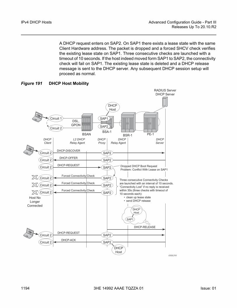
IPv4 DHCP Hosts
1194
Advanced Configuration Guide - Part IIIReleases Up To 20.10.R2
3HE 14992 AAAE TQZZA 01 Issue: 01
A DHCP request enters on SAP2. On SAP1 there exists a lease state with the same Client Hardware address. The packet is dropped and a forced SHCV check verifies the existing lease state on SAP1. Three consecutive checks are launched with a timeout of 10 seconds. If the host indeed moved form SAP1 to SAP2, the connectivity check will fail on SAP1. The existing lease state is deleted and a DHCP release message is sent to the DHCP server. Any subsequent DHCP session setup will proceed as normal.
Figure 191 DHCP Host MobilityRADIUS ServerDHCP Server
BSR-1DHCPClient
L2 DHCPRelay Agent
DHCPRelay Agent
DHCPServer
DHCPProxy
BSA-1
DHCP-DISCOVER
DHCP-OFFER
BSAN
Host NoLonger
Connected
PE-1
DSL,GPON
OSSG393
Forced Connectivity Check
Forced Connectivity Check
Forced Connectivity Check
DHCP-REQUEST
DHCP-RELEASE
Dropped DHCP Boot RequestProblem: Conflict With Lease on SAP1
Three consecutive Connectivity Checksare launched with an interval of 10 seconds.“Connectivity Lost” if no reply is receivedwithin 30s (three checks with timeout of10 seconds each): • clean up lease state • send DHCP release
SAP1
SAP2
SAP2
DHCP-REQUEST
DHCP-ACKSAP2
SAP2
SAP2
SAP2
SAP2
SAP2
Circuit 1
Circuit 2
Circuit 2
Circuit 2
Circuit 2 SAP2
Circuit 2
Circuit 2
Circuit 2
Circuit 2
Circuit 2
DHCPHost
DHCPHost
SAP1
DHCPHost

Advanced Configuration Guide - Part III Releases Up To 20.10.R2
IPv4 DHCP Hosts
Issue: 01 3HE 14992 AAAE TQZZA 01 1195
Note that for host mobility to function, host-connectivity-verification must be enabled. Next to periodic connectivity checks, it also enables forced checks triggered by moving hosts.
For Bridged CO, host-connectivity-verify must be enabled on the SAPs. When no interval is specified, it will default to 10 minutes for the periodic connectivity checks.
# Brigded COconfigure
servicevpls 1
sap 1/1/3:1host-connectivity-verify source-ip 10.1.0.253
exitsap 1/1/3:2
host-connectivity-verify source-ip 10.1.0.253exit
exitexit
exit
The configured source-ip should be an unused unique ip address in the DHCP client subnet or alternatively use source-ip 0.0.0.0. As the host-connectivity-verify application is sending a unicast ARP to the DHCP host, its ARP table is updated with the configured source-ip and source-mac (chassis MAC if not configured). If you would use an existing IP address, the DHCP host ARP table gets poisoned, breaking the connectivity to that host.
For Routed CO, host-connectivity-verify must be enabled on the group-interface. When no interval is specified, it will default to 10 minutes for the periodic connectivity checks.
# Routed COconfigure
servicevprn 1 customer 1 create
subscriber-interface "sub-int-1" creategroup-interface "group-int-1" create
host-connectivity-verifyexit
exitexit
exitexit
The source IP address is not configurable. The source-ip used in the unicast ARP is fixed to the local subscriber interface address in the subnet of the DHCP hosts that is checked for connectivity.

IPv4 DHCP Hosts
1196
Advanced Configuration Guide - Part IIIReleases Up To 20.10.R2
3HE 14992 AAAE TQZZA 01 Issue: 01
Conclusion
This chapter provides configuration and troubleshooting commands for dynamic DHCP hosts. DHCP hosts can be instantiated in a Layer 2 bridged CO (VPLS) environment as well as in a Layer 3 Routed CO (IES/VPRN subscriber interface) context.

Advanced Configuration Guide - Part III Releases Up To 20.10.R2
L2TP for Subscriber Access — LAC
Issue: 01 3HE 14992 AAAE TQZZA 01 1197
L2TP for Subscriber Access — LACThis chapter provides information about L2TP for subscriber access.
Topics in this chapter include:
• Applicability• Overview• Configuration• Conclusion
Applicability
This chapter describes L2TP Access Concentrator (LAC) support for the L2TP Access Aggregation (LAA) architecture model and was initially written for SR OS release 11.0.R4. The CLI in the current edition is based on release 16.0.R7. PPP hosts are supported in a Routed CO model (with IES or VPRN services) using ATM, Ethernet or Ethernet over Pseudowire SAPs. A description of the L2TP Tunnel Switch (LTS) and L2TP Network Server (LNS) functions are out of the scope of this chapter.
Overview
PPP Access Architectures
The Broadband Forum proposes two architectures for Point-to-Point Protocol (PPP) access.
• The PPP Terminated Aggregation architecture (PTA) • The L2TP Access Aggregation architecture (LAA)
The PTA architecture (local-access model) uses the Broadband Network Gateway (BNG) to terminate user PPP sessions (see scenario PPPoE-5 in Figure 192).
The LAA architecture (which is a tunneled access model) uses a LAC and an LNS to transport PPP sessions from the LAC to the LNS which performs tunnel termination (see scenario PPPoE-1 and PPPoE -2 in Figure 192).

L2TP for Subscriber Access — LAC
1198
Advanced Configuration Guide - Part IIIReleases Up To 20.10.R2
3HE 14992 AAAE TQZZA 01 Issue: 01
Optionally, an LTS can be used in the transport network to perform the grooming of traffic between tunnels (see scenarios PPPoE-3 and PPPoE-4 in Figure 192).
The LNS is the logical termination point of the PPP sessions originated by the remote clients and tunneled by the LAC/LTS.
Figure 192 PPP Access Architectures
L2TP Tunnels - LAC and LNS Reachability Options
The router instance where the L2TP tunnel starts and where ESM is handled can be one and the same, but does not need to be the same. The LNS peer address can be reachable via IP, BGP/IGP shortcuts, over a spoke SDP (GRE/MPLS), RFC 4364 VPRNs (BGP/MPLS IP Virtual Private Networks), but cannot be an address belonging to a directly connected interface. See Figure 193.
al_0521
PPPoE-1PPPoE-2
PPPoE-3
PPPoE-4
PPPoE-5
BNG-1 BNG-3 BNG-4
L2TP Tunnel L2TP Tunnel
L2TP Tunnel
BNG-2
ESM
ESM
ESM
ESMESM
LTS FunctionL2TP Tunnel
LAC Function
PTA Function
LNS Function

Advanced Configuration Guide - Part III Releases Up To 20.10.R2
L2TP for Subscriber Access — LAC
Issue: 01 3HE 14992 AAAE TQZZA 01 1199
Figure 193 Supported LT2P Reachability Options
Recap of the L2TPv2 Protocol
L2TPv2 is a client-server protocol relying on UDP and encapsulates Layer 2 packets such as PPP for transmission across a network. L2TPv2 passes control and data messages over separate control and data channels, thus defines following message types:
• Control messages—The in-band control channel passes sequenced control messages, supporting connection management, call management, error reporting, and session control. Optionally, a shared-secret challenge authentication method can be used between the tunnel endpoints. The following messages are used for L2TP tunnel management:
al_0519
LNSLAC
PPPoE ESMIES/VPN
ESMIES/VPN
L2TPBase
L2TPBase
nw port
LAC L2TP over IPLAC L2TP over BGP/IGP shortcuts
nw port
LNSLAC
PPPoE ESMIES/VPN
ESMIES/VPN
L2TPVPN
L2TPVPN
VRF SAP
LAC in VRF
VRF SAPIES SAP
LNSLAC
PPPoE ESMIES/VPN
ESMIES/VPN
L2TPIES/VPN
L2TPIES/VPN
Spoke-sdp Spoke-sdp
LNSLAC
PPPoE ESMIES/VPN
ESMIES/VPN
L2TPVPN
L2TPVPN
nw portvpn-ipv4
L2TP over VPN RFC4364
nw port
LAC L2TP GRE/MPLS

L2TP for Subscriber Access — LAC
1200
Advanced Configuration Guide - Part IIIReleases Up To 20.10.R2
3HE 14992 AAAE TQZZA 01 Issue: 01
- Tunnel setup (Control Connection Management)• Start-Control-Connection-Request (SCCRQ)• Start-Control-Connection-Reply (SCCRP)• Start-Control-Connection-Connected (SCCCN)• Stop-Control-Connection-Notification (StopCCN)
- Tunnel keepalive• Hello (HELLO)
The following messages are used for L2TP session (call) management:- Session setup over an existing tunnel
• Incoming-Call-Request (ICRQ)• Incoming-Call-Reply (ICRP)• Incoming-Call-Connected (ICCN)• Call-Disconnect-Notify (CDN)
Zero-Length Body (ZLB) messages are control packets with an L2TP header only and are used to explicitly acknowledge packets, making the control channel reliable.L2TP message encoding is done through Attribute Value Pairs (AVP).
• Data messages — Data messages encapsulate the PPP frames that are sent into the L2TP tunnel.
L2TPv2 sessions run over an L2TP tunnel and are referenced by an L2TP session-id. An L2TP tunnel can carry none, one, or multiple L2TP sessions. An L2TP session corresponds to a PPPoE session. L2TPv3 for LAC-LNS dynamic tunnel setup is not supported.

Advanced Configuration Guide - Part III Releases Up To 20.10.R2
L2TP for Subscriber Access — LAC
Issue: 01 3HE 14992 AAAE TQZZA 01 1201
L2TP Header and AVP Layout
The L2TPv2 header consists of following fields (RFC 2611, URN Namespace Definition Mechanisms):
al_0513A
T
0 8 16 31
L – S – O P – Version Length
Session-ID
Nr
Offset Pad
Tunnel-ID
Ns
Offset Size
Table 37 L2TPv2 Header Fields And Descriptions
Field Description
T Type of L2TP message (1 bit): 0—data message 1—control message
L Indicates if the optional Length field is present in the message (1 bit): 0—the field is left out of the message entirely 1—the field is included (must be included in control messages)
- Reserved for future use, must be set to zero.
S Indicates if the Ns and Nr fields are present (1 bit): 0 — the fields are left out of the message; entirely 1 — the fields are included (must be included in control messages)
O Indicates if the Offset field is present (1 bit): 0 — the field is left out of the message entirely (must be left out of control messages); 1 — the field is included
P Used with data messages only. Indicates priority of the data message (1 bit): 0 — no (this value is used for all control messages); 1 — yes
Version The version of the message (4 bits): 2 — this is the latest version of the L2TP data message header; 1 — indicates an L2F packet as described in RFC 2341 Packets with an unknown version number are discarded.
Length The total length (in bytes) of the L2TP message (16 bits).
Tunnel-ID Identifies the L2TP tunnel (that is, the control connection).This number has local significance — each end gives the same tunnel different tunnel IDs. The ID refers to the receiver, not the sender, and is assigned during tunnel creation (16 bits).
Session-ID Identifies the PPP session within a tunnel. This number has local significance — each end gives the same session different session IDs. The ID refers to the receiver, not the sender, and is assigned during session creation (16 bits).

L2TP for Subscriber Access — LAC
1202
Advanced Configuration Guide - Part IIIReleases Up To 20.10.R2
3HE 14992 AAAE TQZZA 01 Issue: 01
The AVP header consists of following fields (RFC2611):
Ns The sequence number of the message. This is mandatory for control messages (to enable re-transmission of lost messages) but optional for data messages (to re-order data messages that were mis-sequenced during forwarding). The number, which starts at 0 and increments by 1, is assigned by an L2TP peer for each session in a tunnel (16 bits).
Nr The sequence number of the next control message expected to be received. This is equal to the sequence number of last received control message plus 1. Used by the receiving peer to ensure that control messages are sent in order without duplication. In data messages, the field (if present as indicated by the S bit) is ignored (16 bits).
Offset Size The location of the L2TP payload, expressed as the number of octets from the start of the message header (16 bits).
Offset pad User-defined bytes used to pad the message header so that the payload starts at the location indicated by the Offset Size field (16 bits).
Table 37 L2TPv2 Header Fields And Descriptions (Continued)
Field Description (Continued)
al_0513B
0 6 16 31
M H – Length Vendor-ID
Attribute Type Attribute Value
Table 38 AVP Header Fields And Descriptions
Field Description
M Mandatory bit — If the M bit is set on an unrecognized AVP within a message associated with a particular session, the session associated with this message MUST be terminated (1 bit).
H Hidden bit — Identifies the hiding of data in the Attribute-Value field of an AVP. This capability can be used to avoid the passing of sensitive data, such as user passwords, as clear text in an AVP. The H-bit MUST only be set if a shared secret exists between the LAC and LNS. The shared secret is the same secret that is used for tunnel authentication. If the H-bit is set in any AVP(s) in a given control message, a Random Vector AVP must also be present in the message and MUST precede the first AVP having an H bit of 1 (1 bit).
- Reserved for future use, must be set to zero (4 bits).
Length Indicates the total number of bytes (including the overall length and bitmask fields) contained in this AVP (10 bits).
Vendor-id Any vendor wishing to implement their own L2TP extensions can use their own Vendor ID along with private Attribute values. Vendor-ID=0 means that the standard AVPs are used (2 bytes).

Advanced Configuration Guide - Part III Releases Up To 20.10.R2
L2TP for Subscriber Access — LAC
Issue: 01 3HE 14992 AAAE TQZZA 01 1203
RADIUS-Triggered Tunnel/Session Setup without LNS Renegotiation
Figure 194 depicts the complete PPP session setup, using RADIUS authentication on both LAC and LNS. After the discovery phase (PADI/PADO/PADR/PADS) and LCP negotiation phase (LCP config_request/Ack), the LAC initiates the L2TP tunnel setup based on RADIUS authentication information (RADIUS Request/Accept) and includes the negotiated PPP user-LAC information (called LCP proxy information). The LNS replies directly with a successful CHAP authentication if it agrees with the received proxy information. IP negotiation (IPCP config_request/Ack) is handled between the user and the LNS, and the LAC has no IP knowledge of this PPP session.
Attribute Type
A value with a unique interpretation across all AVPs defined under a given Vendor (2 bytes).
Attribute Value
This is the actual value as indicated by the Vendor ID and Attribute Type (2 bytes).
Table 38 AVP Header Fields And Descriptions (Continued)
Field Description (Continued)

L2TP for Subscriber Access — LAC
1204
Advanced Configuration Guide - Part IIIReleases Up To 20.10.R2
3HE 14992 AAAE TQZZA 01 Issue: 01
Figure 194 RADIUS Triggered Tunnel/Session Setup without LNS Renegotiation
RADIUS-Triggered Tunnel/Session Setup with LNS Renegotiation
Figure 195 shows the scenario where the LNS does not agree with the received LCP proxy information and (re)starts the LCP phase (LCP config_request/Ack) directly with the PPP user. The rest of this scenario is the same as shown in Figure 194.
al_0523
PPPoE User
PADI/PADQ/PADR/PADS
LCP Configuration Req/Ack
CHAP Challenge/Response
CHAP Authentication Successful
IPCP Configuration Req/Ack
PPP Keepalive
PPP Keepalive
L2TP HELLO
L2TP ICRQ/ICRP/ICCN/ZLB
L2TP SCCRQ/SCCRP/SCCCN/ZLB
L2TP HELLO
Data Over PPP Over L2TP
RequestAccept
Request
Accept
BSAN LAC
Network ProviderRADIUS Server
Service ProviderRADIUS Server
LNS
LAC Receives Tunnel Info DuringAuthentication (RADIUS or LUDB)
L2TP Tunnel Start IP on LAC
LAC Has No IP Knowledge from User
L2TP TunnelEnd IP on LNS
L2TP Tunnel KeepaliveBetween LAC and LNS
PPPoE KeepaliveBetween User-LNS
Create ESM User
ESMService
ESMService
Data Over PPPoE
L2TP Tunnel
Data Over IP
No User-LNS Renegotiation
Required. LNS Uses and AgreesOn All User-LACNegotiated Info.

Advanced Configuration Guide - Part III Releases Up To 20.10.R2
L2TP for Subscriber Access — LAC
Issue: 01 3HE 14992 AAAE TQZZA 01 1205
Figure 195 RADIUS Triggered Tunnel/Session Setup with LNS Renegotiation
Running Multiple PPP Sessions Over a Single L2TP Tunnel
Figure 196 shows multiple PPP sessions tunneled over a single L2TP Tunnel. The LAC encapsulates each PPP session with a different L2TP session-id (SID) but with the same L2TP Tunnel-id (TID).
al_0524
PPPoE User
PADI/PADQ/PADR/PADS
LCP Configuration Req/Ack
CHAP Challenge/Response
CHAP Authentication Successful
IPCP Configuration Req/Ack
LCP Configuration Req/Ack
CHAP Challenge/Response
PPP Keepalive
PPP KeepaliveL2TP HELLO
L2TP ICRQ/ICRP/ICCN/ZLB
L2TP SCCRQ/SCCRP/SCCCN/ZLB
L2TP HELLO
Data Over PPP Over L2TP
RequestAccept
Request
Accept
BSAN LAC
Network ProviderRADIUS Server
Service ProviderRADIUS Server
LNS
LAC receives tunnel info duringauthentication (RADIUS or LUDB)
L2TP tunnel start IP on LAC
LAC has no IP knowledge from user
L2TP tunnelend IP on LNS
L2TP tunnel Keepalivebetween LAC and LNS
PPPoE Keepalivebetween User-LNS
Create ESM User
ESMService
ESMService
Data Over PPPoE
L2TP Tunnel
Data Over IP
Yes User-LNS renegotiation
required. LNS does not agreeon all User-LACnegotiated info.

L2TP for Subscriber Access — LAC
1206
Advanced Configuration Guide - Part IIIReleases Up To 20.10.R2
3HE 14992 AAAE TQZZA 01 Issue: 01
Figure 196 Running Multiple PPP Sessions Over a Single L2TP Tunnel
PPP User-Initiated Release/Terminate
Figure 197 shows the user initiated terminate_request tunneled by the LAC followed by the user initiated PADT terminated on the LAC. The LAC informs the LNS about the termination of the session via the L2TP CDN message. The L2TP tunnel can be optionally (idle-timeout) terminated via the L2TP StopCCN message.
al_0522
User 1
PPPoE User 1 Setup
Data Over PPPoE User 1
PPPoE User 2 Setup
Data Over PPPoE User 2
PPPoE User 3 Setup
Data Over PPPoE User 3
Data Over PPPoE Data Over PPPoL2TP
L2TP Tunnel-id 1
Data
L2TP ICRQ/ICRP/ICCN
L2TP ICRQ/ICRP/ICCN
L2TP ICRQ/ICRP/ICCN
User 1 | SID-1 | TID-1
Tunnel-id 1 : TID-1
Session-id 1 : SID-1
Session-id 2 : SID-2
Session-id 3 : SID-3
User 2 | SID-2 | TID-1
User 3 | SID-3 | TID-1
L2TP SCCRQ/SCCRP/SCCCN
BSAN LAC LNS
User 2
User 3L2TP Tunnel Setup
L2TP Session Setup
1 LT2P tunnel hasmany L2TP sessions

Advanced Configuration Guide - Part III Releases Up To 20.10.R2
L2TP for Subscriber Access — LAC
Issue: 01 3HE 14992 AAAE TQZZA 01 1207
Figure 197 PPP User Initiated Release/Terminate
L2TP Tunnel/Session State Diagram
Figure 198 gives an overview of the main L2TP tunnel and session states. An L2TP tunnel in the establishedIdle state is a tunnel without sessions. A tools command (see Advanced Topics) can put an L2TP tunnel in a draining state (this prevents adding new sessions on tunnel but leaves the current sessions intact) or in a drained state (moved from draining to drained when all sessions terminated). The draining and drained state are not shown in the state diagram.
The L2TP tunnel setup occurs first with the triggers being: session activation, auto-establish, and a tools start command (see the Advanced Topics section). An L2TP session setup trigger is always session based.
al_0525
PPPoE User
PPPoE LCP Terminate Request
PPPoE LCP Terminate Request
PADT
L2TP CDN
L2TP StopCCNIdle-timeout (See Further)
PADT
BSAN LAC LNS
ESMService
ESMService
L2TP Tunnel

L2TP for Subscriber Access — LAC
1208
Advanced Configuration Guide - Part IIIReleases Up To 20.10.R2
3HE 14992 AAAE TQZZA 01 Issue: 01
Figure 198 L2TP Tunnel and Session State Diagram
Configuration
Scenario 1: RADIUS-Derived L2TP Parameters
In the first scenario, the LAC receives an incoming connection and contacts the LAC RADIUS server. The RADIUS server retrieves the attributes for the user's domain (for example @wholesale.com) and passes the tunnel attributes to the LAC. Based on these RADIUS provided tunnel attributes, the LAC selects or initiates a new tunnel to the LTS or directly to the LNS. Once the tunnel is established, the LNS authenticates the end user using its own RADIUS server. Configuring the LNS and the LTS are out of the scope of this example.
al_0515
LACTUNNEL
state-diagram
wait-reply
established idle
established idle
established
closed
closedByPeer
• session-trigger• auto-establish• tools command start
LNS
L2TP SCCRQ
L2TP SCCRP
L2TP ICRQ/ICRP/ICCN
L2TP CDN
L2TP stop CC
L2TP stop CC
L2TP SCCCN
Tunnel OKno session
Tunnel OKno session
LACSESSION
state-diagram
wait-reply
established
closed
closedByPeer
LNS
L2TP ICRQ
L2TP ICRP/ICCN
L2TP CDN
L2TP CDN
idle-timeout

Advanced Configuration Guide - Part III Releases Up To 20.10.R2
L2TP for Subscriber Access — LAC
Issue: 01 3HE 14992 AAAE TQZZA 01 1209
In a RADIUS driven L2TP setup, either all or some of the required L2TP attributes are returned via RADIUS. If the RADIUS server only returns the L2TP [67] Tunnel-Server-Endpoint attributes, then the L2TP tunnel/session is established using the ‘l2tp node parameter values’ for the other required L2TP parameters. The ‘l2tp node parameters’ are defined under the configure router/service l2tp hierarchy. If the RADIUS server does not return all of the L2TP attributes and the node values are not configured, then the system falls back to default settings for these L2TP parameters.
The standard and vendor specific [26-6572] L2TP RADIUS attributes are listed in the tables below, together with the corresponding l2tp node parameters and defaults.
Table 39 Generic L2TP RADIUS Attributes
AttributeID
Attribute Name Mandatory CLI Node Parameter
Corresponding Defaults
64 Tunnel-Type Y - - -
65 Tunnel-Medium-Type Y - - -
66 Tunnel-Client-Endpoint:[0-31]
N local-address no local-address
system-ip
67 Tunnel-Server-Endpoint N - - -
69 Tunnel-Password N password no password -
82 Tunnel-Assignment-ID:0
N - - default_radius_group
82 Tunnel-Assignment-ID:[1..31]
N - - Unnamed
83 Tunnel-Preference N preference no preference
50
90 Tunnel-Client-Auth-ID N local-name no local-name
system-name
91 Tunnel-Server-Auth-ID N - - -
Table 40 Nokia Specific L2TP RADIUS Attributes
26-6527 Attribute Name Mandatory CLI Node Parameter
Corresponding Defaults
-46 Alc-Tunnel-Group N - - -

L2TP for Subscriber Access — LAC
1210
Advanced Configuration Guide - Part IIIReleases Up To 20.10.R2
3HE 14992 AAAE TQZZA 01 Issue: 01
Base Router Hosted LAC with Single Endpoint/Single Tunnel
Using the mandatory L2TP RADIUS attributes (see the following RADIUS user file) the LAC initiates an L2TP tunnel. The source address for the tunnel is the IPv4 address of a loopback interface in the Base router system (LAC tunnel endpoint).The destination for the tunnel is defined by the Tunnel-Server-Endpoint RADIUS attribute [67], and is also known as the peer tunnel LNS endpoint address.
-47 Alc-Tunnel-Algorithm N session-assign-method
no session-assign-method
existingFirst
-48 Alc-Tunnel-Max-Sessions:0
N - group-session-limit
131071
-48 Alc-Tunnel-Max-Sessions:[1..31]
N - tunnel-session-limit
32767
-49 Alc-Tunnel-Idle-Timeout N idle-timeout no idle-timeout
Infinite
-50 Alc-Tunnel-Hello-Interval
N hello-interval no hello-interval
300 sec
-51 Alc-Tunnel-Destruct-Timeout
N destruct-timeout
no destruct-timeout
60 sec
-52 Alc-Tunnel-Max-Retries-Estab
N max-retries-estab
no max-retries-estab
5
-53 Alc-Tunnel-Max-Retries-Not-Estab
N max-retries-not-estab
no max-retries-not-estab
5
-54 Alc-Tunnel-AVP-Hiding N avp-hiding no avp-hiding Never
-97 Alc-Tunnel-Challenge N challenge no challenge Never
-104 Alc-Tunnel-Serv-Id N - - Base
-120 Alc-Tunnel-Rx-Window-Size
N receive-window-size
no receive-window-size
64
-144 Alc-Tunnel-Acct-Policy N radius-accounting-policy
no radius-accounting-policy
-
Table 40 Nokia Specific L2TP RADIUS Attributes (Continued)
26-6527 Attribute Name Mandatory CLI Node Parameter
Corresponding Defaults

Advanced Configuration Guide - Part III Releases Up To 20.10.R2
L2TP for Subscriber Access — LAC
Issue: 01 3HE 14992 AAAE TQZZA 01 1211
Figure 199 Base Router Hosted LAC with Single Endpoint/Single Tunnel
The PPPoE user terminates on IES service 1, sap 1/1/3:100, and is authenticated via RADIUS authentication-policy authentication-1 which provides wholesale/retail (L2TP) information.
configureservice
ies 1 customer 1 createsubscriber-interface "sub-l2tp" create
unnumbered "system"group-interface "grp-l2tp" create
authentication-policy "radius-1"sap 1/1/3:100 create
sub-sla-mgmtsub-ident-policy "all-subscribers"multi-sub-sap 1000no shutdown
exitexitpppoe
sap-session-limit 10no shutdown
exitexit
exitno shutdown
exitexit
exit
The excerpt from the FreeRADIUS users file below shows the attributes to be returned.
[email protected] Cleartext-Password := "letmein", NAS-Identifier == "LAC"
al_0516
LNS
Use Case A
LAC
AAA
L2TP ESMIES 1
192.168.22.1
AAA returns single LNS endpoint.
PPPoE
L2TP192.168.22.2
L2TPBase
Loopback IP

L2TP for Subscriber Access — LAC
1212
Advanced Configuration Guide - Part IIIReleases Up To 20.10.R2
3HE 14992 AAAE TQZZA 01 Issue: 01
Alc-Subsc-ID-Str = "%{User-name}",Alc-Subsc-Prof-Str = "sub-profile-1",Alc-SLA-Prof-Str = "sla-profile-1",Tunnel-Type:1 += L2TP,Tunnel-Medium-Type:1 +=IP,Tunnel-Server-Endpoint:1 += 192.168.22.2,
L2TP is enabled (no shutdown) in the related service instance.
The L2TP tunnel is set up in the base instance and not in a VRF because the attribute Alc-Tunnel-Serv-Id is not returned from RADIUS.
Missing L2TP parameters are taken from defaults defined in the router l2tp context.
configure router l2tpcalling-number-format "%S %s" # L2TP AVP 22 format
# Default format ‘system-name sap-id’---snipped---no local-name # default name equals system-nameno max-retries-estab # default value equals 5---snipped---no shutdown # enable L2TP
This scenario shows the PPPoE session termination (base IES service 1) and the L2TP tunnel setup in the base router instance.
Base Router Hosted LAC with Multiple Endpoints
Figure 200 Base Router Hosted LAC with Multiple Endpoints
al_0516B
LNSUse Case B
LAC
AAA
L2TP ESM
LNS1 192.168.22.2
IES 1
192.168.22.1
AAA returns multiple LNS endpoints.LAC selects one of them.
PPPoE
L2TP192.168.22.2
L2TPBase
Loopback IP
LNS4 192.168.22.5
LNS3 192.168.22.4
LNS2 192.168.22.3

Advanced Configuration Guide - Part III Releases Up To 20.10.R2
L2TP for Subscriber Access — LAC
Issue: 01 3HE 14992 AAAE TQZZA 01 1213
The following excerpt from the FreeRADIUS users file shows that user [email protected] has 4 possible endpoints (LNS), each with its own tunnel preference. The LAC selects one L2TP endpoint out of these 4 tunnel specifications according to the configured L2TP selection process. This use case uses weighted load balancing between RADIUS-tunnel-1 and RADIUS-tunnel-2. The L2TP tunnel selection process is out of the scope of this chapter.
[email protected] Cleartext-Password := "letmein", NAS-Identifier == "LAC"Alc-Subsc-ID-Str = "%{User-name}",Alc-Subsc-Prof-Str = "sub-profile-1",Alc-SLA-Prof-Str = "sla-profile-1",
# group related infoTunnel-Client-Endpoint:0 = 192.168.22.1,Alc-Tunnel-Algorithm:0 = weighted-access,Tunnel-Client-Auth-Id:0 = "lac-pe1",Tunnel-Assignment-Id:0 = "RADIUS-group",Alc-Tunnel-Max-Retries-Estab:0 = 2,
# tunnel-1 related infoTunnel-Type:1 += L2TP,Tunnel-Medium-Type:1 +=IP,Tunnel-Server-Endpoint:1 += 192.168.22.2,Tunnel-Assignment-Id:1 += "RADIUS-tunnel-1",Tunnel-Preference:1 += 100,
# tunnel-2 related infoTunnel-Type:2 += L2TP,Tunnel-Medium-Type:2 +=IP,Tunnel-Server-Endpoint:2 += 192.168.22.3,Tunnel-Assignment-Id:2 += "RADIUS-tunnel-2",Tunnel-Preference:2 += 80,
# tunnel-3 related infoTunnel-Type:3 += L2TP,Tunnel-Medium-Type:3 +=IP,Tunnel-Server-Endpoint:3 += 192.168.22.4,Tunnel-Assignment-Id:3 += "RADIUS-tunnel-3",
--- snipped ---
This scenario shows the PPPoE session termination (base IES service 1) and the L2TP tunnel setup in the base router instance.
VRF Hosted LAC
Figure 201 shows the PPPoE session termination (base IES service 1) and the L2TP tunnel setup in a different router instance (VPRN 65536).

L2TP for Subscriber Access — LAC
1214
Advanced Configuration Guide - Part IIIReleases Up To 20.10.R2
3HE 14992 AAAE TQZZA 01 Issue: 01
Figure 201 VRF Hosted LAC
Using the following L2TP RADIUS attributes, the LAC initiates an L2TP tunnel in VPRN 65536. The PPPoE session is still handled by IES service 1, which proves that both router instances can be different. (See use-case A for configuration details of IES service 1).
[email protected] Cleartext-Password := "letmein", NAS-Identifier == "LAC"Alc-Subsc-ID-Str = "%{User-name}",Alc-Subsc-Prof-Str = "sub-profile-1",Alc-SLA-Prof-Str = "sla-profile-1",Alc-Tunnel-Serv-Id = 65536,Tunnel-Client-Auth-Id:0 = "lac-pe1",Tunnel-Assignment-Id:0 = "RADIUS-returned-TG",Tunnel-Type:1 += L2TP,Tunnel-Medium-Type:1 +=IP,Tunnel-Server-Endpoint:1 += 192.168.33.2,Tunnel-Assignment-Id:1 += "RADIUS-returned-TN",
If RADIUS does not return the L2TP source IP address (Tunnel-Client-Endpoint), then the IP address from the VPRN 65536 interface named ‘system’ is used as the L2TP source address. The tunnel setup fails if this system interface does not exist.
configureservice
vprn 65536interface "system" create
address 192.168.33.1/32loopback
exitl2tp
no shutdownexit
al_0517C
LNS
Use Case C
LAC
AAA
ESMIES 1
192.168.33.1
AAA returns single Tunnel-Server-Endpoint.Radius does not return Tunnel-Client-Endpoint.
PPPoE
L2TP192.168.33.2
VPN65536
VPN65536
VPN Loopback IP

Advanced Configuration Guide - Part III Releases Up To 20.10.R2
L2TP for Subscriber Access — LAC
Issue: 01 3HE 14992 AAAE TQZZA 01 1215
Scenario 2: Node-Derived L2TP Parameters
In the second scenario, the LAC receives the incoming connection and an ‘L2TP tunnel-group-name’ is assigned during LUDB or RADIUS authentication. This tunnel-group-name refers to the CLI preconfigured tunnel-group name context (configure router <router-name> l2tp group <tunnel-group-name>), which provides the context for all relevant tunnel attributes.
Based on these attributes, the LAC selects and initiates a tunnel to the LTS or directly to the LNS as in Scenario 1: RADIUS-Derived L2TP Parameters.
RADIUS Returns L2TP Tunnel Group
In use case D, the L2TP tunnel-group-name is assigned during RADIUS authentication.
Figure 202 RADIUS Returns L2TP Tunnel Group
[email protected] Cleartext-Password := "letmein", NAS-Identifier == "LAC"Alc-Subsc-ID-Str = "%{User-name}",Alc-Subsc-Prof-Str = "sub-profile-1",Alc-SLA-Prof-Str = "sla-profile-1",Alc-Tunnel-Serv-Id = 65536,Alc-Tunnel-Group = "wholesale.com",
al_0517D
LNS
Use Case D
LAC
AAA
ESMIES 1
192.168.33.1
AAA returns: Alc-Tunnel-Serv-IdAlc-Tunnel-Group
PPPoE
L2TP192.168.33.2
VPN65536
VPN65536

L2TP for Subscriber Access — LAC
1216
Advanced Configuration Guide - Part IIIReleases Up To 20.10.R2
3HE 14992 AAAE TQZZA 01 Issue: 01
The L2TP tunnel is initiated from VPRN 65536 (Alc-Tunnel-Serv-Id) and all L2TP tunnel information is taken from the l2tp group wholesale.com hierarchy (Alc-Tunnel-Group) as defined on the node.
configureservice
vprn 65536--- snipped ---interface "system" create
address 192.168.33.1/32loopback
exitl2tp
group "wholesale.com" createtunnel "wholesale.com" create
local-address 192.168.33.1local-name "lac-pe1"peer 192.168.33.2no auto-establishno shutdown
exitno shutdown
exitno shutdown
exitno shutdown
exitexit
exit
An L2TP tunnel is set up by either a PPP session-trigger, a tools command or by the l2tp group tunnel auto-establish parameter configuration. See the Advanced Topics section for the non-session-triggered tunnel setup.
LUDB Returns L2TP Tunnel Group
In use case E, the L2TP tunnel-group-name is assigned during LUDB authentication, so this essentially is a RADIUS-less scenario.

Advanced Configuration Guide - Part III Releases Up To 20.10.R2
L2TP for Subscriber Access — LAC
Issue: 01 3HE 14992 AAAE TQZZA 01 1217
Figure 203 LUDB Returns L2TP Tunnel Group
The PPPoE user enters on an IES service 1, sap 1/1/3:100, and is authenticated via the LUDB which provides L2TP wholesale/retail and ESM information. The PPPoE context refers to a local-user database l2tp to provide the subscriber authentication and the tunnel setup parameters, so no RADIUS is needed.
configureservice
ies 1 customer 1 createsubscriber-interface "sub-l2tp" create
unnumbered "system"group-interface "grp-l2tp" create
sap 1/1/3:100 createsub-sla-mgmt
sub-ident-policy "all-subscribers"multi-sub-sap 1000no shutdown
exitexitpppoe
sap-session-limit 10user-db "l2tp"no shutdown
exitexit
exitno shutdown
exitexit
exit
al_0518
LNS
Use Case E
LAC
AAA
ESMIES 1
192.168.2.2
PPPoE
L2TP192.168.2.6
L2TPBase L2TP
LUDB returns: Alc-Tunnel-Serv-IdAlc-Tunnel-Group

L2TP for Subscriber Access — LAC
1218
Advanced Configuration Guide - Part IIIReleases Up To 20.10.R2
3HE 14992 AAAE TQZZA 01 Issue: 01
The referenced local user database l2tp configuration provides all of the required L2TP and ESM information.
configuresubscriber-mgmt
local-user-db "l2tp" createppp
match-list usernamehost "wholesale.com" create
host-identificationusername "wholesale.com" domain-only
exitpassword ignoreidentification-strings 254 create
subscriber-id "[email protected]"sla-profile-string "sla-profile-1"sub-profile-string "sub-profile-1"
exitl2tp
group "wholesale.com" service-id 65536exitno shutdown
exitexitno shutdown
exitexit
exit
Operation and Troubleshooting
The subsequent sections explain how the use cases A to E described in the configuration section are verified using show, debug, and tools commands.
The standard router debugging tools can be used to monitor and troubleshoot the L2TP tunnel and session setup.
Useful show commands are:
show service id <service-id> ppp session [detail]show router l2tp tunnel [detail]show router l2tp session [detail]show router l2tp peer [ip-address]
To debug and show PPPoE packets:
debug service id <service-id> ppp packet mode egr-ingr-and-droppeddebug service id <service-id> ppp packet detail-level medium
To debug and show RADIUS authentication:

Advanced Configuration Guide - Part III Releases Up To 20.10.R2
L2TP for Subscriber Access — LAC
Issue: 01 3HE 14992 AAAE TQZZA 01 1219
debug router radius packet-type authentication
To debug and show LUDB authentication:
debug subscriber-mgmt local-user-db <local-user-db-name> detail all
To debug and show the LAC tunnel selection process and L2TP state machine:
debug router l2tp event lac-session-setupdebug router l2tp event finite-state-machine
To debug and show the L2TP tunnel and session setup:
debug router l2tp packet direction bothdebug router l2tp packet detail-level high
Understanding the L2TP Debug Output
The following L2TP ICRQ message (debug router l2tp packet) is used to explain how the displayed debug output should be interpreted. See Recap of the L2TPv2 Protocol -L2TP Header and AVP Layout for more details.
19 2019/05/21 14:02:10.811 CEST MINOR: DEBUG #2001 Base L2TP(v2, ctrl, egress)"L2TP(v2, ctrl, egress): UDP 192.0.2.1:1701 -> 192.168.22.2:1701tunnel 13008 session 0, ns 2 nr 1, flags:, reserved=0
AVP MessageType(0,0), flags: mandatory, reserved=0IncomingCallRequest(10)
AVP AssignedSessionId(0,14), flags: mandatory, reserved=026540
AVP CallSerialNumber(0,15), flags: mandatory, reserved=025216
AVP CallingNumber(0,22), flags: mandatory, reserved=0"LAC 1/1/3:100"
AVP AgentCircuitId(3561,1), flags:, reserved=0"circuit0"
AVP AgentRemoteId(3561,2), flags:, reserved=0"remote0"
AVP ActDataRateUp(3561,129), flags:, reserved=02000000
AVP ActDataRateDown(3561,130), flags:, reserved=04000000"
• L2TP(v2, ctrl, egress): UDP 192.0.2.1:1701 -> 192.168.22.2:1701- version: v2 - type field (T-bit): control message (ctrl)- 192.0.2.1:1701 -> 192.168.22.2:1701
• 192.0.2.1:1701 - source tunnel-end-point:source udp port

L2TP for Subscriber Access — LAC
1220
Advanced Configuration Guide - Part IIIReleases Up To 20.10.R2
3HE 14992 AAAE TQZZA 01 Issue: 01
• 192.168.22.2:1701 - destination tunnel-end-point:destination udp port • tunnel 13008 session 0, ns 2 nr 1, flags:, reserved=0
- tunnel-id: 13008- session-id: 0- ns:2- nr:1- flags: 0 (refers to T/L/S/O/P bits L2TP header)- reserved field:0
• AVP CallingNumber(0,22), flags: mandatory, reserved=0 - AVP MessageType(0,22): "LAC 1/1/3:100"
• Vendor-id: 0 - Standard Attribute• Attribute Type: 22 – Calling Number AVP• Attribute Value: "LAC 1/1/3:100"
Scenario 1: RADIUS-Derived L2TP Parameters
Base Router Hosted LAC with Single Endpoint/Single Tunnel
The debug service id <service-id> ppp packet mode egr-ingr-and-dropped command shows the PPPoE packet exchange. The following PADI packet shows the service, SAP, and received PPPoE tags. The received PPPoE DSL forum tags are by default copied during the LAC L2TP tunnel setup into the Incoming Call Request (ICRQ) DSL Forum AVP’s (RFC 5515).
1 2019/05/21 14:02:10.779 CEST MINOR: DEBUG #2001 Base PPPoE"PPPoE: RX Packet
IES 1, SAP 1/1/3:100
DMAC: ff:ff:ff:ff:ff:ffSMAC: 00:00:00:00:01:01Ether Type: 0x8863 (Discovery)
PPPoE Header:Version: 1 Type : 1Code : 0x09 (PADI) Session-Id: 0x0000 (0)Length : 48
PPPoE Tags:[0x0101] Service-Name: ""[0x0103] Host-Uniq: len = 1, value = 31[0x0105] Vendor-Specific: vendor-id = 0x0de9 (ADSL Forum)
[0x01] Agent-Circuit-Id: "circuit0"

Advanced Configuration Guide - Part III Releases Up To 20.10.R2
L2TP for Subscriber Access — LAC
Issue: 01 3HE 14992 AAAE TQZZA 01 1221
[0x02] Agent-Remote-Id: "remote0"[0x81] Actual-Upstream: 2000[0x82] Actual-Downstream: 4000
"
The debug router radius packet-type authentication command shows the actual authentication parameters returned by RADIUS. This example returns the minimum set of L2TP related RADIUS attributes.
12 2019/05/21 14:02:10.806 CEST MINOR: DEBUG #2001 Base RADIUS"RADIUS: Receive
Access-Accept(2) id 16 len 89 from 172.16.1.11:1812 vrid 1 pol rsp-radius-1VSA [26] 15 Nokia(6527)
SUBSC PROF STR [12] 13 sub-profile-1VSA [26] 15 Nokia(6527)
SLA PROF STR [13] 13 sla-profile-1TUNNEL TYPE [64] 4 1 L2TP(3)TUNNEL MEDIUM TYPE [65] 4 1 IPv4(1)TUNNEL SERVER ENDPOINT [67] 13 1 192.168.22.2
"
The debug router l2tp event lac-session-setup command shows the LAC tunnel selection for this example. An L2TP group-name ‘default_radius_group’ with tunnel-name ‘unnamed’ is created in this case, because RADIUS did not return an explicit group and tunnel name.
13 2019/05/21 14:02:10.808 CEST MINOR: DEBUG #2001 Base PPPoE 13->L2TP"PPPoE 13->L2TP: UDP 192.0.2.1:1701 -> 192.168.22.2:1701preference 50 tunnel default_radius_group:unnamed
request to open new tunnel 1640"
14 2019/05/21 14:02:10.808 CEST MINOR: DEBUG #2001 Base PPPoE 13->L2TP"PPPoE 13->L2TP: UDP 192.0.2.1:1701 -> 192.168.22.2:1701preference 50 tunnel default_radius_group:unnamed
create session 107505580"
The debug router l2tp packet detail-level command shows the L2TP tunnel and session setup for this example.
For the tunnel setup, the LAC sends a Start-Control-Connection-Request (SCCRQ) containing the assigned tunnel-id (no tunnel authentication in the example). The tunnel is now in a wait-reply state.
15 2019/05/21 14:02:10.808 CEST MINOR: DEBUG #2001 Base L2TP(v2, ctrl, egress)"L2TP(v2, ctrl, egress): UDP 192.0.2.1:1701 -> 192.168.22.2:1701tunnel 0 session 0, ns 0 nr 0, flags:, reserved=0
AVP MessageType(0,0), flags: mandatory, reserved=0StartControlConnectionRequest(1)
AVP ProtocolVersion(0,2), flags: mandatory, reserved=0version=1, revision=0
AVP HostName(0,7), flags: mandatory, reserved=0"lac-pe1"
AVP WindowSize(0,10), flags: mandatory, reserved=0

L2TP for Subscriber Access — LAC
1222
Advanced Configuration Guide - Part IIIReleases Up To 20.10.R2
3HE 14992 AAAE TQZZA 01 Issue: 01
64AVP FramingCapabilities(0,3), flags: mandatory, reserved=0
sync=no, async=noAVP BearerCapabilities(0,4), flags: mandatory, reserved=0
digital=yes, analogue=noAVP FirmwareRevision(0,6), flags:, reserved=0
4869AVP VendorName(0,8), flags:, reserved=0
"Nokia"AVP AssignedTunnelId(0,9), flags: mandatory, reserved=0
1640"
The LNS can bring up the tunnel, so the LNS replies with a Start-Control-Connection-Reply (SCCRP) including the assigned tunnel-id.
16 2019/05/21 14:02:10.809 CEST MINOR: DEBUG #2001 Base L2TP(v2, ctrl, ingress)"L2TP(v2, ctrl, ingress): UDP 192.168.22.2:1701 -> 192.0.2.1:1701tunnel 1640 session 0, ns 0 nr 1, flags:, reserved=0
AVP MessageType(0,0), flags: mandatory, reserved=0StartControlConnectionReply(2)
AVP ProtocolVersion(0,2), flags: mandatory, reserved=0version=1, revision=0
AVP HostName(0,7), flags: mandatory, reserved=0"lns-pe2"
AVP WindowSize(0,10), flags: mandatory, reserved=064
AVP FramingCapabilities(0,3), flags: mandatory, reserved=0sync=no, async=no
AVP BearerCapabilities(0,4), flags: mandatory, reserved=0digital=yes, analogue=no
AVP FirmwareRevision(0,6), flags:, reserved=04869
AVP VendorName(0,8), flags:, reserved=0"Nokia"
AVP AssignedTunnelId(0,9), flags: mandatory, reserved=013008"
As the last step in the tunnel setup phase, the LAC responds with a Start-Control-Connection-Connected (SCCCN) message. After an LNS ZLB acknowledgment, the tunnel is in the establishedIdle state.
17 2019/05/21 14:02:10.810 CEST MINOR: DEBUG #2001 Base L2TP(v2, ctrl, egress)"L2TP(v2, ctrl, egress): UDP 192.0.2.1:1701 -> 192.168.22.2:1701tunnel 13008 session 0, ns 1 nr 1, flags:, reserved=0
AVP MessageType(0,0), flags: mandatory, reserved=0StartControlConnectionConnected(3)"
Once the tunnel exists the session setup starts, a three-way exchange for session establishment within the tunnel is performed. The LAC sends an Incoming-Call-Request (ICRQ) with the parameter information for the session. The session is now in the wait-reply state.
19 2019/05/21 14:02:10.811 CEST MINOR: DEBUG #2001 Base L2TP(v2, ctrl, egress)"L2TP(v2, ctrl, egress): UDP 192.0.2.1:1701 -> 192.168.22.2:1701tunnel 13008 session 0, ns 2 nr 1, flags:, reserved=0

Advanced Configuration Guide - Part III Releases Up To 20.10.R2
L2TP for Subscriber Access — LAC
Issue: 01 3HE 14992 AAAE TQZZA 01 1223
AVP MessageType(0,0), flags: mandatory, reserved=0IncomingCallRequest(10)
AVP AssignedSessionId(0,14), flags: mandatory, reserved=026540
AVP CallSerialNumber(0,15), flags: mandatory, reserved=025216
AVP CallingNumber(0,22), flags: mandatory, reserved=0"LAC 1/1/3:100"
AVP AgentCircuitId(3561,1), flags:, reserved=0"circuit0"
AVP AgentRemoteId(3561,2), flags:, reserved=0"remote0"
AVP ActDataRateUp(3561,129), flags:, reserved=02000000
AVP ActDataRateDown(3561,130), flags:, reserved=04000000"
The LNS then sends an Incoming-Call-Reply (ICRP) that contains the assigned session-id. The session is now in the connect state.
21 2019/05/21 14:02:10.813 CEST MINOR: DEBUG #2001 Base L2TP(v2, ctrl, ingress)"L2TP(v2, ctrl, ingress): UDP 192.168.22.2:1701 -> 192.0.2.1:1701tunnel 1640 session 26540, ns 1 nr 3, flags:, reserved=0
AVP MessageType(0,0), flags: mandatory, reserved=0IncomingCallReply(11)
AVP AssignedSessionId(0,14), flags: mandatory, reserved=02466"
Finally the LAC sends an Incoming Call Connected (ICCN) and provides the LNS with additional information from the user initiated session. This information includes the LCP information from the negotiation that the LAC and remote user performed. This information is used by the LNS to decide whether to start LCP re-negotiation and/or Authentication re-negotiation with the PPP user or not. After an LNS ZLB acknowledgment, the session is in the established state.
24 2019/05/21 14:02:10.814 CEST MINOR: DEBUG #2001 Base L2TP(v2, ctrl, egress)"L2TP(v2, ctrl, egress): UDP 192.0.2.1:1701 -> 192.168.22.2:1701tunnel 13008 session 2466, ns 3 nr 2, flags:, reserved=0
AVP MessageType(0,0), flags: mandatory, reserved=0IncomingCallConnected(12)
AVP FramingType(0,19), flags: mandatory, reserved=0sync=no, async=no
AVP TxConnectSpeed(0,24), flags: mandatory, reserved=04294967295
AVP InitialRxLcpConfReq(0,26), flags:, reserved=001 04 05 d4[1] MRU: 1492
AVP LastTxLcpConfReq(0,27), flags:, reserved=001 04 05 d4 03 05 c2 23 05 05 06 75 25 ad d3[1] MRU: 1492[3] Authentication-Protocol: 0xc223 (CHAP), Algorithm = 5 (MD5)[5] Magic-Number: 0x7525add3
AVP LastRxLcpConfReq(0,28), flags:, reserved=001 04 05 d4[1] MRU: 1492
AVP ProxyAuthenType(0,29), flags:, reserved=0

L2TP for Subscriber Access — LAC
1224
Advanced Configuration Guide - Part IIIReleases Up To 20.10.R2
3HE 14992 AAAE TQZZA 01 Issue: 01
chap(2)AVP ProxyAuthenName(0,30), flags:, reserved=0
"[email protected]"AVP ProxyAuthenChallenge(0,31), flags:, reserved=0
13 ba fc db 18 15 b5 21 03 c9 61 8d 8a 1b 43 00c3 4a 80 51 df 52 f4 06 26 c8 16 db ce 2b 7d 62e5 7a bd 7d 0f
AVP ProxyAuthenId(0,32), flags:, reserved=0id=1, reserved=0
AVP ProxyAuthenResponse(0,33), flags:, reserved=0da c4 40 35 e4 4b 3f 72 3f eb 84 7b 09 99 5d f7
AVP RxConnectSpeed(0,38), flags:, reserved=04294967295"
The operational PPPoE session information for the IES 1 (base router) instance is as follows.
*A:LAC# show service id 1 ppp session
===============================================================================PPP sessions for service 1===============================================================================User-Name
Descr.Up Time Type Termination IP/L2TP-Id/Interface-Id MC-Stdby
-------------------------------------------------------------------------------user1@wholesale.com
svc:1 sap:1/1/3:100 mac:00:00:00:00:01:01 sid:10d 00:10:01 oE lac 107505580
-------------------------------------------------------------------------------No. of PPP sessions: 1===============================================================================*A:LAC#
The operational tunnel information in the base instance shows that the tunnel is established.
*A:LAC# show router l2tp tunnel===============================================================================Conn ID Loc-Tu-ID Rem-Tu-ID State Blacklist-state Ses Active
Group Ses TotalAssignment
-------------------------------------------------------------------------------107479040 1640 13008 established not-blacklisted 1
default_radius_group 1unnamed
-------------------------------------------------------------------------------No. of tunnels: 1===============================================================================*A:LAC#
Detailed operational tunnel information is obtained using following command.
*A:LAC# show router l2tp tunnel tunnel-id 1640 detail
===============================================================================

Advanced Configuration Guide - Part III Releases Up To 20.10.R2
L2TP for Subscriber Access — LAC
Issue: 01 3HE 14992 AAAE TQZZA 01 1225
L2TP Tunnel 107479040===============================================================================
Connection ID: 107479040Protocol : v2State : establishedIP : 192.0.2.1UDP : 1701Peer IP : 192.168.22.2Peer UDP : 1701Tx dst-IP : 192.168.22.2Tx dst-UDP : 1701Rx src-IP : 192.168.22.2Rx src-UDP : 1701Name : lac-pe1Remote Name : lns-pe2Assignment ID: unnamedGroup Name : default_radius_groupAcct. Policy : N/AError Message: N/A
Remote Conn ID : 852492288Tunnel ID : 1640 Remote Tunnel ID : 13008Preference : 50 Receive Window : 64Hello Interval (s): 300 AVP Hiding : neverIdle TO (s) : infinite Destruct TO (s) : 60Max Retr Estab : 5 Max Retr Not Estab: 5Cfg'd Sess Limit : unlimited Oper Session Limit: 32767 'Transport Type : udpIp Challenge : neverTime Started : 05/21/2019 14:02:11 Time Idle : N/ATime Established : 05/21/2019 14:02:11 Time Closed : N/AStop CCN Result : noError General Error : noErrorBlacklist-state : not-blacklistedSet Dont Fragment : true
FailoverState : not-recoverableRecovery Conn ID : N/ARecovery state : not-applicableRecovered Conn ID : N/ARecovery method : mcsTrack SRRP : (Not specified)Ctrl msg behavior : handleRecovery time (ms)Requested : N/APeer : N/A--------------------------------------------------------------------------------------------------------------------------------------------------------------No. of tunnels: 1===============================================================================*A:LAC#
The operational L2TP session information shows the L2TP session is established.
*A:LAC# show router l2tp session
===============================================================================L2TP Session Summary

L2TP for Subscriber Access — LAC
1226
Advanced Configuration Guide - Part IIIReleases Up To 20.10.R2
3HE 14992 AAAE TQZZA 01 Issue: 01
===============================================================================ID Control Conn ID Tunnel-ID Session-ID State-------------------------------------------------------------------------------107505580 107479040 1640 26540 established-------------------------------------------------------------------------------No. of sessions: 1===============================================================================*A:LAC#
For detailed operational L2TP session information use the following command.
*A:LAC# show router l2tp session session-id 26540 detail
===============================================================================L2TP Session 107505580===============================================================================
Connection ID: 107505580State : establishedTunnel Group : default_radius_groupAssignment ID: unnamedError Message: N/A
Control Conn ID : 107479040 Rem Cntrl Conn ID : 852492288Tunnel ID : 1640 Remote Tunnel ID : 13008Session ID : 26540 Remote Session ID : 2466PW Type : ppp Remote Conn ID : 852494754Time Started : 05/21/2019 14:02:11Time Established : 05/21/2019 14:02:11 Time Closed : N/ACDN Result : noError General Error : noError--------------------------------------------------------------------------------------------------------------------------------------------------------------No. of sessions: 1===============================================================================*A:LAC#
Base Router Hosted LAC with Multiple Endpoints
The debug router radius packet-type authentication command shows the actual RADIUS authentication parameters returned. This example returns multiple tunnel endpoints from which the LAC selects one. This example uses weighted load balancing. (The L2TP tunnel selection process is out of the scope of this example).
12 2019/05/22 10:57:38.331 CEST MINOR: DEBUG #2001 Base RADIUS"RADIUS: Receive
Access-Accept(2) id 83 len 225 from 172.16.1.11:1812 vrid 1 pol rsp-radius-1VSA [26] 15 Nokia(6527)
SUBSC PROF STR [12] 13 sub-profile-1VSA [26] 15 Nokia(6527)
SLA PROF STR [13] 13 sla-profile-1TUNNEL CLIENT ENDPOINT [66] 12 192.168.22.1VSA [26] 6 Nokia(6527)
TUNNEL ALGORITHM [47] 4 weighted access(1)

Advanced Configuration Guide - Part III Releases Up To 20.10.R2
L2TP for Subscriber Access — LAC
Issue: 01 3HE 14992 AAAE TQZZA 01 1227
TUNNEL CLIENT AUTH ID [90] 7 lac-pe1TUNNEL ASSIGNMENT ID [82] 12 RADIUS-groupVSA [26] 6 Nokia(6527)
TUNNEL MAX RETRIES ESTAB [52] 4 0 2TUNNEL TYPE [64] 4 1 L2TP(3)TUNNEL MEDIUM TYPE [65] 4 1 IPv4(1)TUNNEL SERVER ENDPOINT [67] 13 1 192.168.22.2TUNNEL ASSIGNMENT ID [82] 16 1 RADIUS-tunnel-1TUNNEL PREFERENCE [83] 4 1 100TUNNEL TYPE [64] 4 2 L2TP(3)TUNNEL MEDIUM TYPE [65] 4 2 IPv4(1)TUNNEL SERVER ENDPOINT [67] 13 2 192.168.22.3TUNNEL ASSIGNMENT ID [82] 16 2 RADIUS-tunnel-2TUNNEL PREFERENCE [83] 4 2 80
"
The debug router l2tp event lac-session-setup command shows the LAC tunnel LNS2-T2 is selected for this example.
13 2019/05/22 10:57:38.332 CEST MINOR: DEBUG #2001 Base PPPoE 38->L2TP"PPPoE 38->L2TP: UDP 192.168.22.1:1701 -> 192.168.22.3:1701preference 80 tunnel RADIUS-group:RADIUS-tunnel-2
request to open new tunnel 8880"
14 2019/05/22 10:57:38.332 CEST MINOR: DEBUG #2001 Base PPPoE 38->L2TP"PPPoE 38->L2TP: UDP 192.168.22.1:1701 -> 192.168.22.3:1701preference 80 tunnel RADIUS-group:RADIUS-tunnel-2
create session 581989428"
The operational PPPoE session information in IES 1/base instance is shown as follows.
*A:LAC# show service id 1 ppp session
===============================================================================PPP sessions for service 1===============================================================================User-Name
Descr.Up Time Type Termination IP/L2TP-Id/Interface-Id MC-Stdby
-------------------------------------------------------------------------------user1@wholesale.com
svc:1 sap:1/1/3:100 mac:00:00:00:00:01:01 sid:10d 00:01:19 oE lac 1066935934
-------------------------------------------------------------------------------No. of PPP sessions: 1===============================================================================*A:LAC#
The operational L2TP tunnel information (base instance) is shown below.
*A:LAC# show router l2tp tunnel===============================================================================Conn ID Loc-Tu-ID Rem-Tu-ID State Blacklist-state Ses Active
Group Ses Total

L2TP for Subscriber Access — LAC
1228
Advanced Configuration Guide - Part IIIReleases Up To 20.10.R2
3HE 14992 AAAE TQZZA 01 Issue: 01
Assignment-------------------------------------------------------------------------------581959680 8880 11367 established not-blacklisted 1
RADIUS-group 1RADIUS-tunnel-2
-------------------------------------------------------------------------------No. of tunnels: 1===============================================================================*A:LAC#
Operational session information (base instance) shows the session is in the established state.
*A:LAC# show router l2tp session
===============================================================================L2TP Session Summary===============================================================================ID Control Conn ID Tunnel-ID Session-ID State-------------------------------------------------------------------------------581989428 581959680 8880 29748 established-------------------------------------------------------------------------------No. of sessions: 1===============================================================================*A:LAC#
The L2TP endpoint/peer information shows there are two tunnels for tunnel endpoint 192.168.22.2.
*A:LAC# show router l2tp peer===============================================================================L2TP Peers===============================================================================Peer IP Port Tun Active Ses Active
Drain Reachability Tun Total Ses Total-------------------------------------------------------------------------------192.168.22.2 1701 0 0
0 0192.168.22.3 1701 1 1
1 1-------------------------------------------------------------------------------No. of peers: 2===============================================================================*A:LAC#
The following command gives a system overview of subscriber session related data. This system overview shows the current and peak values per session type (local PTA, LAC, LTS, LNS) and an overview of the number of originated or terminated L2TP tunnels. Peak values can be cleared via the clear subscriber-mgmt peakvalue-stats command.
*A:LAC# show subscriber-mgmt statistics session system
===============================================================================Subscriber Management Statistics for System

Advanced Configuration Guide - Part III Releases Up To 20.10.R2
L2TP for Subscriber Access — LAC
Issue: 01 3HE 14992 AAAE TQZZA 01 1229
===============================================================================Type Current Peak Peak Timestamp
-------------------------------------------------------------------------------
-------------------------------------------------------------------------------PPP Session Statistics-------------------------------------------------------------------------------Local PPP Sessions - PPPoE 0 0
PPP Sessions - PPPoEoA 0 0PPP Sessions - PPPoA 0 0PPP Sessions - L2TP (LNS) 0 0
-------------------------------------------------------------------------------LAC PPP Sessions - PPPoE 1 2 05/22/2019 10:13:30
PPP Sessions - PPPoEoA 0 0PPP Sessions - PPPoA 0 0PPP Sessions - L2TP (LTS) 0 0
-------------------------------------------------------------------------------Total PPP Sessions - established 1 2 05/22/2019 10:13:30
PPP Sessions - in setup 0 1 05/22/2019 10:57:38PPP Sessions - local 0 0PPP Sessions - LAC 1 2 05/22/2019 10:13:30
-------------------------------------------------------------------------------L2TP L2TP Tunnels - originator 1 3 05/21/2019 14:49:38
L2TP Tunnels - receiver 0 0Total L2TP Tunnels 1 3 05/21/2019 14:49:38
-------------------------------------------------------------------------------
-------------------------------------------------------------------------------IPOE Session Statistics-------------------------------------------------------------------------------Total IPOE Sessions - established 0 0
IPOE Sessions - in setup 0 0-------------------------------------------------------------------------------===============================================================================Peak values last reset at : n/a*A:LAC#
VRF Hosted LAC
This example returns VPRN 65536 as the L2TP service instance [26-6527-104 Alc-Tunnel-Serv-Id]. The VPRN 65536 interface system address is used as the L2TP source address since the attribute Tunnel-Client-Endpoint is not returned.
The IP address 192.168.33.1 (Tunnel-Server-Endpoint) needs to be routable in VRF 65536 over a SAP or to a remote PE. This example uses BGP/MPLS IP Virtual Private Networks (VPNs) (RFC4364) to access the remote PE.
*A:LAC# show router 65536 route-table
===============================================================================Route Table (Service: 65536)===============================================================================Dest Prefix[Flags] Type Proto Age Pref
Next Hop[Interface Name] Metric

L2TP for Subscriber Access — LAC
1230
Advanced Configuration Guide - Part IIIReleases Up To 20.10.R2
3HE 14992 AAAE TQZZA 01 Issue: 01
---------------------------------------------------------------------------------- snipped ---192.168.33.1/32 Local Local 01d21h26m 0
system 0192.168.33.2/32 Remote BGP VPN 20h03m54s 170
192.0.2.2 (tunneled) 10--- snipped ---===============================================================================*A:LAC#
Operational PPPoE session information for IES 1 (base instance) is shown using following command.
*A:LAC# show service id 1 ppp session
===============================================================================PPP sessions for service 1===============================================================================User-Name
Descr.Up Time Type Termination IP/L2TP-Id/Interface-Id MC-Stdby
-------------------------------------------------------------------------------user1@wholesale.com
svc:1 sap:1/1/3:100 mac:00:00:00:00:01:01 sid:10d 00:07:40 oE lac 893192647
-------------------------------------------------------------------------------No. of PPP sessions: 1===============================================================================*A:LAC#
Operational tunnel information for VPRN 65536 is displayed as follows.
*A:LAC# show router 65536 l2tp tunnel===============================================================================Conn ID Loc-Tu-ID Rem-Tu-ID State Blacklist-state Ses Active
Group Ses TotalAssignment
-------------------------------------------------------------------------------893190144 13629 14251 established not-blacklisted 1
RADIUS-returned-TG 1RADIUS-returned-TN
-------------------------------------------------------------------------------No. of tunnels: 1===============================================================================*A:LAC#
Operational session information for VPRN 65536 is displayed using following command, and shows that the session is established.
*A:LAC# show router 65536 l2tp session
===============================================================================L2TP Session Summary===============================================================================ID Control Conn ID Tunnel-ID Session-ID State-------------------------------------------------------------------------------

Advanced Configuration Guide - Part III Releases Up To 20.10.R2
L2TP for Subscriber Access — LAC
Issue: 01 3HE 14992 AAAE TQZZA 01 1231
893192647 893190144 13629 2503 established-------------------------------------------------------------------------------No. of sessions: 1===============================================================================*A:LAC#
Scenario 2: Node-Derived L2TP Parameters
RADIUS Returns L2TP Group
This example returns VPRN 65536 as the L2TP service instance [26-6527-104 ] Alc-Tunnel-Serv-Id and an l2tp group-name wholesale.com [26-6527-46 ] Alc-Tunnel-Group.
12 2019/05/22 11:15:46.604 CEST MINOR: DEBUG #2001 Base RADIUS"RADIUS: Receive
Access-Accept(2) id 85 len 95 from 172.16.1.11:1812 vrid 1 pol rsp-radius-1VSA [26] 15 Nokia(6527)
SUBSC PROF STR [12] 13 sub-profile-1VSA [26] 15 Nokia(6527)
SLA PROF STR [13] 13 sla-profile-1VSA [26] 6 Nokia(6527)
TUNNEL SERVICE ID [104] 4 65536VSA [26] 15 Nokia(6527)
TUNNEL GROUP [46] 13 wholesale.com"
For operational PPPoE session information in IES 1/base instance, use following command.
A:LAC# show service id 1 ppp session
===============================================================================PPP sessions for service 1===============================================================================User-Name
Descr.Up Time Type Termination IP/L2TP-Id/Interface-Id MC-Stdby
-------------------------------------------------------------------------------user1@wholesale.com
svc:1 sap:1/1/3:100 mac:00:00:00:00:01:01 sid:10d 00:02:35 oE lac 217909462
-------------------------------------------------------------------------------No. of PPP sessions: 1===============================================================================*A:LAC#
Operational tunnel information for VPRN 65536 shows the tunnel is in the established state.

L2TP for Subscriber Access — LAC
1232
Advanced Configuration Guide - Part IIIReleases Up To 20.10.R2
3HE 14992 AAAE TQZZA 01 Issue: 01
*A:LAC# show router 65536 l2tp tunnel===============================================================================Conn ID Loc-Tu-ID Rem-Tu-ID State Blacklist-state Ses Active
Group Ses TotalAssignment
-------------------------------------------------------------------------------217907200 3325 374 established not-blacklisted 1
wholesale.com 1wholesale.com
-------------------------------------------------------------------------------No. of tunnels: 1===============================================================================*A:LAC#
The operational session information for VPRN 65536 shows the session is in the established state.
*A:LAC# show router 65536 l2tp session===============================================================================L2TP Session Summary===============================================================================ID Control Conn ID Tunnel-ID Session-ID State-------------------------------------------------------------------------------217909462 217907200 3325 2262 established-------------------------------------------------------------------------------No. of sessions: 1===============================================================================*A:LAC#
LUDB Returns L2TP Group
This example returns VPRN 65536 as the L2TP service instance and l2tp group-name wholesale.com (LUDB l2tp group "wholesale.com" service-id 65536).
The debug subscriber-mgmt local-user-db l2tp detail all command shows the LUDB authentication access (The returned parameter details are not shown).
11 2019/05/22 11:26:21.277 CEST MINOR: DEBUG #2001 Base LUDB"LUDB: User lookup success - host found
user-name:original: [email protected]: [email protected]
Host wholesale.com found in user data base l2tp"
To show the operational data from LUDB l2tp, use the following command.
*A:LAC# show subscriber-mgmt local-user-db "l2tp" ppp-host "wholesale.com"| match N/A invert-match| match none invert-match
===============================================================================

Advanced Configuration Guide - Part III Releases Up To 20.10.R2
L2TP for Subscriber Access — LAC
Issue: 01 3HE 14992 AAAE TQZZA 01 1233
PPP Host "wholesale.com"===============================================================================Admin State : UpLast Mgmt Change : 05/20/2019 13:45:52
Host IdentificationUser Name : wholesale.com (domain only)
Matched Objects : userName
Password Type : ignorePADO Delay : 0msecDiameter app policy : (Not Specified)Diameter auth policy : (Not Specified)Force IPv6CP : DisabledIgnore DF Bit : Disabled
DHCPv6 lease timesRenew timer : > 9999 daysRebind timer : > 9999 daysPreferred lifetime : 0d 00:00:00Valid lifetime : 0d 00:00:00
Identification Strings (option 254)Subscriber Id : [email protected] Profile String : sla-profile-1Sub Profile String : sub-profile-1
L2TPService : 65536Tunnel Group : wholesale.com
MSAP defaults
Filter Overrules
Access loop info===============================================================================*A:LAC#
The debug router l2tp event lac-session-setup command shows the LAC tunnel selected for this example.
12 2019/05/22 11:26:21.278 CEST MINOR: DEBUG #2001 vprn65536 PPPoE 41->L2TP"PPPoE 41->L2TP: UDP 192.168.33.1:1701 -> 192.168.33.2:1701preference 50 tunnel wholesale.com:wholesale.com
request to open new tunnel 11734"
13 2019/05/22 11:26:21.278 CEST MINOR: DEBUG #2001 vprn65536 PPPoE 41->L2TP"PPPoE 41->L2TP: UDP 192.168.33.1:1701 -> 192.168.33.2:1701preference 50 tunnel wholesale.com:wholesale.com
create session 769017741"
For the operational PPPoE session information in IES 1/base instance, use the following command.

L2TP for Subscriber Access — LAC
1234
Advanced Configuration Guide - Part IIIReleases Up To 20.10.R2
3HE 14992 AAAE TQZZA 01 Issue: 01
*A:LAC# show service id 1 ppp session
===============================================================================PPP sessions for service 1===============================================================================User-Name
Descr.Up Time Type Termination IP/L2TP-Id/Interface-Id MC-Stdby
-------------------------------------------------------------------------------user1@wholesale.com
svc:1 sap:1/1/3:100 mac:00:00:00:00:01:01 sid:10d 00:03:12 oE lac 769017741
-------------------------------------------------------------------------------No. of PPP sessions: 1===============================================================================*A:LAC#
Operational tunnel information for VPRN 65536 can be obtained using following command.
*A:LAC# show router 65536 l2tp tunnel===============================================================================Conn ID Loc-Tu-ID Rem-Tu-ID State Blacklist-state Ses Active
Group Ses TotalAssignment
-------------------------------------------------------------------------------768999424 11734 4184 established not-blacklisted 1
wholesale.com 1wholesale.com
-------------------------------------------------------------------------------No. of tunnels: 1===============================================================================*A:LAC#
The operational session information for VPRN 65536 shows the session is in the established state.
*A:LAC# show router 65536 l2tp session
===============================================================================L2TP Session Summary===============================================================================ID Control Conn ID Tunnel-ID Session-ID State-------------------------------------------------------------------------------769017741 768999424 11734 18317 established-------------------------------------------------------------------------------No. of sessions: 1===============================================================================*A:LAC#

Advanced Configuration Guide - Part III Releases Up To 20.10.R2
L2TP for Subscriber Access — LAC
Issue: 01 3HE 14992 AAAE TQZZA 01 1235
Advanced Topics
Non-Session-Triggered L2TP Tunnel Setup
In addition to the ppp-session-triggered setup, an L2TP tunnel can also be set up via a tools command or an auto-establish command.
These non-session-triggers are useful, for example, during the initial configuration phase where the LAC-LNS tunnel setup can be tested without the need for a user to attempt and establish a PPPoE connection.
The PPPoE user still triggers the L2TP session-setup over this L2TP tunnel and RADIUS needs to return an l2tp group-name with the relevant name during authentication.
Auto-Establish
Every minute, a check is performed to determine if tunnels need to be established (a process referred to as scan auto-establish). The tunnel state is establishedIdle when the tunnel is setup, and becomes established when user triggered sessions are set up over this tunnel.
configureservice
vprn 65536 customer 1 createl2tp
group "wholesale.com" createtunnel "wholesale.com" create
local-address 192.168.33.1local-name "lac-pe1"peer 192.168.33.2auto-establishno shutdown
exitno shutdown
exitno shutdown
exitno shutdown
exitexit
exit
There is no difference in operational behavior for a tunnel set up via a session-trigger or an auto-establish command. Removing the auto-establish parameter has no impact on active tunnels (establishedIdle or established).

L2TP for Subscriber Access — LAC
1236
Advanced Configuration Guide - Part IIIReleases Up To 20.10.R2
3HE 14992 AAAE TQZZA 01 Issue: 01
*A:LAC# show router 65536 l2tp tunnel===============================================================================Conn ID Loc-Tu-ID Rem-Tu-ID State Blacklist-state Ses Active
Group Ses TotalAssignment
-------------------------------------------------------------------------------475136000 7250 6770 establishedIdle not-blacklisted 0
wholesale.com 0wholesale.com
-------------------------------------------------------------------------------No. of tunnels: 1===============================================================================*A:LAC#
Tools Tunnel Start
First revert to the original situation, without auto-establish, as follows:
*A:LAC# configure service vprn 65536 l2tp group "wholesale.com"tunnel "wholesale.com" no auto-establish
*A:LAC#
Verify the tunnel does not exist anymore, as follows:
*A:LAC# show router 65536 l2tp tunnelNo entries found.*A:LAC#
Issue the tools command to manually establish the L2TP tunnel, as follows:
*A:LAC# tools perform router 65536 l2tp group "wholesale.com"tunnel "wholesale.com" start
*A:LAC#
Verify a new tunnel has been created, as follows:
*A:LAC# show router 65536 l2tp tunnel===============================================================================Conn ID Loc-Tu-ID Rem-Tu-ID State Blacklist-state Ses Active
Group Ses TotalAssignment
-------------------------------------------------------------------------------282394624 4309 4437 establishedIdle not-blacklisted 0
wholesale.com 0wholesale.com
-------------------------------------------------------------------------------No. of tunnels: 1===============================================================================*A:LAC#

Advanced Configuration Guide - Part III Releases Up To 20.10.R2
L2TP for Subscriber Access — LAC
Issue: 01 3HE 14992 AAAE TQZZA 01 1237
How Long Remains A Tunnel Idle Before Torn Down?
An L2TP tunnel can be torn down automatically, after the expiration of an idle-timer, or manually through a tools command.
Idle-Timeout
A persistent tunnel is a tunnel that remains available after the last session over that tunnel is closed. To create a persistent tunnel, the idle-timeout parameter must be set to infinite.
A non-persistent tunnel is torn down immediately (idle-timeout zero) after the last session over that tunnel is closed or after a configurable delay. The idle-timeout parameter is set via the RADIUS [26-6527-49] Alc-Tunnel-Idle-Timeout attribute or the corresponding node parameter. The default value for this parameter is infinite (persistent).
configure router l2tp | configure service vprn l2tpidle-timeout [0..3600] s---snipped---group <tunnel-group-name>
idle-timeout [0..3600] s | infinite---snipped---tunnel <tunnel-name>
idle-timeout [0..3600] s | infinite---snipped---
The following shows an example of a non-persistent tunnel (idle-timeout 30 seconds). The tunnel changes state from established to establishedIdle when the last session is terminated. Idle-timeout seconds later, the session changes to the closed state. For the purpose of troubleshooting, the operational data stays available for destruct-timeout seconds (see later).
*A:LAC# show router l2tp tunnel detail
===============================================================================L2TP Tunnel 921436160===============================================================================
Connection ID: 921436160Protocol : v2State : closedIP : 192.0.2.1
--- snipped ---
Name : lac-pe1Remote Name : lns-pe2Assignment ID: unnamedGroup Name : default_radius_group

L2TP for Subscriber Access — LAC
1238
Advanced Configuration Guide - Part IIIReleases Up To 20.10.R2
3HE 14992 AAAE TQZZA 01 Issue: 01
Acct. Policy : N/AError Message: idle timeout (30 seconds) expired
Remote Conn ID : 280231936Tunnel ID : 14060 Remote Tunnel ID : 4276Preference : 50 Receive Window : 64Hello Interval (s): 300 AVP Hiding : neverIdle TO (s) : 30 Destruct TO (s) : 60Max Retr Estab : 5 Max Retr Not Estab: 5Cfg'd Sess Limit : unlimited Oper Session Limit: 32767 'Transport Type : udpIp Challenge : never
--- snipped ---
No. of tunnels: 1===============================================================================*A:LAC#
The following shows an example of a persistent tunnel (idle-timeout infinite).
*A:LAC# show router l2tp tunnel detail
===============================================================================L2TP Tunnel 235405312===============================================================================
Connection ID: 235405312Protocol : v2State : establishedIdleIP : 192.0.2.1
--- snipped ---
Name : lac-pe1Remote Name : lns-pe2Assignment ID: unnamedGroup Name : default_radius_groupAcct. Policy : N/AError Message: N/A
Remote Conn ID : 154861568Tunnel ID : 3592 Remote Tunnel ID : 2363Preference : 50 Receive Window : 64Hello Interval (s): 300 AVP Hiding : neverIdle TO (s) : infinite Destruct TO (s) : 60Max Retr Estab : 5 Max Retr Not Estab: 5Cfg'd Sess Limit : unlimited Oper Session Limit: 32767Transport Type : udpIp Challenge : never
--- snipped ---
No. of tunnels: 1===============================================================================*A:LAC#

Advanced Configuration Guide - Part III Releases Up To 20.10.R2
L2TP for Subscriber Access — LAC
Issue: 01 3HE 14992 AAAE TQZZA 01 1239
Tools Tunnel Stop
In addition to the idle-timeout used for tunnel termination, a tools stop command is also available that can be used to terminate persistent and non-persistent tunnels at any moment in time. Be aware that this command is very destructive and destroys all sessions carried over the closed tunnel.
Following command shows the tunnel is in the establishedIdle state.
*A:LAC# show router 65536 l2tp tunnel===============================================================================Conn ID Loc-Tu-ID Rem-Tu-ID State Blacklist-state Ses Active
Group Ses TotalAssignment
-------------------------------------------------------------------------------60293120 920 7499 establishedIdle not-blacklisted 0
wholesale.com 0wholesale.com
-------------------------------------------------------------------------------No. of tunnels: 1===============================================================================*A:LAC#
The following command terminates the l2tp tunnel. The tunnel is aborted (the LAC sends StopCCN) using the <connection-id> or <tunnel-group-name>+<tunnel-name> as input. This StopCCN indicates "operator request" as the error reason.
*A:LAC# tools perform router 65536 l2tp group "wholesale.com"tunnel "wholesale.com" stop
INFO: CLI stopped 1 tunnels, destructed 0 tunnels.*A:LAC#
The following debug output shows the tunnel being aborted.
13 2019/05/22 12:12:28.377 CEST MINOR: DEBUG #2001 vprn65536 L2TP(v2, ctrl, egress)"L2TP(v2, ctrl, egress): UDP 192.168.33.1:1701 -> 192.168.33.2:1701tunnel 12828 session 0, ns 2 nr 1, flags:, reserved=0
AVP MessageType(0,0), flags: mandatory, reserved=0StopControlConnectionNotification(4)
AVP ResultCode(0,1), flags: mandatory, reserved=0result-code: "generalRequestToClearControlConnection"(1),
error-code: "noGeneralError"(0)error-msg: "operator request"
AVP AssignedTunnelId(0,9), flags: mandatory, reserved=03695"
Alternatively, the tunnel can also be stopped with the following command. The effect would be the same.
*A:LAC# tools perform router 65536 l2tp tunnel 964886528 stop

L2TP for Subscriber Access — LAC
1240
Advanced Configuration Guide - Part IIIReleases Up To 20.10.R2
3HE 14992 AAAE TQZZA 01 Issue: 01
Keepalive - L2TP Hello
A keepalive mechanism is employed by L2TP in order to differentiate between tunnel outages and no control or data activity on a tunnel for an extended period. This is accomplished by injecting Hello control messages after a specified period of time has elapsed since the last data or control message (ZLB not included) was received on a tunnel. As for any other L2TP control message, if the Hello message is not reliably delivered, then the tunnel is declared down and reset, as defined in RFC 2661, Layer Two Tunneling Protocol “L2TP”. This means that SR OS does not send Hello packets if session control traffic is handled over this tunnel. The hello timer is reset if the system transmits any control packet over this tunnel (ZLB packets and data traffic are not taken into account).
The keepalive function is disabled (not recommended) using RADIUS [26-6527-50] Alc-Tunnel-Hello-Interval -1 or hello-interval infinite (default 300). The number of retries for unsuccessful Hello packet delivery equals RADIUS [26-6527-52] Alc-Tunnel-Max-Retries-Estab or node parameter max-retries-estab (default 5). The retry interval is initially set to 1 second and doubles on each retry with a maximum interval of 8 seconds. Using a max-retries-estab 7 results in a retry of [1,2,4,8,8,8,8 seconds].
configure router l2tp | configure service vprn l2tp]hello-interval [60..3600] s | infinite # default 300 smax-retries-estab [2..7] # default 5--- snipped ---group <tunnel-group-name>
hello-interval [60..3600] s | infinitemax-retries-estab [2..7]--- snipped ---tunnel <tunnel-name>
hello-interval [60..3600] s | infinitemax-retries-estab [2..7]--- snipped ---
For example, the LAC can be configured with an hello-timer of 1 minute and the LNS with an hello-timer of 2 minutes. The hello-timer interval for LAC and LNS do not have to be same because the keepalive mechanism works asynchronous. See L2TP Keepalive Mechanism.
*A:LAC# show router l2tp tunnel===============================================================================Conn ID Loc-Tu-ID Rem-Tu-ID State Blacklist-state Ses Active
Group Ses TotalAssignment
-------------------------------------------------------------------------------794361856 11364 5391 established not-blacklisted 1
default_radius_group 1unnamed
-------------------------------------------------------------------------------No. of tunnels: 1===============================================================================

Advanced Configuration Guide - Part III Releases Up To 20.10.R2
L2TP for Subscriber Access — LAC
Issue: 01 3HE 14992 AAAE TQZZA 01 1241
Figure 204 L2TP Keepalive Mechanism
Figure 204 shows the tunnel being closed after 5 unsuccessful Hello deliveries with error-message connection with peer lost.
*A:LAC# show router 65536 l2tp tunnel detail
===============================================================================L2TP Tunnel 479985664===============================================================================
Connection ID: 479985664
--- snipped ---
Acct. Policy : N/AError Message: connection with peer lost
Remote Conn ID : 201195520Tunnel ID : 7324 Remote Tunnel ID : 3070Preference : 50 Receive Window : 64Hello Interval (s): 60 AVP Hiding : never
--- snipped ---
No. of tunnels: 1===============================================================================*A:LAC#
al_0511
LACL2TP
Keepalive
Hello tunnel-id 5391 Hello tunnel-id 5391
1e + 1s
2e + 2s
3e + 4s
4e + 8s
5e + 8s
Hello tunnel-id 5391
Hello tunnel-id 5391
Hello tunnel-id 5391
Hello tunnel-id 5391
Hello tunnel-id 5391
Stop-CCN “connection with peer lost”
ZLB tunnel-id 11364
Hello tunnel-id 5391ZLB tunnel-id 11364
Hello tunnel-id 5391ZLB tunnel-id 11364
Hello tunnel-id 5391ZLB tunnel-id 11364
ZLB tunnel-id 5391Hello tunnel-id 11364
ZLB tunnel-id 5391Hello tunnel-id 11364
L2TPKeepalive
LNSKeepalive Successful Keepalive Failure
LAC LNS
LAC users60 secondshello-timer
LNS users120 secondshello-timer
Keepalivelost. No ZLB.
Exponentialback off
Max interval 8s
Max-retries-estab 5

L2TP for Subscriber Access — LAC
1242
Advanced Configuration Guide - Part IIIReleases Up To 20.10.R2
3HE 14992 AAAE TQZZA 01 Issue: 01
Keeping Closed Tunnel and Session Information
The destruct-timeout parameter (expressed in seconds) controls the period of time that the tunnel, or session data related to a closed (disconnected) tunnel, or session persists before being removed. The destruct_timeout is a debugging aid by keeping underlying memory structures after the tunnel or session is terminated. It is configured via the RADIUS [26-6527-51] Alc-Tunnel-Destruct-Timeout attribute or the corresponding node parameter. Default value for this parameter is 60 seconds.
configure router l2tp | configure service vprn l2tpdestruct-timeout [60..86400]--- snipped ---group <tunnel-group-name>
destruct-timeout [60..86400]--- snipped ---tunnel <tunnel-name>
destruct-timeout [60..86400]
The following output shows a session that is closed and the reason for it being terminated.
*A:LAC# show router l2tp session detail
===============================================================================L2TP Session 900466242===============================================================================
Connection ID: 900466242State : closedTunnel Group : default_radius_groupAssignment ID: unnamedError Message: Terminated by PPPoE: Received PPPoE PADT
Control Conn ID : 900464640 Rem Cntrl Conn ID : 899416064Tunnel ID : 13740 Remote Tunnel ID : 13724Session ID : 1602 Remote Session ID : 23489PW Type : ppp Remote Conn ID : 899439553Time Started : 05/22/2019 13:54:44Time Established : 05/22/2019 13:54:44 Time Closed : 05/22/2019 13:54:50CDN Result : generalError General Error : vendorSpecific--------------------------------------------------------------------------------------------------------------------------------------------------------------No. of sessions: 1===============================================================================*A:LAC#
The following output shows a tunnel that is closed and the reason for it being closed.
*A:LAC# show router l2tp tunnel detail
===============================================================================L2TP Tunnel 900464640===============================================================================

Advanced Configuration Guide - Part III Releases Up To 20.10.R2
L2TP for Subscriber Access — LAC
Issue: 01 3HE 14992 AAAE TQZZA 01 1243
Connection ID: 900464640Protocol : v2State : closedIP : 192.0.2.1UDP : 1701Peer IP : 192.168.22.2Peer UDP : 1701Tx dst-IP : 192.168.22.2Tx dst-UDP : 1701Rx src-IP : 192.168.22.2Rx src-UDP : 1701Name : lac-pe1Remote Name : lns-pe2Assignment ID: unnamedGroup Name : default_radius_groupAcct. Policy : N/AError Message: idle timeout (60 seconds) expired
--- snipped ---
No. of tunnels: 1===============================================================================*A:LAC#
When the Destruct TO expires the tunnel and session is deleted, as follows:
*A:LAC# show router l2tp session detailNo entries found.*A:LAC# show router l2tp tunnel detailNo entries found.*A:LAC#
Floating Peers
A floating peer exists if the peer LNS address indicated in the source address of the SCCRP is different from the peer address known on the LAC. Floating peer allowance is configuration driven and is rejected by default.
The parameter peer-address-change-policy specifies whether the LAC accepts, ignores or rejects requests from a peer to change the destination IP address or UDP port.
configure router l2tp | configure service vprn l2tppeer-address-change-policy accept | ignore | reject
• accept — Specifies that this system accepts any source IP address change for received L2TP control messages related to a locally originated tunnel in the state wait-reply and rejects any peer address change for other tunnels. In case the new peer IP address is accepted, it is learned and used as destination address in subsequent L2TP messages.
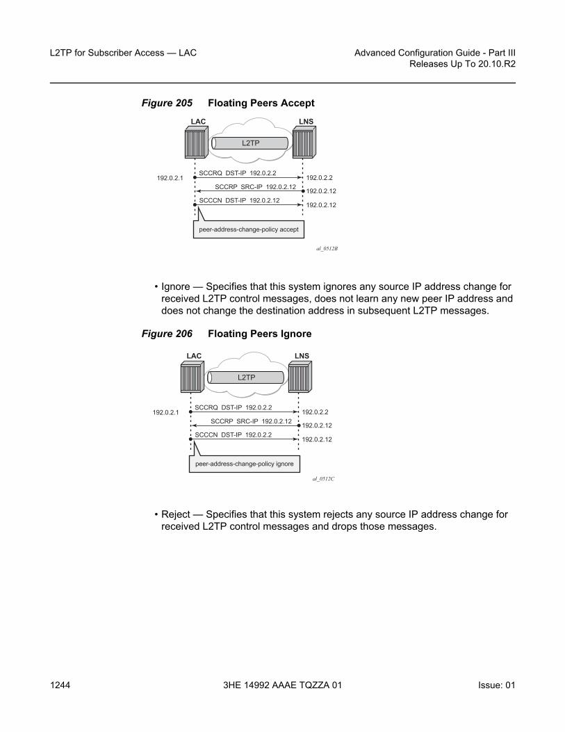
L2TP for Subscriber Access — LAC
1244
Advanced Configuration Guide - Part IIIReleases Up To 20.10.R2
3HE 14992 AAAE TQZZA 01 Issue: 01
Figure 205 Floating Peers Accept
• Ignore — Specifies that this system ignores any source IP address change for received L2TP control messages, does not learn any new peer IP address and does not change the destination address in subsequent L2TP messages.
Figure 206 Floating Peers Ignore
• Reject — Specifies that this system rejects any source IP address change for received L2TP control messages and drops those messages.
al_0512B
LAC
L2TP
SCCRQ DST-IP 192.0.2.2192.0.2.1 192.0.2.2
SCCCN DST-IP 192.0.2.12192.0.2.12
192.0.2.12SCCRP SRC-IP 192.0.2.12
LNS
peer-address-change-policy accept
al_0512C
LAC
L2TP
SCCRQ DST-IP 192.0.2.2192.0.2.1 192.0.2.2
SCCCN DST-IP 192.0.2.2192.0.2.12
192.0.2.12SCCRP SRC-IP 192.0.2.12
LNS
peer-address-change-policy ignore

Advanced Configuration Guide - Part III Releases Up To 20.10.R2
L2TP for Subscriber Access — LAC
Issue: 01 3HE 14992 AAAE TQZZA 01 1245
Figure 207 Floating Peers Reject
The values Peer IP, Tx dst-IP and Rx src-IP in the show router l2tp tunnel detail command indicates if floating peers are used or not.
An example of a floating peer (peer-address-change-policy accept) is as follows.
*A:LAC# show router l2tp tunnel detail=======================================L2TP Tunnel Status=======================================Connection ID: 897122304State : establishedIP : 192.0.2.1UDP : 1701Peer IP : 192.0.2.2 # (1) peer address used in SCCRQPeer UDP : 1701Tx dst-IP : 192.0.2.12 # (3) peer address used in SCCCNTx dst-UDP : 1701Rx src-IP : 192.0.2.12 # (2) SCCRP different IP receivedRx src-UDP : 1701---snipped---
Tx/Rx Connect Speed - AVP 24/38
The Connect Speed (TX AVP 24 and RX AVP 38) is passed in the ICCN messages sent from the LAC to the LNS. The L2TP AVP 24 defines the (Tx) connect speed in bps from the perspective of traffic flowing from the LAC towards the subscriber (BNG downstream rate).The L2TP AVP 38 defines the (Rx) connect speed in bps from the perspective of traffic flowing from the subscriber towards the LAC (BNG upstream rate).
The report-rate configuration option indicates what rate is reported to the LNS when creating an L2TP session.
al_0512A
LAC
L2TP
SCCRQ DST-IP 192.0.2.2192.0.2.1 192.0.2.2
192.0.2.12SCCRP SRC-IP 192.0.2.12
LNS
peer-address-change-policy reject
X

L2TP for Subscriber Access — LAC
1246
Advanced Configuration Guide - Part IIIReleases Up To 20.10.R2
3HE 14992 AAAE TQZZA 01 Issue: 01
configure subscriber-mgmt sla-profile <sla-profile-name> ingress | egressreport-rate agg-rate-limit|scheduler|pppoe-actual-rate|
policer|rfc5515-actual-rate
• agg-rate-limit — Take the aggregate rate as received from the RADIUS Access-Accept message in VSA Alc-Subscriber-QoS-Override. When this RADIUS VSA is not present in the Access-Accept, or when RADIUS is not used, then take the configured aggregate rate limit. In the case where this is not configured, then take the port rate.
• scheduler <scheduler-name> — Take the rate of the specified scheduler. In case the scheduler is not linked with the scheduler-policy from the subscriber-profile, then take the port rate.
• pppoe-actual-rate — Take the rate from the DSL-Forum Vendor-Specific PPPoE Tag when available, otherwise take the port rate.
• rfc5515-actual-rate — Put the same value as the transmitted Actual-Data-Rate-Upstream AVP in the Rx-Connect-Speed AVP, and the same value as the transmitted Actual-Data-Rate-Downstream AVP in the Tx-Connect-Speed AVP.
Calling Number AVP 22 Format
The format of AVP 22 Calling Number in the ICRQ message is configurable via the parameter calling-number-format. The default format is "%S<space>%s" and corresponds to the concatenation of system-name<space>sap-id. Available parameters are %S (system-name), %c (Agent Circuit Id), %r Agent Remote Id, %s (sap-id), %l (Logical Line ID) and fixed strings. A combination can be configured from any of these parameters, but the total configured format cannot exceed 255 characters.
Example 1: Default configuration.
configure router l2tp calling-number-format "%S %s"
19 2019/05/22 14:01:04.885 CEST MINOR: DEBUG #2001 Base L2TP(v2, ctrl, egress)"L2TP(v2, ctrl, egress): UDP 192.0.2.1:1701 -> 192.168.22.2:1701tunnel 5593 session 0, ns 2 nr 1, flags:, reserved=0
AVP MessageType(0,0), flags: mandatory, reserved=0IncomingCallRequest(10)
AVP AssignedSessionId(0,14), flags: mandatory, reserved=015342
AVP CallSerialNumber(0,15), flags: mandatory, reserved=084781
AVP CallingNumber(0,22), flags: mandatory, reserved=0"LAC 1/1/3:100"
AVP AgentCircuitId(3561,1), flags:, reserved=0"circuit0"
AVP AgentRemoteId(3561,2), flags:, reserved=0"remote0"

Advanced Configuration Guide - Part III Releases Up To 20.10.R2
L2TP for Subscriber Access — LAC
Issue: 01 3HE 14992 AAAE TQZZA 01 1247
AVP ActDataRateUp(3561,129), flags:, reserved=02000000
AVP ActDataRateDown(3561,130), flags:, reserved=04000000"
Example 2: Customized configuration and all parameters (%S %s %c) are available to construct the requested AVP 22.
configure router l2tp calling-number-format "start-%S###%s###%c-end"
19 2019/05/22 14:05:28.116 CEST MINOR: DEBUG #2001 Base L2TP(v2, ctrl, egress)"L2TP(v2, ctrl, egress): UDP 192.0.2.1:1701 -> 192.168.22.2:1701tunnel 832 session 0, ns 2 nr 1, flags:, reserved=0
AVP MessageType(0,0), flags: mandatory, reserved=0IncomingCallRequest(10)
AVP AssignedSessionId(0,14), flags: mandatory, reserved=024748
AVP CallSerialNumber(0,15), flags: mandatory, reserved=084782
AVP CallingNumber(0,22), flags: mandatory, reserved=0"start-LAC###1/1/3:100###circuit0-end"
AVP AgentCircuitId(3561,1), flags:, reserved=0"circuit0"
AVP AgentRemoteId(3561,2), flags:, reserved=0"remote0"
AVP ActDataRateUp(3561,129), flags:, reserved=02000000
AVP ActDataRateDown(3561,130), flags:, reserved=04000000"
Example 3: Customized configuration and not all parameters are available to construct the requested AVP 22. Option-82 circuit-id (%c),remote-id (%r), and LLID (%l) information are lacking and therefore missing (skipped) in the formatted attribute.
configure router l2tp calling-number-format "%S#%c#%r#%l#%s"
19 2019/05/22 14:07:26.302 CEST MINOR: DEBUG #2001 Base L2TP(v2, ctrl, egress)"L2TP(v2, ctrl, egress): UDP 192.0.2.1:1701 -> 192.168.22.2:1701tunnel 255 session 0, ns 2 nr 1, flags:, reserved=0
AVP MessageType(0,0), flags: mandatory, reserved=0IncomingCallRequest(10)
AVP AssignedSessionId(0,14), flags: mandatory, reserved=020814
AVP CallSerialNumber(0,15), flags: mandatory, reserved=084783
AVP CallingNumber(0,22), flags: mandatory, reserved=0"LAC#circuit0#remote0##1/1/3:100"
AVP AgentCircuitId(3561,1), flags:, reserved=0"circuit0"
AVP AgentRemoteId(3561,2), flags:, reserved=0"remote0"
AVP ActDataRateUp(3561,129), flags:, reserved=02000000

L2TP for Subscriber Access — LAC
1248
Advanced Configuration Guide - Part IIIReleases Up To 20.10.R2
3HE 14992 AAAE TQZZA 01 Issue: 01
Prevent LAC from Transmitting Calling Number AVP 22 to LNS
By default, the LAC includes the Calling Number AVP 22 in the L2TP incoming-call-request (ICRQ) packets transmitted to LNS. This AVP identifies the interface that is connected to the customer in the access network. Network access interface information can be hidden by configuring the LAC not to send the Calling Number AVP to the LNS.
Use the following command to disable the sending of L2TP Calling Number AVP 22.
configure router l2tpexclude-avps calling-number
AVP 100 - Cisco-Nas-Port
Interoperation with a Cisco LNS requires that the LAC communicates a NAS port type to the LNS via the L2TP ICRQ ‘Cisco Nas Port Info AVP (100)’. This AVP (100) includes information that identifies the NAS port and indicates whether the port type is Ethernet or ATM and is configured via the cisco-nas-port parameter.
The Cisco AVP 100 format is as follows:
• First 5 bytes are NAS-Port-Type: - 0f10090203 (Ethernet)- 0f10090201 (ATM)
• Remaining 4 bytes corresponds with the configured cisco-nas-port value
Example:
• Ethernet 12b s-vlan-id; 10b c-vlan-id; 3b slot number; 2b MDA nbr; 5b port• ATM 12b VPI; 10b VCI; 3b slot number; 2b MDA nbr; 5b port
configure router l2tpcisco-nas-port ethernet "*12o*10i*3s*2m*5p" atm "*12v*10c*3s*2m*5p"
nas-port 1/1/3:100 corresponds to 102563 (000000000000 0001100100 001 01 00011).
19 2019/05/22 14:11:49.431 CEST MINOR: DEBUG #2001 Base L2TP(v2, ctrl, egress)"L2TP(v2, ctrl, egress): UDP 192.0.2.1:1701 -> 192.168.22.2:1701tunnel 13002 session 0, ns 2 nr 1, flags:, reserved=0
AVP MessageType(0,0), flags: mandatory, reserved=0IncomingCallRequest(10)
AVP CiscoNasPort(9,100), flags:, reserved=0102563 type=ethernet(0f:10:09:02:03)

Advanced Configuration Guide - Part III Releases Up To 20.10.R2
L2TP for Subscriber Access — LAC
Issue: 01 3HE 14992 AAAE TQZZA 01 1249
AVP AssignedSessionId(0,14), flags: mandatory, reserved=02461
AVP CallSerialNumber(0,15), flags: mandatory, reserved=084784
AVP CallingNumber(0,22), flags: mandatory, reserved=0"LAC 1/1/3:100"
AVP AgentCircuitId(3561,1), flags:, reserved=0"circuit0"
AVP AgentRemoteId(3561,2), flags:, reserved=0"remote0"
AVP ActDataRateUp(3561,129), flags:, reserved=02000000
AVP ActDataRateDown(3561,130), flags:, reserved=04000000"
L2TP Group/Peer/Tunnel Draining
When the LAC has established sessions, the LAC can avoid the creation of new sessions for a specific group, peer, or tunnel, via the drain command.
No new sessions are created for a group, peer or tunnel that is being drained (draining state) but the current sessions are left intact.
After the drain command is issued, the group, peer, or tunnel moves from a draining to drained state when the last session is closed. A drained group, peer, or tunnel can then be managed (reconfigured, deleted) without any user impact.
Be aware that a group, peer, or tunnel in a draining or drained state is skipped in the tunnel selection process. The next example shows a tunnel draining; group and peer draining works according in the same way.
A tunnel has 1 session and is in established state.
*A:LAC# show router 65536 l2tp tunnel===============================================================================Conn ID Loc-Tu-ID Rem-Tu-ID State Blacklist-state Ses Active
Group Ses TotalAssignment
-------------------------------------------------------------------------------1023868928 15623 9957 established not-blacklisted 1
wholesale.com 1wholesale.com
-------------------------------------------------------------------------------No. of tunnels: 1===============================================================================*A:LAC#
The following tools drain command puts the tunnel in a draining state and leaves the sessions intact.

L2TP for Subscriber Access — LAC
1250
Advanced Configuration Guide - Part IIIReleases Up To 20.10.R2
3HE 14992 AAAE TQZZA 01 Issue: 01
*A:LAC# tools perform router 65536 l2tp tunnel 1023868928 drain*A:LAC#
Initially the tunnel is in the draining state.
*A:LAC# show router 65536 l2tp tunnel===============================================================================Conn ID Loc-Tu-ID Rem-Tu-ID State Blacklist-state Ses Active
Group Ses TotalAssignment
-------------------------------------------------------------------------------1023868928 15623 9957 draining not-blacklisted 1
wholesale.com 1wholesale.com
-------------------------------------------------------------------------------No. of tunnels: 1===============================================================================*A:LAC#
The tunnel moves to the drained state at the moment the last session is closed. Debugging shows that a drained tunnel is also not used as last resort and is skipped during the tunnel selection process.
*A:LAC# show router 65536 l2tp tunnel===============================================================================Conn ID Loc-Tu-ID Rem-Tu-ID State Blacklist-state Ses Active
Group Ses TotalAssignment
-------------------------------------------------------------------------------1023868928 15623 9957 drained not-blacklisted 0
wholesale.com 1wholesale.com
-------------------------------------------------------------------------------No. of tunnels: 1===============================================================================*A:LAC#
The following output shows new sessions cannot select a drained tunnel.
82289 2019/05/22 14:43:56.549 CEST MINOR: DEBUG #2001 vprn65536 PPPoE 19644->L2TP"PPPoE 19644->L2TP: UDP 192.168.33.1:1701 -> 192.168.33.2:1701preference 50 tunnel wholesale.com:wholesale.com
no additional session can be created in tunnel 15623"
82290 2019/05/22 14:43:56.549 CEST MINOR: DEBUG #2001 vprn65536 PPPoE 19644->L2TP"PPPoE 19644->L2TP:
stop: no more tunnels can be tried"
The drained tunnel can then be closed without user impact.
*A:LAC# tools perform router 65536 l2tp tunnel 1023868928 stop*A:LAC#
207376 2019/05/22 14:45:01.981 CEST MINOR: DEBUG #2001 vprn65536 L2TP(v2, ctrl,

Advanced Configuration Guide - Part III Releases Up To 20.10.R2
L2TP for Subscriber Access — LAC
Issue: 01 3HE 14992 AAAE TQZZA 01 1251
ingress)"L2TP(v2, ctrl, ingress): UDP 192.168.33.2:1701 -> 192.168.33.1:1701tunnel 15623 session 0, ns 2 nr 8, flags:, reserved=0"
207377 2019/05/22 14:46:01.853 CEST MINOR: DEBUG #2001 vprn65536 L2TP(v2, ctrl,ingress)
"L2TP(v2, ctrl, ingress): UDP 192.168.33.2:1701 -> 192.168.33.1:1701tunnel 15623 session 0, ns 2 nr 8, flags:, reserved=0
AVP MessageType(0,0), flags: mandatory, reserved=0StopControlConnectionNotification(4)
AVP ResultCode(0,1), flags: mandatory, reserved=0result-code: "generalRequestToClearControlConnection"(1),
error-code: "noGeneralError"(0)error-msg: "idle timeout (60 seconds) expired"
AVP AssignedTunnelId(0,9), flags: mandatory, reserved=09957"
For draining and undraining for example a group, following commands can be used.
tools perform router 65536 l2tp group "wholesale.com" draintools perform router 65536 l2tp group "wholesale.com" no drain
Conclusion
This example provides the LAC L2TP access server configuration and troubleshooting commands for the LAA architecture (tunneled-access) model.

L2TP for Subscriber Access — LAC
1252
Advanced Configuration Guide - Part IIIReleases Up To 20.10.R2
3HE 14992 AAAE TQZZA 01 Issue: 01

Advanced Configuration Guide - Part III Releases Up To 20.10.R2
Local User Database Basics
Issue: 01 3HE 14992 AAAE TQZZA 01 1253
Local User Database BasicsThis chapter provides information about Local User Database (LUBD) Basics.
Topics in this chapter include:
• Applicability• Overview• Configuration• Conclusion
Applicability
This chapter is applicable to the 7x50 SR series, was based on SR OS 13.0.R1 and is updated to release 16.0.R4.
Overview
A Local User Database (LUDB) is a data source containing a set of host entries, providing full or partial Enhanced Subscriber Management (ESM) data so that subscribers and subscriber hosts can be instantiated when end-users connect their devices.
An LUDB can be accessed for the following applications; see Figure 208.
1. To support ESM for retrieval of data to instantiate hosts and subscribers. This applies to the Routed Central Office [CO] model only.
2. To support a local DHCPv4 server; for example for assigning fixed IP addresses to dedicated end-user devices.
3. To allow the system to provide the ESM data in case the RADIUS server referenced from the authentication policy is not available. The LUDB serves as a fallback for RADIUS authentication.

Local User Database Basics
1254
Advanced Configuration Guide - Part IIIReleases Up To 20.10.R2
3HE 14992 AAAE TQZZA 01 Issue: 01
Figure 208 LUDB Applications
The LUDB lookup process is common to the applications shown in Figure 208, and performs the following steps:
• Applying match criteria, to select the input parameters that will be used for the lookup.
• Optionally, applying a mask to one or more of the remaining input parameters.• Performing the lookup.
The LUDB lookup process translates a set of input parameters (the host identification fields) into a set of output parameters; see Figure 209 for the following example:
• An LUDB lookup is requested for a client with MAC address and SAP as input parameters (1).
• The match criteria indicate to consider the SAP only, so the MAC address is ignored (2).
• The masking defines the stripping of the VLAN-tag from the SAP (3).• The lookup then uses SAP 1/1/1 and finds entry1 to be the matching entry, so
the LUDB returns the SLA-profile string and the SUB-profile string together with the Gi address.
Optionally, an LUDB defines a default host entry, which is used in case none of the other entries matches the lookup request, so it serves as a wildcard (*).
Not finding any matching host entry in an LUDB results in a setup failure.
al_0806
1
3
2
IPoE/PPP(DHCPv4, DHCPv6, SLAAC)
LUDB
LUDB
ESM
AAA
DHCPv4Server
RADIUSDiameter

Advanced Configuration Guide - Part III Releases Up To 20.10.R2
Local User Database Basics
Issue: 01 3HE 14992 AAAE TQZZA 01 1255
Figure 209 Processing an LUDB Lookup Request
Configuration
Creating LUDBs
An LUDB is identified by a name of 32 characters maximum (Figure 210).
*A:BNG-1>config>subscr-mgmt# local-user-db- local-user-db <local-user-db-name> [create]
Multiple LUDBs can be defined, and their respective names must be unique.
An LUDB can provide the data for IPoE (DHCPv4, DHCPv6, and SLAAC) as well as for PPP users.
*A:BNG-1>config>subscr-mgmt>loc-user-db$[no] description - Description for this local user database
ipoe + Configure IPOE hostsppp + Configure PPP hosts
[no] shutdown - Administratively enable/disable this local user database
al_0807
LUDB
Lookup
InputParameters
Output parameters
MatchCriteria
SAP(Masking)
SAP: strip VLAN
MAC = 00:00:00:11:11:11SAP = 1/1/1:500
SLA-profile = sla-prof-1SUB-profile = sub-prof-1Gi = 10.1.1.254... sla-prof-1
sub-prof-1Gi = 10.1.1.254
SAP = 1/1/1:500
(1) (2) (3)
1
n
(4)
SAP = 1/1/1SAP = 1/1/1
entry1
identification fields
output fields

Local User Database Basics
1256
Advanced Configuration Guide - Part IIIReleases Up To 20.10.R2
3HE 14992 AAAE TQZZA 01 Issue: 01
For an LUDB to be active, the LUDB must be in the no shutdown state.
Individual host entries in an LUDB can match single or multiple hosts.
Figure 210 Creating LUDBs and LUDB Entries
Creating Host Entries
A host entry is identified by name of 32 characters maximum (Figure 210).
*A:BNG-1>config>subscr-mgmt>loc-user-db>ipoe$ host- host <host-name> [create]
The name default can optionally be used as a wildcard for situations where otherwise the lookup fails to find a matching entry. A host entry belongs to either the IPoE or the PPP section of an LUDB. The name of a host entry must be unique within the section. A host entry contains two sets of fields. The first set of fields are the host-identification fields and are used for the lookup, the second set of fields are output to the lookup process.
The host-identification fields available for IPoE are, in alphabetical order:
al_0808
local-user-db <name>
ppp (match-list)ipoe (match-list)
host <name> (host-identification) host <name> (host-identification)
host <name> (host-identification)host <name> (host-identification)
host default (match *) host default (match *)
address-informationidentification-strings
address-informationidentification-strings
address-informationidentification-strings
address-informationidentification-strings
address-informationidentification-strings
address-informationidentification-stringsoutput fields
output fields
output fields output fields
output fields
output fields
...
...
... ...
...
...
......

Advanced Configuration Guide - Part III Releases Up To 20.10.R2
Local User Database Basics
Issue: 01 3HE 14992 AAAE TQZZA 01 1257
• circuit-id• derived-id, which must be defined using a Python script, which derives the value
from DHCP messages• encap-tag-range• ip-prefix• mac-address• option 60• remote-id• sap-id• service-id• string• system-id
The host-identification fields available for PPP are, in alphabetical order:
• circuit-id: taken from the PPPoE tags• derived-id, which must be defined using a Python script, which derives the value
from PPP messages• encap-tag-range• mac• remote-id: taken from the PPPoE tags• sap-id• service-name• username
The output fields of the lookup process include the identification strings, DHCP options, IP address information, MSAP information, and so on.
Entry Validation
For a host entry to be active, it must be put in the no shutdown state.
Before adding the host entry to the lookup database, the system validates the host entry:
• A default host entry can be added, preferably without host identification fields.*A:BNG-1>config>subscr-mgmt>loc-user-db>ipoe# host default create*A:BNG-1>config>subscr-mgmt>loc-user-db>ipoe>host$ no shutdown
INFO: DHCPS #1138 This host will be considered as the default host*A:BNG-1>config>subscr-mgmt>loc-user-db>ipoe>host$

Local User Database Basics
1258
Advanced Configuration Guide - Part IIIReleases Up To 20.10.R2
3HE 14992 AAAE TQZZA 01 Issue: 01
Defining a default host entry with identification fields is not recommended, because it would turn the default host entry into a regular entry, instead of a match all entry, when the match-list is changed.
• A non default host entry without host identification fields cannot be added to the lookup database.
MINOR: DHCPS #1126 Host-identification must have at least 1 item defined
• A non default host entry with none of its host identification fields in common with the match-list is added to the unmatched host list.
INFO: DHCPS #1107 Host could not be inserted in lookup database - nomatch values
• A non default host entry is added to the lookup database when at least one of the defined host identification fields is in common with the match-list, even when some of the host identification fields are not on the match-list.
• Two or more non default host entries with the same host-identification definitions are considered as duplicates. The second entry with the same host-identification definitions is not added to the lookup database; it is considered as a configuration mistake.
INFO: DHCPS #1107 Host could not be inserted in lookup database — duplicate
LUDB informational and error messages appear to be originating from the DHCPS application (DHCPS #nnn in the preceding outputs), even though the LUDB is not associated with a DHCPv4 server.
Creating a Match-List
Retrieving data from an LUDB requires one or more criteria to be put on a match-list. A match-list is a sequential list of parameters considered for the lookup; other parameters provided on LUDB access are ignored.
For IPoE, up to four criteria can be defined; for PPP, the maximum is three. The criteria on a match-list are processed in the order specified.
For IPoE users, the following match criteria are allowed, in alphabetical order:
• circuit-id• derived-id (defined by a Python script)• dual-stack-remote-id (IPv4 and IPv6, with IPv6 enterprise-id stripped off)• encap-tag-range• ip

Advanced Configuration Guide - Part III Releases Up To 20.10.R2
Local User Database Basics
Issue: 01 3HE 14992 AAAE TQZZA 01 1259
• mac-address• option 60• remote-id (IPv4 and IPv6, including the IPv6 enterprise-id)• sap-id• service-id• string• system-id
*A:BNG-1>config>subscr-mgmt>loc-user-db>ipoe# match-list- no match-list- match-list <ipoe-match-type-1> [<ipoe-match-type-2>...(up to 4 max)]
<ipoe-match-type> : circuit-id|derived-id|dual-stack-remote-id|encap-tag-range|ip|mac|option60|remote-id|sap-id|service-id|string|system-id
*A:BNG-1>config>subscr-mgmt>loc-user-db>ipoe#
For PPP users, the following match criteria are allowed, in alphabetical order:
• circuit-id• derived-id (defined by a Python script)• encap-tag-range• mac-address• remote-id (IPv4 and IPv6, including the IPv6 enterprise-id)• sap-id• service-name• username (complete username, domain part only, host part only)
*A:BNG-1>config>subscr-mgmt>loc-user-db>ppp# match-list- no match-list- match-list <ppp-match-type-1> [<ppp-match-type-2>...(up to 3 max)]
<ppp-match-type> : circuit-id|derived-id|mac|remote-id|sap-id|encap-tag-range|service-name|username
*A:BNG-1>config>subscr-mgmt>loc-user-db>ppp#
Masking
Optionally, the parameters considered for the lookup can be masked.
Masking is prefix- or suffix- based, or a combination of both. A prefix or suffix string, or a prefix or suffix length, can be specified.

Local User Database Basics
1260
Advanced Configuration Guide - Part IIIReleases Up To 20.10.R2
3HE 14992 AAAE TQZZA 01 Issue: 01
For PPP users, masks can be applied to the circuit-id, remote-id, sap-id, service-name, and username. For IPoE users, masks can be applied to the circuit-id, option 60, remote-id, sap-id, string, and system-id.
*A:BNG-1>config>subscr-mgmt>loc-user-db>ppp# mask ?- mask type <ppp-match-type>{[prefix-string <prefix-string> | prefix-length <prefix-length>][suffix-string <suffix-string> | suffix-length <suffix-length>]}
- no mask type <ppp-match-type>
<ppp-match-type> : circuit-id|remote-id|sap-id|service-name|username<prefix-string> : [127 chars max] ('*' is wildcard)<prefix-length> : [1..127]<suffix-string> : [127 chars max] ('*' is wildcard)<suffix-length> : [1..127]
*A:BNG-1>config>subscr-mgmt>loc-user-db>ipoe# mask ?- mask type <ipoe-match-type>{[prefix-string <prefix-string> | prefix-length <prefix-length>][suffix-string <suffix-string> | suffix-length <suffix-length>]}
- no mask type <ipoe-match-type>
<ipoe-match-type> : circuit-id|option60|remote-id|sap-id|string|system-id<prefix-string> : [127 chars max] ('*' is wildcard)<prefix-length> : [1..127]<suffix-string> : [127 chars max] ('*' is wildcard)<suffix-length> : [1..127]
The lookup occurs after applying the optional masks.
The examples in Table 41 illustrate masking. For the third example, a combination of both prefix and suffix matching is used.
Table 41 Masking Examples
Mask Type prefix-length
suffix-length
prefix-string
suffix-string
result
username circuit-id remote-id
- - 87654321-BSAN-1
9 - - - BSAN-1
- BSAN-2|1|100|1/2/1
- - 11 - - BSAN-2
- - - - *@ .com domain-1
Advanced Configuration Guide - Part III Releases Up To 20.10.R2
Local User Database Basics
Issue: 01 3HE 14992 AAAE TQZZA 01 1261
Lookup
The following rules apply while scanning through an LUDB in search of a single matching entry:
1. Only criteria on the match-list are considered.Assume a client with MAC-address, a circuit-id, and a remote-id. If the match-list only defines the MAC-address to be used as criterion, then the circuit-id and the remote-id are ignored. Only the MAC-address is used for selecting the proper host entry.
2. The order of the criteria on the match-list is important.The match-list is a sequential list, and the criteria are processed left to right.
3. As many of the host-identification fields as possible must be matched, while still obeying rule 1.Only the (optionally masked) parameters from the match list are verified.
4. A default host is excluded from the scan, if defined. A default host is used as a fallback when scanning through an LUDB does not provide any result.

Local User Database Basics
1262
Advanced Configuration Guide - Part IIIReleases Up To 20.10.R2
3HE 14992 AAAE TQZZA 01 Issue: 01
Figure 211 Host Matching Examples
The examples in Figure 211 and Figure 212 illustrate these rules:
a. Matching is based on the MAC-address only. When client-a with mac-1 connects, host ipoe-x is matched.
b. Matching is based on the MAC-address, circuit-id, and remote-id, in this sequence. As client-b enters with mac-1, cid-1 and rid-1, the match-list is scanned and matched left to right, so host ipoe-z is matched.
c. Matching is based on the MAC-address only. Even though client-c connects with mac-1, cid-1, and rid-1, the system ignores the circuit-id and the remote-id, so the matching host is ipoe-x. Note that host ipoe-y can never be matched using the match-list defined; it is on the unmatched host list.
d. Matching is based on the MAC-address and the circuit-id, in this sequence. Client-d connects with mac-1 and cid-2, but because the system scans the match-list left through right, the MAC-address takes priority over the circuit-id. The matching host is ipoe-x.
al_0809
local-user-db ludb-1
ipoe (mac)
host ipoe-x (mac-1)address-information
192.1.2.121identification-strings
host ipoe-y (mac-2)address-information
192.1.2.131identification-strings
local-user-db ludb-3
ipoe (mac)
host ipoe-x (mac-1)address-information
192.1.2.123identification-strings
host ipoe-y (cid-1, rid-1)address-information
192.1.2.133identification-strings
client-a(mac-1)
local-user-db ludb-2
ipoe (mac, circuit-id, remote-id)
host ipoe-x (mac-1)address-information
192.1.2.122identification-strings
host ipoe-y (mac-1, cid-1)address-information
192.1.2.132identification-strings
host ipoe-z (mac-1, cid-1, rid-1)address-information
identification-strings
client-b(mac-1,cid-1,rid-1)
local-user-db ludb-4
ipoe (mac, circuit-id)
host ipoe-x (mac-1)address-information
192.1.2.124identification-strings
host ipoe-y (cid-1)address-information
192.1.2.134
192.1.2.144192.1.2.142
identification-strings
host ipoe-z (cid-2)address-information
identification-strings
client-d(mac-1,cid-2)
client-c(mac-1,cid-1,rid-1)
(A) (C)
(D)(B)

Advanced Configuration Guide - Part III Releases Up To 20.10.R2
Local User Database Basics
Issue: 01 3HE 14992 AAAE TQZZA 01 1263
Figure 212 Host Matching Examples (Continued)
e. For the top part, matching is based on MAC-address and the circuit-id, in this sequence. When client-e connects (mac-1, cid-1, and rid-1), the system scans ludb-5-1 and matches host ipoe-x.For the bottom part, matching is based on the circuit-id first, then the MAC-address. When client-e connects (mac-1, cid-1, and rid-1), the system scans ludb-5-2 and matches host ipoe-y.
f. Matching is based on MAC-address and the circuit-id, in this sequence. When client-f-1 (mac-1) connects, the matching host is ipoe-x because only the MAC-address is provided and checked. When client-f-2 (cid-1) connects, the matching host is ipoe-y because only the client-id is provided and checked. When client-f-3 (mac-1, cid-1) connects, the matching host is ipoe-z.
g. Matching is based on the MAC-address only. When client-g with mac-2 connects, host default is matched because there is no explicit entry matching mac-2.
As shown is these examples, the system only checks the parameters provided by the client in the sequence as defined by the match-list. Parameters not provided by a client will not be searched for.
al_0810
local-user-db ludb-5-1
ipoe (mac, circuit-id)
host ipoe-x (mac-1)address-information
192.1.2.125identification-strings
host ipoe-y (cid-1)address-information
192.1.2.135identification-strings
client-e(mac-1,cid-1,rid-1)
local-user-db ludb-5-2
ipoe (circuit-id, mac)
host ipoe-x (mac-1)address-information
192.1.2.125identification-strings
host ipoe-y (cid-1)address-information
192.1.2.135identification-strings
client-e(mac-1,cid-1,rid-1)
local-user-db ludb-7
ipoe (mac)
host ipoe-x (mac-1)address-information
192.1.2.127identification-strings
host defaultidentification-strings
client-g(mac-2)
(E) local-user-db ludb-6
ipoe (mac, circuit-id)
host ipoe-x (mac-1)address-information
192.1.2.126identification-strings
host ipoe-y (cid-1)address-information
192.1.2.136identification-strings
host ipoe-z (mac-1, cid-1)address-information
identification-stringsclient-f-3(mac-1,cid-1)
client-f-2(cid-1)
client-f-1(mac-1)
192.1.2.146
(F)
(G)

Local User Database Basics
1264
Advanced Configuration Guide - Part IIIReleases Up To 20.10.R2
3HE 14992 AAAE TQZZA 01 Issue: 01
Tools Commands
The following tools command manually triggers the lookup of an IPoE host in an LUDB and is useful during commissioning, troubleshooting, and verification of the configured database, without the need for an external client.
*A:BNG-1# tools perform subscriber-mgmt local-user-db "ludb-1" ipoe host-lookup ?- host-lookup [mac <ieee-address>] [remote-id <remote-id-ascii>]
[sap-id <sap-id>] [service-id <service-id>] [string <vso-string>][system-id <system-id>] [option60 <option-60-ascii>][circuit-id <circuit-id-ascii>] [circuit-id-hex <circuit-id-hex>][option60-hex <option60-hex>] [remote-id-hex <remote-id-hex>][derived-id <derived-id>] [ip-prefix <ip-prefix/ip-prefix-length>]
<ieee-address> : xx:xx:xx:xx:xx:xx or xx-xx-xx-xx-xx-xx<remote-id-ascii> : [255 chars max]<sap-id> : [255 chars max]<service-id> : [1..2148278317]|<svc-name:64 char max><vso-string> : [255 chars max]<system-id> : [255 chars max]<option-60-ascii> : [32 chars max]<circuit-id-ascii> : [127 chars max]<circuit-id-hex> : [0x0..0xFFFFFFFF...(max 254 hex nibbles)]<option60-hex> : [0x0..0xFFFFFFFF...(max 64 hex nibbles)]<remote-id-hex> : [0x0..0xFFFFFFFF...(max 510 hex nibbles)]<derived-id> : [255 chars max]<ip-prefix/ip-pref*> : ipv4-prefix - a.b.c.d (host bits must be 0)
ipv4-prefix-le - [0..32]ipv6-prefix - x:x:x:x:x:x:x:x (eight 16-bit pieces)
x:x:x:x:x:x:d.d.d.dx - [0..FFFF]Hd - [0..255]D
ipv6-prefix-le - [0..128]
A similar command exists for the lookup of a PPP host in an LUDB.
*A:BNG-1# tools perform subscriber-mgmt local-user-db "ludb-1" ppp host-lookup ?- host-lookup [circuit-id <circuit-id>] [circuit-id-hex <circuit-id-hex>][derived-id <derived-id>] [mac <ieee-address>] [remote-id <remote-id>][remote-id-hex <remote-id-hex>] [sap-id <sap-id>][service-name <service-name>] [user-name <user-name>]
<circuit-id> : [127 chars max]<circuit-id-hex> : [0x0..0xFFFFFFFF...(max 254 hex nibbles)]<derived-id> : [255 chars max]<ieee-address> : xx:xx:xx:xx:xx:xx or xx-xx-xx-xx-xx-xx<remote-id> : [255 chars max]<remote-id-hex> : [0x0..0xFFFFFFFF...(max 510 hex nibbles)]<sap-id> : [255 chars max]<service-name> : [255 chars max]<user-name> : [253 chars max]

Advanced Configuration Guide - Part III Releases Up To 20.10.R2
Local User Database Basics
Issue: 01 3HE 14992 AAAE TQZZA 01 1265
Example 1: Single Match Criterion
The following shows an excerpt from ludb-1. Host entry-11 defines the parameters for an IPoE host, and host entry-55 defines the parameters for a PPPoE host. Host matching IPoE hosts is MAC-address based, whereas host matching PPP hosts is username based.
configuresubscriber-mgmt
local-user-db "ludb-1" createdescription "example user-db"ipoe
match-list machost "default" create
address pool "pool4-1"no shutdown
exithost "entry-11" create
host-identificationmac 00:00:00:11:11:11
exitaddress 10.1.1.211--- snip ---no shutdown
exit--- snip ---
exitppp
match-list usernamehost "entry-55" create
host-identificationusername "sub55@domain1"
exitpassword chap sub55address 10.1.2.252--- snip ---no shutdown
exit--- snip ---
exitno shutdown
exit
IPoE hosts
IPoE host entry lookup using a MAC-address only is triggered with following tools command.
*A:BNG-1# tools perform subscriber-mgmt local-user-db "ludb-1" ipoehost-lookup mac 00:00:00:11:11:11
===============================================================================IPoE Host Lookup results===============================================================================Result : SuccessMatched Host Name : entry-11Admin State : Up

Local User Database Basics
1266
Advanced Configuration Guide - Part IIIReleases Up To 20.10.R2
3HE 14992 AAAE TQZZA 01 Issue: 01
Last Mgmt Change : 11/20/2018 11:25:10
Host IdentificationCircuit Id : N/AMac Address : 00:00:00:11:11:11Remote Id : N/ASap Id : N/AService Id : N/AString : N/AOption 60 : N/ASystem Id : N/AEncap Tag Range : N/ADerived Id : N/AIP prefix : N/A
Matched Objects : mac--- snipped ---===============================================================================*A:BNG-1#
The debug output confirms the successful lookup.
1 2018/11/20 11:40:41.132 CET MINOR: DEBUG #2001 Base LUDB"LUDB: User lookup success - host found
mac: 00:00:00:11:11:11
Host entry-11 found in user data base ludb-1"*A:BNG-1#
The following command is using a MAC-address, a circuit-id, and a remote-id for the lookup. The output shows that only the MAC-address is used, the other input parameters are ignored (N/A) so again entry-11 is selected.
*A:BNG-1# tools perform subscriber-mgmt local-user-db "ludb-1" ipoehost-lookup mac 00:00:00:11:11:11 circuit-id AA remote-id BB
===============================================================================IPoE Host Lookup results===============================================================================Result : SuccessMatched Host Name : entry-11Admin State : UpLast Mgmt Change : 11/20/2018 11:25:10
Host IdentificationCircuit Id : N/AMac Address : 00:00:00:11:11:11Remote Id : N/ASap Id : N/AService Id : N/AString : N/AOption 60 : N/ASystem Id : N/AEncap Tag Range : N/ADerived Id : N/AIP prefix : N/A
Matched Objects : mac

Advanced Configuration Guide - Part III Releases Up To 20.10.R2
Local User Database Basics
Issue: 01 3HE 14992 AAAE TQZZA 01 1267
--- snipped ---===============================================================================*A:BNG-1#
The following command triggers the lookup of a non-existing MAC-address, leading to a host not found message.
*A:BNG-1# tools perform subscriber-mgmt local-user-db "ludb-1" ipoehost-lookup mac 00:00:00:12:34:56
===============================================================================IPoE Host Lookup results===============================================================================Result : host not found*A:BNG-1#
The host not found message is also confirmed by the debug output.
3 2018/11/20 11:43:30.351 CET MINOR: DEBUG #2001 Base LUDB"LUDB: User lookup success - host not found
mac: 00:00:00:12:34:56
Host not found in user data base ludb-1"
To allow IPoE users with unknown MAC-addresses to successfully connect, a default host can be created, at which time an informational message is returned:
*A:BNG-1# configure subscriber-mgmt local-user-db "ludb-1" ipoe host "default" create*A:BNG-1>config>subscr-mgmt>loc-user-db>ipoe>host# address pool pool4-1*A:BNG-1>config>subscr-mgmt>loc-user-db>ipoe>host# no shutdownINFO: DHCPS #1138 This host will be considered as the default host*A:BNG-1>config>subscr-mgmt>loc-user-db>ipoe>host# exit all*A:BNG-1#
After the previous commands are executed, devices with MAC-addresses not explicitly listed in the LUDB can also connect.
*A:BNG-1# tools perform subscriber-mgmt local-user-db "ludb-1" ipoehost-lookup mac 00:00:00:12:34:56
===============================================================================IPoE Host Lookup results===============================================================================Result : SuccessMatched Host Name : defaultAdmin State : UpLast Mgmt Change : 11/20/2018 11:45:02
Host IdentificationCircuit Id : N/AMac Address : N/ARemote Id : N/ASap Id : N/AService Id : N/AString : N/AOption 60 : N/A

Local User Database Basics
1268
Advanced Configuration Guide - Part IIIReleases Up To 20.10.R2
3HE 14992 AAAE TQZZA 01 Issue: 01
System Id : N/AEncap Tag Range : N/ADerived Id : N/AIP prefix : N/A
Matched Objects : N/A--- snipped ---===============================================================================*A:BNG-1#
PPP hosts
Manually authenticating a PPP host is done as follows.
*A:BNG-1# tools perform subscriber-mgmt local-user-db "ludb-1"ppp authentication user-name sub55@domain1 password sub55
===============================================================================Authentication results===============================================================================Result : SuccessMatched Host Name : entry-55Admin State : UpLast Mgmt Change : 11/20/2018 11:25:10
Host IdentificationMac Address : N/ACircuit Id : N/ARemote Id : N/ASap Id : N/AService Name : N/AUser Name : sub55@domain1Encap Tag Range : N/ADerived Id : N/A
Matched Objects : userName--- snipped ---===============================================================================*A:BNG-1#
When the wrong password is provided, the following message is returned:
*A:BNG-1# tools perform subscriber-mgmt local-user-db "ludb-1"ppp authentication user-name sub55@domain1 password sub5x
===============================================================================Authentication results===============================================================================Result : invalid password*A:BNG-1#
PPP host entry lookup is similar to the IPoE host lookup. The following example demonstrates a user-name based lookup.
*A:BNG-1# tools perform subscriber-mgmt local-user-db "ludb-1"ppp host-lookup user-name sub55@domain1
===============================================================================PPP host Lookup results

Advanced Configuration Guide - Part III Releases Up To 20.10.R2
Local User Database Basics
Issue: 01 3HE 14992 AAAE TQZZA 01 1269
===============================================================================Result : SuccessMatched Host Name : entry-55Admin State : UpLast Mgmt Change : 11/20/2018 11:25:10
Host IdentificationMac Address : N/ACircuit Id : N/ARemote Id : N/ASap Id : N/AService Name : N/AUser Name : sub55@domain1Encap Tag Range : N/ADerived Id : N/A
Matched Objects : userName--- snipped ---===============================================================================*A:BNG-1#
The following command is using a user-name and a MAC-address for the lookup.
*A:BNG-1# tools perform subscriber-mgmt local-user-db "ludb-1"ppp host-lookup user-name sub55@domain1 mac 00:00:00:11:11:11
===============================================================================PPP host Lookup results===============================================================================Result : SuccessMatched Host Name : entry-55Admin State : UpLast Mgmt Change : 11/20/2018 11:25:10
Host IdentificationMac Address : N/ACircuit Id : N/ARemote Id : N/ASap Id : N/AService Name : N/AUser Name : sub55@domain1Encap Tag Range : N/ADerived Id : N/A
Matched Objects : userName--- snipped ---===============================================================================*A:BNG-1#
Similar to the IPoE host lookup, the lookup of a non-existing user fails if no default entry is defined for PPP. In this case, a default host can be defined.
Example 2: Multiple Match Criteria
The following shows an excerpt from ludb-2, with multiple match criteria.
The match-list includes mac, circuit-id, and remote-id, in this sequence.

Local User Database Basics
1270
Advanced Configuration Guide - Part IIIReleases Up To 20.10.R2
3HE 14992 AAAE TQZZA 01 Issue: 01
configuresubscriber-mgmt
local-user-db "ludb-2" createipoe
match-list mac circuit-id remote-idhost "entry-11" create
host-identificationmac 00:00:00:11:11:11
exitaddress 10.1.1.111--- snipped ---no shutdown
exithost "entry-12" create
host-identificationcircuit-id string "11"mac 00:00:00:11:11:11
exitaddress 10.1.1.112--- snipped ---no shutdown
exithost "entry-13" create
host-identificationcircuit-id string "11"mac 00:00:00:11:11:11remote-id string "AA"
exitaddress 10.1.1.113--- snipped ---no shutdown
exithost "entry-14" create
host-identificationcircuit-id string "11"remote-id string "AA"
exitaddress 10.1.1.114--- snipped ---no shutdown
exit
The following tools command uses a MAC-address only, with entry-11 being matched.
*A:BNG-1# tools perform subscriber-mgmt local-user-db "ludb-2"ipoe host-lookup mac 00:00:00:11:11:11
===============================================================================IPoE Host Lookup results===============================================================================Result : SuccessMatched Host Name : entry-11Admin State : UpLast Mgmt Change : 11/20/2018 11:25:10
Host IdentificationCircuit Id : N/AMac Address : 00:00:00:11:11:11

Advanced Configuration Guide - Part III Releases Up To 20.10.R2
Local User Database Basics
Issue: 01 3HE 14992 AAAE TQZZA 01 1271
Remote Id : N/ASap Id : N/AService Id : N/AString : N/AOption 60 : N/ASystem Id : N/AEncap Tag Range : N/ADerived Id : N/AIP prefix : N/A
Matched Objects : mac--- snipped ---===============================================================================*A:BNG-1#
The corresponding debug output shows the parameters from the match-list and their values, in sequence. The values for the circuit-id and the remote-id are left empty as they were not provided for the lookup.
10 2018/11/20 11:52:30.777 CET MINOR: DEBUG #2001 Base LUDB"LUDB: User lookup success - host found
mac: 00:00:00:11:11:11circuit-id:remote-id:
Host entry-11 found in user data base ludb-2"
The following tools command uses a circuit-id and a remote-id, with entry-14 being matched.
*A:BNG-1# tools perform subscriber-mgmt local-user-db "ludb-2"ipoe host-lookup circuit-id 11 remote-id AA
===============================================================================IPoE Host Lookup results===============================================================================Result : SuccessMatched Host Name : entry-14Admin State : UpLast Mgmt Change : 11/20/2018 11:25:10
Host IdentificationCircuit Id : 11Mac Address : N/ARemote Id : AASap Id : N/AService Id : N/AString : N/AOption 60 : N/ASystem Id : N/AEncap Tag Range : N/ADerived Id : N/AIP prefix : N/A
Matched Objects : circ-id remote-id--- snipped ---===============================================================================

Local User Database Basics
1272
Advanced Configuration Guide - Part IIIReleases Up To 20.10.R2
3HE 14992 AAAE TQZZA 01 Issue: 01
*A:BNG-1#
The corresponding debug output shows that the original and the masked values of the circuit-id and the remote-id are the same, because no masks are applied.
11 2018/11/20 11:53:46.129 CET MINOR: DEBUG #2001 Base LUDB"LUDB: User lookup success - host found
mac:circuit-id:
original: 11masked: 11
remote-id:original: AAmasked: AA
Host entry-14 found in user data base ludb-2"
Accessing ludb-2 with a remote-id only returns a failure.
*A:BNG-1# tools perform subscriber-mgmt local-user-db "ludb-2"ipoe host-lookup remote-id AA
===============================================================================IPoE Host Lookup results===============================================================================Result : host not found*A:BNG-1#
12 2018/11/20 11:54:44.948 CET MINOR: DEBUG #2001 Base LUDB"LUDB: User lookup success - host not found
mac:circuit-id:remote-id:
original: AAmasked: AA
Host not found in user data base ludb-2"
Example 3: Masking (1)
The following shows an excerpt from ludb-3, applying masks.
The match-list includes the circuit-id and the MAC-address, in this sequence. Masking applies to the circuit-id, which has the leading 8 characters and the trailing characters (behind the last vertical bar, and including the vertical bar) stripped.
configuresubscriber-mgmt
local-user-db "ludb-3" createdescription "masking example, ipoe"ipoe
match-list circuit-id macmask type circuit-id prefix-length 8 suffix-string "|*"host "entry-111" create
host-identification
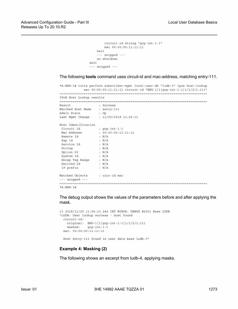
Advanced Configuration Guide - Part III Releases Up To 20.10.R2
Local User Database Basics
Issue: 01 3HE 14992 AAAE TQZZA 01 1273
circuit-id string "grp-int-1-1"mac 00:00:00:11:11:11
exit--- snipped ---no shutdown
exit--- snipped ---
The following tools command uses circuit-id and mac-address, matching entry-111.
*A:BNG-1# tools perform subscriber-mgmt local-user-db "ludb-3" ipoe host-lookupmac 00:00:00:11:11:11 circuit-id "BNG-1|1|grp-int-1-1|1/1/2/1:111"
===============================================================================IPoE Host Lookup results===============================================================================Result : SuccessMatched Host Name : entry-111Admin State : UpLast Mgmt Change : 11/20/2018 11:25:11
Host IdentificationCircuit Id : grp-int-1-1Mac Address : 00:00:00:11:11:11Remote Id : N/ASap Id : N/AService Id : N/AString : N/AOption 60 : N/ASystem Id : N/AEncap Tag Range : N/ADerived Id : N/AIP prefix : N/A
Matched Objects : circ-id mac--- snipped ---===============================================================================*A:BNG-1#
The debug output shows the values of the parameters before and after applying the mask.
13 2018/11/20 11:56:10.244 CET MINOR: DEBUG #2001 Base LUDB"LUDB: User lookup success - host found
circuit-id:original: BNG-1|1|grp-int-1-1|1/1/2/1:111masked: grp-int-1-1
mac: 00:00:00:11:11:11
Host entry-111 found in user data base ludb-3"
Example 4: Masking (2)
The following shows an excerpt from ludb-4, applying masks.

Local User Database Basics
1274
Advanced Configuration Guide - Part IIIReleases Up To 20.10.R2
3HE 14992 AAAE TQZZA 01 Issue: 01
The match-list includes the username, circuit-id, and remote-id, in this sequence. Masking applies to both the username and the circuit-id. The username has everything before the @-sign and the trailing .org stripped. The circuit-id has the trailing 11 characters stripped.
configuresubscriber-mgmt
local-user-db "ludb-4" createppp
match-list username circuit-id remote-idmask type circuit-id suffix-length 11mask type username prefix-string "*@" suffix-string ".org"host "entry-11" create
host-identificationusername domain1circuit-id string "BSAN-2"
exitaddress pool "pool4-1"identification-strings 254 create
sla-profile-string "sla-prof-1"sub-profile-string "sub-prof-2"
exitno shutdown
exit--- snipped ---
exitno shutdown
exit--- snipped ---
The following tools command does not result in a match, which is not the intention.
*A:BNG-1# tools perform subscriber-mgmt local-user-db "ludb-4" ppp host-lookupuser-name [email protected] circuit-id "BSAN-2|100|1/2/1:111"
===============================================================================PPP host Lookup results===============================================================================Result : host not found*A:BNG-1#
The debug output shows the original and the masked value of the user-name and the circuit-id; the remote-id was not provided.
14 2018/11/20 11:57:45.554 CET MINOR: DEBUG #2001 Base LUDB"LUDB: User lookup success - host not found
user-name:original: [email protected]: domain1
circuit-id:original: BSAN-2|100|1/2/1:111masked: BSAN-2|10
remote-id:
Host not found in user data base ludb-4"

Advanced Configuration Guide - Part III Releases Up To 20.10.R2
Local User Database Basics
Issue: 01 3HE 14992 AAAE TQZZA 01 1275
The preceding output shows that three more characters (the |10) must be stripped to have a successful lookup, and following configuration changes are needed.
configuresubscriber-mgmt
local-user-db "ludb-4" createppp
mask type circuit-id suffix-length 14
Modifying the mask results in host entry-11 being matched.
*A:BNG-1# tools perform subscriber-mgmt local-user-db "ludb-4" ppp host-lookupuser-name [email protected] circuit-id "BSAN-2|100|1/2/1:111"
===============================================================================PPP host Lookup results===============================================================================Result : SuccessMatched Host Name : entry-11Admin State : UpLast Mgmt Change : 11/20/2018 11:25:11
Host IdentificationMac Address : N/ACircuit Id : BSAN-2Remote Id : N/ASap Id : N/AService Name : N/AUser Name : domain1Encap Tag Range : N/ADerived Id : N/A
Matched Objects : userName circ-id--- snipped ---===============================================================================*A:BNG-1#
The debug output shows the effect of the modified mask.
15 2018/11/20 11:58:29.339 CET MINOR: DEBUG #2001 Base LUDB"LUDB: User lookup success - host found
user-name:original: [email protected]: domain1
circuit-id:original: BSAN-2|100|1/2/1:111masked: BSAN-2
remote-id:
Host entry-11 found in user data base ludb-4"
Example 5: VLAN Range
LUDB matching also supports the use of encap-tag-range. Host-identification then needs a start and an end for the range, which both use the following format:
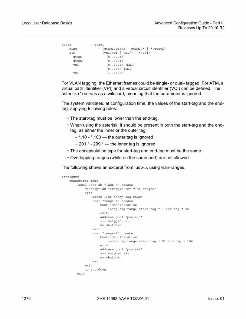
Local User Database Basics
1276
Advanced Configuration Guide - Part IIIReleases Up To 20.10.R2
3HE 14992 AAAE TQZZA 01 Issue: 01
dot1q - qtag1qinq - (qtag1.qtag2 | qtag1.* | *.qtag2)atm - (vpi/vci | vpi/* | */vci)
qtag1 - [0..4094]qtag2 - [0..4094]vpi - [0..4095] (NNI)
[0..255] (UNI)vci - [1..65535]
For VLAN tagging, the Ethernet frames could be single- or dual- tagged. For ATM, a virtual path identifier (VPI) and a virtual circuit identifier (VCI) can be defined. The asterisk (*) serves as a wildcard, meaning that the parameter is ignored.
The system validates, at configuration time, the values of the start-tag and the end-tag, applying following rules:
• The start-tag must be lower than the end-tag.• When using the asterisk, it should be present in both the start-tag and the end-
tag, as either the inner or the outer tag:- *.10 - *.100 — the outer tag is ignored- 201.* - 299.* — the inner tag is ignored
• The encapsulation type for start-tag and end-tag must be the same.• Overlapping ranges (while on the same port) are not allowed.
The following shows an excerpt from ludb-5, using vlan-ranges.
configuresubscriber-mgmt
local-user-db "ludb-5" createdescription "example for vlan ranges"ipoe
match-list encap-tag-rangehost "range-1" create
host-identificationencap-tag-range start-tag *.1 end-tag *.50
exitaddress pool "pool4-3"--- snipped ---no shutdown
exithost "range-2" create
host-identificationencap-tag-range start-tag *.51 end-tag *.100
exitaddress pool "pool4-4"--- snipped ---no shutdown
exitexitno shutdown
exit

Advanced Configuration Guide - Part III Releases Up To 20.10.R2
Local User Database Basics
Issue: 01 3HE 14992 AAAE TQZZA 01 1277
The following tools command specifies a sap-id including an outer and an inner tag, matching host range-1.
*A:BNG-1# tools perform subscriber-mgmt local-user-db "ludb-5"ipoe host-lookup sap-id 1/1/1:50.4
===============================================================================IPoE Host Lookup results===============================================================================Result : SuccessMatched Host Name : range-1Admin State : UpLast Mgmt Change : 11/20/2018 11:25:11
Host IdentificationCircuit Id : N/AMac Address : N/ARemote Id : N/ASap Id : N/AService Id : N/AString : N/AOption 60 : N/ASystem Id : N/AEncap Tag Range : start-tag *.1 end-tag *.50Derived Id : N/AIP prefix : N/A
Matched Objects : encap-tag-range
Address : pool "pool4-3"--- snipped ---===============================================================================*A:BNG-1#
Operational Considerations
Following operational considerations should be kept in mind:
• Names of LUDBs and LUDB entries cannot be changed.• Modification of the host identification fields is possible only when the host-entry
is put in the shutdown state. Modifying output fields does not require the host-entry to be in the shutdown state. *A:BNG-1>config>subscr-mgmt>...>ppp>host>host-ident# circuit-id string x-y-zMINOR: DHCPS #1133 Not allowed. Host is not shutdown
• Modifying a match-list requires the LUDB to be in the shutdown state.• Modifying a match-list results in a re-evaluation of all host entries of the LUDB
block, so that the lookup database and the unmatched host list are re-populated.*A:BNG-1>config>subscr-mgmt>loc-user-db>ipoe# match-list circuit-idINFO: DHCPS #1107 Host could not be inserted in lookup database- lookup database constructed, 1 hosts not inserted: 1 no match, 0 duplicate

Local User Database Basics
1278
Advanced Configuration Guide - Part IIIReleases Up To 20.10.R2
3HE 14992 AAAE TQZZA 01 Issue: 01
Modifying the match-list also imposes the risk of a default entry with host-identification fields suddenly not being the fallback (default) entry anymore, which is why defining a default entry with host-identification fields is not recommended.
• Modifying one or more mask types does not require the LUDB to be in the shutdown state.
• Deletion of an LUDB requires that the LUDB is not referenced and the LUDB is in the shutdown state. Use caution: the status of the individual entries is not taken into account when deleting an LUDB.*A:BNG-1>config>subscr-mgmt# no local-user-db "ludb-1"MINOR: DHCPS #1103 User data base still referenced
*A:BNG-1>config>subscr-mgmt# no local-user-db "ludb-11"MINOR: DHCPS #1104 Not allowed when user db admin state is up
Troubleshooting and Debugging LUDBs
The tools command can also be used for troubleshooting; the example is not repeated for brevity.
Show Commands
The following command shows which LUDBs are available in the system, including the administrative state and the host count. The host count equals the total number of configured ipoe and ppp entries, regardless of their administrative state (shutdown/no shutdown).
*A:BNG-1# show subscriber-mgmt local-user-db
===============================================================================Local User Databases===============================================================================Name Admin Host Description
State Count-------------------------------------------------------------------------------ludb-1 Up 10 example user-dbludb-2 Up 4ludb-22 Up 5ludb-3 Down 5ludb-4 Up 1ludb-5 Up 2 example for vlan ranges-------------------------------------------------------------------------------Number of Local User Databases : 6 Number of Hosts : 27===============================================================================*A:BNG-1#

Advanced Configuration Guide - Part III Releases Up To 20.10.R2
Local User Database Basics
Issue: 01 3HE 14992 AAAE TQZZA 01 1279
For showing the host count and the IPoE and PPP match types for a single LUDB, following command is useful.
*A:BNG-1# show subscriber-mgmt local-user-db "ludb-1"
===============================================================================Local User Database "ludb-1"===============================================================================Description : example user-dbAdmin State : UpLast Mgmt Change : 11/20/2018 11:25:10Host Count : 10IPoE Match Types : macPPP Match Types : userName===============================================================================*A:BNG-1#
Listing all IPoE hosts in a specific LUDB is performed with the following command.
*A:BNG-1# show subscriber-mgmt local-user-db "ludb-1" ipoe-all-hosts
===============================================================================Local User Database "ludb-1" IPoE hosts===============================================================================Name Admin Matched objects
State-------------------------------------------------------------------------------default Up -entry-11 Up mac--- snipped ----------------------------------------------------------------------------------Number of IPoE Hosts : 5===============================================================================*A:BNG-1#
A similar command lists all PPP hosts.
*A:BNG-1# show subscriber-mgmt local-user-db "ludb-1" ppp-all-hosts
===============================================================================Local User Database "ludb-1" PPP Hosts===============================================================================Name Admin Matched objects
State-------------------------------------------------------------------------------entry-55 Up userName--- snipped ----------------------------------------------------------------------------------Number of PPP Hosts : 5===============================================================================*A:BNG-1#
To find the places where a specific LUDB is applied, use the following command.
*A:BNG-1# show subscriber-mgmt local-user-db "ludb-1" association

Local User Database Basics
1280
Advanced Configuration Guide - Part IIIReleases Up To 20.10.R2
3HE 14992 AAAE TQZZA 01 Issue: 01
===============================================================================DHCP Server associations for ludb-1===============================================================================Server-Name Router-Name-------------------------------------------------------------------------------dhcp4-srv Base-------------------------------------------------------------------------------No. of Server(s): 1===============================================================================
===============================================================================DHCP client interface associations for ludb-1===============================================================================Interface-Name Svc-Id Type-------------------------------------------------------------------------------grp-int-1-1 1 IESgrp-int-1-2 1 IESgrp-int-2-1 1 IESgrp-int-2-2 1 IES-------------------------------------------------------------------------------No. of Interface(s): 4===============================================================================
===============================================================================DHCP6 interface associations for ludb-1===============================================================================Interface-Name Svc-Id Type-------------------------------------------------------------------------------grp-int-1-1 1 IESgrp-int-1-2 1 IESgrp-int-2-1 1 IESgrp-int-2-2 1 IES-------------------------------------------------------------------------------No. of Interface(s): 4===============================================================================
No Router solicit interface associations found.
===============================================================================PPP client interface associations for ludb-1===============================================================================Interface-Name Svc-Id Type-------------------------------------------------------------------------------grp-int-1-1 1 IESgrp-int-1-2 1 IESgrp-int-2-1 1 IESgrp-int-2-2 1 IES-------------------------------------------------------------------------------No. of Interface(s): 4===============================================================================
No PPPoE client interface associations found.
No IPoE client interface associations found.
No capture SAP associations found.
No associated L2TP groups found.
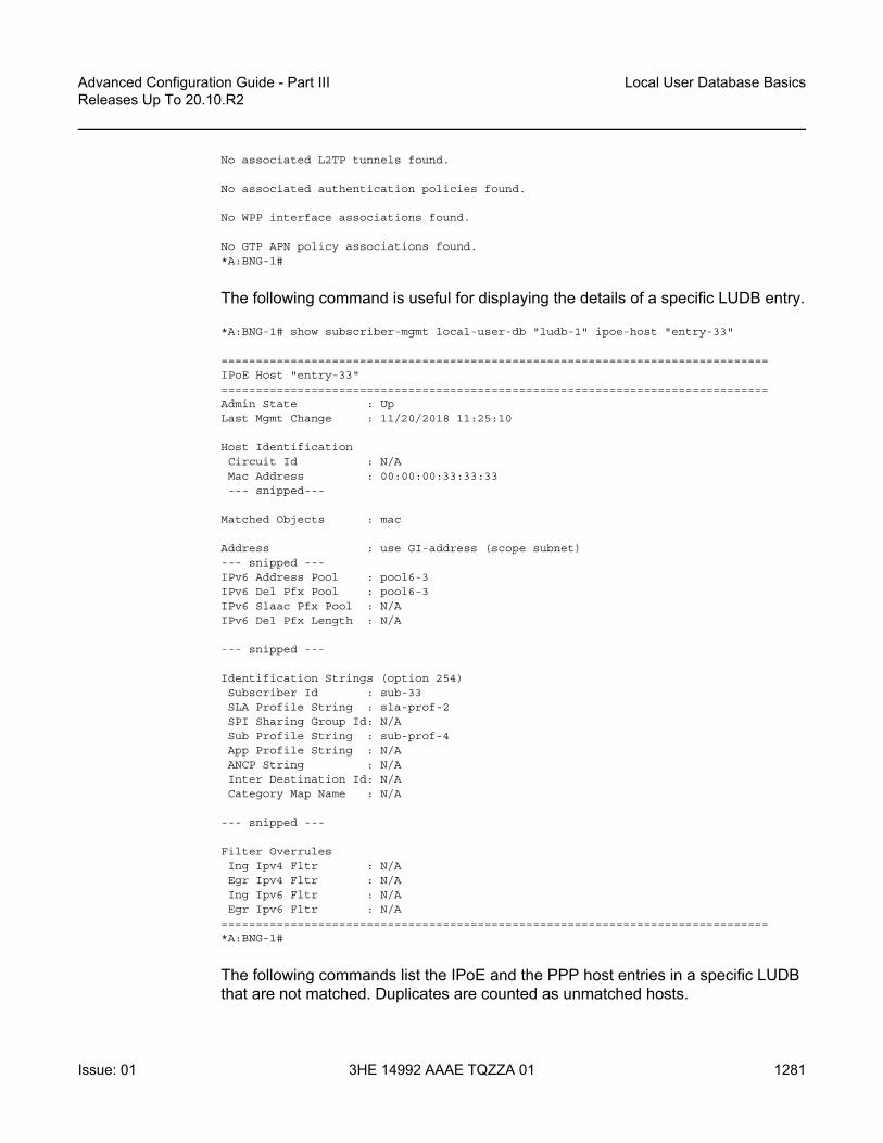
Advanced Configuration Guide - Part III Releases Up To 20.10.R2
Local User Database Basics
Issue: 01 3HE 14992 AAAE TQZZA 01 1281
No associated L2TP tunnels found.
No associated authentication policies found.
No WPP interface associations found.
No GTP APN policy associations found.*A:BNG-1#
The following command is useful for displaying the details of a specific LUDB entry.
*A:BNG-1# show subscriber-mgmt local-user-db "ludb-1" ipoe-host "entry-33"
===============================================================================IPoE Host "entry-33"===============================================================================Admin State : UpLast Mgmt Change : 11/20/2018 11:25:10
Host IdentificationCircuit Id : N/AMac Address : 00:00:00:33:33:33--- snipped---
Matched Objects : mac
Address : use GI-address (scope subnet)--- snipped ---IPv6 Address Pool : pool6-3IPv6 Del Pfx Pool : pool6-3IPv6 Slaac Pfx Pool : N/AIPv6 Del Pfx Length : N/A
--- snipped ---
Identification Strings (option 254)Subscriber Id : sub-33SLA Profile String : sla-prof-2SPI Sharing Group Id: N/ASub Profile String : sub-prof-4App Profile String : N/AANCP String : N/AInter Destination Id: N/ACategory Map Name : N/A
--- snipped ---
Filter OverrulesIng Ipv4 Fltr : N/AEgr Ipv4 Fltr : N/AIng Ipv6 Fltr : N/AEgr Ipv6 Fltr : N/A
===============================================================================*A:BNG-1#
The following commands list the IPoE and the PPP host entries in a specific LUDB that are not matched. Duplicates are counted as unmatched hosts.

Local User Database Basics
1282
Advanced Configuration Guide - Part IIIReleases Up To 20.10.R2
3HE 14992 AAAE TQZZA 01 Issue: 01
*A:BNG-1# show subscriber-mgmt local-user-db "ludb-22" ipoe-unmatched-hosts
===============================================================================Local User Database "ludb-22" IPoE unmatched hosts===============================================================================Name Reason Duplicate Host-------------------------------------------------------------------------------this-is-a-no-match No match N/Athis-is-a-duplicate Duplicate entry-12-------------------------------------------------------------------------------Number of IPoE Unmatched Hosts : 2===============================================================================*A:BNG-1#
*A:BNG-1# show subscriber-mgmt local-user-db "ludb-22" ppp-unmatched-hosts
===============================================================================Local User Database "ludb-22" PPP unmatched hosts===============================================================================Name Reason Duplicate Host--------------------------------------------------------------------------------------------------------------------------------------------------------------No PPP Unmatched Hosts found===============================================================================*A:BNG-1#
Debugging Commands
The following configuration enables debugging for both ludb-1 and for ludb-2.
debugsubscriber-mgmt
local-user-db "ludb-1"detail all
exitlocal-user-db "ludb-2"
detail allexit
exitexit
To ensure that the debug output is sent to the console, the following additional configuration is needed.
configurelog
log-id 1from debug-traceto sessionno shutdown
exitexit

Advanced Configuration Guide - Part III Releases Up To 20.10.R2
Local User Database Basics
Issue: 01 3HE 14992 AAAE TQZZA 01 1283
After the preceding configuration, debug output appears as part of the session.
2 2018/11/20 11:42:27.965 CET MINOR: DEBUG #2001 Base LUDB"LUDB: User lookup success - host found
mac: 00:00:00:11:11:11
Host entry-11 found in user data base ludb-1"
12 2018/11/20 11:54:44.948 CET MINOR: DEBUG #2001 Base LUDB"LUDB: User lookup success - host not found
mac:circuit-id:remote-id:
original: AAmasked: AA
Host not found in user data base ludb-2"
37 2018/11/20 12:18:59.141 CET MINOR: DEBUG #2001 Base LUDB"LUDB: User lookup failed
Problem: user db is shutdown"
Conclusion
In this chapter general LUDB concepts are explained. LUDBs are defined and host entries for both IPoE as well as for PPP are described. The different match criteria are explained and demonstrated by means of examples, including the use of single and multiple match criteria. Match criteria are handled left to right, in sequence, so that a natural priority is taken care of. Debugging aids are provided through show, debug and tools commands.

Local User Database Basics
1284
Advanced Configuration Guide - Part IIIReleases Up To 20.10.R2
3HE 14992 AAAE TQZZA 01 Issue: 01

Advanced Configuration Guide - Part III Releases Up To 20.10.R2
Local User Database for DHCPv4 Server
Issue: 01 3HE 14992 AAAE TQZZA 01 1285
Local User Database for DHCPv4 ServerThis chapter provides information about Local User Database (LUDB) for DHCPv4 server.
Topics in this chapter include:
• Applicability• Overview• Configuration• Conclusion
Applicability
This chapter is applicable to the 7x50 SR series, was based on SR OS release 13.0.R1 and is updated to release 16.0.R4.
Basic LUDB knowledge is a prerequisite for understanding this chapter.
Overview
In SR OS, a local DHCPv4 server can be assigned a Local User Database (LUDB).
Assigning an LUDB to a DHCPv4 server allows the server to:
• control IP address assignment; for example, by assigning a fixed IP address based on the user’s MAC address.
• control DHCPv4 options for native as well as for simulated DHCPv4 clients used by PPP. In the case of PPP, users are identified to the DHCPv4 server using the DHCPv4 Vendor-Specific Information Sub-option [82,9][6] in the DHCPv4 discover/request messages.
• provide ESM strings (referred to as identification-strings in CLI) using a user-defined unassigned DHCPv4 option (option 254 is provided as default).

Local User Database for DHCPv4 Server
1286
Advanced Configuration Guide - Part IIIReleases Up To 20.10.R2
3HE 14992 AAAE TQZZA 01 Issue: 01
Introduction
A local DHCPv4 server can be used for IPoE users as well as for PPP users (see Figure 213).
When a DHCPv4 user connects, the typical Discover, Offer, Request, and Acknowledge (DORA) message sequence running between the DHCPv4 client and the DHCPv4 server also passes through a relay agent.
When a PPP user connects through LCP/IPCP, an internal DHCPv4 client manages the communication toward the DHCPv4 server, on the condition that the relay agent also has relaying enabled for PPP applications. This internal DHCPv4 client is also referred to as a local (DHCPv4) client.
The DHCPv4 server can be located in the same node as the relay agent and the local client, but that is not required.
Figure 213 LUDB Access via a DHCPv4 Server
The relay agent must be configured correctly in order to forward the messages toward a DHCPv4 server. The DHCPv4 server IP address is defined. The relay agent can include following configurable options and sub-options to be used by the DHCPv4 server:
• [82,1] Agent Circuit ID Sub-option• [82,2] Agent Remote ID Sub-option• [82,9] Vendor-Specific Information Sub-option (VSO)
- [1] system-ID (7x50 system-name)- [2] client MAC-address
al_0811
PPP
DHCPv4
Local client
Relay agentDHCPv4server
LUDB
User defined options
ipoehost entry-11host entry-12...
pool-1
DORA
DORA
DORA
Fixed options
IPCP
pool-2
subnet-1subnet-2
subnet-3subnet-4
ppphost entry-21host entry-22...
DORA- Discover, Offer, Request, Acknowledge

Advanced Configuration Guide - Part III Releases Up To 20.10.R2
Local User Database for DHCPv4 Server
Issue: 01 3HE 14992 AAAE TQZZA 01 1287
- [3] service-ID (7x50 IES/VPRN service-id)- [4] sap-ID- [5] string- [13] pool-name
The local client uses the same DHCPv4 server IP address as the preceding relay agent, and can include its own set of (unconfigurable) options and sub-options to be used by the DHCPv4 server:
• [60] vendor class (fixed string: ALU7XXXSBM)• [82,1] Agent Circuit ID Sub-option• [82,2] Agent Remote ID Sub-option• [82,6] Subscriber-ID Sub-option (equals PPPoE username)• [82,9] Vendor-Specific Information Sub-option
- [1] system-ID (not included in a redundant node)- [2] client MAC-address- [3] service-ID (7x50 IES/VPRN service-id)- [4] sap-ID (not included for retail VPRN and redundant node)- [6] client type (1=ppp)- [13] pool-name- [14] service name (PPPoE tag service-name)- [17] session-ID (PPPoE session-id)
When one or more of these options and sub-options are included, the DHCPv4 server can use them while accessing the LUDB, for selection of the section (client type 1 is the PPP section), and the host entry in that section. For example, not including the service-ID VSO [82,9][3] to the DHCPv4 server, when LUDB host identification needs the MAC address and service ID, will result in an LUDB lookup failure on the DHCPv4 server and a silent drop of the DHCPv4 discover message.
LUDB Input Parameters
The following IPoE host identification fields are supported when accessing an LUDB from a DHCPv4 server:
• circuit-id• encap-tag-range• mac

Local User Database for DHCPv4 Server
1288
Advanced Configuration Guide - Part IIIReleases Up To 20.10.R2
3HE 14992 AAAE TQZZA 01 Issue: 01
• option60• remote-id• sap-id• service-id • string• system-id
The LUDB lookup process can match up to four IPoE match-criteria, as defined by the IPoE match-list.
The following PPP host identification fields are supported when accessing an LUDB from a DHCPv4 server:
• circuit-id• encap-tag-range• mac• remote-id• sap-id• service-name• username
The LUDB lookup process can match up to three PPP match-criteria, as defined by the PPP match-list.
LUDB Output Parameters
Addressing Information
The host entry address field has the following configuration options when the LUDB is associated with a DHCPv4 server:
• no addressHost access is not allowed. The clients mapping to this host entry will not get an IP address.
23 2018/11/21 13:20:09.958 CET MINOR: DEBUG #2001 Base DHCP server"DHCP server: dhcp4-srvDISCOVER dropped: host=entry-66, host found but no valid address info

Advanced Configuration Guide - Part III Releases Up To 20.10.R2
Local User Database for DHCPv4 Server
Issue: 01 3HE 14992 AAAE TQZZA 01 1289
• address <ip-address> A fixed IP address is offered to the client and should not overlap with the address ranges configured in the local DHCP server.
• address pool <pool-name> [secondary-pool <sec-pool-name>]The DHCPv4 server allocates an address from one of the subnets in that pool on the condition that the DHCPv4 server is configured to use pool names for address selection. Optionally, a secondary pool can be defined, to be used in case the primary pool is exhausted.Pool-name addressing is useful when the subscriber management node is not capable of inserting the pool-name VSO [82,9][13] or when a specific host requires a specific pool-name different from the pool-name included by the subscriber management node.
• address gi-address [scope <subnet|pool>]When the scope is set to subnet, the DHCPv4 server allocates an address from the subnet that includes the Gi address. When the scope is set to pool, the DHCPv4 server allocates an address from the subnet that includes the Gi address, or from the other subnets belonging to the same pool. Gi-addressing is useful when the subnet that the Gi address belongs to is exhausted.
• address use-pool-from-client [delimiter <delimiter>]The DHCPv4 server allocates an address from one of the subnets in the pool, as indicated by the pool-name VSO [82,9][13]. If two pools are available in this VSO, the configured delimiter distinguishes the first pool-name from the second pool-name.
Identification Strings
An LUDB can optionally return identification strings (also known as ESM strings). The DHCPv4 server returns them in a user-defined DHCPv4 option (default: 254) to the requesting entity (the relay agent or the local client). The identification strings, in alphabetical order, are:
• ancp-string• app-profile-string• category-map-name• inter-dest-id• sla-profile-string• sub-profile-string• subscriber-id

Local User Database for DHCPv4 Server
1290
Advanced Configuration Guide - Part IIIReleases Up To 20.10.R2
3HE 14992 AAAE TQZZA 01 Issue: 01
Options
An LUDB can return options to be used by the relay agent, the internal client, or the end-user device.
The IPoE user options configurable by option-name are:
• default-router• dns-server• domain-name• lease-rebind-timer• lease-renew-timer• lease-time• netbios-name-server• netbios-node-type• subnet-mask
The PPP user options configurable by option-name are:
• dns-server• netbios-name-server
Additional options, configurable by option-number, can be configured for both IPoE and PPP users by using the custom-option command.
*A:BNG-1>config>subscr-mgmt>loc-user-db>ipoe>host>options# custom-option ?- custom-option <option-number> address [<ip-address>...(upto 4 max)]- custom-option <option-number> hex <hex-string>- custom-option <option-number> string <ascii-string>- no custom-option <option-number>
<option-number> : [1..254]<ip-address> : a.b.c.d<ascii-string> : [127 chars max]<hex-string> : [0x0..0xFFFFFFFF...(max 254 hex nibbles)]
*A:BNG-1>config>subscr-mgmt>loc-user-db>ipoe>host>options#
The encoding of these custom options is either in hexadecimal, ASCII, or IP address format. In debug output, these custom options are indicated as Unknown options and presented in Type-Length-Value (TLV) format.
Options and custom options can be configured at three different levels:
• LUDB host entry level• DHCPv4 server pool level

Advanced Configuration Guide - Part III Releases Up To 20.10.R2
Local User Database for DHCPv4 Server
Issue: 01 3HE 14992 AAAE TQZZA 01 1291
• DHCPv4 server subnet level
Options and custom options defined at the host entry level overrule options defined at either of the server levels.
Other Parameters
All other parameters in the host entry definition are silently ignored (for example, IPv6 related parameters, msap-defaults, retail-service-id, and so on) because they are not applicable for a DHCPv4 server-associated LUDB.
Configuration
Figure 214 shows the example configuration used in this chapter.
Figure 214 Example Configuration
An LUDB can be associated with a DHCPv4 server in the base router instance or in a VPRN service instance using the following commands:
configure router dhcp local-dhcp-server <name> user-db <name>configure service vprn <service-id> dhcp local-dhcp-server <name> user-db <name>
al_0812
IES 1
DHCPv4 server - dhcp4-srv
LUDB - ludb-1
interface int-DHCP address 10.11.11.1/32 dhcp4-srv
user-db ludb-1pool4-1 subnet 10.1.1.0/24pool4-2 subnet 10.1.2.0/24...
ipoe entry-11 address 10.1.1.211ppp entry-55 address pool pool4-2
dhcp server 10.11.11.1/321/1/1
10.1.1.254/2410.1.2.254/24
grp-int-1-2
sub-int-11/1/1:111
1/1/1:112
1/1/1:121
1/1/1:122
grp-int-1-1

Local User Database for DHCPv4 Server
1292
Advanced Configuration Guide - Part IIIReleases Up To 20.10.R2
3HE 14992 AAAE TQZZA 01 Issue: 01
The following example has the DHCPv4 server created in the base router instance.
configurerouter
dhcplocal-dhcp-server "dhcp4-srv" create
user-db "ludb-1"use-gi-addressuse-pool-from-clientpool "pool4-1" create
subnet 10.1.1.0/24 createoptions
subnet-mask 255.255.255.0default-router 10.1.1.254
exitaddress-range 10.1.1.1 10.1.1.100
exitexitpool "pool4-2" create
subnet 10.1.2.0/24 createoptions
subnet-mask 255.255.255.0default-router 10.1.2.254
exit
address-range 10.1.2.1 10.1.2.254exit
exit--- snip ---no shutdown
exitexit
The server is then associated with the loopback interface at address 10.11.11.1, as follows:
configurerouter
interface "int-DHCP"address 10.11.11.1/32loopbacklocal-dhcp-server "dhcp4-srv"no shutdown
exitexit
The following is a partial configuration of service IES 1. Note that the DHCPv4 relay agent is configured to include the service-ID VSO [82,9][3] because this option is used in the LUDB for matching purposes.
configureservice
ies 1 customer 1 createsubscriber-interface "sub-int-1" create
address 10.1.1.254/24address 10.1.2.254/24

Advanced Configuration Guide - Part III Releases Up To 20.10.R2
Local User Database for DHCPv4 Server
Issue: 01 3HE 14992 AAAE TQZZA 01 1293
group-interface "grp-int-1-1" createarp-populatedhcp
optionaction replacecircuit-idremote-idvendor-specific-option
pool-nameservice-id
exitexitserver 10.11.11.1trustedlease-populate 100client-applications dhcp pppgi-address 10.1.1.254no shutdown
exitsap 1/1/1:111 create
sub-sla-mgmtdef-sub-profile "sub-prof-1"def-sla-profile "sla-prof-1"sub-ident-policy "sub-id-pol-1"multi-sub-sapno shutdown
exitexit--- snip ---pppoe
session-limit 100sap-session-limit 100no shutdown
exitexit
exit
In the following example, IPoE users are matched against the service-id, the MAC address and option 60. Host entry-11 returns a fixed IP address, three identification strings, and a set of options. PPP users are matched against the MAC address. Host entry-55 returns an address-pool, two identification strings, and two DNS servers as options.
configuresubscriber-mgmt
local-user-db "ludb-1" createdescription "example user-db"ipoe
match-list service-id mac option60host "entry-11" create
host-identificationmac 00:00:00:11:11:11service-id 1option60 hex 0xaabb
exitaddress 10.1.1.211identification-strings 254 create

Local User Database for DHCPv4 Server
1294
Advanced Configuration Guide - Part IIIReleases Up To 20.10.R2
3HE 14992 AAAE TQZZA 01 Issue: 01
subscriber-id "sub-11"sla-profile-string "sla-profile-1"sub-profile-string "sub-profile-1"
exitoptions
subnet-mask 255.255.255.0default-router 10.1.1.251dns-server 2.2.2.2 2.2.2.1domain-name "domain.org"netbios-name-server 10.1.1.252netbios-node-type Blease-time hrs 12custom-option 251 hex 0x010203
exitno shutdown
exit--- snip ---
exitppp
match-list machost "entry-55" create
host-identificationmac 00:00:00:55:55:55
exitaddress pool "pool4-2"identification-strings 254 create
subscriber-id "sub-55"sla-profile-string "sla-prof-3"sub-profile-string "sub-prof-3"
exitoptions
dns-server 2.2.2.2 2.2.2.1exit--- snip ---no shutdown
exitexitno shutdown
exit
Entry-11 defines a fixed IP address in one of the subnets allowed on the group interface grp-int-1-1 on IES 1, but out of the range defined in the DHCPv4 server.
Debugging
The following example debugs the local DHCP server and the LUDB ludb-1.
debugrouter "Base"
local-dhcp-server "dhcp4"detail-level mediummode egr-ingr-and-dropped
exitexit

Advanced Configuration Guide - Part III Releases Up To 20.10.R2
Local User Database for DHCPv4 Server
Issue: 01 3HE 14992 AAAE TQZZA 01 1295
subscriber-mgmtlocal-user-db "ludb-1"
detail allexit
exitexit
The following additional configuration ensures that the debug output is sent to the current login session.
configurelog
log-id 1from debug-traceto sessionno shutdown
exitexit
exit
IPoE Users Verification
The following command shows the DHCPv4 server lease state record for LUDB host entry-11. The address type is set to fixed because ludb-1 returns a fixed IP address.
*A:BNG-1# show router dhcp local-dhcp-server "dhcp4-srv" leases 10.1.1.211 detail
===============================================================================Lease for DHCP server dhcp4-srv router Base===============================================================================IP-address : 10.1.1.211Lease-state : stableLease started : 2018/11/21 13:14:34Last renew : N/ARemaining LifeTime : 11h59m31sRemaining Potential Exp. Time: 0h0m0sSticky-lease Host Name : N/AMAC address : 00:00:00:11:11:11Xid : 0x1Failover Control : localClient Type : dhcpUser-db Host Name : entry-11User-db Address Type : fixedPersistence Key : N/AOpt82 Hex Dump : (length=54)
: 52 34 01 1d 42 4e 47 2d 31 7c 31 7c 67 72 70 2d: 69 6e 74 2d 31 2d 31 7c 31 2f 31 2f 31 3a 31 31: 31 02 06 00 00 00 11 11 11 09 0b 00 00 19 7f 06: 03 04 00 00 00 01
Opt82 Circuit Id : BNG-1|1|grp-int-1-1|1/1/1:111Opt82 Remote Id : (hex) 00 00 00 11 11 11Opt82 Subscr Id :Opt82 VS System :

Local User Database for DHCPv4 Server
1296
Advanced Configuration Guide - Part IIIReleases Up To 20.10.R2
3HE 14992 AAAE TQZZA 01 Issue: 01
Opt82 VS Clnt MAC :Opt82 VS Service : (hex) 00 00 00 01Opt82 VS SAP :Opt82 VS String :Opt60 Hex Dump : (length=2)
: aa bbLease Remaining Hold Time : 0h0m0s
===============================================================================*A:BNG-1#
The debug output on the DHCPv4 server and the LUDB ludb-1 shows that the LUDB is accessed for every incoming message. The identification-strings are returned to the relay agent in the Offer and Acknowledge messages through option [254]; see Figure 215 for the decoding.
1 2018/11/21 13:14:34.703 CET MINOR: DEBUG #2001 Base DHCP server"DHCP server: dhcp4-srvRx DHCP Discover
ciaddr: 0.0.0.0 yiaddr: 0.0.0.0siaddr: 0.0.0.0 giaddr: 10.1.1.254chaddr: 00:00:00:11:11:11 xid: 0x1
DHCP options:[82] Relay agent information: len = 52
[1] Circuit-id: BNG-1|1|grp-int-1-1|1/1/1:111[2] Remote-id: (hex) 00 00 00 11 11 11[9] Vendor-Specific info: len = 11
Enterprise [6527] : len = 6[3] servId: 1
[53] Message type: Discover[60] Class id: (hex) aa bb[255] End
"
2 2018/11/21 13:14:34.703 CET MINOR: DEBUG #2001 Base LUDB"LUDB: User lookup success - host found
svc-id: 1mac: 00:00:00:11:11:11option60:
original: 0xaabbmasked: 0xaabb
Host entry-11 found in user data base ludb-1"
3 2018/11/21 13:14:34.703 CET MINOR: DEBUG #2001 Base DHCP server"DHCP server: dhcp4-srvlease added for 10.1.1.211 state=offer"
4 2018/11/21 13:14:34.703 CET MINOR: DEBUG #2001 Base DHCP server"DHCP server: dhcp4-srvTx DHCP Offer to local relay agent 10.1.1.254 vrId=1

Advanced Configuration Guide - Part III Releases Up To 20.10.R2
Local User Database for DHCPv4 Server
Issue: 01 3HE 14992 AAAE TQZZA 01 1297
ciaddr: 0.0.0.0 yiaddr: 10.1.1.211siaddr: 10.11.11.1 giaddr: 10.1.1.254chaddr: 00:00:00:11:11:11 xid: 0x1
DHCP options:[82] Relay agent information: len = 52
[1] Circuit-id: BNG-1|1|grp-int-1-1|1/1/1:111[2] Remote-id: (hex) 00 00 00 11 11 11[9] Vendor-Specific info: len = 11
Enterprise [6527] : len = 6[3] servId: 1
[53] Message type: Offer[54] DHCP server addr: 10.11.11.1[51] Lease time: 43200[1] Subnet mask: 255.255.255.0[3] Router: 10.1.1.254[6] Domain name server: length = 8
2.2.2.22.2.2.1
[15] Domain name: domain.org[44] NETBIOS name server: 10.1.1.252[46] NETBIOS type: 1[251] Unknown option: len = 3, value = 01 02 03[254] Unknown option: len = 38, value = 07 06 73 75 62 2d 31 31 08 0d 736c 61 2d 70 72 6f 66 69 6c 65 2d 31 09 0d 73 75 62 2d 70 72 6f 66 69 6c 652d 31[60] Class id: (hex) aa bb[255] End
"
5 2018/11/21 13:14:34.718 CET MINOR: DEBUG #2001 Base DHCP server"DHCP server: dhcp4-srvRx DHCP Request
ciaddr: 0.0.0.0 yiaddr: 0.0.0.0siaddr: 0.0.0.0 giaddr: 10.1.1.254chaddr: 00:00:00:11:11:11 xid: 0x1
DHCP options:[82] Relay agent information: len = 52
[1] Circuit-id: BNG-1|1|grp-int-1-1|1/1/1:111[2] Remote-id: (hex) 00 00 00 11 11 11[9] Vendor-Specific info: len = 11
Enterprise [6527] : len = 6[3] servId: 1
[53] Message type: Request[50] Requested IP addr: 10.1.1.211[60] Class id: (hex) aa bb[54] DHCP server addr: 10.11.11.1[255] End
"
6 2018/11/21 13:14:34.718 CET MINOR: DEBUG #2001 Base LUDB"LUDB: User lookup success - host found
svc-id: 1mac: 00:00:00:11:11:11

Local User Database for DHCPv4 Server
1298
Advanced Configuration Guide - Part IIIReleases Up To 20.10.R2
3HE 14992 AAAE TQZZA 01 Issue: 01
option60:original: 0xaabbmasked: 0xaabb
Host entry-11 found in user data base ludb-1"
7 2018/11/21 13:14:34.718 CET MINOR: DEBUG #2001 Base DHCP server"DHCP server: dhcp4-srvlease update for 10.1.1.211 state=stable"
8 2018/11/21 13:14:34.718 CET MINOR: DEBUG #2001 Base DHCP server"DHCP server: dhcp4-srvTx DHCP Ack to local relay agent 10.1.1.254 vrId=1
ciaddr: 0.0.0.0 yiaddr: 10.1.1.211siaddr: 10.11.11.1 giaddr: 10.1.1.254chaddr: 00:00:00:11:11:11 xid: 0x1
DHCP options:[82] Relay agent information: len = 52
[1] Circuit-id: BNG-1|1|grp-int-1-1|1/1/1:111[2] Remote-id: (hex) 00 00 00 11 11 11[9] Vendor-Specific info: len = 11
Enterprise [6527] : len = 6[3] servId: 1
[53] Message type: Ack[54] DHCP server addr: 10.11.11.1[51] Lease time: 43200[1] Subnet mask: 255.255.255.0[3] Router: 10.1.1.254[6] Domain name server: length = 8
2.2.2.22.2.2.1
[15] Domain name: domain.org[44] NETBIOS name server: 10.1.1.252[46] NETBIOS type: 1[251] Unknown option: len = 3, value = 01 02 03[254] Unknown option: len = 38, value = 07 06 73 75 62 2d 31 31 08 0d 736c 61 2d 70 72 6f 66 69 6c 65 2d 31 09 0d 73 75 62 2d 70 72 6f 66 69 6c 652d 31[60] Class id: (hex) aa bb[255] End
"
The user-defined option value for carrying the ESM strings and taken from the LUDB (identification-strings) should match the value defined in the strings-from-option parameter (value 254 in the following example) referenced in the subscriber identification policy on the relaying node.
configuresubscriber-mgmt
sub-ident-policy "sub-id-pol-1" createsub-profile-map
use-direct-map-as-default

Advanced Configuration Guide - Part III Releases Up To 20.10.R2
Local User Database for DHCPv4 Server
Issue: 01 3HE 14992 AAAE TQZZA 01 1299
exitsla-profile-map
use-direct-map-as-defaultexitstrings-from-option 254
exit
The DHCP options in the debug output match the definition of the options in the LUBD.
Figure 215 Decoding the ESM User Option
PPP Users Verification
The following command shows the DHCPv4 server lease state record for LUDB host entry-55. The client type is set to ppp, and the address type is set to dynamic as ludb-1 returns address-pool pool4-2 for this host.
*A:BNG-1# show router dhcp local-dhcp-server "dhcp4-srv" leases 10.1.2.2 detail
===============================================================================Lease for DHCP server dhcp4-srv router Base===============================================================================IP-address : 10.1.2.1Lease-state : stableLease started : 2018/11/21 13:17:06Last renew : N/ARemaining LifeTime : 0h58m36sRemaining Potential Exp. Time: 0h0m0sSticky-lease Host Name : N/A
al_0813
07 06 73 75 62 2d 31 31
08 0d 73 6c 61 2d 70 72 6f 66 69 6c 65 2d 31
09 0d 73 75 62 2d 70 72 6f 66 69 6c 65 2d 31
LengthValue (ASCII encoded)
sla-profile-1
sub-profile-1
sub-11
Type: 07 - subscriber-id 08 - sla-profile-string 09 - sub-profile-string 0a - ancp-string 0b - inter-dest-id 0c - app-profile-string 0f - category-map-name

Local User Database for DHCPv4 Server
1300
Advanced Configuration Guide - Part IIIReleases Up To 20.10.R2
3HE 14992 AAAE TQZZA 01 Issue: 01
MAC address : 00:00:00:55:55:55Xid : 0x2f1dd730Failover Control : localClient Type : pppUser-db Host Name : entry-55User-db Address Type : dynamicPersistence Key : N/AOpt82 Hex Dump : (length=83)
: 52 51 01 1d 42 4e 47 2d 31 7c 31 7c 67 72 70 2d: 69 6e 74 2d 31 2d 31 7c 31 2f 31 2f 31 3a 31 31: 31 02 06 00 00 00 55 55 55 09 28 00 00 19 7f 23: 02 06 00 00 00 55 55 55 06 01 01 01 05 42 4e 47: 2d 31 03 04 00 00 00 01 04 09 31 2f 31 2f 31 3a: 31 31 31
Opt82 Circuit Id : BNG-1|1|grp-int-1-1|1/1/1:111Opt82 Remote Id : (hex) 00 00 00 55 55 55Opt82 VS System : BNG-1Opt82 VS Clnt MAC : 00:00:00:55:55:55Opt82 VS Service : (hex) 00 00 00 01Opt82 VS SAP : 1/1/1:111Opt82 VS String :Opt82 VS PPPoE Session ID :Opt60 Hex Dump : (length=10)
: 41 4c 55 37 58 58 58 53 42 4dLease Remaining Hold Time : 0h0m0s
===============================================================================*A:BNG-1#
The debug output on the DHCPv4 server and the LUDB ludb-1 shows that the LUDB is accessed for every incoming message, as follows. Again the identification-strings are returned to the relay agent in the Offer and Acknowledge messages using option [254].
12 2018/11/21 13:17:06.271 CET MINOR: DEBUG #2001 Base DHCP server"DHCP server: dhcp4-srvRx DHCP Discover
ciaddr: 0.0.0.0 yiaddr: 0.0.0.0siaddr: 0.0.0.0 giaddr: 10.1.1.254chaddr: 00:00:00:55:55:55 xid: 0x2f1dd730
DHCP options:[82] Relay agent information: len = 81
[1] Circuit-id: BNG-1|1|grp-int-1-1|1/1/1:111[2] Remote-id: (hex) 00 00 00 55 55 55[9] Vendor-Specific info: len = 40
Enterprise [6527] : len = 35[2] clntMac: 00:00:00:55:55:55[6] clntType: 1[1] systemId: BNG-1[3] servId: 1[4] sapId: 1/1/1:111
[51] Lease time: 3600[53] Message type: Discover[60] Class id: ALU7XXXSBM[255] End

Advanced Configuration Guide - Part III Releases Up To 20.10.R2
Local User Database for DHCPv4 Server
Issue: 01 3HE 14992 AAAE TQZZA 01 1301
"
13 2018/11/21 13:17:06.271 CET MINOR: DEBUG #2001 Base LUDB"LUDB: User lookup success - host found
mac: 00:00:00:55:55:55
Host entry-55 found in user data base ludb-1"
14 2018/11/21 13:17:06.271 CET MINOR: DEBUG #2001 Base DHCP server"DHCP server: dhcp4-srvlease added for 10.1.2.1 state=offer"
15 2018/11/21 13:17:06.271 CET MINOR: DEBUG #2001 Base DHCP server"DHCP server: dhcp4-srvTx DHCP Offer to local client 10.1.1.254 vrId=1
ciaddr: 0.0.0.0 yiaddr: 10.1.2.1siaddr: 10.11.11.1 giaddr: 10.1.1.254chaddr: 00:00:00:55:55:55 xid: 0x2f1dd730
DHCP options:[82] Relay agent information: len = 81
[1] Circuit-id: BNG-1|1|grp-int-1-1|1/1/1:111[2] Remote-id: (hex) 00 00 00 55 55 55[9] Vendor-Specific info: len = 40
Enterprise [6527] : len = 35[2] clntMac: 00:00:00:55:55:55[6] clntType: 1[1] systemId: BNG-1[3] servId: 1[4] sapId: 1/1/1:111
[53] Message type: Offer[54] DHCP server addr: 10.11.11.1[51] Lease time: 3600[1] Subnet mask: 255.255.255.0[6] Domain name server: length = 8
2.2.2.22.2.2.1
[254] Unknown option: len = 32, value = 07 06 73 75 62 2d 35 35 08 0a 736c 61 2d 70 72 6f 66 2d 33 09 0a 73 75 62 2d 70 72 6f 66 2d 33[3] Router: 10.1.2.254[60] Class id: ALU7XXXSBM[255] End
"
16 2018/11/21 13:17:06.271 CET MINOR: DEBUG #2001 Base DHCP server"DHCP server: dhcp4-srvRx DHCP Request
ciaddr: 0.0.0.0 yiaddr: 0.0.0.0siaddr: 0.0.0.0 giaddr: 10.1.1.254chaddr: 00:00:00:55:55:55 xid: 0x2f1dd730
DHCP options:

Local User Database for DHCPv4 Server
1302
Advanced Configuration Guide - Part IIIReleases Up To 20.10.R2
3HE 14992 AAAE TQZZA 01 Issue: 01
[82] Relay agent information: len = 81[1] Circuit-id: BNG-1|1|grp-int-1-1|1/1/1:111[2] Remote-id: (hex) 00 00 00 55 55 55[9] Vendor-Specific info: len = 40
Enterprise [6527] : len = 35[2] clntMac: 00:00:00:55:55:55[6] clntType: 1[1] systemId: BNG-1[3] servId: 1[4] sapId: 1/1/1:111
[50] Requested IP addr: 10.1.2.1[51] Lease time: 3600[53] Message type: Request[54] DHCP server addr: 10.11.11.1[60] Class id: ALU7XXXSBM[255] End
"
17 2018/11/21 13:17:06.271 CET MINOR: DEBUG #2001 Base LUDB"LUDB: User lookup success - host found
mac: 00:00:00:55:55:55
Host entry-55 found in user data base ludb-1"
18 2018/11/21 13:17:06.271 CET MINOR: DEBUG #2001 Base DHCP server"DHCP server: dhcp4-srvlease update for 10.1.2.1 state=stable"
19 2018/11/21 13:17:06.271 CET MINOR: DEBUG #2001 Base DHCP server"DHCP server: dhcp4-srvTx DHCP Ack to local client 10.1.1.254 vrId=1
ciaddr: 0.0.0.0 yiaddr: 10.1.2.1siaddr: 10.11.11.1 giaddr: 10.1.1.254chaddr: 00:00:00:55:55:55 xid: 0x2f1dd730
DHCP options:[82] Relay agent information: len = 81
[1] Circuit-id: BNG-1|1|grp-int-1-1|1/1/1:111[2] Remote-id: (hex) 00 00 00 55 55 55[9] Vendor-Specific info: len = 40
Enterprise [6527] : len = 35[2] clntMac: 00:00:00:55:55:55[6] clntType: 1[1] systemId: BNG-1[3] servId: 1[4] sapId: 1/1/1:111
[53] Message type: Ack[54] DHCP server addr: 10.11.11.1[51] Lease time: 3600[1] Subnet mask: 255.255.255.0[6] Domain name server: length = 8
2.2.2.22.2.2.1
[254] Unknown option: len = 32, value = 07 06 73 75 62 2d 35 35 08 0a 73

Advanced Configuration Guide - Part III Releases Up To 20.10.R2
Local User Database for DHCPv4 Server
Issue: 01 3HE 14992 AAAE TQZZA 01 1303
6c 61 2d 70 72 6f 66 2d 33 09 0a 73 75 62 2d 70 72 6f 66 2d 33[3] Router: 10.1.2.254[60] Class id: ALU7XXXSBM[255] End
"
Operational Considerations
A DHCPv4 server with an LUDB cannot be used for supporting Local Address Assignment (LAA) scenarios. LAA can be used when the DHCPv4 relay agent and the DHCPv4 server are in the same node, and where IP address assignment for PPP users happens through the API directly into the local DHCPv4 server. See the ESM SLAAC Prefix Assignment via Local Address Server chapter via Local Address Server of the Advanced Configuration Guide for details on this topic.
Conclusion
This chapter explained and demonstrated the use of an LUDB in combination with a DHCPv4 server. For the DHCPv4 server to find matching entries in the LUDB, the relay agent has to be configured with the correct options and sub-options so that entries can be matched in the LUDB. It was noted that the DHCPv4 server does not require the relaying function to be located in the same node. The input and the output parameters of a DHCPv4 server-attached LUDB were listed. Carrying over the identification/ESM strings in a user-defined DHCP option was configured and demonstrated, and the decoding of this option was explained.

Local User Database for DHCPv4 Server
1304
Advanced Configuration Guide - Part IIIReleases Up To 20.10.R2
3HE 14992 AAAE TQZZA 01 Issue: 01
Advanced Configuration Guide - Part III Releases Up To 20.10.R2
Local User Database for Enhanced SubscriberManagement
Issue: 01 3HE 14992 AAAE TQZZA 01 1305
Local User Database for Enhanced Subscriber Management
Applicability
This chapter is applicable to the 7x50 SR series and was initially based on SROS 13.0.R6. The CLI is updated to release 16.0.R4.
Having knowledge of ESM Basics, the Routed CO model, and Local User Database Basics are prerequisites for understanding this chapter.
Summary
A Local User Database (LUDB) is a data source providing Enhanced Subscriber Management (ESM) data so that subscribers and subscriber hosts can be instantiated when end-users connect their devices. ESM data includes identification strings, IP address/prefix, profiles, and so on. See the ESM Basics chapter for more information.
LUDBs offer a self-contained method for providing the ESM data, so that no additional ESM data sources are needed.
Alternative ESM data sources are: RADIUS, Diameter NASREQ, Diameter Gx, DHCP-server, Python, and defaults.
Mixed scenarios, where part of the data is provided by an LUDB and the remaining part is provided through RADIUS, are the subject of the Flexible Authentication Model in ESM chapter.
LUDBs can be used for the following applications:
• assisting a DHCPv4 server in assigning fixed IP addresses to dedicated devices; see the Local User Database for DHCPv4 Server chapter.
• authenticating devices, so that ESM hosts and subscribers can be instantiated. This is supported for the Routed CO model only.
• authenticating devices as a fallback for RADIUS authentication, in case the RADIUS server is not available. This is supported for the Routed CO model only.

Local User Database for Enhanced Subscriber Management
1306
Advanced Configuration Guide - Part IIIReleases Up To 20.10.R2
3HE 14992 AAAE TQZZA 01 Issue: 01
This chapter describes the use of LUDBs for authentication, including:
• parameters that can be returned by LUDBs • contexts where LUDBs can be applied in the system
Overview
LUDB authentication is supported:
• for IPoE as well as for PPP• for regular SAPs as well as for capture and managed SAPs• for the proxy scenario as well as for the relay scenario
LUDB authentication can be started directly through one of the following protocol triggers; see Figure 216:
• DHCPv4 Discover• DHCPv6 Solicit• PPPoE PADI• PPPoA Conf Req• Router Solicit [RS]
Figure 216 LUDB Authentication
LAN
IPoE/PPP
DHCPv4 Discover
(*) – indirect trigger only, via RADIUS fallback
DHCPv6 Solicit
ARP request (*)
PPPoE PADI
PPPoA Conf Req
Router Solicit
fallback
LUDB
subscriber-idsub-profile stringsla-profile stringapp-profile string
… RADIUS
ESM
25536
WAN

Advanced Configuration Guide - Part III Releases Up To 20.10.R2
Local User Database for Enhanced SubscriberManagement
Issue: 01 3HE 14992 AAAE TQZZA 01 1307
When triggered, ESM can directly access an LUDB because the LUDB is applied to the service directly (through one of its sub-contexts), or indirectly as a fallback action for RADIUS (through the authentication policy); see Figure 217. ARP requests can only trigger LUDB authentication indirectly.
Figure 217 Direct and Indirect LUDB Authentication
Three ESM scenarios in which an LUDB is accessed are as follows:
• ESM gets all the data needed for host creation directly from the LUDB.• ESM gets some data from the LUDB and the remaining data from an AAA server
(RADIUS, NASREQ, Gx). This requires the LUDB to provide an authentication or a Diameter application policy, and no authentication or Diameter policy at the group interface level.
• ESM tries to fetch the data from a RADIUS server, but because this server is not reachable, ESM falls back to an LUDB.
Note: An authentication policy can be referenced from a group interface and a capture SAP, or from an LUDB.
25537
subscriber-interface sub-1 group-interface grp-1-1 ipv6 dhcp6 user-db ludb-1 dhcp user-db ludb-1 … pppoe user-db ludb-1
Layer 3 service
Direct LUDB authentication
ipoe entry-1 … entry-2 …ppp entry-3 …
LUDB – ludb-1
subscriber-interface sub-1 group-interface grp-1-1 authentication-policy auth-1 ipv6 dhcp6 …. dhcp …. pppoe ….
Layer 3 service
Indirect LUDB authentication
fallback-action user-db ludb-2
radius-server-policy
AUTH-POLICY – auth-1 ipoe entry-11 address identification-stringsppp entry-22 address identification-strings
LUDB – ludb-2

Local User Database for Enhanced Subscriber Management
1308
Advanced Configuration Guide - Part IIIReleases Up To 20.10.R2
3HE 14992 AAAE TQZZA 01 Issue: 01
The examples in the Configuration section of this chapter describe the first and the last scenario. The second scenario is described in the Flexible Authentication Model in ESM chapter.
LUDB Input and Output Parameters
As described in the Local User Database Basics chapter, when processing an LUDB lookup request, the input parameters are filtered and optionally masked before searching through the entries in the database. Every entry, except for the default, contains one or more host-identification fields that are used for matching purposes. As a result of the lookup process, these output parameters are then used for host creation.
The following IPoE host-identification fields are supported when accessing an LUDB for ESM; see Figure 218:
• mac• circuit-id + remote-id• option60 (excluded for the IPoE session model)• sap-id + encap-tag-range• service-id (7x50 service-id)• string• system-id
The LUDB lookup process can take up to four IPoE match-criteria into account, as defined by the IPoE match-list.
The following PPP host-identification fields are supported when accessing an LUDB for ESM; see Figure 219:
• mac• circuit-id + remote-id• sap-id + encap-tag-range • service-name (PPPoE tag: service name)• username (excluded for the RADIUS fallback scenario)
The LUDB lookup process can take up to three PPP match-criteria into account, as defined by the PPP match-list.
The fields output from the lookup process include the identification strings, options, and others.

Advanced Configuration Guide - Part III Releases Up To 20.10.R2
Local User Database for Enhanced SubscriberManagement
Issue: 01 3HE 14992 AAAE TQZZA 01 1309
See Figure 218 and Figure 219 for the full list of input and output parameters for IPoE and PPPoE, respectively.
Figure 218 LUDB parameters for IPoE

Local User Database for Enhanced Subscriber Management
1310
Advanced Configuration Guide - Part IIIReleases Up To 20.10.R2
3HE 14992 AAAE TQZZA 01 Issue: 01
Figure 219 LUDB parameters for PPPoE
Applying an LUDB for ESM
LUDB authentication for regular SAPs requires an LUDB to be applied at the group interface level in the Layer 3 service (VPRN or IES); see Figure 220. All the SAPs on that group interface share the same authentication configuration. See the Local User Database for DHCPv4 Server chapter for the scenario where a user database is attached to a DHCPv4 server.

Advanced Configuration Guide - Part III Releases Up To 20.10.R2
Local User Database for Enhanced SubscriberManagement
Issue: 01 3HE 14992 AAAE TQZZA 01 1311
Figure 220 LUDB Authentication for Regular SAPs
LUDB authentication for capture and managed SAPs requires an LUDB to be assigned at capture SAP level in the Layer 2 service (capture-VPLS), and at the group interface level in the Layer 3 service (VPRN or IES). Because the trigger messages to create the managed SAPs are received on the capture SAP and subsequent messages on the managed SAP, the authentication configurations for the Layer 2 and the Layer 3 service must align, including the LUDBs; see Figure 221.
pre-auth-policypre-auth-policyauth-policyauth-policy
auth-policy
25538
dhcp user-db auth-policy
authentication-policy
server
relayrelay
relayIPv4
IPv6
user-db
user-db RADIUSfallback
RADIUSfallback
RADIUSfallback
ipv6
ipoe-session
user-db
user-db
user-db
RADIUSfallback
user-db
pre-auth-policyauth-policy
ppp user-db user-db
RADIUSfallback
pre-auth-policyauth-policy
pppoe user-db user-db
RADIUSfallback
wpp user-db user-db
dhcp5
rtr-solicit
auth-policy
auth-policy
group-interface
auth-policy
policy has priorityover user-db
no RADIUSfallback forDHCPv6
no RADIUSfallbackfor RS
relay server
user-db
L3 service

Local User Database for Enhanced Subscriber Management
1312
Advanced Configuration Guide - Part IIIReleases Up To 20.10.R2
3HE 14992 AAAE TQZZA 01 Issue: 01
Figure 221 LUDB Authentication for Capture and Managed SAPs
The following CLI commands are available for applying LUDBs:
configure service vprn | ies subscriber-interface <x> group-interface <y>dhcp user-db <local-user-db-name>ipoe-session user-db <local-user-db-name>ipv6 dhcp6 user-db <local-user-db-name>ipv6 router-solicit user-db <local-user-db-name>ppp user-db <local-user-db-name>pppoe user-db <local-user-db-name>wpp user-db <local-user-db-name>
configure service vpls <x> sap <y>dhcp-user-db <local-user-db-name>dhcp6-user-db <local-user-db-name>ipoe-session user-db <local-user-db-name>ppp-user-db <local-user-db-name>pppoe-user-db <local-user-db-name>rtr-solicit-user-db <local-user-db-name>
relayrelay
user-db
user-db
dhcp5
rtr-solicit
relay
25539
authentication-policy
dhcp-user-db
dhcp6-user-db
rtr-solicit-user-db
ipoe-session
ppp-user-db
pppoe-user-db
captureSAP
user-db
authentication-policy
dhcp
ipv6
ipoe-session
ppp
pppoe
group-interface
L2 service L3 service
user-db
user-db
user-db
user-db
wpp user-db

Advanced Configuration Guide - Part III Releases Up To 20.10.R2
Local User Database for Enhanced SubscriberManagement
Issue: 01 3HE 14992 AAAE TQZZA 01 1313
An LUDB can be assigned in different contexts, and can be reused. Assuming an LUDB contains both IPoE as well as PPP entries, this LUDB is likely to be assigned in a dhcp context as well as in a ppp or a pppoe context.
Configuration Guidelines
The following rules have to be observed when configuring authentication for regular, capture, and managed SAPs:
• If an authentication policy is applied at the capture SAP or group interface level, that authentication policy has priority, no matter whether or in which other sub-contexts an LUDB is assigned. Only when the AAA/RADIUS server referenced from the authentication policy is not available, can the SR OS rely on a fallback LUDB if configured. In that case, only a limited set of parameters are returned; see Figure 218 and Figure 219.This means that for an LUDB to provide ESM data, no authentication policy may be applied at the capture SAP or group interface level, provided that the LUDB is in the no shutdown state.
• An LUDB can return an authentication policy so that the ESM data can be partially provided by the LUDB, and partially by an AAA/RADIUS server. For this mixed scenario, RADIUS fallback is only possible for PPP, PPPoE, DHCPv4, IPoE sessions, and WPP, but not for DHCPv6 and IPv6 router solicitation. For more information, see the Flexible Authentication Model in ESM chapter. When the AAA/RADIUS server is defined but not available, the SR OS can rely on a fallback LUDB if configured.
• LUDB authentication for RADIUS fallback requires an LUDB to be applied to an authentication policy as a fallback action:configure subscriber-mgmt authentication-policy <name>
fallback-action user-db <local-user-db-name>
• The DHCPv4 server referenced from a group interface in the dhcp context (for supporting the relay scenario) can have an LUDB assigned; see the Local User Database for DHCPv4 Server chapter. See Figure 218 and Figure 219 for the parameters that this LUDB can return to the DHCPv4 server. An LUDB cannot be assigned to a DHCPv6 server.
• If an LUDB is applied in the ipoe-session context of a group interface or capture SAP, the LUDBs assigned in the dhcp, dhcp6, and router-solicit contexts of the same group interface or capture SAP are ignored.This avoids accessing the LUDB on every DHCPv4 DORA or DHCPv6 SARR message, which is the case when no IPoE sessions are used.

Local User Database for Enhanced Subscriber Management
1314
Advanced Configuration Guide - Part IIIReleases Up To 20.10.R2
3HE 14992 AAAE TQZZA 01 Issue: 01
For IPoE sessions, the LUDB host identification cannot be based on option 60. Entries in the LUDB with host-identification option 60 strings are ignored. All the other LUDB entry match criteria are allowed.
• If an LUDB is applied in the ppp or pppoe context of a group interface or capture SAP, PAP or CHAP authentication is based on the password configured in the entry. If no password is required, the password parameter in the LUDB entry must be explicitly set to ignore.A password verification failure leads to a setup failure.
Configuration
Figure 222 shows the baseline configuration used in this chapter. Dual and single stack end-user devices supporting IPoE and PPPoE connect to the SAPs of IES-1. Different LUDBs are added to this baseline configuration later in this chapter, depending on the scenario.
Figure 222 Baseline setup
The following partial configuration applies to IES-1. This service is provisioned with ESM enabled on all of its SAPs, and supports proxy and relay scenarios on all group interfaces for both IPv4 and IPv6. Only the part relevant to subscriber interface sub-int-1 and group interface grp-int-1-1 is shown. The configurations for the other subscriber and group interfaces are similar. Check the ESM Basics and Routed CO chapters for more information.
10.1.1.254/2410.1.2.254/242001:db8:101::/482001:db8:f101::/482001:db8:102::/482001:db8:f102::/48
v4
grp-int-1-1 sub-int-11/1/1:111
1/1/1
1/1/2
1/1/3
1/1/1:1121/1/1:1211/1/1:122
grp-int-1-2
v6
grp-int-2-2
10.2.1.254/2410.2.2.254/242001:db8:201::/482001:db8:f201::/482001:db8:202::/482001:db8:f202::/48
v4
v6
1/1/2:2111/1/2:212
1/1/3:2211/1/3:222
IES 1
grp-int-2-1 sub-int-2
25540
BNG

Advanced Configuration Guide - Part III Releases Up To 20.10.R2
Local User Database for Enhanced SubscriberManagement
Issue: 01 3HE 14992 AAAE TQZZA 01 1315
configureservice
ies 1 customer 1 createsubscriber-interface "sub-int-1" create
address 10.1.1.254/24--- snipped ---ipv6
delegated-prefix-len 56link-local-address fe80::ea:4b:f1subscriber-prefixes
prefix 2001:db8:101::/48 wan-hostprefix 2001:db8:f101::/48 pd--- snipped ---
exitexitgroup-interface "grp-int-1-1" create
ipv6router-advertisements
no shutdownexitdhcp6
proxy-serverclient-applications dhcp pppno shutdown
exitrelay
link-address 2001:db8:101::1server 2001:db8::11client-applications dhcp pppno shutdown
exitexitrouter-solicit
no shutdownexit
exitarp-populatedhcp
proxy-serveremulated-server 10.1.1.254no shutdown
exitoption
action keepexitserver 10.11.11.1trustedlease-populate 100client-applications dhcp pppgi-address 10.1.1.254no shutdown
exitsap 1/1/1:111 create
sub-sla-mgmtdef-sub-profile "sub-prof-1"def-sla-profile "sla-prof-1"sub-ident-policy "sub-id-pol-1"multi-sub-sapno shutdown

Local User Database for Enhanced Subscriber Management
1316
Advanced Configuration Guide - Part IIIReleases Up To 20.10.R2
3HE 14992 AAAE TQZZA 01 Issue: 01
exitexit--- snipped ---
exitexit--- snipped ---
For brevity, the configurations of the local DHCPv4 and DHCPv6 servers are not shown.
An excerpt from the LUDB ludb-rsap follows. Host entry-11 defines the settings for a dual stack IPoE host, and host entry-55 the settings for a dual stack PPPoE host. For both hosts, the LUDB provides all the data needed to ensure host instantiation.
configuresubscriber-mgmt
local-user-db "ludb-rsap" createdescription "LUDB for Regular SAPs"ipoe
match-list machost "entry-11" create
host-identificationmac 00:00:00:11:11:11
exitaddress 10.1.1.211identification-strings 254 create
subscriber-id "sub-11"sla-profile-string "sla-prof-1"sub-profile-string "sub-prof-1"
exitoptions
subnet-mask 255.255.255.0default-router 10.1.1.254dns-server 2.2.2.2 2.2.2.1domain-name "domain.org"custom-option 251 hex 0x010203
exitoptions6
dns-server 2001:db8:ddd:1::1 2001:db8:ddd:2::1exitipv6-address 2001:db8:102:11::11ipv6-delegated-prefix 2001:db8:f102:1100::/56ipv6-delegated-prefix-len 56no shutdown
exit--- snipped ---
exitppp
match-list usernamehost "entry-55" create
host-identificationusername "sub55@domain1"
exitaddress 10.1.1.225/24password chap letmein55identification-strings 254 create
subscriber-id "sub-55"

Advanced Configuration Guide - Part III Releases Up To 20.10.R2
Local User Database for Enhanced SubscriberManagement
Issue: 01 3HE 14992 AAAE TQZZA 01 1317
sla-profile-string "sla-prof-5"sub-profile-string "sub-prof-3"
exitoptions
dns-server 2.2.2.2exitoptions6
dns-server 2001:db8:ddd:1::1 2001:db8:ddd:2::1exitipv6-address 2001:db8:101:55::55ipv6-delegated-prefix 2001:db8:f101:5500::/56ipv6-delegated-prefix-len 56no shutdown
exit--- snipped ---
exitno shutdown
exit
IPoE Authentication - Session Model
In this example, the LUDB ludb-rsap is applied to the group interface in the ipoe-session context. This is the Nokia recommended way for supporting IPoE subscribers through an LUDB.
configureservice
ies 1 customer 1 createsubscriber-interface "sub-int-1"
group-interface "grp-int-1-1"ipoe-session
ipoe-session-policy "ipoe-sess-1"session-limit 100user-db "ludb-rsap"no shutdown
exit
Use the following debug configuration for troubleshooting connection issues.
debugrouter "Base"
ipdhcp
detail-level lowmode egr-ingr-and-dropped
exitdhcp6
mode egr-ingr-and-droppeddetail-level low
exitexit
exitsubscriber-mgmt

Local User Database for Enhanced Subscriber Management
1318
Advanced Configuration Guide - Part IIIReleases Up To 20.10.R2
3HE 14992 AAAE TQZZA 01 Issue: 01
local-user-db "ludb-rsap"detail all
exitexit
exit
The following trace appears when the user with MAC address 00:00:00:11:11:11 first connects using DHCPv4 and subsequently connects using DHCPv6 without removing the DHCPv4 connection. The LUDB is accessed just once, immediately after the DHCPv4 Discover message.
1 2018/11/22 12:45:34.750 CET MINOR: DEBUG #2001 Base PIP"PIP: DHCPinstance 1 (Base), interface index 4 (grp-int-1-1),
received DHCP Boot Request on Interface grp-int-1-1 (1/1/1:111) Port 67
H/W Type: Ethernet(10Mb) H/W Address Length: 6ciaddr: 0.0.0.0 yiaddr: 0.0.0.0siaddr: 0.0.0.0 giaddr: 0.0.0.0chaddr: 00:00:00:11:11:11 xid: 0x1"
2 2018/11/22 12:45:34.750 CET MINOR: DEBUG #2001 Base LUDB"LUDB: User lookup success - host found
mac: 00:00:00:11:11:11
Host entry-11 found in user data base ludb-rsap"
3 2018/11/22 12:45:34.750 CET MINOR: DEBUG #2001 Base PIP"PIP: DHCPinstance 1 (Base), interface index 4 (grp-int-1-1),
transmitted DHCP Boot Reply to Interface grp-int-1-1 (1/1/1:111) Port 68
H/W Type: Ethernet(10Mb) H/W Address Length: 6ciaddr: 0.0.0.0 yiaddr: 10.1.1.211siaddr: 10.1.1.254 giaddr: 10.1.1.254chaddr: 00:00:00:11:11:11 xid: 0x1"
4 2018/11/22 12:45:34.772 CET MINOR: DEBUG #2001 Base PIP"PIP: DHCPinstance 1 (Base), interface index 4 (grp-int-1-1),
received DHCP Boot Request on Interface grp-int-1-1 (1/1/1:111) Port 67
H/W Type: Ethernet(10Mb) H/W Address Length: 6ciaddr: 0.0.0.0 yiaddr: 0.0.0.0siaddr: 0.0.0.0 giaddr: 0.0.0.0chaddr: 00:00:00:11:11:11 xid: 0x1"
5 2018/11/22 12:45:34.774 CET MINOR: DEBUG #2001 Base PIP"PIP: DHCPinstance 1 (Base), interface index 4 (grp-int-1-1),
transmitted DHCP Boot Reply to Interface grp-int-1-1 (1/1/1:111) Port 68
H/W Type: Ethernet(10Mb) H/W Address Length: 6

Advanced Configuration Guide - Part III Releases Up To 20.10.R2
Local User Database for Enhanced SubscriberManagement
Issue: 01 3HE 14992 AAAE TQZZA 01 1319
ciaddr: 0.0.0.0 yiaddr: 10.1.1.211siaddr: 10.1.1.254 giaddr: 10.1.1.254chaddr: 00:00:00:11:11:11 xid: 0x1"
6 2018/11/22 12:46:00.160 CET MINOR: DEBUG #2001 Base TIP"TIP: DHCP6_PKT
Incoming DHCP6 Msg : SOLICIT (1)on itf grp-int-1-1"
7 2018/11/22 12:46:00.160 CET MINOR: DEBUG #2001 Base TIP"TIP: DHCP6_PKT
Outgoing DHCP6 Msg : ADVERTISE (2)to itf grp-int-1-1"
8 2018/11/22 12:46:00.179 CET MINOR: DEBUG #2001 Base TIP"TIP: DHCP6_PKT
Incoming DHCP6 Msg : REQUEST (3)on itf grp-int-1-1"
9 2018/11/22 12:46:00.180 CET MINOR: DEBUG #2001 Base TIP"TIP: DHCP6_PKT
Outgoing DHCP6 Msg : REPLY (7)to itf grp-int-1-1"
The active subscriber hosts for service 1 are shown with the following command.
*A:BNG-1# show service id 1 subscriber-hosts
=============================================================Subscriber Host table=============================================================Sap Subscriber
IP AddressMAC Address PPPoE-SID Origin Fwding State
-------------------------------------------------------------1/1/1:111 sub-11
10.1.1.21100:00:00:11:11:11 N/A DHCP Fwding
1/1/1:111 sub-112001:db8:102:11::11/128
00:00:00:11:11:11 N/A IPoE-DHCP6 Fwding1/1/1:111 sub-11
2001:db8:f102:1100::/5600:00:00:11:11:11 N/A IPoE-DHCP6 Fwding
-------------------------------------------------------------Number of subscriber hosts : 3=============================================================*A:BNG-1#
The following command shows the session details for MAC address 00:00:00:11:11:11. This information aligns with the LUDB configuration of ludb-rsap, and the origin codes are set to UserDb.

Local User Database for Enhanced Subscriber Management
1320
Advanced Configuration Guide - Part IIIReleases Up To 20.10.R2
3HE 14992 AAAE TQZZA 01 Issue: 01
*A:BNG-1# show service id 1 ipoe session mac 00:00:00:11:11:11 detail
===============================================================================IPoE sessions for service 1===============================================================================
SAP : 1/1/1:111Mac Address : 00:00:00:11:11:11Circuit-Id : 11Remote-Id : AASession Key : sap-mac
MC-Standby : No
Subscriber-interface : sub-int-1Group-interface : grp-int-1-1
Termination Type : localUp Time : 0d 00:01:25Session Time Left : N/ALast Auth Time : 11/22/2018 12:45:35Min Auth Intvl (left) : infinite (N/A)Persistence Key : N/A
Subscriber : "sub-11"Sub-Profile-String : "sub-profile-1"SLA-Profile-String : "sla-profile-1"SPI group ID : (Not Specified)ANCP-String : ""Int-Dest-Id : ""App-Profile-String : ""Category-Map-Name : ""Acct-Session-Id : "0217FF000000315BF696DE"Sap-Session-Index : 1
IP Address : 10.1.1.211/24IP Origin : UserDbPrimary DNS : 2.2.2.2Secondary DNS : 2.2.2.1Primary NBNS : N/ASecondary NBNS : N/AAddress-Pool : N/A
IPv6 Prefix : N/AIPv6 Prefix Origin : NoneIPv6 Prefix Pool : ""IPv6 Del.Pfx. : 2001:db8:f102:1100::/56IPv6 Del.Pfx. Origin : UserDbIPv6 Del.Pfx. Pool : ""IPv6 Address : 2001:db8:102:11::11IPv6 Address Origin : UserDbIPv6 Address Pool : ""Primary IPv6 DNS : 2001:db8:ddd:1::1Secondary IPv6 DNS : 2001:db8:ddd:2::1Router adv. policy : N/ARadius sub-if prefix : N/A
Radius Session-TO : N/ARadius Class :

Advanced Configuration Guide - Part III Releases Up To 20.10.R2
Local User Database for Enhanced SubscriberManagement
Issue: 01 3HE 14992 AAAE TQZZA 01 1321
Radius User-Name :
GTP IMSI :GTP APN : (Not Specified)-------------------------------------------------------------------------------Number of sessions : 1===============================================================================*A:BNG-1#
The commands for showing the IPv4 and IPv6 lease states display the lease origin codes too, as follows:
*A:BNG-1# show service id 1 dhcp lease-state mac 00:00:00:11:11:11
===============================================================================DHCP lease state table, service 1===============================================================================IP Address Mac Address Sap/Sdp Id Remaining Lease MC
LeaseTime Origin Stdby-------------------------------------------------------------------------------10.1.1.211 00:00:00:11:11:11 1/1/1:111 06d23h57m UserDb-------------------------------------------------------------------------------Number of lease states : 1===============================================================================*A:BNG-1#
*A:BNG-1# show service id 1 dhcp6 lease-state mac 00:00:00:11:11:11
===============================================================================DHCP lease state table, service 1===============================================================================IP Address Mac Address Sap/Sdp Id Remaining Lease MC
LeaseTime Origin Stdby-------------------------------------------------------------------------------2001:db8:102:11::11/128
00:00:00:11:11:11 1/1/1:111 23h57m48s UserDb2001:db8:f102:1100::/56
00:00:00:11:11:11 1/1/1:111 23h57m48s UserDb-------------------------------------------------------------------------------Number of lease states : 2===============================================================================*A:BNG-1#
IPoE Authentication - Host Model
In this example, the LUDB ludb-rsap is applied to the group interface in the dhcp6, router-solicit, and dhcp contexts, but not in the ipoe-session context.
configureservice
ies 1subscriber-interface "sub-int-1"
group-interface "grp-int-1-1"

Local User Database for Enhanced Subscriber Management
1322
Advanced Configuration Guide - Part IIIReleases Up To 20.10.R2
3HE 14992 AAAE TQZZA 01 Issue: 01
ipv6dhcp6
user-db "ludb-rsap"exitrouter-solicit
user-db "ludb-rsap"no shutdown
exitexitdhcp
user-db "ludb-rsap"no shutdown
exitexit
With the same debug configuration as for the IPoE session model, the LUDB is accessed multiple times when devices connect, as shown in the following trace.
13 2018/11/22 12:50:55.275 CET MINOR: DEBUG #2001 Base PIP"PIP: DHCPinstance 1 (Base), interface index 4 (grp-int-1-1),
received DHCP Boot Request on Interface grp-int-1-1 (1/1/1:111) Port 67
H/W Type: Ethernet(10Mb) H/W Address Length: 6ciaddr: 0.0.0.0 yiaddr: 0.0.0.0siaddr: 0.0.0.0 giaddr: 0.0.0.0chaddr: 00:00:00:11:11:11 xid: 0x1"
14 2018/11/22 12:50:55.275 CET MINOR: DEBUG #2001 Base LUDB"LUDB: User lookup success - host found
mac: 00:00:00:11:11:11
Host entry-11 found in user data base ludb-rsap"
15 2018/11/22 12:50:55.275 CET MINOR: DEBUG #2001 Base PIP"PIP: DHCPinstance 1 (Base), interface index 4 (grp-int-1-1),
transmitted DHCP Boot Reply to Interface grp-int-1-1 (1/1/1:111) Port 68
H/W Type: Ethernet(10Mb) H/W Address Length: 6ciaddr: 0.0.0.0 yiaddr: 10.1.1.211siaddr: 10.1.1.254 giaddr: 10.1.1.254chaddr: 00:00:00:11:11:11 xid: 0x1"
16 2018/11/22 12:50:55.286 CET MINOR: DEBUG #2001 Base PIP"PIP: DHCPinstance 1 (Base), interface index 4 (grp-int-1-1),
received DHCP Boot Request on Interface grp-int-1-1 (1/1/1:111) Port 67
H/W Type: Ethernet(10Mb) H/W Address Length: 6ciaddr: 0.0.0.0 yiaddr: 0.0.0.0siaddr: 0.0.0.0 giaddr: 0.0.0.0chaddr: 00:00:00:11:11:11 xid: 0x1"

Advanced Configuration Guide - Part III Releases Up To 20.10.R2
Local User Database for Enhanced SubscriberManagement
Issue: 01 3HE 14992 AAAE TQZZA 01 1323
17 2018/11/22 12:50:55.286 CET MINOR: DEBUG #2001 Base LUDB"LUDB: User lookup success - host found
mac: 00:00:00:11:11:11
Host entry-11 found in user data base ludb-rsap"
18 2018/11/22 12:50:55.288 CET MINOR: DEBUG #2001 Base PIP"PIP: DHCPinstance 1 (Base), interface index 4 (grp-int-1-1),
transmitted DHCP Boot Reply to Interface grp-int-1-1 (1/1/1:111) Port 68H/W Type: Ethernet(10Mb) H/W Address Length: 6ciaddr: 0.0.0.0 yiaddr: 10.1.1.211siaddr: 10.1.1.254 giaddr: 10.1.1.254chaddr: 00:00:00:11:11:11 xid: 0x1"
19 2018/11/22 12:51:20.248 CET MINOR: DEBUG #2001 Base TIP"TIP: DHCP6_PKT
Incoming DHCP6 Msg : SOLICIT (1)on itf grp-int-1-1"
20 2018/11/22 12:51:20.248 CET MINOR: DEBUG #2001 Base LUDB"LUDB: User lookup success - host found
mac: 00:00:00:11:11:11
Host entry-11 found in user data base ludb-rsap"
21 2018/11/22 12:51:20.248 CET MINOR: DEBUG #2001 Base TIP"TIP: DHCP6_PKT
Outgoing DHCP6 Msg : ADVERTISE (2)to itf grp-int-1-1"
22 2018/11/22 12:51:20.261 CET MINOR: DEBUG #2001 Base TIP"TIP: DHCP6_PKT
Incoming DHCP6 Msg : REQUEST (3)on itf grp-int-1-1"
23 2018/11/22 12:51:20.261 CET MINOR: DEBUG #2001 Base LUDB"LUDB: User lookup success - host found
mac: 00:00:00:11:11:11
Host entry-11 found in user data base ludb-rsap"
24 2018/11/22 12:51:20.262 CET MINOR: DEBUG #2001 Base TIP"TIP: DHCP6_PKT
Outgoing DHCP6 Msg : REPLY (7)to itf grp-int-1-1"

Local User Database for Enhanced Subscriber Management
1324
Advanced Configuration Guide - Part IIIReleases Up To 20.10.R2
3HE 14992 AAAE TQZZA 01 Issue: 01
The LUDB is accessed for every incoming message. In a proxy case, the LUDB is accessed two times per host because the downstream messages (Offer and Reply for IPv4, Solicit and Reply for IPv6) are generated by ESM. In a relay case, where an IP address or an IP prefix is allocated by the DHCP server, the LUDB is accessed four times per host.
The command to list the active subscriber hosts is the same as for the IPoE session model, and is not repeated here. The same applies to the other commands providing origin codes.
PPPoE Authentication
In this example, the LUDB ludb-rsap is applied to the group interface in the pppoe context.
configureservice
ies 1subscriber-interface "sub-int-1"
group-interface "grp-int-1-1"pppoe
user-db "ludb-rsap"no shutdown
exitexit
The following debug configuration applies for this example.
debugservice
id 1ppp
packetmode egr-ingr-and-droppeddetail-level highdiscoverypppdhcp-client
exitexit
exitexitsubscriber-mgmt
local-user-db "ludb-rsap"detail all
exitexit
exit

Advanced Configuration Guide - Part III Releases Up To 20.10.R2
Local User Database for Enhanced SubscriberManagement
Issue: 01 3HE 14992 AAAE TQZZA 01 1325
The trace shows that the LUDB ludb-rsap is accessed once when user sub55@domain1 connects. In this example, the LUDB is accessed in the middle of the CHAP authentication.
--- snipped ---
37 2018/11/22 12:52:59.419 CET MINOR: DEBUG #2001 Base PPPoE"PPPoE: TX Packet
IES 1, SAP 1/1/1:111
DMAC: 00:00:00:55:55:55SMAC: 02:17:01:01:00:01Ether Type: 0x8864 (Session)
PPPoE Header:Version: 1 Type : 1Code : 0x00 Session-Id: 0x0001 (1)Length : 50
PPP:Protocol : 0xc223 (CHAP)Code : 1 (Challenge)Identifier: 1 Length : 48
Value-Size: 38Value : 3c d2 f7 9c 6b d5 9d 12 0e d7 96 8e ac d8 61 b5 e2 d2 8c 06 8a8b 50 b3 10 f4 d3 81 80 f8 ca 3d 4b 42 d9 b6 98 78Name : "BNG-1"
Hex Packet Dump:11 00 00 01 00 32 c2 23 01 01 00 30 26 3c d2 f7 9c 6b d5 9d 12 0e d7 96 8eac d8 61 b5 e2 d2 8c 06 8a 8b 50 b3 10 f4 d3 81 80 f8 ca 3d 4b 42 d9 b6 9878 42 4e 47 2d 31"
38 2018/11/22 12:52:59.420 CET MINOR: DEBUG #2001 Base PPPoE"PPPoE: RX Packet
IES 1, SAP 1/1/1:111
DMAC: 02:17:01:01:00:01SMAC: 00:00:00:55:55:55Ether Type: 0x8864 (Session)
PPPoE Header:Version: 1 Type : 1Code : 0x00 Session-Id: 0x0001 (1)Length : 36
PPP:Protocol : 0xc223 (CHAP)Code : 2 (Response)Identifier: 1 Length : 34
Value-Size: 16Value : c5 02 13 0e 6c bf f4 58 61 51 e8 92 91 7c 53 94Name : "sub55@domain1"
Hex Packet Dump:

Local User Database for Enhanced Subscriber Management
1326
Advanced Configuration Guide - Part IIIReleases Up To 20.10.R2
3HE 14992 AAAE TQZZA 01 Issue: 01
11 00 00 01 00 24 c2 23 02 01 00 22 10 c5 02 13 0e 6c bf f4 58 61 51 e8 9291 7c 53 94 73 75 62 35 35 40 64 6f 6d 61 69 6e 31 00 00 00 00"
39 2018/11/22 12:52:59.420 CET MINOR: DEBUG #2001 Base LUDB"LUDB: User lookup success - host found
user-name:original: sub55@domain1masked: sub55@domain1
Host entry-55 found in user data base ludb-rsap"
40 2018/11/22 12:52:59.420 CET MINOR: DEBUG #2001 Base PPPoE"PPPoE: TX Packet
IES 1, SAP 1/1/1:111
DMAC: 00:00:00:55:55:55SMAC: 02:17:01:01:00:01Ether Type: 0x8864 (Session)
PPPoE Header:Version: 1 Type : 1Code : 0x00 Session-Id: 0x0001 (1)Length : 33
PPP:Protocol : 0xc223 (CHAP)Code : 3 (Success)Identifier: 1 Length : 31
Message: "CHAP authentication success"
Hex Packet Dump:11 00 00 01 00 21 c2 23 03 01 00 1f 43 48 41 50 20 61 75 74 68 65 6e 74 6963 61 74 69 6f 6e 20 73 75 63 63 65 73 73"
--- snipped ---
With this dual stack PPP user connected, the subscriber hosts created are:
*A:BNG-1# show service id 1 subscriber-hosts
=============================================================Subscriber Host table=============================================================Sap Subscriber
IP AddressMAC Address PPPoE-SID Origin Fwding State
-------------------------------------------------------------1/1/1:111 sub-55
10.1.1.22500:00:00:55:55:55 1 IPCP Fwding
1/1/1:111 sub-552001:db8:101:55::55/128
00:00:00:55:55:55 1 PPP-DHCP6 Fwding1/1/1:111 sub-55
2001:db8:f101:5500::/56

Advanced Configuration Guide - Part III Releases Up To 20.10.R2
Local User Database for Enhanced SubscriberManagement
Issue: 01 3HE 14992 AAAE TQZZA 01 1327
00:00:00:55:55:55 1 PPP-DHCP6 Fwding-------------------------------------------------------------Number of subscriber hosts : 3=============================================================*A:BNG-1#
Detailed session information for PPP user sub55@domain55 shows the origin codes.
*A:BNG-1# show service id 1 ppp session user-name "sub55@domain1" detail
===============================================================================PPP sessions for service 1===============================================================================User-Name : sub55@domain1
Description : svc:1 sap:1/1/1:111 mac:00:00:00:55:55:55 sid:1Up Time : 0d 00:01:00Type : oETermination : localIP/L2TP-Id/If-Id : 10.1.1.225 02:00:00:FF:FE:55:55:55MC-Standby : NoSession Time Left : N/A
LCP State : OpenedIPCP State : OpenedIPv6CP State : OpenedPPP MTU : 1492PPP Auth-Protocol : CHAPPPP User-Name : sub55@domain1
Subscriber-interface : sub-int-1Group-interface : grp-int-1-1
IP Origin : local-user-dbDNS Origin : local-user-dbNBNS Origin : none
Subscriber : "sub-55"Sub-Profile-String : "sub-prof-3"SLA-Profile-String : "sla-prof-5"SPI group ID : (Not Specified)
--- snipped ---
IP Address : 10.1.1.225/32Primary DNS : 2.2.2.2Secondary DNS : N/APrimary NBNS : N/ASecondary NBNS : N/AAddress-Pool : N/AIPv6 Prefix : N/AIPv6 Prefix Origin : noneIPv6 Prefix Pool : ""IPv6 Del.Pfx. : 2001:db8:f101:5500::/56IPv6 Del.Pfx. Origin : local-user-dbIPv6 Del.Pfx. Pool : ""IPv6 Address : 2001:db8:101:55::55

Local User Database for Enhanced Subscriber Management
1328
Advanced Configuration Guide - Part IIIReleases Up To 20.10.R2
3HE 14992 AAAE TQZZA 01 Issue: 01
IPv6 Address Origin : local-user-dbIPv6 Address Pool : ""Primary IPv6 DNS : 2001:db8:ddd:1::1Secondary IPv6 DNS : 2001:db8:ddd:2::1Router adv. policy : N/A
--- snipped ---
-------------------------------------------------------------------------------No. of sessions: 1===============================================================================*A:BNG-1#
The following command shows the lease origin.
*A:BNG-1# show service id 1 dhcp6 lease-state session ppp
===============================================================================DHCP lease state table, service 1===============================================================================IP Address Mac Address Sap/Sdp Id Remaining Lease MC
LeaseTime Origin Stdby-------------------------------------------------------------------------------2001:db8:101:55::55/128
00:00:00:55:55:55 1/1/1:111 23h58m07s UserDb2001:db8:f101:5500::/56
00:00:00:55:55:55 1/1/1:111 23h58m07s UserDb-------------------------------------------------------------------------------Number of lease states : 2===============================================================================*A:BNG-1#
Regular SAPs versus Capture and Managed SAPs
When an LUDB is to be used for regular SAPs, the LUDB must be assigned at the group interface level of a Layer 3 service (IES or VPRN). This LUDB is then used for all SAPs on that group interface, as described in the section Applying an LUDB for ESM.
When an LUDB is to be used for capture and managed SAPs, the LUDB must be assigned at the capture SAPs of the Layer 2 (VPLS) service and at the group interface level of the corresponding Layer 3 service (IES or VPRN).
Because the managed SAPs are dynamically created at the group interface of a Layer 3 service, this service must have its authentication configuration aligned with the Layer 2 service; see Figure 221.
Capture and managed SAPs support IPoE (session and host model) and PPP.
The capture VPLS is defined as follows.

Advanced Configuration Guide - Part III Releases Up To 20.10.R2
Local User Database for Enhanced SubscriberManagement
Issue: 01 3HE 14992 AAAE TQZZA 01 1329
configureservice
vpls 3 customer 1 createstp
shutdownexitsap 1/1/2:* capture-sap create
trigger-packet arp dhcp dhcp6 pppoe rtr-solicitdhcp-user-db "ludb-cmsap"pppoe-user-db "ludb-cmsap"ipoe-session
ipoe-session-policy "ipoe-sess-1"user-db "ludb-cmsap"no shutdown
exitmsap-defaults
group-interface "grp-int-1-1"policy "msap-pol-1"service 2
exitexitno shutdown
exit
The VPRN on which the managed SAPs are created is defined as follows.
configureservice
vprn 2 customer 1 create--- snipped ---subscriber-interface "sub-int-1" create
address 10.111.1.254/24ipv6
delegated-prefix-len 56subscriber-prefixes
prefix 2001:db8:901::/48 wan-hostprefix 2001:db8:f901::/48 pd
exitexitgroup-interface "grp-int-1-1" create
--- snipped ---ipoe-session
ipoe-session-policy "ipoe-sess-1"sap-session-limit 100user-db "ludb-cmsap"no shutdown
exitoper-up-while-emptypppoe
session-limit 100user-db "ludb-cmsap"no shutdown
exitexit
exitexit

Local User Database for Enhanced Subscriber Management
1330
Advanced Configuration Guide - Part IIIReleases Up To 20.10.R2
3HE 14992 AAAE TQZZA 01 Issue: 01
The msap-defaults needed for creation of the managed SAPs can be taken from the capture SAP, but can also be obtained from an LUDB, as the following example shows. In that case, they overrule the capture SAP msap-defaults.
configuresubscriber-mgmt
local-user-db "ludb-cmsap" createdescription "LUDB for capture/managed SAPs"ipoe
match-list machost "entry-1" create
host-identificationmac 00:00:00:01:01:01
exitaddress 10.111.1.101identification-strings 254 create
subscriber-id "sub-priv-1"sla-profile-string "sla-prof-3"sub-profile-string "sub-prof-4"
exitmsap-defaults
group-interface "grp-int-1-1"policy "msap-pol-1"service 2
exitoptions
subnet-mask 255.255.255.0exitipv6-address 2001:db8:901:11::11ipv6-delegated-prefix 2001:db8:f901:1100::/56ipv6-delegated-prefix-len 56no shutdown
exitexitppp
match-list machost "entry-1" create
host-identificationmac 00:00:00:05:05:05
exitaddress 10.111.1.105/32identification-strings 254 create
subscriber-id "sub-05"sla-profile-string "sla-prof-2"sub-profile-string "sub-prof-4"
exitmsap-defaults
group-interface "grp-int-1-1"policy "msap-pol-1"service 2
exitipv6-address 2001:db8:901:5::5ipv6-delegated-prefix 2001:db8:f901:500::/56ipv6-delegated-prefix-len 56no shutdown
exitexit

Advanced Configuration Guide - Part III Releases Up To 20.10.R2
Local User Database for Enhanced SubscriberManagement
Issue: 01 3HE 14992 AAAE TQZZA 01 1331
Detailed information on managed and capture SAPs is in the Managed SAPs with Routed CO chapter.
The commands to display the subscribers, lease, and session states with the origin codes are the same as in the section PPPoE Authentication, so these are not repeated.
LUDB for ESM as RADIUS Fallback
RADIUS fallback can be triggered in the following situations; see also Figure 220 and Figure 221:
• with the authentication policy directly assigned at the group interface level• with the authentication policy referenced from an LUDB
For the second case, first-level authentication is performed by the LUDB, and second-level authentication should be performed by the RADIUS server. For both cases, when the RADIUS server is not reachable, fallback happens.
Although RADIUS fallback applies to both IPoE and PPP, only IPoE is shown in the example that follows.
To demonstrate the use of an LUDB for RADIUS fallback, the configuration of the previous example with capture and managed SAPs is modified, as follows.
# the (capture-)VPLSconfigure
servicevpls 3 customer 1 create
sap 1/1/2:* capture-sap createauthentication-policy "auth-pol-1"exit
exitexit
exit
# the VPRNconfigure
servicevprn 2 customer 1 create
subscriber-interface "sub-int-1"group-interface "grp-int-1-1"
authentication-policy "auth-pol-1"
Note: RADIUS fallback is not supported when the LUDB is attached to the group interface or capture SAP via the ipv6 dhcp6 and rtr-solicit contexts.

Local User Database for Enhanced Subscriber Management
1332
Advanced Configuration Guide - Part IIIReleases Up To 20.10.R2
3HE 14992 AAAE TQZZA 01 Issue: 01
exitexit
exitexit
The authentication policy is applied in the VPLS at the SAP level, and in the VPRN at the group interface level. Even with LUDBs assigned in other contexts at that group interface, the authentication policy takes higher priority.
The LUDB used for RADIUS fallback is defined as follows, and both the ipoe and the ppp sections contain a default host entry.
configuresubscriber-mgmt
local-user-db "ludb-radiusfb" createdescription "LUDB for RADIUS fallback"ipoe
match-list machost "default" create
msap-defaultsgroup-interface "grp-int-1-1"policy "msap-pol-1"service 2
exitno shutdown
exitexitppp
match-list usernamehost "default" createmsap-defaults
group-interface "grp-int-1-1"policy "msap-pol-1"service 2
exitno shutdown
exitexitno shutdown
exit
The authentication policy from which this LUDB is referenced is defined as follows.
configuresubscriber-mgmt
authentication-policy "auth-pol-1" createfallback-action user-db "ludb-radiusfb"radius-server-policy "rsp-1"
exit
The definition of the RADIUS server policy is not relevant so it is not shown.
The following debug configuration applies.

Advanced Configuration Guide - Part III Releases Up To 20.10.R2
Local User Database for Enhanced SubscriberManagement
Issue: 01 3HE 14992 AAAE TQZZA 01 1333
debugrouter "Base"
radiuspacket-type authentication accounting coadetail-level high
exitexitrouter "2"
ipdhcp
detail-level mediummode egr-ingr-and-dropped
exitexit
exitservice
id 3dhcp
mode egr-ingr-and-droppedexit
exitexitsubscriber-mgmt
local-user-db "ludb-radiusfb"detail all
exitexit
exit
The following partial debug output shows that when a DHCPv4 user connects, the LUDB ludb-radiusfb is accessed after failing to connect to the RADIUS server. Similar debug output appears when connecting through DHCPv6 via IPoE sessions, or PPP.
62 2018/11/22 13:03:15.510 CET MINOR: DEBUG #2001 Base SVCMGR"SVCMGR: RX DHCP Packet
VPLS 3, SAP 1/1/2:*
BootRequest to UDP port 67ciaddr: 0.0.0.0 yiaddr: 0.0.0.0siaddr: 0.0.0.0 giaddr: 0.0.0.0chaddr: 00:00:00:01:01:01 xid: 0x3
DHCP options:[82] Relay agent information: len = 8
[1] Circuit-id: 11[2] Remote-id: AA
[53] Message type: Discover[255] End"
63 2018/11/22 13:03:15.510 CET MINOR: DEBUG #2001 Base RADIUS"RADIUS: Transmit
server 192.168.66.66:1812 not reachable"

Local User Database for Enhanced Subscriber Management
1334
Advanced Configuration Guide - Part IIIReleases Up To 20.10.R2
3HE 14992 AAAE TQZZA 01 Issue: 01
64 2018/11/22 13:03:15.510 CET MINOR: DEBUG #2001 Base RADIUS"RADIUS: Access-Request
user 00:00:00:01:01:01 policy rsp-1send failed"
65 2018/11/22 13:03:15.510 CET MINOR: DEBUG #2001 Base LUDB"LUDB: User lookup success - host found
mac: 00:00:00:01:01:01
Host default found in user data base ludb-radiusfb"
66 2018/11/22 13:03:15.513 CET MINOR: DEBUG #2001 vprn2 PIP"PIP: DHCPinstance 2 (2), interface index 10 (grp-int-1-1),
received DHCP Boot Request on Interface grp-int-1-1 (1/1/2:123) Port 67H/W Type: Ethernet(10Mb) H/W Address Length: 6ciaddr: 0.0.0.0 yiaddr: 0.0.0.0siaddr: 0.0.0.0 giaddr: 0.0.0.0chaddr: 00:00:00:01:01:01 xid: 0x3DHCP options:[82] Relay agent information: len = 8
[1] Circuit-id: 11[2] Remote-id: AA
[53] Message type: Discover[255] End”
--- snipped ---
72 2018/11/22 13:03:15.524 CET MINOR: DEBUG #2001 vprn2 PIP"PIP: DHCPinstance 2 (2),
received DHCP Boot Reply on 10.111.111.1 Port 67
H/W Type: Ethernet(10Mb) H/W Address Length: 6ciaddr: 0.0.0.0 yiaddr: 10.111.1.3siaddr: 10.111.111.1 giaddr: 10.111.1.254chaddr: 00:00:00:01:01:01 xid: 0x3
DHCP options:[82] Relay agent information: len = 8
[1] Circuit-id: 11[2] Remote-id: AA
[53] Message type: Ack[54] DHCP server addr: 10.111.111.1[51] Lease time: 864000[1] Subnet mask: 255.255.255.0[255] End"
73 2018/11/22 13:03:15.525 CET MINOR: DEBUG #2001 vprn2 PIP"PIP: DHCPinstance 2 (2), interface index 10 (grp-int-1-1),
transmitted DHCP Boot Reply to Interface grp-int-1-1 (1/1/2:123) Port 68
H/W Type: Ethernet(10Mb) H/W Address Length: 6ciaddr: 0.0.0.0 yiaddr: 10.111.1.3siaddr: 10.111.111.1 giaddr: 10.111.1.254

Advanced Configuration Guide - Part III Releases Up To 20.10.R2
Local User Database for Enhanced SubscriberManagement
Issue: 01 3HE 14992 AAAE TQZZA 01 1335
chaddr: 00:00:00:01:01:01 xid: 0x3DHCP options:[82] Relay agent information: len = 8
[1] Circuit-id: 11[2] Remote-id: AA
[53] Message type: Ack[54] DHCP server addr: 10.111.111.1[51] Lease time: 864000[1] Subnet mask: 255.255.255.0[255] End"
In this example, the LUDB accessed (on RADIUS fallback) defines a default host for ipoe as well as for ppp with msap-defaults only, which means relaying applies where the DHCPv4 and DHCPv6 servers provide the IP addresses and prefixes.
See Figure 218and Figure 219 for the list of supported parameters for IPoE and PPP in the RADIUS fallback scenario.
Operational Considerations and Remarks
The operational considerations listed in the Local User Database Basics chapter still apply.
To maintain backward compatibility with previous software releases, LUDB informational and error messages are sent to the error logs as if they are originating from the DHCPS application (DHCPS #xyz in the preceding outputs).
Conclusion
LUDBs offer a self-contained method of providing ESM data locally stored on the router, so that no external database is needed for supporting authentication. In case authentication relies on an AAA/RADIUS server that fails, an LUDB can provide the ESM data instead through RADIUS fallback. LUDBs can be used on regular, managed, and capture SAPs.

Local User Database for Enhanced Subscriber Management
1336
Advanced Configuration Guide - Part IIIReleases Up To 20.10.R2
3HE 14992 AAAE TQZZA 01 Issue: 01

Advanced Configuration Guide - Part III Releases Up To 20.10.R2
Managed SAPs with Routed CO
Issue: 01 3HE 14992 AAAE TQZZA 01 1337
Managed SAPs with Routed COThis chapter provides information about Managed SAPs with Routed CO.
Topics in this chapter include:
• Applicability• Overview• Configuration• Conclusion
Applicability
This chapter is applicable to SR OS routers and was initially written for release 8.0.R1. The CLI in this edition corresponds to release 15.0.R2.
Overview
Managed SAPs (MSAP) are SAPs dynamically created after the reception of a trigger packet on a capture SAP. The creation of the MSAP is controlled through an MSAP policy, which is defined during the authentication phase along with the subscriber host parameters required for host instantiation.
Following trigger packet types can lead to the creation of an MSAP:
• arp• dhcp• dhcp6• rtr-solicit• pppoe• ppp• data
Multiple trigger packet types can be enabled for a single capture SAP.

Managed SAPs with Routed CO
1338
Advanced Configuration Guide - Part IIIReleases Up To 20.10.R2
3HE 14992 AAAE TQZZA 01 Issue: 01
MSAP creation takes several steps:
• Reception of a trigger packet on the capture SAP.• Authentication, for example via RADIUS, LUDB, NASREQ, etc.
Authentication provides the MSAP policy and the target service context required in the next step.
• The actual creation of the MSAP in the service defined during the authentication step, taking the MSAP policy into account.
MSAPs are supported in the Bridged Central Office model and the Routed Central Office (RCO) model. For the bridged model, the service context returned by authentication is the service ID of a VPLS. For the routed model, the service context is the service ID of a routed service (IES or VPRN) plus the name of a group-interface in the target service. Only the RCO model is explained in this chapter.
The capture SAP receives trigger packets and initiates authentication. The capture SAP is defined in a VPLS, and does not forward traffic.
The MSAP is created in the target service, and the VLAN of the MSAP is the same as the VLAN of the trigger packet. The MSAP behaves as a regular SAP, but its configuration is not user editable and not maintained in the configuration file. The MSAP remains active as long as the session is active. MSAPs and regular SAPs can co-exist on the same port and in the same service.
MSAPs can be created in a wholesale VPRN service while the corresponding subscriber host or session is terminated in a retail VPRN or IES service. Both wholesale MSAP data (service, group-interface, and policy) and retail service id must be provided during authentication.
Knowledge of TPSDA (Triple Play Service Delivery Architecture) and functionality is assumed throughout this chapter.
Capture SAP
The IOM classifies traffic based on the tags present in the incoming packets, and sends traffic to existing SAPs if the tag or tag combination in the incoming packet is known to the IOM.
The capture SAP is used if a more specific match for the Q or Q-in-Q tags is not found by the traffic classification on the IOM.
Trigger packets received on the capture SAP are sent to the CPM, non-trigger packets received on the capture SAP are dropped.

Advanced Configuration Guide - Part III Releases Up To 20.10.R2
Managed SAPs with Routed CO
Issue: 01 3HE 14992 AAAE TQZZA 01 1339
Following formats are allowed on the capture SAP:
By default, the MSAP created will have one q-tag (for dot1q) or two q-tags (for qinq), and these are taken from the original trigger packet. The optional allow-dot1q-msaps command additionally enables single tagged trigger packet support for QinQ capture SAPs. See the user manual for a full description.
MSAP with Redundant Configurations
MSAPs are High Availability (HA) enabled (there is no service impact following a CPM failover). In addition, the MSAPs are also stored in the subscriber management persistence file (if enabled), allowing the MSAPs to be recreated after a reboot.
MSAPs can be used in dual-homed BNG scenarios with multi-chassis LAG, multi-chassis ring and subscriber router redundancy protocol.
RADIUS Authentication and Vendor Specific Attributes (VSAs) for MSAP
The Alc-MSAP-Serv-Id attribute returned by the RADIUS server defines the service in which the MSAP must be created.
In the RCO scenario, the MSAP is created in a group-interface context. The Alc-MSAP-Interface attribute returned by the RADIUS server defines the group-interface where the MSAP must be installed, and must exist in the target service.
The Alc-MSAP-Policy attribute returned by the RADIUS server defines the MSAP parameters required for creating the MSAP.
SAP 1/2/2:* for dot1QSAP 1/2/2:*.* for QinQSAP 1/2/2:Q1.* for QinQSAP 1/2/2:*.Q1 for QinQ (inverse capture SAP)

Managed SAPs with Routed CO
1340
Advanced Configuration Guide - Part IIIReleases Up To 20.10.R2
3HE 14992 AAAE TQZZA 01 Issue: 01
Topology
The network topology is displayed in Figure 223. This chapter uses the RCO model with PPPoE, IPv4, and RADIUS authentication for demonstrating MSAPs.
Figure 223 Network Topology
Configuration
RADIUS
In this chapter the management router is used for RADIUS communication, and the configuration used is as follows:
configurerouter "management"
radius-serverserver "radius-138.203.10.250" address 172.31.117.84
secret vsecret1 createdescription "Management router is used for RADIUS"accept-coa
exitexit
exitexit
configureaaa
radius-server-policy "rad-serv-pol-1" createservers
router "management"source-address 172.31.117.75server 1 name "radius-172.31.117.84"
OOB_Mgmt IP172.31.117.75
172.31.117.84Capture SAP1/2/2:*
BNG-1192.0.2.1
DSLAM
PPPoEClients
RADIUS-1
VPLS
VRF
OSSG412

Advanced Configuration Guide - Part III Releases Up To 20.10.R2
Managed SAPs with Routed CO
Issue: 01 3HE 14992 AAAE TQZZA 01 1341
exitexit
exitexit
configuresubscriber-mgmt
authentication-policy "authentication-1" createdescription "RADIUS authentication policy"password "letmein"pppoe-access-method pap-chapinclude-radius-attribute
remote-idnas-identifiermac-address
exitradius-server-policy "rad-serv-pol-1"
exitexit
exit
The value of the secret is defined as vsecret1. The secret is a case sensitive character string of 20 characters maximum, which must be configured in the clients.conf file on the RADIUS server.
The management routing instance with the out-of-band 172.31.117.75 IP address is used as the source to communicate authentication messages between the BNG and the RADIUS server. The RADIUS server IP address is 172.31.117.84. Up to sixteen servers can be configured in the RADIUS server policy. When multiple servers are defined, the access algorithm can be set to direct, or round-robin.
The authentication method used in this example is PAP/CHAP, so the pap-chap value is used for the pppoe-access-method.
The user’s remote-id and mac-address are included with the nas-identifier into the access request message sent to the RADIUS.
QoS SAP Policies
The following QoS SAP ingress and egress policies are used later in this chapter. The dot1p and dscp values used are examples:
configureqos
sap-ingress 20 createdescription "64K_upstream"queue 1 create
rate 64exitqueue 11 multipoint create

Managed SAPs with Routed CO
1342
Advanced Configuration Guide - Part IIIReleases Up To 20.10.R2
3HE 14992 AAAE TQZZA 01 Issue: 01
exitexit--- snipped ---sap-egress 50 create
description "2M_downstream"queue 1 create
rate 2048exitfc be create
queue 1dot1p 3dscp cs1
exitexit
exitexit
Enhanced Subscriber Management Parameters
SLA profiles are configured where the downstream speed is four times the upstream speed and the SLA profile will be named with the downstream speed. A subscriber profile is configured to initiate RADIUS accounting. A subscriber identification profile is configured for direct mapping subscriber and SLA profiles, as follows:
configuresubscriber-mgmt
sla-profile "sla-profile-1M" createingress
qos 40 shared-queuingexit
exitegress
qos 40exitno qos-marking-from-sap
exitexit--- snipped ---sub-profile "sub-profile-default" create
radius-accountingpolicy "accounting-11"
exitsla-profile-map
use-direct-map-as-defaultexit
exitsub-ident-policy "sub-id-default" create
sub-profile-mapuse-direct-map-as-default
exitsla-profile-map
use-direct-map-as-defaultexit
exit

Advanced Configuration Guide - Part III Releases Up To 20.10.R2
Managed SAPs with Routed CO
Issue: 01 3HE 14992 AAAE TQZZA 01 1343
MSAP Policy
MSAP policies contain the parameters which are used for MSAP creation and the information required to complete the subscriber identification process.
Creation of an MSAP requires an MSAP policy. The MSAP policy to be used can be defined during authentication. If authentication does not return an MSAP policy, then the default MSAP policy configured in the capture-sap as msap-defaults is used instead.
configuresubscriber-mgmt
msap-policy "msap-ISP1" createsub-sla-mgmt
def-sub-id use-sap-iddef-sub-profile "sub-profile-default"def-sla-profile "sla-profile-512K"sub-ident-policy "sub-id-default"single-sub-parameters
profiled-traffic-onlyexit
exitexitmsap-policy "msap-default" create
sub-sla-mgmtdef-sub-id use-sap-iddef-sub-profile "sub-profile-default"def-sla-profile "sla-profile-256K"sub-ident-policy "sub-id-default"single-sub-parameters
profiled-traffic-onlyexit
exitexit
exitexit
If managed routes are required for some subscribers, then the anti-spoof command is required in the msap-policy. The default value for anti-spoof is ip-mac. Managed routes are out of the scope of this chapter.
configuresubscriber-mgmt
msap-policy "msap-ISP1" createies-vprn-only-sap-parameters
anti-spoof nh-macexit
exitexit
exit

Managed SAPs with Routed CO
1344
Advanced Configuration Guide - Part IIIReleases Up To 20.10.R2
3HE 14992 AAAE TQZZA 01 Issue: 01
VPLS Service with a Capture SAP
Configure a VPLS service with capture SAP and define the triggering packet types. The trigger-packet is mandatory. In case of RADIUS authentication, an authentication-policy is required. Additionally, the cpu-protection command can be added to enable CPU protection policies, as follows:
configureservice
vpls 1 customer 1 createdescription "VPLS for Capture SAPs"stp
shutdownexitsap 1/2/2:* capture-sap create
description "capture SAP for MSAP creation on port 1/2/2"trigger-packet arp dhcp pppoemsap-defaults
policy "msap-default"exitauthentication-policy "authentication-1"
exitno shutdown
exitexit
exit
Verify the details of capture SAP:
*A:BNG-1# show service id 1 sap 1/2/2:* detail
===============================================================================Service Access Points(SAP)===============================================================================Service Id : 1SAP : 1/2/2:* Encap : q-tagDescription : capture SAP for MSAP creation on port 1/2/2Admin State : Up Oper State : UpFlags : NoneMulti Svc Site : NoneLast Status Change : 05/18/2017 15:44:05Last Mgmt Change : 05/22/2017 15:38:49Sub Type : captureTriggers : arp dhcp pppoeDot1Q Ethertype : 0x8100 QinQ Ethertype : 0x8100Split Horizon Group: (Not Specified)
--- snipped ---
Auth Policy : authentication-1DHCP User Db : NonePPP Policy : NonePPP User Db : NonePPPoE Policy : defaultPPPoE User Db : None

Advanced Configuration Guide - Part III Releases Up To 20.10.R2
Managed SAPs with Routed CO
Issue: 01 3HE 14992 AAAE TQZZA 01 1345
DHCPv6 User Db : NoneIPoE Policy : NoneIPoE User Db : NoneRtr-Sol User Db : NoneDHCP Python policy : NoneDHCP6 Python policy: NonePPPoE Python policy: NoneDiameter auth plcy : NoneDynamic svc plcy : NoneAllow dot1q msap : DisabledDestMac Rewrite : DisabledSendBvplsEvpnFlush : Enabled
--- snipped ---
-------------------------------------------------------------------------------Sap Statistics-------------------------------------------------------------------------------Last Cleared Time : N/A
Packets OctetsCPM Ingress : 474539 33476253
Forwarding Engine StatsDropped : 9 842
DHCP Capture StatsReceived : 0Redirected : 0Dropped : 0
PPPoE Capture StatsReceived : 406735Redirected : 0Dropped : 0
ARP Capture StatsReceived : 0Redirected : 0Dropped : 0
DHCP6 Capture StatsReceived : 0Redirected : 0Dropped : 0
PPP Capture StatsReceived : 0Redirected : 0Dropped : 0
Rtr-Sol Capture StatsReceived : 0Redirected : 0Dropped : 0
Unknown Capture StatsReceived : 0Redirected : 0

Managed SAPs with Routed CO
1346
Advanced Configuration Guide - Part IIIReleases Up To 20.10.R2
3HE 14992 AAAE TQZZA 01 Issue: 01
Dropped : 0-------------------------------------------------------------------------------Sap per Queue stats-------------------------------------------------------------------------------
Packets OctetsNo entries found===============================================================================* indicates that the corresponding row element may have been truncated.*A:BNG-1#
The Sap Statistics section provides statistics for the capture SAP per trigger type, which can help troubleshooting the service. The dropped packet counter indicates the amount of non triggering packets received on the capture SAP. No SAP queues are instantiated for a capture SAP.
VPRN Service - VLAN-Per-Subscriber (PPPOE)
The following output shows an RCO configuration example. No static SAPs are defined in this example, but it is allowed.
configureservice
vprn 2 customer 1 createroute-distinguisher 64496:2subscriber-interface "sub-int-1" create
address 10.255.255.254/8group-interface "grp-int-1" create
description "ROUTED CO MSAP VLAN X"authentication-policy "authentication-1"pppoe
session-limit 2000no shutdown
exitexit
exitno shutdown
exitexit
exit
Initially, no MSAPs are present, so the operational state of both the subscriber interface and group interface context are down.
*A:BNG-1# show router 2 interface
===============================================================================Interface Table (Service: 2)===============================================================================Interface-Name Adm Opr(v4/v6) Mode Port/SapId
IP-Address PfxState-------------------------------------------------------------------------------grp-int-1 Up Down/Down VPRN G* n/a

Advanced Configuration Guide - Part III Releases Up To 20.10.R2
Managed SAPs with Routed CO
Issue: 01 3HE 14992 AAAE TQZZA 01 1347
sub-int-1 Up Down/Down VPRN S* subscriber10.255.255.254/8 n/a
-------------------------------------------------------------------------------Interfaces : 2===============================================================================* indicates that the corresponding row element may have been truncated.*A:BNG-1#
To allow the subscriber interface to consider this group interface to be operationally enabled without any active MSAPs, the following command can be added to the configuration (this would be useful in order to propagate the subnet interface address into a routing protocol):
configureservice
vprn 2subscriber-interface "sub-int-1"
group-interface "grp-int-1"oper-up-while-empty
exitexit
exitexit
exit
The status of the interfaces then is as follows:
*A:BNG-1# show router 2 interface
===============================================================================Interface Table (Service: 2)===============================================================================Interface-Name Adm Opr(v4/v6) Mode Port/SapId
IP-Address PfxState-------------------------------------------------------------------------------grp-int-1 Up Down/Down VPRN G* n/asub-int-1 Up Up/Down VPRN S* subscriber
10.255.255.254/8 n/a-------------------------------------------------------------------------------Interfaces : 2===============================================================================* indicates that the corresponding row element may have been truncated.*A:BNG-1#
Check the status of the group interface once the first MSAP is created.
RADIUS User File
The following entry is an example of a user entry in the RADIUS users file for the FreeRadius server:

Managed SAPs with Routed CO
1348
Advanced Configuration Guide - Part IIIReleases Up To 20.10.R2
3HE 14992 AAAE TQZZA 01 Issue: 01
"[email protected]" Cleartext-Password := "letmein"Alc-Subsc-ID-Str := "%{ADSL-Agent-Remote-Id}",Alc-SLA-Prof-Str == "sla-profile-2M",Alc-MSAP-Serv-ID = 2,Alc-MSAP-Policy == "msap-ISP1",Alc-MSAP-Interface == "grp-int-1",Framed-IP-Address = 10.255.0.1,Alc-Primary-DNS = 172.31.31.31,Alc-Secondary-DNS = 172.31.31.32,
So when the PPPoE user sends the correct username and password, the RADIUS accepts the access message and returns the correct VPRN service id 2, the correct group interface group-int-1, the MSAP policy to use msap-ISP1.
In case no MSAP policy is returned by the RADIUS server, the default MSAP policy msap-default under the capture SAP is used instead.
In the preceding entry, the PPPoE user will have its IP address and DNS assigned by RADIUS as well.
Connect PPPoE user
Connect PPPoE user user1, initiate a PPPoE session on VLAN 1, and verify PPPoE session establishment.
*A:BNG-1# show service id 2 pppoe session
===============================================================================PPPoE sessions for svc-id 2===============================================================================Sap Id Mac Address Sid Up Time Type
IP/L2TP-Id/Interface-Id MC-Stdby-------------------------------------------------------------------------------[1/2/2:1] 00:00:00:01:01:01 1 0d 00:01:12 local
10.255.0.1-------------------------------------------------------------------------------Number of sessions : 1===============================================================================*A:BNG-1#
The PPPoE session is established successfully and the IP address and subscriber strings obtained from the RADIUS server are used.
In order to differentiate between the MSAP and the normal SAP, the MSAP will be shown between square brackets [1/2/2:1] in the show commands.

Advanced Configuration Guide - Part III Releases Up To 20.10.R2
Managed SAPs with Routed CO
Issue: 01 3HE 14992 AAAE TQZZA 01 1349
Verify Subscriber Values
Verify subscriber values returned from RADIUS for user1.
*A:BNG-1# show service id 2 pppoe session ip-address 10.255.0.1 detail
===============================================================================PPPoE sessions for svc-id 2===============================================================================Sap Id Mac Address Sid Up Time Type
IP/L2TP-Id/Interface-Id MC-Stdby-------------------------------------------------------------------------------[1/2/2:1] 00:00:00:01:01:01 1 0d 00:00:51 local
10.255.0.1
LCP State : OpenedIPCP State : OpenedIPv6CP State : ClosedPPP MTU : 1492PPP Auth-Protocol : CHAPPPP User-Name : [email protected]
Subscriber-interface : sub-int-1Group-interface : grp-int-1
IP Origin : radiusDNS Origin : radiusNBNS Origin : none
Subscriber : "user1"Sub-Profile-String : ""SLA-Profile-String : "sla-profile-2M"ANCP-String : ""Int-Dest-Id : ""App-Profile-String : ""Category-Map-Name : ""Acct-Session-Id : "14F2FF00000006591EA903"Sap-Session-Index : 1
IP Address : 10.255.0.1/32Primary DNS : 172.31.31.31Secondary DNS : 172.31.31.32Primary NBNS : N/ASecondary NBNS : N/AAddress-Pool : N/A
IPv6 Prefix : N/AIPv6 Prefix Origin : noneIPv6 Prefix Pool : ""IPv6 Del.Pfx. : N/AIPv6 Del.Pfx. Origin : noneIPv6 Del.Pfx. Pool : ""IPv6 Address : N/AIPv6 Address Origin : noneIPv6 Address Pool : ""Primary IPv6 DNS : N/A

Managed SAPs with Routed CO
1350
Advanced Configuration Guide - Part IIIReleases Up To 20.10.R2
3HE 14992 AAAE TQZZA 01 Issue: 01
Secondary IPv6 DNS : N/ARouter adv. policy : N/A
Ignoring DF bit : falseRadius sub-if prefix : N/A
Circuit-Id : DSLAM1_1/1/1/1:0.35Remote-Id : user1
Radius Session-TO : N/ARadius Class :Radius User-Name : [email protected] :Service-Name :-------------------------------------------------------------------------------Number of sessions : 1===============================================================================*A:BNG-1#
Check Actual Values
Check the actual values used by user1, including the subscriber profile, SLA profile, VPRN and group interface association, the subscriber queues statistics and others.
*A:BNG-1# show service active-subscribers subscriber "user1" detail
===============================================================================Active Subscribers===============================================================================-------------------------------------------------------------------------------Subscriber user1 (sub-profile-default)-------------------------------------------------------------------------------I. Sched. Policy : N/AE. Sched. Policy : N/A E. Agg Rate Limit: MaxI. Policer Ctrl. : N/AE. Policer Ctrl. : N/AI. vport-hashing : DisabledI. sec-sh-hashing: DisabledQ Frame-Based Ac*: DisabledAcct. Policy : N/A Collect Stats : DisabledANCP Pol. : N/AHostTrk Pol. : N/AIGMP Policy : N/AMLD Policy : N/APIM Policy : N/ASub. MCAC Policy : N/ANAT Policy : N/AFirewall Policy : N/AUPnP Policy : N/ANAT Prefix List : N/ADef. Encap Offset: none Encap Offset Mode: noneAvg Frame Size : N/AVol stats type : fullPreference : 5LAG hash class : 1

Advanced Configuration Guide - Part III Releases Up To 20.10.R2
Managed SAPs with Routed CO
Issue: 01 3HE 14992 AAAE TQZZA 01 1351
LAG hash weight : 1Sub. ANCP-String : "user1"Sub. Int Dest Id : ""Igmp Rate Adj : N/ARADIUS Rate-Limit: N/AOper-Rate-Limit : Maximum-------------------------------------------------------------------------------Radius Accounting-------------------------------------------------------------------------------Policy : accounting-1Session Opti.Stop: False* indicates that the corresponding row element may have been truncated.-------------------------------------------------------------------------------(1) SLA Profile Instance
- sap:[1/2/2:1] (VPRN 2 - grp-int-1)- sla:sla-profile-2M
-------------------------------------------------------------------------------Description : (Not Specified)Host Limits : No LimitEgr Sched-Policy : N/AIngress Qos-Policy : 50 Egress Qos-Policy : 50Ingress Queuing Type : Shared-queuing (Not Applicable to Policer)Ingr IP Fltr-Id : N/A Egr IP Fltr-Id : N/AIngr IPv6 Fltr-Id : N/A Egr IPv6 Fltr-Id : N/AIngress Report-Rate : MaximumEgress Report-Rate : MaximumEgress Remarking : from SLA Profile QosCredit Control Pol. : N/ACategory Map : (Not Specified)Use ing L2TP DSCP : falseHs-Agg-Rate-Limit : MaximumHs-Oper-Rate-Limit : MaximumEgr hqos mgmt status : disabled--------------------------------------------------------------------------------------------------------------------------------------------------------------IP Address
MAC Address Session Origin Svc Fwd-------------------------------------------------------------------------------10.255.0.1
00:00:00:01:01:01 PPP 1 IPCP 2 Y--------------------------------------------------------------------------------------------------------------------------------------------------------------SLA Profile Instance statistics-------------------------------------------------------------------------------
Packets Octets
Off. HiPrio : 0 0Off. LowPrio : 0 0Off. Uncolor : 0 0Off. Managed : 0 0
Queueing Stats (Ingress QoS Policy 50)Dro. HiPrio : 0 0Dro. LowPrio : 0 0For. InProf : 0 0For. OutProf : 0 0
Queueing Stats (Egress QoS Policy 50)Dro. In/InplusProf : 0 0

Managed SAPs with Routed CO
1352
Advanced Configuration Guide - Part IIIReleases Up To 20.10.R2
3HE 14992 AAAE TQZZA 01 Issue: 01
Dro. Out/ExcProf : 0 0For. In/InplusProf : 0 0For. Out/ExcProf : 2 128
-------------------------------------------------------------------------------SLA Profile Instance per Queue statistics-------------------------------------------------------------------------------
Packets Octets
Ingress Queue 1 (Unicast) (Priority)Off. HiPrio : 0 0Off. LowPrio : 0 0Dro. HiPrio : 0 0Dro. LowPrio : 0 0For. InProf : 0 0For. OutProf : 0 0
Egress Queue 1Dro. In/InplusProf : 0 0Dro. Out/ExcProf : 0 0For. In/InplusProf : 0 0For. Out/ExcProf : 2 128
===============================================================================*A:BNG-1#
Where, the subscriber id is user1, and the subscriber profile is sub-profile-default.
Because the RADIUS server did not return a subscriber profile string, the system uses the def-sub-profile configured under the msap-policy msap-ISP1.
Another command can also be used to show less detail in a hierarchical form.
*A:BNG-1# show service active-subscribers hierarchy subscriber "user1"
===============================================================================Active Subscribers Hierarchy===============================================================================-- user1 (sub-profile-default)
|+-- sap:[1/2/2:1] - sla:sla-profile-2M
|+-- PPP-session - mac:00:00:00:01:01:01 - sid:1 - svc:2
| circuit-id:DSLAM1_1/1/1/1:0.35| remote-id:user1|+-- 10.255.0.1 - IPCP
===============================================================================*A:BNG-1#
Verify that the IPv4 state of the group interface now is up, as follows:
*A:BNG-1# show router 2 interface

Advanced Configuration Guide - Part III Releases Up To 20.10.R2
Managed SAPs with Routed CO
Issue: 01 3HE 14992 AAAE TQZZA 01 1353
===============================================================================Interface Table (Service: 2)===============================================================================Interface-Name Adm Opr(v4/v6) Mode Port/SapId
IP-Address PfxState-------------------------------------------------------------------------------grp-int-1 Up Up/Down VPRN G* 1/2/2sub-int-1 Up Up/Down VPRN S* subscriber
10.255.255.254/8 n/a-------------------------------------------------------------------------------Interfaces : 2===============================================================================* indicates that the corresponding row element may have been truncated.*A:BNG-1#
The MSAP details display the capture service id, capture SAP and MSAP policy, as follows:
*A:BNG-1# show service id 2 sap 1/2/2:1 detail
===============================================================================Service Access Points(SAP)===============================================================================Service Id : 2SAP : 1/2/2:1 Encap : q-tagDescription : Managed SAP - Capture Svc 1 1/2/2:*Admin State : Up Oper State : UpFlags : NoneMulti Svc Site : NoneLast Status Change : 05/18/2017 15:43:43Last Mgmt Change : 05/19/2017 10:12:51Sub Type : managedCapture Service Id : 1 Capture SAP : 1/2/2:*MSAP Policy : msap-ISP1Idle : no Sticky : noDot1Q Ethertype : 0x8100 QinQ Ethertype : 0x8100Split Horizon Group: (Not Specified)
--- snipped ---
-------------------------------------------------------------------------------Sap per Queue stats-------------------------------------------------------------------------------
Packets OctetsNo entries found===============================================================================* indicates that the corresponding row element may have been truncated.*A:BNG-1#
The Sub Type shows “managed” for MSAPs, or “regular” for normal SAPs (a SAP created manually under a group-interface).

Managed SAPs with Routed CO
1354
Advanced Configuration Guide - Part IIIReleases Up To 20.10.R2
3HE 14992 AAAE TQZZA 01 Issue: 01
MSAP QoS
By default an MSAP is created with default QoS policies.
*A:BNG-1# show service id 2 sap 1/2/2:1 detail
===============================================================================Service Access Points(SAP)===============================================================================Service Id : 2SAP : 1/2/2:1 Encap : q-tagDescription : Managed SAP - Capture Svc 1 1/2/2:*Admin State : Up Oper State : Up
--- snipped ---
-------------------------------------------------------------------------------QOS-------------------------------------------------------------------------------Ingress qos-policy : 1 Egress qos-policy : 1Ingress FP QGrp : (none) Egress Port QGrp : (none)Ing FP QGrp Inst : (none) Egr Port QGrp Inst: (none)Shared Q plcy : default Multipoint shared : DisabledI. Sched Pol : (Not Specified)E. Sched Pol : (Not Specified)I. Policer Ctl Pol : (Not Specified)E. Policer Ctl Pol : (Not Specified)E. HS Sec. Shaper : (Not Specified)I. QGrp Redir. List: (Not Specified)E. QGrp Redir. List: (Not Specified)-------------------------------------------------------------------------------Subscriber Management-------------------------------------------------------------------------------Admin State : Up MAC DA Hashing : FalseDef Sub-Id : Use sap-id (1/2/2:1)Def Sub-Profile : sub-profile-defaultDef SLA-Profile : sla-profile-512KDef Inter-Dest-Id : NoneDef App-Profile : NoneSub-Ident-Policy : sub-id-default
--- snipped ---
===============================================================================* indicates that the corresponding row element may have been truncated.*A:BNG-1#
The default QoS policy associated with MSAPs can be changed:
• To save queue resources when profiled-traffic-only cannot be used, for example when more than one subscriber is active on an MSAP. See further.
• To provide adequate QoS treatment for multicast traffic in a per MSAP replication mode.
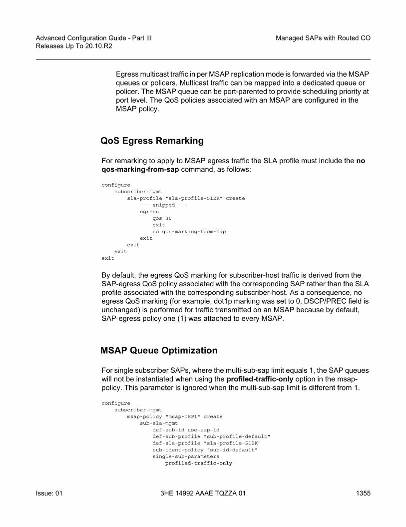
Advanced Configuration Guide - Part III Releases Up To 20.10.R2
Managed SAPs with Routed CO
Issue: 01 3HE 14992 AAAE TQZZA 01 1355
Egress multicast traffic in per MSAP replication mode is forwarded via the MSAP queues or policers. Multicast traffic can be mapped into a dedicated queue or policer. The MSAP queue can be port-parented to provide scheduling priority at port level. The QoS policies associated with an MSAP are configured in the MSAP policy.
QoS Egress Remarking
For remarking to apply to MSAP egress traffic the SLA profile must include the no qos-marking-from-sap command, as follows:
configuresubscriber-mgmt
sla-profile "sla-profile-512K" create--- snipped ---egress
qos 30exitno qos-marking-from-sap
exitexit
exitexit
By default, the egress QoS marking for subscriber-host traffic is derived from the SAP-egress QoS policy associated with the corresponding SAP rather than the SLA profile associated with the corresponding subscriber-host. As a consequence, no egress QoS marking (for example, dot1p marking was set to 0, DSCP/PREC field is unchanged) is performed for traffic transmitted on an MSAP because by default, SAP-egress policy one (1) was attached to every MSAP.
MSAP Queue Optimization
For single subscriber SAPs, where the multi-sub-sap limit equals 1, the SAP queues will not be instantiated when using the profiled-traffic-only option in the msap-policy. This parameter is ignored when the multi-sub-sap limit is different from 1.
configuresubscriber-mgmt
msap-policy "msap-ISP1" createsub-sla-mgmt
def-sub-id use-sap-iddef-sub-profile "sub-profile-default"def-sla-profile "sla-profile-512K"sub-ident-policy "sub-id-default"single-sub-parameters
profiled-traffic-only

Managed SAPs with Routed CO
1356
Advanced Configuration Guide - Part IIIReleases Up To 20.10.R2
3HE 14992 AAAE TQZZA 01 Issue: 01
exitexit
exitexit
exit
For multi subscriber MSAPs, a QoS policy can be associated with an MSAP in which all forwarding classes are mapped to a policer. In that case, a single ingress and egress policer is instantiated per MSAP (instead of ingress and egress queues). QoS policies associated with an MSAP are configured in the MSAP policy:
configuresubscriber-mgmt
msap-policy "msap-ISP2" createies-vprn-only-sap-parameters
egressqos 10
exitingress
qos 10 shared-queuingexit
exitexit
exitexit
Troubleshooting
The authentication policy used on the capture SAP must be the same as the policy used on the managed SAP.
The managed SAP will not be created if the authentication policy on the group-interface is different from the authentication policy defined on the capture SAP.
configureservice
vpls 1--- snip ---sap 1/2/2:* capture-sap create
--- snip ---authentication-policy "authentication-1"
exitno shutdown
exit
configureservice
vprn 2subscriber-interface "sub-int-1"create
--- snip ---group-interface "group-int-1" create

Advanced Configuration Guide - Part III Releases Up To 20.10.R2
Managed SAPs with Routed CO
Issue: 01 3HE 14992 AAAE TQZZA 01 1357
authentication-policy "authentication-2"--- snip ---
exitexitno shutdown
exit
This can be seen in log 99:
*A:BNG-1# show log log-id 99
8 2017/05/19 10:50:43.70 CEST MINOR: SVCMGR #2214 Base Managed SAP creation failure"The system could not create Managed SAP:1/2/2:1, MAC:00:00:00:01:01:01, CapturingSAP:1/2/2:*, Service:1. Description: MSAP group-interface "grp-int-1" RADIUS auth
-policy "authentication-2" differs from capture SAP"
7 2017/05/19 10:50:30.28 CEST WARNING: SVCMGR #2501 Base Subscriber deleted"Subscriber user1 has been removed from the system"
6 2017/05/19 10:50:29.68 CEST WARNING: SNMP #2004 vprn2 sub-int-1"Interface sub-int-1 is not operational"
--- snipped ---
*A:BNG-1#
Enable debug for PPPoE and RADIUS packets for troubleshooting purposes:
debugrouter "management"
radiuspacket-type authentication accounting coadetail-level medium
exitexitservice
id 1ppp
packetmode egr-ingr-and-droppeddetail-level mediumdiscoveryppp
exitexit
exitid 2
ppppacket
mode egr-ingr-and-droppeddetail-level mediumdiscoverypppdhcp-client
exitexit
exit

Managed SAPs with Routed CO
1358
Advanced Configuration Guide - Part IIIReleases Up To 20.10.R2
3HE 14992 AAAE TQZZA 01 Issue: 01
exitexit
configurelog
log-id 1from debug-traceto session
exitexit
exit
Disconnect/connect user1, then check the RADIUS access request/accept and accounting messages from the debug output.
11 2017/05/19 10:58:55.13 CEST MINOR: DEBUG #2001 management RADIUS"RADIUS: Transmit
Access-Request(1) 172.31.117.84:1812 id 202 len 174 vrid 4095 pol authentication-1
USER NAME [1] 14 [email protected] IP ADDRESS [4] 4 172.31.117.75SERVICE TYPE [6] 4 Framed(2)FRAMED PROTOCOL [7] 4 PPP(1)CHAP PASSWORD [3] 17 1 0x39721157837095dd2dc4a9351670e543CHAP CHALLENGE [60] 39 0x9e0eb2baf4c436f2f9a364ac0eb43cc6446943f5912d2c96570
ffd572732b245416501b5a9b6a8VSA [26] 7 DSL(3561)
AGENT REMOTE ID [2] 5 user1NAS PORT TYPE [61] 4 PPPoEoVLAN(33)NAS PORT ID [87] 7 1/2/2:1NAS IDENTIFIER [32] 5 BNG-1VSA [26] 19 Nokia(6527)
CHADDR [27] 17 00:00:00:01:01:01"
12 2017/05/19 10:58:55.14 CEST MINOR: DEBUG #2001 management RADIUS"RADIUS: Receive
Access-Accept(2) id 202 len 131 from 172.31.117.84:1812 vrid 4095 pol authentication-1
VSA [26] 7 Nokia(6527)SUBSC ID STR [11] 5 user1
VSA [26] 16 Nokia(6527)SLA PROF STR [13] 14 sla-profile-2M
VSA [26] 6 Nokia(6527)MSAP SERVICE ID [31] 4 2
VSA [26] 11 Nokia(6527)MSAP POLICY [32] 9 msap-ISP1
VSA [26] 11 Nokia(6527)MSAP INTERFACE [33] 9 grp-int-1
FRAMED IP ADDRESS [8] 4 10.255.0.1VSA [26] 6 Nokia(6527)
PRIMARY DNS [9] 4 172.31.31.31VSA [26] 6 Nokia(6527)
SECONDARY DNS [10] 4 172.31.31.32"

Advanced Configuration Guide - Part III Releases Up To 20.10.R2
Managed SAPs with Routed CO
Issue: 01 3HE 14992 AAAE TQZZA 01 1359
The MSAP policies can be checked as follows:
*A:BNG-1# show subscriber-mgmt msap-policy
===============================================================================Managed SAP Policies===============================================================================Name Num Description
MSAPs-------------------------------------------------------------------------------msap-ISP1 1 (Not Specified)msap-default 0 (Not Specified)-------------------------------------------------------------------------------Number of MSAP Policies : 2Number of MSAPs : 1===============================================================================*A:BNG-1#
The MSAP policy associations can be checked as follows:
*A:BNG-1# show subscriber-mgmt msap-policy "msap-ISP1" association
===============================================================================MSAP Policy Associations===============================================================================Service-Id : 2 (VPRN)- SAP : [1/2/2:1]
-------------------------------------------------------------------------------Number of associated MSAPs: 1Flags: (I) = Idle MSAP===============================================================================*A:BNG-1#
All MSAPs created and associations with the services can be checked as follows:
*A:BNG-1# show service sap-using msap
===============================================================================Service Access Points===============================================================================PortId SvcId Ing. Ing. Egr. Egr. Adm Opr
QoS Fltr QoS Fltr-------------------------------------------------------------------------------[1/2/2:1] 2 1 none 1 none Up Up-------------------------------------------------------------------------------Number of SAPs : 1-------------------------------------------------------------------------------Number of Managed SAPs : 1, indicated by [<sap-id>]Flags : (I) = Idle MSAP-------------------------------------------------------------------------------===============================================================================*A:BNG-1#
It is possible to use a tools command to update an existing MSAP when a specific msap-policy has changed.

Managed SAPs with Routed CO
1360
Advanced Configuration Guide - Part IIIReleases Up To 20.10.R2
3HE 14992 AAAE TQZZA 01 Issue: 01
*A:BNG-1# tools perform subscriber-mgmt eval-msap ?- eval-msap { policy <msap-policy-name> | msap <sap-id> }
<msap-policy-name> : [32 chars max]<sap-id> : dot1q - <port-id|lag-id>:qtag1
qtag1 - [0..4094]qinq - <port-id|lag-id>:qtag1.qtag2
qtag1 - [0..4094]qtag2 - [0..4094]
atm - <port-id>:vpi/vcivpi - [0..4095] (NNI)
[0..255] (UNI)vci - [1..65535]
port-id - slot/mda/portlag-id - lag-<id>
lag - keywordid - [1..800]
*A:BNG-1#
An MSAP can be deleted as follows:
*A:BNG-1# clear service id 2 msap 1/2/2:1
This event is recorded in log 99 as follows:
*A:BNG-1# show log log-id 99
===============================================================================Event Log 99===============================================================================Description : Default System LogMemory Log contents [size=500 next event=55 (not wrapped)]
54 2017/05/19 11:24:04.29 CEST WARNING: SVCMGR #2501 Base Subscriber deleted"Subscriber user1 has been removed from the system"
53 2017/05/19 11:24:04.03 CEST INDETERMINATE: LOGGER #2010 Base Clear SVCMGR"Clear function clearSvcIdMsap has been run with parameters: svc-id="2" sap-id="1/2/2:1". The completion result is: success. Additional error text, if any, is: "
--- snipped ---
*A:BNG-1#
To delete all MSAPs associated with a certain MSAP policy use the following command:
*A:BNG-1# clear service id 2 msap-policy msap-ISP1
This event is recorded in log 99 as follows:
*A:BNG-1# show log log-id 99
===============================================================================

Advanced Configuration Guide - Part III Releases Up To 20.10.R2
Managed SAPs with Routed CO
Issue: 01 3HE 14992 AAAE TQZZA 01 1361
Event Log 99===============================================================================Description : Default System LogMemory Log contents [size=500 next event=74 (not wrapped)]
67 2017/05/19 11:29:15.28 CEST WARNING: SVCMGR #2501 Base Subscriber deleted"Subscriber user1 has been removed from the system"
66 2017/05/19 11:29:14.54 CEST INDETERMINATE: LOGGER #2010 Base Clear SVCMGR"Clear function clearSvcIdMsapPlcy has been run with parameters: svc-id="2" policy-name="msap-ISP1". The completion result is: success. Additional error text, if any,is: "
65 2017/05/19 11:29:14.54 CEST MINOR: SVCMGR #2213 vprn2 MSAP delete"Managed SAP, 1/2/2:1 in service 2, has been deleted."
--- snipped ---
*A:BNG-1#
Conclusion
MSAP allows dynamic creation of SAPs which results in:
• Less provisioning.• Less possibility for introducing provisioning errors.• Reduced configuration file size.

Managed SAPs with Routed CO
1362
Advanced Configuration Guide - Part IIIReleases Up To 20.10.R2
3HE 14992 AAAE TQZZA 01 Issue: 01

Advanced Configuration Guide - Part III Releases Up To 20.10.R2
Multi-Chassis Ring Layer 2 with EnhancedSubscriber Management
Issue: 01 3HE 14992 AAAE TQZZA 01 1363
Multi-Chassis Ring Layer 2 with Enhanced Subscriber ManagementThis chapter provides information about MC-Ring Layer 2 with Enhanced Subscriber Management (ESM).
Topics in this chapter include:
• Applicability• Summary• Overview• Configuration• Conclusion
Applicability
These configuration notes are applicable to all of the 7450, 7750 and 7710 SR series and was tested on Release 7.0R5. The 7750 SR-c4 is supported from 8.0R4 and higher.
MC-Ring L2 with Enhanced Subscriber Management (ESM) was introduced in SR OS 6.0. There are no other prerequisites for the 7450, 7750 and 7710 SR this configuration.
Summary
Multi-Chassis Ring (MC-ring) is an extension for dual homing support in TPSDA (Triple Play Service Delivery Architecture) networks based on Layer 2 CO (Layer 2 Central Office) model. The extension addresses networks where multiple access nodes (for example, DSLAMs, GPON OLT) are connected in a single ring.
MC Ring Layer 2 ESM is considered an extension or evolution for ring topologies of the Multi-Chassis LAG dual-homing solution used for directly connected access nodes.
MC Ring Layer 2 CO is documented in the Triple Play Enhanced Subscriber Management / Dual Homing section of the Triple Play Guide.

Multi-Chassis Ring Layer 2 with Enhanced Subscriber Management
1364
Advanced Configuration Guide - Part IIIReleases Up To 20.10.R2
3HE 14992 AAAE TQZZA 01 Issue: 01
Overview
MC-Ring
Figure 224 shows a typical ring-based configuration of network model based on the Layer 2 CO model.
Individual rings of access nodes are aggregated at the Broadband Service Aggregator (BSA) level in one (or multiple) Virtual Private LAN Service (VPLS) service(s). At higher aggregation levels, Broadband Service Router (BSR) individual BSAs are connected to a Layer 3 interface (Internet Enhanced Service (IES) or Virtual Private Routed Network (VPRN)) by means of a spoke SDP (Service Distribution Point) termination. Every Layer 3 interface at the BSR level aggregates all subscribers in one or more subnets. ESM is performed in the BSAs.
Figure 224 MC-Ring Layer 2 CO Dual Homing
OSSG424
BSR-2
VRF
BSR-1
VRF
BSA-2
Spoke-sdp
MCS
mesh-sdp
VRRP
Spoke-sdp
BSA-1
IP/MPLSCore

Advanced Configuration Guide - Part III Releases Up To 20.10.R2
Multi-Chassis Ring Layer 2 with EnhancedSubscriber Management
Issue: 01 3HE 14992 AAAE TQZZA 01 1365
The key functional components of the MC-Ring Layer 2 CO dual-homing redundancy solution are:
1. Mirroring of the subscriber state between the two BSAs performing subscriber management using the multi-chassis synchronization (MCS) protocol (BSA-1 and BSA-2 in Figure 224).
2. Ring control between the two BSAs, using the following mechanisms:- In-band bi-directional forwarding detection (BFD) between the BSAs over
the ring to monitor ring integrity and detect failures. A BFD session between BSA-1 and BSA-2 runs through the access ring using a dedicated IES/VPRN interface configured on both BSAs. This connection uses a separate VLAN throughout the ring (access nodes provide transparent bridging for this VLAN).
- Out-of-band communication between the BSA nodes to exchange information about the reachability of individual access nodes, and to verify the configuration consistency of the ring. The information on configuration is synchronized through MCS (this use of MCS is related to, but independent to, MCS for subscriber-state synchronization mentioned above).
3. Ring Node Connectivity Verification (RNCV). Each BSA uses RNCV to detect the reachability of individual Access Nodes. It is used after a ring failure to determine which BSA should handle the traffic of each Access Node. RNCV uses ARP requests to “ping” individual ANs, which must be configured with an IP address for this purpose.
4. Per-subscriber attribute (intermediate destination ID) for the BSA to know the Access Node each subscriber is connected to (assigned through RADIUS or DHCP/Python).
5. VRRP in the BSRs to provide a redundant default gateway to the CPEs/Home Gateways. BSRs do not perform any subscriber management functions.
The operation of dual homing at the BSA level will be covered based on two underlying mechanisms.
MC-Ring Layer 2 CO Operation
To describe the functional behavior and operation of the dual-homing concept in a ring, it is best to sub-divide the description into the following three parts:
• Steady-state operation with ring fully closed• Transition to ring-broken state• Transition from ring-broken to steady state operation

Multi-Chassis Ring Layer 2 with Enhanced Subscriber Management
1366
Advanced Configuration Guide - Part IIIReleases Up To 20.10.R2
3HE 14992 AAAE TQZZA 01 Issue: 01
Steady-State Operation of Dual-Homed Ring
Figure 225 illustrates the detailed operation of the dual-homed ring. The steady-state is achieved under following conditions:
• Both nodes are configured in a consistent way• The MCS peering relation is up • In-Band Ring Control Connection (IB-RCC) is in an operationally UP state.
Figure 225 Dual homing Under Steady-State Condition
Under the above conditions, the ring is fully closed and every access node (the ring-node) has two possible paths toward the VPLS core. Figure 225 refers to them as path-a and path-b. In order to avoid the loop created by the ring, only one of the paths may be used by any given ring-node for any given VLAN. The assignment of the individual VLANs to path-a or path-b, respectively, has to be provisioned on both BSAs in a consistent manner. The BSA with a lower IP address in the interface used for BFD will be the master for the VLANs associated with path-a and standby for the VLANs associated with path-b.
The following summarizes the behavior of the master and standby BSA for a given path (a or b) and the VLANs configured for that path:
Note: This connection is set-up using BFD session between IP interfaces on BSA-1 and BSA-2
OSSG425
BSA-2 path-bpath-a
Spoke-sdp
MCS
BFDSession
RNCV
RNCVRNCV
mesh-sdp
Spoke-sdp
BSA-1

Advanced Configuration Guide - Part III Releases Up To 20.10.R2
Multi-Chassis Ring Layer 2 with EnhancedSubscriber Management
Issue: 01 3HE 14992 AAAE TQZZA 01 1367
Master BSA for the VLANs/SAPs associated with a given path (a or b):
• SAPs associated with the path are operationally up and FDB entries for sub-hosts point to the corresponding SAP
• Master BSA for a path performs RNCV checks to all ring nodes. RNCV failures trigger an alarm but do not trigger a switchover
• The ARP reply agent replies to ARP requests for subscriber-hosts associated with ring-nodes for which the BSA is master
Standby BSA:
• All SAPs associated with the path for which the BSA is standby will be operationally down and all FDB entries of subscriber hosts associated with those SAPs will point towards an SDP connecting to the master BSA.
Broken-Ring Operation and the Transition to this State
Figure 226 illustrates the scenario with the broken ring (link failure or ring-node failure). This state is reached under following conditions:
• Both nodes are configured in a consistent way• The MCS peering relation is up • IB-RCC is in operationally down state
In this situation, every ring node has only one access path towards the VPLS core and hence the path-a and path-b notion has no real meaning in this situation.
From a functional point of view, both BSAs are now the master for the ring-nodes they can reach. For all hosts behind unreachable ring-nodes, the corresponding subscriber host FDB (Forwarding DataBase) entries will point to SDP pointing to the other head-end ring PE.

Multi-Chassis Ring Layer 2 with Enhanced Subscriber Management
1368
Advanced Configuration Guide - Part IIIReleases Up To 20.10.R2
3HE 14992 AAAE TQZZA 01 Issue: 01
Figure 226 Broken Ring State
Transition from Broken to Closed Ring State
MC-ring operates in a revertive mode. This means that whenever the ring connectivity is restored, the BSA with the lower IP address in the IB-RCC communication channel will become master of path-a and slave for ring-b with vice versa operations on the other BSA.
The actions in this case are straightforward. After restoration of BFD session, the master functionality is assumed by respective BSAs. The FDB tables are updated according to the master/standby role of the given BSA and FDB population messages will be sent accordingly.
OSSG426
BSA-2 path-bpath-a
Spoke-sdp
MCS
mesh-sdp
Spoke-sdp
BSA-1

Advanced Configuration Guide - Part III Releases Up To 20.10.R2
Multi-Chassis Ring Layer 2 with EnhancedSubscriber Management
Issue: 01 3HE 14992 AAAE TQZZA 01 1369
Configuration
Figure 227 Network Topology
The network topology is displayed in Figure 227. The setup consists of two BSA nodes (PE-1 and PE-2), two BSR nodes (PE-3, PE-4) and another PE router (PE-5). A setup with one BSR node and two BSA nodes can also be used, but in this example, two (2) BSR nodes were used to show the typical Layer 2-CO setup with VRRP and Protocol Independent Multicast (PIM) on the BSRs. The access ring consists of four CE nodes.
Base Topology
This section assumes that the following base configuration has been implemented on the PE:
• Cards, MDAs and ports configured• Interfaces configured• IGP (Interior Gateway Protocol) configured and converged LDP (Label
Distribution Protocol) configured on the interfaces between PE-3-PE-1, PE-1-PE-2 and PE-2-PE-4
• T-LDP (Targeted-LDP) configured on PE-1, PE-2, PE-3, PE-4• SDPs configured between PE-3-PE-1, PE-1-PE-2 and PE-2-PE-4
CE-1172.16.0.1
CE-4172.16.0.4
BTV-clientDSLAM-simulator
BTV-serverDHCP-server
PE-1192.0.2.1
PE-2192.0.2.2
PE-3
192.0.2.3
PE-4192.0.2.4
PE-5
192.0.2.5
OSSG427
192.168.1.0/30
192.168.3.0/30
192.168.4.0/30
192.168.5.0/30
192.168.2.0/30192.168.0.0/30
CE-2172.16.0.2
CE-3172.16.0.3
192.168.0.0/30 192.168.9.0/30

Multi-Chassis Ring Layer 2 with Enhanced Subscriber Management
1370
Advanced Configuration Guide - Part IIIReleases Up To 20.10.R2
3HE 14992 AAAE TQZZA 01 Issue: 01
7750 SR routers are used as ring-nodes to simulate Access Nodes. Ring-nodes can be any L2 device that support VLANs and have the ability to connect an IP interface to one VLAN (required for RNCV).
NTP Configuration
Time must be the same on the redundant NSAs (PE-1 and PE-2); otherwise, the lease times will be different on both nodes. NTP can be used:
configure system timentp
server 10.30.30.30 preferno shutdown
exitexit all
MC-Ring Configuration
Configure a VPLS service on the CE routers for the In-Band Ring Control connection (BFD packets between PE-1 and PE-2 traversing the ring). This VPLS service will also be used for RNCV.
In this example, QinQ encapsulation is used and BFD and RNCV packets will use VLAN tag 1. Note that dot1q encapsulation can also be used.
The configuration of CE-1 is shown below. A similar configuration is required on the other CE routers.
configureport 1/1/1
ethernetmode accessencap-type qinq
Note: You can choose between OSPF and IS-IS as the IGP. Both LDP and RSVP (Resource Reservation Protocol) can be used for signaling the transport MPLS labels. Alternatively, GRE (Generic Routing Encapsulation) can be used for the transport tunnels. In this example, OSPF is configured and LDP SDPs are used.
Note: An Epipe service can also be used in case the service is only used for BFD. In that case, a separate service is required for the RNCV.

Advanced Configuration Guide - Part III Releases Up To 20.10.R2
Multi-Chassis Ring Layer 2 with EnhancedSubscriber Management
Issue: 01 3HE 14992 AAAE TQZZA 01 1371
exitno shutdown
exitport 1/1/2
ethernetmode accessencap-type qinq
exitno shutdown
exitservice
vpls 1 customer 1 createinterface "lo1" create
address 172.16.0.1/24exitsap 1/1/1:1.0 createexitsap 1/1/2:1.0 createexitno shutdown
exitexit all
An interface lo1 is created in the VPLS. This interface will be used for RNCV.
On the BSA nodes (PE-1 and PE-2), configure an IES services that will originate BFD and RNCV messages. On PE-1:
configureport 1/1/1
ethernetmode accessencap-type qinq
exitno shutdown
exitservice
ies 1 customer 1 createinterface "bfd-rncv1" create
address 172.16.0.251/24bfd 100 receive 100 multiplier 3sap 1/1/1:1.0 createexit
exitno shutdown
exitexit all
On PE-2:
configureport 1/1/2
ethernetmode accessencap-type qinq
exit

Multi-Chassis Ring Layer 2 with Enhanced Subscriber Management
1372
Advanced Configuration Guide - Part IIIReleases Up To 20.10.R2
3HE 14992 AAAE TQZZA 01 Issue: 01
no shutdownexitservice
ies 1 customer 1 createinterface "bfd-rncv1" create
address 172.16.0.252/24bfd 100 receive 100 multiplier 3sap 1/1/2:1.0 createexit
exitno shutdown
exitexit all
In-Band Ring Control Connection BFD is always originated on an IES or VPRN service on the BSA nodes. RNCV messages can be originated from the same IES/VPRN service or from a separate service.
Configure Multi-Chassis Synchronization (MCS) on the BSA nodes. Enable MCS for igmp-snooping, mc-ring and sub-mgmt. The configuration of PE-1 is shown below. The configuration of PE-2 is similar.
configure redundancy multi-chassis peer 192.0.2.2 createsync
igmp-snoopingmc-ringsub-mgmtport 1/1/1 sync-tag "l2ring1" createexitno shutdown
exitno shutdown
exit all
Add the MC-ring configuration on the BSA nodes and link the Ring Control Connection BFD session to the IES service created before.
configure redundancy multi-chassis peer 192.0.2.2 createmc-ring
ring "l2ring1" createin-band-control-path
service-id 1interface "bfd-rncv1"dst-ip 172.16.0.252
exitno shutdown
exitexitno shutdown
exit all
Note that the ring name is exactly the same as the sync-tag already configured.

Advanced Configuration Guide - Part III Releases Up To 20.10.R2
Multi-Chassis Ring Layer 2 with EnhancedSubscriber Management
Issue: 01 3HE 14992 AAAE TQZZA 01 1373
At this moment, the MC-ring should be up:
A:PE-1# show redundancy multi-chassis mc-ring peer 192.0.2.2 ring l2ring1 detail===============================================================================Multi-Chassis MC-Ring Detailed Information===============================================================================Peer : 192.0.2.2Ring Type : Layer 2Sync Tag : l2ring1Port ID : 1/1/1Admin State : inServiceOper State : connectedAdmin Change : 11/05/2009 21:17:54Oper Change : 11/05/2009 21:17:54Failure Reason : NoneControl B Path : No-------------------------------------------------------------------------------In Band Control Path-------------------------------------------------------------------------------Service ID : 1Interface Name : bfd-rncv1Oper State : connectedDest IP : 172.16.0.252Src IP : 172.16.0.251...
Next, configure under MCS the ring nodes on PE-1 and PE-2. This configuration will be used for the RNCV. The ring node configuration for CE-1 is shown below:
configure redundancy multi-chassis peer 192.0.2.2 mc-ring ring l2ring1ring-node "CE-1" create
connectivity-verifydst-ip 172.16.0.1interval 1service-id 1vlan 1no shutdown
exitexit
exit all
The configuration on PE-2 is identical and the configuration of the other ring nodes is similar.
Note: The interval parameter is the interval used to check the reachability of the CE nodes (configurable from 1 to 6000 minutes). A BFD failure will also be a trigger for a reachability check.

Multi-Chassis Ring Layer 2 with Enhanced Subscriber Management
1374
Advanced Configuration Guide - Part IIIReleases Up To 20.10.R2
3HE 14992 AAAE TQZZA 01 Issue: 01
Configure VLAN 3 to take path-b (default is path-a).
configure redundancy multi-chassis peer 192.0.2.2 mc-ring ring l2ring1path-b
range 3-3exit
exit all
MC-Ring Verification
Verify that MCS is up and running:
A:PE-1# show redundancy multi-chassis all===============================================================================Multi-Chassis Peers===============================================================================Peer IP Src IP Auth Peer Admin MC-Ring Oper MC-EP AdmMCS Admin MCS Oper MCS State MC-LAG Adm MC-LAG Oper
-------------------------------------------------------------------------------192.0.2.2 192.0.2.1 None Enabled inService --Enabled Enabled inSync Disabled Disabled
===============================================================================
The output shows that MCS is administrative and operational up and that both peers are synchronized. MC-ring is operational in service.
The following output shows more detailed information about the configured ring:
A:PE-1# show redundancy multi-chassis mc-ring peer 192.0.2.2 ring l2ring1 detail===============================================================================Multi-Chassis MC-Ring Detailed Information===============================================================================Peer : 192.0.2.2Ring Type : Layer 2Sync Tag : l2ring1Port ID : 1/1/1Admin State : inServiceOper State : connectedAdmin Change : 11/05/2009 21:22:29Oper Change : 11/05/2009 21:22:29Failure Reason : NoneControl B Path : No-------------------------------------------------------------------------------In Band Control Path-------------------------------------------------------------------------------Service ID : 1Interface Name : bfd-rncv1Oper State : connectedDest IP : 172.16.0.252Src IP : 172.16.0.251Debounce State : inServiceDebounce Max : 10 sDebounce Guard : 60 s

Advanced Configuration Guide - Part III Releases Up To 20.10.R2
Multi-Chassis Ring Layer 2 with EnhancedSubscriber Management
Issue: 01 3HE 14992 AAAE TQZZA 01 1375
-------------------------------------------------------------------------------VLAN Managed Range-------------------------------------------------------------------------------full range-------------------------------------------------------------------------------VLAN Map B Path Provisioned-------------------------------------------------------------------------------range 3-3-------------------------------------------------------------------------------VLAN Map Excluded Path Provisioned-------------------------------------------------------------------------------no range-------------------------------------------------------------------------------VLAN Map B Path Operational-------------------------------------------------------------------------------range 3-3-------------------------------------------------------------------------------VLAN Map Excluded Path Operational-------------------------------------------------------------------------------no range
The output above shows that the ring l2ring1 on port 1/1/1 is in service and connected. Ring-node Connectivity Check (BFD) is running on interface bfd-rncv1 in service 1. All VLANs on port 1/1/1 use path-a (default) except VLAN 3, which uses path-b.
The BSA peer with the lower IP address (the master) will put the SAPs configured for path-a in operational up state while the SAPs configured in path-b will be put in operational down state. The other BSA peer will do the reverse. This is done to prevent loops in the ring.
Check which ring-nodes are configured and connected:
A:PE-1# show redundancy multi-chassis mc-ring peer 192.0.2.2 ring l2ring1 ring-node==============================================================================MC-Ring Node entries==============================================================================Name Loc Oper St. Failure Reason
In Use Rem Oper St.------------------------------------------------------------------------------CE-1 connected None
No notTestedCE-2 connected None
No notTestedCE-3 connected None
No notTestedCE-4 connected None
No notTested------------------------------------------------------------------------------
Note: No VLANs are configured to be excluded from the paths. If a VLAN is configured to be excluded from the paths, the respective SAPs of this VLAN on both BSA nodes will be operationally up.

Multi-Chassis Ring Layer 2 with Enhanced Subscriber Management
1376
Advanced Configuration Guide - Part IIIReleases Up To 20.10.R2
3HE 14992 AAAE TQZZA 01 Issue: 01
No. of MC-Ring Node entries: 4==============================================================================A:PE-1#
The output above shows that four ring-nodes are connected. Only the master will send RNCV messages to the ring-nodes. As soon as a ring failure occurs, the BFD session goes down and both BSA nodes send out RNCV messages to see which ring-nodes are connected.
More detail about each ring-node can be provided with following command:
A:PE-1# show redundancy multi-chassis mc-ring peer 192.0.2.2 ring l2ring1 ring-node CE-1 detail===============================================================================Multi-Chassis MC-Ring Node Detailed Information===============================================================================Peer : 192.0.2.2Sync Tag : l2ring1Node Name : CE-1Oper State Loc : connectedOper State Rem : notTestedIn Use : FalseAdmin Change : 11/05/2009 21:21:30Oper Change : 11/05/2009 21:22:32Failure Reason : None-------------------------------------------------------------------------------Ring Node Connectivity Verification-------------------------------------------------------------------------------Admin State : inServiceService ID : 1Encap Value : 1Dest IP : 172.16.0.1Src IP : NoneInterval : 1 minutesSrc MAC : None===============================================================================A:PE-1#
Unicast Services Configuration
Figure 228 shows the logical setup of the services that will be created. A mesh SDP is used between PE-1 and PE-2. A spoke SDP could also be used.
Note: When the reachability of the CE nodes is determined, the RNCV messages will be sent at a continuous interval (see above).

Advanced Configuration Guide - Part III Releases Up To 20.10.R2
Multi-Chassis Ring Layer 2 with EnhancedSubscriber Management
Issue: 01 3HE 14992 AAAE TQZZA 01 1377
Figure 228 Unicast Services — Logical Topology
In this setup, two unicast services (VPLS 2 and VPLS 3) are created. VPLS 2 uses path-a and VPLS 3 uses path-b.
The services use a mesh SDP between PE-1 and PE-2 and a spoke-SDP between PE-1/PE-3 and another spoke SDP between PE-2/PE-4. On PE-3 and PE-4 a spoke SDP terminated IES is configured with a VRRP default gateway address. The VRRP packets are switched through the BSAs.
IGMP snooping and ESM are configured on both services. ESM is required since the BSA node must know which ring-node each subscriber is connected to. In this setup, the intermediate destination identifier (int_dest_id) will be returned by Option 254 in x Dynamic Host Control Protocol (DHCP). ESM configuration details are outside the scope of this document. Refer to the appropriate platform OS Triple Play Guide.
The following output shows the configuration of VPLS 2 on PE-1:
configure servicevpls 2 customer 1 create
description "VLAN_2"split-horizon-group "RSHG" residential-group createexitsap 1/1/1:2.* split-horizon-group "RSHG" create
dhcpsnoop
OSSG428
VPLS
IES
PE-1VPLS
CE-1
VPLS
CE-4
VPLS
CE-3
VPLS
CE-2
BFDRNCV
BFD RNCVDHCP-serverDHCP-server
IES
PE-3
VPLS
IES
PE-2
VRRPMesh-SDP
Spoke-SDP
Spoke-SDP
IES
PE-4
PE-5
= SDP
= SAP

Multi-Chassis Ring Layer 2 with Enhanced Subscriber Management
1378
Advanced Configuration Guide - Part IIIReleases Up To 20.10.R2
3HE 14992 AAAE TQZZA 01 Issue: 01
lease-populate 10no shutdown
exitanti-spoof ip-macsub-sla-mgmt
def-sub-profile "initial"def-sla-profile "initial"sub-ident-policy "speedy"multi-sub-sap 10no shutdown
exitexitmesh-sdp 12:2 create
dhcpsnoop
exitexitspoke-sdp 13:2 create
dhcpsnoop
exitexitno shutdown
exitexit all
The configuration of VPLS 3 is similar. The configuration of VPLS 2 and 3 are similar on PE-2.
The output below shows the subscriber management configuration on PE-1. Similar configuration is required on PE-2.
configure subscriber-mgmtsla-profile "initial" createexitsub-profile "initial" createexitsub-ident-policy "speedy" create
strings-from-option 254exit
exit all
Also, configure VLAN 2 and 3 on all the ring-nodes. This configuration is straightforward. Below is an example of the VLAN 2 configuration on CE-1. In this example, the client is connect to port 1/1/3 and should send packets with an outer tag of 2:
configure servicevpls 2 customer 1 create
sap 1/1/1:2.* createexitsap 1/1/2:2.* createexitsap 1/1/3:2.* createexit

Advanced Configuration Guide - Part III Releases Up To 20.10.R2
Multi-Chassis Ring Layer 2 with EnhancedSubscriber Management
Issue: 01 3HE 14992 AAAE TQZZA 01 1379
no shutdownexit
exit all
In the example, VLAN 2.* and 3.* is used to allow for transparent transport of the customer VLAN.
The IES service where VPLS 2 terminates looks like this on BSR PE-3:
configure serviceies 2 customer 1 create
interface "VLAN_2" createaddress 10.0.2.3/24dhcp
server 10.10.10.10trustedno shutdown
exitip-mtu 1500vrrp 2
backup 10.0.2.254ping-reply
exitlocal-proxy-arpspoke-sdp 31:2 createexit
exitno shutdown
exitexit all
And on PE-4:
configure serviceies 2 customer 1 create
interface "VLAN_2" createaddress 10.0.2.4/24dhcp
server 10.10.10.10trustedno shutdown
exitip-mtu 1500vrrp 2
backup 10.0.2.254ping-reply
exitlocal-proxy-arpspoke-sdp 42:2 createexit
exitno shutdown
exitexit all

Multi-Chassis Ring Layer 2 with Enhanced Subscriber Management
1380
Advanced Configuration Guide - Part IIIReleases Up To 20.10.R2
3HE 14992 AAAE TQZZA 01 Issue: 01
Notice that the ip-mtu must be set to match the vc-mtu signaled by the other side of the spoke-SDP. Otherwise, the service will be operationally down with a ServiceMTUMismatch.
Note also in the configuration that DHCP relay is done by configuring a DHCP server under the IES interface.
The configuration of IES 3 on PE-3 and PE-4 is similar..
On PE-5 an IES interface is configured to the DHCP-server. The interface is configured with a Dot1Q encapsulated port because this port will be also be used for an interface to the multicast server.
configure serviceies 2 customer 1 create
interface "dhcp-server" createaddress 192.168.6.1/30sap 1/1/3:2 createexit
exitno shutdown
exitexit all
Unicast Services Verification
Request an IP address on VLAN 2 on CE-1. On BSA routers PE-1 and PE-2 following DHCP info can be checked:
A:PE-1# show service id 2 dhcp lease-state===============================================================================DHCP lease state table, service 2===============================================================================IP Address Mac Address Sap/Sdp Id Remaining Lease MC
LifeTime Origin Stdby-------------------------------------------------------------------------------10.0.2.107 00:00:64:01:01:02 1/1/1:2.* 09d07h38m DHCP-------------------------------------------------------------------------------Number of lease states : 1===============================================================================
ESM show commands can be used to obtain the subscriber identity, IP address, MAC address and SLA-profile:
A:PE-1# show service active-subscribers===============================================================================Active Subscribers===============================================================================-------------------------------------------------------------------------------Subscriber subscriber_1_vlan_2 (initial)-------------------------------------------------------------------------------

Advanced Configuration Guide - Part III Releases Up To 20.10.R2
Multi-Chassis Ring Layer 2 with EnhancedSubscriber Management
Issue: 01 3HE 14992 AAAE TQZZA 01 1381
-------------------------------------------------------------------------------(1) SLA Profile Instance sap:1/1/1:2.* - sla:initial-------------------------------------------------------------------------------IP Address MAC Address PPPoE-SID Origin-------------------------------------------------------10.0.2.107 00:00:64:01:01:02 N/A DHCP
-------------------------------------------------------------------------------Number of active subscribers : 1===============================================================================
The following command gives more information about a specific subscriber:
A:PE-1# show service active-subscribers subscriber subscriber_1_vlan_2 detail
===============================================================================Active Subscribers===============================================================================-------------------------------------------------------------------------------Subscriber subscriber_1_vlan_2 (initial)-------------------------------------------------------------------------------I. Sched. Policy : N/AE. Sched. Policy : N/A E. Agg Rate Limit: MaxQ Frame-Based Ac*: DisabledAcct. Policy : N/A Collect Stats : DisabledRad. Acct. Pol. : N/ADupl. Acct. Pol. : N/AANCP Pol. : N/AHostTrk Pol. : N/ASub. ANCP-String : "subscriber_1_vlan_2"Sub. Int Dest Id : "CE-1"Host Trk Rate Adj: N/A-------------------------------------------------------------------------------(1) SLA Profile Instance
- sap:1/1/1:2.* (VPLS 2)- sla:initial
-------------------------------------------------------------------------------Description : (Not Specified)Host Limit : No LimitIngress Qos-Policy : 1 Egress Qos-Policy : 1Ingress Queuing Type : Service-queuingIngress Filter-Id : N/A Egress Filter-Id : N/AIngress Report-Rate : N/AEgress Report-Rate : N/AEgress Remarking : from Sap QosCredit Control Pol. : N/A--------------------------------------------------------------------------------------------------------------------------------------------------------------IP Address MAC Address PPPoE-SID Origin-------------------------------------------------------10.0.2.107 00:00:64:01:01:02 N/A DHCP
The output above gives more details about which ring-node the customer is connected to (Sub. Int Dest Id : CE-1), which QoS policies are applied, statistics of each queue,

Multi-Chassis Ring Layer 2 with Enhanced Subscriber Management
1382
Advanced Configuration Guide - Part IIIReleases Up To 20.10.R2
3HE 14992 AAAE TQZZA 01 Issue: 01
MCS Verification
Check if the two redundant peers are in sync and check the detailed MCS info:
A:PE-1# show redundancy multi-chassis sync peer 192.0.2.2===============================================================================Multi-chassis Peer Table===============================================================================Peer-------------------------------------------------------------------------------Peer IP Address : 192.0.2.2Description : (Not Specified)Authentication : DisabledSource IP Address : 192.0.2.1Admin State : Enabled-------------------------------------------------------------------------------Sync-status-------------------------------------------------------------------------------Client Applications : IGMPSnooping SUBMGMT RINGSync Admin State : UpSync Oper State : UpDB Sync State : inSyncNum Entries : 11Lcl Deleted Entries : 0Alarm Entries : 0Rem Num Entries : 11Rem Lcl Deleted Entries : 0Rem Alarm Entries : 0===============================================================================MCS Application Stats===============================================================================Application : igmpNum Entries : 0Lcl Deleted Entries : 0Alarm Entries : 0-------------------------------------------------------------------------------Rem Num Entries : 0Rem Lcl Deleted Entries : 0Rem Alarm Entries : 0-------------------------------------------------------------------------------Application : igmpSnoopingNum Entries : 0Lcl Deleted Entries : 0Alarm Entries : 0-------------------------------------------------------------------------------Rem Num Entries : 0Rem Lcl Deleted Entries : 0Rem Alarm Entries : 0-------------------------------------------------------------------------------Application : subMgmtNum Entries : 1Lcl Deleted Entries : 0Alarm Entries : 0-------------------------------------------------------------------------------Rem Num Entries : 1Rem Lcl Deleted Entries : 0Rem Alarm Entries : 0-------------------------------------------------------------------------------

Advanced Configuration Guide - Part III Releases Up To 20.10.R2
Multi-Chassis Ring Layer 2 with EnhancedSubscriber Management
Issue: 01 3HE 14992 AAAE TQZZA 01 1383
Application : srrpNum Entries : 0Lcl Deleted Entries : 0Alarm Entries : 0-------------------------------------------------------------------------------Rem Num Entries : 0Rem Lcl Deleted Entries : 0Rem Alarm Entries : 0-------------------------------------------------------------------------------Application : mcRingNum Entries : 10Lcl Deleted Entries : 0Alarm Entries : 0-------------------------------------------------------------------------------Rem Num Entries : 10Rem Lcl Deleted Entries : 0Rem Alarm Entries : 0-------------------------------------------------------------------------------Application : mldSnoopingNum Entries : 0Lcl Deleted Entries : 0Alarm Entries : 0-------------------------------------------------------------------------------Rem Num Entries : 0Rem Lcl Deleted Entries : 0Rem Alarm Entries : 0-------------------------------------------------------------------------------Application : dhcpServerNum Entries : 0Lcl Deleted Entries : 0Alarm Entries : 0-------------------------------------------------------------------------------Rem Num Entries : 0Rem Lcl Deleted Entries : 0Rem Alarm Entries : 0-------------------------------------------------------------------------------Application : subHostTrkNum Entries : 0Lcl Deleted Entries : 0Alarm Entries : 0-------------------------------------------------------------------------------Rem Num Entries : 0Rem Lcl Deleted Entries : 0Rem Alarm Entries : 0-------------------------------------------------------------------------------===============================================================================A:PE-1#
The output shows that both MCS peers are in sync and that entries are populated for MC-ring and Subscriber Management (DHCP lease states).
Notice that the lease states are also populated on PE-2:
A:PE-2# show service id 2 dhcp lease-state===============================================================================DHCP lease state table, service 2===============================================================================IP Address Mac Address Sap/Sdp Id Remaining Lease MC

Multi-Chassis Ring Layer 2 with Enhanced Subscriber Management
1384
Advanced Configuration Guide - Part IIIReleases Up To 20.10.R2
3HE 14992 AAAE TQZZA 01 Issue: 01
LifeTime Origin Stdby-------------------------------------------------------------------------------10.0.2.107 00:00:64:01:01:02 1/1/2:2.* 09d06h16m DHCP Yes-------------------------------------------------------------------------------Number of lease states : 1===============================================================================A:PE-2#
The output is similar to the output on PE-1 except that on PE-2 the flag MC-Stdby is set to yes, which implies that this node is in standby mode for this VLAN.
This can be verified by looking at the status of the SAP on PE-1 and PE-2. On PE-1 the SAP is operationally up:
A:PE-1# show service id 2 sap 1/1/1:2.*===============================================================================Service Access Points(SAP)===============================================================================Service Id : 2SAP : 1/1/1:2.* Encap : qinqQinQ Dot1p : DefaultDescription : (Not Specified)Admin State : Up Oper State : UpFlags : NoneMulti Svc Site : NoneLast Status Change : 11/06/2009 17:17:26Last Mgmt Change : 11/04/2009 22:51:15===============================================================================
On PE-2 the situation is different:
A:PE-2# show service id 2 sap 1/1/2:2.*===============================================================================Service Access Points(SAP)===============================================================================Service Id : 2SAP : 1/1/2:2.* Encap : qinqQinQ Dot1p : DefaultDescription : (Not Specified)Admin State : Up Oper State : DownFlags : StandByForMcRingMulti Svc Site : NoneLast Status Change : 11/06/2009 18:07:30Last Mgmt Change : 11/04/2009 23:43:16===============================================================================
Notice that the SAP on PE-2 is operationally down and that a flag is set: StandByForMcRing.
The situation is reversed for VLAN 3 since it was configured for path-b; here the SAP on PE-1 is operationally down and the SAP on PE-2 is operationally up.

Advanced Configuration Guide - Part III Releases Up To 20.10.R2
Multi-Chassis Ring Layer 2 with EnhancedSubscriber Management
Issue: 01 3HE 14992 AAAE TQZZA 01 1385
Ring Failure Verification
In case a ring failure occurs (either ring link failure or ring-node failure), the IB-RCC BFD session between PE-1 and PE-2 will go down and both nodes will put the SAP in operational up state.
Break the link between CE-2 and CE-1.
Observe that the ring is now in a broken state:
A:PE-1# show redundancy multi-chassis mc-ring peer 192.0.2.2==============================================================================MC-Ring entries==============================================================================Sync Tag Oper State Failure Reason------------------------------------------------------------------------------l2ring1 broken None------------------------------------------------------------------------------No. of MC-Ring entries: 1==============================================================================
The following command shows the BSA to ring nodes connections:
A:PE-1# show redundancy multi-chassis mc-ring peer 192.0.2.2 ring l2ring1 ring-node==============================================================================MC-Ring Node entries==============================================================================Name Loc Oper St. Failure Reason
In Use Rem Oper St.------------------------------------------------------------------------------CE-1 connected None
Yes disconnectedCE-2 disconnected None
No connectedCE-3 disconnected None
No connectedCE-4 disconnected None
No connected------------------------------------------------------------------------------No. of MC-Ring Node entries: 4==============================================================================
The output shows that CE-1 is connected to PE-1. CE-2, CE-3 and CE4 are connected to PE-2.
Notice that the SAPs on both PE-1 and PE-2 are now operationally up. This can be checked with the show service id 2 sap 1/1/1:2.* command on PE1 and the show service id 2 sap 1/1/2:2.* command on PE2.
Following the ring failure, the BSA nodes send a MAC address withdrawal message to all the SDP peers configured in the VPLS.
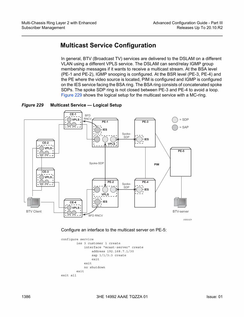
Multi-Chassis Ring Layer 2 with Enhanced Subscriber Management
1386
Advanced Configuration Guide - Part IIIReleases Up To 20.10.R2
3HE 14992 AAAE TQZZA 01 Issue: 01
Multicast Service Configuration
In general, BTV (Broadcast TV) services are delivered to the DSLAM on a different VLAN using a different VPLS service. The DSLAM can send/relay IGMP group membership messages if it wants to receive a multicast stream. At the BSA level (PE-1 and PE-2), IGMP snooping is configured. At the BSR level (PE-3, PE-4) and the PE where the video source is located, PIM is configured and IGMP is configured on the IES service facing the BSA ring. The BSA ring consists of concatenated spoke SDPs. The spoke SDP ring is not closed between PE-3 and PE-4 to avoid a loop. Figure 229 shows the logical setup for the multicast service with a MC-ring.
Figure 229 Multicast Service — Logical Setup
Configure an interface to the multicast server on PE-5:
configure serviceies 3 customer 1 create
interface "mcast-server" createaddress 192.168.7.1/30sap 1/1/3:3 createexit
exitno shutdown
exitexit all
OSSG429
VPLS
IES
PE-1VPLS
CE-1
VPLS
CE-4
VPLS
CE-3
VPLS
CE-2
BFDRNCV
BFD RNCVBTV-serverBTV Client
IES
PE-3
VPLS
IES
PE-2
PIMSpoke-SDP
Spoke-SDP
Spoke-SDP
IES
PE-4
PE-5
= SDP
= SAP

Advanced Configuration Guide - Part III Releases Up To 20.10.R2
Multi-Chassis Ring Layer 2 with EnhancedSubscriber Management
Issue: 01 3HE 14992 AAAE TQZZA 01 1387
Configure a VPLS service on PE-1 and PE-2. The configuration on PE-1 is shown below. The VPLS configuration on PE-2 is similar.
configure servicevpls 4 customer 1 create
description "Multicast VLAN"igmp-snooping
no shutdownexitsap 1/1/1:4.* createexitspoke-sdp 12:4 create
igmp-snoopingmrouter-port
exitexitspoke-sdp 13:4 create
igmp-snoopingmrouter-port
exitexitno shutdown
exitexit all
Notice that igmp-snooping has been enabled and that the spoke SDPs are configured as mrouter-ports in order to forward the IGMP joins to the BSRs.
Configure a spoke SDP terminated IES service on PE-3:
configure serviceies 4 customer 1 create
interface "btv-dst" createaddress 10.0.4.3/24ip-mtu 1500spoke-sdp 31:4 createexit
exitno shutdown
exitexit all
On PE-4:
configure serviceies 4 customer 1 create
interface "btv-dst" createaddress 10.0.4.4/24ip-mtu 1500spoke-sdp 42:4 createexit
exitno shutdown
exitexit all

Multi-Chassis Ring Layer 2 with Enhanced Subscriber Management
1388
Advanced Configuration Guide - Part IIIReleases Up To 20.10.R2
3HE 14992 AAAE TQZZA 01 Issue: 01
Notice that also here the ip-mtu must be configured to bring the service up. The ip-mtu is required to have an MTU match on the spoke SDP between the IES service and the VPLS service.
Configure PIM on PE-3, PE-4 and PE-5. The configuration on PE-3 is shown below. The PIM configuration on PE-4 and PE-5 is similar.
configure router piminterface "system"exitinterface "int-PE-3-PE-4"
priority 10exitinterface "int-PE-3-PE-5"exitinterface "btv-dst"exitrp
staticaddress 192.0.2.5
group-prefix 224.0.0.0/4exit
exitexit
exit all
Configure IGMP on PE-3/PE-4:
configure router igmp interface btv-dst no shutdown
The service should also be configured on all ring nodes. Below, the configuration on CE-2 is shown. Similar configurations are required on the other ring-nodes.
configure servicevpls 4 customer 1 create
sap 1/1/1:4.* createexitsap 1/1/2:4.* createexitsap 1/1/3:4.* createexitno shutdown
exitexit all
Note: PE-5 is statically configured as the RP. This is just an example. Different configurations can be used.

Advanced Configuration Guide - Part III Releases Up To 20.10.R2
Multi-Chassis Ring Layer 2 with EnhancedSubscriber Management
Issue: 01 3HE 14992 AAAE TQZZA 01 1389
Multicast Service Verification
Configure the multicast server to send one or more multicast streams. Have the BTV client connected to CE-2 send an IGMP join message for this multicast stream.
On the BSA routers (PE-1/PE-2), IGMP snooping can be checked:
A:PE-1# show service id 4 mfib===============================================================================Multicast FIB, Service 4===============================================================================Source Address Group Address Sap/Sdp Id Svc Id Fwd/Blk-------------------------------------------------------------------------------* * sdp:12:4 Local Fwd
sdp:13:4 Local Fwd* 225.1.1.1 sap:1/1/1:4.* Local Fwd
sdp:12:4 Local Fwdsdp:13:4 Local Fwd
-------------------------------------------------------------------------------Number of entries: 2===============================================================================
On PE-3/PE-4 the IGMP groups can be checked:
A:PE-3# show router igmp group===============================================================================IGMP Groups===============================================================================
(*,225.1.1.1) Up Time : 0d 00:01:03Fwd List : btv-dst
-------------------------------------------------------------------------------(*,G)/(S,G) Entries : 1===============================================================================
Following command shows that the MCS peers are synchronized and that there is one IGMP entry on both peers:
A:PE-1# show redundancy multi-chassis sync peer 192.0.2.2 detail===============================================================================Multi-chassis Peer Table===============================================================================Peer-------------------------------------------------------------------------------Peer IP Address : 192.0.2.2Description : (Not Specified)Authentication : DisabledSource IP Address : 192.0.2.1Admin State : Enabled-------------------------------------------------------------------------------Sync-status-------------------------------------------------------------------------------Client Applications : IGMPSnooping SUBMGMT RINGSync Admin State : UpSync Oper State : Up

Multi-Chassis Ring Layer 2 with Enhanced Subscriber Management
1390
Advanced Configuration Guide - Part IIIReleases Up To 20.10.R2
3HE 14992 AAAE TQZZA 01 Issue: 01
DB Sync State : inSyncNum Entries : 12Lcl Deleted Entries : 0Alarm Entries : 0Rem Num Entries : 12Rem Lcl Deleted Entries : 0Rem Alarm Entries : 0===============================================================================MCS Application Stats===============================================================================Application : igmpNum Entries : 1Lcl Deleted Entries : 0Alarm Entries : 0-------------------------------------------------------------------------------Rem Num Entries : 1Rem Lcl Deleted Entries : 0Rem Alarm Entries : 0
Notice that the MFIB on PE-2 has also been updated:
A:PE-2# show service id 4 mfib===============================================================================Multicast FIB, Service 4===============================================================================Source Address Group Address Sap/Sdp Id Svc Id Fwd/Blk-------------------------------------------------------------------------------* * sdp:21:4 Local Fwd
sdp:24:4 Local Fwd* 225.1.1.1 sap:1/1/2:4.* Local Fwd
sdp:21:4 Local Fwdsdp:24:4 Local Fwd
-------------------------------------------------------------------------------Number of entries: 2===============================================================================A:PE-2#
The SAP on PE-2 is down to avoid duplicated traffic and loops:
A:PE-2# show service id 4 sap 1/1/2:4.*===============================================================================Service Access Points(SAP)===============================================================================Service Id : 4SAP : 1/1/2:4.* Encap : qinqQinQ Dot1p : DefaultDescription : (Not Specified)Admin State : Up Oper State : DownFlags : StandByForMcRingMulti Svc Site : NoneLast Status Change : 11/06/2009 18:56:25Last Mgmt Change : 11/04/2009 23:43:16===============================================================================

Advanced Configuration Guide - Part III Releases Up To 20.10.R2
Multi-Chassis Ring Layer 2 with EnhancedSubscriber Management
Issue: 01 3HE 14992 AAAE TQZZA 01 1391
If a failure occurs in the ring-node, the IB-RCC BFD session between PE-1 and PE-2 will go down and the SAP on both PE-1 and PE-2 will be put in operational up state.
Configuration Notes
RNCV (used for ring-node connectivity check) and BFD (used for ring control connection) can either run on the same VLAN in the same IES or VPRN service or can run on different VLAN.
MCS for IGMP or DHCP states on a MC-ring requires ESM since the BSA nodes must know which ring node a subscriber is connected to in case a ring failure occurs. The ring-node name is returned through a Python script, a RADIUS server or through a local user database. This string (int_dest_id) must match one of the ring nodes defined in the redundancy configuration.
Convergence time after a ring failure should be 3 * BFD timer + MCS convergence time. Convergence time after a BSA failure should be likewise.
Note that a debounce timer runs on the MC-ring peers. After a ring failure, the MC-ring converges immediately (after the BFD session times out) and the debounce timer is started. After the ring is fixed and the BFD session is up the MC-ring converges immediately again. If another ring failure occurs before the debounce timer expires, convergence will be slowed down by two (2) seconds. If a third ring failure occurs before the debounce timer expires, four second delays are introduced. In case of a fourth failure, an eight second delay is introduced. 200 seconds of delay is the maximum. The debounce timer can be configured under the MC-ring.
Conclusion
This chapter covers an extension of dual homing support in TPSDA networks based on Layer 2 CO model. The extension addresses networks where multiple access nodes (for example, DSLAMs) are connected in a single ring. The examples show the use of a ring with four access nodes in a ring. The behavior is described in normal operation and in case a failure occurs in the access ring.

Multi-Chassis Ring Layer 2 with Enhanced Subscriber Management
1392
Advanced Configuration Guide - Part IIIReleases Up To 20.10.R2
3HE 14992 AAAE TQZZA 01 Issue: 01

Advanced Configuration Guide - Part III Releases Up To 20.10.R2
Python Cache Support for ESM Applications
Issue: 01 3HE 14992 AAAE TQZZA 01 1393
Python Cache Support for ESM ApplicationsThis chapter provides information about Python cache support for ESM applications.
Topics in this chapter include:
• Applicability• Overview• Configuration• Conclusion
Applicability
This feature is applicable to 7750 SR-7/12/12e systems, and 7450 systems in mixed mode, with CPM3 or later. It is also applicable to the virtualized simulator but only when running as a distributed simulator. It is not applicable to the 7750 SR c4/12.
The configuration was tested with SR OS release 12.0.R4.
Overview
SR OS sports an embedded Python scripting engine which can be used to manipulate selected messages of protocols including DHCPv4, DHCPv6, RADIUS and Diameter.
Python cache provides a central key-value memory cache with a set of APIs allowing Python scripts to store and retrieve strings across different runs of the same or even different Python scripts.
The following are some basic concepts of Python cache:
• Multiple Python policies can be defined, and each Python policy has a separate cache; only scripts configured in the Python policy can access and share that policy’s cache.
• A cache entry consists of a key and a value, both of them being strings. The key is used to search and fetch the cache entry.

Python Cache Support for ESM Applications
1394
Advanced Configuration Guide - Part IIIReleases Up To 20.10.R2
3HE 14992 AAAE TQZZA 01 Issue: 01
• A cache entry has a lifetime and the system automatically removes expired entries.
The following are the Python cache APIs:
• alc.cache.save(val,key): Save the value identified by the key into the cache.• alc.cache.retrieve(key): Return the cached entry’s value identified by the key.• alc.cache.clear(key): Remove the entry identified by the key from the cache. • cache.get_lifetime(key): The system returns an integer indicating the remaining
lifetime of the specified entry expressed in seconds. • cache.set_lifetime(key,new_lifetime): new_lifetime is an integer; the system
sets the remaining lifetime of the specified entry (in seconds).
Configuration
The test topology is shown in Figure 230.
Figure 230 Test Topology
The example shows how the Python cache can be used to store multiple class attributes from the RADIUS access-accept packets and reflect them into RADIUS accounting request packets (start/interim-update/stop).
Test setup:
• A PC is used as DHCPv4 host, connect to SAP 1/1/9 of BNG-1• SAP 1/1/9 is attached to group interface grp-int-1, which is under subscriber
interface sub-int-1 of IES 1• DHCP host is authenticated via RADIUS server, which resides in management
routing instance of BNG-1• A Python script python-script-1 stores all class attributes in access-accept and
add stored attributes into RADIUS accounting requests.• RADIUS user-name is used as cache key, which is the MAC address of the PC.
al_0691
BNG-1 SAP: 1/1/9
Sys: 192.0.2.1sub-int-1:
10.0.0.254/24management:
192.168.1.254/24 192.168.1.1/24
RADIUSServer
PC

Advanced Configuration Guide - Part III Releases Up To 20.10.R2
Python Cache Support for ESM Applications
Issue: 01 3HE 14992 AAAE TQZZA 01 1395
The Python cache configuration commands are shown below.
config>python>py-policy>[no] cache [create]
[no] entry-size <size>[no] max-entries <count>[no] max-entry-lifetime [days <days>] [hrs <hours>]
[min <minutes>] [sec <seconds>][no] mcs-peer <ip-address> sync-tag <[32 chars max]>[no] minimum-lifetimes
[no] high-availability <seconds>[no] multi-chassis-redundancy <seconds>[no] persistence <seconds>
[no] persistence[no] shutdown
config>system>persistence>python-policy-cache
[no] description <desc>[no] location <cflash-id>
config>redundancy>multi-chassis>peer>sync>[no] python
Refer to the SR OS Triple Play Guide for details of above commands. The basic configuration of the Python cache is the cache create statement in the python-policy as shown below:
config>python>py-policy>----------------------------------------------
cache createno shutdown
exitradius access-accept direction ingress script "python-script-1"radius accounting-request direction egress script "python-script-1"
----------------------------------------------
The cache create configuration enables the cache support for the Python policy. The system’s behavior can be tuned in the following aspects:
• Configure entry-size and max-entries to limit the memory usage.• Configure max-entry-lifetime to specify the maximum lifetime.• Enable persistence to make cache entries persistent across reboot.• Configure mcs-peer to enable Multi-Chassis Synchronization.
In this example only the basic cache configuration is used.

Python Cache Support for ESM Applications
1396
Advanced Configuration Guide - Part IIIReleases Up To 20.10.R2
3HE 14992 AAAE TQZZA 01 Issue: 01
Step 0. Configuring ESM
As a prerequisite ESM must be enabled and as such BNG-1 is configured as follows:
• An authentication-policy radius-auth-policy-1 is used to authenticate DHCPv4 hosts on group interface grp-int-1.
• A radius-accounting-policy radius-acct-policy-1 is configured in the sub-profile sub-profile-1 to enable RADIUS accounting.
• The user-name is included in radius-acct-policy-1 since the User-Name is used as cache entry key.
• Interim-update is enabled in the radius-acct-policy-1 with an interval 5 minutes.• The local DHCPv4 server dhcpv4-svr is used to assign address to hosts.
#--------------------------------------------------echo "Management Router Configuration"#--------------------------------------------------
router managementradius-server
server "radius-svr-1" address 192.168.1.1 secret"iaCuILBunKirJurE4jK2URAnzip6nK32" hash2 create
exitexit
exit#--------------------------------------------------echo "Router (Network Side) Configuration"#--------------------------------------------------
routerdhcp
local-dhcp-server "dhcpv4-svr" createexit
exitinterface "system"
address 192.0.2.1/32local-dhcp-server "dhcpv4-svr"no shutdown
exitexit
#--------------------------------------------------echo "Subscriber-mgmt Configuration"#--------------------------------------------------
subscriber-mgmtauthentication-policy "radius-auth-policy-1" create
password "mcgLj0q0695Dp.pD5DthrCv9Bu8X2qPVSvGYWQmCgUg" hash2radius-server-policy "radius-svr-policy-1"
exitradius-accounting-policy "radius-acct-policy-1" create
update-interval 5update-interval-jitter absolute 0include-radius-attribute
user-nameexitradius-server-policy "radius-svr-policy-1"
exit

Advanced Configuration Guide - Part III Releases Up To 20.10.R2
Python Cache Support for ESM Applications
Issue: 01 3HE 14992 AAAE TQZZA 01 1397
sla-profile "sla-profile-1" createexitsub-profile "sub-profile-1" create
radius-accounting-policy "radius-acct-policy-1"exit
exit#--------------------------------------------------echo "Service Configuration"#--------------------------------------------------
serviceies 1 customer 1 create
subscriber-interface "sub-int-1" createaddress 10.0.0.254/24group-interface "grp-int-1" create
dhcpserver 192.0.2.1gi-address 10.0.0.254no shutdown
exitauthentication-policy "radius-auth-policy-1"sap 1/1/9 create
sub-sla-mgmtdef-sub-id use-auto-iddef-sub-profile "sub-profile-1"def-sla-profile "sla-profile-1"no shutdown
exitexit
exitexitno shutdown
exitexit
#--------------------------------------------------echo "Local DHCP Server (Base Router) Configuration"#--------------------------------------------------
routerdhcp
local-dhcp-server "dhcpv4-svr" createuse-gi-addresspool "addr-pool-1" create
subnet 10.0.0.0/24 createoptions
subnet-mask 255.255.255.0default-router 10.0.0.254
exitaddress-range 10.0.0.1 10.0.0.100
exitexitno shutdown
exitexit
exit#--------------------------------------------------echo "AAA Configuration"#--------------------------------------------------
aaaradius-server-policy "radius-svr-policy-1" create
servers

Python Cache Support for ESM Applications
1398
Advanced Configuration Guide - Part IIIReleases Up To 20.10.R2
3HE 14992 AAAE TQZZA 01 Issue: 01
router "management"server 1 name "radius-svr-1"
exitexit
exit
Step 1. Create the Python script file.A Python script is created and stored on the local storage, for example as CF3:\python_cache.py. This script handles the RADIUS packets listed below: - Access-Accept — All class attributes from the access-accept packets
are stored in the cache by combining them into a single string. The user-name (MAC address) is used as the key, and the format of this string is:
• 1st byte is the number of class attributes in this string• 2nd – nth bytes: each byte holds the number of bytes for class-n
attributes• Rest of bytes: combined string of class-1 to class-n
- Acct-Start — Retrieves the stored combined class string using the user name as key. The combined string is parsed and split into the individual class attributes and then inserted into the packet.
- Interim-Update — The cached entry is parsed and the stored class attributes are inserted, then the lifetime is reset to 15 minutes. This is greater than the interim-update interval (5 minutes) so the cached entry will not expire before next interim-update arrives.
- Acct-Stop — The cached entry is parsed and the stored class attributes are inserted, then the cached entry is removed.
#-------------------------------------------------------------------------------# Name: Nokia SR OS Python Cache Support Example# Purpose: This script is used to demonstrate SR OS python cache support for# the following use case:# RADIUS sever returns multiple Class attributes in# access-accept, these Class attributes need to be reflected# in accounting request packets#-------------------------------------------------------------------------------from alc import cachefrom alc import radius
Note: There is some error checking and exception handling logic in the script which causes the script to drop the packet if certain errors occur. This script is only an overview example so the error handling logic should be added according to real application requirements. In addition to the exception handling logic included in the script, the action-on-fail command could be used in the python-script command to define system’s action upon failed execution, for example when an un-captured exception is encountered.

Advanced Configuration Guide - Part III Releases Up To 20.10.R2
Python Cache Support for ESM Applications
Issue: 01 3HE 14992 AAAE TQZZA 01 1399
import structdef main():
radius_header = radius.header()if radius_header['code'] == 2: # in case of access-accept
entry_key = radius.attributes.get(1) # use user-name as the cache entry# key
if entry_key == "": #drop the packet if there is no user-name presentradius.drop()return
class_list = radius.attributes.getTuple(25) # get a list of Class# attributes
if class_list == (): #drop the packet if there is no class presentradius.drop()return
class_len_str = ''class_str = ''class_count = 0for radius_class in class_list:
class_len_str += chr(len(radius_class))class_str += radius_classclass_count += 1
entry_val = chr(class_count)+class_len_str+class_strtry:
cache.save(entry_val,entry_key)except:
radius.drop() #drop the packet if cache.save failsreturn
elif radius_header['code'] == 4: # in case of acct-requestentry_key = radius.attributes.get(1)if entry_key == "": #drop the packet if there is no user-name present
radius.drop()return
try:entry_val = cache.retrieve(entry_key)
except:#drop the packet if cache.retrieve failsradius.drop()return
class_count = ord(entry_val[0])pos = class_count+1class_list = []for i in range(class_count):
class_len = ord(entry_val[i+1])class_list.append(entry_val[pos:pos+class_len])pos += class_len
radius.attributes.set(25,tuple(class_list))acct_type=struct.unpack('>I',radius.attributes.get(40))[0]if acct_type == 2: # in case of acct-stop
cache.clear(entry_key) # remove the cache entryelif acct_type == 3: # in case of interim-update
try:cache.set_lifetime(entry_key,900) # reset the lifetime
except:#drop the packet if cache.set_lifetime failsradius.drop()return
main()

Python Cache Support for ESM Applications
1400
Advanced Configuration Guide - Part IIIReleases Up To 20.10.R2
3HE 14992 AAAE TQZZA 01 Issue: 01
Step 2. Configure python-script and python-policy.- Enable python-script-1 to process received (ingress) access-accept
packets and transmitted (egress) accounting-request packets.- Enable the Python cache by configuring cache create in python-
policy-1.- Reference python-policy-1 in the radius-server-policy-1.
#--------------------------------------------------echo "PYTHON Configuration"#--------------------------------------------------
pythonpython-script "python-script-1" create
primary-url "cf3:/python_cache.py"no shutdown
exitpython-policy "python-policy-1" create
cache createno shutdown
exitradius access-accept direction ingress script "python-script-1"radius accounting-request direction egress script "python-script-1"
exitexit#--------------------------------------------------echo "AAA Configuration"#--------------------------------------------------
aaaradius-server-policy "radius-svr-policy-1" create
python-policy "python-policy-1"
Step 3. Configure the RADIUS server so that:- The DHCP host is authenticated via its MAC address.- The RADIUS server returns the following class attributes and values in
access-accept packets:• “Class-1”• “Class-22”• “Class-333”
Step 4. Enable debug on BNG-1 to observe the Python cache in action. - Enable the following debug on BNG-1:
debugrouter "Base"
ipdhcp
detail-level lowmode egr-ingr-and-dropped
exitexit
exit

Advanced Configuration Guide - Part III Releases Up To 20.10.R2
Python Cache Support for ESM Applications
Issue: 01 3HE 14992 AAAE TQZZA 01 1401
router "management"radius
packet-type authentication accounting coadetail-level medium
exitexitpython
python-script "python-script-1"script-all-info
exitexit
exit
A:BNG-1>config>log# info----------------------------------------------
log-id 10from debug-traceto session
exit----------------------------------------------
Step 5. Initiate DHCPv4 on the PC.- Initiate the DHCPv4 process on the PC. When the PC sends out a
DHCPv4 discover message, BNG-1 contacts the RADIUS server to authenticate the user and a DHCPv4 ESM host is created.
- RADIUS accounting-start will be sent upon host creation and interim-update will be sent every 5 minutes.
The following describes the debug output:- The system initiates RADIUS authentication upon receipt of a DHCP
discovery message.- The RADIUS server returns an access-accept with the three class
attributes.- The system executes python-script-1, stores the three class attributes.- After the DHCP host is created, the system sends RADIUS accounting-
start and interim-update messages in which python-script-1 adds the three stored class attributes.
26 2014/06/26 03:02:18.34 UTC MINOR: DEBUG #2001 Base PIP"PIP: DHCPinstance 1 (Base), interface index 3 (grp-int-1),
received DHCP Boot Request on Interface grp-int-1 (1/1/9) Port 67
H/W Type: Ethernet(10Mb) H/W Address Length: 6ciaddr: 0.0.0.0 yiaddr: 0.0.0.0siaddr: 0.0.0.0 giaddr: 0.0.0.0chaddr: 00:20:fc:1e:cd:53 xid: 0x1e866b74
"
27 2014/06/26 03:02:18.34 UTC MINOR: DEBUG #2001 management RADIUS"RADIUS: Transmit
Access-Request(1) 192.168.1.1:1812 id 7 len 63 vrid 4095 pol radius-svr-policy -1

Python Cache Support for ESM Applications
1402
Advanced Configuration Guide - Part IIIReleases Up To 20.10.R2
3HE 14992 AAAE TQZZA 01 Issue: 01
USER NAME [1] 17 00:20:fc:1e:cd:53PASSWORD [2] 16 R/mc867ChKkdx50PJauB5UNAS IP ADDRESS [4] 4 192.168.1.254
"
28 2014/06/26 03:02:18.34 UTC MINOR: DEBUG #2001 management RADIUS"RADIUS: Receive
Access-Accept(2) id 7 len 69 from 192.168.1.1:1812 vrid 4095 pol radius-svr-policy-1
CLASS [25] 7 0x436c6173732d31CLASS [25] 8 0x436c6173732d3232CLASS [25] 9 0x436c6173732d333333USER NAME [1] 17 00:20:fc:1e:cd:53
"
29 2014/06/26 03:02:18.34 UTC MINOR: DEBUG #2001 Base Python Output"Python Output: python-script-1"
30 2014/06/26 03:02:18.34 UTC MINOR: DEBUG #2001 Base Python Result"Python Result: python-script-1"
31 2014/06/26 03:02:18.34 UTC MINOR: DEBUG #2001 management RADIUS"RADIUS: ScriptAccess-Accept(2) id 7 len 69 from 192.168.1.1:1812 policy python-policy-1 stat us success"
32 2014/06/26 03:02:18.34 UTC MINOR: DEBUG #2001 Base PIP"PIP: DHCPinstance 1 (Base),
transmitted DHCP Boot Request to 192.0.2.1 Port 67
H/W Type: Ethernet(10Mb) H/W Address Length: 6ciaddr: 0.0.0.0 yiaddr: 0.0.0.0siaddr: 0.0.0.0 giaddr: 10.0.0.254chaddr: 00:20:fc:1e:cd:53 xid: 0x1e866b74
"
33 2014/06/26 03:02:18.34 UTC MINOR: DEBUG #2001 Base PIP"PIP: DHCPinstance 1 (Base),
received DHCP Boot Reply on 192.0.2.1 Port 67
H/W Type: Ethernet(10Mb) H/W Address Length: 6ciaddr: 0.0.0.0 yiaddr: 10.0.0.1siaddr: 192.0.2.1 giaddr: 10.0.0.254chaddr: 00:20:fc:1e:cd:53 xid: 0x1e866b74
"
34 2014/06/26 03:02:18.34 UTC MINOR: DEBUG #2001 Base PIP"PIP: DHCPinstance 1 (Base), interface index 3 (grp-int-1),
transmitted DHCP Boot Reply to Interface grp-int-1 (1/1/9) Port 68
H/W Type: Ethernet(10Mb) H/W Address Length: 6ciaddr: 0.0.0.0 yiaddr: 10.0.0.1siaddr: 192.0.2.1 giaddr: 10.0.0.254

Advanced Configuration Guide - Part III Releases Up To 20.10.R2
Python Cache Support for ESM Applications
Issue: 01 3HE 14992 AAAE TQZZA 01 1403
chaddr: 00:20:fc:1e:cd:53 xid: 0x1e866b74"
35 2014/06/26 03:02:18.34 UTC MINOR: DEBUG #2001 Base PIP"PIP: DHCPinstance 1 (Base), interface index 3 (grp-int-1),
received DHCP Boot Request on Interface grp-int-1 (1/1/9) Port 67
H/W Type: Ethernet(10Mb) H/W Address Length: 6ciaddr: 0.0.0.0 yiaddr: 0.0.0.0siaddr: 0.0.0.0 giaddr: 0.0.0.0chaddr: 00:20:fc:1e:cd:53 xid: 0x1e866b74
"
36 2014/06/26 03:02:18.35 UTC MINOR: DEBUG #2001 Base PIP"PIP: DHCPinstance 1 (Base),
transmitted DHCP Boot Request to 192.0.2.1 Port 67
H/W Type: Ethernet(10Mb) H/W Address Length: 6ciaddr: 0.0.0.0 yiaddr: 0.0.0.0siaddr: 0.0.0.0 giaddr: 10.0.0.254chaddr: 00:20:fc:1e:cd:53 xid: 0x1e866b74
"
37 2014/06/26 03:02:18.35 UTC MINOR: DEBUG #2001 Base PIP"PIP: DHCPinstance 1 (Base),
received DHCP Boot Reply on 192.0.2.1 Port 67
H/W Type: Ethernet(10Mb) H/W Address Length: 6ciaddr: 0.0.0.0 yiaddr: 10.0.0.1siaddr: 192.0.2.1 giaddr: 10.0.0.254chaddr: 00:20:fc:1e:cd:53 xid: 0x1e866b74
"
38 2014/06/26 03:02:18.38 UTC MINOR: DEBUG #2001 Base PIP"PIP: DHCPinstance 1 (Base), interface index 3 (grp-int-1),
transmitted DHCP Boot Reply to Interface grp-int-1 (1/1/9) Port 68
H/W Type: Ethernet(10Mb) H/W Address Length: 6ciaddr: 0.0.0.0 yiaddr: 10.0.0.1siaddr: 192.0.2.1 giaddr: 10.0.0.254chaddr: 00:20:fc:1e:cd:53 xid: 0x1e866b74
"
39 2014/06/26 03:02:18.38 UTC MINOR: DEBUG #2001 Base Python Output"Python Output: python-script-1"
40 2014/06/26 03:02:18.38 UTC MINOR: DEBUG #2001 Base Python Result"Python Result: python-script-1RADIUS Attribute: Type 25, SET
'Class-1''Class-22''Class-333'
"

Python Cache Support for ESM Applications
1404
Advanced Configuration Guide - Part IIIReleases Up To 20.10.R2
3HE 14992 AAAE TQZZA 01 Issue: 01
41 2014/06/26 03:02:18.38 UTC MINOR: DEBUG #2001 management RADIUS"RADIUS: Transmit
Accounting-Request(4) 192.168.1.1:1813 id 8 len 152 vrid 4095 pol radius-svr-policy-1
STATUS TYPE [40] 4 Start(1)NAS IP ADDRESS [4] 4 192.168.1.254USER NAME [1] 17 00:20:fc:1e:cd:53SESSION ID [44] 63 00:20:fc:1e:cd:53|1/1/9@1/1/9@sla-profile-1_2014/06/26 03
:02:18EVENT TIMESTAMP [55] 4 1403751738CLASS [25] 7 0x436c6173732d31CLASS [25] 8 0x436c6173732d3232CLASS [25] 9 0x436c6173732d333333
"
42 2014/06/26 03:02:18.38 UTC MINOR: DEBUG #2001 management RADIUS"RADIUS: Receive
Accounting-Response(5) id 8 len 20 from 192.168.1.1:1813 vrid 4095 pol radius-svr-policy-1"
43 2014/06/26 03:02:18.38 UTC MINOR: DEBUG #2001 management RADIUS"RADIUS: Script
Accounting-Response(5) id 8 len 20 from 192.168.1.1:1813 policy python-policy-1 status success"44 2014/06/26 03:07:18.71 UTC MINOR: DEBUG #2001 Base Python Output"Python Output: python-script-1"
45 2014/06/26 03:07:18.71 UTC MINOR: DEBUG #2001 Base Python Result"Python Result: python-script-1RADIUS Attribute: Type 25, SET
'Class-1''Class-22''Class-333'
"
46 2014/06/26 03:07:18.71 UTC MINOR: DEBUG #2001 management RADIUS"RADIUS: Transmit
Accounting-Request(4) 192.168.1.1:1813 id 9 len 302 vrid 4095 pol radius-svr-policy-1
STATUS TYPE [40] 4 Interim-Update(3)NAS IP ADDRESS [4] 4 192.168.1.254USER NAME [1] 17 00:20:fc:1e:cd:53SESSION ID [44] 63 00:20:fc:1e:cd:53|1/1/9@1/1/9@sla-profile-1_2014/06/26 03
:02:18SESSION TIME [46] 4 300EVENT TIMESTAMP [55] 4 1403752038VSA [26] 12 Alcatel(6527)
INPUT_INPROF_OCTETS_64 [19] 10 0x00010000000000000000VSA [26] 12 Alcatel(6527)
INPUT_OUTPROF_OCTETS_64 [20] 10 0x00010000000000000000VSA [26] 12 Alcatel(6527)
INPUT_INPROF_PACKETS_64 [23] 10 0x00010000000000000000VSA [26] 12 Alcatel(6527)
INPUT_OUTPROF_PACKETS_64 [24] 10 0x00010000000000000000VSA [26] 12 Alcatel(6527)
OUTPUT_INPROF_OCTETS_64 [21] 10 0x00010000000000000bea

Advanced Configuration Guide - Part III Releases Up To 20.10.R2
Python Cache Support for ESM Applications
Issue: 01 3HE 14992 AAAE TQZZA 01 1405
VSA [26] 12 Alcatel(6527)OUTPUT_OUTPROF_OCTETS_64 [22] 10 0x00010000000000000000
VSA [26] 12 Alcatel(6527)OUTPUT_INPROF_PACKETS_64 [25] 10 0x00010000000000000019
VSA [26] 12 Alcatel(6527)OUTPUT_OUTPROF_PACKETS_64 [26] 10 0x00010000000000000000
CLASS [25] 7 0x436c6173732d31CLASS [25] 8 0x436c6173732d3232CLASS [25] 9 0x436c6173732d333333
"
47 2014/06/26 03:07:18.71 UTC MINOR: DEBUG #2001 management RADIUS"RADIUS: Receive
Accounting-Response(5) id 9 len 20 from 192.168.1.1:1813 vrid 4095 pol radius-svr-policy-1"
48 2014/06/26 03:07:18.71 UTC MINOR: DEBUG #2001 management RADIUS"RADIUS: Script
Accounting-Response(5) id 9 len 20 from 192.168.1.1:1813 policy python-policy-1 status success"44 2014/06/26 03:07:18.71 UTC MINOR: DEBUG #2001 Base Python Output"Python Output: python-script-1"
45 2014/06/26 03:07:18.71 UTC MINOR: DEBUG #2001 Base Python Result"Python Result: python-script-1RADIUS Attribute: Type 25, SET
'Class-1''Class-22''Class-333'
"
46 2014/06/26 03:07:18.71 UTC MINOR: DEBUG #2001 management RADIUS"RADIUS: Transmit
Accounting-Request(4) 192.168.1.1:1813 id 9 len 302 vrid 4095 pol radius-svr-policy-1
STATUS TYPE [40] 4 Interim-Update(3)NAS IP ADDRESS [4] 4 192.168.1.254USER NAME [1] 17 00:20:fc:1e:cd:53SESSION ID [44] 63 00:20:fc:1e:cd:53|1/1/9@1/1/9@sla-profile-1_2014/06/26 03
:02:18SESSION TIME [46] 4 300EVENT TIMESTAMP [55] 4 1403752038VSA [26] 12 Alcatel(6527)
INPUT_INPROF_OCTETS_64 [19] 10 0x00010000000000000000VSA [26] 12 Alcatel(6527)
INPUT_OUTPROF_OCTETS_64 [20] 10 0x00010000000000000000VSA [26] 12 Alcatel(6527)
INPUT_INPROF_PACKETS_64 [23] 10 0x00010000000000000000VSA [26] 12 Alcatel(6527)
INPUT_OUTPROF_PACKETS_64 [24] 10 0x00010000000000000000VSA [26] 12 Alcatel(6527)
OUTPUT_INPROF_OCTETS_64 [21] 10 0x00010000000000000beaVSA [26] 12 Alcatel(6527)
OUTPUT_OUTPROF_OCTETS_64 [22] 10 0x00010000000000000000VSA [26] 12 Alcatel(6527)

Python Cache Support for ESM Applications
1406
Advanced Configuration Guide - Part IIIReleases Up To 20.10.R2
3HE 14992 AAAE TQZZA 01 Issue: 01
OUTPUT_INPROF_PACKETS_64 [25] 10 0x00010000000000000019VSA [26] 12 Alcatel(6527)
OUTPUT_OUTPROF_PACKETS_64 [26] 10 0x00010000000000000000CLASS [25] 7 0x436c6173732d31CLASS [25] 8 0x436c6173732d3232CLASS [25] 9 0x436c6173732d333333
"
47 2014/06/26 03:07:18.71 UTC MINOR: DEBUG #2001 management RADIUS"RADIUS: Receive
Accounting-Response(5) id 9 len 20 from 192.168.1.1:1813 vrid 4095 pol radius-svr-policy-1"
48 2014/06/26 03:07:18.71 UTC MINOR: DEBUG #2001 management RADIUS"RADIUS: Script
Accounting-Response(5) id 9 len 20 from 192.168.1.1:1813 policy python-policy-1 status success"
As the debug output shows, python-script-1 stores the three class attributes from the access-accept message which then are reflected into the accounting-start and interim-update messages.The tools dump python python-policy <name> cache command can be used to show the existing cached entries in the specified python-policy:
A:BNG-1# tools dump python python-policy "python-policy-1" cache===============================================================================Python policy cache "python-policy-1" entries===============================================================================Key : 00:20:fc:1e:cd:53Value : (hex) 03 07 08 09 43 6c 61 73 73 2d 31 43 6c 61 73 73 2d 32 32 43 6c 6173 73 2d 33 33 33Time Left : 0d 00:12:08DDP Key : N/A===============================================================================
Step 6. Release DHCPv4 lease on the PC - Release DHCPv4 lease on the PC which is sent to BNG-1.- DHCPv4 release message from the PC will trigger BNG-1 to remove
the ESM host on BNG-1.- BNG-1 will send an accounting-stop packet to the RADIUS server.
The following is the debug output:"Python Output: python-script-1"
67 2014/06/26 03:26:14.84 UTC MINOR: DEBUG #2001 Base Python Result"Python Result: python-script-1RADIUS Attribute: Type 25, SET
'Class-1''Class-22''Class-333'
"

Advanced Configuration Guide - Part III Releases Up To 20.10.R2
Python Cache Support for ESM Applications
Issue: 01 3HE 14992 AAAE TQZZA 01 1407
68 2014/06/26 03:26:14.85 UTC MINOR: DEBUG #2001 management RADIUS"RADIUS: Transmit
Accounting-Request(4) 192.168.1.1:1813 id 13 len 308 vrid 4095 pol radius-svr-policy-1
STATUS TYPE [40] 4 Stop(2)NAS IP ADDRESS [4] 4 192.168.1.254USER NAME [1] 17 00:20:fc:1e:cd:53SESSION ID [44] 63 00:20:fc:1e:cd:53|1/1/9@1/1/9@sla-profile-1_2014/06/26 03
:02:18SESSION TIME [46] 4 1436TERMINATE CAUSE [49] 4 User Request(1)EVENT TIMESTAMP [55] 4 1403753174VSA [26] 12 Alcatel(6527)
INPUT_INPROF_OCTETS_64 [19] 10 0x00010000000000000000VSA [26] 12 Alcatel(6527)
INPUT_OUTPROF_OCTETS_64 [20] 10 0x00010000000000000000VSA [26] 12 Alcatel(6527)
INPUT_INPROF_PACKETS_64 [23] 10 0x00010000000000000000VSA [26] 12 Alcatel(6527)
INPUT_OUTPROF_PACKETS_64 [24] 10 0x00010000000000000000VSA [26] 12 Alcatel(6527)
OUTPUT_INPROF_OCTETS_64 [21] 10 0x00010000000000001a36VSA [26] 12 Alcatel(6527)
OUTPUT_OUTPROF_OCTETS_64 [22] 10 0x00010000000000000000VSA [26] 12 Alcatel(6527)
OUTPUT_INPROF_PACKETS_64 [25] 10 0x00010000000000000037VSA [26] 12 Alcatel(6527)
OUTPUT_OUTPROF_PACKETS_64 [26] 10 0x00010000000000000000CLASS [25] 7 0x436c6173732d31CLASS [25] 8 0x436c6173732d3232CLASS [25] 9 0x436c6173732d333333
"
69 2014/06/26 03:26:14.85 UTC MINOR: DEBUG #2001 management RADIUS"RADIUS: Receive
Accounting-Response(5) id 13 len 20 from 192.168.1.1:1813 vrid 4095 pol radius-svr-policy-1"
70 2014/06/26 03:26:14.85 UTC MINOR: DEBUG #2001 management RADIUS"RADIUS: Script
Accounting-Response(5) id 13 len 20 from 192.168.1.1:1813 policy python-policy-1 status success"
As the debug output shows, python-script-1 inserts three RADIUS class attributes in the accounting-stop message. The tools dump python python-policy <name> cache command can be used to verify the cached entry has been removed:
A:BNG-1# tools dump python python-policy "python-policy-1" cache===============================================================================Python policy cache "python-policy-1" entries==============================================================================================================================================================

Python Cache Support for ESM Applications
1408
Advanced Configuration Guide - Part IIIReleases Up To 20.10.R2
3HE 14992 AAAE TQZZA 01 Issue: 01
Step 7. Manually change the lifetime of a cached entry (optional).A tools command can be used to manually change the lifetime of an existing cached entry, with following syntax:
tool perform python-policy <name> cache {hex-key <hex-str>|string-key <str>} set-lifetime <newlifetime>
However, manually changing the lifetime might cause issues with the Python script (for example, if reducing the lifetime causes the entry to expire) that needs the cached entry so it should be used with caution.To demonstrate this recreate the cached entry by initiating a DHCPv4 discover from the PC (see Step 5, Initiate DHCPv4 on the PC.), then change the lifetime to 20 minutes.
A:BNG-1# tools dump python python-policy "python-policy-1" cache===============================================================================Python policy cache "python-policy-1" entries===============================================================================Key : 00:20:fc:1e:cd:53Value : (hex) 03 07 08 09 43 6c 61 73 73 2d 31 43 6c 61 73 73 2d 32 32 43 6c 6173 73 2d 33 33 33Time Left : 0d 00:09:48DDP Key : N/A===============================================================================A:BNG-1# tools perform python-policy "python-policy-1" cache string-key "00:20:fc:1e:cd:53" set-lifetime 1200A:BNG-1# tools dump python python-policy "python-policy-1" cache===============================================================================Python policy cache "python-policy-1" entries===============================================================================Key : 00:20:fc:1e:cd:53Value : (hex) 03 07 08 09 43 6c 61 73 73 2d 31 43 6c 61 73 73 2d 32 32 43 6c 6173 73 2d 33 33 33Time Left : 0d 00:19:57DDP Key : N/A===============================================================================
Step 8. Manually remove a cached entry (optional).Manually removing an existing cached entry can be done using a clear command with following syntax:
clear python python-policy <name> cache {hex-key <hex-str>|string-key <str>}
Manually removing a cached entry can result in unexpected results (for example, if a script expects an entry to exist but it has been removed), so this should be used with caution.The following command sequence demonstrates the effect of the clear command after initiating a DHCPv4 discover from the PC to recreate the cached entry (see Step 5, Initiate DHCPv4 on the PC.).
A:BNG-1# tools dump python python-policy "python-policy-
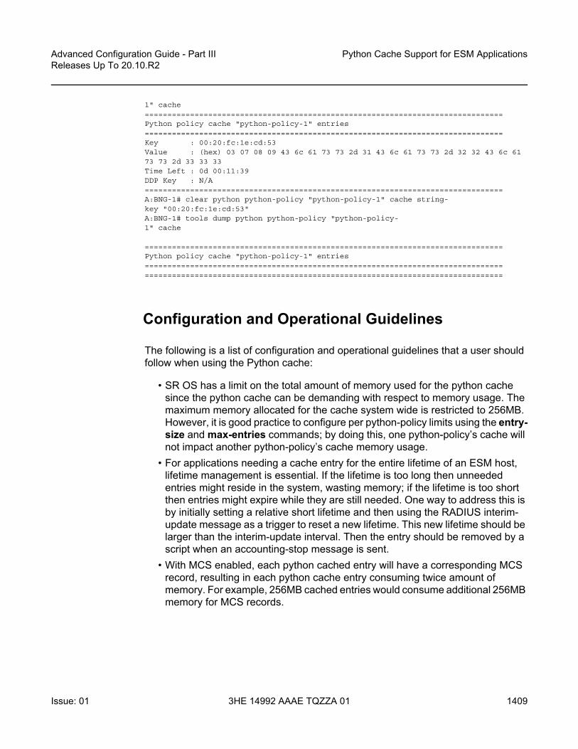
Advanced Configuration Guide - Part III Releases Up To 20.10.R2
Python Cache Support for ESM Applications
Issue: 01 3HE 14992 AAAE TQZZA 01 1409
1" cache===============================================================================Python policy cache "python-policy-1" entries===============================================================================Key : 00:20:fc:1e:cd:53Value : (hex) 03 07 08 09 43 6c 61 73 73 2d 31 43 6c 61 73 73 2d 32 32 43 6c 6173 73 2d 33 33 33Time Left : 0d 00:11:39DDP Key : N/A===============================================================================A:BNG-1# clear python python-policy "python-policy-1" cache string-key "00:20:fc:1e:cd:53"A:BNG-1# tools dump python python-policy "python-policy-1" cache
===============================================================================Python policy cache "python-policy-1" entries==============================================================================================================================================================
Configuration and Operational Guidelines
The following is a list of configuration and operational guidelines that a user should follow when using the Python cache:
• SR OS has a limit on the total amount of memory used for the python cache since the python cache can be demanding with respect to memory usage. The maximum memory allocated for the cache system wide is restricted to 256MB. However, it is good practice to configure per python-policy limits using the entry-size and max-entries commands; by doing this, one python-policy’s cache will not impact another python-policy’s cache memory usage.
• For applications needing a cache entry for the entire lifetime of an ESM host, lifetime management is essential. If the lifetime is too long then unneeded entries might reside in the system, wasting memory; if the lifetime is too short then entries might expire while they are still needed. One way to address this is by initially setting a relative short lifetime and then using the RADIUS interim-update message as a trigger to reset a new lifetime. This new lifetime should be larger than the interim-update interval. Then the entry should be removed by a script when an accounting-stop message is sent.
• With MCS enabled, each python cached entry will have a corresponding MCS record, resulting in each python cache entry consuming twice amount of memory. For example, 256MB cached entries would consume additional 256MB memory for MCS records.

Python Cache Support for ESM Applications
1410
Advanced Configuration Guide - Part IIIReleases Up To 20.10.R2
3HE 14992 AAAE TQZZA 01 Issue: 01
• Choosing the right key is important, a network designer needs to choose the key meeting the application requirement in terms of their uniqueness. For example: if an application needs to store per-host information then the key for that host must be unique (for example, its MAC address or remote-id). The key must be derived from the trigger packet. For example: if an application needs to store information on DHCP discovery and retrieve it on receiving a RADIUS accounting-request message for the same host, then the script needs to be able derive the same key from both the DHCP discovery as well as from the RADIUS accounting-request message.
• Using tools or clear commands to manually change cached entries could cause problems if the entries are needed by a script. Only use these commands when it is absolutely necessary.
• The minimum-lifetimes exist to make the system more efficient in handling system memory before a cache entry could be synced or made persistent (e.g. when a new entry is created or when MCS is enabled). The cache entry’s lifetime must be equal or larger than the configured minimal-lifetime listed below for that function to occur.
1. high-availability — The minimum lifetime of a cache entry for it to be synchronized from the active CPM to the standby CPM. The default is 0 seconds, resulting in all entries being synchronized.
2. multi-chassis-redundancy — The minimum lifetime of a cache entry for it to be synchronized between chassis. The default is 0 seconds, resulting in all entries being synchronized.
3. persistence — The minimum lifetime of a cache entry for it to be written to the persistency file. The default is 0 seconds, resulting in all entries will be synchronized.
Conclusion
The Python cache provides a very powerful and flexible way to share information across different Python scripts in SR OS.

Advanced Configuration Guide - Part III Releases Up To 20.10.R2
RADIUS-Triggered Dynamic Data ServiceProvisioning
Issue: 01 3HE 14992 AAAE TQZZA 01 1411
RADIUS-Triggered Dynamic Data Service ProvisioningThis chapter describes advanced RADIUS-triggered dynamic data service provisioning configurations.
Topics in this chapter include:
• Applicability• Overview• Configuration• Conclusion
Applicability
This example is applicable to all 7750 SR and 7450 ESS in mixed mode with multi-core CPM (CPM-3 and later) and ESM capability.
This feature is not supported on the 7950 XRS or 7450 ESS.
The configuration was tested on release 11.0.R2.
Overview
RADIUS-triggered dynamic data services enables a zero touch, single-ended provisioning model for business services on the basis of Enhanced Subscriber Management functionality.
Triggered by the authentication of a single or dual stack PPPoE or IPoE session or a single stack IPv4 host as the “control channel” from the business CPE, parameters are passed in a RADIUS Access Accept or Change of Authorization (CoA) message to set up one or multiple Layer 2 or Layer 3 data services.

RADIUS-Triggered Dynamic Data Service Provisioning
1412
Advanced Configuration Guide - Part IIIReleases Up To 20.10.R2
3HE 14992 AAAE TQZZA 01 Issue: 01
This concept removes the need to have an Operations Support System (OSS) responsible for the service provisioning and is particularly beneficial in a highly dynamic network environment, where physical network topologies – especially in the access – change frequently. With a regular service provisioning, frequent changes would be hard to keep track of. In the RADIUS-based model the service gets instantiated wherever it “pops-up” in the network. Even planned customer moves to a different office would not require advanced notifications and lead times but could be instantaneous, assuming the pure physical connectivity is given.
A variation of the current service offering will only require one or a few modified service parameters in the RADIUS user database and does not require timely and costly IT changes (for RADIUS those service parameters are just attributes; the RADIUS server does not check the logic). This speeds up the time-to-market for new service offerings, which is another big advantage.
Taking this logic to its full extent, it becomes immediately clear that the managed business CPE terminating the carrier service (and being responsible for the PPP or DHCP control channel) also needs to be provisioned in the most flexible way. Through the control channel or a dedicated management channel instantiated as the first dynamic data service, the business CPE should get its full configuration from a configuration server via a pre-populated configuration file. The details of the CPE provisioning are outside of the scope of this example and therefore not discussed further.
As the whole approach is centered around the principle of “highly flexible in a highly dynamic environment”, it is naturally required to maintain as little state information about connections in the RADIUS parameter attributes as possible. For example, fixed remote peer IP-addresses for the SDPs used in a VPLS service in the RADIUS parameter lists would remove all the flexibility and would not allow access services to be moved dynamically. As such the data services for this functionality focuses on those types where a control protocol like BGP is used to exchange VPN membership information. Dynamic data services supported include local Epipe VLL services, Epipe VLL services with dynamic Multi-Segment PseudoWires (MS-PWs) (FEC129) or spoke SDP, VPLS services with BGP-AD PWs or mesh/spoke SDPs, IES, and VPRN services.
To display the complete white list of dynamic data services CLI configuration commands, use the tools dump service dynamic-services command-list CLI command.
A Python script interface adds a flexible abstraction layer so that only the business user specific service parameters (service type, IP address, QoS and filter parameters, etc.) are required from RADIUS and are then used in a CLI template to set up the target service.
The setup sequence is shown in Figure 231 with the example of a VPLS service.

Advanced Configuration Guide - Part III Releases Up To 20.10.R2
RADIUS-Triggered Dynamic Data ServiceProvisioning
Issue: 01 3HE 14992 AAAE TQZZA 01 1413
Figure 231 Principle Model of Dynamic Data Services
1. Business CPE initiates a PPP or DHCP “control channel” session. This session is important to let the BNG and RADIUS understand the existence of a new access circuit and the location of the service endpoint.
2. BNG sends an Access-Request with all user credentials to RADIUS.3. RADIUS replies using an Access-Accept with attributes for the PPP/DHCP
control channel and attributes for the dynamic data service (Service-type, SAP-VLAN, QoS, Filter, etc.).
4. BNG creates a dynamic data service instance (if it is first access-circuit for this service) and a SAP, thus completing the service configuration.
5. BNG sends an Accounting Start for PPP/DHCP control channel session and also for the dynamic data service session (and subsequently interim accountings and accounting stop for both).
6. BNG advertises VPLS instance-ID (123) via BGP-AD to other PEs/BNGs.7. PEs/BNGs with same service instance will auto-establish SDPs to the BNG.
The result is a fully functional service which is the same as a traditionally configured service.
The lifetime of the dynamic data services are bound to the existence of the control channel session. If, for whatever reason, the control channel session is torn down all associated dynamic data services will also be terminated.
Dynamic data service SAPs have to be located on dot1q or qinq encapsulated Ethernet ports and can be part of a LAG.
al_0286
DCN
Access-request withAll User Credentials
Send Accounting Information for Trigger Session and Data Channel
Access-accept with Service Informationfor Trigger Session (IP@, Assign to DCN, etc.)and Service Information for Dynamic Data Service(VPLS, SAP-VLAN, QoS, Filters, MAC-limit, etc.)
PPP or DHCP Control ChannelSession on VLAN x
Create Service Instanceand SAP on VLAN y
Advertise New ServiceVia BGP-AD
Auto.createSDPs
1
2
4
5
67
3
123
123
123
RADIUS
BNGBNG
BNG

RADIUS-Triggered Dynamic Data Service Provisioning
1414
Advanced Configuration Guide - Part IIIReleases Up To 20.10.R2
3HE 14992 AAAE TQZZA 01 Issue: 01
Both XML accounting and RADIUS accounting can be enabled on a dynamic data service SAP. The RADIUS accounting data can be sent to up to two different RADIUS servers.
There is a strict separation of services created by dynamic service provisioning and services created via the CLI or through other standard mechanisms (5620 SAM, SNMP). It is therefore not allowed to:
• create a dynamic services object in a local provisioned CLI/SNMP context (e.g. create a dynamic SAP in a local provisioned VPLS).
• create a local provisioned object in a dynamic service context (e.g. create a SAP via CLI/SNMP in a dynamic VPLS service).
• change parameters in a local provisioned CLI/SNMP context using the dynamic services model (change system name with dynamic services provisioning).
• change parameters with the CLI/SNMP in a dynamically created context.• delete a local provisioned object using dynamic provisioning model.• delete a dynamic provisioning object using the CLI/SNMP.• create a reference to a dynamic services object in a local provisioned CLI/SNMP
context (reference to dynamic interface in router ospf)
A special command exists to overcome some of the above rules. This command is designed to ease Python script creation and testing and not for normal operations. This is discussed in Configuration.
Configuration
It is assumed that the reader is familiar with the regular Enhanced Subscriber Management (ESM) functionality as well as with general service related configurations. Furthermore certain knowledge about Python programming is also assumed.
The test topology is shown in Figure 232.

Advanced Configuration Guide - Part III Releases Up To 20.10.R2
RADIUS-Triggered Dynamic Data ServiceProvisioning
Issue: 01 3HE 14992 AAAE TQZZA 01 1415
Figure 232 Test Topology
The pure service setup can be tested with a single node acting as BNG. However an Epipe service between two nodes will not normally become status “up” with only one endpoint in an up state. As such, for packets should be sent through the established dynamic data service, a remote PE could also be configured. The remote PE could have its data service configured in a regular fashion, meaning via CLI/SNMP or 5620 SAM.
The required functionality on the BNG is divided into multiple building blocks. The following sections discuss each building block in detail.
Figure 233 Building Blocks of Dynamic Data Services
al_0287
172.31.1.2
192.0.2.1
MSAP
HG or Test Deviceto Generate PPPor DHCP Session
RADIUS
BNG
Remote PE
al_0288
Control Channel RADIUS Attributes
Dyn Serv Policy Python Script
CLI Snippets RADIUS Accounting

RADIUS-Triggered Dynamic Data Service Provisioning
1416
Advanced Configuration Guide - Part IIIReleases Up To 20.10.R2
3HE 14992 AAAE TQZZA 01 Issue: 01
Based on a PPP or DHCP control session, RADIUS will return the required parameters for the dynamic data service via dedicated Vendor Specific Attributes (VSAs). The existence of those attributes in the RADIUS Accept message will trigger the relaying of the parameters relating to those attributes towards the Python script defined in the dynamic service policy, which will process them to generate the regular CLI output for the various service types (IES, VPRN, Epipe, VPLS).
For efficiency and flexibility the Python script needs to be structured into different parts per service which then reference each other internally. Those parts are called snippets.
Finally, as the services are initiated from RADIUS, RADIUS accounting messages per dynamic data service will be sent to the RADIUS server as a necessary feedback mechanism to inform the RADIUS server about a successful or failed service setup.
Building Block: Control Channel
The configuration to authenticate and instantiate a dynamic data service control channel is identical to a residential Enhanced Subscriber Management (ESM) configuration. Examples for this can be found in other chapters of the advanced configuration guide and will not be covered here in detail.
Building Block: Dynamic Services Policy
The dynamic services parameters are configured under the configure service dynamic-services CLI context. The following output shows two policy examples.
configure service dynamic-servicesdynamic-services-policy "dynamic-services-1" create
accounting-1server-policy "radius-server-policy-1"update-interval min 5
exitaccounting-2
server-policy "radius-server-policy-2"stats-type timeupdate-interval min 5update-interval-jitter absolute 10
exitcli-user "dynuser"description "Dynamic Service Policy #1"sap-limit 4000script-policy "script-policy-1"
exitdynamic-services-policy "dynamic-services-2" create
accounting-1
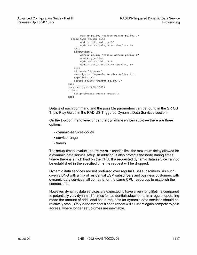
Advanced Configuration Guide - Part III Releases Up To 20.10.R2
RADIUS-Triggered Dynamic Data ServiceProvisioning
Issue: 01 3HE 14992 AAAE TQZZA 01 1417
server-policy "radius-server-policy-2"stats-type volume-time
update-interval min 30update-interval-jitter absolute 20
exitaccounting-2
server-policy "radius-server-policy-2"stats-type timeupdate-interval min 5update-interval-jitter absolute 10
exitcli-user "dynuser"description "Dynamic Service Policy #2"sap-limit 100script-policy "script-policy-2"
exitservice-range 1000 10000timers
setup-timeout access-accept 3exit
Details of each command and the possible parameters can be found in the SR OS Triple Play Guide in the RADIUS Triggered Dynamic Data Services section.
On the top command level under the dynamic-services sub-tree there are three options:
• dynamic-services-policy• service-range• timers
The setup-timeout value under timers is used to limit the maximum delay allowed for a dynamic data service setup. In addition, it also protects the node during times where there is a high load on the CPU. If a requested dynamic data service cannot be established in the specified time the request will be dropped.
Dynamic data services are not preferred over regular ESM subscribers. As such, given a BNG with a mix of residential ESM subscribers and business customers with dynamic data services, all compete for the same CPU resources to establish the connections.
However, dynamic data services are expected to have a very long lifetime compared to potentially very dynamic lifetimes for residential subscribers. In a regular operating mode the amount of additional setup requests for dynamic data services should be relatively small. Only in the event of a node reboot will all users again compete to gain access, where longer setup-times are inevitable.

RADIUS-Triggered Dynamic Data Service Provisioning
1418
Advanced Configuration Guide - Part IIIReleases Up To 20.10.R2
3HE 14992 AAAE TQZZA 01 Issue: 01
The service-range value reserves a certain amount of service IDs for the use of dynamic data services. The configured range is no longer available for regular provisioned services configured via the CLI/SNMP.
The dynamic-services-policy contains a CLI-user identifier, SAP-limits, accounting parameters and reference to a Python script policy which is used when creating a dynamic data service. Multiple dynamic services policies can be created to enable different profiles to be used for different users/customers or services (as an example, two different departments within the service provider, one responsible for Layer 2 services, one for Layer 3 services). The policy used for a dynamic data service is determined from the Alc-Dyn-Serv-Policy [26-6527-167] RADIUS attribute. If the attribute is not present and a policy named default exists, then the default policy is used, otherwise the dynamic data service creation fails.
Up to two accounting server policies can be defined. This allows the use of separate RADIUS accounting servers independent from the accounting servers used for residential services. The parameters defined in the accounting sections are the default values which are used if no specific values are sent via RADIUS VSAs.
As the service is established via RADIUS, a feedback mechanism towards RADIUS is most likely required which would be at least RADIUS start and stop messages per service/session. In addition performance counters (with a fixed set of parameters) can also be included in the RADIUS messages. It is also possible to use the standard service-accounting under the service instance and remove any counters from the RADIUS accounting messages.
The specification of a CLI user allows linking of the dynamic data service to a specific user-profile. In addition, this facilitates limiting of the scope of allowed service configurations even further, based on the specified context under the user profile.
The CLI-user needs to be configured locally on the node and needs to have a local user profile (remote authorization via TACACS/RADIUS is not possible).
The radius-script-policy is configured under the configure aaa CLI context.
configure aaaradius-script-policy "script-policy-2”
action-on-fail passthroughprimary
script-url "cf3:/scripts/dyn_services.py"no shutdown
exitsecondary
script-url ftp://user*:*[email protected]/scripts/dyn_services.py"no shutdown
exitexit
exit

Advanced Configuration Guide - Part III Releases Up To 20.10.R2
RADIUS-Triggered Dynamic Data ServiceProvisioning
Issue: 01 3HE 14992 AAAE TQZZA 01 1419
The parameters are no different to what have been defined generally for the use of Python scripting on the BNG.
When the very first session request arrives, the Python script is loaded into memory and executed. For all subsequent session requests the script is executed without the need for a reload. It is possible for both primary and secondary locations to be FTP sites (the small transfer delay for the first session is acceptable), however, it is recommended to have a compact-flash (cf1 or cf2) as the primary location and a remote location as backup.
Building Block: RADIUS Attributes
A series of vendor specific attributes (VSAs) have been defined to setup, teardown or modify dynamic data services from RADIUS.
The VSAs and their meaning are as follows:
• Alc-Dyn-Serv-SAP-Id [26-6527-164], type “string”This attribute identifies the dynamic service SAP. The format can be any valid Ethernet SAP format (dot1q or qinq encapsulation), including LAGs. A wildcard (“#”) can be specified for the port field and optionally for one of the tag fields of a qinq interface. To define the dynamic data service SAP-ID, the wildcard fields are replaced with the corresponding field from the Control Channel SAP-ID.Examples: “1/2/7:10.100” or “#:#.100”
• Alc-Dyn-Serv-Script-Action [26-6527-166], type “integer”A mandatory VSA in a COA to the control channel accounting session ID or the accounting session ID of the dynamic data service (only applicable for modify or teardown). Tells the system what script action is required: setup, modify or teardown of a dynamic data service.Values: 1=setup, 2=modify, 3=teardown
• Alc-Dyn-Serv-Policy [26-6527-167], type “string”Specifies the dynamic service policy to use for provisioning the dynamic service. The policy must be configured in the “configure service dynamic-services dynamic-services-policy < dynsrv-policy-name>” CLI context.

RADIUS-Triggered Dynamic Data Service Provisioning
1420
Advanced Configuration Guide - Part IIIReleases Up To 20.10.R2
3HE 14992 AAAE TQZZA 01 Issue: 01
• Alc-Dyn-Serv-Script-Params [26-6527-165], type “string”This VSA contains parameters that can be used by the Python script to setup or modify a dynamic data service. The parameters can be split into multiple instances of the same attribute, linked together by the same tag, that is, the parameters can cross an attribute boundary. The concatenation of all “Alc-Dyn-Serv-Script-Params” attributes with the same tag in a single message must be formatted as “function-key = {dictionary}” where function-key specifies which Python functions will be called and {dictionary} contains the actual parameters in a Python dictionary structure format.Example: “business_1 = { 'as_id' : '100', 'comm_id' : '200', 'if_name' : 'itf1', 'ipv4_address' : '172.16.1.1', 'egr_ip_filter' : '100' , 'routes' : [{'to' : '172.16.100.0/24', 'next-hop' : '172.16.1.2'}, {'to' : '172.16.200.0/24', 'next-hop' : '172.16.1.2'}]}The above example shows each parameter with a keyword and the associated value. Alternatively only the parameter values can be sent with a pre-defined (and always constant) sequence.Example: “business_1 = {“t”: '100', '200', 'itf1', '172.16.1.1', '100', '172.16.100.0/24', '172.16.1.2', '172.16.200.0/24', '172.16.1.2'}.
• Alc-Dyn-Serv-Acct-Interim-Ivl-1 [26-6527-168], type “integer”This VSA defines the number of seconds between each accounting interim update message for the primary accounting server. It overrides the local configured “update-interval” value in the dynamic services policy “accounting-1” CLI context. A value of 0 (zero) corresponds to no accounting interim update messages. A value [1..299] seconds is rounded to 300s (min. CLI value) and a value above 15552000 seconds (180 days, maximum CLI value) is rounded to the maximum CLI value.Range = 0 | [300 - 15552000].
• Alc-Dyn-Serv-Acct-Interim-Ivl-2 [26-6527-169], type “integer”Same function and values as Alc-Dyn-Serv-Acct-Interim-Ivl-1 [26-6527-168], for the second accounting server. It overrides the locally configured “update-interval” value in the dynamic services policy “accounting-2” CLI context.
• Alc-Dyn-Serv-Acct-Stats-Type-1 [26-6527-170], type “integer”Enable or disable dynamic data service accounting to the primary accounting server and specify the type of statistics that should be reported: volume and time or time only. It overrides the locally configured value in the dynamic services policy “accounting-1” CLI context.Values: 1=off, 2=volume-time, 3=time

Advanced Configuration Guide - Part III Releases Up To 20.10.R2
RADIUS-Triggered Dynamic Data ServiceProvisioning
Issue: 01 3HE 14992 AAAE TQZZA 01 1421
• Alc-Dyn-Serv-Acct-Stats-Type-2 [26-6527-171], type “integer”Enable or disable dynamic data service accounting to the secondary accounting server and specify the type of statistics that should be reported: volume and time or time only. It overrides the locally configured “stats-type” value in the dynamic services policy “accounting-2” CLI context.Values: 1=off, 2=volume-time, 3=time
All VSAs are tagged to enable manipulation of up to 32 (tag values 0..31) dynamic data services in a single RADIUS message. VSAs with an identical tag belong to the same dynamic data service.
The use of the VSAs in RADIUS Access-Accept, CoA and Disconnect Messages is detailed in Table 42. An Access-Accept message can only contain dynamic data service setup requests. A CoA can be used to setup, modify or terminate a dynamic data service. A Disconnect Message can only be used to terminate a dynamic data service.
Table 42 Dynamic Service Attribute List for Setup, Modify and Teardown
Attribute Name Access Accept
CoA Disc.Message
Comment
Setup Setup Modify Teardown Teardown
Acct-Session-Id N/A M M M M Acct-Session-Id of the Control Channel or in case of a CoA: any other valid CoA key for ESM hosts/sessions.
Alc-Dyn-Serv-SAP-Id M M(*) M(*) M(*) N/A Identifies the dynamic data service
Alc-Dyn-Serv-Script-Params
O M(*) M(*) N/A N/A For a Modify, the script parameters represent the new parameters required for the change.
Alc-Dyn-Serv-Script-Action
O M(*) M(*) M(*) N/A Must be “setup” if specified in an access-accept.
Alc-Dyn-Serv-Policy O O O O N/A The default policy used when not specified for create.In CoA, must be same as used for Setup if Specified for Modify or Teardown.

RADIUS-Triggered Dynamic Data Service Provisioning
1422
Advanced Configuration Guide - Part IIIReleases Up To 20.10.R2
3HE 14992 AAAE TQZZA 01 Issue: 01
To summarize, Table 43 shows resulting dynamic service script actions as function of the RADIUS message (Access-Accept, CoA or DM) and the target (Control Channel or Dynamic Service SAP).
Alc-Dyn-Serv-Acct-Interim-Ivl-1
O O X(**) X(**) N/A
Alc-Dyn-Serv-Acct-Interim-Iv2
O O X(**)) X(**)) N/A
Alc-Dyn-Serv-Acct-Stats-Type-1
O O X(**) X(**)) N/A
Alc-Dyn-Serv-Acct-Stats-Type-2
O O X(**)) X(**)) N/A
M = Mandatory, O= Optional, X = May not, N/A = Not Applicable (ignored)
(*) = CoA Nak’d, if not specified (Error Cause: 402 - Missing Attribute)
(**) = CoA Nak’d if specified (Error Cause:405 - Unsupported Service)
Table 42 Dynamic Service Attribute List for Setup, Modify and Teardown (Continued)
Attribute Name Access Accept
CoA Disc.Message
Comment
Setup Setup Modify Teardown Teardown
Table 43 Dynamic Service Actions on Control- and Data-Channel
Target RADIUS Message
Dynamic Service Script Action
Comments
Control Channel
Access-Accept Setup Up to 32 dynamic data services in single message.Alc-Dyn-Serv-Script-Action VSA optional.
Modify/Teardown Not supported.
CoA(acct-session-id or any other valid CoA key for ESM hosts/sessions)
Create/Modify/Teardown
Cannot be mixed with session/post parameter changes in the same RADIUS message (results in CoA NAK).Up to 32 dynamic data services in single message.Alc-Dyn-Serv-Script-Action VSA mandatory.
Disconnect N/A Teardown the Control Channel session and all associated dynamic data services.

Advanced Configuration Guide - Part III Releases Up To 20.10.R2
RADIUS-Triggered Dynamic Data ServiceProvisioning
Issue: 01 3HE 14992 AAAE TQZZA 01 1423
Building Block: Python Script
Dynamic data services scripts are built using a Python script engine. The following dedicated functions are available in the alc.dyn module:
• dyn.reference(function-key, reference-id string, dictionary) This function creates a dynamic reference to another function in the script. This function eases the creation of N:1 relationships in the script. For more information about use cases, see Building Block: CLI Snippets. The function-key specifies the key in the action dictionary to find the corresponding setup/modify/teardown function calls.The reference-id (typically derived from a parameter specified from RADIUS, for example: service-name) specifies a unique instance string that identifies this reference.The dictionary specifies a dictionary with parameters that can be used in the parent function to generate CLI script output.
• dyn.action(d) When called, the dyn.action will take the “function-key” string specified in the Alc-Dyn-Serv-Script-Params attribute, and perform a lookup in the specified dictionary d to find the corresponding Python function to execute. The format of the dictionary is d = {key-1 : (Setup-1, Modify-1, Revert-1, Teardown-1), …, key-n : (Setup-n, Modify-n, Revert-n, Teardown-n) }. If the function-key matches, for
Dynamic Service
CoA(acct-session-id of the dynamic data service sap)
Modify/Teardown Only single dynamic data service per message (Acct-Session-Id).Alc-Dyn-Serv-Script-Action VSA mandatory.
Setup Not supported.
Disconnect(acct-session-id of the dynamic data service sap)
N/A Teardown the corresponding dynamic data service.
Table 43 Dynamic Service Actions on Control- and Data-Channel (Continued)
Target RADIUS Message
Dynamic Service Script Action
Comments

RADIUS-Triggered Dynamic Data Service Provisioning
1424
Advanced Configuration Guide - Part IIIReleases Up To 20.10.R2
3HE 14992 AAAE TQZZA 01 Issue: 01
example, key-1 and the corresponding Alc-Dyn-Script-Action is “setup”, then the function specified as “Setup-1” will be executed. Setup and teardown functions are mandatory. Modify and revert functions are optional. If a modify function is defined, a corresponding revert function must also be defined. If no modify/revert function is required, the keyword “None” should be used instead.
• dyn.add_cli(string)This function is used to generate CLI output in the Python script. The use of dyn.add_cli (”””) allows the specification of strings spanning multiple lines, which drastically improves the readability of the script. A subset of all available CLI commands is currently enabled for dynamic data services. The command “tools dump service dynamic-services command-list” provides a complete overview of all available CLI nodes for dynamic data services. In the allowed nodes section, all CLI nodes are listed that can be navigated to and where attributes can be modified. The pass through nodes section shows CLI nodes that can be navigated to but no attribute changes are allowed. For example, it is not allowed to change the autonomous system of a router (configure router autonomous-system <autonomous-system>) because “configure router” is a “pass through node”. However, you can navigate to configure router, because you can add a static route: “/configure router static-route 0.0.0.0/0 next-hop 192.168.1.1” is part of the “allowed nodes”.
• dyn.select_free_id(“service-id”)This function is used to select a free service ID within the service ID range defined under dynamic-services context. An automatic assignment of the service id is one option, but it is also possible to provide the service id as one of the parameters in the “Alc-Dyn-Serv-Script-Params” list from RADIUS.The service-ID is a node-internal attribute. As such it is valid to let the node select the ID itself. However, in a network with multiple BNGs and a single customer service spanning two or more BNGs, a network administrator may actually prefer to use the same service-id for this customer service on all nodes for better visibility, which cannot be guaranteed if the automatic option is chosen. 5620 SAM is also using the service-ID as one attribute in addition to others to discover service-entities across the whole network. If SAM is in use for general management and service assurance, it is advised to manually specify the service-ID and not to use the automatic selection.In any case, the administrator needs to make a choice between the automatic ID assignment and the specific assignment for all dynamic data services, as a mix between both is not recommended.When the automatic assignment is chosen, there is no “binding/memory” of a service ID to a provisioned service, which means a service that may have service ID xyz initially may get another service ID the next time it comes up. In other words, as soon as a service is disconnected, the service ID is freed up for the next activated service.

Advanced Configuration Guide - Part III Releases Up To 20.10.R2
RADIUS-Triggered Dynamic Data ServiceProvisioning
Issue: 01 3HE 14992 AAAE TQZZA 01 1425
• dyn.get_sap()This function returns the value of the evaluation of the “Alc-Dyn-Serv-SAP-Id” attribute as a string. Wildcards (“#”) in the Alc-Dyn-Serv-SAP-Id are replaced with the corresponding port/vlan information of the control channel SAP-ID. So if, for example, the “Alc-Dyn-Serv-SAP-Id” contains “#:#.1” and the control channel SAP ID is “1/1/5:100.100”, the resulting SAP for the data service would be “1/1/5:100.1”.
• dyn.get_circuit_id()This function returns a string which is equal to the Control Channel Circuit-ID (from the DHCP relay agent option 82 or PPP tags). This function may be useful, for example, to use the circuit id in the SAP description.
• dyn.get_remote_id()This function returns a string which is equal to the Control Channel Remote-ID (from the DHCP relay agent option 82 or PPP tags). This function may be useful, for example, to use the remote id in the SAP description.
In addition to the RADIUS dictionary, the node will also store service-related parameters in a service-specific dictionary. The information in the RADIUS messages or in the stored dictionary are used for the various functions as outlined in Table 44:
Table 44 Function and Dictionary Relationship
Function Name Input Returns
setup dynsvc(rd*) rd: radius dictionary in the parameter list in Alc-Dyn-Serv-Script-Params. VSA Passed to setup function.
A dictionary that will be stored for the lifetime of the dynamic service (sd).
modify_dynsvc(rd,sd**) rd: radius dictionary in the parameter list in Alc-Dyn-Serv-Script-Params. VSA passed to modify function.sd: previously stored dictionary of the setup/previous modify functions.
Updated stored dictionary (sd)
revert_dynsvc(rd, sd) rd: radius dictionary in the parameter list in Alc-Dyn-Serv-Script-Params. VSA passed to revert function.sd: previously stored dictionary of the setup/previous modify function.
The function does not return (store) any information. The previously stored dictionary (sd) is kept.
teardown_dynsvc(sd) sd: previously stored dictionary by the setup function or a previous modify function are passed to the teardown function.
The function does not return (store) any information. The stored dictionary (sd) is deleted.
(*) rd = radius dictionary

RADIUS-Triggered Dynamic Data Service Provisioning
1426
Advanced Configuration Guide - Part IIIReleases Up To 20.10.R2
3HE 14992 AAAE TQZZA 01 Issue: 01
Building Block: CLI Snippets
The necessary functional parts of a service configuration cannot typically be put into one large script (one single actionable function). This is best described with a small and simple example:
Imagine a single script where the setup action creates both the service instance and the SAP, and the teardown action removes the service instance and the SAP. For a service with just one SAP per service instance this may work fine, however, in a multi SAP service like a VPLS this will cause problems, especially during the service teardown action. This is because if multiple SAPs have been instantiated in a single service, the disconnect of just one SAP would trigger the teardown action which would try to remove the SAP (still ok) but then would try to remove the service instance. This action would fail as other SAPs still exist in the service. As such the script execution would fail.
It is therefore necessary to structure the whole required configuration into individual actionable pieces which are referenced by each other with specific reference-IDs. Those actionable pieces are called “snippets”.
Referenced snippets may or may not be executed depending on whether the functional instance exists already or not. As shown on the left of the picture below, the action to create a SAP references the creation of a service and then to the creation of a customer. For the very first business site to come up all three snippets will be executed. For any further business site to come up in the same service the script to create the SAP will be executed, the referenced service script and subsequently the customer script will not be executed again as those instances already exist. The same logic applies during the teardown action. Only when the last SAP in a service is removed is the service-instance itself removed, and potentially also the customer (unless it too is associated with other services).
(**) sd = stored dictionary. sd is required for modifies, reverts and teardowns.
Table 44 Function and Dictionary Relationship (Continued)
Function Name Input Returns

Advanced Configuration Guide - Part III Releases Up To 20.10.R2
RADIUS-Triggered Dynamic Data ServiceProvisioning
Issue: 01 3HE 14992 AAAE TQZZA 01 1427
Figure 234 Hierarchy of Snippets
The implementation supports a three level hierarchy of snippets for high flexibility as shown in the picture. A reference to the fourth level as shown on the right side would result in an error.
Furthermore, snippets can be scaled “horizontally”, so from one level multiple references to other snippets are possible. An example for that would be the creation of a SAP triggers the creation of a service as well as the creation of an Ethernet CFM association for that SAP.
Identifiers are needed for the referencing. The same identifier can be used on the “horizontal” level, but not on the vertical level between the same pair of snippets, also shown above.
Snippets are heavily used in the service examples in Bringing it all together where the logic and the referencing are described with real data.
al_0289
setup_A
Allowed sincereference to
different functionscan have samereference-ids
Allowed sincereference to
same functionhave differentreference-ids
Only 2sequential dynamicreferences allowed(3 hierarchy levels)
Not allowed sincereferences to the
same functionmust have different
reference-ids
“Interface/ SAP”
“Service”
“Customer”
snippet A
setup_B
“id1”
L1
“id1”
L2
snippet BRefcount
setup_E
snippet ERefcount
setup_C
snippet CRefcount
setup_A
snippet A
setup_B
“id2”
L1
L1
“id1”
L1
L1
“id1”
L1
“id1”
“id1”
“id1”
“id1”
L2
L2
dynamic referencereference “id1”
level 1
invaliddynamic reference
snippet BRefcount
setup_C
snippet CRefcount
“id1”
L3setup_D
snippet DRefcount

RADIUS-Triggered Dynamic Data Service Provisioning
1428
Advanced Configuration Guide - Part IIIReleases Up To 20.10.R2
3HE 14992 AAAE TQZZA 01 Issue: 01
Building Block: RADIUS Accounting
As dynamic data services are instantiated through RADIUS, it is also typically required to provide feedback to the RADIUS server for service establishment and teardown. This is achieved via RADIUS accounting records for the dynamic data channels in addition to the accounting messages for the PPP or DHCP control channel.
Up to two dedicated accounting destinations can be defined within the dynamic services policy. Thus, the accounting for the dynamic data services can be handled by an independent set of accounting servers (from the accounting for general ESM subscribers). But the same servers can also be used.
Each dynamic data service has its own accounting start/stop/interim messages based on a unique accounting session ID. In addition, the accounting packets contain a multi-session ID which is identical to the accounting session ID of the control channel and is therefore displayed in show commands as Acct-Session-ID-Ctrl as shown below.
A:BNG-1# show service dynamic-services saps summary===============================================================================Dynamic Services SAP's summary===============================================================================SAP Acct-Session-ID Acct-Session-ID-Ctrl-------------------------------------------------------------------------------3/2/1:4.3 D6E559000000B951668AEB D6E559000000B851668AEB3/2/2:1.1 D6E559000000C75166CFF4 D6E559000000C45166CFF43/2/2:1.2 D6E559000000C85166CFF4 D6E559000000C45166CFF43/2/2:1.3 D6E559000000C95166CFF4 D6E559000000C45166CFF43/2/2:1.4 D6E559000000CA5166CFF4 D6E559000000C45166CFF4-------------------------------------------------------------------------------No. of SAP's: 5===============================================================================
The Accounting Session ID (in the centre above) is the one for the dynamic data service itself, the one on the right is from the control-channel. The above example clearly shows that the last 4 dynamic services all belong to the same control channel, as they all have the same Acct-Session-ID-Ctrl.
If the accounting stats-type is set to “volume-time”, the interim and stop accounting messages will also contain counters for the data traffic through the service. With the accounting stats-type “time”, no counters are included, only session time is reported.
As a dynamic data service is functionally no different from a regular data service, traffic volumes can also be gathered by assigning accounting policies within the service for file-based XML accounting.

Advanced Configuration Guide - Part III Releases Up To 20.10.R2
RADIUS-Triggered Dynamic Data ServiceProvisioning
Issue: 01 3HE 14992 AAAE TQZZA 01 1429
Bringing it all together
This section gives examples of all of the above parameters and will also cover show, log and debug information.
In the given example, a single user in the database has four different associated data services. Not only are the data service types all different, but also other aspects of the parameter set, this has an effect on how the data is entered in the RADIUS VSAs and how the Python script is constructed. More detail is given below. The different models for specifying parameters are presented to show the flexibility. An operator typically chooses a single model and uses that for all its services.
As all of the information for these four services will potentially be sent in one RADIUS message, the VSAs need to be tagged so that the BNG can link the appropriate VSAs to each other and differentiate the services. For better visibility, the different sections in the RADIUS users file are displayed with bold black and dark grey text.
The freeradius users file format is used for this example.
1. "[email protected]" Cleartext-Password := "ALU"2. Alc-Subsc-ID-Str := "pppoe-user12",3. Framed-IP-Address = 10.2.1.200,4 Alc-Dyn-Serv-SAP-Id:1 = "#:#.1",5. Alc-Dyn-Serv-Script-Params:1 = "business_epipe={'t':('EPipe-6. CustomerName','CustomerName-Circuit-1','3','3','64496',7. '192.0.2.5','192.0.2.1','3333')}",8. Alc-Dyn-Serv-Policy:1 = "dynamic-services-2",9. Alc-Dyn-Serv-SAP-Id:2 += "#:#.2",10. Alc-Dyn-Serv-Script-Params:2 += "business_vprn={'t':('9999',11. 'VPRN-CustomerName','64497','100000','CustomerName-Circuit-12. 1','172.16.10.1/30','3','1','3','2','172.16.100.0/24',13. '172.16.10.2','100')}",14. Alc-Dyn-Serv-Acct-Interim-Ivl-1:2 += "600",15. Alc-Dyn-Serv-Acct-Interim-Ivl-2:2 += "0",16. Alc-Dyn-Serv-Policy:2 += "dynamic-services-2",17. Alc-Dyn-Serv-SAP-Id:3 += "#:#.3",18. Alc-Dyn-Serv-Script-Params:3 += "business_vpls={'inst':19. 'VPLS-CustomerName','if_name':'CustomerName-Circuit-1','ing_qos':'3',20. 'egr_qos':'3','imp_comm_val':'10000','exp_comm_val':'10000',21. 'rt':'64498','rd':'64498'}",22. Alc-Dyn-Serv-Policy:3 += "dynamic-services-2",23. Alc-Dyn-Serv-Acct-Interim-Ivl-1:3 += "0",24. Alc-Dyn-Serv-Acct-Interim-Ivl-2:3 += "0",25. Alc-Dyn-Serv-Acct-Stats-Type-1:3 += off,26. Alc-Dyn-Serv-Acct-Stats-Type-2:3 += off,27. Alc-Dyn-Serv-SAP-Id:4 += "#:#.4",28. Alc-Dyn-Serv-Script-Params:4 += "business_ies={'t':29. ('IES-CustomerName','CustomerName-Circuit-1','172.16.11.1/30',30. '2001:db8:5100:1000::1/64','5','1','1','6','2','2','5','25',31. 'cfm-Mep-to-CPE','100',",32. Alc-Dyn-Serv-Script-Params:4 += "[{'to':'172.16.110.0/24',33, 'n-h':'172.16.11.2'},{'to':'2001:db8:bbbb::/56',34. 'n-h':'2001:db8:5100:1000::2'}])}",

RADIUS-Triggered Dynamic Data Service Provisioning
1430
Advanced Configuration Guide - Part IIIReleases Up To 20.10.R2
3HE 14992 AAAE TQZZA 01 Issue: 01
35. Alc-Dyn-Serv-Policy:4 += "dynamic-services-2",36. Alc-Dyn-Serv-Acct-Interim-Ivl-1:4 += "600",37. Alc-Dyn-Serv-Acct-Interim-Ivl-2:4 += "0",38. Alc-Dyn-Serv-Acct-Stats-Type-1:4 += "3",39. Alc-Dyn-Serv-Acct-Stats-Type-2:4 += "2",
The first section (lines 1 — 3) shows a minimal parameter set for the (PPP) control channel. As the focus of this example is on the dynamic data services, all default parameters will be used for the control-session which are defined under the msap.
The second section (lines 4 — 8, attributes with tag “:1”) shows a possible parameter set for an Epipe service. Only the absolutely minimum set of VSAs is used (see Dynamic Service Attribute List for Setup, Modify and Teardown). Furthermore, all service parameters are listed without keywords in a pre-defined order. No service ID number is specified in “Alc-Dyn-Serv-Script-Params”, hence the Python script should dynamically select the next free ID.
The third section (lines 9 — 16, attributes with tag “:2”) shows a possible parameter set for a VPRN service. A few more VSAs are defined, thus some of the default parameters in the dynamic service policy are overwritten for this service. The first entry in the “Alc-Dyn-Serv-Script-Params” attribute specifies the Service-ID number for this service, so the Python script should not select a service ID automatically. Furthermore, static-routing information towards the CPE is added as normal attributes at the end of the list.
The fourth section (line 17 — 26, attributes with tag “:3”) shows a possible parameter set for a VPLS service. Notice the difference with the first two services in the “Alc-Dyn-Serv-Script-Params” part: now all parameters are given their specific keyword. As such, the sequence of those parameters is not important. The effect on the Python script is shown further down.
The fifth section (lines 27 — 39, attributes with tag “:4”) finally shows a possible parameter set for an IES service. All of the required parameters for this service do not fit into a single “Alc-Dyn-Serv-Script-Params” attribute anymore (limited to 247 bytes). As is shown, multiple VSAs can be “concatenated” by simply splitting the attributes. It is important that the order in which the different “Alc-Dyn-Serv-Script-Params” attributes with the same tag is received can be guaranteed. Furthermore the second appearance of this VSA shows a different way of provisioning static-routing information towards the CPE.
To better understand the details it is necessary to take a closer look into the active Python script. The first important part is the section with the dynamic actions.
-snip-
d = {"vprn": (setup_vprn, None, None, teardown_vprn),"ies": (setup_ies, None, None, teardown_ies),"vpls": (setup_vpls, None, None, teardown_vpls),

Advanced Configuration Guide - Part III Releases Up To 20.10.R2
RADIUS-Triggered Dynamic Data ServiceProvisioning
Issue: 01 3HE 14992 AAAE TQZZA 01 1431
"epipe": (setup_epipe, None, None, teardown_epipe),"ethcfm" : (setup_ethcfm_domain, None, None, teardown_ethcfm_domain),"business_vprn" : (setup_business_vprn, None, None, teardown_business_vprn),"business_ies" : (setup_business_ies, None, None, teardown_business_ies),"business_vpls" : (setup_business_vpls, None, None, teardown_business_vpls),"business_epipe" : (setup_business_epipe, modify_business_epipe,
revert_business_epipe, teardown_business_epipe)}dyn.action(d)
The function-key string specified at the start of the “Alc-Dyn-Serv-Script-Params” (for example Alc-Dyn-Serv-Script-Params:1 = “business_epipe={…}”) has a 1:1 mapping with the keys of the dictionary “d” in the highlighted section of the above sample (for example d = { …, "business_epipe" : (…)}. For services, different values for setup, modify, revert and teardown are given which point to other sections in the Python script (see below). Setup and teardown functions are mandatory, whereas modify and revert functions are optional.
In the unbolded text of the previous example, there are other actions defined that are not contained in the RADIUS attributes (for example d = { "vprn": (…) , … ). Those actions are referenced by the four main functions.
In the next part, there is more detail presented in each service example and maps it to the corresponding Python function.
It is advisable to read through all examples, as only the deltas between each service are explicitly explained.
Example 1 – Epipe service
# copy of the RADIUS attributes from above-snip-
Alc-Dyn-Serv-SAP-Id:1 = "#:#.1",Alc-Dyn-Serv-Script-Params:1 = "business_epipe={'t':
('EPipe-CustomerName','CustomerName-Circuit-1','3','3','64496','192.0.2.5','192.0.2.1','3333')}",
Alc-Dyn-Serv-Policy:1 = "dynamic-services-2",-snip-
# Python-partd = {-snip-"business_epipe" : (setup_business_epipe, modify_business_epipe,
revert_business_epipe, teardown_business_epipe)dyn.action(d)-snip-def setup_business_epipe(d):
keys = ('inst', 'if_name', 'ing_qos', 'egr_qos', 'as', 'remote_ip','local_ip', 'glb_svc_id')
d = dict(zip(keys, d['t']))ref_d = dyn.reference("epipe", d['inst'], d)d['svc_id'] = ref_d['svc_id']d['sap_id'] = dyn.get_sap()dyn.add_cli("""

RADIUS-Triggered Dynamic Data Service Provisioning
1432
Advanced Configuration Guide - Part IIIReleases Up To 20.10.R2
3HE 14992 AAAE TQZZA 01 Issue: 01
configureservice
epipe %(svc_id)ssap %(sap_id)s create
description "%(if_name)s"ingressqos %(ing_qos)s
exitegressqos %(egr_qos)s
exitexitspoke-sdp-fec %(svc_id)s fec 129 aii-type 2 create
pw-template-bind 2saii-type2 %(as)s:%(local_ip)s:%(glb_svc_id)staii-type2 %(as)s:%(remote_ip)s:%(glb_svc_id)sno shutdown
exitexit
exitexit""" % d)
return d
def setup_epipe(d):d['svc_id'] = dyn.select_free_id("service-id")dyn.add_cli("""
configureservice
epipe %(svc_id)s customer 1 createservice-name "%(inst)s"description "%(inst)s"no shutdown
exitexit
exit""" % d)
return {'svc_id':d['svc_id']}
def teardown_epipe(d):dyn.add_cli("""
configureservice
epipe %(svc_id)sshutdown
exitno epipe %(svc_id)s
exitexit""" % d)
def teardown_business_epipe(d):dyn.add_cli("""
configureservice
epipe %(svc_id)ssap %(sap_id)s
shutdownexit

Advanced Configuration Guide - Part III Releases Up To 20.10.R2
RADIUS-Triggered Dynamic Data ServiceProvisioning
Issue: 01 3HE 14992 AAAE TQZZA 01 1433
spoke-sdp-fec %(svc_id)sshutdown
exitno sap %(sap_id)sno spoke-sdp-fec %(svc_id)s
exitexit
exit""" % d)-snip-
Based on the dictionary specified in the dyn.action(d) call, the function definition “setup_business_epipe” in the Python script corresponds with the function that will be called if the function-key “business-epipe” is specified in the “Alc-Dyn-Serv-Script-Params” attribute as dictionary name and if a setup action is required. The dictionary containing the parameters in the RADIUS VSA “Alc-Dyn-Serv-Script-Params” has a single key-value pair, with the parameters stored in a tuple. The individual parameters cannot be identified with a keyword hence the order in which they are specified in the RADIUS VSA should match the order in which they are extracted in the Python script. The first two lines in this part of the script extract the parameters out of the array “t” and link them to unique keywords, which are used for the rest of the script.
The parameter “inst” is important in this logic, as it defines whether access circuits belong to the same service-instance or different instances (the RADIUS VSAs for two SAPs belonging to the same service therefore need to have the same “inst” value). If you look at the CLI of the “setup_business_epipe” function, you can see that it creates the SAP and all related attributes, but not the service itself. It is the “ref_d = dyn.reference("epipe", d['inst'], d)” that references a part in the script to create the actual service-instance. The referenced function is found by using the first parameter in the dyn.reference call (“epipe”) as a function-key lookup in the dictionary specified in the dyn.action(d) and finding the corresponding setup function: d = { …, "epipe" : (setup_epipe, … ), …}. The second parameter (“d['inst']”) is used as unique identification of the service instance. The last parameter (“d”) is a dictionary with parameters that can be used by the references function. When the first customer endpoint with a new “inst” name comes up, the service itself gets created.
By looking at “def setup_epipe(d):” the first line “d['svc_id'] = dyn.select_free_id("service-id")” of the script automatically picks a free service-id out of the range defined in the dynamic service policy, as no service ID was provided in the RADIUS parameters. The rest of this function creates the service instance. Service attributes that were provided by RADIUS and are placed in a service specific dictionary are available to this function via the third parameter in the dyn.reference call. The newly generated service ID is returned to the calling script by the “return {'svc_id':d['svc_id']}” command at the end of the function. The service specific dictionary (as explained in the Python Script Building Block) is updated with the appropriate information.

RADIUS-Triggered Dynamic Data Service Provisioning
1434
Advanced Configuration Guide - Part IIIReleases Up To 20.10.R2
3HE 14992 AAAE TQZZA 01 Issue: 01
Back to “def setup_business_epipe(d):”, the service ID together with the SAP ID and the parameters from the Alc-Dyn-Serv-Script-Params VSA are used to create the appropriate CLI code for the SAP and the SDP within the service.
Similar to the setup, there is also a teardown part for both service and SAP. The teardown function is called either through the termination of the control-channel, through a COA with Alc-Dyn-Script-Action = teardown or through a disconnect message. The CLI for the teardown script must be written in the correct sequence as applied by the SR OS CLI logic so that SAP(s) and service(s) are removed in the correct order.
Example 2 – VPRN service
RADIUS-part from above-snip-
Alc-Dyn-Serv-SAP-Id:2 += "#:#.2",Alc-Dyn-Serv-Script-Params:2 += "business_vprn={'t':
('9999','VPRN-CustomerName','64497','100000','CustomerName-Circuit-1','172.16.10.1/30','3','1','3','2','172.16.100.0/24','172.16.10.2','100')}",
Alc-Dyn-Serv-Acct-Interim-Ivl-1:2 += "600",Alc-Dyn-Serv-Acct-Interim-Ivl-2:2 += "0",Alc-Dyn-Serv-Policy:2 += "dynamic-services-2",
-snip-
Python-partd = {-snip-"business_vprn" : (setup_business_vprn, None, None, teardown_business_vprn)dyn.action(d)-snip-def setup_business_vprn(d):
keys = ('svc_id', 'inst', 'as_id', 'comm_id', 'if_name', 'ipv4_address','ing_qos', 'ing_ip_filter', 'egr_qos', 'egr_ip_filter', 'lan_pfx','nxt_hop', 'metric')
d = dict(zip(keys, d['t']))ref_d = dyn.reference("vprn", d['inst'], d)d['sap_id'] = dyn.get_sap()dyn.add_cli("""
configureservice
vprn %(svc_id)sinterface "%(if_name)s" create
address %(ipv4_address)surpf-check mode strictsap %(sap_id)s createingress
qos %(ing_qos)sfilter ip %(ing_ip_filter)s
exitegress
qos %(egr_qos)sfilter ip %(egr_ip_filter)s
exitexit
exit

Advanced Configuration Guide - Part III Releases Up To 20.10.R2
RADIUS-Triggered Dynamic Data ServiceProvisioning
Issue: 01 3HE 14992 AAAE TQZZA 01 1435
exitexitrouter
static-route %(lan_pfx)s next-hop %(nxt_hop)s metric %(metric)sexit
exit""" % d)
return d
def setup_vprn(d):dyn.add_cli("""
configureservice
vprn %(svc_id)s customer 1 createservice-name "%(inst)s"description "%(inst)s"autonomous-system %(as_id)sroute-distinguisher %(as_id)s:%(comm_id)sauto-bind mplsvrf-target target:%(as_id)s:%(comm_id)sno shutdown
exitexit
exit""" % d)
return {'svc_id':d['svc_id']}
def teardown_vprn(d):dyn.add_cli("""
configureservice
vprn %(svc_id)sshutdown
exitno vprn %(svc_id)s
exitexit""" % d)
def teardown_business_vprn(d):dyn.add_cli("""
configurerouter
no static-route %(lan_pfx)s next-hop %(nxt_hop)sexitservice
vprn %(svc_id)sinterface "%(if_name)s"
sap %(sap_id)sshutdown
exitno sap %(sap_id)sshutdown
exitno interface "%(if_name)s"
exitexit
exit""" % d)

RADIUS-Triggered Dynamic Data Service Provisioning
1436
Advanced Configuration Guide - Part IIIReleases Up To 20.10.R2
3HE 14992 AAAE TQZZA 01 Issue: 01
-snip-
In this example of a VPRN service two additional RADIUS VSAs are used to overwrite the accounting interim update intervals for the two RADIUS Accounting servers that are specified in the dynamic services policy. The Stats-Type configuration (time or volume-time) is obtained from the dynamic services policy as no RADIUS VSA is provided for that.
The beginning of the “setup_business_vprn” definition is identical to the earlier Epipe service example. This time a service identifier is provided as part of the parameter list. The referenced function to create the VPRN service (def setup_vprn) does not need the line to auto-generate the service ID.
At the end of the setup-procedure there is a basic example to add static-route information in case they are needed for PE-CE communication. Later on, in the IES service example, a more flexible alternative is shown.
Example 3 – VPLS service
RADIUS-part from above-snip-
Alc-Dyn-Serv-SAP-Id:3 += "#:#.3",Alc-Dyn-Serv-Script-Params:3 += "business_vpls={'inst':
'VPLS-CustomerName','if_name':'CustomerName-Circuit-1','ing_qos':'3','egr_qos':'3','imp_comm_val':'10000','exp_comm_val':'10000','rt':'64498','rd':'64498'}",
Alc-Dyn-Serv-Policy:3 += "dynamic-services-2",Alc-Dyn-Serv-Acct-Interim-Ivl-1:3 += "0",Alc-Dyn-Serv-Acct-Interim-Ivl-2:3 += "0",Alc-Dyn-Serv-Acct-Stats-Type-1:3 += off,Alc-Dyn-Serv-Acct-Stats-Type-2:3 += off,
-snip-
Python-partd = {-snip-"business_vpls" : (setup_business_vpls, None, None, teardown_business_vpls)-snip-def setup_business_vpls(d):
ref_d = dyn.reference("vpls", d['inst'], d)d['svc_id'] = ref_d['svc_id']d['sap_id'] = dyn.get_sap()dyn.add_cli("""
configureservicevpls %(svc_id)s
sap %(sap_id)s createdescription "%(if_name)s"ingressqos %(ing_qos)s
exitegressqos %(egr_qos)s
exit

Advanced Configuration Guide - Part III Releases Up To 20.10.R2
RADIUS-Triggered Dynamic Data ServiceProvisioning
Issue: 01 3HE 14992 AAAE TQZZA 01 1437
collect-statsaccounting-policy 10
exitexit
exitexit""" % d)
return d
def setup_vpls(d):d['svc_id'] = dyn.select_free_id("service-id")dyn.add_cli("""
configureservice
vpls %(svc_id)s customer 1 createservice-name "%(inst)s"description "%(inst)s"bgp
route-distinguisher %(rd)s:%(exp_comm_val)sroute-target export target:%(rt)s:%(exp_comm_val)s
import target:%(rt)s:%(imp_comm_val)spw-template-binding 1exit
exitbgp-ad
vpls-id %(rt)s:%(exp_comm_val)sno shutdown
exitno shutdown
exitexit
exit""" % d)
return {'svc_id':d['svc_id']}
def teardown_vpls(d):dyn.add_cli("""
configureservice
vpls %(svc_id)sshutdownbgp-ad
shutdownexitno bgp-adbgp
no pw-template-binding 1exit
exitno vpls %(svc_id)s
exitexit""" % d)
def teardown_business_vpls(d):dyn.add_cli("""
configureservice
vpls %(svc_id)s

RADIUS-Triggered Dynamic Data Service Provisioning
1438
Advanced Configuration Guide - Part IIIReleases Up To 20.10.R2
3HE 14992 AAAE TQZZA 01 Issue: 01
sap %(sap_id)sshutdown
exitno sap %(sap_id)s
exitexit
exit""" % d)-snip-
In the VPLS example the “Alc-Dyn-Serv-Acct-Stats-Type” is set to “off” for both RADIUS accounting destinations, meaning RADIUS accounting is switched off, even if it is enabled in the dynamic data services policy. In the script you can see that this service uses XML-accounting on the SAP instead (“collect-stats” and “accounting-policy 10”).
The dictionary containing the parameters in the RADIUS VSA “Alc-Dyn-Serv-Script-Params” has a key-value pair for each parameter. In the Python script the individual parameters can be identified immediately with the dictionary key. The order in which they are specified in the RADIUS VSA does not have to be strictly defined. The drawback of this approach is that the length of the parameter VSA increases. A single parameter VSA is limited to a length of 246 bytes and the total length of all parameter VSAs for a single service is limited to 1000 bytes.
Example 4 – IES service
RADIUS-part from above-snip-
Alc-Dyn-Serv-SAP-Id:4 += "#:#.4",Alc-Dyn-Serv-Script-Params:4 += "business_ies={'t':
('IES-CustomerName','CustomerName-Circuit-1','172.16.11.1/30','2001:db8:5100:1000::1/64','5','1','1','6','2','2','5','25','cfm-Mep-to-CPE','100',",
Alc-Dyn-Serv-Script-Params:4 += "[{'to':'172.16.110.0/24','n-h':'172.16.11.2'},{'to':'2001:db8:bbbb::/56','n-h':'2001:db8:5100:1000::2'}])}",
Alc-Dyn-Serv-Policy:4 += "dynamic-services-2",Alc-Dyn-Serv-Acct-Interim-Ivl-1:4 += "600",Alc-Dyn-Serv-Acct-Interim-Ivl-2:4 += "0",Alc-Dyn-Serv-Acct-Stats-Type-1:4 += "3",Alc-Dyn-Serv-Acct-Stats-Type-2:4 += "2",
-snip-
Python-partd = {-snip-"business_ies" : (setup_business_ies, None, None, teardown_business_ies)-snip-def setup_business_ies(d):
keys = ('inst', 'if_name', 'ipv4_address', 'ipv6_address', 'ing_qos','ing_ip_filter', 'ing_ipv6_filter', 'egr_qos', 'egr_ip_filter','egr_ipv6_filter', 'ing_bw', 'egr_bw', 'cfm_assoc_id', 'metric','routes')

Advanced Configuration Guide - Part III Releases Up To 20.10.R2
RADIUS-Triggered Dynamic Data ServiceProvisioning
Issue: 01 3HE 14992 AAAE TQZZA 01 1439
d = dict(zip(keys, d['t']))ref_d = dyn.reference("ies", d['inst'], d)d['svc_id'] = ref_d['svc_id']d['sap_id'] = dyn.get_sap()d['cfm_domain'] = 1ref_d_cfm = dyn.reference("ethcfm", str(d['cfm_domain']), d)dyn.add_cli("""
configureeth-cfm
domain %(cfm_domain)sassociation %(svc_id)s format string name "%(cfm_assoc_id)s"
bridge-identifier %(svc_id)sexitccm-interval 1remote-mepid 2
exitexit
exitservice
ies %(svc_id)sinterface "%(if_name)s" create
address %(ipv4_address)surpf-check mode strictcflowd interface bothipv6address %(ipv6_address)surpf-check mode strict
exitsap %(sap_id)s create
description "%(if_name)s"ingress
scheduler-policy "Business Services"scheduler-override
scheduler "root-t1" createrate %(ing_bw)s000
exitexitqos %(ing_qos)sfilter ip %(ing_ip_filter)sfilter ipv6 %(ing_ipv6_filter)s
exitegress
qos %(egr_qos)sfilter ip %(egr_ip_filter)sfilter ipv6 %(egr_ip_filter)sagg-rate-limit %(egr_bw)s000 queue-frame-based-accounting
exitcollect-statsaccounting-policy 10eth-cfm
mep 1 domain %(cfm_domain)s association %(svc_id)s direction downccm-enableno shutdown
exitexit
exiturpf-checkexit
exit

RADIUS-Triggered Dynamic Data Service Provisioning
1440
Advanced Configuration Guide - Part IIIReleases Up To 20.10.R2
3HE 14992 AAAE TQZZA 01 Issue: 01
exitexitrouter
""" % d)for route in d['routes']:
dyn.add_cli("""static-route %s next-hop %s metric %s tag 80
"""% (route["to"], route["n-h"], d['metric']))dyn.add_cli("""exit
exit""" % d)
return d
def setup_ies(d):d['svc_id'] = dyn.select_free_id("service-id")dyn.add_cli("""
configureservice
ies %(svc_id)s customer 1 createservice-name "%(inst)s"description "%(inst)s"no shutdown
exitexit
exit""" % d)
return {'svc_id':d['svc_id']}
def setup_ethcfm_domain(d):dyn.add_cli("""
configureeth-cfm
domain %(cfm_domain)s format none level 1exit
exitexit""" % d)
return {'cfm_domain':d['cfm_domain']}
def teardown_ethcfm_domain(d):dyn.add_cli("""
configureeth-cfm
no domain %(cfm_domain)sexit
exit""" % d)
def teardown_ies(d):dyn.add_cli("""
configureservice
ies %(svc_id)sshutdown
exitno ies %(svc_id)s
exitexit

Advanced Configuration Guide - Part III Releases Up To 20.10.R2
RADIUS-Triggered Dynamic Data ServiceProvisioning
Issue: 01 3HE 14992 AAAE TQZZA 01 1441
""" % d)
def teardown_business_ies(d):dyn.add_cli("""
configurerouter
""")for route in d['routes']:
dyn.add_cli("""no static-route %s next-hop %s
"""% (route["to"], route["n-h"]))dyn.add_cli("""
exitexit""")
dyn.add_cli("""configure
serviceies %(svc_id)s
interface "%(if_name)s"sap %(sap_id)sshutdowneth-cfm
mep 1 domain %(cfm_domain)s association %(svc_id)sshutdown
exitno mep 1 domain %(cfm_domain)s association %(svc_id)s
exitexitno sap %(sap_id)sshutdown
exitno interface "%(if_name)s"
exitexiteth-cfm
domain %(cfm_domain)sassociation %(svc_id)s
no bridge-identifier %(svc_id)sexitno association %(svc_id)s
exitexit
exit""" % d)-snip-
The IES example has the most attributes. The maximum length of a tagged RADIUS VSA is 246 bytes. If the amount of data is too big to fit into one attribute, simply add a second or third one in the syntax shown above in the RADIUS part. There is no need to separate the attributes exactly at 246 bytes; it can be cut at any position in the list (preferably between two attributes for better readability). Note also that all the parameter VSAs that belong to the same service should have the same tag (“:4” in this example).

RADIUS-Triggered Dynamic Data Service Provisioning
1442
Advanced Configuration Guide - Part IIIReleases Up To 20.10.R2
3HE 14992 AAAE TQZZA 01 Issue: 01
In case of multiple parameter VSAs, the order in which they are specified is important and must be guaranteed as the concatenation of all the attributes must result in a Python dictionary in the form: “dictionary-name = {…}”. The Python script is not aware that multiple attributes were used.
Another difference to the previous examples is that there is not only a reference to the function for the service creation, but also a similar reference to a function for Ethernet Connectivity Fault Management (CFM). Considering that you may want to put all of the Eth-CFM endpoints under the same domain within unique associations, the Eth-CFM domain needs to be created first and torn down as last.
Finally, a different way to provide static-route information is shown at the end of the “setup_business_ies” definition (starting with “for route in d['routes']:”). Also note the difference in how this information is implemented at the end of the “Alc-Dyn-Serv-Script-Params” list. The static routes themselves are defined as a dictionary and thus as many routes as required can be added with this method. Compare this to the VPRN example where a more basic mechanism was used.
As outlined before, dynamic data services can be triggered during the Access-Accept for the control channel but also through a CoA to the control channel Accounting Session ID.
Example 5 – modify an Epipe service using CoA
So far the focus was on service establishment and teardown. It is also possible to change a running dynamic data service using the “modify” function. This will be explained with the previously configured Epipe service.
RADIUS attributes in the COA messageAcct-Session-Id = D6E559000000BD5166BF34 #Alc-Dyn-Serv-SAP-Id:1 = "#:#.1",Alc-Dyn-Serv-Script-Params:1 = "business_epipe={'ing_qos':'4','egr_qos':'4'}",Alc-Dyn-Serv-Script-Action:1 = modify,Alc-Dyn-Serv-Policy:1 = "dynamic-services-2",
Python-partd = {-snip-"business_epipe" : (setup_business_epipe, modify_business_epipe, revert_business_epipe, teardown_business_epipe)}dyn.action(d)-snip-def modify_business_epipe(d, sd):
sd['ing_qos'] = d['ing_qos']sd['egr_qos'] = d['egr_qos']dyn.add_cli("""
configureservice
epipe %(svc_id)ssap %(sap_id)singress

Advanced Configuration Guide - Part III Releases Up To 20.10.R2
RADIUS-Triggered Dynamic Data ServiceProvisioning
Issue: 01 3HE 14992 AAAE TQZZA 01 1443
qos %(ing_qos)sexitegress
qos %(egr_qos)sexit
exitexit
exitexit"""% sd)
return sd
def revert_business_epipe(d, sd):dyn.add_cli("""
configureservice
epipe %(svc_id)ssap %(sap_id)singress
qos %(ing_qos)sexitegress
qos %(egr_qos)sexit
exitexit
exitexit""" % sd)-snip-
Through the function-key in the parameter list (Alc-Dyn-Serv-Script-Params:1 = "business_epipe= …) and the action attribute of “modify” (Alc-Dyn-Serv-Script-Action:1 = modify), the script will identify the relevant routine to be invoked for the modification (modify_business_epipe). If a modify function is defined, there must also be a definition for a revert function. A revert function cannot be initiated from RADIUS, but it is automatically executed to restore the initial configuration in case the modify script execution fails.
A modify action for an existing service is triggered with a CoA message. For this CoA, either the Accounting Session ID (ASID) of the control channel or the Accounting Session ID of the dynamic data channel can be used. In case the ASID of the control channel is used, the “Alc-Dyn-Serv-SAP-Id” can contain wildcards, as the appropriate port and VLAN information will be taken from the control channel. If the ASID of the dynamic data channel itself is used, the “Alc-Dyn-Serv-SAP-Id” needs to be fully specified, without wildcards. Otherwise the script execution will fail.

RADIUS-Triggered Dynamic Data Service Provisioning
1444
Advanced Configuration Guide - Part IIIReleases Up To 20.10.R2
3HE 14992 AAAE TQZZA 01 Issue: 01
For a modify action, the “Alc-Dyn-Serv-Script-Params” only contains the parameters to be changed and does not need any further service identifying information. The service is identified based on the ASID and the “Alc-Dyn-Serv-SAP-Id”. Parameters which have been previously received by the setup or an earlier modify function are available in the stored dictionary (sd). Those are combined with the dictionary in the RADIUS message (d). Service modifications which relate to subsequent modifications, or for the service teardown, need to be updated in the stored dictionary so that they can be used in those later actions. This is achieved by the “return sd” command.
As with “manual” provisioned services, the new QoS settings from our example take effect immediately.
A dynamic data service can also be disconnected using a RADIUS Disconnect Message containing the Accounting Session ID of the dynamic data service, or indirectly via a RADIUS Disconnect Message containing the Accounting Session ID of the control channel which would result in a teardown of all associated dynamic data services.
Debugging
It is obvious that the Python scripts need extensive testing in the lab before they are deployed in the field. This testing may require a number of iterations: write the script, testing, verification, improvement and testing again. Every time there is a change in the Python script the node needs to reload the script. This is achieved by a shutdown and no shutdown of the active script using the command:
configure aaa radius-script-policy <script-policy-name> <primary/secondary> shutdown
configure aaa radius-script-policy <script-policy-name> <primary/secondary> no shutdown
Testing the script may result in some problems if certain aspects may not work as expected (see also debug functions later in this section). It can be that a dynamically created service cannot be removed properly because the teardown script contains errors and the whole service, or fragments of that service, may still exist on the node.

Advanced Configuration Guide - Part III Releases Up To 20.10.R2
RADIUS-Triggered Dynamic Data ServiceProvisioning
Issue: 01 3HE 14992 AAAE TQZZA 01 1445
Dynamic data services cannot be edited in normal CLI mode as it may potentially make a later removal of that service through the script impossible. For troubleshooting there is a procedure to manipulate those services during the testing phase, thus avoiding the need to reboot the box to clear the state. The enable-dynamic-services-config command allows for the editing dynamic services just like normal services. As this is an action that should only be executed by authorized personnel, the activation of this command is protected by the use of a password, defined under configure system security password dynsvc-password.
The show users command has been extended to visualize the respective mode ('D' indicates a user is in dynamic service edit mode). A user in dynamic services edit mode cannot modify regular services.
no enable-dynamic-services-config returns the user to normal mode.
To support the creation and the troubleshooting during the test phase the SR OS debug functions have been extended extensively to allow for a detailed review of what is happening in the script and on the CLI.
debug dynamic-servicesdebug dynamic-services scriptsdebug dynamic-services scripts eventdebug dynamic-services scripts event clidebug dynamic-services scripts event errorsdebug dynamic-services scripts event executed-cmddebug dynamic-services scripts event state-changedebug dynamic-services scripts event warningsdebug dynamic-services scripts instancedebug dynamic-services scripts instance eventdebug dynamic-services scripts instance event clidebug dynamic-services scripts instance event errorsdebug dynamic-services scripts instance event executed-cmddebug dynamic-services scripts instance event state-changedebug dynamic-services scripts instance event warningsdebug dynamic-services scripts scriptdebug dynamic-services scripts script eventdebug dynamic-services scripts script event clidebug dynamic-services scripts script event errorsdebug dynamic-services scripts script event executed-cmddebug dynamic-services scripts script event state-changedebug dynamic-services scripts script event warnings
It is advised to enable all debug options when starting and then remove more and more debugs options as the script becomes more complete and stable. The debug output gives clear indications about errors in the script or its execution in case something goes wrong.

RADIUS-Triggered Dynamic Data Service Provisioning
1446
Advanced Configuration Guide - Part IIIReleases Up To 20.10.R2
3HE 14992 AAAE TQZZA 01 Issue: 01
An additional aid is the use of “print” commands in the Python script itself for certain attributes during the execution of the script. The print output will appear in the debug log. “Print” commands in the Python script should only be used during the testing phase and not in the normal operations mode.
The following command allows the execution of a dynamic services Python script without the need for RADIUS interaction:
tools perform service dynamic-services evaluate-script sap <sap-id> control-session <acct-session-id> action <script-action> [dynsvc-policy <name>]
show service dynamic-services script statistics provides general statistics about script execution.
show service dynamic-services script snippets displays the individual service configuration parts and allows to check if all “snippets” are actually referenced (the counter will increment/decrement with every function call).
In the case of a failed script action a SAP may not be deleted properly and it remains in the configuration as an “orphaned” object.
An orphaned object no longer has any references, which can be seen using show service dynamic-services root-objects where the snippet name and snippet instance is set to “N/A”.
Complete setup flow example
To finalize the section about the interaction between RADIUS and the Python script, the complete setup flow for the Epipe example is shown using extracts from the debug output (any missing sequence numbers in the flow below are simple acknowledge messages from RADIUS and are left out to focus on the important information). The debug settings to be used for this output are the following.
*A:BNG-1# show debugdebug
router "Base"radius
packet-type authentication accounting coadetail-level medium
exitexitrouter "management"
radiuspacket-type authentication accounting coadetail-level medium
exitexitdynamic-services
scriptsevent
cli

Advanced Configuration Guide - Part III Releases Up To 20.10.R2
RADIUS-Triggered Dynamic Data ServiceProvisioning
Issue: 01 3HE 14992 AAAE TQZZA 01 1447
exitinstance "dynamic-services-1"
eventcli
exitexit
exitexit
exit
The first sequence in the flow is the Access-Request to the RADIUS server for the control channel. The information provided is that configured as part of the regular ESM configuration.
9 2013/04/12 20:47:23.73 UTC MINOR: DEBUG #2001 Base RADIUS"RADIUS: TransmitAccess-Request(1) 172.31.1.2:1812 id 70 len 206 vrid 1 pol authentication-2USER NAME [1] 24 [email protected] IP ADDRESS [4] 4 192.0.2.1SERVICE TYPE [6] 4 Framed(2)FRAMED PROTOCOL [7] 4 PPP(1)CHAP PASSWORD [3] 17 1 0xd4b73e0a17c0ad7f03c19bc1db5c291dCHAP CHALLENGE [60] 41 0x620fa5f8be193d2066f6abad96c7de2df03986e3421f9733220d9520137b0bf40b30edc9c92bea30a2VSA [26] 29 DSL(3561)AGENT CIRCUIT ID [1] 13 circuit-id-12AGENT REMOTE ID [2] 12 remote-id-12NAS PORT ID [87] 11 3/2/2:1.100CALLING STATION ID [31] 17 00:00:64:01:02:03NAS IDENTIFIER [32] 5 BNG-1NAS PORT TYPE [61] 4 PPPoEoQinQ(34)
If the subscriber can be authenticated and authorized, RADIUS responds with an Access-Accept containing attributes for both the control channel and the dynamic data service.
10 2013/04/12 20:47:23.73 UTC MINOR: DEBUG #2001 Base RADIUS"RADIUS: Receive
Access-Accept(2) id 70 len 211 from 172.31.1.2:1812 vrid 1 pol authentication-2VSA [26] 14 Alcatel(6527)
SUBSC ID STR [11] 12 pppoe-user12FRAMED IP ADDRESS [8] 4 10.2.1.200VSA [26] 8 Alcatel(6527)
DYN SERV SAP ID [164] 6 1 #:#.1VSA [26] 118 Alcatel(6527)
DYN SERV SCRIPT PARAMS [165] 116 1 business_epipe={'t':('EPipe-CustomerName','CustomerName-Circuit-1','3','3','64496','192.0.2.5','192.0.2.1','3333')}
VSA [26] 21 Alcatel(6527)DYN SERV POLICY [167] 19 1 dynamic-services-2

RADIUS-Triggered Dynamic Data Service Provisioning
1448
Advanced Configuration Guide - Part IIIReleases Up To 20.10.R2
3HE 14992 AAAE TQZZA 01 Issue: 01
The existence of the Dyn Serv VSAs in the response triggers the BNG to start the execution of the Python script, but first the control channel session is completely established and an accounting start message is send to RADIUS. This is a standard accounting message for ESM subscribers.
11 2013/04/12 20:47:23.75 UTC MINOR: DEBUG #2001 Base RADIUS"RADIUS: Transmit
Accounting-Request(4) 172.31.1.2:1813 id 108 len 191 vrid 1 pol accounting-2STATUS TYPE [40] 4 Start(1)NAS IP ADDRESS [4] 4 192.0.2.1SERVICE TYPE [6] 4 Framed(2)FRAMED PROTOCOL [7] 4 PPP(1)FRAMED IP ADDRESS [8] 4 10.2.1.200FRAMED IP NETMASK [9] 4 255.255.255.255NAS IDENTIFIER [32] 5 BNG-1SESSION ID [44] 22 D6E559000000D2516872DBMULTI SESSION ID [50] 22 D6E559000000D3516872DBEVENT TIMESTAMP [55] 4 1365799643NAS PORT TYPE [61] 4 PPPoEoQinQ(34)NAS PORT ID [87] 11 3/2/2:1.100VSA [26] 29 DSL(3561)
AGENT CIRCUIT ID [1] 13 circuit-id-12AGENT REMOTE ID [2] 12 remote-id-12
VSA [26] 14 Alcatel(6527)SUBSC ID STR [11] 12 pppoe-user12
"
Next, the creation of the dynamic data service starts. As this is the first SAP for this service, the script which we reviewed above first creates the service instance.
12 2013/04/12 20:47:23.74 UTC MINOR: DEBUG #2001 Base dyn-script cli 1/1"dyn-script cli 1/1: epipe:EPipe-CustomerName(cli 172 dict 0->31)
configureservice
epipe 1000 customer 1 createservice-name "EPipe-CustomerName"description "EPipe-CustomerName"no shutdown
exitexit
exit"
Next, the SAP and the SDP are created within this service by the main function.
14 2013/04/12 20:47:23.74 UTC MINOR: DEBUG #2001 Base dyn-script cli 1/1"dyn-script cli 1/1: business_epipe:3/2/2:1.1(cli 418 dict 0->308)
configureservice
epipe 1000

Advanced Configuration Guide - Part III Releases Up To 20.10.R2
RADIUS-Triggered Dynamic Data ServiceProvisioning
Issue: 01 3HE 14992 AAAE TQZZA 01 1449
sap 3/2/2:1.1 createdescription "CustomerName-Circuit-1"ingressqos 3
exitegressqos 3
exitexitspoke-sdp-fec 1000 fec 129 aii-type 2 create
pw-template-bind 2saii-type2 64496:192.0.2.1:3333taii-type2 64496:192.0.2.5:3333no shutdown
exitexit
exitexit"
The service is created and is now active. As two RADIUS accounting destinations are configured in the dynamic services policy a RADIUS Accounting-Start message is sent to each destination to indicate the service is up.
16 2013/04/12 20:47:23.76 UTC MINOR: DEBUG #2001 Base RADIUS"RADIUS: Transmit
Accounting-Request(4) 172.31.1.2:1813 id 252 len 294 vrid 1 pol radius-server-policy-2
STATUS TYPE [40] 4 Start(1)NAS IP ADDRESS [4] 4 192.0.2.1SESSION ID [44] 22 D6E559000000D4516872DBNAS PORT ID [87] 9 3/2/2:1.1DELAY TIME [41] 4 0NAS IDENTIFIER [32] 5 BNG-1EVENT TIMESTAMP [55] 4 1365799643MULTI SESSION ID [50] 22 D6E559000000D1516872DBUSER NAME [1] 24 [email protected] [26] 29 DSL(3561)
AGENT CIRCUIT ID [1] 13 circuit-id-12AGENT REMOTE ID [2] 12 remote-id-12
VSA [26] 117 Alcatel(6527)DYN SERV SCRIPT PARAMS [165] 115 business_epipe={'t':('EPipe-
CustomerName','CustomerName-Circuit-1','3','3','64496','192.0.2.5','192.0.2.1','3333')}"
15 2013/04/12 20:47:23.76 UTC MINOR: DEBUG #2001 Base RADIUS"RADIUS: Transmit
Accounting-Request(4) 172.31.1.2:1813 id 251 len 294 vrid 1 pol radius-server-policy-2
STATUS TYPE [40] 4 Start(1)NAS IP ADDRESS [4] 4 192.0.2.1SESSION ID [44] 22 D6E559000000D4516872DBNAS PORT ID [87] 9 3/2/2:1.1DELAY TIME [41] 4 0NAS IDENTIFIER [32] 5 BNG-1EVENT TIMESTAMP [55] 4 1365799643

RADIUS-Triggered Dynamic Data Service Provisioning
1450
Advanced Configuration Guide - Part IIIReleases Up To 20.10.R2
3HE 14992 AAAE TQZZA 01 Issue: 01
MULTI SESSION ID [50] 22 D6E559000000D1516872DBUSER NAME [1] 24 [email protected] [26] 29 DSL(3561)
AGENT CIRCUIT ID [1] 13 circuit-id-12AGENT REMOTE ID [2] 12 remote-id-12
VSA [26] 117 Alcatel(6527)DYN SERV SCRIPT PARAMS [165] 115 business_epipe={'t':('EPipe-
CustomerName','CustomerName-Circuit-1','3','3','64496','192.0.2.5','192.0.2.1','3333')}"
For both RADIUS accounting destinations the interim accounting updates are also configured.
21 2013/04/12 20:51:46.69 UTC MINOR: DEBUG #2001 Base RADIUS"RADIUS: Transmit
Accounting-Request(4) 172.31.1.2:1813 id 173 len 511 vrid 1 pol radius-server-policy-1
STATUS TYPE [40] 4 Interim-Update(3)NAS IP ADDRESS [4] 4 192.0.2.1SESSION ID [44] 22 D6E559000000D4516872DBNAS PORT ID [87] 9 3/2/2:1.1DELAY TIME [41] 4 0NAS IDENTIFIER [32] 5 BNG-1EVENT TIMESTAMP [55] 4 1365799906SESSION TIME [46] 4 125174MULTI SESSION ID [50] 22 D6E559000000D1516872DBUSER NAME [1] 23 [email protected] [26] 27 DSL(3561)
AGENT CIRCUIT ID [1] 12 circuit-id-12AGENT REMOTE ID [2] 11 remote-id-12
VSA [26] 241 Alcatel(6527)DYN SERV SCRIPT PARAMS [165] 115 business_epipe={'t':('EPipe-
CustomerName','CustomerName-Circuit-1','3','3','64496','192.0.2.5','192.0.2.1','3333')}
INPUT_INPROF_OCTETS_64 [19] 10 0x00010000000000000000INPUT_OUTPROF_OCTETS_64 [20] 10 0x00010000000000000000INPUT_INPROF_PACKETS_64 [23] 10 0x00010000000000000000INPUT_OUTPROF_PACKETS_64 [24] 10 0x00010000000000000000INPUT_HIGH_OCTETS_OFFER_64 [73] 10 0x00010000000000000000INPUT_LOW_PACK_OFFER_64 [76] 10 0x00010000000000000000INPUT_HIGH_PACK_OFFER_64 [75] 10 0x00010000000000000000INPUT_LOW_OCTETS_OFFER_64 [74] 10 0x00010000000000000000INPUT_UNC_PACK_OFFER_64 [78] 10 0x00010000000000000000INPUT_UNC_OCTETS_OFFER_64 [77] 10 0x00010000000000000000INPUT_HIGH_PACK_DROP_64 [71] 10 0x00010000000000000000INPUT_LOW_PACK_DROP_64 [72] 10 0x00010000000000000000INPUT_HIGH_OCTETS_DROP_64 [69] 10 0x00010000000000000000INPUT_LOW_OCTETS_DROP_64 [70] 10 0x00010000000000000000OUTPUT_INPROF_OCTETS_64 [21] 10 0x0001000000000000033c
VSA [26] 84 Alcatel(6527)OUTPUT_OUTPROF_OCTETS_64 [22] 10 0x00010000000000000000OUTPUT_INPROF_PACKETS_64 [25] 10 0x0001000000000000000bOUTPUT_OUTPROF_PACKETS_64 [26] 10 0x00010000000000000000OUTPUT_INPROF_PACK_DROP_64 [81] 10 0x00010000000000000000OUTPUT_OUTPROF_PACK_DROP_64 [82] 10 0x00010000000000000000OUTPUT_INPROF_OCTS_DROP_64 [83] 10 0x00010000000000000000OUTPUT_OUTPROF_OCTS_DROP_64 [84] 10 0x00010000000000000000

Advanced Configuration Guide - Part III Releases Up To 20.10.R2
RADIUS-Triggered Dynamic Data ServiceProvisioning
Issue: 01 3HE 14992 AAAE TQZZA 01 1451
"
19 2013/04/12 20:48:56.69 UTC MINOR: DEBUG #2001 Base RADIUS"RADIUS: Transmit
Accounting-Request(4) 172.31.1.2:1813 id 253 len 241 vrid 1 pol radius-server-policy-2
STATUS TYPE [40] 4 Interim-Update(3)NAS IP ADDRESS [4] 4 192.0.2.1SESSION ID [44] 22 D6E559000000D4516872DBNAS PORT ID [87] 9 3/2/2:1.1DELAY TIME [41] 4 0NAS IDENTIFIER [32] 5 BNG-1EVENT TIMESTAMP [55] 4 1365799736SESSION TIME [46] 4 125004MULTI SESSION ID [50] 22 D6E559000000D1516872DBUSER NAME [1] 23 [email protected] [26] 27 DSL(3561)
AGENT CIRCUIT ID [1] 12 circuit-id-12AGENT REMOTE ID [2] 11 remote-id-12
VSA [26] 61 Alcatel(6527)DYN SERV SCRIPT PARAMS [165] 115 business_epipe={'t':('EPipe-
CustomerName','CustomerName-Circuit-1','3','3','64496','192.0.2.5','192.0.2.1','3333')}"
The “Stats-Type” in the dynamic service policy (or obtained via RADIUS in a VSA) defines what information is sent back to the accounting server (per server). In this example one was set to Stats-Type “time” and the other to “volume-time”. The first accounting message displays the content of “volume-time”. A full set of statistics counters per service class are provided for the dynamic service. This is equivalent to the extended accounting statistics also provided in the ESM context. The second accounting message shows the content of “time”. No volume statistics counters are provided in this case.
Once the dynamic data services are instantiated they can be displayed with the regular show commands.
A:BNG-1# show service service-using===============================================================================Services===============================================================================ServiceId Type Adm Opr CustomerId Service Name-------------------------------------------------------------------------------1 VPLS Up Up 1 VPLS_For_Capture_SAPs2 VPRN Up Up 1 VPRN_Control_Channel3 VPRN Up Up 1 VPRN_REsidential_Subs4 IES Up Up 110 VPRN Up Up 199 Mirror Up Up 1500 Mirror Up Up 1[1000] Epipe Up Up 1 EPipe-CustomerName[1001] VPLS Up Up 1 VPLS-CustomerName[1002] IES Up Up 1 IES-CustomerName[5000] IES Up Up 1 IES-5000

RADIUS-Triggered Dynamic Data Service Provisioning
1452
Advanced Configuration Guide - Part IIIReleases Up To 20.10.R2
3HE 14992 AAAE TQZZA 01 Issue: 01
[9999] VPRN Up Up 1 VPRN-CustomerName10001 VPLS Up Up 110002 Epipe Up Up 1-snip--------------------------------------------------------------------------------Matching Services : 20-------------------------------------------------------------------------------Dynamic Services : 5, indicated by [<svc-id>]-------------------------------------------------------------------------------===============================================================================
The dynamically created services are shown in the standard service list with their service IDs between brackets. It is possible to filter only the dynamic services using the origin dyn-script option.
A:BNG-1# show service service-using origin dyn-script===============================================================================Services===============================================================================ServiceId Type Adm Opr CustomerId Service Name-------------------------------------------------------------------------------[1000] Epipe Up Up 1 EPipe-CustomerName[1001] VPLS Up Up 1 VPLS-CustomerName[1002] IES Up Up 1 IES-CustomerName[5000] IES Up Up 1 IES-5000[9999] VPRN Up Up 1 VPRN-CustomerName-------------------------------------------------------------------------------Matching Services : 5-------------------------------------------------------------------------------Dynamic Services : 5, indicated by [<svc-id>]-------------------------------------------------------------------------------===============================================================================
Similarly, the active SAPs can also be shown with the regular command.
A:BNG-1# show service sap-using===============================================================================Service Access Points===============================================================================PortId SvcId Ing. Ing. Egr. Egr. Adm Opr
QoS Fltr QoS Fltr-------------------------------------------------------------------------------3/2/1:*.100 1 1 none 1 none Up Up3/2/1:*.200 1 1 none 1 none Up Up3/2/2:*.100 1 1 none 1 none Up Up[3/2/1:4.100] 2 1 none 1 none Up Up[3/2/2:1.100] 2 1 none 1 none Up Up3/2/2:1000.1000 2 1 none 1 none Up Up[3/2/1:2.200] 3 1 none 1 none Up Up[3/2/1:3.200] 3 1 none 1 none Up Up3/2/1:1001.1001 3 1 none 1 none Up Up3/2/2:500.500 3 1 none 1 none Up Up3/2/2:100.100 4 1 none 1 none Up Up3/2/2:99.99 99 1 none 1 none Up Up[3/2/2:1.1] [1000] 3 none 3 none Up Up

Advanced Configuration Guide - Part III Releases Up To 20.10.R2
RADIUS-Triggered Dynamic Data ServiceProvisioning
Issue: 01 3HE 14992 AAAE TQZZA 01 1453
[3/2/2:1.3] [1001] 3 none 3 none Up Up[3/2/2:1.4] [1002] 5 ip4+ip6 6 ip4+i* Up Up[3/2/1:4.3] [5000] 1 none 1 none Up Up[3/2/2:1.2] [9999] 3 ip4 3 ip4 Up Up3/2/1:99.99 10001 1 none 1 none Up Up3/2/19:100 10001 1 none 1 none Up Up3/2/20:100 10001 1 none 1 none Up Up-snip--------------------------------------------------------------------------------Number of SAPs : 31-------------------------------------------------------------------------------Number of Managed SAPs : 4, indicated by [<sap-id>]-------------------------------------------------------------------------------Number of Dynamic Service SAPs : 5, indicated by [<sap-id>] [<svc-id>]-------------------------------------------------------------------------------===============================================================================* indicates that the corresponding row element may have been truncated.
The description at the end of this show command explains how the dynamic services SAPs are displayed. Note that there are managed SAPs created for the control channel as well as dynamic data services SAPs.
If only the SAPs for dynamic data services should be displayed, the command show service sap-using dyn-script can be used.
A:BNG-1# show service sap-using dyn-script===============================================================================Service Access Points===============================================================================PortId SvcId Ing. Ing. Egr. Egr. Adm Opr
QoS Fltr QoS Fltr-------------------------------------------------------------------------------[3/2/2:1.1] [1000] 3 none 3 none Up Up[3/2/2:1.3] [1001] 3 none 3 none Up Up[3/2/2:1.4] [1002] 5 ip4+ip6 6 ip4+i* Up Up[3/2/1:4.3] [5000] 1 none 1 none Up Up[3/2/2:1.2] [9999] 3 ip4 3 ip4 Up Up-------------------------------------------------------------------------------Number of SAPs : 5-------------------------------------------------------------------------------Number of Dynamic Service SAPs : 5, indicated by [<sap-id>] [<svc-id>]-------------------------------------------------------------------------------===============================================================================* indicates that the corresponding row element may have been truncated.
Dynamic data services CLI is not saved as part of the configuration file. The active dynamic data services configuration is hidden in the output of the "admin display-config" CLI command. To display the dynamic services configuration, use:
• "info" in a configuration CLI context for SR OS Releases prior to 14.0.R1• "info include-dynamic" in a configuration context for SR OS Release 14.0.R1 or
later

RADIUS-Triggered Dynamic Data Service Provisioning
1454
Advanced Configuration Guide - Part IIIReleases Up To 20.10.R2
3HE 14992 AAAE TQZZA 01 Issue: 01
Conclusion
RADIUS-based dynamic data services provide an innovative way for business service provisioning. They are created both automatically and instantaneously.

Advanced Configuration Guide - Part III Releases Up To 20.10.R2
Raw Formatting of DHCPv4/v6 Options in ESM
Issue: 01 3HE 14992 AAAE TQZZA 01 1455
Raw Formatting of DHCPv4/v6 Options in ESMThis chapter provides information about raw formatting of DHCPv4/v6 options in ESM.
Topics in this chapter include:
• Applicability• Overview• Configuration• Conclusion
Applicability
This example is applicable to DHCPv4/v6 subscriber-hosts using the Routed Central Office ESM model.
A local DHCPv4/v6 server is used for address/prefix assignment, which implies a 7x50 DHCP relay scenario (as opposed to a 7x50 DHCP proxy scenario where the IP address/prefix is assigned via a RADIUS server or an LUDB).
The information and configuration in this chapter is based on a single homed environment using SR OS 12.0.R4.
Overview
The 7x50 supports IP address assignment to its DHCP clients via two IP address assignment authorities:
• DHCP server — In this model the 7x50 behaves as a DHCP relay between the DHCP client and the 7x50 DHCP server.
• RADIUS/LUDB — In this model the IP address/prefix is assigned via a RADIUS server. or an LUDB and the 7x50 internal or external behaves as a proxy between the DHCP client and the non-DHCP aware RADIUS/LUDB.

Raw Formatting of DHCPv4/v6 Options in ESM
1456
Advanced Configuration Guide - Part IIIReleases Up To 20.10.R2
3HE 14992 AAAE TQZZA 01 Issue: 01
Note that the term proxy can also refer to the functionality where the DHCP server is used for address assignment. In this case, the 7x50 would hide the DHCP server from the client and pretend to be the DHCP server to the client, passing the DHCP parameters between the client and the server (lease times, etc).
Within these two fundamental address assignment models, there are several mechanisms available on the 7x50 by which DHCP parameters (DHCP options and various parameters within the options) can be passed to the DHCP client during the address assignment phase.
For example, in the RADIUS/LUDB address assignment model, the DHCP parameters can be supplied via RADIUS, LUDB and Python, while in the DHCP server model, the DHCP parameters can also be also supplied via the DHCP server itself (in addition to RADIUS, LUDB and Python).
Some of the more commonly used DHCP parameters have their own RADIUS and CLI constructs. For example, a default router has its own RADIUS attribute(s):
Alc-Default-Router (26-6527-18)
or even its own CLI keyword:
config>router>dhcp>server>pool>subnet>options# default-routerconfig>service>router>dhcp>server>pool>subnet>options# default-routerconfig>subscr-mgmt>ludb>ipoe>host>options# default-router
Other less common DHCP options can be defined and inserted by the 7x50 DHCP relay agent using the pre-formatted (IP address, domain, or string) or the non-formatted (hex) custom-option CLI command:
config>router>dhcp>server>pool>options# custom-optionconfig>router>dhcp>server>pool>subnet>options# custom-optionconfig>router>dhcp6>server>pool>options# custom-optionconfig>router>dhcp6>server>pool>prefix>options# custom-optionconfig>service>vprn>dhcp>server>pool>options# custom-optionconfig>service>vprn>dhcp>server>pool>subnet>options# custom-optionconfig>service>vprn>dhcp6>server>pool>options# custom-optionconfig>service>vprn>dhcp6>server>pool>prefix>options# custom-optionconfig>subscriber-mgmt>ludb>ipoe>host>options# custom-option
The most flexible way of configuring DHCP parameters is by means of ‘raw’ (or hexadecimal) formatting. Any DHCP option can be hexadecimally (raw) formatted via the following RADIUS attributes:
Alc-ToClient-Dhcp-OptionsAlc-ToClient-Dhcp6-Options

Advanced Configuration Guide - Part III Releases Up To 20.10.R2
Raw Formatting of DHCPv4/v6 Options in ESM
Issue: 01 3HE 14992 AAAE TQZZA 01 1457
and/or via the custom-options CLI commands as outlined above. These options are then passed on to the DHCP client via the DHCP relay agent in the 7x50.
In addition to raw formatting via RADIUS or CLI, Python scripting can be used to intercept DHCP messages and modify their content.
The focus of this example is to demonstrate how the raw DHCP options are formatted via RADIUS. The messages can be optionally pre/post-processed by a Python script in the 7x50 before they are passed on to the DHCP client.
In this example, the following DHCP parameters are passed to the DHCP client using the Alc-ToClient-Dhcp-Options and the Alc-ToClient-Dhcp6-Options RADIUS attributes:
The DHCP parameters in the following DHCP messages are altered by a Python script:
Table 45 RADIUS Inserted Raw Options
RADIUS
DHCPv4ToClient-Dhcp-Options
DHCPv6 ToClient-Dhcp6-Options
(default-)router [3] = 10.10.10.254 DNS server [23] = 2001:db8:1:1:1:1:1:1 2001:db8:1:1:1:1:1:2
DNS server [6] = 172.22.250.250 172.22.250/251
Domain search list [24] = ‘Nokia.com’ ‘test.com’
Domain name [15] = ‘alcatel.com’ Vendor specific-option [17] = ‘custom-test-option’
Custom option [230] = ‘custom test option’
Renew time [58] = 5 min (300sec)
Rebind time [59] = 6min 40sec (400sec)
Table 46 Python Modified DHCP Fields
Python
DHCPv4 (DHCP Request) DHCPv6 (LDRA DHCP Request)
Lease-time [51] = 8min 20sec (500sec) IA-NA Preferred-Lifetime = 66min 40sec (4000sec)

Raw Formatting of DHCPv4/v6 Options in ESM
1458
Advanced Configuration Guide - Part IIIReleases Up To 20.10.R2
3HE 14992 AAAE TQZZA 01 Issue: 01
The following DHCP parameters are configured via CLI in the 7x50 DHCPv4/v6 server:
The RADIUS injected raw options are prepended by the DHCP relay agent in the 7x50 to any existing DHCP options already present in the DHCP message before being sent to the client. The existing options could be generated by the DHCP server (internal or external) or by the LUDB. No check is performed on the outgoing DHCP message towards the client in order to verify whether any of the RADIUS inserted
IA-NA Valid-Lifetime = 66min 40sec (4000sec)
IA-NA Renew-Time (T1) = 33min 20sec (2000sec)
IA-NA Rebind-Time (T2) = 50min (3000sec)
IA-PD Preferred-Lifetime = 66min 40sec (4000sec)
IA-PD Valid-Lifetime = 66min 40sec (4000sec)
IA-PD Renew-Time (T1) = 33min 20sec (2000sec)
IA-PD Rebind-Time (T2) = 50min (3000sec)
Table 46 Python Modified DHCP Fields (Continued)
Python
DHCPv4 (DHCP Request) DHCPv6 (LDRA DHCP Request)
Table 47 CLI Inserted DHCP Options
CLI DHCP Server Pool/prefix Options
DHCPv4 DHCPv6
DNS server [6] = 172.22.250.253 DNS server [23] = 2001:db8:1:1:1:1:1:3
Custom option [231] = ‘dhcp injected custom option 231’
Custom option [232]= ‘v6 custom option 232’
IA-NA Preferred-Lifetime = 20min (1200sec)
IA-NA Valid-Lifetime = 20min (1200sec)
IA-NA Renew-Time (T1) = 10 min (600 sec)
IA-NA Rebind-Time (T2) = 15min (900 sec)
IA-PD Preferred-Lifetime = 20min (1200sec)
IA-PD Valid-Lifetime = 20min (1200sec)
IA-PD Renew-Time (T1) = 10min (600 sec)

Advanced Configuration Guide - Part III Releases Up To 20.10.R2
Raw Formatting of DHCPv4/v6 Options in ESM
Issue: 01 3HE 14992 AAAE TQZZA 01 1459
options are already present in the DHCP message. This could potentially lead to duplication of DHCP options in the outgoing DHCP messages in case that the same option is inserted via the DHCP server and via RADIUS. To prove the point, this example supplies the same DHCP option (with different values) via multiple sources (RADIUS and CLI).
Configuration of DHCP lease related times requires closer examination. In DHCPv4, the DHCP lease-time option (51) is always supplied by the DHCPv4 server (this cannot be disabled). In case the lease-time is also supplied via RADIUS in an Alc-ToClient-Dhcp-Options VSA, the client would receive two lease-times for the same IP address. This can lead to unpredictable behavior not only on the client side but also on the 7x50 DHCPv4 server side since the DHCPv4 server (and the 7x50 DHCPv4 relay agent) creates the lease state only for the lease-time supplied by the DHCP server, and ignores the one supplied via RADIUS or LUDB. This scenario is shown in Figure 235:
1. DHCP Discover arrives.2. Radius authentication is triggered.3. RADIUS returns lease-time value ‘B’ (Alc-ToClient-DHCP-Option) in
Authentication-Accept message.4. DHCP Discover is forwarded by the DHCP relay agent to the DHCP server.5. DHCP server offers an IP lease with the configured lease-time of ‘A’.6. The DHCP offer is sent to the DHCP relay agent.7. The DHCP relay agent appends the lease-time ‘B’ supplied by RADIUS to the
DHCP message.8. The DHCP relay forwards the message to the DHCP client with both lease-times
‘A’ and ‘B’.Note that the example in Figure 235 does not represent a typical deployment case. This example is solely chosen to clarify the behavior in 7x50.

Raw Formatting of DHCPv4/v6 Options in ESM
1460
Advanced Configuration Guide - Part IIIReleases Up To 20.10.R2
3HE 14992 AAAE TQZZA 01 Issue: 01
Figure 235 DHCPv4 Lease-Time Inserted by RADIUS and DHCPv4 Server
To ensure DHCPv4 lease time unambiguity, the lease-time should be supplied by a single source, in this case by the DHCPv4 server.
Since this eliminates RADIUS as a source of the DHCPv4 lease-time, an alternate method operating on the raw level is used to influence the automatic selection of the lease-time in the DHCPv4 server. This alternate method relies on the fact that the DHCPv4 server accepts hints received from the client as to what the desired lease-time should be. In other words, if the client sends the option 51 (lease-time) with a specific value, the 7x50 DHCPv4 server will honor this hint, as long as this value is within the configured range of values specified in the DHCP server. To demonstrate this behavior, a Python script is invoked upon receipt of a DHCPv4 Request message during the IP address assignment process (DORA – Discover-Offer-Request-Ack). The Python script inserts a new option 51 with the desired value for the lease-time. The DHCPv4 server honors this hint from the client and it returns the requested lease-time back to the client. This scenario is shown in Figure 236:.
1. DHCP Discover arrives.2. DHCP Discover is intercepted by the Python processing engine and the lease-
time ‘B’ is inserted in DHCP Discover message. This is then used as a hint to the DHCP server.
al_0613
RADIUSServer
DHCPv4Client DHCPv4
Server
7750
2
3
5
41
68
7DHCPv4
Relay
Lease-time = B
DHCP Discover
DHCP OfferLease-time = A
DHCP OfferLease-time = ALease-time = B
Lease-time = A
Auth-Req Auth-Accept Alc-ToClient-Dhcp-Option = lease-time = B

Advanced Configuration Guide - Part III Releases Up To 20.10.R2
Raw Formatting of DHCPv4/v6 Options in ESM
Issue: 01 3HE 14992 AAAE TQZZA 01 1461
3. DHCP Discover message is sent to the DHCP relay agent.4. RADIUS authentication is triggered.5. User is authenticated. This time lease-time is not returned via RADIUS.6. DHCP Discover is forwarded to the DHCP server.7. The DHCP server honors the hint from the DHCP Discover and offers lease-time
‘B’, even though the server is configured with lease-time ‘A’. 8. The DHCP server replies with a DHCP Offer message.9. DHCP Offer is forwarded by the DHCP relay agent to the client.
Figure 236 Python Injected Hint for Lease-Time
By default the local 7x50 DHCP server does not inject Renew (T1) and Rebind (T2) times so these two timers can still be supplied via RADIUS without duplication by the local 7x50 DHCP server.
When it comes to lease-time related parameters, the behavior of the 7x50 DHCPv6 server is different from the behavior of the 7x50 DHCPv4 server.
al_0614
RADIUSServer
DHCPv4Client DHCPv4
ServerDHCPv4
Relay
7750
4
5
7
31
89
2
6
Python EngineInsert lease-time = B
in DHCP Discover
DHCP OfferLease-time = B
DHCP DiscoverLease-time = B
ConfiguredLease-time = A
Lease-time = Bfrom the DHCP
Discover
DHCP OfferLease-time = B
Auth-Req Auth-Accept
DHCP Discover

Raw Formatting of DHCPv4/v6 Options in ESM
1462
Advanced Configuration Guide - Part IIIReleases Up To 20.10.R2
3HE 14992 AAAE TQZZA 01 Issue: 01
DHCPv6 lease related timers are not DHCP options. Instead, they are parameters within the IPv6 addressing option. An IPv6 address or prefix is assigned to the client via the IA-NA or IA-PD option, which contains additional parameters (which are not considered options) such as the IP address/prefix and the lease related timers. Figure 237 shows the IA-NA option that carries the T1/T2 parameters.
Figure 237 Format of the IA-NA Option
The format of the IA address option is shown in Figure 238. This option carries preferred and valid lifetimes.
Figure 238 Format of the IA Address Option
In this example, the IPv6 address/prefix is provided by the local 7x50 DHCPv6 server and as such, RADIUS cannot modify the parameters within the DHCPv6 options supplied by the DHCP server. Therefore, the desired IPv6 lease timers (preferred-life time, valid-lifetime, renew-time[T1], rebind-time[T2]) are part of the IPv6 pool configuration in the 7x50 DHCPv6 server.
al_0615
IA_NA-option
T2
T1
IAID (4 octets)
Option_IA_NA Option-len
0 1 2 3 4 5 6 7 8 9 0 1 2 3 4 5 6 7 8 9 0 1 2 3 4 5 6 7 8 9 0 1 0 1 2 3
al_0616
Preferred-lifetime
Valid-lifetime
IPv6 address
IAaddr-options
Option_IAADDR Option-len
0 1 2 3 4 5 6 7 8 9 0 1 2 3 4 5 6 7 8 9 0 1 2 3 4 5 6 7 8 9 0 1 0 1 2 3

Advanced Configuration Guide - Part III Releases Up To 20.10.R2
Raw Formatting of DHCPv4/v6 Options in ESM
Issue: 01 3HE 14992 AAAE TQZZA 01 1463
Alternatively Python can be used to intercept the outgoing DHCPv6 message and then change the timers within the IA-NA and IA-PD options. Although this would configure the lease timers for the client, the action of modifying the outgoing DHCP6 message occurs after the DHCPv6 server processing. This would result in different lease times in the client and the DHCPv6 server, without any intermediary between them (such as a DHCPv6 Proxy) to deal with the differences.
For consistency purposes with the DHCPv4 example, a Python script processes the incoming DHCPv6 message (DHCPv6 Request) altering the lease timers (preferred/valid/renew/rebind) as a hint to the DHCPv6 server to request those values. However, the 7x50 DHCPv6 server does not honor those hints and uses its own values (default or configured) instead.
Configuration
The topology is shown in Figure 239.
Figure 239 Topology
Access Ethernet Port with QinQ Encapsulation
configure port 1/1/5ethernet
mode accessencap-type qinq
exitno shutdown
al_0612
7750 BNG
1/1/5
1/1/10
RADIUSServer
DHCPv4DHCPv6 (LDRA)Client Simulator
DHCPv4/6Server
PythonEngine

Raw Formatting of DHCPv4/v6 Options in ESM
1464
Advanced Configuration Guide - Part IIIReleases Up To 20.10.R2
3HE 14992 AAAE TQZZA 01 Issue: 01
Capture SAP
A capture SAP is used to dynamically detect VLAN ID(s) in incoming DHCP (trigger) packets. This example uses RADIUS authentication along with Python scripting for DHCP message processing and therefore the authentication and Python policies must be configured under the capture SAP.
configure service vpls 10sap 1/1/5:1.* capture-sap create
description "circuit-id authentication"trigger-packet dhcp dhcp6dhcp-python-policy "acg"dhcp6-python-policy "acg"authentication-policy "rad"
MSAP-Policy Configuration
The MSAP-policy defines the anti-spoofing mode which is set to next-hop MAC (nh-mac) in this example. It also defines the default subscriber management parameters in case that they are not supplied via LUDB or RADIUS.
MSAP-policy configuration is mandatory when a capture-SAP is deployed. In this example, the MSAP-policy name is supplied via RADIUS:
Alc-MSAP-Policy = "msaps"
configure subscriber-mgmt msap-policy “msaps”sub-sla-mgmt
sub-ident-policy “sub_ident_pol”multi-sub-sap limit 500
exities-vprn-only-sap-parameters
anti-spoof nh-macexit
Subscriber-Interface and Group-Interface Configuration
In this example the subscriber-interface is a ‘numbered interface’ in which the interface IPv4 address and the interface IPv6 prefixes are explicitly configured. The IPv4 address is used as the default-gateway by the IPoE attached clients. The IPv4 subnet to which this address belongs and the configured IPv6 prefixes are used for routing aggregation and are treated as local subnets/prefixes in the 7x50 routing table.

Advanced Configuration Guide - Part III Releases Up To 20.10.R2
Raw Formatting of DHCPv4/v6 Options in ESM
Issue: 01 3HE 14992 AAAE TQZZA 01 1465
The managed (dynamic) SAPs are created under the group-interface which contains the reference to the authentication-policy name, the Python script, the v4/6 policy names and the DHCPv4/v6 relay related configuration settings (for example, a reference to DHCP servers). Both the authentication-policy name and the Python policy name referenced under the group-interface must match those configured under the capture-SAP.
configure service vprn 1subscriber-interface "int1-1" createaddress 10.10.10.254/24 # Numbered IPv4 subscriber interface.ipv6
delegated-prefix-len 54subscriber-prefixes
prefix 2001:db8:3::/48 pd # Numbered IPv6 subscriber interface.prefix 2001:db8:4::/48 wan-host # Numbered IPv6 subscriber interface.
exitexitgroup-interface "g1-1" create
ipv6router-advertisements
no shutdownexitdhcp6
python-policy "acg" # Python script for DHCPv6 messages.relay
server 2001:db8::1001 # IPv6 address of the DHCPv6 server.client-applications dhcpno shutdown
exitexit
exitdhcp
python-policy "acg” # Python script for DHCPv4 messages.option
action keep # Keep option82 in the received DHCP packet.vendor-specific-option
pool-name # Pool-name obtained via RADIUS (or LUDB) will be passed
# via DHCP relay to the local DHCP server. This name# will be used for pool selection in DHCPv4 server.
exitexitserver 192.168.100.1 # IPv4 address of the DHCPv4 server.lease-populate 100 # Maximum number of DHCPv4 lease under each
# SAP of the group-interface.client-applications dhcpno shutdown
exitauthentication-policy "rad" # RADIUS authentication policy.
exitexit

Raw Formatting of DHCPv4/v6 Options in ESM
1466
Advanced Configuration Guide - Part IIIReleases Up To 20.10.R2
3HE 14992 AAAE TQZZA 01 Issue: 01
Loopback (DHCP) Interface Configuration
The loopback interface is used for the DHCPv4/v6 server binding. It is configured with the IPv4/IPv6 addresses which are referenced from the DHCP relay configuration under the group-interface.
configure service vprn 1interface "loopback1-1" create
address 192.168.100.1/32 # IPv4 address of the DHCPv4 server.ipv6
address 2001:db8::1001/128 # IPv6 address of the DHCPv6 server.local-dhcp-server "v6" # Binding of the DHCPv6 server
# to this interface.exitlocal-dhcp-server "v4" # Binding of the DHCPv4 server
# to this interface.loopback
exit
DHCPv4/6 Server Configuration
The local DHCP server configuration contains the pool selection method, pool information and DHCP options which are passed to the DHCP client at IP address/prefix assignment time.
configure service vprn 1dhcp
local-dhcp-server "v4"use-pool-from-client # Pool-name received in the DHCP messages
# sent by the DHCP relay. The pool-name# is used in pool selection.
pool "non-shared-left"options
dns-server 172.22.250.253 # DHCPv4 option passed on to the client.
custom-option 231 string "dhcp server injected custom option 231"
exit # DHCPv4 option passed on to the client.
subnet 10.10.10.0/24 createaddress-
range 10.10.10.5 10.10.10.100 # IPv4 address range available# for address allocation.
exitexit
exitexitdhcp6
local-dhcp-server "v6"use-pool-from-clientpool "pd-left" create
options

Advanced Configuration Guide - Part III Releases Up To 20.10.R2
Raw Formatting of DHCPv4/v6 Options in ESM
Issue: 01 3HE 14992 AAAE TQZZA 01 1467
dns-server 2001:db8:1:1:1:1:1:3custom-option 232 string "v6 custom option 232"
exitprefix 2001:db8:4::/48 pd # IPv6 prefix range available for dele
gated# prefix allocation by this DHCPv6 ser
ver.preferred-lifetime min 20 # Preferred lifetime of the allocated
# delegated prefix.rebind-timer min 15 # Rebind (T2) time of the allocated
# delegated prefix.renew-timer min 10 # Renew (T1) time of the allocated
# delegated prefix.valid-lifetime min 20 # Valid lifetime of the allocated
# delegated prefix.exit
exitpool "wan-left" create
optionsdns-server 2001:db8:1:1:1:1:1:3custom-option 232 string "v6 custom option 232"
exitprefix 2001:db8:3::/56 wan-host
preferred-lifetime min 20 # Preferred lifetime of the# allocated IPv6 address.
rebind-timer min 15 # Rebind (T2) time of the# allocated IPv6 address.
renew-timer min 10 # Renew (T1) time of the# allocated IPv6 address.
valid-lifetime min 20 # Valid lifetime of the# allocated IPv6 address.
exitexitno shutdown
exitexit
RADIUS Authentication-Policy Configuration
The RADIUS authentication-policy is referenced under the capture-sap and under the group-interface configuration.
authentication-policy "rad" createpassword "ALU" hash2radius-authentication-serverrouter "Base"
server 1 address 192.168.114.1 secret "ALU" hash2exituser-name-format circuit-idinclude-radius-attribute
circuit-idremote-idnas-port-idnas-identifier
exit

Raw Formatting of DHCPv4/v6 Options in ESM
1468
Advanced Configuration Guide - Part IIIReleases Up To 20.10.R2
3HE 14992 AAAE TQZZA 01 Issue: 01
exit
Subscriber-Identification Policy
The subscriber-identification policy in this example defines a mapping method between the subscriber strings and the predefined subscriber profiles (sub and sla) locally configured on the 7x50. In our example the subscriber strings (sub and sla) are provided via RADIUS and are directly mapped to the preconfigured sub-profiles and sla-profiles with the matching names.
The subscriber-identification policy can be configured with default subscriber profiles in case the strings are not explicitly obtained via other means (RADIUS, LUSB, Python or statically provisioned). Subscriber-identification policy configuration is mandatory.
sub-ident-policy "sub_ident_pol" createsub-profile-map
use-direct-map-as-defaultexitsla-profile-map
use-direct-map-as-defaultexit
Sla-Profile and Sub-Profile Configuration
The following is the configuration of the sub-profile and the sla-profile which are used to setup the subscriber-host. The sla and sub profiles are mandatory when creating subscriber-hosts in 7x50.
sla-profile "sla-profile-1" createingress
qos 2exit
exitegress
qos 2exit
exitexit
sub-profile "sub-profile-1" createexit

Advanced Configuration Guide - Part III Releases Up To 20.10.R2
Raw Formatting of DHCPv4/v6 Options in ESM
Issue: 01 3HE 14992 AAAE TQZZA 01 1469
Python-Policy Configuration
The python-policy defined below is applied under the capture-sap and under the group-interface. It references the python-script command which defines the location of the script. A python-policy specifies the DHCP messages along with the direction to which the script processing applies.
The DHCPv4 script in this example is applied to incoming DHCPv4 Request messages. The python script inserts the lease-time option in the DHCPv4 Request message as a hint to the DHCPv4 server.
Similar logic is applied to the incoming Lightweight DHCPv6 Relay Agent
(LDRA) DHCPv6 messages where IA-NA and IA-PD related lease times are altered. Note that in the DHCPv6 case the local DHCPv6 server does not honor the hint and therefore the lease related times are explicitly configured in the DHCPv6 server.
python-script "acg" createaction-on-
fail passthrough #In case of python script failure, do not drop themessage but instead continue with message processing
in 7750.primary-url "ftp://a.b.c.d/pub/configs/alu/SIMS/acg.py"no shutdown
exitpython-script "acg6" create
action-on-fail passthroughprimary-url "ftp://a.b.c.d/pub/configs/alu/SIMS/acg6.py"no shutdown
exitpython-policy "acg" create #Python policy that is applied under the capture-sap and
under the group-interface.dhcp request direction ingress script "acg"dhcp6 relay-forward direction ingress script "acg6"
exit
Python Script Configuration
In this example the Python script is located in an external location and downloaded to the 7x50 once the python-script CLI node is enabled (no shutdown).
The DHCPv4 Python script has exception code included (try/except statements). This makes script debugging easier in case one of the commands in the script fails.
For simplicity reasons, the exception code is removed from the DHCPv6 Python script. Note that in real deployments it is recommended for the exception code to be included in all Python scripts.

Raw Formatting of DHCPv4/v6 Options in ESM
1470
Advanced Configuration Guide - Part IIIReleases Up To 20.10.R2
3HE 14992 AAAE TQZZA 01 Issue: 01
DHCPv4 Python Script:
from alc import dhcpv4try:
myopt = dhcpv4.getOptionList()if myopt != []:
print "option-list ", repr(myopt)print "\n"
except Exception:print "Can't retrieve DHCP options"
#lease 500s 8min 20sectry:
dhcpv4.set(51,('\x00\x00\x01\xf4', #Insert the lease-time (opt51) in the incoming
DHCPv4 request as a hint to the DHCPv4 server.except Exception:
print "Can't set time lease"
DHCPv6 Python Script:
from alc import dhcpv6import structpacket = dhcpv6.get_relaymsg()# Extract the original DHCPv6 packet within LDRA.
msgType = ord(packet.msg_type) # Get the message type.ia_na = packet.get_iana() # Store the IA-NA option for further processing later on.ia_pd = packet.get_iapd() # Store the IA-PD option for further processing later on.
if msgType == 3: # If the message in the LDRA packet is DHCPv6 Request, insert the lease related times in address/prefic options.
ia_na[0][1] = '\x00\x00\x07\xd0'# Set the renew time (T1) in IA-NA to 2000sec.ia_na[0][2] = '\x00\x00\x0b\xb8'# Set the rebind time (T2) in IA-NA to 3000sec.ia_na[0][3][5][0][1] = '\x00\x00\x0f\xa0’ # Set the preferred time in IA-NA to
# 4000sec.ia_na[0][3][5][0][2] = '\x00\x00\x0f\xa0'# Set the valid time in IA-
NA to 4000sec.packet.set_iana(ia_na) # Update the stored packet with the new values for IA-NA.
ia_pd[0][1] = '\x00\x00\x07\xd0'# Set the renew time (T1) in IA-PD to 2000sec.ia_pd[0][2] = '\x00\x00\x0b\xb8'# Set the rebind time (T2) in IA-PD to 3000sec.ia_pd[0][3][26][0][0] = '\x00\x00\x0f\xa0’ # Set the preferred time in IA-PD to
# 4000sec.ia_pd[0][3][26][0][1] = '\x00\x00\x0f\xa0'# Set the valid time in IA-
PD to 4000sec.packet.set_iapd(ia_pd) # Update the stored packet with the new values for IA-PD.dhcpv6.set_relaymsg(packet) # Insert the packet in the LDRA message.

Advanced Configuration Guide - Part III Releases Up To 20.10.R2
Raw Formatting of DHCPv4/v6 Options in ESM
Issue: 01 3HE 14992 AAAE TQZZA 01 1471
RADIUS Access-Accept
Upon authentication, RADIUS returns the Access-Accept message with the following attributes:
Sending Access-Accept of id 66 to 192.168.114.2 port 64384Alc-Subsc-Prof-Str = "sub-profile-1"Alc-SLA-Prof-Str = "sla-profile-2"Alc-MSAP-Interface = "g1-1"Alc-MSAP-Policy = "msaps"Alc-MSAP-Serv-Id = 1Framed-Pool = "non-shared-left"Framed-IPv6-Pool = "wan-left"Alc-Delegated-IPv6-Pool = "pd-left"Alc-ToClient-Dhcp-Options += 0x03040a0a0afeAlc-ToClient-Dhcp-Options += 0x0608ac16fafaac16fafbAlc-ToClient-Dhcp-Options += 0x0f0b616c636174656c2e636f6dAlc-ToClient-Dhcp-Options += 0xe612637573746f6d2074657374206f7074696f6eAlc-ToClient-Dhcp-Options += 0x3a040000012cAlc-ToClient-Dhcp-Options += 0x3b0400000190Alc-ToClient-Dhcp6-
Options += 0x0011001a0000197f00e60012637573746f6d2074657374206f7074696f6eAlc-ToClient-Dhcp6-
Options += 0x0017002020010db800010001000100010001000120010db8000100010001000100010002
Alc-ToClient-Dhcp6-Options += 0x0018001e0e616c636174656c2d6c7563656e7403636f6d00047465737403636f6d
It is possible to concatenate multiple DHCP options in a single RADIUS Alc-ToClient-DHCP6-Option but for clarity each option is in a separate attribute in this example.
The following table contains the explanation of the DHCP options inserted via RADIUS:
Table 48 DHCP options inserted via RADIUS
Alc-ToClient-Dhcp-Options += 0x03040a0a0afe (default) router (3) = 10.10.10.254
Alc-ToClient-Dhcp-Options += 0x0608ac16fafaac16fafb dns (6) = 172.16.250.250 172.16.250.251
Alc-ToClient-Dhcp-Options += 0x0f0b616c636174656c2e636f6d domain-name (15) = alcatel.com
Alc-ToClient-Dhcp-Options += 0xe612637573746f6d2074657374206f7074696f6ecustom -option (230) = "custom test option"
Alc-ToClient-Dhcp-Options += 0x3a040000012c renewal time T1 (58) = 300s (5min)

Raw Formatting of DHCPv4/v6 Options in ESM
1472
Advanced Configuration Guide - Part IIIReleases Up To 20.10.R2
3HE 14992 AAAE TQZZA 01 Issue: 01
Results and Verification
The results are verified via debug output and show commands on the 7x50, and also via pcap (Wireshark® packet capture) files on the DHCP client side.
Debug output on the 7x50 is enabled for DHCPv4/6 messages and for the Python script.
The DHCP debug output shows the options sent to the client in the DHCPv4/6 Ack/Reply messages.
The following commands enables debugging information to be sent to the current telnet/ssh session:
*A:BNG1# configure log*A:BNG1>config>log# info----------------------------------------------
log-id 50 # Capturing and displaying debug output is configured via log.from debug-trace # Capture debug output.to session # Output the debug to the current tcp/ssh session.
exit----------------------------------------------
The following commands enable DHCP related debugging:
*A:BNG1>config>log# show debugdebug
router "1"
Alc-ToClient-Dhcp-Options += 0x3b0400000190rebind time T2 (59) = 400s (6min 40sec)
Alc-ToClient-Dhcp6-Options += 0x0011001a0000197f00e60012637573746f6d2074657374206f7074696f6e v6 vendor option (17) [opt-id(2) len(2) entp-id(4) vopt-code(2) vlen(2) vdata] = 17 26 6527 230 18 "custom test option"
Alc-ToClient-Dhcp6-Options += 0x0017002020010db800010001000100010001000120010db8000100010001000100010002 dns servers (23) [opt-id(2) len(2) servers-v6@] = 23 32 2001:0db8:0001:0001:0001:0001:0001:0001 2001:0db8:0001:0001:0001:0001:0001:0002
Alc-ToClient-Dhcp6-Options += 0x0018001e0e616c636174656c2d6c7563656e7403636f6d00047465737403636f6d0 domain list (24) = Nokia.com test.com [formatting as described in section 3.1 of RFC 1035 (as referenced by RFC 4704 and RFC 3315)].
Table 48 DHCP options inserted via RADIUS (Continued)

Advanced Configuration Guide - Part III Releases Up To 20.10.R2
Raw Formatting of DHCPv4/v6 Options in ESM
Issue: 01 3HE 14992 AAAE TQZZA 01 1473
ipdhcp
detail-level highmode egr-ingr-and-dropped
exitdhcp6
mode egr-ingr-and-droppeddetail-level high
exitexitlocal-dhcp-server "v4"
detail-level highmode egr-ingr-and-dropped
exitlocal-dhcp-server "v6"
detail-level highmode egr-ingr-and-dropped
exitexit
DHCPv4 Results
The following output displays the DHCPv4 Request message as it was received by the 7x50 DHCP server.
This message has been modified by the Python script on ingress and the lease-time option [51] has been inserted as a hint to the DHCPv4 server.
Option [82] is partially added by the access-node (relay-agent —> circuit-id and remote-id) and partially by the internal 7x50 DHCP-relay (pool name).
32830 2014/07/24 03:02:46.44 WEST MINOR: DEBUG #2001 vprn1 DHCP server"DHCP server: v4Rx DHCP Request
ciaddr: 0.0.0.0 yiaddr: 0.0.0.0siaddr: 0.0.0.0 giaddr: 10.10.10.254chaddr: 00:00:65:01:03:01 xid: 0x159dd536
DHCP options:[82] Relay agent information: len = 42
[1] Circuit-id: ds-left[2] Remote-id: remote0[9] Vendor-Specific info: len = 22
Enterprise [6527] : len = 17[13] dhcpPool: non-shared-left
[53] Message type: Request[54] DHCP server addr: 192.168.100.1[50] Requested IP addr: 10.10.10.34[51] Lease time: 500[255] End

Raw Formatting of DHCPv4/v6 Options in ESM
1474
Advanced Configuration Guide - Part IIIReleases Up To 20.10.R2
3HE 14992 AAAE TQZZA 01 Issue: 01
The next output captures the DHCPv4 ACK message (within the 7x50) that is on its way to the client.
It can be observed that the DHCPv4 server inserted options are listed first:
• Opt[82] is echoed back by 7x50 DHCPv4 server• Opt[53], [54], [51] and [1] are by default inserted by the local 7x50 DHCPv4
server and they cannot be disabled. The value for the lease-time [51] is set by the Python script.
• The next two options ([6] and [231]) are the options configured explicitly in the DHCPv4 server (Table 47).
The remaining options (with the exception of the end [255] option) are provided by RADIUS and they appear in the exact same order as they appear in the RADIUS Alc-ToClient-Dhcp-Options attributes (Table 45).
There are two options [6] since they are inserted by both DHCP and RADIUS server.
Custom options [231] and [230] are decoded in Table 45 and Table 47.
32834 2014/07/24 03:02:46.44 WEST MINOR: DEBUG #2001 vprn1 PIP"PIP: DHCPinstance 2 (1), interface index 11 (g1-1),
transmitted DHCP Boot Reply to Interface g1-1 (1/1/5:1.3) Port 68
H/W Type: Ethernet(10Mb) H/W Address Length: 6ciaddr: 0.0.0.0 yiaddr: 10.10.10.34siaddr: 192.168.100.1 giaddr: 10.10.10.254chaddr: 00:00:65:01:03:01 xid: 0x159dd536
DHCP options:[82] Relay agent information: len = 18
[1] Circuit-id: ds-left[2] Remote-id: remote0
[53] Message type: Ack[54] DHCP server addr: 192.168.100.1[51] Lease time: 500[1] Subnet mask: 255.255.255.0[6] Domain name server: 172.22.250.253[231] Unknown option: len = 38, value = 64 68 63 70 20 73 65 72 76 65 7220 69 6e 6a 65 63 74 65 64 20 63 75 73 74 6f 6d 20 6f 70 74 69 6f 6e 20 3233 31[3] Router: 10.10.10.254[6] Domain name server: length = 8
172.22.250.250172.22.250.251
[15] Domain name: alcatel.com[230] Unknown option: len = 18, value = 63 75 73 74 6f 6d 20 74 65 73 7420 6f 70 74 69 6f 6e[58] Renew timeout: 300[59] Rebind timeout: 400[255] End

Advanced Configuration Guide - Part III Releases Up To 20.10.R2
Raw Formatting of DHCPv4/v6 Options in ESM
Issue: 01 3HE 14992 AAAE TQZZA 01 1475
The Wireshark® output shown on the next page is captured at the client side (N2X Ixia) and it effectively mirrors what is shown in the 7x50 debug output.

Raw Formatting of DHCPv4/v6 Options in ESM
1476
Advanced Configuration Guide - Part IIIReleases Up To 20.10.R2
3HE 14992 AAAE TQZZA 01 Issue: 01
The show command for the DHCP-relay lease state only displays the well known options inserted by the DHCPv4 server. The custom option inserted by the DHCPv4 server and any of the RADIUS supplied options are not kept as part of the DHCP-relay lease state.
*A:BNG1# show service id 1 dhcp lease-state detail===============================================================================DHCP lease states for service 1===============================================================================Service ID : 1IP Address : 10.10.10.34Client HW Address : 00:00:65:01:03:01Subscriber-interface : int1-1Group-interface : g1-1SAP : [1/1/5:1.3]Up Time : 0d 00:10:46Remaining Lease Time : 0d 00:07:35Remaining SessionTime: N/APersistence Key : N/A
Sub-Ident : "ds-left"Sub-Profile-String : "sub-profile-1"SLA-Profile-String : "sla-profile-2"App-Profile-String : ""Lease ANCP-String : ""Lease Int Dest Id : ""Category-Map-Name : ""
Lease Info origin : DHCP
Ip-Netmask : 255.255.255.0Broadcast-Ip-Addr : N/ADefault-Router : N/APrimary-Dns : 172.22.250.253Secondary-Dns : N/APrimary-Nbns : N/ASecondary-Nbns : N/A
ServerLeaseStart : 07/24/2014 03:02:46ServerLastRenew : 07/24/2014 03:12:46ServerLeaseEnd : 07/24/2014 03:21:06Session-Timeout : N/ALease-Time : 0d 00:08:20DHCP Server Addr : 192.168.100.1
Relay Agent InformationCircuit Id : ds-leftRemote Id : remote0
Radius User-Name : "ds-left"-------------------------------------------------------------------------------Number of lease states : 1===============================================================================

Advanced Configuration Guide - Part III Releases Up To 20.10.R2
Raw Formatting of DHCPv4/v6 Options in ESM
Issue: 01 3HE 14992 AAAE TQZZA 01 1477
DHCPv6 Results
The DHCPv6 server receives the DHCPv6 Request message with Python modified lease times (preferred, valid, renew and rebind) for IA-NA and IA-PD.
32877 2014/07/24 03:15:28.32 WEST MINOR: DEBUG #2001 vprn1 DHCP server"DHCP server: v6Rx DHCPv6 RELAY_FORW
Hop Count : 1Link Addr : 2001:db8:4::Peer Addr : fe80::200:65ff:fe01:301Option : RELAY_MSG (9), Length : 184
Msg Type : RELAY_FORW (12)Hop Count : 0Link Addr : ::Peer Addr : fe80::200:65ff:fe01:301Option : INTERFACE_ID (18), Length : 7
Interface Id : 64732d6c656674 (ds-left)Option : RELAY_MSG (9), Length : 135
Msg Type : REQUEST (3)Trans Id : 0x060000Option : ELAPSED_TIME (8), Length : 2Time : 0 seconds
Option : CLIENTID (1), Length : 10LL : HwTyp=0001,LL=00006501030100030001000065010301
Option : SERVERID (2), Length : 10LL : HwTyp=0001,LL=d896ff00000000030001d896ff000000
Option : ORO (6), Length : 4Requested Option : IA_NA (3)Requested Option : IA_PD (25)
Option : IA_NA (3), Length : 40IAID : 0Time1: 2000 secondsTime2: 3000 secondsOption : IAADDR (5), Length : 24
Address : 2001:db8:3:1::1Preferred Lifetime : 4000 secondsValid Lifetime : 4000 seconds
Option : IA_PD (25), Length : 41IAID : 0Time1: 2000 secondsTime2: 3000 secondsOption : IAPREFIX (26), Length : 25
Prefix : 2001:db8:4:400::/54Preferred Lifetime : 4000 secondsValid Lifetime : 4000 seconds
Option : VENDOR_OPTS (17), Length : 37Enterprise : 0000197fOption : WAN_POOL (1), Length : 8
wan-leftOption : PFX_POOL (2), Length : 7
pd-leftOption : PFX_LEN (3), Length : 1

Raw Formatting of DHCPv4/v6 Options in ESM
1478
Advanced Configuration Guide - Part IIIReleases Up To 20.10.R2
3HE 14992 AAAE TQZZA 01 Issue: 01
The hinted DHCPv6 lease-times are not honored by the 7x50 DHCPv6 server and instead the 7x50 DHCPv6 server default values are inserted in the outgoing DHCPv6 Reply message towards the client as shown in the output below.
The explicitly configured DHCPv6 options are inserted by the DHCPv6 server first (Table 47) followed by the RADIUS supplied options inserted by the DHCPv6 relay (Table 45).
There are two DNS options [23] since they are supplied via two sources (DHCPv6 server and RADIUS Alc-ToClient-DHCP-Option VSA).
32885 2014/07/24 03:15:28.32 WEST MINOR: DEBUG #2001 vprn1 TIP"TIP: DHCP6_PKT
Outgoing DHCP6 Msg : RELAY_REPLY (13)to itf g1-1
Hop Count : 0Link Addr : ::Peer Addr : fe80::200:65ff:fe01:301Option : RELAY_MSG (9), Length : 265
Msg Type : REPLY (7)Trans Id : 0x060000Option : SERVERID (2), Length : 10
LL : HwTyp=0001,LL=d896ff00000000030001d896ff000000
Option : CLIENTID (1), Length : 10LL : HwTyp=0001,LL=00006501030100030001000065010301
Option : IA_NA (3), Length : 40IAID : 0Time1: 600 secondsTime2: 900 secondsOption : IAADDR (5), Length : 24Address : 2001:db8:3:1::1Preferred Lifetime : 1200 secondsValid Lifetime : 1200 seconds
Option : IA_PD (25), Length : 41IAID : 0Time1: 600 secondsTime2: 900 secondsOption : IAPREFIX (26), Length : 25Prefix : 2001:db8:4:400::/54Preferred Lifetime : 1200 secondsValid Lifetime : 1200 seconds
Option : DNS_NAME_SRVR (23), Length : 16Server : 2001:db8:1:1:1:1:1:3
Option : UNKNOWN (232), Length : 20763620637573746f6d206f7074696f6e20323332
Option : VENDOR_OPTS (17), Length : 26Enterprise : 0000197fOption : UNKNOWN (230), Length : 18637573746f6d2074657374206f7074696f6e
Option : DNS_NAME_SRVR (23), Length : 32Server : 2001:db8:1:1:1:1:1:1Server : 2001:db8:1:1:1:1:1:2
Option : DOM_SRCH_LIST (24), Length : 30SearchList : .Nokia.com..test.com.

Advanced Configuration Guide - Part III Releases Up To 20.10.R2
Raw Formatting of DHCPv4/v6 Options in ESM
Issue: 01 3HE 14992 AAAE TQZZA 01 1479
Option : INTERFACE_ID (18), Length : 7Interface Id : 64732d6c656674 (ds-left)
The Wireshark® capture of the DHCPv6 Reply message on the client side mirrors the debug information captured by the 7x50:

Raw Formatting of DHCPv4/v6 Options in ESM
1480
Advanced Configuration Guide - Part IIIReleases Up To 20.10.R2
3HE 14992 AAAE TQZZA 01 Issue: 01
The following command captures the information kept in the 7x50 DHCPv6 relay lease state:
*A:BNG1# show service id 1 dhcp6 lease-state detail===============================================================================DHCP lease states for service 1===============================================================================Service ID : 1IP Address : 2001:db8:3:1::1/128Client HW Address : 00:00:65:01:03:01Subscriber-interface : int1-1

Advanced Configuration Guide - Part III Releases Up To 20.10.R2
Raw Formatting of DHCPv4/v6 Options in ESM
Issue: 01 3HE 14992 AAAE TQZZA 01 1481
Group-interface : g1-1SAP : [1/1/5:1.3]Up Time : 0d 00:02:41Remaining Lease Time : 0d 00:17:18Remaining SessionTime: N/APersistence Key : N/A
Sub-Ident : "ds-left"Sub-Profile-String : "sub-profile-1"SLA-Profile-String : "sla-profile-2"App-Profile-String : ""Lease ANCP-String : ""Lease Int Dest Id : ""Category-Map-Name : ""Dhcp6 ClientId (DUID): 00030001000065010301Dhcp6 IAID : 0Dhcp6 IAID Type : non-temporaryDhcp6 Client Ip : fe80::200:65ff:fe01:301Primary-Dns : N/ASecondary-Dns : N/APool Name : "wan-left"Dhcp6 Server Addr : 2001:db8::1001Dhcp6 ServerId (DUID): 00030001d896ff000000Dhcp6 InterfaceId : ds-leftDhcp6 RemoteId : N/A
Lease Info origin : DHCP
ServerLeaseStart : 07/24/2014 03:15:28ServerLastRenew : 07/24/2014 03:15:28ServerLeaseEnd : 07/24/2014 03:35:27Session-Timeout : N/ARadius User-Name : "ds-left"-------------------------------------------------------------------------------Service ID : 1IP Address : 2001:db8:4:400::/54Client HW Address : 00:00:65:01:03:01Subscriber-interface : int1-1Group-interface : g1-1SAP : [1/1/5:1.3]Up Time : 0d 00:02:41Remaining Lease Time : 0d 00:17:18Remaining SessionTime: N/APersistence Key : N/A
Sub-Ident : "ds-left"Sub-Profile-String : "sub-profile-1"SLA-Profile-String : "sla-profile-2"App-Profile-String : ""Lease ANCP-String : ""Lease Int Dest Id : ""Category-Map-Name : ""Dhcp6 ClientId (DUID): 00030001000065010301Dhcp6 IAID : 0Dhcp6 IAID Type : prefixDhcp6 Client Ip : fe80::200:65ff:fe01:301Primary-Dns : N/ASecondary-Dns : N/APool Name : "pd-left"

Raw Formatting of DHCPv4/v6 Options in ESM
1482
Advanced Configuration Guide - Part IIIReleases Up To 20.10.R2
3HE 14992 AAAE TQZZA 01 Issue: 01
Dhcp6 Server Addr : 2001:db8::1001Dhcp6 ServerId (DUID): 00030001d896ff000000Dhcp6 InterfaceId : ds-leftDhcp6 RemoteId : N/A
Lease Info origin : DHCP
ServerLeaseStart : 07/24/2014 03:15:28ServerLastRenew : 07/24/2014 03:15:28ServerLeaseEnd : 07/24/2014 03:35:27Session-Timeout : N/ARadius User-Name : "ds-left"-------------------------------------------------------------------------------Number of lease states : 2===============================================================================
Python Debug Output
DHCPv4
For debugging purpose a line is added to the Python script printing all DHCP option numbers present in the incoming DHCP packets.
It can also be observed that all Python induced modifications to the original DHCP message are also displayed in the debugging output (inserting option [51] in this case).
Python script:
from alc import dhcpv4myopt = dhcpv4.getOptionList()print "option-list =", repr(myopt)#lease 500s 8min 20secdhcpv4.set(51,('\x00\x00\x01\xf4',))
Debug Output:
32826 2014/07/24 03:02:46.44 WEST MINOR: DEBUG #2001 Base Python Output"Python Output: acgoption-list (53, 54, 50, 82, 255)"32827 2014/07/24 03:02:46.44 WEST MINOR: DEBUG #2001 Base Python Result"Python Result: acgDHCPv4 Option 51, SET
'\x00\x00\x01\xf4'"

Advanced Configuration Guide - Part III Releases Up To 20.10.R2
Raw Formatting of DHCPv4/v6 Options in ESM
Issue: 01 3HE 14992 AAAE TQZZA 01 1483
DHCPV6
Also the DHCPv6 Python script has some lines added to demonstate Python debugging capabilities. The new lines print assigned values to the debugging output.
DHCPv6 script
from alc import dhcpv6import structpacket = dhcpv6.get_relaymsg()msgTop = ord(dhcpv6.msg_type)msgBot = ord(packet.msg_type)ia_na = packet.get_iana()ia_pd = packet.get_iapd()print 'ia-na = ', ia_naprint '\n'print 'ia-pd = ', ia_pdprint '\n'print 'msg type Top = ', msgTopprint 'msg type Bot = ', msgBot
msgType = struct.unpack('B',packet.msg_type)[0]print "relay packet: ", msgType
# in relay request insert DHCPv6 lease timesif msgBot == 3:
ia_na[0][1] = '\x00\x00\x07\xd0'ia_na[0][2] = '\x00\x00\x0b\xb8'ia_na[0][3][5][0][1] = '\x00\x00\x0f\xa0'ia_na[0][3][5][0][2] = '\x00\x00\x0f\xa0'packet.set_iana(ia_na)ia_pd[0][1] = '\x00\x00\x07\xd0'ia_pd[0][2] = '\x00\x00\x0b\xb8'ia_pd[0][3][26][0][0] = '\x00\x00\x0f\xa0'ia_pd[0][3][26][0][1] = '\x00\x00\x0f\xa0'packet.set_iapd(ia_pd)dhcpv6.set_relaymsg(packet)
Python debugging output
32873 2014/07/24 03:15:28.32 WEST MINOR: DEBUG #2001 Base Python Output"Python Output: acg6
ia-na = [['\x00\x00\x00\x00', '\x00\x00\x02X', '\x00\x00\x03\x84', {5: [[' \x01\r\xb8\x00\x03\x00\x01\x00\x00\x00\x00\x00\x00\x00\x01', '\x00\x00\x04\xb0', '\x00\x00\x04\xb0', {}]]}]]
ia-pd = [['\x00\x00\x00\x00', '\x00\x00\x02X', '\x00\x00\x03\x84', {26: [['\x00\x00\x04\xb0', '\x00\x00\x04\xb0', '6', ' \x01\r\xb8\x00\x04\x04\x00\x00\x00\x00\x00\x00\x00\x00\x00', {}]]}]]
msg type Top = 12msg type Bot = 3relay packet: 3"

Raw Formatting of DHCPv4/v6 Options in ESM
1484
Advanced Configuration Guide - Part IIIReleases Up To 20.10.R2
3HE 14992 AAAE TQZZA 01 Issue: 01
32874 2014/07/24 03:15:28.32 WEST MINOR: DEBUG #2001 Base Python Result"Python Result: acg6DHCPv6 Option 9, SET
'\x03\x06\x00\x00\x00\x08\x00\x02\x00\x00\x00\x01\x00\n\x00\x03\x00\x01\x00\x00e\x01\x03\x01\x00\x02\x00\n\x00\x03\x00\x01\xd8\x96\xff\x00\x00\x00\x00\x06\x00\x04\x00\x03\x00\x19\x00\x03\x00(\x00\x00\x00\x00\x00\x00\x07\xd0\x00\x00\x0b\xb8\x00\x05\x00\x18 \x01\r\xb8\x00\x03\x00\x01\x00\x00\x00\x00\x00\x00\x00\x01\x00\x00\x0f\xa0\x00\x00\x0f\xa0\x00\x19\x00)\x00\x00\x00\x00\x00\x00\x07\xd0\x00\x00\x0b\xb8\x00\x1a\x00\x19\x00\x00\x0f\xa0\x00\x00\x0f\xa06 \x01\r\xb8\x00\x04\x04\x00\x00\x00\x00\x00\x00\x00\x00\x00'"
Conclusion
The most common DHCP options that need to be passed by the 7x50 to the clients can be directly configured in CLI with a DHCP option specific command (such as DNS or a router option in IPv4). The DHCP option specific commands hide the complexity of the option encoding from the operator.
Less common options can be configured via a custom-option command in CLI. This scenario requires the operator to be familiar with the encoding of the option.
Similarly, RADIUS provides the means to pass the DHCP options destined to the client in the form of option specific RADIUS attributes (lease-time, etc). For less common options, two RADIUS attributes are provided: Alc-ToClient-Dhcp-Options and Alc-ToClient-Dhcp6-Options. These two attributes allow the operator to encode client destined DHCP options using hexadecimal notation. Although this process requires manual encoding it provides a very flexible way of providing options to the client.
The custom options supplied via LUDB or RADIUS are appended by the 7x50 DHCP-relay agent to any existing options that may have been already inserted by the DHCP server in the DHCP packet.
Python processing can additionally assist in DHCP message processing where the options or the parameters within the existing options can be added, removed or modified.

Advanced Configuration Guide - Part III Releases Up To 20.10.R2
Routed CO
Issue: 01 3HE 14992 AAAE TQZZA 01 1485
Routed COThis chapter provides information about Routed Central Office (Routed CO) configurations.
Topics in this chapter include:
• Applicability• Summary• Overview• Configuration• Conclusion
Applicability
The information and configuration in this chapter are based on SR OS 11.0.R4.
Summary
In the Routed Central Office (Routed CO) model, subscriber management features are implemented on a Layer 3 subscriber interface, available in a VPRN or an IES service. Compared to regular Layer 3 interfaces, a subscriber-interface supports multiple SAP’s, see later.
Customer originated traffic enters an Access Node (AN) and can be aggregated via either a Layer 2 or a Layer 3 aggregation network before being handled by a Broadband Network Gateway (BNG). Alternatively, an AN can be directly connected to the BNG.
Routed CO supports numbered, unnumbered and hybrid (combined numbered/unnumbered) subscriber interface configurations.
Enhanced Subscriber Management (ESM) is not mandatory for IPoEv4 in Routed CO, but is mandatory for PPPoE and all IPoEv6 scenarios.
The numbered and unnumbered scenarios in this example use an IES service with:
• Dual Stack IPoEv4 + IPoEv6

Routed CO
1486
Advanced Configuration Guide - Part IIIReleases Up To 20.10.R2
3HE 14992 AAAE TQZZA 01 Issue: 01
• Single stack PPPoEv4
General knowledge of Triple Play Service Delivery Architecture is assumed throughout this chapter. Refer to the 7x50 SR OS Triple Play Guide.
Overview
The Routed CO model offers through the subscriber and group interface construct:
• Flexible subnet management- Subnets can be shared across multiple access nodes.
• Support for different deployment models, for example:- VLAN/service model.- VLAN/subscriber model.- VLAN/service/subscriber model.- VLAN/access node model.
• Per group-interface load balancing in multi-chassis redundancy configurations. Redundancy is out of the scope of this example.
The components needed in the Routed CO model are depicted in Figure 240.
For the Routed CO model two interface types are needed:
• First, one or more subscriber interfaces must be created. • Second, one or more group interfaces must be created within the subscriber
interface context.

Advanced Configuration Guide - Part III Releases Up To 20.10.R2
Routed CO
Issue: 01 3HE 14992 AAAE TQZZA 01 1487
Figure 240 Components of the Routed CO Model
Subscriber Interface
A subscriber interface is a set of one or more group interfaces and identified by name.
A subscriber interface is created under an IES or VPRN service context, and supports up to 256 subnets (sum of IPv4 subnets and IPv6 prefixes).
Three types of subscriber interface configurations are available:
• Numbered subscriber interface.• Unnumbered subscriber interface.• Hybrid subscriber interface (numbered and unnumbered combined).
Subnet/Prefix Assignment
For the numbered scenario, the subscriber interface is configured with
• One or more IPv4 subnets.• One or more IPv6 subscriber prefixes:
al_0380
SAP1
GRP I/F A SUB I/F A
SUB I/F A
IES/VRPN
GRP I/F B
GRP I/F X
SAP2
SAP3
SAPX
SAP1
SAP2
AN1
1/1/2Not Allowed
BNG
subnet-A...subnet-X
subnet-AA...subnet-XX
1/1/1
RGW
AN2
Core
R1
RGW

Routed CO
1488
Advanced Configuration Guide - Part IIIReleases Up To 20.10.R2
3HE 14992 AAAE TQZZA 01 Issue: 01
- For WAN-hosts, using the DHCPv6 Identity Association for Non-temporary Addresses (IA_NA) option or Stateless Address Auto Configuration (SLAAC) and the prefix length is /64.
- For Prefix Delegation-hosts (PD-hosts), using the DHCPv6 Identity Association for Prefix Delegation (IA_PD) option and the prefix length is defined by the Delegated Prefix Length (DPL).
This allows for subscriber-host address assignment in these subnets/prefixes only.
For the unnumbered scenario, the subscriber interface is configured with:
• IPv4: - No IPv4 subnets.- The keyword unnumbered plus an interface in the same routing instance
(for example the system interface). The IP address of the interface referenced in the unnumbered command is used in IPCP negotiation.
• IPv6: - No IPv6 prefixes.- allow-unmatching-prefixes.
This allows for subscriber-host address assignment in any subnet/prefix. For IPv4, the keywords unnumbered and allow-unmatching-subnets are mutually exclusive.
For the hybrid scenario the subscriber interface is configured with:
• One or more IPv4 subnets and/or IPv6 subscriber prefixes.• For IPv4: the keyword allow-unmatching-subnets.• For IPv6: the keyword allow-unmatching-prefixes.
This allows for both subscriber-host address assignment within and outside of these subnets/prefixes.
Host IP Reachability
For the numbered scenario, host IP reachability requires:
• Adding the subscriber interfaces to the Interior Gateway Protocol (IGP).• Or an export policy matching the subscriber interface subnets/prefixes.
For the unnumbered scenario, host IP reachability requires:

Advanced Configuration Guide - Part III Releases Up To 20.10.R2
Routed CO
Issue: 01 3HE 14992 AAAE TQZZA 01 1489
• An export policy matching the addresses of all individual subscriber hosts (from protocol sub-mgmt).
For the hybrid scenario, host IP reachability requires:
• An export policy matching both the subscriber interface subnets/prefixes as well as all individual subscriber hosts addresses.
Detailed examples of numbered/unnumbered/hybrid scenarios, including host IP reachability are included below.
Group Interface
A group interface is a set of one or more SAPs belonging to the same port and identified by name.
Configuration
This section covers:
• The definition of subscriber and group interfaces.• A description of the numbered, unnumbered and hybrid scenarios.• Options ensuring host IP reachability throughout the network.
Subscriber Interface
The configuration of the subscriber interface appears as follows.
configureservice
ies 1subscriber-interface "sub-int-1" create
address 10.1.1.254/24address 10.1.2.254/24ipv6
delegated-prefix-len 56link-local-address FE80::EA:48:FFsubscriber-prefixes
prefix 2001:DB8:101::/48 wan-hostprefix 2001:DB8:102::/48 pdprefix 2001:DB8:F101::/48 wan-host

Routed CO
1490
Advanced Configuration Guide - Part IIIReleases Up To 20.10.R2
3HE 14992 AAAE TQZZA 01 Issue: 01
prefix 2001:DB8:F102::/48 pdexit
exitexitsubscriber-interface "sub-int-2" create
address 10.2.1.254/24address 10.2.2.254/24ipv6
delegated-prefix-len 56link-local-address FE80::EA:48:FFsubscriber-prefixes
prefix 2001:DB8:201::/48 wan-hostprefix 2001:DB8:202::/48 pdprefix 2001:DB8:F201::/48 wan-hostprefix 2001:DB8:F202::/48 pd
exitexit
exit
Notice that once a subnet/prefix is assigned to a subscriber interface, the subnet/prefix is tied to that interface, meaning that the same subnet/prefix cannot be used on another subscriber interface or regular interface in the same routing instance. When using VPRN for the Routed CO model, overlapping subnets/prefixes are allowed when on different VPRN services.
As long as no group interfaces are configured within the subscriber interface context, the subscriber interfaces are in the operationally down state as shown in the following output. The subscriber-interfaces, sub-int-1 and sub-int-2, are operational down since no group-interfaces have been assigned at this stage.
*A:BNG# show router "Base" interface===============================================================================Interface Table (Router: Base)===============================================================================Interface-Name Adm Opr(v4/v6) Mode Port/SapId
IP-Address PfxState-------------------------------------------------------------------------------sub-int-1 Up Down/Down IES Sub subscriber
10.1.1.254/24 n/a10.1.2.254/24 n/a2001:DB8:101::/48 INACCESSIBLE2001:DB8:102::/48 INACCESSIBLE2001:DB8:F101::/48 INACCESSIBLE2001:DB8:F102::/48 INACCESSIBLEFE80::EA:48:FF/64 INACCESSIBLE
sub-int-2 Up Down/Down IES Sub subscriber10.2.1.254/24 n/a10.2.2.254/24 n/a2001:DB8:201::/48 INACCESSIBLE2001:DB8:202::/48 INACCESSIBLE2001:DB8:F201::/48 INACCESSIBLE2001:DB8:F202::/48 INACCESSIBLEFE80::EA:48:FF/64 INACCESSIBLE
system Up Up/Up Network system192.0.2.75/32 n/a

Advanced Configuration Guide - Part III Releases Up To 20.10.R2
Routed CO
Issue: 01 3HE 14992 AAAE TQZZA 01 1491
2001:DB8::75/128 PREFERREDtoDHCP-1 Up Up/Up Network loopback
10.11.11.1/32 n/a2001:DB8::11/128 PREFERREDFE80::E84B:FFFF:FE00:0/64 PREFERRED
toRADIUS-1 Up Up/Down Network 1/1/10192.168.202.75/24 n/a
-------------------------------------------------------------------------------Interfaces : 5===============================================================================*A:BNG#
The corresponding IPv4 routing table looks as follows.
*A:BNG# show router "Base" route-table ipv4===============================================================================Route Table (Router: Base)===============================================================================Dest Prefix[Flags] Type Proto Age Pref
Next Hop[Interface Name] Metric-------------------------------------------------------------------------------10.11.11.1/32 Local Local 00h30m12s 0
toDHCP-1 0192.0.2.75/32 Local Local 00h30m12s 0
system 0192.168.202.0/24 Local Local 00h29m54s 0
toRADIUS-1 0-------------------------------------------------------------------------------No. of Routes: 3Flags: L = LFA nexthop available B = BGP backup route available
n = Number of times nexthop is repeated===============================================================================*A:BNG#
The corresponding IPv6 routing table looks as follows.
*A:BNG# show router "Base" route-table ipv6===============================================================================IPv6 Route Table (Router: Base)===============================================================================Dest Prefix[Flags] Type Proto Age Pref
Next Hop[Interface Name] Metric-------------------------------------------------------------------------------2001:DB8::11/128 Local Local 00h30m19s 0
toDHCP-1 02001:DB8::75/128 Local Local 00h30m21s 0
system 0-------------------------------------------------------------------------------No. of Routes: 2Flags: L = LFA nexthop available B = BGP backup route available
n = Number of times nexthop is repeated===============================================================================*A:BNG#

Routed CO
1492
Advanced Configuration Guide - Part IIIReleases Up To 20.10.R2
3HE 14992 AAAE TQZZA 01 Issue: 01
No subscriber interface subnets/prefixes are present in the IPv4 and the IPv6 routing table as the subscriber interfaces are operational down.
Group Interface
A group interface is created under the subscriber-interface hierarchy.
configureservice
ies 1subscriber-interface "sub-int-1" create
group-interface "grp-int-1-1" createipv6exitsap 1/1/1:111 createexitsap 1/1/1:112 createexit
exitgroup-interface "grp-int-1-2" create
ipv6exitsap 1/1/1:121 createexit
exitexitsubscriber-interface "sub-int-2" create
group-interface "grp-int-2-1" createipv6exitsap 1/1/2:211 createexit
exitgroup-interface "grp-int-2-2" create
ipv6exitsap 1/1/3:221 createexitsap 1/1/3:222 createexit
exitexit
exit
Static SAPs are created manually under the group-interface context. Managed SAPs (MSAPs) are dynamically created when a trigger packet (DHCP, DHCPv6, ARP, PPPoE) is successfully authenticated, which eliminates the provisioning of static SAPs. The creation and use of capture and managed SAPs (MSAPs) is explained in the example on Managed SAPs with Routed CO.

Advanced Configuration Guide - Part III Releases Up To 20.10.R2
Routed CO
Issue: 01 3HE 14992 AAAE TQZZA 01 1493
A group interface is operationally up when at least one of its statically configured SAPs is operationally up or when no static SAPs are configured while the parameter oper-up-while-empty under the group-interface context is enabled. The following output shows all group interfaces are operationally up.
*A:BNG# show router "Base" interface ipv4===============================================================================Interface Table (Router: Base)===============================================================================Interface-Name Adm Opr(v4/v6) Mode Port/SapId
IP-Address PfxState-------------------------------------------------------------------------------grp-int-1-1 Up Up/Up IES Grp 1/1/1grp-int-1-2 Up Up/Up IES Grp 1/1/1grp-int-2-1 Up Up/Up IES Grp 1/1/2grp-int-2-2 Up Up/Up IES Grp 1/1/3sub-int-1 Up Up/Up IES Sub subscriber
10.1.1.254/24 n/a10.1.2.254/24 n/a
sub-int-2 Up Up/Up IES Sub subscriber10.2.1.254/24 n/a10.2.2.254/24 n/a
system Up Up/Up Network system192.0.2.75/32 n/a
toDHCP-1 Up Up/Up Network loopback10.11.11.1/32 n/a
toRADIUS-1 Up Up/Down Network 1/1/10192.168.202.75/24 n/a
-------------------------------------------------------------------------------Interfaces : 9===============================================================================*A:BNG#
The IPv4 routing table includes the subnets configured on the subscriber-interfaces.
*A:BNG# show router "Base" route-table ipv4===============================================================================Route Table (Router: Base)===============================================================================Dest Prefix[Flags] Type Proto Age Pref
Next Hop[Interface Name] Metric-------------------------------------------------------------------------------10.1.1.0/24 Local Local 00h25m32s 0
sub-int-1 010.1.2.0/24 Local Local 00h25m32s 0
sub-int-1 010.2.1.0/24 Local Local 00h25m32s 0
sub-int-2 010.2.2.0/24 Local Local 00h25m32s 0
sub-int-2 010.11.11.1/32 Local Local 01h01m53s 0
toDHCP-1 0192.0.2.75/32 Local Local 01h01m53s 0
system 0192.168.202.0/24 Local Local 01h01m36s 0
toRADIUS-1 0

Routed CO
1494
Advanced Configuration Guide - Part IIIReleases Up To 20.10.R2
3HE 14992 AAAE TQZZA 01 Issue: 01
-------------------------------------------------------------------------------No. of Routes: 7Flags: L = LFA nexthop available B = BGP backup route available
n = Number of times nexthop is repeated===============================================================================*A:BNG#
For IPv6, the interface table looks as follows.
*A:BNG# show router "Base" interface ipv6===============================================================================Interface Table (Router: Base)===============================================================================Interface-Name Adm Opr(v4/v6) Mode Port/SapId
IP-Address PfxState-------------------------------------------------------------------------------grp-int-1-1 Up Up/Up IES Grp 1/1/1grp-int-1-2 Up Up/Up IES Grp 1/1/1grp-int-2-1 Up Up/Up IES Grp 1/1/2grp-int-2-2 Up Up/Up IES Grp 1/1/3sub-int-1 Up Up/Up IES Sub subscriber
2001:DB8:101::/48 PREFERRED2001:DB8:102::/48 PREFERRED2001:DB8:F101::/48 PREFERRED2001:DB8:F102::/48 PREFERREDFE80::EA:48:FF/64 PREFERRED
sub-int-2 Up Up/Up IES Sub subscriber2001:DB8:201::/48 PREFERRED2001:DB8:202::/48 PREFERRED2001:DB8:F201::/48 PREFERRED2001:DB8:F202::/48 PREFERREDFE80::EA:48:FF/64 PREFERRED
system Up Up/Up Network system2001:DB8::75/128 PREFERRED
toDHCP-1 Up Up/Up Network loopback2001:DB8::11/128 PREFERREDFE80::E84B:FFFF:FE00:0/64 PREFERRED
toRADIUS-1 Up Up/Down Network 1/1/10- -
-------------------------------------------------------------------------------Interfaces : 9===============================================================================*A:BNG# #
The IPv6 routing table includes the prefixes configured on the subscriber interfaces.
*A:BNG# show router "Base" route-table ipv6===============================================================================IPv6 Route Table (Router: Base)===============================================================================Dest Prefix[Flags] Type Proto Age Pref
Next Hop[Interface Name] Metric-------------------------------------------------------------------------------2001:DB8::11/128 Local Local 14d04h08m 0
toDHCP-1 0

Advanced Configuration Guide - Part III Releases Up To 20.10.R2
Routed CO
Issue: 01 3HE 14992 AAAE TQZZA 01 1495
2001:DB8::75/128 Local Local 14d04h08m 0system 0
2001:DB8:101::/48 Local Local 14d03h10m 0sub-int-1 0
2001:DB8:102::/48 Local Local 14d03h10m 0sub-int-1 0
2001:DB8:201::/48 Local Local 14d03h08m 0sub-int-2 0
2001:DB8:202::/48 Local Local 14d03h08m 0sub-int-2 0
2001:DB8:F101::/48 Local Local 14d03h10m 0sub-int-1 0
2001:DB8:F102::/48 Local Local 14d03h10m 0sub-int-1 0
2001:DB8:F201::/48 Local Local 14d03h08m 0sub-int-2 0
2001:DB8:F202::/48 Local Local 14d03h08m 0sub-int-2 0
-------------------------------------------------------------------------------No. of Routes: 10Flags: L = LFA nexthop available B = BGP backup route available
n = Number of times nexthop is repeated===============================================================================*A:BNG#
Numbered Scenario
Figure 241 depicts the numbered scenario outlined below, including the connecting subscribers and subscriber hosts. Subscribers sub-11 and sub-44 are using PPPv4 hosts, and subscribers sub-22 and sub-33 are using dual stack DHCP hosts. Their VLANs and the MAC addresses are shown, as are the IP addresses and prefixes assigned once they are connected.

Routed CO
1496
Advanced Configuration Guide - Part IIIReleases Up To 20.10.R2
3HE 14992 AAAE TQZZA 01 Issue: 01
Figure 241 Numbered Scenario For IES 1
The configuration for the numbered scenario is shown below. Only the configuration items specific to the numbered scenario are shown.
In the numbered scenario the subscriber interfaces have following configuration:
• IPv4- Subnets.- no allow-unmatching-subnets.- no unnumbered.
• IPv6- A delegated prefix length.- subscriber prefixes.- no allow-unmatching-prefixes.
al_0381
1/1/1:111
1/1/1:112
1/1/1:121
1/1/1:122
1/1/2:211
1/1/2:212
grp-int-1-1
grp-int-1-2
grp-int-2-1
sub-int-1 IES 1
sub-int-2
1/1/2
BNG
10.1.1.254/2410.1.2.254/242001:db8:101::/482001:db8:102::/48
v4
v6
1/1/1
1/1/3:221
1/1/3:222grp-int-2-2
1/1/3
10.2.2.11
10.1.1.12
10.1.1.11
10.1.1.13
IPoEv4v6sub-33
00:00:00:33:33:33
IPoEv4v6sub-22
00:00:00:22:22:22
PPPoEv4([email protected])sub-11
00:00:00:11:11:11
PPPoEv4([email protected])sub-44
00:00:00:44:44:44
2001:db8:101:2::1/1282001:db8:102:300:/56
2001:db8:102:200:/562001:db8:101:1::1/128
10.2.1.254/2410.2.2.254/242001:db8:201::/482001:db8:202::/48
v4
v6

Advanced Configuration Guide - Part III Releases Up To 20.10.R2
Routed CO
Issue: 01 3HE 14992 AAAE TQZZA 01 1497
configureservice
ies 1subscriber-interface "sub-int-1" create
address 10.1.1.254/24address 10.1.2.254/24ipv6
delegated-prefix-len 56link-local-address FE80::EA:4B:FFsubscriber-prefixes
prefix 2001:DB8:101::/48 wan-hostprefix 2001:DB8:102::/48 pd
exitexitgroup-interface "grp-int-1-1" create
ipv6--- snip ---
exitarp-populatedhcp
--- snip ---lease-populate 100no shutdown
exitauthentication-policy "auth-pol-1"local-proxy-arpsap 1/1/1:111 create
anti-spoof ip-macsub-sla-mgmt--- snip ---exit
exitsap 1/1/1:112 create
anti-spoof ip-macsub-sla-mgmt--- snip ---exit
exitpppoe
--- snip ---no shutdown
exitexitgroup-interface "grp-int-1-2" create
ipv6--- snip ---
exitarp-populatedhcp
--- snip ---lease-populate 100no shutdown
exitauthentication-policy "auth-pol-1"local-proxy-arpsap 1/1/1:121 create
anti-spoof ip-macsub-sla-mgmt--- snip ---

Routed CO
1498
Advanced Configuration Guide - Part IIIReleases Up To 20.10.R2
3HE 14992 AAAE TQZZA 01 Issue: 01
exitexitsap 1/1/1:122 create
anti-spoof ip-macsub-sla-mgmt--- snip ---exit
exitpppoe
--- snip ---no shutdown
exitexit
exitsubscriber-interface "sub-int-2" create
address 10.2.1.254/24address 10.2.2.254/24ipv6
delegated-prefix-len 56link-local-address FE80::EA:4B:FFsubscriber-prefixes
prefix 2001:DB8:201::/48 wan-hostprefix 2001:DB8:202::/48 pd
exitexitgroup-interface "grp-int-2-1" create
ipv6--- snip ---
exitarp-populatedhcp
--- snip ---lease-populate 100no shutdown
exitauthentication-policy "auth-pol-1"local-proxy-arpsap 1/1/2:211 create
anti-spoof ip-macsub-sla-mgmt--- snip ---exit
exitsap 1/1/2:212 create
anti-spoof ip-macsub-sla-mgmt--- snip ---exit
exitpppoe
--- snip ---no shutdown
exitexitgroup-interface "grp-int-2-2" create
ipv6--- snip ---
exitarp-populate

Advanced Configuration Guide - Part III Releases Up To 20.10.R2
Routed CO
Issue: 01 3HE 14992 AAAE TQZZA 01 1499
dhcp--- snip ---lease-populate 100no shutdown
exitauthentication-policy "auth-pol-1"local-proxy-arpsap 1/1/3:221 create
anti-spoof ip-macsub-sla-mgmt--- snip ---exit
exitsap 1/1/3:222 create
anti-spoof ip-macsub-sla-mgmt--- snip ---exit
exitpppoe
--- snip ---no shutdown
exitexit
exitno shutdown
The following parameters are mandatory for the routed CO model:
• lease-populate — DHCPv4 lease state population is enabled by default on a group-interface with DHCPv4 configured as no shutdown. The number of leases allowed on each SAP of the group-interface must be configured. By default one single DHCPv4 host is allowed on each SAP. This parameter enables the creation of an ESM host table entry for each DHCPv4 lease. For DHCPv6 the ESM host table entry creation is implicit: no CLI parameter is required.
• arp-populate — The ARP table is populated with dynamically learned entries from the DHCP lease state table or static entries from the static host table. The BNG does not send downstream ARPs for those managed ARP table entries.
• local-proxy-arp — Enables user to user traffic in a split-horizon environment. The BNG responds with its own MAC address to ARP requests targeting subnets configured on the subscriber interface. If the ARP request is targeting a host of the same subscriber on the same SAP, the ARP request is silently discarded. This prevents traffic within a single bridged home to be attracted to the BNG. Local-proxy-arp is enabled by default.
• anti-spoof — Checks the source MAC and/or source IP of the upstream subscriber traffic. This parameter is configured at the SAP level with values ip-mac (default), ip or nh-mac. With ESM enabled, anti-spoof must include the source mac (values ip-mac or nh-mac).

Routed CO
1500
Advanced Configuration Guide - Part IIIReleases Up To 20.10.R2
3HE 14992 AAAE TQZZA 01 Issue: 01
Optional settings are:
• description — Can be used to assign a descriptive text to the item and used for administrative reasons.
• delayed-enable — To be used in redundant configurations. It is expressed in seconds and defines the additional time the BNG waits before the interface is enabled.
Verification
The interfaces on the BNG are listed using following command. Notice that all subscriber and group interfaces are operational up for IPv4 and IPv6.
A:BNG# show router "Base" interface===============================================================================Interface Table (Router: Base)===============================================================================Interface-Name Adm Opr(v4/v6) Mode Port/SapId
IP-Address PfxState-------------------------------------------------------------------------------grp-int-1-1 Up Up/Up IES Grp 1/1/1grp-int-1-2 Up Up/Up IES Grp 1/1/1grp-int-2-1 Up Up/Up IES Grp 1/1/2grp-int-2-2 Up Up/Up IES Grp 1/1/3sub-int-1 Up Up/Up IES Sub subscriber
10.1.1.254/24 n/a10.1.2.254/24 n/a2001:DB8:101::/48 PREFERRED2001:DB8:102::/48 PREFERREDFE80::EA:48:FF/64 PREFERRED
sub-int-2 Up Up/Up IES Sub subscriber10.2.1.254/24 n/a10.2.2.254/24 n/a2001:DB8:201::/48 PREFERRED2001:DB8:202::/48 PREFERREDFE80::EA:48:FF/64 PREFERRED
system Up Up/Up Network system192.0.2.75/32 n/a2001:DB8::75/128 PREFERRED
toDHCP-1 Up Up/Up Network loopback10.11.11.1/32 n/a2001:DB8::11/128 PREFERREDFE80::E84B:FFFF:FE00:0/64 PREFERRED
toR1 Up Up/Up Network 1/1/12192.168.12.1/24 n/a2001:DEAD::1/64 PREFERREDFE80::E84B:FFFF:FE00:0/64 PREFERRED
toRADIUS-1 Up Up/Down Network 1/1/10192.168.202.75/24 n/a
-------------------------------------------------------------------------------Interfaces : 10===============================================================================A:BNG#

Advanced Configuration Guide - Part III Releases Up To 20.10.R2
Routed CO
Issue: 01 3HE 14992 AAAE TQZZA 01 1501
Successfully created hosts have forwarding state Fwding. Hosts not in the Fwding state cannot forward any data.
A:BNG# show service id 1 subscriber-hosts=============================================================Subscriber Host table=============================================================Sap Subscriber
IP AddressMAC Address PPPoE-SID Origin Fwding State
-------------------------------------------------------------1/1/1:111 sub-11
10.1.1.1100:00:00:11:11:11 1 IPCP Fwding
1/1/1:112 sub-2210.1.1.12
00:00:00:22:22:22 N/A DHCP Fwding1/1/1:112 sub-22
2001:DB8:101:1::1/12800:00:00:22:22:22 N/A IPoE-DHCP6 Fwding
1/1/1:112 sub-222001:DB8:102:200::/56
00:00:00:22:22:22 N/A IPoE-DHCP6 Fwding1/1/1:122 sub-33
10.1.1.1300:00:00:33:33:33 N/A DHCP Fwding
1/1/1:122 sub-332001:DB8:101:2::1/128
00:00:00:33:33:33 N/A IPoE-DHCP6 Fwding1/1/1:122 sub-33
2001:DB8:102:300::/5600:00:00:33:33:33 N/A IPoE-DHCP6 Fwding
1/1/3:222 sub-4410.2.2.11
00:00:00:44:44:44 1 IPCP Fwding-------------------------------------------------------------Number of subscriber hosts : 8=============================================================A:BNG#
The list of active subscribers can be displayed as follows.
A:BNG# show service active-subscribers===============================================================================Active Subscribers===============================================================================-------------------------------------------------------------------------------Subscriber sub-11 (sub-prof-1)--------------------------------------------------------------------------------------------------------------------------------------------------------------(1) SLA Profile Instance sap:1/1/1:111 - sla:sla-prof-1-------------------------------------------------------------------------------IP Address
MAC Address PPPoE-SID Origin--------------------------------------------------------10.1.1.11
00:00:00:11:11:11 1 IPCP

Routed CO
1502
Advanced Configuration Guide - Part IIIReleases Up To 20.10.R2
3HE 14992 AAAE TQZZA 01 Issue: 01
-------------------------------------------------------------------------------Subscriber sub-22 (sub-prof-1)--------------------------------------------------------------------------------------------------------------------------------------------------------------(1) SLA Profile Instance sap:1/1/1:112 - sla:sla-prof-1-------------------------------------------------------------------------------IP Address
MAC Address PPPoE-SID Origin--------------------------------------------------------10.1.1.12
00:00:00:22:22:22 N/A DHCP2001:DB8:101:1::1/128
00:00:00:22:22:22 N/A IPoE-DHCP62001:DB8:102:200::/56
00:00:00:22:22:22 N/A IPoE-DHCP6-------------------------------------------------------------------------------Subscriber sub-33 (sub-prof-1)--------------------------------------------------------------------------------------------------------------------------------------------------------------(1) SLA Profile Instance sap:1/1/1:122 - sla:sla-prof-1-------------------------------------------------------------------------------IP Address
MAC Address PPPoE-SID Origin--------------------------------------------------------10.1.1.13
00:00:00:33:33:33 N/A DHCP2001:DB8:101:2::1/128
00:00:00:33:33:33 N/A IPoE-DHCP62001:DB8:102:300::/56
00:00:00:33:33:33 N/A IPoE-DHCP6-------------------------------------------------------------------------------Subscriber sub-44 (sub-prof-1)--------------------------------------------------------------------------------------------------------------------------------------------------------------(1) SLA Profile Instance sap:1/1/3:222 - sla:sla-prof-1-------------------------------------------------------------------------------IP Address
MAC Address PPPoE-SID Origin--------------------------------------------------------10.2.2.11
00:00:00:44:44:44 1 IPCP-------------------------------------------------------------------------------Number of active subscribers : 4-------------------------------------------------------------------------------A:BNG#
Manually cross-referencing the SAPs from this output with the actual configuration shows the following for IPv4, and is depicted in Figure 241.
• Sub-11 and sub-22 are connected to the same subscriber and group interface (sub-int-1 and grp-int-1-1) but via different SAPs (1/1/1:111 and 1/1/1:112) and are sharing the same IPv4 subnet.

Advanced Configuration Guide - Part III Releases Up To 20.10.R2
Routed CO
Issue: 01 3HE 14992 AAAE TQZZA 01 1503
• Sub-33 is also connected to the same subscriber interface (sub-int-1) but via a different group-interface (grp-int-1-2). Sub-33 shares the same IPv4 subnet as sub-11 and sub-12, showing that the same subnet is shared across multiple group-interfaces.
• Sub-44 is connected to a different subscriber and group interface, and does not share a subnet with the other subscribers.
An alternative way to find where, for example, subscriber sub-33 is connected is shown below.
*A:BNG# show service active-subscribers subscriber "sub-33" detail===============================================================================Active Subscribers===============================================================================-------------------------------------------------------------------------------Subscriber sub-11 (sub-prof-1)-------------------------------------------------------------------------------I. Sched. Policy : N/A
--- snip ---
Oper-Rate-Limit : Maximum* indicates that the corresponding row element may have been truncated.-------------------------------------------------------------------------------(1) SLA Profile Instance
- sap:1/1/1:112 (IES 1 - grp-int-1-2)- sla:sla-prof-1
-------------------------------------------------------------------------------Description : (Not Specified)
--- snip ---
An alternative to find where, for example, IP address 10.1.1.13 is connected is shown below.
*A:BNG# show service id 1 dhcp lease-state ip-address 10.1.1.13 detail===============================================================================DHCP lease states for service 1===============================================================================Service ID : 1IP Address : 10.1.1.13Client HW Address : 00:00:00:33:33:33Subscriber-interface : sub-int-1Group-interface : grp-int-1-2SAP : 1/1/1:122--- snip ---
Sub-Ident : "sub-33"Sub-Profile-String : "sub-prof-1"SLA-Profile-String : "sla-prof-1"App-Profile-String : ""
--- snip ---

Routed CO
1504
Advanced Configuration Guide - Part IIIReleases Up To 20.10.R2
3HE 14992 AAAE TQZZA 01 Issue: 01
DHCP Server Addr : 10.11.11.1Radius User-Name : "00:00:00:33:33:33"-------------------------------------------------------------------------------Number of lease states : 1===============================================================================*A:BNG#
For IPv6, the situation is as follows:
• Sub-22 and sub-33 are connected to the same subscriber interface (sub-int-1) but to different group interfaces. Both subscribers share the same IPv6 prefix for prefix-delegation (PD) and wan-host.
With these subscriber hosts connected, the IPv4 routing table (RIB) for the base router looks as follows.
*A:BNG# show router "Base" route-table ipv4===============================================================================Route Table (Router: Base)===============================================================================Dest Prefix[Flags] Type Proto Age Pref
Next Hop[Interface Name] Metric-------------------------------------------------------------------------------10.1.1.0/24 Local Local 02h25m15s 0
sub-int-1 010.1.1.11/32 Remote Sub Mgmt 02h25m10s 0
[grp-int-1-1] 010.1.1.12/32 Remote Sub Mgmt 00h49m52s 0
[grp-int-1-1] 010.1.1.13/32 Remote Sub Mgmt 00h47m40s 0
[grp-int-1-2] 010.1.2.0/24 Local Local 02h25m15s 0
sub-int-1 010.2.1.0/24 Local Local 02h25m15s 0
sub-int-2 010.2.2.0/24 Local Local 02h25m15s 0
sub-int-2 010.2.2.11/32 Remote Sub Mgmt 02h25m10s 0
[grp-int-2-2] 010.11.11.1/32 Local Local 02h25m33s 0
toDHCP-1 0192.0.2.75/32 Local Local 02h25m33s 0
system 0192.0.2.76/32 Remote ISIS 02h24m43s 15
192.168.12.2 10192.168.12.0/24 Local Local 02h25m15s 0
toR1 0192.168.202.0/24 Local Local 02h25m15s 0
toRADIUS-1 0-------------------------------------------------------------------------------No. of Routes: 13Flags: L = LFA nexthop available B = BGP backup route available
n = Number of times nexthop is repeated===============================================================================*A:BNG#

Advanced Configuration Guide - Part III Releases Up To 20.10.R2
Routed CO
Issue: 01 3HE 14992 AAAE TQZZA 01 1505
The IPv6 routing table (RIB) for the base router displays as follows.
*A:BNG# show router "Base" route-table ipv6===============================================================================IPv6 Route Table (Router: Base)===============================================================================Dest Prefix[Flags] Type Proto Age Pref
Next Hop[Interface Name] Metric-------------------------------------------------------------------------------2001:DB8::11/128 Local Local 02h27m23s 0
toDHCP-1 02001:DB8::75/128 Local Local 02h27m24s 0
system 02001:DB8::76/128 Remote ISIS 02h26m32s 15
FE80::E84C:FFFF:FE00:0-"toR1" 102001:DB8:101::/48 Local Local 02h27m06s 0
sub-int-1 02001:DB8:101:1::1/128 Remote Sub Mgmt 01h13m43s 0
[grp-int-1-1] 02001:DB8:101:2::1/128 Remote Sub Mgmt 01h13m25s 0
[grp-int-1-2] 02001:DB8:102::/48 Local Local 02h27m06s 0
sub-int-1 02001:DB8:102:200::/56 Remote Sub Mgmt 01h13m43s 0
[grp-int-1-1] 02001:DB8:102:300::/56 Remote Sub Mgmt 01h13m25s 0
[grp-int-1-2] 02001:DB8:201::/48 Local Local 02h27m06s 0
sub-int-2 02001:DB8:202::/48 Local Local 02h27m06s 0
sub-int-2 02001:DEAD::/64 Local Local 02h27m05s 0
toR1 0-------------------------------------------------------------------------------No. of Routes: 12Flags: L = LFA nexthop available B = BGP backup route available
n = Number of times nexthop is repeated===============================================================================*A:BNG#
The corresponding IPv4 FIB on card 1 looks as follows.
*A:BNG# show router "Base" fib 1 ipv4===============================================================================FIB Display===============================================================================Prefix Protocol
NextHop-------------------------------------------------------------------------------10.1.1.0/24 LOCAL
10.1.1.0 (sub-int-1)10.1.2.0/24 LOCAL
10.1.2.0 (sub-int-1)10.2.1.0/24 LOCAL
10.2.1.0 (sub-int-2)10.2.2.0/24 LOCAL
10.2.2.0 (sub-int-2)

Routed CO
1506
Advanced Configuration Guide - Part IIIReleases Up To 20.10.R2
3HE 14992 AAAE TQZZA 01 Issue: 01
10.11.11.1/32 LOCAL10.11.11.1 (toDHCP-1)
192.0.2.75/32 LOCAL192.0.2.75 (system)
192.0.2.76/32 ISIS192.168.12.2 (toR1)
192.168.12.0/24 LOCAL192.168.12.0 (toR1)
192.168.202.0/24 LOCAL192.168.202.0 (toRADIUS-1)
-------------------------------------------------------------------------------Total Entries : 9-------------------------------------------------------------------------------===============================================================================*A:BNG#
The corresponding IPv6 FIB on card 1 is as follows.
*A:BNG# show router "Base" fib 1 ipv6===============================================================================FIB Display===============================================================================Prefix Protocol
NextHop-------------------------------------------------------------------------------2001:DB8::11/128 LOCAL
2001:DB8::11 (toDHCP-1)2001:DB8::75/128 LOCAL
2001:DB8::75 (system)2001:DB8::76/128 ISIS
FE80::E84C:FFFF:FE00:0 (toR1)2001:DB8:101::/48 LOCAL
2001:DB8:101:: (sub-int-1)2001:DB8:102::/48 LOCAL
2001:DB8:102:: (sub-int-1)2001:DB8:201::/48 LOCAL
2001:DB8:201:: (sub-int-2)2001:DB8:202::/48 LOCAL
2001:DB8:202:: (sub-int-2)2001:DEAD::/64 LOCAL
2001:DEAD:: (toR1)-------------------------------------------------------------------------------Total Entries : 8-------------------------------------------------------------------------------===============================================================================*A:BNG#
The addresses of the individual subscriber hosts show up in the RIB but they do not show up in the FIB.
• /32 for IPv4-hosts.• /DPL (Delegated Prefix Length) for IPv6 DP hosts, /56 in this example.• /128 or /64 for IPv6 wan host.

Advanced Configuration Guide - Part III Releases Up To 20.10.R2
Routed CO
Issue: 01 3HE 14992 AAAE TQZZA 01 1507
Downstream traffic is forwarded based on a subscriber host table lookup. For specific network designs, subscriber host IPv4 addresses can optionally be included in the FIB with the populate-host-routes statement added to the subnet configuration. This is out of scope of this example.
Unnumbered Scenario
Figure 242 depicts the unnumbered scenario outlined below, including the connecting subscribers and subscriber hosts. Sub-11 and sub-44 are using single stack PPPoEv4 hosts, and sub-22 and sub-33 are using dual stack DHCP hosts. Their VLANs and the MAC addresses are shown, as are the IP addresses and prefixes assigned once they are connected.
Figure 242 Unnumbered Scenario for IES 1
al_0382
1/1/1:111
1/1/1:112
1/1/1:121
1/1/1:122
1/1/2:211
1/1/2:212
grp-int-1-1
grp-int-1-2
grp-int-2-1
sub-int-1 IES 1
sub-int-2
1/1/2
BNG
unnumbered “system”allow-unmatching-prefixes
unnumbered “system”allow-unmatching-prefixes
1/1/1
1/1/3:221
1/1/3:222grp-int-2-2
1/1/3
10.1.1.102
10.2.2.1
10.1.1.101
10.2.2.2
IPoEv4v6sub-33
00:00:00:33:33:33
IPoEv4v6sub-22
00:00:00:22:22:22
PPPoEv4([email protected])sub-11
00:00:00:11:11:11
PPPoEv4([email protected])sub-44
00:00:00:44:44:44
2001:db8:101::1/1282001:db8:102:100:/56
2001:db8:102::/562001:db8:101::1/128

Routed CO
1508
Advanced Configuration Guide - Part IIIReleases Up To 20.10.R2
3HE 14992 AAAE TQZZA 01 Issue: 01
The configuration for the unnumbered scenario is show below. Only the configuration items specific to the unnumbered scenario are shown.
In the unnumbered scenario the subscriber interfaces have following properties:
• IPv4:- No subnets configured.- unnumbered, with an IPv4 interface or an IPv4 address used for IPCP
negotiation.- no allow-unmatching-subnets.
• IPv6:- No subscriber prefixes configured.- allow-unmatching-prefixes.
configureservice
ies 1subscriber-interface "sub-int-1" create
unnumbered "system"ipv6
delegated-prefix-len 56allow-unmatching-prefixeslink-local-address FE80::EA:4B:FF
exitgroup-interface "grp-int-1-1" create
ipv6--- snip ---
exitarp-populatedhcp
--- snip ---lease-populate 100no shutdown
exitauthentication-policy "auth-pol-1"sap 1/1/1:111 create
anti-spoof ip-macsub-sla-mgmt
--- snip ---exit
exitsap 1/1/1:112 create
anti-spoof ip-macsub-sla-mgmt
--- snip ---exit
exitpppoe
--- snip ---no shutdown
exitexitgroup-interface "grp-int-1-2" create

Advanced Configuration Guide - Part III Releases Up To 20.10.R2
Routed CO
Issue: 01 3HE 14992 AAAE TQZZA 01 1509
ipv6--- snip ---
exitarp-populatedhcp
--- snip ---lease-populate 100no shutdown
exitauthentication-policy "auth-pol-1"sap 1/1/1:121 create
anti-spoof ip-macsub-sla-mgmt
--- snip ---exit
exitsap 1/1/1:122 create
anti-spoof ip-macsub-sla-mgmt
--- snip ---exit
exitpppoe
--- snip ---no shutdown
exitexit
exitsubscriber-interface "sub-int-2" create
unnumbered "system"ipv6
delegated-prefix-len 56allow-unmatching-prefixeslink-local-address FE80::EA:4B:FF
exitgroup-interface "grp-int-2-1" create
ipv6--- snip ---
exitarp-populatedhcp
--- snip ---lease-populate 100no shutdown
exitauthentication-policy "auth-pol-1"sap 1/1/2:211 create
anti-spoof ip-macsub-sla-mgmt
--- snip ---exit
exitsap 1/1/2:212 create
anti-spoof ip-macsub-sla-mgmt
--- snip ---exit
exitpppoe

Routed CO
1510
Advanced Configuration Guide - Part IIIReleases Up To 20.10.R2
3HE 14992 AAAE TQZZA 01 Issue: 01
--- snip ---no shutdown
exitexitgroup-interface "grp-int-2-2" create
ipv6--- snip ---
exitarp-populatedhcp
--- snip ---lease-populate 100no shutdown
exitauthentication-policy "auth-pol-1"sap 1/1/3:221 create
anti-spoof ip-macsub-sla-mgmt
--- snip ---exit
exitsap 1/1/3:222 create
sub-sla-mgmtanti-spoof ip-macsub-sla-mgmt
--- snip ---exitexit
exitpppoe
--- snip ---no shutdown
exitexit
exitno shutdown
The same mandatory and optional settings as for the numbered scenario apply.
Verification
The interfaces on the BNG are listed using following command. Notice that all subscriber and group interfaces are operational up for IPv4 and IPv6.
A:BNG# show router "Base" interface===============================================================================Interface Table (Router: Base)===============================================================================Interface-Name Adm Opr(v4/v6) Mode Port/SapId
IP-Address PfxState-------------------------------------------------------------------------------grp-int-1-1 Up Up/Up IES Grp 1/1/1grp-int-1-2 Up Up/Up IES Grp 1/1/1

Advanced Configuration Guide - Part III Releases Up To 20.10.R2
Routed CO
Issue: 01 3HE 14992 AAAE TQZZA 01 1511
grp-int-2-1 Up Up/Up IES Grp 1/1/2grp-int-2-2 Up Up/Up IES Grp 1/1/3lb-pool4-1 Up Up/Down Network loopback
10.1.1.254/24 n/alb-pool4-2 Up Up/Down Network loopback
10.1.2.254/24 n/alb-pool4-3 Up Up/Down Network loopback
10.2.1.254/24 n/alb-pool4-4 Up Up/Down Network loopback
10.2.2.254/24 n/asub-int-1 Up Up/Up IES Sub subscriber
Unnumbered If[system] n/aFE80::EA:4B:FF/64 PREFERRED
sub-int-2 Up Up/Up IES Sub subscriberUnnumbered If[system] n/aFE80::EA:4B:FF/64 PREFERRED
system Up Up/Up Network system192.0.2.75/32 n/a2001:DB8::75/128 PREFERRED
toDHCP-1 Up Up/Up Network loopback10.11.11.1/32 n/a2001:DB8::11/128 PREFERREDFE80::E84B:FFFF:FE00:0/64 PREFERRED
toR1 Up Up/Down Network 1/1/12192.168.12.1/24 n/a
toRADIUS-1 Up Up/Down Network 1/1/10192.168.202.75/24 n/a
-------------------------------------------------------------------------------Interfaces : 14===============================================================================A:BNG#
Successfully created hosts have forwarding state Fwding. Hosts not in the Fwding state cannot forward any data.
*A:BNG# show service id 1 subscriber-hosts=============================================================Subscriber Host table=============================================================Sap Subscriber
IP AddressMAC Address PPPoE-SID Origin Fwding State
-------------------------------------------------------------1/1/1:111 sub-11
10.1.1.10100:00:00:11:11:11 1 IPCP Fwding
1/1/1:122 sub-2210.2.2.1
00:00:00:22:22:22 N/A DHCP Fwding1/1/1:122 sub-22
2001:DB8:101::1/12800:00:00:22:22:22 N/A IPoE-DHCP6 Fwding
1/1/1:122 sub-222001:DB8:102::/56
00:00:00:22:22:22 N/A IPoE-DHCP6 Fwding1/1/2:211 sub-33
10.2.2.200:00:00:33:33:33 N/A DHCP Fwding

Routed CO
1512
Advanced Configuration Guide - Part IIIReleases Up To 20.10.R2
3HE 14992 AAAE TQZZA 01 Issue: 01
1/1/2:211 sub-332001:DB8:101:1::1/128
00:00:00:33:33:33 N/A IPoE-DHCP6 Fwding1/1/2:211 sub-33
2001:DB8:102:100::/5600:00:00:33:33:33 N/A IPoE-DHCP6 Fwding
1/1/2:212 sub-4410.1.1.102
00:00:00:44:44:44 1 IPCP Fwding-------------------------------------------------------------Number of subscriber hosts : 8=============================================================*A:BNG#
A variant of the show service active-subscribers command shows the subscriber hierarchy.
*A:BNG# show service active-subscribers hierarchy===============================================================================Active Subscriber hierarchy===============================================================================-- sub-11 (sub-prof-1)
||-- sap:1/1/1:111 - sla:sla-prof-1| || |-- 10.1.1.101| | 00:00:00:11:11:11 - 1 (IPCP)| |
-- sub-22 (sub-prof-1)||-- sap:1/1/1:122 - sla:sla-prof-1| || |-- 10.2.2.1| | 00:00:00:22:22:22 - N/A (DHCP)| || |-- 2001:DB8:101::1/128| | 00:00:00:22:22:22 - N/A (IPoE-DHCP6)| || |-- 2001:DB8:102::/56| | 00:00:00:22:22:22 - N/A (IPoE-DHCP6)| |
-- sub-33 (sub-prof-1)||-- sap:1/1/2:211 - sla:sla-prof-1| || |-- 10.2.2.2| | 00:00:00:33:33:33 - N/A (DHCP)| || |-- 2001:DB8:101:1::1/128| | 00:00:00:33:33:33 - N/A (IPoE-DHCP6)| || |-- 2001:DB8:102:100::/56| | 00:00:00:33:33:33 - N/A (IPoE-DHCP6)| |

Advanced Configuration Guide - Part III Releases Up To 20.10.R2
Routed CO
Issue: 01 3HE 14992 AAAE TQZZA 01 1513
-- sub-44 (sub-prof-1)||-- sap:1/1/2:212 - sla:sla-prof-1| || |-- 10.1.1.102| | 00:00:00:44:44:44 - 1 (IPCP)| |
===============================================================================*A:BNG#
Manually cross-referencing the SAPs from this output with the actual configuration shows the following for IPv4, and is represented in Figure 242.
• Sub-11 and sub-44 share the same IPv4 subnet even though they are connected to different subscriber interfaces.
• Sub-22 and sub-33 share the same subnet even though they are connected to different subscriber interfaces.
For IPv6 the situation is as follows:
• Sub-22 and sub-33 are in different subscriber interfaces and do not share IPv6 prefixes in this example.
With these subscriber hosts are connected, the IPv4 RIB for the base router looks as follows.
A:BNG# show router "Base" route-table ipv4===============================================================================Route Table (Router: Base)===============================================================================Dest Prefix[Flags] Type Proto Age Pref
Next Hop[Interface Name] Metric-------------------------------------------------------------------------------10.1.1.0/24 Local Local 00h49m42s 0
lb-pool4-1 010.1.1.101/32 Remote Sub Mgmt 00h23m24s 0
[grp-int-1-1] 010.1.1.102/32 Remote Sub Mgmt 00h02m32s 0
[grp-int-2-1] 010.1.2.0/24 Local Local 00h49m42s 0
lb-pool4-2 010.2.1.0/24 Local Local 00h49m42s 0
lb-pool4-3 010.2.2.0/24 Local Local 00h49m42s 0
lb-pool4-4 010.2.2.1/32 Remote Sub Mgmt 00h27m18s 0
[grp-int-1-2] 010.2.2.2/32 Remote Sub Mgmt 00h27m10s 0
[grp-int-2-1] 010.11.11.1/32 Local Local 00h49m42s 0
toDHCP-1 0192.0.2.75/32 Local Local 00h49m42s 0
system 0192.0.2.76/32 Remote ISIS 00h41m48s 15

Routed CO
1514
Advanced Configuration Guide - Part IIIReleases Up To 20.10.R2
3HE 14992 AAAE TQZZA 01 Issue: 01
192.168.12.2 10192.168.12.0/24 Local Local 00h49m24s 0
toR1 0192.168.202.0/24 Local Local 00h49m24s 0
toRADIUS-1 0-------------------------------------------------------------------------------No. of Routes: 13Flags: L = LFA nexthop available B = BGP backup route available
n = Number of times nexthop is repeated===============================================================================A:BNG#
The IPv6 RIB for the base router looks as follows.
.A:BNG# show router "Base" route-table ipv6===============================================================================IPv6 Route Table (Router: Base)===============================================================================Dest Prefix[Flags] Type Proto Age Pref
Next Hop[Interface Name] Metric-------------------------------------------------------------------------------2001:DB8::11/128 Local Local 01h03m27s 0
toDHCP-1 02001:DB8::75/128 Local Local 00h06m34s 0
system 02001:DB8:101::1/128 Remote Sub Mgmt 00h36m12s 0
[grp-int-1-2] 02001:DB8:101:1::1/128 Remote Sub Mgmt 00h35m58s 0
[grp-int-2-1] 02001:DB8:102::/56 Remote Sub Mgmt 00h36m12s 0
[grp-int-1-2] 02001:DB8:102:100::/56 Remote Sub Mgmt 00h35m58s 0
[grp-int-2-1] 0-------------------------------------------------------------------------------No. of Routes: 6Flags: L = LFA nexthop available B = BGP backup route available
n = Number of times nexthop is repeated===============================================================================A:BNG# #
The corresponding IPv4 FIB on card 1 looks as follows.
A:BNG# show router "Base" fib 1 ipv4===============================================================================FIB Display===============================================================================Prefix Protocol
NextHop-------------------------------------------------------------------------------10.1.1.0/24 LOCAL
10.1.1.0 (lb-pool4-1)10.1.1.101/32 LOCAL
10.1.1.101 (sub-int-1)10.1.1.102/32 LOCAL
10.1.1.102 (sub-int-2)
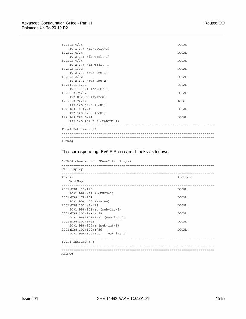
Advanced Configuration Guide - Part III Releases Up To 20.10.R2
Routed CO
Issue: 01 3HE 14992 AAAE TQZZA 01 1515
10.1.2.0/24 LOCAL10.1.2.0 (lb-pool4-2)
10.2.1.0/24 LOCAL10.2.1.0 (lb-pool4-3)
10.2.2.0/24 LOCAL10.2.2.0 (lb-pool4-4)
10.2.2.1/32 LOCAL10.2.2.1 (sub-int-1)
10.2.2.2/32 LOCAL10.2.2.2 (sub-int-2)
10.11.11.1/32 LOCAL10.11.11.1 (toDHCP-1)
192.0.2.75/32 LOCAL192.0.2.75 (system)
192.0.2.76/32 ISIS192.168.12.2 (toR1)
192.168.12.0/24 LOCAL192.168.12.0 (toR1)
192.168.202.0/24 LOCAL192.168.202.0 (toRADIUS-1)
-------------------------------------------------------------------------------Total Entries : 13-------------------------------------------------------------------------------===============================================================================A:BNG#
The corresponding IPv6 FIB on card 1 looks as follows:
A:BNG# show router "Base" fib 1 ipv6===============================================================================FIB Display===============================================================================Prefix Protocol
NextHop-------------------------------------------------------------------------------2001:DB8::11/128 LOCAL
2001:DB8::11 (toDHCP-1)2001:DB8::75/128 LOCAL
2001:DB8::75 (system)2001:DB8:101::1/128 LOCAL
2001:DB8:101::1 (sub-int-1)2001:DB8:101:1::1/128 LOCAL
2001:DB8:101:1::1 (sub-int-2)2001:DB8:102::/56 LOCAL
2001:DB8:102:: (sub-int-1)2001:DB8:102:100::/56 LOCAL
2001:DB8:102:100:: (sub-int-2)-------------------------------------------------------------------------------Total Entries : 6-------------------------------------------------------------------------------===============================================================================A:BNG#

Routed CO
1516
Advanced Configuration Guide - Part IIIReleases Up To 20.10.R2
3HE 14992 AAAE TQZZA 01 Issue: 01
The addresses of the individual subscriber hosts appear in the RIB and the FIB, which is the main difference with the numbered model. The forwarding plane here needs the individual addresses to forward the traffic towards the individual subscriber hosts.
Hybrid Scenario
An alternative to the scenarios described above does exist in the form of a mixed numbered/unnumbered (hybrid) scenario as depicted in Figure 243.
The subscriber interface is configured with
• One or more IPv4 subnets and/or IPv6 subscriber prefixes.• For IPv4: the keyword allow-unmatching-subnets.• For IPv6: the keyword allow-unmatching-prefixes.
No explicit configuration is shown as it is a mix of the numbered and the unnumbered scenario described above, and as such the behavior is mixed.
Figure 243 Hybrid Configuration
al_0380
SAP1
GRP I/F A SUB I/F A
SUB I/F A
IES/VRPN
GRP I/F B
GRP I/F X
SAP2
SAP3
SAPX
SAP1
SAP2
AN1
1/1/2Not Allowed
BNG
subnet-A...subnet-X
subnet-AA...subnet-XX
1/1/1
RGW
AN2
Core
R1
RGW

Advanced Configuration Guide - Part III Releases Up To 20.10.R2
Routed CO
Issue: 01 3HE 14992 AAAE TQZZA 01 1517
Host IP Reachability
To ensure reachability to the individual subscriber hosts, the subnets and prefixes of the subscriber interfaces/subscriber hosts need to be distributed to other routers in the network.
Three options are available:
• Without an export policy.• With an export policy using, for example, from protocol direct.• With an export policy using, for example, from protocol sub-mgmt.
Option 1 – No Export Policy
The key properties for the first option are:
• Subscriber interface subnets and prefixes are distributed into the network by adding the subscriber interfaces as passive interfaces to the routing protocol.
• It is used in combination with IGP based route distribution.• It works with the numbered model only.
In this option the BNG uses IS-IS as IGP and no export policy is needed.
configurerouter
isisarea-id 48.0001multi-topology
ipv6-unicastexitinterface "system"
no shutdownexitinterface "sub-int-1"
passiveno shutdown
exitinterface "sub-int-2"
passiveno shutdown
exitinterface "toR1"
interface-type point-to-pointno shutdown
exitno shutdown
exit

Routed CO
1518
Advanced Configuration Guide - Part IIIReleases Up To 20.10.R2
3HE 14992 AAAE TQZZA 01 Issue: 01
The corresponding IPv4 RIB on router R1 (from Figure 240) lists the subscriber-interface subnets, not the individual subscriber host addresses.
A:R1# show router "Base" route-table ipv4===============================================================================Route Table (Router: Base)===============================================================================Dest Prefix[Flags] Type Proto Age Pref
Next Hop[Interface Name] Metric-------------------------------------------------------------------------------10.1.1.0/24 Remote ISIS 00h14m11s 15
192.168.12.1 2010.1.2.0/24 Remote ISIS 00h14m11s 15
192.168.12.1 2010.2.1.0/24 Remote ISIS 00h14m05s 15
192.168.12.1 2010.2.2.0/24 Remote ISIS 00h14m05s 15
192.168.12.1 20192.0.2.75/32 Remote ISIS 00h14m17s 15
192.168.12.1 10192.0.2.76/32 Local Local 62d21h22m 0
system 0192.168.12.0/24 Local Local 05d04h43m 0
toBNG 0-------------------------------------------------------------------------------No. of Routes: 7Flags: L = LFA nexthop available B = BGP backup route available
n = Number of times nexthop is repeated===============================================================================A:R1#
The corresponding IPv6 RIB on router R1 lists the subscriber-interface prefixes, not the individual subscriber host addresses/prefixes.
A:R1# show router "Base" route-table ipv6===============================================================================IPv6 Route Table (Router: Base)===============================================================================Dest Prefix[Flags] Type Proto Age Pref
Next Hop[Interface Name] Metric-------------------------------------------------------------------------------2001:DB8::75/128 Remote ISIS 00h04m25s 15
FE80::E84B:FFFF:FE00:0-"toBNG" 102001:DB8::76/128 Local Local 02d05h54m 0
system 02001:DB8:101::/48 Remote ISIS 00h04m25s 15
FE80::E84B:FFFF:FE00:0-"toBNG" 202001:DB8:102::/48 Remote ISIS 00h04m25s 15
FE80::E84B:FFFF:FE00:0-"toBNG" 202001:DB8:201::/48 Remote ISIS 00h04m25s 15
FE80::E84B:FFFF:FE00:0-"toBNG" 202001:DB8:202::/48 Remote ISIS 00h04m25s 15
FE80::E84B:FFFF:FE00:0-"toBNG" 202001:DEAD::/64 Local Local 01h42m18s 0
toBNG 0-------------------------------------------------------------------------------

Advanced Configuration Guide - Part III Releases Up To 20.10.R2
Routed CO
Issue: 01 3HE 14992 AAAE TQZZA 01 1519
No. of Routes: 7Flags: L = LFA nexthop available B = BGP backup route available
n = Number of times nexthop is repeated===============================================================================A:R1#
Alternatively the same result can be achieved with OSPF/OSPFv3.
Option 2 – Export Policy (from protocol direct)
The key properties for the second option are:
• Subscriber interface subnets and prefixes are distributed into the network by applying an export policy.
• It is most typically used in combination with BGP based route distribution. • It works with the numbered model only.
The following export policy is used for this example.
configurerouter
policy-optionspolicy-statement "local-subnets-out"
entry 10from
protocol directexitaction acceptexit
exitexit
In this option the BNG relies on BGP using the policy local-subnets-out as an export policy. The neighbor address is the IPv4 system address of router R1.
configurerouter
autonomous-system 65536bgp
group "grp-1"family ipv4 ipv6export "local-subnets-out"peer-as 65536neighbor 192.0.2.76
advertise-label ipv6exit
exitno shutdown
exit

Routed CO
1520
Advanced Configuration Guide - Part IIIReleases Up To 20.10.R2
3HE 14992 AAAE TQZZA 01 Issue: 01
The following command shows the IPv4 routes advertised by applying the local-subnets-out policy. The subscriber interface subnets are advertised, as are some other local subnets.
*A:BNG# show router bgp neighbor 192.0.2.76 advertised-routes ipv4===============================================================================BGP Router ID:192.0.2.75 AS:65536 Local AS:65536
===============================================================================Legend -Status codes : u - used, s - suppressed, h - history, d - decayed, * - validOrigin codes : i - IGP, e - EGP, ? - incomplete, > - best, b - backup
===============================================================================BGP IPv4 Routes===============================================================================Flag Network LocalPref MED
Nexthop Path-Id LabelAs-Path
-------------------------------------------------------------------------------i 10.1.1.0/24 100 None
192.0.2.75 None -No As-Path
i 10.1.2.0/24 100 None192.0.2.75 None -No As-Path
i 10.2.1.0/24 100 None192.0.2.75 None -No As-Path
i 10.2.2.0/24 100 None192.0.2.75 None -No As-Path
i 10.11.11.1/32 100 None192.0.2.75 None -No As-Path
i 192.0.2.75/32 100 None192.0.2.75 None -No As-Path
i 192.168.12.0/24 100 None192.0.2.75 None -No As-Path
i 192.168.202.0/24 100 None192.0.2.75 None -No As-Path
-------------------------------------------------------------------------------Routes : 8===============================================================================*A:BNG#
The same applies for IPv6.
*A:BNG# show router bgp neighbor 192.0.2.76 advertised-routes ipv6===============================================================================BGP Router ID:192.0.2.75 AS:65536 Local AS:65536
===============================================================================Legend -Status codes : u - used, s - suppressed, h - history, d - decayed, * - validOrigin codes : i - IGP, e - EGP, ? - incomplete, > - best, b - backup
===============================================================================

Advanced Configuration Guide - Part III Releases Up To 20.10.R2
Routed CO
Issue: 01 3HE 14992 AAAE TQZZA 01 1521
BGP IPv6 Routes===============================================================================Flag Network LocalPref MED
Nexthop Path-Id LabelAs-Path
-------------------------------------------------------------------------------i 2001:DB8::11/128 100 None
::FFFF:C000:24B None 2No As-Path
i 2001:DB8::75/128 100 None::FFFF:C000:24B None 2No As-Path
i 2001:DB8:101::/48 100 None::FFFF:C000:24B None 2No As-Path
i 2001:DB8:102::/48 100 None::FFFF:C000:24B None 2No As-Path
i 2001:DB8:201::/48 100 None::FFFF:C000:24B None 2No As-Path
i 2001:DB8:202::/48 100 None::FFFF:C000:24B None 2No As-Path
i 2001:DEAD::/64 100 None::FFFF:C000:24B None 2No As-Path
-------------------------------------------------------------------------------Routes : 7===============================================================================*A:BNG#
The corresponding IPv4 RIB on router R1 lists the subscriber-interface subnets, not the individual subscriber host addresses. Notice the list also includes other routes local to the BNG.
*A:R1# show router "Base" route-table ipv4===============================================================================Route Table (Router: Base)===============================================================================Dest Prefix[Flags] Type Proto Age Pref
Next Hop[Interface Name] Metric-------------------------------------------------------------------------------10.1.1.0/24 Remote BGP 00h13m34s 170
192.168.12.1 010.1.2.0/24 Remote BGP 00h13m34s 170
192.168.12.1 010.2.1.0/24 Remote BGP 00h13m34s 170
192.168.12.1 010.2.2.0/24 Remote BGP 00h13m34s 170
192.168.12.1 010.11.11.1/32 Remote BGP 00h13m34s 170
192.168.12.1 0192.0.2.75/32 Remote ISIS 00h15m38s 15
192.168.12.1 10192.0.2.76/32 Local Local 03h11m54s 0
system 0

Routed CO
1522
Advanced Configuration Guide - Part IIIReleases Up To 20.10.R2
3HE 14992 AAAE TQZZA 01 Issue: 01
192.168.12.0/24 Local Local 03h11m25s 0toBNG 0
192.168.202.0/24 Remote BGP 00h13m34s 170192.168.12.1 0
-------------------------------------------------------------------------------No. of Routes: 9Flags: L = LFA nexthop available B = BGP backup route available
n = Number of times nexthop is repeated===============================================================================*A:R1#
The corresponding IPv6 RIB on router R1 lists the subscriber-interface prefixes, not the individual subscriber host addresses/prefixes. They are tunneled through the IPv4 core.
*A:R1# show router "Base" route-table ipv6===============================================================================IPv6 Route Table (Router: Base)===============================================================================Dest Prefix[Flags] Type Proto Age Pref
Next Hop[Interface Name] Metric-------------------------------------------------------------------------------2001:DB8::11/128 Remote BGP 00h00m49s 170
192.0.2.75 (tunneled) 02001:DB8::75/128 Remote ISIS 00h54m05s 15
FE80::E84B:FFFF:FE00:0-"toBNG" 102001:DB8::76/128 Local Local 05h18m12s 0
system 02001:DB8:101::/48 Remote BGP 00h00m49s 170
192.0.2.75 (tunneled) 02001:DB8:102::/48 Remote BGP 00h00m49s 170
192.0.2.75 (tunneled) 02001:DB8:201::/48 Remote BGP 00h00m49s 170
192.0.2.75 (tunneled) 02001:DB8:202::/48 Remote BGP 00h00m49s 170
192.0.2.75 (tunneled) 02001:DEAD::/64 Local Local 05h17m42s 0
toBNG 0-------------------------------------------------------------------------------No. of Routes: 8Flags: L = LFA nexthop available B = BGP backup route available
n = Number of times nexthop is repeated===============================================================================*A:R1# #
The same export policy can be used in combination with IGP based route distribution. However, when IGP based route distribution is needed option 1 is the preferred method.

Advanced Configuration Guide - Part III Releases Up To 20.10.R2
Routed CO
Issue: 01 3HE 14992 AAAE TQZZA 01 1523
Option 3 – Export Protocol (from protocol sub-mgmt)
The key properties for the third option are:
• Host addresses and prefixes are distributed into the network by applying an export policy.
• It is most typically used in combination with BGP based route distribution, as IGP based route distribution does not scale for a large number of subscribers.
• It is most typically used for the unnumbered model, and in some cases for the numbered model.
The following export policy is used for this option.
configurerouter
policy-optionspolicy-statement "subsc-hosts-out"
entry 10from
protocol sub-mgmtexitaction acceptexit
exitexit
In this option the BNG relies on BGP using the policy subsc-hosts-out as an export policy.
configurerouter
autonomous-system 65536bgp
group "grp-1"family ipv4 ipv6export "subsc-hosts-out"peer-as 65536neighbor 192.0.2.76
advertise-label ipv6exit
exitno shutdown
exit
The following command shows the IPv4 routes advertised by applying the subsc-hosts-out policy. Now the subscriber host addresses are advertised individually.
*A:BNG# show router bgp neighbor 192.0.2.76 advertised-routes ipv4===============================================================================BGP Router ID:192.0.2.75 AS:65536 Local AS:65536
===============================================================================Legend -

Routed CO
1524
Advanced Configuration Guide - Part IIIReleases Up To 20.10.R2
3HE 14992 AAAE TQZZA 01 Issue: 01
Status codes : u - used, s - suppressed, h - history, d - decayed, * - validOrigin codes : i - IGP, e - EGP, ? - incomplete, > - best, b - backup
===============================================================================BGP IPv4 Routes===============================================================================Flag Network LocalPref MED
Nexthop Path-Id LabelAs-Path
-------------------------------------------------------------------------------? 10.1.1.101/32 100 0
192.0.2.75 None -No As-Path
? 10.1.1.102/32 100 0192.0.2.75 None -No As-Path
? 10.2.2.1/32 100 0192.0.2.75 None -No As-Path
? 10.2.2.2/32 100 0192.0.2.75 None -No As-Path
-------------------------------------------------------------------------------Routes : 4===============================================================================*A:BNG#
For IPv6, the host addresses and prefixes are advertised.
*A:BNG# show router bgp neighbor 192.0.2.76 advertised-routes ipv6===============================================================================BGP Router ID:192.0.2.75 AS:65536 Local AS:65536
===============================================================================Legend -Status codes : u - used, s - suppressed, h - history, d - decayed, * - validOrigin codes : i - IGP, e - EGP, ? - incomplete, > - best, b - backup
===============================================================================BGP IPv6 Routes===============================================================================Flag Network LocalPref MED
Nexthop Path-Id LabelAs-Path
-------------------------------------------------------------------------------? 2001:DB8:101::1/128 100 0
::FFFF:C000:24B None 2No As-Path
? 2001:DB8:101:1::1/128 100 0::FFFF:C000:24B None 2No As-Path
? 2001:DB8:102::/56 100 0::FFFF:C000:24B None 2No As-Path
? 2001:DB8:102:100::/56 100 0::FFFF:C000:24B None 2No As-Path
-------------------------------------------------------------------------------Routes : 4===============================================================================*A:BNG#

Advanced Configuration Guide - Part III Releases Up To 20.10.R2
Routed CO
Issue: 01 3HE 14992 AAAE TQZZA 01 1525
The corresponding IPv4 RIB on router R1 looks as follows. Notice the individual host addresses do appear.
A:R1# show router route-table ipv4===============================================================================Route Table (Router: Base)===============================================================================Dest Prefix[Flags] Type Proto Age Pref
Next Hop[Interface Name] Metric-------------------------------------------------------------------------------10.1.1.101/32 Remote BGP 00h40m49s 170
192.168.12.1 010.1.1.102/32 Remote BGP 00h19m53s 170
192.168.12.1 010.2.2.1/32 Remote BGP 00h44m49s 170
192.168.12.1 010.2.2.2/32 Remote BGP 00h44m17s 170
192.168.12.1 0192.0.2.75/32 Remote ISIS 00h59m41s 15
192.168.12.1 10192.0.2.76/32 Local Local 01h22m11s 0
system 0192.168.12.0/24 Local Local 01h21m42s 0
toBNG 0-------------------------------------------------------------------------------No. of Routes: 7Flags: L = LFA nexthop available B = BGP backup route available
n = Number of times nexthop is repeated===============================================================================A:R1#
The corresponding IPv6 RIB on router R1 looks as follows. Notice the individual host addresses and prefixes are distributed in this case.
A:R1# show router route-table ipv6===============================================================================IPv6 Route Table (Router: Base)===============================================================================Dest Prefix[Flags] Type Proto Age Pref
Next Hop[Interface Name] Metric-------------------------------------------------------------------------------2001:DB8::76/128 Local Local 01h22m16s 0
system 02001:DB8:101::1/128 Remote BGP 00h36m40s 170
192.0.2.75 (tunneled) 02001:DB8:101:1::1/128 Remote BGP 00h36m40s 170
192.0.2.75 (tunneled) 02001:DB8:102::/56 Remote BGP 00h36m40s 170
192.0.2.75 (tunneled) 02001:DB8:102:100::/56 Remote BGP 00h36m40s 170
192.0.2.75 (tunneled) 02001:DEAD::/64 Local Local 01h21m47s 0
toBNG 0-------------------------------------------------------------------------------No. of Routes: 6Flags: L = LFA nexthop available B = BGP backup route available
n = Number of times nexthop is repeated

Routed CO
1526
Advanced Configuration Guide - Part IIIReleases Up To 20.10.R2
3HE 14992 AAAE TQZZA 01 Issue: 01
===============================================================================A:R1#
Conclusion
This example explains how to configure and use the Routed CO model. The subscriber and the group interfaces were configured for the numbered, unnumbered and hybrid scenario, showing the flexibility of the Routed CO model in terms of subnet/prefix assignment as well as the impact on the forwarding and the reachability to and from the subscriber hosts.

Advanced Configuration Guide - Part III Releases Up To 20.10.R2
Subscriber Redundancy for Routed CO
Issue: 01 3HE 14992 AAAE TQZZA 01 1527
Subscriber Redundancy for Routed COThis chapter provides information about Subscriber Redundancy for Routed CO (SRRP).
Topics in this chapter include:
• Applicability• Summary• Overview• Configuration• Conclusion
Applicability
This chapter is applicable to SROS routers and was initially based on release 7.0.R5. The CLI is updated to release 16.0.R6.
Summary
This chapter focuses on the delivery of redundant services in an enhanced subscriber management (ESM) routed-CO environment using Internet enhanced service (IES) or virtual private routed network (VPRN).
It is applicable to delivering high speed Internet (HSI), voice-over-IP (VoIP) and video-on-demand (VoD) to subscribers.
Redundancy is provided at two levels:
• system redundancy• network redundancy
The system redundancy is based on the high availability features of the SR OS routers, such as component redundancy (power, fans, control processor modules etc.) and software redundancy (service and protocol redundancy and non-stop-routing), which are not discussed here.

Subscriber Redundancy for Routed CO
1528
Advanced Configuration Guide - Part IIIReleases Up To 20.10.R2
3HE 14992 AAAE TQZZA 01 Issue: 01
The network redundancy for subscriber access in an ESM routed CO environment requires that each broadband service access node (BSAN) is dual-homed to two SR OS routers, either in a point-to-point fashion with the BSANs having direct physical connectivity to the SR OS routers, or by having Layer 2 aggregation between the BSANs and the SR OS routers.
This connection will operate in a master-slave relationship providing both link and system redundancy for the subscribers on the BSAN when accessing the configured services.
Subscriber redundancy for routed-CO aims to minimize the outage due to a failure.
This chapter provides configuration and troubleshooting commands for SRRP with static-host ip-mac.
Knowledge of the triple play service delivery architecture (TPSDA) concepts is assumed throughout this document.
Overview
There are three components on SR OS routers to implement network redundancy:
1. Redundant access from the BSANs to two SR OS routers provided by the SRRP.
2. Mirroring of subscriber state between two SR OS routers is achieved through the multi-chassis synchronization (MCS) protocol.
3. Backup spoke SDP traffic path between two SR OS peers.
These components are shown in Figure 244.

Advanced Configuration Guide - Part III Releases Up To 20.10.R2
Subscriber Redundancy for Routed CO
Issue: 01 3HE 14992 AAAE TQZZA 01 1529
Figure 244 Network Redundancy Components for ESM Routed CO
The following configuration tasks should be done first and are not explained in this chapter:
• Basic service router configuration (system interface, IGP, MPLS, BGP)• Routed CO service topology: VPRN or IES service with subscriber and group
interface on broadband network gateways (BNGs)• ESM configuration• Static host configuration
This chapter will focus on SRRP in a VPRN service subscriber-interface on BNG (routed-CO). In case of routed CO, it is also possible to configure SRRP in the base routing instance using an IES service.
SRRP Protocol
The SRRP protocol operates on a specific SAP within the group interface under the subscriber-interface of an IES/VPRN service. Through a method similar to the virtual router redundancy protocol (VRRP), it provides a set of default gateways to the subscribers on the BSAN. These are active on the SR OS router in the master state and inactive on the router in the backup state. Upstream and downstream traffic is
OSSG420
BSAN
Simulated
SRRP
Backup/Standby
Active/Master
BNG-1
7750/7710
7750/7710
BNG-2
PE-1
IES
/VP
RN
Sub-int
grp-intS
SR
P
MCS
Red-intf
Red-intf
IES
/VP
RN
Sub-int
grp-intS
SR
P
MCS
Internet

Subscriber Redundancy for Routed CO
1530
Advanced Configuration Guide - Part IIIReleases Up To 20.10.R2
3HE 14992 AAAE TQZZA 01 Issue: 01
forwarded through the master. If the backup loses connectivity with the master (for example, fails to receive SRRP messages from the master), it transitions to the master state and takes over the ownership of the default gateways and the responsibility for forwarding traffic to and from the subscriber. This provides redundancy from the BSAN toward the provider network.
If an SRRP fail over were to occur, it is important that the subscriber state (IP/MAC addresses, QOS profiles, etc.) be immediately available on the new SRRP master; otherwise, subscriber traffic will be dropped due to the anti-spoofing security. The subscriber state is synchronized through the MCS protocol, which mirrors the subscriber state between the two peers. This allows both peers to know the details of the active subscribers and therefore forward traffic on their behalf with the correct QOS actions both to and from the BSAN if that peer is the SRRP master.
The last topic relates to the forwarding from the provider network to the subscribers. If the IP routing causes this traffic to forward through the SRRP master, then the traffic will automatically be forwarded to the subscriber. However, if the provider routing scheme causes traffic destined to a subscriber to arrive at the router in the SRRP backup state for that subscriber, it will be dropped as the backup does not forward traffic out of the subscriber SAPs.
To avoid this, a redundant interface is configured between the two SR OS routers under the subscriber/group-interfaces. Any traffic arriving on the router for an active subscriber, where its associated SRRP instance is in the backup state, will be forwarded through the redundant interface to the SRRP master, which in turn forwards the traffic to the subscriber.
In addition to successful forwarding the traffic, this operation also maintains the subscriber QOS compliance as all traffic for a given subscriber enters and exits the routed-CO interface through a single SAP, allowing the associated IOM hardware to perform the correct QOS actions.
Configuration
Subscriber Interface Configuration
Redundant Default Gateway
The redundant default gateway IP addresses must be configured under the subscriber-interface (within the IES/VPRN service) for each subnet defined.

Advanced Configuration Guide - Part III Releases Up To 20.10.R2
Subscriber Redundancy for Routed CO
Issue: 01 3HE 14992 AAAE TQZZA 01 1531
Three subnets are configured under the subscriber-interface sub-int-1, each with a gw-ip-address which is used as the default gateway by the subscribers in that subnet.
# on BNG-2configure
servicevprn 1 customer 1 create
--- snipped ---subscriber-interface "sub-int-1" create
address 10.2.0.2/16 gw-ip-address 10.2.0.254address 10.3.0.2/16 gw-ip-address 10.3.0.254address 10.4.0.2/16 gw-ip-address 10.4.0.254--- snipped ---
exitexit
exitexit
The gw-ip-address could be a virtual (unused) address in this subnet or the address of one of the actual subscriber-interfaces on the two routers, but it must not be used as a subscriber address.
If DHCP were to be used, the associated subscriber-interface address should be used as the gi-address configured for DHCP under the group-interface (will not be covered here as static host is used). This ensures that the offer returned from the DHCP server and arriving at the SRRP backup (rather than master) will be forwarded by the backup SRRP router to the master SRRP router through the redundant interface.
In environments where there are many subscribers, it will take time to synchronize the subscriber state between the peers when the subscriber-interface is enabled (perhaps, after a reboot). In order to ensure that the state has time to get synchronized, a hold timer can be applied to the subscriber interface. The optional init-only parameter can be added to use this timer only after a reboot.
*A:BNG-2>config>service>vprn>red-if>hold-time#[no] down - Configure the hold time when the interface is coming up[no] up - Configure the hold time when the interface is going down
*A:BNG-2>config>service>vprn>red-if>hold-time#
# on BNG-2configure
servicevprn 1 customer 1 create
subscriber-interface "sub-int-1" createhold-time
down ip 1200 init-onlyexit
exitexit
exit

Subscriber Redundancy for Routed CO
1532
Advanced Configuration Guide - Part IIIReleases Up To 20.10.R2
3HE 14992 AAAE TQZZA 01 Issue: 01
Group Interface Configuration
The group interface group-int-1 providing connectivity to the BSAN is configured under the subscriber interface:
# on BNG-2configure
servicevprn 1 customer 1 create
subscriber-interface "sub-int-1" creategroup-interface "group-int-1" create--- snipped ---
exitexit
exitexit
Static Host Configuration
First enable the sub-sla-mgmt and sub-ident-policy sub-id-default under sap 1/1/3:1, then define a static host (ip-mac) with sla-profile sla-profile-1, sub-profile sla-profile-1 and subscriber static-host-routed-10.2.0.3.
# on BGG-2configure
servicevprn 1 customer 1 create
subscriber-interface "sub-int-1" creategroup-interface "group-int-1" create
sap 1/1/3:1 createsub-sla-mgmt
sub-ident-policy "sub-id-default"multi-sub-sapno shutdown
exitstatic-host ip 10.2.0.3 mac 00:00:00:00:00:01 create
sla-profile "sla-profile-1"sub-profile "sub-profile-1"subscriber "static-host-routed-10.2.0.3"no shutdown
exitexit
exitexit
exitexit
exit

Advanced Configuration Guide - Part III Releases Up To 20.10.R2
Subscriber Redundancy for Routed CO
Issue: 01 3HE 14992 AAAE TQZZA 01 1533
SRRP Configuration
In order for the redundant gateway information to be used by subscribers through SAPs belonging to a particular group-interface, an SRRP instance must be added in the group interface context.
# on BNG-2configure
servicevprn 1 customer 1 create
subscriber-interface "sub-int-1" creategroup-interface "group-int-1" create
srrp 1 create--- snipped ---
exitexit
exitno shutdown
exitexit
exit
At this point, any subscriber ARPing for the gw-ip-address will receive a response from the SRRP master with a source MAC of 00-00-5E-00-01-<xx>, where <xx> is the first byte of the SRRP identifier in hexadecimal, so in this case for SRRP=1 the source MAC will be 00-00-5E-00-01-01.
The redundant default gateway MAC address could be explicitly configured, if desired, by use of the gw-mac parameter.
*A:BNG-2>config>service>vprn>sub-if>grp-if>srrp# gw-mac- gw-mac <mac-address>- no gw-mac
<mac-address> : xx:xx:xx:xx:xx:xx or xx-xx-xx-xx-xx-xx
*A:BNG-2>config>service>vprn>sub-if>grp-if>srrp#
There can be only one SRRP instance per group-interface and all SRRP identifiers must be unique per system.
When an SRRP instance is enabled, or when there is an SRRP failover from one device to another, gratuitous ARPs are sent on all VLANs associated with this instance for all gw-ip-addresses (for example, on all subscriber SAPs and on the SRRP message path SAP in the associated group interface). This allows all downstream devices to relearn the path to the new master.

Subscriber Redundancy for Routed CO
1534
Advanced Configuration Guide - Part IIIReleases Up To 20.10.R2
3HE 14992 AAAE TQZZA 01 Issue: 01
The SRRP messages are normally forwarded through the BSAN, thereby verifying the connectivity from one router through the BSAN to the other router. In order to achieve this, a non-subscriber SAP must be configured under the group-interface which is referenced in the SRRP configuration by the message-path parameter. This not only selects the SAP to be used for the SRRP messages but also avoids the subscriber anti-spoofing from automatically dropping the received messages (as there would be no subscriber IP-to-MAC entry corresponding to the received information) and causing both peers to become master.
The message-path SAP configuration effectively disables IP-MAC anti-spoofing on that SAP.
# on BNG-2configure
servicevprn 1 customer 1 create
subscriber-interface "sub-int-1" creategroup-interface "group-int-1" create
---- snipped ---sap 1/1/3:2 createexitsrrp 1 create
message-path 1/1/3:2no shutdown
exitexit
exitno shutdown
exitexit
exit
The SRRP messages are then not sent on the same SAP as the subscriber data traffic, under the assumption that the path traversed by the SRRP messages is the same as the path for the subscriber data; if this is not the case, then the SRRP state would not necessarily reflect a failure in the data path.
The master of the SRRP instance generates advertisement messages at the keep-alive-interval (which is encoded in the message) ranging from one (1) to 100 in multiples of 100ms with a default of 10 (for example, 1 second). The SRRP backup will monitor the reception of these messages and assume the role of the master if three consecutive messages are not received.
At all times the keep-alive-interval of the master is used.
*A:BNG-2>config>service>vprn>sub-if>grp-if>srrp# keep-alive-interval- keep-alive-interval <interval>- no keep-alive-interval
<interval> : [1..100] tenths of a second
*A:BNG-2>config>service>vprn>sub-if>grp-if>srrp#

Advanced Configuration Guide - Part III Releases Up To 20.10.R2
Subscriber Redundancy for Routed CO
Issue: 01 3HE 14992 AAAE TQZZA 01 1535
Only two devices can participate in an SRRP protocol exchange for a given SRRP instance, this being another difference from VRRP which allows more potential backup devices. This is a consequence of the direct relationship between the SRRP instance and the associated redundant interface and MCS peering.
This protocol exchange is also used for the master/backup election, based on the priority (1 to 254) configured in the SRRP instance. The device with the highest priority will become master.
*A:BNG-2>config>service>vprn>sub-if>grp-if>srrp# priority- no priority- priority <priority>
<priority> : [1..254]
*A:BNG-2>config>service>vprn>sub-if>grp-if>srrp#
The message source IP address (system IP address) is used as a tie break when the priorities are the same (the lower IP address becomes the master). The master/backup status is per SRRP instance (not per IP address). For example, the master is the active gateway for all gw-ip-addresses under the subscriber interface for the associated group-interface (this is true even if the backup is the IP address owner for one of the gw-ip-addresses). Priority 0 is sent by the master when it is transitioning to the backup role due to the appearance of a high priority peer. Higher priority backups always preempt a lower priority master.
A basic form of load distribution can be achieved by having the master SRRP for some group-interfaces on one peer and the master for other group interfaces on the other peer. Clearly, a failure may cause all masters to be active on a single peer, which must be taken into account when designing the network.
The minimum keep-alive-timer of 1 is configured, together with the message-path defining the SAP to be used for the SRRP messages. The priority is set to 250 (default is 100) in order to force this peer to be the SRRP master when both peers are active.
# on BNG-2configure
servicevprn 1 customer 1 create
subscriber-interface "sub-int-1" creategroup-interface "group-int-1" create--- snipped ---srrp 1 create
keep-alive-interval 1message-path 1/1/3:2priority 250no shutdown
exitexit
exit

Subscriber Redundancy for Routed CO
1536
Advanced Configuration Guide - Part IIIReleases Up To 20.10.R2
3HE 14992 AAAE TQZZA 01 Issue: 01
SRRP Configuration Notes
A VRRP policy statement can be added to the SRRP instance definition in order to dynamically adjust the SRRP priority based on certain non-SRRP related events occurring (for example, port down, LAG degrade, host unreachable or route unknown).
The gw-ip-addresses are accessible by active subscribers, for example, regardless which peer is the master, an active subscriber can ping or telnet to its associated gw-ip-address (clearly, filters can be configured to control this).
Bi-directional Forwarding Detection
Bi-directional forwarding detection (BFD) can be configured with SRRP to speed up the convergence.
# on BNG-2configure
servicevprn 1 customer 1 create
subscriber-interface "sub-int-1" creategroup-interface "group-int-1" create--- snipped ---
srrp 1 create--- snipped ---bfd-enable 2 interface "bfd-1" dst-ip 10.1.1.1no shutdown
exitexit
exitexit
exitexit
An IES service needs to be created for the BFD session.
# on BNG-1configure
serviceies 2 customer 1 create
interface "bfd-1" createaddress 10.1.1.1/31bfd 100 receive 100 multiplier 3sap 1/1/3:3 createexit
exitno shutdown
exitexit
exit

Advanced Configuration Guide - Part III Releases Up To 20.10.R2
Subscriber Redundancy for Routed CO
Issue: 01 3HE 14992 AAAE TQZZA 01 1537
Monitoring In-Band Communications Path
In order to monitor the in-band communications path between the subscribers and two routers, SRRP uses a slightly modified VRRP advertisement message.
The SRRP message destination IP address (224.0.0.18) and IP protocol number (112) are the same as for VRRP but there are changes in the following areas:
• The source IP address of the message is the system IP address, as opposed to the interface IP address.
• The protocol version has been set to eight (8) (the current version of VRRP is two (2)).
• The virtual router identifier has been extended from one byte (maximum 255) to four bytes (maximum 4294967295) though the maximum number of SRRPs that can be defined is 255.
• The source MAC address is included instead of the virtual router IP addresses (this being 00-00-5E-00-01-<xx>, where <xx> is the first byte of the SRRP identifier in hexadecimal).
Synchronizing the SRRP Peer State
In order to troubleshoot an SRRP environment, the state of each peer is synchronized with the other peer through multi-chassis synchronization (MCS). MCS is a proprietary protocol used for synchronizing application state between two peers. SRRP will function without synchronizing its state but this synchronization allows for the current state of both the local and remote peers to be displayed and appropriate error messages to be reported when the peer state is not correct. It also allows the master SRRP subscriber-interface to be pinged through the backup peer (through the redundant interface).
To link information being mirrored between two routers, a sync-tag value is configured to correspond to either an entire port/LAG or under a port/LAG for a VLAN range. This allows each router to know exactly which information should be in sync on each device. The sync-tag must be unique on the two peers involved.
This example configuration shows only the SRRP aspects. The SRRP instance has been configured for MCS peer 192.0.2.1 using VLANs 1-2 on port 1/1/3. Here, a sync-tag is associated with the SRRP instance.
# on BNG-2configure
redundancymulti-chassis

Subscriber Redundancy for Routed CO
1538
Advanced Configuration Guide - Part IIIReleases Up To 20.10.R2
3HE 14992 AAAE TQZZA 01 Issue: 01
peer 192.0.2.1 createauthentication-key "sync-testing"sync
srrpsub-mgmt ipoeport 1/1/3 "st1" create
range 1-2 sync-tag "st1"exitno shutdown
exitno shutdown
exit
Alternatively, if the information needs to be synchronized for all VLANs on port 1/1/3, then the following port command could be used instead of the preceding port-plus-ranges shown.
# on BNG-2configure
redundancymulti-chassis
peer 192.0.2.1 createauthentication-key "sync-testing"sync
srrpsub-mgmt ipoeport 1/1/3 sync-tag "st1" createexitno shutdown
exitno shutdown
exit
The VLANs used within the group interfaces must match between the two peers, clearly the physical ports identifiers may differ.
Multi-Chassis Synchronization
Multi-chassis synchronization (MCS) is a general propriety protocol used to synchronize information between two peers. It can be used for the several applications, such as:
• IGMP• IGMP snooping• Subscriber management• Subscriber router redundancy protocol
This chapter only covers the subscriber management and SRRP applications.

Advanced Configuration Guide - Part III Releases Up To 20.10.R2
Subscriber Redundancy for Routed CO
Issue: 01 3HE 14992 AAAE TQZZA 01 1539
Subscriber Management Synchronization
In order to ensure that the QOS defined for a subscriber is adhered to, all traffic for a given subscriber needs to be forwarded by a single port. When an MSAN is dual-homed to two routers, this is achieved using the SRRP protocol (described above) and the redundant interface (described below); specifically, the traffic is forwarded through the SRRP master of the related group-interface.
When a subscriber is created on the master SRRP, a host route (/32) for its IP address is inserted in the FIB pointing towards the appropriate group-interface.
The same subscriber on the backup peer will have a host route in the IP FIB pointing to the redundant interface. On the backup peer, this requires the subscriber subnet to also be present in the FIB, which in turn requires one of the following:
• The local subscriber-interface is up.• The subscriber subnets are learned from the active broadband network gateway
(BNG) through the routing protocol.• Forcing the subscriber-interface to stay up by creating a dummy group interface
with the oper-up-when-empty command.
# on BNG-2configure
servicevprn 1 customer 1 create
subscriber-interface "sub-int-1" creategroup-interface "group-int-1" create
oper-up-while-emptysap 1/1/3:1 create
--- snipped ---exit
exitexit
exitexit
exit
Redundant Interface
The requirement for the redundant interface stems from the situation where traffic destined to a subscriber arrives on the router where the associated SRRP state is not master.

Subscriber Redundancy for Routed CO
1540
Advanced Configuration Guide - Part IIIReleases Up To 20.10.R2
3HE 14992 AAAE TQZZA 01 Issue: 01
When the SRRP state is backup for a particular group-interface, subscriber traffic is normally not forwarded in/out of the associated subscriber SAPs. Also traffic could arrive where the specific group-interface for that subscriber is down. These situations could occur due to the regular routing within the provider network or temporarily during an SRRP failover. Note that as the subscriber subnets are configured under the subscriber-interface, it is not possible to stop advertising these subnets into the provider core in the case where only a subset of the group interfaces are down or the associated SRRP instances are in backup. The advertisement of the subscriber subnet could therefore attract traffic to the router, while not being the SRRP master.
In these cases, traffic must be sent to the active SRRP router in order to be forwarded to the subscriber. This is achieved through the configuration of a redundant interface between two SRRP peers, protecting against failures of related group interfaces.
The redundant interface is configured under the IES/VRPN service. It must use a single pseudowire, configured as a spoke SDP, to provide connectivity to the peer router. This is essential as it avoids any possibility of the traffic being misrouted by any other system between the two peers. It can either use a /31 IP subnet mask or a longer mask with the remote IP being explicitly specified.
# on BRG-2configure
servicevprn 1 customer 1 create
--- snipped ---redundant-interface "bng-2-bng-1-vprn-1" create
address 192.168.4.1/31spoke-sdp 21:1 createexit
exit--- snipped ---
exitexit
exit
If a non /31 address is used, the remote IP address will be required.
*A:BNG-2>config>service>vprn# redundant-interface "bng-2-bng-1-vprn-1"*A:BNG-2>config>service>vprn>red-if# address 192.168.4.1/30INFO: PIP #1399 Invalid or unspecified remote IP address -Non /31 address requires remote IP address

Advanced Configuration Guide - Part III Releases Up To 20.10.R2
Subscriber Redundancy for Routed CO
Issue: 01 3HE 14992 AAAE TQZZA 01 1541
The remote-ip address can be defined by the following command:
*A:BNG-2>config>service>vprn>red-if# address 192.168.4.1/30 remote-ip 192.4.1.2
Then each group-interface must be assigned a redundant interface, as follows:
# on BNG-2configure
servicevprn 1 customer 1 create
--- snipped ---subscriber-interface "sub-int-1" create
--- snipped ---group-interface "group-int-1" create
redundant-interface "bng-2-bng-1-vprn-1"oper-up-while-empty--- snipped ---
exitexitno shutdown
exitexit
exit
Only one redundant interface is required for a given IES/VPRN service on each peer, though it is possible to create multiple redundant interfaces and assign group interfaces to each individually. Clearly, each redundant interface needs to terminate on a matching redundant interface in the corresponding peer service.
When traffic arrives from the core network for an active subscriber on a SAP in group-interface group-int-1, and if the associated SRRP instance is in the backup state, then this traffic will be forwarded over the redundant-interface bng-2-bng-1-vprn-1 to the peer router. It will then be forwarded to the subscriber as the associated SRRP instance will be in the master state.
The information about the redundant interfaces is mirrored through MCS as part of the SRRP synchronization.
Show and Debug Commands
Routing Table Related Information
A host route (/32) for the static host is inserted in the FIB pointing toward the appropriate group-interface.

Subscriber Redundancy for Routed CO
1542
Advanced Configuration Guide - Part IIIReleases Up To 20.10.R2
3HE 14992 AAAE TQZZA 01 Issue: 01
*A:BNG-2# show router 1 route-table protocol sub-mgmt
===============================================================================Route Table (Service: 1)===============================================================================Dest Prefix[Flags] Type Proto Age Pref
Next Hop[Interface Name] Metric-------------------------------------------------------------------------------10.2.0.1/32 Remote Sub Mgmt 01h39m55s 0
[bng-2-bng-1-vprn-1] 010.2.0.3/32 Remote Sub Mgmt 02h05m21s 0
[group-int-1] 010.3.0.1/32 Remote Sub Mgmt 01h39m55s 0
[bng-2-bng-1-vprn-1] 010.4.0.1/32 Remote Sub Mgmt 01h39m55s 0
[bng-2-bng-1-vprn-1] 0-------------------------------------------------------------------------------No. of Routes: 4Flags: n = Number of times nexthop is repeated
B = BGP backup route availableL = LFA nexthop availableS = Sticky ECMP requested
===============================================================================*A:BNG-2#
The same subscriber on the backup peer will have a host route in the FIB pointing to the redundant interface.
*A:BNG-1# show router 1 route-table protocol sub-mgmt
===============================================================================Route Table (Service: 1)===============================================================================Dest Prefix[Flags] Type Proto Age Pref
Next Hop[Interface Name] Metric-------------------------------------------------------------------------------10.2.0.2/32 Remote Sub Mgmt 01h42m50s 0
[bng-1-bng-2-vprn-1] 010.2.0.3/32 Remote Sub Mgmt 02h08m31s 0
[bng-1-bng-2-vprn-1] 010.3.0.2/32 Remote Sub Mgmt 01h42m50s 0
[bng-1-bng-2-vprn-1] 010.4.0.2/32 Remote Sub Mgmt 01h42m50s 0
[bng-1-bng-2-vprn-1] 0-------------------------------------------------------------------------------No. of Routes: 4Flags: n = Number of times nexthop is repeated
B = BGP backup route availableL = LFA nexthop availableS = Sticky ECMP requested
===============================================================================*A:BNG-1#

Advanced Configuration Guide - Part III Releases Up To 20.10.R2
Subscriber Redundancy for Routed CO
Issue: 01 3HE 14992 AAAE TQZZA 01 1543
Subscriber Related Information
To check the subscriber information:
*A:BNG-2# show service id 1 subscriber-hosts
=============================================================Subscriber Host table=============================================================Sap Subscriber
IP AddressMAC Address PPPoE-SID Origin Fwding State
-------------------------------------------------------------1/1/3:1 static-host-routed-10.2.0.3
10.2.0.300:00:00:00:00:01 N/A Static Fwding
-------------------------------------------------------------Number of subscriber hosts : 1=============================================================*A:BNG-2#
To check the subscriber details:
*A:BNG-2# show service id 1 subscriber-hosts mac 00:00:00:00:00:01 detail
=============================================================Subscriber Host table=============================================================Sap Subscriber
IP AddressMAC Address PPPoE-SID Origin Fwding State
-------------------------------------------------------------1/1/3:1 static-host-routed-10.2.0.3
10.2.0.300:00:00:00:00:01 N/A Static Fwding
-------------------------------------------------------------Subscriber-interface : sub-int-1Group-interface : group-int-1Sub Profile : sub-profile-1SLA Profile : sla-profile-1App Profile : N/AEgress Q-Group : N/AEgress Vport : N/AAcct-Session-Id : 021BFF000000005CA701E9Acct-Q-Inst-Session-Id: 021BFF000000015CA701E9Address Origin : StaticOT HTTP Rdr IP-FltrId : N/AOT HTTP Rdr Status : N/AOT HTTP Rdr Fltr Src : N/AHTTP Rdr URL Override : N/AGTP local break-out : NoDIAMETER session ID Gx: N/A-------------------------------------------------------------Number of subscriber hosts : 1=============================================================*A:BNG-2#

Subscriber Redundancy for Routed CO
1544
Advanced Configuration Guide - Part IIIReleases Up To 20.10.R2
3HE 14992 AAAE TQZZA 01 Issue: 01
The same command on the peer would show the same information except for the port identifier part of the SAP, which is specific to the peer and may differ.
MCS Redundancy Related Information
The high-level state of MCS can be seen in the following output:
*A:BNG-2# show redundancy multi-chassis all
===============================================================================Multi-Chassis Peers===============================================================================Peer Info Client Admin Oper State-------------------------------------------------------------------------------Peer Address : 192.0.2.1Source Addre*: 192.0.2.2Peer Admin : inServiceAuthenticati*: None* indicates that the corresponding row element may have been truncated.
MC-Sync: inService inService inSyncMC-Ring: -- -- --MC-Endpt: -- -- --MC-Lag: outOfService outOfService --MC-IPsec: -- -- Disabled
===============================================================================*A:BNG-2#
Information about the peering, the use of authentication, the state of MCS (Enabled) and the fact that MCS is inSync is shown.
*A:BNG-2# show redundancy multi-chassis sync
===============================================================================Multi-chassis Peer Table===============================================================================Peer-------------------------------------------------------------------------------Peer IP Address : 192.0.2.1Description : (Not Specified)Authentication : EnabledSource IP Address : 192.0.2.2Admin State : EnabledWarm standby : NoRemote warm standby : No-------------------------------------------------------------------------------Sync-status-------------------------------------------------------------------------------Client Applications : SUBMGMT-IPOE SUBMGMT-PPPOE SRRPSync Admin State : UpSync Oper State : UpSync Oper Flags :DB Sync State : inSyncNum Entries : 26

Advanced Configuration Guide - Part III Releases Up To 20.10.R2
Subscriber Redundancy for Routed CO
Issue: 01 3HE 14992 AAAE TQZZA 01 1545
Lcl Deleted Entries : 0Alarm Entries : 0OMCR Standby Entries : 0OMCR Alarm Entries : 0Rem Num Entries : 26Rem Lcl Deleted Entries : 0Rem Alarm Entries : 0Rem OMCR Standby Entries: 0Rem OMCR Alarm Entries : 0==============================================================================================================================================================*A:BNG-2#
In the output, it can be seen that SUBMGMT-IPOE, SUBMGMT-PPPOE and SRRP are client applications and they are inSync with 26 database entries both on this peer and the remote peer.
If the preceding command requested detailed output for peer 192.0.2.1, additional information would be shown.
*A:BNG-2# show redundancy multi-chassis sync peer 192.0.2.1 detail
===============================================================================Multi-chassis Peer Table===============================================================================Peer-------------------------------------------------------------------------------Peer IP Address : 192.0.2.1Description : (Not Specified)Authentication : EnabledSource IP Address : 192.0.2.2Admin State : EnabledWarm standby : NoRemote warm standby : No-------------------------------------------------------------------------------Sync-status-------------------------------------------------------------------------------Client Applications : SUBMGMT-IPOE SUBMGMT-PPPOE SRRPSync Admin State : UpSync Oper State : UpSync Oper Flags :DB Sync State : inSyncNum Entries : 26Lcl Deleted Entries : 0Alarm Entries : 0OMCR Standby Entries : 0OMCR Alarm Entries : 0Rem Num Entries : 26Rem Lcl Deleted Entries : 0Rem Alarm Entries : 0Rem OMCR Standby Entries: 0Rem OMCR Alarm Entries : 0
===============================================================================MCS Application Stats===============================================================================Application : igmp

Subscriber Redundancy for Routed CO
1546
Advanced Configuration Guide - Part IIIReleases Up To 20.10.R2
3HE 14992 AAAE TQZZA 01 Issue: 01
Num Entries : 0Lcl Deleted Entries : 0Alarm Entries : 0OMCR Standby Entries : 0OMCR Alarm Entries : 0
--- snipped ---
-------------------------------------------------------------------------------Application : srrpNum Entries : 26Lcl Deleted Entries : 0Alarm Entries : 0OMCR Standby Entries : 0OMCR Alarm Entries : 0-------------------------------------------------------------------------------Rem Num Entries : 26Rem Lcl Deleted Entries : 0Rem Alarm Entries : 0Rem OMCR Standby Entries: 0Rem OMCR Alarm Entries : 0-------------------------------------------------------------------------------
--- snipped ---
===============================================================================Ports synced on peer 192.0.2.1===============================================================================Port/Encap Tag-------------------------------------------------------------------------------1/1/3 st1===============================================================================
--- snipped ---
===============================================================================Diameter proxy instances synced on peer 192.0.2.1===============================================================================Diameter-Peer-Policy Tag-------------------------------------------------------------------------------No instances found==============================================================================================================================================================*A:BNG-2#
This shows that there are 26 entries on both peers for SRRP.
If the hold-time parameter is configured under the subscriber-interface, in order to allow time for the MCS to fully synchronize, its setting and current expiry time can be seen as follows:
A:BNG-2# show service id 1 interface "sub-int-1" detail
===============================================================================Interface Table

Advanced Configuration Guide - Part III Releases Up To 20.10.R2
Subscriber Redundancy for Routed CO
Issue: 01 3HE 14992 AAAE TQZZA 01 1547
===============================================================================
-------------------------------------------------------------------------------Interface-------------------------------------------------------------------------------If Name : sub-int-1Admin State : Up Oper (v4/v6) : Down/--Down Reason Code : delayedStartEnabledDown Reason V4 : delayedStartEnabledDown Reason V6 : ifProtoOperDownProtocols : NoneIP Addr/mask : 10.2.0.2/16HoldUp-Time : 0 Track Srrp Inst : 0IP Addr/mask : 10.3.0.2/16HoldUp-Time : 0 Track Srrp Inst : 0IP Addr/mask : 10.4.0.2/16HoldUp-Time : 0 Track Srrp Inst : 0Ignore Port State: None-------------------------------------------------------------------------------Details-------------------------------------------------------------------------------Description : (Not Specified)If Index : 5 Virt. If Index : 5Last Oper Chg : 08/18/2016 10:22:20 Global If Index : 258Mon Oper Grp : NoneSrrp En Rtng : Disabled Hold time : N/AV4 Delay IfUp : 300 init-only V4 Time to IfUp : 278
Unmatching Subnet : NoUnmatching Pfxs : No
If Type : VPRN Sub
DHCP DetailsGi-Addr : Not configured Gi-Addr as Src Ip : DisabledVirt. subnet : disabled
===============================================================================Interface sub-int-1 group-interfaces===============================================================================Interface-Name Adm Opr(v4/v6) Mode Port/SapId
IP-Address PfxState-------------------------------------------------------------------------------group-int-1 Up Up/-- VPRN G* 1/1/3-------------------------------------------------------------------------------Group-Interfaces : 1===============================================================================* indicates that the corresponding row element may have been truncated.-------------------------------------------------------------------------------Interfaces : 1===============================================================================A:BNG-2#
Tool Dump Commands Related Information
The database entries can be view in more detail with the tools dump redundancy multi-chassis command.

Subscriber Redundancy for Routed CO
1548
Advanced Configuration Guide - Part IIIReleases Up To 20.10.R2
3HE 14992 AAAE TQZZA 01 Issue: 01
*A:BNG-2# tools dump redundancy multi-chassis sync-database
The following totals are for:peer ip ALL, port/lag/sdp ALL, sync-tag ALL, application ALL
Valid Entries: 26Locally Deleted Entries: 0Locally Deleted Alarmed Entries: 0Pending Global Delete Entries: 0Omcr Alarmed Entries: 0Omcr Standby Entries: 0Associated Shared Records (ALL): 0Associated Shared Records (LD): 0*A:BNG-2#
The output of the “tool dump redundancy multi-chassis” command is as follows:
*A:BNG-2# tools dump redundancy multi-chassis srrp-sync-databaseTag Key: sap = 1/1/3:2Key Info: (Type/Owner)
SMK_BASE_CONFIG / 192.0.2.1Data Info:
srrpId: 1 svcId: 1 svcType: VPRNsystem IP: 0xc0000201 Group interface MAC: 02:19:01:01:00:03Gateway MAC: 00:00:5e:00:01:01Subscriber interface name: sub-int-1
Tag Key: sap = 1/1/3:2Key Info: (Type/Owner)
SMK_BASE_CONFIG / 192.0.2.2Data Info:
srrpId: 1 svcId: 1 svcType: VPRNsystem IP: 0xc0000202 Group interface MAC: 02:1b:01:01:00:03Gateway MAC: 00:00:5e:00:01:01Subscriber interface name: sub-int-1
Tag Key: sap = 1/1/3:2Key Info: (Type/Owner)
SMK_GRP_IF / 192.0.2.1Data Info:
Group interface name: group-int-1Redundant interface name: bng-1-bng-2-vprn-1Redundant Interface IP/Mask:
IP: 0xc0a80400 Mask: 0xfffffffeAdminUp: Up, OperState: SRRP_STATE_BACKUP_SHUNT, InUsePriority: 100, Red-If OK:
Yes, MessageSap OK: Yes
Tag Key: sap = 1/1/3:2Key Info: (Type/Owner)
SMK_GRP_IF / 192.0.2.2Data Info:
Group interface name: group-int-1Redundant interface name: bng-2-bng-1-vprn-1Redundant Interface IP/Mask:
IP: 0xc0a80401 Mask: 0xfffffffeAdminUp: Up, OperState: SRRP_STATE_MASTER, InUsePriority: 250, Red-If OK: Yes,
MessageSap OK: Yes
Tag Key: sap = 1/1/3:2

Advanced Configuration Guide - Part III Releases Up To 20.10.R2
Subscriber Redundancy for Routed CO
Issue: 01 3HE 14992 AAAE TQZZA 01 1549
Key Info: (Type/Owner)SMK_GRP_IF_SAP_BUCKET0 / 192.0.2.1
Data Info:
--- snipped ---
Tag Key: sap = 1/1/3:2Key Info: (Type/Owner)
SMK_GRP_IF_SAP_BUCKET9 / 192.0.2.2Data Info:
Tag Key: sap = 1/1/3:2Key Info: (Type/Owner)
SMK_SUBNET_INFO / 192.0.2.1 vRtrId 2, ifIdx 5Data Info:
Subscriber IP Addr: 10.2.0.1 Mask: 0xffff0000 Gateway: 10.2.0.254Subscriber IP Addr: 10.3.0.1 Mask: 0xffff0000 Gateway: 10.3.0.254Subscriber IP Addr: 10.4.0.1 Mask: 0xffff0000 Gateway: 10.4.0.254
Tag Key: sap = 1/1/3:2Key Info: (Type/Owner)
SMK_SUBNET_INFO / 192.0.2.2 vRtrId 2, ifIdx 5Data Info:
Subscriber IP Addr: 10.2.0.2 Mask: 0xffff0000 Gateway: 10.2.0.254Subscriber IP Addr: 10.3.0.2 Mask: 0xffff0000 Gateway: 10.3.0.254Subscriber IP Addr: 10.4.0.2 Mask: 0xffff0000 Gateway: 10.4.0.254
*A:BNG-2#
Also shown are the port/VLANs synchronized with their respective sync-tags.
To further troubleshoot and debug this configuration, there are commands to both dump the sync and SRRP MCS information and to dump the SRRP database:
tools dump redundancy multi-chassis sync-database [application {sub-mgmt|srrp}]
The command provides the same information as the equivalent show commands. However, the detailed version gives more information about the contents of the sync-database.
For SRRP, there are entries for the base configuration, group interface and subnet information for each of the SRRP instances. This should show corresponding entries for the local and remote peer. Specifying the sync-tag st1 shows only the information for SRRP instance 1.
*A:BNG-2# tools dump redundancy multi-chassis sync-database application srrpsync-tag st1 detail
If no entries are present for an application, no detail will be displayed.
FLAGS LEGEND: ld - local delete; da - delete alarm; pd - pending global delete;oal - omcr alarmed; ost - omcr standby
Peer Ip 192.0.2.1

Subscriber Redundancy for Routed CO
1550
Advanced Configuration Guide - Part IIIReleases Up To 20.10.R2
3HE 14992 AAAE TQZZA 01 Issue: 01
Application SRRPSap-id Client KeySyncTag DLen Flags timeStampdeleteReason code and description #ShRec
-------------------------------------------------------------------------------1/1/3:2 SMK_BASE_CONFIG / 192.0.2.1st1 88 -- -- -- --- --- 04/05/2019 09:46:390x0 0
1/1/3:2 SMK_BASE_CONFIG / 192.0.2.2st1 88 -- -- -- --- --- 04/05/2019 09:46:390x0 0
1/1/3:2 SMK_GRP_IF / 192.0.2.1st1 212 -- -- -- --- --- 04/05/2019 09:46:390x0 0
1/1/3:2 SMK_GRP_IF / 192.0.2.2st1 212 -- -- -- --- --- 04/05/2019 09:46:390x0 0
1/1/3:2 SMK_GRP_IF_SAP_BUCKET0 / 192.0.2.1st1 4 -- -- -- --- --- 04/05/2019 09:46:390x0 0
--- snipped ---
1/1/3:2 SMK_GRP_IF_SAP_BUCKET9 / 192.0.2.2st1 4 -- -- -- --- --- 04/05/2019 09:46:390x0 0
1/1/3:2 SMK_SUBNET_INFO / 192.0.2.1 vRtrId 2, ifIdx 5st1 40 -- -- -- --- --- 04/05/2019 09:46:390x0 0
1/1/3:2 SMK_SUBNET_INFO / 192.0.2.2 vRtrId 2, ifIdx 5st1 40 -- -- -- --- --- 04/05/2019 09:46:390x0 0
The following totals are for:peer ip ALL, port/lag/sdp ALL, sync-tag st1, application SRRP
Valid Entries: 26Locally Deleted Entries: 0Locally Deleted Alarmed Entries: 0Pending Global Delete Entries: 0Omcr Alarmed Entries: 0Omcr Standby Entries: 0Associated Shared Records (ALL): 0Associated Shared Records (LD): 0*A:BNG-2#
The same information can be seen in more detail by dumping the SRRP database. This output is for SRRP instance 1, and shows the detailed information for each peer. This should clearly reflect the configuration and current state of the SRRP instances. Again there are two entries (one for the local peer and the other for the remote peer) for the BASE_CONFIG, GRP_IF and SUBNET_INFO.
*A:BNG-2# tools dump redundancy multi-chassis srrp-sync-database instance 1Tag Key: sap = 1/1/3:2Key Info: (Type/Owner)
SMK_BASE_CONFIG / 192.0.2.1Data Info:

Advanced Configuration Guide - Part III Releases Up To 20.10.R2
Subscriber Redundancy for Routed CO
Issue: 01 3HE 14992 AAAE TQZZA 01 1551
srrpId: 1 svcId: 1 svcType: VPRNsystem IP: 0xc0000201 Group interface MAC: 02:19:01:01:00:03Gateway MAC: 00:00:5e:00:01:01Subscriber interface name: sub-int-1
Tag Key: sap = 1/1/3:2Key Info: (Type/Owner)
SMK_BASE_CONFIG / 192.0.2.2Data Info:
srrpId: 1 svcId: 1 svcType: VPRNsystem IP: 0xc0000202 Group interface MAC: 02:1b:01:01:00:03Gateway MAC: 00:00:5e:00:01:01Subscriber interface name: sub-int-1
Tag Key: sap = 1/1/3:2Key Info: (Type/Owner)
SMK_GRP_IF / 192.0.2.1Data Info:
Group interface name: group-int-1Redundant interface name: bng-1-bng-2-vprn-1Redundant Interface IP/Mask:
IP: 0xc0a80400 Mask: 0xfffffffeAdminUp: Up, OperState: SRRP_STATE_BACKUP_SHUNT, InUsePriority: 100, Red-If OK:
Yes, MessageSap OK: Yes
Tag Key: sap = 1/1/3:2Key Info: (Type/Owner)
SMK_GRP_IF / 192.0.2.2Data Info:
Group interface name: group-int-1Redundant interface name: bng-2-bng-1-vprn-1Redundant Interface IP/Mask:
IP: 0xc0a80401 Mask: 0xfffffffeAdminUp: Up, OperState: SRRP_STATE_MASTER, InUsePriority: 250, Red-If OK: Yes,
MessageSap OK: Yes
Tag Key: sap = 1/1/3:2Key Info: (Type/Owner)
SMK_GRP_IF_SAP_BUCKET0 / 192.0.2.1Data Info:
Tag Key: sap = 1/1/3:2Key Info: (Type/Owner)
SMK_GRP_IF_SAP_BUCKET0 / 192.0.2.2Data Info:
--- snipped ---
Tag Key: sap = 1/1/3:2Key Info: (Type/Owner)
SMK_GRP_IF_SAP_BUCKET9 / 192.0.2.1Data Info:
Tag Key: sap = 1/1/3:2Key Info: (Type/Owner)
SMK_GRP_IF_SAP_BUCKET9 / 192.0.2.2Data Info:
Tag Key: sap = 1/1/3:2

Subscriber Redundancy for Routed CO
1552
Advanced Configuration Guide - Part IIIReleases Up To 20.10.R2
3HE 14992 AAAE TQZZA 01 Issue: 01
Key Info: (Type/Owner)SMK_SUBNET_INFO / 192.0.2.1 vRtrId 2, ifIdx 5
Data Info:Subscriber IP Addr: 10.2.0.1 Mask: 0xffff0000 Gateway: 10.2.0.254Subscriber IP Addr: 10.3.0.1 Mask: 0xffff0000 Gateway: 10.3.0.254Subscriber IP Addr: 10.4.0.1 Mask: 0xffff0000 Gateway: 10.4.0.254
Tag Key: sap = 1/1/3:2Key Info: (Type/Owner)
SMK_SUBNET_INFO / 192.0.2.2 vRtrId 2, ifIdx 5Data Info:
Subscriber IP Addr: 10.2.0.2 Mask: 0xffff0000 Gateway: 10.2.0.254Subscriber IP Addr: 10.3.0.2 Mask: 0xffff0000 Gateway: 10.3.0.254Subscriber IP Addr: 10.4.0.2 Mask: 0xffff0000 Gateway: 10.4.0.254
*A:BNG-2#
The following is an example of messages that could be seen due to this synchronization which otherwise would not be available.
An event will be generated in log 99, if the IP address was removed from the redundant interface on the remote peer.
*A:BNG-2# show log log-id 99 ascending
--- snipped ---
89 2019/04/05 12:14:37.258 CEST WARNING: MC_REDUNDANCY #2012 vprn1 SRRP/MCS: PeerRed i/f no addr
"SRRP ID 1: Redundant interface bng-1-bng-2-vprn-1 on peer 192.0.2.1 / interfacegroup-int-1 does not match local 192.0.2.2 / interface group-int-1."
90 2019/04/05 12:14:37.258 CEST WARNING: MC_REDUNDANCY #2012 vprn1 SRRP/MCS: PeerRed i/f down
"SRRP ID 1: Redundant interface bng-1-bng-2-vprn-1 on peer 192.0.2.1 / interfacegroup-int-1 does not match local 192.0.2.2 / interface group-int-1."
*A:BNG-2#
The SRRP Instance Related Information
The SRRP instance information can be displayed by the following commands:
The master BNS shows the master in the operation status.
*A:BNG-2# show srrp
===============================================================================SRRP Table===============================================================================ID Service Group Interface Admin Oper-------------------------------------------------------------------------------1 1 group-int-1 Up master

Advanced Configuration Guide - Part III Releases Up To 20.10.R2
Subscriber Redundancy for Routed CO
Issue: 01 3HE 14992 AAAE TQZZA 01 1553
-------------------------------------------------------------------------------No. of SRRP Entries: 1===============================================================================*A:BNG-2#
The backup BNG shows a backupShunt in the operation status.
*A:BNG-1# show srrp
===============================================================================SRRP Table===============================================================================ID Service Group Interface Admin Oper-------------------------------------------------------------------------------1 1 group-int-1 Up backupShunt-------------------------------------------------------------------------------No. of SRRP Entries: 1===============================================================================*A:BNG-1#
To check detailed information:
*A:BNG-2# show srrp 1 detail
===============================================================================SRRP Instance 1===============================================================================Description : (Not Specified)Admin State : Up Oper State : masterPreempt : yes One GARP per SAP : noMonitor Oper Group : NoneSystem IP : 192.0.2.2Service ID : VPRN 1Group If : group-int-1 MAC Address : 02:1b:01:01:00:03Grp If Description : N/AGrp If Admin State : Up Grp If Oper State: UpSubscriber If : sub-int-1Sub If Admin State : Up Sub If Oper State: UpAddress : 10.2.0.2/16 Gateway IP : 10.2.0.254Address : 10.3.0.2/16 Gateway IP : 10.3.0.254Address : 10.4.0.2/16 Gateway IP : 10.4.0.254Redundant If : bng-2-bng-1-vprn-1Red If Admin State : Up Red If Oper State: UpAddress : 192.168.4.1/31Red Spoke-sdp : 21:1Msg Path SAP : 1/1/3:2Admin Gateway MAC : Oper Gateway MAC : 00:00:5e:00:01:01Config Priority : 250 In-use Priority : 250Master Priority : 250Keep-alive Interval : 1 deci-seconds Master Since : 04/05/2019 09:21:14Fib Population Mode : allVRRP Policy 1 : None VRRP Policy 2 : None
-------------------------------------------------------------------------------BFD interface-------------------------------------------------------------------------------Service ID : 2

Subscriber Redundancy for Routed CO
1554
Advanced Configuration Guide - Part IIIReleases Up To 20.10.R2
3HE 14992 AAAE TQZZA 01 Issue: 01
Interface Name : bfd-1Src IP : 10.1.1.0Dst IP : 10.1.1.1Session Oper State : connected
-------------------------------------------------------------------------------Statistics-------------------------------------------------------------------------------Become Master : 1 Master Changes : 1Become Bkup Routing : 1 Become Bkup Shunt: 1Become Non-Master : 0Adv Sent : 151493 Adv Received : 3Pri 0 Pkts Sent : 0 Pri 0 Pkts Rcvd : 0Preempt Events : 1 Preempted Events : 0Mesg Intvl Discards : 0 Mesg Intvl Errors: 0
===============================================================================*A:BNG-2#
If this command is executed on the backup (BNG-1), an extra line appears after the keep-alive-interval showing the interval during which the receipt of no SRRP messages would cause the master to be considered down, together with the instantaneous time to this interval expiring.
*A:BNG-1# show srrp 1 detail
===============================================================================SRRP Instance 1===============================================================================Description : (Not Specified)Admin State : Up Oper State : backupShuntPreempt : yes One GARP per SAP : noMonitor Oper Group : NoneSystem IP : 192.0.2.1Service ID : VPRN 1Group If : group-int-1 MAC Address : 02:19:01:01:00:03Grp If Description : N/AGrp If Admin State : Up Grp If Oper State: UpSubscriber If : sub-int-1Sub If Admin State : Up Sub If Oper State: UpAddress : 10.2.0.1/16 Gateway IP : 10.2.0.254Address : 10.3.0.1/16 Gateway IP : 10.3.0.254Address : 10.4.0.1/16 Gateway IP : 10.4.0.254Redundant If : bng-1-bng-2-vprn-1Red If Admin State : Up Red If Oper State: UpAddress : 192.168.4.0/31Red Spoke-sdp : 12:1Msg Path SAP : 1/1/3:2Admin Gateway MAC : Oper Gateway MAC : 00:00:5e:00:01:01Config Priority : 100 In-use Priority : 100Master Priority : 250Keep-alive Interval : 1 deci-seconds Master Since : 04/05/2019 09:21:14Master Down Interval: 0.300 sec (Expires in 0.250 sec)Fib Population Mode : allVRRP Policy 1 : None VRRP Policy 2 : None
-------------------------------------------------------------------------------

Advanced Configuration Guide - Part III Releases Up To 20.10.R2
Subscriber Redundancy for Routed CO
Issue: 01 3HE 14992 AAAE TQZZA 01 1555
BFD interface-------------------------------------------------------------------------------Service ID : 2Interface Name : bfd-1Src IP : 10.1.1.1Dst IP : 10.1.1.0Session Oper State : connected
-------------------------------------------------------------------------------Statistics-------------------------------------------------------------------------------Become Master : 1 Master Changes : 2Become Bkup Routing : 2 Become Bkup Shunt: 2Become Non-Master : 1Adv Sent : 148 Adv Received : 151469Pri 0 Pkts Sent : 1 Pri 0 Pkts Rcvd : 0Preempt Events : 0 Preempted Events : 1Mesg Intvl Discards : 0 Mesg Intvl Errors: 0
===============================================================================*A:BNG-1#
Monitoring the Traffic on Redundant Interface
The Oper State reflects both the state of the SRRP instance and its action with respect to the redundant interface. Specifically, when the peer is SRRP master the operational state is always master – traffic is sent directly to the subscriber over its associated SAP. If the peer is SRRP backup and the redundant interface is Up then the Oper State will be backupShunt, if the redundant interface is down then the Oper State is backupRouting. In the backupShunt state, traffic to the subscriber is shunted (for example, forwarded) across the redundant interface to the peer (to the master) in order to be forwarded to the subscriber.
When in the backupRouting state, the SRRP instance is in backup but the redundant interface is down, so the traffic is forwarded directly to the subscriber through its associated SAP.
A useful command to see the traffic on the redundant interface is:
*A:BNG-2# monitor service id 1 sdp 21:1 rate interval 11 repeat 3
===============================================================================Monitor statistics for Service 1 SDP binding 21:1===============================================================================-------------------------------------------------------------------------------At time t = 0 sec (Base Statistics)-------------------------------------------------------------------------------I. Fwd. Pkts. : 193 I. Dro. Pkts. : 0I. Fwd. Octs. : 6076 I. Dro. Octs. : 0E. Fwd. Pkts. : 49 E. Fwd. Octets : 3022
-------------------------------------------------------------------------------

Subscriber Redundancy for Routed CO
1556
Advanced Configuration Guide - Part IIIReleases Up To 20.10.R2
3HE 14992 AAAE TQZZA 01 Issue: 01
At time t = 11 sec (Mode: Rate)-------------------------------------------------------------------------------I. Fwd. Pkts. : 1 I. Dro. Pkts. : 0I. Fwd. Octs. : 84 I. Dro. Octs. : 0E. Fwd. Pkts. : 1 E. Fwd. Octets : 98
-------------------------------------------------------------------------------At time t = 22 sec (Mode: Rate)-------------------------------------------------------------------------------I. Fwd. Pkts. : 1 I. Dro. Pkts. : 0I. Fwd. Octs. : 84 I. Dro. Octs. : 0E. Fwd. Pkts. : 1 E. Fwd. Octets : 98
-------------------------------------------------------------------------------At time t = 33 sec (Mode: Rate)-------------------------------------------------------------------------------I. Fwd. Pkts. : 1 I. Dro. Pkts. : 0I. Fwd. Octs. : 87 I. Dro. Octs. : 0E. Fwd. Pkts. : 1 E. Fwd. Octets : 98
===============================================================================*A:BNG-2#
BFD-Related Information
To check the BFD session state.
*A:BNG-2# show router bfd session
===============================================================================Legend:
Session Id = Interface Name | LSP Name | Prefix | RSVP Sess Name | Service Idwp = Working path pp = Protecting path
===============================================================================BFD Session===============================================================================Session Id State Tx Pkts Rx Pkts
Rem Addr/Info/SdpId:VcId Multipl Tx Intvl Rx IntvlProtocols Type LAG Port LAG ID
-------------------------------------------------------------------------------bfd-1 Up 143677 143677
10.1.1.1 3 100 100srrp iom N/A N/A
-------------------------------------------------------------------------------No. of BFD sessions: 1===============================================================================*A:BNG-2#
To check the MAC addresses of the SRRP, this is can be done by checking the MACs table in the BSAN.
*A:DSLAM# show service fdb-mac
===============================================================================

Advanced Configuration Guide - Part III Releases Up To 20.10.R2
Subscriber Redundancy for Routed CO
Issue: 01 3HE 14992 AAAE TQZZA 01 1557
Service Forwarding Database===============================================================================ServId MAC Source-Identifier Type Last Change
Transport:Tnl-Id Age-------------------------------------------------------------------------------1 00:00:00:00:00:01 sap:1/2/1:1 L/0 04/05/19 14:53:541 00:00:5e:00:01:01 sap:1/1/2:1 L/0 04/05/19 14:53:511 02:19:01:01:00:03 sap:1/1/1:1 L/0 04/05/19 14:53:551 02:1b:01:01:00:03 sap:1/1/2:1 L/0 04/05/19 14:57:532 00:00:5e:00:01:01 sap:1/1/2:2 L/0 04/05/19 14:53:51-------------------------------------------------------------------------------No. of Entries: 5-------------------------------------------------------------------------------Legend: L=Learned O=Oam P=Protected-MAC C=Conditional S=Static Lf=Leaf===============================================================================*A:DSLAM#
SRRP Debug Commands
There are debug command to show the SRRP protocol events and packets.
*A:BNG-2# debug router 1 srrp events*A:BNG-2# debug router 1 srrp packets
To display the debugging information, a dedicated log should be created:
configurelog
log-id 1from debug-traceto memory 3000no shutdown
exitexit
exit
The following output displays a sample SRRP debug log:
2558 2019/04/05 13:57:55.104 CEST MINOR: DEBUG #2001 vprn1 SRRP"SRRP: Receiving Pkt
Version (SRRP) : 8Type : Advertisement (1)Vr Id : 1Priority : 250Count Ip Addresses : 3Advertise Interval : 10 centi-secondChecksum : 0x21ef
Raw Pkt:
81 00 fe 00 00 00 00 01 00 00 5e 00 01 01 00 0a00 03 21 ef "

Subscriber Redundancy for Routed CO
1558
Advanced Configuration Guide - Part IIIReleases Up To 20.10.R2
3HE 14992 AAAE TQZZA 01 Issue: 01
An example SRRP message captured with tshark looks as follows:
Frame 1 (60 bytes on wire, 60 bytes captured)Arrival Time: Apr 8, 2019 09:20:52.989717000[Time delta from previous captured frame: 0.000000000 seconds][Time delta from previous displayed frame: 0.000000000 seconds][Time since reference or first frame: 0.000000000 seconds]Frame Number: 1Frame Length: 60 bytesCapture Length: 60 bytes[Frame is marked: False][Protocols in frame: eth:vlan:ip:vrrp]
Ethernet II, Src: IETF-VRRP-virtual-router-VRID_01 (00:00:5e:00:01:01),Dst: IPv4mcast_00:00:12 (01:00:5e:00:00:12)
Destination: IPv4mcast_00:00:12 (01:00:5e:00:00:12)Address: IPv4mcast_00:00:12 (01:00:5e:00:00:12).... ...1 .... .... .... .... = IG bit: Group address
(multicast/broadcast).... ..0. .... .... .... .... = LG bit: Globally unique address
(factory default)Source: IETF-VRRP-virtual-router-VRID_01 (00:00:5e:00:01:01)
Address: IETF-VRRP-virtual-router-VRID_01 (00:00:5e:00:01:01).... ...0 .... .... .... .... = IG bit: Individual address (unicast).... ..0. .... .... .... .... = LG bit: Globally unique address
(factory default)Type: 802.1Q Virtual LAN (0x8100)
802.1Q Virtual LAN, PRI: 0, CFI: 0, ID: 2000. .... .... .... = Priority: 0...0 .... .... .... = CFI: 0.... 0000 0000 0010 = ID: 2Type: IP (0x0800)Trailer: 0000
Internet Protocol, Src: 192.0.2.2 (192.0.2.2), Dst: 224.0.0.18 (224.0.0.18)Version: 4Header length: 20 bytesDifferentiated Services Field: 0xc0 (DSCP 0x30: Class Selector 6; ECN: 0x00)
1100 00.. = Differentiated Services Codepoint: Class Selector 6 (0x30).... ..0. = ECN-Capable Transport (ECT): 0.... ...0 = ECN-CE: 0
Total Length: 40--- snipped ---Protocol: VRRP (0x70)Header checksum: 0x1f66 [correct]
[Good: True][Bad : False]
Source: 192.0.2.2 (192.0.2.2)Destination: 224.0.0.18 (224.0.0.18)
Virtual Router Redundancy ProtocolVersion 8, Packet type 1 (Advertisement)
1000 .... = VRRP protocol version: 8.... 0001 = VRRP packet type: Advertisement (1)
Virtual Rtr ID: 0Priority: 250 (Non-default backup priority)Count IP Addrs: 0Auth Type: No Authentication (0)Adver Int: 0Checksum: 0x0001 [correct]

Advanced Configuration Guide - Part III Releases Up To 20.10.R2
Subscriber Redundancy for Routed CO
Issue: 01 3HE 14992 AAAE TQZZA 01 1559
As an example, in the following output BNG-2 is the SRRP master for instance 1 and sends SRRP advertisement messages. Then BNG-2 receives an SRRP message with a higher priority (254) from its peer BNG-1. This causes an event Become Pending-Backup Shunt where BNG-2 prepares to transition to the backup state. To achieve this, BNG-2 sends and SRRP message with priority 0. If BNG-2 continues to receive priority 254 SRRP messages from its peer BNG-1, it passes into the backup state with the event Become Backup Shunt.
3267 2019/04/08 08:57:13.388 CEST MINOR: DEBUG #2001 vprn1 SRRP"SRRP: Sending Pkt
Version (SRRP) : 8Type : Advertisement (1)Vr Id : 1Priority : 250Count Ip Addresses : 3Advertise Interval : 10 centi-secondChecksum : 0x25ef
Raw Pkt:
81 00 fa 00 00 00 00 01 00 00 5e 00 01 01 00 0a00 03 25 ef "
3268 2019/04/08 08:57:13.390 CEST MINOR: DEBUG #2001 vprn1 SRRP"SRRP: Receiving Pkt
Version (SRRP) : 8Type : Advertisement (1)Vr Id : 1Priority : 254Count Ip Addresses : 3Advertise Interval : 10 centi-secondChecksum : 0x21ee
Raw Pkt:
81 01 fe 00 00 00 00 01 00 00 5e 00 01 01 00 0a00 03 21 ee "
3269 2019/04/08 08:57:13.390 CEST MINOR: DEBUG #2001 vprn1 SRRP"SRRP: EventBecome Pending-Backup Shunt: vRtrId 2, ifIdx 6, IPv4 vr_id 1, Master IP 192.0.2.1"
3270 2019/04/08 08:57:13.390 CEST MINOR: DEBUG #2001 vprn1 SRRP"SRRP: Sending Pkt
Version (SRRP) : 8Type : Advertisement (1)Vr Id : 1Priority : 0Count Ip Addresses : 3Advertise Interval : 10 centi-secondChecksum : 0x1ff0

Subscriber Redundancy for Routed CO
1560
Advanced Configuration Guide - Part IIIReleases Up To 20.10.R2
3HE 14992 AAAE TQZZA 01 Issue: 01
Raw Pkt:
81 00 00 00 00 00 00 01 00 00 5e 00 01 01 00 0a00 03 1f f0 "
3271 2019/04/08 08:57:13.392 CEST MINOR: DEBUG #2001 vprn1 SRRP"SRRP: Receiving Pkt
Version (SRRP) : 8Type : Advertisement (1)Vr Id : 1Priority : 254Count Ip Addresses : 3Advertise Interval : 10 centi-secondChecksum : 0x21ef
--- snipped ---
SRRP Traffic Marking
The SRRP messages are sent by default with DSCP of nc1 and with 802.1p bits of 0, as can be seen in the following tshark snippet.
802.1Q Virtual LAN, PRI: 0, CFI: 0, ID: 2000. .... .... .... = Priority: 0...0 .... .... .... = CFI: 0.... 0000 0000 0010 = ID: 2Type: IP (0x0800)Trailer: 0000
Internet Protocol, Src: 192.0.2.2 (192.0.2.2), Dst: 224.0.0.18 (224.0.0.18)Version: 4Header length: 20 bytesDifferentiated Services Field: 0xc0 (DSCP 0x30: Class Selector 6; ECN: 0x00)
1100 00.. = Differentiated Services Codepoint: Class Selector 6 (0x30).... ..0. = ECN-Capable Transport (ECT): 0.... ...0 = ECN-CE: 0
Total Length: 40
*A:BNG-2# show qos dscp-table
============================================================DSCP Mapping============================================================DSCP Name DSCP Value TOS (bin) TOS (hex)------------------------------------------------------------be 0 0000 0000 00--- snipped ---nc1 48 1100 0000 C0--- snipped ---cp63 63 1111 1100 FC============================================================*A:BNG-2#

Advanced Configuration Guide - Part III Releases Up To 20.10.R2
Subscriber Redundancy for Routed CO
Issue: 01 3HE 14992 AAAE TQZZA 01 1561
Where DSCP 0x30=48 (DSCP value). This can be changed to EF, for example, using the following command:
*A:BNG-2# configure service vprn 1 sgt-qos application srrp dscp ef
Conclusion
This chapter provides configuration and troubleshooting commands for SRRP with static (IP-MAC) host in a Layer 3 Routed-CO (IES/VPRN subscriber interface) context.

Subscriber Redundancy for Routed CO
1562
Advanced Configuration Guide - Part IIIReleases Up To 20.10.R2
3HE 14992 AAAE TQZZA 01 Issue: 01

Advanced Configuration Guide - Part III Releases Up To 20.10.R2
Virtual Residential Gateway Authentication Scenarios
Issue: 01 3HE 14992 AAAE TQZZA 01 1563
Virtual Residential Gateway Authentication ScenariosThis chapter describes virtual residential gateway authentication scenarios.
Topics in this chapter include:
• Applicability• Overview• Configuration• Conclusion
Applicability
This chapter is applicable to SR OS routers and is based on SR OS 14.0.R3.
Overview
In the virtual residential gateway (vRGW) model, the Layer 3 (L3) functions are moved out of the traditional residential gateway (RGW) and into the network. The Virtual Residential Gateway Home Pool Management chapter provides the rationale for this scenario, and describes how services must be configured for the service router to support this model.
The home network can be self-managed through a service portal, where end users can connect and change home-specific settings; see Figure 245. The portal logic is implemented in a controlling entity providing a RESTful interface. A protocol conversion and mediation platform (PCMP) is needed to translate the RESTful interface into RADIUS (and SNMP), and vice versa. The PCMP operates in conjunction with the 5620 SAM. In the remainder of this chapter, PCMP and the controller are represented as a single component.
Managing individual BRGs requires the vRGW to maintain a context for every BRG, so each BRG is identified through the BRG ID. This context is created when authenticating the BRG, and stores the home-level settings. The BRG context is deleted when the BRG is not deemed alive anymore.

Virtual Residential Gateway Authentication Scenarios
1564
Advanced Configuration Guide - Part IIIReleases Up To 20.10.R2
3HE 14992 AAAE TQZZA 01 Issue: 01
The BRG ID can be derived from any of the parameters in the RADIUS Access-Request message, such as the SAP, tunnel-source, or called-station ID by a controlling entity; see the Implicit Authentication and Explicit Authentication sections that follow in this chapter. Typically, the MAC address of the BRG serves as the BRG ID, and that is what is used throughout this chapter.
Figure 245 BRG and Home Device Management
The vRGW supports two scenarios for authenticating bridged gateways and their hosts:
• Explicit authentication• Implicit authentication
Explicit Authentication
Two main phases are distinguished in the explicit authentication scenario; see Figure 246. The first phase is the BRG authentication phase, the second phase is the device authentication phase. The example in Figure 246 uses IPv4, but also works with IPv6.
25959
AccessNetwork
Home Wi-Fi+ Ethernet
7750 SRvRGW
Home 3
Home 2
Home 1
Home Wi-Fi+ Ethernet
Home Wi-Fi+ Ethernet
ProtocolConversion &
Mediation
AAA
Controller
SELF SERVEPORTAL
RADIUS
REST
RADIUS/SNMP
DHCP LAN(Home aware
Address mgmt)
L2-awareNATBRG context
(per home)
ESM(IPoE Sessions)
L2oGREL2TPv3, L2-AP
encap
BridgedCVLAN
UPnPIGD
ApplicationAssurance

Advanced Configuration Guide - Part III Releases Up To 20.10.R2
Virtual Residential Gateway Authentication Scenarios
Issue: 01 3HE 14992 AAAE TQZZA 01 1565
Figure 246 Explicit BRG Authentication
The first message in the first phase is an Access-Request message sent by the BRG toward the AAA/RADIUS server, and uses the extensible authentication protocol (EAP). This message is proxied by the vRGW as well as by the controller to the AAA server, and the BRG ID is used as the username. The last message of the first phase is the Access-Accept message. When the controller receives this message from the AAA server, it fetches and adds the per-home configuration parameters to the Access-Accept message before forwarding this message to the vRGW.
The second phase starts with the Discover message of a typical Discover-Offer-Request-Ack (DORA) message sequence. The vRGW then initiates device authentication toward the controller, which returns the BRG ID and, optionally, device-specific configuration data in an Access-Accept message. The controller usually will not proxy device authentication toward the AAA server. Typically, the RADIUS protocol is used between the vRGW and the controller. As such, the vRGW will send an Access-Request message to the controller for every new device, including static devices, to get the per-device configuration.
Usually, the vRGW combines the home-specific data with the device-specific data, where the more specific device data overrules the home-specific data. The combined data is then used to create the corresponding ESM hosts and IPoE sessions.
vRGWBRG Controller AAA
RADIUS: Access-Accept(EAP ID, Success)
RADIUS: Access-Request(device ID)
DHCP Ack
RADIUS: Access-Accept(device ID, device config,
BRG ID)DHCP Offer
DHCP: Discover
DHCP Request
Device
RADIUS: Access-Request (EAP ID, username = BRG ID)
RADIUS: Access-Request (EAP ID, username = BRG ID)
RADIUS: Access-Request (EAP ID, username = BRG ID)
RADIUS: Access-Accept (EAP ID, Success, home config)
25960
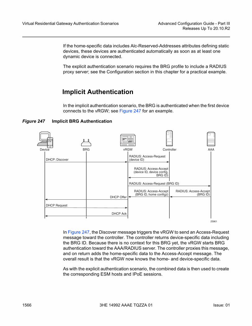
Virtual Residential Gateway Authentication Scenarios
1566
Advanced Configuration Guide - Part IIIReleases Up To 20.10.R2
3HE 14992 AAAE TQZZA 01 Issue: 01
If the home-specific data includes Alc-Reserved-Addresses attributes defining static devices, these devices are authenticated automatically as soon as at least one dynamic device is connected.
The explicit authentication scenario requires the BRG profile to include a RADIUS proxy server; see the Configuration section in this chapter for a practical example.
Implicit Authentication
In the implicit authentication scenario, the BRG is authenticated when the first device connects to the vRGW; see Figure 247 for an example.
Figure 247 Implicit BRG Authentication
In Figure 247, the Discover message triggers the vRGW to send an Access-Request message toward the controller. The controller returns device-specific data including the BRG ID. Because there is no context for this BRG yet, the vRGW starts BRG authentication toward the AAA/RADIUS server. The controller proxies this message, and on return adds the home-specific data to the Access-Accept message. The overall result is that the vRGW now knows the home- and device-specific data.
As with the explicit authentication scenario, the combined data is then used to create the corresponding ESM hosts and IPoE sessions.
vRGWBRG Controller AAA
RADIUS: Access-Request(device ID)
DHCP Ack
RADIUS: Access-Accept(device ID, device config,
BRG ID)
RADIUS: Access-Accept(BRG ID, home configz)
RADIUS: Access-Accept(BRG ID)
DHCP Offer
DHCP: Discover
DHCP Request
Device
25961
RADIUS: Access-Request (BRG ID)

Advanced Configuration Guide - Part III Releases Up To 20.10.R2
Virtual Residential Gateway Authentication Scenarios
Issue: 01 3HE 14992 AAAE TQZZA 01 1567
No separate BRG authentication is required when subsequent devices connect and device authentication returns a BRG ID that is already known to the vRGW.
As with the explicit authentication scenario, if the home-specific data includes Alc-Reserved-Addresses attributes defining static home devices, the static devices are authenticated automatically when at least one dynamic device is connected.
The implicit authentication scenario requires the BRG profile to include a RADIUS authentication context defining a RADIUS server policy and a password; see the Configuration section in this chapter for an example.
Connectivity Verification and BRG Deletion
For the purpose of clearing resources when these resources are not needed anymore, the vRGW performs the BRG connectivity verification and deletion process. When BRG connectivity is considered lost, the BRG and its hosts are deleted automatically.
Parameters controlling the BRG connectivity verification and deletion process are located in the BRG profile context:
*A:BNG>config>subscr-mgmt>brg-profile#connectivity-verification count 3 timeout 30 retry-time 900
count <nr-of-attempts> : [1..5] – default: 3timeout <timeout-seconds> : [5..60] – default: 30retry-time <retry-seconds> : [300..3600] – default: 300
hold-time <seconds> [30..86400] - default: no hold-timeinitial-hold-time <seconds> [0..900] - default: 300
When the last dynamic host associated with a BRG is deleted, while at the same time connectivity-verification is enabled, the vRGW starts a liveliness test toward the BRG through ICMP (v4 or v6) messages. These messages are sent to either the BRG tunnel source IP address or the BRG RADIUS source IP address. If the BRG has neither of these addresses (for example, because each BRG is managed through a unique VLAN in the implicit authentication scenario), connectivity verification is not executed and only the hold-timer applies. If no answer is returned by the BRG in time (timeout), the vRGW considers the BRG in a failed state, and tries again (retry-time) for some maximum number of times (count).
The vRGW starts the hold-timer when the maximum number of tries is reached, or when connectivity verification is disabled (no connectivity verification). When the hold-timer expires, the BRG context is deleted together with the associated hosts.

Virtual Residential Gateway Authentication Scenarios
1568
Advanced Configuration Guide - Part IIIReleases Up To 20.10.R2
3HE 14992 AAAE TQZZA 01 Issue: 01
The initial-hold-timer is required in the scenario where operators want to use explicit authentication without connectivity-verification, and with no hold-timer defined. In this scenario, defining a non-zero initial-hold-timer value avoids BRG contexts from being deleted immediately after their creation.
If a new dynamic host connects while executing the liveliness test or while the hold-timer or the initial-hold-timer is running, the connectivity verification and BRG deletion process is canceled.
The hold-timer is ignored when manually clearing BRGs and related hosts with the following command.
clear subscriber-mgmt brg gatewaybrg-id <brg-ident>
host <ieee-address>all-hostsidle-bindings
all-gateways
Configuration
The services configuration shown in Figure 4 applies to the examples throughout this chapter. Because the main focus of this chapter is on BRG and home device authentication, the detailed configuration of VPLS 10 containing the capture SAP and of VPRN-2 containing the outside L2-aware NAT range is not repeated here. See the Virtual Residential Gateway Home Pool Management chapter for those configurations.
In summary, VPRN-1 provides the connection toward the customer premises, and hosts the NAT inside addresses. VPRN-2 provides the connection toward the Internet, and hosts the NAT outside addresses. Also, VPRN-3 provides connection to the management interfaces of the BRGs, and is used for the explicit BRG authentication scenario.

Advanced Configuration Guide - Part III Releases Up To 20.10.R2
Virtual Residential Gateway Authentication Scenarios
Issue: 01 3HE 14992 AAAE TQZZA 01 1569
Figure 248 Example Service Configuration for Explicit and Implicit BRG Authentication
Service Configuration
An excerpt of the configuration of VPRN-1 follows. The group interface grp-int-1-1 has RADIUS authentication enabled through authentication policy radius-AUTH, and BRG authentication through the default BRG profile brg-prof-1.
configureservice
vprn 1 customer 1 create--- snipped ---subscriber-interface "sub-int-1" create
address 198.51.100.254/24address 192.168.1.1/24--- snipped ---group-interface "grp-int-1-1" create
ipv6--- snipped ---ipoe-bridged-mode
exit--- snipped ---authentication-policy "radius-AUTH"ipoe-session
ipoe-session-policy "sess-pol-SAP-MAC"sap-session-limit 128no shutdown
exitbrg
default-brg-profile "brg-prof-1"no shutdown
25962
BRG00:0c:29:00:00:10
10.1.0.1000:0c:29:00:00:11
00:0c:29:00:00:14 Home
implicit BRGauthentication
explicit BRGauthentication
00:0c:29:00:00:10/10.1.0.10
198.51.100.254/24192.168.1.1/24
VPRN 1managed SAP
[1/1/1:81]
int-BRG10.1.0.254/24
1/1/1:1
brg-profile
sub-int-1
ipoe-session-policy
VPRN 3
radius-proxyvRGW
ipoe-bridged-mode
grp-int-1-1 to VPRN-2

Virtual Residential Gateway Authentication Scenarios
1570
Advanced Configuration Guide - Part IIIReleases Up To 20.10.R2
3HE 14992 AAAE TQZZA 01 Issue: 01
exitoper-up-while-empty
exitexitnat
insidel2-aware
address 192.168.0.1/16exit
exitexitno shutdown
exitexit
exit
BRG Profile
The BRG profile brg-prof-1 is defined in the subscriber management context and provides an SLA profile, a subscriber profile, a DHCP pool, a RADIUS server policy plus the corresponding password, and a RADIUS proxy server.
For explicit BRG authentication, the RADIUS proxy server is used; for implicit BRG authentication, the RADIUS server policy and password defined in the RADIUS authentication context are used.
configuresubscriber-mgmt
--- snipped ---brg-profile "brg-prof-1" create
description "default BRG-profile, demo purposes"sla-profile-string "sla-prof-1"sub-profile-string "sub-prof-1"dhcp-pool
subnet 192.168.1.1/24 start 192.168.1.2 end 192.168.1.254exitradius-authentication
password letmeinradius-server-policy "rad-serv-pol-RSP"
exitradius-proxy-server router 3 name "rad-prox-RPROX"
exitexit
exit

Advanced Configuration Guide - Part III Releases Up To 20.10.R2
Virtual Residential Gateway Authentication Scenarios
Issue: 01 3HE 14992 AAAE TQZZA 01 1571
RADIUS Proxy Configuration
VPRN-3 is defined for supporting explicit BRG authentication via a RADIUS proxy. The int-BRG interface is on SAP 1/1/1:1, and provides connectivity to the management interface of the physical BRGs. The RADIUS proxy listens on the int-LB-PROXY interface, and directs the incoming RADIUS messages to the server, as defined by the default authentication-server policy.
configureservice
vprn 3route-distinguisher 64496:3interface "int-LB-PROXY" create
address 10.33.33.1/32loopback
exitinterface "int-BRG" create
address 10.1.0.254/24sap 1/1/1:1 createexit
exitradius-proxy
server "rad-prox-RPROX" purpose authentication createdefault-authentication-server-policy "rad-serv-pol-RSP"interface "int-LB-PROXY"secret vsecret1no shutdown
exitexitno shutdown
exitexit
exit
RADIUS Policies
The RADIUS authentication and accounting policies are defined as follows, so authentication and accounting happens via the base router instance.
configurerouter
radius-serverserver "radius-172.16.1.2" address 172.16.1.2 secret vsecret1 create
accept-coaexit
exitexit
exit
configureaaa

Virtual Residential Gateway Authentication Scenarios
1572
Advanced Configuration Guide - Part IIIReleases Up To 20.10.R2
3HE 14992 AAAE TQZZA 01 Issue: 01
radius-server-policy "rad-serv-pol-RSP" createservers
router "Base"source-address 192.0.2.1server 1 name "radius-172.16.1.2"
exitexit
exitexit
configuresubscriber-mgmt
authentication-policy "radius-AUTH" createdescription "RADIUS authentication policy"password letmeinradius-server-policy "rad-serv-pol-RSP"
exitradius-accounting-policy "radius-ACCT" create
update-interval 5include-radius-attribute
mac-addressnat-port-rangesubscriber-id
exitradius-accounting-server
source-address 192.0.2.1router "Base"server 1 address 172.16.1.2 secret vsecret1
exitexit
exitexit
RADIUS User Configuration
Although a PCMP will be used in conjunction with an external controller, for demonstration purposes, this chapter relies on a RADIUS server only.
A sample RADIUS user configuration follows. MAC addresses are used for authentication. MAC address 00:0c:29:00:00:10 identifies the BRG. The addresses ranging from 00:0c:29:00:00:11 to 00:0c:29:00:00:1f identify the home devices connected to that BRG so they all return the same Alc-BRG-Id.
00:0c:29:00:00:10 Cleartext-Password := "letmein"Alc-BRG-Id = "00:0c:29:00:00:10",Framed-IPv6-Prefix = 2001:db8:101:1010::/64,Alc-DMZ-address = 192.168.1.254,Alc-Home-Aware-Pool =
"192.168.1.1/24 192.168.1.100-192.168.1.254",Alc-Reserved-Addresses =
"sticky 00:0c:29:00:00:11 192.168.1.110",Alc-Reserved-Addresses +=
"static 00:0c:29:00:00:1f 192.168.1.254",

Advanced Configuration Guide - Part III Releases Up To 20.10.R2
Virtual Residential Gateway Authentication Scenarios
Issue: 01 3HE 14992 AAAE TQZZA 01 1573
Alc-Reserved-Addresses +="static 00:0c:29:00:00:1e 198.51.100.110",
Alc-Portal-Url = "http://11.11.11.11",Alc-Primary-Dns = 1.1.1.1,Alc-Secondary-Dns = 1.1.2.2,Alc-Primary-Nbns = 2.2.1.1,Alc-Secondary-Nbns = 2.2.2.2,Alc-Ipv6-Primary-DNS = 2001:db8:dddd:1::1,Alc-Ipv6-Secondary-DNS = 2001:db8:dddd:2::1,
00:0c:29:00:00:11 Cleartext-Password := "letmein"Alc-BRG-Id = "00:0c:29:00:00:10",
00:0c:29:00:00:12 Cleartext-Password := "letmein"Alc-BRG-Id = "00:0c:29:00:00:10",
00:0c:29:00:00:13 Cleartext-Password := "letmein"Alc-BRG-Id = "00:0c:29:00:00:10",
00:0c:29:00:00:14 Cleartext-Password := "letmein"Alc-BRG-Id = "00:0c:29:00:00:10",Alc-Primary-Dns = 1.1.3.3,
Debug Configuration
The following debug configuration can be used for troubleshooting purposes.
debugrouter "Base"
radiuspacket-type authentication accounting coadetail-level high
exitexitrouter "1"
ipdhcp
detail-level mediummode egr-ingr-and-dropped
exiticmp6
exitexitrouter "3"
radius-proxyserver "rad-prox-RPROX"
detail-level highdirection bothpacket-type access-request access-accept access-reject
access-challenge accounting-requestaccounting-response other
exitexit
exitexit

Virtual Residential Gateway Authentication Scenarios
1574
Advanced Configuration Guide - Part IIIReleases Up To 20.10.R2
3HE 14992 AAAE TQZZA 01 Issue: 01
Explicit Authentication
In the explicit authentication scenario, the BRG is authenticated before any home device attempts to connect. The following trace shows that the RADIUS proxy server in router 3 receives an Access-Request from BRG with BRG ID 00:0c:29:00:00:10, and passes this to the AAA/RADIUS server, which returns the BRG specific data. Two static addresses and one sticky address are associated with this BRG.
1 2016/09/20 16:27:22.11 CEST MINOR: DEBUG #2001 vprn3 RADIUS"RADIUS: Receive
Proxy-server rad-prox-RPROX"
2 2016/09/20 16:27:22.11 CEST MINOR: DEBUG #2001 vprn3 RADIUS"RADIUS: Receive
Access-Request(1) id 18 len 81 from 10.1.0.10:49169 vrid 3 pol rad-serv-pol-RSPUSER NAME [1] 17 00:0c:29:00:00:10PASSWORD [2] 16 bD5mfBsZr5M/aFgOa7iAtENAS IP ADDRESS [4] 4 10.1.0.10MESSAGE AUTHENTICATOR [80] 16 0x6c9a951328e303920ba50fa8f7eea0c3
"
3 2016/09/20 16:27:22.11 CEST MINOR: DEBUG #2001 Base RADIUS"RADIUS: Transmit
Access-Request(1) 172.16.1.2:1812 id 1 len 81 vrid 1 pol rad-serv-pol-RSPUSER NAME [1] 17 00:0c:29:00:00:10PASSWORD [2] 16 m9Lo8f7y.V35pw3KzGBs.UNAS IP ADDRESS [4] 4 10.1.0.10MESSAGE AUTHENTICATOR [80] 16 0xbe54c468e3e6952f0cedfadd3477683b
Hex Packet Dump:--- snipped ---
"
4 2016/09/20 16:27:22.11 CEST MINOR: DEBUG #2001 Base RADIUS"RADIUS: Receive
Access-Accept(2) id 1 len 388 from 172.16.1.2:1812 vrid 1 pol rad-serv-pol-RSPVSA [26] 19 Alcatel(6527)
BRG ID [225] 17 00:0c:29:00:00:10FRAMED IPV6 PREFIX [97] 18 2001:db8:101:1010::/64VSA [26] 6 Alcatel(6527)
BRG DMZ ADDRESS [221] 4 192.168.1.254VSA [26] 44 Alcatel(6527)
BRG HOME AWARE POOL [220] 42 192.168.1.1/24 192.168.1.100-192.168.1.254VSA [26] 40 Alcatel(6527)
BRG RESERVED ADDRESS [223] 38 sticky 00:0c:29:00:00:11 192.168.1.110VSA [26] 40 Alcatel(6527)
BRG RESERVED ADDRESS [223] 38 static 00:0c:29:00:00:1f 192.168.1.254VSA [26] 41 Alcatel(6527)
BRG RESERVED ADDRESS [223] 39 static 00:0c:29:00:00:1e 198.51.100.110VSA [26] 20 Alcatel(6527)
PORTAL URL [177] 18 http://11.11.11.11VSA [26] 6 Alcatel(6527)
PRIMARY DNS [9] 4 1.1.1.1VSA [26] 6 Alcatel(6527)
SECONDARY DNS [10] 4 1.1.2.2VSA [26] 6 Alcatel(6527)

Advanced Configuration Guide - Part III Releases Up To 20.10.R2
Virtual Residential Gateway Authentication Scenarios
Issue: 01 3HE 14992 AAAE TQZZA 01 1575
PRIMARY NBNS [29] 4 2.2.1.1VSA [26] 6 Alcatel(6527)
SECONDARY NBNS [30] 4 2.2.2.2VSA [26] 18 Alcatel(6527)
IPV6 PRIMARY DNS [105] 16 2001:db8:dddd:1::1VSA [26] 18 Alcatel(6527)
IPV6 SECONDARY DNS [106] 16 2001:db8:dddd:2::1
Hex Packet Dump:--- snipped ---
"
5 2016/09/20 16:27:22.12 CEST MINOR: DEBUG #2001 vprn3 RADIUS"RADIUS: Transmit
Proxy-server rad-prox-RPROX"
6 2016/09/20 16:27:22.12 CEST MINOR: DEBUG #2001 vprn3 RADIUS"RADIUS: Transmit
Access-Accept(2) 10.1.0.10:49169 id 18 len 388 vrid 3VSA [26] 19 Alcatel(6527)
BRG ID [225] 17 00:0c:29:00:00:10FRAMED IPV6 PREFIX [97] 18 2001:db8:101:1010::/64VSA [26] 6 Alcatel(6527)
BRG DMZ ADDRESS [221] 4 192.168.1.254VSA [26] 44 Alcatel(6527)
BRG HOME AWARE POOL [220] 42 192.168.1.1/24 192.168.1.100-192.168.1.254VSA [26] 40 Alcatel(6527)
BRG RESERVED ADDRESS [223] 38 sticky 00:0c:29:00:00:11 192.168.1.110VSA [26] 40 Alcatel(6527)
BRG RESERVED ADDRESS [223] 38 static 00:0c:29:00:00:1f 192.168.1.254VSA [26] 41 Alcatel(6527)
BRG RESERVED ADDRESS [223] 39 static 00:0c:29:00:00:1e 198.51.100.110VSA [26] 20 Alcatel(6527)
PORTAL URL [177] 18 http://11.11.11.11VSA [26] 6 Alcatel(6527)
PRIMARY DNS [9] 4 1.1.1.1VSA [26] 6 Alcatel(6527)
SECONDARY DNS [10] 4 1.1.2.2VSA [26] 6 Alcatel(6527)
PRIMARY NBNS [29] 4 2.2.1.1VSA [26] 6 Alcatel(6527)
SECONDARY NBNS [30] 4 2.2.2.2VSA [26] 18 Alcatel(6527)
IPV6 PRIMARY DNS [105] 16 2001:db8:dddd:1::1VSA [26] 18 Alcatel(6527)
IPV6 SECONDARY DNS [106] 16 2001:db8:dddd:2::1"
As a result, the vRGW creates and stores context for this BRG, which can be displayed using the following command. The Proxy authenticated flag is set to “yes”.
*A:BNG# show subscriber-mgmt brg gateways
===============================================================================Bridged Residential Gateways===============================================================================Identifier : 00:0c:29:00:00:10SLAAC prefix : 2001:db8:101:1010::/64

Virtual Residential Gateway Authentication Scenarios
1576
Advanced Configuration Guide - Part IIIReleases Up To 20.10.R2
3HE 14992 AAAE TQZZA 01 Issue: 01
Subnet : 192.168.1.1/24Subnet start address : 192.168.1.100Subnet end address : 192.168.1.254DMZ address : 192.168.1.254DNS 1 v4 : 1.1.1.1DNS 1 v6 : 2001:db8:dddd:1::1DNS 2 v4 : 1.1.2.2DNS 2 v6 : 2001:db8:dddd:2::1NBNS 1 : 2.2.1.1NBNS 2 : 2.2.2.2DHCP lease time : 21600DHCP stream destination : (Not Specified)IPv4 portal URL : http://11.11.11.11IPv6 portal URL : (Not Specified)BRG profile : brg-prof-1Subscriber profile : sub-prof-1SLA profile : sla-prof-1UPnP policy override : (Not Specified)DMZ address in use : noProxy authenticated : yesIngress IPv4 filter override : N/AEgress IPv4 filter override : N/AIngress IPv6 filter override : N/AEgress IPv6 filter override : N/ANo QoS overrides found.No Filter rules received.
-------------------------------------------------------------------------------No. of gateways: 1===============================================================================*A:BNG#
Initially, no hosts are created and associated with this BRG, as the following command shows.
*A:BNG# show subscriber-mgmt brg gateway brg-id "00:0c:29:00:00:10" hostsNo entries found.*A:BNG#
To show the static and sticky addresses associated with the BRG, use the following command. Even without any device connected to this BRG, some bindings are created.
*A:BNG# show subscriber-mgmt brg gateway brg-id "00:0c:29:00:00:10" bindings
===============================================================================Bridged Residential Gateway home-aware pool address bindings===============================================================================Home-aware pool : 00:0c:29:00:00:10-------------------------------------------------------------------------------MAC address : 00:0c:29:00:00:11IP address : 192.168.1.110Allocation type : sticky-ip-addressDHCP lease : falseRemaining lease time : (Unknown)Lease start time : N/A

Advanced Configuration Guide - Part III Releases Up To 20.10.R2
Virtual Residential Gateway Authentication Scenarios
Issue: 01 3HE 14992 AAAE TQZZA 01 1577
MAC address : 00:0c:29:00:00:1eIP address : 198.51.100.110Allocation type : staticDHCP lease : (Unknown)Remaining lease time : (Unknown)Lease start time : N/A
MAC address : 00:0c:29:00:00:1fIP address : 192.168.1.254Allocation type : staticDHCP lease : (Unknown)Remaining lease time : (Unknown)Lease start time : N/A
-------------------------------------------------------------------------------No. of bindings: 3===============================================================================*A:BNG#
When the first device connects, in this example using DHCPv4 (DORA), this device is authenticated using RADIUS, and the controller returns the corresponding BRG ID and device-specific primary DNS server (messages 7 and 8). Because the BRG has two static addresses associated with it, at the same time these are also authenticated (messages 12 and 15 for the first static host, 13 and 16 for the second static host). The device with MAC address 00:0c:29:00:00:14 has a dedicated primary DNS server, which overrules the primary DNS server defined at BRG level (messages 8, 10, and 14).
7 2016/09/20 16:29:08.53 CEST MINOR: DEBUG #2001 Base RADIUS"RADIUS: Transmit
Access-Request(1) 172.16.1.2:1812 id 2 len 79 vrid 1 pol rad-serv-pol-RSPUSER NAME [1] 17 00:0c:29:00:00:14PASSWORD [2] 16 Lh/0pV5SVw5Cp7gBJe75s.NAS IP ADDRESS [4] 4 192.0.2.1NAS PORT TYPE [61] 4 Ethernet(15)NAS PORT ID [87] 8 1/1/1:81
Hex Packet Dump:--- snipped ---
"
8 2016/09/20 16:29:08.53 CEST MINOR: DEBUG #2001 Base RADIUS"RADIUS: Receive
Access-Accept(2) id 2 len 57 from 172.16.1.2:1812 vrid 1 pol rad-serv-pol-RSPVSA [26] 19 Alcatel(6527)
BRG ID [225] 17 00:0c:29:00:00:10VSA [26] 6 Alcatel(6527)
PRIMARY DNS [9] 4 1.1.3.3
Hex Packet Dump:--- snipped ---
"
9 2016/09/20 16:29:08.53 CEST MINOR: DEBUG #2001 vprn1 PIP"PIP: DHCP

Virtual Residential Gateway Authentication Scenarios
1578
Advanced Configuration Guide - Part IIIReleases Up To 20.10.R2
3HE 14992 AAAE TQZZA 01 Issue: 01
instance 2 (1), interface index 6 (grp-int-1-1),received DHCP Boot Request on Interface grp-int-1-1 (1/1/1:81) Port 67
H/W Type: Ethernet(10Mb) H/W Address Length: 6ciaddr: 0.0.0.0 yiaddr: 0.0.0.0siaddr: 0.0.0.0 giaddr: 0.0.0.0chaddr: 00:0c:29:00:00:14 xid: 0x2
DHCP options:[53] Message type: Discover[255] End
"
10 2016/09/20 16:29:08.53 CEST MINOR: DEBUG #2001 vprn1 PIP"PIP: DHCPinstance 2 (1), interface index 6 (grp-int-1-1),
transmitted DHCP Boot Reply to Interface grp-int-1-1 (1/1/1:81) Port 68
H/W Type: Ethernet(10Mb) H/W Address Length: 6ciaddr: 0.0.0.0 yiaddr: 192.168.1.100siaddr: 192.168.1.1 giaddr: 192.168.1.1chaddr: 00:0c:29:00:00:14 xid: 0x2
DHCP options:[53] Message type: Offer[54] DHCP server addr: 192.168.1.1[51] Lease time: 21600[1] Subnet mask: 255.255.255.0[3] Router: 192.168.1.1[6] Domain name server: length = 8
1.1.3.31.1.2.2
[44] NETBIOS name server: length = 82.2.1.12.2.2.2
[255] End"
11 2016/09/20 16:29:08.64 CEST MINOR: DEBUG #2001 vprn1 PIP"PIP: DHCPinstance 2 (1), interface index 6 (grp-int-1-1),
received DHCP Boot Request on Interface grp-int-1-1 (1/1/1:81) Port 67
H/W Type: Ethernet(10Mb) H/W Address Length: 6ciaddr: 0.0.0.0 yiaddr: 0.0.0.0siaddr: 0.0.0.0 giaddr: 0.0.0.0chaddr: 00:0c:29:00:00:14 xid: 0x2
DHCP options:[53] Message type: Request[50] Requested IP addr: 192.168.1.100[54] DHCP server addr: 192.168.1.1[255] End
"
12 2016/09/20 16:29:08.64 CEST MINOR: DEBUG #2001 Base RADIUS"RADIUS: Transmit
Access-Request(1) 172.16.1.2:1812 id 3 len 79 vrid 1 pol rad-serv-pol-RSPUSER NAME [1] 17 00:0c:29:00:00:1e

Advanced Configuration Guide - Part III Releases Up To 20.10.R2
Virtual Residential Gateway Authentication Scenarios
Issue: 01 3HE 14992 AAAE TQZZA 01 1579
PASSWORD [2] 16 hW.TR6SdCXXMO/3iZ.3WNkNAS IP ADDRESS [4] 4 192.0.2.1NAS PORT TYPE [61] 4 Ethernet(15)NAS PORT ID [87] 8 1/1/1:81
Hex Packet Dump:--- snipped ---
"
13 2016/09/20 16:29:08.64 CEST MINOR: DEBUG #2001 Base RADIUS"RADIUS: Transmit
Access-Request(1) 172.16.1.2:1812 id 4 len 79 vrid 1 pol rad-serv-pol-RSPUSER NAME [1] 17 00:0c:29:00:00:1fPASSWORD [2] 16 vXTCIxeAZzeGRFAQy8eS/kNAS IP ADDRESS [4] 4 192.0.2.1NAS PORT TYPE [61] 4 Ethernet(15)NAS PORT ID [87] 8 1/1/1:81
Hex Packet Dump:--- snipped ---
"
14 2016/09/20 16:29:08.64 CEST MINOR: DEBUG #2001 vprn1 PIP"PIP: DHCPinstance 2 (1), interface index 6 (grp-int-1-1),
transmitted DHCP Boot Reply to Interface grp-int-1-1 (1/1/1:81) Port 68
H/W Type: Ethernet(10Mb) H/W Address Length: 6ciaddr: 0.0.0.0 yiaddr: 192.168.1.100siaddr: 192.168.1.1 giaddr: 192.168.1.1chaddr: 00:0c:29:00:00:14 xid: 0x2
DHCP options:[53] Message type: Ack[54] DHCP server addr: 192.168.1.1[51] Lease time: 21600[1] Subnet mask: 255.255.255.0[3] Router: 192.168.1.1[6] Domain name server: length = 8
1.1.3.31.1.2.2
[44] NETBIOS name server: length = 82.2.1.12.2.2.2
[255] End"
15 2016/09/20 16:29:08.63 CEST MINOR: DEBUG #2001 Base RADIUS"RADIUS: Receive
Access-Accept(2) id 3 len 45 from 172.16.1.2:1812 vrid 1 pol rad-serv-pol-RSPVSA [26] 19 Alcatel(6527)
BRG ID [225] 17 00:0c:29:00:00:10
Hex Packet Dump:--- snipped ---
"
16 2016/09/20 16:29:08.63 CEST MINOR: DEBUG #2001 Base RADIUS"RADIUS: Receive
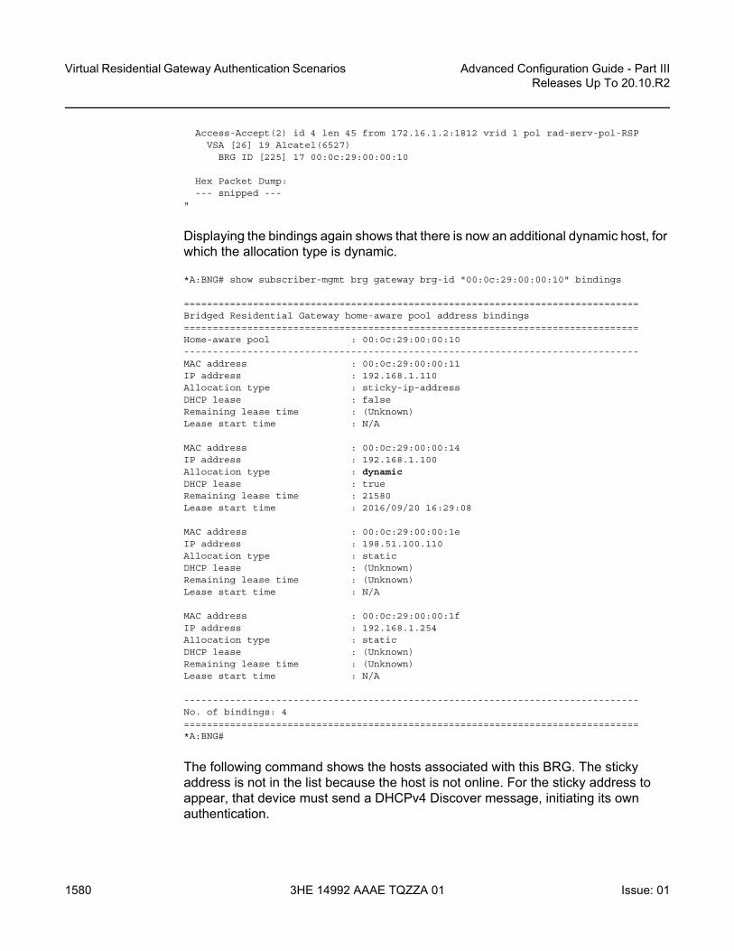
Virtual Residential Gateway Authentication Scenarios
1580
Advanced Configuration Guide - Part IIIReleases Up To 20.10.R2
3HE 14992 AAAE TQZZA 01 Issue: 01
Access-Accept(2) id 4 len 45 from 172.16.1.2:1812 vrid 1 pol rad-serv-pol-RSPVSA [26] 19 Alcatel(6527)
BRG ID [225] 17 00:0c:29:00:00:10
Hex Packet Dump:--- snipped ---
"
Displaying the bindings again shows that there is now an additional dynamic host, for which the allocation type is dynamic.
*A:BNG# show subscriber-mgmt brg gateway brg-id "00:0c:29:00:00:10" bindings
===============================================================================Bridged Residential Gateway home-aware pool address bindings===============================================================================Home-aware pool : 00:0c:29:00:00:10-------------------------------------------------------------------------------MAC address : 00:0c:29:00:00:11IP address : 192.168.1.110Allocation type : sticky-ip-addressDHCP lease : falseRemaining lease time : (Unknown)Lease start time : N/A
MAC address : 00:0c:29:00:00:14IP address : 192.168.1.100Allocation type : dynamicDHCP lease : trueRemaining lease time : 21580Lease start time : 2016/09/20 16:29:08
MAC address : 00:0c:29:00:00:1eIP address : 198.51.100.110Allocation type : staticDHCP lease : (Unknown)Remaining lease time : (Unknown)Lease start time : N/A
MAC address : 00:0c:29:00:00:1fIP address : 192.168.1.254Allocation type : staticDHCP lease : (Unknown)Remaining lease time : (Unknown)Lease start time : N/A
-------------------------------------------------------------------------------No. of bindings: 4===============================================================================*A:BNG#
The following command shows the hosts associated with this BRG. The sticky address is not in the list because the host is not online. For the sticky address to appear, that device must send a DHCPv4 Discover message, initiating its own authentication.

Advanced Configuration Guide - Part III Releases Up To 20.10.R2
Virtual Residential Gateway Authentication Scenarios
Issue: 01 3HE 14992 AAAE TQZZA 01 1581
*A:BNG# show subscriber-mgmt brg gateway brg-id "00:0c:29:00:00:10" hosts
===============================================================================Bridged Residential Gateway hosts===============================================================================Identifier : 00:0c:29:00:00:10MAC address : 00:0c:29:00:00:14IP address : 192.168.1.100Service : 1 (VPRN)Allocation type : dynamicHome-aware pool : 00:0c:29:00:00:10DHCP lease : trueRemaining lease time : 21567Lease start time : 2016/09/20 16:29:08
Identifier : 00:0c:29:00:00:10MAC address : 00:0c:29:00:00:1eIP address : 198.51.100.110Service : 1 (VPRN)Allocation type : staticHome-aware pool : 00:0c:29:00:00:10DHCP lease : (Unknown)Remaining lease time : (Unknown)Lease start time : N/A
Identifier : 00:0c:29:00:00:10MAC address : 00:0c:29:00:00:1fIP address : 192.168.1.254Service : 1 (VPRN)Allocation type : staticHome-aware pool : 00:0c:29:00:00:10DHCP lease : (Unknown)Remaining lease time : (Unknown)Lease start time : N/A
-------------------------------------------------------------------------------No. of BRG hosts: 3===============================================================================*A:BNG#
Even when the last dynamic host disconnects, the static hosts remain, as shown by the following command.
*A:BNG# show subscriber-mgmt brg gateway brg-id "00:0c:29:00:00:10" hosts
===============================================================================Bridged Residential Gateway hosts===============================================================================Identifier : 00:0c:29:00:00:10MAC address : 00:0c:29:00:00:1eIP address : 198.51.100.110Service : 1 (VPRN)Allocation type : staticHome-aware pool : 00:0c:29:00:00:10DHCP lease : (Unknown)

Virtual Residential Gateway Authentication Scenarios
1582
Advanced Configuration Guide - Part IIIReleases Up To 20.10.R2
3HE 14992 AAAE TQZZA 01 Issue: 01
Remaining lease time : (Unknown)Lease start time : N/A
Identifier : 00:0c:29:00:00:10MAC address : 00:0c:29:00:00:1fIP address : 192.168.1.254Service : 1 (VPRN)Allocation type : staticHome-aware pool : 00:0c:29:00:00:10DHCP lease : (Unknown)Remaining lease time : (Unknown)Lease start time : N/A
-------------------------------------------------------------------------------No. of BRG hosts: 2===============================================================================*A:BNG#
As long as the BRG is still alive, these hosts will remain, and so will the BRG context. For that reason, the vRGW might start connectivity verification and eventually delete the BRG and its hosts, depending on the configuration.
The BRG context can also be cleared manually using the following command, after which the BRG and the associated hosts are deleted.
*A:BNG# clear subscriber-mgmt brg gateway brg-id "00:0c:29:00:00:10"
*A:BNG# show subscriber-mgmt brg gateway brg-id "00:0c:29:00:00:10" hostsNo entries found.
*A:BNG# show subscriber-mgmt brg gatewaysNo entries found.*A:BNG#
Implicit Authentication
In the implicit authentication scenario, the BRG is authenticated when the first host is authenticated, which requires two phases. In the first phase, the RADIUS server is accessed for authenticating the device (00:0c:29:00:00:11), returning the device-specific data including the BRG ID. In the second phase, the RADIUS server is accessed for authenticating the BRG (00:0c:29:00:00:10), returning the home-specific data. Because the RADIUS server returns two reserved static addresses, SR OS additionally authenticates the static devices.
18 2016/09/20 16:30:59.88 CEST MINOR: DEBUG #2001 Base RADIUS"RADIUS: Transmit
Access-Request(1) 172.16.1.2:1812 id 5 len 79 vrid 1 pol rad-serv-pol-RSPUSER NAME [1] 17 00:0c:29:00:00:11PASSWORD [2] 16 OhUXqlDfL7XPKlx8EmoMak

Advanced Configuration Guide - Part III Releases Up To 20.10.R2
Virtual Residential Gateway Authentication Scenarios
Issue: 01 3HE 14992 AAAE TQZZA 01 1583
NAS IP ADDRESS [4] 4 192.0.2.1NAS PORT TYPE [61] 4 Ethernet(15)NAS PORT ID [87] 8 1/1/1:81
Hex Packet Dump:--- snipped ---
"
19 2016/09/20 16:30:59.89 CEST MINOR: DEBUG #2001 Base RADIUS"RADIUS: Receive
Access-Accept(2) id 5 len 45 from 172.16.1.2:1812 vrid 1 pol rad-serv-pol-RSPVSA [26] 19 Alcatel(6527)
BRG ID [225] 17 00:0c:29:00:00:10
Hex Packet Dump:--- snipped ---
"
20 2016/09/20 16:30:59.89 CEST MINOR: DEBUG #2001 Base RADIUS"RADIUS: Transmit
Access-Request(1) 172.16.1.2:1812 id 6 len 88 vrid 1 pol rad-serv-pol-RSPUSER NAME [1] 17 00:0c:29:00:00:10PASSWORD [2] 16 u87pDAyiQx.TVIGEHFV22UNAS IP ADDRESS [4] 4 192.0.2.1VSA [26] 19 Alcatel(6527)
BRG ID [225] 17 00:0c:29:00:00:10
Hex Packet Dump:--- snipped ---
"
21 2016/09/20 16:30:59.89 CEST MINOR: DEBUG #2001 Base RADIUS"RADIUS: Receive
Access-Accept(2) id 6 len 388 from 172.16.1.2:1812 vrid 1 pol rad-serv-pol-RSPVSA [26] 19 Alcatel(6527)
BRG ID [225] 17 00:0c:29:00:00:10FRAMED IPV6 PREFIX [97] 18 2001:db8:101:1010::/64VSA [26] 6 Alcatel(6527)
BRG DMZ ADDRESS [221] 4 192.168.1.254VSA [26] 44 Alcatel(6527)
BRG HOME AWARE POOL [220] 42 192.168.1.1/24 192.168.1.100-192.168.1.254VSA [26] 40 Alcatel(6527)
BRG RESERVED ADDRESS [223] 38 sticky 00:0c:29:00:00:11 192.168.1.110VSA [26] 40 Alcatel(6527)
BRG RESERVED ADDRESS [223] 38 static 00:0c:29:00:00:1f 192.168.1.254VSA [26] 41 Alcatel(6527)
BRG RESERVED ADDRESS [223] 39 static 00:0c:29:00:00:1e 198.51.100.110VSA [26] 20 Alcatel(6527)
PORTAL URL [177] 18 http://11.11.11.11VSA [26] 6 Alcatel(6527)
PRIMARY DNS [9] 4 1.1.1.1VSA [26] 6 Alcatel(6527)
SECONDARY DNS [10] 4 1.1.2.2VSA [26] 6 Alcatel(6527)
PRIMARY NBNS [29] 4 2.2.1.1VSA [26] 6 Alcatel(6527)
SECONDARY NBNS [30] 4 2.2.2.2VSA [26] 18 Alcatel(6527)
IPV6 PRIMARY DNS [105] 16 2001:db8:dddd:1::1

Virtual Residential Gateway Authentication Scenarios
1584
Advanced Configuration Guide - Part IIIReleases Up To 20.10.R2
3HE 14992 AAAE TQZZA 01 Issue: 01
VSA [26] 18 Alcatel(6527)IPV6 SECONDARY DNS [106] 16 2001:db8:dddd:2::1
Hex Packet Dump:--- snipped ---
"
22 2016/09/20 16:30:59.89 CEST MINOR: DEBUG #2001 vprn1 PIP"PIP: DHCPinstance 2 (1), interface index 6 (grp-int-1-1),
received DHCP Boot Request on Interface grp-int-1-1 (1/1/1:81) Port 67
H/W Type: Ethernet(10Mb) H/W Address Length: 6ciaddr: 0.0.0.0 yiaddr: 0.0.0.0siaddr: 0.0.0.0 giaddr: 0.0.0.0chaddr: 00:0c:29:00:00:11 xid: 0x1
DHCP options:[53] Message type: Discover[255] End
"
23 2016/09/20 16:30:59.89 CEST MINOR: DEBUG #2001 vprn1 PIP"PIP: DHCPinstance 2 (1), interface index 6 (grp-int-1-1),
transmitted DHCP Boot Reply to Interface grp-int-1-1 (1/1/1:81) Port 68
H/W Type: Ethernet(10Mb) H/W Address Length: 6ciaddr: 0.0.0.0 yiaddr: 192.168.1.110siaddr: 192.168.1.1 giaddr: 192.168.1.1chaddr: 00:0c:29:00:00:11 xid: 0x1
DHCP options:[53] Message type: Offer[54] DHCP server addr: 192.168.1.1[51] Lease time: 21600[1] Subnet mask: 255.255.255.0[3] Router: 192.168.1.1[6] Domain name server: length = 8
1.1.1.11.1.2.2
[44] NETBIOS name server: length = 82.2.1.12.2.2.2
[255] End"
24 2016/09/20 16:31:00.00 CEST MINOR: DEBUG #2001 vprn1 PIP"PIP: DHCPinstance 2 (1), interface index 6 (grp-int-1-1),
received DHCP Boot Request on Interface grp-int-1-1 (1/1/1:81) Port 67
H/W Type: Ethernet(10Mb) H/W Address Length: 6ciaddr: 0.0.0.0 yiaddr: 0.0.0.0siaddr: 0.0.0.0 giaddr: 0.0.0.0chaddr: 00:0c:29:00:00:11 xid: 0x1
DHCP options:[53] Message type: Request

Advanced Configuration Guide - Part III Releases Up To 20.10.R2
Virtual Residential Gateway Authentication Scenarios
Issue: 01 3HE 14992 AAAE TQZZA 01 1585
[50] Requested IP addr: 192.168.1.110[54] DHCP server addr: 192.168.1.1[255] End
"
25 2016/09/20 16:31:00.00 CEST MINOR: DEBUG #2001 vprn1 PIP"PIP: DHCPinstance 2 (1), interface index 6 (grp-int-1-1),
transmitted DHCP Boot Reply to Interface grp-int-1-1 (1/1/1:81) Port 68
H/W Type: Ethernet(10Mb) H/W Address Length: 6ciaddr: 0.0.0.0 yiaddr: 192.168.1.110siaddr: 192.168.1.1 giaddr: 192.168.1.1chaddr: 00:0c:29:00:00:11 xid: 0x1
DHCP options:[53] Message type: Ack[54] DHCP server addr: 192.168.1.1[51] Lease time: 21600[1] Subnet mask: 255.255.255.0[3] Router: 192.168.1.1[6] Domain name server: length = 8
1.1.1.11.1.2.2
[44] NETBIOS name server: length = 82.2.1.12.2.2.2
[255] End"
26 2016/09/20 16:31:00.00 CEST MINOR: DEBUG #2001 Base RADIUS"RADIUS: Transmit
Access-Request(1) 172.16.1.2:1812 id 7 len 79 vrid 1 pol rad-serv-pol-RSPUSER NAME [1] 17 00:0c:29:00:00:1ePASSWORD [2] 16 hz9D.7GnC2H.LSaqMZ4TiENAS IP ADDRESS [4] 4 192.0.2.1NAS PORT TYPE [61] 4 Ethernet(15)NAS PORT ID [87] 8 1/1/1:81
Hex Packet Dump:--- snipped ---
"
27 2016/09/20 16:31:00.00 CEST MINOR: DEBUG #2001 Base RADIUS"RADIUS: Transmit
Access-Request(1) 172.16.1.2:1812 id 8 len 79 vrid 1 pol rad-serv-pol-RSPUSER NAME [1] 17 00:0c:29:00:00:1fPASSWORD [2] 16 zIWsyfz7KatfZ42IB4/uY.NAS IP ADDRESS [4] 4 192.0.2.1NAS PORT TYPE [61] 4 Ethernet(15)NAS PORT ID [87] 8 1/1/1:81
Hex Packet Dump:--- snipped ---
"
28 2016/09/20 16:30:59.99 CEST MINOR: DEBUG #2001 Base RADIUS"RADIUS: Receive
Access-Accept(2) id 7 len 45 from 172.16.1.2:1812 vrid 1 pol rad-serv-pol-RSP

Virtual Residential Gateway Authentication Scenarios
1586
Advanced Configuration Guide - Part IIIReleases Up To 20.10.R2
3HE 14992 AAAE TQZZA 01 Issue: 01
VSA [26] 19 Alcatel(6527)BRG ID [225] 17 00:0c:29:00:00:10
Hex Packet Dump:--- snipped ---
"
29 2016/09/20 16:30:59.99 CEST MINOR: DEBUG #2001 Base RADIUS"RADIUS: Receive
Access-Accept(2) id 8 len 45 from 172.16.1.2:1812 vrid 1 pol rad-serv-pol-RSPVSA [26] 19 Alcatel(6527)
BRG ID [225] 17 00:0c:29:00:00:10
Hex Packet Dump:--- snipped ---
"
Subsequent connections of additional devices connected to the BRG result in one single RADIUS access per device. There is no need to reauthenticate the BRG.
30 2016/09/20 16:32:10.74 CEST MINOR: DEBUG #2001 vprn1 PIP"PIP: DHCPinstance 2 (1), interface index 6 (grp-int-1-1),
received DHCP Boot Request on Interface grp-int-1-1 (1/1/1:81) Port 67
H/W Type: Ethernet(10Mb) H/W Address Length: 6ciaddr: 0.0.0.0 yiaddr: 0.0.0.0siaddr: 0.0.0.0 giaddr: 0.0.0.0chaddr: 00:0c:29:00:00:14 xid: 0x2
DHCP options:[53] Message type: Discover[255] End
"
31 2016/09/20 16:32:10.74 CEST MINOR: DEBUG #2001 Base RADIUS"RADIUS: Transmit
Access-Request(1) 172.16.1.2:1812 id 9 len 79 vrid 1 pol rad-serv-pol-RSPUSER NAME [1] 17 00:0c:29:00:00:14PASSWORD [2] 16 TcHWkAooYb5Tcpj9KPR3M.NAS IP ADDRESS [4] 4 192.0.2.1NAS PORT TYPE [61] 4 Ethernet(15)NAS PORT ID [87] 8 1/1/1:81
Hex Packet Dump:--- snipped ---
"
32 2016/09/20 16:32:10.74 CEST MINOR: DEBUG #2001 Base RADIUS"RADIUS: Receive
Access-Accept(2) id 9 len 57 from 172.16.1.2:1812 vrid 1 pol rad-serv-pol-RSPVSA [26] 19 Alcatel(6527)
BRG ID [225] 17 00:0c:29:00:00:10VSA [26] 6 Alcatel(6527)
PRIMARY DNS [9] 4 1.1.3.3
Hex Packet Dump:--- snipped ---

Advanced Configuration Guide - Part III Releases Up To 20.10.R2
Virtual Residential Gateway Authentication Scenarios
Issue: 01 3HE 14992 AAAE TQZZA 01 1587
"
33 2016/09/20 16:32:10.74 CEST MINOR: DEBUG #2001 vprn1 PIP"PIP: DHCPinstance 2 (1), interface index 6 (grp-int-1-1),
transmitted DHCP Boot Reply to Interface grp-int-1-1 (1/1/1:81) Port 68
H/W Type: Ethernet(10Mb) H/W Address Length: 6ciaddr: 0.0.0.0 yiaddr: 192.168.1.100siaddr: 192.168.1.1 giaddr: 192.168.1.1chaddr: 00:0c:29:00:00:14 xid: 0x2
DHCP options:[53] Message type: Offer[54] DHCP server addr: 192.168.1.1[51] Lease time: 21600[1] Subnet mask: 255.255.255.0[3] Router: 192.168.1.1[6] Domain name server: length = 8
1.1.3.31.1.2.2
[44] NETBIOS name server: length = 82.2.1.12.2.2.2
[255] End"
34 2016/09/20 16:32:10.84 CEST MINOR: DEBUG #2001 vprn1 PIP"PIP: DHCPinstance 2 (1), interface index 6 (grp-int-1-1),
received DHCP Boot Request on Interface grp-int-1-1 (1/1/1:81) Port 67
H/W Type: Ethernet(10Mb) H/W Address Length: 6ciaddr: 0.0.0.0 yiaddr: 0.0.0.0siaddr: 0.0.0.0 giaddr: 0.0.0.0chaddr: 00:0c:29:00:00:14 xid: 0x2
DHCP options:[53] Message type: Request[50] Requested IP addr: 192.168.1.100[54] DHCP server addr: 192.168.1.1[255] End
"
35 2016/09/20 16:32:10.84 CEST MINOR: DEBUG #2001 vprn1 PIP"PIP: DHCPinstance 2 (1), interface index 6 (grp-int-1-1),
transmitted DHCP Boot Reply to Interface grp-int-1-1 (1/1/1:81) Port 68
H/W Type: Ethernet(10Mb) H/W Address Length: 6ciaddr: 0.0.0.0 yiaddr: 192.168.1.100siaddr: 192.168.1.1 giaddr: 192.168.1.1chaddr: 00:0c:29:00:00:14 xid: 0x2
DHCP options:[53] Message type: Ack[54] DHCP server addr: 192.168.1.1[51] Lease time: 21600[1] Subnet mask: 255.255.255.0

Virtual Residential Gateway Authentication Scenarios
1588
Advanced Configuration Guide - Part IIIReleases Up To 20.10.R2
3HE 14992 AAAE TQZZA 01 Issue: 01
[3] Router: 192.168.1.1[6] Domain name server: length = 8
1.1.3.31.1.2.2
[44] NETBIOS name server: length = 82.2.1.12.2.2.2
[255] End"
The following command shows the corresponding BRG hosts.
*A:BNG# show subscriber-mgmt brg gateway brg-id "00:0c:29:00:00:10" hosts
===============================================================================Bridged Residential Gateway hosts===============================================================================Identifier : 00:0c:29:00:00:10MAC address : 00:0c:29:00:00:11IP address : 192.168.1.110Service : 1 (VPRN)Allocation type : sticky-ip-addressHome-aware pool : 00:0c:29:00:00:10DHCP lease : trueRemaining lease time : 21514Lease start time : 2016/09/20 16:31:00
Identifier : 00:0c:29:00:00:10MAC address : 00:0c:29:00:00:14IP address : 192.168.1.100Service : 1 (VPRN)Allocation type : dynamicHome-aware pool : 00:0c:29:00:00:10DHCP lease : trueRemaining lease time : 21584Lease start time : 2016/09/20 16:32:10
Identifier : 00:0c:29:00:00:10MAC address : 00:0c:29:00:00:1eIP address : 198.51.100.110Service : 1 (VPRN)Allocation type : staticHome-aware pool : 00:0c:29:00:00:10DHCP lease : (Unknown)Remaining lease time : (Unknown)Lease start time : N/A
Identifier : 00:0c:29:00:00:10MAC address : 00:0c:29:00:00:1fIP address : 192.168.1.254Service : 1 (VPRN)Allocation type : staticHome-aware pool : 00:0c:29:00:00:10DHCP lease : (Unknown)Remaining lease time : (Unknown)

Advanced Configuration Guide - Part III Releases Up To 20.10.R2
Virtual Residential Gateway Authentication Scenarios
Issue: 01 3HE 14992 AAAE TQZZA 01 1589
Lease start time : N/A
-------------------------------------------------------------------------------No. of BRG hosts: 4===============================================================================*A:BNG#
Releasing both dynamic devices results in all BRG hosts being deleted, including the static hosts.
*A:BNG# show subscriber-mgmt brg gateway brg-id "00:0c:29:00:00:10" hostsNo entries found.*A:BNG#
Also, the BRG is deleted automatically.
*A:BNG# show subscriber-mgmt brg gatewaysNo entries found.*A:BNG#
Conclusion
This chapter describes the explicit and the implicit authentication models for the BRG. The explicit authentication model requires the BRG to contain an embedded RADIUS client, and offers better security in comparison with the implicit model, which does not require an embedded RADIUS client.

Virtual Residential Gateway Authentication Scenarios
1590
Advanced Configuration Guide - Part IIIReleases Up To 20.10.R2
3HE 14992 AAAE TQZZA 01 Issue: 01

Advanced Configuration Guide - Part III Releases Up To 20.10.R2
Virtual Residential Gateway Home LAN Extension
Issue: 01 3HE 14992 AAAE TQZZA 01 1591
Virtual Residential Gateway Home LAN ExtensionThis chapter describes the home LAN extension of the Virtual Residential Gateway. Sections in this chapter include:
• Applicability• Overview• Configuration• Conclusion
Applicability
The information and configuration in this chapter are based on SR OS Release 15.0.R6. Hardware that supports the Wireless LAN Gateway (WLAN-GW) must be used (ISA1/ISA2 cards).
Overview
With Virtual Residential Gateway (vRGW), all L3 routing and services (DHCP server, NAT, firewall, Application Assurance (AA), and so on) are moved out of the home CPE to the service provider network.
The home CPE (known as Bridged Residential Gateway (BRG)) runs in a bridged mode and acts as an L2 switch between all connected home devices and the vRGW. Therefore, in-home traffic will be switched locally while other traffic will be sent to the vRGW.
However, there are some services/applications implemented on the cloud (for example, Data Center (DC)) that need to appear as if they are on the same home LAN and need L2 bridged access, so they need a Home LAN Extension (HLE).
Examples:
• Digital Living Network Alliance (DLNA) server in the cloud for media streaming• Storage server in the cloud, discoverable via Server Message Block (SMB)
protocol

Virtual Residential Gateway Home LAN Extension
1592
Advanced Configuration Guide - Part IIIReleases Up To 20.10.R2
3HE 14992 AAAE TQZZA 01 Issue: 01
HLE provides the capability to deploy new services in a DC that require L2 reachability to the home and being reachable on L2 to each individual host at home.
A unique per-home Bridge Domain (BD) is created on the WLAN-GW ISA1/ISA2. This acts as an L2 switch before any IP routing functionality is performed.
By using BGP-EVPN VPLS services, a BD is extended via a Virtual Extensible Local Area Network (VXLAN) tunnel to a virtual machine (VM) in a DC. Access from the home CPE can be a soft-GRE or an L2 Tunnel Protocol version 3 (L2TPv3) tunnel or Native VLAN terminated on the WLAN-GW group ISA via L2 Access Point (L2-AP). The HLE network side relies on MP-BGP for the control plane, whereas the data plane is based on VXLAN; see Figure 249.
Figure 249 vRGW-HLE
Bridge Domain Characteristics
The BD bridges traffic between the following connections:
• access-facing connection (for example, home) - GRE/L2TPv3/L2-AP• network-facing connection (for example, DC) - VXLAN tunnel• ESM SAP-facing connection - each home has its own ESM SAP
Figure 250 shows the BD connections in the data plane.
DataCenter
Internet
Home WIFI+ Ethernet
Home-1GRE/L2TPv3
tunnel ornative LAN
Inter home trafficlocally bridged
Non-home traffictunneled toWLAN-GW
WLAN-GW
Home-1L2 Domain
L3 GWprocessing
27632
CPE devices

Advanced Configuration Guide - Part III Releases Up To 20.10.R2
Virtual Residential Gateway Home LAN Extension
Issue: 01 3HE 14992 AAAE TQZZA 01 1593
Figure 250 BD Connections in the Data Plane
With HLE services, each home host constitutes a WLAN-GW User Equipment (UE) object and an ESM host object. Each network host (such as a VM in a DC) constitutes a WLAN-GW UE object but not an ESM host.
Each BD maintains the following tables:
• MAC table: this table contains the learned MAC address by access and network connections
• flood table: this table contains flood destinations for broadcast, unknown unicast, multicast (BUM) traffic; these are typically the access and network connections
• IPv4 ARP table: this table contains learned ARP entries by access and network connections. The ARP and neighbor tables are populated when Assistive Address Resolution (AAR) is enabled (see the Assistive Address Resolution section for more information).
• IPv6 neighbor table: this table contains learned neighbor entries by access and network connections.
Configuration
vRGW Configuration
The following prerequisite configurations are based on vRGW, in the order to be created.
Data Center
Home1-L2Domain
Home1-VM
VRGW
Home1-VM MAC: 00:00:d8:3e:1c:29Home1-VM IP: 192.168.0.100
ISA
IOM
Home1UE
L3 homeGateway
UE MAC: 1a:1e:56:77:00:00UE IP: 192.168.0.50
DCGWBD-Home1
ESM
10.10.10.3 1.1.1.1
GRE tunnel
20.20.20.1 3.3.3.3
VXLAN tunnel
27633

Virtual Residential Gateway Home LAN Extension
1594
Advanced Configuration Guide - Part IIIReleases Up To 20.10.R2
3HE 14992 AAAE TQZZA 01 Issue: 01
WLAN-GW Group
configure wlan-gw-group <wlan-gw-group-id> [create] [redundancy <unit>]
<wlan-gw-group-id> : [1..4]<create> : keyword<unit> : iom|mda
configureisa
wlan-gw-group 1 create redundancy mdaactive-mda-limit 1mda 3/1no shutdown
exitexit
exit
RADIUS Policies
ISA RADIUS Policyconfigure
aaaisa-radius-policy "isa-rad-pol-1" create
password nokiaservers
router "Base"source-address-range 44.44.44.44server 1 create
authenticationcoaip-address 192.77.77.2secret Nokia123no shutdown
exitexit
exitexit
exit
RADIUS Server Policyconfigure
routerradius-server
server "FreeRadius" address 192.77.77.2 secret Nokia123 createaccept-coa
exitexit

Advanced Configuration Guide - Part III Releases Up To 20.10.R2
Virtual Residential Gateway Home LAN Extension
Issue: 01 3HE 14992 AAAE TQZZA 01 1595
exitexit
configureaaa
radius-server-policy "rad-serv-pol-1" createservers
router "Base"source-address 10.10.10.4server 1 name "FreeRadius"
exitexit
exitexit
RADIUS Accounting Policyconfigure
subscriber-mgmtradius-accounting-policy "rad-acc-pol-1" create
--- snipped ---radius-server-policy "rad-serv-pol-1"
exitexit
L2-Aware NAT
configureservice
vprn 333 customer 1 createnat
insidel2-aware
address 192.168.0.101/24exit
exitoutside
pool "nat-pool-1" nat-group 1 type l2-aware createport-reservation blocks 1address-range 120.1.0.1 120.1.0.100 createexitno shutdown
exitexit
exitexitnat
nat-policy "nat-pol-1" createpool "nat-pool-1" router 333
exitexit
exitexit

Virtual Residential Gateway Home LAN Extension
1596
Advanced Configuration Guide - Part IIIReleases Up To 20.10.R2
3HE 14992 AAAE TQZZA 01 Issue: 01
Subscriber Management Parameters
configuresubscriber-mgmt
authentication-policy "auth-pol-1" createexitsla-profile "sla-prof-def" createexitsub-profile "sub-prof-def" create
nat-policy "nat-pol-1"radius-accounting
policy "rad-acc-pol-1"exit
exitsub-ident-policy "sub-ident-pol-def" create
sub-profile-mapuse-direct-map-as-default
exitsla-profile-map
use-direct-map-as-defaultexit
exitexit
exit
BRG Profile
configuresubscriber-mgmt
vrgwbrg
brg-profile "brg-prof-1" createdhcp-pool
subnet 192.168.0.1/24 start 192.168.0.50 end 192.168.0.99exitradius-authentication
password nokiaradius-server-policy "rad-serv-pol-1"
exitexit
exitexit
exitexit
vRGW BRG Service
A service can be either an IES or a VPRN; in this example, a VPRN is shown.
*A:SR7-CMPT-vRGW# configure service vprn 333*A:SR7-CMPT-vRGW>config>service>vprn# info

Advanced Configuration Guide - Part III Releases Up To 20.10.R2
Virtual Residential Gateway Home LAN Extension
Issue: 01 3HE 14992 AAAE TQZZA 01 1597
----------------------------------------------route-distinguisher 333:333subscriber-interface "sub-int-1" create
allow-unmatching-subnetsaddress 192.168.1.1/24group-interface "grp-int-1" wlangw create
sap-parameterssub-sla-mgmt
def-sla-profile "sla-prof-def"def-sub-id use-auto-iddef-sub-profile "sub-prof-def"sub-ident-policy "sub-ident-pol-def"
exitexitdhcp
proxy-serveremulated-server 192.168.1.1no shutdown
exittrustedlease-populate 1000gi-address 192.168.1.1no shutdown
exitauthentication-policy "auth-pol-1"wlan-gw
gw-address 1.1.1.1learn-ap-macrouter "Base"wlan-gw-group 1l2-access-points
l2-ap 4/2/1 createencap-type dot1qno shutdown
exitexitvlan-tag-ranges
range defaultauthentication
authentication-policy "isa-rad-pol-1"exitauthenticate-on-dhcpvrgw
brgdefault-brg-profile "brg-prof-1"no shutdown
exitexit
exitexitno shutdown
exitexit
exitnat
--- snipped ---exitno shutdown
----------------------------------------------

Virtual Residential Gateway Home LAN Extension
1598
Advanced Configuration Guide - Part IIIReleases Up To 20.10.R2
3HE 14992 AAAE TQZZA 01 Issue: 01
BGP Configuration
Because HLE is based on BGP-EVPN, the operator needs to configure BGP with address family EVPN and define the corresponding neighbors, where a neighbor can, for example, be a Nuage Virtualized Service Controller (VSC) in a DC, a DC Gateway (DCGW), or a Route Reflector (RR) to avoid full mesh iBGP between iBGP speakers.
configurerouter
bgpmin-route-advertisement 1rapid-withdrawalrapid-update evpngroup "EVPN"
family vpn-ipv4 evpntype internalneighbor 10.10.10.3exit
exitno shutdown
exitexit
exit
HLE RADIUS Attributes and User Configuration
Each BD has a unique ID, which is an integer returned by the RADIUS server as the mandatory attribute [241.26.6527.9] Alc-Bridge-Id during BRG and device authentication. The returned value must be equal on both authentication levels.
The Alc-Bridge-Id is the ID of the per-subscriber BD on the ISA. It is different from the Alc-BRG-ID, which is the ID of the BRG.
Optional attributes can be returned by the RADIUS server during BRG authentication, which are used for BGP-EVPN VPLS to extend the BD to the remote network in the DC:
• HLE BGP-EVPN route target (RT): [241.26.6527.14] Alc-RT, which defines which BD the route belongs to. If not returned, the system defines the RT as "target:<configured_lanext_as>:<Alc-Bridge-Id>". Configuring LANEXT AS will be covered in the VXLAN/EVPN Parameters section later in this chapter.
• HLE BGP-EVPN route distinguisher (RD): [241.26.6527.15] Alc-RD; if not returned, the system defines the RD as "<configured_lanext_as>:<Alc-Bridge-Id>"

Advanced Configuration Guide - Part III Releases Up To 20.10.R2
Virtual Residential Gateway Home LAN Extension
Issue: 01 3HE 14992 AAAE TQZZA 01 1599
• HLE BGP-EVPN VXLAN VNI: [241.26.6527.10] Alc-Vxlan-VNI (VXLAN Virtual Network Identifier), which is encoded in the MPLS label field in the EVPN routes, and is used to demux the VXLAN packet into the correct BD. If not returned, the system automatically assigns a VNI.
Examples for user entries on RADIUS server (FreeRadius) follow:
Device (Host) authentication
1a:1e:56:55:00:00 Cleartext-Password := "nokia"Alc-Subsc-ID-str := "BRG-ID-5",Alc-Bridge-Id := 555
Home (BRG) authentication
BRG-ID-5 Cleartext-Password := "nokia"Alc-Bridge-Id := 555,Alc-RT := target:100:555,Alc-RD := 100:555,Alc-Vxlan-VNI := 3
For accounting, in addition to the previous attributes, the operator can add the following attribute into accounting messages sent to the accounting server:
[241.26.6527.28] Alc-HLE-Device-Type to indicate the type of HLE host; the value is fixed to " home".
An example RADIUS accounting policy including LANEXT attributes follows:
configuresubscriber-mgmt
radius-accounting-policy "rad-acc-pol-1" create--- snipped ---include-radius-attribute
--- snipped ---lanext-bridge-idlanext-device-typelanext-route-distinguisherlanext-route-targetlanext-vni--- snipped ---
exitradius-server-policy "rad-serv-pol-1"
exitexit
exit
VXLAN/EVPN Parameters
A:WLANGW# configure router vrgw lanext

Virtual Residential Gateway Home LAN Extension
1600
Advanced Configuration Guide - Part IIIReleases Up To 20.10.R2
3HE 14992 AAAE TQZZA 01 Issue: 01
- lanext[no] vxlan-port - Configure the remote VXLAN UDP port[no] vxlan-vtep-ran* - Configure a range of VXLAN VTEP addresses[no] wlan-gw-group - Configure the ISA WLAN Gateway group[no] shutdown - Enable/disable the Home LAN Extension functionality
Where:
- vxlan-port <4789|8472> # default is 4789- vxlan-vtep-range start <ip-address|ipv6-address> end <ip-address|ipv6-address>- wlan-gw-group <wlan-gw-group-id> # value configured in previous step
Example:
configurerouter
vrgwlanext
vxlan-vtep-range start 20.20.20.1 end 20.20.20.20wlan-gw-group 1no shutdown
exitexit
exitexit
HLE is enabled on the Base routing instance.
As mentioned, RT is derived from the target:LANEXT_AS:bridge-id.
The LANEXT Autonomous System (AS) number can be configured in the following context:
A:WLANGW# configure subscriber-mgmt vrgw lanext router-target-as-number- router-target-as-number <as-number>
<as-number> : [1..65535]
Example:
configuresubscriber-mgmt
vrgwlanext
router-target-as-number 100exit
exitexit
exit
If the router AS number is not configured on the WLAN-GW, it must be returned from RADIUS in both Alc-RT & Alc-RD attributes during BRG authentication; otherwise, the host DHCP fails and the system shows the following error message in log 99.

Advanced Configuration Guide - Part III Releases Up To 20.10.R2
Virtual Residential Gateway Home LAN Extension
Issue: 01 3HE 14992 AAAE TQZZA 01 1601
53 2018/01/03 15:48:53.236 PST WARNING: DHCP #2005 vprn333 Lease State PopulationError"Lease state table population error on SAP 3/1/nat-out-ip:2145.22 in service 333 -Could not link IPoE session (3/1/nat-out-ip:2145.22 -1a:1e:56:77:00:00) with BRG BRG-ID-7: Router AS number is not configured"
BD-related Settings
On the group-interface level, the overall number of allowed BDs created can be limited. By default, the limit is zero, but it can be set between 1 and 131 071.
A:WLANGW>config>service>vprn>sub-if>grp-if>wlan-gw# max-lanext-bd- max-lanext-bd <[1..131071]>
When HLE is enabled (under the VLAN vRGW LANEXT hierarchy) and max-lanext-bd on the group-interface level is zero, the following error message is displayed when the WLAN-GW is enabled in the group-interface context:
*A:WLANGW>config>service>vprn>sub-if>grp-if>wlan-gw# no shutdownMINOR: SVCMGR #8456 The group-interface's max-lanext-bd must be greater than 0 to enable lanext in the VLAN range - VLAN range 4096-4096
If the number of BDs reaches that limit, the following message is displayed in log 99:
114 2018/01/03 16:04:14.215 PST WARNING: DHCP #2029 Base Miscellaneous DHCP Problem"Failed to create bridge domain: max-lanext-bd limit reached -Bridge ID: 555, MAC: 1a:1e:56:55:00:00"
BD Access-Side Settings
The max-mac parameter in the access context is used to limit the number of MAC addresses learned from home devices:
*A:SR7-CMPT-vRGW>grp-if>wlan-gw>ranges>range>vrgw>lanext# access- access
[no] max-mac - Configure maximum number of MAC entries in bridged domain[no] multi-access - Allow multiple access
The max-mac ranges between 1 and 128, with a default value of 20.
The multi-access parameter is used for Multi-Dwelling Unit (MDU) scenarios.
To override the default parameters, the vRGW LANEXT hierarchy should be in the shutdown state; an error is raised when trying to configure these parameters when LANEXT is enabled.

Virtual Residential Gateway Home LAN Extension
1602
Advanced Configuration Guide - Part IIIReleases Up To 20.10.R2
3HE 14992 AAAE TQZZA 01 Issue: 01
*A:WLANGW>grp-if>wlan-gw>ranges>range>vrgw>lanext>access# max-mac 128MINOR: SVCMGR #8452 Not allowed when lanext is no shut
*A:WLANGW>grp-if>wlan-gw>ranges>range>vrgw>lanext>access# multi-access
MINOR: SVCMGR #8452 Not allowed when lanext is no shut
BD Network-Side Settings
The max-mac parameter in the network context is used to limit the number of MAC addresses learned from EVPN/DC.
*A:SR7-CMPT-vRGW>grp-if>wlan-gw>ranges>range>vrgw>lanext# network- network
[no] max-mac - Configure maximum number of VM MAC entries in bridged domain[no] shutdown - Enable/disable data center connections
The max-mac ranges between 1 and 64, with a default value of 20. LANEXT is by default enabled (no shutdown).
*A:SR7-CMPT-vRGW>grp-if>wlan-gw>ranges>range>vrgw>lanext>network# max-mac<[1..64]>
The operator can shut down the network side to disable the connection to the DC.
To override the default configuration, LANEXT should be shut down, as follows:
*A:SR7-CMPT-vRGW>grp-if>wlan-gw>ranges>range>vrgw>lanext>network# max-mac 64MINOR: SVCMGR #8452 Not allowed when lanext is no shut
*A:SR7-CMPT-vRGW>grp-if>wlan-gw>ranges>range>vrgw>lanext>network# shutdownMINOR: SVCMGR #8452 Not allowed when lanext is no shut
Finally, the LANEXT functionality is enabled under the following context:
*A:WLANGW>grp-if>wlan-gw>ranges>range>vrgw>lanext#[no] shutdown - Enable/disable the Home LAN Extension functionality

Advanced Configuration Guide - Part III Releases Up To 20.10.R2
Virtual Residential Gateway Home LAN Extension
Issue: 01 3HE 14992 AAAE TQZZA 01 1603
ARP/ND Handling and MAC Advertisement Optimizations
Assistive Address Resolution
AAR is an optional HLE feature used to avoid sending ARP/ND requests from the home across a WAN to a remote network, or sending ARP/ND requests from the remote network across an access network to a home. The system responds to the ARP/ND request from the network or home with the learned ARP/ND entries, instead of flooding them.
With AAR enabled, the system populates the ARP and neighbor tables with the learned ARP and neighbor entries via either:
• BGP EVPN MAC routes that contain an IP address, or• (G)ARP/ND/NS packets
AAR Disabled
AAR is disabled by default. With AAR disabled, the ARP request is flooded from one side to the other; see Figure 251. The BD ARP table will only be populated for the GW address and any IP/MAC learned via BGP EVPN MAC routes that contain an IP address.
Figure 251 ARP Requests Flooded with AAR Disabled
No AAR
ARP request:Who has IP2? Tell IP1
Access Network
1
ARP reply:IP2 is at MAC2
4
ARP request:Who has IP2?Tell IP1
2
ARP reply:IP2 is at MAC2
3
27634
UEIP1/MAC1
VMIP2/MAC2

Virtual Residential Gateway Home LAN Extension
1604
Advanced Configuration Guide - Part IIIReleases Up To 20.10.R2
3HE 14992 AAAE TQZZA 01 Issue: 01
AAR Enabled
To enable AAR, assistive-address-resolution is configured in the lanext context, as follows:
*A:SR7-CMPT-vRGW>grp-if>wlan-gw>ranges>range>vrgw>lanext#[no] assistive-addr* - Enable/disable assistive address resolution in bridged domains
AAR can only be enabled when lanext is shut down, as follows:
A:WLANGW>grp-if>wlan-gw>ranges>range>vrgw>lanext# assistive-address-resolutionMINOR: SVCMGR #8452 Not allowed when lanext is no shut
In Figure 252, when an ARP request is received, the ISA performs a lookup in the ARP table with the IP address as a key, and if found, it answers without flooding to the other side.
Figure 252 No ARP Request Flooding with AAR Enabled
MAC Address Translation
MAC Address Translation (MAT) is an optional HLE feature that translates the host MAC address of a subscriber into a single BD MAC address. This feature decreases the number of BGP EVPN MAC routes to advertise per subscriber to one, and prevents BGP sending update messages when hosts are created and removed, which increases BGP stability.
MAT is performed on traffic in both directions:
• traffic from access to network - the system changes the source MAC address to BD MAC address, as shown in Figure 253.
AAR*
* An ARP entry already exists for IP2/MAC2
ARP request:Who has IP2?Tell IP1
Access Network
1
ARP reply:IP2 is at MAC2
2
27635
UEIP1/MAC1
VMIP2/MAC2

Advanced Configuration Guide - Part III Releases Up To 20.10.R2
Virtual Residential Gateway Home LAN Extension
Issue: 01 3HE 14992 AAAE TQZZA 01 1605
Figure 253 MAT - Access to Network Direction
• traffic from network to access - the system changes the destination MAC address (BD MAC) to the real host MAC address based on the ARP table or neighbor table lookup using the IP address as key, as shown in Figure 254.
Figure 254 MAT - Network to Access Direction
MAT is disabled by default. MAC is enabled by configuring mac-translation and bd-mac-prefix under the lanext context, as follows.
*A:SR7-CMPT-vRGW>grp-if>wlan-gw>ranges>range>vrgw>lanext#[no] assistive-addr* - Enable/
disable assistive address resolution in bridged domains[no] bd-mac-prefix - Configure MAC translation prefix in bridged domains[no] mac-translation - Enable/disable MAC translation in bridged domains
To configure MAT, the following conditions apply:
MAT
Access Network
27636
MAC SA
MAC1
MAC DA
MAC BD
MAC SA
MAC BD
MAC DA
MAC2
MAT
Access Network
27637
MAC SA
MAC BD
MAC DA
MAC1
MAC SA
MAC2
MAC DA
MAC BD

Virtual Residential Gateway Home LAN Extension
1606
Advanced Configuration Guide - Part IIIReleases Up To 20.10.R2
3HE 14992 AAAE TQZZA 01 Issue: 01
• Assistive address resolution must be enabled *A:WLANGW>grp-if>wlan-gw>ranges>range>vrgw>lanext# no shutdownMINOR: SVCMGR #8455 mac-translation requires assistive-address-resolution
• lanext context must be shut downA:WLANGW>grp-if>wlan-gw>ranges>range>vrgw>lanext# mac-translationMINOR: SVCMGR #8452 Not allowed when lanext is no shut
• BD-MAC-Prefix must be configured *A:WLANGW>grp-if>wlan-gw>ranges>range>vrgw>lanext# shutdown*A:WLANGW>grp-if>wlan-gw>ranges>range>vrgw>lanext# mac-translation*A:WLANGW>grp-if>wlan-gw>ranges>range>vrgw>lanext# no shutdownMINOR: SVCMGR #8454 mac-translation requires a bd-mac-prefix to be set*A:WLANGW>grp-if>wlan-gw>ranges>range>vrgw>lanext#
When MAT is configured, the BD ARP table will use a system-generated MAC address with MAC prefix as the configured BD-MAC-prefix, instead of the group-interface MAC address for the default GW entry.
This MAC address will be advertised toward the network as a BGP EVPN MAC route (route type 2), and used for MAC translation, as shown in Figure 253 and Figure 254.
Table 49 shows possible combinations for ARP/MAT/BD-MAC-Prefix, where Combo1 is the default combination.
Note:
• When MAT is disabled (default), ARP replies contain the real MAC address, in case there is an existing entry in the ARP table; otherwise, the ARP requests are flooded to the other side. Data traffic will contain the real MAC destination address (DA).
• When MAT is enabled, ARP replies use the BD MAC address in both directions. No MAC routes from the host side are learned at the network side. Data traffic will contain the BD MAC DA.
• For two hosts within the same BD, and for traffic in the network to access direction, the ISA does a lookup for ARP entries with the IP DA as a key. If the IP DA is found, the MAC DA is replaced by the MAC DA of the corresponding host.
Table 49 ARP/MAT/BD-MAC-Prefix Possible Combinations
vRGW lanext Combo1 Combo2 Combo3 Combo4 Combo5
assistive-address-resolution Disabled Disabled Enabled Enabled Enabled
bd-mac-prefix Disabled Enabled Disabled Enabled Enabled
mac-translation Disabled Disabled Disabled Disabled Enabled

Advanced Configuration Guide - Part III Releases Up To 20.10.R2
Virtual Residential Gateway Home LAN Extension
Issue: 01 3HE 14992 AAAE TQZZA 01 1607
Show Commands
The following command displays BD info, or a specific BD:
show subscriber-mgmt vrgw lanext bd [<bridge-id>]
A:WLANGW# show subscriber-mgmt vrgw lanext bd 555
===============================================================================Bridge Domain(s)===============================================================================Bridge-id : 555VNI : 3Route Target : target:100:555Route Distinguisher : 100:555WlanGw GrpId : 1ISA MemberId : 1WlanGw Bd VlanTag : N/AWlanGw Bd Service : 333WlanGw Bd Interface : grp-int-1WlanGw Bd Mac Translation : enabledWlanGw Bd Mac : aa:bb:cc:00:00:03WlanGw Bd Assist.Addr.Res : enabledWlanGw Bd Netw MaxMac : 20WlanGw Bd Netw State : enabledWlanGw Bd Accs MaxMac : 20
-------------------------------------------------------------------------------No. of Bridge Domains: 1===============================================================================
The following command displays UE information for a specific BD:
show subscriber-mgmt wlan-gw ue bd <bridge-id>
Each host at home or VM in a DC is considered a WLAN-GW UE object, as follows:
A:WLANGW# show subscriber-mgmt wlan-gw ue bd 777
===============================================================================User Equipments===============================================================================Bridge ID : 777MAC address : 00:00:d8:3e:1c:29-------------------------------------------------------------------------------VLAN Q-tag : (Not Specified)MPLS label : (Not Specified)Tunnel router : "Base"Tunnel remote IP address : 3.3.3.3Tunnel local IP address : 20.20.20.1Tunnel encapsulation : vxlanRetail service : N/ASSID : (Not Specified)Previous Access Point IP : (Not Specified)IMSI : (Not Specified)

Virtual Residential Gateway Home LAN Extension
1608
Advanced Configuration Guide - Part IIIReleases Up To 20.10.R2
3HE 14992 AAAE TQZZA 01 Issue: 01
Subscriber host service : N/ASubscriber host SAP : N/ALast move time : 2018/01/04 19:33:35
Bridge ID : 777MAC address : 00:21:05:a1:ba:6a-------------------------------------------------------------------------------VLAN Q-tag : (Not Specified)MPLS label : (Not Specified)Tunnel router : "Base"Tunnel remote IP address : 3.3.3.3Tunnel local IP address : 20.20.20.1Tunnel encapsulation : vxlanRetail service : N/ASSID : (Not Specified)Previous Access Point IP : (Not Specified)IMSI : (Not Specified)Subscriber host service : N/ASubscriber host SAP : N/ALast move time : 2018/01/04 19:31:57
Bridge ID : 777MAC address : 1a:1e:56:77:00:00-------------------------------------------------------------------------------VLAN Q-tag : 777MPLS label : 1020Tunnel router : "Base"Tunnel remote IP address : 10.10.10.3Tunnel local IP address : 1.1.1.1Tunnel encapsulation : greRetail service : N/ASSID : (Not Specified)Previous Access Point IP : (Not Specified)IMSI : (Not Specified)Subscriber host service : 333Subscriber host SAP : 3/1/nat-out-ip:2145.24Last move time : 2018/01/04 19:31:55
-------------------------------------------------------------------------------No. of UE: 3=============================================================
The previous example was for GRE access (tunnel encapsulation GRE for UE on the access side); the following example is for the VLAN native L2-AP case.
*A:WLANGW# show subscriber-mgmt wlan-gw ue bd 555
===============================================================================User Equipments===============================================================================Bridge ID : 555MAC address : 00:00:d8:3e:1c:27-------------------------------------------------------------------------------VLAN Q-tag : (Not Specified)MPLS label : (Not Specified)Tunnel router : "Base"Tunnel remote IP address : 10.10.10.3Tunnel local IP address : 20.20.20.1

Advanced Configuration Guide - Part III Releases Up To 20.10.R2
Virtual Residential Gateway Home LAN Extension
Issue: 01 3HE 14992 AAAE TQZZA 01 1609
Tunnel encapsulation : vxlanRetail service : N/ASSID : (Not Specified)Previous Access Point IP : (Not Specified)IMSI : (Not Specified)Subscriber host service : N/ASubscriber host SAP : N/ALast move time : 2018/01/05 10:44:41
Bridge ID : 555MAC address : 1a:1e:56:55:00:00-------------------------------------------------------------------------------VLAN Q-tag : (Not Specified)MPLS label : (Not Specified)Tunnel router : "Base"Tunnel remote IP address : fe80::22bf:ffff:fe00:1901Tunnel local IP address : fe80::ff:fe02:202Tunnel encapsulation : vlanRetail service : N/ASSID : (Not Specified)Previous Access Point IP : (Not Specified)IMSI : (Not Specified)Subscriber host service : 333Subscriber host SAP : 3/1/nat-out-ip:2145.29Last move time : 2018/01/05 10:43:54
-------------------------------------------------------------------------------No. of UE: 2===============================================================================
Tools Commands
The following lists tools commands dump info regarding BD data plane tables, as well as BD statistics:
*A:WLANGW# tools dump wlan-gw lanext bd- bd <bridge-id>
arp-table - Dump bridge domain ARP tableflood-table - Dump bridge domain flood tablemac-table - Dump bridge domain MAC tableneighbor-table - Dump bridge domain neighbor tablestatistics - Dump bridge domain statistics
The following tools command is used to clear ARP/MAC/Neighbor table entries, as well as BD statistics:
*A:WLANGW# tools perform wlan-gw lanext bd- bd <bridge-id>
clear-arp - Clear bridge domain ARP tableclear-mac - Clear bridge domain MAC tableclear-neighbor - Clear bridge domain neighbor table

Virtual Residential Gateway Home LAN Extension
1610
Advanced Configuration Guide - Part IIIReleases Up To 20.10.R2
3HE 14992 AAAE TQZZA 01 Issue: 01
clear-statisti* - Clear bridge domain statistics
ARP Table
The following tools command shows the ARP table when AAR is disabled and ARP requests are flooded when the ARP table does not contain an entry for the IP DA:
A:WLANGW# tools dump wlan-gw lanext bd 777 arp-table
===============================================================================Matched 2 ARP entries for Bridge Domain 777 on Slot #3 MDA #1===============================================================================IP Address MAC Address Class Timestamp-------------------------------------------------------------------------------192.168.0.101 00:21:05:a1:ba:6a Network 01/03/2018 11:59:39192.168.0.1 00:00:00:02:02:02 Access 01/03/2018 11:59:37===============================================================================
Where:
• 192.168.0.1 00:00:00:02:02:02 is the entry learned from the BRG subnet default GW and group-interface MAC
• 192.168.0.101 00:21:05:a1:ba:6a is an entry learned from the network side via the BGP EVPN MAC route (type 2), which contains IP address 192.168.0.101, as shown in the following output:
A:WLANGW# show router bgp routes evpn mac mac-address 00:21:05:a1:ba:6a===============================================================================BGP Router ID:10.10.10.4 AS:65100 Local AS:65100
===============================================================================Legend -Status codes : u - used, s - suppressed, h - history, d - decayed, * - valid
l - leaked, x - stale, > - best, b - backup, p - purgeOrigin codes : i - IGP, e - EGP, ? - incomplete
===============================================================================BGP EVPN MAC Routes===============================================================================Flag Route Dist. MacAddr ESI
Tag Mac Mobility Label1Ip AddressNextHop
-------------------------------------------------------------------------------u*>i 200:777 00:21:05:a1:ba:6a ESI-0
0 Static VNI 777192.168.0.1013.3.3.3
-------------------------------------------------------------------------------Routes : 1===============================================================================

Advanced Configuration Guide - Part III Releases Up To 20.10.R2
Virtual Residential Gateway Home LAN Extension
Issue: 01 3HE 14992 AAAE TQZZA 01 1611
The following tools command shows the ARP table when AAR is enabled and bd-mac-prefix configured:
*A:WLANGW# tools dump wlan-gw lanext bd 666 arp-table
===============================================================================Matched 4 ARP entries for Bridge Domain 666 on Slot #3 MDA #1===============================================================================IP Address MAC Address Class Timestamp-------------------------------------------------------------------------------192.168.0.100 00:00:d8:3e:1c:28 Network 01/05/2018 11:27:59192.168.0.51 1a:1e:56:66:00:01 Access 01/05/2018 11:27:59192.168.0.1 aa:bb:cc:00:00:02 Access 01/05/2018 10:43:54192.168.0.50 1a:1e:56:66:00:00 Access 01/05/2018 11:27:59===============================================================================
Where:
• 192.168.0.1 aa:bb:cc:00:00:02 is the entry for the BRG subnet default GW with bd-mac-prefix AA:BB:CC configured
• 192.168.0.100 00:00:d8:3e:1c:28 is an entry learned from the network side via ARP
MAC Table
The following tools command shows the MAC table for GRE access:
*A:WLANGW# tools dump wlan-gw lanext bd 777 mac-table
===============================================================================Matched 3 MAC entries for Bridge Domain 777 on Slot #3 MDA #1===============================================================================UE-Mac Vlan Bridge-Id Description L2-Svc L2-Vlan
Tunnel Class Type Router Src-IPAnchor Dst-IP
-------------------------------------------------------------------------------1a:1e:56:77:00:00 777 777 ESM-user N/A N/A
3/1 Access GRE Base 10.10.10.33/1/nat-out-ip:2145.28 1.1.1.1
-------------------------------------------------------------------------------00:00:d8:3e:1c:29 N/A 777 ESM-user N/A N/A
3/1 Network VXLAN Base 3.3.3.33/1/nat-out-ip:2145.28 20.20.20.1
-------------------------------------------------------------------------------00:21:05:a1:ba:6a N/A 777 ESM-user N/A N/A
3/1 Network VXLAN Base 3.3.3.33/1/nat-out-ip:2145.28 20.20.20.1
-------------------------------------------------------------------------------===============================================================================
The following tools command shows the MAC table for VLAN native L2-AP access:

Virtual Residential Gateway Home LAN Extension
1612
Advanced Configuration Guide - Part IIIReleases Up To 20.10.R2
3HE 14992 AAAE TQZZA 01 Issue: 01
A:WLANGW# tools dump wlan-gw lanext bd 555 mac-table
===============================================================================Matched 2 MAC entries for Bridge Domain 555 on Slot #3 MDA #1===============================================================================UE-Mac Vlan Bridge-Id Description L2-Svc L2-Vlan
Tunnel Class Type Router Src-IPAnchor Dst-IP
-------------------------------------------------------------------------------00:00:d8:3e:1c:27 N/A 555 ESM-user N/A N/A
3/1 Network VXLAN Base 10.10.10.33/1/nat-out-ip:2145.29 20.20.20.1
-------------------------------------------------------------------------------1a:1e:56:55:00:00 N/A 555 ESM-user 2147483692 555
3/1 Access L2 Base fe80::22bf:ffff:fe00:19013/1/nat-out-ip:2145.29 fe80::ff:fe02:202
-------------------------------------------------------------------------------===============================================================================
The type is VXLAN for MAC addresses learned from the network side.
Flood Table
The following tools command shows the flood table for GRE:
*A:WLANGW# tools dump wlan-gw lanext bd 777 flood-table
===============================================================================Matched 2 flood entries for Bridge Domain 777 on Slot #3 MDA #1===============================================================================Tunnel Class Type Vlan Src-IPPort Encap Dst-IP-------------------------------------------------------------------------------3/1 Access GRE 777 10.10.10.33/1/nat-in-ip 2049.1 1.1.1.1-------------------------------------------------------------------------------3/1 Network VXLAN N/A 3.3.3.33/1/nat-out-ip 2081.3 20.20.20.1-------------------------------------------------------------------------------===============================================================================
The following tools command shows the flood table for VLAN native L2-AP:
*A:WLANGW# tools dump wlan-gw lanext bd 555 flood-table
===============================================================================Matched 2 flood entries for Bridge Domain 555 on Slot #3 MDA #1===============================================================================Tunnel Class Type Vlan Src-IPPort Encap Dst-IP-------------------------------------------------------------------------------3/1 Access L2 N/A fe80::22bf:ffff:fe00:19013/1/nat-in-ip 2305.1 fe80::ff:fe02:202-------------------------------------------------------------------------------

Advanced Configuration Guide - Part III Releases Up To 20.10.R2
Virtual Residential Gateway Home LAN Extension
Issue: 01 3HE 14992 AAAE TQZZA 01 1613
3/1 Network VXLAN N/A 10.10.10.33/1/nat-out-ip 2081.3 20.20.20.1-------------------------------------------------------------------------------===============================================================================
Statistics
To view statistics for traffic crossing a specific BD, the following tools command is used:
*A:WLANGW# tools dump wlan-gw lanext bd 555 statistics
===============================================================================Statistics for Bridge Domain 555 on Slot #3 MDA #1===============================================================================upstream rx frames : 9703260downstream rx frames : 2upstream rx octets : 9664443740downstream rx octets : 692arp entry dropped : 0arp entry no resources : 0arp entry expired : 0arp entry conflict : 0neighbor entry dropped : 0neighbor entry no resources : 0neighbor entry expired : 0neighbor entry conflict : 0flood entry dropped : 0flood no resources : 0flood throttled : 0flood upstream forward : 1flood upstream dropped : 0flood downstream forward : 0flood downstream dropped : 0===============================================================================
Where:
• Upstream direction means traffic coming from the DC or home going toward the BD.
• Downstream direction means traffic coming from the Internet toward the BD.
Conclusion
This chapter describes HLE based on vRGW and BGP EVPN to extend home LAN to DC VMs via VXLAN, for different access models (softGRE and VLAN L2-AP).

Virtual Residential Gateway Home LAN Extension
1614
Advanced Configuration Guide - Part IIIReleases Up To 20.10.R2
3HE 14992 AAAE TQZZA 01 Issue: 01

Advanced Configuration Guide - Part III Releases Up To 20.10.R2
Virtual Residential Gateway Home Pool Management
Issue: 01 3HE 14992 AAAE TQZZA 01 1615
Virtual Residential Gateway Home Pool ManagementThis chapter describes virtual residential gateway home pool management.
Topics in this chapter include:
• Applicability• Overview• Configuration• Conclusion
Applicability
The information and configuration in this chapter are applicable to SR OS Release 14.0.R3.
Overview
In the virtual residential gateway model, the Layer 3 (L3) functions are moved out of the traditional residential gateway (RGW) and into the network; see Figure 255. Examples of L3 functions moved to the network are:
• DHCPv4• Network Address Translation (NAT)• Firewalling• Universal Plug and Play
The in-home equipment interconnecting all devices in the home is referred to as the bridged residential gateway (BRG). The BRG only handles Layer 2 (L2) connectivity (for example, Ethernet and WiFi) and is always operating in bridged mode. The BRG has an L2 uplink connecting it to the virtual residential gateway (vRGW), either through a direct link or through tunneling technology. The vRGW handles all L3 connectivity.
For the vRGW to offer IPv4 connectivity to the devices in the home network, the vRGW provides the following features:

Virtual Residential Gateway Home Pool Management
1616
Advanced Configuration Guide - Part IIIReleases Up To 20.10.R2
3HE 14992 AAAE TQZZA 01 Issue: 01
• Private addresses from a single home address pool are offered. The address pools can overlap between homes.
• Sticky or static addresses provide a fixed device to IP mapping.• Public addresses can be assigned, to enable home servers to be publicly
accessible.• A demilitarized (DMZ) host can be defined.
Because multiple homes are allowed to use the same private subnet, the vRGW requires L2-aware NAT. L2-aware NAT is handled in the L2-aware NAT (with dNAT and MNPs)chapter.
For the vRGW to offer IPv6 connectivity to the devices in the home network, the vRGW provides the following features:
• A /64 SLAAC prefix is assigned per home.• IA_NA address allocation using DHCPv6 relay or proxy is supported, following
standard ESM rules.• Prefix Delegation (PD) is not supported.
Using the vRGW model, the ISP now has visibility on the MAC and IP addresses used by the in-home devices.
Figure 255 Virtual Residential Gateway in the Network with Bridged Residential Gateway at Home
25957
MAC d
AAA
MAC a – 198.51.100.10 (public)MAC b - 192.168.1.2/24 (private)SLAAC - 2001:db8:101:1010::/64
Internet
MAC aMAC b
MAC cL2 switch
BRG vRGW

Advanced Configuration Guide - Part III Releases Up To 20.10.R2
Virtual Residential Gateway Home Pool Management
Issue: 01 3HE 14992 AAAE TQZZA 01 1617
DHCP and IP Address Management
The vRGW has the following characteristics for DHCPv4:
• One pool per home• IP overlap between homes• Sticky IP addresses
Sticky IP addresses are DHCPv4 addresses assigned to devices that need to have the same address all the time and are provided through the DHCP protocol. Home servers, network-attached storage (NAS), and network printers are examples of devices that typically are configured with sticky IP addresses. The vRGW sets a flag indicating that the IP address is reserved, to avoid assigning the sticky address to devices that do not have this requirement.
Static IP addresses can be used and configured for devices that do not use or support the DHCP protocol, and are configured manually on the device. The static IP address used can be a public or a private address. Traffic to and from private addresses undergoes NAT, whereas traffic to and from public addresses does not undergo NAT. The vRGW drops DHCP messages originating from devices that are considered to be static.
The vRGW requires the use of IPoE sessions for supporting BRGs, and creates an IPoE session per device. Static devices require at least one dynamic host to be created first so that the associated SAP or tunnel can be defined to send traffic over. Each static device is authenticated individually using RADIUS to retrieve the per-device parameters.
The vRGW has the following characteristics for IPv6:
• Both SLAAC and IA_NA allocation are supported.• Static IPv6 addresses are not supported. However, a static IPv4 device can get
an IPv6 SLAAC prefix if IPoE-linking is enabled.• No per-home pool is supported for IA_NA, but DHCPv6 can be relayed to an
external or local DHCPv6 server.
The vRGW only operates in IPoE bridged mode, so that multiple hosts on the same BRG share the same SLAAC/64 prefix. Only one SLAAC prefix per BRG is supported.
Prefix delegation (PD) is not supported in the vRGW.

Virtual Residential Gateway Home Pool Management
1618
Advanced Configuration Guide - Part IIIReleases Up To 20.10.R2
3HE 14992 AAAE TQZZA 01 Issue: 01
Demilitarized Zone (DMZ)
When a DMZ host is specified within a home, all downstream traffic not matching an existing flow or port forwarding rule is sent to that host. Without a DMZ host, this traffic is dropped. DMZ requires a single port-reservation block to be defined on the outside L2-aware NAT range.
Configuration
The services configuration overview shown in Figure 256 applies to the examples used throughout this chapter. For L2-aware NAT, two routed services are configured. In this example, VPRN-1 provides the connection toward the customer premises, and hosts the NAT inside addresses. VPRN-2 provides the connection toward the Internet, and hosts the NAT outside addresses. Addresses from the documentation range as defined in RFC 5737 are used for the public addresses.
The examples in this chapter use capture and managed SAPs. The capture SAP is created manually on VPLS-10, and the managed SAPs are created dynamically on VPRN-1. Also, static SAPs can be used to support BRGs, but in that case the configuration file can grow rapidly when many SAPs are required.
Figure 256 Services Configuration Overview
198.51.100.254/24192.168.1.1/24
VPRN 1 VPRN 2
msap-defaultsservice 1
grp-int-1-1
ipoe-bridged-mode
capture SAP1/1/1:*
managed SAP[1/1/1:81]
192.168.0.1/16 pool nat-outside-1 l2-awareaddress-range 203.0.113.1 203.0.113.10
VPLS 10
nat insidel2-aware
nat outsidepool
brg-profile
sub-int-1grp-int-1-1
ipoe-session-policy
25958

Advanced Configuration Guide - Part III Releases Up To 20.10.R2
Virtual Residential Gateway Home Pool Management
Issue: 01 3HE 14992 AAAE TQZZA 01 1619
Services Configuration
An excerpt of the configuration of VPRN-1 follows. This VPRN contains subscriber interface sub-int-1 with group interface grp-int-1-1, thereby using the routed central office (CO) model. No static SAPs are configured; managed SAPs will be created when triggers are received on VPLS-10. The IPoE session policy required for the vRGW is sess-pol-SAP-MAC, and the default BRG profile used is brg-prof-1.
Relay and proxy scenarios are configured for DHCPv4 and DHCPv6. SLAAC prefixes are taken from the wan-host prefix range, and must be advertised to devices using router-advertisement (RA) messages in response to router-solicit (RS) messages. For that purpose, group interface grp-int-1-1 is configured in its IPv6 context to support router advertisement and router solicitation. Also IPoE bridged mode is enabled in this context, so that the same SLAAC prefix can be allocated multiple times to the same SAP.
RADIUS authentication is enabled through authentication policy radius-AUTH. The inside L2-aware NAT range is 192.168.0.1/16, and the DHCP pool subnets defined in the BRG profile must belong to that range; see the ESM Configuration part in this chapter.
configureservice
vprn 1 customer 1 create--- snipped ---route-distinguisher 64496:1interface "int-DHCP" create
address 10.11.11.1/32ipv6
address 2001:db8::11/128local-dhcp-server "dhcp6-SRVC1"
exitloopback
exitsubscriber-interface "sub-int-1" create
address 198.51.100.254/24address 192.168.1.1/24ipv6
link-local-address fe80::1subscriber-prefixes
prefix 2001:db8:101::/48 wan-hostexit
exitgroup-interface "grp-int-1-1" create
ipv6router-advertisements
prefix-optionsautonomous
exitno shutdown
exitdhcp6
proxy-server

Virtual Residential Gateway Home Pool Management
1620
Advanced Configuration Guide - Part IIIReleases Up To 20.10.R2
3HE 14992 AAAE TQZZA 01 Issue: 01
no shutdownexitrelay
server 2001:db8::11no shutdown
exitexitrouter-solicit
inactivity-timer hrs 2no shutdown
exitipoe-bridged-mode
exit--- snipped ---arp-populatedhcp
proxy-serveremulated-server 198.51.100.254no shutdown
exittrustedlease-populate 128gi-address 198.51.100.254no shutdown
exitauthentication-policy "radius-AUTH"ipoe-session
ipoe-session-policy "sess-pol-SAP-MAC"sap-session-limit 128no shutdown
exitbrg
default-brg-profile "brg-prof-1"no shutdown
exitoper-up-while-empty
exitexitnat
insidel2-aware
address 192.168.0.1/16exit
exitexitno shutdown
exitexit
exit
VPRN-2 defines an interface to the outside world, int-VPRN2-INTERNET, as well as the outside L2-aware NAT range, which is 203.0.113.1 up to 203.0.113.10. Port-reservation blocks is set to 1, to ensure a unique outside IP per subscriber (home) and correct operation of the DMZ feature.
configureservice

Advanced Configuration Guide - Part III Releases Up To 20.10.R2
Virtual Residential Gateway Home Pool Management
Issue: 01 3HE 14992 AAAE TQZZA 01 1621
vprn 2 customer 1 createroute-distinguisher 64496:2interface "int-VPRN2-INTERNET" create
--- snipped ---exitnat
outsidepool "nat-outside-1" nat-group 1 type l2-aware create
port-reservation blocks 1address-range 203.0.113.1 203.0.113.10 createexitno shutdown
exitexit
exitno shutdown
exitexit
exit
VPLS-10 defines the capture SAP on port 1/1/1. The triggers configured are dhcp, dhcp6, and rtr-solicit. The authentication policy and the IPoE session policy used are the same as the ones used on VPRN-1, and are radius-AUTH and sess-pol-SAP-MAC, respectively. The MSAP defaults indicate that the managed SAPs must be created on service 1, group interface grp-int-1-1, using MSAP policy msap-pol-MSAP.
configureservice
vpls 10 customer 1 createdescription "VPLS for capture SAPs - BRG-demo"stp
shutdownexitsap 1/1/1:* capture-sap create
description "capture SAP for MSAP creation on 1/1/1"trigger-packet dhcp dhcp6 rtr-solicitipoe-session
ipoe-session-policy "sess-pol-SAP-MAC"no shutdown
exitmsap-defaults
group-interface "grp-int-1-1"policy "msap-pol-MSAP"service 1
exitauthentication-policy "radius-AUTH"no shutdown
exitno shutdown
exitexit
exit

Virtual Residential Gateway Home Pool Management
1622
Advanced Configuration Guide - Part IIIReleases Up To 20.10.R2
3HE 14992 AAAE TQZZA 01 Issue: 01
RADIUS User Configuration
Although a protocol conversion and mediation platform (PCMP) will be used in conjunction with an external controller, for demonstration purposes this chapter relies on a RADIUS server only.
A sample RADIUS user configuration follows. The user’s MAC address is used for authenticating purposes. MAC address 00:0c:29:00:00:10 identifies the BRG. The addresses ranging from 00:0c:29:00:00:11 to 00:0c:29:00:00:1f identify the home devices connected to the same BRG so they all return the same Alc-BRG-Id. For the BRG, RADIUS provides primary and secondary DNS and NBNS servers, a set of reserved addresses, a DMZ address, a framed IPv6 prefix (used for SLAAC), a home-aware pool, and the BRG profile. The home pool subnet must be a subnet of the L2-aware inside subnet.
00:0c:29:00:00:10 Cleartext-Password := "letmein"Alc-BRG-Id = "00:0c:29:00:00:10",Alc-BRG-Profile = "brg-prof-1",Framed-IPv6-Prefix = 2001:db8:101:1010::/64,Alc-DMZ-address = 192.168.1.254,Alc-Home-Aware-Pool =
"192.168.1.1/24 192.168.1.100-192.168.1.254",Alc-Reserved-Addresses =
"sticky 00:0c:29:00:00:11 192.168.1.110",Alc-Reserved-Addresses +=
"static 00:0c:29:00:00:1f 192.168.1.254",Alc-Reserved-Addresses +=
"static 00:0c:29:00:00:1e 198.51.100.110",Alc-Portal-Url = "http://11.11.11.11",Alc-Primary-Dns = 1.1.1.1,Alc-Secondary-Dns = 1.1.2.2,Alc-Primary-Nbns = 2.2.1.1,Alc-Secondary-Nbns = 2.2.2.2,Alc-Ipv6-Primary-DNS = 2001:db8:dddd:1::1,Alc-Ipv6-Secondary-DNS = 2001:db8:dddd:2::1,
00:0c:29:00:00:11 Cleartext-Password := "letmein"Alc-BRG-Id = "00:0c:29:00:00:10",
00:0c:29:00:00:12 Cleartext-Password := "letmein"Alc-BRG-Id = "00:0c:29:00:00:10",
00:0c:29:00:00:13 Cleartext-Password := "letmein"Alc-BRG-Id = "00:0c:29:00:00:10",
00:0c:29:00:00:14 Cleartext-Password := "letmein"Alc-BRG-Id = "00:0c:29:00:00:10",Alc-Primary-Dns = 1.1.3.3,
--- snipped ---

Advanced Configuration Guide - Part III Releases Up To 20.10.R2
Virtual Residential Gateway Home Pool Management
Issue: 01 3HE 14992 AAAE TQZZA 01 1623
The RADIUS server is allowed to return a SLAAC pool name using the Alc-SLAAC-IPv6-Pool attribute, but in that case local address assignment needs to be configured on the vRGW. See the ESM SLAAC Prefix Assignment via Local Address Server chapter for more information.
ESM Configuration
The subscriber management policies and profiles are defined as follows. The BRG profile brg-prof-1 provides an SLA profile, a sub-profile, a RADIUS server policy, plus the corresponding password, a RADIUS proxy server, and a DHCP pool. The DHCP pool is within the inside L2-aware NAT range defined for VPRN-1.
configuresubscriber-mgmt
ipoe-session-policy "sess-pol-SAP-MAC" createexitsla-profile "sla-prof-1" createexitsub-profile "sub-prof-1" create
nat-policy "nat-pol-1"exitsub-ident-policy "sub-ident-DIRECT" create
sub-profile-mapuse-direct-map-as-default
exitsla-profile-map
use-direct-map-as-defaultexit
exitmsap-policy "msap-pol-MSAP" create
sub-sla-mgmtdef-sub-id use-sap-iddef-sub-profile "sub-prof-1"def-sla-profile "sla-prof-1"sub-ident-policy "sub-ident-DIRECT"
exitexitbrg-profile "brg-prof-1" create
description "default BRG-profile, demo purposes"sla-profile-string "sla-prof-1"sub-profile-string "sub-prof-1"dhcp-pool
subnet 192.168.1.1/24 start 192.168.1.2 end 192.168.1.254exitradius-authentication
password letmeinradius-server-policy "rad-serv-pol-RSP"
exitexit
exitexit

Virtual Residential Gateway Home Pool Management
1624
Advanced Configuration Guide - Part IIIReleases Up To 20.10.R2
3HE 14992 AAAE TQZZA 01 Issue: 01
The RADIUS authentication and accounting policies are defined as follows.
configurerouter
radius-serverserver "radius-172.16.1.2" address 172.16.1.2 secret vsecret1 create
accept-coaexit
exitexit
exit
configureaaa
radius-server-policy "rad-serv-pol-RSP" createservers
router "Base"source-address 192.0.2.1server 1 name "radius-172.16.1.2"
exitexit
exitexit
configuresubscriber-mgmt
authentication-policy "radius-AUTH" createdescription "Radius authentication policy"password letmeinradius-authentication-server
source-address 192.0.2.1exitradius-server-policy "rad-serv-pol-RSP"
exitradius-accounting-policy "radius-ACCT" create
update-interval 5include-radius-attribute
mac-addressnat-port-rangesubscriber-id
exitradius-accounting-server
source-address 192.0.2.1router "Base"server 1 address 172.16.1.2 secret vsecret1
exitexit
exitexit
NAT Policy configuration
The NAT policy used in support for the BRGs is nat-pol-1, and refers to the outside address pool defined in VPRN-2.

Advanced Configuration Guide - Part III Releases Up To 20.10.R2
Virtual Residential Gateway Home Pool Management
Issue: 01 3HE 14992 AAAE TQZZA 01 1625
configureservice
natnat-policy "nat-pol-1" create
pool "nat-outside-1" router 2exit
exitexit
exit
Operation and Verification
The following command shows the current BRG hosts. Six hosts are connected. The first host has a sticky address, the third a plain dynamic address, the fifth a public static address, and the last a private static address. The second and the fourth hosts correspond to the SLAAC hosts, and their allocation type is “not-applicable”. For the static hosts, no DHCP lease information is maintained.
*A:BNG# show subscriber-mgmt brg brg-hosts
===============================================================================Bridged Residential Gateway hosts===============================================================================Identifier : 00:0c:29:00:00:10MAC address : 00:0c:29:00:00:11IP address : 192.168.1.110Service : 1 (VPRN)Allocation type : sticky-ip-addressHome-aware pool : 00:0c:29:00:00:10DHCP lease : trueRemaining lease time : 11479Lease start time : 2016/09/19 20:51:22
Identifier : 00:0c:29:00:00:10MAC address : 00:0c:29:00:00:11IP address : 2001:db8:101:1010::Service : 1 (VPRN)Allocation type : not-applicable
Identifier : 00:0c:29:00:00:10MAC address : 00:0c:29:00:00:14IP address : 192.168.1.100Service : 1 (VPRN)Allocation type : dynamicHome-aware pool : 00:0c:29:00:00:10DHCP lease : trueRemaining lease time : 11480Lease start time : 2016/09/19 20:51:24
Identifier : 00:0c:29:00:00:10MAC address : 00:0c:29:00:00:14

Virtual Residential Gateway Home Pool Management
1626
Advanced Configuration Guide - Part IIIReleases Up To 20.10.R2
3HE 14992 AAAE TQZZA 01 Issue: 01
IP address : 2001:db8:101:1010::Service : 1 (VPRN)Allocation type : not-applicable
Identifier : 00:0c:29:00:00:10MAC address : 00:0c:29:00:00:1eIP address : 198.51.100.110Service : 1 (VPRN)Allocation type : staticHome-aware pool : 00:0c:29:00:00:10DHCP lease : (Unknown)Remaining lease time : (Unknown)Lease start time : N/A
Identifier : 00:0c:29:00:00:10MAC address : 00:0c:29:00:00:1fIP address : 192.168.1.254Service : 1 (VPRN)Allocation type : staticHome-aware pool : 00:0c:29:00:00:10DHCP lease : (Unknown)Remaining lease time : (Unknown)Lease start time : N/A
-------------------------------------------------------------------------------No. of BRG hosts: 6===============================================================================*A:BNG#
The following command shows the active BRGs. Because all the hosts from the previous command belong to the same BRG, only a single BRG gateway exists. The SLAAC prefix, subnet, start address, end address, DMZ address, DNS addresses for IPv4 and IPv6, NBNS-1 and NBNS-2 addresses, and IPv4 and IPv6 portal addresses are obtained from the RADIUS server. “DMZ address in use” is set to “yes” because RADIUS returned the Alc-DMZ-address, and the outside L2 NAT pool has a single port-reservation block configured (ref. VPRN-2).
*A:BNG# show subscriber-mgmt brg gateways
===============================================================================Bridged Residential Gateways===============================================================================Identifier : 00:0c:29:00:00:10SLAAC prefix : 2001:db8:101:1010::/64Subnet : 192.168.1.1/24Subnet start address : 192.168.1.100Subnet end address : 192.168.1.254DMZ address : 192.168.1.254DNS 1 v4 : 1.1.1.1DNS 1 v6 : 2001:db8:dddd:1::1DNS 2 v4 : 1.1.2.2DNS 2 v6 : 2001:db8:dddd:2::1NBNS 1 : 2.2.1.1

Advanced Configuration Guide - Part III Releases Up To 20.10.R2
Virtual Residential Gateway Home Pool Management
Issue: 01 3HE 14992 AAAE TQZZA 01 1627
NBNS 2 : 2.2.2.2DHCP lease time : 21600DHCP stream destination : (Not Specified)IPv4 portal URL : http://11.11.11.11IPv6 portal URL : (Not Specified)BRG profile : brg-prof-1Subscriber profile : sub-prof-1SLA profile : sla-prof-1UPnP policy override : (Not Specified)DMZ address in use : yesProxy authenticated : noIngress IPv4 filter override : N/AEgress IPv4 filter override : N/AIngress IPv6 filter override : N/AEgress IPv6 filter override : N/ANo QoS overrides found.No Filter rules received.
-------------------------------------------------------------------------------No. of gateways: 1===============================================================================*A:BNG#
The following command shows the active subscribers. Only a single subscriber exists, with two SLAAC hosts (origin is SLAAC), two dynamic hosts (origin is DHCP), and two “static” hosts (origin is AAA). Also, the NAT policy used and the outside IP address and the ports are shown.
*A:BNG# show service active-subscribers===============================================================================Active Subscribers===============================================================================-------------------------------------------------------------------------------Subscriber 00:0c:29:00:00:10 (sub-prof-1)-------------------------------------------------------------------------------NAT Policy: nat-pol-1Outside IP: 203.0.113.1 (vprn2)Ports : 1024-5119
--------------------------------------------------------------------------------------------------------------------------------------------------------------(1) SLA Profile Instance sap:[1/1/1:81] - sla:sla-prof-1-------------------------------------------------------------------------------IP Address
MAC Address Session Origin Svc Fwd-------------------------------------------------------------------------------192.168.1.110
00:0c:29:00:00:11 IPoE DHCP 1 Y2001:db8:101:1010::/64
00:0c:29:00:00:11 IPoE SLAAC 1 Y192.168.1.100
00:0c:29:00:00:14 IPoE DHCP 1 Y2001:db8:101:1010::/64
00:0c:29:00:00:14 IPoE SLAAC 1 Y198.51.100.110
00:0c:29:00:00:1e IPoE AAA 1 Y192.168.1.254
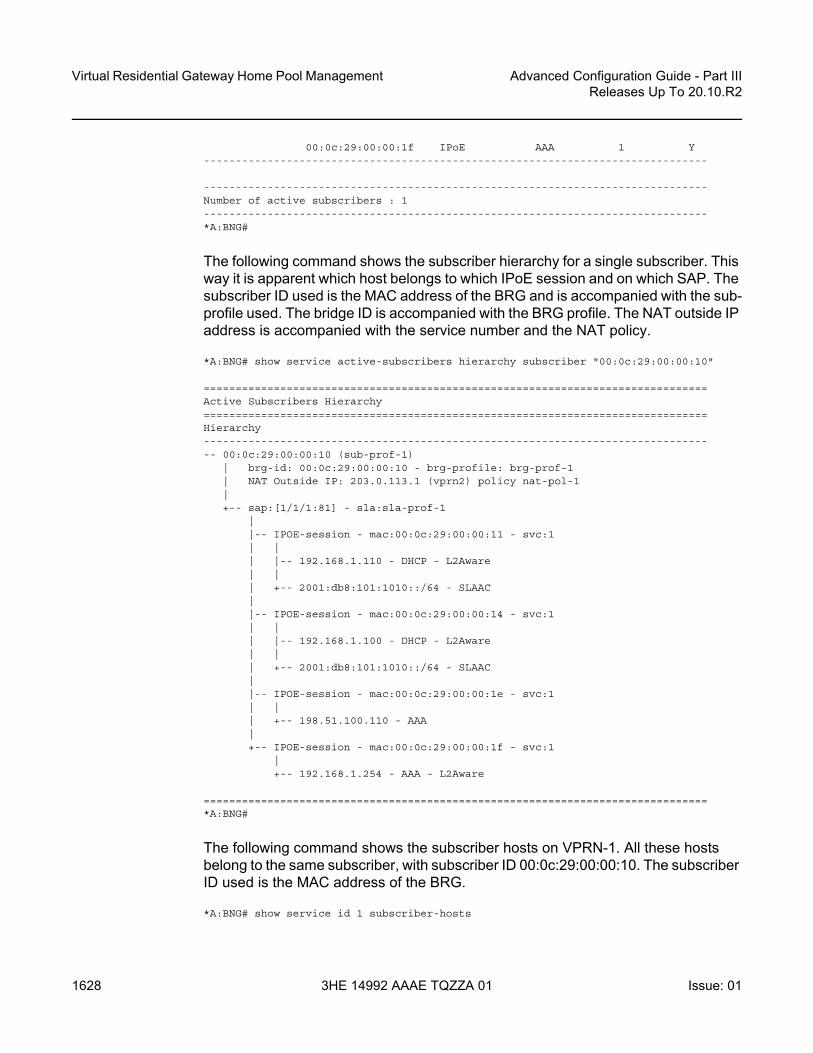
Virtual Residential Gateway Home Pool Management
1628
Advanced Configuration Guide - Part IIIReleases Up To 20.10.R2
3HE 14992 AAAE TQZZA 01 Issue: 01
00:0c:29:00:00:1f IPoE AAA 1 Y-------------------------------------------------------------------------------
-------------------------------------------------------------------------------Number of active subscribers : 1-------------------------------------------------------------------------------*A:BNG#
The following command shows the subscriber hierarchy for a single subscriber. This way it is apparent which host belongs to which IPoE session and on which SAP. The subscriber ID used is the MAC address of the BRG and is accompanied with the sub-profile used. The bridge ID is accompanied with the BRG profile. The NAT outside IP address is accompanied with the service number and the NAT policy.
*A:BNG# show service active-subscribers hierarchy subscriber "00:0c:29:00:00:10"
===============================================================================Active Subscribers Hierarchy===============================================================================Hierarchy--------------------------------------------------------------------------------- 00:0c:29:00:00:10 (sub-prof-1)
| brg-id: 00:0c:29:00:00:10 - brg-profile: brg-prof-1| NAT Outside IP: 203.0.113.1 (vprn2) policy nat-pol-1|+-- sap:[1/1/1:81] - sla:sla-prof-1
||-- IPOE-session - mac:00:0c:29:00:00:11 - svc:1| || |-- 192.168.1.110 - DHCP - L2Aware| || +-- 2001:db8:101:1010::/64 - SLAAC||-- IPOE-session - mac:00:0c:29:00:00:14 - svc:1| || |-- 192.168.1.100 - DHCP - L2Aware| || +-- 2001:db8:101:1010::/64 - SLAAC||-- IPOE-session - mac:00:0c:29:00:00:1e - svc:1| || +-- 198.51.100.110 - AAA|+-- IPOE-session - mac:00:0c:29:00:00:1f - svc:1
|+-- 192.168.1.254 - AAA - L2Aware
===============================================================================*A:BNG#
The following command shows the subscriber hosts on VPRN-1. All these hosts belong to the same subscriber, with subscriber ID 00:0c:29:00:00:10. The subscriber ID used is the MAC address of the BRG.
*A:BNG# show service id 1 subscriber-hosts

Advanced Configuration Guide - Part III Releases Up To 20.10.R2
Virtual Residential Gateway Home Pool Management
Issue: 01 3HE 14992 AAAE TQZZA 01 1629
=============================================================Subscriber Host table=============================================================Sap Subscriber
IP AddressMAC Address PPPoE-SID Origin Fwding State
-------------------------------------------------------------[1/1/1:81] 00:0c:29:00:00:10
192.168.1.10000:0c:29:00:00:14 N/A DHCP Fwding
[1/1/1:81] 00:0c:29:00:00:10192.168.1.110
00:0c:29:00:00:11 N/A DHCP Fwding[1/1/1:81] 00:0c:29:00:00:10
192.168.1.25400:0c:29:00:00:1f N/A AAA Fwding
[1/1/1:81] 00:0c:29:00:00:10198.51.100.110
00:0c:29:00:00:1e N/A AAA Fwding[1/1/1:81] 00:0c:29:00:00:10
2001:db8:101:1010::/6400:0c:29:00:00:11 N/A IPoE-SLAAC Fwding
[1/1/1:81] 00:0c:29:00:00:102001:db8:101:1010::/64
00:0c:29:00:00:14 N/A IPoE-SLAAC Fwding-------------------------------------------------------------Number of subscriber hosts : 6=============================================================*A:BNG#
The DHCP lease state table on VRPN-1 can then be shown with the following command. These addresses are taken from the Alc-Home-Aware-Pool as defined by the RADIUS server. The 192.168.1.110 address is a sticky address returned in the Alc-Reserved-Addresses attribute. Obviously, no entries appear for the static hosts.
*A:BNG# show service id 1 dhcp lease-state
===============================================================================DHCP lease state table, service 1===============================================================================IP Address Mac Address Sap/Sdp Id Remaining Lease MC
LeaseTime Origin Stdby-------------------------------------------------------------------------------192.168.1.100 00:0c:29:00:00:14 [1/1/1:81] 03h11m20s Radius192.168.1.110 00:0c:29:00:00:11 [1/1/1:81] 03h11m18s Radius-------------------------------------------------------------------------------Number of lease states : 2===============================================================================*A:BNG#
Because a public static IP address is returned by the RADIUS server when authenticating the BRG, a ‘static’ BRG host was created, and the routing table is adjusted accordingly.
*A:BNG# show router 1 route-table

Virtual Residential Gateway Home Pool Management
1630
Advanced Configuration Guide - Part IIIReleases Up To 20.10.R2
3HE 14992 AAAE TQZZA 01 Issue: 01
===============================================================================Route Table (Service: 1)===============================================================================Dest Prefix[Flags] Type Proto Age Pref
Next Hop[Interface Name] Metric-------------------------------------------------------------------------------10.11.11.1/32 Local Local 11h48m56s 0
int-DHCP 0192.168.1.0/24 Local Local 11h48m56s 0
sub-int-1 0198.51.100.0/24 Local Local 11h48m56s 0
sub-int-1 0198.51.100.110/32 Remote Sub Mgmt 11h48m41s 0
[grp-int-1-1] 0-------------------------------------------------------------------------------No. of Routes: 4Flags: n = Number of times nexthop is repeated
B = BGP backup route availableL = LFA nexthop availableS = Sticky ECMP requested
===============================================================================*A:BNG#
The following command shows the corresponding L2-aware hosts. Only three L2-aware hosts are created, using private IP addresses on the ‘inside’, and public address on the ‘outside’. Traffic for these hosts passes through the ISA. Traffic for the static public address (10.0.10.110) does not undergo NAT and does not pass through the ISA.
*A:BNG# show service nat l2-aware-hosts
===============================================================================Layer-2-Aware NAT hosts===============================================================================Subscriber : 00:0c:29:00:00:10Inside IP address : 192.168.1.100-------------------------------------------------------------------------------Policy : nat-pol-1Outside router : 2Outside IP address : 203.0.113.1
Subscriber : 00:0c:29:00:00:10Inside IP address : 192.168.1.110-------------------------------------------------------------------------------Policy : nat-pol-1Outside router : 2Outside IP address : 203.0.113.1
Subscriber : 00:0c:29:00:00:10Inside IP address : 192.168.1.254-------------------------------------------------------------------------------Policy : nat-pol-1Outside router : 2Outside IP address : 203.0.113.1
-------------------------------------------------------------------------------No. of hosts: 3

Advanced Configuration Guide - Part III Releases Up To 20.10.R2
Virtual Residential Gateway Home Pool Management
Issue: 01 3HE 14992 AAAE TQZZA 01 1631
===============================================================================*A:BNG#
The following command shows the corresponding IPoE sessions. There is one session per device/MAC-address, so there are four IPoE sessions for this subscriber.
*A:BNG# show service id 1 ipoe session
===============================================================================IPoE sessions for svc-id 1===============================================================================Sap Id Mac Address Up Time MC-Stdby
Subscriber-Id[CircuitID] | [RemoteID]
-------------------------------------------------------------------------------[1/1/1:81] 00:0c:29:00:00:11 0d 11:48:42
00:0c:29:00:00:10[1/1/1:81] 00:0c:29:00:00:14 0d 11:48:40
00:0c:29:00:00:10[1/1/1:81] 00:0c:29:00:00:1e 0d 11:48:42
00:0c:29:00:00:10[1/1/1:81] 00:0c:29:00:00:1f 0d 11:48:42
00:0c:29:00:00:10-------------------------------------------------------------------------------CID | RID displayed when included in session-keyNumber of sessions : 4===============================================================================*A:BNG#
With this single subscriber connected, the following command shows the managed hosts that are created.
*A:BNG# show service id 1 managed-hosts type aaa
===============================================================================Managed aaa hosts===============================================================================IP address MAC address-------------------------------------------------------------------------------192.168.1.254/32 00:0c:29:00:00:1f198.51.100.110/32 00:0c:29:00:00:1e-------------------------------------------------------------------------------No. of Managed hosts: 2===============================================================================*A:BNG#

Virtual Residential Gateway Home Pool Management
1632
Advanced Configuration Guide - Part IIIReleases Up To 20.10.R2
3HE 14992 AAAE TQZZA 01 Issue: 01
Conclusion
Using a BRG in the home network instead of a full-fledged L3 RGW offers network operators a view on the IP addresses and MAC addresses used by home devices, enabling them to provide per-device service offerings. Integrating BRGs in their networks can help the operators to optimize the revenue stream.

Advanced Configuration Guide - Part III Releases Up To 20.10.R2
WiFi Aggregation and Offload — Basic Open SSID
Issue: 01 3HE 14992 AAAE TQZZA 01 1633
WiFi Aggregation and Offload — Basic Open SSIDThis chapter provides information about WiFi Aggregation and Offload — Basic Open SSID.
Topics in this chapter include:
• Applicability• Overview• Configuration• Conclusion
Applicability
The information and configuration in this chapter are based on SR OS release 12.0.R5.
Overview
WiFi Aggregation and Offload functionality for the 7750 SR is supported on SR OS 10.0.R3 or later. The functionality includes a RADIUS proxy server with a RADIUS proxy cache and support for soft-GRE tunnels.
WLAN-GW subscribers are implemented using Enhanced Subscriber Management (ESM) on the Control Processing Module (CPM), to benefit from the extensive ESM features available on the 7750 SR platform. Many different WiFi Offload configurations are possible, with the two most versatile configurations being open and secure Service Set Identifier (SSID).
This configuration should be used as a starting point for operators who need to offer an open SSID, where any client can connect to an Access Point (AP) and obtain an IP address without authentication. In most cases, operators want users to go through an authentication process before allowing full Internet access using the open SSID; therefore, this configuration also includes a web portal.

WiFi Aggregation and Offload — Basic Open SSID
1634
Advanced Configuration Guide - Part IIIReleases Up To 20.10.R2
3HE 14992 AAAE TQZZA 01 Issue: 01
IP address assignment and Internet connectivity can be achieved using various methods in SR OS. In this configuration, a local DHCP server provides IP addresses to the User Equipment (UE) and routing to the Internet is performed using Global Routing Table (GRT) leaking.
Several considerations typically affect the choice of a WiFi Offload solution:
• Access can be free or paid. • Equipment can be preconfigured or users can bring their own WiFi device.
When there is no pre-existing subscription, an open SSID is the most obvious solution. To provide a paywall or to have the user acknowledge certain terms of use due to legal reasons, a web portal may also be required.
When a web portal is implemented, users who connect to the open SSID which are not yet authenticated have all their web traffic redirected to the web portal landing page. This is performed using an http-redirect filter applied to the initial (limited) Service Level Agreement (SLA) profile assigned to the UE. Typically, the operating system of the UE will detect the presence of the web portal and automatically open the login page for the user. When the user logs in, the web portal sends a RADIUS Change of Authorization (CoA) request to the WLAN-GW, changing the SLA profile to one that does not contain an http-redirect filter.
Besides authentication, a major consideration is the method used to achieve Internet connectivity. Will the users require public addresses or are private addresses sufficient? In case few public IP addresses are available, private IP addresses can be assigned to UEs and the WLAN-GW can perform a Network Address Translation (NAT) function. If public routable IP addresses can be made available to all UEs, traffic from the UEs can be routed by the WLAN-GW to the Internet.
When a UE connects to an open SSID (as shown in Figure 257), typically the UE attempts to obtain an IP address using Dynamic Host Configuration Protocol (DHCP). The WLAN-GW can serve as a DHCP relay or proxy and may obtain the IP address from an external source, or use a local DHCP server function. A DHCP Discover or Request packet from a UE will trigger a form of authentication where the WLAN-GW requests information about the UE, such as SLA profile or DHCP local pool name. This authentication is separate from the web portal authentication and occurs immediately when a UE connects.
In summary:
• DHCP Discover triggering RADIUS authentication• DHCP completes and UE has SLA profile with limited access• UE logs into a web portal

Advanced Configuration Guide - Part III Releases Up To 20.10.R2
WiFi Aggregation and Offload — Basic Open SSID
Issue: 01 3HE 14992 AAAE TQZZA 01 1635
• Successful login causes the portal to send a RADIUS CoA which assigns an SLA profile with full access
Figure 257 Call Flow for Open SSID
al_0831
APUE WLAN GW Portal InternetAAA
UE is Connected
DHCP Discover (chaddr=UE-MAC) GRE (DHCP Discover (chaddr=UE-MAC)
GRE (DHCP Offer (chaddr=UE-MAC, your-ip=UE-IP,Subnet-Mask, Router=WLAN-GW-IP, Lease-Time))
RADIUSAccess-Request
(NAS-ID)
RADIUSAccess-Accept (Sub-ID,Sub-Profile, SLA-Profile,
Framed-IP-Address, Framed-IP-Netmask)
DHCP Offer (chaddr=UE-MAC,your-ip=UE-IP, Subnet-Mask,
Router=WLAN-GW-IP, Lease-Time)
GRE (DHCP Ack (chaddr=UE-MAC, your-ip=UE-IP,Subnet-Mask, Router=WLAN-GW-IP, Lease-Time))
DHCP Ack (chaddr=UE-MAC,your-ip=UE-IP, Subnet-Mask,
Router=WLAN-GW-IP, Lease-Time)
GRE (DHCP Request (chaddr=UE-MAC, Requested-IP-Address=UE-IP)
DHCP Request (chaddr=UE-MAC,Requested-IP-Address=UE-IP)
GRE (HTTP GET (Internet URL))HTTP GET (Internet URL)
GRE (HTTP Redirect/302 (Portal URL))
HTTP GET (Portal URL)
HTTP GET (Internet URL)
Portal authentication
RADIUS CoA(SLA-Profile)
HTTP Redirect/302 (Portal URL)
Disconnect
ESM subscibercreated on CPM
SLA-Profileupdated, redirect
filter removed

WiFi Aggregation and Offload — Basic Open SSID
1636
Advanced Configuration Guide - Part IIIReleases Up To 20.10.R2
3HE 14992 AAAE TQZZA 01 Issue: 01
The SR OS is flexible in allowing the operator to separate the various WiFi Offload functions between different routing instances. All functions can be configured in the same routing instance, or as shown in Figure 258, the connectivity to the APs (and soft-GRE tunnels) can be provided in one Virtual Private Routed Network (VPRN), the users can be instantiated in another VPRN, and Authentication, Authorization and Accounting (AAA) access can be provided in yet another routing instance (in this case, the Base router). This clear separation of functions can enhance security; for example, by separating user traffic from authentication traffic.
Configuration
The WiFi offload scenario shown in Figure 258 has following characteristics:
• Open SSID with web portal authentication• Local breakout to Internet using GRT leaking, routing through Base routing
instance• Same private IP address assigned to all UEs, with L2-aware NAT• AP access in VPRN 1000• UEs terminated in VPRN 2005• Local DHCP server assigning public IP addresses
Figure 258 WiFi Offload Scenario with Open SSID and Local DHCP Server
al_0832
GRTLeak
UE10.165.5.2
AP10.1.3.10
WLAN-GW10.10.10.165
VPRN1000
VPRN2005
Base
RADIUS/Portal
10.43.186.2
DNS Server10.43.186.43
WiFi-165-5
Interface to AP: 10.1.2.1/24
DHCP local pool:10.165.5.0/25DHCP Server addr: 10.0.0.1Soft-gre gw-address: 192.5.5.5

Advanced Configuration Guide - Part III Releases Up To 20.10.R2
WiFi Aggregation and Offload — Basic Open SSID
Issue: 01 3HE 14992 AAAE TQZZA 01 1637
WLAN-GW
Note that the uplink interface, Interior Gateway Protocol (IGP), and system configuration is outside the scope of this document.
The following card and Media Dependent Adapter (MDA) configuration shows only the WLAN-Input/Output Module (IOM). An IOM3-XP-B containing two Multi-Service Integrated Service Adapter (MS-ISA) cards provides the WLAN-GW functionality. The MDA type for the ISA cards is isa-bb, the same type that is used for NAT.
*A:WLAN-GW# /configure card 2*A:WLAN-GW>config>card# info----------------------------------------------
card-type iom3-xp-bmda 1
mda-type isa-bbno shutdown
exitmda 2
mda-type isa-bbno shutdown
exitno shutdown
----------------------------------------------
The following ISA configuration defines a wlan-gw-group referencing the IOM in slot two which hosts the two MS-ISA cards and providing the WLAN-GW functions.
A:WLAN-GW# /configure isaA:WLAN-GW>config>isa# info----------------------------------------------
wlan-gw-group 1 createactive-iom-limit 1iom 2no shutdown
exit----------------------------------------------
The following is a RADIUS server configuration, where the secret must match the secret configured on the external RADIUS server. The accept-coa option must be configured to allow the change of SLA profile by the web portal using a CoA request.
*A:WLAN-GW# /configure router radius-server*A:WLAN-GW>config>router>radius-server# info----------------------------------------------
server "Server2" address 10.43.186.2 secret "zmLYVgt8UOLypJamceNSSHDWbZproq7Y" hash2 create
accept-coaexit
----------------------------------------------

WiFi Aggregation and Offload — Basic Open SSID
1638
Advanced Configuration Guide - Part IIIReleases Up To 20.10.R2
3HE 14992 AAAE TQZZA 01 Issue: 01
The following AAA configuration contains a RADIUS server policy used in the authentication policy. The source address must match the IP address configured for this client on the RADIUS server.
*A:WLAN-GW# /configure aaa*A:WLAN-GW>config>aaa# info----------------------------------------------
radius-server-policy "RS_5" createservers
router "Base"source-address 10.10.10.165server 1 name "Server2"
exitexit
----------------------------------------------
The following policy configuration is used for exporting routes so that they are reachable by the public network. These policies are used for exporting UE routes in subsequent configuration sections.
*A:WLAN-GW# /configure router policy-options*A:WLAN-GW>config>router>policy-options# info----------------------------------------------
prefix-list "WiFi-clients"prefix 10.165.0.0/16 longer
exitpolicy-statement "WiFi-clients"
entry 10from
prefix-list "WiFi-clients"exitaction acceptexit
exitexit
----------------------------------------------
The uplink network configuration is outside the scope of this document. However, note that the IGP (here ISIS) must be aware of the UE addresses so that they are accessible from the Internet.
*A:WLAN-GW# /configure router isis*A:WLAN-GW>config>router>isis# info----------------------------------------------
export "WiFi-clients"----------------------------------------------
The following IP filter redirects all HTTP traffic to the web portal. The filter should also allow DNS and potentially other traffic, so the entry that allows TCP port 80 traffic to the web portal address must be placed before the entry that redirects all traffic to that portal; otherwise, there will be a redirect loop.

Advanced Configuration Guide - Part III Releases Up To 20.10.R2
WiFi Aggregation and Offload — Basic Open SSID
Issue: 01 3HE 14992 AAAE TQZZA 01 1639
The HTTP redirect URL also includes a parameter that provides the MAC address of the UE to the web portal. In this configuration, either $MAC or $SUB can be used since both variables contain the MAC address of the UE. The web portal can reply with a CoA request specifying this particular UE MAC as the Subscriber ID after successful login. The URL also returns the IP address of the WLAN-GW to the web portal, so that the portal knows which WLAN-GW to send the CoA request to.
*A:WLAN-GW# /configure filter*A:WLAN-GW>config>filter# info----------------------------------------------
ip-filter 2005 createdefault-action forwardentry 70 create
match protocol udpdst-port eq 53
exitaction forward
exitentry 80 create
match protocol icmpexitaction forward
exitentry 90 create
match protocol tcpdst-ip 10.43.186.2/32dst-port eq 80
exitaction forward
exitentry 100 create
match protocol tcpdst-port eq 80
exitaction http-redirect "http://portal2.3ls.net/portal-no-
login.php?gw=10.10.10.165&mac=$SUB"exit
exit
The following is a subscriber management configuration, with the RADIUS authentication policy used to authenticate DHCP requests, including the accept-authorization-change option to allow for SLA profile change after portal authentication. This DHCP authentication request also sends the NAS ID attribute that allows the RADIUS server to match on the configuration for this particular SSID. All UEs will be authenticated with their MAC address as user name, and alcatel as their password (any DHCP request will result in a successful authentication).
Two SLA profiles are required: profile SLAP_5_portal is initially used for each UE and refers to the portal redirect filter, while profile SLAP is applied using a CoA request after the user successfully authenticates on the web portal. A subscriber identity policy is also required.

WiFi Aggregation and Offload — Basic Open SSID
1640
Advanced Configuration Guide - Part IIIReleases Up To 20.10.R2
3HE 14992 AAAE TQZZA 01 Issue: 01
configure subscriber-mgmtauthentication-policy "WiFi-165-5-auth-policy" create
password alcatelaccept-authorization-changeinclude-radius-attribute
nas-identifierexitradius-server-policy "RS_5"
exitsla-profile "SLAP" createexitsla-profile "SLAP_5_portal" create
ingressip-filter 2005
exitexitsub-profile "SUBP" createexitsub-ident-policy "SIP" create
sub-profile-mapuse-direct-map-as-default
exitsla-profile-map
use-direct-map-as-defaultexit
exit
The following VPRN 1000 configuration contains the interface to the AP, and has GRT lookup with export-grt configured to allow APs to be managed from the Base routing instance.
*A:WLAN-GW# /configure service vprn 1000*A:WLAN-GW>config>service>vprn# info----------------------------------------------
route-distinguisher 65400:1000interface "toAP3" create
address 10.1.3.1/24sap 1/1/10 createexit
exitgrt-lookup
enable-grtstatic-route 0.0.0.0/0 grt
exitexport-grt "WiFi-APs"
exitno shutdown
----------------------------------------------
VPRN 2005 is used for UE termination and contains:
• A local DHCP server with a single pool of addresses that are assigned to UEs.• A loopback interface used by the DHCP server.• A subscriber interface and group interface of type wlangw (called softgre prior
to release 12.0).

Advanced Configuration Guide - Part III Releases Up To 20.10.R2
WiFi Aggregation and Offload — Basic Open SSID
Issue: 01 3HE 14992 AAAE TQZZA 01 1641
• Subscriber parameters.• The authentication policy, which will run each time a UE requests a DHCP
address.• The host-connectivity-verify function, which periodically checks the presence of
UEs and quickly removes disconnected UEs even before their DHCP lease expires; the WLAN-GW has no other way of knowing when a UE has disconnected from the AP.
• The wlan-gw CLI-node (called soft-gre prior to release 12.0), including the wlan-gw GRE tunnel end-point address,and the routing instance where AP traffic is terminated, the ISA WLAN-GW group, and mobility parameters, which allow the UE state to be kept if the UE moves between two APs broadcasting the same SSID.
• GRT lookup with export-grt configured to allow UE traffic to be routed to the Internet.
*A:WLAN-GW# /configure service vprn 2005*A:WLAN-GW>config>service>vprn# info----------------------------------------------
description "WiFi-165-5 Open SSID"dhcp
local-dhcp-server "local_dhcp_2005" createuse-pool-from-clientpool "pool1" create
max-lease-time hrs 1options
dns-server 10.43.186.43exitsubnet 10.165.5.0/25 create
optionssubnet-mask 255.255.255.128default-router 10.165.5.1
exitaddress-range 10.165.5.2 10.165.5.99
exitexitno shutdown
exitexitroute-distinguisher 65400:2005interface "dhcp-server" create
address 10.0.0.1/24local-dhcp-server "local_dhcp_2005"loopback
exitsubscriber-interface "SI5" create
address 10.165.5.1/24group-interface "GI5" wlangw create
sap-parameterssub-sla-mgmt
def-sla-profile "SLAP_5_portal"def-sub-profile "SUBP"sub-ident-policy "SIP"
exitexit

WiFi Aggregation and Offload — Basic Open SSID
1642
Advanced Configuration Guide - Part IIIReleases Up To 20.10.R2
3HE 14992 AAAE TQZZA 01 Issue: 01
dhcpoption
action replacecircuit-idno remote-idvendor-specific-option
pool-nameexit
exitserver 10.0.0.1trustedlease-populate 10000gi-address 10.165.5.1no shutdown
exitauthentication-policy "WiFi-165-5-auth-policy"host-connectivity-verify interval 5 action removewlan-gw
gw-address 192.5.5.5mobility
trigger data iappexitrouter 1000wlan-gw-group 1no shutdown
exitexit
exitgrt-lookup
enable-grtexitexport-grt "WiFi-clients"
exitno shutdown
Freeradius
This simple default configuration section matches on any host. During the DHCP authentication phase, RADIUS returns the DHCP pool name pool1 informing the WLAN-GW DHCP server which pool to assign the UE IP address from:
/etc/freeradius/usersDEFAULT Auth-Type := Local, User-Password := "alcatel", user-name=~""
Alc-Subsc-ID-Str = "%{User-Name}",Framed-Pool = "pool1",
In /etc/freeradius/clients.conf, the secret must match the secret configured in the WLAN-GW RADIUS server configuration.
client 10.10.10.165 {secret = alcatelshortname = WLAN-GW
}

Advanced Configuration Guide - Part III Releases Up To 20.10.R2
WiFi Aggregation and Offload — Basic Open SSID
Issue: 01 3HE 14992 AAAE TQZZA 01 1643
The RADIUS CoA sent during successful portal login allows this UE full access, by applying SLA profile SLAP which does not have an http-redirect filter.
echo "ALC-Subsc-Id-Str='68:7f:74:8b:3d:d7',ALC-Subsc-Prof-Str='SUBP_5',ALC-SLA-Prof-Str='.SLAP',Alc-Primary-Dns = '10.43.186.43'" | /usr/bin/radclient -x -r 1 -t 2 '10.10.10.165' coa 'alcatel'
Access Points
At a minimum, the following must be configured on the Access Point:
• IP address 10.1.3.10/24• Default route to 10.1.3.1• Open SSID WiFi-165-5 mapped to VLAN 50• Soft-GRE tunnel with destination 192.5.5.5, with VLAN 50 mapped to this tunnel
Show Commands
The following show commands reflect the status of the router after the UE has connected and obtained an IP address using DHCP.
The following output displays the UEs presently connected.
*A:WLAN-GW# show subscriber-mgmt wlan-gw ue===============================================================================User Equipments===============================================================================MAC address : 68:7f:74:8b:3d:d7-------------------------------------------------------------------------------VLAN Q-tag : 50MPLS label : (Not Specified)Tunnel router : 1000Tunnel remote IP address : 10.1.3.10Tunnel local IP address : 192.5.5.5Retail service : N/ASSID : (Not Specified)Previous Access Point IP : (Not Specified)IMSI : (Not Specified)Last move time : 2014/09/22 10:47:58
-------------------------------------------------------------------------------No. of UE: 1===============================================================================
The DHCP lease information indicates that the address was assigned by the local DHCP server.

WiFi Aggregation and Offload — Basic Open SSID
1644
Advanced Configuration Guide - Part IIIReleases Up To 20.10.R2
3HE 14992 AAAE TQZZA 01 Issue: 01
*A:WLAN-GW# show service id 2005 dhcp lease-state===============================================================================DHCP lease state table, service 2005===============================================================================IP Address Mac Address Sap/Sdp Id Remaining Lease MC
LeaseTime Origin Stdby-------------------------------------------------------------------------------10.165.5.2 68:7f:74:8b:3d:d7 [2/1/nat-out-ip:20* 00h59m27s DHCP-------------------------------------------------------------------------------Number of lease states : 1===============================================================================* indicates that the corresponding row element may have been truncated.
DHCP statistics can be displayed using following command.
*A:WLAN-GW# show service id 2005 dhcp statistics====================================================================DHCP Global Statistics, service 2005====================================================================Rx Packets : 2Tx Packets : 2Rx Malformed Packets : 0Rx Untrusted Packets : 0Client Packets Discarded : 0Client Packets Relayed : 2Client Packets Snooped : 0Client Packets Proxied (RADIUS) : 0Client Packets Proxied (User-Db) : 0Client Packets Proxied (Lease-Split) : 0Server Packets Discarded : 0Server Packets Relayed : 2Server Packets Snooped : 0DHCP RELEASEs Spoofed : 0DHCP FORCERENEWs Spoofed : 0====================================================================
The route table for the routing instance where UEs are terminated shows an entry for the UE.
*A:WLAN-GW# show router 2005 route-table===============================================================================Route Table (Service: 2005)===============================================================================Dest Prefix[Flags] Type Proto Age Pref
Next Hop[Interface Name] Metric-------------------------------------------------------------------------------10.0.0.0/24 Local Local 00h32m12s 0
dhcp-server 010.165.5.0/24 Local Local 00h27m20s 0
SI5 010.165.5.2/32 Remote Sub Mgmt 00h00m33s 0
[GI5] 0-------------------------------------------------------------------------------No. of Routes: 3Flags: n = Number of times nexthop is repeated
B = BGP backup route availableL = LFA nexthop available

Advanced Configuration Guide - Part III Releases Up To 20.10.R2
WiFi Aggregation and Offload — Basic Open SSID
Issue: 01 3HE 14992 AAAE TQZZA 01 1645
S = Sticky ECMP requested===============================================================================
The active subscribers view shows the initial limited SLA profile SLAP_5_portal before the user has logged in to the portal.
*A:WLAN-GW>config>service>vprn# show service active-subscribers===============================================================================Active Subscribers===============================================================================-------------------------------------------------------------------------------Subscriber 68:7f:74:8b:3d:d7 (SUBP)--------------------------------------------------------------------------------------------------------------------------------------------------------------(1) SLA Profile Instance sap:[2/1/nat-out-ip:2049.3] - sla:SLAP_5_portal-------------------------------------------------------------------------------IP Address
MAC Address PPPoE-SID Origin--------------------------------------------------------10.165.5.2
68:7f:74:8b:3d:d7 N/A DHCP
-------------------------------------------------------------------------------Number of active subscribers : 1-------------------------------------------------------------------------------
The following output shows the active subscribers view after the user has logged in and the SLA profile has been updated with the unrestricted SLA profile SLAP.
*A:WLAN-GW# show service active-subscribers===============================================================================Active Subscribers===============================================================================-------------------------------------------------------------------------------Subscriber 68:7f:74:8b:3d:d7 (SUBP_5)--------------------------------------------------------------------------------------------------------------------------------------------------------------(1) SLA Profile Instance sap:[2/1/nat-out-ip:2049.3] - sla:SLAP-------------------------------------------------------------------------------IP Address
MAC Address PPPoE-SID Origin--------------------------------------------------------10.165.5.2
68:7f:74:8b:3d:d7 N/A DHCP
-------------------------------------------------------------------------------Number of active subscribers : 1-------------------------------------------------------------------------------
The following output shows the RADIUS statistics for the DHCP authentication.
*A:WLAN-GW# show aaa radius-server-policy "RS_5" statistics
===============================================================================RADIUS server policy "RS_5" statistics===============================================================================

WiFi Aggregation and Offload — Basic Open SSID
1646
Advanced Configuration Guide - Part IIIReleases Up To 20.10.R2
3HE 14992 AAAE TQZZA 01 Issue: 01
Tx transaction requests : 1Rx transaction responses : 1Transaction requests timed out : 0Transaction requests send failed : 0Packet retries : 0Transaction requests send rejected : 0Authentication requests failed : 0Accounting requests failed : 0Ratio of access-reject over auth responses : 0%Transaction success ratio : 100%Transaction failure ratio : 0%Statistics last reset at : n/a
Server 1 "Server2" address 10.43.186.2 auth-port 1812 acct-port 1813-------------------------------------------------------------------------------Tx request packets : 1Rx response packets : 1Request packets timed out : 0Request packets send failed : 0Request packets send failed (overload) : 0Request packets waiting for reply : 0Response packets with invalid authenticator : 0Response packets with invalid msg authenticator : 0Authentication packets failed : 0Accounting packets failed : 0Avg auth response delay (10 100 1K 10K) in ms : 7.24 7.24 7.24 7.24Avg acct response delay (10 100 1K 10K) in ms : n/aStatistics last reset at : n/a
===============================================================================
The following output shows the CoA statistics after portal authentication.
*A:WLAN-GW# show subscriber-mgmt authentication coa-statistics===============================================================================Radius Notify Statistics Change-Of-Authorization Disconnect-Messages===============================================================================Requests Received 1 0Requests Accepted 1 0Requests Rejected 0 0Requests Dropped 0 0
No Auth Policy found 0 0Invalid message 0 0Out of resources 0 0Authentication failure 0 0
===============================================================================
Debug
The following is a complete debug of a UE connecting and logging in to the portal. Shortly after logging in, the UE disconnects from the SSID and the subscriber is removed by host-connectivity-verify.

Advanced Configuration Guide - Part III Releases Up To 20.10.R2
WiFi Aggregation and Offload — Basic Open SSID
Issue: 01 3HE 14992 AAAE TQZZA 01 1647
The following debug configuration applies:
debugrouter "Base"
radiuspacket-type authentication accounting coadetail-level medium
exitexitrouter "2005"
ipdhcp
detail-level mediummode egr-ingr-and-dropped
exitexitlocal-dhcp-server "local_dhcp_2005"
detail-level mediummode dropped-only
exitexitservice
id 2005host-connectivity-verify
mac 68:7f:74:8b:3d:d7exit
exitexit
exit
The WLAN-GW is notified of the UE after receiving the first DHCP packet.
1 2014/09/22 10:47:58.46 EDT MINOR: DEBUG #2001 vprn2005 PIP"PIP: DHCPinstance 5 (2005), interface index 3 (GI5),
received DHCP Boot Request on Interface GI5 (2/1/nat-out-ip:2049.3) Port 67
H/W Type: Ethernet(10Mb) H/W Address Length: 6ciaddr: 0.0.0.0 yiaddr: 0.0.0.0siaddr: 0.0.0.0 giaddr: 0.0.0.0chaddr: 68:7f:74:8b:3d:d7 xid: 0x8c0fc642
DHCP options:[53] Message type: Discover[61] Client id: (hex) 01 68 7f 74 8b 3d d7[50] Requested IP addr: 10.165.5.2[12] Host name: W81VM[60] Class id: MSFT 5.0[55] Param request list: len = 13
1 Subnet mask15 Domain name3 Router6 Domain name server
44 NETBIOS name server46 NETBIOS type47 NETBIOS scope31 Router discovery33 Static route

WiFi Aggregation and Offload — Basic Open SSID
1648
Advanced Configuration Guide - Part IIIReleases Up To 20.10.R2
3HE 14992 AAAE TQZZA 01 Issue: 01
121 Unknown option249 Unknown option252 Unknown option43 Vendor specific
[255] End"
DHCP triggers sending the RADIUS Access-Request.
2 2014/09/22 10:47:58.48 EDT MINOR: DEBUG #2001 Base RADIUS"RADIUS: Transmit
Access-Request(1) 10.43.186.2:1812 id 1 len 79 vrid 1 pol RS_5USER NAME [1] 17 68:7f:74:8b:3d:d7PASSWORD [2] 16 IyDg9t17sGTbfR/6h0Bs1UNAS IP ADDRESS [4] 4 10.10.10.165NAS IDENTIFIER [32] 14 WLAN-GW
"
The UE authentication request is always accepted and the Access-Accept message contains the required subscriber management and IP parameters, in this case, at least the subscriber ID string as well as the pool name to be used by the local DHCP server.
3 2014/09/22 10:47:58.50 EDT MINOR: DEBUG #2001 Base RADIUS"RADIUS: Receive
Access-Accept(2) id 1 len 52 from 10.43.186.2:1812 vrid 1 pol RS_5VSA [26] 19 Alcatel(6527)
SUBSC ID STR [11] 17 68:7f:74:8b:3d:d7FRAMED POOL [88] 5 pool1
"
The DHCP request is transmitted to the local DHCP server, which assigns the IP address to the UE.
4 2014/09/22 10:47:58.50 EDT MINOR: DEBUG #2001 vprn2005 PIP"PIP: DHCPinstance 5 (2005),
transmitted DHCP Boot Request to 10.0.0.1 Port 67
H/W Type: Ethernet(10Mb) H/W Address Length: 6ciaddr: 0.0.0.0 yiaddr: 0.0.0.0siaddr: 0.0.0.0 giaddr: 10.165.5.1chaddr: 68:7f:74:8b:3d:d7 xid: 0x8c0fc642
DHCP options:[82] Relay agent information: len = 54
[1] Circuit-id: WLAN-GW|2005|GI5|2/1/nat-out-ip:2049.3[9] Vendor-Specific info: len = 12
Enterprise [6527] : len = 7[13] dhcpPool: pool1
[53] Message type: Discover[61] Client id: (hex) 01 68 7f 74 8b 3d d7[50] Requested IP addr: 10.165.5.2[12] Host name: W81VM[60] Class id: MSFT 5.0

Advanced Configuration Guide - Part III Releases Up To 20.10.R2
WiFi Aggregation and Offload — Basic Open SSID
Issue: 01 3HE 14992 AAAE TQZZA 01 1649
[55] Param request list: len = 131 Subnet mask
15 Domain name3 Router6 Domain name server
44 NETBIOS name server46 NETBIOS type47 NETBIOS scope31 Router discovery33 Static route
121 Unknown option249 Unknown option252 Unknown option43 Vendor specific
[255] End"
5 2014/09/22 10:47:58.50 EDT MINOR: DEBUG #2001 vprn2005 PIP"PIP: DHCPinstance 5 (2005),
received DHCP Boot Reply on 10.0.0.1 Port 67
H/W Type: Ethernet(10Mb) H/W Address Length: 6ciaddr: 0.0.0.0 yiaddr: 10.165.5.2siaddr: 10.0.0.1 giaddr: 10.165.5.1chaddr: 68:7f:74:8b:3d:d7 xid: 0x8c0fc642
DHCP options:[82] Relay agent information: len = 54
[1] Circuit-id: WLAN-GW|2005|GI5|2/1/nat-out-ip:2049.3[9] Vendor-Specific info: len = 12
Enterprise [6527] : len = 7[13] dhcpPool: pool1
[53] Message type: Offer[54] DHCP server addr: 10.0.0.1[51] Lease time: 3600[1] Subnet mask: 255.255.255.128[3] Router: 10.165.5.1[6] Domain name server: 10.43.186.43[12] Host name: W81VM[60] Class id: MSFT 5.0[255] End
"
6 2014/09/22 10:47:58.52 EDT MINOR: DEBUG #2001 vprn2005 PIP"PIP: DHCPinstance 5 (2005), interface index 3 (GI5),
transmitted DHCP Boot Reply to Interface GI5 (2/1/nat-out-ip:2049.3) Port 68
H/W Type: Ethernet(10Mb) H/W Address Length: 6ciaddr: 0.0.0.0 yiaddr: 10.165.5.2siaddr: 10.0.0.1 giaddr: 10.165.5.1chaddr: 68:7f:74:8b:3d:d7 xid: 0x8c0fc642
DHCP options:[53] Message type: Offer[54] DHCP server addr: 10.0.0.1[51] Lease time: 3600[1] Subnet mask: 255.255.255.128

WiFi Aggregation and Offload — Basic Open SSID
1650
Advanced Configuration Guide - Part IIIReleases Up To 20.10.R2
3HE 14992 AAAE TQZZA 01 Issue: 01
[3] Router: 10.165.5.1[6] Domain name server: 10.43.186.43[12] Host name: W81VM[60] Class id: MSFT 5.0[255] End
"
7 2014/09/22 10:47:58.69 EDT MINOR: DEBUG #2001 vprn2005 PIP"PIP: DHCPinstance 5 (2005), interface index 3 (GI5),
received DHCP Boot Request on Interface GI5 (2/1/nat-out-ip:2049.3) Port 67
H/W Type: Ethernet(10Mb) H/W Address Length: 6ciaddr: 0.0.0.0 yiaddr: 0.0.0.0siaddr: 0.0.0.0 giaddr: 0.0.0.0chaddr: 68:7f:74:8b:3d:d7 xid: 0x8c0fc642
DHCP options:[53] Message type: Request[61] Client id: (hex) 01 68 7f 74 8b 3d d7[50] Requested IP addr: 10.165.5.2[54] DHCP server addr: 10.0.0.1[12] Host name: W81VM[81] client FQDN: rcode1: 0, rcode2: 0, domain name = (hex) 00 57 38 31 564d[60] Class id: MSFT 5.0[55] Param request list: len = 13
1 Subnet mask15 Domain name3 Router6 Domain name server
44 NETBIOS name server46 NETBIOS type47 NETBIOS scope31 Router discovery33 Static route
121 Unknown option249 Unknown option252 Unknown option43 Vendor specific
[255] End"
8 2014/09/22 10:47:58.69 EDT MINOR: DEBUG #2001 vprn2005 PIP"PIP: DHCPinstance 5 (2005),
transmitted DHCP Boot Request to 10.0.0.1 Port 67
H/W Type: Ethernet(10Mb) H/W Address Length: 6ciaddr: 0.0.0.0 yiaddr: 0.0.0.0siaddr: 0.0.0.0 giaddr: 10.165.5.1chaddr: 68:7f:74:8b:3d:d7 xid: 0x8c0fc642
DHCP options:[82] Relay agent information: len = 54
[1] Circuit-id: WLAN-GW|2005|GI5|2/1/nat-out-ip:2049.3[9] Vendor-Specific info: len = 12
Enterprise [6527] : len = 7[13] dhcpPool: pool1

Advanced Configuration Guide - Part III Releases Up To 20.10.R2
WiFi Aggregation and Offload — Basic Open SSID
Issue: 01 3HE 14992 AAAE TQZZA 01 1651
[53] Message type: Request[61] Client id: (hex) 01 68 7f 74 8b 3d d7[50] Requested IP addr: 10.165.5.2[54] DHCP server addr: 10.0.0.1[12] Host name: W81VM[81] client FQDN: rcode1: 0, rcode2: 0, domain name = (hex) 00 57 38 31 564d[60] Class id: MSFT 5.0[55] Param request list: len = 13
1 Subnet mask15 Domain name3 Router6 Domain name server
44 NETBIOS name server46 NETBIOS type47 NETBIOS scope31 Router discovery33 Static route
121 Unknown option249 Unknown option252 Unknown option43 Vendor specific
[255] End"
9 2014/09/22 10:47:58.69 EDT MINOR: DEBUG #2001 vprn2005 PIP"PIP: DHCPinstance 5 (2005),
received DHCP Boot Reply on 10.0.0.1 Port 67
H/W Type: Ethernet(10Mb) H/W Address Length: 6ciaddr: 0.0.0.0 yiaddr: 10.165.5.2siaddr: 10.0.0.1 giaddr: 10.165.5.1chaddr: 68:7f:74:8b:3d:d7 xid: 0x8c0fc642
DHCP options:[82] Relay agent information: len = 54
[1] Circuit-id: WLAN-GW|2005|GI5|2/1/nat-out-ip:2049.3[9] Vendor-Specific info: len = 12
Enterprise [6527] : len = 7[13] dhcpPool: pool1
[53] Message type: Ack[54] DHCP server addr: 10.0.0.1[51] Lease time: 3600[1] Subnet mask: 255.255.255.128[3] Router: 10.165.5.1[6] Domain name server: 10.43.186.43[12] Host name: W81VM[81] client FQDN: rcode1: 0, rcode2: 0, domain name = (hex) 00 57 38 31 564d[60] Class id: MSFT 5.0[255] End
"
10 2014/09/22 10:47:58.69 EDT MINOR: DEBUG #2001 vprn2005 PIP"PIP: DHCPinstance 5 (2005), interface index 3 (GI5),
transmitted DHCP Boot Reply to Interface GI5 (2/1/nat-out-ip:2049.3) Port 68

WiFi Aggregation and Offload — Basic Open SSID
1652
Advanced Configuration Guide - Part IIIReleases Up To 20.10.R2
3HE 14992 AAAE TQZZA 01 Issue: 01
H/W Type: Ethernet(10Mb) H/W Address Length: 6ciaddr: 0.0.0.0 yiaddr: 10.165.5.2siaddr: 10.0.0.1 giaddr: 10.165.5.1chaddr: 68:7f:74:8b:3d:d7 xid: 0x8c0fc642
DHCP options:[53] Message type: Ack[54] DHCP server addr: 10.0.0.1[51] Lease time: 3600[1] Subnet mask: 255.255.255.128[3] Router: 10.165.5.1[6] Domain name server: 10.43.186.43[12] Host name: W81VM[81] client FQDN: rcode1: 0, rcode2: 0, domain name = (hex) 00 57 38 31 564d[60] Class id: MSFT 5.0[255] End
"
At this point in the configuration, the UE has network connectivity but all HTTP traffic is redirected to the web portal, as configured in the IP filter included in the initial SLA profile.
After web portal authentication, the WLAN-GW receives a RADIUS CoA for this subscriber, which includes the new unrestricted SLA profile SLAP.
11 2014/09/22 10:48:12.54 EDT MINOR: DEBUG #2001 Base RADIUS"RADIUS: Receive
Change of Authorization(43) id 162 len 71 from 10.43.186.2:55255 vrid 1VSA [26] 19 Alcatel(6527)
SUBSC ID STR [11] 17 68:7f:74:8b:3d:d7VSA [26] 8 Alcatel(6527)
SUBSC PROF STR [12] 6 SUBP_5VSA [26] 6 Alcatel(6527)
SLA PROF STR [13] 4 SLAP"
12 2014/09/22 10:48:12.54 EDT MINOR: DEBUG #2001 Base RADIUS"RADIUS: Transmit
Change of Authorization Ack(44) 10.43.186.2:55255 id 162 len 20 vrid 1"
The host has accessed a few web sites, then disconnected from the SSID, which is not known by the WLAN-GW. After 5 minutes of inactivity, host-connectivity-verify removes the subscriber and the DHCP lease is cleared.
13 2014/09/22 10:48:58.90 EDT MINOR: DEBUG #2001 vprn2005 SHCV"SHCV: Periodic Check
2/1/nat-out-ip:2049.3DHCP lease state 10.165.5.2 68:7f:74:8b:3d:d7"
14 2014/09/22 10:49:08.90 EDT MINOR: DEBUG #2001 vprn2005 SHCV"SHCV: Periodic Check
2/1/nat-out-ip:2049.3DHCP lease state 10.165.5.2 68:7f:74:8b:3d:d7"

Advanced Configuration Guide - Part III Releases Up To 20.10.R2
WiFi Aggregation and Offload — Basic Open SSID
Issue: 01 3HE 14992 AAAE TQZZA 01 1653
15 2014/09/22 10:49:18.90 EDT MINOR: DEBUG #2001 vprn2005 SHCV"SHCV: Periodic Check
2/1/nat-out-ip:2049.3DHCP lease state 10.165.5.2 68:7f:74:8b:3d:d7"
16 2014/09/22 10:49:28.90 EDT MINOR: DEBUG #2001 vprn2005 SHCV"SHCV: Connectivity Lost
2/1/nat-out-ip:2049.3DHCP lease state 10.165.5.2 68:7f:74:8b:3d:d7"
17 2014/09/22 10:49:30.00 EDT MINOR: DEBUG #2001 vprn2005 PIP"PIP: DHCPinstance 5 (2005),
transmitted DHCP Boot Request to 10.0.0.1 Port 68
H/W Type: Ethernet(10Mb) H/W Address Length: 6ciaddr: 10.165.5.2 yiaddr: 0.0.0.0siaddr: 0.0.0.0 giaddr: 0.0.0.0chaddr: 68:7f:74:8b:3d:d7 xid: 0x0
DHCP options:[53] Message type: Release[54] DHCP server addr: 10.0.0.1[255] End
"
Conclusion
The 7750 SR WLAN-GW can support many WiFi Offload architectures, including open SSID with portal authentication. WiFi Offload functions such as terminating GRE tunnels or subscribers can be performed in separate routing instances, if required. IP addresses can be assigned from an external or local source and routing can be performed using NAT, by connecting the UE routing instance directly to the Internet, or by leaking routes to other routing instances. Using http-redirect, a web portal can be used to allow users to log in to a paid service or to accept the terms of service for a free WiFi service. Several show commands and debug options are available to help the operator monitor and troubleshoot the solution.

WiFi Aggregation and Offload — Basic Open SSID
1654
Advanced Configuration Guide - Part IIIReleases Up To 20.10.R2
3HE 14992 AAAE TQZZA 01 Issue: 01

Advanced Configuration Guide - Part III Releases Up To 20.10.R2
WiFi Aggregation and Offload — Basic Secure SSIDwith Distributed RADIUS Proxy
Issue: 01 3HE 14992 AAAE TQZZA 01 1655
WiFi Aggregation and Offload — Basic Secure SSID with Distributed RADIUS ProxyThis chapter provides information about WiFi Aggregation and Offload — Basic Secure SSID with Distributed RADIUS Proxy.
Topics in this chapter include:
• Applicability• Summary• Overview• Configuration• Conclusion
Applicability
The information and configuration in this chapter are based on SR OS release 13.0.R3.
Summary
WiFi Aggregation and Offload functionality for the 7750 SR has been supported in SR OS 10.0.R3, and later. This includes a RADIUS proxy server and support for soft-GRE tunnels.
WLAN-GW subscribers can be implemented using Enhanced Subscriber Management (ESM) on the CPM in order to benefit from the extensive ESM features available on the 7750 SR platform. Many different WiFi Offload configurations are possible, with two versatile categories being open and secure SSID.
Starting from SR OS release 12.0.R4, distributed RADIUS-proxy functionality (DRP) has been added to the MS-ISA. This feature allows running a high-performance proxy over multiple MS-ISA cards instead of being limited to a single CPM, greatly increasing scalability.
WiFi Aggregation and Offload — Basic Secure SSID with Distributed RADIUS Proxy
1656
Advanced Configuration Guide - Part IIIReleases Up To 20.10.R2
3HE 14992 AAAE TQZZA 01 Issue: 01
This chapter can be used as a starting point for operators who wish to configure a secure SSID scenario using DRP and ESM. In a secure SSID scenario, the Access Point (AP) uses 802.1x and Extensible Authentication Protocol (EAP) to authenticate the UE. The EAP method used is transparent to the WLAN-GW. In this chapter, PEAP/EAP-MSCHAPv2 is used to associate with the SSID by entering a user name and password, but other methods such as EAP-Subscriber Identity Module (EAP-SIM) can also be used without any configuration change on the WLAN-GW.
IP address assignment and Internet connectivity can be achieved by using various methods on the 7750. In this scenario, the RADIUS server provides the IP addresses to the User Equipment (UEs). The same IP private address is assigned to every UE and L2-aware Network Address Translation (NAT) is used to provide a public IP address on the Internet.
Overview
For a WiFi Offload solution where the service provider has a record of their users, that is, where users have login accounts, the provider may consider offering a secure SSID as a more convenient and secure alternative to an open SSID with a web portal. In a secure SSID scenario, all user traffic is encrypted between the UE and the AP, and UEs are only granted access if they authenticate successfully. This makes attacks more difficult and blocks non-paying users who only connect to test if they can get free access.
Authentication in this case requires a centralized Authentication, Authorization and Accounting (AAA) which keeps track of the user accounts. The user is granted full access immediately after connecting to the secure SSID. One drawback is that WiFi clients may need some configuring by the user before they are able to connect to the SSID using the correct EAP method. In the case of EAP-SIM, users do not need to know their user name and password because authentication is done based on credentials contained in the SIM card, but the SSID configuration may need to be preloaded by the operator on the mobile device or provided to the user ahead of time. For other EAP methods such as PEAP/EAP-MSCHAPv2, users need to supply the correct user name and password, without the help of a portal or any instructions to guide them.
An operator offering Internet access to a large number of users while only a limited number of public IP addresses are available will likely use Network Address Translation (NAT) in order to conserve public IP addresses. NAT typically maps a few public IP addresses and ports to a large number of inside (private) IP addresses and ports. The 7750 SR WLAN-GW supports several NAT configurations including L2-aware NAT, where the MAC address of the UE is also used when creating the mapping between the inside IP/port and the outside IP/port. Therefore with L2-aware

Advanced Configuration Guide - Part III Releases Up To 20.10.R2
WiFi Aggregation and Offload — Basic Secure SSIDwith Distributed RADIUS Proxy
Issue: 01 3HE 14992 AAAE TQZZA 01 1657
NAT, the same private IP address can be assigned to all UEs because the unique MAC address for each UE allows the WLAN-GW to distinguish between each UE. This greatly simplifies IP address assignment; the RADIUS server can assign the same private IP address to all UEs and there is no DHCP server required. Using a RADIUS server for IP address assignment means DHCP proxy needs to be configured on the WLAN-GW.
The 7750 SR platform is flexible in terms of allowing the operator to separate the various WiFi Offload functions between different routing instances. All functions can be configured in the same routing instance, or as shown in the following configuration, the connectivity to the APs (and soft-GRE tunnels) can be provided in one Virtual Private Routed Network (VPRN), the users can be instantiated in another VPRN, and AAA access can be provided in yet another routing instance (in this example the Base router). This provides a clear separation of functions and can enhance security, by separating user traffic from authentication and management traffic.
Configuration
The WiFi offload scenario with SSID and L2-aware NAT shown in Figure 259 has following characteristics:
• Secure SSID with EAP authentication• Local breakout to Internet, routing through the Base routing instance• Same private IP address assigned to all UEs by RADIUS• L2-aware NAT• AP access in VPRN 1000• UEs terminated in VPRN 2001

WiFi Aggregation and Offload — Basic Secure SSID with Distributed RADIUS Proxy
1658
Advanced Configuration Guide - Part IIIReleases Up To 20.10.R2
3HE 14992 AAAE TQZZA 01 Issue: 01
Figure 259 WiFi Offload Scenario with Secure SSID and L2-Aware NAT
WLAN-GW
Note that configuring the uplink interface, Interior Gateway Protocol (IGP) and system configuration is outside the scope of this chapter and only partial configuration is provided.
Card and Media Dependent Adapter (MDA) configuration showing only the WLAN-IOM. An IOM3-XP-B containing two MS-ISA cards provides the WLAN-GW functionality. The MDA type for the ISA cards is isa-bb, the same type that is used for NAT.
*A:WLAN-GW# /configure card 2*A:WLAN-GW>config>card# info----------------------------------------------
card-type iom3-xp-bmda 1
mda-type isa-bbno shutdown
exitmda 2
mda-type isa-bbno shutdown
exitno shutdown
----------------------------------------------
The ISA configuration contains a wlan-gw-group referencing the IOM in slot 2, which hosts the two MS-ISA cards providing the WLAN-GW functions.
A:WLAN-GW# /configure isaA:WLAN-GW>config>isa# info----------------------------------------------
wlan-gw-group 1 create
al_0815
NAT
UE192.168.1.9
AP10.1.3.10
WLAN-GWVPRN1000
VPRN2001
Base
RADIUS10.93.186.2
DNS Server10.92.186.92
WiFi-165-1
Interface to AP: 10.1.3.1/24
Sub-interface: 192.168.1.1/24DHCP Proxy addr: 192.168.1.1Soft-gre gw-address: 192.1.1.1Dist. RADIUS Proxy: 192.11.11.11

Advanced Configuration Guide - Part III Releases Up To 20.10.R2
WiFi Aggregation and Offload — Basic Secure SSIDwith Distributed RADIUS Proxy
Issue: 01 3HE 14992 AAAE TQZZA 01 1659
active-iom-limit 1iom 2no shutdown
exit----------------------------------------------
The AAA configuration contains an ISA RADIUS policy used for authentication requests. The source address range configures the source address of the first MS-ISA in the wlan-gw-group. The second MS-ISA card gets the next consecutive IP address and so on. All the IP addresses assigned this way to MS-ISA cards must be configured as clients on the RADIUS server. The secret here must match the secret configured on the RADIUS server.
A:WLAN-GW# /configure aaaA:WLAN-GW>config>aaa# info----------------------------------------------
isa-radius-policy "IRS_1" createservers
router "Base"source-address-range 10.10.165.1server 1 create
authenticationip-address 10.93.186.2secret "7USmr6f7JkxaGnDDq1uqwEAJKGbhZr5i" hash2no shutdown
exitexit
exit----------------------------------------------
The following policy shows the two routes that must be exported for this scenario to work: UE NAT outside routes (NAT is configured in the next step), to make UEs reachable on the Internet, and MS-ISA RADIUS source address routes, in order for the MS-ISAs to be reachable from the RADIUS server. This policy should be used for export in the IGP configuration (not shown).
A:WLAN-GW# /configure router policy-optionsA:WLAN-GW>config>router>policy-options# info----------------------------------------------
prefix-list "WiFi"prefix 10.10.165.0/24 longerprefix 10.165.0.0/16 longer
exitpolicy-statement "WiFi"
entry 10from
prefix-list "WiFi"exitaction acceptexit
exitexit
----------------------------------------------

WiFi Aggregation and Offload — Basic Secure SSID with Distributed RADIUS Proxy
1660
Advanced Configuration Guide - Part IIIReleases Up To 20.10.R2
3HE 14992 AAAE TQZZA 01 Issue: 01
The following configures L2-aware NAT by creating an outside NAT pool with a public IP address range. The private inside address used by the UE will be mapped to an outside IP address routable on the Internet. NAT port mapping parameters can be set in this configuration, controlling how many outside ports can be used by each UE. Details of NAT configuration are outside the scope of this document.
A:WLAN-GW# /configure router natA:WLAN-GW>config>router>nat# info----------------------------------------------
outsidepool "WiFi-165-1" nat-group 1 type l2-aware create
address-range 10.165.1.0 10.165.1.255 createexitno shutdown
exitexit
----------------------------------------------
The following configures a NAT policy under services, linking this policy with the outside NAT pool. When the NAT policy is invoked for a subscriber, this associates the subscriber with the correct outside pool.
A:WLAN-GW# /configure service natA:WLAN-GW>config>service>nat# info----------------------------------------------
nat-policy "WiFi-165-1" createpool "WiFi-165-1" router Base
exit----------------------------------------------
The following subscriber management configuration includes an SLA profile, a subscriber identity policy, and the subscriber profile that makes use of the previously defined NAT policy. This allows subscriber traffic to be forwarded to the Internet through the Base routing instance where the outside NAT pool exists.
A dummy authentication-policy is required for the CPM to handle the DHCP Discover messages forwarded by the MS-ISA cards.
A:WLAN-GW# /configure subscriber-mgmtA:WLAN-GW>config>subscr-mgmt# info----------------------------------------------
authentication-policy "dummy-auth-policy" createexitsla-profile "SLAP_1" createexitsub-profile "SUBP_1" create
nat-policy "WiFi-165-1"exitsub-ident-policy "SIP" create
sub-profile-mapuse-direct-map-as-default
exitsla-profile-map
use-direct-map-as-default

Advanced Configuration Guide - Part III Releases Up To 20.10.R2
WiFi Aggregation and Offload — Basic Secure SSIDwith Distributed RADIUS Proxy
Issue: 01 3HE 14992 AAAE TQZZA 01 1661
exitexit
----------------------------------------------
VPRN 1000 contains the interface to the AP as well as the distributed RADIUS proxy server RP_1. The RADIUS proxy wlan-gw address configures a special NAT route in VPRN 1000 that forwards RADIUS packets from the AP to the correct MS-ISA. That address is known to the AP as the RADIUS server address it uses for EAP authentication for this SSID. The secret configured here has to match the RADIUS secret configured on the AP.
The RADIUS proxy is configured to create cache entries based on attribute 31 in RADIUS access-request packets (Calling-Station-ID), which contains the MAC address of the UE. These cache entries will be stored temporarily and used to authenticate DHCP packets from the UE. The track-accounting start parameter allows mobility to be triggered for a UE upon receiving an accounting-start message. The UE’s associated tunnel will be moved to the IP address indicated by the NAS-IP-Address. The track-accounting stop parameter allows the UE session to be terminated immediately when the AP sends a RADIUS accounting-stop for the UE, when this UE disconnects from the SSID.
The default-authentication-server-policy links the RADIUS proxy with the isa-radius-policy that authenticates the UEs. If accounting is required, the accounting policy can be specified in this configuration and can be the same as or different from the isa-radius-policy. The send-accounting-response option makes the WLAN-GW acknowledge (and then discard) the RADIUS accounting messages from the AP, instead of proxying the accounting messages to the external RADIUS server.
A:WLAN-GW# /configure service vprn 1000A:WLAN-GW>config>service>vprn# info----------------------------------------------
route-distinguisher 65400:1000interface "toAP3" create
address 10.1.3.1/24sap 1/1/10 createexit
exitradius-proxy
server "DRP_1" purpose accounting authentication wlan-gw-group 1 create
cachekey packet-type request attribute-type 31track-accounting start stopno shutdown
exitdefault-authentication-server-policy "IRS_1"secret "nUeorYjgFZtuAqIwoUOLODFxF43rhSf/" hash2send-accounting-responsewlan-gw
address 192.11.11.11exitno shutdown

WiFi Aggregation and Offload — Basic Secure SSID with Distributed RADIUS Proxy
1662
Advanced Configuration Guide - Part IIIReleases Up To 20.10.R2
3HE 14992 AAAE TQZZA 01 Issue: 01
exitexitno shutdown
----------------------------------------------
VPRN 2001 is used for UE termination and contains:
• A subscriber interface and group interface of type wlangw (softgre prior to release 12.0).
• Default subscriber parameters assigned to every UE.• DHCP proxy, which allows the RADIUS-assigned IP address parameters stored
in the DRP cache during authentication to be passed to the UE.• A dummy authentication policy which allows the CPM to handle the DHCP
Discover passed on by the MS-ISA.• The wlan-gw node (soft-gre prior to release 12.0), which includes:
- The gw-address that is the end-point of the GRE tunnel- The routing instance where AP traffic is terminated- The ISA wlan-gw-group, which associates this WLAN-GW configuration
with a set of IOMs- Mobility parameters, which allow the UE state to be kept if the UE moves
between two APs broadcasting the same SSID- The authenticate-on-dhcp option required for the CPM to instantiate ESM
UEs when using DRP- The L2-aware address/subnet used for L2-aware NAT. This address
matches the default gateway assigned to the UEs.
A:WLAN-GW# /configure service vprn 2001A:WLAN-GW>config>service>vprn# info----------------------------------------------
description "WiFi-165-1 Secure SSID"route-distinguisher 65400:2001subscriber-interface "SI1" create
address 192.168.1.1/24 populate-host-routesgroup-interface "GI1" wlangw create
sap-parameterssub-sla-mgmt
def-sla-profile "SLAP_1"def-sub-profile "SUBP_1"sub-ident-policy "SIP"
exitexitdhcp
proxy-serveremulated-server 192.168.1.1no shutdown
exitlease-populate 10000gi-address 192.168.1.1

Advanced Configuration Guide - Part III Releases Up To 20.10.R2
WiFi Aggregation and Offload — Basic Secure SSIDwith Distributed RADIUS Proxy
Issue: 01 3HE 14992 AAAE TQZZA 01 1663
no shutdownexitauthentication-policy "dummy-auth-policy"wlan-gw
gw-address 192.1.1.1mobility
trigger data iappexitrouter 1000wlan-gw-group 1vlan-tag-ranges
range defaultauthenticate-on-dhcp
exitexitno shutdown
exitexit
exitnat
insidel2-aware
address 192.168.1.1/24exit
exitexitno shutdown
----------------------------------------------
Freeradius
This part of the user’s configuration file matches on the user name entered by the UE while connecting to this secure SSID. If the password entered is correct, RADIUS returns the IP addressing parameters configured as follows. The same IP address 192.168.1.9 is assigned to every user on this SSID, but the L2-aware NAT on the WLAN-GW can distinguish between all the UEs based on their L2 MAC address.
/etc/freeradius/users:"user1" User-Password := "alcatel"
Alc-Subsc-ID-Str = "%{User-Name}",Alc-Default-Router = 192.168.1.1,Alc-Primary-Dns = 10.43.186.43,Framed-IP-Address = 192.168.1.9,Framed-IP-Netmask = 255.255.255.0,
In /etc/freeradius/clients.conf the secret matches the one configured in the WLAN-GW isa-radius-policy configuration. Since there are only two MS-ISA cards in the wlan-group used in this example, two clients are configured.
client 10.10.165.1 {secret = alcatelshortname = WLAN-GW-ISA1
}

WiFi Aggregation and Offload — Basic Secure SSID with Distributed RADIUS Proxy
1664
Advanced Configuration Guide - Part IIIReleases Up To 20.10.R2
3HE 14992 AAAE TQZZA 01 Issue: 01
client 10.10.165.2 {secret = alcatelshortname = WLAN-GW-ISA2
}
Access Points
The following must be configured on the Access Point as a minimum:
• IP address 10.1.3.10/24• Default route to 10.1.3.1• Secure SSID WiFi-165-1 mapped to VLAN 10, using WPA2 with EAP/802.1x
authenticating against RADIUS server 192.11.11.11, with RADIUS accounting enabled
• Soft-GRE tunnel with destination 192.1.1.1, with VLAN 10 mapped to this tunnel
Show Commands
The following show commands reflect the status of the WLAN-GW after the UE has connected and obtained and IP address using DHCP.
The following output displays the connected UEs:
A:WLAN-GW# show subscriber-mgmt wlan-gw ue===============================================================================User Equipments===============================================================================MAC address : 68:7f:74:8b:3d:d7-------------------------------------------------------------------------------VLAN Q-tag : 10MPLS label : (Not Specified)Tunnel router : 1000Tunnel remote IP address : 10.1.3.10Tunnel local IP address : 192.1.1.1Retail service : N/ASSID : "WiFi-165-1"Previous Access Point IP : (Not Specified)IMSI : (Not Specified)Subscriber host service : 2001Subscriber host SAP : 2/1/nat-out-ip:2049.1Last move time : 2015/09/15 16:20:01
-------------------------------------------------------------------------------No. of UE: 1===============================================================================
A:WLAN-GW# tools dump wlan-gw ue

Advanced Configuration Guide - Part III Releases Up To 20.10.R2
WiFi Aggregation and Offload — Basic Secure SSIDwith Distributed RADIUS Proxy
Issue: 01 3HE 14992 AAAE TQZZA 01 1665
===============================================================================Matched 1 session on Slot #2 MDA #1===============================================================================UE-Mac : 68:7f:74:8b:3d:d7 UE-vlan : 10UE IP Addr : N/A UE Timeout : N/ADHCPv6 Timeout : N/A SLAAC Timeout : N/ADHCPv6 IA-NA ID : N/A RA Timeout : N/ADHCPv6 Addr : N/ASLAAC Prefix : N/ADescription : ESM-userAuth/CoA-time : 09/16/2015 10:47:38 Retail Service : N/ATunnel MDA : 2/2 Tunnel Router : 1000MPLS label : N/A Shaper : 1Tunnel Src IP : 10.1.3.10 Tunnel Dst IP : 192.1.1.1Tunnel L2 Svc : N/A Tunnel L2 Vlan : N/ATunnel Type : GREAnchor SAP : 2/1/nat-out-ip:2049.2AP-Mac : 00:0d:67:39:0b:65 AP-RSSI : UnknownAP-SSID : "WiFi-165-1"Last-forward : 09/16/2015 15:59:26 Last-move : 09/16/2015 10:47:38Session Timeout : None Idle Timeout : N/AAcct Update : None Acct Interval : N/AAcct Session-Id : N/AAcct Policy : N/ANAT Policy : N/ARedirect Policy : N/AIP Filter : N/AApp-profile : N/ARx Oper PIR : N/A Rx Oper CIR : N/ATx Oper PIR : N/A Tx Oper CIR : N/ARx Frames : N/A Rx Octets : N/ATx Frames : N/A Tx Octets : N/A-------------------------------------------------------------------------------===============================================================================No sessions on Slot #2 MDA #2 match the query
The DHCP lease information indicates that the address was assigned by RADIUS.
A:WLAN-GW# show service id 2005 dhcp lease-state===============================================================================DHCP lease state table, service 2001===============================================================================IP Address Mac Address Sap/Sdp Id Remaining Lease MC
LeaseTime Origin Stdby-------------------------------------------------------------------------------192.168.1.9 68:7f:74:8b:3d:d7 [2/1/nat-out-ip:20* 06d23h59m Radius-------------------------------------------------------------------------------Number of lease states : 1===============================================================================* indicates that the corresponding row element may have been truncated.
When troubleshooting DHCP issues, displaying DHCP statistics is useful.
A:WLAN-GW# show service id 2005 dhcp statistics====================================================================DHCP Global Statistics, service 2001====================================================================

WiFi Aggregation and Offload — Basic Secure SSID with Distributed RADIUS Proxy
1666
Advanced Configuration Guide - Part IIIReleases Up To 20.10.R2
3HE 14992 AAAE TQZZA 01 Issue: 01
Rx Packets : 2Tx Packets : 2Rx Malformed Packets : 0Rx Untrusted Packets : 0Client Packets Discarded : 0Client Packets Relayed : 0Client Packets Snooped : 0Client Packets Proxied (RADIUS) : 2Client Packets Proxied (Diameter) : 0Client Packets Proxied (User-Db) : 0Client Packets Proxied (Lease-Split) : 0Server Packets Discarded : 0Server Packets Relayed : 0Server Packets Snooped : 0DHCP RELEASEs Spoofed : 0DHCP FORCERENEWs Spoofed : 0====================================================================
The following output lists the active subscribers, showing each UE SLA profile, MAC address and IP address.
A:WLAN-GW# show service active-subscribers===============================================================================Active Subscribers===============================================================================-------------------------------------------------------------------------------Subscriber DUACBU2ZLE (SUBP_1)-------------------------------------------------------------------------------NAT Policy: WiFi-165-1Outside IP: 10.165.1.0Ports : 1024-65535--------------------------------------------------------------------------------------------------------------------------------------------------------------(1) SLA Profile Instance sap:[2/1/nat-out-ip:2049.1] - sla:SLAP_1-------------------------------------------------------------------------------IP Address
MAC Address PPPoE-SID Origin--------------------------------------------------------192.168.1.9
68:7f:74:8b:3d:d7 N/A DHCP
-------------------------------------------------------------------------------Number of active subscribers : 1-------------------------------------------------------------------------------
The following output displays distributed RADIUS proxy server statistics after the UE has authenticated, showing all the EAP messages exchanged between the AP and RADIUS proxy:
A:WLAN-GW# show router 1000 radius-proxy-server "DRP_1" statistics===============================================================================ISA RADIUS Proxy server statistics for "DRP_1"===============================================================================Group 1 member 1-------------------------------------------------------------------------------Rx packet : 12

Advanced Configuration Guide - Part III Releases Up To 20.10.R2
WiFi Aggregation and Offload — Basic Secure SSIDwith Distributed RADIUS Proxy
Issue: 01 3HE 14992 AAAE TQZZA 01 1667
Rx Access-Request : 11Rx Accounting-Request : 1Rx dropped : 0
Retransmit : 0Wrong purpose : 0No UE MAC to cache : 0Client context limit reached : 0No ISA RADIUS policy configured : 0Invalid attribute encoding : 0Invalid password : 0Accounting-Request with invalid Acct-Status-Type : 0Accounting-Request with no Acct-Status-Type : 0Invalid accounting Authenticator : 0Invalid Message-Authenticator : 0Management core overload : 0
Tx Access-Accept : 1Tx Access-Reject : 0Tx Access-Challenge : 10Tx Accounting-Response : 1Tx dropped : 0
Server timeout : 0Invalid response Authenticator : 0Invalid Message-Authenticator : 0Invalid attribute encoding : 0RADIUS server send failure : 0
Group 1 member 2-------------------------------------------------------------------------------Rx packet : 0Rx Access-Request : 0Rx Accounting-Request : 0Rx dropped : 0
Retransmit : 0Wrong purpose : 0No UE MAC to cache : 0Client context limit reached : 0No ISA RADIUS policy configured : 0Invalid attribute encoding : 0Invalid password : 0Accounting-Request with invalid Acct-Status-Type : 0Accounting-Request with no Acct-Status-Type : 0Invalid accounting Authenticator : 0Invalid Message-Authenticator : 0Management core overload : 0
Tx Access-Accept : 0Tx Access-Reject : 0Tx Access-Challenge : 0Tx Accounting-Response : 0Tx dropped : 0
Server timeout : 0Invalid response Authenticator : 0Invalid Message-Authenticator : 0Invalid attribute encoding : 0RADIUS server send failure : 0
===============================================================================

WiFi Aggregation and Offload — Basic Secure SSID with Distributed RADIUS Proxy
1668
Advanced Configuration Guide - Part IIIReleases Up To 20.10.R2
3HE 14992 AAAE TQZZA 01 Issue: 01
The following output shows the ISA RADIUS policy statistics after the UE has connected, showing the transactions between the WLAN-GW and the RADIUS server.
A:WLAN-GW# show aaa isa-radius-policy "IRS_1"===============================================================================ISA RADIUS policy "IRS_1"===============================================================================Description : (Not Specified)Include attributes acct : N/AInclude attributes auth : nas-ip-addressUser name format : macUser name MAC format : aluNAS-IP-Address : system-ip-------------------------------------------------------------------------------RADIUS server settings-------------------------------------------------------------------------------Router : "Base"Source address start : 10.10.165.1Source address end : 10.10.165.2Access algorithm : directRetry : 3Timeout (s) : 5Last management change : 09/15/2015 15:05:02==============================================================================================================================================================Servers for "IRS_1"===============================================================================Index Address Acct-port Auth-port CoA-port-------------------------------------------------------------------------------1 10.93.186.2 0 1812 0==============================================================================================================================================================Status for ISA RADIUS server policy "IRS_1"===============================================================================Server 1, group 1, member 1-------------------------------------------------------------------------------Purposes Up : authenticationSource IP address : 10.10.165.1Acct Tx Requests : 0Acct Tx Retries : 0Acct Tx Timeouts : 0Acct Rx Replies : 0Auth Tx Requests : 11Auth Tx Retries : 0Auth Tx Timeouts : 0Auth Rx Replies : 11CoA Rx Requests : 0
Server 1, group 1, member 2-------------------------------------------------------------------------------Purposes Up : (None)Source IP address : 10.10.165.2Acct Tx Requests : 0Acct Tx Retries : 0Acct Tx Timeouts : 0Acct Rx Replies : 0Auth Tx Requests : 0

Advanced Configuration Guide - Part III Releases Up To 20.10.R2
WiFi Aggregation and Offload — Basic Secure SSIDwith Distributed RADIUS Proxy
Issue: 01 3HE 14992 AAAE TQZZA 01 1669
Auth Tx Retries : 0Auth Tx Timeouts : 0Auth Rx Replies : 0CoA Rx Requests : 0===============================================================================
Call Flow
Figure 260 shows the call flow for a secure SSID with DRP. The main steps are:
• EAP authentication using DRP on MS-ISA placing UE authorized-only state• UE sends DHCP Discover which is forwarded by the MS-ISA to the CPM• CPM places UE in ESM-user state• Upon disconnect, the AP sends a RADIUS accounting-stop which clears the UE
context on the WLAN-GW

WiFi Aggregation and Offload — Basic Secure SSID with Distributed RADIUS Proxy
1670
Advanced Configuration Guide - Part IIIReleases Up To 20.10.R2
3HE 14992 AAAE TQZZA 01 Issue: 01
Figure 260 Call Flow for Secure SSID with DSM
al_0816
APUE WLAN GWMS-ISA
WLAN GWCPM
AAA
IEEE 802.1XUnauthorized State
EAP Request (ID)
EAP Response (ID)
RADIUS Access-Request (EAP-ID,NAS-Port=AP-Port, Calling-Station-ID=UE-MAC,
Called-Station-ID=AP-MAC:SSID)
RADIUS Access-Request (EAP-ID,NAS-Port=AP-Port, Calling-Station-ID=UE-MAC,
Called-Station-ID=AP-MAC:SSID)
RADIUS Access-Request (EAP-Response,NAS-Port=AP-Port, Calling-Station-ID=UE-MAC,
Called-Station-ID=AP-MAC:SSID)
RADIUS Access-Accept (Sub-ID, Sub-Profile,SLA-Profile, Framed-IP-Address, Framed-IP-Netmask)
RADIUS Access-Accept (Sub-ID, Sub-Profile,SLA-Profile, Framed-IP-Address, Framed-IP-Netmask)
RADIUS Access-Request (EAP-Response,NAS-Port=AP-Port, Calling-Station-ID=UE-MAC,
Called-Station-ID=AP-MAC:SSID)
EAP Request (Challenge) RADIUS Access-Challenge (EAP-Challenge) RADIUS Access-Challenge (EAP-Challenge)
EAP Response (Response)
EAP Success
DHCP Discover (chaddr=UE-MAC)
DHCP Offer (chaddr=UE-MAC,your-ip=UE-IP Subnet-Mask,
Router=WLAN-GW-IP, Lease-Time)
DHCP Ack (chaddr=UE-MAC,your-ip-UE-IP Subnet-Mask,
Router=WLAN-GW-IP, Lease-Time)
DHCP Request (chaddr=UE-MAC,Requested-IP-Address=UE-IP)
GRE (DHCP Discover (chaddr=UE-MAC)
GRE (DHCP Offer (chaddr=UE-MAC, your-ip+UE-IP,Subnet-mask, Router=WLAN-GW_IP, Lease-Time)
GRE (DHCP Offer (chaddr=UE-MAC, your-ip+UE-IP,Subnet-mask, Router=WLAN-GW_IP, Lease-Time)
RADIUS Accounting-Request (Acct-Status-Type=Start,NAS-Port=AP-Port, Calling-Station-ID=UE-MAC,
Called-Station-id=AP-MAC:SSID)
RADIUS Accounting-Request (Acct-Status-Type=Stop,NAS-Port=AP-Port, Calling-Station-ID=UE-MAC,
Called-Station-id=AP-MAC:SSID)
RADIUS Accounting-Request (Acct-Status-Type=Stop,NAS-Port=AP-Port, Calling-Station-ID=UE-MAC,
Called-Station-id=AP-MAC:SSID)
RADIUS Accounting-Response
RADIUS Accounting-Response
RADIUS Accounting-Response
GRE (DHCP Ack (chaddr=UE-MAC,Requested-IP-Address=UE-IP)
DHCP Discover+ DRPcache
DHCP Offer
DHCP Request
DHCP Ack
IEEE 802.1XAuthorized State
Authorized-onlyUE State
ESM-user UE State
Disconnect
Clear ESM Context

Advanced Configuration Guide - Part III Releases Up To 20.10.R2
WiFi Aggregation and Offload — Basic Secure SSIDwith Distributed RADIUS Proxy
Issue: 01 3HE 14992 AAAE TQZZA 01 1671
Debug
In this example, the following debug configuration is used (note that some default options are automatically added and do not need to be entered manually, e.g. mode under dhcp). For DRP, only a limited number of UEs can be debugged at a time and their MAC address have to be specified.
debugrouter "2001"
ipdhcp
detail-level mediummode egr-ingr-and-dropped
exitexit
exitwlan-gw
group 1ue 68:7f:74:8b:3d:d7 packet radius dhcp
exitexit
exit
The following is a partial debug of a UE connecting to the SSID and authenticating with the RADIUS server. Shortly after logging in the UE disconnects from the SSID and the subscriber is removed on reception of the RADIUS accounting-stop message.
As soon as the UE attempts to connect to the secure SSID, the WLAN-GW distributed RADIUS proxy in VPRN 1000 receives the first Access-Request packet from the AP. Note that the CALLING STATION ID [31] attribute contains the MAC address of the UE, and that the AP sends the SSID name in the NAS IDENTIFIER [32] attribute.
1464 2015/09/15 16:19:52.93 EDT MINOR: DEBUG #2001 Base WLAN-GW"WLAN-GW: MDA 2/1, SeqNo 3291
Info: anchor ingressing frameradius upstream from client
IP/UDP: from 10.1.3.10 (port 51235) to 192.11.11.11 (port 1812)
RADIUS: Access-Request (1) id 122 len 190USER NAME [1] 5 user1NAS IP ADDRESS [4] 4 10.1.3.10FRAMED IP ADDRESS [8] 4 255.255.255.255NAS IDENTIFIER [32] 10 WiFi-165-1CALLED STATION ID [30] 28 00-0D-67-39-0B-65:WiFi-165-1NAS PORT TYPE [61] 4 Wireless - IEEE 802.11(19)NAS PORT [5] 4 0CALLING STATION ID [31] 17 68-7F-74-8B-3D-D7CONNECT INFO [77] 21 CONNECT 0Mbps 802.11bSESSION ID [44] 17 556F2789-0000008DFRAMED MTU [12] 4 1400

WiFi Aggregation and Offload — Basic Secure SSID with Distributed RADIUS Proxy
1672
Advanced Configuration Guide - Part IIIReleases Up To 20.10.R2
3HE 14992 AAAE TQZZA 01 Issue: 01
EAP MESSAGE [79] 10 0x02e2000a017573657231MESSAGE AUTHENTICATOR [80] 16 0xbc3a66d7f9d4e02465797f2018914ed7
"
The WLAN-GW MS-ISA forwards the Access-Request to the RADIUS server in the Base router.
1465 2015/09/15 16:19:52.94 EDT MINOR: DEBUG #2001 Base WLAN-GW"WLAN-GW: MDA 2/1, SeqNo 3292
Info: anchor egressing frameradius upstream to server
IP/UDP: from 10.10.165.1 (port 1024) to 10.93.186.2 (port 1812)
RADIUS: Access-Request (1) id 20 len 190USER NAME [1] 5 user1NAS IP ADDRESS [4] 4 10.1.3.10FRAMED IP ADDRESS [8] 4 255.255.255.255NAS IDENTIFIER [32] 10 WiFi-165-1CALLED STATION ID [30] 28 00-0D-67-39-0B-65:WiFi-165-1NAS PORT TYPE [61] 4 Wireless - IEEE 802.11(19)NAS PORT [5] 4 0CALLING STATION ID [31] 17 68-7F-74-8B-3D-D7CONNECT INFO [77] 21 CONNECT 0Mbps 802.11bSESSION ID [44] 17 556F2789-0000008DFRAMED MTU [12] 4 1400EAP MESSAGE [79] 10 0x02e2000a017573657231MESSAGE AUTHENTICATOR [80] 16 0xbf48919833584995109b8387efc03b21
"
Many RADIUS Access-Request and Access Challenge messages are exchanged, which encapsulate the EAP authentication between the UE and the RADIUS server. At the end of the exchange, for a successful authentication, the WLAN-GW receives an Access-Accept message (for a failed authentication it would receive an Access-Reject).
1506 2015/09/15 16:20:01.69 EDT MINOR: DEBUG #2001 Base WLAN-GW"WLAN-GW: MDA 2/1, SeqNo 3333
Info: anchor ingressing frameradius downstream from server
IP/UDP: from 10.93.186.2 (port 1812) to 10.10.165.1 (port 1024)
RADIUS: Access-Accept (2) id 25 len 203VSA [26] 6 Alcatel(6527)
DEFAULT ROUTER [18] 4 192.168.1.1VSA [26] 6 Alcatel(6527)
PRIMARY DNS [9] 4 10.92.186.92FRAMED IP ADDRESS [8] 4 192.168.1.9FRAMED IP NETMASK [9] 4 255.255.255.0USER NAME [1] 5 user1VSA [26] 52 Microsoft(311)
MS MPPE RECV KEY [17] 50 0xc1af6befb148f03d5bd9bb8863500dd0a1ffcf57392dcda8db5529be6e2de52fc239d3595212ee1b181e50c064e292595db8
VSA [26] 52 Microsoft(311)MS MPPE SEND KEY [16] 50 0xcbe708a0751bc3c9ef43bb58e2b103cca0a6373b6800279

Advanced Configuration Guide - Part III Releases Up To 20.10.R2
WiFi Aggregation and Offload — Basic Secure SSIDwith Distributed RADIUS Proxy
Issue: 01 3HE 14992 AAAE TQZZA 01 1673
148a0f1934176f000e1540e5078eeba9d43af5f42d4799b16a79dEAP MESSAGE [79] 4 0x03ec0004MESSAGE AUTHENTICATOR [80] 16 0xb3d2459f830217fd455b26e7767012c3
"
The Access-Accept contains the IP addressing parameters for the UE such as the IP address, netmask, and default gateway, as well as the subscriber ID string. The IP addressing information is used by the WLAN-GW, but the Access-Accept message is also forwarded by the RADIUS proxy to the AP to tell it that the UE authenticated successfully so it can associate with the SSID.
1507 2015/09/15 16:20:01.69 EDT MINOR: DEBUG #2001 Base WLAN-GW"WLAN-GW: MDA 2/1, SeqNo 3334
Info: anchor egressing frameradius downstream to client
IP/UDP: from 192.11.11.11 (port 1812) to 10.1.3.10 (port 51235)
RADIUS: Access-Accept (2) id 132 len 203VSA [26] 6 Alcatel(6527)
DEFAULT ROUTER [18] 4 192.168.1.1VSA [26] 6 Alcatel(6527)
PRIMARY DNS [9] 4 10.92.186.92FRAMED IP ADDRESS [8] 4 192.168.1.9FRAMED IP NETMASK [9] 4 255.255.255.0USER NAME [1] 5 user1VSA [26] 52 Microsoft(311)
MS MPPE RECV KEY [17] 50 0xc1afa8a2e9f23dbe5c0d41410a8bcc7fc42406813a3bff6a61c957fbad58b7af6de0447898603980aeebe5cc2d5db54b8ca7
VSA [26] 52 Microsoft(311)MS MPPE SEND KEY [16] 50 0xcbe7fb9182312534ea50ecdfc8ed59874401515968ae276
7826fa664e3871d0b13e2946b01750825dbb95b3fe6ee615afa1aEAP MESSAGE [79] 4 0x03ec0004MESSAGE AUTHENTICATOR [80] 16 0x66b269e340328cee108dfc1d27f46fca
"
After the AP allows the UE to connect to the secure SSID, establishing L2 connectivity to the WLAN-GW across the soft-GRE tunnel, the UE can obtain an IP address through DHCP. The WLAN-GW receives a DHCP Discover from the UE on MS-ISA MDA 2/1:
1508 2015/09/15 16:20:01.83 EDT MINOR: DEBUG #2001 Base WLAN-GW"WLAN-GW: MDA 2/1, SeqNo 3335
Info: anchor ingressing framereceived upstream from tunnel
Ethernet: from 68:7f:74:8b:3d:d7 to ff:ff:ff:ff:ff:ff (ethertype: 0x0800)
IP/UDP: from 0.0.0.0 (port 68) to 255.255.255.255 (port 67)
DHCP:ciaddr: 0.0.0.0 yiaddr: 0.0.0.0siaddr: 0.0.0.0 giaddr: 0.0.0.0chaddr: 68:7f:74:8b:3d:d7 xid: 0xfb4fb37

WiFi Aggregation and Offload — Basic Secure SSID with Distributed RADIUS Proxy
1674
Advanced Configuration Guide - Part IIIReleases Up To 20.10.R2
3HE 14992 AAAE TQZZA 01 Issue: 01
DHCP options:[53] Message type: Discover[61] Client id: (hex) 01 68 7f 74 8b 3d d7[12] Host name: VMS11[60] Class id: MSFT 5.0[55] Param request list: len = 12
1 Subnet mask15 Domain name3 Router6 Domain name server
44 NETBIOS name server46 NETBIOS type47 NETBIOS scope31 Router discovery33 Static route
121 Unknown option249 Unknown option43 Vendor specific
[255] End"
The MS-ISA forwards the DHCP Discover to the CPM and it arrives on group interface GI1 in VPRN 2001.
1509 2015/09/15 16:20:01.83 EDT MINOR: DEBUG #2001 vprn2001 PIP"PIP: DHCPinstance 6 (2001), interface index 3 (GI1),
received DHCP Boot Request on Interface GI1 (2/1/nat-out-ip:2049.1) Port 67
H/W Type: Ethernet(10Mb) H/W Address Length: 6ciaddr: 0.0.0.0 yiaddr: 0.0.0.0siaddr: 0.0.0.0 giaddr: 0.0.0.0chaddr: 68:7f:74:8b:3d:d7 xid: 0xfb4fb37
DHCP options:[53] Message type: Discover[61] Client id: (hex) 01 68 7f 74 8b 3d d7[12] Host name: VMS11[60] Class id: MSFT 5.0[55] Param request list: len = 12
1 Subnet mask15 Domain name3 Router6 Domain name server
44 NETBIOS name server46 NETBIOS type47 NETBIOS scope31 Router discovery33 Static route
121 Unknown option249 Unknown option43 Vendor specific
[255] End"
The WLAN-GW sends a DHCP Offer to the UE with the IP address information retrieved from the RADIUS Access-Accept message.

Advanced Configuration Guide - Part III Releases Up To 20.10.R2
WiFi Aggregation and Offload — Basic Secure SSIDwith Distributed RADIUS Proxy
Issue: 01 3HE 14992 AAAE TQZZA 01 1675
1510 2015/09/15 16:20:01.85 EDT MINOR: DEBUG #2001 vprn2001 PIP"PIP: DHCPinstance 6 (2001), interface index 3 (GI1),
transmitted DHCP Boot Reply to Interface GI1 (2/1/nat-out-ip:2049.1) Port 68
H/W Type: Ethernet(10Mb) H/W Address Length: 6ciaddr: 0.0.0.0 yiaddr: 192.168.1.9siaddr: 192.168.1.1 giaddr: 192.168.1.1chaddr: 68:7f:74:8b:3d:d7 xid: 0xfb4fb37
DHCP options:[53] Message type: Offer[54] DHCP server addr: 192.168.1.1[51] Lease time: 604800[1] Subnet mask: 255.255.255.0[3] Router: 192.168.1.1[6] Domain name server: 10.92.186.92[28] Broadcast addr: 192.168.1.255[61] Client id: (hex) 01 68 7f 74 8b 3d d7[12] Host name: VMS11[255] End
"
The Offer message is sent to the MS-ISA and towards the UE (not shown). The UE then sends a DHCP Request and the WLAN-GW responds with an Ack.
1513 2015/09/15 16:20:01.86 EDT MINOR: DEBUG #2001 Base WLAN-GW"WLAN-GW: MDA 2/1, SeqNo 3337
Info: anchor ingressing framereceived upstream from tunnel
Ethernet: from 68:7f:74:8b:3d:d7 to ff:ff:ff:ff:ff:ff (ethertype: 0x0800)
IP/UDP: from 0.0.0.0 (port 68) to 255.255.255.255 (port 67)
DHCP:ciaddr: 0.0.0.0 yiaddr: 0.0.0.0siaddr: 0.0.0.0 giaddr: 0.0.0.0chaddr: 68:7f:74:8b:3d:d7 xid: 0xfb4fb37
DHCP options:[53] Message type: Request[61] Client id: (hex) 01 68 7f 74 8b 3d d7[50] Requested IP addr: 192.168.1.9[54] DHCP server addr: 192.168.1.1[12] Host name: VMS11[81] client FQDN: rcode1: 0, rcode2: 0, domain name = (hex) 00 56 4d 53 3131[60] Class id: MSFT 5.0[55] Param request list: len = 12
1 Subnet mask15 Domain name3 Router6 Domain name server
44 NETBIOS name server46 NETBIOS type47 NETBIOS scope31 Router discovery

WiFi Aggregation and Offload — Basic Secure SSID with Distributed RADIUS Proxy
1676
Advanced Configuration Guide - Part IIIReleases Up To 20.10.R2
3HE 14992 AAAE TQZZA 01 Issue: 01
33 Static route121 Unknown option249 Unknown option43 Vendor specific
[255] End"
1515 2015/09/15 16:20:01.86 EDT MINOR: DEBUG #2001 vprn2001 PIP"PIP: DHCPinstance 6 (2001), interface index 3 (GI1),
transmitted DHCP Boot Reply to Interface GI1 (2/1/nat-out-ip:2049.1) Port 68
H/W Type: Ethernet(10Mb) H/W Address Length: 6ciaddr: 0.0.0.0 yiaddr: 192.168.1.9siaddr: 192.168.1.1 giaddr: 192.168.1.1chaddr: 68:7f:74:8b:3d:d7 xid: 0xfb4fb37
DHCP options:[53] Message type: Ack[54] DHCP server addr: 192.168.1.1[51] Lease time: 604800[1] Subnet mask: 255.255.255.0[3] Router: 192.168.1.1[6] Domain name server: 10.92.186.92[28] Broadcast addr: 192.168.1.255[61] Client id: (hex) 01 68 7f 74 8b 3d d7[12] Host name: VMS11[81] client FQDN: rcode1: 0, rcode2: 0, domain name = (hex) 00 56 4d 53 3131[255] End
"
The AP sends a RADIUS accounting Start to the WLAN-GW as a result of the UE successfully associating with the SSID.
1518 2015/09/15 16:20:01.88 EDT MINOR: DEBUG #2001 Base WLAN-GW"WLAN-GW: MDA 2/1, SeqNo 3339
Info: anchor ingressing frameradius upstream from client
IP/UDP: from 10.1.3.10 (port 51236) to 192.11.11.11 (port 1813)
RADIUS: Accounting-Request (4) id 133 len 197SESSION ID [44] 17 556F2789-0000008DEVENT TIMESTAMP [55] 4 1442292269STATUS TYPE [40] 4 Start(1)AUTHENTIC [45] 4 RADIUS(1)USER NAME [1] 5 user1NAS IP ADDRESS [4] 4 10.1.3.10FRAMED IP ADDRESS [8] 4 192.168.1.9NAS IDENTIFIER [32] 10 WiFi-165-1CALLED STATION ID [30] 28 00-0D-67-39-0B-65:WiFi-165-1NAS PORT TYPE [61] 4 Wireless - IEEE 802.11(19)NAS PORT [5] 4 0CALLING STATION ID [31] 17 68-7F-74-8B-3D-D7CONNECT INFO [77] 21 CONNECT 0Mbps 802.11bSESSION ID [44] 17 556F2789-0000008DDELAY TIME [41] 4 0

Advanced Configuration Guide - Part III Releases Up To 20.10.R2
WiFi Aggregation and Offload — Basic Secure SSIDwith Distributed RADIUS Proxy
Issue: 01 3HE 14992 AAAE TQZZA 01 1677
"
At the end of the session, the UE disconnects from the SSID, and the AP sends a RADIUS accounting Stop to the WLAN-GW.
1520 2015/09/15 16:20:37.45 EDT MINOR: DEBUG #2001 Base WLAN-GW"WLAN-GW: MDA 2/1, SeqNo 3401
Info: anchor ingressing frameradius upstream from client
IP/UDP: from 10.1.3.10 (port 51237) to 192.11.11.11 (port 1813)
RADIUS: Accounting-Request (4) id 134 len 233SESSION ID [44] 17 556F2789-0000008DEVENT TIMESTAMP [55] 4 1442292304STATUS TYPE [40] 4 Stop(2)AUTHENTIC [45] 4 RADIUS(1)USER NAME [1] 5 user1NAS IP ADDRESS [4] 4 10.1.3.10FRAMED IP ADDRESS [8] 4 192.168.1.9NAS IDENTIFIER [32] 10 WiFi-165-1CALLED STATION ID [30] 28 00-0D-67-39-0B-65:WiFi-165-1NAS PORT TYPE [61] 4 Wireless - IEEE 802.11(19)NAS PORT [5] 4 0CALLING STATION ID [31] 17 68-7F-74-8B-3D-D7CONNECT INFO [77] 21 CONNECT 0Mbps 802.11bSESSION ID [44] 17 556F2789-0000008DDELAY TIME [41] 4 0SESSION TIME [46] 4 35INPUT PACKETS [47] 4 57OUTPUT PACKETS [48] 4 36INPUT OCTETS [42] 4 5228OUTPUT OCTETS [43] 4 5538TERMINATE CAUSE [49] 4 User Request(1)
"
This removes the subscriber from the WLAN-GW, clears the DHCP state, and also removes the GRE tunnel if this UE is the last one on the tunnel.
Conclusion
The 7750 SR WLAN-GW can support many WiFi Offload architectures including secure SSID with various types of EAP authentication. WiFi Offload functions such as terminating GRE tunnels, NAT, and RADIUS server connectivity can be performed in separate routing instances if required. UE IP addresses can be assigned locally or from an external source such as RADIUS, and routing to the Internet can be performed in various ways, including NAT. Several show commands and debug options are available to help the operator monitor and troubleshoot the solution.

WiFi Aggregation and Offload — Basic Secure SSID with Distributed RADIUS Proxy
1678
Advanced Configuration Guide - Part IIIReleases Up To 20.10.R2
3HE 14992 AAAE TQZZA 01 Issue: 01

Advanced Configuration Guide - Part III Releases Up To 20.10.R2
WiFi Aggregation and Offload — IPv4/v6 Dual-StackUEs
Issue: 01 3HE 14992 AAAE TQZZA 01 1679
WiFi Aggregation and Offload — IPv4/v6 Dual-Stack UEsThis chapter provides information about WiFi aggregation and offload IPv4/v6 dual-stack UEs.
Topics in this chapter include:
• Applicability• Summary• Overview• Configuration• Conclusion
Applicability
The information and configuration in this chapter are based on SR OS release 13.0.R3.
Summary
WiFi Aggregation and Offload functionality for the 7750 SR is supported on SR OS 10.0.R3 or later. The functionality includes enhanced subscriber management (ESM) for user equipment (UE) that gains network access via a WiFi service.
This chapter provides a functional description of the WLAN-GW features related to IPv4/v6 dual-stack UEs, as well as the related configuration.
Overview
Because IP address demand is mainly due to mobile devices, the support of IPv6 on mobile devices is a major requirement to manage IPv4 address depletion.
However, IPv6 on mobile devices is currently considered as an add-on rather than a replacement of IPv4, so the demand is for IPv4/v6 dual-stack UEs.

WiFi Aggregation and Offload — IPv4/v6 Dual-Stack UEs
1680
Advanced Configuration Guide - Part IIIReleases Up To 20.10.R2
3HE 14992 AAAE TQZZA 01 Issue: 01
The basic concepts of ESMv6 for IPoE dual-stack hosts also apply to dual-stack UEs. However, WLAN-GW operates in a bridged environment where the Access Point (AP) performs L2 forwarding of Ethernet frames between the IEEE 802.11 air interface and the soft-GRE, soft-L2TPv3, or VLAN tunnel. Therefore, a WLAN-GW treats each UE as an individual subscriber who connects to the WiFi service. This contrasts with ESMv6 IPoE hosts behind a routed residential gateway (RG), where multiple hosts connect via the RG and the BNG treats the RG as the subscriber.
Depending on the type of UE, it may be allocated an IPv4 address through DHCPv4 and an IPv6 address through Stateless Address Auto-Configuration (SLAAC), or DHCPv6, or both (not all UEs have support for DHCPv6). Therefore, a UE can instantiate up to three IPoE hosts: a DHCPv4 host, a SLAAC host, and a DHCPv6 host.
Authentication and authorization depend on whether the UE connects to a WiFi with open or closed SSID. With an open SSID, authentication and authorization are performed when the first packet is received from the UE (typically a DHCPv4 Discover, an ICMPv6 Router-Solicit, or a DHCPv6 Solicit), similar to the routed RG model. Upon successful authentication, the Access-Accept is stored for 10 s on the WLAN-GW, so for a dual-stack IPv4/v6 UE, two or three authentication rounds can be avoided if DHCPv4, SLAAC, and DHCPv6 are started within this 10 s interval.
When the UE has successfully authenticated with the portal, a CoA-Request may lift the HTTP redirect filter by changing the SLA profile and, optionally, the subscriber profile. If the CoA-Request contains the subscriber ID, the CoA-Request applies to both the DHCPv4 host and the SLAAC and/or DHCPv6 host. See the RADIUS attributes reference guide for more information about alternative subscriber host identification in RADIUS CoA-Request messages.

Advanced Configuration Guide - Part III Releases Up To 20.10.R2
WiFi Aggregation and Offload — IPv4/v6 Dual-StackUEs
Issue: 01 3HE 14992 AAAE TQZZA 01 1681
Figure 261 DHCPv4 + SLAAC/64 — Open SSID
With a closed SSID, there is a separation between the authentication and authorization phases. When a UE connects to a WiFi with closed SSID in WPA-Enterprise mode, also known as WPA-802.1X mode, the UE initiates authentication before it obtains an IP address. The WLAN-GW is aware of the successful authentication when it receives the DHCPv4 Discover, the ICMPv6 Router-Solicit, or the DHCPv6 Solicit.
As with ESMv6, the WLAN-GW supports SLAAC/64 and DHCPv6/128 Identity Association for Non-temporary Addresses (IA_NA). DHCPv6 Identity Association for Prefix Delegation (IA_PD) is not supported because the UEs are considered as individual hosts that have direct Layer 2 connectivity with the WLAN-GW. Devices that use the UE as an IPv6 gateway are currently not supported.
al_0818
WAP WLAN GW
RADIUS“10s”
transactioncache
SLAAC host
DHCPv4 host
AAA
After successful authentication with the portal
Remove the HTTP redirect filter for the DHCPv4 and for the SLAAC host
Create entry in the RADIUS“10s” transaction cache
Instantiate SLAAC hostwith HTTP redirect filter
Instantiate DHCPv4 hostwith HTTP redirect filter
DHCPv4 Discover DHCPv4 Discover | GRE
DHCPv4 Offer | GREDHCPv4 Offer
RADIUS Access-Request
RADIUS Access-Accept
RADIUS CoA-Request
RADIUS CoA-Accept
ICMPv6 Router-Solicit
ICMPv6 Router-Advertise
DHCPv4 Request
DHCPv4 Ack
ICMPv6 Router-Solicit | GRE
ICMPv6 Router-Advertise | GRE
DHCPv4 Request | GRE
DHCPv4 Ack | GRE
•••
•••
Soft-GREDual-Stack
UE

WiFi Aggregation and Offload — IPv4/v6 Dual-Stack UEs
1682
Advanced Configuration Guide - Part IIIReleases Up To 20.10.R2
3HE 14992 AAAE TQZZA 01 Issue: 01
For SLAAC/64 hosts, the DNS information can be advertised with the recursive DNS server (RDNSS) option [RFC6106] via SLAAC or via stateless DHCPv6 [RFC3736]. For DHCPv6/128 hosts, the DNS information is advertised via DNS options for DHCPv6 [RFC3646]. If the AP supports a Lightweight DHCPv6 Relay Agent (LDRA), the WLAN-GW can learn the AP MAC address and the SSID that the UE connects to if the DHCPv6 Interface-Id option is in the format <ap-mac>:<ssid>:{o (open) | s (secure)} This information can then be used in subsequent accounting messages.
The following three IPv4/v6 dual-stack UE IP address assignment models are available:
• DHCPv4 + SLAAC/64• DHCPv4 + SLAAC/64 with DHCPv4 linking• DHCPv4 + DHCPv6/128 IA_NA
In the DHCPv4 + SLAAC/64 model, DHCPv4 DORA and SLAAC/64 are processed independently of each other. If successful, two IPoE hosts are instantiated on the WLAN-GW for a particular UE: a DHCPv4 IPoE host and an IPv6 SLAAC/64 host.
Figure 262 DHCPv4 + SLAAC/64 Model — Closed SSID
al_0819
WAP WLAN GW
RADIUSproxy cache
SLAAC host
DHCPv4 host
AAA
Create entry in theRADIUS priority cache
Instantiate SLAAC host
Instantiate SLAAC host
EAP Request (Id)
Soft-GRE
RADIUS Access-AcceptEAP Success
RADIUS Access-Request
RADIUS Access-Accept
EAP Response (Id)
DHCPv4 Discover
DHCPv4 Offer
ICMPv6 Router-Solicit
RADIUS Access-Request
DHCPv4 Discover | GRE
DHCPv4 Offer | GRE
ICMPv6 Router-Solicit | GRE
DHCPv4 Request
DHCPv4 Ack | GREDHCPv4 Ack
DHCPv4 Request | GRE
ICMPv6 Router-Advertise ICMPv6 Router-Advertise | GRE
•••
•••
•••
Dual-StackUE

Advanced Configuration Guide - Part III Releases Up To 20.10.R2
WiFi Aggregation and Offload — IPv4/v6 Dual-StackUEs
Issue: 01 3HE 14992 AAAE TQZZA 01 1683
When the AP sends a RADIUS Accounting-Stop for a particular UE while track-accounting is enabled for Accounting-Stop messages, both the DHCPv4 IPoE host and the IPv6 SLAAC/64 host will be removed.
However, it is not always possible for the AP to send RADIUS accounting messages (for example, in the case of an open SSID). Because SLAAC has no renew or release mechanism, the only way to delete a SLAAC host is to determine which UE was stopped using the SLAAC prefix; for example, by using idle-timeout and/or by periodic Subscriber Host Connectivity Verification (SHCV).
In the DHCPv4 + SLAAC/64 with DHCPv4 linking model, a SLAAC/64 host is instantiated when a DHCPv4 host is instantiated. The state of the SLAAC/64 host is linked to the state of the DHCPv4 host. This is useful to speed up the removal of the SLAAC host in cases where the AP does not send RADIUS accounting messages. With DHCPv4 linking, when the DHCPv4 host is removed, also the SLAAC/64 host is removed.
Figure 263 DHCPv4 + SLAAC/64 with DHCPv4 Linking Model — Closed SSID
In the DHCPv4 + DHCPv6/128 IA_NA model, similar to the DHCPv4 + SLAAC/64 model, DHCPv4 DORA and DHCPv6/128 IA_NA are processed independently of each other. SLAAC/64 is optional in this model although it is typically enabled because some UEs do not support DHCPv6.
al_0820
WAP WLAN GW
RADIUSproxy cache
SLAAC hostDHCPv4 host
+
AAA
Create entry in theRADIUS priority cache
Ignore the ICMPv6 Router-Solicit
If gratuitous-rtr-adv is configured
Instantiate DHCPv4 +SLAAC host
EAP Request (Id)
Soft-GRE
RADIUS Access-AcceptEAP Success
RADIUS Access-Request
RADIUS Access-Accept
EAP Response (Id)
DHCPv4 Discover
DHCPv4 Offer
ICMPv6 Router-Solicit
RADIUS Access-Request
DHCPv4 Discover | GRE
DHCPv4 Offer | GRE
ICMPv6 Router-Solicit | GRE
DHCPv4 Request
DHCPv4 Ack | GREDHCPv4 Ack
DHCPv4 Request | GRE
ICMPv6 Router-Advertise ICMPv6 Router-Advertise | GRE
•••
•••
•••
Dual-StackUE

WiFi Aggregation and Offload — IPv4/v6 Dual-Stack UEs
1684
Advanced Configuration Guide - Part IIIReleases Up To 20.10.R2
3HE 14992 AAAE TQZZA 01 Issue: 01
UEs that do support stateful address auto-configuration only initiate DHCPv6 when they receive an ICMPv6 Router-Advertisement with the M-bit set (RFC 2462, IPv6 Stateless Address Autoconfiguration). Because the WLAN-GW does not know whether the UE supports DHCPv6, the WLAN-GW must include a SLAAC/64 prefix in the ICMPv6 Router-Advertisement, also for UEs that do support DHCPv6. Therefore, for a UE that does support DHCPv6, three IPoE hosts are instantiated in the WLAN-GW. To avoid this, the WLAN-GW can be configured to flush the SLAAC/64 host when a DHCPv6/128 IA_NA host is established. The UE should always prefer the DHCPv6/128 IA_NA address for sending data traffic above the IPv6 address derived from the SLAAC/64 prefix.
Figure 264 DHCPv4 + DHCPv6/128 IA_NA Model — Closed SSID
al_0821
WAPDual-Stack
UE WLAN GW
RADIUSproxy cache
SLAAC host
DHCPv4 host
DHCPv6 host
AAA
Create entry in theRADIUS priority cache
Instantiate DHCPv4 host
Instantiate DHCPv6 host +remove SLAAC host if
override-slaac is configured
Instantiate SLAAC host
M-bit set so OKto proceed with
DHCPv6
EAP Request (Id)
Soft-GRE
RADIUS Access-AcceptEAP Success
RADIUS Access-Request
RADIUS Access-Accept
EAP Response (Id)
DHCPv4 Discover
DHCPv4 Offer
ICMPv6 Router-Solicit
RADIUS Access-Request
DHCPv4 Discover | GRE
DHCPv4 Offer | GRE
DHCPv6 Solicit DHCPv6 Solicit | GRE
DHCPv6 Advertise DHCPv6 Advertise | GRE
DHCPv6 Request DHCPv6 Request | GRE
DHCPv6 Reply DHCPv6 Reply | GRE
DHCPv4 Request DHCPv4 Request | GRE
ICMPv6 Router-Solicit | GRE
ICMPv6 Router-Advertise
DHCPv4 Ack | GREDHCPv4 Ack
ICMPv6 Router-Advertise | GRE
•••
•••
•••

Advanced Configuration Guide - Part III Releases Up To 20.10.R2
WiFi Aggregation and Offload — IPv4/v6 Dual-StackUEs
Issue: 01 3HE 14992 AAAE TQZZA 01 1685
As with ESMv6, the SLAAC/64 prefix could come from the Local User Database (LUDB); this is typically not used because it requires configuring individual UE MAC addresses with their associated SLAAC/64 prefix. Alternatively, the SLAAC/64 prefix could come from RADIUS via the Framed-IPv6-Prefix attribute, or from a local SLAAC prefix pool that is referenced in the LUDB or from RADIUS via the Alc-SLAAC-IPv6-Pool attribute.
The DHCPv6/128 prefix comes from a DHCPv6 server that could be local (collocated with the WLAN-GW) or external, or from RADIUS via the Alc-IPv6-Address attribute. When a DHCPv6 server is used, the WLAN-GW relays the DHCPv6 messages between the UE and the local or external DHCPv6 server. If the DHCPv6/128 prefix comes from RADIUS/LUDB, the WLAN-GW must be configured as a DHCPv6 proxy server.
Note that IPv6 for WLAN-GW UEs is not supported in combination with certain other features, which include GPRS Tunneling Protocol (GTP(v2)) offload, migrant UEs, and data-triggered authentication (DTA).
Data-triggered authentication is not supported for IPv6 hosts, which means that an IPv6 packet from a UE for which no ESM context exists will not trigger RADIUS authentication. However, by using SLAAC/64 with DHCPv4 linking, the SLAAC host will be created together with the DHCPv4 host by successful completion of IPv4 data-triggered authentication. This requires the RADIUS Access-Accept to contain the necessary DHCPv4 and SLAAC/64 attributes.

WiFi Aggregation and Offload — IPv4/v6 Dual-Stack UEs
1686
Advanced Configuration Guide - Part IIIReleases Up To 20.10.R2
3HE 14992 AAAE TQZZA 01 Issue: 01
Figure 265 DHCPv4 + SLAAC/64 with DHCPv4 Linking Model — DTA
IPv6 is also not supported for migrant UEs, which means that ICMPv6 Router-Solicitation and DHCPv6 Solicit messages will be dropped by the WLAN-GW as long as the UE is in a migrant state. However, by using SLAAC/64 with DHCPv4 linking, when the UE becomes an ESM subscriber and a DHCPv4 host is created, a SLAAC/64 host is also created.
Configuration
Open Versus Closed SSID
The configuration examples in this chapter always refer to a closed SSID scenario. With an open SSID, the lookup in the RADIUS proxy cache is typically not configured. Instead, an authentication policy is directly referenced.
al_0822
WAPDual-Stack
UE WLAN GW
SLAAC host
+
+
DHCPv4 host
SLAAC hostDHCPv4 host
AAA
Instantiate DHCPv4+ SLAAC host
Instantiate DHCPv4+ SLAAC host
If gratuitous-rtr-adv is configured
Clear DHCPv4 + SLAAC hostUE out-of-range
UE again in range
Soft-GRE
DHCPv4 Ack | GREDHCPv4 Ack
RADIUS Accounting-Start
RADIUS Accounting-Response
RADIUS Accounting-Stop
RADIUS Accounting-Response
DHCPv4 Discover DHCPv4 Discover | GRE
IPv4 Data IPv4 Data | GRE
•••
•••
•••
•••
RADIUS Access-Request
RADIUS Access-Accept
•••

Advanced Configuration Guide - Part III Releases Up To 20.10.R2
WiFi Aggregation and Offload — IPv4/v6 Dual-StackUEs
Issue: 01 3HE 14992 AAAE TQZZA 01 1687
configure service vprn 2 customer 1 createsubscriber-interface "sub-int-1" create
group-interface "group-int-1" wlangw createauthentication-policy "auth-pol-1"dhcp
no user-dbexit
exitexit
exit
DHCPv4 + SLAAC/64 Model
In this model, DHCPv4 and SLAAC/64 are enabled independently of each other. The autonomous flag tells the UE that the IPv6 prefix in the ICMPv6 Router-Advertisement can be used for SLAAC. The no on-link configuration commands the UE to always perform neighbor discovery for the WLAN-GW, even for destinations within the IPv6 prefix.
configure service vprn 2 customer 1 createsubscriber-interface "sub-int-1" create
address 10.255.255.254/8ipv6
subscriber-prefixesprefix 2001:db8:ffff::/48 wan-host
exitexitgroup-interface "group-int-1" wlangw create
ipv6router-advertisements
no managed-configurationno other-stateful-configurationdns-options
include-dnsexitprefix-options
autonomousno on-link
exitno shutdown
exitrouter-solicit
user-db "ludb-1"no shutdown
exitexitipoe-linking
shutdownexitsap-parameters
sub-sla-mgmtdef-sub-id use-auto-idsub-ident-policy "policy-sub-ident-1"
exit

WiFi Aggregation and Offload — IPv4/v6 Dual-Stack UEs
1688
Advanced Configuration Guide - Part IIIReleases Up To 20.10.R2
3HE 14992 AAAE TQZZA 01 Issue: 01
exitdhcp
proxy-serveremulated-server 172.16.0.1no shutdown
exitlease-populate 10000user-db "ludb-1"no shutdown
exitip-mtu 1454wlan-gw
gw-address 172.16.74.244gw-ipv6-address 2001:db8::1:1router 1tcp-mss-adjust 1400wlan-gw-group 1no shutdown
exitexit
exitno shutdown
exit
The SLAAC/64 prefix can come from the RADIUS server, as in the following RADIUS users file:
"user-1" Cleartext-Password := "pass-1"Alc-Subsc-ID-Str := "user-1",Alc-Subsc-Prof-Str := "sub-profile-1",Alc-SLA-Prof-Str := "sla-profile-1",Framed-IP-Address := 10.255.0.1,Alc-Primary-DNS := 67.138.54.100,Framed-IPv6-Prefix := 2001:db8:ffff::/64,Alc-IPv6-Primary-Dns := 2001:db8::8:8:8:8,Alc-IPv6-Secondary-Dns := 2001:db8::8:8:4:4
If the UE is successfully connected, two IPoE hosts will exist on the WLAN-GW.
*A:WLAN-GW # show service active-subscribers===============================================================================Active Subscribers===============================================================================-------------------------------------------------------------------------------Subscriber user-1 (sub-profile-1)--------------------------------------------------------------------------------------------------------------------------------------------------------------(1) SLA Profile Instance sap:[4/2/nat-out-ip:2049.4] - sla:sla-profile-1-------------------------------------------------------------------------------IP Address
MAC Address PPPoE-SID Origin--------------------------------------------------------10.255.0.1
b0:9f:ba:b9:40:f8 N/A DHCP2001:db8:ffff::/64
b0:9f:ba:b9:40:f8 N/A IPoE-SLAAC-------------------------------------------------------------------------------

Advanced Configuration Guide - Part III Releases Up To 20.10.R2
WiFi Aggregation and Offload — IPv4/v6 Dual-StackUEs
Issue: 01 3HE 14992 AAAE TQZZA 01 1689
Number of active subscribers : 1-------------------------------------------------------------------------------
The trigger that created the SLAAC host and the origin is shown by issuing:
*A:WLAN-GW # show service id 2 slaac host detail===============================================================================SLAAC hosts for service 2===============================================================================Service ID : 2Prefix : 2001:db8:ffff::/64Interface Id : N/AMac Address : b0:9f:ba:b9:40:f8Subscriber-interface : sub-int-1Group-interface : group-int-1SAP : [4/2/nat-out-ip:2049.4]Creation Time : 2015/07/09 11:24:19Persistence Key : N/A
IPoE Trigger : rtr-solicitLast Auth Time : 2015/07/09 11:24:19Inactivity Timer : 0d 00:03:59
Sub-Ident : "user-1"Sub-Profile-String : "sub-profile-1"SLA-Profile-String : "sla-profile-1"App-Profile-String : ""ANCP-String : ""Int Dest Id : ""Category-Map-Name : ""
Info origin : radiusPool : ""
Primary-Dns : 2001:db8::8:8:8:8Secondary-Dns : 2001:db8::8:8:4:4
Circuit Id : N/ARemote Id : N/A-------------------------------------------------------------------------------Number of hosts : 1===============================================================================
The SLAAC/64 prefix can also come from a local SLAAC prefix pool:
configure service vprn 2 customer 1 createdhcp6
local-dhcp-server "local-dhcp-server-1" createuse-pool-from-clientpool "slaac-prefix-pool-1" create
prefix 2001:db8:ffff:ffff::/64 wan-host createoptions
dns-server 2001:db8::8:8:8:8exit
exitexit

WiFi Aggregation and Offload — IPv4/v6 Dual-Stack UEs
1690
Advanced Configuration Guide - Part IIIReleases Up To 20.10.R2
3HE 14992 AAAE TQZZA 01 Issue: 01
no shutdownexit
exitexit
The subscriber interface must then be configured with local-address-assignment enabled:
configure service vprn 2 customer 1 createsubscriber-interface "sub-int-1" create
group-interface "group-int-1" wlangw createlocal-address-assignment
ipv6client-application ipoe-slaacserver "local-dhcp-server-1"
exitno shutdown
exitexit
exitexit
The origin of the SLAAC host then changes to:
*A:WLAN-GW # show service id 2 slaac host detail | match originInfo origin : localPool
DHCPv4 + SLAAC/64 with DHCPv4 linking model
In this model, DHCPv4 linking instantiates a SLAAC/64 host when a DHCPv4 host is instantiated. This requires ipoe-linking to be configured:
configure service vprn 2 customer 1 createsubscriber-interface "sub-int-1" create
address 10.255.255.254/8ipv6
subscriber-prefixesprefix 2001:db8:ffff::/48 wan-host
exitexitgroup-interface "group-int-1" wlangw create
ipv6router-advertisements
no managed-configurationno other-stateful-configurationdns-options
include-dnsexitprefix-options
autonomousno on-link
exitno shutdown
exitrouter-solicit
shutdown

Advanced Configuration Guide - Part III Releases Up To 20.10.R2
WiFi Aggregation and Offload — IPv4/v6 Dual-StackUEs
Issue: 01 3HE 14992 AAAE TQZZA 01 1691
exitexitipoe-linking
gratuitous-rtr-advno shutdown
exitsap-parameters
sub-sla-mgmtdef-sub-id use-auto-idsub-ident-policy "policy-sub-ident-1"
exitexitdhcp
proxy-serveremulated-server 172.16.0.1no shutdown
exitlease-populate 10000user-db "ludb-1"no shutdown
exitip-mtu 1454wlan-gw
gw-address 172.16.74.244gw-ipv6-address 2001:db8::1:1router 1tcp-mss-adjust 1400wlan-gw-group 1no shutdown
exitexit
exitno shutdown
exit
Note that DHCPv4 linking is mutually exclusive with ICMPv6 Router-Solicit handling. Configuring DHCPv4 linking while ICMPv6 Router-Solicit handling is still enabled results in the following error:
*A:WLAN-GW # configure service vprn 2 subscriber-interface "sub-int-1" group-interface "group-int-1" ipoe-linking no shutdownMINOR: SVCMGR #1543 Can't enable linking if router solicit authentication is enabled
Similarly, enabling ICMPv6 Router-Solicit handling while DHCPv4 linking is still enabled, results in the following error:
*A:WLAN-GW # configure service vprn 2 subscriber-interface "sub-int-1" group-interface "group-int-1" ipv6 router-solicit no shutdownMINOR: SVCMGR #1544 Can't enable router solicit authentication if linking is enabled
As with the DHCPv4 + SLAAC/64 model without DHCPv4 linking, if the UE is successfully connected, two IPoE hosts will exist on the WLAN-GW:
*A:WLAN-GW # show service active-subscribers

WiFi Aggregation and Offload — IPv4/v6 Dual-Stack UEs
1692
Advanced Configuration Guide - Part IIIReleases Up To 20.10.R2
3HE 14992 AAAE TQZZA 01 Issue: 01
===============================================================================Active Subscribers===============================================================================-------------------------------------------------------------------------------Subscriber user-1 (sub-profile-1)--------------------------------------------------------------------------------------------------------------------------------------------------------------(1) SLA Profile Instance sap:[4/2/nat-out-ip:2049.4] - sla:sla-profile-1-------------------------------------------------------------------------------IP Address
MAC Address PPPoE-SID Origin--------------------------------------------------------10.255.0.1
b0:9f:ba:b9:40:f8 N/A DHCP2001:db8:ffff::/64
b0:9f:ba:b9:40:f8 N/A IPoE-SLAAC-------------------------------------------------------------------------------Number of active subscribers : 1-------------------------------------------------------------------------------
The trigger that created the SLAAC host and the origin is shown by issuing:
*A:WLAN-GW # show service id 2 slaac host detail===============================================================================SLAAC hosts for service 2===============================================================================Service ID : 2Prefix : 2001:db8:ffff::/64Interface Id : N/AMac Address : b0:9f:ba:b9:40:f8Subscriber-interface : sub-int-1Group-interface : group-int-1SAP : [4/2/nat-out-ip:2049.4]Creation Time : 2015/07/09 11:49:42Persistence Key : N/A
IPoE Trigger : linkingLast Auth Time : N/AInactivity Timer : N/A
Sub-Ident : "user-1"Sub-Profile-String : "sub-profile-1"SLA-Profile-String : "sla-profile-1"App-Profile-String : ""ANCP-String : ""Int Dest Id : ""Category-Map-Name : ""
Info origin : radiusPool : ""
Primary-Dns : 2001:db8::8:8:8:8Secondary-Dns : 2001:db8::8:8:4:4
Circuit Id : N/ARemote Id : N/A-------------------------------------------------------------------------------Number of hosts : 1

Advanced Configuration Guide - Part III Releases Up To 20.10.R2
WiFi Aggregation and Offload — IPv4/v6 Dual-StackUEs
Issue: 01 3HE 14992 AAAE TQZZA 01 1693
===============================================================================
Clearing the DHCPv4 host results in both the DHCPv4 host and the SLAAC host being deleted.
*A:WLAN-GW # clear service id 2 dhcp lease-state mac b0:9f:ba:b9:40:f8
*A:WLAN-GW # show service active-subscribers===============================================================================Active Subscribers===============================================================================-------------------------------------------------------------------------------No active subscribers found-------------------------------------------------------------------------------
DHCPv4 + DHCPv6/128 IA_NA Model
Because some UEs do not support DHCPv6, this model configures DHCPv4 + DHCPv6/128 IA_NA with SLAAC/64 enabled. To avoid having two IPv6oE hosts set up for the UEs that do support DHCPv6, the allow-multiple-wan-addresses and override-slaac parameters are both configured. The allow-multiple-wan-addresses allows handling of DHCPv6 when a SLAAC host exists already, and the override-slaac parameter removes the SLAAC host after successful assignment of an IPv6 address via DHCPv6:
configure service vprn 2 customer 1 createsubscriber-interface "sub-int-1" create
address 10.255.255.254/8ipv6
subscriber-prefixesprefix 2001:db8:ffff::/48 wan-host
exitexitgroup-interface "group-int-1" wlangw create
ipv6allow-multiple-wan-addressesrouter-advertisements
managed-configurationother-stateful-configurationdns-options
include-dnsexitprefix-options
autonomousno on-link
exitno shutdown
exitrouter-solicit
user-db "ludb-1"no shutdown
exit

WiFi Aggregation and Offload — IPv4/v6 Dual-Stack UEs
1694
Advanced Configuration Guide - Part IIIReleases Up To 20.10.R2
3HE 14992 AAAE TQZZA 01 Issue: 01
dhcp6user-db "ludb-1"proxy-server
no shutdownexitoverride-slaac
exitexitipoe-linking
shutdownexitsap-parameters
sub-sla-mgmtdef-sub-id use-auto-idsub-ident-policy "policy-sub-ident-1"
exitexitdhcp
proxy-serveremulated-server 172.16.0.1no shutdown
exitlease-populate 10000user-db "ludb-1"no shutdown
exitip-mtu 1454wlan-gw
gw-address 172.16.74.244gw-ipv6-address 2001:db8::1:1router 1tcp-mss-adjust 1400wlan-gw-group 1no shutdown
exitexit
exitno shutdown
exit
If the UE is successfully connected, two IPoE hosts will exist on the WLAN-GW:
*A:WLAN-GW # show service active-subscribers===============================================================================Active Subscribers===============================================================================-------------------------------------------------------------------------------Subscriber user-1 (sub-profile-1)--------------------------------------------------------------------------------------------------------------------------------------------------------------(1) SLA Profile Instance sap:[4/2/nat-out-ip:2049.4] - sla:sla-profile-1-------------------------------------------------------------------------------IP Address
MAC Address PPPoE-SID Origin--------------------------------------------------------10.255.0.1
b0:9f:ba:b9:40:f8 N/A DHCP2001:db8:ffff::1/128

Advanced Configuration Guide - Part III Releases Up To 20.10.R2
WiFi Aggregation and Offload — IPv4/v6 Dual-StackUEs
Issue: 01 3HE 14992 AAAE TQZZA 01 1695
b0:9f:ba:b9:40:f8 N/A IPoE-DHCP6-------------------------------------------------------------------------------Number of active subscribers : 1-------------------------------------------------------------------------------
The origin of the DHCPv6 lease is shown by issuing:
*A:WLAN-GW # show service id 2 dhcp6 lease-state===============================================================================DHCP lease state table, service 2===============================================================================IP Address Mac Address Sap/Sdp Id Remaining Lease MC
LeaseTime Origin Stdby-------------------------------------------------------------------------------2001:db8:ffff::1/128
b0:9f:ba:b9:40:f8 [4/2/nat-out-ip:20* 23h59m29s Radius-------------------------------------------------------------------------------Number of lease states : 1===============================================================================* indicates that the corresponding row element may have been truncated.
Conclusion
The WLAN-GW supports IPv4/v6 dual-stack UEs. Although the IPv6 support for UEs can handle single-stack IPv6-only UEs, the UEs only have IPv6 support as an add-on to IPv4.

WiFi Aggregation and Offload — IPv4/v6 Dual-Stack UEs
1696
Advanced Configuration Guide - Part IIIReleases Up To 20.10.R2
3HE 14992 AAAE TQZZA 01 Issue: 01

Advanced Configuration Guide - Part III Releases Up To 20.10.R2
WiFi Aggregation and Offload — Migrant UserSupport
Issue: 01 3HE 14992 AAAE TQZZA 01 1697
WiFi Aggregation and Offload — Migrant User SupportThis chapter provides information about WiFi aggregation and offload for migrant user support configurations.
Topics in this chapter include:
• Applicability• Overview• Configuration• Conclusion
Applicability
The configuration with migrant user support enabled was tested on release 11.0R4.
Overview
The term “Migrant user” refers to user equipment (UEs) that connects to a WiFi network service set identification (SSID) but moves out of the range of the access point before initiating or completing authentication. For open-SSIDs, a migrant user may stay in the range of the access point just long enough to get a DHCP lease from the WLAN-GW. In actual WiFi deployments with portal authentication, it has been observed that a large percentage of users are migrant such that they get a DHCP lease but do not initiate or complete authentication.
Prior to this feature, an Enhanced Subscriber Management (ESM) host is created when the DHCP process completes. This results in the consumption of resources on both the CPM and IOM, limiting the ESM scale and performance for fully authenticated active users. This feature adds support to create an ESM host only after a user has been fully authenticated, either via a web portal or with an AAA server based on completing EAP exchange. In addition, with this feature L2-aware NAPT is required, such that each UE gets the same shared configured inside IP address from the ISA via DHCP. Until a user is authenticated, forwarding of user traffic is constrained (via policy) to DNS and portal server access only.

WiFi Aggregation and Offload — Migrant User Support
1698
Advanced Configuration Guide - Part IIIReleases Up To 20.10.R2
3HE 14992 AAAE TQZZA 01 Issue: 01
Each user is allocated a small number of configured NAT outside ports to minimize public IP address consumption for unauthenticated users. Once the user is successfully authenticated, as indicated via a RADIUS Change of Authorization (COA) on successful portal authentication, an ESM host is created, and the L2-aware NAT is applied via a normal per-subscriber NAT policy. The inside IP address of the user does not change. The outside IP pool used is as per the NAT policy, and the L2-aware NAT could be 1:1 or NAPT with larger number of outside ports than in the un-authenticated phase. If a user is already pre-authenticated (for example if the RADIUS server remembers the MAC address of the UE from a previous successful portal authentication) then the initial access-accept from RADIUS will trigger the creation of the ESM host.
Migrant User Support for Open SSID Based on Portal Authentication
Sequence Of Events
1. DHCP Is Received From UE On ISABased on the DHCP and L2-aware NAT configuration on the ISA, an IP address is assigned to the user via DHCP. The DHCP and L2-aware NAT configuration is under the soft-gre node under the group-interface, or under vlan-tag range under the soft-gre node on the group-interface.A different DHCP lease-time can be configured for an un-authenticated user (initial-lease-time) and an authenticated user (active-lease-time) for which an ESM host has been created. It is suggested that the initial lease be configured to a smaller value while the UE is migrant so that resources can be reclaimed quickly for a truly migrant user that will not complete authentication.In addition to lease-times, DHCP return options, for example primary and secondary DNS and NBNS server addresses, that can be configured. This configuration can be per soft-GRE group interface or per VLAN range (where a VLAN tag corresponds to an SSID).Up to 512 bytes of received DHCP options from clients are stored on the ISA. Once the DHCP ACK is sent back to the UE from the ISA, the UE will be created on the ISA in “migrant (or unauthenticated) state”.A configured L2-aware IP address is returned to each UE and a temporary L2-aware host is created on the anchor ISA for the UE. The NAT policy applicable to this L2-aware NAT for UE in migrant state is also configured under the group-interface (under soft-gre node or under vlan-tag range).

Advanced Configuration Guide - Part III Releases Up To 20.10.R2
WiFi Aggregation and Offload — Migrant UserSupport
Issue: 01 3HE 14992 AAAE TQZZA 01 1699
ARP requests coming from the UE in migrant state will be responded to from the ISA. The authentication to RADIUS is triggered on receiving the first Layer 3 data packet as opposed to on a DHCP DISCOVER.
2. Layer 3 Data Packet Received on the ISA The first Layer 3 packet (other than DHCP) will trigger RADIUS authentication from the ISA based on configured isa-radius-policy in the configure>aaa context. The user-name in the access-request is as per the user-name-format configured in the isa-radius-policy. By default it is the MAC address of the UE. The isa-radius-policy can be configured as the authentication policy under the soft-gre group-interface, or under specific VLAN tag ranges on the soft-gre group-interface. The latter allows for the use of a different authentication policy per SSID.The RADIUS packets from the ISA are sourced with the IP address owned by the ISA. Each ISA in the WLAN-GW group gets an IP address from a set of contiguous addresses, the start of which is configurable in isa-radius-policy. The nas-ip-address sent in access-request message is configurable in the isa-radius-policy as the ISA’s local IP address or the system IP address. In case the RADIUS server is behind a load-balancer which updates the source IP address of the RADIUS messages, the RADIUS server may use nas-ip-address to route the RADIUS response back. In this case the nas-ip-address should be configured as the ISA’s IP address otherwise the response would incorrectly be routed to the CPM instead of the ISA.The debug output below shows a RADIUS accept-request being sent to the RADIUS server on reception of first Layer 3 packet. The debug can be enabled by issuing:
debug router "management" radius packet-type authentication | accounting | coa
253 2013/08/07 20:58:35.53 UTC MINOR: DEBUG #2001 Base WLAN-GW"WLAN-GW: MDA 2/1, SeqNo 11830
Info: anchor egressing frameradius-auth-req
IP/UDP: from 192.168.0.2:1142 to 192.0.2.3:1812
RADIUS: Access-Request (continued)"
254 2013/08/07 20:58:35.53 UTC MINOR: DEBUG #2001 Base RADIUS"RADIUS: Transmit
Access-Request(1) 192.168.0.2:1142 id 40 len 158 vrid 1NAS IP ADDRESS [4] 4 192.0.2.3NAS PORT TYPE [61] 4 Virtual(5)NAS PORT ID [87] 43 GRE rtr-3#lip-192.168.0.1#rip-192.0.2.1USER NAME [1] 17 00:0a:0a:00:01:00PASSWORD [2] 16 rCmhFboYeM2M8hOuBYJXJkCALLING STATION ID [31] 17 00:0a:0a:00:01:00VSA [26] 19 Alcatel(6527)
CHADDR [27] 17 00:0a:0a:00:01:00"

WiFi Aggregation and Offload — Migrant User Support
1700
Advanced Configuration Guide - Part IIIReleases Up To 20.10.R2
3HE 14992 AAAE TQZZA 01 Issue: 01
Received Layer 3 packets from the UE are handled as per the redirect-policy configured under the soft-gre group-interface or under applicable VLAN tag range on the soft-gre interface. The redirect-policy is an IP ACL that should contain one more “forward rules” for traffic that should be forwarded while the UE is pending portal authentication. This typically should include traffic to and from DNS and web portal and is subjected to temporary L2-aware NAT. The redirect-policy also specifies the URL for redirecting triggered by http packets. The redirect-policy and/or the redirect URL can also be overridden via the RADIUS access-accept. Any other non-http traffic that does not match the forward rules is dropped.While a UE is pending portal authentication no accounting messages are sent to the AAA server. Disconnect-Message from AAA server is supported while the UE is pending authentication.
3. Access-accept from RADIUSThe access-accept is received on the ISA from which the access-request was generated. The initial access-accept from RADIUS can indicate if a user needs to be authenticated by the portal or is a pre-authenticated user. The indication is based on inclusion of a “redirect policy” applicable to the user in a vendor specific attribute (VSA) (Alc-Wlan-Portal-Redirect, type = string) received from the RADIUS server. The access-accept can also include a redirect URL VSA (Alc-Wlan-Portal-Url, type = string) for the user. An empty Alc-Wlan-Portal_redirect VSA forces the use of the redirect policy that is locally specified under the soft-gre interface or under vlan-tag ranges on soft-gre interface. The redirect-policy is created under sub-mgmt node. The UE state is changed to “portal” to indicate the UE is pending portal authentication and has limited access.The debug below shows the RADIUS accept-request being received from the RADIUS server and being processed by the WLAN-GW.
255 2013/08/07 20:58:35.61 UTC MINOR: DEBUG #2001 Base WLAN-GW"WLAN-GW: MDA 2/1, SeqNo 11831
Info: anchor ingressing frameportal auth-accept
IP/UDP: from 192.0.2.3:1812 to 192.168.0.2:1142
RADIUS: Access-Accept (continued)"
256 2013/08/07 20:58:35.62 UTC MINOR: DEBUG #2001 Base RADIUS"RADIUS: Receive
Access-Accept(2) id 40 len 64 from 192.0.2.3:1812 vrid 1VSA [26] 14 Alcatel(6527)
SUBSC ID STR [11] 12 migrant_userVSA [26] 18 Alcatel(6527)
WLAN PORTAL REDIRECT [172] 16 redirect-policy-1"

Advanced Configuration Guide - Part III Releases Up To 20.10.R2
WiFi Aggregation and Offload — Migrant UserSupport
Issue: 01 3HE 14992 AAAE TQZZA 01 1701
The following command is used to display UE information on the ISA, including the state of the UE and the GRE tunnel to the AP through which the UE is connected.
*A:PE-1# tools dump wlan-gw ue===============================================================================Matched 1 session on Slot #2 MDA #1===============================================================================UE-Mac : 00:0a:0a:00:01:00 UE-vlan : N/AUE IP Addr : 10.0.0.10 Description : PortalUE timeout : 288 sec Auth-time : 08/07/13 20:58:35Tunnel MDA : 2/2 Tunnel Router : 10MPLS label : 3000 Shaper : DefaultGRE Src IP Addr : 192.0.2.2 GRE Dst IP Addr : 192.168.0.1Anchor SAP : 2/1/nat-out-ip:2049.1Last-forward : None Last-move : NoneRx Frames : 0 Rx Octets : 0Tx Frames : 0 Tx Octets : 0-------------------------------------------------------------------------------===============================================================================No sessions on Slot #2 MDA #2 match the query
If neither of the two redirect related VSAs are included in access-accept, then this indicates a “pre-authenticated user”, and an ESM host is created for the subscriber with a subscriber-profile and other subscriber configuration from access-accept; from here normal ESM based forwarding occurs for the subscriber.
If a user is determined as a “pre-authenticated user”, a message is generated to the CPM to create an ESM host. The information received from RADIUS in the access-accept message (for example subscriber-profile, app-profile etc) and the information from DHCP (for example the DHCP options) are passed in this message.

WiFi Aggregation and Offload — Migrant User Support
1702
Advanced Configuration Guide - Part IIIReleases Up To 20.10.R2
3HE 14992 AAAE TQZZA 01 Issue: 01
• COA from RADIUSWhen user’s credentials entered on the portal are successfully verified, the portal triggers the AAA server to generate COA to WLAN-GW. The COA serves as a trigger to create an ESM host. The COA MUST contain the subscriber-id and user-name, which are used as a key to identify the UE pending portal authentication.The following shows an example debug of a COA being received from the AAA server.
248 2013/08/07 19:12:38.29 UTC MINOR: DEBUG #2001 Base RADIUS"RADIUS: Transmit
Change of Authorization(43) 192.0.2.3:36776 id 124 len 96 vrid 1VSA [26] 19 Alcatel(6527)
SUBSC ID STR [11] 17 00:0a:0a:00:01:00USER NAME [1] 17 00:0a:0a:00:01:00VSA [26] 10 Alcatel(6527)
SLA PROF STR [13] 8 sla-profile-1VSA [26] 10 Alcatel(6527)
SUBSC PROF STR [12] 8 sub-profile-1"
When the COA is received and successfully processed, a COA-ACK is sent back to the AAA server. The COA message is passed to the CPM to create an ESM host. The information received in the COA, as well as stored information from DHCP (for example the DHCP options) are passed in this message. Once the ESM host is successfully created, the state of the UE on the ISA is changed accordingly to “ESM-user“, and can be seen in the output of tools dump WLAN-GW UE command, as shown below.The UE now has full access (and is not restricted by the original redirect-policy). The COA provides a reference to a subscriber profile that contains the NAT policy for an authenticated UE. The UE continues to keep the same inside L2-aware IP address that was provided originally via DHCP on the ISA. However, the NAT for an authenticated user could be an L2-aware 1:1 NAT or NAPT with a different outside pool and outside ports than the UE in migrant state. The ESM host that is created as described above will also result in the creation of a normal L2-aware host. The original temporary L2-aware host is retained for 10 seconds (and then deleted) to ensure the http response from the portal can be successfully routed back to the UE on the existing connection.
A:PE-1# tools dump wlan-gw ue===============================================================================Matched 1 session on Slot #2 MDA #1===============================================================================UE-Mac : 00:0a:0a:00:01:00 UE-vlan : N/AUE IP Addr : N/A Description : ESM-userUE timeout : N/A Auth-time : 08/07/13 19:12:38Tunnel MDA : 2/2 Tunnel Router : 10MPLS label : 3000 Shaper : 1GRE Src IP Addr : 192.0.2.2 GRE Dst IP Addr : 192.168.0.1

Advanced Configuration Guide - Part III Releases Up To 20.10.R2
WiFi Aggregation and Offload — Migrant UserSupport
Issue: 01 3HE 14992 AAAE TQZZA 01 1703
Anchor SAP : 2/1/nat-out-ip:2049.1Last-forward : 08/07/13 19:12:25 Last-move : NoneRx Frames : 1 Rx Octets : 88Tx Frames : 1 Tx Octets : 222-------------------------------------------------------------------------------===============================================================================No sessions on Slot #2 MDA #2 match the query
If UE goes out of range such that the idle timeout expires, the ESM host is deleted and an accounting-stop is sent to the AAA server. If a UE then comes back, and still has a valid DHCP lease, it may not send DHCP DISCOVER or REQUEST and continue to send data. The data-triggered-ue-creation command can be configured under soft-gre node on the group-interface (or under vlan-tag ranges on the group-interface) to trigger authentication and recreation of the ESM host for this UE.
The overall sequence of events to take a UE from migrant to authenticated state, where the forwarding of UE traffic is not restricted, is shown in Figure 266.

WiFi Aggregation and Offload — Migrant User Support
1704
Advanced Configuration Guide - Part IIIReleases Up To 20.10.R2
3HE 14992 AAAE TQZZA 01 Issue: 01
Figure 266 Sequence of Events to Establish and Authenticate a Migrant User (continued)
al_0377
UEDHCP Discover
DHCP Offer
DHCP Request
DHCP Ack
UE state created as “IP assigned.”ISA stores up to 512 bytes
of DHCP options
Install Web-redirect and createtemporary L2-aware NAT host
UE provided credentialsand portal-auth completes
ARP Req
ARP Resp
L3 Packet (Except DHCP)
L3 Packet (Except DHCP) L3 Packet thatHit Fwd Rule
L3 PacketL3 Packet
L3 Packet
Trigger RADIUS toGenerate CoA
CoA (User-name, Subscriber-ID, VSAs...) to Promote UE to an ESM Host
Auth Request (User-name = MAC or MAC + IP)
ISA Must Reply to ARPs Requests During the Migrant Phase
Incoming IP Packet (Except DHCP) will Trigger RADIUS Auth
Handle Packets According to Redirect Policy.Forwarded Packets Go Through L2-aware Host.
Auth Response (Subscribe-ID, Portal Redirect Related VSA(s)...)
ISATemporary
L2-aware Host CPM RADIUSPortal, DNS...
Servers

Advanced Configuration Guide - Part III Releases Up To 20.10.R2
WiFi Aggregation and Offload — Migrant UserSupport
Issue: 01 3HE 14992 AAAE TQZZA 01 1705
Figure 267 Sequence of Events to Establish and Authenticate a Migrant Use
Configuration
The authentication-policy as shown below is used to configure a RADIUS server, and is applicable to the UEs in authenticated state.
subscriber-mgmtauthentication-policy "authentication-1" createpassword "E40PedK6aqrEIpr2DEoJyVR8PQ3XkFF7" hash2
radius-authentication-serversource-address 192.0.2.1router "management"server 1 address 192.0.2.3 secret "6uuGli25Vtl49q0." hash2
exitaccept-authorization-changeinclude-radius-attribute
acct-session-idcircuit-idremote-idnas-port-idnas-identifiernas-port-typepppoe-service-namedhcp-optionsdhcp-vendor-class-id
al_0378
UE
ESM Host Creation Request(UE Info Including DHCP and RADIUS
UE state created as “IP assigned.”ISA stores up to 512 bytes
of DHCP options
Remove redirect. Normal L2 aware NATactive for ESM host. Temporary L2-aware host
still exists to allow last packets from portalto reach the UE.
Create real L2-aware NAT host
After 10 seconds temporaryL2-aware host is deleted
Update UE to State “ESM”
L3 Packet -Normally Forwarded
ACK CoA
ISATemporary
L2-aware Host CPM RADIUSPortal, DNS...
Servers

WiFi Aggregation and Offload — Migrant User Support
1706
Advanced Configuration Guide - Part IIIReleases Up To 20.10.R2
3HE 14992 AAAE TQZZA 01 Issue: 01
access-loop-optionsmac-addresscalled-station-idcalling-station-id sap-stringtunnel-server-attrs
An isa-radius-policy is required for authentication from the ISA, as below – this contains the attributes to be sent in the access request message to the RADIUS server, which is also configured in this policy.
aaaisa-radius-policy "isa-policy-1" create
nas-ip-address-origin isa-ippassword "CAO6ALDnhyBJERE4xnXoW15MQ/hu74x5nDE7F.OJxHM" hash2auth-include-attributes
called-station-idcalling-station-idcircuit-iddhcp-optionsdhcp-vendor-class-idmac-addressnas-identifiernas-port-idnas-port-typeremote-id
exitservers
router 1source-address-range 192.168.0.2server 1 create
authenticationcoaip-address 192.0.2.3secret "CAO6ALDnhyBJERE4xnXoW15MQ/hu74x5nDE7F.OJxHM" hash2no shutdown
exitexit
exitexit
The HTTP redirect policy is shown below, this is enforced on ISA while a UE is migrant and contains the configurations defining the forwarding of traffic in this state.
subscriber-mgmthttp-redirect-policy "redirect-policy-1" create
url "http://66.185.84.163"forward-entries
dst-ip 192.168.1.1 protocol udp dst-port 53dst-ip 192.168.1.2 protocol udp dst-port 53dst-ip 66.185.84.163 protocol tcp dst-port 80dst-ip 10.0.0.1 protocol udp dst-port 67dst-ip 10.0.0.1 protocol udp dst-port 68
exitexit
exit

Advanced Configuration Guide - Part III Releases Up To 20.10.R2
WiFi Aggregation and Offload — Migrant UserSupport
Issue: 01 3HE 14992 AAAE TQZZA 01 1707
The NAT pool configuration for migrant and authenticated UEs is shown below.
vprn 10 customer 1 createnat
insidel2-aware
address 10.0.0.1/24exit
exitoutside
pool "migrant-pool-1" nat-group 1 type wlan-gw-anchor createaddress-range 192.168.2.0 192.168.2.255 createexitno shutdown
exitpool "auth-pool-1" nat-group 1 type l2-aware create
address-range 192.168.3.0 192.168.3.255 createexitno shutdown
exitexit
exitexit
The NAT policy for migrant UEs is as follows.
servicenat
nat-policy "migrant-policy" createpool "migrant-pool-1" router 1timeouts
tcp-established min 1exit
exitexit
exit
Below is the NAT policy for authenticated UEs.
servicenat
nat-policy "nat-auth-policy-1" createpool "auth-pool-1" router 10
exitexit
exit
The migrant user configuration under the soft-gre group-interface within the VPRN service is shown below. This includes configuration for authentication, DHCP, and forwarding from the ISA, as defined in the sections above. The migrant user related configuration can be specified per VLAN tag (or range) under soft-gre interface, where each VLAN tag represents an SSID.
vprn 1 customer 1 createsubscriber-interface "sub-int-1" create

WiFi Aggregation and Offload — Migrant User Support
1708
Advanced Configuration Guide - Part IIIReleases Up To 20.10.R2
3HE 14992 AAAE TQZZA 01 Issue: 01
address 10.0.0.1/24group-interface "soft-gre-1" softgre create
sap-parameterssub-sla-mgmt
def-sla-profile "sla-profile-1"def-sub-id use-auto-iddef-sub-profile "sub-profile-1"sub-ident-policy "sub_ident"
exitexitdhcp
proxy-serveremulated-server 10.0.0.1lease-time hrs 1no shutdown
exittrustedlease-populate 32767gi-address 10.0.0.1no shutdown
exit
authentication-policy "authentication-1"host-connectivity-verify
soft-greauthentication
authentication-policy "isa-policy-1"exitgw-address 192.168.0.1mobility
hold-time 0trigger data iapp
exitrouter 1wlan-gw-group 1vlan-tag-ranges
range start 100 end 100authentication
authentication-policy "isa-policy-1"exitdata-triggered-ue-creationdhcp
active-lease-time min 12initial-lease-time min 5l2-aware-ip-address 10.0.0.10primary-dns 192.168.1.1secondary-dns 192.168.1.2no shutdown
exithttp-redirect-policy "redirect-policy-1"nat-policy "migrant-policy"
exit
exitno shutdown
exitexit
exit

Advanced Configuration Guide - Part III Releases Up To 20.10.R2
WiFi Aggregation and Offload — Migrant UserSupport
Issue: 01 3HE 14992 AAAE TQZZA 01 1709
exit
Conclusion
Migrant user support is a useful feature that optimizes system resources (public IP addresses, ESM hosts, CPU processing, etc.) to provide the scale and performance required in live hot-spot and home-spot WiFi deployments at peak times.

WiFi Aggregation and Offload — Migrant User Support
1710
Advanced Configuration Guide - Part IIIReleases Up To 20.10.R2
3HE 14992 AAAE TQZZA 01 Issue: 01

Advanced Configuration Guide - Part III Releases Up To 20.10.R2
WiFi Aggregation and Offload — Open SSID withDSM and Lawful Intercept
Issue: 01 3HE 14992 AAAE TQZZA 01 1711
WiFi Aggregation and Offload — Open SSID with DSM and Lawful InterceptThis chapter provides information about WiFi Aggregation and Offload — Open SSID with DSM and Lawful Intercept.
Topics in this chapter include:
• Applicability• Summary• Overview• Configuration• Conclusion
Applicability
The information and configuration in this chapter are based on SR OS release 12.0.R4.
Summary
WiFi Aggregation and Offload functionality for the 7750 SR has been supported in SR OS 10.0.R1 and later. This includes a RADIUS proxy server with RADIUS proxy cache and support for soft-GRE tunnels.
Initially, WLAN-GW subscribers were implemented using Enhanced Subscriber Management (ESM) on the Control Processing Module (CPM). To achieve higher scalability, subscribers can be implemented using Distributed Subscriber Management (DSM) on the Multi-Service Integrated Service Adapter (MS-ISA) cards, as described in this chapter.
Law enforcement agencies often require operators to provide a method of intercepting traffic from specific User Equipment (UE). This chapter describes a method of configuring Lawful Intercept (LI) for a DSM UE.
WiFi Aggregation and Offload — Open SSID with DSM and Lawful Intercept
1712
Advanced Configuration Guide - Part IIIReleases Up To 20.10.R2
3HE 14992 AAAE TQZZA 01 Issue: 01
Overview
Starting with release 12.0.R4, DSM can be used for higher scalability by instantiating subscribers on the MS-ISA cards, even after authentication, instead of creating them on the CPM as when using ESM. Therefore, the maximum number of UEs per WLAN-GW, and other performance factors such as setup rate, are higher. When using DSM, commands that are different from those used with ESM are used to monitor the UEs. These commands are similar to those used by the previously available migrant users feature, which only instantiated the users on the MS-ISA cards prior to their authentication.
Lawful intercept can also be configured to intercept traffic to and from a UE. For security reasons, the configuration for LI can be kept separate and invisible to the regular admin user of the 7750 SR, even if this admin user has full admin access. In this situation, any information about the intercept is only available to the LI user. An example LI configuration is shown in this document, with the intercept configured using CLI. It is also possible to trigger DSM LI using RADIUS (in Access-Accept or Change of Authorization (CoA) messages). The RADIUS attributes are encrypted so that knowledge of the intercept cannot be gained by examining a packet capture.
Configuration
The WiFi offload scenario with open SSID, DSM and LI shown in Figure 268 has following characteristics:
• Open SSID with web portal authentication• DSM with fixed IPv4 address for all UEs, with L2-aware NAT• Access Point (AP) access in Virtual Private Routed Network (VPRN) 1000• UEs terminated in VPRN 2004• Lawful Intercept with separate user account for monitoring or configuring
intercepts using the CLI

Advanced Configuration Guide - Part III Releases Up To 20.10.R2
WiFi Aggregation and Offload — Open SSID withDSM and Lawful Intercept
Issue: 01 3HE 14992 AAAE TQZZA 01 1713
Figure 268 WiFi Offload Scenario with Open SSID, DSM and LI
WLAN-GW
Note that the uplink interface, Interior Gateway Protocol (IGP), and system configuration is outside the scope of this document.
The following Card and Media Dependent Adapter (MDA) configuration only shows the WLAN-Input/Output Module (IOM). An IOM3-XP containing two MS-ISA cards provides the WLAN-GW functionality. The MDA type for the ISA cards is isa-bb, the same type that is used for NAT.
*A:WLAN-GW# /configure card 3*A:WLAN-GW>config>card# info----------------------------------------------
card-type iom3-xpmda 1
mda-type isa-bbno shutdown
exitmda 2
mda-type isa-bbno shutdown
exitno shutdown
----------------------------------------------
al_0814
NAT
UE10.1.4.2
AP10.1.0.10
WLAN-GW10.10.10.186
VPRN1000
Base
VPRN2004 RADIUS
10.43.186.1
Servers10.43.186.4310.44.186.44
WiFi-4
Interface to AP: 10.1.0.1/24
Sub-interface: 10.0.4.1/24DHCP Proxy addr: 10.0.4.1Soft-gre gw-address: 192.4.4.4

WiFi Aggregation and Offload — Open SSID with DSM and Lawful Intercept
1714
Advanced Configuration Guide - Part IIIReleases Up To 20.10.R2
3HE 14992 AAAE TQZZA 01 Issue: 01
The following ISA configuration applies.
*A:WLAN-GW# /configure isa*A:WLAN-GW>config>isa# info----------------------------------------------
wlan-gw-group 1 createactive-iom-limit 1iom 3no shutdown
exit----------------------------------------------
The following NAT configuration provides an outside pool of type wlan-gw-anchor required to support DSM.
*A:WLAN-GW# /configure router nat*A:WLAN-GW>config>router>nat# info----------------------------------------------
outsidepool "WiFi-4-dsm" nat-group 1 type wlan-gw-anchor create
port-reservation ports 15address-range 10.0.40.0 10.0.40.255 createexitno shutdown
exitexit
----------------------------------------------
*A:WLAN-GW# /configure service nat*A:WLAN-GW>config>service>nat# info----------------------------------------------
nat-policy "WiFi-4-dsm" createpool "WiFi-4-dsm" router Base
exit----------------------------------------------
The following Authentication, Authorization and Accounting (AAA) configuration contains an isa-radius-policy. The nas-ip-address-origin parameter selects the IP address sent as the Network Access Server (NAS) IP Address attribute in the ISA RADIUS requests. The source-address-range configures the IP address used by the first MS-ISA card on this WLAN-GW to send and receive RADIUS messages. Other WLAN IOM MS-ISA cards will get consecutive IP addresses in order of slot number. The password and secret configured here have to match the RADIUS server configuration.
*A:WLAN-GW# /configure aaa*A:WLAN-GW>config>aaa# info----------------------------------------------
isa-radius-policy "IRS_4" createnas-ip-address-origin isa-ippassword "7USmr6f7JkxD5zb3MeEZnjf1BSqaZkcH" hash2servers
access-algorithm round-robinrouter "Base"source-address-range 10.10.186.1

Advanced Configuration Guide - Part III Releases Up To 20.10.R2
WiFi Aggregation and Offload — Open SSID withDSM and Lawful Intercept
Issue: 01 3HE 14992 AAAE TQZZA 01 1715
server 1 createauthenticationcoaip-address 10.43.186.1secret "7USmr6f7JkxD5zb3MeEZnjf1BSqaZkcH" hash2no shutdown
exitexit
exit----------------------------------------------
The following subscriber management configuration contains the http-redirect-policy for redirecting newly connected UEs to the web portal, and allowing only traffic to the web portal IP address and the Domain Name Server (DNS) server.
*A:WLAN-GW# /configure subscriber-mgmt*A:WLAN-GW>config>subscr-mgmt# info----------------------------------------------
http-redirect-policy "WiFi-4-dsm-redirect" createurl "http://portal1.3ls.net/portal4.php?mac=$MAC"forward-entries
dst-ip 10.43.186.1 protocol tcp dst-port 80 prefix-length 32dst-ip 10.43.186.43 protocol udp dst-port 53 prefix-length 32
exitexit
----------------------------------------------
The following policy configuration is used for exporting required routes, including the address of the APs, the outside NAT prefixes, and the ISA RADIUS source IP addresses.
*A:WLAN-GW# /configure router policy-options*A:WLAN-GW>config>router>policy-options# info----------------------------------------------
prefix-list "WiFi"prefix 10.0.0.0/16 longerprefix 10.10.186.0/24 longer
exitprefix-list "WiFi-APs"
prefix 10.1.0.0/16 longerexitpolicy-statement "toisis"
entry 10from
prefix-list "WiFi" "WiFi-APs"exitaction acceptexit
exitexitpolicy-statement "WiFi-APs"
entry 10from
prefix-list "WiFi-APs"exitaction accept

WiFi Aggregation and Offload — Open SSID with DSM and Lawful Intercept
1716
Advanced Configuration Guide - Part IIIReleases Up To 20.10.R2
3HE 14992 AAAE TQZZA 01 Issue: 01
exitexit
exit----------------------------------------------
The following configuration is used for exporting the outside NAT prefixes and the ISA RADIUS source IP addresses to ISIS.
*A:WLAN-GW# /configure router isis*A:WLAN-GW>config>router>isis# info----------------------------------------------
export "toisis"----------------------------------------------
The following configures VPRN 1000 for AP connectivity, where the AP prefix is exported to the Global Route Table (GRT) so that it can be managed from servers reachable through the Base router.
*A:WLAN-GW# /configure service vprn 1000*A:WLAN-GW>config>service>vprn# info----------------------------------------------
route-distinguisher 65400:1000interface "toAP" create
address 10.1.0.1/24sap 1/1/7 createexit
exitgrt-lookup
enable-grtstatic-route 0.0.0.0/0 grt
exitexport-grt "WiFi-APs"
exit----------------------------------------------
The following configures VPRN 2004 for UE termination, with distributed-sub-mgmt enabled and the ISA RADIUS policy configured under vlan-tag-ranges.
*A:WLAN-GW# /configure service vprn 2004*A:WLAN-GW>config>service>vprn# info----------------------------------------------
description "Open WiFi with DSM"route-distinguisher 65400:2004subscriber-interface "SI4" create
address 10.0.4.1/24group-interface "GI4" wlangw create
wlan-gwgw-address 192.4.4.4mobility
trigger data iappexitrouter 1000wlan-gw-group 1vlan-tag-ranges
range default
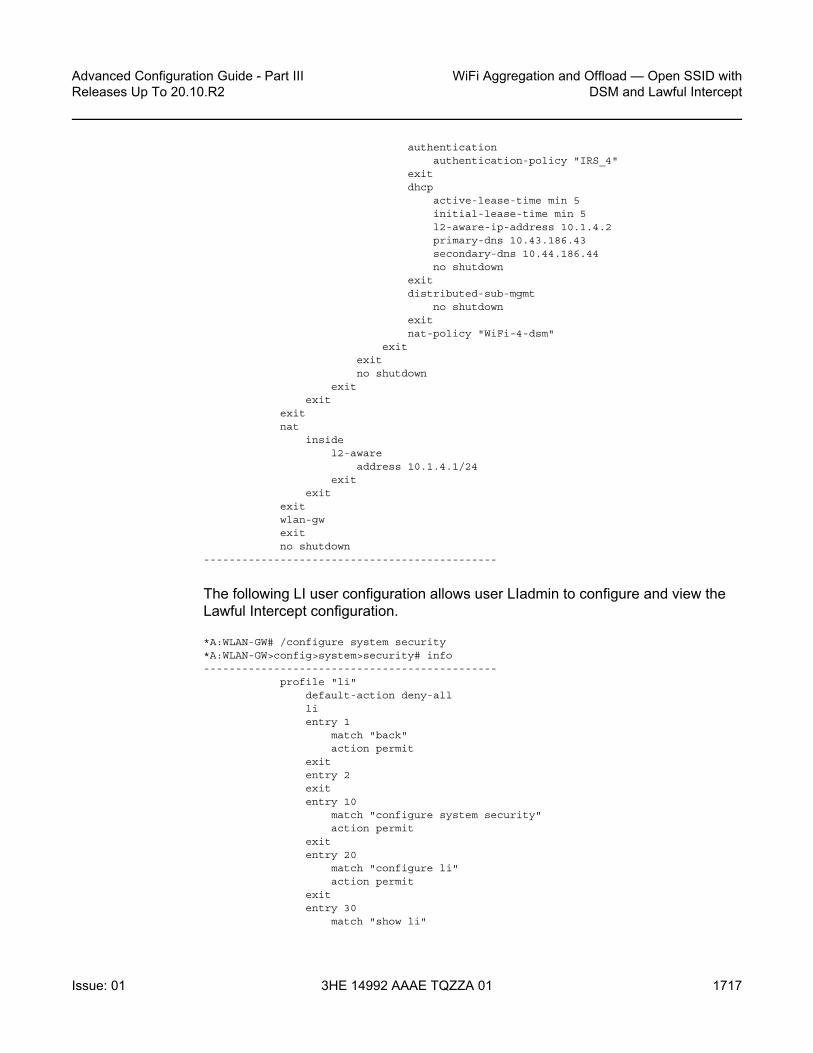
Advanced Configuration Guide - Part III Releases Up To 20.10.R2
WiFi Aggregation and Offload — Open SSID withDSM and Lawful Intercept
Issue: 01 3HE 14992 AAAE TQZZA 01 1717
authenticationauthentication-policy "IRS_4"
exitdhcp
active-lease-time min 5initial-lease-time min 5l2-aware-ip-address 10.1.4.2primary-dns 10.43.186.43secondary-dns 10.44.186.44no shutdown
exitdistributed-sub-mgmt
no shutdownexitnat-policy "WiFi-4-dsm"
exitexitno shutdown
exitexit
exitnat
insidel2-aware
address 10.1.4.1/24exit
exitexitwlan-gwexitno shutdown
----------------------------------------------
The following LI user configuration allows user LIadmin to configure and view the Lawful Intercept configuration.
*A:WLAN-GW# /configure system security*A:WLAN-GW>config>system>security# info----------------------------------------------
profile "li"default-action deny-alllientry 1
match "back"action permit
exitentry 2exitentry 10
match "configure system security"action permit
exitentry 20
match "configure li"action permit
exitentry 30
match "show li"

WiFi Aggregation and Offload — Open SSID with DSM and Lawful Intercept
1718
Advanced Configuration Guide - Part IIIReleases Up To 20.10.R2
3HE 14992 AAAE TQZZA 01 Issue: 01
action permitexitentry 40
match "file"action permit
exitentry 50
match "info"action permit
exitentry 60
match "admin display-config"action permit
exitentry 70
match "tools perform security"action permit
exitentry 80
match "tools dump li wlan-gw ue"action permit
exitentry 100
match "exit"action permit
exitexituser "LIadmin"
password "$2y$10$Yp3sQZpGlbg6K3CeQoCHi.wyBOj7ts5/tsY/nqb0bbFjuFZ9G5wsi"
access console liconsole
no member "default"member "li"
exitexit
----------------------------------------------
The following mirror configuration of type ip-only forwards intercepted traffic to a server.
*A:WLAN-GW# /configure mirror*A:WLAN-GW>config>mirror# info----------------------------------------------
mirror-dest 199 type ip-only createencap
layer-3-encap ip-udp-shim creategateway create
ip src 10.10.10.186 dest 10.43.186.43udp src 3199 dest 3199
exitexit
exitno shutdown
exit----------------------------------------------

Advanced Configuration Guide - Part III Releases Up To 20.10.R2
WiFi Aggregation and Offload — Open SSID withDSM and Lawful Intercept
Issue: 01 3HE 14992 AAAE TQZZA 01 1719
The following configures a BOF, with li-local-save, a local LI config file, and li-separate, ensuring that only the LI user can view or modify LI parameters.
*A:WLAN-GW# show bof===============================================================================BOF (Memory)===============================================================================
li-local-saveli-separate
The following LI source configuration to intercept the UE can only be configured or viewed by user LIadmin. The configuration is saved in cf3:\li.cfg, encrypted. The intercept-id and session-id will appear in the LI packets, which can be decoded in Wireshark using Decode As, Jmirror.
*A:WLAN-GW# /configure li*A:WLAN-GW>config>li# info----------------------------------------------#--------------------------------------------------echo "LI Log Configuration"#--------------------------------------------------
logexit
#--------------------------------------------------echo "LI Filter Lock State Configuration"#--------------------------------------------------
li-filter-lock-state locked#--------------------------------------------------echo "LI Mirror Source Configuration"#--------------------------------------------------
li-source 199wlan-gw
dsm-subscriber mac 68:7f:74:8b:3d:d7intercept-id 1session-id 199
exitexitno shutdown
exit----------------------------------------------
Freeradius
This default configuration section sets the VSA Alc-Wlan-Ue-Creation-Type with value 1, which triggers the creation of a DSM host (value 0 is ESM). The Nas-Ip-Address is returned in the Alc-Wlan-Portal-URL to tell the web portal which MS-ISA address should receive the RADIUS CoA request:
/etc/freeradius/users:
DEFAULT Auth-Type := Local, User-Password := "alcatel", user-name=~"^.*$"Alc-Subsc-ID-Str = "%{User-Name}",

WiFi Aggregation and Offload — Open SSID with DSM and Lawful Intercept
1720
Advanced Configuration Guide - Part IIIReleases Up To 20.10.R2
3HE 14992 AAAE TQZZA 01 Issue: 01
Alc-Wlan-Ue-Creation-Type = 1,Alc-Wlan-Portal-Redirect = "WiFi-4-dsm-redirect",Alc-Wlan-Portal-
URL = "http://portal1.3ls.net/portal4.php?nas=%{Nas-Ip-Address}&mac=%{User-Name}&ssid=WiFi-4",
As an alternative to configuring the LI for the UE in the CLI, the following RADIUS attributes can be sent in the Access-Accept and CoA.
Alc-LI-Action = "enable",Alc-LI-Destination = "199",Alc-LI-Intercept-Id = 1,
In /etc/freeradius/clients.conf, each ISA is a client.
client 10.10.186.1 {secret = alcatelshortname = WLAN-GW-ISA1
}client 10.10.186.2 {
secret = alcatelshortname = WLAN-GW-ISA2
}
A RADIUS CoA sent during a successful portal login makes the following UE a DSM subscriber with full access.
echo "User-Name='.$mac.',Alc-Wlan-Ue-Creation-Type="1",Alc-Subsc-Prof-Str="SUBP_4",Alc-SLA-Prof-Str=SLAP_4,Alc-Primary-Dns = 10.43.186.43," | /usr/bin/radclient -x -r 1 -t 2 '.$nas.' coa alcatel
Access Points
The following must be configured on the Access Point as a minimum:
• IP address 10.1.1.10/24• Default route to 10.1.1.1• Open SSID WiFi-4 mapped to VLAN 40• Soft-GRE tunnel with destination 192.4.4.4, with VLAN 40 mapped to this tunnel
Show Commands
The following commands show the status of the UEs. For DSM users, the UEs are displayed using a tools command. Before portal authentication, the UE is in Portal state.

Advanced Configuration Guide - Part III Releases Up To 20.10.R2
WiFi Aggregation and Offload — Open SSID withDSM and Lawful Intercept
Issue: 01 3HE 14992 AAAE TQZZA 01 1721
*A:WLAN-GW# /tools dump wlan-gw ue===============================================================================Matched 1 session on Slot #3 MDA #1===============================================================================UE-Mac : 68:7f:74:8b:3d:d7 UE-vlan : 40UE IP Addr : 10.1.4.2 UE timeout : 293 secDescription : PortalAuth-time : 09/08/2014 11:30:34Tunnel MDA : 3/2 Tunnel Router : 1000MPLS label : 40 Shaper : DefaultTunnel Src IP : 10.1.0.10 Tunnel Dst IP : 192.4.4.4Tunnel Type : GREAnchor SAP : 3/1/nat-out-ip:2049.3AP-Mac : Unknown AP-RSSI : UnknownAP-SSID : UnknownLast-forward : 09/08/2014 11:30:39 Last-move : NoneSession Timeout : None Idle Timeout : N/AAcct Update : None Acct Interval : N/AAcct Session-Id : N/AAcct Policy : N/ANAT Policy : WiFi-4-dsmRedirect Policy : WiFi-4-dsm-redirectIP Filter : N/AApp-profile : N/ARx Oper PIR : N/A Rx Oper CIR : N/ATx Oper PIR : N/A Tx Oper CIR : N/ARx Frames : 204 Rx Octets : 17381Tx Frames : 78 Tx Octets : 67793-------------------------------------------------------------------------------===============================================================================No sessions on Slot #3 MDA #2 match the query
After login to the web portal, the UE transitions to a DSM-user and the Redirect Policy is removed,
*A:WLAN-GW# /tools dump wlan-gw ue===============================================================================Matched 1 session on Slot #3 MDA #1===============================================================================UE-Mac : 68:7f:74:8b:3d:d7 UE-vlan : 40UE IP Addr : 10.1.4.2 UE timeout : 284 secDescription : DSM-userAuth-time : 09/08/2014 11:30:45Tunnel MDA : 3/2 Tunnel Router : 1000MPLS label : 40 Shaper : DefaultTunnel Src IP : 10.1.0.10 Tunnel Dst IP : 192.4.4.4Tunnel Type : GREAnchor SAP : 3/1/nat-out-ip:2049.3AP-Mac : Unknown AP-RSSI : UnknownAP-SSID : UnknownLast-forward : 09/08/2014 11:30:47 Last-move : NoneSession Timeout : None Idle Timeout : N/AAcct Update : None Acct Interval : N/AAcct Session-Id : N/AAcct Policy : N/ANAT Policy : WiFi-4-dsmRedirect Policy : N/AIP Filter : N/A

WiFi Aggregation and Offload — Open SSID with DSM and Lawful Intercept
1722
Advanced Configuration Guide - Part IIIReleases Up To 20.10.R2
3HE 14992 AAAE TQZZA 01 Issue: 01
App-profile : N/ARx Oper PIR : N/A Rx Oper CIR : N/ATx Oper PIR : N/A Tx Oper CIR : N/ARx Frames : 273 Rx Octets : 23186Tx Frames : 122 Tx Octets : 108083-------------------------------------------------------------------------------===============================================================================No sessions on Slot #3 MDA #2 match the query
User LIadmin can view the configured intercept,
*A:WLAN-GW>config>li# /tools dump li wlan-gw ue===============================================================================Matched 1 session on Slot #3 MDA #1===============================================================================UE-Mac : 68:7f:74:8b:3d:d7 Mirror Service : 199LI Intercept-Id : 1 LI Session-Id : 199-------------------------------------------------------------------------------===============================================================================No sessions on Slot #3 MDA #2 match the query
Debug
In this example, the following debug configuration applies.
debugmirror-source 99
port 1/1/7 egress ingressport 1/1/9 egress ingressno shutdown
exitwlan-gw
group 1ue 68:7f:74:8b:3d:d7 packet dhcp radius
exitexit
exit
The debug trace starts with DHCP.
150 2014/09/08 11:30:31.93 EDT MINOR: DEBUG #2001 Base WLAN-GW"WLAN-GW: MDA 3/1, SeqNo 3528
Info: anchor ingressing framereceived upstream from tunnel
Ethernet: from 68:7f:74:8b:3d:d7 to ff:ff:ff:ff:ff:ff (ethertype: 0x0800)
IP/UDP: from 0.0.0.0 (port 68) to 255.255.255.255 (port 67)
DHCP:ciaddr: 0.0.0.0 yiaddr: 0.0.0.0siaddr: 0.0.0.0 giaddr: 0.0.0.0chaddr: 68:7f:74:8b:3d:d7 xid: 0xca073331

Advanced Configuration Guide - Part III Releases Up To 20.10.R2
WiFi Aggregation and Offload — Open SSID withDSM and Lawful Intercept
Issue: 01 3HE 14992 AAAE TQZZA 01 1723
DHCP options:[53] Message type: Discover[61] Client id: (hex) 01 68 7f 74 8b 3d d7[12] Host name: W81VM[60] Class id: MSFT 5.0[55] Param request list: len = 13
1 Subnet mask15 Domain name3 Router6 Domain name server
44 NETBIOS name server46 NETBIOS type47 NETBIOS scope31 Router discovery33 Static route
121 Unknown option249 Unknown option252 Unknown option43 Vendor specific
[255] End"
151 2014/09/08 11:30:31.93 EDT MINOR: DEBUG #2001 Base WLAN-GW"WLAN-GW: MDA 3/2, SeqNo 706
Info: tunnel ingressing framereceived downstream from anchor
Ethernet: from 00:00:00:02:02:02 to 68:7f:74:8b:3d:d7 (ethertype: 0x0800)
IP/UDP: from 10.1.4.1 (port 67) to 10.1.4.2 (port 68)
DHCP:ciaddr: 0.0.0.0 yiaddr: 10.1.4.2siaddr: 10.1.4.1 giaddr: 0.0.0.0chaddr: 68:7f:74:8b:3d:d7 xid: 0xca073331
DHCP options:[53] Message type: Offer[54] DHCP server addr: 10.1.4.1[1] Subnet mask: 255.255.255.0[3] Router: 10.1.4.1[51] Lease time: 300[6] Domain name server: length = 8
10.43.186.4310.44.186.44
[255] End"
152 2014/09/08 11:30:32.09 EDT MINOR: DEBUG #2001 Base WLAN-GW"WLAN-GW: MDA 3/1, SeqNo 3529
Info: anchor ingressing framereceived upstream from tunnel
Ethernet: from 68:7f:74:8b:3d:d7 to ff:ff:ff:ff:ff:ff (ethertype: 0x0800)
IP/UDP: from 0.0.0.0 (port 68) to 255.255.255.255 (port 67)
DHCP:ciaddr: 0.0.0.0 yiaddr: 0.0.0.0

WiFi Aggregation and Offload — Open SSID with DSM and Lawful Intercept
1724
Advanced Configuration Guide - Part IIIReleases Up To 20.10.R2
3HE 14992 AAAE TQZZA 01 Issue: 01
siaddr: 0.0.0.0 giaddr: 0.0.0.0chaddr: 68:7f:74:8b:3d:d7 xid: 0xca073331
DHCP options:[53] Message type: Request[61] Client id: (hex) 01 68 7f 74 8b 3d d7[50] Requested IP addr: 10.1.4.2[54] DHCP server addr: 10.1.4.1[12] Host name: W81VM[81] client FQDN: rcode1: 0, rcode2: 0, domain name = (hex) 00 57 38 31 564d[60] Class id: MSFT 5.0[55] Param request list: len = 13
1 Subnet mask15 Domain name3 Router6 Domain name server
44 NETBIOS name server46 NETBIOS type47 NETBIOS scope31 Router discovery33 Static route
121 Unknown option249 Unknown option252 Unknown option43 Vendor specific
[255] End"
153 2014/09/08 11:30:32.09 EDT MINOR: DEBUG #2001 Base WLAN-GW"WLAN-GW: MDA 3/2, SeqNo 707
Info: tunnel ingressing framereceived downstream from anchor
Ethernet: from 00:00:00:02:02:02 to 68:7f:74:8b:3d:d7 (ethertype: 0x0800)
IP/UDP: from 10.1.4.1 (port 67) to 10.1.4.2 (port 68)
DHCP:ciaddr: 0.0.0.0 yiaddr: 10.1.4.2siaddr: 10.1.4.1 giaddr: 0.0.0.0chaddr: 68:7f:74:8b:3d:d7 xid: 0xca073331
DHCP options:[53] Message type: Ack[54] DHCP server addr: 10.1.4.1[1] Subnet mask: 255.255.255.0[3] Router: 10.1.4.1[51] Lease time: 300[58] Renew timeout: 150[59] Rebind timeout: 263[6] Domain name server: length = 8
10.43.186.4310.44.186.44
[255] End"
RADIUS authentication is triggered by the first data packet.

Advanced Configuration Guide - Part III Releases Up To 20.10.R2
WiFi Aggregation and Offload — Open SSID withDSM and Lawful Intercept
Issue: 01 3HE 14992 AAAE TQZZA 01 1725
154 2014/09/08 11:30:34.76 EDT MINOR: DEBUG #2001 Base WLAN-GW"WLAN-GW: MDA 3/1, SeqNo 3563
Info: anchor egressing frameradius-auth-req
IP/UDP: from 10.10.186.1 (port 1082) to 10.43.186.1 (port 1812)
RADIUS: Access-Request (continued)"
155 2014/09/08 11:30:34.76 EDT MINOR: DEBUG #2001 Base RADIUS"RADIUS: Transmit
Access-Request(1) 10.10.186.1:1082 id 45 len 126 vrid 1NAS IP ADDRESS [4] 4 10.10.186.1USER NAME [1] 17 68:7f:74:8b:3d:d7PASSWORD [2] 16 MvqAtmAOvSeeWgNIGyT/t.CALLING STATION ID [31] 17 68:7f:74:8b:3d:d7CALLED STATION ID [30] 17 00:00:00:00:00:00VSA [26] 19 Alcatel(6527)
CHADDR [27] 17 68:7f:74:8b:3d:d7"
156 2014/09/08 11:30:34.76 EDT MINOR: DEBUG #2001 Base WLAN-GW"WLAN-GW: MDA 3/1, SeqNo 3564
Info: anchor ingressing frameportal auth-accept
IP/UDP: from 10.43.186.1 (port 1812) to 10.10.186.1 (port 1082)
RADIUS: Access-Accept (continued)"
157 2014/09/08 11:30:34.76 EDT MINOR: DEBUG #2001 Base RADIUS"RADIUS: Receive
Access-Accept(2) id 45 len 258 from 10.43.186.1:1812 vrid 1VSA [26] 19 Alcatel(6527)
SUBSC ID STR [11] 17 68:7f:74:8b:3d:d7VSA [26] 20 Alcatel(6527)VSA [26] 20 Alcatel(6527)VSA [26] 20 Alcatel(6527)VSA [26] 6 Alcatel(6527)
WLAN UE CREATION TYPE [184] 4 1VSA [26] 25 Alcatel(6527)
WLAN PORTAL REDIRECT [172] 23 WiFi-4-dsm-redirectVSA [26] 86 Alcatel(6527)
WLAN PORTAL URL [173] 84 http://portal1.3ls.net/portal4.php?nas=10.10.186.1&mac=68:7f:74:8b:3d:d7&ssid=WiFi-4"
RADIUS returns the redirect policy and portal URL, and the UE is then in Portal state. Next, the user logs in and a CoA is sent by the portal.
159 2014/09/08 11:30:45.07 EDT MINOR: DEBUG #2001 Base RADIUS"RADIUS: Receive
Change of Authorization(43) id 220 len 91 from 10.43.186.1:53449 vrid 1USER NAME [1] 17 68:7f:74:8b:3d:d7VSA [26] 6 Alcatel(6527)
WLAN UE CREATION TYPE [184] 4 1
WiFi Aggregation and Offload — Open SSID with DSM and Lawful Intercept
1726
Advanced Configuration Guide - Part IIIReleases Up To 20.10.R2
3HE 14992 AAAE TQZZA 01 Issue: 01
VSA [26] 8 Alcatel(6527)SUBSC PROF STR [12] 6 SUBP_4
VSA [26] 8 Alcatel(6527)SLA PROF STR [13] 6 SLAP_4
VSA [26] 6 Alcatel(6527)PRIMARY DNS [9] 4 10.43.186.43
"
Finally the UE is in DSM state with unrestricted access.
Conclusion
The 7750 SR WLAN-GW, with Open SSID, can support WiFi Offload users as DSM subscribers instantiated on MS-ISA cards. This allows the support of a greater number of UEs on a single system when a full ESM feature set is not required. DSM UEs, just as ESM UEs, can have their traffic intercepted using LI.

Customer Document and Product Support
Customer DocumentationCustomer Documentation Welcome Page
Technical SupportProduct Support Portal
Documentation FeedbackCustomer Documentation Feedback

© 2017-2021 Nokia.3HE 14992 AAAE TQZZA 01
Copyright © 2022 FDOKUMEN