
ADMINISTRATION AND PROCEDURES MANUAL
63
i ADMINISTRATION AND PROCEDURES MANUAL TABLE OF CONTENTS1 CHAPTER 1. ADMINISTRATION......................................................................................................... 1 ARTICLE 1. GENERAL...................................................................................................................................... 1 Sec. 1.1.1. POWERS AND DUTIES OF THE ADMINISTRATIVE OFFICIAL. ......................................... 1 CHAPTER2. PROCEDURES. .............................................................................................................. 1 ARTICLE 1. GENERAL,..................................................................................................................................... 1 Sec, 2.1.1. DEVELOPMENT PERMITS. ........................................................................................................ 1 Sec. 2.1.2. APPLICATIONS. ........................................................................................................................... 1 Sec. 2.1.3. CERTIFICATE OF COMPLIANCE, ............................................................................................. 1 Sec. 2.1.4. EXPIRATION OF DEVELOPMENT PERMIT. ........................................................................... 2 Sec. 2.1.5. USE OR CONSTRUCTION AT VARIANCE WITH THAT AUTHORIZED. ............................ 2 Sec. 2.1.6. MISCELLANEOUS PROVISIONS. .............................................................................................. 2 CHAPTER 5-SITE PLAN REVIEW INFORMATION REQUIREMENTS ............................................... 1 ARTICLE 1. GENERAL...................................................................................................................................... 1 Sec. 5.1.1. INTENT. ......................................................................................................................................... 1 Sec. 5.1.2. INFORMATION REQUIRENTS BY DEVELOPMENT ACTIVITY. ......................................... 1 Sec. 5.1.3. SITE PLAN INFORMATION. ....................................................................................................... 1 CHAPTER 6-IMPACT STATEMENTS. ................................................................................................ 1 ARTICLE 1. GENERAL...................................................................................................................................... 1 Sec,6.1.1. INTENT ........................................................................................................................................... 1 Sec. 6.1.2. APPLICATIONS. ........................................................................................................................... 1 Sec. 6.1.3. DEVELOPMENTS REQUIRING IMPACT STATEMENTS. ...................................................... 1 Sec. 6.1.4. IMPACT REVIEW PROCESS. ...................................................................................................... 2 Sec. 6.1.5. GENERAL INFORMATION REQUIRED FOR THE IMPACT STATEMENT. ........................ 3 Sec. 6.1.6. SPECIFIC INFORMATION REQUIRED FOR THE IMPACT STATEMENT. .......................... 3 CHAPTER 7. STREET, ALLEY, CURB, UTILITY DESIGN CRITERIA ANDCONSTRUCTION STANDARDS. ...................................................................................................................................... 1 ARTICLE 1. STREETS. ...................................................................................................................................... 1 Sec. 7.1.1. INTENT. ......................................................................................................................................... 1 Sec. 7.1.2. STREET DESIGN CRITERIA. ...................................................................................................... 1 ARTICLE 2. ALLEYS ......................................................................................................................................... 3 Sec. 7.2.1. DESIGN CRITERIA....................................................................................................................... 3 ARTICLE 3. CURB AND GUTTER. ................................................................................................................. 3 Sec. 7.3.1. DESIGN CRITERIA AND CONSTRUCTION STANDARDS. ................................................... 3
-
Upload
khangminh22 -
Category
Documents
-
view
1 -
download
0
Transcript of ADMINISTRATION AND PROCEDURES MANUAL

i
ADMINISTRATION AND PROCEDURES MANUAL
TABLE OF CONTENTS1
CHAPTER 1. ADMINISTRATION ......................................................................................................... 1
ARTICLE 1. GENERAL...................................................................................................................................... 1 Sec. 1.1.1. POWERS AND DUTIES OF THE ADMINISTRATIVE OFFICIAL. ......................................... 1
CHAPTER2. PROCEDURES. .............................................................................................................. 1
ARTICLE 1. GENERAL,..................................................................................................................................... 1 Sec, 2.1.1. DEVELOPMENT PERMITS. ........................................................................................................ 1 Sec. 2.1.2. APPLICATIONS. ........................................................................................................................... 1 Sec. 2.1.3. CERTIFICATE OF COMPLIANCE, ............................................................................................. 1 Sec. 2.1.4. EXPIRATION OF DEVELOPMENT PERMIT. ........................................................................... 2 Sec. 2.1.5. USE OR CONSTRUCTION AT VARIANCE WITH THAT AUTHORIZED. ............................ 2 Sec. 2.1.6. MISCELLANEOUS PROVISIONS. .............................................................................................. 2
CHAPTER 5-SITE PLAN REVIEW INFORMATION REQUIREMENTS ............................................... 1
ARTICLE 1. GENERAL...................................................................................................................................... 1 Sec. 5.1.1. INTENT. ......................................................................................................................................... 1 Sec. 5.1.2. INFORMATION REQUIRENTS BY DEVELOPMENT ACTIVITY. ......................................... 1 Sec. 5.1.3. SITE PLAN INFORMATION. ....................................................................................................... 1
CHAPTER 6-IMPACT STATEMENTS. ................................................................................................ 1
ARTICLE 1. GENERAL...................................................................................................................................... 1 Sec,6.1.1. INTENT ........................................................................................................................................... 1 Sec. 6.1.2. APPLICATIONS. ........................................................................................................................... 1 Sec. 6.1.3. DEVELOPMENTS REQUIRING IMPACT STATEMENTS. ...................................................... 1 Sec. 6.1.4. IMPACT REVIEW PROCESS. ...................................................................................................... 2 Sec. 6.1.5. GENERAL INFORMATION REQUIRED FOR THE IMPACT STATEMENT. ........................ 3 Sec. 6.1.6. SPECIFIC INFORMATION REQUIRED FOR THE IMPACT STATEMENT. .......................... 3
CHAPTER 7. STREET, ALLEY, CURB, UTILITY DESIGN CRITERIA ANDCONSTRUCTION STANDARDS. ...................................................................................................................................... 1
ARTICLE 1. STREETS. ...................................................................................................................................... 1 Sec. 7.1.1. INTENT. ......................................................................................................................................... 1 Sec. 7.1.2. STREET DESIGN CRITERIA. ...................................................................................................... 1
ARTICLE 2. ALLEYS ......................................................................................................................................... 3 Sec. 7.2.1. DESIGN CRITERIA. ...................................................................................................................... 3
ARTICLE 3. CURB AND GUTTER. ................................................................................................................. 3 Sec. 7.3.1. DESIGN CRITERIA AND CONSTRUCTION STANDARDS. ................................................... 3

ii
ARTICLE 4. STREET CONSTRUCTION STANDARDS. ............................................................................. 3 Sec. 7.4.1. INTENT. ......................................................................................................................................... 3 Sec. 7.4.2. STANDARDS. ................................................................................................................................ 4
ARTICLE 5. UTILITY DESIGN. ....................................................................................................................... 5 Sec. 7.5.1. SANITARY SEWERAGE. ............................................................................................................. 5 Sec. 7.5.2. WATER: DOMESTIC AND FIRE PROTECTION. ...................................................................... 7 Sec. 7.5.3. UNDERGROUND UTILITIES; ELECTRIC, TELEPHONE AND SIMILAR SERVICES. ........ 8
ARTICLE 6. SIDEWALKS. ................................................................................................................................ 9
(See Chapter 12, Article 7 of the LDR) ............................................................................................................... 9
ARTICLE 7. INSPECTION; ACCOUNTABILITY; RIGHT OF ACCESS; MATERIAL TESTING. ...... 9 Sec. 7.7.1. INTENT. ......................................................................................................................................... 9
CHAPTER 9. UTILITY SYSTEM ADDITIONS POLICY ....................................................................... 1
ARTICLE 1. EXTENSIONS TO PROPERTIES OUTSIDE THE CITY ....................................................... 1 Sec. 9.1.1. GENERAL ...................................................................................................................................... 1 Sec. 9.1.2. PROCEDURES FOR REQUESTING UTILITY SERVICE TO PROPERTIES LYING OUTSIDE THE CORPORATE LIMITS OF THE CITY OF AUBURNDALE. ............................................... 1 Sec, 9.1.3. RESPONSIBILITY FOR INSTALLATION: ................................................................................. 2 Sec. 9.1,4. OVERSIZING OF UTILITIES EXTENSIONS ............................................................................. 2
ARTICLE 2. LIFT STATION POLICY ............................................................................................................ 2 Sec. 9.2.1. MAINTENANCE RESPONSIBILITY .......................................................................................... 2 Sec. 9.2.2. REQUIREMENTS. ......................................................................................................................... 2 Sec. 9.2.3. PRIVATE RESPONSIBILITY. ...................................................................................................... 3 Sec. 9.2.4. PUMPING RATE RESTRICTIONS. ............................................................................................. 3 Sec. 9.2.5. MANIFOLD PUMP STATIONS. .................................................................................................. 3
ARTICLE 3. SUBMITTALS/REQUIREMENTS FOR UTILITY SYSTEM ADDITIONS ......................... 3 Sec. 9.3.1. PRELIMINARY SUBMITTALS ................................................................................................... 3 Sec. 9.3.2. ENGINEER'S RESPONSIBILITIES .............................................................................................. 3 Sec. 9.3.3. DEVELOPER'S RESPONSIBILITIES .......................................................................................... 4 Sec. 9.3.4. CONTRACTOR'S RESPONSIBILITIES ....................................................................................... 4
ARTICLE 4. RECORD DRAWINGS................................................................................................................. 5 Sec. 9.4.1. RECORD DRAWINGS .................................................................................................................. 5 Sec. 9.4.2. COMPUTER DOCUMENTATION ............................................................................................... 5
ARTICLE 5. DETAILED SPECIFICATIONS-WATER SYSTEMS ............................................................. 5 Sec. 9.5.1. GENERAL ...................................................................................................................................... 5 Sec. 9.5.2. SUBMITTALS ................................................................................................................................ 6 Sec. 9.5.3. MINIMUM LINE SIZE .................................................................................................................. 6 Sec. 9.5.4. LOOPING OF DISTRIBUTION SYSTEM ................................................................................... 6 Sec. 9.5.5. PRODUCTS .................................................................................................................................... 6 Sec. 9.5.6. INSTALLATION ............................................................................................................................ 8 Sec. 9.5.7. TESTING ...................................................................................................................................... 10 Sec. 9.5.8. DISINFECTION ........................................................................................................................... 11 Sec. 9.5.9. WARRANTY ................................................................................................................................ 11

iii
ARTICLE 6, DETAILED SPECIFICATIONS - WASTEWATER SYSTEMS ........................................... 12 Sec. 9.6.1 GENERAL .................................................................................................................................... 12 Sec. 9.6.2. SUBMITTALS .............................................................................................................................. 12 Sec. 9.6.3. MINIMUM LINE SIZE ................................................................................................................ 12 Sec. 9.6.4. PRODUCTS .................................................................................................................................. 12 Sec. 9.6.5. INSTALLATION .......................................................................................................................... 16
ARTICLE 7. DETAILED SPECIFICATIONS - WASTEWATER PUMPING STATIONS ..................... 19 Sec. 9.7.1. GENERAL .................................................................................................................................... 19 Sec. 9.7.2. SUBMITTALS .............................................................................................................................. 19 Sec. 9.7.3. PRODUCTS .................................................................................................................................. 20 Sec. 9.7.4. PUMPS .......................................................................................................................................... 22 Sec. 9.7.5. CONTROL PANEL ...................................................................................................................... 22 Sec. 9.7.6. SPARE PARTS. ............................................................................................................................ 29 Sec. 9.7.7. INSTALLATION. ......................................................................................................................... 29 Sec. 9.7.8. DETAILED SPECIFICATIONS - WASTEWATER PUMPING. ............................................... 30
ARTICLE 8. FIRE FLOW REQUIREMENTS ............................................................................................... 30
CHAPTER 10. FEES AND EXPENSES. .............................................................................................. 1
ARTICLE 1. GENERAL...................................................................................................................................... 1
ARTICLE 2. PAYMENT. .................................................................................................................................... 1 Sec. 10.2.1. FEES AND EXPENSES TO BE PAID IN FULL, ........................................................................ 1
ARTICLE 3. COST. ............................................................................................................................................. 1 Sec. I0.3.1, ESTABLISHED FEES-. ................................................................................................................. 1 Sec. 10.3.2. EXTRAORDINARY EXPENSES: ................................................................................................ 5
CHAPTER 11. GENERIC SUBSTANCE LIST ..................................................................................... 1 GENERIC SUBSTANCE LIST ......................................................................................................................... 1

APM 1-1
ADMINISTRATION AND PROCEDURES MANUAL
CHAPTER 1. ADMINISTRATION
ARTICLE 1. GENERAL
Sec. 1.1.1. POWERS AND DUTIES OF THE ADMINISTRATIVE OFFICIAL. 1.1.1.1. An Administrative Official, appointed by the City Commission and provided with such assistance as
the City Commission may direct, shall be responsible for the administration and enforcement of the Land
Development Regulations.
1.1.1.2. The Administrative Official shall diligently enforce the Land Development Regulations, making
necessary inspections to this end and investigating promptly all complaints; reporting the findings and
actions to complainants and using the best endeavors to prevent violations and to detect and secure the
correction of violations.
1.1.1.3. If it is found that any of the provisions of the Land Development Regulations are being violated,
written notification shall be given by the Administrative Official to the person responsible for such
violation, indicating the nature of the violation and ordering the action necessary to correct it. The
Administrative Official shall order discontinuance of illegal use of land or structures, removal of illegal
structures or of illegal additions, alterations or structural changes; discontinuance of any illegal work being
done; and shall take or cause to be taken any other action authorized by the Land Development
Regulations or other laws of the City, County or State to insure compliance with, and prevent violations of,
the provisions of the Land Development Regulations.
1.1.1.4. The Administrative Official shall maintain records of all official actions with relation to administration,
and of all complaints and actions taken with regard thereto, and of all violations discovered by whatever
means, with remedial action taken and disposition of cases.

APM 2-1
CHAPTER2. PROCEDURES.
ARTICLE 1. GENERAL,
Sec, 2.1.1. DEVELOPMENT PERMITS. No building or other structure shall be erected, moved, added to or structurally altered without a development
permit therefore, issued by the Administrative Official. No development permit shall be issued by the
Administrative Official except in conformity with the provisions of the Land Development Regulations,
unless under a written order from the Board of Adjustment in the form of an administrative review, special
exception or variance as provided for by the Land Development Regulations.
Sec. 2.1.2. APPLICATIONS. 2.1.2.1. In addition to the requirements contained in the Administrative and Procedures Manual, all
applications for development permits shall be accompanied by plans in triplicate, drawn to scale, showing the
actual dimensions and shape of the lot or parcel to be built upon, the exact sizes and locations on the lot of
buildings already existing, if any, and the location and dimensions of the proposed building or alteration. This
information shall be prepared by or shall be taken from information prepared by a registered land surveyor.
The application shall include such other information as lawfully may be required by the Administrative Official,
including existing or proposed building(s) or alteration; existing or proposed uses of the building(s) and land;
the number of families, housekeeping units or rental units the building is designed to accommodate if
residential in character; conditions existing on the lot, and such other matter as may be necessary to
determine conformance with, and provide for the enforcement of the Land Development Regulations. Aft
such information shall be provided as required in the Administrative and Procedures Manual.
2.1.2.2. In addition to the requirements contained in the Administrative and Procedures Manual, one copy
of the plans shall be returned to the applicant by the Administrative Official, after marking _such copy either
as approved or disapproved and attested to same on such copy. The original and one copy of the plans,
similarly marked, shall be retained by the Administrative Official.
Sec. 2.1.3. CERTIFICATE OF COMPLIANCE, 2.1.3.1 It shall be unlawful to use or occupy or permit the use or occupancy of any building or premises,
or both, or part thereof hereafter created, erected, changed, converted or wholly or partly altered or enlarged
in its use or structure until a certificate of compliance shall have been issued therefore by the Administrative
Official stating that the proposed use of the building or land conforms to the applicable requirements of the
Land Development Regulations. No occupational license shall be issued by the City until the building official,
fire official, and County health official when applicable, shall sign off their approval, concurring that the
proposed use of the building or land conforms to the applicable requirements of the Land Development
Regulations.
2.1.3.2. No nonconforming structure or use shall be maintained, renewed or changed, and no
nonconforming structure shall be extended, until a certificate of compliance e shall have been issued by the
Administrative Official; provided, that upon enactment or amendment of the Land Development Regulations,
owners or occupants of nonconforming structures or uses shall have 90 days to apply for certificates of
compliance. The certificate shall state specifically wherein the nonconforming use or structure differs from the

APM 2-2
provisions of the Land Development Regulations. Failure to make such application within the 90 days
indicated shall be presumptive evidence that the property was being used in conformity with the terms of the
Land Development Regulations, or that the structure so conformed, at the time of its adoption or amendment,
and that any variation from use or structural regulations of the Land Development Regulations is illegal.
2.1.3.3. No permit for erection, alteration, moving or repair of any building shall be issued until an
application has been made for a certificate of compliance, and the certificate shall be issued in conformity with
the provisions of the Land Development Regulations upon completion of the work.
2.1.3.4. A temporary certificate of compliance may be issued by the Administrative Official for a period not
exceeding 6 months during alterations or partial occupancy of a building pending its completion; provided,
that such temporary certificate may include such conditions and safeguards as will protect the safety of the
occupants and the public.
2.1.3:5. The Administrative Official shall maintain a record of all certificates of compliance, and a copy
shall be furnished upon request to any person.
2.1.3.6. Failure to obtain a certificate of compliance shall be a violation of the Land Development
Regulations and punishable as provided for in the Land Development Regulations
Sec. 2.1.4. EXPIRATION OF DEVELOPMENT PERMIT. 2.1.4.1. Except as may be provided otherwise in the Land Development Regulations, if the work
described in any development permit has not begun within 6 months from the date of issuance thereof, said
permit shall expire and be canceled by the Administrative Official. Written notice shall be provided to the
person(s) affected.
2.1.4.2. If the work described in any development permit has not been substantially completed within one
year of the date of issuance, except as may be provided for otherwise in the Land Development Regulations,
said permit shall expire and be canceled by the Administrative Official. Written notice shall be provided the
person(s) affected that further work as described in the canceled permit shall not proceed unless and until a
new development permit has been obtained. However, the Administrative Official may authorize extension of
such term when due cause is demonstrated to the satisfaction of the Administrative Official.
Sec. 2.1.5. USE OR CONSTRUCTION AT VARIANCE WITH THAT AUTHORIZED. Development permits or certificates of compliance issued on the basis of plans and applications approved by the
Administrative Official authorize only the use, arrangement, and construction set forth in such approved
plans and applications, and no other use, arrangement or construction. Use, arrangement or construction
at variance with that authorized shall be deemed a violation of the Land Development Regulations, and
punishable as provided for in the Land Development Regulations.
Sec. 2.1.6. MISCELLANEOUS PROVISIONS. In their interpretation and application, the provisions of the Land Development Regulations shall be held to be
minimum requirements, adopted for the protection, promotion and improvement of the public health,
safety, comfort, order, appearance, convenience, morals and general welfare. Wherever the
requirements of the Land Development Regulations are at variance with the requirements of other
lawfully adopted rules, regulations or ordinances, the most restrictive or that imposing the higher
standards shall govern.

APM 2-3

APM 5-1
CHAPTER 5-SITE PLAN REVIEW INFORMATION REQUIREMENTS
ARTICLE 1. GENERAL
Sec_ 5.1.1. INTENT. In order to promote safety and improve traffic circulation on and around a site and to prevent potential adverse
effects on adjoining properties, petitioners for all development activities, including special exceptions and
zoning amendments, except as provided for below, shall submit a site plan as a part of the development
review process. The level of detail required shall be determined by the category of development activity
as stated below.
Sec. 5.1.2. INFORMATION REQUIRENTS BY DEVELOPMENT ACTIVITY. The information required according to the category of development activity shall be based upon the information
listed in Sec. 5.1.3.
5.1.2.1. Individually owned single family detached; as per 5.1.3.1., 2., 15, 16, and 20.
5.1.2.2. Zoning amendments not requiring an impact statement; as per 5.1.3.1. thru 5.1.3.13.
5.1.2.3. Special exceptions not requiring an impact statement; as per 5.1.3.1. thru 5.1.3.22.
All other new development not requiring an impact statement; as per 5.1.3.1. thru 5.1.3.22.
Planned Unit Development; as per Chapter 6 of the Land Development Regulations.
Sec. 5.1.3. SITE PLAN INFORMATION. In addition to other requirements contained elsewhere in the Land Development Regulations for all new
construction and development, including zoning amendment and special exception petitions it shall be
required that the below materials be submitted as applicable, in triplicate, for review by City staff and
Boards and Commissions so involved. While some information asked for in this Section may appear to be
duplication the information requirements are more stringent for a special exception since such a petition,
if approved, will procedurally next lead to requests for construction permits. If there are conflicts in the
requirements, the most restrictive or stringent shall apply
5.1.3.1. Location map showing the relationship of the proposed project to streets, parks and open spaces,
lakes, utilities and similar features of the city.
5.1-.3.2. A property map showing the current land use and zoning of the property and all contiguous
properties.
5.1.3.3. All property owners within 300 feet of the site and their most current mailing address.
5.1.3.4. Topographic map with contour intervals of no greater than 5 feet, and delineation of areas of
special flood hazard (100-year flood plain) as shown on the Flood Insurance Rate Maps, issued by the
Federal Emergency Management Agency (FEMA) for the City.
5.1.3.5. Title of the proposed development, name of the developer or owner and the project planner (if
applicable).
5.1.3.6. Scale, north arrow.
5.1.3.7. A dimensioned general site plan at a scale of 1:100 or less showing the proposed locations and
arrangement of buildings, streets, off-street parking, required yards, open spaces, service areas, setbacks
and buffers for the development.

APM 5-2
5 1.3.8. A legal survey at a scale of 1:100 or less indicating boundaries and ownership Of all properties
included in the petition.
5.1.3.9. Soils map, soils and subsoil conditions, using at a minimum Soil Conservation Service (SCS)
maps and surveys; define property drainage problems.
5.1.3.10. Demonstrate the methods to be used by the petitioner to protect the environmentally sensitive
qualities of the site and immediate surrounding area; describe methods to be used to protect water, air, noise,
view, and rebated environmental considerations.
5.1.3.11. Describe the .general community facilities arid that will be used or required as a result of the
proposed development.
5.1.3.12. A traffic circulation map identifying all existing roads on or adjacent to the proposed development
and containing the name of the roads, 24 hour traffic counts (where available from the county or FDOT),
maintenance jurisdiction, pavement and right of way widths.
5.1.3.14 Describe how the proposed development is consistent with the Comprehensive Plan. Additional
information required for special exception petitions shall be as listed below.
5.1.3.15. A dimensioned site plan at a scale of 1:100 or less, except for an individually owned single family
detached dwellings which shall be at a scale of 1/4":1' or less, showing the locations and arrangements of
buildings, open space, required yards, setbacks, buffers, signs as applicable and related features of the
development. The site plan shall indicate the approximate total floor area of each building and for the total
development.
5.1.3.16. A topographic survey at a maximum of 2-foot contour intervals and at a Corresponding scale to
the boundary survey.
5.1.3.17. Show lot arrangements, typical lot sizes and dimensions, streets, ingress and egress and sizes,
parking and off-street loading facilities and sign locations.
5.1.3.18. The gross density in dwelling units per acre for each type of residential use and/or the size and
type of commercial, industrial or other- proposed land uses.
5.1.3.19. A drainage plan, prepared by a Florida registered engineer, which provides a solution for
retaining the first 1" of rainfall, based on a 25 year frequency storm on site and where and how the excess
rainfall will be dispose.
5.1.3:20. Establish public utility requirements necessary for the proposed development, including the
volume of sewage waste to be generated, water needs and methods to be utilized to meet these needs.
5.1.3.21. Establish the amount and types of vehicular traffic to be generated that will result from the
proposed development and what thoroughfares will be used by the anticipated traffic.
5.1.3.22. Establish the phasing and timing schedule, as applicable, for the proposed development.

APM 6-1
CHAPTER 6-IMPACT STATEMENTS.
ARTICLE 1. GENERAL.
Sec,6.1.1. INTENT Large and/or intensive land use developments, by their very nature, impact the City by creating demands for
additional water, sewer and drainage facilities, public streets for access, parks and recreation areas and
related services. In order to better plan for, respond to and address these issues, the City requires that
an Impact Statement be prepared by the developer and/or property owner. The Impact Statement
provides the City officials and the general public with factual information as they evaluate the effect the
proposed development will have on the City and its residents.
Sec. 6.1.2. APPLICATIONS. Applications for zoning amendments and special exceptions involving large land areas, relatively high densities,
or intense uses shall be required to prepare and submit an Impact Statement for review by the City Staff
and public agencies having jurisdictional concerns with the proposed development. Developments which
qualify as a Development of Regional Impact (DRI) pursuant to Chapter 380.06, Florida Statutes, may
substitute an Application for Development Approval (ADA) for the Impact Statement required by the Land
Development Regulations.
Sec. 6.1.3. DEVELOPMENTS REQUIRING IMPACT STATEMENTS. Developments that require impact statements are as follows:
6.1.3.1. Institutional, Commercial, Office, or Industrial zoning districts or developments involving a land
area in excess of 2 acres;
6.1.3.2. Residential zoning districts or developments involving one or more of the following:
6.1.3.2.1. More than 5 acres;
6.1:3.2.2. More than 25 dwelling units;
6.1.3.2.3. More than 3 acres at a density of 6 to 8 dwelling units per acre;
6.1.3.2.4. More than 2 acres at a density of greater than 8 but not more
that 12 dwelling units per acre;
6.1.3.2.5. More than 12 dwelling units per acre.
6.1.3.2.6. Planned Unit Developments shall be required to submit an Impact Statement report as
applicable to the specific PUD classification, which requires the petitioner to address the impacts
created by the entire PUD.
6.1.3.2.7. The requirement for an Impact Statement shall not be subverted by applications for a
fractional portion of a property. Applications may be made for a portion of a property; however, a
subsequent action for a contiguous property by the same owner within a 5-year period may be
refused unless an Impact Statement for both properties is submitted with the subsequent
applications.

APM 6-2
Sec. 6.1.4. IMPACT REVIEW PROCESS. 6.1.4.1. Six copies of the Impact Statement shall be submitted to the Administrative Official. All
documentation shall be submitted in the form of a bound or loose-leaf cover format, properly identified
according to the information required, and not to exceed 11 by 14 inches in size. All maps and/or other large-
scale documentation materials shall be at the scale and size required by the applicable actions being
requested. Should the applicant feel that some portion of the information requested is not applicable, the
applicant must provide supportive written reasons for this position.
6.1.4.2. The Impact Statement shall be reviewed by the Administrative Official for sufficiency Of the
information, provided. If found insufficient, the Administrative Official .shall notify the applicant in writing,
within 14 working days after the receipt of the application, of any additional information required. The
applicant may supply the information requested or notify the Administrative Official in writing that the
requested information will not be supplied. After notification of insufficiency, processing of the application
shall halt until either the additional information is obtained or notification is received that the information will
not provided.
6.1.4.3. When the Administrative Official determines the Impact Statement is sufficient or receives written
notification from the applicant that the additional requested information will not be supplied, copies of the
application and Impact Statement will be distributed to the Impact Review Committee.
6.1.4.4. The Administrative Official shall schedule and conduct a meeting of the Impact Review
Committee of local, regional, State and Federal public agencies having jurisdictional concerns with the
proposed development or accept letters from the agencies in the lieu of meetings. These agencies as
applicable, include the following:
Polk County Health Department
Southwest Florida Water Management District
Central Florida Regional Planning Council
Soil Conservation Service, United States Department of Agriculture
United States Environmental Protection Agency
Florida Department of Transportation
Florida Department of Natural Resources
Florida Department of Community Affairs
Florida Department of Environmental Regulations
Health and Rehabilitative Services, and
United States Army Corps of Engineers
The reports of the participation public review agencies shall neither ensure not preclude approval Of any
application, but will provide technical staff input to assist the Planning Commission and the City
Commission in evaluating the request.
6.1.4.5. The Administrative Official shall prepare a composite report of the findings of the Impact Review
Committee and forward the report to the appropriate Commissions.
6.1.4.6. The Polk County School Board shall be notified, at the time of receipt of complete petitions, for all
residential development orders requiring an impact statement and shall be supplied with applicable
information regarding the number of dwelling units and occupant profiles, if available.

APM 6-3
Sec. 6.1.5. GENERAL INFORMATION REQUIRED FOR THE IMPACT STATEMENT. Answers to the following questions or request for information must be provided to establish a basis for
consideration by the City for the proposed action. The questions and information relate to such
considerations as site conditions, suitability of the site for the proposed use or uses, relationship to
adjoining land uses, compatibility with the Comprehensive Plan, infrastructure needs, changing conditions
causing the need for the proposed development and the benefits to the City (public) should the request
be granted. These responses will serve as an overview of the proposed development and will be used by
City staff and the Commissions in public hearings.
6.1.5.1. Will the proposed change be contrary to the established land use pattern(s ) in the surrounding
area? If an incompatibility would be created between the proposed and existing land uses, describe the
techniques and methods that would be used to minimize such differences.
6.1.5.2. Describe how the proposed development would be consistent with the city comprehensive Plan
in relation to land use, transportation, recreation, utilities and related Plan Elements.
6.1.5.3. What changed or changing conditions in the area make the approval of this petition necessary?
6,1.5.4. Describe why the site is suitable for the uses permissible or permitted by the proposed zoning
amendment (where applicable).
6.1.5.5. Describe the site and list all land uses (by area calculations) and structures existing on site as of
the petition date.
6.1.5.6. Will the proposed development materially alter the population density of the area and thereby
increase the demand on public facilities, i.e. schools, parks, sewers, water, etc.?
6.1.5.7. Will the proposed development adversely affect property values of adjacent property?
6.1.5.8. Will the proposed development create environmental problems? How will the proposed
development take into account the natural features of the site, such as topography, wetlands and similar
conditions and what steps will be taken to protect these features?
6.1.5.9. Will the proposed development encroach on or disturb rare, endangered, threatened and
special concern species wildlife habitat? What steps will be established steps to be taken to protect these
habitats.
6.1.5.10. Will the proposed development create or excessively increase traffic congestion or otherwise
affect public safety?
6.1.5.11. Will the proposed development adversely impact living conditions on adjoining properties or
within the neighborhood?
6.1.5.12. If the proposed development is located in an area presently undeveloped, describe how the
proposed development may or may not influence future land uses in the area.
6.1.5.13. Is it impossible to find other sites within the City suitable for the type of development proposed on
land already zoned for such use(s)?
Sec. 6.1.6. SPECIFIC INFORMATION REQUIRED FOR THE IMPACT STATEMENT.
6.1.6.1. LAND USES. Describes each of the proposed land uses and identify the following where
applicable:
6.1.6.1.1. The density, typical floor areas and types of residential dwelling units;

APM 6-4
6.1.6.1.2. Types of commercial industrial or other land uses proposed of the development;
6.1.6.1.3. The customer service area for commercial and/or industrial land uses;
6.1.6.1.4. The gross land area proposed for each type of use, including parking, open space, recreation
and the gross areas of pervious and impervious surfaces, including structures, for the site.
6.1.6.2. POPULATION POTENTIAL. 6.1.6.2.1. Calculate the projected resident (and seasonal) population of the proposed development
and/or the population generated in the case of commercial or industrial land uses.
6.1.6.2.2. If the proposed development is a commercial or industrial use, describe the employment
characteristics, including the anticipated number of employees, type of job skills or training required
for the new jobs, percentage of local people that will be employed and/or will be brought in from
other locations, number of shifts per day and peak shift employees.
6.1.6.2.3. Describe the demographic composition of any additional population generated as a result of
the proposed development.
6.1.6.2.4. Describe the proposed development's service area and indicate the service areas present
population.
6.1.6.3. STREETS AND ACCESS. 6.1.6.3.1 Estimate the number of vehicle trips per day expected to be generated and at what peak
hour(s), for all streets impacted by the development. Use the trip generation equations for each
applicable land use contained in the Institute of Transportation Engineers (ITE) Trip Generation
Manual, as revised. Establish background traffic counts and determine the impact on those streets
affected by the proposed development.
6.1.6.3.2. Any proposed development generating more than 750 trips per day shall be required to
provide a trip distribution model and traffic analysis prepared by a licensed traffic engineer.
6.1.6.3.3. What modifications would be required of the present transportation system (streets) of
the City, County and/or State to meet the needs of the proposed development?
6.1.6.3.4. Describe the off street parking facilities to be used and the total number of spaces required
for the proposed development.
6.1.6.3.5. Describe the methods to be utilized for provision of ingress and egress to the site.
6.1.6.3.6. What walkway or other systems are planned for accommodating pedestrian traffic?
6.1.6.4. SITE CONDITIONS, SURFACE AND STORMWATER MANAGEMENT, WILDLIFE HABITAT. 6.1.6.4.1. Describe the impact the proposed development will have on surface and storm water
management, including methods to be utilized to control discharges of detergents, solvents, fuel,
oils, silts, sediments and surface run-off.
6.1.6.4.2. Describe any alteration of the site's natural drainage features or systems that would be
necessary for the proposed development.
6.1.6.4.3. Describe the local aquifer recharge system, groundwater conditions and well cones of
influence and any changes to these water supplies which would result from the proposed
development.

APM 6-5
6.1.6.4.4. Identify all rare, endangered, threatened and special concern species of wildlife and their
habitats found on the site. Describe the impact0f the proposed development on this wildlife and
the proposed mitigation of these impacts.
6.1.6.5. POTABLE WATER. 6.1.6.5.1. Indicate the location of the City water main that will serve the proposed development, size
of line, extensions required, number of units of customers to be served, estimated gallons per day
required, and impact and connection fees to be paid to the City.
6.1.6.6. SEWAGE. 6.1.6.6.1. Indicate the location of the City sewer main that will serve the proposed development, size
of line, extensions required, number of units or customers to be served, estimated gallons per day
to be generated, and impact and connection fees to be paid to the City.
6.1.6.7. SOLID WASTE MANAGEMENT. 6.1.6.7.1. Calculate the solid waste volume anticipated to be generated in pounds per capita per day
or tons per day, as a result of the proposed development.
6.1.6.7.2. If contract services are to be considered, identify the solid waste disposal site and the entity
responsible for collection and disposal.
6.1.6.8. RECREATION. 6.1.6.8.1. Calculate the number of users to be created, as a result of the proposed development, of
City recreation facilities. Use the LOS standards contained in the Concurrency Management
System (Chapter 23 of the LDR) as the basis for calculations.
6.1.6.9. GENERAL INFORMATION. 6.1.6.9.1. Describe the user demands and provisions for the following services:
6.1.6.9.1.1. Educational facilities (K- 12);
6.1.6.9.1.2. Health care;
6.1.6.9.1.3. Fire protection;
6.1.6.9.1.4. Police protection;
6.1.6.9.1.5. Electric power, gas and phone.
6.1.6.10. TAXES. 6.1.6.10.1. Calculate the estimated ad Valorem tax yield to the city government, school board and any
special taxing districts that levy taxes on the property, for the next 5 years.
6.1.8.11. REQUIRED EXHIBITS, MAPS. Exhibits and maps shall be of sufficient size and type to
facilitate understanding of the components of the proposed development. The scale shall be
dependent upon the specific application and applicable requirements detailed in the Land
Development Regulation& Dates of preparation and any amendments shall be note on all exhibits
and maps. The following exhibits and maps shall be provided as a part of all Impact Statements:
6.1.6.11.1. A location map showing the proposed development in relationship to streets, community
facilities, schools and natural features of the area such as lakes and drainage ways.

APM 6-6
6.1.6.11.2. A topographic map with contour intervals meeting the requirements as spelled out for
the particular petition and delineation of areas special flood hazard (100 year flood plain) as
identified on the Flood Insurance Rate Maps (FIRM) issued by the Federal Emergency
Management Agency (FEMA) for the City or for Polk County in the case of annexation.
6.1.6.11.3. An existing land use and zoning map of the site and the abutting properties.
6.1.6.11.4. A soils map with the accompanying soils classifications as provided by the Soils Conservation
Service. If other sources are utilized for this information, such data and maps shall be fully
explained and interpreted.
6.1.6.11.5. A traffic circulation map identifying existing streets on or adjacent to the proposed
development site, identifying then by name, maintenance responsibility, pavement width and
right of way dimensions.
6.1.6.11.6. A site plan meeting the requirements of the specific petition but in any case showing at a
minimum the proposed land uses, type and maximum density for each residential area, typical
minimum lot sizes and dimensions for each use and unit by type, dimensions of buffers, easements,
open space areas, parking and loading areas, setbacks and circulation routes.
6.1.6.11.7. A drainage plan showing existing and proposed drainage areas, water retention sites,
structures, easements, canals, wetlands, water courses and any other drainage features that
may be necessary for the proposed development.

APM 7-1
CHAPTER 7. STREET, ALLEY, CURB, UTILITY DESIGN CRITERIA ANDCONSTRUCTION STANDARDS.
ARTICLE 1. STREETS.
Sec. 7.1.1. INTENT. The purpose of this Chapter is to provide developers with design criteria and construction standards for specified
improvements that, at a minimum, protect the consumer and the public in the investment for their future.
The goals, objectives and policies adopted as a part of the Traffic Circulation Element of the
Comprehensive Plan shall serve as the guiding principles for the Articles and Sections herein with regard
to street network function, layout and safety features and the associated systems that typically
accompany street construction and improvements.
Sec. 7.1.2. STREET DESIGN CRITERIA. 7.1.2.1. The arrangement, character, extent, width, grade, and location of all streets shall conform to the
Future Land Use and Traffic Circulation Elements of the Comprehensive Plan and shall be considered in their
relation to existing and planned streets, to topographic conditions, public convenience and safety, and in their
appropriate relation to the proposed used of the land to be served by such streets.
7.1.2.2. Where streets are not identified in the Future Land Use and Traffic Circulation Element, the
arrangement of streets in a subdivision or development shall either:
7.1.2.2.1. Provide for the continuation of appropriate projection of existing principal streets in
surrounding areas; or
7.1.2.2.2. Conform to a plan for the neighborhood approved or adopted by the City Commission to
meet a particular situation where topographic or other conditions make continuance or
conformance to existing streets impracticable.
7.1.2.3. Minor streets shall be so laid out that their use by through traffic will be discouraged.
7.1.2.4. Where a subdivision or development abuts or contains an existing or proposed arterial street, the
City Commission may require marginal access streets, reverse frontage with buffer plantings contained in a
nonaccess reservation along the rear property line, or such other treatment as may be necessary for
adequate protection when such street serve residential uses and to afford separation of through and local
traffic.
7.1.2.5. Where a subdivision or development borders on or contains a railroad right-of-way, or a limited
access in highway right-of-way, the City Commission may require a street approximately parallel to and on
each side of such right-of-way, at a distance suitable for the appropriate use of the intervening land, as for
park purposes in residential districts, or for commercial or industrial uses in appropriate districts. Distances
involving rights-of-way shall also be determined with due regard for the requirements of approach grades and
future grade separations.
7.1.2.6. Reserve strips controlling access to streets shall be prohibited.
7.1.2.7. Street jogs with centerline offsets of less than 125 feet shall be prohibited.

APM 7-2
7.1.2.8. Except for private streets, a tangent at least 100 feet long shall be introduced between reverse
curves on streets having radius less than 500 feet unless unusual circumstances dictate alternate standards
approved by the City (consulting) engineer.
7,1.2.9. Streets shall be laid out so as to intersect with other streets as approximate right angles. Streets
shall have a minimum tangent of 100 feet at intersections unless otherwise approved.
7.1.2.10. Property lines at street intersections shall be rounded with a minimum radius of 25 feet, or of a
greater radius where the City Commission may deem it necessary. The City (consulting) engineer may
recommend comparable cutoffs or chords in place of round corners.
7.1.2.11. Street right-of-way widths shall be as shown in the Traffic Circulation Element and where not
shown therein shall be not less than as follows:
Street Type Right-of-way Feet
Arterial 100
Collector 60
Local 50
Minor 40-w/standard curb
Minor 46-w/Miami curb
Loop Drives 40 w/standard curb
Loop Drives 46 w/Miami curb
Marginal Access 50
Alley 15
Pedestrian and Service Easement 15
7.1.2.12. Private streets shall have a minimum driving surface width of 22 feet for two-way traffic and 12
feet for one-way traffic, except as provided for herein, built according to the minor street construction
standards. Private streets serving only one residence shall provide a minimum driving width of 12 feet.
Private streets serving more than one but less than 3 residences shall provide a minimum driving width of 16
feet. Such streets shall not be maintained at public expense.
7.1.2.13. Half streets shall be prohibited.
7.1.2.14. Dead-end streets, designed to be so permanently, shall have a length no greater than 600 feet
measured the full length of the right-of-way and shall be provided at the closed end with a turnaround having
an outside roadway radius of at least 50 feet, and a street right-of-way radius of at least 50 feet or, within the
above configurations, a 'T' type turnaround may be provided.
7.1.2.15. No street names shall be used which will duplicate or be confused with the names of existing
streets, provided that where alignment is appropriate, new streets shall bear the names of existing street.
Street names shall be subject to the approval of the City Commission.
7.1.2.16. Street grades, where feasible, shall not exceed 5% nor be less than 0.4%.

APM 7-3
ARTICLE 2. ALLEYS
Sec. 7.2.1. DESIGN CRITERIA. 7.2.3.1. Alleys shall be provided in commercial and industrial districts, except that the City Commission
may waive this requirement where other definite and assured provision is made for service access, such as
off-street loading, unloading, and parking consistent with and adequate for the uses proposed.
7.2.3.2. The width of an alley shall not be less than 15 feet.
7.2.3.3. Alley intersections and sharp changes in alignment shall be avoided, but where necessary,
corners shall be rounded to a minimum radius of 20 feet to permit safe vehicular movement.
7.2.3.4. Dead-end alleys shall be prohibited.
7.2.3.5. Alleys shall be prohibited in residential areas except in circumstances where the City Commission
finds extension of alleys from commercial and industrial districts necessary.
ARTICLE 3. CURB AND GUTTER.
Sec. 7.3.1. DESIGN CRITERIA AND CONSTRUCTION STANDARDS. 7.3.1.1. The requirements for curbs and gutters will vary according to the function of the street, character
of the area in which the street t is located and density of development. Raised curbs and gutters shall be
required on all arterial and collector streets so indicated in the Traffic Circulation Element. Minor and marginal
access streets shall be provided with curbs according to their function, alignment and site conditions. Curbs
shall be required on all streets. Roadside swales shall be prohibited on all curbed streets. The developer
shall-provide adequate proof, by means of topography, percolation tests, drainage plans, and acceptable
calculations that raised curbs are unnecessary to handle the surface drainage conditions prior to approval of
Miami curbs by the City Commission.
7.3.1.2. In commercial developments, including shopping centers, or where other similar intensive urban
uses exist or are anticipated, raised curbs shall be required on streets and in parking lots.
7.3.1.3. Private streets shall be provided with curbs according to the conditions as stated in 7.3.1.1.
above, except that this shall apply only to areas where the existing or anticipated residential density of the
area, within and surrounding the proposed subdivision or development served by a common street, equals
one dwelling unit per gross acre.
7.3.1.4. Curbs shall be constructed of Portland Cement and work shall comply with the Florida
Department of Transportation Standard Specifications for Roads and Bridge Construction, latest edition.
ARTICLE 4. STREET CONSTRUCTION STANDARDS.
Sec. 7.4.1. INTENT. Streets designed in accordance with sound engineering principles to adequately handle anticipated traffic
volumes shall be installed by the developer. The design shall include all streets within the limits of said
subdivision or development, plus appropriate conditions and alignments where necessary to maintain
continuity with those streets adjoining the subdivision or project.

APM 7-4
Sec. 7.4.2. STANDARDS. 7.4.2.1. ARTERIAL STREETS, as defined and identified in the Traffic Circulation Element, shall have a
minimum paved driving surface width of 12 feet per lane, according to the Traffic Circulation Element
requirements, with a minimum of 12 inches of sub base at 40 LBR, 8 inches compacted lime rock stabilized
base compacted to 98% modified proctor and 1 ½ inches of Type S-1 asphaltic concrete surface course.
7.4.2.2. COLLECTOR STREETS, as defined and identified in the Traffic Circulation Element, shall have a
minimum paved driving surface width of 24 feet or 48 feet, according to the transportation element
requirements, with a minimum of 12 inches of sub base at 40 LBR, 8 inches compacted lime rock stabilized
base compacted to 98% modified proctor with 1 1/4 inches of Type S-1 asphaltic concrete surface course. A
2-foot wide gutter with raised concrete curb shall be provided along the outer edges of the paved driving
surface of arterial and collector streets.
7.4.2.3. MINOR AND MARGINAL ACCESS STREETS shall have a minimum paved driving surface width
of 22 feet with a minimum of 8 inches of sub base at 40 LBR, 6 inches compacted lime rock stabilized base
compacted to 98% modified proctor and 1 1/4 inches of Type S-1 or Type II asphaltic concrete surface
course: Either a 2 feet wide gutter with raised concrete curb or Miami curb and gutter shall be provided along
the outer edge of the paved driving surface. All of the above street paving widths are designed for use with
no on street parking. Where on-street parking is provided, an additional cross section width of 8.5 feet shall
be added to the above required driving surface width for each added parking lane. The sub base materials
shall be high bearing value soil, sand-clay, lime rock, shell or other materials that are approved by the City
(consulting) engineer and will meet the LBR requirements for type of street being constructed.
7.4.2.4. PARKING LOTS shall be designed to carry the anticipated Ioadings. In no case shall the
pavement strength design be less than that required for minor street& Unless otherwise provided herein, the
developer shall submit a certificate, signed by a registered engineer attesting the adequacy of the pavement
design to carry the loads anticipated.
7.4.2.5. ALLEYS shall be paved to a minimum driving surface width of 12 feet and constructed as for
minor and marginal access streets, as provided in 7.4.2.3. above.
7.4.2.6. RADII OF PAVEMENTS AT STREET INTERSECTIONS shall be not less than 25 feet at edge of
pavement or face of curb lines. Where residential streets intersect collector or arterial streets, the minimum
radius shall be not less than 35 feet.
7.4.2.7. CROSS SECTIONS OF ALL STREETS, GRADING, AND (CENTERLINE GRADIENTS
shall be according to plans and profiles approved by the City (consulting) engineer.
7.4.2.8. THE FOLLOWING GENERAL REQUIREMENTS shall apply to the clearing, grubbing and
grassing phases of construction:
7.4.2.8.1. Only the portion of the right-of-way necessary for pavement and drainage facilities need be
cleared and grubbed according to the requirements of the Florida Department of Transportation
Standard Specifications for Road and Bridge Construction, latest edition. Florida native trees of 4-
inch caliper or greater trunk diameter shall be saved wherever they will net constitute a safety
hazard, nor be defaced by utility construction, or be damaged by the required street construction.
The Administrative Official shall require that trees to be saved, due to these requirements, be
prominently marked and barricaded before the beginning of construction.

APM 7-5
7.4.2.8.2. All finished earth surfaces within public right-of-way shall be grassed according to the
following criteria to prevent erosion and to improve the appearance of the completed work.
7.4.2.8.2.1. Finished surfaces with ratios less steep than 4 horizontal to 1 vertical shall be grassed
and mulched.
7.4.2.8.2.2. Finished surfaces with ratios as steep as or steeper than 4:1 shall be sodded.
7.4.2.8.2.3, All swales and retention/detention areas shall be sodded.
7.4.2.8.2.4. All swale ditches with an average velocity exceeding 2 feet per second shall be sodded. In
no case shall swale velocities exceed 6 feet per second for ditch slopes less than 5% and 4 feet
per second for ditch slopes greeter than 5%
7.4.2.9. STREETS SERVING COMMERCIAL DEVELOPMENTS OR SUBDIVISIONS and accessory
parking areas shall be planned to connect. with arterial or collector streets so as not to generate traffic on
minor streets nor to provide principal access through residential developments. The intersections of
driveways from parking areas with arterial or collector streets shall be located so as to cause the least
possible interference with traffic movement on the street, and shall be located no less than 100 feet from the
intersection of an arterial or collector street with any other street, and shall be spaced not less than 100 feet
from each other. The City Commission may require marginal access streets to provide maximum safety and
convenience.
7.4.2.10. STREETS SERVING INDUSTRIAL DEVELOPMENT OR SUBDIVISIONS and accessory
parking shall be planned to serve industrial areas exclusively and shall connect with arterial or collector
streets so that no industrial traffic will be directed onto any residential street. The intersections of service
streets from parking areas with arterial streets shall not be less than 100 feet from the intersection of the
arterial street with any other street. Streets shall be planned to be extended to the boundaries of any
adjoining land planned for industrial uses, except in the case of severe site conditions or limitations or if the
city Commission finds such extension is not in accord with the approved plan of the area to be served.
7.4.2.11. CONCRETE PAVING OR OTHER ALTERNATIVE PAVING METHODS (i.e. interlocking
pavers, paver brick, or similar systems) may be utilized if approved in advance by City Staff. Concrete
paving shall be designed according to the latest edition of the Florida Department of Transportation design
standards for rigid paving. Developer shall submit calculations proving adequacy of any proposed alternate
paving method to City Staff.
ARTICLE 5. UTILITY DESIGN.
Sec. 7.5.1. SANITARY SEWERAGE. 7.5.1.1. Where the City determines that public sanitary sewers are feasible, such sewers shall installed by
the developer or its agents at the expense of the developer to City specifications and design standards and
under City supervision.
7.5.1.2. Where the City is unable to provide public sanitary sewers, private septic tanks with be permitted
only if approved by the Department of Health. Where a private sewerage plant is proposed, it must be
approved by the FDER and the City. Any such private sewerage plant shall be designed as an extended
aeration facility in accordance with FDER and Ten State standards. Plants shall be sized according to the
below sewerage flows:

APM 7-6
SEWAGE FLOW ESTIMATE TABLE
AVERAGE DALLY FLOW (ADF)
TYPE OF ESTABLISHMENT ESTIMATED SEWAGE FLOW
Single Family Residences 350 GPD/residence
Apartments, Condominiums & Mobile Home Parks
(includes all types of permanent dwelling units).
1 bedroom 150 GPD/unit
2 bedrooms & duplex 250 GPD/unit
3 & more bedrooms 350 GPD/unit
Carwashes 4.78 GPD/sq. ft.
Service Stations 1000 GPD/first bay &
500 GPD each additional bay
Laundromats 400 GPD/machine
Restaurants:
Drive In (Parking only) 20 GPDI car space
Drive In (Parking & seating) 40 GPD/car space & seat
Conventional Restaurant 70 GPD/seat
24 Hour Restaurant 100 GPD/seat
Clubs:
Country or Golf Clubs 66 GPD/member
Swimming Club or Pools 17 GPD/member
Boating Club 11 GPD/member
Barber Shops 55 GPD/chair
Beauty Salons 270 GPD/chair
Tourist Campgrounds and Recreational Vehicle Parks:
With Central Facilities 100 GPD/space
With Individual Facilities 150 GPD/space
Motels (no food service) 100 GPD/unit
Cocktail Lounges 40 GPD/seat
Elementary Schools 15 GPD/pupil
High Schools 20 GPD/pupil
Hospitals (no resident personnel) 200 GPD/bed
Nursing & Rest Homes 100 GPD/person
Institutions (resident) 100 GPD/person
Factories (no showers-no industrial waste) 25 GPD/employee/shift
Factories (no showers-no industrial waste) 35 GPD/employee/shift
Youth & Recreation Camps 50 GPD/camper
Assembly Hall, Auditoriums
(no food service) 3 GPD/seat

APM 7-7
Vacation Cottage 50 GPD/person
Churches 3-5 GPD/seat
Shopping Centers including Department Stores without
food service or laundries 0.16 GPD/sq. ft.
Office Building:
General Offices 0.14 GPD/sq. ft.
Medical Offices 0.62 GPD/sq. ft.
Warehouse (without showers) 100 GPD/water closet
Warehouse (with showers) 200 GPD/water closet
Bowling Alleys (no food service) 75 GPD/lane
Light Industrial Parks 3000 GPD/acre
Heavy Industry Flow to be based on type of facilities
Stadiums, Frontons, Ball
Parks, etc. 3 GPD/seat
Theaters:
Drive-in 5 GPD/car space
Indoors 5 GPD/seat
Boarding Schools 75 GPD/pupil
7.5.1.3. In the event that septic tanks or private sewerage plants are permitted in areas where public
sanitary sewers are planned for later extension, such systems shall be located in such a manner as to
facilitate later connection with public system. All such private systems shall be required to connect to the City
public system when the public system is within 600 feet, measured along public rights-of-way, of the private
system.
7.5.1.4. All sewer lines, with the exception of service laterals, shall be a minimum of eight inches in
diameter and laid at t minimum slope of 0.4%. Where possible, sewer lines shall be oriented parallel to the
centerline of the road right-of-way. In no case shall a lateral line be longer than 50 feet to the right-of-way. All
sewer lines shall be extra strength vitrified clay pipe or PVC. PVC sewer pipe shall have a minimum Standard
Dimensional Ratio (SDR) of 35.
7.5.1.5. All improvements as stated above shall be subject to approval of appropriate State agencies
regarding minimum standards for guidance on sewerage and subdivision development.
Sec. 7.5.2. WATER: DOMESTIC AND FIRE PROTECTION. 7.5.2.1. All residential and nonresidential structures in subdivisions shall be connected to a public water
supply. The City may install, through its own forces or its agents, but with the developer providing all materials
and bearing all expenses, water systems to provide domestic water supply and fire protection. However, with
City Commission approval the developer may install a water system provided all city design standards are
met and prior City Staff plan approvals have been received.
7.5.2.2. The City's latest standard details shall be minimum standards for guidance on constructing water
lines. Fire hydrants shall be not more than 700 feet apart and no home shall be more than 350 feet from a
fire hydrant measured along public rights-of-way in residential areas, or as may be determined by the Fire

APM 7-8
Chief. Fire hydrant spacing shall be decreased to 600 feet or a radius of not more than 300 feet apart along
public rights-of-way or private drives within residential developments other than single-family detached
dwellings. All fire hydrants shall be serviced by not less than 8-inch water mains or lines. Specifications for fire
hydrants and other portions of the fire protection water installation shall be as set forth by the American
Water-Works Association and shall be compatible with existing installations.
7.5.2.3. All new waterlines shall be PVC or ductile iron pipe. All PVC pipe shall meet the requirements or
minimum 150-psi pressure rating, AWWA C- 900 or C-905 pipe, as applicable, and shall be laid with 14-
gauge copper trace wire. Installation shall be in accordance with City standards. All fittings shall be
mechanical joint, short-body ductile iron. All valves shall be gate valves with all valves larger than 3 inch being
of the resilient wedge type. All valves shall meet applicable AWWA standards.
7.5.2.4. For nonresidential construction and development orders, all development shall be required to
provide at developers expense, fire hydrants at a maximum of 300 feet separation, measured along the public
right-of-way.
Sec. 7.5.3. UNDERGROUND UTILITIES; ELECTRIC, TELEPHONE AND SIMILAR SERVICES. 7.5.3.1. All residential subdivisions hereinafter developed under these regulations shall have all electric,
telephone and television cables placed underground. Such utility cables may be placed with random
separation in the same trench according to the requirements of the City building, plumbing and electrical
codes. Street light standards shall have underground feet cables with no overhead lines being permitted. All
underground electrical conductors, including secondary conductors, carrying more than 24 volts shall be in
metal or PVC conduit. PVC conduit shall be laid with magnetic marking tape.
7.5.3.2. All such underground utilities may be placed within the rights-of-way of the streets or, if
impractical in a specific case, within utility easements at the side or rear lot lines within the subdivision. Such
variation must be approved by the City (consulting) engineer.
7.5.3.3. Transformer pads, telephone and television connection boxes and the like shall be place within
the right-of-way or utility easements. Such pads and boxes may be placed underground if adequate
waterproofing containers and systems are used and are acceptable to the City (consulting) engineer.
7.5.3.4. Gas and water lines may be placed in the same trench with spacing to be regulated by City
building, plumbing, gas and electrical codes.
7.5.3.5. Where overhead utility service is in place prior to platting of lots and will not be removed, the new
lots immediately adjoining the existing service may be continued to be served from these overhead services.
7.5.3.6. Each new subdivision or development, with public or private streets, shall have a minimum of one
street light at the entrance, one at each street intersection and a minimum of one street light along the streets
with a maximum spacing of 400 feet. Except as provided below, all street lights shall be installed on concrete
poles with a high pressure sodium fixture with a minimum 70 watt ]amp.
7.5.3.7. All private developments planned and operated as a single entity, such as multiple family
developments, apartments, townhouses, condominiums, commercial, industrial or any other private
land developments, shall be required to provide street lighting adequate for the safety and well being of the
occupants. Amount and number of streetlights shall be determined by the Administrative Official, City Staff
and developer.

APM 7-9
7.5.3.8. The developer may submit plans for light standards other than concrete and if determined by City
Staff to provide lighting equal to requirements of 7.5.3.6. above, the City Commission may grant approval of
any alternate system of street lighting for the subdivision for development.
ARTICLE 6. SIDEWALKS.
(See Chapter 12, Article 7 of the LDR)
ARTICLE 7. INSPECTION; ACCOUNTABILITY; RIGHT OF ACCESS; MATERIAL TESTING.
Sec. 7.7.1. INTENT. In order to assure that the public is being properly served as construction progresses and that improvements
meet City minimum construction standards, all construction within the subdivision or development shall be
subject to the following requirements.
7.7.1.1. The City Commission may, if conditions warrant such action, require that improvements be
designed and constructed to higher standards than are incorporated herein.
7.7.1.2. The City shall be notified in advance of proposed construction of streets and utility improvements
or stages thereof within the subdivision or development. During construction, designated City inspectors shall
visit the project at appropriate stages to assure that construction is in accordance with plans and
specifications, and may halt construction until plans and defects or defaults are corrected to their satisfaction.
Should construction continue without City approval, the contractor and developer shall be subject to legal
action as provided for in the Land Development Regulations.
7.7.1.3. All work performed under these regulations shall meet the minimum requirements of the Florida
Department of Transportation Standard Specifications for Road and Bridge Construction, latest edition,
where applicable unless stated otherwise herein. These specifications are intended to govern the
equipment, materials, construction methods and quality control of the work, unless otherwise provided for
herein. The provisions of these Specifications pertaining to methods of measurement and basis of payment
are not applicable to the Land Development Regulations.
7.7.1.4. The developer shall furnish the City with Certificates of Compliance executed by the manufacturer
or supplier of any materials which are incorporated into the work. Such certificates shall indicate full
compliance with the applicable specifications.
7.7.1.5. The developer shall furnish mix designs for all job-mixed material including bituminous
pavements, soil cement bases, portland cement concrete or other materials to be used in the work. Such
mix designs shall be prepared by a recognized testing laboratory and signed by a registered engineer.
7.7.1.6. The developer shall employ a recognized testing firm to perform such field inspections and tests
as may be required to ensure that the work is performed in compliance with the Specifications. Prior to
acceptance of the completed work by the City, the laboratory shall furnish to the City a certificate attesting
that the work has been inspected and tested in accordance with accepted good practice, and that it meets or
exceeds the specified requirements.
7.7.1.7. Tests for the sub grade bearing capacity and compaction shall be located no more than 500 feet
apart and shall be staggered to the left, right and on the centerline of the roadway. When multiple failures

APM 7-10
indicate that conditions warrant additional testing, the developer shall be responsible for performing such
additional testing as may be required by the City.
7.7.1.8. The City reserves the right to inspect and/or test any work, and to reject any workmanship and/or
materials found to be deficient. The City shall bear the costs of such inspections, except that in case of failure
of the work and/or materials to conform to the specifications, the developer shall bear the costs of all removal,
replacement, and/or corrective work required and of those inspections and tests required to prove the
adequacy of such removal, replacement and/or correction.
7.7.1.9. All sanitary sewer lines shall be tested for infiltration/exfiltration using a leakage method. In
addition, all sewer lines, including laterals, shall be inspected with a video camera and a VHS format tape of
the inspection provided to the City.
7.7.1.10. All water lines shall be disinfected in accordance with Health Department standards. All water
lines shall be pressure tested at least two hours for leakage in accordance with recognized test methods.

APM 9-1
CHAPTER 9. UTILITY SYSTEM ADDITIONS POLICY
ARTICLE 1. EXTENSIONS TO PROPERTIES OUTSIDE THE CITY
Sec. 9.1.1. GENERAL The following provides a means by which the City of Auburndale's utility systems may be connected to or
extended. In general, developers are responsible for all cost and installation of utility systems within and
adjacent to the proposed development, except for portions of individually metered service installations.
Sec. 9.1.2. PROCEDURES FOR REQUESTING UTILITY SERVICE TO PROPERTIES LYING OUTSIDE THE CORPORATE LIMITS OF THE CITY OF AUBURNDALE.
The extension of City of Auburndale utility services to properties lying outside and non-contiguous to the
corporate limits of the City of Auburndale shall be considered by the City Commission. The extension of
utility service to properties lying outside, but contiguous to the corporate city limits shall be considered by
the City Manager. The extension of utility service to properties lying within and outside the corporate City
limits, but contiguous to existing utility lines, may be considered by the City Manager. The below
procedure shall be utilized in all applications for utility service to properties outside the corporate limits of
the City.
9.1.2.1. The petitioner (Owner of Record) of the property to be served by the utility system must formally
request that the City make City utility services available to the site. In order to initiate the request, the
petitioner should contact the City Public Utilities Director and provide the following information in order for
Administration to properly evaluate the request:
9.1.2.1.1. A project location map and complete legal-description of the subject property.
9.1.2.1.2. Proof of ownership, e.g., a copy of deed to property site.
9.1.2.1.3. A comprehensive, itemized breakdown of the proposed land use intended for the subject
site.
9.1.2.1.4. An estimate of the daily water and wastewater demands of the subject property. Unit
consumption/generation rates shall be in accordance with City standards unless the developer can
provide evidence that other consumption/generation rates would be more appropriate.
9.1.2.2. For noncontiguous properties, the required information shall be provided to the City Public
Utilities Director at least 10 days prior to the Commission meeting at which the request for utility
service is to be considered.
9.1.2.3. The petitioner must execute a "Petition for Utility Service" before the City Commission, or
where applicable, the City Manager, will consider the request. The execution of a "Petition for
Utility Service" obligates the developer to construct the utility system in compliance with certain
conditions:
9.1.2.3.1. All utilities construction within the subject property shall be in conformance with all applicable
Land Development Regulations, Administration and Procedures Manual, City codes, specifications,
and requirements.
9.1.2.3.2. All costs associated with extension of City of Auburndale utility services to the subject property
are to be made at no expense to the City, except as provided below for over-sizing.

APM 9-2
Sec, 9.1.3. RESPONSIBILITY FOR INSTALLATION: 9.1.3.1. The developer shall be totally responsible for all installation costs within the development andany
extension required to serve the development, and all costs incurred except for that cost agreed upon by the
City (See Sec. 9.1.4.) and except as noted below.
9.1.3.2. Extensions will be of the City's minimum size or greater if needed by the developer.
9.1.3.3. Where it is deemed by the City to be more feasible to serve a development with a new water or
wastewater facility rather than by extending existing City utilities, the developer shall be responsible for the
cost of constructing the required facilities. Water and/or wastewater treatment plants may be designed by the
developer's Engineer in accordance with City standard details and specifications and requirements of the City
Engineer. The City may require over sizing of the facility
Sec. 9.1,4. OVERSIZING OF UTILITIES EXTENSIONS 9.1.4.1. The City may, at its discretion, require the over sizing of utility lines, lift stations, and/or other utility
facilities to benefit the overall utility system.
9.1.4.2. Where the City elects to oversize any utility line, lift station, or other utility facility, the City shall
reimburse the developer for the documented cost differential directly attributable to over sizing or additional
facilities of benefit only to the City. The determination of that portion of the extension cost paid by the City
shall be made from a minimum of 3 bids, submitted for evaluation by the City.
9.1.4.3 Future development that will benefit from the oversizing of the utility shall reimburse the City for
that portion of the oversize that the development is utilizing.
ARTICLE 2. LIFT STATION POLICY
Sec. 9.2.1. MAINTENANCE RESPONSIBILITY To better manage the expansion of the City's wastewater service area, the City has established a policy relevant
to the maintenance responsibility for wastewater pump stations. This policy is intended to encourage
developers to plan the expansion of wastewater Systems in an orderly fashion and to limit the number of
pump stations that are to be maintained by the City.
Sec. 9.2.2. REQUIREMENTS. In order for the City to consider accepting the maintenance responsibility for a wastewater pump station, the
following minimum requirements must be met:
9.2:2.1. The pump station site must be accessible by a paved road.
9.2.2.2. The pump station site and force main easements, as required, must be dedicated to the City.
9.2.2.3. The pump station pumps and motors must be of a make, size, and specification approved by the
City Public Utilities Department.
9.2.2.4. The development must generate a minimum average wastewater flow of 35,000 gallons per day.
9.2.2.5. Where the sizing of the pump station pumps and motors is dependent upon the pump station
serving future phases of development, either on or off-site, then the developer must sufficiently document this
future flow and provide a reasonable time frame for this additional capacity to be required of the station.

APM 9-3
9,2.2,6. The design and construction of the pump station and the wastewater force main shall be approved
by the City Public Utilities Department and City (consulting) Engineer.
Sec. 9.2.3. PRIVATE RESPONSIBILITY. If the above conditions can not be met, then the maintenance responsibility for the operation of the pump station
shall remain private.
Sec. 9.2.4. PUMPING RATE RESTRICTIONS. The pumping rate of any pump station, whether privately- or publicly-maintained, shall be restricted, as nearly as
possible, to the theoretical peak flow of the gravity collection system which drains to the pump station.
Sec. 9.2.5. MANIFOLD PUMP STATIONS. Manifolded force mains, where multiple lift ‘stations pump into a common force main, shall not be allowed unless
approved by the City (consulting) Engineer. The City (consulting) Engineer may request hydraulic
analyses from the developer documenting the effect of the manifolded pump stations.
ARTICLE 3. SUBMITTALS/REQUIREMENTS FOR UTILITY SYSTEM ADDITIONS
Sec. 9.3.1. PRELIMINARY SUBMITTALS Preliminary or conceptual plans are to be submitted to the City (consulting) Engineer for review. A minimum of 4
sets shall be submitted. If service from the City utilities Systems is determined to be feasible, the
following procedures shall be utilized.
Sec. 9.3.2. ENGINEER'S RESPONSIBILITIES 9.3.2.1. The engineer shall submit a minimum of 4 copies of engineering drawings, drawn to scale, and 4
copies of specifications, showing the proposed system design. The City (consulting) Engineer and City staff
shall, upon payment of required review fee, review the drawings and specifications and request additional
information if necessary.
9.3.2.2. The City (consulting) Engineer or other appointed official shall return to the developer's engineer
one 'set of plans and specifications with City comments regarding the design within 15 days of receipt by the
City. The developer's engineer will make any modifications requested by the City or will respond in writing to
the City's comments.
913.2.3. Five sets of final plans showing all utility improvements shall be submitted to the City
(consulting) Engineer, along with 5 sets of all water and sewer permit applications. Sewer permit applications
shall be the latest revision of DER form 17-1.205(2). The City will issue wastewater collection system permits
for a maximum of 2 years.
9.3.2:4. The developer's engineer shall obtain all required from the Florida Department of Environmental
Regulation and the Polk County Health Department, together with all required City, County or State right-of-
way use permits, CSX railroad permits, or other required permits. Where the proposed utility extension
crosses or utilizes an easement owned by another utility, the developer's engineer shall be responsible for
obtaining permission from the utility owning the easement.
9.3.2.5. If requested by the City (consulting) Engineer, the developer's engineer shall conduct a pre-
construction conference. This conference shall include the developer's engineer, the project construction

APM 9-4
inspector, the construction contractor, representatives of affected, utilities, and at least one staff member from
the City Utilities Department. The scope of the work shall be discussed fully to ensure that all work is
conducted in accordance with City standards and requirements.
9.3.2.6. At intervals deemed appropriate by the City, a representative of the City Utilities Department shall
inspect the construction to ensure that City construction standards are being met.
9.3.2.7. Prior to final acceptance by the City, a final inspection Shall be conducted. This inspection shall
include, but not be limited to, a review of the inspectors' (City, County, and State) comments, an inspection of
above ground facilities, and an inspection of site restoration and clean-up. In addition, certified reports on
pressure and leak tests and line disinfection tests shall be submitted by the developer's engineer.
9.3.2.8. The developer's engineer shall submit one set of reproducible mylar plans stamped "record
drawing" and one set of blue line plans, stamped "record drawing" and signed and sealed by the engineer of
record. The record drawings shall be in conformance with City requirements for record drawings. In addition,
the developer's engineer shall submit computer diskettes with the record drawings in electronic form.
9.3.2.9. In addition, the engineer's Certification shall be submitted to the City utilizing the latest revision of
DER Form 17-555.910(9), Request for Letter of Release to Place Water Supply System into Service. This
form shall be submitted in duplicate with one copy being forwarded to the Polk County Health Department for
their release.
Sec. 9.3.3. DEVELOPER'S RESPONSIBILITIES 9.3.3.1. All connections to the existing City system shall be made by the City and shall be paid in advance
by the developer. In the event there is an existing stub from previous construction, no charge will be made.
The City will provide all wet taps through 2 inches in size. Sizes larger than 2 inches will be made by the
contractor at the developer's expense to City standards, and under the City's inspection and control. No
charges will be assessed by the City for contractor installed connections.
9.3.3.2. Formal application for utilities service (Petition for Utility Service) shall be made by the
owner/developer. No sewer and/or water system permit applications shall be signed by the City until the
application is received and approved.
9.3.3.3. Utility easements for system maintenance/operation shall be dedicated to the City by the
Owner or Owners. Deeds for all easements shall be submitted prior to final acceptance by the City.
Sec. 9.3.4. CONTRACTOR'S RESPONSIBILITIES 9.3.4.1. The contractor must exhibit a good working knowledge and experience in the installation of
underground utility systems. Contractor shall be licensed by State of Florida as either an underground
contractor or a general contractor.
9.3.4.2. The contractor shall conduct pressure, infiltration, and leakage tests as required by the engineer
of record and conforming to approved standards. The contractor shall have all gravity sewer lines televised
in accordance with City standards. Contractor shall provide at least 48 hours notification to City Public
Utilities Department personnel before any test.
9.3.4:3. The contractor shall conduct disinfection operations on water lines as required by the engineer
and shall submit bacteriological samples to the Polk County Health Department for analysis and approval.
Two copies of the test results shall be submitted to the City (consulting) Engineer.

APM 9-5
9.3.4.4. The name of the contractor to perform the construction, the construction project manager,
and the telephone number at which he can be reached must be submitted to the City prior to commencing
construction.
9.3.4.5. The contractor shall submit proof of insurance meeting the requirements of the City for any
work done on portions of the project where the City is signer or co-signer to a use permit. This includes
County, DOT, or CSX Railroad permit applications. The City shall be listed as additional insureds on the
Contractor's policy.
ARTICLE 4. RECORD DRAWINGS
Sec. 9.4.1. RECORD DRAWINGS Record drawings shall be a complete, accurate visual representation of the exact location of any and all facilities
installed for use by the City Public Utilities Department. The record drawings shall include, but not be
limited to :
9.4.1.1. An accurate scale.
9.4.1.2. All dimensions necessary to easily locate a facility. Measurements shall be from a permanent,
above-ground facility to the City's facilities or to a point directly above an underground facility. All valves,
services, manholes, air release valves, etc,. shall be indicated by accurate dimensions.
9.4.1.3. For underground facilities, depth from final grade or Other fixed point of reference shall be shown.
The location where depth from final grade is required will be determined by the utility's representative. As an
alternative, depths may be referenced to USGS standard datum.
9.4.1.4. Location dimensions on pipe runs shall be indicated as necessary to accurately define the
permanent location at terminations, at service wyes, and at any deflection, vertically or horizontally.
Sec. 9.4.2. COMPUTER DOCUMENTATION The Developer's Engineer, in addition to the mylar and blue line record documents, shall provide a complete set
of record documents, in computerized form to the City. This documentation shall be on DOS-compatible
diskettes, in AutoCAD or DXF format. The diskettes may be either 5 1/4 or 3 ½ inches. In addition to the
diskette(s), the engineer shall provide a document listing the layers and color/line types utilized in
preparation of the drawings. These computer files shall contain all the information shown on the record
drawings.
ARTICLE 5. DETAILED SPECIFICATIONS-WATER SYSTEMS
Sec. 9.5.1. GENERAL Contractor shall furnish all labor, equipment, and materials and shall perform all operations in connection with
installation of a complete water distribution system ready for use in accordance with the specifications
and the City's requirements either specific or implied. This includes any and all restoration required to
duplicate original site conditions prior to the commencement of construction. All excavation, trenching,
and backfill for the installation of underground piping systems shall be conducted as specified hereunder.

APM 9-6
Sec. 9.5.2. SUBMITTALS Two copies of shop drawings shall be submitted to the City (consulting) Engineer for review on any materials
which are. requested as a substitute for previously approved materials.- The City retains the right to
refuse any proposed substitution.
Sec. 9.5.3. MINIMUM LINE SIZE All new water mains shall be a minimum of 8 inches in diameter, or greater is needed by the developer.
Sec. 9.5.4. LOOPING OF DISTRIBUTION SYSTEM It is the City's policy that all new water lines shall be looped to minimize dead-end conditions and the need of
flushing of the system. Wherever possible, lines shall be looped to provide at least two points of
connection to the existing system. Where this is not feasible, as determined by the City staff, then
easements and/or rights-of-way shall be provided to facilitate looping as future construction allows.
Sec. 9.5.5. PRODUCTS 9.5.5.1. All materials shall be new, of first quality, manufactured in the United States, and shall conform to
the appropriate AWWA standard, latest revision.
9.5.5.2. All fittings and materials shall be inspected by the City Utilities Department after delivery and prior
to being installed.
9.5.5.3. DUCTILE IRON PIPE 9.5.5.3.1. Shall comply with the requirements of ANSI A21.50-81 (AWWAC 150-81).
9.5.5.3.2. All underground pipe shall be a minimum of Class 50 with push-on or mechanical joints,
Unless otherwise indicated, Where cover exceeds 4.5 feet, the pipe manufacturer shall determine
the additional wall thickness required, if any. All aboveground pipe to be Class 53 with flanged
joints.
9.5.5.3.3. Pipe manufacturing shall be in accordance with ANSI A21.51-81 (AWVVA C151-81).
9.5.5.3.4. Pipe shall be cement lined/bituminous coated in accordance with ANSI A2.1.4-7t (AVVVVA
C104-71)_
9.5.5.4. POLYVINYL CHLORIDE (PVC) PIPE 9.5.5.4.1. Four inches diameter to 12 inches diameter shall be Class 150 pipe meeting the requirements
of AWWA C-900, with a DR OF 18.
9.5.5.4.2. PVC pipe larger than 12 inches shall meet the requirements of AWWA C-905, with a cast
iron pipe outside diameter. Pipe shall have a pressure rating of 165 psi, and shall have a DR of
25.
9.5.5.4.3. Each length shall be clearly labeled so as to allow identification and specification
conformance. Pipe shall bear the National Sanitation Foundation Seal for potable water pipe.
9.5.5.4.4. All PVC pipe shall be blue in color or bear an acceptable indelible blue marking in 3 locations
for the length of the pipe.

APM 9-7
9.5.5.4.5. Connection for PVC water pipe 2 inches and larger shall be rubber compression ring type.
Bell shall consist of an integral wall section with a solid cross-section elastomeric ring which meets
the requirements of ASTM-D 1869.
9.5.5.4.6. PVC water pipe 2 inches diameter and smaller shall conform to ASTM-2241 with an SDR of
21.
9.5.5.4.7. Trace wire shall be 14-gauge UF wire with joint seal.
9.5.5.5. POLYETHYLENE WATER SERVICE TUBING -Polyethylene water service tubing shall be used
or service piping only. Piping shall be Driscopipe, no substitutions
9.5.5.6. FITTINGS 9.5.5.6.1. All fittings shall be rated for not less than 150 psi working pressure.
9.5.5.6.2. Grade for ductile-iron fittings shall conform with ANSI/AWWA Standard C110-77 or
ANSI/AWWA Cl11/A21.11-80, and shall be cement lined inside and bituminous coated outside.
Mechanical joint ductile-iron fittings complying with AWWA C153 are acceptable.
9.5.5.6.3. Malleable iron fittings shall be galvanized conforming to the applicable provision of Federal
Specification WW-P-52113, Type II, and may be used in sized 2 inches and under only.
9.5.5.6.4. Polyvinyl chloride (PVC) fittings shall be minimum Schedule 40 and may be used in sizes 2
inches and under only
9.5.5.7. GATE VALVES 9.5.5.7.1. Gate valves 4 inches and over shall be of the resilient wedge type and shall be in accordance
with ANSI/AWWA C509 (latest edition) with O-ring type stem seal and 2 inch square operating nut
for buried services. Valves shall be mechanical joint unless otherwise noted and open left (counter
clockwise).
9.5.5.7.2. Gate valves 2 inches and under shall conform with Federal Specifications WW-V54, Type II,
solid wedge disc, rising stem, secured joints and of bronze construction. Valves shall have
malleable iron hand wheels.
9.5.5.7.3. All valves shall be American made, minimum, 150 psi cold water rated and shall be cast with
manufacturer's name and pressure rating.
9.5.5.8. VALVE BOXES 9.5.5.8.1. Boxes shall be cast iron of standard design with adjustable drop section to fit disc or cover
over valve. Interior diameter shall be not less than 5 inches, with cast iron cover marked "WATER".
9.5.5.9. FIRE HYDRANTS - Shall be in compliance with ANSl/AWWA C502- 80 and the following
requirements:
9.5.5.9.1. Dry barrel compression type.
9.5.5.9.2. O-ring seal at operating nut stem and means for lubrication.
9.5.5.9.3. Traffic model with frangible sections at ground line.
9.5.5.9.4. Open left (counter clockwise).
9.5.5.9.5. Two 2 ½ inch hose nozzles and one 4 ½ inch pump nozzle with National Standard threads.
9.5.5.9.6. Main valve openings shall be not less than 5 1/4 inches.

APM 9-8
9.5.5.9.7. Paint shall be one coat primer and 2 coats finish to match City standard.
9.5.5.9.8. Pipe outlet shall be 6 inch mechanical joint.
9.5.5.9.9. Operating nut shall be pentagonal measuring 1 ½ inch point to flat.
9.5.5.9.10. All hydrant leads shall be valved.
9.5.5.9.11. All hydrants shall be installed plumb and in true alignment with the connection pipe to the
water main. A minimum of 18 inch clearance shall be provided between hose nozzles and finish
grade.
9.5.5.9.12. Acceptable are Mueller Centurion, Waterous "Pacer", or Kennedy D-11.
9.5.5.10. STEEL PIPE SLEEVES AND CARRIER PIPE - All construction projects requiring steel sleeves
shall conform to the minimum D.O.T. requirements for roadway crossing. Railroad crossings shall conform to
railroad requirements. The following casing sizes shall be used for the corresponding carrier pipes:
CARRIER PIPE STEEL CASING
Normal O.D.) (Required Dia.)
4" 10"
6" 12"
8" 16"
10" 18"
12" 24"
16" 30"
20" 36"
9.5.5.11. AIR-VACUUM VALVES - shall be constructed with cast iron body and coyer, stainless steel float
and Buna rubber seat. All interior parts shall be stainless steel or bronze. Shall be Model No. 200 as
manufactured by Apco Valve and Primer Corporation, Schamburg, IL, or CIow Style 5401. Valves shall be
sized by City (consulting) Engineer as required.
9.5.5.12. TAPPING SADDLES & TAPPING VALVE RESILIENT SEAT – All connections to the existing
City system through 2 inches in size shall be made by the City at the developer's expense. Sizes 2 inches
and above shall be made by the Contractor, utilizing only materials approved by the City and under City
direction.
9.5.5.13. Meter boxes 314 inch through 2 inches shall be supplied by the City. Type and size of meter
boxes shall be determined by the City or its representative. Meter boxes 3 inches and larger shall be installed
by the contractor and shall conform to approved City standards. All shop drawings shall be reviewed and
approved by the City (consulting) Engineer.
9.5.5.14. Variation of product requirements by brand name or specification number may be made by the
Administrative Official when it can be determined by the Administrative Official that the substitute is equal
to or better than the product required or that the substitute product will better meet the public need and that
the intent of these regulations are being met
Sec. 9.5.6. INSTALLATION 9.5.6.1. PREPARATION - Remove scale and dirt, on inside and outside, before assembly.
9.5.6.2. PIPE AND FITTINGS

APM 9-9
9.5.6.2.1. Trenches shall be maintained in a dry condition at all times unless otherwise approved by
the City's Inspector.
9.5.6.2.2. Maintain 10 feet minimum horizontal or 18 inches minimum vertical separation of water main
from sewer piping in accordance with State requirements.
9.5.6.2.3. Install pipe to indicated elevation to within tolerance of 5/8 inches. Minimum cover shall
be 36 inches unless otherwise stipulated or authorized by the City.
9.5.6.2.4. Install ductile iron piping and fittings to comply with requirements of ANSl/AWWA C600.
Install PVC piping to comply with Uni-B-3 recommended practices.
9.5.6.2.5. Route pipe in straight line, except as noted. Deflections from a straight line or grade are not
allowed, except with fittings.
9.5.6.2.6. Install pipe to allow for expansion and contraction without stressing pipe or joints.
9.5.6.2.7. Install access fittings to permit disinfection of water system.
9.5.6.2.8. All fittings and valves shall be restrained with retainer glands in accordance with the City's
standard details. All stubs shall be restrained with a minimum of 60 lineal feet of pipe beyond the
valve. Where this is not possible, utilize City-approved retaining glands.
9.5.6.2.9. . A blue-coated #14 gauge UF solid tracer wire and joint seal shall be installed along all pipe
and service. Trace wire shall be taped to the pipe and stubbed up at all hydrants and valves.
9.5.6.2.10. Pipe shall be laid in a level trench. Hand trim excavation for accurate placement of pipe to
elevations indicated. The width of trenches for installation of all lines shall be in accordance with
the pipe manufacturer's recommendations, OSHA safety requirements, and all applicable codes.
Trench widths shall not be less than necessary for safe and proper construction. Where required,
excavation support systems shall be provided.
9.5.6.2.11. Contractor shall place bedding material at trench bottom, level fill materials in one
continuous layer not exceeding 8 inches compacted depth, compacted to 95 percent.
9.5.6.2.12. Contractor shall backfill around sides and to top of pipe with fill, tamped in place and
compacted to 95 percent. Maintain optimum moisture content of bedding material to attain required
compaction density.
9.5.6.2.13. Installation and restoration operation under roads, shoulders or other level areas shall be
performed in compliance with any City, County or State requirement which may apply.
9.5.6.2.14. Every effort shall be made to cover pipe ends during installation and a watertight plug or
other approved seal must be used when installation is not in progress.
9.5.6.2.15. Length of open trench on existing roads may be limited by the inspector to minimize public
inconvenience or danger to life or property.
9.5.6.3. VALVES AND HYDRANTS 9.5.6.3.1. Set valves on solid bearing.
9.5.6.3.2. Center and plumb valve box over valve. Set box cover flush with finished grade. Pour
concrete pad around valve box in accordance with standard details. Sod 10 feet in all directions.
9.5.6.3.3. Set hydrants plumb and locate pumper nozzle perpendicular to roadway.

APM 9-10
9.5.6.3.4. Hydrants shall be set at the bury line with a minimum of 18 inch clearance from the hose
connection to finish grade.
9.5.6.3.5. The control valve shall be attached directly to the water main by a gland, swivel tee, or a
tapping saddle as approved by the City. Restraining rods shall be at least 3/4 inch stock and shall
be galvanized or stainless steel.
9.5.6.3.6. Hydrants shall be painted in accordance with City requirements.
9.5.6.4. SERVICE LINES 9.5.6.4.1. Water installation shall include service stubs at alternate lot lines or other locations as
required by the City Utilities Department.
9.5.6.4.2. In all cases, a gate valve shall immediately adjoin the main connection and a second gate
valve, equivalent in size to the service crossing, shall be provided at termination adjacent to the
property line or other specified point. This valve should be approximately 12 inches deep, buried
and staked. No valve box required in either case unless the valve is located in a paved area.
9.5.6.5. CONNECTIONS TO EXISTING LINES 9.5.6.5.1. All connections to existing City water mains up to 2 inches in size shall be performed by the
City at the developer's expense. All connections over 2 inches shall be made under the direction
of the City at the developer's expense.
9.5.6.5.2. Where connections are required to be made between new mains and existing water mains,
the connection shall be made in a thorough and workmanlike manner using proper materials,
fittings, and labor practices to suit the actual materials and conditions.
9.5.6.5.3. Where connection is made to an existing fitting, the contractor shall schedule his work so
that the excavation and location of this existing fitting can be completed prior to starting trench work
on the line.
9.5.6.5.4. Cut-ins to existing lines shall be done by the Contractor under the direction of the city unless
otherwise approved.
9.5.6.5.5. Whenever it is required to interrupt existing water supplies to residences or business, the
contractor shall notify all concerned parties or agencies at least 24 hours in advance of such cut-
off. Contractor must first obtain approval from the Director of Public Utilities.
9.5.6.6. TERMINATIONS - No distribution line shall be terminated without a hydrant or a blow-off. Blow-
offs shall be one-half the size of the distribution main and shall be constructed with galvanized or ductile iron
pipe and fittings and enclosed in a meter box in accordance with the City's Standard details.
Sec. 9.5.7. TESTING 9.5.7.1. A 24-hour notice must be provided to the City prior to testing. After installation is completed, the
system shall be filled with water and flushed at the highest obtainable-velocity and at the furthest points.
Velocity must be at least 2.5 feet per second. All air must be expelled. A pressure at least equal to the City's
existing system should be maintained for a period of one hour. Flushing of the system and control of the
connecting valve shall be under the direct control of the City's inspector. All connections and pipe for fire

APM 9-11
service shall be flushed prior to entering the structure. No flushing shall take place through backflow
preventers. Should the system appear tight, the leakage test may begin.
9.5.7.2. The contractor will pump his lines to a pressure equal to or greater than 150 psi. Should pressure
fall below 150 psi during the test period, it shall be voided and restarted. Test period shall be one hour.
Allowable leakage shall be computed on the basis of Table 6, Section 4, AWVVA C600, latest revision, or the
applicable formula for installed pipe lengths other than 18 feet.
9.5.7.3. The following table approximates the above for a 1,000 foot segment at 150 psi and may be used
in lieu thereof:
ALLOWABLE LEAKAGE PER 1,000 FEET OF PIPELINE
Pipe Size (inches) Allowable Leakaqe (Gallons)
2" 0.19
4" 0.37
6" 0.55
8" 0.74
10" 0.92
12" 1.10
Sec. 9.5.8. DISINFECTION 9.5.8.1. Before any portion of the newly installed system can be placed in service, all mains and
appurtenances shall be thoroughly disinfected and tested.
9.5.8.2. Procedures to be used conform to AWVVA Standard C601. Pertinent requirements are as follow:
9.5.8.2.1. Chlorine solution shall be added to ensure a 50 ppm residual in all portions of the system.
Inspectors may designate points where residual is measured.
9.5.8.2.2. Retention time shall be not less than 24 hours.
9.5.8.2.3. A minimum 25 ppm chlorine residual must remain at the end of the 24 hour period.
9.5.8.2.4. Chlorine may be used in the following forms:
9.5.8.2.4.1. Liquid chlorine as gas/water mixture through an approved solution feeding device.
9.5,8.2.4.2. Sodium Hypochlorite in a package liquid form with 5% to 15% available chlorine.
9.5,8.2.4.3. Calcium Hypochlorite in a dry form (powder or tablets) with 80% available solution
such as HTH or Perchloron.
9.5.8.3. After the disinfection process has been completed, all lines shall be thoroughly flushed to a
condition equal to the normal base residual.
9.5.8.4. A minimum of 2 bacteriological samples shall be drawn from the newly installed system at remote
points. Samples shall be taken on two acceptable techniques using a suitable sterile container.
9.5.8.5. Proof of satisfactory results will be required from the Polk County Health Department before
service will be provided by the City.
Sec. 9.5.9. WARRANTY All portions of the installed water system and site restoration shall be fully guaranteed against material defects of
improper workmanship for a period of one year from acceptance by the City. During this time, repairs will

APM 9-12
be made by the developer at no cost to the City. Any repairs made on the newly installed system by the
City during this period will be charged to the developer.
ARTICLE 6, DETAILED SPECIFICATIONS - WASTEWATER SYSTEMS
Sec. 9.6.1 GENERAL Contractor shall furnish all labor, equipment, and materials and shall perform all operations in connection with
installation of a complete waste water collection and pumping system ready for use in accordance with
the specifications and the City's requirements, either specific or implied. This includes any and all
restoration required to duplicate original site conditions prior to the commencement of construction.
Sec. 9.6.2. SUBMITTALS Two copies of shop drawings shall be submitted to the City (consulting) Engineer for review on any materials
which are requested as a substitute for previously approved materials. The City retains the right to refuse
any proposed substitution.
Sec. 9.6.3. MINIMUM LINE SIZE All new gravity sanitary sewer lines shall be a minimum of 8 inches in diameter, or greater if needed by the
developer. All new force mains shall be a minimum of 6 inches in diameter, or greater if needed by the
developer.
Sec. 9.6.4. PRODUCTS 9.6.4.1. All materials shall be new, of first quality, manufactured in the United States, and shall conform to
the appropriate ASTM and/or AWWA standard, latest revision.
9.6.4.2. All fittings and materials shall be inspected by the City Utilities Department after delivery and prior
to being installed.
9.6.4.3. POLYVlNYL CHLORIDE (PVC) GRAVITY SEWER PIPE 9.6.4.3.1. Provide ring-tight gravity sewer pipe and fittings to meet or exceed the requirements of ASTM
D 3034 SDR 35. Specified length per section of pipe is 12.5 feet. Pipe shall be dyed green or have
green identification markings at 90-degree intervals around the pipe circumference.
9.6.4.3.2. PVC gravity sewer pipe and fittings 18 inches and larger shall meet or exceed the
requirements of ASTM F679. Pipe shall be dyed green or have identification markings at 90-degree
intervals around the pipe circumference.
9.6.4.4. DUCTILE IRON GRAVITY SEWER PIPE 9.6.4.4.1. Provide push-on joint ductile iron pipe to meet or exceed the requirements of ANSI/AWWA
C111/A21.1 Class 50, Pipe shall have exterior bituminous coating and cement lining with
bituminous seal coat.
9.6.4.5. SANITARY SEWER MANHOLES 9.6.4.5.1. Sewer manholes shall be constructed in accordance with the City's standard details.
Excavation shall be made in accordance with applicable sections of these specifications.

APM 9-13
9.6.4.5.2. Concrete manholes shall be constructed of 4,000 pound, Type I1 Acid Resistant Concrete,
Pre-cast manholes shall be in accordance with ASTM C478.
9.4.5.3. Precast concrete manholes shall have a minimum wall thickness of 5 inches. Cast-in-place
manholes shall have a minimum wall thickness of 8 inches.
9.6.4.5.4. Manholes shall have inverts accurately and smoothly formed and may be constructed of half
pipe with finished surfaces shaped as shown on the detail. Use of brick or concrete block to form
the invert is not acceptable.
9.6.4.5.5. When the manhole is complete, the frame and cover of dimensions shown shall be set in
place in mortar to the line and grade which matches finish grade.
9.6.4.5.6. Interior and exterior of all manholes shall receive two (2) coats of Devoe Devtar 5A, or equal,
epoxy.
9.6.4.5, 7. Backfill shall be made in accordance with applicable section of these specifications.
9.6.4.5.8. All connections of pipes to manholes shall be made utilizing resilient pipe connectors.
9.6.4.5.9. Drop pipe to manholes shall be installed by the Contractor when the difference in elevation
of the incoming sewer invert and the manhole invert exceeds two (2) feet, or where directed by the
City (consulting) Engineer. The difference in elevation shall be measured from the invert of the
incoming pipe to the invert at the center of the manhole.
9.6.4.5.10. All castings for manhole covers and other purposes shall conform to specifications of the
ASTM, Designation A48-74 for Class 30 gray iron. The castings shall be true pattern in form and
dimensions, free from pouring faults, sponginess, cracks, blow-holes, and other defects in position
affecting their strength and value for the service intended.
9.6.4.5.11. Manhole frames and covers shall have the words "CITY OF AUBURNDALE" and "SANITARY
SEWER" cast thereon. Circular covers must fit the frames in any position. Contact surfaces of both
frames and covers shall be machined and any tendency to rattle, as determined by test before or
after installation, will be sufficient cause for rejection of the frames and cover.
9.6.4.6. DUCTILE IRON FORCE MAIN 9.6.4.6.1. Ductile iron force main shall comply with ANSI A21.50-81 (AWWA C 150-81 )
9.6.4.6.2. All ductile iron force mains 6 inch diameter and greater shall be a minimum of thickness
Class 50 with mechanical joint or push-on joints. Where indicated, flanged pipe shall be thickness
Class 53 with 150 pound flanges.
9.6.4.6.3. All ductile iron piping 4 inch diameter and smaller shall be a minimum of thickness Class 51.
9.6.4.6.4. Pipe manufacturing shall be in accordance with-ANSI A21.51- 81 (AWWA C151-81).
9.6.4.6.5. Ductile iron force main shall be bituminous coated in accordance with ANSI A21.4-71
(AWWA C 104-71). Interior lining to be 40 rail polyethylene.
9.6.4.6.6. Above ground and exposed pipe to be painted brown with high build epoxy paint system.
9.6.4.7. POLYVlNYL CHLORIDE (PVC) FORCE MAIN 9.6.4.7.1. All PVC force mains 4 inch diameter and greater shall be Class 200 pipe meeting ASTM
D1784 and D2241 (DR) to be 21.

APM 9-14
9.6.4.7.2. Each length should be clearly labeled so as to allow identification and specification
conformance. Force Main Pipe shall be dyed brown or shall have brown identification markings at
120 degree intervals around the pipe circumference.
9.6.4.7.3. Force main piping 2 inch diameter and smaller - ASTM-2241 with an SDR of 21.
9.6.4.6. FITTINGS 9.6.4.8.1. All fittings shall be rated for not less than 150 psi working pressure.
9.6.4.8.2. Grade for ductile-iron fittings shall conform with ANSl/AWWA Standard C110-77 or
ANSI/AWWA C111/A21.11-80, and shall be polyethylene lined inside and bituminous coated
outside. Mechanical joint ductile-iron fittings complying with AWWA C153 are acceptable.
9.6.4.8.3. Malleable iron fittings shall be galvanized conforming to the applicable provision of Federal
Specification WVV-P-521D, Type II, and may be used in size 2 inches and under only.
9.6.4.8.4. Polyvinyl chloride (PVC) fittings shall be minimum Schedule 40 and may be used in size 2
inches and under only.
9.6.4.9. PLUG VALVES: Plug valves shall be of the eccentric plug type, nonlubricated, with port area
equal to a minimum of 100% of pipe area. Minimum pressure rating shall be 150 psi. Valve bodies to be cast
iron ASTM A126, Class B. Plugs shall be cast iron with neoprene facing and shall be of the single piece
design. Plug shall be of same configuration for all valves and shall require no stiffening member opposite the
plug for balance or support. Valve body seats shall have a welded in overlay not less than 90°,4 nickel.
Packing shall be adjustable and shall be replaceable without removing the valve from service, depressurizing
the line, or removing the valve operator. Bushings in both upper and lower journals to be type 316 stainless
steel. Valve shall be drip tight in both directions to the full pressure rating. All exposed nuts, bolts, springs
and washers to be stainless steel. All plug valves to be DeZurik Figure 118 or equal. Coat valve exterior with
2 coats of Koppers 300M, 12 mils each coat, in accordance with manufacturer's directions.
9.6.4.10. SEWAGE COMBINATION AIR VALVES: Valves to be APCO Series 440 SCAV as manufactured
by Valve & Primer Corporation, Schaumburg, IL or approved equal. The Combination Air Valves shall be fitted
with inlet isolation valves, blow off valves, flush valves and minimum of five (5) feet of rubber hose with quick
disconnects for back flushings. Isolation valves shall be bronze gate valves. Valves shall have phenolic red
oxide primer and shall be coated with 2 coats Koppers Torex 800, or equal, chlorinated rubber base coating
to a minimum dry film thickness of 2.0 mils.
9.6.4.11. VALVE OPERATORS 9.6.4.11.1. Provide suitable hand wheels for gate, globe, angle, and drain valves and inside hose bibbs
mounted above-ground. Provide wrench operator having adjustable, open stop memory positions
for exposed plug valves smaller than 4 inches.
9.6.4.11.2. Provide 2 inch AWWA operating nut for all buried valves.
9.6.4.11.3. Provide gear operators for plug valves 4 inches and larger.---Gear operators for plug valves
4 inches through 20 shall be of the worm and gear type. Operator shall include spur gears, AWWA
input stops, stainless steel bolting, and shall be outfitted for buried service, if applicable.

APM 9-15
9.6.4.11.3.1. Gear operators shall be enclosed, suitable for running in oil, with shaft seals to prevent
entry of dirt and/or water. The actuator shaft and sector gear shall be supported on permanently
lubricated bronze bushings. Actuators without bronze bushings will not be allowed.
9.6.4.11.3.2. Gear operators shall be of the totally enclosed design and shall be proportioned to
permit operation of the valve under full rated pressure in either direction with a maximum force of
80 pounds on the hand wheel or crank. Provide stop limiting devices in the operator at the open
and closed positions. Operators shall be of the self locking type to prevent creeping. Design
components between input and stop limiting devices to withstand without damage a pull of 200
pounds for hand wheel and crank operators and an input torque of 300 foot-pounds for operating.
9.6.4.11.3.3. Worm gear shall be one-piece design of gear bronze material (ASTM B427),
accurately machine cut. Sector gear shall be hardened alloy steel. Reduction gearing shall run in
proper lubricant. Operators shall be Limitorque or ElM.
9.6.4.11.3.4. Gear operators for above-ground service shall be hand wheels with a minimum
diameter of twelve (12) inches. Operator shall contain a dial indicating position of the valve plug.
Chain operators shall be provided as required.
9.6.4.11.3.5. Gear Operators for underground service shall have two inch AWWA operating nut.
Provide watertight shaft seals and actuator cover gaskets. Provide operators designed for buried
service.
9.6.4.11.4. All operators to open by turning counter clockwise.
9.6.4.12. VALVE BOXES 9.6.4.12.1. Boxes shall be cast iron of standard design with adjustable drop section to fit disc or cover
over valve. Interior diameter shall be not less than 5 inches, with cast iron cover marked "SEWER
9.6.4.13. STEEL PIPE SLEEVES AND CARRIER PIPE - All construction projects requiring steel sleeves
shall conform to the minimum D.O.T. requirements for roadway crossings. Railroad crossings shall conform
to railroad requirements. The following casing sizes shall be used for the corresponding carrier pipes:
CARRIER PIPE STEEL CASING
(Normal O.D.) (Required Dia.)
4" 10"
6" 12"
8" 16"
10" 18"
12" 24"
16" 30"
20" 36"
9.6.4.14. Marker wire shall be in accordance with City standards and shall be installed on all PVC pipe
9.6.4.15. Variation of product requirements by brand name or specification number may be made by the
Administrative Official when it can be determined by the Administrative Official that the substitute is equal to
or better than the product required or that the substitute product will better meet the public need and that the
intent of these regulations are being met.
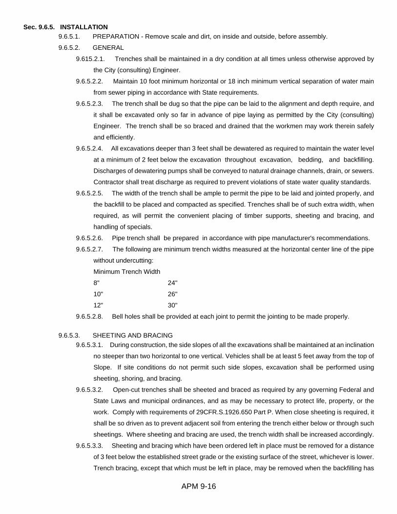
APM 9-16
Sec. 9.6.5. INSTALLATION 9.6.5.1. PREPARATION - Remove scale and dirt, on inside and outside, before assembly.
9.6.5.2. GENERAL
9.615.2.1. Trenches shall be maintained in a dry condition at all times unless otherwise approved by
the City (consulting) Engineer.
9.6.5.2.2. Maintain 10 foot minimum horizontal or 18 inch minimum vertical separation of water main
from sewer piping in accordance with State requirements.
9.6.5.2.3. The trench shall be dug so that the pipe can be laid to the alignment and depth require, and
it shall be excavated only so far in advance of pipe laying as permitted by the City (consulting)
Engineer. The trench shall be so braced and drained that the workmen may work therein safely
and efficiently.
9.6.5.2.4. All excavations deeper than 3 feet shall be dewatered as required to maintain the water level
at a minimum of 2 feet below the excavation throughout excavation, bedding, and backfilling.
Discharges of dewatering pumps shall be conveyed to natural drainage channels, drain, or sewers.
Contractor shall treat discharge as required to prevent violations of state water quality standards.
9.6.5.2.5. The width of the trench shall be ample to permit the pipe to be laid and jointed properly, and
the backfill to be placed and compacted as specified. Trenches shall be of such extra width, when
required, as will permit the convenient placing of timber supports, sheeting and bracing, and
handling of specials.
9.6.5.2.6. Pipe trench shall be prepared in accordance with pipe manufacturer's recommendations.
9.6.5.2.7. The following are minimum trench widths measured at the horizontal center line of the pipe
without undercutting:
Minimum Trench Width
8" 24"
10" 26"
12" 30"
9.6.5.2.8. Bell holes shall be provided at each joint to permit the jointing to be made properly.
9.6.5.3. SHEETING AND BRACING 9.6.5.3.1. During construction, the side slopes of all the excavations shall be maintained at an inclination
no steeper than two horizontal to one vertical. Vehicles shall be at least 5 feet away from the top of
Slope. If site conditions do not permit such side slopes, excavation shall be performed using
sheeting, shoring, and bracing.
9.6.5.3.2. Open-cut trenches shall be sheeted and braced as required by any governing Federal and
State Laws and municipal ordinances, and as may be necessary to protect life, property, or the
work. Comply with requirements of 29CFR.S.1926.650 Part P. When close sheeting is required, it
shall be so driven as to prevent adjacent soil from entering the trench either below or through such
sheetings. Where sheeting and bracing are used, the trench width shall be increased accordingly.
9.6.5.3.3. Sheeting and bracing which have been ordered left in place must be removed for a distance
of 3 feet below the established street grade or the existing surface of the street, whichever is lower.
Trench bracing, except that which must be left in place, may be removed when the backfilling has

APM 9-17
reached the respective levels of such bracing. Sheeting, except that which has been left in place,
may be removed after the backfilling has been completed or has been brought up to such an
elevation to permit its safe removal.
9.6.5.3.4. Sheeting and bracing may be removed before flooding the trench, but only in such manner
as will insure that adequate protection of the completed structures and adjacent underground or
surface structures, and prevent the disturbance of adjacent ground.
9.6.5.4. HANDLING MATERIAL 9.6.5.4.1. All pipe and accessories shall be loaded and unloaded by lifting with hoists or skidding in a
manner that will avoid shock or damage. Under no circumstances will such materials be dropped.
Pipe handled on skid ways shall not be skidded or rolled against pipe already on the ground.
9.6.5.5. INSTALLATION - GRAVITY SANITARY SEWERS 9.6.5.5.1. Trenching shall be in accordance with manufacturer's recommendations.
9.6.5.5.2. Gravity sewers shall be laid to exact line and grace by the use of a grade line supported on
batter boards spaced at not more than 25 foot centers or by laser beam. Sewers will be inspected
with a light at each manhole when the line is completed and backfill has been placed to a depth of
one-foot Over the pipe. Backfill may be completed only after approval of each section is given for
alignment and grade. Laser beam control is encouraged. Faulty sections of sewer lines rejected
by the City shall be removed and re-laid by the Contractor at his own expense.
9.6.5.6. INSTALLATION - FORCE MAIN 9.6.5.6.1. All pipe shall be laid to a minimum cover of 36 inches from established grade if not otherwise
indicated. Any variation there from shall be approved by the City (consulting) Engineer.
9.6.5.6.2. The pipe fittings shall be inspected for defects and while suspended above grade.
9.6.5.6.3. Every precaution shall be taken to prevent foreign material from entering the pipe while it is
being placed in the line. If the pipe laying crew cannot put the pipe into the trench and in place
without getting earth into it, the Engineer may require that before lowering the .pipe into the trench,
a heavy, tightly woven canvas bag of suitable size shall be placed over each end and left there until
connection is to be made to the preceding joint. During laying operations, no debris, tools, clothing,
or other materials shall be placed into the pipe.
9.6.5,6.4. After placing a length of pipe into the trench, the end shall be centered in the coupling and
the pipe forced home and brought to correct line and grade. The pipe shall be secured in place
with approved backfill material tamped under it except at the joints. Pipe and fittings which do not
allow a sufficient and uniform space for joint shall be removed and replaced with pipe fittings of
proper dimensions to insure such uniform space. Precautions shall be taken to prevent dirt from
entering the joint space.
9.6.5.6.5. At times when pipe laying is not in progress, the open ends of pipe shall be closed by a
watertight plug or other means approved by the Engineer. Joints of pipe in the trench which cannot
be poured shall be caulked with packing to make them as watertight as possible. This provision

APM 9-18
shall apply during the noon hour as well as overnight. If water is in the trench, the seal shall remain
in place until the trench is pumped completely dry.
9.6.5.6.6. The cutting of pipe for inserting fittings or closure shall be done in a neat and workmanlike
manner without damage to the pipe so as to leave a smooth end at right angles to the axis of the
pipe.
9.6.5.6.7. Install trace wire with all force main installations in accordance with City requirements.
9.6.5.6.8. All plugs, caps, tees, and bends deflecting 22 1/2 degrees or more on main 4 inches in
diameter or larger shall be provided with restraining glands and thrust blocks in accordance
with City standards.
9.6.5.6.9. Reaction backing shall be ready-mix concrete having a compressive strength of not less
than 2,500 psi in 28 days. Hand mixing will not be permitted. Backing shall be placed between
solid ground and the fitting to be anchored. The backing shall, unless approved by the City
(consulting) Engineer, be so placed that the pipe and fitting joints will be accessible for repair.
9.6.5.7. TESTING - GRAVITY SANITARY SEWERS 9.6.5.7.1. Each gravity sanitary sewer, upon completion, or at such time as the Engineer may direct, is
to be cleaned, tested, and inspected. All repairs or alterations shown necessary by these tests
shall be made; all broken or cracked pipe removed; all excessive infiltration stopped; all deposits
in pipe and manholes removed and the sewer left clear1, true to line and grade, and ready for use.
Each section of pipe form manhole to manhole is to show a full circle of light form either end. Each
manhole shall be to the specified form and size, to the proper depth, and watertight. The frame and
cover shall be permanently set to exact positions and grade. Any defects found in the system shall
be repaired to the satisfaction of the City. Gravity sewers will also be tested or gauged to determine
the amount of infiltration, and sewers in which the leakage or infiltration exceeds the following
maximum limit will not be acceptable. "50 gallons per 24 hours per mile of sewer pipe per inch of
nominal diameter where the invert of the sewer is constructed above the usual ground water
elevation.
9.6.5.7.2. Before final acceptance, gravity sewer lines shall be televised by a contractor with
qualifications suitable to the City. Each line will be recorded using a VHS video cassette. Each
run will be clearly labeled showing the manholes and with a counter indicating the lineal number of
feet run from the reference point. Film shall be in color and shall include inspection of all newly
installed laterals. The original video cassette shall be provided to the City.
9.6.5.7.3. Any deviation from grade greater than 1/2 inch for slopes of 0.4%, and less, and greater than
1 inch for grades than 0.4%, shall be cause for rejection of the installation.
9.6.5.8. TESTING - FORCE MAINS 9.6.5.8.1. Before pressure testing force main, place a minimum cover of 6 inches above the top of pipe
but leave all joints exposed. The backfill should be free of stones and hard earth. Pressure test
the pipe in the presence of the City Inspector and carefully examine joints for leaks. After pressure
testing, joints should be covered with same select backfill as used for pipe.

APM 9-19
9.6.5.8.2. Each valved section of force main shall be slowly filled with water and the specified test
pressure, based on the elevation of the lowest point of the line or section under test, and corrected
to the elevation of the test gauge, shall be applied by means of a gasoline driven test pump
connected to the pipe in a manner satisfactory to the City. The Contractor shall make
arrangements for metering the amount of water used during the test.
9.6.5.8.3. All joints shall be left uncovered during the test. If they become covered they shall be re-
dug. If the ditch is wet, each joint shall be pumped dry for inspection of loose bolts and leaks.
Sufficient manpower shall be employed to insure the inspection of each joint during the two-hour
test period. 9.6.5.8.4. Before applying the specified test pressure, all air shall be expelled from
the pipe. Taps at points of highest elevation shall be made before the test is made and plugs
inserted after the line has been flooded.
9.6.5.8.5. All exposed pipes, fittings, and joints will be carefully examined during the open trench test.
Any cracked or defective pipes or fittings discovered in consequence of this pressure test shall be
removed and replaced with sound material and the test shall be repeated until satisfactory to the
Engineer. 9.6.5.8.6. The leakage test shall be conducted at a minimum pressure of 150 psi.
9.6.5.8.7. Leakage is defined as the quantity of water to be supplied into the newly laid pipe, or in any
valved section thereof, necessary to maintain the specified leakage test pressure after the pipe has
been filled with water and the air expelled.
9.6.5.8.8. No pipe installation will be accepted until the leakage is less than the number of gallons per
hour as determined by the formula: L = ND (sq. rt. P) 3,700 in which L equals the allowable leakage
in gallons per hour; N is the number of joints in the length of the pipe line tested; D is the nominal
diameter of the pipe in inches; and P is the average test pressure during the leakage test, in pounds
per square inch gauge. (The allowable leakage, according to the formula is equivalent to 10.5 U.S.
gallons per 24 hours, per mile of pipe, per inch nominal diameter, for pipe in 20-foot lengths
evaluated on a pressure basis of 150 psi.)
9.6.5.8.9. Where any section of main is provided with concrete reaction backing, the hydrostatic
pressure test shall not be made until at least five clays have elapsed after the concrete reaction
backing was installed. If high early strength cement is used in the concrete reaction backing; the
hydrostatic pressure test shall not be made until at least two days have elapsed.
ARTICLE 7. DETAILED SPECIFICATIONS - WASTEWATER PUMPING STATIONS
Sec. 9.7.1. GENERAL Contractor shall furnish all labor, equipment, and materials and shall perform all operations in connection with
installation of a complete waste water pumping station ready for use in accordance with the specifications
and the City's requirements, either specific or implied. This includes any and all restoration required to
duplicate original site conditions prior to the commencement of construction.
Sec. 9.7.2. SUBMITTALS 9.7.2.1. Two copies of shop drawings for all components, including wet well and valve box, shall be
submitted to the City (consulting) Engineer for review. The City retains the right to refuse any proposed
substitution.
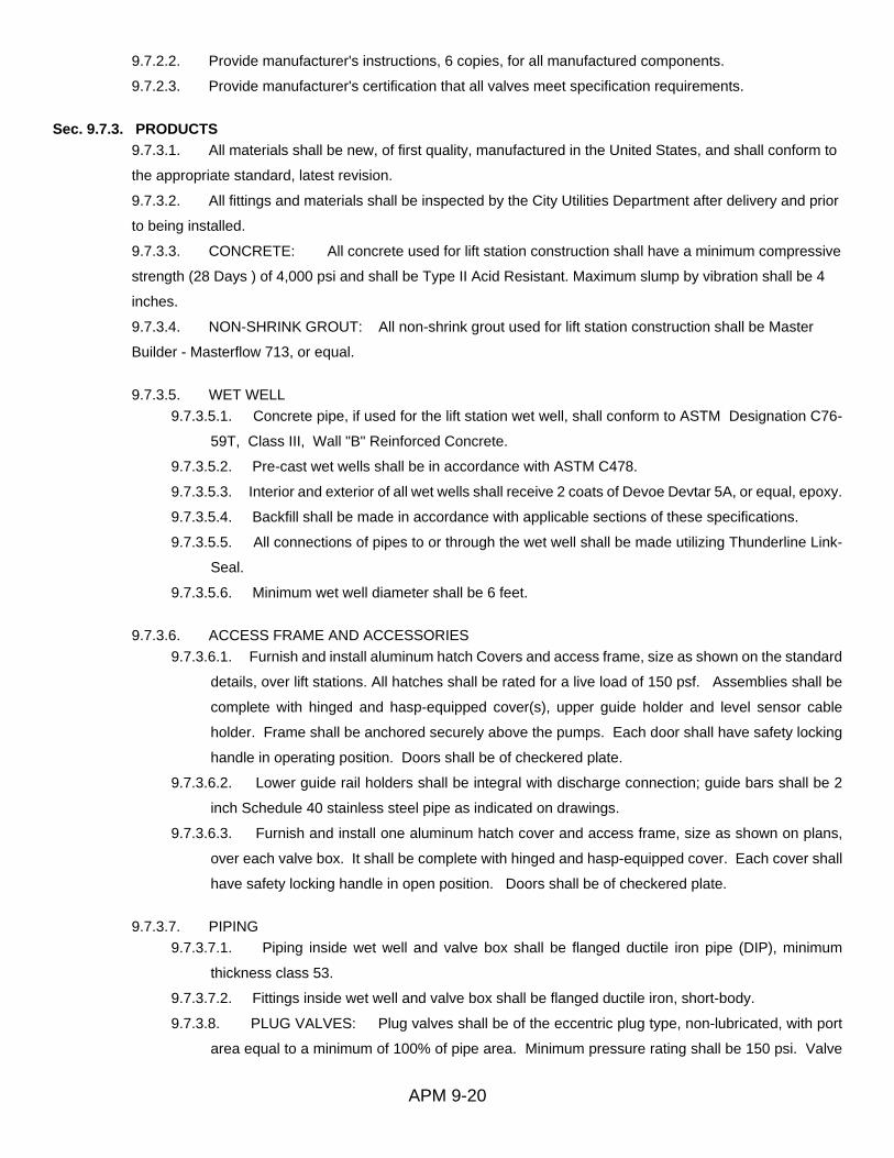
APM 9-20
9.7.2.2. Provide manufacturer's instructions, 6 copies, for all manufactured components.
9.7.2.3. Provide manufacturer's certification that all valves meet specification requirements.
Sec. 9.7.3. PRODUCTS 9.7.3.1. All materials shall be new, of first quality, manufactured in the United States, and shall conform to
the appropriate standard, latest revision.
9.7.3.2. All fittings and materials shall be inspected by the City Utilities Department after delivery and prior
to being installed.
9.7.3.3. CONCRETE: All concrete used for lift station construction shall have a minimum compressive
strength (28 Days ) of 4,000 psi and shall be Type II Acid Resistant. Maximum slump by vibration shall be 4
inches.
9.7.3.4. NON-SHRINK GROUT: All non-shrink grout used for lift station construction shall be Master
Builder - Masterflow 713, or equal.
9.7.3.5. WET WELL 9.7.3.5.1. Concrete pipe, if used for the lift station wet well, shall conform to ASTM Designation C76-
59T, Class III, Wall "B" Reinforced Concrete.
9.7.3.5.2. Pre-cast wet wells shall be in accordance with ASTM C478.
9.7.3.5.3. Interior and exterior of all wet wells shall receive 2 coats of Devoe Devtar 5A, or equal, epoxy.
9.7.3.5.4. Backfill shall be made in accordance with applicable sections of these specifications.
9.7.3.5.5. All connections of pipes to or through the wet well shall be made utilizing Thunderline Link-
Seal.
9.7.3.5.6. Minimum wet well diameter shall be 6 feet.
9.7.3.6. ACCESS FRAME AND ACCESSORIES 9.7.3.6.1. Furnish and install aluminum hatch Covers and access frame, size as shown on the standard
details, over lift stations. All hatches shall be rated for a live load of 150 psf. Assemblies shall be
complete with hinged and hasp-equipped cover(s), upper guide holder and level sensor cable
holder. Frame shall be anchored securely above the pumps. Each door shall have safety locking
handle in operating position. Doors shall be of checkered plate.
9.7.3.6.2. Lower guide rail holders shall be integral with discharge connection; guide bars shall be 2
inch Schedule 40 stainless steel pipe as indicated on drawings.
9.7.3.6.3. Furnish and install one aluminum hatch cover and access frame, size as shown on plans,
over each valve box. It shall be complete with hinged and hasp-equipped cover. Each cover shall
have safety locking handle in open position. Doors shall be of checkered plate.
9.7.3.7. PIPING 9.7.3.7.1. Piping inside wet well and valve box shall be flanged ductile iron pipe (DIP), minimum
thickness class 53.
9.7.3.7.2. Fittings inside wet well and valve box shall be flanged ductile iron, short-body.
9.7.3.8. PLUG VALVES: Plug valves shall be of the eccentric plug type, non-lubricated, with port
area equal to a minimum of 100% of pipe area. Minimum pressure rating shall be 150 psi. Valve

APM 9-21
bodies to be cast iron ASTM A126, Class B. Plugs shall be cast iron with neoprene facing and
shall be of the single piece design. Plug shall be of same configuration for all valves and shall
require no stiffening member opposite the plug for balance or support. Valve body seats shall have
a welded in overlay no less than 90% nickel. Packing shall be adjustable and shall be replaceable
without removing the valve from service, depressurizing the line, or removing the valve operator.
Bushings in both upper and lower journals to by type 316 stainless steel. Valve shall be drip !light
in both directions to the full pressure rating. All exposed nuts, bolts, springs and washers to be
stainless steel. All plug valves to be De7urik Figure 118 or equal. Coat valve exterior with 2 coats
of Koppers 300M, 12 mils each coat, in accordance with manufacturer's directions.
9.7.3.9. VALVE OPERATORS 9.7.3.9.1. Provide suitable hand wheels for gate, globe, angle, and drain valves and inside hose bibbs
mounted above-ground. Provide wrench operator having adjustable, open stop memory positions
for exposed plug valves smaller than 4 inches.
9.7.3.9.2. Provide gear operators for plug valves 4 inches and larger. Gear operators for plug valves
4 inches through 20 shall be of the worm and gear type. Operator shall include spur gears, AWWA
input stops, stainless steel bolting, and shall be outfitted for buried service, if applicable.
9.7.3.9.2.1. Gear operators shall be enclosed, suitable for running in oil, with shaft seals to prevent
entry of dirt and/or water. The actuator shaft and sector gear shall be supported on permanently
lubricated bronze bushings. Actuators without bronze bushings will not be allowed.
9.7.3.9.2.2. Gear operators shall be of the totally enclosed design and shall be proportioned to
permit operation of the valve under full rated pressure in either direction with a maximum force of
80 pounds on the hand wheel or crank. Provide stop limiting devices in the .operator at the open
and closed positions. Operators shall be of the self locking type to prevent creeping. Design
components between input and stop limiting devices to withstand without damage a pull of 200
pounds for hand wheel and crank operators and an input torque of 300 foot-pounds for wrench
nuts.
9.7.3.9.2.3. Worm gear shall be one-piece design for gear bronze material (ASTM B427),
accurately machine cut. Sector gear shall be hardened alloy steel. Reduction gearing shall run in
proper lubricant. Operators shall be Limitorque or ElM.
9.7.3.9.2.4. Gear operators for above-ground service shall be hand wheels with a minimum
diameter of 12 inches. Operator shall contain a dial indicating position of the valve plug. Chain
operators shall be provided as required.
9.7.3.9.2.5. All operators to open by turning counter clockwise.
9.7.3.10. CHECK VALVES 9.7.3.10.1. Valves shall be rubber flapper type check valve with full cast iron body and cover. Valve shall
be Apce Series 100, or equal.

APM 9-22
Sec. 9.7.4. PUMPS 9.7.4.1. Each pump shall be of the sealed submersible type. The pumps shall be capable of handling raw,
unscreened sewage and shall utilize impellers as shown in the pump schedule. The pump casing shall be
fitted with bronze wear rings. Each pump shall have mechanical seals with an oil chamber between seals.
Rotating seal faces shall be carbon and stationary seal faces are to be ceramic. Each pump shall be
equipped with seal failure probes and heat sensors.
9.7.4.2. All metal parts of the seal, including the spring, shall be 303 stainless steel. All pump fasteners
shall be 303 stainless steel.
9.7.4.3. Each pump motor shall be Of the sealed submersible type with Class F insulation for operation in
high-dielectnc oil to give better heat dissipation and longer bearing life. Each motor starter shall be held in
place with a removable end ring so that it can be removed for repair without heating outer shell or using a
press. Motor housing shall be filled with high-dielectric oil and no pressure balancing devices shall be used.
Pump motor shaft shall be of 303 stainless steel. Pump shall be a standard production pump with attached
rail discharge elbow. Rail guides shall be fastened to the pump so all lifting will be applied to the guide
supports. A lifting chain or cable of stainless steel, with a stainless steel hook shall be supplied for each
pump.
9.7.4.4. The discharge of each pump shall be fitted with a diaphragm type hydraulically operated sealing
flange. When pump is in operation, pressure shall force diaphragm against discharge elbow flange providing
a leak-proof seal. When pump is idle, pressure shall be removed from diaphragm so that pump can be
removed from sump with no mechanical contact of sealing flanges. The complete weight of the pump is to
rest on the bottom support plate, no weight is to be supported on the guide rails or discharge elbow. The
sealing diaphragm is to be removable and mounted on the pump discharge flange. Diaphragm material is to
be Buna N rubber.
9.7.4.5. A separate steel mounting plate shall be furnished for each pump. These plates shall include
adjustable guide rail supports and discharge elbow with flange to align with pump hydraulic sealing flange.
Discharge elbow shall have 125 pound standard flanges. Plates and fittings shall be coated with tar base
epoxy paint. All fasteners, hardware, etc., are to be stainless steel.
9.7.4.6. Pumps shall be as manufactured by Hydromatic. Substitutions are not allowed.
Sec. 9.7.5. CONTROL PANEL
9.7.5.1. GENERAL 9.7.5.1.1. The sewage pump control panels shall be self contained complete duplex pump control unit
containing the features described herein.
9.7.5.1.2. There shall be permanently affixed to the inside of the exterior enclosure door a nameplate
indicating the voltage, phase, horsepower, order reference number, date manufactured and the
control panel manufacture's name, address and telephone.
9.7.5.1.3. All power wire shall be stranded and sized as required for load and application according the
NEC. All control and signal wire shall be a minimum of #14 AWG, 90 degree insulated and color
coded. Colors shall be red for all AC control, blue for all DC control, yellow for external source
control, white for AC neutral, and green for equipment ground wiring. All wiring on the rear of the

APM 9-23
inner door shall be neatly bundled using tie wraps or other means. All internal wiring on the back
plate shall be neatly routed in wire duct with removable covers. All wiring shall be continuous point
to point (no splices) and be totally accessible with permanent number marking on each end to
match the control schematic drawings.
9.7.5.1.4. The panel shall be manufactured using quality workmanship and components. Upon
completion of the panel it shall be completely factory tested. All control and alarm operations shall
be performed with external signals simulated to insure proper operation. The three phase line
voltage source for which the panel is intended shall be used for testing.
9.7.5.1.5. Enclosure Construction and Materials.
9.7.5.1.5.1. The pump controls shall be housed in a NEMA 3R stainless steel enclosure. The
material used shall be 14 gauge, type 304 stainless steel with a 2B brushed finish. Construction
shall be machine formed to provide rounded edges and solid seam welded. The completed
enclosure shall have all welded seams ground smooth to a radius and buffed. The enclosure shall
be mounted as shown and sized to house all the required components and all adequate space for
testing and maintenance as necessary. The enclosure shall have back plate mounting studs,
padlocking provisions, door latches and continuous hinge, all of stainless steel. The door gasket
shall be continuous rubber composition with a molded in spring steel retainer for attachment to the
enclosure without the use of adhesives and provide a positive weatherproof door seal.
9.7.5.1.5.2. The panel shall have a hinged inner door of aluminum with a latch to protect all live
internal wiring from operator personnel. The inner door shall be able to be opened to a minimum
of 150 degrees to allow safe access to the components. Cutouts for breaker handles shall be
provided to allow the operation of all circuit breakers through the inner door. All control switches,
indicator pilot lights, elapsed time meters and motor starter overload reset push buttons shall be
mounted on the inner door. The inner door shall be designed so that the mounting will not in any
way penetrate the exterior of the control panel enclosure and deteriorate the NEMA rating. It shall
also be designed to allow and provide full access to the sides, top and bottom of the control panel
for power and control conduit entrance. All conduit entrances shall be made in a NEC approved
manner. The conduits to the wet well shall have approved seal off fittings installed and properly
sealed to protect the control panel from adverse damage from the wet well. All components shall
be securely mounted to the back plate with plated machine screws through machine thread tapped
holes in the backplate. The screws shall be of adequate size for the device being secured.
Permanent marking to identify each component as shown on the drawing shall be provided on the
backplate.
9.7.5.1.6. Power Distribution.
9.7.5.1,6.1. The panel power distribution shall include all components as indicated below
and be completely wired with stranded conductors having a minimum of 90 degree insulation rating
and an ampacity rating a minimum of 125% of the motor ampere rating, All power wiring shall be
neatly routed and totally accessible. All conductor terminations shall be as recommended by the
device manufacturer and be secure to provide adequate electrical conductivity.

APM 9-24
9.7.5.1.6.2. The panel shall have a normal and emergency main circuit breaker to allow manual
positive switching from the utility normal power source to a remote connected auxiliary standby
power source when the normal power has failed. They shall also provide a positive disconnect for
the normal and ampacity as per the NEC for main breakers. The two breakers must be 3 pole and
of the same frame and size rating. The voltage rating shall match that of the incoming service.
They shall be mounted side by side with an interlock to insure only one can be in the "ON" position
at a time and with the breaker handles and mechanical interlock totally accessible through the inner
door. The line side of the normal breaker shall have adequately sized lugs attached to provide
connection of the incoming normal power source conductors. The line side of the emergency
breaker shall be wired to an exterior mounted standby generator power receptacle. The load side
of the breakers are to be commonly connected and wired to the line side of each pump individual
branch circuit breaker. The normal and emergency breakers must have a permanently attached
positive mechanical interlock made of stainless steel. The interlock must be easily switched
between the two breakers only when both breakers are in the off position. The interlock must
provide that only one breaker shall be in the "ON" position at a time. When one is in the "ON"
position the other must be positively blocked in the "OFF" position and the handle shall not be free
to be inadvertently turned on. When either breaker is in the "ON" position it must be trip free to
allow it to be totally operational should a fault or overcurrent cause the trip unit to open the breaker.
The external power receptacle, for the connection of a standby generator, shall match the system
type. The receptacle shall be of reverse service design, 600 volt rated with an ampacity rating
sufficient to carry the total load of the panel• It shall be securely mounted externally to the side of
the enclosure to be fully accessible. The receptacle shall be totally weatherproof with a cover over
the plug access opening that is permanently attached. Receptacle shall be Russell-Stoll No.
JRSB1044FR for pumps to 25 horsepower and No. JRSB2044FR for pumps larger than 25
horsepower.
9.7.5.1.6.3. The pump motor breakers shall be thermal magnetic trip devices and provide for
individual motor disconnect and overload/short circuit protection as required by the NEC. The
breakers shall be 3 pole and have a trip rating as indicated on the drawings that shall not exceed
the NEC rating for motor branch circuit protection. The voltage rating shall match that of the panel
incoming service. The breaker handles shall be totally accessible through the inner door. All circuit
breakers shall be Square D, Westinghouse, or Allen Bradley.
9.7.5•1.6.4. For all pumps less than 20 HP, the motor starters shall be NEMA rated 3 pole devices
with 3 pole overload relay protection. They shall provide the electrical start/stop control and running
overload protection for each pump and have 120 volt operating coils. The thermal overload unit
heater coils shall be ampacity rated per the specific nameplate ampere rating of the pump motor
and checked upon final inspection prior to system start up. Starters shall be Square D,
Westinghouse, or Allen Bradely.
9.7.5.1.6.5. For all pumps 20 HP and larger, the motor starters shall be SMC Plus Motor
Controllers with pump control option as manufactured by Allen Bradley,
9.7.5.1.7. Power Panel Accessories.

APM 9-25
9,7.5.1.7.1. The panel power accessories shall include all components as indicated below and
be completely wired with stranded conductors. All wiring shall be neatly routed and sized as
required with a minimum of number 12 AWG. 9.7.5.1.7,2. The 120 volt common control circuit
and the 24 volt float circuitry shall be protected by an auxiliary 1 pole circuit breaker. The breaker
handle shall project through the inner door. Circuit breaker shall be Square D, Westinghouse, or
Allen Bradley.
9.7.5.1.7.3. The control panel shall have lightning arrestor protection included mounted on the
outside of the panel to protect the motors and control equipment from lightning induced line surges.
It shall be 600 volt rated and be a three phase unit with connection to ground. The arrestor shall
be mounted near the incoming power source and be properly wired to all three phases and ground.
Lightning arrestor shall be Volt-Guard, no substitutions.
9.7.5.1.7.4, The control panel shall have surge capacitor protection included within the panel to
protect the unit from damaging transient voltage surges. The surge arrestor shall be mounted near
the incoming power source and be properly wired to all three phases and ground. The surge
arrestor shall be a General Electric 9L18BAB301 or an approved equal.
9.7.5.1.7.5. A three phase monitor relay shall be installed to protect the motors. It shall be a three
phase voltage sensing device that is adjustable for the system nominal voltage. It shall protect the
control panel from loss of a single phase, even with a three phase motor running on line, low voltage
on all three phases simultaneously and phase sequence reversal. An output contact shall be wired
in the pump motor starter control circuit. Should the voltage fall below any of the parameters the
phase monitor shall shut off the pumps. The phase monitor shall automatically reset when nominal
voltage is restored to allow the pumps to restart. Phase monitor shall be Diversified SLA-230-ASA
for 230 volt systems and SLA-440-ASA for 460 volt systems.
9.7.5.1.7.6. A receptacle shall be mounted on the inner door to provide a maximum of 3 amperes
at 120 volt. The receptacle shall be a 15 ampere rated 3 wire ground fault interrupter duplex type.
Provide circuit breaker for receptacle. 9.7.5.1.7.7. The panel shall have an ammeter and ammeter
selector switches mounted on the inner door. The ammeter range shall be a 3 ½ inch, 2 percent
meter to indicate the full load ampacity of the pump between 2/3 and 3/4 scale. Matching current
transformers shall be included on each phase of the motor to provide the signal to the ammeters.
One selector switch shall select the pump to which the ammeter is connected. The second
selector switch shall be 4 position to read each phase and off.
9.7.5.2. DUPLEX PUMP CONTROLS 9.7.5.2.1. The control circuit shall provide for the automatic and manual control and alteration of the
pumps to maintain a pumped down condition of the wet well. The control system shall sense the
wet well level through remote wet well level sensing regulator float switches. The source voltage
for the float switches shall be 24 volt AC and the controls shall include all interposing relays. Four
regulator float switches shall include all pumps off level, lead pump on level, lag pump on level, and
high alarm level to control the pumps operation and provide alarms. The set point elevation of each
of the regulator floats shall be as indicated on the drawings. Terminal blocks shall be provided for

APM 9-26
each separate regulator float switch connection and other remote control device. The float switch
cables shall be of sufficient length to be continuous from the panel terminals. All control relays
shall be multi-contact plug in !type with track mounted bases. The pump alternator relay shall be
plug in type with a test switch and an alternator sequence selector switch. The control system shall
include alarm indication for high wet well level. The system shall have a lag pump delay timer to
prevent simultaneous starting of both pumps. Each pump shall have alarm indication and/or shut
clown for motor thermal alarm protection, motor overload alarm, pump failed alarm and seal failure
alarm The controls shall include but not be limited to the following functions and features.
9.7.5.2.2. A 3 position selector switch mounted on the inner door shall provide the Hand, Off or
Automatic operating mode selection for each pump. The switched shall be oil tight with 10 ampere
rated contacts as required. A position indicating legend plate and an identifying engraved
nameplate shall be provided with each switch. In hand position the pumps shall run continuously
without regard to the level sensing. In automatic position the pumps shall respond to the regulator
float switches in the wet well and start/stop on demand and in off position the pumps shall be locked
out and not operate.
9.7.5.2.3. A run pilot light shall be mounted on the inner door for each pump to turn on when the starters
are energized to indicate pump run. The pilot lights shall be 120 volt oil tight type with a red lens.
9.7.5.2.4. An elapsed time meter shall be mounted on the inner door for each pump to record the
accumulated running time of the pump motor. It shall run when the pump is operated in Hand or
Auto mode. It shall be 120 volt non-resettable and record time in hours (6 digits) and 10th.
9.7.5.2.5. An alternator relay shall be included to automatically provide alternation of the lead pump
upon completion of each pumping .cycle. It shall be 120 volt solid state plug in type with DPDT
Form C (double pole double throw) 10 ampere contacts and two LED position indicators to show
the alternator position. It also shall allow the lag pump to operate as a backup on demand.
Alternator shall be as manufactured by Diversified Electric.
9.7.5.2.6. An alternator test switch shall be provided to allow testing of the alternator. It shall be toggle
type switch bracket mounted on the backplate and have two positions, "AIt" for normal automatic
alternator operation and 'q'est" for a test operation. Switch shall have only momentary contact in
the "Test" position. The test cycle operation when repeated shall assure alternator operation.
9.7.5.2.7. A 3 position oil tight selector switch mounted on the inner door shall be provided for manual
alternator operation selection of a fixed sequence operation or automatic alternation of pumps
when operating under the automatic control logic. Selections to include a fixed pump 1 lead/pump
2 lag, automatic alternation, and a fixed pump 2 lead/pump 1 lag operation.
9.7.5.2.8. A lag pump delay timer shall be provided to delay the start of the lag pump after an interruption
in utility power to the control panel and the demand for both pumps to run exists. During normal
automatic operation the timer shall allow the lag pump to start immediately when called for. The
timer should be adjustable and set for 10 to 15 seconds.
9.7.5.2.9. The control circuit shall include a 120 volt to 24 volt transformer with a secondary fuse
to provide a low voltage source for the regulator floats that sense the wet well level for pump
operation. Terminal blocks shall be provided to connect each regulator float switch to the control

APM 9-27
circuitry, Each relay must operate in response to a specific regulator float in respect to the wet well
level with the relay energizing when the normally open float closes. Control relays, with 24 volt
operating coils, shall interface between the floats and the pump starters and alarm functions.
9.7.5.2.10. Liquid level indicator lights shall be provided. Lights shall indicate the position of each float
in the wet well. Pilot lights shall be oil-tight type. Low level float and lead pump float lenses shall
be green. Lag pump float indicator lens shall be yellow (amber). High alarm float indicator lens
shall be red. Provide momentary contact to test toggle switch for each light,
9.7.5.3: ALARM SYSTEMS 9.7.5.3.1. Each of the following alarm functions shall be included in the panel to continually monitor the
specific condition for which it is intended and provide the indication and response described. The
indicator pilot lights for all alarms shall be oil tight 120 volts with nameplates to identify each
function. These alarm functions are to protect the pumps and indicate abnormal conditions of the
system.
9.7.5.3.2. Alarm Light.
9.7.5.3.2.1. The exterior panel mounted alarm light shall be a weatherproof shatterproof red light fixture
with a 40 watt bulb to indicate an alarm condition exists. The general alarm light shall be turned on
by any alarm function. An indicator pilot light on the inner door shall show which of the alarm
conditions has caused the exterior general light to be turned on. The light shall turn off when the
alarm condition is corrected and the alarm circuit is manually reset, if required.
9.7.5.3.3. Audible Alarm Horn,
9.7.5.3.3.1. The exterior panel mounted audible alarm horn shall be a weatherproof device to
provide an audible signal to indicate an alarm condition exists. The alarm horn shall be a minimum
of 80 decibels and be turned on by any alarm function that will turn on the exterior alarm light. The
audible alarm shall be silenced by depressing the Alarm Silence pushbutton, located on the inner
door. The silence circuit shall automatically reset when the alarm condition is cleared.
9.7.5.3.4. High Level Alarm.
9.7.5.3.4.1. The high alarm level regulator float switch shall close on a high wet well level condition.
A High Level Alarm relay and an oil tight red pilot light shall be provided to indicate the alarm
condition. The general alarm shall turn on to indicate the alarm condition. The general alarm and
high level pilot tight shall automatically turn off when the high level condition has cleared.
9.7.5.3.5. Pump Moisture Alarms.
9.7.5.3.5.1. Each pump shall be provided with a seal failure alarm relay and an oil tight amber
pilot light to indicate the condition. The relay shall be a liquid sensing induction type relay and have
a secondary circuit wired to terminals, for each pump, to be connected to the moisture sensing
probe in each pump seal chamber. If probe senses moisture the seal failed relay shall turn on the
Sear Failed alarm pilot light to indicate same.
9.7.5.3.5.2. The pump shall be taken out of service by the seal failed alarm and the general alarm
shall indicate same. Immediate action must be taken for maintenance or replacement of the
failed seal to place the pump back in service and reset the alarm.

APM 9-28
9.7.5.3.6. Motor Temperature Alarms - Auto Reset
9.7.5.3.6.1. Each pump is to be provided with a thermal alarm relay and an oil tight red pilot light
to indicate the condition. Terminal blocks shall be provided for connecting the normally closed
thermal sensing contact located in each motor windings for motor thermal protection. An abnormal
rise in motor winding temperature shall cause the thermal alarm relay to shutdown the pump motor
and turn on the High Temperature red alarm pilot light and the general alarm to indicate same. The
thermal alarm shall automatically reset and restore pump operation upon the thermal contact
resetting when the thermal condition of the windings is back to normal due to the pump shutdown.
The thermal alarm shall also reset after a power failure or if control power is interrupted for any
reason.
9.7.5.3.7. Telemetry Alarm Contacts.
9.7.5.3.7.1. A telemetry alarm contact shall be provided for a remote interface signal to future
telemetry equipment. Each contact shall be a dry contact, open during normal conditions and wired
to terminal blocks. The respective contacts shall close upon alarm and return to normal when the
condition is corrected and the alarm reset. The alarm conditions monitored shall include high
level alarm and pump 1 or 2 failed. Provide 12"x12" space in lower right side of cabinet for future
telemetry system.
9.7.5.4. DRAWINGS AND MARKINGS 9.7.5.4.1. Panel Marking.
9.7.5.4.1.1. All component parts in the control panel shall be permanently marked and identified
as they are indicated on the control drawings. Markings shall be on the backplate adjacent to the
component.
9.7.5.4.1.2. All control panel conductors shall be permanently number marked with wire markers
at each end as close as practical to the termination of the conductor.
9.7.5.4.2. Nameplates.
9.7.5.4.2.1. The panel shall include engraved nameplates on the inner door for all components to
indicate the device function. The nameplates shall be permanently affixed with plated machine
screws or a bonding adhesive suitable for the application. The material shall be white with a black
core and have a minimum of 3/16 inch letters.
9.7.5.4.3. Final Drawings.
9.7.5.4.3.1. Upon completion of the panel a complete set of As Built drawings and Bill of Materials
shall be supplied to the City. The drawings shall include a power and control schematic an a
terminal block diagram showing each remote connection to the panel. An adhesive mylar copy of
the schematic drawings and terminal diagram must be permanently affixed to the inside of the
control panel door.
9.7.5.6. Float switches shall be "Roto-float" as manufactured by Anchor Scientific or approved equal.

APM 9-29
Sec. 9.7.6. SPARE PARTS. One complete set of mechanical seals shall be supplied for each pump bearing furnished. The spare parts for
each control panel shall also include one spare alternator, one complete spare relay with base and spring
retaining clip and one spare phase monitor relay with base.
Sec. 9.7.7. INSTALLATION.
9.7.7.1. PLACEMENT OF CONCRETE 9.7.7.1.1. Forms for bottom slabs may be omitted when the soil and workmanship permit accurate
excavation to size, and the omission is approved by the City.
9.7.7.1.2. Removal of forms shall be done in a manner which will assure complete safety of the
structure. In no case shall the supporting forms be removed until the members have acquired
sufficient strength to support their weight and loads thereon safely.
9.7.7.1.3. All water and foreign matter shall be removed from forms and excavations. Unless otherwise
directed, wood forms must be thoroughly wetted just prior to placing concrete.
9.7.7.1.4. Concrete shall be deposited as nearly as practicable in its final position to avoid segregation
due to rehandling of flowing, conduits, sleeves, hangers and other work required to be built into
concrete shall be inspected and approved by the City. No concrete that has been partially hardened
becomes contaminated by foreign materials, or has been retempered, shall be used. Placement
of concrete shall generally be carried on as a continuous operation until construction joints are
necessary. Except for slabs on earth surfaces, concrete shall be placed with the aid of mechanical
vibrating equipment. The frequency of vibration shall be sufficient to cause flow or settlement of the
concrete into place. The vibration shall be of sufficient duration to accomplish thorough compaction.
Vibration shall be supplemented by forking or spading by hand adjacent to the forms on exposed
faces in order to secure smooth, dense, even surfaces. The concrete shall be compacted and
worked in an approved manner into all corners and angles of the forms and around reinforcement
and embedded fixtures. Light hammer tapping will be allowed at lift lines to prevent air bubbles.
9.7.7.1.5. Curing: Finished concrete shall be kept damp continuously for one week after it
has been poured, or some acceptable curing compound shall be used as directed by the
manufacturer. All concrete shall be used as directed by the manufacturer. All concrete shall be
adequately protected from injurious action by the sun, heavy rains, flowing water and mechanical
injury.
9.7.7.2. TOP SLAB 9.7.7.2.1. Size of top slab shall be as shown on the City's standard details. It is very important that the
Access Cover is properly installed in the top slab, with the proper orientation (hinge side as shown
on drawing).
9.7.7.2.2. Check top slab horizontally with level. Consult manufacturer's individual access over drawing
before installation of access cover.
9.7.7.2.3. Provide padlocks for access covers keyed to City's master key system.
9.7.7.3. AUTOMATIC DISCHARGE CONNECTION

APM 9-30
9.7.7.3.1. The automatic discharge connection shall be attached to the bottom slab level and at the
exact location required relative to the access cover.
9.7.7.4. INTERNAL PIPING AND MANIFOLD 9.7.7.4.1. Use proper gaskets, tighten bolts gradually and evenly. On all lift stations deeper than 15
feet, install discharge pipe brackets to relieve discharge connection from overload and intermediate
guide bar brackets to prevent guide bars from bending when pumps are pulled.
9.7.7.5. INSTALLATION OF PUMPS 9.7.7.5.1. Contractor shall install pumps with City representative present. Lower pump units into place
along guide bars. Check visually contact between volute flange and discharge connection. If
necessary, recheck and re-align discharge connection(s) and guide bars with pumps in place
9.7.7.6. GROUTING 9.7.7.6.1. After proper alignment of all components is established, grout access cover, discharge
connection(s) and pipe thrulets. Build up and shape slopes at pump button in accordance with
drawing. Use top quality grout only (Meadow-Sealtight V-4 Non-Metallic or equal.)
Sec. 9.7.8. DETAILED SPECIFICATIONS - WASTEWATER PUMPING. Variation of product requirements by brand name or specification number may be made by the Administrative
Official when it can be determined by the Administrative Official that the substitute is equal to or better
than the product required or that the substitute product will better meet the public need and that the intent
of these regulations are being met.
ARTICLE 8. FIRE FLOW REQUIREMENTS
All water distribution systems shall be designed to provided adequate fire flow to all new construction. Fire flow
requirements shall be calculated in accordance with one of the 3 methods contained in "Distribution
System Requirements for Fire Protection," AWVVA M31, 1989, except that fire flow for one and two
family dwellings shall be calculated in accordance with Table 1-4 of the same manual.

APM 10-1
CHAPTER 10. FEES AND EXPENSES.
ARTICLE 1. GENERAL. The City Commission may establish a schedule of fees and expenses and a collection procedure for development
permits, certificates of compliance, appeals and other matters pertaining to the Land Development
Regulations and the Comprehensive Plan. The schedule of such fees and expenses shall be posted in
the office of the Administrative Official and other locations deemed appropriate for public access, and
may be altered or amended only by the City Commission.
ARTICLE 2. PAYMENT.
Sec. 10.2.1. FEES AND EXPENSES TO BE PAID IN FULL Until all applicable fees and expenses have been paid in full; no action, including processing or review shall be
taken on any petition or appeal by any City Staff members.
ARTICLE 3. COST.
Sec. I0.3.1. ESTABLISHED FEES-. Fees may be required for more than one of the following categories for the same development, depending upon
the type of development and City actions required.
10.3.1.1. DEVELOPMENT RELATED FEES
Appeal .......................................................................... $100.00
Variance ........................................................................ $100.00
Special exception ......................................................... $200.00
Wth impact statement ............................................. $350.00
Zoning amendment request .......................................... $300.00*
With impact statement ............................................ $450.00*
**Plus area adjustment for acreage over 5 acres ... $5.00/acre
Maximum filing fee ......................................... ........ $1,000.00
Planned Unit Development.
Basic filing fee ........................................................ $300.00**
With impact statement ............................................ $450.00**
**Plus adjustment:
Residential ....................................................... $3.00/acre + $0.30/dwelling
Recreational Vehicle Parks ............................. $3.00/acre + $0.50/lot
Commercial, Industrial, Institutional ................. $5.00/acre

APM 10-2
Final PUD approval:
Without public hearing ............................................ $100.00
Modification of a PUD:
Minor ....................................................................... $75.00
Major ..................................................................... $300.00
Time extensions of planned unit development approvals .................. $30.00
Development of regional impact:
Basic filing fee ......................................................... $1,750.00
**Plus area adjustment:
Residential. ....................................................... $3.00/acre + $0.50/dwelling
Institutional ...................................................... $3.00/acre
Commercial/industrial ....................................... $5.00/acre
Development agreement: ............................................. $300.00
Subdivision plat ............................................................ $500.00 + $5/lot, plus consultant review time as
required by the City. (See Sec. 10.3.2.)
Small lot subdivision plat
(4 or less lots) ...........................................…………$200.00+ consultant review time as required by the
City.(See Sec. 10.3.2.)
Minor plat amendment ........................................... $75.00
Sand mining:
Mining operating permit .......................................... $500.00
Annual progress report .......................................... $150.00
Street vacation .............................................................. $100.00
Site Plan Review:
Commercial, Industrial ............................................ 1/2 the cost of building permit fee + any extraordinary
expenses determined to be necessary by the
Administrative official as provided for in Sec 10.3.2
Residential .............................................................. none
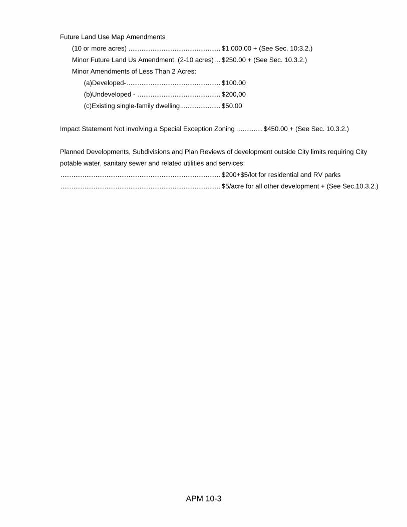
APM 10-3
Future Land Use Map Amendments
(10 or more acres) .................................................. $1,000.00 + (See Sec. 10:3.2.)
Minor Future Land Us Amendment. (2-10 acres) ... $250.00 + (See Sec. 10.3.2.)
Minor Amendments of Less Than 2 Acres:
(a)Developed- ................................................... $100.00
(b)Undeveloped - ............................................. $200,00
(c)Existing single-family dwelling ...................... $50.00
Impact Statement Not involving a Special Exception Zoning .............. $450.00 + (See Sec. 10.3.2.)
Planned Developments, Subdivisions and Plan Reviews of development outside City limits requiring City
potable water, sanitary sewer and related utilities and services:
....................................................................................... $200+$5/lot for residential and RV parks
....................................................................................... $5/acre for all other development + (See Sec.10.3.2.)

APM 10-4
10.3.1.2. CONSTRUCTION RELATED FEES
Building Valuation .......................................................... Building Valuation Data, Square Foot Construction
Cost, as published by the International Code Council
(updated each August)
Minimum Permit Fee ..................................................... $60.00
Building Permit Fee Multiplier ........................................ Building Valuation x.004 (Includes roofs, pools,
sheds, signs, fences, etc.)
Commercial Trade Permit Fees (Mechanical, Electric, Plumbing, Gas)
Job Valuation Under $15,000 ................................. $60.00
Job Valuation Over $15,000 ................................... Job Valuation x .004
Mobile Home Set-up Permit .......................................... $150.00
Temporary Structure Permit .......................................... $50.00
Demolition Permit
Up to 10,000 sq. ft. .................................................. $50.00
Over 10,000 sq. ft. ................................................... $50.00 + $0.50 per 1,000 sq. ft.
Moving Permit ................................................................ $250.00
Plan Review Fee............................................................ ½ $ Amount of Building Permit Fee
Reinspection Fee ........................................................... $35.00
Discount for Private Provider inspection ....................... 70% Discount

APM 10-5
Sec. 10.3.2. EXTRAORDINARY EXPENSES: In addition to the fee schedule outlined above, the applicant shall be responsible for the payment of any
extraordinary expenses incurred by the City of Auburndale, Florida, in analyzing or reviewing all or any
part of an application. The extraordinary expenses may be occasioned by the City's retention of the
services of a third party consultant. Such expenses shall be billed at the actual cost of fees and
expenses incurred for rendering such services. The applicant will be advised of the necessity of such
expense prior to it being incurred. The applicant and Administrative Official of the City must jointly
approve an estimated cost amount before these charges can be authorized. These charges for
extraordinary expenses will be paid in advance to the City in the form of cash or certified check prior to
incurring of such expense. Upon request by the applicant, the City Commission may review such
extraordinary expenses as to the necessity and amount.

AUBURNDALE, FLORIDA 33823
Building & Zoning
Phone: (863) 965-5530
P.O, Box 186
FAX (863) 965_5598
Building and Zoning Division Price List
Generalized Future Land Use Map ............................... $20.00
Official Zoning Map ........................................................ $20.00
Land Development Regulations (LDR) on disk ............. $50.00
Printed Copy of Land Development Regulations (LDR) $150.00
Commercial & Residential Databank Plan Retrieval .... $30.00
24'x36' Site Building or Plot Plan (1st page) ................. $20.00
....................................................................................... (Each additional page) $5.00
APM 10-6

APM 11-1
CHAPTER 11. GENERIC SUBSTANCE LIST
GENERIC SUBSTANCE LIST Acid and basic cleaning solutions
Antifreeze and coolants
Arsenic and
arsenic compounds
Bleaches, peroxides
Brake and transmission fluids
Brine solution
Casting and foundry chemicals
Caulking agents and sealants
Cleaning solvents
Corrosion and rust prevention solution@
Cutting fluids
Degreasing solvents
Disinfectants
Electroplating solutions
Explosives
Fertilizers
Fire extinguishing chemicals
Food processing wastes
Formaldehyde
Fuels and additives
Glues adhesives and resins
Greases
Hydraulic fluid
Indicators
Industrial and commercial janitorial supplies
Industrial sludges and stilIbottoms
Inks. printing and photocopying chemicals

APM 11-2
Laboratory chemicals
Liquid storage batteries
Medical. _pharmaceutical dental, veterinary and hospital solutions.
Mercury and mercury compounds.
Metals finishing solutions
Oils
Paints, primers thinners dyes stains wood preservatives, varnishing and cleaning
COFRDOUDGS.
Painting solvents
PCB's
Pesticides and herbicides
Plastic resins Dlasticizers and catalysts
Photo development chemicals.
Poisons
Polishes
pool chemicals
processed dustanc particulates
Radioactive sources
Reagents and standards
Refrigerants
Roofing Chemicals and sealers
Sanitizers disinfectants, bactericides and algaecides
Soaps, detergents and sudactants
Solders and fluxes
Stripping compounds
Tanning industry chemicals
Transformer and capacitor oils/fluids
Water and wastewater treatment chemicals