Adaptive Modulation Control for Visible Light Communication ...
11
HAL Id: hal-03134465 https://hal.archives-ouvertes.fr/hal-03134465 Submitted on 8 Feb 2021 HAL is a multi-disciplinary open access archive for the deposit and dissemination of sci- entific research documents, whether they are pub- lished or not. The documents may come from teaching and research institutions in France or abroad, or from public or private research centers. L’archive ouverte pluridisciplinaire HAL, est destinée au dépôt et à la diffusion de documents scientifiques de niveau recherche, publiés ou non, émanant des établissements d’enseignement et de recherche français ou étrangers, des laboratoires publics ou privés. Adaptive Modulation Control for Visible Light Communication Systems Antonio Costanzo, Valeria Loscri, Mauro Biagi To cite this version: Antonio Costanzo, Valeria Loscri, Mauro Biagi. Adaptive Modulation Control for Visible Light Com- munication Systems. Journal of Lightwave Technology, Institute of Electrical and Electronics Engi- neers (IEEE)/Optical Society of America(OSA), 2021, 10.1109/JLT.2021.3056177. hal-03134465
-
Upload
khangminh22 -
Category
Documents
-
view
1 -
download
0
Transcript of Adaptive Modulation Control for Visible Light Communication ...
HAL Id: hal-03134465https://hal.archives-ouvertes.fr/hal-03134465
Submitted on 8 Feb 2021
HAL is a multi-disciplinary open accessarchive for the deposit and dissemination of sci-entific research documents, whether they are pub-lished or not. The documents may come fromteaching and research institutions in France orabroad, or from public or private research centers.
L’archive ouverte pluridisciplinaire HAL, estdestinée au dépôt et à la diffusion de documentsscientifiques de niveau recherche, publiés ou non,émanant des établissements d’enseignement et derecherche français ou étrangers, des laboratoirespublics ou privés.
Adaptive Modulation Control for Visible LightCommunication Systems
Antonio Costanzo, Valeria Loscri, Mauro Biagi
To cite this version:Antonio Costanzo, Valeria Loscri, Mauro Biagi. Adaptive Modulation Control for Visible Light Com-munication Systems. Journal of Lightwave Technology, Institute of Electrical and Electronics Engi-neers (IEEE)/Optical Society of America(OSA), 2021, 10.1109/JLT.2021.3056177. hal-03134465

1
Adaptive Modulation Control for Visible LightCommunication Systems
Antonio Costanzo*, Valeria Loscri* IEEE Senior Member and Mauro Biagi**, IEEE Senior Member
Abstract—Visible light communication (VLC) builds on thedual use of lightening infrastructure for communication. Eventhough the advantages of VLC are well known, as emergingcommunication paradigm, some open issues still need to beaddressed in order to rely on it as a robust communicationsystem. First of all, external interference as an extremely varyingsignal impacting on the reliability of the VLC system needsto be analyzed. In this paper, we propose a system where thelink conditions (in terms of signal-to-noise-ratio (SNR)) drivethe modulation scheme and this procedure is managed throughthe use of an uplink/channel, to assure a feedback path. Thereceiver is in charge of choosing the modulation scheme matchingthe requirement in terms of error rate on the basis of themeasured SNR after noise mitigation. The feasibility of thesystem and its effectiveness are evaluated by designing andimplementing a complete bi-directional system. In particular, anuplink channel sending the information regarding the specificselected modulation technique has been implemented and thewhole system is based on a fine synchronization approach in orderto “track” in real time the most suitable modulation scheme.Experimental results show the effectiveness of a bi-directionalsystem in order to implement an adaptive VLC system able tofollow the environmental changes (in terms of interference andnoise).
Keywords:Visible Light Communication, Adaptive Modula-tion, Noise Mitigation, SNR
I. INTRODUCTION
Visible Light Communication (VLC) [1] paradigm en-visages the use of Light Emitting Diodes (LED) for datacommunication. In other words, VLC could be consideredas an extension of optical wireless communication (OWC) tolampshade lights. In recent years, LED lights have becomemore and more convenient in comparison to other lightingsystems, like fluorescent sources; the ratio between LEDelectrical power consumption and brightness considerably de-creased in last years, as well as the price of the radiatingelements. Long lifetime, physical robustness, small size, andfast switching are the main reasons why LED lamps are widelyreplacing other illumination devices. An infrastructure that canbe simultaneously employed for illumination and data commu-nication, allows a huge long term energy saving. Furthermore,VLC presents several other advantages in comparison to radiofrequency (RF) and microwave communication systems. Firstof all, VLC could be exploited in all those places whereRF solutions represent a dangerous source of interferencein critical environments (e.g. hospitals, aircrafts, mines and
Antonio Costanzo, Valeria Loscri are with Inria Lille - Nord EuropeMauro Biagi is with Dept. of Information, Electrical and Telecommunica-
tion (DIET) engineering, “Sapienza” University of Rome, Via Eudossiana 18,00184 Rome, Italy. Ph. no. +39 06 44585856 FAX no. +39 06 44585632.
petrochemical plants). VLC could be used for short distanceunderwater communication [2], [3], because the absorptioncoefficient of water at optical frequencies (especially in theblue range), is several times lower than the one shownat lower frequencies of the electromagnetic spectrum. VLCparadigm has also been considered to obtain affordable indoorpositioning operations [4], [5], and portend future vehicleto vehicle communication [6]. Since frequency spectrum hasbecome significantly crowded in latter years, with a possiblesaturation in the next decade, the integration of VLC systemcould significantly mitigate this problem.
However, even if this VLC paradigm involves indisputableadvantages, improving the quality of the optical signal toachieve higher performance, currently represents a main issueto obtain an effective applicability in real scenarios.
A. State of Art
One of the main challenges is to adapt existing signalprocessing techniques, available for classical wireless com-munication, to the signal diffused by LED lamps. Indeed, datatransmission in VLC systems is usually performed by intensitymodulation and direct detection. According to this technique,information can be transmitted and received only using realand positive signals. Conventional modulation schemes, likeon-off keying (OOK), pulse-amplitude modulation (PAM),pulse position modulation (PPM), frequency shift keying(FSK) and Optical orthogonal frequency-division multiplexing(OFDM) modulation [8] have been properly modified for al-lowing the processing of VLC signals. Regardless of modula-tion scheme, the main issue is represented by the high level ofinterference caused by external light sources and the extremelyvariability of this interference in a real scenario. Recently, ithas been also experimentally demonstrated that other sourceof interference can seriously impact on the performance ofa VLC system [18]. In particular, sunlight can completelywaste the quality of received optical signals, especially inoutdoor environments. Other noise sources are representedby thermal and shot noise. Thermal noise, caused by randommotion of electrons or charges, is mainly generated during theamplifying stage. Shot noise is related to the total amount oflight incident on the photo-detector. Typically, in conventionalmethods, high-pass filters are adapted to block direct current(DC) signals affected by noise [9]. However, since opticalsignals are modulated as square waves, filtering process isnot sufficient to achieve a clean output. In [10] spectralline interference is theoretically analysed and approximatelymitigated by adopting a set of improved waveform samples;

in [11] noise effects on synchronization are reduced using alearning technique based on multi-armed bandit; an effectivenoise mitigation approach, based on the noise listening andsuccessive noise mitigation to limit the effects of externallights on Symbol Error Rate (SER) has been introduced in[12].
B. Goals and organization of the work
Among the first contributions in terms of software definedopen platforms for Visible Light Communications are [19]and [20], where the authors demonstrate the feasibility ofthe communication based on visible light by the means ofa software defined approach and based on the use of low-costcommercial devices.
One of the first and most advanced software defined openplatforms for Visible Light Communication is OpenVLC [21],where the authors highlight the importance and difficulty ofsynchronization between a receiver and a transmitter in abi-directional VLC system. The approach considered by theauthors to avoid mistiming issue consists in oversampling. In[22] the authors implement a unidirectional VLC platform anddemonstrate the OFDM implementation.
To the best of our knowledge there are not real platformsimplementing a robust adaptive communication system basedon visible light, integrating a noise mitigation approach formaking the system suitable to adapt to the most efficient, interms of energy and spectral efficiency, modulation schemeand implementing a robust synchronization scheme betweenthe transmitter and the receiver in order to make the systemable to react in real time to the dynamic of the externalchanges.
In most of previous works, considering adaptive mecha-nisms, a unidirectional data stream is considered. Hence, forfully taking advantage of adaptive schemes in real implemen-tation, it is mandatory to consider an uplink channel. Indeed,when the external conditions vary, the system can report themost suitable modulation to be selected by the means of thischannel used as a feedback link. Based on that, in this work wedesign and implement a VLC system in which we consider anuplink channel between the receiver (Rx) and the transmitter(Tx) nodes in order to effectively adapt the parameters of thesystem based on the surrounding changes. Of course, this kindof implementation implies new challenges, above all in termsof synchronization between the data flow transmission betweenthe Tx and Rx and the corresponding uplink/feedback channel.
The main contributions of this work can be summarized asfollows:• We propose a novel bidirectional VLC system capable to
select the most suitable modulation scheme according tothe reliability level and based on the Signal to Noise Ratio(SNR). The implementation utilizes a two-way VLC linksince we do not consider here illumination constraints.Differently, in the case of ceiling-to-floor communicationit is important to pay attention for the uplink channel dueto light coming from floor-to-ceiling.
• We apply a noise mitigation approach as defined in [12],with the main difference that we integrate this approach
to work in real-time. In practice, the variations of externalconditions directly impact on the performance of the sys-tem evaluated in terms of SNR and thanks to a fine-coarsesynchronized uplink channel, the communication systemis able to adapt with the most appropriate modulationscheme.
• By the means of a software defined approach [16], [17],we design and implement the whole communication pro-tocol, integrating the noise mitigation, the synchroniza-tion approach and we demonstrate not only the feasibilityof such a type of systems but also the effectiveness indifferent real scenarios.
The paper is organized as follows. After introducing thesystem model in section II, we describe the different proce-dures including synchronization, channel estimation, modula-tion control and detection in section III. We give the detailsof the system implementation in section IV. The performanceof the proposed system are reported in section V, while insection VI we conclude the work.
II. SYSTEM MODEL
We assume to have a downlink channel where transmissionand detection take place and an uplink channel, from receiverto transmitter, providing a feedback about the modulationscheme to employ in the next frame. The main actionsperformed by the system are described in Fig. 1
SEND INFO ABOUT NEXT MODULATION
DECODIFY INFO ABOUT
MODULATION
RECEIVERTRANSMITTER
Uplink
MODULATEUSER DATA
SEND USER DATADownlink PERFORM
NOISE MITIGATIONESTIMATE SNR
DECIDENEXT
MODULATION
DEMODULATE USER DATA
Fig. 1. Adaptive modulation control system for VLC: main operations.
A. Downlink channel
Transmitted signal is allowed to have a maximum powerlevel equating Pmax. The modulation schemes we considerin this work are both non-orthogonal and orthogonal, namely2-, 4-, 8-, 16- PAM and 2-, 4-, 8-, 16- PPM. As knownfrom communication theory, the former let increase rate atthe expense of error rate while the latter let achieve highreliability at the expense of transmission rate with increasingof the modulation index. In the case of PAM, the transmittedsignal is
sa(t) = A`x(t) (1)
with A` belonging to the M-ary set of amplitudes charac-terizing the PAM alphabet, x(t) = A0Π(
t−Tp
τ ) represents
2

the rectangular transmitting pulse, delayed by Tp and withduration τ , driving the LED before applying the modulation.A0 = 12V is the constant amplitude of the pulse drivingthe LED in our transmitting circuit . The PPM signalling isrepresented by the following relationship
sd(t) = x(t−∆`Tp) (2)
where ∆` describes the delay ranging from 0 to M-1 asmultiple integer of Tp elementary delay equating, at least,the pulse length in order to grant orthogonality among PPMsymbols. A fair comparison among those two modulations isnot trivial since while PPM assures to have an illuminationequating Pmax in a PPM symbol, PAM is not able anda proper amplitude setting must be carried out. For sakeof fairness we consider that each PPM symbol presents anintensity equating Pmax so the energy among a PPM symbolis EPPM = Pmax/MTp. For PAM we consider to have thesame energy (average) so the amplitudes are in the interval0, ..., 2EPPMTp. In other words we consider to have thesame illumination level for PPM and PAM.
In order to maintain a high level of flexibility, and avoidas much as possible overhead and additive signal processing,data frame involved in the downlink optical communicationincludes only a starting pulse, an information pulse (whichidentifies the type of modulation), user data and an endsequence, as shown in Fig. 2.
Starting Pulse Information Preamble User Data End Sequence
2ppm
4ppm
8ppm
16ppm
2pam
4pam
8pam
16pam
2τ 8τ 14τ 20τ 26τ 32τ 38τ 44τ 50τ
Fig. 2. Downlink Communication: Starting pulse and identification preamblefor all available modulations
The starting pulse,with duration Tstart , lasts 4 times thepulse length of the PPM modulation one and it is used bythe receiver for synchronization issue and identifying thebeginning of the frame. In the description, we consider thenotation A0Π( t−ab ), which represents the rectangular functioncentered at a, with duration b and amplitude A0. Since weconsider the beginning of the starting pulse as zero timereference, a = 2τ and b = Tstart = 4τ . Considering thesignal driving the LED before applying the modulation, A0 isthe constant amplitude of the pulse driving the LED. In ourtransmitting circuit, A0 = 12V . The starting pulse is identicalfor each modulation scheme adopted in the system, namely:
sstart(t) = A0Π
(t− 2τ
4τ
)(3)
The information pulse, with duration Ts, codifies, througha PPM signal, the type of modulation the receiver has to setfor data recovering. We maintained, for the information pulse,the same width of the starting pulse, so Ts = Tstart = 4τ .
In order to avoid synchronization errors, which could leadto misunderstand the correct modulation, guard intervals areplaced between the starting pulse and the information pream-ble, between each possible pulse position and between theinformation preamble and codified user data. The width ofguard intervals is twice the pulse adopted by PPM modulation(Tg = 2τ ). We chose guard intervals at least twice the pulse,in order to easily avoid ambiguity due to rising and fallingedges, clock drifts and other phenomena. Indeed, an errorin retrieving the correct position of the pulse representinginformation preamble, would completely corrupt the wholecontent of user data. We chose the above values for starting andsynchronization pulses, for avoiding any possible ambiguitywith user data. In our case, a starting pulse equal to 4τ islong enough to avoid false trigger caused by background lightand other external optical sources.
Furthermore, being MPPM the order of PPM modulationused by the transmitter (2, 4, 8 or 16), and following the sametime reference used above, the associated synchronizationpulse is:
sMPPM(t) = A0Π
(t− aPPMbPPM
)(4)
where bPPM = 4τ and, aPPM , referring to Fig. 2, is
aPPM = 6τ + log2(MPPM )Tg + (log2(MPPM ) − 1)Ts (5)
According to the time representation in Fig. 2, the first termin Eq. (5) refers to the first possible pulse position (the oneindicating 2PPM), which, in our implementation, is equal toTstart + Tg = 6τ . For further modulation indexes, the pulsesare sequentially delayed by an additive Tg (second term in Eq.(5)) plus a Ts (last term).
In order to avoid complex synchronization schemes, PAMmodulations are indicated with the same mechanism. A furtherdelay aPAM , is added to the position of the pulse related to16PPM modulation, which is located at a16PPM .
Looking at Fig. 2, and being MPAM the order of PAMmodulation, the corresponding synchronization pulse becomes:
sMPAM(t) = A0Π
(t− a16PPM − aPAM
bPAM
)(6)
where, pulse width is:
bPAM = bPPM = 4τ (7)
aPAM = 4τ + log2(MPAM )Tg + (log2(MPAM )−1)Ts (8)
From eq.(5), the delay associated to 16 PPM is
a16PPM = 6τ + log2(16)Tg + (log2(16)− 1)Ts = 26τ (9)
The term 4τ in eq. (8) properly locates pulse associatedto 2PAM, at the end of the slot reserved to 16PPM, butmaintaining a further guard time. So, the final equation forthe pulse which identifies the order of PAM modulation, is:
sMPAM(t) = A0Π
(t− 26τ − aPAM
bPAM
)(10)
3
Once the synchronization signal ys(t) affected by noise isreceived, and the first sample detected, the correct modulationformat indicator is recovered according to the maximumlikelihood (ML) criterion. Let us indicate as sm(t),m ∈ Mthe set of synchronization trails related to both PAM andPPM spanning the modulation orders we considered, we canindividuate the kind of modulation and order on the basis ofµ defined as
µ = arg maxm∈M
∫ Tend
Tstart
sm(t)ys(t)dt. (11)
where Tend is the time at which the information preambleends. In our implementation, according to time reference inFig. 2, Tend = 52τ .
B. Uplink channel
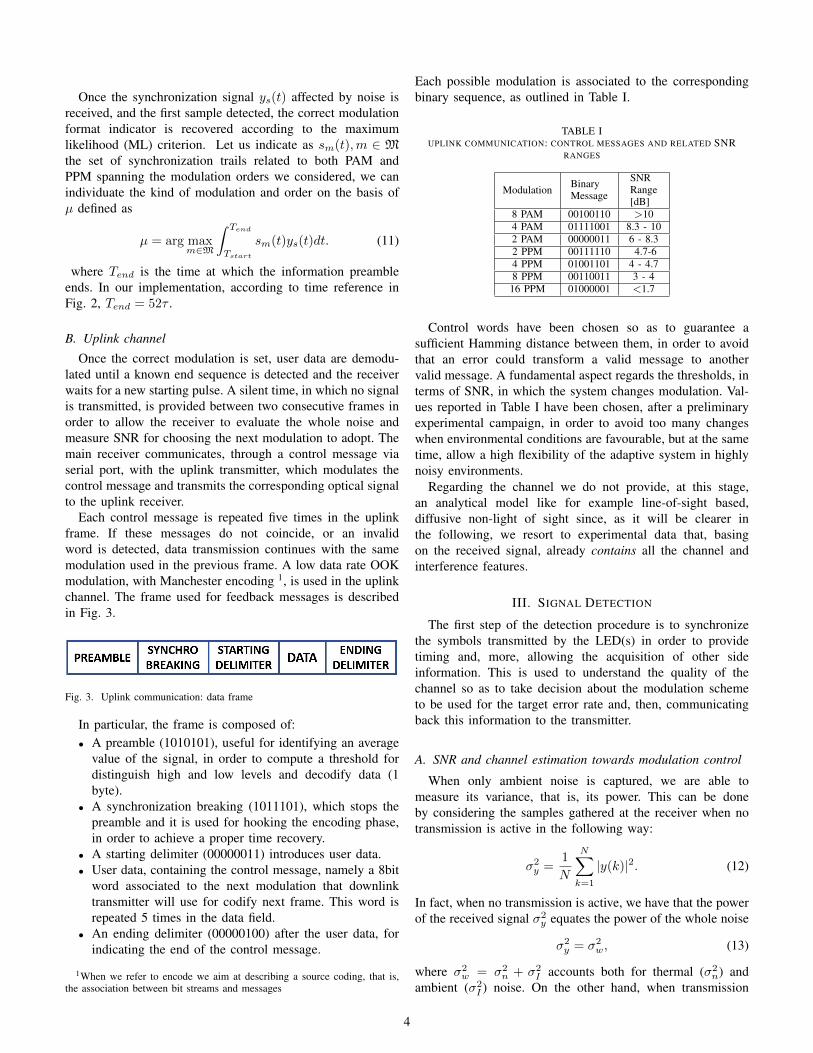
Once the correct modulation is set, user data are demodu-lated until a known end sequence is detected and the receiverwaits for a new starting pulse. A silent time, in which no signalis transmitted, is provided between two consecutive frames inorder to allow the receiver to evaluate the whole noise andmeasure SNR for choosing the next modulation to adopt. Themain receiver communicates, through a control message viaserial port, with the uplink transmitter, which modulates thecontrol message and transmits the corresponding optical signalto the uplink receiver.
Each control message is repeated five times in the uplinkframe. If these messages do not coincide, or an invalidword is detected, data transmission continues with the samemodulation used in the previous frame. A low data rate OOKmodulation, with Manchester encoding 1, is used in the uplinkchannel. The frame used for feedback messages is describedin Fig. 3.
Fig. 3. Uplink communication: data frame
In particular, the frame is composed of:• A preamble (1010101), useful for identifying an average
value of the signal, in order to compute a threshold fordistinguish high and low levels and decodify data (1byte).
• A synchronization breaking (1011101), which stops thepreamble and it is used for hooking the encoding phase,in order to achieve a proper time recovery.
• A starting delimiter (00000011) introduces user data.• User data, containing the control message, namely a 8bit
word associated to the next modulation that downlinktransmitter will use for codify next frame. This word isrepeated 5 times in the data field.
• An ending delimiter (00000100) after the user data, forindicating the end of the control message.
1When we refer to encode we aim at describing a source coding, that is,the association between bit streams and messages
Each possible modulation is associated to the correspondingbinary sequence, as outlined in Table I.
TABLE IUPLINK COMMUNICATION: CONTROL MESSAGES AND RELATED SNR
RANGES
Modulation BinaryMessage
SNRRange[dB]
8 PAM 00100110 >104 PAM 01111001 8.3 - 102 PAM 00000011 6 - 8.32 PPM 00111110 4.7-64 PPM 01001101 4 - 4.78 PPM 00110011 3 - 416 PPM 01000001 <1.7
Control words have been chosen so as to guarantee asufficient Hamming distance between them, in order to avoidthat an error could transform a valid message to anothervalid message. A fundamental aspect regards the thresholds, interms of SNR, in which the system changes modulation. Val-ues reported in Table I have been chosen, after a preliminaryexperimental campaign, in order to avoid too many changeswhen environmental conditions are favourable, but at the sametime, allow a high flexibility of the adaptive system in highlynoisy environments.
Regarding the channel we do not provide, at this stage,an analytical model like for example line-of-sight based,diffusive non-light of sight since, as it will be clearer inthe following, we resort to experimental data that, basingon the received signal, already contains all the channel andinterference features.
III. SIGNAL DETECTION
The first step of the detection procedure is to synchronizethe symbols transmitted by the LED(s) in order to providetiming and, more, allowing the acquisition of other sideinformation. This is used to understand the quality of thechannel so as to take decision about the modulation schemeto be used for the target error rate and, then, communicatingback this information to the transmitter.
A. SNR and channel estimation towards modulation control
When only ambient noise is captured, we are able tomeasure its variance, that is, its power. This can be doneby considering the samples gathered at the receiver when notransmission is active in the following way:
σ2y =
1
N
N∑k=1
|y(k)|2. (12)
In fact, when no transmission is active, we have that the powerof the received signal σ2
y equates the power of the whole noise
σ2y = σ2
w, (13)
where σ2w = σ2
n + σ2I accounts both for thermal (σ2
n) andambient (σ2
I ) noise. On the other hand, when transmission
4
takes place, under the hypothesis of statistical independenceamong noise and signals sent by the transmitter, we have
σ2y = |h|2Px + σ2
w. (14)
h being the channel gain.SNR estimation, given by |h|2Px/σ2
w , can be carried outby considering the following relationship
β =σ2y − σ2
w
σ2w
=σ2y
σ2w
− 1 (15)
and, once acquired this measure, it is possible to proceed tochoose the modulation scheme that is expected to match thereliability constraints with the maximum allowed rate amongthose meeting the BER requirement that we map through SNR.It is important to highlight now that, in case of interferencemitigation procedures, it is possible to obtain lower valuesof σ2
w due to interference processing so as to increase thereal (and not only the estimated) SNR so allowing to usehigher modulation order without increasing the error rate ofthe system. From this point of view, the opportunity of hearinginterference without any information signal is fundamental toacquire information about the disturbing elements. However,the simple measure of interference level, that is power, isnot sufficient to provide statistical elements for interferencemitigation [12]. In order to do so, we resort to linear predictionfor the interference term so as to have the auto-correlationproperties. In this regard, we have that the predicted interfer-ence (ambient noise) is
η =
p∑k=1
akη[n− k] (16)
p being the order of the predictor and ak the coefficients thatcan be found by considering the Yule-Walker equations
p∑k=1
akrη[j − k] = rη[j] (17)
In fact, the goal of the Yule-Walker equations is the minimiza-tion of mean square error defined as
Ep = E[|η − η|2] (18)
with respect to the coefficients ak with E(.) representing theexpected value operator. Hence the Levinson-Durbin algorithmcan fast lead recursively to the solution as detailed in [13,Chapt.10]. The interference predicted is then subtracted tothe received signal so as to try to clean it. In the aboverelationship, we have the term rη[j] that refers to the auto-correlation of the noise. The above term is characterized byboth thermal noise (negligible) and ambient noise. Correlationcan be obtained via very simple estimation procedure, that is,during a silenced phase, before training, that assumes that notransmission takes place so the only samples are given bynoise. This allows to write
rη[j] =1
N
N∑`=1
η[`]η[`+ j] (19)
Hence the value of SNR after noise mitigation βM is thengiven by
βM =|h|2Pxσ2ε
(20)
σ2ε being the residual noise after mitigation that is lower thanσ2w since it is given by σ2
ε = σ2n+Ep, where Ep is the already
mentioned estimation mean square error minimized accordingto eq.(18).
In this direction, we equip the receiver with a table wherewe have in each row, SNR required for the target error ratefor each modulation scheme. Hence, it is able to measureperiodically the SNR by introducing a silenced phase duringwhich noise samples are captured and a training one so asto re-estimate both channel and SNR. Too much frequent re-estimation leads to waste transmission resources (no informa-tion data sent) while too sporadic signalling leads to havingoutdated information. This can be analytically described as inthe pseudo-code reported in Algorithm 1
Algorithm 1 Pseudo-code for modulation selectionfor i=1:L-1if SNRTH(i) < β < SNRTH(i+ 1)then MF=i
Thus meaning that we span all the L different modulationformats by checking if the SNR measured is in the rangelimited by two SNR thresholds for the target error rate[SNRTH(i), SNRTH(i + 1)] so as to choose as modulationformat the i-th one.
B. Channel estimation cadence
When dealing both with a modulation selection and inter-ference mitigation procedure it is reasonable to assume thatchannel does not change if the propagation environment doesnot. Changes may occur when the propagation environment isaffected by more reflections (object around disappear or ap-pear) and/or relative distance between transmitter and receiverchanges. Besides, light sources may induce interference if theillumination is not uniform thus becoming position dependent.From this aspect, it is possible to understand the need ofconsidering how much frequent the estimation procedure, aswell as, interference acquisition must take place. The ideato allow reliable channel estimation, without wasting time totry to estimate channel when it is not needed is to check,during time, for possible changes. This should be done bothfor channel and interference. First of all let us focus on theestimation of channel. We may resort to a criterion, like forexample minimum mean square error, from the literature asreported in [13, Chapt.5] by using training sequences. Thetraining is the already described signalling scheme depictedin Fig.2. However, even though we use training symbols, wecan use the SNR estimation in eq. (20) since it is possible toinfer that since h is always positive and real, it is given by
h =
√βMσ2
n
Px=
√|h|2σ2
n
σ2n + Ep
(21)
5

hence a good interference mitigation leads to reliable channelestimation since Ep is very low and channel estimation con-verges toward the real value.Secondly, let us consider on the rate reduction induced by theacquisition of the statistics. If we assume that the procedurefor interference acquisition last ATp seconds and the channelestimation/synchronization involves 16Tp, if it happens everyF data symbols, we have the rate scales in the following way:
G = R
(1− 16 +A
F + 16 +A
)(22)
where R is the rate of the transmission while G is the net rate.In this regard acquiring both the statistics of noise and channelis fundamental and a proper threshold should be set in order tohave the opportunity to judge the channel as changed or not.The use of a threshold is a reasonable way since asking that thechannel (or the noise) must be exactly the same (identity) is anonsense for our purpose since minimal changes may not haveany effect on performance. Thus, we propose the mechanismwe detail in Algorithm 2. It is possible to appreciate that wefocus on the first s terms of the noise correlation and if nothingchanged considerably (we check the fluctuation through z(i))then the noise is considered as invariant and we can sendmore data (F=2F) without re-estimating the noise, otherwisewe need to re-estimate it.
Algorithm 2 Pseudo-code for setting estimation cadenced=0;for i=1:sif (1− z(i))rη(i)old < rη(i)new < (1 + z(i))rη(i)oldthen d=d+1; endif d==sF=2*F;elseF=F/2;end;
An analogue procedure must be performed on the basis ofthe SNR fluctuations (using the received power in place of thecorrelation) to increase or decrease F .
C. Digital demodulation
About digital demodulation we resort to the maximumlikelihood (ML) criterion starting from the sequence of thereceived signal after noise removal. In this regard we can referto the received and de-noised signal sequence as
z[n] = y[n]− η[n] (23)
Basing of the modulation format, PAM or PPM, we proceedto consider also the effect of channel so as to resort to thefollowing metric that is valid for PPM
v` = zT hs` (24)
h being the estimated channel, s` the vector shape of thePPM transmitted signal associated to the `-th symbol. The
metric v` is then used for digitally demodulating the receivedsignal according to the ML criterion as
l = argmax`=0,...M−1
v` (25)
For what concerns PAM, still starting from eq. 23, we havethat the decision criterion ML leads to the following detectedsymbol
l = argmin`=0,...M−1
||z− hs`||2 (26)
IV. SYSTEM IMPLEMENTATION
Till now we described the system we want to develop byresorting to analytical description both of signals at the trans-mitter and the procedure for mitigating and counterbalance thedifferent impairments coming from the transmission/receptionitself. In line with other works from the literature that presentthe analytical content of the proposal (see [14],[15]), we detailnow how the system we described in the previous sectionshas been implemented in a real fully-functioning two-wayoptical wireless communication link. At this stage, we want toemphasize that the choice of modulation scheme is in chargeof the receiver that, via the uplink channel, must communicateback the word corresponding to the modulation scheme. Forthis motivation, the whole architecture of the system has beendesigned in order to achieve an effective coordination betweenreceiver and transmitter and a robust deliverance of feedbackmessage.
A. Hardware Components
A simplified scheme of the hardware elements composingour bidirectional VLC system is depicted in Fig. 4.
USRPMotherboard
TX PC(LabView)
Arduino IDE
Optical Channel
VLC TRANSMITTER
FeedbackChannel
(1.2 kbit/s)Arduino 1
Optical Channel
Serial COMSerial COM
USRPLFTX
Daugtherboard
USRPLFRX
Daugtherboard
USRPMotherboard
GigabitEthernet
GigabitEthernet
RX PC(LabView)
Arduino IDE
Arduino 1
LEDDriver
LEDArray
LEDDriver
LEDArray
PhotoDiode
TIAmplifier
PhotoDiode
TIAmplifier
MainCommunication(up to 2Mbit/s) VLC
RECEIVER
Fig. 4. VLC bidirectional system: main hardware components
The main optical communication between the transmitterand the receiver is performed using two Universal SoftwareRadio Peripheral (USRP) 2922, a universal platform for soft-ware defined prototyping, provided by National Instruments.In order to allow the platforms to modulate and demodulatethe signal in the range [0-30 MHz] the original front-end hasbeen substituted by a low frequency receiving daughter-board,both provided by Ettus.
However, the original motherboards have been maintainedin the system. The connection between the USRP and the thehost PCs are guaranteed by a Gigabit Ethernet cable. The com-munication between motherboards and daughter-boards and
6
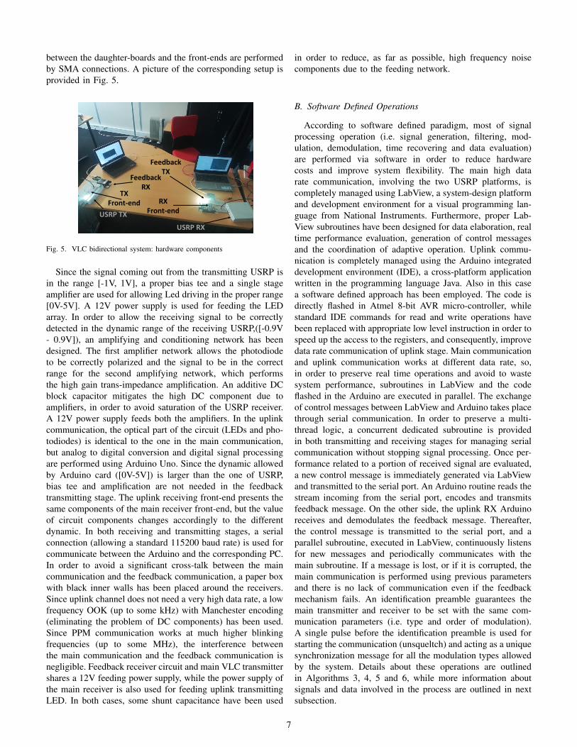
between the daughter-boards and the front-ends are performedby SMA connections. A picture of the corresponding setup isprovided in Fig. 5.
TXFront-end RX
Front-end
FeedbackRX
FeedbackTX
USRP TX
USRP RX
Fig. 5. VLC bidirectional system: hardware components
Since the signal coming out from the transmitting USRP isin the range [-1V, 1V], a proper bias tee and a single stageamplifier are used for allowing Led driving in the proper range[0V-5V]. A 12V power supply is used for feeding the LEDarray. In order to allow the receiving signal to be correctlydetected in the dynamic range of the receiving USRP,([-0.9V- 0.9V]), an amplifying and conditioning network has beendesigned. The first amplifier network allows the photodiodeto be correctly polarized and the signal to be in the correctrange for the second amplifying network, which performsthe high gain trans-impedance amplification. An additive DCblock capacitor mitigates the high DC component due toamplifiers, in order to avoid saturation of the USRP receiver.A 12V power supply feeds both the amplifiers. In the uplinkcommunication, the optical part of the circuit (LEDs and pho-todiodes) is identical to the one in the main communication,but analog to digital conversion and digital signal processingare performed using Arduino Uno. Since the dynamic allowedby Arduino card ([0V-5V]) is larger than the one of USRP,bias tee and amplification are not needed in the feedbacktransmitting stage. The uplink receiving front-end presents thesame components of the main receiver front-end, but the valueof circuit components changes accordingly to the differentdynamic. In both receiving and transmitting stages, a serialconnection (allowing a standard 115200 baud rate) is used forcommunicate between the Arduino and the corresponding PC.In order to avoid a significant cross-talk between the maincommunication and the feedback communication, a paper boxwith black inner walls has been placed around the receivers.Since uplink channel does not need a very high data rate, a lowfrequency OOK (up to some kHz) with Manchester encoding(eliminating the problem of DC components) has been used.Since PPM communication works at much higher blinkingfrequencies (up to some MHz), the interference betweenthe main communication and the feedback communication isnegligible. Feedback receiver circuit and main VLC transmittershares a 12V feeding power supply, while the power supply ofthe main receiver is also used for feeding uplink transmittingLED. In both cases, some shunt capacitance have been used
in order to reduce, as far as possible, high frequency noisecomponents due to the feeding network.
B. Software Defined Operations
According to software defined paradigm, most of signalprocessing operation (i.e. signal generation, filtering, mod-ulation, demodulation, time recovering and data evaluation)are performed via software in order to reduce hardwarecosts and improve system flexibility. The main high datarate communication, involving the two USRP platforms, iscompletely managed using LabView, a system-design platformand development environment for a visual programming lan-guage from National Instruments. Furthermore, proper Lab-View subroutines have been designed for data elaboration, realtime performance evaluation, generation of control messagesand the coordination of adaptive operation. Uplink commu-nication is completely managed using the Arduino integrateddevelopment environment (IDE), a cross-platform applicationwritten in the programming language Java. Also in this casea software defined approach has been employed. The code isdirectly flashed in Atmel 8-bit AVR micro-controller, whilestandard IDE commands for read and write operations havebeen replaced with appropriate low level instruction in order tospeed up the access to the registers, and consequently, improvedata rate communication of uplink stage. Main communicationand uplink communication works at different data rate, so,in order to preserve real time operations and avoid to wastesystem performance, subroutines in LabView and the codeflashed in the Arduino are executed in parallel. The exchangeof control messages between LabView and Arduino takes placethrough serial communication. In order to preserve a multi-thread logic, a concurrent dedicated subroutine is providedin both transmitting and receiving stages for managing serialcommunication without stopping signal processing. Once per-formance related to a portion of received signal are evaluated,a new control message is immediately generated via LabViewand transmitted to the serial port. An Arduino routine reads thestream incoming from the serial port, encodes and transmitsfeedback message. On the other side, the uplink RX Arduinoreceives and demodulates the feedback message. Thereafter,the control message is transmitted to the serial port, and aparallel subroutine, executed in LabView, continuously listensfor new messages and periodically communicates with themain subroutine. If a message is lost, or if it is corrupted, themain communication is performed using previous parametersand there is no lack of communication even if the feedbackmechanism fails. An identification preamble guarantees themain transmitter and receiver to be set with the same com-munication parameters (i.e. type and order of modulation).A single pulse before the identification preamble is used forstarting the communication (unsqueltch) and acting as a uniquesynchronization message for all the modulation types allowedby the system. Details about these operations are outlinedin Algorithms 3, 4, 5 and 6, while more information aboutsignals and data involved in the process are outlined in nextsubsection.
7

Algorithm 3 Downlink TX operation
while (DATA STREAM is not empty)Read DATA STREAMDATA STREAM.append (End Sequence)MODULATED SIGNAL= modulate (DATA STREAM)temp = uplink buffer.read
if (New Valid Value is Available())Control message(j)= temp
elseControl message(j)= Control message(j-1)
Generate Starting PulseNEW SIGNAL.append (Starting Pulse)NEW SIGNAL.Append (Description Preamble)NEW SIGNAL.Append (MODULATED SIGNAL)Transmit NEW SIGNALwait (Silent time)
Algorithm 4 Downlink RX operation
while TRUErx signal = read (front end buffer)wait for Unsqueltch pulseif (unsqueltch pulse is detected)
rx signal.Time Synchronization()Set New Receiving Parametersrx signal.Filter()RECEIVED DATA = modulate(rx signal)if (End Sequence is detected)
NEW FEEDBACK = evaluate (SNR)Write Serial Buffer (NEW FEEDBACK)
V. NUMERICAL RESULTS AND TESTS
In this Section we detail the setup both for computersimulation and tests by showing the main characteristics of thetransmitter and receiver. A short recap of the main parameterscan be found in Table II
TABLE IIEXPERIMENTAL VALIDATIONS: MAIN PARAMETERS OF TRANSMITTING
AND RECEIVING HARDWARE STAGES
Receiver Transmitter
PhotodiodeModel
CENTRONICOSD15-5T
LEDModel
CREEMKRAWT-02-0000
-0D00J2051Active Area 15mm2 Maximum Power 15WResponsivity
(436nm) 0.18-0.21 EffectivePower 4W
Dark Current 1-5 nA MaximumLight Flux 1040 lm
Field of View 45deg Field of View 120degNoise
EquivalentPower
(436nm)
5.5 ∗ 10−14 Forward Voltage 12V
Capacitance 80pF MaximumForward Current 1200 mA
Bandwidth 29.1MHz MaximumSwitching Speed 35MHz
ShuntResistance 200MΩ Reverse Voltage 5V
Rise Time 12 ns Number of LED 5Trans
ImpedanceAmplifier Gain
1 M ΩOptical
ConcentratorGain (6m)
5
The use of a pre-amplifying network allows to properly
Algorithm 5 uplink TX operation
while TRUERX = Read (Serial Buffer)if (New Valid Value is Available)
FEEDBACK MESSAGE = modulate (RX)FEEDBACK MESSAGE.append(Control bits)FEEDBACK MESSAGE.append(Synchro bits)Transmit (FEEDBACK MESSAGE)
Algorithm 6 Uplink RX operation
while TRUEwait for new feedback signaltemp= read (front end buffer)if (temp (is not empty))
RX feedback=temp;Synchronize SignalNEW FEEDBACK MESSAGE= Demodulate (RX
feedback)Write Serial Buffer (NEW FEEDBACK MESSAGE)
bias the trans-impedance stage. Since a high trans-impedancegain can be achieved only using a high value resistance inthe path, a significant amount of additive noise is added inthe circuit and a proper feedback capacity should be addedfor avoiding instability. However, main other parameters arefixed and depend of the correct choice of lamps and photo-detectors. LED lamps have been chosen to have an adequatetrade off between cost, brightness and electrical power neededfor feeding. A photodiode with an adequate responsivity in thesame optical frequency range of LED maximum emission hasbeen selected. Furthermore, a trade off between costs, availablebandwidth and low parasitic effect has been considered.In Fig.6 we show the performance of two different schemes.The first one is related to the absence of interference mit-igation procedure and, by moving slowly 1m/s the receiverfar from the transmitter, we increase distance with a uniforminterference level. The second scheme is related to the samesituation where interference mitigation is acted according tothe above explanation. It is possible to note that by setting
Fig. 6. BER of adaptive scheme with and without interference mitigationwhen uniform lighting is used.
the BER threshold to 10−3, we have an erratic behavior ofthe performance in the no interference mitigation case, sincewhen the SNR is approaching the reference value stored in thetable, a modulation switch is acted and its new performancecan be, as in this case, sufficiently lower. Hence, this erraticbehaviour continues by switching from 8-PAM till to the less
8

Fig. 7. Spectral Efficiency of adaptive scheme with and without interferencemitigation when uniform lighting is used.
complex 2-PAM and then from 2-PPM to 8-PPM. By recallingthat spectral efficiency for PAM is log2M and for PPM isM−1 log2M , the values related to the modulation range from8-PAM to 8-PPM, reduces the spectral efficiency from 3b/s/Hz(8PAM) to 0.375b/s/hz (8PPM). For the reported scenarioit is possible to show how the spectral efficiency scales byconsidering the behavior of the two curves in Fig.7.It is important to note that sometimes the curve seems todisappear. This is due to the fact that the error rate is lowerthan 10−7 and no errors incur in our tests.The performance exhibited by the interference mitigationapproach are really similar in the shape with respect to theno-mitigation even though the BER we achieve is lower andalso the switch is operated at a higher distance, so allowing,at the same distance, a higher rate or, for the same rate, higherdistance.
Fig. 8. BER of adaptive scheme with and without interference mitigationwhen uniform lighting is used and different channel updates are performed.
As previously mentioned, the cadence we use for estimatingboth channel and interference is really important since wecan be outdated and not able to react to channel and/orexternal interference changes. In Fig.8 we show exactly thesame test performed in Fig.6 with interference mitigation withthe difference of considering also not adaptive mechanismto acquire information about interference and channel. Inparticular the curve labeled as fixed update is related to sendingpilots and acquire interference every 106 symbols and whenthe tracking is performed according to the previously detailedmechanism.
In Fig.9 it is possible to appreciate the behaviour withrespect to F and A of the net rate. When A increases therate decreases while increasing the number of consecutive data
symbols increase the net rate at the expenses, as it will beappear clearer in the following, of the reliability. About the
Fig. 9. Net rate as a function of noise acquisition length A and estimationcadence F .
price to be paid to be updated about interference and channel,it is possible to appreciate that if the estimation cadence is tooslow, we are unable to be updated so the real SNR is differentfrom the estimated (supposed) one so we change modulationscheme late with respect to the distance where the receiveris based so violating the constraint on BER required by thesystem performance. Increasing the speed of the receiver mayhighlight this issue since the channel changes faster.
Fig. 10. BER of adaptive scheme with and without interference mitigationwhen non-uniform lighting is used. The yellow lines describe the propagationof disturbing light source over the distance
Furthermore, in order to test the performance of the in-terference mitigation, we remove the hypothesis of uniformdistributed disturbing light and pose one light source at 1.87meters from the transmitter. In Fig.10 it is possible to seethe position of the lighting source represented by the yellowbox, and the yellow lines describe the propagation over thedistance. It is important to highlight that while the case ofno interference suppression, due to the additional interferencechanges fast the modulation scheme scaling from 2-PAM tillto 8-PPM, the interference mitigation case do not change since2-PAM is still able to guarantee the target BER, thus meaningthat the SNR after mitigation is still above the threshold thatstates the switch between 2-PAM and 2-PPM.
VI. CONCLUSION
Visible Light Communication is gaining more and morelarge interest as cost-effective and energy efficient commu-nication wireless technology. In order to be able to efficientlyexploit the high potential and ubiquitous character of VLC it
9

is of paramount importance to develop bi-directional systems,in order to fully exploit the information state at the receiver foradapting the system to the high dynamic environmental condi-tions. In this work we have designed and implemented a com-plete bi-directional system based on USRP and commercialLED and photodiode. Our main objective was to enable thereceiver to send back on a dedicated back channel informationregarding a smart selection of the most suitable modulationtechnique. This selection is based on SNR and threshold values(in terms of BER and data rate) defined on the basis of theapplication. The system needs to correctly synchronize thedownlink and uplink channel, avoiding mutual interference.We have implemented the logic selection at the receiver anddemonstrate the effectiveness of the adaptive system whenadding interference to the communication system.
REFERENCES
[1] H. Burchardt, N. Serafimovski, D. Tsonev, S. Videv, H. Haas, “VLC:Beyond point-to-point communication”, IEEE Communications Maga-zine, vol. 52 , no. 7,pp. 98-105, 2014.
[2] Q. Wang, D. Giustiniano, D. Puccinelli, OpenVLC: “ Software-DefinedVisible Light Embedded Networks”, The 1st ACM Workshop on VisibleLight Communication Systems, The 20th Annual International Confer-ence on Mobile Computing and Networking (ACM MobiCom 2014),Maui, Hawaii, USA, 2014.
[3] C. Wang, H.Y. Yu, Y. J. Zhu, “A Long Distance Underwater VisibleLight Communication System With Single Photon Avalanche Diode,”inIEEE Photonics Journal, vol. 8, no. 5, Oct. 2016.
[4] Y. Zhuang, , L. Hua, , L. Qi, J. Yang, P. Cao, Y. Cao, Y. Wu, , J.Thompson, H. Haas, “A Survey of Positioning Systems Using VisibleLED Lights”. in IEEE Commun. Surv. Tutor., 2018.
[5] A. Costanzo, V. Loscri, “Error Compensation in Indoor PositioningSystems based on Software Defined Visible Light Communication”,Physical Communication, vol. 34, 2019.
[6] Y. H. Kim, W. A. Cahyadi, Y. H. Chung, “Experimental Demonstrationof VLC-Based Vehicle-to-Vehicle Communications Under Fog Condi-tions”, in IEEE Photonics Journal, vol.7, no. 6, Dec. 2015.
[7] E. A. Lee and D. G. Messerschmitt, “Digital Communication”, 2nd ed,Kluwer, 1994.
[8] D. J. F. Barros, S. Wilson , J. M. Kahn, “Comparison of orthogonalfrequency-division multiplexing and pulse-amplitude modulation in in-door optical wireless links”, IEEE Trans Commun, vol. 60, no.1, pp.153–163, 2012.
[9] Z. Wang, C. Yu, W.D. Zhong, J. Chen, W. Chen, “Performance ofa novel LED lamp arrangement to reduce SNR fluctuation for multi-user visible light communication systems”, Opt. Express,vol. 20,pp.4564–4573, 2012.
[10] P. Miao, L. Wu, Z. Chen, “Anti-noise modem for visible light communi-cation systems using the improved M-ary position phase shift keying”,AEU - International Journal of Electronics and Communications, vol.85, 2018.
[11] A. Costanzo, V. Loscri, “Demo: A Context Aware Algorithm for anAdaptive Visible Light Communication System”, EWSN, Madrid, Spain,2018.
[12] A. Costanzo, V. Loscri, M. Biagi, “A Noise Mitigation Approach forVLC Systems”, Global LiFi Congress, Paris, France, 2019.
[13] J.G. Proakis, M. Salehi,“ Digital Communication”, 5th ed, Wiley, 2008.[14] D. Tsonev, S. Videv, H. Haas,“ Unlocking Spectral Efficiency in
Intensity Modulation and Direct Detection Systems. IEEE Journal onSelected Areas in Communications”, vol. 33, pp. 1758-1770, 2015.
[15] A.A. Al-Hameed, S.H. Younus, A.T. Hussein, M.T. Alresheed, J.Elmirghani, “ LiDAL: Light Detection and Localization”, IEEE Access,vol. 7, 2019.
[16] Q. Wang, D. Giustiniano, O. Gnawali, “Low-Cost, Flexible and OpenPlatform for Visible Light Communication Networks”, HotWireless ’15.ACM, New York, NY, USA, pp. 31-35, 2015.
[17] A. Costanzo, V. Loscri, S. Costanzo,“ Adaptive Dual Color Visible LightCommunication (VLC) System”, Trends and Advances in InformationSystems and Technologies, vol. 2, pp.1478-1487, Springer, 2016.
[18] A. Costanzo, V. Loscrı, V. Deniau, J. Rioult.,“ On the InterferenceImmunity of Visible Light Communication (VLC)”, IEEE Global Com-munications Conference (GLOBECOM 2020), Tapei, Taiwan, 2020.
[19] C. G. Gavrincea, J. Baranda and P. Henarejos, “Rapid prototypingof standard-compliant visible light communications system”, in IEEECommunications Magazine, vol. 52, no. 7, pp. 80-87, 2014.
[20] E. Knightly, Y. Qiao, H. Haas, “A software-defined visible light com-munications system with WARP”, in Proc. 1st ACM Workshop VisibleLight Commun. Syst., pp. 2434–2442, 2014.
[21] A. Galisteo, D. Juara, D. Giustiniano, “Research in Visible LightCommunication Systems with OpenVLC1.3”, IEEE 5th World Forumon Internet of Things (WF-IoT), Limerick, Ireland, 2019, pp. 539-544,2019.
[22] B. Aly, M. Elamassie, M. Uysal, E. Kinav., “Experimental Evaluationof Unipo- lar OFDM VLC System on Software Defined Platform”,15th International Conference on Telecommunications (ConTEL), Graz,Austria. pp.1-6, 2019
ACKNOWLEDGEMENT
This work has been partially supported by a grant fromCPER/FEDER DATA project.
10