AD-80i Parts Manual - Laundry Wizard
30
AD-80i Parts Manual American Dryer Corporation 88 Currant Road Fall River MA 02720-4781 USA Telephone: +1 (508) 678-9000 / Fax: +1 (508) 678-9447 e-mail: [email protected] www.adclaundry.com ADC Part No. 450455-2
-
Upload
khangminh22 -
Category
Documents
-
view
0 -
download
0
Transcript of AD-80i Parts Manual - Laundry Wizard

AD-80iParts Manual
American Dryer Corporation88 Currant Road
Fall River MA 02720-4781 USATelephone: +1 (508) 678-9000 / Fax: +1 (508) 678-9447
e-mail: [email protected]
www.adclaundry.com
ADC Part No. 450455-2

2 American Dryer Corporation 450455-2
We have tried to make this manual as complete as possible and hope you will find it useful. ADC reserves the rightto make changes from time to time, without notice or obligation, in prices, specifications, colors, and material, and tochange or discontinue models.
ImportantFor your convenience, log the following information:
DATE OF PURCHASE ____________________________________________________ MODEL NO. ______________
RESELLER’S NAME _________________________________________________________________________________
Serial Number(s) _____________________________________________________________________________________
____________________________________________________________________________________________________
____________________________________________________________________________________________________
Replacement parts can be obtained from your reseller or the ADC factory. When ordering replacement parts from thefactory, you can FAX your order to ADC at (508) 678-9447 or telephone your order directly to the ADC Parts Departmentat (508) 678-9000. Please specify the dryer model number and serial number in addition to the description and partnumber, so that your order is processed accurately and promptly.
The illustrations on the following pages may not depict your particular dryer exactly. The illustrations are a compositeof the various dryer models. Be sure to check the descriptions of the parts thoroughly before ordering.
Retain This Manual In A Safe Place For Future Reference
American Dryer Corporation products embody advanced concepts in engineering, design, and safety. If this productis properly maintained, it will provide many years of safe, efficient, and trouble free operation.
ONLY qualified technicians should service this equipment.
OBSERVE ALL SAFETY PRECAUTIONS displayed on the equipment or specified in the installation manual includedwith the dryer.
The following “FOR YOUR SAFETY” caution must be posted near the dryer in a prominent location.
FOR YOUR SAFETY
Do not store or use gasoline orother flammable vapors andliquids in the vicinity of this orany other appliance.
POUR VOTRE SÉCURITÉ
Ne pas entreposer ni utiliser d’essenceni d’autres vapeurs ou liquidesinflammables à proximité de cet appareilou de tout autre appareil.
AD-80i
“IMPORTANT NOTE TO PURCHASER”
Information must be obtained from your local gas supplier on theinstructions to be followed if the user smells gas. Theseinstructions must be posted in a prominent location near the dryer.

450455-2 www.adclaundry.com 3
Table of Contents
Non-Coin Control Door Assembly ..............................................................................................................4
Coin Control Door Assembly ......................................................................................................................5
Phase 7 Non-Coin Microprocessor Control Box Assembly ........................................................................6
Front Panel Assembly .................................................................................................................................7
Main Door Assembly ...................................................................................................................................8
Main Door Switch Assembly .......................................................................................................................9
Tumbler / Support Assemblies..................................................................................................................10
Front Support Wheels .............................................................................................................................. 11
Lint Coop Sensor Assemblies ..................................................................................................................12
Lint Door Assembly ...................................................................................................................................13
Lint Trap Assembly ...................................................................................................................................14
Lint Door Support Assembly .....................................................................................................................15
Tumbler Bearing Assembly .......................................................................................................................16
Blower Motor Mount Assembly .................................................................................................................17
Drive Motor Mount Assembly ....................................................................................................................18
Gas Burner Assembly ...............................................................................................................................19
Gas Burner Box and Preheat Conduit ......................................................................................................20
Electric Burner Assembly ..........................................................................................................................21
Electric Oven Contactor Assembly ...........................................................................................................22
Electric Heat Terminal Block Panel ..........................................................................................................23
Rear Electrical Panel Assembly................................................................................................................25
VFD and Sail Switch Assemblies..............................................................................................................26
Outer Top / Back Guard Assemblies ........................................................................................................27
Fire Suppression Assembly ......................................................................................................................28
Additional Parts Available .........................................................................................................................29

4 American Dryer Corporation 450455-2
Non-Coin Control Door Assembly
Illus. No. Part No. Qty. Description
1 160015 1 Lock and Key160032 1 1” Straight Cam
2 884483 1 Phase 7.2 Non-Coin Computer with S.A.F.E. System Option884484 1 Phase 7.2 Non-Coin Computer without S.A.F.E. System Option136016 1 5-amp Fast Acting Computer Fuse
3 150300 8 #10-16 x 3/4” TORX PLUS® BTN Type 14 317162 1 Control Door Hinge Bracket5 817827 1 Non-Coin Control Door
(for models mfd. as of June 4, 2015)817766 1 Non-Coin Control Door with Graphics
(for models mfd. prior to June 4, 2015)6 112610 1 Phase 7.2 Non-Coin Keypad (blue)7 150005 5 #6-32 x 1/4” Phillips Screw8 153010 4 #6 Star Washer9 102603 1 Control Door Rod Support Catch10 102502 1 Control Door Support Rod11 102601 1 Control Door Retainer Clip

450455-2 www.adclaundry.com 5
Coin Control Door Assembly
Illus. No. Part No. Qty. Description
1 817851 1 Coin Stainless Steel Control Door(for models mfd. as of June 4, 2015)
817771 1 Coin Stainless Steel Control Door with Graphics(for models mfd. prior to June 4, 2015)
2 150300 10 #10-16 x 1/2” Hex Washer TEK Screw3 150005 8 #6-32 x 1/4” Phillips Round Head Machine Screw4 160032 1 Straight 1” Cam5 160015 1 MK-100 Lock with Hardware6 317162 1 Control Door Hinge Bracket7 112575 1 Phase 7 Keypad8 137270 1 16” x 1” Large Character Display9 887011 1 Phase 7 Coin Board (for models without S.A.F.E. System)
887012 1 Phase 7 Coin Board (for models with S.A.F.E. System)136016 1 5-amp Fast Acting Computer Fuse
10 137250 1 Phase 7 Coin Ribbon Cable11 102601 1 Control Door Rod Retainer Clip12 102603 1 Control Door Rod Support Catch13 102502 1 Control Door Support Rod14 855117 1 Coin Vault Assembly15 125917 1 Coin Box16 817755 1 25¢ US Coin Acceptor
805703 1 U.S. and Canadian Program Coin Acceptor830159 1 Euro Prog Coin Acceptor836108 1 Japan, Taiwan, and Chinese Program Coin Acceptor
17 132198 1 Reversing Timer
6 American Dryer Corporation 450455-2
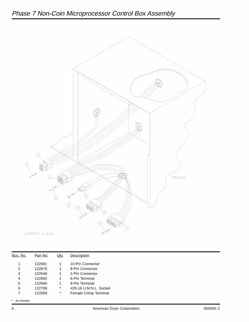
Phase 7 Non-Coin Microprocessor Control Box Assembly
Illus. No. Part No. Qty. Description
1 122681 1 10-Pin Connector2 122676 1 8-Pin Connector3 122646 1 2-Pin Connector4 122683 1 6-Pin Terminal5 122640 1 9-Pin Terminal6 122706 * #20-16 U.M.N.L. Socket7 122669 * Female Crimp Terminal
* As needed.

450455-2 www.adclaundry.com 7
Front Panel Assembly
Illus. No. Part No. Qty. Description
1 817814 1 Front Panel Assembly(for models mfd. as of June 4, 2015)
817823 1 Front Panel Assembly(for models mfd. between April 21, 2014 and June 4, 2015)(includes illus. nos. 1 through 10)
817769 1 Front Panel Assembly(for models mfd. prior to April 21, 2014)(includes illus. nos. 1 through 10)
2 102004 2 Compact Door Magnet3 152223 2 #10-32 x 1/2” Machine Screw4 150331 10 #8-18 x 1/2” Pan Head TORX® Screw5 116359 1 Front Panel Insulation6 317188 1 Front Panel Reversible Bottom Trim
(for models mfd. as of June 4, 2015)317552 1 Front Panel Reversible Bottom Trim
(for models mfd. between April 21, 2014 and June 4, 2015)317192 1 Front Panel Reversible Bottom Trim
(for models mfd. prior to April 21, 2014)7 335508 2 Door Stop8 154205 4 5/32” x 1/4” Stainless Steel Rivet9 121401 1 Rubber Grommet10 117617 4 Foam Gasket (sold by the foot)

8 American Dryer Corporation 450455-2
Main Door Assembly
Illus. No. Part No. Qty. Description
1 817750 1 Main Door Assembly Complete(includes illus. nos. 1 through 8)
835617 1 Main Door Ring Assembly(includes illus. nos. 1, 6, and 7)
2 817749 1 Door Outer Skin Assembly(includes illus. nos. 2 and 6)
3 319298 2 Magnet Bracket4 150445 4 1/4-20 x 3/4” Black Cap Head Setscrew5 817751 1 Door Handle Assembly6 102227 2 Main Door Glass
401038 1 Black Glass Adhesive (10.3 oz. cartridge)7 882411 1 Door Gasket
401038 1 Black Gasket Adhesive (10.3 oz. cartridge)8 152014 6 1/4-20 Free Spin Wash Nut9 153031 1 1/4” Nylon Washer10 881151 1 Black Bottom Hinge Block Assembly
(includes illus. nos. 4, 9, and 10)11 881152 1 Black Top Hinge Block Assembly
(includes illus. nos. 4 and 11)

450455-2 www.adclaundry.com 9
Main Door Switch Assembly
Illus. No. Part No. Qty. Description
1 150006 2 #6-32 x 7/8” Phillips Pan Head Machine Screw2 152013 2 #6-32 Hex Nut3 153010 2 #6 Star Washer4 137005 1 Door Switch5 122636 2 Flag Terminal6 881211 1 Black Main Door Switch Housing ONLY
881153 1 Black Main Door Switch Housing Complete(includes illus. nos. 1 through 4 and 6)
7 150301 2 #8-18 x 7/16” Phillips Pan Head TEK Screw

10 American Dryer Corporation 450455-2
Tumbler / Support Assemblies
Illus. No. Part No. Qty. Description
1 817783 1 Stainless Steel Tumbler / Support Assembly(includes illus. nos. 1 through 12)
817742 1 Galvanized Tumbler / Support Assembly(includes illus. nos. 1 through 12)
2 115154 1 Front Felt Collar3 317112 4 Stainless Steel Tumbler Rib
317177 4 Galvanized Tumbler Rib4 150407 1 5/16-18 x 3/4” Socket Button Head Screw5 100905 4 0.375-16 x 37” Tie Rod6 153004 4 3/8” Flat Washer7 817784 1 Tumbler Support8 152027 4 3/8-16 Hex Nylon Insert Lock Nut9 153005 4 3/8” Lock Washer10 153004 4 3/8” Flat Washer11 115927 1 Rear Felt Collar— 401010 1 #847 Adhesive for Felt Collar (5.0 oz. tube)12 100812 1 1-3/8” Retaining Clip

450455-2 www.adclaundry.com 11
Front Support Wheels
Illus. No. Part No. Qty. Description
1 154264 2 #10-M8 x 25 mm Shoulder Screw Black Oxide2 180060 2 Tumbler Wheel3 154284 2 Tumbler Wheel Spacer4 154200 – 5/32” Pop Rivet5 317157 1 Right Wheel Guard
317156 1 Left Wheel Guard6 153002 2 5/16” Lock Washer7 154013 2 M8 Hex Nut

12 American Dryer Corporation 450455-2
Lint Coop Sensor Assemblies
Illus. No. Part No. Qty. Description
1 150301 6 #8-18 x 7/16” Phillips Pan Head TEK Screw2 819188 1 Variable Speed Temperature Sensor Assembly3 833522 1 1/4” Exhaust Temperature Sensor Probe Assembly4 130098 1 190° Hi-Limit Thermostat

450455-2 www.adclaundry.com 13
Lint Door Assembly
Illus. No. Part No. Qty. Description
1 817830 1 Stainless Steel Drop Lint Door Assembly(for models mfd. as of June 4, 2015)
817821 1 Stainless Steel Drop Lint Door Assembly(for models mfd. between April 21, 2014 and June 4, 2015)(includes illus. nos. 1 through 8)
817764 1 Stainless Steel Drop Lint Door Assembly(for models mfd. prior to April 21, 2014)(includes illus. nos. 1 through 8)
2 835650 2 Lint Door Magnet Catch and Lint Switch Actuator3 817829 1 Drop Lint Door Handle Stud Assembly
(for models mfd. as of June 4, 2015)817788 1 Drop Lint Door Handle Stud Assembly
(for models mfd. between April 21, 2014 and June 4, 2015)817759 1 Drop Lint Door Handle Stud Assembly
(for models mfd. prior to April 21, 2014)4 317209 1 Drop Lint Door Bottom Trim
(for models mfd. as of April 21, 2014)305285 1 Drop Lint Door Bottom Trim
(for models mfd. prior to April 21, 2014)5 152014 5 1/4-20 Serrated Hex Flange Nut6 102420 74 .375 Rubber Gasket (sold by the inch)7 154205 3 5/32” x 1/4” Stainless Steel Rivet8 117604 3 .375 x .125 Neo Sponge Tape

14 American Dryer Corporation 450455-2
Lint Trap Assembly
Illus. No. Part No. Qty. Description
1 817725 1 Lint Trap Assembly Complete(includes illus. nos. 1 and 3 through 5)
817726 1 Lint Trap ONLY2 154210 8 5/32” Pop Rivet3 317155 1 Lint Screen Holder ONLY4 150300 4 #10-16 x 1/2” Hex Washer TEK Screw5 800506 1 Lint Screen Assembly6 835571 1 Lint Switch Bracket Assembly
122116 1 Lint Switch ONLY7 ——— 1 Lint Door Support Assembly (Parts Breakdown on page 15)8 154024 2 #10-32 x 3/4” Standoff9 153049 2 .875 OD Washer10 183129 2 #10-32 x 1/2” TORX® Head Machine Screw

450455-2 www.adclaundry.com 15
Lint Door Support Assembly
Illus. No. Part No. Qty. Description
1 335551 1 Drop Lint Door Support Mount2 335549 1 Drop Lint Door Support Slide Arm3 335550 1 Drop Lint Door Support Bracket4 183008 2 Keyhole Button5 183129 4 #10-32 x 1/2” TORX® Truss Head Machine Screw6 154220 2 3/16” Pop Rivet

16 American Dryer Corporation 450455-2
Tumbler Bearing Assembly
Illus. No. Part No. Qty. Description
1 817736 1 1-3/4” Flange Bearing Mount(includes illus. nos. 1 and 3)
2 884485 1 1-3/8” Flange Bearing Assembly(includes illus. nos. 2, 13, and 14)
3 152038 4 5/16-18 Hex Serrated Flange Nut4 822735 1 Rotation Sensor5 835596 1 Rotation Sensor Assembly
(includes illus. nos, 4 through 6)6 150300 1 #10-16 x 1/2” Hex Washer TEK7 101257 1 24.75” 15 Groove Pulley8 102430 1 15 Rib J-Belt9 100717 1 5/16” x 2-3/4” Key10 101256 1 1-3/8” Bushing11 153005 4 3/8” Lock Washer12 152005 4 3/8-16 Hex Nut13 154321 2 Setscrew14 170608 1 0.25 x 0.25 Magnet

450455-2 www.adclaundry.com 17
Blower Motor Mount Assembly
Illus. No. Part No. Qty. Description
1 100702 1 1/8” x 1/8” x 1-1/2” Key2 152006 2 1/2-20 Left Hand Jam Nut3 153050 2 1/2” S.A.E. Flat Washer4 150501 4 5/16-18 x 3/4” Tap Bolt5 153002 4 5/16” Lock Washer6 153001 4 5/16” Flat Washer7 100075 1 1 hp 208-480V 3ø Motor
100069 1 3/4 hp 120-240V 1ø 60 Hz Fan Motor with Plug100068 1 3/4 hp 240V 1ø 50 Hz Fan Motor with Plug
8 122701 8 Socket Terminal ONLY (1ø motor only)122801 1 Pin / Socket Extraction Tool
9 137030 1 8-Pin Housing Connector (1ø motor only)10 152004 4 5/16-18 Hex Nut11 153002 4 5/16” Lock Washer12 153001 4 5/16” Flat Washer13 117600 4 Noise Suppressor Tape (sold by the foot)14 154000 4 5/16-18 Tinnerman Nut15 803561 1 Motor Mount ONLY (56Z frame)
817779 1 1 hp 208-480V 3ø Fan Motor Mount Assembly Complete817758 1 3/4 hp 208-240V 1ø 60 Hz Fan Motor Mount Assembly Complete with Plug Motor817710 1 3/4 hp 240V 1ø 50 Hz Fan Motor Mount Assembly Complete with Plug Motor
16 153050 2 1/2” S.A.E. Flat Washer17 812019 1 15” Impellor with 3/4” Bore (for 3ø 60 Hz machines)
817762 1 15” Impellor with 1/2” Bore (for 1ø 60 Hz)822364 1 16” Impellor with 1/2” Bore (for 50 Hz machines)

18 American Dryer Corporation 450455-2
Drive Motor Mount Assembly
Illus. No. Part No. Qty. Description
1 150619 1 3/8-16 x 3” Hex Head Tap Bolt2 153004 2 0.375 Flat Washer3 153001 8 5/16 Flat Washer4 153002 8 5/16” Lock Washer5 150501 5 5/16-18 x 3/4” Hex Head Machine Bolt6 317629 1 Motor Sheave
(for models mfd. as of September 10, 2014)317617 1 Motor Sheave
(for models mfd. prior to September 10, 2014)7 817836 1 Drive Motor Carriage
(for models mfd. as of September 10, 2014)835585 1 Drive Motor Carriage
(for models mfd. prior to September 10, 2014)8 152004 4 5/16-18 Hex Nut9 152005 2 3/8-16 Hex Nut10 154321 1 5/16-24 x 3/8” Alan Setscrew11 181199 1 1 hp 208-230/460V 50/60 Hz 6 Pole Motor
(for models mfd. as of September 10, 2014)181198 1 1 hp 208-230/460V 50/60 Hz 6 Pole Motor
(for models mfd. prior to September 10, 2014)

450455-2 www.adclaundry.com 19
Gas Burner Assembly
Illus. No. Part No. Qty. Description
1 312644 1 Burner Tube Mounting Bracket2 140839 1 #2 Natural Gas Orifice
140820 1 #29 Liquid Propane Gas Orifice884497 1 Liquid Propane Conversion Kit
3 128918 1 Flame Sensor4 150301 2 #8-18 x 7/16” Phillips Pan Head TEK Screw5 150331 16 #8-18 x 1/2” Pan Head TORX® Screw6 141131 1 Upshot Burner Assembly7 887133 1 DSI Module 3 Tries8 153017 2 #6 SAE Washer9 152013 2 #6-32 Hex Nut10 317144 1 1/2” Straight Burner Manifold11 317141 1 CE Gas Valve Outlet Bracket12 317145 1 Gas Pipe Bracket13 128902 1 Ignitor with 36” Noise Suppression Cable14 128979 1 Gas Valve 24V, 50/60 Hz15 141317 1 1/2 Bronze Union Elbow16 317145 1 Gas Valve Inlet Bracket17 317194 1 Gas Train Mounting Channel18 154338 2 m4 x 6mm Phillips Head Slotted Machine Screw19 153008 2 6 Split Lock Washer20 142636 1 1/2” x 36” Black Pipe Nipple21 154355 1 U-Bolt for 1/2” Pipe with Nuts22 142935 1 1/2” B.S.P.T. x 1/2” N.P.T. Transition Coupling (for 50 Hz models only)

20 American Dryer Corporation 450455-2
Gas Burner Box and Preheat Conduit
Illus. No. Part No. Qty. Description
1 817719 1 Burner Box2 154211 – 5/32” Buttonhead Rivet3 150331 – #8-18 x 1/2” Pan Head TORX® Screw4 154200 7 5/32” Pop Rivet5 116249 1 Burner Box Insulation6 130201 1 330° F Manual Reset Thermostat7 335468 1 Hi-Limit Bracket8 817722 1 Preheat Top Conduit
(includes illus. nos. 3, 6, and 7)9 817724 1 Preheat Rear Conduit
(includes illus. no. 10)10 317151 1 Rear Conduit Access Cover

450455-2 www.adclaundry.com 21
Electric Burner Assembly
Illus. No. Part No. Qty. Description
1 150331 8 #8-18 x 1/2” Pan Head TORX® Screw2 305270 1 Electric Burner Box Cover3 154211 27 5/32” Buttonhead Rivet4 817369 1 Burner Box Assembly
(includes illus. nos. 1, 2, 3, and 9)5 817367 1 Electric Heat Top Conduit6 335468 1 Hi-Limit Bracket7 130301 1 225° Hi-Limit Thermostat8 805101 1 Electric Oven Assembly
(includes illus. no. 11)9 116249 1 Burner Box Insulation10 817366 1 Front Heat Deflector11 119997 1 Electric Element

22 American Dryer Corporation 450455-2
Illus. No. Part No. Qty. Description
1 305273 1 Electric Heat Contactor and Relay Bracket2 131379 1 TPST 40-amp Oven Contactor
131378 1 TPST 65-amp Oven Contactor3 131406 1 Relay SPDT 24VAC Panel Mount4 305421 1 Electric Heat Contactor and Relay Cover5 150331 8 #8-18 x 1/2” Pan Head TORX® Screw6 121410 2 1-3/8” Universal Bushing7 121400 1 7/8” Universal Bushing
Electric Oven Contactor Assembly

450455-2 www.adclaundry.com 23
Illus. No. Part No. Qty. Description
1 136120 2 25-amp Time Delay Fuse2 154200 2 5/32” Pop Rivet3 136037 1 Class CC Fuse Block4 120699 2 2-Pole Power Terminal Block
120698 2 2-Pole Power Terminal Block Insulator5 121010 1 L70 14-4 Terminal Lug
Electric Heat Terminal Block Panel

24 American Dryer Corporation 450455-2
Steam Coil Assembly
Illus. No. Part No. Qty. Description
1 165067 2 Steam Coil2 142601 4 3/4” Union3 142708 1 3/4 N.P.T. x 3” Nipple4 142645 2 Pipe Coupling 3/4 N.P.T.5 143361 1 3/4 Stainless Steel Flex Hose 3/4 M.N.P.T.6 317626 2 Outlet Pipe Bracket7 317625 1 Inlet Pipe Bracket8 142859 1 3/4” Tee9 142647 1 3/4 N.P.T. x 9 Nipple10 142646 1 3/4 N.P.T. x 10” Nipple11 153007 8 1/4 Split Lock Washer12 152002 8 1/4-20 Hex Nut13 153018 8 1/4 Flat Washer14 817834 1 Dual Steam Plenum Assembly15 150309 9 #10-16 x 1/2 Hex Head TEK Crimptite Screw16 142648 2 3/4 N.P.T. x 12” Long Black Iron Nipple17 142854 1 3/4 x 3/4 Street Elbow18 117616 52 1/2 x 1/2 EPDM

450455-2 www.adclaundry.com 25
Rear Electrical Panel Assembly
NOTE: Illustration may not be an exact representation of your machine.
Illus. No. Part No. Qty. Description
1 398301 1 Electrical Panel ONLY835965 1 120V 1ø Electrical Panel with 1 VFD803385 1 208-240V 1ø Electrical Panel with 1 VFD805644 1 208-240V 1ø Electric Panel with 2 VFDs805581 1 208-240V 3ø Electrical Panel with 1 VFD805676 1 208-240V 3ø Electrical Panel with 2 VFDs805515 1 380-416V 3ø Electrical Panel (electric heat only)805661 1 380-480V 3ø Electrical Panel with 1 VFD
2 131394 1 3-Pole Contactor132498 1 2-Pole Contactor
3 120786 – 2 Cod. Thru Terminal Block4 120787 1 End Plate5 150301 – #8-18 x 7/16” Phillips Pan Head TEK Screw6 120910 2 Green Ground Screw7 121010 1 L70 14-4 Terminal Lug8 132109 1 120-240V Transformer
132111 1 380-480V Transformer9 131406 – Relay SPDT 24 VAC Panel Mount10 136008 – Fuse Holder 120-416V
136037 – Fuse Holder 460-480V11 150297 1 #10-16 x 0.5 Hex Washer TEK Screw (green)12 136101 – .8-amp Slo-Blo Fuse (for 120-416V machines)
136114 – 1-amp Class C Fuse (for 460-480 volt machines)

26 American Dryer Corporation 450455-2
VFD and Sail Switch Assemblies
Illus. No. Part No. Qty. Description
1 335438 1 VFD Mounting Bracket2 150331 4 #8-18 x 1/2” Pan Head TORX® Screw3 154200 4 5/32” Pop Rivet4 884550 1 200-240 Volt 1ø and 3ø Variable Speed Drive
(for models mfd. as of December 10, 2014)884549 1 120V Variable Speed Drive
(for models mfd. as of December 10, 2014)884551 1 380-480 Volt Variable Speed Drive
(for models mfd. as of December 10, 2014)115612 1 Keypad for M400 Inverter181175 – 200-240V Variable Speed Drive
(for models mfd. prior to December 10, 2014)181150 – 120V Variable Speed Drive
(for models mfd. prior to December 10, 2014)5 884507 – Logicstick (only used with inverters PN 181150 and 181175)6 828238 1 Sail Switch Assembly7 150331 2 #8-18 x 1/2” Pan Head TORX® Screw

450455-2 www.adclaundry.com 27
Outer Top / Back Guard Assemblies
Illus. No. Part No. Qty. Description
1 355017 1 Back Electrical Box Cover2 150331 4 #8-18 x 1/2” Pan Head TORX® Screw3 317169 1 Top Back Guard (gas and electric)
317628 1 Top Back Guard (steam)4 150331 5 #8-18 x 1/2” Pan Head TORX® Screw5 150331 7 #10-16 x 1/2” Hex Washer TEK Screw6 817733 1 Outer Top7 317168 1 Bottom Back Guard8 150331 9 #8-18 x 1/2” Pan Head TORX® Screw9 103500 4 Leveling Leg

28 American Dryer Corporation 450455-2
Fire Suppression Assembly
Illus. No. Part No. Qty. Description
1 143356 1 3/4” NH Male x 3/8” N.P.T. Reducing Bushing (for 60 Hz)143263 1 0.750 x 0.375 Brass Reducing Bushing (for 50 Hz)
2 143348 1 3/8” x 1-1/2” Brass Nipple3 143182 1 0.75 x Ght 0.125 x 0.375 N.P.T. Brass Tee4 165119 1 F.S.S. Water Inlet Valve5 143183 1 0.4375-20 x 0.375 N.P.T. Brass Adapter6 143251 1 0.375 MPT Brass Plug7 143220 1 0.375 F.P.T. Brass Tee8 136987 1 Water Jet Pressure Switch9 150331 6 #8-18 x 1/2” Pan Head TORX® Screw10 317180 1 F.S.S. S.A.F.E. Valve Bracket11 317181 1 Nozzle Bracket12 824081 1 R.C. Network Assembly13 143320 1 0.375 Comp x 0.375 M.N.P.T. Brass Elbow14 143099 9 0.375 Soft Copper Tubing 8.5”15 143208 1 0.375 Comp x 0.375 M.P.T. Connector16 143308 2 0.375” x 5” Brass Nipple17 143581 1 Fire Suppression Nozzle18 143155 2 0.375 Brass Street Elbow19 143257 1 0.375 Bulkhead Adapter20 184123 1 3/8” Brass Coupling21 122679 1 Connector ONLY22 150301 2 #8-18 Pan Head Screw23 185428 1 Sensor Bracket ONLY24 154007 2 Push-On Fastener25 819188 1 S.A.F.E. Temperature Probe Assembly
(includes illus. nos. 21, 23, and 24)

450455-2 www.adclaundry.com 29
Additional Parts Available
Part No. Description
114006 “WARNING – Fire Hazards” Label
112280 “Clean Lint Screen” Label
114001 “CAUTION – Exhaust / Lint Screen” Label
120100 3/8” Straight (BX) Connector
120300 3/8” x 45° (BX) Connector
120400 3/8” Red Jacket (BX) Insulator
120500 3/8” Jiffy Clip (BX retainer clip)
120600 3/8” Greenfield (BX)
120707 (2-Position) Terminal Strip
120708 (3-Position) Terminal Strip
120800 1/4” In-Line Connector
120802 Red Butt Connector
120902 #74B Wire Nut
120903 Crimp-On Wire Nut
121014 1/4” Insulated (female) Terminal
121026 Tab Receptacle Combination
121499 5-1/2” Harness Tie
121500 8” Harness Tie
122804 Manometer (hydro gauge) for Measuring Gas Pressure
404502 White Brush-In-Cap Bottle Touch-Up Paint

ADC Part No. 450455 2 - 09/26/16