Installation Installation Manual - Rocky Mountain Generator ...
Upload
khangminh22Category
view
2download
0
ACCESSFLOORSTOREINSTALLATION GUIDELINE
CONTENTS
Page
SAFETY 1
OFF-LOADING 1
STORAGE 1
BUILDING CONDITION 1
SUB-FLOORS 1
TOOLS REQUIRED 2
INSTALLATION 3
TOLERANCES 3LOCATING THE STARTING POINT 4ESTABLISHING THESTARTINGLINE 4SETTINGOUT THEGRID 4ESTABLISHING THE FLOOR HEIGHT 5INSTALLATION OF PANELS ANDPEDESTALS 5AVOIDING SMALL PERIMETER CUT PANELS 9
GENERAL INSTALLATION INSTRUCTIONS 10
CUTTING TOPERIMETERS 10STRINGERS 10PEDESTAL ADHESIVE 10PEDESTAL ADJUSTMENT 11PEDESTAL OVERLAP 11PANEL PARALLELOGRAM 11LEVELLING 11FINISHED MODULE SIZE 11CUT OUT PANELS 12MECHANICAL FIXING 12UPLIFTING AND REPLACING PANELS 12CARPET TACKIFIER ADHESIVES 13CAVITY BARRIERS 13
INSTALLATION PROBLEMS 13
ROCKING PANELS 13LIPPING PANELS 13GRID/MODULE OUT 13LOSS OF LEVEL 14
PROTECTION OF FINISHED INSTALLATIONS 14
MAINTENANCE AND USE 15
1
SAFETYIn addition to the statutory and specific site safety requirements, the following points should beconsideredwhen carryingout the installation of accessflooring and theassociatedworks.
(1) The correct stances and techniques should be used when lifting materials to avoidstrains and injuries during material handling.
(2) The appropriate safety equipment and procedures should be employed when usingpedestal adhesive, sub-floor sealers, carpet adhesives etc
(3) The appropriate safety equipment and procedures should always be employed whenusing installation equipment, eg power tools, bandsaws etc.
OFF-LOADINGWhilst access flooring materials are generally very robust, care should be taken when off-loading to avoiddamage causedby forklift truck,manual handling or hoist facilitiesetc
STORAGEMaterials must be stored in areas which are dry, watertight and sufficiently ventilated to ensurethat there are no excessive variations in temperature or humidity. The parameters fortemperature and humidity are 5oC - 30oC and maximum 75% R.H. Materials should bestackedin such amanner that structural floors arenot overloadedor damaged.
BUILDING CONDITIONWherever possible ambient temperature and humidity levels should be maintained duringinstallation asclose aspossible to levelswhichwill prevailduringbuilding occupancy.
Notwithstanding the above, the conditions stated in the “STORAGE” section of this documentalsoapply to installation anduse.
SUB-FLOORS(A) Condition - Sub-floors must be free of any dust, debris, oil, grease or other contaminantswhich may be detrimental to the pedestal adhesive bond. The sub-floor surface should bereasonably flat and smooth to allow for satisfactory seating of the pedestal base plates. Theoverall level of the sub-floor should be checked to ensure that variations are within theadjustment range of the access floor support pedestals. The minimum temperature of the sub-floor to allow full curing of pedestal adhesive is 5oC.
(B) Strength - The strength, composition and general condition of sub-floors is normallyoutside of the installation contractors control and responsibility but should be of suchspecification to provide adequate strength. One of the most common problems experienced isfailure of the fixing of the pedestal base to the concrete sub-floor. Detachment is usually causedby failure of the concrete and not the adhesive bond. The dynamic impact test shall be carriedout on site by the fixing contractor. For details of pedestal bond strength test consult PSA MOBPF2PS
(C) Sealing - Sealing of the sub-floor within the underfloor void is normally only requiredwhen the void is to be used as a HVAC plenum. When sealing of the sub-floor is specificallyrequested it is essential to ensure that the sealant is compatible with the proposed pedestaladhesive.
2
(D) Other Sub-floors Existing timber, asphalt or floors with various coverings etc., shouldbe evaluated for suitability and compatibility with the access flooring. Sub-floors that deflectwill cause the same effect in the access floor. Pedestal adhesive compatibility must beconsidered. The strength of the existing flooring bond must be strong enough to preventfailure.Mechanical fixingsmaybe required for certainsub-floors.
TOOLS REQUIREDThequality and efficiencyof an installation is reflected in the tools chosen to execute the work.Thefollowing tools should beconsideredforuseonall ACCESSFLOORSTORE AccessFloorinstallations.口LaserLevel - emits a narrow rotating beam of light and is the ideal levelling instrument forinstalling an access floor. It can be operated by one man only to level an entire installationquickly, easily and accurately. Alternatively more than one installer can use it to worksimultaneously. Laser levels can also be used to quickly check sub-floors to ascertain ifvariations are within pedestal adjustment ranges. Some have the facility to emit beams at 900
for setting out purposes.口SmallLevel-suitableforcheckingthatpedestalsareperpendicular.口3.6mStraight Edge -markedat600mm centres for thesettingout and levellingof pedestalswhen using the “BLOCK”method installation.口Bandsaw - a good quality bandsaw can save a great deal of time during installation, forcuttingpanels toperimetersneatlyandaccurately.口Athroat size (the distance between the blade and the body of the machine) of 600mm ispreferred although 300mm will suffice.口Usea bi-metal blade,14-tooth, 12mmwide, 1.5mm thick. This blade will cut steel-encasedchipboardpanels,stringers,pedestalsandothermiscellaneousitems.口CordlessPower Screwdriver - Particularly useful for installing large areas screw downpanel systems.口OtherTools
1) Metal tape,30M2) Metal tape,5M3) Chalk lines4) Electric or hand drill5) Screwdrivers6) Panel lifters suction or carpet
3
INSTALLATION
TolerancesThe following excerpts from PSA MOB PF2 PS outline the main tolerances applicable to theinstallationofraisedaccessfloors.
For full information on tolerances for installation the following documents should be the pointof reference.
1 )Property Services Agency MOB PF2 PSPerformanceSpecification PlatformFloors(Raised AccessFloors)Jan 1990
2) Property Services Agency MOB 01-707 TechnicalGuidancePlatformFloorsMar 1982
3) Access Flooring Association ACCESSFLOORS: ASite &User Guide
P3.03 GAPSBETWEENPANELSThemaximum gap between panelswhen located in their respective positions shall not exceed1mm.
P3.06 FITThe system shall not rely on perimeter walls, columns etc., for lateral stability. It shall provide aclose fit to all such interfaces whilst allowing for possible building movement and hygrothermalmovement in the floor systembut without anydetrimental effect on the floor performance.At perimeters and around columns etc., the maximum allowable gap shall be 15mm with theedgepanelsbeing positively located to prevent lateralmovement of the floor assembly.Special consideration should be given to the panel support arrangements at thresholdinterfaces,whichwill not create ahazard topedestrians.
P3.07 OVERALLLEVELSBefore the application of any load, the platform floor surfaceshall be level to within:
A) +/- 1.5mm over any5metre squareanB) +/- 6mm over any sizeof basicspace.
The system shall be capable of adjustment to meet this requirement when the system isinstalled on a structural sub-floor constructed to normal tolerances in accordance with goodbuilding practice.
P3.08 PANELLEVELSThe difference in height between adjacent panels without floor finish, panels with a hardsurface type floor finish and panels with lipped edges shall not exceed 0.75mm before theapplication of any load and shall not exceed 3.25mm between the edge of any panel beingsubjected to any of the static loadings specified in section P4.00 and any adjacent unloadedpanel.
P5.03 SEALINGEDGESOFCUTPANELSWhere panels consist of a substrate which, will absorb moisture and which are nominallysealed against the ingress of moisture on all faces, all cut edges shall be suitably sealed againstthe ingress of moisture to prevent any deterioration of dimensional and structuralperformance.
4
P9.00 ELECTRICAL REQUIREMENTSFor information relating to electrical requirements consult:
A) PSA MOB PF2 PSB) I.E.ERegulations
All tests forelectrical resistanceorcontinuity shallbearrangedbythefixingcontractor.
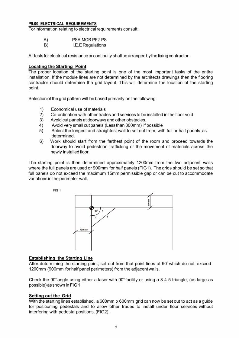
Locating the Starting PointThe proper location of the starting point is one of the most important tasks of the entireinstallation. If the module lines are not determined by the architects drawings then the flooringcontractor should determine the grid layout. This will determine the location of the startingpoint.
Selectionof the grid pattern will be basedprimarily on the following:
1) Economical use ofmaterials2) Co-ordination with other trades and services to be installed in the floor void.3) Avoid cut panels at doorways and other obstacles.4) Avoid very small cut panels (Less than 300mm) if possible5) Select the longest and straightest wall to set out from, with full or half panels as
determined.6) Work should start from the farthest point of the room and proceed towards the
doorway to avoid pedestrian trafficking or the movement of materials across thenewly installed floor.
The starting point is then determined approximately 1200mm from the two adjacent wallswhere the full panels are used or 900mm for half panels (FIG1). The grids should be set so thatfull panels do not exceed the maximum 15mm permissible gap or can be cut to accommodatevariations in the perimeter wall.
FIG 1
Establishing the Starting LineAfter determining the starting point, set out from that point lines at 90owhich do not exceed1200mm (900mm for half panel perimeters) from the adjacentwalls.
Check the 90o angle using either a laser with 90o facility or using a 3-4-5 triangle, (as large aspossible)asshown inFIG1.
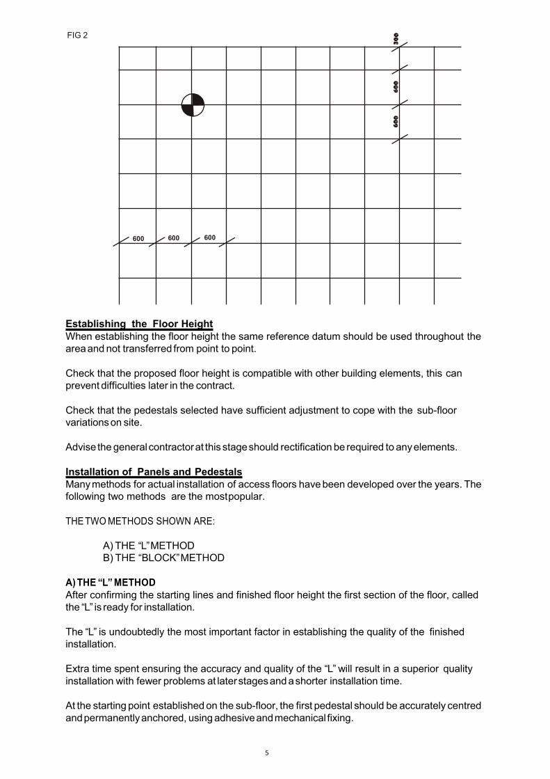
Setting out the GridWith the starting lines established, a 600mm x 600mm grid can now be set out to act as a guidefor positioning pedestals and to allow other trades to install under floor services withoutinterfering with pedestal positions. (FIG2).
1200mm
900 4
3 5
900m
m
5
FIG 2
600 600 600
Establishing the Floor HeightWhen establishing the floor height the same reference datum should be used throughout theareaand not transferred from point to point.
Check that the proposed floor height is compatible with other building elements, this canprevent difficulties later in the contract.
Check that the pedestals selected have sufficient adjustment to cope with the sub-floorvariationson site.
Advise the generalcontractorat this stageshould rectification be required to anyelements.
Installation of Panels and PedestalsManymethods for actual installation of access floors havebeen developed over the years. Thefollowing two methods are the mostpopular.
THETWOMETHODS SHOWN ARE:
A) THE “L”METHODB) THE “BLOCK”METHOD
A)THE “L”METHODAfter confirming the starting lines and finished floor height the first section of the floor, calledthe “L” is ready for installation.
The “L” is undoubtedly the most important factor in establishing the quality of the finishedinstallation.
Extra time spent ensuring the accuracy and quality of the “L” will result in a superior qualityinstallation with fewer problems at laterstagesandashorter installation time.
At the starting point establishedon the sub-floor, the first pedestal should be accurately centredandpermanentlyanchored, usingadhesiveandmechanical fixing.
6
12 panels long
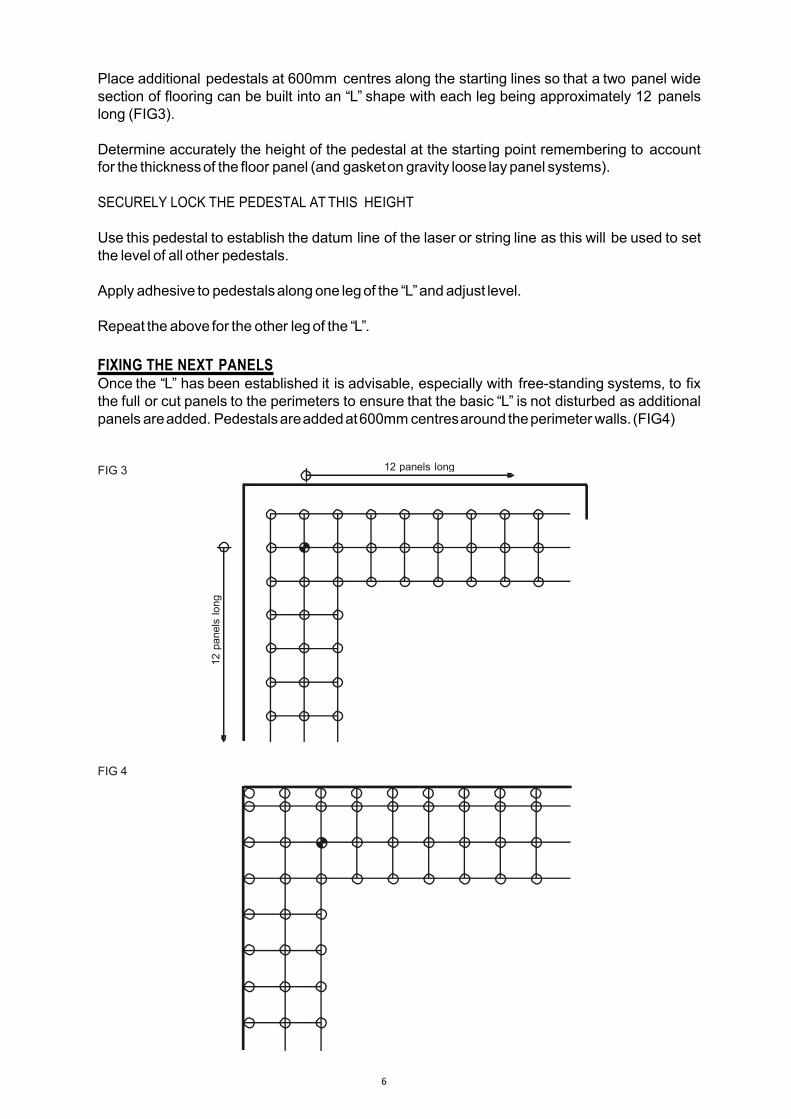
Place additional pedestals at 600mm centres along the starting lines so that a two panel widesection of flooring can be built into an “L” shape with each leg being approximately 12 panelslong (FIG3).
Determine accurately the height of the pedestal at the starting point remembering to accountfor the thicknessof the floor panel (and gasketon gravity loose laypanel systems).
SECURELY LOCK THE PEDESTAL ATTHIS HEIGHT
Use this pedestal to establish the datum line of the laser or string line as this will be used to setthe level of all other pedestals.
Apply adhesive to pedestalsalongone legof the “L”andadjust level.
Repeat the above for the other legof the “L”.
FIXING THE NEXT PANELSOnce the “L” has been established it is advisable, especially with free-standing systems, to fixthe full or cut panels to the perimeters to ensure that the basic “L” is not disturbed as additionalpanels areadded. Pedestalsareaddedat600mmcentresaround theperimeterwalls. (FIG4)
FIG 3
FIG 4
12panelslong
7
NOTE!If for any reason perimeter panels cannot be fixed at this point then the pedestals adjacent tothe perimeter which only have panels on one half of the pedestal head should be positionedwithout the adhesive.
Pedestals not loaded with a panel on all four quadrants are susceptible to tipping very slightlywithin the pedestal adhesive, which will cause panel lipping or rocking at later stages whenpanels are locatedon theother quadrants of the head.Thisisalso true for pedestals installed at the endof thework day.Only pedestals which are loaded on all four quadrants of the pedestal head should be glueddown. If this is not possible the pedestal must be left until such time that it can be glued andloadedwith a panel on all four quadrants.
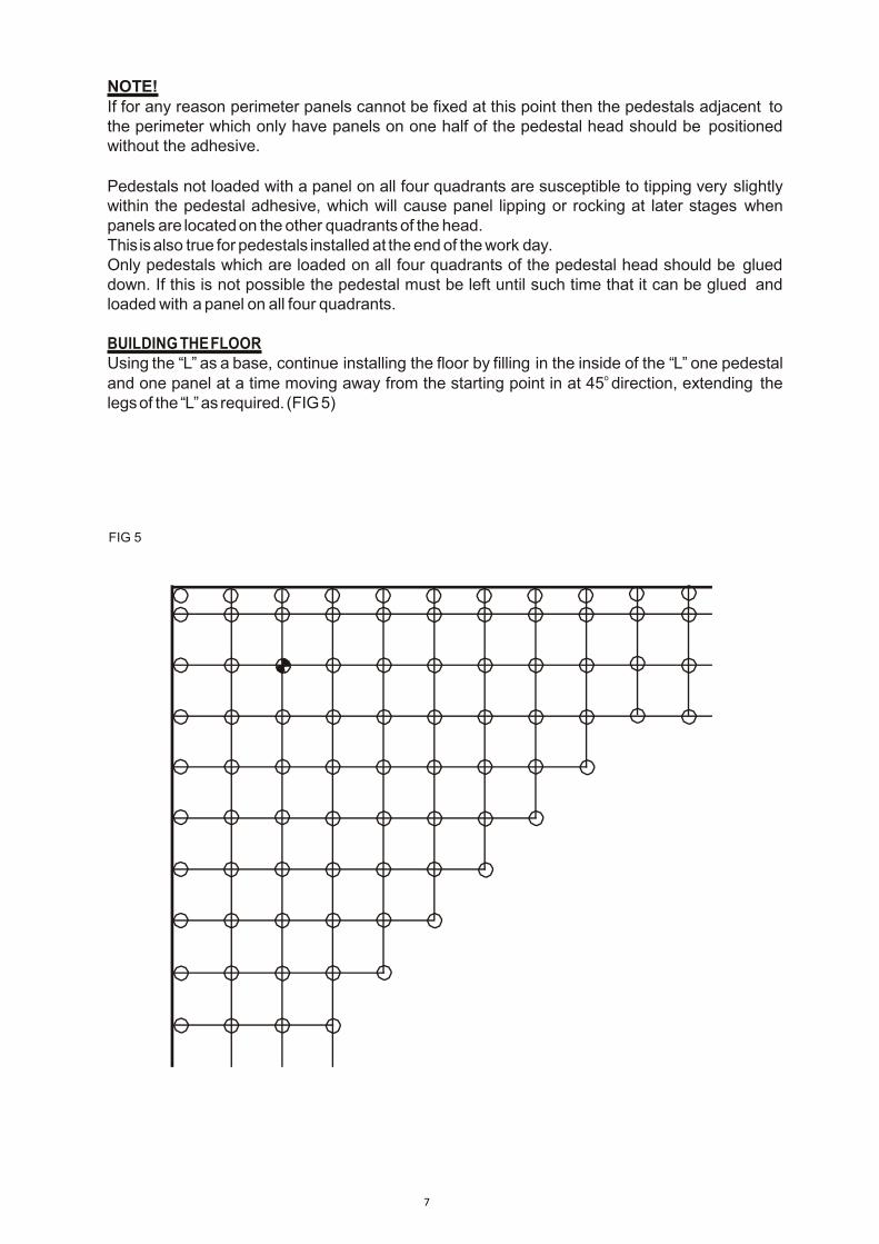
BUILDINGTHEFLOORUsing the “L” as a base, continue installing the floor by filling in the inside of the “L” one pedestaland one panel at a time moving away from the starting point in at 45o direction, extending thelegsof the “L”as required. (FIG5)
FIG 5
㠀
A) THE “BLOCK” METHOD
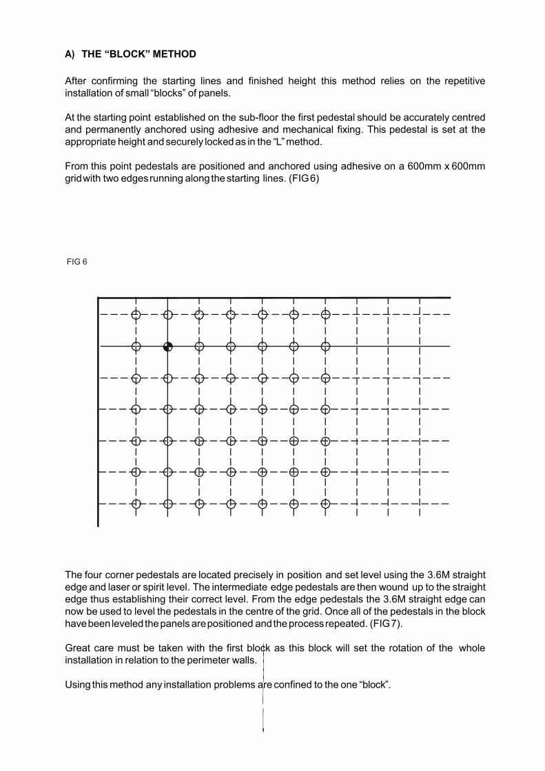
After confirming the starting lines and finished height this method relies on the repetitiveinstallation of small “blocks” of panels.
At the starting point established on the sub-floor the first pedestal should be accurately centredand permanently anchored using adhesive and mechanical fixing. This pedestal is set at theappropriate height andsecurely lockedas in the “L”method.
From this point pedestals are positioned and anchored using adhesive on a 600mm x 600mmgridwith two edgesrunning along thestarting lines. (FIG6)
FIG 6
The four corner pedestals are located precisely in position and set level using the 3.6M straightedge and laser or spirit level. The intermediate edge pedestals are then wound up to the straightedge thus establishing their correct level. From the edge pedestals the 3.6M straight edge cannow be used to level the pedestals in the centre of the grid. Once all of the pedestals in the blockhavebeen leveled thepanels arepositioned andtheprocessrepeated. (FIG7).
Great care must be taken with the first block as this block will set the rotation of the wholeinstallation in relation to the perimeter walls.
Using thismethod any installation problems areconfined to the one “block”.
9
FIG 7
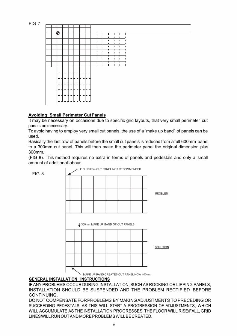
Avoiding Small Perimeter CutPanelsIt may be necessary on occasions due to specific grid layouts, that very small perimeter cutpanels are necessary.Toavoid having to employ very small cut panels, the use of a “make up band” of panels can beused.Basically the last row of panels before the small cut panels is reduced from a full 600mm panelto a 300mm cut panel. This will then make the perimeter panel the original dimension plus300mm.(FIG 8). This method requires no extra in terms of panels and pedestals and only a smallamount of additional labour.
FIG 8
PROBLEM
SOLUTION
MAKE UP BAND CREATES CUT PANEL NOW 400mm
GENERAL INSTALLATION INSTRUCTIONSIF ANY PROBLEMSOCCURDURING INSTALLATION, SUCH ASROCKING OR LIPPING PANELS,INSTALLATION SHOULD BE SUSPENDED AND THE PROBLEM RECTIFIED BEFORECONTINUING.DONOTCOMPENSATEFORPROBLEMS BYMAKINGADJUSTMENTS TOPRECEDINGORSUCCEEDING PEDESTALS, AS THIS WILL START A PROGRESSION OF ADJUSTMENTS, WHICHWILL ACCUMULATE ASTHE INSTALLATION PROGRESSES.THE FLOORWILL RISE/FALL, GRIDLINESWILLRUNOUTANDMOREPROBLEMSWILLBECREATED.
E.G. 100mm CUT PANEL NOT RECOMMENDED
300mm MAKE UP BAND OF CUT PANELS

10
IT IS ESSENTIAL THATANY PROBLEM IS CORRECTED ATSOURCEPotential problems, their causesandsolutions arecovered later in thisdocument.
Panels damaged in any way due to handling on site (dented corners or edges etc.) should notbe used to build the floor, as they will cause the grid to wander. Any such panels should beplaced to one sideandused for perimeter cuts.
Cutting to PerimetersPanels should be cut to perimeters in accordance with PF2 PS recommendations (see page 4 -FIT) and sealed using the aluminum foil tape (Ref. A19680015). It is a requirement of PSA MOBPF2PSthatperimeterpanelsarescrewed to thepedestalhead.
Thisisonlyarequirement for installationsspecifiedtoPSAMOB PF2PSStandard.
StringersThese are steel cross braces, which locate from pedestal head to pedestal head to create amatrix across the floor. Normally supplied in “Snap-on” format they provide additional rigidity tothe system, particularly where high floor levelsare involved.
Stringers where required should be installed in natural sequence with panels and pedestals anddo not affect the basic installation techniquesdescribed.
Pedestal AdhesivePedestal adhesive allows pedestals to be slightly re-positioned for a short while after adhesion.Neveradhere more pedestals thancanbepositioned andadjusted in one shift.
Pedestaladhesivewill fixapproximately 20Nopedestalsperkg.
11
PedestalAdjustmentOnce the level of the pedestal is determined it should be securely locked in position. It isimperative that pedestals are installed vertically (plumb) otherwise an uneven floor will result.Thisis the root causeofmany installation problems.
Pedestal OverlapThe adjustment shown in the pedestal selection chart should NEVER be exceeded. Rangesareset to ensure that enough of the pedestal head stud remains in the pedestal base to providesystemsafetyandperformance.
Panel ParallelogramIt is essential that the installation be maintained where all panel module lines are straight andcorners meet equally. If this is not observed then the condition will continue and become worseas the installation progresses. If this condition is allowed to progress it is extremely difficult torectify at a later stage. For this reason it is necessary that each panel is checked for level, positionandstability as it is installed.
LevellingWhen using a laser level always take the elevation reference line from the centre of the beam.Always take the level reading off the same point on each pedestal and ensure that the pedestalis perpendicular before doing so.
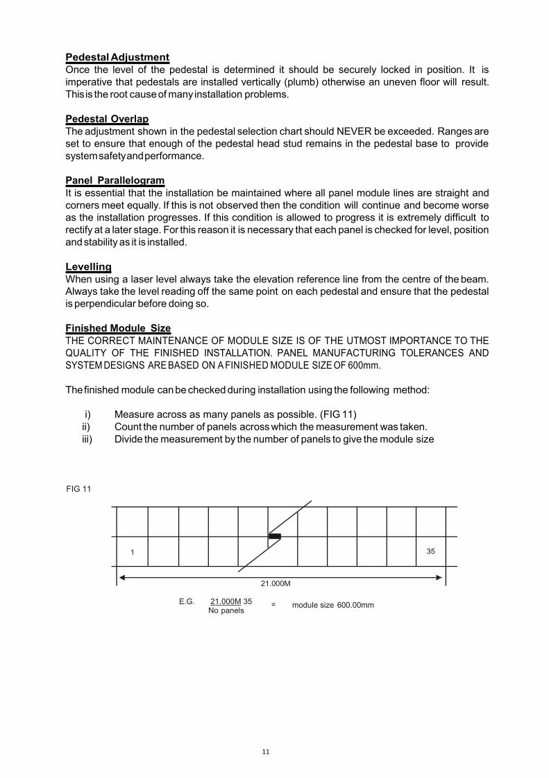
Finished Module SizeTHE CORRECT MAINTENANCE OF MODULE SIZE IS OF THE UTMOST IMPORTANCE TO THEQUALITY OF THE FINISHED INSTALLATION. PANEL MANUFACTURING TOLERANCES ANDSYSTEMDESIGNS AREBASED ON AFINISHEDMODULE SIZEOF 600mm.
Thefinished module canbecheckedduring installation using the following method:
i) Measure across as many panels as possible. (FIG11)ii) Count the number of panels acrosswhich themeasurement was taken.iii) Divide themeasurement by the number of panels to give the module size
FIG 11
1 35
21.000M
E.G. 21.000M 35No panels
= module size 600.00mm
12
Whilst this gives an accurate module size care must be taken to ensure that the module isconsistentand that the areasof tight and loose installation do not occur.
Whilst the gap condition of a loose installation is unsightly and obvious, the worst scenario of anoverly tight installation can lead to more serious problems as systems are designed to beinstalled on a 600mm module to allow for building movement and system expansion andcontraction under changing hygrothermal conditions.
As the Eurodek gravity loose panel systems are free standing systems, the finished module sizeis essentially fixed by the panel size. Panels should be positioned loosely together withoutexcessive use of force. Ambient hygrothermal conditions prevalent at the time of theinstallation MUST be taken into consideration aspanels will expand/contract byapproximately0.11mm per 15oCchange in temperature.
EXCESSIVE FORCE AND THE USE OF HAMMERS OR MALLETS SHOULD NOT BE ALLOWEDUNDERANYCIRCUMSTANCES.
Cut-out PanelsHoles of any description cut into floor panels may, depending on their size and position, requireadditional support pedestals to maintain the integrity of the installation. In any case cut-outsshould be no closer to the panel edge than 50mm. All cut-outs should be sealed usingaluminum tape.
Mechanical FixingIt may be necessary under certain conditions e.g. poor quality sub-floors or very high-levelfloors, to mechanically fix (bolt, screw or nail) pedestals to the sub-floor in addition to the epoxyadhesive fixing.
Mechanical fixing should take place when the pedestal adhesive is semi-cured. This isnecessarytoensurethat:
a) Mechanical fixingsdonot pull pedestals from the vertical position if adhesive is too wet.b) Mechanical fixingsdo not shatter adhesivewhich has cured.
Holes are provided in the pedestal base plate for the purposes of mechanical fixing. A hole isdrilled through these (normally two fixings diagonally opposite per pedestal) and into the sub-floor at a diameter appropriate to accept a proprietary fixing, adequate in size to achieve therequired fixingstrength.
Uplifting and Replacing PanelsAlways use the appropriate lifting tool to remove or replace panels. Never try to remove panelsusing screwdrivers etc. or replace by kicking into position DAMAGE WILLOCCUR.
13
Carpet Tackifier AdhesivesWhen fixing carpet finishes to bare panel systems it is imperative that tackifier adhesive is notallowed to ingress the panel joints, as once set it will hinder panel removal and if dirt or dust isalso present may cause grating noises between panels. Adhesives, particularly water-basedtypes must be allowed to fully dry before carpet finishes are applied to prevent trappedmoisture attackingpanel protective finishes.
CavitybarriersThe current Building Regulations give requirements for the provision of cavity barriers, toprevent the passage of fire through building voids. These provisions may include voids createdby access floors.There are anumber of proprietary cavitybarriers available, or alternatively thesecanbeconstructedonsite.
INSTALLATION PROBLEMSProviding the above procedures are followed, the installation of access flooring is generally asimple straightforward operation. The following points are the most common problemsencountered on site and can be overcome easily providing care is taken and problems areresolvedatsource.
Rocking PanelsA common problem which can generally be easily resolved if dealt with at the point ofinstallation. It is caused by one pedestal head not being in the same plane of level as the otherthree.
It canusually beattributed to one ormore of the following:
i) Pedestals not setperpendicularii) Dirt or debris on one pedestal headiii) Anearth bonding clip missing from one quadrant of the pedestal headgasket.
The other main cause of rocking panels, which is not as easily rectifiable, is the trafficking of theaccess floor prior to the full curing of the pedestal adhesive. The only method of preventionbeing the strict adherence to the 24 HR RULEas described under the “PROTECTION” section ofthis document.
Lipping PanelsThis is the situation where one edge of a panel is significantly higher than that of the adjacentpanel.Thespecifiedmaximumforthiscondition isgiveninthe“TOLERANCES”section.It is mainly caused by pedestals not being fixed perpendicular, but can also be caused by dirt ordebris on pedestal heads. Can occur where pedestals have been glued down with panel weighton one side only, causing pedestals to tip slightly in the adhesive when adhesive is cured andother panelsaddedadifference in level occurs.
Grid/Module OutCanbecausedbydamaged panels (dented) beingused,overly looseor tight installation, orlackof carewhen positioning panels. Extremelydifficult to remedy if allowed to progress.
14
Loss ofLevelUsing different datum points as opposed to a single reference point will cause levels to change.The other prime causes being hurried installation, equipment faults and non-rectification ofproblems such asrockingor lipping panelsatsource.
IF ANY PROBLEMS OCCUR DURING INSTALLATION SUCH AS ROCKING ORLIPPING PANELS,INSTALLATION SHOULD BE SUSPENDED AND THE PROBLEM RECTIFIED BEFORECONTINUING.
DO NOT COMPENSATE FOR PROBLEMS BY MAKING ADJUSTMENTS TO PRECEEDING ORSUCCEEDING PEDESTALSOR PANELS ASTHIS WILL STARTAPROGRESSION OF ADJUSTMENTS,WHICH WILL ACCUMULATE AS THE INSTALLATION PROGRESSES AND MORE PROBLEMS WILLBE CREATED.
IT IS ESSENTIAL THAT ANY PROBLEM IS CORRECTED ATSOURCE.
PROTECTION OF FINISHED INSTALLATIONSOnce an area of installation is complete, the correct protection will ensure its quality anddurability. Having completed an individual area, it must be cordoned off immediately and notraffic whatsoever must be allowed for a minimum of 24 hours, preferably 48 hours. Inparticularly cold conditions adhesive curing times may become extended and adhesivecondition should be checkedafter 24 hours before traffic is permitted.
If an installation is trafficked before adhesive has fully cured, rocking or lipping panels andchangesin levelwill undoubtedly occur.
Finished installations should be protected from excessive dust, dirt and debris, preferably by theuseof hardboard or similar proprietary protective finishes.
Protection is obviously a particular necessity on panels, which have a pre-bonded finish.Particular care should be takenwith pedestal adhesive as once semi-cured it is impervious to allcleaningagents.
Care must also be taken to ensure that floors are not overloaded or abused when moving othermaterials or equipment on site, especially when using moving equipment with wheels orcastors asthese magnifythe load transmitted on the floor.
Wheels or castors carrying light loads may not overload the access floor system but may causedamage to panel finishes.
Although access floor systems are of robust construction their quality and durability is mirroredby the standardof protection afforded them.
The access floor is part of the building finish and should be treated accordingly. Damage, abuseand overloading must be prevented to ensure that the floor system performs to its designspecification.
FLOOR SYSTEMS SUBJECT TO WATER DAMAGE CAN NOT BE GUARANTEED IN TERMS OFPERFORMANCEAND SHOULD BEREMOVED AND REPLACED.
15
MAINTENANCEANDUSE
Basic access floor systems require a little if anymaintenance oncethe installation is complete andthe void cleaned.Installations shouldbeinspectedduringnormaluseforsignsofdamageordeterioration.
Other thanvacuum cleaning of the voidwhen required and ensuring that thepedestal heads arecleanwhenreplacingpanels, cleaningof thesystem isnotnormallynecessary.
Cleaningofpanel finishes shouldbecarriedout inaccordancewiththemanufacturers instructions,avoiding the use of water which could permeate the finish and attack floor panel protectivecoatings,orsubstanceswhichmaybedetrimental tothefinishes'adhesivebond.
Panelsshouldberemovedverticallyusingtheappropriate liftingdevice,never removingpanelswithscrewdrivers etc. They should be replaced in the same rotation never dropping or kicking panelsintoposition. If stringersorgaskets areremoved for any reason it isessential that theybereplaced.Pedestals arenot tobeusedas pulleys for drawing incablesetc.
Once removed, panels should be replaced in the same position androtation as soonas possible inorder to protect the floor, its void contents and in the interests of safety. Always ensure that paneledgesarecleanbeforereplacing.
When access to thevoid is necessary, theminimumnumber of panels should be removed at anyone time.Aminimum of two rows of panels should remain intact between rows of uplifted panelsandthecreationof“islands”ofpanelswithintheinstallation shouldbeavoidedatalltimes.
Panels should always be replaced in their original position and rotation. This beingparticularlyimportant forpanels withpre-bonded finishes.
WHILST AS MANYPERTINENT POINTS AS POSSIBLE HAVE BEEN COVERED IN THISGUIDE IT IS OBVIOUSLY NOT A FULLY COMPREHENSIVE G UIDE TOACCESS FLOORING. FOR FURTHER INFORMATION ON ANY ASPECT OFACCESS FLOORING PLEASE CONSULT:

ACCESSFLOORSTOREInstallation & Services Limited
No.45 Weifu RdChangzhou CityJiangsu Provinve213103China
www.accessfloorstore.com
T:+8651983811288P:+8618018280738
Copyright © 2022 FDOKUMEN