Access Unit - Tiptel
112
www.2n.cz Access Unit Access Control Configuration Manual Firmware: 2.25 Version: 2.25
-
Upload
khangminh22 -
Category
Documents
-
view
2 -
download
0
Transcript of Access Unit - Tiptel
www.2n.cz
Access UnitAccess Control
Configuration Manual Firmware: 2.25 Version: 2.25
The 2N TELEKOMUNIKACE a.s. is a Czech manufacturer and supplier of telecommunications equipment.
The product family developed by 2N TELEKOMUNIKACE a.s. includes GSM gateways, private branch exchanges (PBX), and door and lift communicators. 2N TELEKOMUNIKACE a.s. has been ranked among the Czech top companies for years and represented a symbol of stability and prosperity on the telecommunications market for almost two decades. At present, we export our products into over 120 countries worldwide and have exclusive distributors on all continents.
2N is a registered trademark of 2N TELEKOMUNIKACE a.s. Any product and/or other ®names mentioned herein are registered trademarks and/or trademarks or brands protected by law.
2N TELEKOMUNIKACE a.s. administers the FAQ database to help you quickly find information and to answer your questions about 2N products and services. On www.faq.2n.cz you can find information regarding products adjustment and instructions for optimum use and procedures „What to do if...".
2N TELEKOMUNIKACE a.s. hereby declares that the 2N product complies with all basic requirements and other relevant provisions of the 1999/5/EC directive. For the full wording of the Declaration of Conformity see the CD-ROM (if enclosed) or our website at www.2n.cz.
The 2N TELEKOMUNIKACE a.s. is the holder of the ISO 9001:2009 certificate. All development, production and distribution processes of the company are managed by this standard and guarantee a high quality, technical level and professional aspect of all our products.
2N TELEKOMUNIKACE a.s., www.2n.cz 3/112
Content:
1. Product Overview
2. Express Wizard for Basic Settings
3. Function Licensing
4. Signalling of Operational Statuses
5. Intercom Configuration
5.1 Status
5.2 Directory
5.3 Hardware
5.4 Services
5.5 System
6. Supplementary Information
6.1 Troubleshooting
6.2 Directives, Laws and Regulations
6.3 General Instructions and Cautions
2N TELEKOMUNIKACE a.s., www.2n.cz 4/112
1. Product Overview
Door access system can (with addon software and/or with 2N Access Unit 2N IP) offers you a whole setup for access controle over any whole object.intercoms
Your can be equipped with a numeric keypad, so you can use it as 2N Access Unitcode lock.
Your can also be equipped with another RFID card reader, so it can be 2N Access Unitused as a part of your security system or attendance system in your company.
Access Uni2N t can be equipped with a relay to control eletric lock or any other device connected to this access system. There are a lot of possibilities to set up, when and how to activate these switches - with code, automaticaly, by pressing a button etc.
The following symbols and pictograms are used in the manual:
Safety
Always abide by this information to prevent persons from injury.
Warning
Always abide by this information to prevent damage to the device.
Caution
Important information for system functionality.
2N TELEKOMUNIKACE a.s., www.2n.cz 5/112
Tip
Useful information for quick and efficient functionality.
Note
Routines or advice for efficient use of the device.
2N TELEKOMUNIKACE a.s., www.2n.cz 6/112
2. Express Wizard for Basic Settings
LAN Connection Setting
You have to know the IP address to connect to the configuration 2N Access Unitinterface successfully. Automatic IP address retrieval from the DHCP server is set by default in the . Thus, if connected to a network in which a DHCP server 2N Access Unitconfigured to assign IP addresses to all new devices is available, the will obtain devicean IP address from the DHCP server. The IP address can be found in 2N Access Unitthe DHCP server status (according to the MAC address given on the production plate), or will be communicated to you by the voice function; refer to 2N Access Unitthe Installation Manual.
If there is no DHCP server in your LAN, use the RESET button to set 2N Access Unitthe static IP address mode; refer to the respective Installation Manual. Your unit address will then be . Use it for the first login and then change it if 192.168.1.100necessary.
Now enter the IP address into your favourite browser. We recommend you to use the latest Chrome, Firefox or Internet Explorer (Edge) versions as is not 2N Access Unitfully compatible with earlier browser versions.
Use the name "admin" and password "2n" (i.e. default reset password) for your first login to the configuration interface. We recommend you to change the default password upon your first login; refer to the Password parameter in the Services / Web
menu. Remember the password well or put it down. It is because if you forget Serverthe password, you will have to reset the intercom to default values (refer to the respective Installation Manual) thus losing all your current configuration changes.
Tip
FAQ: IP address?IP address – How to get the 2N Access Unit
2N TELEKOMUNIKACE a.s., www.2n.cz 7/112
Firmware UpdateWe also recommend you to update your firmware upon the first login to the . deviceRefer to for the latest firmware version. Press the button www.2n.cz Update Firmwarein the menu to upload firmware. The device will get restarted System Maintenance/upon upload and only then the updating process will be complete. The process takes about 1 minute.
2N TELEKOMUNIKACE a.s., www.2n.cz 8/112
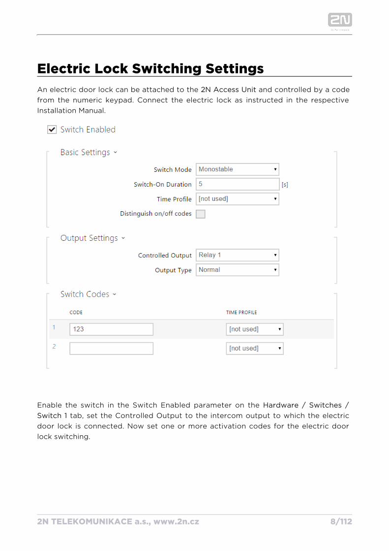
Electric Lock Switching SettingsAn electric door lock can be attached to the and controlled by a code 2N Access Unitfrom the numeric keypad. Connect the electric lock as instructed in the respective Installation Manual.
Enable the switch in the Switch Enabled parameter on the Hardware / Switches / tab, set the Controlled Output to the intercom output to which the electric Switch 1
door lock is connected. Now set one or more activation codes for the electric door lock switching.
2N TELEKOMUNIKACE a.s., www.2n.cz 9/112
3. Function Licensing
2N Access Unit provides just one licensed function – NFC (license Part. No. 916012). This license can be used only with which has 13 MHz card reader 2N Access Unit installed.
For a limited period of 800 hours it is possible to activate a trial license, which includes the NFC functionality.
2N TELEKOMUNIKACE a.s., www.2n.cz 10/112
4. Signalling of Operational Statuses
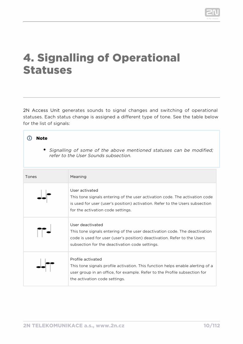
2N Access Unit generates sounds to signal changes and switching of operational statuses. Each status change is assigned a different type of tone. See the table below for the list of signals:
Note
Signalling of some of the above mentioned statuses can be modified; refer to the User Sounds subsection.
Tones Meaning
User activated
This tone signals entering of the user activation code. The activation code
is used for user (user’s position) activation. Refer to the Users subsection
for the activation code settings.
User deactivated
This tone signals entering of the user deactivation code. The deactivation
code is used for user (user’s position) deactivation. Refer to the Users
subsection for the deactivation code settings.
Profile activated
This tone signals profile activation. This function helps enable alerting of a
user group in an office, for example. Refer to the Profile subsection for
the activation code settings.
2N TELEKOMUNIKACE a.s., www.2n.cz 11/112
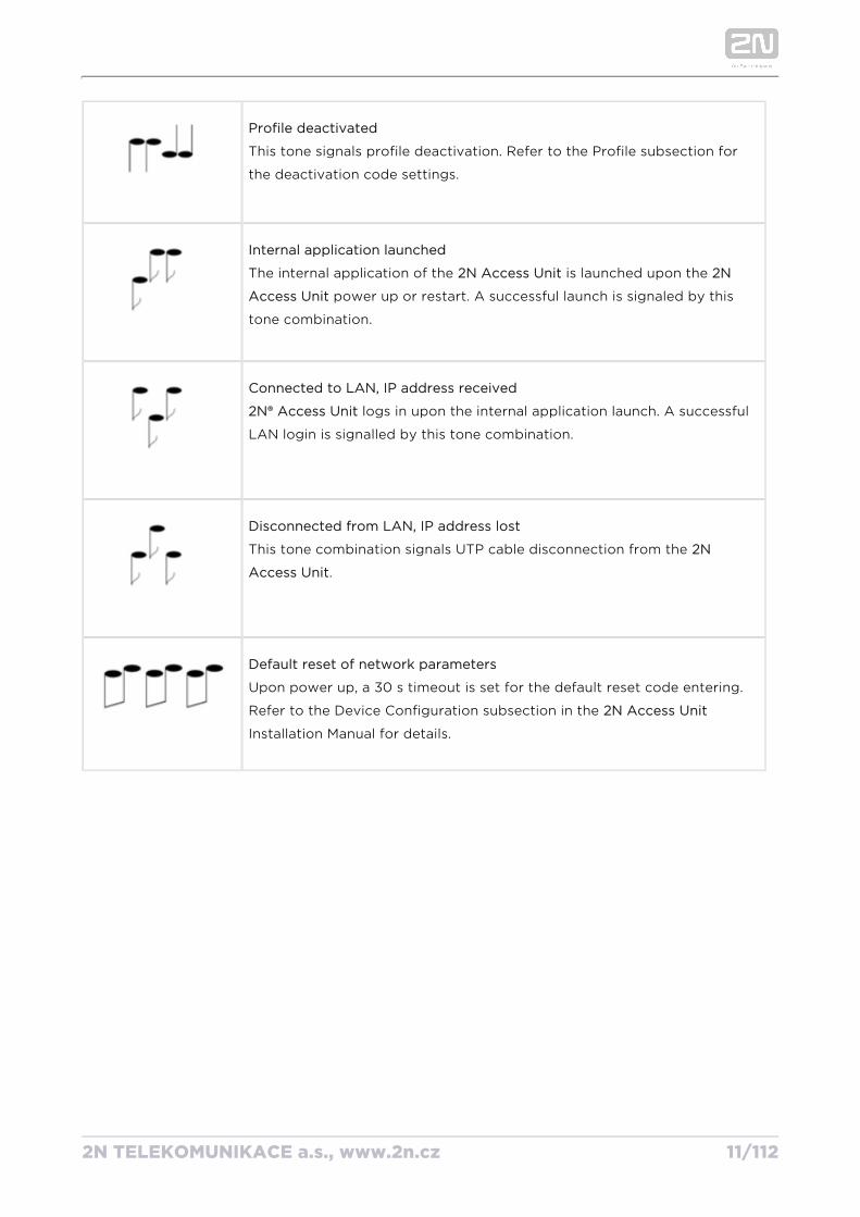
Profile deactivated
This tone signals profile deactivation. Refer to the Profile subsection for
the deactivation code settings.
Internal application launched
The internal application of the is launched upon the 2N Access Unit 2N
power up or restart. A successful launch is signaled by this Access Unit
tone combination.
Connected to LAN, IP address received
2N® Access Unit logs in upon the internal application launch. A successful
LAN login is signalled by this tone combination.
Disconnected from LAN, IP address lost
This tone combination signals UTP cable disconnection from the 2N
.Access Unit
Default reset of network parameters
Upon power up, a 30 s timeout is set for the default reset code entering.
Refer to the Device Configuration subsection in the 2N Access Unit
Installation Manual for details.
2N TELEKOMUNIKACE a.s., www.2n.cz 12/112
5. Intercom Configuration
2N TELEKOMUNIKACE a.s., www.2n.cz 13/112
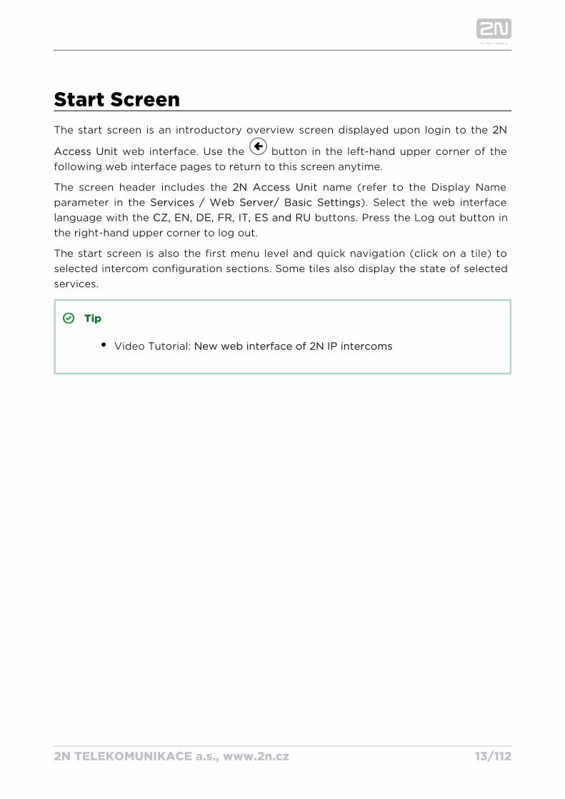
Start ScreenThe start screen is an introductory overview screen displayed upon login to the 2N
web interface. Use the button in the left-hand upper corner of the Access Unitfollowing web interface pages to return to this screen anytime.
The screen header includes the name (refer to the Display Name 2N Access Unitparameter in the ). Select the web interface Services / Web Server Basic Settings/language with the buttons. Press the Log out button in CZ, EN, DE, FR, IT, ES and RUthe right-hand upper corner to log out.
The start screen is also the first menu level and quick navigation (click on a tile) to selected intercom configuration sections. Some tiles also display the state of selected services.
Tip
Video Tutorial: New web interface of 2N IP intercoms
2N TELEKOMUNIKACE a.s., www.2n.cz 14/112
Configuration MenuThe configuration includes 5 main menus: , , ,2N Access Unit Status Directory Hardware
and including submenus; refer to the survey below.Services System
Status
Device – essentials on the 2N Access Unit
Services – information on active services and their states
Licence – current states of licences and available functions2N Access Unit
Access Log – list of last ten access cards
Events – list of events
Directory
Users – settings for user phone numbers, quick dial buttons, access cards and switch control user codes
Time Profiles – time profile settings
Holidays – holiday settings
Hardware
Switches – electric lock, lighting, etc. settings
Audio – audio, signalling tone, etc. volume settings
Keyboard – keyboard and code input settings
Backlight – intensity of backlight
Card – card reader, Wiegand interface settingsReader
Digital Inputs – management of digital inputs
Extenders – extender settings 2N Access Unit
2N TELEKOMUNIKACE a.s., www.2n.cz 15/112
Services
E-mail – sending e-mails when e.g. denied events
Mobile Key – Bluetooth settings and management of paired devices
Automation – flexible intercom settings according to user requirements
HTTP API – application programming interface for controlling selected functions of intercom
Web server – web server and access password settings
SNMP – functionality enabling remote monitoring of intercoms in the network using SNMP protokol
System
Network – LAN connection settings, 802.1x, packet capturing
Date and time – real time and time zone settings
Licence – licence settings, trial licence activation
Certificates – certificate and private key settings
Auto Provisioning – automatic firmware and configuration update settings
Syslog – syslog message sending settings
Maintenance – backup and configuration reset, firmware update
5.1 Status
5.2 Directory
5.3 Hardware
5.4 Services
5.5 System
2N TELEKOMUNIKACE a.s., www.2n.cz 16/112
Caution
In order to ensure the full functioning and guaranteed outputs we strongly recommend a verification of the timeliness of version of product or facility already during the installation process. The customer takes into consideration that the product or facility can achieve the guaranteed outputs and be fully operational pursuant to the producer’s instructions only by using the most recent version of product or facility, which has been tested for full interoperability and has not been determined by the producer as incompatible with certain versions of other products, only in conformity with the producer’s instructions, guidelines, manual or recommendation and only in conjunction with suitable products and facilities of the other producers. The most recent versions are available on the website https://www.2n.cz/cs_CZ/, or specific facilities, depending on their technical capacity, allow updating in the configuration interface. Should the customer use any other version of product or facility than the most recent one, or the version that has been determined by the producer as incompatible with certain versions of other producers’ products of facilities, or the product or facility in a way incompatible with the producer’s instructions, guidelines, manual or recommendation or in conjunction with unsuitable products or facilities of the other producers, he or she is aware of all potential limitations of functionality of such a product or facility and all relating consequences. Should the customer use any other than the most recent version of the product or facility, or the version that has been that has been determined by the producer as incompatible with certain versions of other producers’ products of facilities, or the product or facility in a way incompatible with the producer’s instructions, guidelines, manual or recommendation or in conjunction with unsuitable products or facilities of the other producers, he or she agrees that the company 2N TELEKOMUNIKACE a.s. is not liable neither for any limitation of such a product’s functionality, nor for any damage, loss or injury relating to such a potential limitation of functionality.
2N TELEKOMUNIKACE a.s., www.2n.cz 17/112
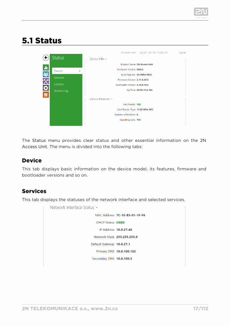
5.1 Status
The menu provides clear status and other essential information on the Status 2N . The menu is divided into the following tabs:Access Unit
DeviceThis tab displays basic information on the device model, its features, firmware and bootloader versions and so on.
ServicesThis tab displays the statuses of the network interface and selected services.
2N TELEKOMUNIKACE a.s., www.2n.cz 18/112
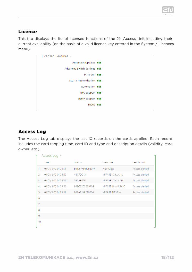
LicenceThis tab displays the list of licensed functions of the including their 2N Access Unitcurrent availability (on the basis of a valid licence key entered in the System / Licencesmenu).
Access LogThe displays the last 10 records on the cards applied. Each record Access Log tab includes the card tapping time, card ID and type and description details (validity, card owner, etc.).
2N TELEKOMUNIKACE a.s., www.2n.cz 19/112
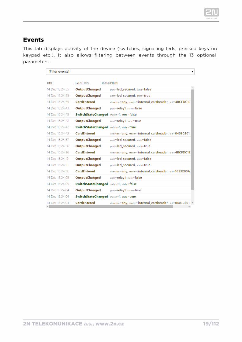
EventsThis tab displays activity of the device (switches, signalling leds, pressed keys on keypad etc.). It also allows filtering between events through the 13 optional parameters.
2N TELEKOMUNIKACE a.s., www.2n.cz 20/112
5.2 DirectoryHere is what you can find in this section:
5.2.1 Users
5.2.2 Time Profiles
5.2.3 Holidays
2N TELEKOMUNIKACE a.s., www.2n.cz 21/112
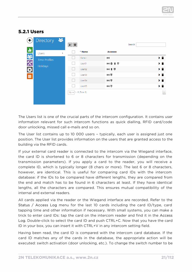
5.2.1 Users
The Users list is one of the crucial parts of the intercom configuration. It contains user information relevant for such intercom functions as quick dialling, RFID card/code door unlocking, missed call e-mails and so on.
The User list contains up to 10 000 users – typically, each user is assigned just one position. The User list provides information on the users that are granted access to the building via the RFID cards.
If your external card reader is connected to the intercom via the Wiegand interface, the card ID is shortened to 6 or 8 characters for transmission (depending on the transmission parameters). If you apply a card to the reader, you will receive a complete ID, which is typically longer (8 chars or more). The last 6 or 8 characters, however, are identical. This is useful for comparing card IDs with the intercom database: if the IDs to be compared have different lengths, they are compared from the end and match has to be found in 6 characters at least. If they have identical lengths, all the characters are compared. This ensures mutual compatibility of the internal and external readers.
All cards applied via the reader or the Wiegand interface are recorded. Refer to the menu for the last 10 cards including the card ID/type, card Status Access Log/
tapping time and other information if necessary. With small systems, you can make a trick to enter card IDs: tap the card on the intercom reader and find it in the Access
. Double-click to select the card ID and push CTRL+C. Now that you have the card LogID in your box, you can insert it with CTRL+V in any intercom setting field.
Having been read, the card ID is compared with the intercom card database. If the card ID matches any of the cards in the database, the appropriate action will be executed: switch activation (door unlocking, etc.). To change the switch number to be
2N TELEKOMUNIKACE a.s., www.2n.cz 22/112
activated, use the parameter in the menu Associated Switch Hardware Card Reader/or the parameter in the menu of the card Associated Switch Hardware Modules/reader module.
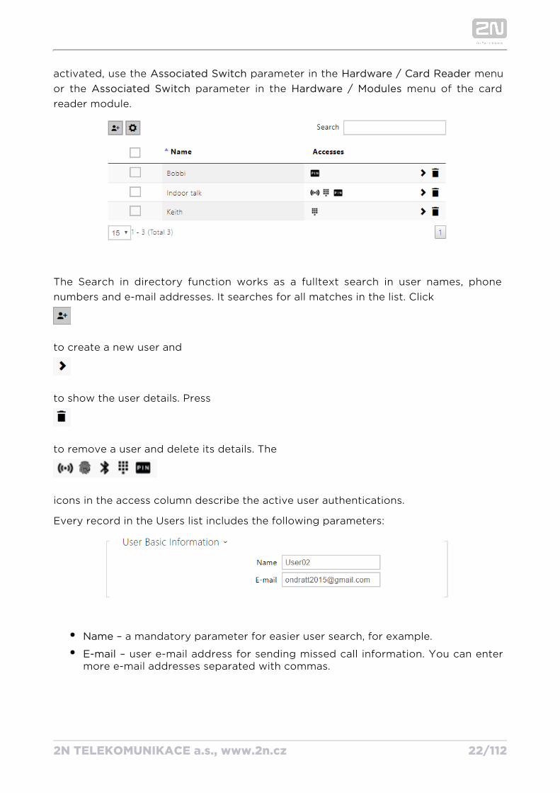
The Search in directory function works as a fulltext search in user names, phone numbers and e-mail addresses. It searches for all matches in the list. Click
to create a new user and
to show the user details. Press
to remove a user and delete its details. The
icons in the access column describe the active user authentications.
Every record in the Users list includes the following parameters:
Name – a mandatory parameter for easier user search, for example.
E-mail – user e-mail address for sending missed call information. You can enter more e-mail addresses separated with commas.
2N TELEKOMUNIKACE a.s., www.2n.cz 23/112
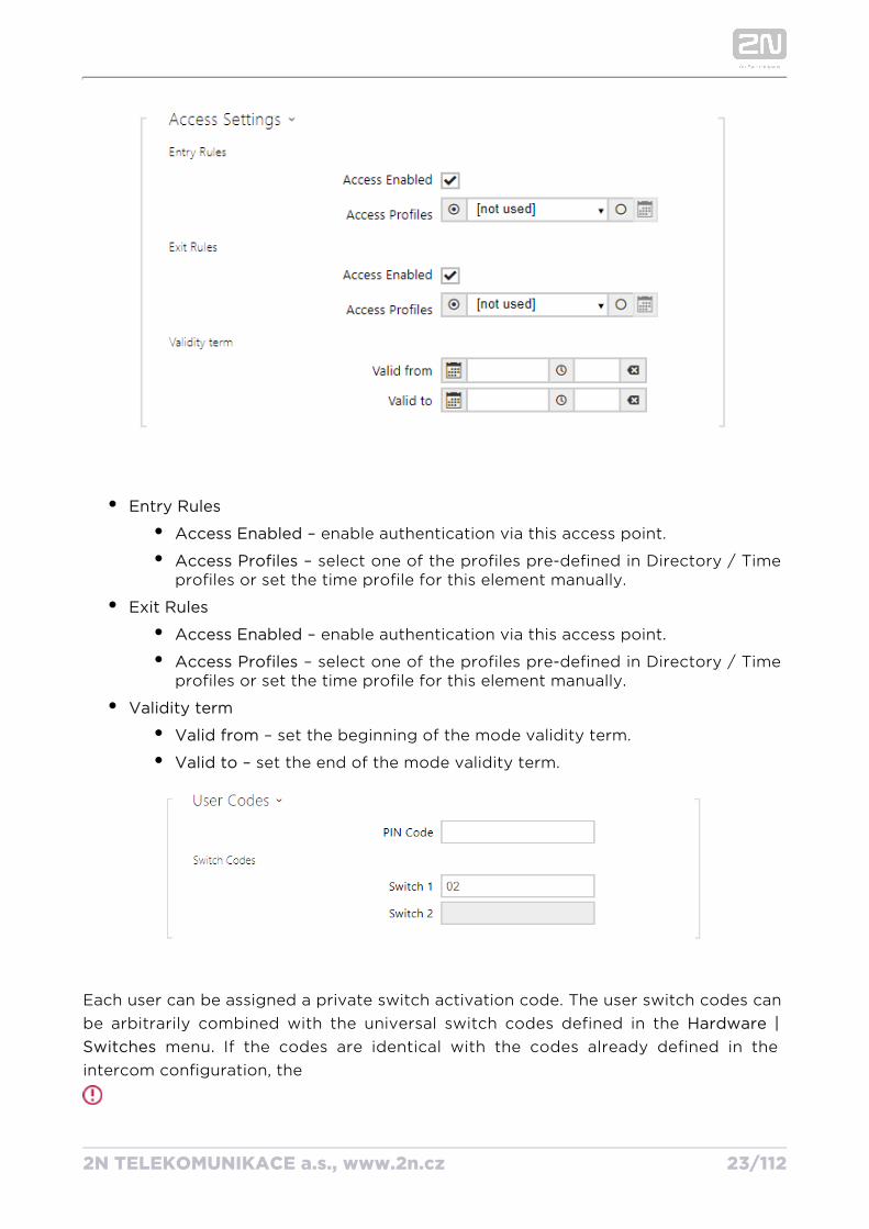
Entry Rules
Access Enabled – enable authentication via this access point.
Access Profiles – select one of the profiles pre-defined in Directory / Time profiles or set the time profile for this element manually.
Exit Rules
Access Enabled – enable authentication via this access point.
Access Profiles – select one of the profiles pre-defined in Directory / Time profiles or set the time profile for this element manually.
Validity term
Valid from – set the beginning of the mode validity term.
Valid to – set the end of the mode validity term.
Each user can be assigned a private switch activation code. The user switch codes can be arbitrarily combined with the universal switch codes defined in the Hardware |
menu. If the codes are identical with the codes already defined in the Switches intercom configuration, the
2N TELEKOMUNIKACE a.s., www.2n.cz 24/112
mark will appear at the colliding codes.
PIN Code – set the user's Personal Identification Number. The code must include 2 characters at least.
Switch1–2 – set a private user switch activation code: up to 16 characters including digits 0–9 only. The code must include at least two door unlocking characters via the intercom keypad and at least one door unlocking character via DTMF.
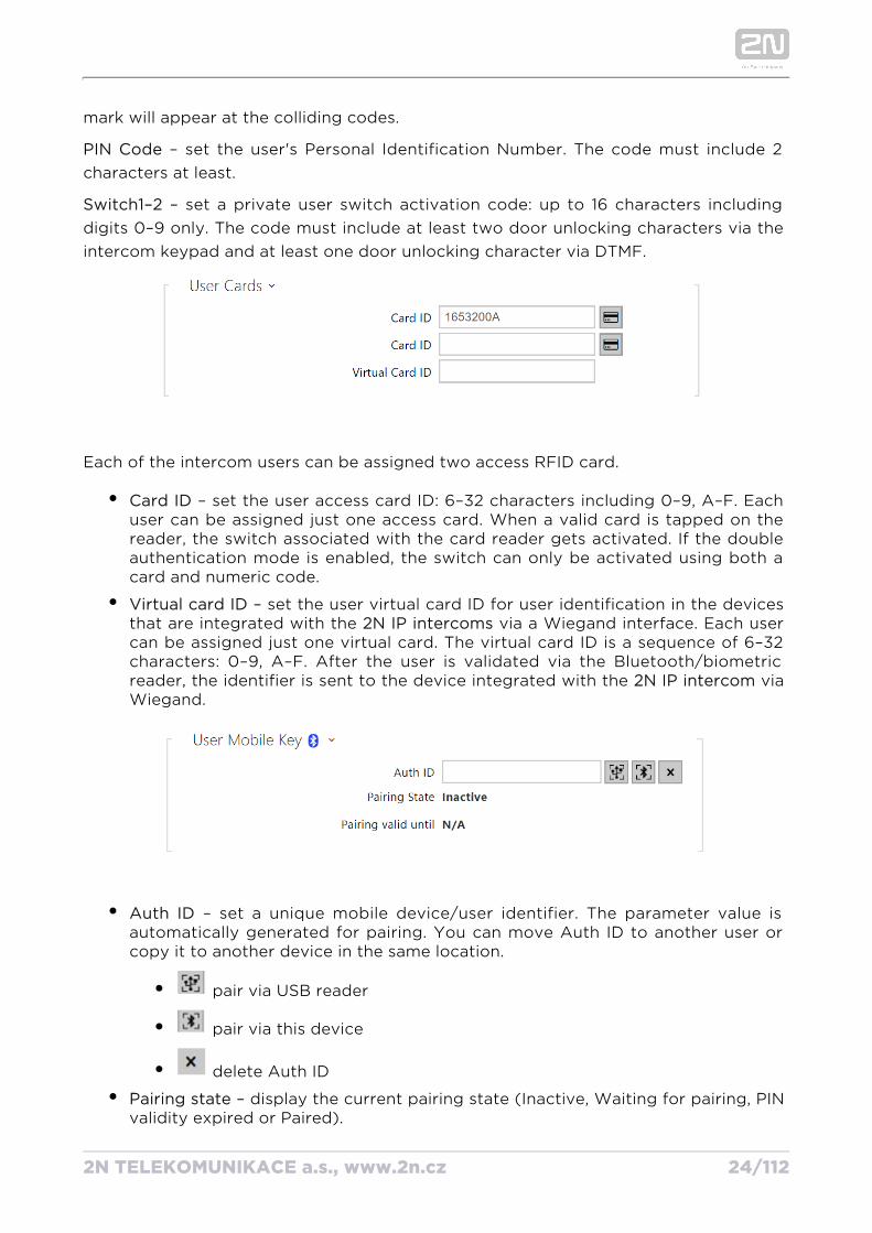
Each of the intercom users can be assigned two access RFID card.
Card ID – set the user access card ID: 6–32 characters including 0–9, A–F. Each user can be assigned just one access card. When a valid card is tapped on the reader, the switch associated with the card reader gets activated. If the double authentication mode is enabled, the switch can only be activated using both a card and numeric code.
Virtual card ID – set the user virtual card ID for user identification in the devices that are integrated with the via a Wiegand interface. Each user 2N IP intercomscan be assigned just one virtual card. The virtual card ID is a sequence of 6–32 characters: 0–9, A–F. After the user is validated via the Bluetooth/biometric reader, the identifier is sent to the device integrated with the via 2N IP intercom Wiegand.
Auth ID – set a unique mobile device/user identifier. The parameter value is automatically generated for pairing. You can move Auth ID to another user or copy it to another device in the same location.
pair via USB reader
pair via this device
delete Auth ID
Pairing state – display the current pairing state (Inactive, Waiting for pairing, PIN validity expired or Paired).
2N TELEKOMUNIKACE a.s., www.2n.cz 25/112
Pairing valid until – display the date and time of the generated authorisation PIN validity end.
Pairing via Bluetooth Module in IntercomTo pair a mobile phone with the user:
Click at Auth ID to start pairing for the selected user account.
A dialogue window with the PIN code is displayed.
Find the appropriate reader in the application and press Start 2N Mobile Key ®pairing.
Enter the code from item 2 into the input field.
Pairing is completed.
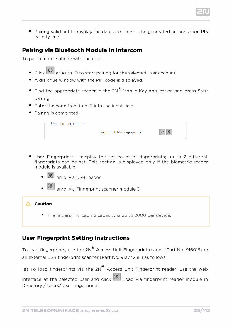
User Fingerprints – display the set count of fingerprints; up to 2 different fingerprints can be set. This section is displayed only if the biometric reader module is available.
enrol via USB reader
enrol via Fingerprint scanner module 3
Caution
The fingerprint loading capacity is up to 2000 per device.
User Fingerprint Setting Instructions
To load fingerprints, use the (Part No. 916019) or 2N Access Unit Fingerprint reader®an external USB fingerprint scanner (Part No. 9137423E) as follows:
1a) To load fingerprints via the , use the web 2N Access Unit Fingerprint reader®interface at the selected user and click Load via fingerprint reader module in Directory / Users/ User fingerprints.
2N TELEKOMUNIKACE a.s., www.2n.cz 26/112
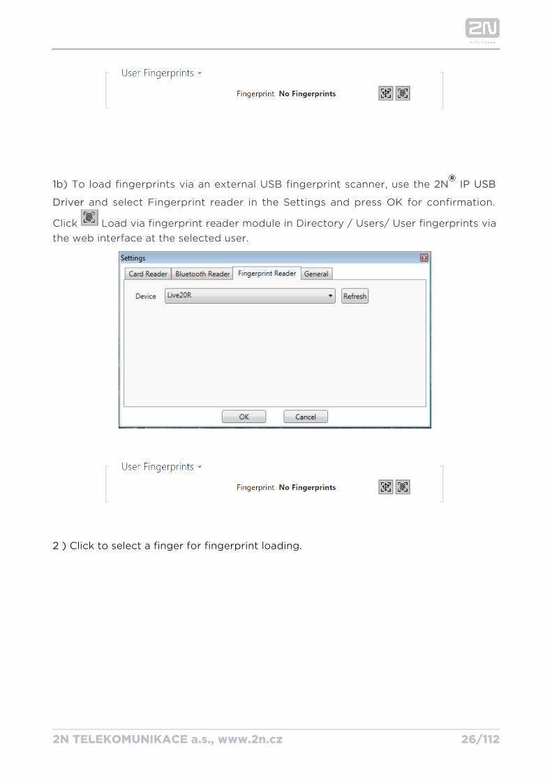
1b) To load fingerprints via an external USB fingerprint scanner, use the 2N IP® USB
and select Fingerprint reader in the Settings and press OK for confirmation. Driver
Click Load via fingerprint reader module in Directory / Users/ User fingerprints via the web interface at the selected user.
2 Click to select a finger for fingerprint loading.)
2N TELEKOMUNIKACE a.s., www.2n.cz 27/112
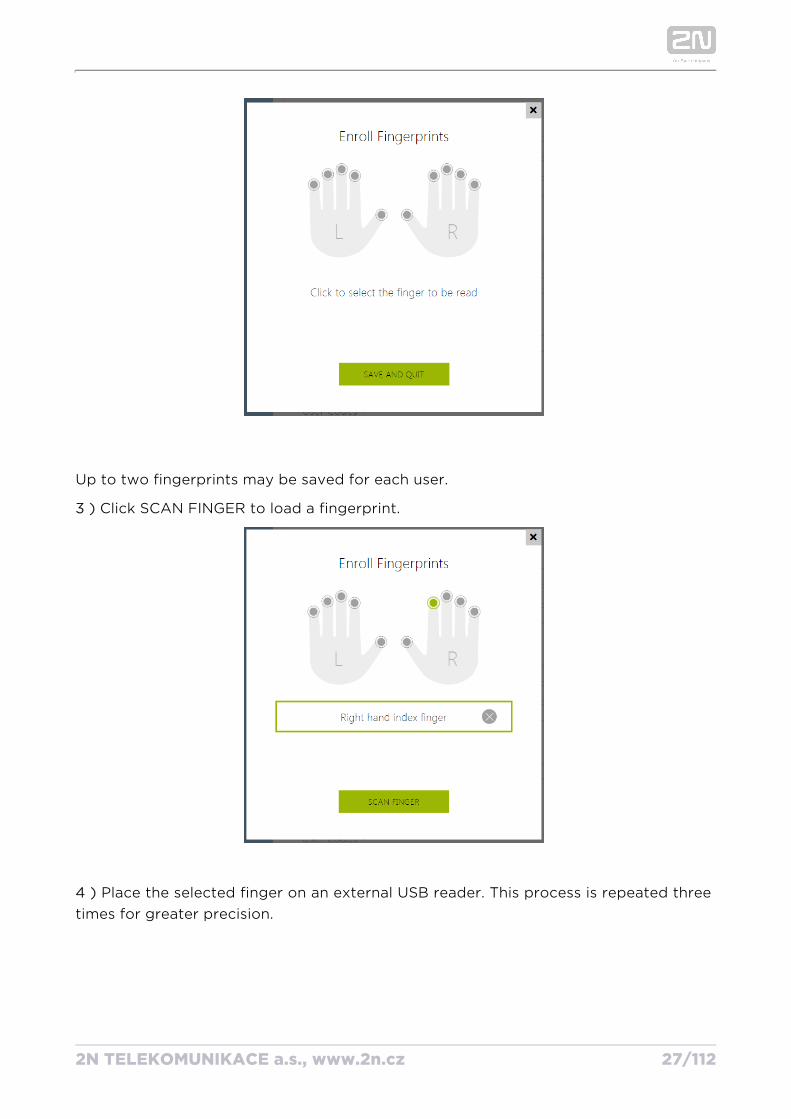
Up to two fingerprints may be saved for each user.
)3 Click SCAN FINGER to load a fingerprint.
)4 Place the selected finger on an external USB reader. This process is repeated three times for greater precision.
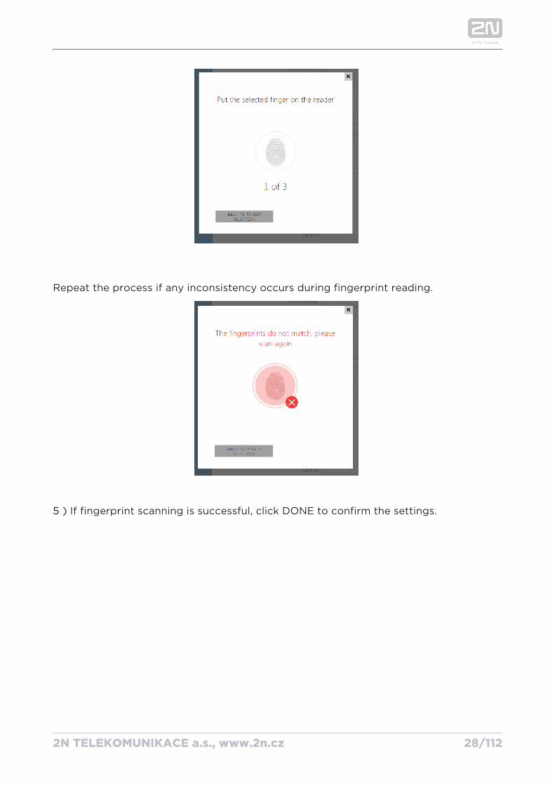
2N TELEKOMUNIKACE a.s., www.2n.cz 28/112
Repeat the process if any inconsistency occurs during fingerprint reading.
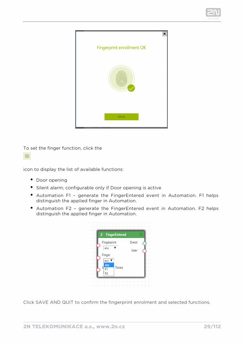
If fingerprint scanning is successful, click DONE to confirm the settings. 5 )
2N TELEKOMUNIKACE a.s., www.2n.cz 29/112
To set the finger function, click the
icon to display the list of available functions:
Door opening
Silent alarm; configurable only if Door opening is active
Automation F1 – generate the FingerEntered event in Automation. F1 helps distinguish the applied finger in Automation.
Automation F2 – generate the FingerEntered event in Automation. F2 helps distinguish the applied finger in Automation.
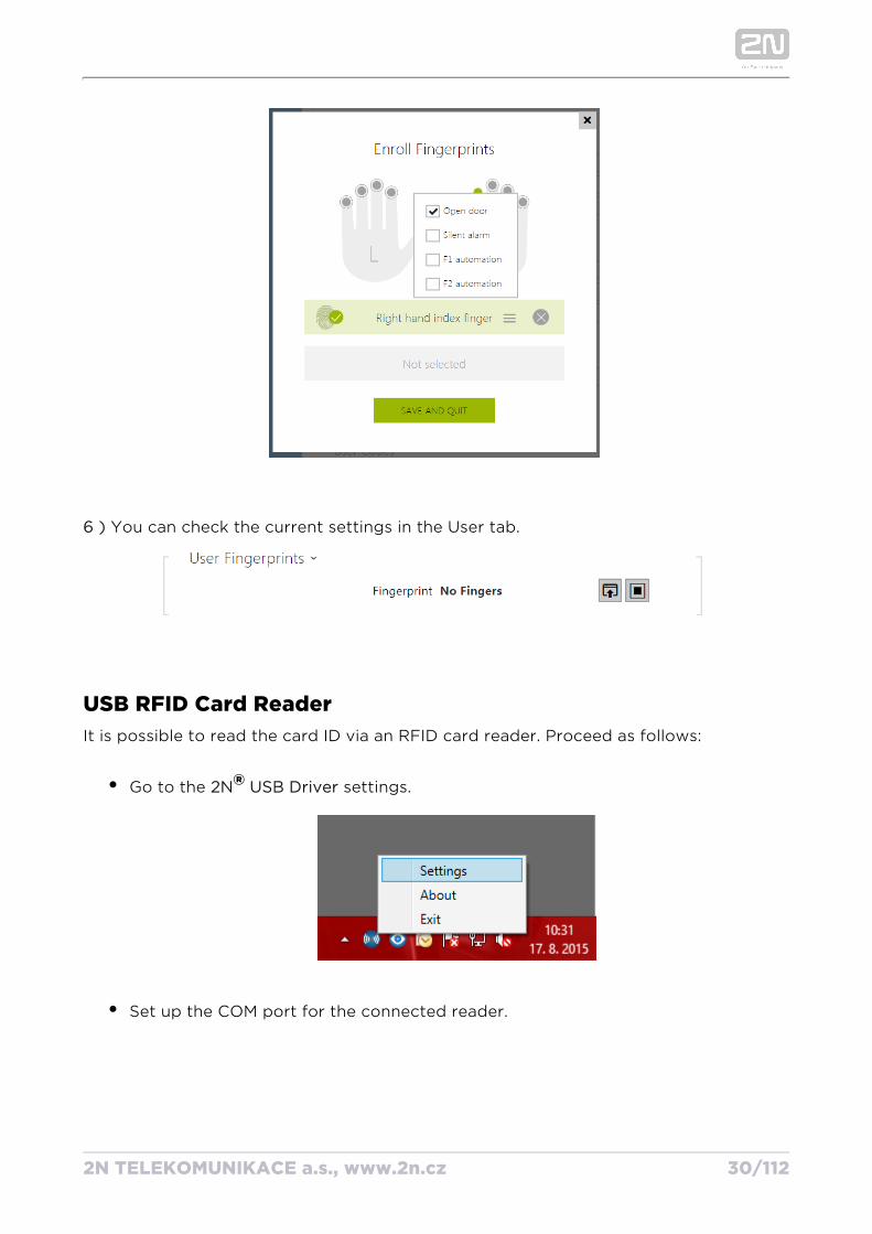
Click SAVE AND QUIT to confirm the fingerprint enrolment and selected functions.
2N TELEKOMUNIKACE a.s., www.2n.cz 30/112
)6 You can check the current settings in the User tab.
USB RFID Card ReaderIt is possible to read the card ID via an RFID card reader. Proceed as follows:
Go to the settings. 2N USB Driver®
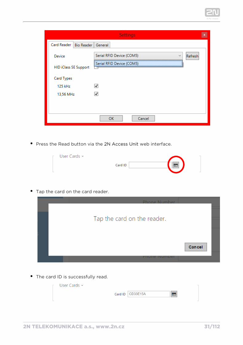
Set up the COM port for the connected reader.
2N TELEKOMUNIKACE a.s., www.2n.cz 31/112
Press the Read button via the web interface.2N Access Unit
Tap the card on the card reader.
The card ID is successfully read.
Do not forget to save the configuration.
2N TELEKOMUNIKACE a.s., www.2n.cz 32/112
Do not forget to save the configuration.
.
2N TELEKOMUNIKACE a.s., www.2n.cz 33/112
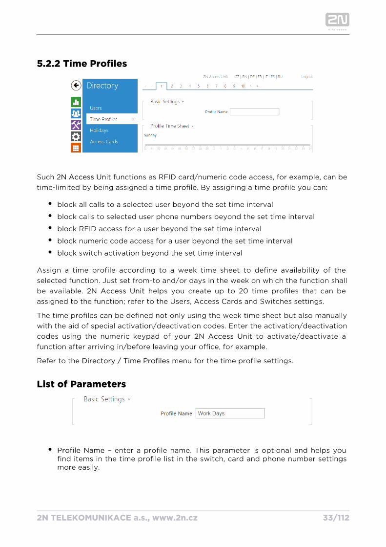
5.2.2 Time Profiles
Such functions as RFID card/numeric code access, for example, can be 2N Access Unittime-limited by being assigned a . By assigning a time profile you can:time profile
block all calls to a selected user beyond the set time interval
block calls to selected user phone numbers beyond the set time interval
block RFID access for a user beyond the set time interval
block numeric code access for a user beyond the set time interval
block switch activation beyond the set time interval
Assign a time profile according to a week time sheet to define availability of the selected function. Just set from-to and/or days in the week on which the function shall be available. helps you create up to 20 time profiles that can be 2N Access Unitassigned to the function; refer to the Users, Access Cards and Switches settings.
The time profiles can be defined not only using the week time sheet but also manually with the aid of special activation/deactivation codes. Enter the activation/deactivation codes using the numeric keypad of your to activate/deactivate a 2N Access Unitfunction after arriving in/before leaving your office, for example.
Refer to the menu for the time profile settings.Directory / Time Profiles
List of Parameters
Profile Name – enter a profile name. This parameter is optional and helps you find items in the time profile list in the switch, card and phone number settings more easily.
2N TELEKOMUNIKACE a.s., www.2n.cz 34/112
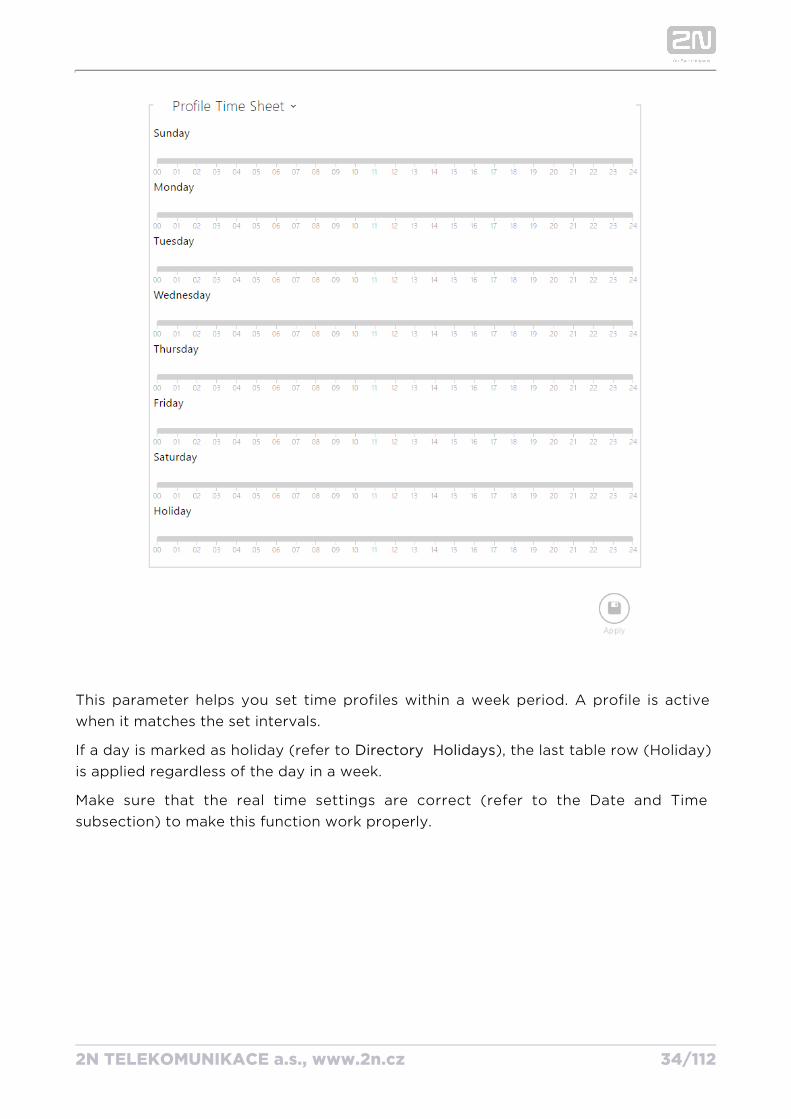
This parameter helps you set time profiles within a week period. A profile is active when it matches the set intervals.
If a day is marked as holiday (refer to ), the last table row (Holiday) Directory Holidaysis applied regardless of the day in a week.
Make sure that the real time settings are correct (refer to the Date and Time subsection) to make this function work properly.
2N TELEKOMUNIKACE a.s., www.2n.cz 35/112
Note
You can set any number of intervals within a day: 8:00–12:00, 13:00–17:00, 18:00–20:00, e.g.
To make a profile active for the whole day, enter one day-covering 00:00–24:00.interval:
2N TELEKOMUNIKACE a.s., www.2n.cz 36/112
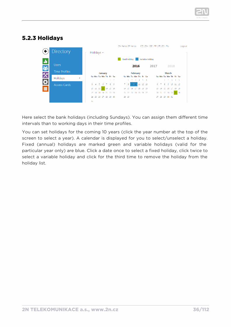
5.2.3 Holidays
Here select the bank holidays (including Sundays). You can assign them different time intervals than to working days in their time profiles.
You can set holidays for the coming 10 years (click the year number at the top of the screen to select a year). A calendar is displayed for you to select/unselect a holiday. Fixed (annual) holidays are marked green and variable holidays (valid for the particular year only) are blue. Click a date once to select a fixed holiday, click twice to select a variable holiday and click for the third time to remove the holiday from the holiday list.
2N TELEKOMUNIKACE a.s., www.2n.cz 37/112
5.3 HardwareHere is what you can find in this section
5.3.1 Switches
5.3.2 Door
5.3.3 Audio
5.3.4 Keyboard
5.3.5 Backlight
5.3.6 Card Reader
5.3.7 Digital Inputs
5.3.8 Extenders
2N TELEKOMUNIKACE a.s., www.2n.cz 38/112
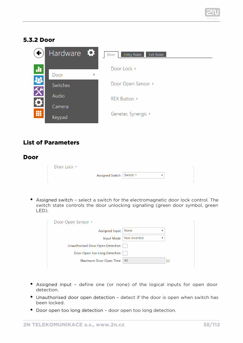
5.3.2 Door
List of Parameters
Door
Assigned switch – select a switch for the electromagnetic door lock control. The switch state controls the door unlocking signalling (green door symbol, green LED).
Assigned input – define one (or none) of the logical inputs for open door detection.
Unauthorised door open detection – detect if the door is open when switch has been locked.
Door open too long detection – door open too long detection.
2N TELEKOMUNIKACE a.s., www.2n.cz 39/112
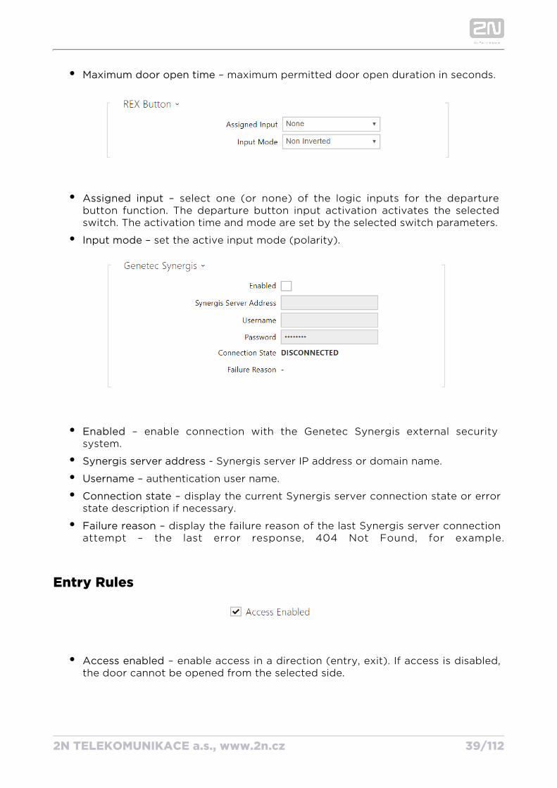
Maximum door open time – maximum permitted door open duration in seconds.
Assigned input – select one (or none) of the logic inputs for the departure button function. The departure button input activation activates the selected switch. The activation time and mode are set by the selected switch parameters.
Input mode – set the active input mode (polarity).
Enabled – enable connection with the Genetec Synergis external security system.
Synergis server address - Synergis server IP address or domain name.
Username – authentication user name.
Connection state – display the current Synergis server connection state or error state description if necessary.
Failure reason – display the failure reason of the last Synergis server connection attempt – the last error response, 404 Not Found, for example.
Entry Rules
Access enabled – enable access in a direction (entry, exit). If access is disabled, the door cannot be opened from the selected side.
2N TELEKOMUNIKACE a.s., www.2n.cz 40/112
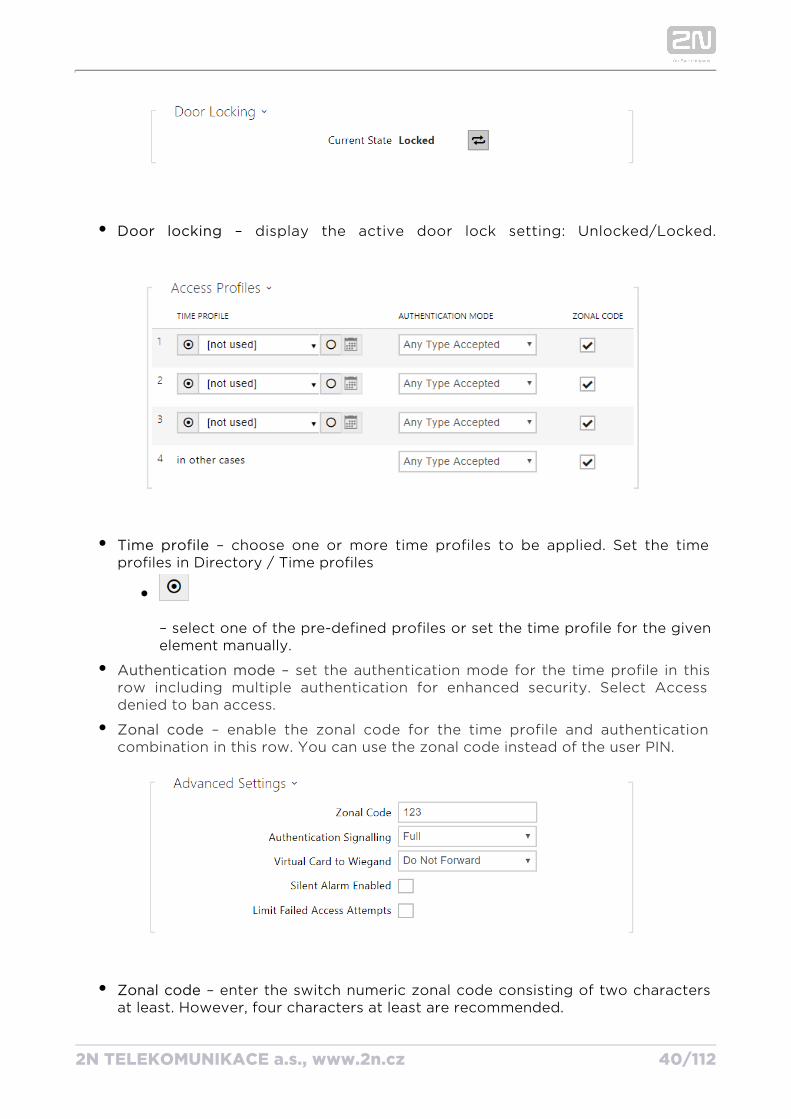
Door locking – display the active door lock setting: Unlocked/Locked.
Time profile – choose one or more time profiles to be applied. Set the time profiles in Directory / Time profiles
– select one of the pre-defined profiles or set the time profile for the given element manually.
– set the authentication mode for the time profile in this Authentication moderow including multiple authentication for enhanced security. Select Access denied to ban access.
– enable the zonal code for the time profile and authentication Zonal codecombination in this row. You can use the zonal code instead of the user PIN.
Zonal code – enter the switch numeric zonal code consisting of two characters at least. However, four characters at least are recommended.
Authentication signalling – select how to signal that a card or another identifier
2N TELEKOMUNIKACE a.s., www.2n.cz 41/112
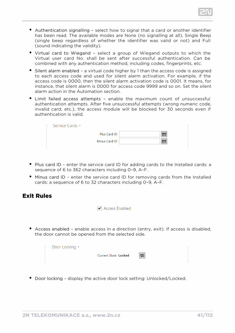
Authentication signalling – select how to signal that a card or another identifier has been read. The available modes are None (no signalling at all), Single Beep (single beep regardless of whether the identifier was valid or not) and Full (sound indicating the validity).
Virtual card to Wiegand – select a group of Wiegand outputs to which the Virtual user card No. shall be sent after successful authentication. Can be combined with any authentication method, including codes, fingerprints, etc.
Silent alarm enabled – a virtual code higher by 1 than the access code is assigned to each access code and used for silent alarm activation. For example, if the access code is 0000, then the silent alarm activation code is 0001. It means, for instance, that silent alarm is 0000 for access code 9999 and so on. Set the silent alarm action in the Automation section.
Limit failed access attempts – enable the maximum count of unsuccessful authentication attempts. After five unsuccessful attempts (wrong numeric code, invalid card, etc.), the access module will be blocked for 30 seconds even if authentication is valid.
Plus card ID – enter the service card ID for adding cards to the Installed cards: a sequence of 6 to 362 characters including 0–9, A–F.
Minus card ID – enter the service card ID for removing cards from the Installed cards: a sequence of 6 to 32 characters including 0–9, A–F.
Exit Rules
Access enabled – enable access in a direction (entry, exit). If access is disabled, the door cannot be opened from the selected side.
Door locking – display the active door lock setting: Unlocked/Locked.
2N TELEKOMUNIKACE a.s., www.2n.cz 42/112
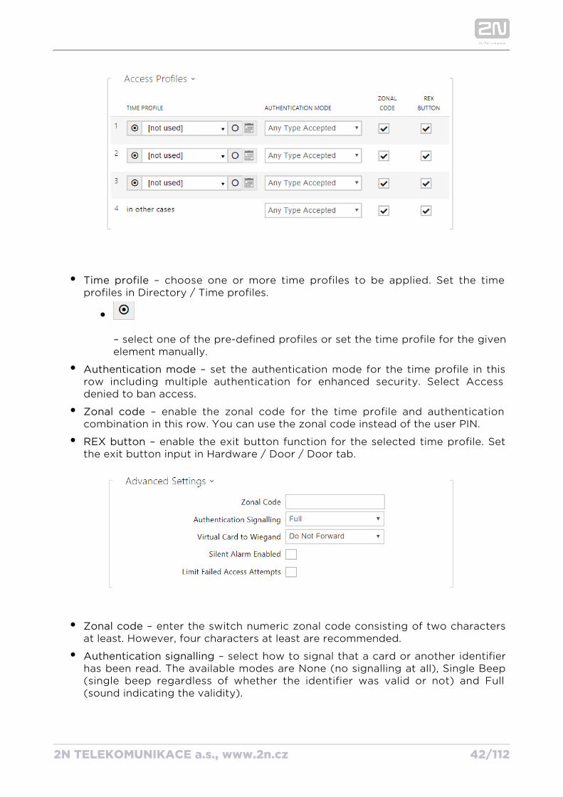
Time profile – choose one or more time profiles to be applied. Set the time profiles in Directory / Time profiles.
– select one of the pre-defined profiles or set the time profile for the given element manually.
Authentication mode – set the authentication mode for the time profile in this row including multiple authentication for enhanced security. Select Access denied to ban access.
Zonal code – enable the zonal code for the time profile and authentication combination in this row. You can use the zonal code instead of the user PIN.
REX button – enable the exit button function for the selected time profile. Set the exit button input in Hardware / Door / Door tab.
Zonal code – enter the switch numeric zonal code consisting of two characters at least. However, four characters at least are recommended.
Authentication signalling – select how to signal that a card or another identifier has been read. The available modes are None (no signalling at all), Single Beep (single beep regardless of whether the identifier was valid or not) and Full (sound indicating the validity).
2N TELEKOMUNIKACE a.s., www.2n.cz 43/112
Virtual card to Wiegand – select a group of Wiegand outputs to which the Virtual user card No. shall be sent after successful authentication. Can be combined with any authentication method, including codes, fingerprints, etc.
Silent alarm enabled – a virtual code higher by 1 than the access code is assigned to each access code and used for silent alarm activation. For example, if the access code is 0000, then the silent alarm activation code is 0001. It means, for instance, that silent alarm is 0000 for access code 9999 and so on. Set the silent alarm action in the Automation section.
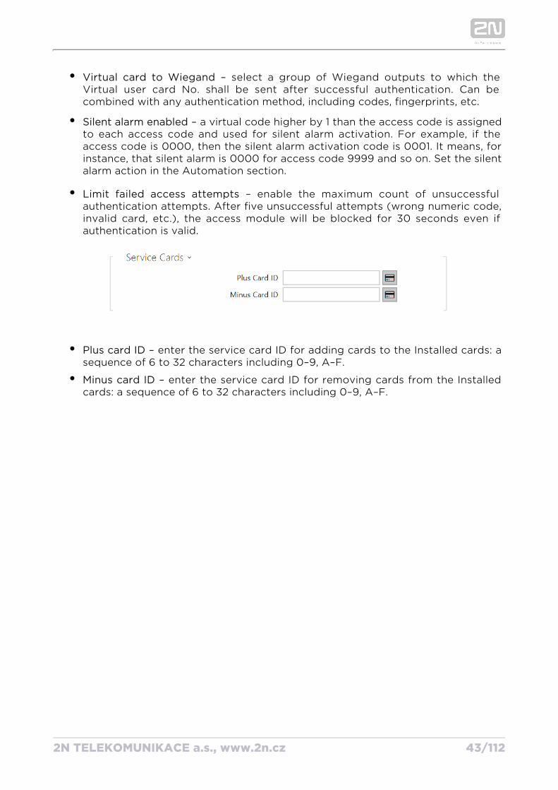
Limit failed access attempts – enable the maximum count of unsuccessful authentication attempts. After five unsuccessful attempts (wrong numeric code, invalid card, etc.), the access module will be blocked for 30 seconds even if authentication is valid.
Plus card ID – enter the service card ID for adding cards to the Installed cards: a sequence of 6 to 32 characters including 0–9, A–F.
Minus card ID – enter the service card ID for removing cards from the Installed cards: a sequence of 6 to 32 characters including 0–9, A–F.
2N TELEKOMUNIKACE a.s., www.2n.cz 44/112
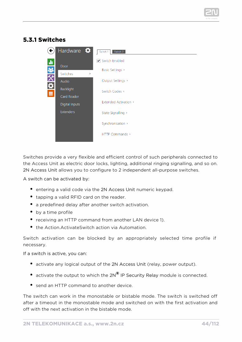
5.3.1 Switches
Switches provide a very flexible and efficient control of such peripherals connected to the Access Unit as electric door locks, lighting, additional ringing signalling, and so on.
allows you to configure to 2 independent all-purpose switches.2N Access Unit
A switch can be activated by:
entering a valid code via the numeric keypad.2N Access Unit
tapping a valid RFID card on the reader.
a predefined delay after another switch activation.
by a time profile
receiving an HTTP command from another LAN device 1).
the Action.ActivateSwitch action via Automation.
Switch activation can be blocked by an appropriately selected time profile if necessary.
If a switch is active, you can:
activate any logical output of the (relay, power output).2N Access Unit
activate the output to which the module is connected.2N® IP Security Relay
send an HTTP command to another device.
The switch can work in the monostable or bistable mode. The switch is switched off after a timeout in the monostable mode and switched on with the first activation and off with the next activation in the bistable mode.
2N TELEKOMUNIKACE a.s., www.2n.cz 45/112
The switch signals its state by:
a programmable beep.
a LED indicator if available in the model.2N Access Unit
List of Parameters
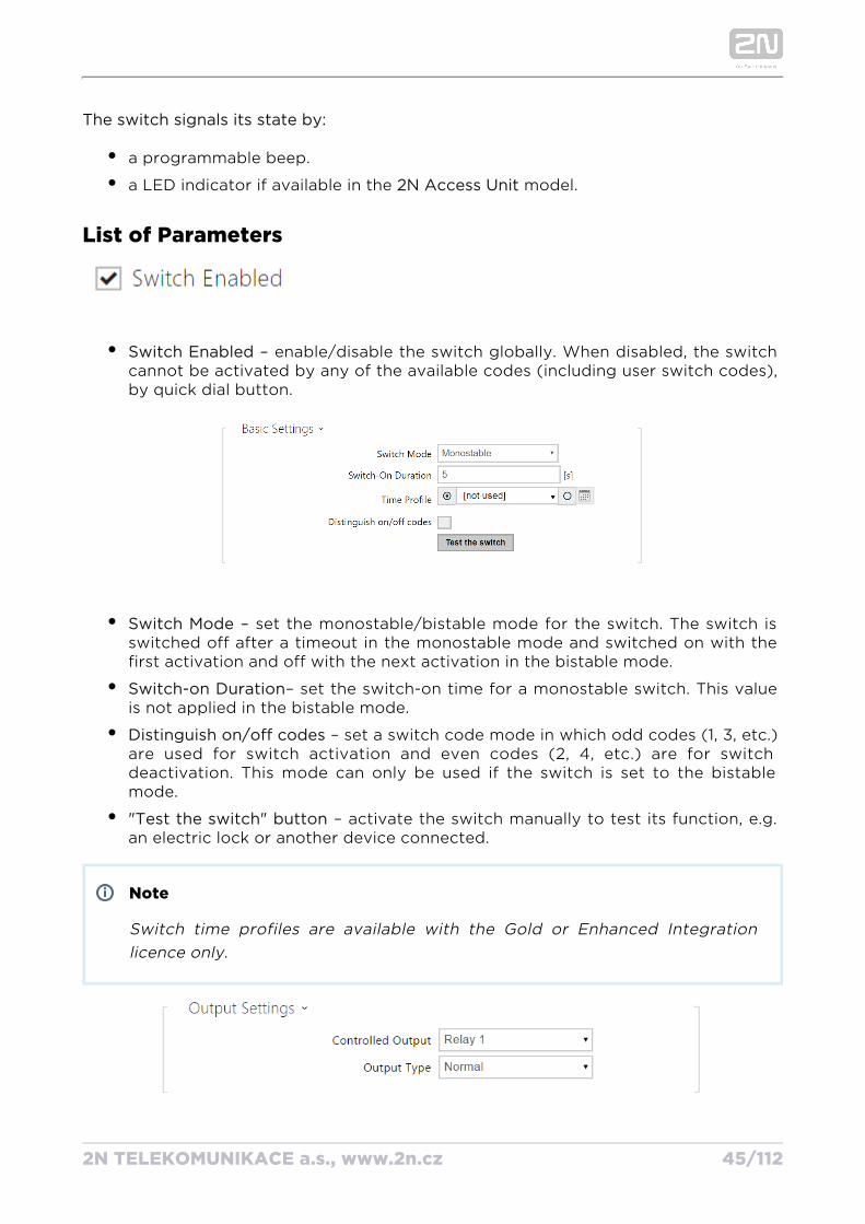
Switch Enabled – enable/disable the switch globally. When disabled, the switch cannot be activated by any of the available codes (including user switch codes), by quick dial button.
Switch Mode – set the monostable/bistable mode for the switch. The switch is switched off after a timeout in the monostable mode and switched on with the first activation and off with the next activation in the bistable mode.
Switch-on Duration– set the switch-on time for a monostable switch. This value is not applied in the bistable mode.
Distinguish on/off codes – set a switch code mode in which odd codes (1, 3, etc.) are used for switch activation and even codes (2, 4, etc.) are for switch deactivation. This mode can only be used if the switch is set to the bistable mode.
"Test the switch" button – activate the switch manually to test its function, e.g. an electric lock or another device connected.
Note
Switch time profiles are available with the Gold or Enhanced Integration licence only.
2N TELEKOMUNIKACE a.s., www.2n.cz 46/112
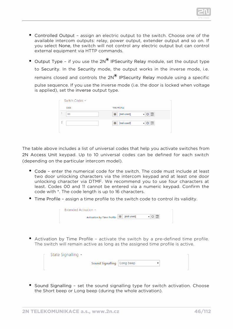
Controlled Output – assign an electric output to the switch. Choose one of the available intercom outputs: relay, power output, extender output and so on. If you select , the switch will not control any electric output but can control Noneexternal equipment via HTTP commands.
Output Type – if you use the module, set the output type 2N® IP Security Relay
to . In the mode, the output works in the inverse mode, i.e. Security Security
remains closed and controls the module using a specific IP2N® Security Relay
pulse sequence. If you use the inverse mode (i.e. the door is locked when voltage is applied), set the output type.inverse
The table above includes a list of universal codes that help you activate switches from keypad. Up to 10 universal codes can be defined for each switch 2N Access Unit
(depending on the particular intercom model).
Code – enter the numerical code for the switch. The code must include at least two door unlocking characters via the intercom keypad and at least one door unlocking character via DTMF. We recommend you to use four characters at least. Codes 00 and 11 cannot be entered via a numeric keypad. Confirm the code with *. The code length is up to 16 characters.
Time Profile – assign a time profile to the switch code to control its validity.
– activate the switch by a pre-defined time profile. Activation by Time ProfileThe switch will remain active as long as the assigned time profile is active.
Sound Signalling – set the sound signalling type for switch activation. Choose the Short beep or Long beep (during the whole activation).
2N TELEKOMUNIKACE a.s., www.2n.cz 47/112
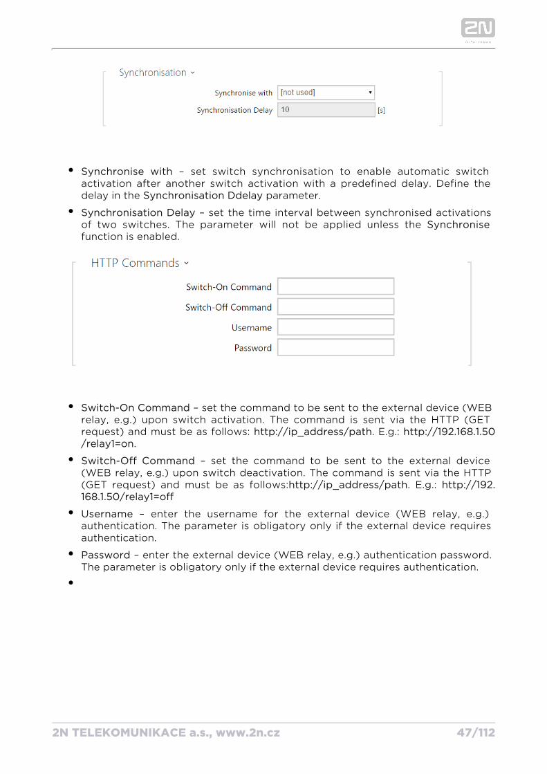
Synchronise with – set switch synchronisation to enable automatic switch activation after another switch activation with a predefined delay. Define the delay in the parameter.Synchronisation Ddelay
Synchronisation Delay – set the time interval between synchronised activations of two switches. The parameter will not be applied unless the Synchronisefunction is enabled.
Switch-On Command – set the command to be sent to the external device (WEB relay, e.g.) upon switch activation. The command is sent via the HTTP (GET request) and must be as follows: . E.g.: http://ip_address/path http://192.168.1.50
./relay1=on
Switch-Off Command – set the command to be sent to the external device (WEB relay, e.g.) upon switch deactivation. The command is sent via the HTTP (GET request) and must be as follows: . E.g.: http://ip_address/path http://192.168.1.50/relay1=off
Username – enter the username for the external device (WEB relay, e.g.) authentication. The parameter is obligatory only if the external device requires authentication.
Password – enter the external device (WEB relay, e.g.) authentication password. The parameter is obligatory only if the external device requires authentication.
2N TELEKOMUNIKACE a.s., www.2n.cz 48/112
Tip
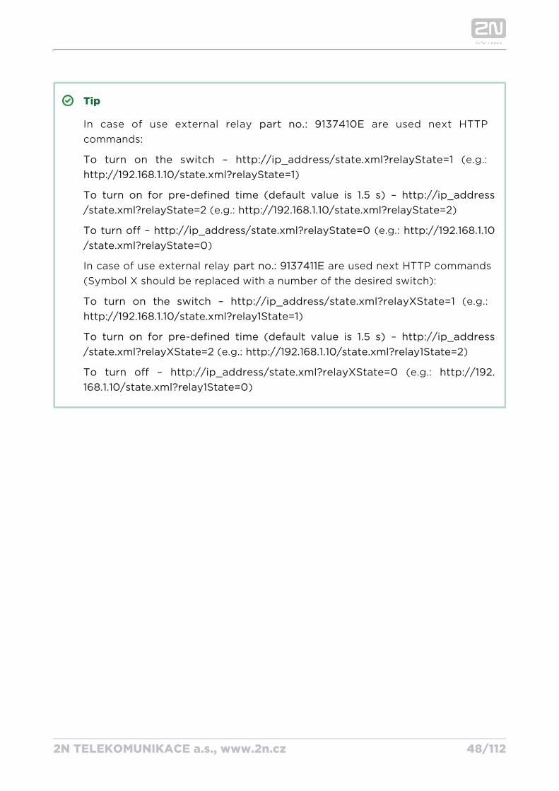
In case of use external relay are used next HTTP part no.: 9137410Ecommands:
To turn on the switch – (e.g.: http://ip_address/state.xml?relayState=1)http://192.168.1.10/state.xml?relayState=1
To turn on for pre-defined time (default value is 1.5 s) – http://ip_address (e.g.: )/state.xml?relayState=2 http://192.168.1.10/state.xml?relayState=2
To turn off – (e.g.: http://ip_address/state.xml?relayState=0 http://192.168.1.10)/state.xml?relayState=0
In case of use external relay are used next HTTP commands part no.: 9137411E(Symbol X should be replaced with a number of the desired switch):
To turn on the switch – (e.g.: http://ip_address/state.xml?relayXState=1)http://192.168.1.10/state.xml?relay1State=1
To turn on for pre-defined time (default value is 1.5 s) – http://ip_address (e.g.: )/state.xml?relayXState=2 http://192.168.1.10/state.xml?relay1State=2
To turn off – (e.g.: http://ip_address/state.xml?relayXState=0 http://192.)168.1.10/state.xml?relay1State=0
2N TELEKOMUNIKACE a.s., www.2n.cz 49/112
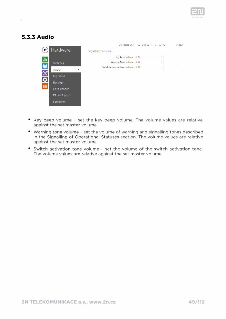
5.3.3 Audio
Key beep volume – set the key beep volume. The volume values are relative against the set master volume.
Warning tone volume – set the volume of warning and signalling tones described in the section. The volume values are relative Signalling of Operational Statusesagainst the set master volume.
Switch activation tone volume – set the volume of the switch activation tone. The volume values are relative against the set master volume.
2N TELEKOMUNIKACE a.s., www.2n.cz 50/112
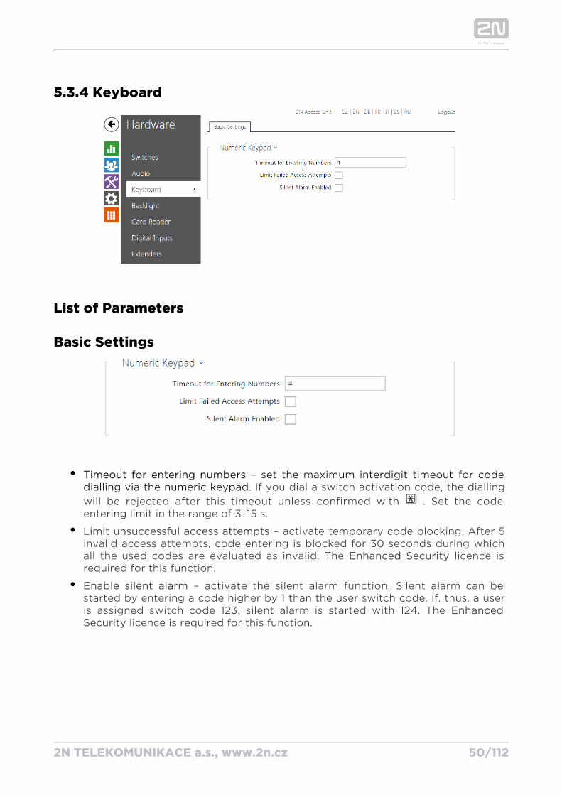
5.3.4 Keyboard
List of Parameters
Basic Settings
Timeout for entering numbers – set the maximum interdigit timeout for code dialling via the numeric keypad. If you dial a switch activation code, the dialling will be rejected after this timeout unless confirmed with . Set the code entering limit in the range of 3–15 s.
– activate temporary code blocking. After 5 Limit unsuccessful access attempts invalid access attempts, code entering is blocked for 30 seconds during which all the used codes are evaluated as invalid. The licence is Enhanced Security required for this function.
– activate the silent alarm function. Silent alarm can be Enable silent alarm started by entering a code higher by 1 than the user switch code. If, thus, a user is assigned switch code 123, silent alarm is started with 124. The Enhanced
licence is required for this function. Security
2N TELEKOMUNIKACE a.s., www.2n.cz 51/112
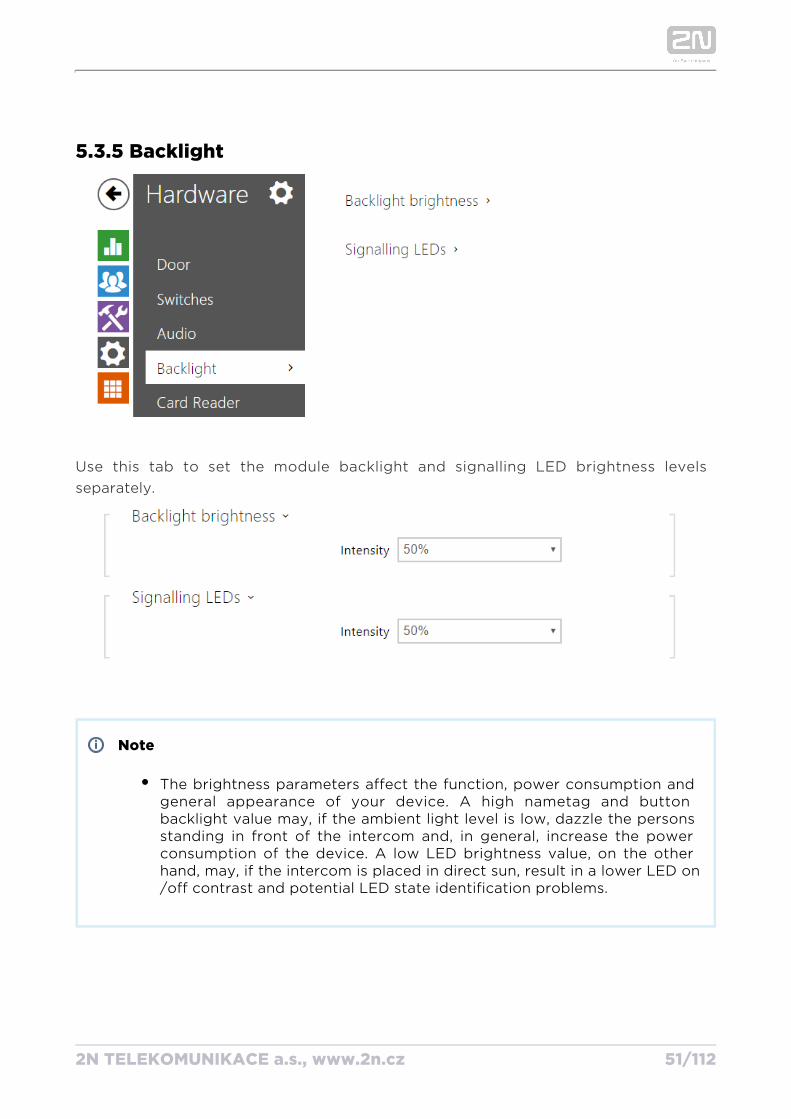
5.3.5 Backlight
Use this tab to set the module backlight and signalling LED brightness levels separately.
Note
The brightness parameters affect the function, power consumption and general appearance of your device. A high nametag and button backlight value may, if the ambient light level is low, dazzle the persons standing in front of the intercom and, in general, increase the power consumption of the device. A low LED brightness value, on the other hand, may, if the intercom is placed in direct sun, result in a lower LED on/off contrast and potential LED state identification problems.
2N TELEKOMUNIKACE a.s., www.2n.cz 52/112
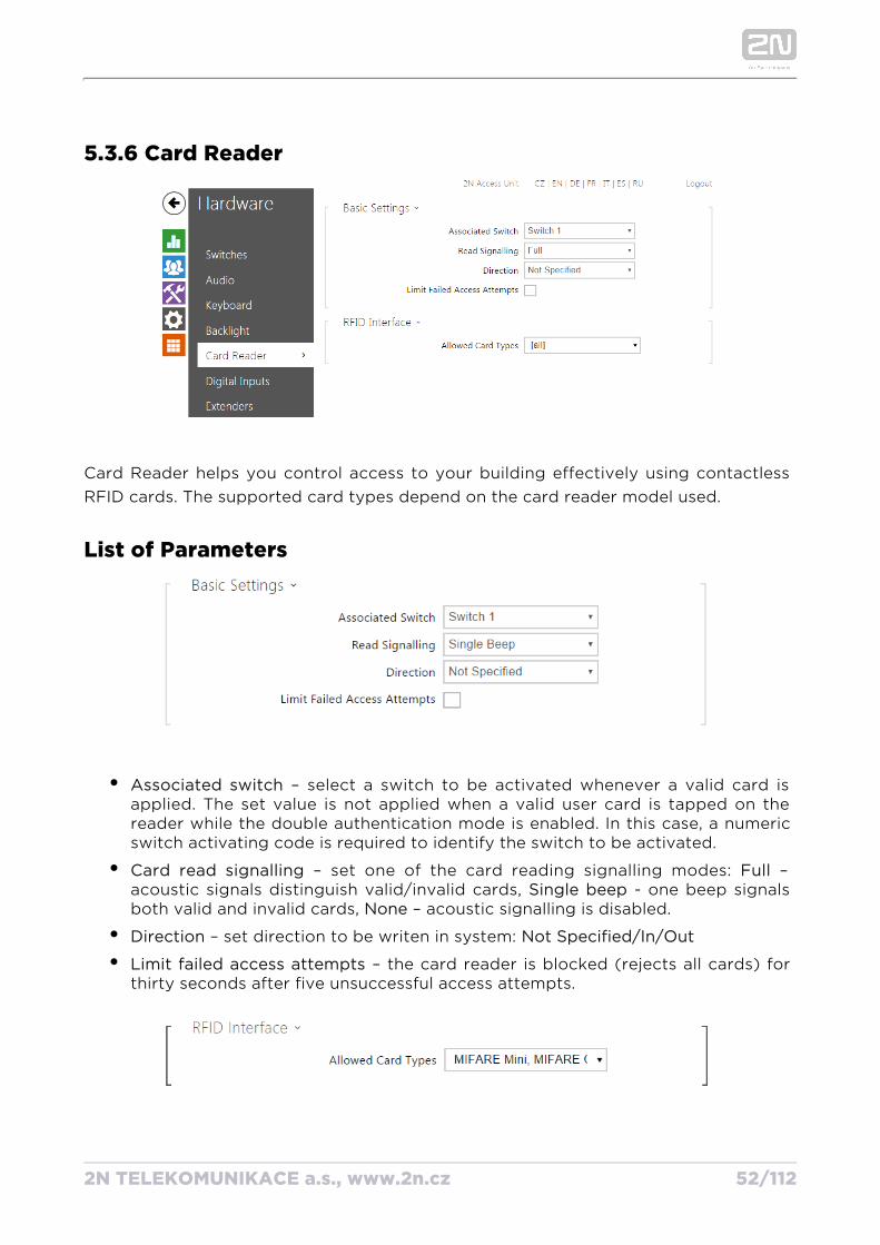
5.3.6 Card Reader
Card Reader helps you control access to your building effectively using contactless RFID cards. The supported card types depend on the card reader model used.
List of Parameters
Associated switch – select a switch to be activated whenever a valid card is applied. The set value is not applied when a valid user card is tapped on the reader while the double authentication mode is enabled. In this case, a numeric switch activating code is required to identify the switch to be activated.
Card read signalling – set one of the card reading signalling modes: – Fullacoustic signals distinguish valid/invalid cards, - one beep signals Single beepboth valid and invalid cards, – acoustic signalling is disabled.None
Direction – set direction to be writen in system: Not Specified/In/Out
Limit failed access attempts – the card reader is blocked (rejects all cards) for thirty seconds after five unsuccessful access attempts.
2N TELEKOMUNIKACE a.s., www.2n.cz 53/112
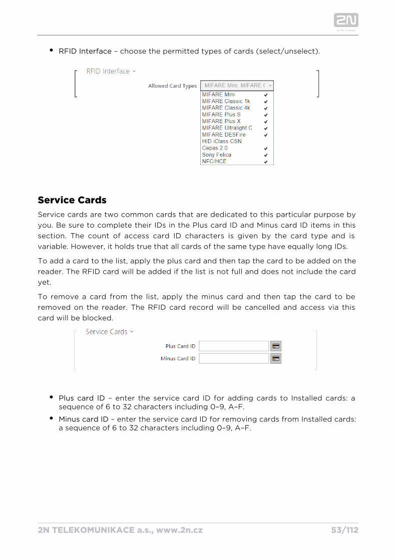
RFID Interface – choose the permitted types of cards (select/unselect).
Service CardsService cards are two common cards that are dedicated to this particular purpose by you. Be sure to complete their IDs in the Plus card ID and Minus card ID items in this section. The count of access card ID characters is given by the card type and is variable. However, it holds true that all cards of the same type have equally long IDs.
To add a card to the list, apply the plus card and then tap the card to be added on the reader. The RFID card will be added if the list is not full and does not include the card yet.
To remove a card from the list, apply the minus card and then tap the card to be removed on the reader. The RFID card record will be cancelled and access via this card will be blocked.
Plus card ID – enter the service card ID for adding cards to Installed cards: a sequence of 6 to 32 characters including 0–9, A–F.
Minus card ID – enter the service card ID for removing cards from Installed cards: a sequence of 6 to 32 characters including 0–9, A–F.
2N TELEKOMUNIKACE a.s., www.2n.cz 54/112
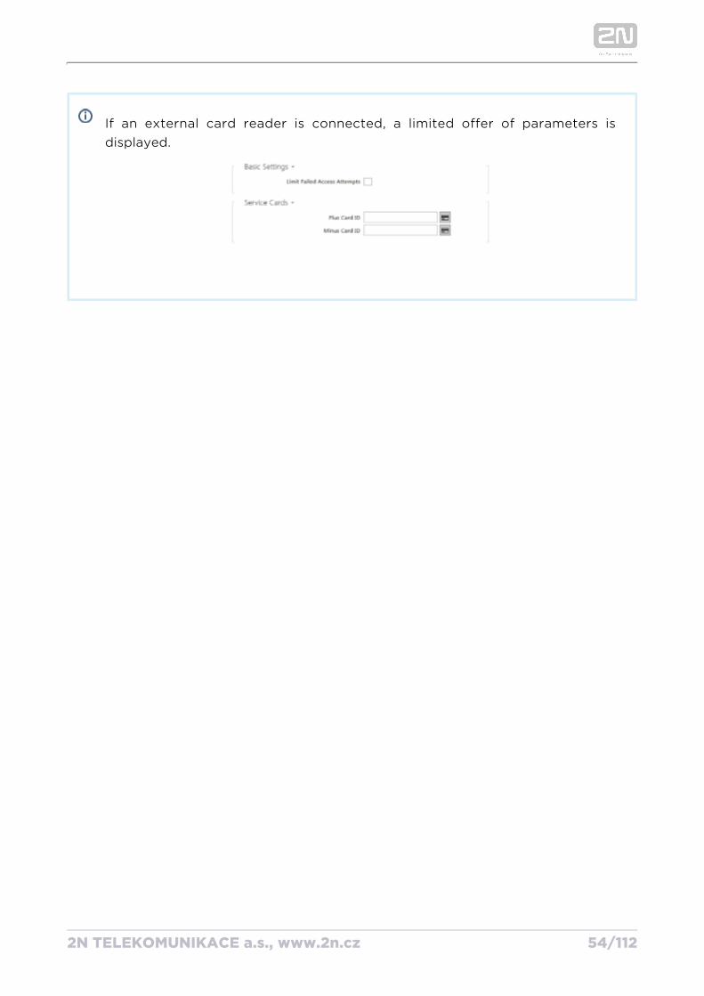
If an external card reader is connected, a limited offer of parameters is displayed.
2N TELEKOMUNIKACE a.s., www.2n.cz 55/112
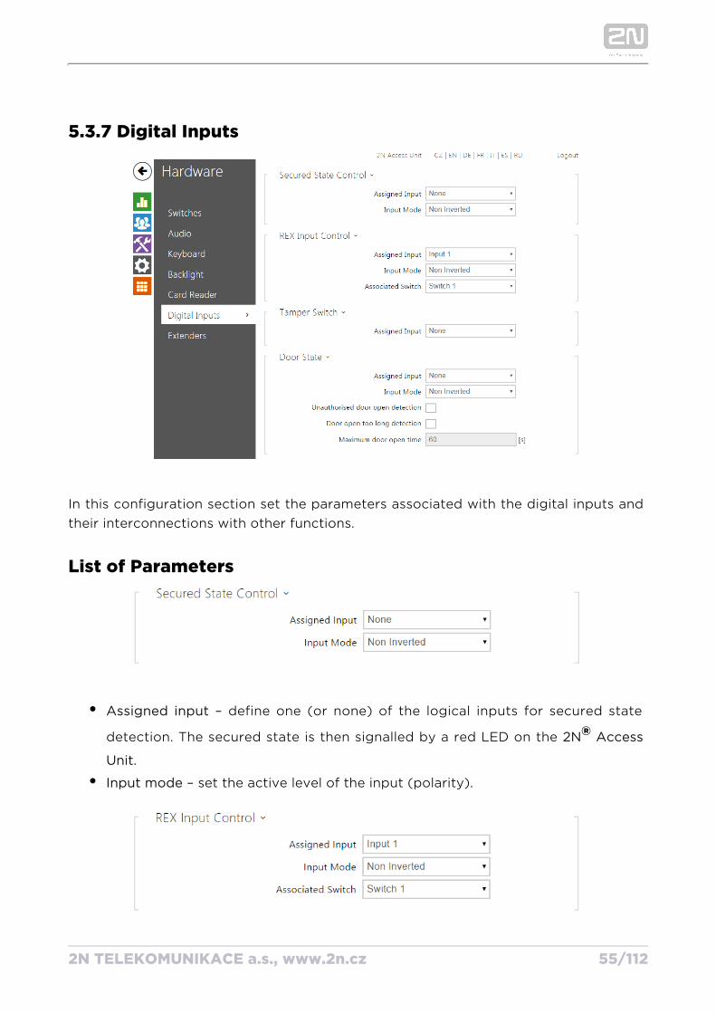
5.3.7 Digital Inputs
In this configuration section set the parameters associated with the digital inputs and their interconnections with other functions.
List of Parameters
Assigned input – define one (or none) of the logical inputs for secured state
detection. The secured state is then signalled by a red LED on the 2N Access ®.Unit
Input mode – set the active level of the input (polarity).
2N TELEKOMUNIKACE a.s., www.2n.cz 56/112
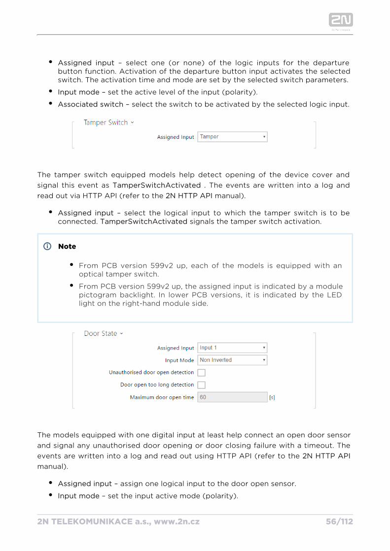
Assigned input – select one (or none) of the logic inputs for the departure button function. Activation of the departure button input activates the selected switch. The activation time and mode are set by the selected switch parameters.
Input mode – set the active level of the input (polarity).
Associated switch – select the switch to be activated by the selected logic input.
The tamper switch equipped models help detect opening of the device cover and signal this event as TamperSwitchActivated . The events are written into a log and
read out via HTTP API (refer to the 2N HTTP API manual).
Assigned input – select the logical input to which the tamper switch is to be connected. signals the tamper switch activation.TamperSwitchActivated
Note
From PCB version 599v2 up, each of the models is equipped with an optical tamper switch.
From PCB version 599v2 up, the assigned input is indicated by a module pictogram backlight. In lower PCB versions, it is indicated by the LED light on the right-hand module side.
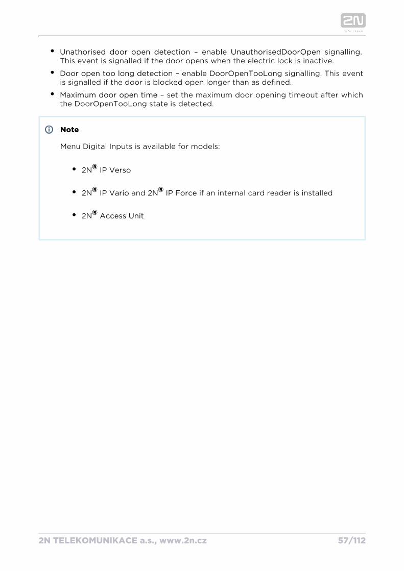
The models equipped with one digital input at least help connect an open door sensor and signal any unauthorised door opening or door closing failure with a timeout. The events are written into a log and read out using HTTP API (refer to the 2N HTTP API manual).
Assigned input – assign one logical input to the door open sensor.
Input mode – set the input active mode (polarity).
Unathorised door open detection – enable signalling. UnauthorisedDoorOpen
2N TELEKOMUNIKACE a.s., www.2n.cz 57/112
Unathorised door open detection – enable signalling. UnauthorisedDoorOpen This event is signalled if the door opens when the electric lock is inactive.
Door open too long detection – enable signalling. This event DoorOpenTooLongis signalled if the door is blocked open longer than as defined.
Maximum door open time – set the maximum door opening timeout after which the DoorOpenTooLong state is detected.
Note
Menu Digital Inputs is available for models:
2N IP Verso®2N IP Vario® and if an internal card reader is installed2N IP Force®2N Access Unit®
2N TELEKOMUNIKACE a.s., www.2n.cz 58/112
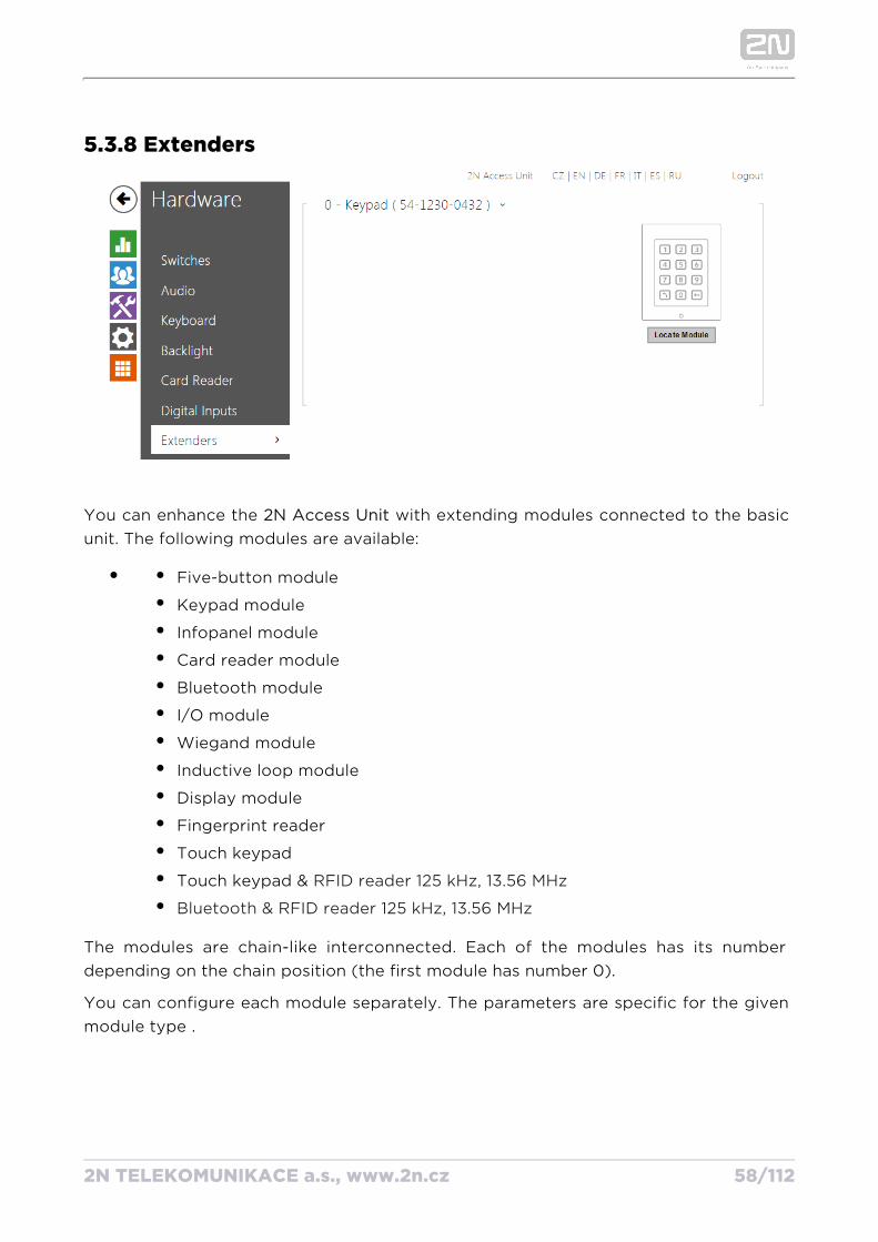
5.3.8 Extenders
You can enhance the with extending modules connected to the basic 2N Access Unitunit. The following modules are available:
Five-button module
Keypad module
Infopanel module
Card reader module
Bluetooth module
I/O module
Wiegand module
Inductive loop module
Display module
Fingerprint reader
Touch keypad
Touch keypad & RFID reader 125 kHz, 13.56 MHz
Bluetooth & RFID reader 125 kHz, 13.56 MHz
The modules are chain-like interconnected. Each of the modules has its number depending on the chain position (the first module has number 0).
You can configure each module separately. The parameters are specific for the given module type .
2N TELEKOMUNIKACE a.s., www.2n.cz 59/112
Note
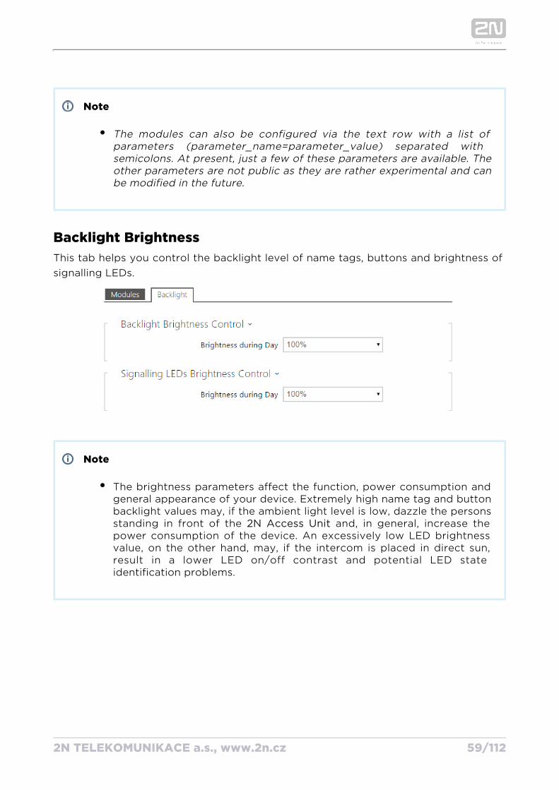
The modules can also be configured via the text row with a list of parameters (parameter_name=parameter_value) separated with semicolons. At present, just a few of these parameters are available. The other parameters are not public as they are rather experimental and can be modified in the future.
Backlight BrightnessThis tab helps you control the backlight level of name tags, buttons and brightness of signalling LEDs.
Note
The brightness parameters affect the function, power consumption and general appearance of your device. Extremely high name tag and button backlight values may, if the ambient light level is low, dazzle the persons standing in front of the and, in general, increase the 2N Access Unitpower consumption of the device. An excessively low LED brightness value, on the other hand, may, if the intercom is placed in direct sun, result in a lower LED on/off contrast and potential LED state identification problems.
2N TELEKOMUNIKACE a.s., www.2n.cz 60/112
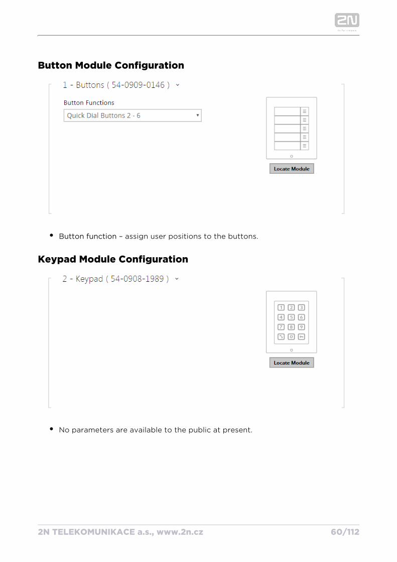
Button Module Configuration
Button function – assign user positions to the buttons.
Keypad Module Configuration
No parameters are available to the public at present.
2N TELEKOMUNIKACE a.s., www.2n.cz 61/112
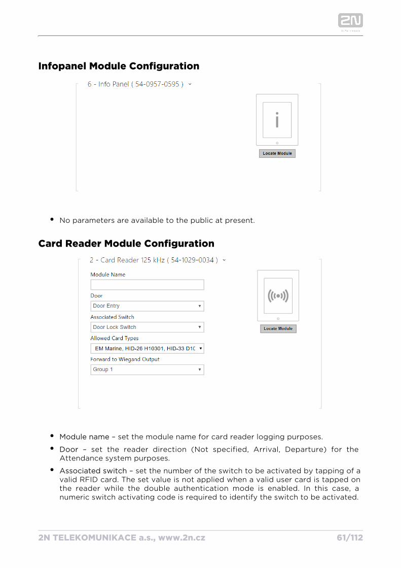
Infopanel Module Configuration
No parameters are available to the public at present.
Card Reader Module Configuration
Module name – set the module name for card reader logging purposes.
Door – set the reader direction (Not specified, Arrival, Departure) for the Attendance system purposes.
Associated switch – set the number of the switch to be activated by tapping of a valid RFID card. The set value is not applied when a valid user card is tapped on the reader while the double authentication mode is enabled. In this case, a numeric switch activating code is required to identify the switch to be activated.
2N TELEKOMUNIKACE a.s., www.2n.cz 62/112
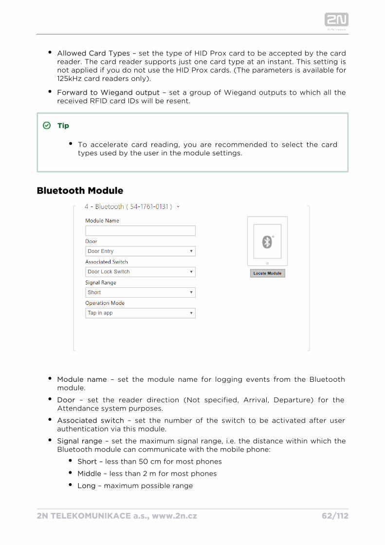
Allowed Card Types – set the type of HID Prox card to be accepted by the card reader. The card reader supports just one card type at an instant. This setting is not applied if you do not use the HID Prox cards. (The parameters is available for 125kHz card readers only).
Forward to Wiegand output – set a group of Wiegand outputs to which all the received RFID card IDs will be resent.
Tip
To accelerate card reading, you are recommended to select the card types used by the user in the module settings.
Bluetooth Module
Module name – set the module name for logging events from the Bluetooth module.
Door – set the reader direction (Not specified, Arrival, Departure) for the Attendance system purposes.
Associated switch – set the number of the switch to be activated after user authentication via this module.
Signal range – set the maximum signal range, i.e. the distance within which the Bluetooth module can communicate with the mobile phone:
Short – less than 50 cm for most phones
Middle – less than 2 m for most phones
Long – maximum possible range
Operation mode – set the authentication method for a mobile phone:
2N TELEKOMUNIKACE a.s., www.2n.cz 63/112
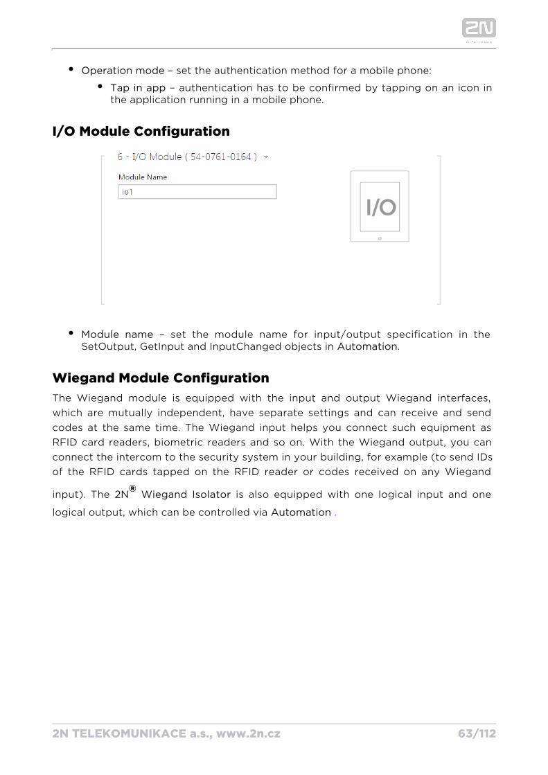
Operation mode – set the authentication method for a mobile phone:
Tap in app – authentication has to be confirmed by tapping on an icon in the application running in a mobile phone.
I/O Module Configuration
Module name – set the module name for input/output specification in the SetOutput, GetInput and InputChanged objects in .Automation
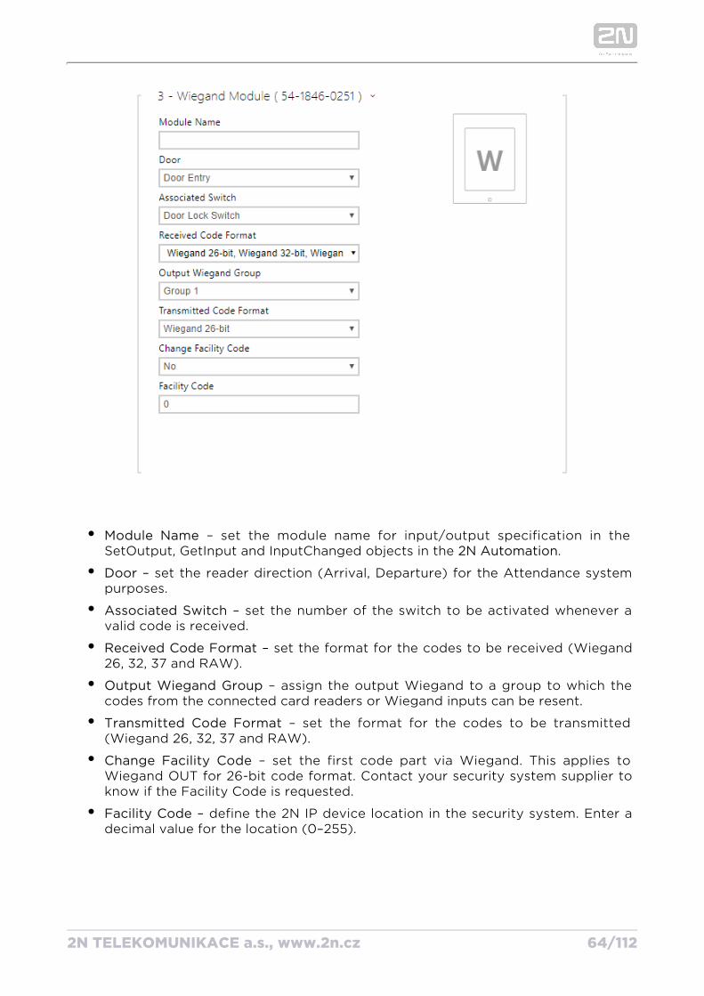
Wiegand Module ConfigurationThe Wiegand module is equipped with the input and output Wiegand interfaces, which are mutually independent, have separate settings and can receive and send codes at the same time. The Wiegand input helps you connect such equipment as RFID card readers, biometric readers and so on. With the Wiegand output, you can connect the intercom to the security system in your building, for example (to send IDs of the RFID cards tapped on the RFID reader or codes received on any Wiegand
input). The is also equipped with one logical input and one 2N ® Wiegand Isolator
logical output, which can be controlled via Automation .
2N TELEKOMUNIKACE a.s., www.2n.cz 64/112
Module Name – set the module name for input/output specification in the SetOutput, GetInput and InputChanged objects in the .2N Automation
Door – set the reader direction (Arrival, Departure) for the Attendance system purposes.
Associated Switch – set the number of the switch to be activated whenever a valid code is received.
Received Code Format – set the format for the codes to be received (Wiegand 26, 32, 37 and RAW).
Output Wiegand Group – assign the output Wiegand to a group to which the codes from the connected card readers or Wiegand inputs can be resent.
Transmitted Code Format – set the format for the codes to be transmitted (Wiegand 26, 32, 37 and RAW).
Change Facility Code – set the first code part via Wiegand. This applies to Wiegand OUT for 26-bit code format. Contact your security system supplier to know if the Facility Code is requested.
Facility Code – define the 2N IP device location in the security system. Enter a decimal value for the location (0–255).
2N TELEKOMUNIKACE a.s., www.2n.cz 65/112
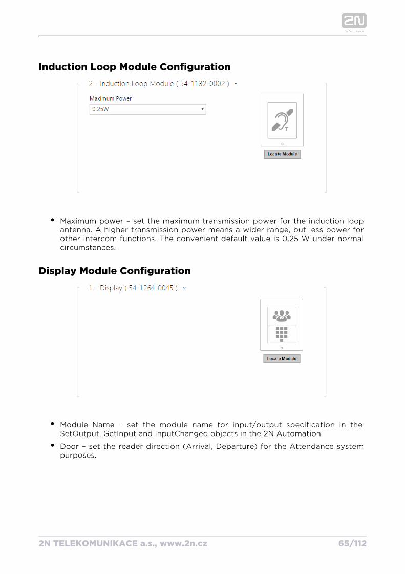
Induction Loop Module Configuration
Maximum power – set the maximum transmission power for the induction loop antenna. A higher transmission power means a wider range, but less power for other intercom functions. The convenient default value is 0.25 W under normal circumstances.
Display Module Configuration
Module Name – set the module name for input/output specification in the SetOutput, GetInput and InputChanged objects in the .2N Automation
Door – set the reader direction (Arrival, Departure) for the Attendance system purposes.
2N TELEKOMUNIKACE a.s., www.2n.cz 66/112
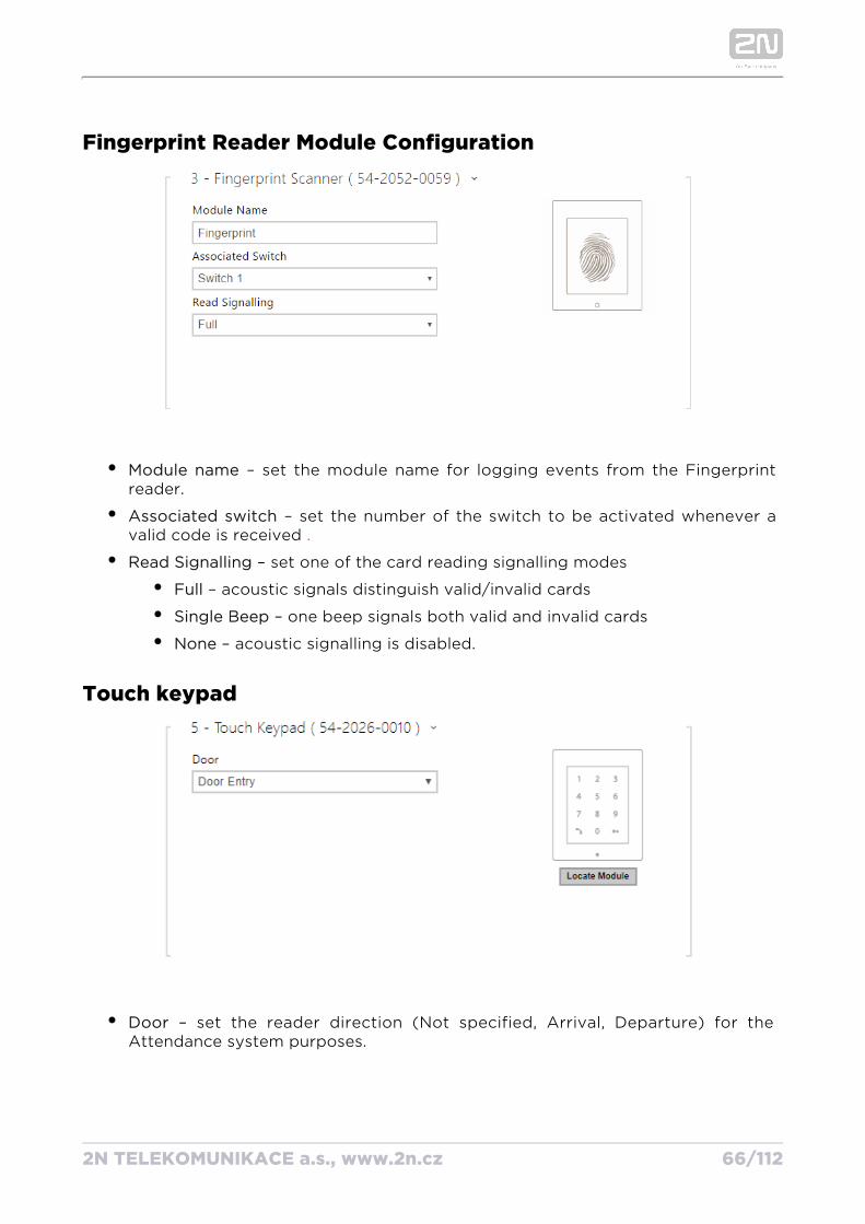
Fingerprint Reader Module Configuration
Module name – set the module name for logging events from the Fingerprint reader.
Associated switch set the number of the switch to be activated whenever a – valid code is received .
– Read Signalling set one of the card reading signalling modes
– acoustic signals distinguish valid/invalid cardsFull
– one beep signals both valid and invalid cardsSingle Beep
– acoustic signalling is disabled.None
Touch keypad
– set the reader direction (Not specified, Arrival, Departure) for the DoorAttendance system purposes.
2N TELEKOMUNIKACE a.s., www.2n.cz 67/112
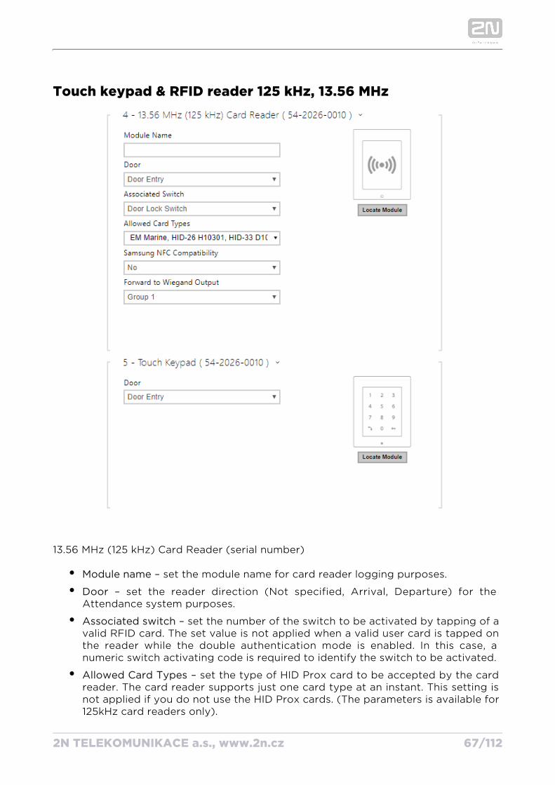
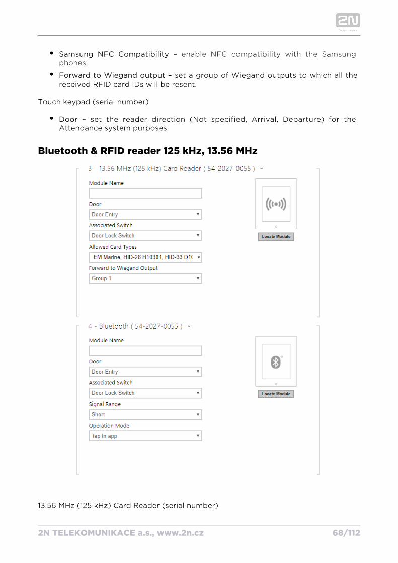
Touch keypad & RFID reader 125 kHz, 13.56 MHz
13.56 MHz (125 kHz) Card Reader (serial number)
Module name – set the module name for card reader logging purposes.
Door – set the reader direction (Not specified, Arrival, Departure) for the Attendance system purposes.
Associated switch – set the number of the switch to be activated by tapping of a valid RFID card. The set value is not applied when a valid user card is tapped on the reader while the double authentication mode is enabled. In this case, a numeric switch activating code is required to identify the switch to be activated.
Allowed Card Types – set the type of HID Prox card to be accepted by the card reader. The card reader supports just one card type at an instant. This setting is not applied if you do not use the HID Prox cards. (The parameters is available for 125kHz card readers only).
2N TELEKOMUNIKACE a.s., www.2n.cz 68/112
Samsung NFC Compatibility – enable NFC compatibility with the Samsung phones.
Forward to Wiegand output – set a group of Wiegand outputs to which all the received RFID card IDs will be resent.
Touch keypad (serial number)
Door – set the reader direction (Not specified, Arrival, Departure) for the Attendance system purposes.
Bluetooth & RFID reader 125 kHz, 13.56 MHz
13.56 MHz (125 kHz) Card Reader (serial number)
2N TELEKOMUNIKACE a.s., www.2n.cz 69/112
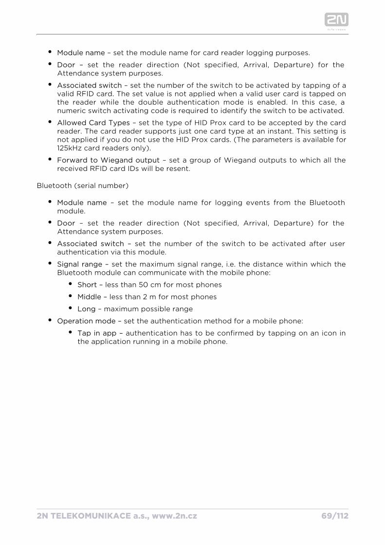
Module name – set the module name for card reader logging purposes.
Door – set the reader direction (Not specified, Arrival, Departure) for the Attendance system purposes.
Associated switch – set the number of the switch to be activated by tapping of a valid RFID card. The set value is not applied when a valid user card is tapped on the reader while the double authentication mode is enabled. In this case, a numeric switch activating code is required to identify the switch to be activated.
Allowed Card Types – set the type of HID Prox card to be accepted by the card reader. The card reader supports just one card type at an instant. This setting is not applied if you do not use the HID Prox cards. (The parameters is available for 125kHz card readers only).
Forward to Wiegand output – set a group of Wiegand outputs to which all the received RFID card IDs will be resent.
Bluetooth (serial number)
Module name – set the module name for logging events from the Bluetooth module.
Door – set the reader direction (Not specified, Arrival, Departure) for the Attendance system purposes.
Associated switch – set the number of the switch to be activated after user authentication via this module.
Signal range – set the maximum signal range, i.e. the distance within which the Bluetooth module can communicate with the mobile phone:
Short – less than 50 cm for most phones
Middle – less than 2 m for most phones
Long – maximum possible range
Operation mode – set the authentication method for a mobile phone:
Tap in app – authentication has to be confirmed by tapping on an icon in the application running in a mobile phone.
2N TELEKOMUNIKACE a.s., www.2n.cz 70/112
5.4 ServicesHere is what you can find in this section:
5.4.1 E-mail
5.4.2 Mobile Key
5.4.3 Automation
5.4.4 HTTP API
5.4.5 Web Server
5.4.6 SNMP
2N TELEKOMUNIKACE a.s., www.2n.cz 71/112
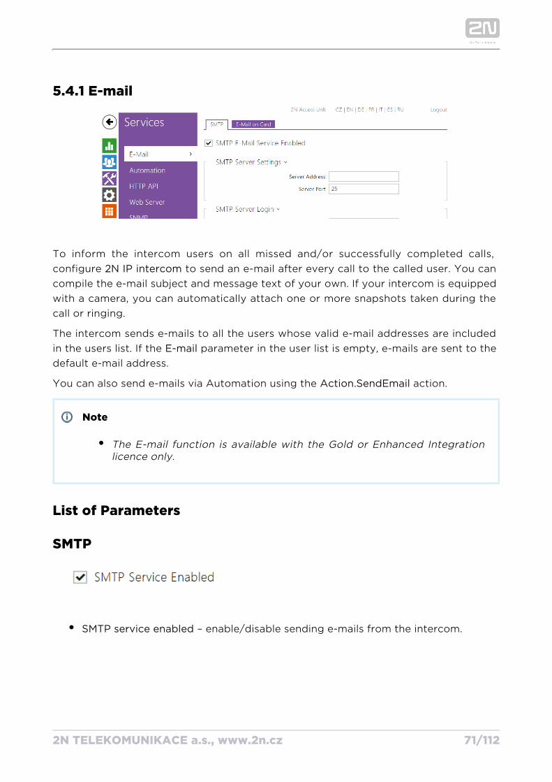
5.4.1 E-mail
To inform the intercom users on all missed and/or successfully completed calls, configure to send an e-mail after every call to the called user. You can 2N IP intercomcompile the e-mail subject and message text of your own. If your intercom is equipped with a camera, you can automatically attach one or more snapshots taken during the call or ringing.
The intercom sends e-mails to all the users whose valid e-mail addresses are included in the users list. If the parameter in the user list is empty, e-mails are sent to the E-maildefault e-mail address.
You can also send e-mails via Automation using the action.Action.SendEmail
Note
The E-mail function is available with the Gold or Enhanced Integration licence only.
List of Parameters
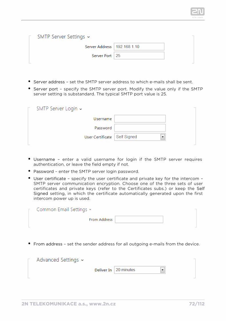
SMTP
SMTP service enabled – enable/disable sending e-mails from the intercom.
2N TELEKOMUNIKACE a.s., www.2n.cz 72/112
Server address – set the SMTP server address to which e-mails shall be sent.
Server port – specify the SMTP server port. Modify the value only if the SMTP server setting is substandard. The typical SMTP port value is 25.
Username – enter a valid username for login if the SMTP server requires authentication, or leave the field empty if not.
Password – enter the SMTP server login password.
User certificate – specify the user certificate and private key for the intercom – SMTP server communication encryption. Choose one of the three sets of user certificates and private keys (refer to the Certificates subs.) or keep the Self
setting, in which the certificate automatically generated upon the first Signed intercom power up is used.
From address – set the sender address for all outgoing e-mails from the device.
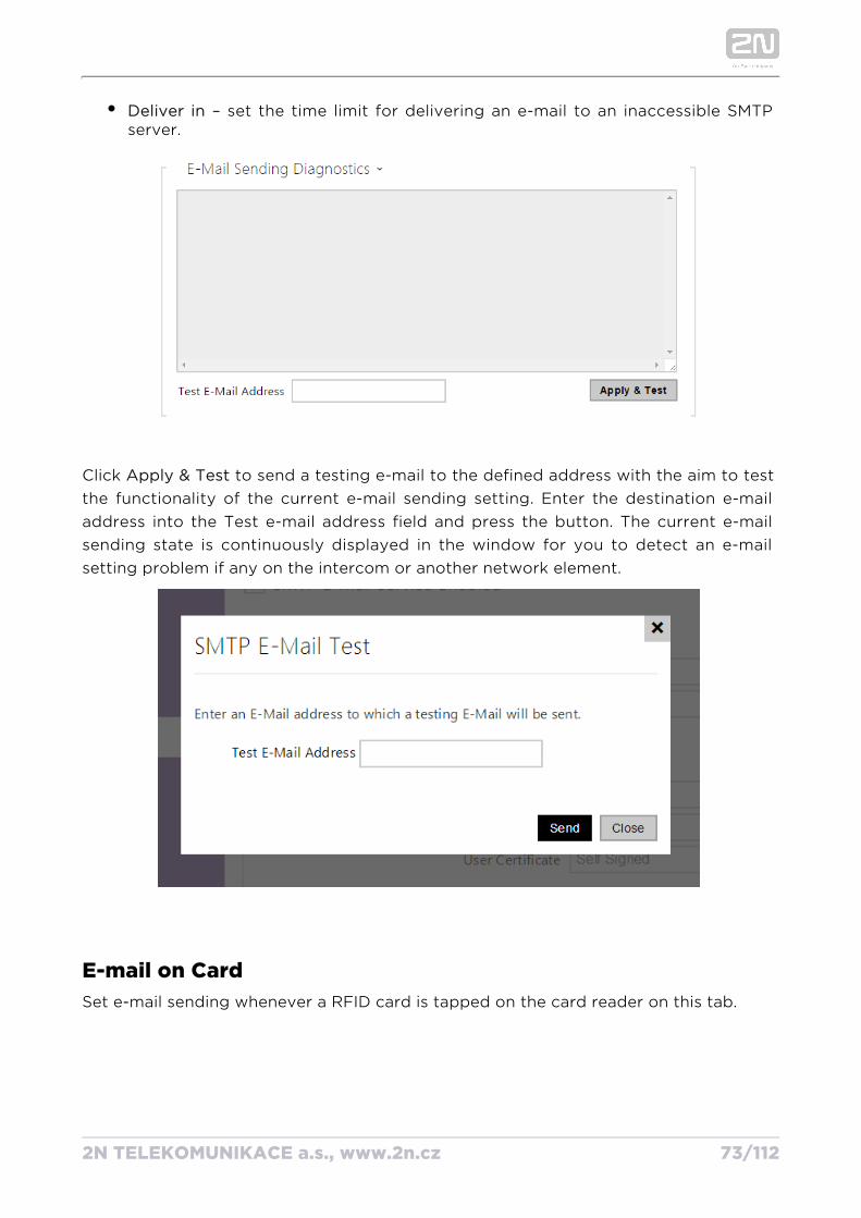
Deliver in – set the time limit for delivering an e-mail to an inaccessible SMTP
2N TELEKOMUNIKACE a.s., www.2n.cz 73/112
Deliver in – set the time limit for delivering an e-mail to an inaccessible SMTP server.
Click to send a testing e-mail to the defined address with the aim to test Apply & Testthe functionality of the current e-mail sending setting. Enter the destination e-mail address into the Test e-mail address field and press the button. The current e-mail sending state is continuously displayed in the window for you to detect an e-mail setting problem if any on the intercom or another network element.
E-mail on CardSet e-mail sending whenever a RFID card is tapped on the card reader on this tab.
2N TELEKOMUNIKACE a.s., www.2n.cz 74/112
1. a.
b.
c.
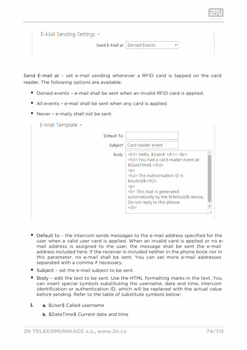
Send E-mail at – set e-mail sending whenever a RFID card is tapped on the card reader. The following options are available:
Denied events – e-mail shall be sent when an invalid RFID card is applied.
All events – e-mail shall be sent when any card is applied.
Never – e-maily shall not be sent.
Default to – the intercom sends messages to the e-mail address specified for the user when a valid user card is applied. When an invalid card is applied or no e-mail address is assigned to the user, the message shall be sent the e-mail address included here. If the receiver is included neither in the phone book nor in this parameter, no e-mail shall be sent. You can set more e-mail addresses separated with a comma if necessary.
Subject – set the e-mail subject to be sent.
Body – edit the text to be sent. Use the HTML formatting marks in the text. You can insert special symbols substituting the username, date and time, intercom identification or authentication ID, which will be replaced with the actual value before sending. Refer to the table of substitute symbols below:
$User$ Called username
$DateTime$ Current date and time
2N TELEKOMUNIKACE a.s., www.2n.cz 75/112
1.
c.
d.
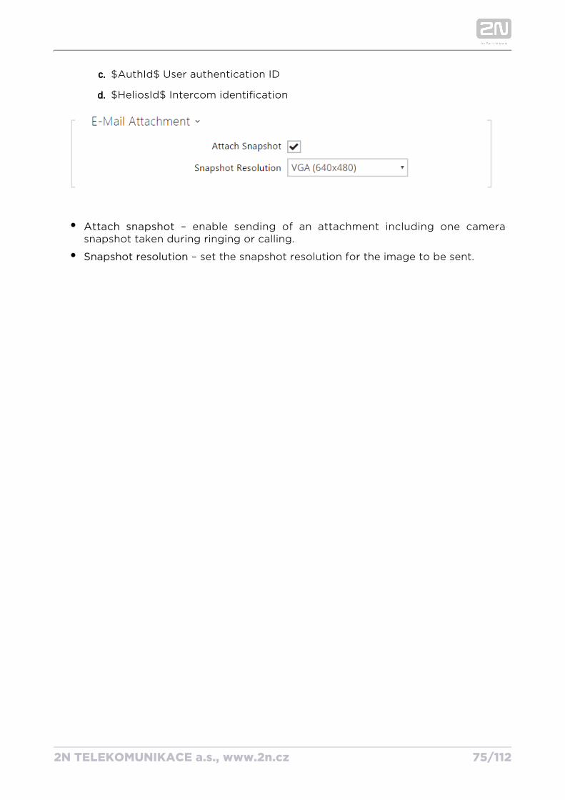
$AuthId$ User authentication ID
$HeliosId$ Intercom identification
Attach snapshot – enable sending of an attachment including one camera snapshot taken during ringing or calling.
Snapshot resolution – set the snapshot resolution for the image to be sent.
2N TELEKOMUNIKACE a.s., www.2n.cz 76/112
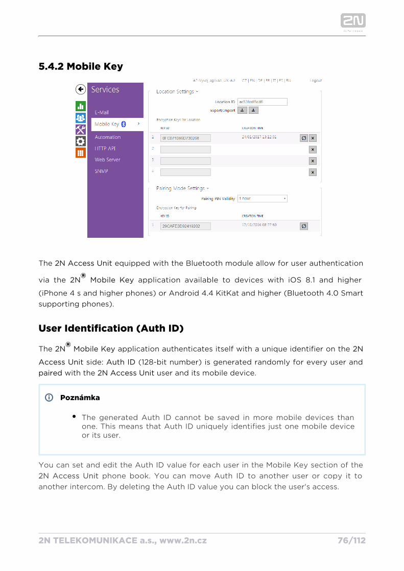
5.4.2 Mobile Key
The equipped with the Bluetooth module allow for user authentication 2N Access Unit
via the application available to devices with iOS 8.1 and higher 2N Mobile Key®(iPhone 4 s and higher phones) or Android 4.4 KitKat and higher (Bluetooth 4.0 Smart supporting phones).
User Identification (Auth ID)
The application authenticates itself with a unique identifier on the 2N Mobile Key® 2N
side: (128-bit number) is generated randomly for every user and Access Unit Auth ID with the user and its mobile device.paired 2N Access Unit
Poznámka
The generated Auth ID cannot be saved in more mobile devices than one. This means that Auth ID uniquely identifies just one mobile device or its user.
You can set and edit the Auth ID value for each user in the Mobile Key section of the phone book. You can move Auth ID to another user or copy it to 2N Access Unit
another intercom. By deleting the Auth ID value you can block the user's access.
Encryption Keys and Locations
2N TELEKOMUNIKACE a.s., www.2n.cz 77/112
Encryption Keys and Locations
The – communication is always encrypted. 2N Mobile Key® 2N Access Unit 2N Mobile ® cannot authenticate a user without knowing the encryption key. The primary Key
encryption key is automatically generated upon the first launch and 2N Access Unitcan be re-generated manually any time later. Together with AuthID, the primary encryption key is transmitted to the mobile device for pairing.
You can export/import the encryption keys and location identifier to other 2N Access . with identical location names and encryption keys form so-Unit 2N Access Units
called . In one location, a mobile device is paired just once and identifies itself locationswith one unique Auth ID (i.e. a user AuthID can be copied from one to 2N Access Unitanother within a location).
PairingPairing means transmission of user access data to a user personal mobile device. The user access data can only be saved into one mobile device, i.e. a user cannot have two mobile devices for authentication, for example. However, the user access data can be saved into multiple locations in one mobile device (i.e. the mobile device is used as a key for more locations at the same time).
To pair a user with a mobile device, use the user's page in the phone 2N Access Unitbook. Physically, you can pair a user locally using the USB Bluetooth module connected to your PC or remotely using an integrated Bluetooth module. The results of both the pairing methods are the same.
The following data is transmitted to a mobile device for pairing:
Location identifier
Location encryption key
U s e r A u t h I D
Encryption Key for PairingAn encryption key other than that used for communication after pairing is used in the pairing mode for security reasons. This key is generated automatically upon the 2N
first launch and can be re-generated any time later.Access Unit
2N TELEKOMUNIKACE a.s., www.2n.cz 78/112
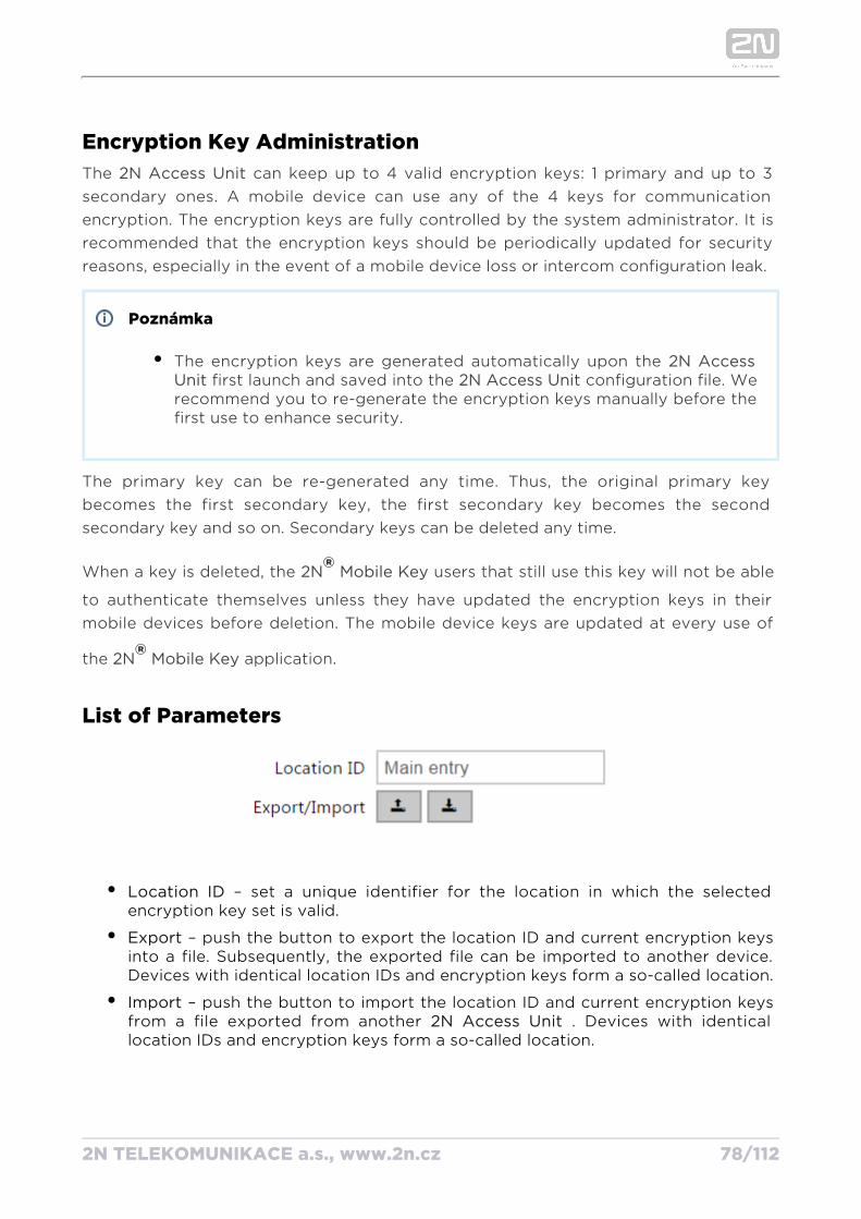
Encryption Key AdministrationThe can keep up to 4 valid encryption keys: 1 primary and up to 3 2N Access Unitsecondary ones. A mobile device can use any of the 4 keys for communication encryption. The encryption keys are fully controlled by the system administrator. It is recommended that the encryption keys should be periodically updated for security reasons, especially in the event of a mobile device loss or intercom configuration leak.
Poznámka
The encryption keys are generated automatically upon the 2N Access first launch and saved into the configuration file. We Unit 2N Access Unit
recommend you to re-generate the encryption keys manually before the first use to enhance security.
The primary key can be re-generated any time. Thus, the original primary key becomes the first secondary key, the first secondary key becomes the second secondary key and so on. Secondary keys can be deleted any time.
When a key is deleted, the users that still use this key will not be able 2N Mobile Key ®to authenticate themselves unless they have updated the encryption keys in their mobile devices before deletion. The mobile device keys are updated at every use of
the application.2N Mobile Key®
List of Parameters
Location ID – set a unique identifier for the location in which the selected encryption key set is valid.
Export – push the button to export the location ID and current encryption keys into a file. Subsequently, the exported file can be imported to another device. Devices with identical location IDs and encryption keys form a so-called location.
Import – push the button to import the location ID and current encryption keys from a file exported from another . Devices with identical 2N Access Unitlocation IDs and encryption keys form a so-called location.
2N TELEKOMUNIKACE a.s., www.2n.cz 79/112
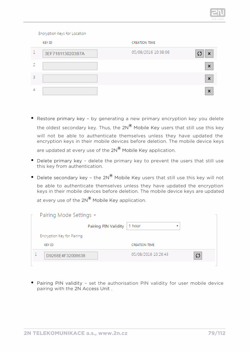
– by generating a new primary encryption key you delete Restore primary key
the oldest secondary key. Thus, the users that still use this key 2N Mobile Key ®will not be able to authenticate themselves unless they have updated the encryption keys in their mobile devices before deletion. The mobile device keys
are updated at every use of the application.2N Mobile Key®– delete the primary key to prevent the users that still use Delete primary key
this key from authentication.
– the users that still use this key will not Delete secondary key 2N Mobile Key ®be able to authenticate themselves unless they have updated the encryption keys in their mobile devices before deletion. The mobile device keys are updated
at every use of the application.2N Mobile Key®
– set the authorisation PIN validity for user mobile device Pairing PIN validity pairing with the .2N Access Unit
2N TELEKOMUNIKACE a.s., www.2n.cz 80/112
1.
2.
Tip
In the case of loss of a mobile phone with access data proceed as follows:
Delete the Mobile Key Auth ID value for the user to block the lost phone and avoid misuse.
Re-generate the primary encryption key (optionally) to avoid misuse of the encryption key stored in the mobile device.
2N TELEKOMUNIKACE a.s., www.2n.cz 81/112
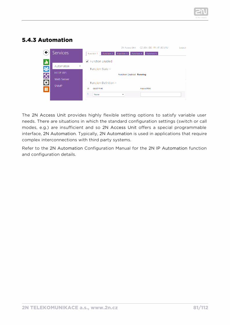
5.4.3 Automation
The provides highly flexible setting options to satisfy variable user 2N Access Unitneeds. There are situations in which the standard configuration settings (switch or call modes, e.g.) are insufficient and so offers a special programmable 2N Access Unitinterface, . Typically, is used in applications that require 2N Automation 2N Automationcomplex interconnections with third party systems.
Refer to the Configuration Manual for the function 2N Automation 2N IP Automationand configuration details.
2N TELEKOMUNIKACE a.s., www.2n.cz 82/112
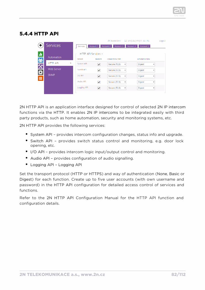
5.4.4 HTTP API
2N HTTP API is an application interface designed for control of selected 2N IP intercomfunctions via the . It enables to be integrated easily with third HTTP 2N IP intercomsparty products, such as home automation, security and monitoring systems, etc.
HTTP API2N provides the following services:
System API – provides intercom configuration changes, status info and upgrade.
Switch API – provides switch status control and monitoring, e.g. door lock opening, etc.
I/O API – provides intercom logic input/output control and monitoring.
Audio API – provides configuration of audio signalling.
Logging API – Logging API
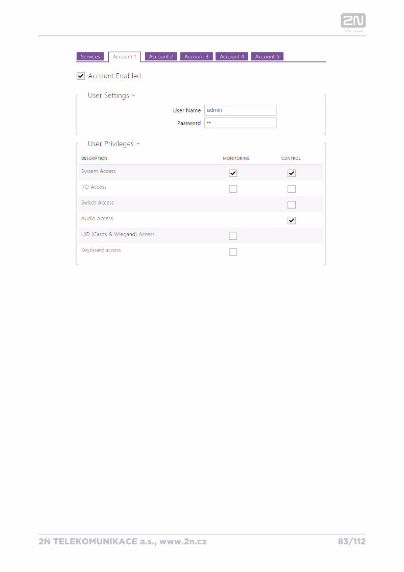
Set the transport protocol ( or ) and way of authentication ( , or HTTP HTTPS None Basic) for each function. Create up to five user accounts (with own username and Digest
password) in the configuration for detailed access control of services and HTTP APIfunctions.
Refer to the Configuration Manual for the HTTP API function and 2N HTTP API configuration details.
2N TELEKOMUNIKACE a.s., www.2n.cz 83/112
2N TELEKOMUNIKACE a.s., www.2n.cz 84/112
1.
2.
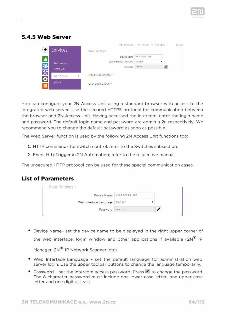
5.4.5 Web Server
You can configure your using a standard browser with access to the 2N Access Unitintegrated web server. Use the secured HTTPS protocol for communication between the browser and . Having accessed the intercom, enter the login name 2N Access Unitand password. The default login name and password are a respectively. We admin 2nrecommend you to change the default password as soon as possible.
The Web Server function is used by the following functions too:2N Access Unit
HTTP commands for switch control, refer to the Switches subsection.
Event.HttpTrigger in ; refer to the respective manual.2N Automation
The unsecured HTTP protocol can be used for these special communication cases.
List of Parameters
Device Name– set the device name to be displayed in the right upper corner of
the web interface, login window and other applications if available (2N IP ®, , etc).Manager 2N IP Network Scanner®
Web Interface Language – set the default language for administration web server login. Use the upper toolbar buttons to change the language temporarily.
Password – set the intercom access password. Press to change the password. The 8-character password must include one lower-case letter, one upper-case letter and one digit at least.
2N TELEKOMUNIKACE a.s., www.2n.cz 85/112
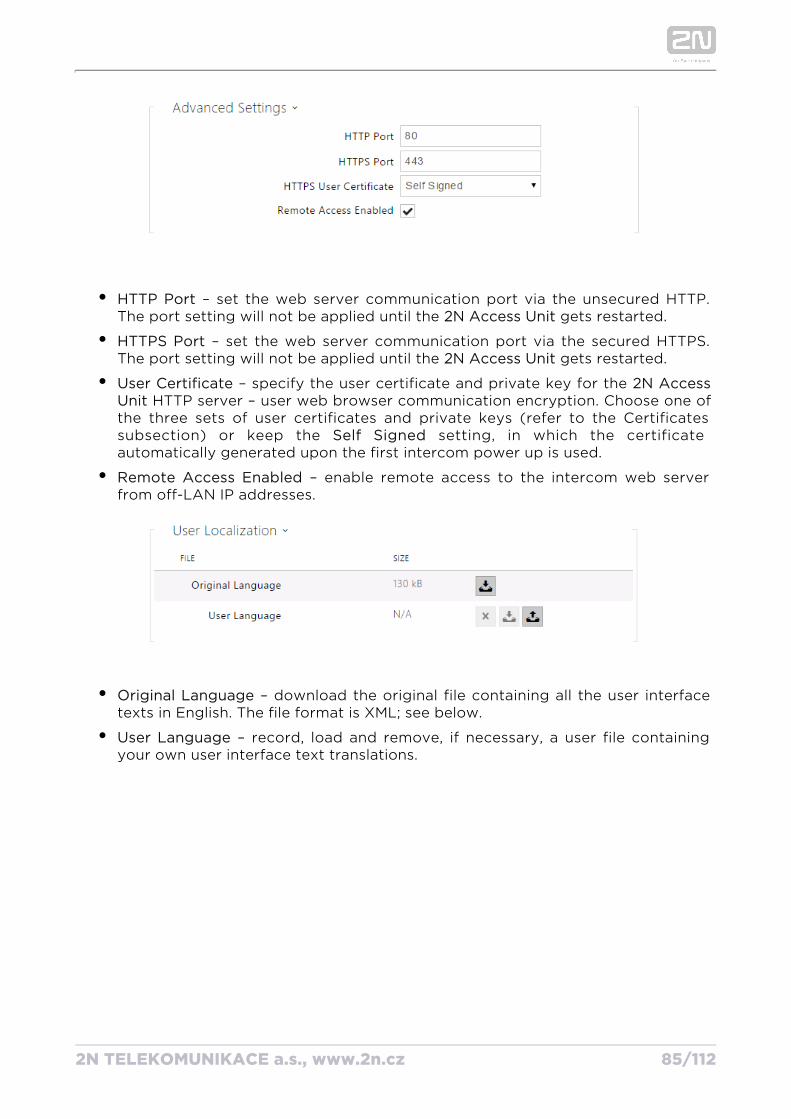
HTTP Port – set the web server communication port via the unsecured HTTP. The port setting will not be applied until the gets restarted.2N Access Unit
HTTPS Port – set the web server communication port via the secured HTTPS. The port setting will not be applied until the gets restarted.2N Access Unit
User Certificate – specify the user certificate and private key for the 2N Access HTTP server – user web browser communication encryption. Choose one of Unit
the three sets of user certificates and private keys (refer to the Certificates subsection) or keep the setting, in which the certificate Self Signedautomatically generated upon the first intercom power up is used.
Remote Access Enabled – enable remote access to the intercom web server from off-LAN IP addresses.
Original Language – download the original file containing all the user interface texts in English. The file format is XML; see below.
User Language – record, load and remove, if necessary, a user file containing your own user interface text translations.
2N TELEKOMUNIKACE a.s., www.2n.cz 86/112
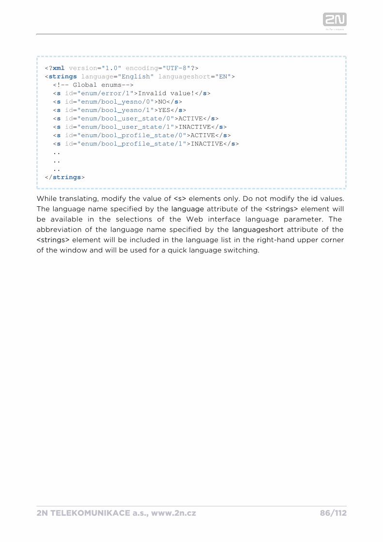
<?xml version="1.0" encoding="UTF-8"?><strings language="English" languageshort="EN"> <!-- Global enums--> <s id="enum/error/1">Invalid value!</s> <s id="enum/bool_yesno/0">NO</s> <s id="enum/bool_yesno/1">YES</s> <s id="enum/bool_user_state/0">ACTIVE</s> <s id="enum/bool_user_state/1">INACTIVE</s> <s id="enum/bool_profile_state/0">ACTIVE</s> <s id="enum/bool_profile_state/1">INACTIVE</s> .. .. ..</strings>
While translating, modify the value of elements only. Do not modify the values. <s> idThe language name specified by the attribute of the element will language <strings>be available in the selections of the Web interface language parameter. The abbreviation of the language name specified by the attribute of the languageshort
element will be included in the language list in the right-hand upper corner <strings>of the window and will be used for a quick language switching.
2N TELEKOMUNIKACE a.s., www.2n.cz 87/112
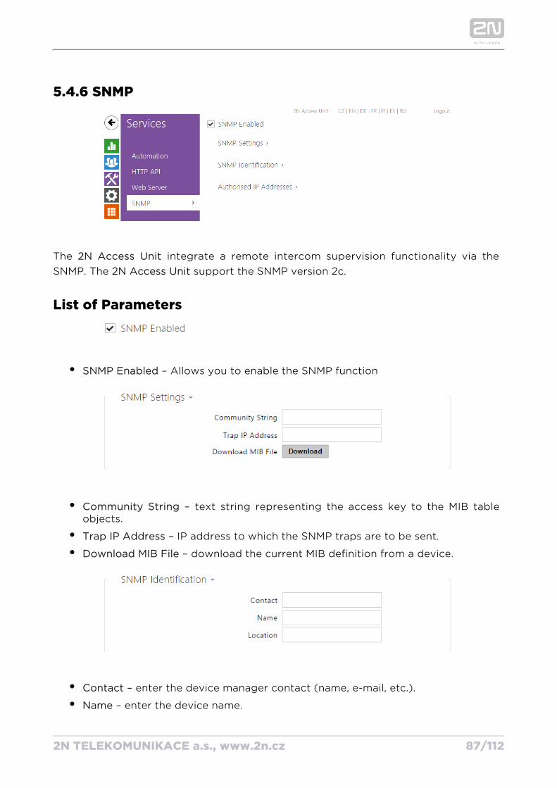
5.4.6 SNMP
The 2N Access Unit integrate a remote intercom supervision functionality via the SNMP. The support the SNMP version 2c. 2N Access Unit
List of Parameters
SNMP Enabled – Allows you to enable the SNMP function
Community String – text string representing the access key to the MIB table objects.
– IP address to which the SNMP traps are to be sent.Trap IP Address
– download the current MIB definition from a device.Download MIB File
Contact – enter the device manager contact (name, e-mail, etc.).
– enter the device name.Name
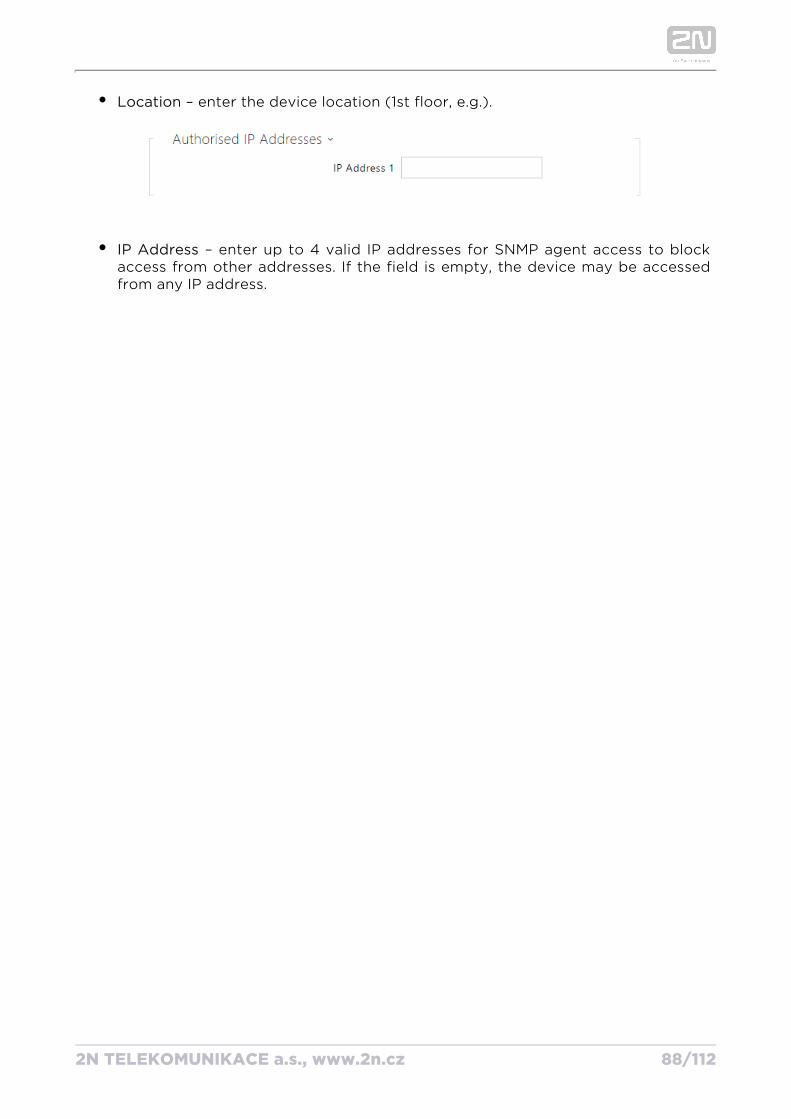
– enter the device location (1st floor, e.g.).Location
2N TELEKOMUNIKACE a.s., www.2n.cz 88/112
– enter the device location (1st floor, e.g.).Location
IP Address – enter up to 4 valid IP addresses for SNMP agent access to block access from other addresses. If the field is empty, the device may be accessed from any IP address.
2N TELEKOMUNIKACE a.s., www.2n.cz 89/112
5.5 SystemHere is what you can find in this section:
5.5.1 Network
5.5.2 Date and Time
5.5.3 Licence
5.5.4 Certificates
5.5.5 Auto Provisioning
5.5.6 Syslog
5.5.7 Maintenance
2N TELEKOMUNIKACE a.s., www.2n.cz 90/112
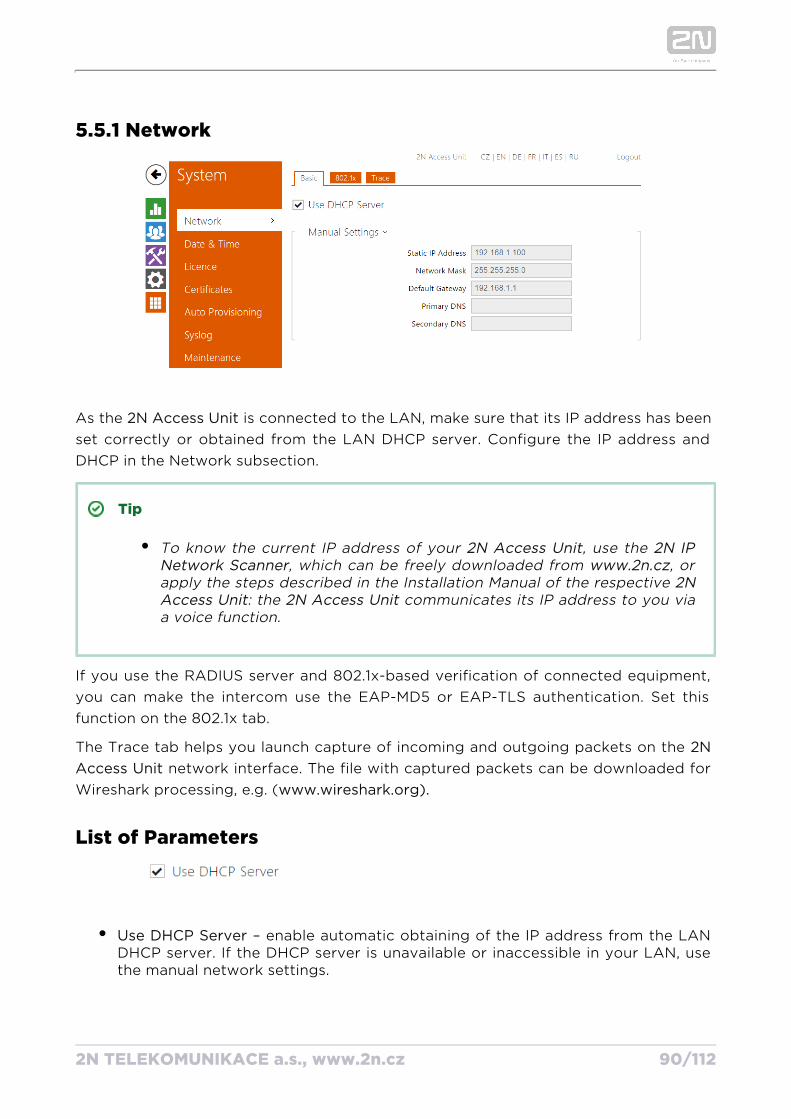
5.5.1 Network
As the is connected to the LAN, make sure that its IP address has been 2N Access Unitset correctly or obtained from the LAN DHCP server. Configure the IP address and DHCP in the Network subsection.
Tip
To know the current IP address of your , use the 2N Access Unit 2N IP , which can be freely downloaded from , or Network Scanner www.2n.cz
apply the steps described in the Installation Manual of the respective 2N : the communicates its IP address to you via Access Unit 2N Access Unit
a voice function.
If you use the RADIUS server and 802.1x-based verification of connected equipment, you can make the intercom use the EAP-MD5 or EAP-TLS authentication. Set this function on the 802.1x tab.
The Trace tab helps you launch capture of incoming and outgoing packets on the 2N network interface. The file with captured packets can be downloaded for Access Unit
Wireshark processing, e.g. (www.wireshark.org).
List of Parameters
Use DHCP Server – enable automatic obtaining of the IP address from the LAN DHCP server. If the DHCP server is unavailable or inaccessible in your LAN, use the manual network settings.
2N TELEKOMUNIKACE a.s., www.2n.cz 91/112
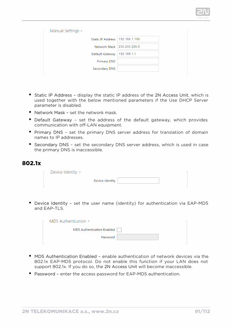
Static IP Address – display the static IP address of the , which is 2N Access Unitused together with the below mentioned parameters if the Use DHCP Server parameter is disabled.
Network Mask – set the network mask.
Default Gateway – set the address of the default gateway, which provides communication with off-LAN equipment.
Primary DNS – set the primary DNS server address for translation of domain names to IP addresses.
Secondary DNS – set the secondary DNS server address, which is used in case the primary DNS is inaccessible.
802.1x
Device Identity – set the user name (identity) for authentication via EAP-MD5 and EAP-TLS.
MD5 Authentication Enabled – enable authentication of network devices via the 802.1x EAP-MD5 protocol. Do not enable this function if your LAN does not support 802.1x. If you do so, the will become inaccessible.2N Access Unit
Password – enter the access password for EAP-MD5 authentication.
2N TELEKOMUNIKACE a.s., www.2n.cz 92/112
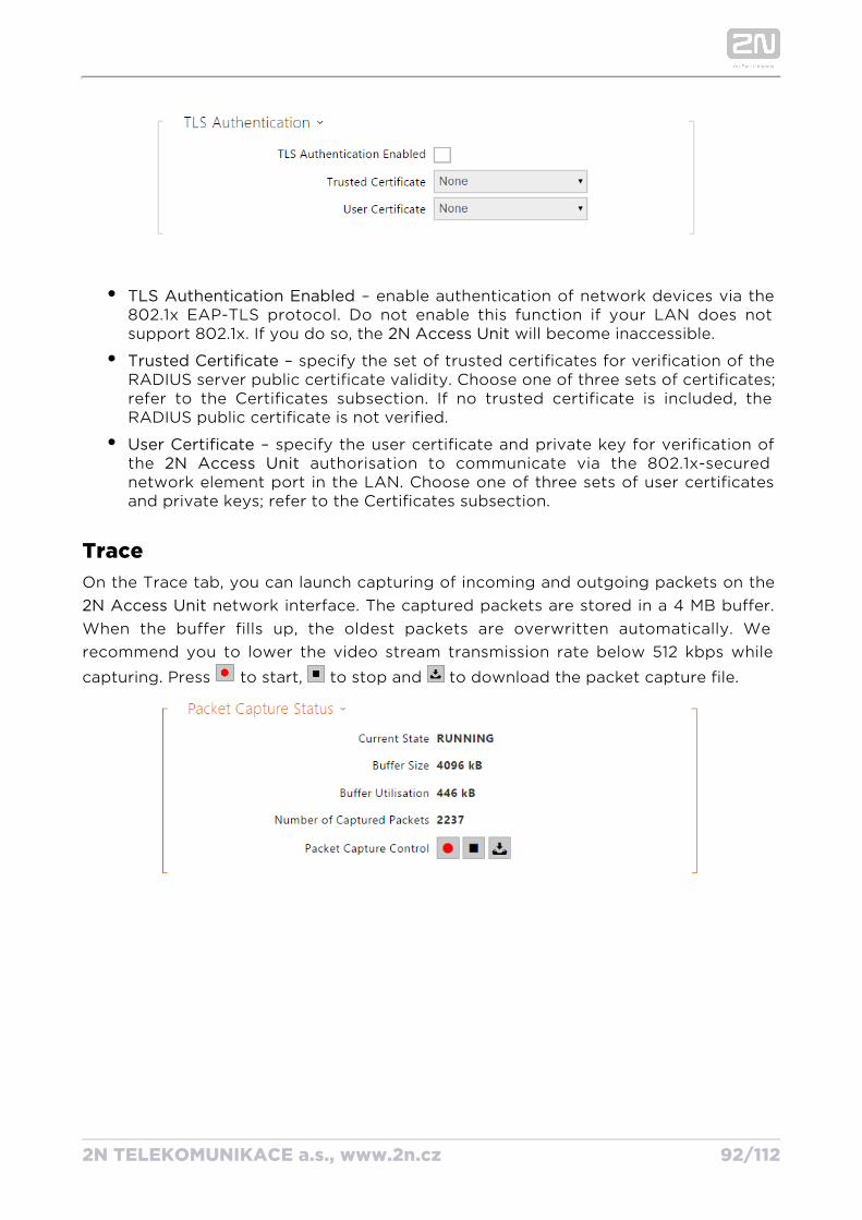
TLS Authentication Enabled – enable authentication of network devices via the 802.1x EAP-TLS protocol. Do not enable this function if your LAN does not support 802.1x. If you do so, the will become inaccessible.2N Access Unit
Trusted Certificate – specify the set of trusted certificates for verification of the RADIUS server public certificate validity. Choose one of three sets of certificates; refer to the Certificates subsection. If no trusted certificate is included, the RADIUS public certificate is not verified.
User Certificate – specify the user certificate and private key for verification of the authorisation to communicate via the 802.1x-secured 2N Access Unitnetwork element port in the LAN. Choose one of three sets of user certificates and private keys; refer to the Certificates subsection.
TraceOn the Trace tab, you can launch capturing of incoming and outgoing packets on the
network interface. The captured packets are stored in a 4 MB buffer. 2N Access UnitWhen the buffer fills up, the oldest packets are overwritten automatically. We recommend you to lower the video stream transmission rate below 512 kbps while
capturing. Press to start, to stop and to download the packet capture file.
2N TELEKOMUNIKACE a.s., www.2n.cz 93/112
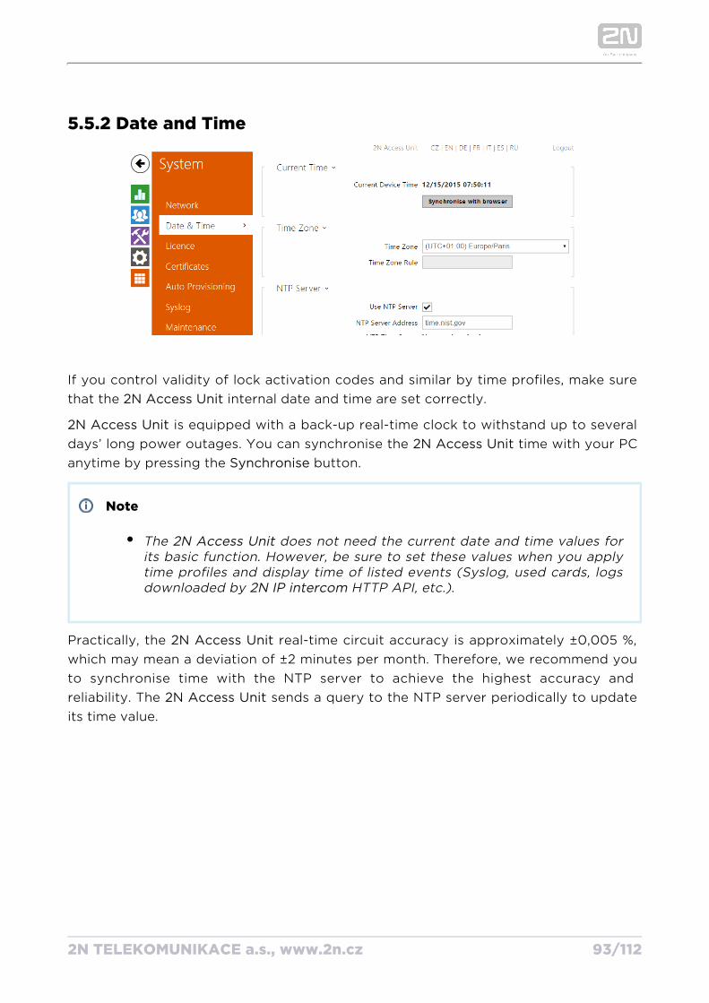
5.5.2 Date and Time
If you control validity of lock activation codes and similar by time profiles, make sure that the internal date and time are set correctly.2N Access Unit
Access Unit2N is equipped with a back-up real-time clock to withstand up to several days’ long power outages. You can synchronise the time with your PC 2N Access Unitanytime by pressing the button.Synchronise
Note
The does not need the current date and time values for 2N Access Unitits basic function. However, be sure to set these values when you apply time profiles and display time of listed events (Syslog, used cards, logs downloaded by HTTP API, etc.).2N IP intercom
Practically, the real-time circuit accuracy is approximately ±0,005 %, 2N Access Unitwhich may mean a deviation of ±2 minutes per month. Therefore, we recommend you to synchronise time with the NTP server to achieve the highest accuracy and reliability. The sends a query to the NTP server periodically to update 2N Access Unitits time value.
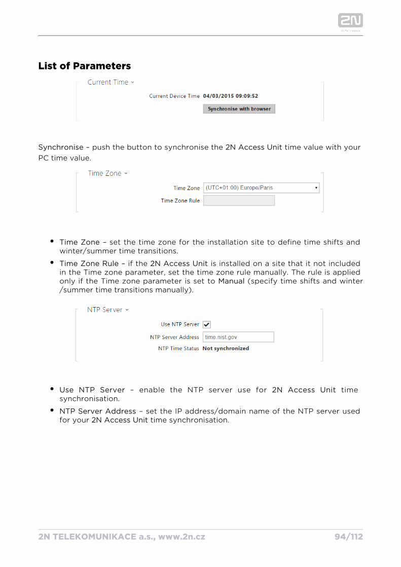
2N TELEKOMUNIKACE a.s., www.2n.cz 94/112
List of Parameters
Synchronise – push the button to synchronise the time value with your 2N Access UnitPC time value.
Time Zone – set the time zone for the installation site to define time shifts and winter/summer time transitions.
Time Zone Rule – if the is installed on a site that it not included 2N Access Unitin the Time zone parameter, set the time zone rule manually. The rule is applied only if the Time zone parameter is set to (specify time shifts and winterManual/summer time transitions manually).
Use NTP Server – enable the NTP server use for time 2N Access Unitsynchronisation.
NTP Server Address – set the IP address/domain name of the NTP server used for your time synchronisation.2N Access Unit
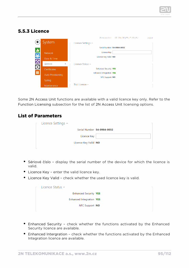
2N TELEKOMUNIKACE a.s., www.2n.cz 95/112
5.5.3 Licence
Some functions are available with a valid licence key only. Refer to the 2N Access Unit subsection for the list of licensing options.Function Licensing 2N Access Unit
List of Parameters
Sériové číslo – display the serial number of the device for which the licence is valid.
Licence Key – enter the valid licence key.
Licence Key Valid – check whether the used licence key is valid.
Enhanced Security – check whether the functions activated by the Enhanced Security licence are available.
Enhanced Intergration – check whether the functions activated by the Enhanced Integration licence are available.
NFC Support – check whether the functions activated.
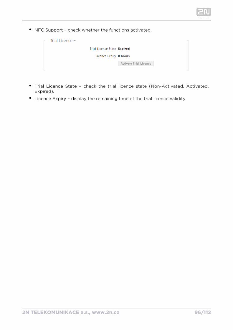
2N TELEKOMUNIKACE a.s., www.2n.cz 96/112
NFC Support – check whether the functions activated.
Trial Licence State – check the trial licence state (Non-Activated, Activated, Expired).
Licence Expiry – display the remaining time of the trial licence validity.
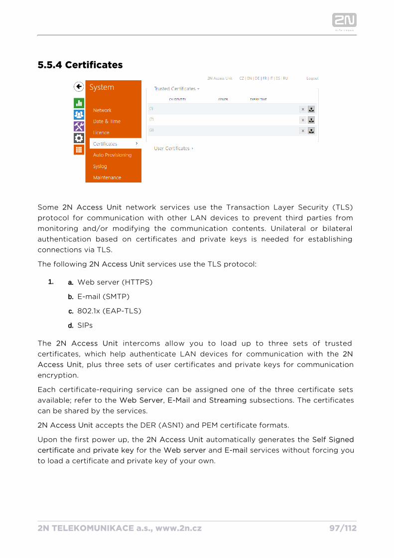
2N TELEKOMUNIKACE a.s., www.2n.cz 97/112
1. a.
b.
c.
d.
5.5.4 Certificates
Some network services use the Transaction Layer Security (TLS) 2N Access Unitprotocol for communication with other LAN devices to prevent third parties from monitoring and/or modifying the communication contents. Unilateral or bilateral authentication based on certificates and private keys is needed for establishing connections via TLS.
The following services use the TLS protocol:2N Access Unit
Web server (HTTPS)
E-mail (SMTP)
802.1x (EAP-TLS)
SIPs
The intercoms allow you to load up to three sets of trusted 2N Access Unitcertificates, which help authenticate LAN devices for communication with the 2N
, plus three sets of user certificates and private keys for communication Access Unitencryption.
Each certificate-requiring service can be assigned one of the three certificate sets available; refer to the , and subsections. The certificates Web Server E-Mail Streamingcan be shared by the services.
Access Unit2N accepts the DER (ASN1) and PEM certificate formats.
Upon the first power up, the automatically generates the 2N Access Unit Self Signed and for the and services without forcing you certificate private key Web server E-mail
to load a certificate and private key of your own.
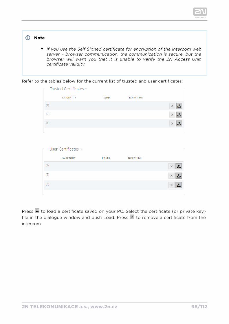
2N TELEKOMUNIKACE a.s., www.2n.cz 98/112
Note
If you use the Self Signed certificate for encryption of the intercom web server – browser communication, the communication is secure, but the browser will warn you that it is unable to verify the 2N Access Unit
certificate validity.
Refer to the tables below for the current list of trusted and user certificates:
Press to load a certificate saved on your PC. Select the certificate (or private key) file in the dialogue window and push . Press to remove a certificate from the Loadintercom.

2N TELEKOMUNIKACE a.s., www.2n.cz 99/112
1.
2.
3.
5.5.5 Auto Provisioning
The allows you to update firmware and configuration manually or 2N Access Unitautomatically from a storage on a TFTP/HTTP server selected by you according to predefined rules.
You can configure the TFTP and HTTP server address manually. The 2N Access Unitsupports automatic address identification via the local DHCP server (Option 66).
FirmwareUse the Firmware tab to set automatic firmware download from a server defined by you. The compares the server file with its current firmware file 2N Access Unitperiodically and, if the server file is more recent, automatically updates firmware and gets restarted (approx. 30 s). Hence, we recommend you to update when the 2N
traffic is very low (at night, e.g.).Access Unit
The expects the following files:2N Access Unit
MODEL-firmware.bin – firmware2N Access Unit
MODEL-common.xml – common configuration for all 2N Access Unit
MODEL- .xml –specific configuration for one MACADDR 2N Access Unit
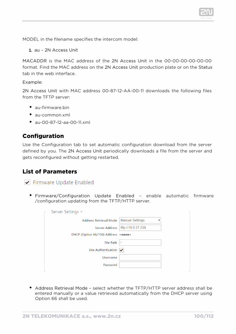
2N TELEKOMUNIKACE a.s., www.2n.cz 100/112
1.
MODEL in the filename specifies the intercom model:
au – 2N Access Unit
MACADDR is the MAC address of the in the 00-00-00-00-00-00 2N Access Unitformat. Find the MAC address on the production plate or on the 2N Access Unit Statustab in the web interface.
Example:
Access Unit2N with MAC address 00-87-12-AA-00-11 downloads the following files from the TFTP server:
au-firmware.bin
au-common.xml
au-00-87-12-aa-00-11.xml
ConfigurationUse the Configuration tab to set automatic configuration download from the server defined by you. The periodically downloads a file from the server and 2N Access Unitgets reconfigured without getting restarted.
List of Parameters
Firmware/Configuration Update Enabled – enable automatic firmware/configuration updating from the TFTP/HTTP server.
Address Retrieval Mode – select whether the TFTP/HTTP server address shall be entered manually or a value retrieved automatically from the DHCP server using Option 66 shall be used.
Server Address – enter the TFTP ( ), HTTP ( ) tftp://ip_address http://ip_address
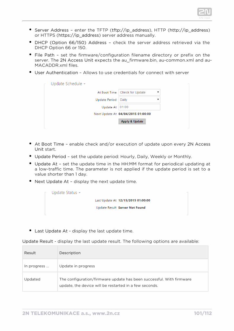
2N TELEKOMUNIKACE a.s., www.2n.cz 101/112
Server Address – enter the TFTP ( ), HTTP ( ) tftp://ip_address http://ip_addressor HTTPS ( ) server address manually.https://ip_address
DHCP (Option 66/150) Address – check the server address retrieved via the DHCP Option 66 or 150.
File Path – set the firmware/configuration filename directory or prefix on the server. The expects the au_firmware.bin, au-common.xml and au-2N Access UnitMACADDR.xml files.
User Authentication – Allows to use credentials for connect with server
At Boot Time – enable check and/or execution of update upon every 2N Access start.Unit
Update Period – set the update period: Hourly, Daily, Weekly or Monthly.
Update At – set the update time in the HH:MM format for periodical updating at a low-traffic time. The parameter is not applied if the update period is set to a value shorter than 1 day.
Next Update At – display the next update time.
Last Update At - display the last update time.
Update Result - display the last update result. The following options are available:
Result Description
In progress ... Update in progress
Updated The configuration/firmware update has been successful. With firmware
update, the device will be restarted in a few seconds.
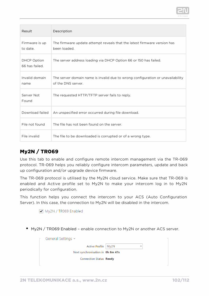
2N TELEKOMUNIKACE a.s., www.2n.cz 102/112
Result Description
Firmware is up
to date.
The firmware update attempt reveals that the latest firmware version has
been loaded.
DHCP Option
66 has failed.
The server address loading via DHCP Option 66 or 150 has failed.
Invalid domain
name
The server domain name is invalid due to wrong configuration or unavailability
of the DNS server.
Server Not
Found
The requested HTTP/TFTP server fails to reply.
Download failed An unspecified error occurred during file download.
File not found The file has not been found on the server.
File invalid The file to be downloaded is corrupted or of a wrong type.
My2N / TR069Use this tab to enable and configure remote intercom management via the TR-069 protocol. TR-069 helps you reliably configure intercom parameters, update and back up configuration and/or upgrade device firmware.
The TR-069 protocol is utilised by the My2N cloud service. Make sure that TR-069 is enabled and Active profile set to My2N to make your intercom log in to My2N periodically for configuration.
This function helps you connect the intercom to your ACS (Auto Configuration Server). In this case, the connection to My2N will be disabled in the intercom.
My2N / TR069 Enabled – enable connection to My2N or another ACS server.
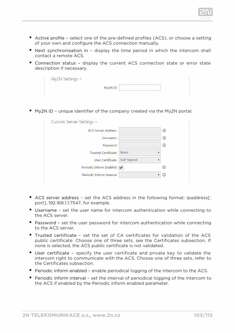
2N TELEKOMUNIKACE a.s., www.2n.cz 103/112
Active profile – select one of the pre-defined profiles (ACS), or choose a setting of your own and configure the ACS connection manually.
Next synchronisation in – display the time period in which the intercom shall contact a remote ACS.
Connection status – display the current ACS connection state or error state description if necessary.
My2N ID – unique identifier of the company created via the My2N portal.
ACS server address – set the ACS address in the following format: ipaddress[: port], 192.168.1.1:7547, for example.
Username – set the user name for intercom authentication while connecting to the ACS server.
Password – set the user password for intercom authentication while connecting to the ACS server.
Trusted certificate – set the set of CA certificates for validation of the ACS public certificate. Choose one of three sets, see the Certificates subsection. If none is selected, the ACS public certificate is not validated.
User certificate – specify the user certificate and private key to validate the intercom right to communicate with the ACS. Choose one of three sets, refer to the Certificates subsection.
Periodic inform enabled – enable periodical logging of the intercom to the ACS.
Periodic inform interval – set the interval of periodical logging of the intercom to the ACS if enabled by the Periodic inform enabled parameter.
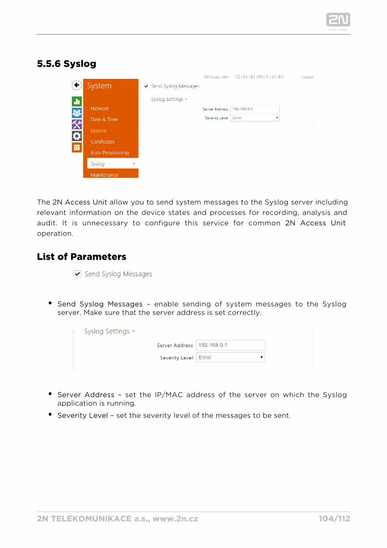
2N TELEKOMUNIKACE a.s., www.2n.cz 104/112
5.5.6 Syslog
The allow you to send system messages to the Syslog server including 2N Access Unit relevant information on the device states and processes for recording, analysis and audit. It is unnecessary to configure this service for common 2N Access Unitoperation.
List of Parameters
Send Syslog Messages – enable sending of system messages to the Syslog server. Make sure that the server address is set correctly.
Server Address – set the IP/MAC address of the server on which the Syslog application is running.
Severity Level – set the severity level of the messages to be sent.
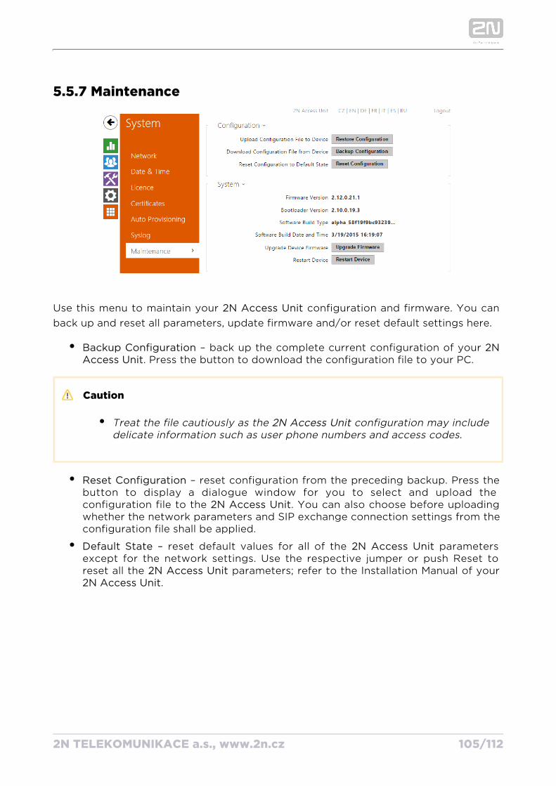
2N TELEKOMUNIKACE a.s., www.2n.cz 105/112
5.5.7 Maintenance
Use this menu to maintain your configuration and firmware. You can 2N Access Unitback up and reset all parameters, update firmware and/or reset default settings here.
Backup Configuration – back up the complete current configuration of your 2N . Press the button to download the configuration file to your PC.Access Unit
Caution
Treat the file cautiously as the configuration may include 2N Access Unitdelicate information such as user phone numbers and access codes.
Reset Configuration – reset configuration from the preceding backup. Press the button to display a dialogue window for you to select and upload the configuration file to the . You can also choose before uploading 2N Access Unitwhether the network parameters and SIP exchange connection settings from the configuration file shall be applied.
Default State – reset default values for all of the parameters 2N Access Unitexcept for the network settings. Use the respective jumper or push Reset to reset all the parameters; refer to the Installation Manual of your 2N Access Unit
.2N Access Unit
2N TELEKOMUNIKACE a.s., www.2n.cz 106/112
Caution
The default state reset deletes the licence key if any. Hence, we recommend you to copy it to another storage for later use.
Upgrade Firmware – upgrade your firmware. Press the button to 2N Access Unitdisplay a dialogue window for you to select and upload the firmware file to the
. The intercom will automatically get restarted and new FW will 2N Access Unitthen be available. The whole upgrading process takes less than one minute. Refer to for the latest FW version for your . FW www.2n.cz 2N Access Unitupgrade does not affect configuration as the intercom checks the FW file to prevent upload of a wrong or corrupted file.
Restart Device – restart the . The process takes about 30 s. When 2N Access Unitthe has obtained the IP address upon restart, the login window 2N Access Unitwill get displayed automatically.
2N TELEKOMUNIKACE a.s., www.2n.cz 107/112
6. Supplementary Information
Here is what you can find in this section:
6.1 Troubleshooting
6.2 Directives, Laws and Regulations
6.3 General Instructions and Cautions
2N TELEKOMUNIKACE a.s., www.2n.cz 108/112
6.1 Troubleshooting
For the most frequently asked questions refer to .faq.2n.cz
2N TELEKOMUNIKACE a.s., www.2n.cz 109/112
6.2 Directives, Laws and Regulations
Europe2N Access Unit conforms to the following directives and regulations:
2014/35/EU on the harmonisation of the laws of the Member States relating to the making available on the market of electrical equipment designed for use within certain voltage limits
2014/30/EU on the harmonisation of the laws of the Member States relating to electromagnetic compatibility
2011/65/EU on the restriction of the use of certain hazardous substances in electrical and electronic equipment
2012/19/EU on waste electrical and electronic equipment
Industry CanadaThis Class B digital apparatus complies with Canadian ICES-003. / Cet appareil numérique de la classe B est conforme a la norme NMB-003 du Canada.
FCCNOTE: This equipment has been tested and found to comply with the limits for a Class B digital device, pursuant to part 15 of the FCC Rules. These limits are designed to provide reasonable protection against harmful interference in a residential installation. This equipment generates, uses and can radiate radio frequency energy and, if not installed and used in accordance with the instructions, may cause harmful interference to radio communications. However, there is no guarantee that interference will not occur in a particular installation. If this equipment does cause harmful interference to radio or television reception, which can be determined by turning the equipment off and on, the user is encouraged to try to correct the interference by one or more of the following measures:
Reorient or relocate the receiving antenna
Increase the separation between the equipment and receiver
Connect the equipment into an outlet on a circuit different from that to which the receiver is connected
Consult the dealer or an experienced radio/TV technician for help.
Changes or modifications to this unit not expressly approved by the party responsible for compliance could void the user's authority to operate this equipment.

2N TELEKOMUNIKACE a.s., www.2n.cz 110/112
6.3 General Instructions and CautionsPlease read this User Manual carefully before using the product. Follow all instructions and recommendations included herein.
Any use of the product that is in contradiction with the instructions provided herein may result in malfunction, damage or destruction of the product.
The manufacturer shall not be liable and responsible for any damage incurred as a result of a use of the product other than that included herein, namely undue application and disobedience of the recommendations and warnings in contradiction herewith.
Any use or connection of the product other than those included herein shall be considered undue and the manufacturer shall not be liable for any consequences arisen as a result of such misconduct.
Moreover, the manufacturer shall not be liable for any damage or destruction of the product incurred as a result of misplacement, incompetent installation and/or undue operation and use of the product in contradiction herewith.
The manufacturer assumes no responsibility for any malfunction, damage or destruction of the product caused by incompetent replacement of parts or due to the use of reproduction parts or components.
The manufacturer shall not be liable and responsible for any loss or damage incurred as a result of a natural disaster or any other unfavourable natural condition.
The manufacturer shall not be held liable for any damage of the product arising during the shipping thereof.
The manufacturer shall not make any warrant with regard to data loss or damage.
The manufacturer shall not be liable and responsible for any direct or indirect damage incurred as a result of a use of the product in contradiction herewith or a failure of the product due to a use in contradiction herewith.
All applicable legal regulations concerning the product installation and use as well as provisions of technical standards on electric installations have to be obeyed. The manufacturer shall not be liable and responsible for damage or destruction of the product or damage incurred by the consumer in case the product is used and handled contrary to the said regulations and provisions.
The consumer shall, at its own expense, obtain software protection of the product. The manufacturer shall not be held liable and responsible for any damage incurred as a result of the use of deficient or substandard security software.
2N TELEKOMUNIKACE a.s., www.2n.cz 111/112
The consumer shall, without delay, change the access password for the product after installation. The manufacturer shall not be held liable or responsible for any damage incurred by the consumer in connection with the use of the original password.
The manufacturer also assumes no responsibility for additional costs incurred by the consumer as a result of making calls using a line with an increased tariff.
Electric Waste and Used Battery Pack Handling
Do not place used electric devices and battery packs into municipal waste containers. An undue disposal thereof might impair the environment!
Deliver your expired electric appliances and battery packs removed from them to dedicated dumpsites or containers or give them back to the dealer or manufacturer for environmental-friendly disposal. The dealer or manufacturer shall take the product back free of charge and without requiring another purchase. Make sure that the devices to be disposed of are complete.
Do not throw battery packs into fire. Battery packs may not be taken into parts or short-circuited either.

2N TELEKOMUNIKACE a.s., www.2n.cz 112/112
2N TELEKOMUNIKACE a.s.
Modřanská 621, 143 01 Prague 4, Czech Republic
Phone: +420 261 301 500, Fax: +420 261 301 599
E-mail: [email protected]
Web: www.2n.cz
v2.25