
ABHISHEK K R Resistance in Series - AWS
85
with ABHISHEK K R B.Tech - Aerospace, Alliance University CBSE Expert | Inventor of RocketPro 6+ Years Teaching Exp | Mentored more than 5000 students Helped 1000s of students get 10 CGPA in CBSE X Resistance in Series Episode 4
-
Upload
khangminh22 -
Category
Documents
-
view
0 -
download
0
Transcript of ABHISHEK K R Resistance in Series - AWS

with
ABHISHEK K RB.Tech - Aerospace, Alliance UniversityCBSE Expert | Inventor of RocketPro6+ Years Teaching Exp | Mentored more than 5000 studentsHelped 1000s of students get 10 CGPA in CBSE X
Resistance in SeriesEpisode 4


ELE
CTR
ICIT
Y Electric Current & Potential Difference
Resistance & Factors Affecting it
Ohm’s Law
Heating effects of Electric Current
Resistance in Series
Resistance in Parallel
Electrical Power & Energy

ELE
CTR
ICIT
Y Electric Current & Potential Difference
Resistance & Factors Affecting it
Ohm’s Law
Heating effects of Electric Current
Resistance in Series
Resistance in Parallel
Electrical Power & Energy


Half timesFour times
Twice One fourth
A B
C D
Q1. If the area of a wire is halved, then its resistance becomes, considering volume of the wire is constant

Q1. If the area of a wire is halved, then its resistance becomes, considering volume of the wire is constant

Half timesFour times
Twice One fourth
A B
C D
Q1. If the area of a wire is halved, then its resistance becomes, considering volume of the wire is constant

86 Ω 80 Ω
70 Ω 90 Ω
A B
C D
Q2.Calculate the resistance of aluminium cable, 10km long and a diameter is 2.0 mm if the resistivity of aluminium is 2.7 x 10⁻⁸ Ωm

Q2.Calculate the resistance of aluminium cable, 10km long and a diameter is 2.0 mm if the resistivity of aluminium is 2.7 x 10⁻⁸ Ωm

86 Ω 80 Ω
70 Ω 90 Ω
A B
C D
Q2.Calculate the resistance of aluminium cable, 10km long and a diameter is 2.0 mm if the resistivity of aluminium is 2.7 x 10⁻⁸ Ωm

ρ/2 ρ
2ρ
4ρ
A B
C D
Q3. A wire of length l, made of material resistivity ρ is cut into two equal parts. The resistivity of the two parts are equal to,

Q3. A wire of length l, made of material resistivity ρ is cut into two equal parts. The resistivity of the two parts are equal to,

ρ/2 ρ
2ρ
4ρ
A B
C D
Q3. A wire of length l, made of material resistivity ρ is cut into two equal parts. The resistivity of the two parts are equal to,

ANSWER : Wire A
Q17. V I graph of two wires A and B are shown in the figure.If both wires are of same length and same thickness, which of the two is made of material of high resistivity. [2014-Boards]


Consider a circuit which has 1 bulb

It Glows! Ha ha, pata hi nhi tha na!!!

Consider more than one bulb is connected in series

Decreases Increases
A B
Q1. What happens to the brightness of each bulb

Decreases Increases
A B
Q1. What happens to the brightness of each bulb

What does this imply?
Source: https://media1.giphy.com
/media/xThtanqVaw
zQN
eHD
20/source.gif

Have you noticed an adaptor of laptops or mobiles?

Have you noticed an adaptor of laptops or mobiles?
These numbers specify Input and ouput voltage and current of the adapter.

Input
Output
Input is in a range.Output is a single value.

Circuit in an adaptor is designed to reduce current and voltage.
Adaptor Circuit

No yes
A B
Q2. By changing resistance can we control the current and voltage in a circuit

No yes
A B
Q2. By changing resistance can we control the current and voltage in a circuit

Let’s Understand Resistance in Series

A device needs a resistance 2 Ω for correct functioning.
Device
2Ω

Device
2Ω
But we have only 1 Ω resistors with us
A device needs a resistance 2 Ω for correct functioning.

Q3. How can we get 2 Ω resistors from 1 Ω here

1Ω 1Ω
Q3. How can we get 2 Ω resistors from 1 Ω here

Now consider a circuit with 2 resistors R1 and R2.
R1 R2

Now consider a circuit with 2 resistors R1 and R2.
R1 R2
V
I
Let the voltage in this circuit be V and current be I

What will be the current in the resistors R1 and R2?
R1 R2
V
I
I1 I2

Current flow in series can be visualised as fluid flow in a pipe

What will be the current in the resistors R1 and R2?
R1 R2
V
I
Current in R1 = Current in R2 = Current in the circuit
I = I1 = I2
I1 I2

What will be the voltage across the resistors R1 and R2?
V
IR1 R2
A B C
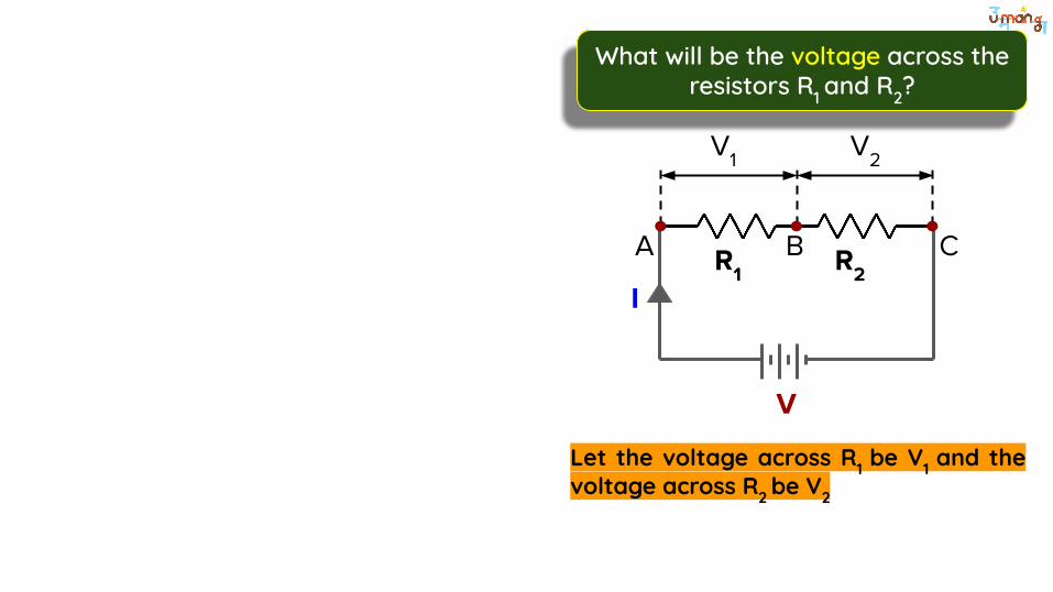
What will be the voltage across the resistors R1 and R2?
Let the voltage across R1 be V1 and the voltage across R2 be V2
V
IR1 R2
A B C
V1 V2

No yes
A B
Q3. Can I say potential difference across R1 = Potential at A - Potential at B

No yes
A B
Q3. Can I say potential difference across R1 = Potential at A - Potential at B

V1 = VA - VB
Similarly , V2 = VB - VC

If we add them we get
V1 + V2 = VA - VC

No yes
A B
Q4. Can I say V1 + V2 = V?

No yes
A B
Q4. Can I say V1 + V2 = V ?

Conclusion:
Current remains constant. Voltage gets distributed.

Conclusion:
Current remains constant. Voltage gets distributed.
Let us SIMULATE!!!

I = I1 = I2
V = V1 + V2
Apply Ohm’s law,I1R1 + I2R2= V

In series connection, Equivalent resistance is the sum of individual resistances.
Req = R1+R2

IR1 R2
V
For 2 resistances
Req = R1 + R2
IR1 R2
V
For 3 resistances
Req = R1 + R2 + R3 R3

For n resistances
I
R1 R2
V
Req = R1 + R2 + R3 …….. + Rn
R3 Rn

Larger Smaller
A B
Q5. In series combination equivalent resistance is _______ than individual resistance

Larger Smaller
A B
Q5. In series combination equivalent resistance is _______ than individual resistance

In series combination, resistors/ devices are connected one after the other

In series combination, resistors/ devices are connected one after the other
Current Remains the same.

In series combination, resistors/ devices are connected one after the other
Current Remains the same.
Voltage gets distributed.

In series combination, resistors/ devices are connected one after the other
Current Remains the same.
Voltage gets distributed.
Equivalent resistance is sum of individual resistance.

V I P

Q6. Study the following circuit and find (i) the current flowing through the circuit and the potential difference across 10 ohm resistor? [2015-Boards]
3V

I = 0.25 A, V = 5 V I = 0.5 A, V = 1 V
I = 0.1 A, V = 1 V I = 0.1 A, V = 10 V
A B
C D
Q6. Study the following circuit and find (i) the current flowing through the circuit and the potential difference across 10 ohm resistor? [2015-Boards]

Q6. Study the following circuit and find (i) the current flowing through the circuit and the potential difference across 10 ohm resistor? [2015-Boards]
3V

I = 0.25 A, V = 5 V I = 0.5 A, V = 1 V
I = 0.1 A, V = 1 V I = 0.1 A, V = 10 V
A B
C D
Q6. Study the following circuit and find (i) the current flowing through the circuit and the potential difference across 10 ohm resistor? [2015-Boards]

1 Ω ⅕ Ω
10 Ω 5 Ω
A B
C D
Q7. What is the maximum resistance which can be made by using 5 resistors each of ⅕ ohm?

Q7. What is the maximum resistance which can be made by using 5 resistors each of ⅕ ohm?

1 Ω ⅕ Ω
10 Ω 5 Ω
A B
C D
Q7. What is the maximum resistance which can be made by using 5 resistors each of ⅕ ohm?

R = 50 Ω , I = 4 A R = 60 Ω , I = 4 A
R = 60 Ω , I = 6 A R = 6 Ω , I = 6 A
A B
C D
Q8. There are three resistors joined in series in a system having resistance equal to 10 Ω, 20 Ω and 30 Ω respectively. If the potential difference of the circuit is 240 V, find the total resistance and current through the circuit.

Q8. There are three resistors joined in series in a system having resistance equal to 10 Ω, 20 Ω and 30 Ω respectively. If the potential difference of the circuit is 240 V, find the total resistance and current through the circuit.

R = 50 Ω , I = 4 A R = 60 Ω , I = 4 A
R = 60 Ω , I = 6 A R = 6 Ω , I = 6 A
A B
C D
Q8. There are three resistors joined in series in a system having resistance equal to 10 Ω, 20 Ω and 30 Ω respectively. If the potential difference of the circuit is 240 V, find the total resistance and current through the circuit.

Q9. Two resistors of resistances 5 ohm and 10 ohm respectively are to be connected to a battery of emf 6 V so as to obtain minimum current flowing. Calculate the strength of the total current in this case. [2009 Boards]

0.4 A 1.8 A
4 A 2 A
A B
C D
Q9. Two resistors of resistances 5 ohm and 10 ohm respectively are to be connected to a battery of emf 6 V ,so as to obtain minimum current flowing. Calculate the strength of the total current in this case. [2009 Boards]

0.4 A 1.8 A
4 A 2 A
A B
C D
Q9. Two resistors of resistances 5 ohm and 10 ohm respectively are to be connected to a battery of emf 6 V ,so as to obtain minimum current flowing. Calculate the strength of the total current in this case. [2009 Boards]

Q10. V1 ,V2 and V3 are the potential differences across the 1Ω, 2Ω and 3Ω resistors in the following diagram, and the current is 5A.Which of the following shows the correct values of V1, V2 and V3 measured in volts?

V1 =5, V2 =10 ,V3 = 15V1 =1, V2 = 2 ,V3 = 3
V1 =5, V2 = 2.5 ,V3 = 2 V1 =5, V2 = 3 ,V3 = 2
A B
C D
Q10. V1 ,V2 and V3 are the potential differences across the 1Ω, 2Ω and 3Ω resistors in the following diagram, and the current is 5A.Which of the following shows the correct values of V1, V2 and V3 measured in volts?

Q10. V1 ,V2 and V3 are the potential differences across the 1Ω, 2Ω and 3Ω resistors in the following diagram, and the current is 5A.Which of the following shows the correct values of V1, V2 and V3 measured in volts?

V1 =5, V2 =10 ,V3 = 15V1 =1, V2 = 2 ,V3 = 3
V1 =5, V2 = 2.5 ,V3 = 2 V1 =5, V2 = 3 ,V3 = 2
A B
C D
Q10. V1 ,V2 and V3 are the potential differences across the 1Ω, 2Ω and 3Ω resistors in the following diagram, and the current is 5A.Which of the following shows the correct values of V1, V2 and V3 measured in volts?

Q11. Find the potential difference across 3 ohm resistor in the following diagram?


ELE
CTR
ICIT
Y Electric Current & Potential Difference
Resistance & Factors Affecting it
Ohm’s Law
Heating effects of Electric Current
Resistance in Series
Resistance in Parallel
Electrical Power & Energy