AAR M 107_M 208 Standard - baixardoc
10
03/2011 G [M-107/M-208] 21 AAR Manual of Standards and Recommended Practices Wheels and Axles M-107/M-208 WHEELS, CARBON STEEL Specification M-107/M-208 Adopted: 1962; Last Revised: 2011 1.0 SCOPE These specifications cover one-wear, two-wear, and multiple-wear wrought and cast carbon steel wheels for locomotives and cars—Classes L, A, B, C, and D (heat-treated) wheels used in inter- change service. All freight car wheels manufactured for AAR interchange service must be heat-treated and of a low-stress design. 1.1 Class B, C, or D wheels must be used for freight cars in interchange service. 1.2 Class B, C, or D wheels are recommended for use on locomotives. 1.3 For passenger car service, the various classes are intended generally as follows: 2.0 DESIGN 2.1 Standard wheel types and tread and flange contours for freight car and locomotive steel wheels shall be as shown in this specification. Interchangeability requirements and tolerances and tread and flange contours for the authorized wheel types are shown in Figs. B.8 through B.14. The interchangeability requirements and tolerances are generally limited to those required to ensure the wheel is compatible with the standard axles, bearings, side frames, and track. In the event that design constraints other than these are shown, the wheel producer may request an exception or change by application, with supporting data, to the AAR Technical Services Division (hereinaf- ter termed AAR). Staff will, in turn, submit the application to the Wheels, Axles, Bearings, and Lubrication (WABL) Working Committee (hereinafter referred to as the “Committee”) for review. 2.2 In the event any company feels there is a need for a wheel type not currently listed, an appli- cation, with supporting data, should be made to the AAR, who will obtain the decision of the Com- mittee. 3.0 Authorization for delivery for interchange use of any AAR wheel type must be obtained from the AAR as described in Appendix A. 4.0 Qualification as a manufacturer of wheels for use in AAR interchange service must be in accordance with Appendix B. Qualification is effective until revoked for cause by the Committee. Failure to maintain reasonable quality standards in manufacturing is an example of cause. Class L —High-speed service with more severe braking conditions than other classes and light wheel loads. Class A—High-speed service with severe braking conditions, but with moderate wheel loads. Class B—High-speed service with severe braking conditions and heavier wheel loads. Class C—(1) Service with light braking conditions and heavy wheel loads. (2) Service with heavier braking conditions where off-tread brakes are employed. 03/2011
-
Upload
khangminh22 -
Category
Documents
-
view
0 -
download
0
Transcript of AAR M 107_M 208 Standard - baixardoc

03/2011 G [M-107/M-208] 21
AAR Manual of Standards and Recommended Practices
Wheels and AxlesM-107/M-208
WHEELS, CARBON STEEL
SpecificationM-107/M-208
Adopted: 1962; Last Revised: 2011
1.0 SCOPE
These specifications cover one-wear, two-wear, and multiple-wear wrought and cast carbon steelwheels for locomotives and cars—Classes L, A, B, C, and D (heat-treated) wheels used in inter-change service. All freight car wheels manufactured for AAR interchange service must beheat-treated and of a low-stress design.
1.1 Class B, C, or D wheels must be used for freight cars in interchange service.
1.2 Class B, C, or D wheels are recommended for use on locomotives.
1.3 For passenger car service, the various classes are intended generally as follows:
2.0 DESIGN
2.1 Standard wheel types and tread and flange contours for freight car and locomotive steelwheels shall be as shown in this specification. Interchangeability requirements and tolerances andtread and flange contours for the authorized wheel types are shown in Figs. B.8 through B.14. Theinterchangeability requirements and tolerances are generally limited to those required to ensurethe wheel is compatible with the standard axles, bearings, side frames, and track. In the eventthat design constraints other than these are shown, the wheel producer may request an exceptionor change by application, with supporting data, to the AAR Technical Services Division (hereinaf-ter termed AAR). Staff will, in turn, submit the application to the Wheels, Axles, Bearings, andLubrication (WABL) Working Committee (hereinafter referred to as the “Committee”) for review.
2.2 In the event any company feels there is a need for a wheel type not currently listed, an appli-cation, with supporting data, should be made to the AAR, who will obtain the decision of the Com-mittee.
3.0 Authorization for delivery for interchange use of any AAR wheel type must be obtained fromthe AAR as described in Appendix A.
4.0 Qualification as a manufacturer of wheels for use in AAR interchange service must be inaccordance with Appendix B. Qualification is effective until revoked for cause by the Committee.Failure to maintain reasonable quality standards in manufacturing is an example of cause.
Class L—High-speed service with more severe braking conditions than other classes and light
wheel loads.
Class A—High-speed service with severe braking conditions, but with moderate wheel loads.
Class B—High-speed service with severe braking conditions and heavier wheel loads.
Class C—(1) Service with light braking conditions and heavy wheel loads.
(2) Service with heavier braking conditions where off-tread brakes are employed.
03/2011

G [M-107/M-208] 22 03/2011
AAR Manual of Standards and Recommended Practices
Wheels and AxlesM-107/M-208
5.0 MANUFACTURE
5.1 Discard
A sufficient discard shall be made from the steel used for the manufacture of all steel wheels toensure freedom from piping and undue segregation.
5.2 Temperature Control
During manufacture of all wheels, necessary care in the regulation of temperature gradients shallbe exercised to prevent the development of internal defects or injurious stresses.
6.0 HEAT TREATMENT
6.1 All wheels must be rim-quenched and tempered.
6.2 Rim-Quenching Treatment
All wheels shall be allowed to cool to a temperature below the critical range and uniformlyreheated to the proper temperature to refine the grain, and then the rims shall be quenched. Fol-lowing quenching, the wheels shall be charged into a furnace for tempering to meet the require-ments of paragraph 10.0 and subsequently cooled under controlled conditions.
7.0 SHOT PEENING
7.1 Scope
This section covers shot peening of steel wheels to provide improvement in plate fatigue strength.
7.2 Requirements
7.2.1 Shot
The shot shall be SAE No. 550 or larger hardened steel as specified in SAE J827.
7.2.2 Shot Size Control
The peening machines shall be equipped with a separator for continuously removing broken shot.Sufficient new shot shall be added to ensure that a minimum of 85% of No. 550 or larger shot ismaintained in the machines at all times.
7.2.3 Peening Intensity
The peening intensity shall be sufficient to produce an average arc height of not less than0.008 (.0075 +) Almen C on the front plate near the hub fillet and on the back plate near the rimfillet of wheels of the standard design and at back plate hub fillet and front plate rim fillet of thereverse plate design. The area to be peened is defined as the plate area extended approximatelyone-half of the way into the hub and rim fillet radii on the front and on the back of the wheel.
7.2.3.1 Arc Height Measurement
Measurements of arc height shall be made in accordance with SAE Standards J442 or SAE Recom-mended Practice J443.
7.2.4 Coverage
The minimum peening time shall be sufficient to ensure that full coverage is attained on theAlmen C strip as defined in SAE Recommended Practices J443, Alternate Procedure, orMIL-S-13165 C, Paragraph 6.11
7.2.5 Sequence
Shot peening will be performed on all wheels and after any corrective surface preparation on theplate area. Plate area is defined in paragraph 7.2.3. Peening may be performed prior to inspection.
03/2011

03/2011 G [M-107/M-208] 23
AAR Manual of Standards and Recommended Practices
Wheels and AxlesM-107/M-208
7.2.6 Portable Peeners
A portable peening device may be used to re-peen small reconditioned areas (no larger than 6 in.2)on wheel plate surfaces, excluding the critical fillet areas (front hub and back rim fillets of wheelsof standard designs and back hub and front plate fillets of wheels of reverse plate design). The por-table equipment must be capable of peening an Almen C strip to develop the required average archeight of not less than 0.008 in. with a reasonable time of peening. Peening time of wheel platesmust be at least as long as the time required to develop the 0.008-in. arc height. The equipmentmust be tested on an Almen C strip each 8-hour shift that the portable peener is used. A record ofthe Almen C test results shall be maintained.
7.3 Quality Assurance Provisions
7.3.1 Wheel Surface Condition
The peened appearance of rim and hub shall not be cause for rejection.
7.3.2 Frequency of Test
Arc height determinations shall be made on Almen C strips attached to a test wheel at the begin-ning and end of each production run but not less than once in each eight operating hours.
7.3.3 Retest
If a test fails to meet the arc height requirements of 0.008 Almen C, two retests will be made.These retests shall be averaged with the first determination. The average shall be not less than0.008, and no more than one value of the three shall be less than 0.008.
7.3.4 Repeening
When test values fail to meet the provisions of paragraph 7.3.3, corrective action shall be initiatedand satisfactory test values secured before proceeding with production peening. If the averageAlmen value of the unsatisfactory test is 0.006 or 0.007, the last half of the wheels peened prior tothe unsatisfactory test (but subsequent to a satisfactory test) shall be repeened with at least 1/2exposure time. If the average Almen value is less than 0.006, all the wheels peened since the lastsatisfactory test shall be repeened with full exposure.
03/2011
G [M-107/M-208] 24 03/2011
AAR Manual of Standards and Recommended Practices
Wheels and AxlesM-107/M-208
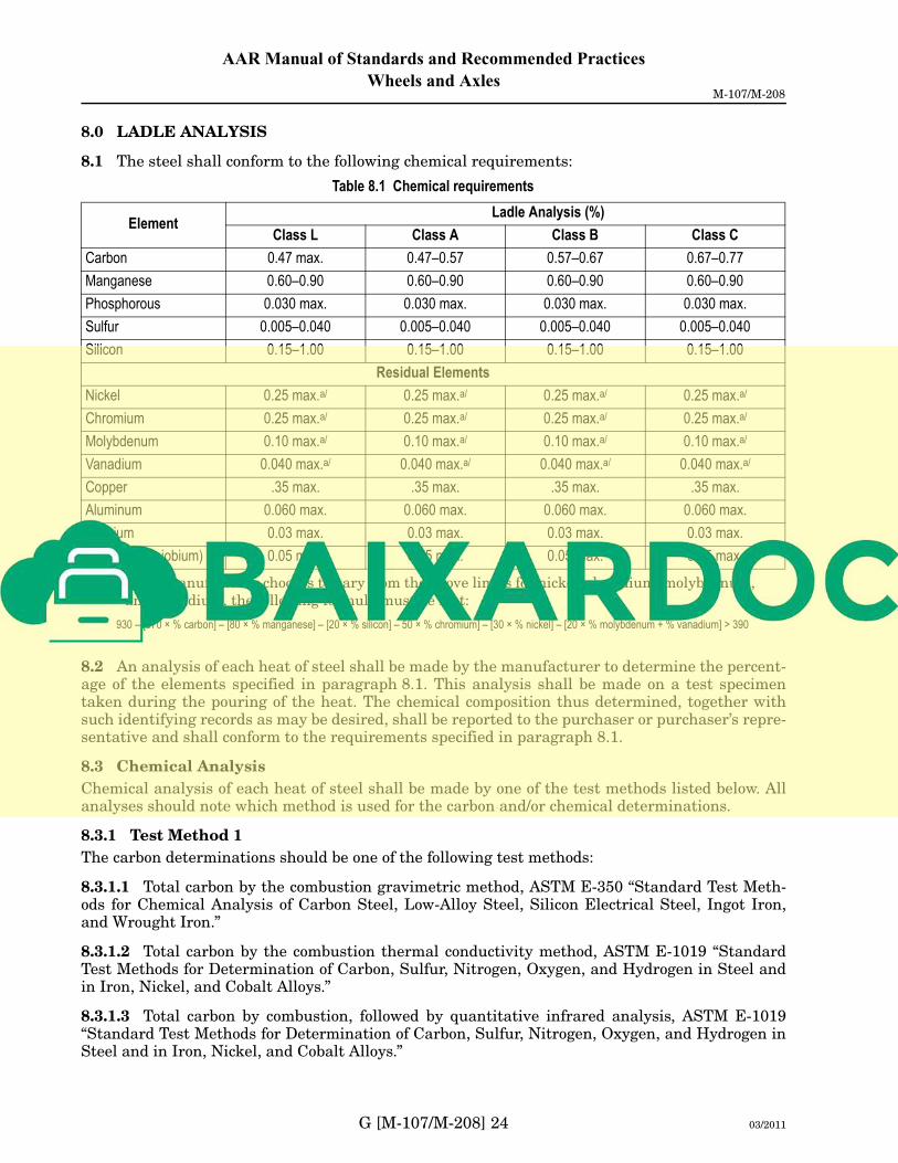
8.0 LADLE ANALYSIS
8.1 The steel shall conform to the following chemical requirements:
8.2 An analysis of each heat of steel shall be made by the manufacturer to determine the percent-age of the elements specified in paragraph 8.1. This analysis shall be made on a test specimentaken during the pouring of the heat. The chemical composition thus determined, together withsuch identifying records as may be desired, shall be reported to the purchaser or purchaser’s repre-sentative and shall conform to the requirements specified in paragraph 8.1.
8.3 Chemical Analysis
Chemical analysis of each heat of steel shall be made by one of the test methods listed below. Allanalyses should note which method is used for the carbon and/or chemical determinations.
8.3.1 Test Method 1
The carbon determinations should be one of the following test methods:
8.3.1.1 Total carbon by the combustion gravimetric method, ASTM E-350 “Standard Test Meth-ods for Chemical Analysis of Carbon Steel, Low-Alloy Steel, Silicon Electrical Steel, Ingot Iron,and Wrought Iron.”
8.3.1.2 Total carbon by the combustion thermal conductivity method, ASTM E-1019 “StandardTest Methods for Determination of Carbon, Sulfur, Nitrogen, Oxygen, and Hydrogen in Steel andin Iron, Nickel, and Cobalt Alloys.”
8.3.1.3 Total carbon by combustion, followed by quantitative infrared analysis, ASTM E-1019“Standard Test Methods for Determination of Carbon, Sulfur, Nitrogen, Oxygen, and Hydrogen inSteel and in Iron, Nickel, and Cobalt Alloys.”
Table 8.1 Chemical requirements
ElementLadle Analysis (%)
Class L Class A Class B Class C
Carbon 0.47 max. 0.47–0.57 0.57–0.67 0.67–0.77
Manganese 0.60–0.90 0.60–0.90 0.60–0.90 0.60–0.90
Phosphorous 0.030 max. 0.030 max. 0.030 max. 0.030 max.
Sulfur 0.005–0.040 0.005–0.040 0.005–0.040 0.005–0.040
Silicon 0.15–1.00 0.15–1.00 0.15–1.00 0.15–1.00
Residual Elements
Nickel 0.25 max.a/
a/ If the manufacturer chooses to vary from the above limits for nickel, chromium, molybdenum,
and vanadium, the following formula must be met:
0.25 max.a/ 0.25 max.a/ 0.25 max.a/
Chromium 0.25 max.a/ 0.25 max.a/ 0.25 max.a/ 0.25 max.a/
Molybdenum 0.10 max.a/ 0.10 max.a/ 0.10 max.a/ 0.10 max.a/
Vanadium 0.040 max.a/ 0.040 max.a/ 0.040 max.a/ 0.040 max.a/
Copper .35 max. .35 max. .35 max. .35 max.
Aluminum 0.060 max. 0.060 max. 0.060 max. 0.060 max.
Titanium 0.03 max. 0.03 max. 0.03 max. 0.03 max.
Colunbium (niobium) 0.05 max. 0.05 max. 0.05 max. 0.05 max.
930 – [570 × % carbon] – [80 × % manganese] – [20 × % silicon] – 50 × % chromium] – [30 × % nickel] – [20 × % molybdenum + % vanadium] > 390
03/2011

03/2011 G [M-107/M-208] 25
AAR Manual of Standards and Recommended Practices
Wheels and AxlesM-107/M-208
8.3.2 Test Method II
ASTM E-415 “Standard Test Method for Optical Emission Vacuum Spectrometric Analysis of Car-bon and Low-Alloy Steel.”
8.4 Check Analysis
An analysis may be made by the purchaser from finished wheels selected by the purchaser from each heat in question. For a serviceable wheel, the sample must be obtained from the rim face in a manner that will not impair the usefulness of the wheel. No drilling of the finished wheel plate is permitted. For a broken wheel, the sample may be taken from any part of the wheel mid-radius to tread. When turnings are used, they must be thoroughly mixed together and must be clean and free of oil, scale, and other foreign substances. The check analysis shall not be used in lieu of the ladle analysis to qualify an individual heat.
8.4.1 Sampling Method
When wheel blocks or whole wheels are not available for chemical analysis, the laboratory con-ducting the chemical analysis shall follow a standard sampling method. This standard method of sampling shall be ASTM E-1806, “Standard Practice for Sampling Steel and Iron for Determina-tion of Chemical Composition.” Then use either ASTM E-350, E-1019, or ASTM E-415 as specified in paragraph 8.3 for chemical analysis of the sample.
8.4.2 Check Analysis—Permitted Variance from Specified Ranges
The following tolerances are permitted between the check analysis and the specified chemical limits:
9.0 INTERIOR CONDITION/MICROCLEANLINESS STANDARDS
9.1 Sample Frequency
The metallurgical cleanliness of the wheel steel shall be determined from samples taken from ran-domly selected finished wheels representing the heat. A minimum of one 33-in. wheel and one 36-in. wheel of different heats produced quarterly per facility shall be tested.
• Facilities that produce only 33-in. or 36-in. wheels shall test two wheels of different heats quarterly.
• Facilities producing different size wheels to AAR specifications during a quarter shall test at least two wheels of different heats during the subject quarter.
• Facilities not producing wheels to AAR specifications during four successive quarters shall, at a minimum, test at least two wheels from a heat specially produced to AAR specifica-tions for the scheduled facility certification continuation inspection once a year.
The purchaser reserves the right to more frequent testing should it be deemed necessary by mutual agreement between the purchaser and producer.
9.2 Sample Size and Location
A minimum of six samples shall be taken from each wheel tested approximately equidistant around the circumference of the wheel. Each sample shall be 7/8 in. long in the circumferential direction (the rolling direction), 3/4 in. wide in the axial direction (the rim width), and 1/2 in. thick in the radial direction (the rim thickness). The circumferential surface for microcleanliness evalu-ation shall be located 1/2 in. below the wheel tread and 2 1/2 in. to 3 1/4 in. from the back rim face. Dimension tolerances are ±1/8 in.
Table 8.2 Check analysis variation from ladle analysis
Carbon±0.04
Manganese±0.03
Phosphorus+0.008
Sulfur±0.005
Silicon±0.05
Nickel+0.03
Chromium+0.03‘
Molybdenum+0.01
Vanadium+0.01
Copper+0.03
Aluminum+0.01
Titanium+0.05
Columbium+0.02
03/2011

IMP
LE
ME
NT
ED
03/2
012
G [M-107/M-208] 26 03/2011
AAR Manual of Standards and Recommended Practices
Wheels and AxlesM-107/M-208
9.3 Sample Preparation and Evaluation
9.3.1 Each 7/8 in. × 3/4 in. × 1/2 in. sample shall be carefully prepared and evaluated to ASTM Standard Practice E1245. The flicker method shall be used to establish the correct setting of the gray-level threshold limits.
9.3.2 The total area evaluated for each sample shall be not less than 1/4 in.2 or 161 mm2. All inclusions greater than 2.5 µm, regardless of inclusions being exogenous or indigenous in the plane of polish, shall be counted. The WABL Committee must approve alternates to this method.
9.3.3 Effective January 1, 2008, average and worst field area percentage oxides, voids, and sul-fides will be recorded. The AAR shall be advised quarterly when the six samples representative of the heat tested average more than 0.100% oxide plus voids; or the worst field area percentage of any one sample is more than 0.750% oxide plus voids; or 0.750% sulfides. If AAR is advised in two successive quarters, the provisions of AAR Manual of Standards and Recommended Practices, Administrative Standards, Standard S-060, paragraph 5.3, shall apply. In such cases, a special facility inspection may be required to demonstrate that the root cause has been identified and addressed.
9.3.4 Each sample shall be permanently marked according to heat and wheels represented and retained for a period of 1 year after the wheels are shipped. Records of test results shall be kept for 10 years after the wheels are shipped. Inspection results will be available for review by the AAR or other interested parties. AAR or other interested parties may have the test samples evaluated by other accredited laboratories at their expense.
10.0 BRINELL HARDNESS
10.1 The hardness of the rim, when measured in accordance with the requirements of paragraph 10.2, shall show the following values:
Note: Class D alloy steel wheels must meet all chemical requirements for Class C wheels and haveapproval of the AAR WABL Committee.
10.2 Method of Measurement
Measurement must be made in accordance with ASTM E-10 (latest revision) on the front face of the rim with the edge of the impression not less than 3/16 in. from the radius joining face and tread. Before making the impression, any decarburized metal shall be removed from the front face of the rim at the point chosen for measurement. The surface of the wheel rim shall be properly pre-pared to permit accurate determination of hardness.
Table 10.1 Brinell hardness of rim
Class Minimum Hardness Maximum Hardness
L 197 BHN 277 BHN
A 255 BHN 321 BHN
B 302 BHN 341 BHN
C 321 BHN 363 BHN
D 341 BHN 415 BHN
03/2011

03/2011 G [M-107/M-208] 27
AAR Manual of Standards and Recommended Practices
Wheels and AxlesM-107/M-208
11.0 NUMBER OF TESTS
11.1 Where continuous heat-treating furnaces are used, BHN measurements shall be made on10% of the wheels from each heat. Where batch-type heat-treating furnaces are used, BHN mea-surements shall be made on 10% of the wheels from each heat-treatment lot. For batch-typeheat-treating, at least one wheel from each heat in the heat-treatment lot must be tested. Foreither heat-treatment process, BHN measurements must be made on a minimum of one wheel in aheat or heat-treatment lot of 10 or less, and on a minimum of 2 wheels in a heat or heat-treatmentlot of 11 to 20.
11.2 If all the wheels tested meet the requirements of paragraph 10.0, all of the wheels repre-sented shall be accepted.
11.3 If any wheel tested fails to meet the requirements of paragraph 10.0, it shall be checked bymaking two additional hardness measurements, one on each side of the point first measured andeach approximately 1 in. from that point. If both of these check measurements meet the require-ments of paragraph 10.0, the wheel shall be considered to have met the requirements ofparagraph 10.0.
11.4 When continuous heat-treating furnaces are used, should any of the wheels tested fail oncheck test to meet the requirements of paragraph 10.0, the manufacturer may test for individualhardness measurements all of the wheels of that heat in the lot submitted for inspection, andthose meeting the requirements of paragraph 10.0 shall be accepted. Where batch heat-treatingfurnaces are used, should any of the wheels tested fail on check test to meet the requirements ofparagraph 10.0, the manufacturer may test all of the wheels in the heat-treatment lot for individ-ual hardness measurement, and those meeting the requirements of paragraph 10.0 shall beaccepted.
11.5 On new wheel designs or existing designs to which process changes are made, hardnessgradient tests shall be performed on a minimum of one wheel from each of the first five heats ofsteel produced. The hardness shall be taken per Fig. 11.1 utilizing an approved hardness testmachine. Values shall meet the requirements as shown in Table 11.1.
If values do not meet the requirements in Table 11.1, an additional five wheels from five heatsshall be tested. All five wheels must meet the requirements in Table 11.1. If one or more wheelsfail to meet the requirements in Table 11.1, testing per paragraph 11.5 shall be repeated after aprocess and/or design change is made. All wheels from heats that have a test wheel that failed tomeet the requirements in Table 11.1 shall be reheat-treated, and one wheel from the heat shall betested. If this wheel fails to meet the requirements in Table 11.1, all wheels from the heat shall bescrapped. Only one reheat treatment shall be allowed.
Table 11.1 Acceptable hardness ranges
Class Minimum Maximum
B285 HB 341 HB
28 Rc 40 Rc
C301 HB 363 HB
30 Rc 42 Rc
D321 HB 415 HB
32 Rc 44 Rc
03/2011

G [M-107/M-208] 28 03/2011
AAR Manual of Standards and Recommended Practices
Wheels and AxlesM-107/M-208
Fig. 11.1 Hardness mapping locations
12.0 RETREATMENT
Any wheel failing to meet the requirements of paragraph 10.0 may be retreated and tested inaccordance with paragraph 11.0.
13.0 MATING
Wheels shall be measured and marked to the lower tape number until the next graduation isreached. Wheels shall be shipped in pairs of the same measured tape size.
14.0 GAUGES
The gauges and tapes shall conform to and be used as required by the standards of the AAR Tech-nical Services Division Alternate tape gauging will meet or exceed the AAR measurement stan-dard for taping wheels. The repeatability and reproducibility of all alternate gauges must bedemonstrated.
15.0 PERMISSIBLE VARIATIONS
15.1 The wheels shall conform to the dimensions with tolerances as specified in Figs. B.8, B.9,B.11, and B.12 for freight car wheels and in Figs. B.8 and B.10 for locomotive wheels.
15.2 Where Figs. B.9 and B.10 allow a certain percentage of the wheels to vary from standarddimensions for tape size by a given amount, the percentage of such wheels shipped by any manu-facturer shall not exceed this percentage during a calendar year. No individual purchaser mayreceive more than this percentage of his daily shipments of such wheels except by agreement withthe manufacturer.
03/2011

IMP
LE
ME
NT
ED
01/2
012
03/2011 G [M-107/M-208] 29
AAR Manual of Standards and Recommended Practices
Wheels and AxlesM-107/M-208
16.0 FINISH
16.1 Wheels shall be rough bored and shall not have black spots in the rough bore. Front hub face of wheels (1-W, 2-W, and MW) shall be parallel to the plane of the vertical reference line and may be smooth forged, cast, or machined. The back hub face may be smooth forged, cast, or machined.
16.2 The contour of tread and flange shall be as shown in Figs. B.11, B.12, or B.13 as applicable. Wrought steel wheels must be machined and finished smooth without excessive tool chatters. Cast steel wheels shall be as cast, machined, or ground, at the option of the manufacturer. Minimum and maximum flange thickness, height, and throat radii gauges shown in Standards S-661 and S-662 shall be used to check proper profile. Wheels that do not meet the criteria must be scrapped or recon-toured.
16.3 Wheels must be free of all condemnable in-service defects. As-produced surfaces must be free from abrupt changes in surface contours. Spot grinding or machining to remove surface defects must not exceed a depth of 1/8 in. (0.125 in.; 3.2 mm). Sectional properties must meet all dimensional requirements following repair of surface defects. Repaired surfaces must have a max-imum surface roughness of 500 µin. prior to final shot peening. Repaired surfaces must provide a uniform transition to the as-produced surfaces.
16.4 Wheels shall not be covered with any substance to such an extent as to hide defects.
16.5 Wheel profile is to be checked using wide flange profile gauge shown in Fig. B.14. There will be no more than 1/32-in. variation from the profile.
17.0 MARKING
17.1 Identification markings shall be legibly stamped as shown in Figs. B.4 or B.5. Wheels for freight service must be hot stamped or cold stamped on the back hub face. If any stamped charac-ters are missing or illegible, these shall be replaced by cold stamping in the proper place in the marking sequence. Passenger car wheels may be hot stamped or cold stamped on front or back (as specified by purchaser) hub face. When ordered, locomotive wheels may be hot or cold stamped on the back rim face; or hot or cold stamped on the front hub face; or hot or cold stamped on the back hub face providing finish machining will completely remove the markings on the back hub face. Locomotive wheels that are to receive final hub machining by the purchaser may be ordered with markings paint stenciled on the wheel plate. After final machining, the purchaser will cold stamp the markings on the front hub face. For wheels having raised cast-on markings, the markings shall be legible characters and be as shown in Fig. B.7. For all wheels, stamping should be centered approximately on the hub. No wheel manufactured after May 1, 2009, may be bored and applied with any portion of the wheel manufacturer’s hub stamp closer than 1/8 in. from the inner hub diameter and no closer than 1/8 in. from the outer hub diameter. No wheel manufactured before May 1, 2009, may be bored and applied with any portion of the wheel manufacturer’s hub stamp breaking over the edge of the inner or outer hub diameter.
17.2 The tape size of all wheels shall be paint stencilled on back plates in characters at least 1 in. high. An “H” shall also be paint stencilled on the front plate at least 1 in. in height on those wheels of curved plate, heat-treated configuration. Stencil paint must be white and have a minimum ser-vice life of 1 year.
17.3 Effective April 1, 2012, bar code labels must be affixed to all new freight car wheels in accordance with the Manual of Standards and Recommended Practices, Section L, Standard S-920.
03/2011

G [M-107/M-208] 30 03/2011
AAR Manual of Standards and Recommended Practices
Wheels and AxlesM-107/M-208
18.0 INSPECTION
18.1 The inspector representing the purchaser shall have free entry, at all times while the work on the purchaser’s contract is being performed, to all parts of the manufacturer’s works that con-cern the manufacture of wheels ordered. The manufacturer shall afford the inspector, free of charge, all reasonable facilities and necessary assistance to satisfy the inspector that the wheels are being furnished in accordance with these specifications. Internal defects are usually detected by ultrasonic testing. Such test shall be used in the manufacture of all wheels. The method to be followed and the equipment to be used shall comply with the requirements as shown in paragraph 18.4. Tests and inspection shall be made at the place of manufacture prior to shipment, unless otherwise specified.
18.2 The purchaser may make tests to govern the acceptance or rejection of the wheels in pur-chaser’s own laboratory or elsewhere. Such tests shall be made at the expense of the purchaser.
18.3 All tests and inspections shall be so conducted so as not to interfere unnecessarily with the operation of the works.
18.4 Ultrasonic Inspection
For detecting internal discontinuities in the rim of all steel wheels, ultrasonic inspection shall be made by following either the procedures shown below or an AAR-approved equivalent. Equipment used in these procedures shall comply with the following requirements.
Each manufacturer shall maintain a documented test method and procedures for ultrasonic inspection of all railroad wheels manufactured under this specification.
18.4.1 Equipment
18.4.1.1 The instrument shall have a pulse echo receiver and shall operate at frequencies of 2 to 5 MHz required for the test method and type of equipment used.
18.4.1.2 The transducers shall be of the type whose composition and dimensions are appropriate for the test method used.
18.4.1.3 The ultrasonic inspection shall be performed with an automated scanning system. An automatic flaw alarm system shall be used in conjunction with the ultrasonic instrumentation.
18.4.1.4 A suitable couplant shall be used between the test surface and the transducer. The cou-plant shall be free of air bubbles. Rust inhibitors, softeners, and wetting agents may be added to the couplant.
18.4.2 Time of Inspection
Inspection shall be performed after final thermal processing.
03/2011