A292/A293/A292P/A293P B098 SERVICE MANUAL - Index of
879
A292/A293/A292P/A293P B098 SERVICE MANUAL (To be used in conjunction with A229 Service Manual) 000930MIU RICOH GROUP COMPANIES
-
Upload
khangminh22 -
Category
Documents
-
view
0 -
download
0
Transcript of A292/A293/A292P/A293P B098 SERVICE MANUAL - Index of

A292/A293/A292P/A293PB098
SERVICE MANUAL(To be used in conjunction with A229 Service Manual)
000930MIURICOH GROUP COMPANIES


®
®
A292/A
293/A292P/A
293P/B098
SERVICE M
AN
UA
L
RICOH GROUP COMPANIES


A292/A293/A292P/A293PB098
SERVICE MANUAL
000930MIU


It is the reader's responsibility when discussing the information contained within thisdocument to maintain a level of confidentiality that is in the best interest of RicohCorporation and its member companies.
NO PART OF THIS DOCUMENT MAY BE REPRODUCED IN ANY
FASHION AND DISTRIBUTED WITHOUT THE PRIOR
PERMISSION OF RICOH CORPORATION.
All product names, domain names or product illustrations, including desktop images,used in this document are trademarks, registered trademarks or the property of theirrespective companies.
They are used throughout this book in an informational or editorial fashion only and forthe benefit of such companies. No such use, or the use of any trade name, or website is intended to convey endorsement or other affiliation with Ricoh products.
2002 RICOH Corporation. All rights reserved.


The Service Manual contains informationregarding service techniques, procedures,processes and spare parts of office equipmentdistributed by Ricoh Corporation. Users of thismanual should be either service trained orcertified by successfully completing a RicohTechnical Training Program.
Untrained and uncertified users utilizinginformation contained in this service manual torepair or modify Ricoh equipment risk personalinjury, damage to property or loss of warrantyprotection.
Ricoh Corporation
WARNING


LEGEND
PRODUCT CODEGESTETNER LANIER RICOH SAVIN
A292 3355 5455 Aficio 551 2055DPA293 3370 5470 Aficio 700 2070DPA292
w/G594 Controller -- Aficio 551P --
A293w/G594 Controller -- Aficio 700P --
B098 5502 LD055 Aficio 1055 2555
DOCUMENTATION HISTORYREV. NO. DATE COMMENTS
* 5/2000 Original Printing1 10/2002 B098 Addition


Rev. 10/2002
SM i A292/A293/B098
TABLE OF CONTENTS
COMPARISON BETWEEN A292/A293 AND A229
OVERALL INFORMATION
1. OVERALL MACHINE INFORMATION........................................ 1-11.1 SPECIFICATIONS.....................................................................................1-1
1.1.1 COPIER ENGINE .............................................................................1-11.1.2 ADF ..................................................................................................1-5
1.2 MACHINE CONFIGURATION...................................................................1-61.3 MECHANICAL COMPONENT LAYOUT ...................................................1-7
1.3.1 COPIER ENGINE .............................................................................1-71.3.2 ADF ..................................................................................................1-9
1.4 PAPER PATH..........................................................................................1-101.5 COPY PROCESS....................................................................................1-111.6 DRIVE LAYOUT ......................................................................................1-13
1.6.1 COPIER ENGINE ...........................................................................1-131.6.2 ADF ................................................................................................1-14
1.7 ELECTRICAL COMPONENT DESCRIPTION.........................................1-151.7.1 COPIER ENGINE ...........................................................................1-151.7.2 ADF ................................................................................................1-21
DETAILED DESCRITPIONS
2. DETAILED DESCRIPTIONS ....................................................... 2-12.1 DOCUMENT FEEDER ..............................................................................2-1
2.1.1 PICK-UP ROLLER RELEASE ..........................................................2-12.1.2 BOTTOM PLATE LIFT......................................................................2-22.1.3 PICK-UP AND SEPARATION ..........................................................2-32.1.4 ORIGINAL FEED..............................................................................2-42.1.5 ORIGINAL SIZE DETECTION..........................................................2-5
Original Length .....................................................................................2-5Original Width .......................................................................................2-5
2.1.6 ORIGINAL TRANSPORT .................................................................2-62.1.7 ORIGINAL SKEW CORRECTION....................................................2-72.1.13 ORIGINAL INVERSION AND FEED-OUT ......................................2-8
General Operation ................................................................................2-8Original Inversion..................................................................................2-9Original Exit (Single-Sided Original Mode)..........................................2-10Original Exit (Double-Sided Original Mode) ........................................2-11
2.1.9 JAM CONDITIONS.........................................................................2-12Feed-in................................................................................................2-12Feed-out .............................................................................................2-12Inversion .............................................................................................2-12

Rev. 10/2002
A292/A293/B098 ii SM
2.2 SCANNING..............................................................................................2-132.2.1 OVERVIEW ....................................................................................2-132.2.2 SCANNER DRIVE ..........................................................................2-142.2.3 ORIGINAL SIZE DETECTION IN BOOK MODE ............................2-15
2.3 IMAGE PROCESSING ............................................................................2-162.3.1 OVERVIEW ....................................................................................2-162.3.2 SBU ................................................................................................2-172.3.3 AUTO IMAGE DENSITY (ADS)......................................................2-182.3.4 IPU (IMAGE PROCESSING UNIT).................................................2-19
Overview.............................................................................................2-192.3.5 IMAGE PROCESSING STEPS AND RELATED SP MODES.........2-202.3.6 AUTO SHADING ............................................................................2-25
Black Level Correction........................................................................2-25White Level Correction........................................................................2-25
2.3.7 BACKGROUND ERASE.................................................................2-26Background Erase ..............................................................................2-26
2.3.13 INDEPENDENT DOT ERASE ......................................................2-272.3.9 FILTERING, MAIN SCAN MAGNIFICATION/REDUCTION ...........2-28
Overview.............................................................................................2-28Filtering ...............................................................................................2-28Main Scan Magnification/Reduction....................................................2-29Sub Scan Magnification ......................................................................2-29
2.3.10 GAMMA (G) CORRECTION.........................................................2-302.3.11 GRADATION PROCESSING .......................................................2-30
Three-graduation Processing..............................................................2-30Four-graduation Processing................................................................2-31Error Diffusion and Dithering...............................................................2-31
2.3.12 LINE WIDTH CORRECTION........................................................2-312.4 LASER EXPOSURE................................................................................2-32
2.4.1 AUTO POWER CONTROL.............................................................2-322.4.2 DUAL BEAM WRITING ..................................................................2-332.4.3 LASER BEAM PITCH CHANGE MECHANISM
(FOR A292/A293 ONLY) .................................................................2-342.4.4 LD SAFETY SWITCHES ................................................................2-35
2.5 DRUM UNIT ............................................................................................2-362.5.1 PROCESS CONTROL....................................................................2-36
Overview.............................................................................................2-36Drum potential sensor calibration .......................................................2-37VSG adjustment..................................................................................2-37VG Adjustment....................................................................................2-38LD power adjustment ..........................................................................2-39Toner Density Adjustment...................................................................2-39VREF Update......................................................................................2-40
2.5.2 DRUM UNIT COMPONENTS.........................................................2-412.5.3 DRUM CHARGE.............................................................................2-42
Overview.............................................................................................2-42Charge Corona Wire Cleaning Mechanism.........................................2-43
2.5.4 DRUM CLEANING AND TONER RECYCLING..............................2-44Overview.............................................................................................2-44

Rev. 10/2002
SM iii A292/A293/B098
Drive Mechanism ................................................................................2-45Cleaning Blade Pressure Mechanism and Side-to-Side Movement....2-46
2.5.5 OTHERS.........................................................................................2-47Air Flow Around the Drum...................................................................2-47Pick-off Mechanism ............................................................................2-48
2.6 DEVELOPMENT AND TONER SUPPLY ................................................2-492.6.1 OVERVIEW ....................................................................................2-492.6.2 DEVELOPMENT MECHANISM......................................................2-502.6.3 DEVELOPMENT BIAS ...................................................................2-512.6.4 TONER DENSITY CONTROL ........................................................2-52
Overview.............................................................................................2-52Sensor control mode...........................................................................2-52Image pixel count control ....................................................................2-53
2.6.5 TONER END DETECTION.............................................................2-54Toner Near End ..................................................................................2-54Toner End ...........................................................................................2-54
2.6.6 TONER END RECOVERY .............................................................2-542.6.7 ABNORMAL TD AND ID SENSOR CONDITIONS .........................2-55
2.7 IMAGE TRANSFER AND PAPER SEPARATION...................................2-562.7.1 IMAGE TRANSFER AND PAPER SEPARATION MECHANISM ...2-562.7.2 TRANSFER BELT UNIT LIFT MECHANISM..................................2-572.7.3 TRANSFER BELT CLEANING MECHANISM ................................2-58
2.13 PAPER FEED........................................................................................2-592.13.1 OVERVIEW ..................................................................................2-592.13.2 DRIVE MECHANISM....................................................................2-602.13.3 TANDEM LCT TRAY 1 ..............................................................2-61
Overview.............................................................................................2-61Connecting the Left and Right Sides of the Tray ................................2-62Paper Lift/Remaining Paper Detection................................................2-63Fence Drive ........................................................................................2-65Rear Fence Drive................................................................................2-66Tray Positioning ..................................................................................2-67
2.13.4 TRAY POSITIONING MECHANISM TRAYS 1 TO 3 .................2-682.13.5 PAPER LIFT MECHANISM - TRAYS 2 AND 3.............................2-692.13.6 VERTICAL TRANSPORT MECHANISM ......................................2-702.13.7 PAPER REGISTRATION..............................................................2-71
Overview.............................................................................................2-712.13.13 PAPER SIZE DETECTION TRAY 2 ........................................2-72
2.9 IMAGE FUSING ......................................................................................2-732.9.1 OVERVIEW ....................................................................................2-732.9.2 FUSING ENTRANCE GUIDE .........................................................2-742.9.3 FUSING DRIVE MECHANISM .......................................................2-75
2.10 PAPER EXIT/DUPLEX ..........................................................................2-762.10.1 OVERVIEW ..................................................................................2-762.10.2 INVERTER ...................................................................................2-77
Feed-in and Jogging ...........................................................................2-77Feed-out .............................................................................................2-78
2.10.3 DUPLEX TRAY FEED MECHANISM ...........................................2-792.10.4 BASIC DUPLEX FEED OPERATION...........................................2-80

Rev. 10/2002
A292/A293/B098 iv SM
Longer than A4 / Letter lengthwise .....................................................2-802.11 ENERGY SAVER MODES ....................................................................2-83
2.11.1 LOW POWER MODE ...................................................................2-83Entering low power mode ...................................................................2-83What happens in low power mode......................................................2-83Return to stand-by mode ....................................................................2-83
INSTALLATION
3. INSTALLATION PROCEDURE................................................... 3-13.1 INSTALLATION REQUIREMENTS ...........................................................3-1
3.1.1 ENVIRONMENT ...............................................................................3-13.1.2 MACHINE LEVEL.............................................................................3-13.1.3 MINIMUM SPACE REQUIREMENTS...............................................3-23.1.4 POWER REQUIREMENTS ..............................................................3-2
3.2 COPIER (A292/A293/B0913) ....................................................................3-33.2.1 ACCESSORY CHECK......................................................................3-33.2.2 INSTALLATION PROCEDURE ........................................................3-4
3.3 LCT (11/B5137) .......................................................................................3-143.3.1 ACCESSORY CHECK....................................................................3-143.3.2 INSTALLATION PROCEDURE ......................................................3-15
3.4 3,000-SHEET FINISHER (9/B5136) ........................................................3-203.4.1 ACCESSORY CHECK....................................................................3-203.4.2 INSTALLATION PROCEDURE ......................................................3-21
3.5 PUNCH UNIT INSTALLATION (A1312) FOR 9/B5136 FINISHER..........3-243.5.1 ACCESSORY CHECK....................................................................3-243.5.2 PUNCH UNIT INSTALLATION .......................................................3-25
3.6 FINISHER (B302) ....................................................................................3-283.6.1 INSTALLATION PROCEDURE ......................................................3-28
3.7 PUNCH UNIT INSTALLATION (A1312) FOR B302 FINISHER...............3-313.7.1 ACCESSORY CHECK....................................................................3-313.7.2 PUNCH UNIT INSTALLATION .......................................................3-32
3.13 KEY COUNTER INSTALLATION ..........................................................3-353.9 COPY CONNECTOR KIT INSTALLATION (10) ......................................3-363.10 LG KIT (B375/B51313) ..........................................................................3-39
3.10.1 ACCESSORY CHECK..................................................................3-393.10.2 INSTALLATION PROCEDURE ....................................................3-40
SERVICE TABLES
4. SERVICE TABLES...................................................................... 4-14.1 GENERAL CAUTIONS..............................................................................4-1
4.1.1 DRUM...............................................................................................4-14.1.2 DRUM UNIT .....................................................................................4-14.1.3 TRANSFER BELT UNIT ...................................................................4-24.1.4 SCANNER UNIT...............................................................................4-24.1.5 LASER UNIT ....................................................................................4-24.1.6 CHARGE CORONA..........................................................................4-3

Rev. 10/2002
SM v A292/A293/B098
4.1.7 DEVELOPMENT ..............................................................................4-34.1.13 CLEANING .....................................................................................4-44.1.9 FUSING UNIT...................................................................................4-44.1.10 PAPER FEED.................................................................................4-44.1.11 USED TONER ................................................................................4-4
4.2 SERVICE PROGRAM MODE....................................................................4-54.2.1 SERVICE PROGRAM MODE OPERATION.....................................4-5
Service Program Access Procedure .....................................................4-5Accessing Copy Mode from within an SP Mode ...................................4-7Selecting the Program Number.............................................................4-8Inputting a Value or Setting for an SP Mode.........................................4-9
4.2.2 SERVICE PROGRAM MODE TABLES..........................................4-104.2.3 TEST PATTERN PRINTING (SP2-902) .........................................4-66
Test Pattern Table (SP2-902-2: Test Pattern Printing IPU) .............4-66Test Pattern Table (SP2-902-3: Test Pattern Printing Printing) .......4-66
4.2.4 INPUT CHECK ...............................................................................4-67Main Machine Input Check (SP5-1303) ..............................................4-67ADF Input Check (SP6-007) ...............................................................4-71
4.2.5 OUTPUT CHECK ...........................................................................4-72Main Machine Output Check (SP5-1304) ...........................................4-72ADF Output Check (SP6-0013) ..........................................................4-73
4.2.6 SYSTEM PARAMETER AND DATA LISTS (SMC LISTS) .............4-734.2.7 MEMORY ALL CLEAR (SP5-1301)................................................4-744.2.13 SOFTWARE RESET ....................................................................4-754.2.9 SYSTEM SETTING AND COPY SETTING (UP MODE) RESET ...4-75
System Setting Reset .........................................................................4-75Copy Features Reset ..........................................................................4-75
4.3 PROGRAM AND DATA DOWNLOAD.....................................................4-764.3.1 OVERVIEW ....................................................................................4-764.3.2 DOWNLOAD THE BICU SOFTWARE FROM BICU TO FLASH
MEMORY CARD .............................................................................4-774.3.3 DOWNLOAD NVRAM DATA TO THE BICU ..................................4-784.3.4 DOWNLOAD NVRAM DATA FROM BICU TO FLASH MEMORY
CARD .............................................................................................4-794.3.5 DOWNLOAD STAMP DATA TO THE BICU...................................4-80
4.4 USER PROGRAM MODE .......................................................................4-814.4.1 HOW TO ENTER AND EXIT UP MODE.........................................4-814.4.2 UP MODE TABLE ..........................................................................4-81
System Setting Table..........................................................................4-81Copy Features Table ..........................................................................4-82
4.4.3 IMAGE QUALITY SETTING BY UP MODE....................................4-86Text Mode...........................................................................................4-86Text/Photo Mode ................................................................................4-90Photo Mode ........................................................................................4-91Pale Mode...........................................................................................4-92Generation Mode ................................................................................4-92
4.5 TEST POINTS/DIP SWITCHES/LEDS....................................................4-934.5.1 DIP SWITCHES..............................................................................4-934.5.2 TEST POINTS ................................................................................4-93

Rev. 10/2002
A292/A293/B098 vi SM
4.5.3 FUSES............................................................................................4-944.5.4 VARIABLE RESISTORS ................................................................4-954.5.5 LEDS ..............................................................................................4-95
4.6 SPECIAL TOOLS AND LUBRICANTS ....................................................4-954.6.1 SPECIAL TOOLS ...........................................................................4-954.6.2 LUBRICANTS.................................................................................4-95
4.7 FIRMWARE HISTORY .............................................................................4-96
PREVENTIVE MAINTENANCE
5. PREVENTIVE MAINTENANCE SCHEDULE .............................. 5-15.1 PM TABLE.................................................................................................5-1
REPLACEMENT AND ADJUSTMENT
6. REPLACEMENT AND ADJUSTMENT........................................ 6-16.1 EXTERIOR ................................................................................................6-1
6.1.1 FILTERS...........................................................................................6-1Ozone Filter: Duct .................................................................................6-1Filter Vacuum........................................................................................6-1
6.2 DOCUMENT FEEDER ..............................................................................6-26.2.1 COVER REMOVAL ..........................................................................6-26.2.2 FEED UNIT REMOVAL AND SEPARATION ROLLER
REPLACEMENT...............................................................................6-46.2.3 FEED BELT REPLACEMENT ..........................................................6-56.2.4 PICK-UP ROLLER REPLACEMENT................................................6-66.2.5 SENSOR REPLACEMENT...............................................................6-7
Entrance and Registration Sensors ......................................................6-7Width Sensor ........................................................................................6-8Exit Sensor and Inverter Sensor ...........................................................6-9
6.2.6 TRANSPORT BELT REPLACEMENT............................................6-106.3 SCANNER UNIT......................................................................................6-11
6.3.1 EXPOSURE GLASS.......................................................................6-116.3.2 LENS BLOCK .................................................................................6-126.3.3 ORIGINAL SIZE SENSORS ...........................................................6-136.3.4 EXPOSURE LAMP.........................................................................6-146.3.5 SCANNER MOTOR / MCU.............................................................6-15
Scanner Motor ....................................................................................6-15MCU....................................................................................................6-15
6.3.6 SCANNER WIRES .........................................................................6-16Rear Scanner Drive Wire ....................................................................6-19Front Scanner Drive Wire ...................................................................6-20Reinstallation ......................................................................................6-21
6.4 LASER UNIT ...........................................................................................6-236.4.1 CAUTION DECAL LOCATIONS.....................................................6-236.4.2 LD UNIT REPLACEMENT..............................................................6-246.4.3 LASER BEAM PITCH ADJUSTMENT............................................6-256.4.4 POLYGON MIRROR MOTOR REPLACEMENT ............................6-29

Rev. 10/2002
SM vii A292/A293/B098
6.5 DRUM UNIT ............................................................................................6-306.5.1 DRUM POTENTIAL SENSOR REPLACEMENT ............................6-306.5.2 DRUM MOTOR REPLACEMENT...................................................6-316.5.3 TONER OUTPUT AND RECYCLING PUMP UNIT
REPLACEMENT.............................................................................6-326.6 DEVELOPMENT AND TONER SUPPLY ................................................6-34
6.6.1 DEVELOPMENT AND AIR DUST FILTER REPLACEMENT .........6-346.6.2 DEVELOPER REPLACEMENT......................................................6-356.6.3 TONER END SENSOR REPLACEMENT.......................................6-376.6.4 DEVELOPMENT MOTOR REPLACEMENT ..................................6-37
6.7 TRANSFER BELT UNIT..........................................................................6-386.7.1 TRANSFER BELT UNIT REMOVAL/INSTALLATION ....................6-38
- Removal - .........................................................................................6-38- Installation - ......................................................................................6-38
6.13 PAPER FEED........................................................................................6-406.13.1 PAPER TRAY REMOVAL ............................................................6-40
Tandem Tray Removal .......................................................................6-40Universal trays (Customer adjust/Technician adjust) Removal...........6-42
6.13.2 REAR FENCE RETURN SENSOR REPLACEMENT...................6-436.13.3 REAR FENCE HP SENSOR REPLACEMENT.............................6-446.13.4 BOTTOM PAPER SENSOR REPLACEMENT .............................6-456.13.5 BOTTOM PLATE LIFT WIRE REPLACEMENT ...........................6-466.13.6 TANDEM LCT PAPER SIZE CHANGE ........................................6-486.13.7 BY-PASS PAPER SIZE BOARD REPLACEMENT.......................6-516.13.13 PAPER FEED CLUTCH/RELAY CLUTCH REMOVAL...............6-536.13.9 BY-PASS FEED MOTOR/CLUTCH REMOVAL ...........................6-566.13.10 REGISTRATION MOTOR REMOVAL........................................6-576.13.11 PAPER TRAY UNIT REMOVAL .................................................6-58
6.9 FUSING UNIT..........................................................................................6-596.9.1 FUSING UNIT REMOVAL ..............................................................6-596.9.2 FUSING THERMISTOR/THERMOFUSE/THERMOSTAT
REPLACEMENT.............................................................................6-60Fusing Thermistor Replacement.........................................................6-60Fusing Thermofuse Replacement (for A292/A293 only) .....................6-60Fusing Thermostat Replacement (for B0913 only) .............................6-61Fusing Thermostat Replacement (for B0913 only) .............................6-61
6.9.3 FUSING LAMP REPLACEMENT ...................................................6-626.9.4 HOT ROLLER REPLACEMENT.....................................................6-636.9.5 OIL SUPPLY/CLEANING ROLLER REPLACEMENT ....................6-656.9.6 PRESSURE ROLLER CLEANING ROLLER REPLACEMENT ......6-666.9.7 MAGNET POSITION ADJUSTMENT .............................................6-676.9.13 HOT ROLLER STRIPPER PAWL REPLACEMENT.....................6-68
6.10 PAPER EXIT/DUPLEX UNIT.................................................................6-706.10.1 1ST AND 2ND EXIT SENSOR .....................................................6-706.10.2 JOGGER MOTOR ........................................................................6-716.10.3 DUPLEX ENTRANCE SENSOR ..................................................6-716.10.4 DUPLEX TRANSPORT/DUPLEX FEED CLUTCHES ..................6-726.10.5 DUPLEX TRANSPORT SENSOR 1 .............................................6-726.10.6 DUPLEX TRANSPORT SENSORS 2 & 3 ....................................6-73

Rev. 10/2002
A292/A293/B098 viii SM
6.10.7 INVERTER EXIT CLUTCH ...........................................................6-746.10.13 DUPLEX INVERTER SENSOR ..................................................6-74
6.11 BOARDS AND OTHER ITEMS .............................................................6-756.11.1 BICU BOARD ...............................................................................6-756.11.2 I/O BOARD ...................................................................................6-766.11.3 PSU ..............................................................................................6-776.11.4 PAPER FEED CONTROL BOARD (PFC) ....................................6-77
6.12 COPY IMAGE ADJUSTMENTS: PRINTING/SCANNING .....................6-786.12.1 PRINTING ....................................................................................6-78
Registration - Leading Edge ...............................................................6-78Registration Side-to-Side .................................................................6-78Tray 1..................................................................................................6-79Tray 2..................................................................................................6-79Tray 3..................................................................................................6-80By-pass Tray.......................................................................................6-80
TROUBLESHOOTING
7. TROUBLESHOOTING ................................................................ 7-17.1 SERVICE CALL CONDITIONS .................................................................7-1
7.1.1 SUMMARY .......................................................................................7-17.1.2 SC CODE DESCRIPTIONS .............................................................7-2
7.2 ELECTRICAL COMPONENT DEFECTS ................................................7-467.2.1 SENSORS ......................................................................................7-467.2.2 SWITCHES.....................................................................................7-50
7.3 BLOWN FUSE CONDITIONS .................................................................7-51
FIRMWARE HISTORY
8. A292/A293 FIRMWARE MODIFICATION HISTORY .................. 8-1
3,000-SHEET FINISHER (B312/B586)
1. OVERALL MACHINE INFORMATION........................................ 9-11.1 SPECIFICATIONS.....................................................................................9-11.2 ELECTRICAL COMPONENT LAYOUT.....................................................9-41.3 ELECTRICAL COMPONENT DESCRIPTION...........................................9-61.4 MECHANICAL COMPONENT LAYOUT ...................................................9-81.5 DRIVE LAYOUT ........................................................................................9-9
2. DETAILED DESCRIPTIONS ..................................................... 9-102.1 TRAY AND STAPLER JUNCTION GATE MECHANISM ........................9-10
Upper tray mode .................................................................................9-10Sort/stack mode..................................................................................9-10Staple mode........................................................................................9-10
2.2 PRE-STACK MECHANISM .....................................................................9-112.3 JOGGER UNIT PAPER POSITIONING MECHANISM............................9-12

Rev. 10/2002
SM ix A292/A293/B098
Vertical Paper Alignment ....................................................................9-12Horizontal Paper Alignment ................................................................9-12
2.4 STAPLER UNIT MOVEMENT MECHANISM ..........................................9-13Side-to-side:........................................................................................9-13Rotation: .............................................................................................9-13
2.5 STAPLER ................................................................................................9-142.6 FEED-OUT MECHANISM .......................................................................9-152.7 SHIFT TRAY UP/DOWN MECHANISM ..................................................9-162.13 SHIFT TRAY SIDE-TO-SIDE MECHANISM..........................................9-172.9 PUNCH UNIT DRIVE MECHANISM........................................................9-182.10 PUNCH WASTE COLLECTION MECHNISM........................................9-192.11 JAM CONDITIONS................................................................................9-20
3. SERVICE TABLES.................................................................... 9-213.1 DIP SWITCHES.......................................................................................9-213.2 TEST POINTS.........................................................................................9-213.3 FUSES ....................................................................................................9-21
4. REPLACEMENT AND ADJUSTMENT...................................... 9-224.1 COVER REPLACEMENT........................................................................9-22
Rear Cover .........................................................................................9-22Upper Left Cover ................................................................................9-22Upper Cover .......................................................................................9-22Front Door...........................................................................................9-22Left Front Cover..................................................................................9-22Shift Tray ............................................................................................9-23Lower Left Cover ................................................................................9-23Right Cover.........................................................................................9-23Front Shift Tray Cover.........................................................................9-23Rear Shift Tray Cover .........................................................................9-23
4.2 POSITIONING ROLLER REPLACEMENT..............................................9-244.3 ALIGNMENT BRUSH ROLLER REPLACEMENT...................................9-254.4 SENSOR REPLACEMNT........................................................................9-26
4.4.1 STACK HEIGHT SENSOR 1 AND 2...............................................9-264.4.2 UPPER TRAY PAPER LIMIT AND EXIT SENSOR........................9-27
Upper Tray Paper Limit Sensor ..........................................................9-27Upper Tray Exit Sensor.......................................................................9-27
4.4.3 SHIFT TRAY EXIT SENSOR..........................................................9-284.4.4 ENTRANCE AND STAPLER TRAY ENTRANCE SENSOR...........9-29
Entrance Sensor .................................................................................9-29Stapler Tray Entrance Sensor.............................................................9-29
4.4.5 STAPLER ROTATION HP SENSOR..............................................9-304.5 STAPLER REMOVAL..............................................................................9-314.6 PUNCH POSITION ADJUSTMENT.........................................................9-32
Right to left..........................................................................................9-32Front to rear ........................................................................................9-32

Rev. 10/2002
A292/A293/B098 x SM
BOOKLET FINISHER A763
1. OVERALL MACHINE INFORMATION...................................... 10-11.1 SPECIFICATIONS...................................................................................10-11.2 ELECTRICAL COMPONENT DESCRIPTION.........................................10-31.3 MECHANICAL COMPONENT LAYOUT .................................................10-7
2. DETAILED DESCRIPTIONS ..................................................... 10-82.1 JUNCTION GATE MECHANISM.............................................................10-8
2.1.1 SHIFT TRAY MODE.......................................................................10-8A4/LT sideways or shorter ..................................................................10-8Longer than A4 sideways....................................................................10-8
2.1.2 PROOF TRAY MODE.....................................................................10-92.1.3 BOOKLET STITCH MODE .............................................................10-9
2.2 PRE-STACK MECHANISM ...................................................................10-102.3 PAPER SHIFT MECHANISM ................................................................10-112.4 PAPER POSITIONING MECHANISM...................................................10-122.5 STAPLER UNIT MOVEMENT MECHANISM ........................................10-13
2.5.1 DRIVE...........................................................................................10-132.5.2 MOVEMENT.................................................................................10-13
Front and Rear Stapling....................................................................10-13Tow-position Stapling........................................................................10-13
2.6 STAPLER ..............................................................................................10-142.7 SHIFT TRAY MECHANISM...................................................................10-152.13 BOOKLET UNIT GATE MECHANISM.................................................10-162.9 RELAY ROLLER AND POSITIONING PLATE MECHANISM ...............10-182.10 POSITIONING ROLLER MECHANISM...............................................10-192.11 BOOKLET UNIT JOGGER MOVEMENT MECHANISM......................10-202.12 BOOKLET STAPLER UNIT.................................................................10-212.13 PAPER FOLDER MECHANISM..........................................................10-22
3. INSTALLATION ...................................................................... 10-243.1 ACCESSORY CHECK ..........................................................................10-243.2 INSTALLATION PROCEDURE .............................................................10-25
4. REPLACEMENT AND ADJUSTMENT.................................... 10-304.1 REMOVAL.............................................................................................10-30
4.1.1 UPPER DOOR .............................................................................10-304.1.2 UPPER REAR COVER.................................................................10-314.1.3 LOWER REAR COVER................................................................10-314.1.4 TOP COVER ................................................................................10-324.1.5 UPPER INNER COVER ...............................................................10-324.1.6 SHIFT TRAY UNIT .......................................................................10-334.1.7 UPPER SHIFT GUIDE..................................................................10-344.1.13 LOWER SHIFT GUIDE...............................................................10-344.1.9 EXIT UNIT ....................................................................................10-354.1.10 BUFFER ROLLER UNIT.............................................................10-364.1.11 STAPLER ...................................................................................10-37

Rev. 10/2002
SM xi A292/A293/B098
4.1.12 FINISHER BOARD ....................................................................10-384.1.13 BOOKLET UNIT .........................................................................10-394.1.14 FOLDER ROLLERS ...................................................................10-414.1.15 FOLDER PLATE.........................................................................10-44
Removal............................................................................................10-44Reinstalling .......................................................................................10-45
4.1.16 BOOKLET STAPLER UNIT ........................................................10-46Removal............................................................................................10-46Adjustment........................................................................................10-47
4.1.17 BOOKLET BOARD.....................................................................10-494.1.113 POSITIONING PLATE UNIT ....................................................10-494.1.19 1ST AND 2ND BOOKLET UNIT GATES....................................10-50
4.2 ADJUSTMENT ......................................................................................10-514.2.1 SHIFT TRAY HEIGHT ..................................................................10-514.2.2 JOGGER FENCE POSITION .......................................................10-524.2.3 STAPLING POSITOIN..................................................................10-534.2.4 BOOKLET STAPLING POSITION.................................................10-54
COPIER CONNECTION KIT B322
1. SPECIFICATIONS..................................................................... 11-1
2. DETAILED DESCRIPTIONS ..................................................... 11-22.1 OVERVIEW .............................................................................................11-22.2 BASIC OPERATION................................................................................11-3
2.2.1 NO SORT AND NO STAPLE MODE..............................................11-32.2.2 SORT, STAPLE MODE ..................................................................11-42.2.3 OPERATION IN IRREGULAR CONDITIONS.................................11-5
Paper end during copying ...................................................................11-5Copy tray full .......................................................................................11-5Paper jam ...........................................................................................11-5
LCT A698/B587
1. OVERALL MACHINE INFORMATION...................................... 12-11.1 SPECIFICATIONS...................................................................................12-11.2 MECHANICAL COMPONENT LAYOUT .................................................12-21.3 ELECTRICAL COMPONENT LAYOUT...................................................12-31.4 ELECTRICAL COMPONENT DESCRIPTIONS ......................................12-41.5 DRIVE LAYOUT ......................................................................................12-5
2. DETAILED DESCRIPTIONS ..................................................... 12-62.1 PAPER FEED MECHANISM...................................................................12-62.2 TRAY LIFT MECHANISM........................................................................12-7
Tray lifting conditions ..........................................................................12-7Tray lowering conditions .....................................................................12-7
2.3 PAPER STACK HEIGHT DETECTION ...................................................12-9

Rev. 10/2002
A292/A293/B098 xii SM
3. SERVICE TABLES.................................................................. 12-103.1 TEST POINTS.......................................................................................12-10
4. REPLACEMENT AND ADJUSTMENT.................................... 12-114.1 COVER REMOVAL ...............................................................................12-11
Tray Cover ........................................................................................12-11Right Cover......................................................................................12-11Front Cover.......................................................................................12-11Upper Rear Cover.............................................................................12-11Lower Rear Cover.............................................................................12-12Feed Unit Cover................................................................................12-12
4.2 ROLLER REPLACEMENT ....................................................................12-134.2.1 PAPER FEED, SEPARATION, AND PICK-UP ROLLERS ...........12-13
Pick-up Roller ...................................................................................12-13Paper Feed Roller.............................................................................12-13Separation Roller ..............................................................................12-13
4.3 PAPER END SENSOR REPLACEMENT..............................................12-144.4 PAPER FEED SENSOR REPLACEMENT............................................12-154.5 PAPER POSITION SENSOR REPLACEMENT ....................................12-164.6 PICK-UP SOLENOID REPLACEMENT.................................................12-174.7 LIFT MOTOR REPLACEMENT.............................................................12-184.13 SIDE FENCE POSITION CHANGE.....................................................12-19
3,000-SHEET FINISHER B302
1. OVERALL MACHINE INFORMATION...................................... 13-11.1 SPECIFICATIONS...................................................................................13-11.2 MECHANICAL COMPONENT LAYOUT .................................................13-31.3 ELECTRICAL COMPONENT DESCRIPTION.........................................13-41.4 DRIVE LAYOUT ......................................................................................13-6
2. DETAILED DESCRIPTIONS ..................................................... 13-72.1 TRAY AND STAPLER JUNCTION GATE ...............................................13-7
Upper Tray Mode................................................................................13-7Sort/Stack Mode .................................................................................13-7Staple Mode........................................................................................13-7
2.2 PAPER PRE-STACKING ........................................................................13-82.3 JOGGER UNIT PAPER POSITIONING ..................................................13-9
Vertical Paper Alignment ....................................................................13-9Horizontal Paper Alignment ................................................................13-9Paper Stack Correction.......................................................................13-9
2.4 STAPLER UNIT MOVEMENT ...............................................................13-10Side-to-Side ......................................................................................13-10Rotation (1) .......................................................................................13-11Rotation (2) .......................................................................................13-11
2.5 STAPLER ..............................................................................................13-122.6 FEED-OUT ............................................................................................13-142.7 SHIFT TRAY UP/DOWN MOVEMENT..................................................13-15

Rev. 10/2002
SM xiii A292/A293/B098
2.13 SHIFT TRAY SIDE-TO-SIDE MOVEMENT.........................................13-162.9 PUNCH UNIT DRIVE ............................................................................13-172.10 PUNCH WASTE COLLECTION ..........................................................13-182.11 JAM CONDITIONS..............................................................................13-19
3. SERVICE TABLES.................................................................. 13-203.1 DIP SWITCHES.....................................................................................13-203.2 TEST POINTS.......................................................................................13-203.3 FUSES ..................................................................................................13-20
4. REPLACEMENT AND ADJUSTMENT.................................... 13-214.1 COVER REPLACEMENT......................................................................13-21
Front Door.........................................................................................13-21Left Inner Cover ................................................................................13-21Inner Cover .......................................................................................13-21Table.................................................................................................13-22Upper Tray........................................................................................13-22Left Upper Cover ..............................................................................13-22Left Lower Cover...............................................................................13-22Upper Cover .....................................................................................13-22Rear Cover .......................................................................................13-22Shift Tray ..........................................................................................13-23Front Shift Tray Cover.......................................................................13-23Rear Shift Tray Cover .......................................................................13-23
4.2 POSITIONING ROLLER REPLACEMENT............................................13-244.3 ALIGNMENT BRUSH ROLLER REPLACEMENT.................................13-254.4 SENSOR REPLACEMENT ...................................................................13-26
4.4.1 STACK HEIGHT 1, 2 AND EXIT GUIDE OPEN SENSOR ...........13-26Stack Height Sensors 1 and 2 ..........................................................13-26Exit Guide Open Sensor ...................................................................13-26
4.4.2 UPPER TRAY PAPER LIMIT AND EXIT SENSOR......................13-27Upper Tray Paper Limit Sensor ........................................................13-27Upper Tray Exit Sensor.....................................................................13-27
4.4.3 SHIFT TRAY EXIT SENSOR........................................................13-284.4.4 ENTRANCE AND STAPLER TRAY ENTRANCE SENSORS ......13-29
Entrance Sensor ...............................................................................13-29Stapler Tray Entrance Sensor...........................................................13-29
4.4.5 PRE-STACK STOPPER SENSOR...............................................13-304.4.6 STAPLE WASTE HOPPER SENSOR..........................................13-314.4.7 STAPLER ROTATION HP AND STAPLER RETURN SENSORS13-32
Stapler Rotation HP Sensor..............................................................13-32Stapler Return Sensor ......................................................................13-32
4.5 STAPLER REMOVAL............................................................................13-334.6 PUNCH POSITION ADJUSTMENT.......................................................13-34
Right to Left ......................................................................................13-34Front to Rear.....................................................................................13-34


1
!IMPORTANT SAFETY NOTICESPREVENTION OF PHYSICAL INJURY
1. Before disassembling or assembling parts of the copier and peripherals,make sure that the copier power cord is unplugged.
2. The wall outlet should be near the copier and easily accessible.
3. Note that some components of the copier and the paper tray unit aresupplied with electrical voltage even if the main power switch is turned off.
4. If any adjustment or operation check has to be made with exterior covers offor open while the main switch is turned on, keep hands away from electrifiedor mechanically driven components.
5. If the Start key is pressed before the copier completes the warm-up period(the Start key starts blinking red and green alternatively), keep hands awayfrom the mechanical and the electrical components as the copier startsmaking copies as soon as the warm-up period is completed.
6. The inside and the metal parts of the fusing unit become extremely hot whilethe copier is operating. Be careful to avoid touching those components withyour bare hands.
HEALTH SAFETY CONDITIONS
1. Never operate the copier without the ozone filters installed.
2. Always replace the ozone filters with the specified ones at the specifiedintervals.
3. Toner and developer are non-toxic, but if you get either of them in your eyesby accident, it may cause temporary eye discomfort. Try to remove with eyedrops or flush with water as first aid. If unsuccessful, get medical attention.
OBSERVANCE OF ELECTRICAL SAFETY STANDARDS
1. The copier and its peripherals must be installed and maintained by acustomer service representative who has completed the training course onthose models.
2. The NVRAM on the system control board has a lithium battery which canexplode if replaced incorrectly. Replace the NVRAM only with an identicalone. The manufacturer recommends replacing the entire NVRAM. Do notrecharge or burn this battery. Used NVRAM must be handled in accordancewith local regulations.

2
1. SAFETY AND ECOLOGICAL NOTES FOR DISPOSALDo not incinerate toner bottles or used toner. Toner dust may ignitesuddenly when exposed to an open flame.
2. Dispose of used toner, developer, and organic photoconductors inaccordance with local regulations. (These are non-toxic supplies.)
3. Dispose of replaced parts in accordance with local regulations.
4. When keeping used lithium batteries in order to dispose of them later, do notput more than 100 batteries per sealed box. Storing larger numbers or notsealing them apart may lead to chemical reactions and heat build-up.
LASER SAFETYThe Center for Devices and Radiological Health (CDRH) prohibits the repair oflaser-based optical units in the field. The optical housing unit can only be repairedin a factory or at a location with the requisite equipment. The laser subsystem isreplaceable in the field by a qualified Customer Engineer. The laser chassis is notrepairable in the field. Customer engineers are therefore directed to return allchassis and laser subsystems to the factory or service depot when replacement ofthe optical subsystem is required.
!WARNINGUse of controls, or adjustment, or performance of procedures other thanthose specified in this manual may result in hazardous radiation exposure.
!WARNINGWARNING: Turn off the main switch before attempting any of theprocedures in the Laser Unit section. Laser beams can seriously damageyour eyes.CAUTION MARKING:

OVERALL INFORMATION A292/A293/B0983,000 SHEET FINISHER B312/B586
DETAILED DESCRIPTIONS A292/A293/B098BOOKLET FINISHER A763
INSTALLATION A292/A293/B098COPIER CONNECTION KIT B322
SERVICE TABLES A292/A293/B098LCT A698/B587
PREVENTIVE MAINTENANCE A292/A293/B0983,000 SHEET FINISHER B302
REPLACEMENT AND ADJUSTMENT A292/A293/B098
TROUBLESHOOTING A292/A293/B098
FIRMWARE HISTORY A292/A293/B098
TAB
POSI
TIO
N 2
TAB
POSI
TIO
N 1
TAB
POSI
TIO
N 3
TAB
POSI
TIO
N 4
TAB
POSI
TIO
N 6
TAB
POSI
TIO
N 5
TAB
POSI
TIO
N 8
TAB
POSI
TIO
N 7
Rev. 10/2002


COMPARISON BETWEENA292/A293 AND A229


DIFFERENT POINTS
SM 1 A292/A293
SECTION 1: OVERALL INFORMATIONSection Item Description Page
Copy Size Minimum: A5/51/2" x 81/2" Lengthwise in 2nd Tray 1-1Zoom Minimum: 25% (A229: 32%) 1-2Copying Speed 70/55 cpm (A229: 65/55 cpm) 1-21 to 1 CopyingSpeed with ADF
70 cpm (A229: 50 cpm)ARDF: New A294
N/A
Resolution Scanning: 600 dpi (A229: 400 dpi)Printing: 600 dpi (A229: 400 dpi)
1-2
First Copy Time Face Up: 3.5 seconds, Face Down: 5.3 seconds(A229: Face Up: 3.7 seconds, Face Down: 5.5seconds)
1-2
Copy PaperCapacity
Tray 1: 3,100 sheets (A229: 1,000 sheets)Tray 3: 550 sheets (A229: 1,500 sheets)
1-2
Memory Capacity RAM: 48 MB (A229: 12 MB)HDD: 4.3 GB (A229: 1.7 GB)
N/A
PowerConsumption
(Refer to service manual) 1-3
Additional Feature Document Server function is available as astandard function.
N/A
Additional Feature User Stamp, etc. N/APeripherals Finisher (B312): Pre-stack function
Finisher (A763):Folds paper in half with 2 staples
Finisher (B302):Pre-stack function, 100 sheets for staplePunch Unit (for B312 B302, A812):2 holes (80 mm / 6.5 mm) (Same as A229)3 holes (108-108 mm / 8 mm) (Same as A229)4 holes (21-70-21 mm / 6.5 mm) (New)4 holes (80-80-80 mm / 6.5 mm) (New)2 holes (70 mm / 8 mm) (New)
LCT (A698): Upgraded versionCopy Connector Unit (B322)Output Tray (B333)Tab Sheet Holder (B373)81/2" x 14" Size Kit (B375)
1-4
Specifi-cations
Consumable New Toner (NA: Type 5105D, EU/Asia: Type5205D)
New Developer (Type 15)Toner Particle: 9.5 µm (A229: 7.5 µm)
2-49

DIFFERENT POINTS
A292/A293 2 SM
SECTION 2: DETAILED DESCRIPTIONSSection Item Description Page
Scanning Overview • The number of exposure lamp is one. (A229: 2lamps)
• The CCD is changed to 4-channel type becauseof a higher processing speed. (A229: 2 channels)
• A reflector is added to 1st scanner.• The Scanner Motor has been changed to a DC
Servo type because of a higher processingspeed.
• The location of Lamp Regulator moves onto the1st scanner.
2-13
LaserExposure
Overview • The LD unit and Polygon Motor have beenchanged because of a higher processing speed.
• The method controlling the LD has been changedbecause the standard resolution has beenchanged from 400 dpi to 600 dpi.
N/A
ProcessControl
Image DensityControl
The toner amount in the development unit isupdated using Vsp/Vsg data in addition to the Vrefupdate.
2-36
Drum Unit Drum Flange The holes for airflow have been added to DrumFlange to make cooling power up because of higherprocessing speed.
2-47
Rotation Speed 362 mm/s (A229: 330 mm/s)This is because a higher copying speed.
N/ADrum Unit
Corona WireCleaner
One of the conditions making the cleaner startmoving “only if the fusing temperature is lower than100°C” has not been used any more because theother condition “only when 5000 or more copieshave been made since the last movement” iseffective enough to function.
2-43
Cleaning Brush • The turning direction of the brush has beenchanged to the counter direction to increase thecleaning ability.
• The brush has been changed from a rope type toa straight type. A rope type scrapes off the drumsurface too much because of the change of theturning direction.
2-44Cleaning
Cleaning BladeSide-to-SideMovement
The location of the cam gear is changed onto themain frame to increase reliability.
2-46
Toner SupplyControl
TBA N/A
ID Sensor Pattern The pattern has become darker to increasereliability of toner supply control.
N/A
Develop-ment
LowerDevelopmentRoller
The shaft of the roller does not turn.It is not necessary to lubricate conductive grease onthe shaft.
N/A

DIFFERENT POINTS
SM 3 A292/A293
Section Item Description PageTransfer Belt The surface treatment has been changed to
increase cleaning ability.N/A
Cleaning BiasRoller
The nylon tube has been added as the surface ofthe cleaning bias roller to increase the cleaningability.This allows to increasing the maximum chargingvoltage up to 1000 V (A229: 330 V).
N/A
Bushing A bearing has been added to the bushing to makethe movement smoother.
N/A
Gear The gear has been changed to a diagonal type withthe color of black to decrease a jitter level.
2-58
Transfer
Transfer Current 1st Copy (Front): 65µA (A229: 60µA)2nd Copy (Front): 65µA (A229: 60µA)By-pass Tray (Front): 75µA (A229: 70µA)Post Card (Front): 165µA (A229: 150µA)This is because of a higher drum rotation speed.
SP2-301
Torque Limitter The type of the Torque Limitter has been changedfrom a non-contact magnet type to a metal powdertype to increase reliability.
N/A
Paper size settingin 2nd tray
The paper size setting can be done at the front sideof the tray for easier operation.
2-72
By-pass TraySwitch
The By-pass Tray Switch has been deleted. The by-pass tray indicator is always on the operation paneland turns on when paper is placed in the tray.
N/A
PaperFeed
Paper Feed Mode The thick paper mode is used for any paper type inall paper feed stations to increase papertransportation ability.
N/A
TonerRecycling
Condition of “FullToner CollectionBottle”
The number of copies, which can be made after thetoner overflow switch is activated and the “full tonercollection bottle” indication lights, becomes only “upto 100 copies”. The other one “the copy job isallowed to end” is not effective any more.
N/A
Inner Cover The grip and the jam removal decal have beenchanged.The procedure of jammed paper removal has alsobeen changed.
N/AFusing
Fusing Sensor The Fusing Sensor has been added to detect ajammed paper with an accordion shape.
2-73
Inverter ExitClutch
The Inverter Exit Clutch has been added to stop apaper coming into the duplex unit for a while.This is to keep the maximum productivity of printingeven when it takes a longer time for imageprocessing for a paper coming out of the duplexunit.When the clutch is ON, paper stops.
N/A
Duplex InverterSensor
The Inverter Exit Sensor has been added to controlthe ON/OFF timing of the Inverter Exit Clutch.
2-79
PaperExit/Duplex
Jogger StartTiming
The Jogger Fences start moving 83 ms after thetrailing edge of paper passes the Duplex EntranceSensor. (A229: 100 ms)
N/A
OzoneFilter
An inlet is added to change the airflow direction ofthe exhaust fan to downward. This is to increase thecooling ability and decrease the ozone smell level.The shape of the rear cover has been changed.
N/A
Rev. 08/2000

DIFFERENT POINTS
A292/A293 4 SM
Section Item Description PageBICU Board • Scanner control circuit has been independent
from SBICU as MCU (Motor Control Unit) andScanner Motor Drive Board is deleted.The name of SBICU is changed to BICU.This is because the Scanner Motor has beenchanged from a stepper motor to a servomotor toenable the copying speed in the ADF 1 to 1 modeto be 70 cpm.
• The exposure lamp, APS sensor and scanner HPsensor are also connected to the MCU.
N/A
I/O Board The RDS function has been independent fromthe I/O board as RDS Board and has beencontrolled by the BICU board because of thefollowing reasons:1. The I/O board can completely turn off in the
weekly timer off mode.2. It has been possible that only the RDS board is
replaced.
N/A
PSU A 38V output has been added for the scanner motorthat is changed from a stepper motor to a servo-motor.
N/A
CNB(ConnectorBoard)
This is a new name of the Interface Boardwhich the functions for the registration motor,by-pass motor and development motor aredeleted from.Those functions are on the DRB (Driver Board) as anew board.This is to reduce the harnesses used.
N/A
12V PowerSupply Board
The DC/DC converter has been deleted and itsfunction has moved to the PSU.
N/A
DRB(Driver Board)
This is an interface board for the signal lines ofthe registration motor, by-pass motor anddevelopment motor.The power line for each motor is connected to theCNB.
N/A
Copy ConnectBoard
The connection between the BICU and CopyConnect Board has been changed from via the FCCcable to via the interface board.This is to make installation easier.
N/A
ElectricalCompo-nents
Printer Controller The connection between the BICU and PrinterController has been changed from only via theFCC cable to via the interface board and theFCC cable.This is to make installation easier.
N/A

DIFFERENT POINTS
SM 5 A292/A293
SECTION 3: INSTALLATIONSection Item Description Page
InstallationProcedure
Finisher(B302, B312)
• The caps on the upper left cover of the copierhave not been equipped, so that it is notnecessary to remove them when a finisher isinstalled.
• New type of grounding bracket.
3-223-29
InstallationProcedure
Output Tray • A cavity has been made in each Paper Exit Rollerand a plug is prepared beside each roller on theshaft. The plugs are necessary to be inserted intothe cavities.
• The caps on the upper left cover have becomeaccessories of the Output Tray and arenecessary to be installed.
• The stack height sensors at the paper exit areahave become accessories of the Output Tray andare necessary to be installed.

DIFFERENT POINTS
A292/A293 6 SM
SECTION 4.2.2.: SERVICE PROGRAM MODE TABLEModeNo. Mode Description Page
1-901 CPM change for thickpaper
The setting range is changed from 0 to 2 to 0to 3 as follows:
0: None1: 55 cpm at 165°C (A229: 50 cpm)2: 45 cpm at 165°C (A229: 45 cpm)3: 35 cpm (newly added)
4-12
2-001-3 Charge Corona BiasAdjustment
Factory setting: -1300 µA (A229: -1200 µA)This is because the copy speed is increased.
4-12
2-201-2 ID Sensor Pattern Factory setting: -400 V (A229: -440 V) 4-142-201-3 OHP Sheet Factory setting: -300 V (A229: -550 V) 4-152-201-4 Development
PerformanceFactory setting: -280 V (A229: -320 V) 4-15
2-210 ID Sensor Interval Factory setting: 10 copies (A229: 50 copies) 4-152-220 VREF Manual Setting Factory setting: 3.0 V or 2.5 V (A229:2.5 V) 4-152-301-1 Transfer Current
AdjustmentFactory setting: 65 µA (A229: 60 µA)This is because the copy speed is increased.
4-16
2-301-2 Transfer CurrentAdjustment
Factory setting: 65 µA (A229: 60 µA)This is because the copy speed is increased.
4-16
2-301-3 Transfer CurrentAdjustment
Factory setting: 75 µA (A229: 70 µA)This is because the copy speed is increased.
4-16
2-301-4 Transfer CurrentAdjustment
Factory setting: 165 µA (A229: 150 µA)This is because the copy speed is increased.
4-16
2-301-6 Transfer CurrentAdjustment
This function is new. 4-16
2-801 TD Sensor Initial Setting This function can also be performed in the Waitcondition.
4-17
2-902-42-902-5
Printing Test Pattern These functions are new. 4-17
2-906-2 Vcont Manual Setting This function is new. 4-182-962 Auto Process Control This function can also be performed in the Wait
condition.4-19
2-963 Toner Supply FromToner Bottle
This function can also be performed in the Waitcondition.
4-19
2-966 Periodical Auto ProcessControl
This function is new. 4-20
2-967 Auto Image DensityAdjustment
This function is new. 4-20
2-970 Transfer Belt ResistanceValue Display
This function is new. 4-20
2-971 Output Value MeasuredBetween Copies
This function is new. 4-20
3-001-2 ID Sensor PWM Setting This function can also be performed in the Waitcondition.
4-20
3-902-7 Process Control DataDisplay
This function is new. 4-21
4-015 Scanner SpeedAdjustment
This function is new. 4-22
4-902 SBU Setting All the functions in SP4-901-X are shifted toSP4-902-X.
4-23to 4-27

DIFFERENT POINTS
SM 7 A292/A293
ModeNo. Mode Description Page
5-824 Upload NVRAM Data This function is new. 4-505-825 Download NVRAM Data This function is new. 4-505-826 Program Upload This function is new. 4-505-829 Stamp Data Download This function is new. 4-505-921 Stamp Data Download This function is new. 4-515-922 Counter Operation
SettingThis function is new. 4-51
5-923 Edge Erase Standard This function is new. 4-515-954 Copy Server password
Display(A229: SP5-940) 4-51
5-965 All Copy Server FileDelete
This function is new. 4-51
6-116 Thick Paper Count This function is new. 4-536-801 Copy Connect I/F Test This function is new. 4-536-901 Original Exchange Time
AdjustmentThis function is new. 4-53
6-902 Saddle StitchAdjustment
This function is new. 4-53
7-304-247-304-257-304-26
Total Copies By CopyMode
These functions are new. 4-56
7-330 Connect Copy Job This function is new. 4-587-331 Connect Copy: Copy This function is new. 4-587-3327-333
Connect Copy: CopyNumber by Copy Mode
These functions are new. 4-584-59
7-504-35to7-504-40
Copy Jam Counter byJam Location
These functions are new. 4-61
7-808 Counters Reset The counters which are reset: SP7-003, SP7-006, SP7-206 and SP7-101-132 (A229: SP7-003, SP7-006 and UP1-19-2)
4-64
7-830 Copy Counter by PaperSize
This function is new. 4-64

DIFFERENT POINTS
A292/A293 8 SM
SECTION 4.2.4: INPUT CHECKReading
Class 3 no.Bitno.
Description0 1
7 Drum Motor Lock Overload Normal6 By-pass Feed Motor Lock Overload Normal
9(Motor Lock/Transport) 5 Development Motor Lock Overload Normal
4 Fusing Motor Lock Overload Normal3 LD Unit Home position
SensorDetected Not detected
2 Fusing Sensor Paperdetected
No paper
1 Exit Sensor Paper detected No paper0 Tray Paper Limit Sensor Not full Full
12(LCT2)
7 Fusing Cooling Fan MotorLock
Overload Normal
6 Not Used5 Front Door Safety Switch Closed Open4 Not Used7 LCT Paper Position Sensor Detected Not detected6 Toner End Sensor Toner End Not toner end5 Not Used
13(By-pass)
4 Relay Sensor Paper detected No paper3 By-pass Paper End Sensor Not paper end Paper end2 Registration Sensor Paper detected No paper1 Not Used0 Not Used
14 7 Inverter Exit Sensor Detected Not detected
(Unit Set) 6 Not used5 Key Counter Set Set Not set4 Total Counter Set Set Not set3 Polygon Motor Cooling Fan
LockNo lock Lock
2 Toner Recycling Sensor Pulse Pulse1 Drum Unit Set Set Not set0 Fusing Unit Set Set Not set
SECTION 4.2.5: OUTPUT CHECKNo. Description No. Description47 Inverter Exit Clutch 7172 7374 7778 79

DIFFERENT POINTS
SM 9 A292/A293
SECTION 5.1: PM TABLE
EM150K
300K
450K
ExpectedLife NOTE
SCANNER/OPTICS1st, 2nd, 3rd Mirror C C C Optics clothReflectors C C C Optics cloth (Newly added)White Reference Plate I I I Water (Newly added)Scanner Guide Rails C C C Dry clothExposure Glass C C C C Dry cloth or alcoholToner Shield Glass C C C Optics clothOptics Dust Filter I R I Blower brush
AROUND THE DRUMCharge Corona Wire C C C 300K Dry Cloth
A229: 150K-ReplacementCharge Corona Casing C C C Damp clothCorona Wire Cleaner C C C 300K A229: 150K-CleaningDrum Potential Sensor C C C Blower brushCharge Corona Grid C C C 300K Blower brush
A229: 150K-CleaningID Sensor C C C Blower brush; initialize with
SP3-001-2 after cleaning.Quenching Lamp C C C Dry clothPick-off Pawls C C C Dry cloth
Replace if necessary.Cleaning Blade 300K A229: 150K-ReplacementCleaning Brush 300K A229: 300K-ReplacementCleaning Brush Seal C Dry clothCleaning Side Seals I I I Dry clothCleaning Entrance Seal C C C Dry cloth
Replace if necessary
DEVELOPMENT UNIT“Development Roller Shaft (Lower)” is deleted. (A229: 150K-Lubricate)Developer RSide Seals I I I Dry cloth or blower brushDevelopment Filter R R REntrance Seal C C C Dry cloth or blower brushAir Filter – Large/ Small R R RDrive Gears C C C Blower brushToner Bottle Holder C C C Dry cloth or vacuum cleanerToner Hopper Entrance C C C Dry clothDevelopment Roller Shaft C C C Dry cloth or blower brush

DIFFERENT POINTS
A292/A293 10 SM
EM150K
300K
450K
ExpectedLife NOTE
PAPER FEEDRegistration Rollers C C C Water or alcoholRelay Rollers C C C Water or alcoholPaper Dust Remover C C C Dry clothRegistration Sensor C C C Blower brushRelay Sensor C C C Blower brushPaper Feed Rollers C C C 300K Replace pick-up, feed and
separation roller as a set.Check the counter value foreach paper tray station(SP7-204). If the value hasreached 300K, replace therollers. After replacing therollers, reset the counter(SP7-816).A229: 150K-Replacement
Paper Feed Guide Plate C C C Water or alcoholVertical Transport Rollers C C C Water or alcoholPaper Feed Sensor C C C Blower brush
TRANSFER BELT UNITTransfer Belt C C C 450K Dry cloth
A229: 300K-ReplacementCleaning Roller CleaningBlade
C 450K A229: 300K-Replacement
Transfer Entrance GuidePlate
C C C Dry cloth
Belt Drive/Guide/Bias Roller/CleaningRoller
C C C AlcoholA229: 300K-Cleaning
Transfer Exit Guide Plate C C C Dry cloth
FUSING/PAPER EXIT“Pressure Roller Cleaning Brush” (EU/Asia only) is deleted. (A229: 150K-Replacement)Hot Roller I I I 200K A229: 150K-replacementHot Roller Bearings I I I 600K A229: Replace if necessaryPressure Roller I I I 450KPressure Roller Bearings I I I 450K
Replace as a set.A229: 300K-replacement
Fusing Thermistor I I I I Replace if necessaryHot Roller Strippers C C C C 300K Water or alcohol
A229: 300K-replacementOil Supply Roller Bushings I I I I Replace if necessaryPressure Roller CleaningRoller and Bushings
R R R Replace as a set
Oil Supply Roller R R ROil Supply Cleaning Roller R R R
Replace as a set
Fusing Entrance and ExitGuide Plates
C C C Clean with water or alcohol
Transport/Exit Rollers C WaterExit Anti-static Brush I A229:150K-Inspection

DIFFERENT POINTS
SM 11 A292/A293
EM150K
300K
450K
ExpectedLife NOTE
DUPLEXEntrance Sensor C C C Blower brushReverse Roller C C C Water or alcoholSeparation Rollers C C CDuplex Roller C C CFeed Rollers C C CEntrance Anti-staticBrush
I I I
Reverse Junction Gate C C C Dry cloth
OTHERSOzone Filter: PCU ROzone Filter: Duct R Newly addedFilter: Vacuum R R R Newly addedUsed Toner Tank I I I I Clean or Replace if
necessary (about 1,000Kcopies).A229:1,500K-Inspection
EM 80K 160K 240K NOTEADF (the PM interval is for the number of originals that have been fed)Transport Belt C R R R Belt cleanerFeed Belt C R R R Belt cleanerSeparation Roller C R R R Dry or damp clothPick-up Roller C R R R Dry or damp clothSensors C C C C Belt brushDrive Gears L L L Grease G501
EM 150K
300K
450K
ExpectedLife NOTE
LCTPaper Feed Roller C C C 300KPick-up Roller C C C 300KSeparation Roller C C C 300K
Check the counter value forthe LCT (SP7-204-5). If thevalue has reached 200K,replace the rollers. Afterreplacing the rollers, resetthe counter (SP7-816-5).A229: 150K-Replacement
Bottom Plate Pad C C C Dry or damp clothPaper Feed Clutch 1,200K A229: 1,500K-ReplacementRelay Clutch 1,200K A229: 1,500K-ReplacementPick-up Solenoid 2,400K A229: 1,500K-Replacement

DIFFERENT POINTS
A292/A293 12 SM
EM 150K
300K
450K
ExpectedLife NOTE
3,000-SHEET FINISHER (50-SHEET STAPLER): B312Rollers C C C C Clean with water or alcohol.Brush Roller I I I I 2,400K A229: Replace if necessary.Discharge Brush C C C C Clean with a dry cloth.Sensors C C C C Blower brushJogger Fences I I I I Replace if necessary.Punch Waste Hopper I I I I Empty the hopper.
EM 150K
300K
450K
ExpectedLife NOTE
3,000-SHEET FINISHER (100-SHEET STAPLER): B302Rollers C C C C Clean with water or alcohol.Brush Roller I I I I 2,000K Check the counter value for
the total copies by copy modefor staple (SP7-304-6). If thevalue has reached 600K,replace the brush roller.
Discharge Brush C C C C Clean with a dry cloth.Sensors C C C C Blower brushJogger Fences I I I I Replace if necessary.Punch Waste Hopper I I I I Empty the hopper.
EM 150K
300K
450K
ExpectedLife NOTE
BOOKLET FINISHER: A763Rollers C C C C Clean with water or alcohol.Brush Roller I I I IDischarge Brush C C C C Clean with a dry cloth.Sensors C C C C Blower brushJogger Fences I I I I Replace if necessary.Punch Waste Hopper I I I I Empty the hopper.

DIFFERENT POINTS
SM 13 A292/A293
SECTION 7: TROUBLESHOOTINGSection Item Description Page
SC124 Scanner motor encoder signal error (New) 7-3SC125 Scanner motor speed error 1 (New) 7-3SC126 Scanner motor speed error 2 (New) 7-3SC127 Scanner motor encoder rotating direction error (New) 7-3SC128 Scanner motor start error (New) 7-4SC129 Scanner motor speed control error (New) 7-4SC130 SBU error (New) 7-4SC300 Charge corona output error 1 (A229: SC302-01) 7-5SC301 Charge corona output error 2 (A229: SC302-02) 7-5SC302 Charge corona output error 3 (A229: SC302-03) 7-5SC303 Charge corona output error 4 (A229: SC302-04) 7-5SC305 Charge corona wire cleaner error 1 (A229: SC303-01) 7-5SC306 Charge corona wire cleaner error 2 (A229: SC303-02) 7-6SC310 Potential sensor error 1 (A229: SC370-01) 7-6SC311 Potential sensor error 2 (A229: SC370-02) 7-6SC312 Potential sensor error 4 (A229: SC370-04) 7-7SC314 Potential sensor error 5 (A229: SC370-05) 7-7SC329 LD unit home position error 3 (A229: SC329) 7-9SC330 LD unit no initial setting (A229: SC329) 7-9SC331 LD unit home position error 4 (A229: SC329) 7-10SC332 LD unit present position error (A229: SC329) 7-10SC335 Polygonal mirror motor error 1 (A229: SC320) 7-10SC336 Polygonal mirror motor error 2 (A229: SC320) 7-11SC337 Polygonal mirror motor error 3 (A229: SC320) 7-11SC338 Polygonal mirror motor error 1 (A229: SC320) 7-11SC340 TD sensor output error (A229: SC390-01) 7-12SC341 TD sensor adjustment error 1 (A229: SC390-02) 7-12SC342 TD sensor adjustment error 2 (A229: SC390-03) 7-13SC345 Development bias leak (A229: SC391) 7-13SC350 ID sensor error 1 (A229: SC350-01) 7-13SC351 ID sensor error 2 (A229: SC350-02) 7-14SC352 ID sensor error 3 (A229: SC350-03) 7-14SC353 ID sensor error 4 (A229: SC350-04) 7-15SC354 ID sensor error 5 (A229: SC350-05) 7-15SC360 Hard disk detection error 1 (A229: SC360) 7-15SC362 Hard disk detection error 2 (A229: SC360) 7-16SC364 Hard disk drive error (A229: SC361) 7-16SC366 Hard disk bad sector maximum (New) 7-16SC367 Hard disk (HDD:R) bad sector maximum (New) 7-16SC370 IMAC (image compression IC) input FIFO error (A229: SC362) 7-17SC372 IMAC (image compression IC) output FIFO error (A229: SC362) 7-17SC374 IMAC (image compression IC) modes setting error (A229: SC362) 7-17SC376 Data transmission error (A229: SC363) 7-17SC380 Data transmission time out (video input) (New) 7-18SC382 Data transmission time out (video output) (New) 7-18SC384 Data transmission time out (connect copy) (A229: SC364) 7-18SC386 Data transmission time out (Hard disk write) (New) 7-18SC388 Data transmission time out (Hard disk read) (New) 7-18
ServiceCallConditions
SC390 CRC error (A229: SC366) 7-19

DIFFERENT POINTS
A292/A293 14 SM
Section Item Description PageSC391 Image storage address error (A229: SC365) 7-19SC400 Transfer roller leak error (A229: SC401-01) 7-19SC401 Transfer roller open error (A229: SC401-02) 7-19SC493 Exhaust fan motor lock (New) 7-20SC494 Fusing exhaust fan motor lock (New) 7-20SC501 1st tray lift malfunction (A229: SC501) 7-21SC502SC503
2nd tray lift malfunction (A229: SC502)3rd tray lift malfunction (A229: SC503)
7-22
SC505 LCT tray malfunction (optional LCT) (A229: SC510) 7-22SC510 Paper feed motor lock (A229: SC506) 7-22SC511 LCT motor lock (optional LCT) (A229: SC507) 7-23SC515 Tandem rear fence motor error (A229: SC508) 7-23SC516 Tandem side fence motor error (A229: SC511) 7-23SC520 Duplex jogger motor error 1 (A229: SC521-1) 7-23SC521 Duplex jogger motor error 2 (A229: SC521-2) 7-24SC543 Fusing overheat error 1 (software) (A229: SC543) 7-25SC544 Fusing overheat error 1 (hardware) (A229: SC543) 7-25SC546 Fusing temperature stability error (A229: SC546) 7-26SC547 Zero cross signal malfunction (A229: SC547) 7-26SC620 Communication error between BICU and ADF 1 (A229: SC620-1) 7-27SC621 Communication error between BICU and ADF 2 (A229: SC620-2) 7-27SC622 Communication error between BICU and ADF 3 (A229: SC620-3) 7-27SC625 Communication error between BICU and finisher 1 (A229: SC621) 7-28SC626 Communication error between BICU and finisher 2 (A229: SC621) 7-28SC635 Communication error between BICU and paper feed board 1
(A229: SC623)7-28
SC636 Communication error between BICU and paper feed board 2(A229: SC623)
7-29
SC650 Key card error 1 (Japan only) -SC651 Key card error 2 (Japan only) -SC652 Key card error 3 (Japan only) -SC653 Key card error 4 (Japan only) -SC701 ADF original pick-up malfunction 2 (New) 7-29SC702 ADF feed-in motor lock (New) 7-30SC703 ADF transport motor lock (New) 7-30SC704 ADF feed-out motor lock (New) 7-30SC705 ADF bottom plate motor error (New) 7-31SC720 Finisher transport motor error (New) 7-31SC731 Finisher paper exit guide plate motor lock (New) 7-33SC735 Finisher pre-stack motor error (New) 7-33SC736 Finisher paper exit guide plate motor error (New) 7-34SC737 Finisher disposal staple full (New) 7-34SC738 Finisher shift tray lift motor error (New) 7-34SC740 1,000-sheet finisher error in finisher area (New) 7-34SC741 1,000-sheet finisher error in saddle stitching area (New) 7-34SC901 Mechanical total counter error (New) 7-35SC956 Scanner parameter setting ID error (New) 7-36SC957 Scanner return ID error (New) 7-36SC958 Scanner ready ID error (New) 7-36SC959 Printer setting ID error (A229: SC959) 7-36
ServiceCallConditions
SC960 Printer return ID error (A229: SC960) 7-37

DIFFERENT POINTS
SM 15 A292/A293
Section Item Description PageSC970 Scanner ready error (New) 7-38SC984 HDD response error (A229: SC981) 7-38
- SC370-3 is deleted. (A229: Page 7-9) -- SC370-6 is deleted. (A229: Page 7-10) -- SC370-7 is deleted. (A229: Page 7-11) -
ServiceCallConditions
- SC491 is deleted. (A229: Page 7-13) -Con-nectorNumber
Connector numbers are changed. 7-40to
7-44
ElectricalCompo-nentDefect Sensors Duplex Inverter Sensor (S35) and Fusing Exit sensor (S43)
are added7-427-43
BlownFuseConditions
Fuse The number of fuses is decreased. 7-45

DIFFERENT POINTS
A292/A293 16 SM
SECTION 9: OPTION – 3,000-SHEET FINISHER (“B312”)Section Item Description Page
Paperweight inpunchmode
The maximum paperweight, that the 2-hole and 3-holepunch units can handle, has become 157 g/m2. (A229:128 g/m2)The 4-hole types can handle up to 128 g/m2.
B312-1Specifications
Paper sizein staplemode
The paper sizes with the same width like A3 and A4sideways and LG and LT sideways can be stapledtogether.
B312-1
ComponentLayout
• A motor and a sensor to move the Paper Exit GuidePlate have been added.
• A motor and a junction gate solenoid for the Pre-stack function have been added.
B312-4toB312-9
Paper feed Pre-stackfunction
The pre-stack tray and a junction gate have beenadded to increase the productivity when using A4, LTand B5 sideways.The pre-stack tray holds the first paper of next jobuntil the stapling for the present job is finished andsends it to the staple tray together with the secondpaper.
B312-11
Number ofstoppers
There are 2 stack stoppers to increase the productivityof when a small number of papers are stapled. (A229:1 stopper)
B312-15Feed-outMechanism
Shift TrayExit Plate
The Shift Tray Exit Plate has become a Open/Closetype because of the following reasons:• To reduce a noise generated when a stapled set of
papers hits the paper exit guide plate.• To feed a stapled set of papers out more smoothly.• A motor and a sensor for this function have been
added to control the movement of the plate.
B312-15
JamConditions
• Entrance sensor ON check: 2 s (A229: 450 ms)• *Entrance sensor OFF check: 850 ms (A229:
1325ms)• Upper tray exit sensor ON check: 1,050 ms (A229:
1,630 ms)• *Upper tray exit sensor OFF check: 850 ms (A229:
1,325 ms)• Shift tray exit sensor ON check: 1,345 ms (A229:
2,090 ms)• *Shift tray exit sensor OFF check: 850 ms (A229:
1,325 ms)• Staple tray entrance sensor ON check: 2,405 ms
(A229: 3,700 ms)• *Staple tray entrance sensor OFF check: 850 ms
(A229: 1,325 ms)• Staple tray paper sensor OFF check: 466 pulses
(A229: 250 pulses)The mark of * means the value in case of A4sideways.
B312-20
ServiceTables
DIPSwitches
• DPS100 is not used any more.• DPS101-1,2,3,4
0,0,0,0: Default1,1,1,0: Free run (one cycle)
B312-21
Rev. 06/26/2000

DIFFERENT POINTS
SM 17 A292/A293
SECTION 10: OPTION – 1,000-SHEET FINISHER (“A763”)Section Item Description
Paper Size A3 to A5, DLT to LTOutput Tray Proof tray, Shift tray and Saddle stitching (Center stapling)
trayPaper Weight Proof tray: 64 to 80 g/m2 , 17 to 21 lb
Shift tray: 64 to 128 g/m2 , 17 to 34 lbSaddle stitching tray:64 to 128 g/m2 , 17 to 34 lb
Paper Capacity Proof tray:A4/LT or smaller: 50 sheetsLarger than A4/LT: 30 sheets
Shift tray:A4/LT or smaller: 1,000 sheets (without staples)
750 sheets (with staples)Larger than A4/LT: 500 sheets (With/without staples)
Staple Position 3 positions1 staple (Front Slant or Rear Slant)2 staples
StaplerCapacity
A4/LT or smaller: 50 sheets (80 g/m2, 20 lb)Larger than A4/LT: 30 sheets (80 g/m2, 20 lb)
StaplerReplenishment
Cartridge (5,000 staples)Type H (5 cartridges/box)
Paper Size forStapling
1 staple: A3 to B5, DLT to LT2 staples: A3 to A4/B5 sideways, DLT to LT sideways
Power Source 24 Vdc (from copier)PowerConsumption
55 W
Weight 45 kg, 20.5 lb
Finisher
Dimension 689 x 582 x 1,047 mm, 27 x 23 x 41 inchesSaddle Stitching Folding in half with/without staplingPaper Size A3 to A4 lengthwise, DLT to LT lengthwiseStaplerCapacity
15 sheets (including a cover page)
Paper Weight 64 to 80 g/m2 , 17 to 21 lb(Cover page: up to 128 g/m2, 34 lb)
Tray Capacity 25 sets (Up to 5 sheets/set)20 sets (Up to 10 sheets/set)10 sets (Up to 15 sheets/set)
Staple Position 2 staples (adjustable)StaplerReplenishment
Cartridge (2,000 staples)Type E (4 cartridges/box)
SaddleStitching
PowerConsumption
160 W
Rev. 06/26/2000


OVERALL INFORMATION


SPECIFICATIONS
SM 1-1 A292/A293/B098
Ove
rall
Info
rmat
ion1. OVERALL MACHINE INFORMATION
1.1 SPECIFICATIONS1.1.1 COPIER ENGINE
Configuration: ConsoleCopy Process: Dry electrostatic transfer systemOriginals: Sheet/BookOriginal Size: Maximum A3/11" x 17"
Minimum B6, 51/2"x 81/2" (using ADF)Original Alignment: Rear left cornerCopy Paper Size: Maximum
A3/11" x 17" (2nd/3rd Tray, By-pass)MinimumA5/51/2" x 81/2" (2nd/3rd Tray)A6/51/2" x 81/2" lengthwise (By-pass)Tandem LCT (1st Tray)A4/81/2" x 11" sideways only
Duplex Copying: Maximum A3/11" x 17"Minimum A5/51/2" x 81/2" lengthwise
Copy Paper Weight: Paper tray: 52.3 ~ 127.9 g/m2, 14 ~ 34 lbBypass feed table: 52.3 ~ 157 g/m2, 14 ~ 41.7 lbDuplex copying: 64 ~ 104.7 g/m2, 17 ~ 28 lb
Reproduction Ratios: 6 reduction and 5 enlargement
Metric Version Inch VersionEnlargement 400%
200%141%122%115%
400%200%155%129%121%
Full Size 100% 100%Reduction 93%
82%75%71%65%50%
93% 85%78%73%65%50%

SPECIFICATIONS
A292/A293/B098 1-2 SM
Zoom: 25 ~ 400%Copy Speed: A292: Max. 55 cpm (A4 / 81/2" x 11" sideways)
A293: Max. 70 cpm (A4 / 81/2" x 11" sideways)B098: Max. 55 cpm (A4 / 81/2 x 11 sideways)
Scanning PrintingA292/A293 600 dpi 400/600 dpi
Resolution:
B098 600 dpi 600 dpiGradation: 256 levelsWarm-up Time: Less than 330 s (from Off-mode)
Less than 30 s (from Low Power Mode)First Copy Time:(1st Tray)
Less than 3.5 s (A4/LT, Face up mode)Less than 5.3 s (A4/LT, Face down mode)
Copy Number Input: Ten-key pad, 1 to 999Copy Paper Capacity: Tray 1: 3100 sheets (when used as a tandem tray)
Tray 2: 550 sheetsTray 3 : 550 sheetsBy-pass Tray: 50 sheets
Copy Tray Capacity:(Output Tray)
A4/81/2" x 11" : 500 sheets (100 µm thickness paper)A3/11" x 17" : 250 sheets
Memory Capacity: RAM: 48 MBHDD: 4.3 GB
Toner Replenishment: Cartridge exchange (1220g/ cartridge)Toner Yield: A292/A293: 42k copies/cartridge
B098: 46k copies/cartridge46k copies/cartridge(A4 sideways, 6% full black, 1 to 5 copying, includingtoner recycling ratio 20%)
Power Source: North America: 120V, 60Hz, 20AEurope/Asia: 220 ~ 240 V, 50Hz/60Hz, 10A
Rev. 10/2002

SPECIFICATIONS
SM 1-3 A292/A293/B098
Ove
rall
Info
rmat
ionPower Consumption: A292/A293 copier (120 V Model)
Copier only Full system*Warm-up About 1.290 kW About 1.300 kWStand-by About 0.255 kW About 0.270 kWCopying About 1.630 kW About 1.650 kW
Maximum Less than 1.75 kW Less than 1.75 kWEnergy Saver About 0.230 kW About 0.240 kW
Low Power About 0.225 kW About 0.235 kWOff Mode About 0.009 kW About 0.009 kW
A292/A293 copier (220 to 240 V Model)Copier only Full system*
Warm-up About 1.255 kW About 1.300 kWStand-by About 0.270 kW About 0.285 kWCopying About 1.610 kW About 1.590 kW
Maximum Less than 1.75 kW Less than 1.75 kWEnergy Saver About 0.245 kW About 0.255 kW
Low Power About 0.240 kW About 0.250 kWOff Model About 0.012 kW About 0.012 kW
B098 copier (120 V Model)Copier only Full system*
Warm-up About 1.200 kW About 1.200 kWStand-by About 0.271 kW About 0.292 kWCopying About 1.400 kW About 1.500 kW
Maximum Less than 1.75 kW Less than 1.85 kWEnergy Saver About 0.260 kW About 0.290 kW
Low Power About 0.207 kW About 0.230 kWOff Model About 0.009kW About 0.023 kW
B098 copier (220 to 240 V Model)Copier only Full system*
Warm-up About 1.200 kW About 1.200 kWStand-by About 0.281 kW About 0.303 kWCopying About 1.400 kW About 1.400 kW
Maximum Less than 1.75 kW Less than 1.75 kWEnergy Saver About 0.256 kW About 0.278 kW
Low Power About 0.212 kW About 0.2400 kWOff Model About 0.012 kW About 0.025 kW
*Full System: A292/A293 :Mainframe with LCT (A698) and Finisher (B302)B098: Mainframe with LCT (B587, Finisher (B586) andPrinter Controller (B590)
Rev. 10/2002

SPECIFICATIONS
A292/A293/B098 1-4 SM
Noise Emission:
Sound Power Level: The measurements were made in accordance with ISO 7779at the operator position.
Copier only Full system
A292/A293 B098 A292/A293 B098
Stand-by Less than49 dB(A)
Less than49dB(A)
Less than49 dB(A)
Less than49 dB(A)
Copying (ADF 1 to 1) Less than75 dB(A)
Less than74dB(A)
Less than75 dB(A)
Less than74dB(A)
Copying (From Memory) Less than71 dB(A)
Less than71 dB(A)
Less than71 dB(A)
Less than71 dB(A)
Sound Pressure Level: The measurements were made in accordance with ISO 7779 atthe operator position.
Copier only Full system
A292/A293 B098 A292/A293 B098
Stand-by Less than35 dB(A)
Less than58 dB(A)
Less than35 dB(A)
Less than58 dB(A)
Copying (ADF 1 to 1) Less than65 dB(A)
Less than64 dB(A)
Less than65 dB(A)
Less than64 dB(A)
Copying (From Memory) Less than58 dB(A)
Less than58 dB(A)
Less than58 dB(A)
Less than58 dB(A)
Dimensions:(W x D x H)
690 x 750 x 1138 mm (27.2" x 29.5" x 44.8")(without ADF right exit tray, and options)
Weight: 188 kg (without options)
A292/A293 B098Optional Equipment: • Output tray (B333-17)
• Finisher (A763)• Finisher (B302)Finisher
(B312)• Punch unit (A812-30, -
31, -32, -57, 67)• Large capacity tray
(A698)• Copy connector kit
(B322)• LG kit (A375)• Tab sheet holder (B373
• )Output tray (B476-17• Finisher (B586)• Punch unit (A812-30, -
31, -32, -57, 67)• Large capacity tray
(B587)• Copy connector kit
(B322)• LG kit (B588)• Tab sheet holder (B373
Rev. 10/2002

SPECIFICATIONS
SM 1-5 A292/A293/B098
Ove
rall
Info
rmat
ion1.1.2 ADF
Original Size: Normal Original Mode:A3 to B6, DLT to HLT
Thin Original Mode:A3 to B6 sideways, DLT to HLT
Duplex Original Mode:A3 to B5, DLT to HLT
Original Weight: Normal Original Mode: 52 ~ 156 g/m2, 14 ~ 42 lbThin Original Mode: 40 ~ 156 g/m2, 11 ~ 42 lbDuplex Original Mode: 52 ~ 128 g/m2, 14 ~ 34 lb
Table Capacity: 100 sheets (80 g/m2, 20 lb)Original Standard Position: Rear left cornerSeparation: FRROriginal Transport: One flat beltOriginal Feed Order: From the top originalPower Source: DC 24 V and DC 38 V from the copierPower Consumption: 130 WDimensions (W x D x H): 680 x 560 x 150 mm

MACHINE CONFIGURATION
A292/A293/B098 1-6 SM
1.2 MACHINE CONFIGURATION
Item Machine Code No.Mainframe A292/A293 B098 3Output Tray B333 B476 2Finisher A763, B302, B312 B586 1Large Capacity Tray A698 B587 4
Punch Unit (Option for Finisher)
A812-30 (4 holes)A812-31 (4 holes)A812-32 (2 holes)A812-57 (3 holes)A812-67 (2 holes)
Inside theFinisher
Copy Connector Kit(for the tandem copy feature) B322
LG Kit(Option for large capacity tray) B375 B588
Tab Sheet Holder B373 N/A
A293V551.WMF
1
2
3 4
Rev. 10/2002

MECHANICAL COMPONENT LAYOUT
SM 1-7 A292/A293/B098
Ove
rall
Info
rmat
ion1.3 MECHANICAL COMPONENT LAYOUT
1.3.1 COPIER ENGINE
A293V115.WMF
30
26
24
23
22212019
25
272829
16131211987654 10 14 15
1718
321
4544
42
41
40
39
43
31
32
333435
37
38
36

MECHANICAL COMPONENT LAYOUT
A292/A293/B098 1-8 SM
1. 3rd Mirror2. 2nd Mirror3. 1st Mirror4. Exposure Lamps5. LD Unit6. Cylindrical Lens7. Polygonal Mirror8. Cleaning Brush9. Quenching Lamp10. Barrel Toroidal Lends (BTL)11. F-theta Mirror12. SBU13. Charge Corona Unit14. Shield Glass15. Laser Synchronization Detector16. Optics Cooling Fan Motor17. Drum Cleaning Blade18. Drum Potential Sensor19. Drum20. Pick-off Pawl21. Development Unit22. TD Sensor23. Pick-up Roller24. Feed Roller (By-pass Tray)25. Separation Roller26. Registration Rollers27. Transfer Belt Unit28. Relay Roller29. Vertical Transport Rollers30. Feed Roller
31. Separation Roller32. Tray 1 (Tandem LCT)33. Tray 2 (550-sheet Tray)34. Tray 3 (550-sheet Tray)35. Pick-up Roller36. Duplex Feed Roller37. Duplex Transport Rollers38. Reverse Trigger Roller39. Inverter Unit Paper Exit Roller40. Inverter Feed Roller41. Pressure Roller42. Transport Rollers43. Paper Exit Rollers44. Curl Correction Roller45. Hot Roller

MECHANICAL COMPONENT LAYOUT
SM 1-9 A292/A293/B098
Ove
rall
Info
rmat
ion1.3.2 ADF
1. Separation Roller2. Feed Belt3. Pick-up Roller4. Bottom Plate5. Original Tray6. Upper Tray Exit Roller7. Inverter Gate8. Inverter Guide Roller9. Inverter Sensor10. Right Tray Exit Roller11. Right Exit Tray
12. Exit Gate13. Inverter Roller14. Exit Sensor15. Upper Exit Tray16. Transport Belt17. Registration Sensor18. Lower Transport Roller19. Width Sensor20. Upper Transport Roller21. Entrance Sensor
A293V554.WMF
11
7
10
9
863 42 5
21
1
20
19
18 17 1213141516

PAPER PATH
A292/A293/B098 1-10 SM
1.4 PAPER PATH
1. ADF2. By-pass Tray3. Optional LCT4. Tray 3 (550-sheet Tray)5. Tray 2 (550-sheet Tray)6. Tray 1 (Tandem LCT)
7. Duplex Unit8. Finisher9. Inverter Unit10. Shift Tray11. Upper Tray
A293V107.WMF
1
2
3
4
5
6
7
8
9
10
11

COPY PROCESS
SM 1-11 A292/A293/B098
Ove
rall
Info
rmat
ion1.5 COPY PROCESS
1. EXPOSUREA xenon lamp exposes the original. Light reflected from the original passes to theCCD, where it is converted into an analog data signal. This data is converted to adigital signal, processed, and stored in the memory. At the time of printing ,the datais retrieved and sent to the laser diode. For multi-copy runs, the original is scannedonce only and stored to the hard disk.2. DRUM CHARGEAn OPC (organic photoconductor) drum is used in this machine. In the dark, thecharge corona unit gives a negative charge to the drum. The grid plate ensuresthat corona charge is applied uniformly. The charge remains on the surface of thedrum because the OPC layer has a high electrical resistance in the dark.3. LASER EXPOSUREThe processed data from the scanned original is retrieved from the hard disk andtransferred to the drum by two laser beams, which form an electrostatic latentimage on the drum surface. The amount of charge remaining as a latent image onthe drum depends on the laser beam intensity, which is controlled by the BICUboard.
A293V553.WMF
A293V501.WMF
23
5
6
7
8
9
10
1
4

COPY PROCESS
A292/A293/B098 1-12 SM
4. DRUM POTENTIAL SENSORThe drum potential sensor detects the electric potential on the drum to correctvarious process control elements.5. DEVELOPMENTThe magnetic developer brush on the development rollers comes in contact withthe latent image on the drum surface. Toner particles are electrostatically attractedto the areas of the drum surface where the laser reduced the negative charge onthe drum.6. IMAGE TRANSFERPaper is fed to the area between the drum surface and the transfer belt at theproper time to align the copy paper and the developed image on the drum. Then,the transfer bias roller applies a high positive charge to the reverse side of thepaper through the transfer belt. This positive charge pulls the toner particles fromthe drum to the paper. At the same time, the paper is electrically attracted to thetransfer belt.7. PAPER SEPARATIONPaper separates from the drum as a result of the electrical attraction between thepaper and the transfer belt. The pick-off pawls also help separate the paper fromthe drum.8. ID SENSORThe laser forms a sensor pattern on the drum surface. The ID sensor measures thereflectivity of the pattern. The output signal is one of the factors used for tonersupply control.9. CLEANINGThe cleaning brush removes toner remaining on the drum after image transfer andthe cleaning blade scrapes off all remaining toner.10. QUENCHINGThe light from the quenching lamp electrically neutralizes the charge on the drumsurface.

DRIVE LAYOUT
SM 1-13 A292/A293/B098
Ove
rall
Info
rmat
ion1.6 DRIVE LAYOUT
1.6.1 COPIER ENGINE
1. Drum Motor2. Scanner Motor3. Fusing/Duplex Motor4. Toner Recycling Clutch5. Paper Feed Motor6. Toner Collection Motor7. Registration Motor8. Relay Clutch9. By-pass Feed Motor10. By-pass Feed Clutch11. Development Motor
! Cleaning Unit" Scanner Unit# Transfer Belt Unit$ Fusing Unit% Duplex Unit& Paper Feed Units' Toner Hopper( Development Unit) Drum
A293V108.WMF
1
3
)
5
6
7
8
9
10
11
2
("
!
# $
%
&
&
'
4
&

DRIVE LAYOUT
A292/A293/B098 1-14 SM
1.6.2 ADF
1. Pick-up Motor2. Bottom Plate Motor3. Feed-in Motor4. Transport Motor5. Upper Exit Roller6. Feed-out Motor7. Right Exit Roller
8. Transport Belt9. Lower Transport Roller10. Upper Transport Roller11. Separation Roller12. Feed Belt13. Pick-up Roller14. Feed-in Clutch
A293V552.WMF
12
34
5
6
7
8
9
1011
1413
12

ELECTRICAL COMPONENT DESCRIPTION
SM 1-15 A292/A293/B098
Ove
rall
Info
rmat
ion1.7 ELECTRICAL COMPONENT DESCRIPTION
Refer to the electrical component layout on the reverse side of the point-to-pointdiagram for the location of the components using the symbols and index numbers.
1.7.1 COPIER ENGINE
Symbol Name Function IndexNo.
MotorsM1 Scanner Drives the 1st and 2nd. 15M2 Polygonal Mirror Turns the polygonal mirror. 22
M3 LD Positioning(for A292/A293 only)
Rotates the LD unit to adjust the LDbeam pitch when a different resolutionis selected.
25
M4 Drum Drives the drum and cleaning unit. 36M5 Development Drives the development unit. 37
M6 Toner Supply Rotates the toner bottle to supply tonerto the development unit. 43
M7 Charge Corona WireCleaner
Drives the charge corona wire cleaner. 68
M8 Fusing/Duplex Drives the fusing unit, duplex unit,inverter unit, and paper exit rollers. 44
M9 Toner Collection Transports the collected toner to thetoner collection bottle. 3
M10 Toner Recycling Drives the air pump to send recycledtoner to the development unit. 6
M11 Paper Feed Drives all feed and transport rollers inthe paper tray unit. 124
M12 1st Tray Lift Raises and lowers the bottom plate inthe 1st paper tray. 125
M13 2nd Tray Lift Raises the bottom plate in the 2ndpaper tray. 127
M14 3rd Tray Lift Raises the bottom plate in the 3rd papertray. 128
M15 By-pass Feed Drives the by-pass feed rollers. 41M16 Registration Drives the registration rollers. 40
M17 Rear Fence Moves the paper stack in the lefttandem tray to the right tandem tray. 136
M18 Jogger Drives the jogger fences to square thepaper stack in the duplex unit. 94
M19 Optics Cooling Fan Removes heat from the optics unit. 21M20 Drum Cooling Fan Sends the air to the drum inside. 38
M21 Exhaust Fan Removes heat from around the fusingunit. 35
M22 Fusing Fan Removes heat from around the fusingunit. 34
M23 Duplex Cooling Fan Removes heat from around the duplexunit. 42
Rev. 10/2002

ELECTRICAL COMPONENT DESCRIPTION
A292/A293/B098 1-16 SM
Symbol Name Function IndexNo.
M24 Exit Cooling Fan(for A292/A293 only)
Removes heat from the exit unit. 45
M25 PSU Cooling Fan Removes heat from around the PSU. 54M26 SBU Cooling Removes the heat from around CCD. 19M27 Exit Cooling Fan 1
(for B098 only)Removes heat from around the PSU 145
M28 Exit Cooling Fan 2(for B098 only)
Removes heat from around the PSU 146
Magnetic Clutches
MC1 Toner Supply Turns the toner supply roller to supplytoner to the development unit. 39
MC2 Toner Recycling Drives the toner recycling unit. 1MC3 1st Paper Feed Starts paper feed from tray 1. 100MC4 2nd Paper Feed Starts paper feed from tray 2. 104MC5 3rd Paper Feed Starts paper feed from tray 3. 109
MC6 By-pass Feed Starts paper feed from the by-passtable. 78
MC7 Inverter Exit Clutch Drives the inverter exit roller. 88
MC8Duplex Transport Drives the duplex transport rollers to
transport the paper to the duplex feedrollers.
89
MC9Duplex Feed Starts paper feed out of the duplex tray
back into the machine via to the relayrollers.
91
MC10 1st Vertical Relay Drives the 1st vertical transport rollers. 101MC11 2nd Vertical Relay Drives the 2nd vertical transport rollers. 105MC12 3rd Vertical Relay Drives the 3rd vertical transport rollers. 108MC13 Bank Relay Drives the bank relay roller. 103MC14 Relay Drives the relay rollers. 81
Switches
SW1Main Power Provides power to the machine. If this is
off, there is no power supplied to themachine.
9
SW2Operation Provides power for machine operation.
The machine still has power if thisswitch is off.
27
SW3 Front Door SafetySwitch 1
Cuts the +5 V LD dc power line. 10
SW4 Front Door SafetySwitch 2
Detects if the front door is open or not,and cuts the +24 V dc power line. 11
SW5 Front Door SafetySwitch 3
Cuts the +5 V LD dc power line. 12
SW6 Lower Front DoorSafety
Cuts the +24 V dc power line. 8
SW7 Toner Collection BottleSet
Detects if the toner collection bottle isset or not. 5
Rev. 10/2002

ELECTRICAL COMPONENT DESCRIPTION
SM 1-17 A292/A293/B098
Ove
rall
Info
rmat
ionSymbol Name Function Index
No.
SW8 Toner Overflow Detects when the toner collection bottleis full. 4
SW9 Paper Size Determines the size of paper in tray 2. 129
Solenoids
SOL1 Transfer Belt Lift Controls the up-down movement of thetransfer belt unit. 70
SOL2 1st Pick-up Controls the up-down movement of thepick-up roller in tray 1. 99
SOL3 2nd Pick-up Controls the up-down movement of thepick-up roller in tray 2. 106
SOL4 3rd Pick-up Controls the up-down movement of thepick-up roller in tray 3. 110
SOL5 By-pass Pick-up Controls the up-down movement of thepick-up roller for by-pass feed. 76
SOL6 1st Separation Roller Controls the up-down movement of theseparation roller in tray 1. 102
SOL7 2nd Separation Roller Controls the up-down movement of theseparation roller in tray 2. 107
SOL8 3rd Separation Roller Controls the up-down movement of theseparation roller in tray 3. 111
SOL9 Right Tray Lock Locks the right tandem tray duringpaper feed from tandem tray. 126
SOL10 Left Tray Lock Locks the left tandem tray during morethe paper from left tray to right tray. 123
SOL11 Front Side Fence Opens the front side fence of righttandem tray. 134
SOL12 Rear Side Fence Opens the rear side fence of righttandem tray. 130
SOL13 Duplex Inverter Gate Moves the junction gate to direct copiesto the duplex tray or to the paper exit. 96
SOL14 Reverse Roller Controls the up-down movement of thereverse trigger roller. 95
SOL15 Guide Plate Opens the guide plate when a papermisfeed occurs around this area. 80
SOL16 Inverter Gate Opens the inverter gate during a duplexjob. 74
Sensors
S1 Scanner HP Informs the CPU when the 1st and 2ndscanners are at home position. 32
S2 Original Width Detects original width. This is one ofAPS (Auto Page Select) sensors. 33
S3 Original Length 1 Detects original length. This is one ofAPS (Auto Page Select) sensors. 16
S4 Original Length 2 Detects original length. This is one ofAPS (Auto Page Select) sensors. 18
S5 LD Unit Home Position(for A292/A293 only)
Informs the CPU when the LD unit is athome position. 24
S6 Drum Potential Detects the drum surface potential. 66
Rev. 10/2002

ELECTRICAL COMPONENT DESCRIPTION
A292/A293/B098 1-18 SM
Symbol Name Function IndexNo.
S7 Toner Density (TD) Detects the amount of toner in thedeveloper. 73
S8 Image Density (ID) Detects the density of the ID sensorpattern on the drum. 69
S9 Toner End Detects toner end. 72S10 Toner Collection Motor Monitors the toner collection motor. 7
S11 Toner Recycling Monitors the toner recycling andcollection unit operation. 2
S121st Paper Feed Controls the 1st paper feed clutch off/on
timing and the 1st pick-up solenoid offtiming.
120
S132nd Paper Feed Controls the 2nd paper feed clutch
off/on timing and the 2nd pick-upsolenoid off timing.
116
S143rd Paper Feed Controls the 3rd paper feed clutch off/on
timing and the 3rd pick-up solenoid offtiming.
114
S15 1st Tray Lift Detects when the paper in tray 1 is atthe correct height for paper feed. 122
S16 2nd Tray Lift Detects when the paper in tray 2 is atthe correct height for paper feed. 118
S17 3rd Tray Lift Detects when the paper in tray 3 is atthe correct height for paper feed. 112
S18 1st Paper End Informs the CPU when tray 1 runs out ofpaper. 121
S19 2nd Paper End Informs the CPU when tray 2 runs out ofpaper. 117
S20 3rd Paper End Informs the CPU when tray 3 runs out ofpaper. 113
S21 By-pass Paper End Informs the CPU that there is no paperin the by-pass feed table. 77
S22 1st Paper Near End Informs the CPU when the paper in tray1 is almost finished. 140
S23 2nd Paper Near End Informs the CPU when the paper in tray2 is almost finished. 119
S24 3rd Paper Near End Informs the CPU when the paper in tray3 is almost finished. 115
S25 Rear Fence HP Informs the CPU when the tandem trayrear fence is in the home position. 139
S26 Rear Fence Return Informs the CPU when the tandem trayrear fence is in the return position. 132
S27 Front Side Fence Open Defects that the front side fence oftandem tray is opened. 135
S28 Front Side FenceClose
Defects that the front side fence oftandem tray is closed. 138
S29 Rear Side Fence Open Defects that the rear side fence oftandem tray is opened. 142
S30 Rear Side Fence Close Defects that the rear side fence oftandem tray is closed. 141

ELECTRICAL COMPONENT DESCRIPTION
SM 1-19 A292/A293/B098
Ove
rall
Info
rmat
ionSymbol Name Function Index
No.
S31Right Tray Down Detects when the bottom plate of the
right tandem tray is completely loweredto stop the 1st tray lift motor.
133
S32 Right Tray Paper Detects whether there is paper or not inthe right tray of tandem tray. 131
S33 Left Tandem TrayPaper
Detects whether there is paper or not inthe left tray of tandem tray. 137
S34Duplex EntranceSensor
Detects the leading and trailing edges ofthe paper to determine the reverse rollersolenoid on or off timing.
98
S35Duplex Inverter Defects the leading edge and tray
edges of the paper to determine theinverter exit clutch on or off timing.
97
S36 Duplex TransportSensor 1
Detects the position of paper in theduplex unit. 87
S37 Duplex TransportSensor 2
Detects the position of paper in theduplex unit. 93
S38 Duplex TransportSensor 3
Detects the position of paper in theduplex unit. 92
S39 Duplex Jogger HP Detects if the duplex jogger fences areat the home position or not. 90
S40 Relay Detects misfeeds. 82
S41 Registration Detects misfeeds and controlsregistration clutch off-on timing. 83
S42 Guide Plate Position Detects whether the registration guideplate is closed or not. 75
S43 Fusing Exit Defects misfeeds 62S44 1st Exit Detects misfeeds. 84S45 2nd Exit Detects misfeeds. 85
S46 Tray Paper Limit(option)
Detects paper overflow on the outputtray. 86
PCBs
PCB1BICU Controls all base engine functions both
directly and through other controlboards.
20
PCB2 PSU Provides dc power to the system and acpower to the fusing lamp and heaters. 53
PCB3IOB Controls the mechanical parts of the
machine (excluding the scanner unitsection), and the fusing lamp.
47
PCB4 SBU Contains the CCD, and outputs a videosignal to the SBICU board. 17
PCB5 MCU Controls the components in the scannerunit. 46
PCB6 Lamp Regulator Provides dc power to the exposurelamp. 14
PCB7CNB Passes signals and dc supplies from the
PSU and IOB to motors and othercomponents.
59

ELECTRICAL COMPONENT DESCRIPTION
A292/A293/B098 1-20 SM
Symbol Name Function IndexNo.
PCB8 DRB Drives the registration, by-pass feedand development motor. 50
PCB9 Paper Feed ControlBoard (PFB)
Controls the mechanical parts of allpaper feed sections. 52
PCB10 Operation Panel 1 Controls the components on the right-hand side of the operation panel. 28
PCB11 Operation Panel 2 Controls the components on the left-hand side of the operation panel. 31
PCB12 LCD Control Controls the LCD. 30
PCB13 By-pass Paper Size Detects the paper width on the by-passtray. 79
PCB14 Mother (Option) Connects the printer control board. PCB15 Printer Control (Option) Receives print data from a PC.
PCB16 Copy Connect Receives and sends data to othercopier.
PCB17 RSS Board Passes signal for RDS function 51
Lamps
L1 Exposure Lamp Apply high intensity light to the originalfor exposure. 13
L2 Fusing Lamp 1 Provides heat to the hot roller. 64L3 Fusing Lamp 2 Provides heat to the hot roller. 63
L4 Quenching Neutralizes any charge remaining onthe drum surface after cleaning. 67
Power Packs
PP1 Charge Provides high voltage for the chargecorona wires and the grid plate. 65
PP2 Development Provides high voltage for thedevelopment unit. 49
PP3 Transfer Provides high voltage for the transferbelt. 71
Others
TF1 Fusing Thermofuse(for A292/A293 only)
Opens the fusing lamp circuit if thefusing unit overheats. 61
TH1 Fusing Thermistor Detects the temperature of the hotroller. 60
H1Drum Turns on when the main switch is off to
prevent moisture from forming aroundthe drum.
58
H2 Tray Heater 1 Turns on when the main switch is off tokeep paper dry in the paper tray. 57
H3 Tray Heater 2 Turns on when the main switch is off tokeep paper dry in the paper tray. 55
CB1 Circuit Breaker Provides back-up high currentprotection for the electrical components. 56
HDD 1 HDD Scanned image data is compressed andheld here temporarily. 48
Rev. 10/2002

ELECTRICAL COMPONENT DESCRIPTION
SM 1-21 A292/A293/B098
Ove
rall
Info
rmat
ionSymbol Name Function Index
No.
LCD 1 LCD Displays the operation menus andmessages. 29
LSD 1 Laser SynchronizationDetector
Detects the laser beam at the start ofthe main scan. 23
LDU1 Laser Diode Unit Controls the laser diode. 26TP1 Touch Panel Monitors the key matrix. (29)
TS 1 Thermostat 1(for B098 only)
Opens the fusing lamp circuit if thefusing unit overheats. 143
TS 2 Thermostat 2(for B098 only)
Opens the fusing lamp circuit if thefusing unit overheats. 144
1.7.2 ADFSymbol Name Function Index No.Motors
M1 Pick-up Moves the pick-up roller up and down. 3
M2 Feed-in Drives the feed belt, and the separation,pick-up, and transport rollers. 8
M3 Transport Belt Drives the transport belt. 9M4 Feed-out Drives the exit and inverter rollers. 14M5 Bottom Plate Moves the bottom plate up and down. 7
Sensors
S1
APS Start Informs the CPU when the DF is openedand closed (for platen mode) so that theoriginal size sensors in the copier cancheck the original size.
12
S2 DF Position Detects whether the DF is lifted or not. 13
S3 Original Set Detects whether an original is on thetable. 19
S4 Bottom Plate HP Detects whether the bottom plate is inthe down position or not. 20
S5 Bottom PlatePosition
Detects when the original is at the correctposition for feeding. 4
S6 Pick-up Roller HP Detects whether the pick-up roller is upor not. 2
S7
Entrance Detects when to restart the pick-up motorto lift up the pick-up roller, detects whento change the feed motor direction,detects the trailing edge of the original tofinish checking the original length, andchecks for misfeeds.
26
S8
Registration Detects the leading edge of the originalto check the original length, detects whento stop the original on the exposureglass, and checks for misfeeds.
21
S9 Original Width 1 Detects the original width. 22
Rev. 10/2002

ELECTRICAL COMPONENT DESCRIPTION
A292/A293/B098 1-22 SM
Symbol Name Function Index No.S10 Original Width 2 Detects the original width. 23S11 Original Width 3 Detects the original width. 24S12 Original Length Detects the original length. 25
S13 Exit Detects when to stop the transport beltmotor and checks for misfeeds. 18
S14Inverter Detects when to turn the inverter gate
and exit gate solenoids off and checksfor misfeeds.
17
S15 Feed Cover Detects whether the feed cover is openor not. 5
S16 Exit Cover Detects whether the exit cover is open ornot. 15
SolenoidsSOL1 Exit Gate Opens and closes the exit gate. 16SOL2 Inverter Gate Opens and closes the inverter gate. 11
Magnetic Clutches
MC1 Feed-in Drives the feed belt, separation roller,and pick-up roller. 1
PCBs
PCB1 DF Main Controls the DF and communicates withthe main copier boards. 10
PCB2DF Indicator Indicates whether an original has been
placed in the feeder, and indicateswhether SADF mode has been selected.
6

DETAILED DESCRIPTIONS


DOCUMENT FEEDER
SM 2-1 A292/A293/B098
Det
aile
dD
escr
iptio
ns
2. DETAILED DESCRIPTIONS2.1 DOCUMENT FEEDER2.1.1 PICK-UP ROLLER RELEASE
When the original set sensor is off (no original on the original tray), the pick-uproller stays in the up position.When the original set sensor turns on (or when the trailing edge of a page passesthe entrance sensor while pages remain on the original tray), the pick-up motor [A]turns on. The cam [B] rotates away from the pick-up roller release lever [C]. Thelever then rises and the pick-up roller [D] drops onto the original.When the original reaches the entrance sensor, the pick-up motor turns on again.The cam pushes the lever down, and the pick-up roller rises until the pick-up rollerHP sensor [E] detects the actuator [F].
B301D103.WMF
[A][D]
[C]
[E][B]
[F]

DOCUMENT FEEDER
A292/A293/B098 2-2 SM
2.1.2 BOTTOM PLATE LIFT
When an original is placed on the original tray, the original set sensor [A] turns on,the pick-up roller [B] drops on to the original, and the bottom plate position sensor[C] turns off. Then the bottom plate motor [D] turns on and lifts the bottom plate [E]by raising the lift lever [F] until the bottom plate position sensor turns on.The level of the pick-up roller drops as the stack of originals becomes smaller, andeventually, the bottom plate position sensor [C] turns off. Then, the bottom platemotor turns on and lifts the bottom plate until the bottom plate position sensor turnson. This keeps the original at the correct height for feeding.
B301D105.WMF
[F]
[D]
[F]
[A]
[B]
[C]
[E]
[B]

DOCUMENT FEEDER
SM 2-3 A292/A293/B098
Det
aile
dD
escr
iptio
ns
2.1.3 PICK-UP AND SEPARATION
The original separation system is a Feed and Reverse Roller (FRR) system. Thepick-up roller [A], feed belt [B], and separation roller [C] are driven by the feed-inmotor [D].To drive this mechanism, the feed-in motor [D] and feed-in clutch [E] turn on.When two sheets of originals are fed by the pick-up roller, the separation rollerturns in the opposite direction to the feed belt and the 2nd sheet is pushed back tothe original tray. When there is only one sheet between the feed belt andseparation roller, the separation roller rotates in the same direction as the feed belt.This is because the separation roller contains a torque limiter.
B301D102.WMF
B301D506.WMF
[E]
[A]
[B]
[D]
[A]
[C]
[B]
[C]

DOCUMENT FEEDER
A292/A293/B098 2-4 SM
2.1.4 ORIGINAL FEED
When the leading edge of the original turns the entrance sensor [A] on, the feed-inclutch [B] turns off and the drive for the feed belt is released. The original is fed bythe transport rollers [C].At the same time, the pick-up motor starts again and the pick-up roller [D] is liftedup. When the pick-up roller HP sensor turns on, the pick-up motor stops (see Pick-up Roller Release).
B301D109.WMF
[B][D]
[A]
[C]

DOCUMENT FEEDER
SM 2-5 A292/A293/B098
Det
aile
dD
escr
iptio
ns
2.1.5 ORIGINAL SIZE DETECTION
The DF detects the original size by combining the readings of original lengthsensor [A], and original width sensors-1 [B], -2 [C], and -3 [D].
Original LengthThe original length sensor and the disk [E] (connected to the transport roller)generate a pulse signal. The CPU counts pulses, starting when the leading edge ofthe original turns on the registration sensor [F], until the trailing edge of the originalturns off the entrance sensor [G].
Original WidthThe CPU detects original width using three original width sensors -1, -2, -3 asshown above. Three small circles on the diagram indicate the positions of thesensors.
B301D104.WMF
B301D503.WMF
[E]
[G]
[D]
[A][F]
[C][B]

DOCUMENT FEEDER
A292/A293/B098 2-6 SM
2.1.6 ORIGINAL TRANSPORT
The transport belt [A] is driven by the transport belt motor [B]. The transport beltmotor starts when the copier sends an original feed-in signal.Inside the transport belt are six pressure rollers which maintain the correctpressure between the belt and original. The pressure roller [C] closest to the leftoriginal scale is made of rubber for the stronger pressure needed for thick originals.The other rollers are sponge rollers.Normally, originals are manually placed at the left rear corner, so an original [D] fedfrom the DF must also be at this position. But if the original is fed along the rearscale [E], original skew, jam, or wrinkling may occur.To prevent such problems, the original transfer position is set to 3.5 mm away fromthe rear scale as shown. The 3.5 mm gap is compensated for by changing thestarting position of the main scan.
B301D106.WMF
B301D509.WMF
[C]
[E]
[B]
[A]
3.5 mm[D]

DOCUMENT FEEDER
SM 2-7 A292/A293/B098
Det
aile
dD
escr
iptio
ns
2.1.7 ORIGINAL SKEW CORRECTION
The transport belt motor remains energized to carry the original about 7 mm pastthe left scale [A] (see the middle drawing). Then the motor stops and reverses tofeed the original back against the left scale (see the bottom drawing). This forcesthe original to hit the left scale, which aligns the trailing edge to minimize originalskew on the exposure glass.If thin original mode is selected, the original is not forced back against the leftscale. This is to prevent damage to the original.After a two-sided original has been inverted to copy the 2nd side, it is fed in fromthe inverter against the left scale (see the bottom drawing; the top two drawings donot apply in this mode).The amount of reverse feed against the left scale can be adjusted with SP modes.
B301D500.WMF
[A]7 mm

DOCUMENT FEEDER
A292/A293/B098 2-8 SM
2.1.8 ORIGINAL INVERSION AND FEED-OUT
General Operation
When the scanner reaches the return position, the copiers CPU sends the feed-outsignal to the DF. When the DF receives the feed-out signal, the transport belt motorand feed-out motor [A] turn on. The original is then fed out to the exit tray or fedback to the exposure glass after reversing in the inverter section.This DF has two exit trays. For single-sided original mode, the original is fed out tothe right exit tray and for double-sided original mode, the original is fed out to theupper exit tray.This causes the originals to be fed out in the correct order on the exit trays andallow the maximum one-to-one copy speed for each mode. The user can changethe exit tray to the upper exit tray for single-sided mode (for example, if there is notenough space in the room for the right exit tray to be installed). However, one-to-one copy speed for this mode is reduced.
B301D107.WMF
[A]

DOCUMENT FEEDER
SM 2-9 A292/A293/B098
Det
aile
dD
escr
iptio
ns
Original Inversion
When the DF receives the original invert signal from the copier, the transport beltmotor, feed-out motor, exit gate solenoid [A], and inverter gate solenoid [B] turn onand the original is fed back to the exposure glass through the inverter roller [C], exitgate [D], inverter guide roller [E], inverter gate [F], and inverter roller.The transport belt motor turns in reverse shortly after the leading edge of theoriginal turns on the inverter sensor [G], and feeds the original to the left scale.
B301D113.WMF
[C]
[A]
[B]
[F]
[G]
[D]
[E]

DOCUMENT FEEDER
A292/A293/B098 2-10 SM
Original Exit (Single-Sided Original Mode)
The exit gate solenoid [A] remains off and the original is fed out to the right exittray. The transport belt motor turns off after the exit sensor [B] turns off.To stack the originals neatly on the exit tray, the feed-out motor speed is reduced30 mm before the trailing edge of the original turns off the exit sensor.
B301D111.WMF
[B]
[A]

DOCUMENT FEEDER
SM 2-11 A292/A293/B098
Det
aile
dD
escr
iptio
ns
Original Exit (Double-Sided Original Mode)
The exit gate solenoid [A] turns on and the inverter gate solenoid [B] remains off,and the original is fed out to the upper tray. The transport belt motor turns off whenthe trailing edge of the original passes through the exit sensor [C].To stack the originals neatly on the upper tray, the feed-out motor speed isreduced shortly after the trailing edge of the original turns off the inverter sensor[D].
B301D112.WMF
[A]
[B]
[D]
[C]

DOCUMENT FEEDER
A292/A293/B098 2-12 SM
2.1.9 JAM CONDITIONS
Feed-in1. The entrance sensor [A] is still off 500 ms after the feed-in motor turned on.
2. The registration sensor [B] is still not off 300 ms after the feed-in motor speedincreased.
3. The entrance sensor is still on when the feed-in and transport motors have fedthe original 442 mm after the registration sensor turned on.
Feed-out
4. The registration sensor is still on when the feed-in and transport motors havefed the original 751 mm after the registration sensor turned on.
5. The exit sensor [C] is still off when the transport and feed-out motors have fedthe original 129 mm after the feed-out motor turned on.
6. The exit sensor is still on when feed-out motor has fed the original X mm(X = original length x 1.3) after the exit sensor turned on.
Inversion
7. The exit sensor is still off when the transport and exit motors have fed theoriginal 198 mm after the transport motor turned on to feed the original to theinverter section.
8. The exit sensor is still on when the feed-out motor has fed the original X mm(X = original length x 1.3) after the exit sensor turned on.
9. The inverter sensor [D] is still off when the transport and feed-out motors havefed the original 96 mm after the exit sensor turned on.
10. The inverter sensor is still off when the transport and feed-out motors have fedthe original 96 mm to the exposure glass after the exit sensor turned off.
B301D501.WMF
[B]
[A] [D]
[C]

SCANNING
SM 2-13 A292/A293/B098
Det
aile
dD
escr
iptio
ns
2.2 SCANNING2.2.1 OVERVIEW
The original is illuminated by the exposure lamp (a xenon lamp in this model) [A].The image is reflected onto a CCD (charge coupled device) [B] via the 1st, 2nd,and 3rd mirrors, and through the lens [C].The 1st scanner consists of the exposure lamp, the 1st mirror and the lampregulator [D].The exposure lamp is energized by a dc supply (24 V) to avoid uneven lightintensity while the 1st scanner moves in the sub scan direction (down the page).The entire exposure lamp surface is frosted to ensure even exposure in the mainscan direction (across the page).There is an optics cooling fan [E] on the right side of the optics cavity to draw coolair inside. The hot air exits through the vents in the upper cover. The fan operateswhenever the operation switch is turned on.
A293D575.WMF[B][C]
[D][A]
[E]

SCANNING
A292/A293/B098 2-14 SM
2.2.2 SCANNER DRIVE
The scanner drive motor is a dc servo motor. The 1st and 2nd scanners [A, B] aredriven by the scanner drive motor [C] through the timing belt [D], scanner drivepulley [E], scanner drive shaft [F], and two scanner wires [G].The MCU board controls the scanner drive motor. In full size mode, the 1st scannerspeed is 425 mm/s during scanning. The 2nd scanner speed is half that of the 1stscanner.In reduction or enlargement mode, the scanning speed depends on themagnification ratio. The returning speed is always the same, whether in full size ormagnification mode. The image length is changed in the sub scan direction bychanging the scanner drive motor speed, and in the main scan direction it ischanged by image processing on the BICU board.Magnification in the sub-scan direction can be adjusted by changing the scannerdrive motor speed using SP4008.
A293D001.WMF
[A]
[B][C]
[D]
[E]
[F]
[G]
[G]

SCANNING
SM 2-15 A292/A293/B098
Det
aile
dD
escr
iptio
ns
2.2.3 ORIGINAL SIZE DETECTION IN BOOK MODE
Original Size LengthSensor Width Sensor
A4/A3Version LT/DLT Version 2 1 3 4 5
SP4301Display
A3 11" x 17" !!!! !!!! !!!! !!!! !!!! 10011111B4 10" x 14" !!!! !!!! !!!! !!!! X 10011110F4 81/2" x 14" (8" x 13") !!!! !!!! !!!! X X 10011100
A4-L 81/2" x 11" X !!!! !!!! X X 10001100B5-L X !!!! X X X 10001000A5-L 51/2" x 81/2" X X X X X 10000000A4-S 11" x 81/2" X X !!!! !!!! !!!! 10000111B5-S X X !!!! !!!! X 10000110A5-S 81/2" x 51/2" X X !!!! X X 10000100
-L: Lengthwise, -S: Sideways, O: High (Paper Present), X: Low
The original size data is taken by the main CPU when the DF position sensor isactivated. This is when the DF is positioned about 15 cm above the exposureglass. At this time, only the sensor(s) located underneath the original receive thereflected light and switch on. The other sensor(s) are off. The main CPU canrecognize the original size from the on/off signals from the five sensors.If the copy is made with the platen open, the main CPU decides the original sizefrom the sensor outputs when the Start key is pressed.The above table shows the outputs of the sensors for each original size. Thisoriginal size detection method eliminates the necessity for a pre-scan andincreases the machine's productivity. However, if the by-pass tray is used, themachine assumes that the copy paper is lengthwise. For example, if A4 sidewayspaper is placed on the by-pass tray, the machine thinks it is A3 paper and scansthe full A3 area, disregarding the original size sensors. However, for each page,the data signal to the laser diode is stopped to match the copy paper lengthdetected by the registration sensor. This means that copy time for the first pagemay be slower (because of the longer time required for scanning), but it will benormal for the rest of the job.

IMAGE PROCESSING
A292/A293/B098 2-16 SM
2.3 IMAGE PROCESSING2.3.1 OVERVIEW
The CCD generates an analog video signal. The SBU (Sensor Board Unit)converts the analog signal to an 8-bit digital signal, then it sends the digital signalto the BICU (Base-engine, and Image Processing Control Unit) board.The BICU board can be divided into two image processing blocks; the IPU (ImageProcessing Unit) and the memory control IC. These two ICs mainly do thefollowing:
• IPU: Auto shading, filtering, magnification, γ correction, gradationprocessing, and video path control
• Memory Controller: Image compression, image rotation, interface withHDD controller, image repeat, and combine originals
Finally, the BICU board sends the video data to the LD drive board.
LDDriver
IPUDrum
BICULDDR
SBU
CC
D
HDDGA1
LDController
(GAVD)LD
Driver
GA2
MemoryControl ICs
A293D579.WMF

IMAGE PROCESSING
SM 2-17 A292/A293/B098
Det
aile
dD
escr
iptio
ns
2.3.2 SBU
The CCD converts the light reflected from the original into an analog signal. TheCCD line has 7,500 pixels and the resolution is 600 dpi (23.6 lines/mm).The CCD has four output lines: OS1, OS2, OS3, and OS4. OS1 and OS2 are forthe first half of the scan line (Non-operation side), and OS3 and OS4 are for thelast half of the scan line (Operation side). There are two analog processing ICs;one handles the first half line (OS 1 and OS2) and the other handles the last halfline (OS3 and OS4). The analog processing IC performs the following operations:
1) Combines the odd and even signals into one line signal.2) Adjust the black reference level of each CCD output channel.3) Amplifies the analog signal from the CCD.
After the above processing, the analog signals are converted to 8-bit signals by theA/D converter. This gives a value for each pixel on scale of 256 grades. Then, thetwo 8-bit signals are sent to the BICU board through the LVDS (Low VoltageDifferential Signaling). The LVDS is a noise-resistant interface.
BICUSBUOS4
CC
D
AnalogProcessing (First)
AnalogProcessing (Last)
A/D 2
A/D 1
8-bit dataLVDS
8-bit dataLVDS
IPUGA
OS3
OS2
OS1
⇒
Rev. 08/2000

IMAGE PROCESSING
A292/A293/B098 2-18 SM
2.3.3 AUTO IMAGE DENSITY (ADS)
This mode prevents the background of an original from appearing on copies.The copier scans the auto image density detection area [A]. This corresponds to anarrow strip at one end of the main scan line, as shown in the diagram. As thescanner scans down the page, the IPU on the BICU detects the peak white levelfor each scan line, within this narrow strip only. From this peak white level, the IPUdetermines the reference value for A/D conversion for the scan line. Then, the IPUsends the reference value to the A/D controller on the SBU.When an original with a gray background is scanned, the density of the gray areais the peak white level density. Therefore, the original background will not appearon copies. Because peak level data is taken for each scan line, ADS corrects forany changes in background density down the page.As with previous digital copiers, the user can select manual image density whenselecting auto image density mode and the machine will use both settings whenprocessing the original.
75mm15mm
0.5mm
Sub scan direction
A293D676.WMF
[A]

IMAGE PROCESSING
SM 2-19 A292/A293/B098
Det
aile
dD
escr
iptio
ns
2.3.4 IPU (IMAGE PROCESSING UNIT)
Overview
The image data from the SBU goes to the IPU (Image Processing Unit) IC on theBICU board, which carries out the following processes on the image data.
1. Auto shading2. Text/Photo separation3. Background/Independent dot erase4. Filtering (MTF and smoothing)5. Magnification
6. γ correction7. Grayscale processing8. Error diffusion9. Dithering10. Video path control11. Test pattern generation
LD1
LD2
IPU
DRAM
SBU
BICU
LDDR
HDD
GAVD
GA1
GA2
A293D581.WMF

IMAGE PROCESSING
A292/A293/B098 2-20 SM
2.3.5 IMAGE PROCESSING STEPS AND RELATED SP MODES
Text ModeMTF filtering is used in text mode. The MTF filtering coefficient and strength can beadjusted individually for both main and sub scan. Low density originals areproduced better when a stronger MTF filter is selected, but in this case, moirétends to appear.With UP Mode (Copy Features General Features Original Mode Quality Level),the user can select Soft, Normal, Sharp, and SP Mode Changed. The settingsof the SP modes indicated with an asterisk (*) are not used unless the user selectsSP Mode Changed.
Image Processing Steps Related SP Modes
InputCorrection 1
• SP4903-065 *(Scanner Gamma ThresholdLevel)
• SP4903-070 *(Background Erase Level)
InputCorrection 2
• SP4903-060(Independent Dot Erase Level)
Filtering• SP4903-010 to 011 *
(Pre-Filter Coefficient)• SP4903-020 to 035 *
(MTF Filter Strength)
Magnification • SP2909-001(Main Scan Magnification)
ID Control • SP4903-84 *(Scanner gamma setting)
Gradation • SP4903-78 to 80 *, 4904-20(Line Width Correction Type)
Auto Shading
Background Erase
Independent Dot Erase
MTF
Main Scan Magnification
γ Correction
Error Diffusion/Line Width Correction

IMAGE PROCESSING
SM 2-21 A292/A293/B098
Det
aile
dD
escr
iptio
ns
Photo ModeNormally, the smoothing filter is used in photo mode but MTF filtering can also beselected with SP mode.With UP Mode (Copy Features General Features Original Mode Quality Level),the user can select Screen Printed, Normal, Continuous Tone, and SP ModeChanged. The settings of the SP modes indicated with an asterisk (*) are not usedunless the user selects SP Mode Changed.When the user selects Normal Paper and Continuous Tone, error diffusion isused for the gradation process. However, if the user selects Screen Printed,dither processing is used.
Image Processing Path Related SP Modes
InputCorrection 1
InputCorrection 2
• SP4903-66 *(Scanner Gamma Thresh Level)
• SP4903-071 *(Background Erase Level)
Filtering
• SP4903-012 *(Pre Filter Coefficient)
• SP4903-009 *(Filter Type Selection)
• SP4903-036 to 038 *(Smoothing/MTF Filter CoefficientLevel in Photo Mode)
• SP4904-006(Smoothing Filter Level)
Magnification • SP2909-001(Main Scan Magnification)
ID Control
Gradation• SP4904-002 *
(Grayscale Process Selection:Dither or Error Diffusion)
Auto Shading
Background Erase
Smoothing/MTF
Main Scan Magnification
γ Correction
Error Diffusion/Dither Matrix

IMAGE PROCESSING
A292/A293/B098 2-22 SM
Text/Photo ModeMTF filtering is used for text/photo mode.With UP Mode (Copy Features General Features Original Mode Quality Level),the user can select Photo Mode, Normal, Text Mode, and SP Mode Changed.The settings of the SP modes indicated with an asterisk (*) are not used unless theuser selects SP Mode Changed.
Image Processing Path Related SP Modes
InputCorrection 1
• SP4930-67 *(Scanner Gamma Thresh Level)
• SP4903-072 *(Background Erase Level)
• SP4906 *(On/Off in Text/Photo Mode)
InputCorrection 2
• SP4903-062(Independent Dot Erase Level)
Filtering
• SP4903-013 to 014 *(Pre Filter Coefficient)
• SP4903-039 to 054 *(Filter Level and Strength)
• SP4904-007(Texture Erase Filter Level)
Magnification • SP2909-001(Main Scan Magnification)
ID Control • SP4903-85 *(Scanner gamma setting)
Gradation• SP4904-003, 005 *
(Error Diffusion)• SP4903-81 to 83 *, SP4904-22
(Line Width Correction Type)
Auto Shading
Background Erase
Independent Dot Erase
MTF
Main Scan Magnification
γ Correction
Error Diffusion/Line Width Correction

IMAGE PROCESSING
SM 2-23 A292/A293/B098
Det
aile
dD
escr
iptio
ns
Pale ModeThe image processing for pale mode is basically the same as in text mode.However, the contrast of the original is low. So, to preserve details, a stronger MTFfilter is used. Also, the independent dot erase level is set at a lower level, so thatonly the faintest of dots are deleted; this ensures that dotted lines and periods arenot deleted.With UP Mode (Copy Features General Features Original Mode Quality Level),the user can select Soft, Normal, Sharp, and SP Mode Changed. The settingsof the SP modes indicated with an asterisk (*) are not used unless the user selectsSP Mode Changed.
Image Processing Path Related SP Modes
InputCorrection 1
• SP4903-068 *(Scanner Gamma Thresh Level)
• SP4903-73 *(Background Erase Level)Input
Correction 2
• SP4903-063(Independent Dot Erase Level)
Filtering
• SP4903-015 *(Pre Filter)
• SP4903-055 to 056 *(MTF Filter Coefficient PaleOriginals)
Magnification • SP2909-001(Main Scan Magnification)
ID Control
Gradation • SP4904-23(Line Width Correction Type)
Auto Shading
Independent Dot Erase
MTF
Main Scan Magnification
γ Correction
Background Erase
Grayscale Processing/Line Width Correction

IMAGE PROCESSING
A292/A293/B098 2-24 SM
Generation Copy ModeThe image processing for generation mode is basically the same as in text mode,except that in order to prevent lines in the main scan direction from beingreproduced too thickly, line width correction is applied for the final gradationtreatment. Also, to reduce unwanted black dots, a weaker MTF filter is used; thisensures that isolated dots do not get bigger, and are spread out. These dots willthen be deleted by the independent dot erase feature. This feature, however, iskept at a low setting to ensure that important details such as dotted lines andperiods are not deleted.With UP Mode (Copy Features General Features Original Mode Quality Level),the user can select Soft, Normal, Sharp, and SP Mode Changed. The settingsof the SP modes indicated with an asterisk (*) are not used unless the user selectsSP Mode Changed.
Image Processing Path Related SP Modes
InputCorrection 1
• SP4903-069 *(Scanner Gamma Thresh Level)
• SP4903-074 *(Background Erase Level)Input
Correction 2
• SP4903-064(Independent Dot Erase Level)
Filtering
• SP4903-016 *(Pre Filter Coefficient)
• SP4903-057 to 058 *(MTF Filter Coefficient Generation Copy)
Magnification • SP2909-001(Main Scan Magnification)
ID Control
Gradation • SP4903-75 to 77*, SP4904-24(Line Width Correction Type)
Auto Shading
Background Erase
Independent Dot Erase
MTF
Main Scan Magnification
γ Correction
Grayscale Processing/Line Width Correction

IMAGE PROCESSING
SM 2-25 A292/A293/B098
Det
aile
dD
escr
iptio
ns
2.3.6 AUTO SHADING
Two things happen during auto shading.
Black Level CorrectionThe black level is zeroed for each scan line of data by reading the dummyelements at the end of the CCD signal for each scan line, which should be black.
White Level CorrectionThe data is corrected for variations in white level across the main scan. To do this,a white reference plate is scanned before each original (book mode) or every 30 s(ADF mode). This corrects for the following effects on each pixel:
• Loss of brightness at the ends of the exposure lamp and the edges of thelens
• Variations in sensitivity among the CCD elements• Distortions in the light path
A293D582.WMF

IMAGE PROCESSING
A292/A293/B098 2-26 SM
2.3.7 BACKGROUND ERASE
Background EraseThe background erase process is used only when setting of SP 4-903-70 to 75 ischanged from the default setting (the default is disabled).Usually, dirty background is erased using Auto Image Density (ADS). BackgroundErase should be used when ADS cannot fully erase the dirty background.There are two Background Erase modes. The one that is being used depends onthe SP mode setting. Setting 2 has a stronger effect than setting 1, but setting 2may cause sudden changes in the data around the threshold level.
Setting 1: MTF correction is not applied to any low image density data thatremains after auto shading if the data is lower than a threshold level [A].The overall effect is to reduce the background in a similar way to thatshown by the dotted line in the diagram. This process can be applied foreach image mode (except for photo mode) by changing the setting ofSP4-903-70, 72, 73 or 74.
Setting 2: Any low image density data that remains after auto shading will betreated as 0 if the data is lower than a threshold level [A]. Thebackground is cut off as shown by the solid vertical line in the diagramat [A]. This process can be applied for each image mode by changingthe setting of SP4-903-70, 71, 72, 73 or 74.
The thresholds can be changed with SP4-903-65 to 69.
0
255
255
Scanner Output
Scanner Input
[A] (Threshold)
A293D583.WMF

IMAGE PROCESSING
SM 2-27 A292/A293/B098
Det
aile
dD
escr
iptio
ns
2.3.8 INDEPENDENT DOT ERASE
By default, this process is used in all image processing modes except for photomode. This function allows independent black dots appearing on copies to beerased.As shown in the drawing below, the software compares each pixel with the pixels inthe surrounding 5 x 5 area (except for the immediately adjacent pixels).If all of the surrounding pixels are white, and the difference between the value ofthe object pixels and the average of the surrounding pixel is larger than thethreshold level, the object pixel is either changed to 0 (white) or reduced in density.The combination of the threshold value and the pixel data reduction ratio dependson the setting of SP4-903-60, 62, 63 or 64. If a larger number is selected, the effectof independent dot erase will be stronger. If 0 is selected, independent dot erase isdisabled.
20
30
30
0
3030403020
60
30
30
40203040
2010
50
0 3070
20 300
50
Object pixel
Surrounding pixels to be used forcalculation
Ignored pixels
A293D584.WMF

IMAGE PROCESSING
A292/A293/B098 2-28 SM
2.3.9 FILTERING, MAIN SCAN MAGNIFICATION/REDUCTION
OverviewAfter auto shading, the image data is processed by both filtering and main scanmagnification. However, to reduce the occurrence of moiré in the image, theprocessing order depends on the reproduction ratio, as follows.
1. 64% reduction or lessMain Scan Reduction → Filtering
2. 65% reduction or higherFiltering → Main Scan Magnification
FilteringBy default, an individual MTF filter is used for each image processing mode, toenhance the desired image qualities. (For Photo mode, smoothing filter is selectedas the default setting.)A stronger MTF filter emphasizes sharpness and leads to better reproduction oflow image density areas, but may leads to the occurrence of moiré in the image.The MTF filter strength can be changed by changing the coefficient (MTF FilterLevel) and strength of the MTF filter in combination using SP mode. Refer to thecombination chart in Image Quality Setting by UP Mode in section 4. The filtercoefficient and strength can be adjusted in the main scan and sub scan directionsindividually. This allows the copy quality to be adjusted more precisely, to matchthe originals normally scanned by a particular customer.Example: In a case when vertical lines (sub scan) are reproduced clearly, but
horizontal lines (main scan) are not reproduced clearly, the techniciancan adjust the main scan filter only.
For photo mode, the smoothing filter is the default filter, but the MTF filter may beselected by SP mode 4-903-9. This is effective when putting more weight onimproving the resolution when copying from continuous tone originals.

IMAGE PROCESSING
SM 2-29 A292/A293/B098
Det
aile
dD
escr
iptio
ns
Main Scan Magnification/Reduction
However, reduction and enlargement in the main scan direction are handled by theIPU chip on the BICU board.Scanning and laser writing are done at a fixed pitch (the CCD elements cannot besqueezed or expanded). So, to reduce or enlarge an image, imaginary points arecalculated that would correspond to a physical enlargement or reduction of theimage. The correct image density is then calculated for each of the imaginarypoints based on the image data of the nearest four true points. The calculatedimage data then becomes the new (reduced or enlarged) image data.Main scan magnification can be disabled with SP4-903-5 to test the IPU chip.
Sub Scan MagnificationWhen the selected magnification is 50% or larger, the image magnification in thesub scan direction is changed by changing the scanner speed. (As themagnification ratio increases, the scanner speed is reduced.)However, when a magnification ratio smaller than 50% is selected, the requiredscanner speed exceeds the limit of the scanner motor. So, the scanner speed isreduced to half of the required speed for that reduction ratio. As a result, there aretwice as many scan lines as needed. So alternate lines are removed.Foe example, if a 49% magnification ratio is selected, the scanner speed is thesame as the speed of 98% magnification, but the number of sub scan lines usedfor the image is half of that for 98% magnification.
A293D585.WMF

IMAGE PROCESSING
A292/A293/B098 2-30 SM
2.3.10 GAMMA (γγγγ) CORRECTION
Gamma correction ensures accurate generation of the various shades in the grayscale from black to white, accounting for the characteristics of the scanner andprinter.Scanner gamma correction corrects the data output to the IPU to account for thecharacteristics of the scanner (e.g., CCD response, scanner optics).Printer gamma correction corrects the data output from the IPU to the laser diodeto account for the characteristics of the printer (e.g., the characteristics of the drum,laser diode, and lenses).The scanner and printer gamma settings can be changed for the Service Modeoriginal type of text and text/photo modes, using SP4-903-84 and 85.
2.3.11 GRADATION PROCESSING
Various processes are available to try to reproduce various types of original asfaithfully as possible.The following processes are used in combination depending on the image modesettings.
1) Three-graduation processing2) Four-graduation processing3) Error diffusion4) Dithering
These three processes are used as follows:Text Mode: Error diffusion + line width correction and four-
graduation processingText/Photo Mode: Error diffusion + line width correction and four-
graduation processingPhoto Mode: Error diffusion or dithering, and three-graduation
processingGeneration Copy Mode: Error diffusion + line width correction, and three-
graduation processingPale Mode: Error diffusion and four-graduation processing
Three-graduation ProcessingThis mode is used in Photo mode.The image density data after gamma correction is changed into three-graduationdata (full dot, half dot, or blank) using two thresholds. With this processing, halftoneimages are reproduced smoother than with four-graduation processing because ofstable dot image reproduction due to only one intermediate density level.

IMAGE PROCESSING
SM 2-31 A292/A293/B098
Det
aile
dD
escr
iptio
ns
Four-graduation ProcessingThis process is used in Text mode and Text/Photo mode.The image density data after gamma correction is changed into 2-bit data using 3thresholds. The four graduations are reproduced by laser power control. Thisprocess is suitable for reproducing fine originals which do not include halftoneareas.
Error Diffusion and DitheringError diffusion reduces the difference in contrast between light and dark areas of ahalftone image. Each pixel is corrected using the difference between it and thesurrounding pixels. The corrected pixels are then corrected using an error diffusionmatrix.With dithering, each pixel is compared with a pixel in a dither matrix. Severalmatrixes are available, to increase or decrease the detail on the copy.Comparing with dithering, error diffusion gives a better resolution, and is moresuitable for continuous toned originals. On the other hand, dithering is moresuitable for screen printed originals.In Photo mode, when the user selects Normal Paper or Continuous Tone, errordiffusion is used. However, if the user selects Screen Printed, dither processing isused. If the user selects SP Mode Changed, then error diffusion or one of threetypes dither matrix can be selected with SP4-904-002. There are three types ofdither matrix, 8" x 8", 6" x 6", and 4" x 4". A larger dither matrix causes halftoneareas to become coarser.
2.3.12 LINE WIDTH CORRECTION
This function is effective for Text, Text/Photo and Generation modes.The software compares each pixel with adjacent pixels. If the differences betweenthe object pixel and adjacent pixels are more than a threshold, the software judgesthat the pixel is on a line edge, and line width correction is applied.The line width correction setting can be changed separately for Text, Text/Photoand Generation modes. The widths of vertical and horizontal lines can be correctedseparately.• Thinner 1: If the pixel is on the edge of a line, its density is multiplied by 0.75• Thinner 2: If the pixel is on the edge of a line its density is multiplied by 0.5• Thicker: If the pixel is on the edge of a line, 48 is added to its density
The threshold for detecting edges of lines can also be changed separately forvertical lines and horizontal lines.Use SP4-903-75 to 83 to adjust the line width correction settings.Line width can also be corrected by adjusting the laser output (SP4904-20 to 24).

LASER EXPOSURE
A292/A293/B098 2-32 SM
2.4 LASER EXPOSURE2.4.1 AUTO POWER CONTROL
IC2 and IC3 on the LDDR drive the laser diodes. Even if a constant electric currentis applied to the laser diode, the intensity of the output light changes with thetemperature. The intensity of the output decreases as the temperature increases.In order to keep the output level constant, IC2 and IC3 monitor the current passingthrough the photodiode (PD). Then they increase or decrease the current to thelaser diode as necessary, comparing it with the reference levels (REF1 and REF2).This auto power control is done just after the machine is turned on and duringprinting while the laser diode is active.The reference levels are adjusted on the production line. Do not touch the variableresistors on the LDDR in the field.
VIDEO
VIDEO
VIDEO
LDDR
GAVD(IC 7)
IC 2
LD1
ErrorError
Front Cover Safety Switch
BICU
LDOFF
LEVEL1
LEVEL2
REF1
+5V +5VLD
PB
LD
LD2PB
LD
IC 3
+5VLD
Error
REF2
LDPD
PDLD
A293R577.WMF

LASER EXPOSURE
SM 2-33 A292/A293/B098
Det
aile
dD
escr
iptio
ns
2.4.2 DUAL BEAM WRITING
This LD unit has two laser diodes; LD1 [A] and LD2 [B] for writing the image. Thismeans that each face of the polygon mirror writes two main scan lines, and twelvemain scans are produced when the polygon mirror rotates once. The reasons forthis mechanism are as follows.
1) To reduce the polygon motor rotation speed2) To reduce the noise generated by the polygon motor3) To reduce the frequency of the image data clock
Two laser beams are transferred to the polygon mirror [C] through collimating lens[D] and prism [E]. The two laser beams arrive on the drum surface about 2 mmaway from each other in the main scan direction and about 0.04 mm (at 600 dpi) inthe sub scan direction (see the next page).The reason for the two-mm difference in the main scan direction is so that themachine can detect a laser synchronization signal for each beam.
A293D598.WMF
[A]
[B] [C]
[D]
[E]
[D]

LASER EXPOSURE
A292/A293/B098 2-34 SM
2.4.3 LASER BEAM PITCH CHANGE MECHANISM (FOR A292/A293 ONLY)
A printer option is available for this machine and the resolution of the printer is 400dpi or 600 dpi. The machine changes the resolution between 400 and 600 dpi byrotating the LD unit.When the LD positioning motor [A] turns, the metal block [B] (which contacts theLD unit housing [C]) moves up and down. This changes the position of the L2 laserbeam (L1 does not move).Both LD unit positions are at fixed distances from the LD home position sensor [D](measured by motor pulses). Usually, the LD unit moves directly to the properposition. However, when the number of times that the resolution has changedreaches the value of SP2-109-5, the LD unit moves to the home position (the homeposition sensor activates), then it moves to the proper position. This recalibratesthe LD unit positioning mechanism.
A293D599.WMF
A293D650.WMF
[A]
[B] [C][D]
2 mm
P1P2
P1: 400 dpiP2: 600 dpi
Rev. 10/2002

LASER EXPOSURE
SM 2-35 A292/A293/B098
Det
aile
dD
escr
iptio
ns
2.4.4 LD SAFETY SWITCHES
To ensure technician and user safety and to prevent the laser beam frominadvertently switching on during servicing, there are two safety switches located atthe front cover. These two switches are installed in series on the LD5 V line comingfrom the power supply unit (PSU) through the BICU board.When the front cover or the upper right cover is opened, the power supply to thelaser diode is interrupted.
CN403-1
CN403-3
CN402-3
CN402-4
CN308-2C
N11
3-6
CN
301-
6
+5VPSU
BICU LDDR+5V
LD5V
LD1LD2
Front CoverSafety Sw
-1
A293D578.WMF

DRUM UNIT
A292/A293/B098 2-36 SM
2.5 DRUM UNIT2.5.1 PROCESS CONTROL
OverviewThe drum potential will gradually change because of the following factors.
• Dirty charge corona casing and grid plate
• Changes in drum sensitivityTo maintain good copy quality, the machine does the following just after the mainswitch has been turned on (if the fusing temperature is less than 100 °C and SP3-901 is on).1) Potential Sensor Calibration2) VSG Adjustment3) VG(Grid Voltage) Adjustment4) LD Power Adjustment5) VREF Update6) Density AdjustmentThis process is known as Process Control Initial Setting. The rest of this sectionwill describe these steps in more detail.Processes 1, 3, and 4 in the above list compensate for changes in drum potential.Processes 2 and 5 are for toner density control; see the Development and TonerSupply section for more details.
⇒
Rev. 05/2000

DRUM UNIT
SM 2-37 A292/A293/B098
Det
aile
dD
escr
iptio
ns
Drum potential sensor calibration
The drum potential sensor [A] detects the electric potential of the drum surface [B].Since the output of the sensor is affected by environmental conditions, such astemperature and humidity, the sensor needs recalibration at times. This is doneduring process control initial setting.The development power pack [C] has two relay contacts. Usually RA102 groundsthe drum. However, to calibrate the sensor, the BICU switches RA102 and RA101over, which applies the power pack output voltage to the drum shaft [D].The machine automatically calibrates the drum potential sensor by measuring theoutput of the sensor when 200V and 700V are applied to the drum. From thesetwo readings, the machine can determine the actual drum potential from thepotential sensor output that is measured during operation.During calibration, if the rate of change in drum potential sensor response toapplied voltage is out of the target range, SC310 or 311 is logged and auto processcontrol turns off. The VG and LD power adjustments are skipped; VG is set to thevalue stored in SP2-001-01, and LD power is set to the values stored in SP2-103.VSG adjustmentThis calibrates the ID sensor output for a bare drum to 4.0 ± 0.2V. It does this bychanging the intensity of the light shining on the drum from the sensor. This is doneautomatically during process control initial setting, and it can also be donemanually with SP3-001-002.If the ID sensor output cannot be adjusted to within the standard, SC353 or 354 islogged and toner density control is done using the TD sensor only.For details of how the machine determines an abnormal sensor detection, seesection 7 (Troubleshooting).
-200/-700
RA102
RA101
A293D556.WMF
[A]
[B][C]
[D]

DRUM UNIT
A292/A293/B098 2-38 SM
VG Adjustment
The potential on unexposed areas of the drum (VD) gradually changes during drumlife. To keep VD constant, the grid voltage (VG) is adjusted during process controlinitial setting.The BICU checks VD using the drum potential sensor [A]. If it is not within thetarget range (-900V ± 10V), the BICU adjusts VG (Grid Voltage) through theCharge/Grid power pack to get the correct target voltage.The most recently detected values can be displayed with SP3-902-2 (VD) and 3-902-4 (VG).If the CPU cannot get VD within the target range by changing VG, VG is set to thevalue in SP2001-001 and SC312 is logged.For details of how the machine determines an abnormal sensor detection, seesection 7 (Troubleshooting).
Charge/GridP.P
BICU
A293D551.WMF
[A]

DRUM UNIT
SM 2-39 A292/A293/B098
Det
aile
dD
escr
iptio
ns
LD power adjustment
This adjustment uses the drum potential sensor to keep the ID sensor pattern atthe same density, so that VREF will be updated correctly (see the next page).The VH pattern is developed using the current LD power. The drum potentialsensor detects the potential on this pattern. The LD power is adjusted until VHbecomes 300V ±20V.This is done only during process control initial setting.The latest VH can be displayed using SP3-902-3. The corrected LD power can bedisplayed using SP3-902-5 (the default is stored in SP2-103-1-4). See Laserexposure for more details about laser power.If VH cannot be adjusted to within the standard within 25 attempts, LD power is setto the latest value (the one used for the 25th attempt) and SC314 is logged.For details of how the machine determines an abnormal sensor detection, seesection 7 (Troubleshooting).
Toner Density AdjustmentThis adjustment uses the ID sensor to maintain the toner density in thedevelopment unit to around the target range as follows.
Vsp/Vsg ≥ Target range: Supply TonerVsp/Vsg ≤ Target range: Consume Toner
LDDR
BICU
A293D552.WMF

DRUM UNIT
A292/A293/B098 2-40 SM
VREF UpdateThe TD sensor reference voltage (VREF) is updated to stabilize the concentration oftoner in the development unit as follows;
New VREF = Current VREF + ∆VREF
∆VREF is determined using the following Vsp/Vsg and VREF VT table
Vsp/Vsg (B)B < 0.055 0.055 < B =< 0.07 ⋅ ⋅ ⋅ ⋅ ⋅ ⋅ ⋅ ⋅ ⋅ 0.15 < B
VREF VT A =< 0.2 0.25 0.22 : 0.03(A) 0.2< A =<0.1 0.25 0.22 : 0.05
::
::
::
::
::
0.2 < A 0 0.05 : 0.25
VT : TD Sensor Output
When SC350, 351 or 352 (ID Sensor Abnormal) is generated, VREF is not updated.The machine uses the current value.VREF is updated during process control initial setting. It is also updated if both ofthe following conditions exist:• 10 or more copies have been made since the last VREF update• The copy job is finished

DRUM UNIT
SM 2-41 A292/A293/B098
Det
aile
dD
escr
iptio
ns
2.5.2 DRUM UNIT COMPONENTS
The drum unit consists of the components shown in the above illustration. Anorganic photoconductor drum (diameter: 100 mm) is used for this model.
1. OPC Drum2. Drum Potential Sensor3. Pick-off Pawl4. Image Density Sensor5. Toner Collection Coil
6. Cleaning Brush7. Cleaning Blade8. Charge Power Pack9. Quenching Lamp10. Charge Corona Unit
A293D202.WMF
2
1098
7
5
1
6
34

DRUM UNIT
A292/A293/B098 2-42 SM
2.5.3 DRUM CHARGE
Overview
This copier uses a double corona wire scorotron system to charge the drum. Twocorona wires are needed to give a sufficient negative charge to the drum surface.The stainless steel grid plate makes the corona charge uniform and controls theamount of negative charge on the drum surface by applying a negative grid biasvoltage.The charge power pack [A] gives a constant corona current to the corona wires(-1300 µA).The bias voltage to the grid plate is automatically controlled to maintain the correctimage density in response to changes in drum potential caused by dirt on the gridplate and charge corona casing. This is described in the Process Control section inmore detail.
A293D594.WMF
[A]

DRUM UNIT
SM 2-43 A292/A293/B098
Det
aile
dD
escr
iptio
ns
Charge Corona Wire Cleaning Mechanism
Air flowing around the charge corona wire may deposit toner particles on thecorona wires. These particles may interfere with charging and cause low densitybands on copies.The wire cleaner pads [A] automatically clean the wires to prevent such a problem.The wire cleaner is driven by a dc motor [B]. Normally the wire cleaner [C] islocated at the front end (this is the home position). Just after the main switch isturned on, the wire cleaner motor turns on to bring the wire cleaner to the rear andthen back to the home position. When the wire cleaner moves from the rear to thehome position (black arrow in the illustration), the wire cleaner pads clean thewires. This is only done when 5000 or more copies have been made since thewires were cleaned last.
A293D595.WMF
[A]
[B]
[C]
[A]

DRUM UNIT
A292/A293/B098 2-44 SM
2.5.4 DRUM CLEANING AND TONER RECYCLING
Overview
This copier uses a counter blade system to clean the drum. In a counter bladesystem, the drum cleaning blade [A] is angled against drum rotation. The counterblade system has the following advantages:• Less wearing of the cleaning blade edge• High cleaning efficiency
Due to the high efficiency of this cleaning system, the pre-cleaning corona andcleaning bias are not used for this copier.The cleaning brush [B] supports the cleaning blade. The brush removes toner fromthe drum surface and any remaining toner is scraped off by the cleaning blade.Toner on the cleaning brush is scraped off by the mylar [C] and falls onto the tonercollection coil [D]. The coil transports the toner to the toner collector bottle.To remove any accumulated toner at the edge of the cleaning blade, the drumturns in reverse for about 10 mm at the end of every copy job. The accumulatedtoner is deposited on the drum and is removed by the cleaning brush.
A293D203.WMF
A293D555.WMF
10 mm
[A] [A]
[B] [B]
[B]
[C]
[D]
[A]

DRUM UNIT
SM 2-45 A292/A293/B098
Det
aile
dD
escr
iptio
ns
Drive Mechanism
Drive from the drum motor [A] is transmitted to the cleaning unit drive gear via thetiming belt [B] and the cleaning unit coupling [C]. The cleaning unit drive gear [D]then transmits the drive to the front through the cleaning brush [E]. The gear at thefront drives the toner collection coil gear [F].
A293D596.WMF
A293D597.WMF
[D]
[E]
[F]
[A]
[B][C]
[F]

DRUM UNIT
A292/A293/B098 2-46 SM
Cleaning Blade Pressure Mechanism and Side-to-Side Movement
The spring [A] always pushes the cleaning blade against the drum. The cleaningblade pressure can be manually released by pushing up the release lever [B]. Toprevent cleaning blade deformation during transportation, the release lever mustbe locked in the pressure release (upper) position.The pin [C] at the rear end of the cleaning blade holder touches the cam gear [D],which moves the blade from side to side. This movement helps to disperseaccumulated toner to prevent early blade edge wear.
A293D204.WMF
[B]
[C]
[D]
[D]
[A]

DRUM UNIT
SM 2-47 A292/A293/B098
Det
aile
dD
escr
iptio
ns
2.5.5 OTHERS
Air Flow Around the Drum
The drum cooling fan [A] provides air flow into the drum to cool the drum and thecharge corona unit to prevent uneven build-up of negative ions that can causeuneven drum surface charge. The exhaust fan [B] located above the fusing unitcauses air to flow out of the machine.An ozone filter [C] absorbs the ozone around the drum.To keep the temperature inside the machine constant, the drum cooling fan andthe exhaust fan turn slowly during stand-by, and turn quickly during copying.
A293D201.WMF
[B]
[C]
[A]

DRUM UNIT
A292/A293/B098 2-48 SM
Pick-off Mechanism
The pick-off pawls are always in contact with the drum surface as a result of weakspring pressure. They move from side to side during the copy cycle to preventdrum wear at any particular location. This movement is made via a shaft [A] and ana cam [B].
A293D586.WMF
[A]
[B]
[B]

DEVELOPMENT AND TONER SUPPLY
SM 2-49 A292/A293/B098
Det
aile
dD
escr
iptio
ns
2.6 DEVELOPMENT AND TONER SUPPLY2.6.1 OVERVIEW
• Paddle Roller [A]• Upper Development Roller [B]• Lower Development Roller [C]• Toner Density Sensor [D]• Developer Agitator [E]• Toner Auger [F]
• Development Filter [G]• Toner Supply Motor [H]• Toner End Sensor [I]• Toner Agitator [J]• Toner Supply Roller [K]• Toner Hopper [L]
This copier uses a double roller development (DRD) system. Each roller has adiameter of 20 mm.This system differs from single roller development systems in that:(1) It develops the image in a narrower area(2) It develops the image twice(3) The relative speed of each development roller against the drum is reduced.
Also, this machine uses fine toner (about 9.5 µm) and developer (about 80 µm).Both the DRD system and new consumables improve the image quality, especiallyof thin horizontal lines, the trailing edges of the half-tone areas, and black crosspoints.The machine contains a toner recycling system. The recycled toner is carried to thetoner hopper [L] by the toner recycling motor and mixed with new toner by the toneragitator [J]. (The toner recycling system is described in the Drum Cleaning AndToner Recycling section.)
A293D587.WMF
A293D588.WMF
[A]
[B]
[C]
[D] [E]
[F][G]
[H][I]
[J]
[K]
[L]
[L]

DEVELOPMENT AND TONER SUPPLY
A292/A293/B098 2-50 SM
2.6.2 DEVELOPMENT MECHANISM
The paddle roller [A] picks up developer and transports it to the upper developmentroller [B]. Internal permanent magnets in the development rollers attract thedeveloper to the development roller sleeve. The upper development roller carriesthe developer past the doctor blade [C]. The doctor blade trims the developer tothe desired thickness and creates backspill to the cross mixing mechanism.In this machine, black areas of the latent image are at a low negative charge(about 120 V) and white areas are at a high negative charge (about 900 V).The development roller is given a negative bias (-550 V) to attract negativelycharged toner to the black areas of the latent image on the drum.The development rollers continue to turn, carrying the developer to the drum [D].When the developer brush contacts the drum surface, the low-negatively chargedareas of the drum surface attract and hold the negatively charged toner. In thisway, the latent image is developed.
A293D589.WMF[A]
[B]
[C]
[D]
⇒
Rev. 05/2000

DEVELOPMENT AND TONER SUPPLY
SM 2-51 A292/A293/B098
Det
aile
dD
escr
iptio
ns
2.6.3 DEVELOPMENT BIAS
To attract negatively charged toner to the black areas of the latent image on thedrum, the development power pack [A] applies the negative development bias tothe upper and lower sleeve roller through the terminal [B] and roller shafts [C].Also, the bias is applied to the lower casing through the spring which is mountedon the front lower development shaft. The bias applied to the lower casing preventstoner from being attracted back from the drum.
A293D301.WMF
[A]
[B]
[C]

DEVELOPMENT AND TONER SUPPLY
A292/A293/B098 2-52 SM
2.6.4 TONER DENSITY CONTROL
OverviewThere are two modes for controlling toner supply: sensor control mode and imagepixel count control mode. The mode can be changed with SP2-208. The factorysetting is sensor control mode. Image pixel count mode should only be used if theTD and ID sensor are defective.
Sensor control modeIn sensor control mode, the machine varies toner supply for each copy to maintainthe correct proportion of toner in the developer and to account for changes in drumreflectivity over time. The adjustment depends on two factors.
• The amount of toner required to print the page (based on the black pixel amountfor the page)
• Readings from the TD sensor [A] and ID sensor [B].
Toner density sensor initial settingWhen the new developer is installed, TD sensor initial setting must be done usingSP2-801. This sets the sensor output to 3.0V. This value will be used as the TDsensor reference voltage (VREF).If Vt cannot be adjusted to within standard, SC341 or 342 is generated and themachine cannot make copies.
TD SensorOutput (VT)
ID Sensor Output(VSP/VSG)
GAINPixel Count
Toner Supply Clutch On TimeCalculation
VREF Update
TD Sensor InitialSetting (VREF)
VT ReferenceVoltage (VREF)
VT ReferenceVoltage Update
(New VREF)
A293D554.WMF
[A][B]

DEVELOPMENT AND TONER SUPPLY
SM 2-53 A292/A293/B098
Det
aile
dD
escr
iptio
ns
VSP and VSG detectionThe ID sensor detects the following voltages.
• VSG: The ID sensor output when checking the drum surface
• VSP: The ID sensor output when checking the ID sensor patternIn this way, the reflectivity of both the drum and the pattern on the drum arechecked.The ID sensor pattern is made on the drum with the charge corona and laser diode.VSP/VSG is detected at the end of a copy job of more than 10 pages to update theTD sensor reference voltage (VREF). This interval can be changed using SP2-210.This compensates for any variations in the reflectivity of the pattern on the drum orthe reflectivity of the drum surface.
VREF UpdateVREF is updated using VSP/VSG and VT. This is done (or at the end of a copy job ofmore than 10 pages, and during process control initial setting. See VREF Updatein the Process Control section for details.
VT detectionThe toner density in the developer is detected once every copy cycle after thetrailing edge of the image passes through the development roller.
Image pixel countFor each copy, the CPU adds up the image data value of each pixel and convertsthe sum to a value between 0 and 255. (The value would be 255 if the page wascompletely black.)
Gain DeterminationGAIN is another factor in the toner supply clutch on time calculation. Its value canbe 0, 1, 2, 3, or 4. It is calculated every copy using VREF VT.
Toner Supply Clutch On Time CalculationThe toner supply clutch on time for each copy is decided using the followingformula: (GAIN × Image pixel count × 0.7mg/cm2 /Toner Supply Rate) + 50msThe toner supply rate can be changed using SP2-209.
Image pixel count controlThis mode should only be use as a temporary countermeasure while waiting forreplacement parts, such as a TD sensor. This mode controls the toner supply usingthe same formula for the toner supply clutch on time. However, the GAIN value isfixed at 0.7.

DEVELOPMENT AND TONER SUPPLY
A292/A293/B098 2-54 SM
2.6.5 TONER END DETECTION
Toner near end and toner end are detected every copy using the toner end sensorand toner supply motor as follows.Toner Near EndWhen the toner end sensor is on for two consecutive pages, the toner supply motorturns on for 1.1s. If the toner supply motor has turned on more than 30 times duringthe last 100 prints, Toner Near End is displayed.The Toner Near End condition is cleared if the toner end sensor turns off.Toner EndIf the toner end sensor has been continuously on for 200 copies (toner end sensorcopy counter), Toner End is displayed.If the toner end sensor is off twice consecutively, the toner end sensor copycounter is reset to 0.
2.6.6 TONER END RECOVERY
If the front door is opened and closed while a toner near end or toner end conditionexists, the machine will attempt to recover using measurements from the toner endsensor and TD sensor.At this time, the drum and development motor, charge and development bias turnon.The toner supply motor turns on for 1.1s, then the toner supply clutch turns on for1s. Then the CPU checks the toner end sensor output.If the toner end sensor is off (meaning that there is toner in the toner hopper), theCPU compares VT and VREF.If VT is less than or equal to VREF (meaning that there is enough toner in thedevelopment unit), the CPU waits for 20s to mix the toner in the developer evenly.Then the above components turn off, and the toner end or toner near end iscleared.If VT is more than VREF, the CPU turns on the toner supply clutch for 1s again untilVT becomes less than or equal to VREF.If the toner end sensor output remains on even after trying the above procedure 7times, the components turn off and Toner End remains on.

DEVELOPMENT AND TONER SUPPLY
SM 2-55 A292/A293/B098
Det
aile
dD
escr
iptio
ns
2.6.7 ABNORMAL TD AND ID SENSOR CONDITIONS
If the TD sensor and/or ID sensor is/are defective, the toner supply mode ischanged as follows.
TD Sensor DefectiveThe toner supply amount is controlled by the ID sensor. ID sensor output is used todecide the GAIN factor for the toner supply clutch on time calculation.SC340 is logged.
ID Sensor DefectiveThe toner supply amount is controlled by the TD sensor. However, TD sensorreference output VREF is not updated.SC350, 351, 352, 353 or 354 is logged.
TD and ID sensor defectiveToner supply mode is changed to image pixel count mode.

IMAGE TRANSFER AND PAPER SEPARATION
A292/A293/B098 2-56 SM
2.7 IMAGE TRANSFER AND PAPER SEPARATION2.7.1 IMAGE TRANSFER AND PAPER SEPARATION MECHANISM
After the image transfer is completed, thecharge on the transfer belt holds the paperto the transfer belt. After separating thepaper from the transfer belt, the transferbelt is discharged by the transfer belt driveroller [A].The transfer power pack [B] inside thetransfer belt unit monitors the current (I1and I2) fed back from the drive rollers ateach end of the transfer belt.Then, the power pack adjusts It to keepthe current (I4) constant, even if thepaper, environmental conditions, ortransfer belt surface resistance change.
The varistor [C] keeps the voltage at thecleaning bias roller [D] constant if thereare fluctuations.
A293D590.WMF
A293D591.WMF
[A]
[C]
[B]

IMAGE TRANSFER AND PAPER SEPARATION
SM 2-57 A292/A293/B098
Det
aile
dD
escr
iptio
ns
2.7.2 TRANSFER BELT UNIT LIFT MECHANISM
The transfer belt lift solenoid [A] inside the transfer belt unit turns on to raise thetransfer belt into contact with the drum. The front lever [B] and the rear lever [C] areconnected to the solenoid by links [D], and they push up the stays [E] when thesolenoid turns on.The solenoid turns off after the copy job is finished. The transfer belt must bereleased from the drum for the following reasons:
1. To prevent the ID sensor pattern on the drum from being rubbed off by thetransfer belt, because the transfer belt is located between the development unitand the ID sensor.
2. To decrease the load on the bias roller cleaning blade, it is better to preventtoner on non-image areas (for example VD, VH, ID sensor patterns developedduring process control data initial setting) from being transferred onto thetransfer belt.
3. To prevent drum characteristics from being changed by coming into contactwith material of the rubber belt.
A293D592.WMF
[A]
[B]
[C]
[D]
[E]
[E]

IMAGE TRANSFER AND PAPER SEPARATION
A292/A293/B098 2-58 SM
2.7.3 TRANSFER BELT CLEANING MECHANISM
Some toner may adhere to the transfer belt when paper jams occur, or when theby-pass feed table side fences are set in the wrong position. The adhered tonermust be removed to prevent the rear side of the copy paper from getting dirty.The cleaning roller [A] is always in contact with the transfer belt. It collects tonerand paper dust adhering to the surface of the transfer belt. This is because apositive bias is applied to the cleaning roller and this attracts the negativelycharged toner on the transfer belt.A counter blade system cleans the cleaning roller. The cleaning blade [B] scrapesoff toner collecting on the cleaning roller [A]. The gear [C] moves the agitator plate[D] from side to side to transport toner to the toner collection coil [E]. Toner cleanedoff the transfer belt is transported to the waste toner collection bottle by the coil.
A293D593.WMF
[B]
[A]
[C]
[A]
[C]
[E][D]
[D]

PAPER FEED
SM 2-59 A292/A293/B098
Det
aile
dD
escr
iptio
ns
2.8 PAPER FEED2.8.1 OVERVIEW
This model has three built-in paper feed trays: tandem LCT (1st tray) [A] (1550 +1550 sheets), universal tray (2nd tray) [B] (550 sheets), and single-size tray (3rdtray) [C] (550 sheets).Paper can also be fed using the by-pass feed table [D] which has an independentfeed mechanism. The by-pass feed table can hold 50 sheets of paper.All feed stations use an FRR feed system.
A293D558.WMF
[A]
[B]
[C]
[D]

PAPER FEED
A292/A293/B098 2-60 SM
2.8.2 DRIVE MECHANISM
[A][B][C][D][E][F][I]
Paper Feed MotorPaper Feed ClutchesVertical Relay ClutchesRelay ClutchBy-pass Feed MotorBy-pass Feed ClutchBank Relay Clutch
The paper feed motor [A] drives feed, pick-up, and separation rollers in the traysvia timing belts, clutches [B], and gears. The paper feed motor also drives thevertical transport rollers and the relay roller. Drive is transferred to each of the fourvertical transport rollers by a vertical relay clutch [C], and to the relay roller by therelay clutch [D].The by-pass feed motor [E] drives all the rollers in the by-pass tray via gears and aclutch [F].The second vertical relay clutch has a one-way-gear [G]. This prevents the clutchfrom slipping when the knob [H] is turned to remove jammed paper in the paperfeed tray and vertical transport area.
A293D702.WMF
[A]
[E]
[D]
[F]
[B]
[C]
[H]
[G] [I]

PAPER FEED
SM 2-61 A292/A293/B098
Det
aile
dD
escr
iptio
ns
2.8.3 TANDEM LCT TRAY 1
Overview
1,550 sheets of paper can be set in each of the left [A] and right trays [B]. Paper isfed from the right tray. When the paper in the right tray runs out, the paper in theleft tray automatically transfers to the right tray. After the paper transfer to the righttray, paper feeding resumes.Normally both the right and the left trays are joined together. However, duringcopying, if there is no paper in the left tray, the left tray can be pulled out to loadpaper. During that time, the right tray stays in the machine and paper feedcontinues.
A293D559.WMF
[A]
[B]

PAPER FEED
A292/A293/B098 2-62 SM
Connecting the Left and Right Sides of the Tray
Normally the left tray lock lever [A] in the left tray catches the pin [B] in the righttandem tray. During copying, if there is no paper in the left tray, the tandem trayconnect solenoid [C] turns on to release the tray lock lever so that the left trayseparates from the right tray. Therefore, the left tray can be pulled out to loadpaper while paper is still being fed into the machine from the right tray.When the tandem tray is drawn out fully, the projection [D] pushes up the left traylock lever [A] so that both trays separate for easier paper loading.
A293D673.WMFA293D561.WMF
A293D562.WMF
[D]
[A]
[B][C]
[A]

PAPER FEED
SM 2-63 A292/A293/B098
Det
aile
dD
escr
iptio
ns
Paper Lift/Remaining Paper DetectionThe machine detects when the 1st tray has been placed in the machine bymonitoring the tray set signal through the connector.
When the machine detects that the 1st paper tray is set in the machine, the right1st tray paper sensor [N] (under the tray) checks whether there is paper in the righttandem tray.NOTE: The right half of the tray holds up to 1,550 sheets. So, if the right 1st tray
paper sensor was not present and the tray was empty, the bottom platewould have to lift up fully until the paper end sensor at the top of the traydetected that there was no paper, and this would waste several seconds.
If paper is detected, the lift motor [A] rotates and the coupling gear [B] on the traylift motor engages the pin [C] of the lift shaft [D]. The tray wires [E] are fixed in theslots [F] at the ends of the tray support rods [G, H]. When the lift motor rotatesclockwise, the tray support rods and the tray bottom plate [I] move upward. Thetray goes up until the top paper pushes up the pick-up roller and the lift sensor inthe 1st feed unit is activated, and the paper end sensor at the top of the tray isdeactivated.When the actuator [K] on the front end of the right support rod [G] activates thepaper near end sensor [J], the paper near end condition is detected.When removing the tray, the coupling gear [B] separates from the pin [C], so thatthe tray bottom plate moves downward. The tray lowers until the actuator activatesthe tray down sensor [L]. The damper [M] lets the tray bottom plate drop downslowly.
A293D563.WMF
[E]
[A]
[B]
[N]
[C]
[L] [G]
[I]
[D]
[M][H]
[F][K]
[J]
[E]

PAPER FEED
A292/A293/B098 2-64 SM
When the lift motor turns on, the pick-up solenoid [A] activates to lower the pick-uproller [B]. When the top sheet of paper reaches the correct height for paper feed,the paper pushes up the pick-up roller and the actuator [C] on the pick-up rollersupporter [D] activates the lift sensor [E] to stop the lift motor.After several paper feeds, the paper level gradually lowers then the lift sensor isde-activated and the lift motor turns on again until the lift sensor is activated again.When the tray is drawn out of the feed unit, the lift motor coupling gear [F]disengages the pin [G] of the lift shaft [H], then the tray bottom plate [I] drops (thedamper slows the fall, as explained on the previous page).There is also a paper end sensor for the 1st tray, which works in the same way asthe sensor in the 2nd and 3rd trays.
A293D564.WMF
A293D565.WMF
[F]
[C]
[E][A]
[D]
[B]
[G]
[H] [I]

PAPER FEED
SM 2-65 A292/A293/B098
Det
aile
dD
escr
iptio
ns
Fence Drive
The side fences [A] of the right tray are normally closed. They open only whenpaper in the left tray goes to the right tray.The side fence solenoids [B] drive the side fences. When the paper loaded in theleft tray transfers to the right tray, the side fence solenoids turn on to open the sidefences until the side fence positioning sensor [C] activates.When the rear fence in the left tray has pushed the paper stack into the right tray,the side fence solenoids turn off to close the side fences. Then, when the sidefence close sensor [D] actuates after pushing the tandem tray in, the LCD displaysa message advising the user to set some paper in the left side of the tandem tray.
A293D658.WMF
[B]
[B]
[C]
[D]
[A]
[A][C]
[D]

PAPER FEED
A292/A293/B098 2-66 SM
Rear Fence Drive
When the left 1st tray paper sensor [A] detects paper but the right 1st tray papersensor does not, the rear fence drive motor [B] (a DC motor) in the left tray turnscounter-clockwise causing the rear fence [C] to push the paper stack into the righttray.When the actuator on the rear fence activates the rear fence return position sensor[D], the rear fence drive motor turns clockwise until the actuator activates the rearfence HP sensor [E].While the rear fence is moving, the left 1st tray lock solenoid [F] turns on and thelock lever [G] locks the left tray.
A293D567.WMF
A293D568.WMF
[E]
[A]
[D]
[C]
[B]
[G]
[F]

PAPER FEED
SM 2-67 A292/A293/B098
Det
aile
dD
escr
iptio
ns
Tray Positioning
Side-to-side PositioningWhen the feed tray is set in the paper feed unit, the side-to-side positioning plate[A] presses the feed tray against the stopper [B]. By moving the positioning plate,the tray position can be changed to adjust the side-to-side registration.
A293D570.WMF
A293D571.WMF
[A]
[B]

PAPER FEED
A292/A293/B098 2-68 SM
2.8.4 TRAY POSITIONING MECHANISM TRAYS 1 TO 3
When the tray is placed in the paper feed unit, the lock lever [A] drops behind thelock plate [B] on the support bracket to lock the tray in the proper position.
A293D569.WMF
[A]
[B]

PAPER FEED
SM 2-69 A292/A293/B098
Det
aile
dD
escr
iptio
ns
2.8.5 PAPER LIFT MECHANISM - TRAYS 2 AND 3
When the machine detects that the paper tray has been placed in the machine, thelift motor [A] turns on. The coupling gear [B] on the tray lift motor engages the pin[C] on the lift arm shaft [D], then it turns the tray lift arm [E] to lift the tray bottomplate [F].
A293D572.WMF
[A]
[B]
[C]
[D]
[E]
[F]
[C]

PAPER FEED
A292/A293/B098 2-70 SM
2.8.6 VERTICAL TRANSPORT MECHANISM
The vertical transport rollers [A] in each feed unit are all driven by the paper feedmotor. The vertical transport rollers and the idle vertical transport rollers [B], on theinner and outer vertical guide plates, transport the paper up from each feed unittowards the relay and registration rollers.The vertical transport guides [C] can be opened to remove jammed paper in thevertical transport area.
A293D573.WMF
[A]
[B][C]

PAPER FEED
SM 2-71 A292/A293/B098
Det
aile
dD
escr
iptio
ns
2.8.7 PAPER REGISTRATION
Overview
The registration sensor [A] is positioned just before the registration rollers [B].When the paper leading edge activates the registration sensor, the registrationmotor is off and the registration rollers are not turning. However, the relay clutch [C]stays on for a bit longer. This delay allows time for the paper to press against theregistration rollers and buckle slightly to correct skew. Then, the registration motorenergizes and the relay clutch re-energizes at the proper time to align the paperwith the image on the drum. The registration and relay rollers feed the paper to theimage transfer section.The registration sensor is also used for paper misfeed detection.
A293D704.WMF
[B]
[C]
[A]

PAPER FEED
A292/A293/B098 2-72 SM
2.8.8 PAPER SIZE DETECTION TRAY 2
Paper size L: LengthwiseS: SidewaysSW
Actuated 0De-actuated 1 A4/A3
VersionLT/DLTVersion
01111 A3-L 11" x 17"-L00111 81/4" x 13" 81/2" x 14"-L10011 A4-L 81/2" x 11"-L01001 A4-S 81/2" x 11"-S00100 81/2" x 13" 51/2" x 81/2"-L00010 A5-L 51/2" x 81/2"-S00001 A5-S 8" x 101/2"-L10000 8" x 10"-L11000 8" x 13"-L11100 10" x 14"-L11110 * *
For the first and the third feed trays, the paper size has to be stored with a UPmode.For the second feed tray (universal tray), the paper size switch [A] detects thepaper size. The paper size switch contains five microswitches. The paper sizeswitch is actuated by an actuator plate [B] at the rear of the tray. Each paper sizehas its own unique combination as shown in the table and the CPU determines thepaper size by the combination.Using the asterisk setting (*), a wider range of paper sizes can be used, but thesize has to be entered with a UP mode.
A293D574.WMF
[A][B]

IMAGE FUSING
SM 2-73 A292/A293/B098
Det
aile
dD
escr
iptio
ns
2.9 IMAGE FUSING2.9.1 OVERVIEW
After the developed latent image is transferred from the drum to the paper, thecopy paper enters the fusing unit. Then the image is fused to the copy paper by aheat and pressure process through the use of a hot roller [A] and a pressure roller[B].There are two fusing lamps [C] in the hot roller. Both lamps are 550 W lamps. Theyswitch on and off at the same time.
The fusing lamps turn on and off to keep the operating temperature at 185°C. TheCPU monitors the hot roller surface temperature through a thermistor [D] which isin contact with the hot roller surface. A thermofuse (A292./A293) [E] /thermostats(B098) [F] protects the fusing unit from overheating.The hot roller strippers [G] separate the copy paper from the hot roller and direct itto the fusing exit rollers [H]. The exit sensor in the inverter and paper exit unitmonitors the progress of the copy paper through the fusing unit and acts as amisfeed detector while the exit rollers feed the copy paper to the inverter section.The hooking position of the tension springs [I] on the pressure lever [J] adjusts theroller pressure.The oil supply roller [K] applies a light coat of silicone oil to the hot roller. The oilsupply cleaning roller [L] removes the paper dust attached to the cleaning roller.The fusing sensor [M] detects concertina jams at the fusing unit exit. This sensor isneeded because the user may not see this type of jam inside the machine whenremoving jams at the exit.
A293D501.WMF
[A]
[B]
[C]
[G]
[H]
[I]
[J]
[K]
[L]
[D][E]
[M
Rev. 10/2002

IMAGE FUSING
A292/A293/B098 2-74 SM
2.9.2 FUSING ENTRANCE GUIDE
The entrance guide [A] for this machine is adjustable for thick or thin paper.For thin paper, the entrance guide should be in the upper position (this is thestandard position). This slightly lengthens the paper path which prevents the paperfrom creasing in the fusing unit.For thick paper, move the entrance guide to the lower position. This is becausethick paper does not bend as easily, and is therefore less prone to creasing. Also,the lower setting allows more direct access to the gap between the hot andpressure rollers. This prevents thick paper from buckling against the hot roller,which can cause blurring at the leading edge of the copy.In this model, the transfer belt improves paper transport and the paper path to thefusing entrance is stabilized. This reduces the chance of paper creasing due topaper skew in the fusing unit.
A293D505.WMF
[A]

IMAGE FUSING
SM 2-75 A292/A293/B098
Det
aile
dD
escr
iptio
ns
2.9.3 FUSING DRIVE MECHANISM
The fusing drive gear [A] transmits drive from the fusing/duplex drive motor [B] tothe gear [C], which drives the hot roller gear [D].Rotation passes from the gear [C] through the idle gear [E] to the exit roller drivegear [F].The pressure roller is driven by the friction between the hot and pressure rollers.
A293D507.WMF
[A][C]
[D]
[E]
[F]
[B]

PAPER EXIT/DUPLEX
A292/A293/B098 2-76 SM
2.10 PAPER EXIT/DUPLEX2.10.1 OVERVIEW
The printed page from the fusing unit goes either straight through to the output trayor finisher, or downward through to the inverter or duplex unit, depending on theposition of the junction gate [A].If the page is fed out directly, it arrives on the tray face-up. If the user selectedface-down output, the page goes to the inverter [B] before being fed out.If the user selects duplex mode, the page is directed to the duplex tray [C] afterinverting, and back to the machine for printing the second side.
A293D801.WMF
[A]
[B]
[C]

PAPER EXIT/DUPLEX
SM 2-77 A292/A293/B098
Det
aile
dD
escr
iptio
ns
2.10.2 INVERTER
Feed-in and Jogging
When the paper is fed to the jogger section by the inverter feed roller [A], it pushesdown the gate [B]. After the paper passes through the gate [B], the jogger fences[C] move to square the paper. This happens every page.NOTE: The gate has no solenoid. A spring pushes the gate back up again after the
paper has gone.The jogger motor (a stepper motor) [D] moves the jogger fences [C] inward oroutward.When the main switch is turned on, the jogger motor places the jogger fences atthe home position, which is determined by monitoring the signal from the joggerhome position sensor [E].When the start key is pressed, the jogger motor positions the jogger fences 10 mmaway from the selected paper size to wait for the paper.When the paper is delivered to the jogger fences, the jogger fences move inward tosquare the paper. After this, the jogger fences move back to the previous position(10 mm away from the paper).
A293D802.WMF
A293D557.WMF
[A]
[B]
[C]
[D]
[E]

PAPER EXIT/DUPLEX
A292/A293/B098 2-78 SM
Feed-out
After jogging, the reverse roller solenoid [A] energizes to push down the reversetrigger roller [B]. The reverse roller [C] turns counterclockwise continuously, so thepaper starts to reverse when the reverse trigger roller is down and catches thepaper between the rollers.The paper is fed from the reverse roller to the inverter exit roller [D]. After the paperstarts to be fed by the inverter exit roller, the reverse trigger roller moves back up.
A293D804.WMF
A293D803.WMF
[A]
[B] [C]
[B][D]
[C]

PAPER EXIT/DUPLEX
SM 2-79 A292/A293/B098
Det
aile
dD
escr
iptio
ns
2.10.3 DUPLEX TRAY FEED MECHANISM
In duplex mode, after the paper leaves the inverter, the duplex inverter solenoid [A]switches the junction gate [B] to direct the paper to the duplex tray. The paper isfed through the duplex tray by duplex transport rollers 1 [C] and 2 [D], and theduplex feed roller [E].If duplex mode is not selected, the solenoid does not switch the junction gate, andthe paper goes to the output tray or finisher face down.The duplex inverter sensor [F] controls the on/off timing of the inverter exit clutchwhich stops paper coming into the duplex unit for a while. If image processing forthe page coming out of the duplex unit is taking a long time, this mechanismprevents the paper entering the duplex unit from slipping over the paper at theduplex unit exit and accidentally being fed out of the unit first. The mechanismmaintains the maximum productivity of printing while preventing this type of duplexfeed error. When the clutch is on, paper stops.
A293D674.WMF
[A]
[B]
[C] [D] [E][F]⇒
Rev. 08/2000

PAPER EXIT/DUPLEX
A292/A293/B098 2-80 SM
2.10.4 BASIC DUPLEX FEED OPERATION
Longer than A4 / Letter lengthwise (8.5 x 11 L)The duplex unit can process two sheets of copy paperExample: 8 pages. The number [A] in the illustration shows the order of pages. Thenumber [B] in the illustration shows the order of sheets of copy paper (if shaded,this indicates the second side).
1. The first 2 sheets are fed and printed.1) 1st sheet printed (1st page)2) 2nd sheet printed (3rd page)
2. The first 2 sheets go into the duplex unit
5 8674231 ⇒ ⇒ ⇒ ⇒ ⇒ ⇒1 2 1 3 2 4 3
⇒4
A293D657.WMF
A293D651.WMF
A293D652.WMF
⇒
Rev. 05/2000

PAPER EXIT/DUPLEX
SM 2-81 A292/A293/B098
Det
aile
dD
escr
iptio
ns
3. The back of the 1st sheet (2nd page) isprinted.
4. The 3rd sheet (5th page) is fed andprinted.
5. The 1st sheet (1st and 2nd pages) isfed out.
6. The back of the 2nd sheet (4th page)is printed.
7. The 4th sheet (7th page) is fed andprinted.
A293D653.WMF
A293D654.WMF

PAPER EXIT/DUPLEX
A292/A293/B098 2-82 SM
8. The 2nd sheet (3rd and 4th pages) isfed out
9. The back of the 3rd sheet (6th page)is printed.
10. The 3rd sheet (5th and 6th pagesprinted) is fed out.
11. The back of the 4th sheet (8thpage) is printed.
12. The 4th sheet (7th and 8th pages)is fed out.
A293D655.WMF
A293D656.WMF

ENERGY SAVER MODES
SM 2-83 A292/A293/B098
Det
aile
dD
escr
iptio
ns
2.11 ENERGY SAVER MODES2.11.1 LOW POWER MODE
Entering low power modeThe low power shift timer runs out after the end of a job.
What happens in low power modeThe fusing lamp drops to a certain temperature, that depends on the setting ofSP5-920. The other conditions are the same as for energy saver mode.
Return to stand-by modeThe machine returns to standby mode in exactly the same way as from energysaver mode.The recovery time from low power mode depends on the setting of SP5-920.
ModelRecovery
TimeOperation
SwitchEnergy Saver
LEDFusingTemp.
(SP5-920)System
+5VMain
PowerLED
A292/ About20 seconds On On 170 °C (NA)
160 °C (EU)On On
A293 About20 seconds On On 177 ° On On
B098 About20 seconds On On 160 °C (NA)
155 °C (EU)On On
Rev. 10/2002


INSTALLATION


INSTALLATION REQUIREMENTS
SM 3-1 A292/A293/B098
Inst
alla
tion
3. INSTALLATION PROCEDURE3.1 INSTALLATION REQUIREMENTS3.1.1 ENVIRONMENT
1. Temperature Range: 10°C to 32°C (50°F to 89.6°F)
2. Humidity Range: 15% to 80% RH (27°C 80%, 32°C 54%)
3. Ambient Illumination: Less than 1,500 lux (do not expose to direct sunlightor strong light.)
4. Ventilation: Room air should turn over at least 3 times per hour
5. Ambient Dust: Less than 0.10 mg/m3 (2.7 x 10⁻⁶ oz/yd3)
6. If the place of installation is air-conditioned or heated, do not place the machinewhere it will be:1) Subjected to sudden temperature changes2) Directly exposed to cool air from an air-conditioner3) Directly exposed to heat from a heater
7. Do not place the machine where it will be exposed to corrosive gases.8. Do not install the machine at any location over 2,000 m (6,500 feet) above sea
level.9. Place the copier on a strong and level base.10. Do not place the machine where it may be subjected to strong vibrations.
3.1.2 MACHINE LEVEL
1. Front to back: Within 5 mm (0.2") of level2. Right to left: Within 5 mm (0.2") of level
NOTE: The machine legs may be screwed up or down in order to level themachine. Set a carpenters level on the exposure glass.

INSTALLATION REQUIREMENTS
A292/A293/B098 3-2 SM
3.1.3 MINIMUM SPACE REQUIREMENTSPlace the copier near the power source, providing clearance as shown below. Thesame amount of clearance is necessary when optional equipment is installed.
3.1.4 POWER REQUIREMENTS
!CAUTION1. Make sure the plug is firmly inserted in the outlet.2. Avoid multi-wiring.3. Do not set anything on the power cord.
1. Input voltage level: 120 V/60 Hz: More than 20 A220~240 V/50-60 Hz: More than 10 A
2. Permissible voltage fluctuation: 10%
A293I550.WMF
More than10 cm, 4.0"
More than4 cm, 1.6"
More than 70 cm, 27.6"
3 cm, 1.2"

COPIER (A229/A293/B098)
SM 3-3 A292/A293/B098
Inst
alla
tion
3.2 COPIER (A229/A293/B098)3.2.1 ACCESSORY CHECK
Check the quantity and condition of the accessories in the box against the followinglist:Description Qty
1. Model Name Decal (-15, -22 machines) ..............................1A292/A293: -15, -22 machinesB098: -22 machines
2. Operation Instructions EnglishA292/A294: -15 -15, -17, -22, -26, -29 machinesB098: 17, -26, -29 machines
3. Operations Instructions Chinese (-19, -69 machines) .......14. Operations Instructions Korean (-28 machines)................15. NECR with Envelope English (-17 machines)...................16. NECR Multi-language (-27, -29 machines) .......................17. Operation Panel Brand Decal (-22 machines) .....................18. Paper Size Decal .................................................................19. Decal Face Up..................................................................110. Original Exit Tray ...............................................................111. Tapping Screw M4 x 8 ....................................................312. Plastic Mylar Large .........................................................213. Plastic Mylar Small .........................................................114. Leveling Shoes ..................................................................215. Operation Instruction Holder..............................................1
Rev. 10/2002

COPIER (A229/A293/B098)
A292/A293/B098 3-4 SM
3.2.2 INSTALLATION PROCEDURE
!CAUTIONRating Voltage for Peripherals
Make sure to plug the cables into the correct sockets.
A293I217.WMF
ADFRating voltage of OutputConnector for Accessory;Max. DC 24 V
FINISHERRating voltage of OutputConnector for Accessory;Max. DC 24 V

COPIER (A229/A293/B098)
SM 3-5 A292/A293/B098
Inst
alla
tion
NOTE: Since the installation procedure is not packed with the copier as anaccessory, always bring this manual with you.
!CAUTIONKeep the power cord unplugged when starting the following procedure.
NOTE: 1) Keep the shipping retainers after installing the machine. They will bereused if the machine is moved to another location in the future.
2) Insert the leveling shoes [A] under the leveling feet [B] at the front, andlevel the machine before starting the installation. (The leveling feet [B]can be screwed up or down.) Extra leveling shoes and leveling feet areavailable as spare parts.
1. Remove the strips of tape from the outside as shown above.2. Keep the factory setting data sheet [C] for future usage.
A293I214.WMF
A293I551.WMF
A293I215.WMF
[B]
[A]
[B]
[A]
-A292/A293-
[C]
-B098-
Rev. 10/2002

COPIER (A229/A293/B098)
A292/A293/B098 3-6 SM
3. Draw out trays 1 and 2, and take out the accessory items [A] placed inside.4. Remove the strips of tape from the inside and spring retainer [B] as shown
above.
A293I213.WMF
A293I216.WMF
[A]
[B]

COPIER (A229/A293/B098)
SM 3-7 A292/A293/B098
Inst
alla
tion
5. Open the front cover and remove the strips of tape [A].6. Remove the blade release pin [B] together with the transfer belt lock plate [C]
(1 screw).7. Pull out the fusing unit. Lower the lever [D], remove the oil supply unit [E], and
remove the front and rear clamps [F]. Reinstall the oil supply unit and push inthe fusing unit. Remove the strip of filament tape [G] from the fusing unit.
A293I560.WMF
A293I211.WMF
[B]
[C]
[A]
[G]
[D]
[E][F]
Rev. 10/2002

COPIER (A229/A293/B098)
A292/A293/B098 3-8 SM
8. Remove the shutter inner cover [A] (1 screw).9. Remove the screw [B] securing the toner bottle holder.10. Swing out the toner bottle holder [C].11. Remove the screw [D] that holds the drum stay [E].12. Remove the drum stay knob [F] and the drum stay (turn the knob clockwise to
remove it).
A293I552.WMF
A293I553.PCX
A229I105.WMF
[A]
[C]
[D]
[E]
[F]
[B]

COPIER (A229/A293/B098)
SM 3-9 A292/A293/B098
Inst
alla
tion
13. Disconnect two connectors [A].14. Pull out the development unit [B] as shown.
NOTE: 1) To prevent scratches on the drum, push the development unit to theright while pulling it out.
2) When pulling out the development unit, do not pull the knob [C].3) Place the development unit on a clean sheet of paper [D], to prevent
foreign matter from being attracted to the sleeve rollers.15. Remove the two screws [E] that hold the toner hopper [F].16. Remove the toner hopper by lifting it out.
A293I555.WMF
A293I556.WMF
[A]
[B]
[D]
[E]
[F]
[C]

COPIER (A229/A293/B098)
A292/A293/B098 3-10 SM
17. Pour in one pack of developer [A] while turning the knob [B]. Distribute thedeveloper evenly along the development unit.
18. Attach the toner hopper [C] to the development unit (2 screws).19. Install the development unit in the machine.20. Connect two connectors [D].21. Attach the drum stay [E] and attach the drum stay knob [F] and one screw [G].
NOTE: When installing the drum stay, be careful not to pinch the cables, andkeep the cables away from the gear [H].
A293I557.WMF
A293I558.WMF
A293I559.WMF
[A]
[B]
[C]
[E]
[F]
[G]
[H]
[D]

COPIER (A229/A293/B098)
SM 3-11 A292/A293/B098
Inst
alla
tion
22. Set the toner bottle holder in position (1 screw [A]) and attach the shutter innercover [B] (1 screw).NOTE: When attaching the shutter cover, make sure that the pin [C] in the
shutter engages the stopper [D].23. Install a toner bottle by following the instructions on the decal.24. Attach the three plastic mylar strips [E] to the back of the original exit tray [F].
NOTE: 1) The small mylar strip should be in the middle.2) The mylar strips must be attached to the tray side [G] first, then to
the base copier side [H].
A293I552.WMF
A293I561.WMF
[A]
[B]
[C]
[D]
[E]
[F]
[G]
[H]
[G][H]

COPIER (A229/A293/B098)
A292/A293/B098 3-12 SM
25. Install the original exit tray [A] (3 screws).26. Connect the ARDF connector [B] to the socket at the rear of the copier.27. Attach the face up decal [C] to the feed tray as shown.28. Plug in the power cord, then turn on the main power switch and the operation
switch.NOTE: Do not make any copies until after SP2963 has finished in step 30.
29. Before the machine automatically starts the Auto Process Control (withinapproximately 2 minutes after the main switch is turned on), enter SP mode asfollows:1) Press the clear modes key.2) Enter 1073) Hold down the clear/stop key for more than 3 seconds.
! →→→→ " → # → $ → %NOTE: If you cannot enter the SP mode before the machine automatically starts
Auto Process Control, do not turn off the main switch until step 30 finishes.
A293I562.WMF
[A]
[B][C]

COPIER (A229/A293/B098)
SM 3-13 A292/A293/B098
Inst
alla
tion
30. Select Copy SP on the LCD, and perform the initial setting as follows:1) Enter 2963 using the numeric keys.2) Press the Enter key.3) Press the Start key on the LCD.NOTE: This SP mode performs the TD initial setting and the forced toner
supply. It will stop automatically when both procedures have finished.31. For B098 only: Exit SP mode.32. For B098 only; Set the date and time for the copiers clock inside User tools:
1) Press User Tools/Counter key.2) Select System setting, then Set Time on the LCD.3) Select Set Day and enter the current date.4) Select Set Time and enter the current time.NOTE: Make sure to set the date and time before initializing the electrical copy
counter (Step34 below)33. For B098 only: Exit User Tools and enter SP mode.34. Initialize the electrical copy counter using SP7-825.35. If necessary, select the correct display language (SP5-009).36. Press the Exit key on the LCD to exit SP mode.37. Change the paper size for all paper trays to suit the customers requests. (See
section 3.3 Paper Size Change for details.)38. Attach the appropriate paper size decals, which are included as accessories, to
each paper feed tray.39. Check copy quality and machine operation.
Rev. 10/2002

LCT (A698/B587)
A292/A293/B098 3-14 SM
3.3 LCT (A698/B587)3.3.1 ACCESSORY CHECK
The LCT: A698 is for the A292/A293 copiers.The LCT: B587 is for the B098copier only.
Description Q'ty1. LCT Feed Unit .....................................................................12. Small Cap - Left Cover ........................................................13. Tapping Screw - M4 x 8.......................................................34. Philips Pan Head Screw - M4 x 16 ......................................35. Philips Pan Head Screw - M4 x 6 ........................................16. Installation Procedure (English) ...........................................17. New Equipment Condition Report (A698 only) ....................1
Rev. 10/2002

LCT (A698/B587)
SM 3-15 A292/A293/B098
Inst
alla
tion
3.3.2 INSTALLATION PROCEDURE
!CAUTIONUnplug the copier power cord before starting the following procedure.
1. Remove the four strips of tape [A].2. Open the LCT cover [B] and remove the tape [C] fixing the paper trailing edge
stopper.3. Remove the tray cushion [D] secured with strips of tape [E].4. Remove the LCT connector [F] (3 screws).
A698I500.WMFA698I501.WMF
A698I504.WMF
A698I502.WMF
[B][B]
[C]
[A]
[D]
[E]
[F]
[A]
Rev. 10/2002

LCT (A698/B587)
A292/A293/B098 3-16 SM
5. Remove the feed unit cover [A] (2 screws) and free the LCT connectors [B].6. Remove the shipping retainers [C].7. Install the LCT feed unit [D] to the copier (3 screws - M 4 x 8).
A698I504.WMF
A698I505.WMF
A698I506.WMF
[A] [B] [C]
[C]
[D]
Rev. 10/2002

LCT (A698/B587)
SM 3-17 A292/A293/B098
Inst
alla
tion
8. Install the LCT connector [A] to the copier.1) Remove the three caps [B].2) Set the two pins [C] of the LCT connector into the two holes [D] on the
copier.3) Install the LCT connector to the copier (3 screws - M4 x 16).
9. Remove the screw fixing the upper cover hinge [E] then slide and remove theLCT cover [F] (1 screw).
10. Remove the rear upper cover [G] (2 screws).
A698I507.WMF
A698I508.WMF
[A]
[B]
[D]
[D][C]
[E]
[F]
[G]
Rev. 10/2002

LCT (A698/B587)
A292/A293/B098 3-18 SM
11. Hold the upper stay [A] of the LCT and place the LCT on the plates [B] of theLCT connector.
!CAUTIONProperly place the LCT on the plate [B] of the LCT connector.
12. Insert the two pins [C] on the LCT connector into the two holes on the LCT.13. Secure the LCT to the LCT connector (3 screws).14. Set the cap [D] in the front screw access hole.
A698I509.WMF
A698I510.WMF
[A]
[B]
[C]
[D]
Rev. 10/2002

LCT (A698/B587)
SM 3-19 A292/A293/B098
Inst
alla
tion
15. Connect the connectors.• Between the copier and the LCT (2 connectors).• Between the LCT and the LCT feed unit (2 connectors).NOTE: Confirm that DIPSW1 [A] is set to 288.3rpm. If it is not, change the
switch to this setting.Factory setting of the DIPSW1: A698 ---270 rpm
B587 ---288.3 rpm16. Secure the protective earth wire [B] on the copier (1 screw M4 x 6).17. Install the rear upper cover [C] (2 screws).18. Install the LCT cover [D] (1 screw).19. Plug in the copier and check machine operation.
NOTE: The copier automatically recognizes that the LCT has been installed.
A698I511.WMF
[B]
[A]
[C]
[D]
Rev. 10/2002

3,000-SHEET FINISHER (B312)
A292/A293/B098 3-20 SM
3.4 3,000-SHEET FINISHER (B312)The 3,000-sheet finisher: B312 is for the A292/A293 copiers.The 3,000-sheet finisher: B586 is for the B098 copier only.
3.4.1 ACCESSORY CHECK
Check the accessories in the box according to the following list:
No. Description Qty1 Front Joint Bracket 12 Rear Joint Bracket 13 Entrance Guide Plate 14 Shift Tray 15 Tapping Screw - M3 x 6 16 Tapping Screw - M4 x 14 17 Tapping Screw - M3 x 8 18 Cushion 49 Lower Grounding Plate 4
10 Installation Procedure (English) 111 Exit Guide Mylar (B312 only) 112 Staple Position Decal (B312 only) 113 New Equipment Condition Report (B312 only) 1
B312I505.WMF
5
3
42
1
7
9
8
6
7
Rev. 10/2002

3,000-SHEET FINISHER (B312)
SM 3-21 A292/A293/B098
Inst
alla
tion
3.4.2 INSTALLATION PROCEDURE
!CAUTIONUnplug the main machine power cord before starting the followingprocedure.
1. Unpack the finisher and remove the tapes.
B312I507.WMF
B312I506.WMF
Rev. 10/2002

3,000-SHEET FINISHER (B312)
A292/A293/B098 3-22 SM
2. Install the front joint bracket [A] and rear joint bracket [B] (2 screws - M4 x 14each).
3. Install the lower grounding plate [C].4. The position of the cushion [D] varies depending on which base copier or
peripherals that are installed. Attach the cushion on the plate as follows• Position [E] for A292/A293 and B098 copiers.• Position [F] when the optional mailbox (G909 for A292/A293) in installed.
5. Install the entrance guide plate [G] (2 screws).
B312I502.WMF
B312I102.WMF
B312I512.WMF
[B]
[A][F]
[D]
[G]
[C]
[E]
Rev. 10/2002

3,000-SHEET FINISHER (B312)
SM 3-23 A292/A293/B098
Inst
alla
tion
6. Open the front door of the finisher, and remove the screw [A] which secures thelocking lever [B]. Then pull the locking lever.
7. Align the finisher on the joint brackets, and lock it in place by pushing thelocking lever.NOTE: Before securing the locking lever, make sure that the top edges of the
finisher and the copier are parallel from front to rear as shown [C].8. Secure the locking lever (1 screw) and close the front door.9. Install the shift tray [D] (4 screws).10. Connect the finisher cable [E] to the main machine.11. For B312 only: Attach the staple position decal [F] to the ARDF as shown.12. Turn on the main power switch and check the finisher operation.
B312I510.WMF
B312I534.WMF
[F]
[C]
[A]
[E]
[D]
[B]
Rev. 10/2002

PUNCH UNIT INSTALLATION (A812) FOR B312/B586 FINISHER
A292/A293/B098 3-24 SM
3.5 PUNCH UNIT INSTALLATION (A812) FOR B312/B586FINISHER
The 3,000-sheet finisher: B312 is for the A292/A293 copiers.The 3,000-sheet finisher: B586 id for the B098 copier only.
3.5.1 ACCESSORY CHECK
Check the accessories in the box against the following list.
Description Qty1. Spacer 2 mm .....................................................................12. Spacer 1 mm ....................................................................23. Stepped Screw Short........................................................14. Stepped Screw Long ........................................................15. Punch Unit Knob..................................................................16. Spring ..................................................................................17. Harness Long ...................................................................18. Harness Short...................................................................19. Hopper.................................................................................110. Punch Position Decal.........................................................111. Tapping Screw M4 x 10 ..................................................212. Screw with Flat Washer M4 x 6 ......................................1
Rev. 10/2002

PUNCH UNIT INSTALLATION (A812) FOR B312/B586 FINISHER
SM 3-25 A292/A293/B098
Inst
alla
tion
3.5.2 PUNCH UNIT INSTALLATION
!CAUTIONUnplug the copier power cord and remove the 3,000-sheet finisher from thecopier before starting the following procedure.
1. Unpack the punch unit and remove the shipping retainers [A] (4 screws) and [B](1 screw).
2. Open the front door and remove the hopper cover [C] (2 screws).3. Remove the rear cover (2 screws) and remove the transport guide plate [D] (4
screws).
A812I500.WMF
A812I501.WMF
[A]
[B]
[C]
[D]

PUNCH UNIT INSTALLATION (A812) FOR B312/B586 FINISHER
A292/A293/B098 3-26 SM
4. Install the spacer [A] (thickness = 2 mm).NOTE: There are three spacers in the accessory box. Do not lose the other
two spacers (1 mm), because they are used for adjusting the punchhole position.
5. Install the punch unit [B] and secure it with a long stepped screw [C].6. Install the punch unit knob [D] (1 screw).7. Secure the rear of the punch unit (2 screws [E]).
A812I503.WMF
A812I502.WMF
[A]
[B]
[D]
[C]
[E]

PUNCH UNIT INSTALLATION (A812) FOR B312/B586 FINISHER
SM 3-27 A292/A293/B098
Inst
alla
tion
8. Install the sensor bracket [A] (1 short stepped screw, 1 spring).9. Connect the cables [B].NOTE: 1) The cable binders [C] must not be between the cable clamps [D].
2) The cable binder [E] must be positioned to the left of the cable clamp.
10. When a three-punch-hole-unit is installed: Change switch 1 of DIP SW 100on the punch drive board has been set to ON.
11. Slide the hopper [F] into the finisher.12. Reassemble the finisher and attach it to the copier. Then check the punch unit
operation.
A812I504.WMF
A812I505.WMF
A812I506.WMF
[B]
[C]
[D]
[E]
[F]
[A]
Rev. 10/2002

FINISHER (B302)
A292/A293/B098 3-28 SM
3.6 FINISHER (B302)The finisher: B302 is for the A292/A293 copiers
3.6.1 INSTALLATION PROCEDURE
!CAUTIONUnplug the machine power cord before starting the following procedure.
1. Unpack the finisher and remove the tapes and shipping retainers as shownabove.
2. Open the front door and remove the shipping retainers. Remove the bracket [A](2 screws) securing the stapler unit.
3. Install the front joint bracket [B] and rear joint bracket [C] (two M4 x 14 screwseach) on the left side of the copier.
4. Remove the connection plate [D].
B302I002.WMF B302I003.WMF
B302I014.WMF
B302I019.WMF
[A]
[D]
[C]
[B]
Rev. 10/2002

FINISHER (B302)
SM 3-29 A292/A293/B098
Inst
alla
tion
5. Install the grounding plate [A] (two M3 x 6 screws).NOTE: Set the grounding plate so that there is no gap between the grounding
plate and the bottom frame of the finisher (as shown).6. - A294/A295 copiers only -
Install the rear tray as shown [B] (two M4 x 8 screws).NOTE: The edge of the rear tray should be aligned with the edge of the finisher
(as shown).7. Attach the cushion [C] to the right side of the upper cover.8. Install the entrance guide plate [D] (two M3 x 6 screws).
B302I004.WMF
B302I005.WMF
B302I107.WMF
[A]
[B]
[C]
[D] 0 ~ 2 mm
0 ~ 5 mm

FINISHER (B302)
A292/A293/B098 3-30 SM
9. Open the front door of the finisher, and remove the screw [A] which secures thelocking lever. Then pull the locking lever [B].
10. Align the finisher on the joint brackets, and lock it in place by pushing thelocking lever [B].NOTE: Before securing the locking lever, make sure that the top edges of the
finisher and the copier are parallel from front to rear as shown [C].11. Secure the locking lever (1 screw) and close the front door.12. Install the shift tray [D] (four M3 x 8 screws).13. Connect the finisher cable [E] to the copier.
B302I006.WMF
B302I534.WMF
[A]
[E]
[C]
[D]
[B]

PUNCH UNIT INSTALLATION (A812) FOR B302 FINISHER
SM 3-31 A292/A293/B098
Inst
alla
tion
3.7 PUNCH UNIT INSTALLATION (A812) FOR B302FINISHER
The finisher: B302 is for the A292/A293 copiers.
3.7.1 ACCESSORY CHECK
Check the quantity and condition of the accessories in the box against the followinglist:
Description Quantity1. Spacer - 2 mm ........................................................................... 12. Spacer - 1 mm ........................................................................... 23. Stepped Screw - Short............................................................... 14. Stepped Screw - Long ............................................................... 15. Punch Unit Knob........................................................................ 16. Spring ........................................................................................ 17. Hopper....................................................................................... 18. Tapping Screw - M4 x 10........................................................... 29. Screw with Flat Washer - M4 x 6 ............................................... 110. Sensor Bracket .......................................................................... 111. Punch Position Decal................................................................. 1
A812I101.WMF
10
11
7
5
9 3 8 4 6 2 1
Rev. 10/2002

PUNCH UNIT INSTALLATION (A812) FOR B302 FINISHER
A292/A293/B098 3-32 SM
3.7.2 PUNCH UNIT INSTALLATION
!CAUTIONUnplug the copier power cord and remove the finisher from the copierbefore starting the following procedure.
Unpack the punch unit and remove the shipping retainers [A] (4 screws) and [B] (1screw)
1. Remove the inner cover [C] of the finisher and remove the caps [D].2. Remove the rear cover of the finisher (2 screws) and remove the transport
guide plate [E] (4 screws).
A812I500.WMF
A812I007.WMF
A812I008.WMF
[D]
[C]
[D][E]
[A]
[B]

PUNCH UNIT INSTALLATION (A812) FOR B302 FINISHER
SM 3-33 A292/A293/B098
Inst
alla
tion
3. Install the spacer [A] (thickness = 2 mm).NOTE: There are three spacers in the accessory box. Do not lose the other
two spacers (1 mm), because they are used for adjusting the punchhole position.
4. Reinstall the inner cover.5. Install the punch unit [B] and secure it with a long stepped screw [C].6. Install the punch unit knob [D] (1 screw).7. Secure the rear of the punch unit (2 screws [E]).
A812I010.WMF
A812I011.WMF
[B][A]
[C]
[D]
[E]

PUNCH UNIT INSTALLATION (A812) FOR B302 FINISHER
A292/A293/B098 3-34 SM
8. Install the sensor bracket [A] (1 short stepped screw, 1 spring).9. Connect the cables [B] as shown.10. Slide the hopper [C] into the finisher.11. Reassemble the finisher and attach it to the copier. Then check the punch unit
operation.
A812I013.WMF
A812I012.WMF
A812I009.WMF
[C]
[B]
[A]

KEY COUNTER INSTALLATION
SM 3-35 A292/A293/B098
Inst
alla
tion
3.8 KEY COUNTER INSTALLATION
1. Hold the key counter plates [A] on the inside of the key counter bracket [B] andinsert the key counter holder [C].
2. Secure the key counter holder to the bracket (2 screws).3. Attach the key counter cover [D] (2 screws).4. Remove the small cover [E] on the right side of the copier as shown.5. Remove the jumper connector [F].6. Install the stepped screw [G].7. Install the key counter assembly [H] (1 screw).8. Instruct the users key operator to enable the key counter with the User Tools
(User Tools System Settings Count Manager Key Counter).
A293I569.WMF
A293I568.WMF
A293I567.WMF
[A]
[B]
[C]
[D]
[E]
[F]
[H]
[G]

COPY CONNECTOR KIT INSTALLATION
A292/A293/B098 3-36 SM
3.9 COPY CONNECTOR KIT INSTALLATION
1. If the optional LCT is installed, remove it from the copier.2. Remove the original exit tray.3. Remove the paper feed cover [A] (2 screws).4. Remove the upper right cover [B] (2 screws).5. Remove the connector cover [C] and the clamp cover [D] from the upper right
cover.6. Remove the connecting plate [E] (3 screws).
B322I502.WMF
B322I504.WMF
[A]
[B]
[C]
[D]
[E]

COPY CONNECTOR KIT INSTALLATION
SM 3-37 A292/A293/B098
Inst
alla
tion
7. Connect the harness [A] between the interface board [B] and the connectorboard [C].
8. Connect the cable [D] to the boards.NOTE: The terminals [E] must face the right hand side of the machine.
9. Install the interface board [F] (1 connector).10. Install the connector board [G] (3 screws).
NOTE: Push the HDD cable [H] into the inside of the machine.11. Reassemble the machine.
B322I101.WMF
B322I102.WMF
[A]
[B]
[C]
[D]
[E]
[F][G]
[H]

COPY CONNECTOR KIT INSTALLATION
A292/A293/B098 3-38 SM
12. Install the other copy connector kit in the other machine.13. Connect the two machines with the cable [A] and secure it with clamps [B] (1
screw each).14. Check the operation.
NOTE: To enable the Connect Copy Feature:1. Select User Tools.2. Select Copy/Document Server Features3. Select Count Manager4. Set Connect Copy Master to YES.
B322I505.WMF
[A][B]
[B]
⇒
Rev. 08/2000
COPY TRAY TYPE 700 INSTALLATION
SM 3-39 A292/A293/B098
Inst
alla
tion
3.10 COPY TRAY TYPE 700 INSTALLATION3.10.1 ACCESSORY CHECK
Check the accessories in the box against the following list.
Description Qty1. Copy Tray ............................................................................12. Tray Paper Limit Sensor Assembly......................................1
3. Cap - φ22 .............................................................................44. Connector Cap ....................................................................15. Philips Tapping Screw M4x8.............................................2
3.10.2 INSTALLATION PROCEDURE
1) Remove the left cover [A] (2 screws).
2) Slide the collars (black) [B] into the holes inthe rubber rollers [C] of the exit drive roller.
[A]
[B][C]
[C]
⇒
Rev. 11/2000

COPY TRAY TYPE 700 INSTALLATION
A292/A293/B098 3-40 SM
3) Remove the shorting connector [A].4) Install the tray paper limit sensor
assembly [B].
5) Reinstall the left cover.
6) Install the four caps (φ22) [C] andthe connector cap [D].
7) Install the copy tray [E].
[B]
[A]
[E]
[C]
[D]
⇒
Rev. 11/2000

LG KIT (B375)
SM 3-41 A292/A293/B098
LG K
itB
375
3.11 LG KIT (B375)The LG Kit: B375 is for the A292/A293 copiers.The LG Kit: B588 is for the B098 copiers.
3.11.1 ACCESSORY CHECK
Check the quantity and condition of the accessories in the box against the followinglist:
Description Qty1. LG Tray Frame ....................................................................12. LG Tray Cover .....................................................................13. LG Bottom Plate ..................................................................14. Securing Plate .....................................................................2
5. Philips Pan Head Screw M4 x 6…… ................................66. Tapping Bind Screw M4 x 6..............................................4
Rev. 10/2002

LG KIT (B375)
A292/A293/B098 3-42 SM
3.11.2 INSTALLATION PROCEDURE
1. Open the LCT cover [A] and while covering the paper position sensor [B] andpaper near end sensor [C] with your hand, press the tray down switch [D] tolower the tray bottom plate to its lowest position.
2. Turn off the copier main switch.
3. Remove the LCT cover (1 screw).4. Remove the LCT right cover [E] (2 screws).5. Remove the LCT right stay [F] (4 screws).
B375I504.WMF B375I507.WMF
B375I501.WMF
[A]
[B]
[C]
[D]
[E]
[F]
Rev. 10/2002

LG KIT (B375)
SM 3-43 A292/A293/B098
LG K
itB
375
6. Attach the securing plates [A] to the LCT paper tray [B] (2 screws each).
7. Mount the LG paper tray to the securing plates [C] (2 screws each).
8. Remove the side fence [D] of the LG tray frame [E] (1 screw).
9. Insert the positioning pin [F] to the LCT and secure the LG tray frame (2screws).
B375I502.WMF
B375I503.WMF
[A]
[B]
[C]
[D]
[E]
[F]
Rev. 10/2002

LG KIT (B375)
A292/A293/B098 3-44 SM
10. Remove the front and rear side fences from the LCT [A] (1 screw each).
11. Position the LCT and LG tray side fences [A,B] to LG paper size and securethem (1 screw each).
12. Install the LCT right cover [C] and LG tray cover [D] (3 screws).NOTE: For B588 only:
If the customer requests to the LTR (lengthwise) size paper,reposition the end fence [E] from original to LTR size paperposition (1 screw).
13. Turn on the copier main switch and input the LG paper size with SP5-019.For B375: LGFor B588: LG or LTR (lengthwise)
14. Turn off the copier main switch. After perform the LCT initialization, turn off thecopier main switch and remove the LCT right cover.
15. Reposition the down sensor [E] from original position to LG size paperpositioning [F] which is 82cm higher than original position (1 screw).NOTE: The down sensor repositioning procedure should be done after
reposition the side fences.
B375I505.WMF
B375I506 WMF
[A][B]
[C][D]
[E]
[F]
LTR (8 1/2 x 11) LTR (8 1/2 x 14)
[E]
Rev. 10/2002

SERVICE TABLES


GENERAL CAUTIONS
SM 4-1 A292/A293/B098
Serv
ice
Tabl
es
4. SERVICE TABLES4.1 GENERAL CAUTIONSDo not turn off either of the power switches while any of the electrical componentsare active. Doing so might cause damage to units such as the transfer belt, drum,and development unit when they are pulled out of or put back into the copier.
4.1.1 DRUM
An organic photoconductor (OPC) drum is more sensitive to light and ammonia gasthan a selenium drum. Follow the cautions below when handling an OPC drum.
1. Never expose the drum to direct sunlight.2. Never expose the drum to direct light of more than 1,000 Lux for more than a
minute.3. Never touch the drum surface with bare hands. When the drum surface is
touched with a finger or becomes dirty, wipe it with a dry cloth or clean it withwet cotton. Wipe with a dry cloth after cleaning with wet cotton.
4. Never use alcohol to clean the drum; alcohol dissolves the drum surface.5. Store the drum in a cool, dry place away from heat.6. Take care not to scratch the drum as the drum layer is thin and is easily
damaged.7. Never expose the drum to corrosive gases such as ammonia gas.8. Always keep the drum in the protective sheet when keeping the drum unit, or
the drum itself, out of the copier. Doing so avoids exposing it to bright light ordirect sunlight, and will protect it from light fatigue.
9. Dispose of used drums in accordance with local regulations.10. When installing a new drum, do the Auto Process Control Data Adjustment (SP
2-962).
4.1.2 DRUM UNIT
1. Before pulling out the drum unit, place a sheet of paper under the drum unit tocatch any spilt toner.
2. Make sure that the drum unit is set in position and the drum stay is securedwith a screw before the main switch is turned on. If the drum unit is loose, poorcontact of the drum connectors may cause electrical noise, resulting inunexpected malfunctions (RAM data change is the worst case).
3. To prevent drum scratches, remove the development unit before removing thedrum unit.

GENERAL CAUTIONS
A292/A293/B098 4-2 SM
4.1.3 TRANSFER BELT UNIT
1. Never touch the transfer belt surface with bare hands.2. Take care not to scratch the transfer belt, as the surface is easily damaged.3. Before installing the new transfer belt, clean all the rollers and the inner part of
the transfer belt with a dry cloth to prevent the belt from slipping.
4.1.4 SCANNER UNIT
1. When installing the exposure glass, make sure that the white paint is at the rearleft corner.
2. Clean the exposure glass with alcohol or glass cleaner to reduce the amount ofstatic electricity on the glass surface.
3. Use a cotton pad with water or a blower brush to clean the mirrors and lens.4. Do not bend or crease the exposure lamp flat cable.5. Do not disassemble the lens unit. Doing so will throw the lens and the copy
image out of focus.6. Do not turn any of the CCD positioning screws. Doing so will throw the CCD out
of position.
4.1.5 LASER UNIT
1. Do not loosen the screws that secure the LD drive board to the laser diodecasing. Doing so would throw the LD unit out of adjustment.
2. Do not adjust the variable resistors on the LD unit, as they are adjusted in thefactory.
3. The polygon mirror and F-theta lenses are very sensitive to dust. Do not openthe optical housing unit.
4. Do not touch the glass surface of the polygon mirror motor unit with barehands.
5. After replacing the LD unit, do the laser beam pitch adjustment. Otherwise, anSC condition will be generated.

GENERAL CAUTIONS
SM 4-3 A292/A293/B098
Serv
ice
Tabl
es
4.1.6 CHARGE CORONA
1. Clean the corona wires with a dry cloth. Do not use sandpaper or solvent.2. Clean the charge corona casing with water first to remove NOx based
compounds. Then clean it with alcohol if any toner still remains on the casing.3. Clean the end block with a blower brush first to remove toner and paper dust.
Then clean with alcohol if any toner still remains.4. Do not touch the corona wires with bare hands. Oil stains from fingers may
cause uneven image density on copies.5. Make sure that the wires are correctly between the cleaner pads and that there
is no foreign material (iron filings, etc.) on the casing.6. When installing new corona wires, do not bend or scratch the wire surface.
Doing so may cause uneven charge. Also be sure that the corona wires arecorrectly positioned in the end blocks. (See Charge Corona Wire Replacement)
7. Clean the grid plate with a blower brush (not with a dry cloth).8. Do not touch the charge grid plate with bare hands. Also, do not bend the
charge grid plate or make any dent in it. Doing so may cause uneven charge.
4.1.7 DEVELOPMENT
1. Be careful not to nick or scratch the development roller.2. Place the development unit on a sheet of paper after removing it from the
copier.3. Never disassemble the development roller assembly. The position of the doctor
plate is set with special tools and instruments at the factory to ensure theproper gap between the doctor blade and the development roller.
4. Clean the drive gears after removing used developer.5. Dispose of used developer in accordance with local regulations.6. Never load types of developer and toner into the development unit other than
specified for this model. Doing so will cause poor copy quality and tonerscattering.
7. Immediately after installing new developer, the TD sensor initial settingprocedure should be performed to avoid damage to the copier. Do not performthe TD sensor initial setting with used developer. Do not make any copiesbefore doing the TD sensor initial setting.
8. When using a vacuum cleaner to clean the development unit casing, alwaysground the casing with your fingers to avoid damaging the toner density sensorwith static electricity.
9. When replacing the TD sensor, the developer should be replaced and then theTD sensor initial setting procedure (SP 2-801) should be done.

GENERAL CAUTIONS
A292/A293/B098 4-4 SM
4.1.8 CLEANING
1. When servicing the cleaning section, be careful not to damage the edge of thecleaning blade.
2. Do not touch the cleaning blade with bare hands.3. Before disassembling the cleaning section, place a sheet of paper under it to
catch any toner falling from it.
4.1.9 FUSING UNIT
1. After installing the fusing thermistor, make sure that it is in contact with the hotroller and that it is movable.
2. Be careful not to damage the edges of the hot roller strippers or their tensionsprings.
3. Do not touch the fusing lamp and rollers with bare hands.4. Make sure that the fusing lamp is positioned correctly and that it does not touch
the inner surface of the hot roller.
4.1.10 PAPER FEED
1. Do not touch the surface of the pick-up, feed, and separation rollers.2. To avoid paper misfeeds, the side fences and end fence of the paper tray must
be positioned correctly to align with the actual paper size.
4.1.11 USED TONER
1. We recommend checking the amount of used toner at every EM.2. Dispose of used toner in accordance with local regulations. Never throw toner
into an open flame, for toner dust may ignite.

SERVICE PROGRAM MODE
SM 4-5 A292/A293/B098
Serv
ice
Tabl
es
4.2 SERVICE PROGRAM MODE4.2.1 SERVICE PROGRAM MODE OPERATION
The service program (SP) mode is used to check electrical data, change modes,and adjust values.Service Program Access Procedure
Entering SP mode1) Press the following keys in sequence.
!"→"#"→"$"→"%"→"&NOTE: Hold the & key for more than 3 seconds.
2) A menu of SP modes is displayed on the LCD.
NOTE: 1) The installed applications appear as Copy SP and Printer SP. If theprinter application is not installed, its name does not appear.
2) The meaning of the bottom line is as follows.• Ver 7.15 uk is the BICU board software version.
A293M500.TIF

SERVICE PROGRAM MODE
A292/A293/B098 4-6 SM
3) Touch the application which you need. Then, the applications SP modedisplay will appear, as shown.
Exiting SP mode1) Touch the Exit keys to return to the standby mode display.
A293M501.TIF

SERVICE PROGRAM MODE
SM 4-7 A292/A293/B098
Serv
ice
Tabl
es
Accessing Copy Mode from within an SP Mode1) Touch the Copy Mode key.
2) Select the appropriate copy mode and make trial copies.3) To return to the SP mode, touch the SP mode key.
A293M502.TIF
A293M503.TIF

SERVICE PROGRAM MODE
A292/A293/B098 4-8 SM
Selecting the Program NumberProgram numbers are composed of two or three levels.There are two ways to select the program number.Ten-key PadInput the required program number.Touch Panel1. Touch the 1st level program.
2. Touch the 2nd level program.
NOTE: A * mark indicates that there are 3rd level programs.3. Touch the 3rd level program.
A293M501.TIF
A293M502.TIF
A293M506.TIF

SERVICE PROGRAM MODE
SM 4-9 A292/A293/B098
Serv
ice
Tabl
es
Inputting a Value or Setting for an SP Mode
1. Select the required program mode as explained on the previous page.2. Enter the required setting using the ten-key pad, then touch the Start key or
OK key or ' key.
NOTE: 1) If you forget to touch the Start key or OK key, the previous valueremains.
2) Change between + and - using the • key before entering therequired value.
3. Exit SP mode.

SERVICE PROGRAM MODE
A292/A293/B098 4-10 SM
4.2.2 SERVICE PROGRAM MODE TABLES
NOTE: 1) In the Function column, comments are in italics.2) In the Settings column, the default value is in bold letters.3) An asterisk ( * ) in the right hand side of the mode number column
means that this mode is stored in the NVRAM. If you do a RAM reset, allthese SP modes will be reset to their factory settings.
Mode No.(Class 1 , 2 &&&& 3) Function Settings
1-001 Leading Edge Registration* Adjusts the printing leading edge
registration using the trimming area pattern(SP2-902-3, No.10).
+9 ~ -90.1 mm/step+ 3.0 mm
The specification is 3 ±2 mm. See"Replacement and Adjustment - CopyImage Adjustments" for details.
1-002 Side-to-Side RegistrationAdjusts the printing side-to-sideregistration from the feed stations usingthe trimming area pattern (SP2-902-3,No.10).
1 Tray - 1
2 Tray - 23 Tray - 3
*
The specification is 0 ±2.0 mm in platenmode and 0 ± 4.0 mm in ADF mode.
+9 ~ -90.1 mm/step+ 0.0 mm
4 Tray - 4 * Tray 4 is only for the Japanese version.5 Duplex Tray6 By-pass Tray7 LCT
*
1-003 Paper Feed Timing1 Tray, Duplex * Adjusts the relay clutch timing at
registration. The relay clutch timingdetermines the amount of paper buckle atregistration. (A +ve setting leads to morebuckling.)
+9 ~ -91 mm/step+ 0 mm
2 By-pass Tray * Adjusts the by-pass feed clutch timing atregistration. The by-pass feed clutch timingdetermines the amount of paper buckle atregistration. (A +ve setting leads to morebuckling.)
1-007 By-pass Feed Paper Size DisplayDisplays the paper width sensor data forthe by-pass feed table.132 : A3 160 : DLT133 : A4 Lengthwise 164 : LG134 : A5 Lengthwise 166 : LT Lengthwise141 : B4 Lengthwise 172 : HLT Lengthwise142 : B5 Lengthwise
Rev. 10/2002

SERVICE PROGRAM MODE
SM 4-11 A292/A293/B098
Serv
ice
Tabl
es
Mode No.(Class 1 , 2 &&&& 3) Function Settings
1-008 Duplex Fence Position AdjustmentAdjusts the position of the fence (side-to-side position with reference to paper feed).
0 ~ -20.5 mm/step-1.0 mm
1-103 Fusing Idling* Selects whether fusing idling is done or
not.If fusing is incomplete on the 1st and 2ndcopies, change the setting to a longer time.This may occur if the room is cold.Refer to Detailed Section Descriptions -Fusing Temperature Control for moredetails.
0: 330 sec.1: 10 min.2: 15 min.3: No idling
1-104 Fusing Temperature Control* Selects the fusing temperature control
mode.After changing the setting, turn the mainswitch off and on.
On/OffcontrolPhase control
1-105 Fusing Temperature Adjustment1 Normal * Adjusts the fusing temperature for plain
paper.170 ~ 2001°C/step185°°°°C
2 OHP * Adjusts the fusing temperature for OHPsheets fed from the by-pass feed unit.
+10 ~ -10°C1°C/step0 (165°°°°C)
3 Thick Paper 1 * Adjusts the fusing temperature for thickpaper fed from the by-pass feed unit.
+5 ~ -10°C1°C/step0 (195°°°°C)
Adjusts the fusing temperature for thickpaper (105 g/m2, 28 lb Bond or heavier) fedfrom the by-pass feed unit.(B098 only)
4 Thick Paper 2 *
This SP mode is useful when the LowTemp. environment is selected in the usertools.When copying onto thick paper, the firstcopy time may be longer.
185 - 200°C1°C/step195°C
1-106 Fusing Temperature DisplayDisplays the fusing temperature.
1-107 1st Copy Temperature Setting (B098 only)1 Thick Paper 1 * Adjusts the 1st copy temperature for thick
paper 1 mode.
2 Thick Paper 2 * Adjusts the 1st copy temperature for thickpaper 2 mode.
185 - 200°C1°C/step195°C
Rev. 10/2002

SERVICE PROGRAM MODE
A292/A293/B098 4-12 SM
Mode No.(Class 1 , 2 &&&& 3) Function Settings
1-108 Fusing Idling Thick Paper 2 (B098 only)Selects whether fusing idling is done or notin thick paper 2 mode.
*
The first copy time is longer when ON.
0:OFF1: ON
1-901 CPM Change for Special Paper (NA: North America, EU: Europe)for
A292/A293ThickPaper 1
* Selects the copy speed when the papersetting for the by-pass table is thick paper.
1
forB098 ThickPaper 1
* Select the copy speed when Thick Paper 1is selected from user tools.
0: 25 cpm1: 35 cpm2: 45 cpm3: 55 cpmfor A292/A293NA: 3EU: 2for B098NA: 3EU: 3
2 forA292/A293Tab Stack
* Selects the copy speed when the papersetting for the 2nd tray is tab stack.
forB098 ThickPaper 2
* Selects the copy speed when Thick paper2 is selected from user tools.
0: 25 cpm1: 35 cpm2: 45 cpm3: 55 cpmfor A292/A293NA: 2EU: 0for B098NA: 1EU: 1
1-904 By-pass Tray Paper Size Correction1 Minimum Size Calibrates the minimum paper width
position of the sensor (100 mm).Start
2 Maximum Size Calibrates the maximum paper widthposition of the sensor (A3).
Start
1-905 Thick Paper Mode - By-pass Table* Selects the by-pass feed clutch on mode
for thick paper mode.ON: TwiceOFF: Once
2-001 Charge Corona Bias Adjustment1 Image Area * Adjusts the voltage applied to the grid plate
during copying when auto process controlis off.
-600 ~ -130010 V/step-1000 V
Normally, there is no need to adjust this. Ifthere is an ID or TD sensor problem, themachine goes into fixed toner supplymode.After replacing the drum or charge coronawire, change this value to the default.
Rev. 10/2002

SERVICE PROGRAM MODE
SM 4-13 A292/A293/B098
Serv
ice
Tabl
es
Mode No.(Class 1 , 2 &&&& 3) Function Settings
2-001 2 ID SensorPattern
* Adjusts the voltage applied to the grid platewhen making the ID sensor pattern.
Normally, there is no need to adjust this. Ifthe user wants high density copies, thesensor pattern must be lighter, so thisvoltage must be a higher negative voltage.
-600 ~ -130010 V/step-650 V
3 Total CoronaCurrent
* Adjusts the current applied to the chargecorona wire.Factory use only.
-900 ~ -150010 µA/step1300 µµµµA
4 Image Area * Adjusts the voltage applied to the grid plateduring copying when auto process controlis on.This voltage changes every time autoprocess control starts up (every time themachine is switched on)
-600 ~ -130010 V/step-1000 V
5 OHP Sheet * Adjusts the voltage applied to the grid platewhen OHP mode is selected.Use this if there is a copy quality problemwhen making OHPs.Normally there is no need to adjust this.See 2-001-1.
-600 ~ -130010 V/step700 V
6 Thick Paper 1 * Adjusts the voltage applied to the grid platewhen thick paper 1 mode is selected.(B098 only)
-600 ~ -130010 V/step1000 V
7 Thick Paper 2 * Adjusts the voltage applied to the grid platewhen thick paper 2mode is selected.(B098 only)
-600 ~ -130010 V/step900 V
2-101 Printing Erase Margin1 Leading Edge * Adjusts the leading edge erase margin.
The specification is 3 ±2 mm. See"Replacement and Adjustment - CopyImage Adjustments" for more on SP2-101.
0.0 ~ 9.00.1 mm/step3.0 mm
2 Trailing Edge * Adjusts the trailing edge erase margin.The specification is 3 ±2 mm.
0.0 ~ 9.00.1 mm/step3.0 mm
3 Left * Adjusts the left side erase margin.The specification is 2 ±1.5 mm.
0.0 ~ 9.00.1 mm/step2.0 mm
4 Right * Adjusts the right side erase margin.The specification is 2 +2.5/-1.5 mm.
0.0 ~ 9.00.1 mm/step2.0 mm
Rev. 10/2002

SERVICE PROGRAM MODE
A292/A293/B098 4-14 SM
Mode No.(Class 1 , 2 &&&& 3) Function Settings
2-103 LD Power Adjustment1 LD1 - 400dpi * Adjusts the power of LD1 for 400 dpi
resolution. (A292/A293 only)
Do not change the value.
-127 ~ +1271/step1=1.1 µW+0
2 LD1 - 600dpi * Adjusts the power of LD1 for 600 dpiresolution.Do not change the value.
3 LD2 - 400dpi * Adjusts the power of LD2 for 400 dpiresolution. (A292/A293 only)Do not change the value.
4 LD2 - 600dpi * Adjusts the power of LD2 for 600 dpiresolution.Do not change the value.
5 LD1 PowerAdjustment(Start/End)
* Factory use only. Do not use this SPmode.
StartStop
6 LD2 PowerAdjustment(Start/End)
* Factory use only. Do not use this SPmode.
StartStop
2-109 Laser Beam Pitch Adjustment (A292/A293 only)1 400 dpi * Adjusts the laser beam pitch value for 400
dpi resolution.After replacing the LD unit or replacing orclearing the NVRAM, use this SP modeand SP2-109-3 to adjust the laser beampitch. Refer to Replacement andAdjustment - Laser Beam PitchAdjustment for details.
0 ~ 2624 pulses/step144
2-109 Laser Beam Pitch Adjustment (A292/A293 only)2 600 dpi * Adjusts the laser beam pitch value for 600
dpi resolution.After replacing the LD unit , replacing orclearing the NVRAM, use this SP modeand SP2-109-4 to adjust the laser beampitch. Refer to Replacement andAdjustment - Laser Beam PitchAdjustment for details.
0 ~ 2844 pulses/step168
3 400 dpi InitialSetting
* Initializes the laser beam pitch for 400 dpito the SP2-109-1 value.
Start
After inputting a value for SP2-109-1, thisSP must be used.
4 600 dpi InitialSetting
* Initializes the laser beam pitch for 600 dpito the SP2-109-2 value.
Start
After inputting a value for SP2-109-2, thisSP must be used.
5 * Inputs the interval for the automatic laserbeam pitch adjustment
Auto PitchAdjustmentInterval When the number of times that the
resolution been changed reaches thisvalue, the laser unit position isautomatically corrected.
0 ~ 655351/step1000 times
Rev. 10/2002

SERVICE PROGRAM MODE
SM 4-15 A292/A293/B098
Serv
ice
Tabl
es
Mode No.(Class 1 , 2 &&&& 3) Function Settings
2-109 Laser Beam Pitch Adjustment (A292/A293 only)6 Current LD
Unit Position* Displays the current LD unit position
(number of pulses from home position). Ifthis is different from the value of 2-109-1 or2-109-2, LD unit positioning has failed.
7 Beam PitchChangeCounter
* Displays how many times the LD unitposition has been changed (how manytimes the resolution has changed.)When the laser beam pitch adjustment isdone, this counter is reset to 0.
8 Beam PitchData Reset
* Resets the values of SP2-109-6 and SP2-109-7.After replacing the LD unit, this SP modemust be done.
2-110 Test Mode dpi (A292/A293 only)Designer use only. Do not change thisvalue.
0: 400 dpi1: 600 dpi2: 15.4 x 163: 16 x 15.4
Printer Dot Edge Parameter Setting1 Leading Dot
Level (600dpi)* Change the LD power level for the leading
edge pixel in printer mode, if FCI is off.0 ~ 151/step10
2 Trailing DotLevel (600dpi)
* Change the LD power level for the trailingedge pixel in printer mode, if FCI is off.
0 ~ 151/step10
3 Multiple DotLevel (600dpi)
* Change the LD power level for continuousedge pixel in printer mode, if FCI is off.
0 ~ 151/step10
4 IndependentDot Level(600dpi)
* Change the LD power level forindependent dots in printer mode, if FCI isoff.
0 ~ 151/step10
5 Leading DotLevel (400dpi)
* Change the LD power level for the leadingedge pixel in printer mode, if FCI is off.
0 ~ 151/step8
6 Trailing DotLevel (400dpi)
* Change the LD power level for the trailingedge pixel in printer mode, if FCI is off.
0 ~ 151/step8
7 Multiple DotLevel (400dpi)
* Change the LD power level for continuousedge pixel in printer mode, if FCI is off.
0 ~ 151/step9
2-114
8 IndependentDot Level(400dpi)
* Change the LD power level forindependent dots in printer mode, if FCI isoff.
0 ~ 151/step6
2-201 Development Bias Adjustment1 Image Area * Adjusts the development bias for copying.
This can be adjusted as a temporarymeasure if faint copies appear due to anaging drum.
-200 ~ -70010 V/step-550 V
Rev. 10/2002

SERVICE PROGRAM MODE
A292/A293/B098 4-16 SM
Mode No.(Class 1 , 2 &&&& 3) Function Settings
2-201 Development Bias Adjustment2 ID Sensor
Pattern* Adjusts the development bias for making
the ID sensor pattern for Vspmeasurement.
-200 ~ -70010 V/step-400 V
This should not be used in the field,because it affects ID sensor patterndensity, which affects toner supply.
3 OHP Sheet * Adjusts the development bias for copyingonto OHP sheets.
-200 ~ -70010 V/step-300 V
4 DevelopmentPerformance
* Adjusts the development potential formaking the ID sensor pattern for Vspmeasurement.Do not adjust.
-140 ~ -3801 V/step-280 V
5 Thick Paper 1 * Adjusts the development bias for thickpaper .1 mode.(B098 only)
-200 ~ -70010 V/step-550 V
6 Thick Paper 2 * Adjusts the development bias for thickpaper .2 mode.(B098 only)
-200 ~ -70010 V/step-450 V
2-207 Forced Toner SupplyForces the toner bottle to supply toner tothe toner supply unit for 7 seconds.
Start
This mode finishes automatically after thetoner is supplied 7 times (1 s for eachtime). This process is not normally neededin the field for this model.
2-208 Toner Supply Mode* Selects the toner supply mode.
Use image pixel count mode only as atemporary countermeasure if the ID or TDsensor is defective.
SensorControlImage PixelCount
2-209 Toner Supply Rate* Adjusts the toner supply rate.
Increasing this value reduces the tonersupply clutch on time. Use a lower value ifthe user tends to make lots of copies thathave a high proportion of black.
50 ~ 20005 mg/s/ step850 mg/s
2-210 ID Sensor IntervalChanges the interval for making the IDsensor pattern (VSP/VSG detection).
0 ~ 2001 copy/step10 copies
If the user normally makes copies with ahigh proportion of black, reduce theinterval.
Rev. 10/2002
⇒

SERVICE PROGRAM MODE
SM 4-17 A292/A293/B098
Serv
ice
Tabl
es
Mode No.(Class 1 , 2 &&&& 3) Function Settings
2-220 VREF Manual Setting* Adjusts the TD sensor reference voltage
(VREF).
Change this value after replacing thedevelopment unit with another one thatalready contains toner.For example, when using a developmentunit from another machine for testpurposes, do the following:1. Check the value of SP2-220 in both themachine containing the test unit and themachine that you are going to move it to.2. Install the test development unit, theninput the VREF for this unit into SP2-220.3. After the test, put back the olddevelopment unit, and change SP2-220back to the original value.
1.0 ~ 4.00.01V/step
3.0 V(WhenperformSP2801,SP2963)2.5 V(WhenSP2967 ison)
2-223 VT Display* Displays the current TD sensor output
voltage.2-301 Transfer Current Adjustment
1 1st copy * Adjusts the current applied to the transferbelt during copying on the 1st side of thepaper.
15 ~ 2001 µA/step65 µµµµA
If the user uses thicker paper, the currentmay have to be increased to ensuresufficient transfer of toner.
2 2nd Copy * Adjusts the current applied to the transferbelt during copying on the 2nd side of thepaper.
15 ~ 2001 µA/step65 µµµµA
See above.3 By-pass Tray * Adjusts the current applied to the transfer
belt during copying from the by-pass feedtable.
15 ~ 2001 µA/step75 µµµµA
See above. If the user normally feedsthicker paper from the bypass tray, use ahigher setting.
4 Post Card * Adjusts the current applied to the transferbelt during copying on post cards from theby-pass feed table.
15 ~ 2001 µA/step165 µµµµA
The post card mode is selected when theby-pass tray is selected and the width isdetected as A6.
5 BetweenPapers
* Adjusts the current applied to the transferbelt between the pages.
15 ~ 2001 µA/step15 µµµµA
6 Tab Sheet * Adjusts the current applied to the transferbelt during copying on tab sheet.
15 ~ 2001 µA/step75 µµµµA
Rev. 10/2002

SERVICE PROGRAM MODE
A292/A293/B098 4-18 SM
Mode No.(Class 1 , 2 &&&& 3) Function Settings
2-506 Cleaning Interval Multiple Copy1 Operation
(On/Off)* Selects whether multiple copy jobs are
stopped at regular intervals for thefollowing purposes.1. Stop and turn the drum motor in reverse
to clean the cleaning blade edge2. Make an ID sensor pattern to correct
the toner density control.The interval depends on SP2-506-2.Use if the drum gets dirty or images get toopale or too dark during a long job.
1 : No2 : Yes
2 Interval * Selects the interval at which multi copyjobs are stopped.
1 ~ 1001 minute/step15 minutes
2-801 TD Sensor Initial Setting* Performs the TD sensor initial setting. This
SP mode controls the voltage applied tothe TD sensor to make the TD sensoroutput about 3.0 V. When SP2967 is on,TD sensor output is about 2.5 V. Afterfinishing this, the TD sensor output voltageis displayed.
Start
Use this mode only after changing the TDsensor or the developer.
2-803 Corona Wire Cleaner OnTurns on the corona wire cleanermanually.
Start
When copy density across the paper isuneven at EM, clean the wire with thismode.
2-804 Corona Wire Cleaner Operation Setting1 On/Off Selects whether corona wire cleaner
operation is done.When Operate is selected, the period isset with SP2-804-2.
1:Operate(yes)0:Not operate(No)
2 OperationInterval
* Selects the operation interval of the coronawire cleaner.
100 ~ 10 k100 print/step5 k
2-813 γ-Table Printing Test PatternA γ-table is not used when printing the testpattern (SP2902-003) when 1 is selected.1 is cleared when exiting from SP mode.Procedure for using this SP.1. Select SP2902 -003 and pattern2. Select this SP and 1.3. Change to copy mode and press
Start.
0: Used (theγ-table for theselectedimage modeis used)1: Not used(no γγγγ-table isused)
Rev. 10/2002

SERVICE PROGRAM MODE
SM 4-19 A292/A293/B098
Serv
ice
Tabl
es
Mode No.(Class 1 , 2 &&&& 3) Function Settings
2-902 Printing Test Pattern2 IPU Test
PatternPrints the test patterns for the IPU chip.See section 4.2.3. for how to print testpatterns.This SP mode is useful for finding whetherthe SBICU or the SBU is defective. If theprintout is not OK, the BICU is defective.
3 Printing TestPattern
Prints the printer test patterns.See section 4.2.3. for how to print testpatterns.Example: 10. Trimming AreaThis SP mode is useful for finding whetherthe LDDR or the SBICU is defective. If theprintout is not OK, the LDDR is defective.
4 ApplicationTest Pattern
Prints the test pattern from a PCapplication
0: No1: Pattern 12: Pattern 2
5 PatternDensity
Adjusts the image density of test patternsNo. 12 and 13 of SP2902-002.
0 ~ 2552551/step
2-906 Vcont Manual Setting1 Setting * Factory use only. 9.7 V2 Vctr * Store the VREF value at developer
initialization.2-909 Main Scan Magnification
1 Copier * Adjusts the magnification in the main scandirection for copy mode.
- 2.0 ~+ 2.00.1 %/step+ 0.0 %
See "Replacement and Adjustment CopyImage Adjustments" for details.
2 Printer * Adjusts the magnification in the main scandirection when printing from a personalcomputer.
- 2.0 ~+ 2.00.1 %/step+ 0.0 %
See "Replacement and Adjustment - CopyImage Adjustments" for details.
2-911 Transfer Current On/Off Timing1 La(ON) * Adjusts the transfer current on timing at the
leading edge.-30 ~ +301 mm/step0 mm
3 Lc(OFF) * Adjusts the transfer current off timing (forexample: 5 mm is 5 mm after the trailingedge).
-30 ~ +301 mm/step0 mm
2-912 Drum Reverse Rotation Interval* This SP mode is for designer use only.
Do not change the value..0 ~ 201/step2
Rev. 10/2002

SERVICE PROGRAM MODE
A292/A293/B098 4-20 SM
Mode No.(Class 1 , 2 &&&& 3) Function Settings
2-913 Test Pattern ID AdjustmentAdjusts the image density for printing testpatterns (with SP2-902). Usually this SPmode is only used by designers.
0 ~ 151/step15
The value is cleared when the main powerswitch is turned off and on.
2-920 LD Off CheckChecks whether the LD turns off or onwhen the front door is opened.0 : On 1: Off
Factory use only.2-921 Shading Correction
* Designer use only 0 : No1 : Yes
2-930 Transfer Belt Cleaning* When resolution changes from 400 to 600
dpi, the LD writes a pattern on the drum.Toner is applied, and this must be cleanedoff the belt. This SP mode determineswhether bias is applied to the transfer beltcleaning bias roller at this time.
0 : No1 : Yes
2-961 Developer Initialization (Factory)Factory use only.
2-962 Auto Process Control* Automatically adjusts the following process
control factors.1. ID sensor2. Drum potential sensor3. Charge grid voltage (by changing VD)4. LD power (by changing VH)5. Image density adjustmentBefore using this SP, auto process controlshould be on (SP3-901)
Start
After changing the drum, ID sensor, drumpotential sensor, LD unit, or toner densitysensor, this SP should be used.
2-963 Toner Supply From Toner BottleWhen installing a new machine, thefollowing two process are doneautomatically.1. Developer initialization2. Forced toner supply (sends toner to the
toner hopper)
Start
Do not use this SP after replacing thedeveloper. Use SP2-801 (developerinitialization)
Rev. 10/2002

SERVICE PROGRAM MODE
SM 4-21 A292/A293/B098
Serv
ice
Tabl
es
Mode No.(Class 1 , 2 &&&& 3) Function Settings
2-964 Blade Protection1 Pattern
Interval* Selects the interval for applying a strip of
toner across drum and transfer belt toprevent the drum cleaning blade and beltcleaning blade from peeling off.
0 ~ 501 /step0 (notapplied)
2 PatternDensity
* Selects the LD power for making the tonerstrip on the drum and transfer belt toprevent the drum cleaning blade and beltcleaning blade from peeling off.
0 ~ 151 /step1
2-965 Toner Pump Adjustment1 First Toner
WasteAdjustment
* Factory use only 0 ~ 1001g /step3 g
2 After FirstToner Waste
* Factory use only 0 ~ 1001 g /step3 g
3 Pump ClutchOn Time
* Factory use only 0 ~ 51 /step2 s
4 Pump MotorOn Time
* Factory use only 0 ~ 201 s/step6 s
5 Return to FirstToner Waste
* Factory use only 0 ~ 501 time/step30 times
2-965 Toner Pump Adjustment6 Aggregate of
Toner Waste* Factory use only
2-966 Periodical Auto Process Control* When both the following conditions exist,
auto process control and charge coronawire cleaning will be done automatically.1. The main switch was not turned off
since 24 hours after the last autoprocess control was done.
2. A copy job has finished.
OFF: NoON: Yes
2-967 Auto Image Density Adjustment* During the auto process control after the
main switch is turned on, the toner amountin the development unit is checked andadjusted using the ID sensor.
OFF: NoON: Yes
2-970 Transfer Belt Resistance Value DisplayXX.XMUnit is ΩVery High → 190 ← High → 90 ←Standard → 25 ← Low → 15 ← Very Low
Rev. 10/2002

SERVICE PROGRAM MODE
A292/A293/B098 4-22 SM
Mode No.(Class 1 , 2 &&&& 3) Function Settings
2-971 Output Value Measured Between Copies1 Voltage2 Current
Displays the measurement condition ofvalue in SP2-970.
3-001 ID Sensor PWM Setting1 ID Sensor
PWM Setting* This SP mode is added to recover the
machine when an SC condition occursbecause ID Sensor Initial Setting is notdone after doing an NVRAM Clear orreplacing the NVRAM. Reset this SP to thefactory setting in this case.
0 ~ 2551/step90
The PWM data is stored when ID SensorInitial Setting is done.
2 Initialization * Performs the ID sensor initial setting. TheID sensor output for the bare drum (VSG) isadjusted to 4.0 ± 0.2V.
Start
This SP mode should be performed after:1. Replacing or cleaning the ID sensor2. Replacing the NVRAM or doing an
NVRAM clear3. Replacing the BICU board
3-103 ID Sensor Output Display* Displays the current VSG and VSP output.
VSP= x.xx VVSG= x.xx VIf the ID sensor does not detect the IDpattern, "VSP=5.0V/VSG=5.0V" is displayedand an SC code is generated.If the ID sensor does not detect the barearea of the drum, "VSP=0.0V/VSG=0.0V" isdisplayed and an SC code is generated.
3-901 Auto Process Control* Decides whether or not the machine
checks and corrects the drum potential(VD) and LD power when the fusingtemperature is lower than 100°C at power-up.
ONOFF
3-902 Process Control Data Display1 Auto Process
Control* Displays whether auto process control is
on or off. (O: OFF, 1: ON)2 VD * Displays the drum potential.3 VH (Half Tone) * Displays the drum potential in areas
illuminated by the laser.4 VG * Displays the charge grid voltage which
resulted from the latest VD adjustment.5 LD Power
(Correction)* Displays the LD power correction value
which resulted from the latest VHadjustment.
Rev. 10/2002

SERVICE PROGRAM MODE
SM 4-23 A292/A293/B098
Serv
ice
Tabl
es
Mode No.(Class 1 , 2 &&&& 3) Function Settings
3-902 Process Control Data Display6 VID * Displays the latest drum surface voltage
measured on the ID sensor pattern.7 VQL * Displays the drum potential after
quenching.
Rev. 10/2002

SERVICE PROGRAM MODE
A292/A293/B098 4-24 SM
Mode No.(Class 1 , 2 &&&& 3) Function Settings
4-008 Scanner Sub Scan Magnification* Adjusts the magnification in the sub scan
direction for scanning.If this value is changed, the scanner motorspeed is changed.
- 0.9 ~ + 0.90.1 %/step+ 0.0 %
See "Replacement and Adjustment - CopyImage Adjustments" for details.
4-010 Scanner Leading Edge Registration* Adjusts the leading edge registration for
scanning.- 9.0 ~ + 9.00.1 mm/step
(-): The image moves in the direction of theleading edgeSee "Replacement and Adjustment - CopyImage Adjustments" for details.
+ 0.0 mm
4-011 Scanner Side-to Side Registration* Adjusts the side-to-side registration for
scanning.- 6.0 ~ + 6.00.1 mm/step
(-): The image disappears at the left side.(+): The image appears at the left side.See "Replacement and Adjustment - CopyImage Adjustments" for details.
+ 0.0 mm
4-012 Scanner Erase Margin1 Leading Edge * Adjusts the leading edge erase margin for
scanning.0.0 ~ 0.90.1 mm/step
Do not adjust this unless the user wishes tohave a scanner margin that is greater thanthe printer margin.
0.5 mm
2 Trailing Edge Adjusts the trailing edge erase margin forscanning.
*
See the comment for SP 4-012-1.
3 Left Adjusts the left side erase margin forscanning.
*
See the comment for SP 4-012-1.
4 Right * Adjusts the right side erase margin forscanning.See the comment for SP 4-012-1.
4-013 Scanner Free RunPerforms a scanner free run with theexposure lamp on.
0: Stop1: Start
4-015 Scanner Speed Adjustment* Adjusts the scanner speed variation.
Do not adjust unless instructed by seniortechnical staff.
-20 ~ 201/step0

SERVICE PROGRAM MODE
SM 4-25 A292/A293/B098
Mode No.(Class 1 , 2 &&&& 3) Function Settings
4-301 APS Sensor Output DisplayDisplays the APS sensor output signalswhen an original is placed on the exposureglass.Bit 0: Width sensor 1Bit 1: Width sensor 2Bit 2: Width sensor 3Bit 3: Length sensor 1Bit 4: Length sensor 2See Detailed Section Descriptions Original Size Detection in Platen Mode formore details.
00000000
0: Notdetected
1: Detected
4-303 APS A5/HLT Size Original Detection* Selects whether or not the copier
determines that the original is A5/HLT sizewhen the APS sensor does not detect thesize.If "A5 length/51/2" x 81/2" is selected, papersizes that cannot be detected by the APSsensors are regarded as A5 lengthwise or51/2" x 81/2".If "Not detected" is selected, "Cannot detectoriginal size" will be displayed.If not using 8 k and 16 k paper, select 0 or1.If using 8 k and 16 k paper, select 2 or 3.
0: Notdetected
1: A5 length /51/2" x 81/2"
2: Notdetected
3: A5length/51/2 x 81/2
4-428 Scanner Adjustment1 Flag Display * Displays whether or not the standard white
level adjustment has been done.AdjustedNot adjusted
2 Standard Corrects the standard white level from thewhite plate.
Start
This SP mode is for factory use only. Donot use this SP mode.
4-902 SBU SettingChanges the image data path in the SBU.1 Image data
Path Setting*
This SP mode is for factory use only. Donot use this SP mode.
0 ~51/step0
Displays the ASIC ID of the SBU.2 SBU IDThis SP mode is for factory use only.
3 First-sideE/OAdjustment
Checks the difference value of the blacklevel for the first side after adjusting theblack level at power-up.
0 ~ 2551/step128
*
This SP mode is for designer use only.Do not use this SP mode.
4 Last-sideE/OAdjustment
Checks the difference value of the blacklevel for the last side after adjusting theblack level at power-up.
0 ~ 2551/step128
*
This SP mode is for designer use only.Do not use this SP mode.

SERVICE PROGRAM MODE
A292/A293/B098 4-26 SM
Mode No.(Class 1 , 2 &&&& 3) Function Settings
4-902 SBU Setting7 First-side Bk
AdjustmentChecks the value of the black level for thefirst side after adjusting the black level atpower-up.
0 ~ 2551/step170
*
This SP mode is for designer use only.Do not use this SP mode.
8 Last-sideBk Adjustment
Checks the value of the black level for thelast side after adjusting the black level atpower-up.
0 ~ 2551/step170
*
This SP mode is for designer use only.Do not use this SP mode.
15 First-side GainRangeAdjustment
Checks the AGC gain range of the whitelevel for the first side after adjusting thewhite level at power-up.
0 ~ 2551/step80
*
This SP mode is for designer use only.Do not use this SP mode.
16 Last-side GainRangeAdjustment
Checks the AGC gain value of the whitelevel for the last side after adjusting thewhite level at power-up.
0 ~ 2551/step80
*
This SP mode is for designer use only.Do not use this SP mode.
19 First-side GainAdjustmentE-ch
Checks the AGC gain value of the whitelevel for the EVEN channel of the first sideafter adjusting the white level at power-up.
0 ~ 2551/step0
*
This SP mode is for designer use only.Do not use this SP mode.
20 First-side GainAdjustmentO-ch
Checks the AGC gain value of the whitelevel for the ODD channel of the first sideafter adjusting the white level at power-up.
0 ~ 2551/step0
*
This SP mode is for designer use only.Do not use this SP mode.
21 Last-side GainAdjustmentE-ch
Checks the AGC gain value of the whitelevel for the EVEN channel of the last sideafter adjusting the white level at power-up.
0 ~ 2551/step0
*
This SP mode is for designer use only.Do not use this SP mode.
22 Last-side GainAdjustmentO-ch
Checks the AGC gain value of the whitelevel for the ODD channel of the last sideafter adjusting the white level at power-up.
0 ~ 2551/step0
*
This SP mode is for designer use only.Do not use this SP mode.
25 StandardWhite LevelAdjustment
Checks the value of the standard white levelafter adjusting the white level.
0 ~ 2551/step117
*
This SP mode is for factory use only. Donot use this SP mode.
31 First-side E/OAdjustment(Memory)
Checks the difference value of the blacklevel for the First side after adjusting theblack level at power-up.
0 ~2551/step128
*
This SP mode is for designer use only.

SERVICE PROGRAM MODE
SM 4-27 A292/A293/B098
Mode No.(Class 1 , 2 &&&& 3) Function Settings
4-902 SBU Setting32 Last-side E/O
Adjustment(Memory)
Checks the difference value of the blacklevel for the last side after adjusting theblack level at power-up.
0 ~2551/step128
*
This SP mode is for designer use only.35 First-side Bk
Adjustment(Memory)
* Checks the value of the black level for thefirst side after adjusting the black level atpower-up.
0 ~ 2551/step170
This SP mode is for designer use only.36 Last-side Bk
Adjustment(Memory)
* Checks the value of the black level for thelast side after adjusting the black level atpower-up.
0 ~ 2551/step170
This SP mode is for designer use only.43 First-side Gain
RangeAdjustment(Memory)
* Checks the AGC gain value of the whitelevel for the EVEN channel of the first sideafter adjusting the white level at power-up.
0 ~ 2551/step0
This SP mode is for designer use only.44 Last-side Gain
RangeAdjustment(Memory)
* Checks the AGC gain value of the whitelevel for the ODD channel of the first sideafter adjusting the white level at power-up.
0 ~ 2551/step0
This SP mode is for designer use only.47 First-side Gain
Adjustment E-ch (Memory)
* Checks the AGC gain value of the whitelevel for the EVEN channel of the last sideafter adjusting the white level at power-up.
0 ~ 2551/step0
This SP mode is for designer use only.48 First-side Gain
Adjustment O-ch (Memory)
* Checks the AGC gain value of the whitelevel for the ODD channel of the last sideafter adjusting the white level at power-up.
0 ~ 2551/step0
This SP mode is for designer use only.49 Last-side Gain
Adjustment E-ch (Memory)
* Checks the AGC gain value of the whitelevel for the EVEN channel of the last sideafter adjusting the white level at power-up.
0 ~ 2551/step0
This SP mode is for designer use only.50 Last-side Gain
Adjustment O-ch (Memory)
* Checks the AGC gain value of the whitelevel for the ODD channel of the last sideafter adjusting the white level at power-up.
0 ~ 2551/step0
This SP mode is for designer use only.53 Standard
White LevelAdjustment(Memory)
* Checks the value of the standard white levelafter adjusting the white level.
0 ~ 2551/step117
This SP mode is for factory use only.59 White Level
DataChecks either the maximum or minimumwhite shading data.
0: Maximum1: Minimum
This SP mode is for designer use only.61 First-side Gain
RangeAdjustment atFactory
* Checks the AGC gain value of the whitelevel for the EVEN channel of the first sideafter adjusting the white level at power-up.
0 ~ 2551/step80
This SP mode is for designer use only.

SERVICE PROGRAM MODE
A292/A293/B098 4-28 SM
Mode No.(Class 1 , 2 &&&& 3) Function Settings
4-902 SBU Setting62 Last-side Gain
RangeAdjustment atFactory
* Checks the AGC gain value of the whitelevel for the ODD channel of the first sideafter adjusting the white level at power-up.
0 ~ 2551/step80
This SP mode is for designer use only.65 First-side Gain
Adjustment -Ech at Factory
* Checks the AGC gain value of the whitelevel for the EVEN channel of the last sideafter adjusting the white level at power-up.
0 ~ 2551/step0
This SP mode is for designer use only.66 First-side Gain
Adjustment-Och at Factory
* Checks the AGC gain value of the whitelevel for the ODD channel of the last sideafter adjusting the white level at power-up.
0 ~ 2551/step0
This SP mode is for designer use only.67 Last-side Gain
Adjustment-Ech at Factory
* Checks the AGC gain value of the whitelevel for the EVEN channel of the last sideafter adjusting the white level at power-up.
0 ~ 2551/step0
This SP mode is for designer use only.68 Last-side Gain
Adjustment-Och at Factory
* Checks the AGC gain value of the whitelevel for the ODD channel of the last sideafter adjusting the white level at power-up.
0 ~ 2551/step0
This SP mode is for designer use only.71 Standard
White LevelAdjustment atFactory
* Checks the value of the standard white levelafter adjusting the white level.
0 ~ 2551/step117
This SP mode is for factory use only.75 Overflow Flag Checks the overflow flag data during the
automatic scanner adjustment.0 ~ 10231/step0
This SP mode is for designer use only.76 Time-out Flag Checks the time out flag data during the
automatic scanner adjustment.0 ~ 10231/step0
This SP mode is for designer use only.78 SBU Reset
Error FlagChecks the error flag data during theautomatic scanner adjustment.
0 ~ 151/step0
This SP mode is for designer use only.79 Error Flag Checks the error flag data during the
automatic scanner adjustment.0 ~ 2551/step0
This SP mode is for designer use only.80 Gain
AdjustmentFirst/LastError Times
* Counts the errors during the automaticscanner adjustment.
0 ~ 2551/step0
This SP mode is for designer use only.81 Offset Level
Read ErrorTimes
* Counts the errors during the automaticscanner adjustment.
0 ~ 2551/step0
This SP mode is for designer use only.
Rev. 10/2002

SERVICE PROGRAM MODE
SM 4-29 A292/A293/B098
Mode No.(Class 1 , 2 &&&& 3) Function Settings
4-902 SBU Setting82 Gain Level
Read ErrorTimes
* Counts the errors during the automaticscanner adjustment
This SP mode is for designer use only.83 Offset Level
Read ErrorTimes
* Counts the errors during the automaticscanner adjustment.
This SP mode is for designer use only.84 Gain Level
Read ErrorTimes
* Counts the errors during the automaticscanner adjustment.
This SP mode is for designer use only.85 Retry to Adjust
Error FailTime
* Counts the errors during the automaticscanner adjustment.
This SP mode is for designer use only.86 Retry to Adjust
Success Time* Counts the errors during the automatic
scanner adjustment.This SP mode is for designer use only.Displays the white peak level when themain switch is turned on.
87 White PeakLevel Frontside (E ch)
*
This SP mode is for designer use only.Displays the white peak level when themain switch is turned on.
88 White PeakLevel Frontside (O ch)
*
This SP mode is for designer use only.Displays the white peak level when themain switch is turned on.
89 White PeakLevel Frontside (E ch)
*
This SP mode is for designer use only.Displays the white peak level when themain switch is turned on.
90 White PeakLevel Frontside (E ch)
*
This SP mode is for designer use only.91 BIPU ID
Display* This SP mode is for designer use only.
4-903 Filter Setting5 Full Size
ModeSelects whether the copy is always in fullsize mode even if the magnification ratiohas been changed.
0: Normal operation1: Always full
Set to 1 when checking the magnification inthe main scan direction. If the magnificationis not 100%, something is wrong with theimage processing circuits.
size mode
7 Image Shift inMagnification
Adjusts the pixel shift amount in the mainscan direction in magnification mode.
0 ~ 81911/step
This SP mode is for designer use only. 0
Rev. 10/2002

SERVICE PROGRAM MODE
A292/A293/B098 4-30 SM
Mode No.(Class 1 , 2 &&&& 3) Function Settings
4-903 Filter Setting9 Photo Mode
FilterSelection
* Selects the filter used in photo mode 0: MTF Filter1:SmoothingFilter
10 Pre-filter Type(Text mode25% ~ 49%)
* 0 ~ 101/step1
11 Pre-filter Type(Text mode50% ~ 154%)
* 0 ~ 101/step0
12 Pre-filter Type(Photo mode)
* 0 ~ 101/step1
13 Pre-filter Type(Text/Photomode 25% ~49%)
* 0 ~ 101/step1
14 Pre-filter Type(Text/Photomode 50% ~154%)
* 0 ~ 101/step0
15 Pre-filter Type(Pale mode)
* 0 ~ 101/step1
16 Pre-filter Type(Generationmode)
*
Selects the pre-filter type.
0: None1: Smoothing (Normal)2: Smoothing (Weak)3 ~ 5: Special smoothing filters which
reduce moiré but do not weaken theedges of low contrast text. A suitablefilter should be selected dependingon the original type.
6: MTF (Weak)7: MTF (Normal)8 ~ 10: Special smoothing filters only for the
main scan direction. These filtersshould be used if the edges of linesthat are parallel to the sub scan lineare weakened when a filter from 3 ~5 is selected. A suitable filter shouldbe selected depending on theoriginal type.
This SP is ignored unless the user selectsService Mode in UP mode.
0 ~ 101/step1
20 Filter Level-25% ~ 49%(Main ScanDirection-Text)
Selects the MTF filter coefficient in the mainscan direction for 25% ~ 49% reduction fortext mode. Settings 0 to 6 are MTF filters,and settings 7 to 13 are moiré erase filters.0: Weak 6: Strong 7: Weak 13: Strong
0 ~ 131/step13
*
This SP is ignored unless the user selectsService Mode in UP mode.
21 Filter Level-25% ~ 49%(Sub ScanDirection-Text)
Selects the MTF filter coefficient in the subscan direction for 25% ~ 49% reduction fortext mode.0: Weak 6: Strong
0 ~ 61/step6
*
This SP is ignored unless the user selectsService Mode in UP mode.
22 FilterStrength-25% ~ 49%(Main ScanDirection-Text)
Selects the MTF strength in the main scandirection for 25% ~ 49% reduction for textmode.0: Weak 6:Strong
0 ~ 61/step1
*
This SP is ignored unless the user selectsService Mode in UP mode.

SERVICE PROGRAM MODE
SM 4-31 A292/A293/B098
Mode No.(Class 1 , 2 &&&& 3) Function Settings
4-903 Filter Setting23 Filter
Strength-25% ~ 49%(Sub ScanDirection-Text)
Selects the MTF strength in the sub scandirection for 25% ~ 49% magnification fortext mode.0: Weak 6: Strong
0 ~ 61/step1
*
This SP is ignored unless the user selectsService Mode in UP mode.
24 Filter Level-50% ~ 154%(Main ScanDirection-Text)
Selects the MTF filter coefficient in the mainscan direction for 50% ~ 154% reduction fortext mode. Settings 0 to 6 are MTF filters,and settings 7 to 13 are moiré erase filters.0: Weak 6: Strong 7: Weak 13: Strong
0 ~ 131/step13
*
This SP is ignored unless the user selectsService Mode in UP mode.
25 Filter Level-50% ~ 154%(Sub ScanDirection-Text)
Selects the MTF filter coefficient in the subscan direction for 50% ~ 154% reduction fortext mode.0: Weak 6: Strong
0 ~ 61/step6
*
This SP is ignored unless the user selectsService Mode in UP mode.
26 FilterStrength-50% ~ 154%(Main ScanDirection-Text)
Selects the MTF strength in the main scandirection for 50% ~ 154% reduction for textmode.0: Weak 6: Strong
0 ~ 61/step1
*
This SP is ignored unless the user selectsService Mode in UP mode.
27 FilterStrength-50% ~ 154%(Sub ScanDirection-Text)
Selects the MTF strength in the sub scandirection for 50% ~ 154% magnification fortext mode.0: Weak 6: Strong.
0 ~ 61/step1
*
This SP is ignored unless the user selectsService Mode in UP mode.
28 Filter Level-155% ~ 256%(Main ScanDirection-Text)
Selects the MTF filter coefficient in the mainscan direction for 155% ~ 256% reductionfor text mode. Settings 0 to 6 are MTFfilters, and settings 7 to 13 are moiré erasefilters.0: Weak 6: Strong 7: Weak 13: Strong
0 ~ 131/step13
*
This SP is ignored unless the user selectsService Mode in UP mode.
29 Filter Level-155% ~ 256%(Sub ScanDirection-Text)
Selects the MTF filter coefficient in the subscan direction for 155% ~ 256% reductionfor text mode.0: Weak 6: Strong
0 ~ 61/step2
*
This SP is ignored unless the user selectsService Mode in UP mode.

SERVICE PROGRAM MODE
A292/A293/B098 4-32 SM
Mode No.(Class 1 , 2 &&&& 3) Function Settings
4-903 Filter Setting30 Filter
Strength-155% ~ 256%(Main ScanDirection-Text)
Selects the MTF strength in the main scandirection for 155% ~ 256% reduction for textmode.0: Weak 6: Strong
0 ~ 61/step0
*
This SP is ignored unless the user selectsService Mode in UP mode.
31 FilterStrength-155% ~ 256%(Sub ScanDirection-Text)
* Selects the MTF strength in the sub scandirection for 155% ~ 256% magnification fortext mode.0: Weak 6: Strong
0 ~ 61/step4
This SP is ignored unless the user selectsService Mode in UP mode.
32 Filter Level-257% ~ 400%(Main ScanDirection-Text)
* Selects the MTF filter coefficient in the mainscan direction for 256% ~ 400% reductionfor text mode. Settings 0 to 6 are MTFfilters, and settings 7 to 13 are moiré erasefilters.0: Weak 6: Strong 7: Weak 13: Strong
0 ~ 131/step13
This SP is ignored unless the user selectsService Mode in UP mode.
33 Filter Level-257% ~ 400%(Sub ScanDirection-Text)
* Selects the MTF filter coefficient in the subscan direction for 257% ~ 400% reductionfor text mode.0: Weak 6: Strong
0 ~ 61/step2
This SP is ignored unless the user selectsService Mode in UP mode.
34 FilterStrength-257% ~ 400%(Main ScanDirection-Text)
* Selects the MTF strength in the main scandirection for 257% ~ 400% reduction for textmode.0: Weak 6: Strong
0 ~ 61/step0
This SP is ignored unless the user selectsService Mode in UP mode.
35 FilterStrength-257% ~ 400%(Sub ScanDirection-Text)
* Selects the MTF strength in the sub scandirection for 257% ~ 400% magnification fortext mode.0: Weak 6: Strong
0 ~ 61/step4
This SP is ignored unless the user selectsService Mode in UP mode.
36 MTF Filter-Photo Mode
* Selects the MTF filter coefficient for photomode, if MTF is enabled for this mode withSP4-903-9. Settings 0 to 6 are MTF filters,and settings 7 to 13 are moiré erase filters.0: Weak 6: Strong 7: Weak 13: Strong
0 ~ 131/step13
This SP is ignored unless the user selectsService Mode in UP mode.

SERVICE PROGRAM MODE
SM 4-33 A292/A293/B098
Mode No.(Class 1 , 2 &&&& 3) Function Settings
4-903 Filter Setting37 Smoothing
Filter-Photomode
* Selects the smoothing filter coefficient forphoto mode, if smoothing is enabled for thismode with SP4-903-9.0: Weak 7: Strong
0 ~ 71/step4
This SP is ignored unless the user selectsService Mode in UP mode.
38 FilterStrength-Photo mode
* Selects the smoothing filter coefficient forphoto mode, if MTF is enabled for this modewith SP4-903-9.0: Weak 6: Strong
0 ~ 61/step1
This SP is ignored unless the user selectsService Mode in UP mode.
39 Filter Level-25% ~ 49%(Main ScanDirection-Text/Photo)
* Selects the MTF filter coefficient in the mainscan direction for 25% ~ 49% magnificationfor text areas in text/photo mode.Settings 0 to 6 are MTF filters, and settings7 to 13 are moiré erase filters.0: Weak 6: Strong 7: Weak 13: Strong
0 ~ 131/step13
This SP is ignored unless the user selectsService Mode in UP mode.
40 Filter Level-25% ~ 49%(Sub ScanDirection-Text/Photo)
* Selects the MTF filter coefficient in the subscan direction for 25% ~ 49% magnificationfor text areas in text/photo mode.0: Weak 6: Strong
0 ~ 61/step3
This SP is ignored unless the user selectsService Mode in UP mode.
41 FilterStrength-25%~ 49% (MainScanDirection-Text/Photo)
* Selects the MTF strength in the main scandirection for 25% ~ 49% magnification fortext areas in text/photo mode.0: Weak 6: Strong
0 ~ 61/step0
This SP is ignored unless the user selectsService Mode in UP mode.
42 FilterStrength-25%~ 49% (SubScanDirection-Text/Photo)
* Selects the MTF strength in the sub scandirection for 25% ~ 49% magnification fortext areas in text/photo mode.0: Weak 6: Strong
0 ~ 61/step0
This SP is ignored unless the user selectsService Mode in UP mode.
43 Filter Level-50% ~ 154%(Main ScanDirectionText/Photo)
* Selects the MTF filter coefficient in the mainscan direction for 50% ~ 154%magnification for text areas in text/photomode.Settings 0 to 6 are MTF filters, and settings7 to 13 are moiré erase filters.0: Weak 6: Strong 7: Weak 13: Strong
0 ~ 131/step13
This SP is ignored unless the user selectsService Mode in UP mode.

SERVICE PROGRAM MODE
A292/A293/B098 4-34 SM
Mode No.(Class 1 , 2 &&&& 3) Function Settings
4-903 Filter Setting44 Filter Level-
50% ~ 154%(Sub ScanDirection-Text/Photo)
* Selects the MTF filter coefficient in the subscan direction for 50% ~ 154%magnification for text areas in text/photomode.0: Weak 6: Strong
0 ~ 61/step3
This SP is ignored unless the user selectsService Mode in UP mode.
45 FilterStrength-50%~ 154% (MainScanDirection-Text/Photo)
* Selects the MTF strength in the main scandirection for 50% ~ 154% magnification fortext areas in text/photo mode.0: Weak 6: Strong
0 ~ 61/step0
This SP is ignored unless the user selectsService Mode in UP mode.
46 FilterStrength-50%~ 154% (SubScanDirection-Text/Photo)
Selects the MTF strength in the sub scandirection for 50% ~ 154% magnification fortext areas in text/photo mode.0: Weak 6: Strong
0 ~ 61/step1
*
This SP is ignored unless the user selectsService Mode in UP mode.
47 Filter Level-155% ~ 256%(Main ScanDirection-Text/Photo)
Selects the MTF filter coefficient in the mainscan direction for 155% ~ 256%magnification for text areas in text/photomode.Settings 0 to 6 are MTF filters, and settings7 to 13 are moiré erase filters.0: Weak 6: Strong 7: Weak 13: Strong
0 ~ 131/step13
*
This SP is ignored unless the user selectsService Mode in UP mode.
48 Filter Level-155% ~ 256%(Sub ScanDirection-Text/Photo)
* Selects the MTF filter coefficient in the subscan direction for 155% ~ 256%magnification for text areas in text/photomode.0: Weak 6: Strong
0 ~ 61/step3
This SP is ignored unless the user selectsService Mode in UP mode.
49 FilterStrength-155% ~ 256%(Main ScanDirection-Text/Photo)
* Selects the MTF strength in the main scandirection for 155% ~ 256% magnification fortext areas in text/photo mode.0: Weak 6: Strong
0 ~ 61/step0
This SP is ignored unless the user selectsService Mode in UP mode.

SERVICE PROGRAM MODE
SM 4-35 A292/A293/B098
Mode No.(Class 1 , 2 &&&& 3) Function Settings
4-903 Filter Setting50 Filter
Strength-155% ~ 256%(Sub ScanDirection-Text/Photo)
* Selects the MTF strength in the sub scandirection for 155% ~ 256% magnification fortext areas in text/photo mode.0: Weak 6: Strong
0 ~ 61/step3
This SP is ignored unless the user selectsService Mode in UP mode.
51 Filter Level257% ~ 400%(Main ScanDirection-Text/Photo)
* Selects the MTF filter coefficient in the mainscan direction for 257% ~ 400%magnification for text areas in text/photomode.Settings 0 to 6 are MTF filters, and settings7 to 13 are moiré erase filters.0: Weak 6: Strong 7: Weak 13: Strong
0 ~ 131/step13
This SP is ignored unless the user selectsService Mode in UP mode.
52 Filter Level-257% ~ 400%(Sub ScanDirection-Text/Photo)
* Selects the MTF filter coefficient in the subscan direction for 257% ~ 400%magnification for text areas in text/photomode.0: Weak 6: Strong
0 ~ 61/step3
This SP is ignored unless the user selectsService Mode in UP mode.
53 FilterStrength-257% ~ 400%(Main ScanDirection-Text/Photo)
* Selects the MTF strength in the main scandirection for 257% ~ 400% magnification fortext areas in text/photo mode.0: Weak 6: Strong
0 ~ 61/step0
This SP is ignored unless the user selectsService Mode in UP mode.
54 FilterStrength-257% ~ 400%(Sub ScanDirection-Text/Photo)
* Selects the MTF strength in the sub scandirection for 257% ~ 400% magnification fortext areas in text/photo mode.0: Weak 6: Strong
0 ~ 61/step3
This SP is ignored unless the user selectsService Mode in UP mode.
55 Filter Level-Pale Mode
Selects the table of the MTF filter coefficientfor pale original modeSettings 0 to 6 are MTF filters, and settings7 to 13 are moiré erase filters.0: Weak 6: Strong 7: Weak 13: Strong
0 ~ 131/step3
*
This SP is ignored unless the user selectsService Mode in UP mode.

SERVICE PROGRAM MODE
A292/A293/B098 4-36 SM
Mode No.(Class 1 , 2 &&&& 3) Function Settings
4-903 Filter Setting56 Filter
Strength-PaleMode
Selects the table of the MTF filter strengthfor pale original mode.0: Weak 6: Strong
0 ~ 61/step3
*
This SP is ignored unless the user selectsService Mode in UP mode.
57 Filter Level-GenerationMode
Selects the table of the MTF filter coefficientfor pale original mode.Settings 0 to 6 are MTF filters, and settings7 to 13 are moiré erase filters.0: Weak 6: Strong 7: Weak 13: Strong
0 ~ 131/step13
*
This SP is ignored unless the user selectsService Mode in UP mode.
58 FilterStrength-GenerationMode
Selects the table of the MTF filter strengthfor generation original mode.0: Weak 6: Strong
0 ~ 61/step1
*
This SP is ignored unless the user selectsService Mode in UP mode.
60 IndependentDot Erase-Text Mode
Selects the independent dot erase level fortext mode.
0 ~ 141/step3
*
A larger number erases more dots. 0 meansdisabled. Refer to Detailed SectionDescription Independent Dot Erase fordetails.
62 IndependentDot Erase-Text/PhotoMode
Selects the independent dot erase level fortext/photo mode.
0 ~ 141/step3
*
A larger number erases more dots. 0 meansdisabled. Refer to Detailed SectionalDescription Independent Dot Erase fordetails.
63 IndependentDot Erase-Pale Mode
Selects the independent dot erase level forpale mode.
0 ~ 141/step3
*
A larger number erases more dots. 0 meansdisabled. Refer to Detailed SectionDescription Independent Dot Erase fordetails.
64 IndependentDot Erase -GenerationCopy Mode
* Selects the independent dot erase level forgeneration copy mode.
0 ~ 141/step3
A larger number erases more dots. 0 meansdisabled. Refer to Detailed SectionalDescription Independent Dot Erase fordetails.

SERVICE PROGRAM MODE
SM 4-37 A292/A293/B098
Mode No.(Class 1 , 2 &&&& 3) Function Settings
4-903 Filter Setting65 Scanner
GammaThresh Level -Text
* Adjust the threshold level for thebackground erase function in letter mode.
0 ~ 2551/step0
A larger value reduces dirty background.This SP is ignored unless 1 or 2 is selectedwith SP4-903-70.
66 ScannerGammaThresh Level -Photo
* Adjust the threshold level for thebackground erase function in photo mode.
A larger value reduces dirty background.This SP is ignored unless 1 or 2 is selectedwith SP4-903-71.
67 ScannerGammaThresh Level -Text/Photo
* Adjust the threshold level for thebackground erase function in text/photomode.
A larger value reduces dirty background.This SP is ignored unless 1 or 2 is selectedwith SP4-903-72.
68 ScannerGammaThresh Level -Pale
* Adjust the threshold level for thebackground erase function in pale mode.
A larger value reduces dirty background.This SP is ignored unless 1 or 2 is selectedwith SP4-903-73.
69 ScannerGammaThresh Level -Generation
* Adjust the threshold level for backgrounderase in generation copy mode.
A larger value reduces dirty background.This SP is ignored unless 1 or 2 is selectedwith SP4-903-74.
70 BackgroundErase Mode -Text
* Selects the background erase functionsetting in text mode.0: Not done1: Weak background erase (the MTF filter is
not used if the pixel is below thethreshold selected with SP4-903-65.)
2: Strong background erase (the pixel ischanged to 0 if it is below the thresholdlevel selected with SP4-903-65.)
0 ~ 21/step0
This SP is ignored unless the user selectsService Mode in UP mode.

SERVICE PROGRAM MODE
A292/A293/B098 4-38 SM
Mode No.(Class 1 , 2 &&&& 3) Function Settings
4-903 Filter Setting71 Background
Erase Mode -Photo
* Selects the background erase functionsetting in photo mode.0: Not done1: Strong background erase (the pixel is
changed to 0 if it is below the thresholdlevel selected with SP4-903-66.)
0 ~ 11/step0
This SP is ignored unless the user selectsService Mode in UP mode.
72 BackgroundErase Mode -Text/Photo
* Selects the background erase functionsetting in text/photo mode.0: Not done1: Weak background erase (the MTF filter is
not used if the pixel is below thethreshold selected with SP4-903-67.)
2: Strong background erase (the pixel ischanged to 0 if it is below the thresholdlevel selected with SP4-903-67.)
0 ~ 21/step0
This SP is ignored unless the user selectsService Mode in UP mode.
73 BackgroundErase Mode -Pale
S Selects the background erase functionsetting in pale mode.0: Not done1: Weak background erase (the MTF filter is
not used if the pixel is below thethreshold selected with SP4-903-68.)
2: Strong background erase (the pixel ischanged to 0 if it is below the thresholdlevel selected with SP4-903-68.)
0 ~ 21/step0
This SP is ignored unless the user selectsService Mode in UP mode.
74 BackgroundErase Mode-Generation
* Selects the background erase functionsetting in generation mode.0: Not done1: Weak background erase (the MTF filter is
not used if the pixel is below thethreshold selected with SP4-903-69.
2: Strong background erase (the pixel ischanged to 0 if it is below the thresholdlevel selected with SP4-903-69.
0 ~ 21/step0
This SP is ignored unless the user selectsService Mode in UP mode.

SERVICE PROGRAM MODE
SM 4-39 A292/A293/B098
Mode No.(Class 1 , 2 &&&& 3) Function Settings
4-903 Filter Setting75 Line
ThicknessCorrection-Generation
* Selects the line thickness setting ingeneration mode.
0 ~ 151/step5
0: 1: 2: 3: 4: 5: 6: 7: 8: 9:10:11:12:13:14:15:
Main ScanNo CorrectionNo CorrectionNo CorrectionNo Correction
Thinner 1Thinner 1Thinner 1Thinner 1Thinner 2Thinner 2Thinner 2Thinner 2ThickerThickerThickerThicker
Sub ScanNo Correction
Thinner 1Thinner 2Thicker
No CorrectionThinner 1Thinner 2Thicker
No CorrectionThinner 1Thinner 2Thicker
No CorrectionThinner 1Thinner 2Thicker
Line Thickness:Thicker > No Correction > Thinner 1 >Thinner 2
Refer Line Width Correction in section 2.76 Line
ThicknessCorrection -Threshold(Main Scan -Generation)
* Selects the threshold to determine if linethickness correction is applied for a pixel.If a higher number is selected, theeffectiveness of the line thickness correctionselected with SP4-903-75 becomesstronger.
0 ~ 51/step2
77 LineThicknessCorrection -Generation(Sub Scan)
* Selects the threshold to determine if linethickness correction is applied for a pixel. Ifa higher number is selected, theeffectiveness of the line thickness correctionselected with SP4-903-75 becomesstronger.
0 ~ 51/step2

SERVICE PROGRAM MODE
A292/A293/B098 4-40 SM
Mode No.(Class 1 , 2 &&&& 3) Function Settings
4-903 Filter Setting78 Line
ThicknessCorrection -Text
* Selects the line thickness setting ingeneration mode.
0 ~ 151/step5
0: 1: 2: 3: 4: 5: 6: 7: 8: 9:10:11:12:13:14:15:
Main ScanNo CorrectionNo CorrectionNo CorrectionNo Correction
Thinner 1Thinner 1Thinner 1Thinner 1Thinner 2Thinner 2Thinner 2Thinner 2ThickerThickerThickerThicker
Sub ScanNo Correction
Thinner 1Thinner 2Thicker
No CorrectionThinner 1Thinner 2Thicker
No CorrectionThinner 1Thinner 2Thicker
No CorrectionThinner 1Thinner 2Thicker
Line Thickness:Thicker > No Correction > Thinner 1 >Thinner 2
Refer Line Width Correction in section 2.79 Line
ThicknessCorrection -Threshold(Main Scan-Text)
* Selects the threshold to determine if linethickness correction is applied for a pixel. Ifa higher number is selected, theeffectiveness of the line thickness correctionselected with SP4-903-78 becomesstronger.
0 ~ 51/step2
80 LineThicknessCorrection -Threshold(Sub Scan-Text)
* Selects the threshold to determine if linethickness correction is applied for a pixel. Ifa higher number is selected, theeffectiveness of the line thickness correctionselected with SP4-903-78 becomesstronger.
0 ~ 51/step2

SERVICE PROGRAM MODE
SM 4-41 A292/A293/B098
Mode No.(Class 1 , 2 &&&& 3) Function Settings
4-903 Filter Setting81 Line
ThicknessCorrection -Text/PhotoMode
* Selects the line thickness setting ingeneration mode.
0 ~ 151/step5
0: 1: 2: 3: 4: 5: 6: 7: 8: 9:10:11:12:13:14:15:
Main ScanNo CorrectionNo CorrectionNo CorrectionNo Correction
Thinner 1Thinner 1Thinner 1Thinner 1Thinner 2Thinner 2Thinner 2Thinner 2ThickerThickerThickerThicker
Sub ScanNo Correction
Thinner 1Thinner 2Thicker
No CorrectionThinner 1Thinner 2Thicker
No CorrectionThinner 1Thinner 2Thicker
No CorrectionThinner 1Thinner 2Thicker
Line Thickness:Thicker > No Correction > Thinner 1 >Thinner 2
Refer Line Width Correction in section 2.82 Line
ThicknessCorrection -Threshold(Main Scan-Text/Photo)
* Selects the threshold to determine if linethickness correction is applied for a pixel. Ifhigher number is selected, the effectivenessof the line thickness correction selected withSP4-903-81 becomes stronger.
0 ~ 51/step2
83 LineThicknessCorrection -Threshold(Sub Scan -Text/Photo)
* Selects the threshold to determine if linethickness correction is applied for a pixel. Ifhigher number is selected, the effectivenessof the line thickness correction selected withSP4-903-81 becomes stronger.
0 ~ 51/step2
84 ScannerGammaSelection -Text Mode
* Selects the scanner and printer gammasettings used when Service Mode for Textmode is selected.0: Scanner gamma for Soft is used.1: Scanner gamma for Normal is used.2: Scanner gamma for Sharp is used.
0 ~ 21/step1

SERVICE PROGRAM MODE
A292/A293/B098 4-42 SM
Mode No.(Class 1 , 2 &&&& 3) Function Settings
4-903 Filter Setting85 Scanner
GammaSelection -Text/PhotoMode
Selects the scanner and printer gammasettings used when Service Mode forText/Photo mode is selected.0: Scanner gamma for Photo Priority is
used.1: Scanner gamma for Normal is used.2: Scanner gamma for Text Priority is
used.
0 ~ 21/step1
4-904 IPU Setting -12 Gradation
ProcessingSelection -Photo
* Selects the gradation processing procedure.0: Three-gradation error diffusion1: Four-gradation error diffusion2: 8" x 8" dither matrix3: 6" x 6" dither matrix4: 4" x 4" dither matrix
0 ~ 41
A larger dither matrix gives coarserreproduction of halftones. This SP isignored unless the user selects ServiceMode in UP mode.
4 Forced BinaryMode
* 1: Binary processing is done for all imagemodes.
0: No1: Yes
6 SmoothingFilter Level inPhoto Mode
* Selects the smoothing filter level in photomode.0: None1: Weak5: Strong
0 ~ 52
7 Texture EraseFilter Level inText Mode
* Selects the strength of the filter for erasingtexture from the image in text/photo mode.0: None1: Weak2: Strong
0 ~ 20
20 Thin LineMode in LaserWriting - Text
* Selects thin line mode level in laser writingfor text mode.0: None1: Weak2: Medium3: Strong
0 ~ 32
22 Thin LineMode in LaserWriting -Text/Photo
* Selects thin line mode level in laser writingfor text/photo mode.0: None1: Weak2: Medium3: Strong
0 ~ 32
Rev. 10/2002

SERVICE PROGRAM MODE
SM 4-43 A292/A293/B098
Mode No.(Class 1 , 2 &&&& 3) Function Settings
4-904 IPU Setting -123 Thin Line
Mode in LaserWriting - Pale
Selects thin line mode level in laser writingfor pale mode.0: None1: Weak2: Medium3: Strong
0 ~ 32
24 Thin LineMode in LaserWriting -Generation
Selects thin line mode level in laser writingfor generation mode.0: None1: Weak2: Medium2: Strong
0 ~ 32
4-905 Image Data Path1 Image Data
Path Filtering/Magnification
Selects one of the following video data outputs, which will beused for printing.
0: Magnification → Filtering1: Filtering → Magnification2: Pre-filtering → Magnification → Filtering3: Pre-filtering → Filtering → Magnification4: Normal operation
Do not change the value.4 Printout Type
SelectionSelects one of the following video data outputs, which will beused for the printer controller.0: Normal operation1: Black/white conversion2: Not printed out3: Direct printing of data from the applicationDo not change the value.
4-906 Image Processing Priority in Text/Photo Mode* Selects either text priority or photo priority
for text/photo mode.Photo priority: Background erase is offLetter priority: Background erase is on.
This SP is ignored unless the user selectsSP Mode Changed in UP mode.
1: Photo priority0: Letter priority
4-909 IPU Setting - 21 Data Through
Setting in IPU(ImageProcessing)
* Do not change the value. 0 ~2551/step0
2 Data ThroughSetting in IPU(I/F-1)
* Do not change the value. 0 ~ 2551 /step0
3 Data ThroughSetting in IPU(I/F-2)
* Do not change the value. 0 ~ 151 /step13

SERVICE PROGRAM MODE
A292/A293/B098 4-44 SM
Mode No.(Class 1 , 2 &&&& 3) Function Settings
4-909 IPU Setting - 215 Main Scan
DataConversion
Do not change the value. 0 ~ 10
16 Image DataPath-ScannerTest
Do not change the value. 0 ~ 41 /step0
17 Image DataPath-MSU
Do not change the value. 0 ~ 31 /step3
18 Image DataPath-Application
Do not change the value. 0 ~ 41 /step3
20 Image DataPath-Printer
Do not change the value. 0 ~ 41 /step3
4-910 Data Compression3 ABS Core Do not change the value. 0: On
1: Off4-911 HDD
1 HDD MediaCheck
Checks for bad sectors on the hard disk thatdevelop during machine use. This takes 4minutes.
Start
This SP mode should be done when anabnormal image is printed. There is no needto do this at installation as the hard diskfirmware already contains bad sectorinformation, and damage is not likely duringtransportation.Bad sectors detected with this SP mode willbe stored in the NVRAM with the bad sectordata copied across from the firmware.If the machine detects over 50 bad sectors,SC361 will be generated. At this time, useSP4-911-2.
2 HDDFormatting
Formats the hard disk. This takes 4minutes.Do not turn off the main power switchduring this process.
6 HDD BadSector
Resets the bad sector information which isstored in the NVRAM.
InformationReset
This SP should be used when the hard diskis replaced.
Start
7 HDD BadSector Display
* Displays the number of bad sectors thereare on the hard disk.
Total: 0Copy: 0
If the machine detects a total of over 50 badsectors on the disk, SC361 will begenerated. At this time, use SP4-911-2.
Printer: 0Copy Server:0

SERVICE PROGRAM MODE
SM 4-45 A292/A293/B098
Mode No.(Class 1 , 2 &&&& 3) Function Settings
4-911 HDD8 HDD Model
Name DisplayDisplays the model name of the HDD.
If the HDD is not installed or the HDDconnector is not connected, SC360 will bedisplayed. However, the user can makesingle copies.
5-019 Tray Paper Size Selection5 LCT * Selects the paper size in the optional LCT. A4
LTB5LGLTR
5-024 mm/inch Display Selection* Selects what unit is used. 0: mm
1: inchAfter selecting the unit, turn the main powerswitch off and on.
5-104 A3/DLT Double Count* Specifies whether the counter is doubled for
A3/11"x17" paper.NoYes
If "1" is selected, the total counter and thecurrent user code counter count up twicewhen A3/11"x17" paper is used.
5-106 ID Shift Level6 ADS Level
Selection* Selects the image density level that is used
in ADS mode.1 ~ 71 notch /step4
5-112 Non-standard Paper Selection* Selects whether a non-standard paper size
can be input for tray 2 (universal tray) ornot.
NoYes
If 1 is selected, the customer will be ableto input a non-standard paper size using aUP mode.
5-113 Optional Counter Type* Select the option counter type.
0. None1. Key card (Japan only)2. Key card (Count down type)3. Pre-paid card4. Coin lock5. Key card (Japan only)
0 ~ 51/step0
5-118 Disable Copying* Selects whether the copy function is
disabled or not when printer controller isinstalled.
0: No1: Yes

SERVICE PROGRAM MODE
A292/A293/B098 4-46 SM
Mode No.(Class 1 , 2 &&&& 3) Function Settings
5-120 M/C Option Counter Removal* This SP is for Japan only. Do not change
the value.0 ~ 21/step0
5-121 Counter Up Timing* Determines whether the optional key
counter counts up at paper feed-in or atpaper exit.
0: Feed-in1: Exit
The total counter is not affected by this SPmode.
5-127 APS Mode* Selects whether the APS function is
enabled or not.NoYes
5-131 Paper Size Type Selection* Selects the paper size type (for originals
and copy paper). (Only needs to beadjusted if the optional printer controller isinstalled)• After changing the value, turn the main
power switch off and on.• If the paper size type of the archive files
stored in the HDD is different, abnormalcopies will be made. So, after changingthis setting, perform SP5-822 and askthe user to restore the archive files.
0: Japan1: North America2: Europe3: China
Adjust Position on 2nd side Duplex Copying3 Page Print
Position Side to Side
Adjusts the position (sub scan direction) ofPage Numbering on 2nd side whenmaking duplex copy
-10 ~ +10mm1 mm step0 mm
5-212
4 Page PrintPosition Upand down
Adjusts the position (main scan direction)of Page Numbering on 2nd side whenmaking duplex copy
-10 ~ +10mm1 mm step0 mm
5-501 PM Alarm Interval* Sets the PM interval, with an alarm. 0 ~ 255
1kcopies/step0 k copies
When set to "0", the alarm is disabled.5-504 Jam Alarm Level(RSS function)
1 Jam AlarmLevel
* Japanese version only.Do not change the values.
0: No1: L2: M3: H
2 Jam Auto Call(RSS function)
* Japanese version only.Do not change the values.
0: Off1: On
5-505 Error Alarm Level* Japanese version only.
Do not change the values.0 ~ 255copies/step100
Rev. 10/2002

SERVICE PROGRAM MODE
SM 4-47 A292/A293/B098
Mode No.(Class 1 , 2 &&&& 3) Function Settings
5-507 Paper Supply Call Level128 Others * Japanese version only. 250 ~ 10000132 A3 * Do not change the values. 1 page/step133 A4 * 1000 pages134 A5 *141 B4 *142 B5 *160 DLT *164 LG *166 LT *172 HLT *
5-513 PM Alarm Interval Setting1 Copy Paper
Based* Japanese version only.
Do not change the values.0 ~ 9999k1 k/step300k
2 Original Based * Japanese version only.Do not change the values.
0 ~ 9999k1 k/step300k
5-514 PM Alarm On/Off Setting1 Copy Paper
Based* Japanese version only.
Do not change the values.0: No1: Yes
2 Original Based * Japanese version only.Do not change the values.
0: No1: Yes
5-590 Auto Call Setting2 Door Open * Japanese version only. 0: Off3 Paper Supply * Do not change the values. 1: On4 Stapler Supply *5 Toner Supply *
5-801 Memory All ClearResets all correction data for processcontrol and all software counters. Also,returns all modes and adjustments to thedefault settings.See the "Memory All Clear" section for howto use this SP mode correctly.Touch Start for over 3 seconds, then turnthe main power switch off and on.
Start
Normally, this SP mode should not beused.It is used only after replacing the NVRAM,or when the copier malfunctions due to adamaged NVRAM.The LCD coordinates are also cleared, seeLCD Touch Panel Calibration.
Rev. 10/2002

SERVICE PROGRAM MODE
A292/A293/B098 4-48 SM
Mode No.(Class 1 , 2 &&&& 3) Function Settings
5-802 Printer Free Run* Performs a free run. The scanner scans
once and the printer prints for the number ofcopies requested.
OffOn
To perform the free run, select ON1) Select ON.2) Select Exit.3) Select Copy Mode.4) Make the required settings (such as the
number of copies.).5) Press the Start key.After finishing the free run, return this SP toOFF
5-803 Input Check1 ~14
Displays the signals received from sensorsand switches.See the "Input Check" section for details.
5-804 Output Check1 ~97
Turns on the electrical componentsindividually for test purposes.See the "Output Check" section for details.
OnOff
5-807 Option Connection Check1 ADF Checks the connectors to the optional 0: Not2 Bank peripherals. connected4 Finisher 1: Connected
5-811 Machine Serial Number* Use to input the machine serial number.
(Normally done at the factory.)This serial number will be printed on thesystem parameter list.Use the • key to input A.
5-812 Service Tel. No. Setting1 Service
TelephoneNumber at SC
* Use this to input the telephone number ofthe service representative (this is displayedwhen a service call condition occurs.)
Condition Press the • key to input a pause.Press the "Clear modes" key to delete thetelephone number.
2 Service FaxNumber forCounterPrinting
* Use this to input the fax number of theservice representative (this is printed on theCounter Report UP mode, System No.19)
Press the • key to input a pause.Press the "Clear modes" key to delete thetelephone number.
5-816 CSS Function1 Function
Setting* Japanese version only.
Do not change the values.OffOn
2 CE Call * Japanese version only.Do not change the values.
OffOn
Rev. 10/2002

SERVICE PROGRAM MODE
SM 4-49 A292/A293/B098
Mode No.(Class 1 , 2 &&&& 3) Function Settings
5-821 CSS PI Device Code* Japanese version only.
Do not change the value.0 ~ 41/step0
5-823 Paper Supply Call Tray1 1st Tray2 2nd Tray3 3rd Tray4 4th Tray5 LCT6 By-pass Tray
This SP is for Japan only. Do not changethe value.
0: Call1: Not Call
5-824 Upload NVRAM DataUploads the NVRAM data to the flashmemory card.
Start
When uploading this SP mode data, thefront door should be opened.
5-825 Download NVRAM Data1 All Data Downloads the NVRAM data from flash
memory card to NVRAM.Start
2 Mode Data The following data are not downloadedwhen selecting All Data.
SP7-003-***SP7-006-***
When the serial number of NVRAM andflash memory card are not the same, youcannot download the data.
5-826 Program UploadUploads the machine program to the flashmemory card.
Start
5-829 Stamp Data DownloadDownloads the stamp data from the flashmemory card.
Start
5-849 Counter Clear Data (B098 only)1 Indication * Display the date when resets the electrical
total counter (7-825).2 Print out
setting* Selects whether or not the counter date is
printed on the counter print.0: No Print1: Print
5-907 Plug & Play (Brand Name and Production Name Setting)Selects the brand name and the productionname for Windows 95 Plug & Play. Thisinformation is stored in the NVRAM. If theNVRAM is defective, these names shouldbe registered again.After selecting, press the Original Typekey and # key at the same time. When thesetting is completed, the beeper sounds fivetimes.
Rev. 10/2002
⇒

SERVICE PROGRAM MODE
A292/A293/B098 4-50 SM
Mode No.(Class 1 , 2 &&&& 3) Function Settings
5-914 Printer Counter Display* Selects whether or not the total printer
counter is displayed in the UP mode.OffOn
5-915 Mechanical Counter DetectionChecks whether the mechanical counterinside the inner cover is connected or not.
0: Not detected1: Detected2: Unknown
5-920 Fusing Temperature in Low Power ModeAdjusts the fusing temperature in low powermode. Default setting as follows:.For A292 NA: 170°C EU: 160°CFor A293 NA: 177°CFor B098 NA: 160°C EU: 155°C
*
Do not change the value.
170 ~ 1821°C /step
5-921 Data Port Change* Changes the connector for sending the key
card data.0: Key cardconnector1: Keycounterconnector
5-922 Counter Operation Setting* Selects the counter operation for the
optional counter.0: No Interleaf (Productivity is slow in
duplex mode.)1: Interleaf (Productivity is high in duplex
mode.)When using a count down type key cardand duplex mode, the last copy willsometimes be free if 1 is selected.
5-923 Edge Erase Standard* Selects the standard for edge erase.
0: The margin is erased from the originaldata.1: The margin is erased from the data sentto the laser diode.Note that the output resulting from each of thesettings will be different when reduction orenlargement is used.
0: Original1: Paper
5-924 Adjust Margin for each OriginalSelects whether or not Margin per Original isenabled.No: Images are shifted with a binding marginduring image writing.Yes: The margin is applied during scanning.
1 Adjust marginfor eachoriginal
*
After Yes has been selected, the per originalkey is displayed. This key must be pressed toactivate the mode.
NoYes
Rev. 10/2002

SERVICE PROGRAM MODE
SM 4-51 A292/A293/B098
Mode No.(Class 1 , 2 &&&& 3) Function Settings
5-924 Margin per OriginalSelects whether or not Margin per Originalis enabled as default. This setting is givenpriority over 5924-1.
2 Per originalpriority
When this mode is enabled, the ADF feedinterval is longer.
OnOff
5-954 Copy Server Password DisplaySelects whether to display the password when afile with a password is selected on the copyserver.
NormalDisplaypassword
If you forget the password, select 1 to check it.5-965 All Copy Server File Delete
Delete the all copy server files. StartCancel
5-970 Printer Installed (A292/A293 only)* Selects whether the information Now
loading. Please wait is displayed or not.0: No1: Yes
5-971 Enhance Copy Setting2 Effective
OriginalDensity
* Selects the original image ratio at which themode is activated (calc. From setting).
1 ~ 60%1% step4%
3 EffectiveMultiple Copy
* Selects the sheet number at which themode is activated with multi-copy jobs (calc.from setting).
1 ~ 50 sheets1 sheet step3 sheets
5-972 Document Server Counter Selection* Selects the counter 0: Copy
1: Copy orPrinter
5-990 SMC Print1 All Prints all the system parameter lists.
See the "System Parameter and Data Lists"section for how to print the lists.
Start
2 SP Prints the SP mode data list.See the "System Parameter and Data Lists"section for how to print the lists.
Start
3 User Program Prints the UP mode data list.See the "System Parameter and Data Lists"section for how to print the lists.
Start
4 Logged Data Prints the machine status history data list.See the "System Parameter and Data Lists"section for how to print the lists.
Start
6-006 DF Registration Adjustment1 Side-to-Side * Adjusts the printing side-to-side registration
in the ADF mode.-3 ~ +3 0.1 mm/step+ 0.0 mm
Rev. 10/2002

SERVICE PROGRAM MODE
A292/A293/B098 4-52 SM
Mode No.(Class 1 , 2 &&&& 3) Function Settings
6-006 DF Registration Adjustment2 Leading Edge
(Thin Original)* Adjusts the original stop position. -29 ~ +29
0.18mm/step+ 0.0 mm
3 Leading Edge(Duplex-front)
* Adjusts the original stop position against theoriginal left scale in one-sided originalmode.
-29 ~ +29 0.18mm/step+ 0.0 mm
4 Reading Edge(Duplex-rear)
* Adjusts the original stop position against theoriginal left scale in two-sided originalmode.
-29 ~ +29 0.1 mm/step+ 0.0 mm
6-007 ADF Input Check1 Group 1 Displays the signals received from sensors
and switches of the ADF.See the "Input Check" section for details.
2 Group 2 Displays the signals received from sensorsand switches of the ADF.See the "Input Check" section for details.
6-008 ADF Output CheckTurns on the electrical components of theADF individually for test purposes.See the "Output Check" section for details.
6-009 ADF Free Run (Two-sided original)1 Performs an ADF free run in two-sided
original mode. Press 1 to start.OffOn
This is a general free run controlled fromthe copier. For more detailed free runmodes, see the Test Points/DipSwitches/LEDs section.
6-016 Adjust Motor SpeedAdjust the speed of the feed-in, transportand feed-out motors. Perform this SP whenreplacing the Main Board or above motors.
6-020 ADF Speed Adjustment* When the customer points out noise form
the ADF, use this to adjust the ADF speedto low.
High speed:70 cpmLow Speed:55 cpm
6-105 Stapling Position Adjustment* Adjusts the stapling position in the main
scan direction- 3.5~ +3.50.5 mm/step+0.0 mm
A larger value causes the stapling positionto shift outward.
6-113 Punch Hole Adjustment1 2-Holes Adjusts the punch hole position in the sub-
scan direction for the punch unit with twopunch holes.
- 7.5 ~ + 7.50.5 mm/step0 mm
A larger value shifts the punch holestowards the edge of the paper.
⇒
Rev. 10/2002

SERVICE PROGRAM MODE
SM 4-53 A292/A293/B098
Mode No.(Class 1 , 2 &&&& 3) Function Settings
6-113 Punch Hole Adjustment2 3-Holes Adjusts the punch hole position in the sub-
scan direction for the punch unit with threepunch holes.
- 7.5 ~ + 7.50.5 mm/step0 mm
A larger value shifts the punch holestowards the edge of the paper.
6-116 Thick Paper CountMultiply the normal limit by this number todetermine the staple limit number for thickpaper mode.
1 ~ 31 sheet/step3 sheets
6-119 Enable Punch for Thick PaperThis SP functions with the B302 Finisher. Setthis SP to 1 to enable the punch for thick paper.NOTE:1. Before enabling SP6-119, please be sure
that the customer is aware of the specificrange of paper weights that can be usedwith this mode.
2. Do not enable this mode if the customer isusing OHP transparencies.
Range:0 Disabled1 Enabled
Adjust Jogger Fence Position of the Staple Tray001 A3 *002 B4003 A4 lengthwise004 A4 sideways005 B5 lengthwise006 B5 sideways007 DLT008 LG009 LT lengthwise010 LT sideways
6-120
011 Others
0.0 ~ 1.5 mm0.5mm/step 0.0mm
6-801 Copy Connect I/F TestChecks the copy connect kit connection.
6-901 Original Exchange Time Adjustment1 Normal Paper * 500 ~ 700 ms
10 ms/step620 ms
2 Thin Paper *
Adjusts the original exchange time.This is based on the time that the machineestimates (from DF sensor outputs) that thepaper has arrived on the exposure glassand stopped for scanning.If a higher value is set, 1-to-1 copying willbe slower.If a lower value is set, scanning may startbefore the original has stopped on theglass.
500 ~ 700 ms10 ms/step520 ms
6-902 Saddle Stitch Adjustment1 A3/DLT * Adjusts the fold position. 3.0 ~ +3.0
mm0.5 mm/step0.0 mm
⇒
⇒
Rev. 10/2002

SERVICE PROGRAM MODE
A292/A293/B098 4-54 SM
Mode No.(Class 1 , 2 &&&& 3) Function Settings
6-902 Saddle Stitch Adjustment2 B4 * 2.0 ~ +2.0
mm0.5 mm/step0.0 mm
3 A4/LT * 1.5 ~ +1.5mm0.5 mm/step0.0 mm
Rev. 10/2002

SERVICE PROGRAM MODE
SM 4-55 A292/A293/B098
Serv
ice
Tabl
es
Mode No.(Class 1 , 2 &&&& 3) Function Settings
7-001 Main Motor (Drum Motor) Operation Time* Displays the total drum rotation time. Min.
7-002 Original Counter1 Total * Displays the total number of fed originals.
2 Copy * Displays the total number of fed originals incopy mode.
3 DocumentServer
* Displays the total number of fed originals indocument server mode.
7-003 Copy Counter1 Total Count * Displays the total number of prints in all
modes.2 Copy * Displays the total number of prints in copy
mode.4 Printer * Displays the total number of prints in printer
mode.7-006 C/O, P/O Counter
1 C/O * Displays the number of sets of copies peroriginal when making 10 or more sets ofcopies.e.g.: When making 15 sets of copies of anoriginal, this counter value will increase by6.
2 P/O * Displays the number of sets of prints peroriginal data when making 10 or more setsof prints.e.g.: When making 15 sets of prints of anoriginal data, this counter value will increaseby 6.
7-101 Copy Counter Paper Size5 A4 Sideways * Displays the total number of prints by paper6 A5 Sideways * size.14 B5 Sideways *38 LT Sideways *44 HLT Sideways *128 Other Sizes *132 A3 *133 A4 Lengthwise *134 A5 Lengthwise *141 B4 *142 B5 Lengthwise *160 DLT *164 LG *166 LT Lengthwise *172 HLT
Lengthwise*
7-201 Total Scan Count* Displays the total number of scanned
originals.

SERVICE PROGRAM MODE
A292/A293/B098 4-56 SM
Mode No.(Class 1 , 2 &&&& 3) Function Settings
7-202 Original Counter By Size4 A3 * Displays the total number of scanned5 A4 * originals by original size.6 A5 *13 B4 *14 B5 *32 DLT *36 LG *38 LT *44 HLT *128 Other Sizes *
7-204 Copy Counter Paper Tray1 1st Paper Tray * Displays the total number of sheets fed from2 2nd Paper
Tray* each paper feed tray.
3 3rd PaperTray
*
4 4th PaperTray
* 4th tray - Japanese version only
5 LCT *6 By-pass Feed *
7-205 Total ADF Counter* Displays the total number of originals fed by
the ADF.7-206 Staple Counter
1 Normal * Displays the total number of staples used.2 Booklet
7-207 Punch Counter* Displays the total number of hole punch
operations.7-301 Total Copy By Reproduction Ratio
1 25% ~ 49% * Displays the total number of prints by2 50% ~ 99% * reproduction ratio.3 100% *4 101% ~ 200% *5 201% ~ 400% *6 Direct Mag. *7 Direct Size
Mag.*
8 Size Mag. *9 Fixed Mag. *

SERVICE PROGRAM MODE
SM 4-57 A292/A293/B098
Serv
ice
Tabl
es
Mode No.(Class 1 , 2 &&&& 3) Function Settings
7-304 Total Copies By Copy Mode1 Letter * Displays the total number of prints by copy2 Letter/Photo * mode.3 Photo *4 Generation *5 Pale *6 Punch *7 Multiple Copy *8 Sort *9 Staple *10 Combine * Displays the total number of prints by copy11 Erase Copy * mode.12 Duplex Copy *13 ADF *14 Double *15 2-sided
Original*
16 Interrupt *17 Combine
Mode - 1 Side*
18 CombineMode - 2 Side
*
19 Mini BookMode
*
20 MagazineMode
*
21 Batch (SADF)Mode
*
22 Mixed SizeMode
*
23 Thin Original *24 Stamp *25 Index *26 Slip Sheet *
7-305 Total Copies in Multiple Copy Mode1 1 to 1 * Displays the total number of prints by2 1 to 2 ~ 5 * multiple copy quantity.3 1 to 6 ~ 10 *4 1 to 11 ~ 20 *5 1 to 21 ~ 50 *6 1 to 51 ~ 100 *7 1 to 100 ~ 300 *8 1 to 301 ~ *
7-306 Copy : Each Mode Job1 Electrical Sort * Displays the total number of copy jobs that2 Staple * have been done for various modes.3 Punch *4 Next Job *5 Sample Copy *

SERVICE PROGRAM MODE
A292/A293/B098 4-58 SM
Mode No.(Class 1 , 2 &&&& 3) Function Settings
7-320 Document Server : Scanned Storage1 Total Number
of OriginalScan
* Displays the total number of stored originalsin the document server.
7-321 Document Server : Each Size of Original4 A3 * Displays the total number of stored originals5 A4 * in the document server by size.6 A5 *13 B4 *14 B5 *32 DLT *36 LG *38 LT *44 HLT *128 Other Size *
7-323 Document Server : Each Size of Copies5 A4 Sideways * Displays the total number of prints made6 A5 Sideways * from the document server by paper size.14 B5 Sideways *38 LT Sideways *44 HLT Sideways *128 Other Sizes *132 A3 *133 A4 Lengthwise *134 A5 Lengthwise *141 B4 *142 B5 Lengthwise *160 DLT *164 LG *166 LT Lengthwise *172 HLT
Lengthwise*
7-324 Document Server : Print Job1 Duplex * Displays the total number of copy jobs2 Electrical Sort * made from the document server.3 Staple Print
Job*
4 Punch PrintJob
*
5 Sample Copy *6 First Page
Print*
7-325 Document Server : Print Job Page Distribution1 1 * Displays the number of jobs by number of2 2 * pages, made from the document server.3 3 - 5 *4 6 - 10 *5 11 - *

SERVICE PROGRAM MODE
SM 4-59 A292/A293/B098
Serv
ice
Tabl
es
Mode No.(Class 1 , 2 &&&& 3) Function Settings
7-326 Document Server : Print Job File Distribution1 1 * Displays the number of jobs by the number2 2 - 5 * of consecutive files in the job, made from3 6 - 10 * the document server.4 11 - *
7-327 Document Server : Print Job Set Distribution1 1 to 1 * Displays the total number of prints by2 1 to 2 ~ 5 * multiple document quantity, using the3 1 to 6 ~ 10 * document server.4 1 to 11 ~ 20 *5 1 to 21 ~ 50 *6 1 to 51 ~ 100 *7 1 to 100 ~ 300 *8 1 to 301 ~ *
7-328 Document Server : Copy Number of Each Job1 Duplex Copy * Displays the total number of prints for each
type of job.2 Duplex
Original*
6 Punch *8 Sort *9 Staple *12 Duplex *16 Interrupt
DocumentServer
*
19 Booklet *20 Magazine *24 Stamp *25 Index *26 Slip Sheet *
7-330 Connect Copy JobConnect Copy * Displays the total number of jobs as the
master machine.7-331 Connect Copy: Copy
1 Copy Numberof Master
* Display the total number of copies as themaster machine.
2 Copy Numberof Slave
* Display the total number of copies as theslave machine.
7-332 Connect Copy : Copy Number by Copy Mode1 Original Mode
: Text* Display the total number of copies by copy
mode as the master machine.2 Original Mode
: Text/Photo*
3 Original Mode: Photo
*
4 Original Mode: Generation
*
5 Original Mode: Pale
*
6 Punch *

SERVICE PROGRAM MODE
A292/A293/B098 4-60 SM
Mode No.(Class 1 , 2 &&&& 3) Function Settings
7-332 Connect Copy : Copy Number by Copy Mode7 Repeat *8 Sort *9 Staple *10 Series *11 Erase *12 Duplex Copy *13 ADF Mode *14 Double Copy *15 Duplex
Original*
17 Combine 1Side
*
18 Combine 2Side
*
19 Booklet *20 Magazine *21 Batch Mode *22 Mixed Sizes *23 Thin *24 Stamp *25 Index *26 Slip Sheet *
7-333 Connect Copy: Copy Number by Copy Mode6 Punch * Displays the total number of copies by copy
mode as the slave machine.7 Repeat *8 Sort *9 Staple *10 Series *12 Duplex Copy *14 Double Copy *17 Combine 1
Side*
18 Combine 2Side
*
19 Booklet *20 Magazine *24 Stamp *25 Index *26 Slip Sheet *
7-401 Total SC Counter* Displays the total number of service calls
that have occurred.7-403 SC History
1 Latest * Displays the latest 10 service call codes.2 Latest 1st *3 Latest 2nd *4 Latest 3rd *5 Latest 4th *
Rev. 10/2002

SERVICE PROGRAM MODE
SM 4-61 A292/A293/B098
Serv
ice
Tabl
es
Mode No.(Class 1 , 2 &&&& 3) Function Settings
7-403 SC History6 Latest 5th *7 Latest 6th *8 Latest 7th *9 Latest 8th *10 Latest 9th *
7-501 Total Jam Counter* Displays the total number of copy jams and
original jams.7-502 Total Copy Jam Counter
* Displays the total number of copy jams.
7-503 Total Original Jam Counter* Displays the total number of original jams.
7-504 Copy Jam Counter by Jam Location1 At Power On * Displays the total number of copy jams by
location.These are jams when the paper does notactivate the sensor.
3 1st Paper Tray * (1st Paper Feed Sensor)4 2nd Paper
Tray* (2nd Paper Feed Sensor)
5 3rd PaperTray
* (3rd Paper Feed Sensor)
6 4th PaperTray
* (Not Used)
7 LCT RelaySensor
*
12 Relay Sensor *13 Registration
Sensor*
14 Fusing ExitSensor
*
15 1st ExitSensor
*
16 2nd ExitSensor
*
19 DuplexEntranceSensor
*
20 Duplex RelaySensor 1
* (Duplex Transport Sensor 1)
21 Duplex RelaySensor 2
* (Duplex Transport Sensor 2)
22 Duplex RelaySensor 3
* (Duplex Transport Sensor 3)
23 Duplex ExitSensor
* (Not Used)
25 EntranceSensor Fin.
*

SERVICE PROGRAM MODE
A292/A293/B098 4-62 SM
Mode No.(Class 1 , 2 &&&& 3) Function Settings
7-504 Copy Jam Counter by Jam Location26 Upper Tray
Exit Sensor Fin.
*
27 Shift Tray ExitSensor Fin.
*
28 Stapler TrayEntranceSensor Fin.
*
29 Stapler TrayPaper Sensor Fin.
*
30 EntranceSensor - PP
*
31 Proof TrayExit Sensor -PP
*
32 Relay Sensor PP
*
33 Exit Sensor -PP
*
34 By-pass Tray *
35 Stapler TrayEntranceSensor
*
37 EntranceSensor(Booklet FIN)-Late
*
38 TransportSensor(Booklet FIN)
*
39 EntranceSensor(Booklet FIN)-Early
*
40 Staple *41 SR750 * Booklet Exit Sensor (ON check)42 SR750 * Booklet Exit Sensor (OFF check)43 SR750 * Booklet Staple Jam53 1st Paper Tray * These are jams when the paper stays at the
sensor.(1st Paper Feed Sensor)
54 2nd PaperTray
* (2nd Paper Feed Sensor)
55 3rd PaperTray
* (3rd Paper Feed Sensor)
56 4th PaperTray
* (Not Used)
57 LCT RelaySensor
*
⇒⇒⇒
Rev. 10/2000

SERVICE PROGRAM MODE
SM 4-63 A292/A293/B098
Serv
ice
Tabl
es
Mode No.(Class 1 , 2 &&&& 3) Function Settings
7-504 Copy Jam Counter by Jam Location62 Relay Sensor * These are jams when the paper stays at the
sensor.63 Registration
Sensor*
65 1st ExitSensor
*
66 2nd ExitSensor
*
69 DuplexEntranceSensor
*
71 Duplex RelaySensor 2
* (Duplex Transport Sensor 2)
72 Duplex RelaySensor 3
* (Duplex Transport Sensor 3)
7-505 Original Jam Counter by Jam Location1 At Power On * Displays the total number of original jams
by location.3 ADF Feed-in
Sensor* (Entrance and Registration Sensor)
4 ADF Feed-outSensor
* (Exit and Inverter Sensor)
7-506 Jam Counter by Copy Size5 A4 Sideways * Displays the total number of copy jams by6 A5 Sideways * paper size.14 B5 Sideways *38 LT Sideways *44 HLT Sideways *128 Other Size *132 A3 *133 A4 Lengthwise *134 A5 Lengthwise *141 B4 Lengthwise *142 B5 Lengthwise *160 DLT *164 LG *166 LT Lengthwise *172 HLT
Lengthwise*
7-507 Jam History1 Copy : Latest * Displays the following items for the most2 Latest 1 st * recent 10 jams.3 Latest 2 nd * 1. Last 5 digits of the total counter value4 Latest 3 rd * 2. Paper size5 Latest 4 th * 3. Detected position6 Latest 5 th * 4. Stuck or not fed7 Latest 6 th *8 Latest 7 th *9 Latest 8 th *10 Latest 9 th *

SERVICE PROGRAM MODE
A292/A293/B098 4-64 SM
Mode No.(Class 1 , 2 &&&& 3) Function Settings
7-507 Jam History11 Original :
Latest* Displays the following items for the most
recent 10 jams.12 Latest 1 st *13 Latest 2 nd * 1. Last 5 digits of the total counter value14 Latest 3 rd * 2. Paper size15 Latest 4 th * 3. Detected position16 Latest 5 th * 4. Stuck or not fed17 Latest 6 th *18 Latest 7 th *19 Latest 8 th *20 Latest 9 th *
7-617 PM Alarm Counter1 Copy Paper
Based* Displays the PM alarm counter
2 Original Based *7-618 PM Alarm Counter Clear
1 Copy PaperBased
Reset the PM alarm counter. Start
2 Original Based Start7-801 ROM Version Display
1 MAIN Displays the ROM versions.Main CSS(P1)LCDC BankMCU StampHDC
2 Options Displays the ROM versions.ADFFinisherPrint PostPrinterFinisher (Booklet)
7-803 PM Counter Display* Displays the PM counter since the last PM.
7-804 PM Counter ResetResets the PM counter. Start
7-807 SC/Jam Counter ResetResets the SC and jam counters. PressStart to reset.
Start
7-808 Counters ResetResets the counter except followingcounters:Press Start to reset.• All counters of SP7-003• All counters of SP7-006• All counters of SP7-206• All counters of SP7-101-132
Start
Rev. 10/2002

SERVICE PROGRAM MODE
SM 4-65 A292/A293/B098
Serv
ice
Tabl
es
Mode No.(Class 1 , 2 &&&& 3) Function Settings
7-810 Access Code ClearResets both the key operator code and theweekly timer code (Key operator code foroff setting). Press Start to reset.
Start
7-816 Copy Counter Reset Paper Tray1 Paper Tray 1 Resets the total copy counter by paper tray. Start2 Paper Tray 2 Use these SP modes when replacing the3 Paper Tray 3 pick-up, feed, and separation rollers in the4 Paper Tray 4 paper feed stations.5 LCT (Tray 4 is not used)6 By-pass Tray
7-817 ADF Counter ResetResets the counter of SP7-205.
7-822 Copy Counter Reset - MagnificationResets all counters of SP7-301. Start
7-825 Total Counter ResetResets the electrical total counter. StartUsually, this SP mode is done atinstallation.This SP mode works only once when thecounter value is negative
7-828 Punch Counter ResetResets the counter of SP7-207.
7-902 SC DetailsDisplays details about latest SCs. Not allSCs have these details.
7-904 Copy Counter Reset Copy ModeResets all counters of SP7-304. Start
7-905 Copy Counter Reset Multiple Copy ModeResets all counters of SP7-305. Start
7-906 Clear Original Number of Each sizeResets all counters of SP7-202. Start
7-907 Clear Job Number of Each sizeResets all counters of SP7-306. Start
7-908 Document : Clear Original NumberResets all counters of SP7-002-2. Start
7-920 Document Server : Clear Scanned StorageResets the counter of SP7-320. Start
7-921 Document Server : Clear Original Number of Each SizeResets all counters of SP7-321. Start
7-923 Document Server : Clear Print Number of Each CopyResets all counters of SP7-323 Start
7-924 Document Server : Clear Print Job LoggingResets all counters of SP7-324 Start

SERVICE PROGRAM MODE
A292/A293/B098 4-66 SM
Mode No.(Class 1 , 2 &&&& 3) Function Settings
7-925 Document Server : Clear Print Job Page DistributionResets all counters of SP7-325 Start
7-926 Document Server : Clear Print Job File DistributionResets all counters of SP7-326 Start
7-927 Document Server : Clear Print Job Set DistributionResets all counters of SP7-327. Start
7-990 Display the detail information for SC990001 Filename *002 Line Number *003 Value *
Displays the detail information for SC990.⇒
Rev. 10/2002

SERVICE PROGRAM MODE
SM 4-67 A292/A293/B098
Serv
ice
Tabl
es
4.2.3 TEST PATTERN PRINTING (SP2-902)NOTE: Do not operate the machine until the test pattern is printed out completely.
Otherwise, an SC may occur.1. Access the SP mode which contains the test pattern you need.2. Touch the Copy Mode key on the operation panel to access the copy mode
display.3. Select the paper size.4. Press the Start key to print the test pattern.5. After checking the test pattern, exit copy mode by touching the SP Mode key.6. Exit the SP mode.
Test Pattern Table (SP2-902-2: Test Pattern Printing IPU)No. Test Pattern No. Test Pattern0 None 7 Vertical Strips1 Vertical Lines (1-dot) 8 Grayscale (Vertical)2 Vertical Lines (2-dots) 9 Grayscale (Horizontal)3 Horizontal Line (1-Dot) 10 Cross Pattern4 Horizontal Line (2-Dots) 11 Argyle Pattern5 Alternating Dot Pattern 12 Frequency (Horizontal)6 Grid Pattern (1-Dot) 13 Frequency (Vertical)
Test Pattern Table (SP2-902-3: Test Pattern Printing Printing)No. Test Pattern No. Teat Pattern0 None 13 16 Grayscales (Vertical)1 Vertical Line (1-dot) 14 16 Grayscales (Vert./Hor.)2 Horizontal Line (1-dot) 15 16 Grayscales (Vert./Hor Overlay)3 Vertical Line (2 dot) 16 HoundsTooth Check (1-Dot, 600dpi)4 Horizontal Line (2-dot) 17 HoundsTooth Check (1-Dot, 400dpi)5 Grid Pattern (Single-dot) 18 Horizontal Line (1-Dot)(Reverse Order of
LD1 & LD2)6 Grid Pattern (Double-dot) 19 Grid Pattern (1-Dot)(Reverse Order of LD1
& LD2)7 Independent Pattern (1-Dot) 20 Grid Pattern (2-Dot)(Reverse Order of LD1
& LD2)8 Full Dot Pattern 21 Independent Pattern (1-Dot)(Reverse
Order of LD1 & LD2)9 Black Band 22 Blank Page10 Trimming Area 23 Grid Pattern (1-dot) (Overlaying Outside
Data)11 Argyle Pattern 24 Trimming Area (Overlaying Outside Data)12 16 Grayscales (Horizontal)
⇒
Rev. 10/2002
⇒

SERVICE PROGRAM MODE
A292/A293/B098 4-68 SM
4.2.4 INPUT CHECK
Main Machine Input Check (SP5-803)
1. Access SP mode.2. Select the class 3 SP number which will access the switch or sensor you wish
to check.3. Check the status of the sensor or switch.
NOTE: If you wish to change to another class 3 level, press the Next or Prev.key.
4. The reading (0 or 1) will be displayed. The meaning of the display is asfollows.
Bit 7 Bit 6 Bit 5 Bit 4 Bit 3 Bit 2 Bit 1 Bit 0| | | | | | | |0 0 0 0 0 0 0 0
ReadingClass 3 no. Bit no. Description 0 17 Paper Size 1 Switch On Off6 Paper Size 2 Switch On Off
1(Paper Feed
1) 5 Paper Size 3 Switch On Off4 Paper Size 4 Switch On Off3 Paper Size 5 Switch On Off2 2nd Near End Sensor Not detected Near end1 1st Tray Set Detection Set Not Set0 1st Near End Sensor Not detected Near end7 Not used6 Not used
2(Paper Feed
2) 5 Tray Construction 14 Tray Construction 2
4 : 0 , 5 : 1 Export4 : 1 , 5 : 1 Japan
3 Not Used2 Not Used1 3rd Tray Set Detection Set Not Set0 3rd Near End Sensor Not Detected Near end7 Left Tandem Tray Set
Detection 2 (Connector)Set Not set3
(Paper Feed3) 6 Side Fence Positioning
SensorNot Detected Fence
Detected5 Right Tray Down Sensor Not Detected Detected4 Rear Fence HP Sensor Not Detected At home
Position3 Side Fence Close Sensor Open Closed2 Rear Fence Return Sensor Not detected Return
position

SERVICE PROGRAM MODE
SM 4-69 A292/A293/B098
Serv
ice
Tabl
es
ReadingClass 3 no. Bit no. Description 0 13
(Paper Feed3)
1 2nd Paper End Sensor Not paper end Paper end
0 Right Tandem Tray SetDetection 2 (Connector)
Set Not set
7 1st Paper Feed Sensor Paper detected No paper4(Paper Feed
4)6 2nd Paper Feed Sensor Paper detected No paper
5 3rd Paper Feed Sensor Paper detected No paper4 Not used3 Not used2 Not used1 Not used0 Not used7 1st Lift Sensor Lifted No paper6 2nd Lift Sensor Lifted No paper
5(Paper Feed
5) 5 3rd Lift Sensor Lifted No paper4 Not used3 1st Paper End Sensor Not paper end Paper end2 2nd Paper End Sensor Not paper end Paper end1 3rd Paper End Sensor Not paper end Paper end0 Not used7 Not used6 Not used
6(3rd PaperFeed Tray) 5 Not used
4 Not used3 3rd Tray Down Switch On Off2 3rd Tray Down Sensor Not detected Overload1 3rd Tray Motor Lock Normal Overload0 3rd Tray Paper Set No Paper Detected
7 7 Not used(Toner
Collection)6 Not used
5 Not used4 Not used3 Paper Feed Motor Lock Overload Normal2 Toner Overflow Switch Full Not full1 Toner Collection Bottle Set
SwitchSet Not set
0 Toner Collection MotorSensor
Pulse Pulse

SERVICE PROGRAM MODE
A292/A293/B098 4-70 SM
ReadingClass 3 no. Bit no. Description 0 18
(I/O BoardDip Switch
101)
7 Dip Switch 8 On Off
6 Dip Switch 7 On Off5 Dip Switch 6 On Off4 Dip Switch 5 On Off3 Dip Switch 4 On Off2 Dip Switch 3 On Off1 Dip Switch 2 On Off0 Dip Switch 1 On Off7 Drum Motor Lock Overload Normal6 By-pass Feed Motor Lock Overload Normal
9(Motor Lock/Transport) 5 Development Motor Lock Overload Normal
4 Fusing/Duplex Motor Lock Overload Normal3 LD Unit HP Sensor Not detected Detected2 1st Exit Sensor Paper detected No paper1 2nd Exit Sensor Paper detected No paper0 Tray Paper Limit Sensor Not full Full
10 7 Duplex Entrance Sensor Detected Not detected(Duplex) 6 Duplex Transport 3 Sensor Detected Not detected
5 Duplex Transport 2 Sensor Detected Not detected4 Duplex Transport 1 Sensor Detected Not detected3 Duplex Jogger HP Sensor Not detected Detected2 Duplex Connection Connected Not
Connected1 Toner Pump Connection Connected Not
Connected0 Guide Plate Position
SensorIn position Out of
position11 7 LCT Motor Lock Overload Normal
(LCT1) 6 LCT Tray Down Switch On Off5 LCT Connection Connected Not
connected4 LCT Cover Open Switch Closed Open3 LCT Paper End Sensor Paper end Not paper
end2 LCT Down Sensor Not detected Detect1 LCT Lift Sensor Layout Not lifted0 LCT Paper Height 1
SensorNot detected Detected
12 7 Fusing Fan Motor Lock Detected Not detected(LCT2) 6 Not Used
5 Front Door Safety Switch Closed Open4 Not Used

SERVICE PROGRAM MODE
SM 4-71 A292/A293/B098
Serv
ice
Tabl
es
ReadingClass 3 no. Bit no. Description 0 112
(LCT2)3 LCT Paper Height 2
SensorNot detected Detected
2 LCT Paper Height 3Sensor
Not detected Detected
1 LCT Near End Sensor Not detected Near end0 LCT Paper Feed Sensor Paper detected Paper end7 LCT Paper Position
SensorDetected Not detected
6 Toner End Sensor Toner End Not toner end5 Not Used
13(Registration)
4 Relay Sensor Paper detected No paper3 By-pass Paper End
SensorNot paper end Paper end
2 Registration Sensor Paper detected No paper1 Not Used0 Not Used
14 7 Duplex Inverter Sensor Not detected Detected(Unit Set) 6 Fusing Exit Sensor Not detected Detected
5 Key Counter Set Set Not set4 Total Counter Set Set Not set3 Exhaust Fan Lock No lock Lock2 Toner Recycling Sensor Pulse Pulse1 Drum Unit Set Set Not set0 Fusing Unit Set Set Not set
Table 1: 2nd Tray Paper Size Switch CombinationPaper WidthClass 3
no.Bit7
Bit6
Bit5
Bit4
Bit3 A/B size version Inch version
1 0 1 1 1 1 A3 DLT0 0 1 1 1 81/4" x 13" 81/2" x 14"1 0 0 1 1 A4 lengthwise LT lengthwise0 1 0 0 1 A4 sideways LT sideways0 0 1 0 0 81/2" x 13" HLT
sideways0 0 0 1 0 - 8" x 101/2"0 0 0 0 1 A5 sideways 8" x 10"1 0 0 0 0 8K lengthwise
(Taiwan Version only)8" x 13"
1 1 0 0 0 16K lengthwise(Taiwan Version only)
10" x 14"
1 1 1 0 0 16K sideways(Taiwan Version only)
11" x 15"
1 1 1 1 0 * *

SERVICE PROGRAM MODE
A292/A293/B098 4-72 SM
ADF Input Check (SP6-007)ReadingClass 3 No. Bit No. Description 0 1
1 0 Original Set Sensor No Original Originaldetected
1 Original Width Sensor 1 No Original Originaldetected
2 Original Width Sensor 2 No Original Originaldetected
3 Original Width Sensor 3 No Original Originaldetected
4 Entrance Sensor No Original Originaldetected
5 Registration Sensor No original Originaldetected
6 Exit Sensor No original Originaldetected
7 Inverter Sensor No original Originaldetected
2 0 DF Position Sensor Down Up1 APS Start Sensor Start Off2 Feed Cover Sensor Close Open3 Exit Cover Sensor Close Open4 Bottom Plate HP Sensor At home
positionNot homeposition
5 Bottom Plate PositionSensor
Detected Not detected
6 Pick-up Roller HP Sensor At homeposition
Not homeposition
7 Not used

SERVICE PROGRAM MODE
SM 4-73 A292/A293/B098
Serv
ice
Tabl
es
4.2.5 OUTPUT CHECKNOTE: Motors keep turning in this mode regardless of upper or lower limit sensor
signals. To prevent mechanical or electrical damage, do not keep anelectrical component on for a long time.
Main Machine Output Check (SP5-804)
1. Access SP mode 5-804.2. Select the SP number that corresponds to the component you wish to check.3. Press 1, then press ! to check that component.4. Press 0 to interrupt the test.5. If you wish to check another component, press the Next or Prev. Key.
No. Description No. Description1 1st Paper Feed Clutch 37 Not used2 2nd Paper Feed Clutch 38 Relay Solenoid (LCT)3 3rd Paper Feed Clutch 39 Registration Motor4 Not Used 40 Guide Plate Release Solenoid5 By-pass Feed Clutch 41 Inverter Gate Solenoid6 Paper Feed Clutch (LCT) 42 Not used
7, 8 Not used 43 Duplex Transport Clutch9 1st Pick-up Solenoid 44 Duplex Feed Clutch10 2nd Pick-up Solenoid 45 Duplex Inverter Gate Solenoid11 3rd Pick-up Solenoid 46 Reverse Roller Solenoid12 Not Used 47 Inverter Exit Clutch13 By-pass Pick-up Solenoid 48~ 51 Not used14 Pick-up Solenoid (LCT) 52 Toner Supply Clutch
15, 16 Not used 53 Development Motor17 1st Separation Roller Solenoid 54 Toner Recycling Motor18 2nd Separation Roller Solenoid 55 Not used19 3rd Separation Roller Solenoid 56 Toner Supply Motor
20 ~ 21 Not used 57 Transfer Belt Solenoid22 Tandem Tray Connect Solenoid 58 ~ 60 Not used23 Left Tandem Tray Lock Solenoid 61 Not used24 Rear Fence Motor 62 Quenching Lamp25 LCT Motor (LCT) 63 Charge Corona26 Paper Feed Motor 64 Charge Corona Grid27 By-pass Feed Motor 65, 66 Not used28 Main Motor 67 Development Bias
29 ~ 30 Not used 68 Not used31 Fusing/Duplex Motor 69 Transfer Belt Voltage32 1st Vertical Relay Clutch 70 ID Sensor33 2nd Vertical Relay Clutch 71 SBU Cooling Fan Motor34 3rd Vertical Relay Clutch 72 Exposure Lamp35 Not used 73 Optics Cooling Fan Motor36 Relay Clutch 74 Not used
Rev. 10/2002

SERVICE PROGRAM MODE
A292/A293/B098 4-74 SM
No. Description No. Description75 Duplex Fan 75 Duplex Fan Motor76 Exhaust Fan 88 Staple Hammer Motor (Finisher)77 Drum Cooling Fan 89 Punch Motor (Punch Unit)78 Fusing Fan 90 Laser Diode79 Exit Cooling Fan 91 Not used80 Tray Junction Gate Solenoid
(Finisher)92 Tray Lift Motor (Finisher)
81 Stapler Junction Gate Solenoid(Finisher)
93 Jogger Motor (Finisher)
82 Positioning Roller Solenoid(Finisher)
94 Stapler Motor (Finisher)
83 Not used 95 Stack Feed-out Belt Motor(Finisher)
84 Mechanical Counter 96 Shift Motor (Finisher)85 Upper Transport Motor (Finisher) 97 Stapler Rotation Motor (Finisher)86 Lower Transport Motor (Finisher) 98 ~ 99 Not used87 Shift Tray Exit Motor (Finisher)
ADF Output Check (SP6-008)No. Description1 Feed-in Motor (Forward)2 Feed-in Motor (Reverse)3 Transport Motor (Forward)4 Transport Motor (Reverse)5 Feed-out Motor6 Exit Gate Solenoid7 Inverter Gate Solenoid8 DF Indicators9 Pick-up Motor (Forward)
10 Bottom Plate Motor11 Feed-in Clutch
4.1.6 SYSTEM PARAMETER AND DATA LISTS (SMC LISTS)
1. Access the SP mode corresponding to the list that you wish to print.1) SP5-990-1 : All system parameter list2) SP5-990-2 : SP mode data list3) SP5-990-3 : UP mode data list4) SP5-990-4 : Machine status history data list
2. Touch the Copy Mode key to access the copy mode display.3. Select the paper size and press the Start key to print the list.4. After printing the list, exit the copy mode display by touching the SP Mode
key.5. Exit SP mode.
Rev. 10/2002

SERVICE PROGRAM MODE
SM 4-75 A292/A293/B098
Serv
ice
Tabl
es
4.1.7 MEMORY ALL CLEAR (SP5-801)NOTE: Memory All Clear mode resets all the settings stored in the NVRAM to their
default settings except the following:• Electrical total counter value (SP7-003-1)• Machine serial number (SP5-811)• Plug & Play Brand Name and Production Name Setting (SP5-907)
Among the settings that are reset are the correction data for processcontrol and all the software counters.
Normally, this SP mode should not be used. This procedure is requiredonly after replacing the NVRAM or when the copier malfunctions due to adamaged NVRAM.
NV-RAM is not defective NV-RAM is defective
1. Print out all SMC data lists (SP 5-990-1). 1. If possible, print out all SMC data lists (SP 5-990-1).
2. Turn the main power switch off.2. Upload the NVRAM data from the BICU to theflash memory card (SP 5-824). 3. Replace the NVRAM Minus Counter.
3. Turn the main power switch off. 4. Replace the developer because the TD initialdata is missing if the NV-RAM is defective.
4. Replace the NVRAM Minus Counter. 5. Perform memory all clear (SP 5-801).
5. Perform memory all clear (SP 5-801). NOTE 1 6. Turn the main power switch off and on.
6. Turn the main power switch off and on. 7. Calibrate the LCD touch panel.
7. Calibrate the LCD touch panel. 8. Perform the TD initial setting (SP 2-963).Note: Do this step before the machineautomatically starts the Auto Process Control(within approximately 2 minutes after the mainswitch is turned on).
8. Input the machine serial number (SP 5-811). 9. Input the machine serial number (SP 5-811).
10. Adjust the laser beam pitch (SP 2-109).9. Download the NVRAM data from the flashmemory card to the BICU (SP 5-825). Or,referring to the SMC data lists, re-enter anyvalue which has been changed from its factorysetting.
11. Perform the printer and scanner registrationadjustments. (See Replacement andAdjustment Copy Image - Adjustments)
10. Download the stamp data from the flashmemory card (SP5-829).
12. Referring to the SMC data lists, re-enter anyvalue which has been changed from its factorysetting.
11. Check the copy quality and the paper pathand do any necessary adjustments.
13. Download the stamp data from the flashmemory card (SP5-829).
NOTE 1: Hold down the Start key for over 3 seconds. At this time the beeper will sound.
14. Perform SP 3-001-2 (ID Sensor InitialSetting) and SP 4-911-1 (HDD media test).Note: Be sure that the customer is aware thatthe HDD media test will delete copy server andstamp data on the hard drives.
15. Check the copy quality and the paper pathand do any necessary adjustments.
⇒
Rev. 10/2000

SERVICE PROGRAM MODE
A292/A293/B098 4-76 SM
4.1.8 SOFTWARE RESET
The software can be reset when the machine hangs up. Use the followingprocedure.EitherTurn the main power switch off and on.OrHold down the # key and . key at the same time for over 10 seconds.
4.1.9 SYSTEM SETTING AND COPY SETTING (UP MODE) RESET
System Setting ResetThe system settings in the UP mode can be reset to their defaults using thefollowing procedure.
1. Make sure that the machine is in the copier standby mode.2. Press the User Tools key.3. Hold down the # key and touch the System Setting key.4. A confirmation message will be displayed, then press Yes.
Copy Features ResetThe copy settings in the UP mode can be reset to their defaults using the followingprocedure.
1. Make sure that the machine is in the copier standby mode.2. Press the User Tools key.3. Hold down the # key and touch Copy Features key.4. A confirmation message will be displayed, then press Yes.

PROGRAM AND DATA DOWNLOAD
SM 4-77 A292/A293/B098
Serv
ice
Tabl
es
4.3 PROGRAM AND DATA DOWNLOAD4.3.1 OVERVIEW
In this machine, the program, NVRAM data and stamp data are downloaded usingflash memory card as shown in the table.
Flash Card → BICUBICU SoftwareBICU → Flash CardBICU → Flash CardNVRAM DataFlash Card → BICU
Stamp Data Flash Card → BICU
NOTE: The procedure for how to write the source software from a flash memorycard writer to a flash memory card is described in the SwapBox FTLmanual.
4.3.2 DOWNLOADING SOFTWARE FROM FLASH ROM TO THE BICU
1. Turn off the main power switch.2. Remove the flash memory card cover [A].3. Plug the flash memory card [B] into the card slot.
NOTE: Make sure that the surface printed A faces upwards.4. Turn on the main power switch.

PROGRAM AND DATA DOWNLOAD
A292/A293/B098 4-78 SM
5. Touch Install. The machine erases the current software, then writes the newsoftware to the BICU. This takes about 3 minutes.
Display during erasing
Display during writing
Display when the download is complete
If downloading failed, an error message appears on the display. At this time, touchthe OK key to re-try the download.
A229M508.TIF
A229M509.TIF

PROGRAM AND DATA DOWNLOAD
SM 4-79 A292/A293/B098
Serv
ice
Tabl
es
4.3.3 DOWNLOAD THE BICU SOFTWARE FROM BICU TO FLASH MEMORY CARD
1. Turn off the main power switch.2. Remove the flash memory card cover [A].3. Plug the flash memory card [B] into the card slot.
NOTE: Make sure that the surface printed A faces upwards.4. Turn on the main power switch.
5. Enter SP mode.6. Select SP5-826.7. Touch START. The machine erases the current software, then writes the new
software to the flash memory card.8. Exit SP Mode.9. Turn off the main switch.10. Pull out the flash memory card.
A293M551.WMF
A293M504.TIF
[A]
[B]

PROGRAM AND DATA DOWNLOAD
A292/A293/B098 4-80 SM
4.3.4 DOWNLOAD NVRAM DATA TO THE BICU
1. Turn off the main power switch.2. Remove the flash memory card
cover [A].3. Plug the flash memory card [B] into
the card slot.NOTE: Make sure that the surface
printed A faces upwards.4. Turn on the main power switch.5. Enter SP Mode.
6. Open the front door.NOTE: Do not close the front door until the download finishes.
7. Select SP5-825-***.001: All data002: User tools (UP mode) data
NOTE: 1) Data of SP7-003 and SP7-006 are not downloaded.2) When you select 001, no data is downloaded if the serial number
on the BICU is not the same as the one on the flash card.
8. Press Start.9. Exit SP Mode.10. Turn off the main switch.11. Pull out the flash memory card.
A293M552.WMF
A293M507.TIF
[A]
[B]
⇒
Rev. 08/2000

PROGRAM AND DATA DOWNLOAD
SM 4-81 A292/A293/B098
Serv
ice
Tabl
es
4.3.5 DOWNLOAD NVRAM DATA FROM BICU TO FLASH MEMORY CARD
1. Turn off the main power switch.2. Remove the flash memory card cover [A].3. Plug the flash memory card [B] into the card slot.
NOTE: Make sure that the surface printed A faces upwards.4. Turn on the main power switch while holding down the operation switch.
5. Enter SP Mode.6. Select SP5-824.7. Touch the Start key.
A293M552.WMF
A293M504.TIF
[A]
[B]

PROGRAM AND DATA DOWNLOAD
A292/A293/B098 4-82 SM
4.3.6 DOWNLOAD STAMP DATA TO THE BICU
1. Turn off the main power switch.2. Remove the flash memory card cover [A].3. Plug the flash memory card [B] into the card slot.
NOTE: Make sure that the surface printed A faces upwards.4. Turn on the main power switch.5. Enter SP Mode.6. Select SP5-829.7. Open the front door.
NOTE: Do not close the front door until the download finishes.8. Touch the Start key.9. Exit SP Mode.10. Turn off the main switch.11. Pull out the flash memory card.
A293M552.WMF
[A]
[B]

USER PROGRAM MODE
SM 4-83 A292/A293/B098
Serv
ice
Tabl
es
4.4 USER PROGRAM MODEThe user program (UP) mode is accessed by users, and by sales and service staff.UP mode is used to input the copiers default settings.
4.4.1 HOW TO ENTER AND EXIT UP MODE
Press the User Tools button, then select the UP mode program. After finishing theUP mode program, touch Exit key to exit UP mode.
4.4.2 UP MODE TABLENOTE: The function of each UP mode is explained in the System Setting andCopy Reference sections of the operating instructions.System Setting Table
Operation Panel BeeperReady Operation Panel BeeperCopy Count DisplayAuto Response (Human) SensorAuto Tray SwitchingAuto Off TimerLow Power Shift TimeLow Power TimerADF Original Ejection
Basic Page 1
<F/F4> Size SettingBasic Page 2 System Reset
Function PriorityCopy Document Server Output TrayStaple InitializationSet DateSet TimeWeekly Timer : MondayWeekly Timer : TuesdayWeekly Timer : WednesdayWeekly Timer : ThursdayWeekly Timer : FridayWeekly Timer : SaturdayWeekly Timer : Sunday
Set Time
Key Operator Code for Off SettingPaper Size Setting Paper Tray Priority
Tray 1 Paper Size SettingTray 2 Paper Size SettingTray 3 Paper Size Setting
Count Manager Set User CodeKey CounterSet Key CardKey Operator CodeAOF (Keep it on)Counter Print Total Count
PrinterP/OA3/11 x 17 paperStapleCopy

USER PROGRAM MODE
A292/A293/B098 4-84 SM
Copy Features TableTab Item Detail
Auto Paper Select PriorityAuto Paper Select Tray DisplayAuto Image Density PriorityOriginal Mode PriorityOriginal Mode DisplayOriginal Mode Quality Level Text
GeneralFeatures1/3
Text/PhotoPhotoPaleGeneration
Original Image Density Level TextText/PhotoPhotoPaleGeneration
Auto Reset TimerDuplex Mode PriorityGeneral
Features2/3
Copy Orientation in DuplexModeOriginal Orientation in DuplexModeInitial ModeMaximum Copy QuantityOriginal BeeperJob End CallTime for indicating starts.Shortcut keys: F1General
Features3/3
Shortcut keys: F2
Shortcut keys: F3Shortcut keys: F4Shortcut keys: F5Shortcut R/ER/E PriorityEnlarge 1Enlarge 2Enlarge 3Enlarge 4Enlarge 5
Reproduc-tion Ratio1/2
Priority Setting : EnlargeShort CutR/E
RE Priority

USER PROGRAM MODE
SM 4-85 A292/A293/B098
Serv
ice
Tabl
es
Tab Item DetailReduce 1Reproduc-
tion Ratio2/2
Reduce 2
Reduce 3Reduce 4Reduce 5Reduce 6Priority Setting : ReduceShrink & Center RatioFront Margin : Left/RightPage
Format 1/2 Back Margin : Left RightFront Margin : Top/BottomBack Margin : Top/Bottom1→2 Duplex Auto Margin AdjustErase BorderCombine Original ShadowEraseErase CenterRepeat Separation Line
PageFormat 2/2
Double Copies Separation Line
Combine Separation LineCopy Back CoverCover Page in Combine ModeDesignated Slip Sheet Copy inCombineBooklet/Magazine OriginalOrientationCopy Order in Combine Mode
StampSetting
Background Numbering Size
DensitySuperimpose
Preset Stamp (1/4) Stamp PriorityStamp LanguageStamp Position: CopyStamp Position: URGENTStamp Position: PRIORITYStamp Position: For Your Info.Stamp Position: PRELIMINARY
Preset Stamp (2/4) Stamp Position :For Interval Use onlyStamp Position: CONFIDENTIALStamp Position: DRAFT
SizeDensity
Stamp Condition:Copy
Print Page

USER PROGRAM MODE
A292/A293/B098 4-86 SM
Tab Item DetailPreset Stamp (3/4) Size
DensityStamp Condition:URGENT
Print PageSizeDensity
Stamp Condition:PRIORITY
Print PageSizeDensity
Stamp Condition:For Your Info.
Print PageSizeDensity
Stamp Condition:PRELIMINARY
Print PagePreset Stamp (4/4) Size
DensityStamp Condition:For Internal Use
Print PageSizeDensity
Stamp Condition:CONFIDENTIAL
Print PageSizeDensity
Stamp Condition:DRAFT
Print PageSuperimpose
User Stamp (1/2) ProgramProgram/DeleteStamp DeleteStamp Position: 1Stamp Position: 2Stamp Position: 3Stamp Position: 4Stamp Condition: 1Stamp Condition: 2
User Stamp (2/2) Stamp Condition: 3Stamp Condition: 4
Date Stamp FormatFontPosition PrioritySizeSuperimpose
Page Numbering (1/2) Format PriorityFontsizeDuplex Back Page Number PositionPage Numbering in Combine ModeCopy on Slip Sheet in DesignateModePosition Priority: P1, P2, . . . . . . .

USER PROGRAM MODE
SM 4-87 A292/A293/B098
Serv
ice
Tabl
es
Tab Item DetailPage Numbering (2/2) Position Priority: 1/5, 2/5, . . . . .
Position Priority: -1-, -2-, . . . . .Position Priority: P.1, P.2, . . . . .Position Priority: 1, 2, . . . . .Position Priority: 1-1, 1-2, . . . . .Position Priority: 1 page, 2 page, . . .Position Priority: Superimpose
InputOutput
Batch (SADF) Auto Reset Time
ADRF Original Table Rise TimeFace Up/down Selection inPlaten ModeRotate Sort Auto PaperContinueAuto Sort ModeMemory Full Auto Scan RestartSelect Stack or Rotate SortStaple PositionPage Eject: Always Rotate 1800
Check/Reset/Print CopyCounter
Reset CounterReset AllRegisterChangeDelete User Code
CountManager
User CodeRegister/Change/Delete
Delete All User CodesFace Up/Down Selection inBy-Pass ModeConnect Copy MasterAuto File DeleteDelete All the Saved Files Yes
No

USER PROGRAM MODE
A292/A293/B098 4-88 SM
4.4.3 IMAGE QUALITY SETTING BY UP MODEOriginal Mode Level in the General Features UP menu is related to the MTFFilter Settings SP mode.
If a setting from the above three columns [A] is selected, the MTF level (coefficient)and MTF strength (SP4-903-20 to 58) are fixed. Any changes to the SP modesettings are not reflected on the copy. To use the settings specified by SP mode,the user must select Service Mode [B].The detailed relationship between the different original modes, the UP modes, andthe SP modes are as follows.
Text ModeDifferent gamma correction settings are used for Sharp, Normal or Soft mode.So, when adjusting the Service Mode setting, first select a gamma correctionsetting for the basic image setting using SP4-903-84.
1. The following tables should be used when 1 (Normal) or 2 (Sharp) is selectedin SP4-903-84.
Magnification Ratio: 25 ~ 49%MTF Filter Strength Strong WeakUP mode Sharp NormalPre-filter Type TextSP4-903-010 1 1 1 1 1
Filter Level TextMain Scan DirectionSP4-903-020
13 13 13 13 7
Filter Strength TextMain Scan DirectionSP4-903-022
3 2 1 0 0
Soft
Photo Priority
Screened Printed
Soft
Soft
Sharp
Text Priority
Glossy Phot
Sharp
Sharp
Normal
Normal
Normal
Normal
Normal
Text
Text/Photo
Pale
Generation
Photo
Service Mode
Service Mode
Service Mode
Service Mode
Service Mode
A293M550.WMF
[B][A]

USER PROGRAM MODE
SM 4-89 A292/A293/B098
Serv
ice
Tabl
es
Magnification Ratio: 50 ~ 154%MTF Filter Strength Strong WeakUP mode Sharp NormalPre-filter Type TextSP4-903-011 0 0 0 0 2
Filter Level TextMain Scan DirectionSP4-903-024
13 13 13 13 13
Filter Strength TextMain Scan DirectionSP4-903-026
3 2 1 0 0
Magnification Ratio: 155 ~ 256%MTF Filter Strength Strong WeakUP mode Sharp NormalPre-filter Type TextSP4-903-011 0 0 0 0 2
Filter Level TextSP4-903-028 13 13 13 9 7
Filter Strength TextMain Scan DirectionSP4-903-030
2 1 0 0 0
Magnification Ratio: 257 ~ 400%MTF Filter Strength Strong WeakUP mode Sharp NormalPre-filter Type TextSP4-903-011 0 0 0 0 2
Filter Level TextSP4-903-032 13 13 13 9 7
Filter Strength TextMain Scan DirectionSP4-903-034
2 1 0 0 0

USER PROGRAM MODE
A292/A293/B098 4-90 SM
2. The following tables should be used when 0 (Soft) is selected in SP4-903-84.
Magnification Ratio: 25 ~ 49%MTF Filter Strength Strong WeakUP mode SoftPre-filter Type TextSP4-903-010 1 1 1 1 1
Filter Level TextMain Scan DirectionSP4-903-020
3 3 3 3 3
Filter Level TextSub Scan DirectionSP4-903-021
6 6 6 6 6
Filter Strength TextMain Scan DirectionSP4-903-022
4 3 2 1 1
Filter Strength TextSub Scan DirectionSP4-903-023
2 2 1 1 0
Magnification Ratio: 50 ~ 154%MTF Filter Strength Strong WeakUP mode SoftPre-filter Type TextSP4-903-011 0 0 0 0 0
Filter Level TextMain Scan DirectionSP4-903-024
3 3 3 3 3
Filter Level TextSub Scan DirectionSP4-903-025
6 6 6 6 6
Filter Strength TextMain Scan DirectionSP4-903-026
4 3 2 1 1
Filter Strength TextSub Scan DirectionSP4-903-027
2 2 1 1 0

USER PROGRAM MODE
SM 4-91 A292/A293/B098
Serv
ice
Tabl
es
Magnification Ratio: 155 ~ 256%MTF Filter Strength Strong WeakUP mode SoftFilter Level TextMain Scan DirectionSP4-903-028
0 0 0 0 0
Filter Level TextSub Scan DirectionSP4-903-029
2 2 2 2 2
Filter Strength TextMain Scan DirectionSP4-903-030
5 4 2 2 1
Filter Strength TextSub Scan DirectionSP4-903-031
5 4 4 2 1
Magnification Ratio: 257 ~ 400%MTF Filter Strength Strong WeakUP mode SoftFilter Level TextMain Scan DirectionSP4-903-032
0 0 0 0 0
Filter Level TextSub Scan DirectionSP4-903-033
2 2 2 2 2
Filter Strength TextMain Scan DirectionSP4-903-034
5 4 2 2 1
Filter Strength TextSub Scan DirectionSP4-903-035
5 4 4 2 1

USER PROGRAM MODE
A292/A293/B098 4-92 SM
Text/Photo ModeInitially, the same filter settings are used for Sharp, Normal, and Soft in Text/Photomode. The difference of each image mode is due to the gamma correction setting.The following filter settings should be changed after selecting the gammacorrection setting in SP4-903-85.
Magnification Ratio: 25 ~ 49%MTF Filter Strength Strong WeakUP mode Photo Priority/
Normal/Text PriorityPre-filter Type Text/PhotoSP4-903-013 1 1 1 1 1
Filter Level Text/PhotoMain Scan DirectionSP4-903-039
13 13 13 9 7
Filter Strength Text/PhotoMain Scan DirectionSP4-903-041
2 1 0 0 0
Magnification Ratio: 50 ~ 154%MTF Filter Strength Strong WeakUP mode Photo Priority/
Normal/Text PriorityPre-filter Type Text/PhotoSP4-903-014 0 0 0 2 1
Filter Level Text/PhotoMain Scan DirectionSP4-903-43
13 13 13 13 13
Filter Strength Text/PhotoMain Scan DirectionSP4-903-045
2 1 0 0 0
Magnification Ratio: 155 ~ 256%MTF Filter Strength Strong WeakUP mode Normal/Text Priority Photo Priority
Filter Level Text/PhotoMain Scan DirectionSP4-903-047
13 13 13 9 7
Filter Strength Text/PhotoMain Scan DirectionSP4-903-049
2 1 0 0 0

USER PROGRAM MODE
SM 4-93 A292/A293/B098
Serv
ice
Tabl
es
Magnification Ratio: 257 ~ 400%MTF Filter Strength Strong WeakUP mode Normal Text Priority Photo Priority
Filter Level Text/PhotoMain Scan DirectionSP4-903-051
13 13 13 9 7
Filter Strength Text/PhotoMain Scan DirectionSP4-903-053
2 1 0 0 0
Photo ModeNormally the smoothing filter is used in this mode, whether the user selects GlossyPhoto, Normal, or Screen Printed.When a stronger setting is selected, the reproduction of graduations is improved.However, the image tends to go out of focus.
MTF Filter Strength Strong WeakUP mode Screened
Printed Normal GlossyPhoto
Pre-filter Type Photo ModeSP4-903-012 1 2 1 1 1 7 7 10
Smoothing Filter PhotoModeSP4-903-037
4 4 2 1 0 1 0 0
If the user selects Service Mode to use another smoothing filter setting, SP4-903-009 (Filter Type Selection in Photo Mode) should be 1: Smoothing.If the user selects Service Mode to use an MTF filter setting for photo mode, SP4-903-009 (Filter Type Selection in Photo Mode) should be 0: MTF.The following table should be used to change the MTF filter strength for Photomode.
MTF Filter Strength Strong WeakUP modePre-filter Type Photo ModeSP4-903-012 10 10 7 2 1
MTF Filter Photo ModeSP4-903-36 13 13 13 13 13
MTF Filter Strength Photo ModeSP4-903-38
2 1 1 1 0

USER PROGRAM MODE
A292/A293/B098 4-94 SM
Pale Mode
MTF Filter Strength Strong WeakUP mode Sharp Normal SoftPre-filter Type Pale ModeSP4-903-015 1 1 1 1 1 1 1
Filter Level Pale ModeSP4-903-055 3 3 3 3 3 3 1
Filter Strength Pale ModeSP4-903-056 6 5 4 3 2 1 0
Generation Mode
MTF Filter Strength Strong WeakUP mode Sharp Normal SoftPre-filter Type Generation ModeSP4-903-016
1 1 1 1 1 1 1
Filter Level Generation ModeSP4-903-057
13 13 10 13 10 13 7
Filter Strength Generation ModeSP4-903-058
3 2 2 1 1 0 0

TEST POINTS/DIP SWITCHES/LEDS
SM 4-95 A292/A293/B098
Serv
ice
Tabl
es
4.5 TEST POINTS/DIP SWITCHES/LEDS4.5.1 DIP SWITCHES
ADF Main BoardDPS100
1 2 3 4 Description
0 0 0 0 Normal operating mode0 0 0 1 Motor Test: Transport motor Forward0 0 1 0 Motor Test: Transport motor Reverse0 0 1 1 Motor Speed Adjustment (Automatic)
0 1 0 0 Original stop position adjustment Single-sided original mode(No original skew correction)
0 1 0 1 Original stop position adjustment Double sided original mode1 0 0 0 Free Run: Single-sided original mode with skew correction1 0 1 0 Free Run: Single-sided original mode without skew correction0 1 1 0 Free Run: Double-sided original mode
Others Do not select
SADF LED turns on when one of the DIP switches is on.
MCU: All the dip switches should be OFF. Do not change the settings.
4.5.2 TEST POINTS
BICUNumber Monitored Signal
TP113 GDNTP123 5 VETP136 Not usedTP143 Not used
Paper Feed BoardNumber Monitored Signal
TP101 GroundTP102 +24 VTP103 GroundTP104 +5 V
I/O BoardNumber Monitored Signal
TP104 +12 VTP154 +5 VTP155 GroundTP162 +24 VTP163 GroundTP172 12 VTP173 +24 VINT
⇒
Rev. 08/2001

TEST POINTS/DIP SWITCHES/LEDS
A292/A293/B098 4-96 SM
ADF Main BoardNo. Label Monitored Signal
TP100 TXD TXD to the copierTP101 RXD RXD from the copierTP102 GND GroundTP103 12 V +12 VTP104 5 V +5 V
I/O BOARD (DIP SW101)No. Description Function1 Should be off. 2 Should be off. 3 SC codes display. On: SC codes are not displayed.4 Should be off. 5 Should be off. 6 Version 17 Version 28 Version 3
6: Off, 7: Off , 8: - Japanese version6: On, 7: Off , 8: - 115 V version6: Off, 7: On , 8: - 220/240 V version6: Off, 7: On , 8: - Chinese version6: Off, 7: On , 8: - Taiwan version
NOTE: When replacing the I/O board in the field, change the setting of DIP SW6and 7 for your field.
4.5.3 FUSESPSU
Number DescriptionFU101 Protects the ac input line.FU102 Protects +24VFU103 Protects +24VFU104 Protects +24VFU105 Protects +24VFU106 Protects +24VFU107 Protects +24V
ADF Main BoardNumber DescriptionFU100 Protects the 38 V lineFU101 Protects the 24 V line
Rev. 10/2002

TEST POINTS/DIP SWITCHES/LEDS
SM 4-97 A292/A293/B098
Serv
ice
Tabl
es
4.5.4 VARIABLE RESISTORSADF Main Board
Number Function
VR100 Adjusts the original stop position for the single-sided original atno skew correction mode.
VR101 Adjusts the original stop position for the double-sided original.
4.5.5 LEDS
BICUNumber Monitored Signal
LED101 Blinking : NormalStays on or off : CPU defective
LED103 Turns on when the main power switch on.
LED104 Blinking : NormalStays on or off : HDD abnormal
Paper Feed BoardNumber Monitored Signal
LED101Turns on 500ms interval : Normal (software)Turns on 200ms interval : Software errorStays on of off : Paper feed board defective
ADF Main Board : ON : BlinkingLED100 LED101 LED102
Entrance Sensor Jam Registration Sensor Jam Exit Sensor Jam Inverter Sensor Jam
Jammed paper not removed:Between entrance sensor + registration sensor
Jammed paper not removed: On the exposure glass Feed-in Motor Abnormal Transport Motor Abnormal Feed-out Motor Abnormal Pick-up Motor Abnormal Bottom Plate Motor Abnormal DF Position (Open) APS Sensor ON Normal
⇒
Rev. 09/2000

SPECIAL TOOLS AND LUBRICANTS
A292/A293/B098 4-98 SM
4.6 SPECIAL TOOLS AND LUBRICANTS4.6.1 SPECIAL TOOLS
Part Number Description QtyA2309352 Flash Memory Card 4MB 1A2309351 Case Flash Memory Card 1A0069104 Scanner Positioning Pin (4 pcs/set) 154209516 Test Chart OS-A3 (10 pcs/Set) 1A0299387 Digital Multimeter FLUKE 87 1
4.6.2 LUBRICANTSPart Number Description Qty
A0289300 Grease Barrierta JFE 5 5/2 152039502 Silicone Grease G-501 1G0049668 Grease: KS660: SHIN ETSU 1
⇒
Rev. 09/2000

PREVENTIVE MAINTENANCE


PM TABLE
SM 5-1 A292/A293/B098
Pre
ven
tive
M
ain
ten
ance
5. PREVENTIVE MAINTENANCE SCHEDULE
5.1 PM TABLE
NOTE: The amounts mentioned as the PM interval indicate the number of prints, unless stated otherwise.
Symbol key: C: Clean, R: Replace, L: Lubricate, I: Inspect, * =1000K Life
EM
150 K
300 K
450 K
Expected Life K NOTE
SCANNER/OPTICS 1st, 2nd, 3rd Mirror C C C Optics cloth Reflectors C C C Optics cloth White Reference Plate I I I Water Scanner Guide Rails C C C Dry cloth Exposure Glass C C C C Dry cloth or alcohol Toner Shield Glass C C C Optics cloth Optics Dust Filter I R I Blower brush AROUND THE DRUM Charge Corona Wire C C C 300 Dry Cloth Charge Corona Casing C C C Damp cloth Corona Wire Cleaner C C C 300 Drum Potential Sensor C C C Blower brush Charge Corona Grid C C C 300 Blower brush ID Sensor C C C Blower brush; initialize with
SP3-001-2 after cleaning. Quenching Lamp C C C Dry cloth Pick-off Pawls C C C Dry cloth
Replace if necessary. Cleaning Blade 300 Cleaning Brush 300 Cleaning Brush Seal C Dry cloth Cleaning Side Seals I I I Dry cloth Cleaning Entrance Seal C C C Dry cloth
Replace if necessary DEVELOPMENT UNIT Developer R Side Seals I I I Dry cloth or blower brush Development Filter R R R Entrance Seal C C C Dry cloth or blower brush Air Filter – Large/ Small R R R Drive Gears C C C Blower brush Toner Bottle Holder C C C Dry cloth or vacuum cleaner Toner Hopper Entrance C C C Dry cloth Development Roller Shaft C C C Dry cloth or blower brush
Rev. 02/2003
⇒

PM TABLE
A292/A293/B098 5-2 SM
EM
150 K
300 K
450 K
Expected Life K NOTE
PAPER FEED Registration Rollers C C C Water or alcohol Relay Rollers C C C Water or alcohol Paper Dust Remover C C C Dry cloth Registration Sensor C C C Blower brush Relay Sensor C C C Blower brush Paper Feed Rollers Pick-Up Rollers Separation Rollers * = New type parts with 1000K yield are Light Blue
C C C 300 or
(* 1000K)
Replace pick-up, feed and separation roller as a set. Check the counter value for each paper tray station (SP7-204). If the value has reached 300K,or * replace the rollers. After replacing the rollers, reset the counter (SP7-816).
Paper Feed Guide Plate C C C Water or alcohol Vertical Transport Rollers C C C Water or alcohol Paper Feed Sensor C C C Blower brush TRANSFER BELT UNIT Transfer Belt C C C 450 Dry cloth Cleaning Roller Cleaning Blade
C 450
Transfer Entrance Guide Plate
C C C Dry cloth
Belt Drive/Guide/ Bias Roller/Cleaning Roller
C C C Alcohol
Transfer Exit Guide Plate C C C Dry cloth FUSING/PAPER EXIT
I I I 200 Hot Roller:A292/A293 B098 I I I 150 Hot Roller Bearings I I I 600 Pressure Roller I I I 450 Pressure Roller Bearings I I I 450
Replace as a set.
Fusing Thermistor I I I I Replace if necessary. Hot Roller Strippers C C C C 300 Water or alcohol Oil Supply Roller Bushings
I I I I Replace if necessary.
Pressure Roller Cleaning Roller and Bushings
R R R Replace as a set.
Oil Supply Roller R R R Oil Supply Cleaning Roller
R R R
Fusing Entrance and Exit Guide Plates
C C C Clean with water or alcohol
Transport/Exit Rollers C Water Exit Anti-static Brush I
⇒
Rev. 02/2003

PM TABLE
SM 5-3 A292/A293/B098
Pre
ven
tive
M
ain
ten
ance
EM
150 K
300 K
450 K
Expected Life K NOTE
DUPLEX Entrance Sensor C C C Blower brush Reverse Roller C C C Separation Rollers C C C Duplex Roller C C C Feed Rollers C C C
Water or alcohol
Entrance Anti-static Brush
I I I
Reverse Junction Gate C C C Dry cloth OTHERS Ozone Filter: PCU R Ozone Filter: Duct R Filter: Vacuum R R R Blower brush Used Toner Tank I I I I Replace if necessary (about
1,000k copies).
EM 80K 160K 240K NOTE ADF (the PM interval is for the number of originals that have been fed) Transport Belt C R R R Belt cleaner Feed Belt C R R R Belt cleaner Separation Roller C R R R Dry or damp cloth Pick-up Roller C R R R Dry or damp cloth Sensors C C C C Belt brush Drive Gears L L L Grease G501
EM
150K
300K
450K
Expected Life K NOTE
LCT (A698/B587) * =1000 Paper Feed Roller C C C 300 or *
Pick-up Roller C C C 300 or *
Separation Roller C C C 300 or *
Check the counter value for the LCT (SP7-204-5). If the value has reached 300K, replace the rollers. After replacing the rollers, reset the counter (SP7-816-5).
Bottom Plate Pad C C C Dry or damp cloth Paper Feed Clutch 1,200 Relay Clutch 1,200 Pick-up Solenoid 2,400
NOTE: New type parts are light Blue = 1000K yield
⇒
Rev. 02/2003

PM TABLE
A292/A293/B098 5-4 SM
EM 150K
300K
450K
ExpectedLife K NOTE
3,000-SHEET FINISHER (50-SHEET STAPLER): (B312/B586)Rollers C C C C Clean with water or alcohol.Brush Roller I I I I 2,400Discharge Brush C C C C Clean with a dry cloth.Sensors C C C C Blower brushJogger Fences I I I I Replace if necessary.Punch Waste Hopper I I I I Empty the hopper.
EM 150K
300K
450K
ExpectedLife K NOTE
3,000-SHEET FINISHER (100-SHEET STAPLER): (B302)Rollers C C C C Clean with water or alcohol.Brush Roller I I I I 600 Check the counter value for
the total copies by copy modefor staple (SP7-304-9). If thevalue has reached 600K,replace the brush roller.
Discharge Brush C C C C Clean with a dry cloth.Sensors C C C C Blower brushJogger Fences I I I I Replace if necessary.Punch Waste Hopper I I I I Empty the hopper.
EM 150K
300K
450K
ExpectedLife K NOTE
FINISHER: (A763)Rollers C C C C Clean with water or alcohol.Brush Roller I I I IDischarge Brush C C C C Clean with a dry cloth.Sensors C C C C Blower brushJogger Fences I I I I Replace if necessary.
⇒
Rev. 10/2002
⇒

PM COUNTER
SM 5-5 A292/A293/B098
Prev
entiv
eM
aint
enan
ce
5.2 PM COUNTEREach PM part has a counter which counts up at the appropriate time. (For example,the counter for the hot roller counts up every copy, and the counter for a feed rollercounts up when paper is fed from the corresponding tray.) These counters shouldbe used as references for part replacement timing.
5.2.1 PM COUNTER ACCESS PROCEDURE1) Press the following keys in sequence.
!→ " → # → $ → Hold the key for more than 3 secondsThe SP mode menu is displayed.
2) Press [PM Counter ] on the display.
3) The following menu appears on the display.
A294M001.PCX
A294M013.PCX
CC
Rev. 10/2001
⇒

PM COUNTER
A292/A293/B098 5-6 SM
1. All PM Parts List
Displays all the counters for PM parts.
On this screen, the current counter and the target yield of each PM part can be checked.
Additionally, the PM yield indicator setting can be changed. To change the setting press the [Yes/No] key in the “PM yield” column. When “Parts list for PM yield” is selected in the parts replacement menu, only the parts with [Yes] in the “PM yield” are listed. NOTE: New parts yield 1000K are light Blue color.
To clear a counter, press [Clear] on the display. The following appears.
Then press [Yes] to clear the counter.
A294M014.PCX
A294M016.PCX
Rev. 02/2003
⇒

PM COUNTER
SM 5-7 A292/A293/B098
Pre
ven
tive
M
ain
ten
ance
If one of the keys in the “No” column is pressed, the following appears on the display.
On this screen, the records of the last three part replacements are displayed. When ‘Clear current counter’ is pressed, the current counter is cleared, the current counter is overwritten to “Latest 1”, the Latest 1 counter is overwritten to “Latest 2”, and the Latest 2 counter is overwritten to “Latest 3”. NOTE: New parts yield 1000K are light Blue color. Additionally, the target yield can be changed on this screen. To change the target yield setting, do the following:
1) Press [Change target yield] on the screen.
2) Input the target yield using the ten-key pad.
3) Press the # key.
A294M017.PCX
Rev. 02/2003
001
⇒

PM COUNTER
A292/A293/B098 5-8 SM
2. Parts List for PM Yield Indicator
On this screen, only the parts selected in the “All PM parts list” screen are displayed. Normally, the PM parts counters should be checked on this screen.
If the current counter exceeds the target yield, there is a * mark in the “Exceed” column.
Each counter can also be cleared on this screen. To clear all counters on this screen at once, see ‘Counter Clear for Parts Exceeding Target Yield’ on the next page.
3. Parts Exceeding Target Yield
Only the parts whose counters are exceeding the target yield are displayed. If none of the PM counters is exceeding the target yield, this item cannot be selected from the parts replacement menu.
To distinguish new from old parts: New type parts = Light Blue = 1000K yield Old type parts = Gray
A294M015.PCX
Rev. 02/2003
⇒

PM COUNTER
SM 5-9 A292/A293/B098
Prev
entiv
eM
aint
enan
ce
4. Counter Clear for Parts Exceeding Target YieldClears all the counters which are exceeding the target yield. When this item isselected, the following appears on the display.
Press [Yes] to clear the counters.
5. Clear All PM SettingsClears all the PM counters and returns all the settings (PM parts list and targetyield) to the defaults. When this item is selected, the following appears.
Press [Yes] to clear the settings.
A294M018.PCX
A294M019.PCX
Rev. 10/2001

PM COUNTER
A292/A293/B098 5-10 SM
6. Counter List Print OutPrints a list of all the PM part counters. When this item is selected, the followingappears on the display.
Press [Print] to print out the counter list.
7. CSS Calling Setting (RSS Function)This function is for Japanese machines only.
A294M010.PCX
Rev. 10/2001

REPLACEMENT AND ADJUSTMENT


EXTERIOR
SM A292/A293/B0986-1
Rep
lace
men
tan
dAd
just
men
t
6 REPLACEMENT AND ADJUSTMENT!CAUTIONTurn off the main power switch and unplug the machine before attemptingany of the procedures in this section.
6.1 EXTERIOR6.1.1 FILTERS
Ozone Filter: Duct
1. Remove the duct [A] (1screw).2. Replace the ozone fuller [B].
Filter Vacuum
1. Remove the louver [C] (1 hook).2. Replace the vacuum filter [D].
A293R655.WMF
[A]
[B]
[C]
[D]

DOCUMENT FEEDER
A292/A293/B098 SM6-2
6.2 DOCUMENT FEEDER6.2.1 COVER REMOVAL
Front Cover Removal1. Remove the front cover [A] (2 screws).
Rear Cover Removal2. Remove the rear cover [B] (2 screws).
Left Cover Removal1. Remove the front cover.2. Remove the grounding wire (1 screw).3. Remove the left cover [C] (1 screw, 1 connector).
Right Lower Cover Removal
1. Remove the right lower cove [D] (
Upper Exit Cover Removal1. Remove the front and right lower covers.2. Remove the front cover3. Remove the upper exit cover [D] (1 screw).
A806R101.WMF
[A]
[B]
[C]
[D]
Rev. 10/2002

DOCUMENT FEEDER
SM A292/A293/B0986-3
Rep
lace
men
tan
dAd
just
men
t
Original Tray Removal1. Remove the front and rear covers.2. Remove the original tray [A] (4 screws).
Upper Cover Removal1. Remove the front and rear covers2. Remove the original tray.3. Remove the upper cover [B] (2 screws).
Bottom Plate Removal1. Remove the front and rear covers.2. Remove the original tray.3. Remove the bottom plate [C] (1 snap ring, 1 connector).
A806R102.WMF
[A]
[B]
[C]

DOCUMENT FEEDER
A292/A293/B098 SM6-4
6.2.2 FEED UNIT REMOVAL AND SEPARATION ROLLERREPLACEMENT
1. Open the left cover.2. Remove the clip [A].3. Remove the feed unit [B].
(Pull the feed unit to the front, release the shaft at the rear, and release thefront bushing.)
4. Remove the separation roller cover [C].5. Remove the snap ring [D].6. Remove the torque limiter [E] and separation roller [F].
A806R103.WMF
[C]
[E]
[F]
[B]
[D]
[A]

DOCUMENT FEEDER
SM A292/A293/B0986-5
Rep
lace
men
tan
dAd
just
men
t
6.2.3 FEED BELT REPLACEMENT
1. Remove the feed unit.2. Remove the pick-up roller unit [A].3. Remove the feed belt holder [B].
NOTE: The springs [C] come off the feed belt cover easily.4. Replace the feed belt [D].
NOTE: When reinstalling the pick-up roller unit, make sure that levers [E] and[F] on the front and rear original guides are resting on the pick-up rollerunit cover.
A806R104.WMF
A806R113.WMF
[A]
[B]
[C]
[D]
[E]
[F]

DOCUMENT FEEDER
A292/A293/B098 SM6-6
6.2.4 PICK-UP ROLLER REPLACEMENT
1. Open the left cover.2. Remove the two snap rings [A].3. Remove the two bushings [B].4. Replace the pick-up roller [C].
NOTE: When reinstalling the pick-up roller, make sure that the one-way clutch[D] is not at the gear side.
A806R114.WMF
[A]
[B]
[C]
[B]
[D]
[A]

DOCUMENT FEEDER
SM A292/A293/B0986-7
Rep
lace
men
tan
dAd
just
men
t
6.2.5 SENSOR REPLACEMENT
Entrance and Registration Sensors
Entrance Sensor
1. Remove the left cover.2. Remove the guide plate [A] (5 screws).3. Replace the entrance sensor [B] (1 connector).
Registration Sensor
1. Release the transport belt unit [C].2. For B098 only: Remove the two screws [C] securing the original feed base [D].3. Release the transport belt unit [E] (A229/A293: 6 screws, B098: 3 screws).4. Remove the sensor bracket [F] (1 screw).5. Replace the registration sensor [E] (1 connector, 1 screw).
A806R105.WMF
A806R106 WMF
[A]
[B]
[C]
[D]
[E]
Rev. 10/2002

DOCUMENT FEEDER
A292/A293/B098 SM6-8
Width Sensor
1. Remove the feed unit.2. Remove the front cover.3. Remove the stopper screw [A].4. Remove the guide plate [B] (2 screws).5. Release the front end of the upper transport roller [C] (1 bushing, 1 E-ring).6. Remove the sensor unit [D] (1 screw).7. Replace the width sensor.
A806R107.WMF
[A]
[B]
[C]
[D]
DOCUMENT FEEDER
SM A292/A293/B0986-9
Rep
lace
men
tan
dAd
just
men
t
Exit Sensor and Inverter Sensor
Exit Sensor
1. Remove the front and rear covers.2. Remove the exit guide unit [A] (4 screws).3. Replace the exit sensor [B] (1 connector).
NOTE: When reinstalling the exit guide unit, make sure that the guide plate [C]on the exit unit is over the exit gate [D].
Inverter Sensor
1. Remove the front and rear covers.2. For B098 only: Remove the screw [E].3. Remove the right lower cover [F] (4 screws).4. Remove the guide plate [G] (3 screws).5. Replace the inverter sensor [H] (1 connector).
A806R109.WMF
A806R108.WMF
[A]
[B]
[C]
[E]
[F]
[G]
[D]
Rev. 10/2002

DOCUMENT FEEDER
A292/A293/B098 SM6-10
6.2.6 TRANSPORT BELT REPLACEMENT
1. Remove the front cover.2. For A229/A293 only: Remove the lower two screws [A] securing the transport
belt assembly [B].3. For A229/A293 only: Remove the upper four screws [C] securing the transport
belt assembly.For B098: Remove the three screws [C] securing the transport belt assembly[B].
4. Bend up the transport belt assembly extension.5. Pull off the transport belt [D] and replace it.NOTE: 1) When releasing the transport belt assembly, make sure to remove the
two lower screws first. (A229/A293)2) When installing the transport belt, make sure that the belt runs under the
belt guide spacers [E].3) When securing the transport belt assembly with the six screws, make
sure to secure the four upper screws first. (A229/A293)
A806R110.WMF
A806R111.WMF
A806R112.WMF
[A]
[B]
[C]
[D]
[E]
- A229/A293 -- B098 -
Rev. 10/2002

SCANNER UNIT
SM A292/A293/B0986-11
Rep
lace
men
tan
dAd
just
men
t
6.3 SCANNER UNIT6.3.1 EXPOSURE GLASS
1. Open the ADF.2. Remove the left scale [A] (3 screws).3. Remove the 2 screws [B] holding the rear scale.4. Slide the rear scale [C] in the direction of the arrow, then remove it.5. Remove the exposure glass [D].
NOTE: When reinstalling the exposure glass, make sure that the mark [D] ispositioned at the rear left corner, as shown.
A293R008.WMF
[B]
[A]
[C]
[D]

SCANNER UNIT
A292/A293/B098 SM6-12
6.3.2 LENS BLOCK
1. Remove the exposure glass. (See Exposure Glass.)2. Remove the lens cover [A] (11 screws).3. Replace the lens block assembly [B] (2 screws, 3 connectors).4. Do the scanner and printer copy adjustments. (See Replacement and
Adjustment Copy Image Adjustments.)
NOTE: When putting back the lens cover, take care not to pinch the operationpanel cable.
A293R004.WMF
[A]
[B]

SCANNER UNIT
SM A292/A293/B0986-13
Rep
lace
men
tan
dAd
just
men
t
6.3.3 ORIGINAL SIZE SENSORS
1. Remove the exposure glass. (See Exposure Glass.)2. Remove the original width sensor [A] (1 screw, 1 connector).3. Remove the lens cover [B] (11 screws).4. Remove the original length sensors [C] (1 screw and 1 connector each).
A293R016.WMF
[A]
[B]
[C]

SCANNER UNIT
A292/A293/B098 SM6-14
6.3.4 EXPOSURE LAMP
1. Remove the exposure glass. (See Exposure Glass.)2. Slide the 1st scanner [A] to the cutout [B] in the rear scanner frame.3. Remove the lamp cover [C] (2 screws).4. Remove the exposure lamp [D] (1 screw, 2 connectors).
NOTE: Do not touch the glass surface of the exposure lamp with fingers.
A293R002.WMF
[A]
[B]
[C]
[D]

SCANNER UNIT
SM A292/A293/B0986-15
Rep
lace
men
tan
dAd
just
men
t
6.3.5 SCANNER MOTOR / MCU
6.3.5.1 Scanner Motor
1. Remove the scanner rear cover. (See Covers - Rear.)2. Remove the exhaust fan (2 screw, 1 connector and 1 snap fit).3. Remove the scanner motor [A] with the bracket (3 screws, 2 connectors, 1
spring).4. Do the scanner and printer copy adjustments. (See Replacement and
Adjustment Copy Image Adjustments.)
6.3.5.2 MCU
1. Do steps 1 and 2 of the scanner motor removal.2. Replace the MCU [B] (4 screws and 3 connectors).
A293R006.WMF
[A]
[B]

SCANNER UNIT
A292/A293/B098 SM6-16
6.3.6 SCANNER WIRES
1. Remove the ADF.2. Remove the following parts:
• Exposure glass [A] (See Exposure Glass.)• Operation panel under cover [B] (See Scanner H.P Sensor.)• Scanner rear cover [C] (2 screws)• Original exit tray [D] (3 screws)• Upper right cover [E] (4 screws).
A293R007.WMF
[A]
[B]
[C]
[D]
[E]

SCANNER UNIT
SM A292/A293/B0986-17
Rep
lace
men
tan
dAd
just
men
t
3. Remove the left upper stay [A] (5 screws).4. Remove the right upper stay [B] (5 screws).5. Remove the shutter inner cover (see Development Unit) and swing out the
toner bottle holder [C].6. Remove the front frame [D] (6 screws).
A293R009.WMF
A293R657.WMF
[A]
[B]
[C]
[D]

SCANNER UNIT
A292/A293/B098 SM6-18
7. Remove the ARDF support brackets [A] (4 screws each).8. Remove the scanner upper frame [B] (4 screws).
A293R010.WMF
[A]
[B]

SCANNER UNIT
SM A292/A293/B0986-19
Rep
lace
men
tan
dAd
just
men
t6.3.6.1 Rear Scanner Drive Wire
9. Remove the scanner motor and the scanner motor drive board. (See ScannerMotor and Scanner Motor Drive Board.)
10. Remove the drive pulley [A] (1 Allen screw), bearing [B], and the bearing holderbracket [C] (1 screw).
11. Remove the scanner rear frame [D] (5 screws).12. Remove the rear scanner wire bracket [no illustration] (1 screw).13. Remove the cable guide [F] (1 screw).14. Remove the tension spring [G].15. Loosen the screw [H] securing the wire tension bracket [I], and remove the rear
scanner wire [J].16. Remove the pulley [K].
A293R656.WMF
A293R012.WMF
[A]
[C]
[D]
[B]
[F]
[H]
[I]
[K]
[J]
[G]

SCANNER UNIT
A292/A293/B098 SM6-20
6.3.6.2 Front Scanner Drive Wire
17. Remove the tension spring [A].18. Loosen the screw [B] securing the wire tension bracket [C], and remove the
front scanner wire [D].19. Remove the pulley [E] (1 screw).
A293R013.WMF[A]
[B]
[C]
[E]
[D]

SCANNER UNIT
SM A292/A293/B0986-21
Rep
lace
men
tan
dAd
just
men
t
6.3.6.3 Reinstallation
20. While making sure of the direction, place the bead on the middle of the wire inthe pulley hole. Then wind the wire (ball side) [D] clockwise 6 times, and theother side (ring side) 2 times as shown (➀). Secure the pulley with tape to keepthis condition.
21. Place the pulley on the scanner drive shaft.22. Secure the pulley with the Allen screw in the position where the Allen screw
hole faces up.23. Wind the end of the new wire with the ball as shown (➁, ➂, and ➃).24. Wind the end of the new wire with the ring as shown (➄, ➅, and ➆).25. Install the tension spring on the tension bracket [E], and slightly tighten the
tension bracket.
A293R014.WMF
[B]
[E]
➄
➆
➂, ➅
➃
➁
➀
[A]

SCANNER UNIT
A292/A293/B098 SM6-22
26. Install the 1st scanner and adjust the position with the positioning tools (P/NA0069104) [A].
27. Secure the 1st scanner with the scanner wire bracket [B] (1 screw).28. Fully tighten the tension bracket.29. Remove the positioning tools. After sliding the scanner to the right and left
several times, set the positioning tools to check the scanner wire bracket andtension bracket again.
30. Reassemble the scanner and do the scanner and printer copy adjustments(see Replacement and Adjustment Copy Image Adjustments).
A293R015.WMF
[A]
[A]
[B]

LASER UNIT
SM A292/A293/B0986-23
Rep
lace
men
tan
dAd
just
men
t
6.4 LASER UNIT
!WARNINGTurn off the main power switch and unplug the machine before attemptingany of the procedures in this section. Laser beams can seriously damageyour eyes.
6.4.1 CAUTION DECAL LOCATIONS
There are three caution decals in the laser section as shown below.
A293R661.WMF
LASER_PS3.WMF
Rev. 10/2002

LASER UNIT
A292/A293/B098 SM6-24
6.4.2 LD UNIT REPLACEMENT
!WARNINGTurn off the main power switch and unplug the machine before attemptingthis procedure. Laser beams can seriously damage your eyes.
1. Remove the exposure glass. (See Exposure Glass Removal.)2. Remove the LD cover [A] (6 screws).3. Replace the LD unit [B] (A229/A293: 2 screws and 6 connectors, B098: 2
screws and 4 connectors).NOTE: When disconnecting the cables, hold the LD unit.
4. When reinstalling, make sure that the flat cable [C] is mounted above the LDunit, and that the rotation of the unit is not interrupted.
5. After replacing the LD unit, check the laser beam pitch adjustment and teadjustit if necessary.A229/A293: See Laser Beam Pitch AdjustmentB098: See Laser Beam Pitch Adjustment for B098
6. For A229/A293 only: Do SP 2-962 (process control initialization).NOTE: Be sure that the cable does not block LD unit rotation after replacing
the LD unit. If the LD unit cannot rotate smoothly to change theresolution, SC329 (LD unit home position error) may occur.
A293R101.WMF
[A]
[B]
[C]
⇒
⇒
- A229/A293 - Only
Rev. 10/2002

LASER UNIT
SM 6-25 A292/A293/B098
6.4.3 LASER BEAM PITCH ADJUSTMENT
There are two laser beam pitch adjustment procedures: one for 400 dpi, and onefor 600 dpi. These adjustments use the following SP modes.
• SP2-109-1: Laser Beam Pitch Adjustment 400 dpi• SP2-109-2: Laser Beam Pitch Adjustment 600 dpi• SP2-109-3: Laser Beam Pitch Initial Setting 400 dpi• SP2-109-4: Laser Beam Pitch Initial Setting 600 dpi• SP2-902-3, no.17: Hounds Tooth Check (1-dot) Cross Stitch 400 dpi• SP2-902-3, no.16: Hounds Tooth Check (1-dot) Cross Stitch 600 dpi
1. Perform SP2-109-8 (Beam Pitch Data Reset).2. Input the value for 400 dpi that is printed on the LD unit into SP2-109-1.
Use the value printed after P on the new LD unit as shown below.
NOTE: Do not use values printed after a V.3. Press the Enter key.4. Perform SP2-109-3.5. Print the 400-dpi test pattern onto A3 (11x17) paper using SP2-903-3 no.17
(cross stitch). (See Service Tables - Test Pattern Printing).6. Write the value of SP2-109-1 on the test pattern which was input at step 2.7. Change the value of SP2-109-1 and print another test pattern, repeating steps
2 to 5. Print about 5 patterns with different values for SP2-109-1 (e.g. 48, 96,192, 240).
15980300151P: 120, 172
"P": Pitch400 dpi
600 dpi
A229R573.WMFA229R572.WMF
Example
⇒
Rev. 10/2002

LASER UNIT
A292/A293/B098 6-26 SM
Rep
lace
men
tan
dAd
just
men
t
8. Check this test pattern. If the laser beam pitch is not correct, the image lookslike a black vertical stripe pattern.NOTE: If the laser beam pitch is correct, the vertical stripe is not so noticeable.
If the value is not correct, the vertical stripe pattern is darker.9. Adjust the laser beam pitch position until the thin lines are of uniform thickness
(no striping effect should appear on the printout), doing steps 2, 3, and 4. (Instep 2, input a value which is estimated to be correct, then do steps 3 and 4,then if necessary go back to step 2 and try another value.)
10. After adjusting the laser beam pitch for 400 dpi, adjust the laser beam pitch for600 dpi, using the same procedure as for 400 dpi (use the SP modes for 600dpi).
A229R533.WMF
⇒
Feed Direction Feed Direction
Rev. 10/2002

LASER UNIT
SM 6-27 A292/A293/B098
- For B098 -
!WarningTurn off the main power switch and unplug the machine after performingSteps 1 and 2 below. Laser beams can seriously damage your eyes.Use the following procedure to perform the pitch adjustment after replacing the LDunit:1. Print out the test pattern on to a sheet of A3/ 11 x 17 paper (SP2902-003: 16
Cross-stitch).2. Check the test pattern. If the vertical lines are visible, as shown in sample 1 and
2 above, correct the beam pitch as described below.NOTE: The lines are thin, with uniform thickness.
3. Turn off the main switch and unplug the machine.NOTE: For safety reasons, make absolutely sure to perform this step before
continuing.4. Remove the exposure glass. (See Exposure Glass Removal.)
Adjustmentnot complete
Adjustmentcomplete
Rev. 10/2002

LASER UNIT
A292/A293/B098 6-28 SM
Rep
lace
men
tan
dAd
just
men
t
5. Remove the LD cover [A] (6 screws).6. Adjust the laser beam pitch by turning thr adjustment screw [B]. turn the
clockwise or counter-clockwise, depending on what the test pattern looks like:
Test pattern: Adjustment directionSample 1 ClockwiseSample 2 Counter clockwise
7. Reattach the LD cover, exposure glass and left scale [C].8. Print out the test pattern again. If necessary, repeat the adjustment from Step 3
until the lines do not appear.NOTE: If performing the adjustment again, make absolutely sure to turn off the
main power and unplug the machine before beginning.
Sample 1
Sample 2
Adjustmentnot complete
Adjustmentcomplete
Rev. 10/2002

LASER UNIT
SM 6-29 A292/A293/B098
Rep
lace
men
tan
dAd
just
men
t
6.4.4 POLYGON MIRROR MOTOR REPLACEMENT
1. Turn off the main power switch and unplug the machine.2. Remove the exposure glass. (See Exposure Glass Removal.)3. Remove the lens cover. (See Lens Block Assembly Replacement.)4. Remove the lens block assembly. (See Lens Block Assembly Replacement.)5. Remove the polygon mirror motor cover [A] (2 screws).6. Disconnect the LD unit flat cable [B].7. Replace the polygon mirror motor [C] (3 screws and 2 connectors.)NOTE: When reinstalling, make sure that the polygon mirror opening faces the
right. Also, do not pull on the LD flat cable.8. Do the scanner and printer copy adjustments. (See Replacement and
Adjustment Copy Image Adjustments.)
A293R102.WMF
[A]
[B]
[C]
Rev. 08/2000
⇒

DRUM UNIT
A292/A293/B098 6-30 SM
Rep
lace
men
tan
dAd
just
men
t
6.5 DRUM UNIT6.5.1 DRUM POTENTIAL SENSOR REPLACEMENT
1. Take out the drum unit. (Refer to Drum Unit Removal.)2. Disconnect the connector [A].
NOTE: Before removing the drum potential sensor, put a few sheets of paperbetween the sensor and the drum to protect the drum surface.
3. Remove the drum potential sensor [B] and the grounding plate [C] (2 screws).4. Replace the drum potential sensor [B].
!CAUTIONAfter replacing the drum potential sensor, perform the process control datainitial setting (SP mode No. 2-962).
A293R662.WMF[A]
[C]
[B]

DRUM UNIT
SM 6-31 A292/A293/B098
Rep
lace
men
tan
dAd
just
men
t
6.5.2 DRUM MOTOR REPLACEMENT
1. Turn off the main switch.2. Remove the rear cover and the fly wheel. (Refer to Development Motor
Replacement.)3. Loosen the tension brackets [A] (2 screws).4. Remove the timing belts [B] from the drum motors pulleys.5. Remove the support plate [C].6. Replace the drum motor unit [D] (3 screws, 1 connector).
NOTE: When re-installing the drum motor unit, re-install the support platebefore attaching the timing belt and the tension bracket.
A293R573.WMF
A293R907.WMF
A293R574.WMF
[A]
[B]
[A]
[C]
[D]

DRUM UNIT
A292/A293/B098 6-32 SM
Rep
lace
men
tan
dAd
just
men
t
6.5.3 TONER OUTPUT AND RECYCLING PUMP UNIT REPLACEMENT
NOTE: Before starting the procedure, remove the drum unit and the transfer beltunit to prevent toner from dropping into the machine.
1. Turn off the main switch.2. Remove the rear cover and fly wheel. (Refer to Development Motor
Replacement.)3. Remove the DRB board assembly [A] (2 screws).4. Lower the I/O Board (4 screws).5. Remove the spring [B].6. Remove the toner recycling clutch bracket [C] (3 screws, 1 connector)
NOTE: When reinstalling the bracket [C], put the pin on the stopper [D] into thecutout in the clutch.
7. Remove the timing belt [E] from the drum motors pulley.8. Remove the bushing [F].
NOTE: Be careful not to drop the bushing.9. Remove the by-pass feed motor. (Refer to By-pass Feed Motor/Clutch
Replacement.)
A293R909.WMF
A293R575.WMF
[B][C]
[D]
[E]
[A]
[F]

DRUM UNIT
SM 6-33 A292/A293/B098
Rep
lace
men
tan
dAd
just
men
t
10. Release the toner recycling tube [A] from the pump unit.NOTE: When turning the end of the tube downwards, prevent the toner in it
from dropping into the machine.11. Release the air tube [B].12. Remove the toner output and recycling pump unit [C] (2 screws, 1 pin
connectors).NOTE: The lower part of the pin (push lock) drops easily.
A293R576.WMF
[A]
[B][C]

DEVELOPMENT AND TONER SUPPLY
A292/A293/B098 6-34 SM
Rep
lace
men
tan
dAd
just
men
t
6.6 DEVELOPMENT AND TONER SUPPLY6.6.1 DEVELOPMENT AND AIR DUST FILTER REPLACEMENT
1. Take out the development unit. (Refer to Development Unit Removal.)2. Remove the toner hopper [A] (two screws).3. Replace the development filter [B].4. Remove the front air dust filter cover [C] (1 hook).5. Replace the front air dust filter [D].6. Remove the central air dust filter cover [E].7. Replace the central air dust filter [F].
A293R302.WMF
A293R301.WMF
[A]
[B]
[C]
[D]
[E][F]

DEVELOPMENT AND TONER SUPPLY
SM 6-35 A292/A293/B098
Rep
lace
men
tan
dAd
just
men
t
6.6.2 DEVELOPER REPLACEMENT
1. Take out the development unit. (Refer to Development Unit Removal.)2. Place the development unit on a sheet of paper [A].3. Remove the two screws [B] that hold the toner hopper [C].4. Remove the toner hopper from the development unit.5. Turn over the development unit then turn the paddle roller knob [D] to empty
the remaining developer onto the sheet. (The one-way clutch in the knob [D]allows the paddle roller to be turned counterclockwise only.)NOTE: Dispose of used developer in accordance with local regulations.
Make sure that no developer remains on the development rollers or inthe development unit.
A293R674.WMF
A293R675.WMF
[A]
[B]
[C]
[D]

DEVELOPMENT AND TONER SUPPLY
A292/A293/B098 6-36 SM
Rep
lace
men
tan
dAd
just
men
t
6. Clean the side seals [A] and entrance seal [B].NOTE: Cover the sleeve rollers with a sheet of paper [C] to prevent the used
developer from being attracted to the sleeve rollers.7. Pour in one pack of developer [D] evenly across the width of the development
unit, while turning the knob [E].8. Re-install the toner hopper, then re-assemble the machine.
NOTE: 1) Be sure to connect the connectors after installing the developmentunit in the machine.
2) Tilt the toner hopper so that there is toner near the toner end sensor.9. Turn on the main switch, then perform developer initial setting (SP mode No. 2-
801).NOTE: 1) Enter the SP mode before the machine automatically starts the auto
process control. If you could not enter the SP mode before this starts,do the developer initial setting after the print key turns green. Do notturn off the main switch until the developer initial setting has finished.
2) Do not make any copies with the new developer before completing thedeveloper initial setting, otherwise toner density control will beabnormal.
3) When the developer initial setting did not complete correctly, you cannotexit the SP mode by pressing the "Quit" key. If this problem occurs, turnthe main switch off and on, then perform the initial setting again. If theresult is the same, see "SC341 or 342" in the troubleshooting section.
A293R577.WMF
A293R578.WMF
[A]
[B]
[B]
[C] [A]
[D]
[E]

DEVELOPMENT AND TONER SUPPLY
SM 6-37 A292/A293/B098
Rep
lace
men
tan
dAd
just
men
t
6.6.3 TONER END SENSOR REPLACEMENT
1. Take out the toner hopper. (Refer to Developer Replacement.)2. Replace the toner end sensor [A].
6.6.4 DEVELOPMENT MOTOR REPLACEMENT
1. Turn off the main switch.2. Remove the rear covers. (Refer to Exterior Cover Removal.)3. Remove the harness-guide bracket [A] (1 screw).4. Remove the fly wheel [B] (3 screws).5. Remove the drum cooling fan [C].6. Replace the development motor unit [D] (3 screws, 1 connector, and 1 hook).
A293R579.WMF
A293R908.WMFA293R580.WMF
[A][B]
[A]
[D]
[C]

TRANSFER BELT UNIT
A292/A293/B098 6-38 SM
Rep
lace
men
tan
dAd
just
men
t
6.7 TRANSFER BELT UNIT6.7.1 TRANSFER BELT UNIT REMOVAL/INSTALLATION
Removal -
1. Turn off the main switch.2. Remove the transfer belt unit prop [A] (3 screws).3. Disconnect the connector [B].4. While turning the lever [C] counterclockwise, take out the transfer belt unit.
NOTE: 1) Do not touch the transfer belt with bare hands.2) Take care not to scratch the drum with the transfer belt unit. Be
careful when installing the transfer belt unit.
Installation -
1. While turning the lever [C] counterclockwise, install the transfer belt unit.
NOTE: 1) Insert the gear [D] into the opening [E] in the rear frame.2) Place the slot [F] in the transfer belt unit on the rail.
A293R676.WMF
A293R677.WMF
[A]
[B]
[C]
[D] [E][F]

TRANSFER BELT UNIT
SM 6-39 A292/A293/B098
Rep
lace
men
tan
dAd
just
men
t
2. Attach the transfer belt unit prop (3 screws).NOTE: To attach the transfer belt unit prop easily, set the following in order:
lower pins [A], drive roller shaft [B], upper pins [C].3. After installation, check the following points:
1) The transfer belt unit must move up and down smoothly.2) Part [D] of the transfer belt unit must be behind the drum stay.3) Part [D] of the transfer belt unit must be set in the indent [E] in the drum unit
casing.
A293R581.WMF
A293R401.WMF
[D]
[E]
[A]
[C]
[B]

PAPER FEED
A292/A293/B098 6-40 SM
Rep
lace
men
tan
dAd
just
men
t
6.8 PAPER FEED6.8.1 PAPER TRAY REMOVAL
Tandem Tray Removal
1. Open the front cover.2. Draw out the tandem feed tray [A] fully to separate the right tandem tray [B]
from the left one.3. Remove the left tandem tray [C] (5 screws).
A293R582.WMF
A293R583.WMF
[C]
[A]
[B]

PAPER FEED
SM 6-41 A292/A293/B098
Rep
lace
men
tan
dAd
just
men
t4. Remove the right tandem tray [A] (2 screws).NOTE: 1) When re-installing the right tandem tray, make sure that the wheels [B]
ride on the slide rail [C].2) When re-installing the right tandem tray, make sure that the tandem tray
stopper [D] is set behind the stopper [E] on the copier frame.
A293R584.WMF
A293R585.WMF
[A]
[E]
[D]
[C]
[B]

PAPER FEED
A292/A293/B098 6-42 SM
Rep
lace
men
tan
dAd
just
men
t
Universal trays (Customer adjust/Technician adjust) Removal
For A292/A293
1. Draw out the tray.2. Remove the tray [A] from both guide rails [B] as shown (4 screws).
For B098
1. Draw out the tray[C] and remove it as shown.
For A292/A293
For B098
Rev. 10/2002

PAPER FEED
SM 6-43 A292/A293/B098
Rep
lace
men
tan
dAd
just
men
t
6.8.2 REAR FENCE RETURN SENSOR REPLACEMENT
1. Turn off the main switch.2. Draw out the tandem feed tray.3. Remove the rear bottom plate [A] (1 screw).4. Replace the return sensor [B] (1 connector).
A293R586.WMF
[A]
[B]

PAPER FEED
A292/A293/B098 6-44 SM
Rep
lace
men
tan
dAd
just
men
t
6.8.3 REAR FENCE HP SENSOR REPLACEMENT
1. Turn off the main switch.2. Draw out the tandem feed tray.3. Remove the rear bottom plate [A] (1 screw).4. Remove the back fence transport gear [B] (1 screw).5. Move the back fence [C] to the right.6. Remove the rear HP sensor [D] (1 connector).
A293R589.WMF
[D]
[C]
[A]
[B]

PAPER FEED
SM 6-45 A292/A293/B098
Rep
lace
men
tan
dAd
just
men
t
6.8.4 BOTTOM PAPER SENSOR REPLACEMENT
1. Turn off the main switch.2. Remove the right tandem tray. (Refer to Paper Tray Removal.)3. Remove the inner cover [A] (2 screws).4. Remove the side fences [B] (1 screw each).5. Remove the bottom plate [C] (4 screws).6. Disconnect the connector [D].7. Replace the bottom paper sensor [E] (1 screw).
A293R587.WMF
A293R588.WMF
[A]
[B]
[C]
[E]
[D]

PAPER FEED
A292/A293/B098 6-46 SM
Rep
lace
men
tan
dAd
just
men
t
6.8.5 BOTTOM PLATE LIFT WIRE REPLACEMENTNOTE: Before replacing the rear bottom plate lift wire, remove the front bottom
plate lift wire. It is necessary to remove the shaft for replacing the rearbottom plate lift wire.
1. Remove the right tandem tray. (Refer to Paper Tray Removal.)2. Remove the inner cover [A] (2 screws).3. Slightly lift the front bottom plate and unhook the wire stoppers [B].4. Remove the wire covers [C] (1 E-ring each).5. Remove the bracket [D] (1 screw, 1 E-ring, 1 bushing).6. Remove the gear [E].7. Replace the bottom plate lift wire [F].
A293R663.WMF
A293R664.WMF
[A]
[C]
[D]
[E][F]
[B]

PAPER FEED
SM 6-47 A292/A293/B098
Rep
lace
men
tan
dAd
just
men
t
NOTE: When re-installing the bottom plate lift wire:1) Set the positioning pin [A] in the hole [B] and set the projection [C] in the
hole [D].2) Position the wire as shown [E].3) Do not cross the wires.
A293R665.WMF
[E]
[D]
[B]
[A][C]

PAPER FEED
A292/A293/B098 6-48 SM
Rep
lace
men
tan
dAd
just
men
t
6.8.6 TANDEM LCT PAPER SIZE CHANGENOTE: At the factory, this tray is set up for A4 or LT sideways. Only A4 or LT
sideways paper can be used for tandem feed.
1. Open the front cover.2. Completely pull out the tandem feed tray [A] to separate right tandem tray [B]
from the left tandem tray.3. Remove the right tandem inner cover [C] (2 screws).4. Re-position the side fences [D] (1 screw each).
A4: Outer slot position LT: Inner slot position
5. Re-install the right tandem inner cover [C].
A293R667.WMF
A293R666.WMF
[D]
[C]
[A]
[B]

PAPER FEED
SM 6-49 A292/A293/B098
Rep
lace
men
tan
dAd
just
men
t6. Remove the tray cover [A] (2 screws).7. Remove the DC motor cover [B] (4 screws).8. Remove the rear side fence [C] (4 screws) and re-position the rear cover [D] (2
screws).9. Re-position the side fences [C] [E] (4 screws).
A4: Outer slot position LT: Inner slot position
10. Re-install the DC motor cover and the tray cover.
A293R668.WMF
A293R669.WMF
A293R543.WMF
[B]
[A]
[C]
[E]
[C]
[D]

PAPER FEED
A292/A293/B098 6-50 SM
Rep
lace
men
tan
dAd
just
men
t
11. Remove the rear bottom plate [A] (1 screw).12. Re-position the return position sensor bracket [B] (1 screw). To use the paper
tray for A4 size, set the screw on the left hole as shown. (For LT size, the screwshould be placed on the right.)
13. Reinstall the rear bottom plate.14. Enter System Setting in User Tools, and select the paper size that you just set
the fences up for.
A293R670.WMF
[A]
[B]

PAPER FEED
SM 6-51 A292/A293/B098
Rep
lace
men
tan
dAd
just
men
t
6.8.7 BY-PASS PAPER SIZE BOARD REPLACEMENT
1. Turn off the main switch.2. Open the by-pass table and remove the feed unit cover. (Refer to Right Cover
Removal.)3. While pushing the hook [A] with a flat-head screwdriver as shown, remove the
table assembly [B] (2 screws, 1 connector [C]).4. Remove the by-pass paper size board [D] (2 screws).
A293R671.WMF
A293R672.WMF
[A]
[B]
[C]
[D]

PAPER FEED
A292/A293/B098 6-52 SM
Rep
lace
men
tan
dAd
just
men
t
5. Re-install the by-pass paper size sensor, then reassemble the by-pass feedtable.NOTE: When installing the table assembly, route the wires [A] correctly as
shown.The paper guides [B] must be in the lower position as shown.
6. Perform the by-pass tray paper size correction (SP1-904) as follows.1) Press the 1904-1 key and place the side fence [C] at the minimum paper
size position (width = 100 mm). Then press the Start key on the touch panel.2) Press the 1904-2 key and place the side fence [C] at the maximum paper
size position (width = A3). Then press the Start key on the touch panel.
A293R673.WMF
[A]
[B]
[C]
[B]

PAPER FEED
SM 6-53 A292/A293/B098
Rep
lace
men
tan
dAd
just
men
t
6.8.8 PAPER FEED CLUTCH/RELAY CLUTCH REMOVAL
1. Turn off the main switch, then open the right front door and remove the push-lock [A].
2. Remove the toner collection bottle [B].NOTE: If the LCT is installed, remove it from the copier.
3. Remove the lower right cover. (Refer to Lower Right Cover Removal.)4. Remove the vertical transport guide [C].
NOTE: When reinstalling the guide, rest it on the upper and lower pins [D].
A293R651.WMF
A293R650.WMF
[B]
[A]
[C]
[D]
[D]

PAPER FEED
A292/A293/B098 6-54 SM
Rep
lace
men
tan
dAd
just
men
t
5. While holding the shaft [A] with an Allen key, remove the screw [B], thenremove the knob [C].
6. Pull out all paper trays, then remove the paper tray unit inner cover [D] (2screws).
7. Hold the inner vertical transport guide [E] and pull out it (3 screws, 1connector).NOTE: When re-installing the inner vertical transport guide, make sure to set
the pins [F] of the inner vertical guide into the holes [G] in the mainframe.
A293R597.WMF
A293R654.WMF
[D]
[A]
[B][C]
[E]
[G]
[C]
[F]

PAPER FEED
SM 6-55 A292/A293/B098
Rep
lace
men
tan
dAd
just
men
t8. Fully draw out the paper tray.9. Disconnect the connectors [A].10. Grasp the tray feed unit [B] and pull it out (2 screws).
NOTE: Before removing the 1st paper feed unit, remove the inner verticaltransport guide. Otherwise the 1st paper feed unit may be damaged.
11. Remove the bracket [C] (1 screw).12. Remove the paper feed clutch [D] (1 hook, 1 connector).13. Remove the relay clutch [E] (1 connector).
NOTE: When re-installing the clutches, put the stopper [F] of the clutch on thecorrect hook on the bracket.
A293R652.WMF
A293R653.WMF
[B]
[C]
[D][E]
[F]
[A]

PAPER FEED
A292/A293/B098 6-56 SM
Rep
lace
men
tan
dAd
just
men
t
6.8.9 BY-PASS FEED MOTOR/CLUTCH REMOVAL
1. Turn off the main switch.2. Remove the upper rear cover. (Refer to Upper Rear Cover Removal.)3. Remove the bracket of the CSS board and DRB board (2 screws).4. Remove the by-pass feed motor [A] (2 screws, 1 connector).5. Remove the by-pass feed clutch [B] (1 connector, 1 E-ring).
NOTE: When re-installing the by-pass feed clutch, set the clutch pin [C] in thecutout [D] of the stopper.
A293R910.WMF
A293R592.WMF
[A]
[D]
[C]
[B]

PAPER FEED
SM 6-57 A292/A293/B098
Rep
lace
men
tan
dAd
just
men
t
6.8.10 REGISTRATION MOTOR REMOVAL
1. Turn off the main switch.2. Remove the upper rear cover. (Refer to Cover Removal.)3. Remove the bracket [A] (2 screws).4. Remove the fly wheel [B] (3 screws).5. Remove the bracket [C] with the motor (3 screws, 1 connector).6. Remove the registration motor [D] (3 screws, 1 timing belt, and 1 spring).
A293R905.WMF
A293R593.WMF
[A]
[B]
[C]
[D]

PAPER FEED
A292/A293/B098 6-58 SM
Rep
lace
men
tan
dAd
just
men
t
6.8.11 PAPER TRAY UNIT REMOVAL
To facilitate transportation, the upper part of the copier (copier main frame) [A] andthe lower part of the copier (paper tray unit) [B] can be separated as follows:
1. Turn off the main switch.2. Remove the document feeder (2 screws, 1 connector)3. Remove the front cover [C]. (Refer to Front Cover Removal.)4. Remove the rear covers [D].5. Remove the four screws [E].6. Remove the air tube [F].7. Disconnect the thirteen connectors [G] (2 screws).8. Remove the copier main frame [A] from the paper tray unit [B].
NOTE: When re-installing the copier main frame on the paper tray unit, do notpinch the cable between the copier main frame and the paper feed unit.
A293R595.WMF
A293R596.WMF
[A]
[B]
[D]
[C][E]
[E]
[E]
[F]
[G]

FUSING UNIT
SM 6-59 A292/A293/B098
Rep
lace
men
tan
dA
djus
tmen
t
6.9 FUSING UNIT6.9.1 FUSING UNIT REMOVAL
1. Turn off the main switch.2. Open the front door.3. Remove the stopper [A] (1 screw).4. While releasing the lever [B], pull out the fusing unit as shown.
NOTE: Hold the bottom of the fusing unit as shown.
A293R501.WMF
[A]
[B]

FUSING UNIT
A292/A293/B098 6-60 SM
6.9.2 FUSING THERMISTOR AND FUSING THERMOFUSEREPLACEMENT
Fusing Thermistor Replacement
1. Remove the fusing unit. (Refer to Fusing Unit Removal.)2. Remove the knob [A] (1 screw).3. Remove the two screws that hold the fusing front cover [B].4. Pull the lever [C], then lower the cover [B] to unhook the fusing unit.5. Remove the fusing unit upper cover [D] (1 screw).6. Replace the thermistor [E] (1 screw, 1 connector).
NOTE: When re-assembling the fusing unit, secure the harness in the clampscorrectly. Apply a little silicone oil to the point where the thermistorcontacts the hot roller.
Fusing Thermofuse Replacement (for A292/A293 only)
1. Remove the fusing unit upper cover [D]. (Refer to Fusing ThermistorReplacement.)
2. Disconnect the connector [F].3. Remove the terminal bracket [G] (2 screws).4. Disconnect the three connectors [H].5. Replace the fusing thermofuse [I] (1 screw).
NOTE: When re-assembling the fusing unit, secure the harness in the clampscorrectly.
A293R564.WMF
A293R502.WMF
[G][I]
[H]
[G]
[E]
[A]
[B]
[C]
[D]
[F]
Rev. 10/2002

FUSING UNIT
SM 6-61 A292/A293/B098
Rep
lace
men
tan
dA
djus
tmen
t
Fusing Thermostat Replacement (for B098 only)
1. Remove the fusing unit upper cover. (Refer to Fusing Thermistor Replacement.)2. Replace the fusing thermostat [A] (3screws).
NOTE: When re-assembling the fusing unit, secure the harness in the clampscorrectly
Rev. 10/2002

FUSING UNIT
A292/A293/B098 6-62 SM
6.9.3 FUSING LAMP REPLACEMENT
1. Remove the fusing unit. (Refer to Fusing Unit Removal.)2. Disconnect the connector [A].3. Remove the terminal bracket [B] (2 screws).4. Disconnect the front connectors [C] and the rear connectors [D].5. Remove the front fusing lamp holder [E] (1 screw) and the rear fusing lamp
holder [F] (1 screw).6. Replace the fusing lamps [G].
NOTE: At the rear terminal, make sure to connect the connectors [H] (Blue:120V Machine, Green: 230V Machine) and white connector (from thethermofuse) [I] in the correct positions on the terminal.
A293R542.WMF
A293R541.WMF
[B]
[C]
[D][E]
[F]
[B]
[G][H]
[I]
[A]

FUSING UNIT
SM 6-63 A292/A293/B098
Rep
lace
men
tan
dA
djus
tmen
t
6.9.4 HOT ROLLER REPLACEMENT
1. Remove the fusing lamps. (Refer to Fusing Lamp Replacement.)2. Lower the fusing exit assembly [A].3. Remove the upper stay [B] (4 screws).4. Lower the lever [C] and remove the oil supply unit [D].
A293R658.WMF
[A]
[B]
[D]
[C]

FUSING UNIT
A292/A293/B098 6-64 SM
5. Lower the pressure spring holders [A] at both sides using a screwdriver [B] as alever.
6. Remove the front and rear C-rings [C], gear [D], isolating bushings [E], andbearings [F].NOTE: When installing a new hot roller:
1) Lubricate the inner and outer surfaces of the isolating bushings [E]with BARRIERTA L55/2 grease.
2) Lubricate the fusing drive gears and their shafts with G501grease.3) Peel off 3 cm (1 inch) from both ends of the protective sheet, and
install the new hot roller.Before applying fusing pressure, remove the rest of the protectivesheet.
A293R659.WMF
A293R660.WMF
[A]
[B]
[C]
[D]
[E]
[F]
[E]
[C]
[F]
[E]

FUSING UNIT
SM 6-65 A292/A293/B098
Rep
lace
men
tan
dA
djus
tmen
t
6.9.5 OIL SUPPLY/CLEANING ROLLER REPLACEMENT
1. Pull out the fusing unit.2. While lowering the lever [A], remove the oil supply unit [B].3. Remove the springs [C].4. Remove the bushings [D].5. Remove the oil supply roller [E], and the cleaning roller [F].6. Install the new cleaning roller and oil supply roller. Then reassemble the unit.
NOTE: The lot number [G] of the oil supply roller should be at the front side ofthe machine.
A293R503.WMF
A293R565.WMF
[A]
[B]
[C]
[D][E]
[F]
[G]
[C]
[D]
A292/A293
Rev. 10/2002

FUSING UNIT
A292/A293/B098 6-66 SM
6.9.6 PRESSURE ROLLER CLEANING ROLLER REPLACEMENT
1. Pull out the fusing unit.2. Remove the bottom plate [A] (1 screw).3. Remove the cleaning roller unit [B] (2 screws).4. Remove the brackets [C] (1 screw each).5. Remove the bushings [D].6. Replace the cleaning roller [E].7. Reassemble the unit.
A293R504.WMF
A293R553.WMF
[A]
[B]
[C]
[D]
[E] [D]
[E]
[D]

FUSING UNIT
SM 6-67 A292/A293/B098
Rep
lace
men
tan
dA
djus
tmen
t
6.9.7 MAGNET POSITION ADJUSTMENT
NOTE: This is to ensure that the strippers contact the hot roller.
3. Remove the fusing unit. (Refer to Fusing Unit Removal.)4. Remove the fusing upper cover (1 screw). (Refer to Fusing Thermistor
Replacement.)5. Loosen the 2 screws [A].6. Tighten the 2 screws [A] while pushing the exit cover [B] in the arrow direction.
NOTE: Do not push the exit cover too firmly because the magnetic power mayweaken.
7. Check that the exit cover closes easily by opening and closing it several times.
A293R505.WMF[A]
[B]

FUSING UNIT
A292/A293/B098 6-68 SM
6.9.8 HOT ROLLER STRIPPER PAWL REPLACEMENT
For A292/A293
1. Turn off the main switch and pull out the fusing unit.2. Lower the fusing exit assembly [A].3. Remove the fusing exit guide [B] (2 screws).4. Remove the two screws (the front screw [C] is a stepped screw) that hold the
upper exit guide [D].5. Unhook the spring [E] then replace the pawls [F].
NOTE: 1) After installing the new pawls, check that they are correctly held bythe holders [G] as shown. If not, remove the pawl and bend the sides ofthe holder inward. Apply Barrierta L55/2 grease to the inner surfaces ofthe holder.2) when re-attaching the upper exit guide, put the hook [H] in theopening in the fusing exit assembly and fit the rib [I] in the rail.
[F]
[G]
[I][H]
[A]
[A]
[D]
[C]
[B]
[E]
[F]
Rev. 10/2002

FUSING UNIT
SM 6-69 A292/A293/B098
Rep
lace
men
tan
dA
djus
tmen
t
For B098
1. Remove the fusing unit. (Refer to Fusing Unit Removal.)2. Lower the fusing exit assembly [A].3. Gently lift the hot roller stripper unit [B] (as shown by the arrow) and remove
(2 screws).4. Replace the hot roller strippers [C] (1 E-ring, 3 springs).
[A]
[C]
Rev. 10/2002

PAPER EXIT/DUPLEX UNIT
A292/A293/B098 6-70 SM
6.10 PAPER EXIT/DUPLEX UNIT6.10.1 1ST AND 2ND EXIT SENSOR
1. Open the front door.2. Pull out the duplex unit.3. Remove the left cover (see Exterior).4. Remove the left inner cover [A] (2 screws).5. Remove the paper exit unit [B] (4 screws, 1 connector).6. Remove the 1st exit sensor [C] (1 connector).7. Remove the 2nd exit sensor [D] (1 connector).
A293R554.WMF
A293R555.WMF
[A][B] [C]
[D]

PAPER EXIT/DUPLEX UNIT
SM 6-71 A292/A293/B098
Rep
lace
men
tan
dA
djus
tmen
t
6.10.2 JOGGER MOTOR
1. Open the front door.2. Pull out the duplex unit.3. Remove the duplex front cover [A] (3 screws).4. Remove the jogger motor [B] (2 screws, 1 connector).
6.10.3 DUPLEX ENTRANCE SENSOR
1. Open the front door.2. Pull out the duplex unit.3. Remove the sensor bracket [A] (2 screws).4. Remove the duplex entrance sensor [B] (1 connector).
A293R804.WMF
A293R805.WMF
A293R556.WMF
[A]
[B]
[A]
[B]

PAPER EXIT/DUPLEX UNIT
A292/A293/B098 6-72 SM
6.10.4 DUPLEX TRANSPORT/DUPLEX FEED CLUTCHES
1. Open the front door.2. Pull out the duplex unit.3. Remove the two pulleys [A] (1 snap ring each).4. Remove the duplex unit [B].5. Remove the duplex transport clutch [C] (1 E-ring).6. Remove the duplex feed clutch [D] (1 E-ring).
6.10.5 DUPLEX TRANSPORT SENSOR 1
1. Open the front door.2. Pull out the duplex unit.3. Remove the screw [A].4. Open the inverter roller unit [B] (pull the jam removal lever E4).5. Remove the guide [C] (2 screws).6. Remove duplex transport sensor 1 [D] (1 connector).
A293R803.WMFA293R557.WMF
A293R558.WMF
[A]
[B]
[C]
[D]
[A]
[B]
[C]
[D]
[A]

PAPER EXIT/DUPLEX UNIT
SM 6-73 A292/A293/B098
Rep
lace
men
tan
dA
djus
tmen
t
6.10.6 DUPLEX TRANSPORT SENSORS 2 & 3
1. Open the front door.2. Pull out and remove the duplex unit (see Duplex Transport/Duplex Feed Clutch
Removal).3. Remove the duplex front cover (see Jogger Motor Removal).4. Remove the cover bracket [A] (2 screws).5. Remove the center bracket [B] (4 screws, 2 connectors).6. Remove the jogger fences [C] (1 screw each).7. Remove the upper duplex cover [D] (4 screws, 1 connector).8. Remove duplex transport sensor 2 [E] (1 connector).9. Remove the duplex transport sensor bracket [F] (1 screw).10. Remove duplex transport sensor 3 [G] (1 connector).
A293R806.WMF
A293R559.WMF
[A][B]
[C]
[D]
[E]
[F]
[G]

PAPER EXIT/DUPLEX UNIT
A292/A293/B098 6-74 SM
6.10.7 INVERTER EXIT CLUTCH
1. Remove the duplex unit.2. Remove the inverter exit clutch [A] (1 connector).
6.10.8 DUPLEX INVERTER SENSOR
1. Open the front door and pull out the duplex unit.2. Open the E4 part [A].3. Remove the paper guide plate (2 screws, 1 shoulder screw).4. Remove the duplex inverter sensor [B] (1 bracket, 1 screw, 1 connector).
A293R802.WMF
A293R801.WMF
[A]
[A]
[B]

BOARDS AND OTHER ITEMS
SM 6-75 A292/A293/B098
Rep
lace
men
tan
dA
djus
tmen
t
6.11 BOARDS AND OTHER ITEMS6.11.1 BICU BOARD
1. Remove the lens block assembly. (Refer to Lens Block Removal.)2. Remove the original exit tray [A] (3 screws).3. Remove the upper right cover [B] (4 screws).4. Remove the right stay [C] (6 screws).5. Remove the BICU board [D] (7 screws, all connectors).6. Remove the NV-RAM from the old BICU board and install it on the new board.
A293R560.WMF
A293R005.WMF
[A]
[B]
[C]
[D]

BOARDS AND OTHER ITEMS
A292/A293/B098 6-76 SM
6.11.2 I/O BOARD
1. Turn off the main switch.2. Remove the upper rear cover (Refer to Upper Rear Cover Removal.)3. Disconnect all connectors from the I/O Board [A].4. Remove the I/O board [A] (6 screws).
NOTE: If the screws [B] of the I/O board bracket are removed, the I/O boardcan be swung out.
A293R903.WMF
A293R904.WMF
[B]
[A]
[B]

BOARDS AND OTHER ITEMS
SM 6-77 A292/A293/B098
Rep
lace
men
tan
dA
djus
tmen
t
6.11.3 PSU
1. Turn off the main switch.2. Remove the upper and lower rear cover. (Refer to Upper and Lower Rear
Cover Removal.)3. Remove the harness clamps [A] (2 screws).4. Remove the PSU [B] (6 screws, all connectors).
6.11.4 PAPER FEED CONTROL BOARD (PFC)
1. Turn off the main switch.2. Remove the lower rear cover. (Refer to Lower Rear Cover Removal.)3. Remove the Paper Feed Control Board [C] (3 screws, all connectors).
A293R906.WMF
[B]
[C]
[A]

COPY IMAGE ADJUSTMENTS: PRINTING/SCANNING
A292/A293/B098 6-78 SM
6.12 COPY IMAGE ADJUSTMENTS: PRINTING/SCANNING
NOTE: 1) You need to perform these adjustment(s) after replacing any of thefollowing parts:
• Scanner Wires• Lens Block• Scanner Motor• Polygon Mirror Motor• Paper Side Fences• Memory All Clear
2) For more details about accessing SP modes, refer to section 4.
6.12.1 PRINTING
NOTE: 1) Make sure the paper is installed correctly in each paper tray before youstart these adjustments.
2) Use the Trimming Area Pattern (SP2-902-3, No. 10) to print the testpattern for the following procedures.
3) Set SP 2-902-3 to 0 again after completing these printing adjustments.
Registration - Leading Edge
1. Check the leading edge registration using the Trimming Area Pattern, andadjust it using SP1-001 if necessary. The specification is: 3 ± 2 mm.
Registration Side-to-SideDo the parallel image adjustment after the side-to-side registration adjustment.
Using SP Mode
1. Check the side-to-side registration for each paper feed station using theTrimming Area Pattern, and adjust them using the following SP modes ifnecessary.
SP mode SpecificationTray 1 SP1-002-1Tray 2 SP1-002-2Tray 3 SP1-002-3Duplex Tray SP1-002-5By-pass Tray SP1-002-6LCT SP1-002-7
2 ± 1.5 mm
B
A
A293R678.WMF
A: Leading Edge RegistrationB: Side-to-side Registration

COPY IMAGE ADJUSTMENTS: PRINTING/SCANNING
SM 6-79 A292/A293/B098
Rep
lace
men
tan
dA
djus
tmen
t
Mechanical Adjustment
NOTE: This adjustment is especially necessary if the punched hole position variesbetween trays.
Tray 1
1. Loosen the screws [A].2. Reposition the tray and tighten the screws [A].
Tray 2
1. Loosen the screw [A].2. Reposition the positioning plate [B] and tighten the screw [A].
A293R571.WMF
A293R568.WMF
[A]
[A]
[B]

COPY IMAGE ADJUSTMENTS: PRINTING/SCANNING
A292/A293/B098 6-80 SM
Tray 3
1. Loosen the 6 screws [A].2. Reposition the side fences [B] and support plate [C].3. Tighten the 6 screws.
By-pass Tray
1. Loosen the screw [A].2. Reposition the tray [B] and tighten the screw [A].
A293R569.WMF
A293R570.WMF
[A]
[B]
[A]
[B]
[C]

COPY IMAGE ADJUSTMENTS: PRINTING/SCANNING
SM 6-81 A292/A293/B098
Rep
lace
men
tan
dA
djus
tmen
t
Blank MarginNOTE: If the leading edge/side-to-side registration can not be adjusted within the
specifications, adjust the leading/left side edge blank margin.1. Check the trailing edge and right side edge blank margins using the Trimming
Area Pattern, and adjust them using the following SP modes if necessary.
SP mode SpecificationTrailing edge SP2-101-2 More than 1.0 mmRight edge SP2-101-4 More than 0.5 mmLeading edge SP2-101-1 3 ± 2 mmLeft edge SP2-101-3 2 ± 1.5 mm
A: Trailing Edge Blank MarginB: Right Edge Blank MarginC: Leading Edge Blank MarginD: Left Edge Blank Margin
D
C
B
A
A229R634.WMF
Rev. 08/2000
⇒
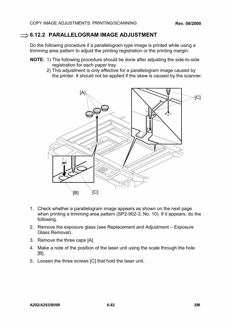
COPY IMAGE ADJUSTMENTS: PRINTING/SCANNING
A292/A293/B098 6-82 SM
6.12.2 PARALLELOGRAM IMAGE ADJUSTMENT
Do the following procedure if a parallelogram type image is printed while using atrimming area pattern to adjust the printing registration or the printing margin.
NOTE: 1) The following procedure should be done after adjusting the side-to-sideregistration for each paper tray.
2) This adjustment is only effective for a parallelogram image caused bythe printer. It should not be applied if the skew is caused by the scanner.
1. Check whether a parallelogram image appears as shown on the next pagewhen printing a trimming area pattern (SP2-902-3, No. 10). If it appears, do thefollowing.
2. Remove the exposure glass (see Replacement and Adjustment ExposureGlass Removal).
3. Remove the three caps [A].4. Make a note of the position of the laser unit using the scale through the hole
[B].5. Loosen the three screws [C] that hold the laser unit.
A229R534.WMF
[A]
[B]
[C]
[C]
Rev. 08/2000
⇒

COPY IMAGE ADJUSTMENTS: PRINTING/SCANNING
SM 6-83 A292/A293/B098
Rep
lace
men
tan
dA
djus
tmen
t
6. Adjust the laser unit position using a flat screwdriver [A] as shown.If the right side of the trimming area pattern is down by about 1 mm as shown[B], the laser unit should be rotated about one tick mark in the direction of theblack arrow as shown [C]. If the opposite side is down, adjust in the oppositedirection.NOTE: The laser unit rotates around the point [D].
7. Tighten the three screws to secure the laser unit.8. Replace the caps and exposure glass.9. Print the trimming area pattern to check the image. If it is still skewed, repeat
steps 2 to 8.
A229R535.WMF
1 mmFeed Direction
A229R591.WMF
[B][A]
[C]
[D]
[B]
Rev. 08/2000
⇒

COPY IMAGE ADJUSTMENTS: PRINTING/SCANNING
A292/A293/B098 6-84 SM
6.12.3 SCANNING
NOTE: 1) Before doing the following scanner adjustments, check the printingregistration/side-to-side adjustment and the blank margin adjustment.
2) Use an OS-A3 test chart to perform the following adjustments.
Registration: Platen Mode
1. Place the test chart on the exposure glass and make a copy from one of thefeed stations.
2. Check the leading edge and side-to-side registration, and adjust them using thefollowing SP modes if necessary.
SP modeLeading Edge SP4-010Side-to-side SP4-011
A: Leading Edge RegistrationB: Side-to-side Registration
MagnificationNOTE: Use an OS-A3 test chart to perform the following
adjustment.
Scanner Sub Scan Magnification
A: Sub Scan Magnification
1. Place the test chart on the exposure glass and make acopy from one of the feed stations.
2. Check the magnification ratio, and adjust it using the following SP mode ifnecessary. The specification is ±1%.
SP modeScanner Sub Scan Magnification SP4-008
B
A
A229R635.WMF
A
A229R636.WMF
⇒Rev. 08/2000

COPY IMAGE ADJUSTMENTS: PRINTING/SCANNING
SM 6-85 A292/A293/B098
Rep
lace
men
tan
dA
djus
tmen
t
6.12.4 ADF IMAGE ADJUSTMENT
Registration
NOTE: Make a temporary test chart as shown above left using A3/DLT paper.1. Place the temporary test chart on the ADF and make a copy from one of the
feed stations.2. Check the registration, and adjust using the following SP modes if necessary.
SP modeSide-to-side Registration SP6-006-1Leading Edge Registration (Thin originalmode)
SP6-006-2
Leading Edge Registration (Single-sided/Duplex: front)
SP6-006-3
Leading Edge Registration (Duplex: rear) SP6-006-4
B
A
A229R692.WMF
A229R637.WMF
A: Leading Edge RegistrationB: Side-to-side Registration
Rev. 08/2000
⇒

TOUCH SCREEN CALIBRATION
A292/A293/B098 6-86 SM
6.13 TOUCH SCREEN CALIBRATIONAfter doing a memory all clear or when the touch panel detection mechanism is notworking properly, calibrate the touch screen as follows.1. Press the following keys in sequence to enter touch screen calibration mode.
!CAUTIONDo not execute any of the other items in the self diagnostic menu.
2. The Self Diagnostics Menu screen will appear.Press the # key to select the Touch Screen Adj. Mode.
3. The Touch Screen Adj. calibration screen will appear. Touch the upper leftcorner then the lower right corner of the panel using a pointed (but not sharp!)tool.
4. Touch a few spots on the LCD touch panel, and confirm that the marker (asmall circle) appears on the screen at exactly the same location as where it istouched. If it does not, touch Cancel on the adjustment screen. Then repeatthe calibration procedure.
5. Touch Ok on the adjustment screen.6. Touch [q] Exit and Execute to exit the self diagnostics menu.
Self Diagnostic Menu
[a] ROM Checksum Test
[b] System RAM R/W Test
[c] Video RAM R/W Test
[d] ROM/RAM Test
[e] LCD Test
[f] Touch Screen Test
[g] Key Test
[h] LED Test
[i] Op.Panel Emulation
[j] LCD Information
[k] Code Dump
[l] Interface Test
[#] Touch Screen Adj.
[0] ARS Test
[*] Process Test
[p] Debug Tools
[q] Exit
Execute
A229R690.WMF
Touch Screen Adj.
Touch the upper left corner and then the lowerright corner of the panel using a pointed tool.
⇒
Rev. 08/2000

TROUBLESHOOTING


SERVICE CALL CONDITIONS
SM 7-1 A292/A293/B098
Trou
ble-
shoo
ting
7. TROUBLESHOOTING7.1 SERVICE CALL CONDITIONS7.1.1 SUMMARY
The SC code types and the procedures to reset them are explained in the followingtable. There are 4 levels of service call conditions.
Level Definition Reset Procedure
A
To prevent the machine from being damaged,the SC can only be reset by a servicerepresentative (see the note below). Thecopier cannot be operated at all.
Enter SP mode, then turn themain power switch off andon.
B
The SC can be reset by turning the mainpower switch off and on if the SC was causedby incorrect sensor detection. These SCsdisable only the features that use thedefective item. Although these SCs are notshown to the user under normal conditions,they are displayed on the operation panelwhen the defective feature is selected.
Turn the operation switch ormain power switch off andon.A level B SC can only bereset by turning the mainpower switch off and on.
C
The copier can be operated as usual exceptfor the unit related to the service call. SCsthat are not shown on the operation panel,are internally logged.
Turn the operation switch offand on.
D
Turning the operation switch or main powerswitch off then on resets SCs displayed onthe operation panel. These are re-displayed ifthe error occurs again. The SC history isupdated. The machine can be operated asusual.
If the SC is not displayed, theSC history is updated. If SCis displayed turn operationswitch or main power switchoff and on.
NOTE: 1) If the problem concerns electrical circuit boards, first disconnect thenreconnect the connectors before replacing the PCBs.
2) If the problem concerns a motor lock, first check the mechanical loadbefore replacing motors or sensors.
3) When a Level A or B SC occurs while in an SP mode, the display doesnot indicate the SC number. If this occurs, check the SC number afterleaving the SP mode. This does not apply to Level B codes.
Rev. 10/2002

SERVICE CALL CONDITIONS
A292/A293/B098 7-2 SM
7.1.2 SC CODE DESCRIPTIONS
SC101: Exposure lamp error- Definition - [D]
The standard white level was not detected properly when scanning the whiteplate.
- Possible cause -• Exposure lamp defective• Lamp regulator defective• Exposure lamp connector defective• Dirty standard white plate• Dirty scanner mirror or scanner mirror out of position• SBU board defective• SBU connector defective• Lens block out of position
SC120: Scanner home position error 1-Definition- [D]
The scanner home position sensor does not detect the on condition duringinitialization or copying.
- Possible causes -• Scanner home position sensor defective• Scanner motor defective• Scanner motor drive board defective• Scanner home position sensor connector defective• Scanner drive motor connector defective
SC121: Scanner home position error 2-Definition- [D]
The scanner home position sensor does not detect the off condition duringinitialization or copying.
- Possible causes -• Scanner home position sensor defective• Scanner drive motor defective• Scanner motor drive board defective• Scanner home position sensor connector defective• Scanner drive motor connector defective
Rev. 10/2002

SERVICE CALL CONDITIONS
SM 7-3 A292/A293/B098
Trou
ble-
shoo
ting
SC124: Scanner motor encoder signal error-Definition- [D]
No encoder signal from the scanner motor-Possible cause-
• Scanner motor connector defective• Scanner motor defective• MCU defective• Scanner wire, timing belt, pulley out of position• PSU defective
SC125: Scanner motor speed error 1-Definition- [D]
The scanner stops before the scanner HP sensor is on when returning.The scanner speed when the scanner HP sensor turns on is slower than thespecified speed.
-Possible cause-• Scanner motor defective• MCU defective• Too much load on scanner drive
SC126: Scanner motor speed error 2-Definition- [D]
The scanner overruns the scanner HP sensor by more than 10 mm whenreturning.
-Possible cause-• Scanner motor defective• MCU defective• Too small load on scanner drive
SC127: Scanner motor encoder rotating direction error-Definition- [D]
The scanner moves in the opposite direction from the instructed direction wheninitializing.
-Possible cause-• Scanner motor defective• MCU defective
Rev. 10/2002
SERVICE CALL CONDITIONS
A292/A293/B098 7-4 SM
SC128: Scanner motor start error-Definition- [D]
The scanner motor speed does not reach the target speed until starting to readthe original.
-Possible cause-• Scanner motor defective• MCU defective• PSU defective• Too much load on scanner drive
SC129: Scanner motor speed control error-Definition- [D]
The scanner speed is out of standard during scanning.-Possible cause-
• Scanner motor defective• PSU defective• MCU defective• Scanner drive defective
SC130: SBU error-Definition- [D]
When the main switch is turned on, the BICU cannot receive the correct signalfrom the SBU.
-Possible cause-• SBU defective• BICU defective• Cable between SBU and BICU defective
Rev. 10/2002

SERVICE CALL CONDITIONS
SM 7-5 A292/A293/B098
Trou
ble-
shoo
ting
SC300: Charge corona output error 1-Definition- [D]
The feedback voltage from the charge corona unit is too high.- Possible causes -
• Charge P.P. defective• Poor charge corona unit connection
SC301: Charge corona output error 2-Definition- [D]
The control PWM for the charge corona unit is too high.- Possible causes -
• Charge P.P. defective• Poor charge corona unit connection
SC302: Charge corona output error 3-Definition- [D]
The control PWM for the charge grid is too high.- Possible causes -
• Charge P.P. defective• Poor charge corona unit connection
SC303: Charge corona output error 4-Definition- [D]
The feedback voltage from the charge grid is too high.- Possible causes -
• Charge P.P. defective• Poor charge corona unit connection
SC305: Charge corona wire cleaner error 1-Definition- [C]
The charge corona wire cleaner does not return to its home position.- Possible causes -
• Charge corona wire cleaner motor defective• Charge P.P. defective• IOB defective
Rev. 10/2002

SERVICE CALL CONDITIONS
A292/A293/B098 7-6 SM
SC306: Charge corona wire cleaner error 2-Definition- [D]
The charge corona wire cleaner motor connector is not connected.- Possible causes -
• The charge corona wire cleaner motor connector is not connected.
SC310: Potential sensor error 1Definition- [C]
When calibrating the drum potential sensor at the process control initial setting,the drum potential sensor output voltage is out of specification.
- Possible causes -• Potential sensor defective• Poor connection between the potential sensor and the I/O board (IOB)• IOB defective• Poor connection between the drum unit and the I/O board (IOB)• Development power pack defective
SC311: Potential sensor error 2Definition- [C]
When calibrating the drum potential sensor at the process control initial setting,the rate of change of drum potential sensor output with voltage on the drum isout of specification.
- Possible causes -• Potential sensor defective• Poor connection between the potential sensor and the I/O board (IOB)• IOB defective• Poor connection between the drum unit and the I/O board (IOB)• Development power pack defective
Rev. 10/2002

SERVICE CALL CONDITIONS
SM 7-7 A292/A293/B098
Trou
ble-
shoo
ting
SC312: Potential sensor error 4Definition- [C]
When adjusting the drum potential (VD) at the process control initial setting, thedrum potential sensor detects that VD is more than VG (grid voltage).
- Possible causes -• Potential sensor defective• Poor connection between the potential sensor and the I/O board (IOB)• IOB defective• Poor connection between the drum unit and the I/O board (IOB)• Development power pack defective• Dirty or worn charge corona wire
SC314: Potential sensor error 5Definition- [C]
When adjusting the drum potential (VH) for LD power adjustment during theprocess control initial setting, the first time the VH pattern is made, the drumpotential sensor detects that VH is more than 500V.
- Possible causes -• Potential sensor defective• Poor connection between the potential sensor and the I/O board (IOB)• IOB defective• Poor connection between the drum unit and the I/O board (IOB)• LD unit defective
SC321: No laser writing signal (F-GATE) error 1- Definition- [D]
The laser writing signal (F-GATE) does not go to LOW for more than 15 secondsafter the copy paper reaches the registration sensor.
- Possible causes -• BICU board defective• Poor connection of the printer controller• Printer controller defective
Rev. 10/2002

SERVICE CALL CONDITIONS
A292/A293/B098 7-8 SM
SC322: 1st laser synchronization error-Definition- [D]
The 1st laser synchronization signal cannot be detected by the main scansynchronization detector board even if the laser diodes are activated.
- Possible causes -• Poor connection between the laser synchronization detector board and the
LD unit• Laser synchronization detector board out of position• Laser synchronization detector board defective• LD unit defective
SC323: LD drive current over-Definition- [D]
The LD drive board applies more than 110 mA to the LD.- Possible causes -
• LD unit defective (not enough power, due to aging)• Poor connection between the LD unit and the BICU board• BICU defective
SC326: 2nd laser synchronization error-Definition- [D]
The 2nd laser synchronization signal cannot be detected by the main scansynchronization detector board even if the laser diodes are activated.
- Possible causes -• Poor connection between the laser synchronization detector board and the
LD unit• Laser synchronization detector board out of position• Laser synchronization detector board defective• LD unit defective
SC327: LD unit home position error 1 (A292/A294 only)-Definition- [D]
The LD unit home position sensor does not detect an on condition when the LDunit moves to its home position.
- Possible causes -• LD unit home position sensor defective• LD positioning motor defective
LD unit movement blocked because of incorrect connector routing
Rev. 10/2002

SERVICE CALL CONDITIONS
SM 7-9 A292/A293/B098
Trou
ble-
shoo
ting
SC328: LD unit home position error 2 (A292/A293 only-Definition- [D]
The LD unit home position sensor does not detect an off condition when the LDunit moves from its home position.
- Possible causes -• LD unit home position sensor defective• LD positioning motor defective• LD unit movement blocked because of incorrect connector routing
SC329: LD unit home position error 3 (A292/A293 only-Definition- [D]
When the LD unit moves to switch the laser beam pitch (except for initialmovement at adjustment), the LD unit HP sensor turns on before the movementreaches the adjusted value.
-Possible cause-• When the main switch is on: SP2-109-3 or SP2-109-4 is not done after SP5-
801 is performed.• While printing: The LD unit does not move so well because of an unexpected
failure, such as the cable being pinched somewhere.• LD unit defective
SC330: LD unit no initial setting (A292/A293 only-Definition- [D]
The main switch is on or a printing/copying job starts without doing SP2-109-3 orSP2-109-4 after SP5-801 is performed.
-Possible cause-• SP2-109-3 or SP2-109-4 is not done after SP5-801 is performed.
Rev. 10/2002

SERVICE CALL CONDITIONS
A292/A293/B098 7-10 SM
SC331: LD unit home position error 4 (A292/A293 only)-Definition- [D]
When the LD unit moves to switch the laser beam pitch, the LD unit HP sensordoes not turn on, even when the expected time for reaching the home positioncomes, according to the data for the present position stored in NVRAM.
-Possible cause-• The LD unit does not move so well because of an unexpected failure, such
as the cable being pinched somewhere.• LD unit defective• HP sensor defective• NVRAM defective
SC332: LD unit present position error(A292/A293 only)-Definition- [D]
When the LD unit moves to switch the laser beam pitch, the data for the presentposition stored in NVRAM is out of the adjustment range.
-Possible cause-• The LD unit does not move so well because of an unexpected failure, such
as the cable being pinched somewhere.• LD unit defective• HP sensor defective• NVRAM defective
SC335: Polygonal mirror motor error 1-Definition- [D]
The XSCRDY signal does not become low within 20 seconds after the polygonalmirror motor turns on or the polygon motor speed is changed.
-Possible cause-• Poor cable connection to the polygonal mirror motor driver.• Polygonal mirror motor (driver) defective• BICU defective
Rev. 10/2002

SERVICE CALL CONDITIONS
SM 7-11 A292/A293/B098
Trou
ble-
shoo
ting
SC336: Polygonal mirror motor error 2-Definition- [D]
The XSCRDY signal does not become high within 20 seconds after thepolygonal mirror motor turns off.
-Possible cause-• Poor cable connection to the polygonal mirror motor driver.• Polygonal mirror motor (driver) defective• BICU defective
SC337: Polygonal mirror motor error 3-Definition- [D]
The XSCRDY signal becomes high while the polygonal mirror motor turns on,even though there was no demand for either turning off the motor or changingthe motor speed.
-Possible cause-• Poor cable connection to the polygonal mirror motor driver.• Polygonal mirror motor (driver) defective• BICU defective
SC338: Polygonal mirror motor error 1-Definition- [D]
The XSCRDY signal does not become stable within 20 seconds after thepolygonal mirror motor turns on or off or the polygon motor speed is changed.
-Possible cause-• Poor cable connection to the polygonal mirror motor driver.• Polygonal mirror motor (driver) defective• BICU defective
Rev. 10/2002

SERVICE CALL CONDITIONS
A292/A293/B098 7-12 SM
SC340: TD sensor output error-Definition- [C]
The TD sensor output voltage (Vt), which is measured during each copyingprocess, is one of the following 10 times consecutively.1) Vt = 0.5 volts or lower2) Vt = 4.0 volts or higher
-Possible cause-• TD sensor defective• Poor connection between the TD sensor and the I/O board.• I/O board defective
In this error condition, the toner supply is controlled using pixel count andVsp/Vsg.
SC341: TD sensor adjustment error 1-Definition- [D]
During the TD sensor auto adjustment, the TD sensor output voltage (Vt) is 2.5volts or higher even though the control voltage is set to the minimum value(PWM = 0)
Note: When this error occurs, the indication of SP2-906-1 is 0.00V.-Possible cause-
• TD sensor defective• Poor connection between the TD sensor and the I/O board.• I/O board defective
Note: In this error condition, the toner supply is controlled using pixel count and Vsp/Vsg.
Rev. 10/2002

SERVICE CALL CONDITIONS
SM 7-13 A292/A293/B098
Trou
ble-
shoo
ting
SC342: TD sensor adjustment error 2-Definition- [D]
During the TD sensor auto adjustment, the TD sensor output voltage (Vt) doesnot come in the target range (2.5 ± 0.1V) within 20 seconds.Note: When this error occurs, the indication of SP2-906-1 is 0.00V.
-Possible cause-• TD sensor defective• Poor connection between the TD sensor and the I/O board.• I/O board defective
Note: In this error condition, the toner supply is controlled using pixel count andVsp/Vsg.
SC345: Development bias leak-Definition- [D -
• Poor connection between the development bias terminal and thedevelopment P.P.
• Development P.P. defective
SC350: ID sensor error 1-Definition- [C]
One of the following ID sensor output voltages was detected twice consecutivelywhen checking the ID sensor pattern.1) Vsp ≥ 2.5V2) Vsp = 0V
- Possible causes -• ID sensor defective• ID sensor connector defective• Poor ID sensor connector connection• I/O board (IOB) defective• Charge or development power pack defective• Dirty ID sensor• Defect at ID sensor pattern writing area of the drum
Rev. 10/2002

SERVICE CALL CONDITIONS
A292/A293/B098 7-14 SM
SC351: ID sensor error 2-Definition- [C]
One of the following ID sensor output voltages was detected twice consecutivelywhen checking the ID sensor pattern.1) Vsg< 2.5V2) Vsg = 0V3) The ID sensor output voltage is 5.0V and the PWM signal input to the ID
sensor is 0 when checking the ID sensor pattern- Possible causes -
• ID sensor defective• ID sensor connector defective• Poor ID sensor connector connection• I/O board (IOB) defective• Charge or development power pack defective• Dirty ID sensor• Defect at the ID sensor pattern writing area of the drum
SC352: ID sensor error 3-Definition- [C]
For 2 s during the ID sensor pattern check, the ID sensor pattern edge voltage isnot 2.5V.
- Possible causes -• ID sensor defective• ID sensor connector defective• Poor ID sensor connector connection• I/O board (IOB) defective• Charge or development power pack defective• Dirty ID sensor• Defect at the ID sensor pattern writing area of the drum
Rev. 10/2002

SERVICE CALL CONDITIONS
SM 7-15 A292/A293/B098
Trou
ble-
shoo
ting
SC353: ID sensor error 4-Definition- [C]
One of the following ID sensor output voltages is detected at ID sensorinitialization.1) Vsg < 4.0V when the maximum PWM input (255) is applied to the ID sensor.2) Vsg ≥ 4.0V when the minimum PWM input (0) is applied to the ID sensor.
- Possible causes -• ID sensor defective• ID sensor connector defective• Poor ID sensor connector connection• I/O board (IOB) defective• Charge or development power pack defective• Dirty ID sensor• Defect at the ID sensor pattern writing area of the drum
SC354: ID sensor error 5-Definition- [C]
Vsg falls out of the adjustment target (4.0 ± 0.2V) during Vsg checking.- Possible causes -
• ID sensor defective• ID sensor connector defective• Poor ID sensor connector connection• I/O board (IOB) defective• Charge or development power pack defective• Dirty ID sensor• Defect at the ID sensor pattern writing area of the drum
SC360: Hard disk detection error 1-Definition- [B]
When the main switch turns on, the machine does not detect the connectionsignal from the HDD.
-Possible cause-• Poor connection between the HDD and BICU• Poor connection on the dc power connector to the HDD• HDD defective• BICU defective

SERVICE CALL CONDITIONS
A292/A293/B098 7-16 SM
SC362: Hard disk detection error 2-Definition- [B]
When the power switch on the operation panel turns on, the machine does notdetect the connection signal from the HDD.
-Possible cause-• Poor connection between the HDD and BICU• Poor connection on the dc power connector to the HDD• HDD defective• BICU defective
SC364: Hard disk drive error-Definition-
The image data stored in the HDD cannot be output properly. Possible causes
• When this SC occurs only once, this problem will be solved after turning themain power switch off and on.
• When this SC occurs while performing SP4-911-1 (HDD media check), it canbe cured by doing SP4-911-2 (HDD formatting).
• HDD defective
SC366: Hard disk bad sector maximum-Definition [D]
The number of bad sectors on the HDD is over the maximum number.-Possible Cause-
• HDD defective• NVRAM defective
SC367: Hard disk (HDD:R) bad sector maximum-Definition [B]
The number of bad sectors on the HDD is over the maximum number.-Possible Cause-
• HDD defective• NVRAM defective
SERVICE CALL CONDITIONS
SM 7-17 A292/A293/B098
Trou
ble-
shoo
ting
SC370: IMAC (image compression IC) input FIFO error-Definition- [D]
An input FIFO error occurs while inputting image processing in the ASIC(IMACB), which handles image compression and image data transmission.
-Possible cause-• BICU defective
SC372: IMAC (image compression IC) output FIFO error-Definition- [D]
An output FIFO error occurs while outputting image processing in the ASIC(IMACB), which handles image compression and image data transmission.
-Possible cause-• BICU defective
SC374: IMAC (image compression IC) modes setting error-Definition-
A mode setting error occurs by changing settings during image processing in theASIC (IMACB), which handles image compression and image data transmission.
-Possible cause-• BICU defective
SC376: Data transmission error-Definition- [D]
A data transmission error occurred at the ASIC which controls data transmissionand compression during connecting mode.
-Possible cause-• Defective connection board• Defective or disconnected interface cable• Defective SBICU
Rev. 10/2002

SERVICE CALL CONDITIONS
A292/A293/B098 7-18 SM
SC380: Data transmission time out (video input)-Definition- [D]
Data input to the IC which controls data transfer and compression is notcompleted within 20 seconds.
-Possible cause-• BICU defective• SBU defective• Printer controller defective
SC382: Data transmission time out (video output)-Definition- [D]
Data output from the IC which controls the data transfer and compression is notcompleted within 20 seconds.
-Possible cause-• BICU defective• LD board defective
SC384: Data transmission time out (connect copy)-Definition-[D]
Data transmission to the memory does not finish properly within 20 secondsafter the start of data transmission.
-Possible cause-• Defective connection board• Defective or disconnected interface cable• Defective SBICU
SC386: Data transmission time out (Hard disk write)-Definition- [D]
Data input to the IC which controls the data transfer and compression is notcompleted with in 20 seconds.
-Possible cause-• BICU defective• SBU defective• Printer controller defective
Rev. 10/2002

SERVICE CALL CONDITIONS
SM 7-19 A292/A293/B098
Trou
ble-
shoo
ting
SC390: CRC error-Definition-[D]
Electrical noise causes sent data and received data to differ. A CRC check candetect this error.
-Possible cause-• Defective connection board• Defective or disconnected interface cable
SC391: Image storage address error-Definition-[D]
The SBICU receives an image data output request signal for data that is notstored in memory.
-Possible causes-• SBICU defective
SC400: Transfer roller leak error-Definition- [D]
A transfer roller current leak signal is detected.- Possible causes -
• Transfer P.P. defective• Poor connection between the transfer current terminal and the transfer P.P.
SC401: Transfer roller open error-Definition- [D]
The transfer roller current feedback signal is not detected.- Possible causes -
• Transfer P.P. defective• Poor connection between the transfer current terminal and the transfer P.P.
SC430: Quenching lamp error-Definition- [C]
When finishing the process control initial setting, the drum potential which isdetected by the drum potential sensor is out of the normal range.
- Possible causes -• Quenching lamp defective• Poor connection between quenching lamp and charge power pack
Rev. 10/2002

SERVICE CALL CONDITIONS
A292/A293/B098 7-20 SM
SC440: Main motor lock-Definition- [D]
The main motor lock signal remains low for 2 seconds while the main motor ison.
- Possible causes -• Too much load on the drive mechanism• Main motor defective
SC441: Development motor lock-Definition- [D]
The development motor lock signal remains low for 2 seconds while thedevelopment motor is on.
- Possible causes -• Too much load on the drive mechanism• Development motor defective
SC493: Exhaust fan motor lock-Definition- [D]
The exhaust fan motor lock signal remains high for 5 seconds while the exhaustfan motor is on.
-Possible cause-• Exhaust fan motor defective• Too much load on the fan
SC494: Fusing exhaust fan motor lock-Definition- [D]
The fusing exhaust fan motor lock signal remains high for 5 seconds while thefusing exhaust fan motor is on.
-Possible cause-• Exhaust fan motor defective• Too much load on the fan
Rev. 10/2002

SERVICE CALL CONDITIONS
SM 7-21 A292/A293/B098
Trou
ble-
shoo
ting
SC495: Toner recycling unit error-Definition- [D]
The toner recycling sensor output signal does not change within 500 ms afterthe main motor turns on.
- Possible causes -• Too much load on the drive mechanism• Toner end sensor detective• Poor connection on the sensor connector
SC496: Toner collection bottle error-Definition- [D]
The toner collection bottle set switch remains off when the front door is closed.- Possible causes -
• No toner collection bottle• Poor connection on the switch connector
SC497: Toner recycling motor error-Definition- [D]
The toner recycling motor connector set signal remains off for 1 second.- Possible causes -
• Toner recycling motor defective• Poor connection on the motor connector
SC501: 1st tray lift malfunction-Definition- [B]
• The lift sensor is activated before the pick-up solenoid is activated when thetray is pushed in.
• The lift sensor is not activated within 10 seconds after the tray lift motor startslifting the bottom plate.
• The lift sensor remains activated for 1.5 seconds after the tray lift motor startslowering the bottom plate.
• The tray down sensor is not activated within 10 seconds after the tray liftmotor starts lowering the bottom plate because of a paper end condition.
-Possible cause-• Tray lift motor defective or poor connection• Lift sensor defective or poor connection• Tray down sensor defective or poor connection• Pick-up solenoid defective or poor connection
Rev. 10/2002

SERVICE CALL CONDITIONS
A292/A293/B098 7-22 SM
SC502: 2nd tray lift malfunction-Definition [B]SC503: 3rd tray lift malfunction-Definition- [B]
• The lift sensor is activated before the pick-up solenoid is activated when thetray is pushed in.
• The lift sensor is not activated within 10 seconds after the tray lift motor startslifting the bottom plate.
• The lift sensor remains activated for 1.5 seconds after the tray lift motor startslowering the bottom plate.
-Possible cause-• Tray lift motor defective or poor connection• Lift sensor defective or poor connection• Pick-up solenoid defective or poor connection
SC505: LCT tray malfunction (optional LCT)-Definition- [B]
• The lift sensor is not activated within 60 seconds after the tray lift motor startslifting the bottom plate.
• The tray down sensor is not activated within 60 seconds after the tray liftmotor starts lowering the bottom plate.
• The lift sensor and tray down sensor are activated at the same time.• The lift sensor is not activated even when the pick-up roller is still lifted up by
the top of paper.-Possible cause-
• Tray lift motor defective or poor connection• Lift sensor defective or poor connection• Pick-up solenoid defective or poor connection• Paper end sensor defective
SC510: Paper feed motor locks-Definition- [B]
• The lock signal from the paper feed motor is detected for 3,000 ms duringrotation.
• Poor connection is checked once when the main switch is on.-Possible cause-
• Paper feed motor defective or poor connection• Too much load on the drive mechanism• Lower front door safety switch defective• Lower front door safety switch bracket deformation
Rev. 10/2002

SERVICE CALL CONDITIONS
SM 7-23 A292/A293/B098
Trou
ble-
shoo
ting
SC511: LCT motor lock (optional LCT)-Definition- [B]
• The lock signal from the LCT transport motor is detected for 50 ms duringrotation. (The detection period does not include 300 ms of the starting up.)
• Poor connection is checked once when the main switch is on.-Possible cause-
• LCT transport motor defective or poor connection• Too much load on the drive mechanism
SC515: Tandem rear fence motor error-Definition- [B]
• When the tray is pushed in, the rear fence return sensor and the rear fenceHP sensor are already on.
• The rear fence return sensor is not on within 10 seconds after the rear fencemotor starts.
• The rear fence HP sensor is not on within 10 seconds after the rear fencestarts moving to the home position.
-Possible cause-• Rear fence motor defective or poor connection• Too much load on the drive mechanism
<Note> The other trays are still available to use.
SC516: Tandem side fence motor error-Definition [B]Japanese version only
SC520: Duplex jogger motor error 1-Definition- [D]
When the jogger fence moves to the home position, the jogger HP sensor doesnot turn on even if the jogger fence motor has moved the jogger fence 153.5mm.
- Possible causes -• Jogger fence motor defective or poor connection• Too much load on the drive mechanism
Rev. 10/2002

SERVICE CALL CONDITIONS
A292/A293/B098 7-24 SM
SC521: Duplex jogger motor error 2-Definition- [D]
When the jogger fence moves from the home position, the jogger fence HPsensor does not turn off even if the jogger motor has moved the jogger fence153.5 mm.
- Possible causes -• Jogger fence motor defective or poor connection• Too much load on the drive mechanism
SC530: By-pass feed motor lock-Definition- [D]
A by-pass feed motor lock signal is detected for more than 2 seconds duringrotation.
- Possible causes -• By-pass feed motor defective or poor connection• Too much load on the drive mechanism
SC531: Fusing/duplex motor lock-Definition- [D]
A fusing/duplex motor lock signal is detected for more than 2 seconds duringrotation.
- Possible causes -• Fusing/duplex motor defective or poor connection• Too much load on the drive mechanism
SC541: Fusing thermistor open-Definition- [A]
The fusing temperature detected by the thermistor is below 7°C for 35 seconds.- Possible causes -
• Fusing thermistor defective or out of position• Poor thermistor terminal connection
Rev. 10/2002

SERVICE CALL CONDITIONS
SM 7-25 A292/A293/B098
Trou
ble-
shoo
ting
SC542: Fusing temperature warming-up error-Definition- [A]
The fusing temperature does not reach the fusing standby temperature within 5minutes after the main power switch is turned on.
- Possible causes -• Fusing thermistor defective or out of position• Fusing lamp open• Fusing thermofuse open• BICU defective• Power supply board defective• Poor fusing unit connection
SC543: Fusing overheat error 1 (software)-Definition- [A]
A fusing temperature of over 230°C is detected for 5 seconds by the fusingthermistor.
- Possible causes -• Fusing thermistor defective• BICU defective• I/O board (IOB) defective
SC544: Fusing overheat error 1 (hardware)-Definition- [A]
The BICU detects an overheat error even if the protection in the software doesnot work.
-Possible cause-• Fusing thermistor defective• BICU defective• I/O board defective

SERVICE CALL CONDITIONS
A292/A293/B098 7-26 SM
SC545: Fusing overheat error 2-Definition- [A]
The fusing lamp stays on at full power for 45 seconds while in the stand-bycondition after warming-up is completed.
- Possible causes -• Fusing thermistor out of position
SC546: Fusing ready temperature malfunction-Definition- [A]
• A change in the fusing temperature by 20°C or more compared with thetemperature of 1 second ago occurs 2 times consecutively.
• A change in the fusing temperature by 20°C or more compared with thetemperature of 1 second ago occurs 3 times consecutively for 1 minute.
-Possible cause-• Poor connection on the thermistor• Poor connection on the fusing unit connector
SC547: Zero cross signal malfunction-Definition- [D]
• When the main switch is on, the frequency measured by the number of zerocross signals for 500 ms is larger than 66Hz or smaller than 45Hz.
• It is measured 3 times consecutively for 500 ms that the interval between azero cross signal and the next one is 7.5 ms or shorter.
-Possible cause-• Power supply unit defective• Noise on the ac power line
SC590: Toner collection motor error-Definition- [D]
The toner collection motor sensor output does not change for 3 seconds whilethe toner collection motor is on.
- Possible causes -• Toner collection motor defective• Too much load on the drive mechanism• Poor toner collection motor connector connection• IOB defective• Toner collection motor sensor defective
Rev. 10/2002

SERVICE CALL CONDITIONS
SM 7-27 A292/A293/B098
Trou
ble-
shoo
ting
SC601: Communication error between BICU and MCU-Definition- [D]
The BICU cannot communicate with the MCU board properly.- Possible causes -
• Poor connection between the BICU and MCU• MCU defective• BICU defective
SC602: Communication error between BICU and HDD controller-Definition- [D]
The BICU cannot communicate with the HDD controller properly.- Possible causes -
• Poor connection between the BICU board and HDD control board• BICU board defective
SC620: Communication error between BICU and ADF 1-Definition- [D]
The TXD and RXD signals between BICU and ADF main board do not stabilize.- Possible causes -
• Poor connection between the BICU board and ADF main board• Noise on interface cable
SC621: Communication error between BICU and ADF 2-Definition- [D]
The TXD and RXD signals between BICU and ADF main board do not stabilize.- Possible causes -
• Poor connection between the BICU board and ADF main board• ADF main board defective• BICU board defective
SC622: Communication error between BICU and ADF 3-Definition- [D]
Software error after abnormal user operation.- Possible causes -
• Software error
Rev. 10/2002

SERVICE CALL CONDITIONS
A292/A293/B098 7-28 SM
SC625: Communication error between BICU and finisher 1-Definition- [D]
The acknowledge signal does not come back from the finisher or mailbox to theBICU board 3 times consecutively.
-Possible cause-• Finisher or mailbox main board defective• BICU board defective• Poor connection between BICU board and finisher or mailbox main board• Noise on the interface cable
SC626: Communication error between BICU and finisher 2-Definition- [D]
The BICU board receives a low signal even when the communication line isconnected between the BICU board and the finisher or mailbox.
-Possible cause-• Finisher or mailbox main board defective• BICU board defective• Poor connection between BICU board and finisher or mailbox main board• Noise on the interface cable• Finisher or mailbox is installed with B098
SC630: CSS (RSS) communication error between line adapter and CSS center-Definition- [C]Japan only
SC635: Communication error between BICU and paper feed board 1-Definition- [B]
The acknowledge signal does not come back from the paper feed board to theBICU board 3 times consecutively.
-Possible cause-• Paper feed board defective• BICU board defective• Poor connection between BICU board and paper feed board• Noise on the interface cable
Rev. 10/2002

SERVICE CALL CONDITIONS
SM 7-29 A292/A293/B098
Trou
ble-
shoo
ting
SC636: Communication error between BICU and paper feed board 2-Definition- [D]
The BICU board receives a low signal even when the communication line isconnected between the BICU board and the paper feed board.
-Possible cause-• Paper feed board defective• BICU board defective• Poor connection between BICU board and paper feed board• Noise on the interface cable
SC700: ADF original pick-up malfunction 1-Definition- [D]
The pick-up roller H.P sensor signal does not change after the pick-up motorhas turned on.
- Possible causes -• Pick-up roller H.P sensor defective• Pick-up motor defective• Timing belt out of position• ADF main board defective
SC701: ADF original pick-up malfunction 2-Definition- [D]
The pick-up roller HP sensor is not activated even after the pick-up motor turnson.
-Possible cause-• Pick-up roller HP sensor defective• Pick-up motor defective• ADF main board defective
Rev. 10/2002

SERVICE CALL CONDITIONS
A292/A293/B098 7-30 SM
SC702: ADF feed-in motor lock-Definition- [D]
1) The encoder signal cannot be detected within a specific time when the feed-in motor is on.
2) The pulse signal from the length sensor is not detected within a specific timewhen the feed-in motor is on.
-Possible cause-• Feed-in motor defective• Length sensor defective• Cable for length sensor or feed-in motor defective• Main board defective
SC703: ADF transport motor lock-Definition- [D]
The encoder signal cannot be detected within a specific time when the transportmotor is on.
-Possible cause-• Transport motor defective• Cable for transport motor defective• Main board defective
SC704: ADF feed-out motor lock-Definition- [D]The encoder signal cannot be detected within a specific time when the feed-outmotor is on.-Possible cause-
• Feed-out motor defective• Cable for feed-out motor defective• Main board defective
Rev. 10/2002

SERVICE CALL CONDITIONS
SM 7-31 A292/A293/B098
Trou
ble-
shoo
ting
SC705: ADF bottom plate motor error-Definition- [D]
1) The bottom plate position sensor does not turn on when the bottom platemotor lifts the bottom plate.
2) The bottom plate HP sensor does not turn on when the bottom plate motorlowers the bottom plate.
-Possible cause-• Bottom plate position sensor defective• Bottom plate HP sensor defective• Bottom plate motor defective• Main board defective
SC720: Finisher transport motor error-Definition- [B]
The encoder pulse of the transport motor does not change state (high/low)within a certain period of time.
-Possible cause-• Finisher transport motor defective or poor connection• Finisher main board defective• Too much load on drive mechanism
SC722: Finisher jogger motor error-Definition- [B]
1) The finisher jogger H.P sensor remains de-activated for more than a certaintime when returning to home position.
2) The finisher jogger H.P sensor remains activated for more than a certaintime when moving away from home position.
- Possible causes -• Jogger H.P sensor defective• Jogger motor defective
SC724: Finisher staple hammer motor error-Definition- [B]
Stapling does not finish within a certain time after the staple hammer motorturned on.
- Possible causes -• Staple hammer motor defective• Staple jam
Rev. 10/2002

SERVICE CALL CONDITIONS
A292/A293/B098 7-32 SM
SC725: Finisher stack feed-out motor error- Definition - [B]
The stack feed-out belt H.P sensor does not activate within a certain time afterthe stack feed-out motor turned on.
- Possible causes -• Stack feed-out H.P sensor defective• Stack feed-out motor defective
SC726: Finisher shift/lift motor error- Definition - [B]
1) Tray shift does not finish within a certain time after the shift motor turned on.2) The stack height sensor does not activate within a certain time after the shift
tray lift motor turned on.- Possible causes -
• Shift motor defective• Shift tray lift motor defective
SC727: Finisher stapler rotation motor error- Definition - [B]
1) Stapler rotation does not finish within a certain time after the stapler rotationmotor turned on.
2) The stapler does not return to its home position within a certain time afterstapling finished.
- Possible causes -• Stapler rotation motor defective• Poor stapler rotation motor connection
SC729: Finisher punch motor error- Definition - [B]
The punch H.P sensor does not activate within a certain time after the punchmotor turned on.
- Possible causes -• Punch motor defective• Punch H.P sensor defective• Poor punch motor connection

SERVICE CALL CONDITIONS
SM 7-33 A292/A293/B098
Trou
ble-
shoo
ting
SC730: Finisher stapler position motor error- Definition - [B]
1) The stapler H.P. sensor stays on for longer than normal when the staplermotor turns on to return the stapler to its home position.
2) The stapler H.P sensor does not turn on within a certain time after thestapler motor turned on to move the stapler away from home position.
- Possible causes -• Stapler motor defective• Stapler H.P sensor defective• Poor stapler motor connection
SC731: Finisher paper exit guide plate motor lock-Definition- [B]
The exit plate HP sensor does not turn on within 800 ms when the exit platereturns to its home position.
-Possible cause-• Exit plate motor defective• Too much load to exit plate motor• Exit plate motor connector defective• Exit plate HP sensor defective• Main board defective
SC735: Finisher pre-stack motor error-Definition- [B]
It occurs 2 times consecutively that the pre-stack HP sensor is not activatedwithin 400 pulses after the pre-stack motor starts.
-Possible cause-• Pre-stack HP sensor defective or poor connection• Pre-stack motor defective• Finisher main board defective• Too much load on the drive mechanism

SERVICE CALL CONDITIONS
A292/A293/B098 7-34 SM
SC736: Finisher paper exit guide plate motor error-Definition- [B]
It occurs 2 times consecutively that the paper exit guide plate HP sensor is notactivated within 750 ms after the paper exit guide plate motor starts.
-Possible cause-• Paper exit guide plate sensor defective or poor connection• Paper exit guide plate motor defective• Finisher main board defective• Too much load on the drive mechanism
SC737: Finisher staple waste full-Definition- [B]
The box for staple waste becomes full.-Possible cause-
• Box is full of staple waste• Staple waste sensor defective
SC738: Finisher shift tray lift motor error-Definition- [D]It occurs 2 times consecutively that;
1) The stack height sensor is not activated within 50 seconds after the motorstarts lifting the tray.
2) The stack height sensor is still activated 5 seconds after the motor startslowering the tray.
-Possible cause-• Stack height sensor defective or poor connection• Shift tray lift motor defective• Finisher main board defective• Too much load on the drive mechanism
SC740: 1,000-sheet finisher error in finisher area- Definition [D]Note: When this SC is displayed, check SP7-902 (SC detail). The first 2 digits
indicate the type of error.Example: 740 0100000000000000
⇒
Rev. 10/2002

SERVICE CALL CONDITIONS
SM 7-35 A292/A293/B098
Trou
ble-
shoo
ting
01: Shutter movement error1) The shutter position switch does not turn on within 1 s after the transport
motor starts to turn in reverse.2) The shutter sensor does not deactivate within 1 s after the transport motor
starts to turn in reverse.3) The shutter position switch is off when the shift tray safety switch is off.
- Possible causes -
• Transport motor defective
• Shutter position switch defective
• Shift tray safety switch defective
02: Exit motor error1) After the exit motor turns on, the exit motor sensor does not send the proper
signal to the finisher board.2) The exit motor sensor does not send the clock signal to the finisher board for
certain period while the exit motor is on.- Possible causes -
• Exit motor defective
• Exit motor sensor defective
03: Upper exit plate movement error1) The upper exit guide 2 switch does not turn on within 1s after the guide plate
motor turns on.2) The upper exit guide sensor does not activate within 1s after the guide plate
motor turns on.3) The upper exit guide 2 switch does not turn on when the shift tray safety
switch is off.- Possible causes -
• Guide plate motor defective
• Upper exit guide 2 switch defective
• Upper exit guide sensor defective
• Shift tray safety switch defective
⇒
Rev. 10/2002

SERVICE CALL CONDITIONS
A292/A293/B098 7-36 SM
04: Jogger motor error1) After the jogger motor turns on to move the jogger fence from its home
position, the jogger HP sensor does not deactivate within 2s.2) After the jogger motor turns on to return the jogger fence to its home position,
the jogger HP sensor does not activate within 2s.- Possible causes -
• Jogger motor defective
• Jogger HP sensor defective
05: Stapler motor error1) After the stapler motor turns on to move the stapler unit from its home
position, the stapler unit HP sensor does not deactivate within 4s.2) After the stapler motor turns on to return the stapler unit to its home position,
the stapler unit HP sensor does not activate within 4s.- Possible causes -
• Stapler motor defective
• Stapler unit HP sensor defective
06: Staple hammer motor error1) The staple hammer HP sensor does not deactivate within 0.5s after the staple
hammer motor turns on.2) The staple hammer HP sensor does not activate within 0.5s after the staple
hammer motor turns on.- Possible causes -
• Staple hammer motor defective
• Staple hammer HP sensor defective
Rev. 10/2002
⇒

SERVICE CALL CONDITIONS
SM 7-37 A292/A293/B098
Trou
ble-
shoo
ting
07: Tray lift motor error1) The tray lift motor does not stop within 15s after being turned on.2) The shift tray HP sensor does not activate within 15s after the tray lift motor
turns on.3) The shift tray upper limit switch turns on while the shift tray is being raised.4) Lift motor sensors 1 & 2 do not send the clock signals to the finisher board
every 200ms while the tray lift motor is on.- Possible causes -
• Tray lift motor defective
• Lift motor sensor 1 defective
• Lift motor sensor 2 defective
• Shift tray HP sensor defective
• Shift tray upper limit switch defective
08: Shift tray height sensor error1) Abnormal communication data between finisher board and shift tray height
sensor.2) No communication between finisher board and shift tray height sensor for a
certain period.3) The finisher board detects a connection error with the connector for the shift
tray height sensor.4) Adjustment error during shift tray height sensor adjustment.
- Possible causes -
• Shift tray height sensor defective
• Finisher board defective
09: Back-up RAM errorThe check sum is abnormal when the main switch is turned on.
- Possible causes -
• Finisher board defective
Rev. 10/2002
⇒

SERVICE CALL CONDITIONS
A292/A293/B098 7-38 SM
0A: Communication errorCommunication error between finisher board and booklet unit board.
- Possible causes -
• Finisher board defective
• Booklet unit board defective
• Poor connection of the interface harness
SC741: 1,000-sheet finisher error in saddle stitching area- Definition [D]Note: When this SC is displayed, check SP7-902 (SC detail). The first 2 digits
indicate the type of error.Example: 741 0100000000000000
01: Positioning plate motor error1) After the positioning plate motor turns on to move the positioning plate from
its home position, the positioning plate HP sensor does not deactivate within1.25s.
2) After the positioning plate motor turns on to return the positioning plate to itshome position, the positioning plate HP sensor does activate within 1s.
- Possible causes -
• Positioning plate motor defective
• Positioning plate HP sensor defective
02: Folder roller motor error1) The folder roller motor sensor doesnt send the clock pulse to the booklet unit
board within a certain period after the folder roller motor turns on.- Possible causes -
• Folder roller motor defective
• Folder roller motor sensor defective
Rev. 10/2002
⇒
⇒

SERVICE CALL CONDITIONS
SM 7-39 A292/A293/B098
Trou
ble-
shoo
ting
03: Shutter guide motor error1) After the shutter guide motor turns on to move the shutter guide from its home
position, the shutter guide HP sensor does not deactivate within 0.4s.2) After the shutter guide motor turns on to return the shutter guide to its home
position, the shutter guide HP sensor does not activate within 1s.- Possible causes -
• Shutter guide motor defective
• Shutter guide HP sensor defective
04: Booklet jogger motor error1) After the booklet jogger motor turns on to move the booklet jogger plate from
its home position, the booklet jogger HP sensor does not deactivate within0.5s.
2) After the booklet jogger motor turns on to return the booklet jogger plate to itshome position, the booklet jogger HP sensor does not activate within 1s.
- Possible causes -
• Booklet jogger motor defective
• Booklet jogger HP sensor defective
05: Stapler motor error1) The front staple hammer HP switch does not turn off within 0.5s after the front
stapler motor turns on.2) The front staple hammer HP switch does not turn on within 0.5s after the front
stapler motor turns on during jam recovery. 3) The rear staple hammer HP switch does not turn off within 0.5s after the rear
stapler motor turns on.4) The rear staple hammer HP switch does not turn on within 0.5s after the rear
stapler motor turns on during jam recovery.- Possible causes -
• Front stapler motor defective
• Front staple hammer HP switch defective
• Rear stapler motor defective
• Rear staple hammer HP switch defective
Rev. 10/2002
⇒

SERVICE CALL CONDITIONS
A292/A293/B098 7-40 SM
06: Folder plate motor error1) After the folder plate motor turns on to return the folder plate to its home
position, the folder plate HP sensor does not activate within 0.3s.2) After the folder plate motor turns on to move the folder plate from its home
position, the folder plate HP sensor does not deactivate within 0.3s.3) After the folder plate motor turns on to return the folder plate to its home
position, the folder plate return sensor does not deactivate within 0.3s.4) The folder plate return sensor does not activate within 0.3s after the HP
sensor deactivates.5) The pulse count from the folder plate motor sensor is lower than the target
minimum.- Possible causes -
• Folder plate motor defective
• Folder plate HP sensor defective
• Folder plate return sensor defective
• Folder plate motor sensor defective
07: Connector error1) The connector of the shutter guide HP sensor is not connected.2) The connector of the folder plate HP sensor is not connected.3) The connector of the folder plate return sensor is not connected.
- Possible causes -
• Poor connection or no connection of the shutter guide HP sensor connector
• Poor connection or no connection of the folder plate HP sensor connector
• Poor connection or no connection of the folder plate return sensor connector
Rev. 10/2002
⇒
SERVICE CALL CONDITIONS
SM 7-41 A292/A293/B098
Trou
ble-
shoo
ting
08: Switch error1) When the booklet entrance guide sensor, lower door sensor and booklet exit
cover sensor are all activated (doors closed), the booklet entrance guidesafety switch does not turn on within 1s after a copy job or warm-up idlingbegins.
2) When the booklet entrance guide sensor, lower door sensor and booklet exitcover sensor are all activated (doors closed), the lower door safety switchdoes not turn on within 1s after a copy job or warm-up idling begins.
3) When the booklet entrance guide sensor, lower door sensor and booklet exitcover sensor are all activated (doors closed), the booklet exit cover safetyswitch does not turn on within 1s after a copy job or warm-up idling begins.
- Possible causes -
• Booklet entrance guide safety switch defective
• Lower door safety switch defective
• Booklet exit cover safety switch defective
SC900: Electrical total counter error-Definition- [D]
The total counter contains something that is not a number.- Possible causes -
• NVRAM defective
SC901: Mechanical total counter error-Definition- [D]
The mechanical counter is not connected.-Possible cause-
• Mechanical total counter defective• Mechanical total counter connector not connected
SC951: F-gate signal error 2-Definition- [D]
When the IPU has already received the F-gate signal (laser writing start triggersignal), the IPU receives another F-gate signal.
- Possible causes -• SBICU defective
Rev. 10/2002
⇒

SERVICE CALL CONDITIONS
A292/A293/B098 7-42 SM
SC953: Scanner image setting error-Definition- [D]
The settings that are required for image processing using the scanner are notsent from the IPU.
- Possible causes -• Software defective
SC954: Printer image setting error-Definition- [D]
The settings that are required for image processing using the printer controllerare not sent from the IPU.
- Possible causes -• Software defective
SC955: Memory setting error-Definition- [D]
The settings that are required for image processing using the memory are notsent from the IPU.
- Possible causes -• Software defective
SC956: Scanner setting ID error-Definition- [D]
The ID that is sent from the IPU for scanner parameter setting is different fromexpected.
-Possible cause-• Software error
SC957: Scanner return ID error-Definition- [D]
The ID that is sent from the IPU for the scanner return signal is different fromexpected.
-Possible cause-• Software error
Rev. 10/2002
⇒

SERVICE CALL CONDITIONS
SM 7-43 A292/A293/B098
Trou
ble-
shoo
ting
SC958: Scanner ready ID error-Definition- [D]
The ID that is sent from the IPU for the scanner ready signal is different fromexpected.
-Possible cause-• Software error
SC959: Printer setting ID error-Definition- [D]
The ID that is sent from the IPU for the printer setting signal is different fromexpected.
-Possible cause-• Software error
SC960: Printer return ID error-Definition- [D]
The ID that is sent from the IPU for the printer return signal is different fromexpected.
-Possible cause-• Software error
SC961: Printer ready ID error-Definition- [D]
The ID that is sent from the printer controller in the printer controller printingready condition is incorrect.
- Possible causes -• Software defective
SC962: Memory setting ID error-Definition- [D]
The ID that is sent from the memory when the IPU sent the memory ready signalis incorrect.
- Possible causes -• Software defective
Rev. 10/2002
⇒

SERVICE CALL CONDITIONS
A292/A293/B098 7-44 SM
SC963: Memory finishing ID error-Definition- [D]
The ID that is sent from the memory when the IPU sent the memory finish signalis incorrect.
- Possible causes -• Software defective
SC964: Printer ready error-Definition- [D]
The print ready signal is not generated for more than 17 seconds after the IPUreceived the print start signal.
- Possible causes -• Software defective
SC966: No laser writing signal (F-GATE) error 2- Definition [D]
The level of the laser writing signal (F-GATE) fails to reach LOW for more than15 seconds after the copy paper reaches the registration sensor.
- Possible causes -• Poor cable connection with the polygon mirror motor driver• Polygon mirror motor (Drive) defective• BICU defective
SC970: Scanner ready error-Definition- [D]
The MCU does not send the ready signal for 10 seconds after the scanning startcommand is sent to the MCU.
-Possible cause-• Communication error between BICU and MCU• MCU software defective• Buffer is full
SC980: HDD access error-Definition- [D]
Incorrect parameter is sent from the BICU to the HDD controller.- Possible causes -
• Software defective• BICU defective
Rev. 10/2002
⇒

SERVICE CALL CONDITIONS
SM 7-45 A292/A293/B098
Trou
ble-
shoo
ting
SC982: HDD construction error-Definition- [D]
A HDD that does not have the correct specifications has been installed.- Possible causes -
• Insufficient memory• Incorrect hard disk type
SC984: HDD response error-Definition- [D]
The HDD controller does not generate any response when the BICU sends aread/write signal to the HDD controller.
- Possible causes -• Software defective• HDD defective or poor connection
SC990: Software performance error-Definition- [D]
The software performs an unexpected function.- Possible causes -
• Software defective
NOTE: When this SC occurs, the file name, address, and data will be stored in theNVRAM. This data can be checked by entering SP mode then pressing 0.
Note the above data and the situation in which this SC occurs. Then reportthe data and conditions to your technical control center.
Rev. 10/2002
⇒

ELECTRICAL COMPONENT DEFECTS
A292/A293/B098 7-46 SM
7.2 ELECTRICAL COMPONENT DEFECTS7.2.1 SENSORS
Component(Symbol)
ConnectorNo. Condition Symptom
Scanner HomePosition (S1)
CN555-2(MCU)
Stays On SC121 is displayed.
Stays Off SC120 is displayed.Original Width
(S2)CN555-6, 7,
8(MCU)
Stays On The CPU cannot detect the original sizeproperly. APS and ARE do not functioncorrectly.
Stays Off The CPU cannot detect the original sizeproperly. APS and ARE do not functioncorrectly.
OriginalLength-1 (S3)
CN555-11(MCU)
Stays On The CPU cannot detect the original sizeproperly. APS and ARE do not functioncorrectly.
Stays Off The CPU cannot detect the original sizeproperly. APS and ARE do not functioncorrectly.
OriginalLength-2 (S4)
CN555-14(MCU)
Stays On The CPU cannot detect the original sizeproperly. APS and ARE do not functioncorrectly.
Stays Off The CPU cannot detect the original sizeproperly. APS and ARE do not functioncorrectly.
LD Unit HomePosition (S5)
CN202-8(IOB)
Stays On SC328 is displayed when the laserbeam pitch is changed.
Stays Off SC327 is displayed when the laserbeam pitch is changed.
CN206-A12 OpenDrum PotentialSensor (S6) (IOB) Shorted
The machine quits auto process controland enters fixed toner supply mode.
CN211-B9 Stays On SC340 is displayed.Toner Density(TD) (S7) (IOB) Stays Off SC340 is displayed.
CN206-B11 Open SC352 is displayed after copying.Image Density(ID) (S8) (IOB) Shorted SC350 is displayed after copying.
CN211-B5 Open Toner End is displayed even if there isenough toner in the toner hopper.
Toner End (S9)
(IOB) Shorted Toner End is not displayed even ifthere is no toner in the toner hopper.
CN270-7 Stays On SC495 is displayed.TonerCollection
Motor (S10)(PFB) Stays Off SC495 is displayed.
CN207-B2 Stays On SC495 is displayed.TonerRecycling (S11) (IOB) Stays Off SC495 is displayed.1st Paper Feed
(S12)CN271-2
(PFB)Stays On Paper Jam is displayed even if there
is no paper.Stays Off Paper Jam is displayed whenever a
copy is made.
Rev. 09/2000
⇒

ELECTRICAL COMPONENT DEFECTS
SM 7-47 A292/A293/B098
Trou
ble-
shoo
ting
Component(Symbol)
ConnectorNo. Condition Symptom
2nd PaperFeed (S13)
CN273-A2(PFB)
Stays On Paper Jam is displayed even if thereis no paper.
Stays Off Paper Jam is displayed whenever acopy is made.
3rd Paper Feed(S14)
CN273-B2(PFB)
Stays On Paper Jam is displayed even if thereis no paper.
Stays Off Paper Jam is displayed whenever acopy is made.
1st Tray Lift C271-8 Stays On SC501 is displayed.(S15) (PFB) Stays Off SC501 is displayed.
2nd Tray Lift(S16)
CN273-A8(PFB)
Stays On SC502 is displayed.
Stays Off SC502 is displayed.3rd Tray Lift
(S17)CN273-B8
(PFB)Stays On SC503 is displayed.
Stays Off SC503 is displayed.1st Paper End
(S18)CN271-5
(PFB)Stays On Paper End is displayed even if there is
paper in the 1st paper tray.Stays Off Paper End is not displayed even if
there is no paper in the 1st paper tray.2nd Paper End
(S19)CN273-A5
(PFB)Stays On Paper End is displayed even if there is
paper in the 2nd tray.Stays Off Paper End is not displayed even if
there is no paper in the 2nd tray.3rd Paper End
(S20)CN273-B5
(PFB)Stays On Paper End is displayed even if there is
paper in the 3rd tray.Stays Off Paper End is not displayed even if
there is no paper in the 3rd tray.By-pass Paper
End (S21)CN211-A5
(IOB)Stays On Paper End is displayed even if there is
paper in the by-pass tray.Stays Off Paper End is not displayed even if
there is no paper in the by-pass tray.1st Paper Near
End (S22)CN265-B6
(PFB)Stays On Paper Near End is not displayed even
if the tray is almost empty.Stays Off Paper Near End is displayed even if
there is enough paper in the paper tray.2nd Paper Near
End (S23)CN263-2
(PFB)Stays On Paper Near End is not displayed even
if the tray is almost empty.Stays Off Paper Near End is displayed even if
there is enough paper in the paper tray.3rd Paper Near
End (S24)CN263-7
(PFB)Stays On Paper Near End is not displayed even
if the tray is almost empty.Stays Off Paper Near End is displayed even if
there is enough paper in the paper tray.
CN266-5 Stays On SC515 is displayed.Rear Fence HP(S25) (PFB) Stays Off SC515 is displayed.
Rev. 09/2000
⇒

ELECTRICAL COMPONENT DEFECTS
A292/A293/B098 7-48 SM
Component(Symbol)
ConnectorNo. Condition Symptom
CN266-9 Stays On SC515 is displayed.Rear FenceReturn (S26) (PFB) Stays Off SC515 is displayed.
CN265-A3 Stays On SC515 may display.Front SideFence Open
(S27)(PFB) Stays Off SC515 may display.
CN265-A6 Stays On SC515 may display.Front SideFence Close
(S28)(PFB) Stays Off SC515 may display.
Rear SideFence Open
(S29)
CN265-A9(PFB)
Stays On SC515 may display.
Stays Off SC515 may displayCN265-A12 Stays On SC515 may displayRear Side
Fence Close(S30)
(PFB) Stays Off SC515 may display
Right TrayDown (S31)
CN265-B3(PFB)
Stays On The bottom plate is not lowered whenpaper on the left tray shift to the righttray, and paper is set in the improperposition. When the main switch turn on,no paper is indicated on the displayeven if there is paper on the right tray.
Stays Off The bottom plate lift lower locks at thelowest position.
Right TrayPaper (S32)
CN265-B9(PFB)
Stays On The bottom plate rises and falls even ifthere is no paper.
Stays Off The bottom plate close not rise even ifthere is paper on the tray.
Left TandemTray Paper
CN266-11 (PFB)
Stays On The rear fence moves back and forthcontinuously.
(S33) Stays Off The paper on the left tray is not movedto the right tray. No paper is indicatedevent if there is paper on the left tray.
DuplexEntrance (S34)
CN208-B14(IOB)
Stays On Paper Jam is displayed even if thereis no paper.
Stays Off Paper Jam is displayed whenever acopy is made.
Duplex Inverter(S35)
CN208-B17(IOB)
Stays On Paper Jam is displayed even if thereis no paper.
Stays Off Paper Jam is displayed whenever acopy is made.
CN208-B5 Stays On Paper Jam is displayed whenever acopy is made.
DuplexTransport 1
(S36) (IOB) Stays Off Paper Jam is displayed even if thereis no paper.
DuplexTransport 2
CN208-B8(IOB)
Stays On Paper Jam is displayed whenever acopy is made.
(S37) Stays Off Paper Jam is displayed even if thereis no paper.
Rev. 09/2000
⇒

ELECTRICAL COMPONENT DEFECTS
SM 7-49 A292/A293/B098
Trou
ble-
shoo
ting
Component(Symbol)
ConnectorNo. Condition Symptom
CN208-B11(IOB)
Stays On Paper Jam is displayed whenever acopy is made.
DuplexTransport 3
(S38) Stays Off Paper Jam is displayed even if thereis no paper.
CN208-B2 Stays On SC521 is displayed.Duplex JoggerHP (S39) (IOB) Stays Off SC520 is displayed.
Relay (S40) CN211-A8(IOB)
Stays On Paper Jam is displayed even if thereis no paper.
Stays Off Paper Jam is displayed whenever acopy is made.
Registration(S41)
CN211-A1(IOB)
Stays On Paper Jam is displayed even if thereis no paper.
Stays Off Paper Jam is displayed whenever acopy is made.
Guide PlatePosition (S42)
CN209-6(IOB)
Stays On A paper jam will occur when the guideplate is opened.
Stays Off Guide Plate Close is displayed afterthe front door is closed even if theguide plate is closed.
Fusing Exit(S43)
CN207-B8(IOB)
Stays On Paper Jam is displayed even if thereis no paper.
Stays Off Paper Jam is displayed whenever acopy is made.
1st Exit (S44) CN204-B2(IOB)
Stays On Paper Jam is displayed whenever acopy is made.
Stays Off Paper Jam is displayed even if thereis no paper.
2nd Exit (S45) CN204-B5(IOB)
Stays On Paper Jam is displayed whenever acopy is made.
Stays Off Paper Jam is displayed even if thereis no paper.
Tray PaperLimit (S46)
CN204-B8(IOB)
Stays On Paper jams may occur.
(Option) Stays Off Paper Full on Exit Tray is displayed.
Rev. 09/2000
⇒

ELECTRICAL COMPONENT DEFECTS
A292/A293/B098 7-50 SM
7.2.2 SWITCHESComponent
(Symbol)Connector
No. Condition Symptom
Main Power(SW1)
CN101-1, 2CN111-1, 2
Open The machine does not turn on.
Shorted The machine does not turn off.Front Door
Safety (SW3,5)CN403-1, 3
(LDU)Open SC322 is displayed.
Shorted -Front Door
Safety (SW4)CN152-3, 6,
7 (CNB)Stays On Close the Door is displayed even if the
front cover is closed.SC440, 441, or 531 is displayed.
Stays Off Close the Door is not displayed even ifthe front cover is opened.
Lower FrontDoor Safety
CN268-1(PFB)
Open SC506 is displayed.
(SW6) Shorted -CN268-10 Open SC 496 is displayed.Toner
CollectionBottle Set
(SW7)
(PFB)CN270-10
Shorted No caution is displayed on the operationpanel even if the toner collection bottle isset incorrectly.
Toner Overflow(SW8)
CN270-12(PFB)
Open Full Used Toner Bottle is displayedeven if the toner collection bottle is notfull.
Shorted Full Used Toner Bottle is not displayedeven if the toner collection bottle is full.
Paper Size(SW9)
CN262-8,9,10,11,1
2
Open
(PFB) Shorted
The CPU cannot detect the proper papersize, and misfeeds may occur when acopy is made.
Rev. 09/2000
⇒

BLOWN FUSE CONDITIONS
SM 7-51 A292/A293/B098
Trou
ble-
shoo
ting
7.3 BLOWN FUSE CONDITIONSRatingFuse 115V 210 ~ 230V
Symptom when turning on the mainpower switch
Power Supply BoardFU101 12A/250V 6.3A/250V No responseFU102 6.3A/125V 6.3A/125V Nothing is displayed on LCD.FU103 6.3A/125V 6.3A/125V SC101 is displayed.FU104 6.3A/125V 6.3A/125V The ADF does not work.FU105 6.3A/125V 6.3A/125V SC520 is displayed.FU106 6.3A/125V 6.3A/125V SC530 is displayed after the start key is
pressed.FU107 6.3A/125V 6.3A/125V SC542 is displayed.
Rev. 09/2000
⇒


FIRMWARE HISTORY


A292/A293 FIRMWARE MODIFICATION HISTORY
SM 8-1 A292/A293/B098
Firm
war
eH
isto
ry
8. FIRMWARE HISTORY8.1 A292/A293 FIRMWARE MODIFICATION HISTORY
A292/A293 BICU FIRMWARE MODIFICATION HISTORY
DESCRIPTION OF MODIFICATION FIRMWARELEVEL
SERIALNUMBER
FIRMWAREVERSION
Initial Production A2937553 B Initial Production 3.0Note:1) The LCDC ROM A2935203C is
required for BICU firmware version 3.1(A2937564, A2937565 andA2937566).
2) Version 3.1 requires the printercontroller.
1. LanguageThe following items have been changedfrom English to the language selected:
1) Stamp SettingNote: For Portuguese and Polish, theStamp setting is still displayed inEnglish.The correction for this will beincluded in the next software update.
2) Language Priority button
A2937553 C Not Available 3.1
2. A3/DLT Double Count corrected forCopy counter and Printer counterWhen making A3/DLT copies, the Copyand Printer Counters do not count up by2,even if A3/DLT Double Count has beenset.
Note: The Total Counter correctly countsup by 2.
3. Key counter in connect copy mode.When the key counter is removed fromthe machine during a copy job in connectcopy mode, both copiers will stop anddisplay paper jam.
4. Slip-Sheet ModeIt is possible to select Copy or Blankfrom the operation panel in Slip-SheetMode.
Continue
⇒
Rev. 09/2000

A292/A293 FIRMWARE MODIFICATION HISTORY
A292/A293/B098 8-2 SM
A292/A293 BICU FIRMWARE MODIFICATION HISTORY
DESCRIPTION OF MODIFICATION FIRMWARELEVEL
SERIALNUMBER
FIRMWAREVERSION
5. MailboxSoftware modified so that the correctpicture indicator is displayed when themailbox door is open.Note: Incorrect indicator was displayedwhen the Mailbox was the only optioninstalled.
6. Conditions for reverse drum rotationTo reduce the load on the units aroundthe drum, the cycle for reverse drumrotation has been changed as follows:
New: The drum is turned in reverse at theend of a copy job if the cumulativerunning time for the drum has reachedor exceeded 4 minutes.
Old: The drum turns in reverse at the endof every copy job.
7. New SP Mode for B302 Finisher:SP6119SP6119 has been added to enable thepunch function for Thick Paper Mode.Note:
1. Before enabling SP6119, please besure that the customer is aware of thespecific range of paper weights thatcan be used with this mode.
2. Do not enable this mode if thecustomer is using OHPtransparencies.
8. 8K/16K Paper Size (China/Taiwan)8K/16K paper size can be fed from Trays2 and 3 by selecting 3:CH in SP5131Paper Size Type Selection.Note: The factory default for SP5131 is3:CH in models for China and Taiwan.
Continue
Mode No. Function SettingPaper Size Type Selection
* Refer to service manual. 0: JP1: NA2: EU3: CH
Mode No. Function SettingPunch Function Enabled (Thick Paper)6119
* Selects whether the punch functionis enabled or not in thick papermode.
No: DisableYes: Enable
Rev. 09/2000
⇒

A292/A293 FIRMWARE MODIFICATION HISTORY
SM 8-3 A292/A293/B098
Firm
war
eH
isto
ry
A292/A293 BICU FIRMWARE MODIFICATION HISTORY
DESCRIPTION OF MODIFICATION FIRMWARELEVEL
SERIALNUMBER
FIRMWAREVERSION
9. New SP Mode added to enable MarginPer Original function (SP5924)The settings for this mode are as follows:
Mode No. Function SettingMargin Per Original1 Margin Per
Original* Selects whether or not Margin Per
Original is enabled.No : Images are shifted with a binding margin during image writing.Yes: The margin is applied during scanning.NOTE: After Yes has been selected,the per original key is displayed.This key must be pressed to activatethe mode.
NoYes
5924
2 Per OriginalPriority
* Selects whether or not Margin PerOriginal is enabled as default.This setting is given priority over5924-1.
OnOff
NOTE: 1) When this mode is enabled, the ADF feed interval is longer.2) Although it is possible to adjust the margins on the operation panel for SampleCopies, the adjustment itself is not applied to the samples.3) The following modes cannot be used with Margin Per Original: Booklet, Magazine,Combine, Double copy, Image repeat.
Rev. 09/2000
⇒

A292/A293 FIRMWARE MODIFICATION HISTORY
A292/A293/B098 8-4 SM
A292/A293 BICU FIRMWARE MODIFICATION HISTORY
DESCRIPTION OF MODIFICATION FIRMWARELEVEL
SERIALNUMBER
FIRMWAREVERSION
Corrections / Updates:
1. New Copy Feature and SP Mode (SP5971) Added
1) New Copy Feature: Enhance DensityModeThis feature has been added toensure that image density does notdrop while making multiple copies oforiginals with a high percent of solidblack areas.To set effective original density andnumber of copies for multi-copymode, use SP5971 (see below).To add the Enhance Density Key tothe display panel and to control thelevel, perform the followingprocedure:
(1) Press the User Tools/Counter key.(2) Press the Copy/Document Server
Features Key.(3) Open General Features, screen 3/3.(4) Select one of the Shortcut Keys from
F1 F5.(5) Register the Enhance Density Key.(6) Open General Features, screen 1/3.(7) Select the setting for Enhance Density Level.
High: Vt+0.6Medium: Vt+0.4 (default)Low: Vt+0.2
2) New SP Mode: SP5971 (EnhanceCopy Setting):The following settings apply toEnhance Density Mode:
A2937553 E Not Available 3.5.1
Continue
Mode No. Function SettingEnhance Copy Setting2 Effective
OriginalDensity
* Selects the original image ratio atwhich the mode is activated (calc. fromsetting).
1 ∼ 60%1% step4%
5971
3 EffectiveMultipleCopy
* Selects the sheet number at whichmode is activated with multi-copy jobs(calc. from setting).
1 ∼ 50sheets1 sheet step3 sheets
⇒
Rev. 10/2000

A292/A293 FIRMWARE MODIFICATION HISTORY
SM 8-5 A292/A293/B098
Firm
war
eH
isto
ry
A292/A293 BICU FIRMWARE MODIFICATION HISTORY
DESCRIPTION OF MODIFICATION FIRMWARELEVEL
SERIALNUMBER
FIRMWAREVERSION
2. Paper jam in finisher (B302) + Printer ModeDepending on the Printer Mode settings,jams can occur in the Finisher whencontinuous print jobs are shifted alternatelybetween the proof and shift trays.The machine is not able to switch fastenough between the two paper paths inthese cases. The interval between jobs hasbeen slightly increased to allow the machinetime enough to make the switch.
3. Fusing Unit Fan Motor Off-Timing ChangeTo ensure that the hot air around the tonerbottle is properly removed, the fusing unitfan motor will be kept on whenever the 24Vis being supplied.Therefore, it will turn off only when the mainswitch or operation switch is turned off orwhen the machine is shut down by the Auto-Off function.
4. Word CorrectionSome display language words and phraseshave been corrected or improved.
Corrections / Updates:1. New SP Mode (SP5970) for EB-70
(Printer controller)The following setting applies when theEB-70 printer controller is installed.
A2937553 F Not Available 3.6
2. Some Part of Image Missing in TabStock when Printing from DocumentServer<Symptom>When files in the Document Server areprinted onto Tab Stock, the image is notrotated even though tab stock can beset sideways only. This is because thedocuments are saved lengthwise only inthe Document Server.<Modification>The error has been corrected.
Continue
Mode No. Function SettingPrinter Installed5970
Selects whether the EB-70 printercontroller is installed or not.
0: No1: Yes
⇒
Rev. 10/2000

A292/A293 FIRMWARE MODIFICATION HISTORY
A292/A293/B098 8-6 SM
A292/A293 BICU FIRMWARE MODIFICATION HISTORY
DESCRIPTION OF MODIFICATION FIRMWARELEVEL
SERIALNUMBER
FIRMWAREVERSION
3. Malfunction with Printer Dot EdgeParameter Setting when Printing fromDocument Server<Symptom>When edge smoothing is off, the linethickness is not changed when theprinter dot edge parameter setting(SP2114) is changed.
1. SP5009 (Language Selection) DeletedThis SP Mode is no longer necessarysince the display language can beselected using Language Priority insideUser Tools.
2. SC990 Misdetection((((Taiwanmachines only))))
<Symptom Corrected>SC990 occurs when the documentserver key is pressed. The cause wasdetermined to be a bug with thesoftware.
3. New Items Added to Output Checks(SP5804)The following items have been added to theoutput check for the tandem tray:
No. Description 22 Right Tray Lock
23 Left Tray Lock4. Incorrect the Drum Unit Setting
<Feature Changed>There is no response when the Startkey is pressed, and the machinedisplays copying. This was becausethe drum unit had not been set properly.The new software version allows themachine to start the job even if the drumhas not been set properly, however thiswill be indicated by an image qualityproblem on the printout. Therefore if thisoccurs, check to see if the drum hasbeen set properly.
5. Page Numbering for Duplex Copy<Feature added>Even when Center has been selectedfor the page numbering position andfine adjustments are made left/right, theactual printing positions on the front andrear sides will match.
A2937553 G Not Available 3.11⇒
Rev. 01/2002

A292/A293 FIRMWARE MODIFICATION HISTORY
SM 8-7 A292/A293/B098
Firm
war
eH
isto
ry
A292/A293 BICU FIRMWARE MODIFICATION HISTORY
DESCRIPTION OF MODIFICATION FIRMWARELEVEL
SERIALNUMBER
FIRMWAREVERSION
6. Scanning Speed IncreasedThe Document Server scanning speedhas been increased from 60 to 70spm.
7. SC Display Error (SC740 instead ofSC720)
<Symptom Corrected>For a finisher motor failure, the machinedisplays SC740 when it should displaySC720. In addition, a SC740occurrence is logged in the machinehistory.
Note: SC740 is an SC error code for theA763 Booklet Finisher.
8. Paper Exit Orientation Error<Symptom Corrected>Normally when switching from platen toDF mode, the copy paper exitorientation will be changed so that thefront side faces up. However, whenswitching over to Batch (SADF) mode,the machine does not make the change(i.e. paper is still exited with the rearside facing up).
9. Error when fusing temperature hasbeen set to 175 or lower.
<Symptom Corrected>If the fusing temperature has been setto 175 or lower and thick paper feed isset for the bypass tray, the machinedisplays copying but the job does notstart.
10. Display Deletion<Symptom Corrected>Tab Stock was displayed in the Tray 2Special Paper Indication menu (UserTools ! System Settings) when theMailbox was connected.
11. Word CorrectionSome words and phrases have beencorrected or improved.For example: System Setting - AutoTray Switching

A292/A293 FIRMWARE MODIFICATION HISTORY
A292/A293/B098 8-8 SM
A292/A293 BICU FIRMWARE MODIFICATION HISTORY
DESCRIPTION OF MODIFICATION FIRMWARELEVEL
SERIALNUMBER
FIRMWAREVERSION
Note: The pre-paid card and key counterhave not been fully tested with theAficio 700/551 by Ricoh, becausethey are not official options for theAficio 700/551. However, thefollowing items (1 and2) have beenimproved as per a field request.
1. Error when connecting the pre-paidcard connector to the mainframe 4-pinkey counter connector:<Symptoms>1) The copier only counts up once forevery 2 copies made.2) When the key card has been set in the
machine and the main switch turnedon, the machine does not detect thecard unless the card is taken out andset again.
* Other symptoms are possible. The actualsymptom can vary depending on thetype of card used.
2. Counter error after key counter isremoved and jam occurs
<Symptom>If a jam occurs after the key counter isremoved during a copy job, the countervalue is less than actual number by 1when copying starts again.
3. SC337 Miss-log<Symptom>SC337 is not displayed but is recorded inthe logging data.< Cause:>There are cases where the 24V is cutbefore the 5V when the main switch isturned off, causing SC337 to occur. Sincethis occurs when the machine is beingturned off, there is no SC337 display; anerror is miss-logged.< Solution:>To prevent SC337 from occurring at poweroff, both the display and logging of theerror will be performed at a fixed time afteroccurrence (200ms). This will allow timefor all power lines to drop to 0V, thuspreventing miss logging of SC337.
A2937553 H Not Available 3.11.1
Rev. 01/2002
⇒

A292/A293 FIRMWARE MODIFICATION HISTORY
SM 8-9 A292/A293/B098
Firm
war
eH
isto
ry
A292/A293 BICU FIRMWARE MODIFICATION HISTORY
DESCRIPTION OF MODIFICATION FIRMWARELEVEL
SERIALNUMBER
FIRMWAREVERSION
. SC990 when printing out SMC sheet:Polish language only<Symptoms>When SP5590-1/-3 is used to print out theSMC sheet and Polish has been selectedas the display language, the wrenchsymbol lights up and an SC990 error islogged.
2. SC990 at copy start when ID sensorVsg=0V
<Symptom>SC990 occurs if copying is initiated whenthe ID sensor Vsg is at 0V. The conditionis cleared when process controlinitialization is performed, however whenthe power is turned off and then on again,it will always occur when copying isinitiated.
3. Diagonal white lines/image shiftingwith SMC sheet
<Symptom>When printing out the SMC sheet orcounter data printout onto 81/2 x 11lengthwise paper, diagonal white linesappear on the copy or the image data isshifted.
4. PM alert display not displayed at PMtiming
<Symptom>The PM alert is not displayed when thePM counter reaches its set value.
A2937553 J NA 3.13
Continued
Rev. 01/2002
⇒

A292/A293 FIRMWARE MODIFICATION HISTORY
A292/A293/B098 8-10 SM
A292/A293 BICU FIRMWARE MODIFICATION HISTORY
DESCRIPTION OF MODIFICATION FIRMWARELEVEL
SERIALNUMBER
FIRMWAREVERSION
5. Margin adjustment setting error -Interrupt key
<Symptom>When the interrupt key is pressed and themargin adjustment settings are changedfor the new job, the machine returns to theoriginal copy job modes/settings, but doesnot return to the original margin settings.
6. Default setting error when performingMemory All Clear on models for China
<Symptom>When SP5801 (Memory All Clear) isperformed on models for China, thedefault for the third paper was displayedas B4, instead of what it should have been(A3). The default value (A3) will now becorrectly set.
7. New SP Mode (SP5972: DocumentServer Counter Selection)
When copy/print files on the documentserver are printed out, this SP modeallows them to be counted separately ascopies and prints, or all together ascopies.
A2937553 J NA 3.13
Mode No. Function SettingDocument Server Counter Selection5972
Select the counter 0: Copy1: Copy or Printer
Rev. 01/2002

A292/A293 FIRMWARE MODIFICATION HISTORY
SM 8-11 A292/A293/B098
Firm
war
eH
isto
ry
A292/A293 BICU FIRMWARE MODIFICATION HISTORY
DESCRIPTION OF MODIFICATION FIRMWARELEVEL
SERIALNUMBER
FIRMWAREVERSION
1. Fusing jam reset conditions changed<Symptoms>To ensure that fusing D jams are properlycleared, the software has been changed sothat the jam condition does not clear unlessthe fusing unit is removed and re-inserted.Previously, the condition could be reset withpower Off/On if the sensor inside the unit didnot detect the jammed paper.Note: Please instruct customers that afterremoving the jammed paper around the fusingunit, it is also necessary to remove andreinsert the fusing unit and check for anyjammed paper inside the unit as well.
2. PM Call Display Error<Symptoms>If the main power is turned Off/On while a PMcall message is displayed, the message andPM alert condition are cleared.
3. LCT paper size selections added to SP5019(Tray Paper Size Selection): A4R and LTR
<Field Request>To enable selection of these sizes, it isnecessary to install the LG Kit and change thesize settings of the side and end fences.
4. OHP/Finisher Hole-Punch Change (B312)<Field Request>Software changed so that OHP transparenciescannot be used with the hole-punch feature ofthe Finisher (B312).When selecting OHP transparencies with the #key (bypass tray feed) and then the hole-punch function, the machine inhibits operationand a warning display appears on the panel.
5. SC 337 detection conditions changedSC 337 detection conditions changed so that itwill not be triggered by such factors aselectrical noise while in standby mode.
A2937553 K NA 3.16
Continued
Rev. 01/2002
⇒

A292/A293 FIRMWARE MODIFICATION HISTORY
A292/A293/B098 8-12 SM
A292/A293 BICU FIRMWARE MODIFICATION HISTORY
DESCRIPTION OF MODIFICATION FIRMWARELEVEL
SERIALNUMBER
FIRMWAREVERSION
6. SC300 detection conditions changed:To minimize unnecessary SC300occurrences, the SC300 detection methodfor charge leaks has been changed asfollows:Old: Counter for number of leaks iscumulative for the entire ON → OFFcharge output interval.
New: Counter is reset every 500ms. 7. Printing Doesn't Start in Interrupt andLow Power Modes
<Symptoms>Copying not possible when the machineenters Low Power Mode from the CopyInterrupt screen, and then recovers backto Ready status (same screen).Order of operation:Copying in interrupt mode→ Machine enters low power mode→ Auto-response brings machine out of
low power mode (still in interrupt)→ Original set in DF, Start key pressed
and original fed→ Start key alternates between green andred, copies cannot be made
1. Display error: Cover/Slip Sheetssettings<Symptom>In the Cover/Slip Sheets settingsscreen for Trays 1/2 (User Tools !System Settings), the display for theDuplex and Simplex buttons wasreversed, causing Duplex to beactivated when Simplex is selected(and vice-versa).Note: This only occurs with theDanish, Finnish and Hungarian displaylanguages.
2. Page numbering error in Cover/SlipSheet mode
<Symptom>The page numbering printed on copiesin Cover/Slip Sheet mode is incorrectwhen Type 4 numbering is selected(e.g. 1-1, 1-2) and the copy job hasbeen set to begin from the 2nd pageonward.
A2937553 L NA 3.17
Rev. 01/2002
⇒

3,000-SHEET FINISHERB312/B586


SPECIFICATIONS
SM 9-1 A292/A293/B098
3,00
0 Sh
eet
Fini
sher
B31
2/B
5861. OVERALL MACHINE INFORMATION
1.1 SPECIFICATIONSPaper Size:
Tray Modes Sizes
Upper tray A3 to A6 lengthwise,DLT to HLT
Sort/stack mode A3 to A5, DLT to LTShift tray No sort/stack
modeA3 to A6 lengthwise,DLT to LT
Staple tray A3 to B5, DLT to LT
Paper Weight:Tray Weight
Shift tray 52 g/m2 to 157 g/m2, 14 to 42 lbUpper tray 52 g/m2 to 157 g/m2, 14 to 42 lbStaple tray 64 g/m2 to 80 g/m2, 17 to 21 lb
Paper Capacity (in case of 80 g/m2, 20 lb):
Tray Modes Paper size Punch mode No punchmode
A4-S, LT-S 2,500 sheets 3,000 sheetsA5 100 sheets 100 sheetsShift tray No stapleOthers 1,500 sheets 1,500 sheetsA4/LT or smaller 200 sheets 250 sheetsUpper tray Larger than A4/LT 50 sheets 50 sheetsA4/LT or smaller 40 sheets 50 sheetsOne size Larger than A4/LT 25 sheets 30 sheetsStaple tray
Mixed sizes A3 and A4-SDLT and LT-S 25 sheets 30 sheets
(-S: Sideways)

SPECIFICATIONS
A292/A293/B098 9-2 SM
Tray Modes Paper size Sheets/set Sets Total
capacity2 to 9 150 300 to 1,350A4-S
LT-S 10 to 50 300 to 60 3,0002 to 9 150 300 to 1,350A4, B5-S
LT 10 to 50 150 to 30 1,5002 to 9 100 200 to 900
StapleNo punchOne size
A3, B4DLT, LG 10 to 30 150 to 50 1,500
2 to 9 150 300 to 1,350A4-SLT-S 10 to 40 250 to 63 2,500
2 to 9 150 300 to 1,350A4, B5-SLT 10 to 40 150 to 37 1,500
2 to 9 100 200 to 900
StaplePunch
One sizeA3, B4DLT, LG 10 to 25 150 to 60 1,500
StapleNo punch
Mixed sizes
A3 and A4-SB4 and B5-S 2 to 30 50 100 to 1,500
Shifttray
StaplePunch
Mixed sizes
A3 and A4-SB4 and B5-S 2 to 25 50 100 to 1,250
(-S: Sideways)Punch Unit (option):
Type
Version Holes Distancebetween holes Diameter
2 2.76 inches 0.31 inchesAmerican 3 4.25 inches 0.31 inches2 80 mm 6.5 mmEuropean 4 80-80-80 mm 6.5 mm
Nordic 4 21-70-21 mm 6.5 mm
Paper SizeType Sizes
American 2 A3 to A5, DLT to LTAmerican 3 A3, B4, A4-S, B5-S, DLT, LT-SEuropean 2 A3 to A5, DLT to LTEuropean 4 A3, A4-S, DLT, LT-S
Nordic 4 A3 to A5, DLT to LT(-S: Sideways)

SPECIFICATIONS
SM 9-3 A292/A293/B098
3,00
0 Sh
eet
Fini
sher
B31
2/B
586Paper Weight
Type WeightAmerican 2American 3European 2
52 g/m2 to 163 g/m2, 14 to 42 lb
European 4Nordic 4 52 g/m2 to 128 g/m2, 14 to 34 lb
Staple Position: 4 positions1 staple: 3 positions (Front, Rear and Rear-Oblique)2 staples: 1 position
Staple Replenishment: Cartridge (5,000 staples)Power Source: 24Vdc (from copier)Power Consumption: 48 W (without Punch unit)
60 W (with Punch unit)Dimensions(W x D x H):
625 x 545 x 960 mm, 24.61 x 21.46 x 37.80 inches
Weight: 45 kg (without Punch unit)47.4 kg (with Punch unit)

ELECTRICAL COMPONENT LAYOUT
A292/A293/B098 9-4 SM
1.2 ELECTRICAL COMPONENT LAYOUT
B312V103.WMF
B312V102.WMF
B312V104.WMF
12
3456789
10
11
12
24
23
22
17161514
29
2827
26
25
13
30
31
3233
34
35
36
3738
41
42
3940
20
1918
21

ELECTRICAL COMPONENT LAYOUT
SM 9-5 A292/A293/B098
3,00
0 Sh
eet
Fini
sher
B31
2/B
586
1. Shift Tray Lift Motor2. Shift Tray Exit Motor3. Tray Junction Gate Solenoid4. Upper Transport Motor5. Stapler Junction Gate Solenoid6. Pre-stack Junction Gate Solenoid7. Pre-stack Motor8. Main Board9. Positioning Roller Solenoid10. Lower Transport Motor11. Shift Tray Lower Limit 1 Sensor12. Shift Tray Lower Limit 2 Sensor13. Upper Tray Paper Limit Sensor14. Upper Tray Exit Sensor15. Shift Tray Exit Plate HP Sensor16. Shift Tray Exit Plate Motor17. Shift Tray Upper Limit Switch18. Punch Board19. Punch Motor20. Punch HP Sensor21. Hopper Sensor
22. Entrance Sensor23. Front Door Safety Switch24. Stapler Tray Entrance Sensor25. Shift Motor26. Shift Tray Half-turn Sensor27. Shift Tray Exit Sensor28. Stack Height 2 Sensor29. Stack Height 1 Sensor30. Stack Feed-out Motor31. Jogger Motor32. Jogger Fence HP Sensor33. Stack Feed-out Belt HP Sensor34. Stapler Tray Paper Sensor35. Stapler Motor36. Stapler Rotation Motor37. Stapler Rotation HP Sensor38. Stapler HP Sensor39. Staple End Switch40. Cartridge Set Switch41. Staple Hammer HP Sensor42. Staple Hammer Motor

ELECTRICAL COMPONENT DESCRIPTION
A292/A293/B098 9-6 SM
1.3 ELECTRICAL COMPONENT DESCRIPTIONSymbol Name Function Index No.Motors
M1UpperTransport
Drives the entrance rollers, the middle andupper transport rollers, and upper tray exitroller.
4
M2LowerTransport
Drives the lower transport rollers, thealignment brush roller, and the positioningroller.
9
M3 Jogger Moves the jogger fence. 31M4 Stapler Moves the staple unit from side to side. 35
M5 StaplerRotation
Rotates the stapler 45 degrees. 36
M6 StapleHammer
Drives the staple hammer. 42
M7 Stack Feed-out Drives the stack feed-out belt. 30M8 Shift Tray Exit Drives the exit roller for the shift tray. 2M9 Shift Moves the shift tray from side to side. 25
M10 Shift Tray Lift Moves the shift tray up or down. 1M11 Punch Drives the punch shaft and roller. 19M12 Pre-stack Drives the pre-stack roller. 7M13 Shift Tray Exit
PlateMoves the exit plate up or down. 16
Sensors
S1 Entrance Detects the copy paper entering the finisherand checks for misfeeds. 22
S2 Stapler TrayEntrance
Detects the copy paper entering the stapletray and checks for misfeeds. 24
S3 Jogger FenceHP
Detects the home position of the jogger fence. 32
S4 Stapler TrayPaper
Detects the copy paper in the staple tray. 34
S5 Stapler HP Detects the home position of the staple unitfor side-to-side movement. 38
S6 StaplerRotation HP
Detects the home position of the stapler unitfor 45-degree rotation. 37
S7 StapleHammer HP
Detects the home position of the staplehammer. 41
S8 Stack Feed-outBelt HP
Detects the home position of the stack feed-out belt. 33
S9 Shift Tray Exit Checks for misfeeds at the shift tray. 27
S10 Stack Height 1 Detects when the top of the copy paper stackin the shift tray is at the correct position. 29
S11 Stack Height 2 Detects when the top of the copy paper stackin the shift tray has become too high. 28
S12 Upper TrayExit
Checks for misfeeds at the upper tray. 14
S13 Upper TrayPaper Limit
Detects when the paper stack height in theupper tray is at its upper limit. 13

ELECTRICAL COMPONENT DESCRIPTION
SM 9-7 A292/A293/B098
3,00
0 Sh
eet
Fini
sher
B31
2/B
586
Symbol Name Function Index No.
S14 Shift TrayHalf-turn
Detects the return position for side-to-sidemovement of the shift tray. 26
S15 Shift TrayLower Limit 1
Detects when the shift tray is nearly at itslower limit. 11
S16 Shift TrayLower Limit 2
Detects when the shift tray is at its lower limit. 12
S17 Hopper Detects when the punch waste hopper is fulland detects when the punch tray is set. 21
S18 Punch HP Detects the home position of the punch shaftand roller. 20
S19 Shift Tray ExitPlate HP
Detects the home position of the exit plate. 15
Switches
SW1 Front DoorSafety
Cuts the dc power when the front door isopened. 23
SW2 Shift TrayUpper Limit
Cuts the power to the shift tray lift motor whenthe shift tray position is at its upper limit. 17
SW3 Staple End Detects the staples in the cartridge. 39SW4 Cartridge Set Detects the staple cartridge in the stapler. 40
Solenoids
SOL1 Tray JunctionGate
Drives the tray junction gate. 3
SOL2 StaplerJunction Gate
Drives the stapler junction gate. 5
SOL3 PositioningRoller
Moves the positioning roller against thestapling tray. 10
SOL4 Pre-stackJunction Gate
Drives the pre-stack junction gate. 6
PCBs
PCB1 Main Controls the finisher and communicates withthe copier. 8
PCB2 Punch Passes signals between the punch unit andthe finisher main board. 18

MECHANICAL COMPONENT LAYOUT
A292/A293/B098 9-8 SM
1.4 MECHANICAL COMPONENT LAYOUT
1. Upper Tray2. Upper Tray Exit Roller3. Upper Transport Roller4. Tray Junction Gate5. 1st Entrance Roller6. Punch Unit7. 2nd Entrance Roller8. Punch Waste Hopper9. Stapler Junction Gate10. Lower Transport Rollers
11. Alignment Brush Roller12. Stapler13. Positioning Roller14. Pre-stack Roller15. Stack Feed-out Belt16. Pre-stack Junction Gate17. Middle Transport Roller18. Shift Tray Exit Roller19. Shift Tray
B312V101.WMF
1
5
2 3 4
6
7
8
9
10
1112
13
15
17
18
19
16
14

DRIVE LAYOUT
SM 9-9 A292/A293/B098
3,00
0 Sh
eet
Fini
sher
B31
2/B
5861.5 DRIVE LAYOUT
1. Shift Tray Exit Plate Motor2. Shift Tray Exit Plate3. Shift Tray Exit Roller4. Shift Motor5. Shift Tray6. Alignment Brush Roller7. Positioning Roller8. Lower Transport Rollers 2 and 39. Lower Transport Motor10. Middle Transport Roller11. Lower Transport Roller 112. Shift Tray Exit Motor
13. 2nd Entrance Roller14. 1st Entrance Roller15. Upper Transport Roller16. Upper Transport Motor17. Upper Tray Exit Roller18. Shift Tray Lift Motor19. Stack Feed-out Motor20. Jogger Motor21. Jogger Fence22. Stack Feed-out Belt23. Stapler Motor24. Stapler Rotation Motor
B312V553.WMF
B312V106.WMF
21
20
19
22
23
24
6
3
4
578
91011121314151617
18 1
2

TRAY AND STAPLER JUNCTION GATE MECHANISM
A292/A293/B098 9-10 SM
2. DETAILED DESCRIPTIONS2.1 TRAY AND STAPLER JUNCTION GATE MECHANISM
Depending on the finishing mode, the copies are directed up, straight through, ordown by the combination of the tray junction gate [A] and stapler junction gate [B].These gates are controlled by the tray junction gate solenoid [C] and staplerjunction gate solenoid [D].
Upper tray modeThe tray junction gate solenoid turns on. The copies go up to the upper tray.
Sort/stack modeThe tray junction gate solenoid and the stapler junction gate solenoid remain off.The copies are sent to the shift tray directly.
Staple modeThe tray junction gate solenoid remains off and the stapler junction gate solenoidturns on. The copies go downwards to the jogger unit.
B312D550.WMF
B312D553.WMFB312D562.WMF
[D]
[A][C]
[B]
[D]
[A][C]
[B]
[A][C]
[B] [D]
- Upper tray mode -
- Sort/stack mode -- Staple mode -

PRE-STACK MECHANISM
SM 9-11 A292/A293/B098
3,00
0 Sh
eet
Fini
sher
B31
2/B
5862.2 PRE-STACK MECHANISM
This mechanism improves productivity in staple mode.During stapling, the copier has to wait. This mechanism reduces the wait byholding the first two sheets of a job while the previous job is still being stapled. Itonly works during the second and subsequent sets of a multi-set copy job.The pre-stack junction gate solenoid [A] turns on shortly after the 1st sheet ofpaper enters the finisher. This opens the junction gate [B], and directs the sheet tothe pre-stack path [C]. (This sheet cannot be fed to the stapler yet, because thefirst set is still being stapled.)When the sheet has passed the pre-stack roller [D], the pre-stack motor turns off tostop the sheet until the second copy comes in.The pre-stack junction gate solenoid turns off again shortly after the trailing edge ofthe 1st sheet enters the finisher, and the 2nd sheet is sent to the main paper path[E].Then the pre-stack motor turns on again to feed the first copy that is stopped in thepre-stack path [C], and the first and second copies are delivered together to thestaple tray.All sheets after the 2nd sheet go to the stapler tray via the main paper path [E].
B312V105.WMF
[A]
[B]
[C]
[D]
[E]

JOGGER UNIT PAPER POSITIONING MECHANISM
A292/A293/B098 9-12 SM
2.3 JOGGER UNIT PAPER POSITIONING MECHANISM
In staple mode, each sheet of copy paper is vertically and horizontally alignedwhen it arrives in the jogger unit.
Vertical Paper AlignmentAfter the trailing edge of the copy passes the stapler tray entrance sensor [A], thepositioning roller solenoid [B] is energized for 280 ms to push the positioning roller[C] into contact with the paper. The positioning roller and alignment brush roller [D]rotate to push the paper back and align the trailing edge of the paper against thestack stopper [E].
Horizontal Paper AlignmentWhen the print key is pressed, the jogger motor [F] turns on and the jogger fences[G] move to the waiting position, which is 7 mm wider on both sides than theselected paper.When the trailing edge of the paper passes the staple unit entrance sensor, thejogger motor turns on for approximately 70 ms to move the jogger fences 5 mmtowards the paper. After a short time, the jogger motor turns on againapproximately for 60 ms for the horizontal paper alignment then goes back to thewaiting position.
B312D554.WMF
[G] [A]
[D]
[E]
[C]
[F]
[B]
[D]
[A]
[C]

STAPLER UNIT MOVEMENT MECHANISM
SM 9-13 A292/A293/B098
3,00
0 Sh
eet
Fini
sher
B31
2/B
5862.4 STAPLER UNIT MOVEMENT MECHANISM
Side-to-side:The stapler motor [A] moves the stapler [B] from side to side. After the start key ispressed, the stapler moves from its home position to the stapling position.If two-staple-position mode is selected, the stapler moves to the front staplingposition first, then moves to the rear stapling position. However, for the next copyset, it staples in the reverse order (at the rear side first then at the front side).After the job is completed, the stapler moves back to its home position. This isdetected by the stapler HP sensor [C].
Rotation:In the oblique staple position mode, the stapler rotation motor [D] rotates thestapler 45° after it moves to the stapling position.
B312D555.WMF
B312D556.WMF
[B] [B]
[C]
[A]
[D]

STAPLER
A292/A293/B098 9-14 SM
2.5 STAPLER
The staple hammer [A] is driven by the staple hammer motor [B] via gears [C], twocams [D], and two links [E].When the aligned copies are brought to the stapling position by the positioningroller, alignment brush roller and jogger fences, the staple hammer motor starts.When the cams complete one rotation, the staple hammer home position sensor[F] turns on, detecting the end of the stapling operation. The staple hammer motorthen stops.There are two sensors in the stapler. One is the staple end switch [G] for detectingstaple end conditions (it detects when there is only one sheet of staples left in thecartridge). The other is the cartridge set switch [H] for detecting whether a staplecartridge is installed.When a staple end or no cartridge condition is detected, a message is displayedadvising the operator to install a staple cartridge. If this condition is detected duringa copy job, the indication will appear, but the copy job will not stop.The staple cartridge has a clinch area [I], in which jammed staples are left.Operators can remove the jammed staples from this area.
B312D558.WMF
A697507.WMF
[C]
[A]
[G]
[E]
[B]
[F]
[D]
[I]
[H]

FEED-OUT MECHANISM
SM 9-15 A292/A293/B098
3,00
0 Sh
eet
Fini
sher
B31
2/B
5862.6 FEED-OUT MECHANISM
After a set of copies has been stapled, the stack feed-out motor [A] starts rotatingto drive the stack feed-out belt [B]. The pawl [C] on the belt lifts the stapled copiesup and transports it to the shift tray exit rollers [D].The shift tray exit plate [E] is opened until the leading edge of the stapled copieshas passed the shift tray exit rollers by a certain distance. Then the shift tray exitplate is closed and the stapled copies are fed out to the shift tray [F].The shift tray exit plate is opened and closed by the shift tray exit plate motor [G]through a cam [H].The stack feed-out motor stops for 300 ms until the exit rollers have completely fedout the stapled copies to the shift tray. This is to prevent the copies from beingpushed out too far on the tray.Then, the motor turns on again and stops when the pawl actuates the stack feed-out belt home position sensor [I].There are two pawls on the belt so that the productivity for a smaller number ofcopies for a stapled set can be kept high.
B312D108.WMF
B312D563.WMF
[A]
[B]
[C]
[I]
[C]
[E]
[F]
[G][H]
[D]

SHIFT TRAY UP/DOWN MECHANISM
A292/A293/B098 9-16 SM
2.7 SHIFT TRAY UP/DOWN MECHANISM
The shift tray lift motor [A] controls the vertical position of the shift tray [B] throughgears and timing belts [C]. When the main switch is turned on, the tray is initializedat the upper position. The tray is moved up until stack height sensor 1 [D] is de-actuated.During copying, the actuator feeler [E] gradually rises as the copy stack grows, andthe actuator gradually moves towards stack height sensor 2 [F].In sort/stack mode, if stack height sensor 2 is actuated for 3 seconds, the shift traylift motor lowers the shift tray for 15 ms.In staple mode, when the stack feed-out motor starts, the tray is moved down untilstack height sensor 1 is actuated and then moved up until stack height sensor 1 isde-actuated. This corrects the current tray position. Then, the tray is moved downagain until stack height sensor 1 is actuated to make space for the coming set ofcopies and then moved up until stack height sensor 1 is de-actuated. This meansthe tray lowers earlier in staple mode, to prevent the next copy suddenly exceedingthe space currently available on the tray.For both modes, the shift tray will rise until stack height sensor 1 is de-actuatedwhen the user takes the stack of paper from the shift tray.This machine has two shift tray lower limit sensors 1 [G], 2 [H]. Shift tray lower limitsensor 1 detects the near lower limit and sensor 2 detects the lower limit. When theactuator [I] enters sensor 1, a message will be displayed and copying will continue.When the actuator enters sensor 2, a message will be displayed and copying willstop.The shift tray upper limit switch [J] prevents the drive gear from being damaged ifstack height sensor 1 fails. When the shift tray pushes up the shift tray positioningroller [K], the switch will cut the power to the shift tray lift motor.
B312D560.WMF
[C]
[A]
[K]
[F]
[D]
[E]
[B]
[H][G][J]
[I]

SHIFT TRAY SIDE-TO-SIDE MECHANISM
SM 9-17 A292/A293/B098
3,00
0 Sh
eet
Fini
sher
B31
2/B
5862.8 SHIFT TRAY SIDE-TO-SIDE MECHANISM
In sort/stack mode, the shift tray [A] moves from side to side to separate the sets ofcopies.The horizontal position of the shift tray is controlled by the shift motor [B] and shiftgear disk [C]. After one set of copies is made and delivered to the shift tray, theshift motor turns on, driving the shift gear disk and the shaft [D]. The end fence [E]is positioned by the shaft, creating the side-to-side movement.When the shift gear disk has rotated 180 degrees (when the shift tray is fully shiftedacross), the cut-out in the shift gear disk turns on the shift tray half-turn sensor [F]and the shift motor stops. The next set of copies is then delivered. The motor turnson, repeating the same process and moving the tray back to the previous position.
B312D561.WMF
[B]
[C]
[D]
[F][E]
[A]

PUNCH UNIT DRIVE MECHANISM
A292/A293/B098 9-18 SM
2.9 PUNCH UNIT DRIVE MECHANISM
The punch unit makes 2 or 3 holes (depending on the type of punch unit) at thetrailing edge of the paper.The punch unit is driven by the punch motor [A]. The punch motor turns on 78 msafter the trailing edge of the paper passes through the entrance sensor [B], andmakes the punch holes.The home position is detected by the punch HP sensor [C]. When the cut-out onthe punch shaft gear disk [D] enters the punch HP sensor, the punch motor stops.The punch position is adjusted as follows:
Right to left: SP modeFront to rear: Spacers
B312D551.WMF
[A]
[C][D]
[B]

PUNCH WASTE COLLECTION MECHNISM
SM 9-19 A292/A293/B098
3,00
0 Sh
eet
Fini
sher
B31
2/B
5862.10 PUNCH WASTE COLLECTION MECHNISM
The punch waste is collected in the punch waste hopper [A], which is under thepunch unit.When the punch waste covers the hole [B] in the hopper, the hopper sensor [C]turns on and a message will be displayed after the copy job finishes.The hopper sensor also works as the hopper set sensor. If the punch waste hopperis not set, the hopper sensor moves away from the hole in the hopper holder [D]and a message is displayed. This message is the same as for the hopper fullcondition.
B312D552.WMF
[C]
[B]
[D]
[A]

JAM CONDITIONS
A292/A293/B098 9-20 SM
2.11 JAM CONDITIONS
1. The entrance sensor does not turn on within 2.0 s after the copier exit sensorturns off.
2. The entrance sensor does not turn off within 850 ms after it turns on.3. The upper tray exit sensor does not turn on within 1,050 ms after the entrance
sensor turns on.4. The upper tray exit sensor does not turn off within 850 ms after it turns on.5. In sort/stack mode, the shift tray exit sensor does not turn on within 1,345 ms
after the entrance sensor turns on.6. In sort/stack mode, the shift tray exit sensor does not turn off within 850 ms
after it turns on.7. In staple mode, the stapler tray entrance sensor does not turn on within 2,405
ms after the entrance sensor turns on.8. In staple mode, the stapler tray entrance sensor does not turn off within 850 ms
after it turns on.9. In staple mode, the stapler tray paper sensor does not turn off within 466
pulses of the stack feed-out motor after it starts.10. In staple mode, the shift tray exit sensor does not turn off within 1,260 ms after
the stack feed-out motor starts.

DIP SWITCHES
SM 9-21 A292/A293/B098
3,00
0 Sh
eet
Fini
sher
B31
2/B
5863. SERVICE TABLES
3.1 DIP SWITCHESDPS101
1 2 3 4 Description
0 0 0 0 Default1 1 1 0 Free run: one staple (rear-oblique)
NOTE: Do not use any other settings.
3.2 TEST POINTSNo. Label Monitored Signal
TP101 (GND) GroundTP102 5V 5VTP103 TXAO TXDTP104 RXD RXD
3.3 FUSESNo. Function
FU101 Protects 24 V.

COVER REPLACEMENT
A292/A293/B098 9-22 SM
4. REPLACEMENT AND ADJUSTMENT4.1 COVER REPLACEMENT
Rear Cover1. Remove the rear cover [A] (3 screws).
Upper Left Cover1. Remove the upper left cover [B] (2 screws).
Upper Cover1. Remove the upper left cover.2. Remove the upper cover [C] (2 screws).
Front Door1. Remove the upper left cover.2. Remove the upper cover.3. Remove the upper bracket [D] (1 screw).4. Remove the front door [E].
Left Front Cover1. Remove the rear cover.2. Remove the upper cover.3. Remove the front door.4. Remove the left front cover [F] (2 screws).
B312R550.WMF
[A]
[E]
[D]
[C]
[B]
[F]

COVER REPLACEMENT
SM 9-23 A292/A293/B098
3,00
0 Sh
eet
Fini
sher
B31
2/B
586
Shift Tray1. Remove the rear cover [A].2. While holding the shift tray [B], move the
gear [C] to release the engagement.3. Lower the shift tray.4. Remove the shift tray (4 screws).
Lower Left Cover1. Remove the shift tray.2. Remove the upper left cover [D].3. Remove the upper cover [E].4. Remove the front door [F].5. Remove the left front cover [G].6. Remove the lower left cover [H] (4 screws).
Right Cover1. Remove the right cover [I] (2 screws).
Front Shift Tray Cover1. Remove the front shift tray cover [J] (1 screw).
Rear Shift Tray Cover1. Remove the rear shift tray cover [K] (1 screw).
B312R550.WMF
B312R101.WMF
[K]
[F]
[D]
[E] [A]
[I]
[G]
[H]
[J]
[B]
[B]
[C]

POSITIONING ROLLER REPLACEMENT
A292/A293/B098 9-24 SM
4.2 POSITIONING ROLLER REPLACEMENT
1. Open the front door.2. Remove the snap ring [A].3. Release the rubber belt [B].4. Replace the positioning roller [C].
B312R551.WMF
[C]
[A]
[B]

ALIGNMENT BRUSH ROLLER REPLACEMENT
SM 9-25 A292/A293/B098
3,00
0 Sh
eet
Fini
sher
B31
2/B
5864.3 ALIGNMENT BRUSH ROLLER REPLACEMENT
1. Open the front door and pull out the jogger unit.2. Remove the rear cover.3. Remove the main board [A] (6 screws, all connectors).4. Remove a screw [B] and a tension spring [C] for the tension bracket [D], and
release the tension of the timing belt.5. Remove the front side E-ring [E] and bushing [F].6. Remove the alignment brush roller assembly.7. Remove the timing pulley [G] (1 E-ring).8. Replace the alignment brush roller [H] (1 spacer, 1 bushing).
B312R552.WMF
[D]
[C]
[B][E]
[F]
[H]
[G]
[A]

SENSOR REPLACEMNT
A292/A293/B098 9-26 SM
4.4 SENSOR REPLACEMNT4.4.1 STACK HEIGHT SENSOR 1 AND 2
1. Remove the upper left cover.2. Remove the upper cover.3. Remove the sensor feeler [A] (1 screw, 1 connector).4. Remove the sensor bracket [B] (1 screw).5. Replace the stack height sensor 1 [C] or 2 [D].
B312R553.WMF
[B]
[A]
[C][D]

SENSOR REPLACEMNT
SM 9-27 A292/A293/B098
3,00
0 Sh
eet
Fini
sher
B31
2/B
5864.4.2 UPPER TRAY PAPER LIMIT AND EXIT SENSOR
1. Remove the upper left cover.2. Remove the upper cover.
Upper Tray Paper Limit Sensor3. Remove the sensor bracket [A] (1 screw).4. Replace the upper tray paper limit sensor [B] (1 connector).
Upper Tray Exit Sensor3. Remove the sensor bracket [C] (1 screw).4. Replace the upper tray exit sensor [D] (1 connector).
B312R554.WMF
[A]
[C]
[D]
[B]

SENSOR REPLACEMNT
A292/A293/B098 9-28 SM
4.4.3 SHIFT TRAY EXIT SENSOR
1. Remove the rear cover.2. Remove the upper left cover.3. Remove the upper cover.4. Open the front door, unhook the joint [A] and remove the upper exit guide [B] (1
plastic clip, 1 connector).5. Remove the guide stay [C] (2 screws).6. Remove the discharge brush [D] (2 screws).7. Replace the shift tray exit sensor [E] (1 screw, 1 connector).
B312R102.WMF
B312R103.WMF
[C]
[B]
[E]
[A]
[D]

SENSOR REPLACEMNT
SM 9-29 A292/A293/B098
3,00
0 Sh
eet
Fini
sher
B31
2/B
5864.4.4 ENTRANCE AND STAPLER TRAY ENTRANCE SENSOR
1. Remove the finisher from the copier.
Entrance Sensor2. Remove the sensor bracket [A] (1 screw).3. Replace the entrance sensor [B] (1 screw, 1 connector).
Stapler Tray Entrance Sensor2. Remove the sensor bracket [C] (1 screw).3. Replace the stapler tray entrance sensor [D] (1 screw, 1 connector).
B312R557.WMF
[B]
[A]
[D]
[C]

SENSOR REPLACEMNT
A292/A293/B098 9-30 SM
4.4.5 STAPLER ROTATION HP SENSOR
1. Remove the stapler unit.2. Remove the screw [A] and rotate the stapler bracket [B].3. Remove the sensor bracket [C] (1 screw).4. Replace the stapler rotation HP sensor [D] (1 connector).
B312R560.WMF
[B]
[A]
[D]
[C]

STAPLER REMOVAL
SM 9-31 A292/A293/B098
3,00
0 Sh
eet
Fini
sher
B31
2/B
5864.5 STAPLER REMOVAL
1. Open the front door and pull out the jogger unit.2. Move the stapler to the front.3. Remove the stapler [A] (1 screw, 1 connector).
B312R559.WMF[A]

PUNCH POSITION ADJUSTMENT
A292/A293/B098 9-32 SM
4.6 PUNCH POSITION ADJUSTMENT
Right to leftThis position is adjusted by SP modes.
Front to rearThe optional punch units have the following 3 spacers as accessories.1 mm thickness: 2 pcs2 mm thickness: 1 pcThe punch position can be adjusted by up to 4 mm by combinations of the 3spacers.
B312R558.WMF

BOOKLET FINISHERA763


SPECIFICATIONS
SM 10-1 A292/A293/B098
Boo
klet
Fini
sher
A76
3
1. OVERALL MACHINE INFORMATION1.1 SPECIFICATIONSPaper Size:
Tray Modes SizesProof tray A3 to A5, DLT to HLT
No staple mode A3 to A5, DLT to HLTTop orbottom
A3 to B5 lengthwise, DLT to HLTShift tray
StapleMode
2 staple A3, A4 sideways, B5 sideways,DLT to HLT sideways
Booklet tray A3 to B5, DLT to LT
Paper Weight:Tray Weight
Stack mode 52 g/m2 to 163 g/m2, 14 to 42 lbStaple mode 64 g/m2 to 80 g/m2, 17 to 21 lb
Saddle stitch mode 64 g/m2 to 80 g/m2, 17 to 21 lb64 g/m2 to 128 g/m2, 17 to 34 lb (Cover sheet only)
Paper Capacity (80 g/m2, 20 lb):Tray Modes Paper size Capacity
A4-S, LT-S or shorter 150 sheetsProof tray A4-L, LT-L or longer 75 sheetsA4-S, LT-S or shorter 147mm stack height
or 1000 sheets (*)No staple A4-L, LT-L or longer 74mm stack height or500 sheet (*)
A4-S, LT-S or shorter 110mm stack heightor 30 sets or 750sheets (*)
Shifttray
Staple A4-L, LT-L or longer 74mm stack height 0r30 sets or 500sheets(*)
1-5 sheets 25 sets6-10 sheets 15 setsStaple
trayOne size
Mixed sizes 11-15 sheets 10 sets
(-L: Lengthwise ,-S: Sideways)Staple Capacity (80 g/m2, 20 lb):
Modes Paper size Total capacityA4-S, LT-S or shorter 2-50 sheetsStaple A4-L, LT-L or longer 2-30 sheets
Saddle stitch 2-15 sheets
(-L: Lengthwise, -S: Sideways)* The machine will inform the operator that the tray is full when any of the conditions are met (whichever occurs first).
⇒
Rev. 10/2000

SPECIFICATIONS
A292/A293/B098 10-2 SM
Staple Position: Staple mode: 3 positions1 staple: 2 positions (Front, Rear)2 staples: 1 position
Saddle stitch mode: 1 positionStaple Replenishment: Cartridge
Staple: 5000 staplesSaddle stitch: 2000 staples
Power Source: 24Vdc (from copier)Power Consumption: 60 WDimensions(W x D x H):
800 x 728 x 980 mm, 31.5 x 28.7 x 38.6 inches
Weight: 45 kg

ELECTRICAL COMPONENT DESCRIPTION
SM 10-3 A292/A293/B098
Boo
klet
Fini
sher
A76
3
1.2 ELECTRICAL COMPONENT DESCRIPTION
Symbol Name Function Index No.Motors
M1 Entrance Drives the entrance roller. 49M2 Transport Roller Drives the 1st and 2nd transport rollers. 47
M3 Buffer Roller Drives the buffer roller and the prooftray exit roller.
48
M4 Jogger Moves the jogger fence. 44M5 Stapler Moves the stapler unit. 52
M6 Staple Hammer Drives the staple hammer in the staplerunit.
51
M7 Guide Plate Moves the upper exit guide plate upand down.
46
M8 Exit Motor Drives the exit roller. 45M9 Tray Lift Moves the shift tray up and down. 50
M10 Booklet Transport Drives the relay roller and thepositioning roller.
56
M11 Positioning Plate Moves the positioning plate up anddown.
54
M12 Shutter Guide Moves the shutter guide up and down. 55M13 Booklet Jogger Drives the jogger fences. 57M14 Front Stapler Drives the staple hammer in the front
stapler.60
M15 Rear Stapler Drives the staple hammer in the rearstapler.
53
M16 Folder Roller Drives the folder rollers. 59M17 Folder Plate Moves the folder plate. 58
Sensors
S1 Entrance Detects copy paper entering the finisherand detects misfeeds.
3
S2Buffer RollerEntrance
Detects copy paper entering the bufferroller or proof tray exit guide anddetects misfeeds.
2
S3 Straight Path Detects copy paper passing under thebuffer roller and detects misfeeds.
21
S4 Staple Tray Paper Detects copy paper in the stapler tray. 8
S5 Jogger HP Detects the home position of the joggerrear fence.
19
S6 Stapler Unit HP Detects the home position of the staplerunit.
16
S7 Staple Hammer HP Detects the home position of the staplehammer.
14
S8 Staple Position Detects when the stapler is in thestapling position.
14
S9 Upper Exit Guide Detects the upper position of the upperexit guide.
4

ELECTRICAL COMPONENT DESCRIPTION
A292/A293/B098 10-4 SM
Symbol Name Function Index No.
S10 Exit Guide Motor Generates pulses to check the exitguide motor. 7
S11 Exit Checks for misfeeds at the shift tray. 18
S12 Exit Motor Generates pulses to check the exitmotor. 13
S13 Shift Tray Paper Detects copy paper on the shift tray. 20
S14Shift Tray height Detects when the top of the copy paper
stack in the shift tray is at the correctheight.
1
S15 Shift Tray HP Detects the home position of the shifttray. 12
S16
Lift Motor 1 Generates pulses to check the liftmotor, to control lift motor position, andto detect the motion direction of shifttray.
11
S17
Lift Motor 2 Generates pulses to check the liftmotor, to control lift motor position, andto detect the motion direction of shifttray.
10
S18 Proof Tray Exit Checks for misfeeds at the proof tray. 6
S19 Proof Tray Limit Detects when the paper stack height inthe proof tray is at its upper limit. 5
S20 Finisher Set Detects whether the finisher is installedinto the copier or not. 20
S21 Shutter Detects whether the shutter is closed ornot. 15
S22 Trailing Edge 1 Detects the relay roller release timing. 24S23 Trailing Edge 2 Detects the relay roller release timing. 23S24 Trailing Edge 3 Detects the relay roller release timing. 22S25 Booklet Entrance Check for paper misfeeds. 32
S26 Positioning PlatePaper
Detects copy paper in the positioningplate. 34
S27 Positioning PlateHP
Detects the home position of thepositioning plate. 35
S28 Positioning Roller Detects whether the positioning roller isreleased or not. 31
S29 Booklet Jogger HP Detects the home position of the joggerfences in the booklet unit. 39
S30 Front Staple End Detects staples in the cartridge of thefront stapler. 43
S31 Rear Staple End Detects staples in the cartridge of therear stapler. 25
S32 Stapler Unit Set Detects whether the stapler unit isinstalled or not. 26
S33 Shutter Guide HP Detects the home position of the shutterguide. 33
S34 Folder Plate HP Detects the home position of the folderplate. 29

ELECTRICAL COMPONENT DESCRIPTION
SM 10-5 A292/A293/B098
Boo
klet
Fini
sher
A76
3
Symbol Name Function Index No.
S35 Folder Plate Return Detects the return position of the folderplate.
S36 Folder Plate Motor Generates pulses to check the foldermotor and its position.
S37 Folder RollerPosition
Detects the position of the folder roller.
S38 Folder Roller HP Detects the home position of the folderroller.
S39 Folder Roller Motor Generates pulses to check the folderroller motor and its position.
S40 Booklet Exit Checks for misfeeds at the booklet tray.S41 Booklet Tray Paper Detects copy paper in the booklet tray.
S42 Booklet EntranceGuide
Detects whether the booklet entranceguide is opened or not.
S43 Lower Door Detects whether the lower door isopened or not.
S44 Booklet Exit Cover Detects whether the booklet exit coveris opened or not.
S45 Upper Door Detects whether the upper door isopened or not
Switches
SW1 Upper CoverSafety
Cuts the +24V for the motor. 77
SW2 Shift Tray Safety Cuts the +24V for the motor. 82SW3 Shutter Position Cuts the +24V for the motor. 76SW4 Upper Exit Guide 1 Cuts the +24V for the motor. 80SW5 Upper Exit Guide 2 Cuts the +24V for the motor. 79
SW6 Shift Tray UpperLimit
Cuts the +24V for the lift motor. 81
SW7 Cartridge Set Detects the staple cartridge in thestapler. 83
SW8 Staple End Detects the staples in the cartridge. 83SW9 Thermo Detects the lift motor temperature. 78
SW10 Lower DoorSafety
Cuts the +24V for the motor. 87
SW11 Booklet EntranceGuide Safety
Cuts the +24V for the motor. 84
SW12 Booklet ExitSafety
Cuts the +24V for the motor. 88
SW13 Front StapleHammer HP
Detects the home position of the staplehammer in the front stapler unit 86
SW14 Rear StapleHammer HP
Detects the home position of the staplehammer in the rear stapler unit 85
SolenoidsSOL1 Booklet Gate Drives the booklet gate. 72
SOL2 Buffer RollerEntrance Gate
Drives the buffer roller entrance gate. 71

ELECTRICAL COMPONENT DESCRIPTION
A292/A293/B098 10-6 SM
Symbol Name Function Index No.SOL3 Proof Tray Gate Drives the proof tray gate. 70
SOL4 Buffer Roller ExitGate
Drives the buffer roller exit gate. 68
SOL5 Transport Belt Moves the transport belt to the stopper. 69SOL6 Paddle Releases the paddle stopper. 97
SOL7 Front GuideRelease
Releases the front guide plate. 66
SOL8 1st Booklet UnitGate
Drives the 1st booklet unit gate. 73
SOL3 2nd Booklet UnitGate
Drives the 2nd booklet unit gate. 74
SOL4 Relay Roller Releases the relay roller. 75
PCBsPCB1 Finisher Controls the upper unit. 61
PCB2
Lift Motor Sensor Generates pulses to check the liftmotor, to control lift motor position, andto detect the motion direction of theshift tray.
63
PCB3 Booklet Unit Controls the booklet unit. 65
PCB4 Trailing EdgeSensor
Detects the relay roller release timing. 64
Others
HR1 Stapler Interface Interfaces the stapler and the finisherboard. 62

MECHANICAL COMPONENT LAYOUT
SM 10-7 A292/A293/B098
Boo
klet
Fini
sher
A76
3
1.3 MECHANICAL COMPONENT LAYOUT
1. Shift Tray2. Shutter3. Lower Exit Roller4. Upper Exit Guide5. 2nd Transport Roller6. Proof Tray7. Buffer Roller Exit Gate8. Buffer Roller9. Proof Tray Gate10. Buffer Roller Entrance Gate11. Booklet Gate12. 1st Transport Roller13. Stapler Unit14. Transport Belt
15. Booklet Unit Entrance Roller16. 1st Booklet Unit Gate17. 2nd Booklet Unit Gate18. Anvil19. Folder Plate20. Positioning Plate21. Shutter Guide22. Booklet Tray23. Exit Guide24. Positioning Roller25. Folder Roller26. Relay Roller27. Booklet Stapler Unit
A763V500.WMFA763V501.WMF
1
2
3
4
56
87
9
11
10
12
13
1421
20
19
18
17
161527
26
25
24
23
22

JUNCTION GATE MECHANISM
A292/A293/B098 10-8 SM
2. DETAILED DESCRIPTIONS2.1 JUNCTION GATE MECHANISM2.1.1 SHIFT TRAY MODE
A4/LT sideways or shorter
The booklet gate [A] and buffer roller entrance gate [B] are closed and the copypaper goes directly to the shift tray [C].Longer than A4 sideways
The booklet gate, proof tray gate [D], and buffer roller exit gate [E] are closed, andthe buffer roller entrance gate is opened. The copy paper passes over the bufferroller [F]. This paper path creates a distance between copies.
A763D564.PCX
A763D565.PCX
[A]
[B]
[C]
[D]
[E]
[F]

JUNCTION GATE MECHANISM
SM 10-9 A292/A293/B098
Boo
klet
Fini
sher
A76
3
2.1.2 PROOF TRAY MODE
The booklet gate [A] is closed. The buffer rollerentrance gate [B] and proof tray gate [C] are open.The copy paper goes to the proof tray [D].
2.1.3 BOOKLET STITCH MODEThe booklet gate is opened and the copy papergoes to the booklet unit.
A763D101.WMF
A763D102.WMF
[A]
[B]
[C]
[D]

PRE-STACK MECHANISM
A292/A293/B098 10-10 SM
2.2 PRE-STACK MECHANISMThis mechanism improves productivity in staple mode and shift mode.During stapling, the copier has to wait. This mechanism reduces the wait byholding the first two sheets of a job while the previous job is still being stapled. Itonly works during the second and subsequent sets of a multi-set copy job.
The buffer roller entrance gate [A] and buffer roller exit gate [B] are opened. Then,the 1st sheet of paper goes around the buffer roller [C].
When the 2nd copy [D] comes to the buffer roller, the buffer roller exit gate isclosed. The two sheets of paper go to the shift tray [E] or staple tray [F].
A763D566.PCX
A763D567.PCX
A763D568.PCX
[A][B]
[C]
[E]
[F]
[D]

PAPER SHIFT MECHANISM
SM 10-11 A292/A293/B098
Boo
klet
Fini
sher
A76
3
2.3 PAPER SHIFT MECHANISM
In sort and stack mode, only the 1st sheet of copy paper from the 2nd set is shiftedto the front to separate each set of copies.When the copy paper comes into the staple tray [A], the upper exit guide [B] (whichcontains the upper exit roller) opens. The paper switches back to the stopper [C].Then the front guide release solenoid [D] turns on and the front guide [E] isreleased, the shift motor moves jogger fence [F] to the front, and the copy papershifts to the front by 30 mm.After copy paper has been shifted, the upper exit guide closes and the lower exitroller [G] turns in the opposite direction to feed out the copy paper.
A763D569.PCX
A763D570.PCX
A763D104.WMF
[A]
[B]
[C]
[A][G]
[D]
[E]
[F]

PAPER POSITIONING MECHANISM
A292/A293/B098 10-12 SM
2.4 PAPER POSITIONING MECHANISM
When the trailing edge of the 1st copy paper passes the 2nd transport roller [A],the lower exit roller [B] stops and turns in reverse. At the same time, the upperguide plate motor turns on and opens the upper exit guide [C]. The copy paper issent to the stopper [D] by the lower exit roller and feed belt [E], and it is aligned bythe jogger motor.The feed belt solenoid [F] turns on to move the feed belt to the stopper. Thisfunction prevents excessive buckling of the paper between belt and stopper.The paddles [G] send the paper to the stopper starting from the 2nd copy paper.When the trailing edge of the 2nd copy paper passes the 2nd transport roller, thepaddle solenoid [H] turns on and the drive from the transport roller transmits to thepaddle shaft.
A763D105.WMFA763D106.WMF
A763D108.WMF A763D111A.WMF
[C]
[A]
[B]
[D]
[E]
[F]
[G]
[G] [H]

STAPLER UNIT MOVEMENT MECHANISM
SM 10-13 A292/A293/B098
Boo
klet
Fini
sher
A76
3
2.5 STAPLER UNIT MOVEMENT MECHANISM2.5.1 DRIVE
The stapler motor [A] drives thestapler unit drive gear [B] via a timingbelt. The stapler unit guide has a rackgear [C]. The stapler unit moves alongthe rack gear via the stapler unit [D]drive gear.
2.5.2 MOVEMENT
Front and Rear StaplingWhen the print key is pressed, thestapler unit moves to the center. Thestapler unit moves to the front (or rear)stapling position when the copy papercomes into the finisher and stays untilthe copy job finishes. It returns to homeposition when the job is finished.
Two-position StaplingWhen the print key is pressed, thestapler unit moves to the center. Thestapler unit moves to the rear staplingposition first and moves to the frontstapling position when stapling. Then itgoes back to the center until the copyjob finishes. It returns to home positionwhen the job is finished.
A763D107.WMF
A763D114.WMF
[A][B]
[C]
[D]
[A]

STAPLER
A292/A293/B098 10-14 SM
2.6 STAPLER
The staple hammer motor [A] drives the cam [B] via 2 gears [C, D] and the guideroller on the staple hammer moves on the cam [D]. When the guide roller moves tothe highest position on the cam, the copy paper is stapled.The stapler unit contains the cartridge set switch [E], staple end switch [F] andstaple position sensor [G].The staple position sensor detects whether the staple sheet has come to the stapleunit or not.
A763D571.PCX
A763D110.WMF
A763D109.WMF
[A][B]
[C][D]
[D]
[A] [E]
[F][G]

SHIFT TRAY MECHANISM
SM 10-15 A292/A293/B098
Boo
klet
Fini
sher
A76
3
2.7 SHIFT TRAY MECHANISM
The guide gear [A] on which the shift tray is mounted is driven by the lift motor [B]via gear [C].The finisher board detects the direction of the motor rotation and motor positionusing the lift motor sensors 1 [D] and 2 [E].The lift motor contains a thermoswitch [F]. When it detects 73.5º C, the finisherboard stops the lift motor until its temperature reaches approximately 40º C.The shutter position switch [G] cuts the lift motor power for safety when the upperexit guide plate opens.The shift tray height sensor [H] detects the distance between the sensor and thetop of the copy paper on the shift tray.
A763D576.PCX
A763D572.PCX
[A]
[B]
[C]
[D]
[E][F]
[G]
[H]

BOOKLET UNIT GATE MECHANISM
A292/A293/B098 10-16 SM
2.8 BOOKLET UNIT GATE MECHANISM
There are two junction gates [A] and three paper sensors [B] at the entrance areaof the booklet unit.Depending on paper size, the appropriate gate solenoid(s) [C] are energized toclose the gate(s) in order to transport paper to the positioning plate [D] through asuitable paper path.This is done for the following reasons:• To detect the trailing edge of paper with the correct sensor.• To prevent the leading edge of the next sheet from hitting the trailing edge of the
previous sheets on the positioning plate.
A763D550.PCX A763D551.PCX A763D552.PCX
A763D563.PCX
[A]
[B]
[D]
[A]
[C]

BOOKLET UNIT GATE MECHANISM
SM 10-17 A292/A293/B098
Boo
klet
Fini
sher
A76
3
The following tables show the relation between paper sizes and solenoids/sensors:
A3, 11" x 17" B4, 11" x 14" A4, 81/2" x 11"1st Solenoid (Gate) OFF (Opened) ON (Closed) ON (Closed)2nd Solenoid (Gate) OFF (Opened) OFF (Opened) ON (Closed)
A3, 11" x 17" B4, 11" x 14" A4, 81/2" x 11"Trailing Edge Sensor 1 ON ON ONTrailing Edge Sensor 2 OFF ON ONTrailing Edge Sensor 3 OFF OFF ON

RELAY ROLLER AND POSITIONING PLATE MECHANISM
A292/A293/B098 10-18 SM
2.9 RELAY ROLLER AND POSITIONING PLATEMECHANISM
When the first sheet of paper comes to the booklet unit, thebooklet transport motor turns on to drive the relay roller [A].The two relay rollers are out of contact with each other beforethe paper comes. When the leading edge of the paper passestrailing edge sensor 1, the relay roller solenoid is energized tomake the two relay rollers contact each other to transport thepaper to the positioning plate [B]. When the trailing edge of thepaper comes to the trailing edge sensor that the paper passeslast, the relay roller solenoid is de-energized. This solenoidon/off cycle is done for each sheet of paper.
Before paper comes, the positioning plate moves up from thehome position to a position that is suitable for the selectedpaper size in order that the middle of the paper just comes tothe stapling position.The positioning plate motor drives the positioning plate usingpulse counts.Only when the first sheet of paper reaches the positioningplate, the positioning plate sensor [C] detects the paper.
A763D573.PCX
A763D574.PCX
A763D563.PCX
[B]
[A]
[A]
[B]
[C]

POSITIONING ROLLER MECHANISM
SM 10-19 A292/A293/B098
Boo
klet
Fini
sher
A76
3
2.10 POSITIONING ROLLER MECHANISM
The booklet transport motor also drives the positioning roller [A] to vertically alignpaper against the positioning plate [B].The positioning roller is not round but elliptical in shape so that it moves away fromthe paper while the paper is being horizontally aligned.The positioning roller sensor [C] detects the actuator [D] on the roller shaft todetermine the rotation of the positioning roller. When the sensor is de-actuated, theroller is away from the paper and the jogger fences [E] start moving.
A763D555.PCX
A763D554.PCX
[A]
[D]
[E]
[B]
[C]
[D]
[E]
[A]
[C]
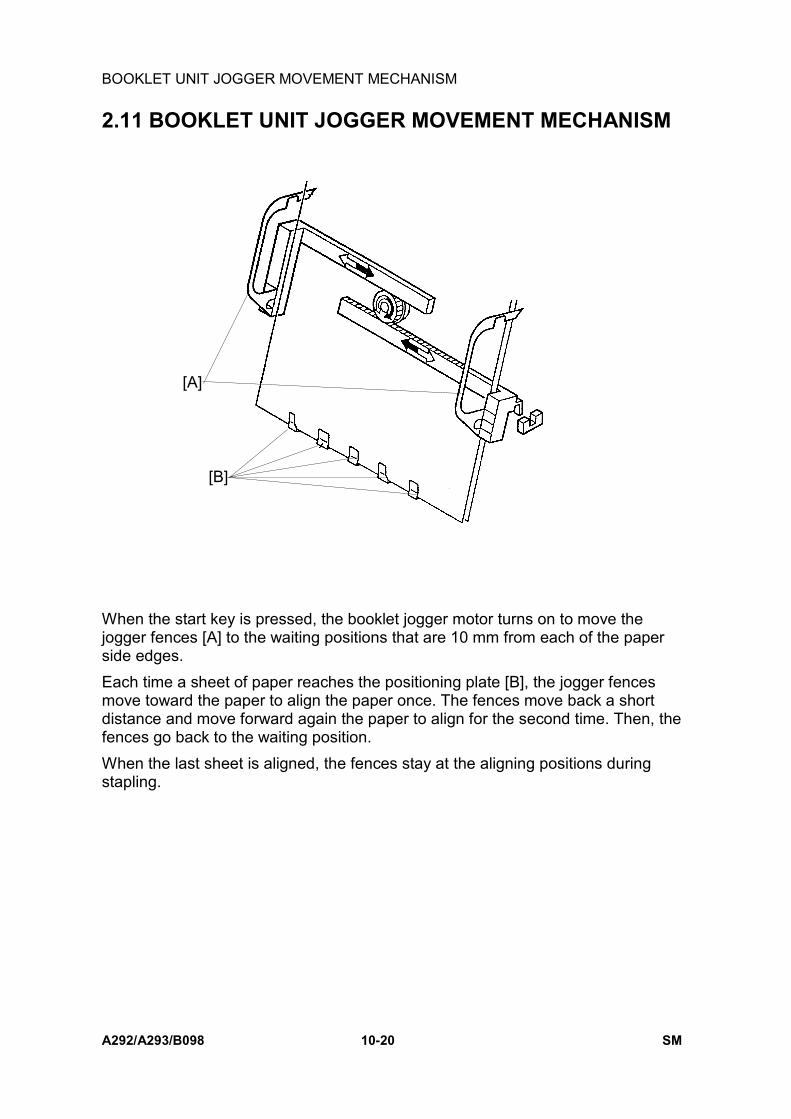
BOOKLET UNIT JOGGER MOVEMENT MECHANISM
A292/A293/B098 10-20 SM
2.11 BOOKLET UNIT JOGGER MOVEMENT MECHANISM
When the start key is pressed, the booklet jogger motor turns on to move thejogger fences [A] to the waiting positions that are 10 mm from each of the paperside edges.Each time a sheet of paper reaches the positioning plate [B], the jogger fencesmove toward the paper to align the paper once. The fences move back a shortdistance and move forward again the paper to align for the second time. Then, thefences go back to the waiting position.When the last sheet is aligned, the fences stay at the aligning positions duringstapling.
A763D557.PCX
[A]
[B]

BOOKLET STAPLER UNIT
SM 10-21 A292/A293/B098
Boo
klet
Fini
sher
A76
3
2.12 BOOKLET STAPLER UNIT
There are two staplers whose positions are fixed.When the jogger fences finish aligning the last sheet, the jogger fences stay at thealigning positions and stapling starts. The two staplers do not operate at the sametime, the rear stapler operates first, then the front one. This is for the followingreasons:• To prevent paper from becoming waved in the area between the two stapled
positions.• To minimize necessary electric power.The staple hammer HP switch in each stapler detects a stapling cycle and thestaple end sensor detects the presence of staples in the cartridge.The stapler unit, including the two staplers, can be pulled out to enable staplecartridge replacement or jam removal. The stapler unit set sensor detects when thestapler unit is back in the right position.
A763D575.PCX

PAPER FOLDER MECHANISM
A292/A293/B098 10-22 SM
2.13 PAPER FOLDER MECHANISM
The positioning plate moves down from the stapling position to a position such thatthe middle of the paper just comes to the folding position. It depends on the papersize.At the same time, the shutter guide motor moves the shutter guide, which iscovering the folder rollers to prevent paper arriving at the positioning plate frombeing caught by the rollers, down to the home position.Shortly after that, the folder plate motor and the folder roller motor start rotating.The folder plate [A] moves to push the middle of the stapled sheets of papertoward the folder rollers [B] until the folder plate return sensor [C] is de-actuated.Then, the folder plate comes back to the home position.After that, the folder rollers and booklet exit roller feed the paper to the booklet tray.
A763D559.PCXA763D560.PCX
A763D562.PCXA763D561.PCX
[A]
[B]
[C]
[A]
[B]
20 mm

PAPER FOLDER MECHANISM
SM 10-23 A292/A293/B098
Boo
klet
Fini
sher
A76
3
In the case of 10 sheets or more of A4 or 81/2" x 11" paper, folding is done twice for20 mm of the leading edge to fold the paper more firmly.When the leading edge of the folded paper passes 20 mm from the folder rollers,the folder roller motor reverses to feed the paper back 20 mm. During this action,the folder plate stays at the return position. (Figure A763D561)Then, the folder roller motor rotates forward again to feed the set of papers out andthe folder plate goes back to the home position. (Figure A763D562)

ACCESSORY CHECK
A292/A293/B098 10-24 SM
3. INSTALLATION3.1 ACCESSORY CHECKCheck the quantity and condition of the accessories in the box against the followinglist.
Description Qty1. Upper Tray...........................................................................12. Shift Tray .............................................................................13. Tapping Screw -M4 x 6........................................................14. Rail Assy.............................................................................15. Joint Bracket ........................................................................16. Tapping Screw - M4 x 16.....................................................27. Rail Bracket .........................................................................18. Tapping Screw - M4 x 6.......................................................19. Harness Cover.....................................................................110. Sensor Feeder...................................................................1
A763I101.WMF
1
2
3
4
5
6
7
8
9
10

INSTALLATION PROCEDURE
SM 10-25 A292/A293/B098
Boo
klet
Fini
sher
A76
3
1.2 INSTALLATION PROCEDURE
!CAUTIONKeep the power cord unplugged when starting the following procedure.
1. Unpack the finisher and remove the tapes and shipping retainers.
A763I102.WMF
A763I104.WMF

INSTALLATION PROCEDURE
A292/A293/B098 10-26 SM
2. Open the front under door and pull out the staple unit [A].3. Remove the stapler unit lock plate [B] (1 screw).4. Push in the stapler unit and shut the front lower door.5. Remove the right lower cover [C] (4 screws).6. Remove the front pressure release bracket [D] (1 screw).7. Remove the rear pressure release bracket [E] (1 screw).
A763I105.WMF
A763I103.WMF
[C]
[E]
[A]
[B]
[D]

INSTALLATION PROCEDURE
SM 10-27 A292/A293/B098
Boo
klet
Fini
sher
A76
3
8. Set the hooks [A] of the shift tray [B] in the notches in the shift tray bracket, andsecure the tray with two M4 x 6 screws.
9. Connect the shift tray sensor harness [C].10. Install the harness cover [D] (2 hooks).
A763I106.WMF
A763I107.WMF
[A][B]
[C]
[D]

INSTALLATION PROCEDURE
A292/A293/B098 10-28 SM
11. Install the upper tray [A] (2 pins).12. Attach the sensor feeler [B] (2 pins).13. Install the joint bracket [F] on the left side of the copier (4 screws).14. Attach the rail [C] to the rail bracket [D] as shown.15. Install the rail bracket [E] on the left lower cover of the copier (2 screws).
A763I108.WMF
A763I110.WMF
[A]
[B]
[C][D]
[E]
[F]

INSTALLATION PROCEDURE
SM 10-29 A292/A293/B098
Boo
klet
Fini
sher
A76
3
16. Secure the rail [B] to the booklet finisher with 1 M4 screw.17. Align the finisher on the joint bracket and lock the 2 hooks [C] of the finisher on
the joint bracket.18. Connect the finisher cable [D] to the copier.19. Plug in the power cord and turn the main switch on, and perform stapler initial
setting as follows.1) Enter User Program mode.2) Press System Settings.3) Press Basic Page 2.4) Press Staple Initialization.5) Press the OK key.
A763I111.WMF[B]
[C][D]

REMOVAL
A292/A293/B098 10-30 SM
4. REPLACEMENT AND ADJUSTMENT4.1 REMOVAL4.1.1 UPPER DOOR
1. Open the upper door [A].2. Remove the lower hinge [B] (1 screw).3. Push up the upper door and remove it.
A763R579.PCX
[A]
[B]

REMOVAL
SM 10-31 A292/A293/B098
Boo
klet
Fini
sher
A76
3
4.1.2 UPPER REAR COVER
1. Hold up the proof tray and open the top cover [A].2. Unhook the upper rear cover [B] and remove it (3 screws).
4.1.3 LOWER REAR COVER
1. Remove the lower rear cover [C] (4 screws).
A763R580.PCX
A763R104.WMF
[A]
[B]
[C]

REMOVAL
A292/A293/B098 10-32 SM
4.1.4 TOP COVER
1. Hold up the upper tray [A] and open the top cover [B].2. Push the hooks [C] of the top cover and remove it.
4.1.5 UPPER INNER COVER
1. Open the upper door.2. Remove the upper inner cover [A] (1 screw).
A763R581.PCX
A763R580.PCX
A763R582.PCX
[B]
[C]
[A]
[A]
[B]

REMOVAL
SM 10-33 A292/A293/B098
Boo
klet
Fini
sher
A76
3
4.1.6 SHIFT TRAY UNIT
1. Remove the upper and lower rear covers.2. Disconnect the connector [A] and remove the grounding wire [B]
(1 screw).3. Unhook the two stoppers [C] and remove them.4. Remove the slide guide [D] by pulling it up.
5. Remove the shift tray unit [E] by pulling it up.NOTE: When reinstalling the shift tray unit, release the clutch gear [F] of the
tray lift motor by carefully inserting a screwdriver.
A763R106.WMFA763R107.WMF
A763R108.WMF
[A]
[B]
[E][C]
[D]
[F]

REMOVAL
A292/A293/B098 10-34 SM
4.1.7 UPPER SHIFT GUIDE
1. Remove the slide guide and shift the shift tray unit down by releasing the clutchgear of the tray lift motor (see Shift Tray Unit Removal).
2. Remove the upper shift guide [A] (6 screws (5 x M4, 1 x M3)).
4.1.8 LOWER SHIFT GUIDE
1. Remove the shift tray unit.2. Remove the lower shift guide [A] (2 connectors, 6 screws (3 x M4, 3 x M3)).
A763R112.WMF
A763R109.WMF
[A]
[A]

REMOVAL
SM 10-35 A292/A293/B098
Boo
klet
Fini
sher
A76
3
4.1.9 EXIT UNIT
1. Remove the shift tray unit, and the upper and lower shift guides.2. Disconnect the connector [A] and remove the screw [B] that secures the
transport belt unit [C].3. Disconnect the 4 connectors [D].4. Hold up the exit unit [E] and remove it with the transport belt unit
(3 screws, 1 clamp).NOTE: When installing the exit unit, make sure to position the exit unit guide
plate (black) [F] over the transport guide plate [G].
A763R113.WMF
A763R114.WMF
[A]
[B]
[C]
[E]
[D]
[F]
[G]

REMOVAL
A292/A293/B098 10-36 SM
4.1.10 BUFFER ROLLER UNIT
1. Remove the upper rear cover and the top cover.2. Disconnect the connector [A].3. Remove the upper shift guide [B] (6 screws) and the guide holder [C] (2
screws).4. Unhook the shafts [D], and remove the buffer roller unit [E] (2 clamps).
A763R583.PCX A763R112.WMF
A763R585.PCXA763R584.PCX
[A]
[D]
[B] [C]
[D]
[E]

REMOVAL
SM 10-37 A292/A293/B098
Boo
klet
Fini
sher
A76
3
4.1.11 STAPLER
1. Open the upper front door.2. Slide the stapler [A] towards the front.3. Remove the stapler (1 screw, 1 connector [B]).4. Remove the cover [C] from the stapler (2 screws).
A763R586.PCX
A763R587.PCX
A763R588.PCX
[A]
[B]
[C]

REMOVAL
A292/A293/B098 10-38 SM
4.1.12 FINISHER BOARD
1. Remove the upper rear cover.2. Remove the finisher board [A] (4 screws, 19 connectors).
NOTE: Do the following adjustments after replacing the board:• Shift tray height• Jogger fence position• Stapling position
A763R589.PCX
[A]

REMOVAL
SM 10-39 A292/A293/B098
Boo
klet
Fini
sher
A76
3
4.1.13 BOOKLET UNIT
1. Remove the following items.• Upper and lower rear covers.• Shift tray unit.• Lower shift guide.
2. Remove the lower right cover [A] (4 screws).3. Remove the folder roller knob [B] (1 stepped screw).4. Remove the lower inner cover [C] and lower door [D] (5 screws).
A763R561.WMF
[A]
[B]
[C]
[D]

REMOVAL
A292/A293/B098 10-40 SM
5. Remove the grounding wire [A] (1 screw) and upper booklet exit guide [B](2 screws).
6. Open the lower booklet exit guide [C] and remove it (1 L-pin [D], 2 connectors [E]).
7. Remove the right front and right rear covers [F , G] (2 screws each).8. Disconnect the two connectors [H].9. Remove the two joints [I] and then pull out the booklet unit [J] from the right
side (3 screws).
A763R110.WMF A763R101.WMF
A763R111.WMF
[A]
[B]
[C]
[D]
[E] [F]
[G]
[H]
[I]
[J]
[I]

REMOVAL
SM 10-41 A292/A293/B098
Boo
klet
Fini
sher
A76
3
4.1.14 FOLDER ROLLERS
1. Remove the booklet unit2. Remove the drive unit [A] (4 connectors [B], 3 screws [C]).3. Remove the front and rear tension springs [D].
A763R590.PCX
A763R593.PCX
A763R591.PCX
A763R592.PCX
[A]
[D][D]
[B] [C]

REMOVAL
A292/A293/B098 10-42 SM
4. Remove the gears [A] and ball bearings [B] (4 C-rings).5. Remove the front and rear tighteners [C] (1 stepped screw each).
4-105B.PCX
A763R595.PCX
A763R596.PCX
A763R597.PCXA763R598.PCX
[A][B]
[B]
[C]
[C]

REMOVAL
SM 10-43 A292/A293/B098
Boo
klet
Fini
sher
A76
3
6. Remove the jogger plates [A] (1 screw each).7. Slide the folder rollers [B] to the front and remove them.
A763R599.PCX
A763R549.PCX
[A]
[B]

REMOVAL
A292/A293/B098 10-44 SM
4.1.15 FOLDER PLATE
Removal
1. Remove the following items• Lower right cover (see Booklet Unit Removal)• Folder roller knob (see Booklet Unit Removal)• Lower door and lower inner cover (see Booklet Unit Removal)• Booklet board
2. Release the harness [A] from the clamps.3. Insert two positioning screws [B] in the holes provided in the folder table [C].4. Tighten the screws until the ends touch the securing plate [D] for the folder
plate.5. Remove the folder plate [E] and the securing plate (3 screws).
A763R117.WMF
A763R116.WMF
[B][C]
[D]
[A]
[D]
[E]

REMOVAL
SM 10-45 A292/A293/B098
Boo
klet
Fini
sher
A76
3
Reinstalling
1. Line up the two small holes [A] in the folder plate with the two small protrusionson the bottom of the securing plate [B]. Then, push the two protrusions throughthe holes. Note: Be sure that the three screw holes are also lined up.
2. Temporarily fix the two plates together by attaching two strips of electrical tape[C] along the line where they meet (see the illustration).NOTE: 1) Be sure to fold the two strips back toward you so that they can
easily be removed.2) Be careful not to attach the tape too close to the three screw holes.
3. Reattach the two plates [A, B] to the folder table [D] (3 screws).NOTE: Tighten these three screws while holding the securing plate against
the two positioning screws [E] that were installed in step 3 of the"Removal" procedure.
4. Remove the two strips of tape.
A763R575.PCXA763R578.PCX
A763R577.PCX
A763R576.PCX
[C]
[A, B]
[D]
[E]
[B]
[B]
[A]
[A]

REMOVAL
A292/A293/B098 10-46 SM
4.1.16 BOOKLET STAPLER UNIT
Removal
1. Remove the lower door and inner cover (see Booklet Unit Removal).2. Remove the guide roller [A] and shaft [B] (1 E-ring).3. Pull out the booklet stapler unit [C].
A763D562.PCX
A763R563.PCX
[A] [B]
[C]

REMOVAL
SM 10-47 A292/A293/B098
Boo
klet
Fini
sher
A76
3Adjustment
1. Remove the booklet stapler cover [A] (3 screws).2. Remove the three paper guides [B] (1 screw each).3. Loosen the two screws on each of the anvils [C].
A763R564.PCX
A763R565.PCX
A763R567.PCX
[A]
[B]
[C]

REMOVAL
A292/A293/B098 10-48 SM
4. Insert the anvil positioning plate [A] into the staple slot of the stapler [B].NOTE: The anvil positioning plate is stored in the booklet stapler cover [C].
5. Rotate the gear to move down the stapler. Then align the anvil positioning plateand the anvil [D]. Then secure the anvils (2 screws each).
A763R568.PCX
A763R569.PCX
A763R570.PCX
[A][B]
[A]
[C]
[A]
[D]

REMOVAL
SM 10-49 A292/A293/B098
Boo
klet
Fini
sher
A76
3
4.1.17 BOOKLET BOARD
1. Remove the lower right cover [A] (4 screws).2. Remove the booklet board [B] (4 screws, 14 connectors).
NOTE: After replacing the board, adjust the booklet stapling position.
4.1.18 POSITIONING PLATE UNIT
1. Remove the booklet board (4 screws, 14 connectors).2. Slide the paper positioning unit [C] to the right and remove it (2 screws, 2
connectors [D]).
A763R115.WMF
A763R571.PCX
[A]
[B]
[C] [D]

REMOVAL
A292/A293/B098 10-50 SM
4.1.19 1ST AND 2ND BOOKLET UNIT GATES
1. Remove the upper and lower rear covers.2. Release the two tension springs [A] of the booklet entrance guide [B].3. Remove the booklet unit gate solenoids [C] (1 screw and 1 spring each).4. Pull out the link of the solenoid [D].5. Remove the booklet unit gates [E].
A763R572.PCX
A763R573.PCX
A763R574.PCX
[A]
[B]
[A]
[C]
[D]
[E]

ADJUSTMENT
SM 10-51 A292/A293/B098
Boo
klet
Fini
sher
A76
3
4.2 ADJUSTMENT4.2.1 SHIFT TRAY HEIGHT
After replacing the finisher board or shift tray height sensor, always do thisadjustment.
1. Remove the upper rear cover.2. Turn on dip switches 3 -1 and -4 on the finisher board.3. Put blank paper (A4/81/2" x 11") on the shift tray.4. Press switch 1 (SW1) on the finisher board.
The finisher automatically adjusts the shift tray height when switch 1 is pressed.• After performing the adjustment, the shift tray will return to home position.• During the adjustment, LED 1 flashes. After performing the adjustment, LED
1 turns on and remains on.• If the automatic adjustment fails, the finisher stops and LED 1 turns off.
5. Turn off dip switches 3 -1 and -4, then turn off the copier main switch.
SW1
SW2
Dip Switch 3
LED 2
LED 1
A763R550.WMF
1
Dip Switch 3
2 3 5 6 7 84
ON
A763R551.WMF

ADJUSTMENT
A292/A293/B098 10-52 SM
4.2.2 JOGGER FENCE POSITION
After replacing the finisher board or if a paper alignment fault occurs, do thisadjustment.Doing this adjustment once will affect all paper sizes.
1. Remove the upper rear cover.2. Turn on dip switch 3-1 on the finisher board.3. Press the following switch on the finisher board.
Using A4: Switch 1 (SW1)Using 81/2" x 11": Switch 2 (SW2)• After pressing the switch, the upper exit unit will open and the jogger fences
will move to the A4 or 81/2" x 11" position.4. Place 10 sheets of A4/81/2" x 11" paper between the jogger fences and push
them until they touch the shutters.5. Adjust the jogger fence position by pressing switch 1 or 2.
• Switch 1: Move to the front (0.35 mm/press)• Switch 2: Move to the rear (0.35 mm/press)
6. Press switches 1 and 2 simultaneously to store the adjustment data.• After pressing the switches, the upper exit unit will close.
7. Turn off dip switch 3-1, then turn off the copier main switch.
SW1
SW2
Dip Switch 3
LED 2
LED 1
A763R550.WMF
RearJogger Fence
Jogger Fence
Front
SW2
SW1
Shutter
A763R553.WMF1
Dip Switch 3
2 3 5 6 7 84
ON
A763R552.WMF

ADJUSTMENT
SM 10-53 A292/A293/B098
Boo
klet
Fini
sher
A76
3
4.2.3 STAPLING POSITOIN
After replacing the finisher board, do this adjustment. Doing this adjustment oncewill affect all paper sizes and all stapling positions.
1. Remove the upper rear cover.2. Turn on dip switches 3 -1 and -2 on the finisher board.3. Press the following switch on the finisher board.
Using A4: Switch 1 (SW1)Using 81/2" x 11": Switch 2 (SW2)• After pressing the switch, the upper exit unit will open and the transport belt
will rotate.4. Within five seconds after pressing the switch, place one sheet of A4/81/2" x 11"
paper between the jogger fences and push it until it touches the shutter.When the staple tray paper sensor detects the paper, the stapler will staple(rear, 1 point).
1. Take out the stapled paper manually and check the staple position.Staple position: Good → Turn off dip switches 3 -1 and -2 to end the
procedure.Staple position: No good → Change the staple position by doing the
following steps.6. Adjust the staple position by pressing switch 1 or 2.
Switch 1: Move the front (0.3 mm/press)Switch 2: Move to the rear (0.3 mm/press)
7. Press switches 1 and 2 simultaneously to store the adjustment data. Afterpressing the switches, check the staple position again.
8. Turn off dip switches 3 -1 and -2, then turn off the copier main switch.
Rear FrontSW2 SW1
Staple
290 ± 2 mm (A4Y), 273 ± 2 mm (LTR)
A763R555.WMF
1
Dip Switch 3
2 3 5 6 7 84
ON
A763R554.WMF

ADJUSTMENT
A292/A293/B098 10-54 SM
1.1.4 BOOKLET STAPLING POSITION
After replacing the booklet board, dip switches 1 -6, -7, -8 on the new board mustbe set up the same way as on the old board.
1. Remove the lower right cover (see Booklet Unit Removal) and lower rearcover.
2. Turn on dip switches 1 -1 and -2 on the booklet board.3. Tape the actuators of the booklet entrance guide sensor (S42) and the booklet
entrance guide safety switch (SW11), so that S42 and SW11 remain actuated.4. Press switch 2 (SW2) on the booklet board.
• After pressing the switch, the booklet transport motor (M10) will start torotate.
5. Put a mark on the trailing edge of some A3/11" x 17" paper (two sheets).
SW2
Dip Switch 1
LED 1
A763R557.WMF
1
Dip Switch 1
2 3 5 6 7 84
ON
A763R556.WMF
Mark(Trailing edge)
Slot in direction(reading edge)
A763R558.WMF

ADJUSTMENT
SM 10-55 A292/A293/B098
Boo
klet
Fini
sher
A76
3
6. Open the booklet entrance guide [A], then slide in the two sheets of paper [B]until their leading edges touch the positioning plate.
7. Press switch 2 on the booklet board.• The booklet finisher makes a booklet automatically.
A763R548.PCX
[A]
[B]

ADJUSTMENT
A292/A293/B098 10-56 SM
Dip switch 1 -6, -7, -8 setting-6 -7 -8
Adjustment(0.25 mm/ step)
OFF ON ON +3OFF ON OFF +2OFF OFF ON +1OFF OFF OFF 0ON OFF ON -1ON ON OFF -2ON ON ON -3ON OFF OFF Do not use
8. Measure the distance (L) between the stapling position and the folder position.9. Adjust the stapling position with dip switches 1 -6, -7, -8.
Inputting a lower value than the current setting moves the stapling positiontowards the leading edge. Adjusting by 1 step moves the stapling position 0.25mm.
Example 1:To move the stapling position 1 mm towards the leading edge.If dip switch 1 is currently set to +2, set the dip switch to reflect -2 (this movesthe stapling position 4 steps towards the leading edge).Example 2:To move the stapling position 0.75 mm away from the leading edge.If dip switch 1 is currently set to -1, set the dip switch to reflect +2 (this movesthe stapling position 3 steps away from the leading edge).
10. Turn off dip switched 1-1 and -2, then turn off the copier main switch.
Mark
Example 1: L= 1 mm
Adjust towards the leading edge
L
Mark
Example 2: L= 0.75 mm
Adjust away from the leading edge
L
Stapling Position
Folding Position
Folding Position
Stapling Position
A763R559.WMF

COPIER CONNECTION KITB322


SPECIFICATIONS
SM 11-1 A292/A293/B098
Cop
ier
Con
nect
ion
Kit
B32
2
1. SPECIFICATIONSCopy Speed: Max:140 cpm (A4 / 8 ½ " x 11" sideways)
(Two 70 cpm machines)Max: 125 cpm (A4 / 8 ½ " x 11" sideways)(One 70 cpm machine and one 55 cpm machine)Max: 110 cpm (A4 / 8 ½ " x 11" sideways)(Two 55 cpm machines)
Copy Number Input: 1 to 999

DETAILED DESCRIPTIONS
A292/A293/B098 11-2 SM
2. DETAILED DESCRIPTIONS2.1 OVERVIEW
This kit connects two A292 copiers, two A293 copiers or A292 and A293 copier. Ifthe user wishes to have two copiers work on one copy job, the user starts the jobon one copier. The copy job will also be made on the other copier.The copier on which the user pressed the Connect key on the display is known asthe Master Unit and the other copier is the Sub Unit.Features for the job can only be selected on the master unit.There is no restriction on the two connected copiers and their configurations (70cpm copier or 55 cpm copier, with finisher or without finisher etc). However, withsome combinations, the available functions are limited.NOTE: The printer function cannot use the copy connect mode.
B322V500.WMF

DETAILED DESCRIPTIONS
SM 11-3 A292/A293/B098
Cop
ier
Con
nect
ion
Kit
B32
2
2.2 BASIC OPERATIONAfter pressing the start key, all originals are read and stored on the HDD. At thesame time, the data is sent to the slave unit and stored on its HDD.After reading all originals, the master and slave units will begin printing. The CPUseparates the job for both units. So, they finish at about same time.The way that the copies are fed out depend on the copy mode, as follows.
2.2.1 NO SORT AND NO STAPLE MODE
= Master Unit =Exit from the copy of the 1st original, face down.
= Slave Unit =Exit from the copy of the last original, face up.Example:Number of originals: 6, 1-sided to 1-sided copy mode, Number of copies: 3
Master Unit Slave Unit 3rd original 3rd copy 4th original 1st copy 3rd original 2nd copy 4th original 2nd copy 3rd original 1st copy 4th original 3rd copy 2nd original 3rd copy 5th original 1st copy 2nd original 2nd copy 5th original 2nd copy 2nd original 1st copy 5th original 3rd copy 1st original 3rd copy 6th original 1st copy 1st original 2nd copy 6th original 2nd copy 1st original 1st copy 6th original 3rd copy
: Face down, : Face upNOTE: The output quantity on the master and slave units depends on the paper
feed tray position, image rotation, and copy speed. If more than two copiesare made from an original, sometimes one of the copies (for example,copies of the 4th original) will print on different units (in the above example,the 1st copy of the 4th original may be made on the master instead of theslave).

DETAILED DESCRIPTIONS
A292/A293/B098 11-4 SM
2.2.2 SORT, STAPLE MODE
The copies exit face down for both units.Example:Number of originals: 3, 1-sided to 1-sided copy mode, Number of sets: 6
Master Unit Slave Unit 3rd set 3rd copy 6th set 3rd copy 3rd set 2nd copy 6th set 2nd copy 3rd set 1st copy 6th set 1st copy 2nd set 3rd copy 5th set 3rd copy 2nd set 2nd copy 5th set 2nd copy 2nd set 1st copy 5th set 1st copy 1st set 3rd copy 4th set 3rd copy 1st set 2nd copy 4th set 2nd copy 1st set 1st copy 4th set 1st copy
: Face down
NOTE: The output quantity (sets) made by the master and slave units depends onthe paper feed tray position, image rotation, and copy speed. A set ofcopies will not be divided between the two machines. For example, if paperruns out on one machine, the other machine will continue to work on othersets of copies, but will not complete any unfinished sets for the machinethat ran out of paper.

DETAILED DESCRIPTIONS
SM 11-5 A292/A293/B098
Cop
ier
Con
nect
ion
Kit
B32
2
2.2.3 OPERATION IN IRREGULAR CONDITIONS
Paper end during copyingWhen a machine enters the paper end condition, it stops and add paper isdisplayed. The other machine continues to make copies. The rest of the copy job istransferred to the other machine.If paper is replenished before the end of the job, the machine will automaticallystart. If the machine was part of the way through a set of copies, it will finish thatset first. Then, if there are any sets still remaining, they will be re-allocated to bothmachines.
Copy tray fullWhen copy tray is full, the machine stops and paper is full is displayed. If thisoccurs on the sub unit, it is displayed on the master unit also. The other machinecontinues with the rest of the job.If the copies are removed from the copy tray before the end of the job, the machinewill automatically start. If the machine was part of the way through a set of copies,it will finish that set first. Then, if there are any sets still remaining, they will be re-allocated to both machines.
Paper jamWhen a paper jam occurs, the following indicators are displayed.1) Paper jam is displayed on the master unit.2) The machine having the jam condition is indicated on the master unit.3) The jam position is displayed on the machine which has the paper jam.When a machine has a paper jam, it stops and the above indicators are displayed.The other machine continues with the rest of the job.If the jam is removed before the end of the job, the machine will automatically start.If the machine was part of the way through a set of copies, it will finish that set first.Then, if there are any sets still remaining, they will be re-allocated to bothmachines.


LCTA698/B587


SPECIFICATIONS
SM 12-1 A292/A293/B098
LCT
A69
8/B
587
1. OVERALL MACHINE INFORMATION1.1 SPECIFICATIONSPaper Size: A4 sideways, B5 sideways, LT sideways
Paper Weight: 64 g/m2 ~ 105 g/m2, 16 lb ~ 24 lbTray Capacity: 3,500 sheets (80 g/m2, 20 lb)Remaining Paper Detection: 4 stepsPower Source: 24 Vdc, 5 Vdc (from copier)Power Consumption: 48 WWeight: 22 kgSize (W x D x H): 403 mm x 529 mm x 608 mm

MECHANICAL COMPONENT LAYOUT
A292/A293/B098 12-2 SM
1.2 MECHANICAL COMPONENT LAYOUT
1. Paper Feed Sensor2. Paper Feed Roller3. Pick-up Solenoid4. Lift Sensor5. Paper End Sensor6. LCT Motor7. Pick-up Roller8. Paper Near End Sensor9. Paper Height Sensor 1
10. Paper Height Sensor 211. Paper Tray12. Paper Height Sensor 313. Lift Motor14. Down Sensor15. Tray Drive Belt16. Paper Position Sensor17. Separation Roller18. Relay Roller
A698D101.WMF
12 3 4 5 6 7
8
9
10
11
12
1314
15
16
17
18

ELECTRICAL COMPONENT LAYOUT
SM 12-3 A292/A293/B098
LCT
A69
8/B
587
1.3 ELECTRICAL COMPONENT LAYOUT
1. Paper Feed Sensor2. Lift Sensor3. Pick-up Solenoid4. Relay Clutch5. Paper Feed Clutch6. LCT Motor7. Feed Unit Cover Switch 18. Feed Unit Cover Switch 29. Near End Sensor10. Paper Height Sensor 111. Paper Height Sensor 2
12. Paper Height Sensor 313. LCT Interface Board14. Lift Motor15. Down Sensor16. Tray Cover Switch 117. Tray Cover Switch 218. Tray Cover Switch 319. Down Switch20. Paper Position Sensor21. Paper End Sensor
A698D102.WMF
1
23 4
56
7
8
9
10
11
12
13
14
15
16
17
18
19
20
21

ELECTRICAL COMPONENT DESCRIPTIONS
A292/A293/B098 12-4 SM
1.4 ELECTRICAL COMPONENT DESCRIPTIONS
Symbol Name Function IndexNo.
MotorsM1 LCT Drives all rollers. 6M2 Lift Drives the paper tray up or down. 14
Sensors
S1 Paper End Informs the copier when the paper hasrun out. 21
S2 Paper Feed Detects the copy paper coming to therelay roller and checks for misfeeds. 1
S3 Lift Detects when the paper is at the correctpaper feed height. 2
S4 Down Detects when the tray is completelylowered, to stop the LCT motor. 15
S5 Paper Height 1 Detects the paper height. 10S6 Paper Height 2 Detects the paper height. 11S7 Paper Height 3 Detects the paper height. 12S8 Near End Detects the paper height. 9
S9 Paper Position Detects when the top of the paper stackis at the correct position for paper feed. 20
Switches
SW1 Tray Cover 1 Detects whether the tray cover is openedor not. 16
SW2 Tray Cover 2 17
SW3 Tray Cover 3Ensures that +24V can be passed to thelift motor whether the cover is open orclosed. 18
SW4 Feed UnitCover 1
Detects whether the feed unit cover isopened or not. 7
SW5Feed UnitCover 2
Ensures that +24V can be passed to thelift motor whether the cover is open orclosed.
8
SW6 Down Lowers the LCT bottom plate if pressed. 19Solenoids
SOL1 Pick-up Controls up-down movement of the pick-up roller. 3
Magnetic ClutchesMC1 Paper Feed Drives the paper feed roller. 5MC2 Relay Drives the relay roller. 4
PCBs
PCB1 LCT Interface Controls the LCT and communicates withthe copier. 13

DRIVE LAYOUT
SM 12-5 A292/A293/B098
LCT
A69
8/B
587
1.5 DRIVE LAYOUT
1. Relay Roller2. Paper Feed Roller3. Relay Clutch4. Paper Feed Clutch5. LCT Motor
6. Lift Motor7. Tray Drive Shaft8. Tray Drive Belt9. Pick-up Roller10. Separation Roller
A698D103.WMF
1
23
45
6
7
8
9
10

PAPER FEED MECHANISM
A292/A293/B098 12-6 SM
2. DETAILED DESCRIPTIONS2.1 PAPER FEED MECHANISM
This LCT uses an FRR paper feed system (paper feed roller [A], separation roller[B], pick-up roller [C]), and those rollers are driven by the LCT motor [D].When the start key is pressed, the paper feed clutch [E], relay clutch [F], and pick-up solenoid [G] energize. The pick-up roller touches the paper and feeds it to thecopier.When the leading edge of the paper reaches the paper feed sensor, the pick-upsolenoid turns off and the pick-up roller lifts away from the paper.
A698D104.WMF
A698D105.WMF
[A] [B] [C]
[D]
[E][F]
[G]

TRAY LIFT MECHANISM
SM 12-7 A292/A293/B098
LCT
A69
8/B
587
2.2 TRAY LIFT MECHANISM
The lift motor [A] controls the vertical position of the tray bottom plate [B] throughgears and timing belts [C].
Tray lifting conditionsWhen the lift sensor [D] turns off during copying, the tray lift motor raises the traybottom plate until the tray lift sensor turns on again.To position the top of the paper stack at the correct height, the pick-up solenoid [E]turns on to lower the pick-up roller onto the paper and the lift motor raises the traybottom plate until the tray lift sensor turns on. Then the motor turns in reverse tolower the tray until the lift sensor turns off, then it changes direction again to lift thetray until the lift sensor turns on again, then it stops. The above procedure is donein the following conditions.• Just after the main switch is turned on• Just after the tray cover is closed• Just after leaving the energy saving mode
Tray lowering conditionsIn the following conditions, the lift motor lowers the tray bottom plate until the downsensor turns on.• Just after the paper end sensor turns on• Just after the down switch is pressed by the user
A698D106.WMF
A698D107.WMF
[A]
[B]
[C]
[D]
[E]

TRAY LIFT MECHANISM
A292/A293/B098 12-8 SM
If the down switch [A] is pressed, or paper runs out, or a paper jam occurs in theLCT, the LCT motor [B] lowers the bottom plate until the paper position sensor [C]activates. At this point, the bottom plate (or the top sheet of paper) is positionedabout 5 cm below the paper feed height. This gives enough space for the user toadd about 500 sheets of paper.If the down switch is then pressed again, the bottom plate moves down once againuntil the top sheet of paper just passes the paper position sensor. In this way, thebottom plate lowers 5 cm at each press of the down switch. This allows thecustomer to replenish paper in convenient amounts and at the same position.
A698D108.WMF
[A]
[B]

PAPER STACK HEIGHT DETECTION
SM 12-9 A292/A293/B098
LCT
A69
8/B
587
2.3 PAPER STACK HEIGHT DETECTION
The amount of the paper in the tray is detected by four sensors (paper heightsensor 1 [A], 2 [B], 3 [C] and near end sensor [D].)
Sensor Remaining amount Display
Near End Sensor Approx. 80 sheets
A698D510.WMF
Paper Height 1 Sensor Approx. 300 sheets
A698D511.WMF
Paper Height 2 Sensor Approx. 1000 sheets
A698D512.WMF
Paper Height 3 Sensor Approx. 2000 sheets
A698D513.WMF
A698D110.WMF
[A]
[B]
[C]
[D]

TEST POINTS
A292/A293/B098 12-10 SM
3. SERVICE TABLES3.1 TEST POINTS
No. Label Monitored SignalTP100 24 V +24 VTP101 GND GroundTP102 CGND GroundTP103 VCC +5 V

COVER REMOVAL
SM 12-11 A292/A293/B098
LCT
A69
8/B
587
4. REPLACEMENT AND ADJUSTMENT4.1 COVER REMOVAL
Tray Cover1. Remove the tray cover [A] (1 screw).
Right Cover1. Remove the right cover [B] (2 screws).
Front Cover1. Remove the right cover.2. Remove the front cover [C] (3 screws).
Upper Rear Cover1. Remove the upper rear cover [D] (2 screws).
A698R101.WMF
[A]
[B]
[C]
[D]

COVER REMOVAL
A292/A293/B098 12-12 SM
Lower Rear Cover1. Remove the tray cover.2. Remove the upper rear cover.3. Remove the lower rear cover [A] (3 screws).
Feed Unit Cover1. Remove the front cover.2. Remove the front hinge cover [B] (1 screw).3. Remove the feed unit cover [C].
A698R101.WMF
[A]
[B]
[C]

ROLLER REPLACEMENT
SM 12-13 A292/A293/B098
LCT
A69
8/B
587
4.2 ROLLER REPLACEMENT4.2.1 PAPER FEED, SEPARATION, AND PICK-UP ROLLERS
1. Push the down switch to lower the tray bottom plate.2. Open the feed unit cover.
Pick-up Roller3. Replace the pick-up roller [A] (1 snap ring).
Paper Feed Roller3. Replace the paper feed roller [B] (1 snap ring).
Separation Roller3. Replace the separation roller [C] (1 snap ring).
A698R102.WMF
[A]
[B]
[C]

PAPER END SENSOR REPLACEMENT
A292/A293/B098 12-14 SM
4.3 PAPER END SENSOR REPLACEMENT
1. Push the down switch to lower the tray.2. Remove the feed unit and tray cover.3. Remove the side fence screws [A].4. Mark the stay position [B]5. Remove the stay [C] (2 screw).6. Replace the paper end sensor [D] (1 screw, 1 connector).NOTE: When reinstalling the stay, make sure that the side-to side registration is
correct (make a test copy). If it must be adjusted, move the stay across asshown in the above drawing (an SP can also be adjusted).
A698R104.WMF
A698R105.WMF
[B] [C]
[D]
[A]

PAPER FEED SENSOR REPLACEMENT
SM 12-15 A292/A293/B098
LCT
A69
8/B
587
4.4 PAPER FEED SENSOR REPLACEMENT
1. Open the feed unit cover [A].2. Remove the paper feed sensor bracket [B] (2 screws).3. Replace the paper feed sensor [C] (1 screw, 1 connector).
R105.WMF
[A]
[B]
[C]

PAPER POSITION SENSOR REPLACEMENT
A292/A293/B098 12-16 SM
4.5 PAPER POSITION SENSOR REPLACEMENT
1. Remove the LCT.2. Open the tray cover and feed unit cover.3. Remove the sensor cover [A] (2 screws).4. Replace the paper position sensor [B] (1 screw, 1 connector).
A698R108.WMF
[A]
[B]

PICK-UP SOLENOID REPLACEMENT
SM 12-17 A292/A293/B098
LCT
A69
8/B
587
4.6 PICK-UP SOLENOID REPLACEMENT
1. Open the feed unit cover.2. Remove the upper rear cover [A] (2 screws).3. Remover the solenoid cover [B] (1 screw).4. Replace the pick-up solenoid [C] (2 screws, 1 connector).
A698R103.WMF
[A]
[B]
[C]

LIFT MOTOR REPLACEMENT
A292/A293/B098 12-18 SM
4.7 LIFT MOTOR REPLACEMENT
1. Remove the upper and lower rear covers.2. Replace the lift motor [A] (2 screws, 1 connector).
A698R107.WMF
[A]

SIDE FENCE POSITION CHANGE
SM 12-19 A292/A293/B098
LCT
A69
8/B
587
4.8 SIDE FENCE POSITION CHANGE
1. Cover the paper position sensor.2. Push the down switch to lower the tray bottom plate to its lowest position.3. Open the tray cover.4. Remove the right cover.5. Remove the front and rear side fences [A, B] (1 screw each).6. Install the side fences in the correct position.7. Input the paper size with SP5-019.
A698D109.WMF
[A] [B]


3,000-SHEET FINISHERB302


Rev. 10/2002 SPECIFICATIONS
SM 13-1 A294/A295/B098
3,00
0-Sh
eet
Fini
sher
B30
2
1. OVERALL MACHINE INFORMATION1.1 SPECIFICATIONSThe punch unit is an option for this machine.Paper Size: No punch mode
Shift Tray: A3 to A5/DLT to HLTUpper Tray: A3 to A5, A6 lengthwise, B6 lengthwise/
DLT to HLTPunch mode
2 holes: A3 to A5/DLT to HLT3 holes: A3, B4, A4 sideways, B5 sideways
DLT, LT sideways4 holes (Europe): A3 to A5
DLT to LT, HLT sideways4 holes (North Europe): A3 to B5, A5 sideways
DLT to LT, HLT sidewaysStaple Mode
A3 to B5/DLT to LTPaper Weight: No punch mode
No staple mode: 52 g/m2 ~ 216 g/m2, 14 ~ 42 lbStaple mode: 64 g/m2 ~ 80 g/m2, 17 ~ 21 lb
Punch mode2 holes: 52 g/m2 ~ 163 g/m2, 14 ~ 42 lb3 holes: 52 g/m2 ~ 163 g/m2, 14 ~ 42 lb4 holes: 52 g/m2 ~ 128 g/m2, 14 ~ 34 lb
Paper Capacity: Shift tray/no staple mode (80 g/m2, 20 lb):Punch mode No punch mode
B5 sidewaysA4 sidewaysLT sideways
2,500 sheets 3,000 sheets
Other sizes 1,500 sheets 1,500 sheets
Shift tray/staple mode/punch mode (80 g/m2, 20 lb):Pages/set Sets
2 to 9 150B5 sidewaysA4 sidewaysLT sideways 10 to 80 200 to 30
2 to 9 100Other sizes 10 to 40 150 to 30

SPECIFICATIONS Rev. 10/2002
A294/A295/B098 13-2 SM
Shift tray/staple mode/no punch mode (80 g/m2, 20 lb):Pages/set Sets
2 to 9 150B5 sidewaysA4 sidewaysLT sideways 10 to 100 200 to 30
2 to 9 150Other sizes 10 to 50 150 to 30
Upper tray (80 g/m2, 20 lb):Punch mode No punch mode
A4/LT or smaller 400 sheets 500 sheetsLarger than A4/LT 200 sheets 250 sheets
Stapler Capacity (pages/set, 80 g/m2, 20 lb paper):Punch mode No punch mode
B5 sidewaysA4 sidewaysLT sideways
80 sheets 100 sheets
Other sizes 40 sheets 50 sheets
Staple Position: 5 positions (4 positions shown, 1 position selectable(*)with in user tools)
1-staple: 3 positions (Front(*), Rear, Rear-Oblique)2-staple: 2 position (double top, double rear(*))
Staple Replenishment: Cartridge (5,000 staples)Power Source: 24 Vdc (from copier)Power Consumption: 120 WWeight: 60 kgSize (W x D x H): 800 mm x 730 mm x 980 mm

Rev. 10/2002 MECHANICAL COMPONENT LAYOUT
SM 13-3 A294/A295/B098
3,00
0-Sh
eet
Fini
sher
B30
2
1.2 MECHANICAL COMPONENT LAYOUT
1. Upper Tray2. Middle Transport Rollers3. Upper Tray Exit Roller4. Upper Transport Rollers5. Tray Junction Gate6. Stapler Junction Gate7. Entrance Rollers8. Punch Unit9. Pre-stack Junction Gate10. Punch Waste Hopper11. Pre-stack Tray
12. Stack Plate13. Staple Waste Hopper14. Stapler15. Alignment Brush Roller16. Positioning Roller17. Stack Feed-out Belt18. Shift Tray Drive Belt19. Lower Transport Rollers20. Shift Tray21. Shift Tray Exit Roller
B302V500.WMF
10
9
15
14
3
11
12
13
16
17
18
20
19
21
4
7
8
1 2 5
6

ELECTRICAL COMPONENT DESCRIPTION Rev. 10/2002
A294/A295/B098 13-4 SM
1.3 ELECTRICAL COMPONENT DESCRIPTIONSymbol Name FunctionMotors
M1 Upper Transport Drives the entrance rollers, the middle and uppertransport rollers, and upper tray exit roller.
M2 Lower Transport Drives the lower transport rollers, the alignment brushroller, and the positioning roller.
M3 Jogger Moves the jogger fence.M4 Stack Plate Drives the stack plate.M5 Stapler Moves the staple unit from side to side.M6 Stapler Rotation Rotates the stapler 45 degrees.M7 Staple Hammer Drives the staple hammer.M8 Stack Feed-out Drives the stack feed-out belt.M9 Exit Guide Opens and closes the upper exit guide.M10 Shift Tray Exit Drives the exit roller for the shift tray.M11 Shift Moves the shift tray from side to side.M12 Shift Tray Lift Moves the shift tray up or down.M13 Punch Drives the punch shaft and roller.
Sensors
S1 Entrance Detects the copy paper entering the finisher andchecks for misfeeds.
S2 Pre-stack TrayPaper
Determines when to turn off the pre-stack paperstopper solenoid.
S3 Stapler TrayEntrance
Detects the copy paper entering the stapler tray andchecks for misfeeds.
S4 Jogger Fence HP Detects the home position of the jogger fence.S5 Stapler Tray Paper Detects the copy paper in the stapler tray.S6 Stack Plate HP Detects the home position of the stack plate.
S7 Stapler HP Detects the home position of the staple unit for side-to-side movement.
S8 Stapler Rotation HP Detects the home position of the stapler unit for 45-degree rotation.
S9 Staple Hammer HP Detects the home position of the staple hammer.S10 Cartridge Set Detects the staple cartridge in the stapler.S11 Staple End Detects the staples in the cartridge.
S12 Staple WasteHopper
Detects when the staple waste hopper is full.
S13 Stack Feed-out BeltHP
Detects the home position of the stack feed-out belt.
S14 Exit Guide Open Detects whether the guide plate is opened or not.S15 Shift Tray Exit Checks for misfeeds at the shift tray.
S16 Stack Height 1 Detects when the top of the copy paper stack in theshift tray is at the correct position.
S17 Stack Height 2 Detects when the top of the copy paper stack in theshift tray has become too high.
S18 Upper Tray Exit Checks for misfeeds at the upper tray.

Rev. 10/2002 ELECTRICAL COMPONENT DESCRIPTION
SM 13-5 A294/A295/B098
3,00
0-Sh
eet
Fini
sher
B30
2
Symbol Name Function
S19 Upper Tray PaperLimit
Detects when the paper stack height in the upper trayis at its upper limit.
S20 Shift Tray Half-turn Detects the return position for side-to-side movementof the shift tray.
S21 Shift Tray LowerLimit 1
Detects when the shift tray is nearly at its lower limit.
S22 Shift Tray LowerLimit 2
Detects when the shift tray is at its lower limit.
S23 Punch WasteHopper
Detects when the punch waste hopper is full anddetects when the punch tray is set.
S24 Punch HP Detects the home position of the punch shaft androller.
S25 Stapler Return Detects the on timing of the stapler return solenoid.
SwitchesSW1 Front Door Safety Cuts the dc power when the front door is opened.
SW2 Shift Tray UpperLimit
Cuts the power to the shift tray lift motor when theshift tray position is at its upper limit.
Solenoids
SOL1 Stapler JunctionGate
Drives the stapler junction gate.
SOL2 Tray Junction Gate Drives the tray junction gate.
SOL3 Pre-stack JunctionGate
Drives the pre-stack junction gate.
SOL4 Pre-stack PaperStopper
Drives the pre-stack paper stopper.
SOL5 Positioning Roller Moves the positioning roller against the stapling tray.
SOL6 Stapler Return Returns the stapler to its guide from the useroperation position.
PCBs
PCB1 Main Controls the finisher and communicates with thecopier.
PCB2 Punch Passes signals between the punch unit and thefinisher main board.

DRIVE LAYOUT Rev. 10/2002
A294/A295/B098 13-6 SM
1.4 DRIVE LAYOUT
1. Upper Transport Roller 22. Upper Tray Exit Roller3. Lower Transport Roller 24. Shift Tray Lift Motor5. Shift Tray Exit Motor6. Shift Tray Exit Roller7. Shift Tray8. Shift Motor9. Staple Tray Exit Roller10. Positioning Roller11. Lower Transport Roller 312. Lower Transport Motor13. Lower Transport Rollers 2
14. Lower Transport Roller 115. Transport Roller 116. Entrance Roller 217. Entrance Roller18. Upper Transport Roller 119. Upper Transport Motor20. Stack Feed-out Motor21. Jogger Motor22. Jogger Fence23. Stack Plate Motor24. Stapler Motor25. Stack Feed-out Belt26. Stapler Rotation Motor
B302V504.WMF
B302V503.WMF
10
1312
1415
1716
1819
11
9 8
7
1 2 3 4 5
6
25
23
26
24
22
21
20

Rev. 10/2002 TRAY AND STAPLER JUNCTION GATE
SM 13-7 A294/A295/B098
3,00
0-Sh
eet
Fini
sher
B30
2
2. DETAILED DESCRIPTIONS2.1 TRAY AND STAPLER JUNCTION GATE
Depending on the finishing mode, the copies are directed up, straight through, ordown by the combination of the tray junction gate [A] and stapler junction gate [B].These gates are controlled by the tray junction gate solenoid [C] and staplerjunction gate solenoid [D].
Upper Tray ModeThe stapler tray junction gate solenoid remains off and the tray junction gatesolenoid turns on. The copies go up to the upper tray.
Sort/Stack ModeThe tray junction gate solenoid and the stapler junction gate solenoid remain off.The copies are sent to the shift tray directly.
Staple ModeThe stapler junction gate solenoid turns on. The copies go downwards to thejogger unit.
B302D507.WMFB302D505.WMF
B302D506.WMF
- Sort/Stack Mode - - Staple Mode -
- Upper Tray Mode -
[B]
[A]
[C]
[D]
[B]
[A]
[C]
[D][A]
[C]
[D]
[B]

PAPER PRE-STACKING Rev. 10/2002
A294/A295/B098 13-8 SM
2.2 PAPER PRE-STACKING
This mechanism improves productivity in staple mode. It is only used when copyingon A4, LT, or B5 (all sideways).During stapling, the copier has to wait. This mechanism reduces the wait byholding the first two sheets of a job while the previous job is still being stapled. Itonly works during the second and subsequent sets of a multi-set copy job.The pre-stack junction gate solenoid [A] turns on about 230 ms after the 1st sheetof paper turns on the entrance sensor, and this directs the sheet to the pre-stacktray [B]. (This sheet cannot be fed to the stapler yet, because the first set is stillbeing stapled.) The pre-stack paper stopper solenoid [C] turns on about 680 msafter the 1st sheet turns on the entrance sensor. The pre-stack paper stopper [D]then stops the paper.The pre-stack junction gate solenoid turns off 450 ms after the trailing edge of the1st sheet passes through the entrance sensor, and the 2nd sheet is sent to thepaper guide [E]. The pre-stack paper stopper is released about 50 ms after the 2ndsheet turns on the pre-stack stopper sensor [F], and the two sheets of copy paperare sent to the stapler tray. All sheets after the 2nd sheet go to the stapler tray viathe paper guide [E].
B302D000.WMF
[F]
[E]
[A]
[B]
[D][C]

Rev. 10/2002 JOGGER UNIT PAPER POSITIONING
SM 13-9 A294/A295/B098
3,00
0-Sh
eet
Fini
sher
B30
2
2.3 JOGGER UNIT PAPER POSITIONING
In staple mode, each sheet of copy paper is vertically and horizontally alignedwhen it arrives in the jogger unit.
Vertical Paper AlignmentApproximately 60 ms after the trailing edge of the copy passes the staple trayentrance sensor [A], the positioning roller solenoid [B] is energized to push thepositioning roller [C] into contact with the paper. The positioning roller andalignment brush roller [D] rotate to push the paper back and align the trailing edgeof the paper against the stack stopper [E].
Horizontal Paper AlignmentWhen the print key is pressed, the jogger motor [F] turns on and the jogger fences[G] move to the waiting position, which is approximately 7 mm wider on both sidesthan the selected paper.When the trailing edge of the paper passes the staple unit entrance sensor, thejogger motor turns on for approximately 32 ms (4.7 mm) to move the jogger fencesapproximately 5 mm towards the paper. After a short time, the jogger motor turnson again approximately 18 ms (3.0 mm) for the horizontal paper alignment thengoes back to the waiting position.
Paper Stack CorrectionAfter the paper is aligned in the stapler tray, the stack plate motor turns [H] on forshort time to correct the paper stack and the stack plate [I] push the paper againstthe staple tray.When the next copy paper turns on the stapler tray entrance sensor, the stackplate motor turns on gain to return to its home position. The home position isdetected by stack plate HP sensor [J].
[C][A]
[E]
[B]
[D]
[G][F]
[J][I] [H]

STAPLER UNIT MOVEMENT Rev. 10/2002
A294/A295/B098 13-10 SM
2.4 STAPLER UNIT MOVEMENT
Side-to-SideThe stapler motor [A] moves the stapler [B] from side to side. After the start key ispressed, the stapler moves from its home position to the stapling position.If two-staple-position mode is selected, the stapler moves to the front staplingposition first, then moves to the rear stapling position. However, for the next copyset, it staples in the reverse order (at the rear side first then at the front side).After the job is completed, the stapler moves back to its home position. This isdetected by the stapler HP sensor [C].
B302D513.WMF
[A]
[B]
[C]

Rev. 10/2002 STAPLER UNIT MOVEMENT
SM 13-11 A294/A295/B098
3,00
0-Sh
eet
Fini
sher
B30
2
Rotation (1)In the oblique staple position mode, the stapler rotation motor [A] rotates thestapler units [B] 45° to counterclockwise after it moves to the stapling position.
Rotation (2)When the staple end condition arises, the stapler motor moves the stapler to thefront and the stapler rotation motor rotates the stapler unit to clockwise to removethe staple cartridge [C]. This allows the user to add new staples.Once the staples have been installed, and the front door closed, the stapler unitreturns to its home position. As the stapler unit is returning to the home position,the stapler return sensor [D] is activated, the return solenoid [E] turns on and itassists the guide roller [F] to return to its guide (this guide directs the stapler duringrotation).
B302D514.WMF
B302D515.WMF
B302D523.WMF
[A]
[B]
[C]
[D]
[F]
[E]

STAPLER Rev. 10/2002
A294/A295/B098 13-12 SM
2.5 STAPLER
When the aligned copies are brought to the stapling position by the positioningroller and jogger fences, the staple hammer motor [A] starts stapling.During stapling, the stapler trims off the excess length [B] of the staples by loweringthe cutter [C]. This excess length depends on the number of copies in the set;there will be very little for a stack containing 100 sheets. The staple waste dropsinto the tray [D] in the stapler. When the stapler unit returns to its home position,the tray hits the shaft [E] and the tray opens. The staple waste drops into the staplewaste hopper [F]. When the staple waste hopper is full, the actuator on its baseactivates the staple waste hopper sensor [G]. An SC is displayed.
B302D516.WMF B302D521.WMF
B302D522.WMF
[A]
[C]
[G]
[F]
[D]
[E]
[E]
[B]

Rev. 10/2002 STAPLER
SM 13-13 A294/A295/B098
3,00
0-Sh
eet
Fini
sher
B30
2The stapler has a staple end sensor [A], cartridge set sensor [B] and staplehammer HP sensor [C].When a staple end or no cartridge condition is detected, a message is displayedadvising the operator to install a staple cartridge. If this condition is detected duringa copy job, the indication will appear, and the copy job will stop.The staple cartridge has a clinch area [D], in which jammed staples are left.Operators can remove the jammed staples from this area.When the operator lifts the release lever [E], the clinch area is released from thecartridge by pushing the holders [F]. The jammed staples can be removed.The staple sheet can be feed manually by sliding the knob [G].
B302D518.WMF
B302D517.WMF
[B]
[C]
[A]
[E]
[D] [F]
[G]

FEED-OUT Rev. 10/2002
A294/A295/B098 13-14 SM
2.6 FEED-OUT
After the copies have been stapled, the stack feed-out motor [A] starts. The pawl[B] on the stack feed-out belt [C] transports the set of stapled copies up and feedsit to the shift tray exit roller [D]. When stapling starts, the exit guide motor [E] opensthe upper exit guide [F], which includes the upper shift tray exit roller [G], in order tofeed out the leading edge of the copy set smoothly. The exit guide motor turns onagain a certain time after stapling is complete, and the upper exit guide plate islowered. Then the shift tray exit roller takes over the stack feed-out.The on-off timing of the exit guide motor is detected by the exit guide open sensor[H].The stack-feed-out motor turns off when the pawl actuates the stack feed-out belthome position sensor [I].
B302D512.WMF
B302D519.WMF
[F]
[B]
[C]
[D][G]
[I]
[A]
[H][E]

Rev. 10/2002 SHIFT TRAY UP/DOWN MOVEMENT
SM 13-15 A294/A295/B098
3,00
0-Sh
eet
Fini
sher
B30
2
2.7 SHIFT TRAY UP/DOWN MOVEMENT
The shift tray lift motor [A] controls the vertical position of the shift tray [B] throughgears and timing belts [C]. When the main switch is turned on, the tray is initializedat the upper position. The tray is moved up until stack height sensor 1 [D] is de-actuated.In sort/stack mode, if stack height sensor 2 [E] is actuated for 2 seconds, the shifttray lift motor lowers the shift tray for 20 ms.In staple mode, when the pawl on the stack feed-out belt reaches the upperposition of the staple unit, the shift tray lift motor lowers the shift tray for 400 msand stops for 200 ms. Then, it lifts the shift tray until stack height sensor 1 is de-actuated by the feeler [F]. This means the tray lowers earlier in staple mode, toprevent the next copy suddenly exceeding the space currently available on thetray.For both modes, the shift tray will rise until stack height sensor 1 is de-actuatedwhen the user takes the stack of paper from the shift tray.This machine has two shift tray lower limit sensors 1 [G], 2 [H]. Shift tray lower limitsensor 1 detects the near lower limit and sensor 2 detects the lower limit. When theactuator [I] enters sensor 1, a message will be displayed and copying will continue.When the actuator enters sensor 2, a message will be displayed and copying willstop.The shift tray upper limit switch [J] prevents the drive gear from being damaged ifstack height sensor 1 fails. When the shift tray pushes up the shift tray positioningroller [K], the switch will cut the power to the shift tray lift motor.
B302D010.WMF
[B]
[F][D]
[E]
[A]
[K]
[G]
[H][J] [C]
[I]

SHIFT TRAY SIDE-TO-SIDE MOVEMENT Rev. 10/2002
A294/A295/B098 13-16 SM
2.8 SHIFT TRAY SIDE-TO-SIDE MOVEMENT
In sort/stack mode, the shift tray [A] moves from side to side to separate the sets ofcopies.The horizontal position of the shift tray is controlled by the shift motor [B] and shiftgear disk [C]. After one set of copies is made and delivered to the shift tray, theshift motor turns on, driving the shift gear disk and the shaft [D]. The end fence [E]is positioned by the shaft, creating the side-to-side movement.When the shift gear disk has rotated 180 degrees (when the shift tray is fully shiftedacross), the cut-out in the shift gear disk turns on the shift tray half-turn sensor [F]and the shift motor stops. The next set of copies is then delivered. The motor turnson, repeating the same process and moving the tray back to the previous position.
B302D520.WMF
[F]
[B]
[C]
[A]
[E]
[D]

Rev. 10/2002 PUNCH UNIT DRIVE
SM 13-17 A294/A295/B098
3,00
0-Sh
eet
Fini
sher
B30
2
2.9 PUNCH UNIT DRIVE
The punch unit makes 2 or 3 holes (depending on the type of punch unit) at thetrailing edge of the paper.The punch unit is driven by the punch motor [A]. The punch motor turns on 78 msafter the trailing edge of the paper passes through the entrance sensor [B], andmakes the punch holes.The home position is detected by the punch HP sensor [C]. When the cut-out in thepunch shaft gear disk [D] enters the punch HP sensor, the punch motor stops.The punch position is adjusted as follows:
• Right to left: SP mode• Front to rear: Spacers
B302D001.WMF
[A]
[D][C]
[B]

PUNCH WASTE COLLECTION Rev. 10/2002
A294/A295/B098 13-18 SM
2.10 PUNCH WASTE COLLECTION
The punch waste is collected in the punch waste hopper [A], which is under thepunch unit.When the punch waste covers the hole [B] in the hopper, the punch waste hoppersensor [C] turns on and a message will be displayed in the operation panel LCD.Then, the copy job will be stopped. After emptying the punch waste and returningthe punch waste hopper [A] to the finisher, the copy job will be resumed.The punch waste hopper sensor also works as the hopper set sensor. If the punchwaste hopper is not set, the sensor stays away from the hole in the hopper holder[D] and a message is displayed. This message is the same as for the hopper fullcondition.
B302D002.WMF
[D]
[C][A]
[B]
⇒
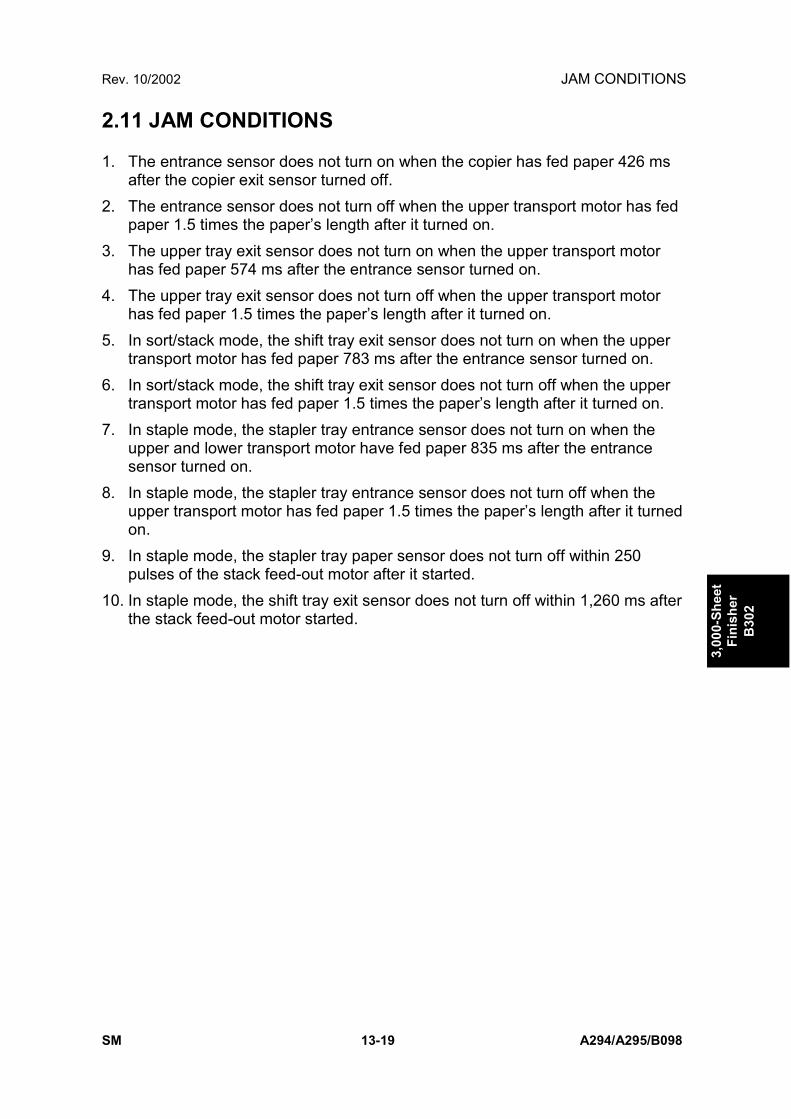
Rev. 10/2002 JAM CONDITIONS
SM 13-19 A294/A295/B098
3,00
0-Sh
eet
Fini
sher
B30
2
2.11 JAM CONDITIONS
1. The entrance sensor does not turn on when the copier has fed paper 426 msafter the copier exit sensor turned off.
2. The entrance sensor does not turn off when the upper transport motor has fedpaper 1.5 times the papers length after it turned on.
3. The upper tray exit sensor does not turn on when the upper transport motorhas fed paper 574 ms after the entrance sensor turned on.
4. The upper tray exit sensor does not turn off when the upper transport motorhas fed paper 1.5 times the papers length after it turned on.
5. In sort/stack mode, the shift tray exit sensor does not turn on when the uppertransport motor has fed paper 783 ms after the entrance sensor turned on.
6. In sort/stack mode, the shift tray exit sensor does not turn off when the uppertransport motor has fed paper 1.5 times the papers length after it turned on.
7. In staple mode, the stapler tray entrance sensor does not turn on when theupper and lower transport motor have fed paper 835 ms after the entrancesensor turned on.
8. In staple mode, the stapler tray entrance sensor does not turn off when theupper transport motor has fed paper 1.5 times the papers length after it turnedon.
9. In staple mode, the stapler tray paper sensor does not turn off within 250pulses of the stack feed-out motor after it started.
10. In staple mode, the shift tray exit sensor does not turn off within 1,260 ms afterthe stack feed-out motor started.

DIP SWITCHES Rev. 10/2002
A294/A295/B098 13-20 SM
3. SERVICE TABLES3.1 DIP SWITCHES
DPS1001 2 3 4 Description
0 0 0 0 Default1 0 0 0 Free run: A4 sideways, staple mode0 1 0 0 Free run: staple and tray shift
NOTE: Do not use any other settings.
3.2 TEST POINTSNo. Label Monitored Signal
TP100 (5V) +5 VTP101 (GND) GroundTP102 (RXD) RXDTP103 (TXD) TXD
3.3 FUSESNo. Function
FU100 Protects 24 V.

Rev. 10/2002 COVER REPLACEMENT
SM 13-21 A294/A295/B098
3,00
0-Sh
eet
Fini
sher
B30
2
4. REPLACEMENT AND ADJUSTMENT4.1 COVER REPLACEMENT
Front Door1. Remove one screw and loosen the other screw of the upper hinge for the front
door [A].2. Remove the front door [B].
Left Inner Cover1. Remove the front door.2. Remove the left inner cover [C] (1 screw).
Inner Cover1. Remove the three screws and unhook the pawls.2. Remove the inner cover [D].
B302R505.WMF
B302R502.WMF
[B]
[A]
[D]
[C]

COVER REPLACEMENT Rev. 10/2002
A294/A295/B098 13-22 SM
Table1. Slide the table [A] to the right and remove it (2 screws).
Upper Tray1. Click the release lever [B].2. Remove the upper tray [C].
Left Upper Cover1. Remove the left upper cover [D].
Left Lower Cover1. Remove the left lower cover [E].
Upper Cover1. Remove the table.2. Remove two stepped screws [F].3. Remove the left upper cover.4. Slide across the right cover [G] and remove it (2 screws).
Rear Cover1. Remove the rear cover [H] (2 screws).
B302R503.WMF
B302R504.WMFB302R504.WMF
[A]
[F]
[B]
[E]
[C]
[H]
[D]
[G]
[E][H]
[D]
[G]

Rev. 10/2002 COVER REPLACEMENT
SM 13-23 A294/A295/B098
3,00
0-Sh
eet
Fini
sher
B30
2
Shift Tray1. Remove the left upper cover.2. Rotate the shift tray lift gear [A] manually to lower the shift tray [B]3. Remove the shift tray (4 screws).
Front Shift Tray Cover1. Remove the front shift tray cover [C] (1 screw).
Rear Shift Tray Cover1. Remove the rear shift tray cover [D] (1 screw).
B302R501.WMF
B302R504.WMF
[B]
[A]
[D]
[B]
[C]

POSITIONING ROLLER REPLACEMENT Rev. 10/2002
A294/A295/B098 13-24 SM
4.2 POSITIONING ROLLER REPLACEMENT
1. Open the front door.2. Remove the snap ring [A].3. Release the rubber belt [B].4. Replace the positioning roller [C].
B302R506.WMF
[B][A][C]

Rev. 10/2002 ALIGNMENT BRUSH ROLLER REPLACEMENT
SM 13-25 A294/A295/B098
3,00
0-Sh
eet
Fini
sher
B30
2
4.3 ALIGNMENT BRUSH ROLLER REPLACEMENT
1. Open the front door and pull out the staple unit.2. Remove the rear cover.3. Remove the screw [A] and a tension spring [B] for the tension bracket [C], and
release the tension of the timing belt.4. Remove the pulley [D] and ball bearing [E] (1 E-ring each).5. Remove screw [F] of the inner cover [G].6. Open the guide [H] and a part of the inner cover, and remove the alignment
brush roller assembly [I] (1 E-ring).7. Replace the alignment brush roller (1 E-ring, 1 ball bearing).
B302R507.WMF
B302R508.WMF
[B] [C]
[G]
[I]
[E][D]
[F]
[H]
[A]

SENSOR REPLACEMENT Rev. 10/2002
A294/A295/B098 13-26 SM
4.4 SENSOR REPLACEMENT4.4.1 STACK HEIGHT 1, 2 AND EXIT GUIDE OPEN SENSOR
1. Remove the upper cover.
Stack Height Sensors 1 and 2
2. Remove the sensor feeler [A] (1 screw).3. Remove the sensor bracket [B] (1 screw).4. Replace the stack height sensor 1 [C] or 2 [D] (1 connector each).
Exit Guide Open Sensor
2. Remove the sensor bracket [E] (1 screw).3. Replace the exit guide open sensor [F] (1 connector).
B302R509.WMF
[F]
[E]
[B] [D]
[A]
[C]

Rev. 10/2002 SENSOR REPLACEMENT
SM 13-27 A294/A295/B098
3,00
0-Sh
eet
Fini
sher
B30
2
4.4.2 UPPER TRAY PAPER LIMIT AND EXIT SENSOR
1. Remove the upper cover.
Upper Tray Paper Limit Sensor
2. Remove the sensor cover [A] (2 screws).3. Remove the sensor bracket [B] (1 screw).4. Replace the upper tray paper limit sensor [C] (1 connector).
Upper Tray Exit Sensor
2. Remove the sensor bracket [D] (1 screw).3. Replace the upper tray exit sensor [E] (1 connector).
B302R510.WMF
[C]
[A]
[D]
[E][B]

SENSOR REPLACEMENT Rev. 10/2002
A294/A295/B098 13-28 SM
4.4.3 SHIFT TRAY EXIT SENSOR
1. Remove the upper cover.2. Open the front door.3. Remove the inner cover.4. Release two springs [A] of the upper exit guide [B].5. Release the link [C] from the cam and remove the upper exit guide (1 plastic
clip, 1 connector).6. Remove the guide stay [D] (2 screws).7. Replace the shift tray exit sensor [E] (1 screw, 1 connector).
B302R512.WMF
B302R511.WMF
[C]
[D][A]
[B]
[A]
[E]

Rev. 10/2002 SENSOR REPLACEMENT
SM 13-29 A294/A295/B098
3,00
0-Sh
eet
Fini
sher
B30
2
4.4.4 ENTRANCE AND STAPLER TRAY ENTRANCE SENSORS
Entrance Sensor
1. Remove the finisher from the copier.2. Remove the sensor bracket [A] (1 screw).3. Replace the entrance sensor [B] (1 screw, 1 connector).
Stapler Tray Entrance Sensor
1. Open the front door.2. Remove the sensor bracket [C] (1 screw).3. Replace the stapler tray entrance sensor [D] (1 screw, 1 connector).
B302R513.WMF
B302R514.WMF
[B][A]
[D]
[C]

SENSOR REPLACEMENT Rev. 10/2002
A294/A295/B098 13-30 SM
4.4.5 PRE-STACK STOPPER SENSOR
1. Remove the rear cover.2. Remove two plastic clips from the guide [A].3. Open the front door.4. Remove the left vertical transport guide [B].5. Remove the middle vertical transport guide [C] (1 connector).6. Replace the pre-stack paper sensor [D] (1 connector).
B302R515.WMF
B302R516.WMF
[A]
[D]
[C]
[B]

Rev. 10/2002 SENSOR REPLACEMENT
SM 13-31 A294/A295/B098
3,00
0-Sh
eet
Fini
sher
B30
2
4.4.6 STAPLE WASTE HOPPER SENSOR
1. Open the front door and pull out the stapler unit.2. Remove the staple waste hopper [A] (1 plastic clip).3. Remove the hopper holder [B] (2 E-rings).4. Replace the staple waste hopper sensor [C] (1 connector).
B302R517.WMF
[B]
[A]
[C]

SENSOR REPLACEMENT Rev. 10/2002
A294/A295/B098 13-32 SM
4.4.7 STAPLER ROTATION HP AND STAPLER RETURNSENSORS
1. Remove the stapler unit.2. Remove the stapler bracket [A] (4 screws, 2 springs).
Stapler Rotation HP Sensor
3. Replace the stapler rotation HP sensor [B] (1 connector).
Stapler Return Sensor
3. Replace the stapler return sensor [C] (1 connector).
B302R519.WMF
[A]
[C]
[B]

Rev. 10/2002 STAPLER REMOVAL
SM 13-33 A294/A295/B098
3,00
0-Sh
eet
Fini
sher
B30
2
4.5 STAPLER REMOVAL
1. Open the front door and pull out the staple tray.2. Remove the stapler unit harness cover [A].3. Remove the stapler [B] (1 screw, 2 connectors).
B302R518.WMF
[B]
[A]

PUNCH POSITION ADJUSTMENT Rev. 10/2002
A294/A295/B098 13-34 SM
4.6 PUNCH POSITION ADJUSTMENT
Right to LeftThis position is adjusted by SP modes.
Front to RearThe optional punch units have the following 3 spacers as accessories.1 mm thickness: 2 pcs2 mm thickness: 1 pcThe punch position can be adjusted by up to 4 mm by combinations of the 3spacers.
B302R520.WMF

Rev. 10/2002 ROM HISTORY
SM 13-35 A294/A295/B098
3,00
0-Sh
eet
Fini
sher
B30
2
4.7 ROM HISTORY4.7.1 FIRMWARE MODIFICATION HISTORY
B302 FINISHER FIRMWARE MODIFICATION HISTORY
DESCRIPTION OF MODIFICATION FIRMWARELEVEL SERIAL NUMBER
First Production B3025103 B From 1st productionCorrects the following:• SP6-120 Staple Jogger Adjustment was missing. The
staple jogger positions for each paper size can beadjusted by SP6-120. This modification becomeseffective when the mainframe firmware is updated toversion 7.23.2 (F) or later.
B3025103 C February 00production
Staple Jogger Adjustment
1 A3
2 B4
3 A4 L
4 A4 S
5 B5 L
6 B5 S
7 DLT L
8 LG L
9 LT L
10 LT S
6-120
11 Others
S Adjusts the staple jogger positions foreach paper size.
+1.5 ~ -1.50.5 mm/step
0 mm
Corrects the following:• Door open is indicated after a staple job• After a staple job, the Staple Unit does not move to
the staple supplying position in the staple endcondition.
• Stapled sheets of paper fed out incorrectly when theinterrupt function is used during printing.
• (A295 w/B302 only) Mistake-stapling, mistake-jogging, R2 Jam, R6 Jam.
B3025103 D March 00production
Corrects the following:• (A295 w/B302 only) Tab paper stack failure, exit
paper jam in different paper length paper shift.
B3025103 E April 00 production


TECHNICAL SERVICE BULLETINS


2000 RICOH Corporation. All rights reserved. CONTROL NO. 039ABW
TECHNICAL SERVICE BULLETINTECHNICAL SERVICE BULLETINTECHNICAL SERVICE BULLETINTECHNICAL SERVICE BULLETIN
BULLETIN NUMBER:BULLETIN NUMBER:BULLETIN NUMBER:BULLETIN NUMBER: A292/A293 - A292/A293 - A292/A293 - A292/A293 - 001001001001 06/01/200006/01/200006/01/200006/01/2000
APPLICABLE MODELAPPLICABLE MODELAPPLICABLE MODELAPPLICABLE MODEL:::: GESTETNER – 3355/3370 GESTETNER – 3355/3370 GESTETNER – 3355/3370 GESTETNER – 3355/3370 RICOH – AFICIO 551/700 RICOH – AFICIO 551/700 RICOH – AFICIO 551/700 RICOH – AFICIO 551/700 SAVIN – 2055DP/2070DP SAVIN – 2055DP/2070DP SAVIN – 2055DP/2070DP SAVIN – 2055DP/2070DP
SUBJECT: SERVICE MANUAL - INSERT
GENERAL:
The Service Manual pages listed below must be replaced with the pages supplied. Each bulletin packagecontains 1 set of replacement pages.
PAGES:
The revised areas have been highlighted by an arrow ⇒.
• 2-36 Updated Information (Drum Unit)• 2-50 Updated Information (Development Mechanism)• 2-79 Updated Information (Duplex Tray Feed Mechanism)• 2-80 Updated Information (Basic Duplex Feed Operation)• 4-79 Updated Information (Download NVRAM Data to the BICU)• 5-2 and 5-4 Updated Information (PM Table)
No
te:T
hiscopy
isintended
asa
master
originalfor
reproductionofadditionalbulletins.
!S
ER
VIC
EM
AN
UA
L

DRUM UNIT
A292/A293 2-36 SM
2.5 DRUM UNIT
2.5.1 PROCESS CONTROL
Overview
The drum potential will gradually change because of the following factors.
• Dirty charge corona casing and grid plate
• Changes in drum sensitivity
To maintain good copy quality, the machine does the following just after the mainswitch has been turned on (if the fusing temperature is less than 100 °C and SP3-901 is on).
1) Potential Sensor Calibration
2) VSG Adjustment
3) VG(Grid Voltage) Adjustment
4) LD Power Adjustment
5) VREF Update
6) Density Adjustment
This process is known as ‘Process Control Initial Setting’. The rest of this sectionwill describe these steps in more detail.
Processes 1, 3, and 4 in the above list compensate for changes in drum potential.Processes 2 and 5 are for toner density control; see the “Development and TonerSupply” section for more details.
⇒
Rev. 05/2000

DEVELOPMENT AND TONER SUPPLY
A292/A293 2-50 SM
2.6.2 DEVELOPMENT MECHANISM
The paddle roller [A] picks up developer and transports it to the upper developmentroller [B]. Internal permanent magnets in the development rollers attract thedeveloper to the development roller sleeve. The upper development roller carriesthe developer past the doctor blade [C]. The doctor blade trims the developer tothe desired thickness and creates backspill to the cross mixing mechanism.
In this machine, black areas of the latent image are at a low negative charge(about –120 V) and white areas are at a high negative charge (about –900 V).
The development roller is given a negative bias (-550 V) to attract negativelycharged toner to the black areas of the latent image on the drum.
The development rollers continue to turn, carrying the developer to the drum [D].When the developer brush contacts the drum surface, the low-negatively chargedareas of the drum surface attract and hold the negatively charged toner. In thisway, the latent image is developed.
A293D589.WMF[A]
[B]
[C]
[D]
⇒
Rev. 05/2000

PAPER EXIT/DUPLEX
SM 2-79 A292/A293
Det
aile
dD
escr
ipti
on
s
2.10.3 DUPLEX TRAY FEED MECHANISM
In duplex mode, after the paper leaves the inverter, the duplex inverter solenoid [A]switches the junction gate [B] to direct the paper to the duplex tray. The paper isfed through the duplex tray by duplex transport rollers 1 [C] and 2 [D], and theduplex feed roller [E].
If duplex mode is not selected, the solenoid does not switch the junction gate, andthe paper goes to the output tray or finisher face down.
The inverter exit sensor [F] controls the on/off timing of the inverter exit clutchwhich stops paper coming into the duplex unit for a while. If image processing forthe page coming out of the duplex unit is taking a long time, this mechanismprevents the paper entering the duplex unit from slipping over the paper at theduplex unit exit and accidentally being fed out of the unit first. The mechanismmaintains the maximum productivity of printing while preventing this type of duplexfeed error. When the clutch is on, paper stops.
A293D674.WMF
[A]
[B]
[C] [D] [E][F]⇒
Rev. 05/2000

PAPER EXIT/DUPLEX
A292/A293 2-80 SM
2.10.4 BASIC DUPLEX FEED OPERATION
Longer than A4 / Letter lengthwise (8.5 x 11 L)
The duplex unit can process two sheets of copy paper
Example: 8 pages. The number [A] in the illustration shows the order of pages. Thenumber [B] in the illustration shows the order of sheets of copy paper (if shaded,this indicates the second side).
1. The first 2 sheets are fed and printed.1) 1st sheet printed (1st page)2) 2nd sheet printed (3rd page)
2. The first 2 sheets go into the duplex unit
5 8674231 ⇒ ⇒ ⇒ ⇒ ⇒ ⇒1 2 1 3 2 4 3
⇒4
A293D657.WMF
A293D651.WMF
A293D652.WMF
⇒
Rev. 05/2000

PROGRAM AND DATA DOWNLOAD
SM 4-79 A292/A293
Ser
vice
Tab
les
4.3.4 DOWNLOAD NVRAM DATA TO THE BICU
1. Turn off the main power switch.
2. Remove the flash memory cardcover [A].
3. Plug the flash memory card [B] intothe card slot.NOTE: Make sure that the surface
printed “A” faces upwards.
4. Turn on the main power switch.
5. Enter SP Mode.
6. Open the front door.NOTE: Do not close the front door until the download finishes.
7. Select SP5-825-***.001: All data002: User tools (UP mode) data
NOTE: 1) Data of SP7-003, SP7-006, and SP7-007 are not downloaded.2) When you select “001”, no data is downloaded if the serial number
on the BICU is not the same as the one on the flash card.
8. Press “Start”.
9. Exit SP Mode.
10. Turn off the main switch.
11. Pull out the flash memory card.
A293M552.WMF
A293M507.TIF
[A]
[B]
⇒⇒
Rev. 05/2000

PM TABLE
A292/A293 5-2 SM
EM150K
300K
450K
ExpectedLife K NOTE
PAPER FEEDRegistration Rollers C C C Water or alcoholRelay Rollers C C C Water or alcoholPaper Dust Remover C C C Dry clothRegistration Sensor C C C Blower brushRelay Sensor C C C Blower brushPaper Feed RollersPick-Up RollersSeparation Rollers
C C C 300 Replace pick-up, feed andseparation roller as a set.Check the counter value foreach paper tray station(SP7-204). If the value hasreached 300K, replace therollers. After replacing therollers, reset the counter(SP7-816).
Paper Feed Guide Plate C C C Water or alcoholVertical Transport Rollers C C C Water or alcoholPaper Feed Sensor C C C Blower brush
TRANSFER BELT UNITTransfer Belt C C C 450 Dry clothCleaning Roller CleaningBlade
C 450
Transfer Entrance GuidePlate
C C C Dry cloth
Belt Drive/Guide/Bias Roller/CleaningRoller
C C C Alcohol
Transfer Exit Guide Plate C C C Dry cloth
FUSING/PAPER EXITHot Roller I I I 200Hot Roller Bearings I I I 600Pressure Roller I I I 450Pressure Roller Bearings I I I 450
Replace as a set.
Fusing Thermistor I I I I Replace if necessary.Hot Roller Strippers C C C C 300 Water or alcoholOil Supply RollerBushings
I I I I Replace if necessary.
Pressure Roller CleaningRoller and Bushings
R R R Replace as a set.
Oil Supply Roller R R ROil Supply CleaningRoller
R R R
Fusing Entrance and ExitGuide Plates
C C C Clean with water or alcohol
Transport/Exit Rollers C WaterExit Anti-static Brush I
⇒
Rev. 05/2000

PM TABLE
A292/A293 5-4 SM
EM 150K
300K
450K
ExpectedLife K NOTE
3,000-SHEET FINISHER (50-SHEET STAPLER): (B312)Rollers C C C C Clean with water or alcohol.Brush Roller I I I I 2,400Discharge Brush C C C C Clean with a dry cloth.Sensors C C C C Blower brushJogger Fences I I I I Replace if necessary.Punch Waste Hopper I I I I Empty the hopper.
EM 150K
300K
450K
ExpectedLife K NOTE
3,000-SHEET FINISHER (100-SHEET STAPLER): (B302)Rollers C C C C Clean with water or alcohol.Brush Roller I I I I 600 Check the counter value for
the total copies by copy modefor staple (SP7-304-9). If thevalue has reached 600K,replace the brush roller.
Discharge Brush C C C C Clean with a dry cloth.Sensors C C C C Blower brushJogger Fences I I I I Replace if necessary.Punch Waste Hopper I I I I Empty the hopper.
EM 150K
300K
450K
ExpectedLife K NOTE
FINISHER: (A763)Rollers C C C C Clean with water or alcohol.Brush Roller I I I IDischarge Brush C C C C Clean with a dry cloth.Sensors C C C C Blower brushJogger Fences I I I I Replace if necessary.
⇒
Rev. 05/2000

2000 RICOH Corporation. All rights reserved. CONTROL NO. 044ABW
TECHNICAL SERVICE BULLETINTECHNICAL SERVICE BULLETINTECHNICAL SERVICE BULLETINTECHNICAL SERVICE BULLETIN
BULLETIN NUMBER:BULLETIN NUMBER:BULLETIN NUMBER:BULLETIN NUMBER: A292/A293 - A292/A293 - A292/A293 - A292/A293 - 002002002002 07/13/200007/13/200007/13/200007/13/2000
APPLICABLE MODELAPPLICABLE MODELAPPLICABLE MODELAPPLICABLE MODEL:::: GESTETNER – 3355/3370 GESTETNER – 3355/3370 GESTETNER – 3355/3370 GESTETNER – 3355/3370 RICOH – AFICIO 551/700 RICOH – AFICIO 551/700 RICOH – AFICIO 551/700 RICOH – AFICIO 551/700 SAVIN – 2055DP/2070DP SAVIN – 2055DP/2070DP SAVIN – 2055DP/2070DP SAVIN – 2055DP/2070DP
SUBJECT: SERVICE MANUAL - INSERT
GENERAL:
The Service Manual pages listed below must be replaced with the pages supplied. Each bulletin packagecontains 1 set of replacement pages.
NOTE: The following updates to the SP Mode Table require ROM ver 2.94.
PAGES:
The revised areas have been highlighted by an arrow ⇒.
• 4-18 through 21 Updated Information (SP Tables)• 4-47 through 53B Updated Information (SP Tables)• 4-65 Updated Information (SP Tables)
No
te:T
hiscopy
isintended
asa
master
originalfor
reproductionofadditionalbulletins.
!S
ER
VIC
EM
AN
UA
L

SERVICE PROGRAM MODE
A292/A293 4-18 SM
Mode No.(Class 1 , 2 &&&& 3)
Function Settings
2-906 Vcont Manual Setting1 Setting * Factory use only. 9.7 V2 Vctr * Store the VREF value at developer
initialization.2-909 Main Scan Magnification
1 Copier * Adjusts the magnification in the main scandirection for copy mode.
- 2.0 ~+ 2.00.1 %/step+ 0.0 %
See "Replacement and Adjustment – CopyImage Adjustments" for details.
2 Printer * Adjusts the magnification in the main scandirection when printing from a personalcomputer.
- 2.0 ~+ 2.00.1 %/step+ 0.0 %
See "Replacement and Adjustment - CopyImage Adjustments" for details.
2-911 Transfer Current On/Off Timing1 La(ON) * Adjusts the transfer current on timing at the
leading edge.-30 ~ +301 mm/step0 mm
3 Lc(OFF) * Adjusts the transfer current off timing (forexample: –5 mm is 5 mm after the trailingedge).
-30 ~ +301 mm/step0 mm
2-912 Drum Reverse Rotation Interval* This SP mode is for designer use only.
Do not change the value..0 ~ 201/step2
2-913 Test Pattern ID AdjustmentAdjusts the image density for printing testpatterns (with SP2-902). Usually this SPmode is only used by designers.
0 ~ 151/step15
The value is cleared when the main powerswitch is turned off and on.
2-920 LD Off CheckChecks whether the LD turns off or onwhen the front door is opened.0 : On 1: Off
Factory use only.2-921 Designer use only⇒
Rev. 06/2000

SERVICE PROGRAM MODE
SM 4-19 A292/A293
Ser
vice
Tab
les
Mode No.(Class 1 , 2 &&&& 3)
Function Settings
2-930 Transfer Belt Cleaning – DPI Change* When resolution changes from 400 to
600 dpi, the LD writes a pattern on thedrum. Toner is applied, and this mustbe cleaned off the belt. This SP modedetermines whether bias is applied tothe transfer belt cleaning bias roller atthis time.
0 : No1 : Yes
2-961 Developer Initialization (Factory)Factory use only.
2-962 Auto Process Control* Automatically adjusts the following process
control factors.1. ID sensor2. Drum potential sensor3. Charge grid voltage (by changing VD)4. LD power (by changing VH)5. Image density adjustmentBefore using this SP, auto process controlshould be on (SP3-901)
Start
After changing the drum, ID sensor, drumpotential sensor, LD unit, or toner densitysensor, this SP should be used.
2-963 Toner Supply From Toner BottleWhen installing a new machine, thefollowing two process are doneautomatically.1. Developer initialization2. Forced toner supply (sends toner to the
toner hopper)
Start
Do not use this SP after replacing thedeveloper. Use SP2-801 (developerinitialization)
2-964 Blade Protection1 Pattern
Interval* Selects the interval for applying a strip of
toner across drum and transfer belt toprevent the drum cleaning blade and beltcleaning blade from peeling off.
0 ~ 501 /step0 (notapplied)
2 PatternDensity
* Selects the LD power for making the tonerstrip on the drum and transfer belt toprevent the drum cleaning blade and beltcleaning blade from peeling off.
0 ~ 151 /step1
Rev. 06/2000

SERVICE PROGRAM MODE
A292/A293 4-20 SM
Mode No.(Class 1 , 2 &&&& 3)
Function Settings
2-965 Toner Pump Adjustment1 First Toner
WasteAdjustment
* Factory use only 0 ~ 1001g /step3 g
2 After FirstToner Waste
* Factory use only 0 ~ 1001 g /step3 g
3 Pump ClutchOn Time
* Factory use only 0 ~ 51 /step2 s
4 Pump MotorOn Time
* Factory use only 0 ~ 201 s/step6 s
5 Return to FirstToner Waste
* Factory use only 0 ~ 501 time/step30 times
2-965 Toner Pump Adjustment6 Aggregate of
Toner Waste* Factory use only
2-966 Periodical Auto Process ControlWhen both the following conditions exist,auto process control and charge coronawire cleaning will be done automatically.1. The main switch was not turned off
since 24 hours after the last autoprocess control was done.
2. A copy job has finished.
OFF: NoON: Yes
2-967 Auto Image Density AdjustmentDuring the auto process control after themain switch is turned on, the toner amountin the development unit is checked andadjusted using the ID sensor.
OFF: NoON: Yes
2-970 Transfer Belt Resistance Value DisplayXX.XMUnit is ΩVery High → 190 ← High → 90 ←Standard → 25 ← Low → 15 ← Very Low
2-971 Output Value Measured Between Copies1 Voltage2 Current
Displays the measurement condition ofvalue in SP2-970.
Rev. 06/2000

SERVICE PROGRAM MODE
SM 4-21 A292/A293
Ser
vice
Tab
les
Mode No.(Class 1 , 2 &&&& 3)
Function Settings
3-001 ID Sensor PWM Setting1 ID Sensor
PWM Setting* This SP mode is added to recover the
machine when an SC condition occursbecause ID Sensor Initial Setting is notdone after doing an NVRAM Clear orreplacing the NVRAM. Reset this SP to thefactory setting in this case.
0 ~ 2551/step90
The PWM data is stored when ID SensorInitial Setting is done.
2 Initialization * Performs the ID sensor initial setting. TheID sensor output for the bare drum (VSG) isadjusted to 4.0 ± 0.2V.
Start
This SP mode should be performed after:1. Replacing or cleaning the ID sensor2. Replacing the NVRAM or doing an
NVRAM clear3. Replacing the BICU board
3-103 ID Sensor Output Display* Displays the current VSG and VSP output.
VSP= x.xx VVSG= x.xx VIf the ID sensor does not detect the IDpattern, "VSP=5.0V/VSG=5.0V" is displayedand an SC code is generated.If the ID sensor does not detect the barearea of the drum, "VSP=0.0V/VSG=0.0V" isdisplayed and an SC code is generated.
3-901 Auto Process Control* Decides whether or not the machine
checks and corrects the drum potential(VD) and LD power when the fusingtemperature is lower than 100°C at power-up.
ONOFF
3-902 Process Control Data Display1 Auto Process
Control* Displays whether auto process control is
on or off. (O: OFF, 1: ON)2 VD * Displays the drum potential.3 Half Tone VH * Displays the drum potential in areas
illuminated by the laser.4 VG * Displays the charge grid voltage which
resulted from the latest VD adjustment.5 LD Power
(Correction)* Displays the LD power correction value
which resulted from the latest VHadjustment.
6 VID * Displays the latest drum surface voltagemeasured on the ID sensor pattern.
7 VQL * Displays the drum potential afterquenching.
Rev. 06/2000

SERVICE PROGRAM MODE
SM 4-47 A292/A293
Ser
vice
Tab
les
Mode No.(Class 1 , 2 &&&& 3)
Function Settings
5-118 Disable Copying* Selects whether the copy function is
disabled or not when printer controller isinstalled.
0: No1: Yes
5-120 M/C Option Counter Removal* This SP is for Japan only. Do not change
the value.0 ~ 21/step0
5-121 Counter Up Timing* Determines whether the optional key
counter counts up at paper feed-in or atpaper exit.
0: Feed-in1: Exit
The total counter is not affected by this SPmode.
5-127 APS Mode* Selects whether the APS function is
enabled or not.NoYes
5-131 Paper Size Type Selection* Selects the paper size type (for originals
and copy paper). (Only needs to beadjusted if the optional printer controller isinstalled)• After changing the value, turn the main
power switch off and on.• If the paper size type of the archive files
stored in the HDD is different, abnormalcopies will be made. So, after changingthis setting, perform SP5-822 and askthe user to restore the archive files.
0: Japan1: North
America2: Europe3: China
Adjust Position on 2nd side Duplex Copying3 Adjust
Position (SubScandirection)
Adjusts the position (sub scan direction) of“Page Numbering” on 2nd side whenmaking duplex copy
-10 ~ +10mm1 mm step0 mm
5-212
4 AdjustPosition (MainScandirection)
Adjusts the position (main scan direction)of “Page Numbering” on 2nd side whenmaking duplex copy
-10 ~ +10mm1 mm step0 mm
5-513 Japanese Market only5-514 Japanese Market only5-501 PM Alarm Interval
* Sets the PM interval, with an alarm. 0 ~ 2551kcopies/step0 k copies
When set to "0", the alarm is disabled.
5-504 Jam Alarm Level(RSS function)1 Jam Alarm
Level* Japanese version only.
Do not change the values.0: No1: L2: M3: H
⇒
⇒⇒
Rev. 06/2000

SERVICE PROGRAM MODE
A292/A293 4-48 SM
Mode No.(Class 1 , 2 &&&& 3)
Function Settings
5-504 Jam Alarm Level(RSS function)2 Jam Auto Call
(RSS function)* Japanese version only.
Do not change the values.0: Off1: On
5-505 Error Alarm Level* Japanese version only.
Do not change the values.0 ~ 255100copies/step
5-507 Paper Supply Call Level128 Others * Japanese version only. 250 ~ 10000132 A3 * Do not change the values. 1 page/step133 A4 * 1000 pages134 A5 *141 B4 *142 B5 *160 DLT *164 LG *166 LT *172 HLT *
5-590 Auto Call Setting1 Original Count * Japanese version only. 0: Off2 Door Open * Do not change the values. 1: On3 Paper Supply *4 Stapler Supply *5 Toner Supply *
5-801 Memory All ClearResets all correction data for processcontrol and all software counters. Also,returns all modes and adjustments to thedefault settings.See the "Memory All Clear" section for howto use this SP mode correctly.Touch “Start” for over 3 seconds, then turnthe main power switch off and on.
Start
Normally, this SP mode should not beused.It is used only after replacing the NVRAM,or when the copier malfunctions due to adamaged NVRAM.The LCD coordinates are also cleared, see“LCD Touch Panel Calibration”.
Rev. 06/2000

SERVICE PROGRAM MODE
SM 4-49 A292/A293
Ser
vice
Tab
les
Mode No.(Class 1 , 2 &&&& 3)
Function Settings
5-802 Printer Free Run* Performs a free run. The scanner scans
once and the printer prints for the number ofcopies requested.
OffOn
To perform the free run, select ”ON”1) Select “ON”.2) Select “Exit”.3) Select “Copy Mode”.4) Make the required settings (such as the
number of copies.).5) Press the Start key.After finishing the free run, return this SP to“OFF”
5-803 Input Check1 ~14
Displays the signals received from sensorsand switches.See the "Input Check" section for details.
5-804 Output Check1 ~97
Turns on the electrical componentsindividually for test purposes.See the "Output Check" section for details.
OnOff
5-807 Option Connection Check1 ADF Checks the connectors to the optional 0: Not2 Bank peripherals. connected3 LCT 1: Connected4 Finisher
5-811 Machine Serial Number* Use to input the machine serial number.
(Normally done at the factory.)This serial number will be printed on thesystem parameter list.Use the “ • ” key to input “A”.
5-812 Service Tel. No. Setting1 Service
TelephoneNumber at SC
* Use this to input the telephone number ofthe service representative (this is displayedwhen a service call condition occurs.)
Condition Press the “ • ” key to input a pause.Press the "Clear modes" key to delete thetelephone number.
2 Service FaxNumber forCounterPrinting
* Use this to input the fax number of theservice representative (this is printed on theCounter Report – UP mode, System No.19)
Press the “ • ” key to input a pause.Press the "Clear modes" key to delete thetelephone number.
Rev. 06/2000
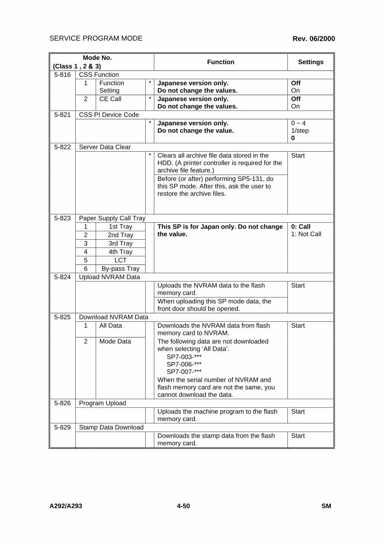
SERVICE PROGRAM MODE
A292/A293 4-50 SM
Mode No.(Class 1 , 2 &&&& 3)
Function Settings
5-816 CSS Function1 Function
Setting* Japanese version only.
Do not change the values.OffOn
2 CE Call * Japanese version only.Do not change the values.
OffOn
5-821 CSS PI Device Code* Japanese version only.
Do not change the value.0 ~ 41/step0
5-822 Server Data Clear* Clears all archive file data stored in the
HDD. (A printer controller is required for thearchive file feature.)
Start
Before (or after) performing SP5-131, dothis SP mode. After this, ask the user torestore the archive files.
5-823 Paper Supply Call Tray1 1st Tray2 2nd Tray3 3rd Tray4 4th Tray5 LCT6 By-pass Tray
This SP is for Japan only. Do not changethe value.
0: Call1: Not Call
5-824 Upload NVRAM DataUploads the NVRAM data to the flashmemory card.
Start
When uploading this SP mode data, thefront door should be opened.
5-825 Download NVRAM Data1 All Data Downloads the NVRAM data from flash
memory card to NVRAM.Start
2 Mode Data The following data are not downloadedwhen selecting ‘All Data’.
SP7-003-***SP7-006-***SP7-007-***
When the serial number of NVRAM andflash memory card are not the same, youcannot download the data.
5-826 Program UploadUploads the machine program to the flashmemory card.
Start
5-829 Stamp Data DownloadDownloads the stamp data from the flashmemory card.
Start
Rev. 06/2000

SERVICE PROGRAM MODE
SM 4-51 A292/A293
Ser
vice
Tab
les
Mode No.(Class 1 , 2 &&&& 3)
Function Settings
5-907 Plug & Play (Brand Name and Production Name Setting)Selects the brand name and the productionname for Windows 95 Plug & Play. Thisinformation is stored in the NVRAM. If theNVRAM is defective, these names shouldbe registered again.After selecting, press the “Original Type”key and “#” key at the same time. When thesetting is completed, the beeper sounds fivetimes.
5-914 Printer Counter Display* Selects whether or not the total printer
counter is displayed in the UP mode.OffOn
5-915 Mechanical Counter DetectionChecks whether the mechanical counterinside the inner cover is connected or not.
0: Notdetected
1: Detected2: Unknown
5-920 Low Power Mode Recovery Time* Determines the recovery time from low
power mode.170°C: Approx. 30s177°C: Approx. 20s
170 ~ 1851°C /step170°°°°C(55cpm)177°°°°C(70cpm)
5-921 Data Port ChangeChanges the connector for sending the keycard data.
0: Key cardconnector1: Keycounterconnector
5-922 Counter Operation SettingSelects the counter operation for theoptional counter.0: No Interleaf (Productivity is slow in
duplex mode.)1: Interleaf (Productivity is high in duplex
mode.)When using a “count down type” key cardand duplex mode, the last copy willsometimes be free if “1” is selected.
Rev. 06/2000


SERVICE PROGRAM MODE
SM 4-53 A292/A293
Ser
vice
Tab
les
Mode No.(Class 1 , 2 &&&& 3)
Function Settings
6-006 4 Reading Edge(Duplex-rear)
* Adjusts the original stop position against theoriginal left scale in two-sided originalmode.
-29 ~ +290.1 mm/step+ 0.0 mm
6-007 ADF Input Check1 Group 1 Displays the signals received from sensors
and switches of the ADF.See the "Input Check" section for details.
2 Group 2 Displays the signals received from sensorsand switches of the ADF.See the "Input Check" section for details.
6-008 ADF Output CheckTurns on the electrical components of theADF individually for test purposes.See the "Output Check" section for details.
6-009 ADF Free Run (Two-sided original)1 Performs an ADF free run in two-sided
original mode. Press “1” to start.OffOn
This is a general free run controlled fromthe copier. For more detailed free runmodes, see the ‘Test Points/DipSwitches/LEDs’ section.
6-016 Adjust Motor SpeedAdjust the speed of the feed-in, transportand feed-out motors. Perform this SP whenreplacing the Main Board or above motors.
6-020 ADF Speed Adjustment* When the customer points out noise form
the ADF, use this to adjust the ADF speedto low.
High speed:70 cpmLow Speed:55 cpm
6-105 Stapling Position Adjustment* Adjusts the stapling position in the main
scan direction- 3.5~ +3.50.5 mm/step+0.0 mm
A larger value causes the stapling positionto shift outward.
6-113 Punch Hole Adjustment1 2-Holes Adjusts the punch hole position in the sub-
scan direction for the punch unit with twopunch holes.
- 7.5 ~ + 7.50.5 mm/step0 mm
A larger value shifts the punch holestowards the edge of the paper.
2 3-Holes Adjusts the punch hole position in the sub-scan direction for the punch unit with threepunch holes.
- 7.5 ~ + 7.50.5 mm/step0 mm
A larger value shifts the punch holestowards the edge of the paper.
⇒
Rev. 06/2000
Rev. 06/2000

SERVICE PROGRAM MODE
A292/A293 4-53A SM
Mode No.(Class 1 , 2 &&&& 3)
Function Settings
6-116 Thick Paper CountMultiply the normal limit by this number todetermine the staple limit number for thickpaper mode.
1 ~ 31 sheet/step3 sheets
6-119 Enable Punch for Thick PaperThis SP functions with the B302 Finisher. Setthis SP to “1” to enable the punch for thick paper.NOTE:1. Before enabling SP6-119, please be sure
that the customer is aware of the specificrange of paper weights that can be usedwith this mode.
2. Do not enable this mode if the customer isusing OHP transparencies.
Range:0 Disabled1 Enabled
Adjust Jogger Fence Position of the Staple Tray001 A3002 B4003 A4 lengthwise004 A4 sideways005 B5 lengthwise006 B5 sideways007 DLT008 LG009 LT lengthwise010 LT sideways
6-120
011 Others
0.0 ~ 1.5 mm0.5mm/step0.0mm
6-801 Copy Connect I/F TestChecks the copy connect kit connection.
6-901 Original Exchange Time Adjustment1 Normal Paper * 500 ~ 700 ms
10 ms/step620 ms
2 Thin Paper *
Adjusts the original exchange time.This is based on the time that the machineestimates (from DF sensor outputs) that thepaper has arrived on the exposure glassand stopped for scanning.If a higher value is set, 1-to-1 copying willbe slower.If a lower value is set, scanning may startbefore the original has stopped on theglass.
500 ~ 700 ms10 ms/step520 ms
6-902 Saddle Stitch Adjustment1 A3/DLT * Adjusts the fold position. –3.0 ~ +3.0
mm0.5 mm/step0.0 mm
2 B4 * –2.0 ~ +2.0mm0.5 mm/step0.0 mm
3 A4/LT –1.5 ~ +1.5mm0.5 mm/step0.0 mm
Rev. 06/2000
⇒
⇒

SERVICE PROGRAM MODE
SM 4-53B A292/A293
Ser
vice
Tab
les
This page intentionally left blank.
Rev. 06/2000

SERVICE PROGRAM MODE
SM 4-65 A292/A293
Ser
vice
Tab
les
Mode No.(Class 1 , 2 &&&& 3)
Function Settings
7-906 Clear Original Number of Each sizeResets all counters of SP7-202. Start
7-907 Clear Job Number of Each sizeResets all counters of SP7-306. Start
7-908 Document : Clear Original NumberResets all counters of SP7-002-2. Start
7-920 Document Server : Clear Scanned StorageResets the counter of SP7-320. Start
7-921 Document Server : Clear Original Number of Each SizeResets all counters of SP7-321. Start
7-923 Document Server : Clear Print Number of Each CopyResets all counters of SP7-323 Start
7-924 Document Server : Clear Print Job LoggingResets all counters of SP7-324 Start
7-925 Document Server : Clear Print Job Page DistributionResets all counters of SP7-325 Start
7-926 Document Server : Clear Print Job File DistributionResets all counters of SP7-326 Start
7-927 Document Server : Clear Print Job Set DistributionResets all counters of SP7-327. Start
7-928 Document Server: Clear Copy Number of Each JobResets all counters of SP7-328 Start
7-990 Display the detail information for SC990001 Filename002 Line Number003 Value
Displays the detail information for SC990.⇒
Rev. 06/2000

2000 RICOH Corporation. All rights reserved. CONTROL NO. 045ABW
TECHNICAL SERVICE BULLETINTECHNICAL SERVICE BULLETINTECHNICAL SERVICE BULLETINTECHNICAL SERVICE BULLETIN
BULLETIN NUMBER:BULLETIN NUMBER:BULLETIN NUMBER:BULLETIN NUMBER: A292A292A292A292/A293 - 003/A293 - 003/A293 - 003/A293 - 003 07/17/200007/17/200007/17/200007/17/2000
APPLICABLE MODELAPPLICABLE MODELAPPLICABLE MODELAPPLICABLE MODEL:::: GESTETNER – 3355/3370 GESTETNER – 3355/3370 GESTETNER – 3355/3370 GESTETNER – 3355/3370 RICOH – AFICIO 551/700 RICOH – AFICIO 551/700 RICOH – AFICIO 551/700 RICOH – AFICIO 551/700 SAVIN – 2055DP/2070DP SAVIN – 2055DP/2070DP SAVIN – 2055DP/2070DP SAVIN – 2055DP/2070DP
SUBJECT: LOW IMAGE DENSITY
SYMPTOM:
Low image density on copies for units with low copy volume (20K to 30K after installation).
CAUSE:
The Fusing Fan Motor stops when the low power timer is met (60 secs). The copier enters Energy SaverMode and because the Fusing Lamp remains on to maintain the Hot Roller temperature, the temperature ofthe areas surrounding the unit also rises. The resulting heat can damage the toner that is stored in the bottleabove the fusing unit causing some of the toner’s ingredients to separate. The altered toner is then sent tothe Development Unit and is mixed in with the developer causing developer chargeability to drop. Thisresults in low image density. The heat damage is especially susceptible on low copy volume machinesbecause the toner remains in the bottle for an extended periods of time.
SOLUTION:
The BICU Firmware has altered the off-timing of the Fusing Fan Motor. The off-timing has been delayed sothe Fusing Fan will have time to remove the hot air around the Toner Bottle.
• On newly installed machines, upgrade the BICU Firmware to version 3.5.1 (Level “E”) during installation.• On field machines that do not exhibit a low image density symptom, upgrade the BICU Firmware to
version 3.5.1 (Level “E”) during the next visit.• On field machines that exhibit a low image density symptom perform the following procedure:
1. Upgrade the BICU Firmware to version 3.5.1 (Level “E”).2. Replace the developer.3. Replace the Toner Bottle.4. Clean the toner from the Toner Hopper.
The BICU Firmware revision E (file name A292REVE.EXE) can be downloaded through the Ricoh TechnicalServices FTP Site http://tsc.ricohcorp.com.
NOTE: Refer to Facts Line Bulletin # FL002 for more information about the FTP Internet Web Site.
Note:T
hiscopy
isintended
asa
master
originalfor
reproductionofadditionalbulletins.
!C
OP
YQ
UA
LIT
Y

2000 RICOH Corporation. All rights reserved. CONTROL NO. 051ABW
TECHNICAL SERVICE BULLETINTECHNICAL SERVICE BULLETINTECHNICAL SERVICE BULLETINTECHNICAL SERVICE BULLETIN
BULLETIN NUMBER:BULLETIN NUMBER:BULLETIN NUMBER:BULLETIN NUMBER: A292/A293 - 004A292/A293 - 004A292/A293 - 004A292/A293 - 004 08/23/200008/23/200008/23/200008/23/2000
APPLICABLE MODELAPPLICABLE MODELAPPLICABLE MODELAPPLICABLE MODEL:::: GESTETNER 3355/3370 GESTETNER 3355/3370 GESTETNER 3355/3370 GESTETNER 3355/3370 RICOH AFICIO 551/700 RICOH AFICIO 551/700 RICOH AFICIO 551/700 RICOH AFICIO 551/700 SAVIN 2055DP/2070DP SAVIN 2055DP/2070DP SAVIN 2055DP/2070DP SAVIN 2055DP/2070DP
SUBJECT: SERVICE MANUAL - INSERT
GENERAL:
The Service Manual pages listed below must be replaced with the pages supplied. Each bulletin packagecontains 1 set of replacement pages.
PAGES:
The revised areas have been highlighted by an arrow ⇒.
• viii Updated Information (Table of Contents)• 2-17 Updated Information (SBU)• 4-46 Updated Information (SP Mode)• 4-66 Updated Information (Test pattern Printing)• 4-79 Updated Information (Download NVRAM Data to the BICU)• 6-24, 24A, 24B and 25 New and Updated Information (Laser Unit)• 6-73 Updated Information (Touch Screen Calibration)• 7-18 Updated Information (Service Codes)
No
te: This copy is intended as a m
aster original for reproduction of additional bulletins.
! S
ER
VIC
E M
AN
UA
L

A292/A293 viii SM
6.11 BOARDS AND OTHER ITEMS .............................................................6-676.11.1 BICU BOARD ...............................................................................6-676.11.2 I/O BOARD ...................................................................................6-686.11.3 PSU ..............................................................................................6-696.11.4 PAPER FEED CONTROL BOARD (PFC) ....................................6-69
6.12 COPY IMAGE ADJUSTMENTS: PRINTING/SCANNING......................6-706.12.1 PRINTING.....................................................................................6-70
Registration - Leading Edge ...............................................................6-70Registration – Side-to-Side .................................................................6-70Tray 1..................................................................................................6-71Tray 2..................................................................................................6-71Tray 3..................................................................................................6-72By-pass Tray.......................................................................................6-72
6.13 TOUCH SCREEN CALIBRATION .........................................................6-73
TROUBLESHOOTING
7. TROUBLESHOOTING ................................................................ 7-17.1 SERVICE CALL CONDITIONS .................................................................7-1
7.1.1 SUMMARY .......................................................................................7-17.1.2 SC CODE DESCRIPTIONS .............................................................7-2
7.2 ELECTRICAL COMPONENT DEFECTS.................................................7-407.2.1 SENSORS ......................................................................................7-407.2.2 SWITCHES.....................................................................................7-44
7.3 BLOWN FUSE CONDITIONS .................................................................7-45
3,000-SHEET FINISHER B302
1. OVERALL MACHINE INFORMATION ........................................ 8-11.1 SPECIFICATIONS.....................................................................................8-11.2 MECHANICAL COMPONENT LAYOUT....................................................8-31.3 ELECTRICAL COMPONENT DESCRIPTION...........................................8-41.4 DRIVE LAYOUT ........................................................................................8-6
2. DETAILED DESCRIPTIONS ....................................................... 8-72.1 TRAY AND STAPLER JUNCTION GATE .................................................8-7
Upper Tray Mode..................................................................................8-7Sort/Stack Mode ...................................................................................8-7Staple Mode..........................................................................................8-7
2.2 PAPER PRE-STACKING...........................................................................8-82.3 JOGGER UNIT PAPER POSITIONING.....................................................8-9
Vertical Paper Alignment ......................................................................8-9Horizontal Paper Alignment ..................................................................8-9Paper Stack Correction.........................................................................8-9
Rev. 08/2000

IMAGE PROCESSING
SM 2-17 A292/A293
Det
aile
dD
escr
ipti
on
s
2.3.2 SBU
The CCD converts the light reflected from the original into an analog signal. TheCCD line has 7,500 pixels and the resolution is 600 dpi (23.6 lines/mm).
The CCD has four output lines: OS1, OS2, OS3, and OS4. OS1 and OS2 are forthe first half of the scan line (Non-operation side), and OS3 and OS4 are for thelast half of the scan line (Operation side). There are two analog processing ICs;one handles the first half line (OS 1 and OS2) and the other handles the last halfline (OS3 and OS4). The analog processing IC performs the following operations:
1) Combines the odd and even signals into one line signal.2) Adjust the black reference level of each CCD output channel.3) Amplifies the analog signal from the CCD.
After the above processing, the analog signals are converted to 8-bit signals by theA/D converter. This gives a value for each pixel on scale of 256 grades. Then, thetwo 8-bit signals are sent to the BICU board through the LVDS (Low VoltageDifferential Signaling). The LVDS is a noise-resistant interface.
BICUSBUOS4
CC
D
Ana logProcessing (First)
Ana logProcessing (Last)
A/D 2
A/D 1
8-bit dataL V D S
8-bit dataL V D S
IPUG A
OS3
OS2
OS1
⇒
Rev. 08/2000

SERVICE PROGRAM MODE
A292/A293 4-46 SM
Mode No.(Class 1 , 2 &&&& 3)
Function Settings
4-912 Text/Photo Separation Setting17 Half Tone
SeparationLevel
* Selects the dot screen detection level.0. Setting of SP4-921-008 ~0151. Letter priority – strong2. Letter priority – weak3. Standard4. Photo priority – weak5. Photo priority – strongDo not use ‘0’; this is for factory use only.
0 ~ 51/step3
18 EffectiveMagnificationRatio
* Selects the maximum magnification that canbe used with dot screen detection.
100 ~ 4001/step109
5-009 Language Selection* Selects the operation panel language.
5-019 Tray Paper Size Selection5 LCT * Selects the paper size in the optional LCT. A4
LTB5
5-024 mm/inch Display Selection* Selects what unit is used. 0: mm
1: inchAfter selecting the unit, turn the main powerswitch off and on.
5-104 A3/DLT Double Count* Specifies whether the counter is doubled for
A3/11"x17" paper.NoYes
If "1" is selected, the total counter and thecurrent user code counter count up twicewhen A3/11"x17" paper is used.
5-106 ID Shift Level6 ADS Level
Selection* Selects the image density level that is used
in ADS mode.1 ~ 71 notch /step4
5-112 Non-standard Paper Selection* Selects whether a non-standard paper size
can be input for tray 2 (universal tray) ornot.
NoYes
If “1” is selected, the customer will be ableto input a non-standard paper size using aUP mode.
5-113 Optional Counter Type* Select the option counter type.
0. None1. Key card (Japan only)2. Key card (Count down type)3. Pre-paid card4. Coin lock5. Key card (Japan only)
0 ~ 51/step0
⇒
Rev. 08/2000

SERVICE PROGRAM MODE
A292/A293 4-66 SM
4.2.3 TEST PATTERN PRINTING (SP2-902)
NOTE: Do not operate the machine until the test pattern is printed out completely.Otherwise, an SC may occur.
1. Access the SP mode which contains the test pattern you need.
2. Touch the “Copy Mode” key on the operation panel to access the copy modedisplay.
3. Select the paper size.
4. Press the “Start” key to print the test pattern.
5. After checking the test pattern, exit copy mode by touching the “SP Mode” key.
6. Exit the SP mode.
Test Pattern Table (SP2-902-2: Test Pattern Printing – IPU)No. Test Pattern No. Test Pattern0 None 7 Vertical Strips1 Vertical Lines (1-dot) 8 Grayscale (Vertical)2 Vertical Lines (2-dots) 9 Grayscale (Horizontal)3 Horizontal Line (1-Dot) 10 Cross Pattern4 Horizontal Line (2-Dots) 11 Argyle Pattern5 Alternating Dot Pattern 12 Frequency (Horizontal)6 Grid Pattern (1-Dot) 13 Frequency (Vertical)
Test Pattern Table (SP2-902-3: Test Pattern Printing – Printing)No. Test Pattern No. Teat Pattern0 None 13 16 Grayscales (Vertical)1 Vertical Line (1-dot) 14 16 Grayscales (Vert./Hor.)2 Horizontal Line (1-dot) 15 16 Grayscales (Vert./Hor Overlay)3 Vertical Line (2 dot) 16 Hound’sTooth Check (1-Dot, 600dpi)4 Horizontal Line (2-dot) 17 Hound’sTooth Check (1-Dot, 400dpi)5 Grid Pattern (Single-dot) 18 Horizontal Line (1-Dot)(Reverse Order
ofLD1 & LD2)6 Grid Pattern (Double-dot) 19 Grid Pattern (1-Dot)(Reverse Order of
LD1 & LD2)7 Independent Pattern (1-Dot) 20 Grid Pattern (2-Dot)(Reverse Order of
LD1 & LD2)8 Full Dot Pattern 21 Independent Pattern (1-Dot)(Reversed
Order of LD1 & LD2)9 Black Band 22 Blank Page10 Trimming Area 23 Grid Pattern (1-dot) (Overlaying
Outside Data)11 Argyle Pattern 24 Trimming Area (Overlaying Outside
Data)12 16 Grayscales (Horizontal)
⇒
Rev. 08/2000
⇒

PROGRAM AND DATA DOWNLOAD
SM 4-79 A292/A293
Ser
vice
Tab
les
4.3.4 DOWNLOAD NVRAM DATA TO THE BICU
1. Turn off the main power switch.
2. Remove the flash memory cardcover [A].
3. Plug the flash memory card [B] intothe card slot.NOTE: Make sure that the surface
printed “A” faces upwards.
4. Turn on the main power switch.
5. Enter SP Mode.
6. Open the front door.NOTE: Do not close the front door until the download finishes.
7. Select SP5-825-***.001: All data002: User tools (UP mode) data
NOTE: 1) Data of SP7-003 and SP7-006 are not downloaded.2) When you select “001”, no data is downloaded if the serial number
on the BICU is not the same as the one on the flash card.
8. Press “Start”.
9. Exit SP Mode.
10. Turn off the main switch.
11. Pull out the flash memory card.
A293M552.WMF
A293M507.TIF
[A]
[B]
⇒
Rev. 08/2000

LASER UNIT
A292/A293 6-24 SM
6.4.2 LD UNIT REPLACEMENT
!WARNINGTurn off the main power switch and unplug the machine before attemptingthis procedure. Laser beams can seriously damage your eyes.
1. Remove the exposure glass. (See Exposure Glass Removal.)
2. Remove the LD cover [A] (6 screws).
3. Replace the LD unit [B] (2 screws and 6 connectors).NOTE: When disconnecting the cables, hold the LD unit.
4. When reinstalling, make sure that the flat cable [C] is mounted above the LDunit, and that the rotation of the unit is not interrupted.
5. Do SP 2-962 (process control initialization).NOTE: Be sure that the cable does not block LD unit rotation after replacing
the LD unit. If the LD unit cannot rotate smoothly to change theresolution, SC329 (LD unit home position error) may occur.
A293R101.WMF
[A]
[B]
[C]
⇒
⇒
Rev. 08/2000

LASER UNIT
A292/A293 6-24 SM
Rep
lace
men
tan
dA
djus
tmen
t
6.4.3 LASER BEAM PITCH ADJUSTMENT
There are two laser beam pitch adjustment procedures: one for 400 dpi, and onefor 600 dpi. These adjustments use the following SP modes.
• SP2-109-1: Laser Beam Pitch Adjustment – 400 dpi• SP2-109-2: Laser Beam Pitch Adjustment – 600 dpi• SP2-109-3: Laser Beam Pitch Initial Setting – 400 dpi• SP2-109-4: Laser Beam Pitch Initial Setting – 600 dpi• SP2-902-3, no.17: Hound’s Tooth Check (1-dot) – Cross Stitch – 400 dpi• SP2-902-3, no.16: Hound’s Tooth Check (1-dot) – Cross Stitch – 600 dpi
1. Perform SP2-109-8 (Beam Pitch Data Reset).
2. Input the value for 400 dpi that is printed on the LD unit into SP2-109-1.Use the value printed after “P” on the new LD unit as shown below.
NOTE: Do not use values printed after a “V”.
3. Press the “Enter” key.
4. Perform SP2-109-3.
5. Print the 400-dpi test pattern onto A3 (11”x17”) paper using SP2-903-3 no.17(cross stitch). (See Service Tables - Test Pattern Printing).
6. Write the value of SP2-109-1 on the test pattern which was input at step 2.
7. Change the value of SP2-109-1 and print another test pattern, repeating steps2 to 5. Print about 5 patterns with different values for SP2-109-1 (e.g. “48”, “96”,“192”, “240”).
8. Check this test pattern. If the laser beam pitch is not correct, the image lookslike a black vertical stripe pattern.NOTE: If the laser beam pitch is correct, the vertical stripe is not so noticeable.
If the value is not correct, the vertical stripe pattern is darker.
15980300151P: 120, 172
"P": Pi tch400 dpi
600 dpi
A229R573.WMFA229R572.WMF
Example
⇒
Rev. 08/2000
A

LASER UNIT
SM A292/A293
9. Adjust the laser beam pitch position until the thin lines are of uniform thickness(no striping effect should appear on the printout), doing steps 2, 3, and 4. (Instep 2, input a value which is estimated to be correct, then do steps 3 and 4,then if necessary go back to step 2 and try another value.)
10. After adjusting the laser beam pitch for 400 dpi, adjust the laser beam pitch for600 dpi, using the same procedure as for 400 dpi (use the SP modes for 600dpi).
Adjustment not complete Adjustment complete
A229R532.WMF A229R533.WMF
Feed Direction Feed Direction
6-24B
Rev. 08/2000
⇒

LASER UNIT
SM A292/A2936-25
Rep
lace
men
tan
dA
djus
tmen
t
6.4.4 POLYGON MIRROR MOTOR REPLACEMENT
1. Turn off the main power switch and unplug the machine.
2. Remove the exposure glass. (See Exposure Glass Removal.)
3. Remove the lens cover. (See Lens Block Assembly Replacement.)
4. Remove the lens block assembly. (See Lens Block Assembly Replacement.)
5. Remove the polygon mirror motor cover [A] (2 screws).
6. Disconnect the LD unit flat cable [B].
7. Replace the polygon mirror motor [C] (3 screws and 2 connectors.)NOTE: When reinstalling, make sure that the polygon mirror opening faces the
right. Also, do not pull on the LD flat cable.
8. Do the scanner and printer copy adjustments. (See Replacement andAdjustment – Copy Image Adjustments.)
A293R102.WMF
[A]
[B]
[C]
Rev. 08/2000
⇒

TOUCH SCREEN CALIBRATION
SM 6-73 A292/A293
Rep
lace
men
tan
dA
dju
stm
ent
6.13 TOUCH SCREEN CALIBRATIONAfter doing a memory all clear or when the touch panel detection mechanism is notworking properly, calibrate the touch screen as follows.
1. Press the following keys in sequence to enter touch screen calibration mode.
!CAUTIONDo not execute any of the other items in the self diagnostic menu.
2. The “Self Diagnostics Menu” screen will appear.Press the # key to select the “Touch Screen Adj.” Mode.
3. The “Touch Screen Adj.” calibration screen will appear. Touch the upper leftcorner then the lower right corner of the panel using a pointed (but not sharp!)tool.
4. Touch a few spots on the LCD touch panel, and confirm that the marker (asmall circle) appears on the screen at exactly the same location as where it istouched. If it does not, touch “Cancel” on the adjustment screen. Then repeatthe calibration procedure.
5. Touch “Ok” on the adjustment screen.
6. Touch “[q] Exit” and “Execute” to exit the self diagnostics menu.
Sel f D iagnost ic Menu
[a ] ROM Checksum Tes t
[b ] Sys tem RAM R/W Tes t
[c ] V ideo RAM R/W Test
[d ] ROM/RAM Tes t
[e ] LCD Test
[ f ] Touch Screen Test
[g] Key Test
[h ] LED Test
[ i ] Op.Panel Emulat ion
[ j ] LCD Informat ion
[k ] Code Dump
[l ] Interface Test
[# ] Touch Screen Adj .
[0 ] ARS Test
[* ] Process Test
[p ] Debug Tools
[q] Exit
Execute
A229R690.WMF
Touch Screen Adj.
Touch the upper left corner and then the lowerright corner of the panel using a pointed tool.
⇒
Rev. 08/2000

SERVICE CALL CONDITIONS
A292/A293 7-18 SM
SC380: Data transmission time out (video input)
-Definition- [B]
Data input to the IC which controls data transfer and compression is notcompleted within 20 seconds.
-Possible cause-
• BICU defective• SBU defective• Printer controller defective
SC382: Data transmission time out (video output)
-Definition- [B]
Data output from the IC which controls the data transfer and compression is notcompleted within 20 seconds.
-Possible cause-
• BICU defective• LD board defective
SC384: Data transmission time out (connect copy)
-Definition-
Data transmission to the memory does not finish properly within 20 secondsafter the start of data transmission.
-Possible cause-
• Defective connection board• Defective or disconnected interface cable• Defective SBICU
SC386: Data transmission time out (Hard disk write)
-Definition- [B]
Data input to the IC which controls the data transfer and compression is notcompleted with in 20 seconds.
-Possible cause-
• BICU defective• SBU defective• Printer controller defective
⇒
Rev. 08/2000

2000 RICOH Corporation. All rights reserved. CONTROL NO. 052ABW
TECHNICAL SERVICE BULLETINTECHNICAL SERVICE BULLETINTECHNICAL SERVICE BULLETINTECHNICAL SERVICE BULLETIN
BULLETIN NUMBER:BULLETIN NUMBER:BULLETIN NUMBER:BULLETIN NUMBER: A292/A293 - 005A292/A293 - 005A292/A293 - 005A292/A293 - 005 08/25/200008/25/200008/25/200008/25/2000
APPLICABLE MODELAPPLICABLE MODELAPPLICABLE MODELAPPLICABLE MODEL:::: GESTETNER 3355/3370 GESTETNER 3355/3370 GESTETNER 3355/3370 GESTETNER 3355/3370 RICOH AFICIO 551/700 RICOH AFICIO 551/700 RICOH AFICIO 551/700 RICOH AFICIO 551/700 SAVIN 2055DP/2070DP SAVIN 2055DP/2070DP SAVIN 2055DP/2070DP SAVIN 2055DP/2070DP
SUBJECT: PARTS CATALOG UPDATES
GENERAL:
The following parts updates are being issued for all A292/A293 Parts Catalogs.
• UPDATE 1:
REFERENCEOLD PART NO. NEW PART NO. DESCRIPTION QTY INT PAGE ITEM
A2935850 A2935845 Bracket – I/O Board 1 1 129 15
UNITS AFFECTED:
A292/A293 Serial Number cut-ins were not available at time of publication.
Continued…
Note: T
his copy is intended as a master original
for reproduction of additional bulletins.
! P
AR
TS
Bracket – I/O Board – To ensure proper grounding, a grounding platehas been added to the I/O Board Bracket. Please update your PartsCatalog with the following information.
Grounding Plate

Tech Service Bulletin No. A292/A293 – 005Page 2 of 4
• UPDATE 2:
Transfer Section 1 - Page 92 Transfer Section 2 - Page 94
REFERENCEOLD PART NO. NEW PART NO. DESCRIPTION QTY INT PAGE ITEM
AB014104 AB014175 Cleaning Roller Gear – 50Z 1 3/S 93 8AB014093 AB014176 Cleaning Roller Gear – 37Z 1 3/S 95 31
UNITS AFFECTED:
A292/A293 Serial Number cut-ins were not available at time of publication.
Continued…
Cleaning Roller Gears – To improve uneven density in half toneareas, the number of teeth on the Cleaning Roller Gears have beenchanged. The Gears must be replaced as a set. Please update yourParts Catalog with the following information.

Tech Service Bulletin No. A292/A293 – 005Page 3 of 4
• UPDATE 3:
Inverter & Duplex Unit 4 – Page 108
REFERENCEOLD PART NO. NEW PART NO. DESCRIPTION QTY INT PAGE ITEM
A2934781 A2934782 DC Solenoid Ass’y 1 1 109 3
UNITS AFFECTED:
A292/A293 Serial Number cut-ins were not available at time of publication.
Continued…
DC Solenoid Ass’y – To prevent “dog ears” when using Legal paper,the Bracket for the DC Solenoid has been modified. Please updateyour Parts Catalog with the following information.

Tech Service Bulletin No. A292/A293 – 005Page 4 of 4
• UPDATE 4:
Inverter & Duplex Unit 5 – Page 110
REFERENCEOLD PART NO. NEW PART NO. DESCRIPTION QTY INT PAGE ITEM
AF020498 AF020533 Duplex Roller 1 1 111 10
UNITS AFFECTED:
A292/A293 Serial Number cut-ins were not available at time of publication.
INTERCHANGEABILITY CHART:
0 OLD and NEW parts can be used in both OLD andNEW machines. 2 NEW parts CAN NOT be used in OLD machines.
OLD parts can be used in OLD and NEW machines.
1 NEW parts can be used in OLD and NEW machines.OLD parts CAN NOT be used in NEW machines. 3 OLD parts CAN NOT be used in NEW machines.
NEW parts CAN NOT be used in OLD machines.
3/S Must be installed as a set on units manufactured prior to the S/N cut-in. On units manufactured after the S/N cut-in orpreviously modified, use the new part numbers individually.
Duplex Roller – To prevent the edges of the copy from being dirtywhen making a duplex copy, the material of the Duplex Roller has beenchanged. Please update your Parts Catalog with the followinginformation.

2000 RICOH Corporation. All rights reserved. CONTROL NO. 063ABW
TECHNICAL SERVICE BULLETINTECHNICAL SERVICE BULLETINTECHNICAL SERVICE BULLETINTECHNICAL SERVICE BULLETIN
BULLETIN NUMBER:BULLETIN NUMBER:BULLETIN NUMBER:BULLETIN NUMBER: A292/A293 005 REISSUE A292/A293 005 REISSUE A292/A293 005 REISSUE A292/A293 005 REISSUE ! 10/18/200010/18/200010/18/200010/18/2000
APPLICABLE MODELAPPLICABLE MODELAPPLICABLE MODELAPPLICABLE MODEL:::: GESTETNER 3355/3370 GESTETNER 3355/3370 GESTETNER 3355/3370 GESTETNER 3355/3370 RICOH AFICIO 551/700 RICOH AFICIO 551/700 RICOH AFICIO 551/700 RICOH AFICIO 551/700 SAVIN 2055DP/2070DP SAVIN 2055DP/2070DP SAVIN 2055DP/2070DP SAVIN 2055DP/2070DP
SUBJECT: PARTS CATALOG UPDATES
GENERAL:
The following parts updates are being issued for all A292/A293 Parts Catalogs.
• UPDATE 1:
REFERENCEOLD PART NO. NEW PART NO. DESCRIPTION QTY INT PAGE ITEM
A2935850 A2935845 Bracket – I/O Board 1 1 129 15
UNITS AFFECTED:
All A292/A293 copiers manufactured after the Serial Numbers listed below will have the new style Bracket –I/O Board installed during production.
MODEL NAME SERIAL NUMBERGestetner 3355 H4705300449Gestetner 3370 H4805300002
Ricoh AFICIO 551 H4705300389Ricoh AFICIO 700 H4805200624
Savin 2055DP H4705300449Savin 2070DP H4805300002
Continued…
Note: T
his copy is intended as a master original
for reproduction of additional bulletins.
! P
AR
TS
Bracket – I/O Board – To ensure proper grounding, a grounding platehas been added to the I/O Board Bracket. Please update your PartsCatalog with the following information.
Grounding Plate
!

Tech Service Bulletin No. A292/A293 – 005 REISSUE !!!!Page 2 of 4
• UPDATE 2:
Transfer Section 1 - Page 92 Transfer Section 2 - Page 94
REFERENCEOLD PART NO. NEW PART NO. DESCRIPTION QTY INT PAGE ITEM
AB014104 AB014175 Cleaning Roller Gear – 50Z 1 3/S 93 8AB014093 AB014176 Cleaning Roller Gear – 37Z 1 3/S 95 31
UNITS AFFECTED:
All A292/A293 copiers manufactured after the Serial Numbers listed below will have the new style CleaningRoller Gears installed during production.
MODEL NAME SERIAL NUMBERGestetner 3355 H4705500301Gestetner 3370 H4805500001
Ricoh AFICIO 551 H4705400515Ricoh AFICIO 700 H4805500001
Savin 2055DP H4705500301Savin 2070DP H4805500001
Continued…
Cleaning Roller Gears – To improve uneven density in half toneareas, the number of teeth on the Cleaning Roller Gears have beenchanged. The Gears must be replaced as a set. Please update yourParts Catalog with the following information.
!

Tech Service Bulletin No. A292/A293 – 005 REISSUE !!!!Page 3 of 4
• UPDATE 3:
Inverter & Duplex Unit 4 – Page 108
REFERENCEOLD PART NO. NEW PART NO. DESCRIPTION QTY INT PAGE ITEM
A2934781 A2934782 DC Solenoid Ass’y 1 1 109 3
UNITS AFFECTED:
All A292/A293 copiers manufactured after the Serial Numbers listed below will have the new style DCSolenoid Assembly installed during production.
MODEL NAME SERIAL NUMBERGestetner 3355 H4705300393Gestetner 3370 H4805300002Ricoh Aficio 551 H4705300001Ricoh Aficio 700 H4805200623Savin 2055DP H4705300393Savin 2070DP H4805300002
Continued…
DC Solenoid Ass’y – To prevent “dog ears” when using Legal paper,the Bracket for the DC Solenoid has been modified. Please updateyour Parts Catalog with the following information.
!

Tech Service Bulletin No. A292/A293 – 005 REISSUE !!!!Page 4 of 4
• UPDATE 4:
Inverter & Duplex Unit 5 – Page 110
REFERENCEOLD PART NO. NEW PART NO. DESCRIPTION QTY INT PAGE ITEM
AF020498 AF020533 Duplex Roller 1 1 111 10
UNITS AFFECTED:
All A292/A293 copiers manufactured after the Serial Numbers listed below will have the new style DuplexRoller installed during production.
MODEL NAME SERIAL NUMBERGestetner 3355 H4705200160Gestetner 3370 H4805200255
Ricoh AFICIO 551 H4705300001Ricoh AFICIO 700 H4805200578
Savin 2055DP H4705200160Savin 2070DP H4805200255
INTERCHANGEABILITY CHART:
0 OLD and NEW parts can be used in both OLD andNEW machines. 2 NEW parts CAN NOT be used in OLD machines.
OLD parts can be used in OLD and NEW machines.
1 NEW parts can be used in OLD and NEW machines.OLD parts CAN NOT be used in NEW machines. 3 OLD parts CAN NOT be used in NEW machines.
NEW parts CAN NOT be used in OLD machines.
3/S Must be installed as a set on units manufactured prior to the S/N cut-in. On units manufactured after the S/N cut-in orpreviously modified, use the new part numbers individually.
Duplex Roller – To prevent the edges of the copy from being dirtywhen making a duplex copy, the material of the Duplex Roller has beenchanged. Please update your Parts Catalog with the followinginformation.
!

2000 RICOH Corporation. All rights reserved. CONTROL NO. 052ABW
TECHNICAL SERVICE BULLETINTECHNICAL SERVICE BULLETINTECHNICAL SERVICE BULLETINTECHNICAL SERVICE BULLETIN
BULLETIN NUMBER:BULLETIN NUMBER:BULLETIN NUMBER:BULLETIN NUMBER: A292/A293 006A292/A293 006A292/A293 006A292/A293 006 08/25/200008/25/200008/25/200008/25/2000
APPLICABLE MODELAPPLICABLE MODELAPPLICABLE MODELAPPLICABLE MODEL:::: GESTETNER 3355/3370 GESTETNER 3355/3370 GESTETNER 3355/3370 GESTETNER 3355/3370 RICOH AFICIO 551/700 RICOH AFICIO 551/700 RICOH AFICIO 551/700 RICOH AFICIO 551/700 SAVIN 2055DP/2070DP SAVIN 2055DP/2070DP SAVIN 2055DP/2070DP SAVIN 2055DP/2070DP
SUBJECT: SERVICE MANUAL - INSERT
GENERAL:
The Service Manual pages listed below must be replaced with the pages supplied. Each bulletin packagecontains 1 set of replacement pages.
PAGES:
The revised areas have been highlighted by an arrow ⇒.
• 3-38 Updated Information (Copy Connector Kit Installation)• 6-73 through 78 Updated Information (Copy Image Adjustments)
No
te: This copy is intended as a m
aster original for reproduction of additional bulletins.
! S
ER
VIC
E M
AN
UA
L

COPY CONNECTOR KIT INSTALLATION
A292/A293 3-38 SM
12. Install the other copy connector kit in the other machine.
13. Connect the two machines with the cable [A] and secure it with clamps [B] (1screw each).
14. Check the operation.
NOTE: To enable the Connect Copy Feature:1. Select User Tools.2. Select Copy/Document Server Features3. Select Count Manager4. Set Connect Copy Master to YES.
B322I505.WMF
[A][B]
[B]
⇒
Rev. 08/2000

COPY IMAGE ADJUSTMENTS: PRINTING/SCANNING
SM 6-73 A292/A293
Rep
lace
men
tan
dA
dju
stm
ent
Blank MarginNOTE: If the leading edge/side-to-side registration can not be adjusted within the
specifications, adjust the leading/left side edge blank margin.
1. Check the trailing edge and right side edge blank margins using the TrimmingArea Pattern, and adjust them using the following SP modes if necessary.
SP mode SpecificationTrailing edge SP2-101-2 More than 1.0 mmRight edge SP2-101-4 More than 0.5 mmLeading edge SP2-101-1 3 ± 2 mmLeft edge SP2-101-3 2 ± 1.5 mm
A: Trailing Edge Blank MarginB: Right Edge Blank MarginC: Leading Edge Blank MarginD: Left Edge Blank Margin
D
C
B
A
A229R634.WMF
Rev. 08/2000
⇒

COPY IMAGE ADJUSTMENTS: PRINTING/SCANNING
A292/A293 6-74 SM
6.12.2 PARALLELOGRAM IMAGE ADJUSTMENT
Do the following procedure if a parallelogram type image is printed while using atrimming area pattern to adjust the printing registration or the printing margin.
NOTE: 1) The following procedure should be done after adjusting the side-to-sideregistration for each paper tray.
2) This adjustment is only effective for a parallelogram image caused bythe printer. It should not be applied if the skew is caused by the scanner.
1. Check whether a parallelogram image appears as shown on the next pagewhen printing a trimming area pattern (SP2-902-3, No. 10). If it appears, do thefollowing.
2. Remove the exposure glass (see Replacement and Adjustment – ExposureGlass Removal).
3. Remove the three caps [A].
4. Make a note of the position of the laser unit using the scale through the hole[B].
5. Loosen the three screws [C] that hold the laser unit.
A229R534.WMF
[A]
[B]
[C]
[C]
Rev. 08/2000
⇒

COPY IMAGE ADJUSTMENTS: PRINTING/SCANNING
SM 6-75 A292/A293
Rep
lace
men
tan
dA
dju
stm
ent
6. Adjust the laser unit position using a flat screwdriver [A] as shown.If the right side of the trimming area pattern is down by about 1 mm as shown[B], the laser unit should be rotated about one tick mark in the direction of theblack arrow as shown [C]. If the opposite side is down, adjust in the oppositedirection.NOTE: The laser unit rotates around the point [D].
7. Tighten the three screws to secure the laser unit.
8. Replace the caps and exposure glass.
9. Print the trimming area pattern to check the image. If it is still skewed, repeatsteps 2 to 8.
A229R535.WMF
1 mmFeed Direct ion
A229R591.WMF
[B][A]
[C]
[D]
[B]
Rev. 08/2000
⇒

COPY IMAGE ADJUSTMENTS: PRINTING/SCANNING
A292/A293 6-76 SM
6.12.3 SCANNING
NOTE: 1) Before doing the following scanner adjustments, check the printingregistration/side-to-side adjustment and the blank margin adjustment.
2) Use an OS-A3 test chart to perform the following adjustments.
Registration: Platen Mode
1. Place the test chart on the exposure glass and make a copy from one of thefeed stations.
2. Check the leading edge and side-to-side registration, and adjust them using thefollowing SP modes if necessary.
SP modeLeading Edge SP4-010Side-to-side SP4-011
A: Leading Edge RegistrationB: Side-to-side Registration
MagnificationNOTE: Use an OS-A3 test chart to perform the following
adjustment.
Scanner Sub Scan Magnification
A: Sub Scan Magnification
1. Place the test chart on the exposure glass and make acopy from one of the feed stations.
2. Check the magnification ratio, and adjust it using the following SP mode ifnecessary. The specification is ±1%.
SP modeScanner Sub Scan Magnification SP4-008
B
A
A229R635.WMF
A
A229R636.WMF
⇒Rev. 08/2000

COPY IMAGE ADJUSTMENTS: PRINTING/SCANNING
SM 6-77 A292/A293
Rep
lace
men
tan
dA
dju
stm
ent
6.12.4 ADF IMAGE ADJUSTMENT
Registration
NOTE: Make a temporary test chart as shown above left using A3/DLT paper.
1. Place the temporary test chart on the ADF and make a copy from one of thefeed stations.
2. Check the registration, and adjust using the following SP modes if necessary.
SP modeSide-to-side Registration SP6-006-1Leading Edge Registration (Thin originalmode)
SP6-006-2
Leading Edge Registration (Single-sided/Duplex: front)
SP6-006-3
Leading Edge Registration (Duplex: rear) SP6-006-4
B
A
A229R692.WMF
A229R637.WMF
A: Leading Edge RegistrationB: Side-to-side Registration
Rev. 08/2000
⇒

TOUCH SCREEN CALIBRATION
A292/A293 6-78 SM
6.13 TOUCH SCREEN CALIBRATIONAfter doing a memory all clear or when the touch panel detection mechanism is notworking properly, calibrate the touch screen as follows.
1. Press the following keys in sequence to enter touch screen calibration mode.
!CAUTIONDo not execute any of the other items in the self diagnostic menu.
2. The “Self Diagnostics Menu” screen will appear.Press the # key to select the “Touch Screen Adj.” Mode.
3. The “Touch Screen Adj.” calibration screen will appear. Touch the upper leftcorner then the lower right corner of the panel using a pointed (but not sharp!)tool.
4. Touch a few spots on the LCD touch panel, and confirm that the marker (asmall circle) appears on the screen at exactly the same location as where it istouched. If it does not, touch “Cancel” on the adjustment screen. Then repeatthe calibration procedure.
5. Touch “Ok” on the adjustment screen.
6. Touch “[q] Exit” and “Execute” to exit the self diagnostics menu.
Sel f D iagnost ic Menu
[a ] ROM Checksum Tes t
[b ] Sys tem RAM R/W Tes t
[c ] V ideo RAM R/W Test
[d ] ROM/RAM Tes t
[e ] LCD Test
[ f ] Touch Screen Test
[g] Key Test
[h ] LED Test
[ i ] Op.Panel Emulat ion
[ j ] LCD Informat ion
[k ] Code Dump
[l ] Interface Test
[# ] Touch Screen Adj .
[0 ] ARS Test
[* ] Process Test
[p ] Debug Tools
[q] Exit
Execute
A229R690.WMF
Touch Screen Adj.
Touch the upper left corner and then the lowerright corner of the panel using a pointed tool.
⇒Rev. 08/2000

2000 RICOH Corporation. All rights reserved. CONTROL NO. 053ABW
TECHNICAL SERVICE BULLETINTECHNICAL SERVICE BULLETINTECHNICAL SERVICE BULLETINTECHNICAL SERVICE BULLETIN
BULLETIN NUMBER:BULLETIN NUMBER:BULLETIN NUMBER:BULLETIN NUMBER: A292/A293 - 007A292/A293 - 007A292/A293 - 007A292/A293 - 007 09/13/200009/13/200009/13/200009/13/2000
APPLICABLE MODELAPPLICABLE MODELAPPLICABLE MODELAPPLICABLE MODEL:::: GESTETNER 3355/3370 GESTETNER 3355/3370 GESTETNER 3355/3370 GESTETNER 3355/3370 RICOH AFICIO 551/700 RICOH AFICIO 551/700 RICOH AFICIO 551/700 RICOH AFICIO 551/700 SAVIN 2055DP/2070DP SAVIN 2055DP/2070DP SAVIN 2055DP/2070DP SAVIN 2055DP/2070DP
SUBJECT: SERVICE MANUAL - INSERT
GENERAL:
The Service Manual pages listed below must be replaced with the pages supplied. Each bulletin packagecontains 1 set of replacement pages.
PAGES:
The revised areas have been highlighted by an arrow ⇒.
• 4-96 and 97 Updated Information (Test Points/Dip Switches/LEDs)
No
te: This copy is intended as a m
aster original for reproduction of additional bulletins.
! S
ER
VIC
E M
AN
UA
L

TEST POINTS/DIP SWITCHES/LEDS
A292/A293 4-96 SM
4.5.4 VARIABLE RESISTORS
ADF Main Board
Number Function
VR100 Adjusts the original stop position for the single-sided original atno skew correction mode.
VR101 Adjusts the original stop position for the double-sided original.
4.5.5 LEDS
BICU
Number Monitored Signal
LED101Blinking : NormalStays on or off : CPU defective
LED103 Turns on when the main power switch on.
LED104Blinking : NormalStays on or off : HDD abnormal
Paper Feed Board
Number Monitored Signal
LED101Turns on 500ms interval : Normal (software)Turns on 200ms interval : Software errorStays on of off : Paper feed board defective
ADF Main Board : ON : Blinking
LED100 LED101 LED102 — — Entrance Sensor Jam— — Registration Sensor Jam — Exit Sensor Jam— — Inverter Sensor Jam
— Jammed paper not removed:Between entrance sensor + registration sensor
Jammed paper not removed: On the exposure glass — — Feed-in Motor Abnormal— — Transport Motor Abnormal— — Feed-out Motor Abnormal — Pick-up Motor Abnormal— Bottom Plate Motor Abnormal DF Position (Open) — APS Sensor ON — — Normal
⇒
Rev. 09/2000

SPECIAL TOOLS AND LUBRICANTS
SM 4-97 A292/A293
Ser
vice
Tab
les
4.6 SPECIAL TOOLS AND LUBRICANTS
4.6.1 SPECIAL TOOLS
Part Number Description Q’tyA2309352 Flash Memory Card – 4MB 1A2309351 Case – Flash Memory Card 1A0069104 Scanner Positioning Pin (4 pcs/set) 154209516 Test Chart – OS-A3 (10 pcs/Set) 1A0299387 Digital Multimeter – FLUKE 87 1
4.6.2 LUBRICANTS
Part Number Description Q’tyA0289300 Grease Barrierta JFE 5 5/2 152039502 Silicone Grease G-501 1G0049668 Grease: KS660: SHIN ETSU 1
⇒
Rev. 09/2000

2000 RICOH Corporation. All rights reserved. CONTROL NO. 056ABW
TECHNICAL SERVICE BULLETINTECHNICAL SERVICE BULLETINTECHNICAL SERVICE BULLETINTECHNICAL SERVICE BULLETIN
BULLETIN NUMBER:BULLETIN NUMBER:BULLETIN NUMBER:BULLETIN NUMBER: A292/A293 - 008A292/A293 - 008A292/A293 - 008A292/A293 - 008 09/18/200009/18/200009/18/200009/18/2000
APPLICABLE MODELAPPLICABLE MODELAPPLICABLE MODELAPPLICABLE MODEL:::: GESTETNER 3355/3370 GESTETNER 3355/3370 GESTETNER 3355/3370 GESTETNER 3355/3370 RICOH AFICIO 551/700 RICOH AFICIO 551/700 RICOH AFICIO 551/700 RICOH AFICIO 551/700 SAVIN 2055DP/2070DP SAVIN 2055DP/2070DP SAVIN 2055DP/2070DP SAVIN 2055DP/2070DP
SUBJECT: SERVICE MANUAL - INSERT
GENERAL:
The Service Manual pages listed below must be replaced with the pages supplied. Each bulletin packagecontains 1 set of replacement pages.
PAGES:
The revised areas have been highlighted by an arrow ⇒.
• vi and viii Updated Information (Table of Contents)• 4-98 through 100 New Information (Firmware History)• 7-34 through 51 Updated Information (Service Call Conditions)
No
te: This copy is intended as a m
aster original for reproduction of additional bulletins.
! S
ER
VIC
E M
AN
UA
L


A292/A293 viii SM
6.11 BOARDS AND OTHER ITEMS .............................................................6-676.11.1 BICU BOARD ...............................................................................6-676.11.2 I/O BOARD ...................................................................................6-686.11.3 PSU ..............................................................................................6-696.11.4 PAPER FEED CONTROL BOARD (PFC) ....................................6-69
6.12 COPY IMAGE ADJUSTMENTS: PRINTING/SCANNING......................6-706.12.1 PRINTING.....................................................................................6-70
Registration - Leading Edge ...............................................................6-70Registration – Side-to-Side .................................................................6-70Tray 1..................................................................................................6-71Tray 2..................................................................................................6-71Tray 3..................................................................................................6-72By-pass Tray.......................................................................................6-72
6.13 TOUCH SCREEN CALIBRATION .........................................................6-73
TROUBLESHOOTING
7. TROUBLESHOOTING ................................................................ 7-17.1 SERVICE CALL CONDITIONS .................................................................7-1
7.1.1 SUMMARY .......................................................................................7-17.1.2 SC CODE DESCRIPTIONS .............................................................7-2
7.2 ELECTRICAL COMPONENT DEFECTS.................................................7-407.2.1 SENSORS ......................................................................................7-407.2.2 SWITCHES.....................................................................................7-44
7.3 BLOWN FUSE CONDITIONS .................................................................7-45
3,000-SHEET FINISHER B302
1. OVERALL MACHINE INFORMATION ........................................ 8-11.1 SPECIFICATIONS.....................................................................................8-11.2 MECHANICAL COMPONENT LAYOUT....................................................8-31.3 ELECTRICAL COMPONENT DESCRIPTION...........................................8-41.4 DRIVE LAYOUT ........................................................................................8-6
2. DETAILED DESCRIPTIONS ....................................................... 8-72.1 TRAY AND STAPLER JUNCTION GATE .................................................8-7
Upper Tray Mode..................................................................................8-7Sort/Stack Mode ...................................................................................8-7Staple Mode..........................................................................................8-7
2.2 PAPER PRE-STACKING...........................................................................8-82.3 JOGGER UNIT PAPER POSITIONING.....................................................8-9
Vertical Paper Alignment ......................................................................8-9Horizontal Paper Alignment ..................................................................8-9Paper Stack Correction.........................................................................8-9
Rev. 08/2000

FIRMWARE HISTORY
A292/A293 4-98 SM
4.7 FIRMWARE HISTORY
4.7.1 A292/A293 FIRMWARE MODIFICATION HISTORY
A292/A293 BICU FIRMWARE MODIFICATION HISTORY
DESCRIPTION OF MODIFICATION FIRMWARELEVEL
SERIALNUMBER
FIRMWAREVERSION
Initial Production A2937553 B Initial Production 3.0
Note:1) The LCDC ROM A2935203C is
required for BICU firmware version 3.1(A2937564, A2937565 andA2937566).
2) Version 3.1 requires the printercontroller.
1. LanguageThe following items have been changedfrom English to the language selected:
1) Stamp SettingNote: For Portuguese and Polish, theStamp setting is still displayed inEnglish.The correction for this will beincluded in the next software update.
2) Language Priority button
A2937553 C Not Available 3.1
2. A3/DLT Double Count corrected forCopy counter and Printer counterWhen making A3/DLT copies, the Copyand Printer Counters do not count up by2,even if A3/DLT Double Count has beenset.
Note: The Total Counter correctly countsup by 2.
3. Key counter in connect copy mode.When the key counter is removed fromthe machine during a copy job in connectcopy mode, both copiers will stop anddisplay “paper jam”.
4. Slip-Sheet ModeIt is possible to select “Copy” or “Blank”from the operation panel in Slip-SheetMode.
Continue …
⇒
Rev. 09/2000

FIRMWARE HISTORY
SM 4-99 A292/A293
Ser
vice
Tab
les
A292/A293 BICU FIRMWARE MODIFICATION HISTORY
DESCRIPTION OF MODIFICATION FIRMWARELEVEL
SERIALNUMBER
FIRMWAREVERSION
5. MailboxSoftware modified so that the correctpicture indicator is displayed when themailbox door is open.Note: Incorrect indicator was displayedwhen the Mailbox was the only optioninstalled.
6. Conditions for reverse drum rotationTo reduce the load on the units aroundthe drum, the cycle for reverse drumrotation has been changed as follows:
New: The drum is turned in reverse at theend of a copy job if the cumulativerunning time for the drum has reachedor exceeded 4 minutes.
Old: The drum turns in reverse at the endof every copy job.
7. New SP Mode for B302 Finisher:SP6119SP6119 has been added to enable thepunch function for Thick Paper Mode.Note:
1. Before enabling SP6119, please besure that the customer is aware of thespecific range of paper weights thatcan be used with this mode.
2. Do not enable this mode if thecustomer is using OHPtransparencies.
8. 8K/16K Paper Size (China/Taiwan)8K/16K paper size can be fed from Trays2 and 3 by selecting 3:CH in SP5131“Paper Size Type Selection”.Note: The factory default for SP5131 is3:CH in models for China and Taiwan.
Continue …
Mode No. Function SettingPaper Size Type Selection
* Refer to service manual. 0: JP1: NA2: EU3: CH
Mode No. Function SettingPunch Function Enabled (Thick Paper)6119
* Selects whether the punch functionis enabled or not in thick papermode.
No: DisableYes: Enable
Rev. 09/2000
⇒

FIRMWARE HISTORY
A292/A293 4-100 SM
A292/A293 BICU FIRMWARE MODIFICATION HISTORY
DESCRIPTION OF MODIFICATION FIRMWARELEVEL
SERIALNUMBER
FIRMWAREVERSION
9. New SP Mode added to enable MarginPer Original function (SP5924)The settings for this mode are as follows:
Mode No. Function SettingMargin Per Original1 Margin Per
Original* Selects whether or not Margin Per
Original is enabled.No : Images are shifted with a binding margin during image writing.Yes: The margin is applied during scanning.NOTE: After Yes has been selected,the “per original” key is displayed.This key must be pressed to activatethe mode.
NoYes
5924
2 Per OriginalPriority
* Selects whether or not Margin PerOriginal is enabled as default.This setting is given priority over5924-1.
OnOff
NOTE: 1) When this mode is enabled, the ADF feed interval is longer.2) Although it is possible to “adjust” the margins on the operation panel for SampleCopies, the adjustment itself is not applied to the samples.3) The following modes cannot be used with Margin Per Original: Booklet,Magazine, Combine, Double copy, Image repeat.
Rev. 09/2000
⇒

SERVICE CALL CONDITIONS
A292/A293 7-34 SM
SC736: Finisher paper exit guide plate motor error
-Definition- [B]
It occurs 2 times consecutively that the paper exit guide plate HP sensor is notactivated within 750 ms after the paper exit guide plate motor starts.
-Possible cause-
• Paper exit guide plate sensor defective or poor connection• Paper exit guide plate motor defective• Finisher main board defective• Too much load on the drive mechanism
SC737: Finisher staple waste full
-Definition- [A]
The box for staple waste becomes full.
-Possible cause-
• Box is full of staple waste• Staple waste sensor defective
SC738: Finisher shift tray lift motor error
-Definition- [B]
It occurs 2 times consecutively that;1) The stack height sensor is not activated within 50 seconds after the motor
starts lifting the tray.2) The stack height sensor is still activated 5 seconds after the motor starts
lowering the tray.-Possible cause-
• Stack height sensor defective or poor connection• Shift tray lift motor defective• Finisher main board defective• Too much load on the drive mechanism
SC740: 1,000-sheet finisher error in finisher area
- Definition – [B]
Note: When this SC is displayed, check SP7-902 (SC detail). The first 2 digitsindicate the type of error.
Example: 740 0100000000000000
⇒
Rev. 09/2000

SERVICE CALL CONDITIONS
SM 7-35 A292/A293
Tro
ub
le-
sho
oti
ng
01: Shutter movement error
1) The shutter position switch does not turn on within 1 s after the transportmotor starts to turn in reverse.
2) The shutter sensor does not deactivate within 1 s after the transport motorstarts to turn in reverse.
3) The shutter position switch is off when the shift tray safety switch is off.
- Possible causes -
• Transport motor defective
• Shutter position switch defective
• Shift tray safety switch defective
02: Exit motor error
1) After the exit motor turns on, the exit motor sensor does not send the propersignal to the finisher board.
2) The exit motor sensor does not send the clock signal to the finisher board forcertain period while the exit motor is on.
- Possible causes -
• Exit motor defective
• Exit motor sensor defective
03: Upper exit plate movement error
1) The upper exit guide 2 switch does not turn on within 1s after the guide platemotor turns on.
2) The upper exit guide sensor does not activate within 1s after the guide platemotor turns on.
3) The upper exit guide 2 switch does not turn on when the shift tray safetyswitch is off.
- Possible causes -
• Guide plate motor defective
• Upper exit guide 2 switch defective
• Upper exit guide sensor defective
• Shift tray safety switch defective
Rev. 09/2000
⇒

SERVICE CALL CONDITIONS
A292/A293 7-36 SM
04: Jogger motor error
1) After the jogger motor turns on to move the jogger fence from its homeposition, the jogger HP sensor does not deactivate within 2s.
2) After the jogger motor turns on to return the jogger fence to its home position,the jogger HP sensor does not activate within 2s.
- Possible causes -
• Jogger motor defective
• Jogger HP sensor defective
05: Stapler motor error
1) After the stapler motor turns on to move the stapler unit from its homeposition, the stapler unit HP sensor does not deactivate within 4s.
2) After the stapler motor turns on to return the stapler unit to its home position,the stapler unit HP sensor does not activate within 4s.
- Possible causes -
• Stapler motor defective
• Stapler unit HP sensor defective
06: Staple hammer motor error
1) The staple hammer HP sensor does not deactivate within 0.5s after the staplehammer motor turns on.
2) The staple hammer HP sensor does not activate within 0.5s after the staplehammer motor turns on.
- Possible causes -
• Staple hammer motor defective
• Staple hammer HP sensor defective
Rev. 09/2000
⇒

SERVICE CALL CONDITIONS
SM 7-37 A292/A293
Tro
ub
le-
sho
oti
ng
07: Tray lift motor error
1) The tray lift motor does not stop within 15s after being turned on.
2) The shift tray HP sensor does not activate within 15s after the tray lift motorturns on.
3) The shift tray upper limit switch turns on while the shift tray is being raised.
4) Lift motor sensors 1 & 2 do not send the clock signals to the finisher boardevery 200ms while the tray lift motor is on.
- Possible causes -
• Tray lift motor defective
• Lift motor sensor 1 defective
• Lift motor sensor 2 defective
• Shift tray HP sensor defective
• Shift tray upper limit switch defective
08: Shift tray height sensor error
1) Abnormal communication data between finisher board and shift tray heightsensor.
2) No communication between finisher board and shift tray height sensor for acertain period.
3) The finisher board detects a connection error with the connector for the shifttray height sensor.
4) Adjustment error during shift tray height sensor adjustment.
- Possible causes -
• Shift tray height sensor defective
• Finisher board defective
09: Back-up RAM error
The check sum is abnormal when the main switch is turned on.
- Possible causes -
• Finisher board defective
Rev. 09/2000
⇒

SERVICE CALL CONDITIONS
A292/A293 7-38 SM
0A: Communication error
Communication error between finisher board and booklet unit board.
- Possible causes -
• Finisher board defective
• Booklet unit board defective
• Poor connection of the interface harness
SC741: 1,000-sheet finisher error in saddle stitching area
- Definition – [B]
Note: When this SC is displayed, check SP7-902 (SC detail). The first 2 digitsindicate the type of error.
Example: 741 0100000000000000
01: Positioning plate motor error
1) After the positioning plate motor turns on to move the positioning plate fromits home position, the positioning plate HP sensor does not deactivate within1.25s.
2) After the positioning plate motor turns on to return the positioning plate to itshome position, the positioning plate HP sensor does activate within 1s.
- Possible causes -
• Positioning plate motor defective
• Positioning plate HP sensor defective
02: Folder roller motor error
1) The folder roller motor sensor doesn’t send the clock pulse to the booklet unitboard within a certain period after the folder roller motor turns on.
- Possible causes -
• Folder roller motor defective
• Folder roller motor sensor defective
Rev. 09/2000
⇒
⇒

SERVICE CALL CONDITIONS
SM 7-39 A292/A293
Tro
ub
le-
sho
oti
ng
03: Shutter guide motor error
1) After the shutter guide motor turns on to move the shutter guide from its homeposition, the shutter guide HP sensor does not deactivate within 0.4s.
2) After the shutter guide motor turns on to return the shutter guide to its homeposition, the shutter guide HP sensor does not activate within 1s.
- Possible causes -
• Shutter guide motor defective
• Shutter guide HP sensor defective
04: Booklet jogger motor error
1) After the booklet jogger motor turns on to move the booklet jogger plate fromits home position, the booklet jogger HP sensor does not deactivate within0.5s.
2) After the booklet jogger motor turns on to return the booklet jogger plate to itshome position, the booklet jogger HP sensor does not activate within 1s.
- Possible causes -
• Booklet jogger motor defective
• Booklet jogger HP sensor defective
05: Stapler motor error
1) The front staple hammer HP switch does not turn off within 0.5s after the frontstapler motor turns on.
2) The front staple hammer HP switch does not turn on within 0.5s after the frontstapler motor turns on during jam recovery.
3) The rear staple hammer HP switch does not turn off within 0.5s after the rearstapler motor turns on.
4) The rear staple hammer HP switch does not turn on within 0.5s after the rearstapler motor turns on during jam recovery.
- Possible causes -
• Front stapler motor defective
• Front staple hammer HP switch defective
• Rear stapler motor defective
• Rear staple hammer HP switch defective
Rev. 09/2000
⇒

SERVICE CALL CONDITIONS
A292/A293 7-40 SM
06: Folder plate motor error
1) After the folder plate motor turns on to return the folder plate to its homeposition, the folder plate HP sensor does not activate within 0.3s.
2) After the folder plate motor turns on to move the folder plate from its homeposition, the folder plate HP sensor does not deactivate within 0.3s.
3) After the folder plate motor turns on to return the folder plate to its homeposition, the folder plate return sensor does not deactivate within 0.3s.
4) The folder plate return sensor does not activate within 0.3s after the HPsensor deactivates.
5) The pulse count from the folder plate motor sensor is lower than the targetminimum.
- Possible causes -
• Folder plate motor defective
• Folder plate HP sensor defective
• Folder plate return sensor defective
• Folder plate motor sensor defective
07: Connector error
1) The connector of the shutter guide HP sensor is not connected.
2) The connector of the folder plate HP sensor is not connected.
3) The connector of the folder plate return sensor is not connected.
- Possible causes -
• Poor connection or no connection of the shutter guide HP sensor connector
• Poor connection or no connection of the folder plate HP sensor connector
• Poor connection or no connection of the folder plate return sensor connector
Rev. 09/2000
⇒

SERVICE CALL CONDITIONS
SM 7-41 A292/A293
Tro
ub
le-
sho
oti
ng
08: Switch error
1) When the booklet entrance guide sensor, lower door sensor and booklet exitcover sensor are all activated (doors closed), the booklet entrance guidesafety switch does not turn on within 1s after a copy job or warm-up idlingbegins.
2) When the booklet entrance guide sensor, lower door sensor and booklet exitcover sensor are all activated (doors closed), the lower door safety switchdoes not turn on within 1s after a copy job or warm-up idling begins.
3) When the booklet entrance guide sensor, lower door sensor and booklet exitcover sensor are all activated (doors closed), the booklet exit cover safetyswitch does not turn on within 1s after a copy job or warm-up idling begins.
- Possible causes -
• Booklet entrance guide safety switch defective
• Lower door safety switch defective
• Booklet exit cover safety switch defective
SC900: Electrical total counter error
-Definition- [A]
The total counter contains something that is not a number.
- Possible causes -
• NVRAM defective
SC901: Mechanical total counter error
-Definition- [B]
The mechanical counter is not connected.
-Possible cause-
• Mechanical total counter defective• Mechanical total counter connector not connected
SC951: F-gate signal error 2
-Definition- [B’]
When the IPU has already received the F-gate signal (laser writing start triggersignal), the IPU receives another F-gate signal.
- Possible causes -
• SBICU defective
Rev. 09/2000
⇒

SERVICE CALL CONDITIONS
A292/A293 7-42 SM
SC953: Scanner image setting error
-Definition- [B’]
The settings that are required for image processing using the scanner are notsent from the IPU.
- Possible causes -
• Software defective
SC954: Printer image setting error
-Definition- [B’]
The settings that are required for image processing using the printer controllerare not sent from the IPU.
- Possible causes -
• Software defective
SC955: Memory setting error
-Definition- [B’]
The settings that are required for image processing using the memory are notsent from the IPU.
- Possible causes -
• Software defective
SC956: Scanner setting ID error
-Definition- [B]
The ID that is sent from the IPU for scanner parameter setting is different fromexpected.
-Possible cause-
• Software error
SC957: Scanner return ID error
-Definition- [B]
The ID that is sent from the IPU for the scanner return signal is different fromexpected.
-Possible cause-
• Software error
Rev. 09/2000
⇒

SERVICE CALL CONDITIONS
SM 7-43 A292/A293
Tro
ub
le-
sho
oti
ng
SC958: Scanner ready ID error
-Definition- [B]
The ID that is sent from the IPU for the scanner ready signal is different fromexpected.
-Possible cause-
• Software error
SC959: Printer setting ID error
-Definition- [B]
The ID that is sent from the IPU for the printer setting signal is different fromexpected.
-Possible cause-
• Software error
SC960: Printer return ID error
-Definition- [B]
The ID that is sent from the IPU for the printer return signal is different fromexpected.
-Possible cause-
• Software error
SC961: Printer ready ID error
-Definition- [B’]
The ID that is sent from the printer controller in the printer controller printingready condition is incorrect.
- Possible causes -
• Software defective
SC962: Memory setting ID error
-Definition- [B’]
The ID that is sent from the memory when the IPU sent the memory ready signalis incorrect.
- Possible causes -
• Software defective
Rev. 09/2000
⇒

SERVICE CALL CONDITIONS
A292/A293 7-44 SM
SC963: Memory finishing ID error
-Definition- [B’]
The ID that is sent from the memory when the IPU sent the memory finish signalis incorrect.
- Possible causes -
• Software defective
SC964: Printer ready error
-Definition- [B’]
The print ready signal is not generated for more than 17 seconds after the IPUreceived the print start signal.
- Possible causes -
• Software defective
SC970: Scanner ready error
-Definition- [B’]
The MCU does not send the ready signal for 10 seconds after the scanning startcommand is sent to the MCU.
-Possible cause-
• Communication error between BICU and MCU• MCU software defective• Buffer is full
SC980: HDD access error
-Definition- [B]
Incorrect parameter is sent from the BICU to the HDD controller.
- Possible causes -
• Software defective• BICU defective
SC982: HDD construction error
-Definition- [B’]A HDD that does not have the correct specifications has been installed.
- Possible causes -
• Insufficient memory• Incorrect hard disk type
Rev. 09/2000
⇒

SERVICE CALL CONDITIONS
SM 7-45 A292/A293
Tro
ub
le-
sho
oti
ng
SC984: HDD response error
-Definition- [B’]
The HDD controller does not generate any response when the BICU sends aread/write signal to the HDD controller.
- Possible causes -
• Software defective• HDD defective or poor connection
SC990: Software performance error
-Definition- [B’]
The software performs an unexpected function.
- Possible causes -
• Software defective
NOTE: When this SC occurs, the file name, address, and data will be stored in theNVRAM. This data can be checked by entering SP mode then pressing “0”.
Note the above data and the situation in which this SC occurs. Then reportthe data and conditions to your technical control center.
Rev. 09/2000
⇒

ELECTRICAL COMPONENT DEFECTS
A292/A293 7-46 SM
7.2 ELECTRICAL COMPONENT DEFECTS
7.2.1 SENSORS
Component(Symbol)
ConnectorNo. Condition Symptom
Scanner HomePosition (S1)
CN555-2(MCU)
Stays On SC121 is displayed.
Stays Off SC120 is displayed.Original Width
(S2)CN555-6, 7,
8(MCU)
Stays On The CPU cannot detect the original sizeproperly. APS and ARE do not functioncorrectly.
Stays Off The CPU cannot detect the original sizeproperly. APS and ARE do not functioncorrectly.
OriginalLength-1 (S3)
CN555-11(MCU)
Stays On The CPU cannot detect the original sizeproperly. APS and ARE do not functioncorrectly.
Stays Off The CPU cannot detect the original sizeproperly. APS and ARE do not functioncorrectly.
OriginalLength-2 (S4)
CN555-14(MCU)
Stays On The CPU cannot detect the original sizeproperly. APS and ARE do not functioncorrectly.
Stays Off The CPU cannot detect the original sizeproperly. APS and ARE do not functioncorrectly.
LD Unit HomePosition (S5)
CN202-8(IOB)
Stays On SC328 is displayed when the laserbeam pitch is changed.
Stays Off SC327 is displayed when the laserbeam pitch is changed.
CN206-A12 OpenDrum PotentialSensor (S6) (IOB) Shorted
The machine quits auto process controland enters fixed toner supply mode.
CN211-B9 Stays On SC340 is displayed.Toner Density(TD) (S7) (IOB) Stays Off SC340 is displayed.
CN206-B11 Open SC352 is displayed after copying.Image Density(ID) (S8) (IOB) Shorted SC350 is displayed after copying.
CN211-B5 Open “Toner End” is displayed even if there isenough toner in the toner hopper.
Toner End (S9)
(IOB) Shorted “Toner End” is not displayed even ifthere is no toner in the toner hopper.
CN270-7 Stays On SC495 is displayed.TonerCollection
Motor (S10)(PFB) Stays Off SC495 is displayed.
CN207-B2 Stays On SC495 is displayed.TonerRecycling (S11) (IOB) Stays Off SC495 is displayed.1st Paper Feed
(S12)CN271-2
(PFB)Stays On “Paper Jam” is displayed even if there
is no paper.Stays Off “Paper Jam” is displayed whenever a
copy is made.
Rev. 09/2000
⇒

ELECTRICAL COMPONENT DEFECTS
SM 7-47 A292/A293
Tro
ub
le-
sho
oti
ng
Component(Symbol)
ConnectorNo. Condition Symptom
2nd PaperFeed (S13)
CN273-A2(PFB)
Stays On “Paper Jam” is displayed even if thereis no paper.
Stays Off “Paper Jam” is displayed whenever acopy is made.
3rd Paper Feed(S14)
CN273-B2(PFB)
Stays On “Paper Jam” is displayed even if thereis no paper.
Stays Off “Paper Jam” is displayed whenever acopy is made.
1st Tray Lift C271-8 Stays On SC501 is displayed.(S15) (PFB) Stays Off SC501 is displayed.
2nd Tray Lift(S16)
CN273-A8(PFB)
Stays On SC502 is displayed.
Stays Off SC502 is displayed.3rd Tray Lift
(S17)CN273-B8
(PFB)Stays On SC503 is displayed.
Stays Off SC503 is displayed.1st Paper End
(S18)CN271-5
(PFB)Stays On “Paper End” is displayed even if there is
paper in the 1st paper tray.Stays Off “Paper End” is not displayed even if
there is no paper in the 1st paper tray.2nd Paper End
(S19)CN273-A5
(PFB)Stays On “Paper End” is displayed even if there is
paper in the 2nd tray.Stays Off “Paper End” is not displayed even if
there is no paper in the 2nd tray.3rd Paper End
(S20)CN273-B5
(PFB)Stays On “Paper End” is displayed even if there is
paper in the 3rd tray.Stays Off “Paper End” is not displayed even if
there is no paper in the 3rd tray.By-pass Paper
End (S21)CN211-A5
(IOB)Stays On “Paper End” is displayed even if there is
paper in the by-pass tray.Stays Off “Paper End” is not displayed even if
there is no paper in the by-pass tray.1st Paper Near
End (S22)CN265-B6
(PFB)Stays On “Paper Near End” is not displayed even
if the tray is almost empty.Stays Off “Paper Near End” is displayed even if
there is enough paper in the paper tray.2nd Paper Near
End (S23)CN263-2
(PFB)Stays On “Paper Near End” is not displayed even
if the tray is almost empty.Stays Off “Paper Near End” is displayed even if
there is enough paper in the paper tray.3rd Paper Near
End (S24)CN263-7
(PFB)Stays On “Paper Near End” is not displayed even
if the tray is almost empty.Stays Off “Paper Near End” is displayed even if
there is enough paper in the paper tray.
CN266-5 Stays On SC515 is displayed.Rear Fence HP(S25) (PFB) Stays Off SC515 is displayed.
Rev. 09/2000
⇒

ELECTRICAL COMPONENT DEFECTS
A292/A293 7-48 SM
Component(Symbol)
ConnectorNo. Condition Symptom
CN266-9 Stays On SC515 is displayed.Rear FenceReturn (S26) (PFB) Stays Off SC515 is displayed.
CN265-A3 Stays On SC515 may display.Front SideFence Open
(S27)(PFB) Stays Off SC515 may display.
CN265-A6 Stays On SC515 may display.Front SideFence Close
(S28)(PFB) Stays Off SC515 may display.
Rear SideFence Open
(S29)
CN265-A9(PFB)
Stays On SC515 may display.
Stays Off SC515 may displayCN265-A12 Stays On SC515 may displayRear Side
Fence Close(S30)
(PFB) Stays Off SC515 may display
Right TrayDown (S31)
CN265-B3(PFB)
Stays On The bottom plate is not lowered whenpaper on the left tray shift to the righttray, and paper is set in the improperposition. When the main switch turn on,no paper is indicated on the displayeven if there is paper on the right tray.
Stays Off The bottom plate lift lower locks at thelowest position.
Right TrayPaper (S32)
CN265-B9(PFB)
Stays On The bottom plate rises and falls even ifthere is no paper.
Stays Off The bottom plate close not rise even ifthere is paper on the tray.
Left TandemTray Paper
CN266-11 (PFB)
Stays On The rear fence moves back and forthcontinuously.
(S33) Stays Off The paper on the left tray is not movedto the right tray. No paper is indicatedevent if there is paper on the left tray.
DuplexEntrance (S34)
CN208-B14(IOB)
Stays On “Paper Jam” is displayed even if thereis no paper.
Stays Off “Paper Jam” is displayed whenever acopy is made.
Duplex Inverter(S35)
CN208-B17(IOB)
Stays On “Paper Jam” is displayed even if thereis no paper.
Stays Off “Paper Jam” is displayed whenever acopy is made.
CN208-B5 Stays On “Paper Jam” is displayed whenever acopy is made.
DuplexTransport 1
(S36) (IOB) Stays Off “Paper Jam” is displayed even if thereis no paper.
DuplexTransport 2
CN208-B8(IOB)
Stays On “Paper Jam” is displayed whenever acopy is made.
(S37) Stays Off “Paper Jam” is displayed even if thereis no paper.
Rev. 09/2000
⇒

ELECTRICAL COMPONENT DEFECTS
SM 7-49 A292/A293
Tro
ub
le-
sho
oti
ng
Component(Symbol)
ConnectorNo. Condition Symptom
CN208-B11(IOB)
Stays On “Paper Jam” is displayed whenever acopy is made.
DuplexTransport 3
(S38) Stays Off “Paper Jam” is displayed even if thereis no paper.
CN208-B2 Stays On SC521 is displayed.Duplex JoggerHP (S39) (IOB) Stays Off SC520 is displayed.
Relay (S40) CN211-A8(IOB)
Stays On “Paper Jam” is displayed even if thereis no paper.
Stays Off “Paper Jam” is displayed whenever acopy is made.
Registration(S41)
CN211-A1(IOB)
Stays On “Paper Jam” is displayed even if thereis no paper.
Stays Off “Paper Jam” is displayed whenever acopy is made.
Guide PlatePosition (S42)
CN209-6(IOB)
Stays On A paper jam will occur when the guideplate is opened.
Stays Off “Guide Plate Close” is displayed afterthe front door is closed even if theguide plate is closed.
Fusing Exit(S43)
CN207-B8(IOB)
Stays On “Paper Jam” is displayed even if thereis no paper.
Stays Off “Paper Jam” is displayed whenever acopy is made.
1st Exit (S44) CN204-B2(IOB)
Stays On “Paper Jam” is displayed whenever acopy is made.
Stays Off “Paper Jam” is displayed even if thereis no paper.
2nd Exit (S45) CN204-B5(IOB)
Stays On “Paper Jam” is displayed whenever acopy is made.
Stays Off “Paper Jam” is displayed even if thereis no paper.
Tray PaperLimit (S46)
CN204-B8(IOB)
Stays On Paper jams may occur.
(Option) Stays Off “Paper Full on Exit Tray” is displayed.
Rev. 09/2000
⇒

ELECTRICAL COMPONENT DEFECTS
A292/A293 7-50 SM
7.2.2 SWITCHES
Component(Symbol)
ConnectorNo. Condition Symptom
Main Power(SW1)
CN101-1, 2CN111-1, 2
Open The machine does not turn on.
Shorted The machine does not turn off.Front Door
Safety (SW3,5)CN403-1, 3
(LDU)Open SC322 is displayed.
Shorted -Front Door
Safety (SW4)CN152-3, 6,
7 (CNB)Stays On “Close the Door” is displayed even if the
front cover is closed.SC440, 441, or 531 is displayed.
Stays Off “Close the Door” is not displayed even ifthe front cover is opened.
Lower FrontDoor Safety
CN268-1(PFB)
Open SC506 is displayed.
(SW6) Shorted -CN268-10 Open SC 496 is displayed.Toner
CollectionBottle Set
(SW7)
(PFB)CN270-10
Shorted No caution is displayed on the operationpanel even if the toner collection bottle isset incorrectly.
Toner Overflow(SW8)
CN270-12(PFB)
Open ”Full Used Toner Bottle” is displayedeven if the toner collection bottle is notfull.
Shorted ”Full Used Toner Bottle” is not displayedeven if the toner collection bottle is full.
Paper Size(SW9)
CN262-8,9,10,11,1
2
Open
(PFB) Shorted
The CPU cannot detect the proper papersize, and misfeeds may occur when acopy is made.
Rev. 09/2000
⇒

BLOWN FUSE CONDITIONS
SM 7-51 A292/A293
Tro
ub
le-
sho
oti
ng
7.3 BLOWN FUSE CONDITIONS
RatingFuse
115V 210 ~ 230VSymptom when turning on the mainpower switch
Power Supply BoardFU101 12A/250V 6.3A/250V No responseFU102 6.3A/125V 6.3A/125V Nothing is displayed on LCD.FU103 6.3A/125V 6.3A/125V SC101 is displayed.FU104 6.3A/125V 6.3A/125V The ADF does not work.FU105 6.3A/125V 6.3A/125V SC520 is displayed.FU106 6.3A/125V 6.3A/125V SC530 is displayed after the start key is
pressed.FU107 6.3A/125V 6.3A/125V SC542 is displayed.
Rev. 09/2000
⇒

2000 RICOH Corporation. All rights reserved. CONTROL NO. 057ABW
TECHNICAL SERVICE BULLETINTECHNICAL SERVICE BULLETINTECHNICAL SERVICE BULLETINTECHNICAL SERVICE BULLETIN
BULLETIN NUMBER:BULLETIN NUMBER:BULLETIN NUMBER:BULLETIN NUMBER: A292/A293 - 009A292/A293 - 009A292/A293 - 009A292/A293 - 009 09/20/200009/20/200009/20/200009/20/2000
APPLICABLE MODELAPPLICABLE MODELAPPLICABLE MODELAPPLICABLE MODEL:::: GESTETNER 3355/3370 GESTETNER 3355/3370 GESTETNER 3355/3370 GESTETNER 3355/3370 RICOH AFICIO 551/700 RICOH AFICIO 551/700 RICOH AFICIO 551/700 RICOH AFICIO 551/700 SAVIN 2055DP/2070DP SAVIN 2055DP/2070DP SAVIN 2055DP/2070DP SAVIN 2055DP/2070DP
SUBJECT: PARTS CATALOG UPDATES
GENERAL:
The following parts updates are being issued for all A292/A293 Parts Catalogs.
• UPDATE 1:
REFERENCEOLD PART NO. NEW PART NO. DESCRIPTION QTY PAGE ITEM
04340080 04340082W Tapping Screw – M4x8 - 15 103--- 04503008B Tapping Screw – M3x8 - 15 106
Continued…
Note: T
his copy is intended as a master original
for reproduction of additional bulletins.
! P
AR
TS
Tapping Screws – Correct the illustration as shown below. Pleaseupdate your parts catalogs with the following information.
106
106

Tech Service Bulletin No. A292/A293 – 009Page 2 of 3
• UPDATE 2:
REFERENCEOLD PART NO. NEW PART NO. DESCRIPTION QTY PAGE ITEM
03530060B Philips Pan Head Screw - M3x6 -03530030B Philips Truss Head Screw - M3x3 -
33 103
• UPDATE 3:
REFERENCEOLD PART NO. NEW PART NO. DESCRIPTION QTY PAGE ITEM
54421924 Exposure Glass CushionAA161137 Cushion – 0.5
2 41 16
• UPDATE 4:
REFERENCEPART NUMBER DESCRIPTION QTY PAGE ITEM
54421924 Exposure Glass Cushion 2 65 16 *
* Denotes new item number.
Continued…
Philips Pan Head Screw – M3x6 – Please update your parts catalogswith the following information.
Cushion – 0.5 – Please update your parts catalogs with the followinginformation.
Exposure Glass Cushion – Please update your parts catalogs withthe following information.

Tech Service Bulletin No. A292/A293 – 009Page 3 of 3
• UPDATE 5:
REFERENCEPART NUMBER DESCRIPTION QTY PAGE ITEM
AA153088 Cleaning Entrance Seal – 3x345x2 1 91 26 *
* Denotes new item number.
• UPDATE 6:
REFERENCEPART NUMBER DESCRIPTION QTY PAGE ITEM
11050199 Clamp - 127 11404140120B Tapping Bind Screw – M4x12 - 127 115
Cleaning Entrance Seal – 3x345x2– Please update your partscatalogs with the following information.
2 6
Tapping Bind Screw – M4x12 & Clamp–. Items 114 and 115 wereomitted from the parts listing. Please update your parts catalogs withthe following information

2000 RICOH Corporation. All rights reserved. CONTROL NO. 058ABW
TECHNICAL SERVICE BULLETINTECHNICAL SERVICE BULLETINTECHNICAL SERVICE BULLETINTECHNICAL SERVICE BULLETIN
BULLETIN NUMBER:BULLETIN NUMBER:BULLETIN NUMBER:BULLETIN NUMBER: A292/A293 - 010A292/A293 - 010A292/A293 - 010A292/A293 - 010 10/05/200010/05/200010/05/200010/05/2000
APPLICABLE MODELAPPLICABLE MODELAPPLICABLE MODELAPPLICABLE MODEL:::: GESTETNER 3355/3370 GESTETNER 3355/3370 GESTETNER 3355/3370 GESTETNER 3355/3370 RICOH AFICIO 551/700 RICOH AFICIO 551/700 RICOH AFICIO 551/700 RICOH AFICIO 551/700 SAVIN 2055DP/2070DP SAVIN 2055DP/2070DP SAVIN 2055DP/2070DP SAVIN 2055DP/2070DP
SUBJECT: PARTS CATALOG UPDATES
GENERAL:
The following parts updates are being issued for all A292/A293 Parts Catalogs.
• UPDATE 1:
BICU BOARD (A292/A293)
REFERENCEOLD PART NO. NEW PART NO. DESCRIPTION QTY INT PAGE ITEM
14075050 - IC-SRAM M48Z128Y-85PM 1→0 - 159 224- A2939099 NV-RAM Minus Counter 1 1 157 5 *
* Denotes new item number.
Continued…
Note: T
his copy is intended as a master original
for reproduction of additional bulletins.
! P
AR
TS
NV-RAM Minus Counter – The NV-RAM Minus Counter (P/NA2939099) (Counter = 9990000) has been registered as a service partin place of IC-SRAM M48Z128Y-85PM (P/N 14075050). The table forthe BICU Board has been changed as shown in the tables below.Please update your parts catalog with the following information.
SYMBOLNO.
INDEXNO.
IC111IC112IC113IC114IC115IC116IC117IC118IC119IC120
142140126132133117132127139145
SYMBOLNO.
INDEXNO.
IC111IC112IC113IC114IC115IC116
(Socket)IC117IC118IC119IC120
142140126132133
224 => 5117132127139145

Tech Service Bulletin No. A292/A293 – 010Page 2 of 3
• UPDATE 2:
REFERENCEOLD PART NO. NEW PART NO. DESCRIPTION QTY PAGE ITEM
A2931732 - 1st Scanner Frame 1→0 45 21A2931733 - Front Side Plate – 1st Scanner 1→→→→0 45 16A2931734 - Rear Side Plate – 1st Scanner 1 →→→→0 45 19
- A2931731 1st Scanner Unit Assembly 1 45 26 *
* Denotes new item number.
• UPDATE 3:
REFERENCEPART NUMBER DESCRIPTION QTY PAGE ITEM
05740040E Hexagon Headless Set Screw – M4x4 n 121 117 *
* Denotes new item number.
Continued…
1st Scanner Unit– Due to a request from the vendor, the ScannerFrame and the Front and Rear Side Plates for the 1st Scanner are nolonger available. If any of these parts should fail, replace the 1stScanner Unit Assembly (P/N A2931731). Please update your partscatalog with the following information.
Hexagon Headless Set Screw – M4x4 – The parts illustrationincorrectly identified the Set Screw for the Flange Fly Wheel as item103. Please correct the illustration and update your parts catalog withthe following information.

Tech Service Bulletin No. A292/A293 – 010Page 3 of 3
• UPDATE 4:
REFERENCEOLD PART NO. NEW PART NO. DESCRIPTION QTY PAGE ITEM
AA063485 - Compression Spring 1 → 0 95 22
UNITS AFFECTED:
All A292/A293 copiers manufactured after the Serial Numbers listed below will have the Compression Springremoved during production.
MODEL NAME SERIAL NUMBERGestetner H4705100281Gestetner H4805100181
Ricoh H4705000001Ricoh H4805000001Savin H4705100281Savin H4805100181
INTERCHANGEABILITY CHART:
0 OLD and NEW parts can be used in both OLD andNEW machines. 2 NEW parts CAN NOT be used in OLD machines.
OLD parts can be used in OLD and NEW machines.
1 NEW parts can be used in OLD and NEW machines.OLD parts CAN NOT be used in NEW machines. 3 OLD parts CAN NOT be used in NEW machines.
NEW parts CAN NOT be used in OLD machines.
3/S Must be installed as a set on units manufactured prior to the S/N cut-in. On units manufactured after the S/N cut-in orpreviously modified, use the new part numbers individually.
Compression Spring– To ensure that the Transfer Belt releases fromthe Drum, the Compression Spring has been removed. Please updateyour parts catalog with the following information.

2000 RICOH Corporation. All rights reserved. CONTROL NO. 058ABW
TECHNICAL SERVICE BULLETINTECHNICAL SERVICE BULLETINTECHNICAL SERVICE BULLETINTECHNICAL SERVICE BULLETIN
BULLETIN NUMBER:BULLETIN NUMBER:BULLETIN NUMBER:BULLETIN NUMBER: A292/A293 - 011A292/A293 - 011A292/A293 - 011A292/A293 - 011 10/05/200010/05/200010/05/200010/05/2000
APPLICABLE MODELAPPLICABLE MODELAPPLICABLE MODELAPPLICABLE MODEL:::: GESTETNER 3355/3370 GESTETNER 3355/3370 GESTETNER 3355/3370 GESTETNER 3355/3370 RICOH AFICIO 551/700 RICOH AFICIO 551/700 RICOH AFICIO 551/700 RICOH AFICIO 551/700 SAVIN 2055DP/2070DP SAVIN 2055DP/2070DP SAVIN 2055DP/2070DP SAVIN 2055DP/2070DP
SUBJECT: SERVICE MANUAL - INSERT
GENERAL:
The Service Manual pages listed below must be replaced with the pages supplied. Each bulletin packagecontains 1 set of replacement pages.
PAGES:
The revised areas have been highlighted by an arrow ⇒.
• 4-101 through 103 Updated Information (Firmware History)
No
te: This copy is intended as a m
aster original for reproduction of additional bulletins.
! S
ER
VIC
E M
AN
UA
L

FIRMWARE HISTORY
SM 4-101 A292/A293
Ser
vice
Tab
les
A292/A293 BICU FIRMWARE MODIFICATION HISTORY
DESCRIPTION OF MODIFICATION FIRMWARELEVEL
SERIALNUMBER
FIRMWAREVERSION
Corrections / Updates:
1. New Copy Feature and SP Mode (SP5971) Added
1) New Copy Feature: Enhance DensityModeThis feature has been added toensure that image density does notdrop while making multiple copies oforiginals with a high percent of solidblack areas.To set effective original density andnumber of copies for multi-copymode, use SP5971 (see below).To add the Enhance Density Key tothe display panel and to control thelevel, perform the followingprocedure:
(1) Press the User Tools/Counter key.(2) Press the Copy/Document Server
Features Key.(3) Open General Features, screen 3/3.(4) Select one of the Shortcut Keys from
F1 – F5.(5) Register the Enhance Density Key.(6) Open General Features, screen 1/3.(7) Select the setting for Enhance Density Level.
High: Vt+0.6Medium: Vt+0.4 (default)Low: Vt+0.2
2) New SP Mode: SP5971 (EnhanceCopy Setting):The following settings apply toEnhance Density Mode:
A2937553 E Not Available 3.5.1
Continue …
Mode No. Function SettingEnhance Copy Setting2 Effective
OriginalDensity
* Selects the original image ratio atwhich the mode is activated (calc. fromsetting).
1 ∼ 60%1% step4%
5971
3 EffectiveMultipleCopy
* Selects the sheet number at whichmode is activated with multi-copy jobs(calc. from setting).
1 ∼ 50sheets1 sheet step3 sheets
⇒
Rev. 10/2000

FIRMWARE HISTORY
A292/A293 4-102 SM
A292/A293 BICU FIRMWARE MODIFICATION HISTORY
DESCRIPTION OF MODIFICATION FIRMWARELEVEL
SERIALNUMBER
FIRMWAREVERSION
2. Paper jam in finisher (B302) + Printer ModeDepending on the Printer Mode settings,jams can occur in the Finisher whencontinuous print jobs are shifted alternatelybetween the proof and shift trays.The machine is not able to switch fastenough between the two paper paths inthese cases. The interval between jobs hasbeen slightly increased to allow the machinetime enough to make the switch.
3. Fusing Unit Fan Motor Off-Timing ChangeTo ensure that the hot air around the tonerbottle is properly removed, the fusing unitfan motor will be kept on whenever the 24Vis being supplied.Therefore, it will turn off only when the mainswitch or operation switch is turned off orwhen the machine is shut down by the Auto-Off function.
4. Word CorrectionSome display language words and phraseshave been corrected or improved.
Corrections / Updates:1. New SP Mode (SP5970) for EB-70
(Printer controller)The following setting applies when theEB-70 printer controller is installed.
A2937553 F Not Availbale 3.6
2. Some Part of Image Missing in TabStock when Printing from DocumentServer<Symptom>When files in the Document Server areprinted onto Tab Stock, the image is notrotated even though tab stock can beset sideways only. This is because thedocuments are saved lengthwise only inthe Document Server.<Modification>The error has been corrected.
Continue …
Mode No. Function SettingPrinter Installed5970
Selects whether the EB-70 printercontroller is installed or not.
0: No1: Yes
⇒
Rev. 10/2000

FIRMWARE HISTORY
SM 4-103 A292/A293
Ser
vice
Tab
les
A292/A293 BICU FIRMWARE MODIFICATION HISTORY
DESCRIPTION OF MODIFICATION FIRMWARELEVEL
SERIALNUMBER
FIRMWAREVERSION
3. Malfunction with Printer Dot EdgeParameter Setting when Printing fromDocument Server<Symptom>When edge smoothing is off, the linethickness is not changed when theprinter dot edge parameter setting(SP2114) is changed.
<Modification>The error has been corrected.
⇒
Rev. 10/2000

2000 RICOH Corporation. All rights reserved. CONTROL NO. 059ABW
TECHNICAL SERVICE BULLETINTECHNICAL SERVICE BULLETINTECHNICAL SERVICE BULLETINTECHNICAL SERVICE BULLETIN
BULLETIN NUMBER:BULLETIN NUMBER:BULLETIN NUMBER:BULLETIN NUMBER: A292/A293 012A292/A293 012A292/A293 012A292/A293 012 10/11/200010/11/200010/11/200010/11/2000
APPLICABLE MODELAPPLICABLE MODELAPPLICABLE MODELAPPLICABLE MODEL:::: GESTETNER 3355/3370 GESTETNER 3355/3370 GESTETNER 3355/3370 GESTETNER 3355/3370 RICOH AFICIO 551/700 RICOH AFICIO 551/700 RICOH AFICIO 551/700 RICOH AFICIO 551/700 SAVIN 2055DP/2070DP SAVIN 2055DP/2070DP SAVIN 2055DP/2070DP SAVIN 2055DP/2070DP
SUBJECT: SERVICE MANUAL - INSERT
GENERAL:
The Service Manual page listed below must be replaced with the page supplied. Each bulletin packagecontains 1 set of replacement pages.
PAGES:
The revised areas have been highlighted by an arrow ⇒.
• 4-74 Updated Information (NVRAM – Ram Replacement)
No
te: This copy is intended as a m
aster original for reproduction of additional bulletins.
! S
ER
VIC
E M
AN
UA
L

SERVICE PROGRAM MODE
A292/A293 4-74 SM
4.2.7 MEMORY ALL CLEAR (SP5-801)
NOTE: Memory All Clear mode resets all the settings stored in the NVRAM to theirdefault settings except the following:• Electrical total counter value (SP7-003-1)• Machine serial number (SP5-811)• Plug & Play Brand Name and Production Name Setting (SP5-907)
Among the settings that are reset are the correction data for processcontrol and all the software counters.
Normally, this SP mode should not be used. This procedure is requiredonly after replacing the NVRAM or when the copier malfunctions due to adamaged NVRAM.
NV-RAM is not defective NV-RAM is defective
1. Print out all SMC data lists (SP 5-990-1). 1. If possible, print out all SMC data lists (SP 5-990-1).
2. Turn the main power switch off.2. Upload the NVRAM data from the BICU to theflash memory card (SP 5-824).
3. Replace the NV–RAM Minus Counter.
3. Turn the main power switch off. 4. Replace the developer because the TD initialdata is missing if the NV-RAM is defective.
4. Replace the NV–RAM Minus Counter. 5. Perform memory all clear (SP 5-801).
5. Perform memory all clear (SP 5-801). NOTE 1 6. Turn the main power switch off and on.
6. Turn the main power switch off and on. 7. Calibrate the LCD touch panel.
7. Calibrate the LCD touch panel. 8. Perform the TD initial setting (SP 2-963).Note: Do this step before the machineautomatically starts the Auto Process Control(within approximately 2 minutes after the mainswitch is turned on).
8. Input the machine serial number (SP 5-811). 9. Input the machine serial number (SP 5-811).
10. Adjust the laser beam pitch (SP 2-109).9. Download the NVRAM data from the flashmemory card to the BICU (SP 5-825). Or,referring to the SMC data lists, re-enter anyvalue which has been changed from its factorysetting.
11. Perform the printer and scanner registrationadjustments. (See Replacement andAdjustment – Copy Image - Adjustments)
10. Download the stamp data from the flashmemory card (SP5-829).
12. Referring to the SMC data lists, re-enter anyvalue which has been changed from its factorysetting.
11. Check the copy quality and the paper pathand do any necessary adjustments.
13. Download the stamp data from the flashmemory card (SP5-829).
NOTE 1: Hold down the “Start” key for over 3 seconds. At this time the beeper will sound.
14. Perform SP 3-001-2 (ID Sensor InitialSetting) and SP 4-911-1 (HDD media test).Note: Be sure that the customer is aware thatthe HDD media test will delete copy server andstamp data on the hard drives.
15. Check the copy quality and the paper pathand do any necessary adjustments.
⇒
Rev. 10/2000

2000 RICOH Corporation. All rights reserved. CONTROL NO. 063ABW
TECHNICAL SERVICE BULLETINTECHNICAL SERVICE BULLETINTECHNICAL SERVICE BULLETINTECHNICAL SERVICE BULLETIN
BULLETIN NUMBER:BULLETIN NUMBER:BULLETIN NUMBER:BULLETIN NUMBER: A292/A293 013A292/A293 013A292/A293 013A292/A293 013 10/18/200010/18/200010/18/200010/18/2000
APPLICABLE MODELAPPLICABLE MODELAPPLICABLE MODELAPPLICABLE MODEL:::: GESTETNER 3355/3370 GESTETNER 3355/3370 GESTETNER 3355/3370 GESTETNER 3355/3370 RICOH AFICIO 551/700 RICOH AFICIO 551/700 RICOH AFICIO 551/700 RICOH AFICIO 551/700 SAVIN 2055DP/2070DP SAVIN 2055DP/2070DP SAVIN 2055DP/2070DP SAVIN 2055DP/2070DP
SUBJECT: APPLICATION BOARD
GENERAL:
The part number for the Application Board was incorrect in the Parts Catalog. The following part correctionis being issued for all A292/A293 Parts Catalogs.
REFERENCEINCORRECT
PART NO.CORRECTPART NO.
DESCRIPTION QTY PAGE ITEM
A2291463 A2931463 Application Board 1 19 22
Note: T
his copy is intended as a master original
for reproduction of additional bulletins.
! P
AR
TS

2000 RICOH Corporation. All rights reserved. CONTROL NO. 064ABW
TECHNICAL SERVICE BULLETINTECHNICAL SERVICE BULLETINTECHNICAL SERVICE BULLETINTECHNICAL SERVICE BULLETIN
BULLETIN NUMBER:BULLETIN NUMBER:BULLETIN NUMBER:BULLETIN NUMBER: A292/A293 014 A292/A293 014 A292/A293 014 A292/A293 014 10/30/200010/30/200010/30/200010/30/2000
APPLICABLE MODELAPPLICABLE MODELAPPLICABLE MODELAPPLICABLE MODEL:::: GESTETNER 3355/3370 GESTETNER 3355/3370 GESTETNER 3355/3370 GESTETNER 3355/3370 RICOH AFICIO 551/700 RICOH AFICIO 551/700 RICOH AFICIO 551/700 RICOH AFICIO 551/700 SAVIN 2055DP/2070DP SAVIN 2055DP/2070DP SAVIN 2055DP/2070DP SAVIN 2055DP/2070DP
SUBJECT: SERVICE MANUAL - INSERT
GENERAL:
The Service Manual pages listed below must be replaced with the pages supplied. Each bulletin packagecontains 1 set of replacement pages.
PAGES:
The revised areas have been highlighted by an arrow ⇒.
• 3-27 Updated Information (Punch Unit Installation)• 4-61 Updated Information (Service Program Mode)• 10-1 Updated Information (A763 Specifications)
No
te: This copy is intended as a m
aster original for reproduction of additional bulletins.
! S
ER
VIC
E M
AN
UA
L

PUNCH UNIT INSTALLATION (A812) FOR B312 FINISHER
SM 3-27 A292/A293
Inst
alla
tio
n
8. Install the sensor bracket [A] (1 short stepped screw, 1 spring).
9. Connect the cables [B].
NOTE: 1) The cable binders [C] must not be between the cable clamps [D].2) The cable binder [E] must be positioned to the left of the cable clamp.
10. When a three-punch-hole-unit is installed: Change switch 1 of DIP SW 100on the punch drive board to ON.
11. Slide the hopper [F] into the finisher.
12. Reassemble the finisher and attach it to the copier. Then check the punch unitoperation.
A812I504.WMF
A812I505.WMF
A812I506.WMF
[B]
[C]
[D]
[E]
[F]
[A]
⇒
Rev. 10/2000

SERVICE PROGRAM MODE
SM 4-61 A292/A293
Ser
vice
Tab
les
Mode No.(Class 1 , 2 &&&& 3)
Function Settings
7-504 Copy Jam Counter by Jam Location26 Upper Tray
Exit Sensor –Fin.
*
27 Shift Tray ExitSensor – Fin.
*
28 Stapler TrayEntranceSensor – Fin.
*
29 Stapler TrayPaper Sensor– Fin.
*
30 EntranceSensor - PP
*
31 Proof TrayExit Sensor -PP
*
32 Relay Sensor– PP
*
33 Exit Sensor -PP
*
34 By-pass Tray *
35 Stapler TrayEntranceSensor
*
37 EntranceSensor(Booklet FIN)-Late
*
38 TransportSensor(Booklet FIN)
*
39 EntranceSensor(Booklet FIN)-Early
*
40 Staple *41 SR750 * Booklet Exit Sensor (ON check)42 SR750 * Booklet Exit Sensor (OFF check)43 SR750 * Booklet Staple Jam53 1st Paper Tray * These are jams when the paper stays at the
sensor.(1st Paper Feed Sensor)
54 2nd PaperTray
* (2nd Paper Feed Sensor)
55 3rd PaperTray
* (3rd Paper Feed Sensor)
56 4th PaperTray
* (Not Used)
57 LCT RelaySensor
*
⇒⇒⇒
Rev. 10/2000

SPECIFICATIONS
SM 10-1 A292/A293
Bo
okl
etF
inis
her
A76
3
1. OVERALL MACHINE INFORMATION
1.1 SPECIFICATIONS
Paper Size:
Tray Modes SizesProof tray A3 to A5, DLT to HLT
No staple mode A3 to A5, DLT to HLTTop orbottom
A3 to B5 lengthwise, DLT to HLTShift tray
StapleMode
2 staple A3, A4 sideways, B5 sideways,DLT to HLT sideways
Booklet tray A3 to B5, DLT to LT
Paper Weight:
Tray WeightStack mode 52 g/m2 to 163 g/m2, 14 to 42 lbStaple mode 64 g/m2 to 80 g/m2, 17 to 21 lb
Saddle stitch mode 64 g/m2 to 80 g/m2, 17 to 21 lb64 g/m2 to 128 g/m2, 17 to 34 lb (Cover sheet only)
Paper Capacity (80 g/m2, 20 lb):
Tray Modes Paper size CapacityA4-S, LT-S or shorter 150 sheets
Proof trayA4-L, LT-L or longer 75 sheetsA4-S, LT-S or shorter 147mm stack height
or 1000 sheets (*)No staple
A4-L, LT-L or longer 74mm stack height or500 sheet (*)
A4-S, LT-S or shorter 110mm stack heightor 30 sets or 750sheets (*)
Shifttray
StapleA4-L, LT-L or longer 74mm stack height 0r
30 sets or 500sheets(*)
1-5 sheets 25 sets6-10 sheets 15 sets
Stapletray
One sizeMixed sizes
11-15 sheets 10 sets
(-L”: Lengthwise ,-S: Sideways)
Staple Capacity (80 g/m2, 20 lb):
Modes Paper size Total capacityA4-S, LT-S or shorter 2-50 sheets
StapleA4-L, LT-L or longer 2-30 sheets
Saddle stitch 2-15 sheets
(-L”: Lengthwise, -S: Sideways)
* The machine will inform the operator that the tray is full when any of the conditions are met (whichever occurs first).
⇒
Rev. 10/2000

2000 RICOH Corporation. All rights reserved. CONTROL NO. 065ABW
TECHNICAL SERVICE BULLETINTECHNICAL SERVICE BULLETINTECHNICAL SERVICE BULLETINTECHNICAL SERVICE BULLETIN
BULLETIN NUMBER:BULLETIN NUMBER:BULLETIN NUMBER:BULLETIN NUMBER: A292/A293 015A292/A293 015A292/A293 015A292/A293 015 11/06/200011/06/200011/06/200011/06/2000
APPLICABLE MODELAPPLICABLE MODELAPPLICABLE MODELAPPLICABLE MODEL:::: GESTETNER 3355/3370 GESTETNER 3355/3370 GESTETNER 3355/3370 GESTETNER 3355/3370 RICOH AFICIO 551/700 RICOH AFICIO 551/700 RICOH AFICIO 551/700 RICOH AFICIO 551/700 SAVIN 2055DP/2070DP SAVIN 2055DP/2070DP SAVIN 2055DP/2070DP SAVIN 2055DP/2070DP
SUBJECT: ADF MAIN CONTROL BOARD
GENERAL:
The following changes have been made to the ADF Main Control Board:
1. If the Motor locks, a surge of current flows through the Motor Driver Circuit on the ADF Main ControlBoard, which may cause damage to the circuit. The current capacitance of the circuit has beenincreased to protect the circuit in the event of a surge.
2. During the production process, it was found that some ADF Main Control Boards had a relatively narrowadjustment range for the Transport Drive Motor speed. In some cases, the Motors could not reach thetarget adjustment speed. The defective boards were not installed in the ADF Units. Therefore, the samesymptom will not occur on production machines released from the factory. To ensure the properfunctionality of the ADF Main Control Board, IC #NJM4151 on the ADF Main Control Board has beenmodified as follows:
Continued…
Note: T
his copy is intended as a master original
for reproduction of additional bulletins.
! P
AR
TS
OldR0 ; 6.2kΩ±5%C0 ;0.0047µF±10%
NewR0; 8.2kΩ±5%C0; 0.0022µF±10%

Tech Service Bulletin No. A292/A293 – 015Page 2 of 2
The following parts updates are being issued for all A292/A293 Parts Catalogs.
REFERENCEOLD PART NO. NEW PART NO. DESCRIPTION QTY INT PAGE ITEM
B3015500 B3015510 ADF Main Control Board 1 1 37 22
UNITS AFFECTED:
A292/A293 Serial Number cut-ins were not available at time of publication.
INTERCHANGEABILITY CHART:
0 OLD and NEW parts can be used in both OLD andNEW machines. 2 NEW parts CAN NOT be used in OLD machines.
OLD parts can be used in OLD and NEW machines.
1 NEW parts can be used in OLD and NEW machines.OLD parts CAN NOT be used in NEW machines. 3 OLD parts CAN NOT be used in NEW machines.
NEW parts CAN NOT be used in OLD machines.
3/S Must be installed as a set on units manufactured prior to the S/N cut-in. On units manufactured after the S/N cut-in orpreviously modified, use the new part numbers individually.

2000 RICOH Corporation. All rights reserved. CONTROL NO. 066ABW
TECHNICAL SERVICE BULLETINTECHNICAL SERVICE BULLETINTECHNICAL SERVICE BULLETINTECHNICAL SERVICE BULLETIN
BULLETIN NUMBER:BULLETIN NUMBER:BULLETIN NUMBER:BULLETIN NUMBER: A292/A293 015 REISSUE A292/A293 015 REISSUE A292/A293 015 REISSUE A292/A293 015 REISSUE ! 11/17/200011/17/200011/17/200011/17/2000
APPLICABLE MODELAPPLICABLE MODELAPPLICABLE MODELAPPLICABLE MODEL:::: GESTETNER 3355/3370 GESTETNER 3355/3370 GESTETNER 3355/3370 GESTETNER 3355/3370 RICOH AFICIO 551/700 RICOH AFICIO 551/700 RICOH AFICIO 551/700 RICOH AFICIO 551/700 SAVIN 2055DP/2070DP SAVIN 2055DP/2070DP SAVIN 2055DP/2070DP SAVIN 2055DP/2070DP
SUBJECT: ADF MAIN CONTROL BOARD
GENERAL:
The following changes have been made to the ADF Main Control Board:
1. If the Motor locks, a surge of current flows through the Motor Driver Circuit on the ADF Main ControlBoard, which may cause damage to the circuit. The current capacitance of the circuit has beenincreased to protect the circuit in the event of a surge.
2. During the production process, it was found that some ADF Main Control Boards had a relatively narrowadjustment range for the Transport Drive Motor speed. In some cases, the Motors could not reach thetarget adjustment speed. The defective boards were not installed in the ADF Units. Therefore, the samesymptom will not occur on production machines released from the factory. To ensure the properfunctionality of the ADF Main Control Board, IC #NJM4151 on the ADF Main Control Board has beenmodified as follows:
Continued…
Note: T
his copy is intended as a master original
for reproduction of additional bulletins.
! P
AR
TS
OldR0 ; 6.2kΩ±5%C0 ;0.0047µF±10%
NewR0; 8.2kΩ±5%C0; 0.0022µF±10%

Tech Service Bulletin No. A292/A293 – 015 REISSUE !!!!Page 2 of 2
The following parts updates are being issued for all A292/A293 Parts Catalogs.
REFERENCEOLD PART NO. NEW PART NO. DESCRIPTION QTY INT PAGE ITEM
B3015500 B3015510 ADF Main Control Board 1 1 37 22
UNITS AFFECTED:
All A292/A293 copiers manufactured after the Serial Numbers listed below will have the new style ADF MainControl Board installed during production.
MODEL NAME SERIAL NUMBERGestetner 3355 H4705600353Gestetner 3370 H4805600003
Ricoh AFICIO 551 H4705600064Ricoh AFICIO 700 H4805600101
Savin 2055DP H4705600353Savin 2070DP H4805600003
INTERCHANGEABILITY CHART:
0 OLD and NEW parts can be used in both OLD andNEW machines. 2 NEW parts CAN NOT be used in OLD machines.
OLD parts can be used in OLD and NEW machines.
1 NEW parts can be used in OLD and NEW machines.OLD parts CAN NOT be used in NEW machines. 3 OLD parts CAN NOT be used in NEW machines.
NEW parts CAN NOT be used in OLD machines.
3/S Must be installed as a set on units manufactured prior to the S/N cut-in. On units manufactured after the S/N cut-in orpreviously modified, use the new part numbers individually.
!

2000 RICOH Corporation. All rights reserved. CONTROL NO. 065ABW
TECHNICAL SERVICE BULLETINTECHNICAL SERVICE BULLETINTECHNICAL SERVICE BULLETINTECHNICAL SERVICE BULLETIN
BULLETIN NUMBER:BULLETIN NUMBER:BULLETIN NUMBER:BULLETIN NUMBER: A292/A293 016 A292/A293 016 A292/A293 016 A292/A293 016 11/06/200011/06/200011/06/200011/06/2000
APPLICABLE MODELAPPLICABLE MODELAPPLICABLE MODELAPPLICABLE MODEL:::: GESTETNER 3355/3370 GESTETNER 3355/3370 GESTETNER 3355/3370 GESTETNER 3355/3370 RICOH AFICIO 551/700 RICOH AFICIO 551/700 RICOH AFICIO 551/700 RICOH AFICIO 551/700 SAVIN 2055DP/2070DP SAVIN 2055DP/2070DP SAVIN 2055DP/2070DP SAVIN 2055DP/2070DP
SUBJECT: SERVICE MANUAL - INSERT
GENERAL:
The Service Manual pages listed below must be replaced with the pages supplied. Each bulletin packagecontains 1 set of replacement pages.
PAGES:
The revised areas have been highlighted by an arrow ⇒.
• iv Updated Information (Table of Contents)• 3-39 & 40 Updated Information (Copy Tray Type 700 Installation)
No
te: This copy is intended as a m
aster original for reproduction of additional bulletins.
! S
ER
VIC
E M
AN
UA
L

A292/A293 iv SM
2.10.4 BASIC DUPLEX FEED OPERATION...........................................2-80Longer than A4 / Letter lengthwise .....................................................2-80
2.11 ENERGY SAVER MODES ....................................................................2-832.11.1 LOW POWER MODE ...................................................................2-83
Entering low power mode ...................................................................2-83What happens in low power mode......................................................2-83Return to stand-by mode ....................................................................2-83
INSTALLATION
3. INSTALLATION PROCEDURE................................................... 3-13.1 INSTALLATION REQUIREMENTS ...........................................................3-1
3.1.1 ENVIRONMENT ...............................................................................3-13.1.2 MACHINE LEVEL.............................................................................3-13.1.3 MINIMUM SPACE REQUIREMENTS...............................................3-23.1.4 POWER REQUIREMENTS ..............................................................3-2
3.2 COPIER (A229/A293)................................................................................3-33.1.1 ACCESSORY CHECK......................................................................3-33.1.2 INSTALLATION PROCEDURE ........................................................3-4
3.3 LCT (A698) ..............................................................................................3-143.3.1 ACCESSORY CHECK....................................................................3-143.3.2 INSTALLATION PROCEDURE ......................................................3-15
3.4 3,000-SHEET FINISHER (B312) .............................................................3-203.4.1 ACCESSORY CHECK....................................................................3-203.4.2 INSTALLATION PROCEDURE ......................................................3-21
3.5 PUNCH UNIT INSTALLATION (A812) FOR B312 FINISHER.................3-243.5.1 ACCESSORY CHECK....................................................................3-243.5.2 PUNCH UNIT INSTALLATION .......................................................3-25
3.6 FINISHER (B302) ....................................................................................3-283.6.1 INSTALLATION PROCEDURE ......................................................3-28
3.7 PUNCH UNIT INSTALLATION (A812) FOR B302 FINISHER.................3-313.7.1 ACCESSORY CHECK....................................................................3-313.1.2 PUNCH UNIT INSTALLATION .......................................................3-32
3.8 KEY COUNTER INSTALLATION ............................................................3-353.9 COPY CONNECTOR KIT INSTALLATION .............................................3-363.10 COPY TRAY TYPE 700 INSTALLATION ..............................................3-39
SERVICE TABLES
4. SERVICE TABLES...................................................................... 4-14.1 GENERAL CAUTIONS..............................................................................4-1
4.1.1 DRUM...............................................................................................4-14.1.2 DRUM UNIT......................................................................................4-14.1.3 TRANSFER BELT UNIT ...................................................................4-24.1.4 SCANNER UNIT...............................................................................4-24.1.5 LASER UNIT.....................................................................................4-24.1.6 CHARGE CORONA..........................................................................4-3
Rev. 11/2000

COPY TRAY TYPE 700 INSTALLATION
SM 3-39 A292/A293
Inst
alla
tio
n
3.10 COPY TRAY TYPE 700 INSTALLATION
3.10.1 ACCESSORY CHECK
Check the accessories in the box against the following list.
Description Q’ty
1. Copy Tray ............................................................................1
2. Tray Paper Limit Sensor Assembly......................................1
3. Cap - φ22 .............................................................................4
4. Connector Cap ....................................................................1
5. Philips Tapping Screw – M4x8.............................................2
3.10.2 INSTALLATION PROCEDURE
1) Remove the left cover [A] (2 screws).
2) Slide the collars (black) [B] into the holes inthe rubber rollers [C] of the exit drive roller.
[A]
[B][C]
[C]
⇒
Rev. 11/2000

COPY TRAY TYPE 700 INSTALLATION
A292/A293 3-40 SM
3) Remove the shorting connector [A].
4) Install the tray paper limit sensorassembly [B].
5) Reinstall the left cover.
6) Install the four caps (φ22) [C] andthe connector cap [D].
7) Install the copy tray [E].
[B]
[A]
[E]
[C]
[D]
⇒
Rev. 11/2000

2000 RICOH Corporation. All rights reserved. CONTROL NO. 066ABW
TECHNICAL SERVICE BULLETINTECHNICAL SERVICE BULLETINTECHNICAL SERVICE BULLETINTECHNICAL SERVICE BULLETIN
BULLETIN NUMBER:BULLETIN NUMBER:BULLETIN NUMBER:BULLETIN NUMBER: A292/A293 017 A292/A293 017 A292/A293 017 A292/A293 017 11/17/200011/17/200011/17/200011/17/2000
APPLICABLE MODELAPPLICABLE MODELAPPLICABLE MODELAPPLICABLE MODEL:::: GESTETNER 3355/3370 GESTETNER 3355/3370 GESTETNER 3355/3370 GESTETNER 3355/3370 RICOH AFICIO 551/700 RICOH AFICIO 551/700 RICOH AFICIO 551/700 RICOH AFICIO 551/700 SAVIN 2055DP/2070DP SAVIN 2055DP/2070DP SAVIN 2055DP/2070DP SAVIN 2055DP/2070DP
SUBJECT: SERVICE MANUAL - INSERT
GENERAL:
The Service Manual pages listed below must be replaced with the pages supplied. Each bulletin packagecontains 1 set of replacement pages.
PAGES:
The revised areas have been highlighted by an arrow ⇒.
• 4-11 Updated Information (SP Mode)• 4-15 Updated Information (SP Mode)• 4-28 Updated Information (SP Mode)• 4-40 Updated Information (SP Mode)• 4-41 Updated Information (SP Mode)• 4-42 Updated Information (SP Mode)• 4-44 Updated Information (SP Mode)• 4-45 Updated Information (SP Mode)• 4-46 Updated Information (SP Mode)• 4-64 Updated Information (SP Mode)• 4-65 Updated Information (SP Mode)
No
te: This copy is intended as a m
aster original for reproduction of additional bulletins.
! S
ER
VIC
E M
AN
UA
L

SERVICE PROGRAM MODE
SM 4-11 A292/A293
Ser
vice
Tab
les
Mode No.(Class 1 , 2 &&&& 3)
Function Settings
1-007 By-pass Feed Paper Size DisplayDisplays the paper width sensor data forthe by-pass feed table.132 : A3133 : A4 Lengthwise134 : A5 Lengthwise141 : B4 Lengthwise142 : B5 Lengthwise160 : DLT164 : LG166 : LT Lengthwise172 : HLT Lengthwise
1-008 Duplex Fence Position AdjustmentAdjusts the position of the fence (side-to-side position with reference to paper feed).
0 ~ -20.5 mm/step-1.0 mm
1-103 Fusing Idling* Selects whether fusing idling is done or
not.If fusing is incomplete on the 1st and 2ndcopies, change the setting to a longer time.This may occur if the room is cold.Refer to “Detailed Section Descriptions -Fusing Temperature Control” for moredetails.
0: 51/2 min.1: 10 min.2: 15 min.3: No idling
1-104 Fusing Temperature Control* Selects the fusing temperature control
mode.After changing the setting, turn the mainswitch off and on.
On/OffcontrolPhase control
1-105 Fusing Temperature Adjustment1 By-pass * Adjusts the fusing temperature for paper
fed from a by-pass tray.170 ~ 2001°C/step185°°°°C
2 OHP * Adjusts the fusing temperature for OHPsheets fed from the by-pass feed unit.
+10 ~ -10°C1°C/step0 (165°°°°C)
3 Thick Paper * Adjusts the fusing temperature for thickpaper fed from the by-pass feed unit.
+5 ~ -10°C1°C/step0 (195°°°°C)
1-106 Fusing Temperature DisplayDisplays the fusing temperature.
⇒
Rev. 11/2000
⇒

SERVICE PROGRAM MODE
SM 4-15 A292/A293
Ser
vice
Tab
les
Mode No.(Class 1 , 2 &&&& 3)
Function Settings
2-201 Development Bias Adjustment3 OHP Sheet * Adjusts the development bias for copying
onto OHP sheets.-200 ~ -70010 V/step-300 V
4 DevelopmentPerformance
* Adjusts the development potential formaking the ID sensor pattern for Vspmeasurement.Do not adjust.
-140 ~ -3801 V/step-280 V
2-207 Forced Toner SupplyForces the toner bottle to supply toner tothe toner supply unit for 7 seconds.
Start
This mode finishes automatically after thetoner is supplied 7 times (1 s for eachtime). This process is not normally neededin the field for this model.
2-208 Toner Supply Mode* Selects the toner supply mode.
Use image pixel count mode only as atemporary countermeasure if the ID or TDsensor is defective.
SensorControlImage PixelCount
2-209 Toner Supply Rate* Adjusts the toner supply rate.
Increasing this value reduces the tonersupply clutch on time. Use a lower value ifthe user tends to make lots of copies thathave a high proportion of black.
50 ~ 20005 mg/s/ step850 mg/s
2-210 ID Sensor IntervalChanges the interval for making the IDsensor pattern (VSP/VSG detection).
0 ~ 2001 copy/step10 copies
If the user normally makes copies with ahigh proportion of black, reduce theinterval.
2-220 VREF Manual Setting* Adjusts the TD sensor reference voltage
(VREF).
Change this value after replacing thedevelopment unit with another one thatalready contains toner.For example, when using a developmentunit from another machine for testpurposes, do the following:1. Check the value of SP2-220 in both themachine containing the test unit and themachine that you are going to move it to.2. Install the test development unit, theninput the VREF for this unit into SP2-220.3. After the test, put back the olddevelopment unit, and change SP2-220back to the original value.
1.0 ~ 4.00.01V/step
3.0 V(WhenperformSP2801,SP2963)2.5 V(WhenSP2967 ison)
⇒
Rev. 11/2000

SERVICE PROGRAM MODE
A292/A293 4-28 SM
Mode No.(Class 1 , 2 &&&& 3)
Function Settings
4-903 Filter Setting10 Pre-filter Type
(Text mode25% ~ 49%)
* 0 ~ 101/step1
11 Pre-filter Type(Text mode50% ~ 154%)
* 0 ~ 101/step0
12 Pre-filter Type(Photo mode)
* 0 ~ 101/step1
13 Pre-filter Type(Text/Photomode 25% ~49%)
* 0 ~ 101/step1
14 Pre-filter Type(Text/Photomode 50% ~154%)
* 0 ~ 101/step0
15 Pre-filter Type(Pale mode)
* 0 ~ 101/step1
16 Pre-filter Type(Generationmode)
*
Selects the pre-filter type.
0: None1: Smoothing (Normal)2: Smoothing (Weak)3 ~ 5: Special smoothing filters which
reduce moiré but do not weaken theedges of low contrast text. A suitablefilter should be selected dependingon the original type.
6: MTF (Weak)7: MTF (Normal)8 ~ 10: Special smoothing filters only for the
main scan direction. These filtersshould be used if the edges of linesthat are parallel to the sub scan lineare weakened when a filter from 3 ~5 is selected. A suitable filter shouldbe selected depending on theoriginal type.
This SP is ignored unless the user selects‘Service Mode’ in UP mode.
0 ~ 101/step1
20 Filter Level-25% ~ 49%(Main ScanDirection-Text)
Selects the MTF filter coefficient in the mainscan direction for 25% ~ 49% reduction fortext mode. Settings 0 to 6 are MTF filters,and settings 7 to 13 are moiré erase filters.0: Weak 6: Strong 7: Weak 13: Strong
0 ~ 131/step13
*
This SP is ignored unless the user selects‘Service Mode’ in UP mode.
21 Filter Level-25% ~ 49%(Sub ScanDirection-Text)
Selects the MTF filter coefficient in the subscan direction for 25% ~ 49% reduction fortext mode.0: Weak 6: Strong
0 ~ 61/step6
*
This SP is ignored unless the user selects‘Service Mode’ in UP mode.
⇒
⇒
Rev. 11/2000

SERVICE PROGRAM MODE
A292/A293 4-40 SM
Mode No.(Class 1 , 2 &&&& 3)
Function Settings
4-903 Filter Setting85 Scanner
GammaSelection -Text/PhotoMode
Selects the scanner and printer gammasettings used when ‘Service Mode’ forText/Photo mode is selected.0: Scanner gamma for ‘Photo Priority’ is
used.1: Scanner gamma for ‘Normal’ is used.2: Scanner gamma for ‘Text Priority’ is
used.
0 ~ 21/step1
4-904 IPU Setting -11 Laser Pulse
Positioning inText and
* Selects whether or not laser pulsepositioning control is used in text andtext/photo modes
0: Off1: On
Text/Photo Do not change the value.2 Gradation
ProcessingSelection -Photo
S Selects the gradation processing procedure.0: Three-gradation error diffusion1: Four-gradation error diffusion2: 8" x 8" dither matrix3: 6" x 6" dither matrix4: 4" x 4" dither matrix
0 ~ 41
A larger dither matrix gives coarserreproduction of halftones. This SP isignored unless the user selects ‘ServiceMode’ in UP mode.
4 Forced BinaryMode
S 1: Binary processing is done for all imagemodes.
0: No1: Yes
6 SmoothingFilter Level inPhoto Mode
S Selects the smoothing filter level in photomode.0: None1: Weak5: Strong
0 ~ 52
7 Texture EraseFilter Level inText Mode
S Selects the strength of the filter for erasingtexture from the image in text/photo mode.0: None1: Weak2: Strong
0 ~ 20
⇒
⇒
Rev. 11/2000

SERVICE PROGRAM MODE
SM 4-41 A292/A293
Ser
vice
Tab
les
Mode No.(Class 1 , 2 &&&& 3)
Function Settings
4-904 IPU Setting -1
20 Thin LineMode in LaserWriting - Text
Selects thin line mode level in laser writingfor text mode.0: None1: Weak2: Medium3: Strong
0 ~ 32
22 Thin LineMode in LaserWriting -Text/Photo
Selects thin line mode level in laser writingfor text/photo mode.0: None1: Weak2: Medium3: Strong
0 ~ 32
23 Thin LineMode in LaserWriting - Pale
Selects thin line mode level in laser writingfor pale mode.0: None1: Weak2: Medium3: Strong
0 ~ 32
⇒
⇒
Rev. 11/2000
⇒
⇒

SERVICE PROGRAM MODE
A292/A293 4-42 SM
Mode No.(Class 1 , 2 &&&& 3)
Function Settings
4-904 IPU Setting -124 Thin Line
Mode in LaserWriting -Generation
Selects thin line mode level in laser writingfor generation mode.0: None1: Weak2: Medium2: Strong
0 ~ 32
4-905 Image Data Path1 Image Data
Path –Filtering/Magnification
Selects one of the following video data outputs, which will beused for printing.
0: Magnification → Filtering1: Filtering → Magnification2: Pre-filtering → Magnification → Filtering3: Pre-filtering → Filtering → Magnification4: Normal operation
Do not change the value.
4 Printout TypeSelection
Selects one of the following video data outputs, which will beused for the printer controller.0: Normal operation1: Black/white conversion2: Not printed out3: Direct printing of data from the applicationDo not change the value.
4-906 Image Processing Priority in Text/Photo Mode* Selects either text priority or photo priority
for text/photo mode.Photo priority: Background erase is offLetter priority: Background erase is on.
This SP is ignored unless the user selects‘SP Mode Changed’ in UP mode.
1: Photo priority0: Letter priority
⇒
⇒
Rev. 11/2000
⇒

SERVICE PROGRAM MODE
A292/A293 4-44 SM
Mode No.(Class 1 , 2 &&&& 3)
Function Settings
4-911 HDD1 HDD Media
CheckChecks for bad sectors on the hard disk thatdevelop during machine use. This takes 4minutes.
Start
This SP mode should be done when anabnormal image is printed. There is no needto do this at installation as the hard diskfirmware already contains bad sectorinformation, and damage is not likely duringtransportation.Bad sectors detected with this SP mode willbe stored in the NVRAM with the bad sectordata copied across from the firmware.If the machine detects over 50 bad sectors,SC361 will be generated. At this time, useSP4-911-2.
2 HDDFormatting
Formats the hard disk. This takes 4minutes.Do not turn off the main power switchduring this process.
6 HDD BadSector
Resets the bad sector information which isstored in the NVRAM.
InformationReset
This SP should be used when the hard diskis replaced.
Start
7 HDD BadSector Display
* Displays the number of bad sectors thereare on the hard disk.
Total: 0Copy: 0
If the machine detects a total of over 50 badsectors on the disk, SC361 will begenerated. At this time, use SP4-911-2.
Printer: 0Copy Server:0
8 HDD ModelName Display
Displays the model name of the HDD.
If the HDD is not installed or the HDDconnector is not connected, SC360 will bedisplayed. However, the user can makesingle copies.
⇒
Rev. 11/2000

SERVICE PROGRAM MODE
SM 4-45 A292/A293
Ser
vice
Tab
les
Mode No.(Class 1 , 2 &&&& 3)
Function Settings
This page intentionally left blank.
⇒
Rev. 11/2000

SERVICE PROGRAM MODE
A292/A293 4-46 SM
Mode No.(Class 1 , 2 &&&& 3)
Function Settings
5-009 Language Selection* Selects the operation panel language.
5-019 Tray Paper Size Selection5 LCT * Selects the paper size in the optional LCT. A4
LTB5
5-024 mm/inch Display Selection* Selects what unit is used. 0: mm
1: inchAfter selecting the unit, turn the main powerswitch off and on.
5-104 A3/DLT Double Count* Specifies whether the counter is doubled for
A3/11"x17" paper.NoYes
If "1" is selected, the total counter and thecurrent user code counter count up twicewhen A3/11"x17" paper is used.
5-106 ID Shift Level6 ADS Level
Selection* Selects the image density level that is used
in ADS mode.1 ~ 71 notch /step4
5-112 Non-standard Paper Selection* Selects whether a non-standard paper size
can be input for tray 2 (universal tray) ornot.
NoYes
If “1” is selected, the customer will be ableto input a non-standard paper size using aUP mode.
5-113 Optional Counter Type* Select the option counter type.
0. None1. Key card (Japan only)2. Key card (Count down type)3. Pre-paid card4. Coin lock5. Key card (Japan only)
0 ~ 51/step0
⇒
Rev. 11/2000

SERVICE PROGRAM MODE
A292/A293 4-64 SM
Mode No.(Class 1 , 2 &&&& 3)
Function Settings
7-808 Counters ResetResets the counter except followingcounters:Press “Start” to reset.• All counters of SP7-003• All counters of SP7-006• All counters of SP7-206• All counters of SP7-101-132
Start
7-810 Access Code ClearResets both the key operator code and theweekly timer code (Key operator code foroff setting). Press “Start” to reset.
Start
7-816 Copy Counter Reset – Paper Tray1 Paper Tray 1 Resets the total copy counter by paper tray. Start2 Paper Tray 2 Use these SP modes when replacing the3 Paper Tray 3 pick-up, feed, and separation rollers in the4 Paper Tray 4 paper feed stations.5 LCT (Tray 4 is not used)6 By-pass Tray
7-817 ADF Counter ResetResets the counter of SP7-205.
7-822 Copy Counter Reset - MagnificationResets all counters of SP7-301. Start
7-825 Total Counter ResetResets the electrical total counter. StartUsually, this SP mode is done atinstallation.This SP mode works only once when thecounter value is negative
7-828 Punch Counter ResetResets the counter of SP7-207.
7-902 SC DetailsDisplays details about latest SCs. Not allSCs have these details.
7-904 Copy Counter Reset – Copy ModeResets all counters of SP7-304. Start
7-905 Copy Counter Reset – Multiple Copy ModeResets all counters of SP7-305. Start
⇒
Rev. 11/2000

SERVICE PROGRAM MODE
SM 4-65 A292/A293
Ser
vice
Tab
les
Mode No.(Class 1 , 2 &&&& 3)
Function Settings
7-906 Clear Original Number of Each sizeResets all counters of SP7-202. Start
7-907 Clear Job Number of Each sizeResets all counters of SP7-306. Start
7-908 Document : Clear Original NumberResets all counters of SP7-002-2. Start
7-920 Document Server : Clear Scanned StorageResets the counter of SP7-320. Start
7-921 Document Server : Clear Original Number of Each SizeResets all counters of SP7-321. Start
7-923 Document Server : Clear Print Number of Each CopyResets all counters of SP7-323 Start
7-924 Document Server : Clear Print Job LoggingResets all counters of SP7-324 Start
7-925 Document Server : Clear Print Job Page DistributionResets all counters of SP7-325 Start
7-926 Document Server : Clear Print Job File DistributionResets all counters of SP7-326 Start
7-927 Document Server : Clear Print Job Set DistributionResets all counters of SP7-327. Start
7-990 Display the detail information for SC990001 Filename002 Line Number003 Value
Displays the detail information for SC990.
⇒
Rev. 11/2000

2000 RICOH Corporation. All rights reserved.
TECHNICAL SERVICE BULLETINTECHNICAL SERVICE BULLETINTECHNICAL SERVICE BULLETINTECHNICAL SERVICE BULLETINBULLETIN NUMBER:BULLETIN NUMBER:BULLETIN NUMBER:BULLETIN NUMBER: A292/A293 - 018A292/A293 - 018A292/A293 - 018A292/A293 - 018 11/20/200011/20/200011/20/200011/20/2000
APPLICABLE MODELAPPLICABLE MODELAPPLICABLE MODELAPPLICABLE MODEL:::: GESTETNER 3355/3370 GESTETNER 3355/3370 GESTETNER 3355/3370 GESTETNER 3355/3370 RICOH AFICIO 551/700 RICOH AFICIO 551/700 RICOH AFICIO 551/700 RICOH AFICIO 551/700 SAVIN 2055DP/2070DP SAVIN 2055DP/2070DP SAVIN 2055DP/2070DP SAVIN 2055DP/2070DP
SUBJECT: PARTS CATALOG UPDATES
GENERAL:
The following parts updates are being issued for all A292 and A293 Parts Catalogs.
• UPDATE 1:
REFERENCEOLD PART NO. NEW PART NO. DESCRIPTION QTY INT PAGE ITEM
A2933850 A2833851 Transfer Belt Unit 1 3/S 93 24A2933900 A2933910 Transfer Casing Unit 1 3/S 95 *
UNITS AFFECTED:
A292/A293 Serial Number cut-in not available at time of publication.
Continued…
Note: T
his copy is intended as a master original
for reproduction of additional bulletins.
! P
AR
TS
Transfer Unit – To improve uneven density in half tone areas the CleaningRoller Gears (Item No. 8 page 93 & Item No. 31 page 95) were changed.Please refer to Technical Service Bulletin A292/A293 – 005, since thesegears were part of an assembly the part number for the Transfer Belt Unit andTransfer Casing Unit have been changed.
Transfer Section 1 – Page 92 Transfer Section 2 – Page 94
CONTROL NO. 067ABW

Tech Service Bulletin No. A292/A293 – 018Page 2 of 2
• UPDATE 2:
REFERENCEOLD PART NO. NEW PART NO. DESCRIPTION QTY INT PAGE ITEM
AW010078 A2941843 Photosensor with Filter – H50 2 1 41 8
UNITS AFFECTED:
A292/A293 Serial Number cut-in not available at time of publication.
INTERCHANGEABILITY CHART:
0 OLD and NEW parts can be used in both OLD andNEW machines. 2 NEW parts CAN NOT be used in OLD machines.
OLD parts can be used in OLD and NEW machines.
1 NEW parts can be used in OLD and NEW machines.OLD parts CAN NOT be used in NEW machines. 3 OLD parts CAN NOT be used in NEW machines.
NEW parts CAN NOT be used in OLD machines.
3/S Must be installed as a set on units manufactured prior to the S/N cut-in. On units manufactured after the S/N cut-in orpreviously modified, use the new part numbers individually.
Original Length Sensor – To ensure the detection of the originallength, a filter has been added to the sensor.

2000 RICOH Corporation. All rights reserved.
TECHNICAL SERVICE BULLETINTECHNICAL SERVICE BULLETINTECHNICAL SERVICE BULLETINTECHNICAL SERVICE BULLETIN
BULLETIN NUMBER:BULLETIN NUMBER:BULLETIN NUMBER:BULLETIN NUMBER: A292/A293 - 019A292/A293 - 019A292/A293 - 019A292/A293 - 019 11/20/200011/20/200011/20/200011/20/2000
APPLICABLE MODELAPPLICABLE MODELAPPLICABLE MODELAPPLICABLE MODEL:::: GESTETNER 3355/3370 GESTETNER 3355/3370 GESTETNER 3355/3370 GESTETNER 3355/3370 RICOH AFICIO 551/700 RICOH AFICIO 551/700 RICOH AFICIO 551/700 RICOH AFICIO 551/700 SAVIN 2055DP/2070DP SAVIN 2055DP/2070DP SAVIN 2055DP/2070DP SAVIN 2055DP/2070DP
SUBJECT: LOW IMAGE DENSITY
SYMPTOM:
Low image density on copies caused by low copy volume made on machine around 20 to 30K afterinstallation.
CAUSE:
The Fusing Fan Motor stops when the low power timer runs out (60 sec) and the machine enters EnergySaver Mode. Because the Fusing Lamp remains on in order to maintain hot roller temperature, thetemperature of the areas surrounding the unit rises. The resulting heat can damage the toner that is storedin the bottle above the Fusing Unit, causing some of the toner’s constituents to separate out. The alteredtoner is then sent to the Development Unit and is mixed in with the developer, causing developerchargeability to drop. This results in low image density on copies.
This heat damage occurs on low copy volume machines, as the toner remains in the bottle for extendedperiod of time.
SOLUTIONS:
Firmware:
The off timing of the Fusing Fan Motor has been delayed to remove the hot air around the Toner Bottle.
Hardware:
As an added measure, a Heat Insulator will be installed between the front frame of the Scanner Unit andToner Bottle to ensure that the toner is not damaged, even if the internal temperature should rise.
Newly Installed Machines:
Upgrade the BICU firmware to ver 3.5.1 or later at installation.
Continued…
Note: T
his copy is intended as a master original
for reproduction of additional bulletins.
!
EL
EC
TR
ICA
L !
CO
PY
QU
AL
ITY
CONTROL NO. 067ABW

Tech Service Bulletin No. A292/A293 – 019Page 2 of 2
Field machines which have no low ID problem:
Please upgrade the BICU firmware to ver 3.5.1 at the next field visit.
The PCB ROM revision ‘F’ version 3.6 (file name A292REVF.EXE) can be downloaded through theTechnology Solution Center FTP Site http://tsc.ricohcorp.com.
NOTE: Refer to Publication Bulletin # 023 for more information about the FTP Internet Web Site.
Field machines which have low ID problem:
1. Upgrade the BICU firmware to ver 3.5.1.2. Replace the developer.3. Replace the toner bottle.4. Remove and clean the toner in the Toner Hopper.

2000 RICOH Corporation. All rights reserved. CONTROL NO. 069ABW
TECHNICAL SERVICE BULLETINTECHNICAL SERVICE BULLETINTECHNICAL SERVICE BULLETINTECHNICAL SERVICE BULLETIN
BULLETIN NUMBER:BULLETIN NUMBER:BULLETIN NUMBER:BULLETIN NUMBER: A292/A293 020 A292/A293 020 A292/A293 020 A292/A293 020 11/28/200011/28/200011/28/200011/28/2000
APPLICABLE MODELAPPLICABLE MODELAPPLICABLE MODELAPPLICABLE MODEL:::: GESTETNER 3355/3370 GESTETNER 3355/3370 GESTETNER 3355/3370 GESTETNER 3355/3370 RICOH AFICIO 551/700 RICOH AFICIO 551/700 RICOH AFICIO 551/700 RICOH AFICIO 551/700 SAVIN 2055DP/2070DP SAVIN 2055DP/2070DP SAVIN 2055DP/2070DP SAVIN 2055DP/2070DP
SUBJECT: PARTS CATALOG UPDATES
GENERAL:
The following parts updates are being issued for all A292/A293 Parts Catalogs.
• UPDATE 1:
REFERENCEOLD PART NO. NEW PART NO. DESCRIPTION QTY INT PAGE ITEM
A2933201 A2933205 Toner Bottle Holder Ass’y (NRG/SVN) 1 1 77 1A2933202 A2933206 Toner Bottle Holder Ass’y (RIC LT) 1 1 77 1A2933203 A2933207 Toner Bottle Holder Ass’y (RIC EU) 1 1 77 1A2933204 A2933208 Toner Bottle Holder Ass’y (INF/LAN) * 1 1 77 1
* See Update 2 for further changes to P/N A2933208.
Continued…
Note: T
his copy is intended as a master original
for reproduction of additional bulletins.
! P
AR
TS
Toner Bottle Holder – If the Shutter Cover is not hung on the hook ofthe Right Inner Cover, machine vibration may cause the Inner Shutterto move and cover the entrance to the Toner Hopper. To secure theShutter Cover in place, a boss (φ2, h=2) has been added to the Cover.When installing the Right Inner Cover, be sure to place the boss in theGuide Rail as shown in the illustration below. Please update your PartsCatalog with the following information.
Right Inner Cover Hook: Right Inner Cover
Shutter Cover
Boss: Shutter Cover
Guide Rail

Tech Service Bulletin No. A292/A293 – 020Page 2 of 4
UNITS AFFECTED:
A292/A293 Serial Number cut-in not available at time of publication.
• UPDATE 2:
REFERENCEOLD PART NO. NEW PART NO. DESCRIPTION QTY INT PAGE ITEM
A2933208 A2933209 Toner Bottle Holder Ass’y 1 1 77 1A2293223 A2933237 Bottle Holder 1 1 77 14
- A2933238 Decal - Caution 1 - 77 37 *
* Denotes new item number.
UNITS AFFECTED:
A292/A293 Serial Number cut-in not available at time of publication.
Continued…
Caution Decal – A Caution Decal has been added to the Toner BottleHolder Assembly. The Decal has been applied to the change made inUpdate 1 and affects P/N A2933208. Please update your PartsCatalog with the following information.
37

Tech Service Bulletin No. A292/A293 – 020Page 3 of 4
• UPDATE 3:
REFERENCEOLD PART NO. NEW PART NO. DESCRIPTION QTY INT PAGE ITEM
A1931752 Left Scale GuideA2931793 Left Scale Sheet
1 1 41 3
UNITS AFFECTED:
A292/A293 Serial Number cut-in not available at time of publication.
Continued…
Left Scale Sheet – To ensure that the Left Scale fits the exposureglass correctly, the width of the Left Scale Sheet has been changedfrom 15.5 mm to 14.5 mm. Please update your Parts Catalog with thefollowing information.

Tech Service Bulletin No. A292/A293 – 020Page 4 of 4
• UPDATE 4:
REFERENCEOLD PART NO. NEW PART NO. DESCRIPTION QTY INT PAGE ITEM
AB014155 AB013778 Gear – 32Z 1 1 63 20
UNITS AFFECTED:
A292/A293 Serial Number cut-in not available at time of publication.
INTERCHANGEABILITY CHART:
0 OLD and NEW parts can be used in both OLD andNEW machines. 2 NEW parts CAN NOT be used in OLD machines.
OLD parts can be used in OLD and NEW machines.
1 NEW parts can be used in OLD and NEW machines.OLD parts CAN NOT be used in NEW machines. 3 OLD parts CAN NOT be used in NEW machines.
NEW parts CAN NOT be used in OLD machines.
3/S Must be installed as a set on units manufactured prior to the S/N cut-in. On units manufactured after the S/N cut-in orpreviously modified, use the new part numbers individually.
Gear- 32Z – To improve the reliability, Gear-32Z with the one-wayclutch has been changed. Please update your Parts Catalog with thefollowing information.

2000 RICOH Corporation. All rights reserved. CONTROL NO. 074ABW
TECHNICAL SERVICE BULLETINTECHNICAL SERVICE BULLETINTECHNICAL SERVICE BULLETINTECHNICAL SERVICE BULLETIN
BULLETIN NUMBER:BULLETIN NUMBER:BULLETIN NUMBER:BULLETIN NUMBER: A292/A293 020 REISSUE A292/A293 020 REISSUE A292/A293 020 REISSUE A292/A293 020 REISSUE ! 12/22/200012/22/200012/22/200012/22/2000
APPLICABLE MODELAPPLICABLE MODELAPPLICABLE MODELAPPLICABLE MODEL:::: GESTETNER 3355/3370 GESTETNER 3355/3370 GESTETNER 3355/3370 GESTETNER 3355/3370 RICOH AFICIO 551/700 RICOH AFICIO 551/700 RICOH AFICIO 551/700 RICOH AFICIO 551/700 SAVIN 2055DP/2070DP SAVIN 2055DP/2070DP SAVIN 2055DP/2070DP SAVIN 2055DP/2070DP
SUBJECT: PARTS CATALOG UPDATES
GENERAL:
The following parts updates are being issued for all A292/A293 Parts Catalogs.
• UPDATE 1:
REFERENCEOLD PART NO. NEW PART NO. DESCRIPTION QTY INT PAGE ITEM
A2933201 A2933205 Toner Bottle Holder Ass’y (NRG/SVN) 1 1 77 1A2933202 A2933206 Toner Bottle Holder Ass’y (RIC LT) 1 1 77 1A2933203 A2933207 Toner Bottle Holder Ass’y (RIC EU) 1 1 77 1A2933204 A2933208 Toner Bottle Holder Ass’y (INF/LAN) * 1 1 77 1
* See Update 2 for further changes to P/N A2933208.
Continued…
Note: T
his copy is intended as a master original
for reproduction of additional bulletins.
! P
AR
TS
Toner Bottle Holder – If the Shutter Cover is not hung on the hook ofthe Right Inner Cover, machine vibration may cause the Inner Shutterto move and cover the entrance to the Toner Hopper. To secure theShutter Cover in place, a boss (φ2, h=2) has been added to the Cover.When installing the Right Inner Cover, be sure to place the boss in theGuide Rail as shown in the illustration below. Please update your PartsCatalog with the following information.
Right Inner Cover Hook: Right Inner Cover
Shutter Cover
Boss: Shutter Cover
Guide Rail

Tech Service Bulletin No. A292/A293 – 020 REISSUE !!!!Page 2 of 4
UNITS AFFECTED:
All A292/A293 copiers manufactured after the Serial Numbers listed below will have the new style TonerBottle Holder Ass’y installed during production.
MODEL NAME SERIAL NUMBERGestetner 3355 H4705400242Gestetner 3370 H4805400429
Ricoh AFICIO 551 H4705400391Ricoh AFICIO 700 H4805500001
Savin 2055DP H4705400242Savin 2070DP H4805400429
• UPDATE 2:
REFERENCEOLD PART NO. NEW PART NO. DESCRIPTION QTY INT PAGE ITEM
A2933208 A2933209 Toner Bottle Holder Ass’y 1 1 77 1A2293223 A2933237 Bottle Holder 1 1 77 14
- A2933238 Decal - Caution 1 - 77 37 *
* Denotes new item number.
Continued…
Caution Decal – A Caution Decal has been added to the Toner BottleHolder Assembly. The Decal has been applied to the change made inUpdate 1 and affects P/N A2933208. Please update your PartsCatalog with the following information.
37
!

Tech Service Bulletin No. A292/A293 – 020 REISSUE !!!!Page 3 of 4
UNITS AFFECTED:
A292/A293 Serial Number cut-in not available at time of publication.
• UPDATE 3:
REFERENCEOLD PART NO. NEW PART NO. DESCRIPTION QTY INT PAGE ITEM
A1931752 Left Scale GuideA2931793 Left Scale Sheet
1 1 41 3
UNITS AFFECTED:
All A292/A293 copiers manufactured after the Serial Numbers listed below will have the new style Left ScaleGuide installed during production.
MODEL NAME SERIAL NUMBERGestetner 3355 H4705700002Gestetner 3370 H4805700001
Ricoh AFICIO 551 H4705700331Ricoh AFICIO 700 H4805600339
Savin 2055DP H4705700002Savin 2070DP H4805700001
Continued…
Left Scale Sheet – To ensure that the Left Scale fits the exposureglass correctly, the width of the Left Scale Sheet has been changedfrom 15.5 mm to 14.5 mm. Please update your Parts Catalog with thefollowing information.
!

Tech Service Bulletin No. A292/A293 – 020 REISSUE !!!!Page 4 of 4
• UPDATE 4:
REFERENCEOLD PART NO. NEW PART NO. DESCRIPTION QTY INT PAGE ITEM
AB014155 AB013778 Gear – 32Z 1 1 63 20
UNITS AFFECTED:
All A292/A293 copiers manufactured after the Serial Numbers listed below will have the new style Gear –32Z installed during production.
MODEL NAME SERIAL NUMBERGestetner 3355 H4705600638Gestetner 3370 H4805600004
Ricoh AFICIO 551 H4705600648Ricoh AFICIO 700 H4805600101
Savin 2055DP H4705600638Savin 2070DP H4805600004
INTERCHANGEABILITY CHART:
0 OLD and NEW parts can be used in both OLD andNEW machines. 2 NEW parts CAN NOT be used in OLD machines.
OLD parts can be used in OLD and NEW machines.
1 NEW parts can be used in OLD and NEW machines.OLD parts CAN NOT be used in NEW machines. 3 OLD parts CAN NOT be used in NEW machines.
NEW parts CAN NOT be used in OLD machines.
3/S Must be installed as a set on units manufactured prior to the S/N cut-in. On units manufactured after the S/N cut-in orpreviously modified, use the new part numbers individually.
Gear- 32Z – To improve the reliability, Gear-32Z with the one-wayclutch has been changed. Please update your Parts Catalog with thefollowing information.
!

2000 RICOH Corporation. All rights reserved. CONTROL NO. 069ABW
TECHNICAL SERVICE BULLETINTECHNICAL SERVICE BULLETINTECHNICAL SERVICE BULLETINTECHNICAL SERVICE BULLETIN
BULLETIN NUMBER:BULLETIN NUMBER:BULLETIN NUMBER:BULLETIN NUMBER: A292/A293 021 A292/A293 021 A292/A293 021 A292/A293 021 11/28/200011/28/200011/28/200011/28/2000
APPLICABLE MODELAPPLICABLE MODELAPPLICABLE MODELAPPLICABLE MODEL:::: GESTETNER 3355/3370 GESTETNER 3355/3370 GESTETNER 3355/3370 GESTETNER 3355/3370 RICOH AFICIO 551/700 RICOH AFICIO 551/700 RICOH AFICIO 551/700 RICOH AFICIO 551/700 SAVIN 2055DP/2070DP SAVIN 2055DP/2070DP SAVIN 2055DP/2070DP SAVIN 2055DP/2070DP
SUBJECT: IMAGE QUALITY OF HALF TONES AND GRAY SCALES
SYMPTOM:
The image quality of half tones or gray scale areas on printouts are not clear or sharp enough.
SOLUTION:
1. Recommend customers to set the Edge Smoothing function to the OFF position in the printer driverwhen printing. The default setting of the Edge Smoothing function for each driver language and printercontroller type is as follows:
Driver Language Controller Type A Controller Type BPCL5e ON OFFPCL6 ON OFFPostScript3 OFF OFF
2. Change the Printer Dot Edge parameter in the printer SP mode (Printer SP – Settings – Printer DotEdge Parameter) from “Normal” (default) to “SP Mode”.
NOTE: With this change, the print line width can be thickened. This change is valid only when the EdgeSmoothing function is set to “OFF”.
3. Change Copy SP2114 (Printer Dot Edge parameter setting) to the original settings.SP Number Original SettingSP2114-1 7SP2114-2 7SP2114-3 11SP2114-4 7
4. If the customer likes even thicker line width, change Copy SP2114 (Printer Dot Edge parameter setting)from the original settings to the thicker settings.
SP Number Original Setting Thicker SettingSP2114-1 7 10SP2114-2 7 10SP2114-3 11 15SP2114-4 7 10
NOTE: Do not set any other combinations of the four settings other than in the above table. Otherwise anunexpected image appears on printouts. This SP is only valid when the Edge Smoothing functionis set to “OFF” and the Printer Dot Edge Parameter in the printer SP Mode is set to “SP Mode”.
Note: T
his copy is intended as a master original
for reproduction of additional bulletins.
! C
OP
Y Q
UA
LIT
Y

2000 RICOH Corporation. All rights reserved.
TECHNICAL SERVICE BULLETINTECHNICAL SERVICE BULLETINTECHNICAL SERVICE BULLETINTECHNICAL SERVICE BULLETIN
BULLETIN NUMBER:BULLETIN NUMBER:BULLETIN NUMBER:BULLETIN NUMBER: A292/A293 - 022A292/A293 - 022A292/A293 - 022A292/A293 - 022 01/15/200101/15/200101/15/200101/15/2001
APPLICABLE MODEL: A292/A293APPLICABLE MODEL: A292/A293APPLICABLE MODEL: A292/A293APPLICABLE MODEL: A292/A293 GESTETNER 3355/3370 GESTETNER 3355/3370 GESTETNER 3355/3370 GESTETNER 3355/3370 RICOH AFICIO 551/700 RICOH AFICIO 551/700 RICOH AFICIO 551/700 RICOH AFICIO 551/700 SAVIN 2055DP/2070DP SAVIN 2055DP/2070DP SAVIN 2055DP/2070DP SAVIN 2055DP/2070DP
SUBJECT: SERVICE CODE 337
SYMPTOMS:
SYMPTOM 1: A Service Code 337 occurs intermittently during a copy/print job or at power up.
SYMPTOM 2: A Service Code 337 is not displayed but is recorded in the service code logging data.
CAUSES:
CAUSE 1: A Capacitor had failed on the BICU Board.
CAUSE 2: When the Main Switch is turned “OFF” the 24vdc is removed before the 5vdc. This may cause a Service Code 337 to occur. Since this occurs when the machine is being turned “OFF”, there is no Service Code 337 displayed, but the code is still recorded in the logging data.
SOLUTIONS:
SOLUTION 1: Replace the BICU Board (P/N: A2937552).
NOTE The part number has not changed.
SOLUTION 2: Update the firmware to level “H” version 3.11.1 or higher.
NOTE SYMPTOM 2 does not require the replacement of the BICU Board. System 2 onlyrequires the firmware to be updated to Level “H” version 3.11.1 or higher.
The firmware revision “H” version 3.11.1 (file name A292REVH.EXE) can be downloaded through theTechnology Solution Center FTP Site http://tsc.ricohcorp.com.
NOTE Refer to Facts Line Bulletin # FL002 and Publication Bulletin #023 for more information about theFTP Internet Web Site and EPROM / Flash Card Exchange program.
Continued…
Note: T
his copy is intended as a master original
for reproduction of additional bulletins.
!
EL
EC
TR
ICA
L !
PA
RT
S
CONTROL NO. 075ABW

Tech Service Bulletin No. A292/A293 – 022Page 2 of 5
UNITS AFFECTED:
All A292/A293 copiers manufactured after the Serial Numbers listed below will have the new style BICUBoard installed during production.
MODELNAME
SERIAL NUMBER
RicohAficio 551
H4705500174 to H4705500177, H4705500179, H4705500182, H4705500184, H4705500185,H4705500188, H4705500189 to H4705500206,H4705500210 to H4705500216, H4705500230, H4705500234, H4705500236, H4705500237,H4705500240, H4705500249, H4705500257, H4705500260, H4705500263, H4705500266,H4705500267, H4705500282, H4705500284, H4705500291, H4705500294, H4705500296,H4705500297, H4705500299, H4705500526 to H4705500716.H4705600001 to H4705600196, H4705600198, H4705600199, H4705600201, H4705600203,H4705600205, H4705600228, H4705600232, H4705600234, H4705600240, H4705600264,H4705600272, H4705600647 to H4705600860.H4705700331 to H4705700775. H4705800301 to H4705800800,H4705800901 to H4705801050. H4705900166, H4705900169 to H4705900220,H4705900222 to H4705900225, H4705900227 to H4705900241,H4705900244 to H4705900255, H4705900257 to H4705900319,H4705900321 to H4705900324, H4705900326 to H4705900462,H4705900464 to H4705900598, H4705900601 to H4705900615,H4705900617 to H4705900629, H4705900631 to H4705900635,H4705900637 to H4705900639, H4705900641, H4705900644,H4705900646 to H4705900650, H4705900652 to H4705900663,H4705900665 to H4705900668, H4705900670 to H4705900678, H4705900680,H4705900682, H4705900684 to H4705900701, H4705900703 to H4705900706,H4705900708 to H4705900710, H4705900712, H4705900714 to H4705900717,H4705900719 to H4705900725, H4705900727, H4705900729, H4705900731, H4705900732,H4705900734, H4705900735, H4705900737, H4705900738,H4705900740 to H4705900754, H4705900756 to H4705900780,H4705900782 to H4705900789, H4705900791 to H4705900798,H4705900800 to H4705900816, H4705900819 to H4705900821, H4705900824,H4705900825, H4705900827 to H4705900831, H4705900834 to H4705900845,H4705900850, H4705900852, H4705900854 to H4705900856, H4705900858,H4705900860 to H4705900868, H4705900871 to H4705900873, H4705900878,H4705900897, H4705900906, H4705900916, H4705900983, H4705901060, H4705901062,H4705901088, H4705901099, H4705901105, H4705901120, H4705901125.
RicohAficio 700
H4805500046 to H4805500427, H4805500429, H4805500431 to H4805500472,H4805600101 to H4805600201, H4805600203 to H4805600207,H4805600209 to H4805600499, H4805700311 to H4805700328,H4805700330 to H4805700615, H4805800001 to H4805800155,H4805800326 to H4805800705.
Savin2055DP
Gestetner3355
H4705500301 to H4705500308, H4705500311 to H4705500331, H4705500333,H4705500431, H4705500435, H4705500440, H4705500443, H4705500452, H4705500465,H4705500476, H4705500477, H4705500484, H4705500487, H4705500489, H4705500525,H4705600417 to H4705600420, H4705600423 to H4705600439,H4705600441 to H4705600446, H4705600448 to H4705600646,H4705700001 to H4705700330, H4705800001 to H4705800300,H4705800801 to H4705800900, H4705900001 to H4705900164.
Continued…

Tech Service Bulletin No. A292/A293 – 022Page 3 of 5
MODELNAME
SERIAL NUMBER
Savin2055DP
Gestetner3355
H4705500301 to H4705500308, H4705500311 to H4705500331, H4705500333,H4705500431, H4705500435, H4705500440, H4705500443, H4705500452, H4705500465,H4705500476, H4705500477, H4705500484, H4705500487, H4705500489, H4705500525,H4705600417 to H4705600420, H4705600423 to H4705600439,H4705600441 to H4705600446, H4705600448 to H4705600646,H4705700001 to H4705700330, H4705800001 to H4705800300,H4705800801 to H4705800900, H4705900001 to H4705900164.
Savin2070DP
Gestetner3370
H4805500473 to H4805500652, H4805600001 to H4805600100,H4805700001 to H4805700125, H4805700127 to H4805700144,H4805700146 to H4805700150, H4805700152 to H4805700154,H4805700156 to H4805700191, H4805700193 to H4805700198,H4805700200 to H4805700202, H4805700205 to H4805700208,H4805700211 to H4805700213, H4805700219 to H4805700221, H4805700223,H4805700225, H4805700227 to H4805700232, H4805700235 to H4805700238,H4805700240 to H4805700257, H4805700259 to H4805700269,H4805700271 to H4805700277, H4805700279 to H4805700310,H4805800156 to H4805700163, H4805800165 to H4805800170,H4805800172 to H4805800187, H4805800189, H4805800191, H4805800192,H4805800194, H4805800195, H4805800197 to H4805800199,H4805800201 to H4805800256, H4805800258 to H4805800325, H4805900002,H4805900005 to H4805900007, H4805900009 to H4805900027, H4805800029,H4805900031, H4805900033, H4805900034, H4805900036, H4805900039,H4805900041 to H4805900057, H4805900059 to H4805900063,H4805900065 to H4805900075, H4805900077, H4805900079, H4805900080,H4805900083, H4805900084, H4805900086 to H4805900090, H4805900092,H4805900093, H4805900095 to H4805900100, H4805900103, H4805900105,H4805900109 to H4805900112, H4805900114, H4805900116 to H4805900130,H4805900132 to H4805900149, H4805900151 to H4805900189,H4805900191 to H4805900195, H4805900197, H4805900199, H4805900200,H4805900202, H4805900206, H4805900209, H4805900210,H4805900212 to H4805900214.
Continued…

Tech Service Bulletin No. A292/A293 – 022Page 4 of 5
RETURN PROCESS:
The Technology Solutions Center has established an assertive program for the return of all BICU Boardsthat exhibit the SC337 phenomenon. The program is simple but requires the cooperation of each location toensure a smooth flow of returned boards. In an effort to meet the demand for replacement BICU Boards werequest your cooperation to identify priority machines exhibiting the Service Code 337 - Symptom 1 problem.Please indicate machines that are a priority by marking an “X” in the priority column on the BICU BoardReturn Authorization form.
RETURN AUTHORIZATION:
Fax the completed form to 714-566-2680 to obtain a Material Return Authorization Number.
REPLACEMENT BICU BOARDS:
Ricoh Electronics Inc. will contact your location by fax with the MRA number and automatically shipreplacement BICU Boards based on the count submitted on the attached MRA Form.
FINAL RETURNS:
Package all BICU Boards for return to the address provided. Ricoh Electronics INC. will maintain a balancebetween what was shipped as replacements and what was actually returned. Include a copy of theMRA Form inside and outside of the return package.
RETURN TO:
Ricoh Electronics Inc.Mr. Minh C La1101 Bell AveTustin, Ca 92780-6428
BILLING:
The servicing location is required to return all defective BICU Boards within 14 business days ofreceiving replacement boards or they will be billed for the parts. If the quantity of returned boards isless than the quantity shipped to your location, REI will begin the billing process for the normal cost for theBICU Boards within 14 days.
DEADLINE:
This program expires on 12/31/01.
Continued…

Tech Service Bulletin No. A292/A293 – 022Page 5 of 5
MRA FORM FOR THE BICU BOARD EXCHANGE
MRA #
INSTRUCTIONS:Fill in the serial numbers for each affected machine and fax the form to 714-566-2680. Upon receiptof your MRA number, return each BICU Board to the address listed below:
Ricoh Electronics Inc.Attn: Mr. Minh C La
1101 Bell AveTustin, Ca 92780-6428
714-566-2680
Include A Copy of the MRA Form inside And Out Side of the Returned Package
BICU BOARD MATERIAL RETURN AUTHORIZATION FORM
Dealership: ______________ Contact: _____________
Ship to Address: _____________ Main Phone # _________
_____________ Fax Phone #: _________
Account #:___________________________
Please indicate machines that are a priority by marking an “x” in the priority column.
Priority Copier Serial Numbers(FOR DEALER USE ONLY)
Boards Sent OutFrom REI
(For REI USE ONLY)
Boards ReturnedFrom Dealer
(For REI USE ONLY)
1.
2.
3.
4.
5.
6.
7.
8.
9.
10.
11.
12.
13.
14.
15.

2000 RICOH Corporation. All rights reserved.
!
"
SUBJECT: NVRAM REMOVAL, REPLACEMENT AND HANDLING PROCEDURE
SYMPTOM:
NVRAM data is erased or pins are damaged during removal and replacement.
CAUSE:
Improper removal and handling of the NVRAM.
SOLUTION:
The following steps should be followed to help avoid damaging the NVRAM during the removal andreplacement process.
NVRAM REMOVAL:
NOTE: Before NVRAM removal, please review the NVRAM download procedure in the field servicemanual on page 4-79 and 4-80.
1. Before NVRAM replacement, the main power switch machine must be turned ‘OFF’ and must be leftplugged in to the wall outlet. The machine is left plugged in to ensure that the frame of the machine iselectrically grounded.
2. To eliminate the possibility of electrical static discharge (ESD) buildup in the body, touch a metal portionof the machine prior to handling any electronic components.
3. Remove the BICU Board from the machine, placing it on a non-conductive surface. If not, this mayresult in the loss of all the data stored inside the NVRAM.
Continued…
CAUTION: The NVRAM contains an internal battery, so please observe the following guidelineswhen removing, handling and replacing the NVRAM:
Note: T
his copy is intended as a master original
for reproduction of additional bulletins.
EL
EC
TR
ICA
L
CONTROL NO. 082ABW

Tech Service Bulletin No. A292/A293 – 023Page 2 of 2
NVRAM REPLACEMENT:
NOTE: It is important to pay close attention to the following steps when Inserting the NVRAM.
1.
CAUTION: Use extreme care NOT to touch any of the NVRAM pins with the screwdriver or insertthe screwdriver too far under the NVRAM where the BICU Board could be damaged.Since the NVRAMs casing is made of a resin (plastic), it is necessary to take extra carewhen removing it so that the casing doesn't break.
Insert a small flat-headscrewdriver here
Insert a small flat-headscrewdriver here4. Insert a small flat-head
(standard) screwdriver intothe space between theNVRAM casing and theNVRAM socket (at bothends where there are nopins) and lift it up on bothends with the screwdriver.Then, remove it by hand.
1. Before handling and installing theNVRAM, to eliminate the possibility ofelectrical static discharge (ESD) buildupin the body, touch a metal portion of themachine prior to handle NVRAM.
1. Ensure the NVRAM is oriented correctlyon the BICU Board and in the socket bylocating the Index Notch on both theNVRAM and BICU Board (see photo tothe right).
2. Ensure that all of the pins on both sidesof the NVRAM have been properly set intheir holes before fully seating it into thesocket.
3. Press downward on the NVRAM chipusing even pressure, to ensure a properfit and to avoid damaging to the pins.
Index Notch Locationon the BICU Board
Index Notch
Pin 1 Location

2000 RICOH Corporation. All rights reserved.
TECHNICAL SERVICE BULLETINTECHNICAL SERVICE BULLETINTECHNICAL SERVICE BULLETINTECHNICAL SERVICE BULLETIN
BULLETIN NUMBER:BULLETIN NUMBER:BULLETIN NUMBER:BULLETIN NUMBER: A292/A293 - A292/A293 - A292/A293 - A292/A293 - 024024024024 05/31/200105/31/200105/31/200105/31/2001
APPLICABLE MODELAPPLICABLE MODELAPPLICABLE MODELAPPLICABLE MODEL:::: GESTETNER 3355/3370 GESTETNER 3355/3370 GESTETNER 3355/3370 GESTETNER 3355/3370 RICOH AFICIO 551/700 RICOH AFICIO 551/700 RICOH AFICIO 551/700 RICOH AFICIO 551/700 SAVIN 2055DP/2070DP SAVIN 2055DP/2070DP SAVIN 2055DP/2070DP SAVIN 2055DP/2070DP
SUBJECT: PAPER JAM IN THE INVERTER SECTION
SYMPTOM:
During copying, a jam occurs in the inverter section.
CAUSE:
SOLUTION:
PRODUCTION COUNTERMEASURE:
The mold of the exit guide plate has been changed.
FIELD COUNTERMEASURE PROCEDURE:
1. Turn off the main power switch.
2. Open the front cover.
3. Remover the stopper [A](1 screw).
4. While releasing the lever [B], pull out the
fusing unit [C] as shown.
NOTE: Hold the bottom of the fusing unit as shown.
Continued…
Note: T
his copy is intended as a master original
for reproduction of additional bulletins.
! P
AP
ER
PA
TH
Defective upper exit guide plate (A2294472)An extra rib was added to some of the guideplates during the molding process at the factory.The extra rib may interfere with the exit guidepawl causing the inverter section to jam.
Extra Rib
CONTROL NO. 088ABW

Tech Service Bulletin No. A292/A293 – 024Page 2 of 3
5. Open the upper exit guide plate (Lever E2) and inspect the guide plate.
• If the guide plate does not have the extra rib, no further action is required.
• If the guide plate has the extra rib then performed the field modification in step 6.
Continued…
GoodThis guide plate does not have the
extra rib, no further action is required.
BadThis guide plate has the extra rib, the fieldmodification in step 6 must be Performed.
6. With a pair of needle-nose pliers, bend the
high-end [E] (dark shaded area as shown) of
the 4th rib from, front to back at its base,
breaking off & removing this portion of the rib.
7. Reassemble the machine.
[E]
[D]
4th rib

Tech Service Bulletin No. A292/A293 – 024Page 3 of 3
UNITS AFFECTED:
All A292/A293 copiers manufactured after the Serial Numbers listed below will have the new style upper exitguide plate installed during production.
MODEL NAME SERIAL NUMBERGestetner 3355 H4715001857 ~Gestetner 3370 H4815001141 ~Ricoh Aficio 551 H4715001857 ~Ricoh Aficio 700 H4815001141 ~Savin 2055DP H4715001857 ~Savin 2070DP H4815001141 ~
UNITS AFFECTED WITH EXTRA RIB:
All A292/A293 copiers manufactured with the Serial Numbers listed below may have the upper exit guideplate installed with the extra rib during production.
Model Name Serial NumberGestetner 3355 H4706001191 ~ 1300, H4714900561 ~ 0940
H4715000397 ~ 0916Gestetner 3370 H4814900186 ~ 0405, H4815000001~0300Ricoh Aficio 551 H4706000276 ~ 1190, H4714900001~0560
H4714900941 ~ 1637, H4715000001~0396H4715000917 ~ 1856
Ricoh Aficio 700 H4806000191 ~ 440, H4814900001 ~ 0185H4814900406 ~ 0980, H4815000301 ~ 1140
Savin 2055DP H4706001191 ~ 1300, H4714900561 ~ 0940H4715000397 ~ 0916
Savin 2070DP H4814900186 ~ 0405, H4815000001 ~ 0300

2000 RICOH Corporation. All rights reserved. CONTROL NO. 091ABW
TECHNICAL SERVICE BULLETINTECHNICAL SERVICE BULLETINTECHNICAL SERVICE BULLETINTECHNICAL SERVICE BULLETIN
BULLETIN NUMBER:BULLETIN NUMBER:BULLETIN NUMBER:BULLETIN NUMBER: A292/A293 A292/A293 A292/A293 A292/A293 025 025 025 025 07/13/200107/13/200107/13/200107/13/2001
APPLICABLE MODELAPPLICABLE MODELAPPLICABLE MODELAPPLICABLE MODEL:::: GESTETNER 3355/3370 GESTETNER 3355/3370 GESTETNER 3355/3370 GESTETNER 3355/3370 RICOH AFICIO 551/700 RICOH AFICIO 551/700 RICOH AFICIO 551/700 RICOH AFICIO 551/700 SAVIN 2055DP/2070DP SAVIN 2055DP/2070DP SAVIN 2055DP/2070DP SAVIN 2055DP/2070DP
SUBJECT: PARTS CATALOG UPDATES
GENERAL:
The following parts updates are being issued for all A292/A293 Parts Catalogs.
• UPDATE 1:
REFERENCEOLD PART NO. NEW PART NO. DESCRIPTION QTY INT PAGE ITEM
A0974126 A2944077 Left Holder (120 V) 1 0 97 10A0974129 A2944078 Right Holder (120 V) 1 0 97 7
NOTE: These parts can be replaced individually but the modification is effective only when both holders arereplaced as a pair.
UNITS AFFECTED:
A92/A293 Serial Number cut-in not available at time of publication.
Continued…
Note: T
his copy is intended as a master original
for reproduction of additional bulletins.
! P
AR
TS
Left/Right Holders – To prevent the left or right holder from breakingin the middle, the shape of the pressure roller cleaning rollers havebeen changed. The strength of the holders have been increased by afactor of 1.65. Please update your A292/A293 Parts Catalog with thefollowing information.

Tech Service Bulletin No. A292/A293 – 025Page 2 of 2
• UPDATE 2:
REFERENCEOLD PART NO. NEW PART NO. DESCRIPTION QTY INT PAGE ITEM
A134 2392 A294 3572 Rear Drum Seal 1 0 91 6
UNITS AFFECTED:
A92/A293 Serial Number cut-in not available at time of publication.
INTERCHANGEABILITY CHART:
0 OLD and NEW parts can be used in both OLD andNEW machines. 2 NEW parts CAN NOT be used in OLD machines.
OLD parts can be used in OLD and NEW machines.
1 NEW parts can be used in OLD and NEW machines.OLD parts CAN NOT be used in NEW machines. 3 OLD parts CAN NOT be used in NEW machines.
NEW parts CAN NOT be used in OLD machines.
3/S Must be installed as a set on units manufactured prior to the S/N cut-in. On units manufactured after the S/N cut-in orpreviously modified, use the new part numbers individually.
Rear Drum Seal – To standardize the rear drum seal with othermodels, the rear drum seal has been changed. Please update yourA292/A293 Parts Catalog with the following information.

Copyright 2001 RICOH Corporation. All rights reserved. CONTROL NO. 097ABW
TECHNICAL SERVICE BULLETINTECHNICAL SERVICE BULLETINTECHNICAL SERVICE BULLETINTECHNICAL SERVICE BULLETIN
BULLETIN NUMBER:BULLETIN NUMBER:BULLETIN NUMBER:BULLETIN NUMBER: A292/A293 025 REISSUE A292/A293 025 REISSUE A292/A293 025 REISSUE A292/A293 025 REISSUE ! 08/21/200108/21/200108/21/200108/21/2001
APPLICABLE MODELAPPLICABLE MODELAPPLICABLE MODELAPPLICABLE MODEL:::: GESTETNER 3355/3370 GESTETNER 3355/3370 GESTETNER 3355/3370 GESTETNER 3355/3370 RICOH AFICIO 551/700 RICOH AFICIO 551/700 RICOH AFICIO 551/700 RICOH AFICIO 551/700 SAVIN 2055DP/2070DP SAVIN 2055DP/2070DP SAVIN 2055DP/2070DP SAVIN 2055DP/2070DP
SUBJECT: PARTS CATALOG UPDATES
GENERAL:
The following parts updates are being issued for all A292/A293 Parts Catalogs.
• UPDATE 1:
REFERENCEOLD PART NO. NEW PART NO. DESCRIPTION QTY INT PAGE ITEM
A0974126 A2944077 Left Holder (120 V) 1 0 97 10A0974129 A2944078 Right Holder (120 V) 1 0 97 7
NOTE: These parts can be replaced individually but the modification is effective only when both holders arereplaced as a pair.
UNITS AFFECTED:
A92/A293 Serial Number cut-in not available at time of publication.
Continued…
Note: T
his copy is intended as a master original
for reproduction of additional bulletins.
! P
AR
TS
Left/Right Holders – To prevent the left or right holder from breakingin the middle, the shape of the pressure roller cleaning rollers havebeen changed. The strength of the holders have been increased by afactor of 1.65. Please update your A292/A293 Parts Catalog with thefollowing information.

Tech Service Bulletin No. A292/A293 – 025 REISSUE !!!!Page 2 of 2
• UPDATE 2:
REFERENCEOLD PART NO. NEW PART NO. DESCRIPTION QTY INT PAGE ITEM
A134 2392 A294 3572 Rear Drum Seal 1 0 91 6
UNITS AFFECTED:
All A292/A293 copiers manufactured after the Serial Numbers listed below will have the new style rear drumseal installed during production.
MODEL NAME SERIAL NUMBERGestetner 3355 H4715200832Gestetner 3370 H4815200918
Ricoh AFICIO 551 H4715200411Ricoh AFICIO 700 H4815200192
Savin 2055DP H4715200832Savin 2070DP H4815200918
INTERCHANGEABILITY CHART:
0 OLD and NEW parts can be used in both OLD andNEW machines. 2 NEW parts CAN NOT be used in OLD machines.
OLD parts can be used in OLD and NEW machines.
1 NEW parts can be used in OLD and NEW machines.OLD parts CAN NOT be used in NEW machines. 3 OLD parts CAN NOT be used in NEW machines.
NEW parts CAN NOT be used in OLD machines.
3/S Must be installed as a set on units manufactured prior to the S/N cut-in. On units manufactured after the S/N cut-in orpreviously modified, use the new part numbers individually.
Rear Drum Seal – To standardize the rear drum seal with othermodels, the rear drum seal has been changed. Please update yourA292/A293 Parts Catalog with the following information.
!

Copyright 2001 RICOH Corporation. All rights reserved. CONTROL NO. 098ABW
TECHNICAL SERVICE BULLETINTECHNICAL SERVICE BULLETINTECHNICAL SERVICE BULLETINTECHNICAL SERVICE BULLETIN
BULLETIN NUMBER:BULLETIN NUMBER:BULLETIN NUMBER:BULLETIN NUMBER: A292/A293 026 A292/A293 026 A292/A293 026 A292/A293 026 09/05/200109/05/200109/05/200109/05/2001
APPLICABLE MODELAPPLICABLE MODELAPPLICABLE MODELAPPLICABLE MODEL:::: GESTETNER 3355/3370 GESTETNER 3355/3370 GESTETNER 3355/3370 GESTETNER 3355/3370 RICOH AFICIO 551/700 RICOH AFICIO 551/700 RICOH AFICIO 551/700 RICOH AFICIO 551/700 SAVIN 2055DP/2070DP SAVIN 2055DP/2070DP SAVIN 2055DP/2070DP SAVIN 2055DP/2070DP
SUBJECT: SERVICE MANUAL - INSERT
GENERAL:
The Service Manual pages listed below must be replaced with the pages supplied. Each bulletin packagecontains 1 set of replacement pages.
PAGES:
The revised areas have been highlighted by an arrow ⇒.
• 4-94 Updated Information (Dip Switches – Main Board)
No
te: This copy is intended as a m
aster original for reproduction of additional bulletins.
! S
ER
VIC
E M
AN
UA
L

TEST POINTS/DIP SWITCHES/LEDS
A292/A293 4-94 SM
4.5 TEST POINTS/DIP SWITCHES/LEDS
4.5.1 DIP SWITCHES
ADF Main Board
DPS1001 2 3 4
Description
0 0 0 0 Normal operating mode0 0 0 1 Motor Test: Transport motor – Forward0 0 1 0 Motor Test: Transport motor – Reverse0 0 1 1 Motor Speed Adjustment (Automatic)
0 1 0 0 Original stop position adjustment – Single-sided original mode(No original skew correction)
0 1 0 1 Original stop position adjustment – Double sided original mode1 0 0 0 Free Run: Single-sided original mode with skew correction1 0 1 0 Free Run: Single-sided original mode without skew correction0 1 1 0 Free Run: Double-sided original mode
Others Do not select
“SADF” LED turns on when one of the DIP switches is on.
MCU: All the dip switches should be OFF. Do not change the settings.
4.5.2 TEST POINTS
BICU
Number Monitored SignalTP113 GDNTP123 5 VE
TP136 Not usedTP143 Not used
Paper Feed Board
Number Monitored SignalTP101 GroundTP102 +24 VTP103 GroundTP104 +5 V
I/O Board
Number Monitored SignalTP104 +12 VTP154 +5 VTP155 GroundTP162 +24 VTP163 GroundTP172 –12 VTP173 +24 VINT
⇒
Rev. 08/2001

Copyright 2001 RICOH Corporation. All rights reserved.
SUBJECT: TANDEM TRAY ENHANCEMENT KIT
SYMPTOMS:
• Right tray does not lift up.• Left tray back fence is damaged.
CAUSES:
Right Tray Does Not Lift Up:
The side fences re-open after the tray has been closed, causing the tray not to lift up (even when paper hasbeen loaded).This has a tendency to happen when the tray is forcibly closed, in which case the paper in the tray will shiftto the left from this shock (causing the side fences to re-open). This can also occur if the customer mis-loadsthe paper in the right tray.
Continued…
Note: T
his copy is intended as a master original
for reproduction of additional bulletins.
ME
CH
AN
ICA
L
CONTROL NO. 099ABW

Tech Service Bulletin No. A292/A293 – 027Page 2 of 3
Left Tray Back Fence Is Damaged:
The shock of closing the left tray (or paper mis-load) causes the right tray side fences to open, which in turncauses the left back fence to move to the right (attempting to shift the paper over to the right tray). Whenthere is paper in the right tray, the left back fence is damaged from the resulting resistance.
SOLUTIONS:
PRODUCTION COUNTERMEASURE:
Right Tray Does Not Lift Up:
A cushion (shock absorber) has been added to the right rear inner cover of the right tray.
Left Tray Back Fence Is Damaged:
The mask ROM software for the tandem tray has been changed so that the left tray back fence does notmove, even when the right tray side fences are open.
Continued…

Tech Service Bulletin No. A292/A293 – 027Page 3 of 3
FIELD COUNTERMEASURE:
Install the Tandem Tray Enhancement Kit (P/N A2939900), which contains the following parts:
• Inner Cover – Right Rear (with cushion)The shape of this part has been changed. In addition, a cushion has been added to this part for shockabsorption.
When the tray is closed, the cushion contacts the rear side plate. As a result, even if the tray is forcefullypushed in, the cushion will absorb the shock and prevent the side fences from re-opening.
• IC – HD6433294C82P (On the Paper Feed Control Board)
The left tray can only move when the right tray is in its lowest position and there is no paper in the right tray.
UNITS AFFECTED:
All A292/A293 copiers manufactured after the Serial Numbers listed below will have the new parts installedduring production.
MODEL NAME SERIAL NUMBERGestetner 3355 H4715400151
H4715500222Gestetner 3370 H4815400001
H4815500001Ricoh Aficio 551 H4715301184
H4715500127Ricoh Aficio 700 H4815400341
H4815500122Savin 2055DP H4715400151
H4715500222Savin 2070DP H4815400001
H4815500001
Inner Cover - Right Rear

Copyright 2001 RICOH Corporation. All rights reserved.
SUBJECT: TANDEM TRAY ENHANCEMENT KIT
SYMPTOMS:
• Right tray does not lift up.• Left tray back fence is damaged.
CAUSES:
Right Tray Does Not Lift Up:
The side fences re-open after the tray has been closed, causing the tray not to lift up (even when paper hasbeen loaded).This has a tendency to happen when the tray is forcibly closed, in which case the paper in the tray will shiftto the left from this shock (causing the side fences to re-open). This can also occur if the customer mis-loadsthe paper in the right tray.
Continued…
Note: T
his copy is intended as a master original
for reproduction of additional bulletins.
ME
CH
AN
ICA
L
CONTROL NO. 109ABW

Tech Service Bulletin No. A292/A293 – 027 REISSUE Page 2 of 3
Left Tray Back Fence Is Damaged:
The shock of closing the left tray (or paper mis-load) causes the right tray side fences to open, which in turncauses the left back fence to move to the right (attempting to shift the paper over to the right tray). Whenthere is paper in the right tray, the left back fence is damaged from the resulting resistance.
SOLUTIONS:
PRODUCTION COUNTERMEASURE:
Right Tray Does Not Lift Up:
A cushion (shock absorber) has been added to the right rear inner cover of the right tray.
Left Tray Back Fence Is Damaged:
The mask ROM software for the tandem tray has been changed so that the left tray back fence does notmove, even when the right tray side fences are open.
Continued…

Tech Service Bulletin No. A292/A293 – 027 REISSUE Page 3 of 3
FIELD COUNTERMEASURE:
Install the Tandem Tray Enhancement Kit (P/N A2939900), which contains the following parts:
• Inner Cover – Right Rear (with cushion)The shape of this part has been changed. In addition, a cushion has been added to this part for shockabsorption.
When the tray is closed, the cushion contacts the rear side plate. As a result, even if the tray is forcefullypushed in, the cushion will absorb the shock and prevent the side fences from re-opening.
• IC – HD6433294C82P (On the Paper Feed Control Board)
The left tray can only move when the right tray is in its lowest position and there is no paper in the right tray.
UNITS AFFECTED:
All A292/A293 copiers manufactured after the Serial Numbers listed below will have the new parts installedduring production.
MODEL NAME SERIAL NUMBERGestetner 3355 H4715400151 (Tray Kit)
H4715500222 (Mask ROM)Gestetner 3370 H4815400001 (Tray Kit)
H4815500001 (Mask ROM)Ricoh Aficio 551 H4715301184 (Tray Kit)
H4715500127 (Mask ROM)Ricoh Aficio 700 H4815400341 (Tray Kit)
H4815500122 (Mask ROM)Savin 2055DP H4715400151 (Tray Kit)
H4715500222 (Mask ROM)Savin 2070DP H4815400001 (Tray Kit)
H4815500001 (Mask ROM)
Inner Cover - Right Rear

2000 RICOH Corporation. All rights reserved.
SUBJECT: PARTS CATALOG UPDATES
GENERAL:
The following part catalog updates are being issued for all A292/A293 Parts Catalogs.
• UPDATE 1:
REFERENCEOLD PART NO. NEW PART NO. DESCRIPTION QTY INT PAGE ITEM
A0963960 A2933960 Belt Unit Knob 1 1 139 16
Continued…
Note: T
his copy is intended as a master original
for reproduction of additional bulletins.
P
AR
TS
Belt Unit Knob – To improve ease of operation, a cover has beenadded to the belt unit knob.
CONTROL NO. 103ABW

Tech Service Bulletin No. A292/A293 – 028Page 2 of 2
• UPDATE 2:
REFERENCENEW PART NUMBER DESCRIPTION QTY PAGE ITEM
A2931871 Optical Housing Assembly 1 49 35*
*DENOTES NEW ITEM NUMBER
INTERCHANGEABILITY CHART:
0 OLD and NEW parts can be used in both OLD andNEW machines. 2 NEW parts CAN NOT be used in OLD machines.
OLD parts can be used in OLD and NEW machines.
1 NEW parts can be used in OLD and NEW machines.OLD parts CAN NOT be used in NEW machines. 3 OLD parts CAN NOT be used in NEW machines.
NEW parts CAN NOT be used in OLD machines.
3/S Must be installed as a set on units manufactured prior to the S/N cut-in. On units manufactured after the S/N cut-in orpreviously modified, use the new part numbers individually.
Optical Housing Assembly – As per field request, the optical housingassembly has been registered as a service part.
35

Copyright 2001 RICOH Corporation. All rights reserved.
SUBJECT: SERVICE MANUAL - INSERT
GENERAL:
The Service Manual pages listed below must be replaced with the pages supplied.Each bulletin package contains 1 set of replacement pages.
PAGES:
The revised areas have been highlighted by an arrow ⇒.
• vi Table of Content Page• 5-5 to 5-10 New Section 5.2 PM Counter
No
te: This copy is intended as a m
aster original for reproduction of additional bulletins.
S
ER
VIC
E M
AN
UA
L
CONTROL NO. 105ABW

A292/A293 vi SM
4.5.2 TEST POINTS ................................................................................4-944.5.3 FUSES............................................................................................4-954.5.4 VARIABLE RESISTORS ................................................................4-964.5.5 LEDS ..............................................................................................4-96
4.6 SPECIAL TOOLS AND LUBRICANTS ....................................................4-964.6.1 SPECIAL TOOLS ...........................................................................4-964.6.2 LUBRICANTS.................................................................................4-96
4.7 FIRMWARE HISTORY ..........................................................................4-100
PREVENTIVE MAINTENANCE
5. PREVENTIVE MAINTENANCE SCHEDULE .............................. 5-15.1 PM TABLE.................................................................................................5-15.2 PM COUNTER ..........................................................................................5-5
REPLACEMENT AND ADJUSTMENT
6. REPLACEMENT AND ADJUSTMENT........................................ 6-16.1 EXTERIOR ................................................................................................6-1
6.1.1 FILTERS...........................................................................................6-1Ozone Filter: Duct .................................................................................6-1Filter Vacuum........................................................................................6-1
6.2 DOCUMENT FEEDER ..............................................................................6-26.2.1 COVER REMOVAL ..........................................................................6-26.2.2 FEED UNIT REMOVAL AND SEPARATION ROLLER REPLACEMENT................................................................................6-46.2.3 FEED BELT REPLACEMENT ..........................................................6-56.2.4 PICK-UP ROLLER REPLACEMENT................................................6-66.2.5 SENSOR REPLACEMENT...............................................................6-7
Entrance and Registration Sensors ......................................................6-7Width Sensor ........................................................................................6-8Exit Sensor and Inverter Sensor ...........................................................6-9
6.2.6 TRANSPORT BELT REPLACEMENT............................................6-106.3 SCANNER UNIT......................................................................................6-11
6.3.1 EXPOSURE GLASS.......................................................................6-116.3.2 LENS BLOCK .................................................................................6-126.3.3 ORIGINAL SIZE SENSORS ...........................................................6-136.3.4 EXPOSURE LAMP.........................................................................6-146.3.5 SCANNER MOTOR / MCU.............................................................6-15
Scanner Motor ....................................................................................6-15MCU....................................................................................................6-15
6.3.6 SCANNER WIRES .........................................................................6-16Rear Scanner Drive Wire ....................................................................6-19Front Scanner Drive Wire ...................................................................6-20Reinstallation ......................................................................................6-21
6.4 LASER UNIT ...........................................................................................6-236.4.1 CAUTION DECAL LOCATIONS.....................................................6-236.4.2 LD UNIT REPLACEMENT..............................................................6-24
Rev. 10/2001

PM COUNTER
SM 5-5 A292/A293
Pre
ven
tive
Mai
nte
nan
ce
5.2 PM COUNTER
Each PM part has a counter which counts up at the appropriate time. (For example,the counter for the hot roller counts up every copy, and the counter for a feed rollercounts up when paper is fed from the corresponding tray.) These counters shouldbe used as references for part replacement timing.
5.2.1 PM COUNTER ACCESS PROCEDURE
1) Press the following keys in sequence.
→ → → →
Hold the key for more than 3 seconds
The SP mode menu is displayed.
2) Press [PM Counter ] on the display.
3) The following menu appears on the display.
A294M001.PCX
A294M013.PCX
C
C
Rev. 10/2001
⇒

PM COUNTER
A292/A293 5-6 SM
1. All PM Parts List
Displays all the counters for PM parts.
On this screen, the current counter and the target yield of each PM part can bechecked.
Additionally, the PM yield indicator setting can be changed. To change the settingpress the [Yes/No] key in the “PM yield” column. When “Parts list for PM yield” isselected in the parts replacement menu, only the parts with [Yes] in the “PM yield”are listed.
To clear a counter, press [Clear] on the display. The following appears.
Then press [Yes] to clear the counter.
A294M014.PCX
A294M016.PCX
Rev. 10/2001

PM COUNTER
SM 5-7 A292/A293
Pre
ven
tive
Mai
nte
nan
ce
If one of the keys in the “No” column is pressed, the following appears on thedisplay.
On this screen, the records of the last three part replacements are displayed. When‘Clear current counter’ is pressed, the current counter is cleared, the currentcounter is overwritten to “Latest 1”, the Latest 1 counter is overwritten to “Latest 2”,and the Latest 2 counter is overwritten to “Latest 3”.
Additionally, the target yield can be changed on this screen. To change the targetyield setting, do the following:
1) Press [Change target yield] on the screen.
2) Input the target yield using the ten-key pad.
3) Press the # key.
A294M017.PCX
Rev. 10/2001
001

PM COUNTER
A292/A293 5-8 SM
2. Parts List for PM Yield Indicator
On this screen, only the parts selected in the “All PM parts list” screen aredisplayed. Normally, the PM parts counters should be checked on this screen.
If the current counter exceeds the target yield, there is a * mark in the “Exceed”column.
Each counter can also be cleared on this screen. To clear all counters on thisscreen at once, see ‘Counter Clear for Parts Exceeding Target Yield’ on the nextpage.
3. Parts Exceeding Target Yield
Only the parts whose counters are exceeding the target yield are displayed. If noneof the PM counters is exceeding the target yield, this item cannot be selected fromthe parts replacement menu.
A294M015.PCX
Rev. 10/2001

PM COUNTER
SM 5-9 A292/A293
Pre
ven
tive
Mai
nte
nan
ce
4. Counter Clear for Parts Exceeding Target Yield
Clears all the counters which are exceeding the target yield. When this item isselected, the following appears on the display.
Press [Yes] to clear the counters.
5. Clear All PM Settings
Clears all the PM counters and returns all the settings (PM parts list and targetyield) to the defaults. When this item is selected, the following appears.
Press [Yes] to clear the settings.
A294M018.PCX
A294M019.PCX
Rev. 10/2001

PM COUNTER
A292/A293 5-10 SM
6. Counter List Print Out
Prints a list of all the PM part counters. When this item is selected, the followingappears on the display.
Press [Print] to print out the counter list.
7. CSS Calling Setting (RSS Function)
This function is for Japanese machines only.
A294M010.PCX
Rev. 10/2001

Copyright 2001 RICOH Corporation. All rights reserved.
SUBJECT: SERVICE MANUAL - INSERT
GENERAL:
Ricoh is pleased to announce the immediate availability of the Ricoh Aficio 551P & 700P (Printer Versions)Digital Imaging Systems with an embedded Fiery EB-70 Controller. These systems are designed to deliverincreased productivity for the most demanding workgroup or production-oriented environments.
The Service Manual pages listed below must be replaced with the pages supplied.Each bulletin package contains 1 set of replacement pages.
PAGES:
• LEGEND Service Manual - Additional models added (Aficio 551P/700P)• LEGEND Parts Catalog - Additional models added (Aficio 551P/700P)
No
te: This copy is intended as a m
aster original for reproduction of additional bulletins.
S
ER
VIC
E M
AN
UA
L
CONTROL NO. 106ABW

LEGEND
PRODUCT CODE COMPANYGESTETNER RICOH SAVIN
A292 3355 Aficio 551 2055DPA293 3370 Aficio 700 2070DPA292
w/G594 Controller-- Aficio 551P --
A293w/G594 Controller
-- Aficio 700P --
DOCUMENTATION HISTORYREV. NO. DATE COMMENTS
* 5/2000 Original Printing

DOCUMENTATION HISTORY
REV. NO. DATE COMMENT* 05/2000 First Printing
LEGENDPRODUCT CODE COMPANY
GESTETNER RICOH SAVINA292 3355 Aficio 551 2055DPA293 3370 Aficio 700 2070DP
A292 w/G594 Controller -- Aficio 551P --A293 w/G594 Controller -- Aficio 700P --
A698 Large Capacity Tray - RT37B302 3,000 Sheet Finisher -SR810 B312 3,000 Sheet Finisher - SR740A763 Booklet Finisher - SR750
B333/B322 Copy Tray/Connector Kit Type 700A812 Punch Unit Type 850B375 LG Kit G594 EB70 Pinter Controller

Copyright 2001 RICOH Corporation. All rights reserved.
TECHNICAL SERVICE BULLETINTECHNICAL SERVICE BULLETINTECHNICAL SERVICE BULLETINTECHNICAL SERVICE BULLETIN
BULLETIN NUMBER:BULLETIN NUMBER:BULLETIN NUMBER:BULLETIN NUMBER: A292/A293 031A292/A293 031A292/A293 031A292/A293 031 10/25/200110/25/200110/25/200110/25/2001
APPLICABLE MODELAPPLICABLE MODELAPPLICABLE MODELAPPLICABLE MODEL:::: GESTETNER 3355/3370 GESTETNER 3355/3370 GESTETNER 3355/3370 GESTETNER 3355/3370 RICOH RICOH RICOH RICOH AFICIO 551/700AFICIO 551/700AFICIO 551/700AFICIO 551/700 SAVIN 2055/2070PSAVIN 2055/2070PSAVIN 2055/2070PSAVIN 2055/2070P
SUBJECT: MOTOR JOINT GEAR
NOTE This bulletin is a duplicate of the original which had an invalid number so please disregardA292/A293-091
SYMPTOM:
The Motor Joint Gear for the toner bottle holder gets worn down, causing noise and uneven rotation.NOTE This symptom has a high tendency to occur after the total counter reaches 1000K.
CAUSE:
The amount of grease applied to the gear during production was not enough to prevent premature wearing.
SOLUTION:
An increased amount of grease has been applied to the gear at the factory since the first lot of May 2001production.
For Field Machines Produced Before May ’2001 Production:
As preventative action for this symptom, grease should be applied to the entire contact surface of the MotorJoint Gear (see Application Procedure on next page). As a result, this countermeasure will ensure that thegear will reach its specified life cycle.
NOTE Please make sure that grease is applied at the next PM visit or inspection.
Continued…
Note: T
his copy is intended as a master original
for reproduction of additional bulletins.
!
ME
CH
AN
ICA
L
CONTROL NO 110ABW

Tech Service Bulletin No. A293 – 031Page 2 of 3
<< Grease Application Procedure >>
Place a sheet of paper on the floor before performing the following. When removing the toner bottle holder,please be careful to ensure that toner does not spill out.
1. Remove the toner bottle.2. Remove the right inner cover [A] (1 screw, 1 nut).3. Remove the registration roller knob [B] (1 screw).4. Remove the right lower inner cover [C] (2 screws).5. Disconnect the DC motor connector.6. Remove the contact point stay [D] (1 screw).7. Remove the lower hinge [E] (2 screws).8. Remove the toner bottle holder assembly.
Continued…
[E]
[D]
[A]
[B]
[C ]

Tech Service Bulletin No. A293 – 031Page 3 of 3
9. Remove the turn bracket [F] (3 screws).10. Remove the toner bottle bracket [G] (2 screws).
11. Apply the grease to the contact surface of Motor Joint Gear [H].12. Re-assemble the removed parts.
NOTE Please make sure to apply a liberal amount of grease to the entire contact surface of the gear.
[H]
[F]
[G]

Copyright 2002 RICOH Corporation. All rights reserved.
TECHNICAL SERVICE BULLETINTECHNICAL SERVICE BULLETINTECHNICAL SERVICE BULLETINTECHNICAL SERVICE BULLETIN
BULLETIN NUMBER:BULLETIN NUMBER:BULLETIN NUMBER:BULLETIN NUMBER: A292/A293 - 032A292/A293 - 032A292/A293 - 032A292/A293 - 032 01/22/200201/22/200201/22/200201/22/2002
APPLICABLE MODEL: - A292/A293APPLICABLE MODEL: - A292/A293APPLICABLE MODEL: - A292/A293APPLICABLE MODEL: - A292/A293 GESTETNER 3355/3370GESTETNER 3355/3370GESTETNER 3355/3370GESTETNER 3355/3370 RICOH RICOH RICOH RICOH AFICIO 551/700AFICIO 551/700AFICIO 551/700AFICIO 551/700 SAVIN 2055DP/2070DPSAVIN 2055DP/2070DPSAVIN 2055DP/2070DPSAVIN 2055DP/2070DP
SUBJECT: PICK-UP ROLLER BRACKET
GENERAL:
The pick-up roller bracket has been changed for purposes of parts standardization. As shown below, the newbracket contains a metallic shaft for the timing pulley (A8062151) to improve the bracket’s strength anddurability. The following part correction is being issued for all A292/A293 Parts Catalogs.
REFERENCEOLD PART NO. NEW PART NO. DESCRIPTION QTY INT PAGE ITEM
A8061314 B3011314 Pick-up Roller Bracket 1 1 25 17
Note: T
his copy is intended as a master original
for reproduction of additional bulletins.
! P
AR
TS
CONTROL NO 117ABW

Copyright 2002 RICOH Corporation. All rights reserved.
TECHNICAL SERVICE BULLETINTECHNICAL SERVICE BULLETINTECHNICAL SERVICE BULLETINTECHNICAL SERVICE BULLETIN
BULLETIN NUMBER:BULLETIN NUMBER:BULLETIN NUMBER:BULLETIN NUMBER: A292/A293 A292/A293 A292/A293 A292/A293 033 033 033 033 01/22/200201/22/200201/22/200201/22/2002
APPLICABLE MODEL: - A292/A293APPLICABLE MODEL: - A292/A293APPLICABLE MODEL: - A292/A293APPLICABLE MODEL: - A292/A293 GESTETNER 3355/3370GESTETNER 3355/3370GESTETNER 3355/3370GESTETNER 3355/3370 RICOH RICOH RICOH RICOH Aficio 551/700Aficio 551/700Aficio 551/700Aficio 551/700 SAVIN 2055DP/2070DPSAVIN 2055DP/2070DPSAVIN 2055DP/2070DPSAVIN 2055DP/2070DP
SUBJECT: SERVICE MANUAL - INSERT
GENERAL:The Service Manual pages listed below must be replaced with the pages supplied. Each bulletin packagecontains 1 set of replacement pages.
An arrow has highlighted the revised areas ⇒.
PAGES:
• vi Updated Information (TOC)• 4-103 Updated Information (BICU Firmware Modification History)• 4-104 Updated Information (BICU Firmware Modification History)• 4-105 Updated Information (BICU Firmware Modification History)• 4-106 Updated Information (BICU Firmware Modification History)• 4-107 Updated Information (BICU Firmware Modification History)• 4-108 Updated Information (BICU Firmware Modification History)• 4-109 Updated Information (BICU Firmware Modification History)
No
te: This copy is intended as a m
aster original for reproduction of additional bulletins.
! S
ER
VIC
E M
AN
UA
L
CONTROL NO 117ABW

A292/A293 vi SM
4.5.2 TEST POINTS ................................................................................4-944.5.3 FUSES............................................................................................4-954.5.4 VARIABLE RESISTORS ................................................................4-964.5.5 LEDS ..............................................................................................4-96
4.6 SPECIAL TOOLS AND LUBRICANTS ....................................................4-964.6.1 SPECIAL TOOLS ...........................................................................4-964.6.2 LUBRICANTS.................................................................................4-96
4.7 FIRMWARE HISTORY . ...........................................................................4-98
PREVENTIVE MAINTENANCE
5. PREVENTIVE MAINTENANCE SCHEDULE .............................. 5-15.1 PM TABLE.................................................................................................5-15.2 PM COUNTER ..........................................................................................5-5
REPLACEMENT AND ADJUSTMENT
6. REPLACEMENT AND ADJUSTMENT........................................ 6-16.1 EXTERIOR ................................................................................................6-1
6.1.1 FILTERS...........................................................................................6-1Ozone Filter: Duct .................................................................................6-1Filter Vacuum........................................................................................6-1
6.2 DOCUMENT FEEDER ..............................................................................6-26.2.1 COVER REMOVAL ..........................................................................6-26.2.2 FEED UNIT REMOVAL AND SEPARATION ROLLER REPLACEMENT................................................................................6-46.2.3 FEED BELT REPLACEMENT ..........................................................6-56.2.4 PICK-UP ROLLER REPLACEMENT ................................................6-66.2.5 SENSOR REPLACEMENT...............................................................6-7
Entrance and Registration Sensors ......................................................6-7Width Sensor ........................................................................................6-8Exit Sensor and Inverter Sensor ...........................................................6-9
6.2.6 TRANSPORT BELT REPLACEMENT............................................6-106.3 SCANNER UNIT......................................................................................6-11
6.3.1 EXPOSURE GLASS.......................................................................6-116.3.2 LENS BLOCK .................................................................................6-126.3.3 ORIGINAL SIZE SENSORS ...........................................................6-136.3.4 EXPOSURE LAMP.........................................................................6-146.3.5 SCANNER MOTOR / MCU.............................................................6-15
Scanner Motor ....................................................................................6-15MCU....................................................................................................6-15
6.3.6 SCANNER WIRES .........................................................................6-16Rear Scanner Drive Wire ....................................................................6-19Front Scanner Drive Wire ...................................................................6-20Reinstallation ......................................................................................6-21
6.4 LASER UNIT ...........................................................................................6-236.4.1 CAUTION DECAL LOCATIONS.....................................................6-236.4.2 LD UNIT REPLACEMENT..............................................................6-24
Rev. 01/2002

FIRMWARE HISTORY
SM 4-103 A292/A293
Ser
vice
Tab
les
A292/A293 BICU FIRMWARE MODIFICATION HISTORY
DESCRIPTION OF MODIFICATION FIRMWARELEVEL
SERIALNUMBER
FIRMWAREVERSION
3. Malfunction with Printer Dot EdgeParameter Setting when Printing fromDocument Server<Symptom>When edge smoothing is off, the linethickness is not changed when theprinter dot edge parameter setting(SP2114) is changed.
1. SP5009 (Language Selection) DeletedThis SP Mode is no longer necessarysince the display language can beselected using Language Priority insideUser Tools.
2. SC990 MisdetectionTaiwan machinesonly
<Symptom Corrected>SC990 occurs when the documentserver key is pressed. The cause wasdetermined to be a bug with thesoftware.
3. New Items Added to Output Checks(SP5804)The following items have been added to theoutput check for the tandem tray:
No. Description
22 Right Tray Lock
23 Left Tray Lock
4. Incorrect the Drum Unit Setting<Feature Changed>There is no response when the Startkey is pressed, and the machinedisplays “copying”. This was becausethe drum unit had not been set properly.The new software version allows themachine to start the job even if the drumhas not been set properly, however thiswill be indicated by an image qualityproblem on the printout. Therefore if thisoccurs, check to see if the drum hasbeen set properly.
5. Page Numbering for Duplex Copy<Feature added>Even when Center has been selectedfor the page numbering position andfine adjustments are made left/right, theactual printing positions on the front andrear sides will match.
A2937553 G Not Available 3.11
Rev. 01/2002
⇒

FIRMWARE HISTORY
A292/A293 4-104 SM
A292/A293 BICU FIRMWARE MODIFICATION HISTORY
DESCRIPTION OF MODIFICATION FIRMWARELEVEL
SERIALNUMBER
FIRMWAREVERSION
6. Scanning Speed IncreasedThe Document Server scanning speedhas been increased from 60 to 70spm.
7. SC Display Error (SC740 instead ofSC720)
<Symptom Corrected>For a finisher motor failure, the machinedisplays SC740 when it should displaySC720. In addition, a SC740occurrence is logged in the machinehistory.
Note: SC740 is an SC error code for theA763 Booklet Finisher.
8. Paper Exit Orientation Error<Symptom Corrected>Normally when switching from platen toDF mode, the copy paper exitorientation will be changed so that thefront side faces up. However, whenswitching over to Batch (SADF) mode,the machine does not make the change(i.e. paper is still exited with the rearside facing up).
9. Error when fusing temperature hasbeen set to 175 or lower.
<Symptom Corrected>If the fusing temperature has been setto 175 or lower and thick paper feed isset for the bypass tray, the machinedisplays “copying” but the job does notstart.
10. Display Deletion<Symptom Corrected>“Tab Stock” was displayed in the Tray 2Special Paper Indication menu (UserTools ! System Settings) when theMailbox was connected.
11. Word CorrectionSome words and phrases have beencorrected or improved.For example: System Setting - AutoTray Switching

FIRMWARE HISTORY
SM 4-105 A292/A293
Ser
vice
Tab
les
A292/A293 BICU FIRMWARE MODIFICATION HISTORY
DESCRIPTION OF MODIFICATION FIRMWARELEVEL
SERIALNUMBER
FIRMWAREVERSION
Note: The pre-paid card and key counterhave not been fully tested with theAficio 700/551 by Ricoh, becausethey are not official options for theAficio 700/551. However, thefollowing items (1 and2) have beenimproved as per a field request.
1. Error when connecting the pre-paidcard connector to the mainframe 4-pinkey counter connector:<Symptoms>1) The copier only counts up once forevery 2 copies made.2) When the key card has been set in the
machine and the main switch turnedon, the machine does not detect thecard unless the card is taken out andset again.
* Other symptoms are possible. The actualsymptom can vary depending on thetype of card used.
2. Counter error after key counter isremoved and jam occurs
<Symptom>If a jam occurs after the key counter isremoved during a copy job, the countervalue is less than actual number by 1when copying starts again.
3. SC337 Miss-log<Symptom>SC337 is not displayed but is recorded inthe logging data.< Cause:>There are cases where the 24V is cutbefore the 5V when the main switch isturned off, causing SC337 to occur. Sincethis occurs when the machine is beingturned off, there is no SC337 display; anerror is miss-logged.< Solution:>To prevent SC337 from occurring at poweroff, both the display and logging of theerror will be performed at a fixed time afteroccurrence (200ms). This will allow timefor all power lines to drop to 0V, thuspreventing miss logging of SC337.
A2937553 H Not Available 3.11.1
Rev. 01/2002
⇒

FIRMWARE HISTORY
A292/A293 4-106 SM
A292/A293 BICU FIRMWARE MODIFICATION HISTORY
DESCRIPTION OF MODIFICATION FIRMWARELEVEL
SERIALNUMBER
FIRMWAREVERSION
. SC990 when printing out SMC sheet:Polish language only<Symptoms>When SP5590-1/-3 is used to print out theSMC sheet and Polish has been selectedas the display language, the wrenchsymbol lights up and an SC990 error islogged.
2. SC990 at copy start when ID sensorVsg=0V
<Symptom>SC990 occurs if copying is initiated whenthe ID sensor Vsg is at 0V. The conditionis cleared when process controlinitialization is performed, however whenthe power is turned off and then on again,it will always occur when copying isinitiated.
3. Diagonal white lines/image shiftingwith SMC sheet
<Symptom>When printing out the SMC sheet orcounter data printout onto 81/2 x 11lengthwise paper, diagonal white linesappear on the copy or the image data isshifted.
4. PM alert display not displayed at PMtiming
<Symptom>The PM alert is not displayed when thePM counter reaches its set value.
A2937553 J NA 3.13
Continued
Rev. 01/2002
⇒

FIRMWARE HISTORY
SM 4-107 A292/A293
Ser
vice
Tab
les
A292/A293 BICU FIRMWARE MODIFICATION HISTORY
DESCRIPTION OF MODIFICATION FIRMWARELEVEL
SERIALNUMBER
FIRMWAREVERSION
5. Margin adjustment setting error -Interrupt key
<Symptom>When the interrupt key is pressed and themargin adjustment settings are changedfor the new job, the machine returns to theoriginal copy job modes/settings, but doesnot return to the original margin settings.
6. Default setting error when performingMemory All Clear on models for China
<Symptom>When SP5801 (Memory All Clear) isperformed on models for China, thedefault for the third paper was displayedas B4, instead of what it should have been(A3). The default value (A3) will now becorrectly set.
7. New SP Mode (SP5972: DocumentServer Counter Selection)
When copy/print files on the documentserver are printed out, this SP modeallows them to be counted separately ascopies and prints, or all together ascopies.
A2937553 J NA 3.13
Mode No. Function SettingDocument Server Counter Selection5972
Select the counter 0: Copy1: Copy or Printer

FIRMWARE HISTORY
A292/A293 4-108 SM
A292/A293 BICU FIRMWARE MODIFICATION HISTORY
DESCRIPTION OF MODIFICATION FIRMWARELEVEL
SERIALNUMBER
FIRMWAREVERSION
1. Fusing jam reset conditions changed<Symptoms>To ensure that fusing “D” jams are properlycleared, the software has been changed sothat the jam condition does not clear unlessthe fusing unit is removed and re-inserted.Previously, the condition could be reset withpower Off/On if the sensor inside the unit didnot detect the jammed paper.Note: Please instruct customers that afterremoving the jammed paper around the fusingunit, it is also necessary to remove andreinsert the fusing unit and check for anyjammed paper inside the unit as well.
2. PM Call Display Error<Symptoms>If the main power is turned Off/On while a PMcall message is displayed, the message andPM alert condition are cleared.
3. LCT paper size selections added to SP5019(Tray Paper Size Selection): A4R and LTR
<Field Request>To enable selection of these sizes, it isnecessary to install the LG Kit and change thesize settings of the side and end fences.
4. OHP/Finisher Hole-Punch Change (B312)<Field Request>Software changed so that OHP transparenciescannot be used with the hole-punch feature ofthe Finisher (B312).When selecting OHP transparencies with the #key (bypass tray feed) and then the hole-punch function, the machine inhibits operationand a warning display appears on the panel.
5. SC 337 detection conditions changedSC 337 detection conditions changed so that itwill not be triggered by such factors aselectrical noise while in standby mode.
A2937553 K NA 3.16
Continued
Rev, 01/2002
⇒

FIRMWARE HISTORY
SM 4-109 A292/A293
Ser
vice
Tab
les
A292/A293 BICU FIRMWARE MODIFICATION HISTORY
DESCRIPTION OF MODIFICATION FIRMWARELEVEL
SERIALNUMBER
FIRMWAREVERSION
6. SC300 detection conditions changed:To minimize unnecessary SC300occurrences, the SC300 detection methodfor charge leaks has been changed asfollows:Old: Counter for number of leaks iscumulative for the entire ON → OFFcharge output interval.
New: Counter is reset every 500ms. 7. Printing Doesn't Start in Interrupt andLow Power Modes
<Symptoms>Copying not possible when the machineenters Low Power Mode from the CopyInterrupt screen, and then recovers backto Ready status (same screen).Order of operation:Copying in interrupt mode→ Machine enters low power mode→ Auto-response brings machine out of
low power mode (still in interrupt)→ Original set in DF, Start key pressed
and original fed→ Start key alternates between green andred, copies cannot be made
1. Display error: Cover/Slip Sheetssettings<Symptom>In the Cover/Slip Sheets settingsscreen for Trays 1/2 (User Tools !System Settings), the display for theDuplex and Simplex buttons wasreversed, causing Duplex to beactivated when Simplex is selected(and vice-versa).Note: This only occurs with theDanish, Finnish and Hungarian displaylanguages.
2. Page numbering error in Cover/SlipSheet mode
<Symptom>The page numbering printed on copiesin Cover/Slip Sheet mode is incorrectwhen Type 4 numbering is selected(e.g. 1-1, 1-2) and the copy job hasbeen set to begin from the 2nd pageonward.
A2937553 L NA 3.17
Rev. 01/2002
⇒

Copyright 2002 RICOH Corporation. All rights reserved.
! " ! " ! " ! "
# # # #
SUBJECT: SCANNER SLAMMING & SC124
SYMPTOM:
Scanner slamming occurs and/or service code 124’s.
CAUSES:
1. Faulty MCU Board.
2. Scanner pulley screws are fractured and/or scanner belt tension is loose.
SOLUTION 1 - MCU BOARD:
REFERENCEOLD PART NO. NEW PART NO. DESCRIPTION QTY INT PAGE ITEM
131 9A2945053 A2935180 MCU Board 1 1
149 *
Continued…
Note: T
his copy is intended as a master original
for reproduction of additional bulletins.
EL
EC
TR
ICA
L
PA
RT
S
The MCU board has been modified to morequickly detect any abnormal movement ofthe scanner so that SC124 will be displayedearlier than before.The following parts correction is beingissued for all A292/A293 Parts Catalogs.
CONTROL NO. 119ABW

Tech Service Bulletin No. A292/A293 – 034Page 2 of 2
SOLUTION - 2 SCANNER PULLEY SCREWS:
The scanner pulley screws have been changed to a hexagonal headless type. The strength of the newscrews has been increased to 34.9kgfcm, from 20.5kgfcm to prevent them from fracturing.The following parts correction is being issued for all A292/A293 Parts Catalogs.
NOTE: Also check the scanner drive belt (index#20). A loose belt may cause SC124 and inconsistentscanner operation.
REFERENCEOLD PART
NO.NEW PART
NO.DESCRIPTION QTY INT PAGE ITEM
A2941765 Sems Screw M3x8 3 1 47 21A2931713 Hexagon Headless Set Screw - M3x8 3 1 47 21
UNITS AFFECTED:
All A292/A293 copiers manufactured after the serial numbers listed below will have the new MCU boardinstalled during production. The serial number cut-in is not available at time of publication for the HexagonHeadless set Screws.
MODEL NAME MCU BOARD SERIAL NUMBERGestetner 3355 H4715600263Gestetner 3370 H4815600001Ricoh Aficio 551 H4715600780Ricoh Aficio 700 H4815700062Savin 2055DP H4715600263Savin 2070DP H4815600001

Copyright 2002 RICOH Corporation. All rights reserved.
TECHNICAL SERVICE BULLETINTECHNICAL SERVICE BULLETINTECHNICAL SERVICE BULLETINTECHNICAL SERVICE BULLETIN
BULLETIN NUMBER:BULLETIN NUMBER:BULLETIN NUMBER:BULLETIN NUMBER: A292/A293 – 035A292/A293 – 035A292/A293 – 035A292/A293 – 035 03/03/03/03/19/200219/200219/200219/2002
APPLICABLE MODEL: - A292/A293APPLICABLE MODEL: - A292/A293APPLICABLE MODEL: - A292/A293APPLICABLE MODEL: - A292/A293 GESTETNER – 3355/3370GESTETNER – 3355/3370GESTETNER – 3355/3370GESTETNER – 3355/3370 RICOH – RICOH – RICOH – RICOH – AFICIO 551/700AFICIO 551/700AFICIO 551/700AFICIO 551/700 SAVIN – 2055DP/2070DPSAVIN – 2055DP/2070DPSAVIN – 2055DP/2070DPSAVIN – 2055DP/2070DP
SUBJECT: FUSING UNIT
GENERAL:
1. As per a request from the field, the Lower Drum Unit and the Fusing Unit are available as spare parts.The Fusing Unit listed below includes all components listed on pages 97, 99 and 101 (section titles“Fusing Unit 1”, “Fusing Unit 2”, “Fusing Unit 3”).
REFERENCENEW PART NO. DESCRIPTION QTY PAGE ITEM
A2932320 Lower Drum unit 1 89 *A2934050 Fusing Unit – 120V 1 97 *
*DENOTES NEW ITEM NUMBER
2. Item number correction:Page 45 16. Optics Section 3:
REFERENCEPART NO. DESCRIPTION QTY PAGE CORRECT
ITEM A2931765 2nd Mirror 1 45 9A2931767 3rd Mirror 1 45 2
3. Omitted part number:Page 69 28. Vertical Transport Section:
REFERENCENEW PART NO. DESCRIPTION QTY PAGE ITEM
12042355 Micro Switch - AM51632A531 n 69 107*
*DENOTES NEW ITEM NUMBER
Note: T
his copy is intended as a master original
for reproduction of additional bulletins.
! P
AR
TS
CONTROL NO 125ABW

Copyright 2002 RICOH Corporation. All rights reserved.
TECHNICAL SERVICE BULLETINTECHNICAL SERVICE BULLETINTECHNICAL SERVICE BULLETINTECHNICAL SERVICE BULLETIN
BULLETIN NUMBER:BULLETIN NUMBER:BULLETIN NUMBER:BULLETIN NUMBER: A292/A293 – 036A292/A293 – 036A292/A293 – 036A292/A293 – 036 03/03/03/03/19/200219/200219/200219/2002
APPLICABLE MODEL: - A292/A293APPLICABLE MODEL: - A292/A293APPLICABLE MODEL: - A292/A293APPLICABLE MODEL: - A292/A293 GESTETNER – 3355/3370GESTETNER – 3355/3370GESTETNER – 3355/3370GESTETNER – 3355/3370 RICOH – RICOH – RICOH – RICOH – AFICIO 551/700AFICIO 551/700AFICIO 551/700AFICIO 551/700 SAVIN – 2055DP/2070DPSAVIN – 2055DP/2070DPSAVIN – 2055DP/2070DPSAVIN – 2055DP/2070DP
SUBJECT: END FENCE GUIDE
GENERAL:
Please add the following components, which were omitted from the Parts Catalog:
REFERENCENEW PART NO. DESCRIPTION QTY PAGE ITEM
A2936712 End Fence Guide 2 57 38*04523006B Tapping Screw – M3x6 n 57 110*
*DENOTES NEW ITEM NUMBER
Note: T
his copy is intended as a master original
for reproduction of additional bulletins.
! P
AR
TS
Item 30 - A2936712End Fence Guide
Item 110 - 04523006BTapping Screw – M3x6
Item 38 - A2936712End Fence Guide
Item 110 - 04523006BTapping Screw – M3x6
Item 22 - A2936714Rear End Fence
Item 16 A2936713Front End Fence
CONTROL NO 125ABW

Copyright 2002 RICOH Corporation. All rights reserved.
TECHNICAL SERVICE BULLETINTECHNICAL SERVICE BULLETINTECHNICAL SERVICE BULLETINTECHNICAL SERVICE BULLETIN
BULLETIN NUMBER:BULLETIN NUMBER:BULLETIN NUMBER:BULLETIN NUMBER: A292/A293 - 037A292/A293 - 037A292/A293 - 037A292/A293 - 037 03/03/03/03/19/200219/200219/200219/2002
APPLICABLE MODEL: - A292/A293APPLICABLE MODEL: - A292/A293APPLICABLE MODEL: - A292/A293APPLICABLE MODEL: - A292/A293 GESTETNER – 3355/3370GESTETNER – 3355/3370GESTETNER – 3355/3370GESTETNER – 3355/3370 RICOH – RICOH – RICOH – RICOH – AFICIO 551/700AFICIO 551/700AFICIO 551/700AFICIO 551/700 SAVIN – 2055DP/2070DPSAVIN – 2055DP/2070DPSAVIN – 2055DP/2070DPSAVIN – 2055DP/2070DP
SUBJECT: SHEET - PHOTOINTERRUPTER
GENERAL:
Sheets have been added to ensure that the photointerrupters stay properly attached to the brackets.
Note: The sheet is used on the following photointerrupters:
Page 56 22. Tandem LCT3
Continued…
Note: T
his copy is intended as a master original
for reproduction of additional bulletins.
! P
AR
TS
Photointerrupter
SheetBracket or Frame
Photointerrupters
CONTROL NO 125ABW

Tech Service Bulletin No. A293 – 037Page 2 of 2
Page 62 25. Paper Feed Section 1
Page 126 57. Drive Section 5
REFERENCENEW PART NO. DESCRIPTION QTY PAGE ITEM
A2671820 Sheet - Photointerrupter 2 57 39*A2671820 Sheet - Photointerrupter 1 63 24*A2671820 Sheet - Photointerrupter 2 127 30*
*DENOTES NEW ITEM NUMBER
UNITS AFFECTED:
A292/A293Serial Number cut-in not available at time of publication.
Photointerrupt
Photointerrupter

Copyright 2002 RICOH Corporation. All rights reserved.
TECHNICAL SERVICE BULLETINTECHNICAL SERVICE BULLETINTECHNICAL SERVICE BULLETINTECHNICAL SERVICE BULLETIN
BULLETIN NUMBER:BULLETIN NUMBER:BULLETIN NUMBER:BULLETIN NUMBER: A292/A293 – 038A292/A293 – 038A292/A293 – 038A292/A293 – 038 04/04/04/04/30/200230/200230/200230/2002
APPLICABLE MODEL:APPLICABLE MODEL:APPLICABLE MODEL:APPLICABLE MODEL: GESTETNER – 3355/3370GESTETNER – 3355/3370GESTETNER – 3355/3370GESTETNER – 3355/3370 RICOH – RICOH – RICOH – RICOH – AFICIO 551/700AFICIO 551/700AFICIO 551/700AFICIO 551/700 SAVIN – 2055DP/2070DPSAVIN – 2055DP/2070DPSAVIN – 2055DP/2070DPSAVIN – 2055DP/2070DP
SUBJECT: POWER SUPPLY
SYMPTOM:
One of the following SCs is activated when the power is turned on by the weekly timer or by the operationswitch (upper right of panel):
SC124: Scanner motor encoder error SC501: 1st tray lift malfunctionSC335: Polygonal mirror motor error 1 SC502: 2nd tray lift malfunctionSC362: Hard disk detector error SC503: 3rd tray lift malfunctionSC493: Exhaust fan motor lock SC520: Duplex jogger motor error 1SC494: Fusing exhaust fan motor lock
CAUSE:
When the power is turned on, the supply of voltage through the 24V line is slow.
FIELD ACTION:
The occurrence rate is predicted to be extremely low because the range of tolerance for the start-up currentin the PSU for 120 V machines is approximately +/- 20%. If you receive reports of any of the SCs mentionedabove, please perform the following procedure:
1. Set the machine to turn off by the weekly timer.2. After the machine has turned off, turn the operation switch on and off at least ten times.3. When any of the SCs listed above is activated, please replace the PSU board.
Note: The PSU boards themselves cannot be modified in the field. Therefore, all PSUs now in Service Partsstock are either modified units or previous units that were found to have no problems (see next pagefor details). The part number for the PSU has not been changed.
Continued…
Note: T
his copy is intended as a master original
for reproduction of additional bulletins.
!
EL
EC
TR
ICA
L
CONTROL NO 130ABW

Tech Service Bulletin No. A292/A293 – 038Page 2 of 2
SOLUTION:
Temporary countermeasure:
The PSUs in Service Parts stock have been checked and the units with defective boards have been sortedout using the IC301-9 output signatures.
Permanent countermeasure:
An 820 Ohms (1/4W) resistor has been added to the PSU board. In order to accomplish this, the boardpattern was changed.
UNITS AFFECTED:
All A292/A293 copiers manufactured after the Serial Numbers listed below will have the new style PSU’sinstalled during production.
MODEL NAME SERIAL NUMBERGestetner 3355 H4705800301Gestetner 3370 H4705700487Ricoh Aficio 551 H4705800301Ricoh Aficio 700 H4805700487Savin 2055DP H4705800301Savin 2070DP H4805700487

TECHNICAL SERVICE BULLETIN
BULLETIN NUMBER: A292/A293 039 05/23/2002
APPLICABLE MODEL: - A292/A293 GESTETNER 3355/3370 RICOH AFICIO 551/700 SAVIN 2055DP/2070DP SUBJECT: SERVICE MANUAL - INSERT N
ote: This copy is intended as a master original
for reproduction of additional bulletins.
! SER
VICE
MA
NU
AL
GENERAL: The Service Manual pages listed below must be replaced with the pages supplied. Each bulletin package contains 1 set of replacement pages. PAGES: The revised areas have been highlighted by an arrow ⇒. • 4-11 Updated Information (SP Mode Tables)
Copyright 2002 RICOH Corporation. All rights reserved. CONTROL NO. 133ABW

SERVICE PROGRAM MODE
SM 4-11 A292/A293
Serv
ice
Tabl
es
Mode No. (Class 1 , 2 & 3)
Function Settings
1-007 By-pass Feed Paper Size Display Displays the paper width sensor data for
the by-pass feed table. 132 : A3 133 : A4 Lengthwise 134 : A5 Lengthwise 141 : B4 Lengthwise 142 : B5 Lengthwise 160 : DLT 164 : LG 166 : LT Lengthwise 172 : HLT Lengthwise
1-008 Duplex Fence Position Adjustment Adjusts the position of the fence (side-to-
side position with reference to paper feed). 0 ~ -2 0.5 mm/step -1.0 mm
1-103 Fusing Idling * Selects whether fusing idling is done or
not. If fusing is incomplete on the 1st and 2nd
copies, change the setting to a longer time. This may occur if the room is cold. Refer to Detailed Section Descriptions - Fusing Temperature Control for more details.
0: 51/2 min. 1: 10 min. 2: 15 min. 3: No idling
1-104 Fusing Temperature Control * Selects the fusing temperature control
mode. After changing the setting, turn the main switch off and on.
On/Off control Phase control
1-105 Fusing Temperature Adjustment 1 Trays except
By-Pass tray * Adjusts the fusing temperature for paper
fed from trays except the by-pass tray. 170 ~ 200 1°C/step 185°C
2 OHP * Adjusts the fusing temperature for OHP sheets fed from the by-pass feed unit.
+10 ~ -10°C 1°C/step 0 (165°C)
3 Thick Paper * Adjusts the fusing temperature for thick paper fed from the by-pass feed unit.
+5 ~ -10°C 1°C/step 0 (195°C)
1-106 Fusing Temperature Display Displays the fusing temperature.
Rev. 05/2002
⇒

Copyright 2002 RICOH Corporation. All rights reserved.
TECHNICAL SERVICE BULLETINTECHNICAL SERVICE BULLETINTECHNICAL SERVICE BULLETINTECHNICAL SERVICE BULLETIN
BULLETIN NUMBER:BULLETIN NUMBER:BULLETIN NUMBER:BULLETIN NUMBER: A292/A293 – 040A292/A293 – 040A292/A293 – 040A292/A293 – 040 05/31/200205/31/200205/31/200205/31/2002
APPLICABLE MODEL:APPLICABLE MODEL:APPLICABLE MODEL:APPLICABLE MODEL: GESTETNER – 3355/3370GESTETNER – 3355/3370GESTETNER – 3355/3370GESTETNER – 3355/3370 RICOH – RICOH – RICOH – RICOH – AFICIO 551/700AFICIO 551/700AFICIO 551/700AFICIO 551/700 SAVIN – 2055DP/2070DPSAVIN – 2055DP/2070DPSAVIN – 2055DP/2070DPSAVIN – 2055DP/2070DP
SUBJECT: SENSOR BRACKET
GENERAL:
To prevent contact with the Right Stay (B3011133), the routing of the DF Position Sensor Harness has beenchanged as shown below. In addition, the length of the harness has been increased.This Technical Service Bulletin has been reissued to include previously missing information.
REFERENCEOLD PART NO. NEW PART NO. DESCRIPTION QTY INT PAGE ITEM
B3011542 B3011543 Sensor Bracket X/O 3/s 39 1B3015380 B3015381 DF Position Sensor Harness X/O 3/s 39 14
*DENOTES NEW ITEM NUMBER
Continued…
Note: T
his copy is intended as a master original
for reproduction of additional bulletins.
!
EL
EC
TR
ICA
L !
PA
RT
S
B3011133 B3015380
B3011542
B3015381
B3011543
CONTROL NO 136ABW

Tech Service Bulletin No. A292/A293 - 040Page 2 of 2
INTERCHANGEABILITY CHART:
0 OLD and NEW parts can be used in both OLD andNEW machines. 2 NEW parts CAN NOT be used in OLD machines.
OLD parts can be used in OLD and NEW machines.
1 NEW parts can be used in OLD and NEW machines.OLD parts CAN NOT be used in NEW machines. 3 OLD parts CAN NOT be used in NEW machines.
NEW parts CAN NOT be used in OLD machines.
3/S Must be installed as a set on units manufactured prior to the S/N cut-in. On units manufactured after the S/N cut-in orpreviously modified, use the new part numbers individually.
UNITS AFFECTED:
. A292/A293 Serial Number cut-in not available at time of publication.

Copyright 2002 RICOH Corporation. All rights reserved.
TECHNICAL SERVICE BULLETINTECHNICAL SERVICE BULLETINTECHNICAL SERVICE BULLETINTECHNICAL SERVICE BULLETIN
BULLETIN NUMBER:BULLETIN NUMBER:BULLETIN NUMBER:BULLETIN NUMBER: A292/A293 –A292/A293 –A292/A293 –A292/A293 – 041 041 041 041 05/31/200205/31/200205/31/200205/31/2002
APPLICABLE MODEL:APPLICABLE MODEL:APPLICABLE MODEL:APPLICABLE MODEL: GESTETNER – 3355/3370GESTETNER – 3355/3370GESTETNER – 3355/3370GESTETNER – 3355/3370 RICOH – RICOH – RICOH – RICOH – AFICIO 551/700AFICIO 551/700AFICIO 551/700AFICIO 551/700 SAVIN – 2055DP/2070DPSAVIN – 2055DP/2070DPSAVIN – 2055DP/2070DPSAVIN – 2055DP/2070DP
SUBJECT: TONER-RECYCLING PUMP
GENERAL:To ensure that toner blocks do not occur in the Toner Pump Unit, the rotation speed of the pump has beenincreased from 225rpm to 400rpm. In accordance with this change, the following changes have been made.
REFERENCEOLD PART NO. NEW PART NO. DESCRIPTION QTY INT PAGE ITEM
AB030458 AB030720 Pulley 3/s 121 28AA043415 AA043573 Timing Belt 3/s 123 24
INTERCHANGEABILITY CHART:
0 OLD and NEW parts can be used in both OLD andNEW machines. 2 NEW parts CAN NOT be used in OLD machines.
OLD parts can be used in OLD and NEW machines.
1 NEW parts can be used in OLD and NEW machines.OLD parts CAN NOT be used in NEW machines. 3 OLD parts CAN NOT be used in NEW machines.
NEW parts CAN NOT be used in OLD machines.
3/S Must be installed as a set on units manufactured prior to the S/N cut-in. On units manufactured after the S/N cut-in orpreviously modified, use the new part numbers individually.
Note: T
his copy is intended as a master original
for reproduction of additional bulletins.
!
ME
CH
AN
ICA
L !
PA
RT
S
Page 123Page 121
CONTROL NO 136ABW

Copyright 2002 RICOH Corporation. All rights reserved.
TECHNICAL SERVICE BULLETINTECHNICAL SERVICE BULLETINTECHNICAL SERVICE BULLETINTECHNICAL SERVICE BULLETIN
BULLETIN NUMBER:BULLETIN NUMBER:BULLETIN NUMBER:BULLETIN NUMBER: A292/A293 – 042A292/A293 – 042A292/A293 – 042A292/A293 – 042 05/31/200205/31/200205/31/200205/31/2002
APPLICABLE MODEL:APPLICABLE MODEL:APPLICABLE MODEL:APPLICABLE MODEL: GESTETNER – 3355/3370GESTETNER – 3355/3370GESTETNER – 3355/3370GESTETNER – 3355/3370 RICOH – RICOH – RICOH – RICOH – AFICIO 551/700AFICIO 551/700AFICIO 551/700AFICIO 551/700 SAVIN – 2055DP/2070DPSAVIN – 2055DP/2070DPSAVIN – 2055DP/2070DPSAVIN – 2055DP/2070DP
SUBJECT: GEAR 25Z and 28Z
GENERAL:
To improve the detection of the toner pump lock, the Toner Recycling unit has been changed as follows:
1. Changed the position of the Toner Recycling Pump Motor Sensor on the Bracket - Toner Recycling Drive.Note: The bracket now contains an additional hole for the new sensor position, but the part number for thebracket has not been changed (A2293585).
2. Added two gears (index #29, 30 below).
Note: The part number for the Drive Sub-unit – Toner recycling (A2293584) has not been changed.
Continued…
Note: T
his copy is intended as a master original
for reproduction of additional bulletins.
! P
AR
TS
Old
New
#29: AB012019
#30: P/N AB012020
#27: AW020056Toner RecyclingPump Sensor
#27: AW020056Toner RecyclingPump Sensor
# 7: A2293551Toner Recycling Pump
#26: A2293584Drive Sub-unit TonerRecycling
#20: H0533208
#26: A2293584Drive Sub-unit TonerRecycling
#25: AB017467
#20: H0532208
CONTROL NO 136ABW

Tech Service Bulletin No. A292/A293 – 042Page 2 of 2
The following parts additions are being issued for all A292/A293 Parts Catalogs.
REFERENCEOLD PART NO. NEW PART NO. DESCRIPTION QTY PAGE ITEM
- AB012019 Gear – 25Z 1 123 29*- AB012020 Gear – 28Z 1 123 30*
*DENOTES NEW ITEM NUMBER
INTERCHANGEABILITY CHART:
0 OLD and NEW parts can be used in both OLD andNEW machines. 2 NEW parts CAN NOT be used in OLD machines.
OLD parts can be used in OLD and NEW machines.
1 NEW parts can be used in OLD and NEW machines.OLD parts CAN NOT be used in NEW machines. 3 OLD parts CAN NOT be used in NEW machines.
NEW parts CAN NOT be used in OLD machines.
3/S Must be installed as a set on units manufactured prior to the S/N cut-in. On units manufactured after the S/N cut-in orpreviously modified, use the new part numbers individually.

Copyright 2002 RICOH Corporation. All rights reserved.
TECHNICAL SERVICE BULLETIN
BULLETIN NUMBER: A292/A293 – 043 10/29/2002
APPLICABLE MODEL: GESTETNER – 3355/3370 RICOH – AFICIO 551/700 SAVIN – 2055DP/2070DP
SUBJECT: OPERATION PANEL UPPER COVER
GENERAL:
The Operation Panel Upper Cover part number has changed to standardize with other models. The followingpart update is being issued for all A292/A293 Parts Catalogs.
REFERENCEOLD PART NO. NEW PART NO. DESCRIPTION QTY INT PAGE ITEM
A2291327 A2931327 Operation Panel Upper Cover 1 1 17 27
INTERCHANGEABILITY CHART:
0 OLD and NEW parts can be used in both OLD andNEW machines. 2 NEW parts CAN NOT be used in OLD machines.
OLD parts can be used in OLD and NEW machines.
1 NEW parts can be used in OLD and NEW machines.OLD parts CAN NOT be used in NEW machines. 3 OLD parts CAN NOT be used in NEW machines.
NEW parts CAN NOT be used in OLD machines.
3/S Must be installed as a set on units manufactured prior to the S/N cut-in. On units manufactured after the S/N cut-in orpreviously modified, use the new part numbers individually.
Note: This copy is intended as a m
aster original for reproduction of additional bulletins.
PA
RTS

Copyright 2002 RICOH Corporation. All rights reserved.
TECHNICAL SERVICE BULLETIN
BULLETIN NUMBER: A292/A293/B098 – 044 10/30/2002
APPLICABLE MODEL: GESTETNER – 3355/3370/5502 RICOH – AFICIO 551/700/1055 SAVIN – 2055DP/2070DP/2555
SUBJECT: SPRING & CONNECTOR GUIDE PIN
GENERAL:
To standardize with other models, the following part numbers and descriptions on page 127 of the partscatalog have been changed. In the parts catalog, the illustration on page 126 for item 16, Connector Springshould be corrected to item 6 as shown in the graphic below. The following part updates are being issued forall A292/A293/B098 Parts Catalogs.
REFERENCEOLD PART NO. NEW PART NO. DESCRIPTION QTY INT PAGE ITEM
AA063609 Spring - Tandem LCTAA063880 Spring 1→2 3/S 127 6
AA143483 Stepped ScrewAA143452 Connector Guide Pin 2 3/S 127 4
- AA063268 Connector Spring 1→0 - 127 16
Continued…
Note: This copy is intended as a m
aster original for reproduction of additional bulletins.
PA
RTS
6
Page 126

Tech Service Bulletin No. A292/A293/B098 – 044Page 2 of 2
UNITS AFFECTED:
All A292/A293/B098 copiers manufactured after the Serial Numbers listed below will have the new styleSpring and Guide Pin installed during production.
MODEL NAME SERIAL NUMBERGestetner 3355 Service Parts OnlyGestetner 3370 Service Parts OnlyGestetner 5502 From 1st ProductionRicoh Aficio 551 Service Parts OnlyRicoh Aficio 700 Service Parts Only
Ricoh Aficio 1055 From 1st ProductionSavin 2055DP Service Parts OnlySavin 2070DP Service Parts Only
Savin 2555 From 1st Production
INTERCHANGEABILITY CHART:
0 OLD and NEW parts can be used in both OLD andNEW machines. 2 NEW parts CAN NOT be used in OLD machines.
OLD parts can be used in OLD and NEW machines.
1 NEW parts can be used in OLD and NEW machines.OLD parts CAN NOT be used in NEW machines. 3 OLD parts CAN NOT be used in NEW machines.
NEW parts CAN NOT be used in OLD machines.
3/S Must be installed as a set on units manufactured prior to the S/N cut-in. On units manufactured after the S/N cut-in orpreviously modified, use the new part numbers individually.

Copyright 2002 RICOH Corporation. All rights reserved.
TECHNICAL SERVICE BULLETIN
BULLETIN NUMBER: A292/A293/B098 – 045 11/04/2002
APPLICABLE MODEL: GESTETNER – 3355/3370 RICOH – Aficio 551/700 SAVIN – 2055DP/2070DP
SUBJECT: SCANNER BUMPS and/or SC101, SC120 or SC129
SYMPTOM:
The A292/A293 scanner bumps the right frame and/or an SC101, SC120, or SC129 occurs. In the worstcase, this may result in damage to the first mirror, scanner drive screw or scanner drive shaft.
CAUSE:
The Scanner Motor connector pins may have been damaged during the assembly process, caused in somecases by oxidization of the pins. This in turn caused electrical resistance in these areas to increase,preventing the MCU Board signals from being properly sent to the Scanner Motor.
FIELD COUNTERMEASURE:
Check the Scanner Motor connector pins are properly connected and show no signs of oxidation.
PRODUCTION COUNTERMEASURE:
1) An inspection process for the Scanner Motor connectors was added starting with the July ’01 production.
2) The MCU Board has been modified from July ‘01 (see Additional Improvements below).
ADDITIONAL IMPROVEMENTSIn addition to inspecting the connector, to further ensure that the damage described above does not occur,the MCU Board was changed for a more precise detection of an SC124, a scanner error condition that haltsall machine operation. Refer to TSB A292/A293 – 034. The new style MCU Board part number is describedbelow.
Note: If poor contact does exist with the MCU connector pins, the symptom is most likely to occur justafter installation. Therefore, even for machines with the previous style of MCU board (before July’01), the occurrence rate in the field is expected to be very low.
A292/A293 only REFERENCEPART NUMBER DESCRIPTION QTY INT PAGE ITEM
A2935180 MCU Board 1 1 131/149 9/*
Continued…
Note: This copy is intended as a m
aster original for reproduction of additional bulletins.
PA
RTS
MEC
HA
NIC
AL

Tech Service Bulletin No. A292/A293/B098 – 045Page 2 of 2
UNITS AFFECTED:
All A292/A293 copiers manufactured after the Serial Numbers listed below will have the new style MCUBoard installed during production.
MODEL NAME SERIAL NUMBERGestetner 3355 H4715600263Gestetner 3370 H4815600001Ricoh Aficio 551 H4715600780Ricoh Aficio 700 H4815700062Savin 2055DP H4715600263Savin 2070DP H4815600001
INTERCHANGEABILITY CHART:
0 OLD and NEW parts can be used in both OLD andNEW machines. 2 NEW parts CAN NOT be used in OLD machines.
OLD parts can be used in OLD and NEW machines.
1 NEW parts can be used in OLD and NEW machines.OLD parts CAN NOT be used in NEW machines. 3 OLD parts CAN NOT be used in NEW machines.
NEW parts CAN NOT be used in OLD machines.
3/S Must be installed as a set on units manufactured prior to the S/N cut-in. On units manufactured after the S/N cut-in orpreviously modified, use the new part numbers individually.

Copyright 2003 RICOH Corporation. All rights reserved.
TECHNICAL SERVICE BULLETIN
BULLETIN NUMBER: A292/A293/B098 – 046 02/25/2003
APPLICABLE MODEL: GESTETNER – 5502 RICOH – AFICIO 1055 SAVIN – 2555 SUBJECT: FIRMWARE MODIFICATION GENERAL: The latest firmware version can be downloaded at the Technology Solution Center FTP Site http://tsc.ricohcorp.com. Be sure to check the README file for important notes and explanations.
NOTE: Refer to Facts Line Bulletin # FL002 and Publication Bulletin #023 for more information about the FTP Internet Web Site and EPROM/Flash Card Exchange program.
BICU FIRMWARE MODIFICATION
DESCRIPTION OF MODIFICATION FIRMWARELEVEL
SERIAL NUMBER
FIRMWARE VERSION
Changes the following: Target yield for the PM parts
The target yields for the following PM parts have been increased from 300K to 1,000K. Note: 1) Machines containing Firmware version 0.15 at
install have been fitted with the new PM parts. 2) At PM parts replacement, be sure to confirm the
target yield setting and change it as follows if necessary, depending on whether the part to be installed is old or new. Color of the roller New type: Light blue Old type: Gray
Please check the following table for proper yield and part number for the desired part.
B0987553 C December 2002
Production
0.15
TARGET YIELD FOR PM PARTS
Note: This copy is intended as a m
aster original for reproduction of additional bulletins.
FIRM
WA
RE

Tech Service Bulletin No. A292-A293 /B098– 046 Page 2 of 2
New Type (Yield: 1,000K)
Old Type (Yield: 300K) No. Description
Part Number Part Number 004 Feed Roller – Tray 1 AF03 1080 AF03 1040 005 Pick-up Roller – Tray 1 AF03 0080 AF03 0040 006 Separation Roller – Tray 1 AF03 2080 AF03 2040 007 Feed Roller – Tray 2 AF03 1080 AF03 1040 008 Pick-up Roller – Tray 2 AF03 0080 AF03 0040 009 Separation Roller – Tray 2 AF03 2080 AF03 2040 010 Feed Roller – Tray 3 AF03 1080 AF03 1040 011 Pick-up Roller – Tray 3 AF03 0080 AF03 0040 012 Separation Roller – Tray 3 AF03 2080 AF03 2040 013 Feed Roller – Tray 4 AF03 1080 AF03 1040 014 Pick-up Roller – Tray AF03 0080 AF03 0040 015 4Separation Roller – Tray 4 AF03 2080 AF03 2040 017 Feed Roller – LCT AF03 1081 AF03 1064 018 Pick-up Roller – LCT AF03 0080 AF03 0050 019 Separation Roller – LCT AF03 2080 AF03 2050 020 Feed Roller – Bypass Feed AF03 1081 AF03 1041 021 Pick-up Roller – Bypass Feed AF03 0080 AF03 0041 022 Separation Roller – Bypass Feed AF03 2080 AF03 2041

Copyright 2003 RICOH Corporation. All rights reserved.
TECHNICAL SERVICE BULLETINTECHNICAL SERVICE BULLETINTECHNICAL SERVICE BULLETINTECHNICAL SERVICE BULLETIN
BULLETIN NUMBER:BULLETIN NUMBER:BULLETIN NUMBER:BULLETIN NUMBER: A292/A293/B098 A292/A293/B098 A292/A293/B098 A292/A293/B098 –––– 047 047 047 047 02/25/200302/25/200302/25/200302/25/2003
APPLICABLE MODEL:APPLICABLE MODEL:APPLICABLE MODEL:APPLICABLE MODEL: GESTETNER GESTETNER GESTETNER GESTETNER –––– 5502 5502 5502 5502 RICOH RICOH RICOH RICOH –––– AFICIO 1055 AFICIO 1055 AFICIO 1055 AFICIO 1055 SAVIN SAVIN SAVIN SAVIN –––– 2555 2555 2555 2555 SUBJECT: SERVICE MANUAL - INSERT GENERAL: Due to Firmware Modification 0.15 the following changes have been implemented. See Bulletin A292/A293/B098 - 046; for B098 Firmware Modification.
The target yields for the following PM parts have been increased from 300K to 1,000K.
TARGET YIELD FOR PM PARTS New Type
(Yield: 1,000K) Old Type
(Yield: 300K) No. Description Part Number Part Number
004 Feed Roller – Tray 1 AF031080 AF031040 005 Pick-up Roller – Tray 1 AF030080 AF030040 006 Separation Roller – Tray 1 AF032080 AF032040 007 Feed Roller – Tray 2 AF030080 AF031040 008 Pick-up Roller – Tray 2 AF030080 AF030040 009 Separation Roller – Tray 2 AF032080 AF032040 010 Feed Roller – Tray 3 AF030080 AF031040 011 Pick-up Roller – Tray 3 AF030080 AF030040 012 Separation Roller – Tray 3 AF032080 AF032040 013 Feed Roller – Tray 4 AF030080 AF031040 014 Pick-up Roller – Tray AF030080 AF030040 015 4Separation Roller – Tray 4 AF032080 AF032040 017 Feed Roller – LCT AF030081 AF031064 018 Pick-up Roller – LCT AF030080 AF030050 019 Separation Roller – LCT AF032080 AF032050 020 Feed Roller – Bypass Feed AF031081 AF031041 021 Pick-up Roller – Bypass Feed AF030080 AF030041 022 Separation Roller – Bypass Feed AF032080 AF032041 NOTE: 1) Machines containing Firmware version 0.15 at install have been fitted with the new PM parts. 2) At PM parts replacement, be sure to confirm the target yield setting and change it as follows if
necessary, depending on whether the part to be installed is old or new. THE COLOR OF THE ROLLER New type: Light blue Old type: Gray
Continued…
No
te: This copy is intended as a m
aster original for reproduction of additional bulletins. N
ote: T
his copy is intended as a master original
for reproduction of additional bulletins.
! S
ER
VIC
E
MA
NU
AL

Tech Service Bulletin No A292/A293/B098 – 047
.Page 2 of 2
SERVICE MANUAL - INSERT The Service Manual pages listed below must be replaced with the pages supplied. Each bulletin package contains 1 set of replacement pages. An arrow has highlighted the revised areas ⇒ . PAGES: • 5-1 Updated Information P.M Table • 5-2 Updated Information Paper feed • 5-3 Updated Information LCT • 5-6 Updated Information All PM parts list • 5-7 Updated Information PM Counter • 5-8 Updated Information Parts List for PM yield Indicator

PM TABLE
SM 5-1 A292/A293/B098
Pre
ven
tive
M
ain
ten
ance
5. PREVENTIVE MAINTENANCE SCHEDULE
5.1 PM TABLE
NOTE: The amounts mentioned as the PM interval indicate the number of prints, unless stated otherwise.
Symbol key: C: Clean, R: Replace, L: Lubricate, I: Inspect, * =1000K Life
EM
150 K
300 K
450 K
Expected Life K NOTE
SCANNER/OPTICS 1st, 2nd, 3rd Mirror C C C Optics cloth Reflectors C C C Optics cloth White Reference Plate I I I Water Scanner Guide Rails C C C Dry cloth Exposure Glass C C C C Dry cloth or alcohol Toner Shield Glass C C C Optics cloth Optics Dust Filter I R I Blower brush AROUND THE DRUM Charge Corona Wire C C C 300 Dry Cloth Charge Corona Casing C C C Damp cloth Corona Wire Cleaner C C C 300 Drum Potential Sensor C C C Blower brush Charge Corona Grid C C C 300 Blower brush ID Sensor C C C Blower brush; initialize with
SP3-001-2 after cleaning. Quenching Lamp C C C Dry cloth Pick-off Pawls C C C Dry cloth
Replace if necessary. Cleaning Blade 300 Cleaning Brush 300 Cleaning Brush Seal C Dry cloth Cleaning Side Seals I I I Dry cloth Cleaning Entrance Seal C C C Dry cloth
Replace if necessary DEVELOPMENT UNIT Developer R Side Seals I I I Dry cloth or blower brush Development Filter R R R Entrance Seal C C C Dry cloth or blower brush Air Filter – Large/ Small R R R Drive Gears C C C Blower brush Toner Bottle Holder C C C Dry cloth or vacuum cleaner Toner Hopper Entrance C C C Dry cloth Development Roller Shaft C C C Dry cloth or blower brush
Rev. 02/2003
⇒

PM TABLE
A292/A293/B098 5-2 SM
EM
150 K
300 K
450 K
Expected Life K NOTE
PAPER FEED Registration Rollers C C C Water or alcohol Relay Rollers C C C Water or alcohol Paper Dust Remover C C C Dry cloth Registration Sensor C C C Blower brush Relay Sensor C C C Blower brush Paper Feed Rollers Pick-Up Rollers Separation Rollers * = New type parts with 1000K yield are Light Blue
C C C 300 or
(* 1000K)
Replace pick-up, feed and separation roller as a set. Check the counter value for each paper tray station (SP7-204). If the value has reached 300K,or * replace the rollers. After replacing the rollers, reset the counter (SP7-816).
Paper Feed Guide Plate C C C Water or alcohol Vertical Transport Rollers C C C Water or alcohol Paper Feed Sensor C C C Blower brush TRANSFER BELT UNIT Transfer Belt C C C 450 Dry cloth Cleaning Roller Cleaning Blade
C 450
Transfer Entrance Guide Plate
C C C Dry cloth
Belt Drive/Guide/ Bias Roller/Cleaning Roller
C C C Alcohol
Transfer Exit Guide Plate C C C Dry cloth FUSING/PAPER EXIT
I I I 200 Hot Roller:A292/A293 B098 I I I 150 Hot Roller Bearings I I I 600 Pressure Roller I I I 450 Pressure Roller Bearings I I I 450
Replace as a set.
Fusing Thermistor I I I I Replace if necessary. Hot Roller Strippers C C C C 300 Water or alcohol Oil Supply Roller Bushings
I I I I Replace if necessary.
Pressure Roller Cleaning Roller and Bushings
R R R Replace as a set.
Oil Supply Roller R R R Oil Supply Cleaning Roller
R R R
Fusing Entrance and Exit Guide Plates
C C C Clean with water or alcohol
Transport/Exit Rollers C Water Exit Anti-static Brush I
⇒
Rev. 02/2003

PM TABLE
SM 5-3 A292/A293/B098
Pre
ven
tive
M
ain
ten
ance
EM
150 K
300 K
450 K
Expected Life K NOTE
DUPLEX Entrance Sensor C C C Blower brush Reverse Roller C C C Separation Rollers C C C Duplex Roller C C C Feed Rollers C C C
Water or alcohol
Entrance Anti-static Brush
I I I
Reverse Junction Gate C C C Dry cloth OTHERS Ozone Filter: PCU R Ozone Filter: Duct R Filter: Vacuum R R R Blower brush Used Toner Tank I I I I Replace if necessary (about
1,000k copies).
EM 80K 160K 240K NOTE ADF (the PM interval is for the number of originals that have been fed) Transport Belt C R R R Belt cleaner Feed Belt C R R R Belt cleaner Separation Roller C R R R Dry or damp cloth Pick-up Roller C R R R Dry or damp cloth Sensors C C C C Belt brush Drive Gears L L L Grease G501
EM
150K
300K
450K
Expected Life K NOTE
LCT (A698/B587) * =1000 Paper Feed Roller C C C 300 or *
Pick-up Roller C C C 300 or *
Separation Roller C C C 300 or *
Check the counter value for the LCT (SP7-204-5). If the value has reached 300K, replace the rollers. After replacing the rollers, reset the counter (SP7-816-5).
Bottom Plate Pad C C C Dry or damp cloth Paper Feed Clutch 1,200 Relay Clutch 1,200 Pick-up Solenoid 2,400
NOTE: New type parts are light Blue = 1000K yield
⇒
Rev. 02/2003

PM COUNTER
A292/A293/B098 5-6 SM
1. All PM Parts List
Displays all the counters for PM parts.
On this screen, the current counter and the target yield of each PM part can be checked.
Additionally, the PM yield indicator setting can be changed. To change the setting press the [Yes/No] key in the “PM yield” column. When “Parts list for PM yield” is selected in the parts replacement menu, only the parts with [Yes] in the “PM yield” are listed. NOTE: New parts yield 1000K are light Blue color.
To clear a counter, press [Clear] on the display. The following appears.
Then press [Yes] to clear the counter.
A294M014.PCX
A294M016.PCX
Rev. 02/2003
⇒

PM COUNTER
SM 5-7 A292/A293/B098
Pre
ven
tive
M
ain
ten
ance
If one of the keys in the “No” column is pressed, the following appears on the display.
On this screen, the records of the last three part replacements are displayed. When ‘Clear current counter’ is pressed, the current counter is cleared, the current counter is overwritten to “Latest 1”, the Latest 1 counter is overwritten to “Latest 2”, and the Latest 2 counter is overwritten to “Latest 3”. NOTE: New parts yield 1000K are light Blue color. Additionally, the target yield can be changed on this screen. To change the target yield setting, do the following:
1) Press [Change target yield] on the screen.
2) Input the target yield using the ten-key pad.
3) Press the # key.
A294M017.PCX
Rev. 02/2003
001
⇒

PM COUNTER
A292/A293/B098 5-8 SM
2. Parts List for PM Yield Indicator
On this screen, only the parts selected in the “All PM parts list” screen are displayed. Normally, the PM parts counters should be checked on this screen.
If the current counter exceeds the target yield, there is a * mark in the “Exceed” column.
Each counter can also be cleared on this screen. To clear all counters on this screen at once, see ‘Counter Clear for Parts Exceeding Target Yield’ on the next page.
3. Parts Exceeding Target Yield
Only the parts whose counters are exceeding the target yield are displayed. If none of the PM counters is exceeding the target yield, this item cannot be selected from the parts replacement menu.
To distinguish new from old parts: New type parts = Light Blue = 1000K yield Old type parts = Gray
A294M015.PCX
Rev. 02/2003
⇒

Copyright 2003 RICOH Corporation. All rights reserved.
TECHNICAL SERVICE BULLETINTECHNICAL SERVICE BULLETINTECHNICAL SERVICE BULLETINTECHNICAL SERVICE BULLETIN
BULLETIN NUMBER:BULLETIN NUMBER:BULLETIN NUMBER:BULLETIN NUMBER: A292/A293/B098 A292/A293/B098 A292/A293/B098 A292/A293/B098 –––– 047 REISSUE 047 REISSUE 047 REISSUE 047 REISSUE ! 03/10/200303/10/200303/10/200303/10/2003
APPLICABLE MODEL:APPLICABLE MODEL:APPLICABLE MODEL:APPLICABLE MODEL: GESTETNER GESTETNER GESTETNER GESTETNER –––– 5502 5502 5502 5502 RICOH RICOH RICOH RICOH –––– AFICIO 1055 AFICIO 1055 AFICIO 1055 AFICIO 1055 SAVIN SAVIN SAVIN SAVIN –––– 2555 2555 2555 2555 SUBJECT: SERVICE MANUAL - INSERT GENERAL: Due to Firmware Modification 0.15 the following changes have been implemented. See Bulletin A292/A293/B098 - 046; for B098 Firmware Modification.
The target yields for the following PM parts have been increased from 300K to 1,000K.
TARGET YIELD FOR PM PARTS New Type
(Yield: 1,000K) Old Type
(Yield: 300K)
No. Description Part Number Part Number
004 Feed Roller – Tray 1 AF031080 AF031040 005 Pick-up Roller – Tray 1 AF030080 AF030040 006 Separation Roller – Tray 1 AF032080 AF032040 007 Feed Roller – Tray 2 AF031080 AF031040 008 Pick-up Roller – Tray 2 AF030080 AF030040 009 Separation Roller – Tray 2 AF032080 AF032040 010 Feed Roller – Tray 3 AF031080 AF031040 011 Pick-up Roller – Tray 3 AF030080 AF030040 012 Separation Roller – Tray 3 AF032080 AF032040 013 Feed Roller – Tray 4 AF031080 AF031040 014 Pick-up Roller – Tray AF030080 AF030040 015 4Separation Roller – Tray 4 AF032080 AF032040 017 Feed Roller – LCT AF031081 AF031064 018 Pick-up Roller – LCT AF030080 AF030050 019 Separation Roller – LCT AF032080 AF032050 020 Feed Roller – Bypass Feed AF031081 AF031041 021 Pick-up Roller – Bypass Feed AF030080 AF030041 022 Separation Roller – Bypass Feed AF032080 AF032041
NOTE: 1) Machines containing Firmware version 0.15 at install have been fitted with the new PM parts. 2) At PM parts replacement, be sure to confirm the target yield setting and change it as follows if
necessary, depending on whether the part to be installed is old or new. THE COLOR OF THE ROLLER New type: Light blue Old type: Gray
Continued…
No
te: This copy is intended as a m
aster original for reproduction of additional bulletins. N
ote: T
his copy is intended as a master original
for reproduction of additional bulletins.
! S
ER
VIC
E
MA
NU
AL
!

Tech Service Bulletin No A292/A293/B098 – 047 REISSUE !!!! .Page 2 of 2
SERVICE MANUAL - INSERT The Service Manual pages listed below must be replaced with the pages supplied. Each bulletin package contains 1 set of replacement pages. An arrow has highlighted the revised areas ⇒ . PAGES: • 5-1 Updated Information P.M Table • 5-2 Updated Information Paper feed • 5-3 Updated Information LCT • 5-6 Updated Information All PM parts list • 5-7 Updated Information PM Counter • 5-8 Updated Information Parts List for PM yield Indicator

PM TABLE
SM 5-1 A292/A293/B098
Pre
ven
tive
M
ain
ten
ance
5. PREVENTIVE MAINTENANCE SCHEDULE
5.1 PM TABLE
NOTE: The amounts mentioned as the PM interval indicate the number of prints, unless stated otherwise.
Symbol key: C: Clean, R: Replace, L: Lubricate, I: Inspect, * =1000K Life
EM
150 K
300 K
450 K
Expected Life K NOTE
SCANNER/OPTICS 1st, 2nd, 3rd Mirror C C C Optics cloth Reflectors C C C Optics cloth White Reference Plate I I I Water Scanner Guide Rails C C C Dry cloth Exposure Glass C C C C Dry cloth or alcohol Toner Shield Glass C C C Optics cloth Optics Dust Filter I R I Blower brush AROUND THE DRUM Charge Corona Wire C C C 300 Dry Cloth Charge Corona Casing C C C Damp cloth Corona Wire Cleaner C C C 300 Drum Potential Sensor C C C Blower brush Charge Corona Grid C C C 300 Blower brush ID Sensor C C C Blower brush; initialize with
SP3-001-2 after cleaning. Quenching Lamp C C C Dry cloth Pick-off Pawls C C C Dry cloth
Replace if necessary. Cleaning Blade 300 Cleaning Brush 300 Cleaning Brush Seal C Dry cloth Cleaning Side Seals I I I Dry cloth Cleaning Entrance Seal C C C Dry cloth
Replace if necessary DEVELOPMENT UNIT Developer R Side Seals I I I Dry cloth or blower brush Development Filter R R R Entrance Seal C C C Dry cloth or blower brush Air Filter – Large/ Small R R R Drive Gears C C C Blower brush Toner Bottle Holder C C C Dry cloth or vacuum cleaner Toner Hopper Entrance C C C Dry cloth Development Roller Shaft C C C Dry cloth or blower brush
Rev. 02/2003
⇒

PM TABLE
A292/A293/B098 5-2 SM
EM
150 K
300 K
450 K
Expected Life K NOTE
PAPER FEED Registration Rollers C C C Water or alcohol Relay Rollers C C C Water or alcohol Paper Dust Remover C C C Dry cloth Registration Sensor C C C Blower brush Relay Sensor C C C Blower brush Paper Feed Rollers Pick-Up Rollers Separation Rollers * = New type parts with 1000K yield are Light Blue
C C C 300 or
(* 1000K)
Replace pick-up, feed and separation roller as a set. Check the counter value for each paper tray station (SP7-204). If the value has reached 300K,or * replace the rollers. After replacing the rollers, reset the counter (SP7-816).
Paper Feed Guide Plate C C C Water or alcohol Vertical Transport Rollers C C C Water or alcohol Paper Feed Sensor C C C Blower brush TRANSFER BELT UNIT Transfer Belt C C C 450 Dry cloth Cleaning Roller Cleaning Blade
C 450
Transfer Entrance Guide Plate
C C C Dry cloth
Belt Drive/Guide/ Bias Roller/Cleaning Roller
C C C Alcohol
Transfer Exit Guide Plate C C C Dry cloth FUSING/PAPER EXIT
I I I 200 Hot Roller:A292/A293 B098 I I I 150 Hot Roller Bearings I I I 600 Pressure Roller I I I 450 Pressure Roller Bearings I I I 450
Replace as a set.
Fusing Thermistor I I I I Replace if necessary. Hot Roller Strippers C C C C 300 Water or alcohol Oil Supply Roller Bushings
I I I I Replace if necessary.
Pressure Roller Cleaning Roller and Bushings
R R R Replace as a set.
Oil Supply Roller R R R Oil Supply Cleaning Roller
R R R
Fusing Entrance and Exit Guide Plates
C C C Clean with water or alcohol
Transport/Exit Rollers C Water Exit Anti-static Brush I
⇒
Rev. 02/2003

PM TABLE
SM 5-3 A292/A293/B098
Pre
ven
tive
M
ain
ten
ance
EM
150 K
300 K
450 K
Expected Life K NOTE
DUPLEX Entrance Sensor C C C Blower brush Reverse Roller C C C Separation Rollers C C C Duplex Roller C C C Feed Rollers C C C
Water or alcohol
Entrance Anti-static Brush
I I I
Reverse Junction Gate C C C Dry cloth OTHERS Ozone Filter: PCU R Ozone Filter: Duct R Filter: Vacuum R R R Blower brush Used Toner Tank I I I I Replace if necessary (about
1,000k copies).
EM 80K 160K 240K NOTE ADF (the PM interval is for the number of originals that have been fed) Transport Belt C R R R Belt cleaner Feed Belt C R R R Belt cleaner Separation Roller C R R R Dry or damp cloth Pick-up Roller C R R R Dry or damp cloth Sensors C C C C Belt brush Drive Gears L L L Grease G501
EM
150K
300K
450K
Expected Life K NOTE
LCT (A698/B587) * =1000 Paper Feed Roller C C C 300 or *
Pick-up Roller C C C 300 or *
Separation Roller C C C 300 or *
Check the counter value for the LCT (SP7-204-5). If the value has reached 300K, replace the rollers. After replacing the rollers, reset the counter (SP7-816-5).
Bottom Plate Pad C C C Dry or damp cloth Paper Feed Clutch 1,200 Relay Clutch 1,200 Pick-up Solenoid 2,400
NOTE: New type parts are light Blue = 1000K yield
⇒
Rev. 02/2003

PM COUNTER
A292/A293/B098 5-6 SM
1. All PM Parts List
Displays all the counters for PM parts.
On this screen, the current counter and the target yield of each PM part can be checked.
Additionally, the PM yield indicator setting can be changed. To change the setting press the [Yes/No] key in the “PM yield” column. When “Parts list for PM yield” is selected in the parts replacement menu, only the parts with [Yes] in the “PM yield” are listed. NOTE: New parts yield 1000K are light Blue color.
To clear a counter, press [Clear] on the display. The following appears.
Then press [Yes] to clear the counter.
A294M014.PCX
A294M016.PCX
Rev. 02/2003
⇒

PM COUNTER
SM 5-7 A292/A293/B098
Pre
ven
tive
M
ain
ten
ance
If one of the keys in the “No” column is pressed, the following appears on the display.
On this screen, the records of the last three part replacements are displayed. When ‘Clear current counter’ is pressed, the current counter is cleared, the current counter is overwritten to “Latest 1”, the Latest 1 counter is overwritten to “Latest 2”, and the Latest 2 counter is overwritten to “Latest 3”. NOTE: New parts yield 1000K are light Blue color. Additionally, the target yield can be changed on this screen. To change the target yield setting, do the following:
1) Press [Change target yield] on the screen.
2) Input the target yield using the ten-key pad.
3) Press the # key.
A294M017.PCX
Rev. 02/2003
001
⇒

PM COUNTER
A292/A293/B098 5-8 SM
2. Parts List for PM Yield Indicator
On this screen, only the parts selected in the “All PM parts list” screen are displayed. Normally, the PM parts counters should be checked on this screen.
If the current counter exceeds the target yield, there is a * mark in the “Exceed” column.
Each counter can also be cleared on this screen. To clear all counters on this screen at once, see ‘Counter Clear for Parts Exceeding Target Yield’ on the next page.
3. Parts Exceeding Target Yield
Only the parts whose counters are exceeding the target yield are displayed. If none of the PM counters is exceeding the target yield, this item cannot be selected from the parts replacement menu.
To distinguish new from old parts: New type parts = Light Blue = 1000K yield Old type parts = Gray
A294M015.PCX
Rev. 02/2003
⇒

Copyright 2003 RICOH Corporation. All rights reserved.
TECHNICAL SERVICE BULLETIN
BULLETIN NUMBER: A292/A293/B098 – 048 02/25/2003
APPLICABLE MODEL: GESTETNER – 3355/3370/5502 RICOH – AFICIO 551/700/1055 SAVIN – 2055DP/2070DP/2555 SUBJECT: ROLLER – SLIDE RAIL GENERAL: The Slide Rail Roller can sometimes come off the rail when the customer pulls out the right tray. This may cause damage to other components if the tray is pushed back in this condition. To ensure that the rollers re-engage the rail when the tray is pushed back in (even if they derail), one of the two Slide Rail Rollers has been deleted, and a Slide Rail Front Roller has been added. The following parts corrections are being issued for all A292/A293 Parts Catalogs.
REFERENCE OLD PART NO. NEW PART NO. DESCRIPTION QTY PAGE ITEM
AF022105 AF022105 Roller – Slide Rail 2→1 57 24 A2946655 Roller – Slide Rail Front 1 57 *40
*DENOTES NEW ITEM NUMBER
Continued…
Note: This copy is intended as a m
aster original for reproduction of additional bulletins.
MEC
HA
NIC
AL
PA
RTS
40 24

Tech Service Bulletin No. A292/A293/B098 – 048 Page 2 of 2 UNITS AFFECTED: All A292/A293 copiers manufactured after the serial numbers listed below will have the new style Roller – Slide Rail Front installed during production.
MODEL NAME SERIAL NUMBER Gestetner 3355 H47250XXXXX Gestetner 3370 H48250XXXXX Gestetner 5502 From first production Ricoh Aficio 551 H4724901217 Ricoh Aficio 700 H48250XXXXX
Ricoh Aficio 1055 From first production Savin 2055 DP H47250XXXXX
Savin 2555 From first production Savin 2070DP H48250XXXXX
INTERCHANGEABILITY CHART:
0 OLD and NEW parts can be used in both OLD and NEW machines. 2 NEW parts CAN NOT be used in OLD machines.
OLD parts can be used in OLD and NEW machines.
1 NEW parts can be used in OLD and NEW machines. OLD parts CAN NOT be used in NEW machines. 3 OLD parts CAN NOT be used in NEW machines.
NEW parts CAN NOT be used in OLD machines.
3/S Must be installed as a set on units manufactured prior to the S/N cut-in. On units manufactured after the S/N cut-in or previously modified, use the new part numbers individually.

TECHNICAL SERVICE BULLETIN
Copyright 2003 RICOH Corporation. All rights reserved. Page 1 of 1
BULLETIN NUMBER: A292/A293/BO98 – 049 03/25/2003
APPLICABLE MODEL: GESTETNER – 3355/3370 LANIER – 5455/5470 RICOH – AFICIO 551/700 SAVIN – 2055DP/2070DP SUBJECT: END FENCE GUIDE SYMPTOM: The shape of the End Fence Guide has been changed so that it does not contact the left tandem tray bottom plate when the right tray is pushed back in, which can cause the end fence to open and become damaged. This occurs when the customer loads the paper incorrectly (not flush against left tray back fence), or when the right tray has slipped off its rail. Please update your A292/A293 Parts Catalog with the following information.
REFERENCE OLD PART NO. NEW PART NO. DESCRIPTION QTY INT PAGE ITEM
A2936712 B0656712 End Fence Guide (A292/A293) 2 1 57 38 UNITS AFFECTED: The End Fence Guide is available as a service part only. INTERCHANGEABILITY CHART:
0 OLD and NEW parts can be used in both OLD and NEW machines. 2 NEW parts CAN NOT be used in OLD machines.
OLD parts can be used in OLD and NEW machines.
1 NEW parts can be used in OLD and NEW machines. OLD parts CAN NOT be used in NEW machines. 3 OLD parts CAN NOT be used in NEW machines.
NEW parts CAN NOT be used in OLD machines.
3/S Must be installed as a set on units manufactured prior to the S/N cut-in. On units manufactured after the S/N cut-in or previously modified, use the new part numbers individually.
PA
RTS

2000 RICOH Corporation. All rights reserved. CONTROL NO. 035ALL
TECHNICAL SERVICE BULLETINTECHNICAL SERVICE BULLETINTECHNICAL SERVICE BULLETINTECHNICAL SERVICE BULLETIN
BULLETIN NUMBER:BULLETIN NUMBER:BULLETIN NUMBER:BULLETIN NUMBER: B322 - 001B322 - 001B322 - 001B322 - 001 08/28/200008/28/200008/28/200008/28/2000
APPLICABLE MODELAPPLICABLE MODELAPPLICABLE MODELAPPLICABLE MODEL:::: GESTETNER COPY CONNECTOR TYPE 700 for 3355/3370 GESTETNER COPY CONNECTOR TYPE 700 for 3355/3370 GESTETNER COPY CONNECTOR TYPE 700 for 3355/3370 GESTETNER COPY CONNECTOR TYPE 700 for 3355/3370 RICOH COPY CONNECTOR TYPE 700 for AFICIO 551/700 RICOH COPY CONNECTOR TYPE 700 for AFICIO 551/700 RICOH COPY CONNECTOR TYPE 700 for AFICIO 551/700 RICOH COPY CONNECTOR TYPE 700 for AFICIO 551/700 SAVIN COPY CONNECTOR TYPE 700 for 2055DP/2070DP SAVIN COPY CONNECTOR TYPE 700 for 2055DP/2070DP SAVIN COPY CONNECTOR TYPE 700 for 2055DP/2070DP SAVIN COPY CONNECTOR TYPE 700 for 2055DP/2070DP
SUBJECT: INTERFACE CABLE
GENERAL:
To meet UL standards, the Interface Cable has been changed. The Clamp has also changed. The followingparts updates are being issued for all B322 Parts Catalogs.
REFERENCEOLD PART NO. NEW PART NO. DESCRIPTION QTY INT PAGE ITEM
B3285050 B3225070 Interface Cable 1 3/S 3 611050389 11050034 Clamp 2 3/S 3 106
UNITS AFFECTED:
B322 Serial Number cut-in not available at time of publication.
INTERCHANGEABILITY CHART:
0 OLD and NEW parts can be used in both OLD andNEW machines. 2 NEW parts CAN NOT be used in OLD machines.
OLD parts can be used in OLD and NEW machines.
1 NEW parts can be used in OLD and NEW machines.OLD parts CAN NOT be used in NEW machines. 3 OLD parts CAN NOT be used in NEW machines.
NEW parts CAN NOT be used in OLD machines.
3/S Must be installed as a set on units manufactured prior to the S/N cut-in. On units manufactured after the S/N cut-in orpreviously modified, use the new part numbers individually.
Note: T
his copy is intended as a master original
for reproduction of additional bulletins.
! P
AR
TS

Copyright 2001 RICOH Corporation. All rights reserved.
TECHNICAL SERVICE BULLETINTECHNICAL SERVICE BULLETINTECHNICAL SERVICE BULLETINTECHNICAL SERVICE BULLETIN
BULLETIN NUMBER:BULLETIN NUMBER:BULLETIN NUMBER:BULLETIN NUMBER: A292/A293 031A292/A293 031A292/A293 031A292/A293 031 10/25/200110/25/200110/25/200110/25/2001
APPLICABLE MODELAPPLICABLE MODELAPPLICABLE MODELAPPLICABLE MODEL:::: GESTETNER 3355/3370 GESTETNER 3355/3370 GESTETNER 3355/3370 GESTETNER 3355/3370 RICOH RICOH RICOH RICOH AFICIO 551/700AFICIO 551/700AFICIO 551/700AFICIO 551/700 SAVIN 2055/2070PSAVIN 2055/2070PSAVIN 2055/2070PSAVIN 2055/2070P
SUBJECT: MOTOR JOINT GEAR
NOTE This bulletin is a duplicate of the original which had an invalid number so please disregardA292/A293-091
SYMPTOM:
The Motor Joint Gear for the toner bottle holder gets worn down, causing noise and uneven rotation.NOTE This symptom has a high tendency to occur after the total counter reaches 1000K.
CAUSE:
The amount of grease applied to the gear during production was not enough to prevent premature wearing.
SOLUTION:
An increased amount of grease has been applied to the gear at the factory since the first lot of May 2001production.
For Field Machines Produced Before May ’2001 Production:
As preventative action for this symptom, grease should be applied to the entire contact surface of the MotorJoint Gear (see Application Procedure on next page). As a result, this countermeasure will ensure that thegear will reach its specified life cycle.
NOTE Please make sure that grease is applied at the next PM visit or inspection.
Continued…
Note: T
his copy is intended as a master original
for reproduction of additional bulletins.
!
ME
CH
AN
ICA
L
CONTROL NO 110ABW

Tech Service Bulletin No. A293 – 031Page 2 of 3
<< Grease Application Procedure >>
Place a sheet of paper on the floor before performing the following. When removing the toner bottle holder,please be careful to ensure that toner does not spill out.
1. Remove the toner bottle.2. Remove the right inner cover [A] (1 screw, 1 nut).3. Remove the registration roller knob [B] (1 screw).4. Remove the right lower inner cover [C] (2 screws).5. Disconnect the DC motor connector.6. Remove the contact point stay [D] (1 screw).7. Remove the lower hinge [E] (2 screws).8. Remove the toner bottle holder assembly.
Continued…
[E]
[D]
[A]
[B]
[C ]

Tech Service Bulletin No. A293 – 031Page 3 of 3
9. Remove the turn bracket [F] (3 screws).10. Remove the toner bottle bracket [G] (2 screws).
11. Apply the grease to the contact surface of Motor Joint Gear [H].12. Re-assemble the removed parts.
NOTE Please make sure to apply a liberal amount of grease to the entire contact surface of the gear.
[H]
[F]
[G]

Copyright 2002 RICOH Corporation. All rights reserved.
TECHNICAL SERVICE BULLETINTECHNICAL SERVICE BULLETINTECHNICAL SERVICE BULLETINTECHNICAL SERVICE BULLETIN
BULLETIN NUMBER:BULLETIN NUMBER:BULLETIN NUMBER:BULLETIN NUMBER: B312 – 001B312 – 001B312 – 001B312 – 001 04/18/200204/18/200204/18/200204/18/2002
APPLICABLE MODEL:APPLICABLE MODEL:APPLICABLE MODEL:APPLICABLE MODEL: GESTETNER – SR740 Finisher for 3355/3370 GESTETNER – SR740 Finisher for 3355/3370 GESTETNER – SR740 Finisher for 3355/3370 GESTETNER – SR740 Finisher for 3355/3370 RICOH – SR740 Finisher for AFICIO 551/700 RICOH – SR740 Finisher for AFICIO 551/700 RICOH – SR740 Finisher for AFICIO 551/700 RICOH – SR740 Finisher for AFICIO 551/700 SAVIN – SR740 Finisher for 2055DP/2070DP SAVIN – SR740 Finisher for 2055DP/2070DP SAVIN – SR740 Finisher for 2055DP/2070DP SAVIN – SR740 Finisher for 2055DP/2070DP
SUBJECT: HARNESS CLAMP
GENERAL:
The shape of the clamp for the stapler harness has been changed, as shown below, to ensure properorientation of the harness.
The following parts corrections are being issued for all B312 Parts Catalogs.
REFERENCEOLD PART NO. NEW PART NO. DESCRIPTION QTY INT PAGE ITEM
11050062 Nylon Clamp – 6n 1 1 19 104B3124160 Harness Clamp 1 1 19 *43
*DENOTES NEW ITEM NUMBER
UNITS AFFECTED:
All B312 finishers manufactured after the Serial Numbers listed below will have the new style Harness Clampinstalled during production.
MODEL NAME SERIAL NUMBERGestetner SR740 H4901100001
Ricoh SR740 H4901100001Savin SR740 H4901100001
Note: T
his copy is intended as a master original
for reproduction of additional bulletins.
ME
CH
AN
ICA
L
PA
RT
S
43
CONTROL NO 072ALL

Copyright 2002 RICOH Corporation. All rights reserved.
TECHNICAL SERVICE BULLETINTECHNICAL SERVICE BULLETINTECHNICAL SERVICE BULLETINTECHNICAL SERVICE BULLETIN
BULLETIN NUMBER:BULLETIN NUMBER:BULLETIN NUMBER:BULLETIN NUMBER: B312 – 002B312 – 002B312 – 002B312 – 002 04/18/200204/18/200204/18/200204/18/2002
APPLICABLE MODEL:APPLICABLE MODEL:APPLICABLE MODEL:APPLICABLE MODEL: GESTETNER – SR740 FINISHER for 3355/3370 GESTETNER – SR740 FINISHER for 3355/3370 GESTETNER – SR740 FINISHER for 3355/3370 GESTETNER – SR740 FINISHER for 3355/3370 RICOH – SR740 FINISHER for AFICIO 551/700 RICOH – SR740 FINISHER for AFICIO 551/700 RICOH – SR740 FINISHER for AFICIO 551/700 RICOH – SR740 FINISHER for AFICIO 551/700 SAVIN – SR740 FINISHER for 2055DP/2070DP SAVIN – SR740 FINISHER for 2055DP/2070DP SAVIN – SR740 FINISHER for 2055DP/2070DP SAVIN – SR740 FINISHER for 2055DP/2070DP
SUBJECT: TIGHTENER
GENERAL:
To prevent the noise coming from the shaft of the tightener, a bearing has been inserted between the shaftand pulley.
The following parts corrections are being issued for all B312 Parts Catalogs.
Continued…
Note: T
his copy is intended as a master original
for reproduction of additional bulletins.
ME
CH
AN
ICA
L
PA
RT
S
CONTROL NO 072ALL

Tech Service Bulletin No. B312 – 002Page 2 of 2
REFERENCEOLD PART NO. NEW PART NO. DESCRIPTION QTY INT PAGE ITEM
A6971625 B3121600 Tightener 1 1 31 8A6971601 B3121610 Tightener 1 1 31 9
*DENOTES NEW ITEM NUMBER
UNITS AFFECTED:
All B312 Finishers manufactured after the Serial Numbers listed below will have the new style Tightener’sinstalled during production.
MODEL NAME SERIAL NUMBERGestetner SR740 H4910200001
Ricoh SR740 H4910200001Savin SR740 H4910200001
INTERCHANGEABILITY CHART:
0 OLD and NEW parts can be used in both OLD andNEW machines. 2 NEW parts CAN NOT be used in OLD machines.
OLD parts can be used in OLD and NEW machines.
1 NEW parts can be used in OLD and NEW machines.OLD parts CAN NOT be used in NEW machines. 3 OLD parts CAN NOT be used in NEW machines.
NEW parts CAN NOT be used in OLD machines.
3/S Must be installed as a set on units manufactured prior to the S/N cut-in. On units manufactured after the S/N cut-in orpreviously modified, use the new part numbers individually.

Copyright 2002 RICOH Corporation. All rights reserved.
TECHNICAL SERVICE BULLETINTECHNICAL SERVICE BULLETINTECHNICAL SERVICE BULLETINTECHNICAL SERVICE BULLETIN
BULLETIN NUMBER:BULLETIN NUMBER:BULLETIN NUMBER:BULLETIN NUMBER: B312 – B312 – B312 – B312 – 003003003003 04/18/200204/18/200204/18/200204/18/2002
APPLICABLE MODEL: - A292/A293APPLICABLE MODEL: - A292/A293APPLICABLE MODEL: - A292/A293APPLICABLE MODEL: - A292/A293 GESTETNER – SR740 FINISHER for 3355/3370 GESTETNER – SR740 FINISHER for 3355/3370 GESTETNER – SR740 FINISHER for 3355/3370 GESTETNER – SR740 FINISHER for 3355/3370 RICOH – SR740 FINISHER for AFICIO 551/700 RICOH – SR740 FINISHER for AFICIO 551/700 RICOH – SR740 FINISHER for AFICIO 551/700 RICOH – SR740 FINISHER for AFICIO 551/700 SAVIN – SR740 FINISHER for 2055DP/2070DP SAVIN – SR740 FINISHER for 2055DP/2070DP SAVIN – SR740 FINISHER for 2055DP/2070DP SAVIN – SR740 FINISHER for 2055DP/2070DP
SUBJECT: REAR SIDE FENCE – SHIFT TRAY
GENERAL:
If the Staple Tray Unit is pulled out with the Staple Tray Upper Entrance Guide (A6972130) already opened,the hook (rear) of the Upper Entrance Guide spring can contact the Staple Tray Rear Side Fence(B3124100), which can cause damage to the Upper Entrance Guide.
The shape of the Staple Tray Rear Side Fence has been changed so that the 2 parts do not contact oneanother, even under the above conditions.
The following parts corrections are being issued for all B312 Parts Catalogs.
Continued…
Note: T
his copy is intended as a master original
for reproduction of additional bulletins.
ME
CH
AN
ICA
L
PA
RT
S
CONTROL NO 072ALL

Tech Service Bulletin No. B312 –003Page 2 of 2
REFERENCEOLD PART NO. NEW PART NO. DESCRIPTION QTY INT PAGE ITEM
B3124100 B3124101 Rear Side Fence – Shift Tray 1 1 17 16
UNITS AFFECTED:
All B312 finishers manufactured after the Serial Numbers listed below will have the new style Rear SideFence – Shift Tray installed during production.
MODEL NAME SERIAL NUMBERGestetner SR740 H4910100001
Ricoh SR740 H4910100001Savin SR740 H4910100001
INTERCHANGEABILITY CHART:
0 OLD and NEW parts can be used in both OLD andNEW machines. 2 NEW parts CAN NOT be used in OLD machines.
OLD parts can be used in OLD and NEW machines.
1 NEW parts can be used in OLD and NEW machines.OLD parts CAN NOT be used in NEW machines. 3 OLD parts CAN NOT be used in NEW machines.
NEW parts CAN NOT be used in OLD machines.
3/S Must be installed as a set on units manufactured prior to the S/N cut-in. On units manufactured after the S/N cut-in orpreviously modified, use the new part numbers individually.

FIRMWARE HISTORY

FIRMWARE HISTORY
PUBLISHED DATE: 04/02/2003
Copyright 2003 RICOH Corporation. All rights reserved. Page 1 of 15
PRODUCT CODE: A292/A293/B098
APPLICABLE MODEL: GESTETNER – 3355/3370/5502 LANIER – 5455/5470/LD055 RICOH – AFICIO 551/700/1055 SAVIN – 2055DP/2070DP/2555 GENERAL: The latest firmware version can be downloaded at the Technology Solutions Center FTP Site at http://tsc.ricohcorp.com. Be sure to check the README file for important notes and explanations.
NOTE: Refer to Facts Line Bulletin # FL002 and Publication Bulletin #023 for more information about the FTP Internet Web Site and EPROM/Flash Card Exchange program.
FlashMemory
Card
FIRM
WA
RE

Firmware History for A292/A293
Page 2 of 15
A292/A293/B098 BICU FIRMWARE MODIFICATION HISTORY
DESCRIPTION OF MODIFICATION FIRMWARE LEVEL
SERIAL NUMBER
FIRMWARE VERSION
Initial Production A2937553 B Initial Production 3.0 Note: 1) The LCDC ROM A2935203C is
required for BICU firmware version 3.1 (A2937564, A2937565 and A2937566).
2) Version 3.1 requires the printer controller.
1. Language
The following items have been changed from English to the language selected: 1) Stamp Setting
Note: For Portuguese and Polish, the Stamp setting is still displayed in English. The correction for this will be included in the next software update.
2) Language Priority button
A2937553 C Not Available 3.1
2. A3/DLT Double Count corrected for Copy counter and Printer counter When making A3/DLT copies, the Copy and Printer Counters do not count up by 2, even if A3/DLT Double Count has been set.
Note: The Total Counter correctly counts up by 2.
3. Key counter in connect copy mode. When the key counter is removed from the machine during a copy job in connect copy mode, both copiers will stop and display “paper jam”.
4. Slip-Sheet Mode It is possible to select “Copy” or “Blank” from the operation panel in Slip-Sheet Mode.

Firmware History for A292/A293
Page 3 of 15
A292/A293/B098 BICU FIRMWARE MODIFICATION HISTORY
DESCRIPTION OF MODIFICATION FIRMWARE LEVEL
SERIAL NUMBER
FIRMWARE VERSION
5. Mailbox Software modified so that the correct picture indicator is displayed when the mailbox door is open. Note: Incorrect indicator was displayed when the Mailbox was the only option installed.
6. Conditions for reverse drum rotation To reduce the load on the units around the drum, the cycle for reverse drum rotation has been changed as follows: New: The drum is turned in reverse at the
end of a copy job if the cumulative running time for the drum has reached or exceeded 4 minutes.
Old: The drum turns in reverse at the end
of every copy job.
7. New SP Mode for B302 Finisher: SP6119 SP6119 has been added to enable the punch function for Thick Paper Mode. Note:
1. Before enabling SP6119, please be sure that the customer is aware of the specific range of paper weights that can be used with this mode.
2. Do not enable this mode if the customer is using OHP transparencies.
Mode No. Function Setting
Punch Function Enabled (Thick Paper) 6119
* Selects whether the punch function is enabled or not in thick
paper mode.
No: Disable Yes: Enable
8. 8K/16K Paper Size (China/Taiwan) 8K/16K paper size can be fed from Trays 2 and 3 by selecting 3:CH in SP5131 “Paper Size Type Selection”. Note: The factory default for SP5131 is 3:CH in models for China and Taiwan.
Mode No. Function Setting
5131 Paper Size Type Selection
* Refer to service manual 0: JP 1: NA 2: EU 3: CH

Firmware History for A292/A293
Page 4 of 15
A292/A293/B098 BICU FIRMWARE MODIFICATION HISTORY
DESCRIPTION OF MODIFICATION FIRMWARE LEVEL
SERIAL NUMBER
FIRMWARE VERSION
9. New SP Mode added to enable Margin Per Original function (SP5924) The settings for this mode are as follows:
Mode No Function Setting 5924 Margin Per Original 1 Margin Per
Original * Selects whether or not Margin Per
Original is enabled. No : Images are shifted with a binding margin during image writing. Yes: The margin is applied during scanning. NOTE: After Yes has been selected, the “per original” key is displayed. This key must be pressed to activate the mode.
No Yes
2 Per Original Priority
* Selects whether or not Margin Per Original is enabled as default. This setting is given priority over 5924-1.
On Off
NOTE: 1) When this mode is enabled, the ADF feed interval is longer. 2) Although it is possible to “adjust” the margins on the operation panel for Sample Copies, the adjustment itself is not applied to the samples. 3) The following modes cannot be used with Margin Per Original: Booklet, Magazine, Combine, Double copy, and Image repeat.

Firmware History for A292/A293
Page 5 of 15
A292/A293/B098 BICU FIRMWARE MODIFICATION HISTORY
DESCRIPTION OF MODIFICATION FIRMWARE LEVEL
SERIAL NUMBER
FIRMWARE VERSION
Corrections / Updates: 1. New Copy Feature and SP Mode (SP5971) Added
1) New Copy Feature: Enhance Density Mode This feature has been added to ensure that image density does not drop while making multiple copies of originals with a high percent of solid black areas. To set effective original density and number of copies for multi-copy mode, use SP5971 (see below). To add the Enhance Density Key to the display panel and to control the level, perform the following procedure: (1) Press the User Tools/Counter key. (2) Press the Copy/Document Server
Features Key. (3) Open General Features, screen 3/3. (4) Select one of the Shortcut Keys from
F1 – F5. (5) Register the Enhance Density Key. (6) Open General Features, screen 1/3. (7) Select the setting for Enhance Density Level.
High: Vt+0.6 Medium: Vt+0.4 (default) Low: Vt+0.2
2) New SP Mode: SP5971 (Enhance Copy Setting): The following settings apply to Enhance Density Mode:
A2937553 E Not Available 3.5.1
Mode No. Function Setting
Enhance Copy Setting 2 Effective Original
Density * Selects the original image ratio at
which the mode is activated (calc. from setting).
1 ∼ 60% 1% step 4%
5971
3 Effective Multiple Copy
* Selects the sheet number at which mode is activated with multi-copy jobs (calc. from setting).
1 ∼ 50sheets 1 sheet step 3 sheets Continued…

Firmware History for A292/A293
Page 6 of 15
A292/A293/B098 BICU FIRMWARE MODIFICATION HISTORY DESCRIPTION OF MODIFICATION FIRMWARE
LEVEL SERIAL
NUMBER FIRMWARE VERSION
2. Paper jam in finisher (B302) + Printer Mode Depending on the Printer Mode settings, jams can occur in the Finisher when continuous print jobs are shifted alternately between the proof and shift trays. The machine is not able to switch fast enough between the two paper paths in these cases. The interval between jobs has been slightly increased to allow the machine time enough to make the switch.
3. Fusing Unit Fan Motor Off-Timing Change To ensure that the hot air around the toner bottle is properly removed, the fusing unit fan motor will be kept on whenever the 24V is being supplied. Therefore, it will turn off only when the main switch or operation switch is turned off or when the machine is shut down by the Auto-Off function.
4. Word Correction Some display language words and phrases have been corrected or improved.

Firmware History for A292/A293
Page 7 of 15
A292/A293/B098 BICU FIRMWARE MODIFICATION HISTORY DESCRIPTION OF MODIFICATION FIRMWARE
LEVEL SERIAL
NUMBER FIRMWARE VERSION
Corrections / Updates: 1. New SP Mode (SP5970) for EB-70
(Printer controller) The following setting applies when the EB-70 printer controller is installed.
A2937553 F Not Available 3.6
2. Some Part of Image Missing in Tab Stock when Printing from Document Server <Symptom> When files in the Document Server are printed onto Tab Stock, the image is not rotated even though tab stock can be set sideways only. This is because the documents are saved lengthwise only in the Document Server. <Modification> The error has been corrected.
3. Malfunction with Printer Dot Edge Parameter Setting when Printing from Document Server <Symptom> When edge smoothing is off, the line thickness is not changed when the printer dot edge parameter setting (SP2114) is changed.
Mode No. Function Setting Printer Installed 5970 Selects whether the EB-70 printer
controller is installed or not. 0: No 1: Yes

Firmware History for A292/A293
Page 8 of 15
A292/A293/B098 BICU FIRMWARE MODIFICATION HISTORY
DESCRIPTION OF MODIFICATION FIRMWARE LEVEL
SERIAL NUMBER
FIRMWARE VERSION
1. SP5009 (Language Selection) Deleted
This SP Mode is no longer necessary since the display language can be selected using Language Priority inside User Tools.
2. SC990 MisdetectionTaiwan
machines only <Symptom Corrected> SC990 occurs when the document server key is pressed. The cause was determined to be a bug with the software.
3. New Items Added to Output Checks
(SP5804) The following items have been added to the output check for the tandem tray:
No. Description 22 Right Tray Lock
23 Left Tray Lock 4. Incorrect the Drum Unit Setting
<Feature Changed> There is no response when the Start key is pressed, and the machine displays “copying”. This was because the drum unit had not been set properly. The new software version allows the machine to start the job even if the drum has not been set properly, however this will be indicated by an image quality problem on the printout. Therefore if this occurs, check to see if the drum has been set properly.
5. Page Numbering for Duplex Copy <Feature added> Even when Center has been selected for the page numbering position and fine adjustments are made left/right, the actual printing positions on the front and rear sides will match.
A2937553 G Not Available 3.11
Continued…

Firmware History for A292/A293
Page 9 of 15
A292/A293/B098 BICU FIRMWARE MODIFICATION HISTORY DESCRIPTION OF MODIFICATION FIRMWARE
LEVEL SERIAL
NUMBER FIRMWARE VERSION
6. Scanning Speed Increased The Document Server scanning speed has been increased from 60 to 70spm.
7. SC Display Error (SC740 instead of
SC720) <Symptom Corrected> For a finisher motor failure, the machine displays SC740 when it should display SC720. In addition, a SC740 occurrence is logged in the machine history. Note: SC740 is an SC error code for the A763 Booklet Finisher.
8. Paper Exit Orientation Error
<Symptom Corrected> Normally when switching from platen to DF mode, the copy paper exit orientation will be changed so that the front side faces up. However, when switching over to Batch (SADF) mode, the machine does not make the change (i.e. paper is still exited with the rear side facing up).
9. Error when fusing temperature has
been set to 175 or lower. <Symptom Corrected> If the fusing temperature has been set to 175 or lower and thick paper feed is set for the bypass tray, the machine displays “copying” but the job does not start.
10. Display Deletion
<Symptom Corrected> “Tab Stock” was displayed in the Tray 2 Special Paper Indication menu (User Tools System Settings) when the Mailbox was connected.
11. Word Correction Some words and phrases have been corrected or improved. For example: System Setting - Auto Tray Switching

Firmware History for A292/A293
Page 10 of 15
A292/A293/B098 BICU FIRMWARE MODIFICATION HISTORY
DESCRIPTION OF MODIFICATION FIRMWARE LEVEL
SERIAL NUMBER
FIRMWARE VERSION
Note: The pre-paid card and key counter have not been fully tested with the Aficio 700/551 by Ricoh, because they are not official options for the Aficio 700/551. However, the following items (1 and2) have been improved as per a field request.
1. Error when connecting the pre-paid
card connector to the mainframe 4-pin key counter connector: <Symptoms> 1) The copier only counts up once for every 2 copies made. 2) When the key card has been set in the
machine and the main switch turned on, the machine does not detect the card unless the card is taken out and set again.
* Other symptoms are possible. The actual symptom can vary depending on the type of card used.
2. Counter error after key counter is removed and jam occurs
<Symptom> If a jam occurs after the key counter is removed during a copy job, the counter value is less than actual number by 1 when copying starts again.
3. SC337 Miss-log <Symptom> SC337 is not displayed but is recorded in the logging data. < Cause:> There are cases where the 24V is cut before the 5V when the main switch is turned off, causing SC337 to occur. Since this occurs when the machine is being turned off, there is no SC337 display; an error is miss-logged. < Solution:> To prevent SC337 from occurring at power off, both the display and logging of the error will be performed at a fixed time after occurrence (200ms). This will allow time for all power lines to drop to 0V, thus preventing miss logging of SC337.
A2937553 H Not Available 3.11.1

Firmware History for A292/A293
Page 11 of 15
A292/A293/B098 BICU FIRMWARE MODIFICATION HISTORY
DESCRIPTION OF MODIFICATION FIRMWARE LEVEL
SERIAL NUMBER
FIRMWARE VERSION
1. SC990 when printing out SMC sheet: Polish language only <Symptoms> When SP5590-1/-3 is used to print out the SMC sheet and Polish has been selected as the display language, the wrench symbol lights up and an SC990 error is logged.
2. SC990 at copy start when ID sensor Vsg=0V
<Symptom> SC990 occurs if copying is initiated when the ID sensor Vsg is at 0V. The condition is cleared when process control initialization is performed, however when the power is turned off and then on again, it will always occur when copying is initiated.
3. Diagonal white lines/image shifting with SMC sheet
<Symptom> When printing out the SMC sheet or counter data printout onto 81/2 x 11 lengthwise paper, diagonal white lines appear on the copy or the image data is shifted.
4. PM alert display not displayed at PM timing
<Symptom> The PM alert is not displayed when the PM counter reaches its set value.
A2937553 J NA 3.13
Continued….

Firmware History for A292/A293
Page 12 of 15
A292/A293/B098 BICU FIRMWARE MODIFICATION HISTORY
DESCRIPTION OF MODIFICATION FIRMWARE LEVEL
SERIAL NUMBER
FIRMWARE VERSION
5. Margin adjustment setting error - Interrupt key
<Symptom> When the interrupt key is pressed and the margin adjustment settings are changed for the new job, the machine returns to the original copy job modes/settings, but does not return to the original margin settings.
6. Default setting error when performing Memory All Clear on models for China
<Symptom> When SP5801 (Memory All Clear) is performed on models for China, the default for the third paper was displayed as B4, instead of what it should have been (A3). The default value (A3) will now be correctly set.
7. New SP Mode (SP5972: Document Server Counter Selection)
When copy/print files on the document server are printed out, this SP mode allows them to be counted separately as copies and prints, or all together as copies.
Mode No. Function Setting Document Server Counter Selection 5972
Select the counter 0: Copy 1: Copy or Printer

Firmware History for A292/A293
Page 13 of 15
A292/A293/B098 BICU FIRMWARE MODIFICATION HISTORY
DESCRIPTION OF MODIFICATION FIRMWARE LEVEL
SERIAL NUMBER
FIRMWARE VERSION
1. Fusing jam reset conditions changed <Symptoms> To ensure that fusing “D” jams are properly cleared, the software has been changed so that the jam condition does not clear unless the fusing unit is removed and re-inserted. Previously, the condition could be reset with power Off/On if the sensor inside the unit did not detect the jammed paper. Note: Please instruct customers that after removing the jammed paper around the fusing unit, it is also necessary to remove and reinsert the fusing unit and check for any jammed paper inside the unit as well.
2. PM Call Display Error
<Symptoms> If the main power is turned Off/On while a PM call message is displayed, the message and PM alert condition are cleared.
3. LCT paper size selections added to SP5019 (Tray Paper Size Selection): A4R and LTR
<Field Request> To enable selection of these sizes, it is necessary to install the LG Kit and change the size settings of the side and end fences.
4. OHP/Finisher Hole-Punch Change (B312)
<Field Request> Software changed so that OHP transparencies cannot be used with the hole-punch feature of the Finisher (B312). When selecting OHP transparencies with the # key (bypass tray feed) and then the hole-punch function, the machine inhibits operation and a warning display appears on the panel.
5. SC 337 detection conditions changed
SC 337 detection conditions changed so that it will not be triggered by such factors as electrical noise while in standby mode.
A2937553 K
NA 3.16
Continued…

Firmware History for A292/A293
Page 14 of 15
A292/A293/B098 BICU FIRMWARE MODIFICATION HISTORY
DESCRIPTION OF MODIFICATION FIRMWARE LEVEL
SERIAL NUMBER
FIRMWARE VERSION
6. SC300 detection conditions changed: To minimize unnecessary SC300 occurrences, the SC300 detection method for charge leaks has been changed as follows: Old: Counter for number of leaks is cumulative for the entire ON → OFF charge output interval.
New: Counter is reset every 500ms. 7. Printing Doesn't Start in Interrupt and Low Power Modes
<Symptoms> Copying not possible when the machine enters Low Power Mode from the Copy Interrupt screen, and then recovers back to Ready status (same screen). Order of operation: Copying in interrupt mode → Machine enters low power mode → Auto-response brings machine out of
low power mode (still in interrupt) → Original set in DF, Start key pressed
and original fed → Start key alternates between green and red, copies cannot be made
1. Display error: Cover/Slip Sheets settings <Symptom> In the Cover/Slip Sheets settings screen for Trays 1/2 (User Tools System Settings), the display for the Duplex and Simplex buttons was reversed, causing Duplex to be activated when Simplex is selected (and vice-versa). Note: This only occurs with the Danish, Finnish and Hungarian display languages.
2. Page numbering error in Cover/Slip Sheet mode
<Symptom> The page numbering printed on copies in Cover/Slip Sheet mode is incorrect when Type 4 numbering is selected (e.g. 1-1, 1-2) and the copy job has been set to begin from the 2nd page onward.
A2937553 L NA 3.17

Firmware History for A292/A293
Page 15 of 15
A292/A293/B098 BICU FIRMWARE MODIFICATION HISTORY
DESCRIPTION OF MODIFICATION FIRMWARE LEVEL
SERIAL NUMBER
FIRMWARE VERSION
1. Off Line Indication <Symptom> “Off Line” is indicated in the message area of the sample print display screen.
2. Convert Paper Size and Wide A4 menu addition The ”Convert Paper Size” and “Wide A4” have been added to the Printer Features Menu. Note: To enable both features, printer controller firmware ver. 0.54 must be installed.
A2937553 M NA 3.18