
A U GU ST 2019 ER H A N ÖZB İLG İN REPUBLIC OF ...
119
AUGUST 2019 ERHAN ÖZBİLGİN REPUBLIC OF TURKEY GAZİANTEP UNIVERSITY GRADUATE SCHOOL OF NATURAL & APPLIED SCIENCES ANALYSIS OF THE SHAPE AND SIZE VARIATION IN SURGE TANKS – CASE STUDY: BİRECİK DAM M.Sc. THESIS IN CIVIL ENGINEERING BY ERHAN ÖZBİLGİN AUGUST 2019 M.Sc. in Civil Engineering
-
Upload
khangminh22 -
Category
Documents
-
view
0 -
download
0
Transcript of A U GU ST 2019 ER H A N ÖZB İLG İN REPUBLIC OF ...

AU
GU
ST
201
9
E
RH
AN
ÖZ
BİL
GİN
REPUBLIC OF TURKEY
GAZİANTEP UNIVERSITY
GRADUATE SCHOOL OF NATURAL & APPLIED SCIENCES
ANALYSIS OF THE SHAPE AND SIZE VARIATION IN SURGE
TANKS – CASE STUDY: BİRECİK DAM
M.Sc. THESIS
IN
CIVIL ENGINEERING
BY
ERHAN ÖZBİLGİN
AUGUST 2019
M.S
c. in C
ivil E
ngin
eering

ANALYSIS OF THE SHAPE AND SIZE VARIATION IN SURGE
TANKS - CASE STUDY: BİRECİK DAM
M.Sc. Thesis
in
Civil Engineering
Gaziantep University
Supervisor
Asst. Prof. Dr. Mazen KAVVAS
by
ERHAN ÖZBİLGİN
August 2019

© 2019 [Erhan ÖZBİLGİN]

REPUBLIC OF TURKEY
GAZİANTEP UNIVERSITY
GRADUATE SCHOOL OF NATURAL & APPLIED SCIENCES
CIVIL ENGINEERING
Name of the Thesis : Analysis of the Shape and Size Variation in Surge Tanks - Case
Study: Birecik Dam
Name of the Student : Erhan ÖZBİLGİN
Exam Date : 06.09.2019
Approval of the Graduate School of Natural and Applied Sciences
Prof. Dr. A. Necmeddin YAZICI
Director
I certify that this thesis satisfies all the requirements as a thesis for the degree of Master
of Science.
Prof. Dr. Hanifi ÇANAKÇI
Head of Department
This is to certify that we have read this thesis and that in our consensus opinion it is
fully adequate, in scope and quality, as a thesis for the degree of Master of Science.
Asst. Prof. Dr. Mazen KAVVAS
Supervisor
Examining Committee Members: Signature
Prof. Dr. Nermin ŞARLAK …………………..
Assoc. Prof. Dr. M. İshak YÜCE …………………..
Asst. Prof. Dr. Mazen KAVVAS …………………..

I hereby declare that all information in this document has been obtained and
presented in accordance with academic rules and ethical conduct. I also declare
that, as required by these rules and conduct, I have fully cited and referenced all
material and results that are not original to this work.
Erhan ÖZBİLGİN

ABSTRACT
ANALYSIS OF THE SHAPE AND SIZE VARIATION IN SURGE TANKS -
CASE STUDY: BİRECİK DAM
ÖZBİLGİN, Erhan
M.Sc. in Civil Engineering
Supervisor: Asst. Prof. Dr. Mazen KAVVAS
August 2019
102 pages
Any problem encountered in water conveyance structures is likely to cause discomfort
in the daily life, malfunction in factories and other unwanted consequences. One of the
main reasons for the damage of a pipe net is the occurrence of water hammer event. A
sudden closure of the water line or high water pressure can cause such events.
However, there are many ways to mimize its influence. An extensive research has been
made on the most influential cure to this problem, which is the construction of a surge
tank, particularly for those flow nets that are frequently used in relatively large
structures. This investigation aims mainly to classify the commonly used models of
surge tanks, analyse the case/s when it is used according to the circumstances of the
project. In addition, a case study is performed on the flow in a tunnel in Birecik Dam
in Turkey. This research aim to help engineers be easily guided to the proper surge
tank regarding its model and size that best fits the conditions of the project in concern.
Keywords: Flownet, Water hammer, Surge Tank, Optimization
ÖZET
DENGE BACALARININ ŞEKİL VE BÜYÜKLÜĞÜNÜN VARYASYON
ANALİZİ – VAKA ÇALIŞMASI: BİRECİK BARAJI
ÖZBİLGİN, Erhan
Yüksek Lisans Tezi, İnşaat Mühendisliği
Danışman: Dr. Öğr. Üyesi Mazen KAVVAS
Ağustos 2019
102 sayfa
Su iletim yapılarında karşılaşılan herhangi bir problemin günlük yaşamda rahatsızlığa,
fabrikalarda arızaya ve diğer istenmeyen sonuçlara neden olması muhtemeldir. Bir
boru ağının hasar görmesinin ana nedenlerinden biri, su darbesi olayının meydana
gelmesidir. Su hattının ani kapanması veya yüksek su basıncı bu gibi olaylara neden
olabilir. Ancak, etkisini en aza indirmenin birçok yolu vardır. Özellikle büyük
yapılarda sıkça kullanılan akış ağları için bir dengeleme deposunun yapımı bu sorunun
en etkili çözümü olup, bu konuda kapsamlı bir araştırma yapılmıştır. Bu araştırma,
denge bacası modellerini sınıflandırmayı, proje koşullarına göre kullanıldığında
durum / durumları analiz etmeyi amaçlamıştır. Ayrıca, Türkiyede bulunan Birecik
Barajının tünelindeki akış üzerine bir çalışma yapılmıştır. Bu araştırmanın amacı,
mühendislerin, yapacakları projelerde en uygun model ve büyüklükteki denge bacasını
seçmede yardımcı olmaktır.
Anahtar Kelimeler: Su Şebekesi, Su Darbesi, Denge Bacası, Optimizasyon

‘’Dedicated to my family’’

viii
ACKNOWLEDGEMENTS
I would like to present my gratitude to my supervisor, Asst. Prof. Dr. Mazen
KAVVAS, for his guidance, endless suppport and patience during this research
without which I would not have completed this thesis.
I would like to express my gratitude Civil Engineering Department and University of
Gaziantep.

ix
TABLE OF CONTENTS
Page
ABSTRACT ................................................................................................................ v
ÖZET .......................................................................................................................... vı
ACKNOWLEDGEMENTS .................................................................................... viii
TABLE OF CONTENTS .......................................................................................... ix
LIST OF FIGURES ................................................................................................ xiii
CHAPTER 1 INTRODUCTION .............................................................................. 1
1.1. General Information ....................................................................................... 1
1.1.1. Water Hammer .................................................................................... 1
1.1.2. Surge Tanks ......................................................................................... 3
1.2. The Target of the Research ............................................................................ 5
CHAPTER 2 LITERATURE REVIEW .................................................................. 7
2.1. Previous Research ...................................................................................... 7
2.2. Definition of Water Hammer ................................................................... 10
2.2.1. Cause of High Pressure .................................................................. 11
2.3. Theory and Calculations .......................................................................... 12
2.3.1. Analysis of a Piping System for the Risk of Water Hammer ........ 15
2.3.1.1. Software with Complex Modeling Capabilities .................. 15
2.3.1.2. Software with Limiting Modeling Capabilities ................... 16
2.4. The Causatives of Water Hammer ........................................................... 16
2.4.1. Water Hammers in Steam Piping Systems .................................... 16
2.4.2. Downstream of Valves................................................................... 18
2.4.3. Pump Trips ..................................................................................... 19
2.4.4. Check Valves ................................................................................. 19
2.4.4.1. Fast Closing Check Valves .................................................. 20
2.4.4.2. Pump Control Valves .......................................................... 22
2.4.5. Vacuum in Elevated Place ............................................................. 23
2.4.6. Flow Restrictors ............................................................................. 24
2.5. The Factors Influencing the Occurance of Water Hammer ..................... 25
2.5.1. Flow Velocity ................................................................................ 25
x
2.5.2. Elasticity of Pipes .......................................................................... 25
2.5.3. The Quality of Valve Performance ................................................ 26
2.5.3.1. Speed of Operation .............................................................. 26
2.5.3.2. The Ideal Curve of the Valves ............................................. 26
2.5.4. Pump Inertia ................................................................................... 27
2.5.5. Compressibility of the Conveyed Liquid ....................................... 28
2.5.6. Minimizing the Occurance of Water Hammer .............................. 28
2.5.6.1. Removal the cause of the hammer ...................................... 28
2.5.6.2. Reduction the pumping velocity .......................................... 28
2.5.6.3. Selection of stronger pipes .................................................. 28
2.5.6.4. Slowing down valve closure ................................................ 29
2.5.6.5. Usage of surge tanks. ........................................................... 29
2.5.6.6. Usage of surge alleviators ................................................... 29
2.5.6.7. Usage of pump flywheels .................................................... 30
2.5.6.8. Usage of pressure relief valves ............................................ 30
2.5.6.9. Usage of air inlet valves ...................................................... 30
2.5.6.10. The Injection of Nitrogen or Air into the Fluid ................. 31
CHAPTER 3 THE MODELS AND FUNCTION OF SURGE TANKS ............. 32
3.1. Functions of Surge Tanks......................................................................... 32
3.2. Location of Surge Tanks .......................................................................... 32
3.3. Types of Surge Tank ................................................................................ 34
3.3.1. Classification of Surge Tanks ........................................................ 34
3.3.2. Simple Surge Tanks ....................................................................... 35
3.3.3. Horizontal Galleries (Expansion) Surge Tanks ............................. 38
3.3.4. Restricted Orifice Surge Tanks ...................................................... 40
3.3.4.1. Requirements for Hydraulic Design of Restricted Orifice
Tank ..................................................................................... 41
3.3.4.2. Critical Discharge ................................................................ 42
3.3.4.3. Orifice-Junction Loss Behavior ........................................... 42
3.3.4.4. Types of Orifice and Mouthpiece ....................................... 44
3.3.4.5. Sudden Contraction and Sudden Expansion ....................... 45
3.3.5. Differential (Johnson’s) Surge Tank.............................................. 46
3.3.6. Closed Surge Tank (Air Chamber) ................................................ 49
3.3.7. Radiator Overflow Tank Work ...................................................... 50

xi
3.3.8. Overflow Type Tank ...................................................................... 51
3.3.9. Spilling Surge Tank ....................................................................... 52
3.3.10. Conical Surge Tank ..................................................................... 53
3.3.11. Inclined Surge Tank ..................................................................... 53
3.3.12. Double Surge Tank ...................................................................... 54
3.3.13. Tailrace Surge Tank ..................................................................... 55
3.4. Other Methods of Protection Against Water Hammer ............................. 56
3.4.1. One-way Surge Tank ..................................................................... 56
3.4.2. Air Inlet Valve ............................................................................... 56
3.4.3. Safety Valves ................................................................................. 56
3.4.4. Opening Pipe-line .......................................................................... 57
3.4.5. Connected Blind Pipe-Line ............................................................ 57
3.5. The Variation of the Type and Size of Surge Tank ................................. 57
CHAPTER 4 TYPICAL CALCULATIONS FOR THE DESIGN OF SURGE
TANKS .............................................................................................. 59
4.1. Steps of Calculations ................................................................................ 59
4.2. Limiting Factors ....................................................................................... 60
4.2.1. Head Losses ................................................................................... 60
4.2.1.1. Calculation of Head Losses Due to Friction ....................... 60
4.2.1.2. Calculation of Minor Loss ................................................... 61
4.2.2. Stability Criteria ............................................................................. 63
4.2.2.1. Minimum Area of a Surge Tank .......................................... 64
4.2.2.2. Freeboard ............................................................................. 67
4.2.2.3. Vortex Control ..................................................................... 67
CHAPTER 5 CASE STUDY OF BİRECİK DAM PROPOSED SURGE TANK70
5.1. The Region of the Project ........................................................................ 70
5.2. Aim of the Investigation .......................................................................... 71
5.2.1. Head Losses Due to Friction .......................................................... 72
5.2.2. Minor Friction Losses .................................................................... 73
5.2.3. Stability Criteria of the Project ...................................................... 74
5.2.3.1. The Determination of the Optimum Location ..................... 74
5.2.3.2. The Determination of Freeboard in the Reservoir of the
Dam ..................................................................................... 75
5.2.3.3. Vortex Control According the Stability Criteria ................. 76

xii
5.2.3.4. Minor Losses According the Stability Criteria .................... 76
5.3. Summary of Results ................................................................................. 78
CHAPTER 6 THE BASICS FOR OPTIMIZING THE DESIGN OF SURGE
TANKS .............................................................................................. 81
6.1. The Safety Optimization of Surge Tanks ................................................. 82
6.2. The Economical Optimization ................................................................. 84
6.3. The Efficiency Optimization .................................................................... 85
CHAPTER 7 CONCLUSION ................................................................................. 93
REFERENCES ......................................................................................................... 96
xiii
LIST OF FIGURES
Page
Figure 1.1 Water hammer............................................................................................ 2
Figure 1.2 Surge tank .................................................................................................. 3 Figure 2.1 Water hammer effect ............................................................................... 10
Figure 2.2 Valve is closed abruptly the flexibility of the water and the pipe
allocates the flow. .................................................................................... 11
Figure 2.3 Hydrostatic pressure in a liquid ............................................................... 12
Figure 2.4 When a steam bubble collapse ................................................................. 17
Figure 2.5 Plan of a short, horizontal steam pipe being filled .................................. 17
Figure 2.6 Cavity growing downstream of the valve ................................................ 18
Figure 2.7 Events following a pump trip .................................................................. 19
Figure 2.8 (a)- Clapper type, (b)- Spring type........................................................... 20
Figure 2.9 Swing check ............................................................................................. 21
Figure 2.10 (a)-Silent check, (b)-Tilted disc, (c)-Swing flex .................................... 22
Figure 2.11 Pump check valve installation ............................................................... 23
Figure 2.12 Vacuum in elevated place ...................................................................... 24
Figure 2.13 The liquid runs at high rate until it reaches the restrictor ...................... 24
Figure 2.14 Elastic pipes on washing machine ......................................................... 26
Figure 2.15 Relative CV and position ....................................................................... 27
Figure 2.16 Typical surge tank .................................................................................. 29
Figure 2.17 Surge alleviators .................................................................................... 29
Figure 2.18 Typical pump station ............................................................................. 30 Figure 3.1 Cylindrical surge tank .............................................................................. 33
Figure 3.2 The most effective location to place the water hammer amestor (surge
tank) ........................................................................................................ 33
Figure 3.3 Simple surge tank system ........................................................................ 35
Figure 3.4 Same options for the dimension of a 20 m2 cross sections and P: (a) 22;
(b) 14; (c) 13; and (d) 14m ...................................................................... 36
Figure 3.5 The same volume tanks............................................................................ 37
xiv
Figure 3.6 Different types of simple surge tanks ...................................................... 37
Figure 3.7 Expansion chambers ................................................................................ 38
Figure 3.8 Different types of Galleries surge tanks .................................................. 39
Figure 3.9 Restricted orifice surge tank .................................................................... 41
Figure 3.10 Different shapes of Restricted orifice surge tanks ................................. 41
Figure 3.11 Flow patterns at orifice junction ............................................................ 43
Figure 3.12 Typical examples of orifices and short tubes......................................... 44
Figure 3.13 Minor loss coefficient ............................................................................ 45
Figure 3.14 Schematic diagram of flow with a sudden contraction .......................... 45
Figure 3.15 Schematic diagram of flow at an abrupt enlargement ........................... 46
Figure 3.16 Differential (Johnson’s) surge tanks ...................................................... 46
Figure 3.17 The parts of differential surge tank ........................................................ 47
Figure 3.18 Detail of bell-mouth port ....................................................................... 47
Figure 3.19 A differential surge tank with an upper and lower chamber.................. 48
Figure 3.20 Cross section of a closed surge tank; 1 a waterway; 2 a surge tank; 3
a penstock; 4 a generating plant; 5 is an air valve installed on the
upper part of the surge tank. .................................................................. 49
Figure 3.21 Radiator overflow tank .......................................................................... 50
Figure 3.22 Overflow corresponds to a chamber ...................................................... 51
Figure 3.23 Spilling surge tank ................................................................................. 52
Figure 3.24 Conical surge tank ................................................................................. 53
Figure 3.25 Inclined surge tank ................................................................................. 54
Figure 3.26 Surge tank in tail race tunnel ................................................................. 55
Figure 3.27 Surge tank cross-section with a variety of shapes ................................. 57 Figure 4.1 Typical K values ...................................................................................... 62
Figure 4.2 Minor loss from tunnel to reservoir ......................................................... 63
Figure 4.3 Minor loss from shaft to reservoir ........................................................... 63
Figure 4.4 Full load rejection with maximum discharge for a simple surge tank ..... 65
Figure 4.5 Full load acceptance with maximum discharge for a simple surge tank …66
Figure 4.6 Full load acceptance with minimum discharge for a simple surge tank .. 66
Figure 4.7 The variation of the rate S/D for different Froude number...................... 69 Figure 5.1 Location of study area [59] ...................................................................... 71
Figure 5.2 Location of project area with detail (N = 37003'12'', E =37053'24') ....... 71
Figure 5.3 Dimensions of the surge tank on figure ................................................... 72

xv
Figure 5.4 The computation results on the figure (considering to scenario)............. 78
Figure 5.5 The relation between shaft diameter and height of surge tank ................ 80 Figure 6.1 Figure Hydropower plant with upstream and downstream surge tank .... 82 Figure 6.2 Vertical Closed Surge Tank (Great Man-Made River Project in Libya)..89 Figure 6.3 Inclined Surge Tank (Great Man-Made River Project in Libya) ............. 90

xvi
LIST OF ABBREVIATIONS
SCV Silent Check Valve
TDCV Tilted Disc Check Valve
SFCV Swing-Flex Check Valve
GRP Glassfiber Reinforced Plastic
CV Correct Valve Characteristic
USST Upstream Single Surge Tank
USDST Upstream Series Double Surge Tank
CR Dish with a Fixed Radius
BOT Build Operate Transfer
DSİ State Hydraulic Works

1
CHAPTER 1
INTRODUCTION
1.1. General Information
In this study, a detailed study was performed about surge tanks. Since the main
purpose of surge tanks is simply to minimize the harm caused by water hammer event,
it appeared obvious that a lot of investigation would be required regarding the water
hammer event at first, and then, regarding the different models of surge tanks proposed
for different conditions. Therefore, the investigation is divided mainly into two main
categories. The first is to collect sufficient information about water hammer event,
and secondly, to work on linking the detailed function of surge tanks in combating
water hammer events. In other words, surge tanks are vessels that aim to prevent the
occurrence of water hammer in structures/projects of different sizes (ordinary factories
or dams). However, the different features, such as the size and configuration of the
surge tank, should be determined and designed according to the specific circumstances
and requirements of the project in concern. Consequently, there are several types and
models of surge tanks designed to serve certain projects according to their aim and
size.
1.1.1. Water Hammer
Water hammer, is a pressure surge which comes about in the sudden velocity change
of fluid in an enclosed space, it is also named as hydraulic transient. It occurs in a
piping system while the liquid flows in a specific direction and comes across a sudden
barrier. At the barrier section within the pipeline, the momentum of the liquid is usually
very high. In such case, a compression wave is created and reversed or diffused as is
shown in Figure 1.1.

2
Figure 1.1 Water hammer [1]
When water flow in pipe systems is cut off abruptly, kinetic energy is replaced by
potential energy or pressure depending on the piping system configuration and the
existence of surge tanks. The created pressure increase in the pipe will create a reversed
wave action that travels very fast backwards and forwards in the pipe until stable
pressure is back to regular pressure again, and this situation will be occurred within a
short time. If the created sudden increase in the pressure is not resisted by the walls
of the pipe, then, the piping system is likely to burst in its weakest point/location, and
also, if the frequency of the wave travel between the two ends of the piping system
coincides with the frequency of the vibration of the piping system, then, the system is
likely to be damaged as well due to the positive feedback event.
Turbine and pump failures are other known cases of a water hammer impact.
Furthermore, such events may occur in home water supply systems due to abrupt
closures of taps. These undesirable events may be avoided if a suitable surge tank is
installed for the relevant piping system.
At first, it was talked about the determinants which boost water hammer and the ways
which decrease these determinants like downstream of valves, pump trips and
alteration of the altitude as will be explained in later section of this thesis.
Cavitation is likely to occur during water hammer event. Therefore, it is essential to
attempt to lower the velocity of flow and use pressure resistant and yet flexible pipes
along with high quality valves in order to minimize the probability of the occurrence
of water hammer.
3
1.1.2. Surge Tanks
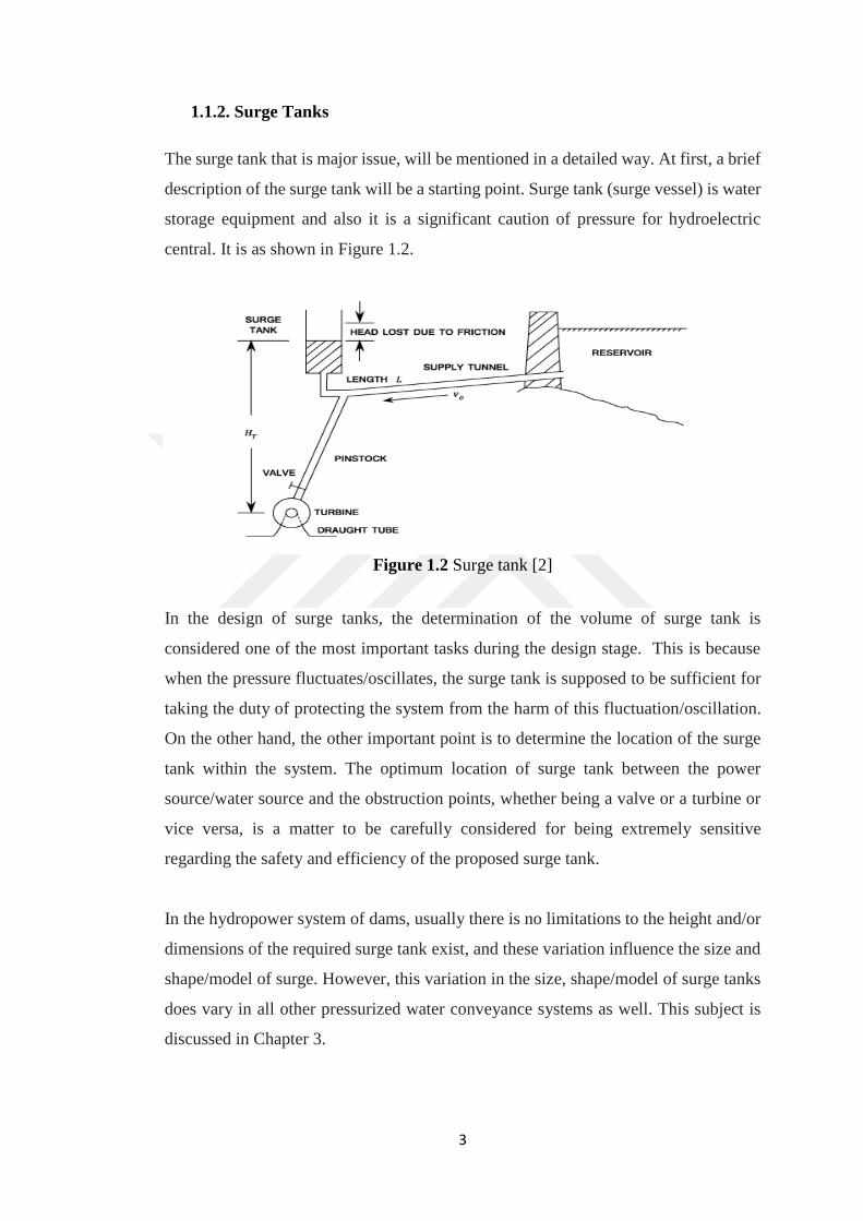
The surge tank that is major issue, will be mentioned in a detailed way. At first, a brief
description of the surge tank will be a starting point. Surge tank (surge vessel) is water
storage equipment and also it is a significant caution of pressure for hydroelectric
central. It is as shown in Figure 1.2.
Figure 1.2 Surge tank [2]
In the design of surge tanks, the determination of the volume of surge tank is
considered one of the most important tasks during the design stage. This is because
when the pressure fluctuates/oscillates, the surge tank is supposed to be sufficient for
taking the duty of protecting the system from the harm of this fluctuation/oscillation.
On the other hand, the other important point is to determine the location of the surge
tank within the system. The optimum location of surge tank between the power
source/water source and the obstruction points, whether being a valve or a turbine or
vice versa, is a matter to be carefully considered for being extremely sensitive
regarding the safety and efficiency of the proposed surge tank.
In the hydropower system of dams, usually there is no limitations to the height and/or
dimensions of the required surge tank exist, and these variation influence the size and
shape/model of surge. However, this variation in the size, shape/model of surge tanks
does vary in all other pressurized water conveyance systems as well. This subject is
discussed in Chapter 3.

4
The most common surge tank is a simple vertical cylindrical shaped tank which is
directly attached to the pipe in the pressurized system with stationary cross-section.
For this reason, head losses which is the smallest amongst other types, is seen in this
kind of tank. This is the reason why it impoverishes the surges which is created by
water hammer, are slower than the other types.
Other common and known tank is the restricted orifice surge tank. At the entrance part
of surge tank, there is a narrow orifice. As the water is flowing through it, some energy
is lost because of decrease of the surge amplitudes. Furthermore, the effect of strength
of the inflow and the outflow through the tank is reduced thanks to its inhibitory
effects. Thus, the dimensions and height of the tank is also decreased. Yet, the region
of the orifice must be selected with a great attention because the inflow and outflow
will be intercepted in it when it is too small. Also, when it is same with the region of
the tunnel, the head loss would be an amount which can be ignored so this makes the
orifice useless. Also, some obstacles exist in this type of tank. Transmission of some
of the water hammer waves to the pipe are caused by inhibitory effects of the orifice.
Besides, the fast improving of the speeding up and the decelerating head makes a
negative efficacy to turbine adjustment.
A differential surge tank is combined by a narrow orifice and a simple surge tank. The
internal riser works like a simple tank and outer tank works like a restricted orifice
one. Therefore, abrupt changes in the system is replied by the differential tank slower
than the restricted orifice tank. Yet, it is faster than the simple tank. It also has smaller
negative efficacy on turbine regulation when it is compared to restricted orifice tank.
In a spillway tank, a spillway is supposed to ensure the steadiness of the elevation of
the surge tank. In this case, the surplus amount of water in the spillway is disposed
off when the water is surged in the tank. Thus, the size of the tank can be decreased
and the tank can be set up in the desired way. If any extra place is not ensured, the
disposed water should be diverted somewhere else. The latter process of water
diversion is likely to be expensive, and this turns the advantage which is provided by
a spillway into a disadvantage.

5
A closed surge tank, which is also called as the air chamber, includes compressed air
in it. The range of water surface fluctuation/oscillation is managed and decreased by
means of enlargement and narrowing of the air layer in the tank.
Furthermore, in the case of very long tunnels, double or multiple tanks can be used it
has been mentioned [53]. In such case, the speed of the full flow in the tunnel may
fluctuate/oscillate due to the variation of the volume of the air trapped in the tunnel as
a result of any probable variation in the efficiency of the relevant pumping station.
Thus, the air is removed from a pipeline instantly by the most suitable valve such as
well service air valves, check valves or manual vent and the like. This type of surges
are frequently observed in daily life as well. As an example, the heating radiator system
in a building has both expansion tank and heating boilers tank which have several
check valves on its pipes in order to prevent any probable damage that may be caused
to the heating systems.
1.2. The Target of the Research
The research starts in presenting the details relevant to both water hammer and surge
tanks. This is explained in both Chapter 2 and 3 consecutively. In Chapter 3, it was
necessary to pay more attention and details to the different types and properties of
surge tanks.
In Chapter 4, the typical calculations relevant to the design of a typical surge tank are
explained while In Chapter 5, a tunnel in the project of Birecik Dam is selected for
investigation where a surge tank has not been implemented.
In Chapter 6, the effort and details concentrated of the way to select and optimize the
model and size of the surge tank according to the regional conditions and project. The
research concentrated on the improvement in the safety and performance of flow in
case a surge tank had been constructed to eliminate any probable water hammer event
that may damage the tunnel system. The improvement on the performance after the
addition of a surge tank to the tunnel in Birecik Dam are presented with the hope that

6
similar steps in future projects will include using the different types and sizes, and
consequently, improve the safety and performance of flow conditions in the project.
In Chapter 7, a brief conclusion and evaluation about the research and results is
presented as well as some proposals for future research in this field.

7
CHAPTER 2
LITERATURE REVIEW
2.1. Previous Research
Water hammer research was initiated by Frizell as early as (1895) in a hydropower
institution in the USA. While he was working in Ogden Hydropower Plant in Utah as
an engineer, he carried out his experiments. He produced of the equations relevant to
pressure increment for the situation of abrupt occlusion.
Joukowsky (1897) is famous as developer of the basic water hammer theory from
Russia. Systems of dissimilar diameters and lengths were examined by him, and he
backed up the results of his experiments by theoretical study. All his study fields were
relevant to wave speed in which the flexibility of the system, the description of the
crucial duration throughout a transient, the ratio among the diminished flux speed and
the increased compression. Besides his various works in this field, he debated how
the surge tanks, air reservoirs and valves operate the compression which occurs
throughout temporary situation of flows.
Dynamic equation with greater accuracy and derived zero-dimensional parameters
were based upon by Allievi (1902) who is famous as the publisher of the general theory
of water hammer. His study area includes identical valve maneuvers, their processes
and also the corresponding increased compression.
Steadiness of a surge tank for the situation of ‘‘constant power’’ was studied by Thoma
(1910). By means of the turbine, the notion is to acquire energy input or output. He
concluded that the surges are steady when the surge tank area is larger than a lowest
value that is known currently as the “Thoma area”.
8
Steadiness of the oscillation in surge tanks was examined by Frank and Schüller
(1938). Resolution for two distinct special situations were derived by them. First one
is known as the ‘‘constant flow’’, it is the variation of the turbines discharge from an
amount of discharge to another and these amounts of discharges correspond to the
steady state amounts. The second situation is known as the ‘‘constant-gate opening’’,
and it is a compound of some specific situations like the full gate entrance because of
an abrupt loading increment, in which situate of the entrance keeps stationary. It is
concluded that, in the first case the undulations are all the time said to be steady when
frictional losses exist, while in the second case the undulations are steady all the time.
Moreover, the formula for computing the elevation of utmost down surge for the
situation of sudden fractional load admission from a turbine was derived by Frank.
The mass oscillations inside surge tanks was examined by C. Jaeger (1953). Several
sorts of surge tanks, particularly the ones connecting to subterranean hydropower
institution were debated together with some extra attention on their steadiness. The
status of loading, which creates the worst situations in a system, were reviewed.
Besides, he produced a review about the primary supposition of different engineers on
the primary differential equations of fluctuation/oscillation analysis. It is concluded
that there exist a compromise on the primary notions of the surge analysis theory
despite some distinctions created by some extraordinary situations.
Pickford (1969) studied water hammer theory and surge control. He graphically
examined the computation operation of different sorts of maneuvers. Moreover, he
produced the basic equations of mass oscillations in surge tanks through finite
difference methods.
Russ (1969) accomplished that the crucial situation to be examined for the steadiness
of the surge in a surge tank is made by smaller oscillations instead of larger ones.
In a German laboratory, Mosonyi and Seth (1975) were pioneers in terms of doing the
surge examination of a restricted orifice surge tank. They improved the governing
equations based upon the presence of the important pressure head increment in
magnitude in the penstock upriver of the surge tank by the process of restricted orifice
tank.

9
A technique for the optimization of the plan parameters of dissimilar types of surge
tanks was suggested by Arshenevskii (1984), primarily the differential and the
restricted orifice surge tank. This proposed technique is based upon removing a design
parameter at every stage. If a parameter is taken as stable and others alter, it suggest
the chance to the designer to select the right set of data. In every stage, a parameter is
selected to some prearranged limit conditions. Eventually, the set of parameters that
will make the minimal expense for a surge tank would be acquired.
Moghaddam (2004) advanced an optimization function, in which the objective
function is to diminish the expense of a system occurring with a conduit and simple
surge tank. He produced basic surge study equations. Then, the equations were
rewritten in zero-dimensional shape facilitating the installation of the objective
mission. The mission is optimized through trial and error, and thus, the diameter of the
pipe and the shape and size of the required surge tank that minimize the cost are
acquired.
A study was performed on investigating the ideal form of a surge tank both
theoretically and experimentally in a hydroelectric institution by Kendir (2006).
Examination of the surge was performed by finite differences method for all types of
surge tanks theoretically. Later on, a preliminary model is built and surge examination
is performed in order to get the corresponding, empirical conclusions. It resulted that
the most suitable form of a surge tank is a V shaped tank.
Mass oscillations in throated surge tanks were analyzed by Lika (2008). In a laboratory
environment, a preliminary model is operated to try varied sized surge tanks with
varied sized throats. Then, these results were compared with the theoretical results
which deduced the finite difference method is suitable to utilize during the surge study
calculations. Moreover, surge tanks having larger tank diameters ought to be used in
the plan processes instead of the ones with smaller diameters. This is due to large
diameters functioning better than the ones with relatively smaller diameters.
Surge studies with and without chambers were performed by Nabi Et all (2011). Their
object was to find if surge tanks with more chambers work better than those with no
chambers at all or those that have a single one. In Pakistan, a case study for two

10
hydropower plants was done with this aim. Surge study was performed for these two
hydropower plants, where the surge heights and their corresponding time of spreading
were confirmed. In conclusion, it was resulted that the surge tanks having more than
one or none chambers works better when it is compared to the others which are based
upon the investigation of lower surge heights and accordingly stability [10].
2.2. Definition of Water Hammer
It was called as water hammer because of the banging sound in the pipes. These sounds
are created by abrupt changes in fluid compression and velocity. Sometimes, it can be
created by fast closure of a tap, particularly when it is a tap that only needs a 900 turn
to close it. As a result, that pipe vibrates because of the pressure waves in the water.
Therefore, it might hit floor joists or wall by creating banging noise. But to get the
worst type of water hammer, lengths of pipes are generally small in the houses and a
domestic tap would need to be closed very rapidly in order to create the banging noise.
Therefore, water hammer is most of the time inconvenience in houses. Yet, water
hammer is more than a minor irritation in terms of industry and could result in
damaging consequences. In the following part, it is explained how it happens and
hereby how it demonstrates itself, and for that reason, how to obstruct it or protect
against it [3].
Other examples of how the water hammer effect is created are the cases of pump or
turbine failures. The abrupt standstill in flow will create the momentum change which
causes water hammer effect, if a pump fails. This can also be observed in home
plumbing systems if taps are turned on and off abruptly. A high hammer noise will be
created and the plumbing system will vibrate in most of the time [4].
Figure 2.1 Water hammer effect [5]
11
2.2.1. Cause of High Pressure
Alterations in compression are in charge of keeping and changing the speed of a liquid.
These changes can cause enforcement on the pipe itself. In general, they are very light
and even their existence is not recognized. But if the incidence of alteration of flow
rate is great enough, the forces can become strong enough to make the pipe budge or
enforce great forces on its supports. If the supports are not stationary, the pipe can be
loosened, or it run against with the limit stops, occasionally strongly [6, 7].
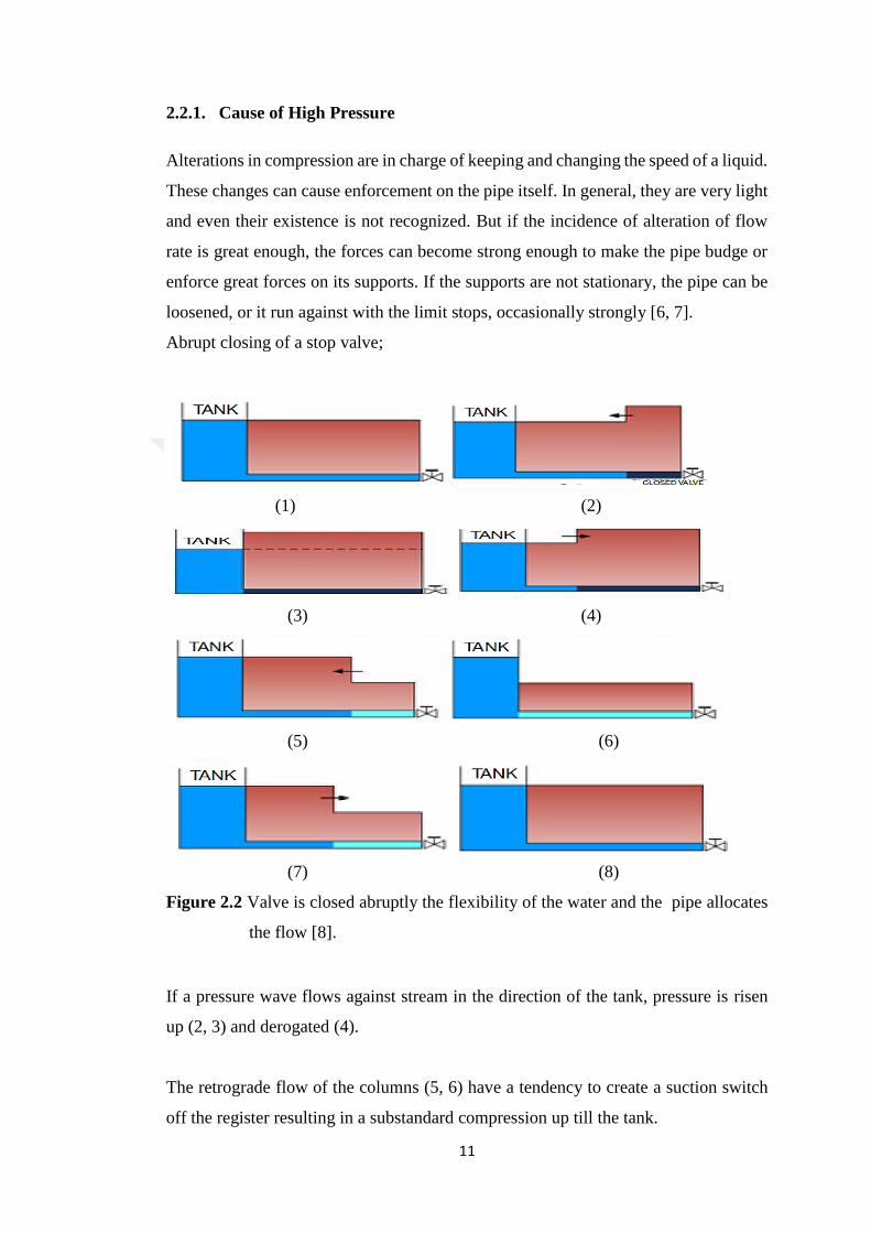
Abrupt closing of a stop valve;
(1) (2)
(3) (4)
(5) (6)
(7) (8)
Figure 2.2 Valve is closed abruptly the flexibility of the water and the pipe allocates
the flow [8].
If a pressure wave flows against stream in the direction of the tank, pressure is risen
up (2, 3) and derogated (4).
The retrograde flow of the columns (5, 6) have a tendency to create a suction switch
off the register resulting in a substandard compression up till the tank.

12
The retrograde flow makes the primary conditions beginning another cycle (6, 7, 8,
and 2) [8].
2.3. Theory and Calculations
This effect was defined first by a Russian scientist Joukowski. He presents that there
is an utmost compression that can be created both theoretically and experimentally,
and it is called as the “Joukowski head” or “Joukowski pressure”. It is shown by the
given Formula;
h = (V . c ) /g (2.1)
where:
c = speed of the sound wave in the pipe, known as the “wave celeric”, m/s,
V = initial velocity of the liquid, m/s,
g = 9.81 m/s2,
h = Joukowski head (m).
The Joukowsky equation is a facilitated method for computing the top temporary
pressure happened while a valve is being closed against a fluid on the move and it is
presented as follows [9]:
Figure 2.3 Hydrostatic pressure in a liquid [32]
Following equation is used to compute hydrostatic pressure in a liquid [32]:
P = h . g . ρ (2.2)

13
where:
ρ : Fluid density (kg/m3)
Joukowski pressure (equation (2.3)) can be obtained when the equation (2.1) is
substituted in equation (2.2) [32];
P = V . c . ρ (2.3)
The wave velocity, is also called as celerity, is a function of the theoretical wave
celerity, which is shown by the following equation;
𝑐’ =√EV
ρ (2.4)
where:
𝑐’ = theoretical wave celerity,
𝐸𝑣 = bulk modulus of elasticity of fluid,
𝜌 = fluid density
The wave velocity is also a task of the composite modulus of elasticity of the pipe,
fluid pipe system, the pipe diameter, modulus of elasticity of the pipe and pipe wall
thickness. The speed of the pressure wave within a pipe is solved by the following
equation;
c = √c′2
1+ 1 + Ev . d
ε .Ep
(2.5)
where:
𝑐 = celerity of pressure wave,
𝐸𝑣 = bulk modulus of elasticity of fluid,
𝑑 = pipe diameter,
𝜀 = thickness of pipe walls,

14
𝐸𝑝 = modulus of elasticity of pipe,
𝑐′ = theoretical wave celerity
When the time of closure is lesser than length of pipe, it should be divided by the wave
celerity;
𝑡 < 𝐿
𝑐 ;
∆P = V0 . c . ρ (2.6)
where:
∆𝑝 = change in pressure,
𝑐 = wave celerity,
𝑉0 = initial velocity
The utmost pressure that will occur in the pipe is the original pressure within the pipe
plus the change in pressure, and it is defined in equation;
Pmax = P0 + ∆P (2.7)
where:
Pmax = maximum pressure,
P0 = initial pressure,
∆P = change in pressure
This pressure variation will alter in cycles at times equal to 𝑡 = 2𝐿
𝑐 for a fast stoppage
of the flow. Over time because of friction losses, the pressure wave will be reduced.
For slow closing within 𝑡 > 𝐿
𝑐, a pipe the alteration in pressure can be found by using
equation below;
∆P = P0 . ( N
2 + √N +
N2
4 ) (2.8)
15
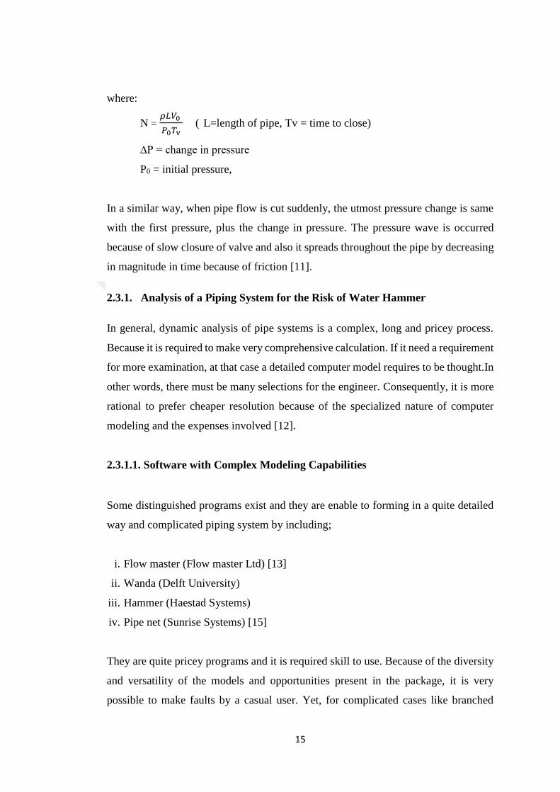
where:
N = 𝜌𝐿𝑉0
𝑃0𝑇v ( L=length of pipe, Tv = time to close)
∆P = change in pressure
P0 = initial pressure,
In a similar way, when pipe flow is cut suddenly, the utmost pressure change is same
with the first pressure, plus the change in pressure. The pressure wave is occurred
because of slow closure of valve and also it spreads throughout the pipe by decreasing
in magnitude in time because of friction [11].
2.3.1. Analysis of a Piping System for the Risk of Water Hammer
In general, dynamic analysis of pipe systems is a complex, long and pricey process.
Because it is required to make very comprehensive calculation. If it need a requirement
for more examination, at that case a detailed computer model requires to be thought.In
other words, there must be many selections for the engineer. Consequently, it is more
rational to prefer cheaper resolution because of the specialized nature of computer
modeling and the expenses involved [12].
2.3.1.1. Software with Complex Modeling Capabilities
Some distinguished programs exist and they are enable to forming in a quite detailed
way and complicated piping system by including;
i. Flow master (Flow master Ltd) [13]
ii. Wanda (Delft University)
iii. Hammer (Haestad Systems)
iv. Pipe net (Sunrise Systems) [15]
They are quite pricey programs and it is required skill to use. Because of the diversity
and versatility of the models and opportunities present in the package, it is very
possible to make faults by a casual user. Yet, for complicated cases like branched

16
networks, partially full pipes, emptying and filling of pipes, and complex rheology,
best valid resolutions can be given by these programs. It should be paid thousands of
dollars every year for these packs [7].
2.3.1.2. Software with Limiting Modeling Capabilities
Also some cheaper packs than those explained exist but they are less advanced in their
capacity. But the mathematical method, which is seen as the best in terms of giving
solution to this kind of problem (the “method of characteristics”) and as such can be
relied on to do safe analyses of easier problems, is still used. These include:
i. HiTrans [14]
ii. Hytran [16]
They incline to be part of smaller organizations which don’t have the facilities to
manage their own operative test [7].
2.4. The Causatives of Water Hammer
2.4.1. Water Hammers in Steam Piping Systems
In appropriately planned and worked steam piping systems, water hammer is not a
trouble. Valves ought to be hit slowly and cool liquid and warm steam should never
be let to relate each other in a way that a steam bubble is trapped. Yet, throughout
operation cool condensate is frequently found in pipes that are filled with steam in
general. If steam is taken in this kind of a pipe too fast, a violent bubble collapse can
be happened leading to detriment to the piping system. In the same way, steam can be
trapped close a leaky valve leaving steam into cold, high compression water so a water
hammer took place if a pump, for example, is unlocked [17].
In the following part, it is shown that is a partial listing of the geometries and processes
which lead to water hammer in inaccurately planned or functioned steam systems;
(Chou, 1990). Water is taken in almost horizontal, steam-filled pipe at a low enough
speed. Therefore, the pipe does not run full, a bubble is trapped, and it intensified
speedily and induces a water hammer. It can be seen in Figure 2.4 [17].

17
i. A steam-filled, closed-end pipe of any processing is filled with cold water
quickly enough, thus the liquid hits the end with sufficient velocity to produce a
water hammer. See Figure 2.5 [17].
ii. Water is received by a vertical steam filled pipe from above which carries down
steam that intensifies quickly and induces a water hammer.
iii. A horizontal pipe is supplied with a resource to cold water at one end and a
resource of steam at the other. For a low enough liquid speed, a long tongue of
cold liquid will broaden into the steam, experience a transition to slug flow
(because of the high, concentration induced relative velocity of the steam and
water) which causes a water hammer. (Bjorge, 1984).
Figure 2.4 When a steam bubble collapse [17]
Series of events leading to a steam bubble collapse caused water hammer if a short,
horizontal steam pipe is loaded with cold water with Froude number lesser than 1.
(Subcritical flow (slow / tranquil flow)). Froude Number is V/√gd, where v is the
liquid of rapidity and D, the tube diameter [17].
Figure 2.5 Plan of a short, horizontal steam pipe being filled [17]

18
Plan of a short, horizontal steam pipe being filled with the Froude number bigger
than one. The abrupt slowdown of the flow when the surge strikes the end of the pipe
induces the water hammer.
In order to plan water hammers out of a system, curve all nominally horizontal pipes
at least 2.8° from the horizontal, take in any cold water from the lowest point in the
system, and keep all alterations in speed or pressure progressive enough so that steam
is not trapped and intensified quickly [17].
2.4.2. Downstream of Valves
For pipes with valves not near to the pipe end, it is more possible that matters will be
experienced downstream of the valve. Here, the compression can decrease to the steam
pressure of the fluid, and boiling can happen. If boiling is occurred, a gap forms. In a
typical case like that it is shown in Figure 2.6, the liquid downstream of the cavity turn
around and set up almost the same speed as the liquid had when the cavity began to
form. But if the liquid turn around the valve or the liquid remaining before the cavity,
the impact is a violent one, equal to a valve closing in a fraction of a second. This can
be concluded vigorous water hammer [7].
Figure 2.6 Cavity growing downstream of the valve [7]

19
2.4.3. Pump Trips
The same kind of cases happens downstream of a pump which has tripped. When the
pump slows the liquid enough rapidly, gap will be occurred downstream of the pump,
and also the vapor collapse creates violent water hammer. Immediately after a trip, the
fluid runs a centrifugal pump like a turbine, and the dynamic behavior is complicated.
In terms of positive displacement pumps, the run-down is mostly unfettered of the fluid
circumstances. In both cases, a cavity can shape in the low pressure area and create a
cavity collapse and following pressure impact [7].
Figure 2.7 Events following a pump trip [18]
2.4.4. Check Valves
Check valves or non-return valves can be one of the problematic cases for the pressure
surge engineer. In general, such valves are kept open by the fluid flow, and are closed
either by a spring, or by the drag of the fluid when there is a reverse flow, e.g. after a
pump trip [7].
In some cases the strategic location of a non-return valve, or check valve or reflux
valve, is enough to avoid or at least decrease water hammer over-pressures. Where
water column separation creates the installation of a non-return valve downstream of
the pocket could prevent reverse flow and the following over pressures.
20
When the head of main pipe drops below the outside, water could be drawn into the
pipeline from the suction reservoir or a tank in another kind of application. The cavity
would be filled with this water and the return surge would be decreased in the same
way [22].
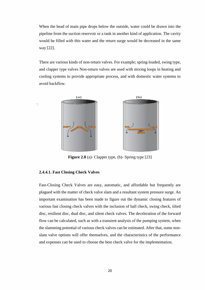
There are various kinds of non-return valves. For example; spring-loaded, swing type,
and clapper type valves Non-return valves are used with mixing loops in heating and
cooling systems to provide appropriate process, and with domestic water systems to
avoid backflow.
Figure 2.8 (a)- Clapper type, (b)- Spring type [23]
2.4.4.1. Fast Closing Check Valves
Fast-Closing Check Valves are easy, automatic, and affordable but frequently are
plagued with the matter of check valve slam and a resultant system pressure surge. An
important examination has been made to figure out the dynamic closing features of
various fast closing check valves with the inclusion of ball check, swing check, tilted
disc, resilient disc, dual disc, and silent check valves. The deceleration of the forward
flow can be calculated, such as with a transient analysis of the pumping system, when
the slamming potential of various check valves can be estimated. After that, some non-
slam valve options will offer themselves, and the characteristics of the performance
and expenses can be used to choose the best check valve for the implementation.

21
The traditional swing check valve is the most ubiquitous kind of check valve is. Swing
check valves are planned to fast close to avoid back spinning of the pump throughout
reverse flow. Traditional swing check valves have 90-degree seats with long hits and
are connected to slamming. Most likely, the most widespread equipment is a lever and
weight. It is usually accepted that the weight makes the valve close faster when it
actually decreases slamming by restricting the hit of the disc, but in return, creates a
significant rise in head loss. The valve closure is also decelerated by the inactivity of
the weight itself and the friction of the stem packaging [19].
Figure 2.9 Swing check [21]
Choosing a check valve which closes before any significant reverse flow develops is
a better resolution for preventing a slam. One this kind of valve is a spring-loaded,
center-guided “Silent” Check Valve (SCV) and it is shown in Figure 2.10.a. An SCV
is near slam-proof due to its short linear stroke (1/4 diameter), place of the disc in the
flow stream, and strong pressure spring. Yet, choosing a Silent Check Valve has a few
pitfalls such as high head loss, no position indication, and restriction to clean water
applications.
Moreover, end of the spectrum is the Tilted Disc Check Valve (TDCV). The TDCV is
shown in Figure 2.10.b has the lowest head loss because its port area is 140% of pipe
size and its disc is similar to a butterfly valve disc in which the flow is allowed to pass
on two sides of the disc. The TDCV also has reliable metal seats and can be equipped
with top or bottom attached oil dashpots to ensure effective means of valve control and
surge minimization. The TDCV is totally automatic and needs no exterior power or
electrical connection to manage the pump.

22
The latest check valve having the biggest effect in the water/wastewater industry
nowadays is the resilient disc check valve, the Swing-Flex® Check Valve (SFCV).
The SFCV is highly reliable with practically no maintenance because the only moving
part is the resilient disc. This valve has a 100% port slanted at a 45-degree angle, which
ensures a short 35-degree stroke, quick closure, and low head loss. The valve is also
existed with a mechanical position indicator and limit switches.
Therefore, one is made available for every system with low head loss and slam-free
operation with all of the check valve probabilities [19].
(a) (b) (c)
Figure 2.10 (a)-Silent check, (b)-Tilted disc, (c)-Swing flex [21]
2.4.4.2. Pump Control Valves
Although a fast-closing check valve may avoid slam, it may not preserve pumping
systems with long crucial periods from speed changes throughout pump startup and
shutdown. For pumping systems in which the crucial period is long, a pump control
valve is frequently used. A pump control valve is wired to the pump circuit and
supplies arrangable opening and closing times in surplus of the system crucial time
duration. Pump control valves are hydraulically worked so the movement of the
closure vehicle of the valve (i.e. a butterfly valve disc) is unchanged by the flow or
compression in the line.
Furthermore, most of the pumps in service have low rotating inactivity and come to a
stop in less than 5 seconds in nowadays. The pump control valve can be closed quickly
throughout power outages or pump trips to preserve the pump. But, if rapid closure is

23
needed, additional surge equipment might be needed as described in the following part.
First, the selection criteria pertaining to pump control valves will be shown though.
The list of potential pump control valves is long because a lot of valves can be
accompanied by the automatic controls necessary for pumping systems. Valves
typically considered are butterfly, plug, ball, and globe-pattern control valves.
Presumably the most common standard used to choose a valve is first cost, but in terms
of pumping systems, the choice process must be cautiously assumed with
consideration given to:
i. Valve and installation costs
ii. Pumping costs
iii. Seat integrity
iv. Reliability
v. Flow characteristics [19:21]
Figure 2.11 Pump check valve installation [19]
2.4.5. Vacuum in Elevated Place
In high places like pipe-bridge, vacuum in the piping system can be formed. In the
case of pump trip, vacuum can be formed at the elevated places where barometric leg
is above tank. After pump restart liquid columns, it will collide resulting in high

24
pressure surge. Even if elevated section is lesser than barometric leg, column separation
might be occurred as it is shown in Figure 2.12.
Figure 2.12 Vacuum in elevated place [24]
Potential resolution to fix this problem is establishing closing valve downstream that
will be automatically closed when power interruption is created [24].
2.4.6. Flow Restrictors
If a flow is limited by a restrictor opening that is close to the end of a pipe, a matter
with pressure surge can happen on startup. On startup, if the pipe is empty, the liquid
runs at high rate until it reaches the restrictor, when its flow abruptly decreases. This
causes a surge event with the velocity being the change in velocity is induced by the
passage of liquid through the restrictor. It can be seen in the Figure below [24].
Figure 2.13 The liquid runs at high rate until it reaches the restrictor [24]
25
2.5. The Factors Influencing the Occurance of Water Hammer
2.5.1. Flow Velocity
It is occasionally said that when the liquid speed is low enough and the pipe can
overcome the expected Joukowski head, so there is nothing to worry about.
Still, it is risky zone. It is probable to have networks that can produce a number of
reflected waves which may meet in an infelicitous process and induce a compression
greater than Joukowski. Unfortunately, it would be suffer a loss from this. Yet, this
detrimental situation is created by being exposed again and again to restrict
compression and force probably [7].
2.5.2. Elasticity of Pipes
The computation of the wave celeric has been debated from equation 2.4. When the
pipe was extremely hard and completely supported, then the pressure wave would flow
at the rapidity of sound in the liquid. But actual pipes aren’t so, and they bulge slightly
under the influence of pressure. This is equal to the fluid being more compressible,
and so the wave goes less rapidly. The final wave speed after this effect is called as
the wave celeric [7].
According to equation 2.1 the greatness of pressure surge is straight connected to the
wave celeric, so it is likely that by making the modulus of the pipe material tiny
enough, or the wall thin enough, after that the wave celeric will also become small and
thus surge problems will be decreased. Yet, there are convenient problems with
making pipes like rubber. GRP pipes (Pipes are made of centrifugally cast glass fiber
reinforced plastics (GRP) contain a compound of thermosetting plastics. For instance;
vinyl ester resins, unsaturated polyester or, chopped glass fibers and reinforcing.
Agents normally have a nominal wave celeric. Their ability to resist compression,
vacuum and surge forces is generally restricted while typically half or less than that of
a steel pipe. Therefore, flexibility is not generally seen as a convenient remedy. Yet,
credit should be taken for the decrease in wave celeric in GRP pipes while calculating
the impacts of pressure surge [25].

26
Figure 2.14 Elastic pipes on washing machine [26]
2.5.3. The Quality of Valve Performance
2.5.3.1. Speed of Operation
One of the good ways to avoid water hammer is decelerating valve operation by
increasing their stroke time. The only right way to compute the minimal stroke time is
containing the correct valve features (CV against angle of closure) by providing a
transient model of the system, and also model different stroke times until a limit is
found. Actuators can be decelerated to accomplish the reliable closure time computed.
Hand valves can be suitable with gearboxes. Therefore, it is not possible for an
operator to close them abruptly. All the time, it should be done in undefended cases
rather than depend on “good operating practice” [7].
2.5.3.2. The Ideal Curve of the Valves
Valves can be created with some different types of curves. Most of valves have little
curves from a surge point of view, and the liquid is decelerated minor throughout the
significant part of their flow, but after that it causes a fast alteration in flow when
closure is approached, for example; the “rapid opening” type. Alteration in speed is
needed for surge protection, and this type of valves aren’t looked with favor on systems
susceptible to surge problems.

27
The ideal curve of CV opposite valve position relies on the proportion of the pressure
drop that happens across the valve if the flow is regular. It is indicated in below. For
an original design, where the valve pressure drop is about 10% to 20% of the total
frictional pressure drop, a curved characteristic (the lower curve) gives the desired
flow and valve position pattern. The valve trim is called as the “equal percentage” type
fits this in an ideal way. Thus, it is given a fairly linear reduction in flow rate when the
valve is closed, and so the decelerating the liquid is shared more evenly across the
valve stroke. This is best for surge avoiding, and the valve stroke time can be decreased
by using such a valve characteristic [7].
Figure 2.15 Relative CV and position [7]
Relative CV and position, such that flow rate is suitable to value position, for three
values of the % of the whole pressure drop across the pipe with the value totally open
[7].
2.5.4. Pump Inertia
Because of a defect of the pump or a breakdown of the electricity supply, possibility
of an abrupt close of a pump is not avoidable definitely. Relying on the results of a
trip, it might be wanted to raise the inactivity of the pump so that its rate of deceleration
is decreased. This can occasionally be done by matching an over-sized motor, but this
28
is not possible when it is required to match a flywheel between the motor and the
pump. This might be looked like an extraordinary regulation, but it has been utilized
on many situations [7].
2.5.5. Compressibility of the Conveyed Liquid
The other way of preventing water hammer is to raise the compressibility of the liquid
by douching a gas into the flow. The compressibility of gas bubbles are raised, thus
the wave velocity is reduced, and the size of any surge problems is decreased. The
wave celeriac can be decreased by as much as 90% by adding as little as 1% by volume
of air in a pipe. Yet, it might be pricey to adjust reliably, and is not a common remedy
[7].
2.5.6. Minimizing the Occurance of Water Hammer
2.5.6.1. Removal the cause of the hammer
Some reasons can be solved by adjusting for the removal or management of the
problem item.
Some causes can be resolved by arranging for the elimination or control of the problem
item. Outside of the items have already been discussed, this might contain vibrating
pressure relief valves, rapid emergency shutdown valve closures, and some manual
valve closures such as butterfly valves. Smooth starters can help with some water
hammer matters which are created by pumps.
2.5.6.2. Reduction the pumping velocity
Reducing the pumping velocity can be done by using a larger pipe diameter or lower
flow rate.
2.5.6.3. Selection of stronger pipes
When pipe specifications are only lightly improved, this can be relatively pricey but it
might be a remedy.

29
2.5.6.4. Slowing down valve closure
Slow down valves or use ones with better discharge characteristics in the pipe system.
2.5.6.5. Usage of surge tanks.
In general, these are only found on water systems to allow liquid to leave or enter the
pipe if water hammer is happened.
Figure 2.16 Typical surge tank [27]
2.5.6.6. Usage of surge alleviators
These are same with pulsation dampers mostly suitable with positive displacement
pumps, but much larger.
Figure 2.17 Surge alleviators [27]

30
2.5.6.7. Usage of pump flywheels
These can be used if water hammer is decelerating too rapidly a conclusion of a pump
by following a trip.
Figure 2.18 Typical pump station [27]
2.5.6.8. Usage of pressure relief valves
These are not appropriate to toxic materials if a catch system isn’t provided.
2.5.6.9. Usage of air inlet valves
These are not convenient unless entrance of air or other potential outer materials is
tolerable.

31
2.5.6.10. The Injection of Nitrogen or Air into the Fluid
A recent remedy would be the injection of nitrogen or air into the fluid. It can’t be seen
that it is used in practice and its use would be needed care, but it is probable in
theoretically [27].
32
CHAPTER 3
THE MODELS AND FUNCTION OF SURGE TANKS
3.1. Functions of Surge Tanks
i. The hydraulic turbine is assisted in terms of features of its arrangement,
ii. The water is stocked in order to increase the pressure in the situation of drop
pressure,
iii. A free reservoir surface is ensured near to the discharge regulation machinery.
The conduit length in charge of hammer pressure will be cut and limited by
that,
iv. The pendulation of water levels fallowing load alteration of even small as well
as large size is provided, and it is suppressed positively and quickly [28, 29].
3.2. Location of Surge Tanks
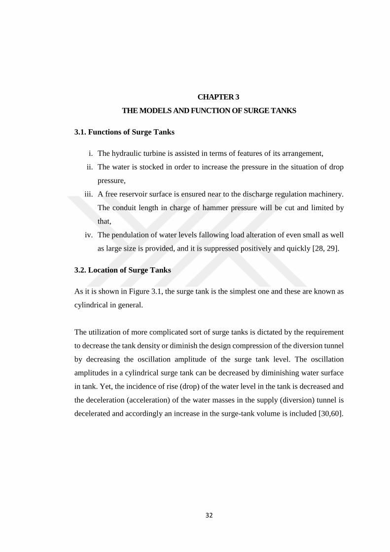
As it is shown in Figure 3.1, the surge tank is the simplest one and these are known as
cylindrical in general.
The utilization of more complicated sort of surge tanks is dictated by the requirement
to decrease the tank density or diminish the design compression of the diversion tunnel
by decreasing the oscillation amplitude of the surge tank level. The oscillation
amplitudes in a cylindrical surge tank can be decreased by diminishing water surface
in tank. Yet, the incidence of rise (drop) of the water level in the tank is decreased and
the deceleration (acceleration) of the water masses in the supply (diversion) tunnel is
decelerated and accordingly an increase in the surge-tank volume is included [30,60].

33
Figure 3.1 Cylindrical surge tank [31]
Also, it is important that the place of surge tank to create better conclusions.
Dimensions and location of the surge tank are based upon by considering;
i. The surge tank should be placed as near to power or pumping plant as much as
possible,
ii. In order to avoid overflow for all situations of process, the surge tank should be
adequate elevation,
iii. The bottom of surge tank should be low enough that the tank is discharged and
the air is taken in the turbine penstock or it is pumped discharge line throughout
its process,
iv. In order to maintain steadiness, the surge tank needs to have enough cross
sectional area [29,34].
Figure 3.2 The most effective location to place the water hammer amestor (surge tank)
[33]
As it is shown in Figure 3.2, location A would be the best because that is where the
pressure wave would be most, as energy will be distributed by the time it gets to either
34
B or C. Yet, because of the height, cavitation at B should be concerned, and putting
the surge tank there would avoid probable cavitation [33].
3.3. Types of Surge Tank
3.3.1. Classification of Surge Tanks
The surge tank can be categorized as;
a. According to the Head Available for the Scheme
i. Surge tanks for high head plants,
ii. Surge tanks for medium high head plants.
b. The Generalized Form
i. Plain or complex store of the flowing water in a free surface tanks are connected
to the conduit straight or through a throttle which is known as surge tank or,
ii. Similar storage of flowing water but which is limited with air pressure is called
as air chamber.
c. According to Their Location Relative to the Terrain
i. Free standing surge tank,
ii. Excavated surge tank.
d. According to Their Position Relative to the Power House
i. Upstream surge tank on head race tunnel,
ii. Downstream surge tank on tail race tunnel.
e. According to the Hydraulic Design
i. Simple surge tank,
ii. Gallery type surge tank,
iii. Restricted orifice surge tank,

35
iv. Differential surge tank,
v. Air chamber (Closed surge tank) [30].
3.3.2. Simple Surge Tanks
In order to start with, a simple surge tank is a tank, which is combined straight to the
pipe with stationary cross-section throughout. A simple surge tank is such as vertical
pipe which is connected in between penstock and turbine generator or shaft of constant
horizontal cross sectional area that connects the pipes of a hydroelectric power plant
for avoiding the pressure surges entering into it (Figure 3.3).These are installed with
greater elevation and assists are also supplied to keep the tank.
If the water flow abruptly rose the water is gathered in the surge tank and neutralize
the compression. Thus, the head losses that occur in this type of tank are the smallest
among all types. This is the reason why it damps the surges created by water hammer
slower compared to other types. Moreover, due to the small head losses, the amplitude
of the surges is bigger, so it requires to be planned higher to avoid an overflow. This
is the reason why it is the most expensive one among all types [29, 34]. Top of the
surge tank is opened to environment when surge tank is entirely loaded, so it overflows
to keep the compression neutralization.
Figure 3.3 Simple surge tank system [35]
It is shown in Figures 3.3; 1, shows a waterway; 2, a surge tank; 3, a penstock; 4, a
generating plant.

36
In a simple surge tank, there is very minor head loss between the surge tank and the
pipeline, and the reservoir is regarded so great that its level stays stable.
If the tap is turned on, the water is expected to flow out of the tank and down the pipe.
Things don't just start acting by themselves.
There must exist power acting on the water in the conduit in order to move it, and also
the evident one has its own weight. Water is pretty stuff - a liter of it weighs a kilogram.
The water in the tank is suppressed on the water in the conduit. The size of the tank
has a problem. It is advised by common sense that a huge tank which keeps more water
must implements more power to the water in the conduit than a little one would. Yet,
common sense is incorrect. Water is pushed down the pipe has nothing to do with the
density of the tank, nor its surface area. Certainly, in an open and large tank because
of surface area vaporization is more. Additionally, building of an excavated tank made
by excavating might be hard due to soil surface like rock. But this is implemented for
these two situations since excavation weight will be equal but one is higher, other is
so large. The water velocity will be lower in large parts. Anyway, writer goal is to
decrease the velocity of water.
But if researcher think about that it is an open channel performance (capacity) changes
inverted with the wetted perimeter (P) and energy losses are less with smaller P such
as example;
Figure 3.4 Same options for the dimension of a 20 m2 cross sections and P: (a) 22; (b)
14; (c) 13; and (d) 14m [36]
Therefore, it is also similar for the surge tanks, energy losses must be little thus
researcher can prefer section c here and the tank should be higher lightly than the

37
surrounding of environment. It is involved with the topography and kind of soil. Tank
should be exerted on a hard surface like a rock.
Besides; the power making the water flow down the conduit must be present at the
entry to the pipe. If it is presumed that the water is stable - any faucet connected to the
conduit are closed. Right now, it should be considered about the column of water
straight above the entry of the pipe (shown as a dotted line). It has weight, and its
weight is a power acting downwards. Subsequently,
Figure 3.5 The same volume tanks [37]
Down-force on the water in the conduit = Weight of water in the column over the pipe.
Weight moves downwards, not toward the sides. The power because of the heaviness
of the water outside the column moves downwards as well - but outside the column.
Therefore, the down-force in the column stays the same no matter how much water
there is around it. As it is mentioned before, both tanks hold the same quantity of water,
but one is twice as long as the other. The water surface in the taller tank is twice as far
away from the pipe, so there is twice as much force thrusting water out. If both tanks
are punctured close the underside, water would squirt out much quicker from the tall
one [37].
Figure 3.6 Different types of simple surge tanks [39]

38
It is shown in Figures 3.6; 1, simple tank; 2, simple shaft; 3, spilling shaft; 4, overflow
type tank. Consequently, there are different kind of surge tanks such as Figure above.
And overflow and spilling shaft surge tanks is given in the following headings.
3.3.3. Horizontal Galleries (Expansion) Surge Tanks
Extra storage galleries are comprised in gallery type surge tank. These store galleries
are also known as expansion chambers. Thus, gallery type surge tank can also be called
as expansion chamber type surge tanks.
These expansion chambers are generally ensured at below and above the surge levels.
Under surge level chambers are employed to storage excess water in it and left if it is
required or there is a brief fall in pressure. Upper surge level chambers are employed
to adsorb the extreme compression [29].
Figure 3.7 Expansion chambers [29]
Due to the reason of increasing the stored volume of surge tank, horizontal galleries
are used. That is, by content treating most of the stored volume near the extremes the
oscillation, it is likely to work in a perfect way with all volumes which are about %50
less than for a simple surge tank of constant section and the same maximum upsurge
and down surge values (Gardel, 1957) [38].

39
The usage of a single or double expansion of vertical shaft of the surge tank is common
in high head plants with perceptible diversification in storage levels. In this case of the
horizontal galleries work as efficient limiters of the maximal amplitude of the
oscillation following abrupt load changes. The galleries are connected by a vertical
shaft with enough cross sectional area to assure adequate stability of operation.
There the stored volume in the vertical shaft was ignored and all the volume was
presumed to be concentrated in the upper and lower galleries, whose free surface levels
continued horizontal throughout.
Especially a criticism of the calculations of the drainage of the lower gallery was
existed and it is crucial to the reliability of the hydropower plant operation. It is
necessary that the upper of the supply conduit is kept under pressure every time.
Therefore, the discharging of the lower chamber needs to be completed before the
water level rises this hazardous point. And as shown figure below there are lots of
different types of galleries surge tanks.
Figure 3.8 Different types of Galleries surge tanks [39]
Figure shows that 1, shaft with upper expansion chamber; 2,shaft with lower chamber;
3, shaft with overflow type upper chamber; 4, overflow type shaft with lower chamber;
5, shaft with two chamber; 6, inclined shaft with two chamber; 7, overflow type tank
with two chambers.

40
In 1930, Jaeger quotes Schoklitsch suggested a more practical type of the discharging
operation. When the level in the shaft comes under the top of the low chamber, a
negative wave is created and it started to act towards the closed end. If the shaft falls
under a depth equal to 2/3 of the gallery height y0, crucial situations may be supposed
at the gallery exit. The resulting wave has a speed equivalent of √23⁄ 𝑔𝑦0 and when the
air cavity over the free surface has a depth of y0 after that the resulting water discharge
reaches the value;
Q = 1
3 √
2
3 yo √𝑔𝑦0 (3.1)
And it keeps stationary until the negative wave came back from the closed end and
turns back to the out division. The accomplished unloading is calculated by the
identical operation. Yet, they are attributed to levels of power lower than 2/3yo, as the
shaft level is reduced below this mark. An empirical research of this drainage model
which completed this was made by Rao (1970) and Ellis and Al-Khairulla (1974) even
though drainage process follows the cyclic pattern suggested by Schoklitsch, the
crucial flow presumptions are not well adjusted and the wave has a speed remarkable
smaller than √23⁄ 𝑔𝑦0 .
Investigation of the loading operation of the horizontal gallery shows that if the shaft
level increases over the floor level a thin wedge shaped wave front is created. While
this wave moves to the closed end of the gallery and back to the exit, the level at the
shaft stays stable. The coming of the reflected wave signalizes an abrupt increase in
shaft level. When the still water depth created behind the reflected wave is pushed
down by the shaft level, another positive wave is created and the filling process is
continued until the horizontal gallery is filled [38].
3.3.4. Restricted Orifice Surge Tanks
This type of surge tank is known a "port". This type can efficiently decrease amplitude
of the water level in the tank and has relatively basic design. Moreover, in the
conditions that a surge tank is built deep below the ground, such as a tailrace surge
tank, the diameter of vertical shaft can be decreased by supplementing upper chamber.

41
Figure 3.9 Restricted orifice surge tank [39]
The restricted orifice design has been selected more constantly in recent surge tank
building because it has the following benefits:
i. It is much better to build in terms of saving and simplicity.
ii. The size of the orifice can be altered with ease when a change of the throttle
opening is requested because of some alteration of the power grid connection.
iii. The form of the orifice plate can be planned with ease to provide a good
performance during both inflow and outflow through the orifice.
iv. The orifice plate can easily be set up, or altered to, any location in the riser or
lateral pipe so that the steady of the surge tank will be risen [30].
Figure 3.10 Different shapes of Restricted orifice surge tanks [39]
There are different kind of restricted orifices surge tanks. And figure above shows that
1,2 simple restricted orifice type tanks; 3, tank with grate type throttling.
3.3.4.1. Requirements for Hydraulic Design of Restricted Orifice Tank
The conditions which are demanded for the design of restricted orifice surge tank are
listed in the followings.

42
i. The maximal amplitude of water level by fluctuating is between the height of
top and bottom of the tank.
ii. To meet the necessary constancy conditions (dynamic and static conditions) of
water level amplitude.
iii. Following critical discharge are not exceeded by maximum discharge.
3.3.4.2. Critical Discharge
i. Critical discharge is described as discharge if amount of water increase at partial
load rejection overruns that at full load rejection in a restricted orifice surge tank.
ii. When the maximum discharge is smaller than the critical discharge, the amount
of water increase in the tank at full load rejection is the greatest.
iii. Even though it is quit the thing to approve the highest level of water increase at
the critical discharge in the condition that the maximal discharge exceeds the
critical discharge, actually, a surge tank is planned so that maximum discharge
does not overrun critical discharge [40].
3.3.4.3. Orifice-Junction Loss Behavior
Much common information is shown in the literature on losses in branching conduits;
Results of research into losses was represented by Tek Li (1972) caused by an orifice
placed in the lateral pipe a junction. Appropriate allowances cannot be made to this
data though, in order to account for the interplay of the surge tank with the orifice and
junction act. It was deduced that some empirical task was required.
With an observation which is approved by dimensional analysis, the major variables
affecting the losses are the rate of flow from or into the tank to the flow in the conduit,
the geometry of the orifice surge tank junction and the Reynolds number.

43
Figure 3.11 Flow patterns at orifice junction [43]
i. Dividing Flow
Minor differentiation was realized between the flow patterns within the branch, orifice
and surge tank for diversified rates of flow into the branch. For a low Q2/Q1 the flow
into the branch was canalized from the top section of the flow in the pipe. A separation
zone continued behind the leading side of the branch within the branch flow. After
that, the flow is narrowed into the orifice and enlarged beyond the orifice. For Q2/Q1
of 1.0 the flow pattern in the delivery pipe was various in that all the flow from the
pipe was being canalized.
ii. Combining Flow
Some distinctions in flow pattern were realized for different rates of Q2/Q3. For low
Q2/Q3 and larger orifice sizes the flow from the tank are constricted into the orifice
plate and then enlarged into the branch. For higher values of Q2/Q3 the jet from the
orifice did not added to the branch walls but hit the wall of the delivery pipe making
significant turbulence. This behavior showed the complicated mutual effect between
the orifice and junction flows.

44
3.3.4.4. Types of Orifice and Mouthpiece
Orifice is a tiny entrance of any cross-section for example; circular, triangular,
rectangular, etc. On the side or at the bottom of a tank, through an orifice fluid is
flowing. In order to evaluate discharge, the orifice is employed. An orifice is ensured
in vertical side of the tank or in the basis.
The orifices are categorized as small orifice or large orifice relying on the size of
orifice and head of liquid from the center of the orifice.
If the head of the liquid from the center of orifice is more than five times the depth of
the orifice, the orifice is known as small orifice. And when the head of the liquid is
lesser than five times the depth of orifice, it is known as large orifice.
Some representative examples of orifices and short tubes are demonstrated [42];
Figure 3.12 Typical examples of orifices and short tubes [42]
∆hm =K 𝑉2
2g (3.2)
where:
∆hm = Head loss because of a minor loss (m),
K = A minor loss coefficient for the corresponding pipe element,
V = Velocity in the section (m/s),
g = Gravitational acceleration (m/s2).

45
Figure 3.13 Minor loss coefficient [42]
According to the theory, these values are utilized in chapter 4 part 4.2.1.b [42].
3.3.4.5. Sudden Contraction and Sudden Expansion
If the flow goes the pipe, it is divided by inactivity from the inner surface close behind
the entry. The division of the flow and the inducted formation of eddies is the main
resource of the pressure loss. The pipe length b makes a dead storage around the
protruding pipe that ensures room for turbulences and cross flows which also conduced
to the loss coefficient.
Figure 3.14 Schematic diagram of flow with a sudden contraction [43]
Shock waves are created by an abrupt enlargement of a pipe cross section. In suddenly
expanded section a jet is shaped which is diverted from the remaining medium by a
boundary surface that is dispersed into severe vortices. When the vortices will be

46
developed and disappeared progressively, the flow will be spread over the cross
section in a length of 8 to 12d2. The speed circulation upstream of a sudden
enlargement is never monotonous, and essentially this conduces to the losses (Idelchik,
1986).
Figure 3.15 Schematic diagram of flow at an abrupt enlargement [43]
3.3.5. Differential (Johnson’s) Surge Tank
It is contrived by R.D. Johnson, in USA. This sort of surge tank has a vertical riser
about the similar diameter of the pipe with some ports or openings as it is indicated in
Figure 3.17 (1) . Flow into the tank is restricted by the capacity of openings in the riser
or by the opening around the base of the riser. Water level undulates more quickly in
the riser than in the major tank with the conclusion that undulates are out of phase and
oscillations in the riser are damped out more rapidly than in simple surge tank [44].
Figure 3.16 Differential (Johnson’s) surge tanks [39]
Figure shows that; 1 and 2, differantial (Johnson type) tanks; 3, differential tank with
upper chamber, 4, double chamber differential tank; 5,double chamber differential
tank throttled lower chamber.
Therefore, the differential surge tank has got the unified advances of a simple and
restricted orifice type of surge tank because it allocate the storage and accelerating or
slowing down operations. The stored water to the system is fed by the outer tank in an
independent, non-synchronous manner, by meeting all requirement of water without

47
creating the changeable, pendulum-like behavior which is a feature of the simple surge
tank [30].
Figure 3.17 The parts of differential surge tank [45]
The flow into and from the tank branches, with the quicker level increasing and falling
in the riser (inner shaft) while the main chamber level lags behind. This can be
observed in practice in diversified modified forms.
Figure 3.18 Detail of bell-mouth port [30]
i. Throughout upsurge the water surface maintains to act upward in the riser, but
some water passes thanks to the ports to the outer tank or expansion chamber.
ii. The level of the water in the riser arrives the spillway and over flows, and water
is still moving into the outer tank by means of the ports.

48
iii. The outer tank is full up to and just above the riser top and the water in the riser
still overflows, causing submerged flow conditions until the water levels in both
the riser and outer tank become equal across the whole tank.
iv. The water level across the whole tank increases or decreases until submerged
situation occurs as it was mentioned before. In this situation, the whole tank acts
like a simple tank.
v. The water from the outer tank passes towards riser in which the water level
initiates reducing causing situations until the water level in the riser arrives its
top (adverse situation of iv).
vi. With reverse flow at the base of the tank, the water level in the riser falls and
some flow passes by means of the ports from the outer tank. For a while, the
water in the outer tank pours out the riser.
vii. Throughout further down surge the water level in the riser decreases more
speedily than that in the outer tank.
Over again, when the ports are placed at the equivalent elevation in the riser as it shown
in Figure 3.18, the calculation is the indifferent as for a simple surge tank with lower
expansion chamber until the water level arrives, from ports, to the lowest down surge
level [30].
A differential surge tank with an upper and lower chamber is shown in Figure 3.19 for
water levels lower than the upper chamber level, it acts like a differential surge tank.
An asymmetric throttle can be set up at the connection with the headrace tunnel.
Figure 3.19 A differential surge tank with an upper and lower chamber [46]

49
3.3.6. Closed Surge Tank (Air Chamber)
A closed surge tank which is created by shutting down the upper part of any of above-
mentioned many kinds of surge tanks and also the tank is prepared with an appropriate
dimensioned air valve. The aim of this closed surge tank is to reduce the alteration of
water level by using the action of the air in the water tank and decreasing its size.
Figure 3.20 Cross section of a closed surge tank; 1 a waterway; 2 a surge tank; 3 a
penstock; 4 a generating plant; 5 is an air valve installed on the upper part
of the surge tank [35].
By means of the coming along technical drawing, the process of this invention is
expressed. In the drawing, as it is shown in Figure 3.3, it is demonstrated the cross
section of an common simple surge tank used at a hydro-electric plant (prior art);
In Figure 3.20, it is shown the cross section of a similar closed surge tank considering
this invention [35];
A closed surge tank has the following benefits for implementation in hydroelectric
settlements:
i. It may have expense lesser than a standard surge tank,
ii. It can be located near the turbine, thus providing surge-control and improving
load response characteristics of the system,
iii. As different from an ordinary surge tank, it can be ensured in almost any
topographic conditions, so in order to make it appealing for reconstruction and
restoration of former plants,
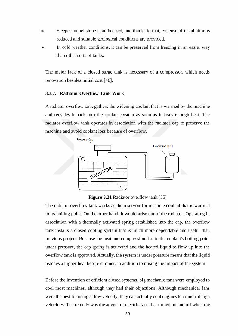
50
iv. Steeper tunnel slope is authorized, and thanks to that, expense of installation is
reduced and suitable geological conditions are provided.
v. In cold weather conditions, it can be preserved from freezing in an easier way
than other sorts of tanks.
The major lack of a closed surge tank is necessary of a compressor, which needs
renovation besides initial cost [48].
3.3.7. Radiator Overflow Tank Work
A radiator overflow tank gathers the widening coolant that is warmed by the machine
and recycles it back into the coolant system as soon as it loses enough heat. The
radiator overflow tank operates in association with the radiator cap to preserve the
machine and avoid coolant loss because of overflow.
Figure 3.21 Radiator overflow tank [55]
The radiator overflow tank works as the reservoir for machine coolant that is warmed
to its boiling point. On the other hand, it would arise out of the radiator. Operating in
association with a thermally activated spring established into the cap, the overflow
tank installs a closed cooling system that is much more dependable and useful than
previous project. Because the heat and compression rise to the coolant's boiling point
under pressure, the cap spring is activated and the heated liquid to flow up into the
overflow tank is approved. Actually, the system is under pressure means that the liquid
reaches a higher heat before simmer, in addition to raising the impact of the system.
Before the invention of efficient closed systems, big mechanic fans were employed to
cool most machines, although they had their objections. Although mechanical fans
were the best for using at low velocity, they can actually cool engines too much at high
velocities. The remedy was the advent of electric fans that turned on and off when the
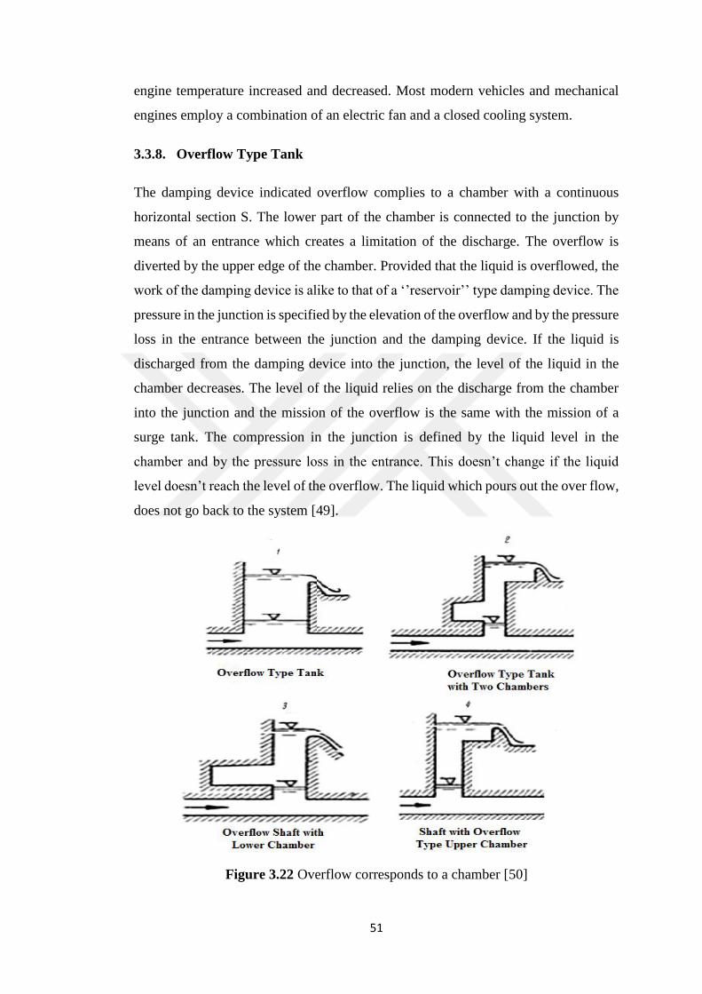
51
engine temperature increased and decreased. Most modern vehicles and mechanical
engines employ a combination of an electric fan and a closed cooling system.
3.3.8. Overflow Type Tank
The damping device indicated overflow complies to a chamber with a continuous
horizontal section S. The lower part of the chamber is connected to the junction by
means of an entrance which creates a limitation of the discharge. The overflow is
diverted by the upper edge of the chamber. Provided that the liquid is overflowed, the
work of the damping device is alike to that of a ‘’reservoir’’ type damping device. The
pressure in the junction is specified by the elevation of the overflow and by the pressure
loss in the entrance between the junction and the damping device. If the liquid is
discharged from the damping device into the junction, the level of the liquid in the
chamber decreases. The level of the liquid relies on the discharge from the chamber
into the junction and the mission of the overflow is the same with the mission of a
surge tank. The compression in the junction is defined by the liquid level in the
chamber and by the pressure loss in the entrance. This doesn’t change if the liquid
level doesn’t reach the level of the overflow. The liquid which pours out the over flow,
does not go back to the system [49].
Figure 3.22 Overflow corresponds to a chamber [50]

52
And figure above shows that 1, overflow type tank; 2, overflow type tank with two
chambers; 3, overflow type shaft with lower chamber; 4, shaft with overflow type
upper chamber. In this kind of surge tank the surge pressure is left with the overflow
water as there will be not much incident of down surge. In order to work in a perfect
way, it is needed to be located on an area which should have favorable topographical
situation for the overflow of water [50].
The overflow damping device may be used to describe a surge tank with overflow or
the outflow from a pipe-line, where one has to contain the effect of absorbing air during
reverse flow in the computation, in addition to other devices with similar missions,
such as; cooling towers [49].
Overflow from the tank would have been transferred by a stream course through the
constant town site for the plan. Because of the possible danger that is related with
abrupt rushes of water along an inhabited area. It was later decided to excavate a
catchment in rock at the upper level to keep the overflow until it could flow back into
the surge tank [48].
3.3.9. Spilling Surge Tank
The narrow riser reacts rapidly creating accelerating or decelerating heads, and also
the expansion of the chambers decrease the maximum up and down surge levels, in
this way limiting the range of surge levels (i.e. easier governing). On the account of
reducing the expense of the structure arrangements may occasionally be ensured either
to wastage (if water cannot scarce) or back to the penstock [51].
Figure 3.23 Spilling surge tank [51]
And the water is employed for;
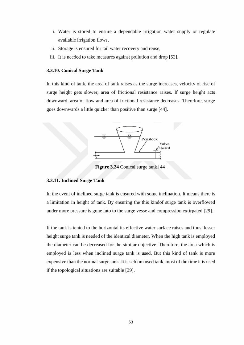
53
i. Water is stored to ensure a dependable irrigation water supply or regulate
available irrigation flows,
ii. Storage is ensured for tail water recovery and reuse,
iii. It is needed to take measures against pollution and drop [52].
3.3.10. Conical Surge Tank
In this kind of tank, the area of tank raises as the surge increases, velocity of rise of
surge height gets slower, area of frictional resistance raises. If surge height acts
downward, area of flow and area of frictional resistance decreases. Therefore, surge
goes downwards a little quicker than positive than surge [44].
Figure 3.24 Conical surge tank [44]
3.3.11. Inclined Surge Tank
In the event of inclined surge tank is ensured with some inclination. It means there is
a limitation in height of tank. By ensuring the this kindof surge tank is overflowed
under more pressure is gone into to the surge vesse and compression extirpated [29].
If the tank is tented to the horizontal its effective water surface raises and thus, lesser
height surge tank is needed of the identical diameter. When the high tank is employed
the diameter can be decreased for the similar objective. Therefore, the area which is
employed is less when inclined surge tank is used. But this kind of tank is more
expensive than the normal surge tank. It is seldom used tank, most of the time it is used
if the topological situations are suitable [39].

54
Figure 3.25 Inclined surge tank [29]
3.3.12. Double Surge Tank
One of the significant advancement methods for hydroelectric energy is hydropower
station with super-long distance headrace tunnel. For this sort of development method,
the main quality is that the hydropower station acquires high working head by utilizing
a super-long distance headrace tunnel, which is generally more than 5 kilometers. On
these days, this sort of hydropower station has been widely used.
The flow inactivity of the super-long distance headrace tunnel is exceedingly large.
For providing the safety and steadiness of hydro-turbine component operations,
pressure decreasing facilities must be installed on the headrace tunnel. Most
widespread used facility of pressure decreasing for hydropower stations is the surge
tank.
The setting of surge tank can effectively shorten the length of penstock and then
decrease the water hammer pressures in load rejection transient process. Generally,
only one surge tank is set on the headrace tunnel. However, for hydropower station
with super-long distance headrace tunnel, the extremely large flow inertia of the tunnel
always leads to a huge cross-sectional area of surge tank .The surge tank with huge
cross-sectional area brings great difficulties and challenges for the design, construction
and operation of hydropower station. The difficulties and challenges can be expounded
from the following three aspects:
i. The arrangement of pipelines system turns into exceedingly difficult;

55
ii. The environment rock stability of surge tank and underground powerhouse turns
into highly hazardous;
iii. The flow pattern of the irregular flow in the surge tank turns into exceedingly
complex.
For the purpose of getting over all these problems which are created by the adjustment
of upstream single surge tank (USST) on the super-long distance headrace tunnel, the
plan of the project of upstream series double surge tanks (USDST) has been suggested.
Two surge tanks are installed in series on the headrace tunnel. Consequently, the cross-
sectional area for each surge tank can be decreased widely at the same time, the water
hammer pressures in load rejection transient operation can still be reduced in an
effective way [53].
3.3.13. Tailrace Surge Tank
Tail race surge tanks are generally ensured to preserve tail race tunnel from water
hammer effect because of surge in load. These are placed downstream of turbines
which unload into long tail race tunnels under pressure. The requirement of tail race
surge tank can be exterminate by supplying free-flow situations in the tunnel however,
because of this event long tunnels may be more expensive than a surge vessel [54].
Figure 3.26 Surge tank in tail race tunnel [54]
56
3.4. Other Methods of Protection Against Water Hammer
Plenty of other apparatus are used to reduce the impact of water hammer. For instances;
3.4.1. One-way Surge Tank
A one-way surge tank or air inlet valve may be employed to avoid cavitation. A one
way surge tank is a receptacle with a free fluid level which is connected to the pipeline
by means of a non-return flap valve. Provided that the compression in the pipeline is
higher than equal to the level in the receptacle, the flux in the pipe line is not affected
in any cases. If the compression in the pipe-line falls under this value, the flap valve
launches, the liquid from the receptacle goes into the pipeline, which avoids any
further drop in compression. When the compression is increased, the valve is closed
again.
3.4.2. Air Inlet Valve
The mission of an air inlet valve is same, but, instead of a liquid, air is absorbed into
the pipe-line if the pressure falls below the atmospheric pressure. This avoids a further
drop in pressure in the pipe-line. Throughout a subsequent rise in pressure, the sucked-
in air is compressed and contributes to the damping of water hammer. However, some
problems may be occurred by the air. It may go along the pipe-line and cause water
hammer in a next stage.
Some air inlet valves are planned so that they allow the sucked-in air progressively to
flee from the pipeline, but to preclude the water from doing so air inlet valves of this
kind may be in some situations represented as very efficient and cheap method for
safety of a system. And also, the air in the pipeline is changed.
3.4.3. Safety Valves
Safety valves are another device used for protecting a pipe-line against water hammer.
They permanently close an opening in an operating pipe-line. If the pressure in the
pipe-line increases to a predetermined limit, the safety valve is opened; if the pressure
decreases, it is closed spontaneously. Occasionally, the closing operation is delayed in
order to avoid alterations in pressure caused by it. The valve is suppressed in closed
position through the agency of a weight or a spring. Limiting the pressure at which the

57
safety valve opens, ought not to be overrun at the point where it is set up. In the course
of very sudden alterations in pressure, such as may happen throughout water hammer,
the safety valve occasionally does not react rapidly enough because of its inactivity.
3.4.4. Opening Pipe-line
Opening in pipe-line are occasionally closed through the medium of thin steel
membranes, which spring if a limiting pressure is overrun. Their benefit is their tiny
inactivity. A diversity of other apparatus may be used to restrict the impact of water
hammer. Various flexible components inserted into the pipe-line walls or directly into
the liquid decrease speed of the wave. The flow velocity can be changed to some extent
by raising the pipe-line diameter.
3.4.5. Connected Blind Pipe-Line
A connected blind pipe-line may damp cyclical changes in pressure when its length is
such that it goes back the reflected pressure waves in stages contrary to that of the
original pressure diversities [49].
3.5. The Variation of the Type and Size of Surge Tank
The reservoir of a surge tank can have either a constant cross-section or a diversity of
shapes. Different shapes of the reservoir are planned mainly to decrease the necessity
of volume of the surge tank, in order to acquire the highest wetting effect and to
provide steadiness of the level in the reservoir.
Figure 3.27 Surge tank cross-section with a variety of shapes [49]
Figure shows that different cross-section or a diversity of shapes; 1 and 2, V shapes
surge tanks; 3, surge tank with longer shaft , 4,5 surge tank with extra galleries. In
58
order to protect hydraulic systems works under higher pressures, use of surge tanks
are not very convenient, because they would have to be very deep. In such situation,
other remedies, an air chamber, for example, can be employed [49].
When the surge tank is to be created completely by diggings, its distance from the
station relies on arrangement of the intervening ground. But, when the surge tank is
completely or partially over the ground, or when the power station is undersoil, it is
easier to decrease the penstock length. Therefore, the pressure variations are reduced.
The irregular length of penstocks ought to be adjusted on the base of examination
carried out for the expense of the surge tank oppose to the expense of strengthening
such penstock for the additional water hammer pressures and the necessary of the
velocity arrangement.
In general, it is less expensive to place surge tank in complete excavation in hard rock
when the site situations allow [30].
59
CHAPTER 4
TYPICAL CALCULATIONS FOR THE DESIGN OF SURGE TANKS
4.1. Steps of Calculations
The general process will be stated gradually before stating all kind of surge tanks
comprehensively.
First, information about the system which exist before is listed below. These are;
i. Maximum and minimum water level in reservoir
ii. Maximum and minimum tunnel discharge
iii. Tunnel length
iv. Tunnel diameter
v. Slope of tunnel
Second, the primary situations of the system are identified considering the sort of
disturbance in the system. For instance, for a total rejection of charge, discharge in the
tunnel is considered as the maximal discharge while turbine discharge is considered as
zero.
Third, a surge vessel diameter is counted. Moreover, shaft diameter for a shafted surge
vessel or an orifice diameter for a restricted orifice surge vessel are counted as well.
Forth, the friction coefficients of tunnel, surge tank, orifice and shaft are computed.
Fifth, surge analysis is implemented by the remedy of the governing differential
equations of the system through the agency of a mathematical method which is entitled

60
as the third order Runge-Kutta. Hence, the rates of maximum upsurge and down surge
for minimum and maximum discharges are acquired.
As a result, height of the surge tank is identified according to counted diameters.
4.2. Limiting Factors
4.2.1. Head Losses
When the system is in the process, a lot of head losses arise.
Furthermore, the oscillation that comes about in the surge tank is damped with head
losses. For this reason, head loss computation needs to be carried out carefully to get
right outcomes.
When the system is in a process, friction losses and minor losses are happened. In this
way, general formulae employed for the computation of these losses are described in
the following parts [56].
4.2.1.1. Calculation of Head Losses Due to Friction
Computation of head losses because of friction, is implemented considering the
Manning’s formula (4.1) [20];
V= 1
n . S1/2 .R2/3 (4.1)
where:
S = Slope of energy grade line,
V = Velocity in the section (m/s),
n = Manning roughness coefficient,
R = Hydraulic Radius of the section which is equal to flow area divided by the
wetted perimeter of the section (m).

61
Which can be reorganized as;
S = V2 . n2
R4/3 (4.2)
When is multiplied by L, the tunnel length, from both sides,
S . L = L . n2
R4/3 V2
(4.3)
Head loss because of friction, Δhf = S . L, is obtained from above
In order to simplify the calculations, βf (Modified friction loss coefficient), is defined;
βf = L
R4/3 . k2 (4.4)
and
Δhf = βf .V2 (4.5)
And writer have local losses around 10-20 percent in the tunnel so multiply head loss
because of the friction with the percentage 0,1 . Δhf
4.2.1.2. Calculation of Minor Loss
Original minor losses that ascend if the system is in the process are because of the pipe
elements such as bends, sudden contraction and rapid expansion of the cross-sections
abruptly. These losses are calculated from Equation 6 [56];
∆hm = K .V2
2g (4.6)

62
where:
∆hm = Head loss due to a minor loss (m),
K = A minor loss coefficient for the corresponding pipe element,
V = Velocity in the section (m/s),
g = Gravitational acceleration (m/s2).
For other losses owing to changing cross-sections it is computed as;
If there is a contraction If there is an expansion
K = 0,42 . (1 - d
2
D) K = (1-
d2
D) 2 (4.7)
where:
d = Diameter of smaller cross-section (m),
D = Diameter of larger cross-section (m).
Type K
Exit (pipe to tank) 1.0
Entrance (tank to pipe) 0.5
90o elbow 0.9
45o elbow 0.4
T- junction 1.8
Gate valve 0.25 – 25
Figure 4.1 Typical K values [57]
The minor loss coefficient K is accepted as 0,5 where there is an entry into the tunnel
from reservoir.

63
Figure 4.2 Minor loss from tunnel to reservoir
∆htunnel = 0,5 . V2
2g V =
QmaxAtunnel
(4.8)
The minor loss coefficient K is accepted as 0,75 where there is an entry into the shaft
from reservoir.
Figure 4.3 Minor loss from shaft to reservoir
∆hshaft = 0,75 . V2
2g V =
QmaxAtunnel
(4.9)
Total lose = ∆htunnel + ∆hshaft + Δhf+ Δhlocal (4.10)
4.2.2. Stability Criteria
On account of categorizing a surge tank as steady;
First, it ought to be able to dampen the fluctuations and get a steady level within
immediately.

64
Second, any vortex trouble which threatens the system should not be existed.
4.2.2.1.Minimum Area of a Surge Tank
If there is a complexity in the system, fluctuation of the water in the surge tank is
occurred. These fluctuations are categorized as stable or unstable. If the fluctuations
are damped down in a plausible time and then they are said to be steady. But, if their
expanse is raise with duration or they are not damped down in a plausible time, the
fluctuations are said to be unbalanced.
On account of having this sort of steadiness in a surge tank, the necessity of minimum
area should be provided by the tank. This area is entitled as the Thoma Area (Thoma,
1910) and it is computed from Equation 4.11 [56],
F = 𝑒 . Lt . At
Btotal . 2g . H0 (4.11)
where:
F =Minimum area of a surge tank required for stability (m2),
Β total = Total modified coefficient of friction calculated from Equation (4.5) for
the total head losses that occur in the system (s2/m),
g = Gravitational acceleration (m/s2),
H0 = Net head on turbine (m) where H0 = Hn - (friction losses + local losses)
Lt= Length of tunnel (m),
At =Area of tunnel (m2),
e =A safety coefficient which is generally taken as 1,5 ~1,8 However, Jaeger
(1955) proved that this factor should vary depending on the system properties.
Therefore, after computation detected a diameter and it needs to be such as Fdecide > F
Ymax = the height of maximum upsurge for the case of maximum discharge, full load
rejection and no friction in the tunnel (m). For the determination of the value Ymax in
Equation 11 [56];
Ymax = Vt .(Lt . At
g . F )1/2 (4.12)

65
where:
Vt = Velocity in tunnel (m/s),
Lt = Length of tunnel (m),
At = Area of tunnel (m2),
g = Gravitational acceleration (m/s2),
F =Minimum area of a surge tank required for stability (m2).
Figure 4.4 Full load rejection with maximum discharge for a simple surge tank [56]
Considering the Jaeger formulas, statically increased level;
Y1 = - ( Ymax - (2
3)Y0 + (
Y02
g . Ymax
)) (4.13)
where:
Ymax = Height of maximum upsurge for the case of maximum discharge,
Y0 = Total lose,
g = Gravitational acceleration (m/s2).

66
Figure 4.5 Full load acceptance with maximum discharge for a simple surge tank [56]
According to the Forchheimer formulas, statically decreased level;
Y2 = (0.178Y0 + [(0.178Y0)2 +Ymax
2)1/2] (4.14)
where:
Y0 = Total loss,
Ymax = The height of maximum upsurge for the case of maximum discharge.
Figure 4.6 Full load acceptance with minimum discharge for a simple surge tank [56]

67
4.2.2.2. Freeboard
In the cause of security, a value, entitled as freeboard is added to preconcert maximum
water level in the tank. Freeboard is computed from Equation (4.15);
P > 0,2 . Ymax (4.15)
where:
P = Freeboard (m),
Ymax = is the height of maximum upsurge for the case of maximum discharge, full
load rejection and maximum water level in reservoir (m) [56].
4.2.2.3. Vortex Control
When a surge tank is in a process, because of an abrupt defect such as; a valve
manoeuvre etc. in the system, water level in the tank can decrease under a certain
height. When it does, air comes into the system. This may cause cavitation problem if
air bubbles are transported by the flow into the turbine area and creates other negative
effects worrisome for the system. Therefore, in order to prevent the air entering, a
vortex control must be done for the worst situation that can happen in the system.
The worst situation for this kind of control generally happens if full load acceptance
exists. The initial system situations can either be least water height in reservoir and
least unloading in tunnel or maximal water level in reservoir and maximum discharge
in tunnel.
Consequently; first, the maximum down surge that causes the minimum water level in
the tank is computed.
Second, the lowest height of the tank is extracted from the minimum water surface
level in the tank. The height of water column in the tank is acquired (Water column
height computations are progressed irrespective of the sorts of the surge tank.).
Then Froude number is computed by Equation (4.16) [56];

68
Fr = V
g . D (4.16)
where:
V = Velocity in tunnel (m/s),
g = Gravitational acceleration (m/s2),
D =Diameter of tunnel (m).
By consuming the Froude number, S/D value is gained from Figure 4.7. From this rate,
S, which is called as the submergence depth, is obtained. If S is under the level of the
water column in the tank, then the system is said to be secure for vortex creation.
Besides the vortex formation control, the system needs also to be controlled if;
B > 0,2 Ymaxdown (4.17)
where:
Ymaxdown = Height of maximum down surge that is used in the vortex control. (m).
B = Height of the water column in the surge tank, which is obtained by the of the
bottom elevation of the surge tank from the minimum water level in the tank that
can happen (m)

69
Figure 4.7 The variation of the rate S/D for different Froude number [56]
70
CHAPTER 5
CASE STUDY OF BİRECİK DAM PROPOSED SURGE TANK
5.1. The Region of the Project
Birecik Dam is used as case study in this examination. The Birecik Dam is one of the
21 dams of the South-eastern Anatolia Project of Turkey, is established on the
Euphrates River 60 km downstream of Atatürk Dam and 8 km upstream of Birecik
town 80 km west of Province of Şanlıurfa in the south eastern region of Turkey. It was
intended for irrigation and production of energy. There is a run-of-the-river
hydroelectric power plant, installed in 2001, at the dam, with a power output of
672MW (six facilities at 112 MW each) can create an average of 2.5 billion kWh per
year. The Birecik dam is a construction which is created with a concrete gravity and
clay core sand gravel fill with a height of 62.5 m from the foundation. It was planned
by Coyne et Bellier. Whole catchment area is 92,700 ha. The Birecik project will be
carried out under the status of Build-Operate-Transfer (BOT) model.
The dam was established on top of the wrecks of the old city of Zeugma. According
to Bogumil Terminski (2015), the building of the dam caused resettlement of almost
6,000 people [58].
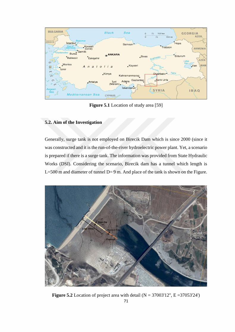
71
Figure 5.1 Location of study area [59]
5.2. Aim of the Investigation
Generally, surge tank is not employed on Birecik Dam which is since 2000 (since it
was constructed and it is the run-of-the-river hydroelectric power plant. Yet, a scenario
is prepared if there is a surge tank. The information was provided from State Hydraulic
Works (DSI). Considering the scenario, Birecik dam has a tunnel which length is
L=500 m and diameter of tunnel D= 9 m. And place of the tank is shown on the Figure.
Figure 5.2 Location of project area with detail (N = 37003'12'', E =37053'24')
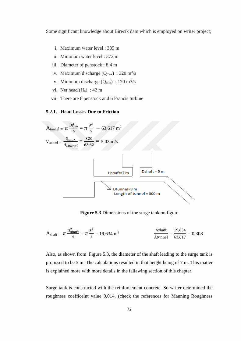
72
Some significant knowledge about Birecik dam which is employed on writer project;
i. Maximum water level : 385 m
ii. Minimum water level : 372 m
iii. Diameter of penstock : 8.4 m
iv. Maximum discharge (Qmax) : 320 m3/s
v. Minimum discharge (Qmin) : 170 m3/s
vi. Net head (Hn) : 42 m
vii. There are 6 penstock and 6 Francis turbine
5.2.1. Head Losses Due to Friction
Atunnel = 𝜋Dtun
2
4 = 𝜋
92
4 = 63,617 m2
vtunnel = 𝑄𝑚𝑎𝑥
𝐴𝑡𝑢𝑛𝑛𝑒𝑙 =
320
63,62 = 5,03 m/s
Figure 5.3 Dimensions of the surge tank on figure
Ashaft = 𝜋Dshaft
2
4 = 𝜋
52
4 = 19,634 m2
Ashaft
Atunnel =
19,634
63,617 = 0,308
Also, as shown from Figure 5.3, the diameter of the shaft leading to the surge tank is
proposed to be 5 m. The calculations resulted in that height being of 7 m. This matter
is explained more with more details in the fallawing section of this chapter.
Surge tank is constructed with the reinforcement concrete. So writer determined the
roughness coefficeint value 0,014. (check the references for Manning Roughness

73
Coefficient (n) for channels, closed conduits flowing partially full tables on the internet
or books).
Wetted parameter = R = A
P =
Dtunnel
4 , k =
1
n =
1
0,014 = 71,428
Modified friction loss coefficient;
βf = L
𝑅4/3𝑘2 =
500
(71,428)2(9
4)
43
= 0,033
Friction losses in energy tunnel;
Δhf = βf .vtunnel2
= 0,033*(5,03)2 = 0,841 m
5.2.2. Minor Friction Losses
%10 of local minor losses so Δhf . 0,1 = 0,841*0,1 = 0,0841 m or 8,4 cm
Minor loss from tunnel to shaft;
∆htunnel = 0.5 𝑉2
2g = 0,5.
5,032
2.9,81
= 0,644 m ≅ 0,65 m

74
Minor loss from shaft to reservoir;
∆htunnel = 0.75 𝑉2
2g (v = 𝑄𝑚𝑎𝑥
𝐴shaft )
Therefore;
V = Qmax
Ashaft = 320
19,63 ≅ 16,297 m/s
∆hshaft = 0,75 𝑉2
2g = 0,75
16,2972
2.9,81 = 10,153 m
Total lose = ∆htunnel + ∆hshaft + Δhf + Δhlocal = 0,64+10,153+0,84+0,084 = 11,71 m
Δhtotal = βf .vtunnel2 → βf =
Δhtotal
vtunnel2 → βf =
11,71
5,032 = 0,4638 ≅ 0,464
According to the net decline axis turbine = Hn - (friction losses + local losses)
H0 = 42 - ( 0,841 + 0,0841 ) = 41,074 m
5.2.3. Stability Criteria of the Project
5.2.3.1. The Determination of the Optimum Location
F = e .L𝑡A𝑡
β𝑓 2g H𝑜 (for e value check chapter 4, part 4.2.2.a, equation 4.11 and e value
chosen 1,7)
F = 1,7 .500 . (63,617)
2 . (9,81) . (0,464) . (41,074) = 144,81 m2
If decided diameter of surge tank 20 m;
Adecide = 𝜋D
4
2 = 𝜋
20
4
2
= 314 m2 so F<Adecide (144,81<314) so chosen 20 m OK

75
The elevation of maximum upsurge for the case of maximum discharge, full load
rejection and no friction in the tunnel (m).
Ymax = Vt (L𝑡A𝑡
gF)1/2
= 5,03. (500.(63,617)
(9,81).314)1/2 =16,16 m
Statically increased level (from Jaegar formulas)
Y1 = - (Y max - 2
3 Y0 +
Y02
g . Ymax ) → Δhtotal = -Y0 (Chapter 4 check equation 4.13)
Thus, it is found that →Δhtotal = 11,736 from above calculations;
Y1 = - (16,16 - 2
3 (11,71) +
(−11,71)2
(16,16).9,81 ) = - 9,20 m
From the static water height decrescent amount (according to Caleme and Guden
formulas)
Y2 = Ymax - 2Y0 = (16,16) - 2 . (11,71) = -7,28 m
According to Forchmeire maximum decrescent level;
Y2 = 0,178 Y0 + [(0,178Y0)2 + Ymax2]1/2
= 0,178 (11,71) + [((0,178.(11,71))2 + 16,162] 1/2 ≅ 18,38m
5.2.3.2. The Determination of Freeboard in the Reservoir of the Dam
P > 0,2 Ymax → P > (0,2) . (16,16)
P > 3,313 m → so chosen 3,3 m for freeboard

76
5.2.3.3. Vortex Control According the Stability Criteria
Maximum water decreasing level;
385- Y2 = 385 – 18,38 = 366,619 m
Min water level vortex check;
Qmin =170 m3/s
vmin=𝑄𝑚𝑖𝑛
𝐴tunnel = 170
63,62 = 2,67 m/s ≅ 2,672 m/s
Friction losses in energy tunnel;
Δhf = βf .vtunnel2 = (0,033).(2,672)2 = 0,237 m
5.2.3.4. Minor Losses According the Stability Criteria
%10 of local minor losses so Δhf .(0,1) = (0,237).(0,1) = 0,0237 m
Minor loss from tunnel to shaft;
∆htunnel = 0,5 𝑉2
2g = 0,5
2,672
2 . (9,81)
= 0,182 m
Minor loss from shaft to reservoir;
∆hshaft = 0,75 𝑉2
2g (v = 𝑄𝑚𝑎𝑥
𝐴shaft )
Consequently;

77
V = 𝑄𝑚𝑖𝑛
𝐴shaft =
170
19,63 = 8,66 m/s
∆hshaft = 0,75 𝑉2
2g = 0,75
8,662
2.(9,81) = 2,865 m
Total lose=∆htunnel + ∆hshaft + Δhf + Δhlocal = 0,185+2,865+0,237+0,0237 = 3,31 m
Qmin - ∆h = 170 - 3,31 = 166,691 (Min energy base level)
Ymax = V (𝐴tunnel . L
g.F)1/2 = 2,7 (
500.(63,61)
(9,81).(314))1/2 = 8,676 ≅ 8,67 m
Y2 = 0,178 Y0 + [(0,178Y0)2 + Ymax2]1/2 →
= 0,178 (3,31) + [(0,178.3,31)2 + 8,672]1/2 = 9,27 m
Then Froude number is calculated by;
Fr = v
(gD)0,5 →
2,67
((9,81).(9))0,5 = 0,284 m
S/D = 1,3 (From Figure 4.7)
S = (1,3).(9) = 11,7 m
Minimum static shaft water level;
Qmin - ∆h = 372 - 3,31 = 368,69 m
Surge tank statically decreasing level
368,69-9,27 = 358,4 m

78
5.3. Summary of Results
Subsequently, it is possible to select the surge tank base level = 358 m < 368,66 m
Energy tunnel top level = 358 -11,7 + 4,5 = 350,8 m
Water layer thickness 358,4 + 4,5 – 350,8 = 12,1 m > 11,7 (thus, no vortex )
Surge tank height (above energy tunnel):
Top level = 385,00 + 9,2 + 3,33 ≅ 398 m
Height = 398 – 350,8 - 4,5= 42,7 m
Figure 5.4 The computation results on the figure (considering to scenario)
The previous calculations show that, in the design process of surge tanks, the main
influential parameters are both the head losses and minor losses. In fact, both are
called friction losses. Head losses are created through the friction between the flowing
liquid and the boundaries of the tunnel (or pipe in other systems). These losses can be
determined by means of using Manning formula. The minor losses are created through

79
the direction changes within the tunnel/pipe system, such as passing through bends, or
from the tunnel to the shaft, or from the shaft to the surge tank as shown in figure 4.2
and 4.3. In this application (proposed surge tank surge for the tunnel in Birecik Dam),
it appears that the total of minor losses from shaft to the surge tank along with the
friction losses in the energy tunnel appears to be about %10 of the total local losses.
The total losses directly influence the determination of the height of surge tank.
The calculation results show that the height of surge tank is supposed to be 42.7 m. In
fact, this is correct theoretically as well as from the calculation point of view. However,
the physical construction of surge tank of such height is not practically feasible.
Therefore, the resultant value from the calculations which usually indicates a simple
surge tank can be replaced with another type in order to decrease the height proposed
through the calculations, such as a horizontal galleries surge tank. Thus, it would be
possible to store the liquid/water in extra horizontal gallery/galleries. In fact, the
implementation of horizontal galleries should decrease the probable oscillation within
the surge tank due to the decrease in its height which means the decrease in the pressure
applied on the flow system during the stage of returning the accumulated water in the
surge tank back to the flow system.
From the previous calculations, it appears that the diameter of surge tank is shown to
be 20 m. When researcher checked the stability criteria of the project (as explained in
section 5.2.3.a), the safety factor is selected to be 1.7 by the designer. According to
this safety factor, the calculations of the minimum area of the required surge tank
diameter resulted in a value of 144.81 m2. However, it is thought to be on the safe side
and the diameter of the surge tank was proposed to be 20 m, which means a cross
sectional area of 314 m2.
Also, as shown above calculation diameter of shaft leading to the surge tank is
proposed to be 5 m, which resulted in a need for a height of 7 m. Both the diameter of
the tunnel and the velocity of flow directly influence the height of the shaft due to
Froude Number. When the flow velocity is decreased or when the diameter of the
energy tunnel is increased the required height of surge shaft would be lower. A surge
tank with relatively lower height indirectly means less cost for construction, less risk

80
against earthquakes (common in Turkey), and also, more efficiency due to the lower
pressure applied on the flow system during returning the liquid stored in the surge tank
back to the flow system.
In Figure 5.5, the relation between the diameter of the shaft and the height of the surge
tank is explained through the repetition of several assumptions for the value for the
diameter of the shaft with increasing sequence, and the relevant heights of surge tank
were obtained through repeating the same classical calculations as explained
previously. The attempt to increase the value of the diameter of shaft shows that the
value 4 m given for the diameter of the shaft results in a relatively less required height
of surge tank compared with the other attempts. Briefly, 4 m diameter shaft would be
more economic regarding the cost of the project.
Figure 5.5 The relation between shaft diameter and height of surge tank
Briefly, a simple calculation of surge tank takes lots of time. Also, trying another
model of surge tank means yet the repetition of all required calculations. This means
that the designer should carefully select the model of surge tank in order to minimize
the time and effort required for the calculations
40,5
41,16
42,7
43,48
40
40,5
41
41,5
42
42,5
43
43,5
44
3,5 4 4,5 5 5,5 6
Hei
ght
of
Surg
e T
ank (
m)
Diameter of Shaft (m)

81
CHAPTER 6
THE BASICS FOR OPTIMIZING THE DESIGN OF SURGE TANKS
The general plan and final design process of surge tank should take into consideration
the following three factors:
a- The project must take safety as number one factor in a way that any malfunction,
misoperation, or any kind of similar unpredicted events can be tolerated through a
good safety factor.
b- The proposed surge tank is supposed to be selected in a way to minimize the cost
as much as possible, particularly for those projects of a large scale.
c- The efficiency of surge tank in a way that it must achieve the proposed target
perfectly. In other words, the efficiency means the determination of the following:
i. The selection of the best type/model that suits the flow conditions as well as
the resistance of construction materials (mainly pipe/tunnel boundaries) to the
wave shocks generated by the any probable water hammer events, and also, to
be durable at least throughout the planned/predicted age of the project.
ii. The determination of the best size and dimensions for the selected model
according to the local conditions of the project with extreme care taken
regarding the proper ratio of safety factor.
The most sensitive, expensive and risky projects among all those that may require
surge tanks to minimize the risk of water hammer event are hydropower plants.
Obviously, there are other important and expensive large projects that include fluid
flow with relatively high velocity such as nuclear power stations where cooling

82
systems are extremely essential and exposed to the probability of water hammer
events. However, the logic behind the selection of the type of surge tank, its size and
location is the same.
For a typical hydropower plant, the optimization process of surge tank design depends
on both the geological and topographical conditions of the region in concern; also,
aims to follow economic construction methods, while keeping in mind that the major
aim is to create steady hydraulic conditions in the proposed surge tank that provides a
steady and safe conditions for the power plant as well as the least need for maintenance
and repairs. As explained in previous chapters, the main purpose of surge tanks is to
decrease the harm caused by the probable occurrence of water hammer. Yet, the design
criteria for the surge tank is identified by the mass oscillations and how they affect the
hydraulic conditions. A conceptual and typical design of a hydropower plant with an
upstream and downstream surge tank is indicated in Figure 6.1.
Figure 6.1 Figure Hydropower plant with upstream and downstream surge tank [47]
6.1. The Safety Optimization of Surge Tanks
One of the most important factors to be considered during the design of flow system
that includes one or more surge tanks is to ensure the total safety of the project. Safety
factor, or the ratio of safety added to the results of final calculations, is always a matter
of dispute between the designer and director of the project. The designer, with good
intention, always wishes to increase the safety factor due to the unknown and
uncontrolled secret/unseen decrease in the level of execution. The latter decrease may
very well result due one or more of several probable reasons. Among those are

83
a- The material producing companies delivering products with specifications of less
quality than those promised during the agreement.
b- The quality of the execution may not be of the expected high level due to the
supervising engineers, formen, and workers being unskilled enough as required for the
project.
c- The control engineer who checks the quality of the final works may not be qualified
enough to confirm the executed works being performed up to the required high level.
d- The designer/s did not take into consideration all the worst probabilities throughout
the function of the system regarding the pressure, velocities and the like.
e- The total dependence on computer program/s in calculating the details of the flow
system. In fact, this is always an additional risk particularly when the required
calculations are too complicated and/or includes iterations that require a lot of time
when performed manually. It is always good to remember that up till there is no ready
program that guarantees the accuracy of the resultant solution, and thus, the designer
is somewhat has no choice but to trust the quality of the program. Here, it is quite
difficult to blame neither the designer nor the company that produced the ready
program. In case of a disaster the question is who to blame? The solution may be to
recommend the implementation of more than one program as well as to employ trusted
and highly qualified engineers that may evaluate the solution resulting from a
computer program. Luckily, computer programs when they make mistakes, they are
very clear ones.
f- The life length of the materials used in the project may be shorter than expected.
This may not appear at the start easily, and only by the time the deterioration may
show itself at a late time, usually, after the end of the guarantee period. In this case,
the only thing that can be done is to ask for a much longer guarantee from the
companies that produce the materials required for construction.

84
g- There are cases when unexpected and outstanding forces (earthquakes, subsiding
foundations, floods, swelling soil, fluctuation in groundwater level and the like) may
impose unprecedented forces and pressures on the flow system in a way that may cause
significant damage. The prediction of the severity of such events may be possible to
some limit; however, nature is usually beautiful but sometimes merciless.
With the consideration of all these factors, the designer/s may very well worry about
the safety of the structure and in order to feel more safe, tends to increase the safety
factor to a limit that the side which will approve the design may not like it (e.g. the
general director of the project or the even the one on the top of him/her). The main
reason for the top man feeling unwell about the proposed relatively high safety factor
is simply because the cost of the project is very likely to be significantly high.
Obviously, all governments wish to complete as many projects within the shortest
period and in the least cost. Consequently, the tendency of the designer group is
always to increase safety ratio and eventually encountered by pressure to do otherwise
from the upper administrative side.
6.2. The Economical Optimization
In order to complete any project in an economical way, there are some factors that
must be carefully considered. Among these factor are the following:
a- The predicated age of the project is supposed to be considered carefully in a way
that the return period of the initial cost must prove being beneficial to the owner (the
sector that owns the project: usually the Government).
b- The owner must be generous in selecting the best company that prepares the
feasibility study of the project. Any miscalculation or misprediction to the details of
the project may very well lead to its failure, or at least, being uneconomic. Being
uneconomic means that the cost of the project becomes larger than the expected
benefits.
c- Selected materials are usually of a wide variety in a way that it is certainly unlikely
to be consumed simultaneously towards the end of the project. However, the most

85
expensive and most commonly used material in the project must be carefully selected
in a way that should guarantee being reliably durable throughout the predicted age of
the project. The rest of the types of materials used for construction should be relatively
of a longer age, or if feasible, may be renewed during the predicted age of the project
with reasonable easiness and cost.
d- The cost of operation of the project must be taken into account. Here, the selected
operators/managers are supposed to be of the highest quality and experience. In fact,
the age of any project may be significantly shortened through low quality management.
e- The cost of operation, regular maintenance and repairs must never be less than the
required, otherwise, this is likely to lead to shortening the age of the project, or may
be, to a failure (economically or physically).
6.3. The Efficiency Optimization
In relevance to this previous introduction, it is found that the preparation of specific
explanation to the case/s where a specific model is selected would be of much help to
engineers. This is likely to help in minimizing the time required for the design as well
as in minimizing the probability of making the wrong decision regarding the selection
of the proper model that suits a specific condition.
The following sections include explanations about the conditions/cases when a
specific model is recommended for implementation as well as the reason for such
recommendation. In fact, the different models explained later on are very briefly
presented in literature with nearly no accompanied explanation for the case/s when
they are supposed to be implemented. This is why the following explanation is thought
to sum up the properties and optimum conditions for using each of the proposed
models.
a- For the most simple type of surge tanks, which is the vertical shaft, the economical
side of the design may influence the height and diameter (or horizontal cross sectional
area in case of being non-circular as shown in Figure 3.6). However, the economical
side of the matter is not the only factor to be considered, in fact, with the consideration

86
that the same discharge is coming to the surge tank, the relatively high with little
horizontal cross sectional area would impose more pressure on the system to return
back the flowing liquid, and this pressure may be unwanted when being relatively high.
The other case is exactly the opposite, where a relatively short and wide based surge
tank may absorb the same inflow but would impose less pressure on the flow system
while returning back the liquid absorbed after the shock. Here, the designer should
evaluate the resistance of the flow system to the pressure coming from the surge tank
whether the high and narrow one would be safer or the short and wide based one. In
case the loss of liquid during the shock event through the surge tank is not of a
significant importance, then, a spillway may be proposed on the side of the surge tank
which would dispose of any amount of liquid that may not be accommodated in its
limited capacity. The latter spillway system may be saving the unnecessary cost of
having a larger surge tank. Obviously, if the value of the liquid is significant for any
reason or, in case it may cause risk of any kind (flammable material or chemically or
biologically harmful), in this case, no risk must be taken of any liquid being spilled off
the tank, and the only solution is to go for a bigger surge tank (taller or with a wider
base). Again, in case the spilled liquid is harmless and may be useful somehow, it may
be directed back to the system, or, to anywhere else as best as can be. For example, if
the liquid is water, then, the spilled amount may be directed either for irrigation or
other domestic consumption.
b- Then, horizontal (expansion) tank is a type that it has been explained in Chapter 3
and shown in Figure 3.7. This system is also similar to the simple tanks explained in
the previous section a, with a difference that they have one or more extra horizontal
galleries. This type is useful and recommended in the condition where the amount of
water delivered to the surge tank is huge and simultaneously nothing should be allowed
to be spilled away. In this case, the horizontal gallery or galleries should have the
large capacity for absorbing huge volumes without the need for the tank neither to be
higher nor with wider base. The calculations of such model do not take into
consideration the existence of those horizontal galleries simply because horizontal
galleries do not add any extra pressure on the pipe system over the already existing
pressure through the height of the gallery within the shaft of the main surge tank. In
other words, the horizontal expansion of surge tanks do not add to the pressure applied

87
on the pipe flow system while the vertical expansion does. Here, it may be useful to
add that more than one horizontal gallery may be implemented/constructed on the
same elevation within the shaft of the surge tank or on different elevations as shown
previously in Figure 3.8. In some special cases, spillways may be added to the top of
the shaft of a surge tank despite having one or more galleries just for increasing safety
to the maximum possible limit.
c- In the cases where the shock event is extremely severe with probability of a huge
amount of liquid being pushed to the surge tank, the Restricted Orifice Surge Tanks
are recommended to be implemented (as shown in Figure 3.10). These kinds of tanks
are meant to compensate the huge size of the surge tank through concentrating on
consuming head as much as possible through the orifice (entrance) of the surge tank.
Obviously, this type means that the absorbance of the shock would be slower than that
of the models explained in the previous sections A and B. However, this slowing down
of the liquid absorbance through the surge tank slows down the shock relieve on the
pipe net, which consequently adds more risk on the flow system. The only way to
implement such model is to make sure that the pipe system is well resistant to pressure
despite the shock of water hammer being released slowly. The three models shown in
Figure 3.10 starts with No. 1 where a simple Restricted Orifice Surge Tank is shown,
and explained in this section. However, the second one No.2 represents a method for
the head dissipation through increasing the height of the narrow section leading to the
surge tank. In this case, yet another design may be followed through directing the flow
resulting from the shock towards a well deep down the flow system but turns upwards
again towards the surge tank such as a u shaped bend starting from the left for the
entrance and ending at the right end towards the surge tank. The latter method may be
considered economic regarding the area and height occupied to solve the problem. The
third model shows some extra smaller adjacent group of entrances allow the flow to
go to the surge tank after consuming lots of head due to the narrow entrances. In this
model, the dangerous side of it is the sudden contractions and expansions before and
after the entrance to the surge tank. Here, the designer must be extremely careful when
considering the limits of the flow system resistance to such obstructions which cause
sudden change in pressure as well as vibration in the relevant sections suffering from
these changes.

88
d- There are cases where the volume of liquid transferred to the surge tank is preferred
to be returned slowly to the system rather than quickly. This case is, somewhat, the
opposite to the case explained in the previous section C, where the volume of water
entering the surge tank is preferred to get in slowly through imposing extra head loss
causatives at the entrance of the surge tank. In this current model/method, which is
called Differential (Johnson’s) Surge Tank, the system is arranged in a way that the
flow resulting from a sudden closure in the system would enter the surge tank with
relatively little resistance/head-loss but returns to the flow net only through some
relatively narrow orifices that slows down the velocity to a significant level, and thus,
the return of the liquid would be too gentle to cause any harm to the system. In fact,
the Figure 3.17 represents a clear figure of a typical differential surge tank with details
relevant to that model, while the different models shown in Figure 3.16 show that a
variety of models can be arranged to facilitate any special requirement regarding the
amount of water entering the surge tank as well as the degree of lowering the velocity
of the liquid returning to the flow net.
e- There are cases when extreme weather conditions (extremely hot or cold weather)
may impose risk on the water in surge tanks with an open top. In this case, the solution
is to implement the Closed Surge Tanks (Air Chamber) models, which are represented
in the symbolic Figure 3.20. In this case, a vertical cylindrical chamber is implemented
with a closed top. This model protects the liquid delivered to such surge tank from the
weathering effects despite the fact that this liquid does not stay in the tank for a long
time. This model has an obvious exponential increase in the pressure of air
trapped/stored at the upper section of the tank during the whole period of the entry of
the liquid. This is due to the decrease of the volume of the air and being replaced by
the volume of the entering liquid. This acts like a shock gentle absorber against the
sudden closure in the flow net. However, if the pressure of air trapped at the top of
the tank reached a limit that may impose a risk on the tank regarding its resistance to
pressure, then, an air release valve should open automatically and decrease the pressure
to a degree that can be tolerated by the tank. This kind of tanks is usually vertical, and
hence, would increase the pressure on the flow system while returning the liquid back
through both the pressure of air trapped on the top of the tank as well as through the
height of the hydrostatic force of the liquid accumulated vertically in the tank.

89
It worth mentioning that there is an advantages to the implementation of the Closed
Surge Tanks, that is having a closed roof protects that liquid from being polluted by
the external pollutants in the atmosphere (dust, flying light objects, falling birds and
the like). However, there is one disadvantage accompanied that is the extra difficulties
encountered during any kind of maintenance or repairs due to the tank being totally
closed. The idea of pressurized closed surge tanks is implemented in relatively small
domestic application in order to comply with the boosters in water supply and pumps
in heating systems in buildings and factories.
Figure 6.2 Vertical Closed Surge Tank (Great Man-Made River Project in Libya)
f- The previously explained Closed Surge tanks are presented as a vertical structures.
As explained in the previous item e , the trapped air in the tank imposes obvious
relatively high increasing in pressure on the liquid. However, there may be some cases
where the advantages of implementing this model is desirable without exposing the
liquid in the tank to such high pressure. In this case, a Closed Surge Tank with inclined

90
position may be used where the inclination would enable to the storage of large amount
of liquid with relatively less hydrostatical pressure on the flow net during the stage
when the liquid is returned back to the flow net. In case of the amount of liquid appears
to be of a huge volume in some projects, the construction of a huge Closed Surge Tank
regardless of being vertical or inclined, the solution would be simply to implement a
group/series of vertical or inclined closed surge tanks as shown in Figure 6.3. This
figure shows a series of inclined closed surge tanks constructed to tolerate any sudden
or even gentle closure in the flow system of the pipes used in the Great Man-Made
River Project in Libya just next to Benghazi city.
Figure 6.3 Inclined Surge Tank (Great Man-Made River Project in Libya)
g- The idea of having an inclined surge tank in order to impose less pressure on the
flow net while returning the liquid back to the flow net may be implemented while
using a closed surge tank as well as on open surge tanks as shown in Figure 3.25. The
main technical difference is that the open ones need only to be strong enough to
withstand the weight of the liquid stored in the tank, while the closed ones must have

91
stronger boundary that is capable of resisting the internal pressure resulting from the
air trapped inside.
h- There are cases where the discharge in pipe is extremely large. This is encountered
in water conveying tunnels or pipes with large diameters. In such cases, the closure
of valves must be slow through an electrical engine. In order to make the closure as
gentle as possible, and also, to decrease pressure fluctuation/oscillation within the flow
system, the slow closure of such huge pipe or tunnel will result initially in a huge
sudden discharge towards the surge tank; however, this discharge will decrease with
the closure valve getting near the end of movement. This way, the flow towards the
surge tank is expected to be large at the start and slow at the end of the closure period,
and thus, the need for the surge tank to accommodate such discharge variation would
be best through a conic shaped tank with a wide bottom and narrow top as shown in
Figure 3.27 No.2. In the same figure, No.1 represents yet another conic surge tank but
with a small base and large top. The latter is useful in case the severity of the flow
shock is relatively little but with large volume of liquid flowing to the surge tank after
the end of the closure in the flow net. This case may be encountered in case there is a
pump closure of moderate size with a large volume of water returning back to the tank
by gravity for example, or any similar case.
i- The Tailrace Surge Tank system shown in Figure 3.26 is yet another model of surge
tanks implemented mainly in projects with relatively large discharge. The figure
shows the location of inflowing water from the source at a relatively high elevation
down to the power plant, and from which it continues towards a reservoir or a
downstream of a river and the like. The surge tank is shown to be located just after
the power plant where any sudden closure to the turbines (one or more due to a
malfunction or any other reason) may very well result in a negative pressure through
the pipe/tunnel that delivers the water towards the reservoir/river. Here, the duty of
the surge tank is to tolerate the resultant negative pressure in the tunnel/pipe by means
of supplying a certain amount of water, and thus reducing the risk of tunnel/pipe being
collapsed (implosion). However, on the other hand, in case the discharge increases
suddenly in the tunnel/pipe after the opening of the gates of one or more of the
previously non-functioning turbine gates (after being repaired/maintained and the

92
like), there will be a sudden increase in the pressure in the tunnel/pipe leading to the
reservoir/river. Again, the surge tank here would be the savior of the system by
absorbing the increased pressure through an increase in the height of the water in the
tank. Here, the tank is assumed to be a closed type (as shown in the figure). However,
in some cases where the increase of the trapped air at the top of the tank may impose
risk on the structure, in this case, a ventilation shaft may be proposed to tolerate such
sudden increments (or decrease) of water level in the tank. The decision in this case
is up to the design engineer after careful estimation to the maximum probable
fluctuation/oscillation in the pressure within the system in concern. In the same figure,
it may be recommended to install yet another surge tank just before the power plant in
order to tolerate any increase in the pressure in case there is a sudden closure to the
gates of the turbines as explained previously in this section. In other words. In case
there is any sudden closure in the gates leading to the turbines, the surge tanks
upstream of the gates should act to tolerate the sudden increase in pressure while the
tailrace surge tank downstream of the gates should act to tolerate the resultant negative
pressure. The case is exactly the opposite when the closed gates are opened later on.
In fact, the different configurations and models of surge tanks enable the design
engineer to have a relative wide range of models and sizes to choose from in order to
fit the requirements of the local regional needs for the project in concern. The selection
of the model is somehow explained in the previous sections. However, the size of the
surge tank can be determined numerically after the determination of the maximum
values of the pressure fluctuation/oscillation within the flow system while considering
the rigidity and flexibility of the boundary of the flow system. The latter has a lot to
do with the frequency and speed of the waves resulting from any water hammer event
throughout the system.

93
CHAPTER 7
CONCLUSION
This research concerns the design of surge tanks which requires good understanding
to the causative, which is water hammer, as well as to the different types of flow nets
which impose the design of different models of surge tanks in order to suit the required
conditions of the flow net in concern.
It is obvious that eliminating the probability of the occurrence of a problem requires a
good understanding to the causative/s of the problem. In fact, minimizing the
probability of the occurrence of water hammer event may be possible through the
consideration of some factors such as that is through decreasing the velocity of the
flow, the implementation of piping system with flexible boundaries, slowing down the
closure of valves. However, in many flow applications, these factors that decrease the
probability of the occurrence of water hammer may not be feasible for many reasons,
such as the need for flow with high velocity in cooling systems and/or for speeding up
the process of delivering the required liquid to the demand point. Consequently, the
implementation of surge tanks in flow nets appear to be inevitable. This is why this
research appears to be essential to enlighten the way for the proper selection design of
surge tanks among the wide variety of models that are proposed by researchers and
engineers to fit and suit the different conditions and purposes of flow nets.
From reviewing and investigating previous literatures, it appeared that, although many
models of surge tanks are briefly presented, the explanation of the cases and conditions
where each of these models may be implemented, there is a clear demand for a better
and more detailed classification of these models along with the case/s where each
model may be used. This research cared to gather all types/models of surge tanks,
classify them, and explain the case/s when they are recommended for implementation.

94
This part of the research follows an explanation of the behavior of water hammer
which is the main causative of the need for surge tanks.
The logic behind the selection of the model of surge tanks to be implemented for a
certain flow net/project is thought to be better explained through a real application on
a real project. Here, the Birecik Dam project seems to be a good example for such
application. The researcher thought to perform typical calculations for the design of a
surge tank that suits the flow net in the tunnel of the projects. In fact, in this project,
a surge tank was not implemented in the project, and the researcher feels that such tank
would be of use in some emergencies and would increase the safety of the project.
It is obvious that the economic side of all projects must be carefully considered. Here,
a sensitive subject appears to the designer as well as to the project owner that is to
determine the threshold that balances the safety with the cost. In fact, this balance
problem appears in nearly all projects where the designer wishes to be on the safe side
while the owner wishes to decrease the cost of the project. Both have good reasons to
do so, however, the dispute seems to exist in the design and construction of most
projects without the knowledge of the public neither about the dispute nor the final
decision.
The selection of the model is not the only concern in flow net projects, in fact, the
determination of the location of surge tanks is also of a great importance in a way that
when being away from the optimum location, the efficiency as well as the size may
vary automatically. In projects where the proper design of surge tanks was not
performed properly, sooner or later the failure of the system is inevitable, and
consequently, the cost of the repairs plus the cost of the project not functioning during
the repairs period is likely to exceed the cost of the implementation of a good surge
tank in the system. In fact, the failure of flow net system may even be so bad that
could cause the loss of the lives of those unlucky workers that may be close to the flow
system during the event of failure.
The research in this subject seems to appear endless with many fields to be developed
for the improvement of both efficiency and safety. Among these fields could be the

95
comparison between the implementation of more than one probable surge tank models
for the same flow net, where different costs and safety levels may appear and enable
for a better and more specific choice. Obviously, computer programs may play an
important role in easing the burden of the calculation required for each model. Also,
the age of surge tanks must be carefully considered in a way that must be compatible
with the age of the project. Unfortunately, the period of research for the M.Sc. allowed
for only this amount of work; however, other researchers hopefully will continue
investigating in this direction which is exist on the overlap fields that exist between
the mechanical and civil engineering field.
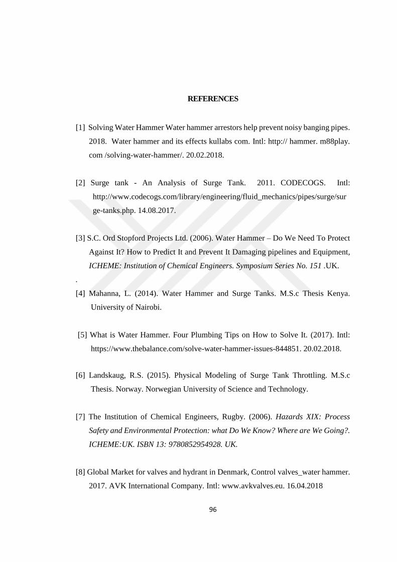
96
REFERENCES
[1] Solving Water Hammer Water hammer arrestors help prevent noisy banging pipes.
2018. Water hammer and its effects kullabs com. Intl: http:// hammer. m88play.
com /solving-water-hammer/. 20.02.2018.
[2] Surge tank - An Analysis of Surge Tank. 2011. CODECOGS. Intl:
http://www.codecogs.com/library/engineering/fluid_mechanics/pipes/surge/sur
ge-tanks.php. 14.08.2017.
[3] S.C. Ord Stopford Projects Ltd. (2006). Water Hammer – Do We Need To Protect
Against It? How to Predict It and Prevent It Damaging pipelines and Equipment,
ICHEME: Institution of Chemical Engineers. Symposium Series No. 151 .UK.
.
[4] Mahanna, L. (2014). Water Hammer and Surge Tanks. M.S.c Thesis Kenya.
University of Nairobi.
[5] What is Water Hammer. Four Plumbing Tips on How to Solve It. (2017). Intl:
https://www.thebalance.com/solve-water-hammer-issues-844851. 20.02.2018.
[6] Landskaug, R.S. (2015). Physical Modeling of Surge Tank Throttling. M.S.c
Thesis. Norway. Norwegian University of Science and Technology.
[7] The Institution of Chemical Engineers, Rugby. (2006). Hazards XIX: Process
Safety and Environmental Protection: what Do We Know? Where are We Going?.
ICHEME:UK. ISBN 13: 9780852954928. UK.
[8] Global Market for valves and hydrant in Denmark, Control valves_water hammer.
2017. AVK International Company. Intl: www.avkvalves.eu. 16.04.2018

97
[9] Joukowsky Equation. 2014. Neutrium. Intl: https:// neutrium. net/fluid_flow/
joukowsky-equation/. 02.05.2017
[10] Berberoğlu, P. (2013). Numerical Investigation of Effective Surge Tank
Dimensions in Hydropower Plants under Various Hydraulic Conditions. Middle
East Technical University the Graduate School of Natural and Applied Sciences.
YÖK Tez No: 338548, 2-3
[11] Water Hammer and Surge Tanks. 2014. Mahanna, Loeb, Magalhaes. Intl:
https://www.engr.colostate.edu/~pierre/ce_old/classes/CIVE%20401/Team%2
0reports/9%20-%20Water%20Hammer%20and%20Surge%20Tanks%20-
%20Loeb%20Magalhaes%20Mahanna.pdf. 20.03.2018
[12] An independent platform news , book reviews, short book notes site. 2019.
Process North : NOTES. Intl:www.process-notes.co.uk. 16.08.2019.
[13] Flowmaster Software. 1D Computational Fluid Dynamics (CFD) modelling and
analysing Intl: www.flowmaster.com. 20.03.2018
[14] HiTrans software. 2016. ISTEC Ingeniería (Istec srl) is an uruguayan company
that provides engineering services. Intl: www.istec.com.uy. Date of Access:
20.03.2018.
[15] PIPENET is the software for rapid fluid flow analysis of pipe and duct networks.
2019. Pipenet software. Intl: http://www.sunrise-sys.com. 10.06.2019.
[16] Hytran Software analyzing a water hammer and Hydroulic transient in pipelines.
2001. Hytran software. Intl: http://www.hytran.net/. 20.03.2018.
[17] Water Hammer by Griffith,Peter. 2011. Intl: http:// www. thermopedia. com/
content/1251/. 26.08.2018.
98
[18] Gwenn, A. P. (2008). Technical Surge Session, Hydraulic Transient and Surge
Protection Devices. Charlatta America Fayat Group. USA.
[19] VAL-MATIC. (2009). Surge Control in Pumping Systems. Val-Matic Valve And
Manufacturing Corp. USA.
[20] Garr, M. J. (2008). Pumping Station Design. 3rd Edition. USA. Elsevier
Butterworth- Heinemann publications, 3.11- 3.12
[21] Lift Station Design, Surge Control in Pumping Systems. 2009. VAL-MATIC:
Valve and Manufacturing Corp. Date of Access: 21.03.2018. USA. Intl=
http://www.pumpfundamentals.com/download-free/surge_control.pdf
[22] Stephenson, D. J. (2001). Developments in Water Science, Pipeflow Analysis,
Elsevier Publications. Netherland. Vol.19, 142
[23] Non-return Valve. 2010. GRUNDFOS Product Center in Denmark. Intl: https://
www.grundfos.com/service-support/encyclopedia- search/nonreturn valve.
html. 08.09.2017.
[24] Water Hammer by Neven Drobnjak (Blogger). 2016. Intl: http:// www. nevend.
info/2016/09/19/water-hammer/. 20.3.2018.
[25] GRP Pipe Material. 2017. HOBAS: A Pipe System Company in Austria. Intl:
http://www.hobas.com/engineering-guide/grp-material.html. 19.12.2017.
[26] Yamada. 2008. Intl: http://interior-yamada.info/blog-entry-1239. html.
25.01.2018
[27] Preventing Water Hammer from Damaging Pumps and Pipes . 2011. Stuart Ord.
(is a chemical engineer in England). Intl:
http://empoweringpumps.com/preventing-water-hammer-from-damaging-
pumps-and-pipes/. 20.03.2018.

99
[28] Naidu, B.A. (1973). Surge Tank for Hydel Power Station. University of Rookie
Press. India. 107832.
[29] Surge Tanks – Types of Surge Tanks, Its Functions and Uses. 2017. Gopal Mishra.
The Constructor blog. Intl: https://theconstructor.org/water-resources/surge-
tank-types-function/12946/. 14.07.2017
[30] Aranovich, G.V, Kartvelishvili, N.A, Lyubimtsev, Ya K.. (1968). Water hammer
and surge tank. Israel Program for Scientific Translation. Moscow.
TCI74.A76I3, 77-88.
[31] Samani H. M. V. (2013). Design-Variable Optimization of Hydropower Tunnels
and Surge Tanks Using a Genetic Algorithm, Journal of Water Resources
Planning and Management. Iran. DOI:10.1061/ASCE WR.1943-5452.0000243,
201
[32] Hydrostatic Pressure. 2010. Engineeringtoolbox. Resources, Tools and Basic
Information for Engineering and Design of Technical Applications, Intl:
https://www.engineeringtoolbox.com/hydrostatic-pressure-water-d_1632.html.
02.06.2017.
[33] Most effective Surge Tank location. 2001-2008. Physics Forums. Intl:
https://www.physicsforums.com/threads/most-effective-surge-tank-
location.533671/. 17.12.2017.
[34] Moghaddam, M. A. (2004). Analysis and Design of a Simple Surge Tank. IJE:
International Journal of Engineering. Iran. Vol. 17, No. 4, 1-2
[35] Yamamoto, H. (1961). Closed Surge Tank. United States Patent: USA. App/Pub
Number 3,201,942, 1-3
[36] Kahya, E. (2007). Açık Kanallarda Akım: Uniform Akım, Hydraulics Lecture
Notes. ITU: Istanbul Technical University. Part11, 15-18

100
[37] Water Flowing in Pipes - why size matters by John Hearfield (Blogger). 2007-
2012. Intl: http://www.johnhearfield.com/Water/Water_in_pipes.htm. 8.10.2017
[38] Montes, J.S, Delphin, P. (1983). Surge Tank with Horizontal Galleries, Eight
Australasian Fluid Mechanic Conference, University of Newcastle, 9c.10-9c.11
[39] Different types of surge tanks used in hydro power plants. 2016. WordPress. Intl:
http://electricalengineeringtutorials.com/different-types-of-surge-tanks-used-
in-hydro-power-plants/. 21.03.2018.
[40] Design of Restricted Orifice Surge Tank. 2013. Civilyarou website. URL:
http://civilyarou.web.fc2.com/WANtaroHP_html5_win/f90_ENGI/dir_SURGE
/en_TeX_SURGE.pdf. 25.03.2018
[41] WILKE, M.A. (1980). Restricted Orifice Surge Tanks on Low Head Pump Rising
Mains. 7th Australasian Hydraulics and Fluid Mechanics Conference, Brisbane.,
356-358.
[42] METU: Middle East Technical University Lecture Notes. (2018). Open-Channel
Flow. Chapter 3 Channel Control, 4-9
[43] Landskaug, R. S. (2015). Physical Modeling of Surge Tank Throttling. Norwegian
University of Science and Technology, Norway, 24, 25
[44] Das, M. M., Saikia, M. D. (2011). Irrigation and Water Power Engineering. PHI
Learning Private Limited, Raj Press. 110001, ISBN-978-81-203-3587-5. New
Delhi, 353

101
[45] Exactly two active pipes must be connected to this type of node in its current
configuration by Scott Kampa. 2018. Bentley Technical Support Group. Intl:
https://communities.bentley.com/products/hydraulics___hydrology/w/hydraulic
s_and_hydrology__wiki/16985/exactly-two-active-pipes-must-be-connected-to-
this-type-of-node-in-its-current-configuration. 20.01.2018
[46] Vinko, J. (2013). Analysis and Modeling of Non-Steady Flow in Pipe and Channel
Networks. A John Wiley & Sons, Ltd., ISBN: 978-1-118-53214-0. United
Kingdom. 94-98
[47] Utseth, S. S. (2016). Surge Tank Atlas for Hydropower Plants. Norwegian
University of Science and Technology, Civil and Environmental Engineering.
32- 43
[48] Chaudhry, M. H. (2014). Applied Hydraulic Transients.3rd Edition. Springer
Science and Business Media. USA. DOI: 10.1007/978-1-4614-8538-4, 386
[49] Zaruba, J. (1993). Development in Water Science 43, Water hammer in pipe-line
systems. Elsevier. Czechoslovakia. ISBN: 0-444-98722-3, 232-233
[50] Surge tank. 2018. Strukts.com. Intl: https:/ /www.strukts. com/ 2012/06/surge-
tank/. 19.2.2018
[51] Novak P. (2001). Hydraulic Structures, Third Edition. Spon Press, London.
ISBN: 0-203-24651-9, 501
[52] NRCS, NHCP: National Conservation Practice Standards, National Historical
Commission of the Philippines. (2011). Natural Resources Conservation Service
Conservation Practice Standard, Irrigation Reservoir. Philippines. Code 436, 1

102
[53] Wencheng, G., Jiandong, Y., Yi, T. (2017). Renewable Energy, Surge wave
characteristics for hydropower station with upstream series double surge tanks
in load rejection transient. Science Direct, Elsevier Ltd. 108(2017)488-501, 488-
489
[54] NPTEL: A Project funded by MHRD (Government of India, Ministry of Human
Resource Development). Hydropower Engineering, Hydropower Water
Conveyance System, Module 5, Lesson 2. Kharagpur, India,18
[55] How does a radiator overflow tank work by Richard Combs (Blogger). 2016.
Intl: https://www.quora.com/How-does-a-radiator-overflow-tank- work.
16.12.2017
[56] Berberoğlu, P. (2013). Numerical Investigation of Effective Surge Tank
Dimensions in Hydropower Plants under Various Hydraulic Conditions. Middle
East Technical University the Graduate School of Natural and Applied Sciences.
YÖK Tez No: 338548, 10-23
[57] Fluid Mechanıcs for Civil Engıneerıng Chapter 4: Flow in Pipelines by Victoria
Cannon (Blogger). 2016.. Intl: http://slideplayer.com/slide/6622347/. 19.01.2018
[58] Wikipedia (online encyclopedia). Birecik Dam. (2001) URL: https://en.
wikipedia. org/ wiki/Birecik_Dam. 18.02.2017
[59] Birecik Dam on the Euphrates River in Turkey. 2013. DFO Home: Dartmouth
Flood Observatory. Intl: https://www.dartmouth.edu/~floods/Samples/Birecik.
html. 07.01.2018
[60] Moghadam, M. F. (2013). Design-Variable Optimization of Hydropower Tunnels
and Surge Tanks Using a Genetic Algorithm. American Society of Civil
Engineers. USA. DOI:10.1061/(ASCE)WR.1943-5452.0000243.