A SURVEY OF AUGMENTED REALITY TECHNOLOGY IN ...
101
NATIONAL TECHNICAL UNIVERSITY OF ATHENS & NATIONAL INSTITUT OF APPLIED SCIENSES OF STRASBOURG A SURVEY OF AUGMENTED REALITY TECHNOLOGY IN THE FIELD OF CULTURAL HERITAGE DIPLOMA THESIS KYRIAZI PELAGIA ATHENS, MARCH 2018
-
Upload
khangminh22 -
Category
Documents
-
view
4 -
download
0
Transcript of A SURVEY OF AUGMENTED REALITY TECHNOLOGY IN ...

NATIONAL TECHNICAL UNIVERSITYOF ATHENS
&
NATIONAL INSTITUT OF APPLIED SCIENSES OF STRASBOURG
A SURVEY OFAUGMENTED REALITY TECHNOLOGY
IN THE FIELD OF CULTURAL HERITAGE
DIPLOMA THESIS
KYRIAZI PELAGIA
ATHENS, MARCH 2018


NATIONAL TECHNICAL UNIVERSITYOF ATHENS
&
NATIONAL INSTITUT OF APPLIED SCIENSES OF STRASBOURG
A survey of Augmented Reality technologyin the field of cultural heritage
Diploma Thesisof
Kyriazi Pelagia
Supervisors:Georgopoulos Andreas, Professor NTUA
Grussenmeyer Pierre, Professor INSA Strasbourg
Tripartite thesis committee:Georgopoulos Andreas, Professor NTUA
Ioannidis Charalabos, Associate Professor NTUADoulamis Nikolaos, Assistant Professor NTUA
Athens, March 2018


Acknowledges
Having completed the present diploma thesis, I would like to thank all the people thatcontributed to its development in any possible way.
First and foremost, I would like to express my sincere gratitude to my research supervisor,Prof. Andreas Georgopoulos, director of the Laboratory of Photogrammetry within the Departmentof Topography and the School of Rural and Surveying Engineering of National Technical Universityof Athens (NTUA), for the valuable guidance that he gave me in working upon my thesis. I amgrateful for his support and trust as he consistently allowed this dissertation to be my own work,but in the same time steered me in the right direction whenever I needed it. The door to Prof.Georgopoulos' office was always open, during all the years of my studies, whenever I ran into atrouble spot or had a question. As he has been my Photogrammetry professor too, I would like tomention that his teaching methods and enthusiasm made a strong impression on me. It would notbe an exaggeration to say that he actually made me love the topic, in cooperation with my othertwo professors of this class, prof. Charalabos Ioannidis and prof. George Karras, to whom I amalso grateful.
I had the opportunity to also have a second supervisor, Prof. Pierre Grussenmeyer, at theDepartment of Civil Engineering and Surveying of National Institute of Applied Science (INSA) ofStrasbourg. Prof. Grussenmeyer's guidance in my first days in a foreign University was veryimportant. He gave me access to the laboratory and research facilities, which allowed me to workon my diploma thesis during my six-month stay in France.
My sincere thanks also go to Athanasios Voulodimos, Research Associate in NationalTechnical University of Athens, who devoted his time to my dissertation at any moment I asked forhis help, although his had no obligation of doing so. His knowledge in computer science gave me anew perspective on programming in Java language. Additionally, I am thankful to prof. NikolaosDoulamis for offering his help in case I wanted to follow another approach for the development ofthe application, even though I finally did not have the chance to work with him.
Getting through my dissertation required more than academic support, and I have manyfriends and family members to thank for listening to and, at times, having to tolerate me over thepast years.
Life has been kind enough to offer me the friendship of many special people, whose love Ihave been getting for many years. I cannot begin to express my gratitude to the friends that I havemade during my years of studying in high school and university. I will not adduce all their names,as I am sure that they know who I am talking about. I want them to know that I count them asfriends for a lifetime and I will not stop reciprocating their encouragement and appreciation. To thiscategory I include my “international” friends from Brazil, Mexico and Germany. Even though I firstmet them just a year ago, they were my family while I was far away from my real one. I could nothave stood the challenges of living abroad without them to support me.
Most importantly, I strongly believe that none of this could have happened without myfamily. My parents, my brother and my grandmother were there for me every time I was ready toquit. During all the years of my life I remember them saying to me that I am strong to accomplisheverything I want, which motivated me to try harder and to set higher targets. This last year theyhave seen me more stressed than I have ever been as there were many times I felt that I woulddisappoint them. Without even having to ask, though, they repeatedly informed me that all theywant for me is to be happy. The fact that they kept supporting me no matter the circumstances ispriceless and makes them role model family to my eyes. This dissertation stands as a testament totheir unconditional love and encouragement.
The study and the rehabilitation project of the Holy Aedicule became possible and wereexecuted under the governance of His Beatitude Patriarch of Jerusalem, Theophilos III. TheCommon Agreement of the Status Quo Christian Communities provided the statutory frameworkfor the execution of the project; His Paternity the Custos of the Holy Land, Archbishop Pierbattista

Pizzaballa (until May 2016 – now the Apostolic Administrator of the Latin Patriarchate ofJerusalem), Fr. Francesco Patton (from June 2016), and His Beatitude the Armenian Patriarch ofJerusalem, Nourhan Manougian, authorized His Beatitude the Patriarch of Jerusalem, TheophilosIII, and NTUA to perform this research and the project. Contributions from all over the worldsecured the project’s funding. Worth noting Ioanna- Maria Ertegun Great Benefactor and JackShear Benefactor through WMF, Aegean Airlines as major transportation donor et al.
Acknowledgements are attributed to the interdisciplinary NTUA team for the Protection ofMonuments, Professors Em. Korres, A. Georgopoulos, A. Moropoulou, C. Spyrakos, Ch. Mouzakisand specifically, A. Moropoulou, as Chief Scientific Supervisor, of the rehabilitation project.
Additionally, for the 3D models of the Aedicule used here, the contributions of Prof. A.Georgopoulos, Prof. Ch. Ioannidis, S. Soile, S. Tapinaki and R. Chliverou members of theGeometric Documentation team are gratefully acknowledged.


A SURVEY OF AUGMENTED REALITY TECHNOLOGY IN THE FIELD OF CULTURAL HERITAGE
Abstract
Augmented Reality (AR) is a technology which allows the enhancement of thephysical, real world environment, through its augmentation with computer generated sensoryinput. The idea of an electronic display that superimposes data over a real-world scene inorder to provide more information about it, already exists from 1901, but it was only recentlythat the first relevant applications came to life. Nowadays, it has practical applications invarious fields, not only scientific but also fields of everyday life. Many researchers andcompanies are trying to develop innovative AR systems.
One of the fields using Augmented Reality is the promoting of cultural heritage. Bycreating three dimensional models of monuments it is possible to display them over an imagefar away from their actual location, giving the opportunity to more people to get to know themand even interact with them. Their visualization through the years is also a potential, whichcan offer an interactive experience to the visitors. Especially in case the monument isnowadays partly destroyed, its presentation during the days of its glory can be veryimpressive and informative. Moreover, the construction of the digital model is a part of thegeometrical documentation of the monument, which contributes to its completeddocumentation and to its maintenance and transmission to future generations. Thistransmission is one of the domain objectives of the architectures and the other scientists whoare in charge of protecting the cultural property.
The present thesis is the result of the research done, in order to better understand theconcept of Augmented Reality and how it can contribute to the field of cultural heritage. Thevision-based methods of tracking the surface are mostly examined, as they are the mostwidespread techniques, as well as the most relevant to the field of photogrammetry. Thethesis is separated in four chapters, each one having a specific role to play.
The first chapter is about the theoretical background. It begins with the definition ofthe Augmented Reality term, to help the readers comprehend its basic characteristics anddistinguish it from other versions of reality. The historical review of how the whole idea cameto life and developed follows, to provide an understanding of its evolution through the yearsand to present all the notable researchers who contributed to make this system available.The next important element is the different aspects of life where it has made inroads. Theimpact that has been left until now is crucial in order to estimate the future development andthe even bigger modifications that are going to be made.
The second chapter aims at the explication of the system's technology. Threecategories of hardware components are essential to create an AR system; sensors,processors and display devices. Their functionality is explained in this part. A briefpresentation of how the whole system works follows, to explain how these components areused to produce the final result. Emphasis is being given to the tracking, as it is the mostimportant procedure for the real-world scene augmentation. The problems, or betterchallenges, that the researchers have to face are also presented here. Last but not least,some of the projects in which monuments or archaeological sites have been enhanced byAugmented Reality systems are described.
The attempt to produce an application which superimposes the 3D model of the Tombof Christ, situated in Jerusalem, on the image of its floor plan, is reported in the third chapter.The chapter begins with the history and the architecture of the Church of the Holy Sepulchre,where the monument is located and it continues with how the monument's digitalconstruction has been done. Next, the tools and the components that have been used for theproduction of the application are presented. Finally, the system's building is described, giving
KYRIAZI PELAGIA | Page 1 of 94

A SURVEY OF AUGMENTED REALITY TECHNOLOGY IN THE FIELD OF CULTURAL HERITAGE
emphasis to the code's most important parts.The last chapter is basically an epilogue. It includes conclusions concerning the thesis
and an evaluation of the application which is based on the results. For the closure,expansions that could possibly be created in the future are discussed.
Key Words: Augmented Reality, Cultural Heritage, Android, Java
KYRIAZI PELAGIA | Page 2 of 94

A SURVEY OF AUGMENTED REALITY TECHNOLOGY IN THE FIELD OF CULTURAL HERITAGE
KYRIAZI PELAGIA | Page 3 of 94

A SURVEY OF AUGMENTED REALITY TECHNOLOGY IN THE FIELD OF CULTURAL HERITAGE
Table of Contents
Abstract.......................................................................................................................................11. Augmented Reality..................................................................................................................7
1.1. Definition.........................................................................................................................71.2. Types of Reality...............................................................................................................81.3. Historical Research..........................................................................................................91.4. AR for Maintenance of Cultural Heritage.....................................................................151.5. Other uses and applications of AR................................................................................17
1.5.1. Military..................................................................................................................171.5.2. Navigation and tourism..........................................................................................171.5.3. Medical..................................................................................................................181.5.4. Education...............................................................................................................181.5.5. Visual Art...............................................................................................................191.5.6. Architecture............................................................................................................191.5.7. Industrial design.....................................................................................................201.5.8. Commerce..............................................................................................................201.5.9. Video games...........................................................................................................211.5.10. Broadcast and Live Events..................................................................................211.5.11. Others...................................................................................................................22
2. Technology............................................................................................................................232.1. Hardware Technology....................................................................................................23
2.1.1. Sensors...................................................................................................................232.1.2. Processors..............................................................................................................242.1.3. Displays.................................................................................................................25
2.1.3.1. Head-Attached Displays................................................................................262.1.3.2. Hand-Held Displays.......................................................................................282.1.3.3. Spatial Displays..............................................................................................29
2.2. Software Technology.....................................................................................................302.2.1. Tracking Methods..................................................................................................31
2.2.1.1. Visible Light Tracking...................................................................................322.2.1.1.1. Fiducial Tracking....................................................................................322.2.1.1.2. Natural Feature Tracking........................................................................332.2.1.1.3. Model Based Tracking...........................................................................34
2.2.1.2. Infrared Light Tracking..................................................................................342.2.1.3. 3D Structure Tracking....................................................................................342.2.1.4. Location-Based tracking................................................................................352.2.1.5. Fusion strategies.............................................................................................36
2.2.2. Pose Calculation in visual tracking methods.........................................................362.3. Today's challenges.........................................................................................................392.4. State of the Art – Cultural Heritage AR Applications...................................................40
2.4.1. Archeoguide...........................................................................................................412.4.2. LIFEPLUS: Revival of life in ancient Pompeii.....................................................422.4.3. Calakmul – Ancient Maya Metropolis...................................................................442.4.4. The PRISMA project.............................................................................................45
KYRIAZI PELAGIA | Page 4 of 94

A SURVEY OF AUGMENTED REALITY TECHNOLOGY IN THE FIELD OF CULTURAL HERITAGE
2.4.5. A Future for the Past..............................................................................................472.4.6. The House of Olbrich............................................................................................482.4.7. The CHESS project................................................................................................482.4.8. LecceAR................................................................................................................502.4.9. The MIRACLE project..........................................................................................51
2.4.9.1. Luostarinmaki Adventure...............................................................................512.4.9.2. Wordsmith......................................................................................................522.4.9.3. House Casagrande..........................................................................................52
3. Producing an AR application................................................................................................533.1. The Church of the Holy Sepulchre................................................................................53
3.1.1. History...................................................................................................................533.1.2. Description and Architecture ................................................................................54
3.2. Preparation of the 3D Model.........................................................................................563.2.1. Reconstructed 3D Model of The Tomb of Christ..................................................573.2.2. Reducing 3D Model's Size.....................................................................................58
3.3. Development tools and equipment................................................................................603.3.1. Programming Language.........................................................................................603.3.2. Framework.............................................................................................................61
3.3.2.1. Selection's procedure.....................................................................................613.3.2.2. ARToolKit – Information and features...........................................................623.3.2.3. ARToolKit – Requirements............................................................................63
3.3.3. System's technical specifications...........................................................................643.4. Using native code..........................................................................................................663.5. Project creation..............................................................................................................67
3.5.1. Building the application.........................................................................................673.5.2. Running the application for the first time..............................................................76
3.5.2.1. Camera's Calibration......................................................................................763.5.2.2. First results.....................................................................................................76
3.5.3. OBJ loader's creation.............................................................................................774. Results and Commentation...................................................................................................80
4.1. Conclusions...................................................................................................................804.2. Application's results.......................................................................................................804.3. Future work...................................................................................................................83
Reference List...........................................................................................................................86
KYRIAZI PELAGIA | Page 5 of 94

A SURVEY OF AUGMENTED REALITY TECHNOLOGY IN THE FIELD OF CULTURAL HERITAGE
KYRIAZI PELAGIA | Page 6 of 94

A SURVEY OF AUGMENTED REALITY TECHNOLOGY IN THE FIELD OF CULTURAL HERITAGE
1 . A ugmented Reality
1.1. Definition
Augmented reality is a rapidly and constantly evolving technology which enables tooverlay computer-generated sensory input on a view of a physical, real-world scene, beingview through a device, in order to create an enhanced version of reality. Nowadays, the inputelements that complement the reality can be sound, video, graphics and GPS data. It isstrongly believed, though, that in some years it will also be possible to use all of our senses,including smelling and tasting. These objects have to be presented as part of the image,giving the impression of coexisting in the same place and time with it [64].
There are plenty of definitions for what augmented reality is. The most commonaccepted is the one of Ronald Azuma, who defined augmented reality as a variation of VirtualEnvironments (VE), with the difference that while VE technologies completely immerse auser inside a synthetic environment, AR allows the user to see the real world, with virtualobjects superimposed upon or composited with the real world. So, as he ends up, ARsupplements reality, rather than completely replacing it [3].
In order to better explain this definition, an explanation of virtual environments (VE),or virtual reality (VR), is also necessary. In virtual reality projects, realistic images, soundsand other sensations are generated, using a software. These sensations replicate a three-dimensional environment, which may either copy real-world attributes, or be a completelyimaginary world. The user can interact with everything existing in this environment, usingspecialized display screens or projectors and other devices [126].
Now that both these types of technology have been defined, it's easier to understandthe crucial difference of Azuma's definition. VR actually brings the user into the digital worldby cutting off outside stimuli, while the real-world scene has the dominant role at AR projects.In fact, as he also claims, AR can be thought of as the “middle ground” between VE(completely synthetic) and telepresence (completely real) [3].
In order to avoid misunderstandings about whether a system can be considered asAR system or not, Azuma also defined the characteristics of every AR system. According tohim, AR systems [3]:
• Combine real and virtual• Are interactive in real time• Are registered in 3-D
Using these characteristic, it is getting easy to understand that a film, for example,cannot be considered as AR system, even if it overlays photorealistic virtual objects on 3-Dreal-world scenes, as long as it is not interactive in real time. Another example is the 2-Doverlays used on top of live video, an interactive in real-time technology which adjust virtualelements on real-world scenes, but not in 3-D.
The possibility to distinguish between the Augmented Reality and other types ofReality systems, is the reason why Azuma's definition is considered really important for everyAR research. There are, though, other definitions, which set AR as a sector of other, moregeneral, types of reality. For the sake of completeness, these types of reality have to bepresented as well.
KYRIAZI PELAGIA | Page 7 of 94

A SURVEY OF AUGMENTED REALITY TECHNOLOGY IN THE FIELD OF CULTURAL HERITAGE
1.2. Types of Reality
Mixed Reality (MR) or, according to others, Hybrid Reality aims to combine allpossible variations of real and virtual objects, so as to produce new environments andvisualizations. In order to connect completely real environments to completely virtual ones,Paul Milgram and Fumio Kishino used the term “virtuality continuum”, which includeAugmented Reality, Augmented Virtuality and other mixed configurations. They definedMixed Reality as anything between the extrema of the virtuality continuum [31].
According to their research, in a representation like the one of figure 1, placing realenvironments at one end of the continuum and virtual environments, meaning Virtual Realityprojects, at the opposite extremum, it's possible to have at least 6 classes of intermediatecategory. These classes depend on the technology used to accomplish the different results.For instance, with monitor-based video displays it's possible to accomplish different resultsfrom the ones accomplished with head-mounted displays (HMD's) or with completely graphicdisplay environments.
They defined AR as any case in which an otherwise real environment is “augmented”by means of virtual (computer graphic) objects, a definition with which 4 of the 6 classes areincluded in the AR term. The fifth class, which refers to completely graphic displayenvironments with video “reality” added, is the one for whom the term Augmented Virtuality isused. Since the world being augmented is a virtual, and not a real one, the name AR wouldnot be the appropriate one. Finally, sixth class, which introduce a virtual environment wheresomeone can use real-world objects (parts of his body, for example), is the reason why theterm Hybrid Reality has been imported, since a blending of many types of display media isused in this case.
An even more general framework, that also includes the reality - virtuality continuum,is the Mediated Reality. In the concept with the name Mediated Reality, the view of the real-world scene can be not only augmented, but generally modified, by a computer. This way thehuman perception can be modified by way of devices for augmenting, deliberatelydiminishing and otherwise altering sensory input [29].
The previous sentence includes one more reality-relevant term, the DiminishedReality. A Diminished Environment is the one where parts of the existing real-world scenehave been diminished. In order to accomplish the diminishment, an object or a collection ofobjects has to be replaced with an appropriate background image [26]. That's the reasonwhy, in some researches, Diminished Reality is thought to be the same as AR, since there isa computer-generated image, being input in both these cases.
KYRIAZI PELAGIA | Page 8 of 94
Figure 1: Reality - Virtuality Continuum [31]

A SURVEY OF AUGMENTED REALITY TECHNOLOGY IN THE FIELD OF CULTURAL HERITAGE
One more concept complementary to AR is that of Amplified Reality. As it is defined inthe relevant search of Falk, Redström and Björk [14], to amplify reality is to enhance thepublicly available properties of a physical object, by means of using embeddedcomputational resources. The difference between Augmented and Amplified Reality is that anamplified object is self-contained in regards to its properties. AR superimposes virtualproperties on an object, enhancing impressions of real objects, but not actually changing it. Itjust changes the way a person experiences it, privately. On the other hand, Amplified Realityenhances the expressions of objects in the real world, emphasizing the importance of theshared experiences that result from publicly available properties of objects.
1.3. Historical Research
Augmented Reality has been known to the masses only the last years. Nevertheless,the first mentions of the idea of an electronic device that overlays data on a real-world sceneto enhance reality takes already place in 1901, by an author, L. Frank Baum [78]. In hisnovel, The Master Key, he imagines a pair of spectacles which overlays a letter on theforehead of people, indicating their character. Only whoever wears the device can see theletter, which is exactly the same logic as the one of the AR devices.
KYRIAZI PELAGIA | Page 9 of 94
Figure 2: Mediated Reality [29]
Figure 3: Main differences between Augmented and Amplified Reality [14]

A SURVEY OF AUGMENTED REALITY TECHNOLOGY IN THE FIELD OF CULTURAL HERITAGE
In 1955 a cinematographer, Morton Heilig, detailed his vision of a multi-sensorytheater, simulated with “reality machines”, in a paper titled the “Cinema of the Feature” [18].Five year later, in 1962, he built a prototype of his vision, named Sensorama, a mechanicaldevice which still functions today. Sensorama is thought to be a predator of digital computing.It had the capability to blow wind, vibrate and surround sound.
In 1968 the computer scientist Ivan Sutherland with his student Bob Sproull created ahead-mounted display (HMD) system, named “the Sword of Damocles”. Using suitable two-dimensional images on the observer's retinas, they managed to create the illusion of three-dimensional display. Half-silvered mirrors were used as optical combiners, allowing the userto see both the computer-generated images reflected from cathode ray tubes (CRTs) and thereal-world scene. The perspective image presented was changing as the user was movinghis head, so all that had to be measured in order to present the appropriate display, was theposition and the orientation of the optical system to the user's head. He managed to do thiswith mechanical and ultrasonic head position sensors. The user was surrounded withdisplayed 3D information of objects, appeared to hang in the space all around him. Theexisting technology permitted the objects displayed to only be transparent “wire frame” linedrawings and not 3D objects, as in today's AR systems. Nevertheless, the “Sword ofDamocles” is considered to be the first VR and AR HMD system. [48]
In 1975 established “Videoplace”, an artificial reality laboratory in which users couldinteract with virtual objects for the first time. Projectors, video cameras, special hardware andonscreen silhouettes have been used for this purpose. The users, situated in separaterooms, had their movements recorded on video and transferred to the silhouetterepresentations in the Artificial Reality environment. All the users where seeing the samerepresentation, including all of them. This way it was possible to interact with each other, nomatter how far away the other rooms were [125].
In 1978, Steve Mann created the first wearable computer, a device which is usingcameras, processors and display systems to help people see better, named “Digital EyeGlass”, as it causes the eye to appear as a glass prosthetic. To accomplish it, this machine
KYRIAZI PELAGIA | Page 10 of 94
Figure 4: The Sword of Damocles [47] Figure 5: Today's HMD system [99]

A SURVEY OF AUGMENTED REALITY TECHNOLOGY IN THE FIELD OF CULTURAL HERITAGE
caused the human eye itself to become both an electronic camera and a television display,using “augmediated reality” vision systems [58].
The 1980s was the decade when AR technology started being used to enhancealready existed sectors of life. In 1981, Dan Reitan was the first one to bring AugmentedReality to TV, as he uses it to enhance the television weather broadcasts. In 1987, DouglasGeorge and Robert Morris created an AR system to superimpose information relevant tostars and celestials over the sky images, on an astronomical telescope-based AR system[64].
As the new technology had already started invading our life, in 1990 the term“Augmented Reality” was used for the first time, by Thomas Caudell, a former Boeingresearcher, to refer to overlaying computer-presented material on top of the real world.Caudall was working on a system that would assist the workers in the assembly andinstallation of electrical cables in the aircrafts. The relevant research published in 1992 [12].The term “Virtual Reality” had already been used in 1989 by Jaron Lanier.
In 1992 Louis Rosenberg developed the first fully immersive AR system, namedvirtual fixture. It is an overlay of augmented sensory information on a workspace, designed toassist in the user while performing real physical tasks. In order to achieve photorealisticresult, two robots controlled by a full upper-body exoskeleton were used. The user, wearingthe exoskeleton and a pair of special binoculars magnifiers, was seeing robot arms where hisarms should be. The system's aim was to demonstrate benefits to human performance [40].
The same year an AR system prototype, KARMA (Knowledge-based AugmentedReality Maintenance Assistance), was presented at the Graphics Interface conference bySteven Feiner, Blair Maclntyre and Doree Seligmann. KARMA is a guide of maintenance andrepair for a laser printer, using see-through head-mounted display (HMD) [96].
In 1993, Loral Electronics Corporation, a defense contractor, presented a series oflive demonstrations combining live AR-equipped vehicles and manned simulators. Vehiclecrews were able to see virtual vehicles and weapon effects and interact with them in real-time on the same battlefield [5].
In 1994, in an Australian TV show called “Dancing in Cyberspace”, created by Julie
KYRIAZI PELAGIA | Page 11 of 94
Figure 6: Virtual Fixtures [40]

A SURVEY OF AUGMENTED REALITY TECHNOLOGY IN THE FIELD OF CULTURAL HERITAGE
Martin, dancers and acrobats manipulated body-sized virtual objects projected onto the stagewith them. The acrobats appeared immersed within the virtual environments [63].
In 1995, Benjamin Bederson introduced the term Audio Augmented Reality, bypresenting a system that demonstrated an augmentation of the audition modality. Thissystem, which uses a MD-player with audio-information relative to the tracked position of theuser, is still in use as a museum guide [6].
The same year, Jun Rekimoto and Katashi Nagao created the NaviCam, the firstpalmtop computer equipped with a video camera mounted on the mobile screen, used foroptical tracking. The computer was programmed to detect color-coded markers in the livecamera image [42].
Inspired by these color-coded markers, Jun Rekimoto created a 2D square-shapedbarcode system of markers, CyberCode, some years later. It was one of the first markersystems to allow camera tracking with six degrees of freedom. Nowadays, a lot of ARapplications still use CyberCode [41].
In 1997, the first mobile augmented reality system (MARS) was presented by StevenFeiner et al. It used a wearable computer, a see-through head worn display with integralorientation tracker, GPS and digital radio for wireless web access [15].
In parallel, a similar system was developed by a group of researchers inMassachusetts Institute of Technology. A group of users, equipped with wearable computersinterconnected over a network, explored possible applications of mobile AR [45].
In 1998, in a paper named “The office of the future”, ideas for spatially immersivedisplay were presented. These ideas have been proved useful for a lot of computer visiontype applications, including Augmented Reality [38].
The same year, an investigation into expanding augmented reality systems to outdoorenvironments was presented at the 2nd International Symposium on Wearable Computers.The researchers developed a system called “map-in-the-hat”, which is a backpack-basedwearable computer with a see-through head-mounted display, an electronic compass and aGPS, used for navigation tasks [50]. With the technology development this system evolved toTinmith project, which is known for many mobile outdoor Augmented Reality applications[122].
In 1999, NASA Johnson Space Center, was developing real-time 3D displays for flightguidance, overlaying three-dimensional terrain models, recommended landing areas andmaps. They used real-time GPS position data and head-up display (HUD) to accomplish thesuccessful result [109].
At the same time, the US Naval Research Laboratory developed wearable systemsfor dismounted soldier operating in urban environment, on a research called BattlefieldAugmented Reality System (BARS). The system targets the augmentation of a battlefieldscene with additional information about environmental infrastructure, but also about possibleenemy ambushes [123].
KYRIAZI PELAGIA | Page 12 of 94

A SURVEY OF AUGMENTED REALITY TECHNOLOGY IN THE FIELD OF CULTURAL HERITAGE
1999 was also the year when ARToolKit, the open-source computer tracking libraryunder the GPL license, currently hosted on GitHub, was released by the University ofWashington HIT Lab (Human Interface Technology Laboratory). ARToolKit was originallydeveloped by Hirokazu Kato and Mark Billinghurst and further developed by other HitLabscientists. [59]
Entering the new millennium, the technology of Augmented Reality was becomingmore and more widespread and the number of researches released also increased. Startingfrom 2000, only the most important historical references for augmented technologydevelopment are presented.
In 2000, the first outdoor mobile AR game, ARQuake, was demonstrated by hiscreator, Bruce H. Thomas, in the International Symposium on Wearable Computers. It is anAugmented Reality version of the popular Quake game, using the wearable computer systemTinmith to track the position and the orientation of the user's body and head [49].
In 2002, the first International Symposium on Mixed Reality and Augmented Reality(ISMAR) was held in Germany. The predecessors of ISMAR, International Workshop onAugmented Reality (IWAR), International Symposium on Mixed Reality (ISMR) andInternational Symposium on Augmented Reality (ISAR), had taken place for the first time in1998, 1999 and 2000 respectively. From 2002 and after, ISMAR is organized annually byIEEE Computer Society and IEEE VGTC at different countries, permitting the researchers toparticipate and exchange opinions and thoughts relevant to these technologies [80].
The following years, cell-phones games using AR started to be released. The firstAugmented Reality game for cell-phones, named Mozzies, was released for Siemens SX1 in2003, winning, also, an award of the best mobile game in 2003 [118].
Just a year later, one more game, named “The invisible train”, is presented. Theinnovation of this game is that it is the first multi-user AR application for handheld devices[120].
Another important technology step was taken in 2004, when Mathias Möhring,Christian Lessig and Oliver Bimber presented a system which supported optical detectionand differentiation of different 3D markers and correct integration of rendered 3D graphics
KYRIAZI PELAGIA | Page 13 of 94
Figure 7: BARS backpack [123]

A SURVEY OF AUGMENTED REALITY TECHNOLOGY IN THE FIELD OF CULTURAL HERITAGE
into the live video stream, on a consumer cell-phone. The technological constraints werecreating limits to the quality of the results, but a first running system was realized, giving theopportunity of further development [32].
In 2006, Reitmayr and Drummond presented a model-based hybrid tracking systemfor outdoor Augmented Reality in urban environments, enabling accurate, real-time overlayson a handheld device. The system combines an edge-based tracker for accurate localization,gyroscope measurements to deal with fast motions and measurements of gravity andmagnetic field to avoid drift [39].
The location-based programs used as travel guides were the next to be developedwith AR systems. In 2008 the company Mobilizy GmbH created Wikitude, a mobile ARtechnology provider, which initially focused on providing location-based experiences. TheWikitude World Browser was using GPS, accelerometer and compass, in order to overlayWikipedia entries on the real-world scene viewed from the mobile's camera [127].
A year later the company SPRXmobile also created a location-based program, namedLayar, a more advanced variant of Wikitude. Using the same registration mechanism asWikitude, it created an open client-server platform, overlaying entries not only from Wikipediabut also from Twitter and Brightkite, as different layers [98].
It is important to mention that the first AR Travel Guide had already been created byColumbia's Computer Graphics and User Interfaces Lab [7]. The first AR browser had alsobeen created by Kooper and Maclntyre [25]. Both these systems were already in use from2001.
In 2010, Microsoft announced the cooperation with Primesense, an Israeli companyworking on structured-light based 3D sensors. The result of this cooperation was Kinect, aline of motion sensing input devices, which enables the users to interact with their computerthrough a natural user interface using gestures and spoken commands [97].
2012 was the year when Google Glass was presented to the public. It is an opticalHMD that can be controlled with an integrated touch-sensitive sensor or natural languagecommands. The glasses reach the Internet through Bluetooth, which connects to the wirelessservice on a user's cellphone [83].
The same year, NVidia also demonstrated a prototype of a head mounted display,supporting accurate accommodation, convergence and binocular-disparity depth cues.Thanks to its accurate accommodation, it can be seen as a next generation wearable displaytechnology for AR [77].
In 2015, Microsoft announced Windows Holographic and the HoloLens AR headset.This device is a complete computer with a see-through display and several sensors. It utilizesvarious sensors and a processing unit to blend high definition holograms with the real world[79][101].
In 2016, Niantic released Pokémon Go for iOS and Android, the location-based gamethat brought Augmented Reality to the mainstream. The players use their mobile's camerasand gyroscopes in order to see and capture virtual creatures. It was credited withpopularizing location-based and augmented-reality technology, promoting physical activityand helping local businesses to grow via foot traffic [107].
KYRIAZI PELAGIA | Page 14 of 94

A SURVEY OF AUGMENTED REALITY TECHNOLOGY IN THE FIELD OF CULTURAL HERITAGE
1.4. AR for Maintenance of Cultural Heritage
In order for someone to understand the meaning of cultural heritage, it would beuseful to examine its words both separately and as a whole.
The word heritage includes the idea of preserving, excavating, displaying andrestoring a collection of old things, but it's also much more than that. It describes theinherited traditions, monuments, history, a state's background. As a result, it strengthens thesense of identity and belonging to a community and, in the same time, it reinforces socialcohesion and the sense of common responsibility. As for the word culture, it has beendefined as that complex whole which includes knowledge, belief, art, morals, law, customand any other capabilities and habits acquired by man as a member of society [124]. Cultureis created by both forces encouraging change and the ones resisting to it. That's exactly thereason why it must be constantly preserved, but also adjustable to the civilization'sdevelopment.
The unification of all these meanings in the term “cultural heritage” adduces thesignificance of the legacy of all the material and intangible attributes which are received frompast generations, with the obligation to be maintained in the present, so as to be transmittedto the future. According to UNESCO, The cultural heritage may be defined as the entirecorpus of material signs – either artistic or symbolic – handed on by the past to each cultureand, therefore, to the whole of humankind [21]. This sentence sums up the concept ofcultural heritage, also explaining why its preservation and presentation are a corner-stone ofany cultural policy [21]. Each structural member of each monument transmits the technologyof its time, as well as the spirit of the constructor.
During the effort to explain the significance of the cultural heritage, two meanings kepton appearing in different words: Preservation and presentation.
The first is the one directly connected to the term in everyone's mind nowadays.During the past years, unfortunately, the awareness for the maintenance of cultural heritagewas not as widespread as today. As a result, a lot of monuments have been destroyed bynatural or human factors. It is possible, thankfully, to construct digital models of their initialsituation, completing the 3D model that can be constructed from the ruins with digital data,which can be created based on the corresponding registered description. As for the onesstanding in one piece, the construction of their 3D model can be proved very practical in the“preservation” part, as future reference. This way, in case of any damage caused, it would beeasier to repair them and to recreate their initial form. As it is said in the Venice Charter,which is a set of guidelines drawn up in 1964, that provides an international framework forthe conservation and restoration of monuments and sites, this aim must have recourse to allthe sciences and techniques which can contribute to the study and safeguarding of thearchitectural heritage [124]. The 3D model construction mentioned above is a way ofcontributing in the geometrical documentation, which is an important subset of a monument'scomplete documentation.
Τhe second meaning, presentation, is exactly the sector in which the usage of the 3Dmodels can make a huge difference compared to the traditional methods. Watching a 2Drepresentation of any item is totally different than being able to interact with it, as it only offersthe ability to see the part presented in a particular view, with all the occlusions that resultfrom this fact. It is easier to understand the problem thinking of an item with a lot of differentparts in it, for instance, a house. An architectural plan for a house usually contains a floorplan or a horizontal section cut and one or more face plans. However, it is impossible forevery item in the house to be presented of every aspect. While that's not a problem when itcomes to a house display, it is certainly important when the item presented is a monument,
KYRIAZI PELAGIA | Page 15 of 94

A SURVEY OF AUGMENTED REALITY TECHNOLOGY IN THE FIELD OF CULTURAL HERITAGE
where, as said above, each structural member transmits special features of its time. Using a3D model instead, there is no reason to worry about which parts have to be presented, as itis possible to include them all. The user just has to turn the model to find the specific aspecthe is interested in, a procedure he can repeat as many times as he wants.
Having understood how the 3D model's usage can contribute to both the preservationand the presentation of the cultural heritage, it's time to explain the difference AugmentedReality can make.
The technology of Augmented Reality gives to everyone the opportunity to admire adigital reconstruction, situated on its proper place, in real time, using a device's camera. Thispossibility allows the audience an interaction with the monument which could not be achievedotherwise. The feeling of admiring an architectural site in its natural space, where it waseither constructed or intended to be, is completely different than seeing it in a foreignenvironment, which has no connection to its history. This is an argument used by historiansand archeologists, who allege that the Parthenon Marbles, also called Elgin Marbles, nowsituated in the British Museum, should return back to Athens. As they say, presenting all theMarbles in their original historical and cultural environment would permit their betterappreciation as a whole. The same argument could be used to justify every monument'sexistence to its initial place for the audience to visit it, because of its fuller understanding andinterpretation that is provided this way.
A second and equally important result that emerges from using Augmented Reality inthe Cultural Heritage field is that it captures the interest of a large amount of people.Technological progress has brought a lot of changes in everyday life, including the fields ofamusement and education, which are both relevant to cultural issues. Nowadays, peopletend to prefer learning about different cultures through a computer, not only because of theconvenience, but also because of the access to a lot of information provided. There is thepossibility, for example, to focus on a specific part of a monument, in which they areinterested and learn information about it, rather than being obliged to read or listen to generalfacts. Augmented Reality, however, offers this possibility while standing in front of thestructure, by including not only texts to read but also images or videos, explaining the specialcharacteristics of each item. The user has the freedom to decide what he wants to listenabout and what he would rather not, or even which way he prefers to do it, just like he coulddo using his computer.
Remaining in the field of attraction coming from technological progress, it is logical toassume that kids' interest in exploring archeological sites will be significantly raised thanks toAugmented Reality, because of two reasons. The obvious one is that the new generationstend to prefer more and more whatever includes technology in all its forms. It would befascinating for children to have a device through which they can explore a whole new worldof items co-existing with them inside their environment, while not being there in real life,something they may have combined with fiction and fantasy movies. The second reasoncomes with modifications which can be made in some devices aimed especially at kids. Withproper reformation, the experience of visiting an archeological site could be turned into afairytale or even a game. As a result, learning would be fun and would attract more and morechildren, creating a new generation of people interested in the cultural field.
Summing up, Augmented Reality can be used as a trump card in the field of CulturalHeritage. Allowing the audience's direct interaction with the item of admiration and thepossibility to display the specific information they are interested in, changes the way of thelearning experience. This way, a purpose under content research, attracting more people tomuseums and archeological sites, can be easily achieved. This new technology, which hascome to create major changes, has just started revealing its possibilities in the specific field.
KYRIAZI PELAGIA | Page 16 of 94

A SURVEY OF AUGMENTED REALITY TECHNOLOGY IN THE FIELD OF CULTURAL HERITAGE
1.5. Other uses and applications of AR
The capability of augmenting a real-world scene with constructed data has generatedthe interest of people dealing with a lot of different sectors, scientific and not. That's thereason why nowadays, Augmented Reality applications cover a broad range of areas.
1.5.1. Military
The military funding of science has had a powerful transformative effect on thepractice and products of scientific research, because advanced science-based technologieshave been viewed as essential elements of a successful military. Augmented Reality is one ofthese elements, as it can be used to provide useful information to the soldiers during thebattle, in real time.
A relevant application, where map overlays were applied to video, indicating satellitesand orbital debris tracks in geographic coordinates, had already occurred by RockwellInternational in 1993 [1]. This way potentially dangerous objects could be tracked.
Other elements provided could be geographical information including street namesand railroads, airports and other points of interest, or even people. The US Army has armedthe Shadow Unmanned Aerial System with the SmartCam3D AR system, which is able tolocate data like these, providing the operator with improved situation awareness. From thesoldier's viewpoint, people and various objects can also be marked with special indicators towarn or potential dangers.
All this information can be transmitted to the soldiers with the usage of specialhelmets, or adjusting HMDs to their helmets. Head-up displays (HUD) and helmet-mounteddisplays (HMD) are in use not only for fighter aircraft, but even in commercial aircraft. A HUDis a transparent display which enable to the pilot to view information with the head positioned“up” and looking forward, without requiring him to look away from the usual viewpoint at lowerinstruments.
For all the reasons mentioned above, there are many research projects, especially atUSA, trying to develop new Augmented Reality Systems for military. These projects arefunded by services like Defense Advanced Research Projects Agency (DARPA), ArmyResearch Laboratory (ARL) and Office of Naval Research (ONR).
1.5.2. Navigation and tourism
The effectiveness of navigation devices can be drastically improved with the usage ofAR technology.
In the driving case, the information augmented can be not only destination directionsand meters but also weather, terrain, road and traffic condition or even alerts to potentialhazards in the path. The digital map including all these data could of course be viewed by amobile device, as it happens nowadays, but it could also be displayed on the automobile'swindshield, in future applications. This way it's easier for the driver to see the informationwithout looking away from the street, making the driving safer than today.
In the case of a flight, it has already been mentioned that even in commercial aircraftsthe pilots wear a HUD, with which it is possible to have all the information they need withoutlooking away. The NASA X-38 was using a Hybrid Synthetic Vision System that overlaid mapdata on video during flight tests from 1998 to 2002. In cases of limited visibility, it waspossible to rely on the maps overlays, as all the data needed were indicated on the video.
One type of navigation that can extremely change with the usage of AR technology is
KYRIAZI PELAGIA | Page 17 of 94

A SURVEY OF AUGMENTED REALITY TECHNOLOGY IN THE FIELD OF CULTURAL HERITAGE
the navigation for the pedestrians. The best example is the location-based programs whichare being used as travel guides. Such programs have started being developed from 2001and are mostly used by tourists. There are a lot of applications linked to geographicallocations which provide information like entries from Wikipedia or other internet pages,regarding a location and its features, when it becomes visible to the user. For some of them itis also possible to see comments or other type of content provided by previous visitors. Inother, more advanced applications it is also possible to see simulations of historical events,places and objects rendered into the landscape.
1.5.3. Medical
During the last years Augmented Reality has been transforming medicine andhealthcare sectors significantly, from improving medical training to making pharmacy benefitmanagement more effective. The most important difference, though, concerns the assistancethat can be given during the process of diagnosis and treatment, as long as the process ofsurgery.
In the field of diagnosis and treatment, data collected from different medicalexaminations, such as scanning, magnetic resonance and echography can be combined inorder to create a final medical image. This combination could be superimposed over thepatient during the examination, to help the doctor better understand the state of his health.
The same logic can be used n the operating room to improve the precision and theefficiency of surgeons at surgeries. A system like this permits the optimization of informationdirectly to the patient's body during the operation. Using a remote control, the doctor couldchoose which image he need to overlay, making the need of incision not necessary, in orderto see right through the patient and localize critical structures. In addition, it is possible togive to the doctor specific instructions for the operation step by step, or even mark withdifferent colors the organs that he should and the organs that he shouldn't touch.
1.5.4. Education
The technology of Augmented Reality can be used for educational reasons in almostevery sector being mentioned in this chapter. For example, it could be used to help thetraining of future doctors by giving them the possibility to understand a body's anatomywithout being present in an operation or future soldiers creating digital battlefield for them topractice, interacting with digital enemies.
KYRIAZI PELAGIA | Page 18 of 94
Figure 8: Wikitude: AR application for navigation [128]

A SURVEY OF AUGMENTED REALITY TECHNOLOGY IN THE FIELD OF CULTURAL HERITAGE
As far as it concerns the elementary school and the high school, the AR technologygives to the students the opportunity to participate interactively in every course. Using specialmarkers printed on the books' pages, they can see text, graphics or even video and audiodata relative to the content of each chapter. The supplementary information provided couldbe used either to give more details or to spark the students' interest for the idea devised [65].
By 2016, AR has already started to become integrated in the classrooms and totransform the active learning experience.
1.5.5. Visual Art
AR is used in museums and art galleries in a lot of different ways, optical andacoustical.
A very common technique used in museums the last years is to provide an audio-device to the visitors as a museum guide. The audio-device has the capability of tracking theposition of the user, in order to give him additional information for the exhibit located closer tohim. Apart from the audio-data, it is also possible for the visitor to explore more optical-data,containing, for example, optical details of the work of art he is viewing, by scanning markersplaced next to it.
Another interesting and innovative idea in the sector of art is the creation of anapplication which allows to the user to create a work of art in his mobile phone, viewing aspecific marker through his camera. An example of such an application is “Konstruct”, whichallows the user to create a virtual sculpture by speaking, whistling or blowing into the device'smicrophone [82].
Except of museums and art galleries, the world of theater and concerts have also letAR technology to introduce in it. More than 20 years ago, in 1994, the TV show “Dancing inCyberspace” had already used AR on stage [63]. Nowadays, even small theatricalproductions use AR to create special effects, as it is cheaper than using theatrical scenery.
1.5.6. Architecture
A field that could be considered to be associated to art, is the one of architecture. ARis used in this sector too, aiding in visualizing building projects. Just as in the field of culturalheritage, same in this one, it is possible to construct a 3D model of a building. Afterwards, themodel can be projected to the place where it is going to be built, offering the possibility notonly to imagine, but to actually see the - after the construction – result, in advance. Thispossibility is given not only for the external, but also for the internal architectural projects. Forsomeone who wants to decorate a room, it is obviously easier to check the best place forevery furniture using AR, than having to move them in every possible place in order todecide.
The method for visualizing projected developments within an existing environment iscalled Inverse Photogrammetry. The custom photogrammetric procedure can be describedas passive photogrammetry, since the purpose is nothing more than a digital construction ofan object's geometry based on perspective views recorded on photographs. Inverse or activephotogrammetry, as the term implies, works in reverse order; the perspective view of a digitalobject has to be recreated to its physical form. To anticipate a project's result, a plannedconstruction, such as a new building, can be superimposed on existing photographsindicating its current view. In this way it is possible to examine the aesthetic andmorphological shape in advance and perhaps modify parts of the design. [17]
KYRIAZI PELAGIA | Page 19 of 94

A SURVEY OF AUGMENTED REALITY TECHNOLOGY IN THE FIELD OF CULTURAL HERITAGE
1.5.7. Industrial design
One of the fields where AR application can change the process significantly isindustrial manufacturing. AR can be used to support some activities in product developmentand manufacturing, through providing information available to reduce and simplify the user'sdecisions.
In this domain, the changes can concern the process of assembling guidance, trainingor simulation, design and planning, the process of maintenance and repair, the process oftraining, the process of quality control and commissioning and the process of monitoring andvisualization [91]. That means that it can be used to enhance almost every stage of theproduct's life.
The Industrial Augmented Reality (IAR) is still considered to be at an infantdevelopment stage, despite the advances in technology. An example of its usage is given byVolkswagen, which used it to verify parts by analyzing their interfering edges and variance.Another project carried out by the same company was the superimposition of calculated andactual crash test imagery, in order to compare the results.
1.5.8. Commerce
In no other fields has the AR excitement exploded in such a huge way than inadvertising and marketing. The constant seeking of new ways for the companies to maketheir products attractive to the customers has implemented a variety of AR applications.
A technique widely used today is using markers over a publication image, whichactivate a video version of the promotional material. It is an easy and cheap way to make, forexample, the publications on magazine's pages interactive, to attract more consumers.
The barcode existed on a product's packaging can be a marker too. The costumerscould scan a barcode and receive useful information about the specific product. IBM hasdemonstrated an app like this, with which the costumer can also choose what information heis interested in [93].
Another innovation is the possibility for the customers to view what's inside aproduct's packaging without opening it. Lego, which has a long history in using newtechnology to enhance its products, has already applied this system with great success, asthe kids are generally easily impressed by new technology projects.
The internal architectural projects mentioned earlier can also be used for commercialreasons. The Swedish home furnishing company IKEA gives to its costumers the choice totest if new furniture looks good where it is intended to be placed before they buy it.Downloading a free catalog and using the printing version of it in the right spot, the productoutline appears in the frame. It can also be rotated and viewed from other aspects.
KYRIAZI PELAGIA | Page 20 of 94
Figure 9: IKEA Catalog Application [90]

A SURVEY OF AUGMENTED REALITY TECHNOLOGY IN THE FIELD OF CULTURAL HERITAGE
1.5.9. Video games
As the commerce industry, the gaming industry is also looking constantly for newideas to create games attractive to young people. Augmented Reality combines all thecharacteristics that excites the youth. As a result, a number of games were developed mostlyfor indoor but also for outdoor environments.
A very well-known game developed for outdoor environment is Pokémon Go, thegame created by Niantic which made Augmented Reality the most popular game technologyof 2016 [107]. It is important to mention, however, that most experts in AR and gamedevelopment agree that the game is best described as a location-based game, as it ispossible to play it without using augmented reality at all. From the other hand, Clandestine:Anomaly, also location-based, satisfy all the conditions to be concerned as an outdoorenvironment AR game. The players have to defend their city from alien enemies, seenthrough their device camera.
As far as it concerns indoor environment games, from the large number of themexisting, Table Ice Hockey is one of the most interesting. Using Playstation Vista and with thehelp of markers the player can place an entire hockey ring wherever he wants and view theaction from any angle. Another impressive game of this category is Drakerz-Confrontation,which brings trading cards to life, as 3D animated monsters pop off the cards to throw downin a battle, using a computer webcam.
1.5.10. Broadcast and Live Events
The enhancement of the weather broadcasts was the first application of AR to bepresented on television, in 1981. Nowadays animated visualizations projected on virtual geo-spaced maps is something very common in weathercasting. The audience watches thepresenter standing in front of a map which is not actually exists and also interacting with it,thanks to augmented reality.
AR has become common in a lot of live events, including sports telecasting. Anexample is the presentation of a line or an area marked with a rectangle, which is used onfootball games to indicate transgression of rules from a player. This shape is only visiblethrough the camera, as it is on augmented reality product. A second example is theadvertisements that are projected on the center of the court during the breaks of the game,
KYRIAZI PELAGIA | Page 21 of 94
Figure 10: Dragonz-Confrontation – Indoor AR game [75]

A SURVEY OF AUGMENTED REALITY TECHNOLOGY IN THE FIELD OF CULTURAL HERITAGE
also only visible through the camera.
1.5.11. Others
The usages mentioned above are the most widespread, but not the only ARapplications. Ideas for other fields' usage also exist.
In the field of translation, AR systems can translate foreign text or even spoken wordsand display them in a user's view as printed subtitles.
In the field of spatial immersion and interaction, human presence can be digitized anda computer-generated model of them can be created, in order to be able to interact andperform various actions in a virtual space.
In the field of emergency management/search and rescue, AR systems can be usedin public safety situations, to provide information to people for how they have to react duringin an emergency. As it is proved that it is easiest for the people to stay calm if they know thatthere is something they can do in such situations, an AR guidance can be really helpful.
In workplace, there are a lot of applications capable of facilitate collaboration amongdistributed team members, like common visualization via touch screen tables, interactivedigital whiteboards, shared designed spaces and others. It is also good to use AR to look“through” a machine in order to understand how it works, to see labels of parts of a systemand to clarify operating instructions in general.
Last but not least, in the field of robotics, an existing AR system includes a simulatorwhich can retrieve real-time data on the environment of the robot and deliver post-processedinformation to the robot swarm. This way it is possible to check how the robot would react insituations that is difficult or even impossible to create within a lab, like radioactive emissionsin a nuclear disaster case.
KYRIAZI PELAGIA | Page 22 of 94

A SURVEY OF AUGMENTED REALITY TECHNOLOGY IN THE FIELD OF CULTURAL HERITAGE
2 . Technology
As is the case for every contemporary system, hardware and software are bothrequired in order to implement a compelling AR experience. The software is the mechanismtelling the system what to do, while the hardware is the equipment that does it. Every systemhas to ensure their close collaboration so as to achieve an operational result.
In this chapter the different components needed for an Augmented Reality applicationare described. In addition. it is shown how these elements cooperate to produce theenhancement of the scenery with digital objects. For a better understanding, examples oftheir usage in innovative projects already completed are also included.
2.1. Hardware Technology
Computer hardware is the physical part of components of a computer. All the relevantto Augmented Reality systems have at least 3 basic hardware components, which aresensors, processors and displays. These elements can have different forms and they canalso carry out different roles within different applications. It is crucial, though, these elementsto be combined, to produce the result pursued.
2.1.1. Sensors
The main purpose of sensors is to provide information about the location and theorientation of the user to the application. Other information they can provide is geographicalcoordinates, images, temperature, pH, illumination and other data relevant to theenvironment [9].
The most common way of tracking, especially for indoor applications, is the opticaltracking, which uses a camera. The light gathered through the lens represents an image,which is analyzed to provide the desired tracking information. Apart from the conventionalcameras there are also special-purpose ones, operating, for instance, in other frequencyranges, to detect objects not visible in the visible spectrum. Such an example are thethermographic cameras which form an image using infrared radiation. Optical tracking is themost widespread way of tracking, as cameras are already available in many devices that canbe used for AR applications, such as smartphones. It is important to ensure that theenvironment to provide information is suitable for tracking, in order for the system to be ableto determine the location and the orientation. An environment can be considered suitable foroptical tracking when specific conditions are fulfilled, like stable illumination and the existenceof features that distinguish from their background. When these conditions are not met,fiducial symbols, called markers, can be introduced to overcome this shortcoming, somethingthat is not always possible or desirable. Another problem when optical tracking systems areused is that they introduce latency to the system, as it takes time to analyze the imagecreated, and determine the desired information.
A supplementary way of tracking is the acoustic tracking, which uses microphonesattached to the object being tracked and others placed in the environment, to track acousticdata. Based on the timing and amplitude of sound sensed by each microphone, the locationof the source of the sound is determined, using, in general, ultrasound, a sound withfrequency higher than what the human hearing system can perceive. To track multipleobjects in the same place, it is also possible to emit different frequencies of sound for eachobject. The problem of this method is that it requires a different sound source attached to
KYRIAZI PELAGIA | Page 23 of 94
A SURVEY OF AUGMENTED REALITY TECHNOLOGY IN THE FIELD OF CULTURAL HERITAGE
each object. As a result, it can only be used in environments in which it is known a priori whatobjects will be tracked. Another problem is that if there are other audio signals in the samefrequency range inside the environment, the tracking is not possible.
Electromagnetic tracking, often used in VR systems, is another alternative to opticaltracking. It uses orthogonal antennas, which are antennas for transmission and reception,designed for measuring the copolarized signal and the cross- polarized signal. In this systema transmitter with three orthogonal antennas emits a signal, sequentially through each ofthem. A corresponding receiver, also with three orthogonal antennas, is attached to the entityto be tracked. The signal acquired by each one of the antennas is analyzed to compute thelocation and orientation of the receiver. The tracking is performed in six degrees of freedom,providing very precise and accurate results. This system can be used at any lightingconditions, as it is not dependent on ambient light levels. It is sensitive, though, to metal inthe environment where it is used, and the usable range is limited, meaning that the receiversneed to be within a few meters of the nearest transmitter to provide information. An importantdisadvantage of the system is that it could not be widespread, as it is costly and not easy touse by non-professional users.
Similar to the electromagnetic tracking is the mechanical tracking, which useslinkages attached to the objects instead of antennas. A mechanical linkage is an assembly ofbodies connected to manage forces and movement. When used for tracking purposes, theyhave sensors at each of their joints, reporting the angle between them. With the use of apotentiometer at the joint, the amount of resistance can be measured as a change in voltage,as the angle changes. The voltage can be used to determine the angle between linkages,computing, finally, the location and pose of every object to be tracked. This method is alsovery precise and, in addition, fast, but except for the advantages, it also has the samedisadvantages with the previous one. That's the reason why it is mostly used in medicalapplications like the AR surgical simulator, where accurate results are of vital importance.
Many tracking systems use a combination of different sensor data, each one of whichcan be used as supplementary information, in conjunction with other tracking technologies, tocreate the best result. For example, depth sensor tracking is a way to have information abouthow far away an object is from the sensor, using different technologies, as optical, acousticaland even radar tracking, to measure this distance. This method only provides informationabout the depth and, furthermore, the resolution and the accuracy fall off quickly as thedistance from the object is being increased. Accelerometers can obtain information aboutrelative motion but not an exact location. Additionally, an error propagation is more possibleto occur with systems which use them as their basis. GPS receivers provide locationinformation and compasses provide information about the orientation of a system. When asystem needs data relevant to relative orientation, as leaning, turning and twisting, agyroscope can be used. The combination of some, or even all the above, is widely used foroutdoor applications, where the other methods described may fail.
2.1.2. Processors
In general, a processor is an electronic circuit which performs operations on someexternal data source, usually memory or some other data stream [108]. It could be said that itis the “brain” of any technological system. In an AR system, the processor's role is tointegrate inputs from sensors, to execute basic instructions from the application programbased on the sensor information and to create the signals that drive the displays of thesystem [9].
Specifically, for Augmented Reality, the processing system does not consist only ofgeneral-purpose micro-processors as the Central Processing Unit (CPU), but also one or
KYRIAZI PELAGIA | Page 24 of 94

A SURVEY OF AUGMENTED REALITY TECHNOLOGY IN THE FIELD OF CULTURAL HERITAGE
more special-purpose Graphics Processing Units (GPU), which are responsible of executingthree-dimensional graphics computations.
The way a processing system works depends on a number of specifications, such asthe number of processors used, their speed, the available memory and storage, the graphicsaccelerators and the network bandwidth and latency. The number of processors can indicatethe number of processor chips in the system, the number of cores, the number of desktopcomputers or other relevant elements. The basic processing required for AR tasks can behandled by any processor nowadays, apart from cases of particularly computationallycomplex tasks. In this last case there is need of not only more processing capability, but alsoreally high speed and the maximum memory and storage possible. The available memory isthe primary concern with handheld devices such as smartphones. Especially if using a GPU,it needs even more memory for graphic computations. The graphic accelerator is thehardware needed to drive the display system. It can support one or multiple display devices.It is also possible to use more than one accelerators, for instance one per display. If thesystem has to include stereoscopic imagery, special capabilities in the graphic acceleratorsare essential. The network bandwidth is how many data can be passed in an amount of time,expressed in bits per seconds. There is need of special attendance for the networkbandwidth only in cases that many high-complexity computer graphics models have to bepassed in a very short amount of time. On the other hand, the network latency is crucialwhen a real-time response is essential for AR applications, as it expresses the delay betweenwhen something should happen and when it actually does. It is the most significant source ofproblems, especially when a network is involved, as it takes even more time for the system tocomplete all the procedures.
There are several processor system architectures, depending on in which system theuser intends to run the application. For example, there is an architecture for handheldsystems such as smartphones, another for handheld systems connected to remote server,another for desktop/laptop computer etc. That depends on the computational power availablein each one of these devices. It is also possible to mix different architectures in many ways,to find the best possible combination for a specific application. In order to have the mostappropriate architecture it is necessary to make choices between power and portability orportability and network access.
2.1.3. Displays
The display is the device that provides the signals that a user can perceive with hissenses. There are many types of displays, that can provide different sensations, such asaudio displays and haptic displays. The current research examines only the visual displays.
The primary role of visual displays is to create signals of light to generate imagessomewhere on the optical path in-between the observer's eye and the real-world scene. A setof components which can be optical, electronic or mechanical are used for this purpose.Depending on the type of the display used, the place where the image is formed and the typeof image produced, meaning planar or curved image, differs. Curved images, for example,can be formed by retinal and several projected-based displays, either on the observer'sretina or directly on the physical object [10].
There are three basic categories of displays being used to augment the reality: Head-attached, hand-held and spatial displays. The different possibilities of where the image canbe formed for each one of these displays, as well as what kind of image is produced in everycase, is illustrated at the following figure:
KYRIAZI PELAGIA | Page 25 of 94

A SURVEY OF AUGMENTED REALITY TECHNOLOGY IN THE FIELD OF CULTURAL HERITAGE
2.1.3.1. Head-Attached Displays
Head-Attached, or else Head-Worn Displays (HWD) are devices that the user wearson his head. Depending on the image generation technology, three main types exist: RetinalDisplays, Head-Mounted Displays and Head-Mounted Projectors.
Retinal Displays apply low-power lasers to project images directly onto the retina ofthe human eye. Thanks to that fact, the field of view is wider than in a screen-based display,while the image is brighter and of higher resolution. It is also important that it consumes lesspower than its screen-based counterparts that need to illuminate all the pixels present in theirscreen array.
Head-Mounted Displays (HMD) use miniature displays in front of the eyes. Two typesof HMD technology exist nowadays: The Video see-through HMD and the optical see-through HMD [3].
The video approach of HMD combines a closed-view video display and one or twominiature head mounted video cameras, incorporating the real world in the closed-videodisplay by blending images from the video cameras. There are two methods to create theblending. Either by replacing a monochrome virtual background with the real-world video,which is named chroma-keying, or by using depth information at each pixel for the real-worldplacement of virtual objects. This second way would allow real objects to cover virtual objectsand vice-versa.
With an optical see-through display, the real-world is seen through semi-transparentmirrors placed in front of the user's eyes. These mirrors are also used to reflect the computergenerated images into the user's eyes, thereby combining the real and the virtual worldviews. The optical combiners usually reduce the amount of light that the user sees from thereal world, so that they can reflect some of the light from the monitors into the user's eyes.
When someone tries to choose between these two technologies, one has to take intoaccount the advantages of each one. The optical display's main advantage is its simplicity, asthe real world is perceived directly, in contrast with the video display which has to digitize thereal images, correct for distortion in the camera and then combine the real and the virtual
KYRIAZI PELAGIA | Page 26 of 94
Figure 11: Image generation for different displays [9]

A SURVEY OF AUGMENTED REALITY TECHNOLOGY IN THE FIELD OF CULTURAL HERITAGE
images, adding time and equipment cost. Moreover, real-world's resolution is significantlybetter, as there is no camera capable of creating an image with the same resolution as thehuman eye. Another advantage is that the user sees the image on its right place, while thereis an eye offset when video technology is used. Finally, using optical technology is moresecured, as in the case of powering down of the system the user keeps on seeing the real-world scene, which does not happen with video technology.
On the other hand, using video technology offers better registration between the realand the virtual world in many aspects. First of all, in optical systems the virtual objects cannotcompletely obscure real objects, as the screen is semi-transparent. As a result, the level ofimmersion in the augmented world is better with video see-through displays. The sameproblem exists with the contrast, as the aforementioned different resolution between the twoworlds doesn't permit the user to sense that he is really placed inside the augmentedenvironment. Furthermore, the distortion, which increases as the user looks away from thecenter of the view, creates a translocation of the virtual objects. With the use of the videotechnology the distortion also exists for the real-world scene and it can be corrected for themboth digitally, in order not to create registration issues between the two worlds. Last but notleast, the possibility to get rid of the latency in order to allow the movement in the real andvirtual views to be synchronized is only possible with the video displays. The latency is notreally vanished, it just exists for both these systems, enabling their presentation as one unit.
Head-Mounted Projectors or Projective Displays make use of miniature projectors orminiature LCD panels with backlighting. This way, a mirror beam-splitter is created, whichredirects the projection frustum, meaning the region of space in the modeled world that mayappear on the screen, so that the images are beamed onto retro-reflective surfaces, locatedin front of the viewer. Each one of the miniature projectors or LCD panels has the uniqueoptical property to reflect light back along its incident direction. As a result, the imagesreflected are brighter than the ones created by normal surfaces that diffuse light.
Even if these devices decrease some problems of the HMDs, as the inconsistency ofaccommodation and convergence related to them and the parallax distortion that occurs ifHMDs are worn incorrectly, they also have limits in their use. They offer limited resolution andthe brightness of the images depends on the environmental lighting conditions, making theiroutdoor usage impossible.
KYRIAZI PELAGIA | Page 27 of 94
Figure 12: Video and optical see-through [3]

A SURVEY OF AUGMENTED REALITY TECHNOLOGY IN THE FIELD OF CULTURAL HERITAGE
During the last years the researchers are trying to create devices that can be usedmore easily, especially because of their portability. The result of this effort is the creation oftwo new head-attached displays: AR glasses and AR contact lenses.
The AR devices resembling glasses can either employ cameras to intercept the real-world view and re-display its augmented view through the eye pieces, or use a system whichprojects digital data through the surfaces of the eyewear lens pieces in order to complete theexisting scene of the environment. Examples of this technology are (i) the Steve Mann'sinvention, EyeTap, which allows the user's eye to operate as both a monitor and a cameraand (ii) the most recent creation of Google, Google Glass, which became available to thepublic in 2014 but its production stopped the following year, as it is being redesigned in orderto be “perfect”, as it has been declared.
The contact lenses that display AR imaging are also still in development. Theprototype is going to contain the elements for display embedded into the lens includingintegrated circuitry, LEDs and an antenna for wireless communication [67].
2.1.3.2. Hand-Held Displays
Hand-Held Displays employ a small display that fits in a user's hand and they areportable and small-sized, in order for the user to be able to carry them with him. PersonalDigital Assistants (PDAs), Tablet PCs and cell-phones have the possibility of combiningprocessor, memory, display and interaction technology, all available in a single device whichgenerates images at arm’s reach.
Both video see-through and optical see-through technology is possible to be used, butthe majority of the devices uses video see-through technology. With this, integrated to thedevice video cameras capture live video streams of the environment, which are overlaid bygraphical augmentations and then displayed.
Hand-held devices have the advantages of the small size and portability, which makethem a good alternative to head-attached devices for mobile applications. They alsoconstitute the only technology with the prospect of gaining widespread acceptance, as themajority of people nowadays has a mobile device with a camera, capable of running anAugmented Reality application. Furthermore, more and more smart-phones withaccelerometers, gyroscopes and compasses are released, while almost all of them alreadyhave GPS. These characteristics make them ideal devices for AR applications' development.
However, there are a lot of factors that create problems, mostly relevant with thesedevices' processors. The processing capability, the memory and the storage of hand-helddevices introduce limitations to the complexity, not allowing the development of applicationsconsisting on big 3D models or many graphics. The image analysis and rendering is possibleto result delay and low frame rates. Another disadvantage is the limited screen size, which
KYRIAZI PELAGIA | Page 28 of 94
Figure 13: reflection properties [106]

A SURVEY OF AUGMENTED REALITY TECHNOLOGY IN THE FIELD OF CULTURAL HERITAGE
restricts the covered field of view. In applications where the real and the digital world appearon a screen in the same time, the amount of the observer's visual field is the major factor thatdefines the degree of immersion. The fact that the user holds the device on his hand insteadof wearing it, worsens the user's feeling of low immersion in a different reality even more.Finally, the limited quality for image processing tasks of these devices' cameras makes themeffective only in a certain depth range.
2.1.3.3. Spatial Displays
The main difference between the aforementioned displays and the spatial ones is thatit is not possible for the user to carry the technology of the spatial displays with him whereverhe goes. In contrast, they are placed in position and they remain there, integrating thetechnology into the environment and obligating the user to go there to use them.
The Video See-Through and Optical See-Through approaches are two of themethods used by spatial displays, in order to augment reality. There is a third method used inthis case, though, the Projection-Based Spatial Displays [10].
The Spatial Video See-Through Displays, sometimes referred to as “window on theworld”, use a regular monitor to display the merged images of the created video. It is quite acommon technique, as it only needs off-the-self hardware components and a standard PC inorder to create and present the augmented scene, a fact that makes it the most cost efficientAR approach.
There are, however, many disadvantages originated by this method, with the mostimportant one being the inability of the user to immerse into the augmented world, as his fieldof view is restricted to the monitor size, to its spatial alignment relative to him and to itsdistance to him. Smaller monitor sizes cause even smaller fields of view. It is also difficult forthis method to support direct interaction with the real environment. Finally, the generaldisadvantages of the video see-through technology, as the limited resolution of the realenvironment, continue to exist in this case.
The Spatial Optical See-Through displays overlay the real environment with computergraphics in such a way that the graphical images and the image of the real environment arevisible at the same time. The images are generated using spatial optical combiners such asplanar or curved mirror beam splitters, transparent screens or optical holograms. Instead offollowing the user's movements, they may move around him.
The most important advantage of this method, is the easier eye accommodation,meaning the possibility of the eye to change optical power to maintain a clear image or focuson an object, as its distance varies. In addition, the calibration is more stable and theenvironment is better controllable, compared to the previous method. It also offers a higherresolution of the real-world scene and a larger field of view.
Speaking of resolution, the aforementioned incompatibility of the real and the virtualimages' resolution exists in this method too, as well as the other problems of the optical see-through technology, relative to registration issues. Another important shortcoming is theincapability to support mobile applications, because of the spatial optical combiners beingused. Last but not least, the limited size of screens and optical combiners causes the virtualobjects outside the display area to be unnaturally cropped, an effect called window violation.
The Projection-Based Spatial Displays are a direct way of augmentation, as theimages are directly projected on physical objects applying front projection, instead of beingdisplayed on an image plane somewhere within the viewer's visual field. This offers the
KYRIAZI PELAGIA | Page 29 of 94

A SURVEY OF AUGMENTED REALITY TECHNOLOGY IN THE FIELD OF CULTURAL HERITAGE
possibility of generating images larger than the actual display device, anywhere in aninteresting feature. In order to increase the potential display area, it is also possible to applysingle or multiple static or steerable projectors.
The necessity for the use of stereoscopic projection depends on the applied changes.If the surface properties of the real objects, like the color and the texture, are the only thingsto change, a simple projection is enough, as the correct depth perception is provided by thephysical depth of the surfaces. On the other hand, if new 3D elements are going to bedisplayed in front of the existing ones, stereoscopic projectors are required.
Apart from the theoretically unlimited field of view, the low cost is the other mainreason why this method becomes more and more widespread. The eye accommodation iseasier in this case too, compared to the non-spatial displays, as the virtual objects aretypically rendered near their real-world location. Furthermore, the real-world resolution is notaffected, while the new objects' resolution is scalable.
Nonetheless, several new problems are introduced. Firstly, the shadow-casting ofwhatever exists between the projectors and the surface, which is due to the utilized front-projection and makes the interaction with the augmented scene not possible. Secondly, whenthe surface to be augmented is non-planar, the projected images appear blurry, asconventional projectors can only focus on a single focal plane. Finally, as the number ofapplied projectors increases, the complexity of consistent geometric alignment and colorcalibration also increases.
Figure 14: Projection-based augmentation of a large environment [27]
2.2. Software Technology
When it comes to an AR system, a key issue is how realistically it integratesaugmentations with the real world. In order to register virtual content in the real world, thesoftware has to be able to locate the exact position where the augmented objects are meantto be placed, examining the images provided by the camera. To do this, the system needs toknow where the user is and what he is looking at, which practically means that it needs todetermine the location and the orientation of the camera, using the available sensors. Oncethe pose of the camera is known, the information is transferred to the processors, where
KYRIAZI PELAGIA | Page 30 of 94

A SURVEY OF AUGMENTED REALITY TECHNOLOGY IN THE FIELD OF CULTURAL HERITAGE
some functions are executed to combine the digital objects and the real-world view that theuser will finally see through the display.
In the current chapter, the different methods for the detection of the user's position indifferent cases, as well as the way this data is edited by the processors to produce the finaloutcome are explained. The most serious problems of the technology that the researchersstill try to face are also presented here.
2.2.1. Tracking Methods
Tracking, the function that detects the user's location, is critical to the accuracy of ARapplications, as more realistic results can be obtained with accurate AR registration. Forinstance, inadequate registration accuracy can cause the user to reach wrong part of the realenvironment because the augmentation has been displayed in another part. The eyes of theusers get used to the error in the virtual environment and after some time of use they start toaccept these errors as correct, a situation which is not desirable.
Depending on the location of the sensor used, two methods are developed: theoutside-in tracking and the inside-out tracking [24]. The sensor may be mechanical,magnetic, ultrasonic, inertial, optical or based on radio frequency identification.
When the sensor is fixed to a place in the environment and it detects objects (e.g.markers) that are placed on the user the method is called outside-in. The inside-out methodis the opposite; the user carries the sensor and the markers are mounted around in theenvironment, at well-known locations, within the sensor's rate. For the majority of ARapplications, the second method is preferred, as the user has to carry a display deviceanyway, where the sensor can be adjusted.
Outside-in tracking can be used to produce a very accurate pose estimation, but themeasurements of orientation are not as accurate as those of inside-out systems, where thesensor is on the display and the observed image changes as the user rotates the device.Furthermore, the range of an inside-out system is limited only by the number of fiducialsplaced in the world. On the contrary, to extend the space where the tracking is feasible in theoutside-in case, it would be the number of cameras to be increased, which is not at all cost-efficient.
For the tracking with display devices such as smartphones, real-time location systems(RTLSs) are typically embedded in them, the purpose of which is to detect the currentgeolocation of a target. Current RTLSs are based on wireless technologies, GPS inputs andon optical ways of localization. Depending on the environment where the augmentation takesplace, a categorization of different techniques can be done under three main cases: indoormethods, outdoor methods, and fusion strategies. A significant difference between indoor andoutdoor environments is that the first ones are more manageable, thus more predictable,while the second ones are limitless in terms of location and orientation.
Indoor environments provide a structure domain for an AR application, with fixeddimensions. The structured domain ensures power for the tracking equipment and presents acontrolled environment [24]. Furthermore, the user's movements are limited only to a specificregion. These elements allow a wide range of tracking methods. The stable lighting andweather conditions are perfect for the development of vision-based solutions. Approachesusing wireless technologies like Wi-Fi, Bluetooth and ultrawideband (UWB) are also feasible.
On the contrary, in outdoor working applications the light and weather conditions canchange at any moment, making the optical tracking way more challenging. Another troublecausing factor when it comes to optical recognition is that the markers that enable the objects
KYRIAZI PELAGIA | Page 31 of 94

A SURVEY OF AUGMENTED REALITY TECHNOLOGY IN THE FIELD OF CULTURAL HERITAGE
to be found cannot last long in such conditions, which means that they will be destroyedsooner or later. The same problem exists when natural features of the objects are usedinstead of markers, as they can also be easily modified in external and uncontrollableenvironments. For all the above reasons, location-based tracking is considered a betteroption than the vision-based one when working outdoors [46].
All the approaches which can be used in both indoors and outdoors environments arefurther explained below.
The tracking method is called vision-based when optical sensors are involved. Thiskind of tracking has become very popular due to its minimal hardware requirements andimproved computational power. There are three different techniques of vision-based tracking,depending on which type of optical sensors is used: Visible Light tracking, Infrared Lighttracking and 3D Structure tracking. On the other hand, when the pose is estimated detectingthe user's position the tracking method is called location-based.
2.2.1.1. Visible Light Tracking
The most common between the vision-based techniques is the Visible Light tracking,mostly because of the possibility to use simple cameras which can be found in a simplemobile device, like a smartphone. Thanks to that, applications working with Visible Lighttracking can reach the masses, as they enable people to download them to their owndevices. They can be divided into three categories: Fiducial Tracking, Natural FeatureTracking and Model Based Tracking [34].
2.2.1.1.1. Fiducial Tracking
Fiducials are artificial markers, the complexity of which varies depending on theapplication and the technology used. These markers, which serve as real world anchors,have geometric or color properties that make them easy to extract and identify in a videoframe. In order to determine the pose of the camera and the scale of the object, a minimumof four points of known position need to be located. The points have to satisfy somerequirements. For instance, if they are the corners of a square, it would be easy to find theobject's position, but there would be no way to determine its orientation. There are two kindsof fiducial markers to meet these requirements; the Classical and the 2D Barcode one.
To ensure enough points are visible at any point in time, a simple way is to use asingle planar fiducial, featuring a quadrilateral shape, the corners of which serve as theknown reference points. This is the classical type. The quadrilateral shape is in white color,surrounded by black color and it includes an embedded high contrast image content, calledpattern. The pattern is what makes the square marker unique.
The second type, the 2D Barcode Marker, is composed of predefined black and whitepatterns of various shapes and sizes, that look like QR codes. An example with squares in asimple grid arrangement (matrix pattern) can be seen in the Figure 15. Each unique matrixpattern is associated with a predetermined identifier. It is possible to use many of thesemarkers in the same real-world scene, each one associated with a different object.
KYRIAZI PELAGIA | Page 32 of 94

A SURVEY OF AUGMENTED REALITY TECHNOLOGY IN THE FIELD OF CULTURAL HERITAGE
The simplicity and the high accuracy of this method made it an extremely popular
technique for AR tracking. One of the most popular planar fiducial systems was theARToolKit, the software development kit developed by Kato and Billinghurst in 1999 [62]. InARToolKit, the fiducial markers are characterized by a thick black outlined square, generallyfilled with a black and white pattern for additional identification information. In order todetermine potential edges of the markers, the system uses binary thresholding and partialline fitting. All the potential marker candidates, which means all the square regions, are usedto calculate a six degree of freedom matrix transformation for the marker. After thetransformation is determined, the system compares the internal pattern of each fiducial with adatabase of known patterns and matches the valid ones with the objects related to them.
Even though placing fiducials in the scene works very well for prototype applicationsin prepared environment, it is often undesirable because of the low aesthetic result theycreate, meaning the alternation of the scenery. Furthermore, the placement and maintenanceof fiducials just may not be practical when dealing with large environments or even multipleinstances of the same environment.
2.2.1.1.2. Natural Feature Tracking
As already explained, importing an artificial marker in the real-world scene is animportant shortcoming of the previous method in some cases. For example, the modificationis strictly forbidden or even not possible to happen when it comes to the augmentation of awork of art. For such cases, features that already exist in the natural environment have to beused. This requires complicated image-processing algorithms to detect features unique intheir surroundings, such as points, corners and intersections of lines. A unique “descriptor” isthen calculated for each one of the features detected. This descriptor allows the identificationand differentiation of each feature, making the matching of them with objects possible.
Since matching features in real-time is difficult, markerless tracking systems typicallyoperate under a number of simplifying assumptions, such as the assumption of smoothcamera motion and frame-to-frame continuity. Some of the most common natural featurealgorithms are the Scale Invariant Feature Transform (SIFT) [112], the Speeded Up RobustFeatures (SURF) [115], the Binary Robust Independent Elementary Features (BRIEF) [68],the Oriented FAST and Rotated BRIEF (ORB) [105], the Binary Robust Invariant ScalableKeypoints (BRISK) [55] and the Fast Retina Key points (FREAK) [56]. Each one of them hasa different way of detecting features, with the last three to be created as developments ofBRIEF. Even if it is difficult to distinguish one of these as the best algorithm, FREAK, whichwas the last one to be designed, has been shown to outperform the others. Testingenvironments have ranked FREAK as the most robust to image deformations and also thefaster when it comes to computation time of the scale and rotation invariant descriptors [2].
KYRIAZI PELAGIA | Page 33 of 94
Figure 15: Classical Square Markers (the two first) and 2D Barcode Markers (the two last)

A SURVEY OF AUGMENTED REALITY TECHNOLOGY IN THE FIELD OF CULTURAL HERITAGE
2.2.1.1.3. Model Based Tracking
For this category, either a 3D reconstructed textured model of the tracking target or apredefined CAD line model, is used for the tracking [37]. The model is compared to the liveview of the object in order to uncover the 6 degrees of freedom pose. For the initialization ofthe CAD based tracking, the user must align an initial pose of the line model to the actualobject, which requires a certain level of expertise. Moreover, these systems have a quicklydeteriorating performance in cluttered environments and especially when sudden illuminationchanges are involved. These factors make them less suitable for many types of applications.
2.2.1.2. Infrared Light Tracking
An infrared search and track (IRST) system is a method for detecting objects that giveoff infrared radiation, which is an electromagnetic radiation with longer wavelengths thanthose of visible light, therefore invisible to the human eye. It extends from the normal rededge of the visible spectrum at 700 nanometers to 1 millimeter.
For AR purposes, this method uses markers that are characterized as active, becausethey are luminescent themselves, contrary to the fiducial ones described earlier, which areconsidered to be passive [30][52]. Active markers are typically IR (infrared radiation) lights,mostly LEDs, that periodically flash. They are easily detected as they appear as bright spotsin the camera images. Usually suitable filters are used on the sensor to make the markersthe only thing visible to them, something that vastly reduces the difficulty and computationalrequirements for tracking. By synchronizing the time that they are on with the camera, it iseasier to block out other IR lights in the tracking area, permitting to different objects to betracked at the same time.
A disadvantage of this technique is that building active markers demands specialequipment, such as an electronic circuit and batteries. That makes the method not only moredifficult to be designed, but also more expensive.
2.2.1.3. 3D Structure Tracking
The 3D structure tracking is another markerless method, which attempts to detectobjects using only features. The difference from the aforementioned natural feature trackingis that the environment in this case is unknown, which practically means that the sensorplatform constructs its representation “on the fly”. The computational problem of constructingor updating a dense map of an unknown environment, while simultaneously keep track of asystem's location within it has been named SLAM, Simultaneous Localization And Mapping,in robotic mapping and navigation [57].
Scanners, RGB cameras and RGB-s cameras (cameras that provide not only colorinformation but also the estimated depth for each pixel), are only some of the sensors thatcan be used to estimate the position of the observer and to construct the 2D or 3D map ofthe environment. In the domain of Augmented Reality, the input of a Single monocular RGBcamera is usually preferred. SLAM methods require a wide panel of algorithms to ensure therobustness of the provided localization.
In the present time most AR SLAM technologies enable only floor recognition andposition tracking, to place digital objects around the user. This means that the system doesnot actually know what is going on in the environment to correctly react to it. More advancedSLAM technologies like Google Tango, can create a mesh of the environment, which offersthe ability to identify not only the floor, but also walls and objects, allowing interaction witheverything around [116].
KYRIAZI PELAGIA | Page 34 of 94

A SURVEY OF AUGMENTED REALITY TECHNOLOGY IN THE FIELD OF CULTURAL HERITAGE
The concept of SLAM has been around since the late 80s. Even if the 3D StructureTracking is not as popular in AR applications as the previous methods, lately there has beenan interest in techniques that use free tracking of unknown environments, mostly because ofthe projects of robot navigation that are being developed. Wikitude, one of the most well-known AR providers, has started included this technology in its SDK since 2015. The latestupdate of ARKit, the Apple's AR system, also supports it.
2.2.1.4. Location-Based tracking
The majority of the AR outdoor applications use tracking based on GNSS, whichstands for Global Navigation Satellite System, sensors. A pure GNSS receiver, however, canonly report position. In order to also receive orientation information, additional sensors likecompasses and tilt sensors have to be adjusted to the system.
A disadvantage of this method is that the accuracy of a GNSS system ranges fromseveral meters to a few centimeters. The correction of the calculation's accuracy withadditional techniques, such as the use of reference signals transmitted by Differential GPS(DGPS) beacons improves the result, but not enough to be compared to the opticaltechniques. Furthermore, compasses are simple and generally cheap but not entirelyaccurate, since the earth’s magnetic field is relatively weak. In addition, magnetic and metalobjects nearby may cause a negative impact on the orientation accuracy.
High precision is always desirable, however not always essential. In simple navigationor commercial AR systems, for instance, the result may not be seriously affected if the digitalobject is not located in the exact position where it should be. In other cases, this method canonly be used as part of a fusion strategy.
The inertial navigation system (INS) is a navigation aid that uses accelerometers,gyroscopes and occasionally magnetometers, to calculate the pose and the velocity of amoving object, relative to a known starting point. Inertial measurement units (IMUs) typicallycontain three orthogonal rate-gyroscopes and three orthogonal accelerometers, measuringangular velocity and linear acceleration respectively. By processing signals from these devices, itis possible to track their position and orientation, as well as the position and orientation of thesystem to which they are attached.
The main problem with this kind of tracking is that errors add up over time, causingdrift. To take care of this, the velocity and/or position must be repeatedly corrected usinganother data source. That is what magnetometers are used for. With their aid, it is possible todetect the trackers' orientation relative to the Earth’s magnetic field. The magnetic field is notan entirely accurate data source, but it prevents the orientation values from drifting too much.
As in the previous case, IMUs are able to stand alone when high precision is notessential, otherwise they can only be part of the system. They are not as widely used asGNSS, though, because of the cost demanded to support their technology.
Another similar approach suggests a network solution, which can be achieved withthe installation of a wireless local area network (WLAN) to cover the area. WLAN is mostlyused for indoor applications, where the most widespread location-based approach, GNSStracking, is not feasible. For this method to operate outdoors, directional antennas have to belocated in a number of access points, to implement the WLAN. The antennas can also link totheir neighbors using secondary point-to point links, in order to make the installation morestable. An application that took advantage of this technology, combining it with other trackingmethods is Archeoguide, a personalized electronic guide to the outdoor historical site ofAncient Olympia, Greece, a system which is going to be explained later.
KYRIAZI PELAGIA | Page 35 of 94

A SURVEY OF AUGMENTED REALITY TECHNOLOGY IN THE FIELD OF CULTURAL HERITAGE
2.2.1.5. Fusion strategies
As already mentioned, some of the tracking systems are unable to provide all thenecessary data on their own, especially in outdoor projects. The solution presented ishybridization, meaning multiple types of tracking devices working together, eachcomplementing or correcting the others. Fusion systems can be either loosely or tightlycoupled, depending on the interrelationship between the sensors [11].
An example of a fusion system where the different components complement eachother is the combination of a pure GPS receiver and a compass or tilt sensors. Thiscomposition, though, is always used as a unit, resulting to it not being considered a hybridsystem any more when it comes to AR applications. That is the reason why it has beenmentioned as an independent, low-accuracy, outdoor method. A GPS sensor can also becombined with visual tracking methods. Whereas a visual tracking method may be able todetect the orientation of the camera, if the system is unaware of its location, it might take anunreasonably long time to examine all possible locations. As a solution, the system may usean approach where GPS indicates the location and visual tracking is then able to deduce theorientation in real-time.
Another popular combinational solution is the visual inertial tracking, due to thecomplementary characteristics of both sensors. Vision allows estimation of the cameraposition directly from the images observed and it is good for small acceleration and velocity,but it is not robust against 3d transformations. For inertial trackers, when standing alone,noise can result in an accumulation of position and orientation errors and they also have longterm stability problems. When these sensors are used together, faster computation can beachieved and the drift errors of the inertial sensor can be corrected with vision. Applicationsgenerally use low frequency vision data and high frequency inertial data [13].
2.2.2. Pose Calculation in visual tracking methods
Summing up how the Augmented Reality technology works, no matter whichcomponents are included, the basic steps are three; the tracking of the object of interestthrough the sensors, the computation of their pose in order to accordingly modify the digitalelements that are going to be superimposed on the real-world scene and their projection onthe display's screen. The first and the third steps have already been analyzed, but thequestion of what transformations are applied to the computer-generated elements is yet to beexplained.
There are a lot of different methods for this procedure, depending on the exactcomponents that constitute the system, making the reference of them all exceeding thepurpose of this thesis. As the visual tracking methods are the most popular ones and they allshare the same basic idea of pose calculation, an explanation of the transformations neededin this case is sufficient.
In every application that involves a camera, the task is to detect elements in a frame.These elements may either be markers, natural features, lines or specific shapes. Their 3Dphysical relations such as the shape and the size of the markers or the relative position of theobject's unique features are already known, permitting their comparison with the resultingimage. Assuming that the camera's internal structure is also known from the calibrationreport, the image coordinates, x, are modified with the procedure of interior orientation andare corresponded to the real-world coordinates, X. In the scientific field of computer vision,the procedure of transforming the three dimensional projective space to the two dimensionalspace of an image is achieved with the central projection [81], which is expressed through
KYRIAZI PELAGIA | Page 36 of 94

A SURVEY OF AUGMENTED REALITY TECHNOLOGY IN THE FIELD OF CULTURAL HERITAGE
homogeneous coordinates, using the equation
x = P X → [xyw] = [
p11 p12 p13 p14p21 p22 p23 p24p31 p32 p33 p34] [
XYZW
]where X= [X Y Z W]T is the vector that describes a real world point and x= [x y w]T is thevector that describes its projection to the image's space, both expressed in homogenouscoordinates. The 3x4 matrix P is called projective camera matrix. The 3D plane thatintersects with the axis X, Y is the front side of the camera, or principal plane, where w=1,which is why the equation is usually expressed as:
[xy1 ] = [
p11 p12 p13 p14p21 p22 p23 p24p31 p32 p33 p34] [
XYZ1]
With the assumptions that the origin of the coordinate reference system is theprincipal point, meaning the point where the optical axis intersects the image plane, thecenter of projection is located at (0,0,0) and the principal axis is parallel to Z axis, as seen infigure 16, the relations
cZ
=xc
X→ xc=
cZ
∗X
andcZ
=yc
Y→ yc=
cZ∗Y
can be used, where c is the principal distance of the camera, meaning the distance betweenthe image plane and the projection center and xc, yc are the image-coordinates of the point(X, Y, Z). In this case the equation can be written as:
[xc
yc
c ] = cZ [
1 0 0 00 1 0 00 0 1 0] [
XYZ1]
However, in general, the origin of the coordinate reference system is not the principalpoint. In computer vision the origin of the coordinate reference system is usually at the top-left pixel, which means that the principal point's coordinates, x0, y0, expressed in pixel size,also have to be added. The image coordinates are thus described by the following relations,in pixel size:
xc=cx
Z⋅X +x0
KYRIAZI PELAGIA | Page 37 of 94

A SURVEY OF AUGMENTED REALITY TECHNOLOGY IN THE FIELD OF CULTURAL HERITAGE
and
yc=c y
Z⋅X +x0
In these relations, cx is the camera's principal distance, expressed in size equal to thelength of the pixels' width and cy is the camera's principal distance, expressed in size equalto the length of pixels' height. As a result, the equation of the central projection can be written
[ xy1 ] = [
c x s x0
0 αc x y0
0 0 1 ] [1 0 0 00 1 0 00 0 1 0] [
XYZ1]
where s is the skew, a factor only used if the pixel array in the sensor is skewed and can inmost cases safely be set to zero and α = cy/cx, is the aspect ratio, which is equal to 1 forsquare pixel elements. The 3x3 matrix can also be written
K= [c x s x0
0 c y y0
0 0 1 ]and it is called the Intrinsic Calibration Matrix [74]. It describes the projection properties of thecamera. It only depends on the camera properties, as the camera's principal distances arethe only unknown variables that have an effect on the image formation.
Figure 16: Central projection geometry
Another factor that has to be taken into consideration is that in general case, thecenter of projection is not located at (0,0,0) and the principal axis is not parallel to Z axis,which means that the coordinate system has to be rotated and moved. For this reason, theimage coordinates are finally described by the relation
[ xy1] = [
c x s x0
0 αc x y0
0 0 1 ] [1 0 0 00 1 0 00 0 1 0] [ R t
0T 1] [XYZ1] ,
KYRIAZI PELAGIA | Page 38 of 94

A SURVEY OF AUGMENTED REALITY TECHNOLOGY IN THE FIELD OF CULTURAL HERITAGE
which can also be written
x = K I [R | t] X → x = K [R | t] X
[R|t] is the Extrinsic Camera Matrix [73], which describes the camera's location in theworld and what direction it is pointing at. It has two components; R3x3 is a rotation matrix thatrepresents the directions of the world-axes in camera coordinates and t3x1 is a 3D translationvector that can be interpreted as the position of the world origin in camera coordinates. Thematrix can be written as
R | t = [r1 , 1 r1 , 2 r1 , 3 t1r2 ,1 r2 , 2 r2 , 3 t2r3 , 1 r3 , 2 r3 , 3 t3] ,
where rij are the elements of the rotation matrix and ti are the elements of the translationvector. It is important that the Extrinsic Matrix describes how the world is transformed relativeto the camera, not how to transform points in camera coordinates to world coordinates.
An actual camera produces systematic geometrical errors, distortions, which occur inthe camera lens due to lens imperfections. The camera model used in this case assumesthat the principal point coincides with the center of distortion, an assumption which is eligibleas most lenses currently manufactured do not have imperfection in the centering. This part ofthe distortion can thus be separated from the camera model.
The real location of each point in world coordinates is known. The system has oneequation for each of the two coordinates of each of the points and six independentparameters. Thus, it is possible to estimate the transformation matrix. Once thetransformation is applied, the virtual object is registered on the screen to the real world [44].
2.3. Today's challenges
Augmented Reality is a constantly evolving technology, which, nowadays, lies at thecore of the technological world, as it is being introduced in more and more fields of life.However, as it is getting ready for mass consumer adoption, there are some significantchallenges that must be overcome.
The first and maybe the most important challenge is relevant to the latency, which isbeing introduced to the system during the tracking, because of the time required for theimage viewed by the camera to be analyzed. Each device has an associated delay betweenits observations of the world and the moment when the AR display presented to the userappears to be affected by a change in the data. These differences in delay, called relativelatencies, are the main source of misregistration, although they are in the range of 30 ms.According to Holloway [20], 1 ms of latency can cause 1 mm of registration error, which is apotential source of up to 30 mm of registration error.
Latency is not the only problem to be faced when trying for a correct registration.Tracking is one of the most important enabling technologies. Even if AR tracking systems hasevolved from simple fiducial marker-based systems to natural feature tracking, there is stillneed for significant work to be done, before the vision of augmentation systems that work no
KYRIAZI PELAGIA | Page 39 of 94

A SURVEY OF AUGMENTED REALITY TECHNOLOGY IN THE FIELD OF CULTURAL HERITAGE
matter the circumstances is achieved. There are also a lot to be done in order to achievesatisfactory results under various circumstances, as, for example, in the case of changingillumination, in order to be able to seamlessly blend the physical and digital worlds.
Ivan Sutherland had a vision of creating the “Ultimate Display” [47]. He imagined it asa room, within which the computer can control the existence of matter, meaning that anythingdisplayed in such a room could actually be used as a real object. Current displays are stillvery far from such a system, which shows that there are important research opportunitiesavailable in the design of displays. The ideal display would be one that provides a wide fieldof view, supports occlusion of the real world when an imaginary object is in front of it and viceversa and provides images at a variety of focal planes, all in a small unencumbering formfactor.
The next problem the researchers are trying to face is the unreliable computingpower. Processors are growing stronger and smaller as they evolve. The fact that they aregetting stronger has led to the creation of new algorithms, like those for natural featuretracking and new possibilities in every aspect Augmented Reality technology. The fact thatthey are getting smaller is the reason why it is now possible to use more and more portabledevices for AR applications. Nevertheless, these devices also require powerful batteries.Smartphones, for example, are getting more powerful as years pass, but their battery lastsless time, as they have too many applications running, contributing to its need for recharging.The balance between the high-capacity, the low-consumption and the small size has yet tobe found, in order the wearable displays to be able to support the new applications.
Finally, there is a problem relevant with the audience impact. Augmented Reality is atechnology that looks like it came from science fiction movies and at the same time, a lot ofapplications that could be used in everyday life have already been released. Nevertheless, itdoesn't seem like people actually believe that this technology is going to change their futurelife. As a result, until recently it was mostly used as a marketing tool for advertisers, which isnot at all representative of its possibilities. A number of researchers had raised socialacceptance as an important issue for AR and were examining the element missing for theapplications to become compelling, something that could result in mass adoption of thetechnology. During the last year it seems like a change has started occurring, as the numberof people beginning to get interested in exploring the new applications is being constantlyincreased.
2.4. State of the Art – Cultural Heritage AR Applications
As mentioned above, Augmented Reality can provoke important changes in theCultural Heritage field when it comes to the presentation part. An Augmented Reality-basedheritage experience gives the visitors the opportunity to feel they are present at significantplaces and times in the past and use a variety of senses to experience what it would have feltlike to be there. This possibility adds a new dimension in understanding history, enhancingeducation and increasing the entertainment level of a visit.
This fact has become more obvious in the last years, leading to the development ofmany relevant projects, which have been introduced as tools, either to promote scientificwork or to be used as electronic aids, providing users with information. In these projects,either the item of interest's special characteristics are highlighted or, in cases when it hasbeen modified over the years, its original form can be viewed. Some of these are the onesfollowing.
KYRIAZI PELAGIA | Page 40 of 94

A SURVEY OF AUGMENTED REALITY TECHNOLOGY IN THE FIELD OF CULTURAL HERITAGE
2.4.1. Archeoguide
One of the first personalized electronic guides to outdoor archeological sites isArcheoguide [51]. The prototype was built in 2001, around the historical site of Olympia,Greece, which is the birthplace of the ancient Olympic games, currently mostly composed ofruins. A combination of mobile computing, Augmented Reality, 3D visualization andnetworking is used, in an attempt to offer both on-site and online tours of the physical site tothe users. Apart from the building reconstructions, the project also introduces augmentedvideos showing avatar athletes competing in the ancient Olympia stadium.
The system contains a site information server, which is used as the central repositoryfor archiving multimedia information, mobile units based on laptop, pen-tablet and palmtopcomputers and a wireless local area network infrastructure, to communicate the informationprovided by the server, to the clients. Touring users in the archaeological site carry the mobileunits and wear an HMD device with variable transparency augmented reality glasses.
The server is the most important component, as it is the brain of the system. All theobjects necessary, such as 2D images, 3D models, video clips, text and audio objects arestored there, organized in a hierarchical tree structure. The attributes of each building partand each artifact can include name, type, date, location, category and detail level, so as tomake it easier for the suitable part to be chosen and presented each time when an item iscalled by the system. Using this type of organization makes it also possible for the users todesign their own tours on a digital map and having the related audiovisual informationprovided to them while they follow their route.
For the server to provide the suitable information, the user's position is constantlycalculated by GPS signals received from satellites. The tools used to identify not only theuser's position, but also his view, DGPS and compass, are attached to the mobile units.These units are also the devices where the tracking and the rendering are taking place,which means they have to contain a really strong operating system, capable of handlingheavy processing in short response time. The final accuracy achieved is less than 1 meter forthe position and 1.5 degrees for the viewing angle [51].
The design of the network infrastructure is also an important factor, as the waitingtime has to be minimized as much as possible. Even when the majority of the information isdownloaded at the tour's beginning, there will definitely be a necessity for updates defined by
KYRIAZI PELAGIA | Page 41 of 94
Figure 17: Archeoguide – virtual reconstruction of ancient temple [51]

A SURVEY OF AUGMENTED REALITY TECHNOLOGY IN THE FIELD OF CULTURAL HERITAGE
the users' movements and point of view. To cover the whole site, three access points withdirectional antennas which implement the WLAN are required, located outside of itsperimeter to eliminate both physical damage and visual disturbance. Solar panels were usedto power the access points. An additional wireless link was also needed to communicatecorrection signals to the DGPS receivers. With the specific design, the network can supportup to 50 users at a time with a bandwidth of 11 Mbps.
The most important decision for every Augmented Reality project is the method whichwill be used for the tracking and the rendering to be accomplished.
Although it has already been said that a location-based tracking has been chosen, forthe specific project the creators have decided to also use vision-based tracking, to increasethe realism of the augmentations' integration with the real world. For that purpose, the VisibleLight tracking has been chosen. Because of the nature of the items of interest, using markerswould cause aesthetic problems, which is why the Natural Feature option was selected.However, as this approach was considered fragile and uncertain in real time applicationsback in 2001, the Archeoguide project uses a method that reduces complex 3D scenetracking and user motion to a 2D problem. In this method, a set of five to ten calibrationreference images are compared to every frame of the user's view live video image and acorrelation score is the criterion to decide the most suitable reference image.
The next step is the evaluation of a 2D transformation of the image decided by thetracking procedure. The transformation is described by a matrix, containing the translation,rotation and scaling parameters. The same transformation is applied to the 3D models of thereconstructed monuments which are aligned to the image. Afterwards, the transformed 3Dmodels are rendered on top of each live video frame, offering to the user the view of theaugmented world, through special glasses he wears.
The final evaluation of the project was positive, as the users praised the AR glassesfor realism and said that the avatar animations helped them better understand the site'shistory and use. However, further work was essential in some points.
There are some problems possible to occur when it comes to the use of referenceimages for tracking. For example, new objects, even visitors, can intervene in the scenery,changing a part of the live image the system receives. This is why an algorithm using all thepixels of the image is implemented, rather than one that uses only local properties. The lightconditions can still change because of the different position of the sun or the clouds, but thenew shadows or highlights created do not significantly affect the result. The Fourier-basedapproach which is used for Archeoguide is effective in such differences and also fast, but itlimits the user's viewpoint and forces to a restricted camera motion.
Another negative factor emerges from the “reduction of the dimensions” mentioned. Asmall error in visualization is introduced to the models' reconstruction, as their final view ispossibly slightly different than the one it was supposed to be presented.
Furthermore, the necessary equipment was considered inconvenient to be transferredby the users, which is logical, especially taking into consideration that in 2001 the laptopswere bigger and heavier than nowadays.
2.4.2. LIFEPLUS: Revival of life in ancient Pompeii
In 2002, a group of scientists decided to bring ancient frescos of ancient Pompeii tolife, through a 3D animated revival of their content, superimposed on a creation of theirhistoric environment [35]. The goal of this project, named LIFEPLUS, was to expand thelimits of Augmented Reality, while helping the public grasp and understand the culture of the
KYRIAZI PELAGIA | Page 42 of 94

A SURVEY OF AUGMENTED REALITY TECHNOLOGY IN THE FIELD OF CULTURAL HERITAGE
ruined city. In LIFEPLUS, a guided tour of the streets of Pompeii in AD 79, just a few minutes
before being destroyed by a major eruption of the Vesuvius volcano, is presented. Besidesthe development of the mobile AR guide, virtual simulations of fauna and flora are alsoincluded, allowing the addition of characters to the AR experience, which was an innovationat the time. These characters perform historical narratives, based on the scenes representedin the archaeological site's frescos. Thus, visitors can experience a high degree of realisticimmersion.
As for the majority of cultural heritage applications, also for the LIFEPLUS case, themodification of the scenery would cause problems to its verisimilitude, which is why fiducialmarkers are not allowed. As a result, the tracking was markerless and the image recognitionhad to be done only with natural features. To achieve high speed computation, instead oftesting the relative changes in rotation and translation, the specific system calculates theabsolute ones for every frame. This leads to instant detection of the designated area aftertracking has been lost because of excessive motion blur or occlusion. To accomplish that, theoperation occurred in two stages; one for recording the scene for a few seconds, which onlyhas to be performed once by the animators and one for displaying the augmented items,after a database of key features and structure of the scene has been created by the trackingsetup software. That meant that a video-see-through display was being used in this case.
Aside from the video see through monoscopic HMD, which is necessary for theaforementioned procedure, there is also need of a Mobile computing equipment, anearphone and a firewire camera. Firewire cameras use an interface standard for a serial busfor high-speed communications and isochronous real-time data transfer, thanks to which theyare able to transmit audio, video and control data. Using this equipment, the system is able toenhance the reality with a combination of technologies, like real-time character rendering inAR, real-time camera tracking, facial stimulation and speech, hair simulation, body and clothanimation, skin rendering and interactive shading, 3D sound, plant simulation and behavioralscripting of actions. In addition to these, a DGPS and Digital Compass support is also usedfor the on-site localization of the visitor.
For the realization of the project, a deep study of realistic cloth simulation systemshas been done for the first time. The research, from which a new simulated model is created,is focused on the real-time constraints for the simulation and the visual cloth motion featuresto which the observer is sensitive. It includes categorization of the clothes in relation to thegeometric deformations that happen to them according to the body model movement, withdifferent method used for the ones that stick to the body and for the ones that move within adistance to the body surface and for the ones flowing around it.
A face modeling study has also been fulfilled, from which a database of human faceshas been created. The initial models used are based to the ones from the paintings, to whichinteractive texture mapping has been added. The real time facial emotion animation includesthe usage of both static expressions, like smile and sadness, which has to be done for eachface-model separately and parameterized mesh deformation algorithm which can be appliedto any compatible facial mesh. Another disadvantage of the first method is its data storagespace requirements. However, the aesthetic result is better and more precise than the onecreated with the parameterized approach. For the realistic speech animation, a data base offacial expressions corresponding to the voice signals has also been created, as it enablesmore natural mouth shapes.
Finally, the designers considered important the enhancement of the scenery with realtime plant simulation, for increasing the immersion and interaction. The virtual plants arespecies developed according to the spatial and historical contexts, a fact that contributes to
KYRIAZI PELAGIA | Page 43 of 94

A SURVEY OF AUGMENTED REALITY TECHNOLOGY IN THE FIELD OF CULTURAL HERITAGE
the cultural meanings of the project.
Figure 18: LIFEPLUS - Augmented View (left) - 3D facial mesh model (right) [35]
Eight years after the project's initial publication, a second version has been released,where the modelling and the animation of the virtual humans are described [28]. According tothis, the models have originally been created by automatic generation methods and thenmanually edited and refined. In this way it is possible to provide realistic results of any body-geometry, modifying the base parameters of the template models. Therefore, for the motionaddition to the models, a VICON Optical Motion Capture system based on markers has beenused. In order for the movements to be ascribed with realism, real actors rehearsed thescenarios that were prepared with the assistance of the historical advisors. Their movementshave then been converted to keyframed animations and have been connected to each other,to create blending types of motion.
2.4.3. Calakmul – Ancient Maya Metropolis
Calakmul is an important ancient Maya metropolis located in the State of Campeche,Mexico and situated deep in a tropical forest, which is why it was only discovered somedecades ago. Although it has been declared a World Heritage site by UNESCO, none of itsfindings had been exhibited and no museum had been established until recently. The ancientbuildings are still partially hidden by the trees that create a protected Biosphere, which has toremain untouched.
The construction of a site museum with virtual objects and a walkthrough in a virtualrecreation of the city was believed to be able to alleviate the difficulty of appreciating theurban design and the characteristics of the important structures. The possibility to not onlyvisualize them but also interact with them, would provide a better understanding of thefindings and would attract more visitors. That is how the idea of applying virtual technologiesto the city was born. The relevant project was realized in 2004 [43].
Augmented Reality was decided to be used for the presentation of the tomb of king
KYRIAZI PELAGIA | Page 44 of 94

A SURVEY OF AUGMENTED REALITY TECHNOLOGY IN THE FIELD OF CULTURAL HERITAGE
Jaguar Claw. The tomb is one of the most interesting findings in Calakmul, although it iscurrently ruined. Using AR technology, the visitor is able to admire two different views of thefuneral chamber: Its actual current condition and its past view. The second one is presentedwith a virtual recreation of its hypothetical original elements, according to laboratory tests,which are superimposed over a view of the remains.
Figure 19: Ancient Maya tomb – virtual reproductions [43]
The project allows for the tomb to be viewed by visitors from specific positions,through AR glasses. The 3D model is the reconstruction of the entire burial with all itsofferings. Three different patterns of this model have been created, saved in three files fromdifferent origins. The type of display can be described as a video see through Head MountedDisplay, adjusted as an output device. The AR glasses play the role of the display in thiscase.
For the development of the application, the ARToolKit software has been chosen. Thecode has been used without important changes, with its original fiducial tracking function.The video is recorded by a web camera and transferred to a computer, where the processorconverts it to high contrast images. These images are being searched by the software'salgorithm for possible patterns. Their orientation is calculated by the system with thecomparison of the patterns found in relation to the original orientation of the saved referenceimages. Once the pattern, as well as its relative position and orientation, are identified, thecorresponding model is superimposed on the image with the same position and orientation.
The project's logo was used as the pattern to be tracked, with some modificationsapplied on it. In particular, the changes pertained to its colors, which were slightly adjusted sothey could blend into a black and white square when the images were converted to highcontrast ones. The logo did not significantly affect the museography appearance.
2.4.4. The PRISMA project
In a lot of tourist destinations it is common for someone to encounter tower viewers. Atower viewer could be a telescope or a pair of binoculars, permanently mounted on a rock,
KYRIAZI PELAGIA | Page 45 of 94

A SURVEY OF AUGMENTED REALITY TECHNOLOGY IN THE FIELD OF CULTURAL HERITAGE
usually located at high altitude. Their purpose is to give to the tourists the possibility toadmire the landscape or to view attractions and events of interest, and thus help them decidewhich places they would like to visit later on. However useful they may be, there is animportant limitation when they are used for something more than just admiring the landscape:Without additional information, it is really hard for people not familiar with the area tounderstand what exactly they see. Even in cases it is easy to understand the type of theattraction from its features, it is really hard to distinguish further details as e.g. its name or itslocation.
In 2005, an innovative way of enhancing the view seen by such devices has beenpresented in the PRISMA project [69]. The idea was the creation of augmented binoculars, adevice which would superimpose animations, virtual recreations and other multimediainformation that the observer could retrieve, about monuments and historical buildings of acity. The aim of the project was not of course to replace the visits to the real environment, butto increase the tourists' interest of it.
In order to test how the aforementioned idea could work, the augmented binocularshave been located on one of the hills of Donostia-san Sebastian city in the North of Spain.Two of the main tourist attractions of the city can be seen from this spot: Santa Clara Island,situated in the middle of the bay and the Cathedral. The information which is beingaugmented by the system includes texts, like directions and telephone numbers, 2D images,such as maps, photographs and videos and 3D models. The user is able to choose what kindof information he is interested in, through a pop-up menu that appears on the screen whenhe clicks a marker of an object.
The technology of the project is using the video see through Head Mounted Display,adjusted as an output device, with binoculars to play the role of the visualization device. Forthe tracking, a camera is necessary to capture the spectator's field of view and an inertialsensor to track the rotation and the orientation of the binoculars. There is also need of aprocessing unit to perform the essential operations, such as to convert these data in anorientation vector, to synchronize the images, to add the multimedia information to everyframe and to send the augmented stream back to the display.
For the development of the application, ARToolKit libraries have been used as base.The initial code has been modified to calculate the camera position and orientation from thedata collected by the inertial sensors rather than using physical markers for the tracking.
What importantly diversifies this project from all the others presented so far is that thescene that has to be augmented is spherical. The graphical objects need to be superimposedon this scene, which means that they ought to be placed with a method that takes intoconsideration the aforementioned factor. For this to happen, the method created providesinformation not only for the virtual objects' distance from the spectator, but also about theangles they form with the Zero-View-Vector.
A “Cameramove” method transforms the data from the inertial sensors into twofloating values which correspond to the horizontal and vertical angles from a referenceposition. These values are used to synchronize the virtual camera movements to the ones ofthe real camera. However, in the demo edition the real camera had a specific velocity, inwhich the virtual one was synchronized. As a result, there was no need to use any sensordata.
The PRISMA project offered the initial idea, but a lot of progress has been done sincethen. Nowadays the user can zoom and navigate in specific areas and, as in a recentlydeveloped project, visualize an area as it was at the past or even as it is predicted to be inthe future [16]. The possibilities of future work are endless, restricted only by people'simagination limits.
KYRIAZI PELAGIA | Page 46 of 94

A SURVEY OF AUGMENTED REALITY TECHNOLOGY IN THE FIELD OF CULTURAL HERITAGE
2.4.5. A Future for the Past
“A Future for the Past” is the name of an exhibition which took place at Allard PiersonMuseum in Amsterdam for the celebration of its 75th anniversary, in 2008. During thisexhibition Augmented Reality technology was used to present two excavation sites, whichhave their beginning in the Roman Empire period: Satricum, a Latin village situated on anacropolis and the Roman Forum, situated at the center of the city of Rome. The purpose wasto help the audience better understand the connection between the archaeological artifactsof the museum and the places where they were found.
For this project, the original sites are brought back into the museum as large scalephotographs, where AR information layers are superimposed. The displayed data arepresented in the form of text, 2D images and videos and 3D reconstructions. The points ofinterest artificially added to the pictures help to bring together the past, the present and thefuture of places, which are situated far away from the museum, but still tightly linked to it.
Figure 20: The project's visualization devices – The revolving Movable screen (left) – UMPC (right) [53]
The system consists of three parts [54]. The static part, which basically means thelarge-scale photographs of the excavation site, the computer-generated data and thevisualization device that connects them. Two different visualization devices have been used,both with the video-see-through technology. The first one is the Movablescreen, a stationarydisplay that can be rotated around 360 degrees, popping up the information associated withthe tracked points of interest in a slideshow form. The second one, UMPC, which stands forUltra-Mobile Personal Computer is a tablet that enables the appearance of relevant videos,images and description texts that the visitor can take his time to read, before he heads to thenext visualization.
The tracking process was developed within the iTACITUS project, presented in [53].For the recognition of the spots that initiate the augmentations, reference images are used.For each frame, the system analyses the image from the camera to find out if it is a givenscene. To reduce computational time, only one reference image is tested for each frame.When a spot is detected, the system switches to the frame-to-frame tracking phase, followingthe position of the project. Its position and orientation are computed and the data to bedisplayed are transformed to the relevant pose.
KYRIAZI PELAGIA | Page 47 of 94

A SURVEY OF AUGMENTED REALITY TECHNOLOGY IN THE FIELD OF CULTURAL HERITAGE
2.4.6. The House of Olbrich
In the majority of the projects mentioned so far, the necessity for heavy wearabledevices was considered a disadvantage by the users. The technological evolution, though,has permitted smaller and lighter devices to be able to support projects that used to demanda lot of space and computational power. Thanks to that, Augmented Reality has the potentialto become a mainstream medium, ready for mass markets. This project, developed on 2011,presents an AR history and architecture guide that realizes the visualizations through amobile phone.
The Josef Maria Olbrich House, used as the main example, is the leading architect'sresidence of the Darmstadt's Mathildenhoehe Artist's Colony, where a group of Jugendstilartists lived and worked. The building was famous for its artistic elements of Art Nouveau, butit was destroyed during World War 2 and has been only rudimentary restored ever since. Theapplication presents elements concerning its architect, design and history, once the usertakes a snapshot of it [23]. 3D reconstructions are also available.
In this case, the developers decided to apply computer vision techniques of 3Dfeature recognition and to face complex tracking situations, as lighting and weather conditionchanges and occlusions. GPS and compass readings are still used, but only as an initialcheck, to detect whether the user is close enough to the building for the augmentations towork properly.
When the user is on a right position, he has to take a photo of the facade. The pictureis then sent to the server for tracking. The installation of markers on the facade is notpossible, which has lead once more to a Natural Feature approach that works with referenceimages. If the image taken matches with one of the reference images, the system calculatesthe pose, makes the necessary transformations and adds the augmented result, whichreveals how the building looked like before it was destroyed, through sketches and yellowhotspots. The yellow hotspots indicate the elements missing from the current view. Each oneof them corresponds to an info panel with Virtual Reality 3D reconstructions, detailed textualinformation and featured media content.
Keeping the application's structure simplified as described was the way the designershave chosen, for the application to remain unaffected to the conditions that usually ruin theoutdoor AR applications. For example, the constantly changing lighting conditions woulddemand too many models to be constructed in order to assure a photo realistic result foreach case. Using the sketch, these alternations do not affect the augmented view, allowingthus the building of a light app construction that the hand-held devices can process. The 3Dreconstruction is still supported in an off-line edition. In fact, the users can also interact withthe model, as they are able to rotate it or zoom in and out.
In case a tracking failure occurs, there is also a backup plan, which works with thecommon method. The GPS and compass readings are used to calculate the approximateuser's position and a 3D model appears. The model reacts on user movements and its posechanges as he is walking around the building.
2.4.7. The CHESS project
As handheld devices became popular in the field of AR, they were included in a lot ofnew projects. The majority of them, though, were enhanced museum guides, usingaugmentations mostly to provide interpretive information about the exhibits. The CHESSproject, developed in 2012, is among the first ones to provide handheld Augmented Realitystorytelling experiences, illustrated by museum exhibits [36]. It aims at designing and
KYRIAZI PELAGIA | Page 48 of 94

A SURVEY OF AUGMENTED REALITY TECHNOLOGY IN THE FIELD OF CULTURAL HERITAGE
evaluating interactive stories for visitors of the Acropolis Museum of Athens. The storiespresented are personalized to the audience characteristics or preferences, offeringalternative plots according to the visitor's profile, position and behavior. They may consist ofnarrations, images and videos, 2D or 3D models, games and any combination of them.
An issue which concerned the designers was the level of mediation between thephysical objects and the augmented data. Two approaches are used in the project. A formalone, where the purpose is to explain the exhibits in a descriptive way and an explorative one,which is focused on the creation of an experience not only to inform but also to entertain theusers, containing a higher level of interaction. The second one is mostly targeted to increasechildren's interest in plots-cases designed as games. Nevertheless, it is also used in versionsoriented toward adults, like the case of the Kore statue, which, through a first-personnarration, is transformed into a character with its own history and attitude.
A server-client architecture working with wireless networks is the base of the system.The server decides the plot that is going to be presented, taking into account the visitor'sprofile. A management component is integrated, to ensure that the activities proposed areavailable on time. Once the system has managed and composed the activities, it sends themto the client, meaning the mobile devices. For some of the activities, however, the majority ofthe data is already stored on the mobile device, to avoid increasing loading time which mayresult from network overload. The client has an application, named instantAR, installed, toreceive the data and take charge of the rest of the procedure. The framework, which isdesigned for iOS devices, includes a browser component, a tracking and a rendering engineand a video preview in the background.
As the project is realized in a museum, it is important not to clutter the environment orthe archaeological original exhibits with artificial markers, which is why the Natural Featureapproach has once more been chosen. With the development of a high accuracy ComputerVision based tracking of 3D targets, it is possible to work with the physical objectsinteractively. The detection of the special features for every item to be augmented has beencompleted in a post-processing step and 3D feature maps have been generated and addedto the mobile devices. Both them and 2D reference images extracted from the videos that arerecorded by the visitors, are used for the tracking.
Figure 21: The Medusa scenario [22]–Plot designed for kids (left) – Original shape of the statue, visually reconstructed for the adults (right)
As poor lighting conditions and occlusions are usually two of the most trouble causingfactors in AR applications, what really facilitates the tracking process is the way the Acropolis
KYRIAZI PELAGIA | Page 49 of 94

A SURVEY OF AUGMENTED REALITY TECHNOLOGY IN THE FIELD OF CULTURAL HERITAGE
Museum is constructed. The Archaic Gallery, where a lot of the archaeological objects linkedwith stories are located, has very stable lighting conditions throughout the day. There arealso high marble bases for the exhibits, thanks to which it is easier to avoid obstacles thatcould be interposing between them and the camera. Even in this case, on crowded days it isgetting difficult for the user to move around the object, keeping his distance from it constant.
What makes the situation harder is that the method of the tracking procedure usedrequires a specific initial position of the camera. This problem is caused because the whitemarble surfaces of the statues do not have distinguished features that can be extracted fromall viewing angles. The tests indicated that the visitors are often confused, as they don't knowexactly where to stand and they are wondering whether the system works or not. A strongguidance from the system is required to overcome this problem.
2.4.8. LecceAR
Lecce is a historic city in southern Italy, commonly nicknamed “The Florence of theSouth” because of the rich Baroque architectural monuments that have been found there. ItsRoman Amphitheater, situated in Piazza Sant'Oronzo, is believed to be the symbol of itsancient origins. The LecceAR project, which was part of the opening exhibition of the LivingLab in the MUST museum in Lecce, provided visitors with a 3D reconstruction of theamphitheater, where lost or hidden details were visible [4].
The application is designed to run on mobile devices like smartphones and tablets,superimposing the 3D model on top of a target image, which can be either synthetic ornatural [4]. The image used was a floor plan of the building. For the construction of the visiblestructures' model, data gathered by both laser scanning and digital photogrammetrytechnologies have been merged to identify morphological and textural elements. Nowadays,only a third of the ancient building is unearthed. To complete the original appearance, thus, alot of assumptions about the missing part have been made. The final shape has beendetermined according to the construction techniques in use in the Roman period.
The application's matching and tracking module is responsible of recognizing a knowntarget image in the field of view. Once the image is visible, the module initializes the trackerand the relevant location and orientation of the mobile are estimated. The tracking continuesfor each frame as the device is moved, for as long as the target is still detected in the videostream. This information is transported to the 3D rendering module, which uses them as aninput to calculate the transformation needed. The 3D model is transformed and thus alignedwith the target image.
Figure 22: LecceAR – Screenshots off the app [4] –The target as framed by the device (left) – The 3D model superimposed on the target image (right)
KYRIAZI PELAGIA | Page 50 of 94

A SURVEY OF AUGMENTED REALITY TECHNOLOGY IN THE FIELD OF CULTURAL HERITAGE
The main element that makes the specific application distinguish from others is itsflexibility and capability to render large and complex 3D models. The renderer, which isdeveloped in OpenGL for the iOS platform, can be encapsulated inside a UIView, the basiciOS widget for visualizing graphics on a screen. This makes it very handy and increases theflexibility of the system in coping with different rendering and shading needs.
Another important attribute is that despite the absence of artificial markers, thealignment between the physical and the virtual world continues even when the target imagebecomes only partially visible. For the initialization of the tracking procedure the whole targetmust be in the field of view, because the module needs it to compute the geometrictransformation. After it is computed, though, the planar form allows to the procedure to becontinued, something that wouldn't be possible in a 3D Natural Feature approach.
2.4.9. The MIRACLE project
MIRACLE [19] is a two-year research project (2015-2016) with a vision to find cost-efficient ways to create attractive Mixed Reality Applications for Culture and LearningExperiences. A number of pilot cases have been tested through demonstrator applicationsand their results are presented in a handbook. A toolkit has also been created and containselements based to the experience gathered [102].
Some of the most relevant to the Cultural field cases of the project are presentedbelow.
2.4.9.1. Luostarinmaki Adventure
With the Luostarinmaki Adventure, which takes place in the Luostarinmaki HandicraftsMuseum in Turku of south-western Finland, the user experiences interaction with digitallycreated characters who are supposed to have lived in the area in the middle of 1850's. Theapplication is constructed as a game, the events of which are happening during the summerof 1855. The player is supposed to be a 23-year-old man from the countryside, who isunfamiliar with many things about the area. The character has some tasks to fulfill, and forthat purpose he wonders around exploring the city. There he meets people, who must explainto him important facts about their everyday life. As the city of the game is actually themuseum and the inhabitants are digital characters that the user can see through a hand-helddevice, a tablet, the game works as a window to history.
A markerless point cloud tracking has been used for the creation of the experience. Toachieve this approach a virtual representation of the environment has been created from alarge number of photographs and has been used as the tracking target. For the visualizationof the characters the designers used the Unity Multipurpose Avatar plugin and the clotheswere modelled to them with the Blender software. The dialogues between the player and thecharacters appear on the screen in text form. The user asks questions by tapping one of thealternative sentences and they answer with lines of speech drawn over their heads.
The evaluation which took part in parallel with the application development withquestionnaires to the users indicated that the experience was pleasant for the majority ofthem. There were some technical problems, like the unstable tracking and the weight of thetablet that tired some visitors. The most important issue, though, was that the immersion inthe game was too much for some of the users and as a result they were not paying attentionto the surrounding museum.
KYRIAZI PELAGIA | Page 51 of 94

A SURVEY OF AUGMENTED REALITY TECHNOLOGY IN THE FIELD OF CULTURAL HERITAGE
2.4.9.2. Wordsmith
Another storytelling experience is offered through the Wordsmith application. Thescenario takes place inside the Turku Cathedral and presents the changes that happened inthe local life from 1514, when the Protestant Reformation started, and during the next 150years, from a viewpoint of a fictional family. Several objects and historical characters aredigitally attending the church, visible on a screen. The application has taken its name fromone of the heroes of the story.
The framework is similar with the one designed for the Luostarinmaki Adventure.Markerless tracking technology based on point clouds are once more used to avoid visiblemarkers and a tablet device is the display through which the digital elements are presented.The app can also be downloaded to Android or iOS personal tablets. A difference is that asecondary tracking system, which consists of Bluetooth beacons discreetly placed in objectslike lamps, is imported. The beacon signals are playing the role that the GPS plays in outdoorapplications, which is the approximate location of the user. Once it is calculated, the appdisplays an image guiding him to the nearest scene.
For the visualizations of the characters several tools are used by a graphical designer.Furthermore, a historian has made their clothes in MarvelousDesigner, a clothing designsoftware. To achieve realistic movements, the scenarios were played by actors and recordedwith special capture equipment. The app also offers the possibility to learn more informationabout the characters and the historical events. Some of the supplementary information isincluded, while web pages links can lead to more extended descriptions.
2.4.9.3. House Casagrande
This application is the first from the list which includes the concept of diminishedreality, which means to virtually remove some real objects from the scene. In this case, theresidential quarter that is now occupied by the House Casagrande in Turku has to bepresented in former periods of time, which requires some of the existing features to beremoved, as they occupy the space where the digital models have to be superimposed.
An architect created the historical buildings' 3D models as they were in differentperiods between 1588 and 1790, with guidance from archaeologists and historians who werebased on descriptions from archaeological sources. The models were afterwards manuallysimplified, removing details that would not be visible through the augmentation and addingtextures to make them photorealistic.
The next step was to decide which diminishing method should be used. There are 3methods to remove existing objects. The most invasive one is the clean plate compositing,that would model most of the surroundings, creating almost the same result as virtual realitywould do. The second one, called diminished, would leave some of the surroundings, using acomplex process. The project is finally realized with the last one, distorting and colorizing thearea, which uses a mist-like effect to partially hide the buildings. Its advantage is its simplicityand that it matches the real light and weather conditions.
KYRIAZI PELAGIA | Page 52 of 94

A SURVEY OF AUGMENTED REALITY TECHNOLOGY IN THE FIELD OF CULTURAL HERITAGE
3. Producing an AR application
To travel in time and space is the dream of everyone who is interested in history andcultural heritage. Nowadays, thanks to the technology revolution that brought internet to oureveryday lives, it is easier than ever to have access to information which concerns places faraway or of another era. Interacting with them, though, is not equally easy. The wish of notonly having access to relevant knowledge, but also being part of experiences that have beencreated based on it, is a dream the can get real with Augmented Reality.
For the current chapter, an attempt to produce such an experience for a monumentsituated to a remote location has been realized. The idea was to create an application thatwould superimpose a computer-generated 3D model of this monument's current situationover a target image. As the image to be used as base is the monument's floor plan, theapplication's idea is similar to that of LecceAR project, mentioned in the second chapter. Themain difference is that instead of the iOS, the Android platform has been selected. Themonument to be presented is the Tomb of Christ, situated in the Church of the HolySepulchre in Jerusalem.
3.1. The Church of the Holy Sepulchre
Over the years a lot of places have been believed to be the location where Jesus wastemporarily entombed for the three days before His Resurrection. The most widespreadaspect, supported by the Catholic Church, Eastern Orthodox churches and Oriental Orthodoxchurches, proposes The Church of the Holy Sepulchre as the one that contains Jesus'sempty tomb [110]. This church, otherwise called Church of the Anastasis, is located in theChristian Quarter of the Old City of Jerusalem. Apart from the tomb, it also contains the sitewhere Jesus of Nazareth was crucified, according to traditions dating back to at least thefourth century [72]. The Status Quo of the Holy Land Sites, a 150-year-old understandingbetween religious communities in Jerusalem and Bethlehem, applies to the site, which is alsoa part of the UNESCO World Heritage Site Old City of Jerusalem.
3.1.1. History
The building's initial form was that of a temple, constructed by the Roman EmperorHadrian in the second century AD and dedicated to the goddess Venus. Its replacement to achurch realized by the first Christian Emperor, Constantine the Great, in about 325 to 326. Itis believed that it was his mother, Helena, who discovered the tomb, as well as the threecrosses on which Jesus and the two thieves were crucified [70]. The control of Jerusalemand thereby the Church of the Holy Sepulchre has changed hands several times throughoutits life, fact that led to a lot of interventions.
In 614 the Church was damaged by fire when the Persians invaded Jerusalem andcaptured the Holy Cross. It was restored by the Emperor Heraclius in 630 but surrendered toMuslim control in 638. During the next centuries it was damaged because of twoearthquakes, repaired by Patriarch Thomas in 810, yet damaged again because of new firesthat occurred in 841, 938 and 966 and burned the inside of the basilica. During these years itcontinued to function as a Christian church, something that changed in October 18, 1009,when a campaign against Christian places of worship in Palestine and Egypt almost totallydestroyed it, leaving only few parts of the early church remaining. Christian Europe's intensereactions led to an agreement that allowed the rebuilding and redecoration of the Church,
KYRIAZI PELAGIA | Page 53 of 94

A SURVEY OF AUGMENTED REALITY TECHNOLOGY IN THE FIELD OF CULTURAL HERITAGE
which was completed by Emperor Constantine IX Monomachos and Patriarch Nicephorus ofConstantinople in 1048. The great basilica remained in ruins, as a total replacement was farbeyond available resources.
The fate of Jerusalem was a main concern of Pope Urban II, who called for the FirstCrusade in 1099. The crusaders refurnished the church into the current Romanesque styleduring the reign of Queen Melisende in 1149 and they made it the seat of the first LatinPatriarchs and the site of the kingdom's scriptorium. The first Sultan of Egypt and Syria,Saladin conquered the city in 1187, allowing though for Christian pilgrims to visit the site.Both the city and the church were regained by the Roman Catholic Church in 1229 and cameto Orthodox hands in 1244, when the Crusades finished.
Subsequent centuries were not altogether kind to the Church of the Holy Sepulchre,which suffered from damage, desecration, and neglect. A further renovation occurred in 1555by the Franciscans, who also demanded control of the church. It is believed that this is whenthe burial bed has been covered in a marble plaque. A new fire in 1808 caused the dome ofthe Rotunda to collapse and smashed the Aedicule's exterior decoration, leading to newrestorations in 1809 by architect Nikolaos Ch. Comnenos of Mytilene. Not until 1959 did thethree major communities - Latins, Greeks and Armenians - agree on a major renovation plan.The guiding principle was that only elements incapable of fulfilling their structural functionwould be replaced [71] [119].
In October 2016, the Edicule that covers the tomb underwent a significant restorationby an interdisciplinary team from the National Technical University of Athens that also aimedto its geometric, structural and architectural documentation [33]. The tomb was opened forthe first time in centuries. Apart from the marble cladding that covered the burial bed, anothermarble slab with a cross carved into its surface was exposed. This indicates that the originallimestone burial bed is intact, which suggests that its location has not changed through time.
3.1.2. Description and Architecture
The church's chaotic history is evident in its current appearance. It is hard to classify itas a specific architectural style, as Byzantine, medieval, Crusader, and modern elements mixin an odd mish-mash of styles and each governing Christian community has decorated itsshrines in its own distinctive way. In the courtyard, which is known as parvis, except for thechurch, there are also a few smaller structures, like Orthodox, Roman-Catholic and Copticmonasteries and chapels, broken columns and the tomb of a royal counselor [71].
The original construction included two connected churches over the two different holysites, the tomb and the site of Golgotha. It included a great basilica, an enclosed colonnadedatrium and a rotunda. Five small chapels were attached to the east of the court ofresurrection at the rebuilding that took place in 1048. A cistern situated under the formerbasilica, where Helena had found the Holy Cross, is also believed to be discovered in thisperiod; it later became the “Chapel of the Discovery of the Cross”. By the crusader period anew chapel dedicated to Helen was constructed in a space that used to be part of Hadrian'stemple, which was discovered while attempting to reach the cistern. The original excavationtunnel was transformed into a staircase that is used to descend to the “Chapel of SaintHelen”. That was also when the bell tower was added and the church took its Romanesquestyle. When the Franciscans rebuilt the Aedicule that covers the tomb in 1555, an ante-chamber, known as the “Chapel of the Angel”, was created. The Ottoman-Baroque style wasadded by architect Nikolaos Ch. Komnenos of Mytilene, who rebuilt the Rotunda and theAedicule's exterior after the fire of 1808. He also changed the interior of the ante-chamber toa square ground-plan, in place of the previously semi-circular western and applied a claddingof red marble to the Aedicule. The current dome dates from 1870.
KYRIAZI PELAGIA | Page 54 of 94

A SURVEY OF AUGMENTED REALITY TECHNOLOGY IN THE FIELD OF CULTURAL HERITAGE
In figure 23, a floor plan of the Church is presented. As it can be seen, when enteringfrom the parvis, the first element to encounter is the Stone of Anoninting or Stone of Unction.The present stone was only added in the 1810 reconstruction, it is believed however to bethe spot where Jesus's body was prepared for the burial. A stairway to the right leads toCalvary (Golgotha), considered as the site of Jesus's crucifixion, where the apex of the Rockof Calvary is contained. The Chapel of the Calvary is split into two halves, a Greek Orthodoxand a Catholic, each one with its own altar. Beneath the main altar, the one in the northernhalf, there is a hole in the rock, supposed to be the place where the cross was raised, factthat makes the Calvary the most visited site in the Church, along with the Tomb of Jesus.
The main altar of the Church is housed in the Greek Orthodox Katholikon, originallystructured by the Crusaders. The compass, an omphalos that was once believed to be thecenter of the world, is also kept there, under a second smaller dome. This dome is topped bythe monumental Golgotha Crucifix, a symbol of the efforts of unity in the community ofChristian Faith. At the rear of the Katholikon is the iconostasis, divided into two by apatterned series of red marble arches and columns, behind which are located the traditionalGreek Orthodox icons. On either side of the iconostasis the two Patriarchal thrones are set,reserved for visits of the Orthodox Patriarchs of Antioch and Jerusalem.
Figure 23: Floor Plan of the Church of the Holy Sepulchre [66]
The space identified as the burial site of Jesus is contained inside the Rotunda,called the Anastasis, which means Resurrection in Greek. The Rotunda's dome is one of themost prominent features of the Church, a soaring structure that has been a part of its severalversions, including the one that stands today. Though simply decorated, the dome isdramatic, with warm, golden rays that stream out from its center oculus.
KYRIAZI PELAGIA | Page 55 of 94

A SURVEY OF AUGMENTED REALITY TECHNOLOGY IN THE FIELD OF CULTURAL HERITAGE
The tomb is located on the west side of the Katholikon, nowadays enclosed in a smallshrine, called the Aedicule in Latin or Kouvouklion in Greek, situated in the center of theRotunda. The original Sepulchre had the Jewish burial carved stone monument form, whichmeans that it was an uncovered monument with an octagonal roof carved in rock. It only tookits present form during the restoration of 1810 [100]. The Aedicule is currently covered by aflat roof with a small Russian-style dome covering its west side. The double curvature leadcupola is supported by a parapet wall with pillars and pillar supports, while it rests on a higharched rim. The side panels are decorated with inscriptions in Greek inviting people andnations to praise the Risen Christ.
The only entrance to the holy Aedicule is on the east side, facing the Katholikon. Thefacade is luxuriously decorated with many elements, as four monolithic Corinthian stylecolumns made by reddish-white marble, a silver/gold plated relief of Christ’s resurrection anda western-style oil-painting of the same theme, rows of hanging oil lamps, a design of a royalcrown held by two angelic forms and a lot of inscriptions in Greek, dedicated to Christ. Thereare twelve candlesticks that encircle the site, six large and six small ones. They belongequally to the Orthodox, Latin and Armenians. As for the rest of the elements, the majority ofthem were offered by the Orthodox. The later additions offered by the Latin and Armeniansoccupy a large part of the surface of the Greek inscriptions. The entrance's original door,which was made by wood and was decorated with mother-of-pearl, has been replaced sincethe fire of 1808 and it is currently kept to the museum of the Patriarchate [100].
The Aedicule is separated in two rooms; the first one contains the Angel's Stone,which is believed to be a fragment of the large stone that sealed the tomb, while the secondone is the Holy Tomb itself [71]. The tomb is covered by a marble cladding to prevent pilgrimsfrom removing bits of the original rock as souvenirs. They can see it, however, as there areseveral thick window wells extending through the marble sheath. They reveal an underlyinglimestone rock, which may be part of the original living rock of the tomb.
Attached to the rear of the shrine is the Chapel of the Copts. A portion of the bed ofrock from which the tomb of Christ's burial was excavated is exposed inside, situatedbeneath the altar [100].
Jerusalem's role in first century Christianity gives it a significant role for Christians,especially during the Holy Week, when the main facts concerning the Salvation occurred inthe city: Jesus's arrest in Gethsemane, His trial, His crucifixion at Golgotha, His burial nearbyand His resurrection and ascension and prophecy to return. The Church of the HolySepulchre is directly tied to these facts, which makes it one of the most important shrines inChristianity. It has been a special place of pilgrimage since it was founded.
Every year on Great Saturday, the day preceding Orthodox Easter, a miraclesupposedly occurs at the Church; a blue light emanates within Jesus Christ's tomb,eventually forming the Holy Fire, from which candles of the pilgrims in attendance are lighted.According to the pilgrims, this Fire does not burn them. It is also said to spontaneously lightother lamps and candles around the Church. There are even special flights, being receivedby church and state leaders, to take the Holy Fire to certain Orthodox countries, such asGreece [117].
3.2. Preparation of the 3D Model
In order to include the model in the application, it not only has to be created, but alsoto be amended for the code to be able to support it. The next chapters are about the Tomb'sdigital reconstruction and the techniques that have been used to reduce its size.
KYRIAZI PELAGIA | Page 56 of 94

A SURVEY OF AUGMENTED REALITY TECHNOLOGY IN THE FIELD OF CULTURAL HERITAGE
3.2.1. Reconstructed 3D Model of The Tomb of Christ
Each part of the 3d model was produced as a unit by the interdisciplinary team fromthe National Technical University of Athens that restored the Aedicule, as part of itsgeometric, structural and architectural documentation. Their construction realized through anautomated photogrammetric image-based method. 30–40 laser scans and many high-resolution photographs have been used for this task.
In figure 24, the composition of these parts to a complete 3D model is presented fromits five aspects. The composition has been made independently from the their production,using the Autodesk Meshmixer toolset.
Figure 24: Complete 3D model of the Aedicule(1) East side – (2) Seen from above – (3) West side – (4) North side – (5) South side
KYRIAZI PELAGIA | Page 57 of 94
(1) (2) (3)
(4) (5)

A SURVEY OF AUGMENTED REALITY TECHNOLOGY IN THE FIELD OF CULTURAL HERITAGE
The 3D model of both the internal and the external parts of the Holy Edicule consistsof 18010861 vertices and 35349698 triangles and the file's size is 3.24 GB. It is obvious thatit is not possible for such a huge file to be imported in an Augmented Reality application,especially to one that is going to use a smartphone's processors and memory. Thankfully, it isnot necessary for the application to incorporate the internal parts, as only the external oneswill be visible anyway.
When only the absolutely necessary elements are maintained, the model consists of4309424 indices and 8606037 triangles, while the file's size is 609 MB. Although thesevalues are significantly reduced comparing to the initial ones, they still forbid the model'susage for the desirable project. In order to be able to use it, techniques to further reduce itscomplexity have to be applied.
3.2.2. Reducing 3D Model's Size
Reducing the complexity of a 3D model can be extremely important – whether thenumber of objects, the polygon count, the texture size, or any combination of these. Smallermodels are more efficient and can significantly improve rendering times. Especially when itcomes to Augmented Reality applications, where the real time performance is a necessity,the final file must use the minimum detail possible.
What is even more important, however, is to present a realistic result. The changes tothe project should not be major, otherwise the appearance of the object may be destroyed.When a reduction of the model's size is taking place, a balance has to be stroked betweenthese two factors; the minimum complexity to achieve the maximum realism has to be found.
One of the first steps in simplifying models is to reduce the number of individualobjects. The first thing to consider is if all of the objects will be visible in a presentationrendering. However, in this specific case, all the external objects are visible, while the internalones have already been removed. The next step is to reduce the polygon count, meaning thenumber of polygons that are used to represent an object.
Meshmixer, which is a software designed to work with triangle meshes, has a Reducetool that allows to re-mesh a set of selected faces in a way that they approximate the originalshape with a new one, made with a smaller number of triangles. There are three ways ofdoing it, depending on what the Reduce operation is trying to achieve.
In Percentage mode, the goal is to reduce the triangle count to a fraction of the inputtriangle count, in Triangle Budget mode a specific triangle count has to be achieved and inmax Deviation mode, the goal is to reduce as much as possible while ensuring that thesurface does not shift too far from the input surface, where this distance is defined by theuser. There are two different Types of Reduce operation. In the Uniform mode, regularly-shaped triangles are achieved, using a shortest-edges-first criterion. In the Shape Preservingmode, which is the software's default, edges which will have the smallest effect on the shapeare incrementally collapsed.
Two more tools can affect the procedure's result; the Preserve Boundaries and thePreserve Group Boundaries. Boundary loops are splits in a face that extend to the boundary.When the first tool is activated, it controls whether any boundary loops are allowed to bemodified and it pins boundary vertices in place to ensure that they will remain unaffected.The second tool controls whether the border loops of facegroups can be constrained. Whenactivated, the vertices on facegroup boundaries can only slide along their respectiveboundary edge loops.
KYRIAZI PELAGIA | Page 58 of 94

A SURVEY OF AUGMENTED REALITY TECHNOLOGY IN THE FIELD OF CULTURAL HERITAGE
To select the method that combines minimum complexity with maximum realism andgives the best result for the specific model, a lot of experimental attempts have beenrealized. The reduce operation has been attempted both to each part of the modelseparately, followed by their composition to one model and directly to the whole model. It hasbeen proved that the best technique is the first one.
The Triangle Budget mode was the one selected for the isolated models' production,using the Shape Preserving mode. Both the Preserve Boundaries and Preserve GroupBoundaries tools have been activated. The composed model that has been created in thisway consists of 1492241 indices and 2548361 triangles and its size is 351 MB.
Figure 25: Details of the final Model, which was created with Meshmixer's Triangle Budget method
Further reduction has also been tried, using the composed model as a whole,however the results were not adequate. As it can be seen in figure 26, the attempt to reducethe percentage of the model to 75% has significantly diminished the realism, while the samehas happened when the maxDeviation mode has been used, setting the distance to 0.02
KYRIAZI PELAGIA | Page 59 of 94

A SURVEY OF AUGMENTED REALITY TECHNOLOGY IN THE FIELD OF CULTURAL HERITAGE
mm. In the same time, the size reduction was negligible.
Figure 26: Further size reduction with Percentage mode (left) and Max Deviation Mode (right), which were not kept in the final model.
3.3. Development tools and equipment
The current chapter's aim is to give information about the development equipmentthat has been used in the procedure of producing the application. The reasons why thespecific tools have been selected among the possible choices are also explained here. Thelast part is about the technical specifications that has to be fulfilled for the realization of theproject.
3.3.1. Programming Language
In mathematics, computer science and linguistics, a formal language is a set ofstrings formed by symbols, letters and tokens, called words, together with a set of rules thatare specific to it. The programming languages belong in this category. They specify a set ofinstructions that can be used to implement specific algorithms.
The application is intended for users with Android phones and tablets. The officiallanguage for Android development is Java, while it is also possible to develop C and C++using the Android Native Development (NDK) kit. These three programming languages havebeen voted among the most popular ones, with Java coming first in the list for years [103][121]. For these reasons Java language has been chosen to be used for the current project.
Java is a general-purpose computer programming language, that is concurrent, class-based, object-oriented and specifically designed to have as few implementationdependencies as possible [94].
The term concurrent means that a lot of computations can be executed at the sametime, without waiting for other computations to be completed. The parallel execution allowsmore tasks to be completed in a given time compared to sequential algorithms, where oneoperation has to be completed for the next to begin. Especially in input-output intensiveprograms the responsiveness is significantly increased, as the time that would be spent
KYRIAZI PELAGIA | Page 60 of 94

A SURVEY OF AUGMENTED REALITY TECHNOLOGY IN THE FIELD OF CULTURAL HERITAGE
waiting for the data importation can be used for another task.A language is considered object-oriented when it not only includes the basic
capabilities for an object, like identity, properties and attributes, but it is also characterized bypolymorphism and inheritance. Polymorphism offers the capability to overload the name of afunction with multiple behaviors based on the objects that are passed to it, while withinheritance it is possible to create extended sub-classes that inherit all the data constraintsand behaviors of a parent class.
An object-oriented language is considered class-based when the inheritance isachieved by defining classes of objects instead of directly using the objects. A class isactually a definition of all objects of a specific type and each object is considered an instanceof that class. Classes may also contain procedures, known as methods.
Java’s popularity with developers, apart from its steadily good performance, is alsodue to its portability, scalability and large community [94].
Java is a compiled programming language, but rather than compile straight toexecutable machine code, it compiles to an intermediate binary form, called JVM (JavaVirtual Machine) byte code. That means that a source code written in one platform can beexecuted in any platform without need of recompiling, as declared by the slogan “Write once,run anywhere” (WORA), which was created to illustrate Java's benefits. Internal details ofJVM differ from platform to platform but since they all still understand the same JavaBytecode, the portability is not particularly affected.
Scalability is the ability of a project to scale, so as to work equally well with a smalland with a large set of data. It is also the potential of a system to be enlarged toaccommodate a growing amount of work. Java is built in a way that allows the creation ofextended versions of a code, while simultaneously maintaining the initial form. For the samereasons, old versions of the language will still run perfectly even after new versions arereleased, so that rewriting the code won't be necessary.
When it comes to programming languages, the more their community increases themore popular they become and vice versa. A large community means that developers caneasily find help on websites about problems they might encounter and a bigger variety ofready-to-use libraries exists. Furthermore, as the number of users is growing, more and moreprojects are developed in Java and more and more systems are using it, which ensures itsfuture popularity.
3.3.2. Framework
One of the most important decisions for a project's production is the framework thatwill be used to create the desirable result. A framework provides functionalities and solutionsfor a particular problem area, serving as a support or guide for the building. A softwareframework offers common code that provides generic functionality, which can be overriddenor specialized by user code in order to provide specific functionality.
3.3.2.1. Selection's procedure
There is a wide variety of Augmented Reality related frameworks, each one running inspecific platforms and offering specific features. For the selection of the most suitable one,reviews indicating the most popular choices were examined. Searching the AugmentedReality Software Development Kits [114] and after consulting internet sites and forums,where opinions concerning the results accomplished with them were given, four developmentkits appeared as the most appropriate choices, among the existing free ones. Their basic
KYRIAZI PELAGIA | Page 61 of 94

A SURVEY OF AUGMENTED REALITY TECHNOLOGY IN THE FIELD OF CULTURAL HERITAGE
characteristics at the time of the selection are presented in the following table:
ARFramework
Company License Supported PlatformsBasic
Tracking Features
Vuforia QualcommFree and
CommercialAndroid, iOS, Unity
Marker, Natural Feature,Visual Search
Metaio MetaioFree and
Commercial
Android, iOS,Windows, Google
Glass, EPSONMoverio BT-200,
Vuzix M-100, Unity
Marker, Natural Feature,GPS, IMU Sensors,
FaceTracking
ARToolKit DAQRI OpenSource
Android, iOS,Windows, Linux, Mac OS X, Silicon
Graphics International
Marker, Natural Feature
Wikitude WikitudeFree and
Commercial
Android, iOS, GoogleGlass, Epson Moverio,
Vuzix M-100, OptinVent ORA1,
PhoneGap, Titanium,Xamarin
GPS, IMU Sensors,ContentAPI
The existence of the Android platform is necessary, as the application is intended forusers with Android phones and tablets. It is also good to have access to Windows and iOSplatforms, which gives the possibility of future expansions to Windows phones and iPhones.All these frameworks support Android and iOS platforms, but Metaio and ARToolKit are theonly ones to also support Windows platform.
As far as it concerns the features, it is necessary for the framework to include Markerand Natural Feature Tracking, as a combination of these two methods is possible to beneeded. These features were included in Vuforia, Metaio and ARToolKit Frameworks, but notin WikiTude. Nowadays, Wikitude has also included vision-based tracking.
Based on these elements, the first choice was Metaio, as it included all the necessarycharacteristics and it is believed to be one of the best SDKs. However, when the research fordocumentation began, it turned out that it was not possible to be used, as Apple hadacquired Metaio one year earlier and it was not available anymore for any public projects.
The second choice, which also includes all the necessary for the specific applicationcharacteristics is ARToolKit and it is the one that is going to be used. An advantage that wasconsidered important at the time of the selection was that apart from the supported platformsmentioned above, ARToolKIT also includes a plugin for the Unity game engine, whichsupports Unity on AS X, Windows, Android and iOS and a plugin for OpenScene Graph.These plugins could make the 3D-model's construction and usage much easier.
3.3.2.2. ARToolKit – Information and features
ARToolKit is an open-source computer tracking library for creation of strongAugmented Reality applications that overlay virtual imagery on the real world [59]. It wasoriginally developed by Hirokazu Kato of Nara Institute of Science and Technology and Mark
KYRIAZI PELAGIA | Page 62 of 94

A SURVEY OF AUGMENTED REALITY TECHNOLOGY IN THE FIELD OF CULTURAL HERITAGE
Billinghurst, in 1999 and released by the University of Washington HIT Lab (Human InterfaceTechnology Laboratory). Later it further developed by other HIT Lab scientists. In 2001 itsfirst open-source version was released through the HIT Lab.
This framework is one of the first AR SDKs for mobile, seen running first on Symbianin 2005, then on iOS in 2008 and finally on Android in 2010. Currently, it is maintained as anopen-source project hosted on Gitub [61]. It was acquired by DAQRI and re-released open-source, starting in 2015, including all the features that were previously available only in theprofessional licensed version.
What this framework actually does, is that it furnishes predefined functions which canbe called in a specific order for developing an AR project. There is also the possibility to usedifferent parts separately. Using OpenGL for the rendering part, GLUT for the event handleraspect and a hardware-dependent video library, it attends to minimize libraries dependencieswithout sacrificing efficiency.
As long as it concerns the framework's features, it is important that it is fast enoughfor real time AR applications and it is optimized for mobile devices. It also offers a variety ofmethods to be used [60].
One of the most difficult parts of developing an AR application is precisely calculatingthe user's viewpoint in real time. When ARToolKit was first created only marker-basedtracking was possible, as the algorithms used for Natural Feature Tracking are consideredcomplicated even with the current technology. As the computational power of devicesimproved, the platform started introducing this type of tracking too. Nowadays it also offersfull marker-less tracking. For the marker tracking, it gives the possibility to choose betweenthe usage of classical square markers, 2D barcode markers and multimarker. In ARToolKitthe term multimarker has a special meaning. Rather than meaning the use of more than onemarker at a time, it refers specifically to the use of multiple square markers fixed to a singleobject. This way, even when one marker is obscured, another may be visible, so the systemis still able to estimate the pose. A combination of the above tracking systems is also achoice with this kit. Additionally, it is possible to use stereo tracking, if more than onecameras are used.
To get best tracking accuracy it is important to calibrate the camera. In the ARToolKitsoftware there is a camera parameter file with default camera properties, sufficient for basictracking for a wide range of different cameras, while documentation is also offered explainingthe way to calibrate the camera independently.
Both video and optical see-through technologies are able to be used, although aHead-Mounted Device would be essential to use the second one.
3.3.2.3. ARToolKit – Requirements
ARToolKit has been ported to various platforms, including the Android mobile one.Android is an open-source software stack for mobile devices, that provides the operatingsystem, as well as middleware, key applications and APIs. For application development,Android offers SDK and development tools, based around the Java programming language.To be able to program in Java, there are additional SDKs and tools that have to be installed.
The most important one is the Android Studio Integrated Development Environment(IDE), which is the official IDE for Android Platform development. It was announced in 2013and it is fully available under the Apache License 2.0. It uses the Gradle build automationsystem, which build upon the concepts of Apache Ant and Apache Maven build automationtools. The Android Software Development Kit is also downloaded with the Android studio IDE.
The Standard Edition Java Development Kit (JDK), which includes tools for
KYRIAZI PELAGIA | Page 63 of 94

A SURVEY OF AUGMENTED REALITY TECHNOLOGY IN THE FIELD OF CULTURAL HERITAGE
developing, debugging and monitoring Java applications, is the next to be installed. It isreleased by Oracle Corporation, under the GNU General Public License (GPL), in 2006.
Java is sufficient for the majority of applications developed with ARToolKit,Nevertheless, there is the possibility to implement parts of a Java application in C or C++,using the Java Native Interface (JNI) framework. Using native code offers the possibility toincrease an application's performance, while it provides access at existing C and C++libraries. Both of these are good motivations for including native coding in an application. Inorder to do it, there are two more requirements:
The Native Development Kit (NDK), which provides the necessary tools headers andlibraries to take advantage of JNI on Android.
The Git distributed version control system, which is used for tracking changes incomputer files and coordinating work on these files and the Git BUSH (Bourne Again Shell),which is a text-only command interface that has features which allow automated scripts to berun.
3.3.3. System's technical specifications
From the information given above it is easy to understand that the system's hardwarehas to be strong enough to support an Augmented Reality project. This chapter is about thecomponents of both the computer and the mobile device that are used for the currentapplication.
The smartphones are designed to keep all their critical components in a relativelysmall area on the device, called system-on-a-chip or SoC, in order to reduce the size of thecomponent board inside and to help make the device faster and more battery efficient. TheSoC includes the processor cores, the graphic cores, the RAM and possibly ROM and more.The three first elements mentioned are the most important ones when it comes to an AR app[113]. Needless to say, two more components are essential; the display for the opticalvisualization and a camera, in this case operating both as a sensor for the tracking and as amean of viewing the real-word scene.
The processor is the brain of the smartphone, where all basic calculations are doneand the code is executed. The Central Processor Unit (CPU) handles the majority of thingson a smartphone, from running the operator system to touch-screen functions. Same with anAR app, CPU is responsible of running it, meaning that it ordinates all the other components,of calculating the transformations needed and of reacting to modifications made by the user.Processors are named according to their numbers of complete independent units known ascores. In theory, the higher the number of cores running in parallel is, the faster theperformance and task handling will be. The speed of each one of the cores, which can becounted in Hz, matters too. In practice there are also other factors to define the performance,as the approaches in the creation of each processor [85].
The Graphic Processing Unit (GPU) is used to handle more complex tasks, where thecentral one would fail, such as the rendering of graphical and visual data like Web pages,gameplay, or, in the specific case, 3D models and high-resolution videos. In the event of aGPU absence, the CPU could handle these tasks too, however not equally efficiently and notwith equally smooth results. This technique was used at the original low-end Android devices,but it was afterwards corrected. At the present time systems, CPU will usually only help out ofcertain calculations in this sector. For an application like the one designed in this case itwould not be an exaggeration to claim that GPU plays the most important role, as therendering is the critical part for a realistic presentation. The speed of the graphic processors
KYRIAZI PELAGIA | Page 64 of 94

A SURVEY OF AUGMENTED REALITY TECHNOLOGY IN THE FIELD OF CULTURAL HERITAGE
is also counted in Hz [86].RAM is one of the critical components of the smartphone along with the processing
cores and dedicated graphics. It is where critical files needed by the processors, such asapplication data, game graphics or operating system components, are stored, waiting to beaccessed. In an AR app that would mean information to help the tracking procedure, 3Dmodels and the image to be tracked, among other data. Smartphones use Dynamic RAM,DRAM, the contents of which can be changed quickly to cope with whatever tasks thesystem is trying to perform. When the system is powered off, the contents of the RAM arelost and they are filled once more at the next boot. ROM is a different type of memory, aRead-Only one as its full name is, which means that the data stored in it are either modifiedslowly and with extreme difficulty or not at all. For this reason, it is mostly used to storefirmware, a type of software that is closely tied to specific hardware and unlikely to needfrequent updates, or application software. Unlike RAM, ROM retains its contents even whenthe computer is turned off. Erasing this memory would damage the system permanently.Apart from that, ROM does not play a specific role in the construction of an AR application.Both the size and the speed are important when it comes to RAM, as having large amountsof memory improves the performance, but only when it can be accessed quickly. The size iscounted in Bytes while the speed is once more counted in Hz [87].
Two main types of smartphone displays are utilized in the present time; Liquid CrystalDisplays (LCDs) and Active-Matrix Organic Light-Emitting Diodes (AMOLEDs). LCDs offeraccurate color reproduction and can be bright and clearly readable, but they are problematicwhen it comes to viewing angles and high contrast. AMOLEDs, on the contrary, haveexcellent viewing angles, high contrast and vibrant colors, but the color reproduction is notaccurate, as mild color tinting is often present. No matter which of these are used, the sizeand the resolution are crucial for the final result, as they define the ppi density, meaning thenumber of pixels that fit in one inch. Individual pixels should not be distinguished at areasonable distance from the user's eyes in order for the images and the text to be presentedat high quality [88].
Last but not least, the type of the camera is very important for AR applications. Thequality of a digital camera is determined by many factors, as the resolution, the lens aperture,which also depends on the focal length, their zoom range and quality and even the softwareused. The number of frames per second (fps) is also important for video recording. As amatter of fact, when it comes to AR apps the number of fps is one of the critical things toexamine, considering of course that all the other elements are usually satisfactory enough inmodern smartphones [89]. In general, the resolution is the criterion mostly used for asmartphone's camera selection, something that does not examine all the factors as it should.
An average smartphone in use is currently equipped with an at least Quad-core 1.2GHz CPU, although the ones launched during the last year contained Hexa-core or Octa-core ones with speed more than 2 GHz. The graphic core speed is usually between 500 and700 GHz and the storage capacity is considered good at 64 GB for ROM and at least 2 GBfor RAM. 300 ppi is an adequate display density. The mobile device where the application issupposed to run is the Samsung Galaxy A5 (2015), which fulfils the minimum requirements. Itcontains a Quad-core 1.2 GHz CPU, an Adreno 306 GPU, the core speed of which is 450MHz, 64 GB ROM and 2 GB RAM capacity and 294 ppi density. Its frame rate is at 30 fps, anappropriate value for AR app production [111].
While the smartphone must have specific features to allow the function of theapplication, the computer has to be able to also support its building, which requires a largenumber of tools to be downloaded and installed. To achieve it, a strong system is required.The components that define a desktop system's strength are the motherboard, the CPU, thegraphic card, the RAM and the hard drive.
KYRIAZI PELAGIA | Page 65 of 94

A SURVEY OF AUGMENTED REALITY TECHNOLOGY IN THE FIELD OF CULTURAL HERITAGE
A motherboard is essential for the computer's operation, as it holds its microprocessorchip and lets everything else connect to it. It has CPU and memory sockets attached on it,providing many functions including support for a heat sink and easy and economicalreplacement. The electrical interface that is formed holds and allows communication betweennot only the central processing unit (CPU) and the memory, but also many of the otherelectronic components of a system, as connectors for other peripherals are also provided onthe printed circuit board (PCB) [104].
The usage of the CPU is basically the same as for the mobile phones. It performs allthe basic arithmetic, logical, control and input/output (I/O) operations specified byinstructions, the sequence of which is called a program. The higher the speed of theprocessor, the faster the computer will be able to handle multiple programs and activities. Atthis point in time their speed is about 300 Mhz, which means that the computer can execute100 million instructions in one second [76].
The graphic card uses a GPU as its brain, just like the motherboard uses a CPU. Thisprogrammable logic chip is specialized for display functions, rendering images, animationsand video for the computer's screen. Its highly parallel structure makes it more efficient thangeneral-purpose CPUs at manipulating computer graphics and image processing, just like ithappens for the smartphones. The card can either be integrated or dedicated, depending onwhether it uses the system's memory or has an independent source of memory for graphicsprocessing. The first one is generally cheaper but less capable, as it can only use 1-5% ofthe computer's RAM for its processing [84].
The hard drive and the RAM have exactly the same purpose as the ROM and RAM inthe mobile devices. Here too, the contents of RAM are always erased when the computershuts down, unlike the ones of the hard drive, which can be powered down and then back onwithout losing its data.
The amount of memory and computational speed a computer needs is significantlydifferentiated accordingly to the way the device is used. The programs that it has to run forthe production of an AR application present a similar performance of those used for heavygaming, which also needs large 3D models rendering and high-speed computations. Some ofthe programs that were installed for this task even had recommendations concerning the sizeand velocity of specific components. The system has been built with all the above elementsin mind, ensuring its efficiency. Its basic components are the intel core i7-7700 CPU (3.60GHz), the MSI Radeon RX 470 8GB (RX 470 GAMING X 8G) graphic card, SamsungMZVLW256HEHP PM961 256GB Internal SSD hard drive and the Corsair Vengeance LPX8GB DDR4-2400MHz RAM.
3.4. Using native code
As already mentioned, ARToolKit includes parts of its code in C or C++ using the JNInaming scheme. The Java Native Interface (JNI) is a standard programming framework thatenables Java code running in a Java Virtual Machine (JVM) to call and be called by nativeapplications and libraries written in C and C++. Thanks to this tool, a native method cancreate Java objects and then inspect and use these objects to perform its tasks. A nativemethod can also inspect and use objects created by Java application code.
In the JNI framework, native functions are implemented in separate .c or .cpp files.When the JVM invokes the function, it passes a JNIEnv pointer, a jobject pointer, and anyJava arguments declared by the Java method. The first pointer includes all the functionsnecessary to work with Java objects, allowing the conversion of arrays and strings from Javato native and vice versa. The second pointer is a reference to the Java object inside whichthis native method has been declared [95].
KYRIAZI PELAGIA | Page 66 of 94

A SURVEY OF AUGMENTED REALITY TECHNOLOGY IN THE FIELD OF CULTURAL HERITAGE
To permit the development with native code, the ARToolKit SDK includes componentsin both C/C++ and Java. The first component, ARToolKitWrapper, is a C++ wrapper, meaninga native shared library that provides high level access to ARToolKit functions and markermanagement. The second, ARBaseLib, is a Java Android library that communicates withARToolKitWrapper. The coordination between these corresponding libraries enables accessto C/C++ code, increasing the application's performance.
3.5. Project creation
Producing an application can be proved really handy, especially for someone that hasnot relevant experience in the past. There are a lot of things to take into consideration andtoo many new information to become familiar with.
The first step was to read the ARToolKIT documentation in order to understand howthe system works. To use all the aforementioned tools, it was also necessary to followtutorials in order to learn the basic functions for Java programming and the way AndroidStudio can be used for an application's development.
The next step was to install all the required tools and to configure their installation,using the Hello-JNI Tutorial, as it was proposed by the ARToolKit's documentation page.Afterwards, a lot of different environment variables had to be set to the computer, to indicatethe paths to specific folders. As it was decided the new application to be created by modifyingparts of an existing code, the next thing to do was to build the native dependencies for theexample projects provided.
3.5.1. Building the application
For the creation of the application, different parts of the provided examples have beencombined. The biggest part of the new code written concerns changes with an aim to adjustthe result for the devices and the platforms utilized and to update certain problematicsections that influenced the functionality and the performance.
The system is developed in 6 steps. At the beginning the camera opens and the videorecording is initialized. Following, a video input frame is grabbed. If the image to be tracked isviewed by the camera, it is detected, otherwise the next video input frame is examined.When the detection of the image is successful, the relevant frame is transported to theprocessor, where the camera transformation is calculated. Afterwards, the 3D model is drawnin the right pose and it appears on the device's screen. The final step is the closure of theapplication when the user selects it.
Following, the code for these steps will be analyzed. It is not possible to provide andexplain the whole code, as it would demand too much space and time, while at the sametime it would be an exaggeration, but it is important to include some basic parts of each oneof the steps mentioned above, in order to indicate how the system works.
➢ Opening the camera
try { camera = Camera.open(); }} catch (RuntimeException exception) { Log.e(TAG, "Cannot open camera. It may be in use by another process.");}
KYRIAZI PELAGIA | Page 67 of 94

A SURVEY OF AUGMENTED REALITY TECHNOLOGY IN THE FIELD OF CULTURAL HERITAGE
The Camera.open() method is obviously responsible of opening the camera. In orderto predict and be able to handle possible errors, though, this method alone is not sufficient.Runtime Exception is the parent class in all exceptions of the Java programming languagethat are expected to crash or break down the program or application when they occur. In thiscase, if such an exception occurs, the log.e() method sends to the user the error logmessage that the camera cannot be opened, as long as the possible cause of the error.
➢ Initializing video recording
The initialization of the video recording is an example of the JNI framework usage.First of all, the nativeStart() method is called inside the application's main activity.
public static native boolean nativeStart();
This line points to a .cpp file, where the corresponding C++ member function islocated. Member function of a class is actually how a method is called in C++, although thename method is still used by programmers coming from other languages like Java. Thepointers JNIEnv and jobject that have been described in the chapter where the JNI usagewas explained (3.4), can be seen here.
JNIEXPORT jboolean JNICALL JNIFUNCTION_NATIVE (nativeStart(JNIEnv* env, jobject object)){ gVid = ar2VideoOpen(""); if (!gVid) { LOGE("Error: ar2VideoOpen.\n"); return (false); } return (true);}
The ar2VideoOpen(“ “) function returns a pointer to an AR2VideoParamT structure, anopaque structure which holds information and configuration for the video stream. Its originaldeclaration occurs in a video.h file, which is a library that provides multi-platform video inputsupport for ARToolKit, abstracting access to hardware video input available on differentmachines and operating systems. In order to be used, the video.h library has to be declaredin an include statement at the beginning of the .cpp file.
Through the pointer, the function is passed to other ar2Video* functions to specifywhich video stream is being operated upon, which corresponds to the gVid variable. In casethe video path is not successfully opened, NULL will be returned. When this happens, the ifstatement will be accessed and an error will appear to the user's screen.
➢ Catching a video input frame
In this case too, the .cpp file is called by the line
public static native boolean nativeVideoInit (int w, int h, int cameraIndex, boolean cameraIsFrontFacing);
where w and h are the camera capture width and height expressed in pixel, used todetermine the image's approximate aspect ratio, cameraIndex is the camera id number,
KYRIAZI PELAGIA | Page 68 of 94

A SURVEY OF AUGMENTED REALITY TECHNOLOGY IN THE FIELD OF CULTURAL HERITAGE
provided by the operating system and cameraIsFrontFacing gives the information aboutwhether the camera is front or rear facing. The corresponding code in the .cpp file is
JNIEXPORT jboolean JNICALL JNIFUNCTION_NATIVE(nativeVideoInit (JNIEnv* env, jobject object, jint w, jint h, jint cameraIndex, jboolean cameraIsFrontFacing)){ gPixFormat = AR_PIXEL_FORMAT_NV21; gVideoFrameSize = (sizeof(ARUint8)*(w*h + 2*w/2*h/2)); gVideoFrame = (ARUint8*) (malloc(gVideoFrameSize)); if (!gVideoFrame) { gVideoFrameSize = 0; LOGE("Error allocating frame buffer"); return false; } videoWidth = w; videoHeight = h; gCameraIndex = cameraIndex; gCameraIsFrontFacing = cameraIsFrontFacing; LOGI("Video camera %d (%s), %dx%d format %s, %d-byte buffer.", gCameraIndex, (gCameraIsFrontFacing ? "front" : "rear"), w, h, arUtilGetPixelFormatName(gPixFormat), gVideoFrameSize);
ar2VideoSetParami(gVid, AR_VIDEO_PARAM_ANDROID_WIDTH, videoWidth); ar2VideoSetParami(gVid, AR_VIDEO_PARAM_ANDROID_HEIGHT, videoHeight); ar2VideoSetParami(gVid, AR_VIDEO_PARAM_ANDROID_PIXELFORMAT, (int)gPixFormat); ar2VideoSetParami(gVid, AR_VIDEO_PARAM_ANDROID_CAMERA_INDEX, gCameraIndex); ar2VideoSetParami(gVid, AR_VIDEO_PARAM_ANDROID_CAMERA_FACE, gCameraIsFrontFacing); ar2VideoSetParami(gVid, AR_VIDEO_PARAM_ANDROID_INTERNET_STATE, gInternetState);
if (ar2VideoGetCParamAsync(gVid, nativeVideoGetCparamCallback, NULL) < 0) { LOGE("Error getting cparam.\n"); nativeVideoGetCparamCallback(NULL, NULL); } return (true);}
This part of the code is not only used to catch a frame, but also to allocate the amountof memory this frame demands. The size of the frame is calculated and given to thegVideoFrameSize variable in order to be used as an argument by the malloc function, whichreturns a pointer to the lowest byte in the allocated memory block that is suitably aligned forthe object type. The cast (ARUint8*) says that the memory ensured will be returned in a(ARUint8*) type, meaning an unsigned char type. The gVideoFrame, where the final value isassigned, is a buffer that contains the current video frame. If the size returned is zero, thegVideoFrameSize will also take the zero value and an error will appear to the user, thanks tothe if statement.
The rest of the block's purpose is to tell arVideo which the parameters of the cameraas the width, the height, the pixel format etc will be for the specific frame, which is assignedto the gVid variable. If the synchronization of the parameters fails, an error appears again. Inthis case, the parameters of the nativeVideoGetCparamCallback function become null andthe system uses the default values.
KYRIAZI PELAGIA | Page 69 of 94

A SURVEY OF AUGMENTED REALITY TECHNOLOGY IN THE FIELD OF CULTURAL HERITAGE
➢ Natural Feature Tracking and transformation code
Once again, native code is used. The line
public static native void nativeVideoFrame(byte[] image);
calls the .cpp file and the corresponding C++ code is
JNIEXPORT void JNICALL JNIFUNCTION_NATIVE(nativeVideoFrame(JNIEnv* env, jobjectobj, jbyteArray pinArray)){ int i, j, k; jbyte* inArray; if (!videoInited) { return; } if (!gARViewInited) { return; } if (!nftDataLoaded) { nftDataLoaded = true; threadWaitQuit(nftDataLoadingThreadHandle); threadFree(&nftDataLoadingThreadHandle); } env->GetByteArrayRegion(pinArray, 0, gVideoFrameSize, (jbyte *)gVideoFrame); videoFrameNeedsPixelBufferDataUpload = true; if (trackingThreadHandle) { float err; int ret; int pageNo; if( detectedPage == -2 ) { trackingInitStart( trackingThreadHandle, gVideoFrame ); detectedPage = -1; } if( detectedPage == -1 ) { ret = trackingInitGetResult( trackingThreadHandle, trackingTrans, &pageNo); if( ret == 1 ) { if (pageNo >= 0 && pageNo < surfaceSetCount) { detectedPage = pageNo; ar2SetInitTrans(surfaceSet[detectedPage], trackingTrans); } else { detectedPage = -2; } } else if( ret < 0 ) { detectedPage = -2; } } if( detectedPage >= 0 && detectedPage < surfaceSetCount) { if( ar2Tracking(ar2Handle, surfaceSet[detectedPage], gVideoFrame, trackingTrans, &err) < 0 ) { detectedPage = -2;
KYRIAZI PELAGIA | Page 70 of 94

A SURVEY OF AUGMENTED REALITY TECHNOLOGY IN THE FIELD OF CULTURAL HERITAGE
} }
} else { detectedPage = -2; }
First of all, the function checks if the video and the ARwiew have started, as there isno point to track until they are both initialized. Then, if the nft data are not already loaded, itloads them, it copies the input frame in pinArray and it uploads the buffer. From this moment,the marker detection on the incoming image can begin.
The variable detectedPage can take the value -2 if something has gone wrong withthe tracking and it has ended, -1 if it has been well initialized and >=0 if the tracking is still tobe initialized. The ret variable takes the value 1 when a page is detected, otherwise it takes anegative value. If the pageNo indicates that the detected page is right, meaning that it isamong the ones that have to be detected, the ar2SetInitTrans function sets an initialtransform for subsequent NFT texture tracking. It thus returns the value 0 if it is successful or-1 in case of an error. Any time a problem occurs, the detectedPage is getting the value -2, togive the system the information that the tracking procedure has not been initialized.
for (i = 0; i < markersNFTCount; i++) { markersNFT[i].validPrev = markersNFT[i].valid; if (markersNFT[i].pageNo >= 0 && markersNFT[i].pageNo == detectedPage) { markersNFT[i].valid = TRUE; for (j = 0; j < 3; j++) for (k = 0; k < 4; k++) { markersNFT[i].trans[j][k] = trackingTrans[j][k]; } } else markersNFT[i].valid = FALSE;
if (markersNFT[i].valid) { if (!markersNFT[i].validPrev) { VirtualEnvironmentHandleARMarkerAppeared(i); } arglCameraViewRHf(markersNFT[i].trans, markersNFT[i].pose.T, 1.0f); VirtualEnvironmentHandleARMarkerWasUpdated(i, markersNFT[i].pose); } else { if (markersNFT[i].validPrev) { VirtualEnvironmentHandleARMarkerDisappeared(i); } } }} // nativeVideoFrame ends here
The next step for the program is to search every marker that possibly exists in theimage. When a marker is found, its transformation matrix changes according to a 3x4 matrix,named trackingTrans and a new pose is estimated. The VirtualEnvironmentHandleARMarkerAppeared and VirtualEnvironmentHandleARMarkerDisappeared functions are responsible ofmaking known when a marker becomes visible or invisible.
The trackingTrans matrix has been filled out with the pose when the ar2SetInitTrans()
KYRIAZI PELAGIA | Page 71 of 94

A SURVEY OF AUGMENTED REALITY TECHNOLOGY IN THE FIELD OF CULTURAL HERITAGE
have been called, setting the initial tracking transform. The initial transform is obtained fromNFT KPM tracking, but it could be also obtained via a fiducial marker embedded in the NFTimage.
➢ Model's rendering
For the rendering, the VirtualEnvironmentInit() function, written in C language, isused. As it would take a lot of pages to describe all the details of the function, only the mostimportant parts will be presented.
if (!VirtualEnvironment_AROSG) { VirtualEnvironment_AROSG = arOSGInit(); if (!VirtualEnvironment_AROSG) { ARLOGe("Error: unable to init arOSG library.\n"); return (0); } }
The function is supposed to load an OSG model, so an OSG initialization is the firstimportant part of the code. In case the initialization fails an error appears to inform the user.
fp = fopen(objectListFile, "r"); if (fp == NULL) { goto bail1; }
numObjects = 0; get_buff(buf, MAXPATHLEN, fp, 1); if (sscanf(buf, "%d", &numObjects) != 1 ) { goto bail2; }
if (objects) { free(objects); objects = NULL; objectCount = 0; } objects = (VEObject *)calloc(numObjects, sizeof(VEObject)); if (!objects) { goto bail2; }
// wherebail1: if (VirtualEnvironment_AROSG) { arOSGFinal(VirtualEnvironment_AROSG); VirtualEnvironment_AROSG = NULL; }
// andbail2: fclose(fp);
It then locates and opens the objects' description file. In case the system is unable toopen it, the virtual environment is declared null and the procedure stops. Otherwise, the code
KYRIAZI PELAGIA | Page 72 of 94

A SURVEY OF AUGMENTED REALITY TECHNOLOGY IN THE FIELD OF CULTURAL HERITAGE
continues with the get_buff function. This function is associated with a fgets() function whichreturns the length of the file, without its not important entries such as comments and blanklines, meaning the actual number of objects. The next step is to allocate space for theobjects. In any case an error occurs during the loading of the objects, the function closes thefile.
for (i = 0; i < numObjects; i++) { if (!get_buff(buf, MAXPATHLEN, fp, 1)) { ARLOGe("Error: unable to read model file name from object data file.\n"); goto bail3; } if (!arUtilGetDirectoryNameFromPath(objectFullpath, objectListFile, sizeof(objectFullpath), 1)) { goto bail3; } strncat(objectFullpath, buf, sizeof(objectFullpath) - strlen(objectFullpath) - 1); // Translation. get_buff(buf, MAXPATHLEN, fp, 1);#ifdef ARDOUBLE_IS_FLOAT if (sscanf(buf, "%f %f %f", &translation[0], &translation[1], &translation[2]) != 3)#else if (sscanf(buf, "%lf %lf %lf", &translation[0], &translation[1], &translation[2]) != 3)#endif { goto bail3; } // Rotation. get_buff(buf, MAXPATHLEN, fp, 1);#ifdef ARDOUBLE_IS_FLOAT if (sscanf(buf, "%f %f %f %f", &rotation[0], &rotation[1], &rotation[2], &rotation[3]) != 4)#else if (sscanf(buf, "%lf %lf %lf %lf", &rotation[0], &rotation[1], &rotation[2], &rotation[3]) != 4)#endif { goto bail3; } // Scale. get_buff(buf, MAXPATHLEN, fp, 1);#ifdef ARDOUBLE_IS_FLOAT if (sscanf(buf, "%f %f %f", &scale[0], &scale[1], &scale[2]) != 3)#else if (sscanf(buf, "%lf %lf %lf", &scale[0], &scale[1], &scale[2]) != 3)#endif { goto bail3; }
// wherebail3: free(objects); objects = NULL;
KYRIAZI PELAGIA | Page 73 of 94

A SURVEY OF AUGMENTED REALITY TECHNOLOGY IN THE FIELD OF CULTURAL HERITAGE
objectCount = 0;
Following, all the info related to the object are read and a path separator is used inorder to read the directory name of the model's file. The name of the file is then added to theend of the object's description file. From this moment the model can be translated and itsrotation and scale can be computed. In any case the procedure fails, either because of anerror before the appendix of the model, or during the translation, rotation and scaling thevalue of the object is being set null, after the memory they consumed is getting availableagain using the free() function.
objects[i].modelIndex = arOSGLoadModel2(VirtualEnvironment_AROSG, objectFullpath, translation, rotation, scale); if (objects[i].modelIndex < 0) { ARLOGe("Error attempting to read object data file %s.\n", objectFullpath); goto bail4; } objectCount++; } // end of for loop fclose(fp); return (objectCount);bail4: for (i--; i >= 0; i--) { arOSGUnloadModel(VirtualEnvironment_AROSG, i); }
Finally, after some modifications concerning the lighting and the markers which havenot been included in the part of the code presented above, the model, together with its pathand its translation, rotation and scale information, is loaded to the object's modelIndex. If themodelIndex's value remains negative the object data file cannot be read and a functionunloads the model. Otherwise, the objectCount's value raises and the next object can beexamined.
When all the objects have been loaded, the objectListFile closes and the final value ofthe objectCount is returned to the VirtualEnvironmentInit() function.
➢ Closing the application
When it is time to close the application, the onStop() method is called.
public void onStop() { super.onStop(); nftActivity.nativeStop();}
To ensure that everything will close correctly, the onStop() method calls thenativeStop() function.
JNIEXPORT jboolean JNICALL JNIFUNCTION_NATIVE(nativeStop(JNIEnv* env, jobject object)){#ifdef DEBUG LOGI("nativeStop\n");#endif
KYRIAZI PELAGIA | Page 74 of 94

A SURVEY OF AUGMENTED REALITY TECHNOLOGY IN THE FIELD OF CULTURAL HERITAGE
int i, j; if (trackingThreadHandle) {#ifdef DEBUG LOGI("Stopping NFT2 tracking thread.");#endif trackingInitQuit(&trackingThreadHandle); detectedPage = -2; } j = 0; for (i = 0; i < surfaceSetCount; i++) { if (surfaceSet[i]) {#ifdef DEBUG if (j == 0) LOGI("Unloading NFT tracking surfaces.");#endif ar2FreeSurfaceSet(&surfaceSet[i]); j++; } }#ifdef DEBUG if (j > 0) LOGI("Unloaded %d NFT tracking surfaces.", j);#endif surfaceSetCount = 0; nftDataLoaded = false;#ifdef DEBUG LOGI("Cleaning up ARToolKit NFT handles.");#endif ar2DeleteHandle(&ar2Handle); kpmDeleteHandle(&kpmHandle); arParamLTFree(&gCparamLT); if (gVideoFrame) { free(gVideoFrame); gVideoFrame = NULL; gVideoFrameSize = 0; } ar2VideoClose(gVid); gVid = NULL; videoInited = false; return (true);}
As it can be seen, this function is responsible of cleaning up all the parts of theapplication that are still open. First of all, it finishes the tracking procedure, giving to thedetectedPage the value -2, which indicates that the tracking has ended. It also unloads theNFT tracking surfaces and it sets the surfaceSet to null. Then, it cleans up all the librariesthat have been used to handle the tracking procedure. Finally, it allocates the space occupiedby the video frames and it stops the video recording.
It is important to mention again that the functions presented above are not quoted asa whole; only parts essential to the explanation of the aforementioned steps have beenincluded. That means that in some cases a sense of discontinuity may exists, but it wasinevitable in order to avoid an extended and exhausting code quotation.
KYRIAZI PELAGIA | Page 75 of 94

A SURVEY OF AUGMENTED REALITY TECHNOLOGY IN THE FIELD OF CULTURAL HERITAGE
3.5.2. Running the application for the first time
Once the building had been concluded, there is one more issue to be taken intoconsideration before the application is ready to be tested. This issue concerns the camera'scalibration.
3.5.2.1. Camera's Calibration
The existing file “camera_para.dat” of the ARToolKit software, which is being readeach time the application is initialized, contains default camera properties that are sufficientfor basic tracking for a wide range of different cameras. The tracking accuracy, though, isreally important, especially when it comes to real-time projects, and in order to achieve thebest results, a cautious calibration is crucial.
ARToolKit offers a utility program, named calib_camera, which can generate aseparate parameter file for the specific camera that is being used. It works by capturingimages of a pre-prepared calibration pattern of black and white squares surrounded by awhite border, the image file of which is provided with the SDK. It locates the corners of thesquares and then it measures the spacing between the corners. This information is used tocalculate the lens distortion measurement, because of which the straight lines naturally blendwhen they are viewed through the camera lens.
When calib_camera is executed using the command prompt, the default calibrationpattern settings appear on the screen. These are the number of intermediate corners inhorizontal and vertical directions (7 for X axis and 5 for Y axis), the width of every square (30cm), the number of the images that were going to be captured for the calibration procedure(10) and the video configuration image size (640,480). As the device that is used does notsupport (640,480) images to be captured, the image size was modified to (2048,1152) usingthe –vconf parameter, maintaining the 16:9 aspect ratio. The rest of the settings were fine, sothere was no need for further modifications.
When the chessboard grid is viewed by the camera, the inner corners of the squaresappear highlighted with 'X' marks and numbered. As long as the view is poor, these marksare green and it is not possible for the calibration image to be captured. When all the cornersare clearly seen by the camera the marks turn red and the capture is enabled. Thisprocedure has to be repeated 10 times, as the default settings indicated. The 10 imageshave to be obtained at a variety of angles to the camera lens, to ensure a good calibration forthe camera.
For each one of the shots the relative positions of the 'X' indicators are calculated andso is the distortion factor associated to the camera device. To consider the calibration datagood, the estimated error in each image has to be low. The estimated error was less thanone for every image captured, it has thus been accepted.
3.5.2.2. First results
The application's rendering code has been based to the NFTBook example of theARToolKit framework, where an animated propeller plane along with a 3D axis has to besuperimposed upon an image, using Natural Feature Tracking. The model .osg file has beenalso used for the first test, in order to ensure that the rendering code was not affected by themodifications that have been made to the rest of the code. The result was successful.
As a next step, the initial project's image has been replaced with the image of thefloor plan that has to be tracked, and the essential modifications to the code have been
KYRIAZI PELAGIA | Page 76 of 94

A SURVEY OF AUGMENTED REALITY TECHNOLOGY IN THE FIELD OF CULTURAL HERITAGE
realized. Once again, the result was successful, as the 3D axis has been superimposed onthe origins of the trackable image, where it was supposed to appear, and the model of theplane has also been superimposed on a random position.
Subsequent to the image's replacement was the replacement of the model. As theoriginal model was of .osg type, an attempt to load the 3D model of Jesus's Tomb in .osgtype has been made. However, even after the model's size reduction that have beendescribed, the model was too big to be supported. The jnilibrary has included a plugin inorder to enable the rendering to be realized with an .obj model.
Unfortunately, as it was revealed during the effort to use it, the gnu C++ runtimelibrary, which was essential for the completion of this procedure, has been abandoned. As aresult, it is not any more compatible with the rest of the libraries and models with typesdifferent from the original cannot be supported [92]. It is a known issue for the developers ofARToolKit, but as a new release of the software is being built at the moment, they are nottrying to face it.
3.5.3. OBJ loader's creation
Since it was not possible to produce the desirable result with the current renderingcode under the specific circumstances, an attempt for the creation of a completely newrenderer code, designed specifically for the loading of .obj models, has been made. Its basicparts are the next thing to be presented and explained.
public class OBJLoader extends Object { public static RawModel LoadObjModel (String fileName, Loader loader) { FileReader fr = null; try { fr = new FileReader(new File("res/Tomb.obj")); } catch (FileNotFoundException e) { System.err.println("Couldn't load file!"); e.printStackTrace(); } BufferedReader reader = new BufferedReader(fr); String line; List<Vector3f> vertices = new ArrayList<Vector3f>(); List<Vector2f> textures = new ArrayList<Vector2f>(); List<Vector3f> normals = new ArrayList<Vector3f>(); List<Integer> indices = new ArrayList<Integer>(); float[] verticesArray = null; float[] normalsArray = null; float[] textureArray = null; int[] indicesArray = null;
The OBJLoader class uses the LoadOBJModel() method to return the .obj model as araw file. A FileReader is created and the .obj model is added in it. A BufferReader is thencreated to handle the attributes' reading. The next elements to be created are four lists; onefor the vertices, one of the textures and one for the normals of the .obj file and the last one toprovide information concerning the file's indices. Their values will be assigned to the fourrelevant arrays that the class can handle.
try { while(true) {
KYRIAZI PELAGIA | Page 77 of 94

A SURVEY OF AUGMENTED REALITY TECHNOLOGY IN THE FIELD OF CULTURAL HERITAGE
line = reader.readLine(); String[] currentLine = line.split(" "); if (line.startsWith("v ")) { Vector3f vertex = new Vector3f(Float.parseFloat (currentLine[1]),Float.parseFloat(currentLine[2]), Float.parseFloat(currentLine[3])); vertices.add(vertex); }else if (line.startsWith("vt ")) { Vector2f texture = new Vector2f(Float.parseFloat (currentLine[1]),Float.parseFloat(currentLine[2])); textures.add(texture); }else if (line.startsWith("vn ")) { Vector3f normal = new Vector3f(Float.parseFloat (currentLine[1]),Float.parseFloat(currentLine[2]), Float.parseFloat(currentLine[3])); normals.add(normal); }else if (line.startsWith("f ")) { textureArray = new float[vertices.size()*2]; normalsArray = new float[vertices.size()*3]; break; } }
The try block is used to check possible invalid formats from the .obj file. Inside it, thewhile loop reads each one of its lines, until either the last line or the break point has beenreached. Each line is splitted to parts with the line.split() method. The lines starting with vcontain vertices, vt is for textures, vn for normals and f for faces. Every registration is addedto the relevant list. In .obj models the faces' registrations begin after the ones for vertices,textures and normals have ended. Because of that, when the line starts with an f it meansthat there are no more elements to be added to the lists. The size of the texture and thenormal arrays can thus be computed. The break statement used stops the reading of the fileto the first face's registration.
while(line!=null) { if (!line.startsWith("f ")) { line = reader.readLine(); continue; // } String[] currentLine = line.split(" "); String[] vertex1 = currentLine[1].split("/"); String[] vertex2 = currentLine[2].split("/"); String[] vertex3 = currentLine[3].split("/"); processVertex(vertex1,indices,textures,normals,textureArray,normalsArray); processVertex(vertex2,indices,textures,normals,textureArray,normalsArray); processVertex(vertex3,indices,textures,normals,textureArray,normalsArray); line = reader.readLine(); } reader.close(); } catch (Exception e) { e.printStackTrace(); }
A second while loop starts, which is going to be repeated until a null line is found,
KYRIAZI PELAGIA | Page 78 of 94
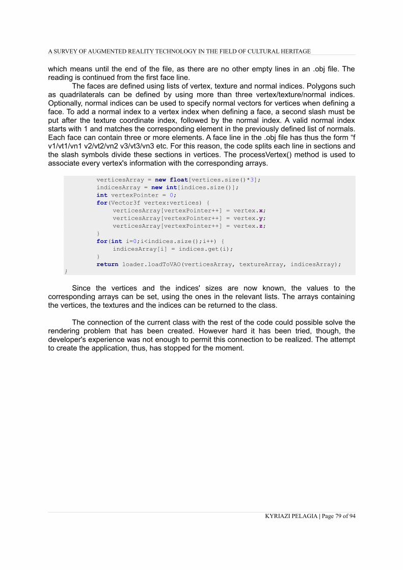
A SURVEY OF AUGMENTED REALITY TECHNOLOGY IN THE FIELD OF CULTURAL HERITAGE
which means until the end of the file, as there are no other empty lines in an .obj file. Thereading is continued from the first face line.
The faces are defined using lists of vertex, texture and normal indices. Polygons suchas quadrilaterals can be defined by using more than three vertex/texture/normal indices.Optionally, normal indices can be used to specify normal vectors for vertices when defining aface. To add a normal index to a vertex index when defining a face, a second slash must beput after the texture coordinate index, followed by the normal index. A valid normal indexstarts with 1 and matches the corresponding element in the previously defined list of normals.Each face can contain three or more elements. A face line in the .obj file has thus the form “fv1/vt1/vn1 v2/vt2/vn2 v3/vt3/vn3 etc. For this reason, the code splits each line in sections andthe slash symbols divide these sections in vertices. The processVertex() method is used toassociate every vertex's information with the corresponding arrays.
verticesArray = new float[vertices.size()*3]; indicesArray = new int[indices.size()]; int vertexPointer = 0; for(Vector3f vertex:vertices) { verticesArray[vertexPointer++] = vertex.x; verticesArray[vertexPointer++] = vertex.y; verticesArray[vertexPointer++] = vertex.z; } for(int i=0;i<indices.size();i++) { indicesArray[i] = indices.get(i); } return loader.loadToVAO(verticesArray, textureArray, indicesArray);}
Since the vertices and the indices' sizes are now known, the values to thecorresponding arrays can be set, using the ones in the relevant lists. The arrays containingthe vertices, the textures and the indices can be returned to the class.
The connection of the current class with the rest of the code could possible solve therendering problem that has been created. However hard it has been tried, though, thedeveloper's experience was not enough to permit this connection to be realized. The attemptto create the application, thus, has stopped for the moment.
KYRIAZI PELAGIA | Page 79 of 94

A SURVEY OF AUGMENTED REALITY TECHNOLOGY IN THE FIELD OF CULTURAL HERITAGE
4 . Results and Commentation
The last chapter's purpose is to conclude and sum up the important parts of the thesisand to present the application's results. Furthermore, future work that can be done to expandthe application will be discussed here.
4.1. Conclusions
The current thesis' purpose was to explain the term of Augmented Reality, framing itshistorical context and describing in detail its technology, and to describe its role in the field ofpreservation and presentation of the cultural heritage. In second place, the development ofan application has been attempted, to present a monument of great historical and theologicalsignificance. The first purpose has been achieved, while the second has been failed.
The application has been proved to be extremely complicated and time consuming.Internet, which is the source of every type of information, does not contain sufficient materialfor the familiarization with the particular subject of augmenting the reality using a smartphonedevice, as it does for other domains. The problems that have been emerged were strenuousto be faced in a logical timeframe. For all these reasons, the desired final result has not beenaccomplished.
Having said that, though, it is significant to point out the knowledge, understanding,capabilities and attitudes that have been developed during this incomplete applicationproduction. At the beginning of the procedure, the computer familiarity level was low,understanding code written in Java was impossible and handling 3D models' skills were atbasic degree. At the present moment, the comprehension level is high for all of the above.Taking into consideration that this is the actual goal of a thesis, the overall experience can beconsidered successful.
4.2. Application's results
Even though the application is not complete, it has already been said that theproblems start when the new 3D model has to be rendered. Until this point the code runsperfectly fine, tracking the image of Aedicule's floor-plan based on its natural features. Toshow how it was supposed to work, thus, the results acquired with the right image and thewrong object can be described and visualized.
Figure 27: Right image to be tracked (left) and wrong model (plane) to appear (right)
KYRIAZI PELAGIA | Page 80 of 94

A SURVEY OF AUGMENTED REALITY TECHNOLOGY IN THE FIELD OF CULTURAL HERITAGE
The way the program is designed, when the image is tracked the model is at firstplaced at a pose indicated by a file that contains information about all the digital objects thatare going to be superimposed on the image. Among the data provided there, the coordinates,the rotations and the dimensions of every item can be found and manually corrected.
The information provided are of the type
where x, y and z are the coordinates, ω, φ, and κ are the rotations around the X, Y and Zaxis and s1, s2 and s3 are the model's three dimensions.
It has been decided for the visualization of the results the trirectangular system ofcoordinates to be placed at the origins of the tracked image, meaning at the down left cornerof its borderline and the plane model to be located at the image's center, as it appears at thefirst image of figure 28. At this figure the table containing the values that have be given to theapplication for the placement of the plane model appear next to the relevant view thatdisplays on the camera. The coordinates of the point considered as the origins of the image(where the 3 axis are encountered) is (-12.0, -37.0, 0.0)
As it can be seen, when the smartphone'scamera's view is vertical the trackingprocedure is very effective, as thetrirectangular system of coordinatesappears exactly at the place where it shouldbe located. There is no way to check theplane's coordinates but this view will beused as a reference for the evaluation ofthe others.
The result when the distance from thetrackable image is increased is indicated inthis snapshot. The distance is about 1meter, which is the maximum distance fromwhich the model was superimposed. Itlooks like there are errors on thecoordinates but as the axes are locatedwhere they should be, it is probably anillusion created by the model's zcoordinate's value.
KYRIAZI PELAGIA | Page 81 of 94
[ x y zω φ κs1 s2 s3]
[15.0 100.0 100.00.0 0.0 0.0
15.0 15.0 15.0 ]
[15.0 100.0 100.00.0 0.0 0.015.0 15.0 15.0 ]

A SURVEY OF AUGMENTED REALITY TECHNOLOGY IN THE FIELD OF CULTURAL HERITAGE
An image taken by the minimum distance inwhich the superimposition is possibleappears here. The distance is about 5 cm.The size of the object in this case has beenchanged, so as the whole model to appearon the display. The results in this case werevery unstable, the object was constantlytrembling and the coordinates' error veryimportant.
In this case the maximum ω viewing angleis examined. As it can be seen, as the angleraises the coordinate's error raises too,especially in x axis, which has beensignificantly moved. The maximum valuebefore the model's disappearance has beenproved to be around 60 degrees.
On the same note, the maximum φ viewingangle is the next to be inspected. Theparadox here is that no error appears,instead of what happens in the previouscase. The maximum rotation possiblearound the Y axis is also around 60degrees.
The rotation around the z axis seems to bea problem rather bigger than what it wasexpected. At first it was considered as anerror arising from the z axis not being onthe perpendicular, but no matter howcarefully the procedure has been repeated,the result would not become any better thanthe one seen in the snapshot.
KYRIAZI PELAGIA | Page 82 of 94
[15.0 100.0 100.00.0 0.0 0.01.0 1.0 1.0 ]
[15.0 100.0 100.00.0 0.0 0.0
15.0 15.0 15.0 ]
[15.0 100.0 100.00.0 0.0 0.0
15.0 15.0 15.0 ]
[15.0 100.0 100.00.0 0.0 0.0
15.0 15.0 15.0 ]

A SURVEY OF AUGMENTED REALITY TECHNOLOGY IN THE FIELD OF CULTURAL HERITAGE
The current snapshot has been receivedfrom a random view, where there arerotations around all the three axes, and alsoenough distance from the object. The errorsare unsurprisingly big on x and ycoordinates, as it can be clearly seen whenthe position of the point of the axes'intersection is examined.
The last thing to be tested is how theapplication reacts in case of poor lightingconditions and occlusions. As it can beseen, even if part of the trackable image iscovered by shadows the model still appearson the screen and the errors emerging arenegligible. The same thing happened whena paper was used to partially cover thesurface.
Figure 28: Examples of the application's results
In all the cases described above, for the model's first appearance the camera had tovertically view the trackable image the distance between them had to be around 30 cm. Itwas also necessary not to have occlusion on the image. However, once the tracking hadbeen realized, it was possible to change all of these factors without having the object'sdisappearance as a result. Summing up the information learned from the tests, the model totally vanishes from theview in three cases. When the distance is less than 5 cm or more than 1 meter, when theviewing angle is more than 60 degrees or when the illumination is not adequate. However,even when these limits are kept, the closest the value is to them the lower the accuracy is.Moreover, in such an occasion the result becomes very unstable and the model cannot stayin one place.
4.3. Future work
First of all, for the application to run correctly two possible solutions exist. The firstone depends on the modifications that the developers of ARToolKit are eager to realize. If anew library, compatible to the rest of the code, takes the place of the problematic one, thenthe project is expected to well fine. The second solution is a brand-new renderer module tobe created, which is what has been tried with the construction of the OBJloader.Unfortunately, in this attempt the previous renderer kept on causing problems, as in the waythe original system has been built, it is really hard to totally delete a whole part of the codeand replace it with another. The methods and functions are mixed up, demanding expertise
KYRIAZI PELAGIA | Page 83 of 94
[15.0 100.0 100.00.0 0.0 0.0
15.0 15.0 15.0 ]
[15.0 100.0 100.00.0 0.0 0.015.0 15.0 15.0 ]

A SURVEY OF AUGMENTED REALITY TECHNOLOGY IN THE FIELD OF CULTURAL HERITAGE
to both Java language and native code, as well as to the way the development environment,in this case Android Studio, is designed. To acquire this type of expertise, a lot of time andoccupation is needed. The best technique for someone who is willing to dedicate his timewould be to start with the creation of simple projects and to progressively delve into it.
Once the application runs as it should, a lot of features could be added. A first idea isthe code to offer the possibility to stop the image on a specific shot and to zoom in and out.The user could use this operation to observe details on the model that are not possible to beseen from the original distance. Another facility could be the environment to be changed fromaugmented to digital when the user decides it. The digital environment would be composedby the model situated to its original place, in this case the museum of the Holy Sepulchre.Rotating the 3D model, the view of the museum would also change. In a virtual environmentit would be also interesting to be able to change the illumination and observe the objectunder different conditions. One more possibility could be to adjust a timeline with which theuser could interact, in order to admire the monument through different time periods, in real-time. Furthermore, hotspots could be added on significant parts of the Aedicule, which wouldcorrespond to information panels with textual and media content that the user could accessby touching them.
To bring all these ideas to life simultaneously, the computational power should be waytoo big, especially when compared with the current systems. However, as the technologyevolves, it is quite likely the hand-held devices like tablets or even smartphones to bepowerful enough to support such features in some years from now.
KYRIAZI PELAGIA | Page 84 of 94

A SURVEY OF AUGMENTED REALITY TECHNOLOGY IN THE FIELD OF CULTURAL HERITAGE
KYRIAZI PELAGIA | Page 85 of 94

A SURVEY OF AUGMENTED REALITY TECHNOLOGY IN THE FIELD OF CULTURAL HERITAGE
Reference List
(1) Abernathy, MF, Houchard, J, Puccetti, MG, and Lambert, JV (1993) 'Debris Correlation Usingthe Rockwell WorldView Simulation System', MIT Linkoln Laboratory Space SurveillanceWorkshop Proceedings, vol. 1, pp. 189-195.
(2) Alahi, A, Ortiz, R, Vandergheynst, P (2012) 'FREAK: Fast Retina Keypoint', in Proceedings ofthe 2012 IEEE Computer Society Conference on Computer Vision and Pattern Recognition,pp. 510-517.
(3) Azuma, R (1997) ‘A Survey of Augmented Reality’, in Presence: Teleoperators and VirtualEnvironments, vol. 6, no. 4, pp. 355-385.
(4) Banterle, F, Cardillo, FA, Malomo, L (2015) 'LecceAR: an augmented reality App for cultural heritage', In ERCIM News, vol. 2015, no. 103, pp. 16 - 17.
(5) Barrilleaux, J (1999) 'Experiences and Observations in Applying Augmented Reality to LiveTraining'.
(6) Bederson, B (1995) 'Audio augmented reality: a prototype automated tour guide', ConferenceCompanion on Human Factors in Computing Systems, pp. 210-211.
(7) Bell, B, Feiner, S, Höllerer, T (2001) 'View Management for Virtual and Augmented Reality',Proceedings of the 14th Annual ACM Symposium on User Interface Software and Technology,New York, USA, pp. 101–110.
(8) Billinghurst, M, Clark, A, Lee, G (2015) 'A Survey of Augmented Reality', The HumanInterface Technology Laboratory New Zealand, vol. 8, No 2-3, pp. 73-272.
(9) Bimber, O, Raskar, R, (2005) 'Spatial Augmented Reality Merging Real and Virtual Worlds',Ltd. Natick, MA, USA, pp. 71-90.
(10) Bimber, O, Raskar, R, (2006) 'Modern Approaches to Augmented Reality', MitsubishiElectric Research Laboratories, pp. 1-11.
(11) Bostanci, E, Kanwal, N, Ehsan, S, Clark, AF (2013) 'User tracking methods for augmentedreality', in International Journal of Computer Theory and Engineering, vol. 1, no. 5, pp. 93-98.
(12) Caudell, TP, Mizell, DW (1992) 'Augmented Reality: an application of heads-up displaytechnology to manual manufacturing processes', System Sciences, Proceedings of the Twenty-Fifth Hawaii Inernational Conference on, vol. 2, pp. 659-669.
(13) Chen, J, Pinz, A (2004) 'Structure and motion by fusion of inertial and vision-based tracking',in Proceedings of the 28th ÖAGM/AAPR Conference, vol. 179, pp. 55–62.
(14) Falk, J, Redström, J, Björk, S (1999) 'Amplifying Reality', 1st International Symposium ofHandheld and Ubiquitous Computing, Springer, Karlsruhe, Germany, pp. 274-280.
KYRIAZI PELAGIA | Page 86 of 94

A SURVEY OF AUGMENTED REALITY TECHNOLOGY IN THE FIELD OF CULTURAL HERITAGE
(15) Feiner, S, MacIntyre, B, Höllerer, T, Webster, A (1997) 'A touring machine: prototyping 3dmobile augmented reality systems for exploring the urban environment', IEEE InternationalSymposium on Wearable Computers, pp. 74–81.
(16) Fritz, F, Susperregui, A, Linaza, MT (2005) 'Enhancing Cultural Tourism experiences withAugmented Reality Technologies', in VAST05: The 6th International Symposium on VirtualReality, Archaeology and Cultural Heritage.
(17) Georgopoulos, A, Karras, G , Stergiopoulos, J (2001) 'Inverse Photogrammetry “anticipates”the future', in CIPA International Symposium, Potsdam.
(18) Heilig, M (1955) 'The Cinema of the Future', Presence, I (3), pp. 279-294.
(19) Helle, S, Salmi, H, Turunen, M, Woodward, C, Hehtonen, T (2017) 'MIRACLE Handbook:Guidelines for Mixed Reality Applications for Culture and Learning Experiences'.
(20) Holloway, RL (1995), 'Registration Errors in Augmenter Reality Systems', University ofNorth Carolina at Chapel Hill, pp. 199-205.
(21) Jokilehto, J (2005) 'Definition of Cultural Heritage, References to Documents in History',Originally for ICCROM, 1990.
(22) Keil, J, Pujol, L, Roussou, M, Engelke, T, Schmitt, M, Eleftheratou, S (2013) 'A digital lookat physical museum exhibits Designing personalized stories with handheld Augmented Realityin museums', in Conference: Digital Heritage International Congress, Marseille, Vol. 2
(23) Keil, J, Zollner, M, Becker, M , Wientapper, F, Engelke, T , Wuest, H (2011) 'The house ofOlbrich - an augmented reality tour through architectural history, In Proceedings of the 2011IEEE International Symposium on Mixed and Augmented Reality – Arts, Media andHumanities, pp. 15-18, IEEE.
(24) Klein, G (2006) 'Visual Tracking for Augmented Reality - PhD Thesis', in University ofCambridge.
(25) Kooper, R, MacIntyre, B (2003) 'Browsing the Real-World Wide Web: MaintainingAwareness of Virtual Information in an AR Information Space', International Journal ofHuman-Computer Interaction, vol. 16, no. 3, pp. 425–446.
(26) Lepetit, V, Berger, M-O (2001) 'An Intuitive Tool For Outlining Objects in Video Sequences:Applications to Augmented and Diminished Reality', Proceedings of International Symposiumon Mixed Reality (ISMAR), pp. 1-2.
(27) Low, K, Welch, G, Lastra, A Fuchs, H (2001) 'Life-Sized Projector-Based Dioramas', In ACMSymposium on Virtual Reality Software and Technology, Banff, Alberta, Canada, November2001, pp. 161–168.
(28) Magnenat-Thalmann, N, Papagiannakis, G. (2010) 'Recreating Daily life in Pompeii', inVirtual Archeology Review, vol. 1, no. 2, pp. 19-23.
(29) Mann, S (2002) 'Mediated Reality with implementations for everyday life', Presence:
KYRIAZI PELAGIA | Page 87 of 94

A SURVEY OF AUGMENTED REALITY TECHNOLOGY IN THE FIELD OF CULTURAL HERITAGE
Teleoperators and Virtual Environments, vol. 11, no. 2, pp. 158-175.
(30) Mehling, M (2006) 'Implementation of a Low Cost Marker Based Infrared Optical TrackingSystem - PhD Thesis', in Fachhochschule Stuttgart.
(31) Milgram, P, Kishino, F (1994) 'A Taxonomy of Mixed Reality Visual Displays', IEICETransactions on Information Systems, vol. E77-D, no. 12, pp. 1321-1329.
(32) Möhring, M, Lessig, L, Bimber, O (2004) 'Optican Tracking and Video see-Through AR onConsumer Cell-Phones', Proceedings of International Symposium on Augmented and MixedReality (ISMAR '04), pp. 252-253.
(33) Moropoulou, A, Korres, Em, Georgopoulos, A, Spyrakos, C, Mouzakis, Ch (2017) 'Faithful Rehabilitation of the Holy Tomb of Christ', in Journal of ASCE, November 2017, pp. 54-78
(34) Neumann, U, You, S, Cho, Y, Lee, J, Park, J (1999) 'Augmented reality tracking in naturalenvironments', in International Symposium on Mixed Reality.
(35) Papagiannakis, G, Ponder, M, Molet, T, Kshirsagar, S, Cordier, F, Magnenat-Thalmann, N,Thalmann, D (2002) 'LIFEPLUS: Revival of life in ancient Pompeii', in Proceedings of the8th International Conference on Virtual Systems and Multimedia (VSMM’02), pp. 25-27.
(36) Pujol, L, Roussou, M, Poulou, S, Balet, O, Vayanou, M, Ioannidis, Y (2012) 'Personalizinginteractive digital storyteeling in archaeological museums: the CHESS project', In 40th AnnualConference of Computer Applications and Quantitative Methods in Archaeology, AmsterdamUniversity Press.
(37) Rambach, J, Pagani, A, Schneider, M, Artemenko, O, Stricker, D (2017), '6DoF ObjectTracking based on 3D Scans for Augmented Reality Remote Live Support', in Basel,Switzerland.
(38) Raskar, R, Welch, G, Cutts, M, Lake, A, Stesin, L, Fuchs, H (1998) 'The Office of the Future:A Unified Approach to Image-Based Modeling and Spatially Immersive Displays', ComputerGraphics Proceedings, Annual Conference Series, pp. 179-188.
(39) Reitmayr, G, Drummond, TW (2006) 'Going out: Robust Tracking for OutDoor AugmentedReality', Proceedings of the 5th IEEE and ACM International Symposium on, pp. 109-118.
(40) Rosenberg, LB (1993) 'Virtual fixtures: Perceptual tools for telerobotic manipulation',Proceedings of the IEEE Annual International Symposium on Virtual Reality, pp. 76–82.
(41) Rekimoto, J, Ayatsuka, Y (2000) 'CyberCode: designing augmented reality environments withvisual tags', Proceedings of DARE 2000 on designing Augmented Reality enironments, pp. 1-10.
(42) Rekimoto, J, Nagao, K (1995) 'The world through the computer: Computer augmentedinteraction with real world environments' Proceedings of the 8th Annual ACM Symposium onUser Interface and Software Technology, New York, USA, pp. 29–36.
(43) Ruiz, R (2004) 'Augmented reality used to recreate a Mayan funeral chamber', in Valencia,Spain.
KYRIAZI PELAGIA | Page 88 of 94

A SURVEY OF AUGMENTED REALITY TECHNOLOGY IN THE FIELD OF CULTURAL HERITAGE
(44) Siltanen, S (2012) 'Theory and applications of marker-based augmented reality'.
(45) Starner, T, Mann, S, Rhodes, BJ, Levine, J, Healey, J, Kirsch, D, Picard, RW, Pentland, A(1997) 'Augmented reality through wearable computing', Presence: Teleoperators and VirtualEnvironments, vol. 6, no. 4, pp. 386–398.
(46) Strand, TER (2008) 'Tracking for Outdoor Mobile Augmented Reality - Further developmentof the Zion Augmented Reality Application', in Norwegian University of Science andTecknology.
(47) Sutherland, I (1965) 'The Ultimate Display', in Proceedings of the IFIP Congress.
(48) Sutherland, I (1968) 'A Head-Mounted three-dimensional Display', Proceedings of the FallJoint Computer Conference, San Francisco, California, pp. 757-764.
(49) Thomas, B, Close, B, Donoghue, J, Squires, J, De Bondi, P, Piekarski, W (2002) 'First PersonIndoor/Outdoor Augmented Reality Application: ARQuake', Personal and UbiquitousComputing, vol. 6, no. 1, pp. 75-86.
(50) Thomas, B, Demczuc, V, Piekarski, W, Hepworth, D, Gunther, B (1998) 'A WearableComputer System with Augmented Reality to Support Terrestrial Navigation', in Proceedings2nd International Symposium on Wearable Computers, pp. 168-171.
(51) Vlahakis, V, Karigiannis, J, Tsotros, M, Gounaris, M, Almeida, L, Stricker, D, Gleue, T,Christou, IT, Carlucci, R and Ioannidis, N (2001) 'Archeoguide: First results of an augmentedreality, mobile computing system in cultural heritage sites', in Proceedings of the 2001Conference on Virtual Reality, Archeology, and Cultural Heritage, VAST ’01, (New York, NY,USA), pp. 131–140.
(52) Welch, G, Bishop, G, Vicci, L, Brumback, S, Keller, K, Colucci, D (2001) 'High-performancewide-area optical tracking: The hiball tracking system', in Presence: Teleoperators and VirtualEnvironments, pp. 1–22, 2001.
(53) Zoellner, M, Stricker, D, Bleser, G, Pastarmov, Y (2007) 'iTACITUS – Novel Interaction andTracking Paradigms for Mobile AR'.
(54) Zöllner, M, Keil, J, Wuest, H, Pletinckx, D (2009) 'An Augmented Reality PresentationSystem for Remote Cultural Heritage Sites', In Short and Project Papers Proceedings,University of Malta, pp. 112-116. sel 46
(55) A tutorial on binary descriptors – part 4 – The BRISK descriptor (Last Modified:08/09/2013), Available at: https://gilscvblog.com/2013/11/08/a-tutorial-on-binary-descriptors-part-4-the-brisk-descriptor/ (Last Accessed: 18/03/2018)
(56) A tutorial on binary descriptors – part 5 – The FREAK descriptor (Last Modified:09/12/2013), Available at: https://gilscvblog.com/2013/12/09/a-tutorial-on-binary-descriptors-part-5-the-freak-descriptor/ (Last Accessed: 18/03/2018)
(57) An Introduction to Simultaneous Localisation and Mapping (Last Modified: 13/05/2016),
KYRIAZI PELAGIA | Page 89 of 94

A SURVEY OF AUGMENTED REALITY TECHNOLOGY IN THE FIELD OF CULTURAL HERITAGE
Available at: https://www.kudan.eu/kudan-news/an-introduction-to-slam/ (Last Accessed:14/03/2018)
(58) Article “Eye Am a Camera” (2012), Available at: http://techland.time.com/2012/11/02/eye-am-a-camera-surveillance-and- sousveillance-in-the-glassage/ (Last Accessed: 11/01/2017)
(59) ARToolKit (Last modified: October 2016), Available at: https://en.wikipedia.org/wiki/ARToolKit (Last Accessed: 11/01/2017)
(60) ARToolKit documentation (Last Modified:2016), Available at: https://artoolkit.org/documentation/ (Last Accessed: 18/01/2017)
(61) ARToolKit GitHub page (Last Modified: 2017), Available at: https://github.com/artoolkit (Last Accessed: 18/01/2017)
(62) ARToolKit Home Page - Human Interface Technology Laboratory, Available at:https://www.hitl.washington.edu/artoolkit/publications/ (Last Accessed: 20/03/2018)
(63) Augmented Reality (Last modified: September 2012), Available at: http://wiki.csisdmz.ul.ie/wiki/Augmented_reality (Last Accessed: 11/01/2017)
(64) Augmented Reality (Last modified: January 2017), Available at: https://en.wikipedia.org/wiki/Augmented_reality (Last Accessed: 11/01/2017)
(65) Augmented Reality in Education (Last Modified: 2018), Available at:https://thinkmobiles.com/blog/augmented-reality-education/ (Last accessed: 14/03/2018)
(66) Beit Emmett: Holy Sepulchre, Succot and Hezekiah's Tunnel (Last Modified: 05/10/2009),Available at: http://beitemmett.blogspot.gr/2009/10/holy-sepulchre-succot-and-hezekiahs.html(Last accessed: 20/03/2018)
(67) Bionic contact lens (Last Modified: December 2016), Available at: https://en.wikipedia.org/wiki/Bionic_contact_lens (Last Accessed: 11/01/2017)
(68) BRIEF (Binary Robust Independent Elementary Features) (Last modified: 2013), Available at: https://en.wikipedia.org/wiki/Oriented_FAST_and_rotated_BRIEF (Last Accessed: 18/03/2018)
(69) Bringing the past and future to life with Digital Placemaking AR Binoculars (Last Modified:26/10/2017), Available at: http://zubr.co/augmented-reality-binoculars/ (Last Accessed:14/03/2018)
(70) Christian Classics Ethereal Library (Last Modified: 13/07/2005), Available at:http://www.ccel.org/ccel/schaff/npnf202.ii.iv.xvii.html (Last Accessed: 14/03/2018)
(71) Church of the Holy Sepulchre (Last Modified: 14/03/2018), Available at:https://en.wikipedia.org/wiki/Church_of_the_Holy_Sepulchre (Last Accessed: 14/03/2018)
(72) Church of the Holy Sepulchre, Jerusalem (Last Modified: 2018), Available at:http://www.sacred-destinations.com/israel/jerusalem-church-of-holy-sepulchre
KYRIAZI PELAGIA | Page 90 of 94

A SURVEY OF AUGMENTED REALITY TECHNOLOGY IN THE FIELD OF CULTURAL HERITAGE
(Last Accessed: 14/03/2018)
(73) Dissecting the Camera Matrix, Part 2: The Extrinsic Matrix (Last modified: 22/08/2012),Available at: http://ksimek.github.io/2012/08/22/extrinsic/ (Last Accessed: 20/03/2018)
(74) Dissecting the Camera Matrix, Part 3: The Intrinsic Matrix (Last modified: 13/08/2013),Available at: http://ksimek.github.io/2013/08/13/intrinsic/ (Last Accessed: 20/03/2018)
(75) DRAKERZ : Augmented Reality Trading Card Game (Last modified: 19/05/2014), Availableat: http://www.f2pmmogs.com/drakerz-confrontation/ (Last Accessed: 20/03/2018)
(76) Features of a Computer (Last modified: 2015), Available at:http://www.agriinfo.in/default.aspx?page=topic&superid=8&topicid=1703 (Last Accessed: 18/03/2018)
(77) Fudzila (Last Updated: January 2016), Available at: http://www.fudzilla.com/news/graphics/39762-nvidia-shows-off-its-light-field-vr-headset-at-vrla-2016 (Last Accessed: 11/01/2017)
(78) History of Information (Last Updated: December 2016), Available at: http://www.historyofinformation.com/expanded.php?id=4698 (Last Accessed: 11/01/2017)
(79) Hololens (Last Modified: January 2017), Available at: https://en.wikipedia.org/wiki/Microsoft_HoloLens (Last Accessed: 11/01/2017)
(80) International Symposium on Mixed and Augmented Reality (Last modified: 09/2016), Available at: https://en.wikipedia.org/wiki/International_Symposium_on_Mixed_and_Augmented_Reality (Last Accessed: 11/01/2017)
(81) Hartley, R, Zisserman, A (1999) 'Multiple View Geometry', Available at: http://users.cecs.anu.edu.au/~hartley/Papers/CVPR99-tutorial/tut_4up.pdf (Last Accessed: 18/03/2018)
(82) Konstruct (2011), Available at: http://apps.augmatic.co.uk/konstruct (Last Accessed: 11/01/2017)
(83) Google Glass (Last Modified: December 2016), Available at: (https://en.wikipedia.org/wiki/Google_Glass (Last Accessed: 11/01/2017)
(84) Graphics Cards: Integrated vs. Dedicated (Last modified: 2018), Available at:http://www.toptenreviews.com/computers/articles/graphics-cards-integrated-vs.-dedicated/(Last Accessed: 18/03/2018)
(85) Guide to smartphone hardware (1/7) Processors, Available at:https://lingualeo.com/ru/jungle/guide-to-smartphone-hardware-1-7-processors-83954#/page/1(Last Accessed: 18/03/2018)
(86) Guide to smartphone hardware (2/7): Graphics (Last modified: 21/02/2012), Available at:https://www.neowin.net/news/guide-to-smartphone-hardware-27-graphics-2 (Last Accessed:
KYRIAZI PELAGIA | Page 91 of 94
http://www.fudzilla.com/news/graphics/39762-nvidia-shows-off-its-light-field-vr-headset-at-vrla-2016

A SURVEY OF AUGMENTED REALITY TECHNOLOGY IN THE FIELD OF CULTURAL HERITAGE
18/03/2018)
(87) Guide to smartphone hardware (3/7): Memory and Storage (Last modified: 12/03/2012),Available at: https://www.neowin.net/news/guide-to-smartphone-hardware-37-memory-and-storage (Last Accessed: 18/03/2018)
(88) Guide to smartphone hardware (4/7): Displays (Last modified: 26/05/2012), Available at:https://www.neowin.net/news/guide-to-smartphone-hardware-47-displays (Last Accessed:18/03/2018)
(89) How to choose a digital camera (Last modified: 2015), Available at:http://users.wfu.edu/matthews/misc/DigPhotog/start/camera.html (Last Accessed: 18/03/2018)
(90) IKEA catalog uses augmented reality to give a virtual preview of furniture in a roomhttps://newatlas.com/ikea-augmented-reality-catalog-app/28703/#gallery
(91) Industrial Augmented Reality (Last Modified: December 2016), Available at: https://en.wikipedia.org/wiki/Industrial_augmented_reality (Last Accessed: 11/01/2017)
(92) Issues · artoolkit/artoolkit5 · GitHub (Last modified: -), Available at:https://github.com/artoolkit/artoolkit5/issues/166 (Last Accessed: 18/03/2018)
(93) ITPRO - IBM showcases augmented reality shopping app (2013), Available at: http://www.itpro.co.uk/apps/19376/ibm-showcases-augmented-reality-shopping-app (Last Accessed: 11/01/2017)
(94) Java (programming language) (Last modified: 14/03/2018), Available at:https://en.wikipedia.org/wiki/Java_(programming_language)#Android (Last Accessed:18/03/2018)
(95) Java Programming Tutorial - Java Native Interface (JNI) (Last modified: 03/2018), Availableat:https://www3.ntu.edu.sg/home/ehchua/programming/java/JavaNativeInterface.html#zz-3.(Last Accessed: 18/03/2018)
(96) KARMA, Available at: http://monet.cs.columbia.edu/projects/karma/karma.html (Last Accessed: 11/01/2017)
(97) Kinect (Last Modified: January 2017), Available at: https://en.wikipedia.org/wiki/Kinect (Last Accessed: 11/01/2017)
(98) Layar (Last Modified: November 2016), Available at: https://en.wikipedia.org/wiki/Layar (Last Accessed: 11/01/2017)
(99) Lunettes See-through (in french), Available at: http://www.see-through.narvaya.fr/limites.html (Last Accessed: 11/01/2017)
(100) Map and Virtual Tour - Holy Sepulchre, Available at:http://www.sepulchre.custodia.org/default.asp?id=4098 (Last Accessed: 14/03/2018)
KYRIAZI PELAGIA | Page 92 of 94

A SURVEY OF AUGMENTED REALITY TECHNOLOGY IN THE FIELD OF CULTURAL HERITAGE
(101) Microsoft Hololens, Available at: https://en.wikipedia.org/wiki/Microsoft_HoloLens (Last Accessed: 20/03/2018)
(102) Mixed Reality – Open Source, Available at: http://trc.utu.fi/ar/research/open-source/ (LastAccessed: 20/03/2018)
(103) Most Popular and Influential Programming Languages of 2018 (Last modified:18/12/2017), Available at: https://stackify.com/popular-programming-languages-2018/ (LastAccessed: 18/03/2018)
(104) Motherboard (Last modified: 14/03/2018), Available at: https://en.wikipedia.org/wiki/Motherboard (Last Accessed: 18/03/2018)
(105) Oriented FAST and rotated BRIEF (Last modified: 20/11/2017), Available at:https://en.wikipedia.org/wiki/Oriented_FAST_and_rotated_BRIEF (Last Accessed:18/03/2018)
(106) Photoelectric Sensors | OMRON Industrial Automation (Last modified: 2018), Available at:https://www.ia.omron.com/support/guide/43/introduction.html (Last Accessed: 20/03/2018)
(107) Pokémon Go (Last Modified: January 2017), Available at: https://en.wikipedia.org/wiki/Pok%C3%A9mon_Go (Last Accessed: 11/01/2017)
(108) Processor (computing) (Last modified: January 2017), Available at: https://en.wikipedia.org/wiki/Processor_(computing) (Last Accessed: 11/01/2017)
(109) Real-time 3D flight guidance (1999), Available at: http://adsabs.harvard.edu/abs/1999SPIE.3691..149D (Last Accessed: 11/01/2017)
(110) Resurrection of Jesus (Last modified: 12/03/2018), Available at: https://en.wikipedia.org/wiki/Resurrection_of_Jesus (Last Accessed: 14/03/2018)
(111) Samsung Galaxy A5 - Full phone specifications (Last modified: 2014), Available at:https://www.gsmarena.com/samsung_galaxy_a5-6761.php (Last Accessed: 18/03/2018)
(112) Scale-invariant feature transform (Last modified: 15/02/2018), Available at:https://en.wikipedia.org/wiki/Scale-invariant_feature_transform (Last Accessed: 18/03/2018)
(113) Smartphones Unlocked: Understanding processors (Last modified: 08/08/2011), Availableat: https://www.cnet.com/news/smartphones-unlocked-understanding-processors/ (LastAccessed: 18/03/2018)
(114) Social Compare – Augmented Reality SDK comparison (Last update: January 2017), Available at: http://socialcompare.com/en/comparison/augmented-reality-sdks (Last Accessed:17/01/2017)
(115) Speeded up robust features (Last modified: 20/08/2017), Available at: https://en.wikipedia.org/wiki/Speeded_up_robust_features (Last Accessed: 18/03/2018)
(116) Tango (platform) (Last modified: 24/02/2018), Available at:https://en.wikipedia.org/wiki/Tango_(platform) (Last Accessed: 20/03/2018)
KYRIAZI PELAGIA | Page 93 of 94

A SURVEY OF AUGMENTED REALITY TECHNOLOGY IN THE FIELD OF CULTURAL HERITAGE
(117) Temple of Resurrection (in greek) (Last Modified: 06/06/2018), Available at:https://el.wikipedia.org/wiki/%CE%9D%CE%B1%CF%8C%CF%82_%CF%84%CE%B7%CF%82_%CE%91%CE%BD%CE%B1%CF%83%CF%84%CE%AC%CF%83%CE%B5%CF%89%CF%82 (Last Accessed: 14/03/2018)
(118) Terence Eden's Blog (Last Modified: 2017), Available at: https://shkspr.mobi/blog/2010/11/augmented-reality-games-how-far-have-we-come-in- 7-years/ (Last Accessed: 11/01/2017)
(119) The Holy Edicule – Jerusalem Patriarchate, Available at: http://www.jerusalem-patriarchate.info/main/eng/page/ %CE%B9%CE%B5%CF%81%CE%BF-%CE%BA%CE%BF%CF%85%CE%B2%CE%BF%CF%85%CE%BA%CE%BB%CE%B9%CE%BF (LastAccessed: 14/03/2018)
(120) The invisible train (2004-2005), Available at: https://studierstube.icg.tugraz.at/invisible_train/ (Last Accessed: 11/01/2017)
(121) The Most Popular Programming Languages of 2016 (Last modified: 18/08/2016), Availableat: https://blog.newrelic.com/2016/08/18/popular-programming-languages-2016-go/ (LastAccessed: 18/03/2018)
(122) Tinmith – mobile outdoor augmented reality (Last Updated: 2016), Available at: http://www.tinmith.net/ (Last Accessed: 11/01/2017)
(123) U.S. Naval research Laboratory, Available at: https://www.nrl.navy.mil/itd/imda/research/5581/augmented-reality (Last Accessed: 11/01/2017)
(124) Venice Charter (Last Modified: January 2017), Available at: https://en.wikipedia.org/wiki/Venice_Charter (Last Accessed: 11/01/2017)
(125) Videoplace (Last Updated: November 2014), Available at: https://en.wikipedia.org/wiki/Videoplace (Last Accessed: 11/01/2017)
(126) Virtual Reality (Last Modified: January 2017), Available at: https://en.wikipedia.org/wiki/Virtual_reality (Last Accessed: 11/01/2017)
(127) Wikitude (Last Modified: January 2017), Available at: https://en.wikipedia.org/wiki/Wikitude (Last Accessed: 11/01/2017)
(128) Wikitude: Un logiciel de navigation en réalité augmentée (in french) , Available at: http://sensebook.reaco.fr/blog/realite-augmentee/wikitude-un-logiciel-de-navigation-en-realite-augmentee/ (Last Accessed: 11/01/2017)
KYRIAZI PELAGIA | Page 94 of 94