A Special Multi-Pulse Converter with Small Active Power Filter
7
A Special Multi-Pulse Converter with Small Active Power Filter Piotr Mysiak, Ryszard Strzelecki, Member, IEEE, and Daniel Wojciechowski Abstract--The article presents the principle of operation and results of laboratory and simulation tests of a multi-pulse power network converter systems with direct-current voltage output, mating with shunt active power filter (APF). The discussed systems allow for significant reduction of undesirable higher harmonics in the power network current, including the elimination of harmonics of an order of 23 and 25, especially in the local power network supply conditions. The multi-pulse nature of operation of the system is obtained using set of coupled three-phase power network reactors (CTR). Index Terms--Active power filters, coupled three-phase power network reactors, local power network, multi-pulse power network converters, power conditioning. I. SYSTEM DESCRIPTION T he project is concerned with a current topic of power-electronic conversion of the alternate current power drawn from a supply line, without negative effect of the converter on this line [4]. Along with more and more popular converters realised with the aid of full- control semiconductor elements, such as power transistors and GTO thyristors, controlled by using modulation techniques applied to pulse width, there is a possibility to build power-electronic converters, which convert the energy of the alternate current into that of the direct current with the aid of a set of properly paired coupled reactors installed between the supply line and the semiconductor rectifier. Proper magnetic pairings and proper pairing of reactor windings makes it possible to convert the three-phase voltage system of the supply line into the system with a larger number of phases without the use of transformers. At the same time, the power of the three-phase coupled reactors is several times lower than that of classical converter transformers. Minimisation of the supply line current deformation is obtained by using a system of coupled power network reactors, the task of which is to increase the number of phases of the converter input voltage with the aid of diodes or conventional thyristors. P. Mysiak is with the Department of Ship Automation, Gdynia Maritime Academy, 81-225 Gdynia, Poland (e-mail: mysiakA,am.gdynia.pl) D. Wojciechowski is with the Department of Ship Automation, Gdynia Maritime Academy, 81-225 Gdynia, Poland (e-mail: dwojcA,am.gdynia.pl). R. Strzelecki is with the Department of Ship Automation, Gdynia Maritime Academy, 81-225 Gdynia, Poland (e-mail: rstrzele am. gdynia. p1). 1-4244-1055-X/07/$25.00 2007 IEEE. The coupled reactors play here a similar role to that of the converter transformers revealing a complicated system of secondary windings; however the power of the reactors is several times smaller. To improve the system power factor and THD coefficient, the small shunt active power filter was implemented by using a three-phase voltage-source IGBT inverter. The filter was also applied to the multi-pulse converter with CTR. The harmonic content, and reactive power absorption of described converter system are sagnificantly reduced by both CTR and shunt active filter. This shunt active power filter is composed of two distinct elements: 1) the PWM converter (power circuit) 2) the active filter controller. In order to reproduce accurately the compensating currents, the PWM converter should have a high switching rate. Normally, f PWM > 1Of .ax , where f .ax represents the frequency of the highest load current harmonic to be compensated. Both voltage-source (VSI) [1] and current-source (CSI) inverters can be used to implement a shunt active filter. Although they are similar to the PWM inverters used for ac motor drives, unlike the PWM inverters for shunt active filters, which must behave as a non-sinusoidal current source, almost all shunt active filters in commercial operation use voltage- source inverters. All experimental results presented in this work were obtained from a prototype realized with a VSI. Fig.la shows the basic configuration of a shunt active filter [8], [9]. It comprises a voltage-source inverter (VSI) with PWM current control (hysteresis control) and an active filter controller that realizes almost instantaneous control algorithm. The shunt active filter works in a closed-loop manner, sensing continuously the load current iL and calculating the instantaneous values of the compensating current reference i*k for the PWM converter. If the switching ratio of the PWM converter is high enough, the current ik will contain high frequency harmonics, that can be easily filtered out using small high-pass filters. In an ideal case, the PWM converter may be considered as a linear power amplifier, where the compensating current ik tracks strictly its reference i*k. The control algorithm implemented in the shunt active filter controller determines the compensation characteristics of the shunt active filter. Fig. lb presents a basic concept of a 12-pulse converter, in which the use of three-phase coupled reactors with shunt active filter allows for generation of two phase- shifted systems of three-phase voltages making the input parameters for two 6-pulse rectifiers. For the time being, examples discussed in the literature mostly apply similar
-
Upload
independent -
Category
Documents
-
view
2 -
download
0
Transcript of A Special Multi-Pulse Converter with Small Active Power Filter

A Special Multi-Pulse Converter with Small ActivePower Filter
Piotr Mysiak, Ryszard Strzelecki, Member, IEEE, and Daniel Wojciechowski
Abstract--The article presents the principle of operation andresults of laboratory and simulation tests of a multi-pulsepower network converter systems with direct-currentvoltage output, mating with shunt active power filter (APF).The discussed systems allow for significant reduction ofundesirable higher harmonics in the power networkcurrent, including the elimination of harmonics of an orderof 23 and 25, especially in the local power network supplyconditions. The multi-pulse nature of operation of thesystem is obtained using set of coupled three-phase powernetwork reactors (CTR).
Index Terms--Active power filters, coupled three-phasepower network reactors, local power network, multi-pulsepower network converters, power conditioning.
I. SYSTEM DESCRIPTION
T he project is concerned with a current topic ofpower-electronic conversion of the alternate currentpower drawn from a supply line, without negative
effect of the converter on this line [4]. Along with moreand more popular converters realised with the aid of full-control semiconductor elements, such as powertransistors and GTO thyristors, controlled by usingmodulation techniques applied to pulse width, there is apossibility to build power-electronic converters, whichconvert the energy of the alternate current into that of thedirect current with the aid of a set of properly pairedcoupled reactors installed between the supply line and thesemiconductor rectifier. Proper magnetic pairings andproper pairing of reactor windings makes it possible toconvert the three-phase voltage system of the supply lineinto the system with a larger number of phases withoutthe use of transformers. At the same time, the power ofthe three-phase coupled reactors is several times lowerthan that of classical converter transformers.Minimisation of the supply line current deformation isobtained by using a system of coupled power networkreactors, the task of which is to increase the number ofphases of the converter input voltage with the aid ofdiodes or conventional thyristors.
P. Mysiak is with the Department of Ship Automation, GdyniaMaritime Academy, 81-225 Gdynia, Poland (e-mail:mysiakA,am.gdynia.pl)
D. Wojciechowski is with the Department of Ship Automation,Gdynia Maritime Academy, 81-225 Gdynia, Poland (e-mail:dwojcA,am.gdynia.pl).
R. Strzelecki is with the Department of Ship Automation, GdyniaMaritime Academy, 81-225 Gdynia, Poland (e-mail:rstrzele am.gdynia. p1).1-4244-1055-X/07/$25.00 2007 IEEE.
The coupled reactors play here a similar role to that ofthe converter transformers revealing a complicatedsystem of secondary windings; however the power of thereactors is several times smaller. To improve the systempower factor and THD coefficient, the small shunt activepower filter was implemented by using a three-phasevoltage-source IGBT inverter. The filter was also appliedto the multi-pulse converter with CTR. The harmoniccontent, and reactive power absorption of describedconverter system are sagnificantly reduced by both CTRand shunt active filter. This shunt active power filter iscomposed oftwo distinct elements:1) the PWM converter (power circuit)2) the active filter controller.
In order to reproduce accurately the compensatingcurrents, the PWM converter should have a highswitching rate. Normally, f PWM > 1Of .ax , where f .axrepresents the frequency of the highest load currentharmonic to be compensated. Both voltage-source (VSI)[1] and current-source (CSI) inverters can be used toimplement a shunt active filter. Although they are similarto the PWM inverters used for ac motor drives, unlike thePWM inverters for shunt active filters, which mustbehave as a non-sinusoidal current source, almost allshunt active filters in commercial operation use voltage-source inverters. All experimental results presented inthis work were obtained from a prototype realized with aVSI. Fig.la shows the basic configuration of a shuntactive filter [8], [9]. It comprises a voltage-sourceinverter (VSI) with PWM current control (hysteresiscontrol) and an active filter controller that realizes almostinstantaneous control algorithm. The shunt active filterworks in a closed-loop manner, sensing continuously theload current iL and calculating the instantaneous values ofthe compensating current reference i*k for the PWMconverter. If the switching ratio of the PWM converter ishigh enough, the current ik will contain high frequencyharmonics, that can be easily filtered out using smallhigh-pass filters. In an ideal case, the PWM convertermay be considered as a linear power amplifier, where thecompensating current ik tracks strictly its reference i*k.The control algorithm implemented in the shunt activefilter controller determines the compensationcharacteristics of the shunt active filter.Fig. lb presents a basic concept of a 12-pulse converter,in which the use of three-phase coupled reactors withshunt active filter allows for generation of two phase-shifted systems of three-phase voltages making the inputparameters for two 6-pulse rectifiers. For the time being,examples discussed in the literature mostly apply similar

12-pulse system, however with no active filters fordoubling the numbers of input voltage phases in voltageinverters supplying induction machines. Moreover, theliterature has not yet provided either detailed analysisconcerned with operation of such a system, or guidesconcerning its design algorithms. Unlikely previouslydiscussed examples, this project included the analysis,which further constituted the basis for designing the 12-pulse system and allowed for analyzing the effect ofsupply line parameters, including its impedance, on theoperation of the system. The researchers also developed afragment of the general theory of improved systems withcoupled reactors, which allowed synthesis of systemswith increased numbers of voltage phases. Simulationtests were carried out to examine the possibility of theuse of the system as a supply source in intermediatefrequency converters for voltage inverters.
a)
b)
Fig. 1: Basic configuration of the shunt active filter (a) and schematicdiagram of 12-pulse diode rectifier with CTR coupled reactor systemand shunt active power filter (b).
The methods for described system examination includedtheoretical analysis, simulation tests and model tests of a
real converter containing two 6-valve bridge systemssupplied from a three-phase power network via a systemof shunt active filter with coupled three-phase power
network reactors. As it was expected, the currents drawnfrom the supply line had almost a sine form, of course nottypical form of classical 12-pulse rectifiers, realised usingthree-phase converters. The test results not only can beused for verification of the developed design algorithmsfor the examined class of converters, they also allow forstudying possibilities of application of the examinedconverter in the direct and alternate current drivingsystems. Because of the requirement of high reliabilitylevel they can be used especially in the marineapplications.The overall project aimed at developing a design methodfor power-electronic converters that would convertalternate voltage into one-way voltage, and would beequipped with a system of three-phase coupled reactorshaving the form close to a sine curve, which secureconsumption of the current. The project includedsimulation and laboratory tests, for which a laboratorymodels of a 2-kVa 12-pulse and 24-pulse converterssystems with shunt active filter were designed andconstructed. The realisation of the project has made itpossible to formulate a more precise theory of anddevelop a design methodology for power-electronicconverters used for converting the energy of the alternatecurrent into that of the direct current. A significantfeature of these converters is reduced consumption of thedeformation power.The essential issues associated with the realisation of theabove indicated research tasks included:* Developing a mathematical model of the system and
determining analytical and synthesizing relations thatallow formulation of a design procedure for aconverter which would consist of a system of three-phase coupled reactors, two in-parallel paired rectifierbridges and shunt active power filter
* Working out a simulation model and carrying ourdetailed simulation tests of the system, to create thebasis for verification of the theoretical results andfinal formulation of the conditions to be met by amagnetic system of reactors and the set of properlyconfigured power semiconductor elements
* Experimental verification of the results of thetheoretical analysis and simulation tests,complemented by the interpretation of the obtainedresults.
The 12-pulse diode rectifier presented in the Fig. lb issupplied from a three-phase power network with thephase voltage U. (n=a,b,c). The input circuit of theconverter comprises linear power network reactors Ls,Ld, shunt active filter and coupled three-phase powernetwork reactor CTR. Input terminals of the reactor CTRare connected with the supply network terminals throughlinear reactors Ls, Ld. Output terminals of the reactorCTR are, in turn, connected with phase limbs of twothree-phase diode bridge systems. Direct-currentterminals of all bridge systems are connected in parallelto the filtering capacitor having the capacitance Co. Thetask of the set of the coupled reactors is to generate threealternating voltages Ukf, of which waveforms take the

sine shape when idling and the 12-step shape at load akclose to nominal. Voltages Uk1, measured with respect to 3the input circuit star point N, can be interpreted as the 21quantities created in result of cyclic starts of the direct 1current voltage 2Ed, via the valves of two bridges. uRequired condition to be met in order to obtain 12-step 1waveforms of voltages Uk11 is that all diodes must conduct 2-------------the current during half of the supply line voltage period. -3---------- I--------T--------- T
The symmetry of the 12-step voltages Uk11 results directlyfrom the phase shift angle, equal to 27c 12, between the 9101012Msconduction states of particular valves in the two bridges.Input terminals K. (m=1,3) of each of the two three-phase bridge systems reveal symmetrical three-phase 4-- ----------------I--------
voltages of the 6-step shape. hose two systems of three------------ --------------
phase voltage are relatively shifted by 27c 12. and 0
therefore creating, via systems CTR, one 6-phase system.Thus, it can be assumed that due to a CTR, the three- 4---------A-----phase line voltage has been transformed into 6-phase -L----------------------
voltage. Moreover, two systems of three-phase currents 09010 11 12
i.are added up in reactors CTR and are converted into a)Mone three-phase system of currents i1, drawn from the
4 .- --supply line. The waveforms of these currents are very ~close to a sine curve. Power network reactors Ld and 2,-- --------
shunt active filter additionally reduce, to a required level, 1-0higher-order harmonics of the currents i1, generated by 1
corresponding harmonics of the 12-step waveforms of -2----------E ---------
three-phase voltages Uk11. -3 i--------
II. SELECTED RESULTS OF THE SYSTEM 101012(ms
The Figure 2 presents the selected results of simulationIkand laboratory experiments - the results of simulationexperiments concerned with 2kW 6-pulse converter with 0 ---------±_power active filter (a), the results of simulationexperiments concerned 2kW 12-pulse converter with oCTR system and power active filter (b) as well as theresults of laboratory experiments on 2kW 12-pulse
05---------------converter only with CTR system (c). The most importantin Fig (b) is visibly small power of implemented shuntactive filter (small value of current ik). In the Fig (c) is 8o 90 '100 1110 121remarkable that the distortion of the net current ia is ms
larger than in the case of net current i, illustrated in figure(b).41 --- --
IL
6~~~~~~~~~~~~~~~~~~~~~~
-4~~~~~~~~~~~~~~~~~~~~~~~~~~~~~~4
-6
80 90 '100 '110 120Ms
,60V re tQ12A
C) ; fIv
Fig.2. The results of simulation experiments concerned with 2kW 6-pulse converter with power active filter (a), the results of simulationexperiments concerned 2kW 12-pulse converter with CTR system andpower active filter (b) as well as the results of laboratory experiments on
2kW 12-pulse converter only with CTR system (c).
The described 12-pulse rectifier served as base for a
concept of a 24-pulse rectifier, which was proposed in[5]. Fig.3 shows a schematic diagram of a 24-pulse non-
adjustable rectifier supplied from a three-phase power
network with the phase voltage U11 (n=a,b,c). Simulationand laboratory tests results for 2kW 24-pulse convertersystem are presented below.
P11
Fig.3. Schematic diagram of 24-pulse non-adjustable rectifier with a
system of CTR coupled reactors.
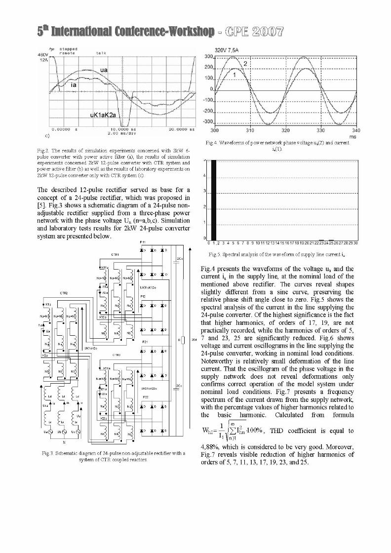
Fig.4. Waveforms of power network phase voltage ua(2) and currentia(l).
4
0 1 2 3 4 5 6 7 8 9 10111213141516171819202122324252627282930
Fig.5. Spectral analysis of the waveform of supply line current ia.
Fig.4 presents the waveforms of the voltage ua and thecurrent ia in the supply line, at the nominal load of thementioned above rectifier. The curves reveal shapesslightly different from a sine curve, preserving therelative phase shift angle close to zero. Fig.5 shows thespectral analysis of the current in the line supplying the24-pulse converter. Of the highest significance is the factthat higher harmonics, of orders of 17, 19, are notpractically recorded, while the harmonics of orders of 5,7 and 23, 25 are significantly reduced. Fig.6 showsvoltage and current oscillograms in the line supplying the24-pulse converter, working in nominal load conditions.Noteworthy is relatively small deformation of the linecurrent. That the oscillogram of the phase voltage in thesupply network does not reveal deformations onlyconfirms correct operation of the model system undernominal load conditions. Fig.7 presents a frequencyspectrum of the current drawn from the supply network,with the percentage values of higher harmonics related tothe basic harmonic. Calculated from formula
1 I '2WhI LIhn 100%, THD coefficient is equal ton)I
4,88%, which is considered to be very good. Moreover,Fig.7 reveals visible reduction of higher harmonics oforders of 5, 7, 11, 13, 17, 19, 23, and 25.
ua.. -aa X M-tf \ 6 | f.. . ..... .... . f fi ... ft . 3 fx ........ .. E f .$> fl <_. a ew .. | nt_ ............................... _ a 4- M < a -1 a .9
UK1aK2a \ fX6 6 1 H/ 6 6 1 /1 6 6 6 61 6 E 6 6 6 6 6 1 1 6 6 6 l111.................... ............ f ........ ........ .... ........... f '20
lZJ
V
1
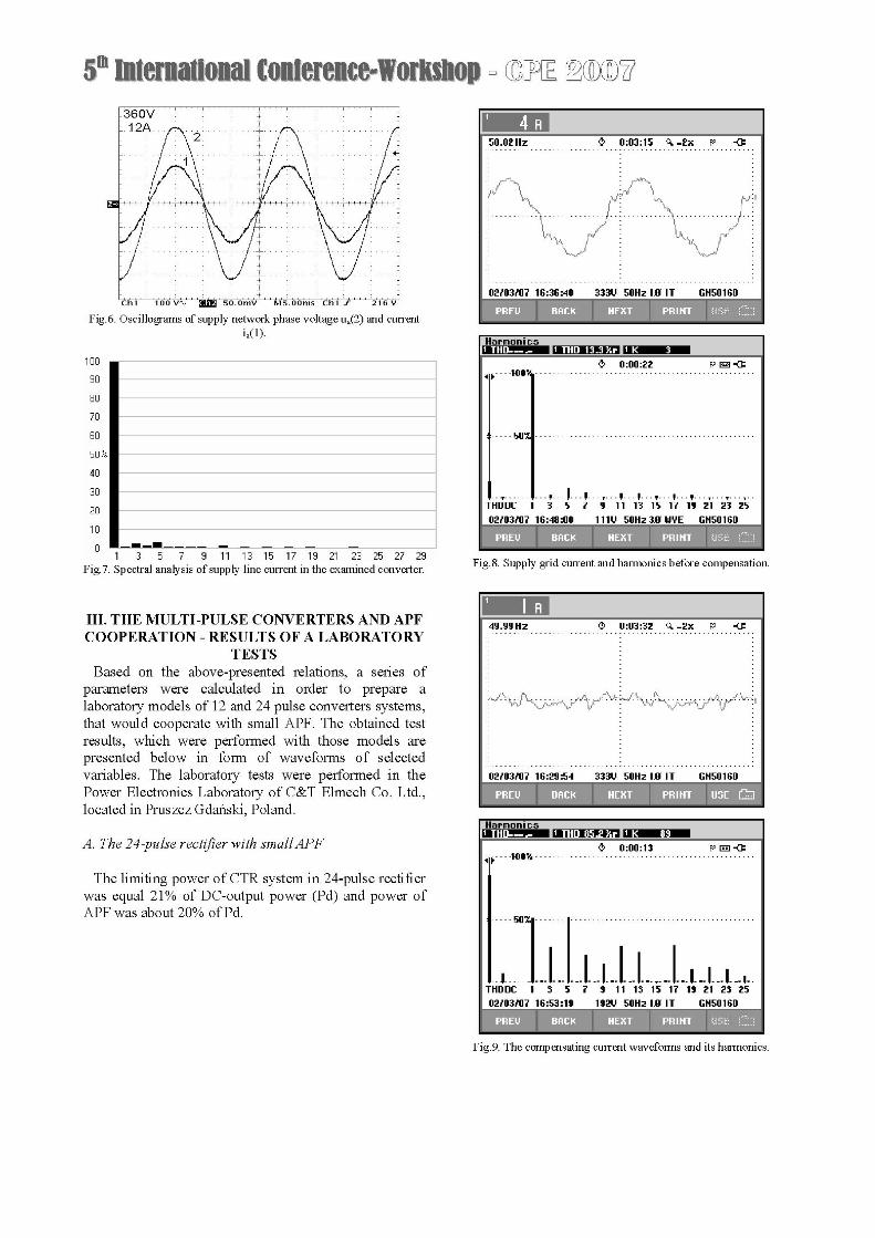
Fig.6. Oscillograms of supply network phase voltage Ua(2) and currentia(l).
100
90
8070
60
50 %
40
30
20
10
0 *___ -_ _ -_ _ -
1 3 5 7 9 11 13 15 17 19 21 23 25 27 29Fig.7. Spectral analysis of supply line current in the examined converter.
III. THE MULTI-PULSE CONVERTERS AND APFCOOPERATION - RESULTS OF A LABORATORY
TESTSBased on the above-presented relations, a series of
parameters were calculated in order to prepare alaboratory models of 12 and 24 pulse converters systems,that would cooperate with small APF. The obtained testresults, which were performed with those models arepresented below in form of waveforms of selectedvariables. The laboratory tests were performed in thePower Electronics Laboratory of C&T Elmech Co. Ltd.,located in Pruszcz Gdan'ski, Poland.
A. The 24-pulse rectifier with smallAPF
The limiting power of CTR system in 24-pulse rectifierwas equal 21% of DC-output power (Pd) and power ofAPF was about 20% of Pd.
Fig.8. Supply grid current and harmonics before compensation.
0210310? 16:29:54 333U 50Hz IlJR IT GH50160
Fig.9. The compensating current waveforms and its harmonics.
50.02 Hz D 0:03:15 A -2x p -<
.~~~~~
0201?16:36:40 333U 50Hz IlJR IT GH50160
kiii- -r
1 o0:00:22 p iJ-e0 .... 8 ..................................................
4.... 50E ..................................................
...,...I...I...Y..i..I.I...Y...I...I.... 7....THDDC 1 3 5 ? 9 11 13 15 17 19 21 23 2502103107 16:48:00 1 1 1 U 50Hz 3fB WYE GH50160
HarOndi c
D 0:00:13 p Es-# ....} 8 ..................................................
.50x1.
*. I.....--- -- - -- - -- ---T--- -|--. .-
THDDC 1 3 5 ? 9 11 13 15 17 19 21 23 2502103107 16:53:19 192U 50Hz I J IT GH50160

SCOPE CURSOR
S80z .1) 0:01:27 A -2x UFP -<:.............................
02103107 17:10:59:268 192U
*r,,OHzf,I .H5016
50Hz lB I T GH50 160
Fig. 10. Power network current and harmonics after compensation.
B. The 12-pulse rectifier with small APF
The limiting power of CTR system in 12-pulse rectifierwas equal 13% of Pd and power of APF was about 20%of Pd.
Fig. 11. Power network current before compensation and compensatingcurrent.
Fig. 12. Power network current and harmonics of supply grid currentafter compensation.
Because of cooperation with APF, in both arrangments ofmulti-pulse converters, application of linear reactors Ldmay be disregarded, and thereby construction cost of thesystem decreases. The system of multi-pulse convertercooperating with the active filter allows to achieve supplycurrent of minor distortion. At the same time it should benoticed that applied system of coupled reactors, as wellas the active filter are charactarized by low power, whichtestifies for their low costs. Practical application of thesystem may be considered with regards to local networkssuch as ship power networks, which more often supplynon-linear receivers. However the application should takeinto account strict requirements to preserve parametersdefining quality of energy. Exemplary network
50.01 Hz -: 0:00:12 A~_2x p -C
.. . .
.~~~~~~~~~~33U5H RI H06
00:00:28 Fp E e-C4 F.... ..................................................
I.... 50E ..................................................
.1-- ... ... . . . ... . ... ...*-.-. .*..-.T*.--.T. .T.*-.-1
THDDC 1 3 5 ? 9 11 13 15 17 19 21 23 2502103107 16:43:32 192U 50Hz 1 GH50160
SCOPE CURSOR
S808tiZ. 0:00:03 < -2x U PF -............................. .............................
~~~~~.
02Z03Z0717:09:5 1 92U 50Hz lB I T GH50 160
SCOPE CURSOR
50e01Hz O 0:01:11 A -2x UFP -<.............................. ..............................
0 ? 10........ 0H .......I.T. ......
............................. ...............................
0210310? 1?:08:4?:420 1 92U 50Hz lB I T GH50 160
Haronh IcS
0:00:07 U P Eii-4 F .... ..................................................
4.... 50E ..................................................
. T. . *. - --T - --T - --T ---T---F..I .-... .. I . T .---T
THDDC 1 3 5 ? 9 11 13 15 17 19 21 23 250210310? 1_:13:00 192_ 50Hz 10 IT GH50160
I

configuration, which supplies passanger ship is showedon the Figure 13.
BOW THRUSTER - COMPlvRESSOxRSD<STERN THRUSTER 2 3 4 BOWTHRUSTER
BUSBAR)l BUSBAR 2 BUSBAR 3 SUSBAR 4
D!D
C ClPIEXEATO DUPLEX REACT7
TDSANDAP iiECIT.I
I . D.) n A :
RECT ULS:ON MOTOR ER L < J L _ _ _JI2M
M II II M~~~~~~~~~~RNSORE
PROPULSIONIIMOTORi
Fig. 13. The scheme of passenger ship supply system.
IV. CONCLUSIONS
The concept of the rectifier system with coupledreactors and the active filter is one approach to the issueof improvement of energy quality absorbed from supplypower network. This approach in particular takes intoconsideration opportunity to construct low cost supplysystems of increased reliability in environmental tryingconditions, for example on board.Discussing the tested systems from the point of view
that focuses on reliability and practical applications inexisting supply systems with high quality reguirements(EMC) is a great challenge for the presented conceptsimultaneusly applying CTR reactor system and APF.Adventagous solution seems to be application of the
system that consists of the CTR coupled reactor withmulti-pulse rectifier and active power filter, because ofthe compromise among limiting power of reactor andfilter, the reduction level for supply power harmonics, thesystem simplification caused by possibility of Ld reactorelimination and power factor of the realized system.
REFERENCES
from VSI (in polish)". Electrical Power Quality and Utilisation,Cracow, 1998.
[8] Wojciechowski D.: "Novel estimator of distorted and unbalancedelectromotive force of the grid for control system ofPWM rectifierwith active filtering", EPE 2005, Dresden, 2005.
[9] Wojciechowski D.: "Grid voltages sensorless control of PWMrectifier with active filtering", Electrical Power Quality andUtilisation Journal, Volume XII-Number 1, December 2006, p.143-48 (ISSN 1234-6799)
Daniel Wojciechowski, Ass. Prof. D.Sc. Eng.,was born in Walbrzych, Poland, in 1976. Hereceived the B.S. and M.Sc. degrees in field of
I)A t g | |telectrical drives and power electronics fromGdansk University of Technology, Gdansk,Po-land, in 2000. He received Ph.D. degree atGdansk University of Technology, Gdansk,Poland in 2005. In that year, he joinedDepartment of Ship Automation at GdyniaMaritime University, Gdynia, Poland, where heis currently an Assistant Professor. Hisresearch interests include modeling and control
of high power factor converters and active filters.
Ryszard Strzelecki, Prof. D.Sc. Eng., wasborn in 1955 in Bydgoszcz, Poland. He
...............received M.Sc. degree from TechnicalUniversity of Kiev, Ph.D. and D.Sc. degreesfrom Institute of Electrodynamics of theUkrainian Academy of Science. Presently, heis Full Professor in Gdynia MaritimeUniversity, Poland. His research interests arein area of power quality and design, andapplication of the modern power electronicssystems. He is authors 5 book and more 200articles. He is Chairman of the Committee on
Power Electronic of the Electrical Engineering Polish Association andmember of several national and international committees, among othersin IEEE, PELS/IES, PES, IAS.
_14AWNW&L Piotr Mysiak, Ass. Prof. D.Sc. Eng., lecturerat the Ship Automation Department, GdyniaMaritime University. Born, on July 2, 1959 inLodz, Poland. Graduated with a M.Sc. degreein Electrical Engineering from the TechnicalUniversity of Lodz in 1984, and from GdyniaMaritime University in 1993. In 1996 hereceived his Ph.D. degree in powerengineering electronics.An author of numerous research publicationsand reports on protection ranges of power-
electronic converters and minimisation of negative effect of thosedevices on a supply network.
[1] Aredes M.:"Active Power Line Conditioners". The doctorengineer dissertation, Technical University ofBerlin, Berlin 1996.
[2] Depenbrock M. ,,A new 18-pulse rectifier circuit with line-sideinterphase transformer and nearly sinusoidal line currents" IAS1990.
[3] Miyairi S. ,,New method for reducing harmonics involved in inputand output of rectifier with interphase transformer" IEEE Trans.on Ind. Aplic. 1986.
[4] Mysiak P. "The DC-output multipulse converter in the low voltagepower network supply conditions (in polish) ". The doctors thesisdissertation, Warsaw Technical University, Warsaw 1996.
[5] Mysiak P." A multi-pulse diode rectifier with a coupled three-phase reactor - the design method and results of the simulation andlaboratory tests, Electrical Power Quality and Utilisation JournalVolume XI-Number 1-2005 ISSN 1234-6799.
[6] Supronowicz H., Strzelecki R.: ,,The power factor in AC-powersupplying systems and its improvement methods (in polish)".Publishing House of Warsaw Technical University, Warsaw 2000.
[7] Tunia H., Barlik R., Mysiak P.: ,,The coupled reactors system forcurrent higher harmonics reducing in three-phase loads supplying
(G ( G (G-)(G